Uni Sketch Manual
User Manual:
Open the PDF directly: View PDF ![]() .
.
Page Count: 52
- Installation and Operation Manual
- Contents
- Getting Started
- Firmware Updater
- Connecting SKAARHOJ Controller with Clients
- Setting IP for non UniSketch Based Controllers
- Network Recommendations
- Device Cores
- Firmware Updater Application
- cores.skaarhoj.com
- Back Connections and Config Mode
- Configuration Mode/Accessing Web Interface
- UniSketch OS Explained
- Web Interface
- Device Settings
- Hardware Interface Components (HWC)
- Devices
- Multiple Actions
- Shift
- States
- Copy / Paste
- Presets
- Troubleshooting
- Contact Support
- Hardware Notes:
- DB-25 Connector Configuration for GPI
- DB-9 Connector Configuration for RCP units (EXT I/O)
- Pinout for Tally Box
- Other Notes:
Installation and Operation Manual
June 2019
Congratulations with your SKAARHOJ controller! Our mission is to ease the
use of broadcast hardware for people making live video and doing so by
means of awesome tactile industrial strength hardware controllers. We are
really proud of how much we have been able to stuff into this device, and we
hope you can see our love and passion for cool and helpful technology shine
through when you browse this manual.
While we really want to make everything intuitive for you, we still need to document some not so obvious
facts and conventions and we have tried to put everything you need to know into this document along with a
few extra tips too.
Please notice this manual is aimed at UniSketch powered SKAARHOJ controllers. If you have a device
not running UniSketch please see other manual at http://skaarhoj.com/support/manual/. In order to
run UniSketch you need a device with the SKAARDUINO Due MCU.
Have fun!
1
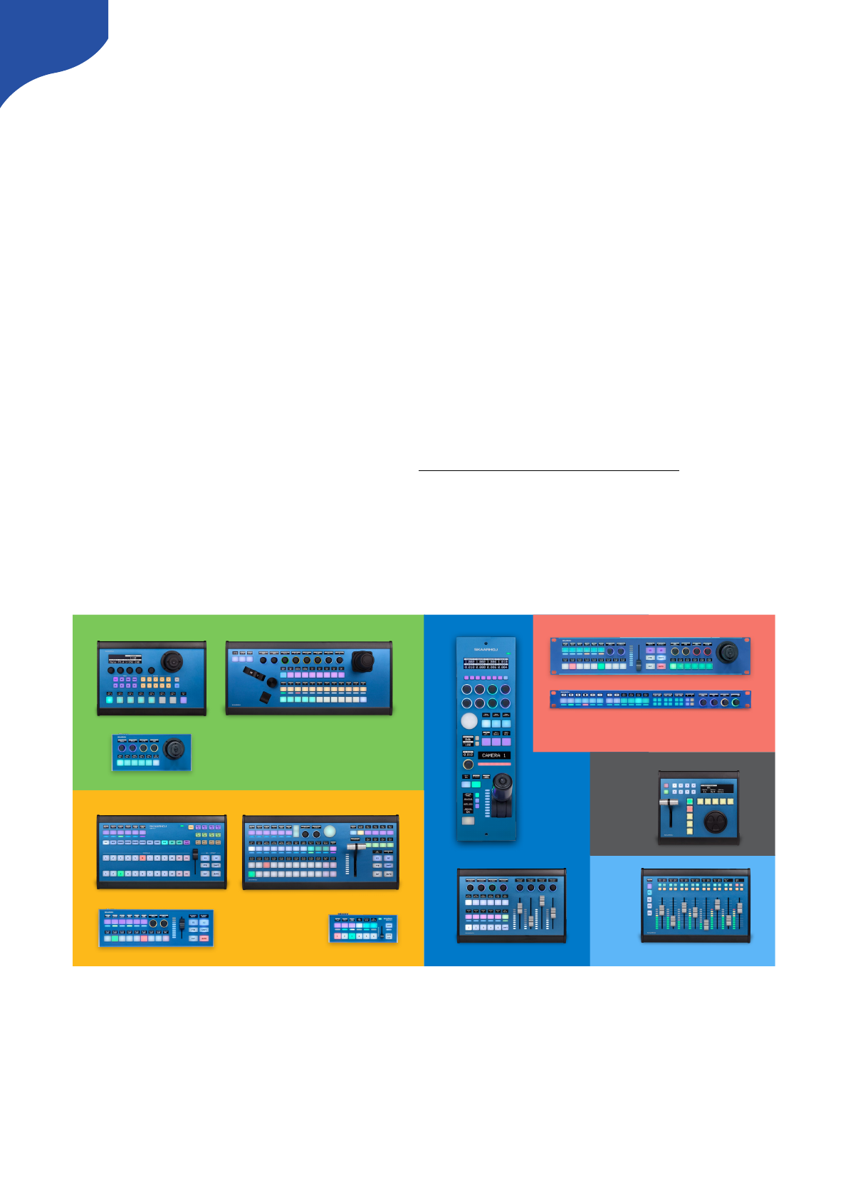
PTZ CONTROL
AUDIO
RCP
VISION
MIXING
UTILITY
REPLAY

Contents
Installation and Operation Manual 1
Contents 2
Getting Started 4
Firmware Updater 5
Connecting SKAARHOJ Controller with Clients 5
Troubleshooting 6
Setting IP for non UniSketch Based Controllers 7
Network Recommendations 8
Facts 8
Power over Ethernet (PoE) Specifications 8
Troubleshooting 8
Connection Stability and NDI 9
Network Guidelines 9
Additional Resources 9
Multicast Data on Network 10
Recommend Managed Network Switches for NDI Network 10
Static IP Address or DHCP 12
Device Cores 14
vMix Device Core 14
Firmware Updater Application 16
Load Firmware from File 16
Port selection on Windows 17
IP Settings 18
Serial Monitor 20
Commands in the Serial Monitor 20
List of Commands 20
Error Occurred during Firmware Upload 22
The Connected Controller is not Fully Registered yet 24
The Controller Appears Bricked/Non Responsive 24
cores.skaarhoj.com 26
Controller Configuration 27
Device Cores 27
Manage Configurations 28
Manage Media 28
Firmware Overview 28
Device Core Options 29
Back Connections and Config Mode 30
Status LED Overview 31
Connection Troubleshooting 32
Configuration Mode/Accessing Web Interface 32
Enter configuration mode 33
2

Access to web interface if SKAARHOJ controller is connected via network router 33
Access via the Firmware Application 33
DHCP 33
Web Interface Troubleshooting 34
UniSketch OS Explained 35
Web Interface 35
Device Settings 35
Hardware Interface Components (HWC) 36
Graphical Displays 36
Devices 37
Multiple Actions 38
Shift 38
States 39
Copy / Paste 39
Presets 40
Troubleshooting 41
Contact Support 43
Hardware Notes: 44
DB-25 Connector Configuration for GPI 44
DB-9 Connector Configuration for RCP units (EXT I/O) 45
Pinout for Tally Box 46
Other Notes: 47
Triggering Actions from Binary Inputs 47
Connection between RCP and ETH-SDI Link using ETH2SDI Firmware 51
Connection between RCP and WIFI-B4 Link 52
3
Getting Started
For UniSketch based controllers a config-slip is included in the package.
Default IP configuration for a SKAARHOJ unit when shipping:!
IP Address: 192.168.10.99 & Subnet: 255.255.255.00
4
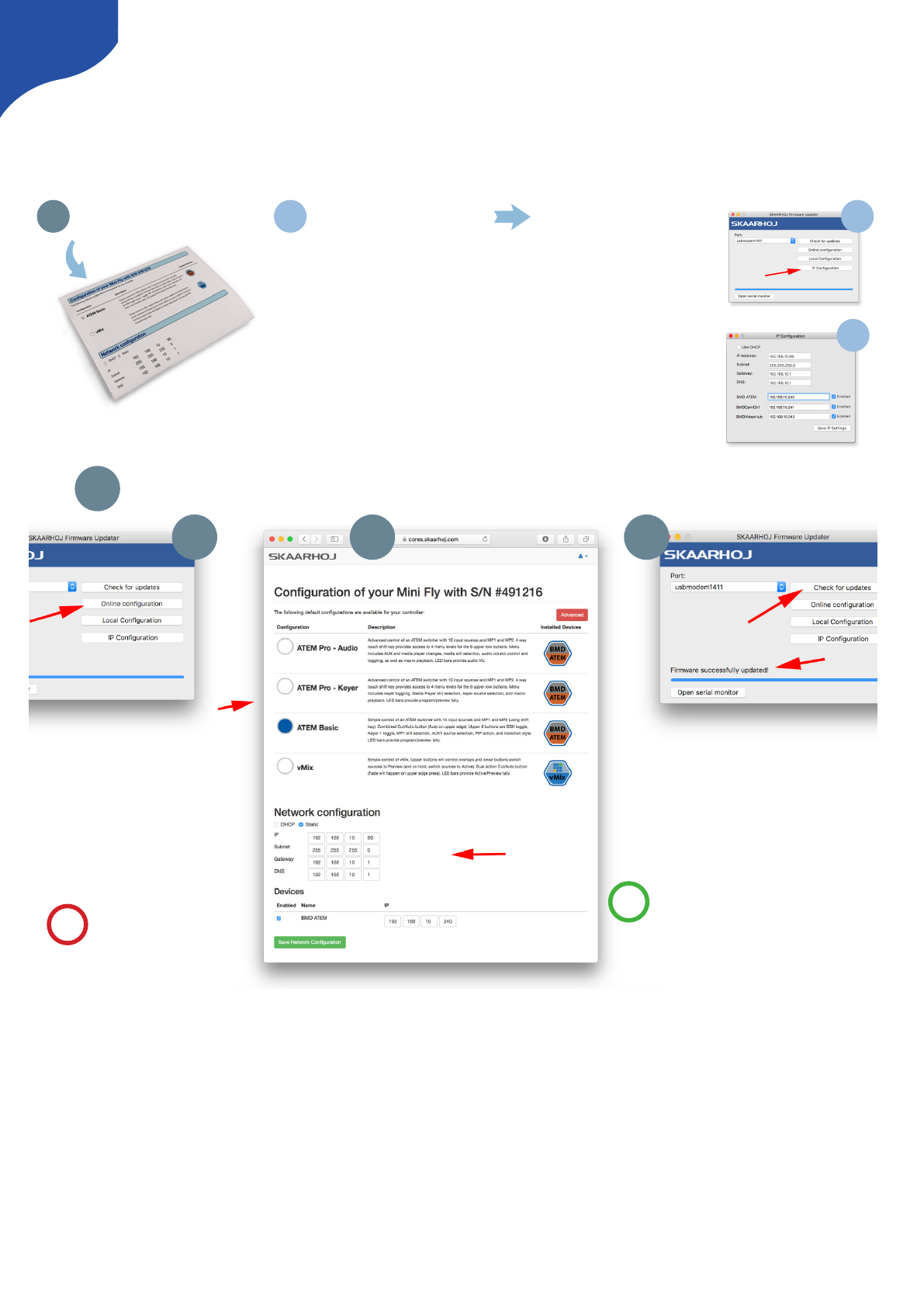
What conguration is installed?
Make sure this is the one you want. If not, read
the next section on how to change it.
What IP addresses are used?
If the conguration is good, but the IP
settings don’t match your network, you’ll have
to change them.
Change the controller IP adresses
To set up the IP addresses, click “IP
Conguration” in the rmware application.
In the pop-up window, make the IP
changes you need, save and power cycle
the controller.
You’re done!
1 2 2a
2b
Download an entirely dierent conguration
Press “Online Conguration” in the
SKAARHOJ Firmware Updater applica-
tion. A web browser will open.
You’ll see the same page printed and
included in this cover; Now, select a
dierent conguration and set the
corresponding IP addresses.
The nal step to bliss is to go back to the
SKAARHOJ Firmware Updater application
and press “Check for updates”. A new unique
rmware with your selected conguration and IP
settings is created, downloaded and installed on
your controller.
You’re done!
Pro-tip: If you are up for some fun later,
notice the “Advanced” button on the web
page. Don’t click it just yet - but go back
there and explore when you have success-
fully worked with a default conguration.
1a
!
Having trouble? Visit http://skaarhoj.com/support
1b 1c
1
Your computer must be
connected to the Internet!
!
Firmware Updater
You won’t get far without the SKAARHOJ Firmware Updater application. Download it www.skaarhoj.com/
support/firmware-updater/. Install, run it and connect your controller. Please notice the USB cable is only to
be used for configuration and firmware upgrade. The USB plug is not designed to be connected during
normal operation. More details are found in the “Firmware Updater Application” section of this manual.
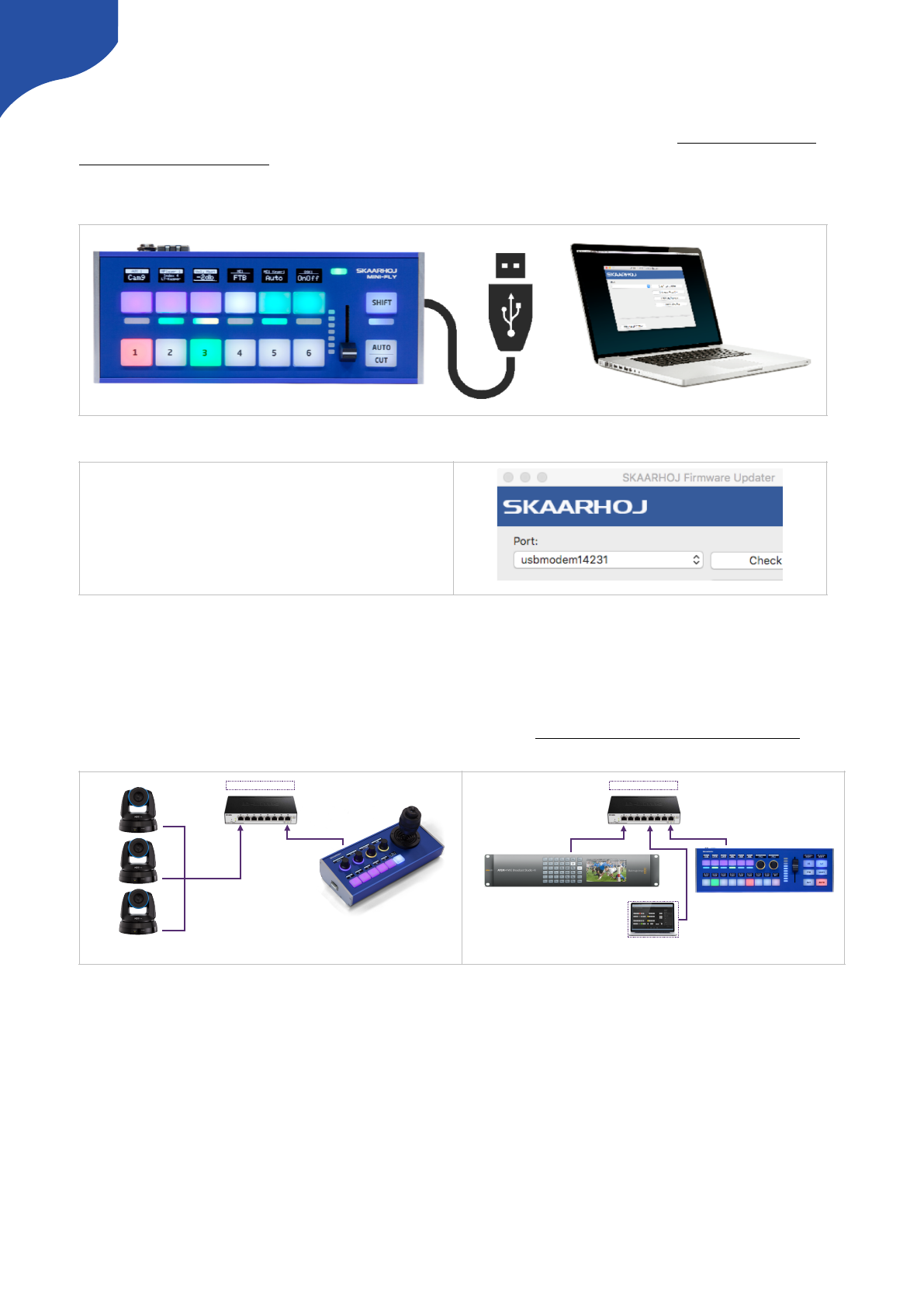
Connecting SKAARHOJ Controller with Clients
Almost all of our controllers are IP based. Below two examples are given for how to connect a SKAARHOJ
controller with a client or multiple clients. Notice communication is ethernet based and not via USB. For
control of multiple PTZ cameras please read the “PTZ Manual” at www.skaarhoj.com/support/manuals/
If you want to control for example an ATEM switcher you do not need a PC/Mac running the ATEM Software
Control Panel for using the SKAARHOJ controller since it connects directly to the ATEM. But you can run
both at the same time if you want, and the changes made in either the SKAARHOJ controller or in the ATEM
Software Control panel will correlate with the other unit. This is the case for most device cores you can install
on your controller, but for more information, consult the support pages for the individual device cores."
Connect the SKAARHOJ controller to your Mac or
PC with the included USB cable. The device shows
up in the Port list (only connect one SKAARHOJ
controller at a time).
5
Ethernet
Ethernet
SKAARHOJ Controller
Multiple Clients
Needs to be on same subnet!
192.168.10.213
192.168.10.214
192.168.10.215
192.168.10.99
Ethernet
Ethernet
SKAARHOJ Controller
Single Client
Ethernet
Needs to be on same subnet!
192.168.10.99
192.168.10.240
Optional: ATEM Software Control Panel
Ethernet
Troubleshooting
If you have followed the above instructions and still have issues here’s some tips
•Check IP and network settings. If the Device Core IP address does not match the client(s) nothing will work
•Double check IP settings! Use the serial monitor to confirm IP address of the controller and clients.
•Consider pressing “clearpresets”. This will remove any presets and IPs stored locally on the controller.
Notice: IPs set via the “IP Configuration” will be removed + any local configuration will be removed by this
command.
•Use the serial monitor in the Firmware Updater Application to check connection status. Depending on
Client type you will get confirmation when clients are connected or not (see illustrations below)
•Avoid having Device Cores enabled if clients does not exist. The controller will use resources trying to
connect to non-existing clients.
•SKAARHOJ controller and client must be on the same subnet.
6
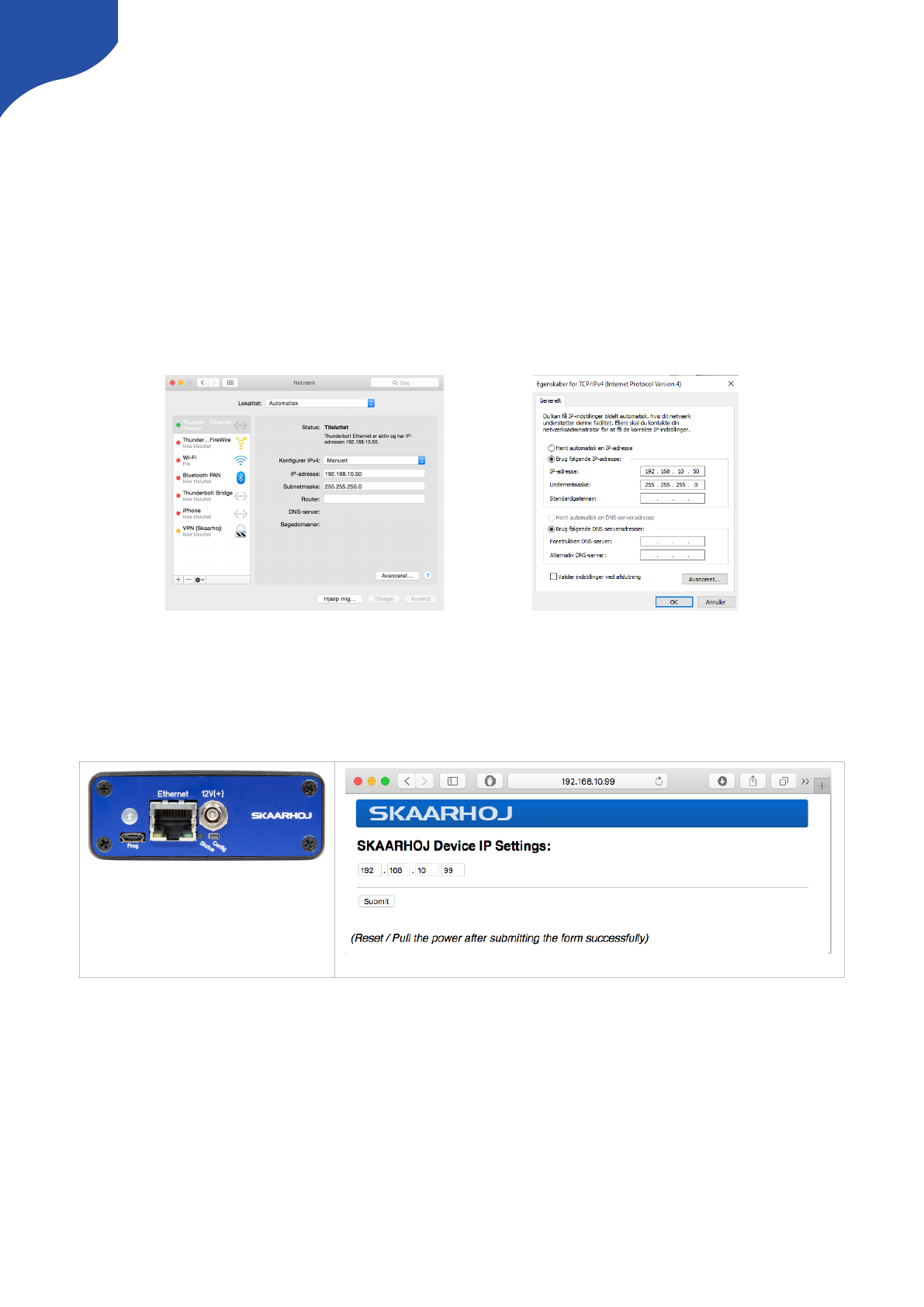
Setting IP for non UniSketch Based Controllers
Some of our products such as the ETH-SDI Link does not run UniSketch OS and for these the procedure for
setting IP address differs.
Set manual IP address for Mac/PC
We recommend connecting your SKAARHOJ controller directly to your PC/Mac with a ethernet cable in
order to access the web interface.
Turn off your wifi and set your IP manually:!
192.168.10.50 PC/Mac IP address!
255.255.255.0 Netmask!
192.168.10.1 Gateway/Router IP address if necessary
Enter Configuration Mode
•Step 1 — Connect SKAARHOJ device to PC/Mac with ethernet cable and power up the unit. Let it boot up.
•Step 2 — Press and hold the config button until the status LED starts to blink
•Step 3 — Access web interface by entering http://192.168.10.99/ in your browser
Notice: The web interface IP is always set to http://192.168.10.99 even if you change the “SKAARHOJ
Device IP Address” in the web interface.
7
Location of “Config” and “Status LED”
Example of web interface on ETH-SDI Link

Network Recommendations
Facts
•SKAARHOJ controllers have a 100 mbps network interface
•Network switch must have Auto-MDI/MDIX
•Network switch must support 100 mbps
•PoE: IEEE 802.3af
When connected to a network switch, the yellow LED (lower left) at the ethernet jack will be on. If the device
in the other end supports TX/RX auto detection you may be able to connect the SKAARHOJ controller
directly to your device, otherwise use a crossed cable or a network switch (the supported setup). Remember
a SKAARHOJ controller and client must be on the same subnet (192.168.10.* or one you set up in the
controller). If you have multiple SKAARHOJ units connected to the same network they need to have different
IP addresses!
Power over Ethernet (PoE) Specifications
We use the PoE industry standard 48V IEEE 802.3af. If you want to power our controllers using PoE it is
important your switch supports this standard. Please notice some manufactures such as Ubiquity have their
own non-standard 24V type of PoE which is incompatible with our controllers. Especially pay attention to the
standard if you use a PoE injector.
Troubleshooting
If you experience no network activity at all try one or more of the following suggestions:
•Use a managed network switch
•Force network switch port to 100 mbps
•Try a different network switch
1GB or 10 GB switches can have issues with our 100 mbps interface if not properly managed. The iMac Pro
with 10 GB have issues if connected directly to our controller. Try with a USB to ethernet adapter in this case.
8

Connection Stability and NDI
Background: People are moving to NDI video on a large scale and while it’s a fantastic technology, it can
lead to frustrating network issues which may first appear as faults on specific and seemingly unrelated
devices like a SKAARHOJ controller. In general, the problem is that NDI used on a poorly configured
network that is not “NDI ready” will lead to flooding of NDI video data to devices that doesn’t want it and
can’t handle it. For a SKAARHOJ controller this means that the essential control data connection is killed by
all the irrelevant video data it receives. Even a single lost control package can lead to poor of connection
stability or the use of a joystick. In the worst case the control won’t even connect. These cases can be
frustrating because they are tipping-point issues where a small change cascades into large consequences.
In general: For any network control system to work - and certainly for a SKAARHOJ controller - you need to
consider that your network is configured so that neither the SKAARHOJ controller nor the devices it
communicates with and no link in between are congested with network traffic that can result in predictably
poor performance. No matter how much error correction we build into a controller, lost communication
information will lead to poor performance. When NDI video data and other Multicast data is shared on a
network it will congest the network unless propper guidance have been taken. Use proper managed
network switches with something called IGMP snooping enabled so the lovely NDI data is only sent to the
devices that wants to receive it. If not - and this is the default unfortunately - all devices including your
SKAARHOJ controllers will receive it too and spend incredibly amount of resources to filter it out.
Below you will find our recommendations as this present time. Please be aware suggestions might get
updated as we get to understand and test further.
If you use our controllers on a network with NDI sources (Multicast) it is absolutely imperative to
configure your network properly to ensure a stable connection.
Network Guidelines
Besides having taken propper network switch considerations such as Gigabit Ethernet on all network switch
ports we recommend the following settings on your Managed Switch when possible:
•Enable IGMP Snooping (mDNS is automatically blocked by many !
switches when snooping is enabled — refer to documentation from your switch vendor)
•Enable Flow Control as Asymmetrical or simply as On
•Disable Quality of Service
•Disable Jumbo Frames
•CONFIGURE IGMP Querier and Query Interval for each switch in multi-switch networks !
when using multicast
Additional Resources
•NewTek: NDI Network Guidelines
•PTZOptics: Setting up a Ubiquiti Network for use with PTZOptics Products
•NewTek Network Settings: https://support.newtek.com/hc/en-us/articles/115001705074-NETWORK-
SETTINGS?mobile_site=true
9
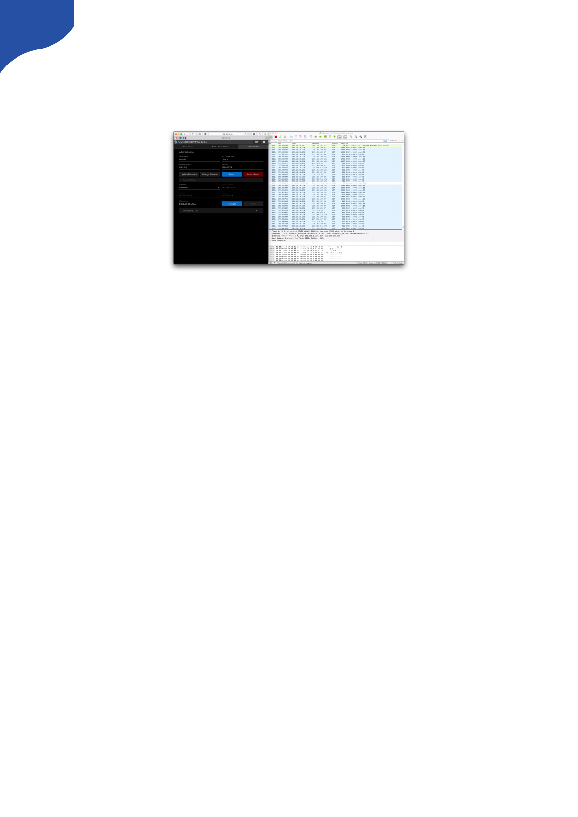
Multicast Data on Network
If you are unsure if Multicast data is present on your network we recommend using a network protocol
analyzer such as Wireshark. Many tutorials can be found online to filter to Multicast data on the network.
See a example here.
Recommend Managed Network Switches for NDI Network
We have tested 2 different managed network switches for a setup where multicast data is present. Below you
will find a quick guide on how to configure these 2 devices to ensure stable connection on your network.
•Ubiquiti UniFi US-8-150W
•Netgear Click GS408EPP
At this current moment we advise against the DGS-1100-08P from D-link as we have experienced poor
performance on this switcher. It can cause network devices to become unresponsive when a SKAARHOJ
controller is connected. We are investigating…"
10
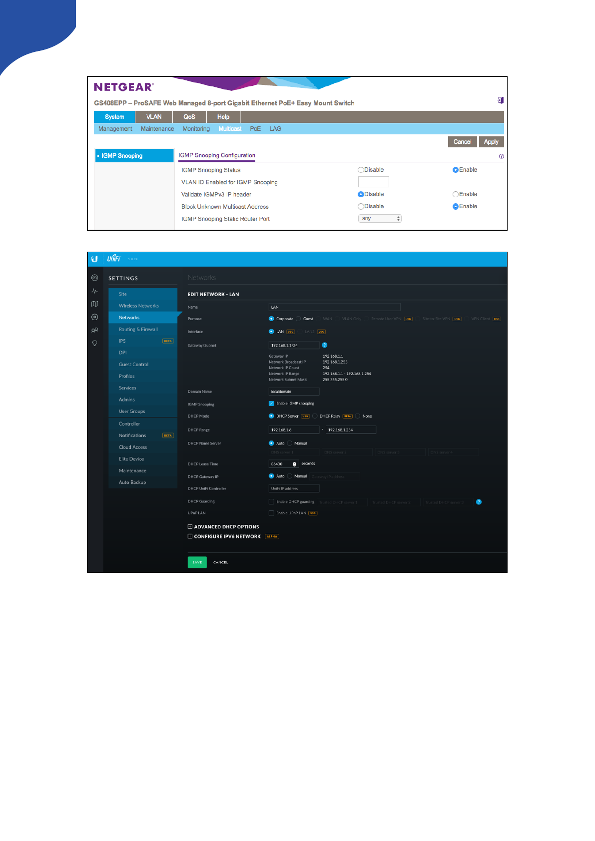
Netgear Click GS408EPP
Ubiquiti UniFi US-8-150W
11
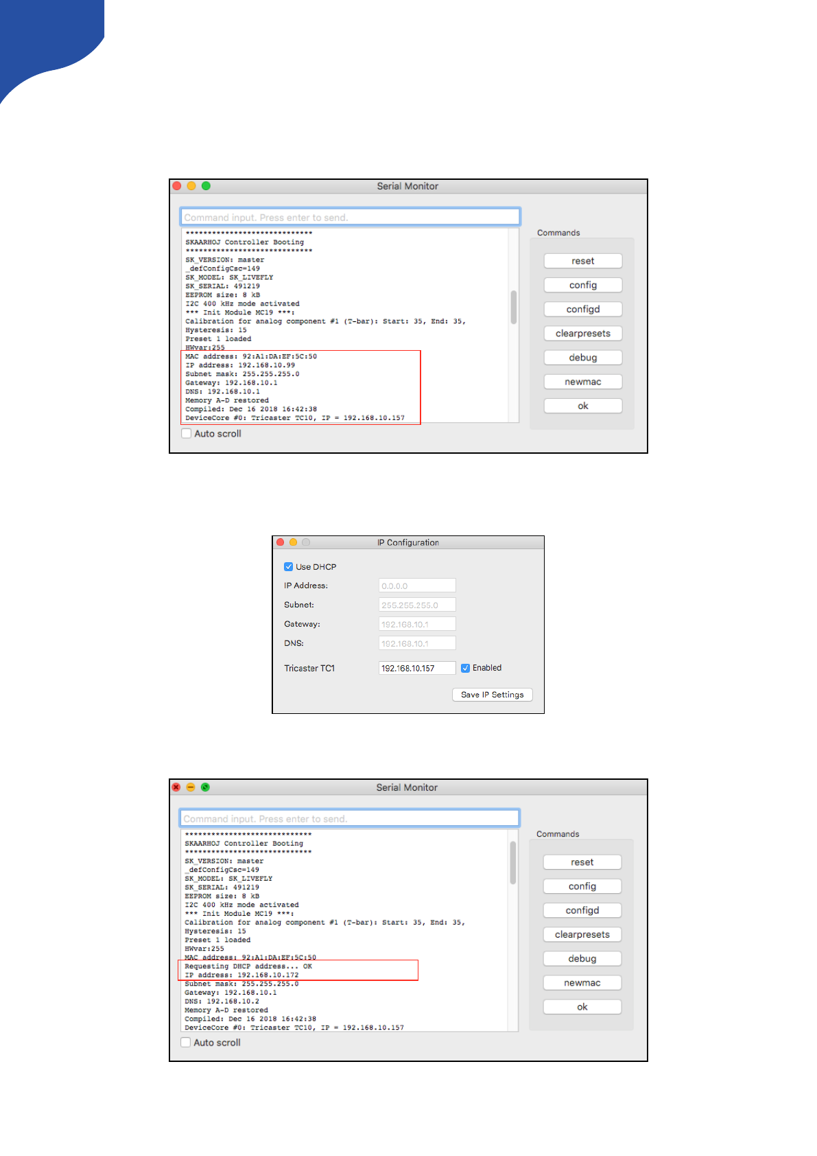
Static IP Address or DHCP
A SKAARHOJ controller running UniSketch will have the IP you set on the configuration page or via the “IP
Configuration” from the Firmware Application. During you boot up process you can always confirm the IP
settings on the controller and the Device Cores.
If the controllers IP is set to 0.0.0.0 (four zeros) or “Use DHCP” is activated in the IP Configuration window the
controller will get a IP address from your DHCP server on your network.
A message with “Requesting DHCP address… OK” will appear in the serial monitor if the controller gets a IP
address from the HDCP server.
12

If the controller is not assigned with a IP address from DHCP during boot up the serial monitor will report
“Requesting DHCP address… failed” and the controller will fall back to IP address 0.0.0.0
The controller will continuously try to get a IP address from the DHCP server. If it fails the message “DHCP
renew failed” will appear.
If successfully the message “DHCP Renewed: x.x.x.x” will appear.
13

Device Cores
External hardware support is made available on your controller as what we call Device
Cores. A device core is the driver - or akin to an “app” - installed on the your controller
that enables communication support with a given piece of broadcast gear. Some are
very mature and full featured, others still just basic, some are in beta versions and yet
others are just planned at this stage
You can always see the latest status here www.skaarhoj.com/support/device-cores/
and find specific Device Core manuals www.skaarhoj.com/support/manuals if they
exist.
vMix Device Core
When using our controller together with vMix the application vMixBridge is necessary to run on your
computer. This gabs communication between our controller and vMix - get it here: www.skaarhoj.com/
support/device-cores/vmix/
Set fixed IP on computer to match vMix Device Core IP address
You can check IP settings in vMix - Settings - Web Controller
Open vMix and vMixBridge. When SKAARHOJ controller
connects the vMixBridge will report
“New connection from …”
Check connection have been established in serial monitor.
Connection is confirmed by “VMIX _hasInitialized = True”
14
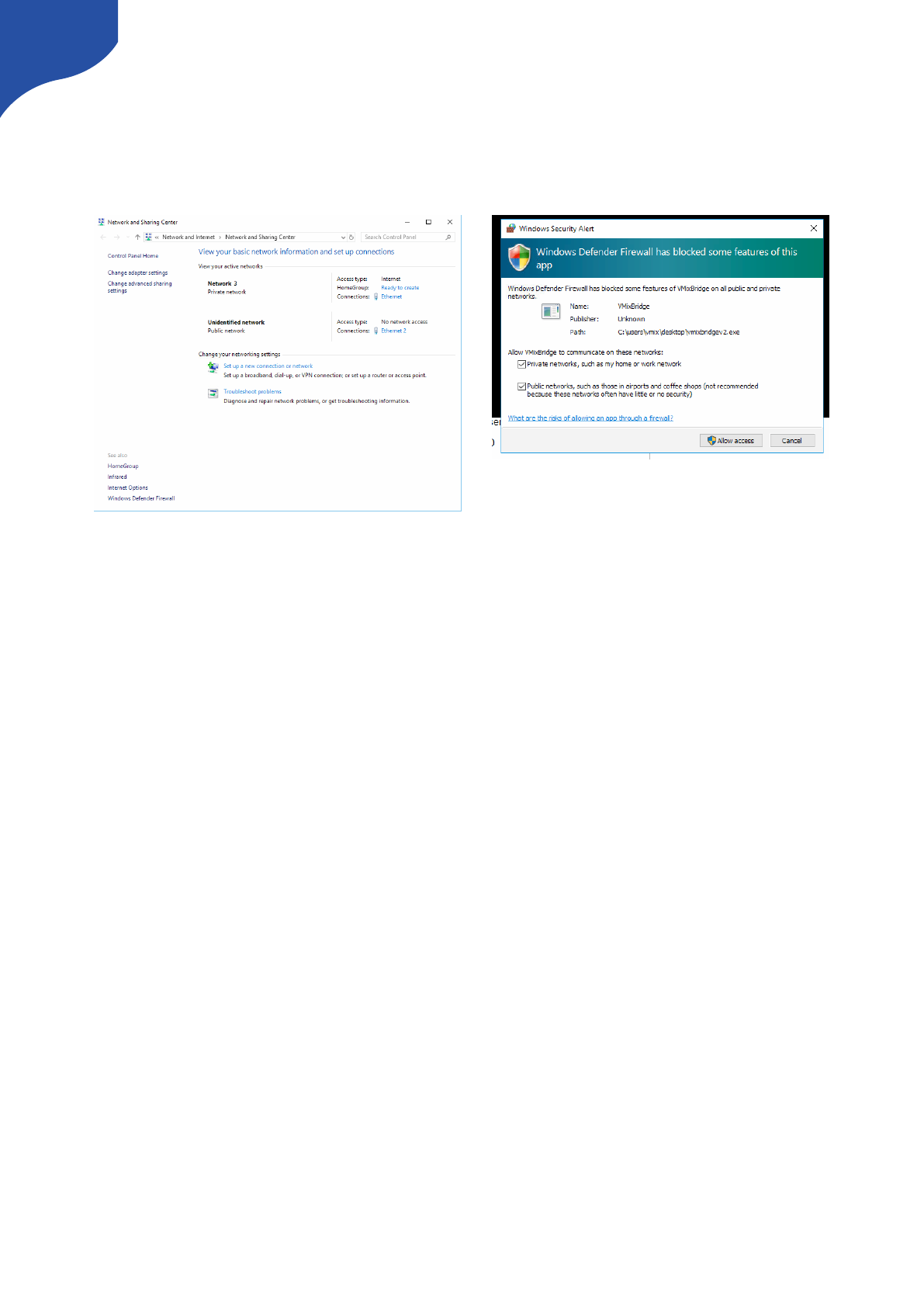
A note on Windows Defender Firewall
In order for the vMixBridge application to work properly you need to make sure the application is granted
access to either your Private Network or your Public Network dependent on which network the SKAARHOJ
controller is connected to.
15
Firmware Updater Application
A quick introduction to the Firmware Updater Application is presented in the “Getting Started” section. Here
we provide some more details. The applications can be downloaded for Mac and PC at: www.skaarhoj.com/
support/firmware-updater/
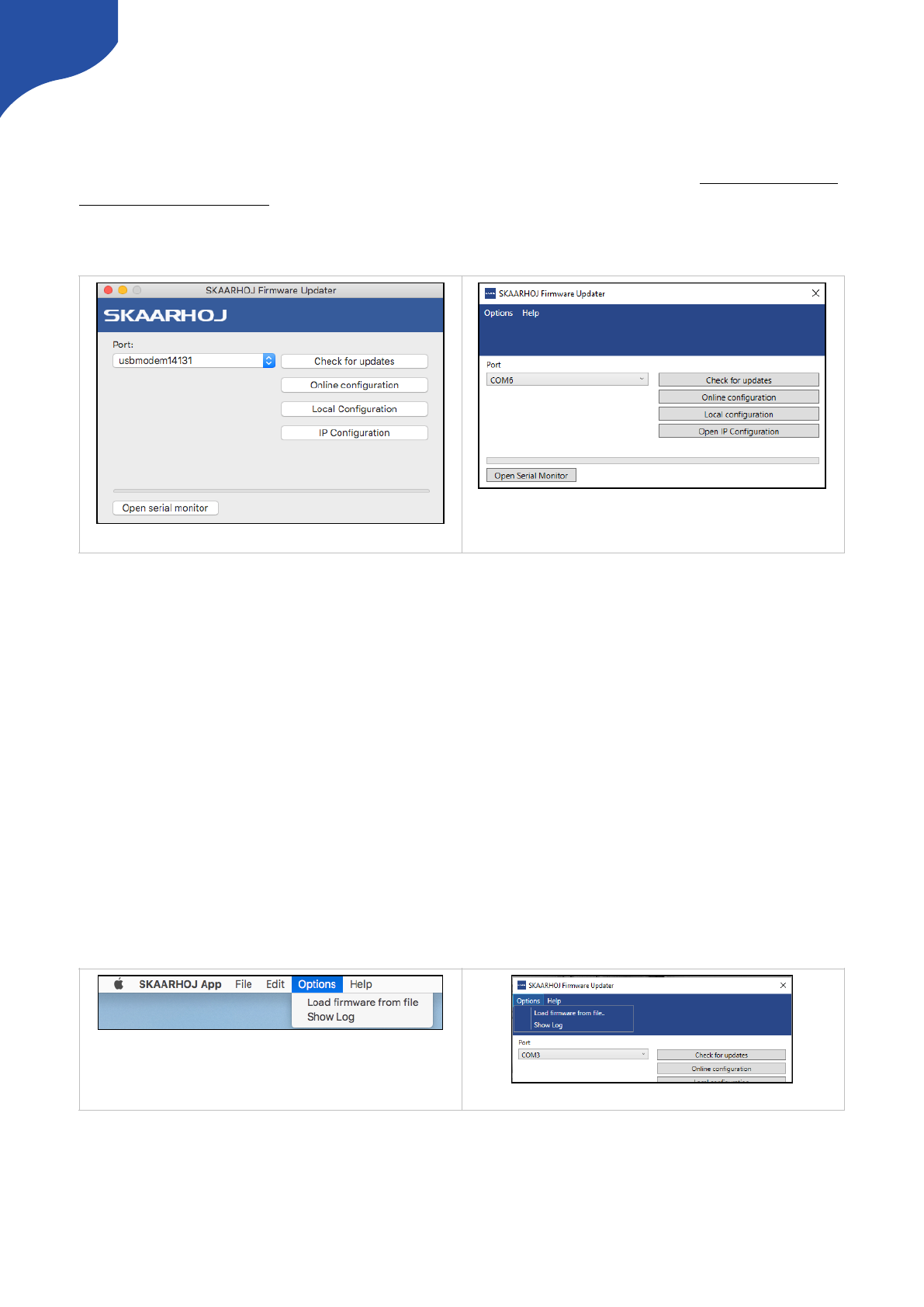
When the application is installed and open, connect your controller with USB to the computer. It should now
be displayed in the “Port” dropdown box. Please only connect one SKAARHOJ controller at a time.
A number of options now exist.
•Check for updates: Generates a new firmware on our server and downloads it to the unit. The is required
whenever a change to the configuration have been made from “Online Configuration”, or we have
updated UniSketch OS and Device Cores.
•Online Configuration: Opens a webbrowser and give you access to the online configuration page of your
controller. Remember a change made here are not saved on the controller before “Check for updates” is
pressed.
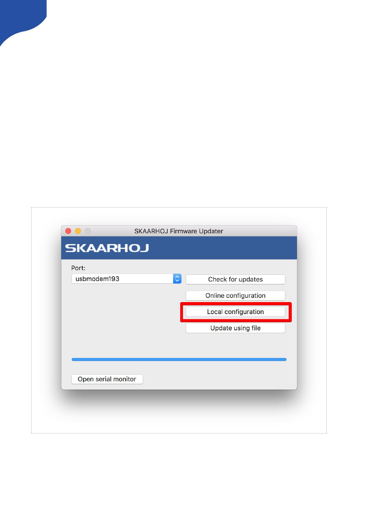
•Local Configuration: Starts a local webserver on the controller and open a webbrowser with a local
configuration page. Please notice changes made in the local configuration will not be synced with your
Online Configuration and whenever a “Check for Updates” command is executed the Local Configuration
will be overwritten!
•IP Configuration: Opens a configuration window for IP settings on the controller and Device Cores.
Load Firmware from File
In addition you will find a “Load Firmware from File” and “Show Log” in the “Options” tab in the application.
The “Load Firmware from file” is used if you have generated a firmware file from the Online Configuration
page and want to upload it manually. Or if you want to update firmware on a unit not integrated in our
UniSketch OS. Please notice firmwares are unique to each controller and paired with a hardware ID for the
controller it have been generated from. Firmware files cannot be uploaded to a different controller than the
one it have been generated from.
Firmware updater v2.4 on Mac
Firmware updater v2.4 on PC
On Mac
On PC
16
The “Show Log” will open a text document with a log from the application. Please included the relevant parts
in a support case.
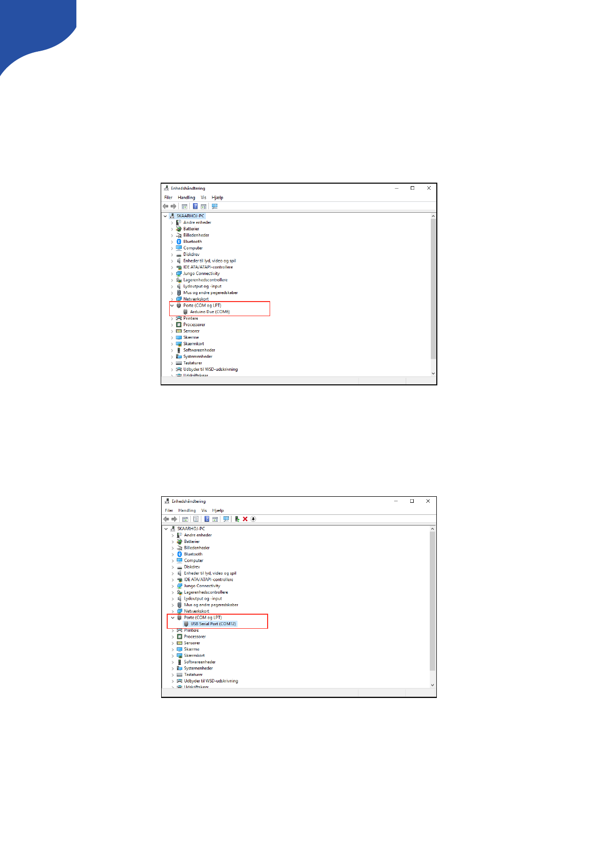
Port selection on Windows
If multiple options are listed in the port selection on Windows you can use Device Manager to find the
relevant COM port. If you have issues getting access to the controller when several COM port are listed in
the application try and disable other COM ports or disconnect other hardware using COM ports. For
UniSketch based units the controller should appear as “Arduino Due”
If you have a unit not running UniSketch such as a ATEM-TCP Link it will typically be listed as a “USB Serial
Port”
17
IP Settings
A couple of methods exist to set IP settings on the Device Cores and the controller itself.
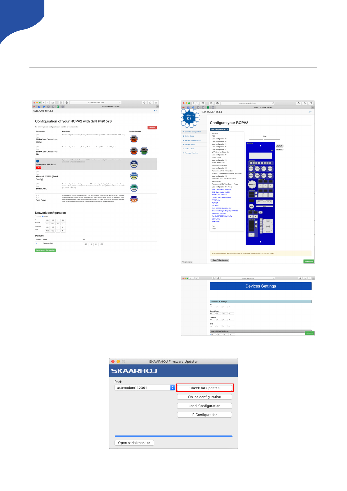
-Method 1: Using “Online Configuration” and “Check for updates” in the Firmware Application
Setting IP for default Configurations
If no custom configurations have been made on a
SKAARHOJ controller, a overview with default configurations
will appear when pressing “Online Configuration”
Setting IP for custom configurations
If custom configurations have been made on a SKAARHOJ
controller a overview like below will appear when pressing
“Online Configuration”
!
Notice on Windows the Port dropdown will display “COM” ports. Please see section “Port selection on Windows”
!
!
In the section “Network configuration” you can set the desired IP
addresses. Press “Save Network Configuration” and then press
“Check for updates” in the Firmware Application.
At the bottom of the config page you set IP settings. Remember to
press “Save Settings” and then press “Check for updates in the
Firmware Application.
18
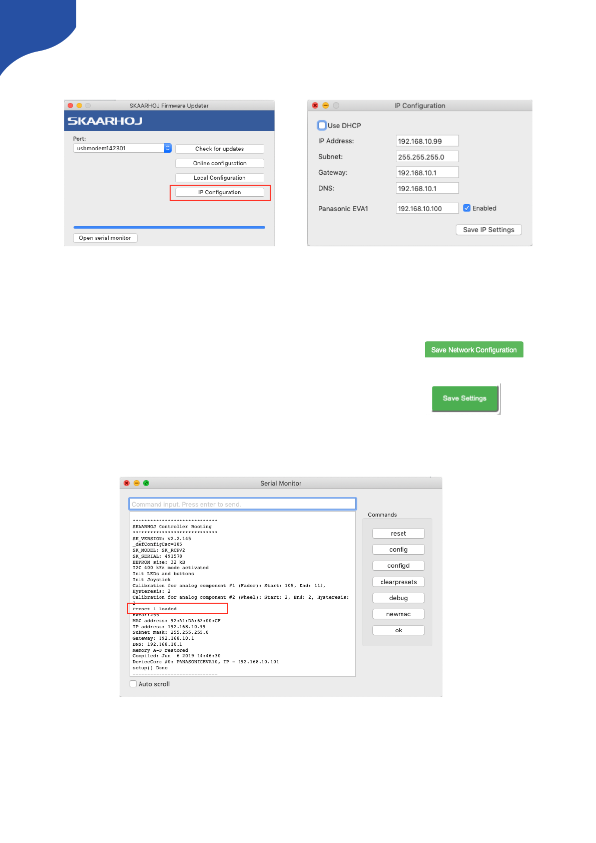
-Method 2: Using “IP Configuration” in the Firmware Application
A alternative way of setting IP addresses is using the “IP Configuration” option in the Firmware Application
Please notice this will generate a local “preset” on the controller. This preset will overrule IP settings set in
the “Network Configuration/Device Settings” on the Configuration page when pressing “Check for updates”
unless:
-One have opened the config page with default configurations and pressed
and then pressed “Check for updates”!
-One have opened the config page with custom configurations and pressed !
and then pressed “Check for updates"
The Serial Monitor can be used to monitor if a “Preset” exist
A preset can be deleted by using the above methods (Save Network Configuration or Save Settings and
then pressing “Check for updates). Alternatively press “clearpresets” in the Serial Monitor.
19
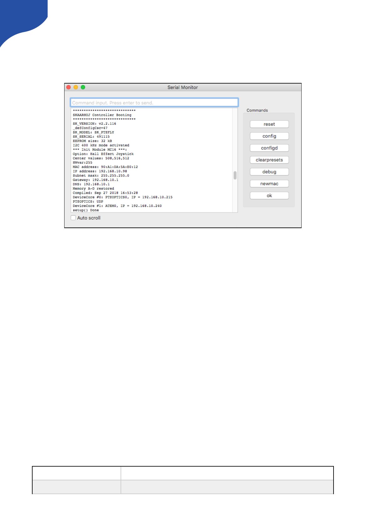
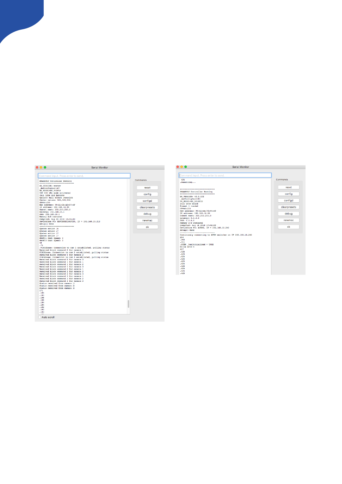
Serial Monitor
The serial monitor in the Firmware Application is an indispensable tool for bug fixing any problems with your
SKAARHOJ controller. The serial monitor runs at 115200 baud and a typical output from the boot process
looks like this:
This tells us the firmware version loaded, model name of the controller, serial number, how a number of
hardware components have been initialized, which IP address, subnet mask and MAC address the controller
has, which date the software was compiled.It also shows us which hardware devices it will try to connect
to.During this process until the ”setup() Done” message is output, the status LED will blink purple.
After the setup, the controller enters normal operational state. You see that it tries to connect to the devices
and that it succeeds in this. During this process, the status LED blinks yellow and eventually it will blink
green.
The serial monitor will continuously output a small dot and a number every second. If this is not the case
permanently, it indicates a crash of the controller. The number indicates the number of times a second the
controller manages to check all device connections and hardware components. It should be higher than 25.
The higher the better. This number may/will drop if there are problems, if something slows down the
controller, if devices are not connected properly or in the process of being connected, if a lot of displays
needs to be updated etc. The lower this value, the less responsive the interface will feel. This value will also
be impacted by the number and type of actions configured for interface components in the web interface.
Network problems may also impact this value. If this value is too low, the controller may further loose
connections to devices and may seem unresponsive to interface operations.
Commands in the Serial Monitor
You can enter commands in the serial monitor to do certain things with the controller. This is particularly
useful for developers and also for bug-fixing and calibration. If you are using the Arduino IDE Enable CR/LF
on the serial monitor dropdown menu in order to send the commands.
List of Commands
”config”
Reboots the device into config mode with its current IP. Similar to holding the config button until the
LED becomes blue.
”configd”
Reboots the device into config default mode (IP always 192.168.10.99). Similar to holding the config
button until the LED becomes white.
20
Technical Notice: Any operation from the serial monitor that reboots the controller, does so with a ”soft”
reset and the Ethernet chip in the controller may still hold old settings. In most cases this is no problem, but
at other times it may lead to strange behaviours and connection problems. In that case; power cycle the unit,
press the reset button shortly or close down and reopen the serial monitor which will also act as a hardware
reset.
”debug”
Reboots and enables debug output to serial monitor
“sockets”
Lists the 8 available sockets and their status. (If “debug” mode is enabled - see above - whenever a
change happens to a socket you will see it printed in the serial monitor on the same form)
”newmac”
Generates a new random MAC address to EEPROM. Power cycle both your controller and network
switch after this operation. Useful if you have network problems.
”clearpresets”
Clears the preset memory completely (flushes all!). Useful/necessary after a firmware upgrade.
Similar to holding the config button until the LED becomes red.
”reset”
Reboots the controller
”HWvar=XXX”
Set Hardware Variant (byte). This value shouldn't be changed by users. It's significance is to inform the
UniSketch software about which hardware revision it's running on in order to take certain specifics into
account.
Bit 0: Determines model of status LED on SKAARDUINO-AVR models.
”list analog”
Lists analog hardware components on the controller with number, description and three calibration
values (start/end/tolerance)
“show analog X”
Shows readings from analog component X where X is the number given by “list analog”. The readings
indicate the value and noise level for the read out. This is useful for debugging. If you move the analog
component you should see values change. Write “hide analog” to stop the display.
“hide analog”
Stops the display of “show analog”
“calibrate analog X”
Starts calibration of analog component X. Instructions will be posted in the serial monitor. The steps
involve moving the analog component to various positions.
“clear analog X”
Resets calibration data for analog component X to default. If X is not given it resets calibration data for
all components.
“set analog X=start,end,tolerance”
Forces calibration data “start”, “end”, and “tolerance” for component X
“exportPresets”
Will dump a large amount of data representing the entire configuration with presets in the controller.
Last two bytes is a checksum
“importPresets”
Will import configuration into the internal EEPROM memory. After sending the command, the
controller will instruct to paste configuration into the serial monitor. It must be formated like the output
from “exportPresets”
“preset X”
Will select the given preset number X if it exists and reboot the controller
“ip=A.B.C.D”
Sets the controller IP address (for the current preset)
“ipDeviceX=A.B.C.D”
Sets the IP address for device index X (see boot up output) for the current preset.
“enableDeviceX=[0/1]”
Enable or disable device X for the current preset.
“clearusermemory”
Clears user memory space (used for various types of device setting presets).
“getVersion”
Shows the current version of UniSketch
“getCID”
Returns the controllers unique ID, which is used to access the configuration pages on
cores.skaarhoj.com. Since this ID gives access to the online configuration, do not share it publicly.
21
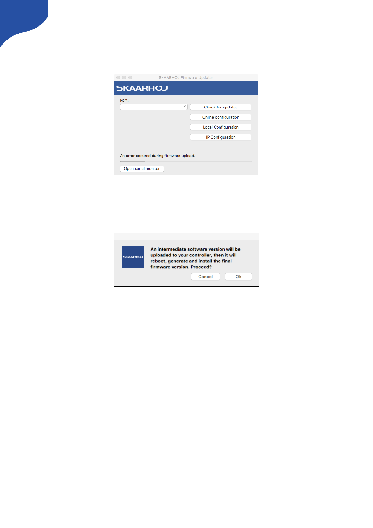
Error Occurred during Firmware Upload
If the update process for whatever reason is interrupted (e.g. power is lost) the firmware will be rendered
useless on your device. A new firmware have to be uploaded to the unit.
Press “Check for updates” - you will be presented with a message about a “intermediate software version…”.
Press “OK” to proceed. A intermediate firmware will be loaded on your unit, and subsequently the final
firmware.
22
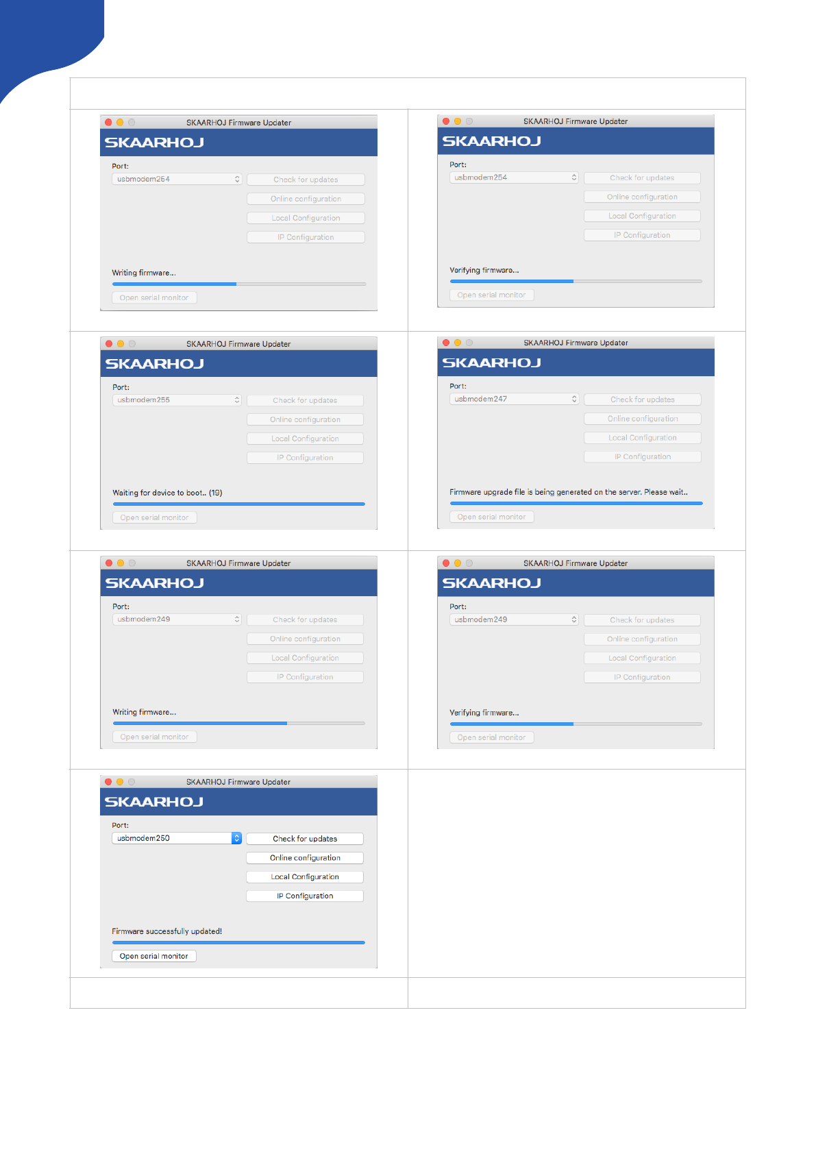
Process for updating firmware with intermediate software version
7) Status
2) Verifying intermediate firmware
5) Writing final firmware
3) Waiting for device to boot
6) Verifying final firmware
1) Intermediate firmware uploading
4) Generating and downloading final firmware
23
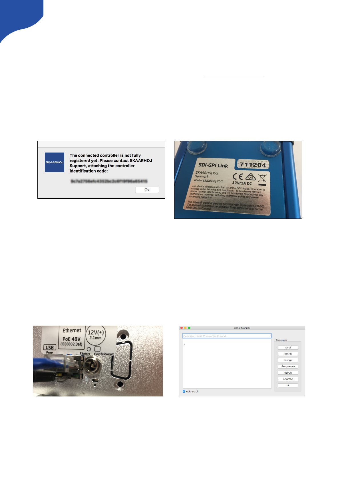
The Connected Controller is not Fully Registered yet
In rare cases you might experience a message from the Firmware Updater stating that the connected
controller is not fully registered yet. This happens if the unique hardware ID of your controller does not
match the record in our database.
In order to solve this issue please send the following information to support@skaarhoj.com
•Identification code from the Firmware Application.
•Serial number of the unit. The serial number is found on a small silver sticker with 6 digits.
After we have confirmed the registration by email press “Check for updates” in the Firmware Application.
This will render a new valid firmware for your device.
The Controller Appears Bricked/Non Responsive
If a firmware update fails or is interrupted (i.e powerloss, Application crash, missed connection from USB
cable) the controller can end up in “Programming Mode”. In this mode no hardware components (buttons,
displays etc will light up) and no lights will be seen on the SKAARDUINO Due - so no lights in the status LED,
no lights on the ethernet port even though the controller is powered via PoE or PSU. The controller still
appear in the Port list in the Firmware Application.
To check if a controller is in Programming mode write # in the serial monitor. The serial monitor should
respond with a > as seen below.
24
No lights from the SKAARDUINO Due. No lights
in the status LED and no activity on the Ethernet
port.
Respond from the serial monitor to determine if
the controller is in “Programming mode. Write #
in the command input and the controller
respond with >
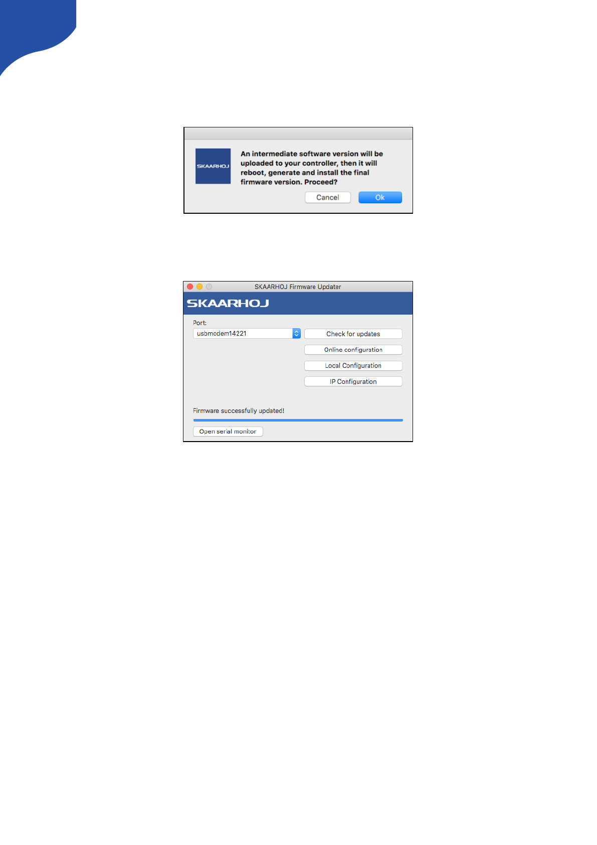
In order to get the controller out of programming mode press “Check for Updates” in the Firmware
Application. You will be prompted with a message about “An intermediate software version will be…” like
illustrated below. Press “OK” to proceed.
The steps from the Firmware application illustrated in the “Error Occurred during Firmware Upload” section
will follow and the controllers firmware will be uploaded and the application states “Firmware successfully
updated!
25
cores.skaarhoj.com
A SKAARHOJ controller running UniSketch OS has a license profile in our online repo at cores.skaarhoj.com.
This is where its software (firmware) came from that was programmed onto the unit when it was delivered.
Whenever you need a firmware upgrade for whatever reason, this is where the firmware will be downloaded
from by the firmware application. But this is only the most basic case. cores.skaarhoj.com provides you a
fantastic way to expand the features of your controller; you can select between different pre-made
configurations, install new device cores (support for more broadcast hardware), change configuration of the
controllers behaviour, add media strings and graphics, add modules and manage multiple configurations for
your controller.
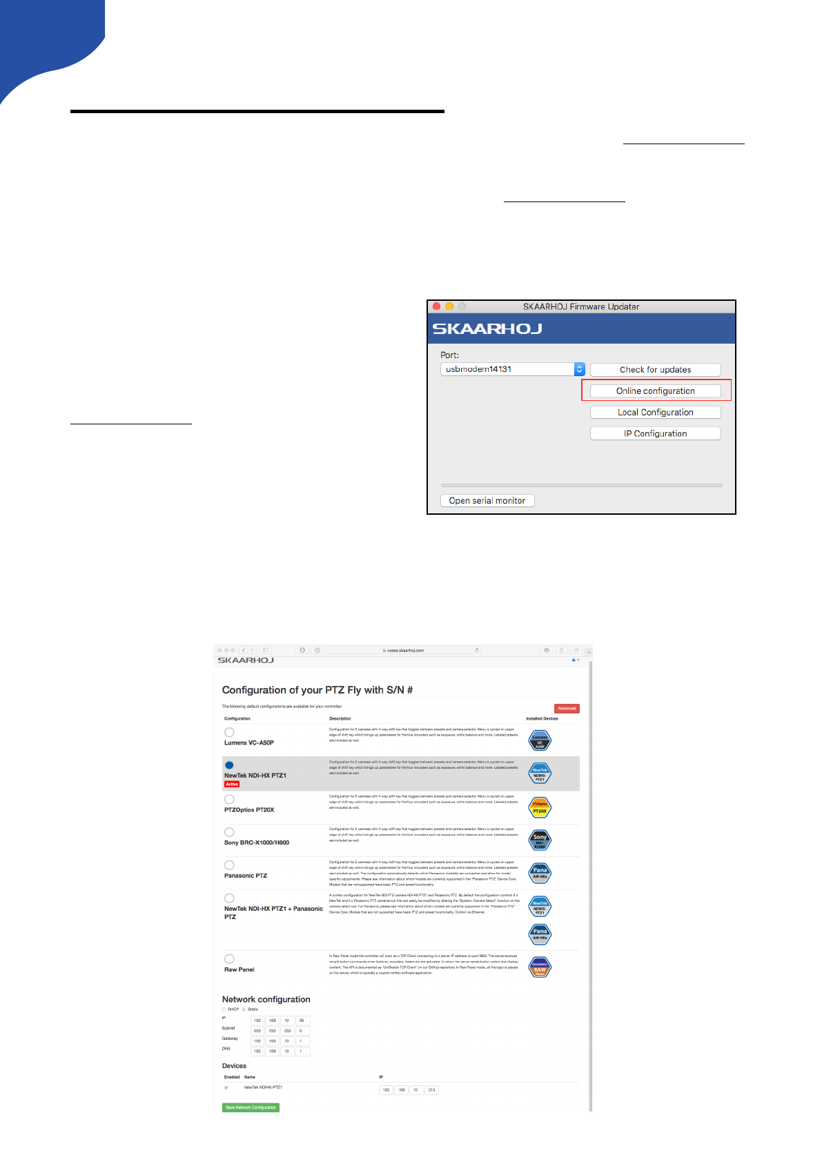
To access the Configuration Page for your controller,
simply connect it by USB to your computer and start
the SKAARHOJ Firmware Application, then press
“Online Configuration”. If the controller correctly
reboots and returns its unique ID, a web browser will
open and take you to the configuration page on
cores.skaarhoj.com. Whenever you are done
changing the configuration online, return to the
SKAARHOJ Firmware App and press “Check for
updates”. A new firmware reflecting the changes will
be created and downloaded to your controller.
By default the configuration page will look something like this. Here you can select between different pre-
made configurations and read a short description. You can also change Network settings and set IP address
for Device Cores. If you press the red “Advanced” button you will access a configuration page where you can
tweak a existing configuration or build one for yourself!
26
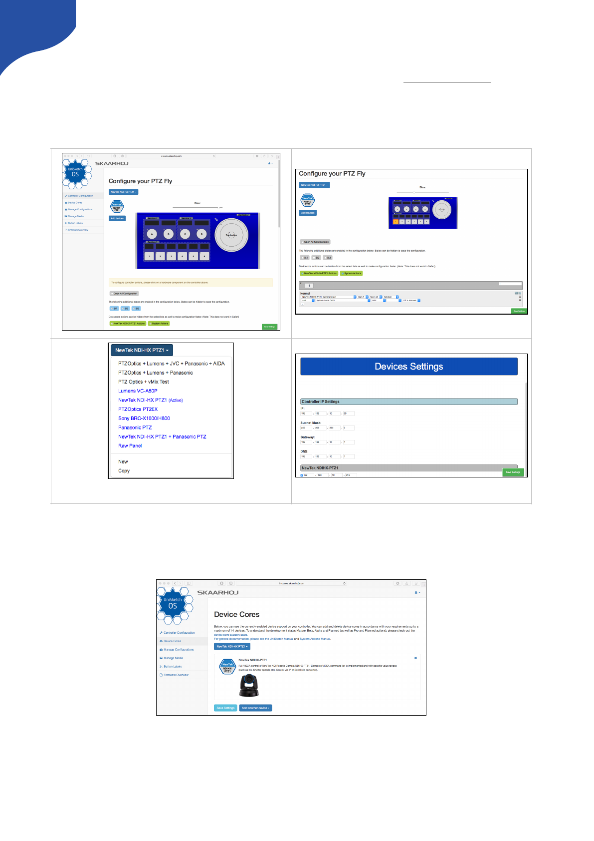
Controller Configuration
This is where the fun begins! On the advanced configuration page on Cores” (cores.skaarhoj.com) the
configuration of your controller shares the same interface as the one documented in this manual in the
UniSketch section. The configuration you set up on “Cores” will become the default configuration of your
controller with the next firmware download. When pressing a hardware interface component the
configuration will jump to that component and you can modify or change the actions.
Device Cores
Add or remove Device Cores on the “Device Core” tab.
Set IP addresses at the bottom of the page
Chose a configuration from the drop down menu, copy or start
with a clean slate
27
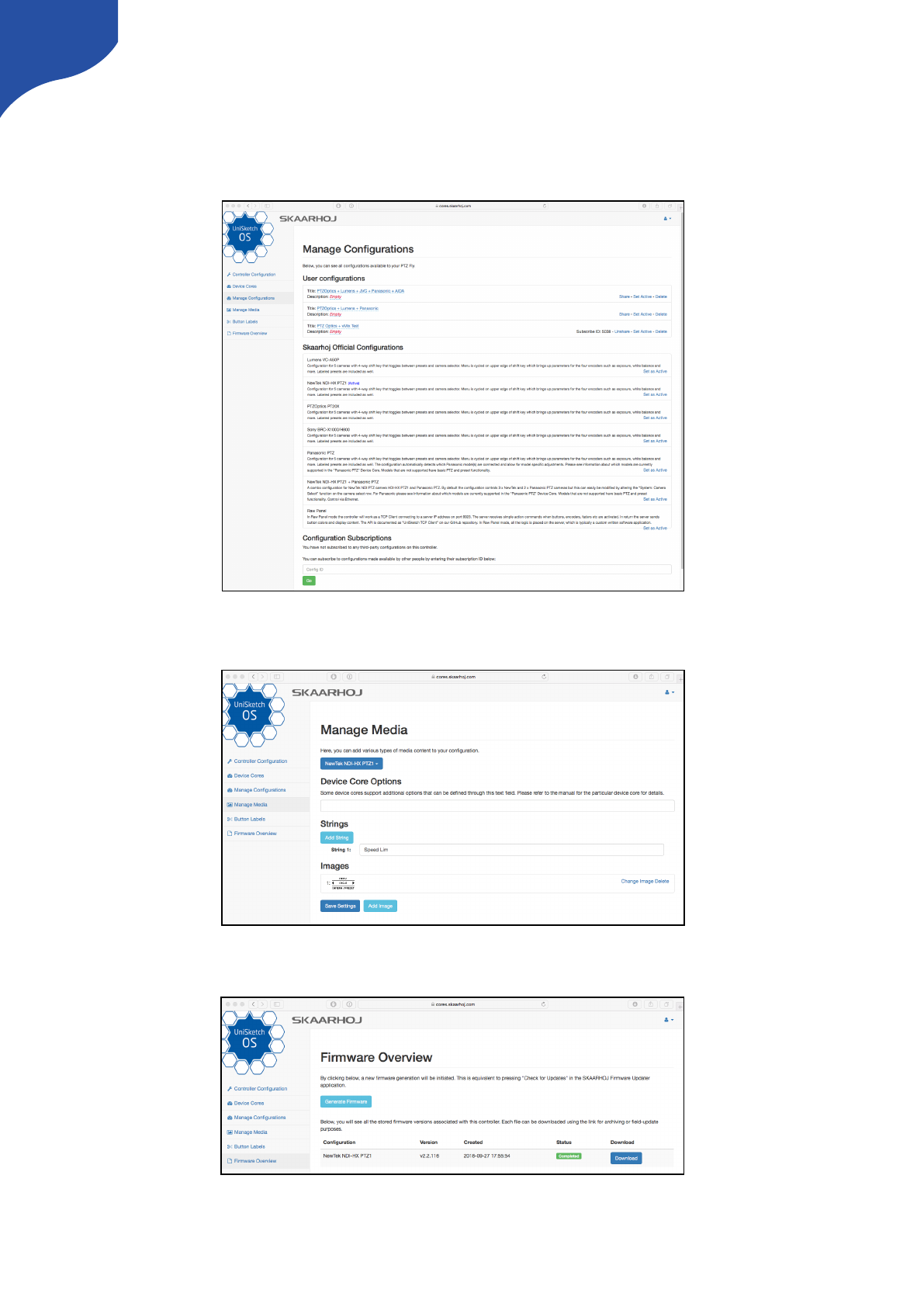
Manage Configurations
Select either SKAARHOJ official configuration from this tab or manage your User Configurations by
assigning names, descriptions or delete. You can even Share a configuration to another controller with the
“Share Button”. This creates a ID number which you subscribe to in the “Configuration Subscriptions” section.
Manage Media
Add strings or images to your configuration. Device Core options are also set on this tab.
Firmware Overview
Download or generate a new firmware file - use it for archiving or field-update purposes.
28

Device Core Options
For some Device Cores a “Device Core Options” can be found. See the specific Device Core manuals for
instructions on how to set these.
Notice if you want to set Device Core options for several Device Cores the structure is as following
Dx:y=z ;Dx:y=z
Setting several Device Core Option indexes for the same Device Core is as following
Dx:y=z,y=z
Where the general form would be “Dx:y=z” where “x” is the number of the device cores installed on the
controller (starting with zero for the first device core), “y” the index number and “z” the value for that index. !
!
!
29
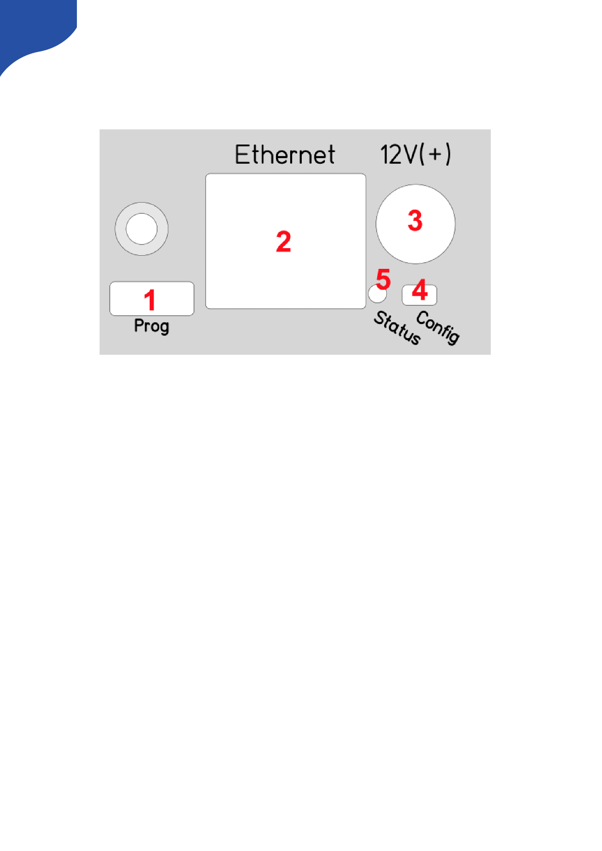
Back Connections and Config
Mode
1. Micro USB plug. Used for service monitoring and programming new software into the unit (”firmware
upgrades”). For some device cores this may also be used for controlling equipment. See ”Programming”
2. Ethernet Jack. Connect this to your ethernet switch. This jack may also support PoE (Power over
Ethernet) if your SKAARHOJ controller was delivered with that option. When connected to a network
switch, the yellow LED (lower left) will be on. When data is sent to/from the controller, the green LED
(lower right) will blink. If the device in the other end supports TX/RX auto detection you may be able to
connect the SKAARHOJ controller directly to your device, otherwise use a crossed cable or a network
switch (the supported setup).
3. DC input. Use a standard 2.1mm center pin plug (center = ”+”). Allowed voltage range is 7-18V. We test
controllers will work at 12V. The device uses max 1A at 12V. Units with BlackMagic 3G-SDI Arduino
Shields needs 12V.
4. Configuration/Reset button. Use a pencil or tooth pick to press the button. When you press the button
shortly, the controller will reset (same as pulling the power plug). If you press and hold the button, you
can reset the controller into configuration mode:
1. Press and hold the button until the status LED becomes blue after a few seconds. Release the button
and the controller is in config mode. You can access the controller web interface with a web browser
on ”http://[CONTROLLER IP]/” where CONTROLLER IP is the IP address used for the currently loaded
preset. The controller will run a diagnostics mode after 2 minutes where displays and buttons will
light up.
2. Press and hold the button longer until the status LED becomes white (which is 2 seconds after
becoming blue). Release the button and the controller is in config default mode. You can access the
controller web interface with a web browser on ”http://192.168.10.99/”. The controller will
immediately run a diagnostics mode where displays and buttons will light up.
3. Press and hold the button even longer until the status LED becomes red (which is 10 seconds after
becoming blue and 8 seconds after becoming white). This will clear all presets in memory thereby
resetting all configuration made in the controllers own web interface (this corresponds to the serial
monitor command “clearpresets” and should only be necessary in case a firmware update requires it
or if there is another tricky error state present).
30
In rare cases you cannot rely on the reset button but have to turn of the power to the controller instead
(“cold start”).
5. Status LED: When the controller is just powered up, you will see the status LED blink purple
during the boot process. In this process, the hardware is initialized. Eventually the LED should end
up blinking slowly (2 sec period) steady green (or blue or white if in config modes). If the LED
blinks yellow quickly it indicates that connection to one or more devices is not established. This is
perfectly normal for a few seconds between the boot up process (purple blinks) and the
operational state (green blinks) when the controller connects to all devices. The status LED should
never be permanently on or off, this indicates a potential freeze in the system. In fact, in normal
healthy operation the LED should blink with a steady 2 sec period, otherwise it could indicate
trouble with connections or hardware. The LED will also light up red for a split second whenever
an analog hardware component (such as a T-bar) is operated (this feature is helpful to determine if
calibration is needed).
Status LED Overview
Purple blinks, uneven durations
The controller is booting up (and for each blink a given step has been completed).
Yellow blinks, quickly
The controller hasn't established necessary connection to one or more devices.
At the end of the boot process this is natural for a few seconds as the controller connects to
devices for the first time.
If you unplug the network cable or turn off an external device the controller is connected to, you
will also see this state. Just turn on the external device again or re-insert the cable and the error
state should restore itself to normal operation (green, steady blinking) after some time.
If this happens during normal operation and without obvious explanations (like removal of a
network cable or shutting down an external device), it's an error state you need to pay attention
to and bug-fix further.
If the controller boots up and never stops blinking yellow, you may want to check if you have
configured devices for the controller which are not currently present in the network set up. Go
to config mode, enter the web interface and check which devices are enabled and their IP
addresses.
Green blinks, steady, period of 2 seconds
Normal mode, everything is connected and working properly. Just bliss
Blue or white blinks, steady, period of 2
seconds
Config mode (white: “config default”) where you can access the controller web interface.
Red blinks (interrupting green or yellow blinks)
This happens if you move an analog hardware interface component like a T-bar or knob and is
totally normal in that case. However if such blinks happen without you touching any analog
components it indicates the need for calibration.
Quick red blinks and no response from
controller
A problem with the preset memory checksum indicates that the preset memory may be
corrupt. However, in most cases a “cold start” by removing the power supply, waiting 10
seconds and connecting the power supply will solve the problem. If after 2-3 attemps with this
solution it still remains a problem, you must clear the preset memory. This is done by holding
the config button pressed, then apply power to the controller and wait for around 15 seconds
until the status LED becoems solid red (before that state, the LED should be first purple, then
blue, then white for 8 seconds and finally solid red). When the LED is red, release the button
and the status LED should start blinking again and the controller should boot up. Notice that
your controller will be reset to factory settings in this case and you may need to reload or
recreate your configuration.
31

Connection Troubleshooting
When you have a ”blinking-yellow-quickly” situation, you need to figure out which device is not connected.
Try some or all of these things:
•You should bring the controller into config mode and access the web interface in order to check which
devices are enabled and what their IP addresses are.
•Make sure the SKAARHOJ controller itself has the expected IP address and subnet mask.
•Make sure the devices you have setup actually are on the network, can be ping'ed and responds to
their respective other types of software connecting over IP.
•Unpower all devices and your network switch for 10 seconds and power them up again.
•Connect a computer to the USB port of the SKAARHOJ controller and open the serial monitor using
the firmware application to see the output from that. This provides the most direct information about
which devices are not answering and at which IP. You can also see the controller IP and Mac address
here. See ”Serial Monitor” section.
Configuration Mode/Accessing Web Interface
In Configuration Mode all device communication is disabled and instead the controller provides a web
interface for configuration of the interface component behaviors. The IP address of the controller in
configuration mode (or ”config” mode) depends on how config mode was entered. There are two options:
”config” mode or ”config default” mode. You can enter either mode using !
A. The Config/Reset button on the controller
B. Using the serial monitor command ”config” or ”configd”.!
•”config” mode: The controller IP address is the ”last used” IP address; the one set up for the currently
loaded preset. This is convenient most of the time since you probably know your controller IP and just
need to boot in config mode and access the web interface with a browser. After 2 minutes in config
mode, the controller will run cyclic test programs on the hardware interface components, typically a lot
of blinking.
•”config default” mode changes the IP address to 192.168.10.99 and this is useful if for some reason
you forgot the controller IP or otherwise want to make absolutely sure you know the right IP address for
the controller. The controller will run cyclic test programs on the hardware interface components
immediately as it has booted up.
Notice that the IP address of your SKAARHOJ controller can be different for each preset you have! This
makes it easy to have presets for completely different network and device configurations.
We recommend connecting your SKAARHOJ controller directly to your PC/Mac with a ethernet cable in
order to access the web interface
Turn off your Wi-Fi and set your IP manually: (these numbers are only valid if you are using the default IP
address configuration from the factory)!
192.168.10.50 PC/Mac IP address!
255.255.255.0 Netmask!
192.168.10.1 Gateway/Router IP address if necessary
32
Enter configuration mode
•Step 1 - Connect the SKAARHOJ controller to PC/Mac with ethernet cable and power up the unit. Let it
boot up.
•Step 2 - Press and hold the config button until the status LED becomes blue. Release the button.
•Step 3 - Access web interface by entering http://[CONTROLLER IP]/” where CONTROLLER IP is the IP
address used for the currently loaded preset in your browser.
Access to web interface if SKAARHOJ controller is connected via network router
We always recommend a direct ethernet connection with manual IP in order to gain access to the web
interface. But depending on your network router settings you might be able to connect to the web interface
without setting a manual IP address on your PC/Mac.
Access via the Firmware Application
The firmware application is always a great help to work with your controller. Connect it by USB and press the
button “Local Configuration”. After the controller reboots, the firmware application will read its IP address for
you and open a web browser to that address. Assuming your computer and the controller are on the same
network, this will work great!
DHCP
If you set the IP address to “0.0.0.0” instead of the default “192.168.10.99” then the controller will ask for a
DHCP address. If it can’t retrieve a DHCP lease, it will fall back to 192.168.10.99.
33

Web Interface Troubleshooting
If you are having problems connecting to the web interface there are numerous things that can trick you:
•Reboot your SKAARHOJ controller completely (disconnect for 10 seconds, re-power)
•Reboot your network switch. Sometimes it may hold old information about the controller IP and MAC !
addresses and to clear this out, reboot it (disconnect for 10 seconds, re-power)
•Check connection to the assumed SKAARHOJ controller IP from your computer with the ”ping”
command. You computer IP settings must be correct too.
34
UniSketch OS Explained
Web Interface
When your controller is in configuration mode, you will be able to access it's web interface with a web
browser. We recommend using the Chrome browser because it's faster, but we have successfully tested it
with other modern browsers such as Firefox, Safari and Internet Explorer in the latests version.
Notice that the web interface heavily depends on modern JavaScript and may malfunction with older
browsers!
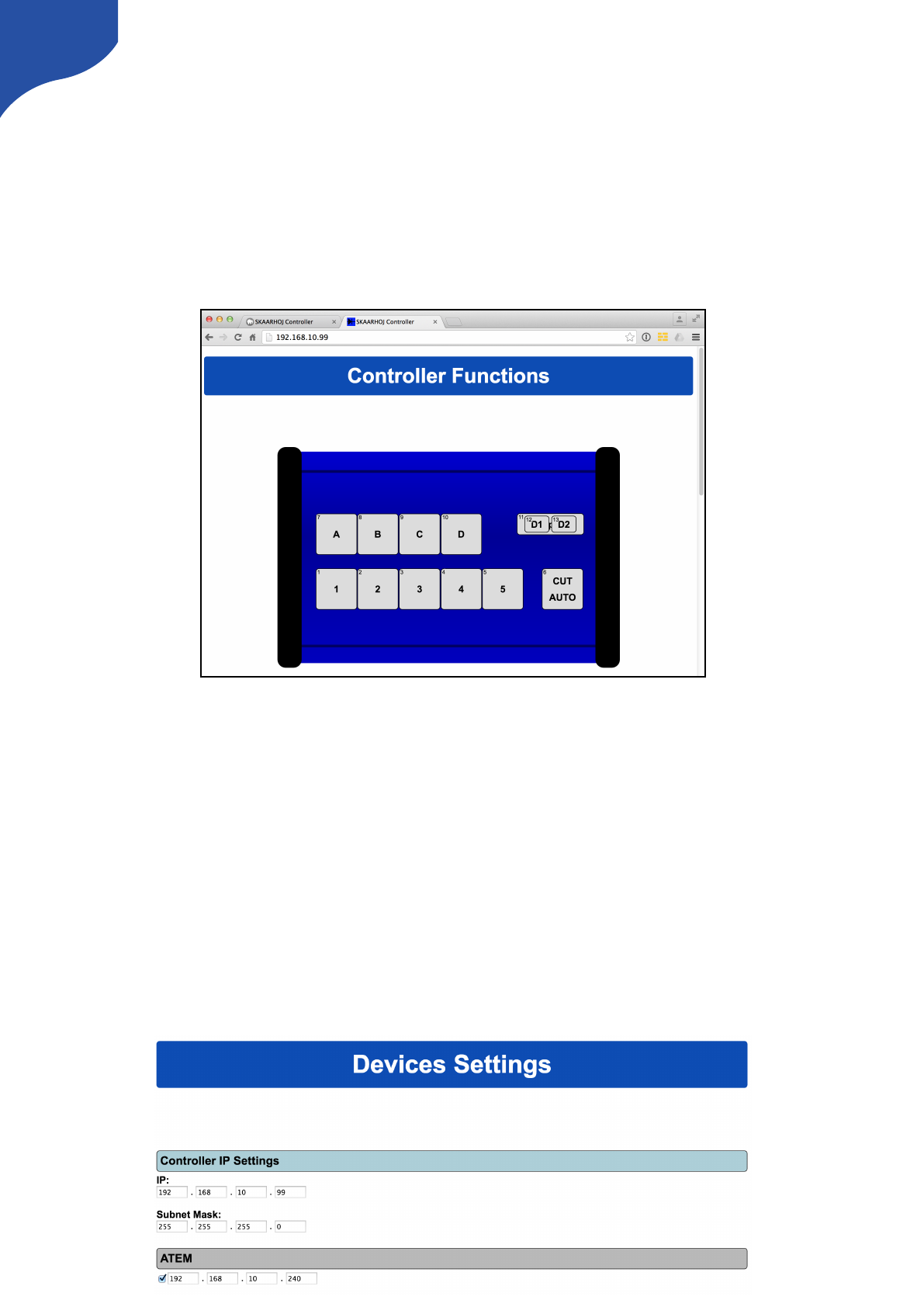
Example of web interface for SKAARHOJ controller.
Device Settings
You set up the IP address, Subnet mask, Gateway and DNS of your SKAARHOJ controller in the web
interface. Likewise any external IP device your controller is configured to work with is listed here. Any device
you want to be active must be enabled here and have a valid IP address set up.
Notice that all these IP settings will be saved with each preset in the controller. This is quite awesome
because different presets allows you different IP configurations so a controller can easily move between
different hardware contexts.
The number and type of external devices listed is compiled into your controller when it is delivered. The list
may vary from controller to controller and can potentially be expanded or change to include other hardware
by time. The “default” configuration for your controller is determined by the settings for it made on
cores.skaarhoj.com.
35
Hardware Interface Components (HWC)
Your SKAARHOJ controller consists of a number of hardware interface components such as buttons, knobs,
dials, levers, displays, LEDs, joysticks, plugs, etc. They generally fall into broad categories such as inputs (eg.
buttons and knobs, GPI) or outputs (eg. displays, LEDs, relay). Sometimes they can be both (most buttons
have an illumination color, some even have a display on them). Input elements can be sub categorized as:
•”binary” such as a button or GPI trigger which is either pushed/triggered or not. Sometimes holding
down a binary input has a special function.
•pulse-generators such as encoders which are knobs that can rotate indefinitely in both directions and
sends a corresponding number of pulses. Encoders typically has a fine/coarse adjustment mode which
is toggled by pressing it. Pressing and holding an encoder down for 1 second will typically send a
binary ”button down” signal to the interface component. Often this can function as a ”reset” feature.
•analog signals such as T-bars or joysticks which provides a free value within some range.
Outputs range from a simple binary output like a relay to red/green LEDs, an array of LEDs (like a VU meter)
or a graphical or text based display.
Hardware Interface Components are configured with actions which is what give them their function. This is
described in the next sections.
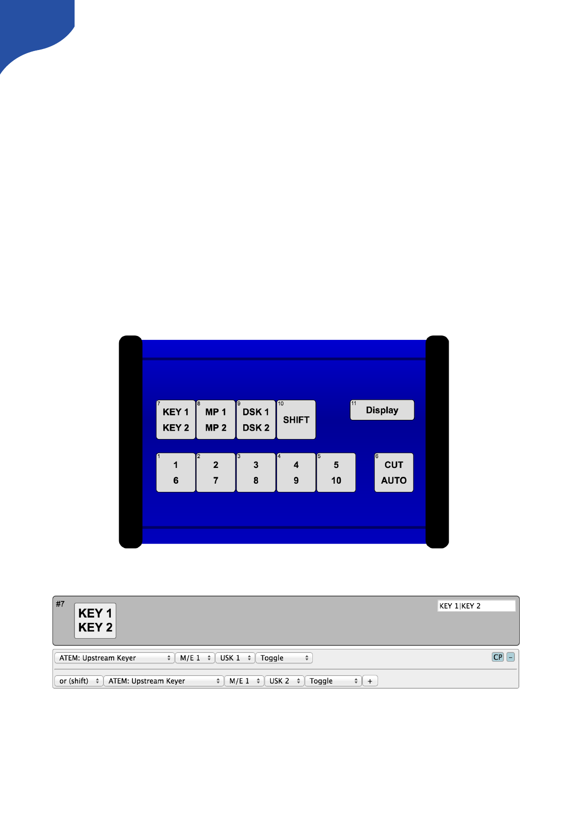
An example of the schematic drawing of a controller as found in the controllers web interface which is
available when booted in configuration mode.
This is how the button ”KEY1 / KEY2” is configured in the web interface. As it appears, this button will toggle
upstream keyer 1 or 2 on an ATEM switcher depending on whether the controller is in shift-state or not.
Graphical Displays
Displays are found in many configurations on SKAARHOJ controllers. One of them is Smart Switches which
are buttons with a display on. Otherwise displays are typically stand alone but can be configured to reflect a
certain button on the controller (through the “Tie to HWC#” system action). An important convention with
36
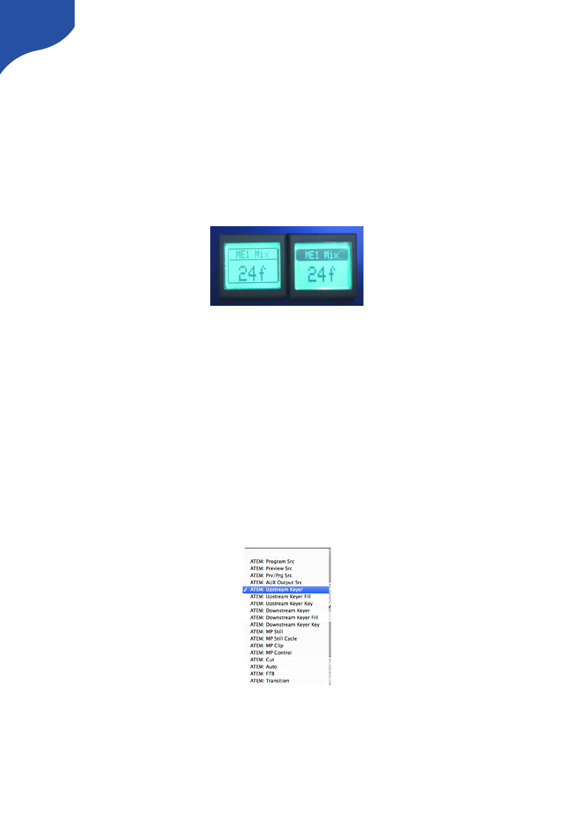
displays is whether it works as a label or displays a current status. Take the picture below as an example.
Here there are two SmartSwitch buttons apparently showing the same thing:
•A label: The button to the left is configured to set the frame rate of Mix transitions to a fixed “24f”. This
can be seen from the fact that the button has a non-solid header bar. This is a label that simply tells us
what will happen if you push the button: You will set a 24 frame mix transition rate.
•A status: The button to the right is configured to also set the frame rate of transitions but is configured
to act in “Cycle” mode so when you press the button you will cycle through transition types and values
by some scheme. The important thing is that the button shows the current value for Mix transitions – 24
frames. And if we change the value to 30 frames, the button will show 30 frames. This is a status that
informs you about the current value of this ATEM feature and this can be seen from the fact that the
button has a solid header bar.
This convention works throughout all displays on your SKAARHOJ controller. Generally, a display will show
the value status unless it has been tied to a button-type interface component in which case a label is typically
shown – unless the particular button operates in some sort of cyclic mode where a status makes more sense
to display.
Devices
You configure your controller by assigning actions to interface components. An action is most typically a
command sent to an external device, such as a video switcher, router, recording deck, monitor etc. External
hardware support is made available on your controller as what we call device cores. A device core is the
driver - or akin to an “app” - installed on the your controller that enables communication support with a
given piece of broadcast gear.
Some actions may also relate to internal registers or ”system functions”. For instance you can have a button
set or clear a ”shift” value which the rest of the interface components will adapt itself to.
Since interface components can be inputs and/or outputs and of various types, the way they affect any given
device via an action is a fixed interpretation coded into the system.
An excerpt of the list of ATEM switcher related actions.
37
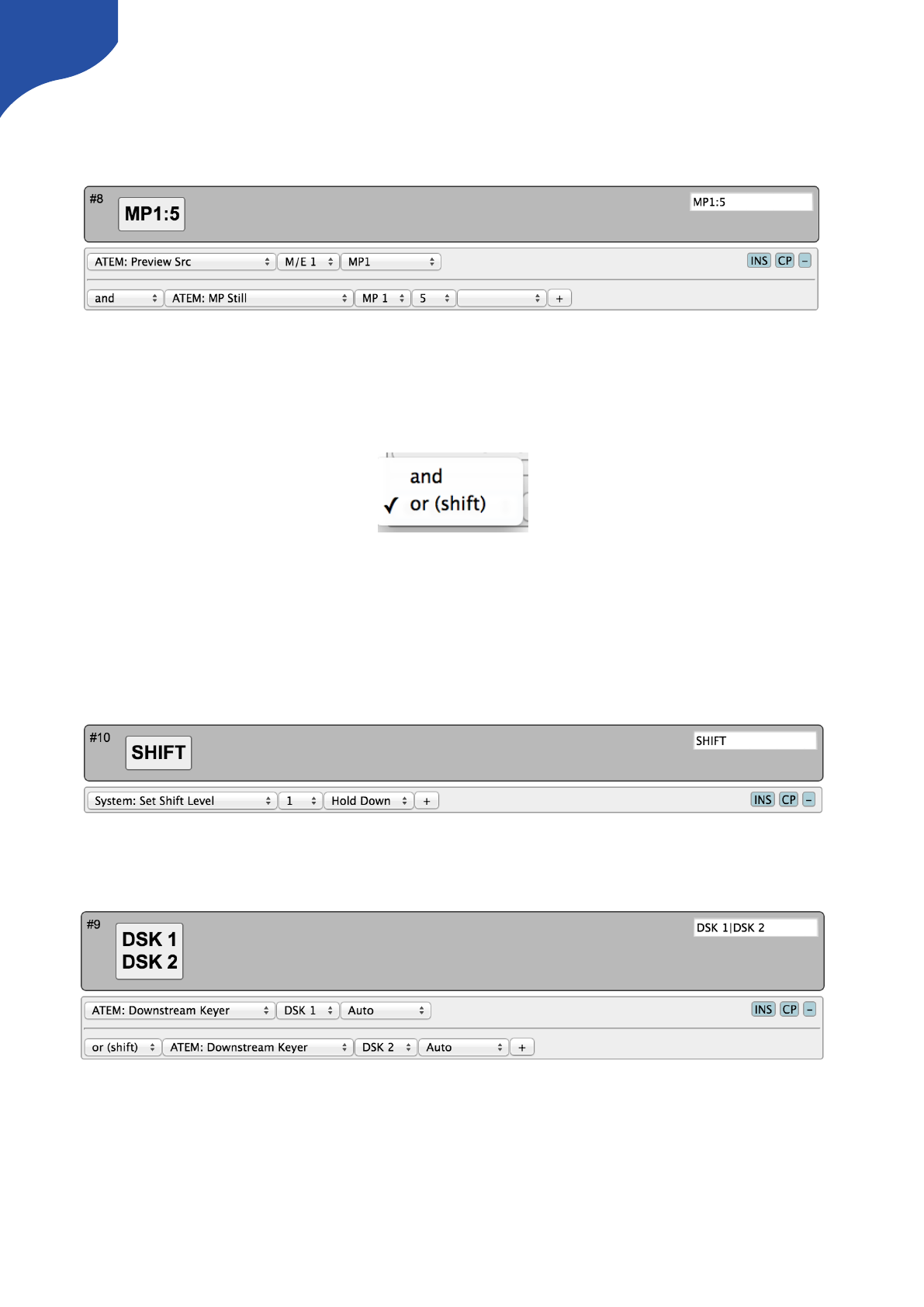
Multiple Actions
You can assign multiple actions – even on different devices – to any interface component. This is done by
simply pressing the ”+” button and setting up the new action:
In this case, the media player 1 (MP1) is brought on Preview on an ATEM switcher and right after the still
number 5 is selected for the media player 1.
The return values, including those driving a display, will always come from the first action in the list (of the
current shift level).
Notice that multiple actions are separated by an ”operator” which is either ”and” or ”or (shift)”:
This is explained in the following.
Shift
You can assign a button to set a shift state on your controller. Even though a shift state sounds like an either/
or option, we have implemented the possibility to have multiple shift-levels. However, in the simple case, a
shift button would be configured as shown below:
This will set the shift-level ”1” in the system as long as the button is held down, otherwise it will be
”0” (normal)
This means another button on the same controller could be configured like this now:
And because the divider between them is ”or (shift)”, the second action is only active when the shift button is
held down.
If no specific action is defined for a shift level, the interface component will use the default list of actions.
If you insert additional “or (shift)” dividers, it will define how shift levels 2 and beyond will act. Within each
shift level you can have multiple actions (see previous section).
38
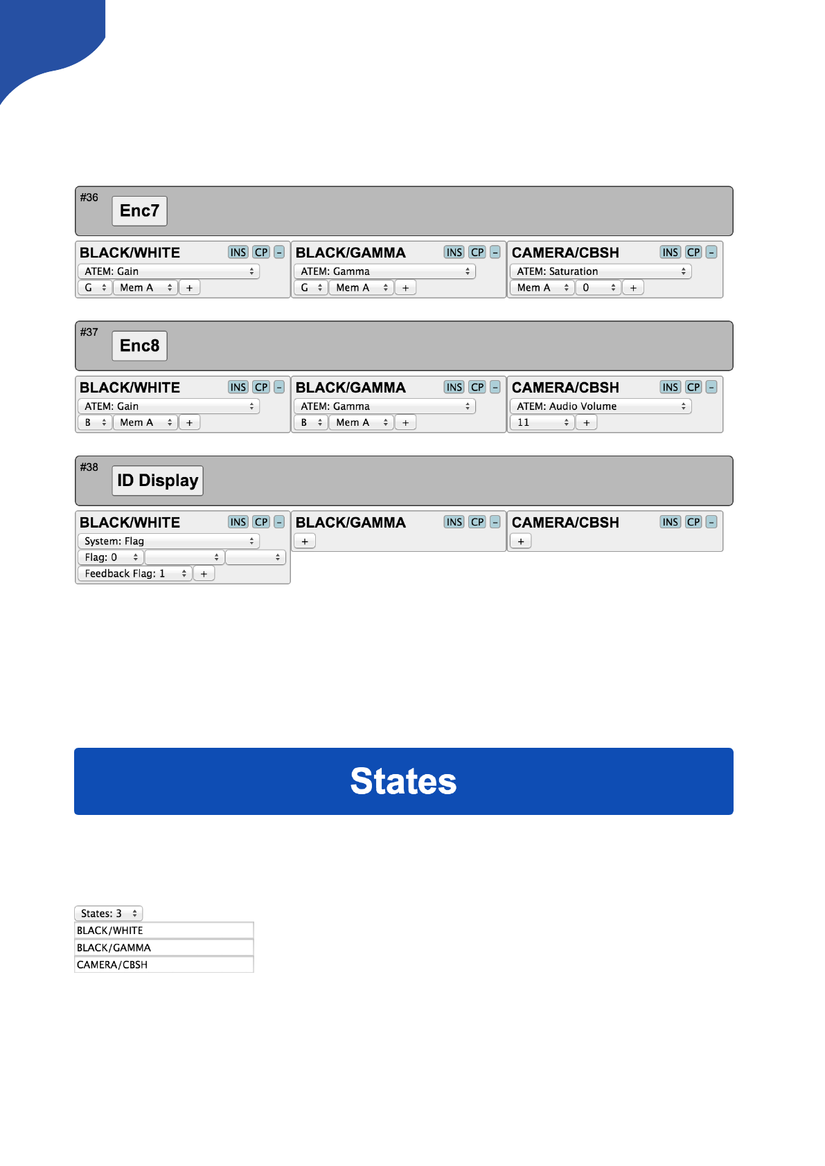
States
Similar to shift levels you can put your controller in various states. States are mainly different from shift levels
by the way the interface lets you set them up. With three states you see three columns of actions for each
interface component:
Like with shift levels you can assign other interface components to change the state of the controller. If
actions are not defined in any given state, they will fall back to the action list in the first column (Normal
state).
States and shift levels can be combined of course; you can have unique shift levels inside each state.
States can also be named. In the above example, they are named ”BLACK/WHITE”, ”BLACK/GAMMA”,
”CAMERA/CBSH”. This is done in the controller web interface as well:
This is where you select how many states the controller should support.
Copy / Paste
Often you will find yourself needing to set up almost the same function on multiple interface components
(such as a row of buttons, all sending inputs to an AUX channel). To make this easy, make sure to use the
Insert / Copy / Delete functions:
39
As soon as you make any change to a given interface components action list, this will be copied to memory
so you just need to go to the next interface component and press ”INS” for insert.
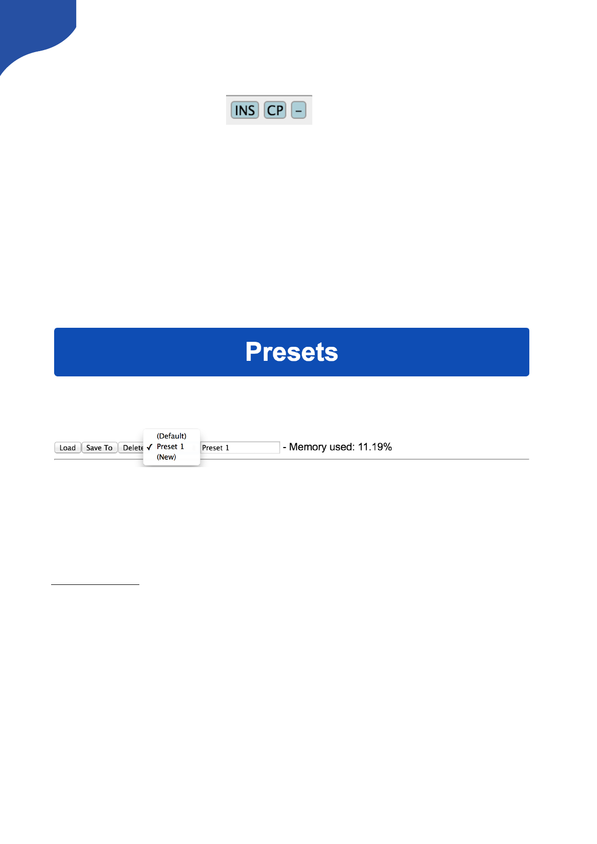
Presets
At the bottom of the web interface you can load, save and reset your presets. Your controller can
theoretically hold any number of presets only subject to the memory usage related to storing them. Pressing
the save button in the web interface will save the configuration to the currently selected preset, but you can
also select a new or different preset to save to using the selector box.
Load the ”(Default)” preset to get back to the factory configuration.
If your presets seems to be messed up for some reason (could be memory overflow which there is currently
no protection against) you may need to clear the entire memory by using the serial monitor command
”clearpresets” (see later).
Presets are a very powerful way to make use of your controller in multiple places since it can change the
entire behavior of the controller including which devices to connect to and which IPs they are on.
There is a nifty way to load presets on most controllers if you have created more than 1 preset: When you
boot your controller, you may see that a number of buttons (corresponding to the number of available
presets) light up for a few seconds and one of them being highlighted. The highlighted button indicate the
currently loaded preset and the other buttons represent other presets. If at this moment you press and hold
any of the other buttons down until that button light up, you will then change the preset of the device
(corresponding to selecting it in the web interface and press the ”Load” button).
Presets are a great way to manage multiple configurations in off-line situations. However, using
cores.skaarhoj.com and the firmware application to manage multiple configurations for your controller is
more powerful in the sense that you can include changes to installed device cores, string and image media
and also have the latest software updates installed.
Notice: Presets will be automatically cleared if a firmware update indicates that the online configuration has
changed. In other words: Always be cautious with firmware upgrades and make sure you “print out”
important local configuration so you can recreate it if necessary.
."
40

Troubleshooting
Controller doesn’t show up under “Port”
If your controller doesn’t show up under ports, try these things first:
• Make sure you have attached your controller with a micro USB cable to your computer and installed
propper drivers (see www.skaarhoj.com/support/firmware-updater/)
• Is the controller turned on?
• Reboot you computer
• Change the USB cable for another one
• Boot the controller in config mode: Disconnect the controllers power, then hold the config button under
the power plug down with a pen tip, power on the controller and hold the button until it lights blue, then
release.
41
If none of the above brings up the USB port, you may try this procedure but only after clearing it with the
SKAARHOJ support team!:
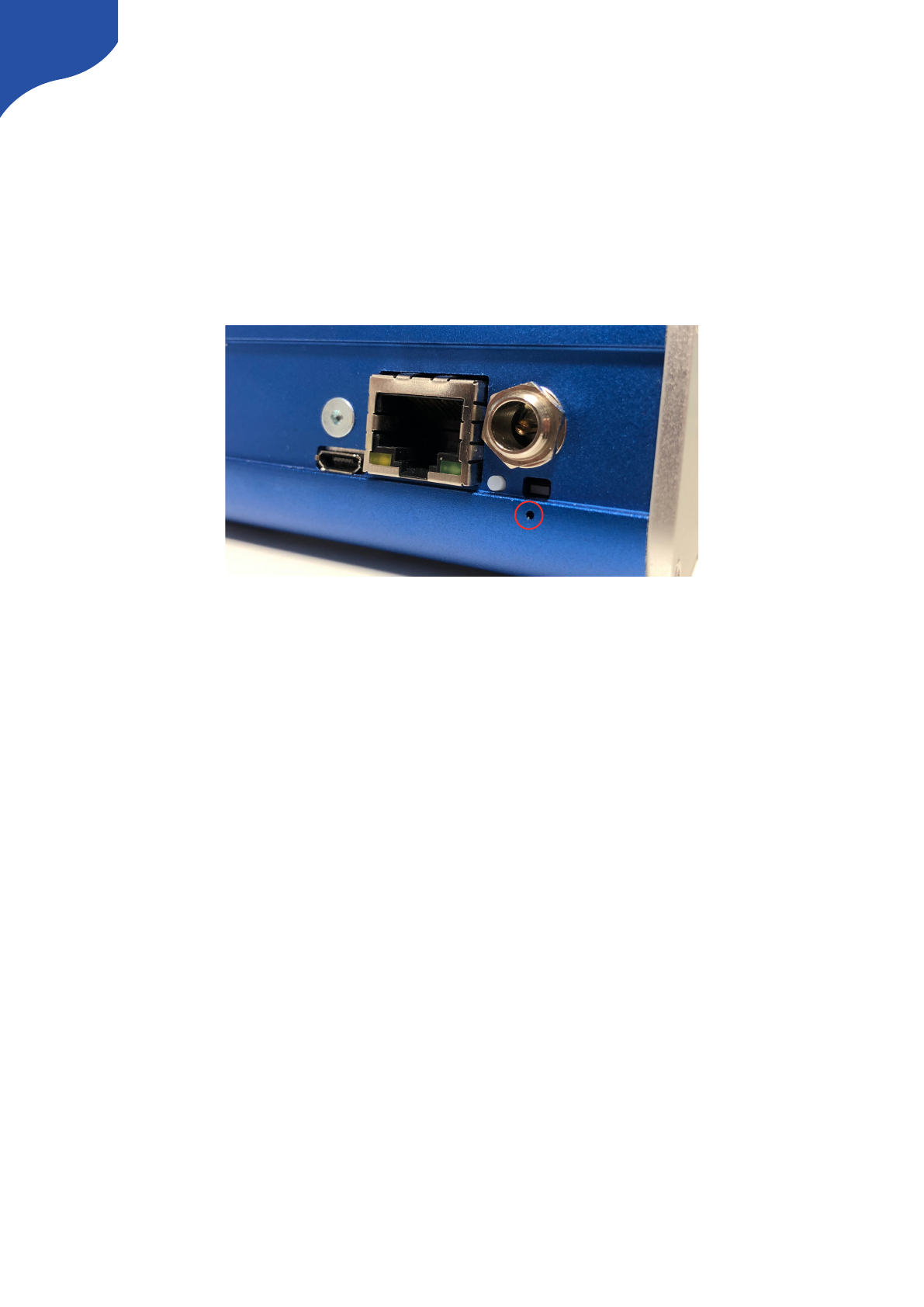
• Locate the small hole just below the config button
• Power on the controller and press this tiny button for a second and release. You may repeat this.
(Pressing this button while the controller is on should reset it completely).
• Turn off the controller, then turn it on again. Now you should see the USB port in the firmware
application and be able to perform a “Check for updates” (which at first will ask to install an intermediate
firmware which you agree to).
Old method if no hole below config button are present:
• Open the controller carefully and locate the SKAARDUINO main board (the one with the ethernet plug)
• Locate the flatcable connector in the corner of this board. Next to this connector you will see a tiny
button.
• Power on the controller and press this tiny button for a second and release. You may repeat this.
(Pressing this button while the controller is on should reset it completely).
• Turn off the controller, then turn it on again. Now you should see the USB port in the firmware
application and be able to perform a “Check for updates” (which at first will ask to install an intermediate
firmware which you agree to)."
42

Contact Support
You are always welcome to contact us for support questions - write an email to support@skaarhoj.com and
we will do our best to accommodate your request.
In order for us to provide the best support please state:
•Which SKAARHOJ unit it is about
•The serial number of your device (small silver label with 6 digits)
•The nature of the problem
•Which hardware device(s) you are controlling and their firmware
version
•If you have successfully installed the Firmware Updater Application and made contact with your device
though the Serial Monitor (you need the USB programming cable)
•Your operating system
43
Hardware Notes:
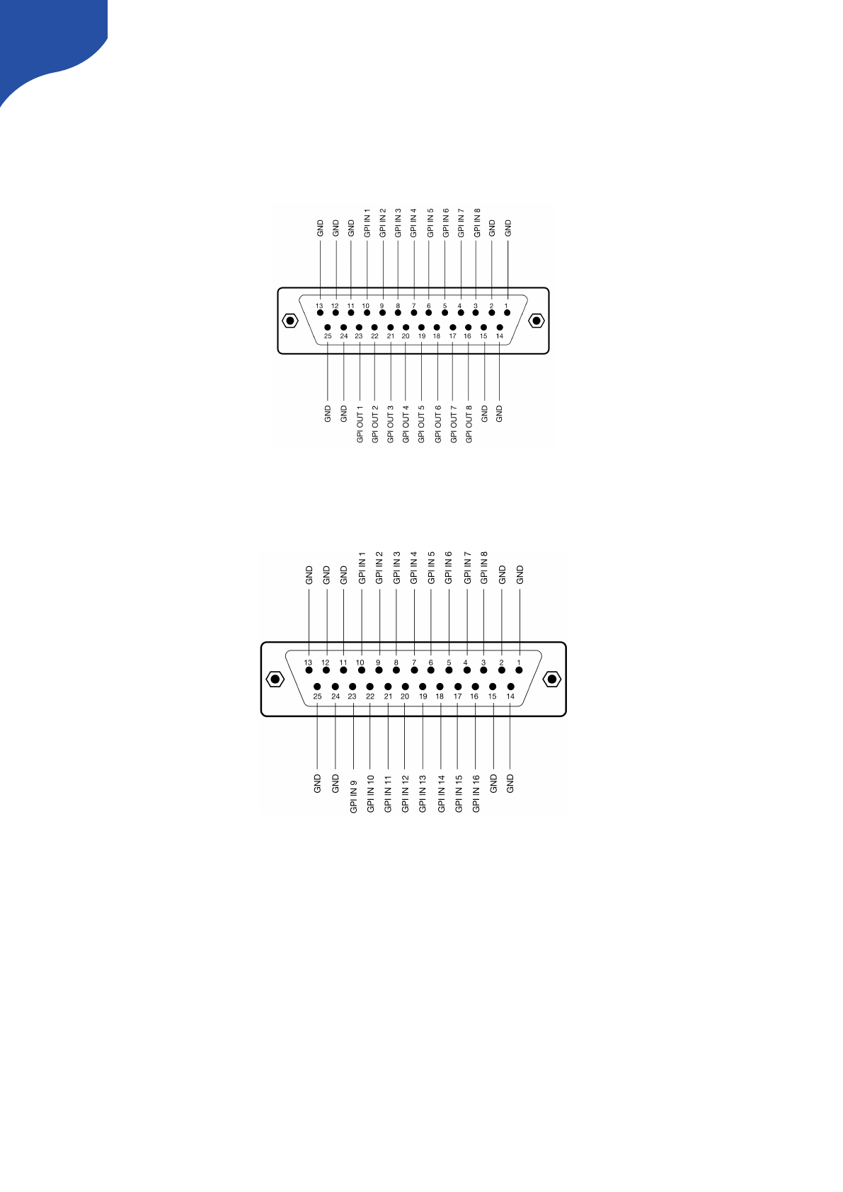
DB-25 Connector Configuration for GPI
This is the pinout for the DB25 Connector we use as a GPI module:
This is the pinout for the DB25 Connector we use on the SDI-GPI Link:
44
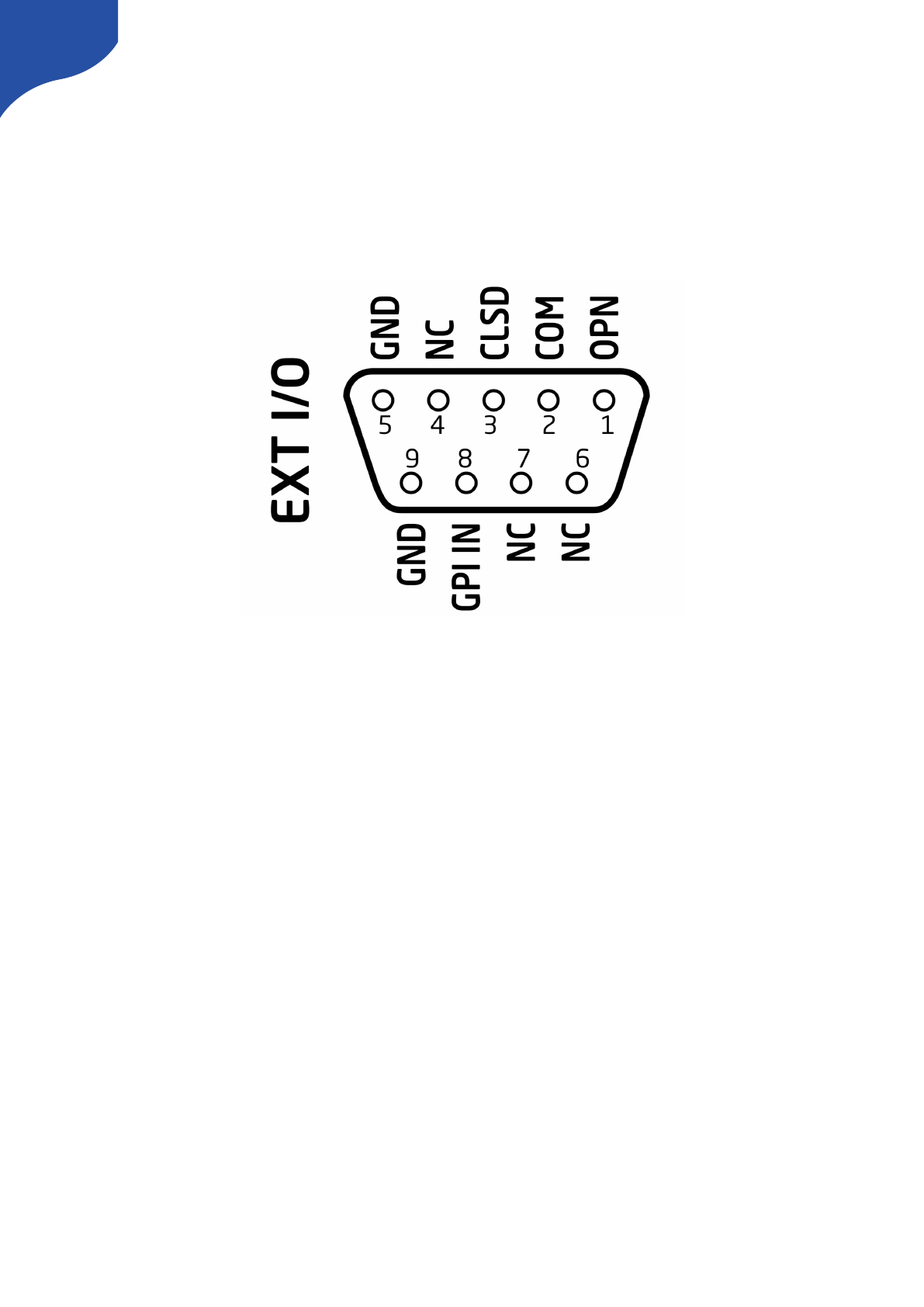
DB-9 Connector Configuration for RCP units (EXT I/O)
This is the pinout for the DB9 we use on our RCP units. Often a default RCP configuration will be configured
so:
-When the joystick top button or the “Prev” button is pressed, a relay is shorting pin 1 and 2
-If pin 8 is shorted to GND (pin 5 or 9) the display backlight will change from white to red
45
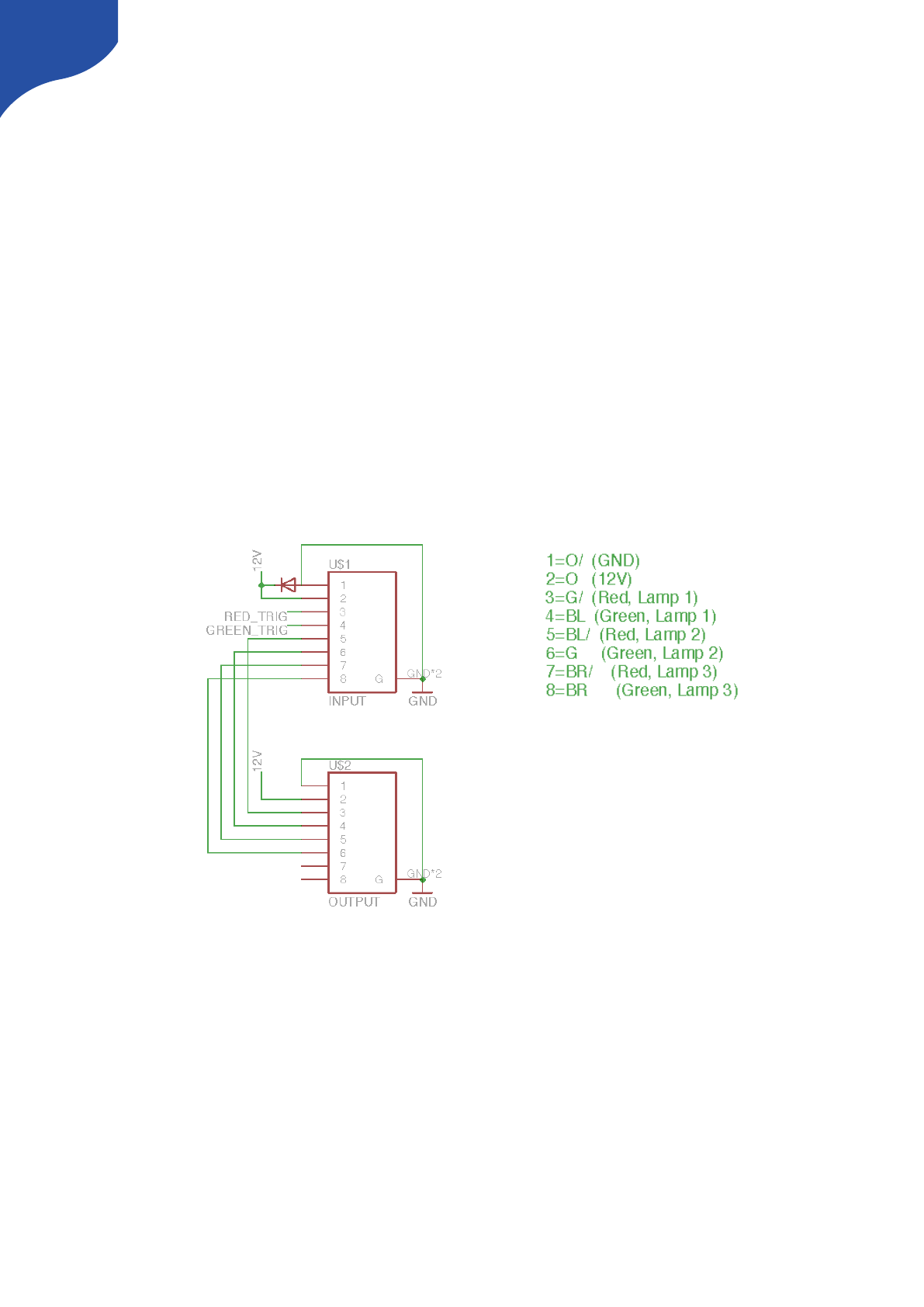
Pinout for Tally Box
The pinout of the RJ-45 connector is as follows:
1. GND
2. 12V
3. 5V control signal for red tally 1
4. 5V control signal for green tally 1
The next four are for daisy-chaining tally lamps:
5. 5V control signal for red tally 2
6. 5V control signal for green tally 2
7. 5V control signal for red tally 3
8. 5V control signal for green tally 3
Our tally lamps need 12V power in order to light up the LEDs. The control signals are 5V so whenever you
apply 5V on one of the pins the corresponding LEDs will illuminate."
46
Other Notes:
Triggering Actions from Binary Inputs
Some of our products such as the ETH-GPI Link have a option to interpret binary inputs. This is used in cases
where one would like to have routing control or the like from a device such as the Panasonic AW-RP50 or the
AW-RP120 PTZ controller.
Example of Tally output from the manual of the Panasonic AW-RP120
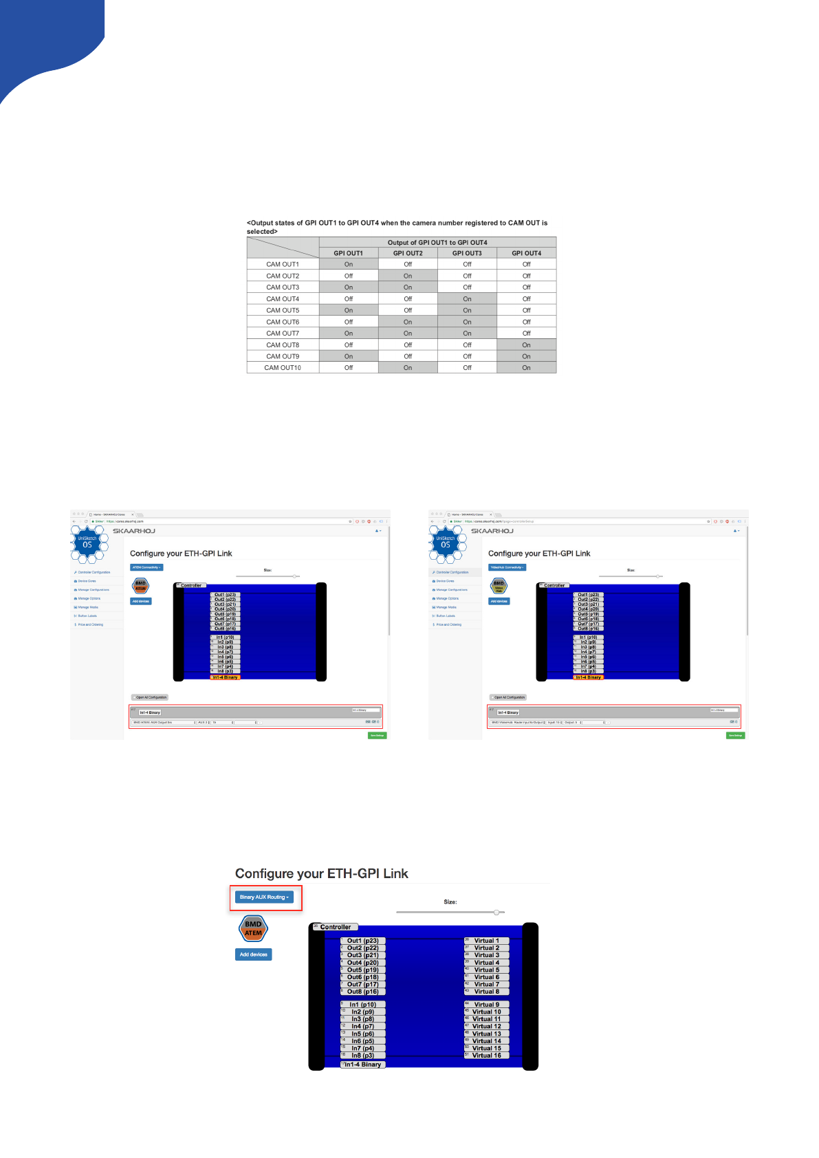
Fixed Routing
The two below examples shows how a configuration should be made to trigger ATEM AUX routing our
Blackmagic Design VideoHub routing. In these cases the routing is fixed so CAM1 from the AW-RPx will
always correspond to CAM1 in the ATEM and Input1 in the VideoHub.
Flexible Routing
In some cases it is not desired to have the fixed coloration between CAM1 on the AW-RPx and CAM1/Input1
on the ATEM/VideoHub. The guide below explains how you achieve your desired routing.
Use the default configuration “Binary AUX Routing”
47
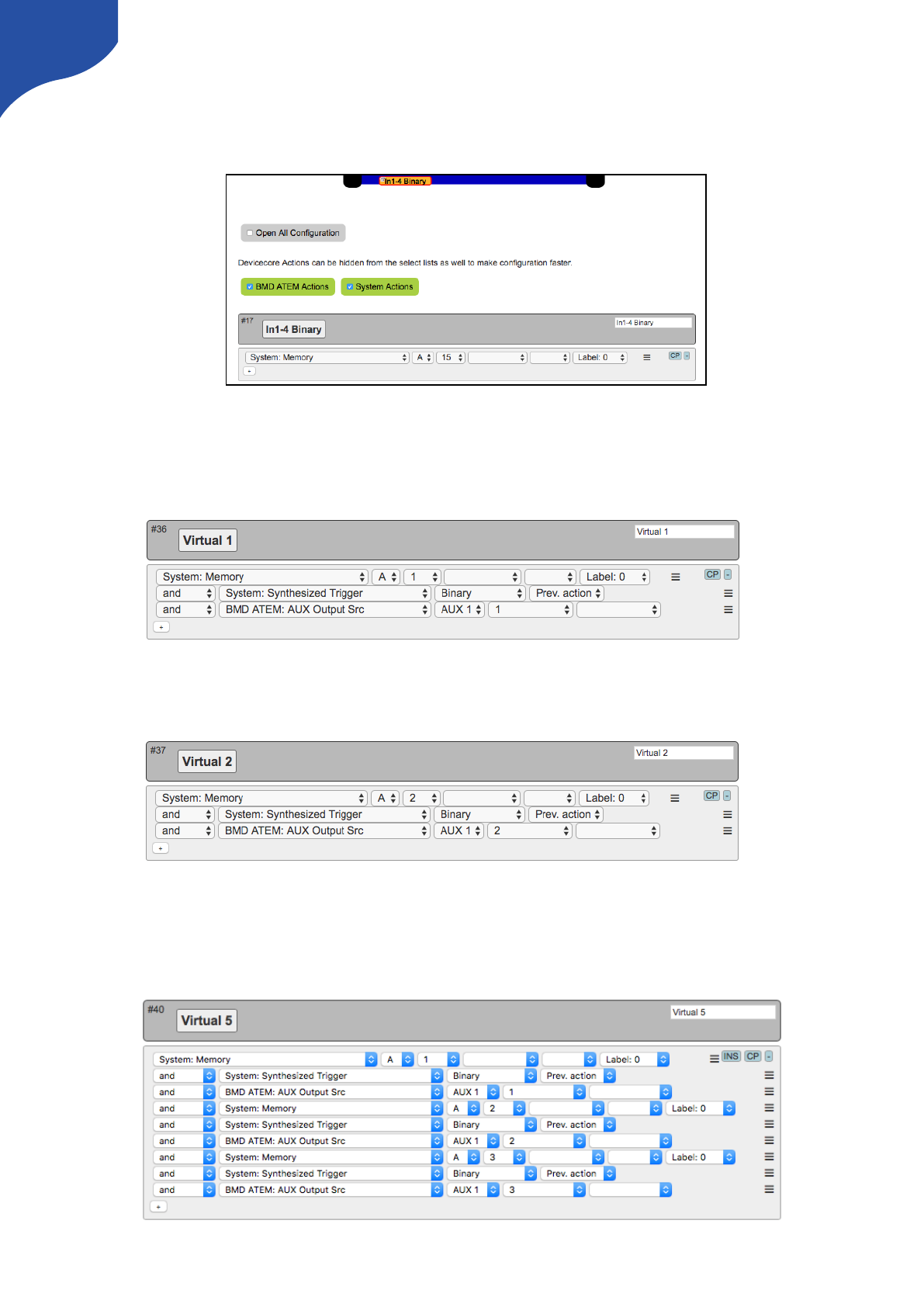
The “In1-4 Binary” is set to “System: Memory A”. This will generate a memory parameter, A, in UniSketch
which we will use to do our routing. If CAM1 is selected on the AW-RPx the memory parameter will be A=1,
if CAM2 is selected it is A=2 and so forth.
Now we will utilise the Virtual Hardware Components called “Virtual 1” and use the command “System:
Synthesized Trigger” to trigger a action. In this case we set it to source 1 for AUX 1 on the ATEM. But you
could as well do it for a different source or a entirely different action such as routing on a Blackmagic
VideoHub or a AJA Kumo Router.
The same procedure is followed for “Virtual 2. Again you can leave the routing as it is, or you can alter the
AUX routing or select a entirely different action.
And then you continue to configure the routing you would like.
You do not need to configure different Virtual Hardware Components - more commands can be assigned to
just one like illustrated below. However for the sake of overview and to avoid making mistakes using
individual Virtual Hardware Components can be recommended.
48
Example
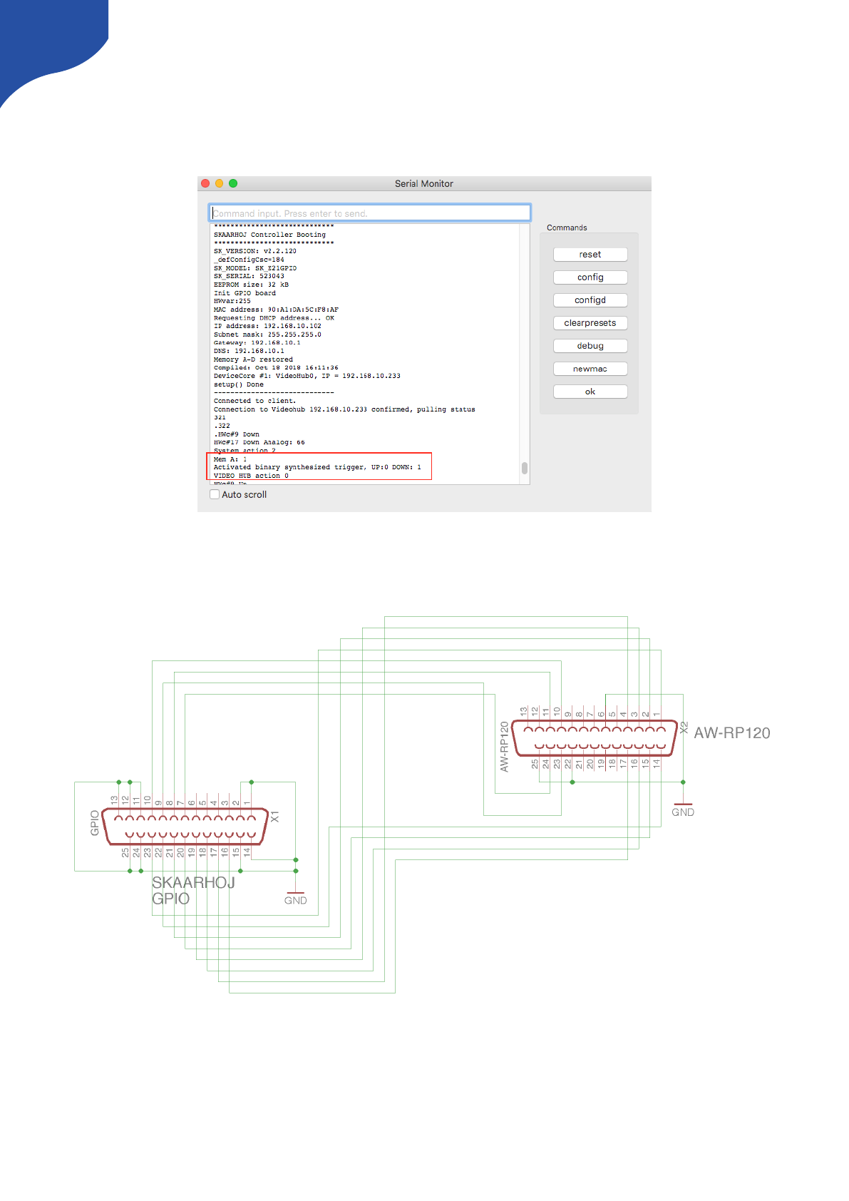
Here is a readout from the Serial Monitor for a ETH-GPI Link connecting to a VideoHub and GPI1 being
triggered. Notice that memory A is set to 1 which entails a binary trigger and finally the VideoHub action.
Cable and AW-RPx setup
Make sure the cable between the AW-RPx and the ETH-GPI Link is correct. Pin 10, 11, 23, 24 + GND on the
AW-RP120 should be connected to pin 10, 9, 8, 7 + GND on the ETH-GPI Link.
49
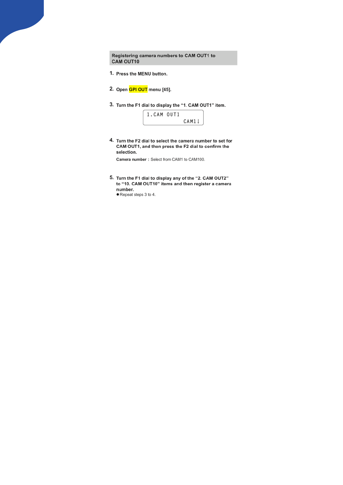
In the menu of the AW-RPx there should be a GPI Out menu. Go into this and make sure everything looks
correct.
50
Connection between RCP and ETH-SDI Link using ETH2SDI Firmware
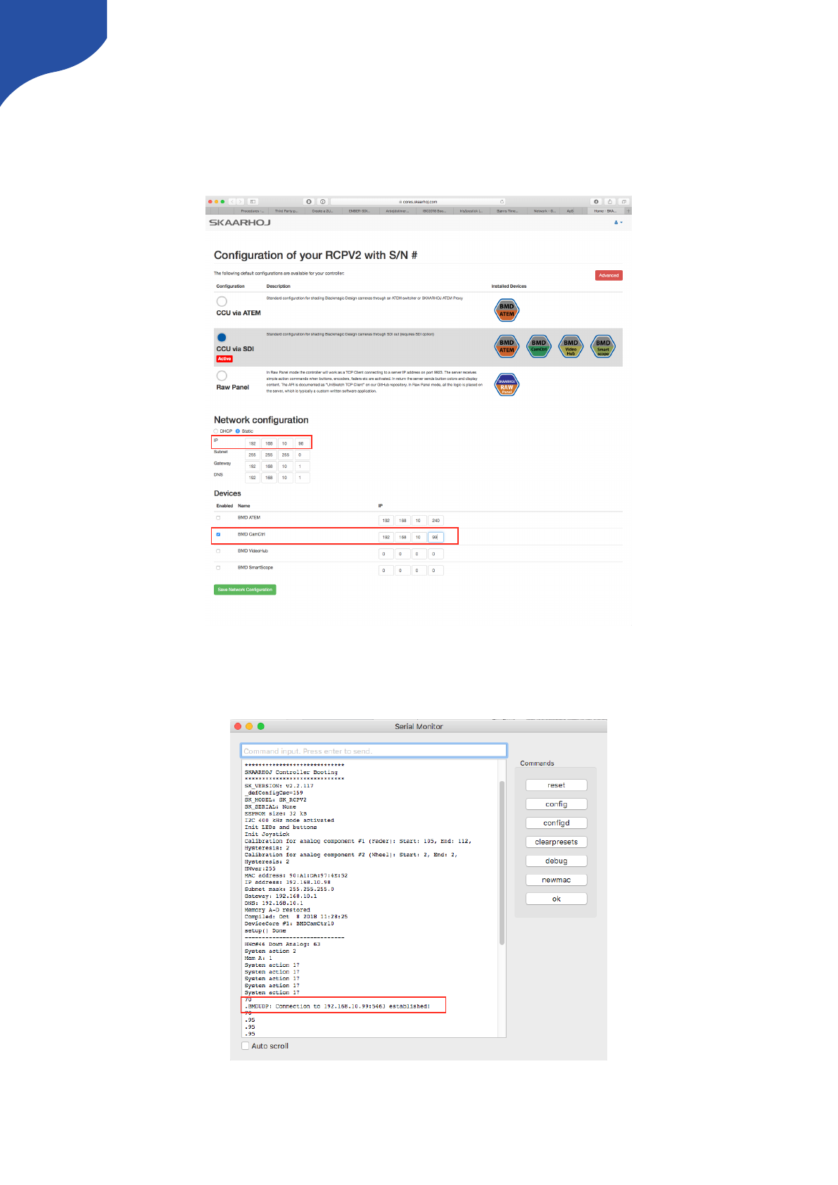
A SKAARHOJ controller such as a RCP should be configured with the “BMD CamCtrl” Device Core. In order
for the device to send commands to a ETH-SDI Link the BMD CamCtrl Device Core IP should be changed
from the default 0.0.0.0 to the IP address set on the ETH-SDI Link. Remember the IP address on the ETH-SDI
Link and the RCP or other main controller should differ.
On the main controller sending commands to the ETH-SDI Link, connection can be confirmed from the serial
monitor with the message “.BMDUDP: Connection to 192.168.10.99:5463 established!” if the IP on the ETH-
SDI Link have been set to 192.168.10.99
51
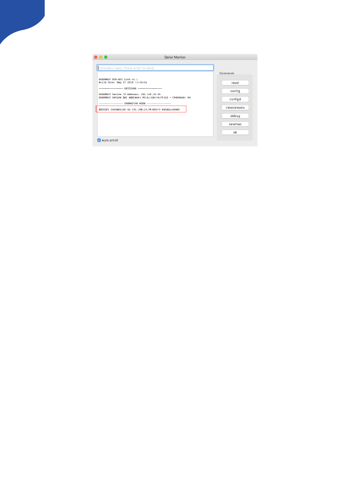
Connection can also be confirmed from the serial monitor on the “ETH-SDI Link” with the message
“BMDUDP: Connection to 192.168.10.98:65070 established!” if the IP on the RCP or main unit have been set
to 192.168.10.98.
The ETH-SDI Link listens on port 5463 UDP. The RCP (or any UniSketch OS based controller) listens on return
data on a random port between 50100 - 65300.
Connection between RCP and WIFI-B4 Link
The procedure have similarities with the above instruction. A SKAARHOJ controller such as a RCP should be
configured with the “BMD CamCtrl” Device Core. In order for the device to send commands to a WIFI-B4
Link the BMD CamCtrl Device Core IP should be changed from the default 0.0.0.0 to the IP address set on
the WIFI-B4 Link. Remember the IP address on the WIFI-B4 Link and the RCP or other main controller should
differ.
52
