Lexium 28 A And BCH2 Servo Drive System User Guide
User Manual:
Open the PDF directly: View PDF ![]() .
.
Page Count: 502 [warning: Documents this large are best viewed by clicking the View PDF Link!]
- Lexium 28 A and BCH2 Servo Drive System
- Table of Contents
- Safety Information
- About the Book
- Servo Drive System Planning
- Servo Drive System Technical Data
- Certifications
- Drive
- Motor
- Accessories and Spare Parts
- Commissioning Tools
- Connectors and Adapters
- External Mains Filters
- DC Bus Accessories
- Application Nameplate
- CANopen Connectors, Distributors, Terminating Resistors
- CANopen Cables with Open Cable Ends
- Motor Cables
- Encoder Cables
- Signal Cables
- Signal Cable for Safety Function STO
- External Braking Resistors and Holding Brake Controller
- Circuit Breakers
- Motor Protection Switches and Power Contactors
- Engineering
- Installation
- Before Mounting
- Drive Installation
- Mechanical Installation Drive
- Electrical Installation Drive
- Connection Grounding Screw
- Connection I/O Interface (CN1)
- Connecting the Motor Encoder (CN2)
- Connection PC (CN3)
- Connection CAN (CN4)
- Connection Logic Supply and Power Stage Supply (CN5)
- Connection DC Bus (CN6)
- Connection Braking Resistor (CN7)
- Connecting the Motor Phases (CN8)
- Holding Brake Connection
- Connection STO (CN9)
- Motor Installation
- Verifying Installation
- Commissioning
- Parameters
- Operation
- Operation
- Operating Modes
- Setting the Operating Mode
- Jog Operation
- Operating Mode Pulse Train (PT)
- Operating Mode Position Sequence (PS)
- Operating Modes Velocity (V) and Velocity Zero (Vz)
- Operating Modes Torque (T) and Torque Zero (Tz)
- Operating Mode CANopen
- Indication of the Operating State
- Changing the Operating State
- Starting and Changing a CANopen Operating Mode
- CANopen Operating Mode Profile Position
- CANopen Operating Mode Profile Velocity
- CANopen Operating Mode Profile Torque
- CANopen Operating Mode Homing
- CANopen Operating Mode Interpolated Position
- CANopen Operating Mode Cyclic Synchronous Position
- CANopen Operating Mode Jog
- CANopen Operating Mode Electronic Gear
- CANopen Operating Mode Analog Velocity
- CANopen Operating Mode Analog Torque
- Diagnostics and Troubleshooting
- Service, Maintenance and Disposal
- CANopen
- Glossary
- Index
EIO0000002305.00
www.schneider-electric.com
Lexium 28
A
and BCH2 Servo Drive System
EIO0000002305 04/2017
Lexium 28 A and BCH2 Servo
Drive System
User Guide
(Original Document)
04/2017

2EIO0000002305 04/2017
The information provided in this documentation contains general descriptions and/or technical character-
istics of the performance of the products contained herein. This documentation is not intended as a
substitute for and is not to be used for determining suitability or reliability of these products for specific user
applications. It is the duty of any such user or integrator to perform the appropriate and complete risk
analysis, evaluation and testing of the products with respect to the relevant specific application or use
thereof. Neither Schneider Electric nor any of its affiliates or subsidiaries shall be responsible or liable for
misuse of the information contained herein. If you have any suggestions for improvements or amendments
or have found errors in this publication, please notify us.
No part of this document may be reproduced in any form or by any means, electronic or mechanical,
including photocopying, without express written permission of Schneider Electric.
All pertinent state, regional, and local safety regulations must be observed when installing and using this
product. For reasons of safety and to help ensure compliance with documented system data, only the
manufacturer should perform repairs to components.
When devices are used for applications with technical safety requirements, the relevant instructions must
be followed.
Failure to use Schneider Electric software or approved software with our hardware products may result in
injury, harm, or improper operating results.
Failure to observe this information can result in injury or equipment damage.
© 2017 Schneider Electric. All Rights Reserved.

EIO0000002305 04/2017 3
Table of Contents
Safety Information. . . . . . . . . . . . . . . . . . . . . . . . . . . . . . . . . . . . . . . . . . . . 9
About the Book . . . . . . . . . . . . . . . . . . . . . . . . . . . . . . . . . . . . . . . . . . . . . . 11
Part I Servo Drive System Planning . . . . . . . . . . . . . . . . . . . . . . . . . . . . . . 15
Chapter 1 General Overview . . . . . . . . . . . . . . . . . . . . . . . . . . . . . . . . . . . . . . . . . . . . 17
Servo Drive Device Overview . . . . . . . . . . . . . . . . . . . . . . . . . . . . . . . . . . . . . . . . . . . . . . . . 18
Drive / Motor References. . . . . . . . . . . . . . . . . . . . . . . . . . . . . . . . . . . . . . . . . . . . . . . . . . . . 19
Chapter 2 Document Navigator . . . . . . . . . . . . . . . . . . . . . . . . . . . . . . . . . . . . . . . . . . 21
Document Navigator . . . . . . . . . . . . . . . . . . . . . . . . . . . . . . . . . . . . . . . . . . . . . . . . . . . . . . . 21
Part II Servo Drive System Technical Data . . . . . . . . . . . . . . . . . . . . . . . . . 23
Chapter 3 Certifications. . . . . . . . . . . . . . . . . . . . . . . . . . . . . . . . . . . . . . . . . . . . . . . . 25
Conditions for UL 508C . . . . . . . . . . . . . . . . . . . . . . . . . . . . . . . . . . . . . . . . . . . . . . . . . . . . . 26
Conditions for CSA . . . . . . . . . . . . . . . . . . . . . . . . . . . . . . . . . . . . . . . . . . . . . . . . . . . . . . . . 27
Chapter 4 Drive . . . . . . . . . . . . . . . . . . . . . . . . . . . . . . . . . . . . . . . . . . . . . . . . . . . . . . 29
4.1 General Overview . . . . . . . . . . . . . . . . . . . . . . . . . . . . . . . . . . . . . . . . . . . . . . . . . . . . . . . . . 30
Servo Drive Description. . . . . . . . . . . . . . . . . . . . . . . . . . . . . . . . . . . . . . . . . . . . . . . . . . . . . 31
Servo Drive Nameplate . . . . . . . . . . . . . . . . . . . . . . . . . . . . . . . . . . . . . . . . . . . . . . . . . . . . . 32
Servo Drive Type Code . . . . . . . . . . . . . . . . . . . . . . . . . . . . . . . . . . . . . . . . . . . . . . . . . . . . . 33
4.2 Drive Technical Data . . . . . . . . . . . . . . . . . . . . . . . . . . . . . . . . . . . . . . . . . . . . . . . . . . . . . . . 34
Environmental Conditions . . . . . . . . . . . . . . . . . . . . . . . . . . . . . . . . . . . . . . . . . . . . . . . . . . . 35
Dimensions . . . . . . . . . . . . . . . . . . . . . . . . . . . . . . . . . . . . . . . . . . . . . . . . . . . . . . . . . . . . . . 37
Electrical Data . . . . . . . . . . . . . . . . . . . . . . . . . . . . . . . . . . . . . . . . . . . . . . . . . . . . . . . . . . . . 38
Single-Phase Connection . . . . . . . . . . . . . . . . . . . . . . . . . . . . . . . . . . . . . . . . . . . . . . . . . . . 39
Three-Phase Connection. . . . . . . . . . . . . . . . . . . . . . . . . . . . . . . . . . . . . . . . . . . . . . . . . . . . 40
Inputs / Outputs Characteristics . . . . . . . . . . . . . . . . . . . . . . . . . . . . . . . . . . . . . . . . . . . . . . 42
Functional Safety. . . . . . . . . . . . . . . . . . . . . . . . . . . . . . . . . . . . . . . . . . . . . . . . . . . . . . . . . . 46
Chapter 5 Motor. . . . . . . . . . . . . . . . . . . . . . . . . . . . . . . . . . . . . . . . . . . . . . . . . . . . . . 47
5.1 General Overview . . . . . . . . . . . . . . . . . . . . . . . . . . . . . . . . . . . . . . . . . . . . . . . . . . . . . . . . . 48
Components and Interfaces . . . . . . . . . . . . . . . . . . . . . . . . . . . . . . . . . . . . . . . . . . . . . . . . . 49
Servo Motor Nameplate. . . . . . . . . . . . . . . . . . . . . . . . . . . . . . . . . . . . . . . . . . . . . . . . . . . . . 50
Servo Motor Type Code . . . . . . . . . . . . . . . . . . . . . . . . . . . . . . . . . . . . . . . . . . . . . . . . . . . . 52
5.2 Motor Technical Data . . . . . . . . . . . . . . . . . . . . . . . . . . . . . . . . . . . . . . . . . . . . . . . . . . . . . . 53
Environmental Conditions . . . . . . . . . . . . . . . . . . . . . . . . . . . . . . . . . . . . . . . . . . . . . . . . . . . 54
Tightening Torque and Property Class of Screws . . . . . . . . . . . . . . . . . . . . . . . . . . . . . . . . . 55
Overload Characteristics Curves. . . . . . . . . . . . . . . . . . . . . . . . . . . . . . . . . . . . . . . . . . . . . . 56
Encoder Technical Data . . . . . . . . . . . . . . . . . . . . . . . . . . . . . . . . . . . . . . . . . . . . . . . . . . . . 57
5.3 BCH2MB Motor . . . . . . . . . . . . . . . . . . . . . . . . . . . . . . . . . . . . . . . . . . . . . . . . . . . . . . . . . . . 58
BCH2MB Dimensions . . . . . . . . . . . . . . . . . . . . . . . . . . . . . . . . . . . . . . . . . . . . . . . . . . . . . . 59
BCH2MB Characteristics Table. . . . . . . . . . . . . . . . . . . . . . . . . . . . . . . . . . . . . . . . . . . . . . . 60
BCH2MB Curves . . . . . . . . . . . . . . . . . . . . . . . . . . . . . . . . . . . . . . . . . . . . . . . . . . . . . . . . . . 61
5.4 BCH2LD Motor . . . . . . . . . . . . . . . . . . . . . . . . . . . . . . . . . . . . . . . . . . . . . . . . . . . . . . . . . . . 62
BCH2LD Dimensions. . . . . . . . . . . . . . . . . . . . . . . . . . . . . . . . . . . . . . . . . . . . . . . . . . . . . . . 63
BCH2LD Characteristics Table . . . . . . . . . . . . . . . . . . . . . . . . . . . . . . . . . . . . . . . . . . . . . . . 64
BCH2LD Curves . . . . . . . . . . . . . . . . . . . . . . . . . . . . . . . . . . . . . . . . . . . . . . . . . . . . . . . . . . 65
5.5 BCH2∙F Motor . . . . . . . . . . . . . . . . . . . . . . . . . . . . . . . . . . . . . . . . . . . . . . . . . . . . . . . . . . . . 66
BCH2∙F Dimensions . . . . . . . . . . . . . . . . . . . . . . . . . . . . . . . . . . . . . . . . . . . . . . . . . . . . . . . 67
BCH2∙F Characteristics Table. . . . . . . . . . . . . . . . . . . . . . . . . . . . . . . . . . . . . . . . . . . . . . . . 68
BCH2∙F Curves. . . . . . . . . . . . . . . . . . . . . . . . . . . . . . . . . . . . . . . . . . . . . . . . . . . . . . . . . . . 69
5.6 BCH2LH Motor . . . . . . . . . . . . . . . . . . . . . . . . . . . . . . . . . . . . . . . . . . . . . . . . . . . . . . . . . . . 70
BCH2LH Dimensions. . . . . . . . . . . . . . . . . . . . . . . . . . . . . . . . . . . . . . . . . . . . . . . . . . . . . . . 71
BCH2LH Characteristics Table . . . . . . . . . . . . . . . . . . . . . . . . . . . . . . . . . . . . . . . . . . . . . . . 72
BCH2LH Curves . . . . . . . . . . . . . . . . . . . . . . . . . . . . . . . . . . . . . . . . . . . . . . . . . . . . . . . . . . 73

4EIO0000002305 04/2017
5.7 BCH2∙M Motor. . . . . . . . . . . . . . . . . . . . . . . . . . . . . . . . . . . . . . . . . . . . . . . . . . . . . . . . . . . . 74
BCH2∙M Dimensions . . . . . . . . . . . . . . . . . . . . . . . . . . . . . . . . . . . . . . . . . . . . . . . . . . . . . . . 75
BCH2∙M Characteristics Table . . . . . . . . . . . . . . . . . . . . . . . . . . . . . . . . . . . . . . . . . . . . . . . 76
BCH2∙M Curves. . . . . . . . . . . . . . . . . . . . . . . . . . . . . . . . . . . . . . . . . . . . . . . . . . . . . . . . . . . 78
5.8 BCH2∙R Motor . . . . . . . . . . . . . . . . . . . . . . . . . . . . . . . . . . . . . . . . . . . . . . . . . . . . . . . . . . . . 80
BCH2∙R Dimensions . . . . . . . . . . . . . . . . . . . . . . . . . . . . . . . . . . . . . . . . . . . . . . . . . . . . . . .81
BCH2∙R Characteristics Table. . . . . . . . . . . . . . . . . . . . . . . . . . . . . . . . . . . . . . . . . . . . . . . . 82
BCH2∙R Curves . . . . . . . . . . . . . . . . . . . . . . . . . . . . . . . . . . . . . . . . . . . . . . . . . . . . . . . . . . . 84
Chapter 6 Accessories and Spare Parts . . . . . . . . . . . . . . . . . . . . . . . . . . . . . . . . . . . . 85
Commissioning Tools. . . . . . . . . . . . . . . . . . . . . . . . . . . . . . . . . . . . . . . . . . . . . . . . . . . . . . . 86
Connectors and Adapters . . . . . . . . . . . . . . . . . . . . . . . . . . . . . . . . . . . . . . . . . . . . . . . . . . . 87
External Mains Filters. . . . . . . . . . . . . . . . . . . . . . . . . . . . . . . . . . . . . . . . . . . . . . . . . . . . . . . 88
DC Bus Accessories . . . . . . . . . . . . . . . . . . . . . . . . . . . . . . . . . . . . . . . . . . . . . . . . . . . . . . . 89
Application Nameplate . . . . . . . . . . . . . . . . . . . . . . . . . . . . . . . . . . . . . . . . . . . . . . . . . . . . . . 90
CANopen Connectors, Distributors, Terminating Resistors . . . . . . . . . . . . . . . . . . . . . . . . . . 91
CANopen Cables with Open Cable Ends. . . . . . . . . . . . . . . . . . . . . . . . . . . . . . . . . . . . . . . . 92
Motor Cables . . . . . . . . . . . . . . . . . . . . . . . . . . . . . . . . . . . . . . . . . . . . . . . . . . . . . . . . . . . . . 93
Encoder Cables . . . . . . . . . . . . . . . . . . . . . . . . . . . . . . . . . . . . . . . . . . . . . . . . . . . . . . . . . . . 94
Signal Cables. . . . . . . . . . . . . . . . . . . . . . . . . . . . . . . . . . . . . . . . . . . . . . . . . . . . . . . . . . . . . 95
Signal Cable for Safety Function STO . . . . . . . . . . . . . . . . . . . . . . . . . . . . . . . . . . . . . . . . . . 96
External Braking Resistors and Holding Brake Controller . . . . . . . . . . . . . . . . . . . . . . . . . . . 97
Circuit Breakers . . . . . . . . . . . . . . . . . . . . . . . . . . . . . . . . . . . . . . . . . . . . . . . . . . . . . . . . . . . 98
Motor Protection Switches and Power Contactors. . . . . . . . . . . . . . . . . . . . . . . . . . . . . . . . . 99
Part III Engineering . . . . . . . . . . . . . . . . . . . . . . . . . . . . . . . . . . . . . . . . . . . . 101
Chapter 7 Engineering . . . . . . . . . . . . . . . . . . . . . . . . . . . . . . . . . . . . . . . . . . . . . . . . . 103
7.1 Electromagnetic Compatibility (EMC) . . . . . . . . . . . . . . . . . . . . . . . . . . . . . . . . . . . . . . . . . . 104
Electromagnetic Compatibility (EMC) . . . . . . . . . . . . . . . . . . . . . . . . . . . . . . . . . . . . . . . . . . 105
External Mains Filters. . . . . . . . . . . . . . . . . . . . . . . . . . . . . . . . . . . . . . . . . . . . . . . . . . . . . . . 107
7.2 Cables . . . . . . . . . . . . . . . . . . . . . . . . . . . . . . . . . . . . . . . . . . . . . . . . . . . . . . . . . . . . . . . . . . 108
Cables . . . . . . . . . . . . . . . . . . . . . . . . . . . . . . . . . . . . . . . . . . . . . . . . . . . . . . . . . . . . . . . . . . 108
7.3 Residual Current Device . . . . . . . . . . . . . . . . . . . . . . . . . . . . . . . . . . . . . . . . . . . . . . . . . . . . 110
Residual Current Device . . . . . . . . . . . . . . . . . . . . . . . . . . . . . . . . . . . . . . . . . . . . . . . . . . . .110
7.4 Common DC Bus . . . . . . . . . . . . . . . . . . . . . . . . . . . . . . . . . . . . . . . . . . . . . . . . . . . . . . . . . . 111
Common DC Bus . . . . . . . . . . . . . . . . . . . . . . . . . . . . . . . . . . . . . . . . . . . . . . . . . . . . . . . . . . 111
7.5 Safety Function STO (“Safe Torque Off”) . . . . . . . . . . . . . . . . . . . . . . . . . . . . . . . . . . . . . . . 112
Process Minimizing Risks Associated with the Machine . . . . . . . . . . . . . . . . . . . . . . . . . . . . 113
Functional Safety . . . . . . . . . . . . . . . . . . . . . . . . . . . . . . . . . . . . . . . . . . . . . . . . . . . . . . . . . . 114
Definitions . . . . . . . . . . . . . . . . . . . . . . . . . . . . . . . . . . . . . . . . . . . . . . . . . . . . . . . . . . . . . . . 116
Function . . . . . . . . . . . . . . . . . . . . . . . . . . . . . . . . . . . . . . . . . . . . . . . . . . . . . . . . . . . . . . . . . 117
Requirements for Using the Safety Function . . . . . . . . . . . . . . . . . . . . . . . . . . . . . . . . . . . . . 118
Application Examples STO . . . . . . . . . . . . . . . . . . . . . . . . . . . . . . . . . . . . . . . . . . . . . . . . . . 121
7.6 Rating the Braking Resistor . . . . . . . . . . . . . . . . . . . . . . . . . . . . . . . . . . . . . . . . . . . . . . . . . . 123
Rating the Braking Resistor . . . . . . . . . . . . . . . . . . . . . . . . . . . . . . . . . . . . . . . . . . . . . . . . . . 124
Internal Braking Resistor . . . . . . . . . . . . . . . . . . . . . . . . . . . . . . . . . . . . . . . . . . . . . . . . . . . . 125
External Braking Resistors. . . . . . . . . . . . . . . . . . . . . . . . . . . . . . . . . . . . . . . . . . . . . . . . . . .126
7.7 Monitoring Functions . . . . . . . . . . . . . . . . . . . . . . . . . . . . . . . . . . . . . . . . . . . . . . . . . . . . . . . 127
Monitoring Functions . . . . . . . . . . . . . . . . . . . . . . . . . . . . . . . . . . . . . . . . . . . . . . . . . . . . . . . 127
7.8 Configurable Inputs and Outputs . . . . . . . . . . . . . . . . . . . . . . . . . . . . . . . . . . . . . . . . . . . . . . 128
Configurable Inputs and Outputs . . . . . . . . . . . . . . . . . . . . . . . . . . . . . . . . . . . . . . . . . . . . . . 128
7.9 Wiring. . . . . . . . . . . . . . . . . . . . . . . . . . . . . . . . . . . . . . . . . . . . . . . . . . . . . . . . . . . . . . . . . . . 129
General Wiring . . . . . . . . . . . . . . . . . . . . . . . . . . . . . . . . . . . . . . . . . . . . . . . . . . . . . . . . . . . . 130
I/O Wiring Example With Modicon M221 Logic Controller . . . . . . . . . . . . . . . . . . . . . . . . . . . 131

EIO0000002305 04/2017 5
Part IV Installation. . . . . . . . . . . . . . . . . . . . . . . . . . . . . . . . . . . . . . . . . . . . . 133
Chapter 8 Before Mounting . . . . . . . . . . . . . . . . . . . . . . . . . . . . . . . . . . . . . . . . . . . . . 135
Inspecting the Product. . . . . . . . . . . . . . . . . . . . . . . . . . . . . . . . . . . . . . . . . . . . . . . . . . . . . . 136
Scope of Supply . . . . . . . . . . . . . . . . . . . . . . . . . . . . . . . . . . . . . . . . . . . . . . . . . . . . . . . . . . 137
Chapter 9 Drive Installation . . . . . . . . . . . . . . . . . . . . . . . . . . . . . . . . . . . . . . . . . . . . . 139
Mechanical Installation Drive. . . . . . . . . . . . . . . . . . . . . . . . . . . . . . . . . . . . . . . . . . . . . . . . . 140
Electrical Installation Drive . . . . . . . . . . . . . . . . . . . . . . . . . . . . . . . . . . . . . . . . . . . . . . . . . . 142
Connection Grounding Screw . . . . . . . . . . . . . . . . . . . . . . . . . . . . . . . . . . . . . . . . . . . . . . . . 144
Connection I/O Interface (CN1) . . . . . . . . . . . . . . . . . . . . . . . . . . . . . . . . . . . . . . . . . . . . . . . 145
Connecting the Motor Encoder (CN2) . . . . . . . . . . . . . . . . . . . . . . . . . . . . . . . . . . . . . . . . . . 156
Connection PC (CN3) . . . . . . . . . . . . . . . . . . . . . . . . . . . . . . . . . . . . . . . . . . . . . . . . . . . . . . 158
Connection CAN (CN4) . . . . . . . . . . . . . . . . . . . . . . . . . . . . . . . . . . . . . . . . . . . . . . . . . . . . . 160
Connection Logic Supply and Power Stage Supply (CN5) . . . . . . . . . . . . . . . . . . . . . . . . . . 163
Connection DC Bus (CN6) . . . . . . . . . . . . . . . . . . . . . . . . . . . . . . . . . . . . . . . . . . . . . . . . . . 166
Connection Braking Resistor (CN7) . . . . . . . . . . . . . . . . . . . . . . . . . . . . . . . . . . . . . . . . . . . 167
Connecting the Motor Phases (CN8). . . . . . . . . . . . . . . . . . . . . . . . . . . . . . . . . . . . . . . . . . . 169
Holding Brake Connection. . . . . . . . . . . . . . . . . . . . . . . . . . . . . . . . . . . . . . . . . . . . . . . . . . . 171
Connection STO (CN9) . . . . . . . . . . . . . . . . . . . . . . . . . . . . . . . . . . . . . . . . . . . . . . . . . . . . . 172
Chapter 10 Motor Installation . . . . . . . . . . . . . . . . . . . . . . . . . . . . . . . . . . . . . . . . . . . . 175
Mechanical Installation Motor . . . . . . . . . . . . . . . . . . . . . . . . . . . . . . . . . . . . . . . . . . . . . . . . 176
Connections and Pin Assignments . . . . . . . . . . . . . . . . . . . . . . . . . . . . . . . . . . . . . . . . . . . . 178
Connection of Motor and Encoder. . . . . . . . . . . . . . . . . . . . . . . . . . . . . . . . . . . . . . . . . . . . . 181
Holding Brake Connection. . . . . . . . . . . . . . . . . . . . . . . . . . . . . . . . . . . . . . . . . . . . . . . . . . . 183
Chapter 11 Verifying Installation . . . . . . . . . . . . . . . . . . . . . . . . . . . . . . . . . . . . . . . . . . 185
Verifying Installation . . . . . . . . . . . . . . . . . . . . . . . . . . . . . . . . . . . . . . . . . . . . . . . . . . . . . . . 185
Part V Commissioning . . . . . . . . . . . . . . . . . . . . . . . . . . . . . . . . . . . . . . . . . 187
Chapter 12 Overview. . . . . . . . . . . . . . . . . . . . . . . . . . . . . . . . . . . . . . . . . . . . . . . . . . . 189
General . . . . . . . . . . . . . . . . . . . . . . . . . . . . . . . . . . . . . . . . . . . . . . . . . . . . . . . . . . . . . . . . . 190
Commissioning Tools . . . . . . . . . . . . . . . . . . . . . . . . . . . . . . . . . . . . . . . . . . . . . . . . . . . . . . 192
Chapter 13 Integrated HMI . . . . . . . . . . . . . . . . . . . . . . . . . . . . . . . . . . . . . . . . . . . . . . 193
Overview . . . . . . . . . . . . . . . . . . . . . . . . . . . . . . . . . . . . . . . . . . . . . . . . . . . . . . . . . . . . . . . . 194
Integrated HMI Structure . . . . . . . . . . . . . . . . . . . . . . . . . . . . . . . . . . . . . . . . . . . . . . . . . . . . 195
7-Segment Display . . . . . . . . . . . . . . . . . . . . . . . . . . . . . . . . . . . . . . . . . . . . . . . . . . . . . . . . 196
Status Information Via the HMI . . . . . . . . . . . . . . . . . . . . . . . . . . . . . . . . . . . . . . . . . . . . . . . 198
Chapter 14 Commissioning Procedure . . . . . . . . . . . . . . . . . . . . . . . . . . . . . . . . . . . . . 201
Commissioning Software. . . . . . . . . . . . . . . . . . . . . . . . . . . . . . . . . . . . . . . . . . . . . . . . . . . . 202
Setting the Device Address, Baud Rate and Connection Settings . . . . . . . . . . . . . . . . . . . . 203
Verifying the Direction of Movement . . . . . . . . . . . . . . . . . . . . . . . . . . . . . . . . . . . . . . . . . . . 205
Test Operation in Operating Mode Velocity (V). . . . . . . . . . . . . . . . . . . . . . . . . . . . . . . . . . . 207
Verifying the Safety Function STO . . . . . . . . . . . . . . . . . . . . . . . . . . . . . . . . . . . . . . . . . . . . 208
Chapter 15 Tuning the Control Loops . . . . . . . . . . . . . . . . . . . . . . . . . . . . . . . . . . . . . . 209
Tuning the Control Loops . . . . . . . . . . . . . . . . . . . . . . . . . . . . . . . . . . . . . . . . . . . . . . . . . . . 210
Easy Tuning. . . . . . . . . . . . . . . . . . . . . . . . . . . . . . . . . . . . . . . . . . . . . . . . . . . . . . . . . . . . . . 211
Comfort Tuning . . . . . . . . . . . . . . . . . . . . . . . . . . . . . . . . . . . . . . . . . . . . . . . . . . . . . . . . . . . 212
Manual Tuning. . . . . . . . . . . . . . . . . . . . . . . . . . . . . . . . . . . . . . . . . . . . . . . . . . . . . . . . . . . . 217
Part VI Parameters . . . . . . . . . . . . . . . . . . . . . . . . . . . . . . . . . . . . . . . . . . . . 229
Chapter 16 Parameters . . . . . . . . . . . . . . . . . . . . . . . . . . . . . . . . . . . . . . . . . . . . . . . . . 231
Representation of the Parameters. . . . . . . . . . . . . . . . . . . . . . . . . . . . . . . . . . . . . . . . . . . . . 232
P0 - Status Parameters . . . . . . . . . . . . . . . . . . . . . . . . . . . . . . . . . . . . . . . . . . . . . . . . . . . . . 233
P1 - Basic Parameters. . . . . . . . . . . . . . . . . . . . . . . . . . . . . . . . . . . . . . . . . . . . . . . . . . . . . . 238
P2 - Extended Parameters . . . . . . . . . . . . . . . . . . . . . . . . . . . . . . . . . . . . . . . . . . . . . . . . . . 250
P3 - Communication Parameters . . . . . . . . . . . . . . . . . . . . . . . . . . . . . . . . . . . . . . . . . . . . . 257
P4 - Diagnostics Parameters. . . . . . . . . . . . . . . . . . . . . . . . . . . . . . . . . . . . . . . . . . . . . . . . . 260
P5 - Motion Settings . . . . . . . . . . . . . . . . . . . . . . . . . . . . . . . . . . . . . . . . . . . . . . . . . . . . . . . 264

6EIO0000002305 04/2017
P6 - Position Sequence Data Sets Group 1. . . . . . . . . . . . . . . . . . . . . . . . . . . . . . . . . . . . . . 269
P7 - Position Sequence Data Sets Group 2. . . . . . . . . . . . . . . . . . . . . . . . . . . . . . . . . . . . . . 276
P8 - Control Loops . . . . . . . . . . . . . . . . . . . . . . . . . . . . . . . . . . . . . . . . . . . . . . . . . . . . . . . . . 282
P9 - DTM Data . . . . . . . . . . . . . . . . . . . . . . . . . . . . . . . . . . . . . . . . . . . . . . . . . . . . . . . . . . . . 288
Part VII Operation . . . . . . . . . . . . . . . . . . . . . . . . . . . . . . . . . . . . . . . . . . . . . . 295
Chapter 17 Operation . . . . . . . . . . . . . . . . . . . . . . . . . . . . . . . . . . . . . . . . . . . . . . . . . . . 297
Access Channels . . . . . . . . . . . . . . . . . . . . . . . . . . . . . . . . . . . . . . . . . . . . . . . . . . . . . . . . . . 298
Operating States . . . . . . . . . . . . . . . . . . . . . . . . . . . . . . . . . . . . . . . . . . . . . . . . . . . . . . . . . . 299
Setting the Digital Signal Inputs . . . . . . . . . . . . . . . . . . . . . . . . . . . . . . . . . . . . . . . . . . . . . . . 300
Setting the Digital Signal Outputs . . . . . . . . . . . . . . . . . . . . . . . . . . . . . . . . . . . . . . . . . . . . . 306
Functions for Target Value Processing . . . . . . . . . . . . . . . . . . . . . . . . . . . . . . . . . . . . . . . . . 310
Setting a Signal Output Via Parameter . . . . . . . . . . . . . . . . . . . . . . . . . . . . . . . . . . . . . . . . . 311
Forcing the Digital Signal Inputs and Signal Outputs. . . . . . . . . . . . . . . . . . . . . . . . . . . . . . . 312
Chapter 18 Operating Modes . . . . . . . . . . . . . . . . . . . . . . . . . . . . . . . . . . . . . . . . . . . . . 315
18.1 Setting the Operating Mode . . . . . . . . . . . . . . . . . . . . . . . . . . . . . . . . . . . . . . . . . . . . . . . . . . 316
Setting the Operating Mode . . . . . . . . . . . . . . . . . . . . . . . . . . . . . . . . . . . . . . . . . . . . . . . . . . 317
Object units . . . . . . . . . . . . . . . . . . . . . . . . . . . . . . . . . . . . . . . . . . . . . . . . . . . . . . . . . . . . . . 319
18.2 Jog Operation. . . . . . . . . . . . . . . . . . . . . . . . . . . . . . . . . . . . . . . . . . . . . . . . . . . . . . . . . . . . . 321
Jog Operation. . . . . . . . . . . . . . . . . . . . . . . . . . . . . . . . . . . . . . . . . . . . . . . . . . . . . . . . . . . . . 321
18.3 Operating Mode Pulse Train (PT) . . . . . . . . . . . . . . . . . . . . . . . . . . . . . . . . . . . . . . . . . . . . . 322
Operating mode Pulse Train (PT) . . . . . . . . . . . . . . . . . . . . . . . . . . . . . . . . . . . . . . . . . . . . . 323
Pulse Settings . . . . . . . . . . . . . . . . . . . . . . . . . . . . . . . . . . . . . . . . . . . . . . . . . . . . . . . . . . . . 324
Gear Ratio . . . . . . . . . . . . . . . . . . . . . . . . . . . . . . . . . . . . . . . . . . . . . . . . . . . . . . . . . . . . . . . 326
Acceleration and Deceleration Limitation. . . . . . . . . . . . . . . . . . . . . . . . . . . . . . . . . . . . . . . . 328
18.4 Operating Mode Position Sequence (PS) . . . . . . . . . . . . . . . . . . . . . . . . . . . . . . . . . . . . . . . 329
Operating mode Position Sequence (PS) . . . . . . . . . . . . . . . . . . . . . . . . . . . . . . . . . . . . . . . 330
Structure of a Data Set. . . . . . . . . . . . . . . . . . . . . . . . . . . . . . . . . . . . . . . . . . . . . . . . . . . . . . 331
Running Data Sets. . . . . . . . . . . . . . . . . . . . . . . . . . . . . . . . . . . . . . . . . . . . . . . . . . . . . . . . . 333
Scaling . . . . . . . . . . . . . . . . . . . . . . . . . . . . . . . . . . . . . . . . . . . . . . . . . . . . . . . . . . . . . . . . . . 337
Homing Data Set for Absolute Movements . . . . . . . . . . . . . . . . . . . . . . . . . . . . . . . . . . . . . . 338
18.5 Operating Modes Velocity (V) and Velocity Zero (Vz) . . . . . . . . . . . . . . . . . . . . . . . . . . . . . . 365
Operating Modes Velocity (V) and Velocity Zero (Vz) . . . . . . . . . . . . . . . . . . . . . . . . . . . . . . 366
Acceleration and Deceleration . . . . . . . . . . . . . . . . . . . . . . . . . . . . . . . . . . . . . . . . . . . . . . . . 369
18.6 Operating Modes Torque (T) and Torque Zero (Tz) . . . . . . . . . . . . . . . . . . . . . . . . . . . . . . . 370
Operating Modes Torque (T) and Torque Zero (Tz) . . . . . . . . . . . . . . . . . . . . . . . . . . . . . . . 370
18.7 Operating Mode CANopen. . . . . . . . . . . . . . . . . . . . . . . . . . . . . . . . . . . . . . . . . . . . . . . . . . .372
Indication of the Operating State . . . . . . . . . . . . . . . . . . . . . . . . . . . . . . . . . . . . . . . . . . . . . . 373
Changing the Operating State . . . . . . . . . . . . . . . . . . . . . . . . . . . . . . . . . . . . . . . . . . . . . . . . 375
Starting and Changing a CANopen Operating Mode . . . . . . . . . . . . . . . . . . . . . . . . . . . . . . . 376
CANopen Operating Mode Profile Position . . . . . . . . . . . . . . . . . . . . . . . . . . . . . . . . . . . . . . 377
CANopen Operating Mode Profile Velocity . . . . . . . . . . . . . . . . . . . . . . . . . . . . . . . . . . . . . . 380
CANopen Operating Mode Profile Torque . . . . . . . . . . . . . . . . . . . . . . . . . . . . . . . . . . . . . . . 382
CANopen Operating Mode Homing . . . . . . . . . . . . . . . . . . . . . . . . . . . . . . . . . . . . . . . . . . . . 384
CANopen Operating Mode Interpolated Position . . . . . . . . . . . . . . . . . . . . . . . . . . . . . . . . . . 386
CANopen Operating Mode Cyclic Synchronous Position . . . . . . . . . . . . . . . . . . . . . . . . . . . 388
CANopen Operating Mode Jog . . . . . . . . . . . . . . . . . . . . . . . . . . . . . . . . . . . . . . . . . . . . . . . 389
CANopen Operating Mode Electronic Gear . . . . . . . . . . . . . . . . . . . . . . . . . . . . . . . . . . . . . . 390
CANopen Operating Mode Analog Velocity . . . . . . . . . . . . . . . . . . . . . . . . . . . . . . . . . . . . . . 392
CANopen Operating Mode Analog Torque . . . . . . . . . . . . . . . . . . . . . . . . . . . . . . . . . . . . . . 394
Part VIII Diagnostics and Troubleshooting. . . . . . . . . . . . . . . . . . . . . . . . . . . . 397
Chapter 19 Diagnostics and Troubleshooting . . . . . . . . . . . . . . . . . . . . . . . . . . . . . . . . . 399
Diagnostics Via the Fieldbus Status LEDs. . . . . . . . . . . . . . . . . . . . . . . . . . . . . . . . . . . . . . . 400
Diagnostics Via the Integrated HMI . . . . . . . . . . . . . . . . . . . . . . . . . . . . . . . . . . . . . . . . . . . . 401
Diagnostics Via the Signal Outputs . . . . . . . . . . . . . . . . . . . . . . . . . . . . . . . . . . . . . . . . . . . . 402

EIO0000002305 04/2017 7
Diagnostics Via the Commissioning Software . . . . . . . . . . . . . . . . . . . . . . . . . . . . . . . . . . . . 402
Diagnostics Via the Fieldbus . . . . . . . . . . . . . . . . . . . . . . . . . . . . . . . . . . . . . . . . . . . . . . . . . 403
Connection for Fieldbus Mode. . . . . . . . . . . . . . . . . . . . . . . . . . . . . . . . . . . . . . . . . . . . . . . . 406
Alert Codes and Error Codes . . . . . . . . . . . . . . . . . . . . . . . . . . . . . . . . . . . . . . . . . . . . . . . . 407
Part IX Service, Maintenance and Disposal . . . . . . . . . . . . . . . . . . . . . . . . . 415
Chapter 20 Service, Maintenance, and Disposal . . . . . . . . . . . . . . . . . . . . . . . . . . . . . 417
General . . . . . . . . . . . . . . . . . . . . . . . . . . . . . . . . . . . . . . . . . . . . . . . . . . . . . . . . . . . . . . . . . 418
Service Address . . . . . . . . . . . . . . . . . . . . . . . . . . . . . . . . . . . . . . . . . . . . . . . . . . . . . . . . . . 419
Maintenance of the Drive. . . . . . . . . . . . . . . . . . . . . . . . . . . . . . . . . . . . . . . . . . . . . . . . . . . . 420
Replacement of Drive . . . . . . . . . . . . . . . . . . . . . . . . . . . . . . . . . . . . . . . . . . . . . . . . . . . . . . 421
Maintenance of the Motor . . . . . . . . . . . . . . . . . . . . . . . . . . . . . . . . . . . . . . . . . . . . . . . . . . . 422
Changing the Motor . . . . . . . . . . . . . . . . . . . . . . . . . . . . . . . . . . . . . . . . . . . . . . . . . . . . . . . . 423
Shipping, Storage, Disposal . . . . . . . . . . . . . . . . . . . . . . . . . . . . . . . . . . . . . . . . . . . . . . . . . 424
Part X CANopen . . . . . . . . . . . . . . . . . . . . . . . . . . . . . . . . . . . . . . . . . . . . . 425
Chapter 21 CANopen Basics. . . . . . . . . . . . . . . . . . . . . . . . . . . . . . . . . . . . . . . . . . . . . 427
Communication Objects . . . . . . . . . . . . . . . . . . . . . . . . . . . . . . . . . . . . . . . . . . . . . . . . . . . . 428
Service Data Communication . . . . . . . . . . . . . . . . . . . . . . . . . . . . . . . . . . . . . . . . . . . . . . . . 429
Process Data Communication. . . . . . . . . . . . . . . . . . . . . . . . . . . . . . . . . . . . . . . . . . . . . . . . 430
Setting the Process Data. . . . . . . . . . . . . . . . . . . . . . . . . . . . . . . . . . . . . . . . . . . . . . . . . . . . 432
Chapter 22 CANopen Object Dictionary . . . . . . . . . . . . . . . . . . . . . . . . . . . . . . . . . . . . 435
22.1 Overview . . . . . . . . . . . . . . . . . . . . . . . . . . . . . . . . . . . . . . . . . . . . . . . . . . . . . . . . . . . . . . . . 436
Specifications for the Objects . . . . . . . . . . . . . . . . . . . . . . . . . . . . . . . . . . . . . . . . . . . . . . . . 437
Object Dictionary Overview . . . . . . . . . . . . . . . . . . . . . . . . . . . . . . . . . . . . . . . . . . . . . . . . . . 439
22.2 1000h…1FFFh Standard Communication Object Group . . . . . . . . . . . . . . . . . . . . . . . . . . . . 440
10xxh Object Group. . . . . . . . . . . . . . . . . . . . . . . . . . . . . . . . . . . . . . . . . . . . . . . . . . . . . . . . 441
12xxh Object Group. . . . . . . . . . . . . . . . . . . . . . . . . . . . . . . . . . . . . . . . . . . . . . . . . . . . . . . . 444
14xxh Object Group. . . . . . . . . . . . . . . . . . . . . . . . . . . . . . . . . . . . . . . . . . . . . . . . . . . . . . . . 445
16xxh Object Group. . . . . . . . . . . . . . . . . . . . . . . . . . . . . . . . . . . . . . . . . . . . . . . . . . . . . . . . 447
18xxh Object Group. . . . . . . . . . . . . . . . . . . . . . . . . . . . . . . . . . . . . . . . . . . . . . . . . . . . . . . . 449
1Axxh Object Group. . . . . . . . . . . . . . . . . . . . . . . . . . . . . . . . . . . . . . . . . . . . . . . . . . . . . . . . 451
22.3 4000h … 4FFFh Vendor-specific Object Group . . . . . . . . . . . . . . . . . . . . . . . . . . . . . . . . . . . 453
40xxh Object Group. . . . . . . . . . . . . . . . . . . . . . . . . . . . . . . . . . . . . . . . . . . . . . . . . . . . . . . . 454
41xxh Object Group. . . . . . . . . . . . . . . . . . . . . . . . . . . . . . . . . . . . . . . . . . . . . . . . . . . . . . . . 456
42xxh Object Group. . . . . . . . . . . . . . . . . . . . . . . . . . . . . . . . . . . . . . . . . . . . . . . . . . . . . . . . 460
43xxh Object Group. . . . . . . . . . . . . . . . . . . . . . . . . . . . . . . . . . . . . . . . . . . . . . . . . . . . . . . . 462
44xxh Object Group. . . . . . . . . . . . . . . . . . . . . . . . . . . . . . . . . . . . . . . . . . . . . . . . . . . . . . . . 464
45xxh Object Group. . . . . . . . . . . . . . . . . . . . . . . . . . . . . . . . . . . . . . . . . . . . . . . . . . . . . . . . 466
46xxh Object Group . . . . . . . . . . . . . . . . . . . . . . . . . . . . . . . . . . . . . . . . . . . . . . . . . . . . . . . 468
47xxh Object Group. . . . . . . . . . . . . . . . . . . . . . . . . . . . . . . . . . . . . . . . . . . . . . . . . . . . . . . . 472
48xxh Object Group. . . . . . . . . . . . . . . . . . . . . . . . . . . . . . . . . . . . . . . . . . . . . . . . . . . . . . . . 476
49xxh Object Group. . . . . . . . . . . . . . . . . . . . . . . . . . . . . . . . . . . . . . . . . . . . . . . . . . . . . . . . 479
4Bxxh Object Group. . . . . . . . . . . . . . . . . . . . . . . . . . . . . . . . . . . . . . . . . . . . . . . . . . . . . . . . 481
4Fxxh Object Group. . . . . . . . . . . . . . . . . . . . . . . . . . . . . . . . . . . . . . . . . . . . . . . . . . . . . . . . 483
22.4 6000h … 6FFFh Device-Specific Object Group . . . . . . . . . . . . . . . . . . . . . . . . . . . . . . . . . . . 484
60xxh Object Group. . . . . . . . . . . . . . . . . . . . . . . . . . . . . . . . . . . . . . . . . . . . . . . . . . . . . . . . 485
65xxh Object Group. . . . . . . . . . . . . . . . . . . . . . . . . . . . . . . . . . . . . . . . . . . . . . . . . . . . . . . . 491
Glossary . . . . . . . . . . . . . . . . . . . . . . . . . . . . . . . . . . . . . . . . . . . . . . . . . . . . . 493
Index . . . . . . . . . . . . . . . . . . . . . . . . . . . . . . . . . . . . . . . . . . . . . . . . . . . . . 497

8EIO0000002305 04/2017
EIO0000002305 04/2017 9
Safety Information
Important Information
NOTICE
Read these instructions carefully, and look at the equipment to become familiar with the device before
trying to install, operate, service, or maintain it. The following special messages may appear throughout
this documentation or on the equipment to warn of potential hazards or to call attention to information that
clarifies or simplifies a procedure.
PLEASE NOTE
Electrical equipment should be installed, operated, serviced, and maintained only by qualified personnel.
No responsibility is assumed by Schneider Electric for any consequences arising out of the use of this
material.
A qualified person is one who has skills and knowledge related to the construction and operation of
electrical equipment and its installation, and has received safety training to recognize and avoid the
hazards involved.
QUALIFICATION OF PERSONNEL
Only appropriately trained persons who are familiar with and understand the contents of this manual and
all other pertinent product documentation are authorized to work on and with this product. These persons
must have sufficient technical training, knowledge and experience and be able to foresee and detect
potential hazards that may be caused by using the product, by modifying the settings and by the
mechanical, electrical and electronic equipment of the entire system in which the product is used.
All persons working on and with the product must be fully familiar with all applicable standards, directives,
and accident prevention regulations when performing such work.

10 EIO0000002305 04/2017
INTENDED USE
The products described or affected by this document are, along with software, accessories and options,
servo drive systems for servo motors and intended for industrial use according to the instructions,
directions, examples and safety information contained in the present document and other supporting
documentation.
The products may only be used in compliance with all applicable safety regulations and directives, the
specified requirements and the technical data.
Prior to using the products, you must perform a risk assessment in view of the planned application. Based
on the results, the appropriate safety-related measures must be implemented.
Since the products are used as components in an entire system, you must ensure the safety of persons by
means of the design of this entire system.
Operate the products only with the specified cables and accessories. Use only genuine accessories and
spare parts.
Any use other than the use explicitly permitted is prohibited and can result in hazards.

EIO0000002305 04/2017 11
About the Book
At a Glance
Document Scope
This document describes the functions of the Servo Drive LXM28A and the BCH2 motor.
Validity Note
This document has been updated with the firmware release of the Lexium 28 A V1.50
The technical characteristics of the devices described in this document also appear online. To access this
information online:
The characteristics that are presented in this manual should be the same as those characteristics that
appear online. In line with our policy of constant improvement, we may revise content over time to improve
clarity and accuracy. If you see a difference between the manual and online information, use the online
information as your reference.
For product compliance and environmental information (RoHS, REACH, PEP, EOLI, etc.), go to
www.schneider-electric.com/green-premium
.
Related Documents
You can download these technical publications and other technical information from our website at
http://www.schneider-electric.com/en/download
.
Product Related Information
The use and application of the information contained herein require expertise in the design and
programming of automated control systems.
Only you, the user, machine builder or integrator, can be aware of all the conditions and factors present
during installation and setup, operation, repair and maintenance of the machine or process.
You must also consider any applicable standards and/or regulations with respect to grounding of all
equipment. Verify compliance with any safety information, different electrical requirements, and normative
standards that apply to your machine or process in the use of this equipment.
Many components of the equipment, including the printed circuit board, operate with mains voltage, or
present transformed high currents, and/or high voltages.
The motor itself generates voltage when the motor shaft is rotated.
Step Action
1 Go to the Schneider Electric home page
www.schneider-electric.com
.
2 In the Search box type the reference of a product or the name of a product range.
-Do not include blank spaces in the reference or product range.
-To get information on grouping similar modules, use asterisks (
*
).
3 If you entered a reference, go to the Product Datasheets search results and click on the reference that
interests you.
If you entered the name of a product range, go to the Product Ranges search results and click on the product
range that interests you.
4 If more than one reference appears in the Products search results, click on the reference that interests you.
5 Depending on the size of your screen, you may need to scroll down to see the data sheet.
6 To save or print a data sheet as a .pdf file, click Download XXX product datasheet.
Title of documentation Reference number
Lexium 28 A and BCH2 Servo Drive System - User Guide (This document)
EIO0000002305 (ENG)
Lexium 28 A DTM Commissioning software - User Guide
EIO0000002317 (ENG)
LXM28 - Common DC bus - Application note
EIO0000002323 (ENG)
EIO0000002325 (FRA)
HBC Holding Brake Controller -Product Manual
0198441113316 (ENG)

12 EIO0000002305 04/2017
This equipment has been designed to operate outside of any hazardous location. Only install this
equipment in zones known to be free of a hazardous atmosphere.
If the power stage is disabled unintentionally, for example as a result of power outage, errors or functions,
the motor is no longer decelerated in a controlled way. Overload, errors or incorrect use may cause the
holding brake to no longer operate properly and may result in premature wear.
Drive systems may perform unanticipated movements because of incorrect wiring, incorrect settings,
incorrect data or other errors.
DANGER
ELECTRIC SHOCK, EXPLOSION, OR ARC FLASH
-Disconnect all power from all equipment including connected devices prior to removing any covers or
doors, or installing or removing any accessories, hardware, cables, or wires.
-Place a "Do Not Turn On" or equivalent hazard label on all power switches and lock them in the non-
energized position.
-Wait 15 minutes to allow the residual energy of the DC bus capacitors to discharge.
-Measure the voltage on the DC bus with a properly rated voltage sensing device and verify that the
voltage is less than 42.4 Vdc.
-Do not assume that the DC bus is voltage-free when the DC bus LED is off.
-Block the motor shaft to prevent rotation prior to performing any type of work on the drive system.
-Do not create a short-circuit across the DC bus terminals or the DC bus capacitors.
-Replace and secure all covers, accessories, hardware, cables, and wires and confirm that a proper
ground connection exists before applying power to the unit.
-Use only the specified voltage when operating this equipment and any associated products.
Failure to follow these instructions will result in death or serious injury.
DANGER
POTENTIAL FOR EXPLOSION
Install and use this equipment in non-hazardous locations only.
Failure to follow these instructions will result in death or serious injury.
WARNING
UNINTENDED EQUIPMENT OPERATION
-Verify that movements without braking effect cannot cause injuries or equipment damage.
-Verify the function of the holding brake at regular intervals.
-Do not use the holding brake as a service brake.
-Do not use the holding brake for safety-related purposes.
Failure to follow these instructions can result in death, serious injury, or equipment damage.
WARNING
UNINTENDED MOVEMENT OR MACHINE OPERATION
-Carefully install the wiring in accordance with the EMC requirements.
-Do not operate the product with undetermined settings and data.
-Perform comprehensive commissioning tests that include verification of configuration settings and
data that determine position and movement.
Failure to follow these instructions can result in death, serious injury, or equipment damage.

EIO0000002305 04/2017 13
1For additional information, refer to NEMA ICS 1.1 (latest edition), “Safety Guidelines for the Application,
Installation, and Maintenance of Solid State Control” and to NEMA ICS 7.1 (latest edition), “Safety
Standards for Construction and Guide for Selection, Installation and Operation of Adjustable-Speed Drive
Systems” or their equivalent governing your particular location.
DC Bus Voltage Measurement
The DC bus voltage can exceed 400 Vdc. The DC bus LED is not an indicator of the absence of DC bus
voltage.
Terminology Derived from Standards
The technical terms, terminology, symbols and the corresponding descriptions in this manual, or that
appear in or on the products themselves, are generally derived from the terms or definitions of international
standards.
In the area of functional safety systems, drives and general automation, this may include, but is not limited
to, terms such as
safety
,
safety function
,
safe state
,
fault
,
fault reset
,
malfunction
,
failure
,
error
,
error
message
,
dangerous
, etc.
Among others, these standards include:
WARNING
LOSS OF CONTROL
-The designer of any control scheme must consider the potential failure modes of control paths and,
for certain critical control functions, provide a means to achieve a safe state during and after a path
failure. Examples of critical control functions are emergency stop and overtravel stop, power outage
and restart.
-Separate or redundant control paths must be provided for critical control functions.
-System control paths may include communication links. Consideration must be given to the
implications of unanticipated transmission delays or failures of the link.
-Observe all accident prevention regulations and local safety guidelines.1
-Each implementation of this equipment must be individually and thoroughly tested for proper operation
before being placed into service.
Failure to follow these instructions can result in death, serious injury, or equipment damage.
DANGER
ELECTRIC SHOCK, EXPLOSION OR ARC FLASH
-Disconnect the voltage supply to all connections.
-Wait 15 minutes to allow the DC bus capacitors to discharge.
-Use a properly rated voltage-sensing device for measuring (greater than 400 Vdc).
-Measure the DC bus voltage between the DC bus terminals (PA/+ and PC/-) to verify that the voltage
is less than 42 Vdc
-Contact your local Schneider Electric representative if the DC bus capacitors do not discharge to less
than 42 Vdc within a period of 15 minutes.
-Do not operate the product if the DC bus capacitors do not discharge properly.
-Do not attempt to repair the product if the DC bus capacitors do not discharge properly.
-Do not assume that the DC bus is voltage-free when the DC bus LED is off.
Failure to follow these instructions will result in death or serious injury.
Standard Description
EN 61131-2:2007 Programmable controllers, part 2: Equipment requirements and tests.
ISO 13849-1:2008 Safety of machinery: Safety related parts of control systems.
General principles for design.
EN 61496-1:2013 Safety of machinery: Electro-sensitive protective equipment.
Part 1: General requirements and tests.
ISO 12100:2010 Safety of machinery - General principles for design - Risk assessment and risk
reduction
EN 60204-1:2006 Safety of machinery - Electrical equipment of machines - Part 1: General
requirements

14 EIO0000002305 04/2017
In addition, terms used in the present document may tangentially be used as they are derived from other
standards such as:
Finally, the term
zone of operation
may be used in conjunction with the description of specific hazards, and
is defined as it is for a
hazard zone
or
danger zone
in the
Machinery Directive
(
2006/42/EC
) and
ISO 12100:2010
.
NOTE: The aforementioned standards may or may not apply to the specific products cited in the present
documentation. For more information concerning the individual standards applicable to the products
described herein, see the characteristics tables for those product references.
EN 1088:2008
ISO 14119:2013
Safety of machinery - Interlocking devices associated with guards - Principles
for design and selection
ISO 13850:2006 Safety of machinery - Emergency stop - Principles for design
EN/IEC 62061:2005 Safety of machinery - Functional safety of safety-related electrical, electronic,
and electronic programmable control systems
IEC 61508-1:2010 Functional safety of electrical/electronic/programmable electronic safety-
related systems: General requirements.
IEC 61508-2:2010 Functional safety of electrical/electronic/programmable electronic safety-
related systems: Requirements for electrical/electronic/programmable
electronic safety-related systems.
IEC 61508-3:2010 Functional safety of electrical/electronic/programmable electronic safety-
related systems: Software requirements.
IEC 61784-3:2008 Digital data communication for measurement and control: Functional safety
field buses.
2006/42/EC Machinery Directive
2014/30/EU Electromagnetic Compatibility Directive
2014/35/EU Low Voltage Directive
Standard Description
IEC 60034 series Rotating electrical machines
IEC 61800 series Adjustable speed electrical power drive systems
IEC 61158 series Digital data communications for measurement and control – Fieldbus for use in
industrial control systems
Standard Description

EIO0000002305 04/2017 15
Lexium 28
A
and BCH2 Servo Drive System
Servo Drive System Planning
EIO0000002305 04/2017
Servo Drive System Planning
Part I
Servo Drive System Planning
What Is in This Part?
This part contains the following chapters:
Chapter Chapter Name Page
1 General Overview 17
2 Document Navigator 21

Servo Drive System Planning
16 EIO0000002305 04/2017

General Overview
18 EIO0000002305 04/2017
Servo Drive Device Overview
Presentation
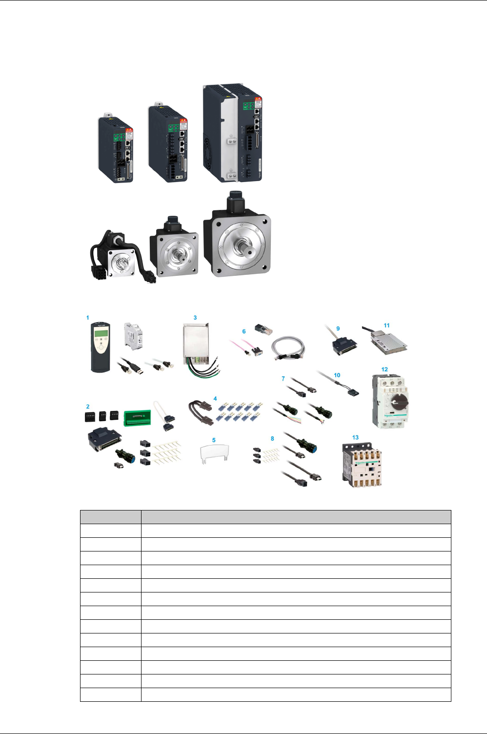
The servo drive system includes:
-the drive
(see page 29)
and the motor
(see page 47)
:
-the accessories and spare parts
(see page 85)
:
Item Description
1 Commissioning tools
(see page 86)
2 Connectors and adapters
(see page 87)
3 External mains filters
(see page 88)
4 DC Bus accessories
(see page 89)
5 Application nameplate
(see page 90)
6 Fieldbus accessories
(see page 91)
7 Motor cables
(see page 93)
8 Encoder cables
(see page 94)
9 Signal cables
(see page 95)
10 Signal cables for safety function STO
(see page 96)
11 External braking resistors
(see page 97)
12 Circuit breakers
(see page 98)
13 Motor protection switches and power contractors
(see page 99)

General Overview
EIO0000002305 04/2017 19
Drive / Motor References
Introduction
The present user guide provides information about the following Drives and Motors reference tables.
The Lexium 28A range is defined by AC-servo drives Lexium 28A for combination with AC-servo motors
BCH2.
-The combinations of servo motors with servo drives are based on the power class: both servo motor
and servo drive must have the same power class.
-The bundle of a servo drive with its related servo motor is designed to cover a nominal power from
0.05 kW up to 4.5 kW (0.067 up to 6.03 hp) with 200…240 V mains supply voltage.
Compatibility between Drive and Motor is defined in the Drive / Motor combinations table
(see page 20)
.
Lexium 28A Drive References List
For further information, refer to the servo drive general overview
(see page 30)
.
BCH2 Motor References List
Drive references Nominal power Supply mains
LXM28AUA5M3X 50 W single phase or 3-phase, 230 Vac
LXM28AU01M3X 100 W single phase or 3-phase, 230 Vac
LXM28AU02M3X 200 W single phase or 3-phase, 230 Vac
LXM28AU04M3X 400 W single phase or 3-phase, 230 Vac
LXM28AU07M3X 750 W single phase or 3-phase, 230 Vac
LXM28AU10M3X 1000 W single phase or 3-phase, 230 Vac
LXM28AU15M3X 1500 W 3-phase, 230 Vac
LXM28AU20M3X 2000 W 3-phase, 230 Vac
LXM28AU30M3X 3000 W 3-phase, 230 Vac
LXM28AU45M3X 4500 W 3-phase, 230 Vac
Motor references Nominal power
BCH2MBA53•C•5C 50 W
BCH2MB013•C•5C 100 W
BCH2LD023•C•5C 200 W
BCH2MM031•C•6C 300 W
BCH2LD043•C•5C 400 W
BCH2LF043•C•5C 400 W
BCH2MM052•C•6C 500 W
BCH2MM061•C•6C 600 W
BCH2HF073•C•5C 750 W
BCH2LF073•C•5C 750 W
BCH2MM081•C•6C 850 W
BCH2MM091•C•6C 900 W
BCH2MM102•C•6C 1000 W
BCH2HM102•C•6C 1000 W
BCH2LH103•C•6C 1000 W
BCH2MM152•C•6C 1500 W
BCH2MM202•C•6C 2000 W
BCH2MR202•C•6C 2000 W
BCH2HR202•C•6C 2000 W
BCH2LH203•C•6C 2000 W
BCH2MR301•C•6C 3000 W
BCH2MR302•C•6C 3000 W

General Overview
20 EIO0000002305 04/2017
For further information, refer to Servo Motor Type Code
(see page 52)
.
Drive / Motor Combinations
The permissible Drive / Motor Combinations are detailed in the following table:
BCH2MR352•C•6C 3500 W
BCH2MR451•C•6C 4500 W
Motor references Nominal power
Drive Motor Nominal
power
Nominal
speed of
rotation
Nominal
torque
Peak
torque
Rotor
inertia
without
holding
brake
Moment
of inertia
Wrpm Nm Nm kg.cm2-
Devices 220 Vac that can be connected via a single phase or three phases
LXM28AUA5M3X BCH2MBA53∙∙∙5C 50 3000 0.16 0.48 0.054 Medium
LXM28AU01M3X BCH2MB013∙∙∙5C 100 3000 0.32 0.96 0.075 Medium
LXM28AU02M3X BCH2LD023∙∙∙5C 200 3000 0.64 1.92 0.16 Low
LXM28AU04M3X
BCH2MM031∙∙∙6C 300 1000 2.86 8.59 6.63 Medium
BCH2LD043∙∙∙5C 400 3000 1.27 3.81 0.27 Low
BCH2LF043∙∙∙5C 400 3000 1.27 3.81 0.67 Low
LXM28AU07M3X
BCH2MM052∙∙∙6C 500 2000 2.39 7.16 6.63 Medium
BCH2MM061∙∙∙6C 600 1000 5.73 17.19 6.63 Medium
BCH2LF073∙∙∙5C 750 3000 2.39 7.16 1.19 Low
BCH2HF073∙∙∙5C 750 3000 2.39 7.16 1.54 High
LXM28AU10M3X
BCH2MM081∙∙∙6C 850 1500 5.39 13.8 13.5 Medium
BCH2MM091∙∙∙6C 900 1000 8.59 25.77 9.7 Medium
BCH2LH103∙∙∙6C 1000 3000 3.18 9.54 2.4 Low
BCH2MM102∙∙∙6C 1000 2000 4.77 14.3 6.63 Medium
BCH2HM102∙∙∙6C 1000 2000 4.77 14.3 8.41 High
LXM28AU15M3X BCH2MM152∙∙∙6C 1500 2000 7.16 21.48 9.7 Medium
Devices 220 Vac that can be connected via three phases
LXM28AU20M3X
BCH2LH203∙∙∙6C 2000 3000 6.37 19.11 4.28 Low
BCH2MM202∙∙∙6C 2000 2000 9.55 28.65 13.5 Medium
BCH2MR202∙∙∙6C 2000 2000 9.55 28.65 26.5 Medium
BCH2HR202∙∙∙6C 2000 2000 9.55 28.65 34.68 High
LXM28AU30M3X BCH2MR301∙∙∙6C 3000 1500 19.1 57.29 53.56 Medium
BCH2MR302∙∙∙6C 3000 2000 14.32 42.97 53.56 Medium
LXM28AU45M3X BCH2MR352∙∙∙6C 3500 2000 16.7 50.3 53.56 Medium
BCH2MR451∙∙∙6C 4500 1500 28.65 71.62 73.32 Medium

EIO0000002305 04/2017 21
Lexium 28
A
and BCH2 Servo Drive System
Document Navigator
EIO0000002305 04/2017
Document Navigator
Chapter 2
Document Navigator
Document Navigator
Document Content
This user guide contains following data:
-Technical data
(see page 23)
Conditions for UL 508C and CSA
(see page 25)
Drive
(see page 29)
Motor
(seepage47)
Accessories and spare parts
(seepage85)
-Engineering
(see page 101)
-Installation
(see page 133)
Before mounting
(see page 135)
Drive installation
(see page 139)
Motor installation
(see page 175)
Verifying installation
(see page 185)
-Commissioning
(see page 187)
Overview
(see page 189)
Integrated HMI
(see page 193)
Commissioning procedure
(see page 201)
Tuning the control loop
(see page 209)
-Parameters
(see page 229)
-Operation
(seepage295)
Operation
(see page 297)
Operating modes
(see page 315)
-Diagnostics and troubleshooting
(see page 397)
-Service, maintenance and disposal
(seepage415)
-CANopen
(see page 425)
CANopen basics
(see page 427)
CANopen object dictionary
(see page 435)

Document Navigator
22 EIO0000002305 04/2017

EIO0000002305 04/2017 23
Lexium 28
A
and BCH2 Servo Drive System
Servo Drive System Technical Data
EIO0000002305 04/2017
Servo Driv e System Technical Data
Part II
Servo Drive System Technical Data
What Is in This Part?
This part contains the following chapters:
Chapter Chapter Name Page
3 Certifications 25
4Drive 29
5Motor 47
6 Accessories and Spare Parts 85

Servo Drive System Technical Data
24 EIO0000002305 04/2017

EIO0000002305 04/2017 25
Lexium 28
A
and BCH2 Servo Drive System
Certifications
EIO0000002305 04/2017
Certifications
Chapter 3
Certifications
Download links
What Is in This Chapter?
This chapter contains the following topics:
Item Link
UL certification status
UL_InfoBY01
CSA certificate
CSA_70022260
EU Declaration of conformity
NHA3487100
TÜV certificate
TUEV_0120554010014
KC certificate Size 1
KC_1333-B797-B43E-FC6C
KC certificate Size 2
KC_8812-6AC0-ECBC-1757
KC certificate Size 3
KC_AE96-6B40-C214-7A18
KC certificate Size 4
KC_A1BB-480B-E156-0EF1
Topic Page
Conditions for UL 508C 26
Conditions for CSA 27

Certifications
26 EIO0000002305 04/2017
Conditions for UL 508C
Introduction
The UL certification status can be downloaded on the
Schneider Electric
website.
If the product is used to comply with UL 508C, the following conditions must also be met.
Wiring
Use at least 75 °C (167 °F) copper conductors.
Fuses
Use fuses as per UL 248 or circuit breaker as per UL 489.
Overvoltage Category
Use only in overvoltage category III or where the maximum available Rated Impulse Withstand Voltage
Peak is equal or less than 4000 Volts, or equivalent as defined in UL 840 and its equivalent defined in
IEC 60664-1.
LXM28A UA5, U01, U02,
U04, U07, U10,
U15
U20, U30, U45
Maximum fuse rating of fuse to be connected upstream 25 A 32 A
Class if fuses are used J J
Class if circuit breakers are used D D

Certifications
EIO0000002305 04/2017 27
Conditions for CSA
The CSA certificate can be downloaded on the
Schneider Electric
website.
If the product is used to comply with CSA, the following conditions must also be met.
Integral solid-state short circuit protection in these drives does not provide branch circuit protection.
For reference groups 1, 2, 3 and 4 (see following table), this product is suitable for use on a circuit capable
of delivering not more than 200 kA RMS symmetrical amperes and 230 Vac maximum, when protected by
Listed Class J, CC or RK5 fuses as indicated in this instruction manual and the Fuse Type table. Instead
of fuses, protection may be provided by circuit breakers of type C60 by Schneider Electric with the
maximum current ratings specified in the following table.
For reference group 1 only, this product is suitable for motor group installation on a circuit capable of
delivering not more than 5 kA RMS symmetrical amperes and 230 Vac maximum, when protected by
Listed Class J or CC fuses as indicated in the instruction manual and the following table. Instead of fuses,
protection may be provided by circuit breakers of type C60 by Schneider Electric with the maximum current
ratings specified in the following table.
The opening of the branch-circuit protective device may be an indication that an electrical interruption has
been detected.
Capacitive voltages above 40 V may remain for up to 15 minutes after power is removed from the drive.
DANGER
ELECTRIC SHOCK, EXPLOSION OR ARC FLASH
Provide branch circuit protection in accordance with the manual instructions, National Electrical Code and
any additional local codes of the type and size specified in the present document.
Failure to follow these instructions will result in death or serious injury.
DANGER
ELECTRIC SHOCK, EXPLOSION OR ARC FLASH
-Examine all current carrying parts and other components of the drive controller for damage and
replace if necessary before replacing fuses or engaging circuit breakers.
-Completely replace overload relays if burnout of the current element occurs.
Failure to follow these instructions will result in death or serious injury.
DANGER
ELECTRIC SHOCK, EXPLOSION, OR ARC FLASH
-Disconnect all power from all equipment including connected devices prior to removing any covers or
doors, or installing or removing any accessories, hardware, cables, or wires.
-Place a "Do Not Turn On" or equivalent hazard label on all power switches and lock them in the non-
energized position.
-Wait 15 minutes to allow the residual energy of the DC bus capacitors to discharge.
-Measure the voltage on the DC bus with a properly rated voltage sensing device and verify that the
voltage is less than 42.4 Vdc.
-Do not assume that the DC bus is voltage-free when the DC bus LED is off.
-Block the motor shaft to prevent rotation prior to performing any type of work on the drive system.
-Do not create a short-circuit across the DC bus terminals or the DC bus capacitors.
-Replace and secure all covers, accessories, hardware, cables, and wires and confirm that a proper
ground connection exists before applying power to the unit.
-Use only the specified voltage when operating this equipment and any associated products.
Failure to follow these instructions will result in death or serious injury.

Certifications
28 EIO0000002305 04/2017
These drives are provided with load and speed adjustable motor overload and short circuit protection.
Adjust the parameter P1-78 ‘User-Defined maximal current’ in the drive which protects the motor by limiting
the maximum current according to the required degree of protection of the motors as indicated on the name
plate.
Other Characteristics
Maximum surrounding Air Temperature: 40 … 55 °C (104 … 131 °F) with current derating of 1% per °C
(per 1.8 °F).
Tightening torque for the connectors labelled CN5, CN7 and CN8 for drive reference group 3 and 4(see
following table): 0.7 … 0.8 Nm (6.2 … 7 lb.in)
Fuse Types
Reference Group Reference Class Maximum Current
1 LXM28AUA5M3X CC or J 25 A
LXM28AU01M3X CC or J 25 A
LXM28AU02M3X CC or J 25 A
LXM28AU04M3X CC or J 25 A
LXM28AU07M3X CC or J 25 A
2 LXM28AU10M3X RK5 or CC or J 25 A
LXM28AU15M3X RK5 or CC or J 25 A
3 LXM28AU20M3X RK5 or J 45 A
4 LXM28AU30M3X RK5 or J 50 A
LXM28AU45M3X RK5 or J 50 A


Drive
EIO0000002305 04/2017 31
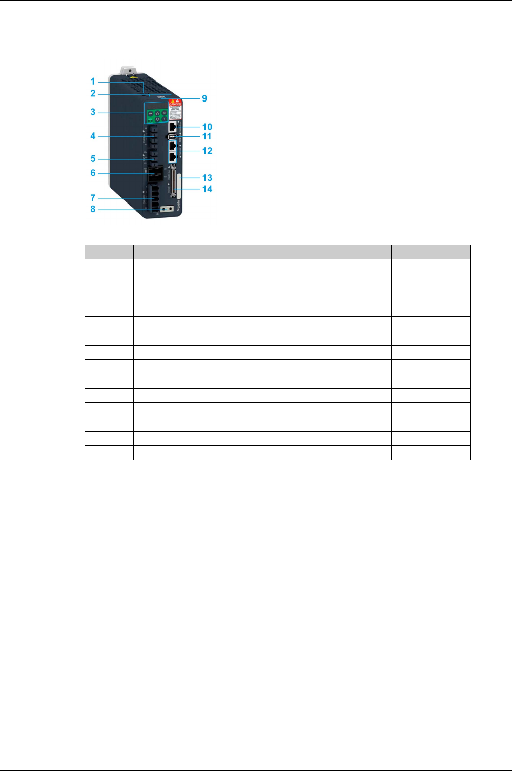
Servo Drive Description
Presentation
Integrated Fieldbus
The Lexium 28 A Servo Drive embeds a dual port CANopen adapter that can be used in a CANopen
industrial fieldbus.
Parameters Access
Servo drive parameters
(see page 231)
may be accessed using:
-The integrated HMI
-The Device Type Manager (DTM)
-Directly using the fieldbus address of the device to read and write to parameters using the object
dictionary
Object Dictionary
The CANopen objects may be accessed through the fieldbus, using their address.
The objects that are also drive parameters are identified by their name in the Parameter column in the
object dictionary table.
Three groups of objects are available in the object dictionary.
-1000h - 1FFFh: Standard communication Object Group
(see page 440)
-4000h - 4FFFh: Vendor-specific Object Group
(see page 453)
-6000h - 6FFFh: Device profile Object Group
(see page 484)
Item Description Connector
1 Connector for safety function STO CN9
(see page 172)
2 Slot for application name plate (VW3M2501) -
3 HMI: 7-segment display, 5 buttons, and 2 status LED -
4 Removable terminal (provided) for motor connection CN8
(see page 169)
5 Removable terminal (provided) for braking resistor connection CN7
(see page 167)
6 DC-bus connector with status LED CN6
(see page 166)
7 Removable terminal (provided) for connecting the power supply CN5
(see page 163)
8 Screw terminal for protective ground (protective earth) -
9 QR code for access to technical data -
10 RJ45 connector for Modbus serial link (commissioning interface) CN3
(see page 158)
11 Connector for the encoder of the motor CN2
(see page 156)
12 2 x RJ45 connectors for integrated CANopen connection CN4
(see page 160)
13 Device Reference -
14 Input/output connector CN1
(see page 145)
Drive
32 EIO0000002305 04/2017
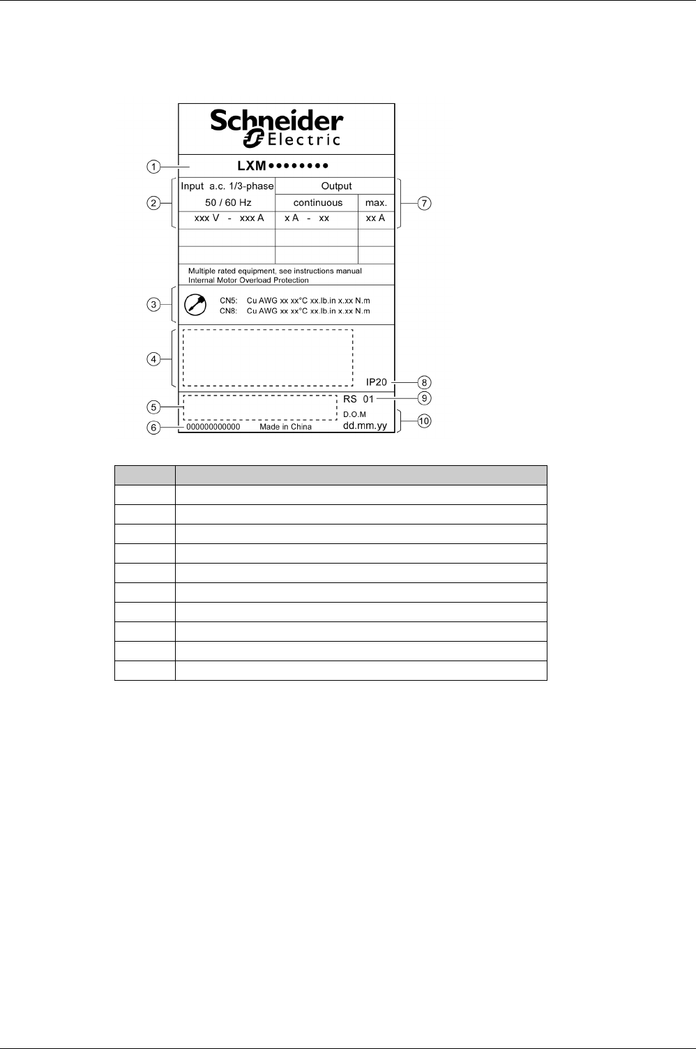
Servo Drive Nameplate
Presentation
The nameplate contains the following data:
Item Description
1 Drive reference
(see page 33)
2 Logic supply
3 Cable specifications
4 Certifications
5 Barcode
6 Serial number
7 Output power
8 Degree of protection
9 Hardware version
10 Date of manufacture

Drive
EIO0000002305 04/2017 33
Servo Drive Type Code
Servo Drive Type Code
Item 12345
Type code (example) LXM 28 A U07 M3X
Item Meaning
1Product designation
LXM = Lexium
2Product type
28 = AC servo drive for one axis
3Interfaces
A = CAN, PTI, I/O interface, commissioning via Modbus RTU
4Continuous power
UA5 = 0.05 kW
U02 = 0.1 kW
U02 = 0.2 kW
U04 = 0.4 kW
U07 = 0.75 kW
U10 = 1 kW
U15 = 1.5 kW
U20 = 2 kW
U30 = 3 kW
U45 = 4.5 kW
5Power stage supply [Vac]
M3X = single phase or 3-phase, 200/230 Vac

Drive
34 EIO0000002305 04/2017
Drive Tech nical Data
Section 4.2
Drive Technical Data
What Is in This Section?
This section contains the following topics:
Topic Page
Environmental Conditions 35
Dimensions 37
Electrical Data 38
Single-Phase Connection 39
Three-Phase Connection 40
Inputs / Outputs Characteristics 42
Functional Safety 46

Drive
EIO0000002305 04/2017 35
Environmental Conditions
Ambient Conditions During Operation
The maximum permissible ambient temperature during operation depends on the mounting distances
between the devices and on the required power. Observe the instructions in the chapter Installation
(see page 140)
.
The following relative humidity is permissible during operation:
Ambient Conditions During Transportation and Storage
The environment during transportation and storage must be dry and free from dust.
The following relative humidity is permissible during transportation and storage:
Installation Site and Connection
For operation, the device must be mounted in a closed control cabinet with a degree of protection of at
least IP 54. The device may only be operated with a permanently installed connection.
Pollution Degree and Degree of Protection
Description Unit Value
Ambient temperature without current derating (no icing, non-condensing °C (°F) 0…40 (32…104)
Ambient temperature with current derating of 1% per 1 °C (1.8 °F) °C (°F) 40…55 (104…131)
Description Unit Value
Relative humidity (non-condensing) % <95
Description Unit Value
Installation altitude above mean sea level without current derating m (ft) <2000 (<6561)
Description Unit Value
Temperature °C (°F) -25…65 (-4…149)
Description Unit Value
Relative humidity (non-condensing) % <95
DANGER
ELECTRIC SHOCK, EXPLOSION, OR ARC FLASH
Install the drive in a control cabinet or housing with a minimum IP 54 rating.
Failure to follow these instructions will result in death or serious injury.
Description Value
Pollution degree 2
Degree of protection IP20

Drive
36 EIO0000002305 04/2017
Degree of Protection When the Safety Function Is Used
You must ensure that conductive substances cannot get into the product (pollution degree 2). Conductive
substances may cause the safety function to become inoperative.
Vibration and Shock During Operation
Vibration and Shock During Transportation and Storage
WARNING
INOPERABLE SAFETY FUNCTION
Ensure that conductive substances (water, contaminated or impregnated oils, metal shavings, etc.)
cannot get into the drive.
Failure to follow these instructions can result in death, serious injury, or equipment damage.
Description Value
Class as per IEC 60721-3-3 3M4 3 mm from 9…200 Hz
Maximum shock 98.1 m/s2 (10 g) Type I
Description Value
Class as per IEC 60721-3-2 2M2
3.5 mm (2…9 Hz)
9.81 m/s2 (1 g) from 9…200 Hz
14.715 m/s2 (1.5 g) from 200…500 Hz
34.335 m/s2 (3.5 g) from 2…9 Hz
Maximum shock 294.3 m/s2 (30 g) Type II
Drive
EIO0000002305 04/2017 37
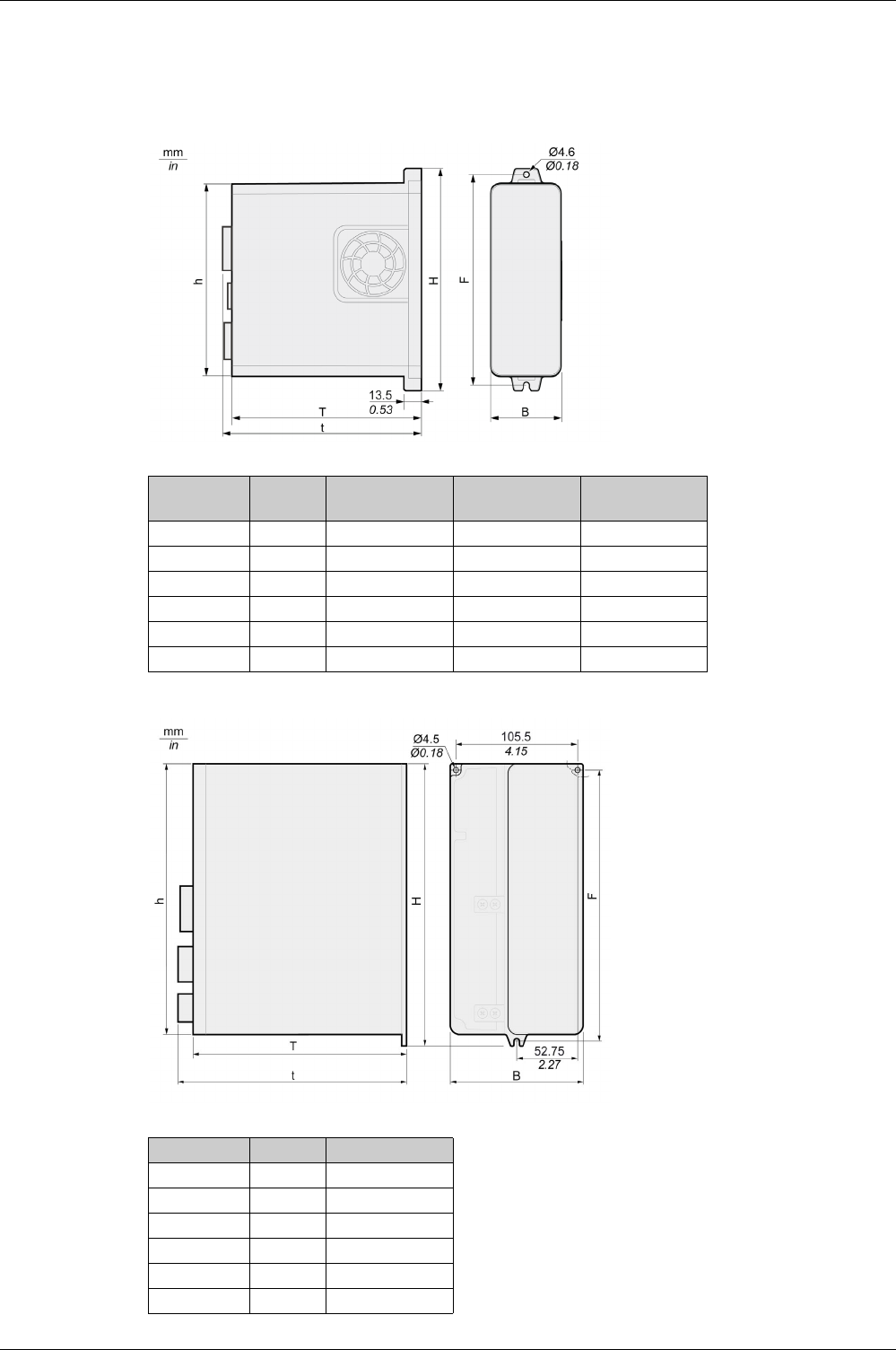
Dimensions
Lexium 28A Dimensions
LXM28AUA5, LXM28AU01, LXM28AU02, LXM28AU04, LXM28AU07, LXM28AU10, LXM28AU15,
LXM28AU20
LXM28AU30, LXM28AU45
LXM28A Unit UA5, U01, U02,
U04, U07
U10, U15 U20
B mm (in) 55 (2.17) 55 (2.17) 62 (2.44)
H mm (in) 173.2 (6.82) 173.5 (6.83) 194.5 (7.66)
h mm (in) 150 (5.91) 150 (5.91) 170 (6.69)
F mm (in) 164 (6.46) 164 (6.46) 185 (7.28)
T mm (in) 146 (5.75) 170 (6.69) 184 (7.24)
d mm (in) 152.7 (6.01) 176.3 (6.94) 197 (7.76)
LXM28A Unit U30, U45
B mm (in) 116 (4.57)
H mm (in) 245 (9.65)
h mm (in) 234 (9.21)
F mm (in) 235 (9.25)
T mm (in) 186 (7.32)
d mm (in) 199 (7.83)

Drive
38 EIO0000002305 04/2017
Electrical Data
Introduction
The products are intended for industrial use and may only be operated with a permanently installed
connection.
Mains Voltage: Range and Tolerance
Type of Grounding
Leakage Current
Monitoring of the Continuous Output Power
The continuous output power is monitored by the device. If the continuous output power is exceeded, the
device reduces the output current.
PWM Frequency Power Stage
PWM frequency power stage The PWM frequency of the power stage is set to a fixed value.
Type of Cooling
Permissible Drive / Motor Combinations
The BCH2 motors can be connected to the Lexium 28A drive range.
Compatibility between Drive and Motor is defined in the Drive / Motor combinations table
(see page 20)
.
Description Unit Value
220 Vac single-phase/three-phase Vac 200 -15 % ... 230 +10 %
Frequency Hz 50 -5 % ... 60 +5 %
Transient overvoltages – Overvoltage category III(1)
Rated voltage to ground Vac 230
(1) Depends on installation altitude, see Environmental Conditions
(see page 35)
Description Value
TT grounding system, TN grounding system Approved
IT mains Not approved
Mains with grounded line conductor Not approved
Description Unit Value
Leakage current (as per IEC 60990, figure 3) mA <30(1)
(1) Measured on mains with grounded neutral point and without external mains filter. Take into account that
a 30 mA RCD can already trigger at 15 mA. In addition, there is a high-frequency leakage current which
is not considered in the measurement. The response to this depends on the type of residual current
device.
LXM28A UA5, U01, U02, U04,
U07, U10, U15
U20, U30, U45
PWM frequency power stage 16 kHz 8 kHz
LXM28A UA5, U01, U02 U04, U07, U10, U15, U20, U30, U45
Type of cooling Convection Fan

Drive
EIO0000002305 04/2017 39
Single-Phase Connection
Electrical Data for Drive Connected Via a Single-Phase
DC bus data for drives connected via a single-phase
LXM28A∙M3X Unit UA5 U01 U02 U04 U07 U10 U15
Nominal voltage V 230 (single-phase)
Inrush current limitation A 8
Maximum fuse to be connected
upstream(1)
A25
Short-circuit current rating (SCCR) kA 5
Continuous output current Arms 0.64 0.9 1.5 2.6 4.5 7 7
Peak output current Arms 2 2.7 4.5 7.8 13.5 21 21
Nominal power(2) W 50 100 200 400 750 1000 1500
Input current(2)(3) Arms 0.8 1.2 2.4 3.8 6 8.5 10
THD (total harmonic distortion)(2)(4) % 262.8 239.2 226.8 211.6 181.8 176.3 166.6
Power dissipation(5) W 8 10 14 22 38 36 41
Maximum inrush current(6) A 175 235
Time for maximum inrush current ms 0.5 0.6
(1) As per IEC 60269; Circuit breakers with C characteristic; See Conditions for UL 508C
(see page 25)
for UL and
CSA; Lower ratings are permissible; The fuse must be rated in such a way that the fuse does not trip at the
specified input current.
(2) At a mains impedance corresponding to the short-circuit current rating (SCCR)
(3) At nominal power and nominal voltage
(4) With reference to the input current
(5) Condition: internal braking resistor not active; value at nominal current, nominal voltage, and nominal power; value
approximately proportional with output current
(6) Extreme case, off/on pulse before the inrush current limitation responds, see next line for maximum time
LXM28A∙M3X Unit UA5 U01 U02 U04 U07 U10 U15
Nominal voltage (single-phase) Vac 230
Nominal voltage DC bus Vdc 322
Undervoltage limit Vdc 160
Overvoltage limit Vdc 420
Maximum continuous power via DC bus W 50 100 200 400 750 1000 1500
Maximum continuous power via DC bus A 0.2 0.3 0.6 1.2 2.3 3.1 4.6

Drive
40 EIO0000002305 04/2017
Three-Phase Connection
Electrical Data for Drive Connected Via Three-Phase
LXM28A∙M3X Unit UA5 U01 U02 U04 U07 U10
Nominal voltage V 230 (3-phase)
Inrush current limitation A 8
Maximum fuse to be connected upstream(1) A25
Short-circuit current rating (SCCR) kA 5
Continuous output current Arms 0.64 0.9 1.5 2.6 4.5 7
Peak output current Arms 2 2.7 4.5 7.8 13.5 21
Nominal power(2) W 50 100 200 400 750 1000
Input current(2)(3) Arms 0.42 0.74 1.25 2.2 3.9 5
THD (total harmonic distortion)(2)(4) % 227.8 212.7 200.7 183.7 160.8 155.5
Power dissipation(5) W 8 10 14 22 38 36
Maximum inrush current(6) A 175 235
Time for maximum inrush current ms 0.5 0.6
(1) As per IEC 60269; Circuit breakers with C characteristic; See Conditions for UL 508C
(see page 25)
for UL and
CSA; Lower ratings are permissible; The fuse must be rated in such a way that the fuse does not trip at the specified
input current.
(2) At a mains impedance corresponding to the short-circuit current rating (SCCR)
(3) At nominal power and nominal voltage
(4) With reference to the input current
(5) Condition: internal braking resistor not active; value at nominal current, nominal voltage, and nominal power; value
approximately proportional with output current
(6) Extreme case, off/on pulse before the inrush current limitation responds, see next line for maximum time
LXM28A∙M3X Unit U15 U20 U30 U45
Nominal voltage V 230 (3-phase)
Inrush current limitation A 8 19.2 17
Maximum fuse to be connected upstream(1) A25 32
Short-circuit current rating (SCCR) kA 5 22
Continuous output current Arms 7 12 19.8 22.8
Peak output current Arms 21 36 60 61
Nominal power(2) W 1500 2000 3000 4500
Input current(2)(3) Arms 5.9 8.7 12.9 18
THD (total harmonic distortion)(2)(4) % 144.8 137.1 155.8 147.1
Power dissipation(5) W41 97
Maximum inrush current(6) A 235 295 300
Time for maximum inrush current ms 0.6 1.0
(1) As per IEC 60269; Circuit breakers with C characteristic; See Conditions for UL 508C
(see page 25)
for UL and CSA; Lower ratings are permissible; The fuse must be rated in such
a way that the fuse does not trip at the specified input current.
(2) At a mains impedance corresponding to the short-circuit current rating (SCCR)
(3) At nominal power and nominal voltage
(4) With reference to the input current
(5) Condition: internal braking resistor not active; value at nominal current, nominal voltage, and
nominal power; value approximately proportional with output current
(6) Extreme case, off/on pulse before the inrush current limitation responds, see next line for
maximum time

Drive
EIO0000002305 04/2017 41
DC bus data for drives connected via three-phase
LXM28A∙M3X Unit UA5 U01 U02 U04 U07 U10
Nominal voltage (three phases) Vac 230
Nominal voltage DC bus Vdc 322
Undervoltage limit Vdc 160
Overvoltage limit Vdc 420
Maximum continuous power via DC bus W 50 100 200 400 750 1000
Maximum continuous power via DC bus A 0.2 0.3 0.6 1.2 2.3 3.1
LXM28A∙M3X Unit U15 U20 U30 U45
Nominal voltage (three phases) Vac 230
Nominal voltage DC bus Vdc 322
Undervoltage limit Vdc 160
Overvoltage limit Vdc 420
Maximum continuous power via DC bus W 1500 2000 3000 4500
Maximum continuous power via DC bus A 4.6 6.2 9.2 13.8

Drive
42 EIO0000002305 04/2017
Inputs / Outputs Characteristics
Logic Type
The outputs are short-circuit protected. The inputs and outputs are galvanically isolated.
The digital inputs and outputs of this product can be wired for positive or negative logic.
Digital Input Signals 24 V
When wired as positive logic, the levels of the opto-isolated inputs DI1...DI5 and DI8 comply with
IEC 61131-2, type 1. The electrical characteristics are also valid when wired as negative logic.
Digital Output Signals 24 V
The levels of the digital 24 V output signals DO∙ comply with IEC 61131-2.
Analog Input Signals
Analog Output Signals
Logic type Active state
Positive logic Output supplies current (source output)
Current flows to the input (sink input)
Negative logic Output draws current (sink output)
Current flows from the input (source input)
Description Unit Value
“0” signal voltage Vdc ≤5
“1” signal voltage Vdc ≥11
Input current (typical) mA 6
Debounce time(1) mA 0...20
(1) Adjustable via parameter P2-09 in increments of 1 ms.
Description Unit Value
Switching voltage Vdc 24
Maximum switching current mA 100
Voltage drop at 100 mA load Vdc < 3
Description Unit Value
Voltage range Vdc -10...10
Input resistance, typical kΩ 10
Resolution Bit 12
Sampling period µs 32.25
Description Unit Value
Voltage range Vdc -8...8
Output current mA 10
Minimum load resistance (voltage source)l kΩ 1
Resolution Bit 12
Sampling period ms 1
Time constant µs 10

Drive
EIO0000002305 04/2017 43
Touch Probe Input Signals 24 V
When wired as positive logic, the levels of the opto-isolated inputs DI6 and DI7 comply with IEC 61131-2,
type 1. The electrical characteristics are also valid when wired as negative logic.
Safety Function STO
The signal inputs STO_0V and STO_24V (CN9) are protected against reverse polarity.
24 Vdc Power Supply (Pin 17):
24 Vdc power supply (pin 17):
CAN Bus Signals:
The CAN bus signals comply with the CAN standard and are short-circuit protected.
ESIM Output Signals
The ESIM output signals comply with the RS422 interface specification.
Description Unit Value
“0” signal voltage Vdc ≤5
“1” signal voltage Vdc ≥11
Input current (typical) mA 7
Debounce time(1) µs 0...100
Jitter Capture µs 1
(1) Adjustable via parameter P2-24 in increments of 1 µs.
Description Unit Value
Nominal voltage Vdc 24
PELV power supply unit – Required
“0” signal voltage (1) Vdc < 5
“1” signal voltage (1) Vdc 15...30
Input current (typical)
LXM28AUA5, U01, U02, U04, U07
LXM28AU10, U15
LXM28AU20
LXM28AU30, U45
mA
110
120
130
160
Maximum peak current A 18
Maximum frequency for OSSD (Output Signal
Switching Device) test pulses
Hz 475
Debounce time ms < 1
Response time of safety function STO ms < 40
(1) Voltage level according to IEC 61131-2 type 2 with the exception of the operation with 15 Vdc instead of
11 Vdc. The condition between 5 Vdc and 15 Vdc is undefined and not permissible.
Description Unit Value
Output voltage Vdc 24
Maximum output current mA 200
Description Unit Value
Logic level – As per RS422(1)
Output frequency per signal kHz 800
Maximum output frequency (quadruple evaluation) kHz 3200
(1) Due to the input current of the optocoupler in the input circuit, a parallel connection of a driver output to
several devices is not permitted.
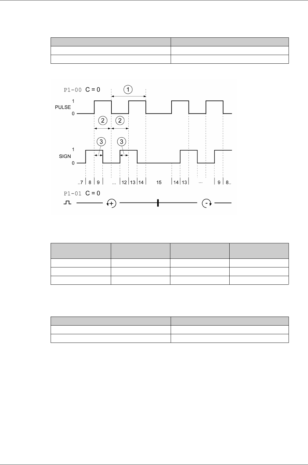
Drive
44 EIO0000002305 04/2017
Function A/B Signals
External A/B signals can be supplied via the PTI input as reference values in operating mode Pulse Train
(Pt).
Time chart with A/B signal, counting forwards and backwards
The signal shape shown relates to the factory setting (P1-00 C=0). The direction of movement shown
relates to the factory setting (P1-01 C=0).
Function CW/CCW
External CW/CCW signals can be supplied via the PTI input as reference values.
Signal Function
Signal SIGN before signal PULSE Movement in positive direction
Signal PULSE before signal SIGN Movement in negative direction
Intervals (minimum) HPULSE / HSIGN with
RS422
PULSE / SIGN with
RS422
PULSE / SIGN with Open
Collector
1 4 MHz 500 kHz 200 kHz
2 0.125 μs 0.1 μs 2.5 μs
3 0.0625 μs 0.5 μs 1.25 μs
Signal Function
Signal PULSE (CCW) Movement in positive direction
Signal SIGN (CW) Movement in negative direction
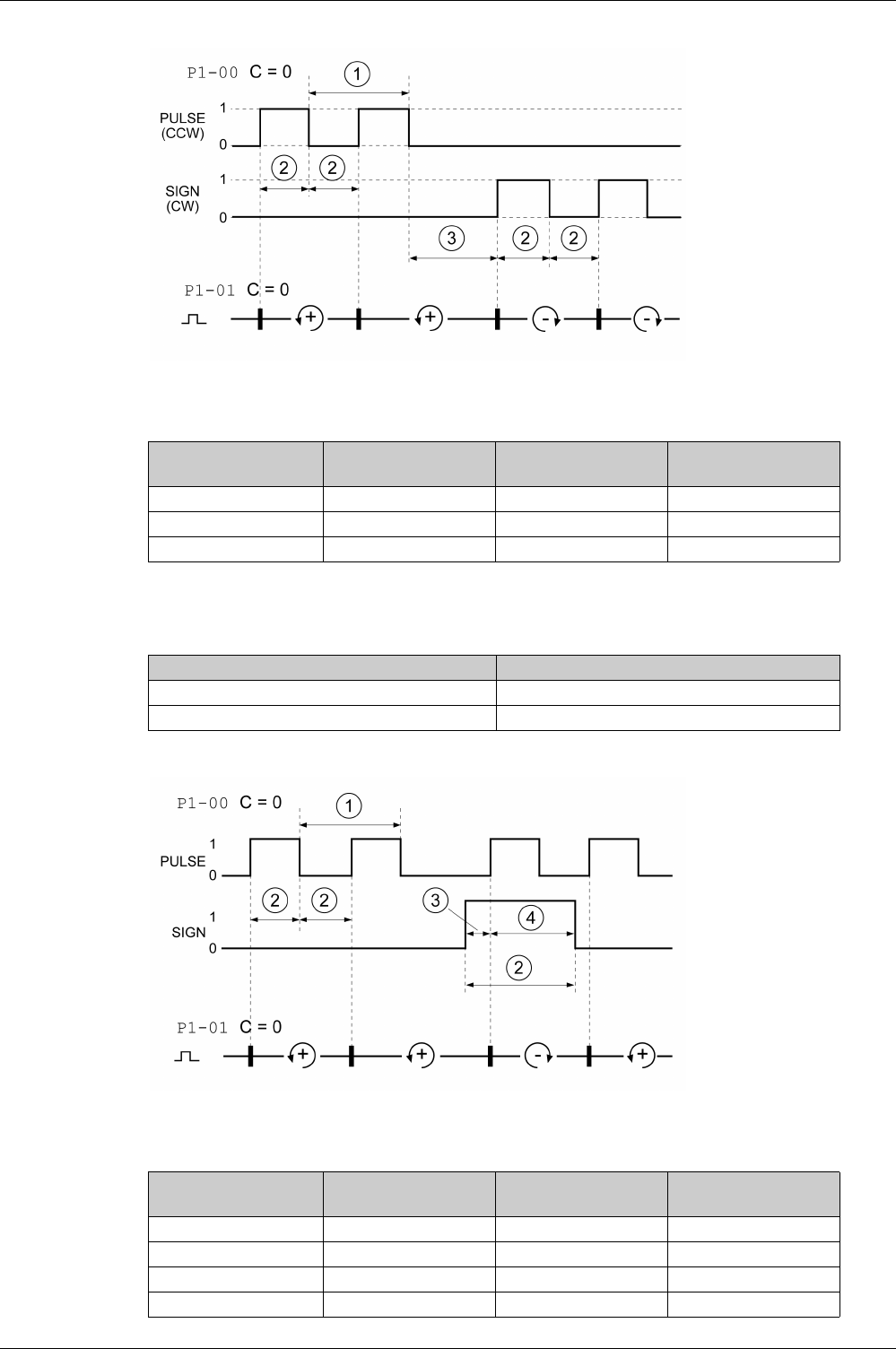
Drive
EIO0000002305 04/2017 45
Time chart with "CW/CCW"
The signal shape shown relates to the factory setting (P1-00 C=0). The direction of movement shown
relates to the factory setting (P1-01 C=0).
Function P/D
External P/D signals can be supplied via the PTI input as reference values.
Time chart with pulse/direction signal
The signal shape shown relates to the factory setting (P1-00 C=0). The direction of movement shown
relates to the factory setting (P1-01 C=0).
Intervals (minimum) HPULSE / HSIGN with
RS422
PULSE / SIGN with
RS422
PULSE / SIGN with Open
Collector
1 4 MHz 500 kHz 200 kHz
2 0.125 μs 0.1 μs 2.5 μs
3 0.0625 μs 0.5 μs 1.25 μs
Signal Function
Signal PULSE Motor movement
Signal SIGN Direction of movement
Intervals (minimum) HPULSE / HSIGN with
RS422
PULSE / SIGN with
RS422
PULSE / SIGN with Open
Collector
1 4 MHz 500 kHz 200 kHz
2 0.125 μs 0.1 μs 2.5 μs
3 0.0625 μs 0.5 μs 1.25 μs
4 0.0625 μs 0.5 μs 1.25 μs
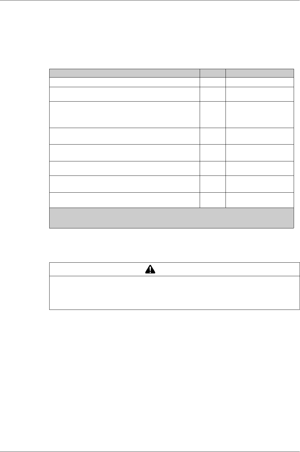
Drive
46 EIO0000002305 04/2017
Functional Safety
Data for Maintenance Plan and the Calculations for the Safety Function
The safety function must be tested at regular intervals. The interval depends on the hazard and risk
analysis of the total system. The minimum interval is 1 year (high demand mode as per IEC 61508).
Use the following data of the safety function STO for your maintenance plan and the calculations for the
safety function:
If two non-adjacent IGBTs have a short circuit, a movement of a maximum of 120 degrees (electrical) can
occur even if the safety function STO is active. Include in your risk analysis the probability of IGBT short
circuits, and make a determination whether it is acceptable as it relates to your application.
The probability of such a condition is 1.5 x 10⁻¹⁵ per hour (without common cause error). Include this in
your calculations for the safety function.
Contact your local sales office for additional data, if required.
Description Unit Value
Lifetime of the safety function STO (IEC 61508)(1) Years 20
SFF (IEC 61508)
Safe Failure Fraction
% 98.9
Safety integrity level
IEC 61508
IEC 62061
IEC 61800-5-2
–SILCL2
PFH (IEC 61508)
Probability of Dangerous Hardware Failure per Hour
1/h STO_A(2): 1.7 x 10⁻⁹
STO_B(3): 1.5 x 10⁻⁹
PFDavg (IEC 61508)
Probability of Failure on Demand, calculated as one demand per year
–STO_A(2): 1.5 x 10⁻⁴
STO_B(3): 1.3 x 10⁻⁴
PL (ISO 13849-1)
Performance Level
– d (category 3)
MTTFd (ISO 13849-1)
Mean Time to Dangerous Failure
Years STO_A(2): 66757
STO_B(3): 78457
DCavg (ISO 13849-1)
Diagnostic Coverage
%≥90
(1) See chapter Lifetime Safety Function STO
(see page 420)
(2) STO_A:LXM28AUA5, U01, U02, U04, U07, U10, U15, U20
(3) STO_B:LXM28AU30, U45
WARNING
UNINTENTIONAL MOVEMENT DURING STO FUNCTION
Use appropriate safety interlocks (such as a service brake) where personnel and/or equipment hazards
exist.
Failure to follow these instructions can result in death, serious injury, or equipment damage.

EIO0000002305 04/2017 47
Lexium 28
A
and BCH2 Servo Drive System
Motor
EIO0000002305 04/2017
Motor
Chapter 5
Motor
What Is in This Chapter?
This chapter contains the following sections:
Section Topic Page
5.1 General Overview 48
5.2 Motor Technical Data 53
5.3 BCH2MB Motor 58
5.4 BCH2LD Motor 62
5.5 BCH2∙F Motor 66
5.6 BCH2LH Motor 70
5.7 BCH2∙M Motor 74
5.8 BCH2∙R Motor 80

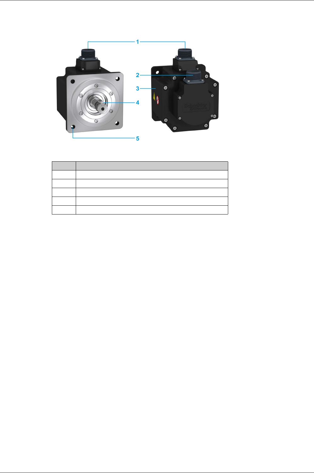
Motor
EIO0000002305 04/2017 49
Components and Interfaces
Presentation
BCH2 servo motors, with a 3-phase stator and rotor with rare earth-based permanent magnets, consist of:
Item Description
1 Connector of the motor cable
(see page 93)
2 Connector of the encoder cable
(see page 94)
3 Housing
4 Smooth or keyed shaft end, depending on the motor reference
5 4-point axial mounting flange
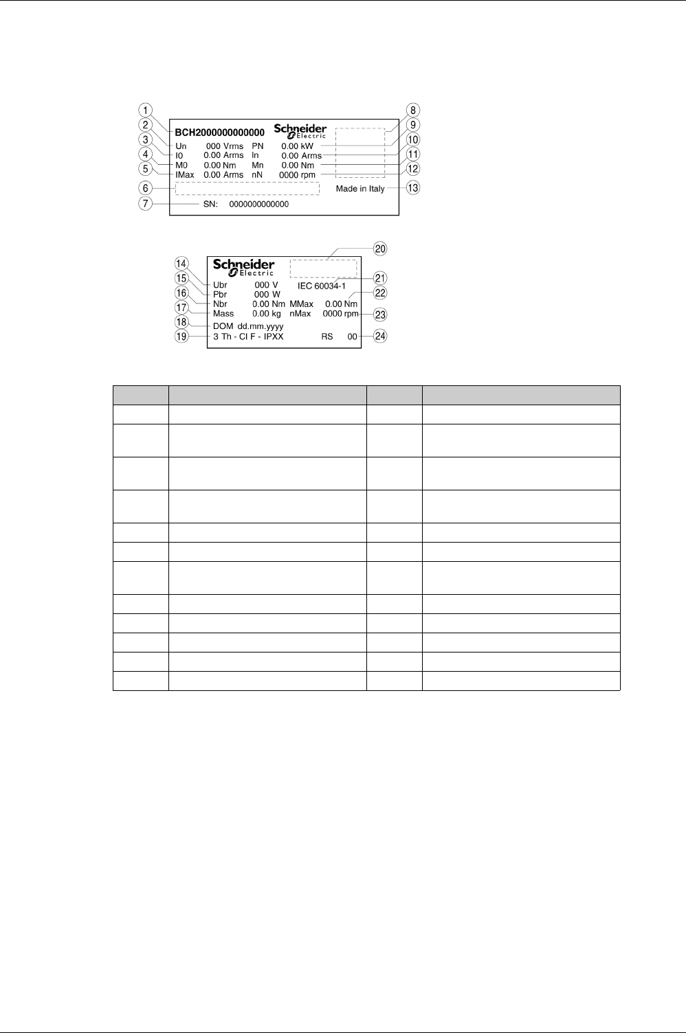
Motor
50 EIO0000002305 04/2017
Servo Motor Nameplate
BCH2∙B
The nameplate contains the following data:
Item Description Item Description
1 Motor reference
(see page 52)
13 Country of manufacture
2 Nominal voltage 14 Nominal voltage of the holding brake
(optional)
3 Continuous stall current 15 Nominal power of the holding brake
(optional)
4 Continuous stall torque 16 Nominal torque of the holding brake
(optional)
5 Maximum current 17 Mass
6 Barcode 18 Date of manufacture DOM
7 Serial number 19 Number of motor phases, temperature
class, degree of protection
8 QR code 20 Certifications
9 Nominal power 21 Applied standard
10 Nominal current 22 Peak torque
11 Nominal torque 23 Maximum permissible speed of rotation
12 Nominal speed of rotation 24 Hardware version
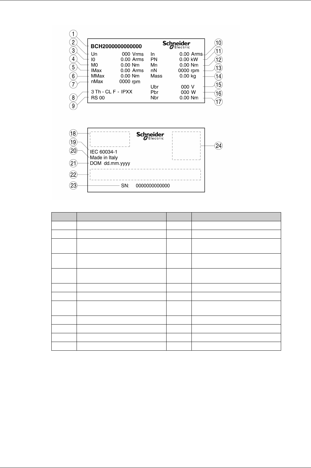
Motor
EIO0000002305 04/2017 51
BCH2∙D, BCH2∙F, BCH2∙H, BCH2∙M, and BCH2∙R
The nameplate contains the following data:
Item Description Item Description
1 Motor reference
(see page 52)
13 Nominal speed of rotation
2 Nominal voltage 14 Mass
3 Continuous stall current 15 Nominal voltage of the holding brake
(optional)
4 Continuous stall torque 16 Nominal power of the holding brake
(optional)
5 Maximum current 17 Nominal torque of the holding brake
(optional)
6 Peak torque 18 Certifications
7 Maximum permissible speed of rotation 19 Applied standard
8 Number of motor phases, temperature
class, degree of protection
20 Country of manufacture
9 Hardware version 21 Date of manufacture DOM
10 Nominal current 22 Barcode
11 Nominal power 23 Serial number
12 Nominal torque 24 QR code

Motor
52 EIO0000002305 04/2017
Servo Motor Type Code
Servo Motor Type Code
Item 12345678910
Type code (example) BCH2 M B 01 3 3 C A 5 C
Item Meaning
1Product family
BCH2 = Brushless servo motors - second generation
2Moment of inertia
L = Low
M = Medium
H = High
3Size (housing)
B = 40 mm flange
D = 60 mm flange
F = 80 mm flange
H = 100 mm flange
M = 130 mm flange
R = 180 mm flange
4Nominal power
A5 = 50 W
01 = 100 W
02 = 200 W
03 = 300 W
04 = 400 W
05 = 500 W
06 = 600 W
07 = 750 W
08 = 850 W
09 = 900 W
10 = 1.0 kW
13 = 1.3 kW
15 = 1.5 kW
20 = 2.0 kW
30 = 3.0 kW
35 = 3.5 kW
45 = 4.5 kW
5Winding
1 = Optimized in terms of torque (1000 rpm/1500 rpm)
2 = Optimized in terms of torque and speed of rotation (2000 rpm)
3 = Optimized in terms of speed of rotation (3000 rpm)
6Shaft and degree of protection(1)
0 = Smooth shaft; degree of protection: shaft IP 54, housing IP 65
1 = Parallel key; degree of protection: shaft IP 54, housing IP 65
2 = Smooth shaft; degree of protection: shaft and housing IP 65
3 = Parallel key; degree of protection: shaft and housing IP 65
7Encoder system
C = High-resolution encoder single turn
8Holding brake
A = Without holding brake
F = With holding brake
9Connection version
5 = Flying leads (for BCH2∙B, BCH2∙D, BCH2∙F)
6 = MIL connector (for BCH2∙H, BCH2∙M, BCH2∙R)
10 Mechanical interface - mounting
C = Asian style
(1) In the case of mounting position IM V3 (drive shaft vertical, shaft end up), the motor has degree of
protection IP 50.


Motor
54 EIO0000002305 04/2017
Environmental Conditions
Ambient Conditions During Operation
The maximum permissible ambient temperature during operation depends on the mounting distances
between the devices and on the required power. Observe the instructions in the chapter Installation
(see page 176)
.
Ambient Conditions During Transportation and Storage
The environment during transportation and storage must be dry and free from dust.
Flange Sizes for Limit Values
Limit values referring to this table relate to flanged motors with the following flange sizes:
Compatibility with Foreign Substances
The motor has been tested for compatibility with many known substances and with the latest available
knowledge at the moment of the design. Nonetheless, you must perform a compatibility test before using
a foreign substance.
Description Unit Value
Ambient temperature(1) for motors without holding brake (no icing,
non-condensing).
°C (°F) -20...40 (-4...104)
Ambient temperature for motors with holding brake (no icing, non-
condensing).
°C (°F) 0...40 (32...104)
Ambient temperature with current derating of 1% per °C (per 1.8 °F) °C (°F) 40...60 (104...140)
Relative humidity (non-condensing) % 5...85
Class as per IEC 60721-3-3 - 3K3, 3Z12, 3Z2, 3B2, 3C1, 3M6(2)
Installation altitude above mean sea level without current derating m (ft) <1000 (<3281)
Installation altitude above mean sea level with current derating of 1%
per 100 m at altitudes higher than 1000 m
m (ft) 1000...3000 (3281...9843)
(1) Limit values with flanged motor, see Flange Sizes for Limit Values
(see page 54)
(2) Tested as per IEC 60068-2-6 and IEC 60068-2-27
Description Unit Value
Temperature °C (°F) -40...70 (-40...158)
Relative humidity (non-condensing) % ≤75
Set of class combinations as per IEC 60721-3-2 – IE 21
Motor Flange material Flange size in [mm (in)]
BCH2MB Aluminum 185 x 185 x 8 (7.28 x 7.28 x 0.31)
BCH2LD Aluminum 250 x 250 x 12 (9.84 x 9.84 x 0.47)
BCH2∙F Aluminum 250 x 250 x 12 (9.84 x 9.84 x 0.47)
BCH2LH Steel 300 x 300 x 20 (11.8 x 11.8 x 0.79)
BCH2∙M Steel 400 x 400 x 20 (15.7 x 15.7 x 0.79)
BCH2∙R Steel 550 x 550 x 20 (21.7 x 21.7 x 0.79)

Motor
EIO0000002305 04/2017 55
Tightening Torque and Property Class of Screws
Housing screws Unit Tightening torque
M3 x 0.50 Nm (lb.in) 1 (8.85)
M4 x 0.70 Nm (lb.in) 2.9 (25.67)
M5 x 0.80 Nm (lb.in) 5.9 (52.22)
M6 x 1.00 Nm (lb.in) 9.9 (87.62)
M7 x 1.25 Nm (lb.in) 24 (212.40)
M8 x 1.50 Nm (lb.in) 49 (433.65)
Property class of the screws H 8.8
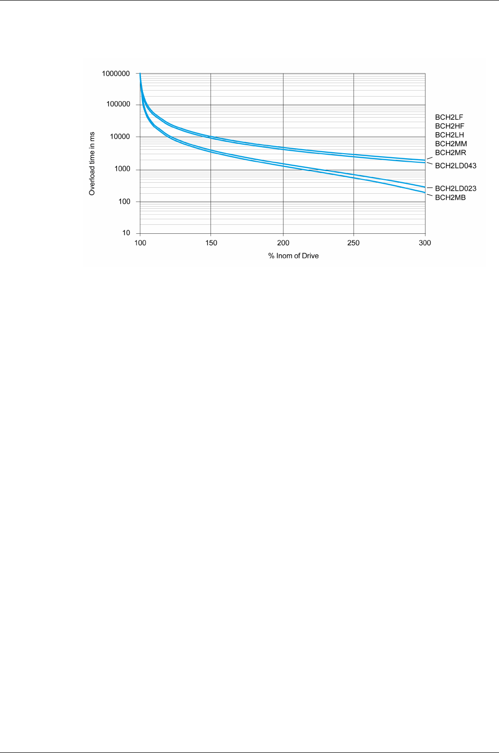
Motor
56 EIO0000002305 04/2017
Overload Characteristics Curves

Motor
EIO0000002305 04/2017 57
Encoder Technical Data
The drive can access the electronic nameplate via the electronic interface of the encoder for easy
commissioning.
The signals meet the PELV requirements.
Description Value
Measuring range absolute 1 revolution
Resolution in increments Depending on evaluation
Accuracy of position ±0.044°
Supply voltage 4.1...5.25 Vdc
Maximum supply current 100 mA
Maximum permissible speed of rotation 6000 rpm
Maximum angular acceleration 100,000 rad/s2

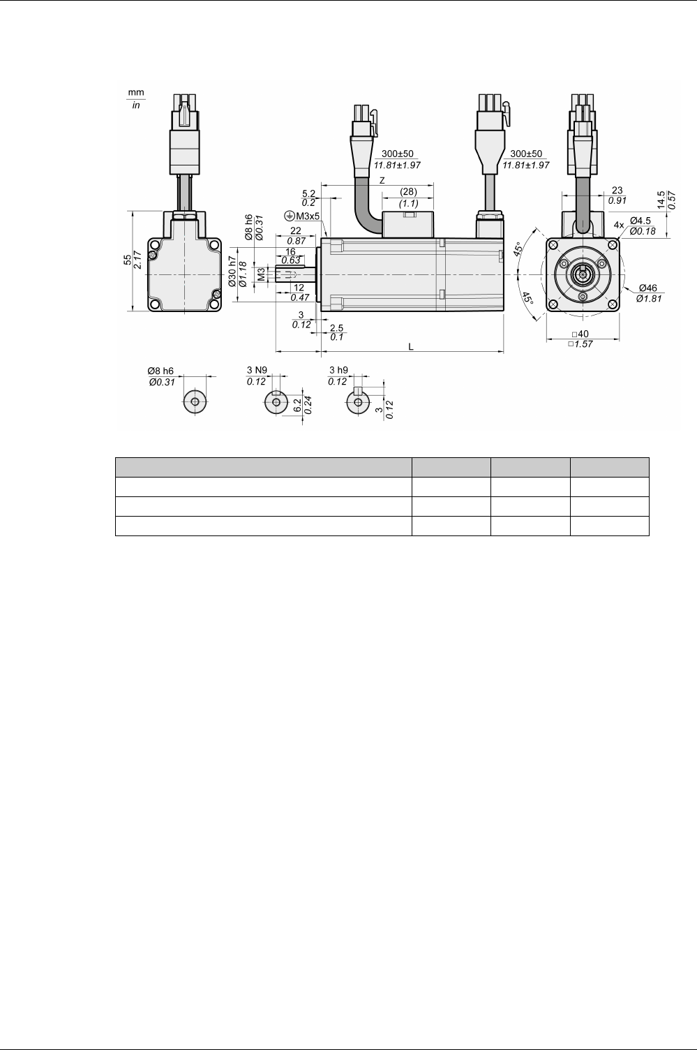
Motor
EIO0000002305 04/2017 59
BCH2MB Dimensions
BCH2MB Unit A5 01
L (without holding brake) mm (in) 82 (3.23) 100 (3.94)
L (with holding brake) mm (in) 112 (4.41) 130 (5.12)
Z mm (in) 43.5 (1.71) 61.5 (2.42)

Motor
60 EIO0000002305 04/2017
BCH2MB Characteristics Table
BCH2MB(1) A53 013
Technical data - general
Continuous stall torque(2) M0Nm 0.16 0.32
Peak torque Mmax Nm 0.48 0.96
With supply voltage Un = 230 Vac
Nominal speed of rotation nNrpm 3000 3000
Nominal torque MNNm 0.16 0.32
Nominal Current INArms 0.59 0.89
Nominal power PNkW 0.05 0.10
Technical data - electrical
Maximum winding voltage Umax Vac 255 255
Maximum winding voltage Umax Vdc 360 360
Maximum voltage to ground – Vac 255 255
Maximum Current Imax Arms 1.8 2.7
Continuous stall current I0Arms 0.54 0.81
Voltage constant(3) kEu-v Vrms 18 24
Torque constant(4) ktNm/A 0.30 0.40
Winding resistance R20u-v Ω 31.0 23.4
Winding inductance Lqu-v mH 26.4 21.5
Winding inductance Ldu-v mH 24.7 20.6
Technical data - mechanical
Maximum permissible speed of rotation nmax rpm 5000 5000
Rotor inertia without brake JMkgcm20.054 0.075
Rotor inertia with brake JMkgcm20.055 0.076
Mass without brake m kg 0.40 0.56
Mass with brake m kg 0.60 0.77
Degree of protection of the shaft – – IP 65 IP 65
Degree of protection of the housing – – IP 65 IP 65
Technical data - holding brake
Holding torque – Nm 0.32 0.32
Nominal voltage – Vdc 24 +/-10% 24 +/-10%
Nominal power (electrical pull-in power) – W 4.4 4.4
(1) Limit values with flanged motor:
Flange material: Aluminum
Flange size in mm (in): 185 x 185 x 8 (7.28 x 7.28 x 0.31)
(2) M0 = Continuous stall torque at 20 rpm and 100 % duty cycle; at speeds of rotation of <20 rpm the
continuous stall torque is reduced to 87 %.
(3) RMS value at 1000 rpm and 20 °C (68 °F).
(4) At n = 20 rpm and 20 °C (68 °F).
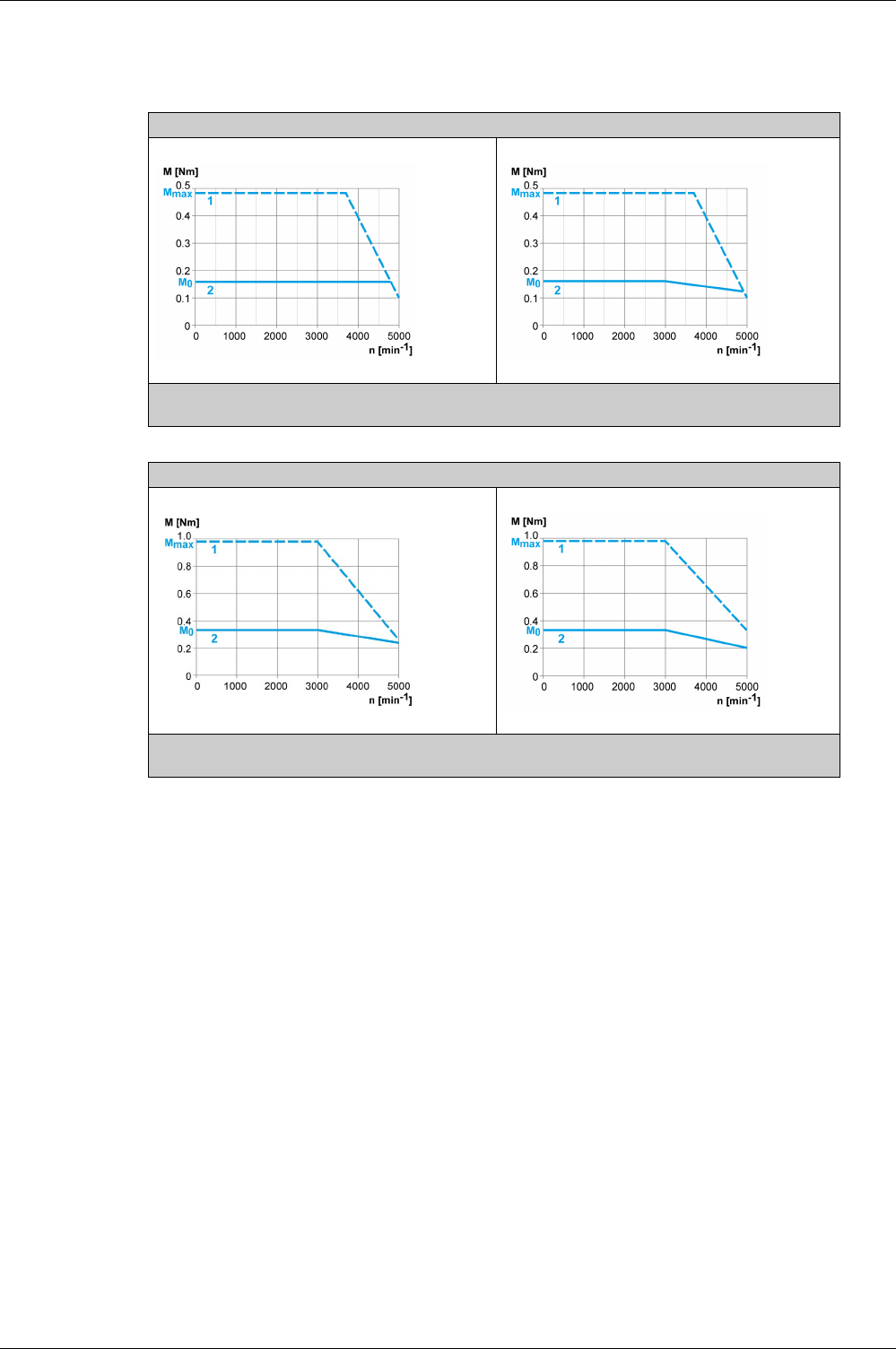
Motor
EIO0000002305 04/2017 61
BCH2MB Curves
BCH2MBA53 + LXM28AUA5
Without shaft sealing ring With shaft sealing ring
(1) Peak torque
(2) Continuous torque
BCH2MB013 + LXM28AU01
Without shaft sealing ring With shaft sealing ring
(1) Peak torque
(2) Continuous torque

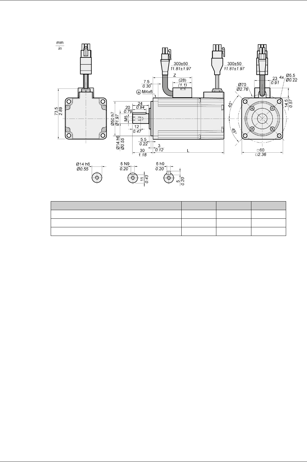
Motor
EIO0000002305 04/2017 63
BCH2LD Dimensions
BCH2LD Unit 02 04
L (without holding brake) mm (in) 104 (4.09) 129 (5.08)
L (with holding brake) mm (in) 140 (5.51) 165 (6.5)
Z mm (in) 57 (2.24) 82 (3.23)

Motor
64 EIO0000002305 04/2017
BCH2LD Characteristics Table
BCH2LD(1) 023 043
Technical data - general
Continuous stall torque(2) M0Nm 0.64 1.27
Peak torque Mmax Nm 1.92 3.81
With supply voltage Un = 230 Vac
Nominal speed of rotation nNrpm 3000 3000
Nominal torque MNNm 0.64 1.27
Nominal Current INArms 1.30 2.50
Nominal power PNkW 0.20 0.40
Technical data - electrical
Maximum winding voltage Umax Vac 255 255
Maximum winding voltage Umax Vdc 360 360
Maximum voltage to ground – Vac 255 255
Maximum Current Imax Arms 4.5 7.8
Continuous stall current I0Arms 1.11 2.19
Voltage constant(3) kEu-v Vrms 35 35
Torque constant(4) ktNm/A 0.58 0.58
Winding resistance R20u-v Ω 12.2 5.2
Winding inductance Lqu-v mH 24.8 12.5
Winding inductance Ldu-v mH 22.7 12.0
Technical data - mechanical
Maximum permissible speed of rotation nmax rpm 5000 5000
Rotor inertia without brake JMkgcm20.16 0.27
Rotor inertia with brake JMkgcm20.17 0.28
Mass without brake m kg 1.02 1.45
Mass with brake m kg 1.50 2.00
Degree of protection of the shaft – – IP 65 IP 65
Degree of protection of the housing – – IP 65 IP 65
Technical data - holding brake
Holding torque – Nm 1.3 1.3
Nominal voltage – Vdc 24 +/-10% 24 +/-10%
Nominal power (electrical pull-in power) – W 11.2 11.2
(1) Limit values with flanged motor:
Flange material: Aluminum
Flange size in mm (in): 250 x 250 x 12 (9.84 x 9.84 x 0.47)
(2) M0=Continuous stall torque at 20 rpm and 100 % duty cycle; at speeds of rotation of <20 rpm the continuous
stall torque is reduced to 87 %
(3) RMS value at 1000 rpm and 20 °C (68 °F).
(4) At n = 20 rpm and 20 °C (68 °F).
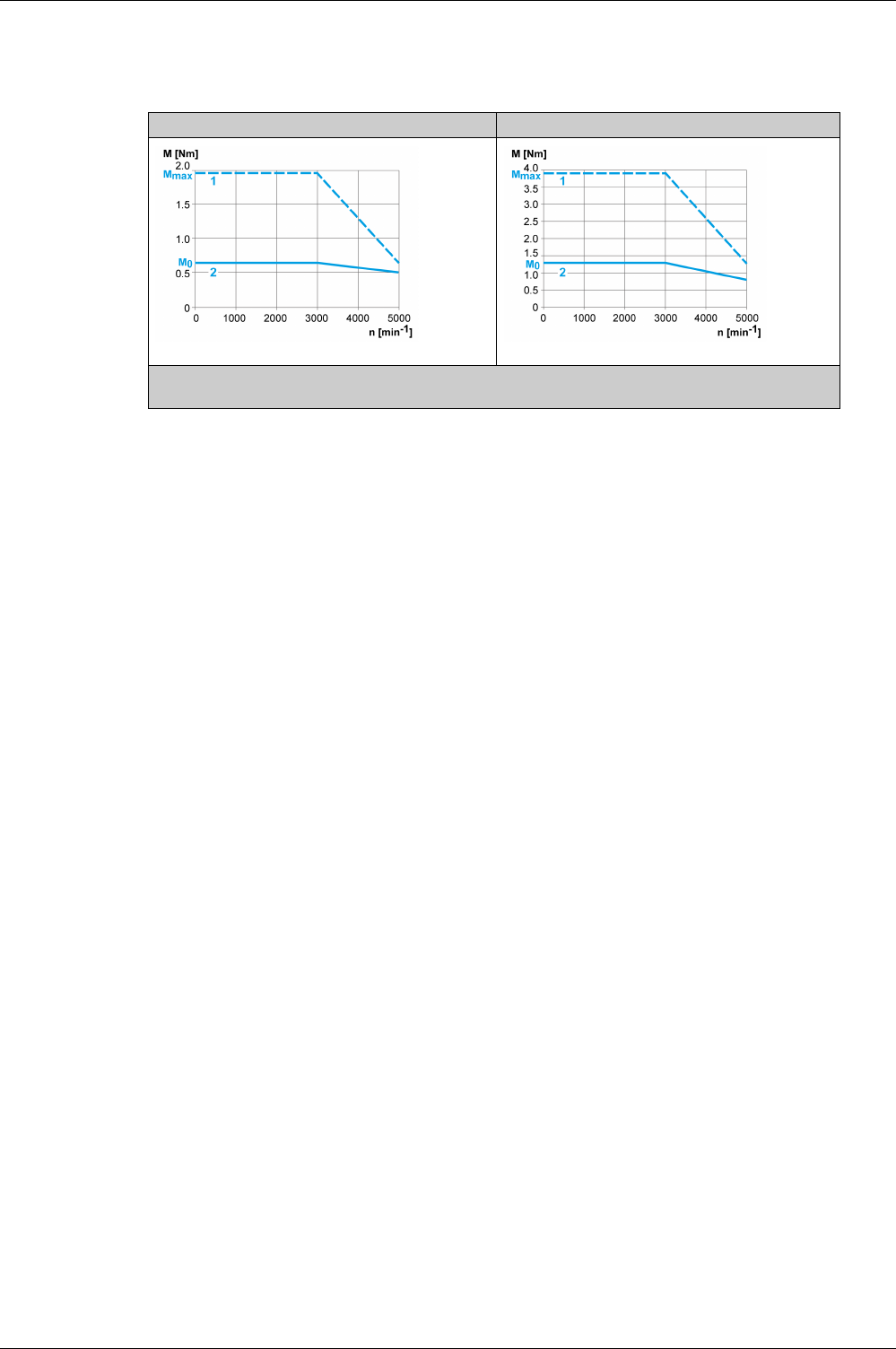
Motor
EIO0000002305 04/2017 65
BCH2LD Curves
BCH2LD023 + LXM28AU02 BCH2LD043 + LXM28AU04
(1) Peak torque
(2) Continuous torque

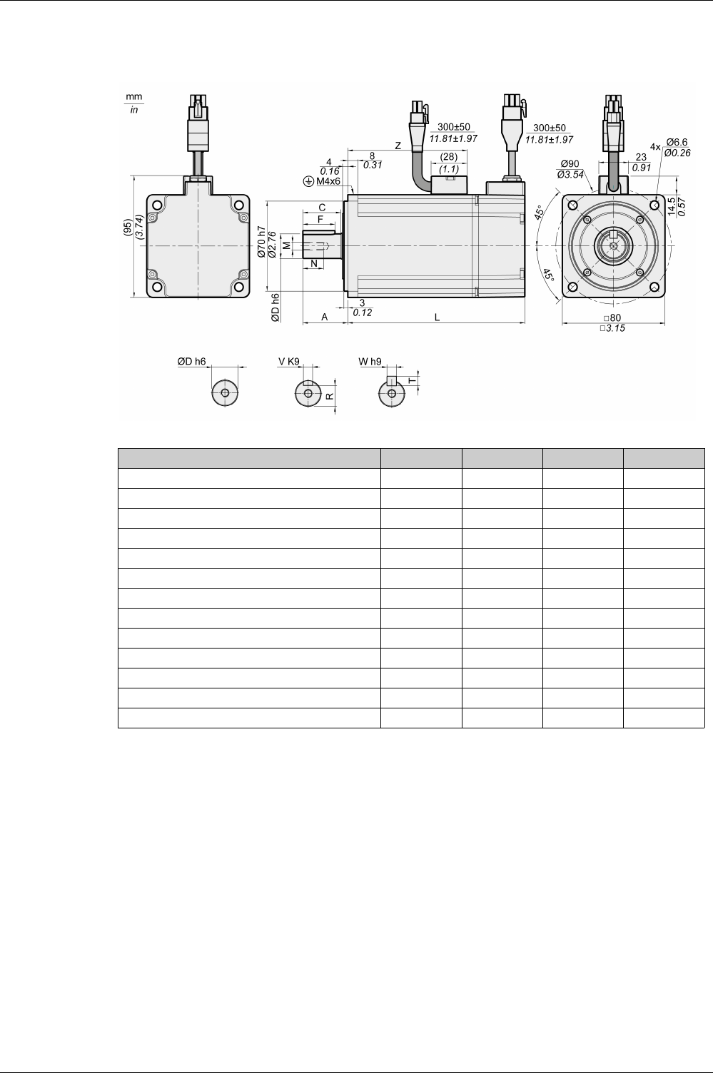
Motor
EIO0000002305 04/2017 67
BCH2∙F Dimensions
BCH2 Unit LF04 HF07 LF07
L (without holding brake) mm (in) 112 (4.41) 138 (5.43) 138 (5.43)
L (with holding brake) mm (in) 152 (5.98) 178 (7.01) 178 (7.01)
A mm (in) 30 (1.18) 35 (1.38) 35 (1.38)
C mm (in) 24.5 (0.96) 29.5 (1.16) 29.5 (1.16)
D mm (in) 14 (0.55) 19 (0.75) 19 (0.75)
F mm (in) 20 (0.79) 25 (0.98) 25 (0.98)
M - M5 M6 M6
N mm (in) 12 (0.47) 16 (0.63) 16 (0.63)
R mm (in) 11 (0.43) 15.5 (0.61) 15.5 (0.61)
T mm (in) 5 (0.2) 6 (0.24) 6 (0.24)
V mm (in) 5 (0.2) 6 (0.24) 6 (0.24)
W mm (in) 5 (0.2) 6 (0.24) 6 (0.24)
Z mm (in) 68 (2.68) 93 (3.66) 93 (3.66)

Motor
68 EIO0000002305 04/2017
BCH2∙F Characteristics Table
BCH2(1) LF043 HF073 LF073
Technical data - general
Continuous stall torque(2) M0Nm 1.27 2.39 2.39
Peak torque Mmax Nm 3.81 7.16 7.16
With supply voltage Un = 230 Vac
Nominal speed of rotation nNrpm 3000 3000 3000
Nominal torque MNNm 1.27 2.39 2.39
Nominal Current INArms 2.52 4.29 4.29
Nominal power PNkW 0.40 0.75 0.75
Technical data - electrical
Maximum winding voltage Umax Vac 255 255 255
Maximum winding voltage Umax Vdc 360 360 360
Maximum voltage to ground – Vac 255 255 255
Maximum Current Imax Arms 7.8 13.5 13.5
Continuous stall current I0Arms 2.29 4.01 4.01
Voltage constant(3) kEu-v Vrms 33.5 36 36
Torque constant(4) ktNm/A 0.55 0.60 0.60
Winding resistance R20u-v Ω 3.20 1.50 1.50
Winding inductance Lqu-v mH 12.0 6.6 6.6
Winding inductance Ldu-v mH 11.3 6.1 6.1
Technical data - mechanical
Maximum permissible speed of rotation nmax rpm 5000 5000 5000
Rotor inertia without brake JMkgcm20.67 1.54 1.19
Rotor inertia with brake JMkgcm20.72 1.59 1.24
Mass without brake m kg 2.00 2.90 2.80
Mass with brake m kg 2.80 3.70 3.60
Degree of protection of the shaft – – IP 65 IP 65 IP 65
Degree of protection of the housing – – IP 65 IP 65 IP 65
Technical data - holding brake
Holding torque – Nm 2.5 2.5 2.5
Nominal voltage – Vdc 24 +/-10% 24 +/-10% 24 +/-10%
Nominal power (electrical pull-in power) – W 10.2 10.2 10.2
(1) Limit values with flanged motor:
Flange material: Aluminum
Flange size in mm (in): 250 x 250 x 12 (9.84 x 9.84 x 0.47)
(2) M0=Continuous stall torque at 20 rpm and 100 % duty cycle; at speeds of rotation of <20 rpm the continuous
stall torque is reduced to 87 %
(3) RMS value at 1000 rpm and 20 °C (68 °F).
(4) At n = 20 rpm and 20 °C (68 °F).
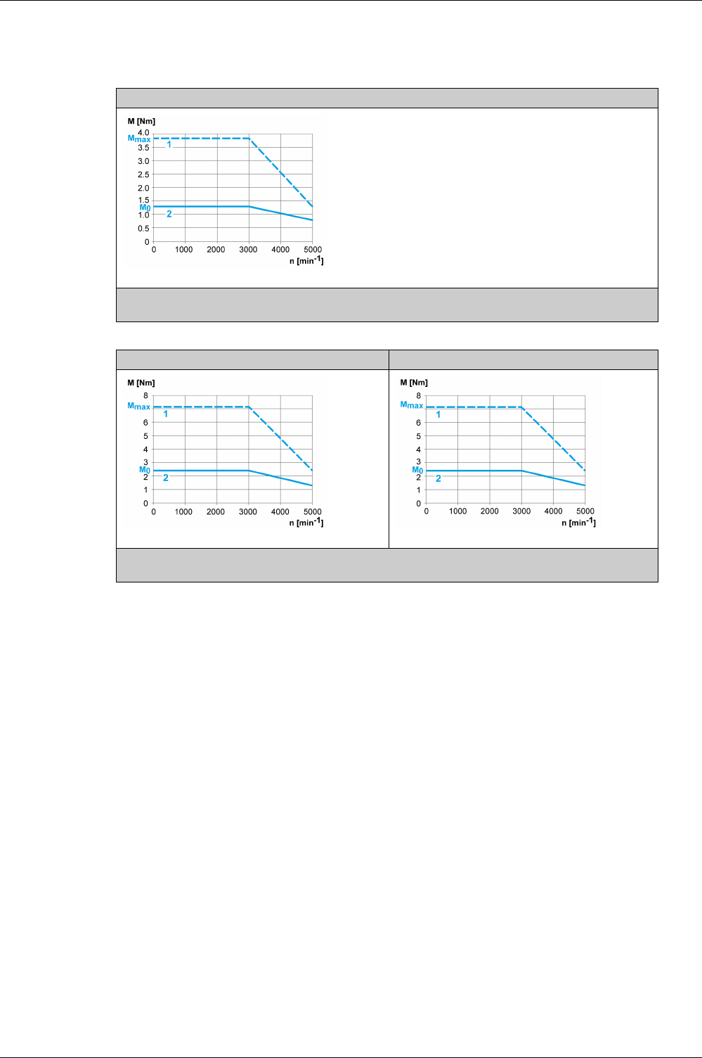
Motor
EIO0000002305 04/2017 69
BCH2∙F Curves
BCH2LF043 + LXM28AU04
(1) Peak torque
(2) Continuous torque
BCH2HF073 + LXM28AU07 BCH2LF073 + LXM28AU07
(1) Peak torque
(2) Continuous torque

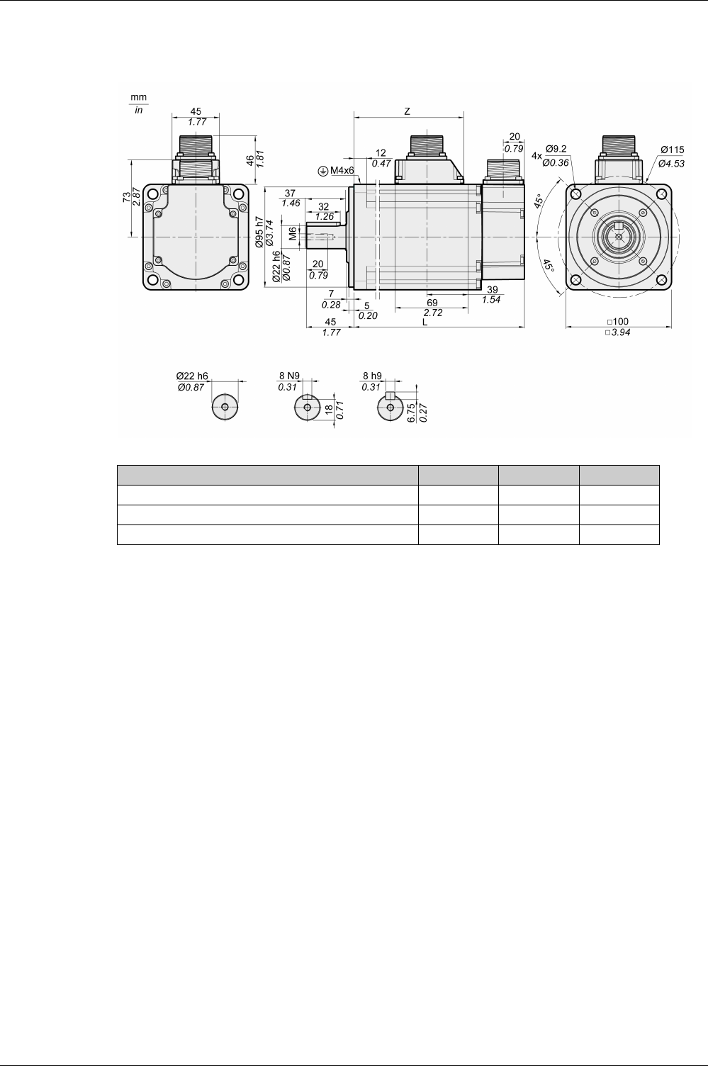
Motor
EIO0000002305 04/2017 71
BCH2LH Dimensions
BCH2LH Unit 103 203
L (without holding brake) mm (in) 153.5 (6.04) 198.5 (7.81)
L (with holding brake) mm (in) 180.5 (7.11) 225.5 (8.88)
Z mm (in) 96 (3.78) 141 (5.55)

Motor
72 EIO0000002305 04/2017
BCH2LH Characteristics Table
BCH2LH(1) 103 203
Technical data - general
Continuous stall torque(2) M0Nm 3.18 6.37
Peak torque Mmax Nm 9.54 19.11
With supply voltage Un = 230 Vac
Nominal speed of rotation nNrpm 3000 3000
Nominal torque MNNm 3.18 6.37
Nominal Current INArms 6.64 10.27
Nominal power PNkW 1.00 2.00
Technical data - electrical
Maximum winding voltage Umax Vac 255 255
Maximum winding voltage Umax Vdc 360 360
Maximum voltage to ground – Vac 255 255
Maximum Current Imax Arms 20.0 35.0
Continuous stall current I0Arms 5.83 9.87
Voltage constant(3) kEu-v Vrms 33 39
Torque constant(4) ktNm/A 0.55 0.65
Winding resistance R20u-v Ω 0.67 0.36
Winding inductance Lqu-v mH 4.3 2.6
Winding inductance Ldu-v mH 4.20 2.59
Technical data - mechanical
Maximum permissible speed of rotation nmax rpm 5000 5000
Rotor inertia without brake JMkgcm22.40 4.28
Rotor inertia with brake JMkgcm22.45 4.35
Mass without brake m kg 4.60 6.70
Mass with brake m kg 5.10 7.20
Degree of protection of the shaft – – IP 65 IP 65
Degree of protection of the housing – – IP 65 IP 65
Technical data - holding brake
Holding torque – Nm 6.5 6.5
Nominal voltage – Vdc 24 +/-10% 24 +/-10%
Nominal power (electrical pull-in power) – W 10.4 10.4
(1) Limit values with flanged motor:
Flange material: Steel
Flange size in mm (in): 300 x 300 x 20 (11.8 x 11.8 x 0.79)
(2) M0=Continuous stall torque at 20 rpm and 100 % duty cycle; at speeds of rotation of <20 rpm the
continuous stall torque is reduced to 87 %
(3) RMS value at 1000 rpm and 20 °C (68 °F).
(4) At n = 20 rpm and 20 °C (68 °F).

Motor
EIO0000002305 04/2017 73
BCH2LH Curves
BCH2LH103 + LXM28AU10 BCH2LH203 + LXM28AU20
(1) Peak torque
(2) Continuous torque

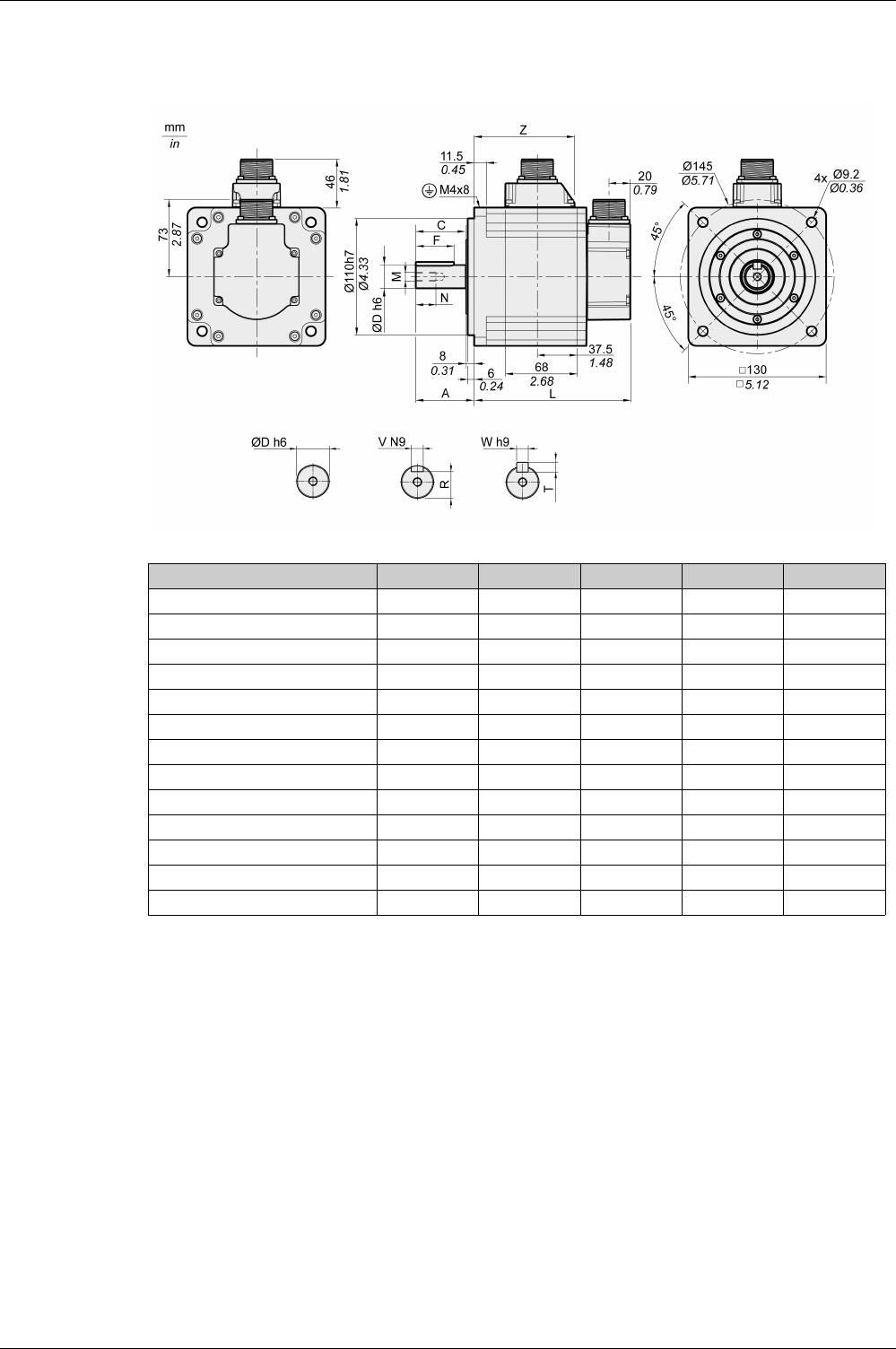
Motor
EIO0000002305 04/2017 75
BCH2∙M Dimensions
BCH2∙M Unit 08 03, 05, 06, 10 09, 15 20
L (without holding brake) mm (in) 187 (7.36) 147 (5.79) 163 (6.42) 187 (7.36)
L (with holding brake) mm (in) 216 (8.5) 176 (6.93) 192 (7.56) 216 (8.5)
A mm (in) 48 (1.89) 55 (2.17) 55 (2.17) 55 (2.17)
C mm (in) 40 (1.57) 47 (1.85) 47 (1.85) 47 (1.85)
D mm (in) 19 (0.75) 22 (0.87) 22 (0.87) 22 (0.87)
F mm (in) 25 (0.98) 36 (1.42) 36 (1.42) 36 (1.42)
M - M6 M8 M8 M8
N mm (in) 16 (0.63) 19 (0.75) 19 (0.75) 19 (0.75)
R mm (in) 15.5 (0.61) 18 (0.71) 18 (0.71) 18 (0.71)
T mm (in) 6 (0.24) 7 (0.28) 7 (0.28) 7 (0.28)
V mm (in) 6 (0.24) 8 (0.31) 8 (0.31) 8 (0.31)
W mm (in) 6 (0.24) 8 (0.31) 8 (0.31) 8 (0.31)
Z mm (in) 134.5 (5.30) 94.5 (3.72) 110.5 (4.35) 134.5 (5.30)

Motor
76 EIO0000002305 04/2017
BCH2∙M Characteristics Table
BCH2(1) MM052 MM031 MM102 HM102 MM081
Technical data - general
Continuous stall torque(2) M0Nm 2.39 2.86 4.77 4.77 5.39
Peak torque Mmax Nm 7.16 8.59 14.30 14.30 13.80
With supply voltage Un = 230 Vac
Nominal speed of rotation nNrpm 2000 1000 2000 2000 1500
Nominal torque MNNm 2.39 2.86 4.77 4.77 5.39
Nominal Current INArms 3.24 2.09 6.29 6.29 6.29
Nominal power PNkW 0.50 0.30 1.00 1.00 0.85
Technical data - electrical
Maximum winding voltage Umax Vac 255 255 255 255 255
Maximum winding voltage Umax Vdc 360 360 360 360 360
Maximum voltage to ground – Vac 255 255 255 255 255
Maximum Current Imax Arms 9.5 6.0 20.0 20.0 15.0
Continuous stall current I0Arms 2.89 1.88 5.77 5.77 5.62
Voltage constant(3) kEu-v Vrms 50 92 50 50 58
Torque constant(4) ktNm/A 0.83 1.52 0.83 0.83 0.96
Winding resistance R20u-v Ω 0.74 2.08 0.74 0.74 0.42
Winding inductance Lqu-v mH 7.84 26.25 7.84 7.84 4.70
Winding inductance Ldu-v mH 7.14 23.91 7.14 7.14 4.30
Technical data - mechanical
Maximum permissible speed of rotation nmax rpm 3000 2000 3000 3000 3000
Rotor inertia without brake JMkgcm26.63 6.63 6.63 8.41 13.5
Rotor inertia with brake JMkgcm26.91 6.91 6.91 8.54 14.1
Mass without brake m kg 7.00 7.00 7.00 7.10 9.60
Mass with brake m kg 8.20 8.20 8.20 8.30 10.90
Degree of protection of the shaft – – IP 65 IP 54 IP 65 IP 65 IP 54
Degree of protection of the housing – – IP 65 IP 65 IP 65 IP 65 IP 65
Technical data - holding brake
Holding torque – Nm 9.6 9.6 9.6 9.6 9.6
Nominal voltage – Vdc 24 +/-10% 24 +/-10% 24 +/-10% 24 +/-10% 24 +/-10%
Nominal power (electrical pull-in power) – W 19.7 19.7 19.7 19.7 19.7
(1) Limit values with flanged motor:
Flange material: Steel
Flange size in mm (in): 400 x 400 x 20 (15.7 x 15.7 x 0.79)
(2) M0=Continuous stall torque at 20 rpm and 100 % duty cycle; at speeds of rotation of <20 rpm the continuous stall
torque is reduced to 87 %
(3) RMS value at 1000 rpm and 20 °C (68 °F).
(4) At n = 20 rpm and 20 °C (68 °F).

Motor
EIO0000002305 04/2017 77
BCH2(1) MM061 MM091 MM152 MM202
Technical data - general
Continuous stall torque(2) M0Nm 5.73 8.59 7.16 9.55
Peak torque Mmax Nm 17.19 25.77 21.48 28.65
With supply voltage Un = 230 Vac
Nominal speed of rotation nNrpm 1000 1000 2000 2000
Nominal torque MNNm 5.73 8.59 7.16 9.55
Nominal Current INArms 4.10 6.15 6.74 11.25
Nominal power PNkW 0.60 0.90 1.50 2.00
Technical data - electrical
Maximum winding voltage Umax Vac 255 255 255 255
Maximum winding voltage Umax Vdc 360 360 360 360
Maximum voltage to ground – Vac 255 255 255 255
Maximum Current Imax Arms 13.5 20.0 21.0 33.0
Continuous stall current I0Arms 3.77 5.64 6.18 9.95
Voltage constant(3) kEu-v Vrms 92 92 70 58
Torque constant(4) ktNm/A 1.52 1.52 1.16 0.96
Winding resistance R20u-v Ω 2.08 1.22 0.64 0.42
Winding inductance Lqu-v mH 26.25 16.40 7.20 4.70
Winding inductance Ldu-v mH 23.91 14.90 6.40 4.30
Technical data - mechanical
Maximum permissible speed of rotation nmax rpm 2000 2000 3000 3000
Rotor inertia without brake JMkgcm26.63 9.70 9.70 13.50
Rotor inertia with brake JMkgcm26.91 10.00 10.00 14.10
Mass without brake m kg 7.00 7.60 7.60 9.70
Mass with brake m kg 8.20 8.80 8.80 11.00
Technical data - holding brake
Holding torque – Nm 9.6 9.6 9.6 9.6
Nominal voltage – Vdc 24 +/-10% 24 +/-10% 24 +/-10% 24 +/-10%
Nominal power (electrical pull-in power) – W 19.7 19.7 19.7 19.7
(1) Limit values with flanged motor:
Flange material: Steel
Flange size in mm (in): 400 x 400 x 20 (15.7 x 15.7 x 0.79)
(2) M0=Continuous stall torque at 20 rpm and 100 % duty cycle; at speeds of rotation of <20 rpm the continuous
stall torque is reduced to 87 %
(3) RMS value at 1000 rpm and 20 °C (68 °F).
(4) At n = 20 rpm and 20 °C (68 °F).
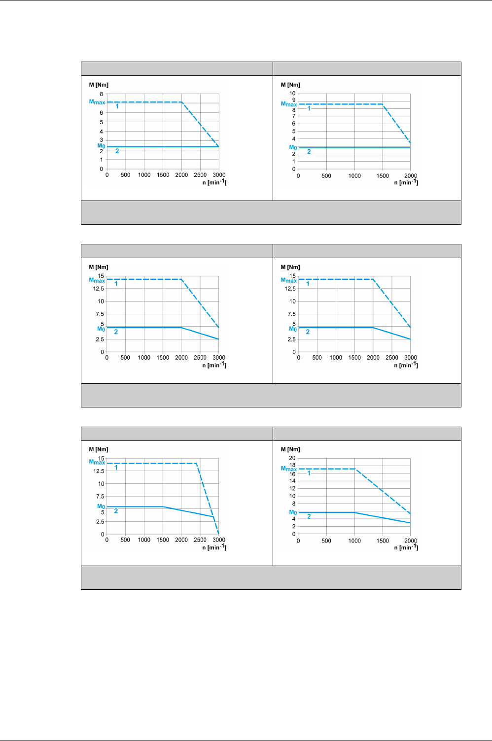
Motor
78 EIO0000002305 04/2017
BCH2∙M Curves
BCH2MM052 + LXM28AU07 BCH2MM031 + LXM28AU04
(1) Peak torque
(2) Continuous torque
BCH2MM102 + LXM28AU10 BCH2HM102 + LXM28AU10
(1) Peak torque
(2) Continuous torque
BCH2MM081 + LXM28AU10 BCH2MM061 + LXM28AU07
(1) Peak torque
(2) Continuous torque
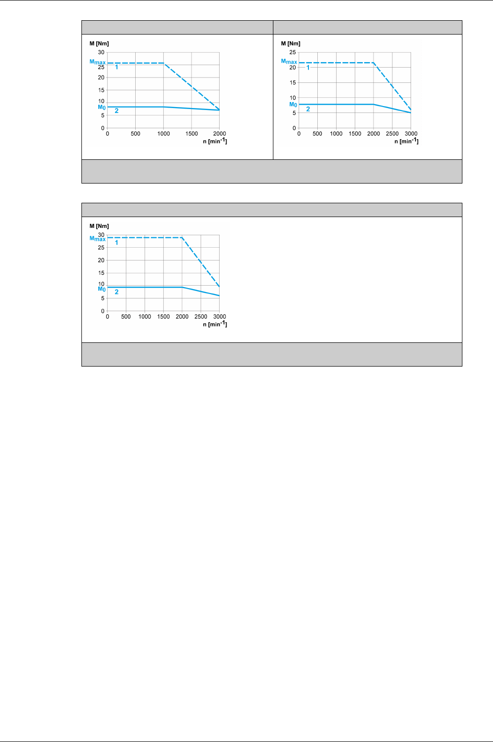
Motor
EIO0000002305 04/2017 79
BCH2MM091 + LXM28AU10 BCH2MM152 + LXM28AU15
(1) Peak torque
(2) Continuous torque
BCH2MM202 + LXM28AU20
(1) Peak torque
(2) Continuous torque

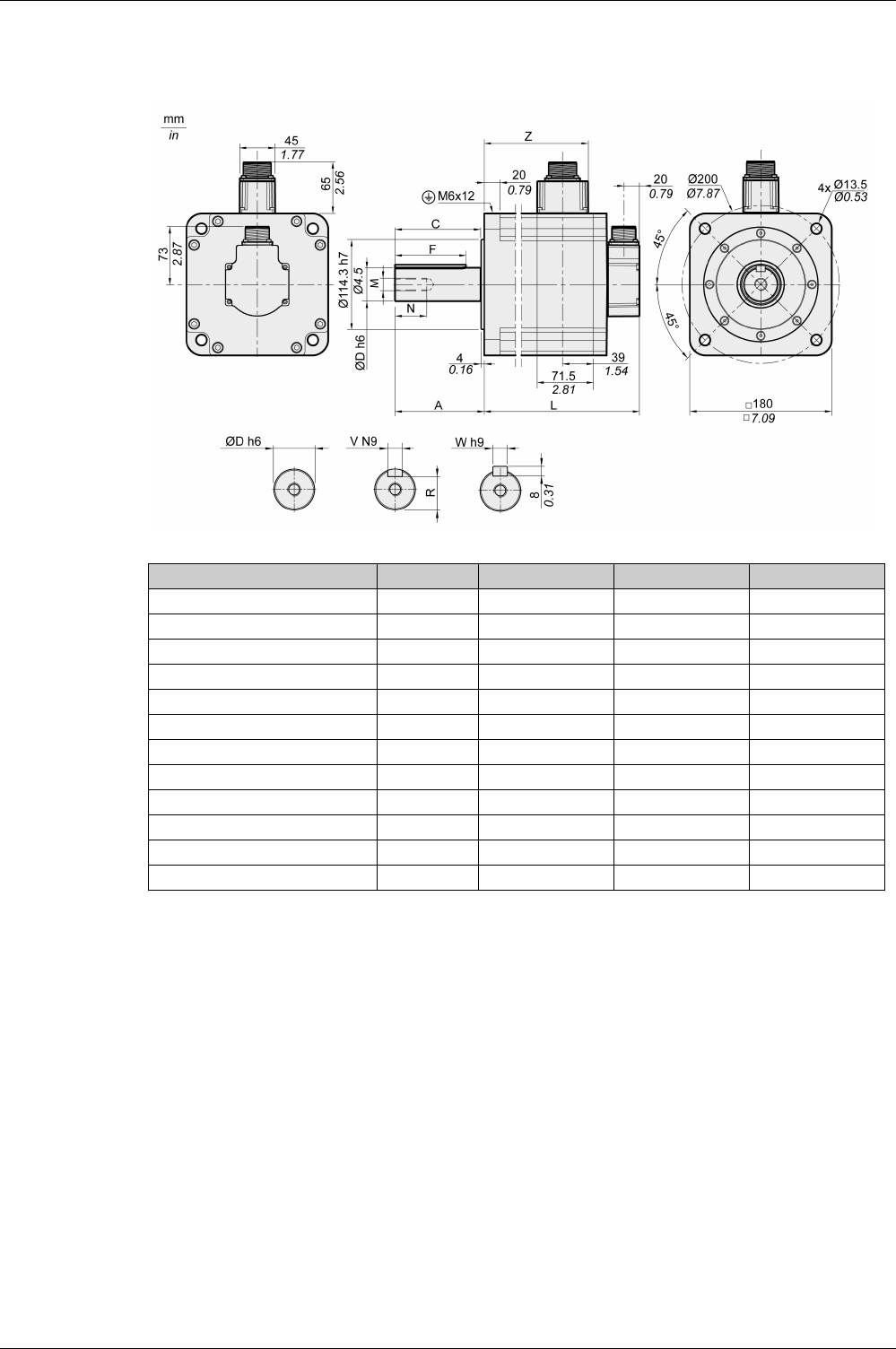
Motor
EIO0000002305 04/2017 81
BCH2∙R Dimensions
BCH2∙R Unit 20 30, 35 45
L (without holding brake) mm (in) 168 (6.61) 201 (7.91) 234 (9.21)
L (with holding brake) mm (in) 203 (7.99) 236 (9.29) 269 (10.59)
A mm (in) 79 (3.11) 79 (3.11) 79 (3.11)
C mm (in) 73 (2.87) 73 (2.87) 73 (2.87)
D mm (in) 35 (1.38) 35 (1.38) 35 (1.38)
F mm (in) 63 (2.48) 63 (2.48) 63 (2.48)
M - M12 M12 M12
N mm (in) 28 (1.10) 28 (1.10) 28 (1.10)
R mm (in) 30 (1.18) 30 (1.18) 30 (1.18)
V mm (in) 10 (0.39) 10 (0.39) 10 (0.39)
W mm (in) 10 (0.39) 10 (0.39) 10 (0.39)
Z mm (in) 103 (4.06) 136 (5.35) 169 (6.65)

Motor
82 EIO0000002305 04/2017
BCH2∙R Characteristics Table
BCH2MR202/301/302, BCH2HR202 technical data
BCH2(1) MR202 HR202 MR302 MR301
Technical data - general
Continuous stall torque(2) M0Nm 9.55 9.55 14.32 19.10
Peak torque Mmax Nm 28.65 28.65 42.97 57.29
With supply voltage Un = 230 Vac
Nominal speed of rotation nNrpm 2000 2000 2000 1500
Nominal torque MNNm 9.55 9.55 14.32 19.10
Nominal Current INArms 9.6 9.6 18.8 18.8
Nominal power PNkW 2.00 2.00 3.00 3.00
Technical data - electrical
Maximum winding voltage Umax Vac 255 255 255 255
Maximum winding voltage Umax Vdc 360 360 360 360
Maximum voltage to ground – Vac 255 255 255 255
Maximum Current Imax Arms 35.5 35.5 56.0 61.0
Continuous stall current I0Arms 8.75 8.75 16.33 16.49
Voltage constant(3) kEu-v Vrms 66 66 53 70
Torque constant(4) ktNm/A 1.09 1.09 0.88 1.16
Winding resistance R20u-v Ω 0.572 0.572 0.168 0.234
Winding inductance Lqu-v mH 6.70 6.70 2.88 3.78
Winding inductance Ldu-v mH 6.10 6.10 2.71 3.45
Technical data - mechanical
Maximum permissible speed of rotation nmax rpm 3000 3000 3000 3000
Rotor inertia without brake JMkgcm226.50 34.68 53.56 53.56
Rotor inertia with brake JMkgcm227.0 35.13 54.1 54.1
Mass without brake m kg 13.00 14.30 18.50 18.50
Mass with brake m kg 18.00 19.30 23.00 23.00
Degree of protection of the shaft – – IP 65 IP 65 IP 65 IP 54
Degree of protection of the housing – – IP 65 IP 65 IP 65 IP 65
Technical data - holding brake
Holding torque – Nm 48 48 48 48
Nominal voltage – Vdc 24 +/-10% 24 +/-10% 24 +/-10% 24 +/-10%
Nominal power (electrical pull-in power) – W 49.6 49.6 49.6 49.6
(1) Limit values with flanged motor:
Flange material: Steel
Flange size in mm (in): 550 x 550 x 20 (21.7 x 21.7 x 0.79)
(2) M0=Continuous stall torque at 20 rpm and 100 % duty cycle; at speeds of rotation of <20 rpm the continuous stall
torque is reduced to 87 %
(3) RMS value at 1000 rpm and 20 °C (68 °F).
(4) At n = 20 rpm and 20 °C (68 °F).

Motor
EIO0000002305 04/2017 83
BCH2MR352/451/551/751 technical data
BCH2(1) MR352 MR451 MR551 MR751
Technical data - general
Continuous stall torque(2) M0Nm 16.70 28.65 35.01 47.75
Peak torque Mmax Nm 50.30 71.62 87.53 119.37
With supply voltage Un = 230 Vac
Nominal speed of rotation nNrpm 2000 1500 1500 1500
Nominal torque MNNm 16.70 28.65 35.01 47.75
Nominal Current INArms 19.3 22.8 28.8 41.5
Nominal power PNkW 3.50 4.50 5.50 7.50
Technical data - electrical
Maximum winding voltage Umax Vac 255 255 255 255
Maximum winding voltage Umax Vdc 360 360 360 360
Maximum voltage to ground – Vac 255 255 255 255
Maximum Current Imax Arms 61.0 61.0 74.2 106.9
Continuous stall current I0Arms 16.83 19.68 25.05 36.08
Voltage constant(3) kEu-v Vrms 60 88 84.5 80
Torque constant(4) ktNm/A 0.99 1.46 1.40 1.32
Winding resistance R20u-v Ω 0.168 0.199 0.104 0.062
Winding inductance Lqu-v mH 2.80 4.00 2.25 1.30
Winding inductance Ldu-v mH 2.57 3.80 2.07 1.22
Technical data - mechanical
Maximum permissible speed of rotation nmax rpm 3000 3000 2700 2700
Rotor inertia without brake JMkgcm253.56 73.32 103.34 142.7
Rotor inertia with brake JMkgcm254.1 73.0 120.2 158.7
Mass without brake m kg 18.50 23.64 32 41.7
Mass with brake m kg 23.00 28.00 36.5 46.2
Technical data - holding brake
Holding torque – Nm 48 48 50 50
Nominal voltage – Vdc 24 +/-10% 24 +/-10% 24 +/-10% 24 +/-10%
Nominal power (electrical pull-in power) – W 49.6 49.6 49.6 49.6
(1) Limit values with flanged motor:
Flange material: Steel
Flange size in mm (in): 550 x 550 x 20 (21.7 x 21.7 x 0.79)
(2) M0=Continuous stall torque at 20 rpm and 100 % duty cycle; at speeds of rotation of <20 rpm the continuous stall
torque is reduced to 87 %
(3) RMS value at 1000 rpm and 20 °C (68 °F).
(4) At n = 20 rpm and 20 °C (68 °F).
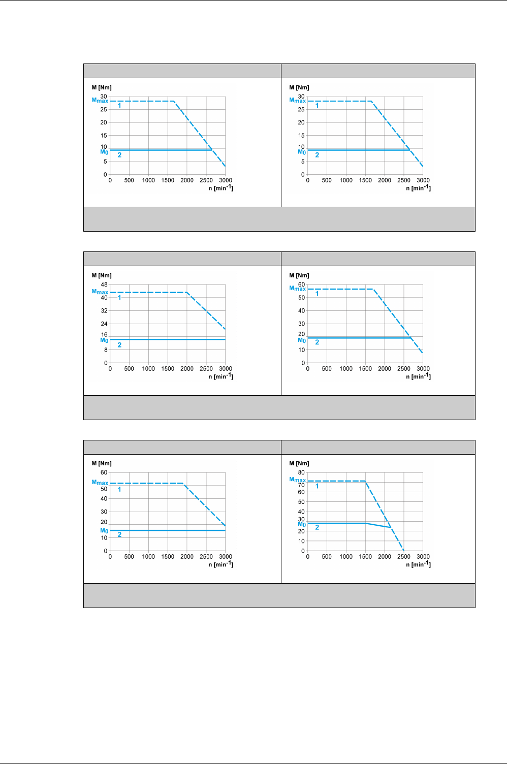
Motor
84 EIO0000002305 04/2017
BCH2∙R Curves
BCH2MR202 + LXM28AU20 BCH2HR202 + LXM28AU20
(1) Peak torque
(2) Continuous torque
BCH2MR302 + LXM28AU30 BCH2MR301 + LXM28AU30
(1) Peak torque
(2) Continuous torque
BCH2MR352 + LXM28AU45 BCH2MR451 + LXM28AU45
(1) Peak torque
(2) Continuous torque

EIO0000002305 04/2017 85
Lexium 28
A
and BCH2 Servo Drive System
Accessories and S pare Parts
EIO0000002305 04/2017
Accessories and Sp are Parts
Chapter 6
Accessories and Spare Parts
What Is in This Chapter?
This chapter contains the following topics:
Topic Page
Commissioning Tools 86
Connectors and Adapters 87
External Mains Filters 88
DC Bus Accessories 89
Application Nameplate 90
CANopen Connectors, Distributors, Terminating Resistors 91
CANopen Cables with Open Cable Ends 92
Motor Cables 93
Encoder Cables 94
Signal Cables 95
Signal Cable for Safety Function STO 96
External Braking Resistors and Holding Brake Controller 97
Circuit Breakers 98
Motor Protection Switches and Power Contactors 99

Accessories and Spare Parts
86 EIO0000002305 04/2017
Commissioning Tools
Description Reference
Commissioning software LXM28 DTM Library, can be downloaded at:
www.schneider-
electric.com
-
PC connection kit, serial connection between drive and PC, USB-A to RJ45 TCSMCNAM3M002P
Multi-Loader, device for copying the parameter settings to a PC or to another drive VW3A8121
Connection cable for Multi-Loader VW3A8126
Modbus cable, 1 m (3.28 ft), 2 x RJ45 VW3A8306R10

Accessories and Spare Parts
EIO0000002305 04/2017 87
Connectors and Adapters
Description Reference
Connector kit for logic supply and power stage supply (CN5), braking resistor (CN7), and
motor (CN8); suitable for LXM28AUA5, LXM28AU01, LXM28AU02, LXM28AU04,
LXM28AU07, LXM28AU10, and LXM28AU15
VW3M4C21
Connector kit for logic supply and power stage supply (CN5), braking resistor (CN7), and
motor (CN8); suitable for LXM28AU20
VW3M4C23
Connector kit for logic supply and power stage supply (CN5), braking resistor (CN7), and
motor (CN8); suitable for LXM28AU30 and LXM28AU45
VW3M4C24
Cable shield connection plate, clamps, and screws; suitable for LXM28AUA5, LXM28AU01,
LXM28AU02, LXM28AU04, LXM28AU07, LXM28AU10, and LXM28AU15
VW3M2C31
Cable shield connection plate, clamps, and screws; suitable for LXM28AU20 VW3M2C33
Cable shield connection plate, clamps, and screws; suitable for LXM28AU30 and
LXM28AU45
VW3M2C34
Interface connector for CN1, 50-pin, 3 pieces VW3M1C12
Interface adapter for CN1, connector with 0.5 m (1.64 ft) cable and connection module with
screw terminals for DIN rail mounting
VW3M1C13
Connector kit for motor; motor end plastic connector without holding brake VW3M5D1A
Connector kit for motor; motor end plastic connector with holding brake VW3M5D1F
Connector kit for motor; motor end MIL connector with holding brake, size 100 ... 130 VW3M5D2A
Connector kit for motor; motor end MIL connector with holding brake, size 180 VW3M5D2B
Connector kit for encoder; motor end flying leads; device end IEEE1394 connector VW3M8D1A
Connector kit for encoder; motor end MIL connector; device end IEEE1394 connector VW3M8D2A

Accessories and Spare Parts
88 EIO0000002305 04/2017
External Mains Filters
Description Reference
Mains filter single-phase; 9 A; 115/230 Vac VW3A4420
Mains filter single-phase; 16 A; 115/230 Vac VW3A4421
Mains filter single-phase; 23 A; 115/230 Vac VW3A4426
Mains filter three-phase; 15 A; 208/400/480 Vac VW3A4422
Mains filter three-phase; 25 A; 208/400/480 Vac VW3A4423
Mains filter three-phase; 47 A; 208/400/480 Vac VW3A4424

Accessories and Spare Parts
EIO0000002305 04/2017 89
DC Bus Accessories
A crimping tool is required for the crimp contacts of the connector kit.
Manufacturer: Tyco Electronics, Heavy Head Hand Tool, Tool Pt. No 180250
Description Reference
DC bus connection cable, 2 x 6 mm2 (2 x AWG 10), pre-assembled, 0.1 m (0.33 ft), 5 pieces VW3M7101R01
DC bus connection cable, 2 x 6 mm2 (2 x AWG 10), Twisted Pair, shielded, 15 m (49.2 ft) VW3M7102R150
DC bus connector kit, connector housing, and crimp contacts for 3 ... 6 mm2 (AWG 12 ... 10),
10 pieces
VW3M2207

Accessories and Spare Parts
90 EIO0000002305 04/2017
Application Nameplate
Description Reference
Application nameplate to be clipped onto the top of the drive, size 38.5 mm (1.52 in) x 13 mm
(0.51 in), 50 pieces
VW3M2501

Accessories and Spare Parts
EIO0000002305 04/2017 91
CANopen Connectors, Distributors, Terminating Resistors
Description Reference
CANopen terminating resistor, 120 Ohm, integrated in RJ45 connector TCSCAR013M120
CANopen cable, 0.3 m (0.98 ft), 2 x RJ45 VW3CANCARR03
CANopen cable, 1 m (3.28 ft), 2 x RJ45 VW3CANCARR1
CANopen cable, 1 m (3.28 ft), D9-SUB (female) with integrated terminating resistor to RJ45 VW3M3805R010
CANopen cable, 3 m (9.84 ft), D9-SUB (female) with integrated terminating resistor to RJ45 VW3M3805R030

Accessories and Spare Parts
92 EIO0000002305 04/2017
CANopen Cables with Open Cable Ends
Cables with open cable ends are suitable for connection of D-SUB connectors. Observe the cable cross
section and the connection cross section of the required connector.
Description Reference
CANopen cable, 50 m (164 ft), [(2 x AWG 22) + (2 x AWG 24)], LSZH standard cable (low-
smoke, zero halogen, flame-retardant, tested as per IEC 60332-1), both cable ends open
TSXCANCA50
CANopen cable, 100 m (328 ft), [(2 x AWG 22) + (2 x AWG 24)], LSZH standard cable (low-
smoke, zero halogen, flame-retardant, tested as per IEC 60332-1), both cable ends open
TSXCANCA100
CANopen cable, 300 m (984 ft), [(2 x AWG 22) + (2 x AWG 24)], LSZH standard cable (low-
smoke, zero halogen, flame-retardant, tested as per IEC 60332-1), both cable ends open
TSXCANCA300
CANopen cable, 50 m (164 ft), [(2 x AWG 22) + (2 x AWG 24)], flame-retardant, tested as per
IEC 60332-2, UL certification, both cable ends open
TSXCANCB50
CANopen cable, 100 m (328 ft), [(2 x AWG 22) + (2 x AWG 24)], flame-retardant, tested as
per IEC 60332-2, UL certification, both cable ends open
TSXCANCB100
CANopen cable, 300 m (984 ft), [(2 x AWG 22) + (2 x AWG 24)], flame-retardant, tested as
per IEC 60332-2, UL certification, both cable ends open
TSXCANCB300
CANopen cable, 50 m (164 ft), [(2 x AWG 22) + (2 x AWG 24)], flexible LSZH HD standard
cable (low-smoke, zero halogen, flame-retardant, tested as per IEC 60332-1), for heavy-duty
or flexible installation, oil-resistant, both cable ends open
TSXCANCD50
CANopen cable, 100 m (328 ft), [(2 x AWG 22) + (2 x AWG 24)], flexible LSZH HD standard
cable (low-smoke, zero halogen, flame-retardant, tested as per IEC 60332-1), for heavy-duty
or flexible installation, oil-resistant, both cable ends open
TSXCANCD100
CANopen cable, 300 m (984 ft), [(2 x AWG 22) + (2 x AWG 24)], flexible LSZH HD standard
cable (low-smoke, zero halogen, flame-retardant, tested as per IEC 60332-1), for heavy-duty
or flexible installation, oil-resistant, both cable ends open
TSXCANCD300

Accessories and Spare Parts
EIO0000002305 04/2017 93
Motor Cables
Description Reference
Motor cable without holding brake 1.5 m (4.92 ft), 4 x 0.82 mm2 (AWG 18) shielded; motor
end plastic connector, other cable end flying leads
VW3M5D1AR15
Motor cable without holding brake 3 m (9.84 ft), 4 x 0.82 mm2 (AWG 18) shielded; motor end
plastic connector, other cable end flying leads
VW3M5D1AR30
Motor cable without holding brake 5 m (16.4 ft), 4 x 0.82 mm2 (AWG 18) shielded; motor end
plastic connector, other cable end flying leads
VW3M5D1AR50
Motor cable with holding brake 3 m (9.84 ft), 6 x 0.82 mm2 (AWG 18) shielded; motor end
plastic connector, other cable end flying leads
VW3M5D1FR30
Motor cable with holding brake 5 m (16.4 ft), 6 x 0.82 mm2 (AWG 18) shielded; motor end
plastic connector, other cable end flying leads
VW3M5D1FR50
Motor cable without holding brake 3 m (9.84 ft), 4 x 1.3 mm2 (AWG 16) shielded; motor end
MIL connector, other cable end flying leads
VW3M5D2AR30
Motor cable without holding brake 5 m (16.4 ft), 4 x 1.3 mm2 (AWG 16) shielded; motor end
MIL connector, other cable end flying leads
VW3M5D2AR50
Motor cable with holding brake 3 m (9.84 ft), 6 x 1.3 mm2 (AWG 16) shielded; motor end MIL
connector, other cable end flying leads
VW3M5D2FR30
Motor cable with holding brake 5 m (16.4 ft), 6 x 1.3 mm2 (AWG 16) shielded; motor end MIL
connector, other cable end flying leads
VW3M5D2FR50
Motor cable without holding brake 3 m (9.84 ft), 4 x 3.3 mm2 (AWG 12) shielded; motor end
MIL connector, other cable end flying leads
VW3M5D4AR30
Motor cable without holding brake 5 m (16.4 ft), 4 x 3.3 mm2 (AWG 12) shielded; motor end
MIL connector, other cable end flying leads
VW3M5D4AR50
Motor cable with holding brake 3 m (9.84 ft), 6 x 3.3 mm2 (AWG 12) shielded; motor end MIL
connector, other cable end flying leads
VW3M5D4FR30
Motor cable with holding brake 5 m (16.4 ft), 6 x 3.3 mm2 (AWG 12) shielded; motor end MIL
connector, other cable end flying leads
VW3M5D4FR50
Motor cable without holding brake 3 m (9.84 ft), 4 x 6 mm2 (AWG 10) shielded; motor end MIL
connector, other cable end flying leads
VW3M5D6AR30
Motor cable without holding brake 5 m (16.4 ft), 4 x 6 mm2 (AWG 10) shielded; motor end MIL
connector, other cable end flying leads
VW3M5D6AR50
Motor cable with holding brake 3 m (9.84 ft), 6 x 6 mm2 (AWG 10) shielded; motor end MIL
connector, other cable end flying leads
VW3M5D6FR30
Motor cable with holding brake 5 m (16.4 ft), 6 x 6 mm2 (AWG 10) shielded; motor end MIL
connector, other cable end flying leads
VW3M5D6FR50

Accessories and Spare Parts
94 EIO0000002305 04/2017
Encoder Cables
Description Reference
Encoder cable 1.5 m (4.92 ft), 10 x 0.13 mm2 (AWG 26) shielded; motor end and device end
plastic connector
VW3M8D1AR15
Encoder cable 3 m (9.84 ft), 10 x 0.13 mm2 (AWG 26) shielded; motor end and device end
plastic connector
VW3M8D1AR30
Encoder cable 5 m (16.4 ft), 10 x 0.13 mm2 (AWG 26) shielded; motor end and device end
plastic connector
VW3M8D1AR50
Encoder cable 3 m (9.84 ft), 10 x 0.13 mm2 (AWG 26) shielded; motor end MIL connector,
other cable end plastic connector
VW3M8D2AR30
Encoder cable 5 m (16.4 ft), 10 x 0.13 mm2 (AWG 26) shielded; motor end MIL connector,
other cable end plastic connector
VW3M8D2AR50

Accessories and Spare Parts
EIO0000002305 04/2017 95
Signal Cables
Description Reference
Signal cable 1 m (3.28 ft) for signal interface CN1, device end 50-pin connector, other cable
end flying leads
VW3M1C10R10
Signal cable 2 m (6.56 ft) for signal interface CN1, device end 50-pin connector, other cable
end flying leads
VW3M1C10R20
Signal cable 3 m (9.84 ft) for signal interface CN1, device end 50-pin connector, other cable
end flying leads
VW3M1C10R30

Accessories and Spare Parts
96 EIO0000002305 04/2017
Signal Cable for Safety Function STO
Description Reference
Signal cable 1 m (3.28 ft) for safety function STO CN9 VW3M1C20R10
Signal cable 2 m (6.56 ft) for safety function STO CN9 VW3M1C20R20
Signal cable 3 m (9.84 ft) for safety function STO CN9 VW3M1C20R30

Accessories and Spare Parts
EIO0000002305 04/2017 97
External Braking Resistors and Holding Brake Controller
Description Reference
Holding brake controller HBC with automatic voltage reduction; 24 V - 1.6 A VW3M3103
Braking resistor IP 65; 10 Ω; maximum continuous power 400 W; 0.75 m (2.46 ft) connection
cable, 2.1 mm2 (AWG 14)
VW3A7601R07
Braking resistor IP 65; 10 Ω; maximum continuous power 400 W; 2 m (6.56 ft) connection
cable, 2.1 mm2 (AWG 14)
VW3A7601R20
Braking resistor IP 65; 10 Ω; maximum continuous power 400 W; 3 m (9.84 ft) connection
cable, 2.1 mm2 (AWG 14)
VW3A7601R30
Braking resistor IP 65; 27 Ω; maximum continuous power 100 W; 0.75 m (2.46 ft) connection
cable, 2.1 mm2 (AWG 14), UL
VW3A7602R07
Braking resistor IP 65; 27 Ω; maximum continuous power 100 W; 2 m (6.56 ft) connection
cable, 2.1 mm2 (AWG 14), UL
VW3A7602R20
Braking resistor IP 65; 27 Ω; maximum continuous power 100 W; 3 m (9.84 ft) connection
cable, 2.1 mm2 (AWG 14), UL
VW3A7602R30
Braking resistor IP 65; 27 Ω; maximum continuous power 200 W; 0.75 m (2.46 ft) connection
cable, 2.1 mm2 (AWG 14), UL
VW3A7603R07
Braking resistor IP 65; 27 Ω; maximum continuous power 200 W; 2 m (6.56 ft) connection
cable, 2.1 mm2 (AWG 14), UL
VW3A7603R20
Braking resistor IP 65; 27 Ω; maximum continuous power 200 W; 3 m (9.84 ft) connection
cable, 2.1 mm2 (AWG 14), UL
VW3A7603R30
Braking resistor IP 65; 27 Ω; maximum continuous power 400 W; 0.75 m (2.46 ft) connection
cable, 2.1 mm2 (AWG 14)
VW3A7604R07
Braking resistor IP 65; 27 Ω; maximum continuous power 400 W; 2 m (6.56 ft) connection
cable, 2.1 mm2 (AWG 14)
VW3A7604R20
Braking resistor IP 65; 27 Ω; maximum continuous power 400 W; 3 m (9.84 ft) connection
cable, 2.1 mm2 (AWG 14)
VW3A7604R30
Braking resistor IP 65; 72 Ω; maximum continuous power 200 W; 0.75 m (2.46 ft) connection
cable, 2.1 mm2 (AWG 14), UL
VW3A7606R07
Braking resistor IP 65; 72 Ω; maximum continuous power 200 W; 2 m (6.56 ft) connection
cable, 2.1 mm2 (AWG 14), UL
VW3A7606R20
Braking resistor IP 65; 72 Ω; maximum continuous power 200 W; 3 m (9.84 ft) connection
cable, 2.1 mm2 (AWG 14), UL
VW3A7606R30
Braking resistor IP 65; 72 Ω; maximum continuous power 400 W; 0.75 m (2.46 ft) connection
cable
VW3A7607R07
Braking resistor IP 65; 72 Ω; maximum continuous power 400 W; 2 m (6.56 ft) connection
cable
VW3A7607R20
Braking resistor IP 65; 72 Ω; maximum continuous power 400 W; 3 m (9.84 ft) connection
cable
VW3A7607R30
Braking resistor IP20; 15 Ω; maximum continuous power 1000 W; M6 terminals, UL VW3A7704
Braking resistor IP20; 10 Ω; maximum continuous power 1000 W; M6 terminals, UL VW3A7705

Accessories and Spare Parts
98 EIO0000002305 04/2017
Circuit Breakers
Description Reference
Circuit breaker - thermal magnetic - 4 … 6.3 A - screw terminals GV2P10
Circuit breaker - thermal magnetic - 6 … 10 A - screw terminals GV2P14
Circuit breaker - thermal magnetic - 9 … 14 A - screw terminals GV2P16
Circuit breaker - thermal magnetic - 13 … 18 A - screw terminals GV2P20
Circuit breaker - thermal magnetic - 17 … 23 A - screw terminals GV2P21
Circuit breaker - thermal magnetic - 20 … 25 A - screw terminals GV2P22
Circuit breaker - thermal magnetic - 24 … 32 A - screw terminals GV2P32

Accessories and Spare Parts
EIO0000002305 04/2017 99
Motor Protection Switches and Power Contactors
Drive Nominal power Order no. motor
protection switch
Rated continuous current
motor protection switch
Order no. power
contactor
LXM28AUA5 50 W GV2L10 6.3 A LC1K0610••
LXM28AU01 100 W GV2L10 6.3 A LC1K0610••
LXM28AU02 200 W GV2L14 10 A LC1D09••
LXM28AU04 400 W GV2L14 10 A LC1D09••
LXM28AU07 750 W GV2L16 14 A LC1D12••
LXM28AU15 1500 W GV2L22 25 A LC1D18••
LXM28AU20 2000 W GV2L32 30 A LC1D32••
LXM28AU30 3000 W GV2L32 30 A LC1D32••
Control voltage power contactor 24 V 48 V 110 V 220 V 230 V 240 V
LC1K•••• 50/60 Hz B7 E7 F7 M7 P7 U7
Control voltage power contactor 24 V 48 V 110 V 220/230 V 230 230/240 V
LC1D•••• 50 Hz B5 E5 F5 M5 P5 U5
60 Hz B6 E& F6 M6 - U6
50/60 Hz B7 E7 F7 M7 P7 U7

Accessories and Spare Parts
100 EIO0000002305 04/2017

EIO0000002305 04/2017 101
Lexium 28
A
and BCH2 Servo Drive System
Engineeri ng
EIO0000002305 04/2017
Engineering
Part III
Engineering

Engineering
102 EIO0000002305 04/2017

EIO0000002305 04/2017 103
Lexium 28
A
and BCH2 Servo Drive System
Engineeri ng
EIO0000002305 04/2017
Engineering
Chapter 7
Engineering
This chapter contains information on the application of the Servo Drive system for the engineering phase.
What Is in This Chapter?
This chapter contains the following sections:
Section Topic Page
7.1 Electromagnetic Compatibility (EMC) 104
7.2 Cables 108
7.3 Residual Current Device 110
7.4 Common DC Bus 111
7.5 Safety Function STO (“Safe Torque Off”) 112
7.6 Rating the Braking Resistor 123
7.7 Monitoring Functions 127
7.8 Configurable Inputs and Outputs 128
7.9 Wiring 129


Engineering
EIO0000002305 04/2017 105
Electromagnetic Compatibility (EMC)
Signal interference can cause unexpected responses of the drive and of other equipment in the vicinity of
the drive.
Limit Values
This product meets the EMC requirements according to the standard IEC 61800-3 if the measures
described in this manual, and in particular the installation of the mains filters, are implemented during
installation.
These types of devices are not intended to be used on a low-voltage public network which supplies
domestic premises. Radio frequency interference is expected if used in such a network.
As a system provider, you may have to include this information in the documentation to your customer.
Equipotential Bonding Conductor
Potential differences can result in excessive currents on the cable shields. Use equipotential bonding
conductors to reduce currents on the cable shields.
1) Multipoint grounding is permissible if connections are made to an equipotential ground plane
dimensioned to help avoid cable shield damage in the event of power system short-circuit currents.
WARNING
SIGNAL AND EQUIPMENT INTERFERENCE
-Only operate the drive with the specified external mains filter.
-Install the wiring in accordance with the EMC requirements described in the present document.
-Verify compliance with the EMC requirements described in the present document.
-Verify compliance with all EMC regulations and requirements applicable in the country in which the
product is to be operated and with all EMC regulations and requirements applicable at the installation
site.
Failure to follow these instructions can result in death, serious injury, or equipment damage.
WARNING
ELECTROMAGNETIC DISTURBANCES OF SIGNALS AND DEVICES
Use proper EMC shielding techniques to help prevent unintended device operation in accordance with
the standard IEC 61800-3.
Failure to follow these instructions can result in death, serious injury, or equipment damage.
WARNING
RADIO INTERFERENCE
Do not use these products in domestic electrical networks.
Failure to follow these instructions can result in death, serious injury, or equipment damage.
WARNING
UNINTENDED EQUIPMENT OPERATION
-Ground cable shields for all fast I/O, analog I/O, and communication signals at a single point. 1)
-Route communications and I/O cables separately from power cables.
Failure to follow these instructions can result in death, serious injury, or equipment damage.

Engineering
106 EIO0000002305 04/2017
The equipotential bonding conductor must be rated for the maximum current. The following conductor
cross sections can be used:
-16 mm2 (AWG 4) for equipotential bonding conductors up to a length of 200 m (656 ft)
-20 mm2 (AWG 4) for equipotential bonding conductors with a length of more than 200 m (656 ft)
EMC Requirements for the Control Cabinet
Additional Measures for EMC Improvement
Depending on the application, the following measures can improve the EMC-dependent values:
EMC measures Objective
Use mounting plates with good electrical conductivity,
connect large surface areas of metal parts, remove
paint from contact areas.
Good conductivity due to large surface contact.
Ground the control cabinet, the control cabinet door,
and the mounting plate with ground straps or ground
wires. The conductor cross section must be at least
10 mm2 (AWG 6).
Reduces emissions.
Install switching devices such as power contactors,
relays, or solenoid valves with interference
suppression units or arc suppressors (for example,
diodes, varistors, RC circuits).
Reduces mutual interference
Do not install power components and control
components adjacent to one another.
Reduces mutual interference
EMC measures Objective
Use mains reactors. Reduces mains harmonics, prolongs product service
life.
Mount in a closed control cabinet with shielded
attenuation of radiated interference
Improves the EMC limit values.

Engineering
EIO0000002305 04/2017 107
External Mains Filters
Filter/Drive Combinations
You can obtain EMC conformance by following the wiring standards and practices in the present document
and installing, for each drive, the following filter/drive combination:
For further information, refer to Electromagnetic compatibility (EMC)
(see page 104)
.
If you use mains filters of other manufacturers, these mains filters must have the same technical data as
specified mains filters.
Emission
The specified limit values are complied with if the external mains filters available as accessories are used.
The following limit values for emission are complied with if the installation is EMC-compliant and if the
cables offered as accessories are used.
LXM28A Mains filter for single-phase
connection
Mains filter for three-phase
connection
UA5 = 0.05 kW
U01 = 0.1 kW
U02 = 0.2 kW
U04 = 0.4 kW
U07 = 0.75 kW
U10 = 1 kW
VW3A4420 VW3A4422
U15 = 1.5 kW VW3A4421 VW3A4422
U20 = 2 kW - VW3A4423
U30 = 3 kW
U45 = 4.5 kW
- VW3A4424
Lexium 28A Category
Conducted interference C3
Radiated emission C3

Engineering
108 EIO0000002305 04/2017
Cables
Section 7.2
Cables
Cables
Suitability of the Cables
Cables must not be twisted, stretched, crushed, or bent. Use only cables that comply with the cable
specification. Consider the following in determining suitability of the cables:
-Suitable for drag chain applications
-Temperature range
-Chemical resistance
-Outdoor installation
-Underground installation
Equipotential Bonding Conductors
Potential differences can result in excessive currents on the cable shields. Use equipotential bonding
conductors to reduce currents on the cable shields
1) Multipoint grounding is permissible if connections are made to an equipotential ground plane
dimensioned to help avoid cable shield damage in the event of power system short-circuit currents.
The equipotential bonding conductor must be rated for the maximum current. The following conductor
cross sections can be used:
-16 mm2 (AWG 4) for equipotential bonding conductors up to a length of 200 m (656 ft)
-20 mm2 (AWG 4) for equipotential bonding conductors with a length of more than 200 m (656 ft)
Conductor Cross Sections According to Method of Installation
The following sections describe the conductor cross sections for two methods of installation:
-Method of installation B2:
Cables in conduits or cable trunking systems
-Method of installation E:
Cables on open cable trays
WARNING
UNINTENDED EQUIPMENT OPERATION
-Ground cable shields for all fast I/O, analog I/O, and communication signals at a single point. 1)
-Route communications and I/O cables separately from power cables.
Failure to follow these instructions can result in death, serious injury, or equipment damage.
Cross section in mm2 (AWG)(1) Current-carrying capacity with
method of installation B2 in A(2)
Current carrying capacity with
method of installation E in A(2)
0.75 (18) 8.5 10.4
1 (16) 10.1 12.4
1.5 (14) 13.1 16.1
2.5 (12) 17.4 22
4 (10) 23 30
6 (8) 30 37
10 (6) 40 52
(1) See chapter “Accessories and spare parts”
(see page 85)
for available cables.
(2) Values as per IEC 60204-1 for continuous operation, copper conductors, and ambient air temperature
40 °C (104 °F); see IEC 60204-1 for additional information.

Engineering
EIO0000002305 04/2017 109
Note the derating factors for grouping of cables and correction factors for other ambient conditions
(IEC 60204-1).
The conductors must have a sufficiently large cross section so that the upstream fuse can trip.
In the case of longer cables, it may be necessary to use a greater conductor cross section to reduce the
energy losses.
For conformance to UL requirements, use 75 °C (167 °F) copper conductors.
16 (4) 54 70
25 (2) 70 88
Cross section in mm2 (AWG)(1) Current-carrying capacity with
method of installation B2 in A(2)
Current carrying capacity with
method of installation E in A(2)
(1) See chapter “Accessories and spare parts”
(see page 85)
for available cables.
(2) Values as per IEC 60204-1 for continuous operation, copper conductors, and ambient air temperature
40 °C (104 °F); see IEC 60204-1 for additional information.

Engineering
110 EIO0000002305 04/2017
Residual Current Device
Section 7.3
Residual Current Device
Residual Current Device
Direct current can be introduced in the protective ground conductor of this drive. If a residual current device
(RCD / GFCI) or a residual current monitor (RCM) is used for protection against direct or indirect contact,
the following specific types must be used:
Conditions for Use of Residual Current Device
-The drive has an increased leakage current at the moment power is applied. Use residual current
devices with a response delay.
-High-frequency currents must be filtered.
WARNING
DIRECT CURRENT CAN BE INTRODUCED INTO THE PROTECTIVE GROUND CONDUCTOR
-Use a Type A Residual Current Device (RCD / GFCI) or a Residual Current Monitor (RCM) for single-
phase drives connected to a phase and to the neutral conductor.
-Use a Type B Residual Current Device (RCD / GFCI) or a Residual Current Monitor (RCM) that has
approval for use with frequency inverters and is sensitive to all types of current for three-phase drives
and for single-phase drives not connected to a phase and the neutral conductor.
Failure to follow these instructions can result in death, serious injury, or equipment damage.

Engineering
EIO0000002305 04/2017 111
Common DC Bus
Section 7.4
Common DC Bus
Common DC Bus
Function Principle
The DC buses of several devices can be connected so that energy can be used efficiently. If on device
decelerates, a different device connected to the common DC bus can use the generated braking energy.
Without a common DC bus, the braking energy would be converted to heat by the braking resistor while
the other device would have to be supplied with energy from mains.
Another advantage of having a common DC bus is that several devices can share one external braking
resistor. The number of the individual external braking resistors can be reduced to a single braking resistor
if the braking resistor is properly rated.
This and other important information can be found in the Common DC bus Application Note for the drive.
If you wish to take advantage of DC bus sharing, you must first consult the Common DC bus Application
Note for important safety-related information.
Requirements for Use
The requirements and limit values for parallel connection of multiple devices via the DC bus are described
in the Common DC bus Application Note for the drive that can be found on
http://www.schneider-
electric.com
. If there are any issues or questions related to obtaining the Common DC bus Application
Note, consult your local Schneider-Electric representative.

Engineering
112 EIO0000002305 04/2017
Safety Function STO (“Safe To rque Off”)
Section 7.5
Safety Function STO (“Safe Torque Off”)
For information on using the IEC 61508 standard, refer to Functional Safety
(seepage114)
.
What Is in This Section?
This section contains the following topics:
Topic Page
Process Minimizing Risks Associated with the Machine 113
Functional Safety 114
Definitions 116
Function 117
Requirements for Using the Safety Function 118
Application Examples STO 121

Engineering
EIO0000002305 04/2017 113
Process Minimizing Risks Associated with the Machine
General
The goal of designing machines safely is to protect people. The risk associated with machines with
electrically controlled drives comes chiefly from moving machine parts and electricity itself.
Only you, the user, machine builder, or system integrator can be aware of all the conditions and factors
realized in the design of your application for the machine. Therefore, only you can determine the
automation equipment and the related safeties and interlocks which can be properly used, and validate
such usage.
Hazard and Risk Analysis
Based on the system configuration and utilization, a hazard and risk analysis must be carried out for the
system (for example, according to EN ISO 12100 or EN ISO 13849-1). The results of this analysis must be
considered when designing the machine, and subsequently applying safety-related equipment and safety-
related functions. The results of your analysis may deviate from any application examples contained in the
present or related documentation. For example, additional safety components may be required. In
principle, the results from the hazard and risk analysis have priority.
The EN ISO 13849-1 Safety of machinery - Safety-related parts of control systems - Part 1: General
principles for design describe an iterative process for the selection and design of safety-related parts of
controllers to reduce the risk to the machine to a reasonable degree:
To perform risk assessment and risk minimization according to EN ISO 12100, proceed as follows:
1. Defining the boundary of the machine.
2. Identifying risks associated with the machine.
3. Assessing risks.
4. Evaluating risks.
5. Minimizing risks by:
Intrinsically safe design
Protective devices
User information (see EN ISO 12100)
6. Designing safety-related controller parts (SRP/CS, Safety-Related Parts of the Control System) in an
interactive process.
To design the safety-related controller parts in an interactive process, proceed as follows:
Additional information is available on
www.schneider-electric.com
.
WARNING
NON-CONFORMANCE TO SAFETY FUNCTION REQUIREMENTS
-Specify the requirements and/or measures to be implemented in the risk analysis you perform.
-Verify that your safety-related application complies to applicable safety regulations and standards.
-Make certain that appropriate procedures and measures (according to applicable sector standards)
have been established to help avoid hazardous situations when operating the machine.
-Use appropriate safety interlocks where personnel and/or equipment hazards exist.
-Validate the overall safety-related function and thoroughly test the application.
Failure to follow these instructions can result in death, serious injury, or equipment damage.
Step Action
1 Identify necessary safety functions that are executed via SRP/CS (Safety-Related Parts of the
Control System).
2 Determine required properties for each safety function.
3 Determine the required performance level PLr.
4 Identify safety-related parts executing the safety function.
5 Determine the performance level PL of the afore-mentioned safety-related parts.
6 Verify the performance level PL for the safety function (PL ≥ PLr).
7 Verify if all requirements have been met (validation).

Engineering
114 EIO0000002305 04/2017
Functional Safety
Overview
Automation and safety engineering are closely related. Engineering, installation, and operation of complex
automation solutions are greatly simplified by integrated safety-related functions and modules.
Usually, the safety-related engineering requirements depend on the application. The level of the
requirements results from, among other things, the risk, and the hazard potential arising from the specific
application and from the applicable standards and regulations.
IEC 61508 and IEC 61800-5-2
The standard IEC 61508 “Functional safety of electrical/electronic/programmable electronic safety-related
systems” defines the safety-related aspects of systems. Instead of a single functional unit of a safety-
related system, the standard treats all elements of a function chain as a unit. These elements must meet
the requirements of the specific safety integrity level as a whole.
The standard IEC 61800-5-2 “Adjustable speed electrical power drive systems – Safety requirements –
Functional” is a product standard that defines the safety-related requirements regarding drives. Among
other things, this standard defines the safety functions for drives.
Safety Integrity Level (SIL)
The standard IEC 61508 defines 4 safety integrity levels (Safety Integrity Level (SIL)). Safety integrity level
SIL1 is the lowest level, safety integrity level SIL4 is the highest level. The safety integrity level required for
a given application is determined on the basis of the hazard potential resulting from the hazard and risk
analysis. This is used to decide whether the relevant function chain is to be considered as a safety-related
function chain and which hazard potential it must cover.
Average Frequency of a Dangerous Failure Per Hour (PFH)
To maintain the function of the safety-related system, the IEC 61508 standard requires various levels of
measures for avoiding and controlling faults, depending on the required safety integrity level (Safety
Integrity Level (SIL)). All components must be subjected to a probability assessment to evaluate the
effectiveness of the measures implemented for controlling faults. This assessment determines the
probability of a dangerous failure per hour PFH (Average Frequency of a Dangerous Failure per Hour
(PFH)) for a safety-related system. This is the frequency per hour with which a safety-related system fails
in a hazardous manner so that it can no longer perform its function correctly. Depending on the SIL, the
average frequency of a dangerous failure per hour must not exceed certain values for the entire safety-
related system. The individual PFH values of a function chain are added. The result must not exceed the
maximum value specified in the standard.
Hardware Fault Tolerance (HFT) and Safe Failure Fraction (SFF)
Depending on the safety integrity level (Safety Integrity Level (SIL)) for the safety-related system, the
IEC 61508 standard requires a specific hardware fault tolerance (Hardware Fault Tolerance (HFT)) in
connection with a specific safe failure fraction (Safe Failure Fraction (SFF)). The hardware fault tolerance
is the ability of a safety-related system to execute the required function even if one or more hardware faults
are present. The safe failure fraction of a safety-related system is defined as the ratio of the rate of safe
failures to the total failure rate of the safety-related system. As per IEC 61508, the maximum achievable
safety integrity level of a safety-related system is partly determined by the hardware fault tolerance and the
safe failure fraction of the safety-related system.
IEC 61800-5-2 distinguishes two types of subsystems (type A subsystem, type B subsystem). These types
are specified on the basis of criteria which the standard defines for the safety-related components.
SIL PFH at high demand or continuous demand
4≥10-9 …<10
-8
3≥10-8 …<10
-7
2≥10-7 …<10
-6
1≥10-6 …<10
-5

Engineering
EIO0000002305 04/2017 115
Fault Avoidance Measures
Systematic errors in the specifications, in the hardware and the software, incorrect usage and maintenance
of the safety-related system must be avoided to the maximum degree possible. To meet these
requirements, IEC 61508 specifies a number of measures for fault avoidance that must be implemented
depending on the required safety integrity level (Safety Integrity Level (SIL)). These measures for fault
avoidance must cover the entire life cycle of the safety-related system, i.e. from design to decommissioning
of the system.
Data for Maintenance Plan and the Calculations for the Safety Function
The safety function must be tested at regular intervals. The interval depends on the hazard and risk
analysis of the total system. The minimum interval is 1 year (high demand mode as per IEC 61508).
Use the following data of the safety function STO for your maintenance plan and the calculations for the
safety function:
If two non-adjacent IGBTs have a short circuit, a movement of a maximum of 120 degrees (electrical) can
occur even if the safety function STO is active. Include in your risk analysis the probability of IGBT short
circuits, and make a determination whether it is acceptable as it relates to your application.
The probability of such a condition is 1.5 x 10⁻¹⁵ per hour (without common cause error). Include this in
your calculations for the safety function.
Contact your local sales office for additional data, if required.
SFF HFT type A subsystem HFT type B subsystem
012012
<60 % SIL1 SIL2 SIL3 --- SIL1 SIL2
60 … <90 % SIL2 SIL3 SIL4 SIL1 SIL2 SIL3
90 … <99 % SIL3 SIL4 SIL4 SIL2 SIL3 SIL4
≥99 % SIL3 SIL4 SIL4 SIL3 SIL4 SIL4
Lifetime of the safety function STO (IEC 61508)(1) Years 20
SFF (IEC 61508)Safe Failure Fraction % 98.9
Safety integrity level
IEC 61508
IEC 62061
IEC 61800-5-2
– SIL CL 2
PFH (IEC 61508)
Probability of Dangerous Hardware Failure per Hour
1/h STO_A(2): 1.7 x 10⁻⁹
STO_B(3): 1.5 x 10⁻⁹
PFDavg (IEC 61508)
Probability of Failure on Demand, calculated as one demand per year
–STO_A(2): 1.5 x 10⁻⁴
STO_B(3): 1.3 x 10⁻⁴
PL (ISO 13849-1)
Performance Level
– d (category 3)
MTTFd (ISO 13849-1)
Mean Time to Dangerous Failure
Years STO_A(2): 66757
STO_B(3): 78457
DC avg(ISO 13849-1)
Diagnostic Coverage
%≥90
(1) See chapter Lifetime Safety Function STO
(see page 420)
(2) STO_A:LXM28AUA5,LXM28AU01, LXM28AU02, LXM28AU04, LXM28AU07, LXM28AU10,LXM28AU15,
LXM28AU20
(3) STO_B: LXM28AU30, LXM28AU45
WARNING
UNINTENTIONAL MOVEMENT DURING STO FUNCTION
Use appropriate safety interlocks (such as a service brake) where personnel and/or equipment hazards
exist.
Failure to follow these instructions can result in death, serious injury, or equipment damage.

Engineering
116 EIO0000002305 04/2017
Definitions
Integrated Safety Function "Safe Torque Off" STO
The integrated safety function STO (IEC 61800-5-2) allows for a category 0 stop as per IEC 60204-1
without external power contactors. It is not necessary to interrupt the supply voltage for a category 0 stop.
This reduces the system costs and the response times.
Category 0 Stop (IEC 60204-1)
In stop category 0 (Safe Torque Off, STO), the drive coasts to a stop (provided there are no external forces
operating to the contrary). The STO safety-related function is intended to help prevent an unintended start-
up, not stop a motor, and therefore corresponds to an unassisted stop in accordance with IEC 60204-1.
In circumstances where external influences are present, the coast down time depends on physical
properties of the components used (such as weight, torque, friction, etc.), and additional measures such
as mechanical brakes may be necessary to help prevent any hazard from materializing. That is to say, if
this means a hazard to your personnel or equipment, you must take appropriate measures.
Category 1 Stop (IEC 60204-1)
For stops of category 1 (Safe Stop 1, SS1), you can initiate a controlled stop via the control system, or
through the use of specific functional safety-related devices. A Category 1 Stop is a controlled stop with
power available to the machine actuators to achieve the stop.
The controlled stop by the control/safety-related system is not safety-relevant, nor monitored, and does not
perform as defined in the case of a power outage or if an error is detected. This has to be implemented by
means of an external safety-related switching device with safety-related delay.
WARNING
UNINTENDED EQUIPMENT OPERATION
-Make certain that no hazards can arise for persons or material during the coast down period of the
axis/machine.
-Do not enter the zone of operation during the coast down period.
-Ensure that no other persons can access the zone of operation during the coast down period.
-Use appropriate safety interlocks where personnel and/or equipment hazards exist.
Failure to follow these instructions can result in death, serious injury, or equipment damage.
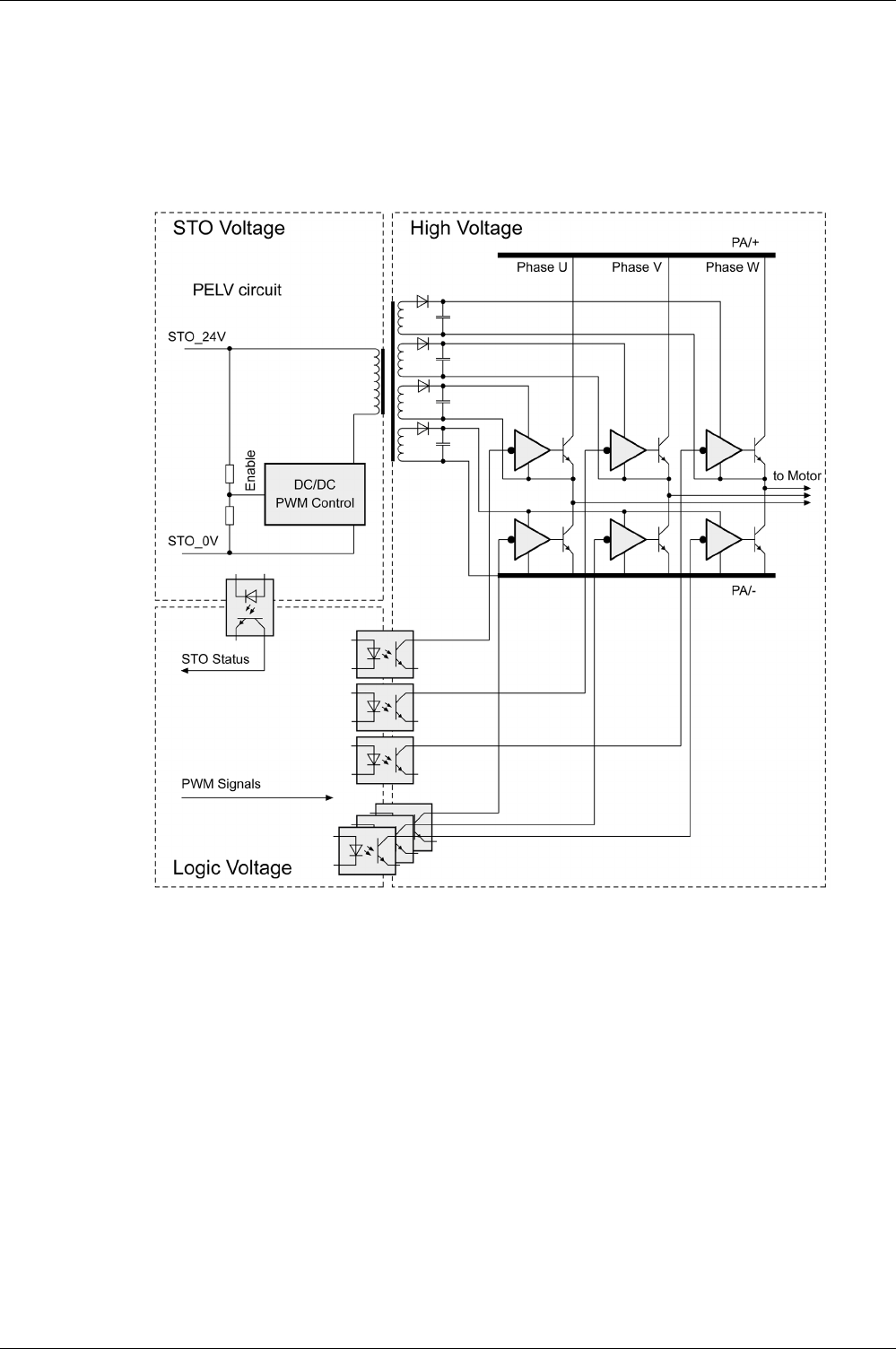
Engineering
EIO0000002305 04/2017 117
Function
The safety function STO integrated into the product can be used to implement an “EMERGENCY STOP”
(IEC 60204-1) for category 0 stops. With an additional, approved EMERGENCY STOP safety relay
module, it is also possible to implement category 1 stops.
The safety function STO switches the supply voltage of the IGBT drivers so that PWM signals cannot
switch the IGBTs. The following diagram illustrates the concept:

Engineering
118 EIO0000002305 04/2017
Requirements for Using the Safety Function
The safety function STO (Safe Torque Off) does not remove power from the DC bus. The safety function
STO only removes power to the motor. The DC bus voltage and the mains voltage to the drive are still
present.
After the safety function STO is triggered, the motor can no longer generate torque and coasts down
without braking in the case of motors without a holding brake. In the case of motors with holding brake, the
holding brake is not a safety-related function, and may not be sufficient to hold the axis at a standstill.
The safety function STO is factory-deactivated by means of the jumper for CN9. If you want to use the
safety function STO, you must remove the jumper for CN9. You may only use the safety function STO with
an external PELV 24 Vdc power supply unit.
For additional information on deactivating the safety function STO, refer to Connection STO (CN9)
(see page 172)
.
Holding Brake and Safety Function STO
When the safety function STO is triggered, the power stage is immediately disabled. In the case of vertical
axes or external forces acting on the load, you may have to take additional measures to bring the load to
a standstill and to keep it at a standstill when the safety function STO is used, for example, by using a
service brake.
If the suspension of hanging / pulling loads is a safety objective for the machine, then you can only achieve
this objective by using an appropriate external brake as a safety-related measure.
DANGER
ELECTRIC SHOCK
-Do not use the safety function STO for any other purposes than its intended function.
-Use an appropriate switch, that is not part of the circuit of the safety function STO, to disconnect the
drive from the mains power.
Failure to follow these instructions will result in death or serious injury.
WARNING
UNINTENDED EQUIPMENT OPERATION
Install a dedicated service brake if coasting does not meet the deceleration requirements of your
application.
Failure to follow these instructions can result in death, serious injury, or equipment damage.
WARNING
UNINTENDED EQUIPMENT OPERATION
-Remove the jumpers connected to the STO power connector (CN9) only if you intend to use the STO
safety-related function for your application.
-Use only an external PELV 24 Vdc power supply unit when applying the safety-related STO function.
Failure to follow these instructions can result in death, serious injury, or equipment damage.
WARNING
FALLING LOAD
Ensure that all loads come to a secure standstill when the safety function STO is used.
Failure to follow these instructions can result in death, serious injury, or equipment damage.

Engineering
EIO0000002305 04/2017 119
NOTE: The drive does not provide its own safety-related output to connect an external brake to use as a
safety-related measure.
Unintended Restart
To help avoid unintended restart of the motor after restoration of power (for example, after power outage),
the parameter P2-68 must be set to “X=0”. A controlled restart must be managed externally from the drive,
note that the external management itself must not trigger an unintended restart.
Degree of Protection When the Safety Function Is Used
You must ensure that conductive substances cannot get into the product (pollution degree 2). Conductive
substances may cause the safety function to become inoperative.
Protected Cable Installation
If short circuits or other wiring errors such as a cross fault between STO inputs can be expected in
connection with safety-related signals, and if these short circuits or other wiring errors are not detected by
upstream devices, protected cable installation as per ISO 13849-2 is required.
ISO 13849-2 describes protected cable installation for cables for safety-related signals. The cables for the
safety function STO must be protected against external voltage. A shield with ground connection helps to
keep external voltage away from the cables for the signals of the safety function STO.
-Use shielded cables for the signals of the safety function STO.
-Do not use the cable for the signals of the safety function STO for other signals.
-Connect one end of the shield.
-When daisychaining the signals of the safety function STO, connect the shield to the equipotential
grounding plane associated to the drives.
WARNING
UNINTENDED AXIS MOVEMENT
-Do not use the internal holding brake as a safety-related measure.
-Only use certified external brakes as safety-related measures.
Failure to follow these instructions can result in death, serious injury, or equipment damage.
WARNING
UNINTENDED EQUIPMENT OPERATION
Set parameter P2-68 setting X to 0 (zero) if the automatic enabling of the power stage presents hazards
in your application.
Failure to follow these instructions can result in death, serious injury, or equipment damage.
WARNING
INOPERABLE SAFETY FUNCTION
Ensure that conductive substances (water, contaminated or impregnated oils, metal shavings, etc.)
cannot get into the drive.
Failure to follow these instructions can result in death, serious injury, or equipment damage.

Engineering
120 EIO0000002305 04/2017
Hazard and Risk Analysis
You must conduct, or ensure that your OEM, system integrator, or anyone responsible for the development
of the application containing the equipment indicated in the present document conducts a hazard and risk
analysis of the entire system. The results of the analysis must be taken into account in the application of
the safety function.
The type of circuit resulting from the analysis may differ from any application examples provided in the
present document or any supplementary documents concerning this equipment. Additional safety
components may be required. The results of the hazard and risk analysis have priority over any other
design considerations. Pay particular attention in conforming to any safety information, different electrical
requirements, and normative standards that would apply to your system.
WARNING
UNINTENDED EQUIPMENT OPERATION
-Perform a hazard and risk analysis to determine the appropriate safety integrity level, and any other
safety requirements, for your specific application based on all the applicable standards.
-Ensure that the hazard and risk analysis is conducted and respected according to EN/ISO 12100
during the design of your machine.
Failure to follow these instructions can result in death, serious injury, or equipment damage.
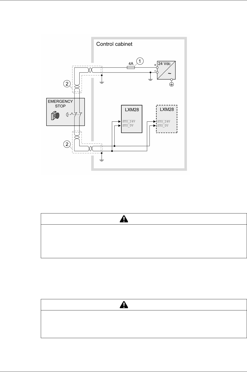
Engineering
EIO0000002305 04/2017 121
Application Examples STO
Example of Category 0 Stop
Use without EMERGENCY STOP safety relay module, category 0 stop.
1 If the maximum output current of the 24 V power supply exceeds 4 A, a 4 A slow-blow fuse is required.
2 Grounded shielded cable for wiring out of the control cabinet.
For more information on STO wiring, see chapter Connection of STO (CN9)
(see page 172)
NOTE: The internal DC power supply of the drive is only to be used to deactivate the safety function STO
via the jumper supplied with the drive.
In this example, when an EMERGENCY STOP is activated, it leads to a category 0 stop:
The power stage is immediately disabled via the inputs STO_24V and STO_0V of the safety function STO.
Power can no longer be supplied to the motor. If the motor is not already at a standstill when the STO is
triggered, it decelerates under the salient physical forces (gravity, friction, etc.) active at the time until
presumably coasting to a standstill.
If the coasting of the motor and its potential load is unsatisfactory as determined by your risk and hazard
analysis, an external service brake may also be required. Refer to Holding Brake and Safety Function STO
(see page 118)
.
WARNING
UNINTENDED EQUIPMENT OPERATION
-Remove the jumpers connected to the STO power connector (CN9) only if you intend to use the STO
safety-related function for your application.
-Use only an external PELV 24 Vdc power supply unit when applying the safety-related STO function.
Failure to follow these instructions can result in death, serious injury, or equipment damage.
WARNING
UNINTENDED EQUIPMENT OPERATION
Install a dedicated service brake if coasting does not meet the deceleration requirements of your
application.
Failure to follow these instructions can result in death, serious injury, or equipment damage.
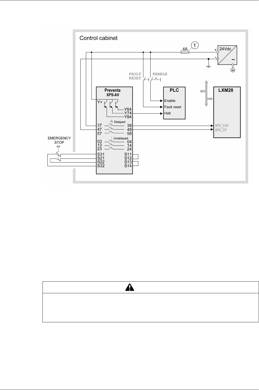
Engineering
122 EIO0000002305 04/2017
Example of Category 1 Stop
Use with EMERGENCY STOP safety relay module, category 1 stop. Example of category 1 stop with
external Preventa XPS-AV EMERGENCY STOP safety relay module.
1 If the maximum output current of the 24 V power supply exceeds 4 A, a 4 A slow-blow fuse is required.
For more information on STO wiring, see chapter Connection of STO (CN9)
(see page 172)
In this example, when an EMERGENCY STOP is activated, it leads to a category 1 stop:
-The safety relay module requests an immediate stop (undelayed) of the drive via the logic controller
(Halt). The logic controller takes the configured or programmed action to instruct the drive to make a
decelerated stop.
-The power stage is disabled via the inputs STO_24V and STO_0V of the safety function STO after the
delay time set in the EMERGENCY STOP safety relay module has elapsed. Power can no longer be
supplied to the motor. If the motor is not already at a standstill when safety function STO is triggered
when the delay time has elapsed, it decelerates under the salient physical forces (gravity, friction, etc.)
active at the time until presumably coasting to a standstill.
If the coasting of the motor and its potential load is unsatisfactory as determined by your risk and hazard
analysis, an external service brake may also be required. Refer to Holding Brake and Safety Function STO
(see page 118)
.
NOTE: The specified minimum current and the permissible maximum current of the relay outputs of the
EMERGENCY STOP safety relay module must be respected.
WARNING
UNINTENDED EQUIPMENT OPERATION
Install a dedicated service brake if coasting does not meet the deceleration requirements of your
application.
Failure to follow these instructions can result in death, serious injury, or equipment damage.


Engineering
124 EIO0000002305 04/2017
Rating the Braking Resistor
Braking resistors are required for dynamic applications. During deceleration, the kinetic energy is
transformed into electrical energy in the motor. The electrical energy increases the DC bus voltage. The
braking resistor is activated when the defined threshold value is exceeded. The braking resistor transforms
electrical energy into heat. If highly dynamic deceleration is required, the braking resistor must be well
adapted to the system. External driving forces acting on the motor can cause high currents to be
regenerated and supplied back to the drive.
An insufficiently rated braking resistor can cause overvoltage on the DC bus. Overvoltage on the DC bus
causes the power stage to be disabled. The motor is no longer actively decelerated.
If multiple drives are connected via a common DC bus, this affects all motors. See chapter Common DC
bus
(see page 111)
for additional information.
An external braking resistor
(see page 97)
is required for applications in which the motor must be
decelerated quickly and the internal braking resistor cannot absorb the excess braking energy.
DANGER
FIRE DUE TO EXTERNAL DRIVING FORCES ACTING ON MOTOR
Verify that no external forces can act on the motor that will exceeded the capacity of the braking resistor.
Failure to follow these instructions will result in death or serious injury.
WARNING
UNINTENDED EQUIPMENT OPERATION
-Verify that the braking resistor has a sufficient rating by performing a test run under maximum load
conditions.
-Verify that the parameter settings for the braking resistor are correct.
Failure to follow these instructions can result in death, serious injury, or equipment damage.

Engineering
EIO0000002305 04/2017 125
Internal Braking Resistor
Introduction
The drive has an internal braking resistor. If the internal braking resistor is insufficient for the dynamics of
the application, one or more external braking resistors must be used.
The resistance values for external braking resistors must not be below the specified minimum resistance.
If an external braking resistor is activated by using the appropriate parameter, the internal braking resistor
is deactivated.
LXM28A Unit UA5 U01 U02 U04 U07
Resistance value of internal braking resistor Ω 100 100 100 100 40
Continuous power internal braking resistor PPR W6060606060
Peak energy ECR(1) Ws 152 152 152 152 380
External braking resistor minimum Ω 25 25 25 25 25
External braking resistor maximum(2) Ω5050505050
Maximum continuous power external braking
resistor
W 640 640 640 640 640
Switch-on voltage braking resistor V 390 390 390 390 390
Capacitance of the internal capacitors μF 820 820 820 820 820
Energy absorption of internal capacitors Evar at
nominal voltage 230 V +10%
Ws 8.87 8.87 8.87 8.87 8.87
(1) Parameter P1-71 is set to 100 ms.
(2) The maximum specified braking resistor can derate the peak power of the device. Depending on the application, it
is possible to use a greater ohm resistor.
LXM28A Unit U10 U15 U20 U30 U45
Resistance value of internal braking resistor Ω 40 40 40 22 22
Continuous power internal braking resistor PPR W606060100100
Peak energy ECR(1) Ws 380 380 380 691 691
External braking resistor minimum Ω 15 15 8 8 8
External braking resistor maximum(2) Ω5050252525
Maximum continuous power external braking
resistor
W 1000 1000 1500 2500 2500
Switch-on voltage braking resistor V 390 390 390 390 390
Capacitance of the internal capacitors μF 1640 1640 2110 3280 3280
Energy absorption of internal capacitors Evar at
nominal voltage 230 V +10%
Ws 17.76 17.76 22.82 35.51 35.51
(1) Parameter P1-71 is set to 100 ms.
(2) The maximum specified braking resistor can derate the peak power of the device. Depending on the application,
it is possible to use a greater ohm resistor.

Engineering
126 EIO0000002305 04/2017
External Braking Resistors
Introduction
An external braking resistor is required for applications in which the motor must be decelerated quickly and
the internal braking resistor cannot absorb the excess braking energy. The temperature of the braking
resistor may exceed 250 °C (482 °F) during operation.
WARNING
HOT SURFACES
-Ensure that it is not possible to make any contact with a hot braking resistor.
-Do not allow flammable or heat-sensitive parts in the immediate vicinity of the braking resistor.
-Verify that the heat dissipation is sufficient by performing a test run under maximum load conditions.
Failure to follow these instructions can result in death, serious injury, or equipment damage.
VW3A760• Unit 1R•• (1) 2R•• 3R•• 4R•• (1) 5R•• 6R•• 7R•• (1)
Resistance Ω 10 27 72
Continuous power W 400 100 200 400 100 200 400
Maximum time in
braking at 115 V / 230 V
s 0.72 0.552 1.08 2.64 1.44 3.72 9.6
Peak power at 115 V /
230 V
kW 18.5 6.8 2.6
Maximum peak energy
at 115 V / 230 V
Ws 13300 3800 7400 18100 3700 9600 24700
Degree of protection - IP 65
(1) Resistors with a continuous power of 400 W are not UL/CSA-approved.
VW3A77• Unit 04 05
Resistance Ω15 10
Continuous power W 1000
Maximum time in braking at 115 V / 230 V s 3.5 1.98
Peak power at 115 V / 230 V kW 12.3 18.5
Maximum peak energy at 115 V / 230 V Ws 43100 36500
Degree of protection - IP20

Engineering
EIO0000002305 04/2017 127
Monitorin g Functions
Section 7.7
Monitoring Functions
Monitoring Functions
Overview
The monitoring functions of the drive can be used to monitor movements and to monitor internal signals.
These monitoring functions are not safety-related functions.
The following monitoring functions are available:
Monitoring function Task
Data connection Monitors data connection for interruption
Limit switch signals Monitors for permissible movement range
Position deviation Monitors for difference between actual position and
reference position
Motor overload Monitors for excessively high current in the motor
phases
Overvoltage and undervoltage Monitors for overvoltage and undervoltage of the
power stage supply and the DC bus
Overtemperature Monitors the drive for overtemperature
Encoder overtemperature Monitors the encoder for overtemperature
Overvoltage and undervoltage Monitors the logic supply and power stage supply for
permissible voltage range
Overvoltage at digital inputs Monitors the digital inputs for overvoltage
Wire break HPULSE inputs Monitors the HPULSE inputs for wire break
Power supply encoder Monitors the encoder supply for short circuit and
permissible voltage range
Current limitation (Foldback) Power limitation in the case of overloads for the
motor, the output current, the output power, and the
braking resistor.

Engineering
128 EIO0000002305 04/2017
Configurable Inputs and Outputs
Section 7.8
Configurable Inputs and Outputs
Configurable Inputs and Outputs
Presentation
This drive has digital inputs and outputs that can be configured. The inputs and outputs have a defined
default assignment depending on the operating mode. This assignment can be adapted to the
requirements of the customer's installation.
For further details, refer to chapter Operation
(see page 297)
.

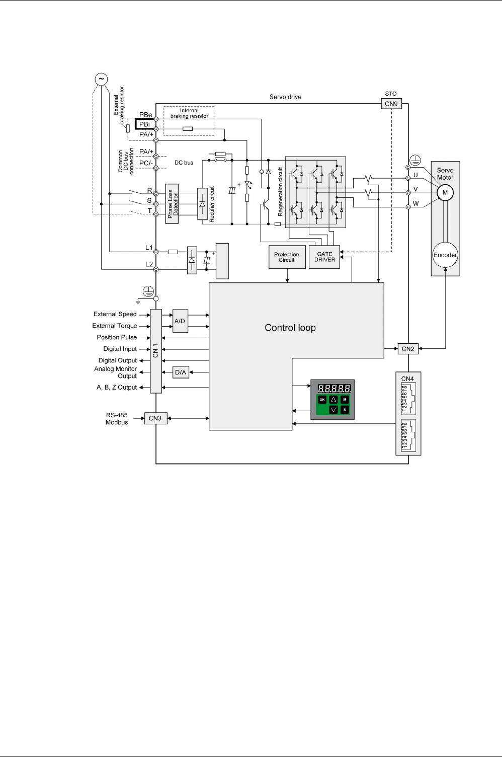
Engineering
130 EIO0000002305 04/2017
General Wiring
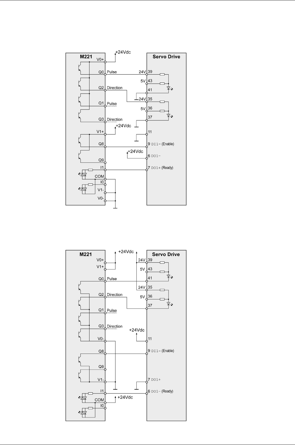
Engineering
EIO0000002305 04/2017 131
I/O Wiring Example With Modicon M221 Logic Controller
Positive Logic
Wiring example with Modicon M221 Logic Controller (positive logic).
Negative Logic
Wiring example with Modicon M221 Logic Controller (negative logic).

Engineering
132 EIO0000002305 04/2017

EIO0000002305 04/2017 133
Lexium 28
A
and BCH2 Servo Drive System
Installation
EIO0000002305 04/2017
Installation
Part IV
Installation
Introduction
An engineering phase is mandatory prior to mechanical and electrical installation. For basic information,
refer to Engineering
(see page 103)
.
In the case of a ground error, the maximum permissible current in the motor phases may be exceeded.
1For additional information, refer to NEMA ICS 1.1 (latest edition), “Safety Guidelines for the Application,
Installation, and Maintenance of Solid State Control” and to NEMA ICS 7.1 (latest edition), “Safety
Standards for Construction and Guide for Selection, Installation and Operation of Adjustable-Speed Drive
Systems” or their equivalent governing your particular location.
DANGER
INSUFFICIENT GROUNDING
-Use a protective ground conductor with at least 10 mm2 (AWG 6) or two protective ground conductors
with the cross section of the conductors supplying the power terminals.
-Verify compliance with all local and national electrical code requirements as well as all other applicable
regulations with respect to grounding of the entire drive system.
-Ground the drive system before applying voltage.
-Do not use conduits as protective ground conductors; use a protective ground conductor inside the
conduit.
-Do not use cable shields as protective ground conductors.
-Keep foreign objects from getting into the product.
-Verify the correct seating of seals and cable entries in order to avoid contamination such as deposits
and humidity.
Failure to follow these instructions will result in death or serious injury.
DANGER
FIRE CAUSED BY INCORRECT INSTALLATION
Use upstream, external ground error detection equipment (Residual Current Device / Ground Fault
Circuit Interrupter).
Failure to follow these instructions will result in death or serious injury.
WARNING
LOSS OF CONTROL
-The designer of any control scheme must consider the potential failure modes of control paths and,
for certain critical control functions, provide a means to achieve a safe state during and after a path
failure. Examples of critical control functions are emergency stop and overtravel stop, power outage
and restart.
-Separate or redundant control paths must be provided for critical control functions.
-System control paths may include communication links. Consideration must be given to the
implications of unanticipated transmission delays or failures of the link.
-Observe all accident prevention regulations and local safety guidelines.1
-Each implementation of this equipment must be individually and thoroughly tested for proper operation
before being placed into service.
Failure to follow these instructions can result in death, serious injury, or equipment damage.
Installation
134 EIO0000002305 04/2017
Conductive foreign objects, dust or liquids may cause safety functions to become inoperative.
The metal surfaces of the product may exceed 70 °C (158 °F) during operation.
What Is in This Part?
This part contains the following chapters:
WARNING
LOSS OF SAFETY FUNCTION CAUSED BY FOREIGN OBJECTS
Protect the system against contamination by conductive substances.
Failure to follow these instructions can result in death, serious injury, or equipment damage.
WARNING
HOT SURFACES
-Avoid unprotected contact with hot surfaces.
-Do not allow flammable or heat-sensitive parts in the immediate vicinity of hot surfaces.
-Verify that the heat dissipation is sufficient by performing a test run under maximum load conditions.
Failure to follow these instructions can result in death, serious injury, or equipment damage.
CAUTION
INOPERABLE EQUIPMENT DUE TO INCORRECT MAINS VOLTAGE CONNECTION
-Verify that you use the correct mains voltage; install a transformer, if necessary.
-Do not connect mains voltage to the output terminals (U, V, W).
Failure to follow these instructions can result in injury or equipment damage.
Chapter Chapter Name Page
8 Before Mounting 135
9 Drive Installation 139
10 Motor Installation 175
11 Verifying Installation 185


Before Mounting
136 EIO0000002305 04/2017
Inspecting the Product
Inspecting the Product
-Verify the product version by means of the type code on the nameplate. Refer to chapter Nameplate
(see page 32)
and chapter Type Code
(see page 33)
.
-Prior to mounting, inspect the product for visible damage.
Damaged products may cause electric shock or unintended equipment operation.
Contact your local Schneider Electric representative if you detect any damage whatsoever to the products.
DANGER
ELECTRIC SHOCK OR UNINTENDED EQUIPMENT OPERATION
-Do not use damaged products.
-Keep foreign objects (such as chips, screws or wire clippings) from getting into the product.
Failure to follow these instructions will result in death or serious injury.

Before Mounting
EIO0000002305 04/2017 137
Scope of Supply
Drive
-Drive Lexium 28A
-Connector kit with 3 connectors for:
Power stage supply and logic supply
Braking resistor
Including jumper between PBi and PBe
Motor
-Plastic tool for opening the spring terminals (available for devices from 50 W to 1.5 kW)
-4-pin connector for deactivating the safety function STO (CN9)
-Adhesive hazard labels in 5 languages (German, French, Italian, Spanish, Chinese)
-Instruction sheet for the product
Motor
-BCH2 servo motor
-BCH2•R: 2 eyebolts
-Information sheet for the product

Before Mounting
138 EIO0000002305 04/2017

EIO0000002305 04/2017 139
Lexium 28
A
and BCH2 Servo Drive System
Drive Installation
EIO0000002305 04/2017
Drive Install ation
Chapter 9
Drive Installation
What Is in This Chapter?
This chapter contains the following topics:
Topic Page
Mechanical Installation Drive 140
Electrical Installation Drive 142
Connection Grounding Screw 144
Connection I/O Interface (CN1) 145
Connecting the Motor Encoder (CN2) 156
Connection PC (CN3) 158
Connection CAN (CN4) 160
Connection Logic Supply and Power Stage Supply (CN5) 163
Connection DC Bus (CN6) 166
Connection Braking Resistor (CN7) 167
Connecting the Motor Phases (CN8) 169
Holding Brake Connection 171
Connection STO (CN9) 172

Drive Installation
140 EIO0000002305 04/2017
Mechanical Installation Drive
Conductive foreign objects, dust or liquids may cause safety functions to become inoperative.
The metal surfaces of the product may exceed 70 °C (158 °F) during operation.
Attaching a Hazard Label with Safety Instructions
Included in the packaging of the drive are adhesive hazard labels in German, French, Italian, Spanish, and
Chinese languages. The English version is affixed to the drive by the factory. If the country to which your
final machine or process is to be delivered is other than English speaking:
-Select the hazard label suitable for the target country.
Respect the safety regulations in the target country.
-Attach the hazard label to the front of the device so that it is clearly visible.
Control Cabinet
The control cabinet (enclosure) must have a sufficient size so that all devices and components can be
permanently installed and wired in compliance with the EMC requirements.
The ventilation of the control cabinet must be sufficient to comply with the specified ambient conditions for
the devices and components operated in the control cabinet.
Install and operate this equipment in a control cabinet rated for its intended environment and secured by
a keyed or tooled locking mechanism.
Mounting Distances, Ventilation
When selecting the position of the device in the control cabinet, note the following:
-Mount the device in a vertical position (±10°). This is required for cooling the device.
-Adhere to the minimum installation distances for required cooling. Avoid heat accumulations.
-Do not mount the device close to heat sources.
-Do not mount the device on or near flammable materials.
-The heated airflow from other devices and components must not heat up the air used for cooling the
device.
DANGER
ELECTRIC SHOCK OR UNINTENDED EQUIPMENT OPERATION
-Keep foreign objects from getting into the product.
-Verify the correct seating of seals and cable entries in order to avoid contamination such as deposits
and humidity.
Failure to follow these instructions will result in death or serious injury.
WARNING
LOSS OF SAFETY FUNCTION CAUSED BY FOREIGN OBJECTS
Protect the system against contamination by conductive substances.
Failure to follow these instructions can result in death, serious injury, or equipment damage.
WARNING
HOT SURFACES
-Avoid unprotected contact with hot surfaces.
-Do not allow flammable or heat-sensitive parts in the immediate vicinity of hot surfaces.
-Verify that the heat dissipation is sufficient by performing a test run under maximum load conditions.
Failure to follow these instructions can result in death, serious injury, or equipment damage.
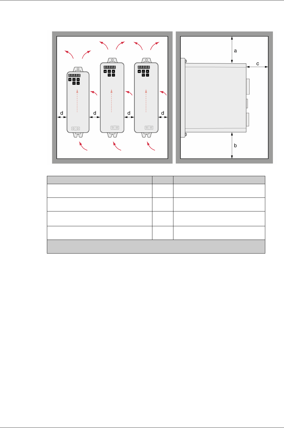
Drive Installation
EIO0000002305 04/2017 141
The connection cables of the devices are routed to the top and to the bottom. The minimum distances must
be adhered to for air circulation and cable installation.
Mounting distances and air circulation
Mounting the Drive
See chapter Dimensions
(seepage37)
for the dimensions of the mounting holes.
Painted surfaces may create electrical resistance or isolation. Before mounting the device to a painted
mounting plate, remove all paint across a large area of the mounting points.
-Respect the ambient conditions in chapter Environmental Conditions
(see page 35)
.
-Mount the device in a vertical position (±10°).
Distance Unit Value
Free space a
above the device
mm
(in)
≥50
(≥1.97)
Free space b
below the device
mm
(in)
≥50
(≥1.97)
Free space c
in front of the device(1)
mm
(in)
≥60
(≥2.36)
Free space d
between devices
mm
(in)
≥15
(≥0.59)
(1) The free space is strictly for observing proper ventilation and may not be sufficient for your wiring
requirements.
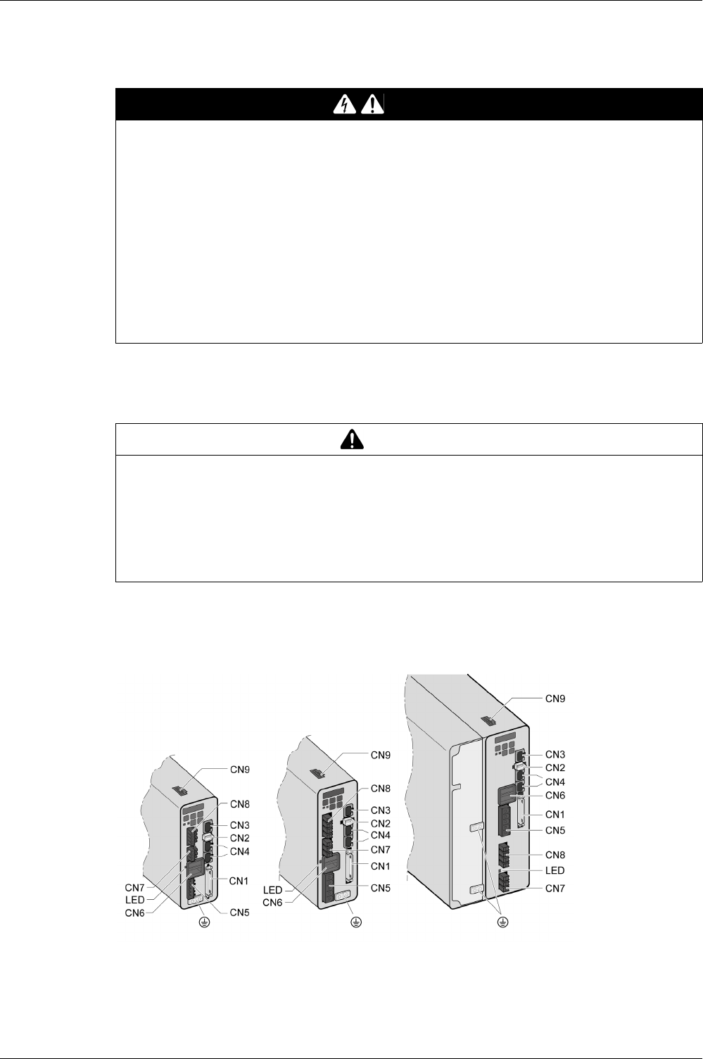
Drive Installation
142 EIO0000002305 04/2017
Electrical Installation Drive
Introduction
Direct current can be introduced in the protective ground conductor of this drive. If a residual current device
(RCD / GFCI) or a residual current monitor (RCM) is used for protection against direct or indirect contact,
the following specific types must be used:
The entire installation procedure must be performed without voltage present.
Overview of interfaces
DANGER
INSUFFICIENT GROUNDING
-Use a protective ground conductor with at least 10 mm2 (AWG 6) or two protective ground conductors
with the cross section of the conductors supplying the power terminals.
-Verify compliance with all local and national electrical code requirements as well as all other applicable
regulations with respect to grounding of the entire drive system.
-Ground the drive system before applying voltage.
-Do not use conduits as protective ground conductors; use a protective ground conductor inside the
conduit.
-Do not use cable shields as protective ground conductors.
-Keep foreign objects from getting into the product.
-Verify the correct seating of seals and cable entries in order to avoid contamination such as deposits
and humidity.
Failure to follow these instructions will result in death or serious injury.
WARNING
DIRECT CURRENT CAN BE INTRODUCED INTO THE PROTECTIVE GROUND CONDUCTOR
-Use a Type A Residual Current Device (RCD / GFCI) or a Residual Current Monitor (RCM) for single-
phase drives connected to a phase and to the neutral conductor.
-Use a Type B Residual Current Device (RCD / GFCI) or a Residual Current Monitor (RCM) that has
approval for use with frequency inverters and is sensitive to all types of current for three-phase drives
and for single-phase drives not connected to a phase and the neutral conductor.
Failure to follow these instructions can result in death, serious injury, or equipment damage.

Drive Installation
EIO0000002305 04/2017 143
Item Description Refer to
CN1 Signal interface
For connecting master controller or I/O signals.
Connection I/O Interface (CN1)
(see page 145)
CN2 Connection for motor encoder Connecting the Motor Encoder (CN2)
(see page 156)
CN3 Modbus (commissioning interface)
For connecting PC via converter TCSMCNAM3M002P
Connection PC (CN3)
(see page 158)
CN4 2 connections for fieldbus CANopen
For connecting master controller or I/O signals.
Connection CAN (CN4)
(see page 160)
CN5 Power stage supply (R,S,T) and logic supply (L1, L2) Connection Logic Supply and Power Stage
Supply (CN5)
(see page 163)
CN6 DC bus connection Connection DC bus (CN6)
(see page 166)
LED DC bus LED
The LED is illuminated when mains voltage or internal
charge are present. The DC bus LED is not an indicator of
the absence of DC bus voltage.
-
CN7 Connection for external braking resistor Connection braking resistor (CN7)
(see page 167)
CN8 Motor phases connection (U, V, W, PE) Connecting the motor phases (CN8)
(see page 169)
CN9 Connection for safety function STO Connection STO (CN9)
(see page 172)

Drive Installation
144 EIO0000002305 04/2017
Connection Grounding Screw
This product has a touch current greater than 3.5 mA. If the protective ground connection is interrupted, a
hazardous touch current may flow if the housing is touched.
The central grounding screw of the product is located at the bottom of the front side.
-Use ring-type cable lugs or fork-type cable lugs.
-Connect the ground connection of the device to the equipotential ground plane of your system.
DANGER
INSUFFICIENT GROUNDING
-Use a protective ground conductor with at least 10 mm2 (AWG 6) or two protective ground conductors
with the cross section of the conductors supplying the power terminals.
-Verify compliance with all local and national electrical code requirements as well as all other applicable
regulations with respect to grounding of the entire drive system.
-Ground the drive system before applying voltage.
-Do not use conduits as protective ground conductors; use a protective ground conductor inside the
conduit.
-Do not use cable shields as protective ground conductors.
-Keep foreign objects from getting into the product.
-Verify the correct seating of seals and cable entries in order to avoid contamination such as deposits
and humidity.
Failure to follow these instructions will result in death or serious injury.
Tightening torque of grounding
screw
Nm
(lb.in)
1.5
(13.28)
Screw type - M4 x 8 socket button head
screw

Drive Installation
EIO0000002305 04/2017 145
Connection I/O Interface (CN1)
The I/O Interface (CN1) is a D-Sub 50-pin female connector. The following table describes the contacts of
the connector:
Pin Signal Meaning Pin Signal Meaning
1 DO4+ Digital output 4 2 DO3- Digital output 3
3 DO3+ Digital output 3 4 DO2- Digital output 2
5 DO2+ Digital output 2 6 DO1- Digital output 1
7 DO1+ Digital output 1 8 DI4- Digital input 4
9 DI1- Digital input 1 10 DI2- Digital input 2
11 COM Reference potential to DI1 ... DI8 12 GND Reference potential analog input
13 GND Reference potential for analog input 14 - Reserved
15 MON2 Analog output 2 16 MON1 Analog output 1
17 VDD 24 Vdc power supply (for external
I/O)
18 T_REF Analog input for reference torque
19 GND Analog input signal ground 20 VCC Output power supply 12 Vdc (for
analog reference values)
21 OA ESIM channel A 22 /OA ESIM channel A, inverted
23 /OB ESIM channel B, inverted 24 /OZ ESIM index pulse, inverted
25 OB ESIM channel B 26 DO4- Digital output 4
27 DO5- Digital output 5 28 DO5+ Digital output 5
29 /HPULSE High-speed pulses, inverted 30 DI8- Digital input 8
31 DI7- Digital input 7 32 DI6- Digital input 6
33 DI5- Digital input 5 34 DI3- Digital input 3
35 PULL HI_S
(SIGN)
Pulse applied Power (SIGN) 36 /SIGN Direction signal, inverted
37 SIGN Direction signal 38 HPULSE High-speed pulses
39 PULL HI_P
(PULSE)
Pulse applied Power (PULSE) 40 /HSIGN Direction signal for high-speed
pulses, inverted
41 PULSE Pulse input 42 V_REF Analog input for reference velocity
43 /PULSE Pulse input 44 GND Analog input signal ground
45 COM- Reference potential to VDD and
DO6(OCZ)
46 HSIGN Direction signal for high-speed
pulses
47 COM- Reference potential to VDD and
DO6(OCZ)
48 DO6(OCZ) ESIM index pulse
Open collector output
49 COM- Reference potential to VDD and
DO6(OCZ)
50 OZ ESIM index pulse
Line driver output
WARNING
UNINTENDED EQUIPMENT OPERATION
Do not connect any wiring to reserved, unused connections, or to connections designated as No
Connection (N.C.).
Failure to follow these instructions can result in death, serious injury, or equipment damage.
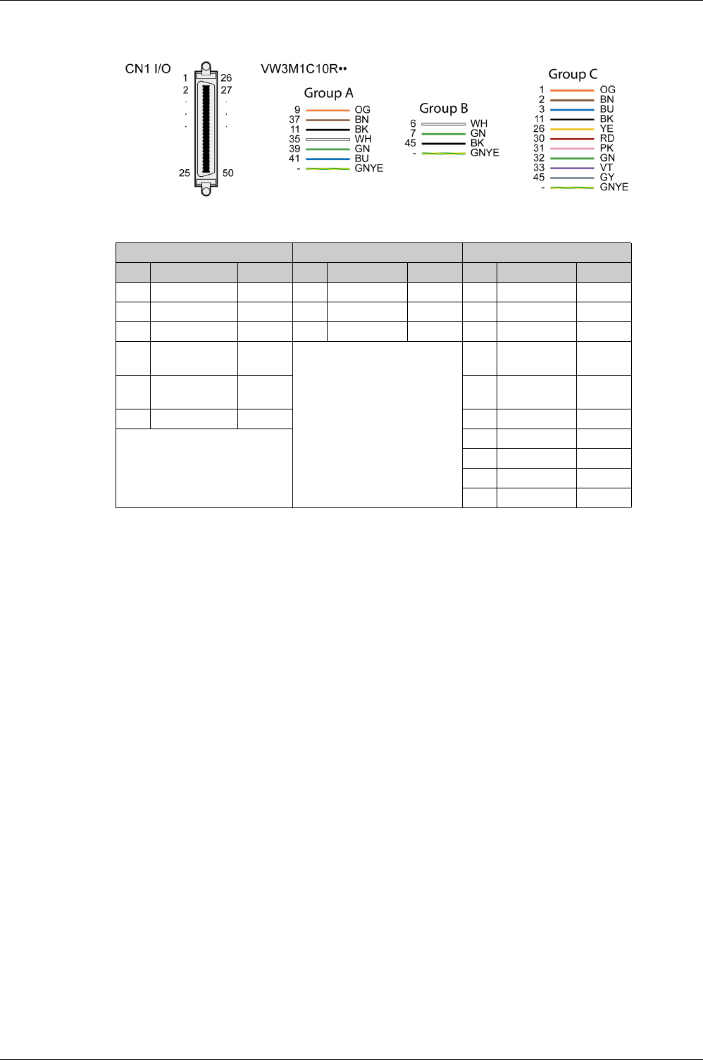
Drive Installation
146 EIO0000002305 04/2017
Prefabricated Cable VW3M1C10R••
Color assignments of the prefabricated cable connected to the I/O interface (CN1):
VW3M1C10R•• Pinout
NOTE: For the CN1 mating connector, use a clip-on (latching) type, such as Schneider Electric reference
VW3M1C12 CN1 Connector Kit.
Inputs and Outputs Signals
The following inputs and outputs signals are available:
-Analog inputs and outputs
(see page 147)
-Pulse input (open collector, negative logic
(see page 147)
)
-Pulse input (open collector, positive logic
(seepage148)
)
-Pulse input (line driver)
(see page 149)
-High-speed pulse input (line driver)
(see page 149)
-Digital outputs (negative logic)
(see page 150)
-Digital outputs (positive logic)
(see page 152)
-Digital inputs (negative logic)
(see page 153)
-Digital inputs (positive logic)
(see page 154)
-Encoder output signal)
(see page 155)
Group A Group B Group C
Pin Signal Color Pin Signal Color Pin Signal Color
9DI1- OG 6DO1- WH 1DO4+ OG
37 SIGN BN 7 DO1+ GN 2 DO3- BN
11COM BK45COM- BK3DO3+ BU
35 PULL HI_S
(SIGN)
WH
-
11 COM BK
39 PULL HI_P
(PULSE)
GN 26 DO4- YE
41 PULSE BU 30 DI8- RD
-
31 DI7- PK
32 DI6- GN
33 DI5- VT
45 COM- BY
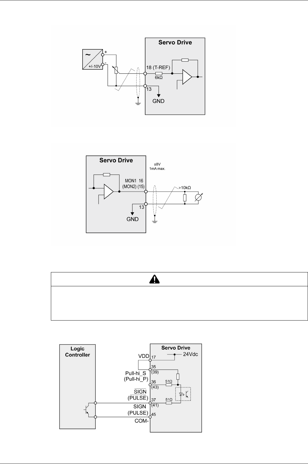
Drive Installation
EIO0000002305 04/2017 147
Analog Inputs and Outputs
Example of reference value via analog input:
Example of analog output:
Pulse Input (Open Collector, Negative Logic)
Example of pulse input (open collector) with internal power supply (negative logic).
WARNING
UNINTENDED EQUIPMENT OPERATION
Do not connect an external, 24 Vdc power supply to the VDD connection of the I/O interface (CN1)
connector.
Failure to follow these instructions can result in death, serious injury, or equipment damage.
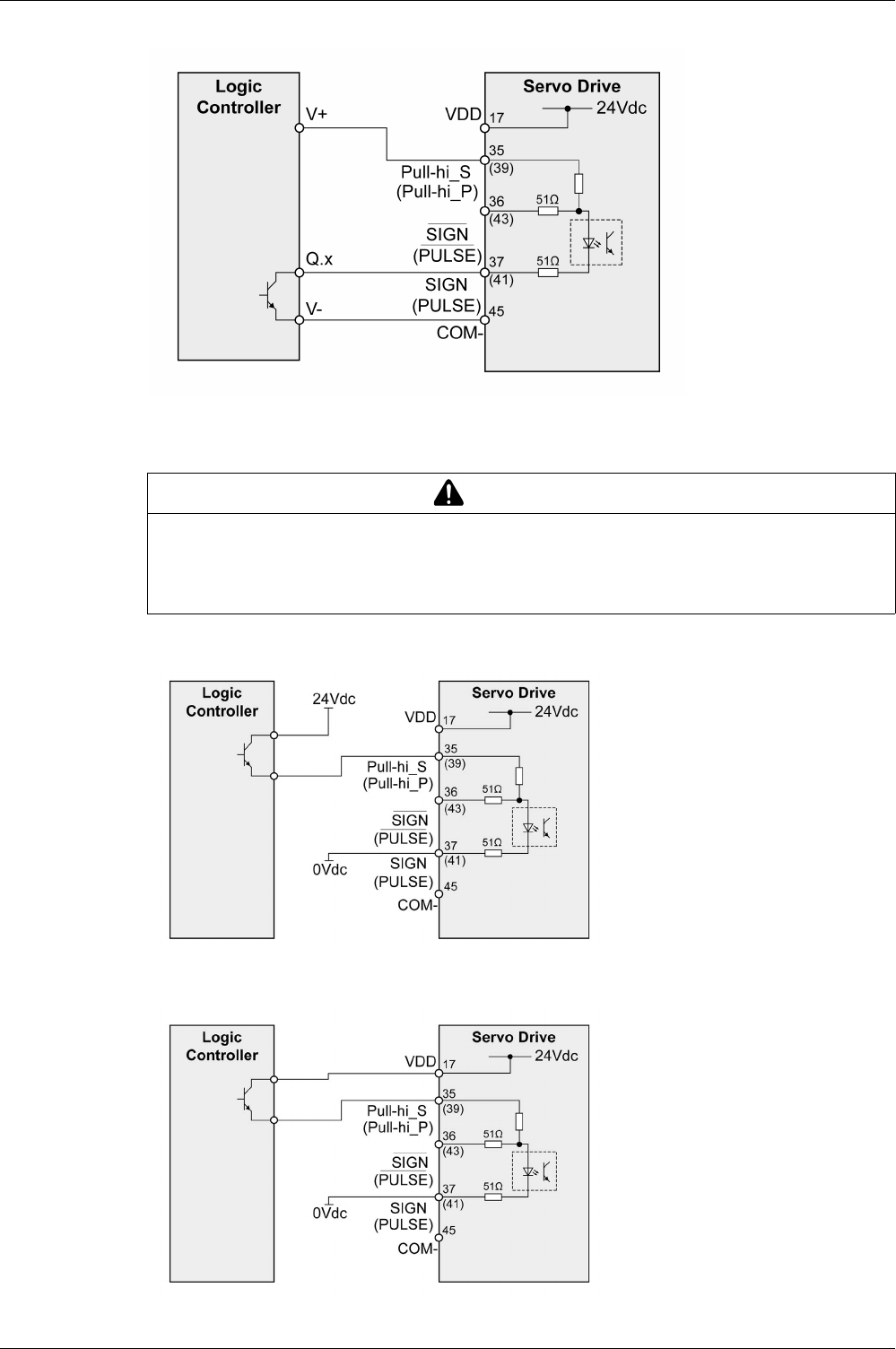
Drive Installation
148 EIO0000002305 04/2017
Example of pulse input (open collector) with external power supply (negative logic).
Pulse Input (Open Collector, Positive Logic)
Example of pulse input (open collector) with internal power supply (positive logic).
Example of pulse input (open collector) with external power supply (positive logic).
WARNING
UNINTENDED EQUIPMENT OPERATION
Do not connect an external, 24 Vdc power supply to the VDD connection of the I/O interface (CN1)
connector.
Failure to follow these instructions can result in death, serious injury, or equipment damage.
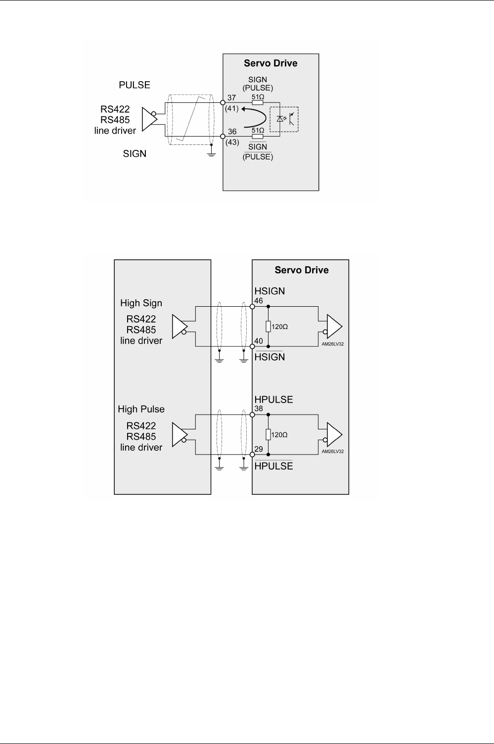
Drive Installation
EIO0000002305 04/2017 149
Pulse Input (Line Driver)
Example of pulse input (line driver).
High-Speed Pulses
Example of high-speed pulse input (line driver).
Connect the cable shield to the equipotential ground of your controller/drive electrical system.
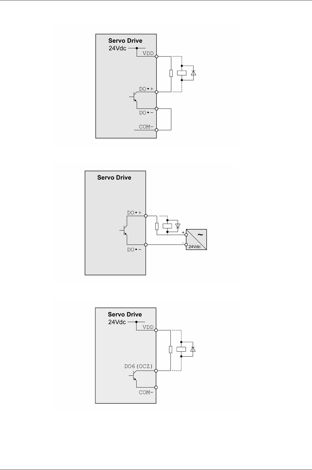
Drive Installation
150 EIO0000002305 04/2017
Wiring of the Digital Outputs (Negative Logic)
Example of digital outputs DO1 ... DO5 with internal power supply (negative logic):
Example of digital outputs DO1 ... DO5 with external power supply (negative logic):
Example of digital output DO6 (OCZ) with internal power supply (negative logic):
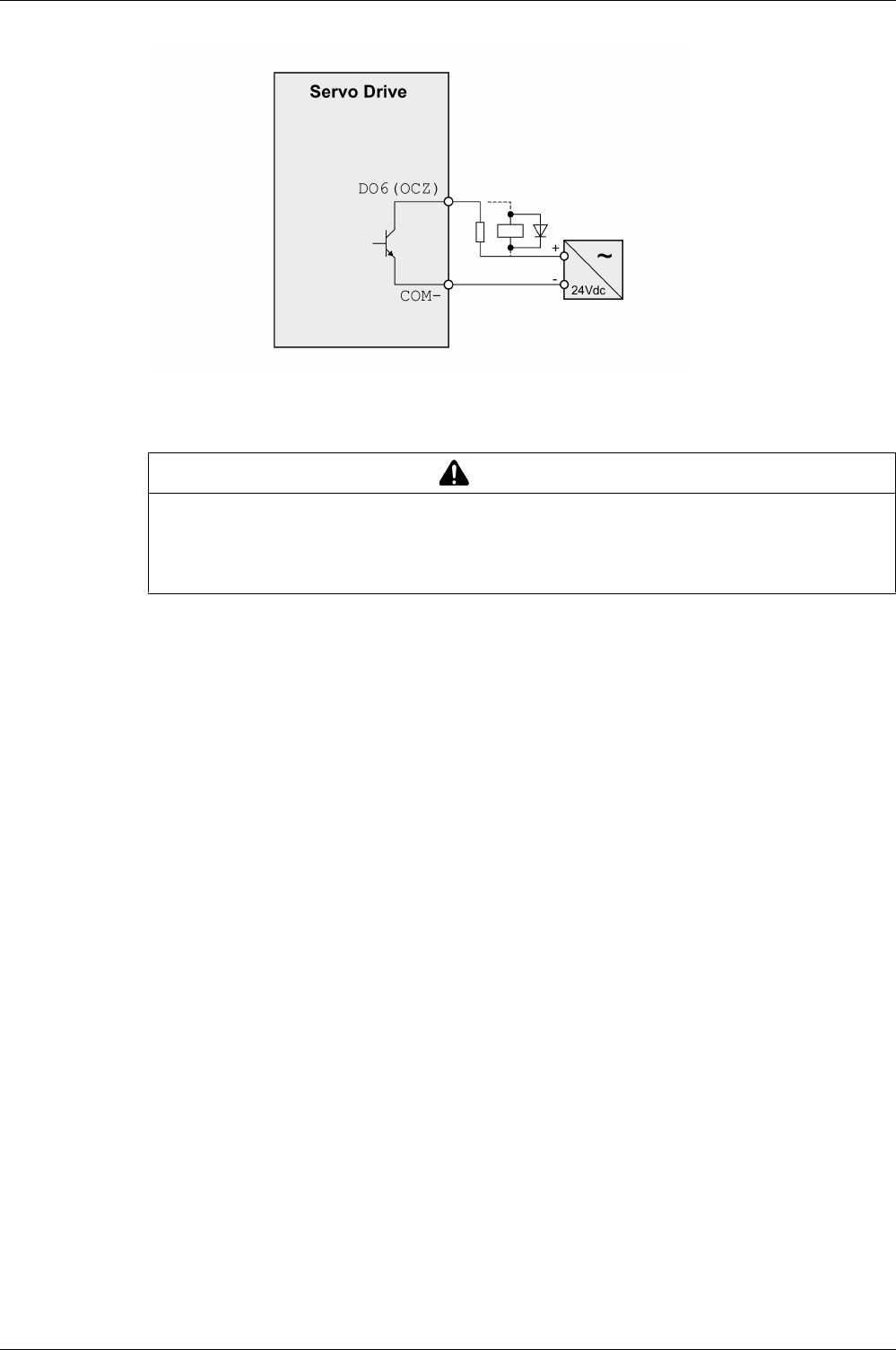
Drive Installation
EIO0000002305 04/2017 151
Example of digital output DO6 (OCZ) with external power supply (negative logic):
Inductive loads using DC voltages may damage the signal outputs. A protection circuit is required to protect
the signal outputs against inductive loads.
A diode can be used to protect the signal outputs against inductive loads.
Use a diode with the following ratings:
-Reverse withstand voltage: voltage of signal output times 10
-Forward current: greater than the load current
CAUTION
OUTPUT CIRCUIT DAMAGE DUE TO INDUCTIVE LOADS
Use an appropriate external protective circuit or device to reduce the inductive direct current load
damage.
Failure to follow these instructions can result in injury or equipment damage.
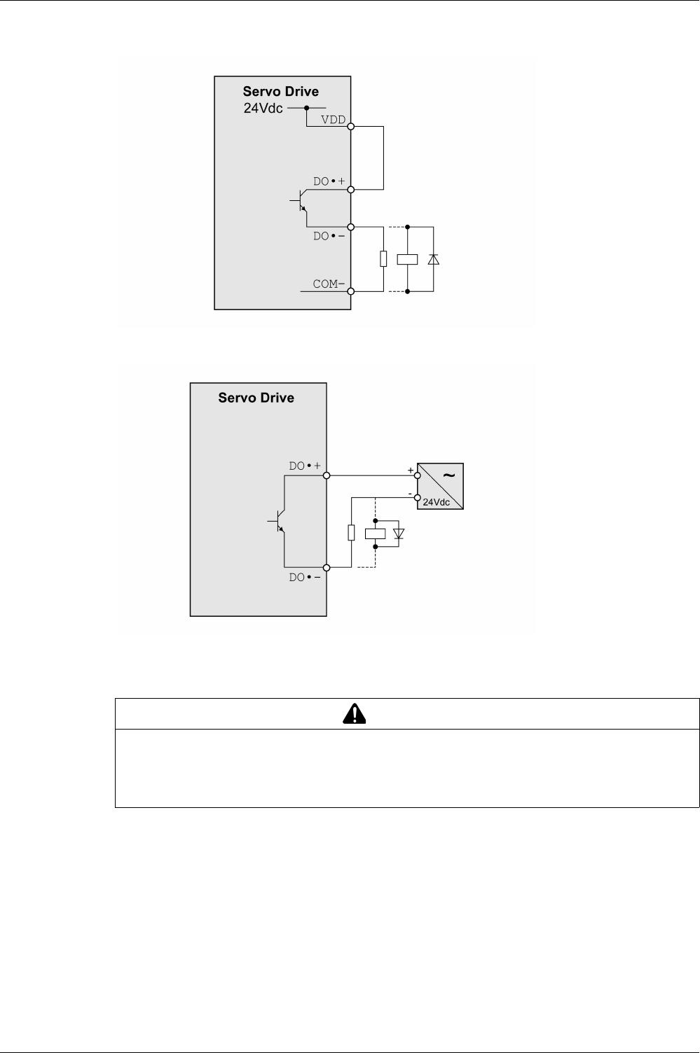
Drive Installation
152 EIO0000002305 04/2017
Wiring of the Digital Outputs (Positive Logic)
Example of digital outputs DO1 ... DO5 with internal power supply (positive logic):
Example of digital outputs DO1 ... DO5 with external power supply (positive logic):
Inductive loads using DC voltages may damage the signal outputs. A protection circuit is required to protect
the signal outputs against inductive loads.
A diode can be used to protect the signal outputs against inductive loads. Use a diode with the following
ratings:
Reverse withstand voltage: voltage of signal output times 10
Forward current: greater than the load current
CAUTION
OUTPUT CIRCUIT DAMAGE DUE TO INDUCTIVE LOADS
Use an appropriate external protective circuit or device to reduce the inductive direct current load
damage.
Failure to follow these instructions can result in injury or equipment damage.
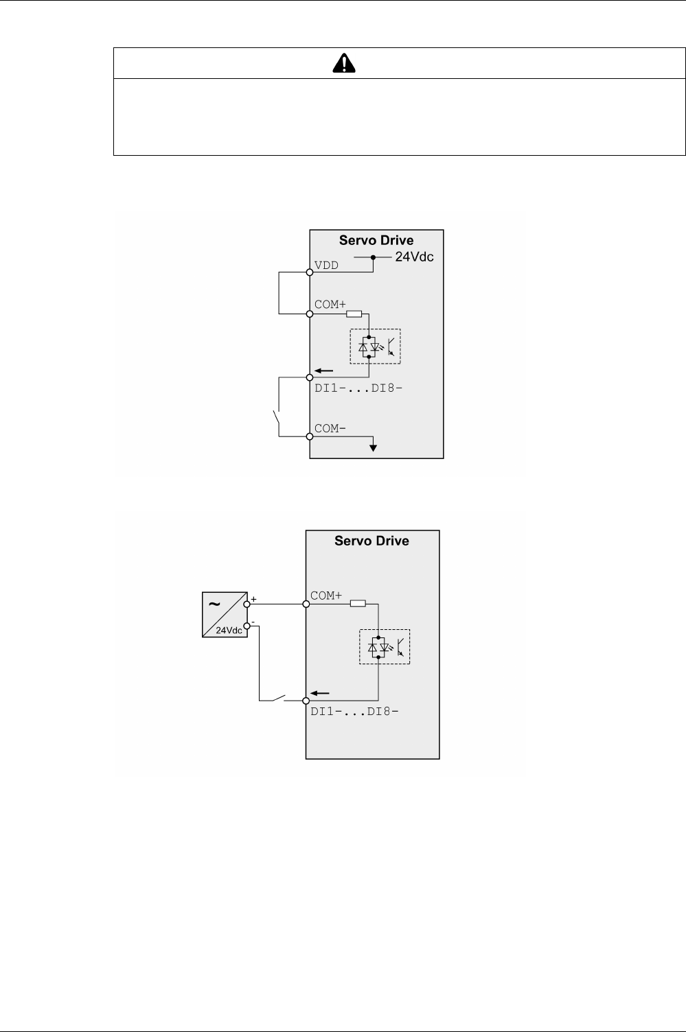
Drive Installation
EIO0000002305 04/2017 153
Wiring of the Digital Inputs (Negative Logic)
Use a relay or an open collector output (NPN transistor) for the input signal.
Example of digital input (negative logic) with internal power supply:
Example of digital input (negative logic) with external power supply:
WARNING
UNINTENDED EQUIPMENT OPERATION
Do not connect an external, 24 Vdc power supply to the VDD connection of the I/O interface (CN1)
connector.
Failure to follow these instructions can result in death, serious injury, or equipment damage.
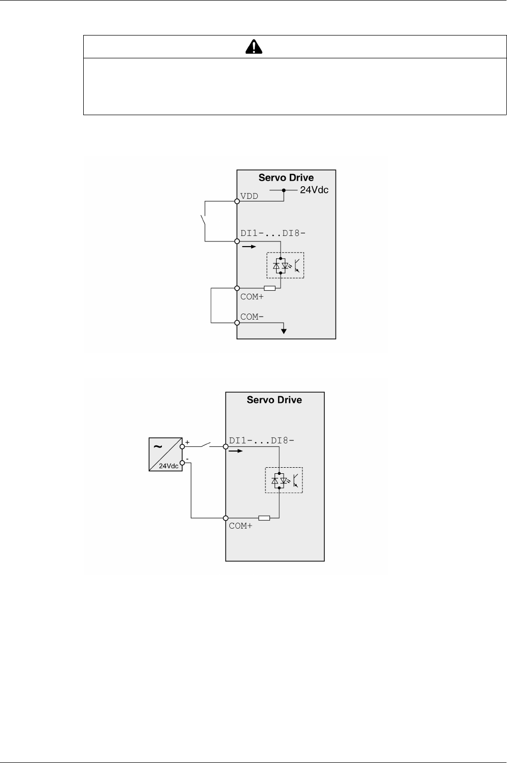
Drive Installation
154 EIO0000002305 04/2017
Wiring of the Digital Inputs (Positive Logic)
Use a relay or an open collector output (PNP transistor) for the input signal.
Example of digital input with internal power supply (positive logic):
Example of digital input with external power supply (positive logic):
WARNING
UNINTENDED EQUIPMENT OPERATION
Do not connect an external, 24 Vdc power supply to the VDD connection of the I/O interface (CN1)
connector.
Failure to follow these instructions can result in death, serious injury, or equipment damage.
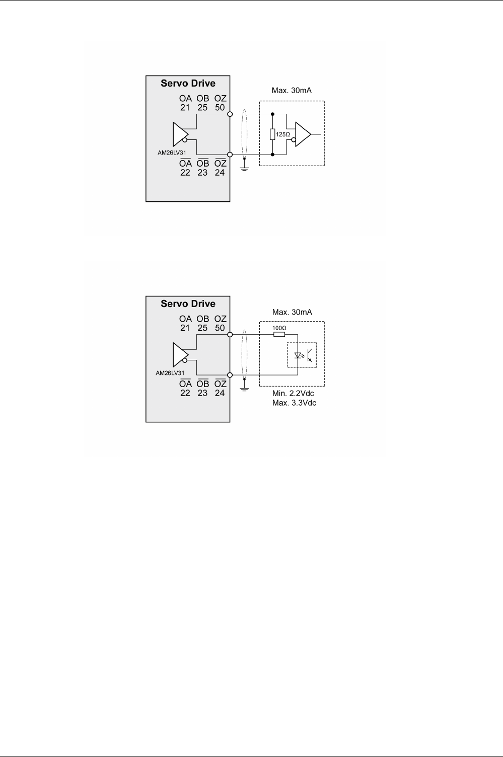
Drive Installation
EIO0000002305 04/2017 155
Encoder Output Signal
Example of encoder output signal Line Driver.
Example of encoder output signal, high-speed optocoupler.
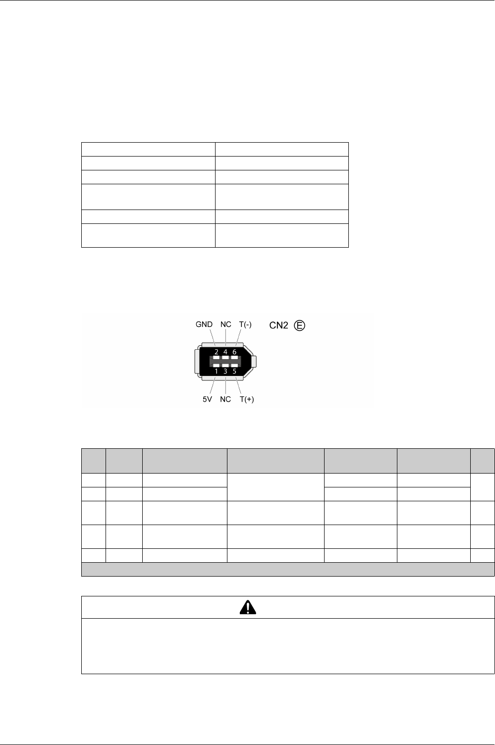
Drive Installation
156 EIO0000002305 04/2017
Connecting the Motor Encoder (CN2)
Function and Encoder Type
The motor encoder is an integrated, high-resolution singleturn absolute encoder. It provides the device with
information on the motor position (analog and digital).
Compatibility between Drive and Motor is defined in the Drive / Motor combinations table
(see page 20)
.
Cable Specifications
For further information, refer to chapter Cables
(see page 108)
.
-Use pre-assembled cables to reduce the risk of wiring errors.
Wiring Diagram
Connection assignment motor encoder (CN2)
The motor encoder interface (CN2) is a 6-pin connector. The following table describes the contacts of the
connector:
Shield: Required, both ends grounded
Twisted Pair: Required
PELV: Required
Cable composition: 10 x 0.13 mm2
(10 x AWG 24)
Maximum cable length: 20 m (65.6 ft)
Special characteristics: Fieldbus cables are not suitable for
connecting encoders.
Pin Signal Color(1) Meaning Motor military
connector
Motor plastic
connector
I/O
5 T+ Blue (BU) Serial communication A1I/O
6 T- Blue/Black (BU/BK) B 4
1 +5 V Red, red/white (RD,
RD/WH)
5 V encoder supply S 7 I
2 GND Black, black/white
(BK, BK/WH)
Reference potential for
encoder supply
R8 O
3, 4 N.C. Reserved - - - -
(1) Color information relates to the cables available as accessories.
WARNING
UNINTENDED EQUIPMENT OPERATION
Do not connect any wiring to reserved, unused connections, or to connections designated as No
Connection (N.C.).
Failure to follow these instructions can result in death, serious injury, or equipment damage.

Drive Installation
EIO0000002305 04/2017 157
Connecting the Motor Encoder
-Verify that wiring, cables, and connected interface meet the PELV requirements.
-Note the information on EMC, see chapter Electromagnetic Compatibility (EMC)
(see page 104)
. Use
equipotential bonding conductors for equipotential bonding.
-Connect the connector to CN2 Encoder.
-Verify that the connector locks snap in properly at the housing.
Route the cables from the motor and the encoder to the device (starting from the motor). Due to the pre-
assembled connectors, this direction is often faster and easier.
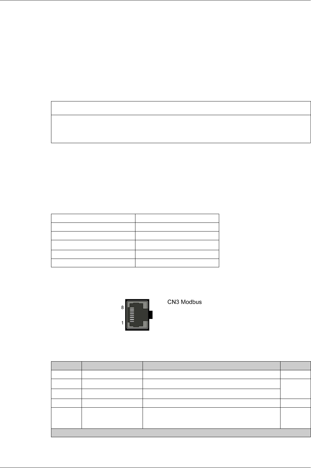
Drive Installation
158 EIO0000002305 04/2017
Connection PC (CN3)
Function
The commissioning interface (CN3) is an RS-485 connection, supported on an RJ45 connector. If the PC
used to connect to the commissioning interface has an RS-485 port, typically supported on a DB9
connector, you can connect it to this connector (RJ45 / DB9 cable). Otherwise, you can use the USB port
of the PC with a USB to RS-485 converter.
The commissioning interface may only be used for a point-to-point connection, but not for a point-to-
multipoint connection (RS-485 network).
If the commissioning interface at the product is directly connected to an Ethernet interface at the PC, the
PC interface may be damaged and rendered inoperable.
Connecting a PC
A PC with the commissioning software LXM28 DTM Library can be connected for commissioning. The PC
is connected via a bidirectional USB/RS485 converter, refer to Accessories and Spare Parts
(see page 86)
.
Cable Specifications
For further information, refer to chapter Cables
(see page 108)
.
Wiring Diagram
Wiring diagram PC with commissioning software
The commissioning interface (CN3) is an RJ45 connector. The following table describes the contacts of
the connector:
NOTICE
INOPERABLE EQUIPMENT
Do not directly connect an Ethernet interface to the commissioning interface of this product.
Failure to follow these instructions can result in equipment damage.
Shield: Required, both ends grounded
Twisted Pair: Required
PELV: Required
Cable composition: 8 x 0.25 mm2 (8 x AWG 22)
Maximum cable length: 100 m (328 ft)
Special characteristics: -
Pin Signal Meaning I/O
1 ... 3 - Reserved -
4MOD_D1(1) Bidirectional transmit/receive signal RS-485
level
5MOD_D0(1) Bidirectional transmit/receive signal, inverted
6 ... 7 - Reserved -
8 and
connector
housing
SHLD Functional ground / shield - internally connected to ground
potential of the drive
-
(1) No polarization.

Drive Installation
EIO0000002305 04/2017 159
NOTE: Verify that the connector locks snap in properly at the housing.
WARNING
UNINTENDED EQUIPMENT OPERATION
Do not connect any wiring to reserved, unused connections, or to connections designated as No
Connection (N.C.).
Failure to follow these instructions can result in death, serious injury, or equipment damage.
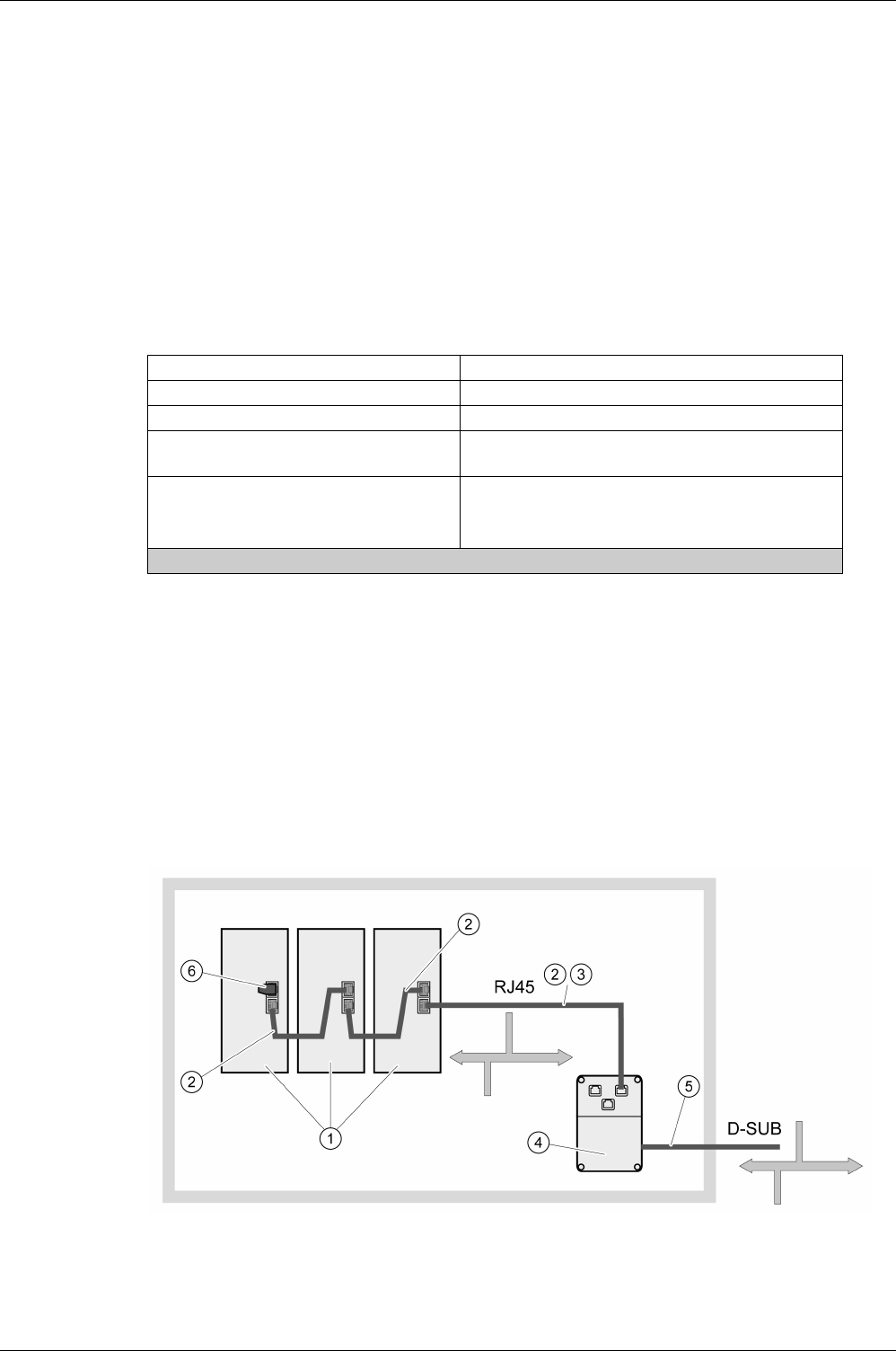
Drive Installation
160 EIO0000002305 04/2017
Connection CAN (CN4)
Function
The device is suitable for connection to CANopen and CANmotion.
A CAN bus connects multiple devices via a bus cable. Each network device can transmit and receive
messages. Data between network devices is transmitted serially.
Each network device must be configured before it can be operated on the network. The device is assigned
a unique 7-bit node address (node ID) between 1 (01h) and 127 (7Fh). The address is set during
commissioning.
The baud rate must be the same for all devices in the fieldbus.
Cable Specifications
For further information, refer to chapter Cables
(see page 108)
.
-Use equipotential bonding conductors.
-Use pre-assembled cables to reduce the risk of wiring errors.
Connectors D-SUB and RJ45
Usually, a cable with D-Sub connectors is used for CAN fieldbus connection in the field. Inside control
cabinets, connections with RJ45 cables have the benefit of easier and faster wiring. In the case of CAN
cables with RJ45 connectors, the maximum permissible bus length is reduced by 50%.
Multiple-port taps can be used to connect an RJ45 system inside the control cabinet to a D-Sub system in
the field, see the figure below. The trunk line is connected to the multiple-port tap by means of screw
terminals; the devices are connected by means of pre-assembled cables. See chapter CANopen
Connectors, Distributors, Terminating Resistors
(see page 91)
.
Connection of RJ45 CAN in the control cabinet to the field
Shield: Required, both ends grounded
Twisted Pair: Required
PELV: Required
Cable composition for cables with RJ45
connectors(1):
8 x 0.14 mm2 (AWG 24)
Cable composition with D-SUB connectors: 2 x 0.25 mm2, 2 x 0.20 mm2 (2 x AWG 22, 2 x AWG 24)
Cross section 0.20 mm2 (AWG 24) for CAN level, cross
section 0.25 mm2 (AWG 22) for reference potential.
(1) Cables with RJ45 connectors may only be used inside of control cabinets.
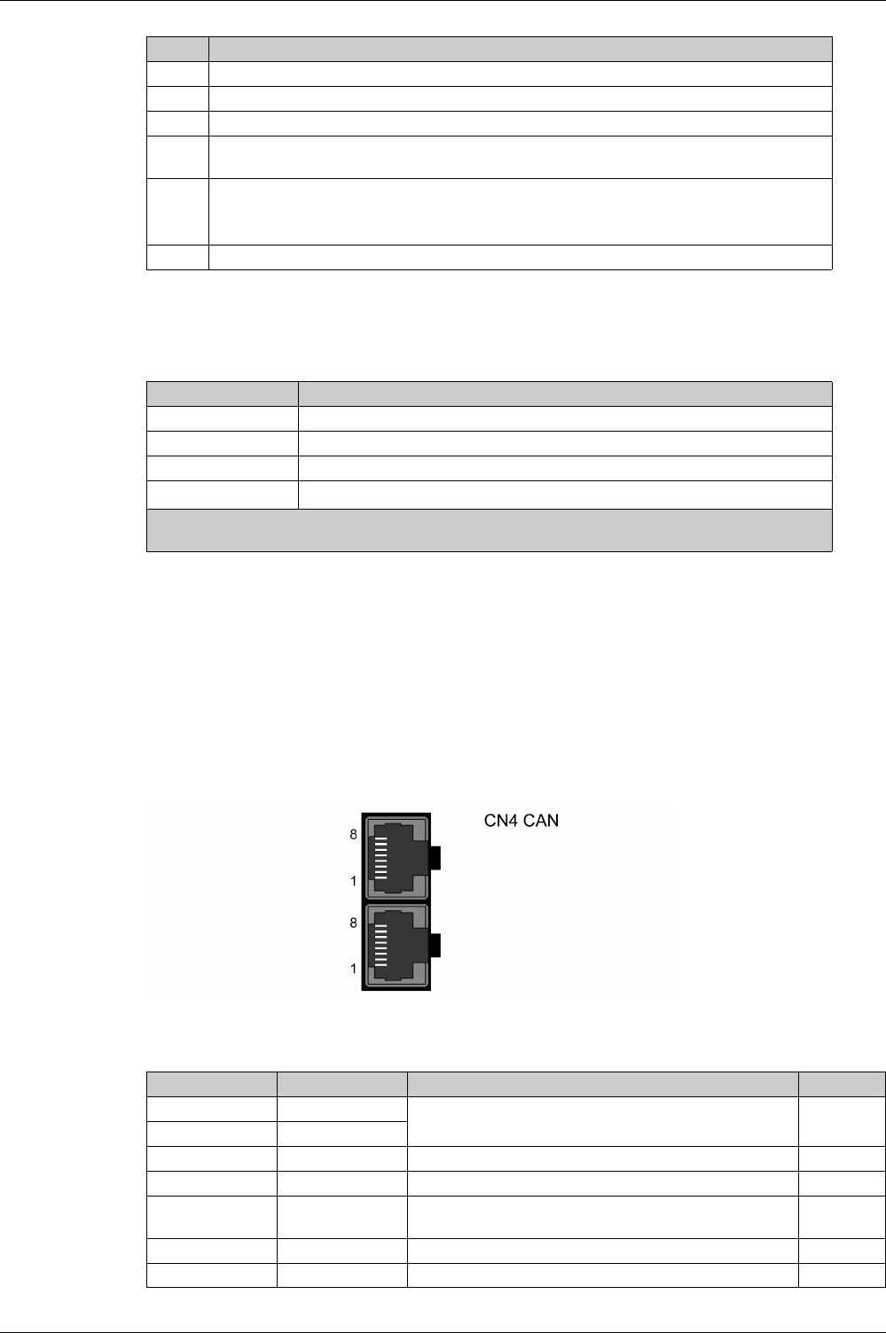
Drive Installation
EIO0000002305 04/2017 161
Maximum Bus Length CAN
The maximum bus length depends on the selected baud rate. The following table shows the maximum
overall length of the CAN bus in the case of cables with D-SUB connectors.
At a baud rate of 1 Mbit/s, the drop lines are limited to 0.3 m (0.98 ft).
Terminating Resistors
Both ends of a CAN bus line must be terminated. A 120 Ω terminating resistor between CAN_L and CAN_H
is used for this purpose.
Connectors with integrated terminating resistors are available as accessories, refer to chapter CANopen
Connectors, Distributors, Terminating Resistors
(see page 91)
.
Wiring Diagram
Wiring diagram CN4 CANopen
The CAN interface (CN4) consists of 2 RJ45 connectors. The following table describes the contacts of the
connectors:
Item Description
1 Devices with RJ45 CAN connection in the control cabinet
2 CANopen cables with RJ45 connectors
3 Connection cables between device and tap, for example TCSCCN4F3M3T for tap TSXCANTDM4
4 Tap in the control cabinet, for example TSXCANTDM4 as D-SUB four-port tap or VW3CANTAP2
as RJ45 tap
5 Fieldbus cable (trunk line) to the bus devices outside of the control cabinet, connected to the tap by
means of screw terminals. Cross section 0.20 mm2 (AWG 24) for CAN level, cross section
0.25 mm2 (AWG 22) for reference potential
6 Terminating resistor 120 Ω RJ45 (TCSCAR013M120)
Baud rate Maximum bus length
125 kbit/s 500 m (1640 ft)
250 kbit/s 250 m (820 ft)
500 kbit/s 100 m (328 ft)
1000 kbit/s 20 m (65.6 ft)(1)
(1) According to the CANopen specification, the maximum bus length is 40 m. However, in practice, limiting
the length to 20 m reduces communication errors caused by external interference.
Pin Signal Meaning I/O
1CAN_H
CAN interface CAN level
2CAN_L
3 CAN_0V Reference potential CAN -
4…5 - Reserved -
6 and connector
housing
SHLD Functional ground / shield - internally connected to ground
potential of the drive
-
7 CAN_0V Reference potential CAN -
8- Reserved -

Drive Installation
162 EIO0000002305 04/2017
Connecting CANopen
-Connect the CANopen cable to CN4 (pins 1, 2, and 3) with an RJ45 connector. Note the information on
using cables with RJ45 connectors.
-Verify that the connector locks snap in properly at the housing.
Equipotential Bonding Conductors
Potential differences can result in excessive currents on the cable shields. Use equipotential bonding
conductors to reduce currents on the cable shields.
1) Multipoint grounding is permissible if connections are made to an equipotential ground plane
dimensioned to help avoid cable shield damage in the event of power system short-circuit currents.
Terminating Resistors
Both ends of a CAN bus line must be terminated. A 120 Ω terminating resistor between CAN_L and CAN_H
is used for this purpose.
WARNING
UNINTENDED EQUIPMENT OPERATION
Do not connect any wiring to reserved, unused connections, or to connections designated as No
Connection (N.C.).
Failure to follow these instructions can result in death, serious injury, or equipment damage.
WARNING
UNINTENDED EQUIPMENT OPERATION
-Ground cable shields for all fast I/O, analog I/O, and communication signals at a single point. 1)
-Route communications and I/O cables separately from power cables.
Failure to follow these instructions can result in death, serious injury, or equipment damage.

Drive Installation
EIO0000002305 04/2017 163
Connection Logic Supply and Power Stage Supply (CN5)
This product has a touch current greater than 3.5 mA. If the protective ground connection is interrupted, a
hazardous touch current may flow if the housing is touched.
The equipment, drives and motors, are intended for industrial use and may only be operated with a
permanently installed connection.
Prior to connecting the equipment, verify the approved mains types, see chapter Electrical Data Drive
(see page 38)
.
Cable Specifications
Respect the required cable properties in chapter Cables
(see page 108)
and in chapter Electromagnetic
Compatibility (EMC)
(see page 104)
.
DANGER
INSUFFICIENT GROUNDING
-Use a protective ground conductor with at least 10 mm2 (AWG 6) or two protective ground conductors
with the cross section of the conductors supplying the power terminals.
-Verify compliance with all local and national electrical code requirements as well as all other applicable
regulations with respect to grounding of the entire drive system.
-Ground the drive system before applying voltage.
-Do not use conduits as protective ground conductors; use a protective ground conductor inside the
conduit.
-Do not use cable shields as protective ground conductors.
-Keep foreign objects from getting into the product.
-Verify the correct seating of seals and cable entries in order to avoid contamination such as deposits
and humidity.
Failure to follow these instructions will result in death or serious injury.
WARNING
INSUFFICIENT PROTECTION AGAINST OVERCURRENT
-Use the external fuses specified in chapter “Technical Data”.
-Do not connect the product to a supply mains whose short-circuit current rating (SCCR) exceeds the
value specified in the chapter “Technical Data”.
Failure to follow these instructions can result in death, serious injury, or equipment damage.
WARNING
INCORRECT MAINS VOLTAGE
Verify that the product is approved for the mains voltage before applying power and configuring the
product.
Failure to follow these instructions can result in death, serious injury, or equipment damage.
Shield: -
Twisted Pair: -
PELV: -
Cable composition: The conductors must have a sufficiently large cross section so that the
fuse at the mains connection can trip if required.
Maximum cable length: 3 m (9.84 ft)
Special characteristics: -
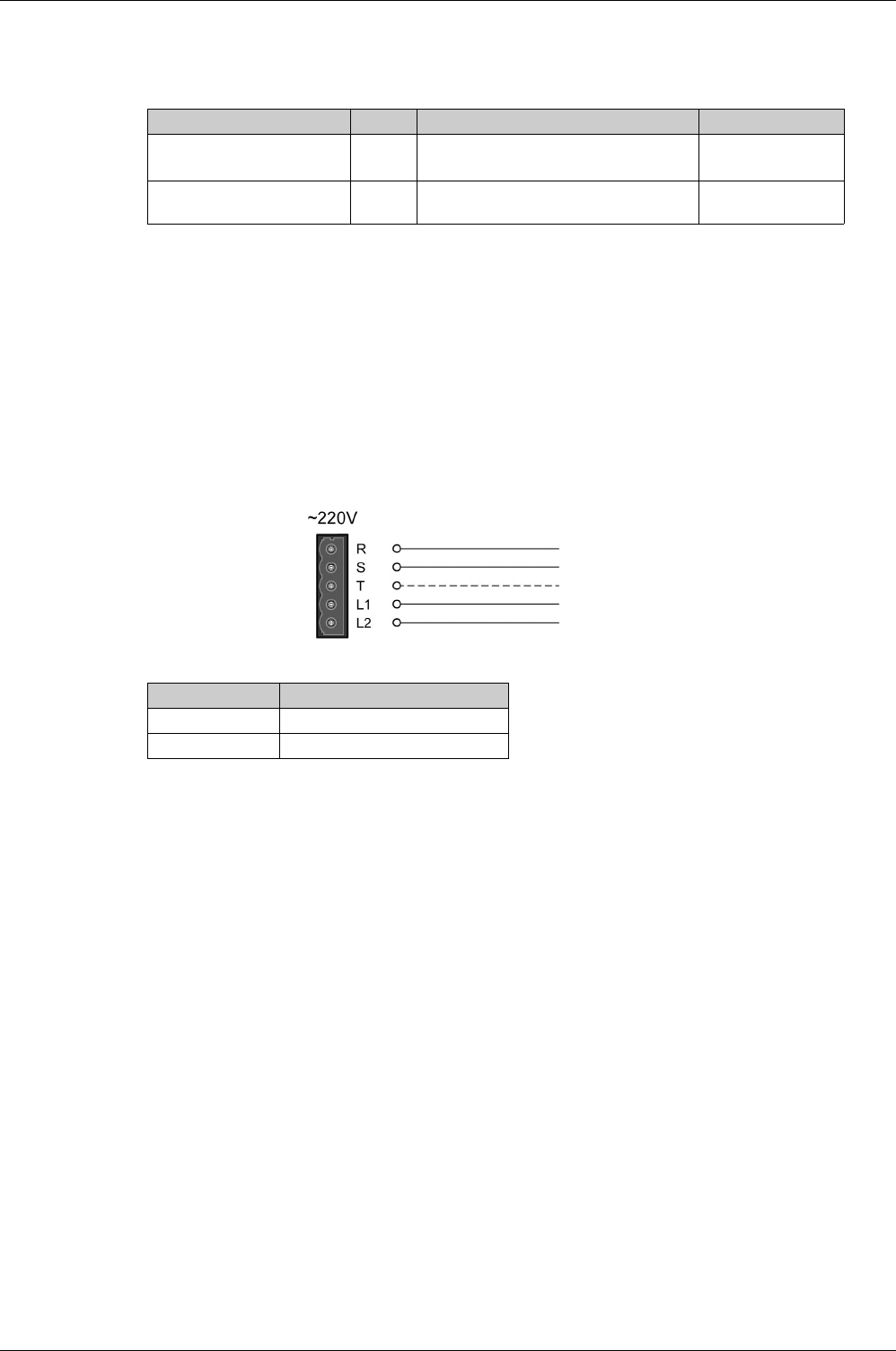
Drive Installation
164 EIO0000002305 04/2017
Properties of the Terminals
The terminals are approved for stranded conductors and solid conductors. Use cable ends (ferrules), if
possible.
Prerequisites for Connecting the Logic Supply
Note the following information:
-Use upstream mains fuses. For further information about fuse types and fuse ratings, refer to chapter
Electrical Data Drive
(see page 38)
.
-Note the EMC requirements. Where required, use surge arresters and mains reactors.
-If the length of the mains cable between the external mains filter and the drive exceeds 200 mm
(7.87 in), it must be shielded and grounded at both ends.
-For a UL-compliant design, refer to chapter Conditions for UL 508C
(see page 25)
.
Connection Logic Supply
Wiring diagram logic supply
-Verify the type of mains. For the approved types of mains, refer to chapter Electrical Data Drive
(see page 38)
.
-Connect the mains cable.
-Verify that the connector locks snap in properly at the housing.
LXM28A Unit UA5, U01, U02, U04, U07, U10, U15 U20, U30, U45
Connection cross section mm2
(AWG)
0.75 ... 2.5
(20 ... 14)
0.75 ... 6
(20 ... 10)
Stripping length mm
(in)
8 ... 9
(0.31 ... 0.35)
15
(0.59)
Connection Meaning
R, S, T Power stage supply
L1, L2 Logic supply
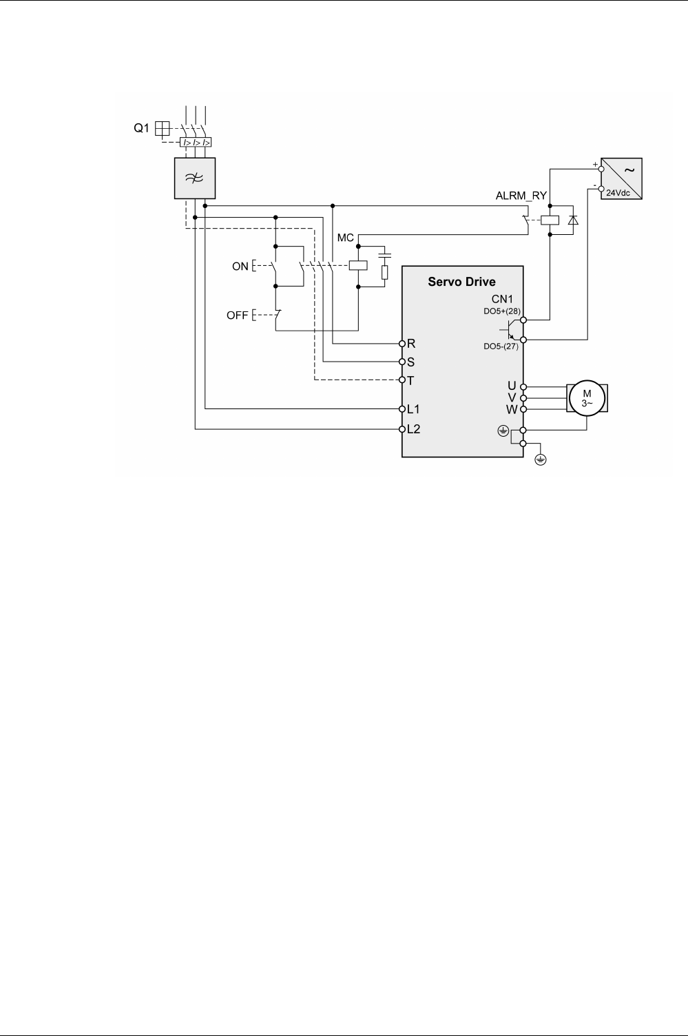
Drive Installation
EIO0000002305 04/2017 165
Wiring Diagram for Devices That Can Be Connected Via a Single-Phase or Three Phases
Drives with a continuous power from 50 W to 1500 W can be connected via a single-phase or via three
phases. Drives with a continuous power of more than 1500 W must be connected via three phases.
Wiring diagram for devices that can be connected via a single-phase or three-phases

Drive Installation
166 EIO0000002305 04/2017
Connection DC Bus (CN6)
Incorrect use of the DC bus may permanently damage the drives either immediately or over time.
This and other important information can be found in the “LXM28 - Common DC bus - Application note
(see page 11)
”. If you wish to take advantage of DC bus sharing, you must first consult the LXM28 -
Common DC bus - Application note for important safety-related information.
Requirements for Use
The requirements and limit values for parallel connection of multiple devices via the DC bus can be found
on
www.schneider-electric.com
in the form of an application note (see chapter Related Documents
(see page 11)
). If there are any issues or questions related to obtaining the Common DC bus Application
Note, consult your local Schneider-Electric representative.
WARNING
INOPERABLE SYSTEM COMPONENTS AND LOSS OF CONTROL
Verify that all requirements for using the DC bus are met.
Failure to follow these instructions can result in death, serious injury, or equipment damage.

Drive Installation
EIO0000002305 04/2017 167
Connection Braking Resistor (CN7)
An insufficiently rated braking resistor can cause overvoltage on the DC bus. Overvoltage on the DC bus
causes the power stage to be disabled. The motor is no longer actively decelerated.
Internal Braking Resistor
A braking resistor is integrated in the device to absorb braking energy. The drive is shipped with the internal
braking resistor active.
External Braking Resistor
An external braking resistor is required for applications in which the motor must be decelerated quickly and
the internal braking resistor cannot absorb the excess braking energy.
Selection and rating of the external braking resistor are described in chapter Rating the Braking Resistor
(see page 123)
. For suitable braking resistors, refer to chapter Accessories and Spare Parts
(see page 97)
.
Cable Specifications
For further information, refer to chapter Cables
(see page 108)
.
The braking resistors listed in chapter Accessories and Spare Parts
(see page 97)
have a 3-wire,
temperature-resistant cable with a length of 0.75 m (2.46 ft) to 3 m (9.84 ft).
Properties of the Terminals (CN7)
The terminals are approved for stranded conductors and solid conductors. Use cable ends (ferrules), if
possible.
The terminals are approved for fine-stranded conductors and solid conductors. Respect the maximum
permissible connection cross section. Take into account the fact that cable ends (ferrules) increase the
conductor cross section.
NOTE: If you use cable ends (ferrules), use only cable ends (ferrules) with collars for these terminals.
WARNING
UNINTENDED EQUIPMENT OPERATION
-Verify that the braking resistor has a sufficient rating by performing a test run under maximum load
conditions.
-Verify that the parameter settings for the braking resistor are correct.
Failure to follow these instructions can result in death, serious injury, or equipment damage.
Shield: Required, both ends grounded
Twisted Pair: -
PELV: -
Cable composition: Minimum conductor cross section: Same cross section as logic
supply.
The conductors must have a sufficiently large cross section so that the
fuse at the mains connection can trip if required.
Maximum cable length: 3 m (9.84 ft)
Special characteristics: Temperature resistance
LXM28A Unit UA5, U01, U02, U04, U07, U10, U15 U20, U30, U45
Connection cross section mm2
(AWG)
0.75 ... 2.5
(20 ... 14)
0.75 ... 6
(20 ... 10)
Stripping length mm
(in)
8 ... 9
(0.31 ... 0.35)
15
(0.59)
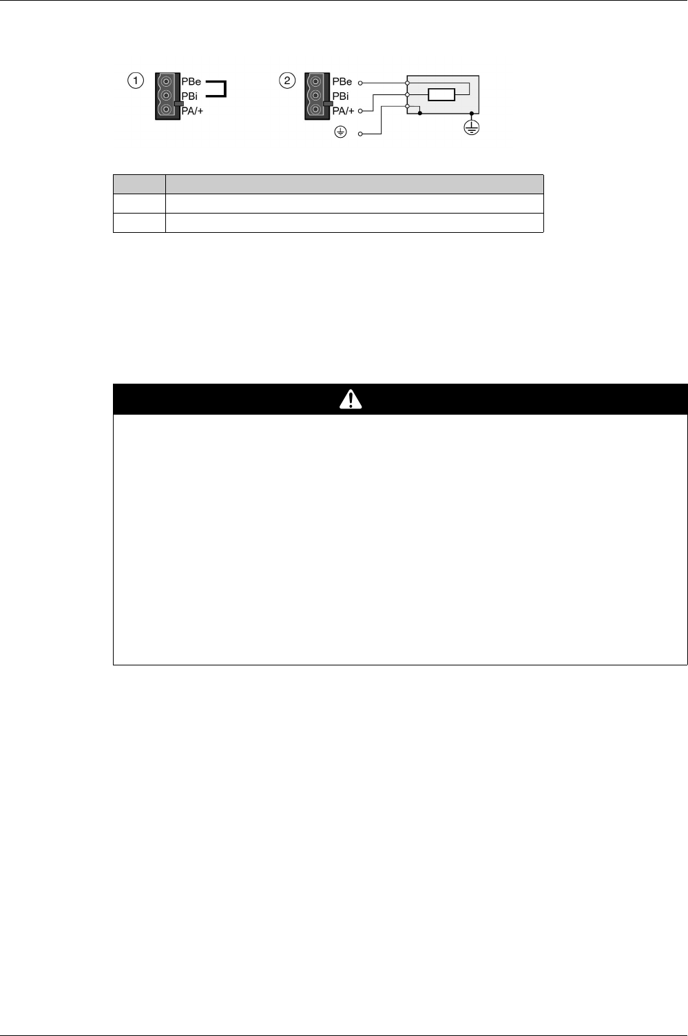
Drive Installation
168 EIO0000002305 04/2017
Wiring Diagram
Wiring diagram internal or external braking resistor
Connecting the External Braking Resistor
-Remove power from all supply voltages. Respect the safety instructions concerning electrical
installation.
-Verify that no voltages are present.
-Ground the ground connection (PE) of the braking resistor.
-Connect the external braking resistor to the device.
-Connect a large surface area of the cable shield to the central grounding point of your system.
Item Description
1 Internal braking resistor activated
2 Connection external braking resistor
DANGER
ELECTRIC SHOCK, EXPLOSION, OR ARC FLASH
-Disconnect all power from all equipment including connected devices prior to removing any covers or
doors, or installing or removing any accessories, hardware, cables, or wires.
-Place a "Do Not Turn On" or equivalent hazard label on all power switches and lock them in the non-
energized position.
-Wait 15 minutes to allow the residual energy of the DC bus capacitors to discharge.
-Measure the voltage on the DC bus with a properly rated voltage sensing device and verify that the
voltage is less than 42.4 Vdc.
-Do not assume that the DC bus is voltage-free when the DC bus LED is off.
-Block the motor shaft to prevent rotation prior to performing any type of work on the drive system.
-Do not create a short-circuit across the DC bus terminals or the DC bus capacitors.
-Replace and secure all covers, accessories, hardware, cables, and wires and confirm that a proper
ground connection exists before applying power to the unit.
-Use only the specified voltage when operating this equipment and any associated products.
Failure to follow these instructions will result in death or serious injury.

Drive Installation
EIO0000002305 04/2017 169
Connecting the Motor Phases (CN8)
High voltages may be present at the motor connection. The motor itself generates voltage when the motor
shaft is rotated. AC voltage can couple voltage to unused conductors in the motor cable.
Incorrect wiring of the motor connection may cause live wires to be exposed outside of the motor connector
below the HMI.
Drive systems may perform unintended movements if unapproved combinations of drive and motor are
used. Even if motors are similar, different adjustment of the encoder system may be a source of hazards.
Even if the connectors for motor connection and encoder connection match mechanically, this does not
imply that the motor is approved for use.
Compatibility between Drive and Motor is defined in the Drive / Motor combinations table
(see page 20)
.
Route the cables from the motor and the encoder to the device (starting from the motor). Due to the pre-
assembled connectors, this direction is often faster and easier.
Cable Specifications
For further information, refer to chapter Cables
(see page 108)
.
DANGER
ELECTRIC SHOCK
-Verify that no voltage is present prior to performing any type of work on the drive system.
-Block the motor shaft to prevent rotation prior to performing any type of work on the drive system.
-Insulate both ends of unused conductors of the motor cable.
-Supplement the motor cable grounding conductor with an additional protective ground conductor to
the motor housing.
-Verify compliance with all local and national electrical code requirements as well as all other applicable
regulations with respect to grounding of all equipment.
Failure to follow these instructions will result in death or serious injury.
DANGER
ELECTRIC SHOCK CAUSED BY INCORRECT WIRING
-Verify that the protective ground connection (PE) of the device is connected to ground.
-Do not remove the cable end (ferrule) from the protective ground terminal (PE) of the motor connector
until you are prepared to wire the protective ground conductor of the motor to the protective ground
terminal (PE) of the motor connector.
-Verify that no bare metal of the wires is exposed outside of the motor connector housing when wiring
the motor connector.
-Regularly, as part of a maintenance plan, assure that the motor wires are secured in the terminals of
the motor connector due to vibration or other influences.
Failure to follow these instructions will result in death or serious injury.
WARNING
UNINTENDED MOVEMENT
Only use approved combinations of drive and motor.
Failure to follow these instructions can result in death, serious injury, or equipment damage.
Shield: Required, both ends grounded
Twisted Pair: -
PELV: The wires for the holding brake must be PELV-compliant.
Cable composition: 3 wires for motor phases
The conductors must have a sufficiently large cross section so that the
fuse at the mains connection can trip if required.
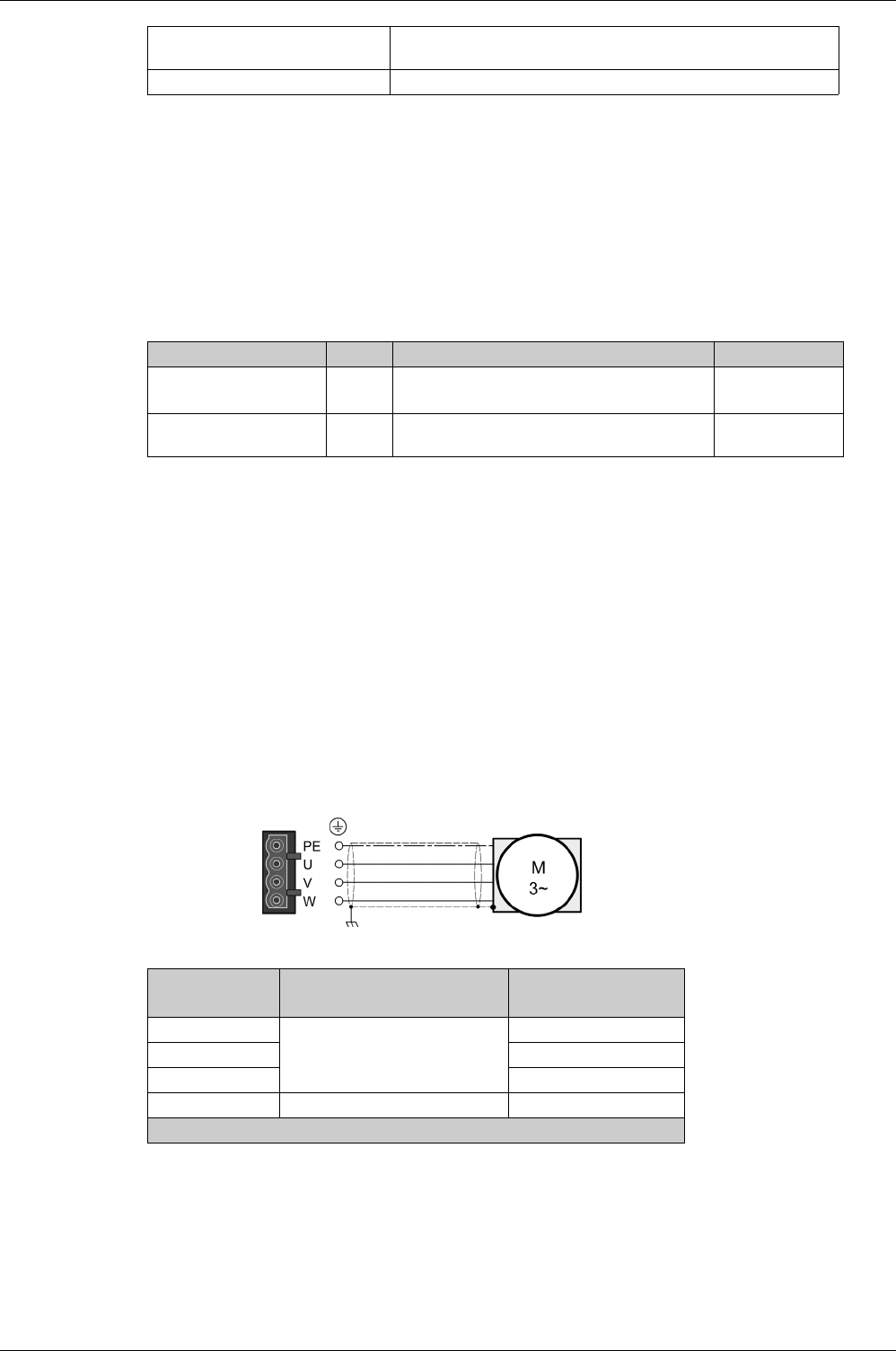
Drive Installation
170 EIO0000002305 04/2017
Note the following information:
-You may only connect the original motor cable.
-If you do not connect the wires at the motor end, you must isolate each wire individually (inductive
voltages).
-Use pre-assembled cables to reduce the risk of wiring errors.
Properties of the Terminals (CN8)
The terminals are approved for stranded conductors and solid conductors. Use cable ends (ferrules), if
possible.
Monitoring
The drive monitors the motor phases for:
-Short circuit between the motor phases
-Short circuit between the motor phases and ground (Not applicable for LXM28AUA5 … U07)
Short circuits between the motor phases and the DC bus, the braking resistor, or the holding brake wires
are not detected.
When a short-circuit is detected, power is removed by disabling the power stage. The firmware reports
error AL001. Once you have resolved the issue of the over-current, you can re-enable the power stage of
the drive.
NOTE: After three successive unsuccessful retries of resetting the power stage, the reset will be blocked
for a minimum of one minute.
Wiring Diagram Motor
Wiring diagram motor
Connecting the Motor Cable
-Note the information on EMC, refer to chapter Electromagnetic Compatibility (EMC)
(see page 104)
.
-Connect the motor phases and protective ground conductor to CN8. Verify that the connections U, V,
W, and PE (ground) match at the motor and the device.
-Verify that the connector locks snap in properly at the housing.
Maximum cable length: Depends on the required limit values for conducted interference.
Category C3: 20 m (65.6 ft)
Special characteristics: Contains wires for the temperature sensor
LXM28A Unit UA5, U01, U02, U04, U07, U10, U15 U20, U30, U45
Connection cross section mm2
(AWG)
0.75 ... 2.5
(20 ... 14)
0.75 ... 6
(20 ... 10)
Stripping length mm
(in)
8...9
(0.31 ... 0.35)
15
(0.59)
Connection Meaning Color(1)
(IEC 757)
U
Motor phase
RD
VWH
WBK
PE Protective ground conductor GN/YE
(1) Color information relates to the cables available as accessories.
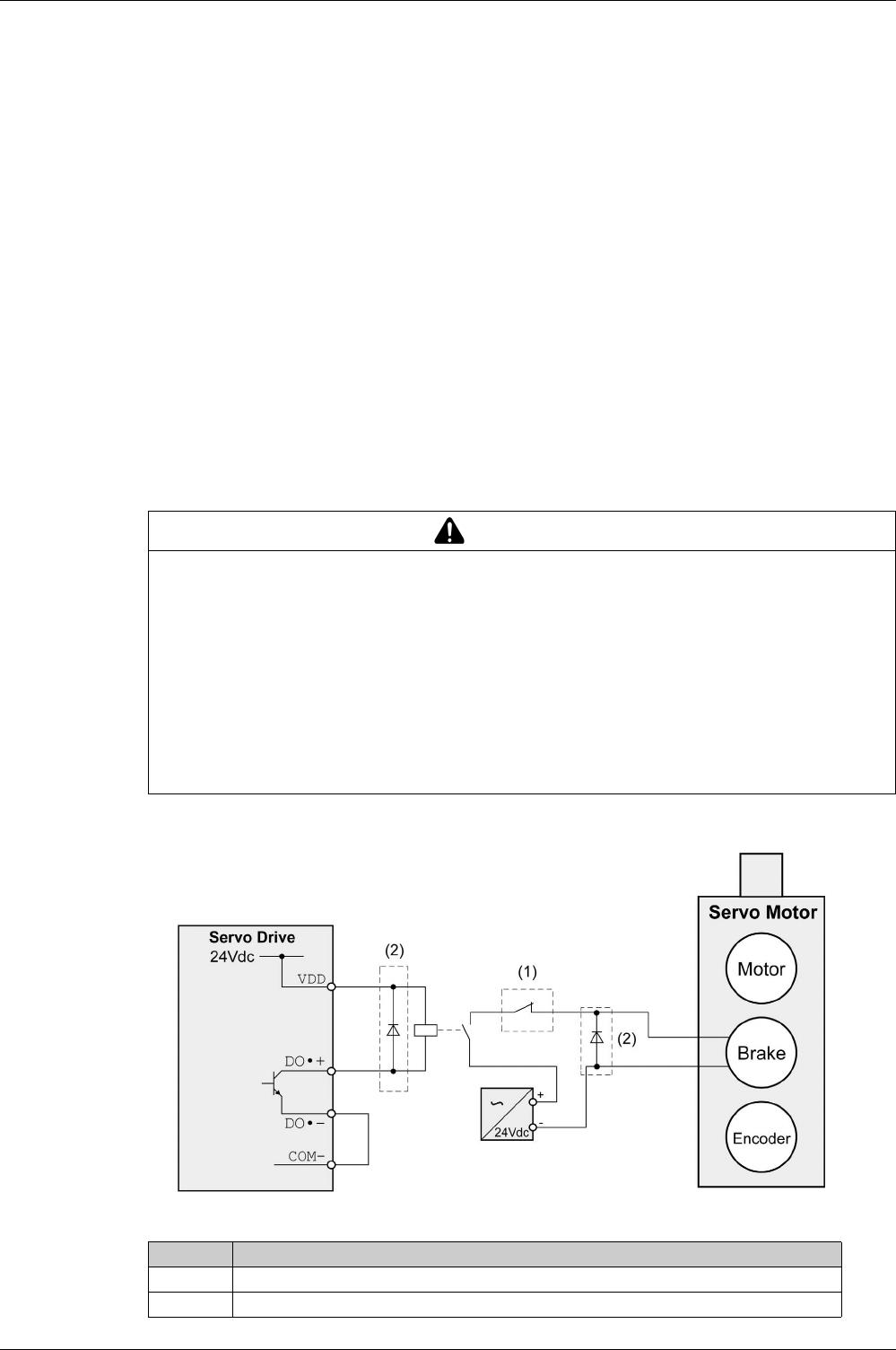
Drive Installation
EIO0000002305 04/2017 171
Holding Brake Connection
The holding brake in the motor has the task of holding the motor position when the power stage is disabled.
The holding brake is not a safety function and not a service brake.
A motor with a holding brake requires a suitable holding brake controller which releases the brake when
the power stage is enabled and locks the motor shaft when the power stage is disabled.
The holding brake is connected to one of the digital outputs DO1…DO5. The signal output function BRKR
must be assigned to the digital output to which the holding brake is connected. The signal output function
BRKR releases the holding brake when the power stage is enabled. When the power stage is disabled, the
holding brake is reapplied.
The factory settings for the signal outputs depend on the operating mode, see chapter Setting the Digital
Signal Outputs
(see page 306)
. Depending on the operating mode, the signal output function is either
assigned to the digital output DO4 or not assigned at all. When you reset the drive to the factory settings
with P2-08 = 10, the assignments of the signal output functions are also reset to the factory settings.
When you switch the operating mode using the parameter P1-01 or the signal input functions V-Px and V-
T, the signal output functions may also be reset to the factory settings for the new operating mode. If you
use the setting D = 0 of parameter P1-01, the assignment of the signal output functions remains the same
in the new operating mode.
Resetting the drive to the factory settings or switching the operating mode can modify the assignment of
the signal output functions in such a way that the holding brake is released unintentionally.
Example (negative logic) of wiring the holding brake
WARNING
UNINTENDED EQUIPMENT OPERATION
-Verify that the digital output to which you have assigned the signal output function BRKR has been
properly wired and configured.
-Before switching to a different operating mode, verify that the signal output function BRKR for the
holding brake will not be assigned to an incorrect digital output in the new operating mode.
-Before resetting the drive to the factory settings, verify that the signal output function BRKR for the
holding brake will be assigned to the correct digital output or reassign the signal output function BRKR
after the factory reset according to the requirements of your application prior to starting the system.
-In all cases, take all necessary measures to prevent unintended movements of the load caused by a
release of the holding brake.
Failure to follow these instructions can result in death, serious injury, or equipment damage.
Item Description
1 Triggering an EMERGENCY STOP should apply the holding brake
2 Flyback diode
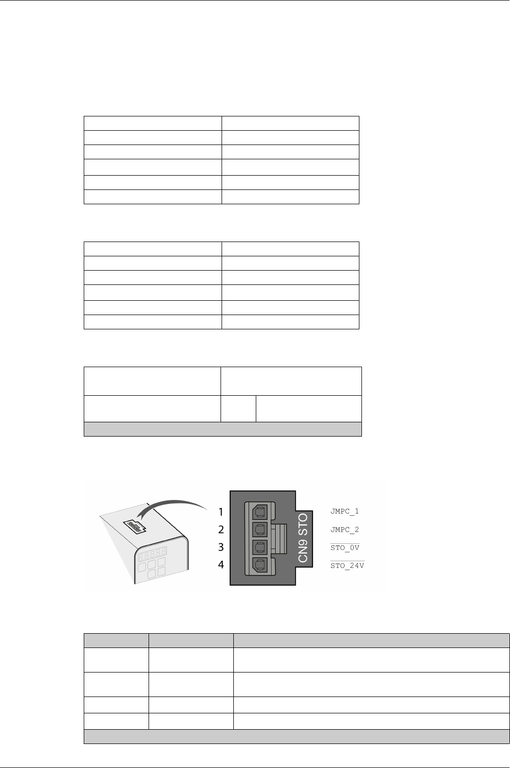
Drive Installation
172 EIO0000002305 04/2017
Connection STO (CN9)
For important safety information, refer to the chapter Safety Function STO (Safe Torque Off)
(see page 112)
for the requirements for using the safety function STO.
Cable Specifications - Cables Outside of Control Cabinet
Cable Specifications - Cables Inside Control Cabinet
Properties of the Connection
Wiring Diagram
Wiring diagram safety function STO
The STO interface (CN9) is a 4-pin female connector. The following table describes the contacts of the
connector:
Shield: Yes
Twisted Pair: Yes
PELV: Required
Minimum conductor cross section: 2 x 0.34 mm2 (AWG 22)
Maximum cable length: 30 m (98.4 ft)
Fuse: 4 A
Shield: No
Twisted Pair: No
PELV: Required
Minimum conductor cross section: 2 x 0.25 mm2 (AWG 24)
Maximum cable length: 3 m (9.84 ft)
Fuse: 4 A
Connectors housing
Connectors crimp contact Molex 436450400(1)
Molex 430300001(1)
Connection cross section mm2
(AWG)
0.25 ... 0.34
(24 ... 22)
(1) Or corresponding equivalent.
Pin Signal Meaning
1 JMPC_1 Jumper connector 1 to be connected to STO_24V if the safety function STO
is not used in your application
2 JMPC_2 Jumper connector 2 to be connected to STO_0V if the safety function STO
is not used in your application
3STO_0V
Safety function STO 0 Vdc input(1)
4 STO_24V Safety function STO 24 Vdc input(1)
(1) PELV power supply is required.
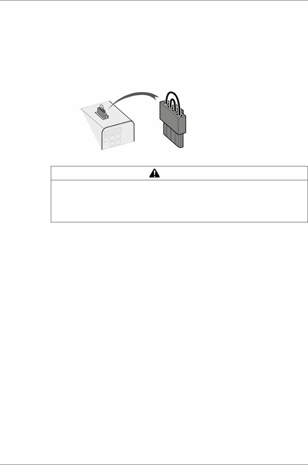
Drive Installation
EIO0000002305 04/2017 173
Connecting the Safety Function STO
-Verify that wiring, cables, and connected interfaces meet the PELV requirements.
-Connect the safety function STO in accordance with the specifications in chapter Safety Function STO
(Safe Torque Off)
(see page 112)
.
Deactivating the Safety Function STO
If the safety function STO is not to be used, it must be deactivated. Plug in the jumper for CN9 to bridge
pin 1 and pin 4 as well as pin 2 and pin 3 to deactivate the safety function STO. The jumper for CN9 is
factory-fitted.
Deactivating the safety function STO
WARNING
UNINTENDED EQUIPMENT OPERATION
-Remove the jumpers connected to the STO power connector (CN9) only if you intend to use the STO
safety-related function for your application.
-Use only an external PELV 24 Vdc power supply unit when applying the safety-related STO function.
Failure to follow these instructions can result in death, serious injury, or equipment damage.

Drive Installation
174 EIO0000002305 04/2017

EIO0000002305 04/2017 175
Lexium 28
A
and BCH2 Servo Drive System
Motor Installa tion
EIO0000002305 04/2017
Motor Installa tion
Chapter 10
Motor Installation
What Is in This Chapter?
This chapter contains the following topics:
Topic Page
Mechanical Installation Motor 176
Connections and Pin Assignments 178
Connection of Motor and Encoder 181
Holding Brake Connection 183
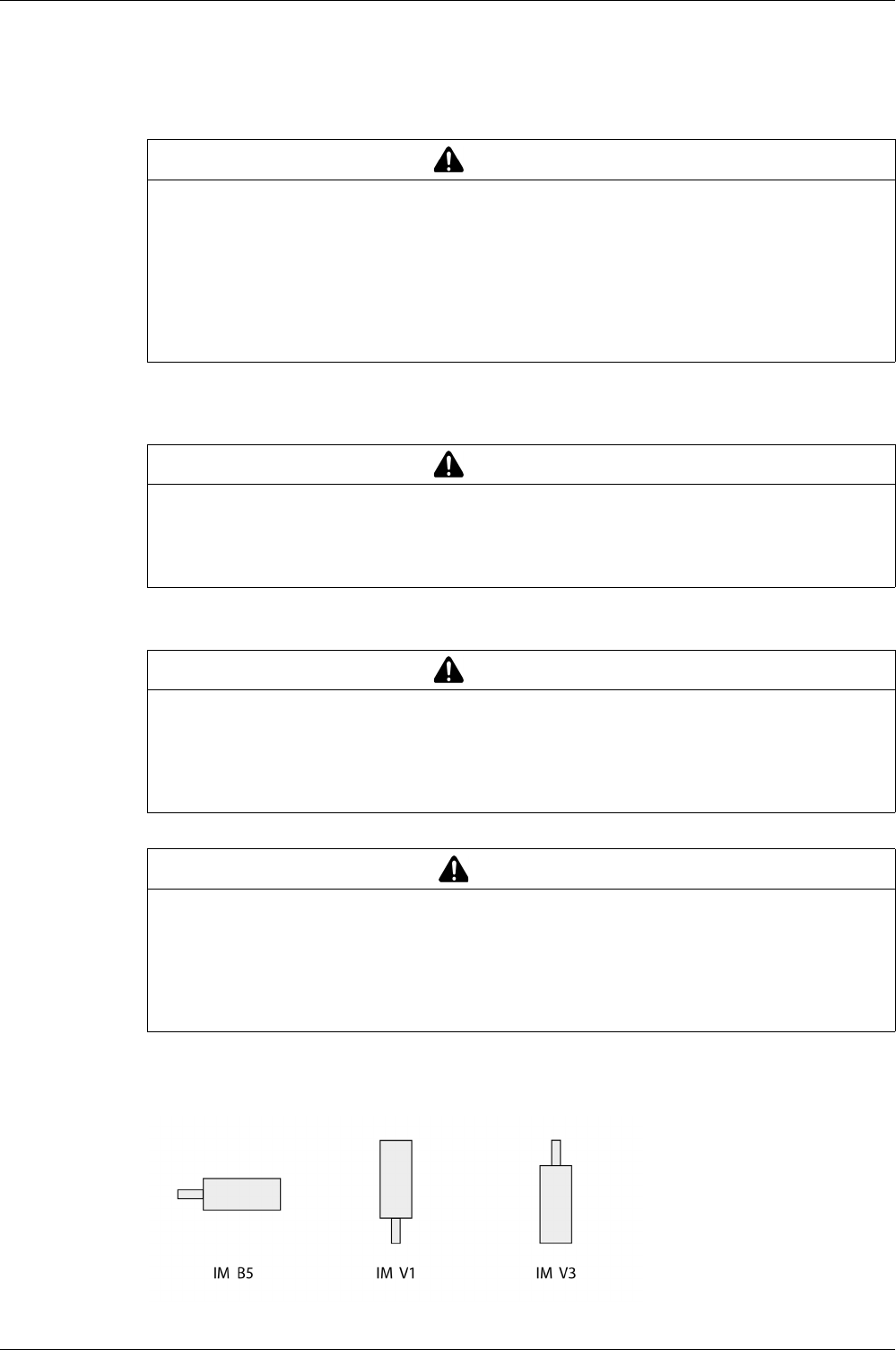
Motor Installation
176 EIO0000002305 04/2017
Mechanical Installation Motor
Motors are very heavy relative to their size. The mass of the motor can cause injuries and damage.
Motors can generate strong local electrical and magnetic fields. This can cause interference in sensitive
devices.
The metal surfaces of the product may exceed 70 °C (158 °F) during operation.
Mounting Position
The following mounting positions are defined and permissible as per IEC 60034-7:
WARNING
HEAVY AND/OR FALLING PARTS
-Use a suitable crane or other suitable lifting gear for mounting the motor if this is required by the weight
of the motor.
-Use the necessary personal protective equipment (for example, protective shoes, protective glasses
and protective gloves).
-Mount the motor so that it cannot come loose (use of securing screws with appropriate tightening
torque), especially in cases of fast acceleration or continuous vibration.
Failure to follow these instructions can result in death, serious injury, or equipment damage.
WARNING
ELECTROMAGNETIC FIELDS
-Keep persons with electronic medical implants, such as pacemakers, away from the motor.
-Do not place electromagnetically sensitive devices in the vicinity of the motor.
Failure to follow these instructions can result in death, serious injury, or equipment damage.
WARNING
HOT SURFACES
-Avoid unprotected contact with hot surfaces.
-Do not allow flammable or heat-sensitive parts in the immediate vicinity of hot surfaces.
-Verify that the heat dissipation is sufficient by performing a test run under maximum load conditions.
Failure to follow these instructions can result in death, serious injury, or equipment damage.
CAUTION
IMPROPER APPLICATION OF FORCES
-Do not use the motor as a step to climb into or onto the machine.
-Do not use the motor as a load-bearing part.
-Use hazard labels and guards on your machine to help prevent the improper application of forces on
the motor.
Failure to follow these instructions can result in injury or equipment damage.
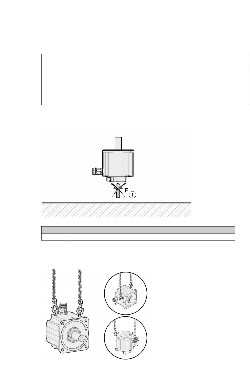
Motor Installation
EIO0000002305 04/2017 177
Mounting
When the motor is mounted to the mounting surface, it must be accurately aligned axially and radially and
make even contact with the mounting surface. All mounting screws must be tightened with the specified
tightening torque. No uneven mechanical load may be applied while the mounting screws are tightened.
For data, dimensions, and degrees of protection (IP), refer to chapter Motor
(see page 47)
.
Mounting Situation
Special Characteristics BCH2•H, BCH2•M, BCH2•R
Rear side of motor
Eyebolts BCH2•R
Consider the mass of the product when mounting the motor. It may be necessary to use suitable lifting
gear.
NOTICE
FORCES APPLIED TO THE REAR SIDE OF THE MOTOR
-Do not place the motor on the rear side.
-Protect the rear side of the motor from impact.
-Do not lift motors via the rear side.
-Only lift motors equipped with eyebolts via the eyebolts.
Failure to follow these instructions can result in equipment damage.
Item Description
1 Protect the rear side of the motor from application of forces.
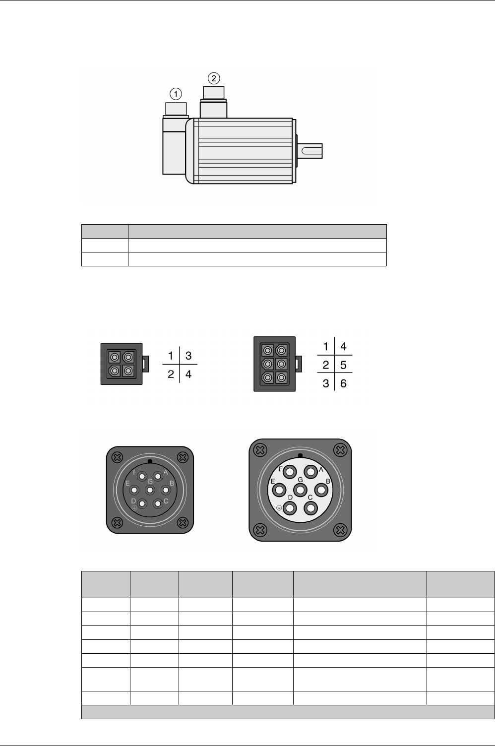
Motor Installation
178 EIO0000002305 04/2017
Connections and Pin Assignments
Connection overview
Pin Assignment Motor Connection
Pin assignments of motor phases and holding brake
Motor connection plastic connector (type A and type B), drive side:
Motor connection MIL connector (type C and type D), motor side:
Item Description
1 Encoder connection
2 Motor connection
Pin
Type A
Pin
Type B
Pin
Type C and D
Signal Meaning Color(1)
(IEC 757)
1 1 E U Motor phase U RD
2 2 G V Motor phase V WH
3 4 B W Motor phase W BK
4 5 D PE Protective ground (protective earth) GN/YE
– 3 F BRAKE_24V Supply voltage holding brake 24 Vdc BU
– 6 A BRAKE_0V Reference potential holding brake
0Vdc
BN
– – C – Reserved –
(1) Color information relates to the cables available as accessories.
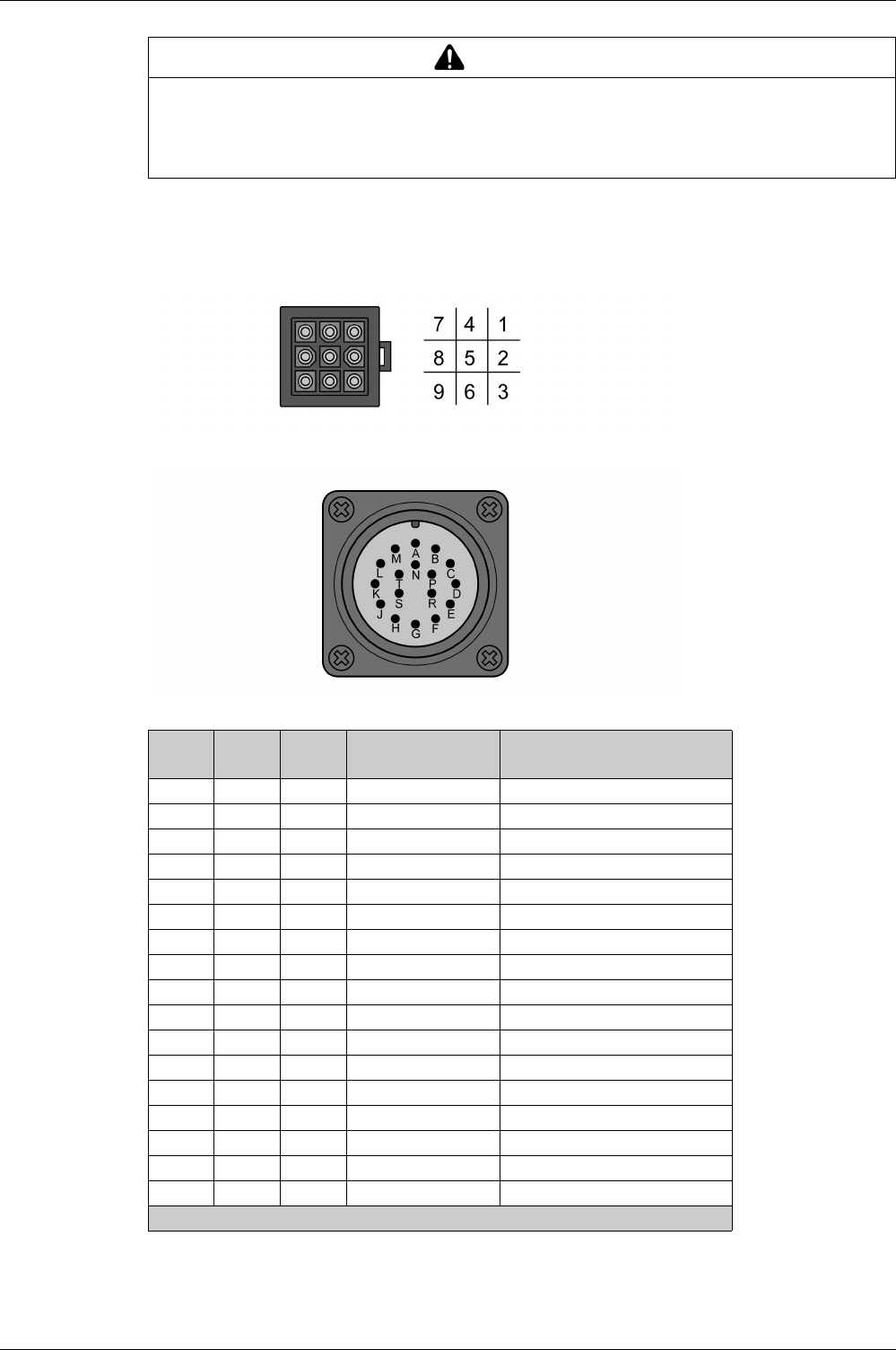
Motor Installation
EIO0000002305 04/2017 179
Pin Assignment Encoder Connection
Pin assignment of the encoder.
Encoder connection plastic connector (Type A), drive side:
Encoder connection MIL connector (Type B), motor side:
WARNING
UNINTENDED EQUIPMENT OPERATION
Do not connect any wiring to reserved, unused connections, or to connections designated as No
Connection (N.C.).
Failure to follow these instructions can result in death, serious injury, or equipment damage.
Pin
Type A
Pin
Type B
Signal Meaning Color(1)
(IEC 757)
1AT+Data BU
2C–Reserved –
3D–Reserved –
4 B T- Data BU/BK
5F–Reserved –
6G–Reserved –
7 S DC+5 V Supply voltage RD/WH
8 R GND Reference potential BK/WH
9 L Shield Shield BK
–E–Reserved –
–H–Reserved –
–J–Reserved –
–K–Reserved –
–M–Reserved –
–N–Reserved –
–P–Reserved –
–T–Reserved –
(1) Color information relates to the cables available as accessories.

Motor Installation
180 EIO0000002305 04/2017
Mating Connector
For suitable mating connectors, refer to chapter Connectors and Adapters
(see page 87)
.
WARNING
UNINTENDED EQUIPMENT OPERATION
Do not connect any wiring to reserved, unused connections, or to connections designated as No
Connection (N.C.).
Failure to follow these instructions can result in death, serious injury, or equipment damage.
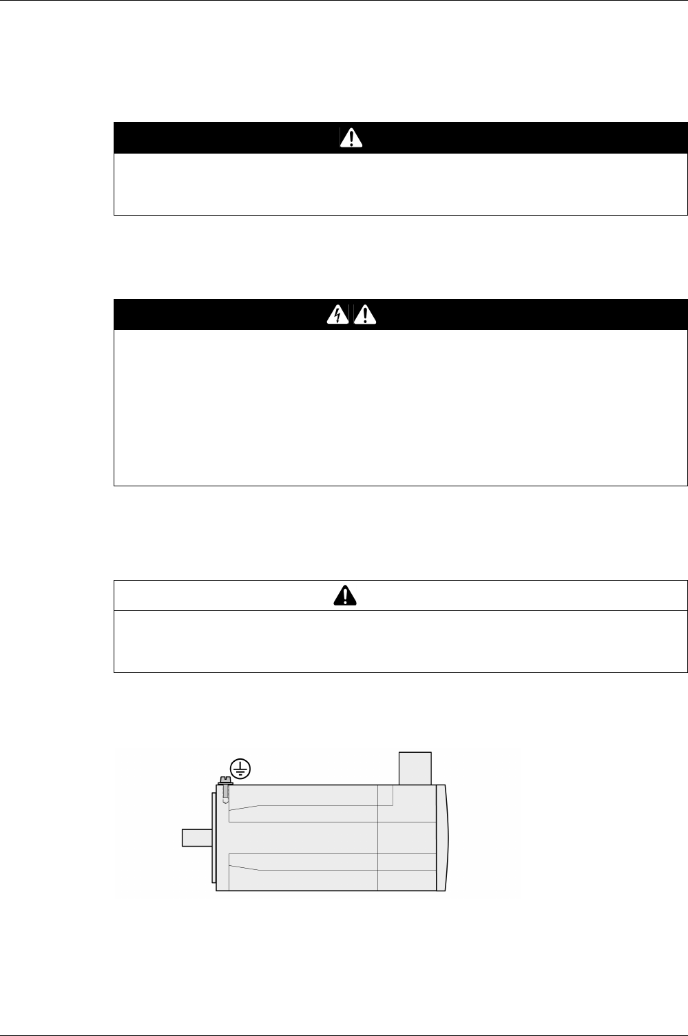
Motor Installation
EIO0000002305 04/2017 181
Connection of Motor and Encoder
The motor is designed for operation via a drive. Connecting the motor directly to line voltage will damage
the motor and can cause fires.
Compatibility between Drive and Motor is defined in the Drive / Motor combinations table
(see page 20)
.
High voltages may be present at the motor connection. The motor itself generates voltage when the motor
shaft is rotated. AC voltage can couple voltage to unused conductors in the motor cable.
Drive systems may perform unintended movements if unapproved combinations of drive and motor are
used. Even if motors are similar, different adjustment of the encoder system may be a source of hazards.
Even if the connectors for motor connection and encoder connection match mechanically, this does not
imply that the motor is approved for use.
Compatibility between Drive and Motor is defined in the Drive / Motor combinations table
(see page 20)
.
Protective Ground Conductor Connection
-Ground the motor via a grounding screw if grounding via the flange and the protective ground conductor
of the motor cable is not sufficient.
-Use parts with suitable corrosion protection.
DANGER
FIRE HAZARD DUE TO INCORRECT CONNECTION
Only connect the motor to a matching, approved drive.
Failure to follow these instructions will result in death or serious injury.
DANGER
ELECTRIC SHOCK
-Verify that no voltage is present prior to performing any type of work on the drive system.
-Block the motor shaft to prevent rotation prior to performing any type of work on the drive system.
-Insulate both ends of unused conductors of the motor cable.
-Supplement the motor cable grounding conductor with an additional protective ground conductor to
the motor housing.
-Verify compliance with all local and national electrical code requirements as well as all other applicable
regulations with respect to grounding of all equipment.
Failure to follow these instructions will result in death or serious injury.
WARNING
UNINTENDED MOVEMENT
Only use approved combinations of drive and motor.
Failure to follow these instructions can result in death, serious injury, or equipment damage.

Motor Installation
182 EIO0000002305 04/2017
Connecting the Cables
Incorrect installation of the cable may destroy the insulation. Broken conductors in the cable or improperly
connected connectors may be melted by arcs.
-Connect the motor cable and the encoder cable to the drive according to the wiring diagram of the drive.
-If your motor is equipped with a holding brake, follow the instructions in chapter Holding Brake
Connection
(see page 183)
.
DANGER
ELECTRIC SHOCK, ARC FLASH AND FIRE CAUSED BY INCORRECT INSTALLATION OF THE
CABLE
-Disconnect all power before plugging in or unplugging the connectors.
-Verify correct pin assignment of the connectors according to the specifications in this chapter before
connecting the cables.
-Verify that the connectors are properly inserted and locked before applying power.
-Avoid forces or movements of the cable at the cable entries.
Failure to follow these instructions will result in death or serious injury.

Motor Installation
EIO0000002305 04/2017 183
Holding Brake Connection
The holding brake in the motor has the task of holding the motor position when the power stage is disabled.
The holding brake is not a safety function and not a service brake.
A motor with a holding brake requires a suitable holding brake controller which releases the brake when
the power stage is enabled and locks the motor shaft when the power stage is disabled.
See chapter Holding Brake Connection
(see page 171)
for additional information.
As a result of damage to the insulation of the motor cable, mains voltage may get to the wires for the
holding brake.
When the product is operated for the first time, there is a risk of unanticipated movements caused by, for
example, incorrect wiring or unsuitable parameter settings. Releasing the holding brake can cause an
unintended movement, for example, lowering of the load in the case of vertical axes.
Cable Specifications
For further information on cable specifications, refer to chapter Cables
(see page 108)
.
DANGER
ELECTRICAL SHOCK CAUSED BY DAMAGE TO THE MOTOR CABLE
-Use a PELV power supply for the holding brake.
-Insulate both ends of unused conductors of the motor cable.
Failure to follow these instructions will result in death or serious injury.
WARNING
UNINTENDED MOVEMENT
-Verify that there are no persons or obstacles in the zone of operation when performing a test of the
holding brake.
-Take appropriate measures to avoid damage caused by falling or lowering loads or other unintended
movements.
-Run initial tests without coupled loads.
-Verify that a functioning emergency stop push-button is within reach of all persons involved in running
tests.
-Anticipate movements in unintended directions or oscillations of the motor.
Failure to follow these instructions can result in death, serious injury, or equipment damage.

Motor Installation
184 EIO0000002305 04/2017

EIO0000002305 04/2017 185
Lexium 28
A
and BCH2 Servo Drive System
Verifying Installation
EIO0000002305 04/2017
Verifying Installation
Chapter 11
Verifying Installation
Verifying Installation
Verify the mechanical installation of the entire drive system:
-Does the installation meet the specified distance requirements?
-Did you tighten all fastening screws with the specified tightening torque?
Verify the electrical connections and the wiring:
-Did you connect all protective ground conductors?
-Do all fuses have the correct rating; are the fuses of the specified type?
-Did you connect all wires of the cables or insulate them?
-Did you properly connect and install all cables and connectors?
-Are the mechanical locks of the connectors correct and effective?
-Did you properly connect the signal wires?
-Are the required shield connections EMC-compliant?
-Did you take all measures for EMC compliance?
-Does the drive installation conform to all local, regional, and national electrical safety codes for the
eventual placement of the equipment?
Verify that all covers and seals of the control cabinet are properly installed to meet the required degree of
protection.

Verifying Installation
186 EIO0000002305 04/2017

EIO0000002305 04/2017 187
Lexium 28
A
and BCH2 Servo Drive System
Commissioning
EIO0000002305 04/2017
Commissioning
Part V
Commissioning
What Is in This Part?
This part contains the following chapters:
Chapter Chapter Name Page
12 Overview 189
13 Integrated HMI 193
14 Commissioning Procedure 201
15 Tuning the Control Loops 209

Commissioning
188 EIO0000002305 04/2017


Overview
190 EIO0000002305 04/2017
General
You must recommission an already configured device if you want to use it under changed operating
conditions.
The safety function STO (Safe Torque Off) does not remove power from the DC bus. The safety function
STO only removes power to the motor. The DC bus voltage and the mains voltage to the drive are still
present.
Unsuitable settings or unsuitable data may trigger unintended movements, trigger signals, damage parts
and disable monitoring functions. Some parameters and other operational data do not become active until
after a restart.
If the power stage is disabled unintentionally, for example as a result of a power outage, errors or functions,
the motor is no longer decelerated in a controlled way.
Applying the holding brake while the motor is running will cause excessive wear and loss of the braking
force.
DANGER
ELECTRIC SHOCK
-Do not use the safety function STO for any other purposes than its intended function.
-Use an appropriate switch, that is not part of the circuit of the safety function STO, to disconnect the
drive from the mains power.
Failure to follow these instructions will result in death or serious injury.
WARNING
UNINTENDED EQUIPMENT OPERATION
-Only start the system if there are no persons or obstructions in the zone of operation.
-Do not operate the drive system with undetermined parameter values.
-Never modify a parameter value unless you fully understand the parameter and all effects of the
modification.
-Restart the drive and verify the saved operational data and/or parameter values after modification.
-Carefully run tests for all operating states and potential error situations when commissioning,
upgrading or otherwise modifying the operation of the drive.
-Verify the functions after replacing the product and also after making modifications to the parameter
values and/or other operational data.
Failure to follow these instructions can result in death, serious injury, or equipment damage.
WARNING
UNINTENDED EQUIPMENT OPERATION
Verify that movements without braking effect cannot cause injuries or equipment damage.
Failure to follow these instructions can result in death, serious injury, or equipment damage.
WARNING
LOSS OF BRAKING FORCE DUE TO WEAR OR HIGH TEMPERATURE
-Do not use the holding brake as a service brake.
-Do not exceed the maximum number of brake applications and the kinetic energy during braking of
moving loads.
Failure to follow these instructions can result in death, serious injury, or equipment damage.

Overview
EIO0000002305 04/2017 191
The metal surfaces of the product may exceed 70 °C (158 °F) during operation.
Rotating parts may cause injuries and may catch clothing or hair. Loose parts or parts that are out of
balance may be ejected.
When the product is operated for the first time, there is a risk of unanticipated movements caused by, for
example, incorrect wiring or unsuitable parameter settings. Releasing the holding brake can cause an
unintended movement, for example, lowering of the load in the case of vertical axes.
The product can be accessed via different types of access channels. Simultaneous access via multiple
access channels or the use of exclusive access may cause unintended equipment operation.
WARNING
HOT SURFACES
-Avoid unprotected contact with hot surfaces.
-Do not allow flammable or heat-sensitive parts in the immediate vicinity of hot surfaces.
-Verify that the heat dissipation is sufficient by performing a test run under maximum load conditions.
Failure to follow these instructions can result in death, serious injury, or equipment damage.
WARNING
MOVING, UNGUARDED EQUIPMENT
Verify that rotating parts cannot cause injuries or equipment damage.
Failure to follow these instructions can result in death, serious injury, or equipment damage.
WARNING
UNINTENDED MOVEMENT
-Verify that there are no persons or obstacles in the zone of operation when performing a test of the
holding brake.
-Take appropriate measures to avoid damage caused by falling or lowering loads or other unintended
movements.
-Run initial tests without coupled loads.
-Verify that a functioning emergency stop push-button is within reach of all persons involved in running
tests.
-Anticipate movements in unintended directions or oscillations of the motor.
Failure to follow these instructions can result in death, serious injury, or equipment damage.
WARNING
UNINTENDED EQUIPMENT OPERATION
-Verify that simultaneous access via multiple access channels cannot cause unintended triggering or
blocking of commands.
-Verify that the use of exclusive access cannot cause unintended triggering or blocking of commands.
-Verify that the required access channels are available.
Failure to follow these instructions can result in death, serious injury, or equipment damage.
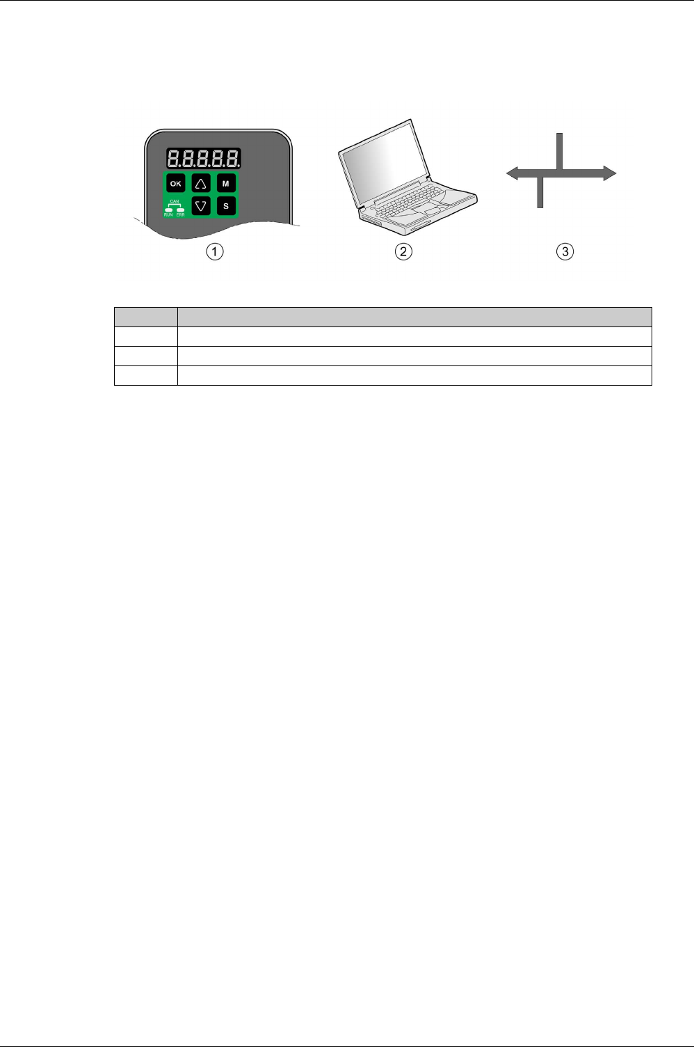
Overview
192 EIO0000002305 04/2017
Commissioning Tools
Overview
The following tools
(see page 86)
can be used for commissioning, parameterization, and diagnostics:
Device settings can be duplicated. Stored device settings can be transferred to a device of the same type.
Duplicating the device settings can be used if multiple devices are to have the same settings, for example,
when devices are replaced.
Item Description
1 Integrated HMI
2 PC with commissioning software LXM28 DTM Library
3 Fieldbus

EIO0000002305 04/2017 193
Lexium 28
A
and BCH2 Servo Drive System
Integrated HMI
EIO0000002305 04/2017
Integrated HMI
Chapter 13
Integrated HMI
What Is in This Chapter?
This chapter contains the following topics:
Topic Page
Overview 194
Integrated HMI Structure 195
7-Segment Display 196
Status Information Via the HMI 198
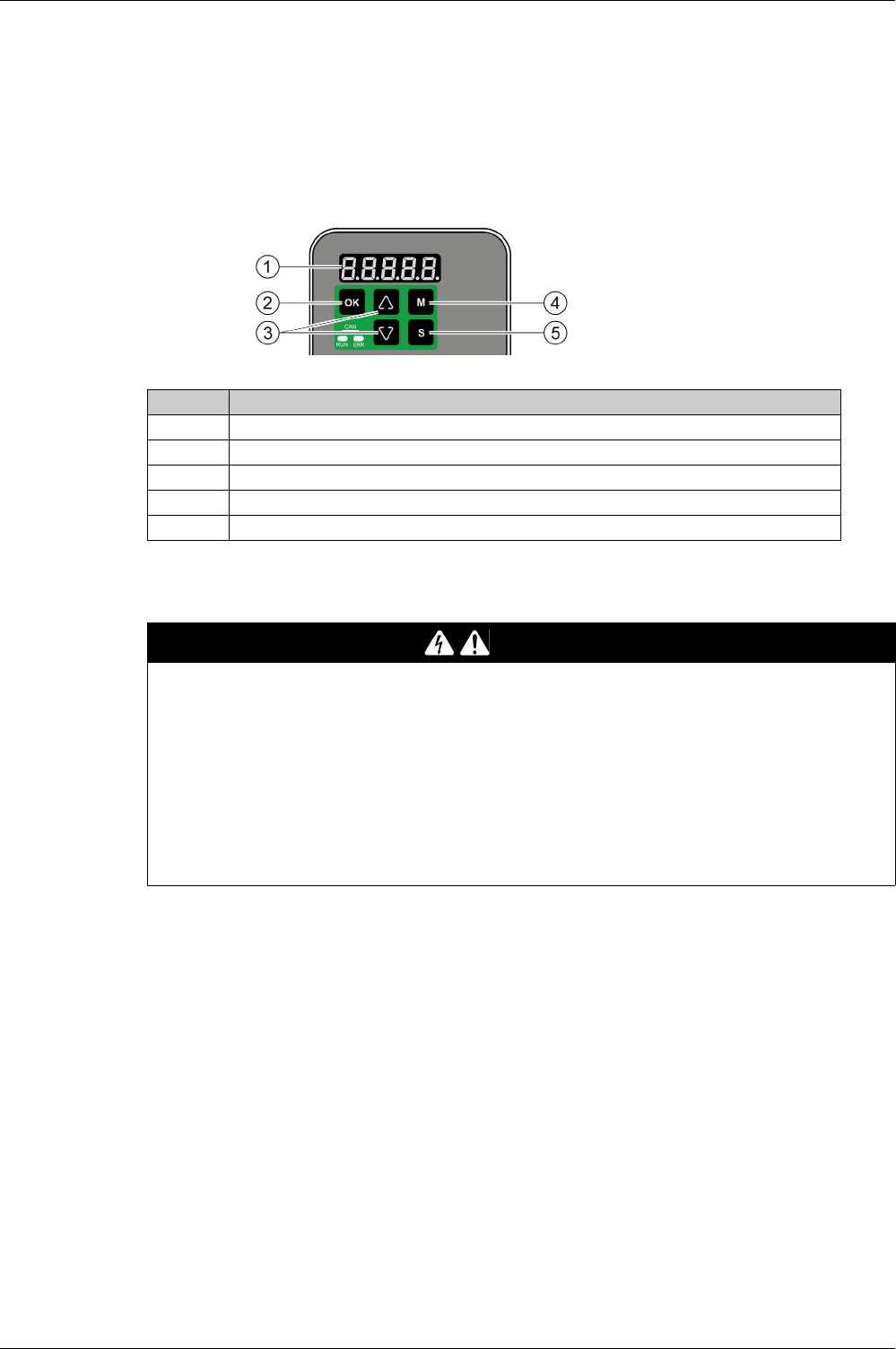
Integrated HMI
194 EIO0000002305 04/2017
Overview
The integrated HMI allows you to edit parameters, start the operating mode Jog or perform autotuning via
the integrated Human-Machine Interface (HMI). Diagnostics information (such as parameter values or
error codes) can also be displayed. The individual sections on commissioning and operation include
information on whether a function can be carried out via the integrated HMI or whether the commissioning
software must be used.
Incorrect wiring of the motor connection may cause live wires to be exposed outside of the motor connector
below the HMI.
Item Description
1 5-digit 7-segment display
2OK key
3 Arrow keys
4M key
5S key
DANGER
ELECTRIC SHOCK CAUSED BY INCORRECT WIRING
-Verify that the protective ground connection (PE) of the device is connected to ground.
-Do not remove the cable end (ferrule) from the protective ground terminal (PE) of the motor connector
until you are prepared to wire the protective ground conductor of the motor to the protective ground
terminal (PE) of the motor connector.
-Verify that no bare metal of the wires is exposed outside of the motor connector housing when wiring
the motor connector.
-Regularly, as part of a maintenance plan, assure that the motor wires are secured in the terminals of
the motor connector due to vibration or other influences.
Failure to follow these instructions will result in death or serious injury.

Integrated HMI
EIO0000002305 04/2017 195
Integrated HMI Structure
When the drive is powered on, the display shows the name of the selected status information function for
approximately one second; after that, it displays the corresponding actual value or status value.
Element Function
HMI display The 5-digit 7-segment display shows actual values, parameter settings, status information,
and error codes.
M key The M key lets you switch between the type of information displayed: status
information/actual values, error codes, and parameters.
If an error is detected, the display shows the error code. If you press the M while the error is
active, you can display other information; however, after approximately 20 seconds without
interaction, the error code is displayed again.
S key The S lets you scroll through the parameter groups.
After you have selected a parameter and its value is displayed, you can use the S key to
move the cursor to the left. The digit at the current cursor position flashes. The arrow keys
let you change the value at the current cursor position.
Arrow keys The arrow keys let you scroll through the actual values/status information and the parameters
within a parameter group. Use the arrow keys to increase or decrease values.
OK key After you have selected a parameter, press the OK key to display the current parameter
value. The arrow keys let you change the displayed value. Pressing the OK key again saves
the value.
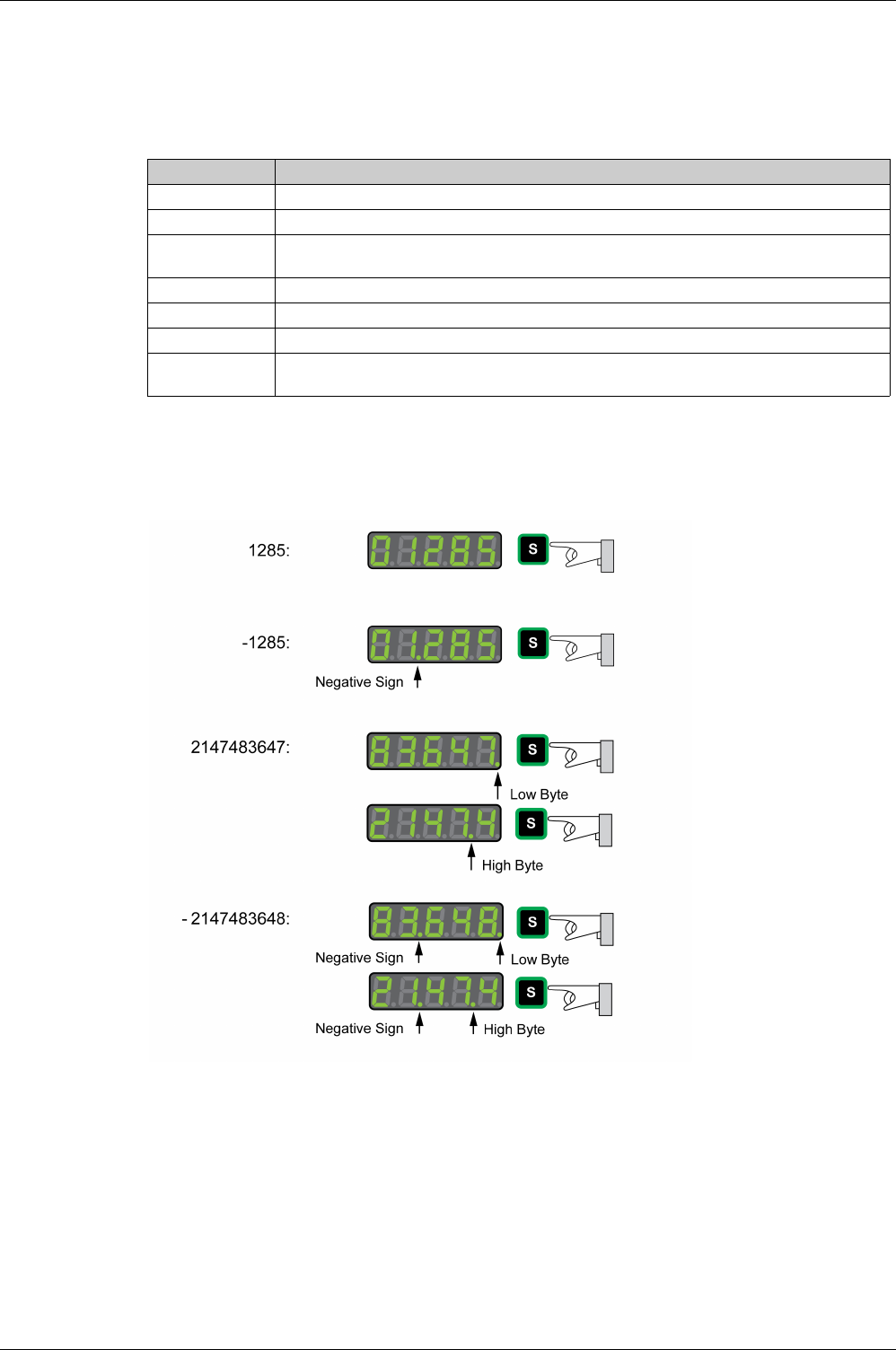
Integrated HMI
196 EIO0000002305 04/2017
7-Segment Display
Saving Settings
If you set a new parameter value and press the OK key, a message is displayed for approximately one
second to provide feedback.
Representation of Numerical Values on the 7-Segment Display
The illustration below shows the decimal representation of a 16-bit value and a 32-bit value as a positive
value and as a negative value each.
Example of representation of decimal values
7-segment display Description
SAuEd The new parameter value was successfully saved.
r-OLY The parameter value is a read-only value and cannot be saved (Read-Only).
Prot Changing a parameter value requires exclusive access. See chapter Access Channels
(see page 298)
.
Out-r The new parameter value is outside the permissible value range (Out of range).
SruOn The new parameter value can only be saved when the power stage is disabled (Servo On).
po-0n The new parameter value becomes active the next time the product is powered on (Power On).
Error Displayed whenever a value you have entered for a parameter is, for various reasons, rejected
by the drive.
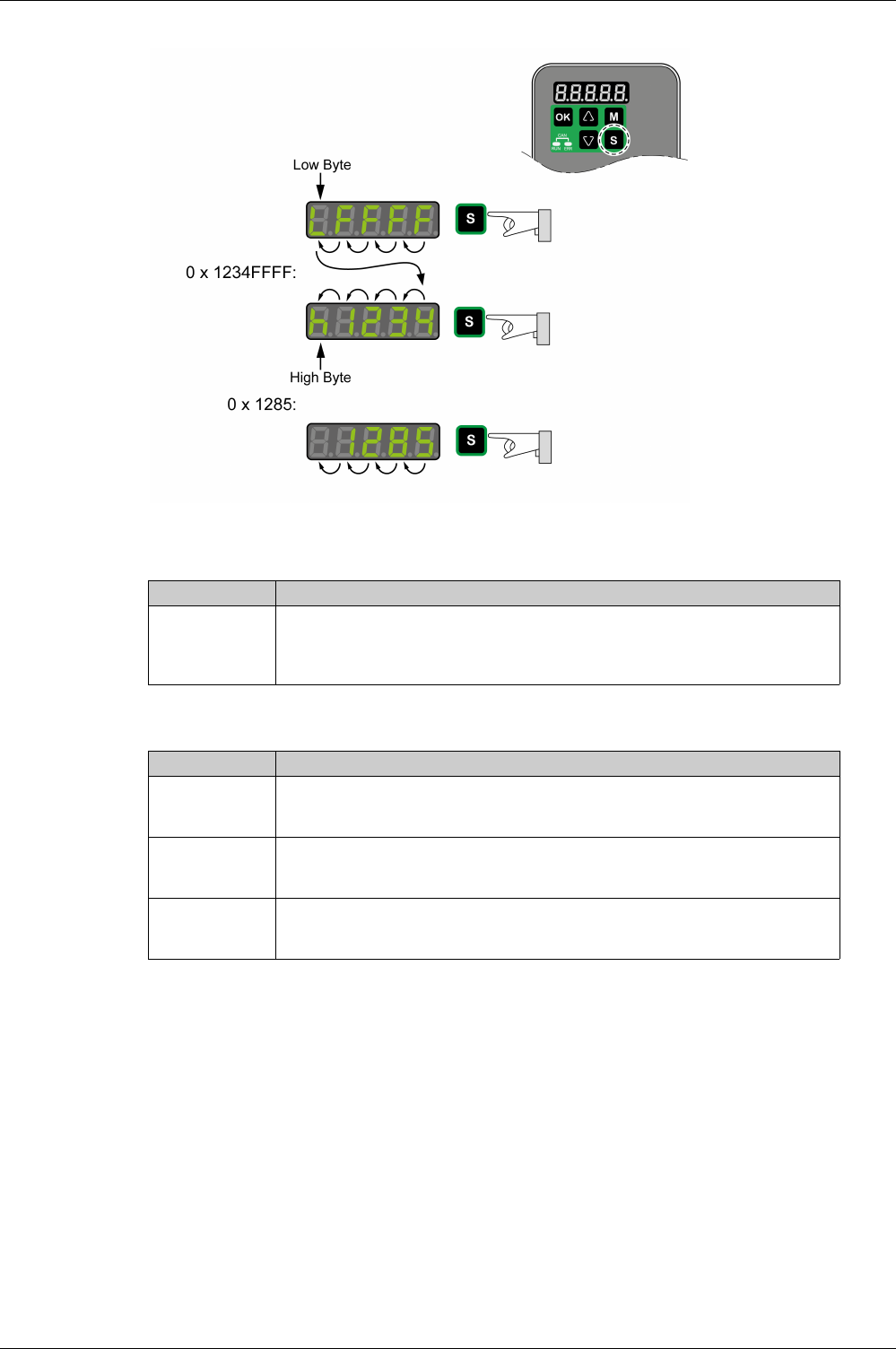
Integrated HMI
EIO0000002305 04/2017 197
Example of representation of hexadecimal values
Changing the Sign Via the 7-Segment Display
Alert Messages and Error Messages on the 7-Segment Display
7-segment display Description
24680
24.680
?343E
?CbC2
You can change the sign of a value by holding down the S key for a period of more than
2 seconds.
Negative decimal values are represented with a dot between the second and the third
position. Negative hexadecimal values are represented as a two's complement.
7-segment display Description
?nnnn If an alert condition is detected, Wnnnn is displayed. Win identifies the code as an alert.
The subsequent 3 digit nnn represent the number of the alert. See chapter Alert Codes
and Error Codes
(see page 407)
for a list of alerts.
ALnnn If an error is detected ALnnn is displayed. AL identifies the code as a detected error. The
subsequent 3 digit nnn represent the error number. For a list of error codes, refer to Alert
Codes and Error Codes
(see page 407)
.
S?OP The display shows STOP if exclusive access is enableds while the power stage is still
enabled. For further information on access channels, refer to Access Channels
(see page 298)
.

Integrated HMI
198 EIO0000002305 04/2017
Status Information Via the HMI
After you have powered on the drive, status information is displayed via the HMI. Use the parameter P0-
02 to select the type of status information to be displayed. For example, if you set the parameter P0-02 to
the value 7, the speed of rotation of the motor after is displayed after you have powered on the drive.
Setting P0-02 Description
0 Actual position (with gear ratio applied) in the unit PUU
1 Target position (with gear ratio applied) in the unit PUU
2 Deviation between actual position and target position (with gear ratio applied) in the unit PUU
3 Actual position in motor increments (1280000 pulses/revolution)
4 Target position in motor increments (1280000 pulses/revolution)
5 Deviation between actual position and target position in motor increments (1280000
pulses/revolution)
6 Reference value in kilopulses per second (kpps)
7 Actual velocity in rpm
8 Voltage for target velocity in V
9 Target velocity in rpm
10 Voltage for target torque in V
11 Target torque in percent of continuous motor current
12 Available current overhead used in percent of continuous motor current
13 Peak current overhead consumed since the last power cycle of the drive in percent of
continuous motor current (maximum value of occurring in setting 12 since last power cycle)
14 Mains voltage in V
15 Ratio of load inertia and motor inertia (divided by 10)
16 Power stage temperature in degrees Celsius (°C)
17 Resonance frequency in Hz
18 Absolute pulse number relative to encoder
19 Mapping parameter 1: Content of parameter P0-25 (mapping target is specified via
parameter P0-35)
20 Mapping parameter 2: Content of parameter P0-26 (mapping target is specified via
parameter P0-36)
21 Mapping parameter 3: Content of parameter P0-27 (mapping target is specified via
parameter P0-37)
22 Mapping parameter 4: Content of parameter P0-28 (mapping target is specified via
parameter P0-38)
23 Status indication 1: Content of parameter P0-09 (the status information to be displayed is
specified by parameter P0-17)
24 Status indication 2: Content of parameter P0-10 (the status information to be displayed is
specified by parameter P0-18)
25 Status indication 3: Content of parameter P0-11 (the status information to be displayed is
specified by parameter P0-19)
26 Status indication 4: Content of parameter P0-12 (the status information to be displayed is
specified by parameter P0-20)
27 Reserved
39 Status of digital inputs (content of P4-07)
40 Status of digital outputs (content of P4-09)
41 Drive status (content of P0-46)
42 Operating mode (content of P1-01)
49 Actual position encoder (content of P5-18)
50 Target velocity in rpm
53 Target torque in 0.1 percent of the nominal torque

Integrated HMI
EIO0000002305 04/2017 199
54 Actual torque in 0.1 percent of the nominal torque
55 Actual torque in 0.01 A
77 Target velocity in rpm in operating modes PT and PS
96 Firmware version and firmware revision of drive (P0-00 and P5-00)
111 Number of detected errors
Setting P0-02 Description

Integrated HMI
200 EIO0000002305 04/2017

EIO0000002305 04/2017 201
Lexium 28
A
and BCH2 Servo Drive System
Commissioning Procedure
EIO0000002305 04/2017
Commissioning Procedure
Chapter 14
Commissioning Procedure
What Is in This Chapter?
This chapter contains the following topics:
Topic Page
Commissioning Software 202
Setting the Device Address, Baud Rate and Connection Settings 203
Verifying the Direction of Movement 205
Test Operation in Operating Mode Velocity (V) 207
Verifying the Safety Function STO 208

Commissioning Procedure
202 EIO0000002305 04/2017
Commissioning Software
The commissioning software LXM28 DTM Library has a graphic user interface and is used for
commissioning, diagnostics, and testing settings.
Online Help
The commissioning software offers help functions, which can be accessed via ?-HelpTopics or by
pressing the F1 key.
Source of Commissioning Software
The latest version of the commissioning software LXM28 DTM Library is available for download from the
Internet.
http://www.schneider-electric.com
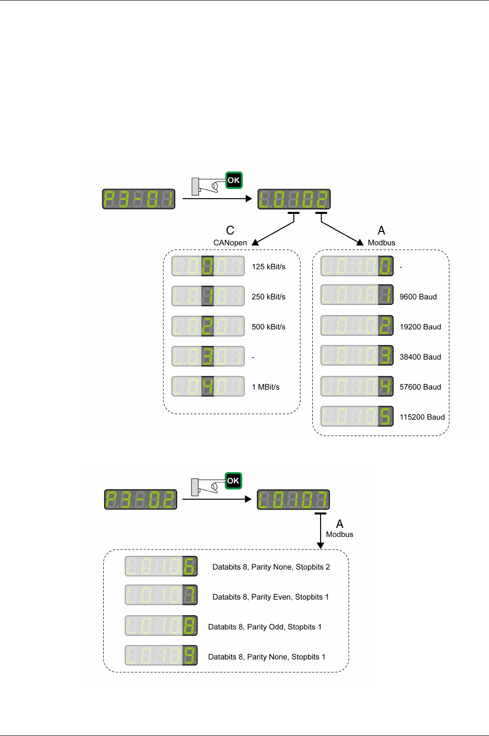
Commissioning Procedure
EIO0000002305 04/2017 203
Setting the Device Address, Baud Rate and Connection Settings
Each device is identified by a unique address. Each device must have its own unique node address, which
may only be assigned once in the network. The transmission rate (baud rate) must be the same for all
devices in the network.
Use the parameter P3-00 to set the Modbus device address.
Use the parameter P3-05 to set the CANopen device address.
Use the parameter P3-01 to set the baud rate.
Use the parameter P3-02 to set the connection settings.
Setting the baud rate:
Modbus Connection Settings

Commissioning Procedure
204 EIO0000002305 04/2017
WARNING
UNINTENDED EQUIPMENT OPERATION
-Verify that there is only one master controller configured on the network or remote link.
-Verify that all devices have unique addresses.
-Confirm that the device address is unique before placing the system into service.
Failure to follow these instructions can result in death, serious injury, or equipment damage.
Parameter name Description Unit
Minimum value
Factory setting
Maximum value
HMI Format
Data type
R/W
Persistent
Parameter
address via
fieldbus
P3-00
ADR
Device Address Modbus
Applicable operating mode: PT, PS, V, T
The device address must be unique.
Changed settings become active the next
time the product is powered on.
-
1
127
247
Decimal
u16
RW
per.
Modbus 400h
CANopen 4300h
P3-01
BRT
Transmission Rate
Applicable operating mode: PT, PS, V, T
This parameter is used to set the data
transmission rate.
If this parameter is set via CANopen, only
the CANopen transmission rate can be set.
Changed settings become active the next
time the product is powered on.
-
0h
102h
405h
Hexadecimal
u16
RW
per.
Modbus 402h
CANopen 4301h
P3-02
PTL
Modbus Connection Settings
Applicable operating mode: PT, PS, V, T
This parameter specifies the Modbus
connection settings.
Changed settings become active the next
time the product is powered on.
-
6h
7h
9h
Hexadecimal
u16
RW
per.
Modbus 404h
CANopen 4302h
P3-03
FLT
Detected Modbus Communication Errors -
Handling
Applicable operating mode: PT, PS, V, T
This parameter specifies the response of
the drive to a detected communication
error.
Value 0: Detected alert
Value 1: Detected error
-
0h
0h
1h
Hexadecimal
u16
RW
per.
Modbus 406h
CANopen 4303h
P3-04
CWD
Modbus Connection Monitoring
Applicable operating mode: PT, PS, V, T
This parameter specifies the maximum
permissible duration for communication
timeout. When this time has elapsed, the
communication timeout is treated as a
detected error.
Setting this parameter to 0 to disables
connection monitoring.
ms
0
0
20000
Decimal
u16
RW
per.
Modbus 408h
CANopen 4304h
P3-05
CMM
Device Address CANopen
Applicable operating mode: PT, PS, V, T
This parameter specifies the CANopen
address of the drive in decimal format.
The device address must be unique.
Change to this parameter becomes
effective only after a restart of the drive.
Changed settings become active the next
time the product is powered on.
-
0
0
127
Decimal
u16
RW
per.
Modbus 40 Ah
CANopen 4305h
P3-07
CDT
Modbus Response Delay Time
Applicable operating mode: PT, PS, V, T
This parameter specifies the time delay
with which the drive responds to the
Modbus master.
0.5 ms
0
0
1000
Decimal
u16
RW
per.
Modbus 40Eh
CANopen 4307h
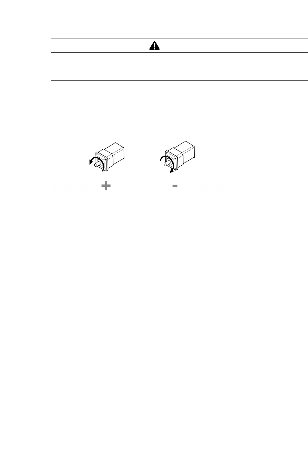
Commissioning Procedure
EIO0000002305 04/2017 205
Verifying the Direction of Movement
Direction of Movement
If your application requires an inversion of the direction of movement, you may parameterize the direction
of movement.
Movements are made in positive or in negative directions.
Definition of the direction of movement: Positive direction of movement is when the motor shaft rotates
counterclockwise as you look at the end of the protruding motor shaft.
Direction of movement with factory settings
Verifying the Direction of Movement
-Start the operating mode Jog. (HMI: P4-05)
The HMI displays the velocity in the unit rpm for the operating mode JOG.
-Set a velocity suitable for your application and conform with the OK key.
The HMI displays J0G.
Movement in positive direction:
-Press the Up Arrow key.
A movement is made in positive direction.
Movement in negative direction:
-Press the Down Arrow key.
A movement is made in negative direction.
Press the M key to terminate the operating mode Jog.
Changing the Direction of Movement
If the expected direction of movement and the actual direction of movement are not identical, you can invert
the direction of movement.
-Inversion of direction of movement is not activated:
Movements are made in positive direction with positive target values.
-Inversion of direction of movement is activated:
Movements are made in positive direction with negative target values.
WARNING
UNINTENDED MOVEMENT CAUSED BY INTERCHANGED MOTOR PHASES
Do not interchange the motor phases.
Failure to follow these instructions can result in death, serious injury, or equipment damage.

Commissioning Procedure
206 EIO0000002305 04/2017
The parameter P1-01 C = 1 allows you to invert the direction of movement.
Changing the direction of movement

Commissioning Procedure
EIO0000002305 04/2017 207
Test Operation in Operating Mode Velocity (V)
-Select the operating mode Velocity (V) via the parameter P1-01: = 2. Refer to Setting the Operating
Mode
(see page 316)
.
-Set the parameter P1-01 to D=1. This assigns defaults to the signal input functions for the operating
mode Velocity (V), DI6…DI8 presets must be modified for this test.
New settings for the parameter P1-01 do not become active until the drive is powered on the next time.
-Restart the drive.
-Select the following signal input functions via the parameters P2-10 to P2-17:
For further information on the settings, refer to Setting the Digital Signal Inputs
(seepage300)
.
Error Messages HMI
If the default presets of the signal inputs OPST, CWL(NL), and CCWL(PL/LIMP) are still present, the
following error codes can be displayed:
-AL013: Parameter P2-17 not set to 0 (deactivated).
-AL014: Parameter P2-15 not set to 0 (deactivated).
-AL015: Parameter P2-16 not set to 0 (deactivated).
For further information on error messages, refer to Diagnostics and Troubleshooting
(see page 407)
.
Target Velocity
The target velocity is selected via the signal input functions SPD0 (least significant bit) and SPD (most
significant bit):
-Enable the power stage via DI1 (SON).
If DI3 (SPD0) and DI4 (SPD1) are deactivated, the target velocity is supplied via the analog input
V_REF.
-Activate DI3 (SPD0).
The target velocity is supplied via the parameter P1-09. The factory setting for the target velocity is
1000 rpm.
Digital input Parameter Setting Signal Function Pin at CN1
DI1 P2-10 0101hSON Enable power stage 9
DI2 P2-11 0109hTRQLM Activate Torque Limitation 10
DI3 P2-12 0114hSPD0 Velocity Reference Value Bit 0 34
DI4 P2-13 0115hSPD1 Velocity Reference Value Bit 1 8
DI5 P2-14 0102hFAULT_RESET Fault Reset 33
DI6 P2-15 0h-- 32
DI7 P2-16 0h-- 31
DI8 P2-17 0h-- 30
-Signal state of the digital
signal inputs
Target velocity via: Range
SPD1 SPD0
S1 0 0 External analog
signal
Voltage between V_REF
(pin 42) and GND (pin 44)
-10 ... 10 Vdc
S2 0 1 Internal
parameters
P1-09 -60000 ... 60000 x 0.1 rpm
S3 1 0 P1-10
S4 1 1 P1-11

Commissioning Procedure
208 EIO0000002305 04/2017
Verifying the Safety Function STO
The safety function STO must be tested at least once per year.
Procedure:
-Operate the system with the nominal voltage at the STO inputs as described in the chapter Inputs /
Outputs Characteristics
(see page 42)
.
-Enable the power stage (operating state 6 Operation Enabled).
-Trigger the safety function STO by switching off the voltage (for example, via an emergency stop push-
button).
The power stage is disabled and the error message AL501 is displayed.
-Verify that drive is in the operating state Fault.
-Check whether the drive can be set to the operating state 6 Operation Enabled.
The drive remains in the operating state Fault.
-Restore the STO voltage at the signal inputs of the safety function STO and trigger a Fault Reset.
-Verify that the drive can be set to the operating state 6 Operation Enabled.
The drive is set to the operating state 6 Operation Enabled. Movements are possible again.

EIO0000002305 04/2017 209
Lexium 28
A
and BCH2 Servo Drive System
Tuning th e Control Loops
EIO0000002305 04/2017
Tuning the Control Loops
Chapter 15
Tuning the Control Loops
What Is in This Chapter?
This chapter contains the following topics:
Topic Page
Tuning the Control Loops 210
Easy Tuning 211
Comfort Tuning 212
Manual Tuning 217

Tuning the Control Loops
210 EIO0000002305 04/2017
Tuning the Control Loops
Autotuning and manual tuning move the motor in order to tune the control loops. Incorrect parameters may
cause unintended movements or the loss of monitoring functions.
Autotuning adapts the control performance of the drive to the mechanical system used and optimizes the
control loop settings appropriately. External factors such as a load at the motor are considered. The control
loop settings can also be optimized by using manual tuning.
Two autotuning methods and manual tuning are provided for control loop optimization:
-Easy Tuning: This type of autotuning is performed without user intervention. For most applications, Easy
Tuning yields good, highly dynamic results.
-Comfort Tuning: This type of autotuning is performed with user intervention. You can select optimization
criteria and set parameters for movement, direction, and velocity.
-Manual Tuning: This type of tuning allows you to perform test movements and optimize the control loop
settings using the Scope function.
WARNING
UNINTENDED MOVEMENT
-Only start the system if there are no persons or obstructions in the zone of operation.
-Verify that the values for the parameters P9-26 and P9-27 do not exceed the available movement
range.
-Verify that the parameterized movement ranges are available.
-In determining the available movement range, consider the additional distance for the deceleration
ramp in the case of an EMERGENCY STOP.
-Verify that the parameter settings for a Quick Stop are correct.
-Verify correct operation of the limit switches.
-Verify that a functioning emergency stop push-button is within reach of all persons involved in the
operation.
Failure to follow these instructions can result in death, serious injury, or equipment damage.
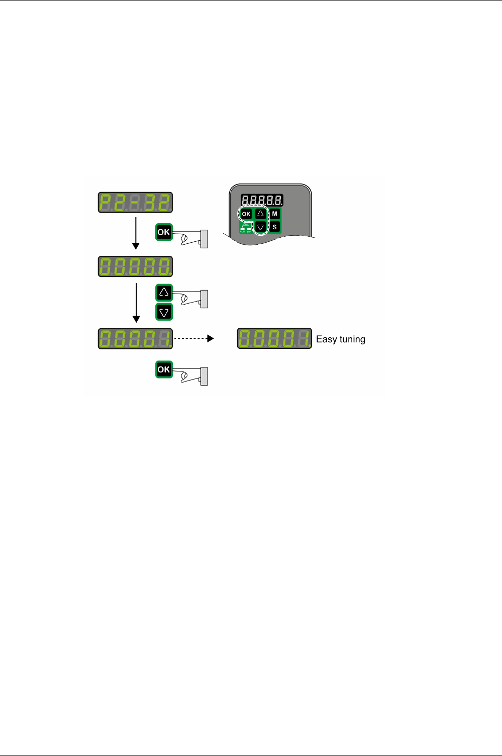
Tuning the Control Loops
EIO0000002305 04/2017 211
Easy Tuning
Easy Tuning is started via the HMI or the commissioning software LXM28 DTM Library.
Easy Tuning requires an available movement range of 5 revolutions. During Easy Tuning, movements of
2.5 revolutions are performed in positive direction of movement and 2.5 revolutions in negative direction of
movement. If this movement range is not available, you must use Comfort Tuning. Comfort Tuning allows
you to set the movement range and the direction of movement manually.
Easy Tuning can be used for a ratio of motor inertia to load inertia of up to 1:50.
Performing Easy Tuning
Set the parameter P2-32 to 1 to perform Easy Tuning.
After you have started Easy Tuning via P2-32, the display of the HMI shows the progress as a percentage
from tn000 to tn100.
Press the M button of the HMI to cancel autotuning.
If autotuning completes successfully, the display of the HMI shows the message done.
Press the OK key of the HMI to save the control loop parameters. The display of the HMI briefly shows the
message saved.
Press the M key of the HMI to discard the autotuning results.
If autotuning does not complete successfully, the display of the HMI shows the message ERROR. The cause
can be read with the parameter P9-30.
The parameter P9-37 provides additional information on the last event that occurred during autotuning.
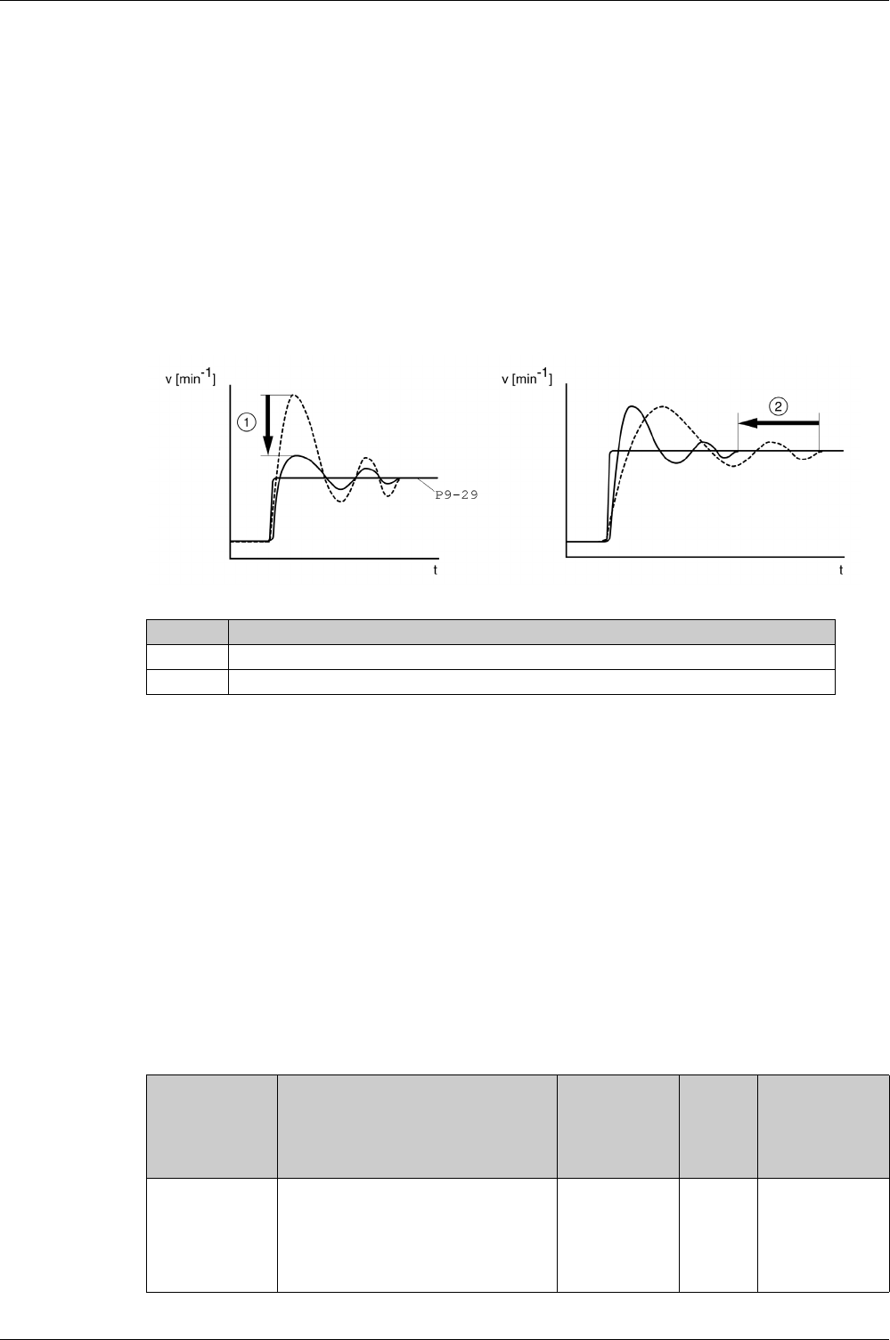
Tuning the Control Loops
212 EIO0000002305 04/2017
Comfort Tuning
Comfort Tuning allows you to select optimization criteria and set values for the movement.
Optimization Criteria for Comfort Tuning
Comfort Tuning allows you to select an optimization criterion for autotuning. The following optimization
criteria are available:
-Optimization of the control loop parameters for minimum settling time with vibration suppression
-Optimization of the control loop parameters for minimum overshoot with vibration suppression
-Optimization of the control loop parameters for minimum settling time without vibration suppression
-Optimization of the control loop parameters for minimum overshoot without vibration suppression
The illustration below shows optimization for minimum overshoot and optimization for minimum settling
time.
Vibration suppression compensates resonance frequencies of the mechanical system. The option
Vibration Suppression is available for both optimization criteria.
Parameters for the Movement for Comfort Tuning
The following settings must be made for Comfort Tuning:
-Direction of movement
-Velocity
-Acceleration and deceleration
-Movement range
-Smoothing
These values must be as close as possible to the values used in the actual application. If you enter
implausible values, Comfort Tuning is canceled.
Setting the Direction of Movement
Set the direction of movement via the parameter P9-20.
Item Description
1 Optimization for minimum overshoot
2 Optimization for minimum settling time
Parameter name Description Unit
Minimum value
Factory setting
Maximum value
HMI Format
Data type
R/W
Persistent
Parameter
address via
fieldbus
P9-20
LTNCYCLE
Autotuning - Direction of Movement
Applicable operating mode: PT, PS, V
This parameter sets the direction of
movement for autotuning.
Value 0: Both directions of movement
Value 2: One direction of movement
-
0
0
3
Decimal
s16
RW
-
Modbus A28h
CANopen 4914h
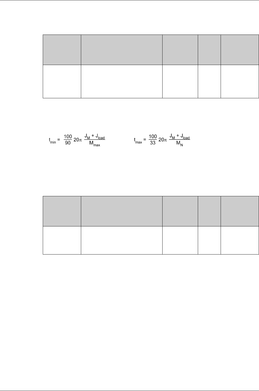
Tuning the Control Loops
EIO0000002305 04/2017 213
Setting the Velocity
Set the velocity via the parameter P9-29.
The velocity must be between 10 ... 100 % of the nominal velocity nN.
Setting Acceleration and Deceleration
Set the acceleration and the deceleration with the P9-31 parameter.
The value for the acceleration and the value for the deceleration must be between tmin and tmax:
JM = Moment of inertia of the motor in kg cm2
Jload = Moment of inertia of the load in kg cm2
Mmax = Peak torque in Nm
MN = Nominal torque in Nm
Parameter name Description Unit
Minimum value
Factory setting
Maximum value
HMI Format
Data type
R/W
Persistent
Parameter
address via
fieldbus
P9-29
LTNVCRUISE
Autotuning - Velocity
Applicable operating mode: PT, PS, V
Bits 0 … 15: Velocity for positive direction
of movement
Bits 16 … 31: Velocity for negative
direction of movement
0.1rpm|0.1rpm
-
-
-
Decimal
u32
RW
-
Modbus A3Ah
CANopen 491Dh
Parameter name Description Unit
Minimum value
Factory setting
Maximum value
HMI Format
Data type
R/W
Persistent
Parameter
address via
fieldbus
P9-31
PTACCDEC
Autotuning - Acceleration and Deceleration
Applicable operating mode: PT, PS, V
Bits 0 … 15: Acceleration for Autotuning
Bits 16 … 31: Deceleration for Autotuning
ms|ms
6| 6
6000| 6000
65500| 65500
Decimal
u32
RW
-
Modbus A3Eh
CANopen 491Fh

Tuning the Control Loops
214 EIO0000002305 04/2017
Setting the Movement Range
Set the movement range via parameters P9-26 and P9-27.
The movement range must be sufficiently large to allow for a constant movement at the set speed in
addition to the acceleration phase and the deceleration phase.
Setting Smoothing
Comfort Tuning uses S-curve smoothing by default. The value for smoothing via the S-curve is optimized
during Comfort Tunings.
The parameter P9-23 allows you to change from automatic smoothing to manual smoothing.
The following options are available for manual smoothing:
-No smoothing
-Smoothing via low-pass filter with a fixed value
-Smoothing via S-curve with a fixed value
Parameter
name
Description Unit
Minimum value
Factory setting
Maximum
value
HMI Format
Data type
R/W
Persistent
Parameter
address via
fieldbus
P9-26
PTPOS
Autotuning - Movement Range in Direction 1
Applicable operating mode: PS
This parameter specifies the movement range for
autotuning in direction of movement 1.
The sign of the value determines the direction of
movement:
Positive value: Positive direction of movement as set
via parameter P1-01
Negative value: Negative direction of movement as set
via parameter P1-01
See parameter P9-20 to select one direction of
movement or both directions of movement for Comfort
Tuning.
PUU
-2147483647
0
2147483647
Decimal
s32
RW
-
Modbus A34h
CANopen 491 Ah
P9-27
PTNEG
Autotuning - Movement Range in Direction 2
Applicable operating mode: PS
This parameter specifies the movement range for
autotuning in direction of movement 2.
The sign of the value determines the direction of
movement:
Positive value: Positive direction of movement as set
via parameter P1-01
Negative value: Negative direction of movement as set
via parameter P1-01
See parameter P9-20 for Comfort Tuning in a single or
in both directions of movement.
See parameter P9-20 to select one direction of
movement or both directions of movement for Comfort
Tuning.
PUU
-2147483647
0
2147483647
Decimal
s32
RW
-
Modbus A36h
CANopen 491Bh
Parameter name Description Unit
Minimum value
Factory setting
Maximum value
HMI Format
Data type
R/W
Persistent
Parameter
address via
fieldbus
P9-23
LTNSTIFF
Defines which values are used for the
position command filters.
Applicable operating mode: PT, PS, V
Value 0: Automatic smoothing via S-
curve optimization of the value
Value 1: Manual smoothing
-
0
0
1
Decimal
u16
RW
-
Modbus A2Eh
CANopen 4917h
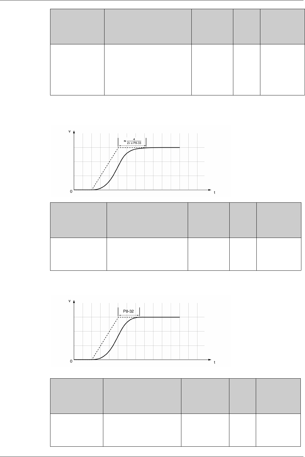
Tuning the Control Loops
EIO0000002305 04/2017 215
The illustration below shows the movement during Comfort Tuning if smoothing via the low-pass filter is
used:
Comfort Tuning with smoothing via low-pass filter
The illustration below shows the movement during Comfort Tuning if smoothing via an S-curve is used:
Comfort Tuning with smoothing via S-curve
P8-34
MOVESMOOTHMODE
Smoothing Filter for Operating modes
PT and PS - Type
Applicable operating mode: PT, PS
Value 0: No smoothing
Value 1: LPF smoothing
Value 2: S-curve smoothing
Setting can only be changed if power
stage is disabled.
-
0
2
2
Decimal
u16
RW
per.
Modbus 944h
CANopen 4822h
Parameter name Description Unit
Minimum value
Factory setting
Maximum value
HMI Format
Data type
R/W
Persistent
Parameter
address via
fieldbus
P8-33
MOVESMOOTHLPFHZ
Low Pass Filter Setting
Applicable operating mode: PT, PS
Hz
1
5000
5000
Decimal
u16
RW
per.
Modbus 942h
CANopen 4821h
Parameter name Description Unit
Minimum value
Factory setting
Maximum value
HMI Format
Data type
R/W
Persistent
Parameter
address via
fieldbus
P8-32
MOVESMOOTHAVG
S-Curve Setting
Applicable operating mode: PT, PS
Setting can only be changed if
power stage is disabled.
0.01 ms
25
1500
25600
Decimal
u32
RW
per.
Modbus 940h
CANopen 4820h
Parameter name Description Unit
Minimum value
Factory setting
Maximum value
HMI Format
Data type
R/W
Persistent
Parameter
address via
fieldbus

Tuning the Control Loops
216 EIO0000002305 04/2017
Performing Comfort Tuning
Start Comfort Tuning by selecting the required method via the parameter P2-32.
If you want Comfort Tuning in both directions, set parameter P9-20 to 0. Then set the parameters P9-26
and P9-27 to the same values, but with different signs (for example, P9-26 = -20000 and P9-27 = +20000).
The value determines the movement range in both directions.
If you want Comfort Tuning in a single direction, set parameter P9-20 to 2. Then set the parameters P9-26
and P9-27 to the same values. The sign of the value determines the direction for Comfort Tuning. For
example, if you set P9-26 = -20000 and P9-27 = -20000, Comfort Tuning is performed in negative direction
of movement with a movement range of 20000 PUU.
NOTE: If you do not enter consistent values for parameters P9-26 and P9-27, the autotuning is
unsuccessful. Parameter P9-30 contains the information on the unsuccessful autotuning attempt.
After you have started the required Comfort Tuning method via P2-32, the display of the HMI shows the
progress as a percentage from tn000 to tn100.
Press the M button of the HMI to cancel autotuning.
If autotuning completes successfully, the display of the HMI shows the message don?.
Press the OK key of the HMI to save the control loop parameters. The display of the HMI briefly shows the
message ????d.
Press the M key of the HMI to discard the autotuning results.
If autotuning does not complete successfully, the display of the HMI shows the message E??O?. The
cause can be read with the parameter P9-30.
The parameter P9-37 provides additional information on the last event that occurred during autotuning.
Parameter name Description Unit
Minimum value
Factory setting
Maximum value
HMI Format
Data type
R/W
Persistent
Parameter
address via
fieldbus
P2-32
ATMODE
Autotuning
Applicable operating mode: PT, PS, V
This parameter is used to start autotuning
with the selected autotuning method.
Value 0: Stop Autotuning
Value 1: Easy Tuning
Value 2: Comfort Tuning [minimum settling
time, vibration suppression]
Value 3: Comfort Tuning [minimum
overshoot, vibration suppression]
Value 52: Comfort Tuning [minimum
settling time, no vibration suppression]
Value 53: Comfort Tuning [minimum
overshoot, no vibration suppression]
-
0
0
56
Decimal
u16
RW
-
Modbus 340h
CANopen 4220h

Tuning the Control Loops
EIO0000002305 04/2017 217
Manual Tuning
Manual tuning is performed in the operating mode Internal Profile. Manual tuning allows you to perform test
movements and optimize the control loop settings using the Scope function.
NOTE: Manual tuning should only be attempted by trained persons who are familiar with and understand
the contents of this manual and all other pertinent product documentation. These persons must have
sufficient technical training, knowledge, and experience and be able to foresee and detect potential
hazards and issues that may be caused by manual tuning, by changing the settings and by the mechanical,
electrical, and electronic equipment of the entire system in which the product is used. No responsibility is
assumed by Schneider Electric for any consequences arising out of the use of manual tuning.
Procedure for Manual Tuning
The control loop parameters are tuned in the following sequence:
Depending on the requirements concerning the control performance, steps 2 and 3 can be omitted.
Perform a movement in both directions after each of the steps below to check the recorded parameter
values on the Scope tab of the commissioning software LXM28 DTM Library.
Step 1: Setting the Derivative Gain
The objective of tuning the derivative gain is to achieve a current ripple that is as low as possible. The
optimum value primarily depends on the load.
Criteria for a well-tuned derivative gain include:
-For loads less than twice the rotor inertia: 5 % of the nominal current may be acceptable
-For greater loads: 10 % of the nominal current may be acceptable
The derivative gain is set via parameter P8-00 (LTND).
Procedure:
-Set the value of parameter P8-03 (LTNP) to 150 (corresponds to 15 Hz).
-Set the value of parameter P8-01 (LTNI) to 0.
-Set the value of parameter P8-02 (LTNIV) to 0.
-Progressively increase the value of parameter P8-00 (LTND) until the oscilloscope shows oscillation of
the reference current, P11-11 (TCMD).
Step Item Parameters
1 Derivative gain P8-00 (LTND)
2 Low-pass filter P8-14 (NLFILTDAMPING)
P8-15 (NLFILTT1)
3 Retuning of the derivative gain P8-00 (LTND)
4 Proportional gain P8-03 (LTNP)
5 Derivative-integral gain P8-02 (LTNIV)
6 Integral gain P8-01 (LTNI)
7 Compensation of the flexibility of the mechanical
system
P8-05(NLAFFLPFHZ)
P8-20(NLPEAFF)
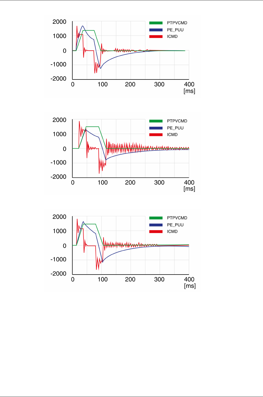
Tuning the Control Loops
218 EIO0000002305 04/2017
Example P8-00 (LTND) set to 1340 (134 Hz)
Example P8-00 (LTND) set too high at 2000 (200 Hz)
Example P8-00 (LTND) OK at 1500 (150 Hz)
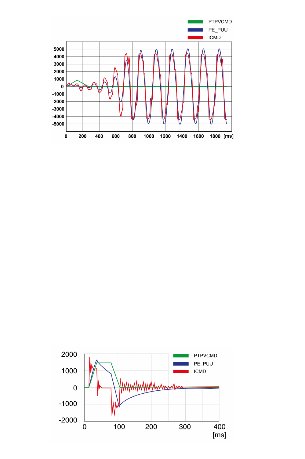
Tuning the Control Loops
EIO0000002305 04/2017 219
Example P8-00 (LTND) set too low at 100 (10 Hz)
NOTE: The process of tuning requires trials of successive approximations. Values that are too high or too
low relative to the other relevant values might cause instability. If it is necessary to have a low or high value
of the parameter in the preceding example, you may need to adjust the values of the other relevant
parameters to compensate and achieve a stable system.
Step 2: Setting the Low-Pass Filter
Setting the low-pass filter is an optional step in manual tuning of the control loop parameters. The low-pass
filter parameters are optimized after you have tuned the derivative gain. The objective of tuning the low-
pass filter parameters is to suppress high-frequency resonance and reduce the response time of the
control loops to a minimum.
The parameter P8-14 (NLFILTDAMPING) maintains the bandwidth of the low-pass filter up to the cutoff
frequency. The parameter value is expressed as a percentage. The parameter P8-15 (NLFILTT1) sets the
inverse frequency of the cutoff frequency. The parameter P8-14 (NLFILTDAMPING) can also be used
independently to allow for a certain degree of compensation of system-related bandwidth limits.
Criteria for a well-tuned low-pass filter include:
-The value of parameter P8-14 (NLFILTDAMPING) is as high as possible.
-The value of parameter P8-15 (NLFILTT1) is as low as possible.
The low-pass filter is set via parameters P8-14 (NLFILTDAMPING) and P8-15 (NLFILTT1).
Procedure:
-Progressively increase the value of parameter P8-14 (NLFILTDAMPING) until the oscilloscope shows
noise and/or oscillation of the reference current, P11-11 (TCMD).
-Progressively decrease the value of parameter P8-15 (NLFILTT1) until the oscilloscope shows noise
and/or oscillation of the reference current P11-11 (TCMD).
-Increase the value of parameter P8-15 (NLFILTT1) by 20 %, however, by at least 0.05 ms.
Example P8-14 (NLFILTDAMPING) OK (75 %)
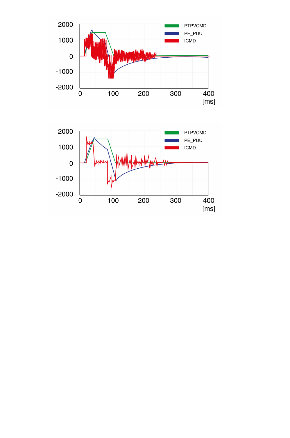
Tuning the Control Loops
220 EIO0000002305 04/2017
Example P8-15 (NLFILTT1) too low (0.5 ms)
Example P8-15 (NLFILTT1) OK (1.2 ms)
Step 3: Re-Tuning of the Derivative Gain
If you have changed the low-pass filter values in parameters P8-14 (NLFILTDAMPING) and P8-15
(NLFILTT1), the derivative gain can be set to a greater value via parameter P8-00 (LTND). Follow the
procedure described in step 1.
The objective of tuning the proportional gain is to get a constant and low position deviation in the
acceleration phase, the constant velocity phase, and the deceleration phase and to have no oscillations
during the transitions between these phases. In the oscilloscope, this is indicated by a shape that is as
square and as flat as possible.
Criteria for a well-tuned proportional gain include:
-No or minimum overshoot of position deviation
-No or minimum current ripple
-No or minimum oscillations at standstill
Step 4: Setting the Proportional Gain
The proportional gain is set via parameter P8-03 (LTNP).
Procedure:
-Progressively increase the value of parameter P8-03 (LTNP) to find the optimum value. The figures
below show examples of the plot as the value approaches the optimum value.
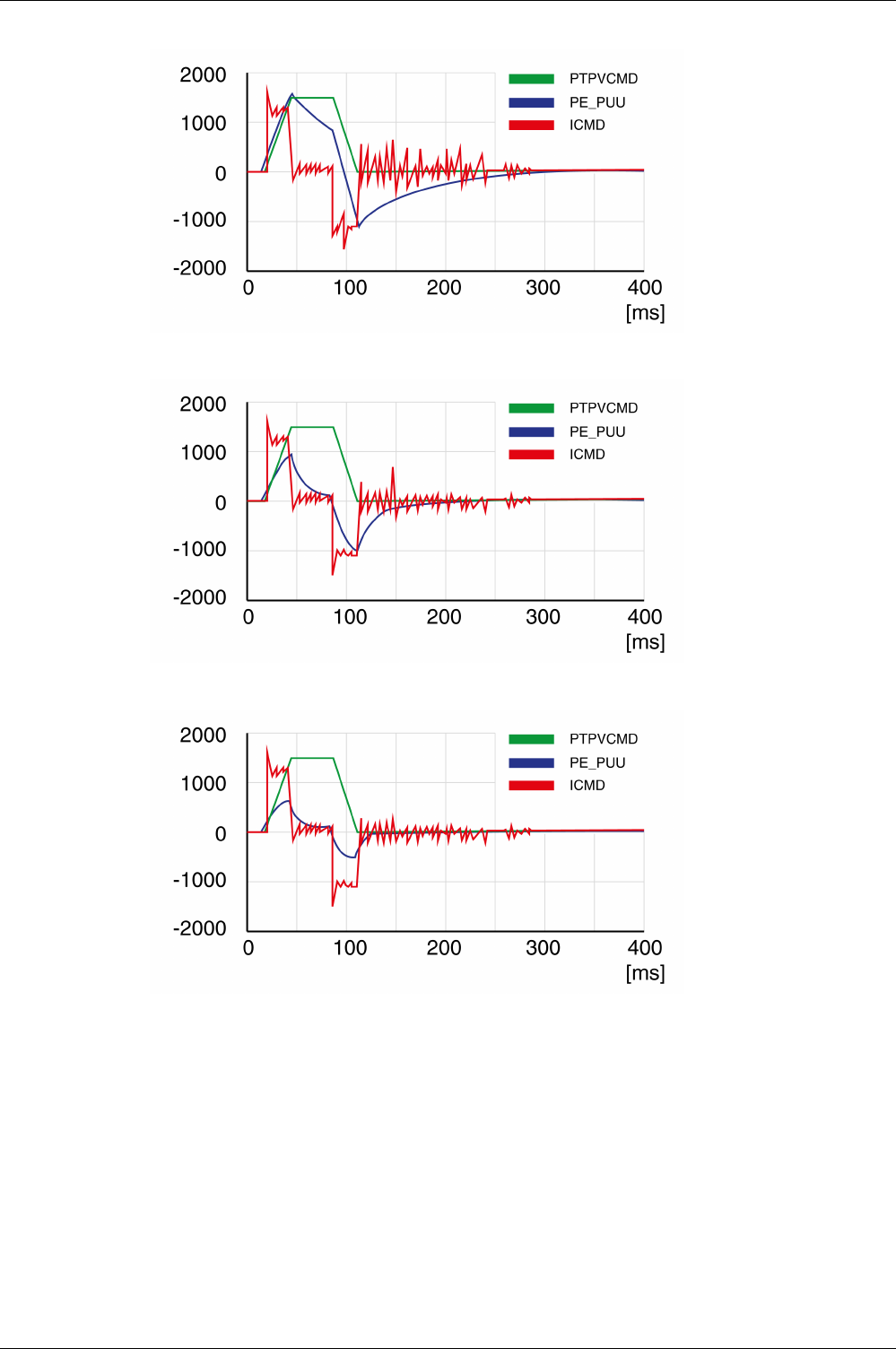
Tuning the Control Loops
EIO0000002305 04/2017 221
Example P8-03 (LTNP) starting value (13 Hz)
Example P8-03 (LTNP) position deviation decreased (25 Hz)
Example P8-03 (LTNP) position deviation further decreased (35 Hz)
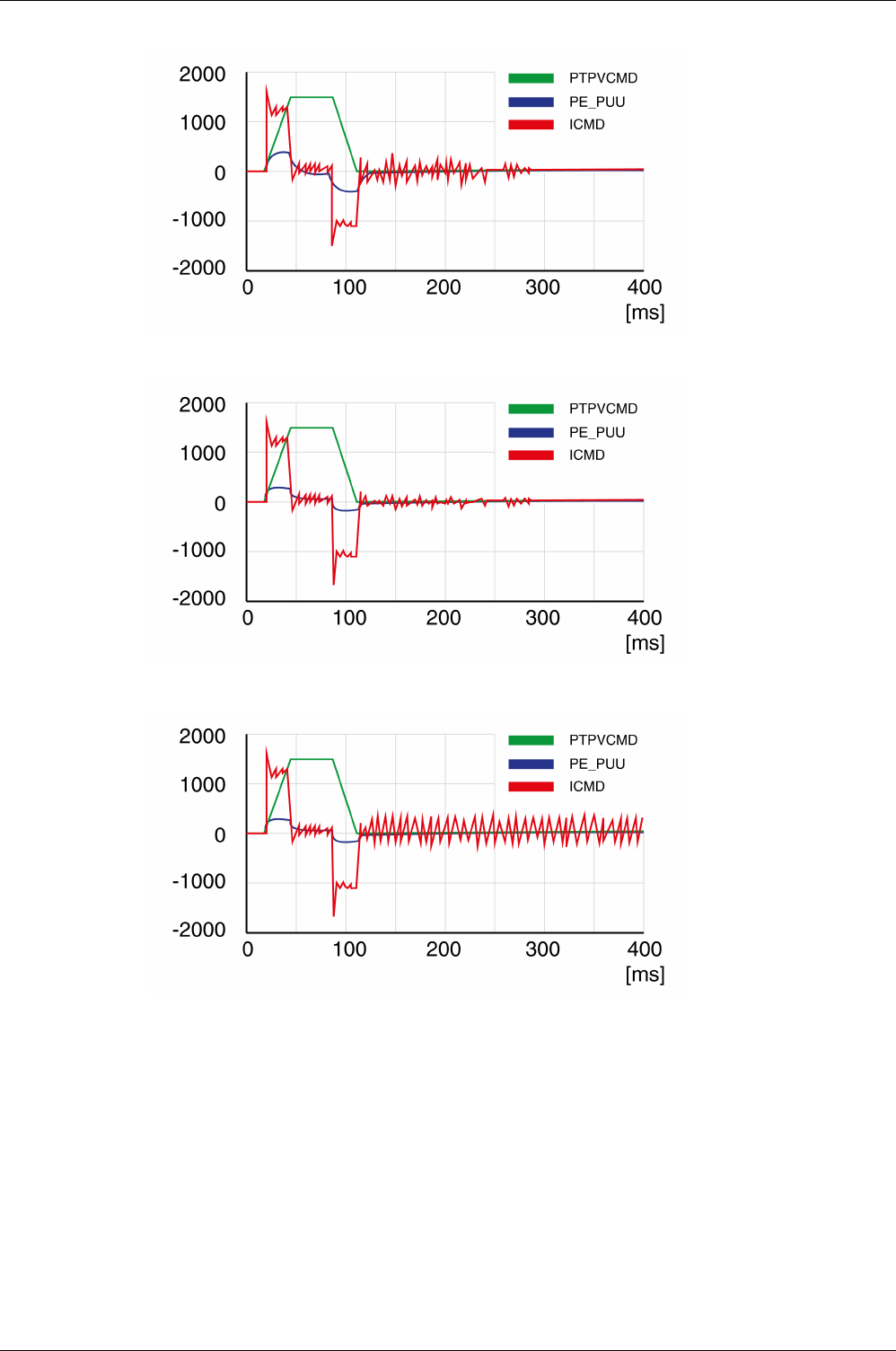
Tuning the Control Loops
222 EIO0000002305 04/2017
Example P8-03 (LTNP) position deviation further decreased (45 Hz)
Example P8-03 (LTNP) value too high - oscillation at standstill (65 Hz)
Example P8-03 (LTNP) value too high - oscillation at standstill (75 Hz)
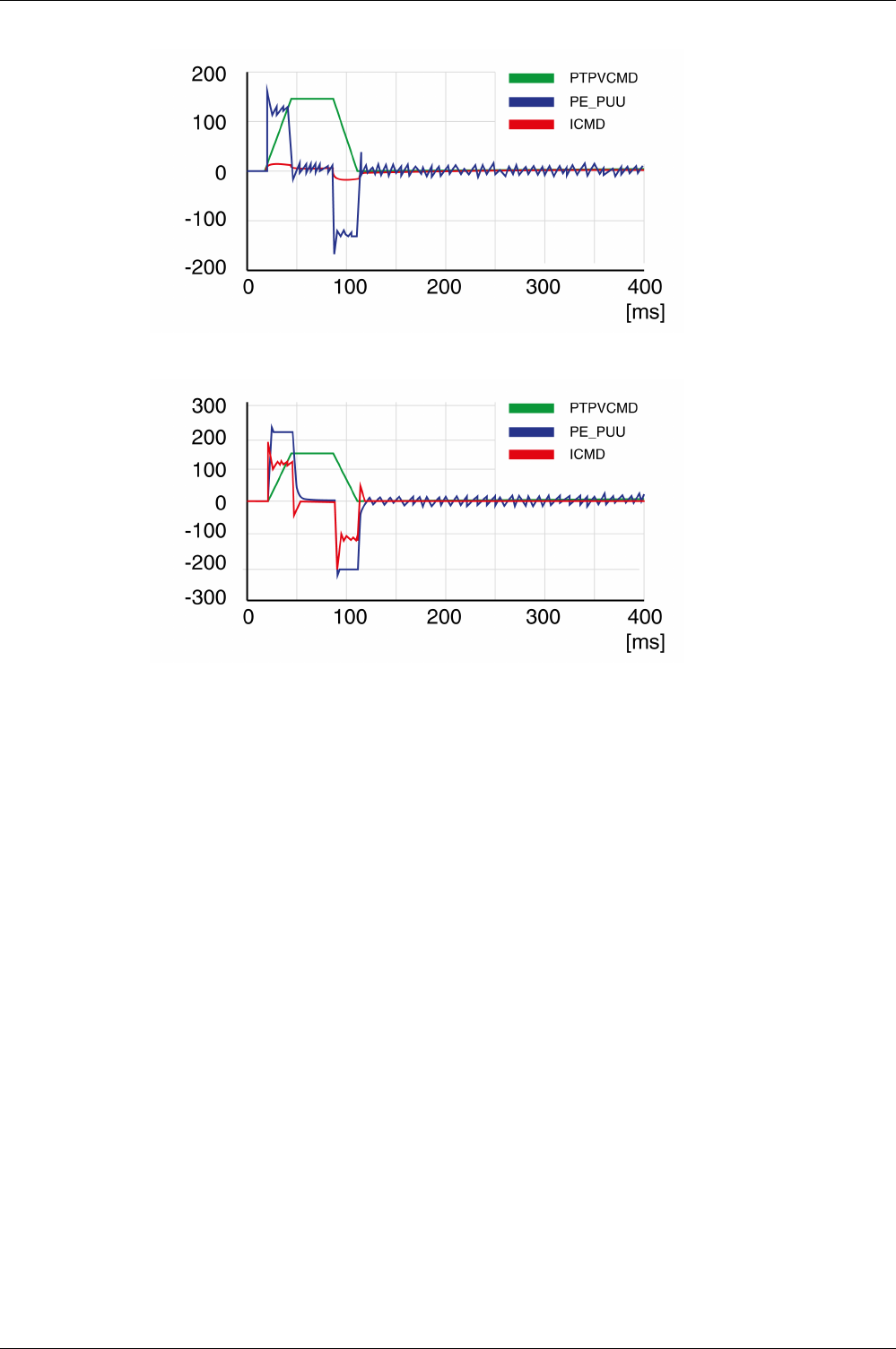
Tuning the Control Loops
EIO0000002305 04/2017 223
Example P8-03 (LTNP) value too high - oscillation at standstill, overshoot of position deviation (100 Hz)
Example P8-03 (LTNP) OK (65 Hz)
Step 5: Setting the Derivative-Integral Gain
The objective of tuning the derivative-integral gain is to reduce the position deviation. As a general rule,
the value for the derivative-integral gain (P8-02LTNIV) is within the following range:
P8-03 (LTNP) / 2 < P8-02 (LTNIV) < 2 x P8-03 (LTNP)
Progressively increasing the value of the derivative-integral gain progressively decreases the position
deviation during the acceleration phase, the constant velocity phase, and the deceleration phase.
Criteria for a well-tuned derivative-integral gain include:
-Position deviation decreases rapidly after each transition of the movement phases (jerk)
-No or minimum overshoot of position deviation
-No or minimum oscillations during transitions between the movement phases
-Oscillations at standstill as low as possible (+/- 1 encoder increment)
The derivative-integral gain is set via parameter P8-02 (LTNIV).
Procedure:
-Progressively increase the value of parameter P8-02 (LTNIV) to find the optimum value. The figures
below show examples of the plot as the value approaches the optimum value.
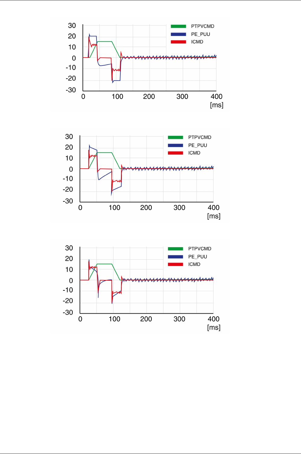
Tuning the Control Loops
224 EIO0000002305 04/2017
Example P8-02 (LTNIV) starting value (30 Hz)
Example P8-02 (LTNIV) position deviation decreased (60 Hz)
Example P8-02 (LTNIV) position deviation decreases rapidly when target velocity is reached (90 Hz)
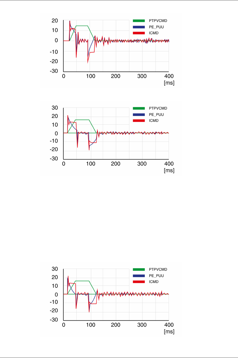
Tuning the Control Loops
EIO0000002305 04/2017 225
Example P8-02 (LTNIV) value too high - oscillation at standstill, overshoot of position deviation (120 Hz)
Example P8-02 (LTNIV) OK (90 Hz)
Step 6: Setting the Integral Gain
The objective of tuning the integral gain is to reduce the position deviation during movements and at
standstill.
Criteria for a well-tuned integral gain include:
-Position deviation further reduced
-No or minimum overshoot of position deviation at the end of the deceleration phase
-Oscillations at standstill as low as possible (+/- 1 encoder increment)
The integral gain is set via parameter P8-01 (LTNI).
Procedure:
-Progressively increase the value of parameter P8-01 (LTNI) until the oscilloscope shows overshoot or
oscillations. The figures below show examples of the plot as the value approaches the optimum value.
Example P8-01 (LTNI) value too high - oscillation at standstill, overshoot of position deviation (50 Hz)
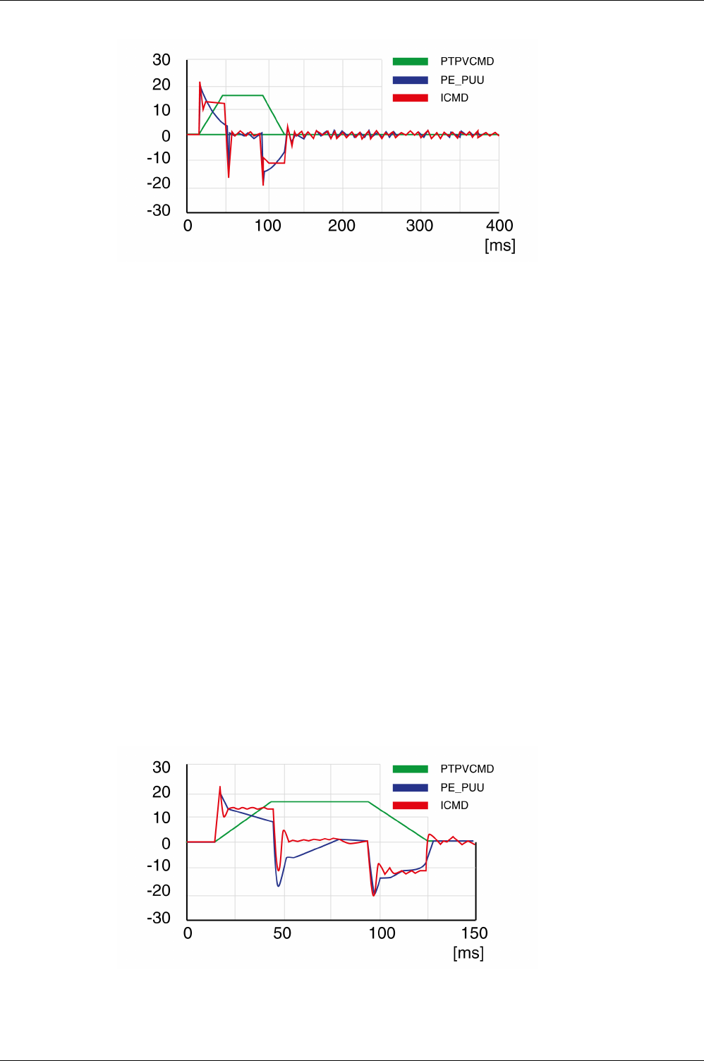
Tuning the Control Loops
226 EIO0000002305 04/2017
Example P8-01 (LTNI) OK (25 Hz)
Step 7: Compensation of the Flexibility of the Mechanical System
The parameters for compensation of the system flexibility reduce the vibrations caused by abrupt changes
in the acceleration (jerk). The parameters can also be used to further minimize overshoot or settling time.
The value of parameter P8-20 (NLPEAFF) reflects the oscillation frequency of the mechanical system, i.e.
the coupling between the motor and the load. The coupling can be very rigid (for example, a direct drive or
a low-backlash coupling) and less rigid (for example, a belt drive or an elastic coupling). Systems with a
high rigidity require a high value. Systems with high load inertia and less rigid couplings require lower
values. The less rigid the coupling, the lower this frequency. Depending on the application, the typical value
range is 400 … 30 Hz.
The parameter P8-05 (NLAFFLPFHZ) sets a low-pass filter for the acceleration profile. If the target value
has a relatively low resolution as, for example, in the case of a pulse train input, the calculated acceleration
may be subject to noise. The low-pass filter set via this parameter can be used to smooth the acceleration
profile. The parameter can be used if the flexibility compensation set via parameter P8-20 (NLPEAFF)
results in noise.
The compensation of the flexibility of the mechanical system is set via parameters P8-05 (NLAFFLPFHZ)
and P8-20 (NLPEAFF).
Procedure:
-Set the value of parameter P8-05 (NLAFFLPFHZ) to a value three times as high as that of parameter
P8-20 (NLPEAFF). With this value, the bandwidth of this low-pass filter is sufficiently higher than the
response time of the system.
-Progressively decrease the value of parameter P8-20 (NLPEAFF) to find the optimum value. The
optimum value depends on your optimization criterion: either short settling time or low position deviation.
Start with a high frequency of 400 Hz. Decrease the value and compare the amplitudes for the position
deviation and the settling time. Select the most suitable value according to your optimization criterion.
The figures below show examples of the plot as the value approaches the optimum value.
Example P8-20 (NLPEAFF) without compensation of the flexibility (5000 Hz)
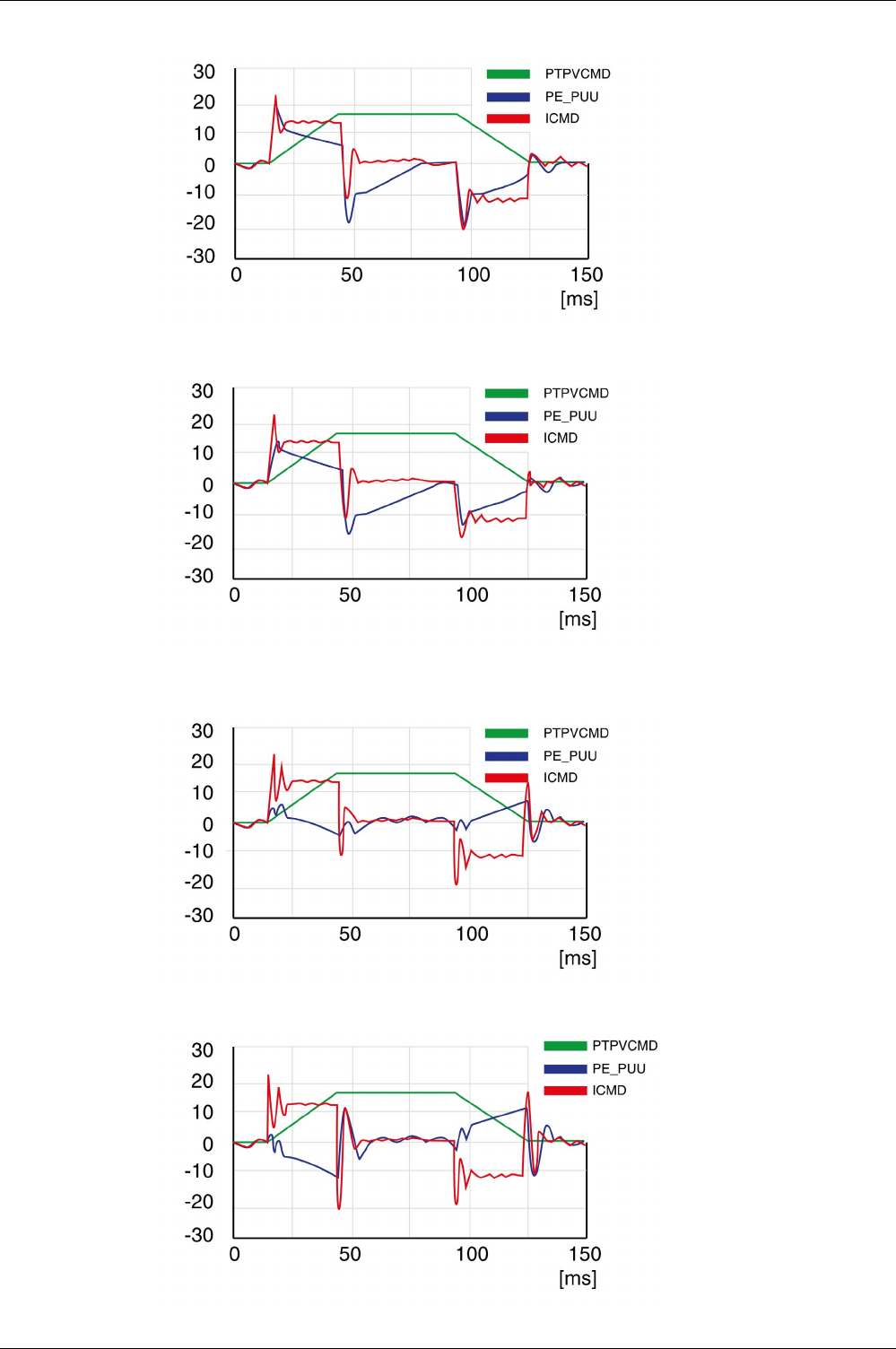
Tuning the Control Loops
EIO0000002305 04/2017 227
Example P8-20 (NLPEAFF) maximum position deviation decreased (300 Hz)
Example P8-20 (NLPEAFF) maximum position deviation further decreased (220 Hz)
Example P8-20 (NLPEAFF) minimum position deviation, short settling time, oscillation at standstill
(120 Hz)
Example P8-20 (NLPEAFF) negative position deviation during acceleration phase (100 Hz)

Tuning the Control Loops
228 EIO0000002305 04/2017

EIO0000002305 04/2017 229
Lexium 28
A
and BCH2 Servo Drive System
Parameters
EIO0000002305 04/2017
Parameters
Part VI
Parameters

Parameters
230 EIO0000002305 04/2017

EIO0000002305 04/2017 231
Lexium 28
A
and BCH2 Servo Drive System
Parameters
EIO0000002305 04/2017
Parameters
Chapter 16
Parameters
What Is in This Chapter?
This chapter contains the following topics:
Topic Page
Representation of the Parameters 232
P0 - Status Parameters 233
P1 - Basic Parameters 238
P2 - Extended Parameters 250
P3 - Communication Parameters 257
P4 - Diagnostics Parameters 260
P5 - Motion Settings 264
P6 - Position Sequence Data Sets Group 1 269
P7 - Position Sequence Data Sets Group 2 276
P8 - Control Loops 282
P9 - DTM Data 288

Parameters
232 EIO0000002305 04/2017
Representation of the Parameters
This chapter provides an overview of the parameters which can be used for operating the product.
Unsuitable settings or unsuitable data may trigger unintended movements, trigger signals, damage parts
and disable monitoring functions. Some parameters and other operational data do not become active until
after a restart.
NOTE: Possible values of a parameter that are not described are considered as reserved and must not be
used.
Parameter Name
The parameter name uniquely identifies a parameter.
Unit
The unit of the value.
WARNING
UNINTENDED EQUIPMENT OPERATION
-Only start the system if there are no persons or obstructions in the zone of operation.
-Do not operate the drive system with undetermined parameter values.
-Never modify a parameter value unless you fully understand the parameter and all effects of the
modification.
-Restart the drive and verify the saved operational data and/or parameter values after modification.
-Carefully run tests for all operating states and potential error situations when commissioning,
upgrading or otherwise modifying the operation of the drive.
-Verify the functions after replacing the product and also after making modifications to the parameter
values and/or other operational data.
Failure to follow these instructions can result in death, serious injury, or equipment damage.
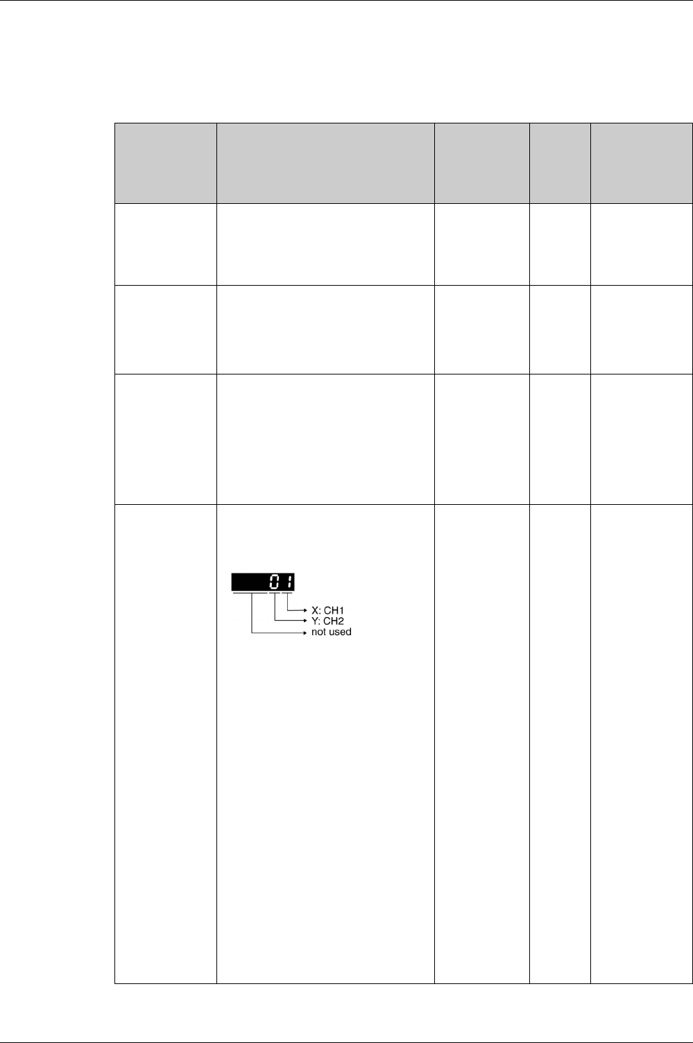
Parameters
EIO0000002305 04/2017 233
P0 - Status Parameters
P0 - Status Parameters
Parameter name Description Unit
Minimum value
Factory setting
Maximum value
HMI Format
Data type
R/W
Persistent
Parameter
address via
fieldbus
P0-00
VER
Firmware Version
Applicable operating mode: PT, PS, V, T
-
0h
0h
FFFFh
Hexadecimal
u16
RO
-
Modbus 100h
CANopen 4000h
P0-01
ALE
Error code of detected error
Applicable operating mode: PT, PS, V, T
This parameter contains the error number
of the most recently detected error.
For a list of the detected error codes, refer
to Error Codes
(see page 407)
.
-
0h
0h
FFFFh
Hexadecimal
u16
RW
-
Modbus 102h
CANopen 4001h
P0-02
STS
Drive Status Displayed by HMI
Applicable operating mode: PT, PS, V, T
This parameter selects the type of status
information to be displayed on the HMI.
Example: If the setting is 7, the HMI
displays the speed of rotation of the motor.
For further information, refer to chapter
Status Information via the HMI
(see page 198)
.
-
0
0
123
Decimal
u16
RW
per.
Modbus 104h
CANopen 4002h
P0-03
MON
Function of Analog Outputs
Applicable operating mode: PT, PS, V, T
This parameter specifies the functions of
the analog outputs.
XY: (X: MON1; Y: MON2)
0: Actual velocity (+/-8 V correspond to
maximum velocity)
1: Actual torque (+/-8 V correspond to
maximum torque)
2: Reference value in kilopulses per
second (+8 V correspond to 4.5 Mpps)
3: Target velocity (+/-8 V correspond to
maximum target velocity)
4: Target torque (+/-8 V correspond to
maximum target torque)
5: DC bus voltage (+/-8 V correspond to
450 V)
6: Reserved
7: Reserved
See P1-04 and P1-05 for setting a voltage
percentage (scaling).
Example:
P0-03 = 01: Voltage value at analog output
indicates the actual velocity.
Velocity = (maximum velocity x V1 / 8) x
P1-04 / 100 if the output voltage value of
MON2 is V1.
-
0h
0h
77h
Hexadecimal
u16
RW
per.
Modbus 106h
CANopen 4003h

Parameters
234 EIO0000002305 04/2017
P0-08
TSON
Operating Hour Meter in Seconds
Applicable operating mode: PT, PS, V, T
s
0
-
4294967295
Decimal
u32
RO
-
Modbus 110h
CANopen 4008h
P0-09
CM1
Status Value 1
Applicable operating mode: PT, PS, V, T
This parameter is used to provide the value
of one of the status indications in P0-02.
The value of this parameter is determined
via P0-17.
Examples:
If the status of the drive is read via the HMI
and if P0-02 is set to 23, VAR-1 is
displayed for approximately two seconds
by the HMI, followed by the value of this
parameter.
If the setting of P0-17 is 3, reading this
parameter displays the actual position in
pulses.
For reading the status via Modbus, read
two 16-bit data stored in the addresses of
0012H and 0013H to generate 32-bit data.
(0013H : 0012H) = (high byte : low byte)
-
-2147483647
-
2147483647
Decimal
s32
RO
-
Modbus 112h
CANopen 4009h
P0-10
CM2
Status Value 2
Applicable operating mode: PT, PS, V, T
This parameter is used to provide the value
of one of the status indications in P0-02.
The value of this parameter is determined
via P0-18.
See P0-09 for details.
-
-2147483647
-
2147483647
Decimal
s32
RO
-
Modbus 114h
CANopen 400 Ah
P0-11
CM3
Status Value 3
Applicable operating mode: PT, PS, V, T
This parameter is used to provide the value
of one of the status indications in P0-02.
The value of this parameter is determined
via P0-19.
See P0-09 for details.
-
-2147483647
-
2147483647
Decimal
s32
RO
-
Modbus 116h
CANopen 400Bh
P0-12
CM4
Status Value 4
Applicable operating mode: PT, PS, V, T
This parameter is used to provide the value
of one of the status indications in P0-02.
The value of this parameter is determined
via P0-20.
See P0-09 for details.
-
-2147483647
-
2147483647
Decimal
s32
RO
-
Modbus 118h
CANopen 400Ch
P0-13
CM5
Status Value 5
Applicable operating mode: PT, PS, V, T
This parameter is used to provide the value
of one of the status indications in P0-02.
The value of this parameter is determined
via P0-21.
See P0-09 for details.
-
-2147483647
-
2147483647
Decimal
s32
RO
-
Modbus 11 Ah
CANopen 400Dh
P0-17
CMA1
Indicate status value 1
Applicable operating mode: PT, PS, V, T
This parameter is used to select a drive
status provided in P0-02. The selected
status is indicated via P0-09.
Example:
If the setting of P0-17 is 7, reading P0-09
returns the speed of rotation of the motor in
rpm.
-
0
0
123
Decimal
u16
RW
per.
Modbus 122h
CANopen 4011h
Parameter name Description Unit
Minimum value
Factory setting
Maximum value
HMI Format
Data type
R/W
Persistent
Parameter
address via
fieldbus

Parameters
EIO0000002305 04/2017 235
P0-18
CMA2
Indicate status value 2
Applicable operating mode: PT, PS, V, T
This parameter is used to select a drive
status provided in P0-02. The selected
status is indicated via P0-10. See P0-17 for
details.
-
0
0
123
Decimal
u16
RW
per.
Modbus 124h
CANopen 4012h
P0-19
CMA3
Indicate status value 3
Applicable operating mode: PT, PS, V, T
This parameter is used to select a drive
status provided in P0-02. The selected
status is indicated via P0-11. See P0-17 for
details.
-
0
0
123
Decimal
u16
RW
per.
Modbus 126h
CANopen 4013h
P0-20
CMA4
Indicate status value 4
Applicable operating mode: PT, PS, V, T
This parameter is used to select a drive
status provided in P0-02. The selected
status is indicated via P0-12. See P0-17 for
details.
-
0
0
123
Decimal
u16
RW
per.
Modbus 128h
CANopen 4014h
P0-21
CMA5
Indicate status value 5
Applicable operating mode: PT, PS, V, T
This parameter is used to select a drive
status provided in P0-02. The selected
status is indicated via P0-13. See P0-17 for
details.
-
0
0
123
Decimal
u16
RW
per.
Modbus 12 Ah
CANopen 4015h
P0-25
MAP1
Parameter Mapping 1
Applicable operating mode: PT, PS, V, T
The parameters from P0-25 ... P0-32 are
used to read and write the values of
parameters with non-consecutive
communication addresses. You can set
P0-35 ... P0-42 as the required read and
write mapping parameter numbers. When
P0-25 ... P0-32 are read, the read or write
values are equivalent to the values of the
parameters specified via P0-35 ... P0-42,
and vice versa. See P0-35 for details.
-
0h
0h
FFFFFFFFh
Hexadecimal
u32
RW
-
Modbus 132h
CANopen 4019h
P0-26
MAP2
Parameter Mapping 2
Applicable operating mode: PT, PS, V, T
See P0-25 and P0-36 for details.
-
0h
0h
FFFFFFFFh
Hexadecimal
u32
RW
-
Modbus 134h
CANopen 401 Ah
P0-27
MAP3
Parameter Mapping 3
Applicable operating mode: PT, PS, V, T
See P0-25 and P0-37 for details.
-
0h
0h
FFFFFFFFh
Hexadecimal
u32
RW
-
Modbus 136h
CANopen 401Bh
P0-28
MAP4
Parameter Mapping 4
Applicable operating mode: PT, PS, V, T
See P0-25 and P0-38 for details.
-
0h
0h
FFFFFFFFh
Hexadecimal
u32
RW
-
Modbus 138h
CANopen 401Ch
P0-29
MAP5
Parameter Mapping 5
Applicable operating mode: PT, PS, V, T
See P0-25 and P0-39 for details.
-
0h
0h
FFFFFFFFh
Hexadecimal
u32
RW
-
Modbus 13 Ah
CANopen 401Dh
Parameter name Description Unit
Minimum value
Factory setting
Maximum value
HMI Format
Data type
R/W
Persistent
Parameter
address via
fieldbus
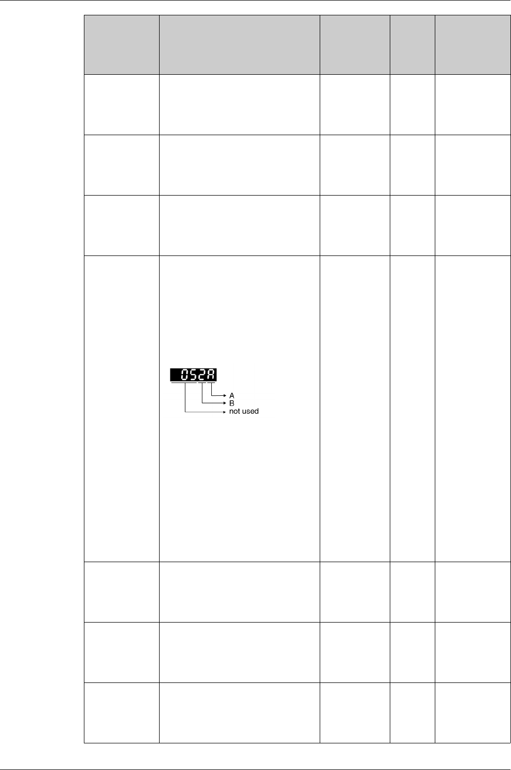
Parameters
236 EIO0000002305 04/2017
P0-30
MAP6
Parameter Mapping 6
Applicable operating mode: PT, PS, V, T
See P0-25 and P0-40 for details.
-
0h
0h
FFFFFFFFh
Hexadecimal
u32
RW
-
Modbus 13Ch
CANopen 401Eh
P0-31
MAP7
Parameter Mapping 7
Applicable operating mode: PT, PS, V, T
See P0-25 and P0-41 for details.
-
0h
0h
FFFFFFFFh
Hexadecimal
u32
RW
-
Modbus 13Eh
CANopen 401Fh
P0-32
MAP8
Parameter Mapping 8
Applicable operating mode: PT, PS, V, T
See P0-25 and P0-42 for details.
-
0h
0h
FFFFFFFFh
Hexadecimal
u32
RW
-
Modbus 140h
CANopen 4020h
P0-35
MAPA1
Block Data Read/Write P0-35…P0-42 1
Applicable operating mode: PT, PS, V, T
The parameters P0-35 ... P0-42 specify the
required read and write parameter
numbers for P0-25 ... P0-32. They read
and write the values of the parameters
whose communication addresses are not
consecutive.
The read/write parameter can be a single
32-bit parameter or two 16-bit parameters.
A: Parameter group code in hexadecimal
format
B: Parameter number in hexadecimal
format
Example:
If you want to read and write the value of
P1-44 (32-bit parameter) via P0-25, set P0-
35 to 012C012Ch.
If you want to read and write the values of
P2-02 (16-bit parameter) and P2-04 (16-bit
parameter) via P0-25, set P0-35 to
02040202h.
-
0h
0h
FFFFFFFFh
Hexadecimal
u32
RW
per.
Modbus 146h
CANopen 4023h
P0-36
MAPA2
Block Data Read/Write P0-35…P0-42 2
Applicable operating mode: PT, PS, V, T
See P0-35 for details.
-
0h
0h
FFFFFFFFh
Hexadecimal
u32
RW
per.
Modbus 148h
CANopen 4024h
P0-37
MAPA3
Block Data Read/Write P0-35…P0-42 3
Applicable operating mode: PT, PS, V, T
See P0-35 for details.
-
0h
0h
FFFFFFFFh
Hexadecimal
u32
RW
per.
Modbus 14 Ah
CANopen 4025h
P0-38
MAPA4
Block Data Read/Write P0-35…P0-42 4
Applicable operating mode: PT, PS, V, T
See P0-35 for details.
-
0h
0h
FFFFFFFFh
Hexadecimal
u32
RW
per.
Modbus 14Ch
CANopen 4026h
Parameter name Description Unit
Minimum value
Factory setting
Maximum value
HMI Format
Data type
R/W
Persistent
Parameter
address via
fieldbus

Parameters
EIO0000002305 04/2017 237
P0-39
MAPA5
Block Data Read/Write P0-35…P0-42 5
Applicable operating mode: PT, PS, V, T
See P0-35 for details.
-
0h
0h
FFFFFFFFh
Hexadecimal
u32
RW
per.
Modbus 14Eh
CANopen 4027h
P0-40
MAPA6
Block Data Read/Write P0-35…P0-42 6
Applicable operating mode: PT, PS, V, T
See P0-35 for details.
-
0h
0h
FFFFFFFFh
Hexadecimal
u32
RW
per.
Modbus 150h
CANopen 4028h
P0-41
MAPA7
Block Data Read/Write P0-35…P0-42 7
Applicable operating mode: PT, PS, V, T
See P0-35 for details.
-
0h
0h
FFFFFFFFh
Hexadecimal
u32
RW
per.
Modbus 152h
CANopen 4029h
P0-42
MAPA8
Block Data Read/Write P0-35…P0-42 8
Applicable operating mode: PT, PS, V, T
See P0-35 for details.
-
0h
0h
FFFFFFFFh
Hexadecimal
u32
RW
per.
Modbus 154h
CANopen 402 Ah
P0-46
SVSTS
State of Signal Output Functions
Applicable operating mode: PT, PS, V, T
This parameter is used to indicate the state
of the signal output function of the drive in
hexadecimal format. If the function is
assigned to a digital output, it would
represent the state of the output given no
forcing on the output.
Bit 0: SRDY (Servo ready)
Bit 1: SON (Servo On)
Bit 2: ZSPD (Zero speed)
Bit 3: TSPD (Speed reached)
Bit 4: TPOS (Movement completed)
Bit 5: TQL (Torque Limit Reached)
Bit 6: ERR (Error Detected)
Bit 7: BRKR (Holding brake control)
Bit 8: HOMED_OK (Homing completed)
Bit 9: OLW (Motor Overload Alert)
Bit 10: WARN (indicates that one of the
following conditions has been detected:
Hardware limit switch triggered,
undervoltage, Nodeguard alert,
Operational Stop (OPST))
Bits 11 ... 15: Reserved
The parameter can also be read via the
fieldbus.
-
0h
0h
FFFFh
Hexadecimal
u16
RO
-
Modbus 15Ch
CANopen 402Eh
P0-47
LAST_WRN
Number of Last Alert
Applicable operating mode: PT, PS, V, T
This parameter contains the number of the
last detected alert. After a Fault Reset, the
number is cleared.
-
0h
0h
FFFFh
Hexadecimal
u16
RO
-
Modbus 15Eh
CANopen 402Fh
Parameter name Description Unit
Minimum value
Factory setting
Maximum value
HMI Format
Data type
R/W
Persistent
Parameter
address via
fieldbus
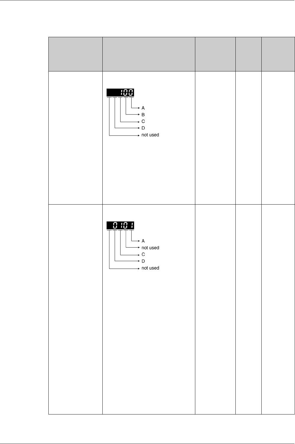
Parameters
238 EIO0000002305 04/2017
P1 - Basic Parameters
P1 - Basic Parameters
Parameter name Description Unit
Minimum value
Factory setting
Maximum value
HMI Format
Data type
R/W
Persistent
Parameter
address via
fieldbus
P1-00
PTT
Reference Value Signal - Pulse Settings
Applicable operating mode: PT
This parameter is used to configure the
reference value signals for the operating
mode PT.
A: Type of reference value signals
B: Signal frequency
C: Input polarity
D: Source of reference value signals
Setting can only be changed if power stage
is disabled.
-
0h
2h
1132h
Hexadecimal
u16
RW
per.
Modbus 200h
CANopen
4100h
P1-01
CTL
Operating Mode and Direction of Rotation
Applicable operating mode: PT, PS, V, T
A: Operating mode
Refer to chapter Setting the Operating
Mode
(see page 316)
.
C: Direction of movement
Refer to chapter Verifying the Direction of
Movement
(see page 205)
.
D: Signal input functions and signal output
functions after operating mode switching
Value 0: The assignments of the signal
input functions and the signal output
functions (P2-10 ... P2-22) remain identical
for the new operating mode.
Value 1: The assignments of the signal
input functions and the signal output
functions (P2-10 ... P2-22)) are set to the
default presets of the new operating mode.
Refer to chapters Default Presets of the
Signal Inputs
(see page 300)
and Default
Presets of the Signal Outputs
(see page 306)
.
Changed settings become active the next
time the product is powered on.
-
0h
Bh
110Bh
Hexadecimal
u16
RW
per.
Modbus 202h
CANopen
4101h
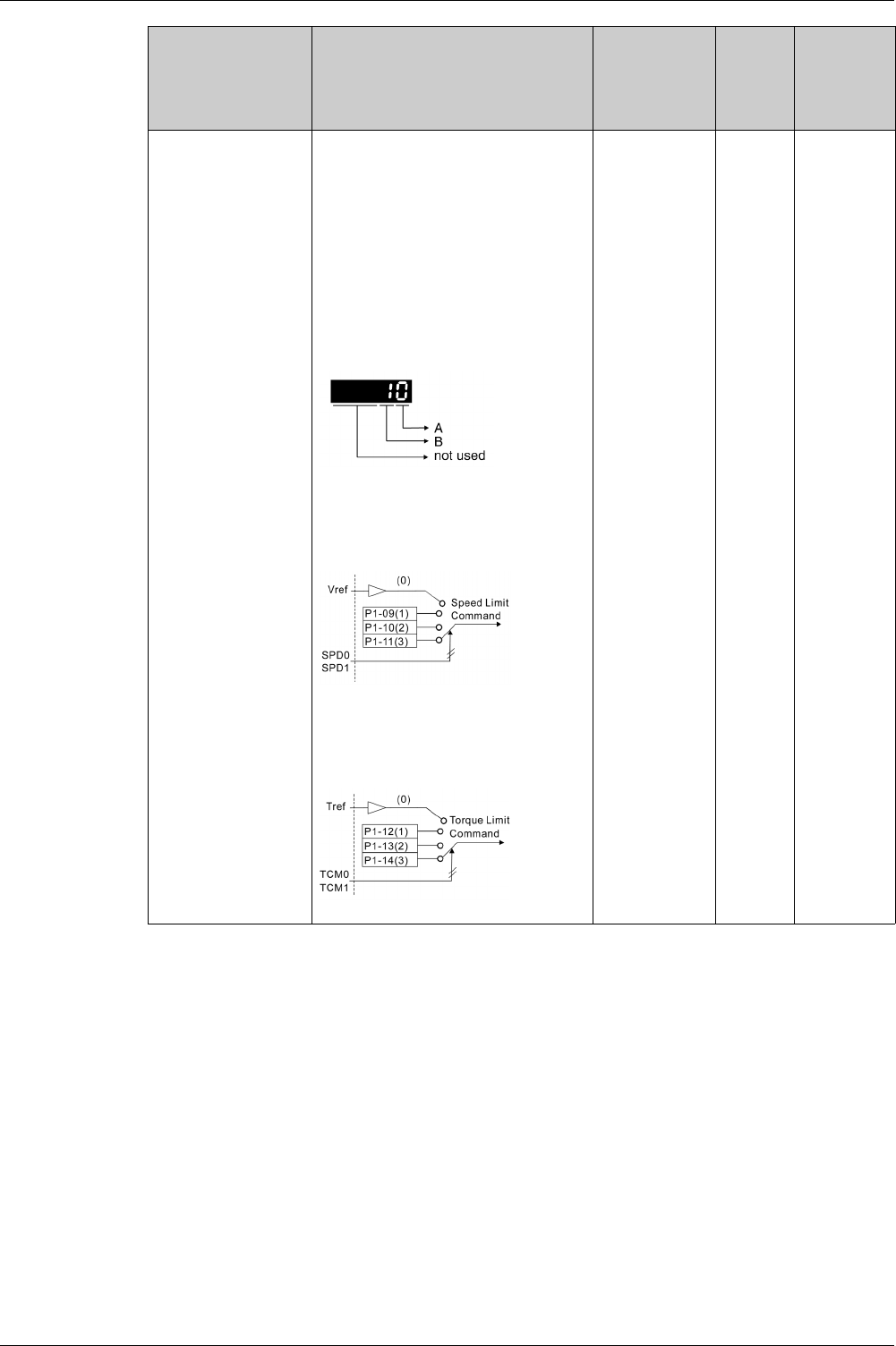
Parameters
EIO0000002305 04/2017 239
P1-02
PSTL
Velocity and Torque Limitations
Activation/Deactivation
Applicable operating mode: PT, PS, V, T
This parameter activates/deactivates
velocity limitation and torque limitation.
It can also be activated via the signal input
functions SPDLM and TRQLM.
The signal input functions SPD0 and SPD1
are used to select velocity values set via
P1-09 to P1-11.
The signal input functions TCM0 and TCM1
are used to select torque values set via P1-
12 to P1-14.
A: Velocity limitation
0: Deactivate
1: Activate (in operating mode T, and
CANopen T (refer to P1-82))
B: Torque limitation
0: Deactivate
1: Activate (operating modes PT, PS,
CANopenV (refer to P1-85), and V))
-
0h
0h
11h
Hexadecimal
u16
RW
per.
Modbus 204h
CANopen
4102h
Parameter name Description Unit
Minimum value
Factory setting
Maximum value
HMI Format
Data type
R/W
Persistent
Parameter
address via
fieldbus

Parameters
240 EIO0000002305 04/2017
P1-03
AOUT
Polarity of Analog Outputs / Polarity of
Pulse Outputs
Applicable operating mode: PT, PS, V, T
This parameter is used to specify the
polarity of analog outputs MON1 and
MON2 and the polarity of pulse outputs.
A: Polarity of analog outputs MON1 and
MON2
0: MON1(+), MON2(+)
1: MON1(+), MON2(-)
2: MON1(-), MON2(+)
3: MON1(-), MON2(-)
B: Polarity of pulse outputs
0: Not inverted
1: Inverted
-
0h
0h
13h
Hexadecimal
u16
RW
per.
Modbus 206h
CANopen
4103h
P1-04
MON1
Scaling Factor Analog Output 1
Applicable operating mode: PT, PS, V, T
%
1
100
100
Decimal
u16
RW
per.
Modbus 208h
CANopen
4104h
P1-05
MON2
Scaling Factor Analog Output 2
Applicable operating mode: PT, PS, V, T
%
1
100
100
Decimal
u16
RW
per.
Modbus 20 Ah
CANopen
4105h
P1-09
SP1
Target Velocity/Velocity Limitation 1
Applicable operating mode: V, T
Target velocity 1
In the operating mode V, this parameter
specifies the first target velocity.
Velocity limitation 1
In the operating mode T, this parameter
specifies the first velocity limitation.
0.1rpm
-60000
10000
60000
Decimal
s32
RW
per.
Modbus 212h
CANopen
4109h
P1-10
SP2
Target Velocity/Velocity Limitation 2
Applicable operating mode: V, T
Target velocity 2
In the operating mode V, this parameter
specifies the second target velocity.
Velocity limitation 2
In the operating mode T, this parameter
specifies the second velocity limitation.
0.1rpm
-60000
20000
60000
Decimal
s32
RW
per.
Modbus 214h
CANopen
410 Ah
P1-11
SP3
Target Velocity/Velocity Limitation 3
Applicable operating mode: V, T
Target velocity 3
In the operating mode V, this parameter
specifies the third target velocity.
Velocity limitation 3
In the operating mode T, this parameter
specifies the third velocity limitation.
0.1rpm
-60000
30000
60000
Decimal
s32
RW
per.
Modbus 216h
CANopen
410Bh
Parameter name Description Unit
Minimum value
Factory setting
Maximum value
HMI Format
Data type
R/W
Persistent
Parameter
address via
fieldbus

Parameters
EIO0000002305 04/2017 241
P1-12
TQ1
Target Torque/Torque Limitation 1
Applicable operating mode: PT, PS, V, T
Target torque 1 in percent of nominal
current
In the operating mode T, this parameter
specifies the first target torque.
Torque limitation 1 in percent of nominal
current
In the operating modes PT, PS and V, this
parameter specifies the first torque
limitation.
The signal output function TQL is activated
if the torque reaches the torque limitations
set via the parameters P1-12 ... P1-14 or
via an analog input.
%
-300
100
300
Decimal
s16
RW
per.
Modbus 218h
CANopen
410Ch
P1-13
TQ2
Target Torque/Torque Limitation 2
Applicable operating mode: PT, PS, V, T
Target torque 2 in percent of nominal
current
In the operating mode T, this parameter
specifies the second target torque.
Torque limitation 2 in percent of nominal
current
In the operating modes PT, PS and V, this
parameter specifies the second torque
limitation.
The signal output function TQL is activated
if the torque reaches the torque limitations
set via the parameters P1-12 ... P1-14 or
via an analog input.
%
-300
100
300
Decimal
s16
RW
per.
Modbus 21 Ah
CANopen
410Dh
P1-14
TQ3
Target Torque/Torque Limitation 3
Applicable operating mode: PT, PS, V, T
Target torque 3 in percent of nominal
current
In the operating mode T, this parameter
specifies the third target torque.
Torque limitation 3 in percent of nominal
current
In the operating modes PT, PS and V, this
parameter specifies the third torque
limitation.
The signal output function TQL is activated
if the torque reaches the torque limitations
set via the parameters P1-12 ... P1-14 or
via an analog input.
%
-300
100
300
Decimal
s16
RW
per.
Modbus 21Ch
CANopen
410Eh
P1-15
LINELOSSMODE
Mains Phase Monitoring - Response to
Missing Mains Phase
Applicable operating mode: PT, PS, V, T
This parameter specifies the response of
the drive if the mains phase monitoring
function detects an error.
Value 0: Detected error if power stage is
enabled or disabled
Value 1: Detected error if power stage is
enabled, alert if power stage is disabled
Value 2: Alert if power stage is enabled or
disabled
-
0
0
2
Decimal
u16
RW
per.
Modbus 21Eh
CANopen
410Fh
P1-16
LINELOSSRECOVER
Mains Phase Monitoring - Fault Reset
Applicable operating mode: PT, PS, V, T
This parameter specifies the type of Fault
Reset after a detected mains phase error
has been removed.
Value 0: No automatic Fault Reset
Value 1: Automatic Fault Reset
-
0
0
1
Decimal
u16
RW
per.
Modbus 220h
CANopen
4110h
Parameter name Description Unit
Minimum value
Factory setting
Maximum value
HMI Format
Data type
R/W
Persistent
Parameter
address via
fieldbus

Parameters
242 EIO0000002305 04/2017
P1-17
LINELOSSTYPE
Mains Phase Monitoring - Type
Applicable operating mode: PT, PS, V, T
This parameter specifies the type of mains
phase monitoring
Value 0: No mains phase monitoring
Value 1: Mains phase monitoring single-
phase connection
Value 2: Mains phase monitoring three-
phase connection
-
0
0
2
Decimal
u16
RW
per.
Modbus 222h
CANopen
4111h
P1-18 Reserved – – –
P1-19
DISTIME
Active Disable - Delay Time Power Stage
Applicable operating mode: PT, PS, V, T
This parameter specifies the delay time
between standstill of the motor and
disabling the power stage.
ms
0
0
6500
Decimal
u16
RW
per.
Modbus 226h
CANopen
4113h
P1-20
ESTOPILIM
Current Limit During Quick Stop
Applicable operating mode: PT, PS, V
This parameter specifies the maximum
current during a Quick Stop (expressed as
factor of P1-78).
0.001
1
1000
1000
Decimal
s16
RW
per.
Modbus 228h
CANopen
4114h
P1-21
FOLD
Status of Foldback Current Drive
Applicable operating mode: PT, PS, V, T
This parameter indicates whether the
foldback current limit is greater than or less
than the maximum current of the drive (see
P1-78).
Value 0: Foldback current limit greater than
P1-78
Value 1: Foldback current limit is less than
P1-78
-
0
-
1
Decimal
u16
RO
-
Modbus 22 Ah
CANopen
4115h
P1-22
IFOLD
Foldback Current Limit - Drive
Applicable operating mode: PT, PS, V, T
Drive foldback current limit
0.01 A
0
-
30000
Decimal
u32
RO
-
Modbus 22Ch
CANopen
4116h
P1-23
IFOLDFTHRESH
Current Monitoring Drive - Detected Error
Threshold Foldback Current
Applicable operating mode: PT, PS, V, T
This parameter specifies the threshold
value used by the drive current monitoring
function to detect a drive foldback current
error.
0.01 A
0
-
30000
Decimal
u32
RW
per.
Modbus 22Eh
CANopen
4117h
P1-24
IFOLDWTHRESH
Current Monitoring Drive - Alert Threshold
Foldback Current
Applicable operating mode: PT, PS, V, T
This parameter specifies the threshold
value used by the drive current monitoring
function to trigger a drive foldback current
alert.
0.01 A
0
-
30000
Decimal
u32
RW
per.
Modbus 230h
CANopen
4118h
P1-25 Reserved – – –
P1-26
MIFOLD
Foldback Current Limit - Motor
Applicable operating mode: PT, PS, V, T
Motor foldback current limit
0.01 A
0
-
30000
Decimal
u32
RO
-
Modbus 234h
CANopen
411 Ah
Parameter name Description Unit
Minimum value
Factory setting
Maximum value
HMI Format
Data type
R/W
Persistent
Parameter
address via
fieldbus

Parameters
EIO0000002305 04/2017 243
P1-27
MIFOLDFTHRESH
Motor Current Monitoring - Detected Error
Threshold Foldback Current
Applicable operating mode: PT, PS, V, T
This parameter specifies the threshold
value used by the motor current monitoring
function to detect a motor foldback current
error.
0.01 A
0
-
30000
Decimal
u32
RW
per.
Modbus 236h
CANopen
411Bh
P1-28
MIFOLDWTHRESH
Motor Current Monitoring - Alert Threshold
Foldback Current
Applicable operating mode: PT, PS, V, T
This parameter specifies the threshold
value used by the motor current monitoring
function to trigger a motor foldback current
alert.
0.01 A
0
-
30000
Decimal
u32
RW
per.
Modbus 238h
CANopen
411Ch
P1-29
OVTHRESH
DC Bus Overvoltage Monitoring -
Threshold
Applicable operating mode: PT, PS, V, T
This parameter specifies the threshold
value used by the DC bus overvoltage
monitoring function.
V
-
-
-
Decimal
u16
RO
-
Modbus 23 Ah
CANopen
411Dh
P1-30
COMMERRMAXCNT
Commutation Monitoring - Maximum
Counter Value
Applicable operating mode: PT, PS, V, T
ms
0
0
0
Decimal
u16
RW
-
Modbus 23Ch
CANopen
411Eh
P1-32
LSTP
Stop Method
Applicable operating mode: PT, PS, V
This parameter specifies how the motor is
stopped if the power stage is to be disabled
(includes signal input function OPST) or if
an error is detected.
Value 0h: Deceleration ramp
Value 10h: Coast to stop
Value 20h: Deceleration ramp to velocity
P1-38, then coast to stop (actual velocity
must be less than the value of P1-38 for 50
ms before coasting to stop starts)
In the operating mode Torque (T), the
deceleration ramp is not used. Instead, the
current is set to zero.
Depending on the event that triggered the
stop, the following deceleration ramps are
used:
- Signal input function STOP: P5-20
- Transmission error detected: P5-21
- Position overflow: P5-22
- Triggering of negative software limit
switch: P5-23
- Triggering of positive software limit
switch: P5-24
- Triggering of negative hardware limit
switch: P5-25
- Triggering of positive hardware limit
switch: P5-26
- Any other event: P1-68
The delay time between standstill of the
motor and disabling the power stage is set
via P1-19.
-
0h
0h
20h
Hexadecimal
u16
RW
per.
Modbus 240h
CANopen
4120h
Parameter name Description Unit
Minimum value
Factory setting
Maximum value
HMI Format
Data type
R/W
Persistent
Parameter
address via
fieldbus

Parameters
244 EIO0000002305 04/2017
P1-34
TACC
Acceleration Period
Applicable operating mode: PT, V
The acceleration period is the time in
milliseconds required to accelerate from
motor standstill to 6000 rpm.
For operating mode V, this parameter
specifies the acceleration.
For operating mode PT, this parameter
specifies an acceleration limitation for the
pulses at the PTI interface.
ms
6
30
65500
Decimal
u16
RW
per.
Modbus 244h
CANopen
4122h
P1-35
TDEC
Deceleration Period
Applicable operating mode: PT, V
The deceleration period is the time in
milliseconds required to decelerate from
6000 rpm to motor standstill.
For operating mode V, this parameter
specifies the deceleration.
For operating mode PT, this parameter
specifies a deceleration limitation for the
pulses at the PTI interface.
ms
6
30
65500
Decimal
u16
RW
per.
Modbus 246h
CANopen
4123h
P1-37
LMJR
Ratio of Load Inertia to Motor Inertia
Applicable operating mode: PT, PS, V, T
This parameter specifies the ratio of load
inertia to motor inertia (J_load / J_motor).
J_load: Total moment of inertia of external
mechanical load
J_motor: Moment of inertia of motor
0.1
0
10
20000
Decimal
u32
RW
per.
Modbus 24 Ah
CANopen
4125h
P1-38
ZSPD
Signal Output Function ZSPD / Signal Input
Function ZCLAMP - Velocity
Applicable operating mode: PT, PS, V, T
This parameter specifies the velocity for the
signal output function ZSPD. The signal
output function ZSPD indicates that the
velocity of the motor is less than the
velocity value set via this parameter.
This parameter specifies the velocity for the
signal input function ZCLAMP. The signal
input function ZCLAMP stops the motor.
The velocity of the motor must be below the
velocity value set via this parameter.
0.1rpm
0
100
2000
Decimal
s32
RW
per.
Modbus 24Ch
CANopen
4126h
P1-39
SSPD
Signal Output Function TSPD - Velocity
Applicable operating mode: PT, PS, V, T
This parameter specifies the velocity for the
signal output function TSPD. The signal
output function TSPD indicates that the
velocity of the motor is greater than the
velocity value set via this parameter.
rpm
0
3000
5000
Decimal
u32
RW
per.
Modbus 24Eh
CANopen
4127h
P1-40
VCM
Velocity Target Value and Velocity
Limitation 10 V
Applicable operating mode: PT, PS, V, T
In the operating mode V, this parameter
specifies the target velocity that
corresponds to the maximum input voltage
of 10 V.
In the operating mode T, this parameter
specifies the velocity limitation that
corresponds to the maximum input voltage
of 10 V.
Example: If the value of this parameter is
3000 in the operating mode V and if the
input voltage is 10 V, the target velocity is
3000 rpm.
rpm
0
-
10001
Decimal
s32
RW
per.
Modbus 250h
CANopen
4128h
Parameter name Description Unit
Minimum value
Factory setting
Maximum value
HMI Format
Data type
R/W
Persistent
Parameter
address via
fieldbus

Parameters
EIO0000002305 04/2017 245
P1-41
TCM
Torque Target Value and Torque Limitation
10 V
Applicable operating mode: PT, PS, V, T
In the operating mode T, this parameter
specifies the target torque that
corresponds to the maximum input voltage
of 10 V.
In the operating modes PT, PS and V, this
parameter specifies the torque limitation
that corresponds to the maximum input
voltage of 10 V.
Example: If the value of this parameter is
100 in the operating mode T and if the input
voltage is 10 V, the target torque is 100 %
of the nominal torque.
Setting can only be changed if power stage
is disabled.
%
0
100
1000
Decimal
u16
RW
per.
Modbus 252h
CANopen
4129h
P1-42
MBT1
Delay Time of Holding Brake
Applicable operating mode: PT, PS, V, T
This parameter specifies the time between
enabling the power stage and starting a
movement (opening time for the holding
brake).
ms
0
0
1000
Decimal
u16
RW
per.
Modbus 254h
CANopen
412 Ah
P1-44
GR1
Electronic Gear Ratio - Numerator 1
Applicable operating mode: PT, PS
This parameter is used to set the
numerator of the gear ratio. The
denominator of the gear ratio is set via P1-
45.
In the operating mode PS, the value of this
parameter can only be changed when the
power stage is disabled.
-
1
128
536870911
Decimal
u32
RW
per.
Modbus 258h
CANopen
412Ch
P1-45
GR2
Electronic Gear Ratio - Denominator
Applicable operating mode: PT, PS
This parameter is used to set the
denominator of the gear ratio. The
numerator of the gear ratio is set via P1-44.
Setting can only be changed if power stage
is disabled.
-
1
10
2147483647
Decimal
u32
RW
per.
Modbus 25 Ah
CANopen
412Dh
P1-46
ENCOUTRES
Encoder Simulation Resolution
Applicable operating mode: PT, PS, V, T
This parameter specifies the number of
increments (AB signal) per revolution.
The calculation of the range of this
parameter depends on the value of P1-55.
Setting can only be changed if power stage
is disabled.
LPR
-
2048
-
Decimal
s32
RW
per.
Modbus 25Ch
CANopen
412Eh
P1-47
SPOK
Signal Output Function SP_OK - Velocity
Applicable operating mode: V
This parameter specifies the velocity
deviation window for the signal output
function SP_OK. The signal output function
SP_OK indicates that actual velocity is
within the velocity deviation window.
rpm
0
10
300
Decimal
u32
RW
per.
Modbus 25Eh
CANopen
412Fh
Parameter name Description Unit
Minimum value
Factory setting
Maximum value
HMI Format
Data type
R/W
Persistent
Parameter
address via
fieldbus

Parameters
246 EIO0000002305 04/2017
P1-48
MCOK
Signal Output Function MC_OK - Settings
Applicable operating mode: PS
This parameter specifies the behavior of
the signal output function MC_OK after it
has been activated. The signal output
function MC_OK indicates that both the
signal output functions CMD_OK and
TPOS have been activated. In addition,
you can specify whether a detected
position deviation is to trigger a detected
error.
A: Behavior of MC_OK after deactivation of
TPOS
Value 0: When TPOS is deactivated,
MC_OK is deactivated.
Value 1: When TPOS is deactivated,
MC_OK remains activated.
B: Response to detected position deviation
via TPOS if A is set to 0
Value 0: No response
Value 1: Detected alert
Value 2: Detected error
-
0h
0h
21h
Hexadecimal
u16
RW
per.
Modbus 260h
CANopen
4130h
P1-52
REGENRES
Braking Resistor - Resistance
Applicable operating mode: PT, PS, V, T
This parameter is used to set the
resistance of the braking resistor.
Value -1: No braking resistor
Ohm
-1
-
32767
Decimal
s16
RW
per.
Modbus 268h
CANopen
4134h
P1-53
REGENPOW
Braking Resistor - Power
Applicable operating mode: PT, PS, V, T
This parameter is used to set the power of
the braking resistor.
Value -1: No braking resistor
W
-1
-
32767
Decimal
s16
RW
per.
Modbus 26 Ah
CANopen
4135h
P1-54
PER
Signal Output Function TPOS - Trigger
Value
Applicable operating mode: PT, PS
This parameter specifies the position
deviation value used to activate the signal
output function TPOS.
Operating mode PT: The signal output
function TPOS indicates that the position
deviation is within the tolerance set via this
parameter.
Operating mode PS: The signal output
function TPOS indicates that the position
deviation at the target position is within the
tolerance set via this parameter.
PUU
0
12800
1280000
Decimal
u32
RW
per.
Modbus 26Ch
CANopen
4136h
P1-55
VLIM
Maximum Velocity - User-Defined
Applicable operating mode: PT, PS, V, T
This parameter specifies the maximum
velocity. Factory setting: maximum motor
speed.
Setting can only be changed if power stage
is disabled.
rpm
10
-
6000
Decimal
u32
RW
per.
Modbus 26Eh
CANopen
4137h
Parameter name Description Unit
Minimum value
Factory setting
Maximum value
HMI Format
Data type
R/W
Persistent
Parameter
address via
fieldbus

Parameters
EIO0000002305 04/2017 247
P1-57
CRSHA
Torque Monitoring - Torque Value
Applicable operating mode: PT, PS, V, T
This parameter is used to configure the
torque monitoring function. The torque
monitoring function detects an error
(AL030) if the torque value set via this
parameter is exceeded for a period of time
set via P1-58.
%
0
0
300
Decimal
u16
RW
per.
Modbus 272h
CANopen
4139h
P1-58
CRSHT
Torque Monitoring - Time Value
Applicable operating mode: PT, PS, V, T
This parameter is used to configure the
torque monitoring function. The torque
monitoring function detects an error
(AL030) if the torque value set via P1-57 is
exceeded for a period of time set via this
parameter.
ms
1
1
1000
Decimal
u16
RW
per.
Modbus 274h
CANopen
413 Ah
P1-59
VELCMDMOVEAVG
S Curve Filter for Operating Mode Velocity
Applicable operating mode: V
This parameter specifies the moving
average time in [us] for the S curve filter in
the operating mode Velocity. The value of
this parameter must be a multiple of 125.
This filter changes a linear acceleration into
an S curve.
Setting can only be changed if power stage
is disabled.
us
0
0
255875
Decimal
u32
RW
per.
Modbus 276h
CANopen
413Bh
P1-60
COMMERRTTHRESH
Commutation Monitoring - Time Threshold
Applicable operating mode: PT, PS, V, T
ms
0
0
3000
Decimal
u16
RW
per.
Modbus 278h
CANopen
413Ch
P1-61
COMMERRVTHRESH
Commutation Monitoring - Velocity
Threshold
Applicable operating mode: PT, PS, V, T
0.1rpm
0
600
60000
Decimal
u32
RW
per.
Modbus 27 Ah
CANopen
413Dh
P1-62
THERMODE
Motor Overtemperature Monitoring -
Response
Applicable operating mode: PT, PS, V, T
This parameter specifies the response of
the drive if the temperature monitoring
function detects motor overtemperature.
Value 0: Disable power stage immediately
Value 3: Ignore overtemperature
Value 4: Alert
Value 5: Alert first, then detected error if
condition persists after P1-63
-
0
0
5
Decimal
u16
RW
per.
Modbus 27Ch
CANopen
413Eh
P1-63
THERMTIME
Motor Overtemperature Monitoring - Delay
Time
Applicable operating mode: PT, PS, V, T
This parameter specifies the delay time
between the detection of motor
overtemperature and the transition to the
operating state Fault (see P1-62).
s
0
30
300
Decimal
u16
RW
per.
Modbus 27Eh
CANopen
413Fh
Parameter name Description Unit
Minimum value
Factory setting
Maximum value
HMI Format
Data type
R/W
Persistent
Parameter
address via
fieldbus

Parameters
248 EIO0000002305 04/2017
P1-64
UVMODE
Undervoltage Monitoring - Response
Applicable operating mode: PT, PS, V, T
This parameter specifies the response of
the drive if the undervoltage monitoring
function detects undervoltage.
Value 0: Detected error
Value 1: Alert (if power stage is enabled)
Value 2: Alert first, then detected error if
condition persists after P1-67 (if power
stage is enabled)
Value 3: Detected error (if power stage is
enabled)
-
0
0
3
Decimal
u16
RW
per.
Modbus 280h
CANopen
4140h
P1-65 Reserved – – –
P1-66
MFOLD
Status of Foldback Current Motor
Applicable operating mode: PT, PS, V, T
This parameter indicates whether the
foldback current limit is greater than or less
than the maximum current of the motor
(see P1-78).
Value 0: Foldback current limit greater than
P1-78
Value 1: Foldback current limit is less than
P1-78
-
0
-
1
Decimal
u16
RO
-
Modbus 284h
CANopen
4142h
P1-67
UVTIME
Undervoltage Monitoring - Delay Time
Applicable operating mode: PT, PS, V, T
This parameter specifies the delay time
between the detection of an undervoltage
condition (displayed as "u")and the
response of the drive to this condition as
specified in P1-64.
s
0
30
300
Decimal
u16
RW
per.
Modbus 286h
CANopen
4143h
P1-68
DECSTOP
Active Disable - Deceleration Ramp
Applicable operating mode: PT, PS, V
This parameter specifies the deceleration
ramp for a power stage Disable request,
see P1-32.
ms
6
30
65500
Decimal
u16
RW
per.
Modbus 288h
CANopen
4144h
P1-69
DECSTOPTIME
Disable - Deceleration Time
Applicable operating mode: PT, PS, V
This parameter specifies the deceleration
ramp for a power stage Disable request,
see P1-32. If the value of this parameter is
not 0, this parameter overrides P1-68.
Setting can only be changed if power stage
is disabled.
ms
0
0
6500
Decimal
u16
RW
per.
Modbus 28 Ah
CANopen
4145h
P1-70
IMAXHALT
Signal Input Function HALT - Maximum
Current
Applicable operating mode: T
This parameter specifies the maximum
current for the signal input function Halt.
The maximum value for this parameter is
the value of P1-79.
0.01 A
-
0
-
Decimal
u32
RW
per.
Modbus 28Ch
CANopen
4146h
P1-71
REGENMAXONTIME
Braking Resistor - Maximum Time in
Braking
Applicable operating mode: PT, PS, V, T
This parameter specifies the maximum
time in braking for the braking resistor. The
maximum time in braking is the maximum
period of time during which the braking
resistor may be activated.
ms
10
40
100
Decimal
u16
RW
per.
Modbus 28Eh
CANopen
4147h
Parameter name Description Unit
Minimum value
Factory setting
Maximum value
HMI Format
Data type
R/W
Persistent
Parameter
address via
fieldbus

Parameters
EIO0000002305 04/2017 249
P1-72
REGENFLTMODE
Braking Resistor Overload Monitoring -
Response
Applicable operating mode: PT, PS, V, T
This parameter specifies the response of
the drive if the braking resistor overload
monitoring function detects braking resistor
overload.
Value 0: Alert
Value 1: Detected error
-
0
0
1
Decimal
u16
RW
per.
Modbus 290h
CANopen
4148h
P1-78
ILIM
User-Defined Maximum Current
Applicable operating mode: PT, PS, V, T
This parameter is specifies a user-defined
maximum current for the drive. The
maximum value of this parameter is the
value of P1-79.
0.01 A
-
-
-
Decimal
u32
RW
per.
Modbus 29Ch
CANopen
414Eh
P1-79
IMAX
Maximum Current
Applicable operating mode: PT, PS, V, T
This parameter indicates the maximum
current for a drive / motor combination.
0.01 A
-
-
-
Decimal
u32
RO
-
Modbus 29Eh
CANopen
414Fh
P1-80
DIPEAK
Maximum Peak Current
Applicable operating mode: PT, PS, V, T
This parameter indicates the maximum
peak current of the drive.
0.01 A
-
-
-
Decimal
u32
RO
-
Modbus 2A0h
CANopen
4150h
P1-81
DICONT
Nominal Current
Applicable operating mode: PT, PS, V, T
This parameter indicates the nominal
current of the drive.
0.01 A
-
-
-
Decimal
u32
RO
-
Modbus 2A2h
CANopen
4151h
P1-82
CANOPEN_VEL_LIMIT
Velocity limitation for CANopen operating
mode Profile Torque
Applicable operating mode: Fieldbus mode
The limitation is effective only if P1-02 is set
to 0x0001.
Value 0: Limitation via analog input
Value 1: Limitation via P1-09
Value 2: Limitation via P1-10
Value 3: Limitation via P1-11
-
0
0
3
Decimal
u16
RW
per.
Modbus 2A4h
CANopen
4152h
P1-84
CFG_MOTOR
Configured motor type
Applicable operating mode: PT, PS, V, T
-
0
-
2147483647
Decimal
u32
RW
per.
Modbus 2A8h
CANopen
4154h
P1-85
CANOPEN_TRQ_LIMIT
Torque Limit For CANopen Modes
Applicable operating mode: Fieldbus mode
The limitation is effective only if P1-02 is set
to 0x0010.
Value 0: Limitation via analog input
Value 1: Limitation via P1-12
Value 2: Limitation via P1-13
Value 3: Limitation via P1-14
-
0
0
3
Decimal
u16
RW
per.
Modbus 2AAh
CANopen
4155h
Parameter name Description Unit
Minimum value
Factory setting
Maximum value
HMI Format
Data type
R/W
Persistent
Parameter
address via
fieldbus

Parameters
250 EIO0000002305 04/2017
P2 - Extended Parameters
P2 - Extended Parameters
Parameter name Description Unit
Minimum value
Factory setting
Maximum value
HMI Format
Data type
R/W
Persistent
Parameter
address via
fieldbus
P2-01
PPR
Gain Switching - Rate for Position Loop
Applicable operating mode: PT, PS
This parameter specifies the gain switching
rate for the position loop. The gain
switching function is configured via this
parameter and parameters P2-05, P2-27
and P2-29.
%
10
100
500
Decimal
u16
RW
per.
Modbus 302h
CANopen 4201h
P2-05
SPR
Gain Switching - Rate for Velocity Loop
Applicable operating mode: PT, PS, V, T
This parameter specifies the gain switching
rate for the velocity loop. The gain
switching function is configured via this
parameter and parameters P2-01, P2-27
and P2-29.
%
10
100
500
Decimal
u16
RW
per.
Modbus 30 Ah
CANopen 4205h
P2-08
PCTL
Factory Reset / Save Parameters
Applicable operating mode: PT, PS, V, T
This parameter provides the following
functions:
- Reset the parameters to the factory
settings
- Save the current parameter values
Changes to this parameter are only
possible when the power stage is disabled.
The factory settings do not become
effective until after you have powered the
drive off and on again.
Value 10: Reset the parameter values to
the factory settings
Value 11: Save the parameter values
-
0
0
406
Decimal
u16
RW
-
Modbus 310h
CANopen 4208h
P2-09
DRT
Debounce Time - Inputs
Applicable operating mode: PT, PS, V, T
This parameter specifies the debounce
time for the digital inputs DI1 ... DI5 and
DI8. See P2-24 for the debounce time for
the fast digital inputs DI6 and DI7.
ms
0
2
20
Decimal
u16
RW
per.
Modbus 312h
CANopen 4209h
P2-10
DITF1
Signal Input Function for DI1
Applicable operating mode: PT, PS, V, T
The parameters P2-10 ... P2-17 are used
to assign signal input functions to the digital
inputs DI1 ... DI8 and to configure the type
of digital input (normally closed, normally
open).
A: Signal input functions:
For the values, refer to chapter Setting the
Digital Signal Inputs
(see page 300)
.
B: Type:
0: Normally closed (contact b)
1: Normally open (contact a)
Example: If the setting of P2-10 is 101, the
signal input function assigned to digital
input 1 is SON (0x01) and the type of
contact is a normally open contact.
The drive must be restarted after the
parameters have been changed.
Forcing of digital inputs is configured via
P3-06 and activated via P4-07.
Setting can only be changed if power stage
is disabled.
-
0h
100h
146h
Hexadecimal
u16
RW
per.
Modbus 314h
CANopen 420 Ah

Parameters
EIO0000002305 04/2017 251
P2-11
DITF2
Signal Input Function for DI2
Applicable operating mode: PT, PS, V, T
See P2-10 for details.
Setting can only be changed if power stage
is disabled.
-
0h
100h
146h
Hexadecimal
u16
RW
per.
Modbus 316h
CANopen 420Bh
P2-12
DITF3
Signal Input Function for DI3
Applicable operating mode: PT, PS, V, T
See P2-10 for details.
Setting can only be changed if power stage
is disabled.
-
0h
100h
146h
Hexadecimal
u16
RW
per.
Modbus 318h
CANopen 420Ch
P2-13
DITF4
Signal Input Function for DI4
Applicable operating mode: PT, PS, V, T
See P2-10 for details.
Setting can only be changed if power stage
is disabled.
-
0h
100h
146h
Hexadecimal
u16
RW
per.
Modbus 31 Ah
CANopen 420Dh
P2-14
DITF5
Signal Input Function for DI5
Applicable operating mode: PT, PS, V, T
See P2-10 for details.
Setting can only be changed if power stage
is disabled.
-
0h
24h
146h
Hexadecimal
u16
RW
per.
Modbus 31Ch
CANopen 420Eh
P2-15
DITF6
Signal Input Function for DI6
Applicable operating mode: PT, PS, V, T
See P2-10 for details.
Setting can only be changed if power stage
is disabled.
-
0h
22h
146h
Hexadecimal
u16
RW
per.
Modbus 31Eh
CANopen 420Fh
P2-16
DITF7
Signal Input Function for DI7
Applicable operating mode: PT, PS, V, T
See P2-10 for details.
Setting can only be changed if power stage
is disabled.
-
0h
23h
146h
Hexadecimal
u16
RW
per.
Modbus 320h
CANopen 4210h
P2-17
DITF8
Signal Input Function for DI8
Applicable operating mode: PT, PS, V, T
See P2-10 for details.
Setting can only be changed if power stage
is disabled.
-
0h
21h
146h
Hexadecimal
u16
RW
per.
Modbus 322h
CANopen 4211h
P2-18
DOTF1
Signal Output Function for DO1
Applicable operating mode: PT, PS, V, T
The parameters P2-18 ... P2-22 are used
to assign signal output functions to the
digital outputs DO1 ... DO5 and to
configure the type of digital output
(normally closed, normally open).
A: Signal output functions:
For the values, refer to chapter Setting the
Digital Signal Outputs
(see page 306)
.
B: Type:
0: Normally closed (contact b)
1: Normally open (contact a)
Example: If the setting of P2-18 is 101, the
signal output function assigned to digital
output 1 is SRDY (0x01) and the type of
contact is a normally open contact.
-
0h
101h
137h
Hexadecimal
u16
RW
per.
Modbus 324h
CANopen 4212h
Parameter name Description Unit
Minimum value
Factory setting
Maximum value
HMI Format
Data type
R/W
Persistent
Parameter
address via
fieldbus

Parameters
252 EIO0000002305 04/2017
P2-19
DOTF2
Signal Output Function for DO2
Applicable operating mode: PT, PS, V, T
See P2-18 for details.
-
0h
100h
137h
Hexadecimal
u16
RW
per.
Modbus 326h
CANopen 4213h
P2-20
DOTF3
Signal Output Function for DO3
Applicable operating mode: PT, PS, V, T
See P2-18 for details.
-
0h
100h
137h
Hexadecimal
u16
RW
per.
Modbus 328h
CANopen 4214h
P2-21
DOTF4
Signal Output Function for DO4
Applicable operating mode: PT, PS, V, T
See P2-18 for details.
-
0h
100h
137h
Hexadecimal
u16
RW
per.
Modbus 32 Ah
CANopen 4215h
P2-22
DOTF5
Signal Output Function for DO5
Applicable operating mode: PT, PS, V, T
See P2-18 for details.
-
0h
7h
137h
Hexadecimal
u16
RW
per.
Modbus 32Ch
CANopen 4216h
P2-23
DOTF6
Signal Output Function for DO6(OCZ)
Applicable operating mode: PT, PS, V, T
Only the signal output function ESIM can
be assigned to the digital output
DO6(OCZ). Use P2-18 … P2-22 for
assigning other signal output functions to
the other digital outputs DO1 … DO5.
See P2-18 for details.
-
0h
40h
137h
Hexadecimal
u16
RW
per.
Modbus 32Eh
CANopen 4217h
P2-24
FDRT
Debounce Time - Fast Inputs
Applicable operating mode: PT, PS, V, T
This parameter specifies the debounce
time for the digital inputs DI6 and DI7. See
P2-09 for the debounce time for the digital
inputs DI1 ... DI5 and DI8.
us
0
50
100
Decimal
u16
RW
per.
Modbus 330h
CANopen 4218h
Parameter name Description Unit
Minimum value
Factory setting
Maximum value
HMI Format
Data type
R/W
Persistent
Parameter
address via
fieldbus

Parameters
EIO0000002305 04/2017 253
P2-27
GCC
Gain Switching - Conditions and Type
Applicable operating mode: PT, PS, V, T
This parameter specifies the conditions for
and the type of gain switching. The gain
switching function is configured via this
parameter and parameters P2-01, P2-05
and P2-29.
A: Conditions for gain switching:
0: Disabled
1: Signal input function GAINUP is active
2: In operating modes PT and PS, the
position deviation is greater than the value
of P2-29
3: Pulse frequency is greater than the value
of P2-29
4: Velocity is greater than the value of P2-
29
5: Signal input function GAINUP is not
active
6: In operating modes PT and PS, the
position deviation is less than the value of
P2-29
7: Pulse frequency is less than the value of
P2-29
8: Velocity is less than the value of P2-29
-
0h
0h
18h
Hexadecimal
u16
RW
per.
Modbus 336h
CANopen 421Bh
P2-29
GPE
Gain Switching - Comparison Value
Applicable operating mode: PT, PS, V, T
This parameter specifies the comparison
value used for the conditions for gain
switching. Depending on the selected
condition, the value entered represents the
number of pulses (position deviation), the
pulse frequency or the velocity. The gain
switching function is configured via this
parameter and parameters P2-01, P2-05
and P2-27.
-
0h
138800h
3A9800h
Hexadecimal
u32
RW
per.
Modbus 33 Ah
CANopen 421Dh
P2-30
INH
Auxiliary Functions
Applicable operating mode: PT, PS, V, T
Value 0: Disabled
Value 1: Enable the power stage
-
-8
0
8
Decimal
s16
RW
-
Modbus 33Ch
CANopen 421Eh
P2-31
LTNEFFORT
Autotuning Optimization Value Threshold
Applicable operating mode: PT, PS, V
This parameter is used to change the gain.
0.001
100
1000
10000
Decimal
u32
RW
-
Modbus 33Eh
CANopen 421Fh
Parameter name Description Unit
Minimum value
Factory setting
Maximum value
HMI Format
Data type
R/W
Persistent
Parameter
address via
fieldbus

Parameters
254 EIO0000002305 04/2017
P2-32
ATMODE
Autotuning
Applicable operating mode: PT, PS, V
This parameter is used to start autotuning
with the selected autotuning method.
Value 0: Stop Autotuning
Value 1: Easy Tuning
Value 2: Comfort Tuning [minimum settling
time, vibration suppression]
Value 3: Comfort Tuning [minimum
overshoot, vibration suppression]
Value 52: Comfort Tuning [minimum
settling time, no vibration suppression]
Value 53: Comfort Tuning [minimum
overshoot, no vibration suppression]
-
0
0
56
Decimal
u16
RW
-
Modbus 340h
CANopen 4220h
P2-34
VEMAX
Velocity Monitoring - Threshold Value
Applicable operating mode: V
This parameter specifies the velocity
threshold for the velocity monitoring
function. If this value is exceeded, error
AL555 is detected.
0.1rpm
0
50000
60000
Decimal
u32
RW
per.
Modbus 344h
CANopen 4222h
P2-35
PDEV
Position Deviation Monitoring - Threshold
Value
Applicable operating mode: PT, PS
This parameter specifies the position
deviation threshold for the position
deviation monitoring function. If this value
is exceeded, error AL009 is detected.
PUU
1
100000
128000000
Decimal
u32
RW
per.
Modbus 346h
CANopen 4223h
P2-36
PT_PULSE_FLTR
PTI Interface Debounce Time - Pulse
Applicable operating mode: PT, PS, V, T
This parameter specifies the debounce
time of the pulse input of the PTI interface.
16.6666*ns
0
30
511
Decimal
u16
RO
-
Modbus 348h
CANopen 4224h
P2-37
PT_DIRECT_FLTR
PTI Interface Debounce Time - Direction
Applicable operating mode: PT, PS, V, T
This parameter specifies the debounce
time of the direction input of the PTI
interface.
16.6666*ns
0
30
511
Decimal
u16
RO
-
Modbus 34 Ah
CANopen 4225h
P2-44
AUTOR_DOMS
Status of Data Set Sequences in Operating
Mode PS
Applicable operating mode: PS
This parameter provides information on the
status of the sequence of data sets
processed with the signal input functions.
Value 0: The functions assigned to the
digital outputs DO1 … DO6 via the
parameters P2-18 … P2-23 are active.
Value 1: The digital outputs provide
information on the status of the sequence
of data sets.
When this parameter is reset to 0, the
previous assignments and configurations
of the digital outputs as set via the
parameters P2-18 … P2-23 are restored.
See Status of Data Set Sequences
(see page 335)
for details.
-
0h
0h
1h
Hexadecimal
u16
RW
per.
Modbus 358h
CANopen 422Ch
P2-50
DCLR
Signal Input Function CLRPOS - Trigger
Applicable operating mode: PT, PS
This parameter specifies how the signal
input function CLRPOSDEV is triggered.
The signal input function CLRPOSDEV
resets the position deviation to zero.
Value 0: Rising edge
Value 1: Level
-
0h
0h
1h
Hexadecimal
u16
RW
per.
Modbus 364h
CANopen 4232h
Parameter name Description Unit
Minimum value
Factory setting
Maximum value
HMI Format
Data type
R/W
Persistent
Parameter
address via
fieldbus

Parameters
EIO0000002305 04/2017 255
P2-60
GR2
Electronic Gear Ratio - Numerator 2
Applicable operating mode: PT, PS
This parameter can be used to set an
additional gear ratio. The additional gear
ratio can be selected via the signal input
functions GNUM0 and GNUM1.
See P1-44 for details.
-
1
128
536870911
Decimal
u32
RW
per.
Modbus 378h
CANopen 423Ch
P2-61
GR3
Electronic Gear Ratio - Numerator 3
Applicable operating mode: PT, PS
See P2-60 for details.
-
1
128
536870911
Decimal
u32
RW
per.
Modbus 37 Ah
CANopen 423Dh
P2-62
GR4
Electronic Gear Ratio - Numerator 4
Applicable operating mode: PT, PS
See P2-60 for details.
-
1
128
536870911
Decimal
u32
RW
per.
Modbus 37Ch
CANopen 423Eh
P2-65
GBIT
Special Function 1
Applicable operating mode: PT, PS, V
Bits 0 … 5: Reserved (must be set to 0).
Bit 6: Reference pulse monitoring
-0: Function activated
-1: Function deactivated
Bits 7 … 8: Reserved (must be set to 0).
Bit 9: Motor phase monitoring
-0: Function deactivated
-1: Function activated
Bit 9: Motor phase monitoring
-0: Function deactivated
-1: Function activated
Bit 10: Acceleration and deceleration for
ZCLAMP:
-0: Immediate stop. Motor is locked at
the position where it was when
ZCLAMP became active.
-1: Motor is decelerated with
deceleration ramp setting. Motor is
locked at the position where standstill is
reached.
Bit 11: NL(CWL)/PL(CCWL) pulse input
inhibit function
-0: Function activated
-1: Function deactivated
If P8-31 is set to 1 or 3 and if a hardware
limit switch is triggered, a Fault Reset
clears the missing master pulses. Only use
the pulse inhibit function with settings 1 or
3 of P8-31 if you do not need a Fault Reset
after a detected hardware limit switch error.
To achieve this, set the Automatic Fault
Reset function of P2-68 to 1.
-
0h
200h
3FC0h
Hexadecimal
u16
RW
per.
Modbus 382h
CANopen 4241h
P2-65(continued) Bit 12: Mains phase monitoring
-0: Function activated (AL022)
-1: Function deactivated
Bit 13: Encoder simulation output
monitoring
-0: Function activated (AL018)
-1: Function deactivated
Bits 14 … 15: Reserved (must be set to 0).
Parameter name Description Unit
Minimum value
Factory setting
Maximum value
HMI Format
Data type
R/W
Persistent
Parameter
address via
fieldbus
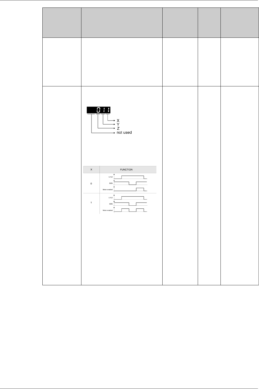
Parameters
256 EIO0000002305 04/2017
P2-66
GBIT2
Special Function 2
Applicable operating mode: PT, PS, V, T
Bits 0 … 1: Reserved (must be set to 0).
Bit 2: This bit specifies the type of Fault
Reset after a detected undervoltage error
has been removed.
0: No automatic Fault Reset
1: Automatic Fault Reset
Bits 3 … 7: Reserved (must be set to 0).
-
0
0
4
Decimal
u16
RW
per.
Modbus 384h
CANopen 4242h
P2-68
AEAL
Auto-Enable and Automatic Hardware
Limit Switch Fault Reset
Applicable operating mode: PT, PS, V, T
X: Automatic power stage enabling
0: Trigger SON to enable power stage
1: Enable power stage automatically if SON
is active after drive has been powered on
Y: Automatic Fault Reset for limit switches
0: Detected hardware limit switch error
(AL014 and AL015) requires Fault Reset
1: Detected hardware limit switch error
(AL014 and AL015) can be reset without
Fault Reset
Z: Repeated attempt to overtravel limit
switch (CANopen only)
0: No detected error
1: Detected error, Fault Reset required
Changed settings become active the next
time the product is powered on.
-
0h
0h
111h
Hexadecimal
u16
RW
per.
Modbus 388h
CANopen 4244h
Parameter name Description Unit
Minimum value
Factory setting
Maximum value
HMI Format
Data type
R/W
Persistent
Parameter
address via
fieldbus

Parameters
EIO0000002305 04/2017 257
P3 - Communication Parameters
P3 - Communication Parameters
Parameter name Description Unit
Minimum value
Factory setting
Maximum value
HMI Format
Data type
R/W
Persistent
Parameter
address via
fieldbus
P3-00
ADR
Device Address Modbus
Applicable operating mode: PT, PS, V, T
The device address must be unique.
Changed settings become active the next
time the product is powered on.
-
1
127
247
Decimal
u16
RW
per.
Modbus 400h
CANopen 4300h
P3-01
BRT
Transmission Rate
Applicable operating mode: PT, PS, V, T
This parameter is used to set the data
transmission rate.
For further information, refer to chapter
Setting the Device Address, Baud Rate and
Connection Settings
(see page 203)
.
If this parameter is set via CANopen, only
the CANopen transmission rate can be set.
Changed settings become active the next
time the product is powered on.
-
0h
102h
405h
Hexadecimal
u16
RW
per.
Modbus 402h
CANopen 4301h
P3-02
PTL
Modbus Connection Settings
Applicable operating mode: PT, PS, V, T
This parameter specifies the Modbus
connection settings.
For further information, refer to chapter
Setting the Device Address, Baud Rate and
Connection Settings
(see page 203)
.
Changed settings become active the next
time the product is powered on.
-
6h
7h
9h
Hexadecimal
u16
RW
per.
Modbus 404h
CANopen 4302h
P3-03
FLT
Detected Modbus Communication Errors -
Handling
Applicable operating mode: PT, PS, V, T
This parameter specifies the response of
the drive to a detected communication
error.
Value 0: Detected alert
Value 1: Detected error
-
0h
0h
1h
Hexadecimal
u16
RW
per.
Modbus 406h
CANopen 4303h
P3-04
CWD
Modbus Connection Monitoring
Applicable operating mode: PT, PS, V, T
This parameter specifies the maximum
permissible duration for communication
timeout. When this time has elapsed, the
communication timeout is treated as a
detected error.
Setting this parameter to 0 to disables
connection monitoring.
ms
0
0
20000
Decimal
u16
RW
per.
Modbus 408h
CANopen 4304h
P3-05
CMM
Device Address CANopen
Applicable operating mode: PT, PS, V, T
This parameter specifies the CANopen
address of the drive in decimal format.
The device address must be unique.
Changes to this parameter become
effective only after a restart of the drive.
Changed settings become active the next
time the product is powered on.
-
0
0
127
Decimal
u16
RW
per.
Modbus 40 Ah
CANopen 4305h

Parameters
258 EIO0000002305 04/2017
P3-06
SDI
Digital Inputs - Forcing Settings
Applicable operating mode: PT, PS, V, T
This parameter determines whether or not
a digital input can be forced.
Bits 0 ... 7: Digital input DI1 ... digital input
DI8
Bit settings:
Value 0: Digital input cannot be forced
Value 1: Digital input can be forced
To actually start forcing, you must write P4-
07.
See P2-10 ... P2-17 for the assignment of
signal input functions to the digital inputs.
-
0h
0h
7FFh
Hexadecimal
u16
RW
-
Modbus 40Ch
CANopen 4306h
P3-07
CDT
Modbus Response Delay Time
Applicable operating mode: PT, PS, V, T
This parameter specifies the time delay
with which the drive responds to the
Modbus master.
0.5ms
0
0
1000
Decimal
u16
RW
per.
Modbus 40Eh
CANopen 4307h
P3-09
SYC
CANopen Master/Slave Synchronization
Applicable operating mode: Fieldbus mode
This parameter specifies synchronization
settings of the CANopen slave and the
CANopen master via the synchronization
signal.
Setting can only be changed if power stage
is disabled.
-
1001h
5055h
9FFFh
Hexadecimal
u16
RW
per.
Modbus 412h
CANopen 4309h
P3-10
LXM_PLC_EN
Drive Profile Lexium - Activation
Applicable operating mode: Fieldbus mode
0: Deactivate Drive Profile Lexium
1: Activate Drive Profile Lexium
-
0h
0h
1h
Hexadecimal
u16
RW
per.
Modbus 414h
CANopen
430 Ah
P3-11
DRIVE_INPUT
Drive Profile Lexium - State of Digital Inputs
Applicable operating mode: Fieldbus mode
-
0h
0h
FFFFh
Hexadecimal
u16
RO
-
Modbus 416h
CANopen 430Bh
P3-12
DRIVE_MODE_CTRL
Drive Profile Lexium - Control Word
Applicable operating mode: Fieldbus mode
-
0h
0h
FFFFh
Hexadecimal
u16
RW
-
Modbus 418h
CANopen 430Ch
P3-13
REFA16
Drive Profile Lexium - RefA 16 Bit
Parameter
Applicable operating mode: Fieldbus mode
-
8000h
0h
7FFFh
Hexadecimal
s16
RW
-
Modbus 41 Ah
CANopen 430Dh
P3-14
REFB32
Drive Profile Lexium - RefB 32 Bit
Parameter
Applicable operating mode: Fieldbus mode
-
80000000h
0h
7FFFFFFFh
Hexadecimal
s32
RW
-
Modbus 41Ch
CANopen 430Eh
P3-15
DRIVE_STAT
Drive Profile Lexium - Drive Status
Applicable operating mode: Fieldbus mode
-
0h
0h
FFFFh
Hexadecimal
u16
RO
-
Modbus 41Eh
CANopen 430Fh
Parameter name Description Unit
Minimum value
Factory setting
Maximum value
HMI Format
Data type
R/W
Persistent
Parameter
address via
fieldbus

Parameters
EIO0000002305 04/2017 259
P3-16
MF_STAT
Drive Profile Lexium - Operating Mode
Status
Applicable operating mode: Fieldbus mode
-
0h
0h
FFFFh
Hexadecimal
u16
RO
-
Modbus 420h
CANopen 4310h
P3-17
MOTION_STAT
Drive Profile Lexium - Motion Status
Applicable operating mode: Fieldbus mode
-
0h
0h
FFFFh
Hexadecimal
u16
RO
-
Modbus 422h
CANopen 4311h
P3-18
PEVM1
PDO Event Mask 1
Applicable operating mode: Fieldbus mode
Changes of values in the object trigger an
event:
Bit 0: First PDO object
Bit 1: Second PDO object
Bit 2: Third PDO object
Bit 3: Fourth PDO object
-
0h
1h
Fh
Hexadecimal
u16
RW
per.
Modbus 424h
CANopen 4312h
P3-19
PEVM2
PDO Event Mask 2
Applicable operating mode: Fieldbus mode
See P3-18 for details.
-
0h
1h
Fh
Hexadecimal
u16
RW
per.
Modbus 426h
CANopen 4313h
P3-20
PEVM3
PDO Event Mask 3
Applicable operating mode: Fieldbus mode
See P3-18 for details.
-
0h
1h
Fh
Hexadecimal
u16
RW
per.
Modbus 428h
CANopen 4314h
P3-21
PEVM4
PDO Event Mask 4
Applicable operating mode: Fieldbus mode
See P3-18 for details.
-
0h
Fh
Fh
Hexadecimal
u16
RW
per.
Modbus 42 Ah
CANopen 4315h
P3-30
INTRN_LIM_SRC
Setting for Bit 11 of parameter
Statusword 6041h
Applicable operating mode: PT, PS, V, T
This parameter assigns a status
information to bit 11 (internal limit active) of
the parameter Statusword 6041h.
Value 0: None: Not used (reserved)
Value 1: Current Below Threshold: Current
threshold value
Value 2: Velocity Below Threshold:
Velocity threshold value
Value 3: In Position Deviation Window:
Position deviation window
Value 4: In Velocity Deviation Window:
Velocity deviation window
Value 9: Hardware Limit Switch: Hardware
limit switch
Value 11: Position Window: Position
window
-
0
0
11
Decimal
u16
RW
per.
Modbus 43Ch
CANopen 431Eh
P3-32
SOD2RTSO
Automatic operating state transition from
Switch On Disabled to Ready To Switch On
Applicable operating mode: PT, PS, V, T
Value 0: Automatic transition
Value 1: Transition according to value of
CANopen control word
-
0h
0h
1h
Hexadecimal
u16
RW
per.
Modbus 440h
CANopen 4320h
Parameter name Description Unit
Minimum value
Factory setting
Maximum value
HMI Format
Data type
R/W
Persistent
Parameter
address via
fieldbus

Parameters
260 EIO0000002305 04/2017
P4 - Diagnostics Parameters
P4 - Diagnostics Parameters
Parameter name Description Unit
Minimum value
Factory setting
Maximum value
HMI Format
Data type
R/W
Persistent
Parameter
address via
fieldbus
P4-00
ASH1
Error History - Error Code of Most
Recent Detected Error n
Applicable operating mode: PT, PS, V,
T
This parameter indicates the error code
of the most recent detected error.
Writing 0 to this parameter clears the
error history.
-
0h
0h
0h
Hexadecimal
u16
RW
-
Modbus 500h
CANopen 4400h
P4-01
ASH2
Error History - Error Code of Most
Recent Detected Error n - 1
Applicable operating mode: PT, PS, V,
T
This parameter indicates the error code
of the detected error n-1, n being the
most recent detected error.
-
0h
0h
0h
Hexadecimal
u16
RO
-
Modbus 502h
CANopen 4401h
P4-02
ASH3
Error History - Error Code of Most
Recent Detected Error n - 2
Applicable operating mode: PT, PS, V,
T
This parameter indicates the error code
of the detected error n-2, n being the
most recent detected error.
-
0h
0h
0h
Hexadecimal
u16
RO
-
Modbus 504h
CANopen 4402h
P4-03
ASH4
Error History - Error Code of Most
Recent Detected Error n - 3
Applicable operating mode: PT, PS, V,
T
This parameter indicates the error code
of the detected error n-3, n being the
most recent detected error.
-
0h
0h
0h
Hexadecimal
u16
RO
-
Modbus 506h
CANopen 4403h
P4-04
ASH5
Error History - Error Code of Most
Recent Detected Error n - 4
Applicable operating mode: PT, PS, V,
T
This parameter indicates the error code
of the detected error n-4, n being the
most recent detected error.
-
0h
0h
0h
Hexadecimal
u16
RO
-
Modbus 508h
CANopen 4404h
P4-05
JOG
Jog Velocity
Applicable operating mode: PT, PS, V,
T
For further information, refer to chapter
Jog Operation
(see page 321)
.
rpm
0
20
5000
Decimal
u32
RW
per.
Modbus 50 Ah
CANopen 4405h

Parameters
EIO0000002305 04/2017 261
P4-06
FOT
Setting a signal output via parameter
Applicable operating mode: PT, PS, V,
T
This parameter lets you set those signal
outputs whose signal output functions
have been set to SDO_0 ... SDO_5.
Bit 0 = 1 sets those signal outputs
whose signal output function has been
set to SDO_0.
Bit 1 = 1 sets those signal outputs
whose signal output function has been
set to SDO_1.
Bit 2 = 1 sets those signal outputs
whose signal output function has been
set to SDO_2.
Bit 3 = 1 sets those signal outputs
whose signal output function has been
set to SDO_3.
Bit 4 = 1 sets those signal outputs
whose signal output function has been
set to SDO_4.
Bit 5 = 1 sets those signal outputs
whose signal output function has been
set to SDO_5.
Bit 6 = 1 sets those signal outputs
whose signal output function has been
set to SDO_6.
Bit 7 = 1 sets those signal outputs
whose signal output function has been
set to SDO_7.
See P2-18 ... P2-22 for assigning the
functions to the digital outputs.
-
0h
0h
FFh
Hexadecimal
u16
RW
-
Modbus 50Ch
CANopen 4406h
P4-07
ITST
State of Digital Inputs / Activate Forcing
Applicable operating mode: PT, PS, V,
T
A read access to this parameter
indicates the state of the digital inputs in
the form of a bit pattern.
Example:
Read value 0x0011: Digital inputs 1 and
5 are logical 1
By writing this parameter, you can
change the state of the inputs provided
that the setting for the corresponding
input in P3-06 allows for forcing (value 1
for the bit corresponding to the input).
Example:
Write value 0x0011: Digital inputs 1 and
5 are set to logical 1, regardless of the
previous state
See P3-06 for permitting forcing of
individual digital inputs.
See P2-10 ... P2-17 for the assignment
of signal input functions to the digital
inputs.
-
0h
0h
FFh
Hexadecimal
u16
RW
-
Modbus 50Eh
CANopen 4407h
Parameter name Description Unit
Minimum value
Factory setting
Maximum value
HMI Format
Data type
R/W
Persistent
Parameter
address via
fieldbus

Parameters
262 EIO0000002305 04/2017
P4-08
PKEY
Status of HMI Keypad
Applicable operating mode: PT, PS, V,
T
This parameter is used to verify proper
operation of the keys on the HMI
keypad of the drive
As a bitwise:
-"1" - key is pressed,
-"0" - key is released.
When:
-S key is indicated by bit0
-M key is indicated by bit1
-UP key is indicated by bit2
-DOWN key is indicated by bit3
-ENT key is indicated by bit4
-
0h
0h
FFh
Hexadecimal
u16
RO
-
Modbus 510h
CANopen 4408h
P4-09
MOT
State of Digital Outputs
Applicable operating mode: PT, PS, V,
T
This parameter indicates the state of
the digital outputs DO1…DO6.
Bit 0 = 1: DO1 is activated
Bit 1 = 1: DO2 is activated
Bit 2 = 1: DO3 is activated
Bit 3 = 1: DO4 is activated
Bit 4 = 1: DO5 is activated
Bit 5 = 1: DO6 is activated
-
0h
0h
3Fh
Hexadecimal
u16
RO
-
Modbus 512h
CANopen 4409h
P4-10
FLTHISTCLR
Clear Error History
Applicable operating mode: PT, PS, V,
T
Writing 0 to this parameter clears the
error history.
-
0
0
0
Decimal
u16
RW
-
Modbus 514h
CANopen 440 Ah
P4-22
ANIN1OFFSET
Analog Input 1 Offset
Applicable operating mode: V
This parameter specifies an offset for
the analog input used in operating
mode V.
mV
-10000
0
10000
Decimal
s16
RW
per.
Modbus 52Ch
CANopen 4416h
P4-23
ANIN2OFFSET
Analog Input 2 Offset
Applicable operating mode: T
This parameter specifies an offset for
the analog input used in operating
mode T.
mV
-10000
0
10000
Decimal
s16
RW
per.
Modbus 52Eh
CANopen 4417h
P4-24
LVL
Undervoltage Monitoring - Threshold
Value
Applicable operating mode: PT, PS, V,
T
This parameter specifies the threshold
value for DC bus undervoltage
monitoring. If the DC Bus voltage is less
than the value of P4-24 x 2, the error
AL003 is detected.
V
140
160
190
Decimal
u16
RW
per.
Modbus 530h
CANopen 4418h
P4-25
STO
Safety Function STO - Status
Applicable operating mode: PT, PS, V,
T
This parameter indicates the status of
the safety function STO.
Bit 0 = 0: Safety function STO triggered
Bit 0 = 1: Safety function STO not
triggered or deactivated via jumper at
CN9
-
0
-
1
Decimal
u16
RO
-
Modbus 532h
CANopen 4419h
Parameter name Description Unit
Minimum value
Factory setting
Maximum value
HMI Format
Data type
R/W
Persistent
Parameter
address via
fieldbus

Parameters
EIO0000002305 04/2017 263
P4-26
DO_FORCEABLE
Digital Outputs - Forcing Information
Applicable operating mode: PT, PS, V,
T
This parameter shows whether or not a
digital output can be forced.
Bits 0 … 4: Digital output DO1 … digital
output DO5
Bit settings:
Value 0: Digital output cannot be forced
Value 1: Digital output can be forced
-
1Fh
1Fh
1Fh
Hexadecimal
u16
RO
-
Modbus 534h
CANopen 441 Ah
P4-27
DO_FORCE_MASK
Digital Outputs - Forcing Settings
Applicable operating mode: PT, PS, V,
T
This parameter determines whether or
not a digital output can be forced.
Bits 0 … 4: Digital output DO1 … digital
output DO5
Bit settings:
Value 0: Digital output cannot be forced
Value 1: Digital output can be forced
To actually start forcing, you must write
P4-28.
See P2-18 … P2-22 for the assignment
of signal output functions to the digital
outputs.
-
0h
0h
1Fh
Hexadecimal
u16
RW
-
Modbus 536h
CANopen 441Bh
P4-28
DO_FORCE_VALUE
State of Digital Outputs / Activate
Forcing
Applicable operating mode: PT, PS, V,
T
A read access to this parameter
indicates the state of the digital outputs
in the form of a bit pattern.
Example:
Read value 0x0011: Digital outputs 1
and 5 are logical 1
By writing this parameter, you can
change the state of the outputs
provided that the setting for the
corresponding output in P4-27 allows
for forcing (value 1 for the bit
corresponding to the output).
Example:
Write value 0x0011: Digital outputs 1
and 5 are set to logical 1, regardless of
the previous state
See P4-27 for permitting forcing of
individual digital outputs.
See P2-18 … P2-22 for the assignment
of signal output functions to the digital
outputs.
-
0h
0h
1Fh
Hexadecimal
u16
RW
-
Modbus 538h
CANopen 441Ch
Parameter name Description Unit
Minimum value
Factory setting
Maximum value
HMI Format
Data type
R/W
Persistent
Parameter
address via
fieldbus

Parameters
264 EIO0000002305 04/2017
P5 - Motion Settings
P5- Motion Settings
Parameter name Description Unit
Minimum value
Factory setting
Maximum value
HMI Format
Data type
R/W
Persistent
Parameter
address via
fieldbus
P5-00
REV
Firmware Revision
Applicable operating mode: PT, PS, V,
T
This parameter contains the revision
number of the firmware.
-
0h
0h
FFFFh
Hexadecimal
u16
RO
-
Modbus 600h
CANopen 4500h
P5-04
HMOV
Homing - Homing Method Selection
Applicable operating mode: PS
This parameter is used to select the
homing method and configure the
behavior of the index pulse and the
limit switches.
For further information, refer to chapter
Operating Mode Position Sequence
(PS)
(see page 329)
.
Setting can only be changed if power
stage is disabled.
-
0h
0h
128h
Hexadecimal
u16
RW
per.
Modbus 608h
CANopen 4504h
P5-05
HOMESPEED1
Homing - Fast Velocity for Reference
Movement
Applicable operating mode: PS
0.1rpm
10
1000
60000
Decimal
u32
RW
per.
Modbus 60 Ah
CANopen 4505h
P5-06
HOMESPEED2
Homing - Slow Velocity for Reference
Movement
Applicable operating mode: PS
0.1rpm
10
200
60000
Decimal
u32
RW
per.
Modbus 60Ch
CANopen 4506h
P5-07
PRCM
Operating Mode PS via Parameter
Applicable operating mode: PS
The operating mode Position
Sequence (PS) provides 32 data sets
that can be executed via the signal
input functions POS0 ... POS4 and
CTRG or via of this parameter.
0: Start operating mode Homing
(Homing data set)
1 ... 32: Trigger data set (equivalent to
the signal input functions CTRG and
POSn).
33 ... 9999: Not permitted
1000: Stop movement (equivalent to
the signal input function STOP)
Values displayed via this parameter:
If a data set is active, but not yet
completed, the value displayed is the
value of this parameter plus 10000.
If a data set has been completed, the
value displayed is the value of this
parameter plus 20000.
Example:
Displayed value 10003: Data set 3 has
been started, but is not yet completed.
Displayed value 20003: Data set 3 has
been completed.
Refer to chapter Operating Mode
Position Sequence (PS)
(see page 329)
.
-
0
0
20032
Decimal
u16
RW
-
Modbus 60Eh
CANopen 4507h

Parameters
EIO0000002305 04/2017 265
P5-08
POSLIMPOS
Positive Software Limit Switch -
Position
Applicable operating mode: PS
Prerequisite: Software limit switches
only work with a valid zero point.
Setting can only be changed if power
stage is disabled.
PUU
-2147483647
134217727
2147483647
Decimal
s32
RW
per.
Modbus 610h
CANopen 4508h
P5-09
POSLIMNEG
Negative Software Limit Switch -
Position
Applicable operating mode: PS
Prerequisite: Software limit switches
only work with a valid zero point.
Setting can only be changed if power
stage is disabled.
PUU
-2147483647
-134217727
2147483647
Decimal
s32
RW
per.
Modbus 612h
CANopen 4509h
P5-10
GEARACCTHRESH
Operating mode Pulse Train -
Maximum Acceleration
Applicable operating mode: PT
This parameter is used to reduce the
acceleration noise.
ms
6
6
65500
Decimal
u16
RW
per.
Modbus 614h
CANopen 450 Ah
P5-11
POSLIMHYST
Software Limit Switches - Hysteresis
Value
Applicable operating mode: PS
This parameter specifies a hysteresis
value for the software limit switches.
Setting can only be changed if power
stage is disabled.
PULSE
0
3556
35555
Decimal
u16
RW
per.
Modbus 616h
CANopen 450Bh
P5-12
PROBE_1_LVL_PRD
Touch Probe Input 1 - Stable Level
Duration
Applicable operating mode: PT, PS
This parameter specifies the period of
time for which the level at Touch Probe
input 1 must be stable.
31.25 μs
2
5
32
Decimal
u16
RW
per.
Modbus 618h
CANopen 450Ch
P5-13
POSLIMMODE
Software Limit Switches - Activation
Applicable operating mode: PS
This parameter activates/deactivates
the software limit switches configured
via P5-08 and P5-09.
Prerequisite: Software limit switches
only work with a valid zero point.
Value 0: Deactivate software limit
switches
Value 1: Activate software limit
switches
Value 2…3: Reserved
-
0
0
1
Decimal
u16
RW
per.
Modbus 61 Ah
CANopen 450Dh
P5-14
ICMDSLOPE
Motion Profile for Torque - Slope
Applicable operating mode: T
This parameter specifies the slope of
the motion profile for torque.
mA/s
1
100000
30000000
Decimal
u32
RW
per.
Modbus 61Ch
CANopen 450Eh
P5-15
ICMDSLOPEEN
Motion Profile for Torque - Activation
Applicable operating mode: T
This parameter activates the motion
profile for torque.
Value 0: Deactivate
Value 1: Activate
Setting can only be changed if power
stage is disabled.
-
0
0
1
Decimal
u16
RW
per.
Modbus 61Eh
CANopen 450Fh
Parameter name Description Unit
Minimum value
Factory setting
Maximum value
HMI Format
Data type
R/W
Persistent
Parameter
address via
fieldbus

Parameters
266 EIO0000002305 04/2017
P5-16
AXEN
Encoder Increments in PUU
Applicable operating mode: PT, PS, V,
T
Setting can only be changed if power
stage is disabled.
This parameter specifies an offset to
the encoder position.
PUU
-2147483647
0
2147483647
Decimal
s32
RW
-
Modbus 620h
CANopen 4510h
P5-18
AXPC
External Encoder (Pulses)
Applicable operating mode: PT, PS, V,
T
This parameter contains the
cumulated pluses counted at the PTI
input since the drive has been
switched on.
-
-2147483648
-
2147483647
Decimal
s32
RO
-
Modbus 624h
CANopen 4512h
P5-20
STP
Deceleration Ramp - Signal Input
Function STOP
Applicable operating mode: PT, PS, V
This parameter specifies the
deceleration ramp for a stop triggered
via the signal input function STOP.
The deceleration period is the time in
milliseconds required to decelerate
from 6000 rpm to motor standstill. It is
used to set the deceleration ramp.
ms
6
50
65500
Decimal
u16
RW
per.
Modbus 628h
CANopen 4514h
P5-21
CTO
Deceleration Ramp - Detected
Transmission Error
Applicable operating mode: PT, PS, V
This parameter specifies the
deceleration ramp for a stop triggered
if a transmission error is detected.
The deceleration period is the time in
milliseconds required to decelerate
from 6000 rpm to motor standstill. It is
used to set the deceleration ramp.
ms
6
50
65500
Decimal
u16
RW
per.
Modbus 62 Ah
CANopen 4515h
P5-22
OVF
Deceleration Ramp - Position
Overflow
Applicable operating mode: PT, PS, V
This parameter specifies the
deceleration ramp for a stop triggered
if a position overflow is detected.
The deceleration period is the time in
milliseconds required to decelerate
from 6000 rpm to motor standstill. It is
used to set the deceleration ramp.
ms
6
30
65500
Decimal
u16
RW
per.
Modbus 62Ch
CANopen 4516h
P5-23
SNL
Deceleration Ramp - Triggering of
Negative Software Limit Switch
Applicable operating mode: PS
This parameter specifies the
deceleration ramp for a stop triggered
if the negative software limit switch is
activated.
The deceleration period is the time in
milliseconds required to decelerate
from 6000 rpm to motor standstill. It is
used to set the deceleration ramp.
ms
6
50
65500
Decimal
u16
RW
per.
Modbus 62Eh
CANopen 4517h
Parameter name Description Unit
Minimum value
Factory setting
Maximum value
HMI Format
Data type
R/W
Persistent
Parameter
address via
fieldbus

Parameters
EIO0000002305 04/2017 267
P5-24
SPL
Deceleration Ramp - Triggering of
Positive Software Limit Switch
Applicable operating mode: PS
This parameter specifies the
deceleration ramp for a stop triggered
if the positive software limit switch is
activated.
The deceleration period is the time in
milliseconds required to decelerate
from 6000 rpm to motor standstill. It is
used to set the deceleration ramp.
ms
6
50
65500
Decimal
u16
RW
per.
Modbus 630h
CANopen 4518h
P5-25
NL
Deceleration Ramp - Triggering of
Negative Hardware Limit Switch
Applicable operating mode: PT, PS, V
This parameter specifies the
deceleration ramp for a stop triggered
if the negative hardware limit switch is
activated.
The deceleration period is the time in
milliseconds required to decelerate
from 6000 rpm to motor standstill. It is
used to set the deceleration ramp.
ms
6
30
65500
Decimal
u16
RW
per.
Modbus 632h
CANopen 4519h
P5-26
PL
Deceleration Ramp - Triggering of
Positive Hardware Limit Switch
Applicable operating mode: PT, PS, V
This parameter specifies the
deceleration ramp for a stop triggered
if the positive hardware limit switch is
activated.
The deceleration period is the time in
milliseconds required to decelerate
from 6000 rpm to motor standstill. It is
used to set the deceleration ramp.
ms
6
30
65500
Decimal
u16
RW
per.
Modbus 634h
CANopen 451 Ah
P5-35
PROBES_POLARITY
Touch Probes Polarity
Applicable operating mode: PT, PS, V,
T
This parameter specifies the touch
probes polarity.
-
0
-
3
Decimal
u16
RO
per.
Modbus 646h
CANopen 4523h
P5-36
CAAX_CANOPEN
Touch Probe Input 1 - Captured
Position CANopen Units
Applicable operating mode: PT, PS, V,
T
This parameter contains the position
captured at Touch Probe input 1.
CANopen PU
-2147483647
-
2147483647
Decimal
s32
RO
per.
Modbus 648h
CANopen 4524h
P5-37
CAAX
Touch Probe Input 1 - Captured
Position
Applicable operating mode: PT, PS, V,
T
This parameter contains the position
captured at Touch Probe input 1.
PUU
-2147483647
0
2147483647
Decimal
s32
RO
-
Modbus 64 Ah
CANopen 4525h
P5-38
PROBE1_CNTR
Touch Probe Input 1 - Event Counter
Applicable operating mode: PT, PS, V,
T
The value is increased by 1 each time
a position has been captured at Touch
Probe input 1.
-
0
0
65535
Decimal
u16
RO
-
Modbus 64Ch
CANopen 4526h
Parameter name Description Unit
Minimum value
Factory setting
Maximum value
HMI Format
Data type
R/W
Persistent
Parameter
address via
fieldbus

Parameters
268 EIO0000002305 04/2017
P5-39
CACT
Touch Probe Input 1 - Configuration
Applicable operating mode: PT, PS, V,
T
X: Activate/deactivate position capture
0: Deactivate
1: Activate (is reset to 0 when the
counter in P5-38 is incremented)
Y: Reserved
U: Reserved
Z: Polarity of Touch Probe input
0: Normally open
1: Normally closed
Where X is the least significant half-
byte and U is the most significant half-
byte of the X/Y/U/Z Integer.
-
0h
0h
101h
Hexadecimal
u16
RW
-
Modbus 64Eh
CANopen 4527h
P5-56
CAAX2_CANOPEN
Touch Probe Input 2 - Captured
Position CANopen Units
Applicable operating mode: PT, PS, V,
T
This parameter contains the position
captured at Touch Probe input 2.
CANopen PU
-2147483647
-
2147483647
Decimal
s32
RO
per.
Modbus 670h
CANopen 4538h
P5-57
CAAX2
Touch Probe Input 2 - Captured
Position
Applicable operating mode: PT, PS, V,
T
This parameter contains the position
captured at Touch Probe input 2.
PUU
-2147483647
0
2147483647
Decimal
s32
RO
-
Modbus 672h
CANopen 4539h
P5-58
PROBE2_CNTR
Touch Probe Input 2 - Event Counter
Applicable operating mode: PT, PS, V,
T
The value is increased by 1 each time
a position has been captured at Touch
Probe input 2.
-
0
0
65535
Decimal
u16
RO
-
Modbus 674h
CANopen 453 Ah
P5-59
CACT2
Touch Probe Input 2 - Configuration
Applicable operating mode: PT, PS, V,
T
X: Activate/deactivate position capture
0: Deactivate
1: Activate (is reset to 0 when the
counter in P5-58 is incremented)
Y: Reserved
Z: Polarity of Touch Probe input
0: Normally open
1: Normally closed
U: Reserved
-
0h
0h
101h
Hexadecimal
u16
RW
-
Modbus 676h
CANopen 453Bh
P5-76
HOME_OFFSET_MOVE
Move Home Offset When Homing
input is found
Applicable operating mode: Fieldbus
mode
-
0
0
1
Decimal
u16
RW
per.
Modbus 698h
CANopen 454Ch
P5-77
PROBE_2_LVL_PRD
Touch Probe Input 2 - Stable Level
Duration
Applicable operating mode: PT, PS
This parameter specifies the period of
time for which the level at Touch Probe
input 2 must be stable.
31.25 μs
2
5
32
Decimal
u16
RW
per.
Modbus 69 Ah
CANopen 454Dh
Parameter name Description Unit
Minimum value
Factory setting
Maximum value
HMI Format
Data type
R/W
Persistent
Parameter
address via
fieldbus

Parameters
EIO0000002305 04/2017 269
P6 - Position Sequence Data Sets Group 1
P6 - PS Data Sets Group 1
Parameter name Description Unit
Minimum value
Factory setting
Maximum value
HMI Format
Data type
R/W
Persistent
Parameter
address via
fieldbus
P6-00
ODAT
Position of Homing Data Set
Applicable operating mode: PS
After a successful reference movement,
this position is automatically set at the
reference point.
Bits 0…31: Position
PUU
-2147483647
0
2147483647
Decimal
s32
RW
per.
Modbus 700h
CANopen 4600h
P6-01
ODEF
Subsequent Data Set and Auto-start of
Homing Data Set
Applicable operating mode: PS
Bit 0:
0 = Do not start Homing after first power
stage enable
1 = Start Homing after first power stage
enable
Bits 1…7: Reserved
Bits 8…15: Number of the subsequent data
set
-
0h
0h
2001h
Hexadecimal
u32
RW
per.
Modbus 702h
CANopen 4601h
P6-02
PATHPOS1
Target Position of Data Set 1
Applicable operating mode: PS
Bits 0…31: Target position
PUU
-2147483647
0
2147483647
Decimal
s32
RW
per.
Modbus 704h
CANopen 4602h
P6-03
PATHCTRL1
Configuration of Data Set 1
Applicable operating mode: PS
Bits 0…3: Reserved
Bit 4:
0 = Wait for preceding data set to complete,
then start this data set
1 = Start this data set immediately
Bits 5…6: Reserved
Bit 7:
0 = Absolute position
1 = Relative (incremental) position
Bits 8…15: Reserved
-
0h
0h
D0h
Hexadecimal
u16
RW
per.
Modbus 706h
CANopen 4603h
P6-04
PATHPOS2
Target Position of Data Set 2
Applicable operating mode: PS
See P6-02 for details.
PUU
-2147483647
0
2147483647
Decimal
s32
RW
per.
Modbus 708h
CANopen 4604h
P6-05
PATHCTRL2
Configuration of Data Set 2
Applicable operating mode: PS
See P6-03 for details.
-
0h
0h
D0h
Hexadecimal
u16
RW
per.
Modbus 70 Ah
CANopen 4605h
P6-06
PATHPOS3
Target Position of Data Set 3
Applicable operating mode: PS
See P6-02 for details.
PUU
-2147483647
0
2147483647
Decimal
s32
RW
per.
Modbus 70Ch
CANopen 4606h
P6-07
PATHCTRL3
Configuration of Data Set 3
Applicable operating mode: PS
See P6-03 for details.
-
0h
0h
D0h
Hexadecimal
u16
RW
per.
Modbus 70Eh
CANopen 4607h

Parameters
270 EIO0000002305 04/2017
P6-08
PATHPOS4
Target Position of Data Set 4
Applicable operating mode: PS
See P6-02 for details.
PUU
-2147483647
0
2147483647
Decimal
s32
RW
per.
Modbus 710h
CANopen 4608h
P6-09
PATHCTRL4
Configuration of Data Set 4
Applicable operating mode: PS
See P6-03 for details.
-
0h
0h
D0h
Hexadecimal
u16
RW
per.
Modbus 712h
CANopen 4609h
P6-10
PATHPOS5
Target Position of Data Set 5
Applicable operating mode: PS
See P6-02 for details.
PUU
-2147483647
0
2147483647
Decimal
s32
RW
per.
Modbus 714h
CANopen 460 Ah
P6-11
PATHCTRL5
Configuration of Data Set 5
Applicable operating mode: PS
See P6-03 for details.
-
0h
0h
D0h
Hexadecimal
u16
RW
per.
Modbus 716h
CANopen 460Bh
P6-12
PATHPOS6
Target Position of Data Set 6
Applicable operating mode: PS
See P6-02 for details.
PUU
-2147483647
0
2147483647
Decimal
s32
RW
per.
Modbus 718h
CANopen 460Ch
P6-13
PATHCTRL6
Configuration of Data Set 6
Applicable operating mode: PS
See P6-03 for details.
-
0h
0h
D0h
Hexadecimal
u16
RW
per.
Modbus 71 Ah
CANopen 460Dh
P6-14
PATHPOS7
Target Position of Data Set 7
Applicable operating mode: PS
See P6-02 for details.
PUU
-2147483647
0
2147483647
Decimal
s32
RW
per.
Modbus 71Ch
CANopen 460Eh
P6-15
PATHCTRL7
Configuration of Data Set 7
Applicable operating mode: PS
See P6-03 for details.
-
0h
0h
D0h
Hexadecimal
u16
RW
per.
Modbus 71Eh
CANopen 460Fh
P6-16
PATHPOS8
Target Position of Data Set 8
Applicable operating mode: PS
See P6-02 for details.
PUU
-2147483647
0
2147483647
Decimal
s32
RW
per.
Modbus 720h
CANopen 4610h
P6-17
PATHCTRL8
Configuration of Data Set 8
Applicable operating mode: PS
See P6-03 for details.
-
0h
0h
D0h
Hexadecimal
u16
RW
per.
Modbus 722h
CANopen 4611h
P6-18
PATHPOS9
Target Position of Data Set 9
Applicable operating mode: PS
See P6-02 for details.
PUU
-2147483647
0
2147483647
Decimal
s32
RW
per.
Modbus 724h
CANopen 4612h
Parameter name Description Unit
Minimum value
Factory setting
Maximum value
HMI Format
Data type
R/W
Persistent
Parameter
address via
fieldbus

Parameters
EIO0000002305 04/2017 271
P6-19
PATHCTRL9
Configuration of Data Set 9
Applicable operating mode: PS
See P6-03 for details.
-
0h
0h
D0h
Hexadecimal
u16
RW
per.
Modbus 726h
CANopen 4613h
P6-20
PATHPOS10
Target Position of Data Set 10
Applicable operating mode: PS
See P6-02 for details.
PUU
-2147483647
0
2147483647
Decimal
s32
RW
per.
Modbus 728h
CANopen 4614h
P6-21
PATHCTRL10
Configuration of Data Set 10
Applicable operating mode: PS
See P6-03 for details.
-
0h
0h
D0h
Hexadecimal
u16
RW
per.
Modbus 72 Ah
CANopen 4615h
P6-22
PATHPOS11
Target Position of Data Set 11
Applicable operating mode: PS
See P6-02 for details.
PUU
-2147483647
0
2147483647
Decimal
s32
RW
per.
Modbus 72Ch
CANopen 4616h
P6-23
PATHCTRL11
Configuration of Data Set 11
Applicable operating mode: PS
See P6-03 for details.
-
0h
0h
D0h
Hexadecimal
u16
RW
per.
Modbus 72Eh
CANopen 4617h
P6-24
PATHPOS12
Target Position of Data Set 12
Applicable operating mode: PS
See P6-02 for details.
PUU
-2147483647
0
2147483647
Decimal
s32
RW
per.
Modbus 730h
CANopen 4618h
P6-25
PATHCTRL12
Configuration of Data Set 12
Applicable operating mode: PS
See P6-03 for details.
-
0h
0h
D0h
Hexadecimal
u16
RW
per.
Modbus 732h
CANopen 4619h
P6-26
PATHPOS13
Target Position of Data Set 13
Applicable operating mode: PS
See P6-02 for details.
PUU
-2147483647
0
2147483647
Decimal
s32
RW
per.
Modbus 734h
CANopen 461 Ah
P6-27
PATHCTRL13
Configuration of Data Set 13
Applicable operating mode: PS
See P6-03 for details.
-
0h
0h
D0h
Hexadecimal
u16
RW
per.
Modbus 736h
CANopen 461Bh
P6-28
PATHPOS14
Target Position of Data Set 14
Applicable operating mode: PS
See P6-02 for details.
PUU
-2147483647
0
2147483647
Decimal
s32
RW
per.
Modbus 738h
CANopen 461Ch
P6-29
PATHCTRL14
Configuration of Data Set 14
Applicable operating mode: PS
See P6-03 for details.
-
0h
0h
D0h
Hexadecimal
u16
RW
per.
Modbus 73 Ah
CANopen 461Dh
Parameter name Description Unit
Minimum value
Factory setting
Maximum value
HMI Format
Data type
R/W
Persistent
Parameter
address via
fieldbus

Parameters
272 EIO0000002305 04/2017
P6-30
PATHPOS15
Target Position of Data Set 15
Applicable operating mode: PS
See P6-02 for details.
PUU
-2147483647
0
2147483647
Decimal
s32
RW
per.
Modbus 73Ch
CANopen 461Eh
P6-31
PATHCTRL15
Configuration of Data Set 15
Applicable operating mode: PS
See P6-03 for details.
-
0h
0h
D0h
Hexadecimal
u16
RW
per.
Modbus 73Eh
CANopen 461Fh
P6-32
PATHPOS16
Target Position of Data Set 16
Applicable operating mode: PS
See P6-02 for details.
PUU
-2147483647
0
2147483647
Decimal
s32
RW
per.
Modbus 740h
CANopen 4620h
P6-33
PATHCTRL16
Configuration of Data Set 16
Applicable operating mode: PS
See P6-03 for details.
-
0h
0h
D0h
Hexadecimal
u16
RW
per.
Modbus 742h
CANopen 4621h
P6-34
PATHPOS17
Target Position of Data Set 17
Applicable operating mode: PS
See P6-02 for details.
PUU
-2147483647
0
2147483647
Decimal
s32
RW
per.
Modbus 744h
CANopen 4622h
P6-35
PATHCTRL17
Configuration of Data Set 17
Applicable operating mode: PS
See P6-03 for details.
-
0h
0h
D0h
Hexadecimal
u16
RW
per.
Modbus 746h
CANopen 4623h
P6-36
PATHPOS18
Target Position of Data Set 18
Applicable operating mode: PS
See P6-02 for details.
PUU
-2147483647
0
2147483647
Decimal
s32
RW
per.
Modbus 748h
CANopen 4624h
P6-37
PATHCTRL18
Configuration of Data Set 18
Applicable operating mode: PS
See P6-03 for details.
-
0h
0h
D0h
Hexadecimal
u16
RW
per.
Modbus 74 Ah
CANopen 4625h
P6-38
PATHPOS19
Target Position of Data Set 19
Applicable operating mode: PS
See P6-02 for details.
PUU
-2147483647
0
2147483647
Decimal
s32
RW
per.
Modbus 74Ch
CANopen 4626h
P6-39
PATHCTRL19
Configuration of Data Set 19
Applicable operating mode: PS
See P6-03 for details.
-
0h
0h
D0h
Hexadecimal
u16
RW
per.
Modbus 74Eh
CANopen 4627h
P6-40
PATHPOS20
Target Position of Data Set 20
Applicable operating mode: PS
See P6-02 for details.
PUU
-2147483647
0
2147483647
Decimal
s32
RW
per.
Modbus 750h
CANopen 4628h
Parameter name Description Unit
Minimum value
Factory setting
Maximum value
HMI Format
Data type
R/W
Persistent
Parameter
address via
fieldbus

Parameters
EIO0000002305 04/2017 273
P6-41
PATHCTRL20
Configuration of Data Set 20
Applicable operating mode: PS
See P6-03 for details.
-
0h
0h
D0h
Hexadecimal
u16
RW
per.
Modbus 752h
CANopen 4629h
P6-42
PATHPOS21
Target Position of Data Set 21
Applicable operating mode: PS
See P6-02 for details.
PUU
-2147483647
0
2147483647
Decimal
s32
RW
per.
Modbus 754h
CANopen 462 Ah
P6-43
PATHCTRL21
Configuration of Data Set 21
Applicable operating mode: PS
See P6-03 for details.
-
0h
0h
D0h
Hexadecimal
u16
RW
per.
Modbus 756h
CANopen 462Bh
P6-44
PATHPOS22
Target Position of Data Set 22
Applicable operating mode: PS
See P6-02 for details.
PUU
-2147483647
0
2147483647
Decimal
s32
RW
per.
Modbus 758h
CANopen 462Ch
P6-45
PATHCTRL22
Configuration of Data Set 22
Applicable operating mode: PS
See P6-03 for details.
-
0h
0h
D0h
Hexadecimal
u16
RW
per.
Modbus 75 Ah
CANopen 462Dh
P6-46
PATHPOS23
Target Position of Data Set 23
Applicable operating mode: PS
See P6-02 for details.
PUU
-2147483647
0
2147483647
Decimal
s32
RW
per.
Modbus 75Ch
CANopen 462Eh
P6-47
PATHCTRL23
Configuration of Data Set 23
Applicable operating mode: PS
See P6-03 for details.
-
0h
0h
D0h
Hexadecimal
u16
RW
per.
Modbus 75Eh
CANopen 462Fh
P6-48
PATHPOS24
Target Position of Data Set 24
Applicable operating mode: PS
See P6-02 for details.
PUU
-2147483647
0
2147483647
Decimal
s32
RW
per.
Modbus 760h
CANopen 4630h
P6-49
PATHCTRL24
Configuration of Data Set 24
Applicable operating mode: PS
See P6-03 for details.
-
0h
0h
D0h
Hexadecimal
u16
RW
per.
Modbus 762h
CANopen 4631h
P6-50
PATHPOS25
Target Position of Data Set 25
Applicable operating mode: PS
See P6-02 for details.
PUU
-2147483647
0
2147483647
Decimal
s32
RW
per.
Modbus 764h
CANopen 4632h
P6-51
PATHCTRL25
Configuration of Data Set 25
Applicable operating mode: PS
See P6-03 for details.
-
0h
0h
D0h
Hexadecimal
u16
RW
per.
Modbus 766h
CANopen 4633h
Parameter name Description Unit
Minimum value
Factory setting
Maximum value
HMI Format
Data type
R/W
Persistent
Parameter
address via
fieldbus

Parameters
274 EIO0000002305 04/2017
P6-52
PATHPOS26
Target Position of Data Set 26
Applicable operating mode: PS
See P6-02 for details.
PUU
-2147483647
0
2147483647
Decimal
s32
RW
per.
Modbus 768h
CANopen 4634h
P6-53
PATHCTRL26
Configuration of Data Set 26
Applicable operating mode: PS
See P6-03 for details.
-
0h
0h
D0h
Hexadecimal
u16
RW
per.
Modbus 76 Ah
CANopen 4635h
P6-54
PATHPOS27
Target Position of Data Set 27
Applicable operating mode: PS
See P6-02 for details.
PUU
-2147483647
0
2147483647
Decimal
s32
RW
per.
Modbus 76Ch
CANopen 4636h
P6-55
PATHCTRL27
Configuration of Data Set 27
Applicable operating mode: PS
See P6-03 for details.
-
0h
0h
D0h
Hexadecimal
u16
RW
per.
Modbus 76Eh
CANopen 4637h
P6-56
PATHPOS28
Target Position of Data Set 28
Applicable operating mode: PS
See P6-02 for details.
PUU
-2147483647
0
2147483647
Decimal
s32
RW
per.
Modbus 770h
CANopen 4638h
P6-57
PATHCTRL28
Configuration of Data Set 28
Applicable operating mode: PS
See P6-03 for details.
-
0h
0h
D0h
Hexadecimal
u16
RW
per.
Modbus 772h
CANopen 4639h
P6-58
PATHPOS29
Target Position of Data Set 29
Applicable operating mode: PS
See P6-02 for details.
PUU
-2147483647
0
2147483647
Decimal
s32
RW
per.
Modbus 774h
CANopen 463 Ah
P6-59
PATHCTRL29
Configuration of Data Set 29
Applicable operating mode: PS
See P6-03 for details.
-
0h
0h
D0h
Hexadecimal
u16
RW
per.
Modbus 776h
CANopen 463Bh
P6-60
PATHPOS30
Target Position of Data Set 30
Applicable operating mode: PS
See P6-02 for details.
PUU
-2147483647
0
2147483647
Decimal
s32
RW
per.
Modbus 778h
CANopen 463Ch
P6-61
PATHCTRL30
Configuration of Data Set 30
Applicable operating mode: PS
See P6-03 for details.
-
0h
0h
D0h
Hexadecimal
u16
RW
per.
Modbus 77 Ah
CANopen 463Dh
P6-62
PATHPOS31
Target Position of Data Set 31
Applicable operating mode: PS
See P6-02 for details.
PUU
-2147483647
0
2147483647
Decimal
s32
RW
per.
Modbus 77Ch
CANopen 463Eh
Parameter name Description Unit
Minimum value
Factory setting
Maximum value
HMI Format
Data type
R/W
Persistent
Parameter
address via
fieldbus

Parameters
EIO0000002305 04/2017 275
P6-63
PATHCTRL31
Configuration of Data Set 31
Applicable operating mode: PS
See P6-03 for details.
-
0h
0h
D0h
Hexadecimal
u16
RW
per.
Modbus 77Eh
CANopen 463Fh
P6-64
PATHPOS32
Target Position of Data Set 32
Applicable operating mode: PS
See P6-02 for details.
PUU
-2147483647
0
2147483647
Decimal
s32
RW
per.
Modbus 780h
CANopen 4640h
P6-65
PATHCTRL32
Configuration of Data Set 32
Applicable operating mode: PS
See P6-03 for details.
-
0h
0h
D0h
Hexadecimal
u16
RW
per.
Modbus 782h
CANopen 4641h
Parameter name Description Unit
Minimum value
Factory setting
Maximum value
HMI Format
Data type
R/W
Persistent
Parameter
address via
fieldbus

Parameters
276 EIO0000002305 04/2017
P7 - Position Sequence Data Sets Group 2
P7 - PS Data Sets Group 2
Parameter name Description Unit
Minimum value
Factory setting
Maximum value
HMI Format
Data type
R/W
Persistent
Parameter
address via
fieldbus
P7-00
HOME_ACC_DEC
Deceleration and Acceleration of Homing
Data Set
Applicable operating mode: PS
Bits 0 ... 15: Deceleration
Bits 16 ... 31: Acceleration
ms|ms
6| 6
200| 200
65500| 65500
Decimal
u32
RW
per.
Modbus 800h
CANopen 4700h
P7-01
HOME_DLY
Waiting Time of Homing Data Set
Applicable operating mode: PS
Bits 0 ... 15: Waiting time until next dataset
is started
Bits 16 ... 31: Reserved
ms
0
0
32767
Decimal
u32
RW
per.
Modbus 802h
CANopen 4701h
P7-02
ACC_DEC1
Deceleration and Acceleration of Data Set
1
Applicable operating mode: PS
Bits 0 ... 15: Deceleration
Bits 16 ... 31: Acceleration
ms|ms
6| 6
200| 200
65500| 65500
Decimal
u32
RW
per.
Modbus 804h
CANopen 4702h
P7-03
SPD_DLY1
Waiting Time and Target Velocity of Data
Set 1
Applicable operating mode: PS
Bits 0 ... 15: Waiting time until next dataset
is started (in ms)
Bits 16 ... 31: Target velocity (in rpm)
0.1rpm|ms
0| 0
200| 0
60000| 32767
Decimal
u32
RW
per.
Modbus 806h
CANopen 4703h
P7-04
ACC_DEC2
Deceleration and Acceleration of Data Set
2
Applicable operating mode: PS
See P7-02 for details.
ms|ms
6| 6
200| 200
65500| 65500
Decimal
u32
RW
per.
Modbus 808h
CANopen 4704h
P7-05
SPD_DLY2
Waiting Time and Target Velocity of Data
Set 2
Applicable operating mode: PS
See P7-03 for details.
0.1rpm|ms
0| 0
200| 0
60000| 32767
Decimal
u32
RW
per.
Modbus 80 Ah
CANopen 4705h
P7-06
ACC_DEC3
Deceleration and Acceleration of Data Set
3
Applicable operating mode: PS
See P7-02 for details.
ms|ms
6| 6
200| 200
65500| 65500
Decimal
u32
RW
per.
Modbus 80Ch
CANopen 4706h
P7-07
SPD_DLY3
Waiting Time and Target Velocity of Data
Set 3
Applicable operating mode: PS
See P7-03 for details.
0.1rpm|ms
0| 0
200| 0
60000| 32767
Decimal
u32
RW
per.
Modbus 80Eh
CANopen 4707h
P7-08
ACC_DEC4
Deceleration and Acceleration of Data Set
4
Applicable operating mode: PS
See P7-02 for details.
ms|ms
6| 6
200| 200
65500| 65500
Decimal
u32
RW
per.
Modbus 810h
CANopen 4708h
P7-09
SPD_DLY4
Waiting Time and Target Velocity of Data
Set 4
Applicable operating mode: PS
See P7-03 for details.
0.1rpm|ms
0| 0
200| 0
60000| 32767
Decimal
u32
RW
per.
Modbus 812h
CANopen 4709h
P7-10
ACC_DEC5
Deceleration and Acceleration of Data Set
5
Applicable operating mode: PS
See P7-02 for details.
ms|ms
6| 6
200| 200
65500| 65500
Decimal
u32
RW
per.
Modbus 814h
CANopen 470 Ah

Parameters
EIO0000002305 04/2017 277
P7-11
SPD_DLY5
Waiting Time and Target Velocity of Data
Set 5
Applicable operating mode: PS
See P7-03 for details.
0.1rpm|ms
0| 0
200| 0
60000| 32767
Decimal
u32
RW
per.
Modbus 816h
CANopen 470Bh
P7-12
ACC_DEC6
Deceleration and Acceleration of Data Set
6
Applicable operating mode: PS
See P7-02 for details.
ms|ms
6| 6
200| 200
65500| 65500
Decimal
u32
RW
per.
Modbus 818h
CANopen 470Ch
P7-13
SPD_DLY6
Waiting Time and Target Velocity of Data
Set 6
Applicable operating mode: PS
See P7-03 for details.
0.1rpm|ms
0| 0
200| 0
60000| 32767
Decimal
u32
RW
per.
Modbus 81 Ah
CANopen 470Dh
P7-14
ACC_DEC7
Deceleration and Acceleration of Data Set
7
Applicable operating mode: PS
See P7-02 for details.
ms|ms
6| 6
200| 200
65500| 65500
Decimal
u32
RW
per.
Modbus 81Ch
CANopen 470Eh
P7-15
SPD_DLY7
Waiting Time and Target Velocity of Data
Set 7
Applicable operating mode: PS
See P7-03 for details.
0.1rpm|ms
0| 0
200| 0
60000| 32767
Decimal
u32
RW
per.
Modbus 81Eh
CANopen 470Fh
P7-16
ACC_DEC8
Deceleration and Acceleration of Data Set
8
Applicable operating mode: PS
See P7-02 for details.
ms|ms
6| 6
200| 200
65500| 65500
Decimal
u32
RW
per.
Modbus 820h
CANopen 4710h
P7-17
SPD_DLY8
Waiting Time and Target Velocity of Data
Set 8
Applicable operating mode: PS
See P7-03 for details.
0.1rpm|ms
0| 0
200| 0
60000| 32767
Decimal
u32
RW
per.
Modbus 822h
CANopen 4711h
P7-18
ACC_DEC9
Deceleration and Acceleration of Data Set
9
Applicable operating mode: PS
See P7-02 for details.
ms|ms
6| 6
200| 200
65500| 65500
Decimal
u32
RW
per.
Modbus 824h
CANopen 4712h
P7-19
SPD_DLY9
Waiting Time and Target Velocity of Data
Set 9
Applicable operating mode: PS
See P7-03 for details.
0.1rpm|ms
0| 0
200| 0
60000| 32767
Decimal
u32
RW
per.
Modbus 826h
CANopen 4713h
P7-20
ACC_DEC10
Deceleration and Acceleration of Data Set
10
Applicable operating mode: PS
See P7-02 for details.
ms|ms
6| 6
200| 200
65500| 65500
Decimal
u32
RW
per.
Modbus 828h
CANopen 4714h
P7-21
SPD_DLY10
Waiting Time and Target Velocity of Data
Set 10
Applicable operating mode: PS
See P7-03 for details.
0.1rpm|ms
0| 0
200| 0
60000| 32767
Decimal
u32
RW
per.
Modbus 82 Ah
CANopen 4715h
P7-22
ACC_DEC11
Deceleration and Acceleration of Data Set
11
Applicable operating mode: PS
See P7-02 for details.
ms|ms
6| 6
200| 200
65500| 65500
Decimal
u32
RW
per.
Modbus 82Ch
CANopen 4716h
Parameter name Description Unit
Minimum value
Factory setting
Maximum value
HMI Format
Data type
R/W
Persistent
Parameter
address via
fieldbus

Parameters
278 EIO0000002305 04/2017
P7-23
SPD_DLY11
Waiting Time and Target Velocity of Data
Set 11
Applicable operating mode: PS
See P7-03 for details.
0.1rpm|ms
0| 0
200| 0
60000| 32767
Decimal
u32
RW
per.
Modbus 82Eh
CANopen 4717h
P7-24
ACC_DEC12
Deceleration and Acceleration of Data Set
12
Applicable operating mode: PS
See P7-02 for details.
ms|ms
6| 6
200| 200
65500| 65500
Decimal
u32
RW
per.
Modbus 830h
CANopen 4718h
P7-25
SPD_DLY12
Waiting Time and Target Velocity of Data
Set 12
Applicable operating mode: PS
See P7-03 for details.
0.1rpm|ms
0| 0
200| 0
60000| 32767
Decimal
u32
RW
per.
Modbus 832h
CANopen 4719h
P7-26
ACC_DEC13
Deceleration and Acceleration of Data Set
13
Applicable operating mode: PS
See P7-02 for details.
ms|ms
6| 6
200| 200
65500| 65500
Decimal
u32
RW
per.
Modbus 834h
CANopen 471 Ah
P7-27
SPD_DLY13
Waiting Time and Target Velocity of Data
Set 13
Applicable operating mode: PS
See P7-03 for details.
0.1rpm|ms
0| 0
200| 0
60000| 32767
Decimal
u32
RW
per.
Modbus 836h
CANopen 471Bh
P7-28
ACC_DEC14
Deceleration and Acceleration of Data Set
14
Applicable operating mode: PS
See P7-02 for details.
ms|ms
6| 6
200| 200
65500| 65500
Decimal
u32
RW
per.
Modbus 838h
CANopen 471Ch
P7-29
SPD_DLY14
Waiting Time and Target Velocity of Data
Set 14
Applicable operating mode: PS
See P7-03 for details.
0.1rpm|ms
0| 0
200| 0
60000| 32767
Decimal
u32
RW
per.
Modbus 83 Ah
CANopen 471Dh
P7-30
ACC_DEC15
Deceleration and Acceleration of Data Set
15
Applicable operating mode: PS
See P7-02 for details.
ms|ms
6| 6
200| 200
65500| 65500
Decimal
u32
RW
per.
Modbus 83Ch
CANopen 471Eh
P7-31
SPD_DLY15
Waiting Time and Target Velocity of Data
Set 15
Applicable operating mode: PS
See P7-03 for details.
0.1rpm|ms
0| 0
200| 0
60000| 32767
Decimal
u32
RW
per.
Modbus 83Eh
CANopen 471Fh
P7-32
ACC_DEC16
Deceleration and Acceleration of Data Set
16
Applicable operating mode: PS
See P7-02 for details.
ms|ms
6| 6
200| 200
65500| 65500
Decimal
u32
RW
per.
Modbus 840h
CANopen 4720h
P7-33
SPD_DLY16
Waiting Time and Target Velocity of Data
Set 16
Applicable operating mode: PS
See P7-03 for details.
0.1rpm|ms
0| 0
200| 0
60000| 32767
Decimal
u32
RW
per.
Modbus 842h
CANopen 4721h
P7-34
ACC_DEC17
Deceleration and Acceleration of Data Set
17
Applicable operating mode: PS
See P7-02 for details.
ms|ms
6| 6
200| 200
65500| 65500
Decimal
u32
RW
per.
Modbus 844h
CANopen 4722h
Parameter name Description Unit
Minimum value
Factory setting
Maximum value
HMI Format
Data type
R/W
Persistent
Parameter
address via
fieldbus

Parameters
EIO0000002305 04/2017 279
P7-35
SPD_DLY17
Waiting Time and Target Velocity of Data
Set 17
Applicable operating mode: PS
See P7-03 for details.
0.1rpm|ms
0| 0
200| 0
60000| 32767
Decimal
u32
RW
per.
Modbus 846h
CANopen 4723h
P7-36
ACC_DEC18
Deceleration and Acceleration of Data Set
18
Applicable operating mode: PS
See P7-02 for details.
ms|ms
6| 6
200| 200
65500| 65500
Decimal
u32
RW
per.
Modbus 848h
CANopen 4724h
P7-37
SPD_DLY18
Waiting Time and Target Velocity of Data
Set 18
Applicable operating mode: PS
See P7-03 for details.
0.1rpm|ms
0| 0
200| 0
60000| 32767
Decimal
u32
RW
per.
Modbus 84 Ah
CANopen 4725h
P7-38
ACC_DEC19
Deceleration and Acceleration of Data Set
19
Applicable operating mode: PS
See P7-02 for details.
ms|ms
6| 6
200| 200
65500| 65500
Decimal
u32
RW
per.
Modbus 84Ch
CANopen 4726h
P7-39
SPD_DLY19
Waiting Time and Target Velocity of Data
Set 19
Applicable operating mode: PS
See P7-03 for details.
0.1rpm|ms
0| 0
200| 0
60000| 32767
Decimal
u32
RW
per.
Modbus 84Eh
CANopen 4727h
P7-40
ACC_DEC20
Deceleration and Acceleration of Data Set
20
Applicable operating mode: PS
See P7-02 for details.
ms|ms
6| 6
200| 200
65500| 65500
Decimal
u32
RW
per.
Modbus 850h
CANopen 4728h
P7-41
SPD_DLY20
Waiting Time and Target Velocity of Data
Set 20
Applicable operating mode: PS
See P7-03 for details.
0.1rpm|ms
0| 0
200| 0
60000| 32767
Decimal
u32
RW
per.
Modbus 852h
CANopen 4729h
P7-42
ACC_DEC21
Deceleration and Acceleration of Data Set
21
Applicable operating mode: PS
See P7-02 for details.
ms|ms
6| 6
200| 200
65500| 65500
Decimal
u32
RW
per.
Modbus 854h
CANopen 472 Ah
P7-43
SPD_DLY21
Waiting Time and Target Velocity of Data
Set 21
Applicable operating mode: PS
See P7-03 for details.
0.1rpm|ms
0| 0
200| 0
60000| 32767
Decimal
u32
RW
per.
Modbus 856h
CANopen 472Bh
P7-44
ACC_DEC22
Deceleration and Acceleration of Data Set
22
Applicable operating mode: PS
See P7-02 for details.
ms|ms
6| 6
200| 200
65500| 65500
Decimal
u32
RW
per.
Modbus 858h
CANopen 472Ch
P7-45
SPD_DLY22
Waiting Time and Target Velocity of Data
Set 22
Applicable operating mode: PS
See P7-03 for details.
0.1rpm|ms
0| 0
200| 0
60000| 32767
Decimal
u32
RW
per.
Modbus 85 Ah
CANopen 472Dh
P7-46
ACC_DEC23
Deceleration and Acceleration of Data Set
23
Applicable operating mode: PS
See P7-02 for details.
ms|ms
6| 6
200| 200
65500| 65500
Decimal
u32
RW
per.
Modbus 85Ch
CANopen 472Eh
Parameter name Description Unit
Minimum value
Factory setting
Maximum value
HMI Format
Data type
R/W
Persistent
Parameter
address via
fieldbus

Parameters
280 EIO0000002305 04/2017
P7-47
SPD_DLY23
Waiting Time and Target Velocity of Data
Set 23
Applicable operating mode: PS
See P7-03 for details.
0.1rpm|ms
0| 0
200| 0
60000| 32767
Decimal
u32
RW
per.
Modbus 85Eh
CANopen 472Fh
P7-48
ACC_DEC24
Deceleration and Acceleration of Data Set
24
Applicable operating mode: PS
See P7-02 for details.
ms|ms
6| 6
200| 200
65500| 65500
Decimal
u32
RW
per.
Modbus 860h
CANopen 4730h
P7-49
SPD_DLY24
Waiting Time and Target Velocity of Data
Set 24
Applicable operating mode: PS
See P7-03 for details.
0.1rpm|ms
0| 0
200| 0
60000| 32767
Decimal
u32
RW
per.
Modbus 862h
CANopen 4731h
P7-50
ACC_DEC25
Deceleration and Acceleration of Data Set
25
Applicable operating mode: PS
See P7-02 for details.
ms|ms
6| 6
200| 200
65500| 65500
Decimal
u32
RW
per.
Modbus 864h
CANopen 4732h
P7-51
SPD_DLY25
Waiting Time and Target Velocity of Data
Set 25
Applicable operating mode: PS
See P7-03 for details.
0.1rpm|ms
0| 0
200| 0
60000| 32767
Decimal
u32
RW
per.
Modbus 866h
CANopen 4733h
P7-52
ACC_DEC26
Deceleration and Acceleration of Data Set
26
Applicable operating mode: PS
See P7-02 for details.
ms|ms
6| 6
200| 200
65500| 65500
Decimal
u32
RW
per.
Modbus 868h
CANopen 4734h
P7-53
SPD_DLY26
Waiting Time and Target Velocity of Data
Set 26
Applicable operating mode: PS
See P7-03 for details.
0.1rpm|ms
0| 0
200| 0
60000| 32767
Decimal
u32
RW
per.
Modbus 86 Ah
CANopen 4735h
P7-54
ACC_DEC27
Deceleration and Acceleration of Data Set
27
Applicable operating mode: PS
See P7-02 for details.
ms|ms
6| 6
200| 200
65500| 65500
Decimal
u32
RW
per.
Modbus 86Ch
CANopen 4736h
P7-55
SPD_DLY27
Waiting Time and Target Velocity of Data
Set 27
Applicable operating mode: PS
See P7-03 for details.
0.1rpm|ms
0| 0
200| 0
60000| 32767
Decimal
u32
RW
per.
Modbus 86Eh
CANopen 4737h
P7-56
ACC_DEC28
Deceleration and Acceleration of Data Set
28
Applicable operating mode: PS
See P7-02 for details.
ms|ms
6| 6
200| 200
65500| 65500
Decimal
u32
RW
per.
Modbus 870h
CANopen 4738h
P7-57
SPD_DLY28
Waiting Time and Target Velocity of Data
Set 28
Applicable operating mode: PS
See P7-03 for details.
0.1rpm|ms
0| 0
200| 0
60000| 32767
Decimal
u32
RW
per.
Modbus 872h
CANopen 4739h
P7-58
ACC_DEC29
Deceleration and Acceleration of Data Set
29
Applicable operating mode: PS
See P7-02 for details.
ms|ms
6| 6
200| 200
65500| 65500
Decimal
u32
RW
per.
Modbus 874h
CANopen 473 Ah
Parameter name Description Unit
Minimum value
Factory setting
Maximum value
HMI Format
Data type
R/W
Persistent
Parameter
address via
fieldbus

Parameters
EIO0000002305 04/2017 281
P7-59
SPD_DLY29
Waiting Time and Target Velocity of Data
Set 29
Applicable operating mode: PS
See P7-03 for details.
0.1rpm|ms
0| 0
200| 0
60000| 32767
Decimal
u32
RW
per.
Modbus 876h
CANopen 473Bh
P7-60
ACC_DEC30
Deceleration and Acceleration of Data Set
30
Applicable operating mode: PS
See P7-02 for details.
ms|ms
6| 6
200| 200
65500| 65500
Decimal
u32
RW
per.
Modbus 878h
CANopen 473Ch
P7-61
SPD_DLY30
Waiting Time and Target Velocity of Data
Set 30
Applicable operating mode: PS
See P7-03 for details.
0.1rpm|ms
0| 0
200| 0
60000| 32767
Decimal
u32
RW
per.
Modbus 87 Ah
CANopen 473Dh
P7-62
ACC_DEC31
Deceleration and Acceleration of Data Set
31
Applicable operating mode: PS
See P7-02 for details.
ms|ms
6| 6
200| 200
65500| 65500
Decimal
u32
RW
per.
Modbus 87Ch
CANopen 473Eh
P7-63
SPD_DLY31
Waiting Time and Target Velocity of Data
Set 31
Applicable operating mode: PS
See P7-03 for details.
0.1rpm|ms
0| 0
200| 0
60000| 32767
Decimal
u32
RW
per.
Modbus 87Eh
CANopen 473Fh
P7-64
ACC_DEC32
Deceleration and Acceleration of Data Set
32
Applicable operating mode: PS
See P7-02 for details.
ms|ms
6| 6
200| 200
65500| 65500
Decimal
u32
RW
per.
Modbus 880h
CANopen 4740h
P7-65
SPD_DLY32
Waiting Time and Target Velocity of Data
Set 32
Applicable operating mode: PS
See P7-03 for details.
0.1rpm|ms
0| 0
200| 0
60000| 32767
Decimal
u32
RW
per.
Modbus 882h
CANopen 4741h
Parameter name Description Unit
Minimum value
Factory setting
Maximum value
HMI Format
Data type
R/W
Persistent
Parameter
address via
fieldbus

Parameters
282 EIO0000002305 04/2017
P8 - Control Loops
P8 - Control Loops
Parameter name Description Unit
Minimum value
Factory setting
Maximum value
HMI Format
Data type
R/W
Persistent
Parameter
address via
fieldbus
P8-00
LTND
Derivative Gain
Applicable operating mode: PT, PS, V
This parameter is used to adjust the
derivative gain. Refer to chapter
Manual Tuning
(see page 217)
.
0.1Hz
0
800
20000
Decimal
u32
RW
per.
Modbus
900h
CANopen
4800h
P8-01
LTNI
Integral Gain
Applicable operating mode: PT, PS, V
This parameter is used to adjust the
integral gain. Refer to chapter Manual
Tuning
(see page 217)
.
0.1Hz
0
100
2000
Decimal
u32
RW
per.
Modbus
902h
CANopen
4801h
P8-02
LTNIV
Derivative-Integral Gain
Applicable operating mode: PT, PS, V
This parameter is used to adjust the
derivative-integral gain. Refer to
chapter Manual Tuning
(see page 217)
.
0.1Hz
0
400
4000
Decimal
u32
RW
per.
Modbus
904h
CANopen
4802h
P8-03
LTNP
Proportional Gain
Applicable operating mode: PT, PS, V
This parameter is used to adjust the
proportional gain. Refer to chapter
Manual Tuning
(see page 217)
.
0.1Hz
0
300
4000
Decimal
u32
RW
per.
Modbus
906h
CANopen
4803h
P8-04
LTNUSERGAIN
Global Gain
Applicable operating mode: PT, PS, V
0.001
100
500
3000
Decimal
u32
RW
per.
Modbus
908h
CANopen
4804h
P8-05
NLAFFLPFHZ
HD Spring Filter
Applicable operating mode: PT, PS, V
This parameter is used to set a low-
pass filter for the acceleration profile
during tuning. Refer to chapter Manual
Tuning
(see page 217)
.
Hz
10
7000
7000
Decimal
u16
RW
per.
Modbus
90 Ah
CANopen
4805h
P8-06
NLANTIVIBGAIN
Anti-Vibration Gain
Applicable operating mode: PT, PS, V
Rad*10-3/N
0
0
10000
Decimal
u32
RW
per.
Modbus
90Ch
CANopen
4806h
P8-07
NLANTIVIBGAIN2
Pe filter 2
Applicable operating mode: PT, PS, V
This parameter is used to set the gain of
the Pe filter 2.
0.001
0
0
99000
Decimal
u32
RW
per.
Modbus
90Eh
CANopen
4807h
P8-08
NLANTIVIBHZ
Anti-Vibration Filter
Applicable operating mode: PT, PS, V
This parameter is used to set the
frequency to remove while using the
anti-vibration filter.
0.1Hz
50
4000
4000
Decimal
u32
RW
per.
Modbus
910h
CANopen
4808h
P8-09
NLANTIVIBHZ2
Pe filter 2
Applicable operating mode: PT, PS, V
This parameter is used to set the
frequency to remove with the Pe filter 2.
0.1Hz
50
4000
4000
Decimal
u32
RW
per.
Modbus
912h
CANopen
4809h
P8-10
NLANTIVIBLMJR
Ratio of Load Inertia to Motor Inertia for
Anti-Vibration
Applicable operating mode: PT, PS, V
Expert parameter for the internal control
loop.
0.1
0
0
6000
Decimal
u32
RW
per.
Modbus
914h
CANopen
480 Ah

Parameters
EIO0000002305 04/2017 283
P8-11
NLANTIVIBN
NL Anti-Resonance Filter Divider
Applicable operating mode: PT, PS, V
Expert parameter for the internal control
loop.
0.01
1
200
10000
Decimal
u32
RW
per.
Modbus
916h
CANopen
480Bh
P8-12
NLANTIVIBSHARP
Anti-Resonance Sharpness
Applicable operating mode: PT, PS, V
Expert parameter for the internal control
loop.
0.001
10
500
10000
Decimal
u16
RW
per.
Modbus
918h
CANopen
480Ch
P8-13
NLANTIVIBSHARP2
Pe Sharpness
Applicable operating mode: PT, PS, V
This parameter is used to optimize the
Pe filter action.
0.001
10
500
10000
Decimal
u16
RW
per.
Modbus
91 Ah
CANopen
480Dh
P8-14
NLFILTDAMPING
Current Filter Damping
Applicable operating mode: PT, PS, V
For further details, refer to Manual
Tuning
(see page 217)
.
%
0
0
100
Decimal
u16
RW
per.
Modbus
91Ch
CANopen
480Eh
P8-15
NLFILTT1
Current Filter Low Pass Filter Rise Time
Applicable operating mode: PT, PS, V
For further details, refer to Manual
Tuning
(see page 217)
.
0.01ms
0
300
3000
Decimal
u16
RW
per.
Modbus
91Eh
CANopen
480Fh
P8-16
NLNOTCH2BW
Current Filter - Second Notch Filter
Bandwidth
Applicable operating mode: PT, PS, V
Hz
0
0
500
Decimal
u16
RW
per.
Modbus
920h
CANopen
4810h
P8-17
NLNOTCH2CENTER
Current Filter - Second Notch Filter
Center
Applicable operating mode: PT, PS, V
Hz
5
100
1800
Decimal
u16
RW
per.
Modbus
922h
CANopen
4811h
P8-18
NLNOTCHBW
Current Filter - Notch Filter Bandwidth
Applicable operating mode: PT, PS, V
Hz
0
0
500
Decimal
u16
RW
per.
Modbus
924h
CANopen
4812h
P8-19
NLNOTCHCENTER
Current Filter - Notch Filter Center
Applicable operating mode: PT, PS, V
For further details, refer to Manual
Tuning
(see page 217)
.
Hz
5
100
1800
Decimal
u16
RW
per.
Modbus
926h
CANopen
4813h
P8-20
NLPEAFF
Elasticity Compensation
Applicable operating mode: PT, PS, V
This parameter is used in the
compensation of the elasticity of the
mechanical system.
For further details, refer to Manual
Tuning
(see page 217)
.
0.1Hz
0
50000
50000
Decimal
u32
RW
per.
Modbus
928h
CANopen
4814h
P8-21
NLPEDFFRATIO
Spring Deceleration Ratio
Applicable operating mode: PT, PS, V
This parameter is used in the
compensation of the elasticity of the
mechanical system.
For further details, refer to Manual
Tuning
(see page 217)
.
0.001
0
1000
2000
Decimal
u16
RW
per.
Modbus
92 Ah
CANopen
4815h
Parameter name Description Unit
Minimum value
Factory setting
Maximum value
HMI Format
Data type
R/W
Persistent
Parameter
address via
fieldbus

Parameters
284 EIO0000002305 04/2017
P8-22
NLVELLIM
Analog NCT standstill
Applicable operating mode: PT, PS, V
If the target value is supplied as an
analog voltage signal, this parameter
can be used to improve the standstill
stability. If the voltage drops below the
value specified via this parameter, the
integral gain set via parameter P8-01
and the derivative-integral gain set via
parameter P8-02 are reduced by one
half.
mV
-3815
0
3815
Decimal
s16
RW
per.
Modbus
92Ch
CANopen
4816h
P8-24
ANIN2LPFHZ
Analog Input 2 - Filter
Applicable operating mode: PT, PS, V,
T
This parameter specifies the cut-off
frequency for the first order low-pass
filter of analog input 2.
Hz
10
1000
10000
Decimal
u16
RW
per.
Modbus
930h
CANopen
4818h
P8-25
GEARFILTAFF
Electronic Gear Filter - Acceleration
Feedforward
Applicable operating mode: PT
This parameter specifies the
acceleration feed-forward for the
electronic gear filter.
Setting can only be changed if power
stage is disabled.
0.001
-2000
0
2000
Decimal
s16
RW
per.
Modbus
932h
CANopen
4819h
P8-26
GEARFILTMODE
Electronic Gear Filter - Activation
Applicable operating mode: PT
This parameter activates/deactivates
the electronic gear filter.
Value 0: Deactivate electronic gear filter
Value 1: Activate electronic gear filter
Setting can only be changed if power
stage is disabled.
-
0
0
1
Decimal
u16
RW
per.
Modbus
934h
CANopen
481 Ah
P8-27
GEARFILTT1
Electronic Gear Filter - Depth
Applicable operating mode: PT
0.01ms
75
200
3200
Decimal
u32
RW
per.
Modbus
936h
CANopen
481Bh
P8-28
GEARFILTT2
Electronic Gear Filter - Velocity and
Acceleration Depth
Applicable operating mode: PT
0.01ms
0
400
6000
Decimal
u16
RW
per.
Modbus
938h
CANopen
481Ch
P8-29
GEARFILTVELFF
Electronic Gear Filter - Velocity
Feedforward
Applicable operating mode: PT
This parameter specifies the velocity
feed-forward for the electronic gear
filter.
Setting can only be changed if power
stage is disabled.
0.01ms
-20000
0
20000
Decimal
s32
RW
per.
Modbus
93 Ah
CANopen
481Dh
Parameter name Description Unit
Minimum value
Factory setting
Maximum value
HMI Format
Data type
R/W
Persistent
Parameter
address via
fieldbus

Parameters
EIO0000002305 04/2017 285
P8-30
GEARINMODE
Interpolation of Input Signal for
Electronic Gear - Activation
Applicable operating mode: PT
This parameter allows for interpolation
of the input signal for electronic gear
and increases the resolution by a factor
of 16.
Value 0: Deactivate interpolation of
input signal for electronic gear
Value 1: Activate interpolation of input
signal for electronic gear
Setting can only be changed if power
stage is disabled.
-
0
1
1
Decimal
u16
RW
per.
Modbus
93Ch
CANopen
481Eh
P8-31
GEARING_MODE
Method for Operating Mode Pulse Train
(PT)
Applicable operating mode: PT
Value 0: Synchronization deactivated
Value 1: Position synchronization
without compensation movement
Value 2: Position synchronization with
compensation movement
Value 3: Velocity synchronization
The parameters for acceleration (P1-
34), deceleration (P1-35) and velocity
(P1-55) act as limitations for the
synchronization.
-
0
1
3
Decimal
u16
RW
per.
Modbus
93Eh
CANopen
481Fh
P8-32
MOVESMOOTHAVG
S-Curve Setting
Applicable operating mode: PT, PS
0.01ms
25
400
25600
Decimal
u32
RW
per.
Modbus
940h
CANopen
4820h
P8-33
MOVESMOOTHLPFHZ
Low Pass Filter Setting
Applicable operating mode: PT, PS
Hz
1
5000
5000
Decimal
u16
RW
per.
Modbus
942h
CANopen
4821h
P8-34
MOVESMOOTHMODE
Smoothing Filter for Operating modes
PT and PS - Type
Applicable operating mode: PT, PS
Value 0: No smoothing
Value 1: LPF smoothing
Value 2: S-curve smoothing
Setting can only be changed if power
stage is disabled.
-
0
2
2
Decimal
u16
RW
per.
Modbus
944h
CANopen
4822h
P8-35
CONTROLMODE
Type of Control
Applicable operating mode: PT, PS, V
This parameter specifies the type of
velocity and position control.
Value 5: Velocity control with integral
gain (P8-01, P8-02)
Value 6: Velocity control without
integral gain
Value 7: Velocity control with P8-00 =
P8-01, P8-02 = 0, P8-03 = 0
Setting can only be changed if power
stage is disabled.
-
5
519
519
Hexadecimal
u16
RW
per.
Modbus
946h
CANopen
4823h
P8-36
NLANTIVIBGAIN3
Pe filter 3
Applicable operating mode: PT, PS, V
This parameter is used to set the gain of
the Pe filter 3
0.001
0
0
6000
Decimal
u32
RW
per.
Modbus
948h
CANopen
4824h
Parameter name Description Unit
Minimum value
Factory setting
Maximum value
HMI Format
Data type
R/W
Persistent
Parameter
address via
fieldbus

Parameters
286 EIO0000002305 04/2017
P8-37
NLANTIVIBHZ3
Pe filter 3
Applicable operating mode: PT, PS, V
This parameter is used to set the
frequency to remove with the Pe filter 3.
0.1Hz
50
4000
8000
Decimal
u32
RW
per.
Modbus
94 Ah
CANopen
4825h
P8-38
NLANTIVIBQ3
Pe filter 3
Applicable operating mode: PT, PS, V
This parameter is used to set the zero-
pole alignment with the Pe filter 3.
0.001
200
1000
10000
Decimal
u32
RW
per.
Modbus
94Ch
CANopen
4826h
P8-39
IGRAV
Gravity Compensation
Applicable operating mode: PT, PS, V,
T
This parameter is used to set the gravity
compensation current for unbalanced
systems.
0.01 A
-
0
-
Decimal
s16
RW
per.
Modbus
94Eh
CANopen
4827h
P8-40
LTNAFRC
HD AFF
Applicable operating mode: PT, PS, V
This parameter is used to set the feed
forward term for the current command.
-
0
0
200
Decimal
u16
RW
per.
Modbus
950h
CANopen
4828h
P8-41
NLANTIVIBSHARP3
Pe Sharpness
Applicable operating mode: PT, PS, V
This parameter is used to optimize the
Pe filter 3 action.
-
10
200
10000
Decimal
u16
RW
per.
Modbus
952h
CANopen
4829h
P8-42
HOME_FAILURE_IND
Homing Error Information
Applicable operating mode: PT, PS, V,
T
This parameter provides information in
case of the homing is not successful.
-
0
-
FFFFFFFFh
Hexadecimal
u32
RO
-
Modbus
954h
CANopen
482 Ah
P8-43
ZSPDLPFHZ
ZSPD Low Pass Filter Value
Applicable operating mode: PT, PS, V,
T
This parameter sets the low pass filter
value for ZSPD output in order to
reduce jitters when the motor speed is
around the Zero speed Threshold (P1-
38) value.
Hz
10
1000
1000
Decimal
u16
RW
per.
Modbus
956h
CANopen
482Bh
P8-45
FEEDBACKTYPE
Feedback type
Applicable operating mode: PT, PS, V,
T
Value 0: No feedback connected or
undetermined feedback connected.
Value 1: single turn encoder.
-
0
-
2
Decimal
u16
RO
-
Modbus
95 Ah
CANopen
482Dh
P8-46
SRVSNS_TEMPERATURE
Encoder temperature
Applicable operating mode: PT, PS, V,
T
Deg.
-
-
-
Decimal
s16
RO
-
Modbus
95Ch
CANopen
482Eh
P8-47
SRVSNS_VER
Encoder firmware and hardware
versions
Applicable operating mode: PT, PS, V,
T
The format is: ZZaabbcc
-aa.bb.cc: firmware version.
-ZZ: hardware version.
-
-
-
4294967295
Decimal
u32
RO
-
Modbus
95Eh
CANopen
482Fh
Parameter name Description Unit
Minimum value
Factory setting
Maximum value
HMI Format
Data type
R/W
Persistent
Parameter
address via
fieldbus

Parameters
EIO0000002305 04/2017 287
P8-48
SRVSNS_FLTS
Encoder errors
Applicable operating mode: PT, PS, V,
T
-Bit 0: The returned position values
are no longer considered as reliable.
-Bit 1: The device temperature is too
high.
-Bit 2: The device temperature is too
low.
-Bit 3: The device is not calibrated or
the calibration data is corrupted. The
device is not able to decode the
position.
-Bit 4: The device supply voltage has
dropped under operational value.
-Bit 16…23: Internal Error detected.
-Bit 24: The FW cannot operate on
the provided HW.
-Bit 25…31: Reserved.
-
-
-
4294967295
Hexadecimal
u32
RO
-
Modbus
960h
CANopen
4830h
P8-49
SRVSNS_WRNS
Encoder alerts
Applicable operating mode: PT, PS, V,
T
-Bit 0: The device temperature is too
high.
-Bit 1: The device temperature is too
low.
-Bit 2: Over speed.
-Bit 3: Over acceleration.
-Bit 4: Invalid checksum value
detected on non-volatile memory
initialization.
-Bit 5: non-volatile memory is empty.
-Bit 6: Internal Parameters area
detected as invalid, default values
are used.
-Bit 7: Invalid decoding sequence
detected.
-Bit 8: Encoder internal flash error
detected.
-Bit 9: The device has detected
unusual high shaft displacement.
Position error might be greater than
usual.
-Bit 10…31: Reserved.
-
-
-
4294967295
Hexadecimal
u32
RO
-
Modbus
962h
CANopen
4831h
P8-99
LTNUSERVCMDGAIN
Adaptive Velocity Reference Value
Gain
Applicable operating mode: PT, PS
0.001
0
1000
3000
Decimal
u32
RW
per.
Modbus
9C6h
CANopen
4863h
Parameter name Description Unit
Minimum value
Factory setting
Maximum value
HMI Format
Data type
R/W
Persistent
Parameter
address via
fieldbus

Parameters
288 EIO0000002305 04/2017
P9 - DTM Data
P9 - DTM Data
Parameter name Description Unit
Minimum value
Factory setting
Maximum value
HMI Format
Data type
R/W
Persistent
Parameter
address via
fieldbus
P9-00
PRGNR
Lexium program number
Applicable operating mode: PT, PS, V, T
Reads the program number
-
0h
0h
FFFFFFFFh
Hexadecimal
u32
RO
-
Modbus A00h
CANopen 4900h
P9-01
DATE
Firmware Version Date
Applicable operating mode: PT, PS, V, T
This parameter contains the date of the
firmware version.
-
0h
0h
FFFFFFFFh
Hexadecimal
u32
RO
-
Modbus A02h
CANopen 4901h
P9-02
MTP_ID
MTP Identification Code
Applicable operating mode: PT, PS, V, T
-
0h
-
FFFFFFFFh
Hexadecimal
u16
RO
-
Modbus A04h
CANopen 4902h
P9-06
UNAME1
User-Defined Application Name 1
Applicable operating mode: PT, PS, V, T
This parameter is provided for a user-
defined application name.
-
0h
0h
FFFFFFFFh
Hexadecimal
u32
RW
per.
Modbus A0Ch
CANopen 4906h
P9-07
UNAME2
User-Defined Application Name 2
Applicable operating mode: PT, PS, V, T
This parameter is provided for a user-
defined application name.
-
0h
0h
FFFFFFFFh
Hexadecimal
u32
RW
per.
Modbus A0Eh
CANopen 4907h
P9-08
UNAME3
User-Defined Application Name 3
Applicable operating mode: PT, PS, V, T
This parameter is provided for a user-
defined application name.
-
0h
0h
FFFFFFFFh
Hexadecimal
u32
RW
per.
Modbus A10h
CANopen 4908h
P9-09
UNAME4
User-Defined Application Name 4
Applicable operating mode: PT, PS, V, T
This parameter is provided for a user-
defined application name.
-
0h
0h
FFFFFFFFh
Hexadecimal
u32
RW
per.
Modbus A12h
CANopen 4909h
P9-10
MBWORD
Modbus Word Order
Applicable operating mode: PT, PS, V, T
This parameter sets the word order for
Modbus.
Value 0: Order of the bytes: 0 1 2 3
Value 1: Order of the bytes: 2 3 0 1
-
0
0
1
Decimal
u16
RW
per.
Modbus A14h
CANopen 490 Ah
P9-11
SERNUM1
Serial Number Part 1
Applicable operating mode: PT, PS, V, T
-
0h
0h
FFFFFFFFh
Hexadecimal
u32
RO
-
Modbus A16h
CANopen 490Bh
P9-12
SERNUM2
Serial Number Part 2
Applicable operating mode: PT, PS, V, T
-
0h
0h
FFFFFFFFh
Hexadecimal
u32
RO
-
Modbus A18h
CANopen 490Ch

Parameters
EIO0000002305 04/2017 289
P9-13
SERNUM3
Serial Number Part 3
Applicable operating mode: PT, PS, V, T
-
0h
0h
FFFFFFFFh
Hexadecimal
u32
RO
-
Modbus A1Ah
CANopen 490Dh
P9-14
SERNUM4
Serial Number Part 4
Applicable operating mode: PT, PS, V, T
-
0h
0h
FFFFFFFFh
Hexadecimal
u32
RO
-
Modbus A1Ch
CANopen 490Eh
P9-15
LTN
Autotuning Method
Applicable operating mode: PT, PS, V, T
-
0
0
6
Decimal
u16
RW
-
Modbus A1Eh
CANopen 490Fh
P9-16
LTNREFERENCE
Autotuning Motion Profile - Type
Applicable operating mode: PT, PS, V
-
0
0
2
Decimal
u16
RW
-
Modbus A20h
CANopen 4910h
P9-17
LTNAVMODE
Anti-vibration tuning mode.
Applicable operating mode: PT, PS, V
-
0
0
6
Decimal
u16
RW
-
Modbus A22h
CANopen 4911h
P9-18
LTNSAVEMODE
Autotuning Results - Save/Discard
Applicable operating mode: PT, PS, V
-
0
0
3
Decimal
u16
RW
-
Modbus A24h
CANopen 4912h
P9-19
LTNNLPEAFF
Autotuning - Elasticity Compensation
Filters
Applicable operating mode: PT, PS, V
-
0
1
1
Decimal
s16
RW
-
Modbus A26h
CANopen 4913h
P9-20
LTNCYCLE
Autotuning - Direction of Movement
Applicable operating mode: PT, PS, V
This parameter sets the direction of
movement for autotuning.
Value 0: Both directions of movement
Value 2: One direction of movement
-
0
0
3
Decimal
s16
RW
-
Modbus A28h
CANopen 4914h
P9-21
LTNDWELLTIME
Minimum Dwell Time for Detection of
Movement Cycle
Applicable operating mode: PT, PS, V
-
100
200
1000
Decimal
u16
RW
-
Modbus A2Ah
CANopen 4915h
P9-22
LTNLMJR
Autotuning - Automatic Estimation of
Ratio of Load Inertia and Motor Inertia
Applicable operating mode: PT, PS, V
-
0
0
1
Decimal
u16
RW
-
Modbus A2Ch
CANopen 4916h
P9-23
LTNSTIFF
Defines which values will be used for the
position command filters.
Applicable operating mode: PT, PS, V
Value 0: Automatic smoothing via S-
curve optimization of the value
Value 1: Manual smoothing
-
0
0
1
Decimal
u16
RW
-
Modbus A2Eh
CANopen 4917h
Parameter name Description Unit
Minimum value
Factory setting
Maximum value
HMI Format
Data type
R/W
Persistent
Parameter
address via
fieldbus

Parameters
290 EIO0000002305 04/2017
P9-25
LTNREFEN
Autotuning Motion Profile - Activation
Applicable operating mode: PT, PS, V
-
0
0
1
Decimal
u16
RW
-
Modbus A32h
CANopen 4919h
P9-26
PTPOS
Autotuning - Movement Range in
Direction 1
Applicable operating mode: PS
This parameter specifies the movement
range for autotuning in direction of
movement 1.
The sign of the value determines the
direction of movement:
Positive value: Positive direction of
movement as set via parameter P1-01
Negative value: Negative direction of
movement as set via parameter P1-01
See parameter P9-20 to select one
direction of movement or both directions
of movement for Comfort Tuning.
PUU
-2147483647
0
2147483647
Decimal
s32
RW
-
Modbus A34h
CANopen 491 Ah
P9-27
PTNEG
Autotuning - Movement Range in
Direction 2
Applicable operating mode: PS
This parameter specifies the movement
range for autotuning in direction of
movement 2.
The sign of the value determines the
direction of movement:
Positive value: Positive direction of
movement as set via parameter P1-01
Negative value: Negative direction of
movement as set via parameter P1-01
See parameter P9-20 for Comfort
Tuning in a single or in both directions of
movement.
See parameter P9-20 to select one
direction of movement or both directions
of movement for Comfort Tuning.
PUU
-2147483647
0
2147483647
Decimal
s32
RW
-
Modbus A36h
CANopen 491Bh
P9-28
LTNACTIVE
Autotuning Active
Applicable operating mode: PT, PS, V
This parameter indicates whether
autotuning is active.
Value 0: Autotuning inactive
Value 1: Autotuning active
-
0
-
1
Decimal
s16
RO
-
Modbus A38h
CANopen 491Ch
P9-29
LTNVCRUISE
Autotuning - Velocity
Applicable operating mode: PT, PS, V
Bits 0 ... 15: Velocity for positive
direction of movement
Bits 16 ... 31: Velocity for negative
direction of movement
0.1rpm|0.1rpm
-
-
-
Decimal
u32
RW
-
Modbus A3Ah
CANopen 491Dh
Parameter name Description Unit
Minimum value
Factory setting
Maximum value
HMI Format
Data type
R/W
Persistent
Parameter
address via
fieldbus

Parameters
EIO0000002305 04/2017 291
P9-30
LTNST
Autotuning - Status
Applicable operating mode: PT, PS, V
Value 0: Inactive
Value 1: Active
Value 2: Successfully completed
Values 3 … 9: Reserved
Value 10: Impossible to set P9-15
Value 11: Impossible to set P9-16
Value 12: Impossible to set P9-17
Value 13: Impossible to set P9-18
Value 14: Impossible to set P9-19
Value 15: Impossible to set P9-21
Value 16: Impossible to set P9-22
Value 17: Impossible to set P9-23
Value 18: Impossible to set P9-24
Value 19: Impossible to set P9-25
Value 20: Impossible to set P9-32
Value 21: Impossible to enable the
power stage
Value 22: Hold is active
Value 23: Undetermined motor
Values 24 … 26: Reserved
Value 27: Impossible to activate
autotuning
Value 28: Autotuning did not run
successfully
Value 29: Reserved
Value 30: Low Effort
Value 31: AVG Zero Init Value
Value 32: Cost factor error detected
Value 33: Pos tune user gain modified
Value 34: Motor Was Not Recognized
Value 35: LTNP Step Updated
Value 36: Movement too small
Value 37: LTNIV verify
Value 38: ICMD Sat
-
0
-
65535
Decimal
u32
RO
-
Modbus A3Ch
CANopen 491Eh
Parameter name Description Unit
Minimum value
Factory setting
Maximum value
HMI Format
Data type
R/W
Persistent
Parameter
address via
fieldbus

Parameters
292 EIO0000002305 04/2017
P9-30
Continued
Value 39: Insufficient velocity (less than
10 % of nominal velocity)
Value 40: Insufficient
acceleration/deceleration (less than 33
% of nominal acc/dec)
Value 41: Excessive
acceleration/deceleration (more than 90
% of nominal acc/dec)
Value 42: Need gravity compensation
Values 43 … 45: Reserved
Value 46: Ratio of load inertia to motor
inertia is too high (>30)
Values 47 … 49: Reserved
Value 50: P9-15 set to 0
Value 51: Power stage disabled during
autotuning
Value 52: Current saturation
Value 53: Reserved
Value 54: Insufficient excitation for
autotuning (poor motion profile: short
distance, low acceleration/deceleration,
etc.)
Value 55: Insufficient tuning effort
Value 56: Halt during autotuning
Value 57: Undetermined motor
Value 58: Motion profile exceeds limits
Value 59: Invalid gains during
autotuning
Value 60: Insufficient movement
Values 61 … 69: Reserved
P9-31
PTACCDEC
Autotuning - Acceleration and
Deceleration
Applicable operating mode: PT, PS, V
Bits 0 ... 15: Acceleration for Autotuning
Bits 16 ... 31: Deceleration for
Autotuning
ms|ms
6| 6
6000| 6000
65500| 65500
Decimal
u32
RW
-
Modbus A3Eh
CANopen 491Fh
P9-32
LTNADVMODE
Autotune advance mode.
Applicable operating mode: PT, PS, V
-
0
1
2
Decimal
u16
RW
-
Modbus A40h
CANopen 4920h
P9-33
LTNEFFORTMAX
Maximum Autotuning Optimization
Value
Applicable operating mode: PT, PS, V
Setting can only be changed if power
stage is disabled.
0.001
0
-
1000
Decimal
u32
RO
-
Modbus A42h
CANopen 4921h
P9-34
LTNBAR
Autotuning Progress Bar
Applicable operating mode: PT, PS, V
-
0
0
100
Decimal
u16
RO
-
Modbus A44h
CANopen 4922h
P9-35
LTNIGRAV
Autotuning - Gravity Estimation
Applicable operating mode: PT, PS, V
-
0
0
1
Decimal
u16
RW
-
Modbus A46h
CANopen 4923h
P9-36
LTNNLAFRC
Set LTNAFRC in Autotune
Applicable operating mode: PT, PS, V
-
0
0
2
Decimal
s16
RW
-
Modbus A48h
CANopen 4924h
Parameter name Description Unit
Minimum value
Factory setting
Maximum value
HMI Format
Data type
R/W
Persistent
Parameter
address via
fieldbus

Parameters
EIO0000002305 04/2017 293
P9-37
LTNWARNING
Autotuning - Last Stored Event
Applicable operating mode: PT, PS, V
-
0
0
65535
Decimal
u32
RO
-
Modbus A4Ah
CANopen 4925h
P9-38
LTNIMPROVEMENT
Mode 2 AT improvement
Applicable operating mode: PT, PS, V, T
-
0
0
100
Decimal
u16
RO
-
Modbus A4Ch
CANopen 4926h
P9-39
LTNCYCLEIDENT
Cycle Identification status
Applicable operating mode: PT, PS, V, T
-
0
0
9
Decimal
u16
RO
-
Modbus A4Eh
CANopen 4927h
P9-40
LTNDEFAULTS
LTN Autotuning Using Defaults
Applicable operating mode: PT, PS, V
-
0
0
65535
Decimal
u16
RW
-
Modbus A50h
CANopen 4928h
Parameter name Description Unit
Minimum value
Factory setting
Maximum value
HMI Format
Data type
R/W
Persistent
Parameter
address via
fieldbus

Parameters
294 EIO0000002305 04/2017


Operation
296 EIO0000002305 04/2017

EIO0000002305 04/2017 297
Lexium 28
A
and BCH2 Servo Drive System
Operation
EIO0000002305 04/2017
Operation
Chapter 17
Operation
What Is in This Chapter?
This chapter contains the following topics:
Topic Page
Access Channels 298
Operating States 299
Setting the Digital Signal Inputs 300
Setting the Digital Signal Outputs 306
Functions for Target Value Processing 310
Setting a Signal Output Via Parameter 311
Forcing the Digital Signal Inputs and Signal Outputs 312

Operation
298 EIO0000002305 04/2017
Access Channels
The product can be accessed via different types of access channels. Simultaneous access via multiple
access channels or the use of exclusive access may cause unintended equipment operation.
The product can be addressed via different access channels.
Access channels are:
-Integrated HMI
-Digital and analog input signals
-Fieldbus
-Commissioning software LXM28 DTM Library
The product allows you to work with exclusive access which limits access to the product via a single access
channel.
Only one access channel can have exclusive access to the product.
Exclusive access can be provided via different access channels:
-Via the integrated HMI:
The operating mode Jog or Autotuning can be started via the HMI.
-Via a fieldbus:
Exclusive access is provided to a fieldbus by blocking the other access channels with the parameter
AccessLock.
-Via the commissioning software LXM28 DTM Library:
The commissioning software receives exclusive access via the switch
Exclusive access
in position
On
.
When the product is powered on, there is no exclusive access via an access channel.
The reference values are effective at the analog inputs and at the pulse inputs when the product is powered
on. If exclusive access has been assigned to an access channel, signal at the pulse inputs are ignored.
The signal inputs of the safety function STO and the signal input functions HALT, FAULT_RESET, SON
(falling edge), CWL(NL) and CCWL(PL) are always effective during exclusive access.
WARNING
UNINTENDED EQUIPMENT OPERATION
-Verify that simultaneous access via multiple access channels cannot cause unintended triggering or
blocking of commands.
-Verify that the use of exclusive access cannot cause unintended triggering or blocking of commands.
-Verify that the required access channels are available.
Failure to follow these instructions can result in death, serious injury, or equipment damage.
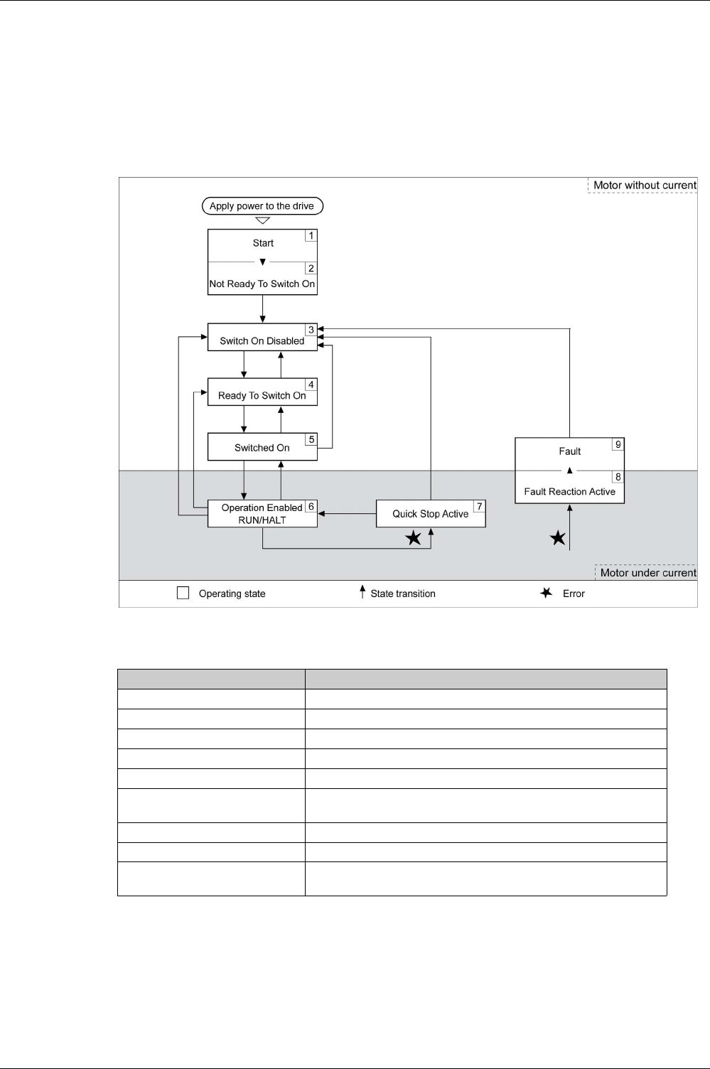
Operation
EIO0000002305 04/2017 299
Operating States
State Diagram
When the product is powered on and when an operating mode is started
(see page 315)
, the product goes
through a number of operating states.
The state diagram (state machine) shows the relationships between the operating states and the state
transitions.
The operating states are internally monitored and influenced by monitoring functions.
Operating States
Resetting an Error Message
After you have removed the cause of the error, you can reset the error message in one of the following
ways:
-With a rising edge of the signal input function FAULT_RESET
-With a rising edge of the signal input function SON
-By setting parameter P0-01 to the value 0
Operating state Description
1Start Electronics are initialized
2Not Ready To Switch On The power stage is not ready to switch on
3Switch On Disabled Impossible to enable the power stage
4Ready To Switch On The power stage is ready to switch on.
5Switched On Power stage is switched on
6Operation Enabled Power stage is enabled
Selected operating mode is active
7Quick Stop Active Quick Stop is being executed
8Fault Reaction Active Error response is active
9Fault Error response terminated
Power stage is disabled

Operation
300 EIO0000002305 04/2017
Setting the Digital Signal Inputs
Various signal functions can be assigned to the digital signal inputs.
The functions of the inputs and outputs depend on the selected operating mode and the settings of the
corresponding parameters.
Default Presets of the Signal Inputs
The following table shows the default presets of the digital signal inputs depending on the selected
operating mode:
WARNING
UNINTENDED EQUIPMENT OPERATION
-Only start the system if there are no persons or obstructions in the zone of operation.
-Verify that the wiring is appropriate for the settings.
-Carefully run tests for all operating states and potential error situations when commissioning,
upgrading or otherwise modifying the operation of the drive.
Failure to follow these instructions can result in death, serious injury, or equipment damage.
Setting A for
P2-
10 ... P2-
17
Short name Name PT PS V T Vz Tz PT
V
PT
T
PS
V
PS
T
V
T
CAN
open
01hSON Servo ON DI1 DI1 DI1 DI1 DI1 DI1 DI1 DI1 DI1 DI1 DI1 -
02hFAULT_RESET Fault Reset DI5 DI5 DI5 DI5 DI5 DI5 -
03hGAINUP Increase Gain -
04hCLRPOSDEV Clear Position
Deviation
DI2 - DI2 DI2 -
05hZCLAMP Zero Clamp -
06hINVDIRROT Inverse Direction
Of Rotation
-
07hHALT Halt -
08hCTRG Start Data Set - DI2 - DI2 DI2 -
09hTRQLM Activate Torque
Limit
- DI2 - DI2 -
10hSPDLM Activate Speed
Limit
- DI2 - DI2 -
11hPOS0 Data Set Bit 0 - DI3 - DI3 DI3 -
12hPOS1 Data Set Bit 1 - DI4 - DI4 DI4 -
13hPOS2 Data Set Bit 2 -
14hSPD0 Speed
Reference Value
Bit 0
- DI3 - DI3 - DI3 - DI5 - DI3 -
15hSPD1 Speed
Reference Value
Bit 1
- DI4 - DI4 - DI4 - DI6 - DI4 -
16hTCM0 Torque
Reference Value
Bit 0
DI3 - DI3 - DI3 - DI3 - DI5 DI5 -
17hTCM1 Torque
Reference Value
Bit 1
DI4 - DI4 - DI4 - DI4 - DI6 DI6 -
18hV-Px Velocity -
Position
- DI7 - DI7 -
19hV-T Velocity - Torque - DI7 -

Operation
EIO0000002305 04/2017 301
1A
hPOS3 Data Set Bit 3 -
1BhPOS4 Data Set Bit 4 -
1ChTPROB1 Touch Probe 1 -
1DhTPROB2 Touch Probe 2 -
20hT-Px Torque - Position - DI7 - DI7 - -
21hOPST Stop and Disable
Power Stage
DI8 DI8 DI8 DI8 DI8 DI8 DI8 DI8 DI8 DI8 DI8 DI8
22hCWL(NL) Negative Limit
Switch
(NL/LIMN)
DI6 DI6 DI6 DI6 DI6 DI6 - DI6
23hCCWL(PL) Positive Limit
Switch
(PL/LIMP)
DI7 DI7 DI7 DI7 DI7 DI7 - DI7
24hORGP Reference
Switch
-DI5
27hGOTOHOME Move To Home
Position
-
2ChPTCMS Type of pulses
for operating
mode Pulse
Train (PT) (OFF:
Low-speed
pulses, ON:
High-Speed
pulses)
-
37hJOGP Jog Positive -
38hJOGN Jog Negative -
39hSTEPU Next Data Set -
40hSTEPD Previous Data
Set
-
41hSTEPB First Data Set -
42hAUTOR Automatic
Position
Sequence: Start
with first data set,
repeat sequence
-
43hGNUM0 Numerator Bit 0
Electronic Gear
Ratio
-
44hGNUM1 Numerator Bit 1
Electronic Gear
Ratio
-
45hINHP Pulse Inhibit -
46hSTOP Stop Motor
(operating mode
PS only)
-
Setting A for
P2-
10 ... P2-
17
Short name Name PT PS V T Vz Tz PT
V
PT
T
PS
V
PS
T
V
T
CAN
open
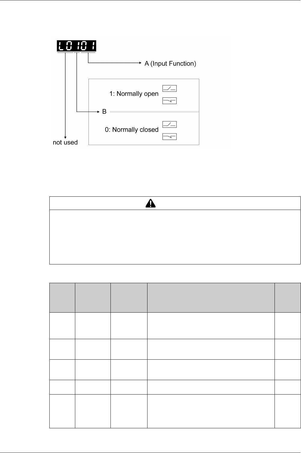
Operation
302 EIO0000002305 04/2017
Parameterization of the Signal Input Functions
The signal input functions for the inputs DI1 ... DI8 are configured via the parameters P2-10 ... P2-17.
A signal input function can only be assigned to one of the signal inputs.
The operating modes Torque (T) and Torque (Tz) and the dual operating modes with Torque (T) and
Torque (Tz) do not provide deceleration functionality in response to a power stage disable request. In these
operating modes, the motor coasts down to a standstill in response to a power stage disable request. You
must install additional equipment such as a dedicated service brake if your application requires faster
deceleration of the load.
The following table provides an overview of the possible signal input functions:
WARNING
UNINTENDED EQUIPMENT OPERATION
-During commissioning, trigger all signals and simulate all conditions that cause a power stage disable
request in order to verify that all loads come to a secure standstill when the power stage is disabled
under maximum load conditions.
-Install a dedicated service brake if removal of power to the motor does not meet the requirements of
your application.
Failure to follow these instructions can result in death, serious injury, or equipment damage.
Setting A
for P2-
10 ... P2-
17
Short name Name Description Signal
inputs
01hSON Servo ON The signal input function SON enables the power stage
(operating state Operation Enabled). The signal input
function SON is only available if no detected errors are
present.
DI1 … DI8
02hFAULT_RESE
T
Fault Reset The signal input function FAULT_RESET performs a Fault
Reset. The cause of the error must have been removed
before a Fault Reset is performed.
DI1 … DI8
03hGAINUP Increase Gain The signal input function GAINUP increases the control
gain according to the values and conditions set via
parameter P2-27.
DI1 … DI8
04hCLRPOSDEV Clear Position
Deviation
The signal input function CLRPOSDEV resets the position
deviation to zero as set via parameter P2-50.
DI1 … DI8
05hZCLAMP Zero Clamp In the operating mode V, the signal input function ZCLAMP
can be used to stop the motor if the velocity of the motor is
below the velocity value set via the parameter P1-38. The
behavior of the signal input function ZCLAMP is set via the
parameter P2-65, bit 10.
DI1 … DI8

Operation
EIO0000002305 04/2017 303
06hINVDIRROT Inverse
Direction Of
Rotation
The signal input function INVDIRROT inverts the direction
of rotation of the motor. The signal input function
INVDIRROT is available in the operating modes Velocity
(V) and Torque (T).
DI1 … DI8
07hHALT Halt The signal input function HALT interrupts the movement
with the deceleration ramp set via the parameter P1-68.
The movement is resumed when the signal input function
is no longer active.
DI1 … DI8
08hCTRG Start Data Set The signal input function CTRG starts the selected data set
in the operating mode Position Sequence (PS). For further
information, refer to Operating Mode Position Sequence
(PS)
(see page 329)
.
DI1 … DI8
09hTRQLM Activate
Torque Limit
The signal input function TRQLM activates the torque
limitations set via parameters P1-12 … P1-14. You can
also use the parameter P1-02 to activate the torque
limitations set via parameters P1-12 … P1-14.
DI1 … DI8
10hSPDLM Activate Speed
Limit
The signal input function SPDLM activates the velocity
limitations set via parameters P1-09 … P1-11. You can
also use the parameter P1-02 to activate the velocity
limitations set via parameters P1-09 … P1-11.
DI1 … DI8
11hPOS0 Data Set Bit 0 The signal input functions POS0 ... POS4 represent bits
0 … 4 required to select one of the 32 data sets available
in the operating mode Position Sequence (PS). For further
information, refer to Operating Mode Position Sequence
(PS)
(see page 329)
.
DI1 … DI8
12hPOS1 Data Set Bit 1 The signal input functions POS0 ... POS4 represent bits
0 … 4 required to select one of the 32 data sets available
in the operating mode Position Sequence (PS). For further
information, refer to Operating Mode Position Sequence
(PS)
(see page 329)
.
DI1 … DI8
13hPOS2 Data Set Bit 2 The signal input functions POS0 ... POS4 represent bits
0 … 4 required to select one of the 32 data sets available
in the operating mode Position Sequence (PS). For further
information, refer to Operating Mode Position Sequence
(PS)
(see page 329)
.
DI1 … DI8
14hSPD0 Speed
Reference
Value Bit 0
The signal input functions SPD0 and SPD1 represent bits
0 and 1 to select one of the three velocity reference values
available in the operating mode Velocity (V). For further
information, refer to Operating Modes Velocity (V) and
Velocity Zero (Vz)
(see page 365)
.
DI1 … DI8
15hSPD1 Speed
Reference
Value Bit 1
The signal input functions SPD0 and SPD1 represent bits
0 and 1 to select one of the three velocity reference values
available in the operating mode Velocity (V). For further
information, refer to Operating Modes Velocity (V) and
Velocity Zero (Vz)
(see page 365)
.
DI1 … DI8
16hTCM0 Torque
Reference
Value Bit 0
The signal input functions TCM0 and TCM1 represent bits
0 and 1 to select one of the three torque reference values
available in the operating mode Torque (T). For further
information, refer to Operating Modes Torque (T) and
Torque Zero (Tz)
(see page 370)
.
DI1 … DI8
17hTCM1 Torque
Reference
Value Bit 1
The signal input functions TCM0 and TCM1 represent bits
0 and 1 to select one of the three torque reference values
available in the operating mode Torque (T). For further
information, refer to Operating Modes Torque (T) and
Torque Zero (Tz)
(see page 370)
.
DI1 … DI8
18hV-Px Velocity -
Position
Operating mode switching between Velocity (V) and Pulse
Train (PT) or between Velocity (V) and Position Sequence
(PS) . For further information, refer to Setting the Operating
Mode
(see page 316)
.
(OFF: Velocity (V), ON: Pulse Train (PT) or Position
Sequence (PS), depending on P1-01)
DI1 … DI8
Setting A
for P2-
10 ... P2-
17
Short name Name Description Signal
inputs

Operation
304 EIO0000002305 04/2017
19hV-T Velocity -
Torque
Operating mode switching between Velocity (V) and
Torque (T). For further information, refer to Setting the
Operating Mode
(see page 316)
.
(OFF: Velocity (V), ON: Pulse Torque (T))
DI1 … DI8
1A
hPOS3 Data Set Bit 3 The signal input functions POS0 ... POS4 represent bits
0 … 4 required to select one of the 32 data sets available
in the operating mode Position Sequence (PS). For further
information, refer to Operating Mode Position Sequence
(PS)
(see page 329)
.
DI1 … DI8
1BhPOS4 Data Set Bit 4 The signal input functions POS0 ... POS4 represent bits
0 … 4 required to select one of the 32 data sets available
in the operating mode Position Sequence (PS). For further
information, refer to Operating Mode Position Sequence
(PS)
(see page 329)
.
DI1 … DI8
1ChTPROB1 Touch Probe 1 The signal input function TPROB1 is used to trigger the
Position Capture function. See the sections on the
parameters P5-37 …P5-39 for additional information.
DI7
1DhTPROB2 Touch Probe 2 The signal input function TPROB2 is used to trigger the
Position Capture function. See the sections on the
parameters P5-37 …P5-39 for additional information.
DI6
20hT-Px Torque -
Position
Operating mode switching between Torque (T) and Pulse
Train (PT) or between Torque (T) and Position Sequence
(PS) . For further information, refer to Setting the Operating
Mode
(see page 316)
.
(OFF: Torque (T), ON: Pulse Train (PT) or Position
Sequence (PS), depending on P1-01)
DI1 … DI8
21hOPST Stop and
Disable Power
Stage
The signal input function OPST stops the motor with the
deceleration ramp set via the parameter P1-68 and then
disables the power stage.
DI1 … DI8
22hCWL(NL) Negative Limit
Switch
(NL/LIMN)
Negative limit switch (NL/LIMN). When the signal input is
activated, an alert is triggered. The deceleration ramp is
specified via parameter P5-25.
DI1 … DI8
23hCCWL(PL) Positive Limit
Switch
(PL/LIMP)
Positive limit switch (PL/LIMP). When the signal input is
activated, an alert is triggered. The deceleration ramp is
specified via parameter P5-26.
DI1 … DI8
24hORGP Reference
Switch
The signal input function ORGP is used for the reference
switch. For further information, refer to Operating Mode
Position Sequence (PS)
(see page 329)
.
DI1 … DI8
27hGOTOHOME Move To Home
Position
The signal input function GOTOHOME triggers a
movement to the Home position set via the parameter P5-
04.
DI1 … DI8
2ChPTCMS Type of pulses
for operating
mode Pulse
Train (PT)
(OFF: Low-
speed pulses,
ON: High-
Speed pulses)
The signal input function PTCMS selects the type of pulses
for the operating mode Pulse Train PT (OFF: Low-speed
pulses, ON: High-speed pulses). You can also use the
parameter P1-00 to select the type of pulses.
DI1 … DI8
37hJOGP Jog Positive The signal input function JOGP triggers a Jog movement in
positive direction if the value determining the direction of
movement in the parameter P1-01 is set to the default
value.
DI1 … DI8
38hJOGN Jog Negative The signal input function JOGN triggers a Jog movement
in negative direction if the value determining the direction
of movement in the parameter P1-01 is set to the default
value.
DI1 … DI8
39hSTEPU Next Data Set The signal input function STEPU starts the next data set in
the operating mode Position Sequence (PS).
DI1 … DI8
Setting A
for P2-
10 ... P2-
17
Short name Name Description Signal
inputs

Operation
EIO0000002305 04/2017 305
40hSTEPD Previous Data
Set
The signal input function STEPD starts the previous data
set in the operating mode Position Sequence (PS).
DI1 … DI8
41hSTEPB First Data Set The signal input function STEPB starts the first data set in
the operating mode Position Sequence (PS).
DI1 … DI8
42hAUTOR Automatic
Position
Sequence:
Start with first
data set, repeat
sequence
The signal input function AUTOR starts a sequence of data
sets from the first data set in the operating mode Position
Sequence (PS). The sequence is repeated as long as the
signal input function AUTOR is active.
DI1 … DI8
43hGNUM0 Numerator Bit 0
Electronic Gear
Ratio
The signal input functions GNUM0 and GNUM1 represent
bits 0 and 1 to select one of the four numerators set via the
parameters P1-44, P2-60 …P2-62. The denominator is
set via the parameter P1-45 . The ratios are used as gear
factors in the operating mode Pulse Train (PT) and as
scaling factors. For further information, refer to Gear Ratio
(see page 326)
and Scaling
(see page 337)
.
DI1 … DI8
44hGNUM1 Numerator Bit 1
Electronic Gear
Ratio
The signal input functions GNUM0 and GNUM1 represent
bits 0 and 1 to select one of the four numerators set via the
parameters P1-44, P2-60 …P2-62. The denominator is
set via the parameter P1-45. The ratios are used as gear
factors in the operating mode Pulse Train (PT) and as
scaling factors. For further information, refer to Gear Ratio
(see page 326)
and Scaling
(see page 337)
.
DI1 … DI8
45hINHP Pulse Inhibit The signal input function INHP is used in the operating
mode Pulse Train (PT) to block pulses received as
reference signals. If the signal input function is active, the
pulses are no longer evaluated and the motor coasts down.
DI1 … DI8
46hSTOP Stop Motor
(operating
mode PS only)
The signal input function STOP stops the motor with the
deceleration ramp set via the parameter P5-20. The power
stage remains enabled. The signal input function STOP is
available in the operating mode Position Sequence (PS).
DI1 … DI8
Setting A
for P2-
10 ... P2-
17
Short name Name Description Signal
inputs

Operation
306 EIO0000002305 04/2017
Setting the Digital Signal Outputs
Various signal functions can be assigned to the digital signal outputs.
The functions of the inputs and outputs depend on the selected operating mode and the settings of the
corresponding parameters.
Default Presets of the Signal Outputs
The following table shows the default presets of the digital signal outputs depending on the selected
operating mode:
WARNING
UNINTENDED EQUIPMENT OPERATION
-Only start the system if there are no persons or obstructions in the zone of operation.
-Verify that the wiring is appropriate for the settings.
-Carefully run tests for all operating states and potential error situations when commissioning,
upgrading or otherwise modifying the operation of the drive.
Failure to follow these instructions can result in death, serious injury, or equipment damage.
Setting A for
P2-18 ... P2-
22
Short name Name PT PS V T Vz Tz PT
V
PT
T
PS
V
PS
T
V
T
CANopen
01hSRDY Servo Ready DO1 DO1 DO1 DO1 DO1 DO1 DO1 DO1 DO1 DO1 DO1 DO1
02hSON Servo On -
03hZSPD Zero Speed DO2 DO2 DO2 DO2 DO2 DO2 DO2 DO2 DO2 DO2 DO2 -
04hTSPD Speed
Reached
- DO3 DO3 DO3 DO3 DO3 DO3 DO3 DO3 DO3 -
05hTPOS Movement
Completed
DO4 DO4 - DO4 DO4 DO4 DO4 -
06hTQL Torque Limit
Reached
-
07hERROR Error Detected DO5 DO5 DO5 DO5 DO5 DO5 DO5 DO5 DO5 DO5 DO5 DO5
08hBRKR Holding Brake
Control
- DO4 DO4 DO4 DO4 -
09hHOMED_OK Homing
Completed
DO3 DO3 -
10hOLW Motor
Overload Alert
-
11hWARN Alert Signal
activated
-
12hOVF Position
command
overflow
-
13hSCWL(SNL) Negative
Software Limit
Switch
Reached
-
14hSCCWL(SPL) Positive
Software Limit
Switch
Reached
-
15hCMD_OK Data set
completed
-
16hCAP1_OK Capture 1
completed
-
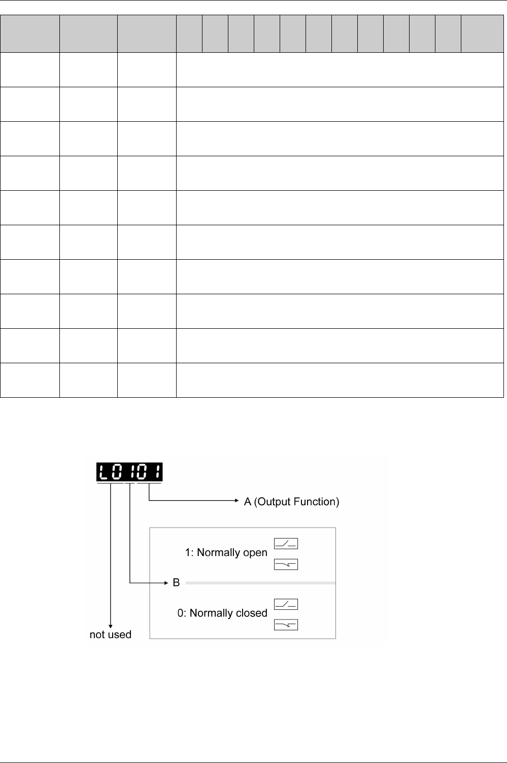
Operation
EIO0000002305 04/2017 307
Parameterization of the Signal Output Functions
The signal output functions for the outputs DO1 ... DO5 are configured via the parameters P2-18 ... P2-
22.
17hMC_OK Motion control
completed
output
-
19hSP_OK Speed
reached
output
-
30hSDO_0 Output the
status of bit 0
of P4-06.
-
31hSDO_1 Output the
status of bit 1
of P4-06.
-
32hSDO_2 Output the
status of bit 2
of P4-06.
-
33hSDO_3 Output the
status of bit 3
of P4-06.
-
34hSDO_4 Output the
status of bit 4
of P4-06.
-
35hSDO_5 Output the
status of bit 5
of P4-06.
-
36hSDO_6 Output the
status of bit 6
of P4-06.
-
37hSDO_7 Output the
status of bit 7
of P4-06.
-
Setting A for
P2-18 ... P2-
22
Short name Name PT PS V T Vz Tz PT
V
PT
T
PS
V
PS
T
V
T
CANopen

Operation
308 EIO0000002305 04/2017
The following table provides an overview of the possible signal output functions:
Setting A for P2-
18 ... P2-22
Short name Name Description
01hSRDY Servo Ready The signal output function SRDY indicates that no errors are
detected, i.e., the drive is not in the operating state Fault.
02hSON Servo On The signal output function SON indicates that the drive is in the
operating state Operation Enabled .
03hZSPD Zero Speed The signal output function ZSPD indicates that the velocity of the
motor is less than the velocity value set via parameter P1-38 .
04hTSPD Speed
Reached
The signal output function TSPD indicates that the velocity of the
motor is greater than the velocity value set via parameter P1-39 .
05hTPOS Movement
Completed
Operating mode Pulse Train (PT): The signal output function
TPOS indicates that the position deviation is within the tolerance
set via the parameter P1-54 and the motor has come to a
standstill.
Operating mode Position Sequence (PS): The signal output
function TPOS indicates that the position deviation at the target
position is within the tolerance set via the parameter P1-54 and
the reference velocity is below the value set via the parameter P1-
38.
06hTQL Torque Limit
Reached
The signal output function TQL indicates that the torque of the
motor has reached the value set via parameters P1-12 ... P1-14
or an analog input.
07hERROR Error
Detected
The signal output function ERROR indicates that an error has been
detected and that the drive has switched to the operating state
Fault. For further information, refer to Diagnostics and
Troubleshooting
(see page 399)
.
08hBRKR Holding
Brake Control
The signal output function BRKR is used to control the holding
brake with the settings made via parameters P1-42 and P1-19. The
holding brake must be connected to the output to which the signal
output function BRKR is assigned. For further information, refer to
Holding Brake Connection
(see page 171)
.
09hHOMED_OK Homing
Completed
The signal output function HOMED_OK indicates that the homing
procedure has been successfully completed. The settings for
Homing are specified via parameters P5-04 … P5-06. For further
information, refer to Operating Mode Position Sequence (PS)
(see page 329)
.
10hOLW Motor
Overload
Alert
The signal output function OLW indicates a motor overload
condition. A threshold for the signal output function OLW can be
set via parameter P1-28.
11hWARN Alert Signal
activated
The signal output function indicates that one of the following
conditions has been detected: Hardware limit switch triggered,
undervoltage, Nodeguard alert, Operational Stop (OPST). For
further information, refer to Diagnostics and Troubleshooting
(see page 399)
.
12h--Reserved
13hSCWL(SNL) Negative
Software
Limit Switch
Reached
The signal output function SCWL(SNL) indicates that the negative
software limit switch set via parameter P5-09 has been reached.
When the software limit switch is reached, an alert is triggered. The
deceleration ramp is specified via parameter P5-23.
14hSCCWL(SPL) Positive
Software
Limit Switch
Reached
The signal output function SCCWL(SPL) indicates that the positive
software limit switch set via parameter P5-08 has been reached.
When the software limit switch is reached, an alert is triggered. The
deceleration ramp is specified via parameter P5-24.
15hCMD_OK Data set
completed
The signal output function CMD_OK indicates that the data set
including the waiting time has been successfully completed.
16hCAP1_OK Capture 1
completed
The signal output function CAP1_OK indicates that a position
capture (Touch Probe) has been successfully completed. The
settings for position capture (Touch Probe) are specified via
parameters P5-37 … P5-39.

Operation
EIO0000002305 04/2017 309
17hMC_OK Motion
control
completed
output
The signal output function MC_OK indicates that both the signal
output functions CMD_OK and TPOS have been activated.
19hSP_OK Speed
reached
output
The signal output function SP_OK indicates that the target velocity
has been reached. The velocity range for activating this signal
output function is set via parameter P1-47.
30hSDO_0 Output the
status of bit 0
of P4-06.
The signal output functions SDO_0 ... SDO_7 provide the bit
pattern (bits 0 ... 7) required to determine the setting of the
parameter P4-06.
31hSDO_1 Output the
status of bit 1
of P4-06.
The signal output functions SDO_0 ... SDO_7 provide the bit
pattern (bits 0 ... 7) required to determine the setting of the
parameter P4-06.
32hSDO_2 Output the
status of bit 2
of P4-06.
The signal output functions SDO_0 ... SDO_7 provide the bit
pattern (bits 0 ... 7) required to determine the setting of the
parameter P4-06.
33hSDO_3 Output the
status of bit 3
of P4-06.
The signal output functions SDO_0 ... SDO_7 provide the bit
pattern (bits 0 ... 7) required to determine the setting of the
parameter P4-06.
34hSDO_4 Output the
status of bit 4
of P4-06.
The signal output functions SDO_0 ... SDO_7 provide the bit
pattern (bits 0 ... 7) required to determine the setting of the
parameter P4-06.
35hSDO_5 Output the
status of bit 5
of P4-06.
The signal output functions SDO_0 ... SDO_7 provide the bit
pattern (bits 0 ... 7) required to determine the setting of the
parameter P4-06.
36hSDO_6 Output the
status of bit 6
of P4-06.
The signal output functions SDO_0 ... SDO_7 provide the bit
pattern (bits 0 ... 7) required to determine the setting of the
parameter P4-06.
37hSDO_7 Output the
status of bit 7
of P4-06.
The signal output functions SDO_0 ... SDO_7 provide the bit
pattern (bits 0 ... 7) required to determine the setting of the
parameter P4-06.
Setting A for P2-
18 ... P2-22
Short name Name Description

Operation
310 EIO0000002305 04/2017
Functions for Target Value Processing
Interrupting a Movement with HALT
The HALT signal input function is available in the operating mode PT only.
With the signal input function HALT, the ongoing movement is interrupted. When the signal input function
HALT is no longer active, the movement is resumed from the point where it was interrupted.
The movement is interrupted via a deceleration ramp. The deceleration ramp is specified via parameter
P1-68.
In order to interrupt a movement via a signal input, you must first parameterize the signal input function
HALT, refer to Setting the Digital Signal Inputs
(see page 300)
.
NOTE: The pulses received while the HALT function is active are ignored. When the HALT is no longer
active, the drive accepts any on-going pulse stream and start movement according to that stream.
If there is uncertainty of the effect of the movement generated by an ongoing pulse stream at the time of
HALT deactivation, you must rehome the application.
Stopping a Movement with OPST
With the signal input function OPST (Operational Stop), the ongoing movement is stopped.
In order to stop a movement via a signal input, you must first parameterize the signal input function OPST,
refer to Setting the Digital Signal Inputs
(seepage300)
.
The movement is interrupted via a deceleration ramp to the point of the defined standstill. After that, the
power stage is disabled once the drive has determined that the motor is at standstill, and if so configured,
the holding brake is applied.
An error, AL013, is detected and presented.
The deceleration ramp is specified via parameter P1-68.
After the OPST function is enabled, you must disable it and re-enable the power stage for continued
operation.
WARNING
UNINTENDED EQUIPMENT OPERATION
-Do not deactivate the HALT function prior to the deceleration of the motor.
-If the deactivation of the HALT function prior to the deceleration of the motor is unavoidable, be sure
to include these circumstances in your hazard and risk analysis of your application.
Failure to follow these instructions can result in death, serious injury, or equipment damage.
WARNING
UNINTENDED EQUIPMENT OPERATION
-During commissioning, trigger all signals and simulate all conditions that cause a power stage disable
request in order to verify that all loads come to a secure standstill when the power stage is disabled
under maximum load conditions.
-Install a dedicated service brake if removal of power to the motor does not meet the requirements of
your application.
Failure to follow these instructions can result in death, serious injury, or equipment damage.

Operation
EIO0000002305 04/2017 311
Setting a Signal Output Via Parameter
The digital signal outputs can be set via a parameter.
In order to set a digital signal output via the parameter, you must first parameterize the signal output
functions SDO_0 … SDO_7, refer to Setting the Digital Signal Outputs
(see page 306)
.
The parameter P4-06 lets you set the digital signal outputs.
Parameter name Description Unit
Minimum value
Factory setting
Maximum value
HMI Format
Data type
R/W
Persistent
Parameter
address via
fieldbus
P4-06
FOT
Setting a signal output via parameter
Applicable operating mode: PT, PS, V, T
This parameter lets you set those signal
outputs whose signal output functions have
been defined by SDO_0 ... SDO_5.
Bit 0 = 1 sets those signal outputs whose
signal output function has been set to
SDO_0.
Bit 1 = 1 sets those signal outputs whose
signal output function has been set to
SDO_1.
Bit 2 = 1 sets those signal outputs whose
signal output function has been set to
SDO_2.
Bit 3 = 1 sets those signal outputs whose
signal output function has been set to
SDO_3.
Bit 4 = 1 sets those signal outputs whose
signal output function has been set to
SDO_4.
Bit 5 = 1 sets those signal outputs whose
signal output function has been set to
SDO_5.
Bit 6 = 1 sets those signal outputs whose
signal output function has been set to
SDO_6.
Bit 7 = 1 sets those signal outputs whose
signal output function has been set to
SDO_7.
See P2-18 ... P2-22 for assigning the
functions to the digital outputs.
-
0h
0h
FFh
Hexadecimal
u16
RW
-
Modbus 50Ch
CANopen 4406h

Operation
312 EIO0000002305 04/2017
Forcing the Digital Signal Inputs and Signal Outputs
Forcing of signals means that the digital inputs and outputs are set manually. Forcing input and output
values can have serious consequences on the operation of a machine or process.
Forcing the Digital Inputs
Forcing of the digital inputs is set via the parameters P3-06 and P4-07.
The parameter P3-06 lets you specify which digital signal inputs are allowed to be forced.
WARNING
UNINTENDED EQUIPMENT OPERATION CAUSED BY FORCING
-Only force I/O if there are no persons or obstructions in the zone of operation.
-Only force I/O if you are fully familiar with the effects of the signals.
-Only force I/O for test purposes, maintenance or other short-term tasks.
-Do not use forcing for regular, long-term or in-service operation.
-Always remove forcing when the task (testing, maintenance or other short-term operation) is
completed.
Failure to follow these instructions can result in death, serious injury, or equipment damage.
Parameter name Description Unit
Minimum value
Factory setting
Maximum value
HMI Format
Data type
R/W
Persistent
Parameter
address via
fieldbus
P3-06
SDI
Digital Inputs - Forcing Settings
Applicable operating mode: PT, PS, V, T
This parameter determines whether a
digital input can be forced.
Bits 0 … 7: Digital input DI1 … Digital input
DI8
Bit settings:
Value 0: Digital input cannot be forced
Value 1: Digital input can be forced
To start forcing, you must write P4-07.
See P2-10 … P2-17 for the assignment of
signal input functions to the digital inputs.
-
0h
0h
7FFh
Hexadecimal
u16
RW
-
Modbus 40Ch
CANopen 4306h

Operation
EIO0000002305 04/2017 313
Use parameter P4-07 to activate forcing of the digital signal inputs.
Forcing the Digital Outputs
Forcing of the digital outputs is set via the parameters P4-27 and P4-28.
The parameter P4-27 lets you specify which digital signal outputs are allowed to be forced.
Parameter name Description Unit
Minimum value
Factory setting
Maximum value
HMI Format
Data type
R/W
Persistent
Parameter
address via
fieldbus
P4-07
ITST
State of Digital Inputs / Activate Forcing
Applicable operating mode: PT, PS, V, T
A read access to this parameter indicates
the state of the digital inputs in the form of
a bit pattern.
Example:
Read value 0x0011: Digital inputs 1 and 5
are activated
By writing this parameter, you can change
the state of the inputs provided that the
setting for the corresponding input in P3-06
allows for forcing (value 1 for the bit
corresponding to the input).
Example:
Write value 0x0011: Digital inputs 1 and 5
are activated
Read value 0x0011: Digital inputs 1 and 5
are activated
See P3-06 for permitting forcing of
individual digital inputs.
See P2-10 ... P2-17 for the assignment of
signal input functions to the digital inputs.
-
0h
0h
FFh
Hexadecimal
u16
RW
-
Modbus 50Eh
CANopen 4407h
Parameter name Description Unit
Minimum value
Factory setting
Maximum value
HMI Format
Data type
R/W
Persistent
Parameter
address via
fieldbus
P4-27
DO_FORCE_MASK
Digital Outputs - Forcing Settings
Applicable operating mode: PT, PS, V, T
This parameter determines whether a
digital output can be forced.
Bits 0 … 4: Digital output DO1 … Digital
output DO5
Bit settings:
Value 0: Digital output cannot be forced
Value 1: Digital output can be forced
To start forcing, you must write P4-28.
See P2-18 … P2-22 for the assignment of
signal output functions to the digital
outputs.
-
0h
0h
1Fh
Hexadecimal
u16
RW
-
Modbus 536h
CANopen 441Bh

Operation
314 EIO0000002305 04/2017
Use parameter P4-28 to activate forcing of the digital signal outputs.
Parameter name Description Unit
Minimum value
Factory setting
Maximum value
HMI Format
Data type
R/W
Persistent
Parameter
address via
fieldbus
P4-28
DO_FORCE_VALUE
State of Digital Outputs / Activate Forcing
Applicable operating mode: PT, PS, V, T
A read access to this parameter indicates
the state of the digital outputs in the form of
a bit pattern.
Example:
Read value 0x0011: Digital outputs 1 and 5
are activated
By writing this parameter, you can change
the state of the outputs provided that the
setting for the corresponding output in P4-
27 allows for forcing (value 1 for the bit
corresponding to the output).
Example:
Write value 0x0011: Digital outputs 1 and 5
are activated
Read value 0x0011: Digital outputs 1 and 5
are activated
See P4-27 for permitting forcing of
individual digital outputs.
See P2-18 … P2-22 for the assignment of
signal output functions to the digital
outputs.
-
0h
0h
1Fh
Hexadecimal
u16
RW
-
Modbus 538h
CANopen 441Ch

EIO0000002305 04/2017 315
Lexium 28
A
and BCH2 Servo Drive System
Operating Modes
EIO0000002305 04/2017
Operating Modes
Chapter 18
Operating Modes
What Is in This Chapter?
This chapter contains the following sections:
Section Topic Page
18.1 Setting the Operating Mode 316
18.2 Jog Operation 321
18.3 Operating Mode Pulse Train (PT) 322
18.4 Operating Mode Position Sequence (PS) 329
18.5 Operating Modes Velocity (V) and Velocity Zero (Vz) 365
18.6 Operating Modes Torque (T) and Torque Zero (Tz) 370
18.7 Operating Mode CANopen 372

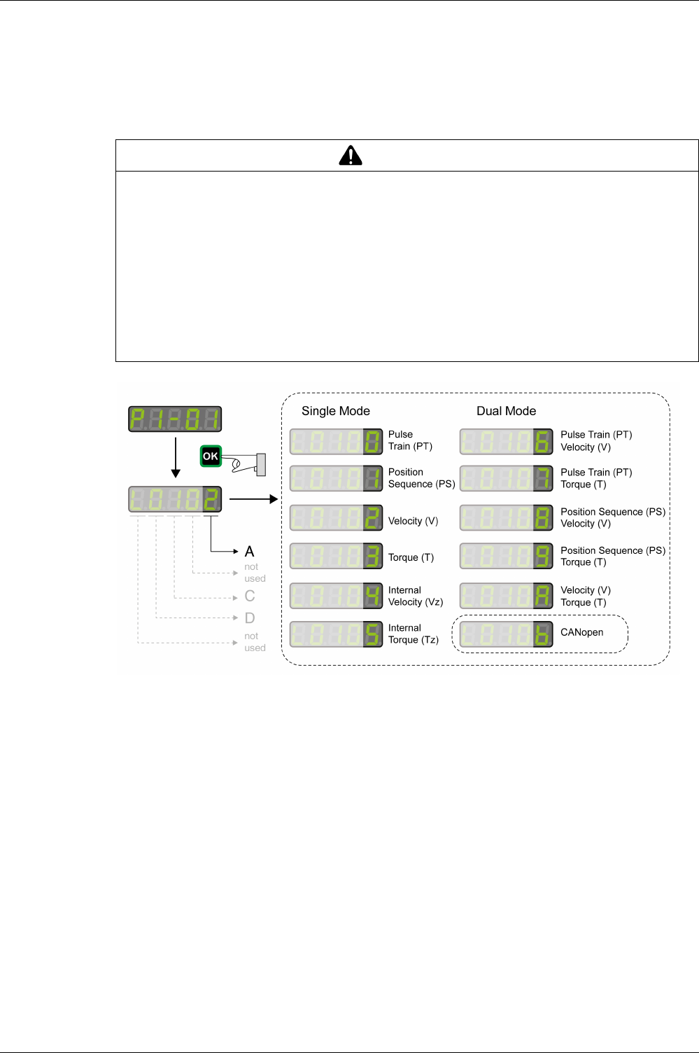
Operating Modes
EIO0000002305 04/2017 317
Setting the Operating Mode
Unsuitable settings or unsuitable data may trigger unintended movements, trigger signals, damage parts
and disable monitoring functions. Some parameters and other operational data do not become active until
after a restart.
The drive has the following types of operating modes:
-Single Mode operating modes
The drive operates in a single operating mode.
-Dual Mode operating modes
The drive operates using 2 operating modes alternately. The signal input functions are used to switch
between the operating modes.
-CANopen Mode operating mode
The drive operates in the operating mode CANopen.
The operating modes Torque (T) and Torque (Tz) and the dual operating modes with Torque (T) and
Torque (Tz) do not provide deceleration functionality in response to a power stage disable request. In these
operating modes, the motor coasts down to a standstill in response to a power stage disable request. You
must install additional equipment such as a dedicated service brake if your application requires faster
deceleration of the load.
WARNING
UNINTENDED EQUIPMENT OPERATION
-Only start the system if there are no persons or obstructions in the zone of operation.
-Do not operate the drive system with undetermined parameter values.
-Never modify a parameter value unless you fully understand the parameter and all effects of the
modification.
-Restart the drive and verify the saved operational data and/or parameter values after modification.
-Carefully run tests for all operating states and potential error situations when commissioning,
upgrading or otherwise modifying the operation of the drive.
-Verify the functions after replacing the product and also after making modifications to the parameter
values and/or other operational data.
Failure to follow these instructions can result in death, serious injury, or equipment damage.

Operating Modes
318 EIO0000002305 04/2017
WARNING
UNINTENDED EQUIPMENT OPERATION
-During commissioning, trigger all signals and simulate all conditions that cause a power stage disable
request in order to verify that all loads come to a secure standstill when the power stage is disabled
under maximum load conditions.
-Install a dedicated service brake if removal of power to the motor does not meet the requirements of
your application.
Failure to follow these instructions can result in death, serious injury, or equipment damage.

Operating Modes
EIO0000002305 04/2017 319
Object units
Overview
CANopen has two objects for setting the gear ratio and the feed constant conversion factors, each of which
has two subindex.
These objects have four equivalent variables:
It is possible to modify the subindex of both objects, but it is usually sufficient to modify only the feed
constant value, as shown in the following example:
Resolution = (6092:1h / 6092:2h) x (6091:1h / 6091:2h)
Example by unit dimensions:
Item CANopen Object Description
Feed
constant
6092:1hFeed
Unit conversion numerator
Conversion factors of the user-defined position unit.
Used to multiply the motor revolution (rotary motors) or
the motor pitch (linear motors), according to the
configured motor type.
6092:2hShaft revolutions
Unit conversion denominator
Gear ratio 6091:1hMotor revolutions
Motor shaft scaling for the
fieldbus gear ratio
Conversion factor of the motor shaft revolution.
6091:2hShaft revolutions
Drive shaft scaling for the
fieldbus gear ratio
Conversion factor of the drive shaft revolution.
Unit dimension Examples
Position units Assuming:
-6091:1h = 360
-6091:2h = 1
-6092:1h = 1
-6092:2h = 1
- The actual position reading = 720
Then:
720 / [(360 / 1) x (1 / 1)] = 2 revolutions
Velocity units Assuming:
-6091:1h = 360
-6091:2h = 1
-6092:1h = 1
-6092:2h = 1
-The actual velocity reading = 720
Then:
720 / [(360 / 1) x (1 / 1)] = 2 revolutions per second
Acceleration units Assuming:
-6091:1h = 360
-6091:2h = 1
-6092:1h = 1
-6092:2h = 1
-The actual acceleration reading = 720
Then:
720 / [(360 / 1) x (1 / 1)] = 2 revolutions per second2
Current units The units are derived from object 6075h (Motor Rated Current)
The value of this object is user-defined, in mA.
After setting a value for 6075h, all other current objects must receive values defined
in 1/1000 (one-thousandth) of 6075h.
For example:
Assuming 6075h has a value of 20000 mA, then to set a value of 15000 mA for 6073h
(Maximum Current), write 750 for 6073h.
The calculation is:
(750 / 1000) × 20000 = 15000 mA

Operating Modes
320 EIO0000002305 04/2017
Examples of Rotary Motor with Gear or Rotary to Linear Motion Translation Device
When using a gear or rotary-to-linear motion translation device, set values for the translation ratio of the
gear in order to define the unit variables.
This units will be as follows:
-Position in mm
-Velocity in mm/sec
-Acceleration in mm.sec2
Using a ball screw that converts Object values to set
100 motor revolutions to 1 mm 6091:1h = 100
6091:2h = 1
6092:1h = 1
6092:2h = 1
3600 rotary degrees to 1 mm 6091:1h = 10
6091:2h = 1
6092:1h = 360
6092:2h = 1
360 rotary degrees to 10 mm 6091:1h = 1
6091:2h = 10
6092:1h = 360
6092:2h = 1
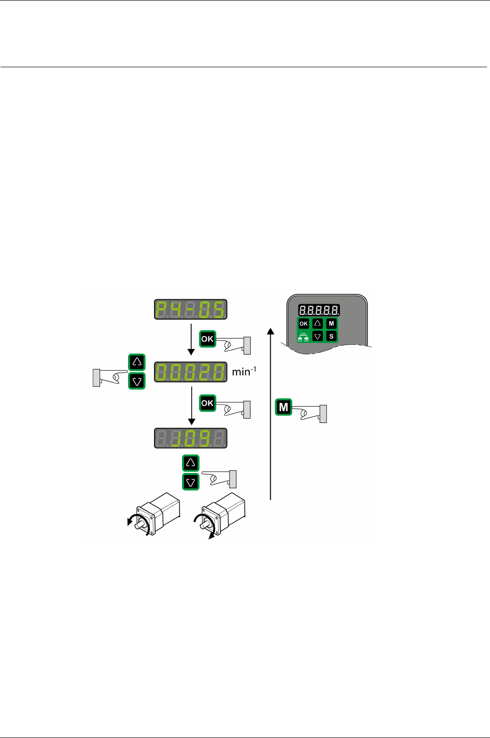
Operating Modes
EIO0000002305 04/2017 321
Jog Operation
Section 18.2
Jog Operation
Jog Operation
Description
In the Jog operation, a movement is made from the actual motor position in the specified direction.
The parameter P4-05 is used to set the velocity for the movement in the unit rpm.
The movement can be performed via the arrow keys at the HMI or via the signal input functions JOGP and
JOGN.
For further information on the parameterizable signal input functions, refer to Setting the Digital Signal
Inputs
(see page 300)
.
Jog Via HMI
If the HMI is used, the movements are performed via the arrow keys. The operating mode is terminated via
the M key.
If the HMI is used, the movements are performed via the arrow keys. The operating mode is terminated via
the M key.

Operating Modes
322 EIO0000002305 04/2017
Operating Mode Pulse Train (PT)
Section 18.3
Operating Mode Pulse Train (PT)
What Is in This Section?
This section contains the following topics:
Topic Page
Operating mode Pulse Train (PT) 323
Pulse Settings 324
Gear Ratio 326
Acceleration and Deceleration Limitation 328

Operating Modes
EIO0000002305 04/2017 323
Operating mode Pulse Train (PT)
Description
In the operating mode Pulse Train (PT), movements are carried out according to externally supplied
reference value signals. A position reference value is calculated on the basis of these external reference
values plus an adjustable gear ratio. The reference value signals can be A/B signals, P/D signals or
CW/CCW signals.
Method
A movement can be made using one of 3 methods:
-Position synchronization without compensation movement
In the case of position synchronization without compensation movement, the movement is made
synchronously (position synchronicity) with the supplied reference value signals. Reference value
signals supplied during an interruption are not taken into account.
-Position synchronization with compensation movement
In the case of position synchronization with compensation movement, the movement is made
synchronously (position synchronicity) with the supplied reference value signals. Reference value
signals supplied during an interruption are taken into account and compensated for.
-Velocity synchronization
In the case of velocity synchronization, the movement is made synchronously (velocity synchronicity)
with the supplied reference value signals.
Parameter name Description Unit
Minimum value
Factory setting
Maximum value
HMI Format
Data type
R/W
Persistent
Parameter
address via
fieldbus
P8-31
GEARING_MODE
Method for Operating Mode Pulse Train
(PT)
Applicable operating mode: PT
Value 0: Synchronization deactivated
Value 1: Position synchronization without
compensation movement
Value 2: Position synchronization with
compensation movement
Value 3: Velocity synchronization
The parameters for acceleration (P1-34),
deceleration (P1-35) and velocity (P1-55)
act as limitations for the synchronization.
-
0
1
3
Decimal
u16
RW
per.
Modbus 93Eh
CANopen 481Fh
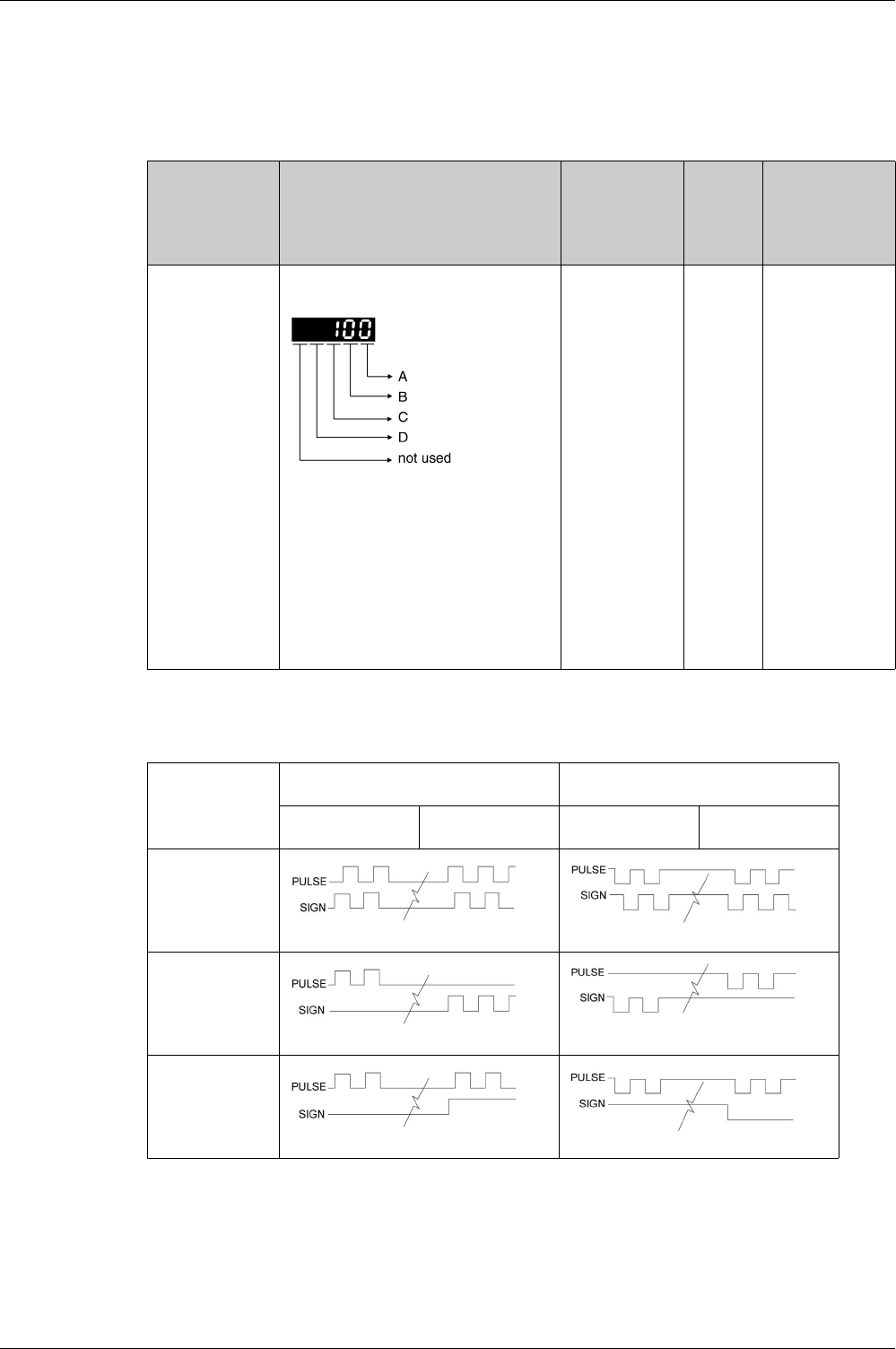
Operating Modes
324 EIO0000002305 04/2017
Pulse Settings
The parameter P1-00 lets you specify the type of reference value signals, the input polarity, the maximum
signal frequency and the source of the pulses.
Settings A and C
Type of reference value signals and input polarity
Parameter name Description Unit
Minimum value
Factory setting
Maximum value
HMI Format
Data type
R/W
Persistent
Parameter
address via
fieldbus
P1-00
PTT
Reference Value Signal - Pulse Settings
Applicable operating mode: PT
This parameter is used to configure the
reference value signals for the operating
mode PT.
A: Type of reference value signals
B: Signal frequency
C: Input polarity
D: Source of reference value signals
Setting can only be changed if power stage
is disabled.
-
0h
2h
1132h
Hexadecimal
u16
RW
per.
Modbus 200h
CANopen 4100h
–C = 0
Positive input polarity
C = 1
Negative input polarity
Positive direction of
movement
Negative direction of
movement
Positive direction of
movement
Negative direction of
movement
A = 0
A/B signals
A = 1
CW/CCW signals
A = 2
P/D signals
0

Operating Modes
EIO0000002305 04/2017 325
Setting B
Maximum signal frequency:
Parameter P2-65 bit 6 allows you to set an error response for frequencies exceeding the maximum signal
frequency by more than 10 %.
Setting D
Source of the pulses:
The source of the pulses can also be set via the signal input function PTCMS. The settings of the signal
input function take priority over the settings of the parameter P1-00.
–Low-speed pulses
PULSE, SIGN
High-speed pulses
HPULSE, HSIGN
B = 0 500 Kpps(1) 4 Mpps
B = 1 200 Kpps 2 Mpps
B = 2 100 Kpps 1 Mpps
B = 3 50 Kpps 500 Kpps
(1) Only possible with RS422.
D = 0 Low-speed pulses CN1 Terminal: PULSE, SIGN
D = 1 High-speed pulses CN1 Terminal: HPULSE, HSIGN
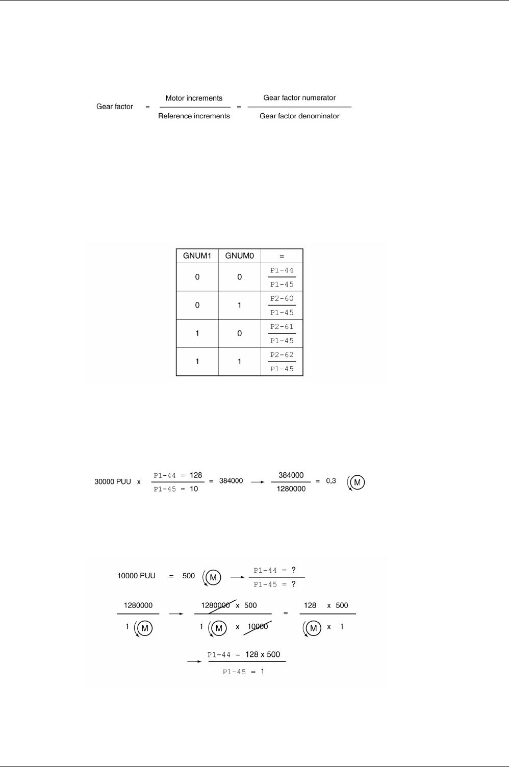
Operating Modes
326 EIO0000002305 04/2017
Gear Ratio
The gear ratio is the ratio of the number of motor increments and the number of reference increments.
The reference increments are supplied as reference value signals via the signal inputs.
With the factory setting for the gear ratio, 100000 reference increments correspond to one revolution.
There are 1280000 motor increments per revolution.
Parameterization
You can set up 4 gear ratios. It is possible to switch between these gear ratios via the signal inputs.
The gear ratios are set via parameters P1-44, P1-45, P2-60, P2-61, and P2-62.
You can switch between the gear ratios with the signal input functions GNUM0 and GNUM1.
In order to switch between the gear ratios via the signal inputs, you must first parameterize the signal input
functions GNUM0 and GNUM1, refer to Setting the Digital Signal Inputs
(see page 300)
.
Example 1
Calculation of number of motor revolutions corresponding to 30000 PUU:
Example 2
Calculation of gear ratio if 10000 PUU are to effect 500 revolutions of the motor shaft:

Operating Modes
EIO0000002305 04/2017 327
Example 3
A machine encoder with 1024 lines per revolution is to effect one revolution of the motor shaft with one
revolution.

Operating Modes
328 EIO0000002305 04/2017
Acceleration and Deceleration Limitation
The parameters P1-34 and P1-35 allow you to set a limitation for the acceleration and deceleration.
Parameter name Description Unit
Minimum value
Factory setting
Maximum value
HMI Format
Data type
R/W
Persistent
Parameter
address via
fieldbus
P1-34
TACC
Acceleration Period
Applicable operating mode: PT, V
The acceleration period is the time in
milliseconds required to accelerate from
motor standstill to 6000 rpm.
For operating mode V, this parameter
specifies the acceleration.
For operating mode PT, this parameter
specifies an acceleration limitation for the
pulses at the PTI interface.
ms
6
30
65500
Decimal
u16
RW
per.
Modbus 244h
CANopen 4122h
P1-35
TDEC
Deceleration Period
Applicable operating mode: PT, V
The deceleration period is the time in
milliseconds required to decelerate from
6000 rpm to motor standstill.
For operating mode V, this parameter
specifies the deceleration.
For operating mode PT, this parameter
specifies a deceleration limitation for the
pulses at the PTI interface.
ms
6
30
65500
Decimal
u16
RW
per.
Modbus 246h
CANopen 4123h

Operating Modes
EIO0000002305 04/2017 329
Operating Mode Position Sequence (PS)
Section 18.4
Operating Mode Position Sequence (PS)
What Is in This Section?
This section contains the following topics:
Topic Page
Operating mode Position Sequence (PS) 330
Structure of a Data Set 331
Running Data Sets 333
Scaling 337
Homing Data Set for Absolute Movements 338

Operating Modes
330 EIO0000002305 04/2017
Operating mode Position Sequence (PS)
Description
The operating mode Position Sequence (PS) allows you to set and execute 32 motion profiles in any
sequence. The motion profiles are defined via 32 data sets.
The following values can be set for each data set:
-Target position
-Type of movement: Absolute or relative
-Type of transition between data sets
-Acceleration
-Target velocity
-Deceleration
-Waiting time after completion of the data set
In addition, a Homing data set is provided. This Homing data set is used to set a reference point for
absolute movements.
Configuration
The data sets are configured by means of the commissioning software LXM28 DTM Library.
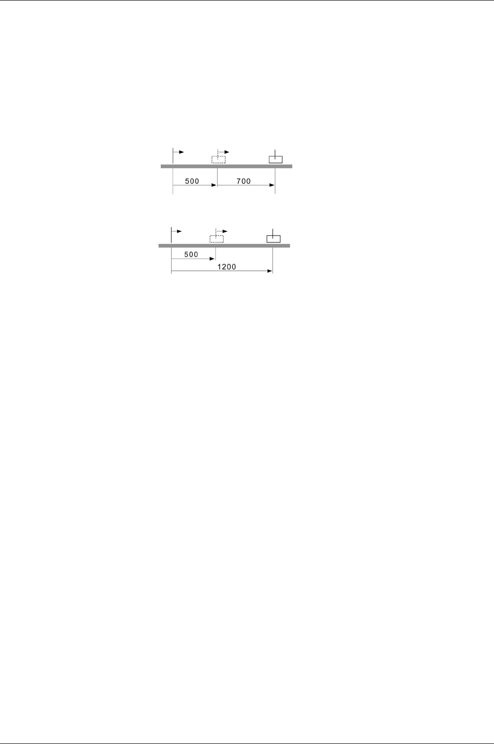
Operating Modes
EIO0000002305 04/2017 331
Structure of a Data Set
Target Position
The target position is set in the user-defined unit. With the factory scaling, the resolution is 100000 user-
defined units per revolution.
For further information on scaling, refer to chapter Scaling
(see page 337)
.
Type of Movement
In the case of a relative movement, the movement is relative with reference to the previous target position
or the current motor position.
In the case of an absolute movement, the movement is absolute with reference to the zero point.
Homing or position setting is required before the first absolute movement can be performed.
Transition Between Data Sets
There are two types of transitions:
-The subsequent data set is only started after the preceding data set has been completed.
-The subsequent data set is started as soon as it is triggered via the signal input function CTRG or the
parameter P5-07.
Acceleration Period
The acceleration period is the time in milliseconds required to accelerate from motor standstill to 6000 rpm.
It is used to set the acceleration ramp.
Target Velocity
The target velocity is reached after the time required for acceleration has passed.
Deceleration Period
The deceleration period is the time in milliseconds required to decelerate from 6000 rpm to motor standstill.
It is used to set the deceleration ramp.
Waiting Time
The waiting time is the period of time that must pass after the target position has been reached for the data
set to be considered completed.

Operating Modes
332 EIO0000002305 04/2017
Parameters for the Data Sets
The data set are configured via parameters P6-02 ... P6-65 and P7-02 ... P7-65. The following table
provides an overview:
Data set Target position Type / transition Acceleration /
deceleration
Waiting time / target
velocity
1 P6-02 P6-03 P7-02 P7-03
2 P6-04 P6-05 P7-04 P7-05
3 P6-06 P6-07 P7-06 P7-07
4 P6-08 P6-09 P7-08 P7-09
5 P6-10 P6-11 P7-10 P7-11
6 P6-12 P6-13 P7-12 P7-13
7 P6-14 P6-15 P7-14 P7-15
8 P6-16 P6-17 P7-16 P7-17
9 P6-18 P6-19 P7-18 P7-19
10 P6-20 P6-21 P7-20 P7-21
11 P6-22 P6-23 P7-22 P7-23
12 P6-24 P6-25 P7-24 P7-25
13 P6-26 P6-27 P7-26 P7-27
14 P6-28 P6-29 P7-28 P7-29
15 P6-30 P6-31 P7-30 P7-31
16 P6-32 P6-33 P7-32 P7-33
17 P6-34 P6-35 P7-34 P7-35
18 P6-36 P6-37 P7-36 P7-37
19 P6-38 P6-39 P7-38 P7-39
20 P6-40 P6-41 P7-40 P7-41
21 P6-42 P6-43 P7-42 P7-43
22 P6-44 P6-45 P7-44 P7-45
23 P6-46 P6-47 P7-46 P7-47
24 P6-48 P6-49 P7-48 P7-49
25 P6-50 P6-51 P7-50 P7-51
26 P6-52 P6-53 P7-52 P7-53
27 P6-54 P6-55 P7-54 P7-55
28 P6-56 P6-57 P7-56 P7-57
29 P6-58 P6-59 P7-58 P7-59
30 P6-60 P6-61 P7-60 P7-61
31 P6-62 P6-63 P7-62 P7-63
32 P6-64 P6-65 P7-64 P7-65
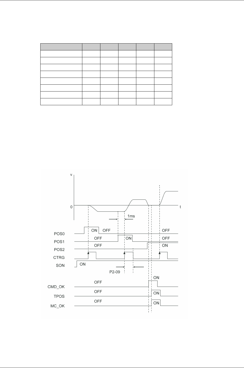
Operating Modes
EIO0000002305 04/2017 333
Running Data Sets
Running Individual Data Sets
Individual data sets are selected via the signal input functions POS0 … POS4.
The following table shows the bit pattern used to select the data sets.
The selected data set is executed and the movement started via the signal input function CTRG, rising
edge, or via the parameter P5-07.
For further information on parameterizing the signal input functions, refer to Setting the Digital Signal Inputs
(see page 300)
.
Example of Running Individual Data Sets
The illustration below shows how the data sets are started and terminated via the signal input functions
and the signal output functions CMD_OK, TPOS and MC_OK:
Operating mode Position Sequence (PS)
For further information, refer to Setting the Digital Signal Inputs
(seepage300)
.
Data set POS4 POS3 POS2 POS1 POS0
1 00000
2 00001
3 00010
4 00011
5 00100
… ……………
31 11110
32 11111

Operating Modes
334 EIO0000002305 04/2017
Running Sequences of Data Sets via the Signal Input Functions AUTOR and STEPB
The signal input function AUTOR allows you to automatically execute a sequence of the 32 available data
sets. When this signal input function is activated, data sets 1 to 32 are executed one after the other with
the values set via the appropriate parameters for each data set (P6-02 … P6-65 and P7-02 … P7-65).
After the last data is completed, the sequence restarts with the first data set. This loop continues as long
as the signal input function AUTOR is active.
If any of the 32 data sets contains an absolute movement, successful homing is required before the signal
input function AUTOR can be used.
The signal input function AUTOR is level-triggered.
If the execution of a data set is interrupted and AUTOR is active again, the data set is resumed where it
was interrupted.
If the signal input function AUTOR is deactivated, the currently active data set is completed. You can use
the signal input function STEPB to return to the first of the 32 data sets.
The parameter P2-44 can be used to provide information on the running sequence of data sets via the
digital outputs. For further information, refer to Status of Data Set Sequences - Parameter P2-44
(see page 335)
.
For further information on assigning signal input functions to the digital inputs, refer to Setting the Digital
Signal Inputs
(see page 300)
.
Running Sequences of Data Sets via the Signal Input Functions STEPU, STEPD, and STEPB
The signal input functions STEPU and STEPD allow you to run data sets in ascending or descending order.
Successful homing is required before the signal input function STEPU and STEPD can be used.
When the signal input function STEPU is activated via a rising edge at the digital input to which the signal
input function STEPU is assigned, the first of the 32 data sets is executed with the values set via the
parameters (P6-02 … P6-03 and P7-02 … P7-03).
Each subsequent rising edge at the digital input to which the signal input function STEPU is assigned starts
the next data set in the sequence. A falling edge at the digital input has no effect. If a rising edge is detected
at the digital input, the next data set is started immediately if the target position has been reached, even if
the waiting time set for the data set currently being executed has not yet elapsed.
When the last data set (data set 32) is reached with the signal input function STEPU, a further rising edge
at the corresponding input has no effect. Use the signal input functions STEPB to return to the first data
set (data set 1).
The signal input function STEPD works like the signal input function STEPU, but instead of the next data
set, it starts the preceding data set.
You can use the signal input function STEPB to return to the first of the 32 data sets.
The parameter P2-44 can be used to provide information on the running sequence of data sets via the
digital outputs. For further information, refer to Status of Data Set Sequences - Parameter P2-44
(see page 335)
.
For further information on assigning signal input functions to the digital inputs, refer to Setting the Digital
Signal Inputs
(see page 300)
.

Operating Modes
EIO0000002305 04/2017 335
Status of Data Set Sequences
Parameter P2-44 allows you to output information on the status of the sequence of data sets processed
with the signal input functions AUTOR, STEPB, STEPU, and STEPD.
The following table shows the meanings of the bit patterns available via the digital outputs when the
parameter P2-44 is set to 1:
Parameter name Description Unit
Minimum value
Factory setting
Maximum value
HMI Format
Data type
R/W
Persistent
Parameter
address via
fieldbus
P2-44
AUTOR_DOMS
Status of Data Set Sequences in Operating
Mode PS
Applicable operating mode: PS
This parameter provides information on the
status of the sequence of data sets.
Value 0: The functions assigned to the
digital outputs DO1 … DO6 via the
parameters P2-18 … P2-23 are active.
Value 1: The digital outputs provide
information on the status of the sequence
of data sets.
When this parameter is reset to 0, the
previous assignments and configurations
of the digital outputs as set via the
parameters P2-18 … P2-23 are restored.
-
0h
0h
1h
Hexadecimal
u16
RW
per.
Modbus 358h
CANopen 422Ch
Item DO6 DO5 DO4 DO3 DO2 DO1 Meaning
1 000000Error detected
2 000001Operating state Operation Enabled
3 000010Homing in progress
4 000011Homing completed
5 000100Data set transition in progress
6 000101Data set 1 target position reached
7 000110Data set 2 target position reached
8 000111Data set 3 target position reached
9 001000Data set 4 target position reached
10 001001Data set 5 target position reached
11 001010Data set 6 target position reached
12 001011Data set 7 target position reached
13 001100Data set 8 target position reached
14 001101Data set 9 target position reached
15 001110Data set 10 target position reached
16 001111Data set 11 target position reached
17 010000Data set 12 target position reached
18 010001Data set 13 target position reached
19 010010Data set 14 target position reached
20 010011Data set 15 target position reached
21 010100Data set 16 target position reached
22 010101Data set 17 target position reached
23 010110Data set 18 target position reached
24 010111Data set 18 target position reached
25 011000Data set 20 target position reached
26 011001Data set 21 target position reached
27 011010Data set 22 target position reached
28 011011Data set 23 target position reached

Operating Modes
336 EIO0000002305 04/2017
29 011100Data set 24 target position reached
30 011101Data set 25 target position reached
31 011110Data set 26 target position reached
32 011111Data set 27 target position reached
33 100000Data set 28 target position reached
34 100001Data set 29 target position reached
35 100010Data set 30 target position reached
36 100011Data set 31 target position reached
37 100100Data set 32 target position reached
Item DO6 DO5 DO4 DO3 DO2 DO1 Meaning
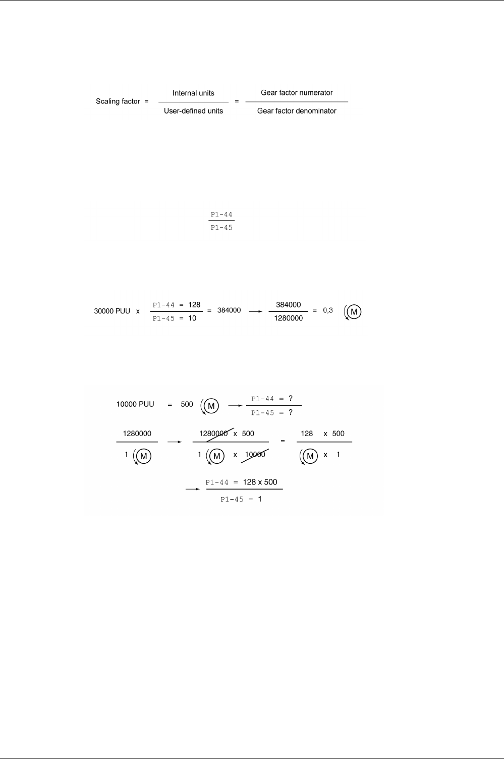
Operating Modes
EIO0000002305 04/2017 337
Scaling
Scaling is the ratio of the number of user-defined units and the number of internal units.
The user-defined units are supplied as parameter values in the unit PUU.
With the factory setting for the scaling factor, 100000 user-defined units correspond to one revolution.
The internal units are 1280000 increments per revolution.
Parameterization
The scaling factor is set using the parameters P1-44 and P1-45.
Example 1
Calculation of number of motor revolutions corresponding to 30000 PUU:
Example 2
Calculation of the scaling factor if 10000 PUU are to effect 500 revolutions of the motor shaft:

Operating Modes
338 EIO0000002305 04/2017
Homing Data Set for Absolute Movements
The Homing data set is used to establish a reference between a mechanical position and the actual
position of the motor.
A reference between a mechanical position and the actual position of the motor is generated by means of
a reference movement or by means of position setting.
A successful reference movement, or position setting, homes the motor.
Homing establishes the zero point for absolute movements.
Methods
The following methods are available:
-Reference movement to a limit switch
In the case of a reference movement to a limit switch, a movement to the negative limit switch or the
positive limit switch is performed.
When the limit switch is reached, the motor is stopped and a movement is made back to the switching
point of the limit switch.
From the switching point of the limit switch, an additional movement can be made to the next index pulse
of the motor.
The switching point of the limit switch or the position of the index pulse point is the reference point.
-Reference movement to the reference switch
In the case of a reference movement to the reference switch, a movement to the reference switch is
performed.
When the reference switch is reached, the motor is stopped and a movement is made back to the
switching point of the reference switch.
From the switching point of the reference switch, an additional movement can be made to the next index
pulse of the motor.
The switching point of the reference switch or the position of the index pulse point is the reference point.
-Reference movement to the index pulse
In the case of a reference movement to the index pulse, a movement is made from the actual position
to the next index pulse. The position of the index pulse is the reference point.
-Position setting
In the case of position setting, the current motor position is set to a desired position value.
A reference movement must be terminated without interruption for the new zero point to be valid. If the
reference movement is interrupted, it must be started again.
Starting the Homing Data Set
The Homing data set can be started in the following ways:
-Automatic start when the power stage is enabled for the first time
The automatic start can be set with the parameter P6-01.
-Start via the signal input function GOTOHOME
The signal input function must have been parameterized, refer to Setting the Digital Signal Inputs
(see page 300)
.

Operating Modes
EIO0000002305 04/2017 339
Setting Automatic Start and the Subsequent Data Set
The parameter P6-01 is used to set the automatic start and select a data set to be executed after
completion of the Homing data set.
The parameter P7-01 is used to set a waiting time for the subsequent data set. The subsequent data set
is started after the waiting time has elapsed.
Setting Acceleration and Deceleration
The acceleration and deceleration for the Homing data set are set via the parameter P7-00.
Setting Velocities
The parameters P5-05 and P5-06 are used to set the velocities for searching the switch and for moving
away from the switch.
Parameter name Description Unit
Minimum value
Factory setting
Maximum value
HMI Format
Data type
R/W
Persistent
Parameter
address via
fieldbus
P6-01
ODEF
Subsequent Data Set and Auto-start of
Homing Data Set
Applicable operating mode: PS
Bit 0:
0 = Do not start Homing after first power
stage enable
1 = Start Homing after first power stage
enable
Bits 1 … 7: Reserved
Bits 8 … 15: Subsequent data set
-
0h
0h
2001h
Hexadecimal
u32
RW
per.
Modbus 702h
CANopen 4601h
P7-01
HOME_DLY
Waiting Time of Homing Data Set
Applicable operating mode: PS
Bits 0 … 15: Waiting time until next dataset
is started
Bits 16 … 31: Reserved
ms
0
0
32767
Decimal
u32
RW
per.
Modbus 802h
CANopen 4701h
Parameter name Description Unit
Minimum value
Factory setting
Maximum value
HMI Format
Data type
R/W
Persistent
Parameter
address via
fieldbus
P7-00
HOME_ACC_DEC
Deceleration and Acceleration of Homing
Data Set
Applicable operating mode: PS
Bits 0 … 15: Deceleration
Bits 16 … 31: Acceleration
ms|ms
6| 6
200| 200
65500| 65500
Decimal
u32
RW
per.
Modbus 800h
CANopen 4700h
Parameter name Description Unit
Minimum value
Factory setting
Maximum value
HMI Format
Data type
R/W
Persistent
Parameter
address via
fieldbus
P5-05
HOMESPEED1
Homing - Fast Velocity for Reference
Movement
Applicable operating mode: PS
0.1rpm
10
1000
60000
Decimal
u32
RW
per.
Modbus 60 Ah
CANopen 4505h
P5-06
HOMESPEED2
Homing - Slow Velocity for Reference
Movement
Applicable operating mode: PS
0.1rpm
10
200
60000
Decimal
u32
RW
per.
Modbus 60Ch
CANopen 4506h
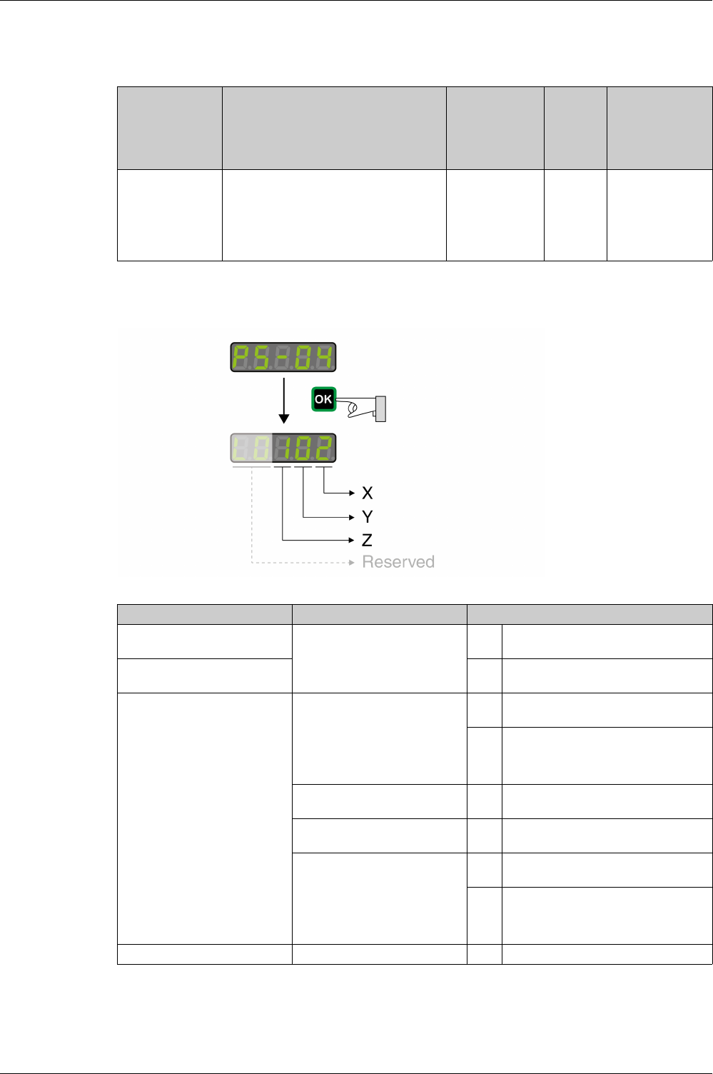
Operating Modes
340 EIO0000002305 04/2017
Defining the Zero Point
The parameter P6-00 is used to specify a position value, which is set at the reference point after a
successful reference movement or after position setting. This position value defines the zero point.
Selecting the Homing Method
The parameter P5-04 is used to set the Homing method.
The illustrations below show the Homing methods.
Parameter name Description Unit
Minimum value
Factory setting
Maximum value
HMI Format
Data type
R/W
Persistent
Parameter
address via
fieldbus
P6-00
ODAT
Position of Homing Data Set
Applicable operating mode: PS
After a successful reference movement,
this position is automatically set at the
reference point.
Bits 0 … 31: Position
PUU
-2147483647
0
2147483647
Decimal
s32
RW
per.
Modbus 700h
CANopen 4600h
Setting Z - limit switch Setting Y - index pulse Settings X - Homing method
- Y=0: Movement back to the last
index pulse
Y=2: No movement to the index
pulse
0 Movement in positive direction to the
positive limit switch
- 1 Movement in negative direction to the
negative limit switch
Z=0: Stop after limit switch is
reached and trigger alert AL014
or AL015
Z=1: Move in opposite direction
after having reached the limit
switch, no alert
Y=0: Movement back to the last
index pulse
Y=1: Movement to the next index
pulse
Y=2: No movement to the index
pulse
2 Movement in positive direction to the
rising edge of the reference switch
3 Movement in negative direction to the
rising edge of the reference switch
- 4 Movement in positive direction to the
next index pulse
- 5 Movement in negative direction to the
next index pulse
Y=0: Movement back to the last
index pulse
Y=1: Movement to the next index
pulse
Y=2: No movement to the index
pulse
6 Movement in positive direction to the
falling edge of the reference switch
7 Movement in negative direction to the
falling edge of the reference switch
- - 8 Position setting
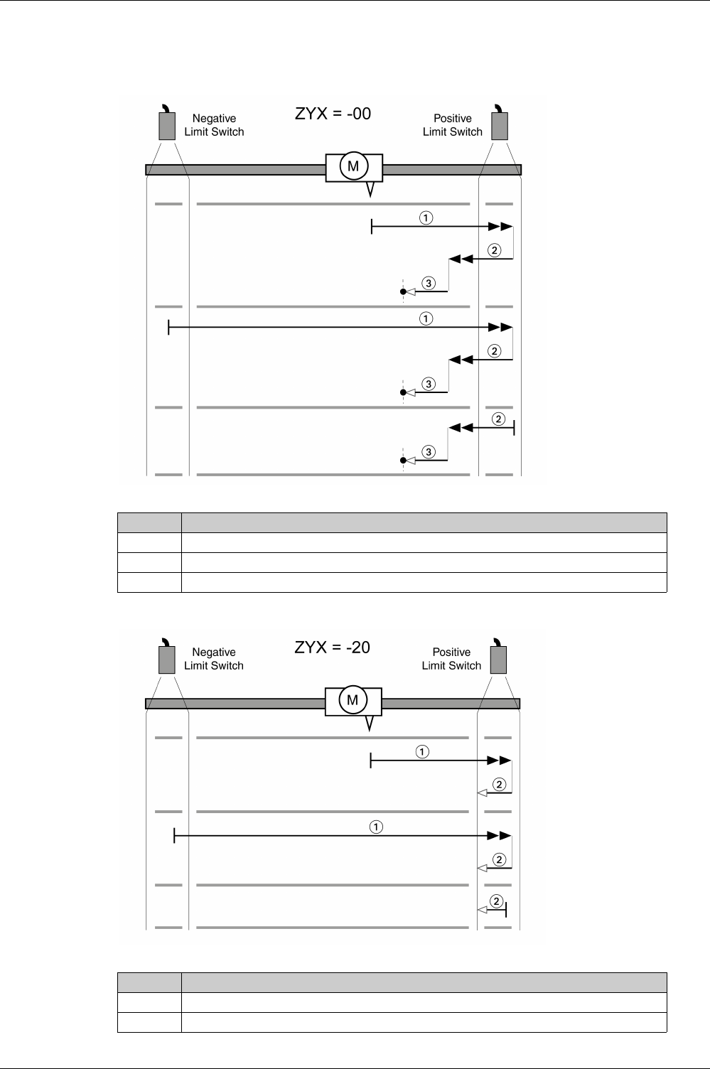
Operating Modes
EIO0000002305 04/2017 341
Reference Movement to the Positive Limit Switch
The following illustrations show reference movements to the positive limit switch from different starting
positions.
Reference movement (ZYX = -00)
Reference movement (ZYX = -20)
Item Description
1 Movement to rising edge at velocity P5-05
2 Movement to falling edge at velocity P5-05
3 Movement to the index pulse at velocity P5-06
Item Description
1 Movement to rising edge at velocity P5-05
2 Movement to falling edge at velocity P5-06
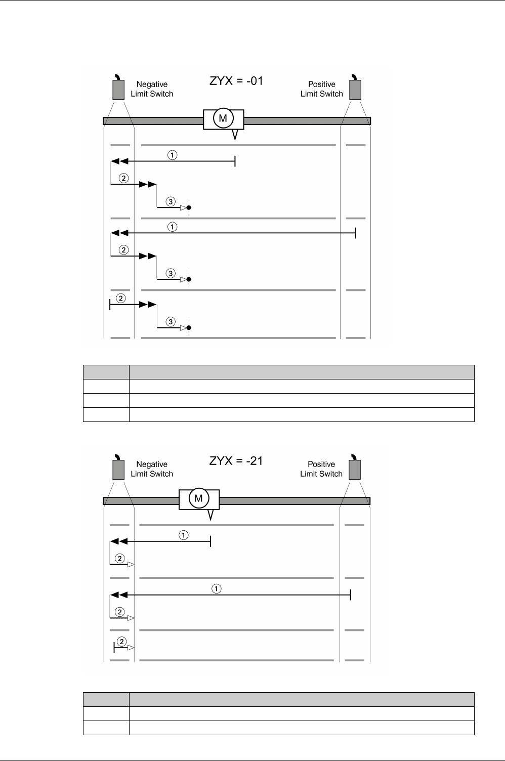
Operating Modes
342 EIO0000002305 04/2017
Reference Movement to the Negative Limit Switch
The following illustrations show reference movements to the negative limit switch from different starting
positions.
Reference movement (ZYX = -01)
Reference movement (ZYX = -21)
Item Description
1 Movement to rising edge at velocity P5-05
2 Movement to falling edge at velocity P5-05
3 Movement to the index pulse at velocity P5-06
Item Description
1 Movement to rising edge at velocity P5-05
2 Movement to falling edge at velocity P5-06
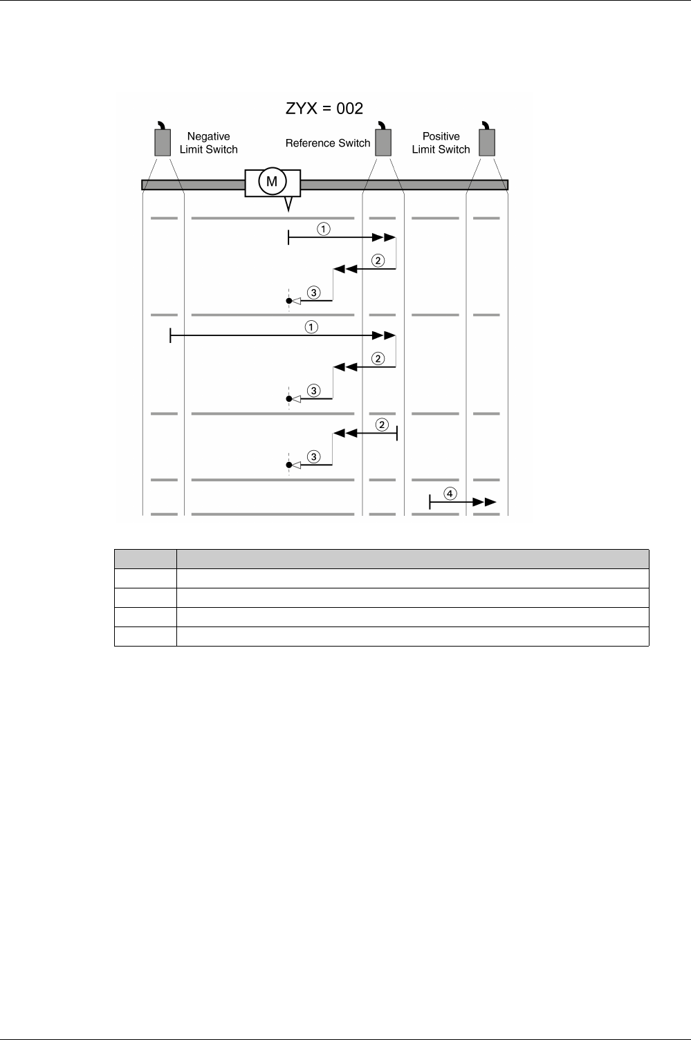
Operating Modes
EIO0000002305 04/2017 343
Reference Movement in Positive Direction to the Rising Edge of the Reference Switch
The following illustrations show reference movements to the rising edge of the reference switch in positive
direction from different starting positions.
Reference movement (ZYX = 002)
Item Description
1 Movement to rising edge at velocity P5-05
2 Movement to falling edge at velocity P5-05
3 Movement to the index pulse at velocity P5-06
4 Movement to the limit switch at velocity P5-05
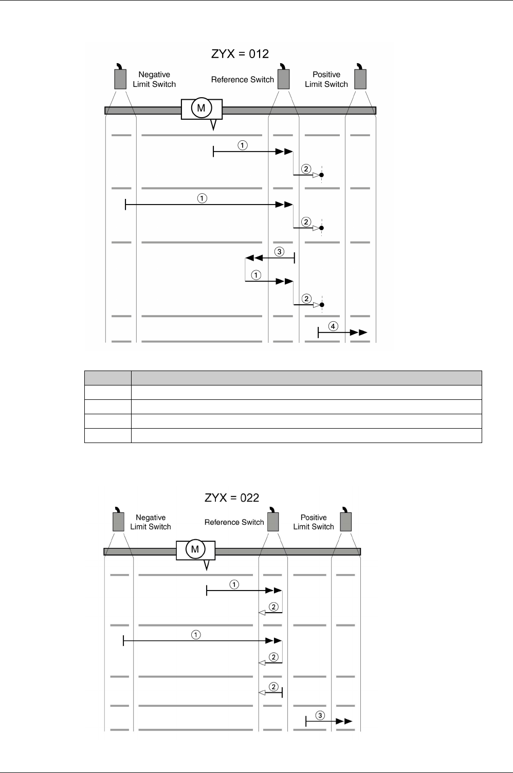
Operating Modes
344 EIO0000002305 04/2017
Reference movement (ZYX = 012)
Reference movement (ZYX = 022)
Item Description
1 Movement to rising edge at velocity P5-05
2 Movement to the index pulse at velocity P5-06
3 Movement to falling edge at velocity P5-05
4 Movement to the limit switch at velocity P5-05
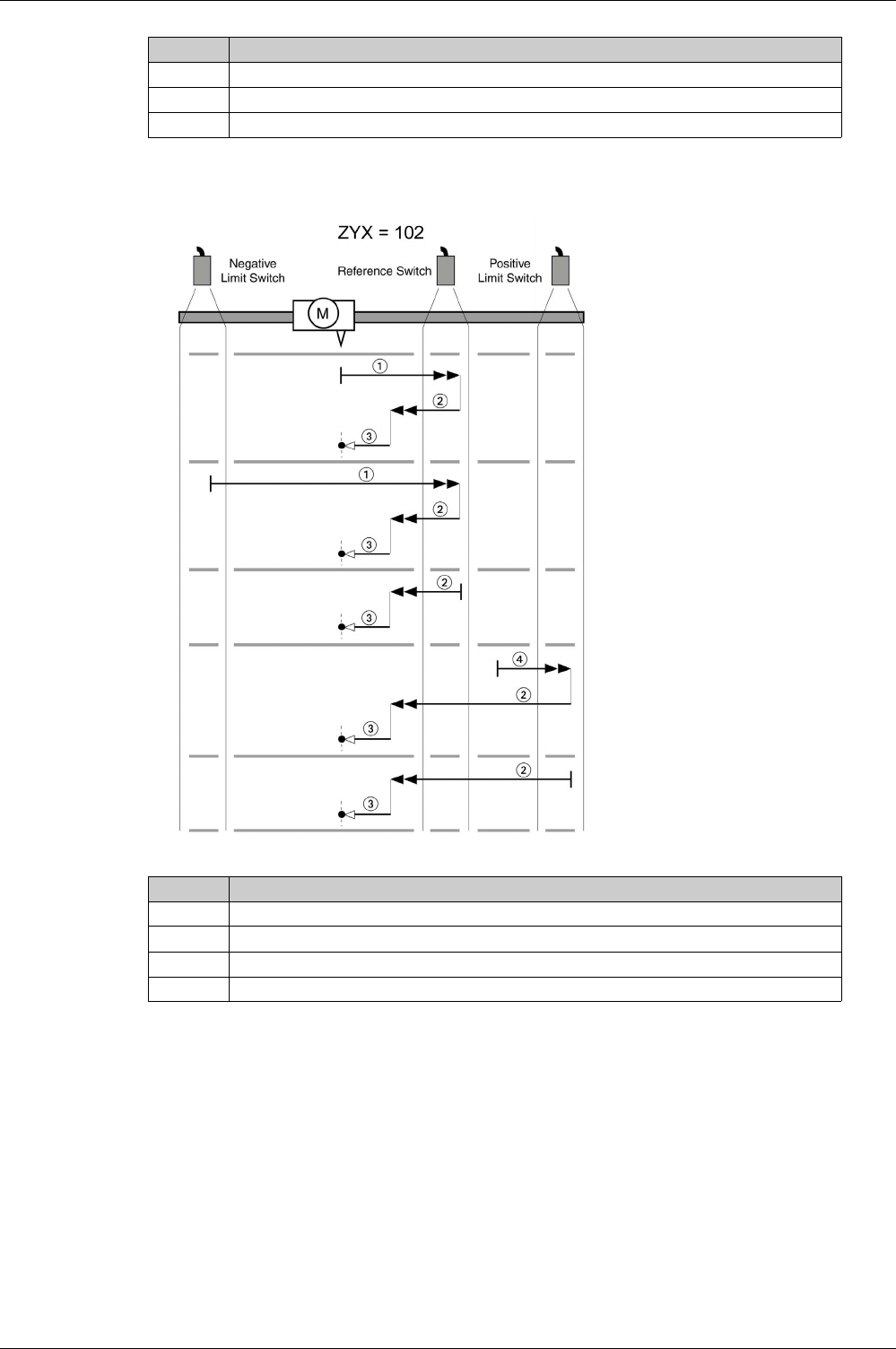
Operating Modes
EIO0000002305 04/2017 345
Reference movement (ZYX = 102)
Item Description
1 Movement to rising edge at velocity P5-05
2 Movement to falling edge at velocity P5-06
3 Movement to the limit switch at velocity P5-05
Item Description
1 Movement to rising edge at velocity P5-05
2 Movement to falling edge at velocity P5-05
3 Movement to the index pulse at velocity P5-06
4 Movement to the limit switch at velocity P5-05
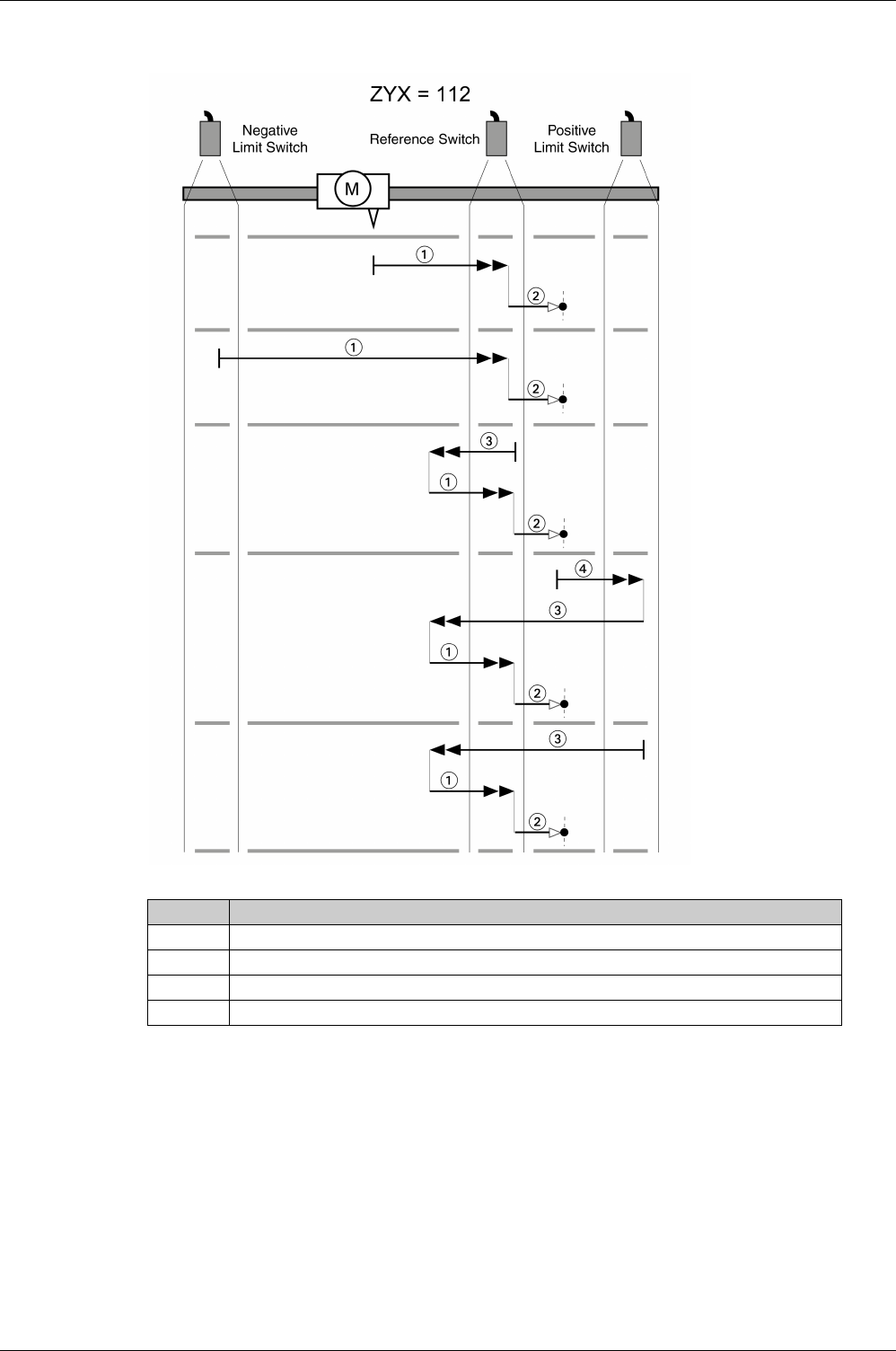
Operating Modes
346 EIO0000002305 04/2017
Reference movement (ZYX = 112)
Item Description
1 Movement to rising edge at velocity P5-05
2 Movement to the index pulse at velocity P5-06
3 Movement to falling edge at velocity P5-05
4 Movement to the limit switch at velocity P5-05
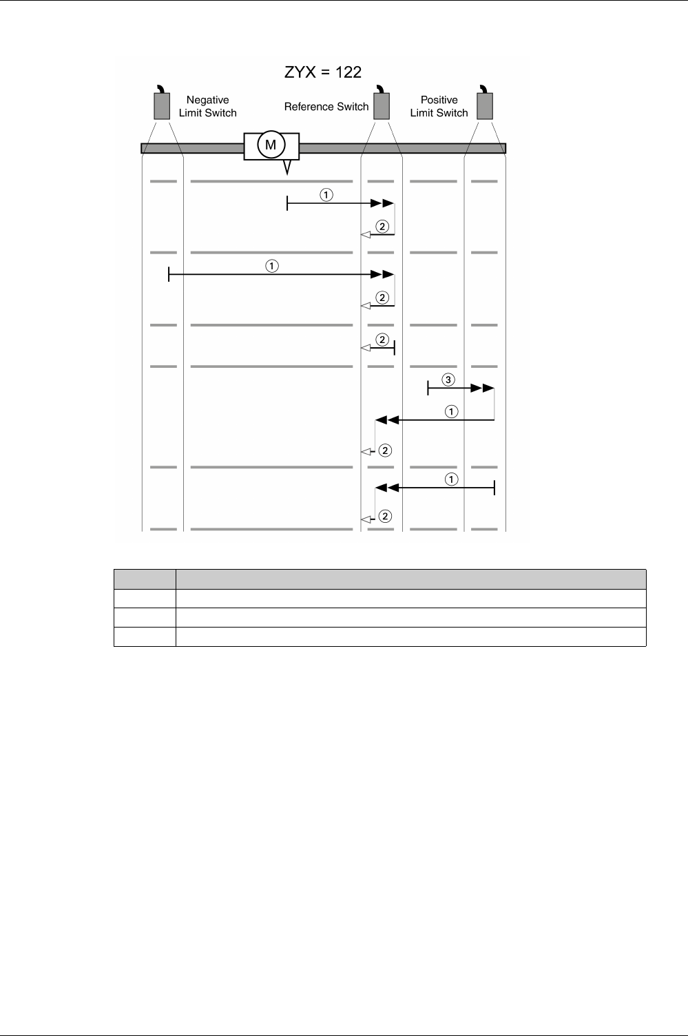
Operating Modes
EIO0000002305 04/2017 347
Reference movement (ZYX = 122)
Item Description
1 Movement to rising edge at velocity P5-05
2 Movement to falling edge at velocity P5-06
3 Movement to the limit switch at velocity P5-05
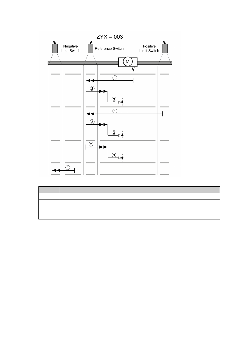
Operating Modes
348 EIO0000002305 04/2017
Reference Movement in Negative Direction to the Rising Edge of the Reference Switch
The following illustrations show reference movements to the rising edge of the reference switch in negative
direction from different starting positions.
Reference movement (ZYX = 003)
Item Description
1 Movement to rising edge at velocity P5-05
2 Movement to falling edge at velocity P5-05
3 Movement to the index pulse at velocity P5-06
4 Movement to the limit switch at velocity P5-05
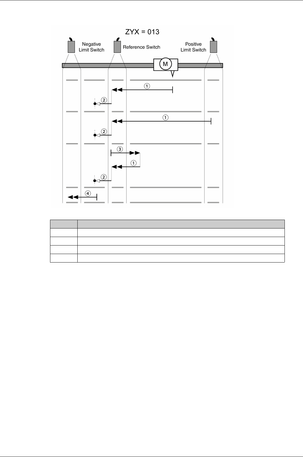
Operating Modes
EIO0000002305 04/2017 349
Reference movement (ZYX = 013)
Item Description
1 Movement to rising edge at velocity P5-05
2 Movement to the index pulse at velocity P5-06
3 Movement to falling edge at velocity P5-05
4 Movement to the limit switch at velocity P5-05
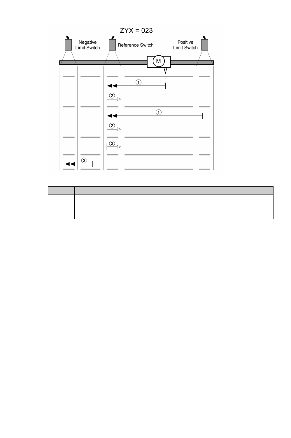
Operating Modes
350 EIO0000002305 04/2017
Reference movement (ZYX = 023)
Item Description
1 Movement to rising edge at velocity P5-05
2 Movement to falling edge at velocity P5-06
3 Movement to the limit switch at velocity P5-05
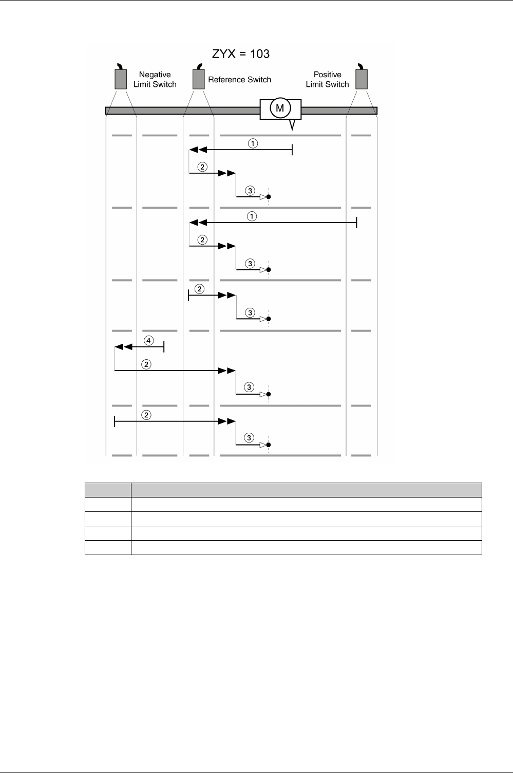
Operating Modes
EIO0000002305 04/2017 351
Reference movement (ZYX = 103)
Item Description
1 Movement to rising edge at velocity P5-05
2 Movement to falling edge at velocity P5-05
3 Movement to the index pulse at velocity P5-06
4 Movement to the limit switch at velocity P5-05
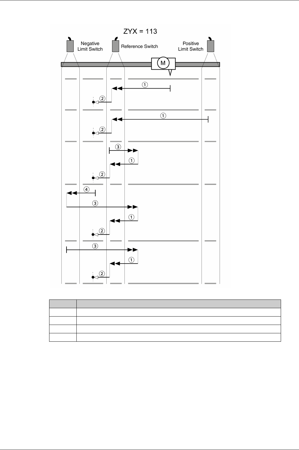
Operating Modes
352 EIO0000002305 04/2017
Reference movement (ZYX = 113)
Item Description
1 Movement to rising edge at velocity P5-05
2 Movement to the index pulse at velocity P5-06
3 Movement to falling edge at velocity P5-05
4 Movement to the limit switch at velocity P5-05
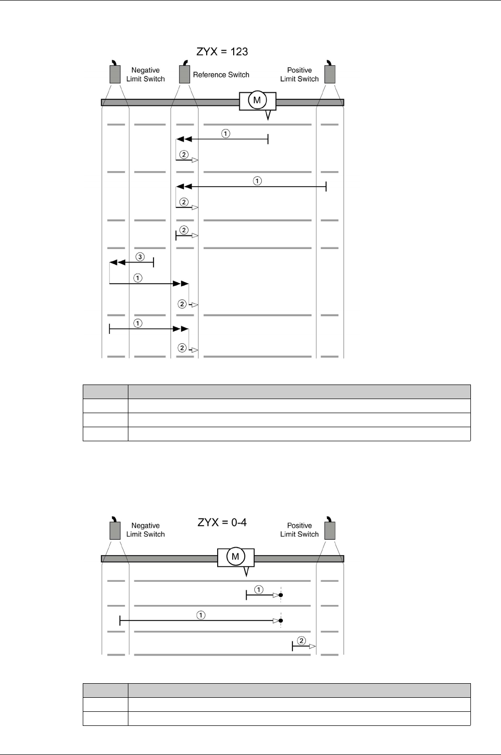
Operating Modes
EIO0000002305 04/2017 353
Reference movement (ZYX = 123)
Reference Movement to the Index Pulse in Positive Direction
The following illustrations show reference movements to the index pulse in positive direction from different
starting positions.
Reference movement (ZYX = 0-4)
Item Description
1 Movement to rising edge at velocity P5-05
2 Movement to falling edge at velocity P5-06
3 Movement to the limit switch at velocity P5-05
Item Description
1 Movement to the next index pulse at velocity P5-06
2 Movement to the limit switch at velocity P5-06
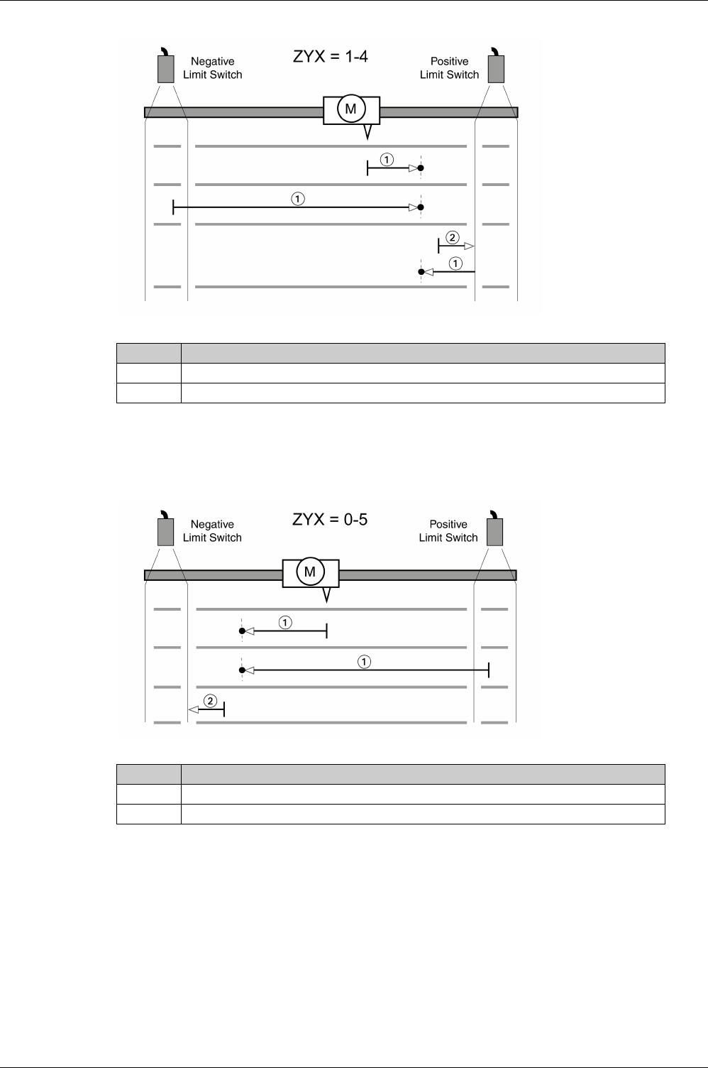
Operating Modes
354 EIO0000002305 04/2017
Reference movement (ZYX = 1-4)
Reference Movement to the Index Pulse in Negative Direction
The following illustrations show reference movements to the index pulse in negative direction from different
starting positions.
Reference movement (ZYX = 0-5)
Item Description
1 Movement to the next index pulse at velocity P5-06
2 Movement to the limit switch at velocity P5-06
Item Description
1 Movement to the next index pulse at velocity P5-06
2 Movement to the limit switch at velocity P5-06
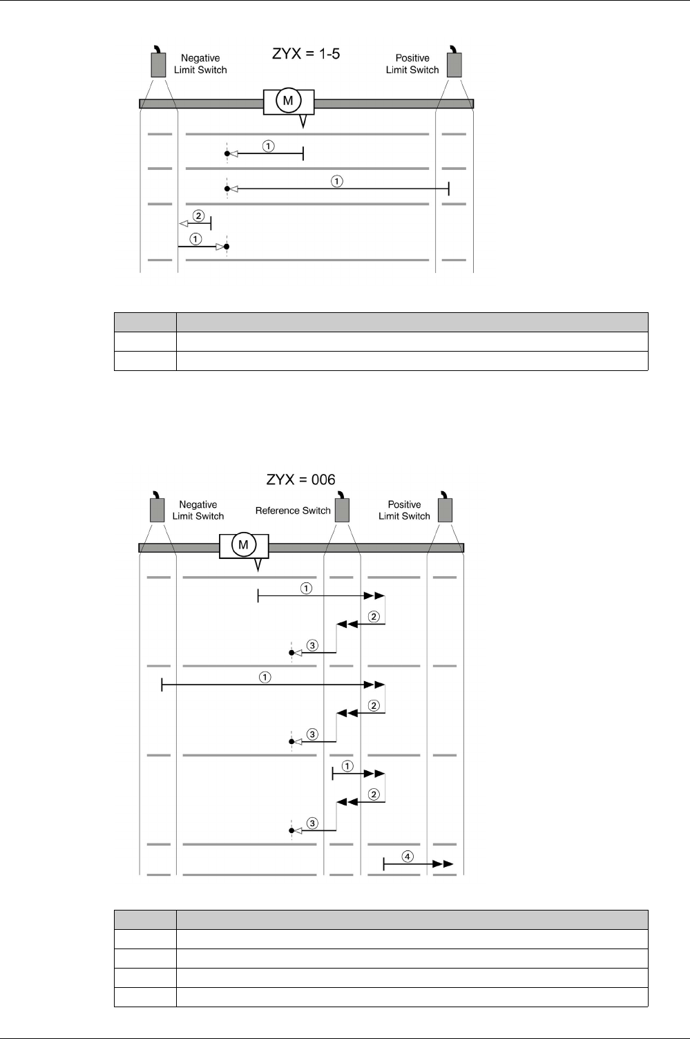
Operating Modes
EIO0000002305 04/2017 355
Reference movement (ZYX = 1-5)
Reference Movement in Positive Direction to the Falling Edge of the Reference Switch
The following illustrations show reference movements to the falling edge of the reference switch in positive
direction from different starting positions.
Reference movement (ZYX = 006)
Item Description
1 Movement to the next index pulse at velocity P5-06
2 Movement to the limit switch at velocity P5-06
Item Description
1 Movement to falling edge at velocity P5-05
2 Movement to rising edge at velocity P5-05
3 Movement to the index pulse at velocity P5-06
4 Movement to the limit switch at velocity P5-05
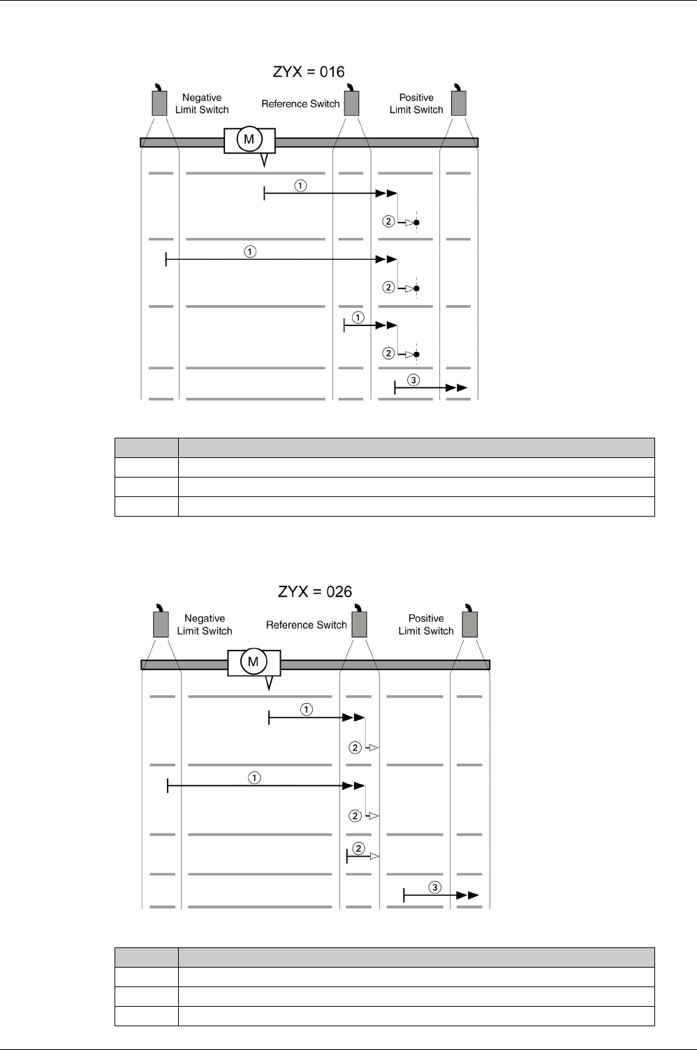
Operating Modes
356 EIO0000002305 04/2017
Reference movement (ZYX = 016)
Reference movement (ZYX = 026)
Item Description
1 Movement to falling edge at velocity P5-05
2 Movement to the index pulse at velocity P5-06
3 Movement to the limit switch at velocity P5-05
Item Description
1 Movement to rising edge at velocity P5-05
2 Movement to falling edge at velocity P5-06
3 Movement to the limit switch at velocity P5-05
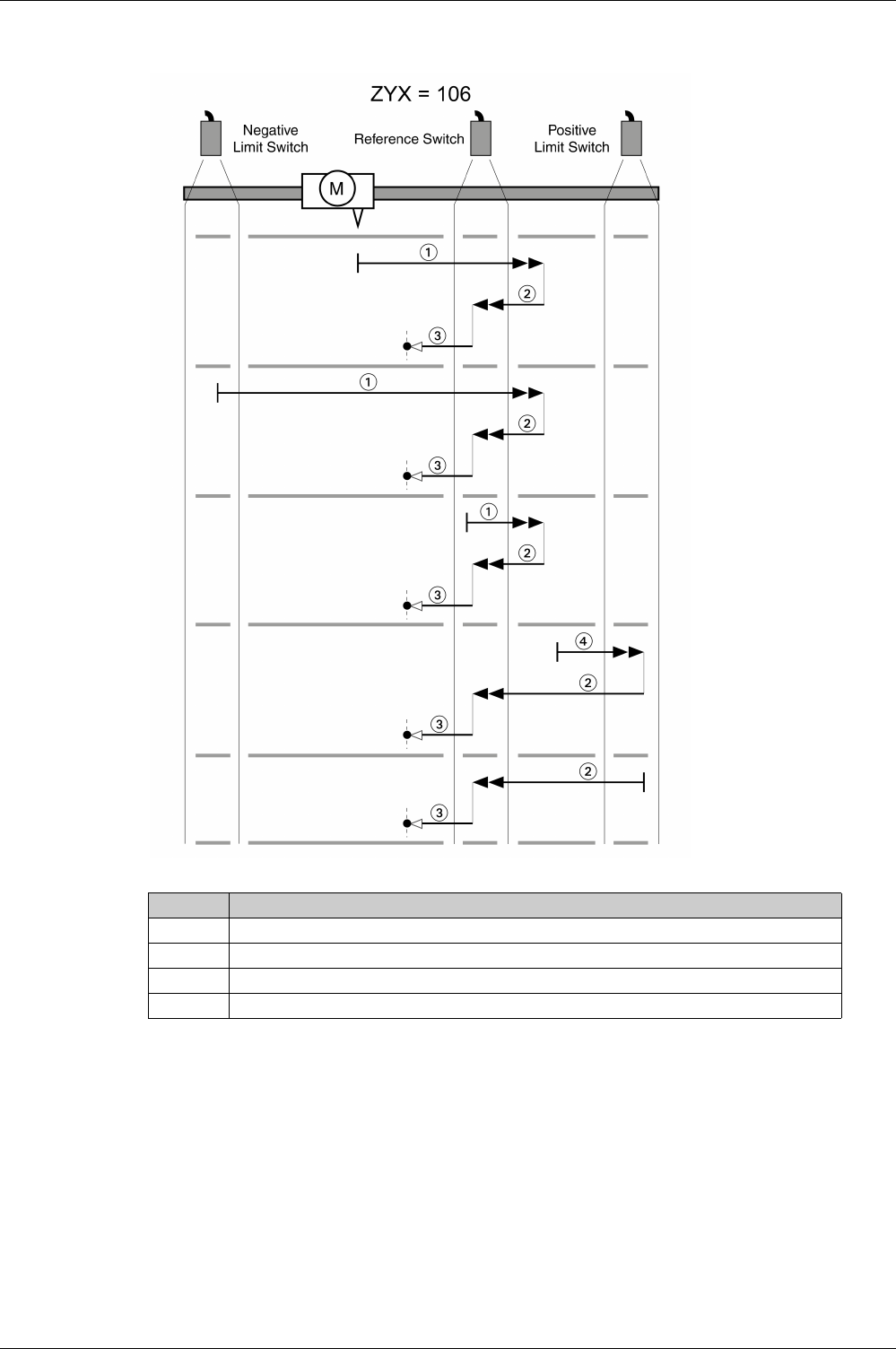
Operating Modes
EIO0000002305 04/2017 357
Reference movement (ZYX = 106)
Item Description
1 Movement to falling edge at velocity P5-05
2 Movement to rising edge at velocity P5-05
3 Movement to the index pulse at velocity P5-06
4 Movement to the limit switch at velocity P5-05
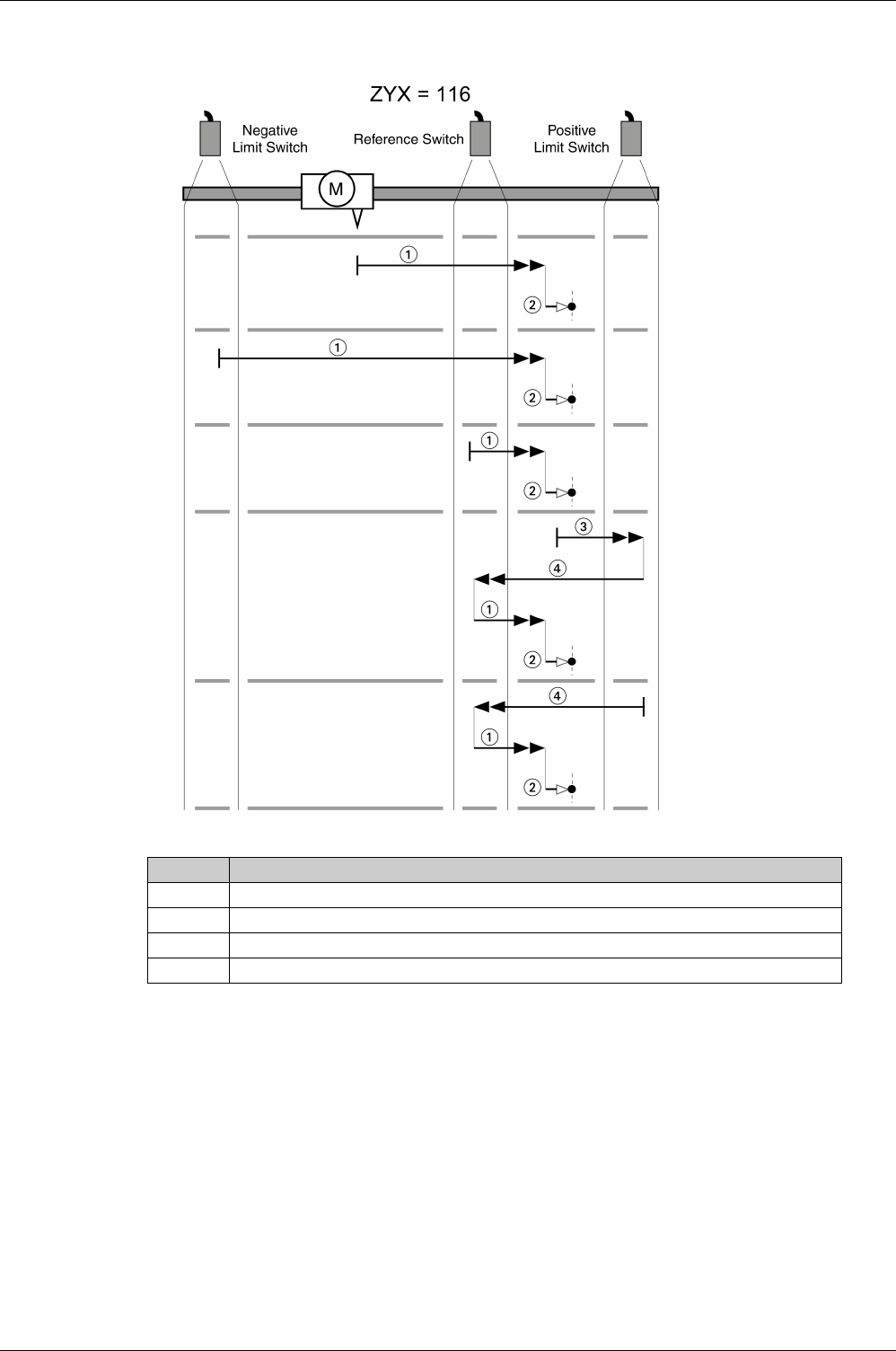
Operating Modes
358 EIO0000002305 04/2017
Reference movement (ZYX = 116)
Item Description
1 Movement to falling edge at velocity P5-05
2 Movement to the index pulse at velocity P5-06
3 Movement to the limit switch at velocity P5-05
4 Movement to rising edge at velocity P5-05
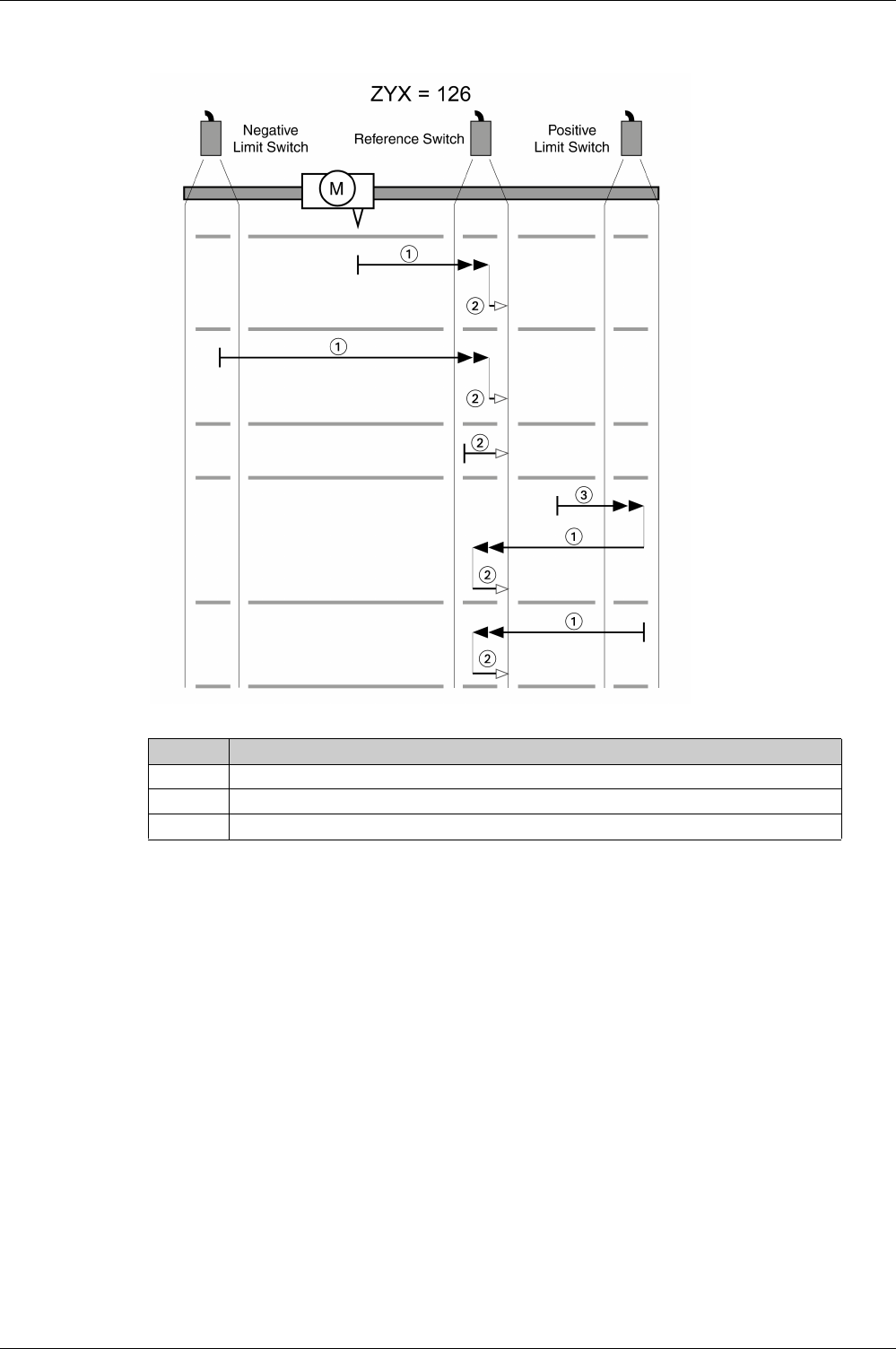
Operating Modes
EIO0000002305 04/2017 359
Reference movement (ZYX = 126)
Item Description
1 Movement to rising edge at velocity P5-05
2 Movement to falling edge at velocity P5-06
3 Movement to the limit switch at velocity P5-05
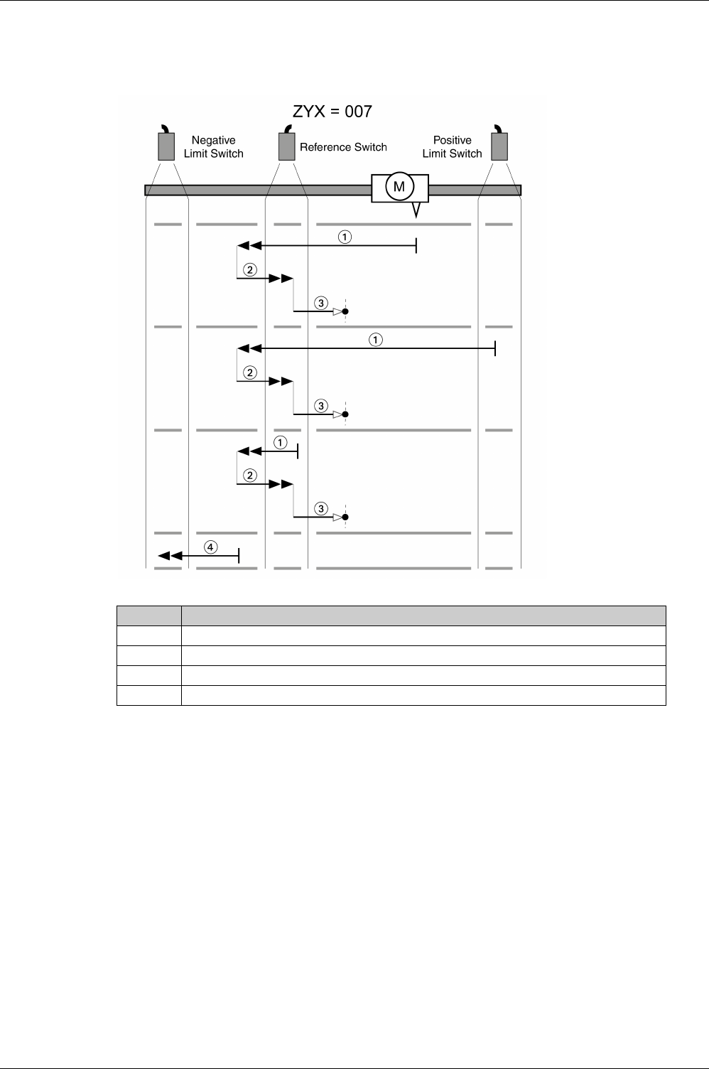
Operating Modes
360 EIO0000002305 04/2017
Reference Movement in Negative Direction to the Falling Edge of the Reference Switch
The following illustrations show reference movements to the falling edge of the reference switch in negative
direction from different starting positions.
Reference movement (ZYX = 007)
Item Description
1 Movement to falling edge at velocity P5-05
2 Movement to rising edge at velocity P5-05
3 Movement to the index pulse at velocity P5-06
4 Movement to the limit switch at velocity P5-05
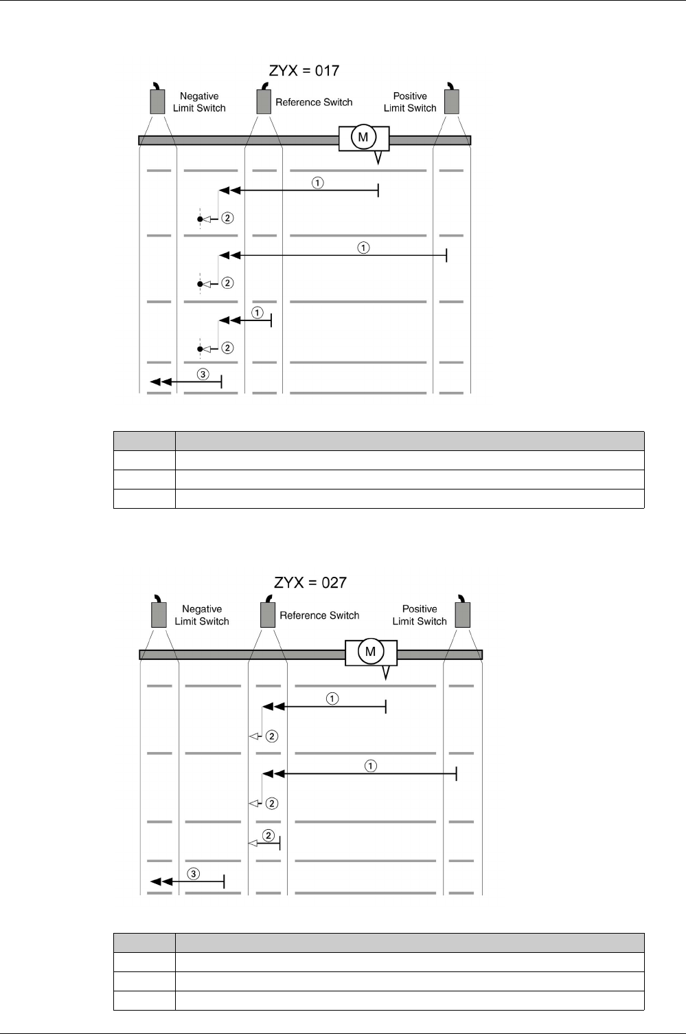
Operating Modes
EIO0000002305 04/2017 361
Reference movement (ZYX = 017)
Reference movement (ZYX = 027)
Item Description
1 Movement to falling edge at velocity P5-05
2 Movement to the index pulse at velocity P5-06
3 Movement to the limit switch at velocity P5-05
Item Description
1 Movement to rising edge at velocity P5-05
2 Movement to falling edge at velocity P5-06
3 Movement to the limit switch at velocity P5-05
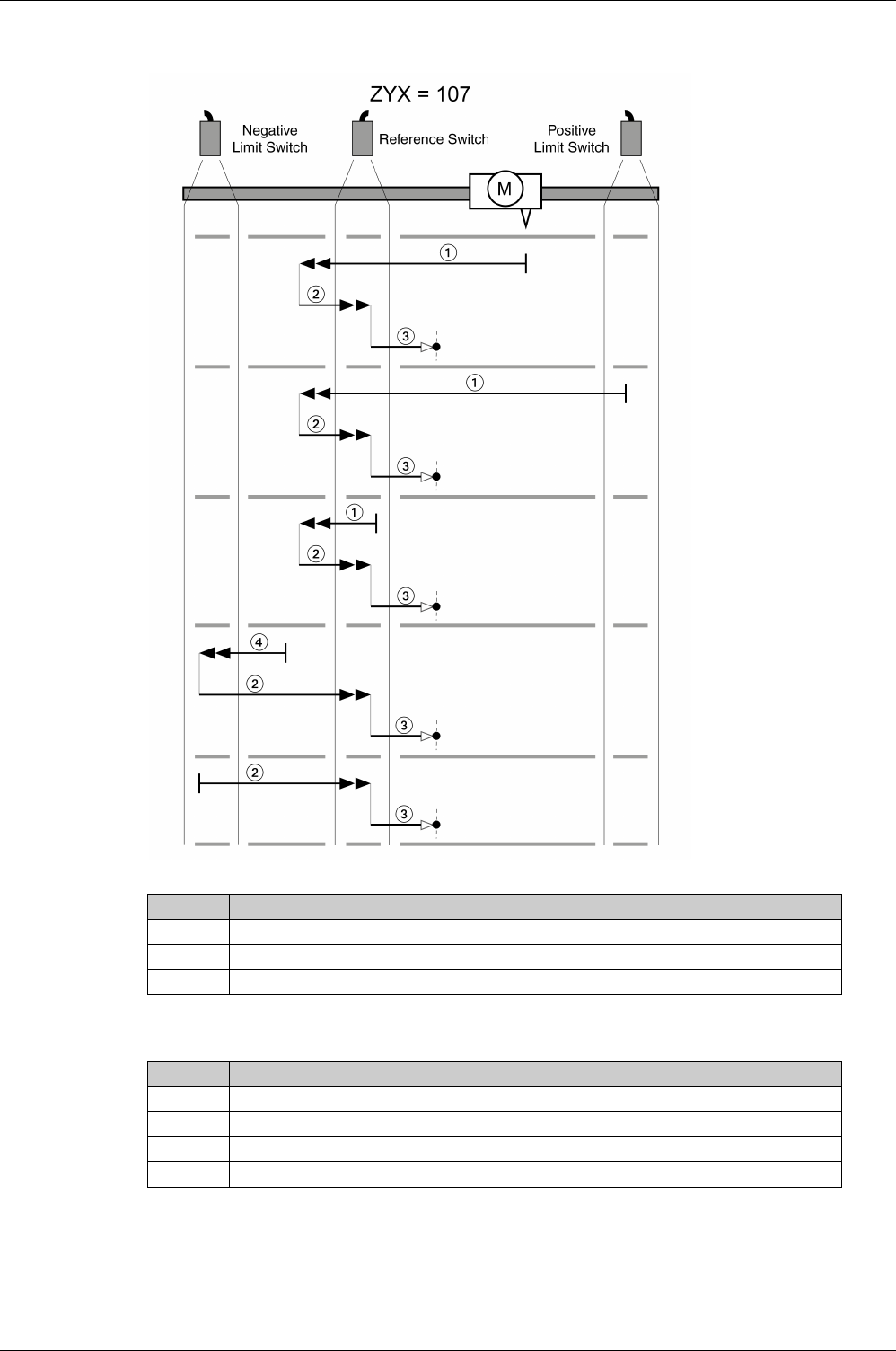
Operating Modes
362 EIO0000002305 04/2017
Reference movement (ZYX = 107)
Item Description
1 Movement to falling edge at velocity P5-05
2 Movement to rising edge at velocity P5-05
3 Movement to the limit switch at velocity P5-06
Item Description
1 Movement to falling edge at velocity P5-05
2 Movement to the index pulse at velocity P5-06
3 Movement to the limit switch at velocity P5-05
4 Movement to rising edge at velocity P5-05
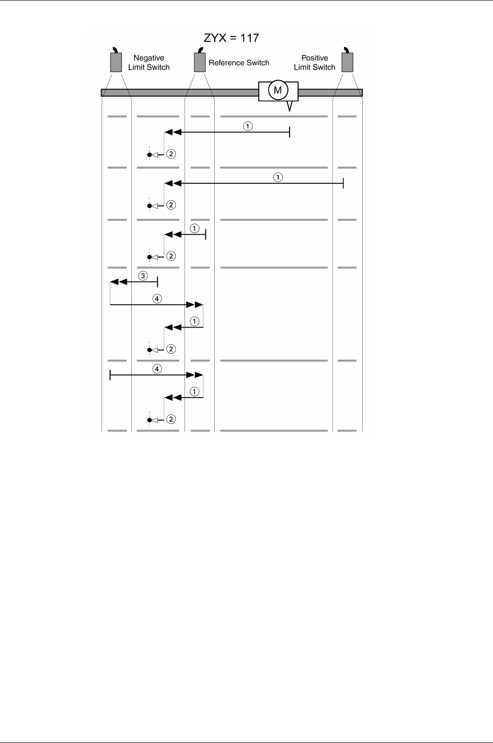
Operating Modes
EIO0000002305 04/2017 363
Reference movement (ZYX = 117)
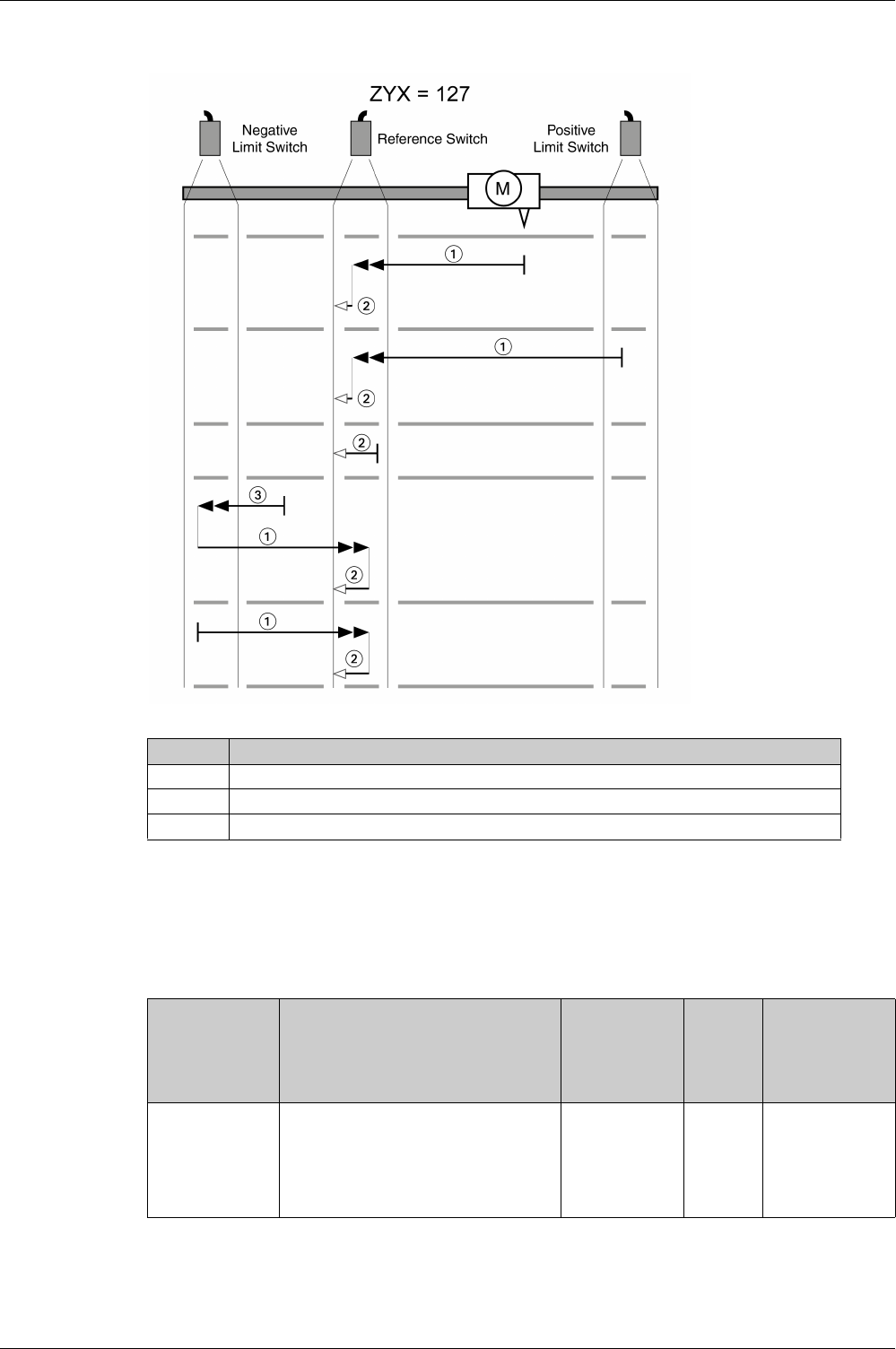
Operating Modes
364 EIO0000002305 04/2017
Reference movement (ZYX = 127)
Position Setting
By means of position setting, the current motor position is set to the position value in parameter P6-00.
This also defines the zero point.
Position setting is only possible when the motor is at a standstill. Any active position deviation remains
active and can still be compensated for by the position controller after position setting.
Item Description
1 Movement to rising edge at velocity P5-05
2 Movement to falling edge at velocity P5-06
3 Movement to the limit switch at velocity P5-05
Parameter name Description Unit
Minimum value
Factory setting
Maximum value
HMI Format
Data type
R/W
Persistent
Parameter
address via
fieldbus
P6-00
ODAT
Position of Homing Data Set
Applicable operating mode: PS
After a successful reference movement,
this position is automatically set at the
reference point.
Bits 0 … 31: Position
PUU
-2147483647
0
2147483647
Decimal
s32
RW
per.
Modbus 700h
CANopen 4600h

Operating Modes
EIO0000002305 04/2017 365
Operating Modes Velocity (V) and Velocity Zero (Vz)
Section 18.5
Operating Modes Velocity (V) and Velocity Zero (Vz)
What Is in This Section?
This section contains the following topics:
Topic Page
Operating Modes Velocity (V) and Velocity Zero (Vz) 366
Acceleration and Deceleration 369
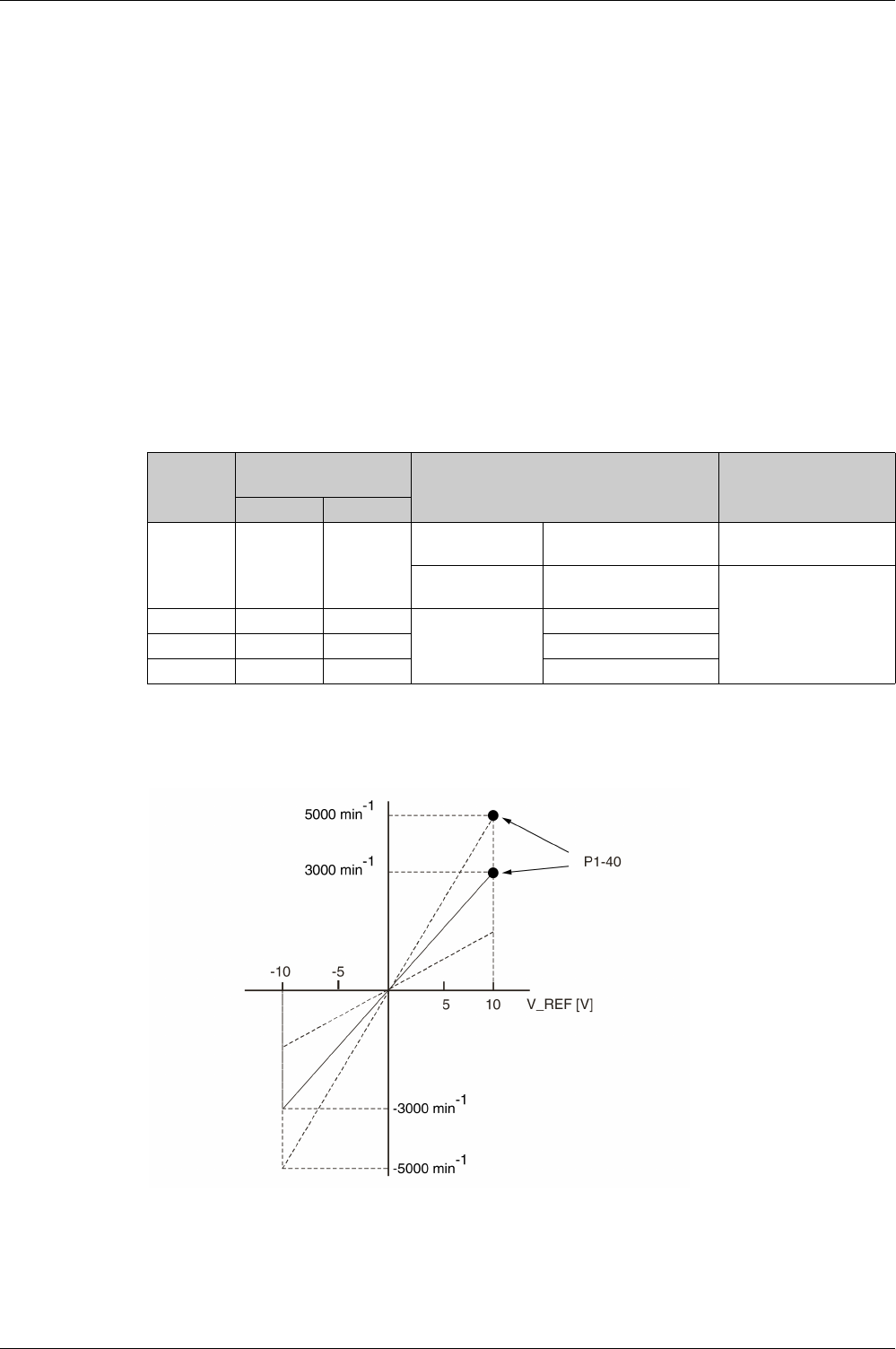
Operating Modes
366 EIO0000002305 04/2017
Operating Modes Velocity (V) and Velocity Zero (Vz)
Description
In the operating mode Velocity (V), a movement is made with a specified target velocity.
Source of Reference Value Signals
In the operating mode Velocity (V), the source of the reference value signals is one of the three values set
via the parameters P1-09 to P1-11.
In the operating mode Velocity Zero (Vz), the source of the reference value signals is either one of the three
values set via the parameters P1-09 to P1-11 or the fixed target velocity 0.
The values of the parameters P1-09 to P1-11 can be selected via the signal input functions SPD0 and
SPD1.
The signal input functions SPD0 and SPD1 take priority over the reference value signal at the analog input
V_REF.
The target velocity is selected via the signal input functions SPD0 (LSB) and SPD1 (MSB) (bit-coded):
For additional information on the parameterizable signal input functions, refer to Setting the Digital Signal
Inputs
(see page 300)
.
Scaling of the Analog Input V_REF
The parameter P1-40 lets you set the velocity corresponding to 10 V. This results in a linear scaling for the
analog input V_REF.
-Signal state of the digital
signal inputs
Target velocity via: Range
SPD1 SPD0
S1
00
Operating mode
Velocity (Vz)
Voltage between V_REF
(Pin42) and GND (pin 44)
-10V ... 10V
Operating mode
Velocity Zero (Vz)
0rpm
-
S2 0 1
Internal
parameters
P1-09
S3 1 0 P1-10
S4 1 1 P1-11
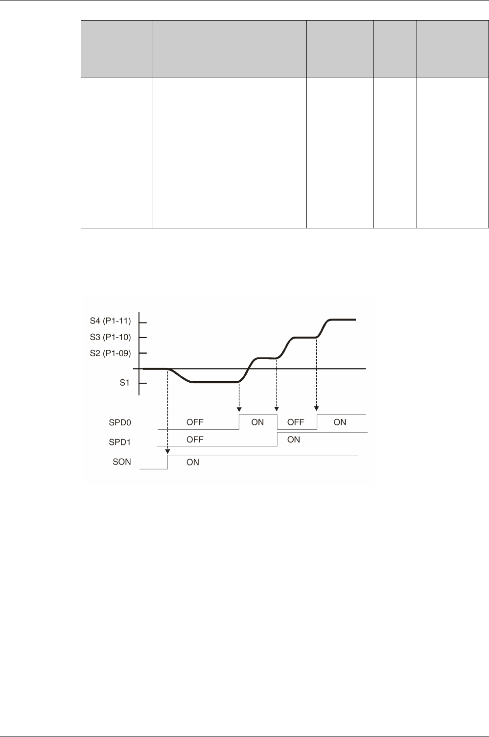
Operating Modes
EIO0000002305 04/2017 367
Example
The illustration below shows how the target velocities are switched by means of the signal input functions
SPD0,SPD1 and SON.
Operating modes Velocity (V) and Velocity Zero (Vz)
For further information, refer to Setting the Digital Signal Inputs
(seepage300)
.
Parameter name Description Unit
Minimum value
Factory setting
Maximum value
HMI Format
Data type
R/W
Persistent
Parameter
address via
fieldbus
P1-40
VCM
Velocity Target Value and Velocity
Limitation 10 V
Applicable operating mode: PT, PS, V, T
In the operating mode V, this parameter
specifies the target velocity that
corresponds to the maximum input voltage
of 10 V.
In the operating mode T, this parameter
specifies the velocity limitation that
corresponds to the maximum input voltage
of 10 V.
Example: If the value of this parameter is
3000 in the operating mode V and if the
input voltage is 10 V, the target velocity is
3000 rpm.
rpm
0
-
10001
Decimal
s32
RW
per.
Modbus 250h
CANopen 4128h

Operating Modes
368 EIO0000002305 04/2017
Stopping the Movement via Signal Input Function ZCLAMP
The movement can be stopped via the digital signal input function ZCLAMP.
Conditions for stopping the movement:
-The reference velocity must be below the velocity value defined in parameter P1-38.
-The signal input function ZCLAMP must be assigned and the signal input must be triggered.
For assigning the signal input function, refer to Setting the Digital Signal Inputs
(see page 300)
.
Additionally the behavior for ZCLAMP can be set via parameter P2-65 bit 10.
Setting of parameter P2-65 bit 10:
-Bit 10 = 0: Immediate stop. Motor is locked at the position where it was when ZCLAMP became active.
-Bit 10 = 1: Motor is decelerated with deceleration ramp setting. Motor is locked at the position where
standstill is reached.
Parameter name Description Unit
Minimum value
Factory setting
Maximum value
HMI Format
Data type
R/W
Persistent
Parameter
address via
fieldbus
P1-38
ZSPD
Signal Output Function ZSPD / Signal Input
Function ZCLAMP - Velocity
Applicable operating mode: PT, PS, V, T
This parameter specifies the velocity for the
signal output function ZSPD. The signal
output function ZSPD indicates that the
velocity of the motor is less than the
velocity value set via this parameter.
This parameter specifies the velocity for the
signal input function ZCLAMP. The signal
input function ZCLAMP stops the motor.
The velocity of the motor must be below the
velocity value set via this parameter.
0.1rpm
0
100
2000
Decimal
s32
RW
per.
Modbus 24Ch
CANopen 4126h

Operating Modes
EIO0000002305 04/2017 369
Acceleration and Deceleration
The parameters P1-34 and P1-35 allow you to set the acceleration and deceleration.
Parameter name Description Unit
Minimum value
Factory setting
Maximum value
HMI Format
Data type
R/W
Persistent
Parameter
address via
fieldbus
P1-34
TACC
Acceleration Period
Applicable operating mode: PT, V
The acceleration period is the time in
milliseconds required to accelerate from
motor standstill to 6000 rpm.
For operating mode V, this parameter
specifies the acceleration.
For operating mode PT, this parameter
specifies an acceleration limitation for the
pulses at the PTI interface.
ms
6
30
65500
Decimal
u16
RW
per.
Modbus 244h
CANopen 4122h
P1-35
TDEC
Deceleration Period
Applicable operating mode: PT, V
The deceleration period is the time in
milliseconds required to decelerate from
6000 rpm to motor standstill.
For operating mode V, this parameter
specifies the deceleration.
For operating mode PT, this parameter
specifies a deceleration limitation for the
pulses at the PTI interface.
ms
6
30
65500
Decimal
u16
RW
per.
Modbus 246h
CANopen 4123h

Operating Modes
370 EIO0000002305 04/2017
Operating Modes Torque (T) and Torqu e Zero (Tz)
Section 18.6
Operating Modes Torque (T) and Torque Zero (Tz)
Operating Modes Torque (T) and Torque Zero (Tz)
Description
In the operating mode Torque (T), a movement is made with a specified target torque. The target torque is
specified in percent of the nominal torque of the motor.
The operating modes Torque (T) and Torque (Tz) and the dual operating modes with Torque (T) and
Torque (Tz) do not provide deceleration functionality in response to a power stage disable request. In these
operating modes, the motor coasts down to a standstill in response to a power stage disable request. You
must install additional equipment such as a dedicated service brake if your application requires faster
deceleration of the load.
Source of Reference Value Signals
In the operating mode Torque (T), the source of the reference value signals is either the analog input
T_REF or one of the three values set via the parameters P1-12 to P1-14.
In the operating mode Torque Zero (Tz), the source of the reference value signals is either one of the three
values set via the parameters P1-12 to P1-14 or the fixed target torque 0 %.
The values of the parameters P1-12 to P1-14 can be selected via the signal input functions TCM0 and
TCM1.
The signal input functions TCM0 and TCM1 take priority over the reference value signal of the analog input
T_REF.
The target torque is selected via the signal input functions TCM0 (LSB) and TCM1 (MSB) (bit-coded):
For further information on the parameterizable signal input functions, refer to Setting the Digital Signal
Inputs
(see page 300)
.
WARNING
UNINTENDED EQUIPMENT OPERATION
-During commissioning, trigger all signals and simulate all conditions that cause a power stage disable
request in order to verify that all loads come to a secure standstill when the power stage is disabled
under maximum load conditions.
-Install a dedicated service brake if removal of power to the motor does not meet the requirements of
your application.
Failure to follow these instructions can result in death, serious injury, or equipment damage.
-Signal state of the digital
signal inputs
Target torque is provided via: Range
TCM1 TCM0
T1
00
Operating mode
Torque (T)
Voltage between T_REF
(pin 18) and GND (pin 19)
-10V ... 10V
Operating mode
Torque Zero (Tz)
0% -
T2 0 1
Internal
parameters
P1-12
-300 ... 300%T3 1 0 P1-13
T4 1 1 P1-14
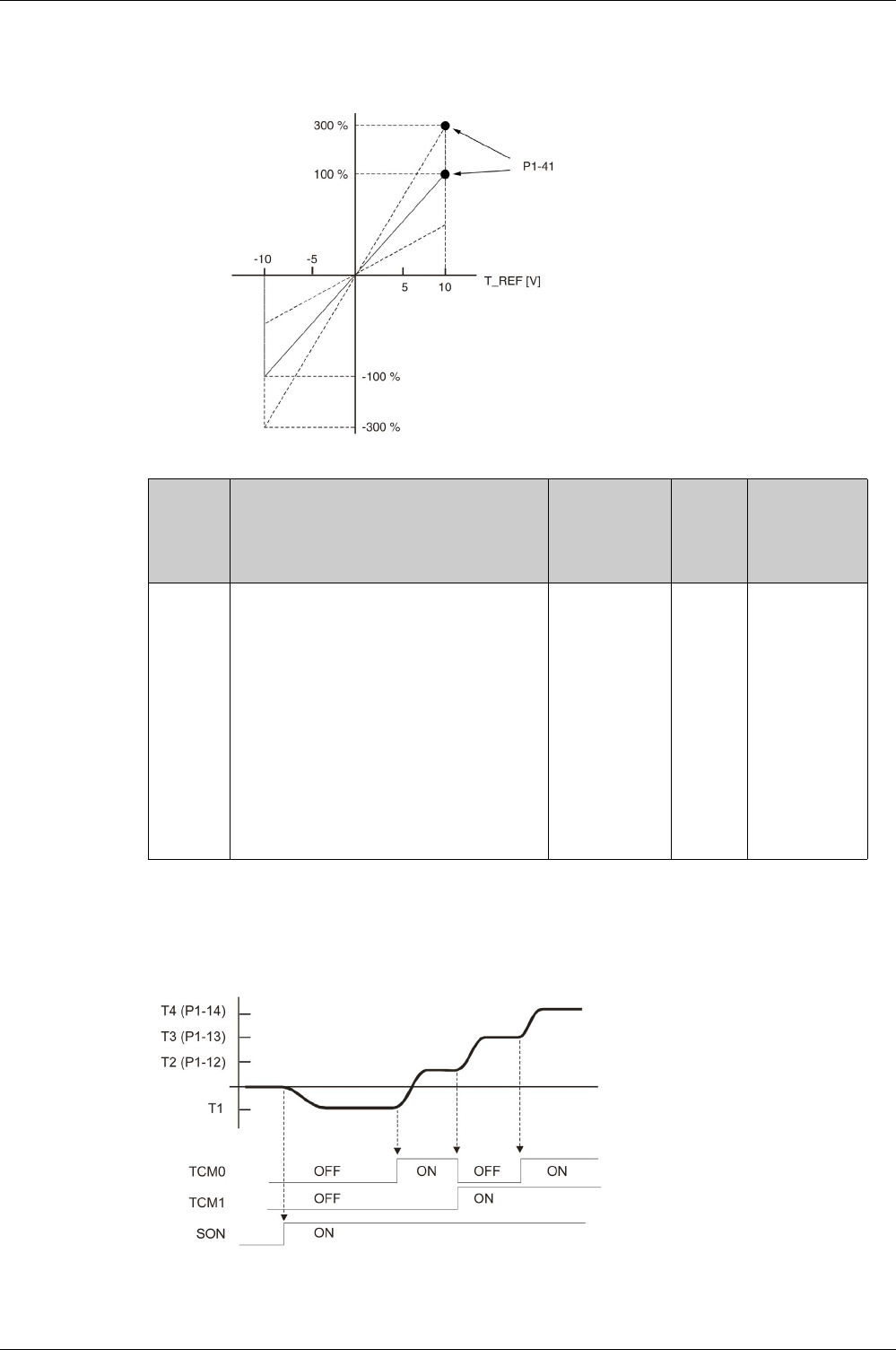
Operating Modes
EIO0000002305 04/2017 371
Scaling of the Analog Input T_REF
The parameter P1-41 lets you set the torque corresponding to 10 V. This results in a linear scaling for the
analog input T_REF.
Example
The illustration below shows how the target torque is switched by means of the signal input functions
TCM0,TCM1 and SON.
Operating modes Torque (T) and Torque Zero (Tz)
For further information, refer to Setting the Digital Signal Inputs
(seepage300)
.
Parameter
name
Description Unit
Minimum value
Factory setting
Maximum value
HMI Format
Data type
R/W
Persistent
Parameter
address via
fieldbus
P1-41
TCM
Torque Target Value and Torque Limitation 10 V
Applicable operating mode: PT, PS, V, T
In the operating mode T, this parameter specifies
the target torque that corresponds to the
maximum input voltage of 10 V.
In the operating modes PT, PS and V, this
parameter specifies the torque limitation that
corresponds to the maximum input voltage of
10 V.
Example: If the value of this parameter is 100 in
the operating mode T and if the input voltage is
10 V, the target torque is 100 % of the nominal
torque.
Setting can only be changed if power stage is
disabled.
%
0
100
1000
Decimal
u16
RW
per.
Modbus 252h
CANopen 4129h

Operating Modes
372 EIO0000002305 04/2017
Operating Mode CANopen
Section 18.7
Operating Mode CANopen
What Is in This Section?
This section contains the following topics:
Topic Page
Indication of the Operating State 373
Changing the Operating State 375
Starting and Changing a CANopen Operating Mode 376
CANopen Operating Mode Profile Position 377
CANopen Operating Mode Profile Velocity 380
CANopen Operating Mode Profile Torque 382
CANopen Operating Mode Homing 384
CANopen Operating Mode Interpolated Position 386
CANopen Operating Mode Cyclic Synchronous Position 388
CANopen Operating Mode Jog 389
CANopen Operating Mode Electronic Gear 390
CANopen Operating Mode Analog Velocity 392
CANopen Operating Mode Analog Torque 394

Operating Modes
EIO0000002305 04/2017 373
Indication of the Operating State
The parameter Statusword 6041h provides information on the operating state of the device and the
processing status of the operating mode.
Bits 0, 1, 2, 3, 5 and 6
Bits 0, 1, 2, 3, 5 and 6 of the parameter Statusword 6041h provide information on the operating state.
Bit 4
Bit 4=1 indicates whether the DC bus voltage is correct. If the voltage is missing or is too low, the device
does not transition from operating state 3 to operating state 4.
Bit 7
Bit 7=1 indicates that an error has been detected.
Bit 8
Bit 8=1 indicates that a "Halt" is active.
Bit 9
If bit 9 is set, the device carries out commands via the fieldbus. If Bit 9 is reset, the device is controlled via
a different interface. In such a case, it is still possible to read or write parameters via the fieldbus.
Bit 10
Bit 10 is used for monitoring the current operating mode. Details can be found in the chapters on the
individual operating modes.
Index Name Object type
Data type
Access
PDO mapping
object
Minimum value
Factory settings
Maximum value
6041hStatusword
Bit assignments:
-Bits 0 … 3: Status bits
-Bit 4: Voltage Enabled
-Bits 5 … 6: Status bits
-Bit 7: Error detected
-Bit 8: Halt request active
-Bit 9: Remote
-Bit 10: Target Reached
-Bit 11: Internal Limit Active
-Bit 12: Operating mode-specific
-Bit 13: x_err
-Bit 14: x_end
-Bit 15: ref_ok
VAR
UINT16
ro
Yes 0
-
65535
Operating state Bit 6
Switch On
Disabled
Bit 5
Quick Stop
Bit 3
Fault
Bit 2
Operation
Enabled
Bit 1
Switch On
Bit 0
Ready To
Switch On
2 Not Ready To Switch On0X0000
3 Switch On Disabled 1X0000
4 Ready To Switch On 0 1 0001
5 Switched On 0 1 0011
6 Operation Enabled 0 1 0111
7 Quick Stop Active 000111
8 Fault Reaction Active 0X1111
9 Fault 0X1000

Operating Modes
374 EIO0000002305 04/2017
Bit 11
The assignment of bit 11 can be set via the parameter P3-30.
Bit 12
Bit 12 is used for monitoring the current operating mode. Details can be found in the chapters on the
individual operating modes.
Bit 13
Bit 13 only becomes "1" in the case of an error which needs to be remedied prior to further processing.
Bit 14
Bit 14 changes to "0" if an operating mode is started. When processing is terminated or interrupted, for
example by a "Halt", bit 14 toggles back to "1" once the motor has come to a standstill. The signal change
of bit 14 to "1" is suppressed if one process is followed immediately by a new process in a different
operating mode.
Bit 15
Bit 15 is "1" if the motor has a valid zero point, for example as a result of a reference movement. A valid
zero point remains valid even if the power stage is disabled.

Operating Modes
EIO0000002305 04/2017 375
Changing the Operating State
The parameter Controlword 6040h can be used to switch between the operating states.
Bits 0 … 3 and 7
Bits 0 … 3 and bit 7 of the parameter Controlword 6040h allow you to switch between the operating states.
Bits 4 … 6 and 9
Bits 4 to 6 and bit 9 are used for the operating mode-specific settings. Details can be found in the
descriptions of the individual operating modes in this chapter.
Bit 8
A "Halt" can be triggered with bit 8=1.
Bits 10 … 15
Reserved.
Index Name Object type
Data type
Access
PDO mapping
object
Minimum value
Factory settings
Maximum value
6040hControlword
Bit assignments:
-Bit 0: Switch On
-Bit 1: Enable Voltage
-Bit 2: Quick Stop
-Bit 3: Enable Operation
-Bits 4 … 6: Operating mode-specific
-Bit 7: Fault Reset
-Bit 8: Halt
-Bit 9: Operating mode-specific
-Bits 10 … 15: Reserved
VAR
UINT16
rww
Yes 0
-
65535
Fieldbus
command
State
transitions
State transition to Bit 7
Fault
Reset
Bit 3
Enable
Operation
Bit 2
Quick
Stop
Bit 1
Enable
Voltage
Bit 0
Switch On
Shutdown T2, T6, T8 4 Ready To Switch On 0 X 1 1 0
Switch On T3 5 Switched On 0 0 1 1 1
Disable
Voltage
T7, T9,
T10, T12
3 Switch On Disabled 0 X X 0 X
Quick Stop T7, T10
T11
3 Switch On Disabled
7 Quick Stop Active
0X01X
Disable
Operation
T5 5 Switched On 0 0 1 1 1
Enable
Operation
T4, T16 6 Operation Enabled 0 1 1 1 1
Fault Reset T5 3 Switch On Disabled 0->1 X X X X

Operating Modes
376 EIO0000002305 04/2017
Starting and Changing a CANopen Operating Mode
Overview of the CANopen Operating Modes
The following CANopen operating modes are available:
-CANopen operating modes as per CiA 402
Profile Position
Profile Velocity
Profile Torque
Homing
Interpolated Position
Cyclic Synchronous Position
-CANopen vendor-specific operating modes
Jog
Electronic Gear
Analog Velocity
Analog Torque
Starting and Changing an Operating Mode
The parameter Modes of Operation 6060h is used to set the operating mode.
The parameter Modes of Operation Display 6061h can be used to read the current operating mode.
Values for the parameters Modes of Operation 6060h and Modes of Operation Display (6061h):
-Value 1: Profile Position
-Value 3: Profile Velocity
-Value 4: Profile Torque
-Value 6: Homing
-Value 7: Interpolated Position
-Value 8: Cyclic Synchronous Position
-Value -1: Jog
-Value -2: Electronic Gear
-Value -3: Analog Velocity
-Value -4: Analog Torque
Index Name Object type
Data type
Access
PDO mapping
object
Minimum value
Factory settings
Maximum value
6060hModes of Operation VAR
INT8
rww
Yes -128
0
8
6061hModes of Operation Display VAR
INT8
ro
Yes -128
-
8
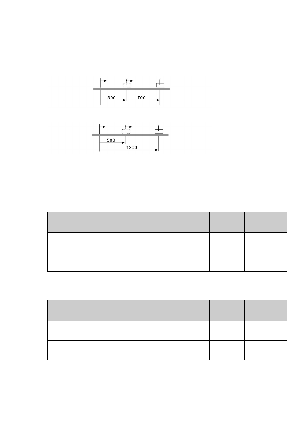
Operating Modes
EIO0000002305 04/2017 377
CANopen Operating Mode Profile Position
Description
In the operating mode Profile Position, a movement to a specified target position is performed.
A movement can be made using one of 2 methods:
-Relative movement
-Absolute movement
In the case of a relative movement, the movement is relative with reference to the previous target position
or the current motor position.
In the case of an absolute movement, the movement is absolute with reference to the zero point.
Starting the Operating Mode
The operating mode must be set in the parameter Modes of Operation 6060h. Writing the parameter
value causes the operating mode to start.
The target position is set via the parameter Controlword 607 Ah and the target position is set via the
parameter Controlword 6081h.
The acceleration is set via the parameter Profile Acceleration 6083h and the deceleration is set via
the parameter Profile Deceleration 6084h.
The movement is started via the parameter Controlword 6040h.
Index Name Object type
Data type
Access
PDO mapping
object
Minimum value
Factory settings
Maximum value
607 AhTarget Position
Unit: User-defined position unit
VAR
INT32
rww
Yes -2147483648
0
2147483647
6081hProfile Velocity in profile position mode
Unit: User-defined position unit/s
VAR
UINT32
rww
Yes 0
0
4294967295
Index Name Object type
Data type
Access
PDO mapping
object
Minimum value
Factory settings
Maximum value
6083hProfile Acceleration
Unit: User-defined position unit/s2
VAR
UINT32
rww
Yes 1
4266666667
4294967295
6084hProfile Deceleration
Unit: User-defined position unit/s2
VAR
UINT32
rww
Yes 1
4266666667
4294967295

Operating Modes
378 EIO0000002305 04/2017
Controlword
Statusword
Terminating the Operating Mode
The operating mode is terminated when the motor is at a standstill and one of the following conditions is
met:
-Target position reached
-Stop caused by "Halt" or "Quick Stop"
-Stop caused by a detected error
Bit 9
Change on
setpoint
Bit 5
Change setpoint
immediately
Bit 4
New setpoint
Meaning
0 0 0->1 Starts a movement to a target position.
Target values transmitted during a movement
become immediately effective and are executed
at the target. The movement is stopped at the
current target position.(1)
1 0 0->1 Starts a movement to a target position.
Target values transmitted during a movement
become immediately effective and are executed
at the target. The movement is not stopped at
the current target position.(1)
X 1 0->1 Starts a movement to a target position.
Target values transmitted during a movement
become immediately effective and are
immediately executed.(1)
(1) Target values include target position, target velocity, acceleration and deceleration.
Controlword Meaning
Bit 2: Quick Stop Triggers a Quick Stop
Bit 6: Absolute / relative 0: Absolute movement
1: Relative movement
Bit 7: Fault Reset Triggers a Fault Reset
Bit 8: Halt Triggers a Halt
Statusword Meaning
Bit 8: Halt request active 0: A Halt request is active
1: A Halt request is active
Bit 10: Target Reached 0: Target position not reached
1: Target position reached
Bit 12: Target value acknowledge 0: New position possible
1: New target position accepted
Bit 13: x_err 0: An error has been detected
1: An error has been detected
Bit 14: x_end 0: Operating mode started
1: Operating mode terminated
Bit 15: ref_ok 0: Zero point is not valid
1: Zero point is valid

Operating Modes
EIO0000002305 04/2017 379
Parameterization
The maximum velocity can be adjusted via the parameter Max profile velocity 607Fh.
The reference for a relative movement can be set via the parameter Position option code 60F2h.
Index Name Object type
Data type
Access
PDO mapping
object
Minimum value
Factory settings
Maximum value
607FhMax Profile Velocity
Unit: User-defined position unit/s
VAR
UINT32
rw
No 1
-
4294967295
Index Name Object type
Data type
Access
PDO mapping
object
Minimum value
Factory settings
Maximum value
60F2hPosition option code
Value 0: Relative with reference to the
previous target position
Value 2: Relative with reference to the
actual position of the motor
VAR
UINT16
rw
No 0
0
65535

Operating Modes
380 EIO0000002305 04/2017
CANopen Operating Mode Profile Velocity
Description
In the operating mode Profile Velocity, a movement is made with a specified target velocity.
Starting the Operating Mode
The operating mode must be set in the parameter Modes of Operation 6060h. Writing the parameter
value causes the operating mode to start.
The parameter Target velocity 60FFh starts the movement.
The acceleration is set via the parameter Profile Acceleration 6083h and the deceleration is set via
the parameter Profile Deceleration 6084h.
Controlword
Statusword
Index Name Object type
Data type
Access
PDO mapping
object
Minimum value
Factory settings
Maximum value
60FFhTarget Velocity
Unit: User-defined position unit/s
VAR
INT32
rww
Yes -2147483648
0
2147483647
Index Name Object type
Data type
Access
PDO mapping
object
Minimum value
Factory settings
Maximum value
6083hProfile Acceleration
Unit: User-defined position unit/s2
VAR
UINT32
rww
Yes 1
4266666667
4294967295
6084hProfile Deceleration
Unit: User-defined position unit/s2
VAR
UINT32
rww
Yes 1
4266666667
4294967295
Controlword Meaning
Bit 2: Quick Stop Triggers a Quick Stop
Bits 4 … 6: Operating mode-specific Not relevant for this operating mode
Bit 7: Fault Reset Triggers a Fault Reset
Bit 8: Halt Triggers a Halt
Bit 9: Operating mode-specific Not relevant for this operating mode
Statusword Meaning
Bit 8: Halt request active 0: A Halt request is active
1: A Halt request is active
Bit 10: Target Reached 0: Target velocity not reached
1: Target velocity reached
Bit 12: Operating mode-specific 0: Velocity = >0
1: Velocity = 0
Bit 13: x_err 0: An error has been detected
1: An error has been detected
Bit 14: x_end 0: Operating mode started
1: Operating mode terminated
Bit 15: ref_ok 0: Zero point is not valid
1: Zero point is valid

Operating Modes
EIO0000002305 04/2017 381
Terminating the Operating Mode
The operating mode is terminated when the motor is at a standstill and one of the following conditions is
met:
-Stop caused by "Halt" or "Quick Stop"
-Stop caused by a detected error
Parameterization
The maximum velocity can be adjusted via the parameter Max profile velocity 607Fh.
Index Name Object type
Data type
Access
PDO mapping
object
Minimum value
Factory settings
Maximum value
607FhMax Profile Velocity
Unit: User-defined position unit/s
VAR
UINT32
rw
No 1
-
4294967295

Operating Modes
382 EIO0000002305 04/2017
CANopen Operating Mode Profile Torque
Description
In the operating mode Profile Torque, a movement is made with a specified target torque.
Starting the Operating Mode
The operating mode must be set in the parameter Modes of Operation 6060h. Writing the parameter
value causes the operating mode to start.
The parameter Target torque 6071h starts the movement.
Controlword
Statusword
Terminating the Operating Mode
The operating mode is terminated when the motor is at a standstill and one of the following conditions is
met:
-Stop caused by "Halt" or "Quick Stop"
-Stop caused by a detected error
Index Name Object type
Data type
Access
PDO mapping
object
Minimum value
Factory settings
Maximum value
6071hTarget Torque
Unit: 1/1000 of nominal torque
VAR
INT16
rww
Yes -32768
0
32767
Controlword Meaning
Bit 2: Quick Stop Triggers a Quick Stop
Bits 4 … 6: Operating mode-specific Not relevant for this operating mode
Bit 7: Fault Reset Triggers a Fault Reset
Bit 8: Halt Triggers a Halt
Bit 9: Operating mode-specific Not relevant for this operating mode
Statusword Meaning
Bit 8: Halt request active 0: A Halt request is active
1: A Halt request is active
Bit 10: Target Reached 0: Target torque not reached
1: Target torque reached
Bit 12: Operating mode-specific Not relevant for this operating mode
Bit 13: x_err 0: An error has been detected
1: An error has been detected
Bit 14: x_end 0: Operating mode started
1: Operating mode terminated
Bit 15: ref_ok 0: Zero point is not valid
1: Zero point is valid

Operating Modes
EIO0000002305 04/2017 383
Parameterization
In the operating mode Profile Torque, the motion profile for torque can be adjusted via the parameter
Torque slope 6087h.
Index Name Object type
Data type
Access
PDO mapping
object
Minimum value
Factory settings
Maximum value
6087hTorque Slope
100% of the torque setting correspond to
the nominal torque.
Unit: 1/1000 of nominal torque/s
Example:
A ramp setting of 10000%/s results in a
torque change of 100% of the nominal
torque in 0.01s.
VAR
UINT32
rww
Yes 1
-
30000000

Operating Modes
384 EIO0000002305 04/2017
CANopen Operating Mode Homing
Description
In the operating mode Homing, a reference is generated between a mechanical position and the actual
position of the motor.
A reference between a mechanical position and the actual position of the motor is generated by means of
a reference movement or by means of position setting.
A successful reference movement or position setting homes the motor and the zero point becomes valid.
The zero point is the point of reference for absolute movements in the CANopen operating mode Profile
Position.
A movement can be made using different methods:
-Reference movement to a limit switch
In the case of a reference movement to a limit switch, a movement to the negative limit switch or the
positive limit switch is performed. When the limit switch is reached, the motor is stopped and a
movement is made back to the switching point of the limit switch. From the switching point of the limit
switch, a movement is made to the next index pulse of the motor or to a parameterizable distance from
the switching point. The position of the index pulse or the position of the parameterizable distance from
the switching point is the reference point.
-Reference movement to the reference switch
In the case of a reference movement to the reference switch, a movement to the reference switch is
performed. When the reference switch is reached, the motor is stopped and a movement is made back
to the switching point of the reference switch. From the switching point of the reference switch, a
movement is made to the next index pulse of the motor or to a parameterizable distance from the
switching point. The position of the index pulse or the position of the parameterizable distance from the
switching point is the reference point.
-Reference movement to the index pulse
In the case of a reference movement to the index pulse, a movement is made from the actual position
to the next index pulse. The position of the index pulse is the reference point.
-Position setting
In the case of position setting, the actual position of the motor is set to a specified position value.
A reference movement must be terminated without interruption for the new zero point to be valid. If the
reference movement is interrupted, it must be started again.
Procedure
-Set Mode of operation 6060h to operating mode Homing (6).
-Set Home offset 607Ch.
-Set Home method 6098h, the value range is 1 to 35 and specifies the different homing methods.
-Set Home speeds 6099:1h to the value for velocity for the search for the limit switches (unit = rpm).
-Set Home speeds 6099:2h to the value for velocity for the search for the index pulse (unit = rpm).
-Set Home acceleration 6099:3h to the value for the acceleration ramp (unit = ms from 0 to 3000
rpm).
Starting the Operating Mode
The operating mode must be set in the parameter Modes of Operation 6060h. Writing the parameter
value causes the operating mode to start.
The movement is started via the Controlword 6040h.
Controlword
Bit 4 in the parameter Controlword 6040h starts a movement, bit 8 terminates the movement.
Controlword Meaning
Bit 4: Homing operation start Start homing
Bits 5 … 6: Operating mode-specific Not relevant for this operating mode
Bit 8: Halt Triggers a Halt
Bit 9: Operating mode-specific Not relevant for this operating mode

Operating Modes
EIO0000002305 04/2017 385
Statusword
Terminating the Operating Mode
The operating mode is terminated when the motor is at a standstill and one of the following conditions is
met:
-Homing successful
-Stop caused by "Halt" or "Quick Stop"
-Stop caused by a detected error
Statusword Meaning
Bit 10: Target Reached 0: Homing not completed
1: Homing completed
Bit 12: Homing attained Homing successfully completed
Bit 13: x_err 0: An error has been detected
1: An error has been detected
Bit 14: Operating mode-specific Not relevant for this operating mode
Bit 15: Operating mode-specific Not relevant for this operating mode

Operating Modes
386 EIO0000002305 04/2017
CANopen Operating Mode Interpolated Position
Description
In the operating mode Interpolated Position, the drive follows the position values transmitted on a cyclic
basis. The transmitted values are linearly interpolated within the drive.
This mode uses a buffer of position commands. The buffer size is always 1, thus it is not possible to give
a list of target position commands in advance
The monitoring functions Heartbeat and Node Guarding cannot be used in this operating mode.
Check cyclical reception of PDOs at the PLC in order to detect an interruption of the connection.
The reference positions are transmitted synchronously with each cycle. The cycle time of a cycle can be
set from 1 … 20 ms.
The movement to the reference positions starts with the SYNC signal.
The drive performs an internal fine interpolation with a raster of 250 μs.
The operating mode is selected by writing 7 in the object Mode of operation 6060h.
Starting and Terminating the Operating Mode
The bits movement is started via the Controlword 6040h.
The operating mode is terminated when the motor is at standstill and if one of the following conditions is
met:
-Target position reached
-Stop caused by Halt or Quick Stop
-Stop caused by a detected error
-Switch to another operating mode
Source of Reference Value Signals
The object Target position 60C1h provides the target position value.
The target position minimum and maximum values depends on
-Scaling factor
-Software limit switches if they are activated
The object Target velocity 6081h provides the target velocity value.
The object Profile acceleration 6083h provides the acceleration value.
The object Profile deceleration 6084h provides the deceleration value.
The target velocity is limited to the setting in Max Profile Velocity 607Fh.
Changed settings become active immediately.
Control Word
In the operating mode, the bit 4 and the bit 8 in the Controlword 6040h start a movement.
Bit Name Meaning
Bit 4 Enable IP mode 0: Interpolated position mode not active
1: Interpolated position mode active
Bit 8 Halt 0: No Halt command
1: Stop movement with Halt

Operating Modes
EIO0000002305 04/2017 387
Status Word
Information on the current movement is available via bits 10 and 12 … 15 in the Statusword 6041h.
Bit Name Meaning
Bit 10 Target reached 0: Target position not reached
1: Target position reached
Bit 12 - 0: New position possible
1: New target position accepted
Bit 13 x_err 0: No error detected
1: A following error has been detected
Bit 14 x_end 0: Operating mode started
1: Operating mode terminated
Bit 15 ref_ok 1: Drive has valid reference point

Operating Modes
388 EIO0000002305 04/2017
CANopen Operating Mode Cyclic Synchronous Position
Description
In the operating mode Cyclic Synchronous Position (CSP), the drive synchronously follows the position
values transmitted on a cyclic basis. The transmitted values are linearly interpolated within the drive.
The motion profile is generated by the master controller.
The possible applications for this operating mode are described in the manual of the master controller.
The operating mode is selected by writing 8 in the object Mode of operation 6060h.
Starting and Terminating the Operating Mode
A transition to the operating state 6 Operation Enabled starts the set operating mode.
The operating mode is terminated when a different operating mode is selected or when the operating state
6 Operation Enabled is left.
Source of Reference Value Signals
The object Target Position 607 Ah provides the target value.
The value is in pulses.
Changed settings become active immediately.
Control Word
In the operating mode, the operating mode-specific bits in the Controlword 6040h have no significance.
Status Word
Information on the current movement is available via bits 10 and 12 … 15 in the Statusword 6041h.
Bit Name Meaning
Bit 10 Reserved Not relevant for this operating mode
Bit 12 - 0: Target position ignored
1: Target position used as input to position control loop
Bit 13 Reserved Not relevant for this operating mode
Bit 14 x_end 0: Operating mode started
1: Operating mode terminated
Bit 15 ref_ok 1: Drive has valid reference point

Operating Modes
EIO0000002305 04/2017 389
CANopen Operating Mode Jog
Description
In the operating mode Jog, the drive performs a movement with the transmitted jog target value.
The motion profile is generated by the drive, taking into account the target values received from the master
controller.
The operating mode is selected by writing -1 in the object Mode of operation 6060h.
Starting and Terminating the Operating Mode
The bits movement is started via the Controlword 6040h.
The operating mode is terminated when the motor is at standstill and if one of the following conditions is
met:
-Stop caused by Halt or Quick Stop
-Stop caused by a detected error
-Switch to another operating mode
Source of Reference Value Signals
The jog method is set with the object Jog Method 4453h.
-0: jog operation at constant speed
-1: Move a distance during a time, and start a jog operation at constant speed
The fast speed is set with the object Jog Speed Fast 4450h.
The slow speed is set with the object Jog Speed Slow 4454h.
The distance is set with the object Jog Step 4452h.
The time is set with the object Jog Time 4451h.
The target velocity is limited to the setting in Max Profile Velocity 607Fh.
The object Profile acceleration 6083h provides the acceleration value.
The object Profile deceleration 6084h provides the deceleration value.
Changed settings become active immediately.
Control Word
In the operating mode, the bits 4 … 6 in the Controlword 6040h start a movement
NOTE: If bit 4 and bit 5 are both at active state, it stops the movement.
Status Word
Information on the current movement is available via bits 10 and 12 … 15 in the Statusword 6041h.
Bit Name Meaning
Bit 4 Forward Movement in positive direction
Bit 5 Reverse Movement in negative direction
Bit 6 Speed 0: Slow speed
1: Fast speed
Bit Name Meaning
Bit 10 Reserved Not relevant for this operating mode
Bit 12 - Not relevant for this operating mode
Bit 13 x_err 0: No error detected
1: An error has been detected
Bit 14 x_end 0: Operating mode started
1: Operating mode terminated
Bit 15 ref_ok 1: Drive has valid reference point

Operating Modes
390 EIO0000002305 04/2017
CANopen Operating Mode Electronic Gear
Description
In the operating mode Electronic Gear, movements are carried out according to externally supplied
reference value signals. A position reference value is calculated on the basis of these external reference
values plus an adjustable gear ratio. The reference value signals can be A/B signals, P/D signals or
CW/CCW signals.
Method
A movement can be made using one of 3 methods:
-Position synchronization without compensation movement
In the case of position synchronization without compensation movement, the movement is made
synchronously (position synchronicity) with the supplied reference value signals. Reference value
signals supplied during an interruption caused by Halt or by a detected error of error class 1 are not
taken into account.
-Position synchronization with compensation movement
In the case of position synchronization with compensation movement, the movement is made
synchronously (position synchronicity) with the supplied reference value signals. Reference value
signals supplied during an interruption caused by Halt or by a detected error of error class 1 are taken
into account and compensated for.
-Velocity synchronization
In the case of velocity synchronization, the movement is made synchronously (velocity synchronicity)
with the supplied reference value signals.
Starting the Operating Mode
The operating mode must be set in the parameter Modes of Operation 6060h. Writing the parameter
value causes the operating mode to start.
Controlword
Parameter name Description Unit
Minimum value
Factory setting
Maximum value
HMI Format
Data type
R/W
Persistent
Parameter
address via
fieldbus
P8-31
GEARING_MODE
Method for Operating Mode Pulse Train
(PT)
Applicable operating mode: PT
Value 0: Synchronization deactivated
Value 1: Position synchronization without
compensation movement
Value 2: Position synchronization with
compensation movement
Value 3: Velocity synchronization
The parameters for acceleration (P1-34),
deceleration (P1-35) and velocity (P1-55)
act as limitations for the synchronization.
-
0
1
3
Decimal
u16
RW
per.
Modbus 93Eh
CANopen 481Fh
Controlword Meaning
Bit 2: Quick Stop Triggers a Quick Stop
Bits 4 … 6: Operating mode-specific Not relevant for this operating mode
Bit 7: Fault Reset Triggers a Fault Reset
Bit 8: Halt Triggers a Halt
Bit 9: Operating mode-specific Not relevant for this operating mode

Operating Modes
EIO0000002305 04/2017 391
Statusword
Terminating the Operating Mode
The operating mode is terminated when the motor is at a standstill and one of the following conditions is
met:
-Stop caused by "Halt" or "Quick Stop"
-Stop caused by a detected error
Pulse Settings
The parameter P1-00 lets you specify the type of reference value signals, the input polarity, the maximum
signal frequency and the source of the pulses.
For further information on the settings of the reference value signal, refer to chapter Pulse Setting
(see page 324)
.
Gear Ratio
The gear ratio is the ratio of the number of motor increments and the number of reference increments.
The reference increments are supplied as reference value signals via the signal inputs.
With the factory setting for the gear ratio, 100000 reference increments correspond to one revolution.
There are 1280000 motor increments per revolution.
The gear ratio can be adjusted via the objects 4FA5:1h and 4FA5:2h.
The velocity window in gearing mode can be adjusted via the objects 4328h and 606Eh.
Statusword Meaning
Bit 8: Halt request active 0: A Halt request is active
1: A Halt request is active
Bit 12: Operating mode-specific Not relevant for this operating mode
Bit 13: x_err 0: An error has been detected
1: An error has been detected
Bit 14: x_end 0: Operating mode started
1: Operating mode terminated
Bit 15: ref_ok 0: Zero point is not valid
1: Zero point is valid
Index Name Object type
Data type
Access
PDO mapping
object
Minimum value
Factory settings
Maximum value
4FA5:1hElectronic Gear Ratio (Numerator) VAR
INT32
rww
Yes 1
128
536870911
4FA5:2hElectronic Gear Ratio (Denominator) VAR
INT32
rww
Yes 1
10
2147483647
Index Name Object type
Data type
Access
PDO mapping
object
Minimum value
Factory settings
Maximum value
4328hVelocity Gearing Window VAR
UINT32
rw
No 0
2100000
4294967295
606EhVelocity Window Time
Unit: ms
VAR
UINT16
rw
No 0
0
65535

Operating Modes
392 EIO0000002305 04/2017
CANopen Operating Mode Analog Velocity
Description
In the operating mode Analog Velocity, a movement is made with a specified target velocity. The source
of the reference value signals is the analog input V_REF.
Starting the Operating Mode
The operating mode must be set in the parameter Modes of Operation 6060h. Writing the parameter
value causes the operating mode to start.
Controlword
Statusword
Terminating the Operating Mode
The operating mode is terminated when the motor is at a standstill and one of the following conditions is
met:
-Stop caused by "Halt" or "Quick Stop"
-Stop caused by a detected error
Controlword Meaning
Bit 2: Quick Stop Triggers a Quick Stop
Bits 4 … 6: Operating mode-specific Not relevant for this operating mode
Bit 7: Fault Reset Triggers a Fault Reset
Bit 8: Halt Triggers a Halt
Bit 9: Operating mode-specific Not relevant for this operating mode
Statusword Meaning
Bit 8: Halt request active 0: A Halt request is active
1: A Halt request is active
Bit 10: Target Reached 0: Target velocity not reached
1: Target velocity reached
Bit 12: Operating mode-specific Not relevant for this operating mode
Bit 13: x_err 0: An error has been detected
1: An error has been detected
Bit 14: x_end 0: Operating mode started
1: Operating mode terminated
Bit 15: ref_ok 0: Zero point is not valid
1: Zero point is valid
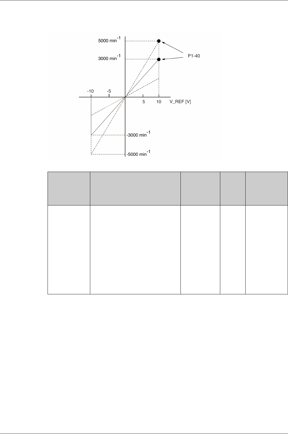
Operating Modes
EIO0000002305 04/2017 393
Scaling of the Analog Input V_REF
The parameter P1-40 lets you set the velocity corresponding to 10 V. This results in a linear scaling for the
analog input V_REF.
Parameter name Description Unit
Minimum value
Factory setting
Maximum value
HMI Format
Data type
R/W
Persistent
Parameter
address via
fieldbus
P1-40
VCM
Velocity Target Value and Velocity
Limitation 10 V
Applicable operating mode: PT, PS, V, T
In the operating mode V, this parameter
specifies the target velocity that
corresponds to the maximum input voltage
of 10 V.
In the operating mode T, this parameter
specifies the velocity limitation that
corresponds to the maximum input voltage
of 10 V.
Example: If the value of this parameter is
3000 in the operating mode V and if the
input voltage is 10 V, the target velocity is
3000 rpm.
rpm
0
-
10001
Decimal
s32
RW
per.
Modbus 250h
CANopen 4128h

Operating Modes
394 EIO0000002305 04/2017
CANopen Operating Mode Analog Torque
Description
In the operating mode Analog Torque, a movement is made with a specified target torque. The target
torque is specified in percent of the nominal torque of the motor. The source of the reference value signals
is the analog input T_REF.
Starting the Operating Mode
The operating mode must be set in the parameter Modes of Operation 6060h. Writing the parameter
value causes the operating mode to start.
Controlword
Statusword
Terminating the Operating Mode
The operating mode is terminated when the motor is at a standstill and one of the following conditions is
met:
-Stop caused by "Halt" or "Quick Stop"
-Stop caused by a detected error
Controlword Meaning
Bit 2: Quick Stop Triggers a Quick Stop
Bits 4 … 6: Operating mode-specific Not relevant for this operating mode
Bit 7: Fault Reset Triggers a Fault Reset
Bit 8: Halt Triggers a Halt
Bit 9: Operating mode-specific Not relevant for this operating mode
Statusword Meaning
Bit 8: Halt request active 0: A Halt request is active
1: A Halt request is active
Bit 10: Target Reached 0: Target torque not reached
1: Target torque reached
Bit 12: Operating mode-specific Not relevant for this operating mode
Bit 13: x_err 0: An error has been detected
1: An error has been detected
Bit 14: x_end 0: Operating mode started
1: Operating mode terminated
Bit 15: ref_ok 0: Zero point is not valid
1: Zero point is valid
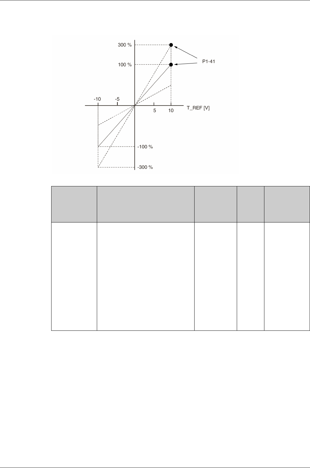
Operating Modes
EIO0000002305 04/2017 395
Scaling of the Analog Input T_REF
The parameter P1-41 lets you set the torque corresponding to 10 V. This results in a linear scaling for the
analog input T_REF.
Parameter name Description Unit
Minimum value
Factory setting
Maximum value
HMI Format
Data type
R/W
Persistent
Parameter
address via
fieldbus
P1-41
TCM
Torque Target Value and Torque Limitation
10 V
Applicable operating mode: PT, PS, V, T
In the operating mode T, this parameter
specifies the target torque that
corresponds to the maximum input voltage
of 10 V.
In the operating modes PT, PS and V, this
parameter specifies the torque limitation
that corresponds to the maximum input
voltage of 10 V.
Example: If the value of this parameter is
100 in the operating mode T and if the input
voltage is 10 V, the target torque is 100 %
of the nominal torque.
Setting can only be changed if power stage
is disabled.
%
0
100
1000
Decimal
u16
RW
per.
Modbus 252h
CANopen 4129h

Operating Modes
396 EIO0000002305 04/2017

EIO0000002305 04/2017 397
Lexium 28
A
and BCH2 Servo Drive System
Diagnostics and Troubleshooting
EIO0000002305 04/2017
Diagnostics and Troubleshooting
Part VIII
Diagnostics and Troubleshooting

Diagnostics and Troubleshooting
398 EIO0000002305 04/2017

EIO0000002305 04/2017 399
Lexium 28
A
and BCH2 Servo Drive System
Diagnostics and Troubleshooting
EIO0000002305 04/2017
Diagnostics and Troubleshooting
Chapter 19
Diagnostics and Troubleshooting
What Is in This Chapter?
This chapter contains the following topics:
Topic Page
Diagnostics Via the Fieldbus Status LEDs 400
Diagnostics Via the Integrated HMI 401
Diagnostics Via the Signal Outputs 402
Diagnostics Via the Commissioning Software 402
Diagnostics Via the Fieldbus 403
Connection for Fieldbus Mode 406
Alert Codes and Error Codes 407
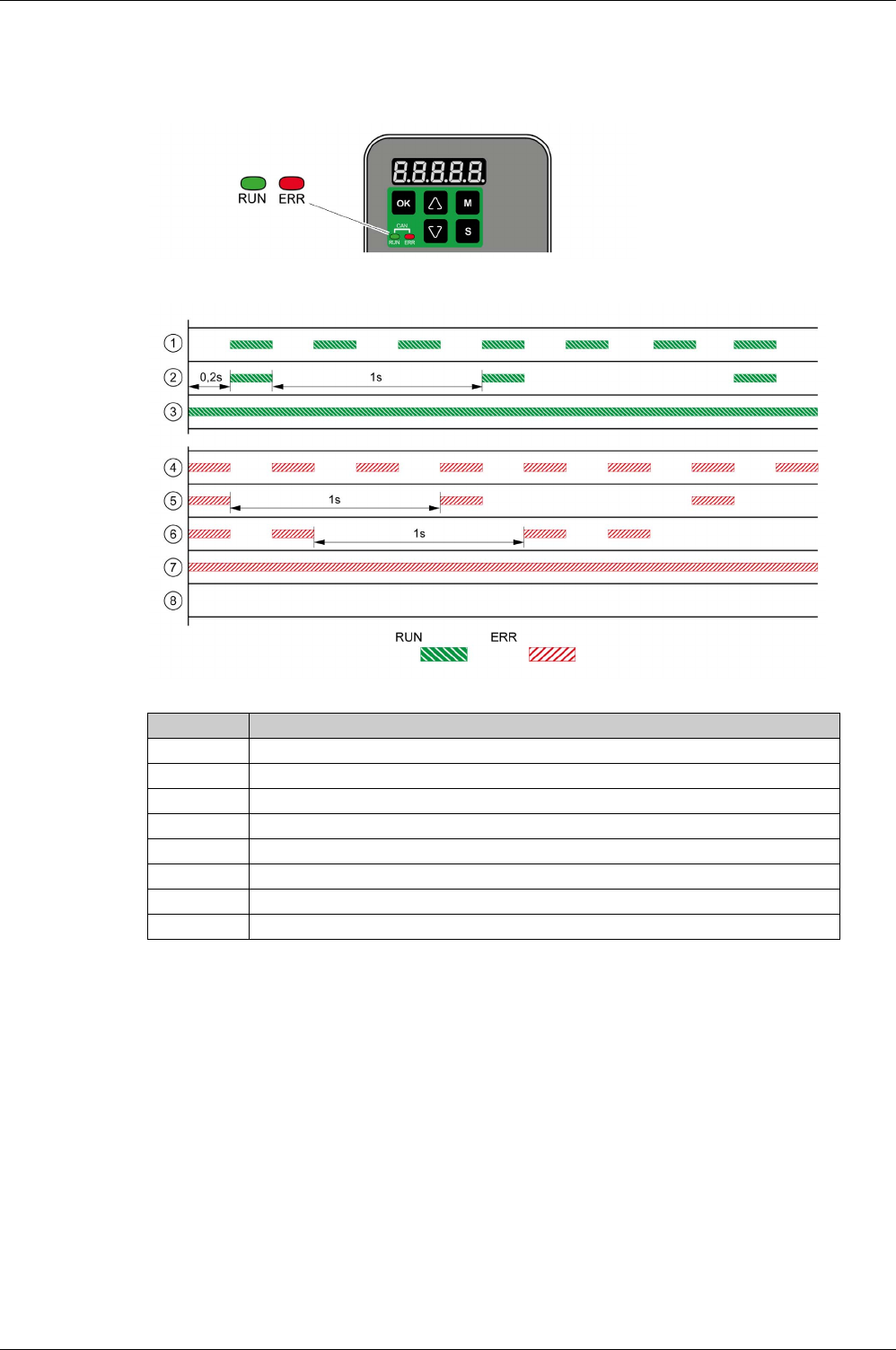
Diagnostics and Troubleshooting
400 EIO0000002305 04/2017
Diagnostics Via the Fieldbus Status LEDs
The fieldbus status LEDs visualize the status of the fieldbus.
The illustration below shows the signals of the CAN bus status LEDs (Run=GN; Err=RD).
Item Description
1 NMT state PRE-OPERATIONAL
2 NMT state STOPPED
3 NMT state OPERATIONAL
4 Incorrect settings, for example, invalid node address
5 Alert limit reached, for example after 16 incorrect transmission attempts
6 Node Guarding
7 CAN is BUS-OFF, for example after 32 incorrect transmission attempts.
8 Fieldbus communication without error message
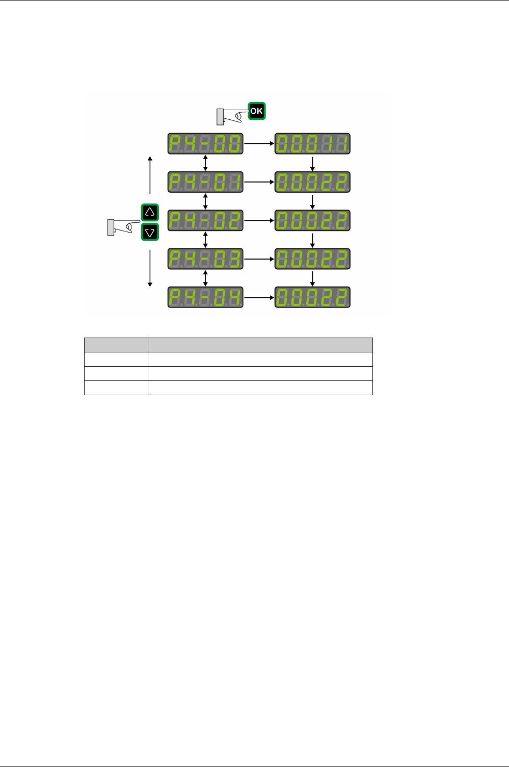
Diagnostics and Troubleshooting
EIO0000002305 04/2017 401
Diagnostics Via the Integrated HMI
Parameters P4-00 to P4-04 allow you to read the error memory.
The error memory also contains a history of the last 5 detected errors.
The parameter P0-47 allows you to read the last detected alert.
Parameter Description
P4-00 Error number of the most recently detected error
……
P4-04 Error number of the oldest detected error

Diagnostics and Troubleshooting
402 EIO0000002305 04/2017
Diagnostics Via the Signal Outputs
The signal outputs allow you to indicate, among other things, operating states and detected errors. The
following list is an excerpt of the parameterizable signal output functions. For additional signal output
functions, refer to Setting the Digital Signal Outputs
(see page 306)
.
Diagnostics Via the Commissioning Software
See the information provided with the commissioning software for details on how to display the device state
via the commissioning software LXM28 DTM Library.
Setting A for
P2-18 ... P2-
22
Short name Name of the
output function
Description
1 SRDY Servo Ready The signal output function SRDY indicates that no errors are
presently detected, i.e. the drive is not in the operating state Fault.
2 SON Servo On The signal output function SON indicates that the drive is in the
operating state Operation Enabled.
7 ERROR Error Detected The signal output function ERROR indicates that an error has been
detected and that the drive has switched to the operating state Fault.
For further information, refer to Diagnostics and Troubleshooting
(see page 399)
.
11 WARN Advisory or
Alert Signal
activated
The signal output function indicates that one of the following
conditions has been detected: Hardware limit switch triggered,
undervoltage, Nodeguard alert, Operational Stop (OPST).

Diagnostics and Troubleshooting
EIO0000002305 04/2017 403
Diagnostics Via the Fieldbus
Reading Error Numbers
The object 603Fh contains the most recently detected error.
The following table is sorted by CANopen error numbers and shows the corresponding error code (ALnnn).
Index Name Object type
Data type
Access
PDO mapping
object
Minimum value
Factory settings
Maximum value
603FhError Code VAR
UINT16
ro
Yes 0
-
65535
Value (hex) Value (dec) Error Code
(see page 409)
2214h8724 AL001
2310h8976 AL006
2311h8977 AL508
2380h9088 AL532
2381h9089 AL539
2382h9090 AL570
3110h12560 AL002
3120h12576 AL003
3180h12672 AL005
3181h12673 AL501
3182h12674 AL505
3183h12675 AL022
3199h12697 AL568
4080h16512 AL528
4081h16513 AL529
4096h16534 AL561
4310h17168 AL016
4410h17424 AL514
5111h20753 AL525
AL526
5530h21808 AL504
5581h21889 AL503
5582h21890 AL522
5583h21891 AL523
5585h21893 AL017
5586h21894 AL507
6380h25472 AL520
6581h25985 AL502
7081h28801 AL533
7090h28816 AL535
7091h28817 AL013
7095h28821 AL595
7121h28961 AL547
7182h29058 AL534

Diagnostics and Troubleshooting
404 EIO0000002305 04/2017
SDO Abort Codes
7198h29080 AL563
7380h29568 AL026
7386h29574 AL3E1
7387h29575 AL018
738Dh29581 AL567
7393h29587 AL517
7580h30080 AL553
7581h30081 AL554
7582h30082 AL557
7583h30083 AL020
7584h30084 AL569
8130h33072 AL180
8210h33296 AL597
8311h33553 AL030
8380h33664 AL596
8481h33921 AL007
8482h33922 AL555
8611h34321 AL009
8680h34432 AL564
8689h34441 AL572
F080h61568 AL401
FF01h65281 AL558
FF02h65282 AL025
FF04h65284 AL588
FF97h65431 AL008
Value (hex) Value (dec) Error Code
(see page 409)
SDO Abort Code Meaning
05040001hClient/server command specifier not valid or undetermined
06010002hAttempt to write a read-only object
06020000hObject does not exist in the object dictionary
06040041hObject cannot be mapped to the PDO
06040042hThe number and length of the objects to be mapped would exceed PDO length
06060000hAccess impossible due to a hardware error (store or restore error)
06070010hData type does not match, length of service parameter does not match
06090011hSubindex does not exist
06090030hValue range of parameter exceeded (only for write access)
08000000hGeneral error
080000a1hObject error reading from non-volatile memory
080000a2hObject error writing to non-volatile memory
080000a3hInvalid Range accessing non-volatile memory
080000a4hChecksum error accessing non-volatile memory
080000a5hPassword error writing encryption zone

Diagnostics and Troubleshooting
EIO0000002305 04/2017 405
08000020hData cannot be transferred to or stored in the application (store or restore signature
error)
08000021hData cannot be transferred to or stored in the application because of the local control
(incorrect state)
SDO Abort Code Meaning

Diagnostics and Troubleshooting
406 EIO0000002305 04/2017
Connection for Fieldbus Mode
Description
If the product cannot be addressed via the fieldbus, check the following connections:
-Power connections to the device.
-Network cable and network wiring.
-Network connection to the device.

Diagnostics and Troubleshooting
EIO0000002305 04/2017 407
Alert Codes and Error Codes
Meaning of an Alert
An alert indicates a potential issue that was detected by a monitoring function. An alert does not trigger a
transition of the operating state.
Number Description Cause Remedy
AL014 Negative hardware limit
switch triggered
--
AL015 Positive hardware limit switch
triggered
--
AL283 Positive software limit switch
triggered
--
AL285 Negative software limit switch
triggered
--
Wn023 Alert threshold reached:
Motor overload (foldback)
The foldback current of the motor
has dropped below the alert
threshold specified via the
parameter P1-28.
Verify correct settings of the
parameter P1-28 for the foldback
current of the motor.
Wn124 Data in PDO out of range - Verify that the minimum and
maximum limit values are not
exceeded.
Wn127 R_PDO data cannot be
written while the power stage
is enabled
--
Wn185 CANopen: A communication
error was detected.
--
Wn283 Target value will cause
movement to positive
software limit switch
- Verify correct target positions.
Wn285 Target value will cause
movement to negative
software limit switch
- Verify correct target positions.
Wn380 Position deviation via signal
output function MC_OK
After a movement has been
successfully completed, MC_OK
was active. Then TPOS became
inactive which caused MC_OK to
become inactive as well.
If you want this condition to cause a
detected error instead of an alert, set
the parameter P1-48 accordingly.
Wn700 Safety function Safe Torque
Off (STO) triggered while the
power stage was disabled
The safety function STO has been
triggered or the signal for the safety
function STO is not properly
connected. If this condition is
detected while the power stage is
enabled, the drive detects an error. If
this condition is detected while the
power stage is disabled, the drive
detects an alert.
Check whether the safety function
STO was triggered intentionally. If
not, verify correct connection of the
signal of the safety function STO.
Wn701 Alert threshold reached: Drive
overload (foldback)
The foldback current of the drive has
dropped below the alert threshold
specified via the parameter P1-24.
Verify correct settings of the
parameter P1-24 for the foldback
current of the drive.
Wn702 The DC bus voltage has
dropped below the alert
threshold.
Power supply loss, poor power
supply.
Verify correct mains supply. Verify
that the undervoltage limit is set
correctly via the parameter P4-24.
Wn703 Alert threshold reached:
Power stage overtemperature
Ambient temperature is too high, fan
is inoperative, dust.
Verify correct operation of the fan.
Improve the heat dissipation in the
control cabinet. Remove pollution
and verify that dust cannot get into
the control cabinet or into the drive.

Diagnostics and Troubleshooting
408 EIO0000002305 04/2017
Wn704 Alert threshold reached:
Motor overtemperature
The motor temperature is
excessively high.
Verify correct settings of the
parameters for temperature
monitoring. Verify proper ventilation
and heat dissipation of the motor.
Clean off pollutants such as dust.
Verify that the motor is evenly
mounted to the flange plate.
Increase the size of the flange plate
to which the motor is mounted to
improve heat dissipation. Verify that
the motor is properly sized for the
application.
Wn707 Alert threshold reached: Drive
overtemperature (controller)
Ambient temperature is too high, fan
is inoperative, dust.
Verify correct operation of the fan.
Improve the heat dissipation in the
control cabinet. Remove pollution
and verify that dust cannot get into
the control cabinet or into the drive.
Wn709 PLL not synchronized - -
Wn713 Positive hardware limit switch
and negative hardware limit
triggered
--
Wn716 Positive software limit switch
and negative software limit
triggered
--
Wn728 Alert: Missing mains supply,
undervoltage mains supply
At least one mains phase is missing.
Mains voltage is out of range. Mains
frequency is out of range.
Verify correct connection of mains
supply. Verify that the values of the
mains power supply network comply
with the technical data.
Wn729 Modbus: Node Guarding
error detected
Incorrect Modbus connection,
incorrect data from Modbus master.
Verify correct Modbus connection.
Verify correct operation of Modbus
master.
Wn730 Alert threshold reached:
Braking resistor overload
The permissible braking resistor
power has been exceeded.
Verify correct rating of the braking
resistor used. Verify your
application.
Wn731 Encoder error detected Refer to parameter P8-49 for details. -
Wn732 Alert threshold reached:
Processing time too long
--
Wn734 Alert threshold reached: Drive
overtemperature (IPM)
Ambient temperature is too high, fan
is inoperative, dust.
Verify correct operation of the fan.
Improve the heat dissipation in the
control cabinet. Remove pollution
and verify that dust cannot get into
the control cabinet or into the drive.
Wn736 PDO packet too long - Verify correct PDO mapping.
Wn737 Parameters have been reset
to the factory settings, but are
not yet saved to the non-
volatile memory.
- Use parameter P2-08 = 11 to save
parameters reset to the factory
settings to the non-volatile memory
and restart the drive.
Wn738 No target values received via
the fieldbus
No target values have been received
via the fieldbus three times in
succession.
Verify that target values are
transmitted via the fieldbus. Verify
that the fieldbus has exclusive
access.
Wn739 Temperature value for
monitoring function not
available
--
Wn740 Target value will cause
movement to positive
software limit switch
--
Wn741 Target value will cause
movement to negative
software limit switch
--
Number Description Cause Remedy

Diagnostics and Troubleshooting
EIO0000002305 04/2017 409
Meaning of an Error
An error is a discrepancy between a computed, measured, or signaled value or condition and the specified
or theoretically correct value or condition detected by a monitoring function. An error triggers a transition
of the operating state.
Wn742 Motor type has changed. The type of motor connected is
different from the previously
connected type of motor.
Reset the drive to the factory
settings.
Wn744 Excessive electronic noise - -
Number Description Cause Remedy
Number Short description Cause Remedy
AL001 Power stage overcurrent An overcurrent has been detected at
the power stage which may be
caused by a short circuit or by
incorrect settings of the current loop
parameters. This condition may
occur up to three times in
succession. After the third time, a
time delay of one minute must pass
before the power stage can be
enabled again.
Verify correct connection of the
motor. Verify correct settings of the
parameters for the current loop.
AL002 DC bus overvoltage The DC bus voltage exceeded the
maximum value.
Verify your application. Reduce the
external load, the motor velocity, or
the deceleration. Use an
appropriately rated braking resistor,
if necessary.
AL003 DC bus undervoltage Power supply loss, poor power
supply.
Verify correct mains supply. Verify
that the undervoltage limitation is set
correctly via the parameter P4-24.
AL005 Braking resistor overload The braking resistor has been on for
such a long period of time that its
overload capability has been
exceeded.
Verify your application. Reduce the
external load, the motor velocity, or
the deceleration. Use a braking
resistor with a greater rating, if
necessary.
AL006 Motor overload (foldback) The foldback current of the motor
has dropped below the value
specified via the parameter P1-27.
Verify correct settings for the
parameter P1-27.
AL007 Actual motor velocity too
high.
The actual motor velocity exceeded
the velocity limitation by more than
20% (P1-55). The analog input
signal is not stable.
Verify that the velocity limitation set
via the parameter P1-55 matches the
requirements of the application.
Verify that the values for the tuning
parameters are suitable. Verify that
the frequency of the analog input
signal is stable using a signal
detector. Use a filter function.
AL008 Frequency of reference value
signal is too high
The frequency of the pulse signal
(A/B, Pulse/Direction, CW/CCW)
exceeds the specified range.
Received pulses may be lost.
Adapt the output pulse frequency of
the external source to fit the input
specification of the drive. Adapt the
gear ratios to the application
requirements (parameters P1-44,
P1-45, P2-60, P2-61 and P2-62).
AL009 Position deviation too high
(following error)
The position deviation has exceeded
the maximum permissible position
deviation specified via the parameter
P2-35 and the drive has detected a
following error.
Verify your application. Reduce the
external load. Increase the
permissible position deviation via the
parameter P2-35. Reduce the motor
velocity via the parameters P1-
09 … P1-11 or the analog input
V_REF. Increase the torque
limitation via the parameters P1-
12 … P1-14 or the analog input
T_REF.

Diagnostics and Troubleshooting
410 EIO0000002305 04/2017
AL013 The input to which the signal
input function OPST is
assigned has been activated.
- Identify the cause which has
triggered the signal input function
OPST. Remove the cause. If your
application does not require the
signal input function OPST, disable
this signal input function.
AL016 Power stage overtemperature Ambient temperature is too high, fan
is inoperative, dust.
Verify correct operation of the fan.
Improve the heat dissipation in the
control cabinet. Remove pollution
and verify that dust cannot get into
the control cabinet or into the drive.
AL017 Error detected in non-volatile
memory
The drive was reset to the factory
settings via parameter P2-08.
Use parameter P2-08 = 11 to save
parameters reset to the factory
settings to the non-volatile memory
and restart the drive.
Contact technical support.
AL018 Encoder simulation frequency
exceeded 4 MHz
The computed equivalent encoder
output frequency exceeds the
maximum limit of 4 MHz for this
signal.
Reduce the resolution of the encoder
simulation via the parameter P1-46
or reduce the maximum velocity.
AL020 Modbus: Node Guarding
error detected
Incorrect Modbus connection,
incorrect data from Modbus master.
Verify correct Modbus connection.
Verify correct operation of Modbus
master.
AL022 Missing mains supply,
undervoltage mains supply
At least one mains phase is missing.
Mains voltage is out of range. Mains
frequency is out of range.
Verify correct connection of mains
supply. Verify that the values of the
mains power supply network comply
with the technical data.
AL025 Not possible to read data of
electronic motor nameplate
Incorrect or missing motor data.
Motor without electronic motor
nameplate has been connected.
Verify that the drive and the
connected motor are a permissible
product combination. Verify correct
connection of the encoder. Contact
Technical Support or replace the
motor.
AL026 Error detected in
communication with motor
encoder
Communication with the encoder
was not initialized correctly.
Verify correct connection of the
encoder. Contact Technical Support
or replace the motor.
AL030 Motor torque too high for an
excessive period of time
The motor torque has exceeded the
value specified via the parameter
P1-57 for a period of time exceeding
the value specified via the parameter
P1-58.
Verify your application. Verify that no
movements are made up to a
mechanical stop (for example, use
limit switches). Verify that the values
for the parameters P1-57 and P1-58
are suitable.
AL180 CANopen: Heartbeat error
detected
The bus cycle time of the CANopen
master is greater than the
programmed heartbeat or node
guard time. The connection between
the CANopen master and the drive is
lost.
Verify correct CANopen connection.
Check the CANopen master. Verify
correct CANopen configuration,
increase the Heartbeat or Node
Guarding time.
AL3E1 Drive is not synchronous with
master cycle
Operating mode has been activated
but drive is not synchronized to
external synchronization signal.
Verify correct CANopen connection.
After having started the
synchronization mechanism, wait for
120 cycles before activating the
operating mode.
AL401 Fieldbus: Communication
error detected
While the power stage was enabled,
a command was received requesting
a different communication state.
Verify that the master does not try to
change the communication state
while the power stage of the drive is
enabled.
Number Short description Cause Remedy

Diagnostics and Troubleshooting
EIO0000002305 04/2017 411
AL501 Safety function Safe Torque
Off (STO) triggered
The safety function STO has been
triggered or the signal for the safety
function STO is not properly
connected. If this condition is
detected while the power stage is
enabled, the drive detects an error. If
this condition is detected while the
power stage is disabled, the drive
detects an alert.
Check whether the safety function
STO was triggered intentionally. If
not, verify correct connection of the
signal of the safety function STO.
AL502 System error detected
(FPGA)
- Contact technical support.
AL503 System error detected (non-
volatile memory)
- Contact technical support.
AL504 System error detected (non-
volatile memory)
- Contact technical support.
AL505 DC bus voltage measurement An error was detected in the circuit
that measures the DC bus voltage.
Perform a Fault Reset. Restart the
drive. If the error persists, contact
Technical Support.
AL507 System error detected (NV
access)
- Contact technical support.
AL508 Drive overload (foldback) The foldback current of the drive has
dropped below the value specified
via the parameter P1-23.
Verify correct settings for the
parameter P1-23.
AL514 Motor overtemperature The motor temperature is
excessively high.
Verify correct settings of the
parameters P1-62 and P1-63 for
temperature monitoring. Verify
proper ventilation and heat
dissipation of the motor. Clean off
pollutants such as dust. Verify that
the motor is evenly mounted to the
flange plate. Increase the size of the
flange plate to which the motor is
mounted to improve heat dissipation.
Verify that the motor is properly sized
for the application.
AL517 Encoder overvoltage or
overcurrent
The current supplied by the drive for
the 5 V encoder supply has
exceeded the limit. This condition
may occur up to three times in
succession. After the third time, a
time delay of one second must pass
before the power stage can be
enabled again.
Verify correct connection of the
encoder (short circuits). Verify the
current consumption of the encoder.
AL520 Target position rejected A target position was rejected
because it would have caused the
motor to exceed the maximum
velocity.
Verify that target positions do not
lead to excessive motor velocities.
AL522 System error detected (CAN
power supply)
The internal supply voltage for the
CAN bus is not correct.
Contact technical support.
AL523 System error detected (self-
test)
The self-test has detected an error. Contact technical support.
AL525 Reserved – –
AL526 Reserved – –
AL527 System error detected
(Watchdog)
The Watchdog function has detected
a system error.
Restart the drive. If the error persists,
contact Technical Support.
AL528 Drive overtemperature (IPM) Ambient temperature is too high, fan
is inoperative, dust.
Verify correct operation of the fan.
Improve the heat dissipation in the
control cabinet. Remove pollution
and verify that dust cannot get into
the control cabinet or into the drive.
Number Short description Cause Remedy

Diagnostics and Troubleshooting
412 EIO0000002305 04/2017
AL529 Drive overtemperature
(controller)
Ambient temperature is too high, fan
is inoperative, dust.
Verify correct operation of the fan.
Improve the heat dissipation in the
control cabinet. Remove pollution
and verify that dust cannot get into
the control cabinet or into the drive.
AL532 Calculated offsets for current
sensors out of range
The calculated offsets for the current
sensors are out of range.
Perform a Fault Reset. Restart the
drive. If the error persists, contact
Technical Support.
AL533 Reserved – –
AL534 Pulse signal missing One of the pulse signals is not
connected.
Verify correct connection of the pulse
inputs.
AL535 System error detected (FPGA
does not match firmware)
The firmware version is not suitable
for the drive.
Update the firmware of the drive.
Contact technical support.
AL539 Motor phase missing One of the motor phases is not
connected.
Verify correct connection of the
motor phases. Contact technical
support.
AL547 Motor blocked The motor was blocked
mechanically, for example, by a
mechanical stop or by the load.
Remove condition causing the
mechanical blocking. Verify your
application.
AL553 No connection between
master and drive
- Connect master and drive.
AL554 Target position rejected A target position was rejected
because it would have caused the
motor to exceed the maximum
acceleration/deceleration.
Verify that target positions do not
lead to excessive
acceleration/deceleration.
AL555 Velocity deviation too high The deviation between actual
velocity and reference velocity has
exceeded the maximum velocity
deviation specified via the parameter
P2-34.
Verify your application. Verify that
the values for the tuning parameters
are suitable. Increase the value for
the maximum velocity deviation in
the parameter P2-34.
AL557 No target values received via
the fieldbus
No target values have been received
via the fieldbus three times in
succession.
Perform a Fault Reset. Verify that
target values are transmitted via the
fieldbus.
AL558 System error detected - Contact technical support.
AL560 Power stage supply off - Power on the power stage supply.
AL561 Temperature sensor
inoperative
- Restart the drive. If the error persists,
contact Technical Support.
AL563 Commutation error detected Motor phases have been
interchanged.
Verify correct connection of the
motor phases.
AL564 Position deviation via signal
output function MC_OK
After a movement has been
successfully completed, MC_OK
was active. Then TPOS became
inactive which caused MC_OK to
become inactive as well.
Use the signal input function
FAULT_RESET to perform a Fault
Reset and set the parameter P0-01
to 0. If you want this condition to
cause an alert instead of a detected
error, set the parameter P1-48
accordingly.
AL567 System error detected
(encoder)
Refer to parameter P8-48 for details. Contact technical support.
AL568 Braking resistor overload The permissible braking resistor
power has been exceeded.
Verify correct rating of the braking
resistor used. Verify your
application.
AL569 Configuration not correctly
transferred via Modbus
- Verify correct connection. Verify that
configuration file and drive are
compatible.
AL570 Overcurrent detected at one
of the digital outputs
- Verify correct wiring of the digital
outputs. Verify that there are no short
circuits.
Number Short description Cause Remedy

Diagnostics and Troubleshooting
EIO0000002305 04/2017 413
AL572 Position deviation too high
(following error)
The position deviation has exceeded
the maximum permissible position
deviation specified via the parameter
P2-35 and the drive has detected a
following error.
Verify your application. Reduce the
external load. Increase the
permissible position deviation via the
parameter P2-35. Reduce the motor
velocity via the parameters P1-
09 … P1-11 or the analog input
V_REF. Increase the torque
limitation via the parameters P1-
12 … P1-14 or the analog input
T_REF.
AL585 CANopen device in state bus-
off
Too many error frames have been
detected. CANopen devices have
different baud rates.
Verify correct baud rates. Verify
CANopen bus installation.
AL588 Reserved – –
AL595 Impermissible combination of
drive and motor
- Use an approved drive/motor
combination.
AL596 Unstable current loop Excessive overshoot in current loop. Verify correct settings of the
parameters for the current loop.
AL597 R_PDO is too short - Verify correct PDO settings for drive
and master.
Number Short description Cause Remedy

Diagnostics and Troubleshooting
414 EIO0000002305 04/2017

EIO0000002305 04/2017 415
Lexium 28
A
and BCH2 Servo Drive System
Service, Maintenance and Disposal
EIO0000002305 04/2017
Service, M aintenance and Disposal
Part IX
Service, Maintenance and Disposal

Service, Maintenance and Disposal
416 EIO0000002305 04/2017

EIO0000002305 04/2017 417
Lexium 28
A
and BCH2 Servo Drive System
Service, Maintenance, and Disposal
EIO0000002305 04/2017
Service, M aintenance, and Disposal
Chapter 20
Service, Maintenance, and Disposal
What Is in This Chapter?
This chapter contains the following topics:
Topic Page
General 418
Service Address 419
Maintenance of the Drive 420
Replacement of Drive 421
Maintenance of the Motor 422
Changing the Motor 423
Shipping, Storage, Disposal 424

Service, Maintenance, and Disposal
418 EIO0000002305 04/2017
General
The product may only be repaired by a Schneider Electric customer service center.
The use and application of the information contained herein require expertise in the design and
programming of automated control systems.
Only you, the user, machine builder or integrator, can be aware of all the conditions and factors present
during installation and setup, operation, repair and maintenance of the machine or process.
You must also consider any applicable standards and/or regulations with respect to grounding of all
equipment. Verify compliance with any safety information, different electrical requirements, and normative
standards that apply to your machine or process in the use of this equipment.
Many components of the equipment, including the printed circuit board, operate with mains voltage, or
present transformed high currents, and/or high voltages.
The motor itself generates voltage when the motor shaft is rotated.
DANGER
ELECTRIC SHOCK, EXPLOSION, OR ARC FLASH
-Disconnect all power from all equipment including connected devices prior to removing any covers or
doors, or installing or removing any accessories, hardware, cables, or wires.
-Place a "Do Not Turn On" or equivalent hazard label on all power switches and lock them in the non-
energized position.
-Wait 15 minutes to allow the residual energy of the DC bus capacitors to discharge.
-Measure the voltage on the DC bus with a properly rated voltage sensing device and verify that the
voltage is less than 42.4 Vdc.
-Do not assume that the DC bus is voltage-free when the DC bus LED is off.
-Block the motor shaft to prevent rotation prior to performing any type of work on the drive system.
-Do not create a short-circuit across the DC bus terminals or the DC bus capacitors.
-Replace and secure all covers, accessories, hardware, cables, and wires and confirm that a proper
ground connection exists before applying power to the unit.
-Use only the specified voltage when operating this equipment and any associated products.
Failure to follow these instructions will result in death or serious injury.

Service, Maintenance, and Disposal
EIO0000002305 04/2017 419
Service Address
If you cannot resolve an error yourself, contact your sales office.
Have the following data available:
-Nameplate (type, identification number, serial number, DOM, ...)
-Type of error (with LED flash code or error code)
-Previous and concomitant circumstances
-Your own assumptions concerning the cause of the error
Also include this information if you return the product for inspection or repair.
If you have any questions, contact your sales office. Your sales office staff will provide you the name of a
customer service office in your area.
http://www.schneider-electric.com

Service, Maintenance, and Disposal
420 EIO0000002305 04/2017
Maintenance of the Drive
Prior to any type of work on the drive system, consult the chapters on Installation and Commissioning for
information to be observed.
Repairs cannot be made with the device installed.
Include the following points in the maintenance plan of your machine.
Connections and Fastening
-Check all connection cables and connectors regularly for damage. Replace damaged cables
immediately.
-Tighten all mechanical and electrical threaded connections to the specified torque.
Cleaning
Clean dust and dirt off the product at regular intervals. Insufficient heat dissipation to the ambient air may
excessively increase the temperature.
Lifetime of the Safety Function STO
The STO safety function is designed for a lifetime of 20 years. After this period, the data of the safety
function are no longer valid. The expiry date is determined by adding 20 years to the DOM shown on the
nameplate of the product.
-This date must be included in the maintenance plan of the system.
Do not use the safety function after this date.
Example:
The DOM on the nameplate of the product is shown in the format DD.MM.YY, for example 31.12.08. (31
December 2008). This means: Do not use the safety function after December 31, 2028.

Service, Maintenance, and Disposal
EIO0000002305 04/2017 421
Replacement of Drive
Unsuitable settings or unsuitable data may trigger unintended movements, trigger signals, damage parts
and disable monitoring functions. Some parameters and other operational data do not become active until
after a restart.
Prepare a list with the parameters required for the functions used.
Observe the following procedure when replacing devices:
WARNING
UNINTENDED EQUIPMENT OPERATION
-Only start the system if there are no persons or obstructions in the zone of operation.
-Do not operate the drive system with undetermined parameter values.
-Never modify a parameter value unless you fully understand the parameter and all effects of the
modification.
-Restart the drive and verify the saved operational data and/or parameter values after modification.
-Carefully run tests for all operating states and potential error situations when commissioning,
upgrading or otherwise modifying the operation of the drive.
-Verify the functions after replacing the product and also after making modifications to the parameter
values and/or other operational data.
Failure to follow these instructions can result in death, serious injury, or equipment damage.
Step Action
1 Save all parameter settings. Save the data to your PC using the commissioning software, refer
to chapter Commissioning Software
(see page 202)
.
2 Power off all supply voltages. Verify that no voltages are present.
3 Label all connections and remove all connection cables (unlock connector locks).
4 Uninstall the product.
5 Note the identification number and the serial number shown on the product nameplate for later
identification.
6 Install the new product as per chapter Installation
(see page 139)
.
7 If the product to be installed has previously been used in a different system or application, you
must restore the factory settings before commissioning the product.
8 Commission the product as per chapter Commissioning
(see page 187)
.

Service, Maintenance, and Disposal
422 EIO0000002305 04/2017
Maintenance of the Motor
Prior to any type of work on the drive system, consult the chapters on Installation and Commissioning for
information to be observed.
Repairs cannot be made with the device installed.
Include the following points in the maintenance plan of your machine.
Connections and Fastening
-Inspect all connection cables and connectors regularly for damage. Replace damaged cables
immediately.
-Verify that all output elements are firmly seated.
-Tighten all mechanical and electrical threaded connections to the specified torque.
Lubricating the Shaft Sealing Ring
In the case of motors with shaft sealing ring, lubricant must be applied to the space between the sealing
lip of the shaft sealing ring and the shaft with a suitable non-metallic tool. If the shaft sealing rings are
allowed to run dry, the service life of the shaft sealing rings will be significantly reduced.
Cleaning
If the permissible ambient conditions are not respected, external substances from the environment may
penetrate the product and cause unintended movement or equipment damage.
Clean dust and dirt off the product at regular intervals. Insufficient heat dissipation to the ambient air may
excessively increase the temperature.
Motors are not suitable for cleaning with a pressure washer. The high pressure may force water into the
motor.
When using solvents or cleaning agents, verify that the cables, cable entry seals, O-rings, and motor paint
are not damaged.
Replacing the Rolling Bearing
When the rolling bearing is replaced, the motor is partially demagnetized and loses power.
WARNING
UNINTENDED MOVEMENT
-Verify that the ambient conditions are respected.
-Do not allow seals to run dry.
-Keep liquids from getting to the shaft bushing (for example, in mounting position IM V3).
-Do not expose the shaft sealing rings and cable entries of the motor to the direct spray of a pressure
washer.
Failure to follow these instructions can result in death, serious injury, or equipment damage.
NOTICE
INOPERABLE EQUIPMENT
Do not replace the rolling bearing.
Failure to follow these instructions can result in equipment damage.

Service, Maintenance, and Disposal
EIO0000002305 04/2017 423
Changing the Motor
Drive systems may perform unintended movements if unapproved combinations of drive and motor are
used. Even if motors are similar, different adjustment of the encoder system may be a source of hazards.
Even if the connectors for motor connection and encoder connection match mechanically, this does not
imply that the motor is approved for use.
Compatibility between Drive and Motor is defined in the Drive / Motor combinations table
(see page 20)
.
Observe the following procedure when changing motors:
If the connected motor is replaced by another approved motor, the new motor is automatically recognized
by the drive.
WARNING
UNINTENDED MOVEMENT
Only use approved combinations of drive and motor.
Failure to follow these instructions can result in death, serious injury, or equipment damage.
Step Action
1 Switch off all supply voltages. Verify that no voltages are present.
2 Label all connections and uninstall the product.
3 Note the identification number and the serial number shown on the product nameplate for later
identification.
4 Install the new product as per chapter Installation
(see page 175)
.
5 Commission the product as per chapter Commissioning
(see page 187)
.

Service, Maintenance, and Disposal
424 EIO0000002305 04/2017
Shipping, Storage, Disposal
Shipping
The product must be protected against shocks during transportation. If possible, use the original packaging
for shipping.
Storage
The product may only be stored in spaces where the specified permissible ambient conditions are met.
Protect the product from dust and dirt.
Disposal
The product consists of various materials that can be recycled. Dispose of the product in accordance with
local regulations.
Visit
http://www.schneider-electric.com/green-premium
for information and documents on environmental
protection as per ISO 14025 such as:
-EoLi (Product End-of-Life Instructions)
-PEP (Product Environmental Profile)


CANopen
426 EIO0000002305 04/2017

EIO0000002305 04/2017 427
Lexium 28
A
and BCH2 Servo Drive System
CANopen Basics
EIO0000002305 04/2017
CANopen Basics
Chapter 21
CANopen Basics
What Is in This Chapter?
This chapter contains the following topics:
Topic Page
Communication Objects 428
Service Data Communication 429
Process Data Communication 430
Setting the Process Data 432

CANopen Basics
428 EIO0000002305 04/2017
Communication Objects
Overview
CANopen manages communication between the network devices with object dictionaries and objects. A
network device can use process data objects (PDO) and service data objects (SDO) to request the object
data from the object dictionary of another device and, if permissible, write back modified values.
-PDOs (process data objects) for real-time transmission of process data.
-SDOs (service data object) for read and write access to the object dictionary.
-Objects for controlling CAN messages:
SYNC object (synchronization object) for synchronization of network devices.
EMCY object (emergency object), for signaling detected errors of a device or its peripherals.
-Network management services:
NMT services for initialization and network control (NMT: network management).
NMT node guarding for monitoring the network devices.
NMT heartbeat for monitoring the network devices.

CANopen Basics
EIO0000002305 04/2017 429
Service Data Communication
SDO Description
Service Data Objects (SDO) can be used to access the entries of an object dictionary using index and
subindex. The values of the objects can be read and, if permissible, also written.
Every network device has at least one SDO server to be able to respond to read and write requests from
a different device.
The TxSDO of a SDO client is used to send the request for data exchange; the RxSDO is used to receive.
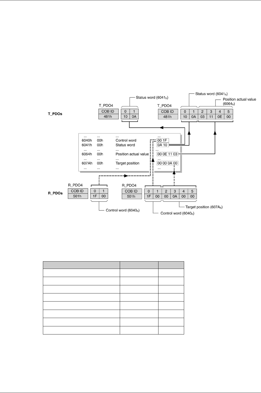
CANopen Basics
430 EIO0000002305 04/2017
Process Data Communication
PDO Mapping
Up to 10 parameters from different areas of the object dictionary can be transmitted with a PDO message.
Mapping of data to a PDO message is referred to as PDO mapping.
Objects that can be used in PDO mapping are identified in the PDO mapping object column in the object
dictionary table.
The groups of objects that are involved in PDO mapping are:
-Vendor-specific Object Group 4000h
(seepage453)
-Device Profile Object Group 6000h
(see page 484)
The picture below shows the data exchange between PDOs and object dictionary based on two examples
of objects in TxPDO4 and RxPDO4 of the PDOs.
Dynamic PDO Mapping
The device uses dynamic PDO mapping. Dynamic PDO mapping means that objects can be mapped to
the corresponding PDO using adjustable settings.
The settings for PDO mapping are defined in an assigned communication object for each PDO.
Object PDO mapping for Type
1st receive PDO mapping (1600h)RxPDO1 Dynamic
2nd receive PDO mapping (1601h)RxPDO2 Dynamic
3rd receive PDO mapping (1602h)RxPDO3 Dynamic
4th receive PDO mapping (1603h)RxPDO4 Dynamic
1st transmit PDO mapping (1A00h) TxPDO1 Dynamic
2nd transmit PDO mapping (1A01h) TxPDO2 Dynamic
3rd transmit PDO mapping (1A02h) TxPDO3 Dynamic
4th transmit PDO mapping (1A03h) TxPDO4 Dynamic

CANopen Basics
EIO0000002305 04/2017 431
Structure of the Entries
Up to 10 parameters can be mapped in a PDO. Each communication object for setting the PDO mapping
provides four subindex entries. A subindex entry contains three pieces of information on the object: the
index, the subindex, and the number of bits that the object uses in the PDO.
Subindex 00h of the communication object contains the number of valid subindex entries.
Object length Bit value
08h8bits
10h16 bits
20h32 bits

CANopen Basics
432 EIO0000002305 04/2017
Setting the Process Data
Overview
4 predefined RxPDOs and 4 predefined TxPDOs are available.
Depending on the selected operating mode, one of the predefined RxPDOs and one of the predefined
TxPDOs can be used:
Only a single predefined RxPDO and only a single predefined TxPDO can be used simultaneously. The
PDOs can be adapted as required.
A maximum of 10 parameters are possible per RxPDO and TxPDO.
First Predefined PDO
The first predefined PDO is suitable for the operating mode Position.
Structure RxPDO1 (1600h)
Structure TxPDO1 (1A00h)
Second Predefined PDO
The second predefined PDO is suitable for the operating mode Velocity.
Structure RxPDO2 (1601h)
Structure TxPDO2 (1A01h)
Operating mode Suitable PDO
Position First predefined PDO
(see page 432)
Velocity Second predefined PDO
(see page 432)
Torque Third predefined PDO
(see page 433)
Any type of switch between:
-Position
-Velocity
-Torque
Fourth predefined PDO
(see page 433)
Index Object name
6040hControl word
607 AhTarget position
60FE:1hDigital outputs
Index Object name
6041hStatus word
6064hPosition actual value
603FhError code
60FDhDigital inputs
Index Object name
6040hControl word
60FFhTarget velocity
60FE:1hDigital outputs
Index Object name
6041hStatus word
6064hPosition actual value
603FhError code
60FDhDigital inputs

CANopen Basics
EIO0000002305 04/2017 433
Third Predefined PDO
The third predefined PDO is suitable for the operating mode Torque.
Structure RxPDO3 (1602h)
Structure TxPDO3 (1A02h)
Fourth Predefined PDO
The fourth predefined PDO is suitable for the operating modes Position, Velocity, and Torque. It is possible
to switch between the operating modes as required.
Structure RxPDO4 (1603h)
Structure TxPDO4 (1A03h)
Index Object name
6040hControl word
6071hTarget torque
60FE:1hDigital outputs
Index Object name
6041hStatus word
6064hPosition actual value
6077hTorque actual value
603FhError code
60FDhDigital inputs
Index Object name
6040hControl word
6060hMode of operation
607 AhTarget position
60FFhTarget velocity
6071hTarget torque
60FE:1hDigital outputs
Index Object name
6041hStatus word
6061hMode of operation display
6064hPosition actual value
60F4hFollowing error actual value
6077hTorque actual value
603FhError code
60FDhDigital inputs

CANopen Basics
434 EIO0000002305 04/2017

EIO0000002305 04/2017 435
Lexium 28
A
and BCH2 Servo Drive System
CANopen Object Dictionary
EIO0000002305 04/2017
CANopen Object Dictionary
Chapter 22
CANopen Object Dictionary
What Is in This Chapter?
This chapter contains the following sections:
Section Topic Page
22.1 Overview 436
22.2 1000h…1FFFh Standard Communication Object Group 440
22.3 4000h … 4FFFh Vendor-specific Object Group 453
22.4 6000h … 6FFFh Device-Specific Object Group 484


CANopen Object Dictionary
EIO0000002305 04/2017 437
Specifications for the Objects
Overview
The object dictionary table contains the following information:
The symbol (-) means that the value is not significant.
Index
The index specifies the position of the object in the object dictionary. The index value is specified as a
hexadecimal value. The subindex is also available in this cell if it is relevant
Name
Name of the object.
Object Type
The object type specifies the data structure of the object:
Data Type
The data type specifies the type of the object:
Access
Indicates the access type for the object:
Index Name Object type
Data type
Access
PDO mapping
object
Minimum value
Factory setting
Maximum value
Object type Description DS306
Coding
VAR A simple value, for example of the type Integer8, Unsigned32 or Visible
String8.
7h
ARRAY A data field in which the entries have the same data type. 8h
RECORD A data field that contains entries that are a combination of simple data
types.
9h
Data type Description Value range Data length DS301 coding
BOOL Boolean 0 = false, 1 = true 1 byte 0001h
INT8 Integer 8 bits -128 ... +127 1 byte 0002h
INT16 Integer 16 bits -32768 ... +32767 2 bytes 0003h
INT32 Integer 32 bits -2147483648 ... 2147483647 4 bytes 0004h
UINT8 Unsigned Integer
8bits
0 ... 255 1 byte 0005h
UINT16 Unsigned Integer
16 bits
0 ... 65535 2 bytes 0006h
UINT32 Unsigned Integer
32 bits
0 ... 4294967295 4 bytes 0007h
VISIBLE_STRING Visible String
8bytes
ASCII characters 8 bytes 0009h
Access type Description
ro Read only
rw Read and write
rww Read and write on process output
const Constant value

CANopen Object Dictionary
438 EIO0000002305 04/2017
PDO Mapping Object
Indicates if the object can be mapped in a PDO:
Minimum Value
The minimum value which can be set.
Factory Setting
The value of the object when the product is shipped from the factory.
Maximum Value
The maximum value which can be set.
PDO mapping object Description
No The object cannot be mapped in a PDO
Yes The object can be mapped in a PDO

CANopen Object Dictionary
EIO0000002305 04/2017 439
Object Dictionary Overview
Description
Each CANopen device manages an object dictionary which contains the objects for communication.
Index and Subindex
The objects are addressed in the object dictionary via a 16 bits index.
One or more 8 bits subindex entries for each object specify individual data fields in the object. Index and
subindex are shown in hexadecimal notation.
Description Object Dictionary
The description object dictionary is made of several object groups:
Object Groups Implemented
Three groups of objects are available in the object dictionary.
-1000h - 1FFFh: Standard communication Object Group
(see page 440)
-4000h - 4FFFh: Vendor-specific Object Group
(see page 453)
-6000h - 6FFFh: Device profile Object Group
(see page 484)
Index (hex) Object
0000 Unused
0001…001F Static data types
0020…003F Complex data types
0040…005F Unused (Manufacturer-specific complex data types)
0060…007F Device profile-specific static data types
0080…009F Device profile-specific complex data types
00A0…0FFF Reserved
1000…1FFF Communication profile area
2000…5FFF Vendor-specific profile area
6000…9FFF Standardized device profile area
A000…FFFF Reserved

CANopen Object Dictionary
440 EIO0000002305 04/2017
1000h…1FFFh Standard Communication Object Group
Section 22.2
1000h…1FFFh Standard Communication Object Group
What Is in This Section?
This section contains the following topics:
Topic Page
10xxh Object Group 441
12xxh Object Group 444
14xxh Object Group 445
16xxh Object Group 447
18xxh Object Group 449
1Axxh Object Group 451

CANopen Object Dictionary
EIO0000002305 04/2017 441
10xxh Object Group
10xxh Standard Communication Object Group
Index Name Object type
Data type
Access
PDO mapping
object
Minimum value
Factory setting
Maximum value
1000hDevice Type VAR
UINT32
ro
No -
4325778
-
1001hError Register VAR
UINT8
ro
No -
-
-
1002hManufacturer Status Register VAR
UINT32
ro
No -
-
-
1003hPre-defined Error Field
History of the errors detected by the drive
and notified via the Emergency Object.
ARRAY
-
-
No -
-
-
1003:0hNumber of Errors
The history of error codes can be cleared by
writing value 0 to this sub index.
VAR
UINT8
rw
No -
0
-
1003:1hStandard Error Field
Error code of most recent detected error n
VAR
UINT32
ro
No -
-
-
1003:2hStandard Error Field
Error code of most recent detected error n-1
VAR
UINT32
ro
No -
-
-
1003:3hStandard Error Field
Error code of most recent detected error n-2
VAR
UINT32
ro
No -
-
-
1003:4hStandard Error Field
Error code of most recent detected error n-3
VAR
UINT32
ro
No -
-
-
1003:5hStandard Error Field
Error code of most recent detected error n-4
VAR
UINT32
ro
No -
-
-
1003:6hStandard Error Field
Error code of most recent detected error n-5
VAR
UINT32
ro
No -
-
-
1003:7hStandard Error Field
Error code of most recent detected error n-6
VAR
UINT32
ro
No -
-
-
1003:8hStandard Error Field
Error code of most recent detected error n-7
VAR
UINT32
ro
No -
-
-
1003:9hStandard Error Field
Error code of most recent detected error n-8
VAR
UINT32
ro
No -
-
-
1003:AhStandard Error Field
Error code of most recent detected error n-9
VAR
UINT32
ro
No -
-
-
1005hCOB-ID SYNC VAR
UINT32
rw
No -
128
-
1006hCommunication Cycle Period VAR
UINT32
rw
No -
0
-
1007hSynchronous Window Length VAR
UINT32
rw
No -
0
-

CANopen Object Dictionary
442 EIO0000002305 04/2017
1008hManufacturer Device Name VAR
VISIBLE_STRING
const
No -
-
-
1009hManufacturer Hardware Version VAR
VISIBLE_STRING
const
No -
-
-
100 AhManufacturer Software Version VAR
VISIBLE_STRING
const
No -
-
-
100ChGuard Time VAR
UINT16
rw
No -
0
-
100DhLife Time Factor VAR
UINT8
rw
No -
0
-
1010hStore Parameter Field ARRAY
-
-
No -
-
-
1010:0hNumber of Entries VAR
UINT8
ro
No -
3
-
1010:1hSave all Parameters VAR
UINT32
rw
No -
-
-
1014hCOB-ID EMCY VAR
UINT32
rw
No -
$NODEID+0x80
-
1015hInhibit Time Emergency VAR
UINT16
rw
No -
0
-
1016hHeartbeat Consumer Entries ARRAY
-
-
No -
-
-
1016:0hNumber of Entries VAR
UINT8
ro
No -
3
-
1016:1hConsumer Heartbeat Time 1 VAR
UINT32
rw
No 0
0
8388607
1016:2hConsumer Heartbeat Time 2 VAR
UINT32
rw
No 0
0
8388607
1016:3hConsumer Heartbeat Time 3 VAR
UINT32
rw
No 0
0
8388607
1017hProducer Heartbeat Time VAR
UINT16
rw
No -
0
-
1018hIdentity Object RECORD
-
-
No -
-
-
1018:0hnumber of entries VAR
UINT8
ro
No 1
4
4
1018:1hVendor ID VAR
UINT32
ro
No -
134217818
-
1018:2hProduct Code VAR
UINT32
ro
No -
614416
-
Index Name Object type
Data type
Access
PDO mapping
object
Minimum value
Factory setting
Maximum value

CANopen Object Dictionary
EIO0000002305 04/2017 443
1018:3hRevision number VAR
UINT32
ro
No -
-
-
1018:4hSerial number VAR
UINT32
ro
No -
-
-
1019hSynchronous counter overflow value VAR
UINT8
rw
No -
0
-
1029hError Behavior ARRAY
-
-
No -
-
-
1029:0hNumber of Entries VAR
UINT8
ro
No 1
1
254
1029:1hCommunication Error VAR
UINT8
rw
No 0
0
-
Index Name Object type
Data type
Access
PDO mapping
object
Minimum value
Factory setting
Maximum value

CANopen Object Dictionary
444 EIO0000002305 04/2017
12xxh Object Group
12xxh Standard Communication Object Group
Index Name Object type
Data type
Access
PDO mapping
object
Minimum value
Factory setting
Maximum value
1200hServer SDO Parameter 1 RECORD
-
-
No -
-
-
1200:0hNumber of Entries VAR
UINT8
ro
No 2
2
2
1200:1hCOB-ID Client -> Server VAR
UINT32
ro
No $NODEID+0x600
$NODEID+0x600
$NODEID+0xBFF
FFFFF
1200:2hCOB-ID Server -> Client VAR
UINT32
ro
No $NODEID+0x580
$NODEID+0x580
$NODEID+0xBFF
FFFFF
1201hServer SDO Parameter 2 RECORD
-
-
No -
-
-
1201:0hNumber of Entries VAR
UINT8
ro
No 2
3
3
1201:1hCOB-ID Client -> Server VAR
UINT32
rw
No -
-
4294967295
1201:2hCOB-ID Server -> Client VAR
UINT32
rw
No -
-
4294967295
1201:3hNode ID of the SDO Client VAR
UINT8
rw
No -
-
127

CANopen Object Dictionary
EIO0000002305 04/2017 445
14xxh Object Group
Objects 14xxh Standard Communication Object Group
Index Name Object type
Data type
Access
PDO mapping
object
Minimum value
Factory setting
Maximum value
1400hReceive PDO Communication
Parameter 1
RECORD
-
-
No -
-
-
1400:0hNumber of Entries VAR
UINT8
ro
No 2
3
5
1400:1hCOB-ID VAR
UINT32
rw
No -
$NODEID+0x200
$NODEID+0xFFFFFFFF
1400:2hTransmission Type VAR
UINT8
rw
No 0
255
255
1400:3hInhibit Time VAR
UINT16
rw
No 0
0
65535
1401hReceive PDO Communication
Parameter 2
RECORD
-
-
No -
-
-
1401:0hNumber of Entries VAR
UINT8
ro
No 2
3
5
1401:1hCOB-ID VAR
UINT32
rw
No -
$NODEID+0x80000300
$NODEID+0xFFFFFFFF
1401:2hTransmission Type VAR
UINT8
rw
No 0
255
255
1401:3hInhibit Time VAR
UINT16
rw
No 0
0
65535
1402hReceive PDO Communication
Parameter 3
RECORD
-
-
No -
-
-
1402:0hNumber of Entries VAR
UINT8
ro
No 2
3
5
1402:1hCOB-ID VAR
UINT32
rw
No -
$NODEID+0x80000400
$NODEID+0xFFFFFFFF
1402:2hTransmission Type VAR
UINT8
rw
No 0
255
255
1402:3hInhibit Time VAR
UINT16
rw
No 0
0
65535
1403hReceive PDO Communication
Parameter 4
RECORD
-
-
No -
-
-
1403:0hNumber of Entries VAR
UINT8
ro
No 2
3
5
1403:1hCOB-ID VAR
UINT32
rw
No -
$NODEID+0x80000500
$NODEID+0xFFFFFFFF

CANopen Object Dictionary
446 EIO0000002305 04/2017
1403:2hTransmission Type VAR
UINT8
rw
No 0
255
255
1403:3hInhibit Time VAR
UINT16
rw
No 0
0
65535
Index Name Object type
Data type
Access
PDO mapping
object
Minimum value
Factory setting
Maximum value

CANopen Object Dictionary
EIO0000002305 04/2017 447
16xxh Object Group
16xxh Standard Communication Object Group
Index Name Object type
Data type
Access
PDO mapping
object
Minimum value
Factory setting
Maximum value
1600hReceive PDO Mapping Parameter 1 RECORD
-
-
No -
-
-
1600:0hNumber of Entries VAR
UINT8
rw
No 0
1
64
1600:1hMapping Entry 1 VAR
UINT32
rw
No 0
1614807056
4294967295
1600:2hMapping Entry 2 VAR
UINT32
rw
No 0
0
4294967295
1600:3hMapping Entry 3 VAR
UINT32
rw
No 0
0
4294967295
1600:4hMapping Entry 4 VAR
UINT32
rw
No 0
0
4294967295
1601hReceive PDO Mapping Parameter 2 RECORD
-
-
No -
-
-
1601:0hNumber of Entries VAR
UINT8
rw
No 0
2
64
1601:1hMapping Entry 1 VAR
UINT32
rw
No 0
1614807056
4294967295
1601:2hMapping Entry 2 VAR
UINT32
rw
No 0
1618608160
4294967295
1601:3hMapping Entry 3 VAR
UINT32
rw
No 0
0
4294967295
1601:4hMapping Entry 4 VAR
UINT32
rw
No 0
0
4294967295
1602hReceive PDO Mapping Parameter 3 RECORD
-
-
No -
-
-
1602:0hNumber of Entries VAR
UINT8
rw
No 0
2
64
1602:1hMapping Entry 1 VAR
UINT32
rw
No 0
1614807056
4294967295
1602:2hMapping Entry 2 VAR
UINT32
rw
No 0
1627324448
4294967295
1602:3hMapping Entry 3 VAR
UINT32
rw
No 0
0
4294967295
1602:4hMapping Entry 4 VAR
UINT32
rw
No 0
0
4294967295

CANopen Object Dictionary
448 EIO0000002305 04/2017
1603hReceive PDO Mapping Parameter 4 RECORD
-
-
No -
-
-
1603:0hNumber of Entries VAR
UINT8
rw
No 0
0
64
1603:1hMapping Entry 1 VAR
UINT32
rw
No 0
0
4294967295
1603:2hMapping Entry 2 VAR
UINT32
rw
No 0
0
4294967295
1603:3hMapping Entry 3 VAR
UINT32
rw
No 0
0
4294967295
1603:4hMapping Entry 4 VAR
UINT32
rw
No 0
0
4294967295
Index Name Object type
Data type
Access
PDO mapping
object
Minimum value
Factory setting
Maximum value

CANopen Object Dictionary
EIO0000002305 04/2017 449
18xxh Object Group
18xxh Standard Communication Object Group
Index Name Object type
Data type
Access
PDO mapping
object
Minimum value
Factory setting
Maximum value
1800hTransmit PDO Communication Parameter 1 RECORD
-
-
No -
-
-
1800:0hNumber of Entries VAR
UINT8
ro
No 2
5
6
1800:1hCOB-ID VAR
UINT32
rw
No -
$NODEID+0x4000
0180
$NODEID+0xFFF
FFFFF
1800:2hTransmission Type VAR
UINT8
rw
No 0
255
255
1800:3hInhibit Time VAR
UINT16
rw
No 0
0
65535
1800:4hCompatibility Entry VAR
UINT8
rw
No 0
0
255
1800:5hEvent Timer VAR
UINT16
rw
No 0
0
65535
1801hTransmit PDO Communication Parameter 2 RECORD
-
-
No -
-
-
1801:0hNumber of Entries VAR
UINT8
ro
No 2
5
6
1801:1hCOB-ID VAR
UINT32
rw
No -
$NODEID+0xC00
00280
$NODEID+0xFFF
FFFFF
1801:2hTransmission Type VAR
UINT8
rw
No 0
255
255
1801:3hInhibit Time VAR
UINT16
rw
No 0
0
65535
1801:4hCompatibility Entry VAR
UINT8
rw
No 0
0
255
1801:5hEvent Timer VAR
UINT16
rw
No 0
100
65535
1802hTransmit PDO Communication Parameter 3 RECORD
-
-
No -
-
-
1802:0hNumber of Entries VAR
UINT8
ro
No 2
5
6

CANopen Object Dictionary
450 EIO0000002305 04/2017
1802:1hCOB-ID VAR
UINT32
rw
No -
$NODEID+0xC00
00380
$NODEID+0xFFF
FFFFF
1802:2hTransmission Type VAR
UINT8
rw
No 0
255
255
1802:3hInhibit Time VAR
UINT16
rw
No 0
0
65535
1802:4hCompatibility Entry VAR
UINT8
rw
No 0
0
255
1802:5hEvent Timer VAR
UINT16
rw
No 0
100
65535
1803hTransmit PDO Communication Parameter 4 RECORD
-
-
No -
-
-
1803:0hNumber of Entries VAR
UINT8
ro
No 2
5
6
1803:1hCOB-ID VAR
UINT32
rw
No -
$NODEID+0xC00
00480
$NODEID+0xFFF
FFFFF
1803:2hTransmission Type VAR
UINT8
rw
No 0
254
255
1803:3hInhibit Time VAR
UINT16
rw
No 0
0
65535
1803:4hCompatibility Entry VAR
UINT8
rw
No 0
0
255
1803:5hEvent Timer VAR
UINT16
rw
No 0
0
65535
Index Name Object type
Data type
Access
PDO mapping
object
Minimum value
Factory setting
Maximum value

CANopen Object Dictionary
EIO0000002305 04/2017 451
1Axxh Object Group
1Axxh Standard Communication Object Group
Index Name Object type
Data type
Access
PDO mapping
object
Minimum value
Factory setting
Maximum value
1A00hTransmit PDO Mapping Parameter 1 RECORD
-
-
No -
-
-
1A00:0hNumber of Entries VAR
UINT8
rw
No 0
1
255
1A00:1hMapping Entry 1 VAR
UINT32
rw
No 0
1614872592
4294967295
1A00:2hMapping Entry 2 VAR
UINT32
rw
No 0
0
4294967295
1A00:3hMapping Entry 3 VAR
UINT32
rw
No 0
0
4294967295
1A00:4hMapping Entry 4 VAR
UINT32
rw
No 0
0
4294967295
1A01hTransmit PDO Mapping Parameter 2 RECORD
-
-
No -
-
-
1A01:0hNumber of Entries VAR
UINT8
rw
No 0
2
255
1A01:1hMapping Entry 1 VAR
UINT32
rw
No 0
1614872592
4294967295
1A01:2hMapping Entry 2 VAR
UINT32
rw
No 0
1617166368
4294967295
1A01:3hMapping Entry 3 VAR
UINT32
rw
No 0
0
4294967295
1A01:4hMapping Entry 4 VAR
UINT32
rw
No 0
0
4294967295
1A02hTransmit PDO Mapping Parameter 3 RECORD
-
-
No -
-
-
1A02:0hNumber of Entries VAR
UINT8
rw
No 0
2
255
1A02:1hMapping Entry 1 VAR
UINT32
rw
No 0
1614872592
4294967295
1A02:2hMapping Entry 2 VAR
UINT32
rw
No 0
1617690656
4294967295
1A02:3hMapping Entry 3 VAR
UINT32
rw
No 0
0
4294967295
1A02:4hMapping Entry 4 VAR
UINT32
rw
No 0
0
4294967295

CANopen Object Dictionary
452 EIO0000002305 04/2017
1A03hTransmit PDO Mapping Parameter 4 RECORD
-
-
No -
-
-
1A03:0hNumber of Entries VAR
UINT8
rw
No 0
0
255
1A03:1hMapping Entry 1 VAR
UINT32
rw
No 0
0
4294967295
1A03:2hMapping Entry 2 VAR
UINT32
rw
No 0
0
4294967295
1A03:3hMapping Entry 3 VAR
UINT32
rw
No 0
0
4294967295
1A03:4hMapping Entry 4 VAR
UINT32
rw
No 0
0
4294967295
Index Name Object type
Data type
Access
PDO mapping
object
Minimum value
Factory setting
Maximum value

CANopen Object Dictionary
EIO0000002305 04/2017 453
4000h … 4FFFh Vendor-specific Object Group
Section 22.3
4000h … 4FFFh Vendor-specific Object Group
What Is in This Section?
This section contains the following topics:
Topic Page
40xxh Object Group 454
41xxh Object Group 456
42xxh Object Group 460
43xxh Object Group 462
44xxh Object Group 464
45xxh Object Group 466
46xxh Object Group 468
47xxh Object Group 472
48xxh Object Group 476
49xxh Object Group 479
4Bxxh Object Group 481
4Fxxh Object Group 483

CANopen Object Dictionary
454 EIO0000002305 04/2017
40xxh Object Group
40xxh Vendor-specific Object Group
This objects list is also available in P0 - Status parameters
(seepage233)
Index Name Parameter Object type
Data type
Access
PDO mapping
object
Minimum value
Factory setting
Maximum value
4000hFirmware Version P0-00 VAR
UINT16
ro
No 0
-
65535
4001hError code of detected
error
P0-01 VAR
UINT16
rw
No 0
-
65535
4002hDrive Status Displayed by
HMI
P0-02 VAR
UINT16
rw
No 0
0
123
4003hFunction of Analog
Outputs
P0-03 VAR
UINT16
rw
No 0
0
119
4008hOperating Hour Meter in
Seconds
P0-08 VAR
UINT32
ro
No 0
-
4294967295
4009hStatus Value 1 P0-09 VAR
INT32
ro
No -2147483647
-
2147483647
400 AhStatus Value 2 P0-10 VAR
INT32
ro
No -2147483647
-
2147483647
400BhStatus Value 3 P0-11 VAR
INT32
ro
No -2147483647
-
2147483647
400ChStatus Value 4 P0-12 VAR
INT32
ro
No -2147483647
-
2147483647
400DhStatus Value 5 P0-13 VAR
INT32
ro
No -2147483647
-
2147483647
4011hIndicate status value 1 P0-17 VAR
UINT16
rw
No 0
0
123
4012hIndicate status value 2 P0-18 VAR
UINT16
rw
No 0
0
123
4013hIndicate status value 3 P0-19 VAR
UINT16
rw
No 0
0
123
4014hIndicate status value 4 P0-20 VAR
UINT16
rw
No 0
0
123
4015hIndicate status value 5 P0-21 VAR
UINT16
rw
No 0
0
123
4019hParameter Mapping 1 P0-25 VAR
UINT32
rw
No 0
-
4294967295
401 AhParameter Mapping 2 P0-26 VAR
UINT32
rw
No 0
-
4294967295
401BhParameter Mapping 3 P0-27 VAR
UINT32
rw
No 0
-
4294967295

CANopen Object Dictionary
EIO0000002305 04/2017 455
401ChParameter Mapping 4 P0-28 VAR
UINT32
rw
No 0
-
4294967295
401DhParameter Mapping 5 P0-29 VAR
UINT32
rw
No 0
-
4294967295
401EhParameter Mapping 6 P0-30 VAR
UINT32
rw
No 0
-
4294967295
401FhParameter Mapping 7 P0-31 VAR
UINT32
rw
No 0
-
4294967295
4020hParameter Mapping 8 P0-32 VAR
UINT32
rw
No 0
-
4294967295
4023hBlock Data Read/Write
P0-35…P0-42 1
P0-35 VAR
UINT32
rw
No 0
0
4294967295
4024hBlock Data Read/Write
P0-35…P0-42 2
P0-36 VAR
UINT32
rw
No 0
0
4294967295
4025hBlock Data Read/Write
P0-35…P0-42 3
P0-37 VAR
UINT32
rw
No 0
0
4294967295
4026hBlock Data Read/Write
P0-35…P0-42 4
P0-38 VAR
UINT32
rw
No 0
0
4294967295
4027hBlock Data Read/Write
P0-35…P0-42 5
P0-39 VAR
UINT32
rw
No 0
0
4294967295
4028hBlock Data Read/Write
P0-35…P0-42 6
P0-40 VAR
UINT32
rw
No 0
0
4294967295
4029hBlock Data Read/Write
P0-35…P0-42 7
P0-41 VAR
UINT32
rw
No 0
0
4294967295
402 AhBlock Data Read/Write
P0-35…P0-42 8
P0-42 VAR
UINT32
rw
No 0
0
4294967295
402EhState of Signal Output
Functions
P0-46 VAR
UINT16
ro
No 0
-
65535
402FhNumber of Last Alert P0-47 VAR
UINT16
ro
No 0
-
65535
Index Name Parameter Object type
Data type
Access
PDO mapping
object
Minimum value
Factory setting
Maximum value

CANopen Object Dictionary
456 EIO0000002305 04/2017
41xxh Object Group
41xxh Vendor-specific Object Group
This objects list is also available in P1 - Basic parameters
(see page 238)
Index Name Parameter Object type
Data type
Access
PDO mapping
object
Minimum value
Factory setting
Maximum value
4100hReference Value Signal - Pulse
Settings
P1-00 VAR
UINT16
rw
No 0
2
4402
4101hOperating Mode and Direction
of Rotation
P1-01 VAR
UINT16
rw
No 0
11
4363
4102hVelocity and Torque Limitations
Activation/Deactivation
P1-02 VAR
UINT16
rw
No 0
0
17
4103hPolarity of Analog Outputs /
Polarity of Pulse Outputs
P1-03 VAR
UINT16
rw
No 0
0
19
4104hScaling Factor Analog Output 1 P1-04 VAR
UINT16
rw
No 1
100
100
4105hScaling Factor Analog Output 2 P1-05 VAR
UINT16
rw
No 1
100
100
4106hCAN Opmode P1-06 VAR
INT16
ro
No -32768
0
32767
4109hTarget Velocity/Velocity
Limitation 1
P1-09 VAR
INT32
rw
No -60000
10000
60000
410 AhTarget Velocity/Velocity
Limitation 2
P1-10 VAR
INT32
rw
No -60000
20000
60000
410BhTarget Velocity/Velocity
Limitation 3
P1-11 VAR
INT32
rw
No -60000
30000
60000
410ChTarget Torque/Torque
Limitation 1
P1-12 VAR
INT16
rw
No -300
100
300
410DhTarget Torque/Torque
Limitation 2
P1-13 VAR
INT16
rw
No -300
100
300
410EhTarget Torque/Torque
Limitation 3
P1-14 VAR
INT16
rw
No -300
100
300
410FhMains Phase Monitoring -
Response to Missing Mains
Phase
P1-15 VAR
UINT16
rw
No 0
0
2
4110hMains Phase Monitoring - Fault
Reset
P1-16 VAR
UINT16
rw
No 0
0
1
4111hMains Phase Monitoring - Type P1-17 VAR
UINT16
rw
No 0
0
2
4112hReserved P1-18 VAR
UINT16
rw
No 0
3
5
4113hActive Disable - Delay Time
Power Stage
P1-19 VAR
UINT16
rw
No 0
0
6500

CANopen Object Dictionary
EIO0000002305 04/2017 457
4114hCurrent Limit During Quick Stop P1-20 VAR
INT16
rw
No 1
1000
1000
4115hStatus of Foldback Current
Drive
P1-21 VAR
UINT16
ro
No 0
-
1
4116hFoldback Current Limit - Drive P1-22 VAR
UINT32
ro
No 0
-
30000
4117hCurrent Monitoring Drive -
Detected Error Threshold
Foldback Current
P1-23 VAR
UINT32
rw
No 0
-
30000
4118hCurrent Monitoring Drive - Alert
Threshold Foldback Current
P1-24 VAR
UINT32
rw
No 0
-
30000
4119hReserved P1-25 VAR
UINT32
rw
No -
-
-
411 AhFoldback Current Limit - Motor P1-26 VAR
UINT32
ro
No 0
-
30000
411BhMotor Current Monitoring -
Detected Error Threshold
Foldback Current
P1-27 VAR
UINT32
rw
No 0
-
30000
411ChMotor Current Monitoring - Alert
Threshold Foldback Current
P1-28 VAR
UINT32
rw
No 0
-
30000
411DhDC Bus Overvoltage Monitoring
- Threshold
P1-29 VAR
UINT16
ro
No -
-
-
411EhCommutation Monitoring -
Maximum Counter Value
P1-30 VAR
UINT16
rw
No 0
0
0
4120hStop Method P1-32 VAR
UINT16
rw
No 0
0
32
4122hAcceleration Period P1-34 VAR
UINT16
rw
No 6
30
65500
4123hDeceleration Period P1-35 VAR
UINT16
rw
No 6
30
65500
4125hRatio of Load Inertia to Motor
Inertia
P1-37 VAR
UINT32
rw
No 0
10
20000
4126hSignal Output Function ZSPD /
Signal Input Function ZCLAMP -
Velocity
P1-38 VAR
INT32
rw
No 0
100
2000
4127hSignal Output Function TSPD -
Velocity
P1-39 VAR
UINT32
rw
No 0
3000
5000
4128hVelocity Target Value and
Velocity Limitation 10 V
P1-40 VAR
INT32
rw
No 0
-
10001
4129hTorque Target Value and
Torque Limitation 10 V
P1-41 VAR
UINT16
rw
No 0
100
1000
412 AhON Delay Time of Holding
Brake
P1-42 VAR
UINT16
rw
No 0
0
1000
Index Name Parameter Object type
Data type
Access
PDO mapping
object
Minimum value
Factory setting
Maximum value

CANopen Object Dictionary
458 EIO0000002305 04/2017
412ChElectronic Gear Ratio -
Numerator 1
P1-44 VAR
UINT32
rw
No 1
128
536870911
412DhElectronic Gear Ratio -
Denominator
P1-45 VAR
UINT32
rw
No 1
10
2147483647
412EhEncoder Simulation Resolution P1-46 VAR
INT32
rw
No -
2048
-
412FhSignal Output Function SP_OK -
Velocity
P1-47 VAR
UINT32
rw
No 0
10
300
4130hSignal Output Function MC_OK
- Settings
P1-48 VAR
UINT16
rw
No 0
0
33
4134hBraking Resistor - Resistance P1-52 VAR
INT16
rw
No -1
-
32767
4135hBraking Resistor - Power P1-53 VAR
INT16
rw
No -1
-
32767
4136hSignal Output Function TPOS -
Trigger Value
P1-54 VAR
UINT32
rw
No 0
12800
1280000
4137hMaximum Velocity - User-
Defined
P1-55 VAR
UINT32
rw
No 10
-
6000
4139hTorque Monitoring - Torque
Value
P1-57 VAR
UINT16
rw
No 0
0
300
413 AhTorque Monitoring - Time Value P1-58 VAR
UINT16
rw
No 1
1
1000
413BhS Curve Filter for Operating
Mode Velocity
P1-59 VAR
UINT32
rw
No 0
0
255875
413ChCommutation Monitoring - Time
Threshold
P1-60 VAR
UINT16
rw
No 0
0
3000
413DhCommutation Monitoring -
Velocity Threshold
P1-61 VAR
UINT32
rw
No 0
600
60000
413EhMotor Overtemperature
Monitoring - Response
P1-62 VAR
UINT16
rw
No 0
0
5
413FhMotor Overtemperature
Monitoring - Delay Time
P1-63 VAR
UINT16
rw
No 0
30
300
4140hUndervoltage Monitoring -
Response
P1-64 VAR
UINT16
rw
No 0
0
3
4141hReserved P1-65 VAR
UINT16
rw
No 0
0
1
4142hStatus of Foldback Current
Motor
P1-66 VAR
UINT16
ro
No 0
-
1
4143hUndervoltage Monitoring -
Delay Time
P1-67 VAR
UINT16
rw
No 0
30
300
Index Name Parameter Object type
Data type
Access
PDO mapping
object
Minimum value
Factory setting
Maximum value

CANopen Object Dictionary
EIO0000002305 04/2017 459
4144hActive Disable - Deceleration
Ramp
P1-68 VAR
UINT16
rw
No 6
30
65500
4145hDisable - Deceleration Time P1-69 VAR
UINT16
rw
No 0
0
6500
4146hSignal Input Function HALT -
Maximum Current
P1-70 VAR
UINT32
rw
No -
0
-
4147hBraking Resistor - Maximum
Time in Braking
P1-71 VAR
UINT16
rw
No 10
40
100
4148hBraking Resistor Overload
Monitoring - Response
P1-72 VAR
UINT16
rw
No 0
0
1
414EhUser-Defined Maximum Current P1-78 VAR
UINT32
rw
No -
-
-
414FhMaximum Current P1-79 VAR
UINT32
ro
No -
-
-
4150hMaximum Peak Current P1-80 VAR
UINT32
ro
No -
-
-
4151hNominal Current P1-81 VAR
UINT32
ro
No -
-
-
4152hVelocity limitation for CANopen
operating mode Profile Torque
P1-82 VAR
UINT16
rw
No 0
0
3
4154hConfigured motor type P1-84 VAR
UINT32
rw
No 0
-
2147483647
4155hTorque Limit For CANopen
Modes
P1-85 VAR
UINT16
rw
No 0
0
3
Index Name Parameter Object type
Data type
Access
PDO mapping
object
Minimum value
Factory setting
Maximum value

CANopen Object Dictionary
460 EIO0000002305 04/2017
42xxh Object Group
42xxh Vendor-specific Object Group
This objects list is also available in P2 - Extended parameters
(see page 250)
Index Name Parameter Object type
Data type
Access
PDO mapping
object
Minimum value
Factory setting
Maximum value
4201hGain Switching - Rate for
Position Loop
P2-01 VAR
UINT16
rw
No 10
100
500
4205hGain Switching - Rate for
Velocity Loop
P2-05 VAR
UINT16
rw
No 10
100
500
4208hFactory Reset / Save
Parameters / Activation of
Forcing of Outputs
P2-08 VAR
UINT16
rw
No 0
0
406
4209hDebounce Time - Inputs P2-09 VAR
UINT16
rw
No 0
2
20
420 AhSignal Input Function for DI1 P2-10 VAR
UINT16
rw
No 0
256
326
420BhSignal Input Function for DI2 P2-11 VAR
UINT16
rw
No 0
256
326
420ChSignal Input Function for DI3 P2-12 VAR
UINT16
rw
No 0
256
326
420DhSignal Input Function for DI4 P2-13 VAR
UINT16
rw
No 0
256
326
420EhSignal Input Function for DI5 P2-14 VAR
UINT16
rw
No 0
36
326
420FhSignal Input Function for DI6 P2-15 VAR
UINT16
rw
No 0
34
326
4210hSignal Input Function for DI7 P2-16 VAR
UINT16
rw
No 0
35
326
4211hSignal Input Function for DI8 P2-17 VAR
UINT16
rw
No 0
33
326
4212hSignal Output Function for
DO1
P2-18 VAR
UINT16
rw
No 0
257
319
4213hSignal Output Function for
DO2
P2-19 VAR
UINT16
rw
No 0
256
319
4214hSignal Output Function for
DO3
P2-20 VAR
UINT16
rw
No 0
256
319
4215hSignal Output Function for
DO4
P2-21 VAR
UINT16
rw
No 0
256
319
4216hSignal Output Function for
DO5
P2-22 VAR
UINT16
rw
No 0
7
319
4217hSignal Output Function for
DO6(OCZ)
P2-23 VAR
UINT16
rw
No 0
64
319

CANopen Object Dictionary
EIO0000002305 04/2017 461
4218hDebounce Time - Fast Inputs P2-24 VAR
UINT16
rw
No 0
50
100
421BhGain Switching - Conditions
and Type
P2-27 VAR
UINT16
rw
No 0
0
24
421DhGain Switching - Comparison
Value
P2-29 VAR
UINT32
rw
No 0
1280000
3840000
421EhAuxiliary Functions P2-30 VAR
INT16
rw
No -8
0
8
421FhAutotuning Optimization
Value Threshold
P2-31 VAR
UINT32
rw
No 100
1000
10000
4220hAutotuning P2-32 VAR
UINT16
rw
No 0
0
56
4222hVelocity Monitoring -
Threshold Value
P2-34 VAR
UINT32
rw
No 0
50000
60000
4223hPosition Deviation Monitoring
- Threshold Value
P2-35 VAR
UINT32
rw
No 1
100000
128000000
4224hPTI Interface Debounce Time
- Pulse
P2-36 VAR
UINT16
ro
No 0
30
511
4225hPTI Interface Debounce Time
- Direction
P2-37 VAR
UINT16
ro
No 0
30
511
4232hSignal Input Function
CLRPOS - Trigger
P2-50 VAR
UINT16
rw
No 0
0
1
423ChElectronic Gear Ratio -
Numerator 2
P2-60 VAR
UINT32
rw
No 1
128
536870911
423DhElectronic Gear Ratio -
Numerator 3
P2-61 VAR
UINT32
rw
No 1
128
536870911
423EhElectronic Gear Ratio -
Numerator 4
P2-62 VAR
UINT32
rw
No 1
128
536870911
4241hSpecial Function 1 P2-65 VAR
UINT16
rw
No 0
512
16320
4242hSpecial Function 2 P2-66 VAR
UINT16
rw
No 0
0
4
4244hAuto-Enable and Automatic
Hardware Limit Switch Fault
Reset
P2-68 VAR
UINT16
rw
No 0
0
273
Index Name Parameter Object type
Data type
Access
PDO mapping
object
Minimum value
Factory setting
Maximum value

CANopen Object Dictionary
462 EIO0000002305 04/2017
43xxh Object Group
43xxh Vendor-specific Object Group
Part of this objects list is also available in P3 - Communication parameters
(see page 257)
Index Name Parameter Object type
Data type
Access
PDO mapping
object
Minimum value
Factory setting
Maximum value
4300hDevice Address Modbus P3-00 VAR
UINT16
rw
No 1
127
247
4301hTransmission Rate for
Integrated Fieldbus and
Modbus
P3-01 VAR
UINT16
rw
No 0
258
1029
4302hModbus Connection Settings P3-02 VAR
UINT16
rw
No 6
7
9
4303hDetected Modbus
Communication Errors -
Handling
P3-03 VAR
UINT16
rw
No 0
0
1
4304hModbus Connection
Monitoring
P3-04 VAR
UINT16
rw
No 0
0
20000
4305hDevice Address Integrated
Fieldbus
P3-05 VAR
UINT16
rw
No 0
0
127
4306hDigital Inputs - Forcing
Settings
P3-06 VAR
UINT16
rw
No 0
0
2047
4307hModbus Response Delay
Time
P3-07 VAR
UINT16
rw
No 0
0
1000
4309hCANopen Master/Slave
Synchronization
P3-09 VAR
UINT16
rw
No 4097
20565
40959
430 AhDrive Profile Lexium -
Activation
P3-10 VAR
UINT16
rw
No 0
0
1
430BhDrive Profile Lexium - State of
Digital Inputs
P3-11 VAR
UINT16
ro
Yes 0
-
65535
430ChDrive Profile Lexium - Control
Word
P3-12 VAR
UINT16
rww
Yes 0
0
65535
430DhDrive Profile Lexium - RefA
16 Bit Parameter
P3-13 VAR
INT16
rww
Yes -32768
0
32767
430EhDrive Profile Lexium - RefB
32 Bit Parameter
P3-14 VAR
INT32
rww
Yes -2147483648
0
2147483647
430FhDrive Profile Lexium - Drive
Status
P3-15 VAR
UINT16
ro
Yes 0
-
65535
4310hDrive Profile Lexium -
Operating Mode Status
P3-16 VAR
UINT16
ro
Yes 0
-
65535
4311hDrive Profile Lexium - Motion
Status
P3-17 VAR
UINT16
ro
Yes 0
-
65535
4312hPDO Event Mask 1 P3-18 VAR
UINT16
rw
No 0
1
15

CANopen Object Dictionary
EIO0000002305 04/2017 463
4313hPDO Event Mask 2 P3-19 VAR
UINT16
rw
No 0
1
15
4314hPDO Event Mask 3 P3-20 VAR
UINT16
rw
No 0
1
15
4315hPDO Event Mask 4 P3-21 VAR
UINT16
rw
No 0
15
15
431EhInternal Limit for Bit 11
DriveCom Statusword 6041h
P3-30 VAR
UINT16
rw
No 0
0
11
4320hAutomatic operating state
transition from Switch On
Disabled to Ready To Switch
On
P3-32 VAR
UINT16
rw
No 0
0
1
4328hVelocity Gearing Window - VAR
UINT32
rw
No 0
2100000
4294967295
4329hVelocity Threshold - VAR
UINT32
rw
No 0
2100000
4294967295
Index Name Parameter Object type
Data type
Access
PDO mapping
object
Minimum value
Factory setting
Maximum value

CANopen Object Dictionary
464 EIO0000002305 04/2017
44xxh Object Group
44xxh Vendor-specific Object Group
Part of this objects list is also available in P4 - Diagnostics parameters
(see page 260)
Index Name Parameter Object type
Data type
Access
PDO mapping
object
Minimum value
Factory setting
Maximum value
4400hError History - Error Number
of the Most Recently
Detected Error n
P4-00 VAR
UINT16
rw
No 0
-
0
4401hError History - Error Number
of the Most Recently
Detected Error n - 1
P4-01 VAR
UINT16
ro
No 0
-
0
4402hError History -Error Number
of the Most Recently
Detected Error n - 2
P4-02 VAR
UINT16
ro
No 0
-
0
4403hError History - Error Number
of the Most Recently
Detected Error n - 3
P4-03 VAR
UINT16
ro
No 0
-
0
4404hError History - Error Number
of the Most Recently
Detected Error n - 4
P4-04 VAR
UINT16
ro
No 0
-
0
4405hJog Velocity P4-05 VAR
UINT32
rw
No 0
20
5000
4406hSetting a signal output via
parameter
P4-06 VAR
UINT16
rw
No 0
0
255
4407hState of Digital Inputs /
Activate Forcing
P4-07 VAR
UINT16
rw
No 0
-
255
4408hStatus of HMI Keypad P4-08 VAR
UINT16
ro
No 0
0
255
4409hState of Digital Outputs P4-09 VAR
UINT16
ro
No 0
-
63
440 AhClear Error History P4-10 VAR
UINT16
rw
No 0
0
0
4416hAnalog Input 1 Offset P4-22 VAR
INT16
rw
No -10000
0
10000
4417hAnalog Input 2 Offset P4-23 VAR
INT16
rw
No -10000
0
10000
4418hUndervoltage Monitoring -
Threshold Value
P4-24 VAR
UINT16
rw
No 140
160
190
4419hSafety Function STO - Status P4-25 VAR
UINT16
ro
No 0
-
1
441 AhDigital Outputs - Forcing
Information
P4-26 VAR
UINT16
ro
No 0
-
31
441BhDigital Outputs - Forcing
Settings
P4-27 VAR
UINT16
rw
No 0
0
31
441ChState of Digital Outputs /
Activate Forcing
P4-28 VAR
UINT16
rw
No 0
0
31

CANopen Object Dictionary
EIO0000002305 04/2017 465
4450hJog Speed Fast - VAR
UINT32
rw
No 0
426674
4294967295
4451hJog Time - VAR
UINT32
rw
No 0
0
4294967295
4452hJog Step - VAR
UINT32
rw
No 0
0
2147483647
4453hJog Method - VAR
UINT16
rw
No 0
0
1
4454hJog Speed Slow - VAR
UINT32
rw
No 0
426674
4294967295
Index Name Parameter Object type
Data type
Access
PDO mapping
object
Minimum value
Factory setting
Maximum value

CANopen Object Dictionary
466 EIO0000002305 04/2017
45xxh Object Group
45xxh Vendor-specific Object Group
This objects list is also available in P5 - Motion settings parameters
(see page 264)
Index Name Parameter Object type
Data type
Access
PDO mapping
object
Minimum value
Factory setting
Maximum value
4500hFirmware Revision P5-00 VAR
UINT16
ro
No 0
-
65535
4504hHoming - Homing Method
Selection
P5-04 VAR
UINT16
rw
No 0
0
296
4505hHoming - Fast Velocity for
Reference Movement
P5-05 VAR
UINT32
rw
No 10
1000
60000
4506hHoming - Slow Velocity for
Reference Movement
P5-06 VAR
UINT32
rw
No 10
200
60000
4507hOperating Mode PS via
Parameter
P5-07 VAR
UINT16
rw
No 0
0
1000
4508hPositive Software Limit
Switch - Position
P5-08 VAR
INT32
rw
No -2147483647
134217727
2147483647
4509hNegative Software Limit
Switch - Position
P5-09 VAR
INT32
rw
No -2147483647
-134217727
2147483647
450 AhOperating mode Pulse Train -
Maximum Acceleration
P5-10 VAR
UINT16
rw
No 6
6
65500
450BhSoftware Limit Switches -
Hysteresis Value
P5-11 VAR
UINT16
rw
No 0
3556
35555
450ChTouch Probe Input 1 - Stable
Level Duration
P5-12 VAR
UINT16
rw
No 2
5
32
450DhSoftware Limit Switches -
Activation
P5-13 VAR
UINT16
rw
No 0
0
1
450EhMotion Profile for Torque -
Slope
P5-14 VAR
UINT32
rw
No 1
100000
30000000
450FhMotion Profile for Torque -
Activation
P5-15 VAR
UINT16
rw
No 0
0
1
4510hEncoder Increments in PUU P5-16 VAR
INT32
rw
No -2147483647
0
2147483647
4512hExternal Encoder (Pulses) P5-18 VAR
INT32
ro
No -2147483648
-
2147483647
4514hDeceleration Ramp - Signal
Input Function STOP
P5-20 VAR
UINT16
rw
No 6
50
65500
4515hDeceleration Ramp -
Detected Transmission Error
P5-21 VAR
UINT16
rw
No 6
50
65500
4516hDeceleration Ramp - Position
Overflow
P5-22 VAR
UINT16
rw
No 6
30
65500

CANopen Object Dictionary
EIO0000002305 04/2017 467
4517hDeceleration Ramp -
Triggering of Negative
Software Limit Switch
P5-23 VAR
UINT16
rw
No 6
50
65500
4518hDeceleration Ramp -
Triggering of Positive
Software Limit Switch
P5-24 VAR
UINT16
rw
No 6
50
65500
4519hDeceleration Ramp -
Triggering of Negative
Hardware Limit Switch
P5-25 VAR
UINT16
rw
No 6
30
65500
451 AhDeceleration Ramp -
Triggering of Positive
Hardware Limit Switch
P5-26 VAR
UINT16
rw
No 6
30
65500
4523hTouch Probes Polarity P5-35 VAR
UINT16
ro
No 0
-
3
4524hTouch Probe Input 1 -
Captured Position CANopen
Units
P5-36 VAR
INT32
ro
No -2147483647
0
2147483647
4525hTouch Probe Input 1 -
Captured Position
P5-37 VAR
INT32
ro
No -2147483647
0
2147483647
4526hTouch Probe Input 1 - Event
Counter
P5-38 VAR
UINT16
ro
No 0
0
65535
4527hTouch Probe Input 1 -
Configuration
P5-39 VAR
UINT16
rw
No 0
0
257
4538hTouch Probe Input 2 -
Captured Position CANopen
Units
P5-56 VAR
INT32
ro
No -2147483647
0
2147483647
4539hTouch Probe Input 2 -
Captured Position
P5-57 VAR
INT32
ro
No -2147483647
0
2147483647
453 AhTouch Probe Input 2 - Event
Counter
P5-58 VAR
UINT16
ro
No 0
0
65535
453BhTouch Probe Input 2 -
Configuration
P5-59 VAR
UINT16
rw
No 0
0
257
454ChMove Offset When Homing P5-76 VAR
UINT16
rw
No 0
0
1
454DhTouch Probe Input 2 - Stable
Level Duration
P5-77 VAR
UINT16
rw
No 2
5
32
Index Name Parameter Object type
Data type
Access
PDO mapping
object
Minimum value
Factory setting
Maximum value

CANopen Object Dictionary
468 EIO0000002305 04/2017
46xxh Object Group
46xxh Vendor-specific Object Group
This objects list is also available in P6 - Data sets group 1 parameters
(see page 269)
Index Name Parameter Object type
Data type
Access
PDO mapping
object
Minimum value
Factory setting
Maximum value
4600hPosition of Homing Data Set P6-00 VAR
INT32
rw
No -2147483647
0
2147483647
4601hSubsequent Data Set and
Auto-start of Homing Data
Set
P6-01 VAR
UINT32
rw
No 0
0
8193
4602hTarget Position of Data Set 1 P6-02 VAR
INT32
rw
No -2147483647
0
2147483647
4603hConfiguration of Data Set 1 P6-03 VAR
UINT16
rw
No 0
0
208
4604hTarget Position of Data Set 2 P6-04 VAR
INT32
rw
No -2147483647
0
2147483647
4605hConfiguration of Data Set 2 P6-05 VAR
UINT16
rw
No 0
0
208
4606hTarget Position of Data Set 3 P6-06 VAR
INT32
rw
No -2147483647
0
2147483647
4607hConfiguration of Data Set 3 P6-07 VAR
UINT16
rw
No 0
0
208
4608hTarget Position of Data Set 4 P6-08 VAR
INT32
rw
No -2147483647
0
2147483647
4609hConfiguration of Data Set 4 P6-09 VAR
UINT16
rw
No 0
0
208
460 AhTarget Position of Data Set 5 P6-10 VAR
INT32
rw
No -2147483647
0
2147483647
460BhConfiguration of Data Set 5 P6-11 VAR
UINT16
rw
No 0
0
208
460ChTarget Position of Data Set 6 P6-12 VAR
INT32
rw
No -2147483647
0
2147483647
460DhConfiguration of Data Set 6 P6-13 VAR
UINT16
rw
No 0
0
208
460EhTarget Position of Data Set 7 P6-14 VAR
INT32
rw
No -2147483647
0
2147483647
460FhConfiguration of Data Set 7 P6-15 VAR
UINT16
rw
No 0
0
208
4610hTarget Position of Data Set 8 P6-16 VAR
INT32
rw
No -2147483647
0
2147483647
4611hConfiguration of Data Set 8 P6-17 VAR
UINT16
rw
No 0
0
208

CANopen Object Dictionary
EIO0000002305 04/2017 469
4612hTarget Position of Data Set 9 P6-18 VAR
INT32
rw
No -2147483647
0
2147483647
4613hConfiguration of Data Set 9 P6-19 VAR
UINT16
rw
No 0
0
208
4614hTarget Position of Data Set
10
P6-20 VAR
INT32
rw
No -2147483647
0
2147483647
4615hConfiguration of Data Set 10 P6-21 VAR
UINT16
rw
No 0
0
208
4616hTarget Position of Data Set
11
P6-22 VAR
INT32
rw
No -2147483647
0
2147483647
4617hConfiguration of Data Set 11 P6-23 VAR
UINT16
rw
No 0
0
208
4618hTarget Position of Data Set
12
P6-24 VAR
INT32
rw
No -2147483647
0
2147483647
4619hConfiguration of Data Set 12 P6-25 VAR
UINT16
rw
No 0
0
208
461 AhTarget Position of Data Set
13
P6-26 VAR
INT32
rw
No -2147483647
0
2147483647
461BhConfiguration of Data Set 13 P6-27 VAR
UINT16
rw
No 0
0
208
461ChTarget Position of Data Set
14
P6-28 VAR
INT32
rw
No -2147483647
0
2147483647
461DhConfiguration of Data Set 14 P6-29 VAR
UINT16
rw
No 0
0
208
461EhTarget Position of Data Set
15
P6-30 VAR
INT32
rw
No -2147483647
0
2147483647
461FhConfiguration of Data Set 15 P6-31 VAR
UINT16
rw
No 0
0
208
4620hTarget Position of Data Set
16
P6-32 VAR
INT32
rw
No -2147483647
0
2147483647
4621hConfiguration of Data Set 16 P6-33 VAR
UINT16
rw
No 0
0
208
4622hTarget Position of Data Set
17
P6-34 VAR
INT32
rw
No -2147483647
0
2147483647
4623hConfiguration of Data Set 17 P6-35 VAR
UINT16
rw
No 0
0
208
4624hTarget Position of Data Set
18
P6-36 VAR
INT32
rw
No -2147483647
0
2147483647
4625hConfiguration of Data Set 18 P6-37 VAR
UINT16
rw
No 0
0
208
Index Name Parameter Object type
Data type
Access
PDO mapping
object
Minimum value
Factory setting
Maximum value

CANopen Object Dictionary
470 EIO0000002305 04/2017
4626hTarget Position of Data Set
19
P6-38 VAR
INT32
rw
No -2147483647
0
2147483647
4627hConfiguration of Data Set 19 P6-39 VAR
UINT16
rw
No 0
0
208
4628hTarget Position of Data Set
20
P6-40 VAR
INT32
rw
No -2147483647
0
2147483647
4629hConfiguration of Data Set 20 P6-41 VAR
UINT16
rw
No 0
0
208
462 AhTarget Position of Data Set
21
P6-42 VAR
INT32
rw
No -2147483647
0
2147483647
462BhConfiguration of Data Set 21 P6-43 VAR
UINT16
rw
No 0
0
208
462ChTarget Position of Data Set
22
P6-44 VAR
INT32
rw
No -2147483647
0
2147483647
462DhConfiguration of Data Set 22 P6-45 VAR
UINT16
rw
No 0
0
208
462EhTarget Position of Data Set
23
P6-46 VAR
INT32
rw
No -2147483647
0
2147483647
462FhConfiguration of Data Set 23 P6-47 VAR
UINT16
rw
No 0
0
208
4630hTarget Position of Data Set
24
P6-48 VAR
INT32
rw
No -2147483647
0
2147483647
4631hConfiguration of Data Set 24 P6-49 VAR
UINT16
rw
No 0
0
208
4632hTarget Position of Data Set
25
P6-50 VAR
INT32
rw
No -2147483647
0
2147483647
4633hConfiguration of Data Set 25 P6-51 VAR
UINT16
rw
No 0
0
208
4634hTarget Position of Data Set
26
P6-52 VAR
INT32
rw
No -2147483647
0
2147483647
4635hConfiguration of Data Set 26 P6-53 VAR
UINT16
rw
No 0
0
208
4636hTarget Position of Data Set
27
P6-54 VAR
INT32
rw
No -2147483647
0
2147483647
4637hConfiguration of Data Set 27 P6-55 VAR
UINT16
rw
No 0
0
208
4638hTarget Position of Data Set
28
P6-56 VAR
INT32
rw
No -2147483647
0
2147483647
4639hConfiguration of Data Set 28 P6-57 VAR
UINT16
rw
No 0
0
208
Index Name Parameter Object type
Data type
Access
PDO mapping
object
Minimum value
Factory setting
Maximum value

CANopen Object Dictionary
EIO0000002305 04/2017 471
463 AhTarget Position of Data Set
29
P6-58 VAR
INT32
rw
No -2147483647
0
2147483647
463BhConfiguration of Data Set 29 P6-59 VAR
UINT16
rw
No 0
0
208
463ChTarget Position of Data Set
30
P6-60 VAR
INT32
rw
No -2147483647
0
2147483647
463DhConfiguration of Data Set 30 P6-61 VAR
UINT16
rw
No 0
0
208
463EhTarget Position of Data Set
31
P6-62 VAR
INT32
rw
No -2147483647
0
2147483647
463FhConfiguration of Data Set 31 P6-63 VAR
UINT16
rw
No 0
0
208
4640hTarget Position of Data Set
32
P6-64 VAR
INT32
rw
No -2147483647
0
2147483647
4641hConfiguration of Data Set 32 P6-65 VAR
UINT16
rw
No 0
0
208
Index Name Parameter Object type
Data type
Access
PDO mapping
object
Minimum value
Factory setting
Maximum value

CANopen Object Dictionary
472 EIO0000002305 04/2017
47xxh Object Group
47xxh Vendor-specific Object Group
Part of this objects list is also available in P7 - Data sets group 2 parameters
(see page 276)
Index Name Parameter Object type
Data type
Access
PDO mapping
object
Minimum value
Factory setting
Maximum value
4700hDeceleration and
Acceleration of Homing Data
Set
P7-00 VAR
UINT32
rw
No 393222
13107400
4292673500
4701hWaiting Time of Homing Data
Set
P7-01 VAR
UINT32
rw
No 0
0
32767
4702hDeceleration and
Acceleration of Data Set 1
P7-02 VAR
UINT32
rw
No 393222
13107400
4292673500
4703hWaiting Time and Target
Velocity of Data Set 1
P7-03 VAR
UINT32
rw
No 0
13107200
3932192767
4704hDeceleration and
Acceleration of Data Set 2
P7-04 VAR
UINT32
rw
No 393222
13107400
4292673500
4705hWaiting Time and Target
Velocity of Data Set 2
P7-05 VAR
UINT32
rw
No 0
13107200
3932192767
4706hDeceleration and
Acceleration of Data Set 3
P7-06 VAR
UINT32
rw
No 393222
13107400
4292673500
4707hWaiting Time and Target
Velocity of Data Set 3
P7-07 VAR
UINT32
rw
No 0
13107200
3932192767
4708hDeceleration and
Acceleration of Data Set 4
P7-08 VAR
UINT32
rw
No 393222
13107400
4292673500
4709hWaiting Time and Target
Velocity of Data Set 4
P7-09 VAR
UINT32
rw
No 0
13107200
3932192767
470 AhDeceleration and
Acceleration of Data Set 5
P7-10 VAR
UINT32
rw
No 393222
13107400
4292673500
470BhWaiting Time and Target
Velocity of Data Set 5
P7-11 VAR
UINT32
rw
No 0
13107200
3932192767
470ChDeceleration and
Acceleration of Data Set 6
P7-12 VAR
UINT32
rw
No 393222
13107400
4292673500
470DhWaiting Time and Target
Velocity of Data Set 6
P7-13 VAR
UINT32
rw
No 0
13107200
3932192767
470EhDeceleration and
Acceleration of Data Set 7
P7-14 VAR
UINT32
rw
No 393222
13107400
4292673500
470FhWaiting Time and Target
Velocity of Data Set 7
P7-15 VAR
UINT32
rw
No 0
13107200
3932192767
4710hDeceleration and
Acceleration of Data Set 8
P7-16 VAR
UINT32
rw
No 393222
13107400
4292673500
4711hWaiting Time and Target
Velocity of Data Set 8
P7-17 VAR
UINT32
rw
No 0
13107200
3932192767

CANopen Object Dictionary
EIO0000002305 04/2017 473
4712hDeceleration and
Acceleration of Data Set 9
P7-18 VAR
UINT32
rw
No 393222
13107400
4292673500
4713hWaiting Time and Target
Velocity of Data Set 9
P7-19 VAR
UINT32
rw
No 0
13107200
3932192767
4714hDeceleration and
Acceleration of Data Set 10
P7-20 VAR
UINT32
rw
No 393222
13107400
4292673500
4715hWaiting Time and Target
Velocity of Data Set 10
P7-21 VAR
UINT32
rw
No 0
13107200
3932192767
4716hDeceleration and
Acceleration of Data Set 11
P7-22 VAR
UINT32
rw
No 393222
13107400
4292673500
4717hWaiting Time and Target
Velocity of Data Set 11
P7-23 VAR
UINT32
rw
No 0
13107200
3932192767
4718hDeceleration and
Acceleration of Data Set 12
P7-24 VAR
UINT32
rw
No 393222
13107400
4292673500
4719hWaiting Time and Target
Velocity of Data Set 12
P7-25 VAR
UINT32
rw
No 0
13107200
3932192767
471 AhDeceleration and
Acceleration of Data Set 13
P7-26 VAR
UINT32
rw
No 393222
13107400
4292673500
471BhWaiting Time and Target
Velocity of Data Set 13
P7-27 VAR
UINT32
rw
No 0
13107200
3932192767
471ChDeceleration and
Acceleration of Data Set 14
P7-28 VAR
UINT32
rw
No 393222
13107400
4292673500
471DhWaiting Time and Target
Velocity of Data Set 14
P7-29 VAR
UINT32
rw
No 0
13107200
3932192767
471EhDeceleration and
Acceleration of Data Set 15
P7-30 VAR
UINT32
rw
No 393222
13107400
4292673500
471FhWaiting Time and Target
Velocity of Data Set 15
P7-31 VAR
UINT32
rw
No 0
13107200
3932192767
4720hDeceleration and
Acceleration of Data Set 16
P7-32 VAR
UINT32
rw
No 393222
13107400
4292673500
4721hWaiting Time and Target
Velocity of Data Set 16
P7-33 VAR
UINT32
rw
No 0
13107200
3932192767
4722hDeceleration and
Acceleration of Data Set 17
P7-34 VAR
UINT32
rw
No 393222
13107400
4292673500
4723hWaiting Time and Target
Velocity of Data Set 17
P7-35 VAR
UINT32
rw
No 0
13107200
3932192767
4724hDeceleration and
Acceleration of Data Set 18
P7-36 VAR
UINT32
rw
No 393222
13107400
4292673500
4725hWaiting Time and Target
Velocity of Data Set 18
P7-37 VAR
UINT32
rw
No 0
13107200
3932192767
Index Name Parameter Object type
Data type
Access
PDO mapping
object
Minimum value
Factory setting
Maximum value

CANopen Object Dictionary
474 EIO0000002305 04/2017
4726hDeceleration and
Acceleration of Data Set 19
P7-38 VAR
UINT32
rw
No 393222
13107400
4292673500
4727hWaiting Time and Target
Velocity of Data Set 19
P7-39 VAR
UINT32
rw
No 0
13107200
3932192767
4728hDeceleration and
Acceleration of Data Set 20
P7-40 VAR
UINT32
rw
No 393222
13107400
4292673500
4729hWaiting Time and Target
Velocity of Data Set 20
P7-41 VAR
UINT32
rw
No 0
13107200
3932192767
472 AhDeceleration and
Acceleration of Data Set 21
P7-42 VAR
UINT32
rw
No 393222
13107400
4292673500
472BhWaiting Time and Target
Velocity of Data Set 21
P7-43 VAR
UINT32
rw
No 0
13107200
3932192767
472ChDeceleration and
Acceleration of Data Set 22
P7-44 VAR
UINT32
rw
No 393222
13107400
4292673500
472DhWaiting Time and Target
Velocity of Data Set 22
P7-45 VAR
UINT32
rw
No 0
13107200
3932192767
472EhDeceleration and
Acceleration of Data Set 23
P7-46 VAR
UINT32
rw
No 393222
13107400
4292673500
472FhWaiting Time and Target
Velocity of Data Set 23
P7-47 VAR
UINT32
rw
No 0
13107200
3932192767
4730hDeceleration and
Acceleration of Data Set 24
P7-48 VAR
UINT32
rw
No 393222
13107400
4292673500
4731hWaiting Time and Target
Velocity of Data Set 24
P7-49 VAR
UINT32
rw
No 0
13107200
3932192767
4732hDeceleration and
Acceleration of Data Set 25
P7-50 VAR
UINT32
rw
No 393222
13107400
4292673500
4733hWaiting Time and Target
Velocity of Data Set 25
P7-51 VAR
UINT32
rw
No 0
13107200
3932192767
4734hDeceleration and
Acceleration of Data Set 26
P7-52 VAR
UINT32
rw
No 393222
13107400
4292673500
4735hWaiting Time and Target
Velocity of Data Set 26
P7-53 VAR
UINT32
rw
No 0
13107200
3932192767
4736hDeceleration and
Acceleration of Data Set 27
P7-54 VAR
UINT32
rw
No 393222
13107400
4292673500
4737hWaiting Time and Target
Velocity of Data Set 27
P7-55 VAR
UINT32
rw
No 0
13107200
3932192767
4738hDeceleration and
Acceleration of Data Set 28
P7-56 VAR
UINT32
rw
No 393222
13107400
4292673500
4739hWaiting Time and Target
Velocity of Data Set 28
P7-57 VAR
UINT32
rw
No 0
13107200
3932192767
Index Name Parameter Object type
Data type
Access
PDO mapping
object
Minimum value
Factory setting
Maximum value

CANopen Object Dictionary
EIO0000002305 04/2017 475
473 AhDeceleration and
Acceleration of Data Set 29
P7-58 VAR
UINT32
rw
No 393222
13107400
4292673500
473BhWaiting Time and Target
Velocity of Data Set 29
P7-59 VAR
UINT32
rw
No 0
13107200
3932192767
473ChDeceleration and
Acceleration of Data Set 30
P7-60 VAR
UINT32
rw
No 393222
13107400
4292673500
473DhWaiting Time and Target
Velocity of Data Set 30
P7-61 VAR
UINT32
rw
No 0
13107200
3932192767
473EhDeceleration and
Acceleration of Data Set 31
P7-62 VAR
UINT32
rw
No 393222
13107400
4292673500
473FhWaiting Time and Target
Velocity of Data Set 31
P7-63 VAR
UINT32
rw
No 0
13107200
3932192767
4740hDeceleration and
Acceleration of Data Set 32
P7-64 VAR
UINT32
rw
No 393222
13107400
4292673500
4741hWaiting Time and Target
Velocity of Data Set 32
P7-65 VAR
UINT32
rw
No 0
13107200
3932192767
Index Name Parameter Object type
Data type
Access
PDO mapping
object
Minimum value
Factory setting
Maximum value

CANopen Object Dictionary
476 EIO0000002305 04/2017
48xxh Object Group
48xxh Vendor-specific Object Group
This objects list is also available in P8 - Control loops parameters
(see page 282)
Index Name Parameter Object type
Data type
Access
PDO mapping
object
Minimum value
Factory setting
Maximum value
4800hDerivative Gain P8-00 VAR
UINT32
rw
No 0
800
20000
4801hIntegral Gain P8-01 VAR
UINT32
rw
No 0
100
2000
4802hDerivative-Integral Gain P8-02 VAR
UINT32
rw
No 0
400
4000
4803hProportional Gain P8-03 VAR
UINT32
rw
No 0
300
4000
4804hGlobal Gain P8-04 VAR
UINT32
rw
No 100
500
3000
4805hHD Spring Filter P8-05 VAR
UINT16
rw
No 10
7000
7000
4806hAnti-Vibration Gain P8-06 VAR
UINT32
rw
No 0
0
10000
4807hPe filter 2 P8-07 VAR
UINT32
rw
No 0
0
99000
4808hAnti-Vibration Filter 2 P8-08 VAR
UINT32
rw
No 50
4000
8000
4809hPe filter P8-09 VAR
UINT32
rw
No 50
4000
4000
480 AhRatio of Load Inertia to Motor
Inertia for Anti-Vibration
P8-10 VAR
UINT32
rw
No 0
0
6000
480BhNL Anti-Resonance Filter
Divider
P8-11 VAR
UINT32
rw
No 1
200
10000
480ChAnti-Resonance Sharpness P8-12 VAR
UINT16
rw
No 10
500
10000
480DhPe Sharpness 2 P8-13 VAR
UINT16
rw
No 10
500
10000
480EhCurrent Filter Damping P8-14 VAR
UINT16
rw
No 0
0
100
480FhCurrent Filter Low Pass Filter
Rise Time
P8-15 VAR
UINT16
rw
No 0
300
3000
4810hCurrent Filter - Second Notch
Filter Bandwidth
P8-16 VAR
UINT16
rw
No 0
0
500
4811hCurrent Filter - Second Notch
Filter Center
P8-17 VAR
UINT16
rw
No 5
100
1800

CANopen Object Dictionary
EIO0000002305 04/2017 477
4812hCurrent Filter - Notch Filter
Bandwidth
P8-18 VAR
UINT16
rw
No 0
0
500
4813hCurrent Filter - Notch Filter
Center
P8-19 VAR
UINT16
rw
No 5
100
1800
4814hElasticity Compensation P8-20 VAR
UINT32
rw
No 0
50000
50000
4815hSpring Deceleration Ratio P8-21 VAR
UINT16
rw
No 0
1000
2000
4816hAnalog NCT standstill P8-22 VAR
INT16
rw
No -3815
0
3815
4817hAnalog Input 1 Filter P8-23 VAR
UINT16
rw
No 10
1000
10000
4818hAnalog Input 2 - Filter P8-24 VAR
UINT16
rw
No 10
1000
10000
4819hElectronic Gear Filter -
Acceleration Feedforward
P8-25 VAR
INT16
rw
No -2000
0
2000
481 AhElectronic Gear Filter -
Activation
P8-26 VAR
UINT16
rw
No 0
0
1
481BhElectronic Gear Filter - Depth P8-27 VAR
UINT32
rw
No 75
200
3200
481ChElectronic Gear Filter -
Velocity and Acceleration
Depth
P8-28 VAR
UINT16
rw
No 0
400
6000
481DhElectronic Gear Filter -
Velocity Feedforward
P8-29 VAR
INT32
rw
No -20000
0
20000
481EhInterpolation of Input Signal
for Electronic Gear -
Activation
P8-30 VAR
UINT16
rw
No 0
1
1
481FhMethod for Operating Mode
Pulse Train (PT)
P8-31 VAR
UINT16
rw
No 0
1
3
4820hS-Curve Setting P8-32 VAR
UINT32
rw
No 25
400
25600
4821hLow Pass Filter Setting P8-33 VAR
UINT16
rw
No 1
5000
5000
4822hSmoothing Filter for
Operating modes PT and PS
- Type
P8-34 VAR
UINT16
rw
No 0
2
2
4823hType of Control P8-35 VAR
UINT16
rw
No 5
519
519
4824hPe filter 3 P8-36 VAR
UINT32
rw
No 0
0
6000
4825hPe filter 3 P8-37 VAR
UINT32
rw
No 50
4000
8000
Index Name Parameter Object type
Data type
Access
PDO mapping
object
Minimum value
Factory setting
Maximum value

CANopen Object Dictionary
478 EIO0000002305 04/2017
4826hPe filter 3 P8-38 VAR
UINT32
rw
No 200
1000
10000
4827hGravity Compensation P8-39 VAR
INT16
rw
No -
0
-
4828hHD AFF P8-40 VAR
UINT16
rw
No 0
0
200
4829hPe Sharpness P8-41 VAR
UINT16
rw
No 10
200
10000
482 AhHoming Incorrect Information P8-42 VAR
UINT32
ro
No 0
-
1000000
482BhZSPD Low Pass Filter Value P8-43 VAR
UINT16
rw
No 10
1000
1000
482DhFeedback type P8-45 VAR
UINT16
ro
No 0
-
2
482EhEncoder temperature P8-46 VAR
INT16
ro
No -
-
-
482FhEncoder firmware and
hardware versions
P8-47 VAR
UINT32
ro
No 0
-
4294967295
4831hEncoder active errors P8-48 VAR
UINT32
ro
No 0
-
4294967295
4832hEncoder active alerts P8-49 VAR
UINT32
ro
No 0
-
4294967295
4863hAdaptive Velocity Reference
Value Gain
P8-99 VAR
UINT32
rw
No 0
1000
3000
Index Name Parameter Object type
Data type
Access
PDO mapping
object
Minimum value
Factory setting
Maximum value

CANopen Object Dictionary
EIO0000002305 04/2017 479
49xxh Object Group
49xxh Vendor-specific Object Group
Part of this objects list is also available in P9 - DTM data parameters
(seepage288)
Index Name Parameter Object type
Data type
Access
PDO mapping
object
Minimum value
Factory setting
Maximum value
4900hLexium program number P9-00 VAR
UINT32
ro
No 0
-
4294967295
4901hFirmware Version Date P9-01 VAR
UINT32
ro
No 0
-
4294967295
4902hMTP Identification Code P9-02 VAR
UINT16
ro
No 0
-
65535
4906hUser-Defined Application
Name 1
P9-06 VAR
UINT32
rw
No 0
0
4294967295
4907hUser-Defined Application
Name 2
P9-07 VAR
UINT32
rw
No 0
0
4294967295
4908hUser-Defined Application
Name 3
P9-08 VAR
UINT32
rw
No 0
0
4294967295
4909hUser-Defined Application
Name 4
P9-09 VAR
UINT32
rw
No 0
0
4294967295
490 AhModbus Word Order P9-10 VAR
UINT16
rw
No 0
0
1
490BhSerial Number Part 1 P9-11 VAR
UINT32
ro
No 0
-
4294967295
490ChSerial Number Part 2 P9-12 VAR
UINT32
ro
No 0
-
4294967295
490DhSerial Number Part 3 P9-13 VAR
UINT32
ro
No 0
-
4294967295
490EhSerial Number Part 4 P9-14 VAR
UINT32
ro
No 0
-
4294967295
490FhAutotuning Method P9-15 VAR
UINT16
rw
No 0
0
6
4910hAutotuning Motion Profile -
Type
P9-16 VAR
UINT16
rw
No 0
0
2
4911hAnti-vibration tuning mode. P9-17 VAR
UINT16
rw
No 0
0
6
4912hAutotuning Results -
Save/Discard
P9-18 VAR
UINT16
rw
No 0
0
3
4913hAutotuning - Elasticity
Compensation Filters
P9-19 VAR
INT16
rw
No 0
1
1
4914hAutotuning - Direction of
Movement
P9-20 VAR
INT16
rw
No 0
0
3

CANopen Object Dictionary
480 EIO0000002305 04/2017
4915hMinimum Dwell Time for
Detection of Movement Cycle
P9-21 VAR
UINT16
rw
No 100
200
1000
4916hAutotuning - Automatic
Estimation of Ratio of Load
Inertia and Motor Inertia
P9-22 VAR
UINT16
rw
No 0
0
1
4917hDefines which values will be
used for the position
command filters.
P9-23 VAR
UINT16
rw
No 0
0
1
4919hAutotuning Motion Profile -
Activation
P9-25 VAR
UINT16
rw
No 0
0
1
491 AhAutotuning - Movement
Range in Direction1
P9-26 VAR
INT32
rw
No -2147483647
0
2147483647
491BhAutotuning - Movement
Range in Direction2
P9-27 VAR
INT32
rw
No -2147483647
0
2147483647
491ChAutotuning Active P9-28 VAR
INT16
ro
No 0
-
1
491DhAutotuning - Velocity P9-29 VAR
UINT32
rw
No -
-
-
491EhAutotuning - Status P9-30 VAR
UINT32
ro
No 0
-
65535
491FhAutotuning - Acceleration and
Deceleration
P9-31 VAR
UINT32
rw
No 393222
393222000
4292673500
4920hAutotune advance mode. P9-32 VAR
UINT16
rw
No 0
1
2
4921hMaximum Autotuning
Optimization Value
P9-33 VAR
UINT32
ro
No 0
-
1000
4922hAutotuning Progress Bar P9-34 VAR
UINT16
ro
No 0
0
100
4923hAutotuning - Gravity
Estimation
P9-35 VAR
UINT16
rw
No 0
0
1
4924hSet LTNAFRC in Autotune P9-36 VAR
INT16
rw
No 0
0
2
4925hAutotuning - Last Stored
Event
P9-37 VAR
UINT32
ro
No 0
0
65535
4926hMode 2 AT improvment P9-38 VAR
UINT16
ro
No 0
0
100
4927hCycle Identification status P9-39 VAR
UINT16
ro
No 0
0
9
4928hLTN Autotuning Using
Defaults
P9-40 VAR
UINT16
rw
No 0
0
1
Index Name Parameter Object type
Data type
Access
PDO mapping
object
Minimum value
Factory setting
Maximum value

CANopen Object Dictionary
EIO0000002305 04/2017 481
4Bxxh Object Group
4Bxxh Vendor-specific Object Group
Index Name Parameter Object type
Data type
Access
PDO mapping
object
Minimum value
Factory setting
Maximum value
4B00hPosition - VAR
INT32
ro
No -
-
-
4B01hTarget Position in PUU - VAR
INT32
ro
No -
-
-
4B02hPosition Deviation in PUU - VAR
INT32
ro
No -
-
-
4B03hActual Position in Pulses - VAR
INT32
ro
No -
-
-
4B04hTarget Position in Pulses - VAR
INT32
ro
No -
-
-
4B05hPosition Deviation in Pulses - VAR
INT32
ro
No -
-
-
4B06hInput Frequency - VAR
INT32
ro
No -
-
-
4B07hActual Velocity in rpm - VAR
INT32
ro
No -
-
-
4B08hTarget Velocity in V - VAR
INT32
ro
No -
-
-
4B09hTarget Velocity in rpm - VAR
INT32
ro
No -
-
-
4B0AhTarget Torque in V - VAR
INT32
ro
No -
-
-
4B0BhTarget Torque in Percent of
Nominal Current
- VAR
INT32
ro
No -
-
-
4B0EhDC Bus Voltage - VAR
INT32
ro
No -
-
-
4B0FhRatio of Load Inertia and
Motor Inertia
- VAR
INT32
ro
No -
-
-
4B10hDrive Temperature - Power
Stage
- VAR
INT32
ro
No -
-
-
4B13hMap P0-25 - VAR
INT32
ro
No -
-
-
4B14hMap P0-26 - VAR
INT32
ro
No -
-
-
4B15hMap P0-27 - VAR
INT32
ro
No -
-
-

CANopen Object Dictionary
482 EIO0000002305 04/2017
4B16hMap P0-28 - VAR
INT32
ro
No -
-
-
4B17hIndicate P0-09 - VAR
INT32
ro
No -
-
-
4B18hIndicate P0-10 - VAR
INT32
ro
No -
-
-
4B19hIndicate P0-11 - VAR
INT32
ro
No -
-
-
4B1AhIndicate P0-12 - VAR
INT32
ro
No -
-
-
4B1BhDrive Temperature -
Controller
-VAR
INT32
ro
No -
-
-
4B27hDigital Inputs - VAR
INT32
ro
No -
-
-
4B28hDigital Outputs - VAR
INT32
ro
No -
-
-
4B29hDrive Status - VAR
INT32
ro
No -
-
-
4B2AhOperating Mode - VAR
INT32
ro
No -
-
-
4B31hExternal Encoder - VAR
INT32
ro
No -
-
-
4B32hTarget Velocity in rpm - VAR
INT32
ro
No -
-
-
4B35hTarget Torque - VAR
INT32
ro
No -
-
-
4B36hActual Torque in Percent - VAR
INT32
ro
No -
-
-
4B37hActual Torque in A - VAR
INT32
ro
No -
-
-
4B4DhTarget Velocity in Operating
Modes PT / PS
-VAR
INT32
ro
No -
-
-
Index Name Parameter Object type
Data type
Access
PDO mapping
object
Minimum value
Factory setting
Maximum value

CANopen Object Dictionary
EIO0000002305 04/2017 483
4Fxxh Object Group
4Fxxh Vendor-specific Object Group
Index Name Parameter Object type
Data type
Access
PDO mapping
object
Minimum value
Factory setting
Maximum value
4FA0hDrive Profile Lexium Control - RECORD
-
-
No -
-
-
4FA0:0hNumOfEntries - VAR
UINT8
ro
No 0
9
9
4FA0:1hShiftRefA - VAR
UINT16
ro
No 0
0
65535
4FA0:2hModeError - VAR
UINT16
ro
No 0
0
65535
4FA0:3hModeErrorInfo - VAR
UINT16
ro
No 0
0
65535
4FA0:4hDpl_int_Lim - VAR
UINT16
rw
No 0
0
65535
4FA0:5hDs402intLim - VAR
UINT16
rw
No 0
0
65535
4FA0:6hMON_V_Threshold - VAR
UINT32
rw
No 0
0
4294967295
4FA0:7hMON_I_Threshold - VAR
UINT16
rw
No -
-
-
4FA0:8hDataError - VAR
UINT16
ro
No -
-
-
4FA0:9hDataErrorInfo - VAR
UINT16
ro
No -
-
-
4FA3hSave/Load Status - VAR
UINT8
ro
No 0
0
255
4FA4hCommanded velocity - VAR
INT32
ro
No -2147483648
0
2147483647
4FA5hElectronic Gear Ratio - ARRAY
-
-
No -
-
-
4FA5:0hNumber of Entries - VAR
UINT8
ro
No 2
2
2
4FA5:1hElectronic Gear Ratio
(Numerator)
- VAR
INT32
rww
Yes 1
128
536870911
4FA5:2hElectronic Gear Ratio
(Denominator)
- VAR
INT32
rww
Yes 1
10
2147483647
4FA6hCANopen Manufacturer
Specific SDO Abort Code
- VAR
UINT32
ro
No 0
-
4294967295


CANopen Object Dictionary
EIO0000002305 04/2017 485
60xxh Object Group
60xxh Device-Specific Object Group
Index Name Object type
Data type
Access
PDO mapping
object
Minimum value
Factory setting
Maximum value
603FhError Code VAR
UINT16
ro
Yes 0
-
65535
6040hControlword VAR
UINT16
rww
Yes 0
-
65535
6041hStatusword VAR
UINT16
ro
Yes 0
-
65535
605DhHalt Option Code VAR
INT16
rw
No 1
1
3
6060hModes of Operation VAR
INT8
rww
Yes -128
0
10
6061hModes of Operation Display VAR
INT8
ro
Yes -128
-
10
6062hPosition Demand Value
Unit: User-defined position unit
VAR
INT32
ro
No -2147483648
-
2147483647
6063hPosition Actual Internal Value
Unit: Increments
VAR
INT32
ro
Yes -2147483648
-
2147483647
6064hPosition Actual Value
Unit: User-defined position unit
VAR
INT32
ro
Yes -2147483648
-
2147483647
6065hFollowing Error Window
Unit: User-defined position unit
VAR
UINT32
rww
Yes 0
1280000
4294967295
6066hFollowing Error Time Out
Unit: ms
VAR
UINT16
rw
No 0
0
65535
6067hPosition Window
Unit: User-defined position unit
VAR
UINT32
rww
Yes 0
163840
4294967295
6068hPosition Window Time
Unit: ms
VAR
UINT16
rw
No 0
1
65535
606BhVelocity Demand Value
Unit: User-defined position unit/s
VAR
INT32
ro
No -2147483648
-
2147483647
606ChVelocity Actual Value
Unit: User-defined position unit/s
VAR
INT32
ro
Yes -2147483648
-
2147483647
606EhVelocity Window Time
Unit: ms
VAR
UINT16
rw
No 0
0
65535
6070hVelocity Threshold Time
Unit: ms
VAR
UINT16
rw
No 0
0
65535
6071hTarget Torque
Unit: 1/1000 of nominal torque
VAR
INT16
rww
Yes -32768
0
32767

CANopen Object Dictionary
486 EIO0000002305 04/2017
6073hMaximum Current
Unit: 1/1000 of nominal current
VAR
UINT16
rww
Yes 0
-
65535
6074hTorque Demand Value
Unit: 1/1000 of nominal torque
VAR
INT16
ro
Yes -32768
-
32767
6075hMotor Rated Current
Unit: mA
VAR
UINT32
ro
No 0
-
150
6076hMotor Rated Torque
Unit: mNm
VAR
UINT32
rw
No 0
0
4294967295
6077hTorque Actual Value
Unit: 1/1000 of nominal torque
VAR
INT16
ro
Yes -32768
-
32767
6078hCurrent Actual Value
Unit: 1/1000 of nominal current
VAR
INT16
ro
Yes -32768
-
32767
6079hDC Link Circuit Voltage
Unit: mV
VAR
UINT32
ro
No 0
-
4294967295
607 AhTarget Position
Unit: User-defined position unit
VAR
INT32
rww
Yes -2147483648
0
2147483647
607ChHome Offset
Unit: User-defined position unit
VAR
INT32
rw
No -2147483648
0
2147483647
607DhSoftware Position Limit ARRAY
-
-
No -
-
-
607D:0hHighest Subindex Supported VAR
UINT8
ro
No 2
2
2
607D:1hMinimum Software Position Limit
Unit: User-defined position unit
VAR
INT32
rw
No -2147483648
-1717986906
2147483647
607D:2hMaximum Software Position Limit
Unit: User-defined position unit
VAR
INT32
rw
No -2147483648
1717986906
2147483647
607EhPolarity VAR
UINT8
rw
No 0
0
192
607FhMaximum Profile Velocity
Unit: User-defined position unit/s
VAR
UINT32
rw
No 1
-
4294967295
6080hMaximum Motor Speed
Unit: User-defined position unit/s
VAR
UINT32
ro
No 0
-
4294967295
6081hProfile Velocity in profile position mode
Unit: User-defined position unit/s
VAR
UINT32
rww
Yes 0
0
4294967295
6083hProfile Acceleration
Unit: User-defined position unit/s2
VAR
UINT32
rww
Yes 1
4266666667
4294967295
6084hProfile Deceleration
Unit: User-defined position unit/s2
VAR
UINT32
rww
Yes 1
4266666667
4294967295
6085hQuick Stop Deceleration
Unit: User-defined position unit/s2
VAR
UINT32
rw
No 1
4266666667
4294967295
Index Name Object type
Data type
Access
PDO mapping
object
Minimum value
Factory setting
Maximum value

CANopen Object Dictionary
EIO0000002305 04/2017 487
6087hTorque Slope
Unit: 1/1000 of nominal torque/s
VAR
UINT32
rww
Yes 1
-
30000000
608FhPosition Encoder Resolution ARRAY
-
-
No -
-
-
608F:0hHighest subindex supported VAR
UINT8
ro
No 2
2
2
608F:1hEncoder Increments
Unit: Increments
VAR
UINT32
ro
No 16
1048576
10000000
608F:2hMotor Revolutions
Unit: Revolutions
VAR
UINT32
ro
No 1
1
1
6091hGear Ratio ARRAY
-
-
No -
-
-
6091:0hHighest subindex supported VAR
UINT8
ro
No 2
2
2
6091:1hMotor Revolutions VAR
UINT32
rw
No 1
1
4294967295
6091:2hShaft Revolutions VAR
UINT32
rw
No 1
1
4294967295
6092hFeed Constant
User-defined position unit
ARRAY
-
-
No -
-
-
6092:0hHighest subindex supported VAR
UINT8
ro
No 2
2
2
6092:1hFeed VAR
UINT32
rw
No 1
1280000
4294967295
6092:2hShaft Revolutions VAR
UINT32
rw
No 1
1
4294967295
6098hHoming Method VAR
INT8
rw
No 1
2
35
6099hHoming Speeds ARRAY
-
-
No -
-
-
6099:0hHighest subindex supported VAR
UINT8
ro
No 2
2
2
6099:1hFast Homing Speed
Unit: User-defined position unit/s
VAR
UINT32
rw
No 1
2133333
4294967295
6099:2hSlow Homing Speed
Unit: User-defined position unit/s
VAR
UINT32
rw
No 1
426667
4294967295
609 AhHoming Acceleration
Unit: User-defined position unit/s2
VAR
UINT32
rw
No 1
640000000
4294967295
60B0hPosition Offset
Unit: User-defined position unit
VAR
INT32
rw
No -2147483648
0
2147483647
Index Name Object type
Data type
Access
PDO mapping
object
Minimum value
Factory setting
Maximum value

CANopen Object Dictionary
488 EIO0000002305 04/2017
60B1hVelocity Offset
Unit: User-defined position unit/s
VAR
INT32
rww
Yes -2147483648
0
2147483647
60B2hTorque Offset
Unit: 1/1000 of nominal torque
VAR
INT16
rww
Yes -32768
0
32767
60B8hTouch Probe Function VAR
UINT16
rww
Yes 0
-
65535
60B9hTouch Probe Status VAR
UINT16
ro
Yes 0
0
65535
60BAhTouch Probe 1 Position Positive Value
Unit: User-defined position unit
VAR
INT32
ro
Yes -2147483648
0
2147483647
60BBhTouch Probe 1 Position Negative Value
Unit: User-defined position unit
VAR
INT32
ro
Yes -2147483648
0
2147483647
60BChTouch Probe 2 Position Positive Value
Unit: User-defined position unit
VAR
INT32
ro
Yes -2147483648
-
2147483647
60BDhTouch Probe 2 Position Negative Value
Unit: User-defined position unit
VAR
INT32
ro
Yes -2147483648
-
2147483647
60C1hInterpolation Data Record ARRAY
-
-
No -
-
-
60C1:0hHighest subindex supported VAR
UINT8
ro
No 1
4
254
60C1:1hData Record 1 VAR
INT32
rww
Yes -2147483648
0
2147483647
60C1:2hData Record 2 VAR
INT32
rww
Yes -2147483648
0
2147483647
60C1:3hData Record 3 VAR
INT32
rww
Yes -2147483648
0
2147483647
60C1:4hData Record 4 VAR
INT32
rww
Yes -2147483648
0
2147483647
60C2hInterpolation Time Period RECORD
-
-
No -
-
-
60C2:0hHighest subindex supported VAR
UINT8
ro
No 2
2
2
60C2:1hInterpolation time period value
Unit: 10(interpolation time index) seconds
VAR
UINT8
rw
No 1
2
255
60C2:2hInterpolation time index VAR
INT8
rw
No -128
-3
63
60C4hInterpolation Data Configuration RECORD
-
-
No -
-
-
60C4:0hHighest subindex supported VAR
UINT8
ro
No 6
6
6
Index Name Object type
Data type
Access
PDO mapping
object
Minimum value
Factory setting
Maximum value

CANopen Object Dictionary
EIO0000002305 04/2017 489
60C4:1hMaximum buffer size
Unit: Number of data records
VAR
UINT32
ro
No 1
1
1
60C4:2hActual buffer size
Unit: Number of data records
VAR
UINT32
rw
No 1
-
1
60C4:3hBuffer organization VAR
UINT8
rw
No 0
0
1
60C4:4hBuffer position VAR
UINT16
rw
No 0
-
0
60C4:5hSize of data record
Unit: Bytes
VAR
UINT8
wo
No 4
-
4
60C4:6hBuffer clear VAR
UINT8
wo
No 0
-
1
60C5hMaximum Acceleration
Unit: User-defined position unit/s2
VAR
UINT32
rw
No 1
4153464149
4294967295
60C6hMaximum Deceleration
Unit: User-defined position unit/s2
VAR
UINT32
rw
No 1
4153464149
4294967295
60D5hTouch probe 1 positive edge counter VAR
UINT16
ro
Yes 0
0
65535
60D6hTouch probe 1 negative edge counter VAR
UINT16
ro
Yes 0
0
65535
60D7hTouch probe 2 positive edge counter VAR
UINT16
ro
Yes 0
0
65535
60D8hTouch probe 2 negative edge counter VAR
UINT16
ro
Yes 0
0
65535
60F2hPosition option code VAR
UINT16
rw
No 0
0
65535
60F4hFollowing Error Actual Value
Unit: User-defined position unit
VAR
INT32
ro
Yes -2147483648
-
2147483647
60FChPosition Demand Internal Value
Unit: Increments
VAR
INT32
ro
No -2147483648
-
2147483647
60FDhDigital Inputs VAR
UINT32
ro
Yes 0
-
4294967295
60FEhDigital Outputs ARRAY
-
-
No -
-
-
60FE:0hHighest subindex supported VAR
UINT8
ro
No 2
2
2
60FE:1hPhysical Outputs VAR
UINT32
rww
Yes 0
-
4294967295
Index Name Object type
Data type
Access
PDO mapping
object
Minimum value
Factory setting
Maximum value

CANopen Object Dictionary
490 EIO0000002305 04/2017
60FE:2hOutput Mask VAR
UINT32
rw
No 0
0
4294967295
60FFhTarget Velocity
Unit: User-defined position unit/s
VAR
INT32
rww
Yes -2147483648
0
2147483647
Index Name Object type
Data type
Access
PDO mapping
object
Minimum value
Factory setting
Maximum value

CANopen Object Dictionary
EIO0000002305 04/2017 491
65xxh Object Group
65xxh Device Profile Object Group
Index Name Object type
Data type
Access
PDO mapping
object
Minimum value
Factory setting
Maximum value
6502hSupported Drive Modes VAR
UINT32
ro
No 237
-
237

CANopen Object Dictionary
492 EIO0000002305 04/2017

EIO0000002305 04/2017 493
Lexium 28
A
and BCH2 Servo Drive System
Glossary
EIO0000002305 04/2017
Glossary
A
ASCII
(
American standard code for Information Interchange
) A protocol for representing alphanumeric characters
(letters, numbers, certain graphics, and control characters).
B
BOOL
(
boolean
) A basic data type in computing. A BOOL variable can have one of these values: 0 (FALSE), 1
(TRUE). A bit that is extracted from a word is of type BOOL; for example, %MW10.4 is a fifth bit of memory
word number 10.
byte
A type that is encoded in an 8-bit format, ranging from 00 hex to FF hex.
C
CANopen
An open industry-standard communication protocol and device profile specification (EN 50325-4).
COB
(
communications object
) CANopen refers to a CAN frame as a communications object. Within the CAN
frame is the COB-ID, which is normally an 11-bit identifier and defines the designated device (node) for the
frame and a function code.
COB ID
Each COB is uniquely identified in a CAN network by a number called the COB Identifier (COB-ID).
D
DTM
(
device type manager
) Classified into 2 categories:
-Device DTMs connect to the field device configuration components.
-CommDTMs connect to the software communication components.
The DTM provides a unified structure for accessing device parameters and configuring, operating, and
diagnosing the devices. DTMs can range from a simple graphical user interface for setting device
parameters to a highly sophisticated application capable of performing complex real-time calculations for
diagnosis and maintenance purposes.
E
EMCY
(
emergency
) The object that enables devices to indicate internal errors detected in and by the device.
When the devices receive this signal, other network participants can evaluate the received information and
start appropriate manufacturer-specific counter actions.
H
HMI
(
human machine interface
) An operator interface (usually graphical) for human control over industrial
equipment.

Glossary
494 EIO0000002305 04/2017
I
IT Mains
Mains in which all active components are isolated from ground or are grounded by a high impedance. IT:
isolé terre (French), isolated ground. Opposite: Grounded mains, see TT/TN mains
N
NMT state machine
(
network management state machine
) The communication behavior of any CANopen device. The
CANopen NMT state machine consists of an initialization state, a pre-operational state, an operational
state, and a stopped state. After power-on or reset, the device enters the initialization state. After the device
initialization is finished, the device automatically enters the pre-operational state and announces the state
transition by sending the boot-up message. In this manner, the device indicates that it is ready to work. A
device that stays in pre-operational state may start to transmit SYNC-, Time Stamp-, or Heartbeat
message. In this state, the device cannot communicate through a PDO; it communicates with an SDO. In
the operational state, the device can use supported communication objects.
node
An addressable device on a communication network.
P
Parameter
Device data and values that can be read and set (to a certain extent) by the user.
PDO
(
process data object
) An unconfirmed broadcast message or sent from a producer device to a consumer
device in a CAN-based network. The transmit PDO from the producer device has a specific identifier that
corresponds to the receive PDO of the consumer devices.
R
RPDO
(
receive process data object
An unconfirmed broadcast message or sent from a producer device to a
consumer device in a CAN-based network. The transmit PDO from the producer device has a specific
identifier that corresponds to the receive PDO of the consumer devices.
RSDO
(
receive service data object
) A message received from a producer device to a consumer device in a CAN-
based network.
S
SDO
(
service data object
) A message used by the field bus master to access (read/write) the object directories
of network nodes in CAN-based networks. SDO types include service SDOs (SSDOs) and client SDOs
(CSDOs).
SYNC
Synchronization Object
T
TN Mains
Grounded mains, differ in terms of the ground connection (PE conductor connection). Opposite:
Ungrounded mains, see IT mains.
TPDO
(
transmit process data object
) An unconfirmed broadcast message or sent from a producer device to a
consumer device in a CAN-based network. The transmit PDO from the producer device has a specific
identifier that corresponds to the receive PDO of the consumer devices.

Glossary
EIO0000002305 04/2017 495
TSDO
(
transmit service data object
) A message sent from a producer device to a consumer device in a CAN-
based network.
TT Mains
Grounded mains, differ in terms of the ground connection (PE conductor connection). Opposite:
Ungrounded mains, see IT mains.

Glossary
496 EIO0000002305 04/2017

EIO0000002305 04/2017 497
Lexium 28
A
and BCH2 Servo Drive System
Index
EIO0000002305 04/2017
Index
A
access channels,
298
accessories
external braking resistors,
126
external mains filters,
107
B
braking resistor
rating,
123
C
cable specifications
protected cable installation,
119
cables,
108
comfort tuning,
212
commissioning software,
202
common DC bus,
111
communication objects,
428
components and interfaces,
49
control cabinet,
140
D
DC bus,
111
degree of protection,
35
dimensions
drive,
37
disposal,
424
,
424
drive:mounting,
141
E
easy tuning,
211
Electrical Installation Drive,
142
electromagnetic compatibility (EMC),
104
,
105
EMC,
104
,
105
improvement of EMC,
106
environmental conditions
drive,
35
motor,
54
equipotential bonding conductor,
105
equipotential bonding conductors,
108
,
162
F
Fault Reset,
299
function
safety function,
117
functional safety,
46
,
114
functions
CW/CCW,
44
P/D,
45
signals A/B,
44
fuses UL,
26
H
hazard and risk analysis,
113
I
improvement of EMC,
106
installation site and connection,
35
Intended Use,
9
,
10
internal braking resistor,
125
M
manual tuning,
217
monitoring functions,
127
mounting distances;ventilation,
140
mounting position,
176
N
nameplate,
32
,
50
O
online help,
202
operating states,
299
overvoltage category UL,
26
P
P0-00,
233
P0-01,
233
P0-02,
233
P0-03,
233
P0-08,
234
P0-09,
234
P0-10,
234
P0-11,
234
P0-12,
234
P0-13,
234
P0-17,
234
P0-18,
235
P0-19,
235
P0-20,
235
P0-21,
235
P0-25,
235
P0-26,
235
P0-27,
235
P0-28,
235
P0-29,
235
P0-30,
236
P0-31,
236
P0-32,
236
P0-35,
236
P0-36,
236
P0-37,
236
P0-38,
236
P0-39,
237
P0-40,
237
P0-41,
237

Index
498 EIO0000002305 04/2017
P0-42,
237
P0-46,
237
P0-47,
237
P1-00,
238
P1-01,
238
P1-02,
239
P1-03,
240
P1-04,
240
P1-05,
240
P1-09,
240
P1-10,
240
P1-11,
240
P1-12,
241
P1-13,
241
P1-14,
241
P1-15,
241
P1-16,
241
P1-17,
242
P1-18,
242
P1-19,
242
P1-20,
242
P1-21,
242
P1-22,
242
P1-23,
242
P1-24,
242
P1-25,
242
P1-26,
242
P1-27,
243
P1-28,
243
P1-29,
243
P1-30,
243
P1-32,
243
P1-34,
244
P1-35,
244
P1-37,
244
P1-38,
244
P1-39,
244
P1-40,
244
P1-41,
245
P1-42,
245
P1-44,
245
P1-45,
245
P1-46,
245
P1-47,
245
P1-48,
246
P1-52,
246
P1-53,
246
P1-54,
246
P1-55,
246
P1-57,
247
P1-58,
247
P1-59,
247
P1-60,
247
P1-61,
247
P1-62,
247
P1-63,
247
P1-64,
248
P1-65,
248
P1-66,
248
P1-67,
248
P1-68,
248
P1-69,
248
P1-70,
248
P1-71,
248
P1-72,
249
P1-78,
249
P1-79,
249
P1-80,
249
P1-81,
249
P1-82,
249
P1-84,
249
P1-85,
249
P2-01,
250
P2-05,
250
P2-08,
250
P2-09,
250
P2-10,
250
P2-11,
251
P2-12,
251
P2-13,
251
P2-14,
251
P2-15,
251
P2-16,
251
P2-17,
251
P2-18,
251
P2-19,
252
P2-20,
252
P2-21,
252
P2-22,
252
P2-23,
252
P2-24,
252
P2-27,
253
P2-29,
253
P2-30,
253
P2-31,
253
P2-32,
254
P2-34,
254
P2-35,
254
P2-36,
254
P2-37,
254
P2-44,
254
P2-50,
254
P2-60,
255
P2-61,
255
P2-62,
255
P2-65,
255
P2-66,
256
P2-68,
256
P3-00,
257
P3-01,
257
P3-02,
257
P3-03,
257
P3-04,
257
P3-05,
257
P3-06,
258
P3-07,
258
P3-09,
258
P3-10,
258
P3-11,
258
P3-12,
258
P3-13,
258
P3-14,
258
P3-15,
258
P3-16,
259
P3-17,
259
P3-18,
259
P3-19,
259
P3-20,
259
P3-21,
259
P3-30,
259

Index
EIO0000002305 04/2017 499
P3-32,
259
P4-00,
260
P4-01,
260
P4-02,
260
P4-03,
260
P4-04,
260
P4-05,
260
P4-06,
261
P4-07,
261
P4-08,
262
P4-09,
262
P4-10,
262
P4-22,
262
P4-23,
262
P4-24,
262
P4-25,
262
P4-26,
263
P4-27,
263
P4-28,
263
P5-00,
264
P5-04,
264
P5-05,
264
P5-06,
264
P5-07,
264
P5-08,
265
P5-09,
265
P5-10,
265
P5-11,
265
P5-12,
265
P5-13,
265
P5-14,
265
P5-15,
265
P5-16,
266
P5-18,
266
P5-20,
266
P5-21,
266
P5-22,
266
P5-23,
266
P5-24,
267
P5-25,
267
P5-26,
267
P5-35,
267
P5-36,
267
P5-37,
267
P5-38,
267
P5-39,
268
P5-56,
268
P5-57,
268
P5-58,
268
P5-59,
268
P5-76,
268
P5-77,
268
P6-00,
269
P6-01,
269
P6-02,
269
P6-03,
269
P6-04,
269
P6-05,
269
P6-06,
269
P6-07,
269
P6-08,
270
P6-09,
270
P6-10,
270
P6-11,
270
P6-12,
270
P6-13,
270
P6-14,
270
P6-15,
270
P6-16,
270
P6-17,
270
P6-18,
270
P6-19,
271
P6-20,
271
P6-21,
271
P6-22,
271
P6-23,
271
P6-24,
271
P6-25,
271
P6-26,
271
P6-27,
271
P6-28,
271
P6-29,
271
P6-30,
272
P6-31,
272
P6-32,
272
P6-33,
272
P6-34,
272
P6-35,
272
P6-36,
272
P6-37,
272
P6-38,
272
P6-39,
272
P6-40,
272
P6-41,
273
P6-42,
273
P6-43,
273
P6-44,
273
P6-45,
273
P6-46,
273
P6-47,
273
P6-48,
273
P6-49,
273
P6-50,
273
P6-51,
273
P6-52,
274
P6-53,
274
P6-54,
274
P6-55,
274
P6-56,
274
P6-57,
274
P6-58,
274
P6-59,
274
P6-60,
274
P6-61,
274
P6-62,
274
P6-63,
275
P6-64,
275
P6-65,
275
P7-00,
276
P7-01,
276
P7-02,
276
P7-03,
276
P7-04,
276
P7-05,
276
P7-06,
276
P7-07,
276
P7-08,
276
P7-09,
276
P7-10,
276
P7-11,
277

Index
500 EIO0000002305 04/2017
P7-12,
277
P7-13,
277
P7-14,
277
P7-15,
277
P7-16,
277
P7-17,
277
P7-18,
277
P7-19,
277
P7-20,
277
P7-21,
277
P7-22,
277
P7-23,
278
P7-24,
278
P7-25,
278
P7-26,
278
P7-27,
278
P7-28,
278
P7-29,
278
P7-30,
278
P7-31,
278
P7-32,
278
P7-33,
278
P7-34,
278
P7-35,
279
P7-36,
279
P7-37,
279
P7-38,
279
P7-39,
279
P7-40,
279
P7-41,
279
P7-42,
279
P7-43,
279
P7-44,
279
P7-45,
279
P7-46,
279
P7-47,
280
P7-48,
280
P7-49,
280
P7-50,
280
P7-51,
280
P7-52,
280
P7-53,
280
P7-54,
280
P7-55,
280
P7-56,
280
P7-57,
280
P7-58,
280
P7-59,
281
P7-60,
281
P7-61,
281
P7-62,
281
P7-63,
281
P7-64,
281
P7-65,
281
P8-00,
282
P8-01,
282
P8-02,
282
P8-03,
282
P8-04,
282
P8-05,
282
P8-06,
282
P8-07,
282
P8-08,
282
P8-09,
282
P8-10,
282
P8-11,
283
P8-12,
283
P8-13,
283
P8-14,
283
P8-15,
283
P8-16,
283
P8-17,
283
P8-18,
283
P8-19,
283
P8-20,
283
P8-21,
283
P8-22,
284
P8-24,
284
P8-25,
284
P8-26,
284
P8-27,
284
P8-28,
284
P8-29,
284
P8-30,
285
P8-31,
285
P8-32,
285
P8-33,
285
P8-34,
285
P8-35,
285
P8-36,
285
P8-37,
286
P8-38,
286
P8-39,
286
P8-40,
286
P8-41,
286
P8-42,
286
P8-43,
286
P8-45,
286
P8-46,
286
P8-47,
286
P8-48,
287
P8-49,
287
P8-99,
287
P9-00,
288
P9-01,
288
P9-02,
288
P9-06,
288
P9-07,
288
P9-08,
288
P9-09,
288
P9-10,
288
P9-11,
288
P9-12,
288
P9-13,
289
P9-14,
289
P9-15,
289
P9-16,
289
P9-17,
289
P9-18,
289
P9-19,
289
P9-20,
289
P9-21,
289
P9-22,
289
P9-23,
289
P9-25,
290
P9-26,
290
P9-27,
290
P9-28,
290
P9-29,
290
P9-30,
291
,
292

Index
EIO0000002305 04/2017 501
P9-31,
292
P9-32,
292
P9-33,
292
P9-34,
292
P9-35,
292
P9-36,
292
P9-37,
293
P9-38,
293
P9-39,
293
P9-40,
293
parallel connection DC bus,
111
PDO mapping:dynamic,
430
PDO mapping:structure of entries,
431
permissible product combinations,
38
pollution degree,
35
protected cable installation,
119
PWM frequency power stage,
38
Q
Qualification of Personnel,
9
,
9
R
rating of braking resistor,
123
Representation of the Parameters,
232
requirements
safety function,
118
resetting error message,
299
S
safe torque off,
112
safety function,
46
function,
117
requirements,
118
safety function STO,
112
scope of supply,
137
shipping,
424
signals
A/B,
44
state diagram,
299
STO,
112
function,
117
requirements,
118
storage,
424
T
tuning the control loops,
210
type code,
33
,
52
drive,
33
motor,
52
type of cooling,
38
U
UL
conditions for wiring,
26
fuses,
26
overvoltage category,
26
W
wiring UL,
26

Index
502 EIO0000002305 04/2017
