V6 User Manual 1.00 V6.2
User Manual: User Manual V6.2
Open the PDF directly: View PDF ![]() .
.
Page Count: 592 [warning: Documents this large are best viewed by clicking the View PDF Link!]
- Contents
- Introduction
- MassCore
- Projects
- Media Management
- Tracks and Track Groups
- Transport and Navigation
- Recording and Acquisition
- Editing
- Editing in the Timeline
- Clips and Compositions
- Clip and Selection Editing
- Clip Properties
- Selection Tab Window
- Selections and Region Selections
- Dragging Clips into a Composition
- Copy and Paste
- Auto-Crossfade By Default
- Clip Fade Commands
- Editing Modes
- Jog-Wheel Editing
- Playlists
- Edit Command highlights:
- Auto Silence Removal
- EDL Tab Window
- The Placement Tool
- Source - Destination Editing
- Fade Editor
- Mixer
- Monitor
- Meter Bridge
- Effects and Plug-Ins
- Effects and Plug-ins
- Adding and Managing Effects
- Parametric EQ
- 10 Bands EQ
- Three Band Tone Control
- Dynamics Processing
- Delay
- Flanger
- MS Encoder
- AnguDion
- AnguDion II
- Mastering Peak/Vu Meters
- Phase-Oscillo
- Surround Meter
- DC Meter
- Modulometer
- Function Generator
- Wordlength Meter
- Effects and Plug-in Automation
- Optional Plug-ins
- VST Support
- External Effects
- Automation
- Strip and Bus Tools
- Project Processes
- File and Project Interchange
- Customizing Pyramix
- Applications
- Project Templates
- Virtual Multi-track
- LTC sync
- Dubbing Mode
- Discontinuous TimeCode
- Metronome / Click Track
- Reconforming to Original Media from Avid &/or OMF
- Digitizing a Tape with Discontinuous TimeCode
- Loop Recording With Simultaneous Playlist Creation
- TimeCode Midnight
- Editing Multitrack Recordings
- Film 24 to NTSC Sync
- Checking AC3 encoded files in Pyramix
- Working with External Machines
- Versioning
- Conforming and Reconforming
- Machine Control
- Remote Control
- GPI / GPO Control
- CD/SACD Mastering
- Mastering a Composition to CD-R
- IMPORTANT! - First Steps
- CD Markers
- CD/SACD Tab Window
- CD/SACD Tab Window Menus
- Default Settings
- Show CD Player
- Ghost Track
- Multiple CDs or versions in one Project
- Red-Book Validation
- DDP Import
- CD Image File / SACD Edited Master Import
- SACD Functions
- Exporting Projects to CD Image Files
- CD Cue Sheets
- DiscWrite
- Importing a U-Matic Tape
- Productivity
- Menus
- Settings
- Troubleshooting
- Appendices
- Appendix I - Mouse Modifier Keys
- Appendix II I/O Daughter-card Options
- Appendix III VS3 Control Panel
- Appendix IV - HDTDM v XDTDM v MassCore
- Appendix V Optional Features
- Appendix VI 9 - Pin connection
- Appendix VII - Mykerinos Latencies
- Appendix IIX - Network Connections
- Appendix IX - Pyramix iXML Implementation
- Index

6.1
USER MANUAL
User Manual
User Manual

No part of this documentation may be reproduced in any form whatsoever or be stored in any
data retrieval system without prior written permission of the copyright owners.
This documentation is supplied on an as-is basis. Information contained within this documenta-
tion is subject to change at any time without notice and must not be relied upon.
All company and product names are ™ or Registered Trademarks ® of their respective owners.
Windows Vista, Windows XP and Windows 2000 are trademarks of Microsoft Corporation.
Merging Technologies makes no warranties express or implied regarding this software, its qual-
ity, performance, merchantability or fitness for a particular purpose. The software is supplied “as
is” you, the purchaser, are assuming the entire risk of the results of using this Merging Technolo-
gies software.
In no circumstances will Merging Technologies, its owners, directors, officers, employees or
agents be liable to you for any consequential, incidental or indirect loss or damages including
loss of time, loss of business, loss of profits, loss of data or similar resulting from the use of or
inability to use the Merging Technologies hardware and or software or for any defect in the
hardware software or documentation.
© Copyright Merging Technologies Inc. 2009. All rights reserved
Merging Technologies
Le Verney 1070 Puidoux Switzerland
Tel: +41 21 946 04 44 • Fax: +41 21 946 04 45
www.merging.com

Contents : iii
Contents
Document Version: V6.1 User Manual-22
Date: 23rd-September-2009

Contents : iv
0 Contents iii
1 Introduction 19
Thank you! 20
Contacting Merging 20
International Office: 20
UK: 20
USA: 20
Installation 21
About This Manual 21
Scope 21
Commands Reference 21
MassCore™ 21
Important Note 22
Pyramix Guides 22
Other Pyramix Guides 22
Assumptions 23
Conventions 23
Pyramix Virtual Studio Overview 24
Program Window 24
Project Window 25
Status Bar 25
Project Editing Panel 26
Project Management Panel 26
Dual Monitors 26
TimeCode Entry 27
Automatic Fades and Crossfades 27
Summary 27
Sample Rate Conversion 28
2 MassCore 29
Overview 30
Windows Boot Choice 30
Memory 31
Windows Vista 31
Windows XP 31
Core Load Indicators 32
Pyramix V6 Latency Modes for MassCore 34
3 Projects 35
Overview 36

Contents : v
Backward Compatibility 36
Editing Project 36
User Templates 38
4 Media Management 39
Housekeeping 40
Audition Play 40
Media Folders 40
Media Target Settings 40
CD Import 40
Drag and Drop 40
Libraries 40
Shelves 41
Project Libraries 41
Global Libraries 41
User Libraries 41
Library Maintenance 42
Practical Media Management 43
The Media Menu 43
Media Management and Libraries Tab Windows 44
Media Management and Library Fields 46
Tools and Menus 46
The Trimmer 46
Library Menus 48
Quick Convert Process Properties Dialogs 55
Managing Media Folders 61
Quick Mount 62
Mounting Rules 63
Offline / Reference Libraries 65
Creating Offline/Reference Libraries 65
Using Offline/Reference Libraries 67
5 Tracks and Track Groups 68
Tracks 69
Adding Tracks 69
Creating tracks via paste 69
Create New Tracks 70
Track Types 71
Tracks Grouping 72
Deleting Tracks 72
Routing Tracks to / from the Mixer 73
Track Header Panel 73

Contents : vi
Track Header Components 74
Track Record Modes 76
Tracks Tab Window 77
Track Tab Column Fields 78
Track Groups 80
Track Group Column Fields 80
Virtual Tracks 82
6 Transport and Navigation 83
Transport Control 84
Navigation 84
Time Scale Bars 84
Playhead Cursor Options 91
Markers 93
Markers Tab Window 93
Jog / Shuttle 94
Jog Settings 94
Mouse Scrubbing Settings 95
Transport Controls 95
Transport Control Panel 97
Zooming and Panning 98
Time Scale Zoom and Pan 98
Track Height Zoom 98
Scroll Wheel 98
The Overview 99
7 Recording and Acquisition 100
Getting Audio into Pyramix Virtual Studio 101
Check Sync 101
File Format and Disk Limitations 101
Pyramix audio file format 102
Recording Audio into a Pyramix Virtual Studio Project 102
Track Record Modes 102
After Recording 103
AutoPunch Mode 103
Safety Record Mode 104
Importing Audio Files into Pyramix Virtual Studio 104
Mounting Media Folders 104
Sample Rate Conversion 104
Digitizing Sessions 106
Manual Digitizing 107
Autoconforming 108

Contents : vii
8 Editing 109
Editing in the Timeline 110
Clips and Compositions 110
Clips in a Composition 110
Sample Rate Mismatch 110
Anatomy of a Clip 111
Locking Clips 112
Grouping Clips 112
Gain Window 112
Clip and Selection Editing 113
Clip Properties 113
Renaming Clips 114
Selection Tab Window 114
Selections and Region Selections 116
Dragging Clips into a Composition 117
Copy and Paste 117
Auto-Crossfade By Default 119
Clip Fade Commands 119
Editing Modes 120
Splitting Clips and Regions 121
Jog-Wheel Editing 121
Playlists 122
Edit Command highlights: 122
Auto Silence Removal 127
EDL Tab Window 128
The Placement Tool 128
Source - Destination Editing 130
Concept 130
Setting up a Source - Destination Environment 130
2,3 and 4 Point Edits 132
9 Fade Editor 133
Fade Editor Tab Window 134
Toolbar 134
The Graphical Display 136
The Faders & Control Section 136
Parameters & Options Section 137
Save X Fade 139
Save Fade 140

Contents : viii
10 Mixer 141
Overview 142
Aux v SubGroup 142
Mixer Pages 142
Configure Page 143
Settings 143
Strip and Bus operations 145
Effect Management 147
External Effects Inserts 149
Organize Page 150
Route Page 151
Automate Page 152
Mix ! 153
Mixer Components 157
Input Strips 157
Direct Monitoring Input Strips 157
Mixing/Monitoring/Aux Send and SubGroup Buses 157
Groups 160
Channel Direct Outputs 161
Strip & Bus Channel Types 161
Basic Strip 167
Creating and Configuring Mixers 170
Mixer Configuration Wizard 171
I/O Buses Explained 172
Input Strip Types 172
Internal Return Buses 172
Mixer Delay Compensation 173
Summary 173
Delay Compensation Switching 173
Delay Compensation 174
Configuring a Blank or Existing Mixer 177
Adding Strips 177
Mixer I/O Assignments 178
Effects and Plug-ins 178
Further Mixer Configuration Options 183
Dithering Options 184
Mixer Presets 185
Mixer Surround Components 186
Surround Control window 187
Peak Logger 189
MT ASIO Bridge 191

Contents : ix
11 Monitor 192
Monitor ! Window 193
Scope 193
Monitor ! page 193
Speaker Sets 195
Configure page 196
Commands 198
Media Manager Monitoring 200
External Metering 200
External Inputs 201
Adding an External Machine 201
Talkback 201
Setting Up 203
Foldback 209
12 Meter Bridge 210
Meter Bridge 211
Scope 211
Meter Bridge Switch 211
Meter Bridge Window 212
Configuring the Meter Bridge 213
Automation Fader Mode and Group Indicators 216
13 Effects and Plug-Ins 217
Effects and Plug-ins 218
Adding and Managing Effects 218
VS3 Plug-In Support 218
Viewing Plug-in Information 219
Common Components 219
Effects Automation 222
Parametric EQ 222
10 Bands EQ 223
Three Band Tone Control 223
Dynamics Processing 224
Delay 226
Flanger 227
MS Encoder 228
AnguDion 228
AnguDion II 229
Mastering Peak/Vu Meters 230
Peak-Meter 231

Contents : x
Global Settings and Presets 232
Phase-Oscillo 236
Surround Meter 238
DC Meter 238
Modulometer 239
Function Generator 240
Wordlength Meter 241
Effects and Plug-in Automation 241
Effects Snapshots 241
Optional Plug-ins 241
Merging Technologies 242
Flux 244
Algorithmix 247
Arkamys 247
Vincent Burel 247
Cedar Audio Restoration Suite for Pyramix 248
Prosoniq 248
Scopein 250
VST Support 251
VST Plug-ins 251
VST Plug-in Automation 254
Direct X Plug-ins 256
External Effects 257
14 Automation 258
Scope 259
Master Automation Controls 259
Global Dynamic Automation Modes 259
Snapshot Automation 259
Dynamic Automation Modes 260
Selecting Automation Modes 260
Auto-Write and Release Modes 262
Projects With Existing Automation 263
Display and Editing of Automation Data 263
View Several Parameters 267
Undo/Redo 267
Editing Automation data 268
Automation Editing Between Strips/Projects 269
Automation Settings 270
Automation in editing and libraries 271
Mixer and Plug-in Snapshots 271

Contents : xi
15 Strip and Bus Tools 272
Strip and Bus Tools 273
Eq, Comp/Limiter/Expander 273
Sections 274
Common Features 274
Bus Tools 280
Delay Compensation 284
Delay Compensation / Pre-Anticipation 286
16 Project Processes 287
Dither 288
Mixing Down Projects 289
Non Real-Time Mixdown 290
Archiving Projects 290
Consolidating Projects 291
Converting Projects 292
Changing Project Length / Pitch 292
Reconforming a Project 292
Surround Post-Processing Projects 292
Rendering Projects 293
Process Plug-ins 294
Effects Rack 294
Glitch Detector 296
Levelizer 296
Nova 296
Pencil 297
Prosoniq MPEX3 298
Cleaning Up Project media 298
Project Notes 298
17 File and Project Interchange 299
File Interchange - Formats 300
File Size Limitations 300
Hard Drive Limitations 301
PMF 301
WAV and BWF 301
Broadcast WAV file Tips. 302
Quicktime 302
Compressed Audio File Formats 303
Codecs 303
How Compressed Audio Support Works 303

Contents : xii
MXF 304
File & Project Interchange with Apple Macintosh 304
Project Interchange 306
Import 308
Export 309
AAF 310
AES-31 313
AKAI DD/DR 314
CD Import 315
CMX EDL 318
Cue Sheets Printer 319
DAR Reel/Segment 319
DDP Import 319
Final Cut Pro XML 319
OMF 320
Open TL 321
ProTools 322
Report Printer 323
SACD Edited Master Import 323
Sonic Solutions 323
Video Clips 323
XML 324
Cue Sheet Printer 324
18 Customizing Pyramix 327
Customizing the User Interface 328
Toolbars and Menus 328
Workspaces 328
Customizing Keyboard Shortcuts 330
User Macros 332
19 Applications 333
Project Templates 334
Virtual Multi-track 334
Player/Recorder Mode 336
Multitrack Editing 336
LTC sync 336
Dubbing Mode 337
Virtual Tape Mode 337
Discontinuous TimeCode 339
Metronome / Click Track 339
Reconforming to Original Media from Avid &/or OMF 341

Contents : xiii
Digitizing a Tape with Discontinuous TimeCode 342
Loop Recording With Simultaneous Playlist Creation 343
TimeCode Midnight 343
Editing Multitrack Recordings 343
Film 24 to NTSC Sync 343
Checking AC3 encoded files in Pyramix 344
Working with External Machines 345
Use Auto-chase 345
Using Freeze Mode 345
Versioning 345
20 Conforming and Reconforming 346
Conforming 347
CMX EDLs 347
Importing a CMX EDL 347
CMX EDL Format 349
CMX Autoconform 350
Reconform 351
Introduction 351
Reconforming with an Existing Change EDL 351
Reconforming Using Pyramix for Picture Change Detection 355
Reconforming Using VCube for Picture Change Detection 363
Relink to New Media 372
21 Machine Control 374
Control of External Device 375
External Machines 375
9-pin (Sony P2 protocol) 375
Setting up an external machine 375
Linking Functions of External and Internal Machines 376
Synchronizer 376
Chase Synchronizer 376
9-Pin Controller/Synchronizer Explained 376
Transport Control Panel 377
Internal / External Machine panels - Features 378
Internal Machine panel - Features 380
External Machine panel - Features 381
TimeCode Registers 383
Controllers Section 383
Examples: 384

Contents : xiv
22 Remote Control 385
Scope 386
Ramses MSC 386
Hardware Control Surfaces 386
ISIS 386
Supported Controllers Table 386
Controllers Table 387
Control by External Device 388
EMC 388
OASIS Protocol 390
23 GPI / GPO Control 392
GPI / GPO Support 393
24 CD/SACD Mastering 396
Mastering a Composition to CD-R 397
IMPORTANT! - First Steps 397
CD Markers 397
Convert Text Markers to CD 398
CD/SACD Tab Window 398
Album: 398
All Markers... 399
Track Inspector 400
Right section 400
CD/SACD Tab Window Menus 401
Discs 401
Markers 402
Offsets 402
ISRC 402
CD-Text 402
View 403
Default Settings 403
Show CD Player 404
Ghost Track 405
Multiple CDs or versions in one Project 406
Red-Book Validation 406
DDP Import 406
CD Image File / SACD Edited Master Import 406
SACD Functions 407
Exporting Projects to CD Image Files 407

Contents : xv
CD Cue Sheets 410
Export 410
DiscWrite 412
Source 412
Info 414
Target 414
Optical Drives - Important Note: 416
CD Text 416
Burning a CD-R 416
DDP Masters 417
Red Book Compatible Masters 417
CD Copy 417
TOCs 417
Importing a U-Matic Tape 418
25 Productivity 423
Locating Clips 424
Waveform Generator Utility 424
Tab Windows 425
Tab Arrangement 425
Optimizing Pyramix 432
Use Templates 432
Pyramix File Format .PMF 432
One File Per Track option 432
Reducing Unnecessary Disk Access 432
DSP optimization 432
DSP Allocation 434
MassCore DSP Allocation 437
Use Work Spaces 438
Creating tracks via paste 438
Disable Skin 438
26 Menus 439
Pyramix Default Menus 440
Project 440
Edit 443
View Menu 448
Clips 453
Tracks 457
Cursors & Marks 459
Selection 463
Fade Editor 464

Contents : xvi
Media 467
Automation 468
Workspaces 469
ADR 470
Machines 470
Macros 475
Settings 475
Window 475
Help 476
27 Settings 477
Configuration - The Settings Dialog Window 478
Settings Buttons 479
Hardware 480
Formats and Sync 480
MassCore 484
I/O Interfaces 485
Master Board(#Serial No.) 485
ADAT Board Settings 486
AES II and AES II SRC Board Settings 487
I/O Interfaces 487
AES/EBU 487
DUAL Board Settings 489
MADI Board Settings 490
SDIF Board Settings 492
TDIF Board Settings 492
HDTDM / XDTDM / MassCore Routing 494
HDTDM Routing 495
XDTDM Routing 496
MassCore 497
DXD Projects I/O Routing 497
DSD Projects I/O routing 498
TimeCode 499
Project 502
General 502
Record 503
Controller Mapping 508
Mixer 509
Level Meter 509
DSP Power Saving 511
Mixer Settings 512
Plug-ins Settings 513

Contents : xvii
Application 514
General 514
Editing 516
Playback/Record 518
Jog/Chase 520
CD/SACD 524
Desktop Layout 525
TimeLine layout 526
Track Headers Layout 528
Keys 529
Location 530
Automation 531
Time Stretch 532
TimeZone Settings 532
Prosoniq MPEX3 Settings 533
Remote Control 534
Machine 534
Controller 539
Virtual Transport 543
28 Troubleshooting 545
Keeping Up To Date 546
Error Messages 546
Multi-channel Audio Files 547
No Sound on Live Inputs 548
Clip Display Problems 549
Relaunch After Improper Exit 549
The I/O Status window 550
Input sources 550
Debug Menu 550
ADAT Daughterboard and XDTDM 552
General Troubleshooting 553
29 Appendices 555
Appendix I - Mouse Modifier Keys 556
Main Editor 556
Overview 557
Notes 558
Media Folder 558
Appendix II I/O Daughter-card Options 559
Daughter Card Support in Pyramix 6.x 562
Appendix III VS3 Control Panel 563

Contents : xviii
Saving Settings 567
Routing 567
Appendix IV - HDTDM v XDTDM v MassCore 568
Internal Bussing & I/O Capabilities 568
Appendix V Optional Features 570
Pyramix DSD / SACD 570
Time-code Sync 571
Cue Sequencer 571
Appendix VI 9 - Pin connection 573
PC RS-232 Serial Port to External Sony P2 RS-422 Controller 573
Connecting an RS422 device using a direct cable 573
Appendix VII - Mykerinos Latencies 575
Appendix IIX - Network Connections 576
Ethernet Connection & Settings 576
Synchronization with Virtual Transport 577
Appendix IX - Pyramix iXML Implementation 579
30 Index 580

USER MANUAL
www.merging.com/Pyramix
Introduction

Introduction : Thank you! 1 - 20
Thank you!
Congratulations on your purchase of Pyramix Virtual Studio. More than just a product, this is a gateway to the
future of sound recording, editing, mixing and mastering. You have joined a worldwide community of users who
have already discovered the Pyramix advantage.
Note: IMPORTANT! - The first thing you need to do is register your software to acquire
your Pyramix key(s) and to be included in our user support list.
Please also subscribe to the User Forum at:
http://forum.merging.com/
Contacting Merging
International Office:
Merging Technologies S.A.
Le Verney
CH-1070 Puidoux
Switzerland
Phone: +41 21 946 0444
Fax: +41 21 946 0445
UK:
Merging UK
St Clare House, St Clare Business Park
Holly Road, Hampton Hill
Middx UK
TW12 1QQ
Phone: +44 (0) 20 894 16547
Fax: +44 (0) 870 1231747
USA:
Merging USA (Independent Audio)
43 Deerfield Road
Portland,
ME 04101-1805
United States of America
Phone: +1 (207) 773 2424
Fax: +1 (207) 773 2422
For all documentation inquiries or suggestions for improvement:
http://www.merging.com

Introduction : Installation 1 - 21
Installation
Please see the Quickstart Guide and/or Installation Guide and the Installation Guides for any hardware you
have purchased.
About This Manual
Automatically installed with Pyramix and available under the Help menu or [F1], this manual is intended to be a
comprehensive reference source for all the standard features and functions in Pyramix 6.1.
Navigation
In electronic form, all the Contents and Index entries and Cross-references are hyperlinks. I.e. clicking on them
will jump to the relevant item.
PLEASE DO NOT PRINT THIS DOCUMENT UNLESS ABSOLUTELY NECESSARY
SAVE TREES AND INK BY USING THE HYPERLINKS
VERY IMPORTANT!
We strongly recommend you consult the other Pyramix guides for a more complete understanding of all the fea-
tures and functions of Pyramix.
HOWEVER,
recognizing that most people do not read manuals until they have to, the Quickstart Guide will enable you to
achieve (almost) instant gratification! The Quickstart Guide will introduce you to Pyramix Virtual Studio Version 6.1
and lead you through a simple set-up, recording and importing audio, simple editing, mixing, adding effects, and
CD recording.
Scope
This manual is principally concerned with Pyramix software installed on workstations with Mykerinos cards.
Although many of the features and functions described also apply to Pyramix Native there are differences. These
are detailed in the Pyramix Native documentation.
Commands Reference
Automatically installed with Pyramix and available under the Help menu, this document lists all the commands
available in Pyramix together with the default Keyboard Shortcuts.
MassCore™
MassCore is an extremely powerful Pyramix option. A truly deterministic real-time engine that does not rely on
the Windows operating system. This avoids the inherent restrictions and latencies introduced by the operating
system and allows the channel/track-count to be increased to an unprecedented level. MassCore is scalable from
16 to 384 Live I/O (768 simultaneous) channels with a massive 512 channel bus structure (At 1FS).
MassCore enables a number of new features:
• Larger Mixer configurations
• Extra 2.66ms and Ultra 1.33ms latency options

Introduction : Important Note 1 - 22
• Full Delay Compensation (VS3 and VST)
• VST inserts on Buses and Auxes
• VST Multi-channel support
• External Inserts (physical effects)
• External Monitor Inputs and Talkback
• Virtual ASIO I/O
Where features are MassCore specific you will see the MassCore logo:
Important Note
Pyramix is not only a very powerful workstation, it is also a highly configurable one, the user interface especially
so. Screenshots in this manual are shown mainly with the default interface on a Windows Vista System with the
graphite scheme and Aero switched on.
If you cannot find something in a Pyramix menu or toolbar that is discussed or shown in the manual, or something
appears differently, please go to:
Settings > All Settings > Desktop Layout and examine the relevant tab window.
Pyramix Guides
Quickstart Guide
Automatically installed with Pyramix and available under the Help menu, this document is intended to enable
new users to achieve good results quickly. It also aims to introduce existing Pyramix users to the new features in
Pyramix 6.0.
Other Pyramix Guides
The other guides listed here are installed along with the Pyramix software and / or may be freely downloaded
from the Merging Technologies website.
http://www.merging.com
Installation Guide
An expanded version of the Installation chapter in the Quickstart Guide
Virtual Transport Guide
This is the reference guide for Virtual Transport.
Pyramix Applications Guides
These guides aim to be a useful resource for Pyramix users. They will contain set-up examples and practical hints
and tips for using Pyramix for specific applications such as;
Music Recording, Editing and Mastering (in development)

Introduction : Important Note 1 - 23
SACD Production Guide (in development)
Sound for Picture (in development)
Radio Production (in development)
Guides for Pyramix Optional Features
Documentation for optional features is provided in PDF format. Some are automatically installed with the Pyramix
software. Others may be freely downloaded from:
http://www.merging.com
Assumptions
This User Manual and the other Pyramix guides assume you are thoroughly familiar with PCs and Windows terms
and concepts. If the PC is new, please ensure the machine is working correctly before attempting to install Pyramix
Virtual Studio.
Conventions
Conventions used in this manual:
Names found on Pyramix screens and menus are shown in bold. E.g. Information & Settings
Menu and sub-menu selections are shown like this:
View > Tracks > Show all Tracks
Which means:
Go to the View pull-down menu, mouse down to the Tracks sub-menu and choose Show all Tracks.
All Pyramix settings have been gathered together in a hierarchical structure. Selecting Settings > All Settings
opens the Pyramix Settings window with a folder and file tree in the left hand pane.
Where a dialog box has several Pages, Tabs are used to ‘turn’ the pages. Tab page selection is shown thus:
Settings > Keyboard Shortcut Editor : Clips
Which means:
Go to the Settings pull down menu, choose Keyboard Shortcut Editor then click on the Clips Tab.
Keyboard Shortcuts are shown thus: [Shift + Alt + R] means hold down the Shift and Alt keys then press R
Important Information
Important information is shown thus:
Note: When producing a CD image the mixer output MUST be stereo, not two monos.
Introduction : Pyramix Virtual Studio Overview 1 - 24
Pyramix Virtual Studio Overview
Pyramix Virtual Studio is a powerful and flexible Digital Audio Workstation (DAW) integrating hard disk record-
ing and editing, digital audio mixing, effects processing, machine control, video, and CD-R mastering.
Pyramix runs on the Merging Technologies Mykerinos hardware platform. Each Mykerinos board is capable of
up to 128 channels of 24-bit digital audio, 64 recording and 64 playback. External access to these 128 channels is
determined by your choice of physical inputs and outputs to the Mykerinos board.
MassCore is scalable from 16 to 384 Live I/O (768 simultaneous) with a massive bus structure. (For now this is lim-
ited in code to a total of 512 at 1FS (256@2FS, 128@4FS, 64@8FS).
With multiple boards the Pyramix workstation is capable of up to 384 channels of 24-bit digital audio. External
access to these inputs and outputs is determined by your choice of daughterboard(s). Note that whilst the ADAT
daughterboard continues to function normally in HDTDM (64 bus) mode it cannot be used for input when in
XDTDM (128 bus) mode and is only capable of 8 outputs via Optical Output A with the same 8 duplicated on Opti-
cal Output B.
WARNING! The original ADAT Daughterboard requires modification before use with XDTDM mode. Failure to do
this may result in data loss. Please contact your Merging Technologies Sales Partner to arrange a modification.
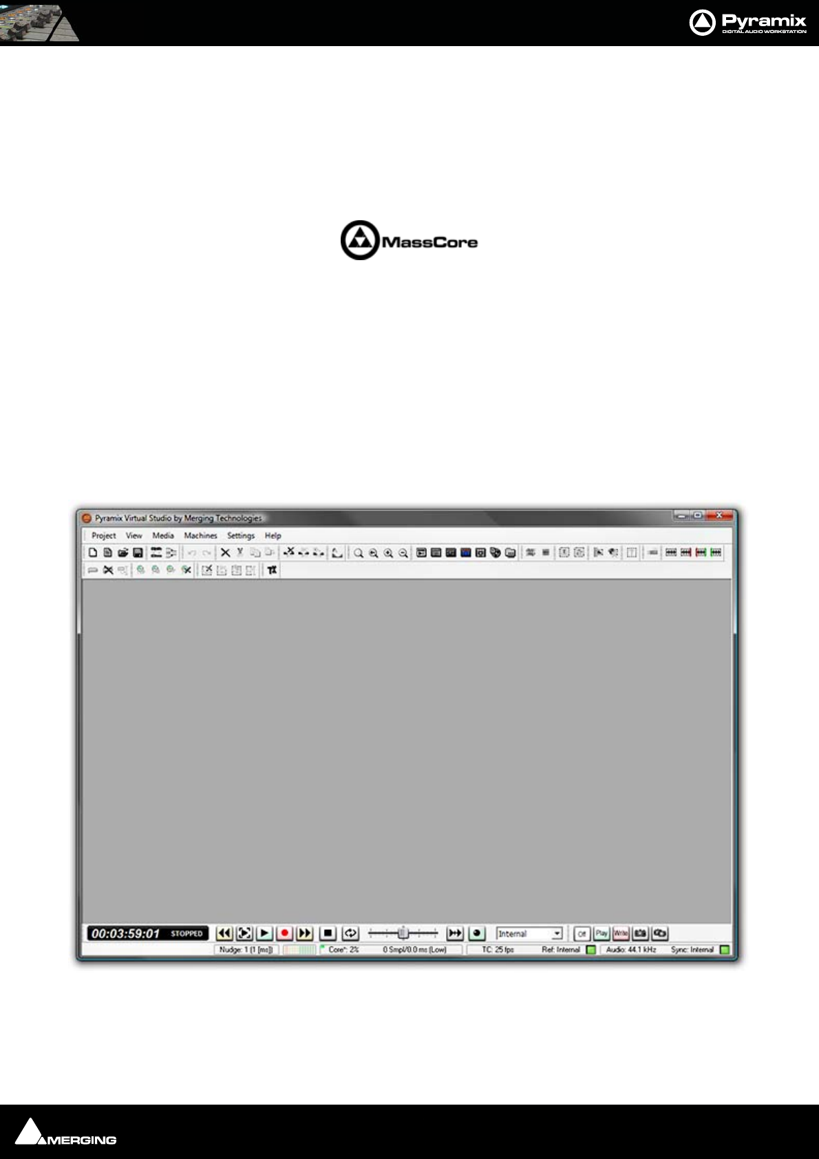
Program Window
The main Pyramix Virtual Studio by Merging Technologies program window appears when the program is
launched. It has dockable Toolbars across the top with a Transport bar and status information at the bottom. This
main window can be resized, moved, minimized or maximized with the conventional Windows control boxes.
Pyramix Program Window
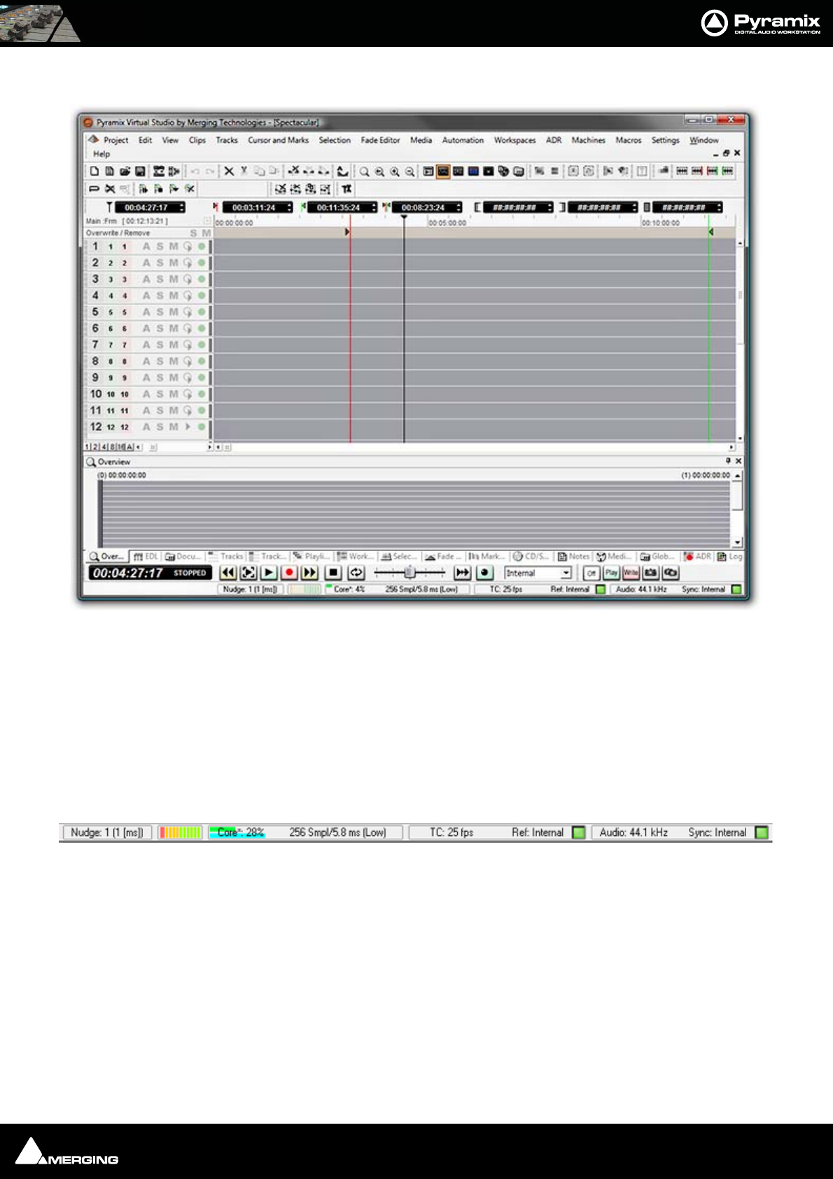
Introduction : Pyramix Virtual Studio Overview 1 - 25
Project Window
The Pyramix Project window is always completely enclosed by the main window. A Project window only exists if
a Project is open, and appears automatically when a new Project is started. A Project window can be resized,
moved, minimized or maximized within the main window. If the Project window is made large enough, two sepa-
rate panels are visible: the Project Editing Panel at the top, contains the Timeline which shows a graphic repre-
sentation of the Composition. The lower section of the screen is the Project Management Panel. The dividing
line between these panels may be grabbed with the mouse and moved up or down, thereby varying the space
allocated to each panel. The Project Editing Panel can be maximised to fill the Project window by clicking on the
square at bottom right where the scroll bars meet. A second click restores the previous window arrangement.
Status Bar
At the very bottom of the Pyramix Window the Status bar shows:
Nudge
Currently selected nudge setting
Playback Buffer Meter
Graphic representation of the current state of the Playback buffers. When the transport is not running or there are
no audio clips under the playhead cursor this will have no segments lit. In normal playback all the segments are lit.
If the number of tracks approaches the disk bandwidth or buffer capabilities less segments will be lit.
Pyramix Project Window
Status Bar

Introduction : Dual Monitors 1 - 26
DSP(Mykerinos DSP Systems) or Core (MassCore Systems)
DSP (or CPU) Load and Input to Output Latency in Samples and Milliseconds
TimeCode
Current Frame Rate and Reference Source.
• If the selected Reference Source is available the LED lights in Green
• If the selected Reference Source is not available then the LED flashes in Red.
• If a Pull-Up, Pull-Down or Varispeed setting produces an invalid Frame Rate, it’s then displayed in Red
Audio
Current Sample Rate and Sync Source.
• If the selected Sync Source is available and locked on the LED lights in Green
• If the selected Sync Source is not available and the system defaulted to Internal then the LED lights in Red
• If the selected Sync Source is available but with a different Sample Rate then the LED flashes in Red.
Project Editing Panel
By default the Project Editing Panel has a number of dockable toolbars at the top, a row of TimeCode register
boxes and below this the Timescale bar and Timeline tracks display. This is where much of the audio editing is
accomplished. Audio Tracks may be created, added or deleted, and audio clips can be edited, moved, copied or
pasted. Note that the Project Editing Panel automatically starts with the same number of audio Tracks as the
number of Input Channels configured in the Mixer of a new Project.
Project Management Panel
The Project Management Panel has a number of tools for managing, navigating and modifying a Project. A sin-
gle click on one of the tool Tabs at the bottom of this Panel, opens its window in the Panel. Double- clicking a Tab
opens it as a floating window. Double-clicking the Tab of a floating window or its Caption Bar returns the window
to the panel.
Note: Clicking the red X close box of a floating Tab Window removes it from the screen.
It can be reinstated as a Tab from View > Editor Tabs
Tab window functions can also be accessed from pull-down menus.
Any or all of the Tab windows can be shown or hidden for a Project, and moved independently and outside of the
main Program window.
Tab Window functionality has been enhanced considerably in Version 6. Please see Tab Windows on page 425
Dual Monitors
By default the screen is horizontally divided with the Tab Windows below the Timeline. When using Dual Monitor
setups, you may wish to divide the main project window vertically. With the Timeline displayed on the left screen
and the Tab Windows on the right, more tracks can be viewed simultaneously. This can be achieved by checking
the Display Timeline on the Left of Tab Windows radio button in the Settings > All Settings > Application >
Timeline Layout page. This change will take effect the next time a Project is opened.
Introduction : TimeCode Entry 1 - 27
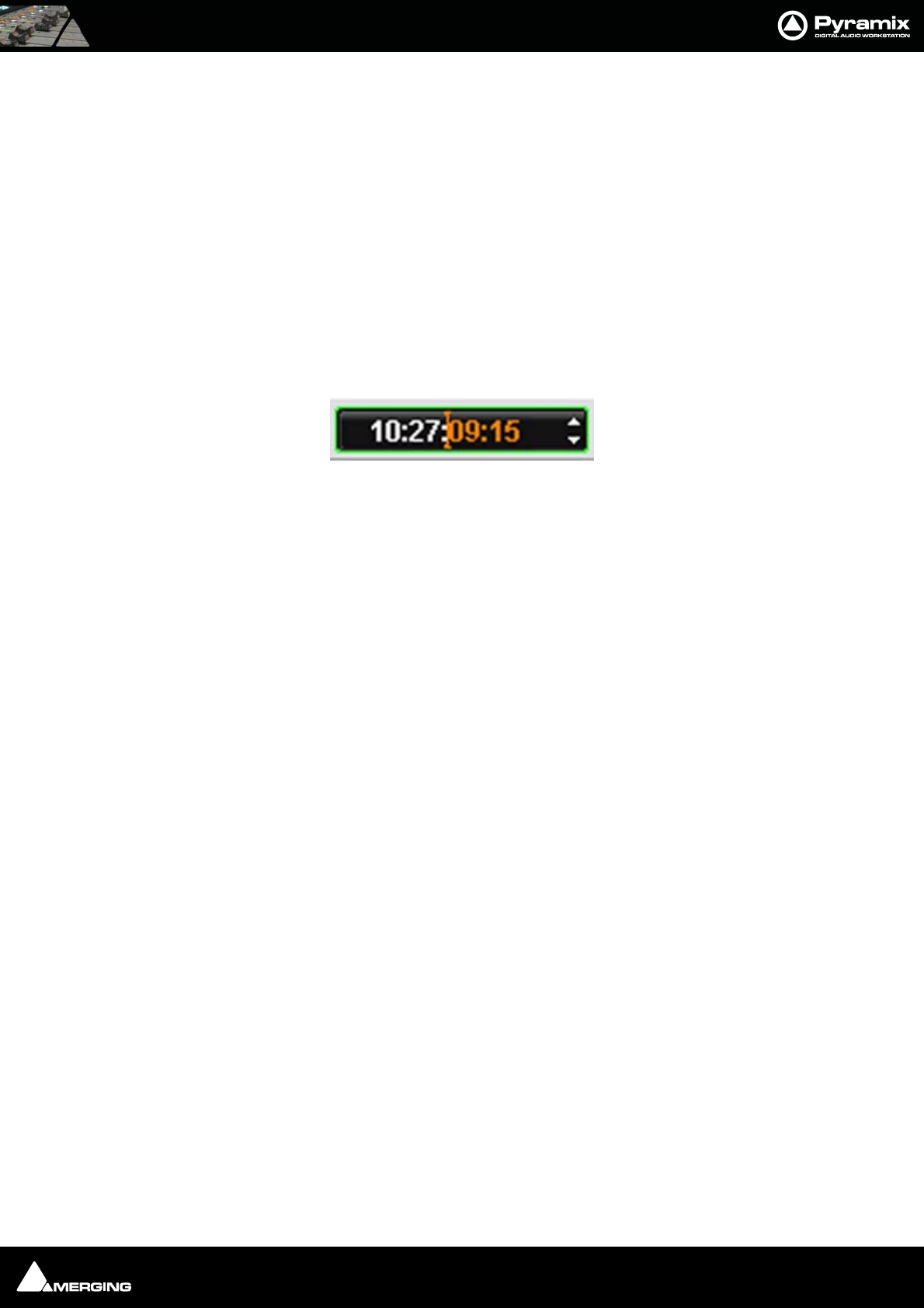
TimeCode Entry
TimeCode values in Pyramix can be changed by using Increment Decrement buttons, by using the on screen
numeric keys or by direct entry from the numeric keypad. an OK button or the ENTER key finalizes the entry. In
Pyramix numbers are entered in time code fields from right to left, a block at a time, progressively overwriting
existing numbers.
This makes the most common TimeCode changes easy, I.e frames or seconds, without having to re-enter the min-
utes or hours.
Clicking in a register inserts a red I-beam cursor and outlines the register in green. Entries must be made in Hours :
Minutes : Seconds : Frames order. So, to enter 10 Hours and 9 seconds and 15 frames, key: 1 0 0 0 0 9 1 5. BUT if you
only want to change the seconds then you only have to enter the seconds and frames E.g. to enter 9 seconds and
15 frames, key: 9 1 5 followed by ENTER. However, to change 10:27:10:15 frames to 10:27:09:15 you would need to
key, 0 9 1 5 followed by ENTER. In practice most operators always enter the leading zero even when it is not
required, to avoid errors.
Arithmetic TimeCode Entry
An existing TimeCode value can have time added to or subtracted from it. I.e. a relative entry. Type the number to
be added or subtracted then, instead of pressing the Numeric Key Pad Enter, press - (Minus) or + (Plus) on the
main keyboard or CONTROL + Minus or CONTROL + Plus on the Numeric Key Pad.
Automatic Fades and Crossfades
Summary
Auto Deglitching:
When enabled (Ramp length is user definable), Auto Deglitching allows on the fly Deglitching in playback when
no fades or crossfades have been created.
This is set globally in Settings > All Settings > Application > Playback/Record
To set Auto Deglitching for individual clips use: Clips > Properties. Clicking in the Auto Deglitching field opens a
drop-down list with the option to Follow General Settings or to set a value for the clip between 1.0 [ms] to 5
[ms] in 0.5 [ms] steps.
(The Auto Deglitch action is not visible on clips, since it only occurs in the playback engine)
Auto Crossfade:
Recording
Set in Settings > All Settings > Project > Record
When enabled (Fade Type and duration is user definable, creates a Fade/Crossfade on clips being recorded.
Playback
Set in Settings > All Settings > Application > Editing in the Drag & Drop section.
Auto-Crossfade by default - Control key for Drag & Drop
When checked, a fade will be created on clips that overlap when they are dragged on top of each other during
editing.
The default X-fade can be modified in the Fade Editor. Simply edit a Crossfade to taste, then "overwrite" the
default X fade. (Click on X Presets : Save Preset and choose Default.
TimeCode Register

Introduction : Sample Rate Conversion 1 - 28
Sample Rate Conversion
Pyramix can convert clips to the current Project sampling rate, automatically and on-the-fly. It can also convert in
non real-time.
Please see: Real-time Sampling Rate Conversion on page 519,
Convert - Quick Convert sub-menu on page 54
and Sample Rate Conversion on page 104

USER MANUAL
www.merging.com/Pyramix
MassCore

MassCore : Overview 2 - 30
Overview
MassCore™ is an extremely powerful Pyramix option. A truly deterministic real-time engine that does not rely on
the Windows operating system. This avoids the inherent restrictions and latencies introduced by the operating
system and allows the channel/track-count to be increased to an unprecedented level. MassCore is scalable from
16 to 384 Live I/O (768 simultaneous) with a massive bus structure. (For now this is limited in code to a total of 512
at 1FS (256@2FS, 128@4FS, 64@8FS).
MassCore enables a number of new features:
• Larger Mixer configurations
• Extra 2.66ms and Ultra 1.33ms latency options
• Full Delay Compensation (VS3 and VST)
• VST inserts on Mix Buses, Aux Send and SubGroup Buses
• VST Multi-channel support
• External Inserts (physical effects)
• External Monitor Inputs and Talkback
•Virtual ASIO support
Windows Boot Choice
You will see a new screen after the P. O. S . T (Power On Self Test) screen before Windows starts to boot. This screen
offers the choice between:
Microsoft Windows Vista (or XP Professional)
and
Merging Technologies MassCore
Please choose Merging Technologies MassCore.

MassCore : Memory 2 - 31
Memory
The total amount of memory available in a MassCore machine affects the memeory available to MassCore and the
number of VST channels which will be available.
The following tables demostrate this for two different machines:
Windows Vista
DELL Dimension E521 (AMD Athlon 64 X2 5000+)
Installed Available MassCore VST channels
1GB 1022 -> 128MB 192
2GB 2046 -> 384MB 384
3GB 3070 -> 384MB 384
4GB 3326 -> 384MB 384
Windows XP
Intel DP35
Installed Available MassCore VST channels
1GB 0.98 -> 128MB 192
2GB 1.98 -> 256MB 384
3GB 2.98 -> 256MB 384
4GB 3.24 -> 256MB 384
MassCore : Core Load Indicators 2 - 32
Core Load Indicators
In MassCore based systems two (4 with quad core CPU) Core Load indicators replace the DSP indicators in the Title
Bar.
Core: xxx% or Core*: xxx%
The * indicates Dedicated mode.
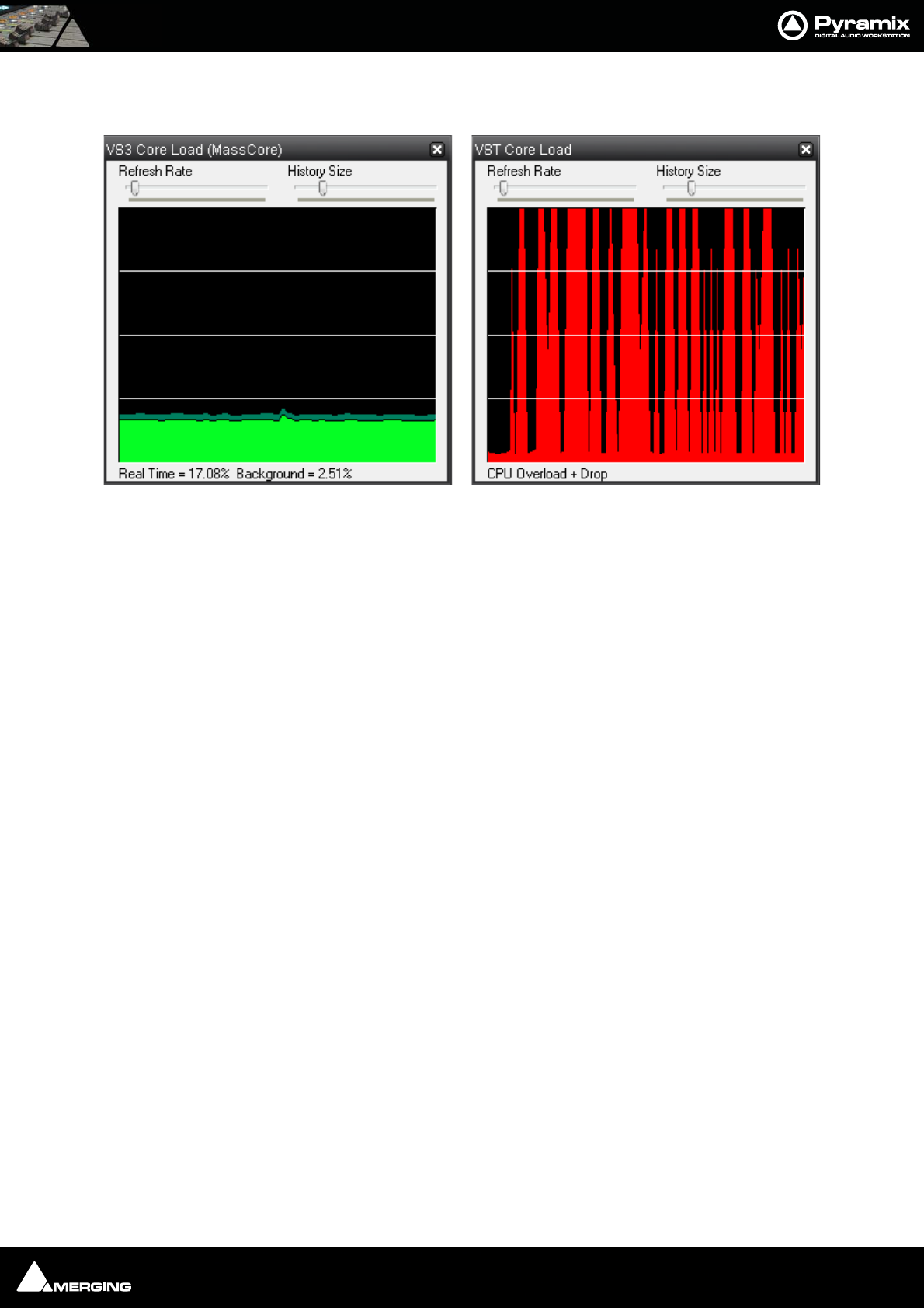
The Core indicator bars section at the bottom of the screen shows two distinct MassCore engines. The upper CORE
bar shows MassCore/VS3 activity in real-time, and the lower bar shows the VST plug-in engine. Both bars are there
to help you gauge the amount of resources that your project is consuming and warn you if an audio “glitch” (a
momentary rupture of processed data producing a discontinuous sound stream to output devices) has occurred
during playback or recording.
The numeric percentage Core load shown is the highest of either the MassCore Loads (Realtime & Background)
or the VST Core Load, depending on which one has the highest load.
MassCore Realtime Load
(light green bar, orange when heavily loaded, red when overloaded): Indicates the MassCore Load, for realtime
processes.
MassCore Background Load
(dark green bar): Indicates the MassCore load for background processing, it will be displayed at the end of the
MassCore Realtime load indicator. For example, the MassCore Background Load will be used by Algorithmix plug-
ins for FFTC.
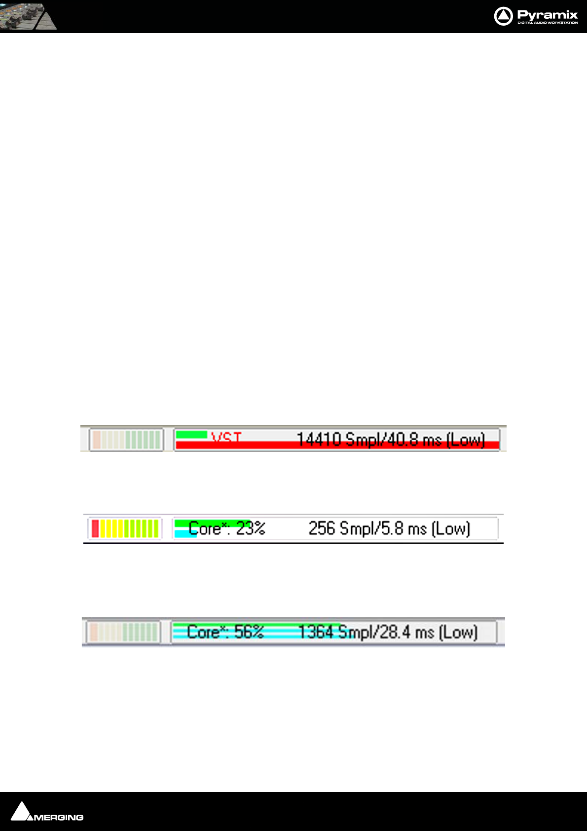
VST Core load
(blue bar, orange when heavily loaded, red when overloaded): Indicates VST core load for VST processing. If you
experience regular VST Core load “drops”, there may be red peaks and the Core label is replaced by VST as in this
screenshot:
In contrast, the following screenshot shows the Core Loads when running a project with 100 Tracks and Input
Strips but only a few VST plug-ins:
Here the highest load is MassCore Realtime since the indicator is higher than the VST Core Load indicator.
VST Core load with Quad Core
If your system is equipped with a quad core processor there are two VST Core load bars:
In all three screenshots the left-hand bargraph display shows disk buffering.
Core Load Indicators in Title bar
Core Load Indicators in Title bar
MassCore : Core Load Indicators 2 - 33
To see more detailed information about both Core Load Indicators, Shift + Click on them to open the two Core
Load debug Windows:
If the VST Core Load display looks anything like the screenshot above we recommend that you increase the VST
Plug-ins engine Latency value.
In order to support some VST plug-ins which need a big buffer to be efficient (e.g. Algorithmix EQ Orange/Red,...)
we recommend that you increase the VST Plug-ins engine Latency size up to 4096 smpl (samples) using the
VST Plug-ins Engine Latencies slider in the AllSettings > Hardware > MassCore page.
Note: this value can only be adjusted when no project is open.
Important! If a Drop (glitch) occurs, the Core indicator will blink. Click on it to reset it.
Note: This indication may be useful if, for example, you do a Realtime Mixdown or
Recording and leave the Studio for a minute to get a coffee. If, on your return, you see
the Core blinking this would mean that you have experienced a drop, so that you proba-
bly have a glitch in you final mix or recording.
Overload Diagnosis and Cures
First determine whether the CORE indicator or the VST indicator is turning red during a glitch.
If the MassCore (CORE) indicator becomes red during playback or recording you have exceeded the capacity of the
workstation. You should reduce the size of your project mixer and/or the amount of active plug-ins you are using,
or try increasing the Max Mixer Delay Compensation slider value in the Mixer Settings page (Settings>AllSet-
tings>Project>Mixer>Mixer Settings). You may also try changing the buffered read and write settings of your
.pmf files from within the Project>Record page under Format/(PMF)/Settings for projects with large numbers of
audio tracks (approaching machine capacity for current sample rate).
If the VST indicator becomes red you might want to increase the MassCore VST Plug-ins engine Latency slider
value. The VST buffer size can be increased in order to support VST plug-ins that need larger buffers in order for
them to work efficiently. So, if you are experiencing VST Core Loads or Peaks (100%) we recommend that you set
the VST Plug-ins engine Latency value higher, it can go up to 4096 samples to help support certain VST plug-ins.
Note that you can also monitor the VST Core load by Shift Clicking on the CORE % indicator, this will open the
VST core load debug window. (See above) If you see spikes (red) during playback or an idle indicator then it may
be advisable to increase the VST Plug-ins engine Latency (Settings>All Settings>MassCore : VST Plug-ins
engine Latencies), this value can only be adjusted if all projects are closed within Pyramix.
Core Load debug Windows
MassCore : Pyramix V6 Latency Modes for MassCore 2 - 34
Note: These bars should be ignored when loading a project, making changes in the
graphical layout of Pyramix when stopped (opening pages, moving the mixer, etc.), or
doing offline processes (renders, non real-time mix-downs, etc.). If the indicators
become red during these phases of your work, simply click on the indicator bar to reset
it.
Very Important!
For the present we recommend that you do not use more than 65-70% of the Core resources to avoid glitches or
problems related to intensive graphic refresh bursts. Three colour zones have been set for the Core load indicator.
0% to 65% Green zone (best performance)
65% to 75% Orange zone (moderate risk)
75% to 100% Red zone (performance could be at risk if major screen redraws are initiated by the user)
For ultimate performance Vista should be run on a QuadCore processor.
Pyramix V6 Latency Modes for MassCore
Note: Please be aware that our competitors only take into account latency from Live In
to Record; in our case this would means 0.665ms in Ultra-Low, 1.33 in Extra-Low and
2.66 in Low Latency, but, since from Live In to Live Out is the ‘real-world’ figure, we cal-
culate it as 1.33ms , 2.66ms , 5.33ms respectively.
P
y
ramix V6 Latenc
y
Modes for
MassCore
Mykerinos/Latency (Note1)
Low Latency
(5.33ms)
Extra Low Latency
(2.66ms)
Ultra Low Latency
(1.33ms)
MYK-MB1
v
MYK-MB2
v
MYK-MB3
v
MYK-MB4
v
MYK-MB5
v
MYK-X30
v
v
v
MYK-X50
v
v
v
Note 1: Latency Modes introduce relative performance penalties. Low: 11%, Extra:22%, Ultra:44%
Latency measurements are LIVE IN to LIVE OUT

USER MANUAL
www.merging.com/Pyramix
Projects
Projects : Overview 3 - 36
Overview
Projects are the top level of Pyramix organisation. There are four types of Project. For most applications the one
most commonly used is the Editing Project. The second type is Digitizing Session. As the name implies this a
special type of project optimized for media acquisition.
Two further Project types, DXD Mixing Project and DSD Project are solely concerned with high-definition audio
and the production of SACD masters.
There is also the option to Load a Template. Templates are the quickest way to configue Pyramix for a specific
purpose. A wide variety of Tempaltes are supplied with Pyramix and can also provide a basis for refining your own
‘User Templates’.
You can find more information about Digitizing Sessions here: Digitizing Sessions on page 106
Backward Compatibility
Even the latest version of Pyramix is capable of saving in project formats back to V4.3. Some current features are
obiously not supported in previous versions but the Project > Save Special option offers the ability to save in all
relevant previous versions back to V4.3
Editing Project
New Project
1. Launch Pyramix Virtual Studio
2. Choose Project > New.
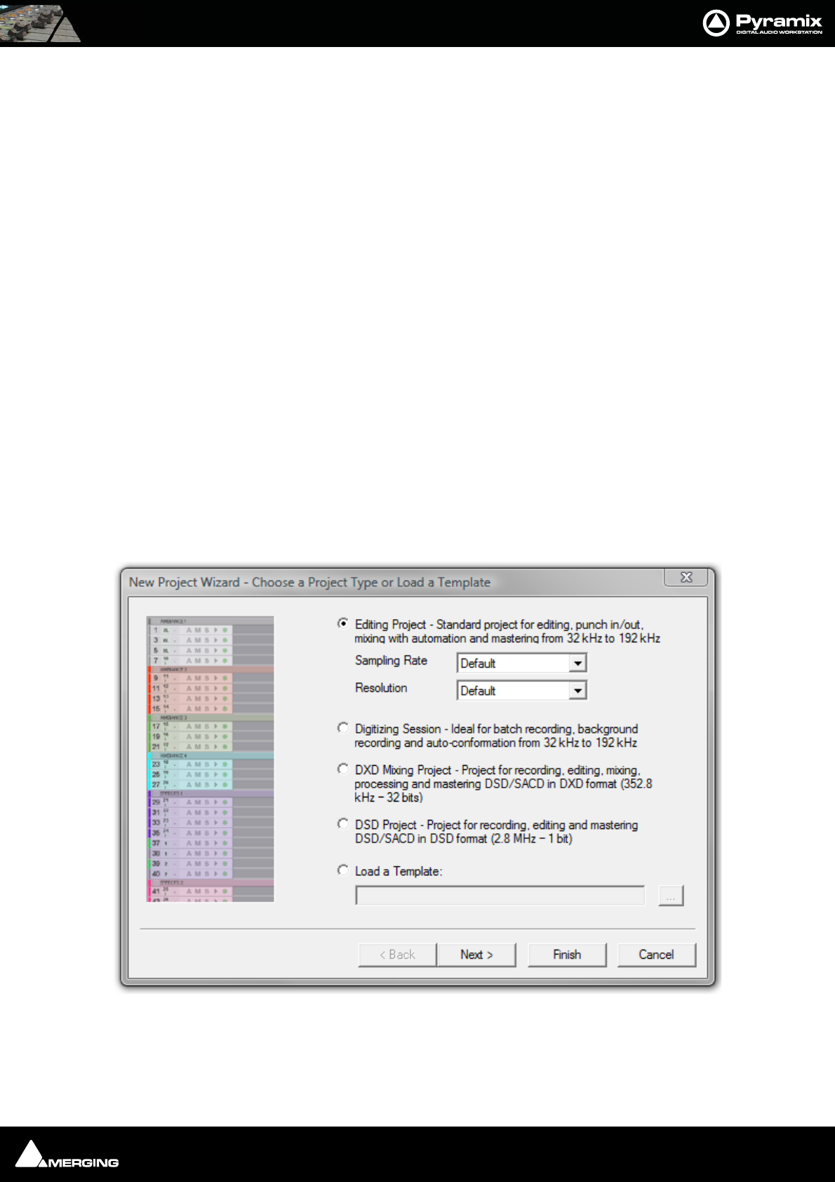
3. The New Project Wizard - Choose a Project Type window will open.
4. The default is Editing Project which is the type we will use.
5. Choose a suitable sampling rate from the Sampling Rate drop-down list. (Use 44.1kHz if in doubt and using
an analogue input)
New Project Wizard - Choose a Project Type dialog
Projects : Overview 3 - 37
6. Choose a suitable bit-depth from the Resolution drop-down list. (Use 24 bit if in doubt)
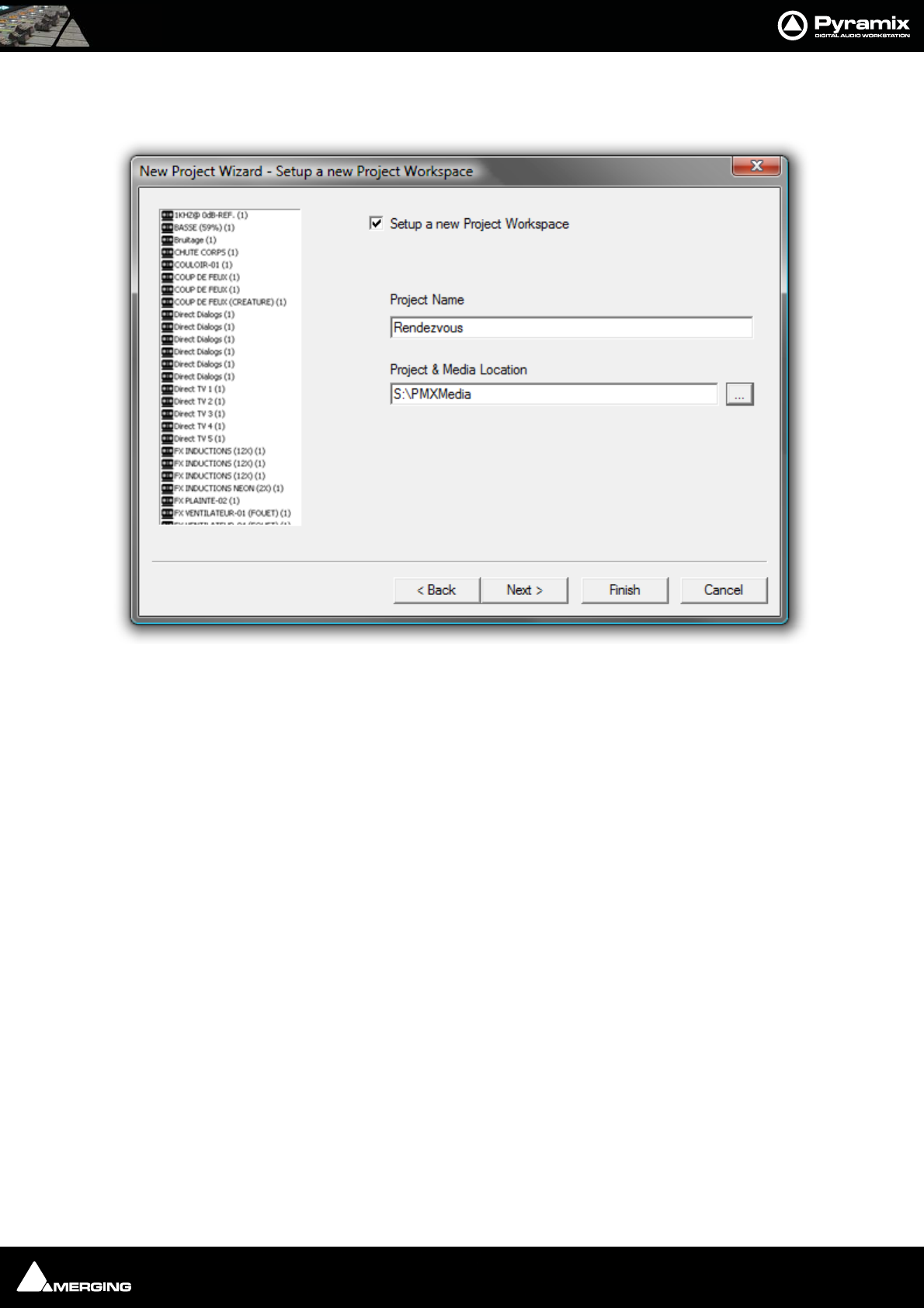
7. Click Next. The New Project WIzard - Setup a New Project Workspace dialog will open.
8. Click in the Setup a new Project Workspace box to tick it.
9. Type a name for the Project and either type a suitable path to the Project and Media Location or use the ...
button to open a Browse for Folder window. This works like a Windows Explorer window and enables you to
navigate to a suitable folder.
New Project Wizard - Setup a new Project Workspace dialog
Projects : User Templates 3 - 38
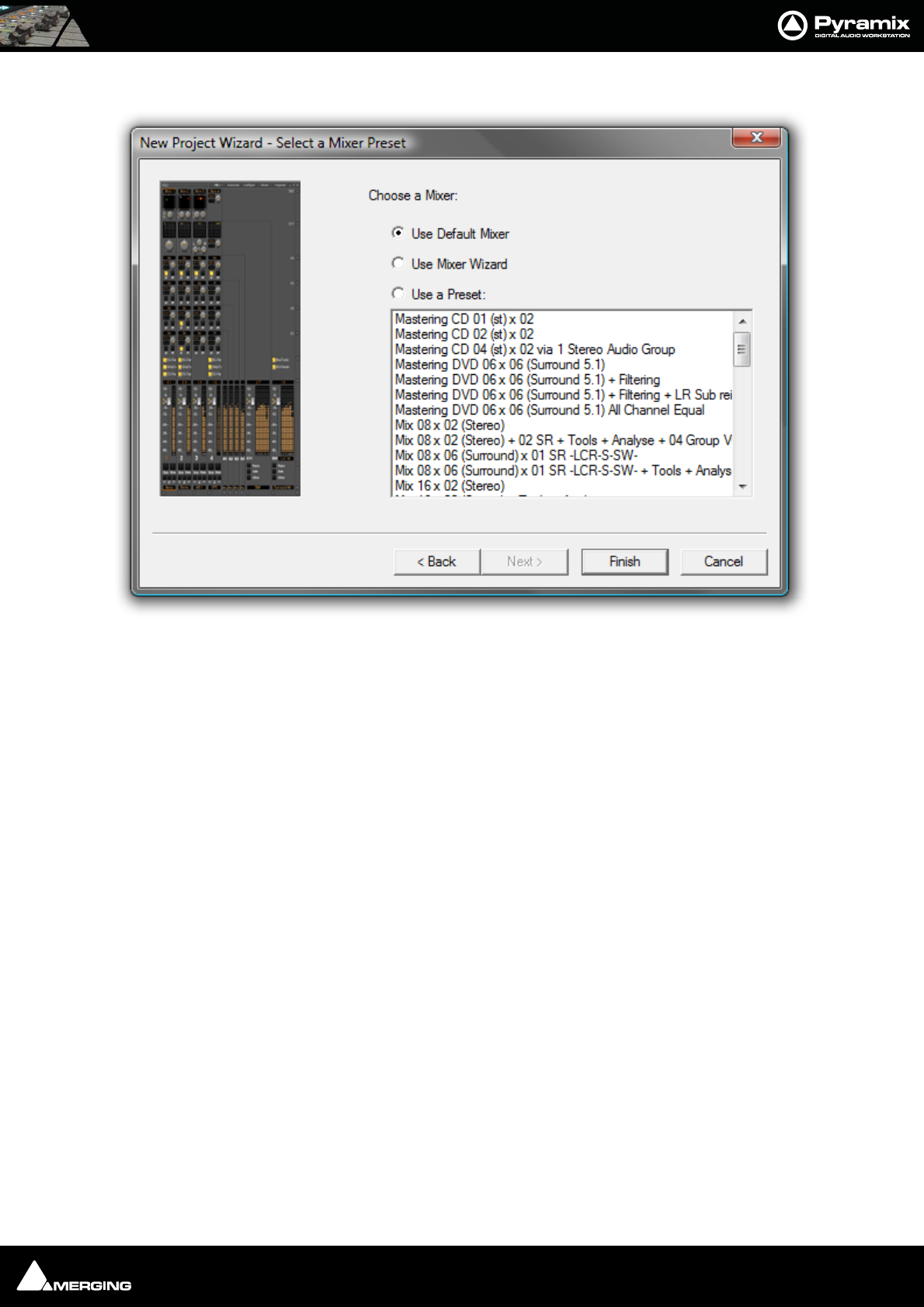
10. Click Next. The New Project Wizard - Select a Mixer Preset dialog will open.
11. If this is the first time you’ve used Pyramix, choose the Mix 08 X 02 (Stereo) preset in the drop-down list by
clicking on the name. Note that the Use a Preset radio button is automatically checked.
12. Click Finish to activate your new Project. It will open with a Project Window and Mixer Window. There will
be 8 empty tracks in the Project Editing Panel corresponding with the 8 Mixer Input channels.
Mixer Wizard
Please see: Mixer Configuration Wizard on page 171
Presets
A considerable number of pre-configured presets are supplied for common tasks. You can add your own custom
Mixer Presets to the list. Please see: Mixer Presets on page 185
User Templates
When you have a Project with a configuration which may be useful for future Projects you can save it as a Tem-
plate. I.e. the current Project minus all the Cues. Simply select:
Project > Save Template
A Browser window opens with the default Templates Folder open. Choose an existing Template folder, if appropri-
ate, or create a new one. Name the Template and click on Save
New Project Wizard - Select a Mixer Preset dialog

USER MANUAL
www.merging.com/Pyramix
Media Management

Media Management : Housekeeping 4 - 40
Housekeeping
The Windows hierarchical filing system can easily become confusing and cluttered. Complex audio projects gener-
ate thousands of more or less enigmatically named files. Keeping track of all the files used in a Project can become
a nightmare even if the user is meticulous.
Pyramix uses the concepts of Media Drives/Folders and Libraries to reduce the clutter and provides manage-
ment tools specifically designed for audio. This Media Management helps users to work in a structured and simple
manner whilst keeping track of all the project components.
Audition Play
Master Clips in the Media Management window and all audio objects in the Library windows can be auditioned
through the Monitor as a MONO downmix. The toolbar Play (Space) and Stop (Esc) buttons starts and stop play-
back of a selected object. Double-clicking an object begins playback at the start.
Media Folders
Media Folders are Windows folders or drives which contain Media Files. Pyramix needs to specifically mount
these Media Folders in order to access the Media Files contained therein. Once mounted, suitable files are dis-
played as Master Clips. I.e. pointers to the underlying audio files. Mono and interleaved Stereo and Multichannel
Media files are all displayed and manipulated as single Master Clips
These can be dragged and dropped or copied and pasted directly into the Timeline or into a User library from
the Media Management Window regardless of format, sampling rate or bit depth.
Media Target Settings
When a Project is created, either with Project > New or Project > New From Template and a Media Folder is cre-
ated or selected, the Project Information : Project Media Folder, the Record : Target settings Media Folder, the
Project > Render : Target Settings Media Folder and the Project > Mix Down : Target Settings Media Folder all
point to the same folder. These target settings can be changed later and each can point to a different folder.
CD Import
Pyramix can import individual tracks or entire CDs to Media folders and libraries. Track listing and other informa-
tion can be automatically obtained from an online database. Please see: CD Import on page 315
Drag and Drop
Audio Media files compatible with Pyramix may be dragged and dropped into Pyramix Libraries. Single or multi-
ple files can be dragged and dropped in the conventional Windows manner from browser windows and from
applications that support such operations, e.g. iTunes. As a rule of thumb, if you can drag and drop a file to the
Desktop, you can drag and drop to a Pyramix library.
Example:
Start Pyramix, open a Project and a library. From a Windows Browser window select one or several audio files and
drag them over the library. If the selection contains compatible audio files the library will highlight. Drop the files
over the library. Any compatible files will be added to the library and can be then used just like any other library
file in Pyramix.
Note: The converse, dragging and dropping from a Pyramix library to the Desktop or to
a browser or other application is NOT supported.
Libraries
Pyramix uses libraries to help make project organization tidier. Libraries are used to organize project material into
logical groupings. However, Libraries are not the same as Windows directories or folders. They are only meaning-
ful within the Pyramix environment. A Library is a database, containing a collection of pointers to different types
of media objects with tools designed to enable you to work quickly and intuitively.
Media Management : Libraries 4 - 41
Shelves
A library Shelf is a sub-folder. You can create many Shelves in a Library and Shelves can also contain further
Shelves.
Project Libraries
When a new Project is created two Project Libraries are also created.
Composition Library
Each Project has a unique, read-only Composition Library. This contains short-cuts to every Master Clip placed
on the Timeline (present in the EDL) in the current Project. Note that the Composition Library may be empty,
I.e. nothing is placed on the Timeline but the user library(s) may contain Master Clips and Compositions which
all form part of the Project.
Default Library
Each new Project also creates an empty User Library named Default Library (‘project name’.pmx). This is pro-
vided to aid housekeeping and is kept with the project.
Global Libraries
Project Libraries are kept with the Project, Global Libraries are available to all projects and users of the system.
This can be helpful for sound effects or where several users need access to the same source material to produce
different end products.
User Libraries
Master Clips can simply be dragged from Media Folders to User Libraries for purposes of clip organization,
grouping, etc. just as they are dragged into Compositions
Clips or Selections can be copied and pasted into User and Global libraries. Library items can be dragged and
dropped onto other libraries, shelves or the Timeline or you can use the familiar Cut, Copy and Paste commands.
User Libraries are not restricted to storing individual clips. Whole Compositions or selected Regions of Compo-
sitions, including all the clips in a Composition in relation to each other on multiple Tracks may be placed in a
library. To do this, select one or more clips in a Composition, hold down the Shift-Alt keys and drag the selection
from the Timeline to the Library, or hold down the Shift-Alt keys and drag the whole Composition from the
Overview panel to the User Library.Media Folders
User Libraries can contain Master Clips, Compositions, Mixer Snapshots, Plug-in Snapshots, Fade Settings,
etc…. Each Project can have an unlimited number of User Libraries open, each with an unlimited number and
mixture of contents.
Libraries - Shelves

Media Management : Libraries 4 - 42
N.B. In Pyramix User Libraries, there is no practical distinction between a Clip, a section of a Composition
(Region) and a complete Composition. Either can be added to a User Library or to an existing Composition. This
is an extremely powerful feature. Any item copied to a User Library from the Timeline appears there as a Compo-
sition automatically labelled Part of ‘composition name’.
Automation in libraries
If the menu item Edit > Enable Automation Cut/Copy/Paste is enabled then any operation (Cut/Copy/Paste
etc…) brings all automation data with it.
Library Maintenance
If media is moved or the path to it is changed (E.g. by copy, backup or moving folders etc.) Libraries referencing
the ‘orphaned’ media can have their paths updated by simply mounting all the media folders involved and select-
ing Drive > Update Media Paths in the Global Libraries tab window.
Libraries (apart from the Composition Library and Default Library which are embedded in the Project) can be
closed from the Library menu, but not deleted. Click on the library you wish to close to highlight it and select
Library > Close Library. This will remove the library from the Project Library list but it can still be opened, if
required, by selecting Library > Open Library and navigating to the library you wish to open, clicking on it to
highlight it, and clicking on Open.
A Shelf can be deleted by clicking on it to highlight it in the right-hand pane and selecting Edit > Cut.
Media Management : Practical Media Management 4 - 43
Practical Media Management
The Media Menu
This menu gathers together the most significant Media related commands for the current Project.
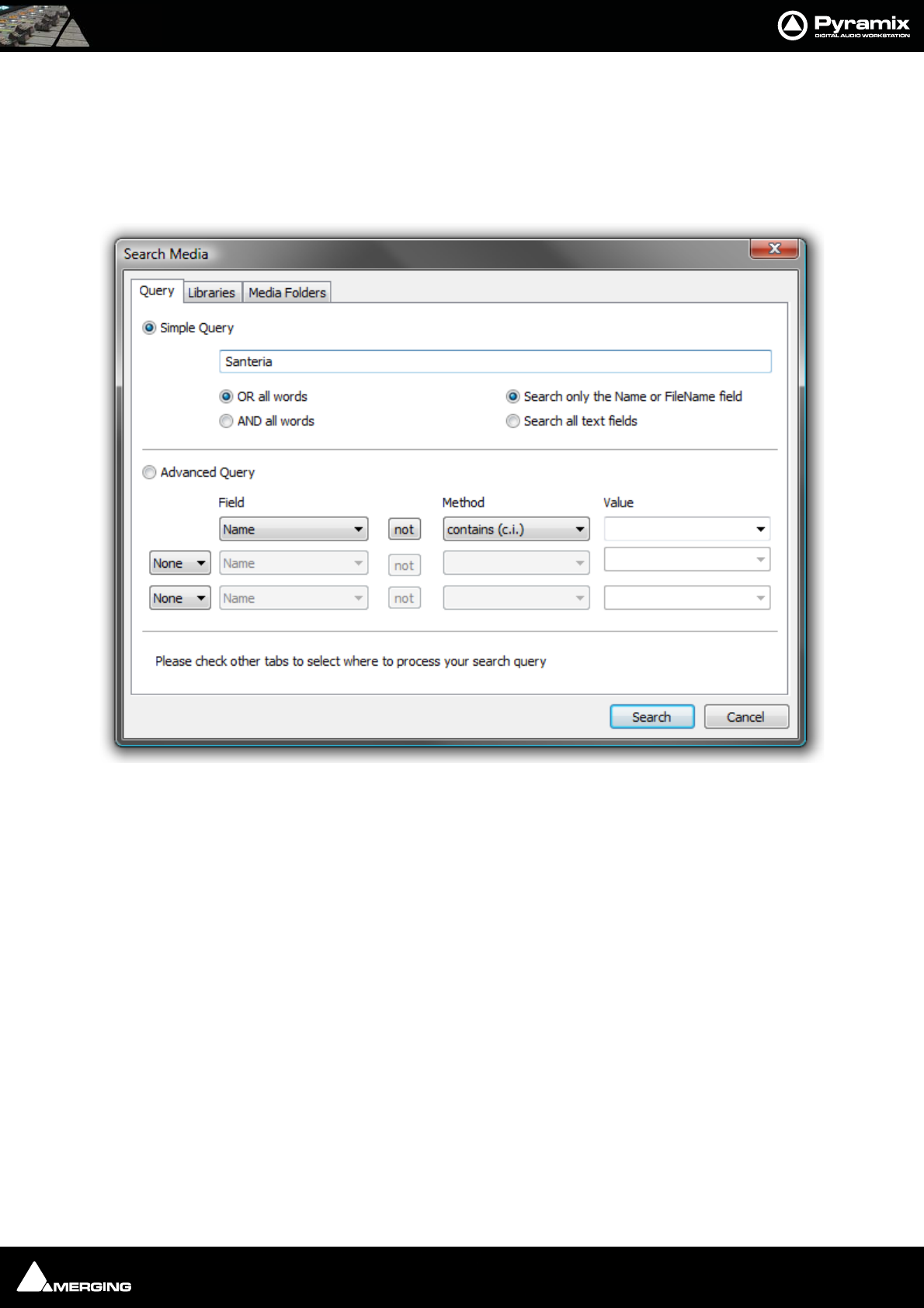
Search Media Opens the Media Search Tool with the Query page displayed.
Before a search can begin, a Library or Libraries, Media Folder or Folders to search must be selected in the Libraries
or Media Folders pages.
Query Page
The Query page offers a choice of Simple or Advanced Queries.
Simple Query
A simple search uses a word or words and does not consider case. Radio buttons offer a choice of Search only the
Name or FileName field or Search all text fields. If more than one word is entered two further radio buttons give
a choice of Or all words or AND all words. E.g. If you type Car Mercedes Door with OR all words selected, the
search will return all Media Files with any of the three words. If AND all words is chosen the search will only return
files with all three words in the selected field(s). The words can appear in any order.
Advanced Query
An advanced search has the same options as a search initiated from the Media Management or Library Tab win-
dows. Please see: Search on page 51
Libraries Page
This is where you can choose which Library(s) to search in.
•All Open Libraries
Media Search Tool - Query page

Media Management : Practical Media Management 4 - 44
• A list of Pyramix Projects and/or Libraries
• A list of folders in which all Pyramix Projects and Libraries present will be searched.
Libraries do not have to be opened in order to search them.
Media Folders Page
Similar to the Libraries page, the Media Folders page allows you to choose which Media Folders to search in.
• All Mounted Folders
• A list of folders containing media files.
All folders in the list will be searched using the QuickMount Library. If there is no QuickMount
present, there is choice of Open each file and search all metadata within it or Search only file
names, which is quicker.
Search Results
Search results appear in a floating Library window. The contents can be manipulated in the same ways as any
other User Library.
Mount Referenced Media Mounts all media not already mounted and used in the current Project
Auto-Mount Media When selected, whenever a reference from an Offline library is placed in the current
Project, the Media will automatically be mounted.
Select Online Clips Selects all Clips in the Timeline whose Media files are currently mounted
Select Offline Clips Selects all Clips in the Timeline whose Media files are not currently mounted
Select Used Media Opens a floating Media Manager window containing all media used by the current
Project.
Select Media present on Project Default Folder Opens a floating Composition Library window with all Media present in the
Project Default folder selected (highlighted)
Select Media NOT present on Project Default Folder Opens a floating Composition Library window with all Media NOT
present in the Project Default folder selected (highlighted)
Collect Media to current Project Default Folder Copies all media files used in the current project (as shown when the previous
Select Media not present ... is invoked to the current Project Default Folder. This func-
tion is especially useful if moving a machine or disk to another studio or where network
resources may not be available.
Clean-Up Media Opens the Choose a Media Folder to Clean-Up window. Choose the Media Folder you
wish to clean-up and click OK. All media not referenced by the current Project will be per-
manently removed from the selected folder.
Media Management and Libraries Tab Windows
The Media Management Tab Window is very similar in appearance and operation to the Document and Global
library Tab Windows. However, the Menus and Toolbars differ reflecting their different capabilities.
Media Management : Practical Media Management 4 - 45
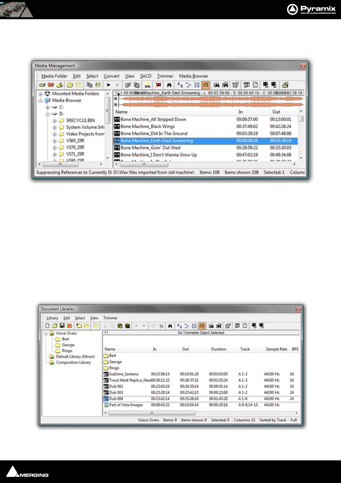
Media Browser
The Media Management window can operate on Mounted Media Folders and act as a Media Browser for any
local or network storage locations.
Below all Mounted Media Folders an “Explorer like” Tree allows Media Folders to be browsed without formally
Mounting them.
When displayed in the Media Browser all recognized Media are temporarily mounted and can be auditioned and
placed in the timeline.
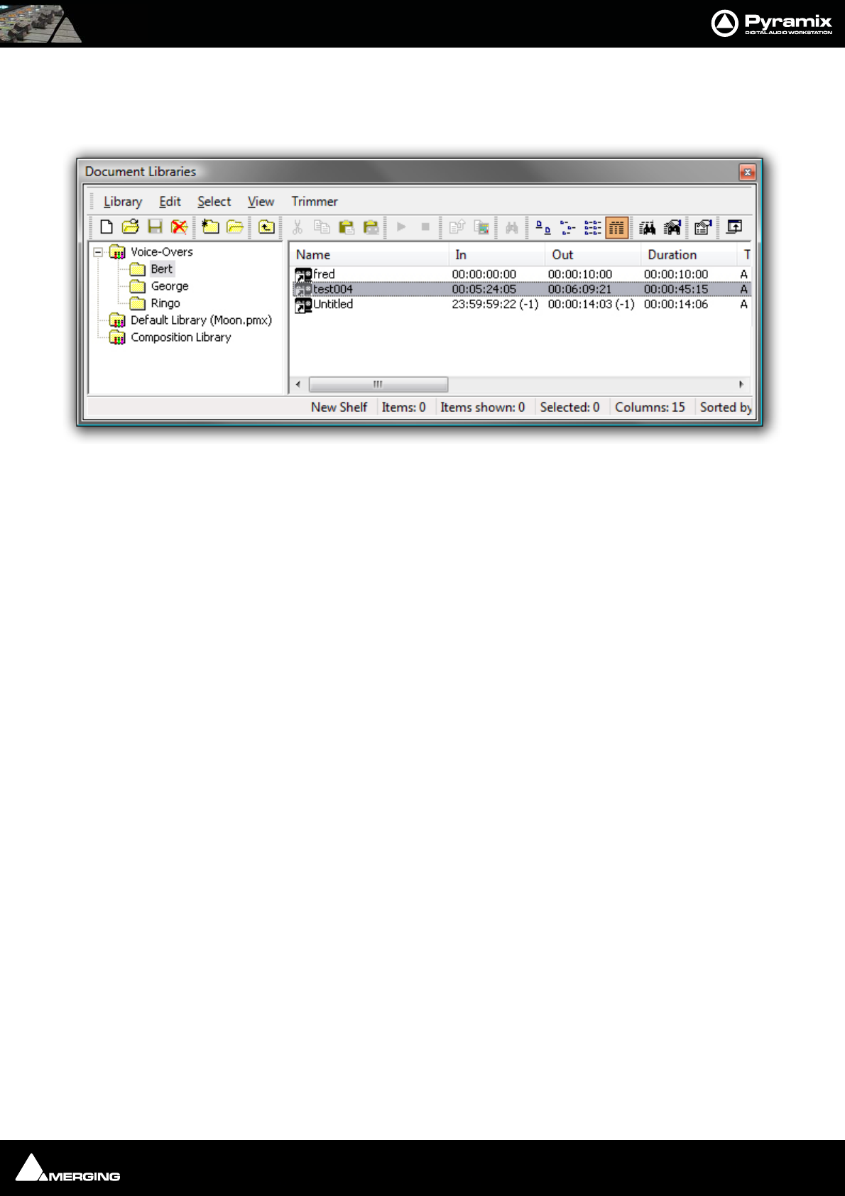
Document and Global Libraries
There is no real difference between Document libraries and Global Libraries. The distinction is an organizational
one, made to help keep complex projects manageable and to provide security features for larger facilities. Librar-
ies designated as Global are available to all projects but can be opened and manipulated from the Document
Library window. Equally, libraries created in the Document Libraries window can be opened in the Global
Libraries window.
The default Project library created with every Project is stored with the Project. It can still be opened in the Global
Libraries window by locating the .PMX project file in the Project’s Media Files sub-folder.
Media Management Tab floating Window
Document Libraries Tab floating Window
Media Management : Tools and Menus 4 - 46
The left hand pane shows Libraries and Shelves associated with the project. The contents of the selected Library
or Shelf is shown in the right-hand pane with information about the objects in columns. Shelves are displayed at
the top with individual library items below. Clicking on the + or - signs in the left-hand pane expands or collapses
Libraries and Shelves.
Libraries allow Drag & Drop operations from the Library content (right side window) to the Library/Shelf tree hier-
archy (left side window).
Media Management and Library Fields
Name Clip or Media File name
In Clip or Media File In TimeCode
Out Clip or media File Out TimeCode
Duration Length of Clip or Media File
Track Shows the tracks the Media File or Clip occupies
Sample Rate Sample rate of Clip or Media File
BPS Bit Depth
Format File format e.g. PMF, WAV etc.
Creation Date Date Media File (Clip) created
File name (Media Only) Media File Name
Media Size (Media Only) In bytes
Frame Rate (Media Only) Where specified
Author Where specified
Scene Where specified
Take Where specified
Notes Where specified
Tape Where specified
Category E.g. Master Clip, Media Folder etc.
Tools and Menus
The Library and Media Management Window menus give access to all available functions. Many have keyboard
short-cuts and a selection of functions are directly available from the Library Window Toolbar with ToolTips indi-
cating their function.
The Trimmer
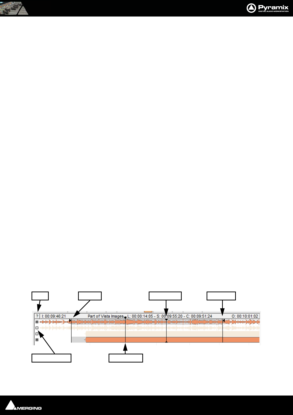
All Library and Media Management Windows have a Composition/Media Trimmer:
The Trimmer can be shown/hidden with the menu item Trimmer > Show. An object highlighted (selected) in the
list view is automatically opened in the trimmer. Multi-channel objects may be auditioned and trimmed. A small
Library Trimmer
Trim In Trim Out
Sync Point
PlayheadMute Buttons
Help
Media Management : Tools and Menus 4 - 47
square to the left of each track displayed allows tracks to be de-selected/selected for playback in the Trimmer.
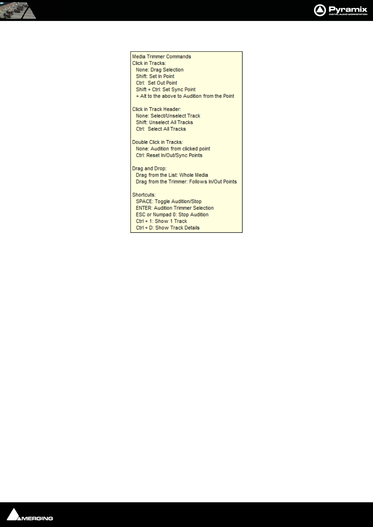
Clicking on the ? at top-left opens the Media Trimmer Commands list:
Media, Clips or Compositions can be trimmed in the following ways:
•Double-click: Plays the object through the Monitoring Section from the point where you double-click.
Note: If no sound is heard through the current L & R Monitor Outputs you may need to
assign values to the None entry in the Main Grid and Downmixes section of the Moni-
tor Please see: Media Manager Monitoring on page 200
•Click & Drag: Drag the object to the timeline or to an other library properly trimmed (from the In point to
the Out point. Dragging it from the list view takes it untrimmed).
•Shift + Click: Sets the Trim In point. The point can be modified later by simply clicking on it.
•Control + Click: Sets the Trim Out point. The point can be modified later by simply clicking on it.
•Control + Shift + Click: Sets a Sync Point. The point can be modified later by simply clicking on it.
•Shift + Alt + Click: Sets the Trim In point and plays from it.
•Control + Alt + Click: Sets the Trim Out point and plays from it.
•Control + Shift + Alt + Click: Sets the Sync Point and plays from it.
•Control + Double-Click: Resets the Trim In and Trim Out and Sync Points.
Trim In, Trim Out and Sync Points
The Trim In, Trim Out and Sync Points are permanently preserved for Compositions and MasterClips stored in a
Library (Project or Global), but only until the next Mount or Refresh for mounted Media in the Media Management
Window.
Compatibility
Because the Media Trimmer allows Trim In, Trim Out and Sync Points to be set and saved in current libraries a
menu option: Library > Save Library As 4.x allows libraries to be saved in a format compatible with version 4.x.
for maximum compatibility.

Media Management : Tools and Menus 4 - 48
Library Menus
The Edit, View and Trimmer menus are almost identical in Library and Media Management windows and details
can be found below. Exceptions are noted where they arise.
Library Menu
The Library menu allows new Libraries and Shelves to be created and existing ones to be opened and saved.
When a library is opened the media used by Masterclips/Compositions may not be mounted, (E.g. on a remov-
able drive). Mount Referenced Media automatically mounts the most recent location where these media were
found
New Library Create new user library
Open Library Open existing user library
Save Library As Save a copy of the current library with a new name or in a new location
Save Library as 4.x Save a copy of the current library in Pyramix 4.x format for maximum compatibility
Close Library Close current library
Mount Referenced Media Automatically mounts the most recent location where media in the current project were
found
Update Referenced Media Paths To update a library, mount all the media folders involved then select this menu item
Import MTInterchange XML Opens the Import MTInterchange XML Browser Window
Export to MTIntercange XML Opens the Export MTInterchange XML Browser Window
Import OMF library (Avid Bin) Opens a File Browser to locate the library you wish to import
Export to Akai DD Series Opens the Export to Akai DD Series window
New Shelf Adds a new Shelf (folder) in the current Library or Shelf
Open Shelf Opens selected/highlighted Shelf
Up One Level Moves right-hand pane display up one level in the hierarchy
Properties Pops up a box with properties of the currently selected object
Edit Menu
Cut (Not in Media Management Tab for safety) Cuts Object from pane. Object will be deleted
unless pasted elsewhere.
Copy Copy object
Copy Trimmer Selection As it says
Paste Paste object (Not in Media Management Tab)
Paste with Media Pastes object complete with associated Media files to wherever the target object is stored
Rename Rename object
Open/Audition/View (Libraries only) Opens highlighted (selected) Clip or Composition in the Trimmer and
begins audition play. Opens highlighted (selected) Shelf
Audition Opens highlighted (selected) master Clip in the trimmer and begins audition play.
Stop Audition Stop audition play and return cursor to beginning
Locate Locates the Playhead Cursor to the start of the first (or only instance) of a single item
selected in the Media Manager list and Selects it in the Timeline
Show Usage Selects all instances in the Timeline of the item(s) selected in the Media Manager list and
zooms the Timeline to show them.
Media Management : Tools and Menus 4 - 49
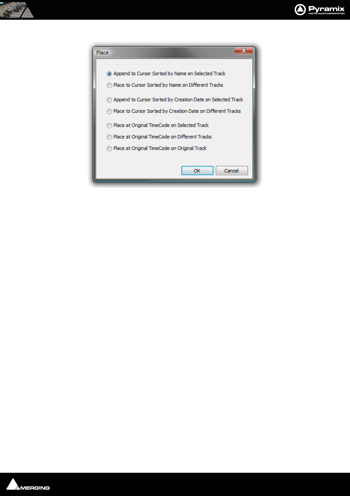
Place Opens the Place dialog:
The selected object(s) will be placed in the Timeline according to the rule chosen here.
The selected object will be placed in the timeline on the selected track and Playhead Cursor position at its Sync
Point or, if no Sync Point has been set, at its In Point
Placement Tool Opens the Placement Tool for placing the object
Send (Libraries only) Sends selected object(s) as e-mail attachment
Library Edit menu Place dialog
Media Management : Tools and Menus 4 - 50
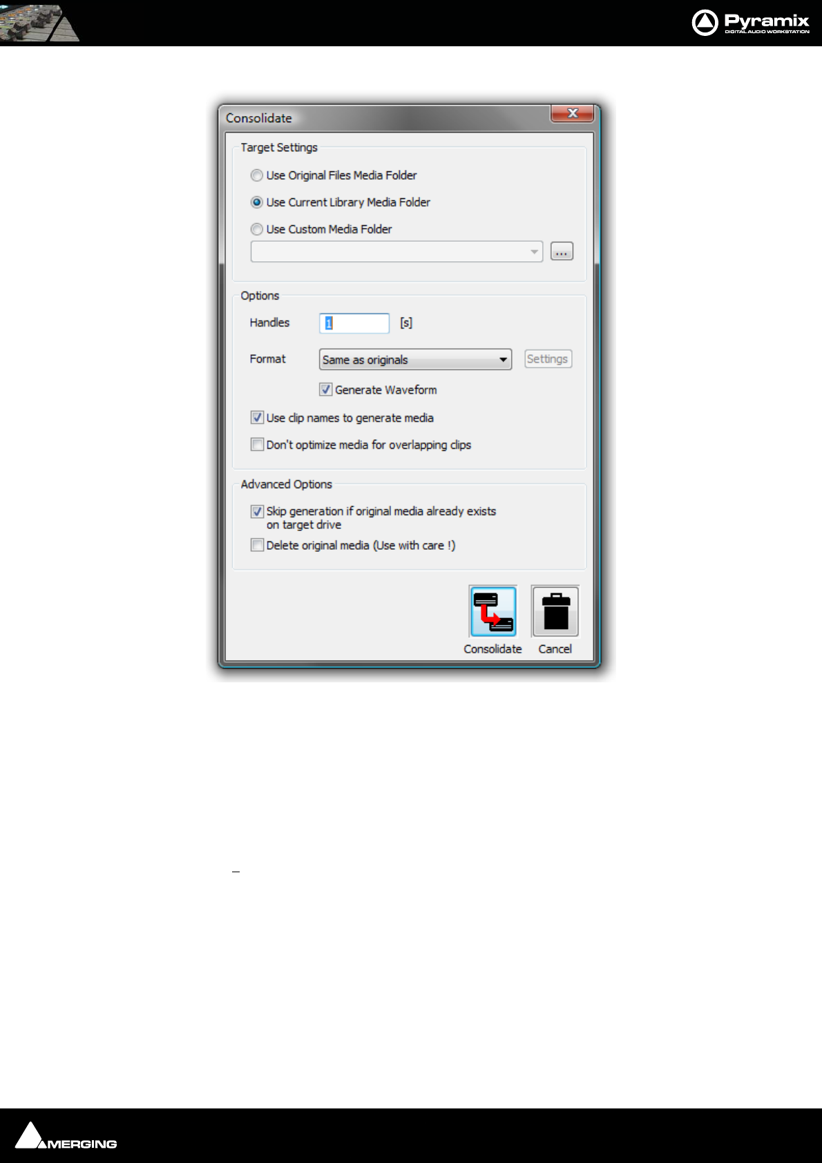
Consolidate (Libraries only) Opens the Consolidate dialog.
The Consolidate function makes a selective backup of the media segments in the selected object. I.e. instead of
backing up the whole of every media file referenced by the clips in a composition, Consolidate backs up only
those parts of the media files that are referenced by the clip segments in the Composition. Extra media, beyond
the clip boundaries can be added using the Handles option. This allows further manipulation of the Composition
within the limits of the handle length.
Please see also: Consolidating Projects on page 291
Delete Media (Media Management only) Deletes the selected Master Clip and Associated Media Files
Important! Delete Media does what it says. This command:
PERMANENTLY REMOVES AUDIO (and its associated Waveform file(s) from the drive.
Select All Selects all objects in the right-hand pane (Ctrl Click toggles selection of individual
objects)
Invert Selection Selected objects are de-selected, unselected objects are selected
Libraries Edit menu Consolidate dialog
Media Management : Tools and Menus 4 - 51
Search
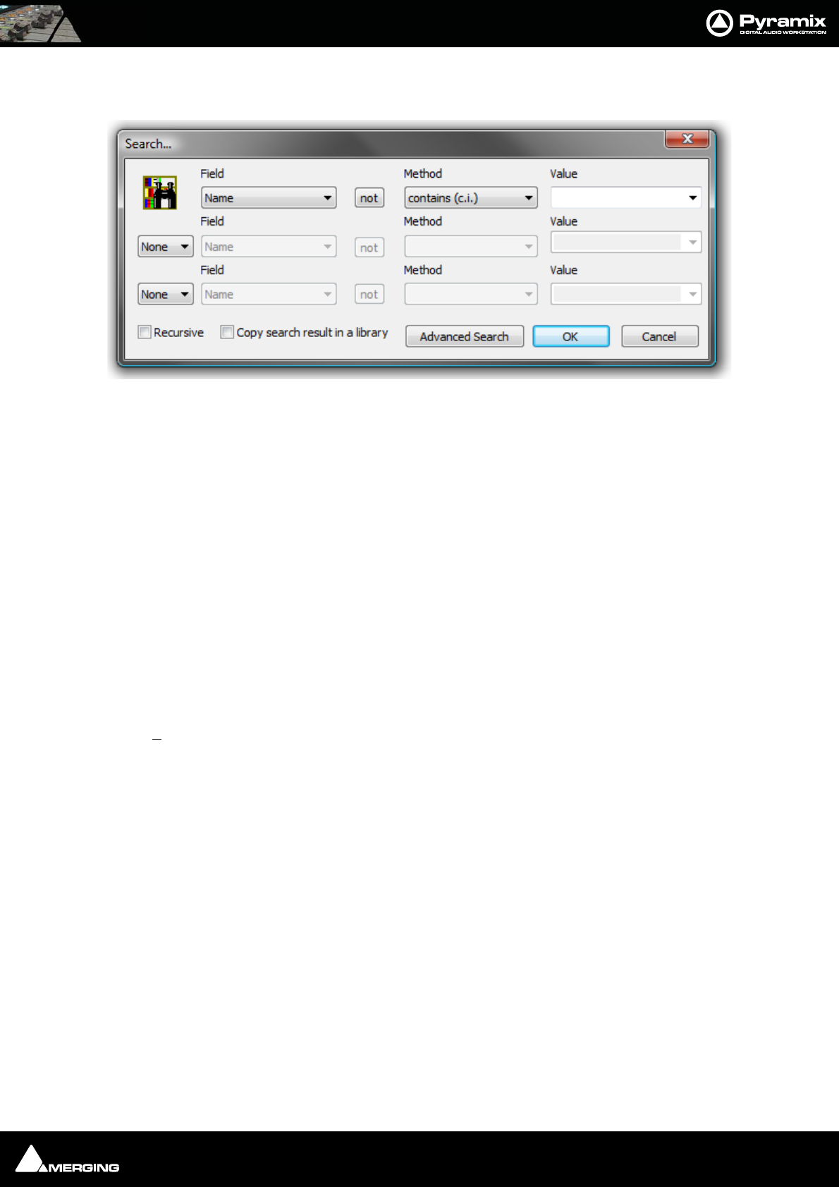
Search Opens the Search dialog
This dialog searching for specific entries using filters.
Field This combo box shows a list of all fields which may be used as the basis for the search.
Not When this button is pressed the query will find every entry in the library that does not
conform to the query parameters.
Method Gives a choice of filter parameters:
Value A value can be typed in or chosen from the list. The list displays all values present in the
library for the selected Field
Recursive When checked, the search will encompass all sub-folders in the library
Copy search result in library
When checked, all items matching the search criteria will be added to a new library
named Search Results in a shelf named as per the query itself. E.g. Name contains ‘D’ in
D:\Pyramix\Media
The two combo boxes on the left-hand side allow two further filters to be added with a choice of AND / OR
View Menu
The View menu determines how information is displayed.
Toolbar Turns the Toolbar on and off
Status Bar Turns the Status bar on and off
Large Show large Icons
Small Show small Icons
List Show as list
Detail Show as list with details
Filter When ticked, filters the items displayed in the right-hand pane of the Window according
to the filter parameters set under:
Filter Options (this dialog offers the same options as Edit > Search)
Library Search dialog
Media Management : Tools and Menus 4 - 52
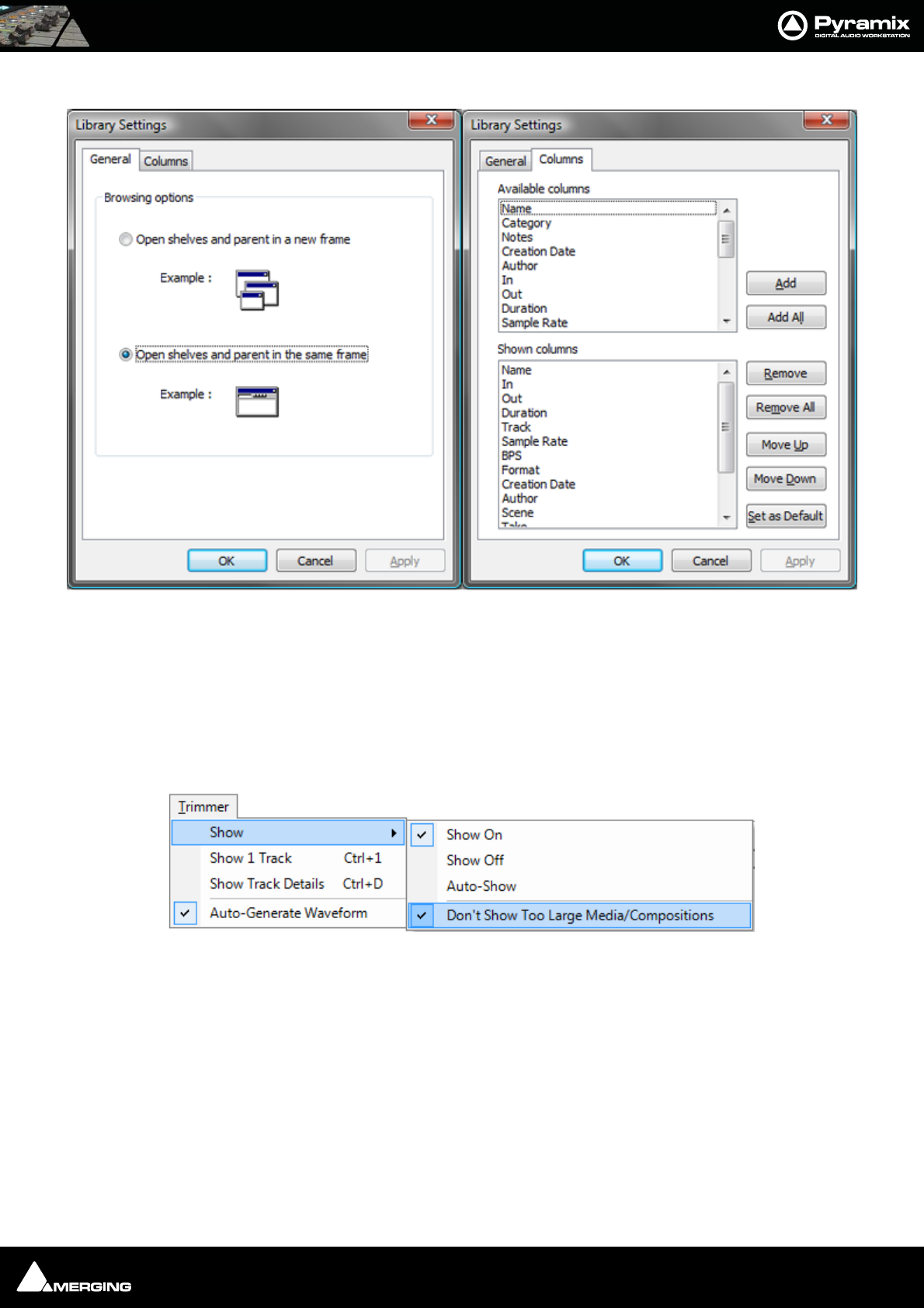
Options Opens the Library Settings dialog box with two Tabs, General and Columns.
The default General tab offers a choice of opening shelves and parent in a new frame or Opening shelves and par-
ent in the same frame and the Columns tab controls what is displayed in the right-hand pane of the Library Tab
Window. The columns displayed and their order are all customizable
New Window Opens another instance of the Library or Media Management Window
Refresh Forces a refresh
Trimmer Menu
Show
Show On When ticked the Trimmer is visible
Show Off When ticked the Trimmer is hidden
Auto-Show When ticked the Trimmer is only shown when a Media file is selected
Auto-Generate Waveform Waveforms are automatically created for objects without them.
Don’t Show too Large Media/Compositions When ticked Large Media files and Compositions will not be
opened in the Trimmer.
Note: When this option is selected Media or Compositions with more than 16 tracks or
more than 100 clips will not be shown in the Trimmer. Selecting this option avoids the
loading time associated with Compositions containing a large number of clips.
Document Libraries View menu Options General and Columns panes

Media Management : Tools and Menus 4 - 53
Show 1 Track Show only the first track of the object displayed in the Trimmer. When this option is
selected Up and down arrows appear at the left of the Trimmer track display which
enable any track to be displayed.
Show Track Details The following information is displayed for each track of the selected Media file:
•Track Name
• Track Number
• Track Type (left, Right, Center etc.)
• Track File Name (If the Media is recorded in One File Per Track mode)
Media Folder Menu
Only available in the Media management window.
Mount Media Folder Opens the Choose a media folder to mount dialog. Mounting a folder makes it visible to
the Pyramix media filing system
Unmount Media Folder Unmounts the selected Media folder (an Are you sure dialog protects from inadvertent
unmounting.) Makes the selected folder invisible to the Pyramix filing system
Refresh Media Folder Refresh works in the same way as Explorer Windows and makes visible files which have
been added since the Media Management Window was opened
Create Offline/Reference Library Please see: Using Offline/Reference Libraries on page 67
Create Quick Mount Libraries Please see: Quick Mount on page 62
Open Folder Opens the Media Management Library for the selected drive and directory. Double click-
ing on the name of the media directory has the same effect
Up One Level Moves up one level in the file hierarchy
Mounting Rules Opens the Mounting Rules dialog. This allows the user to apply special rules when
attempting to mount files that contain the same ‘unique’ identifier. Please
see: Mounting Rules on page 63
Properties Pops up an info box showing properties of the selected Media Folder
Edit, View and Trimmer Menus
The Edit, View and Trimmer menus are almost identical in Library and Media Management windows and details
can be found in Tools and Menus above. Exceptions are noted where they arise.
Convert Menu
Quick Import Enables sound files in any supported format to be imported into a Pyramix Media Drive or
Folder in either their original format or converted to the Pyramix native PMF format.
Note: Files in supported formats do not need to be converted to be used in Pyramix, a
big time-saver.
Media Management : Tools and Menus 4 - 54
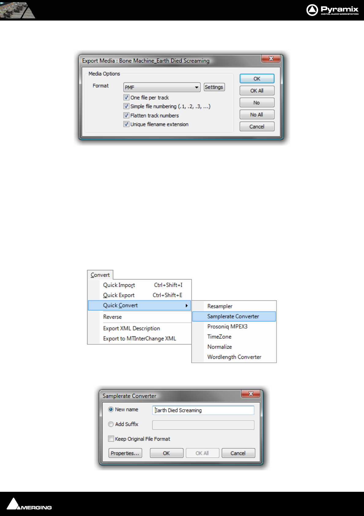
Quick Export Enables Pyramix Master Clips to be exported in any of the supported file formats with a
number of options.
One file per track When checked, multi-channel Master Clips are exported with a single file for each
channel in the clip.
Simple file numbering (.1, .2, .3, ...) When checked resultant files are numbered (.1, .2, .3, … instead of
_##001##_, _##002##_, …)
Flatten track numbers When checked, tracks are numbered 1, 2, 3, 4 instead of, for example 1, 2, 7, 8
Unique filename extension When checked, adds a unique filename extension.
Quick Convert > Enables one or more Media files to be converted in a variety of ways (see below)
Reverse Reverses the selection so it plays backwards
Export XML Description Exports Media Descriptions as an XML file Select a range of media and select Convert >
Export XML Description.
Convert - Quick Convert sub-menu
Output Dialog
Quick Export - Export Media: Dialog
Media Management Convert - Quick Convert sub- menu
Samplerate Converter dialog
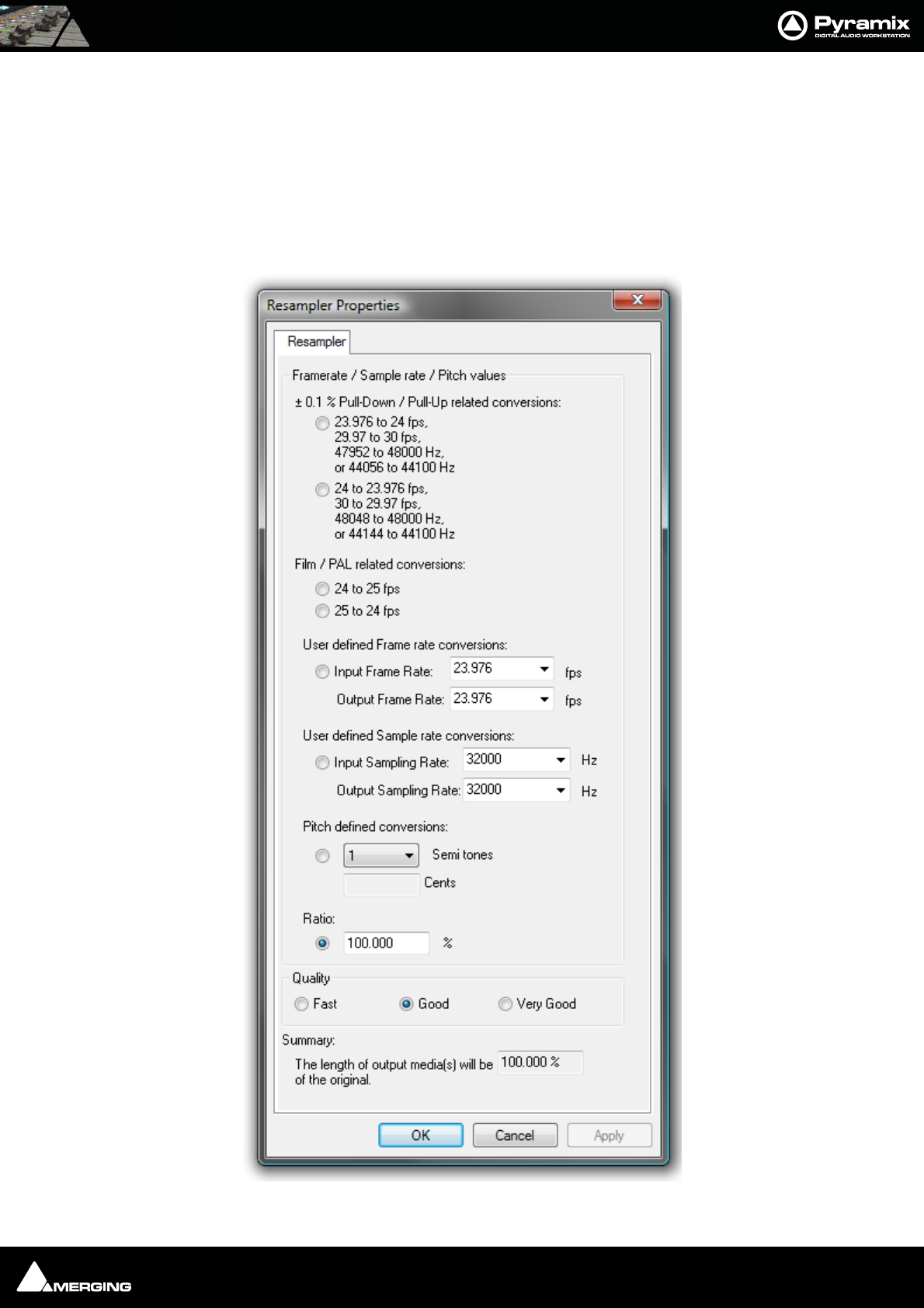
Media Management : Tools and Menus 4 - 55
All these options produce new media files on disk. Whichever conversion option is chosen, this dialog box will
pop-up with a title reflecting the selected process. Either a new name may be chosen or the existing one kept with
a new suffix. If you wish to process multiple files in one operation the Add Suffix button must be selected. When
multiple files are selected and this option chosen the OK All button is available. The Keep Original File Format
checkbox does what it says. The Properties... button opens a dialog box specific to each conversion type. (See
below)
Quick Convert Process Properties Dialogs
Resampler Properties
Resampler Properties dialog
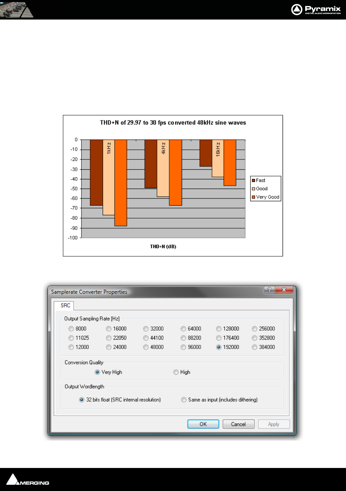
Media Management : Tools and Menus 4 - 56
This module is initially aimed at performing ±0.1 % pull-up / pull- down audio conversions, but there are several
possible ways of defining the ratio between the destination length and the final length (frame rates, sample rates,
pitch and ratio in percent).
The process differs from a Time Stretch operation since the pitch is modified. The Input and Output files have the
same sampling rate but the length of the output files will be: (initial length) x (displayed ratio).
Another setting, Quality, has an effect on the resolution of the oversampling process of the treatment.
This module is available, like MPEX, in the 'Quick convert' list of the Media Manager, the Project menu (to process
all the media in a project), and as a 'Surround Encoder' (Project > Surround Processing).
The following graph gives an indication of the effect of the three Quality settings on THD & Noise.
:Samplerate Converter Properties
Resampler quality setting effect on THD & Noise
Samplerate Converter Properties dialog
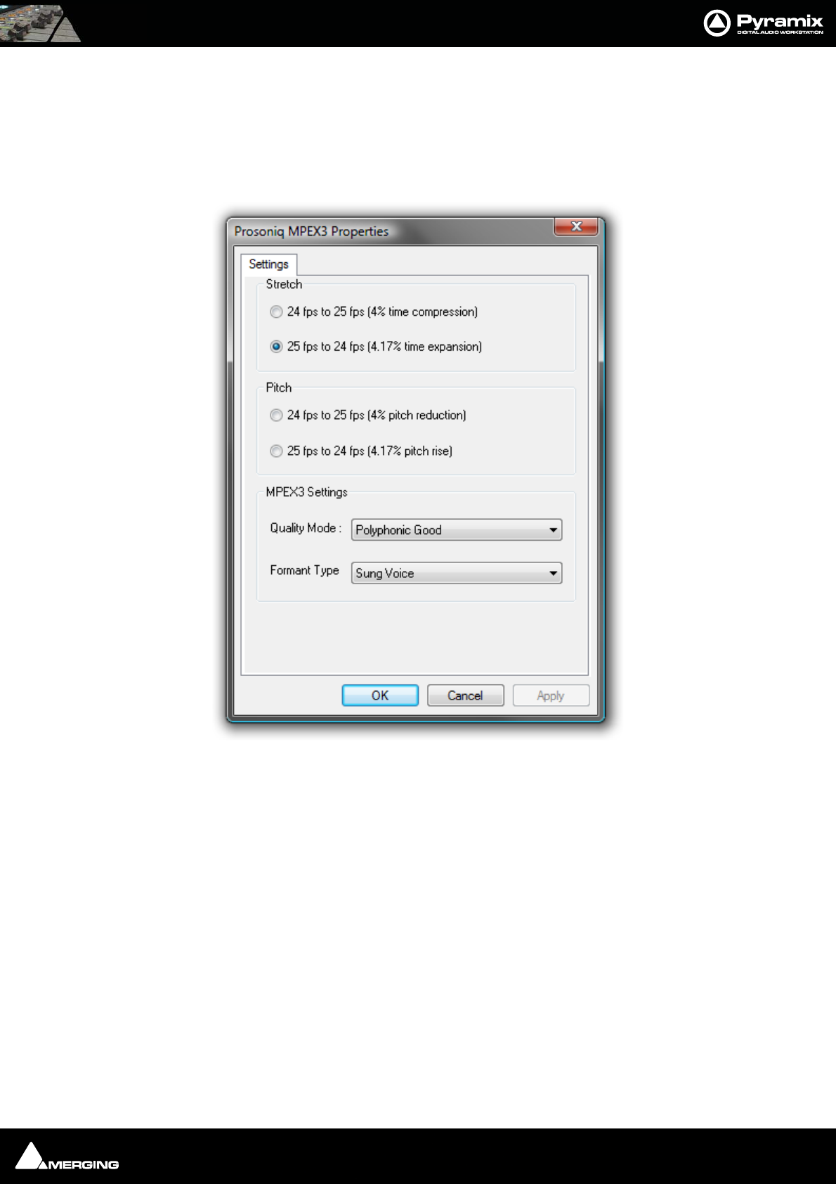
Media Management : Tools and Menus 4 - 57
Output Sampling Rate [Hz] select the desired sampling rate by clicking the relevant radio button.
Conversion Quality Select the desired quality. Very high offers better conversion but takes longer.
Output Wordlength Select the desired Output Wordlength. 32 bits float (SRC internal resolution) (default) or
Same as input (includes dithering)
Prosoniq MPEX3 Properties
Select the required conversion factor from the four Stretch and Pitch options.
Optimize MPEX3 Settings by making appropriate choices from the Quality Mode and Formant Type combo
boxes.
Quality Mode Single Instrument Fast
Single Instrument Best
Polyphonic Fast
Polyphonic Good
Polyphonic Best
Formant Type Sung Voice
Spoken Voice
Prosoniq MPEX3 Properties dialog
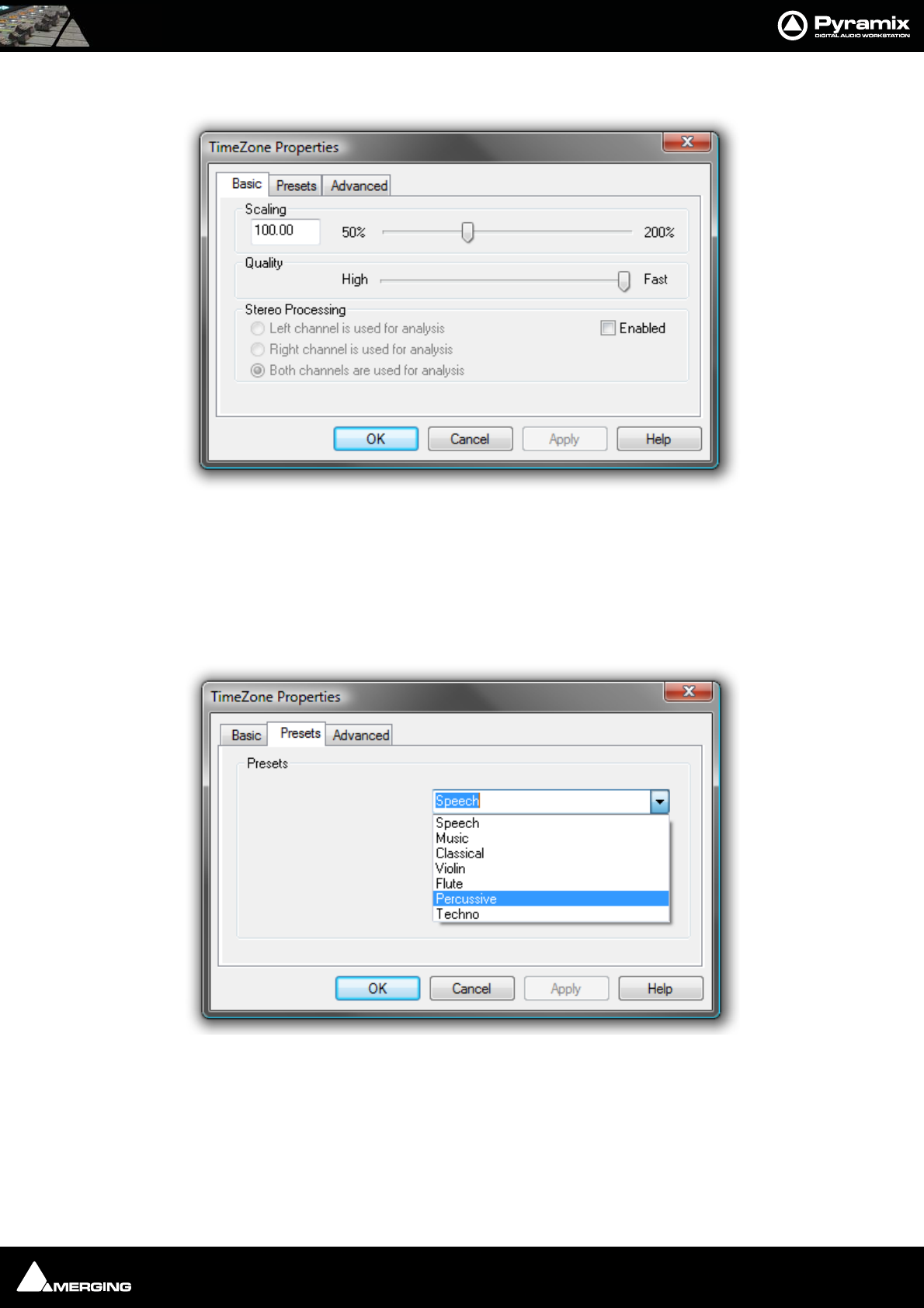
Media Management : Tools and Menus 4 - 58
TimeZone Properties - Basic
Scaling Select the desired change in length in percentage by typing in the box or positioning the slider.
Quality The slider offers a choice between High Quality and Fast processing.
Stereo Processing When the Enabled box is checked offers a choice of which channel(s) of a stereo media will be
used for analysis.
TimeZone Properties - Presets
The drop-down list offers a choice of algorithm presets for various sound types.
TimeZone Basic Properties dialog
TimeZone Presets Properties dialog
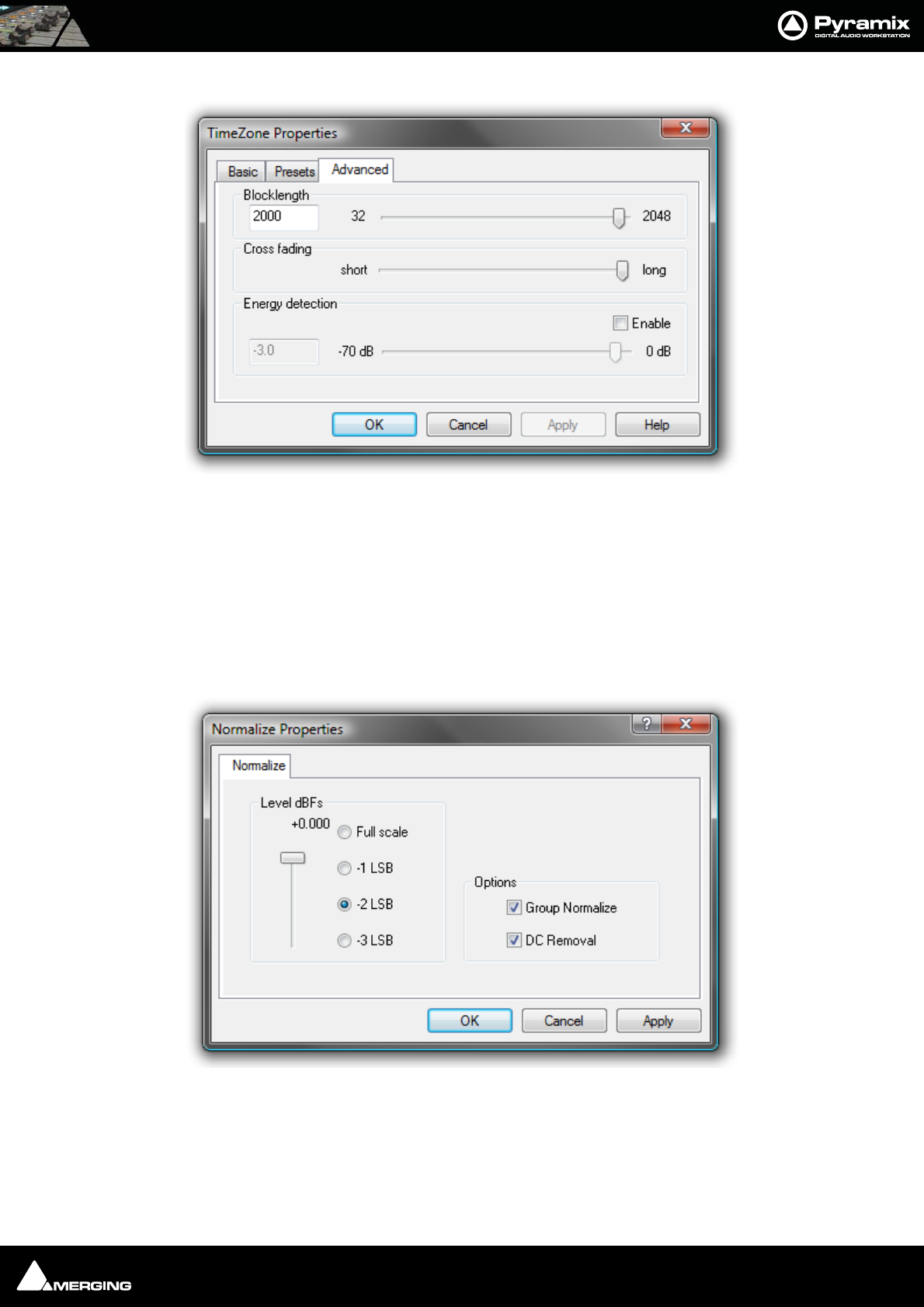
Media Management : Tools and Menus 4 - 59
TimeZone Properties - Advanced
Blocklength Allows the user to determine the length of the blocks used for processing by entering a value
between 32 and 2048 in the text box or by positioning the slider.
Crossfading Allows the user to vary the length of the crossfades between blocks by positioning the slider
Energy Detection When the Enable box is checked the user can set the threshold level by entering a value
between -70dB and 0dB in the text box or by positioning the slider.
These parameters affect the quantity and character of audible artifacts and allow fine tuning of the process to suit
specific material.
Normalize Properties
Level dBfs
Here you can select from four preset values, or use the slider to specify the maximum level for the new file.
Group Normalize
When checked, the level of the highest peak in any group of clips is raised to maximum and level of the other clips
is increase proportionally.
TimeZone Advanced Properties dialog
Normalize Properties dialog
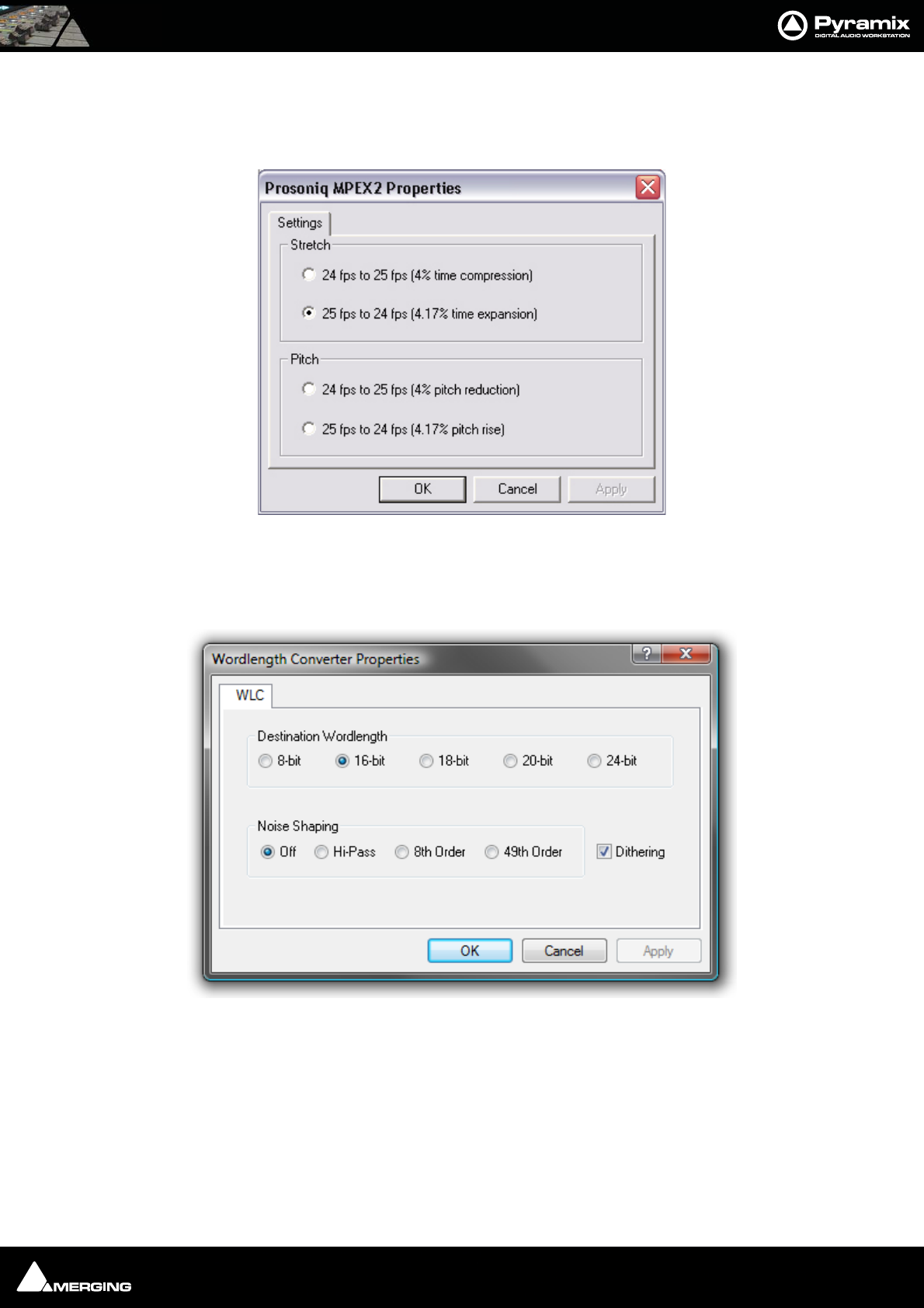
Media Management : Tools and Menus 4 - 60
DC Removal
When checked, D.C. offsets will be removed.
Prosoniq MPEX2 Properties
Select the required conversion factor from the four Stretch and Pitch options.
Wordlength Converter Properties
Destination Wordlength
Select the desired wordlength using the radio buttons.
Noise Shaping
Select the required quality of Noise Shaping.
Hi-Pass is single order shaping with
8th Order and
Prosoniq MPEX2 Properties dialog
Wordlength Converter Properties dialog
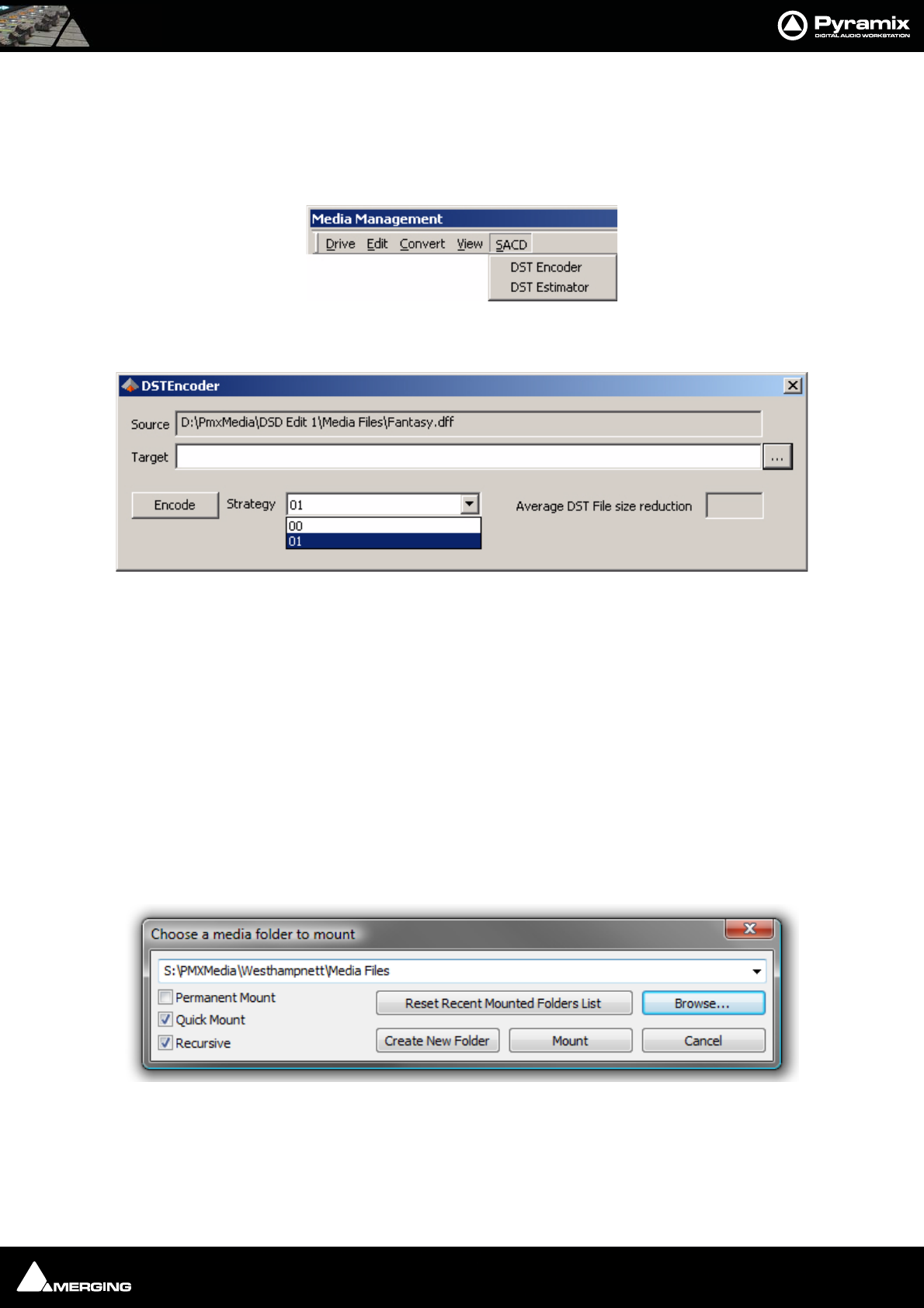
Media Management : Managing Media Folders 4 - 61
49th Order offering improved quality.
A higher quality setting will produce better results, but the processing time will also increase.
Dithering When checked, If dithering is required, dithering will be applied.
SACD Menu
DST Encoder Encode an Edited Master in DST.
DST EstimatorEstimate the DST encoding of an Edited Master with a graph to show the file reduction rate as a
function of the audio material.
Media Browser Menu
Reconnect Media references while browsing allows Pyramix to attempt to automatically relink missing media in any open
projects while browsing for easy searching. This option can be disabled for quicker
browsing.
Mount Currently Displayed Media Folder allows easy mounting of the Media Folder currently displayed in the Media Browser.
(Typically when the proper folder is found).
The Media Browser uses Quick Mount libraries whenever it can to increase browsing speed. Creating Quick
Mount libraries for frequently browsed folders is therefore recommended. Please see: Quick Mount on page 62
Managing Media Folders
This dialog can be opened in several ways. From the Media Management Tab Window Media Folder > Mount
Media Folder or by right-clicking a Media Drive or Media Folder entry in the right-hand pane, and from the New
entry in Media Folder combo boxes in various Pyramix Windows.
Media Management SACD menu
DST Encoder dialog
Choose a media folder to mount dialog
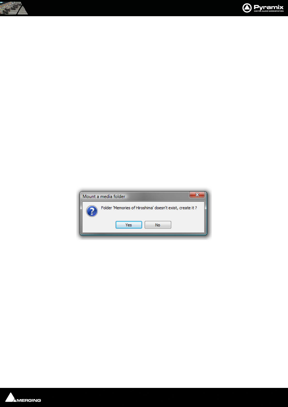
Media Management : Managing Media Folders 4 - 62
The text box allows a complete path to be entered or a Media Folder or Drive can be chosen from the drop down
list. Alternatively, a new Media Folder can be created by typing its name in the text box. The new folder will be cre-
ated below the current one in the tree.
Permanent Mount
When checked, the chosen folder will be mounted at start up for all future Projects. (Can be useful for sound
effects libraries etc.)
Quick Mount
If you check this Quick Mount box the system will load the 'QuickMount' library instead of parsing all the media
files in the folder. (See below)
Recursive
When checked, all sub-folders of the chosen folder will also be mounted.
Reset Recent Mounted Folders List
Clears the drop-down list. The list contains all folders that have been mounted since the list was last cleared.
Browse...
Opens the Browse for Folder dialog box which enables any Windows drive or folder on the local machine or
across a network to be selected for mounting.
Mount
Mounts the selected Media Drive or Folder. To create a new Folder, simply type a name in the text entry box and
click on Mount. (If you want the new folder to be created somewhere other than the current path tree, either type
the full path or use the drop-down list or browser to navigate to the desired directory, then add the new name in
the text entry box after the path) The Mount a media folder info box appears:
Click Yes to create the new folder, or No to cancel the operation.
Quick Mount
Quick Mount mode is on by default.
When a folder is mounted normally, a library called '__QuickMount.pml' is created and stored in the original
folder. This can dramatically reduce the time taken to mount media files when a project is opened.
Note: The double underline is an integral part of the filename
If the QuickMount library is not found then a standard mount is performed and a QuickMount library is created to
enable future Quick Mounts to take place.
Quick Mount libraries automatically regenerate when next mounted if anything changes in the Media Folder.
Quick Mount libraries are not regenerated if Media Folders move, are renamed or change Drive letters.
The menu option Media Folder > Create Quick Mount libraries creates all required Quick Mount libraries for a
given drive, folder or network path, recursively. (Typically this will be carried out overnight on the whole server)
If new media files are added (or removed) to or from a previously 'Quick Mounted' folder, the Quick Mount library
can be manually updated by selecting Media Manager > Refresh.
Mount a media folder info box
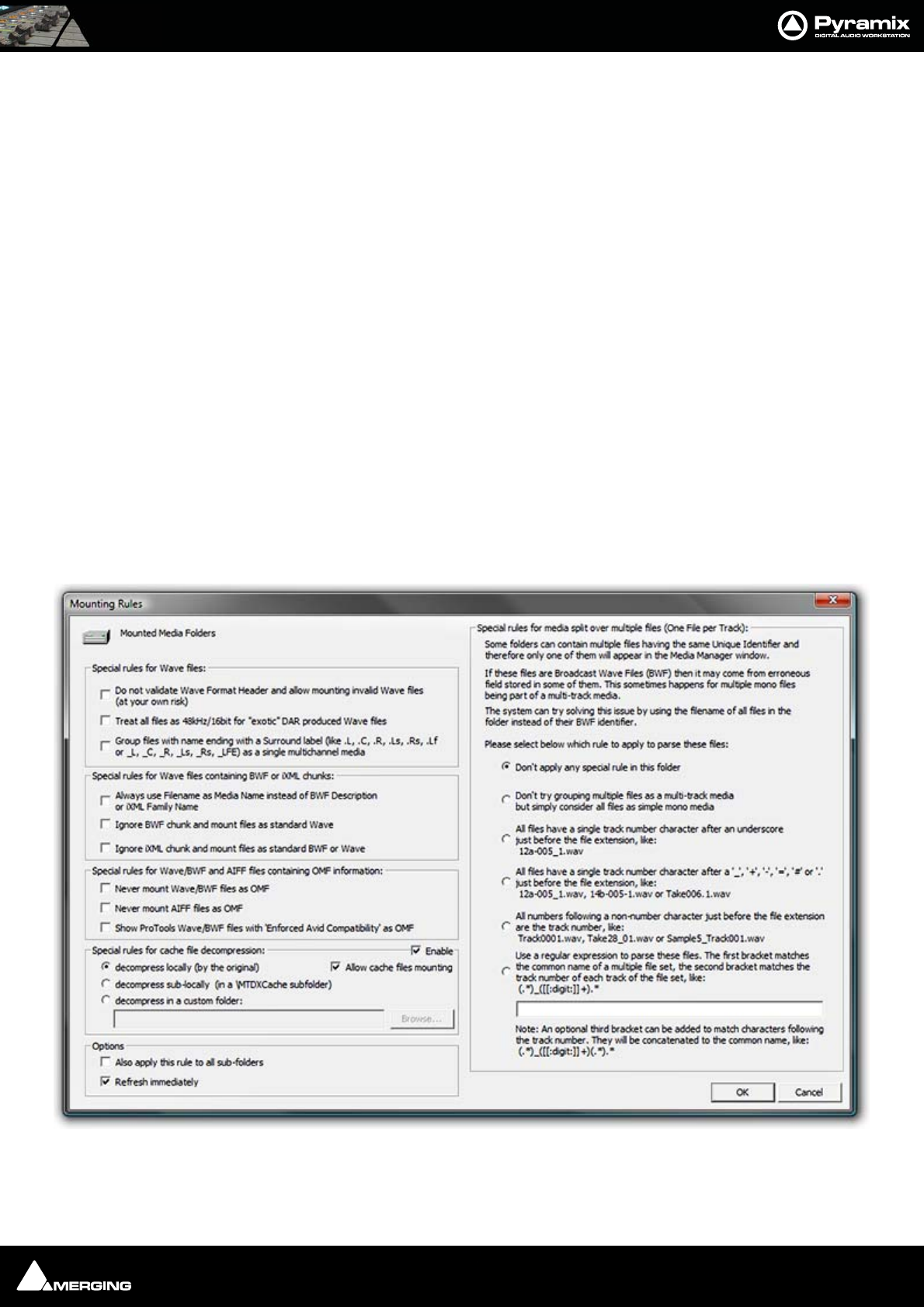
Media Management : Mounting Rules 4 - 63
If the Use Quick Mount whenever possible check box in the Settings > All Settings Application > Location
page is checked, permanently mounted folders are automatically 'Quick Mounted' when the application is started
Mounting Rules
This dialog allows various rules to be applied when parsing BWF or Wave files in a given folder. Pyramix always
tries to group multiple mono files that are part of a single multi-track media when viewed in the Media Manager
so the multiple mono files appear as a single item with multiple tracks numbered in the form A 1-2 or A 1-8, or A 1-
2, 7-8, etc. Otherwise, you would see a separate entry for each mono file whether or not it is part of a multi-track
'set'. In order to achieve this in the case of BWF files Pyramix looks at the BWF header and uses the Originator
Reference field as a Unique Identifier with some rules as defined by the EBU organization and some conventions
adopted between various manufacturers.
It may happen that some files do not follow these rules and therefore sometimes the Pyramix Media Manager fails
to properly mount these files. Sometimes some files are missing, or some tracks within a multi-track media are
missing. The Pyramix Media Manager detects these conflicts at the time the folder is mounted and informs the
user of such a problem, prompting him to go to the Media Manager > Drive > Mounting Rules menu item. The
Mounting Rules dialog allows a variety of different rules to be applied for this or these Media Folders so all files
are properly mounted.
Folders where a conflict has been detected appear in Red.
Folders where a special Mounting Rule has been applied appear in Dark Green.
The Mounting Rules dialog can be found in the Media Management Tab window in the Media Folder menu :
Media Folder > Mounting Rules
Most of the dialog is self-explanatory. The description of the Rules that can be applied appears in the Mounting
Rules dialog as above but for convenience, we have also listed the options on the left of the dialog below.
Mounting Rules dialog

Media Management : Mounting Rules 4 - 64
Special rules for Wave files
Do not validate Wave format Header and allow mounting invalid Wave files (at your own risk)
This can enable files to be mounted that do not follow the Wave specification strictly.
Treat all files as 48kHz/16bit for ‘exotic’ DAR originated Wave files
As it says. Please see DAR WAV file Import on page 64
Group files with name ending with a surround label (like .L,. C, .R, .Ls, .Rs, .Lf or _L, _C, _R, _Ls, _Rs,
_LFE) as a single multichannel media
As it says. Useful when working with files generated by certain other DAWs.
Special rules for Wave files containing BWF or iXML chunks:
Always use Filename as Media Name instead of BWF Description or iXML Family Name
This will allow files recorded in Steinberg’s Nuendo to be mounted and can also help with (re)conforming files
from Aaton Cantar or other location recorders where the filename matches information in the EDL.
Ignore BWF chunk and mount files as standard Wave
This effectively treats Broadcast Wave files as ordinary Wave files and can help with (re)conforming as above.
Ignore iXML chunk and mount files as standard BWF or Wave
This treats iXML files as pure Wave or BWF with the same aims as above.
Special rules for Wave/BWF and AIFF files containing OMF information:
Never mount Wave/BWF files as OMF
Never mount AIFF files as OMF
Show ProTools Wave/BWF files with ‘Enforced Avid Compatibility’ as OMF
Special rules for cache file decompression
When compressed audio files are mounted Pyramix creates an uncompressed WAV version of the file(s) in a cache.
The location of these cache files is determined by this dialog.
Locally (by the original) File(s) will be created in the same location as the original file.
Sub-locally (by the original, in a \MTDXCache sub folder). File(s) will be created in a sub folder created by Pyra-
mix in the same location as the original file.
Custom (files are generated to the specified location). File(s) will be created in a user specified location. When
this option is selected the Browse... button is available to open a file browser window to set the user defined path.
Enable enables the rule.
Allow cache files mounting when ticked, cache files can be mounted directly, otherwise they remain invisible, i.e.
filtered out of Media Manager views.
Options
Also apply this rule to all sub-folders
Refresh immediately
DAR WAV file Import
It seems that DAR systems were strange in that they always played audio at 48khz. Even if 44.1khz audio
was imported into a DAR, it would be converted to 48khz. The sample rate and bit-depth information in
the WAV files was ignored as everything was assumed to be 16-bit/48khz. We've seen WAV files from
DAR systems where the WAV files were identified as containing 128-bit audio or having a 10hz sample
rate. So it would seem there must have been a bug in the DAR software that caused incorrect data to be
stored in the WAV header. There is already code in the Pyramix WAV handler to try to catch these com-
pletely invalid parameters but, unfortunately, the WAV files from DAR don't include any manufacturer
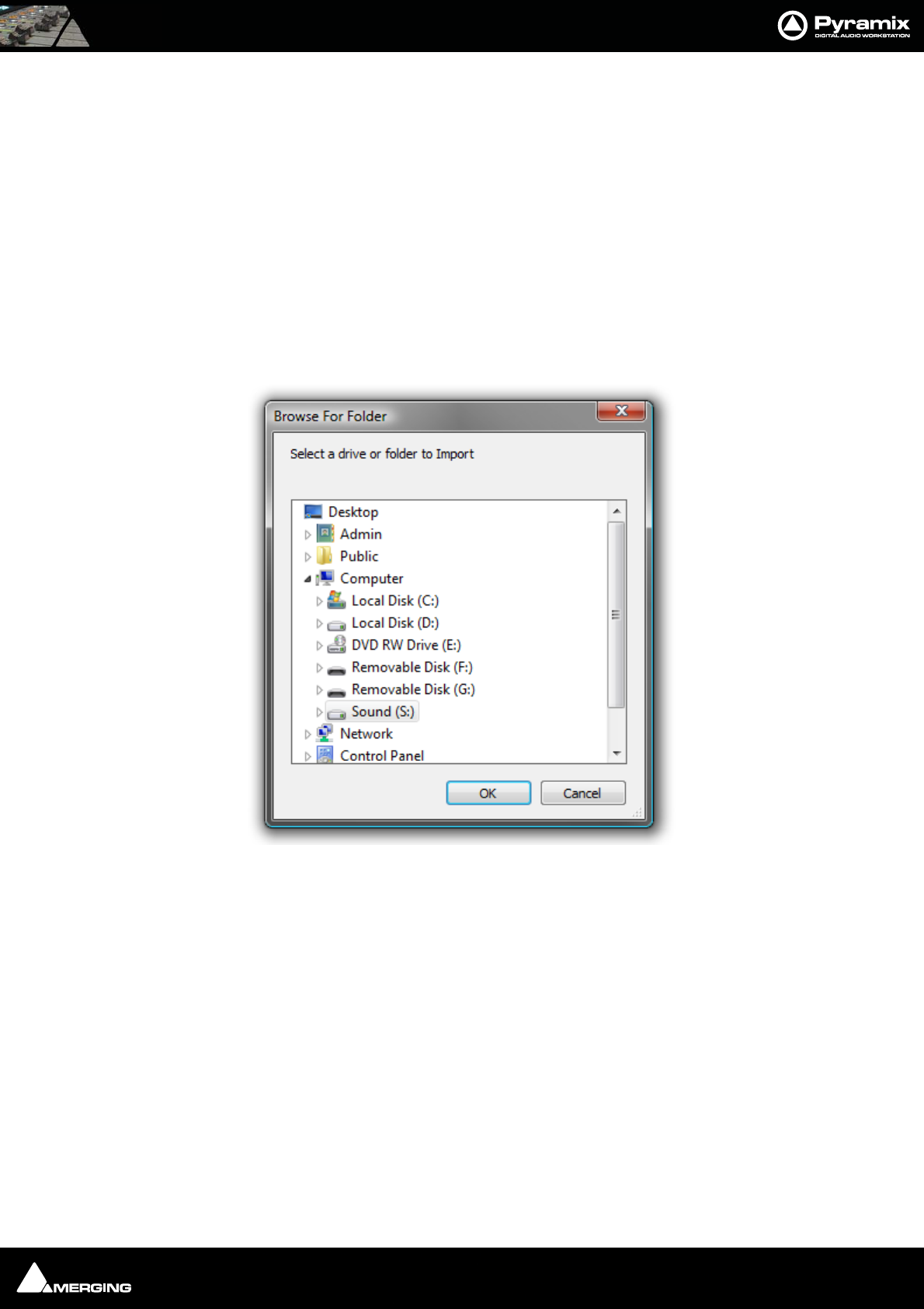
Media Management : Offline / Reference Libraries 4 - 65
identifier so it isn't simply a case of identifying that they are from a DAR and automatically forcing them
to 48khz in Pyramix.
Offline / Reference Libraries
As the name implies Offline/Reference Libraries are useful for keeping track of very large projects and material
on media that may not be permanently on-line.
Creating Offline/Reference Libraries
Offline libraries are created in the Media Management Tab Window by selecting
Media Folder > Create Offline/Reference Library.
This will open a browser Window:
Navigate to the Media Drive or folder you wish to include in the library and click on OK.
Browse For Folder - Select a drive or folder to Import
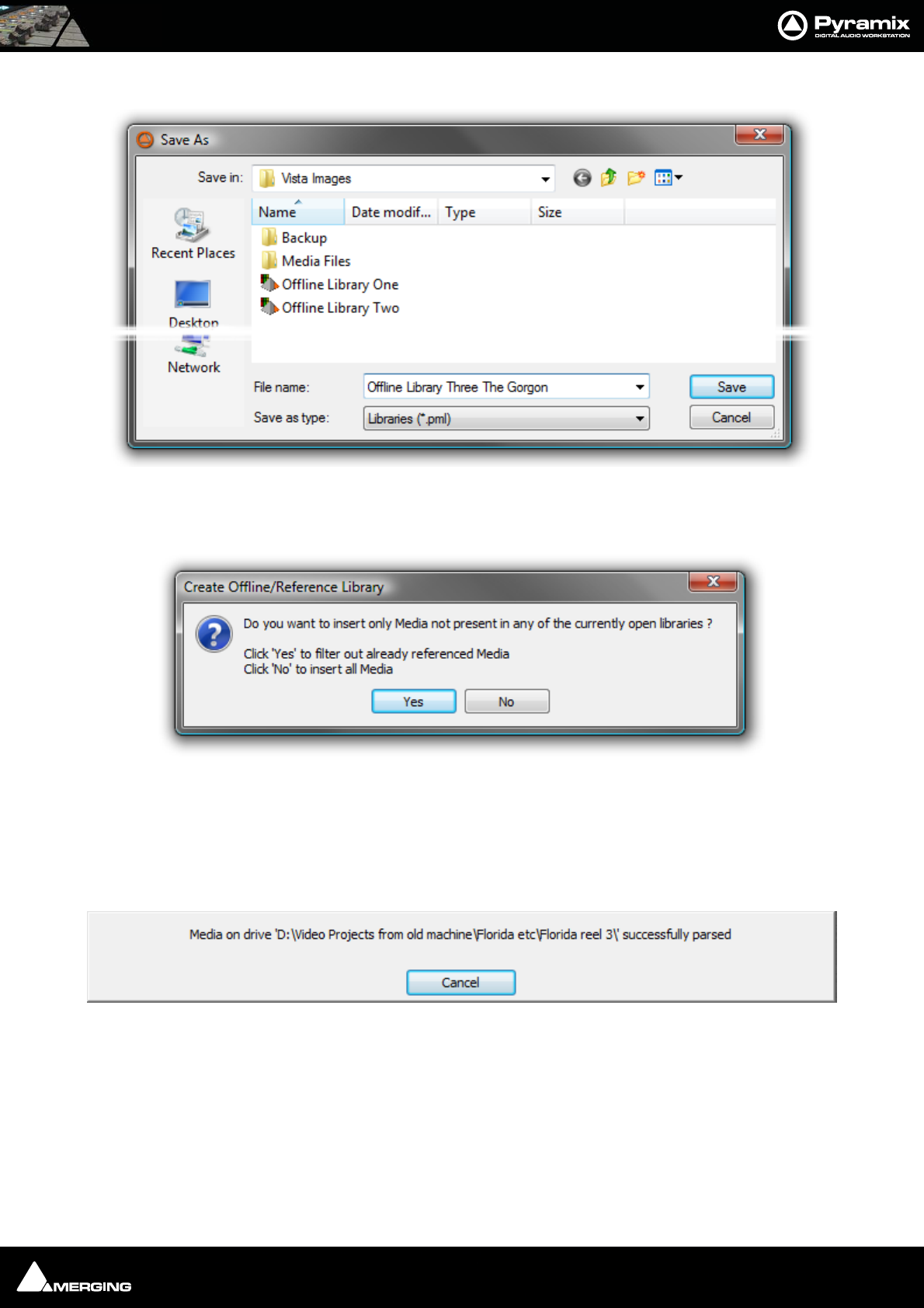
Media Management : Offline / Reference Libraries 4 - 66
A Save As browser Window will open:
Navigate to the folder where you wish to create the new library or create a new folderthen click on Save. The Cre-
ate Offline/Reference Library dialog opens:
Click on Ye s to filter out Media already referenced in any library open currently.
Click on No to insert all Media
A Window opens showing progress. While the library is being created you have the option of aborting the process
by clicking on Cancel:
You might wish to cancel the process if you have inadvertently included a huge archive which could take some
considerable time to parse.
Save As browser
Create Offline/Reference Library dialog
Create Offline/Reference Library progress dialog
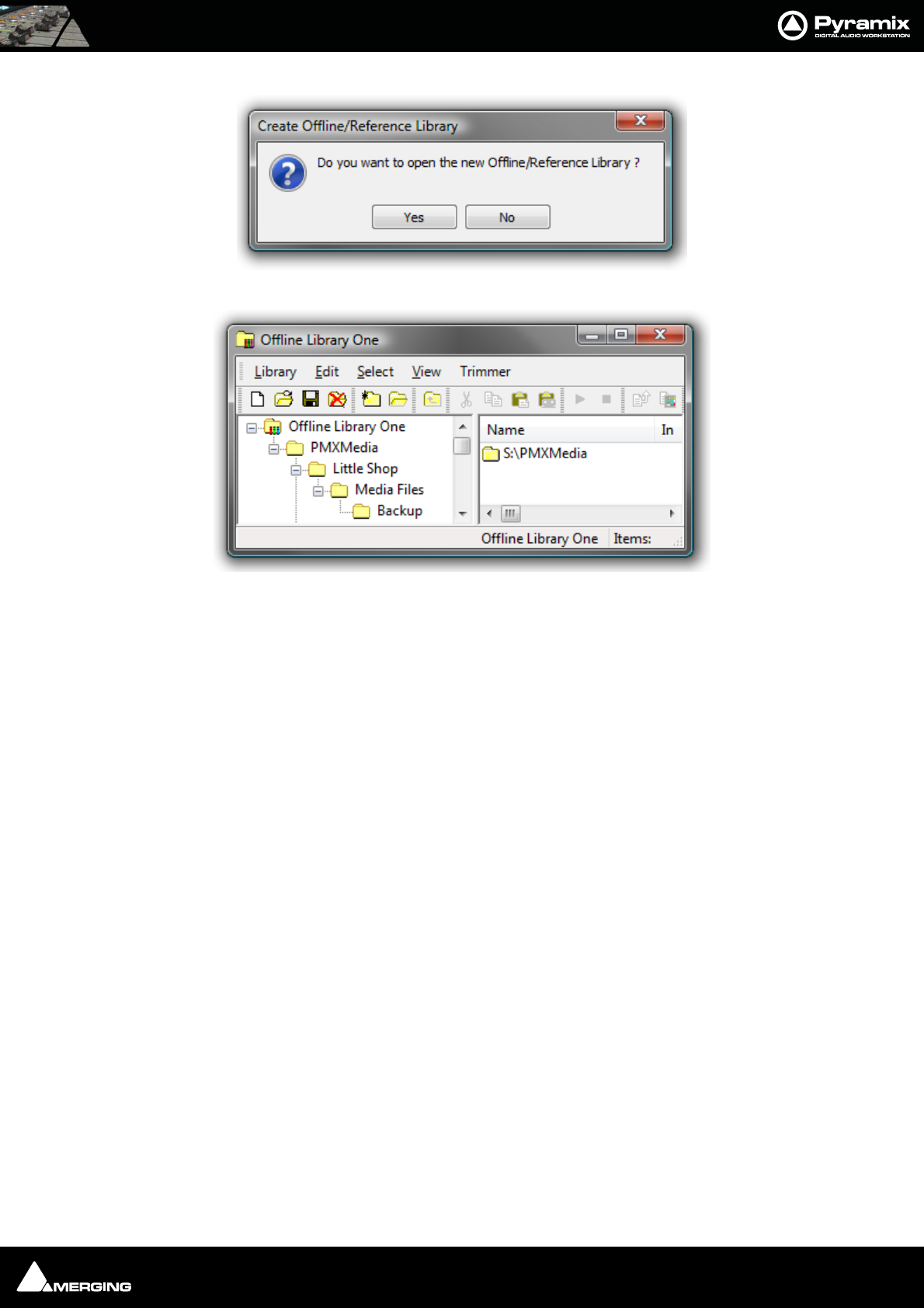
Media Management : Offline / Reference Libraries 4 - 67
When the library creation process is complete this dailog opens:
If you click on Yes the newly created library will be opened:
Using Offline/Reference Libraries
When used in the following manner Offline Libraries provide an extremely powerful organizational tool for man-
aging very large project libraries and, for example, sound effects libraries.
Mount The Media
In the Media Management Tab Window, Mount all folders or disks containing your audio files (as ripped with
LibraryLoader, mTools or any other source). We strongly suggest these files be in either PMF or BWF (Broadcast
Wave Format) as they both have a long description field, a unique identifier and a timestamp.
Note: There may well be Copyright implications when working with ripped files. Please
ensure you comply with any restrictions on copying other people’s material.
Create An Initial Library
Select the Media Management Tab Window Menu item Media Folder > Create Offline/Reference Library and
choose All mounted Media folders and Add all Media. This will create an initial library referencing all your audio
files. All the media files / disks may then be unmounted.
The library can now be re-organized, folders created, items duplicated etc. etc.
You can make searches (queries) or apply filters to your Offline / Reference library(ies) and, if Project > Auto-
mount Media is on, each time an item is dragged onto the Timeline the appropriate audio file will automatically
mount. Or this can be done this manually by calling Project > Mount Referenced Media.
Updating Libraries - Orphaned Entries
If the original audio files are moved or reorganized, just mount all the folders once again, load all your libraries and
call the Library menu command Update Referenced Media Paths.
Updating Libraries - Adding new files
If new audio files are added to your media disk(s), simply mount these folders, load all your libraries and proceed
as in “Create An Initial Library” above, but select the option, Filter Media already present in other libraries.
This will create a new library containing only references to the freshly added audio files. These new items can then
be copied/moved to any (or many) already existing Offline library(ies).
Offline/Reference Library

USER MANUAL
www.merging.com/Pyramix
Tracks and Track Groups

Tracks and Track Groups : Tracks 5 - 69
Tracks
Each Project has a user defined number of audio Tracks on which audio Clips can be placed, or audio inputs can
be recorded. Blocks representing placed or recorded Clips will appear on the Track as soon as a Clip has been
placed or recorded onto it. The Track itself extends horizontally beneath the Time Scale bar, and multiple Tracks
are stacked vertically.
On the left side of each Track is a Header panel with various controls and information displays. Please see: Track
Header Panel on page 73
Some operations only apply to a selected track. A Track can be selected by left-clicking anywhere on the Header
which will then appear in a darker shade of gray. However, when selecting a Track, be careful NOT to inadvert-
ently click on any of the Track buttons, thereby changing a Track function: the Track Name is a good place to click
in order to select it.
Adding Tracks
By default, a new Project opens with the same number of Tracks as there are Input Channels defined in the
Mixer for the Project. However, Tracks can easily be added or deleted.
Creating tracks via paste
If a clip is dragged and dropped or copied and pasted from Media Management or a Library onto a blank area of
the TimeLine where no tracks exist, sufficient tracks will be created below the last existing track to accommodate
the number of channels in the clip.
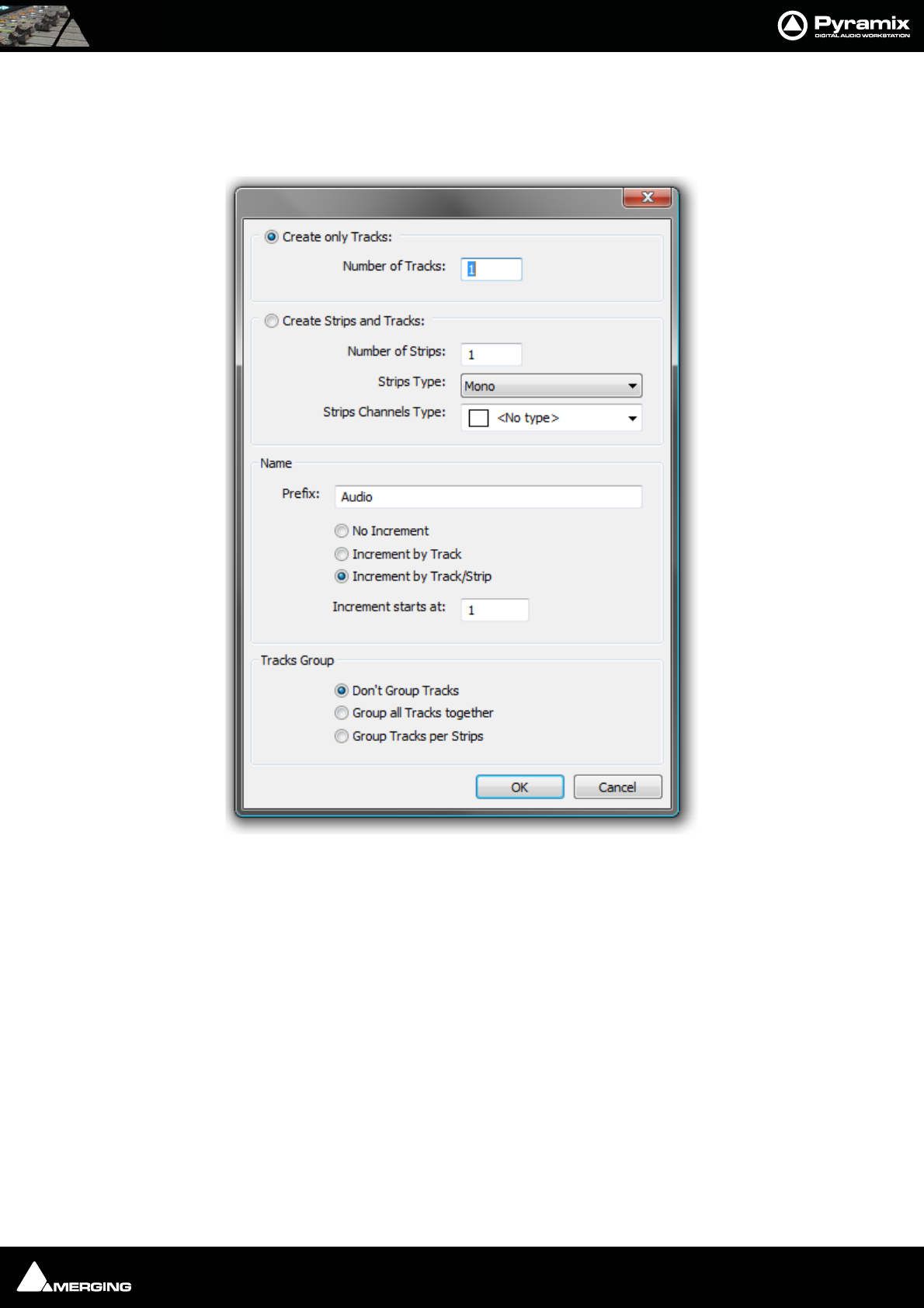
Tracks and Track Groups : Tracks 5 - 70
Create New Tracks
New tracks are inserted below the currently selected track or, if no track is selected, at the bottom after the last
existing track. To add Tracks to the Timeline, select Tracks > New Audio Track (or right-click in a blank area of the
track header and choose New Audio Track from the context menu).
Create only Tracks: / Create Strips and Tracks:
To simply create Mono tracks only, check the Create only Tracks radio button, enter the number of tracks
required into the Number of Tracks data entry box and click OK. The Track(s) will be created with the default
name Audio numbered in ascending order from 1.
If you wish to create Mixer strips at the same time, check the Create Strips and Tracks radio button. Enter the
number of Strips required into the Number of Strips data entry box. Pyramix currently supports four categories of
Strip. The default is Mono.
Create New Tracks dialog
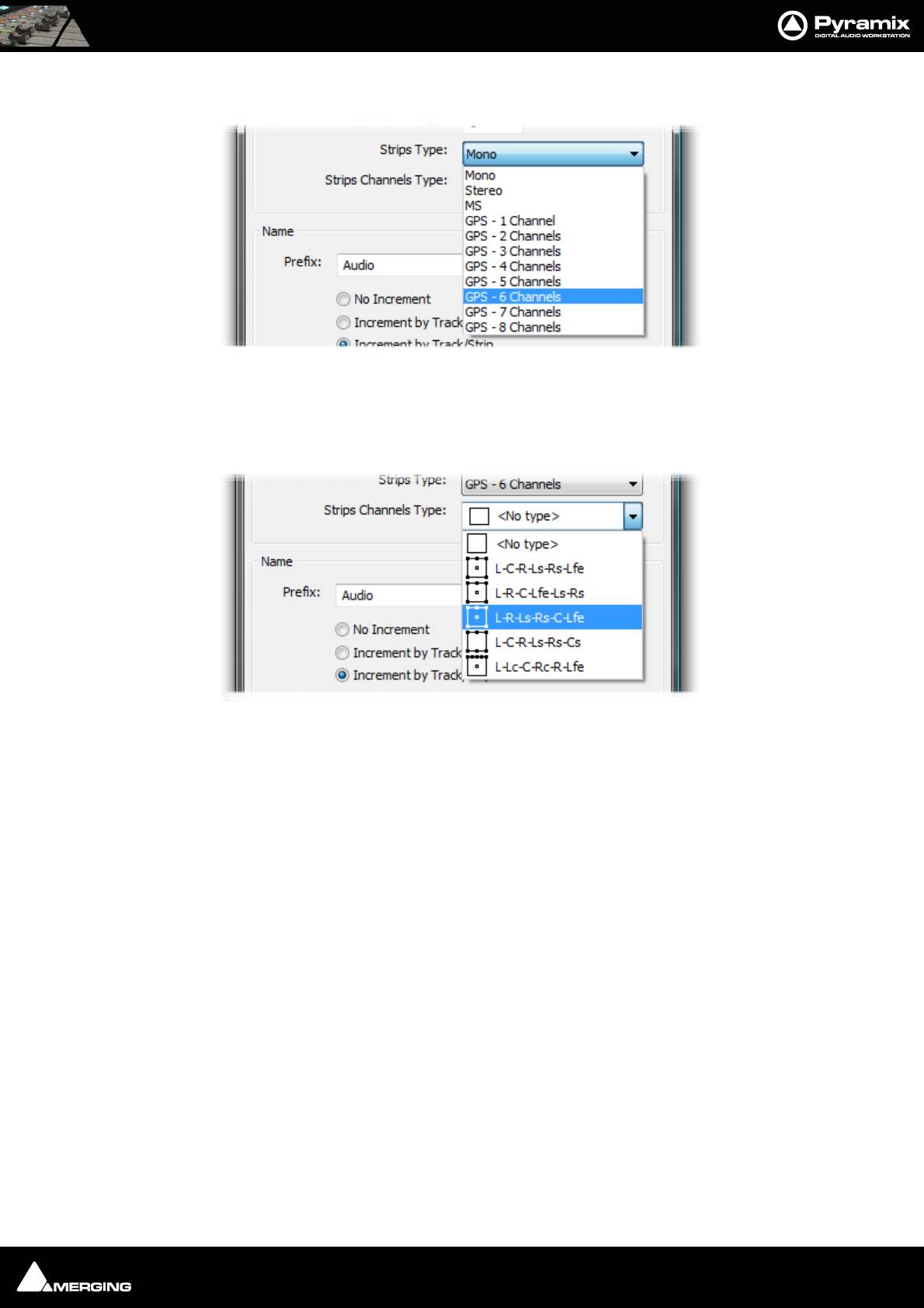
Tracks and Track Groups : Track Types 5 - 71
Other types of strip can be selected from the Strips Type drop-down list.
If you choose anything other than Mono the appropriate number of tracks will be created to suit the chosen strip
type. The strip inputs and outputs will be ‘tagged’ with a letter or letters indicating channel assignments depend-
ing on the choice made in the Strips Channels Type drop-down list.
The formats on offer vary according to the Strip Type chosen. A six channel example is shown above. As a further
example, if you choose MS. <No Type> is the only available choice and the strip I/O is tagged C and W for Centre
and Width since this is the logical format.
Track Types
All tracks are single channel but, when created with a Strip Channels Type format, certain functions are automati-
cally linked, namely: Automation, Solo, Mute, Monitor mode, Record mode, Waveform display.
Create New Tracks dialog - Strips Type
Create New Tracks dialog - Strips Channels Type
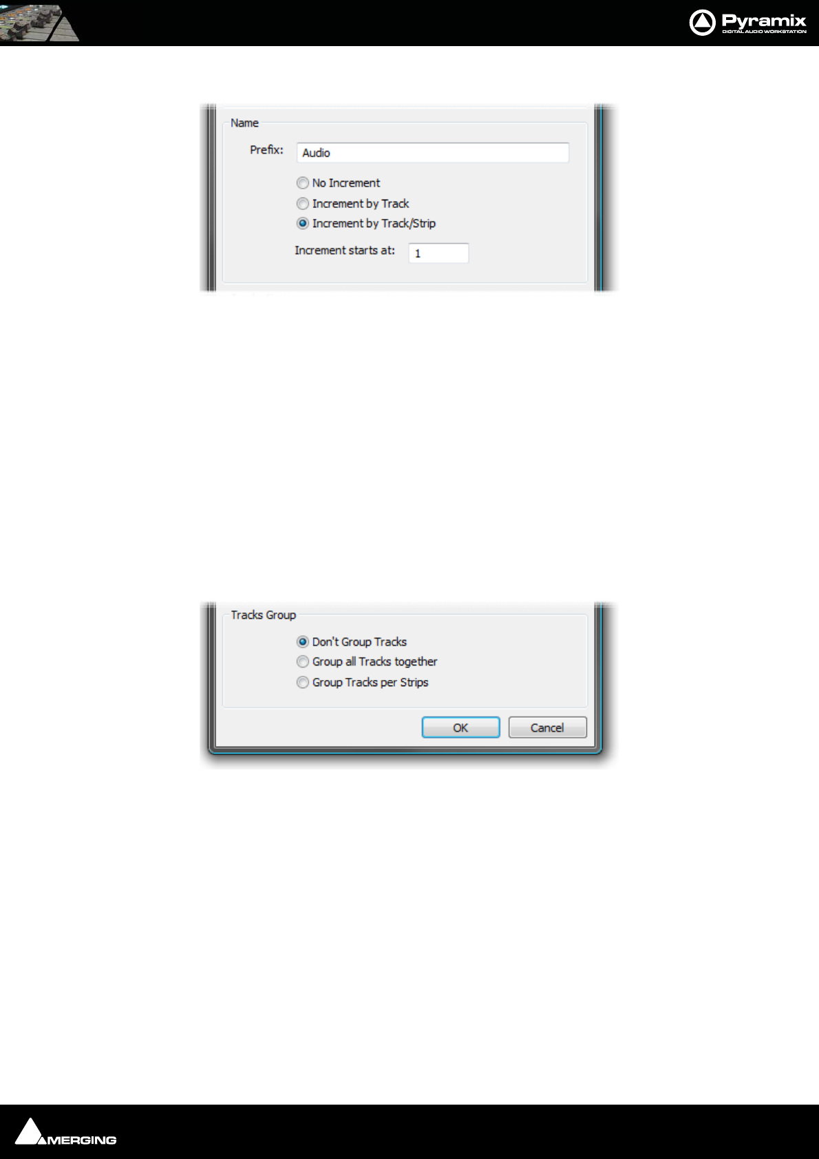
Tracks and Track Groups : Deleting Tracks 5 - 72
Naming and Numbering
However many Tracks and Strips you decide to create, they can be automatically named and incrementally num-
bered.
If the No Increment option is chosen all tracks created will have the same name. I.e. whatever is entered in the
Prefix: text entry box and no number.
If the Increment by Track option is chosen, each individual track will be named using the text entered in the Pre-
fix: text entry box and numbered incrementally. E.g. If you enter say, Atom and add a 5.1 GP strip in L-C-R-Ls-Rs-
Lfe format, six tracks are added. If the Increment starts at: number is set to, say 33 then all the track names will all
be Atom 33 as will the Strip name.
If the Increment by Track/Strip option is chosen in the above example then the tracks will be named Atom 33,
Atom 34 to Atom 38 and the Strip will be named Atom.
Tracks Grouping
There are three options:
Don’t Group Tracks leaves the new tracks ungrouped.
Group all Tracks together groups all the new tracks in a single group.
Group Tracks per Strips groups the tracks as they are assigned to strips. E.g. 12 Tracks assigned to two 5.1 strips
would be grouped as two six-tracks.
Deleting Tracks
Single Track
To delete a Track, first select the Track to delete. Then choose Tracks > Delete from the Project window pull-
down menu. The Track and all clips placed on it will be deleted. Note that only the clip or pointer will be deleted,
not the original Media File.
Create New Tracks dialog - Name
Create New Tracks dialog - Grouping
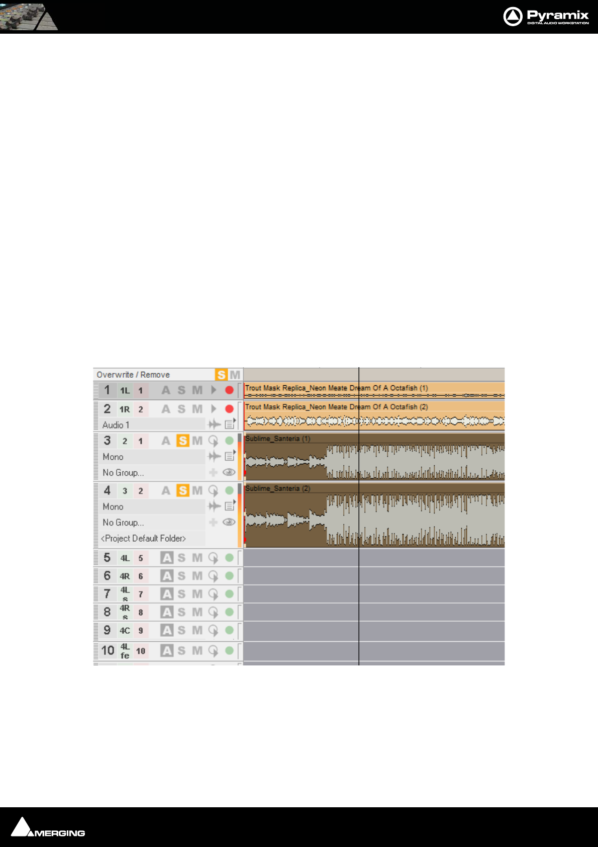
Tracks and Track Groups : Routing Tracks to / from the Mixer 5 - 73
Multiple tracks
You can also delete all tracks from the selected track to the last (highest number) by selecting Delete to Last
instead of Delete.
You can also right-click in the Track Header to add or delete Tracks.
Routing Tracks to / from the Mixer
When you create a Mixer, Pyramix will automatically create the same number of Tracks as Mixer Input Strips
(channels).
If Connect automatically as many inputs and outputs as possible is checked, Pyramix will attempt to automat-
ically route the output of each Track to a corresponding Mixer channel input, so that Track 1 output routes to
Mixer channel 1 input, Track 2 to Mixer channel 2, etc.
Similarly, Pyramix will attempt to automatically route each Mixer channel output to a corresponding Track input,
so that Mixer channel 1 output routes to Track 1 input, Mixer channel 2 to Track 2, etc.
These default Track I/O assignments can easily be changed by the user. See also: Adding Strips on page 177
Track Header Panel
The Track Header Panel contains a number of buttons and information fields.
This screen shot shows Track Headers in variety of states.
In each Track Header, you will find a pale green box with a number (and assignment Tag where applicable)
superimposed on it; and a pale red box with a number superimposed on it. The pale green box shows the mixer
channel number (and Tag if applicable) the Track output is assigned to. The pale red box shows the number of
the physical input or Internal Return Bus feeding the mixer channel and routed to the Track input.
To change a Track Input or Output assignment, just click on the corresponding Track input or output box, then
select the appropriate Mixer channel or Input number from the corresponding pop-up list. Note: changing an
Track Header Panel
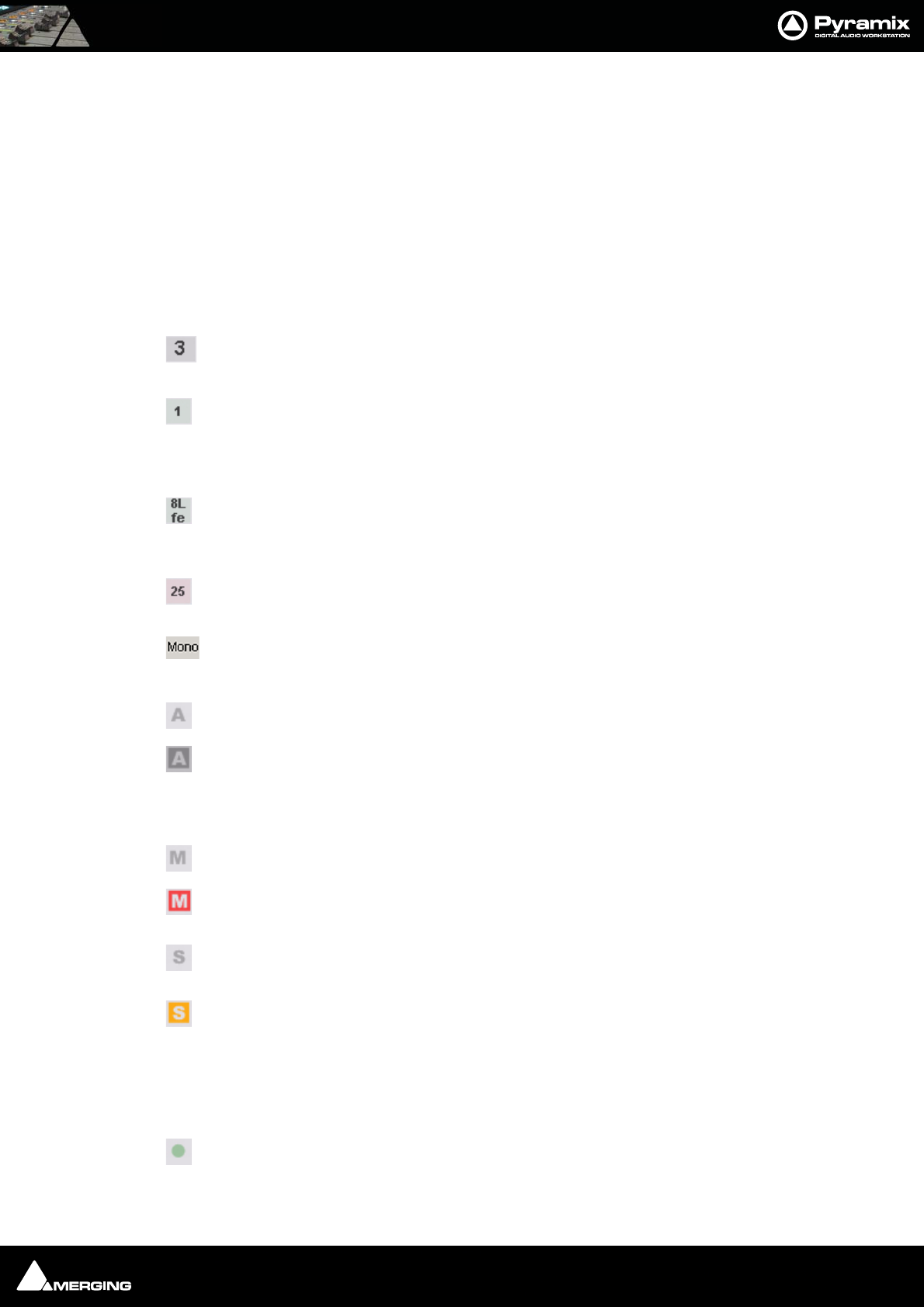
Tracks and Track Groups : Track Header Panel 5 - 74
output assignment to a different Mixer channel will also change the Input to the input selected on the strip. If the
Input assignment is changed in the Track Header, this change is reflected in the strip and vice-versa.
When Track inputs and outputs are not assigned, the corresponding boxes for that Track will have dashes in them
instead of numbers.
Multiple tracks can be assigned to the same Mixer channel. They are therefore sub-mixed before entering the
Mixer. This allows more tracks to be played than the number of Mixer channels.
Many tracks can be fed from the same physical input.
Track Header Components
The large, bold number is the Track number. All tracks including Virtual Tracks are numbered
in ascending order as they appear on screen.
The pale green box shows the number of the Mixer Strip Channel its output is assigned to.
Clicking this icon pops up a list to select from all available Mixer Strip Channels. If the pale
green box shows a dash, no Mixer Strip Channel is selected and recording and or replay is
not possible.
If the pale green block shows a second number, letter or letters tag in addition to the number,
the Mixer Strip is a multichannel type and the letter(s) indicate which channel the track is
assigned to. (In this case, Strip 8 Lfe
Input source - the number shows the selected record input. When this area shows a dash no
record input is selected. This can be also set directly in the Mixer Console window.
Clicking the Track Name area opens a text entry box where the track name can be typed.
Track names default to Mono, Stereo or Audio.
View Automation Off - Automation data overlay is not displayed on the track.
View Automation On - Automation data overlay is displayed on the track.
Right clicking the automation icon pops up the Automation Overlay context menu with options as to what is dis-
played.
The Mute icon toggles the Track Output between Un-Muted, as shown here;
and Track Output Muted, as shown here.
The Solo icon toggles the Track Output between Solo off, as shown here and;
Solo on as shown here.
The Record icon has three possible states.
Record Safe and Record Ready are toggled by left-clicking the icon. AutoPunch Ready is enabled / disabled by
holding down the ALT key while left-clicking the icon.
Record Safe - no recording possible.

Tracks and Track Groups : Track Header Panel 5 - 75
Record Ready - Recording commences when the transport Master Record button is pressed
and finishes either when the Stop button is pressed, or when the Play button is pressed.
Autopunch Ready - Recording commences when the previously set Record In point is
reached and finishes when the previously set Record Out point is reached.
Right-clicking the Record icon opens the Settings Window with the Project > Record page selected.
The Monitor icon also has three possible states.
Note: These icons are only active when both an input and output connected.
These are toggled by left clicking the icon.
Auto - monitoring switches the associated Mixer channel input automatically between input
and repro. Behavior depends on the Auto-monitoring section setting in the Settings > All
Settings > Application > Playback/Record page. European Monitoring (All tracks turn to
INPUT on stop) OR US Monitoring (Only Record Ready tracks turn to INPUT on stop)
Repro - The associated Mixer channel is always fed from the track replay.
Input - The associated Mixer channel is always fed from the track’s selected Input source.
Expand Track Group - Grayed out unless track is member of a Group.
Collapse Track Group - Alternate state of Expand Track Group Only visible when the track
is a member of a Group.
The Waveform icon has three possible states.
Display Waveform - by default shows clips as orange blocks with white waveform superim-
posed.
Display Blocks - by default shows clips as orange blocks without waveform.
Display Envelope - by default shows clips as orange blocks with white waveform and adds a
black line which allows the gain to be adjusted using the mouse by simply clicking and drag-
ging. Pressing the Ctrl key enables the drawing tool for envelopes. This also applies to Auto-
mation curves.
Peak Meter - If the Peak Meter is visible on the far right of the Track Header, clicking on it
hides it. If not visible, clicking in the space where it should be unhides it.
Always Visible off
Always Visible on. When this button is pressed the track will be kept in view on the Timeline
whenever possible.
Playlist opens this menu

Tracks and Track Groups : Track Record Modes 5 - 76
Please see: Playlists on page 122
Track Record Modes
Each Track has a tri-state Record Ready toggle button, located to the left of the Track itself in the Track Informa-
tion and Setup Area.
Tip: Right-clicking on a track arming button opens the Settings > All Settings window immediately on the
Project > Record page.
Play
The Green Dot in the Track Header indicates Record Safe mode, the default when Tracks are newly created.
When in this state, the Track cannot be recorded to.
Record Ready (Manual)
Click on the Green Dot once to toggle to Record Ready mode. This is indicated by the dot turning into the Red
Dot. The Track will now go into Record mode immediately when the Master Record button is pressed in the
Transport Strip or Transport window.
Record Punch In (Auto)
Alt-Click on the Red Dot to toggle to Record Punch In mode. This is indicated by a Red Dot flanked by 2 red
vertical lines. In this mode, when the Master Record button is pressed in the Transport Strip or Transport win-
dow, the Track will stay in Play mode until the current Mark In point is reached, then the Track will go into
Record mode. It will stay in Record mode until the current Mark Out point is reached.
Playlist popup menu
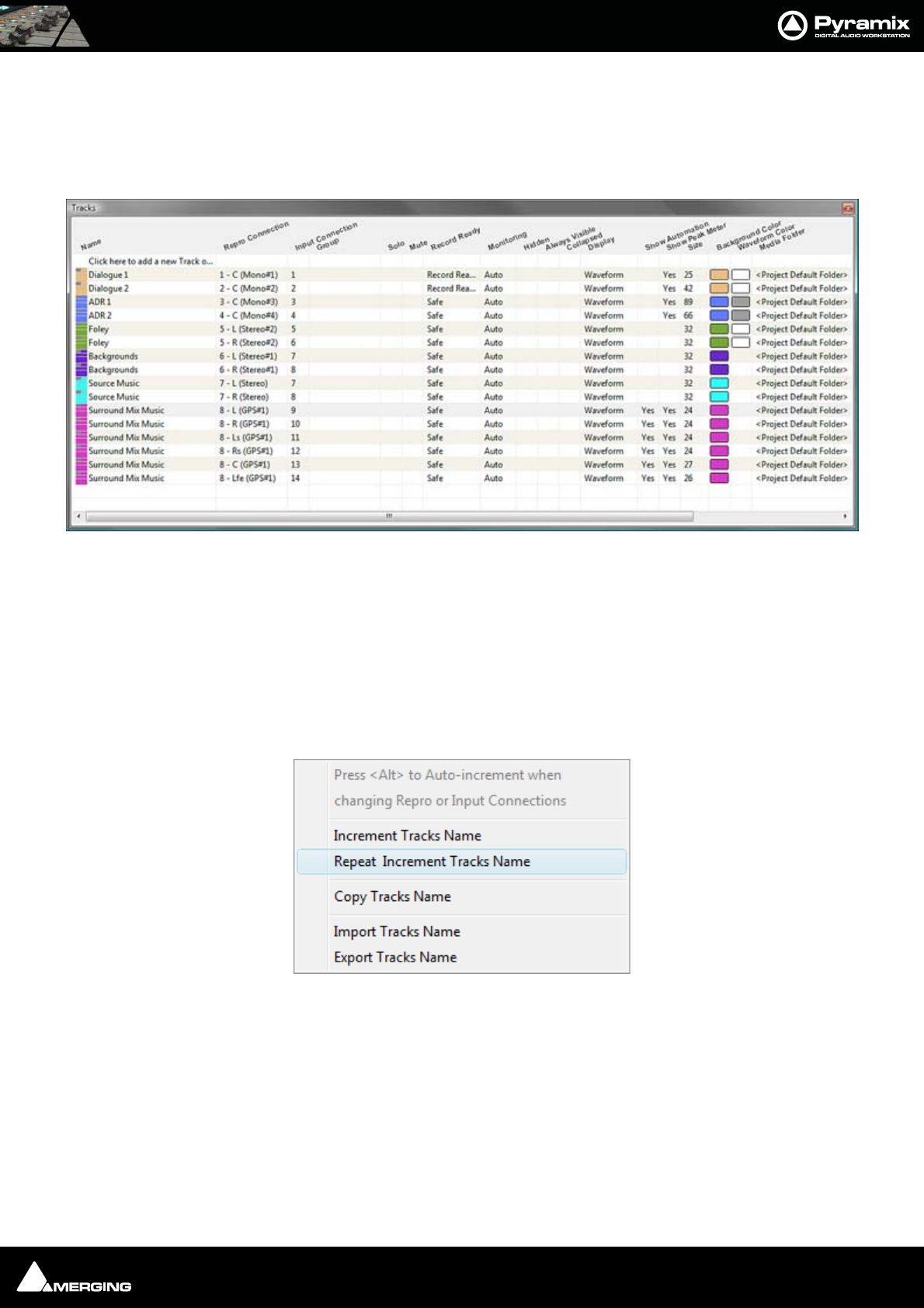
Tracks and Track Groups : Tracks Tab Window 5 - 77
Tracks Tab Window
The Track Tab Window shows a table where each row contains information about a single track and each column
contains information and function selection fields. New tracks can be created or existing ones deleted and the
order of tracks changed. All track parameters are accessible and modifiable.
New tracks can be added by clicking on the first line of the Tab Window and typing a suitable name then pressing
Enter.
Tracks can be deleted by selecting them and pressing the Delete key.
The order of the Tracks can be changed by selecting and dragging tracks. Click on the symbol at the far left of the
Name field and drag to the desired row.
Tracks Tab pop-up
Right-clicking on a selection of tracks or on all tracks (no selection) displays this context menu:
Increment Tracks Name : Adds an incremental number after each selected tracks name, taking into account
an already existing number
Repeat & Increment Tracks Name : Copies the first selected tracks name to the rest of the selection and adds an
incremental number
Copy Tracks Name : Copy the selected tracks name or all if no selection
Paste Tracks Name : Paste the previously selected tracks name to the currently selected tracks
Import Tracks Name : Rename the selected tracks or all tracks if no selection with names coming from a
text file
Export Tracks Name : Saving the selected tracks or all if no selection to a text file
Tracks Tab floating Window

Tracks and Track Groups : Tracks Tab Window 5 - 78
Making Settings Changes to Multiple Tracks
Changes to Tracks settings can be made on a multiple selection of tracks. Press Ctrl and Click on a track to add or
subtract it or press Shift to select a contiguous range of tracks.
Changing Repro or Input connections
Clicking in the column field to drops down a list of available connections. Highlight the required connection to
select it.
With a range of tracks selected, choosing a connection from the list assigns all selected tracks to the same connec-
tion. If Alt is held down while choosing the selected tracks are connected in ascending order.
Track Tab Column Fields
Name
The name of the Track. Up to 29 characters are visible in this field but longer names are accepted. Click in the field
or use F2 to enter a new name.
Repro Connection
Shows which Mixer Input Strip (and Channel if applicable) the track is connected to. Clicking in this column field
drops down a list box with all available Mixer Input strips (and Channels). Strip number on the left followed by
Channel Tag with the Strip Name in brackets.
Input Connection
Shows which Input is feeding the track. Clicking in this column field drops down a list box with all available physi-
cal inputs and Internal Return buses.
Group
Shows which Track Group (if any) the track belongs to. (see below) Clicking in this column field drops down a list
box with all available Track Groups.
Solo
If YES track is soloed.Clicking in this column field toggles between YES and blank.
Mute
If YES track is muted.Clicking in this column field toggles between YES and blank.
Record Ready
Shows the current record ready state. Clicking in this column field drops down a list box with the three possible
states, Safe, Record Ready and Auto-Punch.
Monitoring
Shows the current monitor mode. Clicking in this column field drops down a list box with the three possible
modes, Auto, Input and Repro.
Hidden
If YES the track is not visible in the Timeline but continues to operate normally. Clicking in this column field tog-
gles between YES and blank.
Always Visible
If YES the Track will always appear on screen (if there is sufficient room) even when scrolling other tracks.
Collapsed
If YES the track is a member of a Track Group currently collapsed. (see below)
Display Mode
Shows the current Clip Display Mode mode. Clicking in this column field drops down a list box with the three pos-
sible modes, Block, Waveform or Envelope
Show Automation
Tracks Tab pop-up

Tracks and Track Groups : Tracks Tab Window 5 - 79
If YES the automation envelope is displayed. Clicking in this column field toggles between YES and blank.
Show Peak-Meter
If YES a Peak Meter is displayed in the Track Header. Clicking in this column field toggles between YES and blank.
Size
Shows the current track display Height. (in pixels) Clicking in this field allows a numeric value between 24 and 511
to be entered.
Background Color
Shows clip background color. If blank, color is set to the default. Clicking in this column field pops-up a color
picker. Choosing Standard restores to default.
Waveform Color
Shows clip Waveform color. If blank color, color is set to the default. Clicking in this column field pops-up a color
picker. Choosing Standard restores to default.
Recording Media Folder
Shows the Media Folder where new recordings will be stored. Clicking in this column field pops-up a list of all
mounted Media Folders.
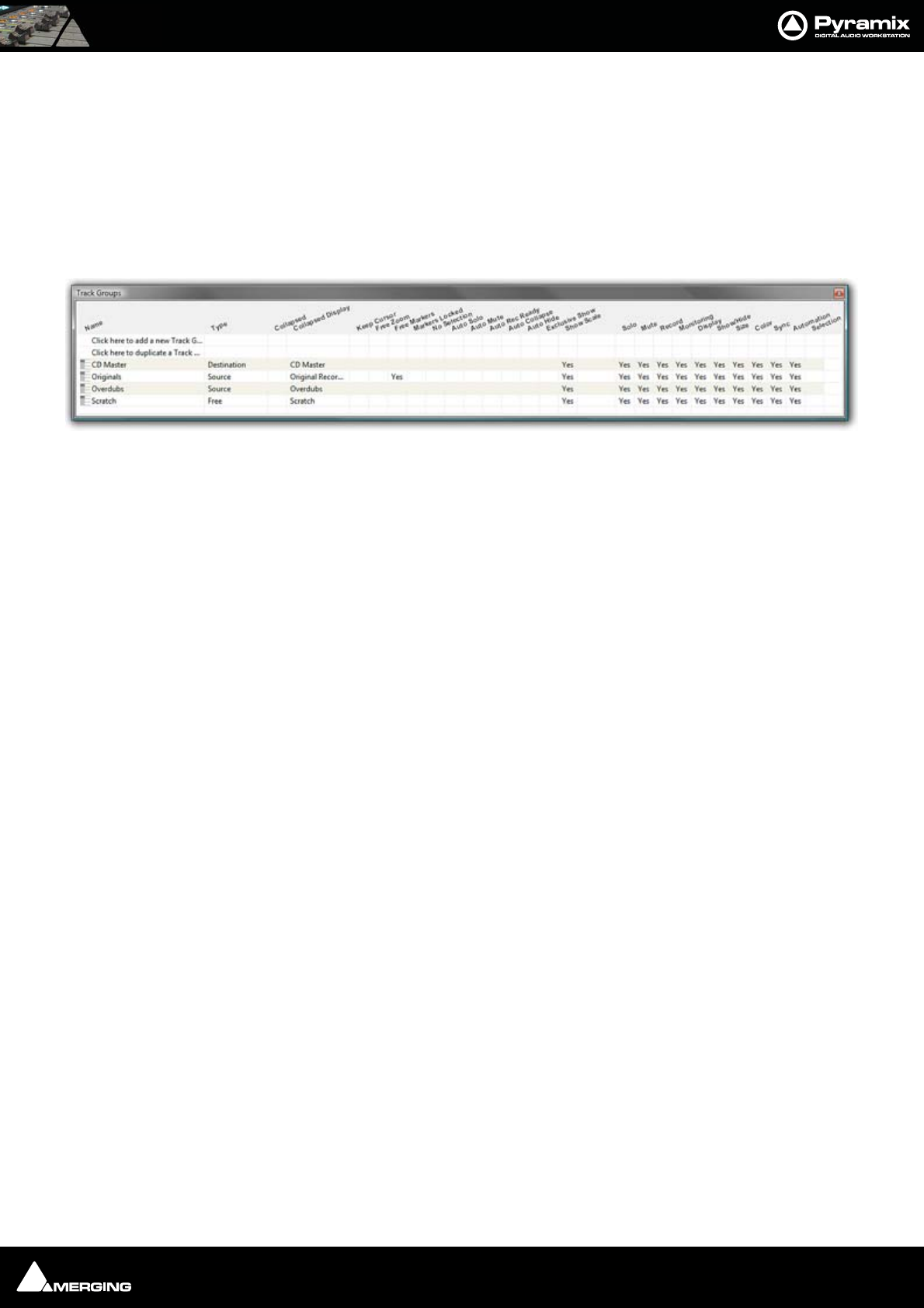
Tracks and Track Groups : Track Groups 5 - 80
Track Groups
Track Groups, as the name implies, enable a number of logical function linkages between tracks and several other
useful methods of improving efficiency. Track groups can be created an manipulated by the user. Track Groups are
also created by default when Recording or Rendering operations occur on more than one track at the same time.
Track Groups Tab Window
Opens a table where each row contains information about a single track group and each column contains Infor-
mation and function selection fields.
The first two rows enable new Track Groups to be created and existing ones to be duplicated by clicking on the
Name field.
To create a new Track Group, click on Click here to add a new Track Group. A text entry box replaces the Name.
Enter a suitable name and press Enter. A new track group will appear at the bottom of the list.
To duplicate an existing track group, click on the Track Group you wish to duplicate then click on Click here to
duplicate a Track Group. A text entry box replaces the Click here to duplicate a Track Group. Type a suitable
name and press Enter. The duplicate Track Group appears in the row below the Track Group you have just cop-
ied. Subsequent rows are moved down the table. The Track Group entries can be re-ordered by clicking on the
symbol at the far left of the Name field and dragging to the desired row.
When tracks are assigned to a Track Group a small group track is shown in the Timeline immediately above the
first assigned track.
Track Groups can be collapsed/expanded by clicking the little [-] or [+] on the Track Group track header.
Track Group Column Fields
Name
The name of the Track Group. Up to 29 characters are visible in this field but longer names are accepted. Click in
the field or F2 to edit the name.
Type
Clicking in this column field drops down a list box with current choices of Free, Source, or Destination.
Free is used to create General purpose Track Groups
Source is used for grouping Tracks to be Sources in the Source/Destination model.
Destination is used for grouping Tracks to be Destinations in the Source/Destination model.
Collapsed
Track Groups can be collapsed, so only one of the tracks of the group is displayed. When set to Yes, only the track
chosen and shown in the Collapsed Display field is displayed in the Timeline. This field has the same function as
the little [-] or [+] on the Track Group header.
If the single visible track is selected the group is expanded.
Collapsed Display
Clicking in this column field drops down a list box which contains the names of all the tracks in the group. The
selected name determines which track will be displayed when the display is collapsed.
Tracks Groups Tab floating Window

Tracks and Track Groups : Track Groups 5 - 81
The rest of the fields
All the other column fields toggle when clicked, either displaying Ye s or a blank. The functions described below
apply when the fields are set to Yes.
Keep Cursor
The Group ‘remembers’ the position of the cursor and restores it each time one of its tracks is selected.
Free Zoom
The group has its own zooming factor, independent of the general zoom factor.
Free Markers
Track Groups can have their own list of markers that are displayed on the Track Group Scale or on the main Time-
Code Scale if the Track Group Scale is hidden (see below).
Markers Locked
Locks the Markers. For the particular Group. Free Markers must be ON
No Selection
Clicking on clips placed on tracks of the group does not select anything, the cursor is simply placed at the position
where the mouse is clicked. Clicking with the Q key held down allows clips to be selected on these tracks.
Auto Solo
If any track of this group is selected, the whole group is automatically Soloed.
Auto Mute
The whole group is automatically muted unless one of its tracks is selected.
Auto Record Ready
When a track of this group is selected, the whole group goes into Record Ready mode.
Auto Collapse
When none of the tracks of this group is selected, the group is automatically collapsed to display a single track.
When this track is selected, the whole group is expanded.
Auto Hide
When none of the tracks of this group is selected, all tracks of the group are automatically hidden. When any track
of the group is selected, the whole group is shown.
Exclusive Show
When any track of this group is selected, all tracks that are not part of this group are hidden. This is the equivalent
of a Solo for the Display.
Show Scale
Toggles show/hide an independent scale for TimeCode if the Track Group is on Free Zoom and Markers if it is in
Free Markers mode. If OFF then the Scale and Markers are displayed in the main Scale of the Timeline when any
of the Tracks of this Group is selected.
Selection
When set to Yes this option ensures that any selection made within a Track Group is extended to all tracks in the
group. Selection is disabled by default for backwards compatibility.
All other columns of the Tab Window (Solo, Mute, Record, Monitoring, Display, Show/Hide, Size, Color, Sync,
Automation Display) define which of the parameters set in the Track Header or in the Tracks Tab window are
affected by the group, I.e. which of these parameters are changed in the whole group when a change is made to
an individual track of the group.
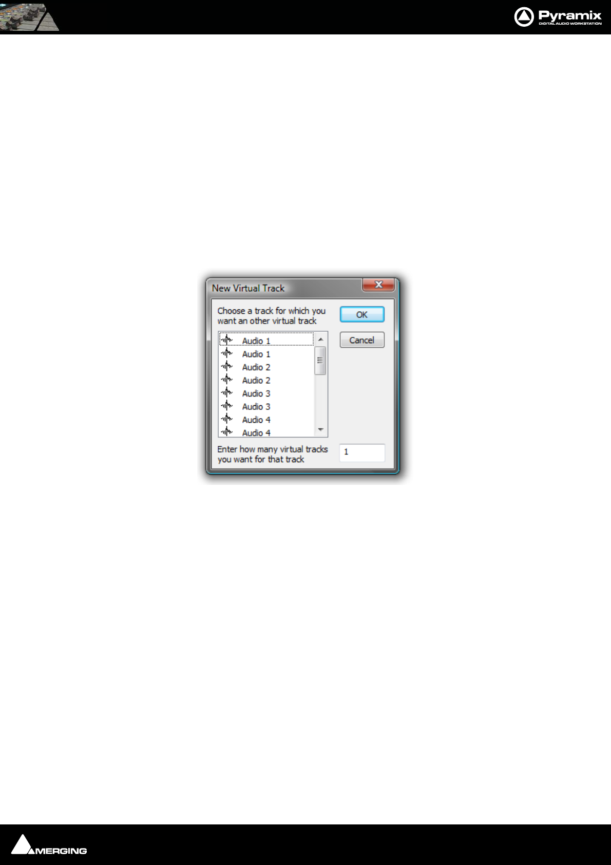
Tracks and Track Groups : Virtual Tracks 5 - 82
Virtual Tracks
A virtual track is a "mirror" of another existing track. It has the same output routing and contains the same clips as
an existing track, but it appears in the Project Editor as a separate track.
Note: Virtual tracks contain non-overlapping clips - that is, each clip on a virtual track is
not allowed to overlap with clips on a related virtual track. However, clips on the exact
same track can still be crossfaded. Virtual tracks can be used for the purpose of visualiz-
ing clips that may have a logical reason to appear on separate tracks of the editor, even
though they will be routed to the same mixer channel. An example of typical use is to
create virtual tracks to allow the display of several automation curves for a single audio
track.
Creating Virtual Tracks
To add Tracks to the Timeline, select Tracks > New Virtual Track
To create a virtual track or tracks, select the origin Track in the list, type the number of Virtual tracks required and
click on OK.
Note: Virtual tracks can be created automatically to display automation data. Please
see: Create a new Virtual Track to display the selection on page 264
Create New Virtual Track dialog

USER MANUAL
www.merging.com/Pyramix
Transport and Navigation
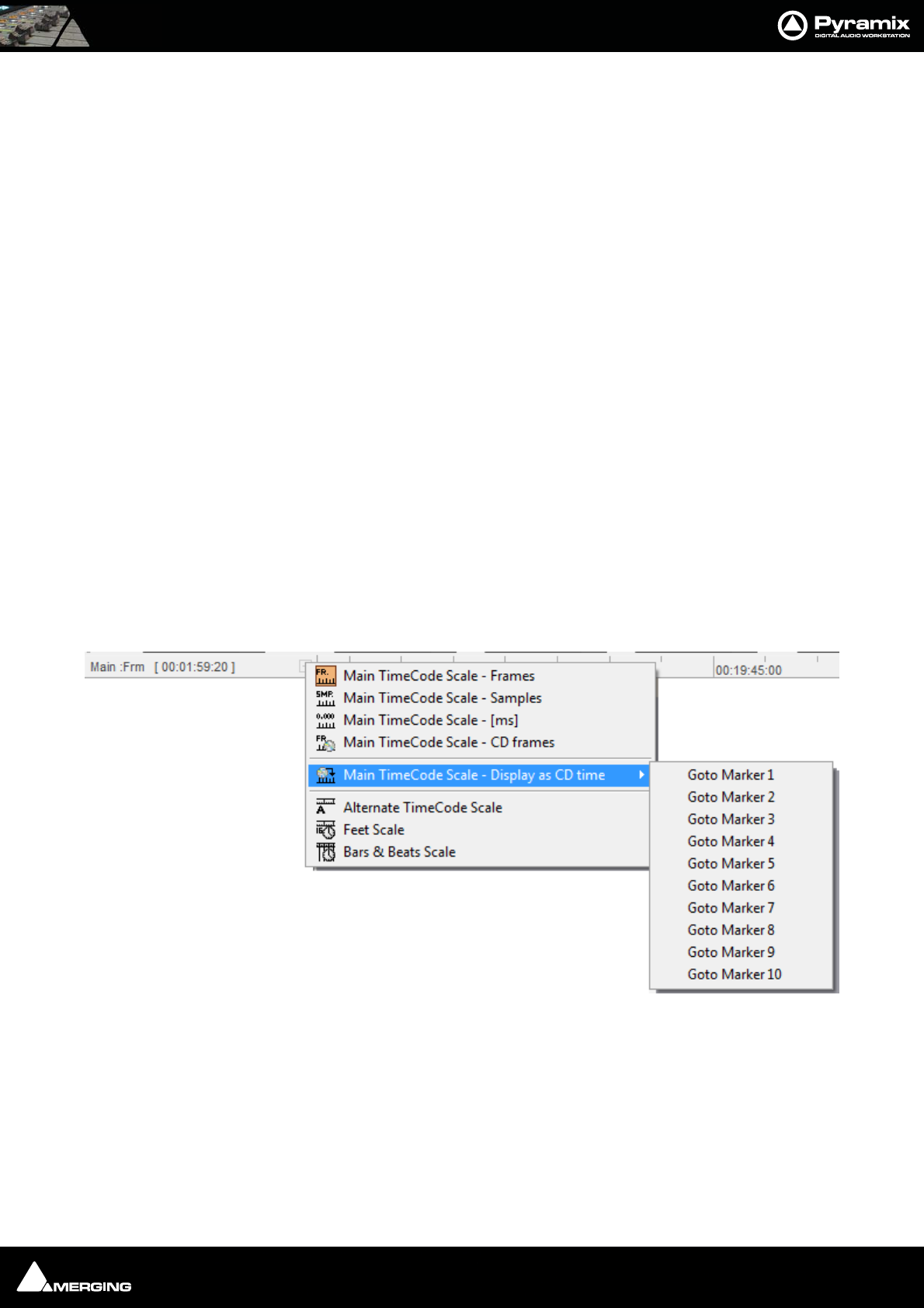
Transport and Navigation : Transport Control 6 - 84
Transport Control
Pyramix features a wide range of Transport Control commands including, unlike many other workstations,
Reverse Play and Play at fractions and multiples of sync play speed both forwards and backwards. These possibil-
ities can be attached to short-cut keys in the Keyboard Shortcut editor. Please see: Customizing Keyboard
Shortcuts on page 330
Of course, these commands are also available via remote controllers that support them.
Navigation
Pyramix Virtual Studio offers a number of ways of navigating around a Project.
Time Scale Bars
Main TimeCode Scale Bar
Near the top of the Project Editing Panel is a horizontal gray area with time code numbers. This is the Main Time-
Code Scale Bar. On the left, above the track headers, the time range, or length of the visible Timeline window is
indicated.
The simplest way to move the Playhead Cursor within the Project Editing Panel is to position the mouse any-
where along the Time Scale Bar and left-click. The Playhead will immediately move to the new position. You can
also left-click the Playhead Cursor and drag it along this bar.
Context Menu
Clicking in the left hand, Header, area of a Time Scale Bar (a small plus + sign indicates there is something worth
clicking on) pops up a context menu.
The first five entries offer a choice of display modes for the Main TimeCode Scale:
•Frames
•Samples
•[ms]
•CD frames
• Display as CD Time
Main TimeCode Scale context menu
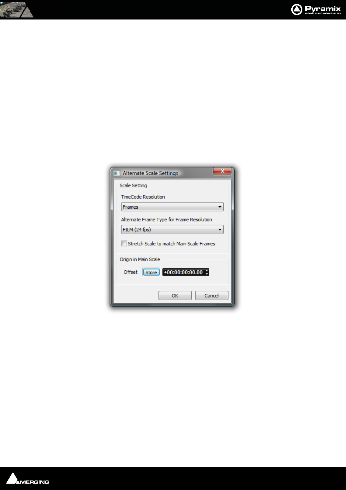
Transport and Navigation : Navigation 6 - 85
Clicking on the arrow opens a sub-menu for direct access to Markers 1 - 10
The remaining three entries add new Scale bars beneath the Main TimeCode Scale
•Alternate TimeCode Scale
•Feet Scale
• Bars & Beats Scale
Alternate Time Scale Bar
To add an alternative Time Scale bar below the Main bar right-click in the Main bar header area and select Alter-
nate TimeCode Scale
You can set up the Alternate Time Scale Bar either by right-clicking in the its Header to open the context menu or
by selecting Alternate TimeCode Scale Settings or View > Scales / Toolbars > Alternate TimeCode Scale Set-
tings:
• Alternate TimeCode Scale Settings
Choosing this pops up the Alternate Scales dialog:
Alternate Scale Settings dialog
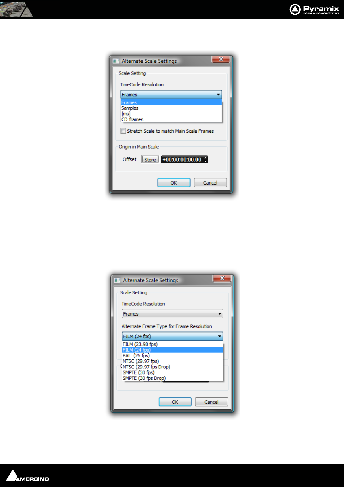
Transport and Navigation : Navigation 6 - 86
Scale Setting
The Scale Setting combo box offers a choice of TimeCode resolution to display:
Stretch Scale to match Main Scale Frames (see below)
Origin in Main Scale
An Offset can set and stored. For example when versioning. I.e. making several sound versions for the same pic-
ture.
The Alternate Frame Type for Frame Resolution combo box offers a choice of frame types appropriate to the
chosen resolution. E.g.
View > Scales / Toolbars > Alternate TimeCode Scale Settings also enables selection of The TimeCode Resolu-
tion for the Alternate Scale from a choice of:
Alternate Scale Settings TimeCode Resolution drop-down menu
Alternate Frame Type for Frame Resolution combo box
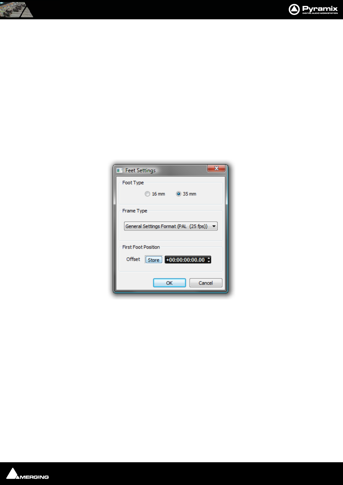
Transport and Navigation : Navigation 6 - 87
•Frames
•Samples
•[ms]
•CD Frames
When the Resolution is set to Frames, an Alternate Frame Rate can be chosen.
When Alternate Frame Rate is chosen, the check box Stretch Scale to match Main Scale Frames allows the
Alternate Scale to no longer display the same time flow as the Main Scale (1 Second = 1 Second). Instead it
matches the length of individual Frames (1 Frame = 1 Frame). In this case the time is not the same in both scales
and this allows making comparisons between, for example, 24 frames events and 25 frames events.
The Origin in Main Scale option allows an offset to be set between the Main Scale and the Alternate Scale.
Film Feet Scale Bar
Like the other scale bars, clicking in the header area pops up a context menu with the extra option Feet Settings
selecting this pops up the Feet Settings dialog:
Foot Type
The radio buttons offer a choice of 16mm feet (units of 40 frames) and 35mm feet (units of 16 frames).
Frame Type
Feet Settings dialog
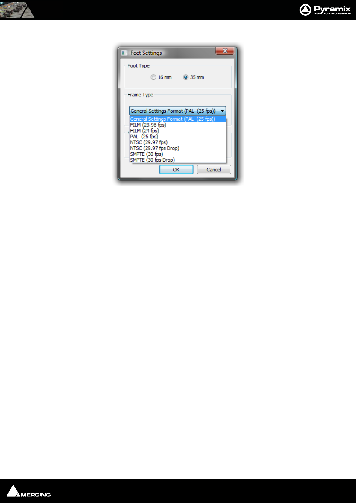
Transport and Navigation : Navigation 6 - 88
The combo box offers a choice of frame rates:
Default is the format selected in All Settings > Formats & Sync > Frequencies. You may need one of the others in
the context of non-linear editing workflows.
Frame Type combo box
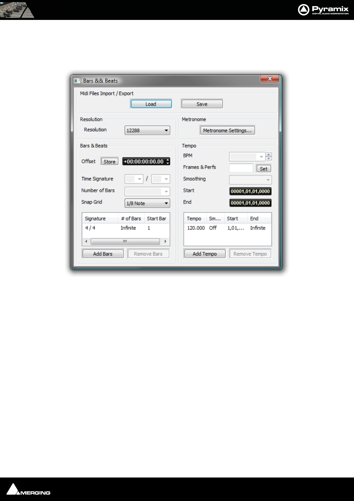
Transport and Navigation : Navigation 6 - 89
Bars & Beats Scale Bar
As with the other Scale Bars clicking in the header area pops up a context menu with show/hide for the Alternate,
Feet and Bars & Beats Scale bars plus two extra options, Bars & Beats Settings and Tempo Map. The Tempo Map
option shows the current Tempo Map below the Bars & Beats Scale Bar.
Midi Files Import / Export
Load
Save
Both buttons open a Browser Window to enable navigation to a file to load or a location to save to.
Note: Currently, when MIDI files of type 2 are imported, only the tempo map and signa-
ture of track 1 is imported.
Resolution
Sets the clock resolution in Pulses Per Quarter Note, PPQ. The combo box offers a choice of values between 192
and 49152
Bars & Beats
Offset Offsets the Bars & Beats scale start from the main Time Scale. Value can be typed
in the TimeCode register and or nudged up or down with the increment, decre-
ment buttons.
Store Offsets the Bars & Beats scale start to the current Playhead Cursor position.
Note: Offsets can be negative or positive.
Bars & Beats Settings dialog
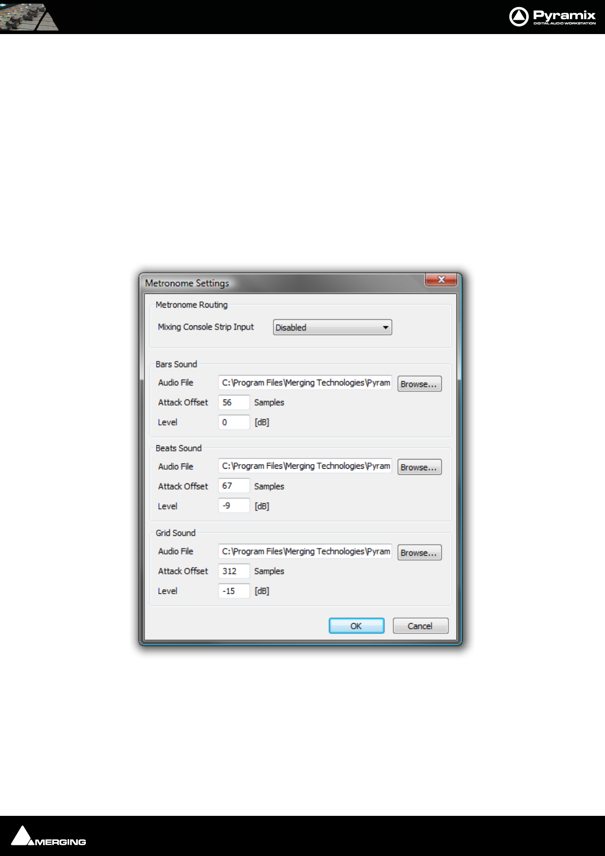
Transport and Navigation : Navigation 6 - 90
Time Signature and Bars
The bottom left panel displays a list of blocks of bars in the order they appear in the ‘song’. The following settings
apply to the currently selected entry in the list.
Time Signature Use the combo boxes to set the Time Signature
Number of Bars Type a value or choose Infinite from the combo box dropdown list.
Snap Grid Combo box offers a choice of Off or values between Note and 1/64 Note .
Add Bars
Click to add a new block of bars to the list above.
Remove Bars
Deletes the selected entry from the list above.
Metronome
Metronome Settings...
Tempo
The bottom right panel displays a list of currently defined Tempos in the order they appear in the ‘song’. The fol-
lowing BPM, Frames & Perfs, Smoothing, Start and End fields reflect the values for the highlighted (selected)
Tempo.
BPM Allows you to pick a tempo from the common values in the drop-down list, to
increment or decrement in 1BPM steps with the up and down buttons or to
directly type a value in the box.
Metronome Settings dialog
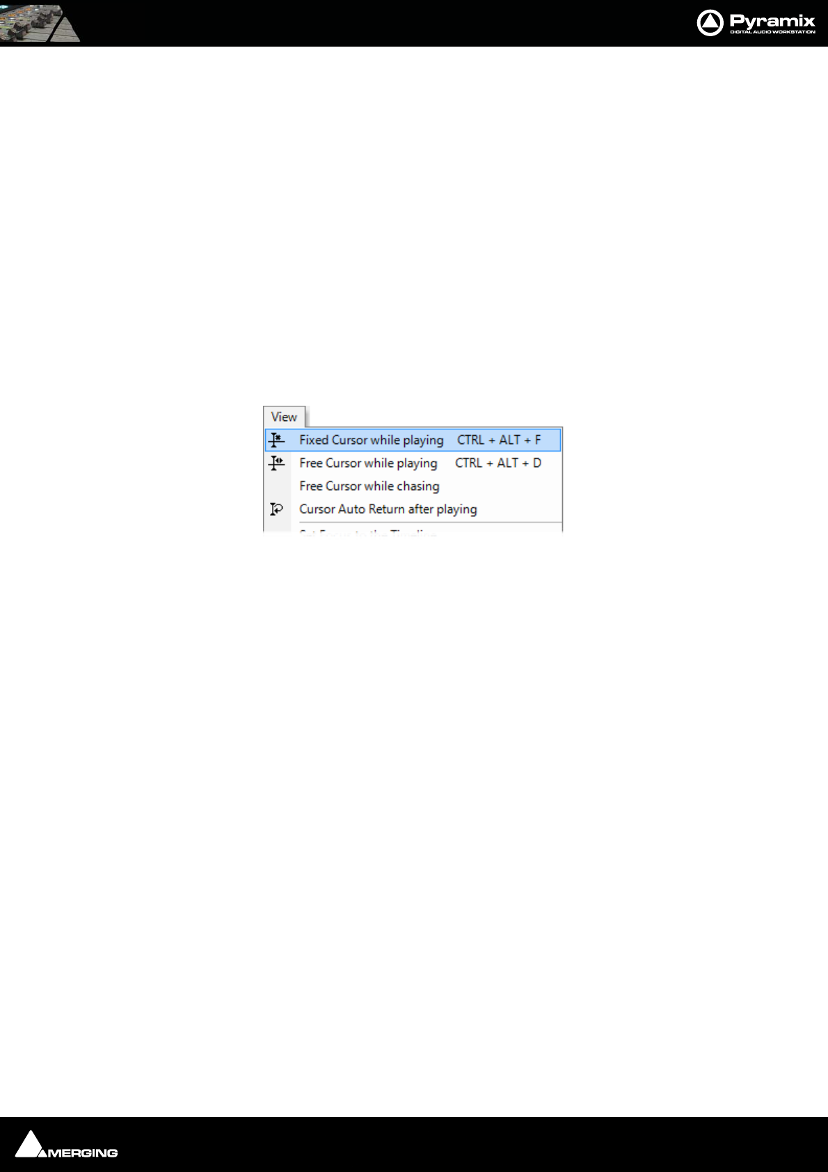
Transport and Navigation : Navigation 6 - 91
Frames & Perfs An alternative method of defining a Tempo used by film composers. It is based on
24 frames per second, each frame subdivided into 8 perfs, or perforations. Thus a
value of 24.0 results in a Tempo of 60BPM. Perfs are entered as decimals. E.g. 12.7.
Illegal entries are rounded.
Smoothing Enables values between Note and 1/64 . to be chosen. (or OFF)
Start The starting point for the Tempo can be entered by typing.
End The end point for the Tempo can be entered by typing.
The Information pane shows all currently defined Tempos.
Add Tempo
Adds a new Tempo
Remove Tempo
Removes the highlighted (selected Tempo) from the list.
Playhead Cursor Options
Four Playhead Cursor options will be found at the top of the View menu:
Local Options
Fixed or Moving Playhead Cursor
The Playhead Cursor can be static with the Timeline moving (choose: View > Fixed Cursor while playing) or the
Playhead Cursor can move while the Timeline remains static, ‘Paging’ when the Playhead Cursor hits the screen
edge. (Choose: View > Free Cursor while playing).
Chase Options
When Free Cursor while chasing is selected in conjuction with either of the local options the Playhead Cursor
and Timeline position can be freely manipulated from the workstation whenever the TimeCode Master machine is
in Stop, Rew, FF, Play, Locate, etc. as well as while chasing, but as soon as Pyramix has locked to incoming Time-
Code, the cursor will "jump" to current TC. This mode is useful for Cinema mixing since it allows the Sound Editor
to make good use of idle moments to perform quick edits and adjustments, anywhere in the Timeline and regard-
less of current TC position. This used to be the default behavior.
When Free Cursor while chasing is NOT selected, the Cursor will always be locked to TimeCode when Pyramix is
set to chase, whether in Stop, Rew, FF, Play, Locate, etc. as well as while chasing.This mode is desirable for TV Post,
where the Pyramix Playhead cursor and Timeline display should always reflect the current TC position.
Auto Return
Cursor Auto-Return after playing. When this is selected with either of the local options, the Playhead Cursor
will return to the point at which Play began when Stop is selected.
Playhead Position
When View > Fixed Cursor while playing is selected, the Playhead position can be set in Settings > All Settings
> Application > Playback/Record in the Fixed Cursor Settings section. The Place of Cursor in Screen combo
box offers a range of choices between 1/10th and 1/2 of Screen.
View menu (part)
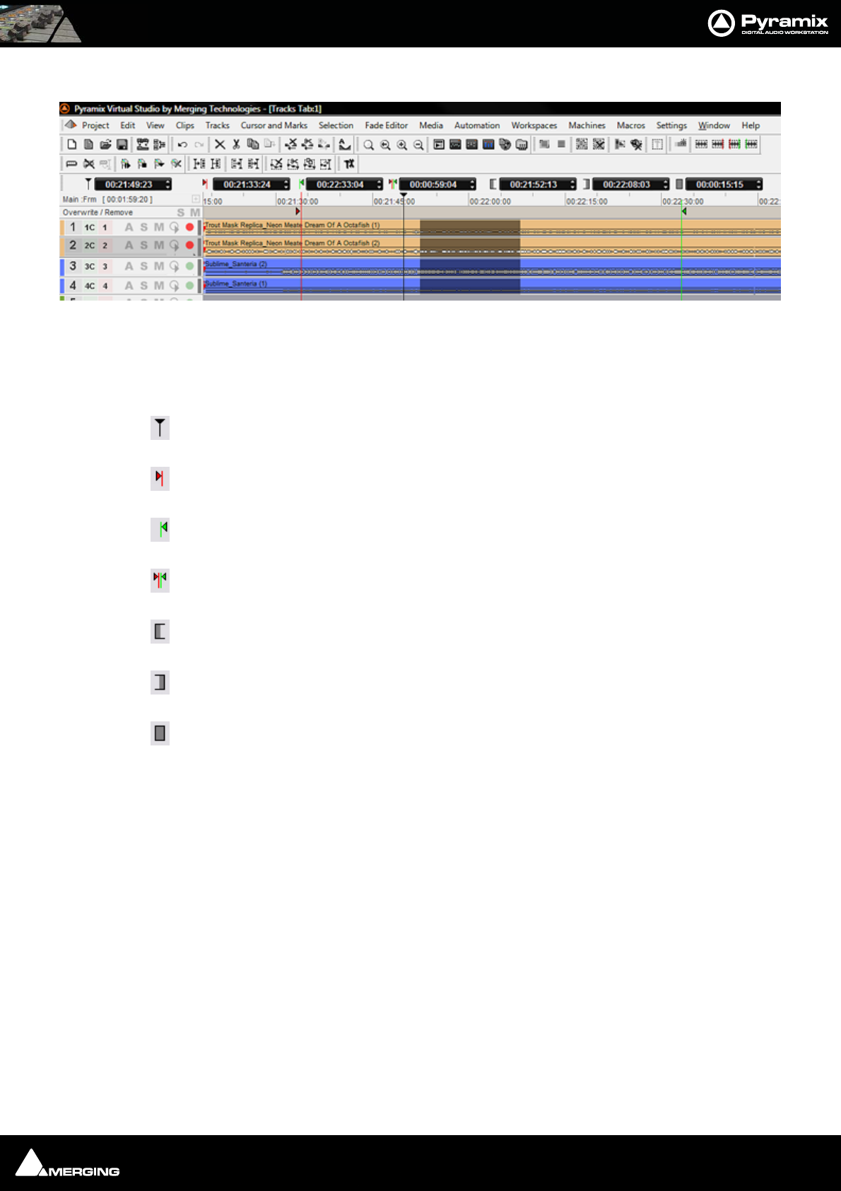
Transport and Navigation : Navigation 6 - 92
Composition Information and Settings Toolbar.
Above the Time Scale Bar(s) and below the Project Editing Panel Toolba r(s) is the TimeCode Toolbar. This con-
tains a number of Icons and TimeCode register boxes with increment / decrement arrows. From left to right these
are;
Playhead Cursor - current position
Mark In
Mark Out
Mark In to Mark Out
Selection In
Selection Out
Selection In to Out
All the registers accept direct keyboard entry of TimeCode.
When values are typed into the Mark In to Mark Out or Selection In to Selection Out registers, the In value
remains fixed while the Out is adjusted.
Clicking on the icons beside the registers changes the view of the Composition in the Timeline as follows;
Clicking Cursor moves the view of the Timeline to the current Cursor position with the Cursor in the center of
the track display. Similarly, clicking on the Mark In, Mark Out, Selection In or Selection Out buttons centres the
display on the current Mark In, Mark Out, Selection In or Selection Out marker positions. Clicking on the Mark
In to Mark Out or Selection In to Selection Out icons centres the display on the area between the Mark In and
Mark Out or the selected area, changing the zoom factor to make the area almost fill the track display.
Composition Information and Settings Toolbar
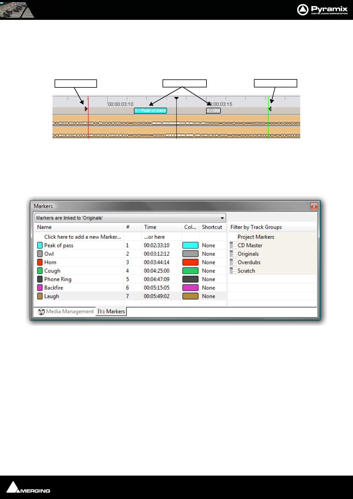
Transport and Navigation : Markers 6 - 93
Markers
Markers are shown in a Markers Track just above the TimeLine tracks display. Pyramix has several types of Marker.
For information about CD and SACD Markers please see: CD Markers on page 397 and the SACD Production
Guide.
The Cursor & Markers menu, Toolbar and keyboard shortcuts all offer methods of placing Markers and using
them for locating etc. The menu entries should be self explanatory. Please see: Cursors & Marks on page 459
Markers Tab Window
Markers can also be added and managed from within the Markers Tab Window.
Up to 48 Markers can be attached to shortcut keys and/or mapped to a hardware controller. Different lists of Mark-
ers can be edited by selecting the desired Track Group or the main Project Markers List in the Markers Tab Win-
dow. Markers are numbered in ascending order by their position in time. If a Marker is moved before or after
another Marker, the affected markers are automatically re-numbered.
Clicking on the first entry in the Name Field ‘Click here to add a new Marker’ Adds a new Marker at 00:00:00:00
This value can be edited in the usual way.
Marker colors are user selectable. Clicking in the Color field drops down a list box with all the available colors.
Double-clicking on a Marker’s Name Field jumps the Playhead Cursor to the Marker.
Double-click with CTRL pressed plays from the marker TimeCode
Double-click with SHIFT pressed plays from the marker TimeCode with the first Preroll. This also applies to CD
markers
Right-click to open a menu that enables Markers to be Cut / Copy / Pasted between Groups or Projects.
Markers
Mark OUT
Mark IN Markers
Markers Tab Window

Transport and Navigation : Jog / Shuttle 6 - 94
Markers Linking
The Markers Linking drop-down list menu is at the top of the Markers Tab Window.
The selection made here determines the behavior of markers when tracks are edited.
Markers Independent (markers are locked to the scale)
Linked to Any Track (markers follow any track operation)
Linked to Tracks without Group (markers follow any track that is not a member of a group)
Linked to ‘Effects’, ‘Music’, ‘Foley’ etc. (markers follow any track of groups listed here)
Jog / Shuttle
Scrub Using the Middle Mouse Button
Audio can be scrubbed by holding down the middle mouse button while the cursor is in the Timescale area and
moving the cursor left to scrub in reverse or right to scrub forward. The distance moved away from the current
play cursor position will determine the relative playback speed. When the play cursor reaches the current mouse
pointer position, or the middle mouse button is released, playback will stop.
Shuttle
The transport can be shuttled with audio output at up to 8 times speed.
Jog Settings
Jog / Scrub parameters are set in Settings > All Settings > Application > Jog / Chase.
Auto Jog on move
If a physical controller with a Jog/Shuttle wheel is available and this box is checked, then moving the jog wheel
will automatically enter Jog mode.
Auto-Solo Selection
When checked the selected track or tracks are automatically soloed when in Jog mode.
Speed ceiling
Four Radio Buttons offer the choice of 1X, 2X, 4X or 8X nominal play speed.
Sensitivity
The value typed in the box (in seconds) determines the number of seconds the transport will move per revolution
of an attached physical jog wheel.
Smoothing Filter
The value typed in the box (in video frames) determines the degree of smoothing that will be applied.
Flywheel Inertia
The slider varies the flywheel effect when jogging.
Markers Linking drop-down list menu
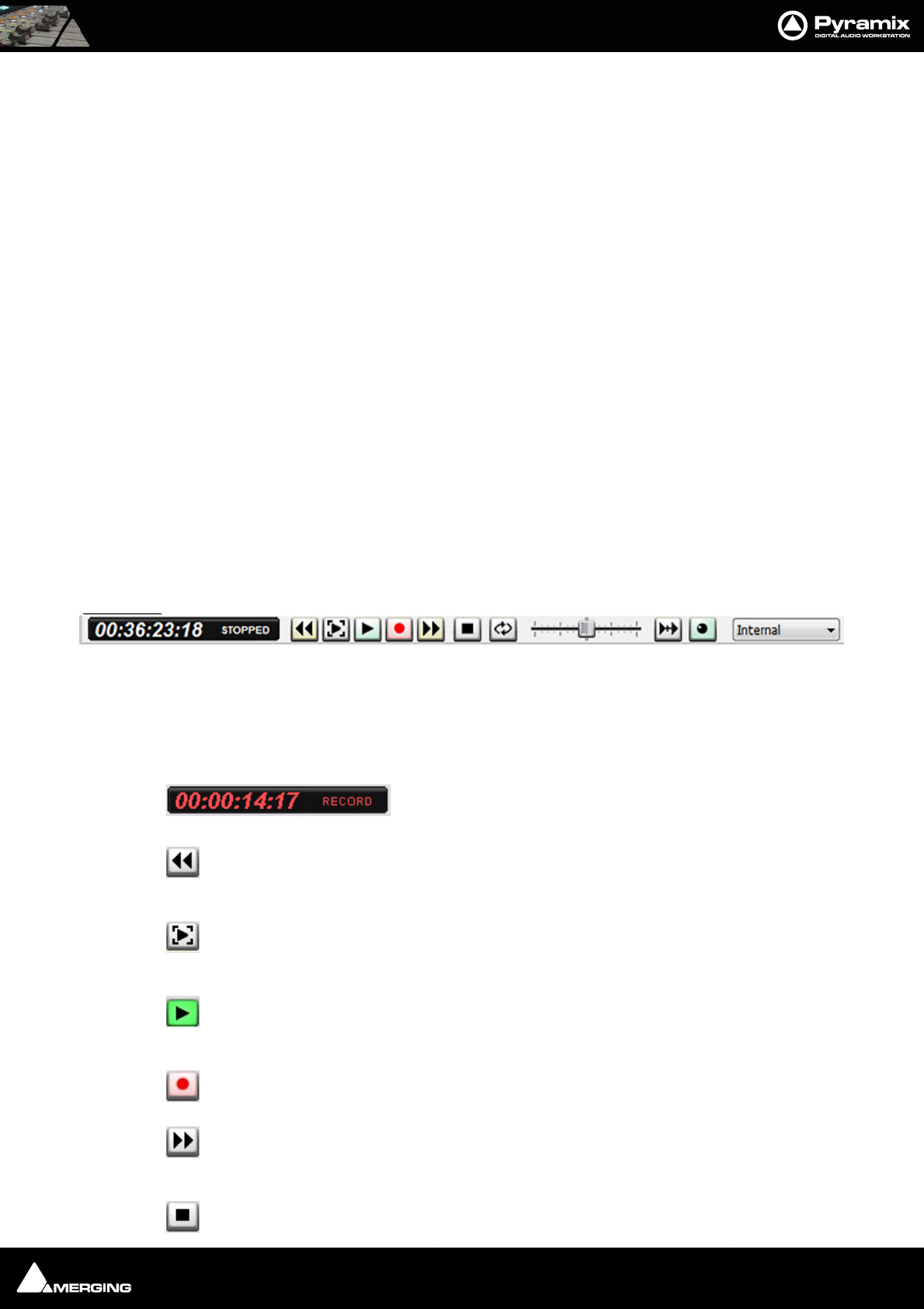
Transport and Navigation : Transport Controls 6 - 95
Transient response accelerator
The slider varies the jog response between the smoothest possible audio at one extreme and the greatest posi-
tional accuracy, I.e. sync, at the other.
Mouse Scrubbing Settings
There are two scrub modes, Analog Tape Mode and Repeat Loop Mode. Check the appropriate box for the
required mode. The length of the loop in Repeat Loop Mode is related to the base sampling frequency so the
loop will be 116mS long at 44.1, 88.2 and 176.4 kHz or 106ms at 48, 96 and 192 kHz.
If Limit to speed ceiling is selected, Mouse scrubbing will be limited to the Speed Ceiling set in the Jog Settings
section.
If Silent locate is selected no audio will be heard when scrubbing or jogging.
Scrub Settings
Audio Quality
Two Radio Buttons offer a choice between Standard and Improved quality of scrubbed audio. Improved is the
default. High quality scrubbing is very processor intensive so Improved mode is provided with a Max simulta-
neous tracks data entry box. The default setting is 6. When more than the specified maximum number of simulta-
neous tracks are playing, scrub will automatically revert back to standard mode to preserve playback integrity.
Transport Controls
The Transport Bar brings together the most commonly used Transport Controls, Chase and Capture Offset but-
tons, and a Counter / transport status display.
From left to right, the controls are as follows:
The counter shows the current Active Machine position and transport mode.
Counter in Record mode.
The Rewind button moves the Active Machine at an accelerated speed backwards. A sec-
ond press doubles the speed.
The Play Selection button plays the current highlighted selection area when the Active
Machine is the Internal Machine (Pyramix).
The Play button plays the Active Machine at normal speed forward. A subsequent press
Pauses playback and another Restarts.
The Record button puts the Active Machine into Record mode.
The Fast Forward button moves the Active Machine at an accelerated speed forwards. A
second press doubles the speed.
The Stop button stops playback.
Transport Bar
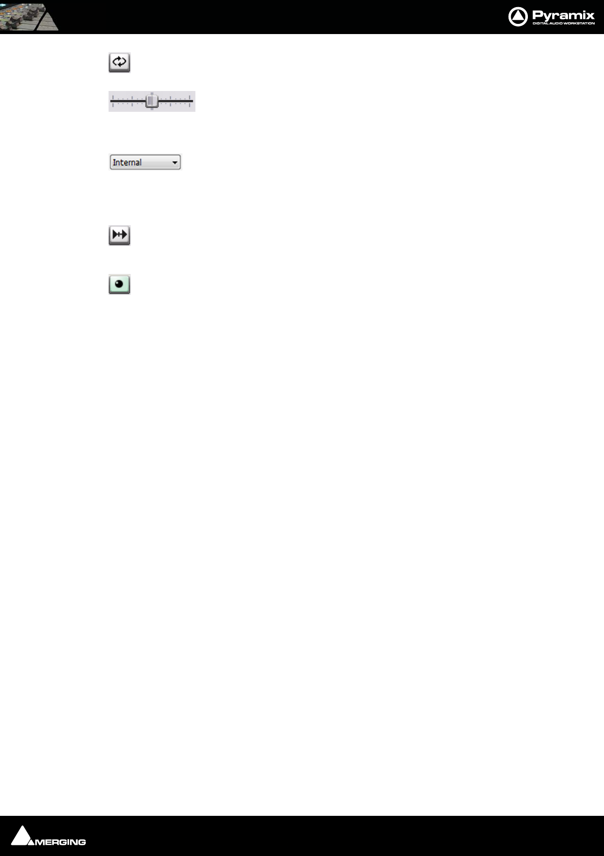
Transport and Navigation : Transport Controls 6 - 96
The Loop Play toggle button puts the Active Machine into a Loop Play Mode, which continu-
ously plays between the current In and Out points.
The Shuttle Control slider shuttles the Play Head forward (right) or backward (left)
at up to 2 X play speed. It Scrubs the audio on all Tracks as it shuttles through the Composi-
tion.
The drop down list selects which machine is currently controlled. Select Internal from
the list to ensure you are directly controlling the Pyramix Composition Play Head and not
some external device (I.e.RS-422 Sony 9-pin P2 controlled machine)
When the Chase toggle button is active, the Active Machine will only play back when valid
time code is detected on the chosen TimeCode input port.
The Controllers Online / Offline button. (Green = Online Red = Offline) Toggles external
hardware controllers On and Off line.
To the right of this is an area where any of the Floating Tool Palettes can be ‘Docked’. By default this will have the
Automation Toolbar docked.
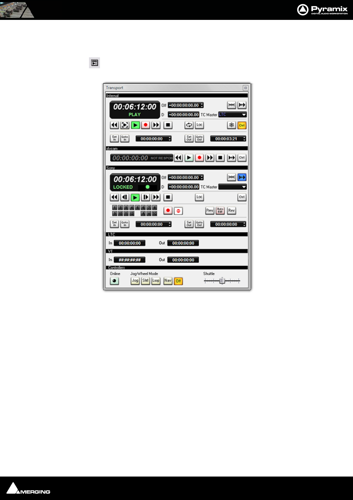
Transport and Navigation : Transport Controls 6 - 97
Transport Control Panel
Pressing the Transport Control Panel button or [Alt T], or selecting View > Windows /
Tools > Transport opens a floating Transport Window displaying all available
machines with individual sets of buttons and status indicators.
Note: This Window contains a set of transport controls for each machine installed and
enabled with the Internal Transport (Pyramix) at the top. Below the machines are dis-
plays for LTC and VT (and VITC when applicable) TimeCode Sources and at the bottom of
the panel there are controls which affect hardware Remote Controllers.
Clicking on the black name bar toggles the individual area between collapsed and full.
For example, dvcam is collapsed in the above illustration.
Important! For details of machine installation and settings Please see: Machine on page 534
and for details of these Transport Controls Please see: Internal / External Machine panels - Features
on page 378
Transport Control Panel floating Window
Transport and Navigation : Zooming and Panning 6 - 98
Zooming and Panning
The Project Editing Panel allows two kinds of zoom: horizontal or Time Scale zooming; and vertical or Track
Height zooming.
Time Scale Zoom and Pan
Icons on the View Toolbar zoom in or out at the current Play Head location.
The Fit in window [Alt 1]icon on the Toolbar automatically adjusts the horizontal scale to fit
the selected area inside the Project Editing Panel with a small margin.
The Previous zoom [Alt 2] icon restores the horizontal scale to the previous size.
Zoom In [Alt 3]and
Zoom Out [Alt 4]
Holding down the Alt key, then selecting an area of the Composition by clicking and dragging the mouse to the
left or right zooms in horizontally on the selected area.
Similarly, an area of the Composition can be selected by clicking and dragging.
The Scrollbar beneath the Tracks Pans the view of the Timeline horizontally left or right.
Track Height Zoom
1, 2, 4, 8, 16, and A buttons at the bottom left of the Project Editing Panel automatically scale the vertical Track
size so that 1, 2, 4, 8, 16 or All (as many as possible given the vertical space) Tracks fit in the vertical space allocated
to the Project Editing Panel.
The horizontal Scrollbar adjacent to these buttons enables continuous adjustment of the Track height.
Scroll Wheel
It is well worth while using a three button mouse with a scroll wheel.
Scroll Scrolls vertically through the tracks shown in the Project Editing Panel
Scroll + Ctrl Scrolls the Timeline
Scroll + Alt Zooms the Timeline timescale
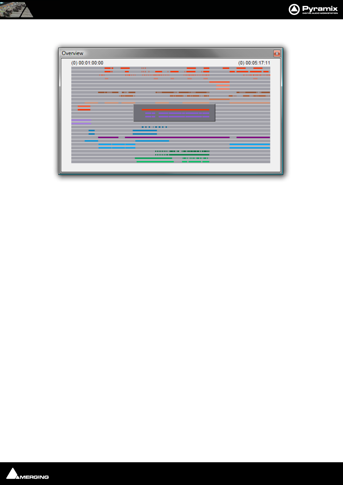
Transport and Navigation : The Overview 6 - 99
The Overview
The Project Management Panel Overview Tab offers a powerful and simple means of navigating around the
Project Editing Panel.
Overview displays a graphic representation of the entire current Composition, showing the location of all clips. A
shaded gray box indicates the location and zoom range of the part of the Composition which is currently dis-
played in the Project Editing Panel. clips are shown as rectangles in the same color as their background on the
Timeline.
Click anywhere in the Overview to center the Project Editing Panel display on that point. Click and drag on the
shaded gray box to move the section of the Composition shown in the Project Editing Panel without changing the
current horizontal zoom. The zoom range of the Project Editing Panel can be adjusted by dragging the edges of
the shaded gray box in the Overview. An alternative method for adjusting horizontal zoom is to press the Alt key
while clicking and dragging across the desired range for the zoom, just as you can do directly in the Project Editing
Panel itself.
Overview Tab Window

USER MANUAL
www.merging.com/Pyramix
Recording and Acquisition
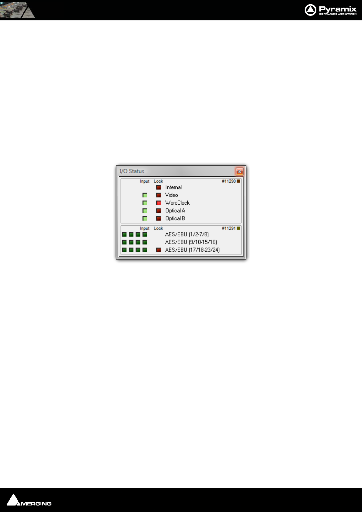
Recording and Acquisition : Getting Audio into Pyramix Virtual Studio 7 - 101
Getting Audio into Pyramix Virtual Studio
There are two basic methods of getting audio into Pyramix initially: you can record audio directly into the pro-
gram, or you can import previously existing audio files.
Please see also: Digitizing Sessions on page 106
Check Sync
Before attempting to record any audio please check Pyramix and the audio source(s) are synchronized as you
intend.
I/O Status Window
The I/O status window can be opened by clicking in the Sync: xxxxx section of the Status bar (bottom right of the
main Pyramix window. (the XXX’s are the current sync source)
This window shows useful information about the input and synchronization status of Pyramix.
Input sources
All the possible input sources are shown, each with an associated red and a green light. The green lights show the
presence of a valid digital signal (This does not necessarily mean, that the sampling rate of this input matches the
current clock source of Pyramix). When the red light is on and steady, Pyramix is using this input as it’s clock refer-
ence and is successfully locked up.
Default Clock Source
If Pyramix is set up to lock to an external clock source but cannot get a valid signal from this source, it will switch to
Internal clock. In this case the red light associated with Internal will be on, and the red light associated with the
intended clock source will be blinking.
Sampling Rate Mismatch
If Pyramix is set up to lock to an external clock source and the sampling rate set in the Virtual Studio Mixer does
not match the sampling rate of the clock source, the green light associated with the clock source will be on, but
the red light will be blinking showing the sampling rate mismatch.
File Format and Disk Limitations
File Size Limitations
By design legacy SD2, WAV or BWF files are limited to a maximum of 2GB due to their 32bit signed addressing
(thus 31 available bits) formats, while 32bits unsigned addressing AIF files are limited to 4GB. Please keep this in
mind when recording and/or exporting to any of these formats, the 2GB/4GB limit might in fact be quite close,
particularly when working with high sample rate multitrack files.
I/O Status window

Recording and Acquisition : Getting Audio into Pyramix Virtual Studio 7 - 102
As a comparison, Pyramix, thanks to its own PMF 64bit addressing file format can generate PMF files of virtually
limitless size. This makes it the file type of choice for creating single file, large multitrack projects at high sampling
rates.
The WAV file format can now accomodate RIFF64 removing the 2GB limitation. Please see: WAV and BWF on
page 301
Hard Drive Limitations
A very similar 2GB/4GB* limit can also be encountered the hard way when attempting to write large files, even in
PMF format, onto storage units (hard drives, memory cards etc.) formatted using an old 32bit file system such as
FAT32 or HFS.
Yet another, higher, limitation also exists with IDE ATA/ATAPI drives. This will show up at around 137GB. This may
be caused by part of a system (drivers, controllers and/or old Windows version) only recognizing the 28bit
addressing of the original ATA specifications, and not the enhanced 48bits available on newer equipment. This is
usually solved by installing fresh and or updated Bios/Drivers/OS.
*The official limit is 4GB, but serious trouble can start at around 2GB.
Pyramix audio file format
Unless there is a good reason for using another file format for recordings we strongly recommend using the
default .PMF file format. This will give the best performance in a number of key areas. For further information
please see: Optimizing Pyramix on page 432
Recording Audio into a Pyramix Virtual Studio Project
Start a new Project, or open an existing one. Make certain the Mixer sample rate and sync source is set as desired.
You will need to configure at least the same number of Mixer channels as Tracks you wish to record.
Before beginning audio capture, check or select appropriate record settings. Open the Settings > All Settings >
Project > Record page (alternatively use the keyboard short-cut Ctrl - f and click the Record Tab) There are many
settings in this dialog page, but for now you need only be concerned with; Destination Drive (Media File folder),
Resolution (bit depth or word length) and Format (file type). As previously mentioned, unless you have a specific
reason for using a different format we recommend using the default PMF format.
Note: These settings are completely independent of the settings for Mix-down and
Render.
Track Record Modes
Each Track has a tri-state Record Ready toggle button, located to the left of the Track itself in the Track Informa-
tion and Setup Area.
Tip: Right clicking on a track arming button opens the Settings > Project page immediately on the Record page.
Play
The Green Dot in the Track Header indicates Record Safe mode, the default when Tracks
are newly created. When in this state, the Track cannot be recorded to.
Record Ready (Manual)
Click on the Green Dot once to toggle to Record Ready mode. This is indicated by the dot
turning into the Red Dot. The Track will now go into Record mode immediately when the
Master Record button is pressed in the Transport Strip or Transport window.
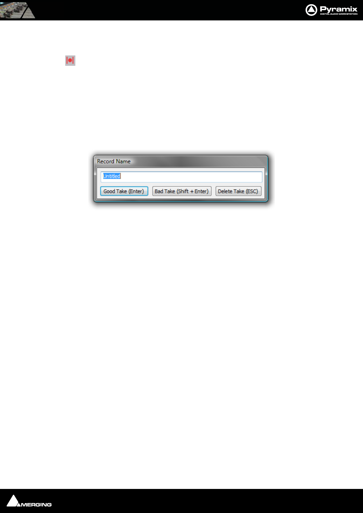
Recording and Acquisition : Getting Audio into Pyramix Virtual Studio 7 - 103
Record Punch In (Auto)
Alt-Click on the Red Dot to toggle to Record Punch In mode. This is indicated by a Red Dot
flanked by 2 red vertical lines. In this mode, when the Master Record button is pressed in
the Transport Strip or Transport window, the Track will stay in Play mode until the current
Mark In point is reached, then the Track will go into Record mode. It will stay in Record
mode until the current Mark Out point is reached.
After Recording
New recordings will be processed according to the settings made in the Settings > All Settings > Project >
Record page. Please see: Record on page 503
If the Prompt for name after recording box is checked the Record Name dialog appears when the recording is
finished and the transport stopped.
Type a name for the recording (or leave the default) then select one of the button options.
AutoPunch Mode
AutoPunch when Chasing TimeCode
If tracks are set to Auto-Punch mode (Alt+Click on Rec Ready button) then the system will start recording (after
locking to TC) when it reaches the Mark In point and punch out when it reaches the Mark Out point.
If the Mark In is located before the current location (and the Mark Out far after) then the system will immediately
record once locked and stop recording when unlocking.
Recording from a tape with Discontinuous TimeCode
Pyramix AutoPunch Mode makes this a simple operation.
Place the Mark In at 00:00:00:00 and Mark Out at 23:59:59:24 (default values for a new project)
Connect LTC Out from the tape machine into Pyramix
Set Chase mode to HARD CHASE
Rewind the tape
Press Play on the tape machine
Each time a valid TC is encountered Pyramix will lock and start recording a new clip, then stop when the timecode
stops or jumps. A separate media will be created for each continuous section of timecode on the tape.
Record Name dialog

Recording and Acquisition : Importing Audio Files into Pyramix Virtual Studio 7 - 104
Safety Record Mode
Pyramix is equipped with a Safe Record mode for the Internal Machine.
Safety Record is turned off by default. It can be activated by selecting Machines > Internal Machine >Safety
Record. When this mode is active an S is superimposed on the Transport Controls Record button.
Once a recording has begun the only way to stop it is to go to the Menu and de-activate Safety Record mode.
Apart from this no key presses, mouse clicks or external control inputs will stop the recording.
Note: Whilst it is possible to assign a Keyboard Shortcut to the Safety Record toggle, for
maximum security, it might be wiser not to.
Importing Audio Files into Pyramix Virtual Studio
Different file types with different bit depths (word lengths) can be freely combined in a Composition. Simply
Mount the Media Drive or Media Folder and drag-and-drop the required material into the Timeline.
Files with different sample rates can also be freely combined.
Note: If a clip has a different sample rate to the current project the clip will play at the
‘wrong’ speed! E.g. in a 48kHz project a 96kHz clip will play at half speed. With most
material this will be glaringly obvious, however with sound effects, smaller differences in
rate (E.g. 44.1kHz - 48kHz) may well go unnoticed.
Mounting Media Folders
If many audio files already exist in a single Windows directory or folder, it is easy to mount that Windows folder as
a Pyramix Media Folder. Once mounted, the supported files become available for use in a Project.
1. Start a New Project or Open an existing one.
2. Click the Media Management Tab in the Project Management Panel to open the Media window, or double-
click to open it as a floating window.
3. Select Media Folder > Mount Media Folder. This opens the Choose a media folder to mount dialog box.
4. Click the Browse... button, then navigate to the Windows directory containing the audio files you wish to
import.
5. Click the OK button to mount that Windows directory as a Media Folder. All supported audio file types will be
seen by Pyramix, and be available for use in the Project. A check in the Recursive box means Pyramix will look
in sub-directories of the chosen folder as well as the root. A check in the Permanent mount box means Pyra-
mix will attempt to mount the folder whenever the application is launched. I.e. make it available to all
Projects. A check in the Quick Mount box will create a special a library called '__QuickMountLocal.pml' (or
'__QuickMountRemote.pml' depending on whether you access this folder locally or through the network)
and store it the original folder. This can dramatically reduce the time taken to mount media files when a
project is opened.
Sample Rate Conversion
Where the sampling rate of a Media File is different to the current Project, Pyramix offers a simple means of con-
verting the Media File’s sample rate.
1. Select a Master Clip file or files in the main Media Management window.
2. Choose Convert > Quick Convert > Samplerate Converter. A Samplerate Converter dialogue box appears.
Radio buttons offer the choice of two text entry fields, New name for the file or Add Suffix to the existing file-
name. A checkbox selects Keep Original File Format otherwise the file will be converted to PMF format as
well as sample rate converted.
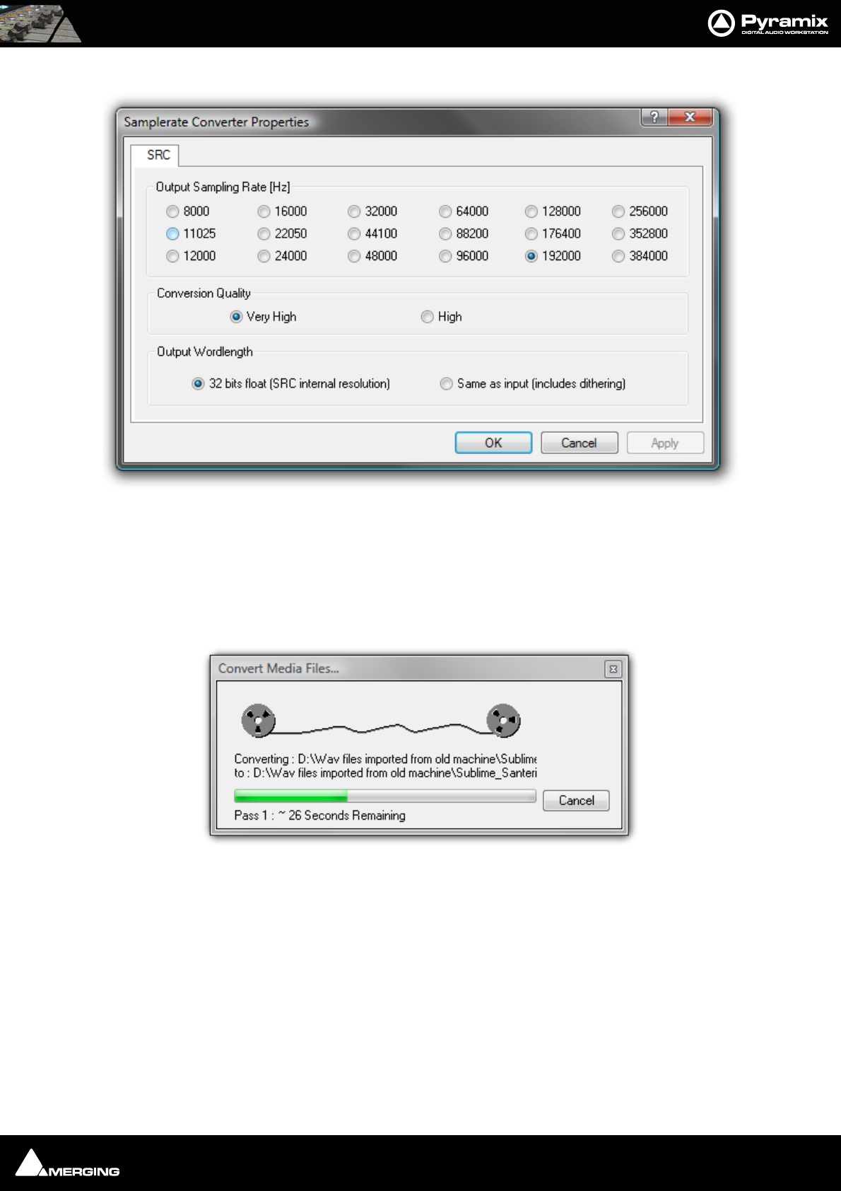
Recording and Acquisition : Importing Audio Files into Pyramix Virtual Studio 7 - 105
3. Selecting Properties opens the Samplerate Converter Properties dialog box:
4. Choose the required target sample rate by clicking on one of the Output Sampling Rate [Hz] radio buttons.
Conversion Quality defaults to High with the option of Very High. The remaining option is Output
Wordlength choose either 32 bits float (SRC internal resolution) or Same as input (includes dithering)
Finally click on OK to close the dialog
5. Choose OK in the Samplerate Converter dialogue box to begin the conversion. When converting multiple
files, choose OK to convert the files one at a time with the possibility of changing parameters on each file or, if
Add Suffix was chosen in step 2, you can choose OK all to convert all the selected files in one operation.
Samplerate Converter Properties dialog
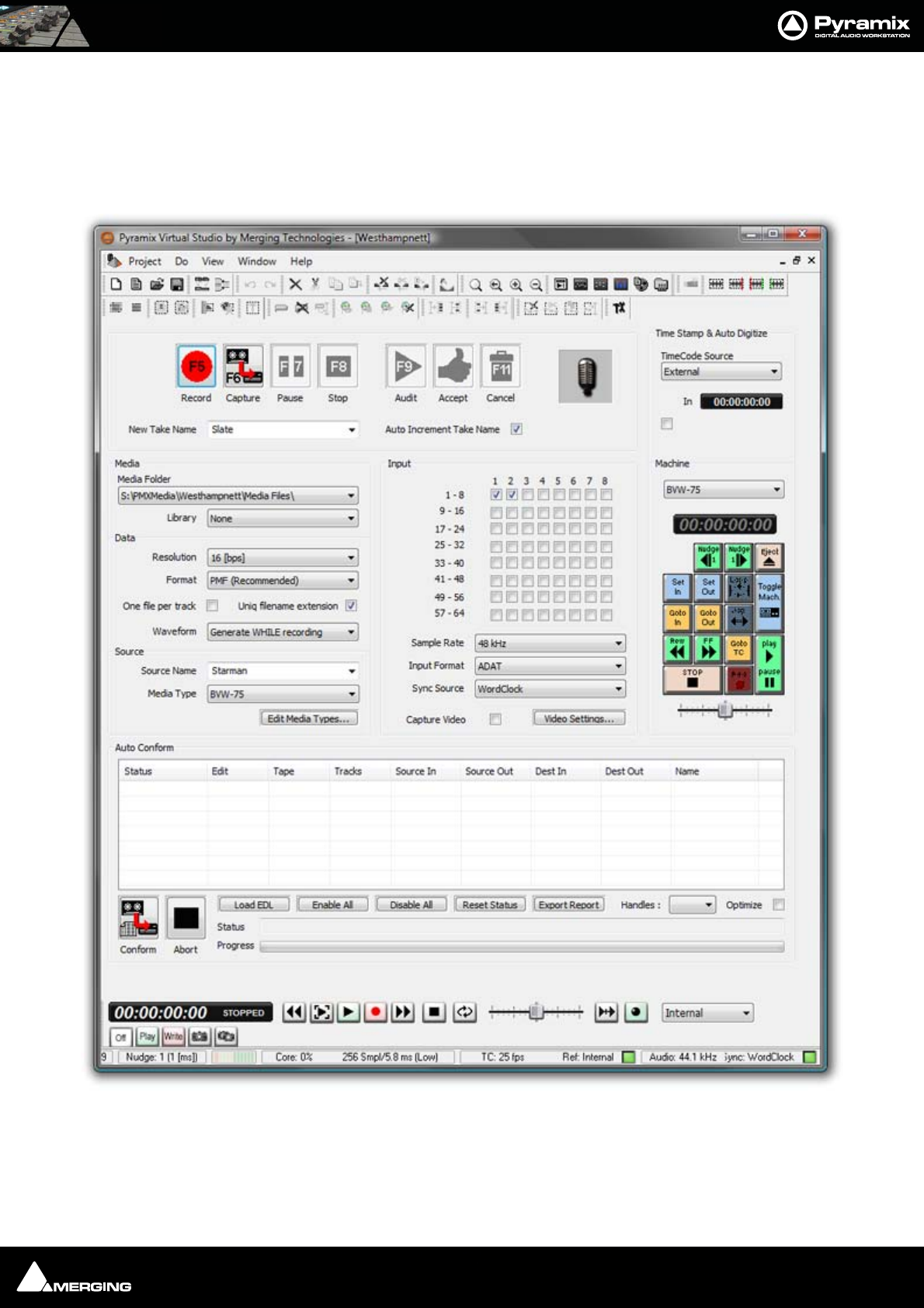
Recording and Acquisition : Digitizing Sessions 7 - 106
Digitizing Sessions
A Digitizing Session is a special type of Pyramix Project which is intended for efficiently loading audio material
into Pyramix. One advantage to using a Digitizing Session for capture is that Master Clips referencing the audio
Media Files can be generated and saved directly into a specified Library for later placement.
Digitizing Session Project Window

Recording and Acquisition : Digitizing Sessions 7 - 107
Manual Digitizing
1. In the Media section, choose an appropriate Media Folder to which to your captured files will be saved. If you
wish to simultaneously save Master Clip references to these Media Files into a previously created Library,
select that Library from the Library drop-down list.
2. In the Data section, choose the appropriate Resolution (bit depth or word length) and Format (file type) for
the saved audio files. Check One File per track ON to generate a separate file for each Track recorded. I.e. two
files for a stereo source, six for a discrete 5.1 source and so on.
3. In the Input radio button matrix, check ON for each Input you wish to record from. Also set the Sample Rate,
Input Format and Sync Source as appropriate.
4. Type in a New Take Name to name the captured files. If the Auto Increment Take Name box is checked all
subsequent takes will use the name typed in the New Take Name field as a ‘seed’ with a numerical suffix to
denote the individual takes. E.g. Enter ‘Vocal’ as the New Take Name, check the Auto Increment Take Name
box and record a few seconds, stop then record another few seconds. The first take will be called ‘Vocal’ and
the second ‘Vocal 2’
5. You can monitor incoming audio through the Mixer. Click on the Show/Hide Mixer icon to display the Mixer,
and set levels as appropriate.
6. Any external machine can be used as the source. However, it is much more convenient to use a machine
which can be controlled by Pyramix. A machine can be selected from the Machine drop-down list. It’s control
panel appears below the list.
7. Locate the required material on the source tape.
8. Click on the red Record button to begin recording. The system will remain in record until the Stop, Pause or
Cancel button is pressed.
9. Press the Stop button to stop recording.
10. You can press the Audit button to audition the recording just made.
11. Press the Accept button to save the recording to the destination Media Folder, or press the Cancel button to
delete the recording without saving it.

Recording and Acquisition : Digitizing Sessions 7 - 108
Autoconforming
1. Pyramix can record audio selectively according to an EDL (Edit Decision List) in the CMX format.
2. Follow the set-up suggestions above and ensure the source machine is working correctly under 9-pin control.
3. Click the Load EDL button, navigate to the directory containing the EDL you wish to load the audio for.
4. If the list is not already in Reel order, click the Optimize button. This will sort the list so that audio is digitized
with the minimum of reel changing and spooling. All overlapping edits will be merged.
5. Load the first reel in the list, click the Capture button and Pyramix will automatically control the source
machine. All the required audio in the reel will be digitized.
6. Change the reel when prompted until all the required audio has been digitized.
If you know the audio is not available for certain edits in the list, or you wish to digitize only certain edits, uncheck
the box(es) in the Status field for the relevant entries before clicking Capture. The Status filed will show when
clips have been captured which match the edits.
Enable All
Checks all the boxes in the Status Field for capture.
Disable All
Un-checks all the boxes in the Status Field. I.e. no edits are selected for capture.
Reset Status
Restores the Status Field check boxes to their previous state.
Export Report
Exports an .rtf file detailing the edits which were captured and those which were not.
Handles
Sets an extra amount of audio to be captured at each end of the edits. This allows greater freedom in editing but
may cause problems in some circumstances. The drop-down list gives a choice of from 0 to 10 frames.

USER MANUAL
www.merging.com/Pyramix
Editing
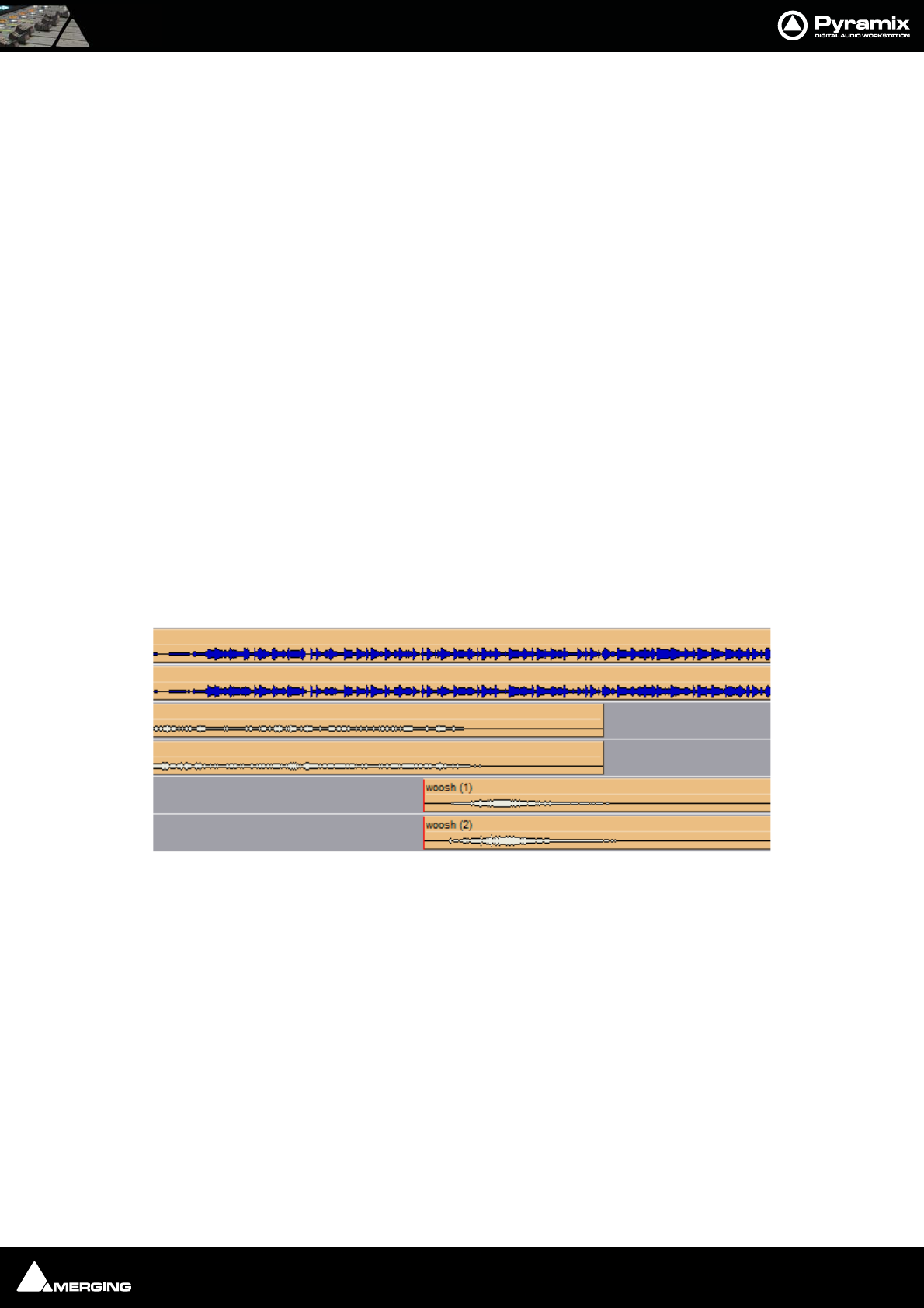
Editing : Editing in the Timeline 8 - 110
Editing in the Timeline
The Timeline is the place in Pyramix where audio clips can be edited, faded up and down and otherwise arranged
into a mono, stereo or multi-channel digital audio Composition.
A Project Editing Panel containing the Timeline will be visible as soon as you open a Project.
The Fade Editor provides elegant alternative methods of viewing and adjusting the parameters of edits in the
Timeline.
Clips and Compositions
Clips in a Composition
As with clips in a Media Drive or Library, clips in a Composition are just pointers to the original audio Media
File. Any actions performed on a clip in a Composition will affect neither the original audio Media File, nor the
Master Clip in the Media Folder or Library it came from. In the Project Editing Panel, a clip can be edited, short-
ened, split into 2 clips, moved, level controlled, deleted, etc., and all actions will ONLY affect the Composition.
Once placed in the Composition, each clip by default displays a Waveform of the Media file to which it points. This
Waveform display can be enabled or disabled by the user.
Sample Rate Mismatch
Pyramix allows clips of any supported sample rate to be placed in the Timeline. By default Clips that do not match
the Project sample rate are converted ‘on-the-fly’ to the project sampling rate. (Please see also: Real-time Sam-
pling Rate Conversion on page 519) To help avoid inadvertent placement of clips that do not match the project
sample rate the waveform in such clips appears in a different color, by default, blue:
Note: Each clip’s assumed sample rate is determined by information contained in the file
header. If this information is incorrect (as with certain DAR files) the clips will not play
back at the correct speed or pitch.
Please see also: DAR WAV file Import on page 64
Sample Rate Mismatch

Editing : Clips and Compositions 8 - 111
Anatomy of a Clip
Many Edit Commands refer to parts of a clip rather than the entire clip.
Once a clip is selected, Trim Handles appear at each end which are used to manipulate the clip. If these are diffi-
cult to see or get hold of, zoom in on both axes until they are accessible. Each Trim Handle consists of 3 Control
Points. The Control Points on the left side of the clip allows adjustment of the beginning of the clip, and the Con-
trol Points on the right side allows adjustment of the end. Click and drag on the middle Control Point to move
the head or tail of the clip as desired to shorten or lengthen the clip. These can be moved out to the full extent of
the original audio Media File to which the clip is pointing. Select View > Show Media to view the unused audio
(if any) as a grayed out waveform.
Head
The beginning of a clip on a Track is referred to as the Head. The Head may or may not represent the actual begin-
ning of the Media File for the clip, since the clip is just a set of pointers to an area of the whole media file.
Tail
The end of a clip on a Track is referred to as the Tail. The Tail may or may not represent the actual end of the media
file for the clip, since the clip is just a set of pointers to an area of the whole Media File.
Sync Point
The Sync Point is an internal reference point inside the clip. This defaults to the start of a clip until moved.The Sync
Point may be moved by dragging its handle within the clip. If the Play cursor is positioned over some part of the
clip, the Sync Point may be snapped within the clip to the position of the Play Cursor by choosing Clips > Set Sync
Point to Cursor.
Trim Handle
The Trim Handle is the middle handle available at either end of the clip when the clip is selected. This handle is
used to shorten or lengthen the clip (trim the clip in or out) up to the limit of the available media. To trim the clip,
drag the handle.
Fade Handles
The Fade Handles are the top and bottom handles available at either end of the clip when the clip is selected. The
handles are used to create a fade in at the beginning of the clip, or a fade out at the end of the clip. To create or
adjust a fade, drag one of the trim handles to create the desired fade in or fade out. The top handle adjusts the
fade within the clip and the bottom handle trims the clip in or out as you adjust the fade. If the Top Handle is used
with the CTRL key modifier, a symmetrical crossfade is created with any adjacent clips, centered at the original end
point of the selected clip. If no adjacent clip exists, then it extends or shrinks the duration of the fade while main-
taining the duration of the selected clip.
Waveform Display
Clips can appear either as a block with the clip name inside, or can show the audio waveform of the media refer-
enced by the clip.
Trim Handle
Sync Point
Fade Handles
Tai l
Waveform Display
Head
Clip Gain
Features of a Clip in the Timeline
Clip Name
Unused Media
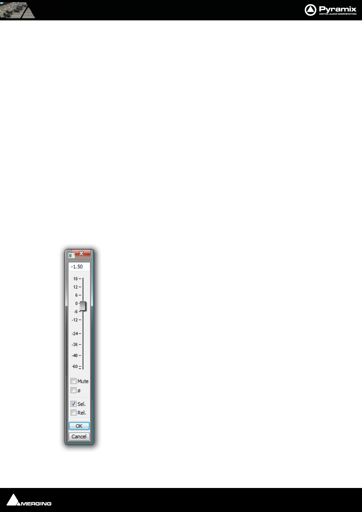
Editing : Clips and Compositions 8 - 112
Clip Name
The name of the clip is shown unless suppressed. View > Waveform Display > Hide Clip Name when Waveform
Shown.
Clip Gain
The overall Gain applied to the clip is shown. This value is displayed in decibels.
Gain can be adjusted by selecting Clips > Clip Gain. The Gain window appears. If a Region is selected the Gain
will be changed on all clips in the selection.
Locking Clips
Clips can be protected from being displaced during editing by selecting Clips > Lock. A locked clip cannot be
moved in time or to another track until it is unlocked. Clips > Unlock. If you simply wish to prevent loss of sync
select Clips > Lock Horizontal Drag.
Grouping Clips
To Group multiple clips, whether they are on the same or different Tracks, select the clips you wish to Group
together. Now choose Clips > Group. When any clip in a Group is selected, copied, deleted or moved, all clips in
its Group will be similarly selected, copied, deleted or moved.
To ungroup previously Grouped clips to treat them separately, select the Group and choose Clips > Ungroup.
Groups can be nested. I.e. one group may be inside another group. For example a stereo or multi-channel clip is
simply a group of mono clips. Stereo or Multi-channel clips may be ungrouped into individual mono ones in the
same way as any other group.
Gain Window
The Gain window allows the gain to be set for the current selection. The gain value can be
typed into the box at the top of the strip or set by clicking and dragging the fader
Mute when checked, mutes the selection but retains the gain value
Sel. box (Selection). When checked, the gain change will be applied to the whole selec-
tion (default is checked)
Rel. box (Relative) When checked and a series of clips are grouped, the gain change is rel-
ative to pre-existing levels
When neither box is checked any gain change is only applied to the clip which was last
right clicked (even if others are selected)
OK button makes any changes selected in the Gain window and closes it
Cancel button cancels any changes selected in the Gain window and closes it
Gain Window
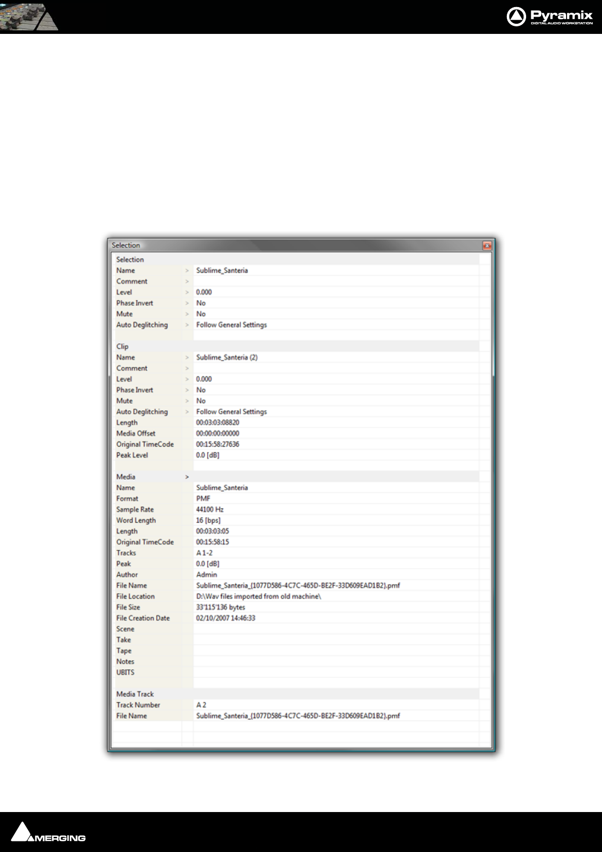
Editing : Clip and Selection Editing 8 - 113
Clip and Selection Editing
Master Clips appear in the Timeline as blocks which can be edited on a track (or tracks, depending on how many
tracks the Master Clip contains) The clip can be trimmed, split, crossfaded, and have many other operations per-
formed on it without ever affecting the underlying media file. Each instance of a clip references the entire media
file, and can always be "opened up" by using the Trim Handles to reveal more of the clip until the complete under-
lying Media File is visible. Clips can be dragged in the Timeline while the transport is playing.
Clip Properties
Clips > Properties opens the Properties window for the selected clip. If multiple clips are selected, opens the
Properties window for the first clip selected.
Selection Window
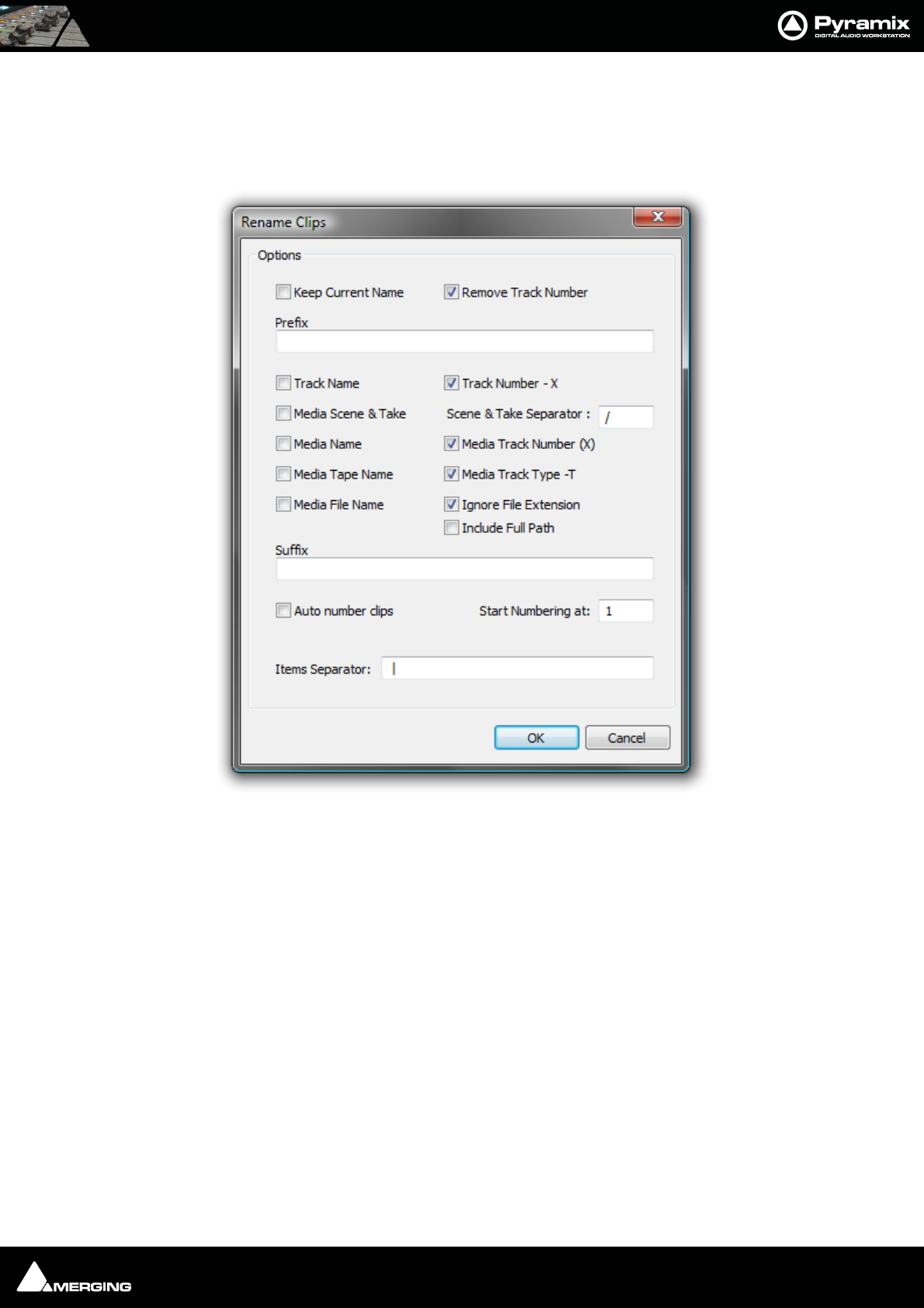
Editing : Selection Tab Window 8 - 114
Renaming Clips
Although Clips can be renamed in the Clips > Properties Selection Window, Pyramix offers a more convenient
method of renaming clips in a logical and orderly manner.
Clips Rename open the Rename Clips dialog:
The Clip Name can be composed out of user text, automatically generated data or a combination of both. The dia-
log box is largely self explanatory. Auto numbering is relevant where a number of clips are selected when the
Rename Clips dialog is opened.
Selection Tab Window
The Selection Tab Window groups together Selection Properties, Clip Properties and Media Properties fields in
a table.
When choosing Selection Properties or a Properties Menu item, this Tab Window is displayed. If the Tab Win-
dows section is hidden, then the Selection Tab Window is undocked to ensure it is visible. Parameters that can be
modified are marked with a ‘>’ sign. Click on the ‘>’ sign or on the parameter itself to change/edit it.
Selection and Clip Modifiable Fields
Name
This field shows the name of clip as it appears in the composition. This name will also be displayed in
the clip block when the clip is set to Show Text.
Rename Clips Dialog

Editing : Selection Tab Window 8 - 115
Comment
This field shows a user comment concerning the clip. The information displayed here will also be shown in the
Comment field in the EDL Tab window
Level
Available in both
Pops up a window with a fader and numerical entry box for level, and two check boxes, Sel.ection and Rel.ative.
When neither box is checked any gain change is only applied to the clip on which you last right clicked (even if
others are selected). If Sel. is checked, the gain will be applied to the whole selection (selected by default). If Rel. is
checked and you have a grouped series of clips the gain change is relative to pre-existing levels.
If you click on the > in the “selection” part gain is applied to the whole selection, and if you click in the “clip” part,
the gain is applied only to the clip which was under the mouse when you clicked.
E.g: Three clips are selected, the first at -1 dB, the second at -2 dB and the third at -3 dB. You wish to increase the
gain of all the selected clips by 1dB. Check the Rel. box and add 1 dB either with the fader or in the numeric box.
This will result in the first track at 0 dB, second at -1, third at -2.
Phase Invert
Toggles between No and Ye s (Phase inverted)
Mute
Toggles between No and Ye s (Muted)
Auto Deglitching
Drops down a list box with choice of None, Follow General Settings or fade settings between 1.0 [mS] and 5.0
[mS] in 0.5[mS] increments. This feature avoids the necessity to manually make short fades when quickly making
cut edits. On any clips that do not already have a fade a small ramp is automatically applied to avoid clicks at the
beginning and end. Any clips with fades previously applied bypass the Auto-Deglitching feature.
Note: the global Automatic -Deglitching value is set in the Settings > All Settings >
Application > Playback/Record page in the Automatic Deglitching section.
Clip Information Only Fields
Apart from the modifiable fields listed above, clip also shows the following information fields:
Length
This shows the total length of the selected clip segment.
Media Offset
This field shows the amount by which the start of the selected clip segment is offset from the beginning of the
entire Master Clip.
Original TimeCode
This field shows the original TimeCode stamp at the head of the clip.
Peak Level
This field shows the highest level (in Decibels Full Scale) reached by any sample within a clip. This is only shown for
clips which have had a Waveform display generated.
Media Information Only Fields
Name
Shows the original short name of the audio media.
Format
Shows the media format as PMF, Wave etc.
Sample Rate

Editing : Selections and Region Selections 8 - 116
Word Length
Length
Shows the total length of the media file referenced by the clip.
Original TimeCode
Tracks
Shows the tracks the media was originally recorded to.
Peak
This field shows the highest level (in Decibels Full Scale) reached by any sample within a media file.
Author
Shows the user who was logged in when the file was created.
File Name
Shows the full media filename including the unique identifier and extension.
File Location
Shows the full Windows path to the media file
File Size
Shows file size in bytes.
File Creation Date
Scene
Take
Tape
Notes
UBITS
Media Track Information Only Fields
Track Number
Shows the track number within the media file. I.e. a stereo file will have A1 and A2 for the two tracks.
File Name
Shows the full media filename including the unique identifier and extension.
Note: The values shown in the Clip, Media and Media Track sections reflect the track
clicked on in the Timeline. Where a selection contains several, possibly multi-channel,
clips, clicking on the individual items in the Timeline updates the information to reflect
the last item clicked.
The Selection Tab Window is automatically updated when the selection changes and can therefore remain float-
ing.
Selections and Region Selections
Selection Operations
Many Pyramix editing operations can only be carried out if a clip or region is selected.
There are two ways of selecting material in the Timeline. Whole Clips and Regions.

Editing : Dragging Clips into a Composition 8 - 117
Clip Selection
Clicking in a clip selects it (the color becomes darker and Handles appear). The whole clip is ready for editing.
Clicking on other clips while holding down the Shift key adds them to the selection. If the clip is grouped with
other clips, this will select the entire group. To select a single clip in a group, first ungroup the clips, then select the
desired clip.
Region Selection
A Region Selection is a selected area of the Composition. A Region can include many clips on many tracks or
only a portion of a single clip. It is indicated as a darker gray rectangular area over one or more Tracks. When
selecting a clip within a group, the Region is automatically extended to the whole group. This can be avoided by
pressing the Shift key while selecting. A Region can be made by clicking and dragging the mouse across one or
more Tracks.
Of course, keyboard shortcuts exist for making Regions, and this is one of the most useful ways to mark a region.
The Pyramix default method of marking a Region in point is to press [ on the keyboard: this selects everything to
the right of the current Play Head Cursor location on the currently selected track. ] marks a region out point: this
selects everything to the left of the current Play Head Cursor location, up to a previously marked in point. Once a
Region has been defined in this manner it can be extended or ‘grown’ across more tracks by using Ctrl +Shift
+Cursor UP or DOWN arrows. Ctrl +Alt +Shift +Cursor UP or DOWN shrinks. (Assuming the standard Pyramix
keyboard shortcut assignments are in use.)
Using the keyboard short-cuts, Regions can be easily made on-the-fly while playing or scrubbing the Timeline.
This is particularly efficient when used in conjunction with the Numerical Keypad transport control short-cuts.
Dragging Clips into a Composition
The simplest way to place an audio clip into your Composition is by dragging it from a Media Folder or Library.
To drag from a Media Folder:
1. Click on the Media Management Tab to open the Media Management tab window.
2. Double-click on a mounted Media Folder or subfolder to open it. The Master Clips will all be listed on the
right side of that window.
3. Select a Master Clip by left-clicking and holding. Drag the Master Clip into a Track. You can place it into any
Track, at any point on the Track.
The procedure for dragging an object from a Library is virtually identical to that outlined above for Media Drives.
However, access the required Library using the Global Libraries or Document Libraries Tabs in the Project
Management Panel.
Copy and Paste
Another way to get objects into a Composition is by copying and pasting them.
1. Select an object in a Media Folder or Library.
2. Right-click on the Master Clip, and choose Copy from the pop-up.
3. Place the Play Head Cursor where you want to paste the beginning of the Master Clip.
4. Right-click on the Track to which you wish to place the clip, and choose Paste to Cursor from the pop-up.
The beginning of the object will be placed at the Play Head in the Track on which you right-clicked. Alterna-
tively, simply click the mouse on the track and at the time you want the clip to start, right -click and choose
Paste to insert the clip where you placed the mouse cursor.
Selecting a Clip
Click on any clip in the Composition to select it. It will change color to indicate selection. Shift-click to select multi-
ple clips at the same time.
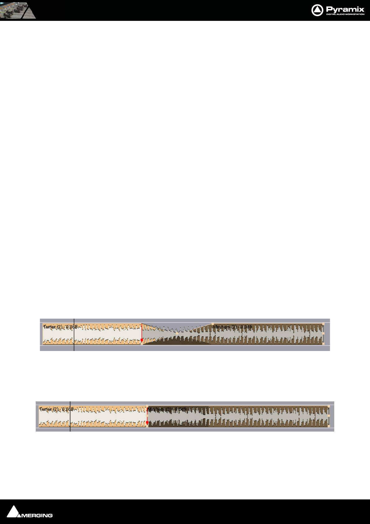
Editing : Copy and Paste 8 - 118
Simple Copy and Paste
1. Left-click a clip to select it.
2. Right-click and choose Copy from the pop-up. (or use menu Edit > Copy or use Ctrl + C)
3. Place the Play Head Cursor where you want to paste the beginning of the Master Clip.
4. Right-click on the Track to which you wish to place the clip, and choose Paste to Cursor from the pop-up. (or
use menu Edit > Paste to Cursor or use Ctrl + V). The beginning of the clip will be placed at the Play Head in
the Track on which you right-clicked. Alternatively, simply place the mouse cursor on the track and at the
time you want the clip to start, right-click and choose Paste to insert the clip where you placed the mouse
cursor.
Selecting a Region
To select a region, click the mouse at one end of the region you wish to select, and drag the cursor to the other end
of the region you wish to select.
A region can include more than one clip, and may extend across multiple tracks. The selected region may also
include the area(s) on a track where no clip is present.
Adding Tracks to a Selected Region
With a region selected, Shift + Click on other tracks to add them to the selection. The tracks do not have to be
continuous. For example:
Note: Discontinuous regions cannot be selected horizontally.
Clip Selection Behavior
The following lists the various behaviors for a selected clip depending on different modifier keys.
When a Clip is selected:
No Modifier Key
With no key modifier, the clip can be manipulated in standard Edit Mode.
CTRL Key Modifier (Auto Crossfade Mode)
While a clip is selected, pressing and holding the CTRL key before clicking and dragging automatically creates a
cross-fade when the clip is moved to overlap any adjacent clip. The mouse cursor changes to a hand with an X
over it to indicate Auto Crossfade Mode is engaged. While in Auto-Crossfade Mode selected clips can only be
moved in time, not to other Tracks.
CTRL Key Modifier Option (Layering Mode)
When in the CTRL Crossfade mode, if the CTRL Key is released (while still holding the left mouse button) Layering
Mode is entered. This mode allows clips to be overlapped. (Technically, the result is a crossfade with zero length
fades.)
CTRL SHIFT Key Modifier (Slip Media Mode)
While a clip is selected, pressing the CTRL and SHIFT keys will allow the audio contents of the clip to be slipped in
time. The Media can be slipped to the extent of its availability.
Auto Crossfade Mode
Layering Mode
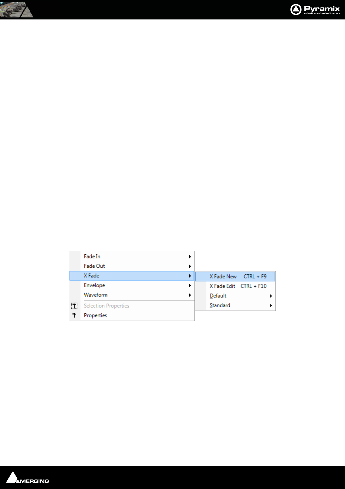
Editing : Auto-Crossfade By Default 8 - 119
CTRL ALT Key Modifier (Slip Clip Mode)
While a clip is selected, pressing the CTRL and ALT keys will allow the In and Out point of the clip to be slipped
together in time while the Media remains where it is in time. Think of this as moving a "window" within the media.
ALT SHIFT Key Modifier
While a clip is selected, pressing the ALT and SHIFT keys will allow the clip to be dropped into a Library as a new
Composition.
Note: When a clip is moved over another in either within the TimeLine in Layering or
Auto-Crossfade Modes or from a Library or Media Management, the clip color tempo-
rarily changes to red. This is particularly helpful where there are hidden clips on the right
side of the screen that may be erased by the new clip or move.
Auto-Crossfade By Default
Auto Crossfade / Layering can be set as the default editing mode. This reverses the functionality described
above. When this mode is engaged, pressing the CTRL key enables the Edit mode.
This mode can be engaged by selecting Edit > Auto-Crossfade or by checking the Auto-Crossfade by Default -
Control key for Drag & Drop box in Settings > All Settings > Editing.
Clip Fade Commands
Fade In
Fade Out
X Fade Each of these three entries on the Clips menu lead to sub-menus which all look like this:
New Creates a fade when a region is defined at the beginning (Fade In) the end (Fade
Out) or across overlapping clips (X Fade)
Edit When chosen from either the Fade In or Fade Out sub-menus, opens the Fade Edi-
tor with the current fade. From the Cross Fade sub-menu opens the Fade Editor
only when a region is defined across an existing cross fade. (Please see: Fade Edi-
tor Tab Window on page 134)
Default When a clip is selected or a Region is defined which includes the clip start or end,
Fade In or Out > Default > Complete recalls the length and shape of the Default
Fade In or Out and applies it to the selection.Default > Curve Only recalls only
the curve shape.
When a region is defined on a clip or clips which are cross-faded X Fade > Default
Complete or Curve Only recalls and applies the Default Crossfade length and
shape or shape only respectively.
Standard Sub-menu offers a choice of fade types
Power Linear
Crossfade sub-menu
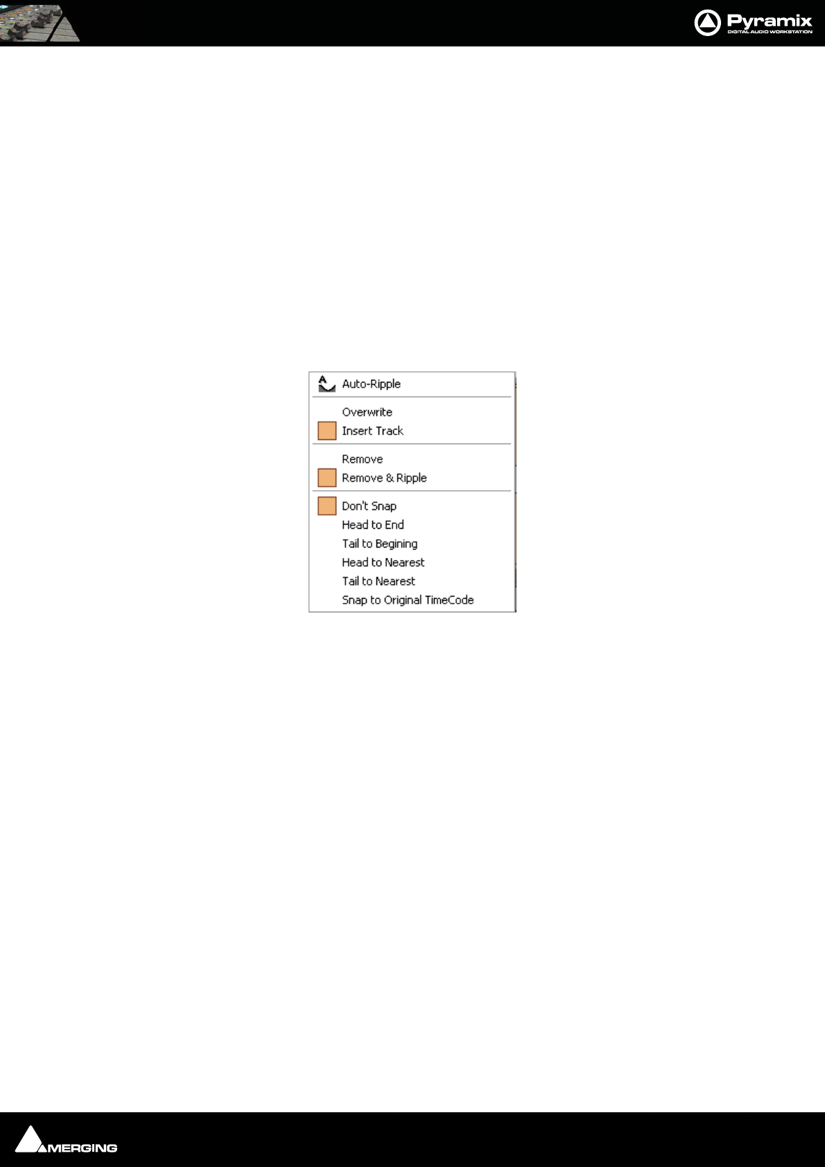
Editing : Editing Modes 8 - 120
Tension Linear
dB Linear
Cosine
Root Cosine
Editing Modes
The current Editing Modes are shown in the Markers Header. If either Remove, Insert or Snap modes will result
in rippling of other clips. I.e. loss of sync, the Editing Modes are shown in Red Some of the editing commands
which delete clips from, or paste clips into the Timeline behave differently depending on the current settings of
the Insert mode and the Remove mode.
Edit Modes Context Menu
Clicking on the Markers header pops up the Edit Modes context menu:
Auto-Ripple When this option is checked (enabled) all Insert or Remove operations ripple the
rest of the track
Overwrite When checked, any clip placed so that it overlaps an existing clip will overwrite the
part of that clip where the two overlap.
Insert Track When checked, any clip placed on a track will be inserted into the track and will rip-
ple all other material on the track later in time (to the right) by the length of the clip
being inserted.
Remove When checked any selected material will simply be removed from the Timeline.
Everything else will be left intact and in the same place.
Remove and Ripple When checked any selected material will be removed from the Timeline. Everything
else to the right (after) the removed material will be Rippled (moved) to the left (ear-
lier) to take up the space left by the removed material.
Don’t Snap No snap mode set. This mode doesn't affect the behavior of objects placed on a
track. Behavior follows the existing Insert and Remove modes.
Head to End This mode will cause the beginning of any clip placed on a track to snap to the end
of the last clip on the track, abutting the head of the new clip to the end (tail) of the
last clip.
Tail to Beginning This mode will cause any clip placed on a track to snap to the beginning of the first
clip on the track, abutting the tail of the new clip to the head of the first clip.
Head to Nearest This mode will cause any clip placed on a track to snap the head of the clip to the
nearest edit point or mark on the track. This includes the head or tail of existing clips
on the track, as well as the Play Head Cursor, Mark In, Mark Out, Named Markers, or
CD Marks. The clip will interact with existing clips according to the Insert Mode set-
ting.
Edit Modes Context Menu

Editing : Jog-Wheel Editing 8 - 121
Tail to Nearest This mode will cause any clip placed on a track to snap the tail of the clip to the near-
est edit point or mark on the track. This include the head or tail of existing clips on
the track, as well as the Play Head Cursor, Mark In, Mark Out, Named Markers, or CD
Marks. The clip will interact with existing clips according to the Insert Mode setting.
Snap to Original TimeCode This mode will cause any clip placed on a track to snap the head of the clip
to the time location represented by the clips original TimeCode. The clip will interact
with existing clips according to the Insert Mode setting.
Splitting Clips and Regions
Splitting a Selection
Splitting Clips
Edit > Split (or Ctrl + T) makes an edit on the selected clip(s) at the cursor position splitting it (them). If a region is
defined within a clip or clips then this region is Split (edited) by using this command. Each split portion of the orig-
inal clip(s) now becomes a new, independent clip in its own right.
Splitting Regions
If the Play Cursor is positioned over a selected Region rather than a whole clip or clips, then choosing the Edit >
Split command will split the selected Region from the surrounding material at the edges of the selection area, not
under the Playhead Cursor.
Once a Region is marked on a clip, simply clicking on the Region makes an edit. (same effect as the Edit > Split
menu command.) This will split the clip or clips at the region boundaries. If a Region is across several Tracks, Edits
will be made on all Tracks within the Region.
Cutter
Holding down the C key changes the mouse pointer to a cutter. Edits (cuts) are made wherever the user clicks. To
make an edit with the cutter on a range of clips at the same position, just select them before cutting.
Duplicate Selection
Holding down the D key while clicking on the selection then dragging to a new location duplicates the selected
material and moves the copy.
Holding down the F key while clicking on the selection then dragging to another track (or tracks if the selection
covers more than one track) duplicates the selected material and moves the copy locked in time.
Moving a Selection
Simply drag a selected clip move or reposition it to another location on the same track or a different track. If a
Region is selected, clicking on it will split it from the surrounding material. The resulting separate clip can then be
dragged to a different location or track. To constrain a clip in time when moving it to another track, hold down the
Alt, Shift and Ctrl keys at the same time while dragging the clip to the new track.
Adjusting a Region Selection
Simply position the Arrow Cursor at the edge (beginning or ending) of the region. The cursor will change shape to
indicate the Region can now be adjusted by clicking and dragging. You may drag the edge beyond the other end
of the region. Doing so ensures that the new selection region begins (or ends) exactly where the original region
ended (or began). This also applies to the top and bottom edges of the region. For example, you can extend the
selected region on one track up or down to include additional tracks.
Jog-Wheel Editing
A number of editing actions may be undertaken on a selected clip or group of clips using a jog-wheel on an exter-
nal hardware controller.
First select the Clip or group of Clips, then select the desired Jog-Wheel Editing Mode from:
Edit > Jog-Wheel Editing > Move

Editing : Playlists 8 - 122
Trim In
Trim Out
Trim Fade Out
Tim Fade In
Trim Fade In Symmetrically
Trim Fade Out Symmetrically
Trim Sync Point
Slip In
Slip Out
Slide Media
Now simply move the jog wheel to Move, Trim, Slip or Slide the clip(s)
Pressing the Spacebar or Enter confirms the change(s), Esc cancels.
Playlists
Playlists enable different versions of the content of a selection of tracks to be easily stored and any stored version
to be recalled.
Playlists have a name (and can be renamed). A Playlist shows the list of tracks it keeps versions of. By selecting a
Track Group or one or more Tracks in the Playlist Tab Window, you can:
• Create a new empty playlist for these tracks
• Create a new Playlist for these tracks containing a copy of their current content
You can also:
• Create a new empty Playlist for all tracks in Record Ready mode
• Create a new playlist for all tracks in Record Ready containing a copy of their current content
Double-clicking on a Playlist icon replaces the content of the tracks it references with the version it contains.
Modifications made on the tracks referenced by a Playlist are updated in the last recalled Playlist when another
one is recalled. A new Playlist can be automatically created for each recording for every recorded track by check-
ing this option in Playlists section of Settings > All Settings > Project > Record.
The Playlist icon displayed on each Track header enables:
• The creation of an empty Playlist for each track in Record Ready Mode, all Tracks in Group or Strip, or the
selected Track
• Creating a copy Playlist for each track in Record Ready Mode, all Tracks in Group or Strip, or the selected
Track
• Recalling a Playlist. A list of Playlists that reference the selected track is presented for recalling.
• Merging a Playlist with the current content of the tracks. A list of Playlists that reference the selected track
is presented for recalling.
Edit Command highlights:
Further Editing commands are to be found on the main Edit menu. Please see: Edit on page 443
Undo Pyramix keeps track of all edit decisions and operations so they can be undone if neces-
sary. This menu item shows the name of the last operation. To undo this operation, simply
click on the Undo (operation) menu item and the listed operation will be undone. When-
ever an item is undone, it immediately shows up as the most recent item in the Redo list.

Editing : Edit Command highlights: 8 - 123
Undo History Pyramix keeps track of the most recent edit decisions and operations and shows them
here in a sub-menu. These are listed from the most recent at the top, to the oldest at the
bottom of the list. To undo a whole block of operations, click on the name of the oldest
operation and everything since that time (from that point in the list to the top of the list)
will be undone. The name of the next operation in the list will be shown as the next Undo
item, and all the items that have been undone are immediately added to the Redo His-
tory list. The size of the undo history is set to 32 steps by default, but it can be adjusted in
the All Settings > Settings > Application > General page.
Redo If an operation has been undone using the Undo commands in this menu, the most
recently undone operation will be shown here. To Redo the operation, simply click on
Edit > Redo and the operation will be Redone. Whenever an item is Redone, it immedi-
ately shows up as the most recent item in the Undo list in this menu. The next edit opera-
tion carried out in Pyramix will then purge this item since the operation could cause a
conflict with previous operations and therefore renders the Redo invalid.
Redo History Pyramix keeps track of the most recent operations that have been undone, and shows
them here in the Redo History sub-menu. To Redo a whole block of operations, click on
the name of the oldest operation and everything since that time (from that point in the
list to the top of the list) will be Redone. The name of the next operation in the list will be
shown as the next Redo menu item, and all the items that have been Redone are immedi-
ately added to the Undo History list. The next edit operation carried out in Pyramix will
then purge this list since the operation could cause a conflict with previous operations
and therefore renders the Redo list invalid.
Delete This command deletes the selected clip or region. When a selection is deleted, other
material on the track behaves according to the current Remove mode setting.
Cut Cuts the current selection from the project and places it on the Clipboard. When a Selec-
tion is Cut, other material on the track behaves according to the current Remove mode
setting.
Copy Copies the current selection from the project and places it on the Clipboard
Paste>
Paste to Cursor Inserts the contents of the Clipboard starting at the current Playhead Cursor posi-
tion. When the contents of the Clipboard is Pasted, other material on the track
behaves according to the current Insert mode setting.
Paste Tail to Cursor Inserts the contents of the Clipboard ending at I.e.before, the current Playhead
Cursor position. When the contents of the Clipboard is Pasted, other material on
the track behaves according to the current Insert mode setting.
Paste Sync Point to Cursor Inserts the contents of the Clipboard with the first sync point in the Clipboard con-
tents at the current Playhead Cursor position. Depending on where the first sync
point is, the material pasted may start, end or straddle the current Playhead Cursor
Position. When the contents of the Clipboard is Pasted, other material on the track
behaves according to the current Insert mode setting.
Paste & Place Opens the Placement Tool with extensive placement options. Please see: The
Placement Tool on page 128
Paste to Original TC If the Clipboard contains a single clip, insert this at its original TimeCode *
Paste to original TimeCode Works differently with clips and Range Selections. If the Clipboard contains a single
clip this will be pasted to its original time code. If the Clipboard contains more than
one clip or a selection of a clip or clips this will be pasted to the time code at the
beginning of where the selection was made on the next track(s) where there are
no clips which would be overwritten.
Paste to End of Selection Inserts beginning of contents of Clipboard to end of current selection
Fill Selection This command will substitute the Clipboard contents for the selected clip or region
Replace Selection This command will substitute the Clipboard contents for the selected clip or region and
ripple following clips if there's a length difference
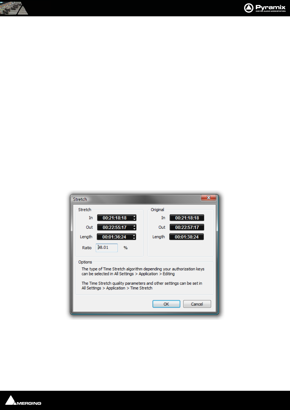
Editing : Edit Command highlights: 8 - 124
Loop Selection This command will substitute a loop of the Clipboard contents for the selected clip or
region without changing sync on the track. Very useful for extending effects to fit a given
space.
Fit Selection This command allows inserted clips to be fit into specified regions on the Timeline. This
requires the Timezone Time compression/Expansion plug-in
Delete and Ripple Deletes the current Selection forcing a Ripple to occur on all affected tracks.
Cut and Ripple Cuts the current Selection and places it on the Clipboard forcing a Ripple to occur on all
affected tracks.
Paste and Ripple Inserts the contents of the Clipboard to the current Playhead Cursor position forcing a
Ripple on all affected tracks.
Insert Silence Inserts silence (blank space) into the current selection, forcing a ripple on all selected
tracks.
Delete and Join Deletes the currently selected Clip/Selection and ripples the end of the clip.
Cut and Join Cuts and saves to the Clipboard the currently selected Clip/Selection and ripples the end
of the Clip.
Delete and Ripple to Black Deletes the currently selected clip/selection and ripples all following butted or cross-
faded clips.
Cut and Ripple to Black Cuts and saves to the clipboard the currently selected Clip/Selection and ripples all fol-
lowing butted or crossfaded Clips.
Stretch Opens the Stretch plug-in dialog.
The Increment and Decrement buttons allow the In point, Out point or Length of the selection to be adjusted. The
Ratio of stretch or squeeze is shown as a percentage. Clicking the OK button starts the process. Cancel aborts.
Depending on the available authorization keys, the Time Stretch algorithm can be selected in:
All Settings > Application > Editing : Time Stretch Tool : Selected combo box
Settings for the chosen algorithm can be made in:
All Settings > Application > Time Stretch > ‘Plug-in name’ Settings
Stretch dialog
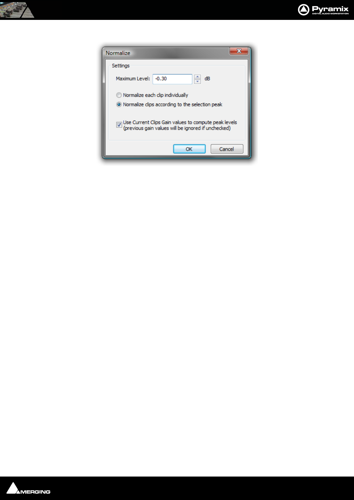
Editing : Edit Command highlights: 8 - 125
Normalize Opens the Normalize dialog.
The Maximum Level can be set by typing or using the increment / decrement buttons.
The process can be applied to:
•Normalize each clip individually
•Normalize clips according to the selection peak
Clicking on OK starts the process. The selected Clip or Clips are examined to locate the highest peak, then the
overall gain of the clip(s) is increased so that this reaches the maximum level specified. All other selected Clips are
either treated individually or raised in level by the same amount.
When in Normalize clips according to the selection peak mode, if the following box is checked:
• Use Current Clips Gain values to compute peak levels (previous gain values will be ignored if
unchecked)
Then:
MaxPeak of the selection will be computed using the level of clips:
MaxPeak = Max(peak + Level)
DeltaGainToApply = DesiredMaximumLevel - MaxPeak
And then for each clip, of the selection:
Level = Level + DeltaGainToApply
Note: this check-box is grayed out when Normalize each clip individually is selected.
Normalize dialog
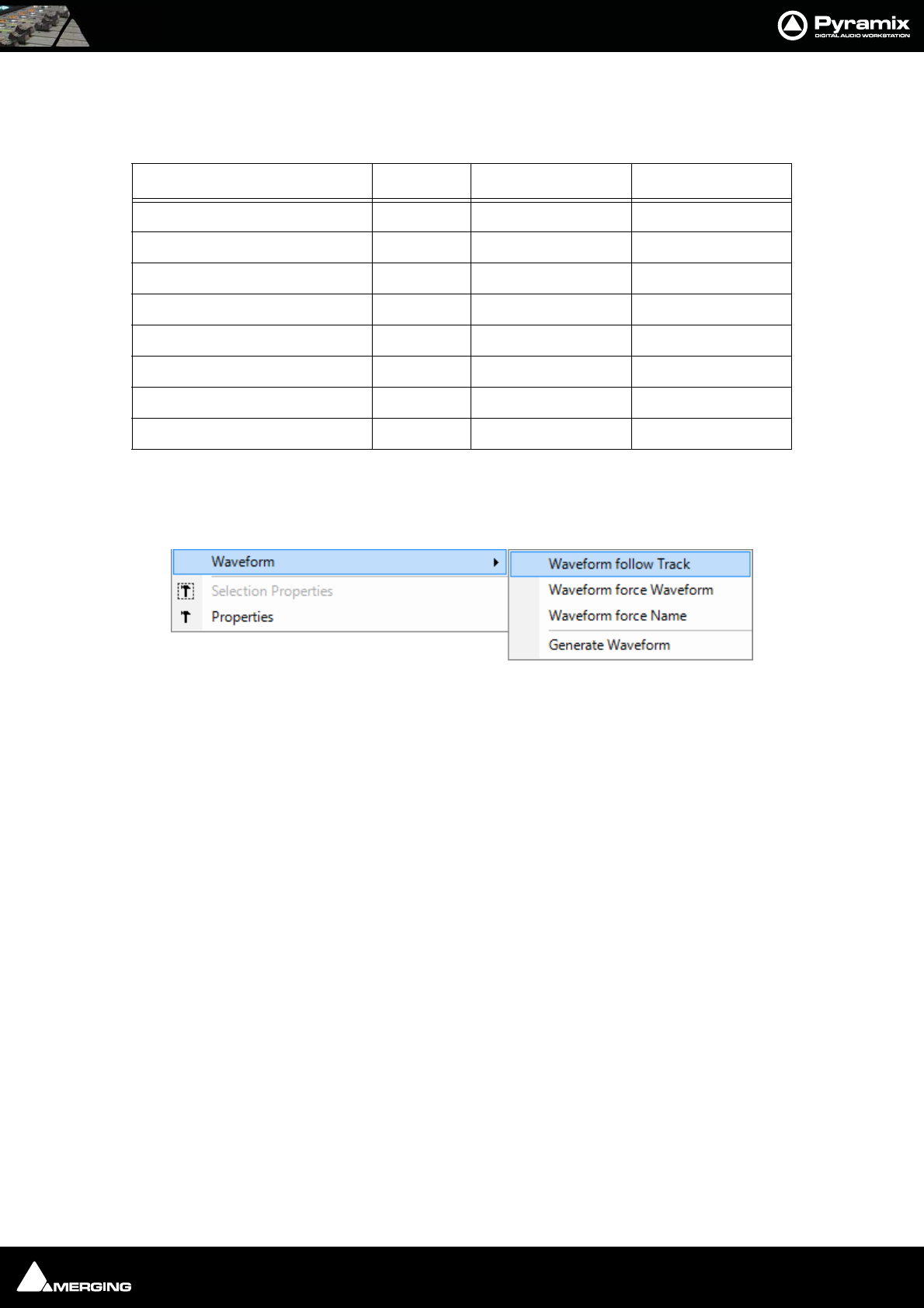
Editing : Edit Command highlights: 8 - 126
Normalize Example:
In this case with Maximum Level = -0.3 dB and “Use Current Clips Gain values to compute peak levels (previ-
ous gain values will be ignored if unchecked)” selected:
Consolidate Opens the Consolidate Project dialog box. Please see: Consolidating Projects on
page 291
Waveform Leads to the Waveform sub-menu:
Follow Track Clip displays whatever is selected for the entire Track.
Force Waveform Clip displays Waveform regardless of the overall Track setting
Force Name Clip displays Clip Name regardless of the overall Track setting
Peak Level Original Gain Value New Gain Value
Clip 1 -18.0 4.0 3.8
Clip 2 -16.0 4.5 4.3
Clip 3 -12.0 -1.0 -1.2
Clip 4 -9.0 -2.6 -2.8
Clip 5 -3.0 1.0 0.8
Clip 6 0.0 -0.1 -0.3
Clip 7 -40.0 2.0 1.8
Clip 8 -20.0 4.2 4.0
Waveform sub-menu
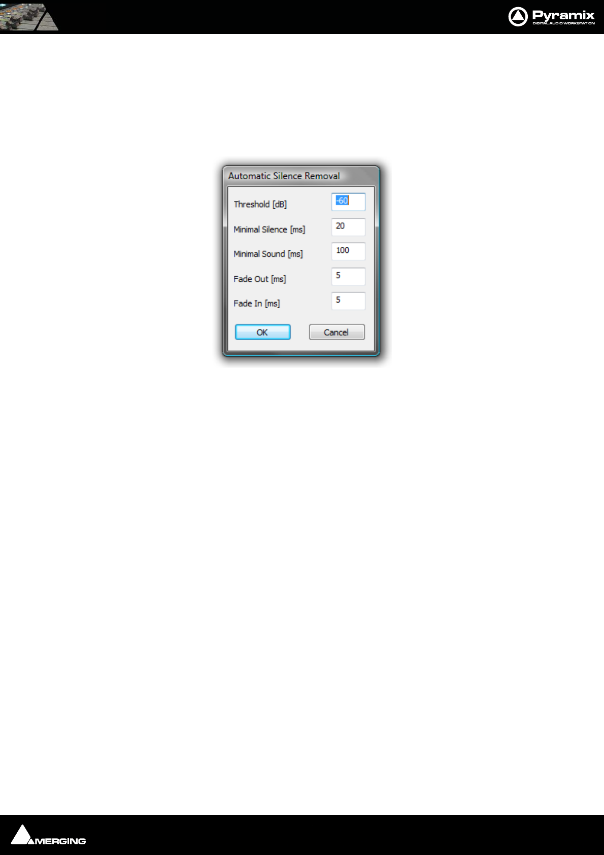
Editing : Auto Silence Removal 8 - 127
Auto Silence Removal
Edit > Automatic Silence Removal
Automatic Silence Removal operates by scanning the Selection and then automatically editing it into smaller clips
by removing regions which fall below the threshold level and meet the ‘Minimal Sound’ and ‘Silence’ criteria set in
the Automatic Silence Removal dialog.
Note: This function is non-destructive of the Media file - it edits the Clip by breaking it
up into smaller Clips, not by deleting any actual audio from the hard drive.
Threshold [dB]
This field determines the threshold level in dB below which material in the clip will be removed.
Minimal Silence [ms] / Minimal Sound [ms]
Sets the shortest periods of silence and sound which can be created by removing material that drops below the
threshold. Some audio material (E.g. speech) contains very short gaps. If all of these were removed, the audio
would become too "chopped up". On speech the object of the exercise is usually to break it into areas where
speech is present not remove small gaps between words or sentences. Some audio material may have very short
transient peaks in the midst of a segment that falls below the threshold. If all of these short transients were created
as clips the end result might well sound worse than the original.
The minimum setting is 10 ms and the maximum is 5000ms (5 seconds).
Fade Out [ms] / Fade In [ms]
Sets the length of the automatic Fade Out and Fade In that will be applied to all new clips created by the Auto-
matic Silence Removal operation. The range for this setting is between 5 ms and 500ms (1/2 second).
Once the parameters have been set, click OK.
This process takes into account the current Remove Mode to determine whether to leave gaps between the
newly created clips, or to join or ripple the clips on the track together.
Automatic Silence Removal cannot be executed on cross-faded Clips.
Automatic Silence Removal dialog

Editing : EDL Tab Window 8 - 128
EDL Tab Window
The EDL (Edit Decision List) Window, is a textual and numeric representation of the same information shown
graphically in the Timeline and Fade Editor. Changes made here are reflected in the Timeline and vice-versa The
list shows information concerning the clips in the form of a list of text or TimeCode fields, most of which can be
edited. This provides an alternate way of viewing and editing the composition. To edit a field, click in it to produce
a cursor, or drag across the text in the field to select it, then type the desired information using normal text entry
procedures. Fields available in the Edit Decision List Panel are:
Absolute Sources in EDL View
When View Sources in EDL View is checked in the Settings > All Settings > Application > TimeLine Layout
page, the original Source In, Source Out and Sync Point times are shown in Absolute Time in the EDL View.
Absolute time is the incoming TimeCode recorded at the audio capture. When this mode is disabled, the default
start time of TimeCode for the captured clip is 00:00:00:00.
The Placement Tool
Although the Placement Tool remains an extremely flexible paste option most important operations are
directly available as single commands in the Edit menu. All these commands can be mapped to a keyboard
key or included in a macro. In most cases, this is a far more efficient way to work.
Field Description Editable
Name Clip Name Yes
Type Type of Clip(e.g. audio, video, midi etc.) No
Dest In Clip’s In time in the Timeline Yes
Dest Out Clip’s out time in the Timeline Yes
Fade In Clip’s Fade In length Yes
Fade Out Clip’s Fade Out length Yes
Length Length of Clip in the Timeline Yes
Source In Media TimeCode value at Clip’s Head Yes
Source Out Media TimeCode value at Clip’s Tail Yes
Sync Source Media TimeCode value at the Clip’s sync point Yes
Track Name of Track Clip is assigned to No
Comment Comments about the Clip from the properties page Yes
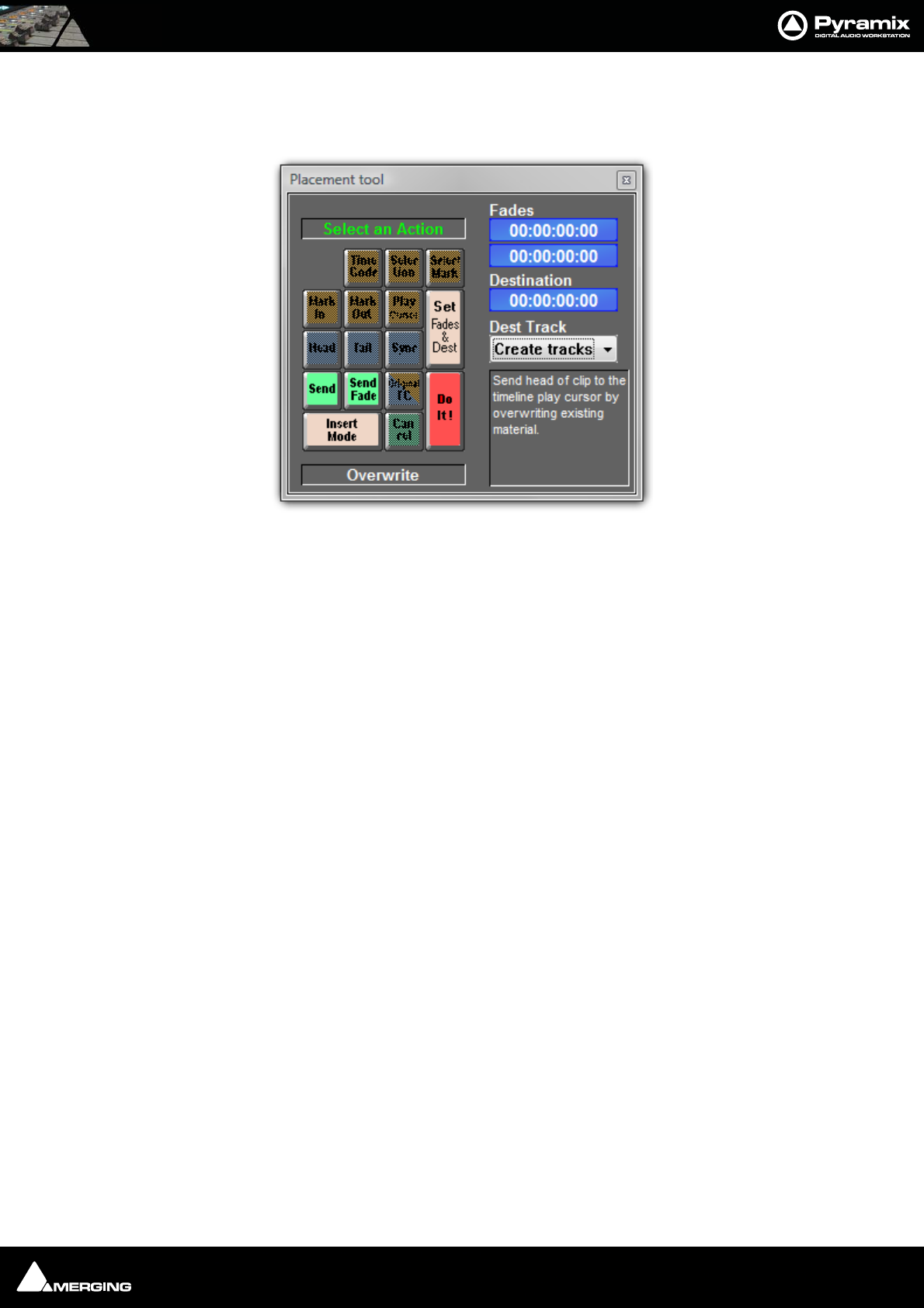
Editing : The Placement Tool 8 - 129
Several different placement options for a Paste action can be chosen from the Edit menu or from the pop-up
menu which appears if there is something to be pasted and the cursor is over a track when you right-click E.g.
Paste to Cursor.
Open the Placement Tool window by selecting Paste & Place... from the right-click Paste options above, or
choose Edit > Paste Place from the Edit menu.
The Placement Tool window allows the user to customize the placement of a clip in extremely powerful and
flexible ways.
The button layout corresponds to the numeric pad on a standard keyboard.
.Select a Paste Place action by choosing amongst the sequence of lit buttons in the window.
For example, you could choose to Send the Sync Point of a clip to a typed Time Code location on a Destina-
tion Track chosen from a pop-up list; or you could Send the Tail of a clip to the Play Cursor. Nearly every per-
mutation of placement is possible. Whatever action you choose, the results of your choices will be displayed as
text in the lower-right corner of the window before you choose to Do It!
Remember to choose an Insert Mode to determine how the surrounding clips will be adjusted when the new
clip is placed in the Track.
Placement tool floating Window

Editing : Source - Destination Editing 8 - 130
Source - Destination Editing
Concept
Source - Destination Editing is a powerful method of viewing and editing material especially applicable to edit-
ing multiple, multi-track, takes into one, ‘ideal’ take. Special Source and Destination Track Groups allow multiple
Timelines to be visible simultaneously. Each Source and destination Timeline has its own zoom level and Playhead
cursor. By taking advantage of the ‘Collapse’ feature, editing 48 track source material becomes almost as simple as
editing mono or stereo.
Source - Destination editing can also be extremely useful in broadcast and tracklaying applications. Pyramix can
have as many clip editors as you wish. Just create some tracks, group them, set the group as a Source. Set the Clip
Editor track or tracks as ‘always visible’ (in the Tracks Tab Window, so each Clip Editor always stays on top of the
composition and that’s it.
If there is no Destination group in your composition then the section between the Gates in the Source Group/Clip
Editor is sent to the positions delineated by the Mark In/Mark Out on the selected track(s) in the composition.
Setting up a Source - Destination Environment
Templates
The quickest and easiest way to get started with Source - Destination editing is to use one of the supplied Tem-
plates. Choose the one which most closely matches your requirements, modify to taste and save as a Template
for future use.
Starting from Scratch
In the Track Groups window, Create as many Source groups as there are alternate versions of the material you are
editing and select their type as Source.
Tip: Create a Group, select its type as Source then choose Tracks > Duplicate Selected Track Group repeatedly
until you have the required number of Source groups.
Create as many Destination groups you want to edit to (generally only one) and select its (their) type as Destina-
tion.
Create as many Tracks for each source take as you need for your editing and associate a Group to each of them.
Set these groups as Keep Cursor, Free Zoom, Auto-Solo and No Selection.
Select the option "Auto Select Tracks" in the Tracks menu. Tracks > Auto Select Tracks
Show the Source - Destination Toolbar, View > Scales > Toolbars > Source - Destination.
You are now ready to proceed with the Source - Destination Editing the following manner:
Source and Destination Groups have special markers called Gate In and Gate Out which can be set, nudged and
auditioned:
Set the selected Track Group Gate In/Out of the selected Track Group to Cursor with the menu Cursor & Marks >
Gate In/Out to Cursor
To remove a Gate set it again in the same position.
Gates can be dragged with the mouse by clicking on them and moving.
Gate colors:
By default, Gates are displayed in Grey.
The Source Gates currently selected for the next edit operation are displayed in White.
The Destination Gates currently selected for the next edit operation are displayed in Black.
The current Source and Destination Gates for the next edit operation are the selected group Gates or if no groups
are selected the last group where Gates have been set/removed/modified.

Editing : Source - Destination Editing 8 - 131
In 3 point editing, the “virtual” missing gate of the group that has only one gate set is displayed in Grey.
Set the Cursor to the selected Track Group Gate In/Out
Cursor & Marks > Cursor to Gate In/Out
Zoom to the selected Track Group Gate In/Out.
Cursor & Marks > Show Gate In/Out
Nudge the selected Track Group Gate In/Out with the menu selection
Cursor & Marks > Nudge Gates > Nudge Gate In/Out to Left/Right.
Each nudge operation can be auditioned automatically by setting 'Audition
after Nudge' in the Settings > All Settings > Application > Editing page
Audition the selected Track Group Gate In/Out Pre/Through/Post with the
menu selection: Machines > Internal Machine > Audition > Audition Gate In/Out
Pre/Audition/Post.
The space between Gate In and Gate Out can be selected with the menu
Selection > Select between Gates.
Positions of Gate In and Gate Out for each selected groups can be displayed and manually modified with the
Source-Destination Toolbar (If not already visible show with View > Scales > Toolbars > Source-Destination)
Once Gates In and Out have been set, Source - Destination operations can be applied FROM either the selected
Source Track Group or the last Source Track Group whose Gates have been set TO either the selected Destination
Track Group or the last Destination Track Group whose Gates have been set.
Both Source and Destination Gate In and Gate Out can be set or removed
(by setting them twice at the same position) to perform any combination of Source - Destination editing opera-
tion described in the table below.
When Gates are set the following Source-Destination operations available in the Edit menu can be applied:
• Auto-Edit Source to Destination
• Overwrite Source to Destination
• Insert Source to Destination
• Replace Source to Destination
• Fit Source to Destination
When the Source has only 1 Gate then the region to edit can be automatically adjusted to the end (or beginning in
case of a single Gate Out) of the clip under the Gate when the edit operation is performed. This is available by
choosing the menu item:
Edit > Source – Destination Settings > Limit 1 Gate Sources to End/Beginning of clip.
When the Source has 2 Gates set and the Destination has 1 Gate set, then the behavior of the Auto-Edit Source to
Destination operation can be chosen between Overwrite or Insert by choosing the menu item:
Edit > Source- Destination Settings > 3 Gates Auto-Edit does Overwrite/Insert
The menu item:
Edit > Source - Destination Settings > Auto Set Destination Gate In after Edit
allows the Destination Gate In to be set to the previous Destination Out point after any Source-Destination opera-
tion. This automatically prepares the Destination for the next operation. The Destination is also automatically cen-
tered around the new Gate In.

Editing : Source - Destination Editing 8 - 132
The menu item Edit > Source - Destination Settings > Auto Set Destination Gate In after Edit allows the Desti-
nation Track Group to be automatically selected after any Source-Destination operation.
All these operations works independently of the Auto-Ripple mode (they have their own overwrite/ripple modes
described in the table on the next page) but follow the Auto-Crossfade settings accessible in the menu Edit >
Auto-Crossfade.
Keyboard Shortcuts
Most Source - Destination operations are available as Keyboard Shortcuts.
2,3 and 4 Point Edits
Source-Destination
operations
Source
Gate In OR Gate Out Only
Source
Gate In & Gate Out
Destination
Gate In OR Gate Out Only
Auto-Edit: Performs 2 points edit-
ing by doing the following Over-
write operation.
Overwrite: Copies material FROM
Source Gate In to the end of the
Track or from start of Track to Gate
Out
TO Destination Gate In or Destina-
tion Gate Out by overwriting Desti-
nation material
Auto-Edit: Performs 3 point editing by doing
the following Overwrite or Insert operation
depending which one is selected in the menu
Edit > Source-Destination Settings.
Overwrite: Copies material between Source
Gate In and Source Gate Out to Destination
Gate In or Destination Gate Out by overwrit-
ing Destination material
Insert: Copies material between Source Gate
In and Source Gate Out to Destination Gate In
or Destination Gate Out by rippling Destina-
tion material
Destination
Gate In & Gate Out
Auto-Edit: Performs 3 points edit-
ing by doing the following Over-
write operation.
Overwrite: Copies material from
Source Gate In or Source Gate Out
to Destination Gate In and Gate
Out by overwriting Destination
material
Auto-Edit: Performs 4 point editing by doing
the following Replace operation.
Overwrite: Copies material between Source
Gate In and Source Gate Out to Destination
Gate In by overwriting Destination material.
Insert: Copies material between Source Gate
In and Source Gate Out to Destination gate In
by rippling Destination material
Replace: Replaces material between Destina-
tion Gate In and Gate Out by material
between Source Gate In and Source Gate Out
by rippling the Destination material
Fit: Replaces material between Destination
Gate In and Gate Out by material between
Source Gate In and Source Gate Out by
stretching or squeezing the Source material

USER MANUAL
www.merging.com/Pyramix
Fade Editor
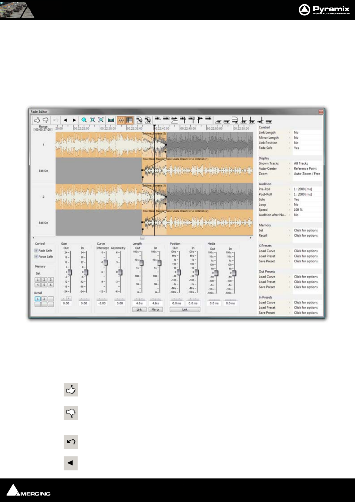
Fade Editor : Fade Editor Tab Window 9 - 134
Fade Editor Tab Window
The Pyramix Fade Editor offers several methods for creating fades and cross-fades. Fades can be made graphically
by simply clicking and dragging appropriate points on the display or by using a specialized set of faders and but-
tons or by directly entering numeric data. A comprehensive set of auditioning options is provided together with
libraries for user defined fade shapes and fades.
The Fade Editor always displays the fades for the current selection in the main Editor. The nearest fade to the click
point is automatically selected.:
Toolbar
Contains these buttons:
Accept & Close Editor (Close the Fade Editor and keep the changes, in effect an ‘OK’ button)
Restore & Close Editor (Restore the fade to its state prior to opening the Fade Editor or
selecting a new fade, effectively a Cancel button)
Undo last fade change
Select/Edit Previous Fade
Fade Editor Tab floating Window
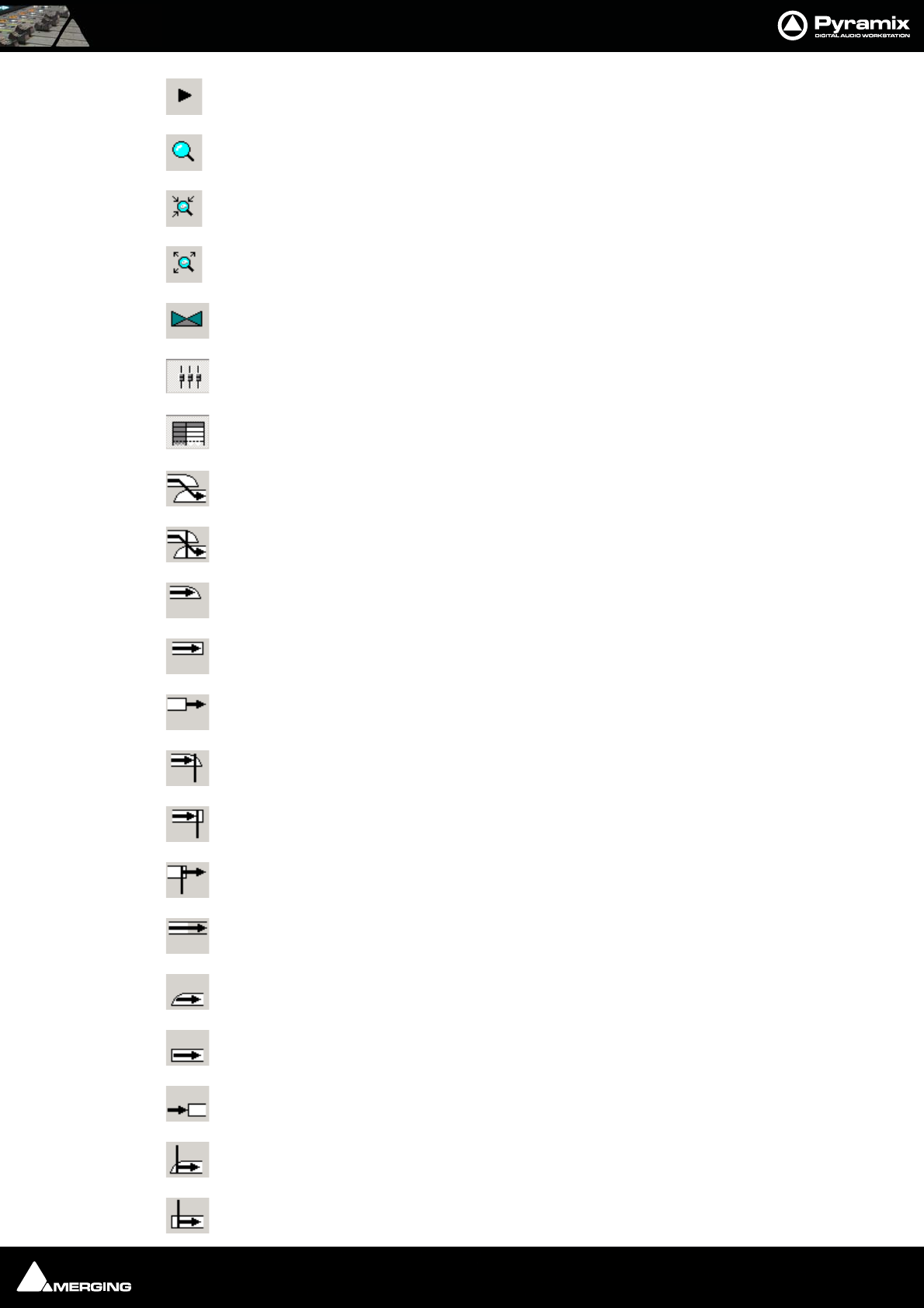
Fade Editor : Toolbar 9 - 135
Select/Edit Next Fade
Zoom around the current Fade (Reset Zoom)
Zoom In
Zoom Out
Xify (Reset the current fade to a standard Power X fade)
Show/Hide Faders & Control Section
Show/Hide Parameters & Options Section
Audition whole X Fade with Pre-Roll and Post-Roll set before and after the X Fade boundaries
Audition whole X Fade with Pre-Roll and Post-Roll set around the Reference Point
Audition Fade Out up to its End with Curve
Audition Fade Out up to its End without Curve
Audition after the End of Fade Out
Audition Fade Out up to the Reference Point with Curve
Audition Fade Out up to the Reference Point without Curve
Audition after the End of Fade Out from the Reference Point
Audition Fade Out without stopping at its End
Audition Fade In from its Start with Curve
Audition Fade from its Start without Curve
Audition before Start of Fade In
Audition Fade In from the Reference Point with Curve
Audition Fade from the Reference Point without Curve
Fade Editor : The Graphical Display 9 - 136
Audition before Start of Fade In from the Reference Point
Audition Fade In before its Start
The Graphical Display
Consists of the following elements:
• The TimeCode scale displaying the Zoom range on its left.
• A Reference Point which is set by default at the edit point or in the middle of the (X) Fade. This marker can
be moved by clicking in the TimeCode Scale and is just a Reference Point for Auditioning (see above) or for
Auto-Center (see below)
• All tracks or a selection can be displayed (see Parameters & Options below)
• At the left of each track display The Track name of each clip is shown, with a toggling Edit On/Off selector.
This allows one or more Clip’s/Fades to be excluded from further modification.
• A Vertical Scrollbar navigates through hidden tracks if any
• An Horizontal Scrollbar navigates before and after the Fade position
• The outgoing and incoming clip fades are displayed with curves
• The Fade Position can be moved by clicking and dragging within the Fade area (Cursor changes to
hand)
• The Fade Length can be changed by clicking and dragging on the left or right side of the Fade area.
(cursor changes to <|>)
• The Media of the clips can be moved by clicking and dragging outside the Fade area. (Cursor
changes to hand with tape reel)
• The Fade Curves can be modified by clicking and dragging on the Bezier Control Point Handles in
the Fade black box
Waveform Color Change
The waveform color can be used to indicate where the main Playhead Cursor is in relation to the Reference Point.
When the Update waveform color with cursor position checkbox is ticked in Settings > All Settings > Applica-
tion > Editing : Fade Editor the waveform(s) color will change to the color chosen in Settings > All Settings >
Application > TimeLine Layout : Clips & Waveforms - FadeEditor Waveform Position Color according to the
location of the main Playhead Cursor and the Reference Point (default is centre of crossfade)
Context Menu
Right-clicking in the graphical display pops-up a context menu:
The Fade In, Fade Out and X Fade sub-menus offer choices of Default (complete or Curve Only), Standard, (any
of the standard fade curves) and Load (from the list of previously saved presets)
The Faders & Control Section
Has the following controls and displays:
•The Fade Safe check box in the Fader section ensures (when checked) that all following fades to the right
of the one being edited are left intact while editing the current fade. This enables Auto-Ripple to be used
without Auto-Ripple while keeping Fade synchronization clean.

Fade Editor : Parameters & Options Section 9 - 137
• When the Force Safe box is checked the Fade Editor forces Fade Safe to enabled after each edit change.
• Six Memory Set and six Memory Recall buttons store and recall all the settings in the Fade Editor. The
recall buttons are only numbered when there are stored parameters to recall.
•Gain Faders, Nudge buttons and Manual Entry Value Box (in dB) for both Fade Out & Fade In
•Intercept and Asymmetry Faders, Nudge buttons and Manual Entry Value Box (in dB)
•Length Faders, Nudge buttons and Manual Entry Value Box (in milliseconds. Type an s after any numeric
entry to obtain a value in seconds) for both Fade Out & In
• Length of Fade Out & In can be linked by clicking the Link button
• Length of Fade Out and In can be changed symmetrically (centered) by clicking the Mirror button.
•Position Faders, Nudge buttons and Manual Entry Value Box (in milliseconds, type an s after any number
entry for a value in seconds) for both Fade Out & In
• Position of Fade Out & In can be linked by clicking the Link button
•Media Position Faders, Nudge buttons and Manual Entry
•Value Box (in millisecond, type an s after any number entry for a value in seconds) for Fade In
Parameters & Options Section
In this table parameters and options may be modified by clicking on >.
There are these sections and fields:
Control
• Link Length (see above)
• Mirror Length (see above)
• Link Position (see above)
• Fade Safe (see above)
Display
•Shown Tracks offers these choices:
• All tracks
• Follow TimeLine Display
•Choice of tracks. The number of tracks selected in the TimeLine controls the available choices. So, if
4 tracks are selected, there will be the option of 1, 2, 3, or 4 tracks
•Auto-Center, enables automatic re-centering of the display around the Fade or Reference Point after cer-
tain operations
•None
•Fade
• Reference Point
•Zoom, can be one of the following:
•Free, follows only Zoom Reset, In and Out
•Auto-Zoom, automatically Zooms around the current Fade after some operations
•Auto-Zoom / Free, automatically Zooms around the current Fade but only when it enters the Fade
Editor, thereafter, the Zoom is Free
•Timeline, follows the Timeline Zoom factor
• Choice of User defined Zoom Presets (see menu View > Zoom)

Fade Editor : Parameters & Options Section 9 - 138
Audition
•Pre-Roll from the choices defined in the Settings > All Settings Application Playback/Record Page
•Post-Roll from the choices defined in the Settings > All Settings Application Playback/Record Page
•Solo, when On only the edited tracks are auditioned, when Off all tracks of the composition are audi-
tioned as well
•Loop, any audition operation is repeated until Stop is pressed
•Speed, allows choice between 100%, 50% and 25% of normal play speed for auditioning
•Audition after Nudge, to automatically audition the Fade after nudging any parameter
Memory
•Set, allows saving up to 6 temporary Fades for comparison
•Recall, allows recall of one of the 6 temporary saved Fades
X Presets / Out Presets / In Presets
•Load Curve, allows loading the Curve SHAPE only from a choice of:
• Default
•Power
• Linear
•dB
•Cosine
•Root-Cosine
•Any User-defined curves
•Load Preset, allows loading a Fade from a choice of:
•Default Fade
• Any user defined Fades
•Save Preset,
•Default Fade
• New opens the Save X Fade or Save Fade pop-up dialog box (See below)
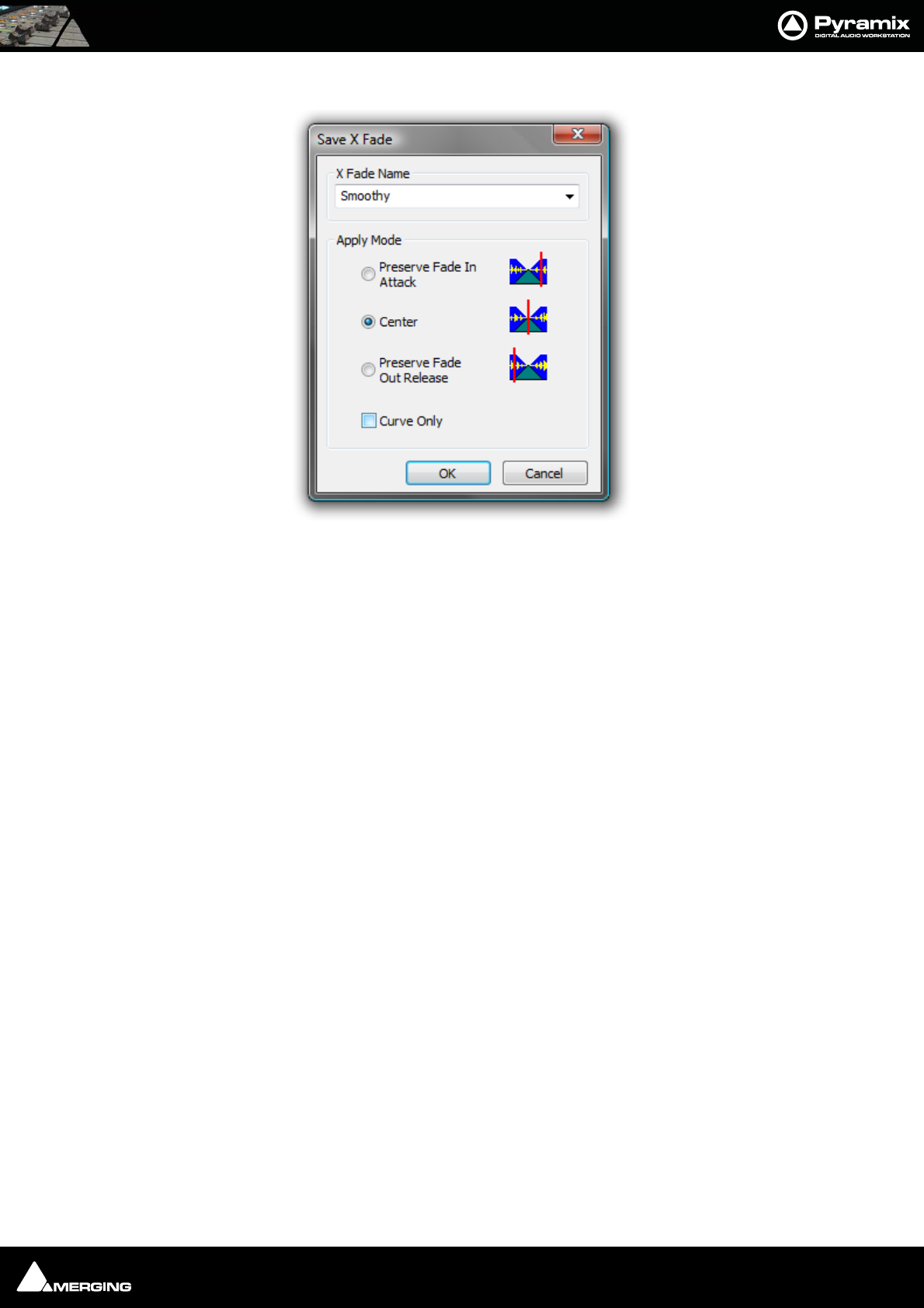
Fade Editor : Parameters & Options Section 9 - 139
Save X Fade
The dialog box opens with the cursor in the X Fade Name box. Simply type a name for the new preset or choose
an existing one to over-write using the dropdown list. Choose appropriate options and click OK or hit the Enter
key to save the preset.
Apply Mode Options
A number of options are provided which affect the way the Fade will be applied when recalled.
Curve Only
When this box is checked only the curve shape will be recalled and applied to the overlapping tracks for the dura-
tion of the existing cross-fade. If left unchecked, the original duration and positions of the start, end and reference
point will also be applied to the existing cross-fade.
Preserve Fade In Attack
Fade will be aligned to the left, relative to the edge of the clip, when recalled.
Center
Fade will be centered, relative to the edge of the clip, when recalled
Preserve Fade Out Release
Fade will be aligned to the right, relative to the edge of the clip, when recalled.
Save X Fade dialog
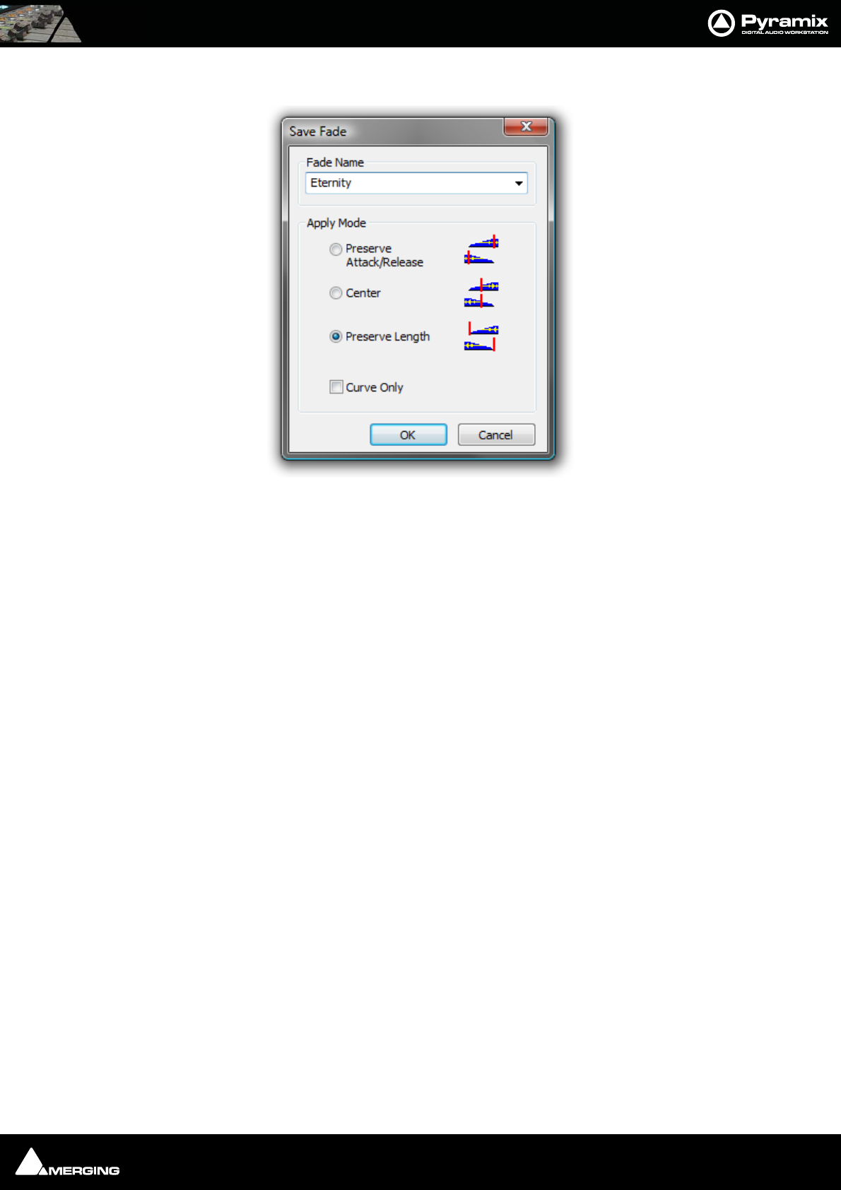
Fade Editor : Parameters & Options Section 9 - 140
Save Fade
The dialog box opens with the cursor in the Fade Name box. Simply type a name for the new preset or choose an
existing one to over-write using the dropdown list. Choose appropriate options and click OK or hit the Enter key
to save the preset.
Apply Mode Options
A number of options are provided which affect the way the Fade will be applied when recalled.
Preserve Attack or Release
Center
Preserve Length
Save Fade dialog

USER MANUAL
www.merging.com/Pyramix
Mixer
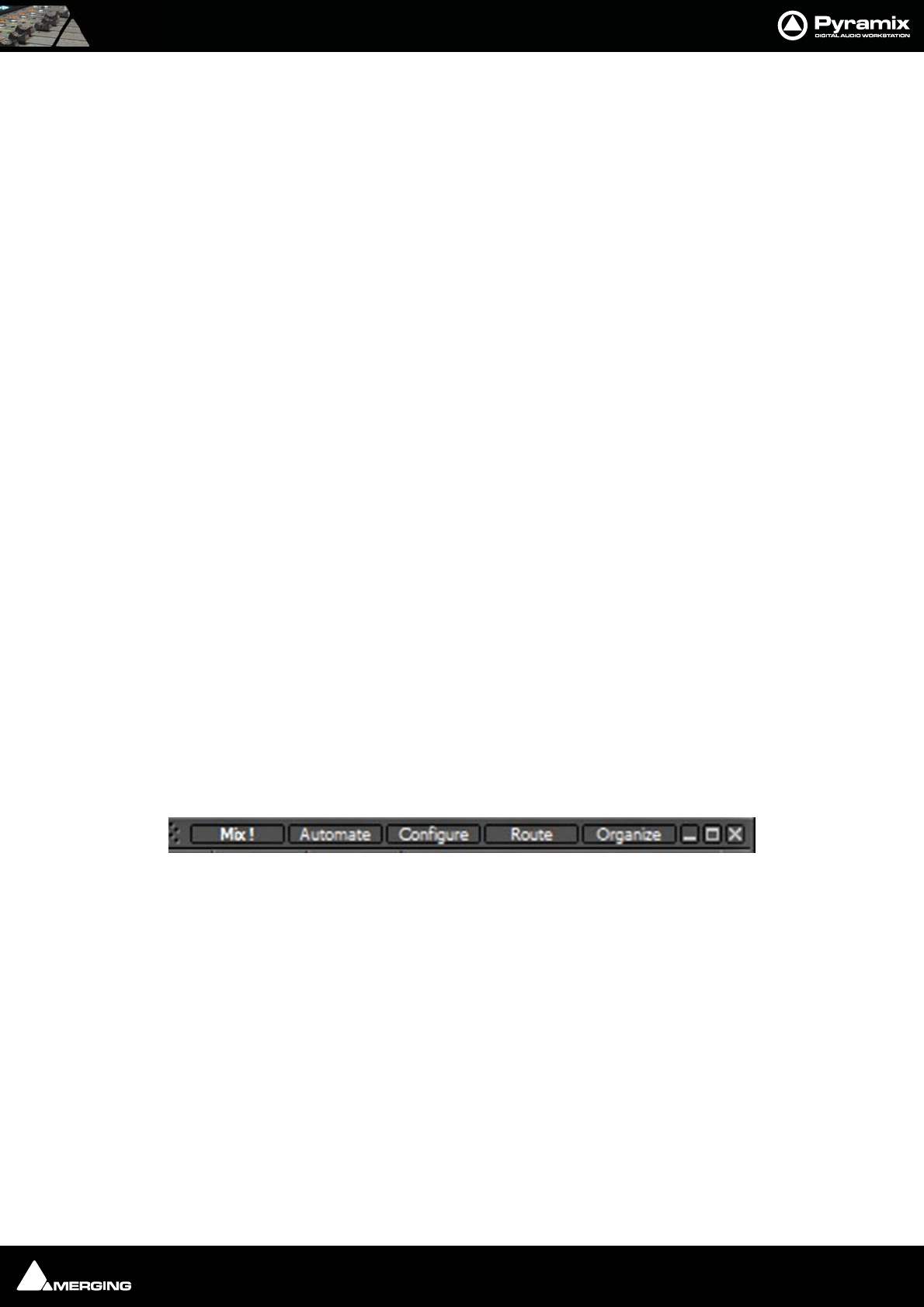
Mixer : Overview 10 - 142
Overview
The Pyramix Mixer has evolved into an extremely powerful tool kit. The extensive range of components and the
routing and automation possibilities can be a potential source of confusion. However, the basic principles are sim-
ple and logical. Signals enter mixer strips at the bottom, go through various controls and processing to the top of
the strip where they are routed to a bus or buses. The buses run horizontally and the sum of the bus signals enters
the bus master strip at the top and moves down through a master fader and other controls to the output(s).
Native VS3, VST and External Insert plug-in effects can be inserted in Input Strips, Aux Send Bus masters, Sub-
Groups and Mix Buses.
Note: For low latency foldback when recording an artist the Direct Monitoring Strip type
should be used.
The mixer can also take the output from an ASIO enabled application and merge it into the MassCore engine and
I/O and send audio to the ASIO enabled application.
If you are new to Pyramix, please use one of the simpler mixer templates to become familiar with the basic fea-
tures. E.g. Mix 08 X 02 (Stereo)
Aux v SubGroup
In Pyramix Aux buses are intended solely for foldback purposes. They are not intended to be used as a means of
applying effects, internal or external, to a collection of sources, with the bus output re-routed back to an input
strip. Effects can however be inserted into Aux buses in order to enhance the artists experience.
SubGroup buses are intended to be used as conventional sub-groups and, of course, can have internal VS3 and
VST effects inserted and or external inserts.
Using SubGroup buses for mix effects ensures that the full automatic (and manual) delay compensation features
will function correctly.
Mixer Pages
The Mixer user interface is arranged in five pages grouping functions in a logical manner. Most time will be spent
working in the main Mix ! page. The other pages, Automation, Configure, Route and Organize, toggle with the
Mix ! screen and are accessed from buttons at top right of the screen...
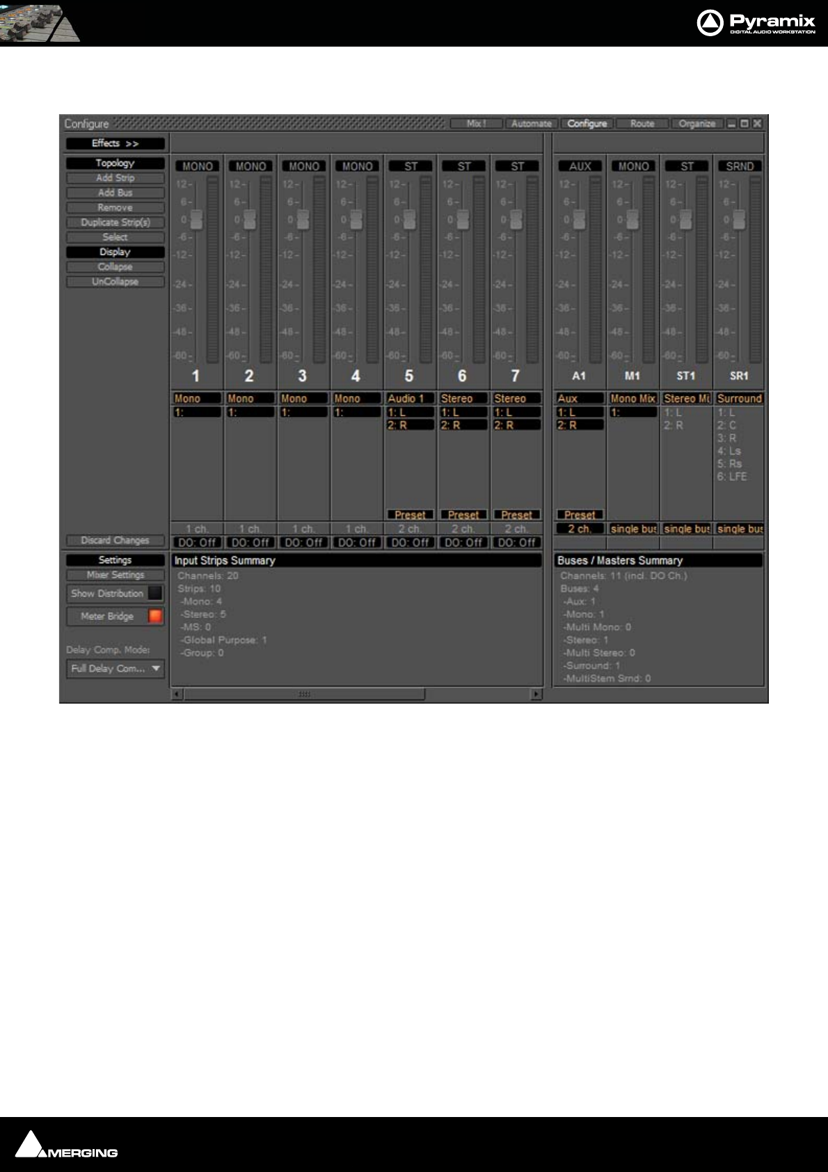
Mixer : Configure Page 10 - 143
Configure Page
In the Configure page multiple changes may be made to the mixer without it rebuilding after each change. The
rebuild only occurs when you exit the page.
Settings
Mixer Settings
Opens the Mixer Settings window at the All Settings > Misc > Mixer Settings page.
Show Distribution
When on (lit), a narrow colored bar is inserted at the bottom of each input strip. This indicates which card (in a
multi-board system) is providing the DSP for the strip.
Meter Bridge
When turned on (lit) the Meter Bridge Window is available to be opened from View > Windows / Tools > Meter
Bridge or the Toolbar icon. Please see: Meter Bridge on page 211
Mixer Configure Page
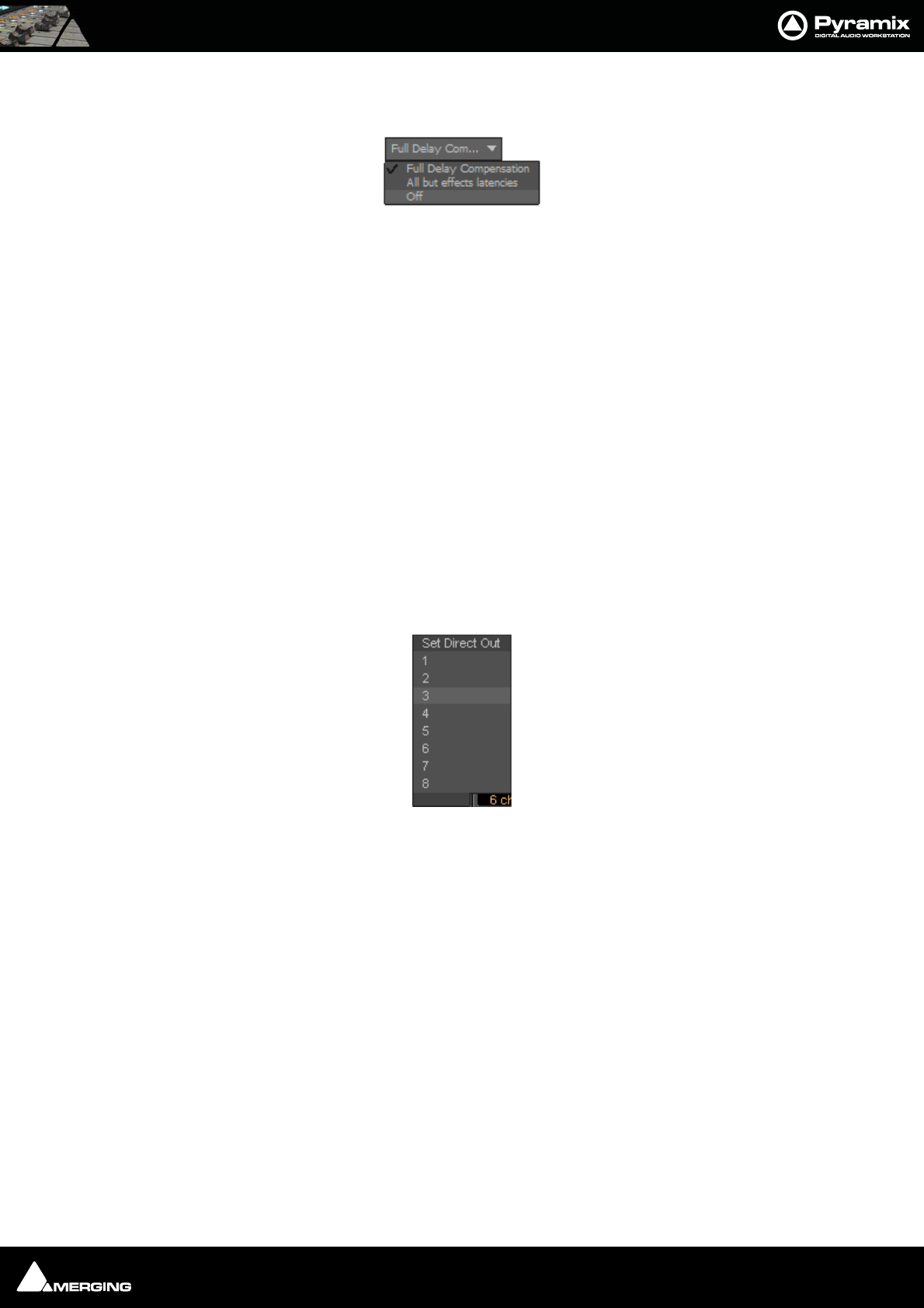
Mixer : Configure Page 10 - 144
Delay Comp Mode
Drop down list menu:
Offers the choice of Full Delay Compensation, All but effects latencies and Off.
Please see: Mixer Delay Compensation on page 173
Mixer Configuration Summaries
The two panels at bottom right summarize the current mixer configuration. Input Strip Summary lists the total
number of Channels and Input Strips and the quantity of each type. Buses / Masters Summary lists the total
number of bus channels and buses strips with the quantity of each type.
Note: Rebuilding a large mixer with many effects can take some time.
Click and drag the separator bar between Strips and buses to show more or less buses. The scroll bars give access
to strips currently off screen.
Direct Outputs
The Direct Out connection is disabled by default. It can be enabled in the Configuration Page by selecting the
strip and clicking on the DO: Off box or disabled if the box shows DO: On. Alternatively Direct Out can be set in
the Route Page by clicking on the Strip Header.
The Direct Out can be routed by Channel to any output of the HDTDM or XDTDM bus. The Direct Out can be sent
Pre or Post Fader. Click on the DO: Post box in the Mixer I/O section to toggle. The Direct Out is currently always
Post Effects. For multi-channel strips clicking in the box above the DO: box pops-up a Set Direct Out list:
Highlight the required channel. This will be fed to the logical output assigned in the Mixer Route page or by click-
ing on the DO XLR icon in the Mix page.
Selecting Strips
Strips can be selected by clicking on the label at the top of the strip which turns orange to show it is selected.
Selection uses the conventional modifier logic: Clicking a second strip while holding SHIFT selects all strips in
between and strips can be individually added or subtracted from a selection by clicking with the Ctrl key held
down. Ctrl + A selects all strips. Strips can be selected by type using the Select context menu.
Set Direct Out
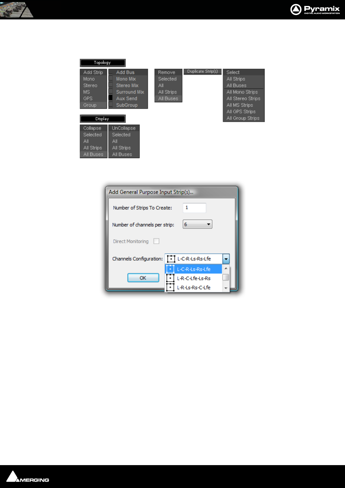
Mixer : Configure Page 10 - 145
Strip and Bus operations
Once selected, strips can be dragged and dropped to reorganize. Other strip operations make use of the Topol-
ogy and Display menu buttons. Each button pops up a list of options:
Add Strip - Mono, Stereo, MS, GPS and Group pops up a dialog with appropriate options:
Note: Notice the Direct Monitoring checkbox. (Grayed out in this case because it is only
applicable to Mono, Stereo and MS Strips). When checked, the strip added will be a
Direct Monitoring Strip. Please see Direct Monitoring Input Strips on page 157
Topology and Display menus
Add General Purpose Input Strip(s) dialog
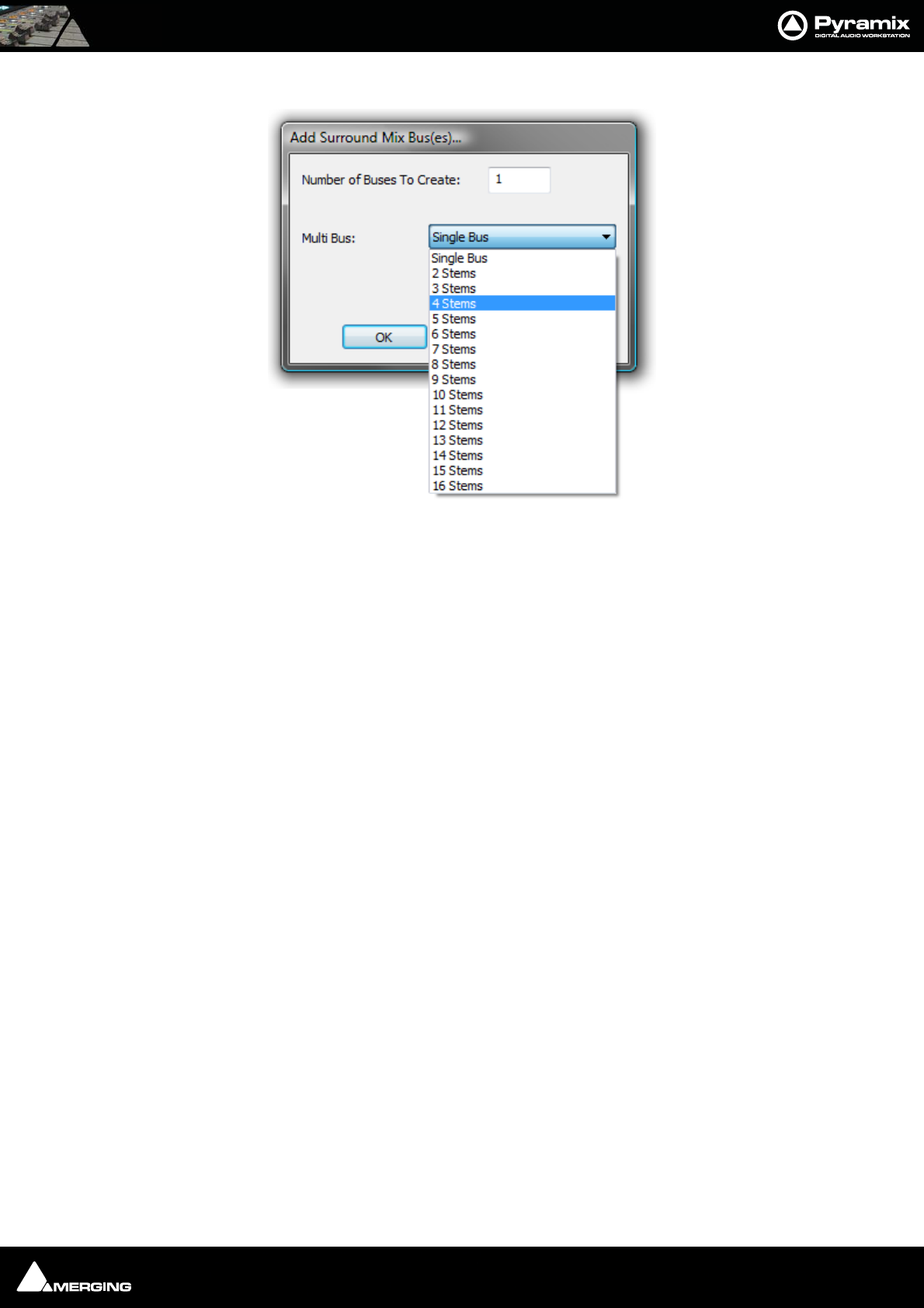
Mixer : Configure Page 10 - 146
Add Bus - Mono Mix, Stereo Mix, Surround Mix, Aux Send and SubGroup is similar:
Duplicate Strip(s) adds a copy of the selected strip(s) to the right of the selected strip(s) including settings (pan,
gain etc.) and effects.
Select Offers selection choices to speed up configuration.
All Strips
All Buses
All Mono Strips
All Stereo Strips
All GPS Strips
All Group Strips
Productivity Shortcuts
Ctrl + A selects All Strips, DELete, deletes all selected strips.
Selected Strips can be dragged to a new location in the mixer. The screen scrolls horizontally when you hit the
edges of the Strip panel.
Double-clicking a Strip toggles it’s collapsed/uncollapsed states.
Strip names can be edited by clicking in the name box and typing. Tab moves to the name box of the next strip to
the right, SHIFT + Tab moves to the name box of the next Strip on the left.
Add Surround Mix Bus(es) dialog
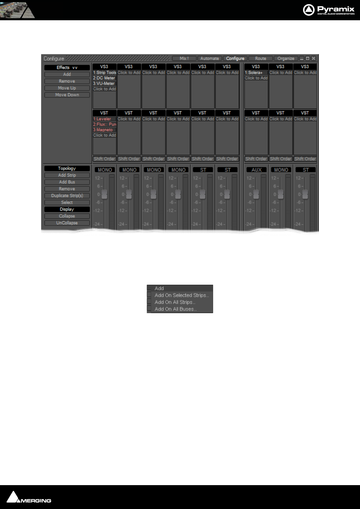
Mixer : Configure Page 10 - 147
Effect Management
Clicking on Effects >> expands the Effects section.
This offers several methods of managing effects on strips and buses.
Configure: Effects Buttons
Add Pops up a sub-menu with options
Add On Selected Strips..
Add On All Strips..
Add On All Buses..
Configure Page - Effects section
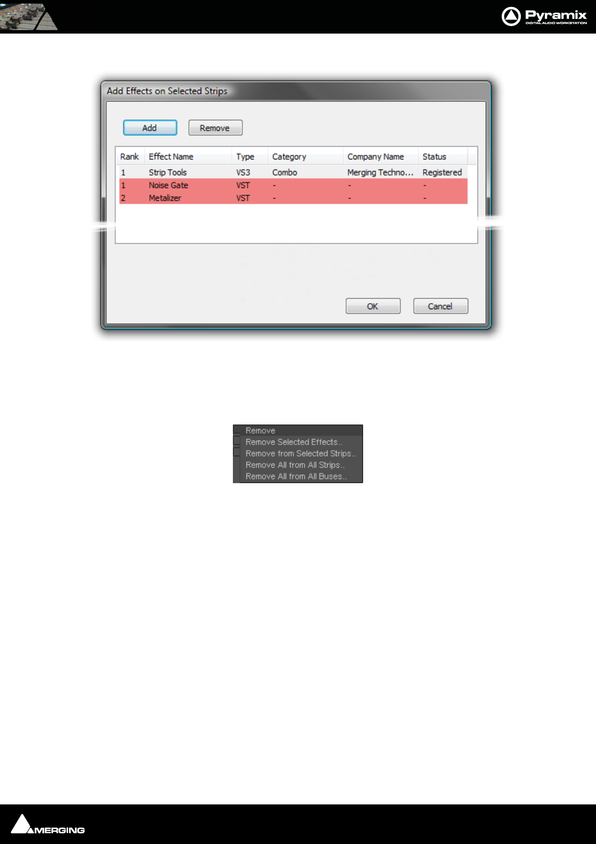
Mixer : Configure Page 10 - 148
Each of these three options opens an Add Effect On XXX dialog, identical apart from the title
Note: That the different types of effect are shown by color. Pale Gray for VS3 and Red for
VST. These colors are also used when effects are shown in containers in the Strips display.
Remove Pops up a sub-menu with options:
Remove Selected Effects..
Remove From Selected Strips..
Remove All From All Strips..
Remove All From All Buses..
Move Up Moves the selected effect(s) up in the list.
Move Down Moves the selected effect(s) down in the list.
Effects Section Containers
The Effects section of each strip is divided into two container areas by plug-in type, VS3 at the top and VST below.
Clicking on the Click to Add buttons in each container pops-up a list of available plug-ins in the relevant format
sub-grouped by type. E.g. Dynamics, Restoration etc. Simply select from the list by clicking on an entry to install
the plug-in in the Strip. When a Strip or Bus has many effects, the container expands to accommodate them.
Shift Order
You can change the order of the VS3 and VST containers by clicking on the Shift Order buttons below the contain-
ers.
Selecting, Copying and Moving Effects
You can select an installed effect with a left-Click then drag and drop to move or Ctrl + drag and drop to copy
effects of the same type to a Strip or Bus of the same dimensions or change the order of effects within the effect
type container of the strip. SHIFT + Clicking a second effect with an effect already selected, selects all effects
between the first and last selected. Ctrl + Click adds to selection.
Add Effects On Selected Strips dialog
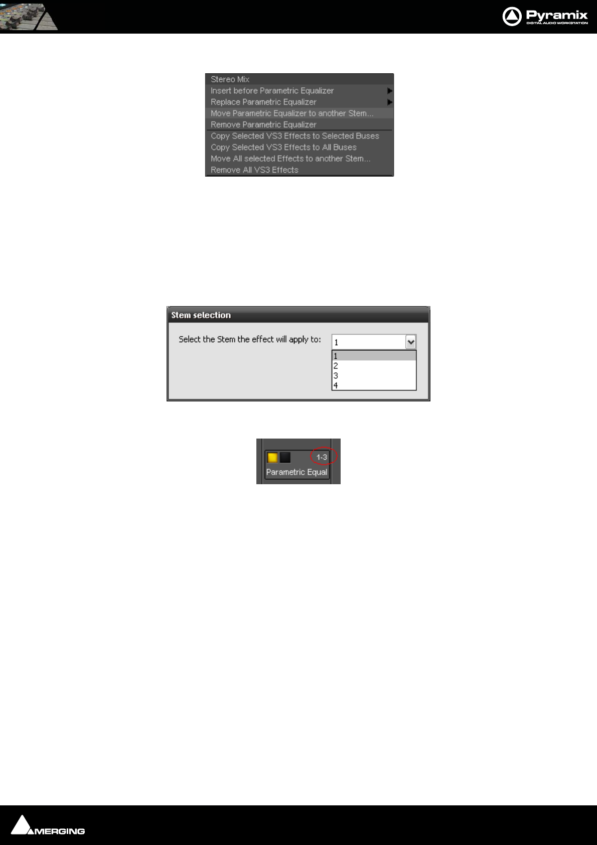
Mixer : Configure Page 10 - 149
Right-clicking on an installed plug-in pops-up a context menu, for example:
Insert before (effect clicked on) > drops down a list of effects of the same type that can be inserted before current the
effect.
Replace (effect clicked on) > drops down a list of effects of the same type that can replace the current effect. Dou-
ble-Clicking an installed effect does the same thing.
Remove (effect clicked on) Uninstalls the current effect from the Strip or Bus
Move ( VS3 Effect clicked on) to another stem
Pops up a dialog with all available stems for this bus. (Only present when the Effect is in a
Multi-Stem Bus) The Iteration and Stem numbers are then shown on the Effect:
Thus 1-3 means Iteration 1 on Stem 3
Copy Selected (Effect type) Effects to selected strips As it says. Target strips can be selected before or after selecting the
effect(s)
Copy Selected (Effect type) to All Strips As it says.
Remove All (Effect type) Effects Removes all effect of the current type clicked on from the Strip.
Remove All Effects Removes all effects of all types from the current Strip.
Copy All Effects to All Strips Copies all the effects installed in the current Strip to all other Strips.
Copy All Effects to Selected Strips Copies all the effects installed in the current Strip to all selected Strips.
External Effects Inserts
External Inserts are added in the same way as VS3 Effects. Click on Click to Add and choose Other > External
Insert
Effect context popup
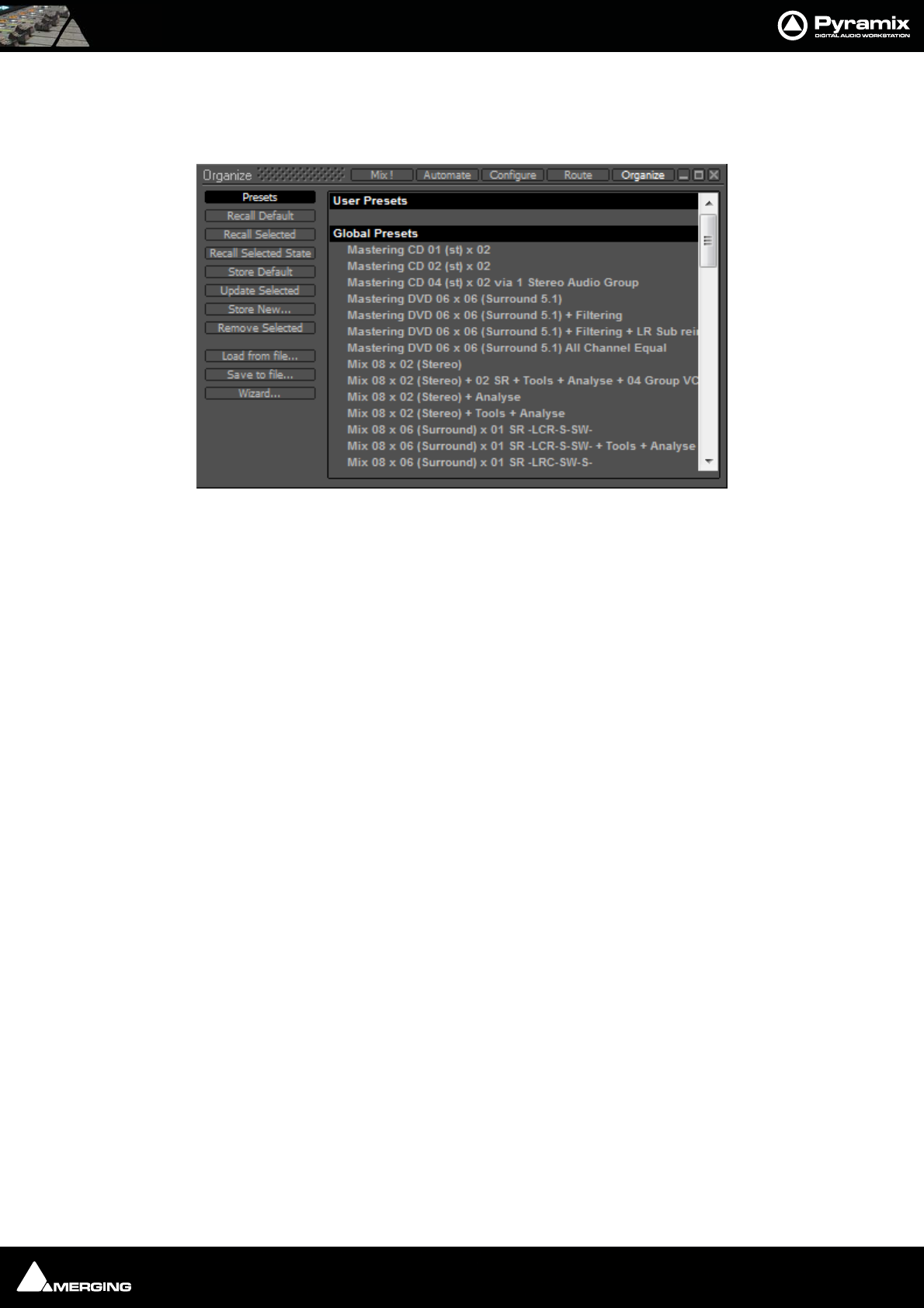
Mixer : Organize Page 10 - 150
Organize Page
Here, Mixer Presets and Settings can be managed:
Presets
Storing and Recalling Mixer Presets
Mixer Presets can be saved in a user folder or added to the main Mixer Preset list either for the current user or all
users.
Default Mixer
To Save the current Mixer setup as the default Mixer, select Store Default.
Storing New Mixer Presets
To add a preset to the main list of available Mixer presets I.e. the list which appears when starting a new project,
Store New… and enter a name for your Mixer Preset. If the Global box is checked then the preset will be available
for any user logged on the current machine, if not the preset will be available only for the user that created the
new preset.
Removing Mixer Presets
To remove a preset from the main list, select it and click on Remove Selected. The Remove Preset dialog box
appears with OK and Cancel options.
Updating Mixer Presets
To update a Preset with the current settings, highlight it in the list and select Update Selected... the Update Pre-
set dialog appears asking if you wish to replace the ‘current preset’. Choose OK or Cancel.
Recall Selected State
This option recalls parameters, panning, levels etc. from a saved mixer preset and applies these to the current
mixer.
Note: This only applies to strips and effects common to both configurations. If the cur-
rent mixer does not have the same plug-ins etc. non-coincident items will be ignored.
similarly if you recall the state of a 100 strip mixer to a 10 strip mixer the last 90 strips are
ignored.
Saving / Loading Mixer Presets to / from files
Mixer Presets can also be stored in Windows folders. Select Load from file... or Save to file... as appropriate. A
Windows Explorer window opens enabling a previously saved Mixer Preset to be loaded or the current Mixer Pre-
set to be named and saved to any Windows folder.
Mixer Organize Page
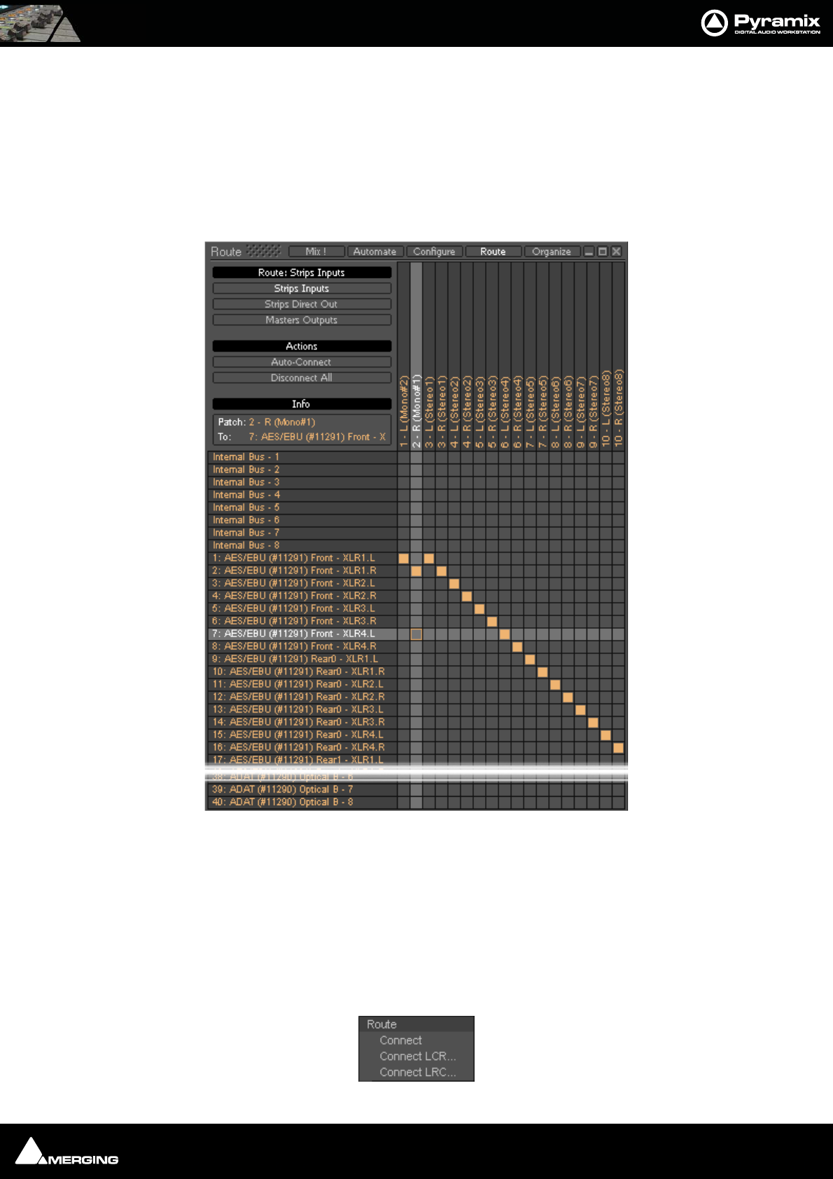
Mixer : Route Page 10 - 151
Wizard...
Opens the Configuration Wizard Window
Route Page
Route brings together all routing to and from physical I/O in an intuitive matrix routing grid environment. It opens
in the Strips Input page:
Strips Direct Out and Masters Outputs are similar.
Making Connections
When the cursor is hovering over a destination crosspoint the column and row are highlighted for ease of viewing.
If the cursor is over a crosspoint which is part of a multichannel strip or bus the other channels in the group are
also dimly highlighted. In Strips Inputs clicking on a crosspoint routes the source in the left hand column to the
destination in the top row. In Strips Direct Out and Masters Outputs sources are horizontal and destinations ver-
tical. Clicking and dragging allow multiple assignments to be made rapidly.
Right-clicking a crosspoint pops-up a context menu with options appropriate to the destination.:
Mixer Configure Page

Mixer : Route Page 10 - 152
Auto-Connect
Connects all the Strip Input Channels to physical inputs in ascending order.
Disconnect All
Removes all crosspoint assignments.
Info
The Info box shows detail about the currently highlighted crosspoint.
Automate Page
UNDER CONSTRUCTION
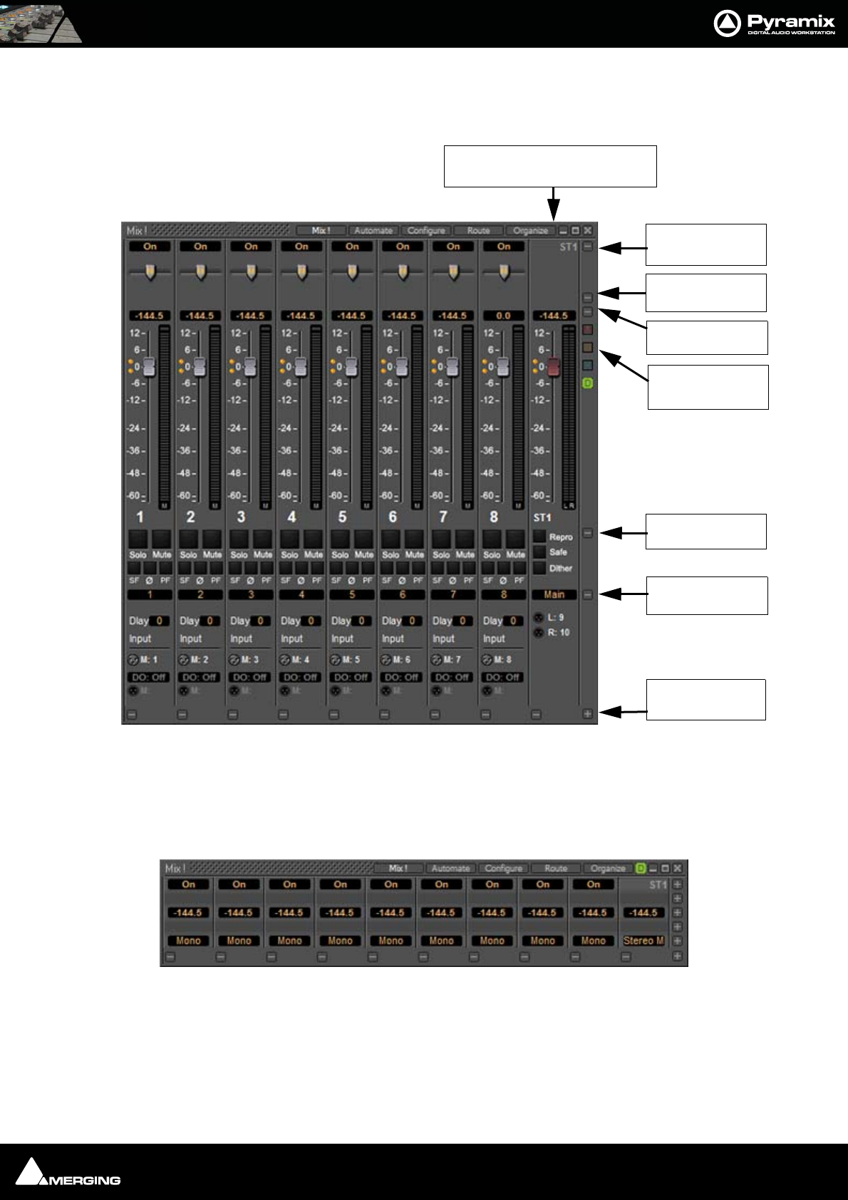
Mixer : Mix ! 10 - 153
Mix !
Basic Mixer
Expand / Collapse
The small, grey + - boxes on the right of the mixer surface toggle horizontal areas of the mixers surface shown full
size or collapsed. They also pop-up context menus when the cursor is above them. (see below) Expand / Collapse
and Hide can reduce clutter by concealing unused controls. This is the same mixer with all areas Collapsed:
Stereo Bus
pop-up
Effects
pop-up
Gain
pop-up
Mute
pop-up
I/O
pop-up
Mixer
pop-up
Simple 8 X 2 stereo mixer Window with all areas visible
Automatic Delay Compensation
Indicator / Button
Mixer Global
Indicators/buttons
Simple 8 X 2 stereo mixer Window with all areas hidden
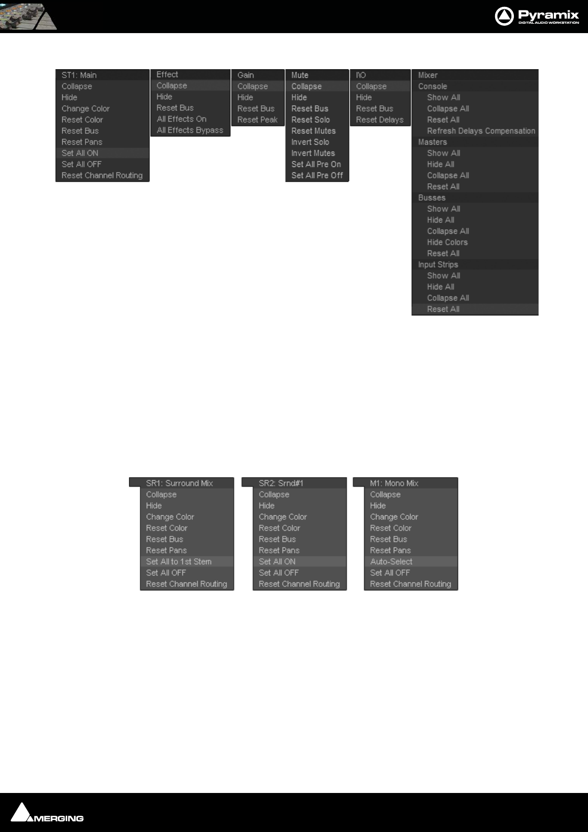
Mixer : Mix ! 10 - 154
Each + - box also pops-up a menu relevant to the area of the mixer it deals with when the cursor is above it. E.g. :
Collapse/Hide
Choosing Collapse leaves a small artefact of the mixer area visible, a gray horizontal bar with a + box at the right-
hand side. Hide completely removes the area from view. Choosing Show All in the Mixer + - pop-up will restore.
Resets
These context menus also provide a convenient way to restore all controls of specific types or, in the relevant sec-
tions, the entire strip or mixer to the default condition.
Bus + - context menus
The precise content of this pop-up depends on the type of bus and whether there are multiple stems:
Set All to 1st Stem
As it says. All sources will be routed to the first stem of a multiple bus.
Set All ON/OFF
Activates/deactivates the routing to a Bus or Bus Stem for every Input Strip.
Auto-Select
Is exactly the same function as the one provided in the right-click menu over a Multi Mono bus from the 1st strip;
ie it auto-sets the routing of every strip’s channels to a Multi Channel Bus, so that (as far as possible) each Input
Strip channel is routed to a Bus channel matching the same grid index (diagonal routing).
Simple 8 X 2 stereo mixer + - pop-up menus
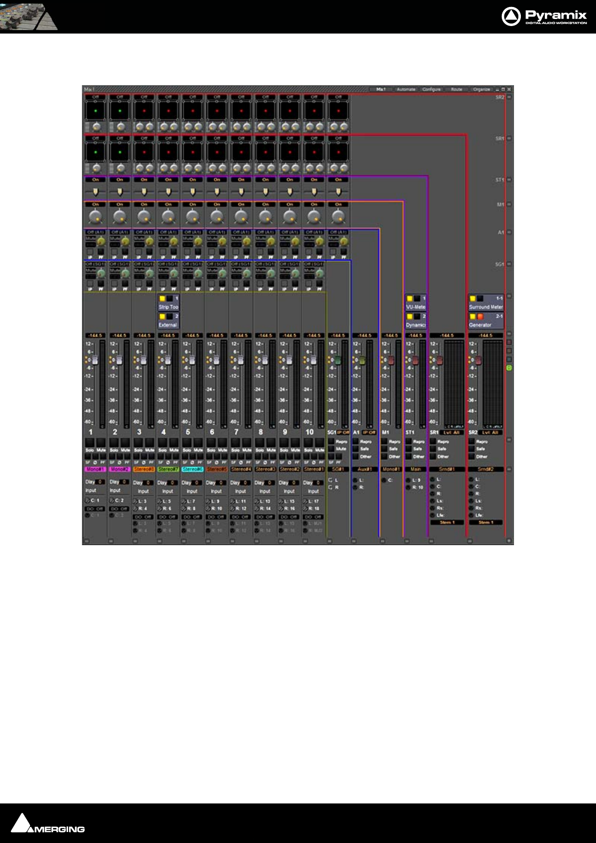
Mixer : Mix ! 10 - 155
Colors
Bus paths can be colored to aid comprehension.
Hide or Show Colors hides or restores the colored lines. Change color allows the color of an individual bus to be
altered. Reset color restores the color to its previous state.
Mixer with colored bus paths
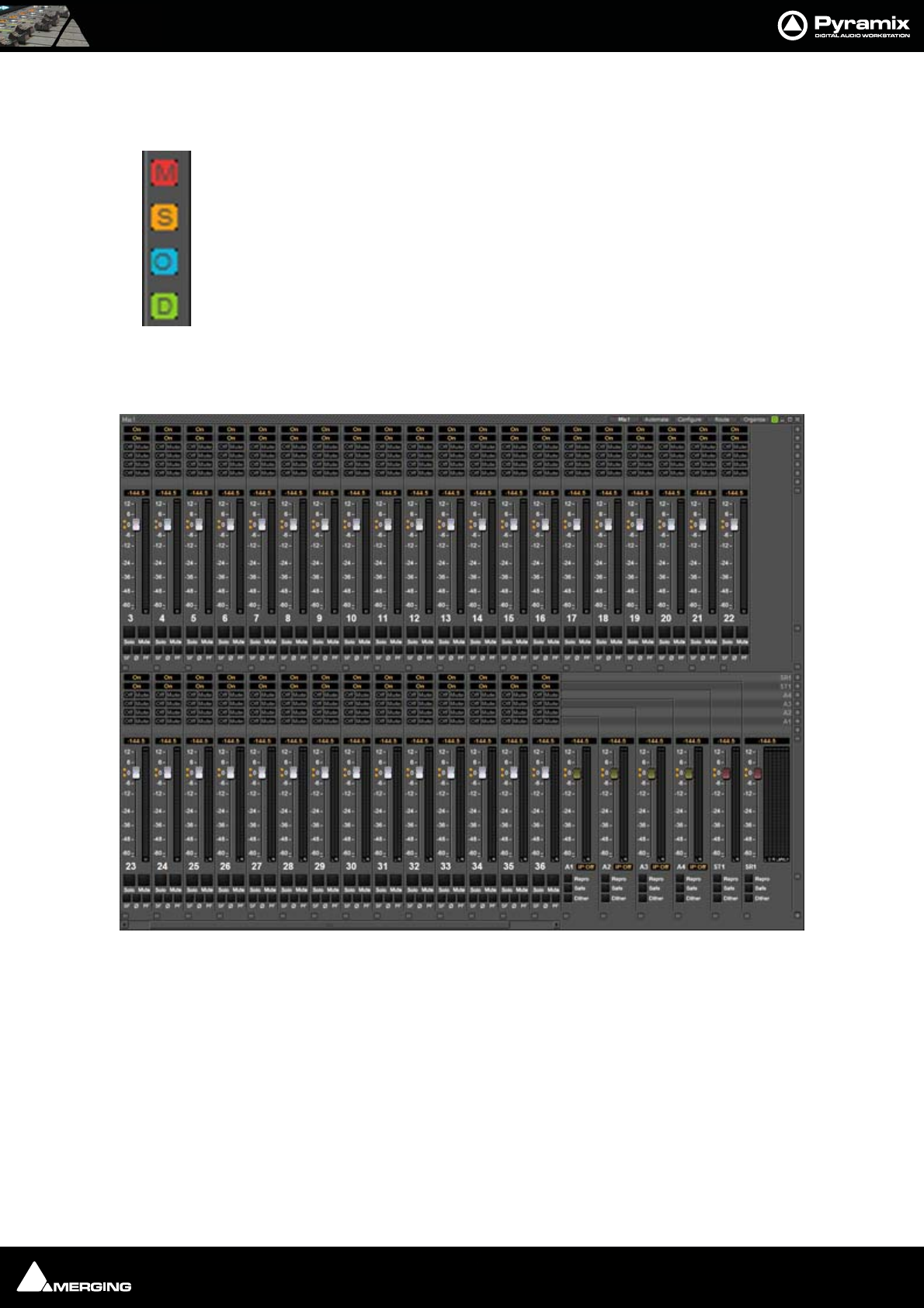
Mixer : Mix ! 10 - 156
Global Indicators / Buttons
The small indicators/buttons on the right-hand side of the mixer window, adjacent to the Fader row have the fol-
lowing functions:
Two Fader Row Display
With large mixer configurations it may be convenient to show the strips in two rows, one above the other like this:
The mixer will automatically be shown with two rows of faders when the mixer is configured with more strips than
can be displayed in a single row AND when there is sufficient vertical space in the mixer window to accommodate
two rows. This requires that several of the buses/mutes/I/O be collapsed, as seen above, or hidden. If a bus or other
mixer component is expanded or un-hidden that increases the height of the mixer window beyond the resolution
of the monitor then the Mixer display reverts to single row of faders with scroll bar to access the hidden strips.
MUTE - Lit when a Mute or mutes are active. Clicking on the lit button cancels all active Mutes.
SOLO - Lit when a Solo or Solos are active. Clicking on the lit button cancels all active Solos.
Overload - Lit when an Overload indicator is latched. Clicking on the lit button cancels all active Overload
LEDs.
Automatic Delay Compensation Status
Please see : Delay Compensation on page 174
Mixer with two rows of faders

Mixer : Mixer Components 10 - 157
Mixer Components
Input Strips
Mixer Input Strips associated with tracks (the pale green box in the track header) are fed by and control the moni-
tor output of the tracks. The Mixer Strip Channel Live (physical) or Internal Return Bus Input goes direct to the
associated Track. When a strip has no associated track it is fed by and controls the Live (physical) or Internal
Return Bus input assigned to it.
When the strip has an associated track, the track output is automatically switched between input and playback
output depending on transport mode, the monitoring setting in the track header and the setting of the Settings
> All Settings > Application > Playback/Record : Auto-monitoring option, European Monitoring (all tracks
turn to INPUT on stop) or US Monitoring (only Record Ready tracks turn to INPUT on stop)
Note: When strip channels have an associated track NONE of the strip controls, fader,
mute, eq etc. affect the signal fed to the track input.
Mixer Input Strips have the same functions as the input strips of any standard mixing console providing level con-
trol, pan, mute, etc.
The following types of input strips are available:
• Mono input Strips
• Stereo input Strips
• MS decoder Strips - decode a Sum and Difference signal to standard stereo format
• GPS (General Purpose Strip)
Direct Monitoring Input Strips
Direct Monitoring Input Strips are a special version of the basic Input Strip designed specifically for recording. The
principal feature of these strips is minimum monitoring latency for the artist. This is achieved by applying auto-
matic delay compensation only to the signal fed to the main output bus. For this reason, Aux Sends and Effects
cannot be installed in Direct Monitoring Input Strips and they cannot be routed to SubGroups. Three types are
available:
• Mono - Direct Monitoring
• Stereo - Direct Monitoring
•MS - Direct Monitoring
Note: These strips are intended for live inputs only. It is not possible to feed them from
tracks.
To add a Direct Monitoring Strip right-click on a blank area of an existing strip to the right of where you wish to
add it. Select Strip > Add > Mono -Direct Monitoring, Stereo - Direct Monitoring or MS - Direct Monitoring
from the context menu as appropriate. Or use the Configure Mixer page. Please see: Strip and Bus operations
on page 145
Note: If Auto-Delay Compensation is turned on for the Mixer then the recording from a
Direct Monitoring Input Strip will be in sync with the existing tracks while maintaining
minimum latency for foldback to the artist.
Mixing/Monitoring/Aux Send and SubGroup Buses
These are the summing buses where mixer strip signals are routed to. Each bus type (Mix, Aux Send or SubGroup)
has a Repro button in the Master section to allow this bus to output signal only when the system is playing back.
No signal will be output in Stop or Record modes, for example to avoid audio feedback (howl round) in the Studio
main speakers when Tracks auto switch to Input monitor when Recording or Stopped.

Mixer : Mixer Components 10 - 158
Mix Bus
A mix bus is the destination for the final product of your mix. The outputs of a mix bus are usually routed to a mas-
ter machine to record the final mix. They can also be routed via Internal Return Buses. Apart from their other
uses, these enable the final mix to be recorded in Pyramix. Main Mixing, Aux Send and SubGroup Buses also
appear in the Monitor.
Mix Buses are available in several formats:
Mono Mix
Provides a single mono output. Any input strip can be routed to it.
Multiple Mono Mix
Provides several mono outputs. Any input strip can be routed to any or all of them
Stereo Mix
Provides a single stereo output. Any input strip can be routed to it
Multiple Stereo Mix
Provides several stereo outputs and allows any input strip to be routed to any or all of them
Surround Mix - 5.1 format
Multiple Surround Mix - provides several surround outputs and allows to route any mixer strip onto any of them.
Note: Unlike mono and stereo multiple buses, input strips can only be routed to ONE 5.1
destination stem of a multiple surround bus. This reflects their normal use. E.g. a com-
mon set-up will have three surround bus stems for Dialogue, Effects and Music. Each
Input strip is routed to the appropriate surround bus by clicking on the Stem ‘X’ button.
All surround bus stems can be summed for monitoring in the Monitor.
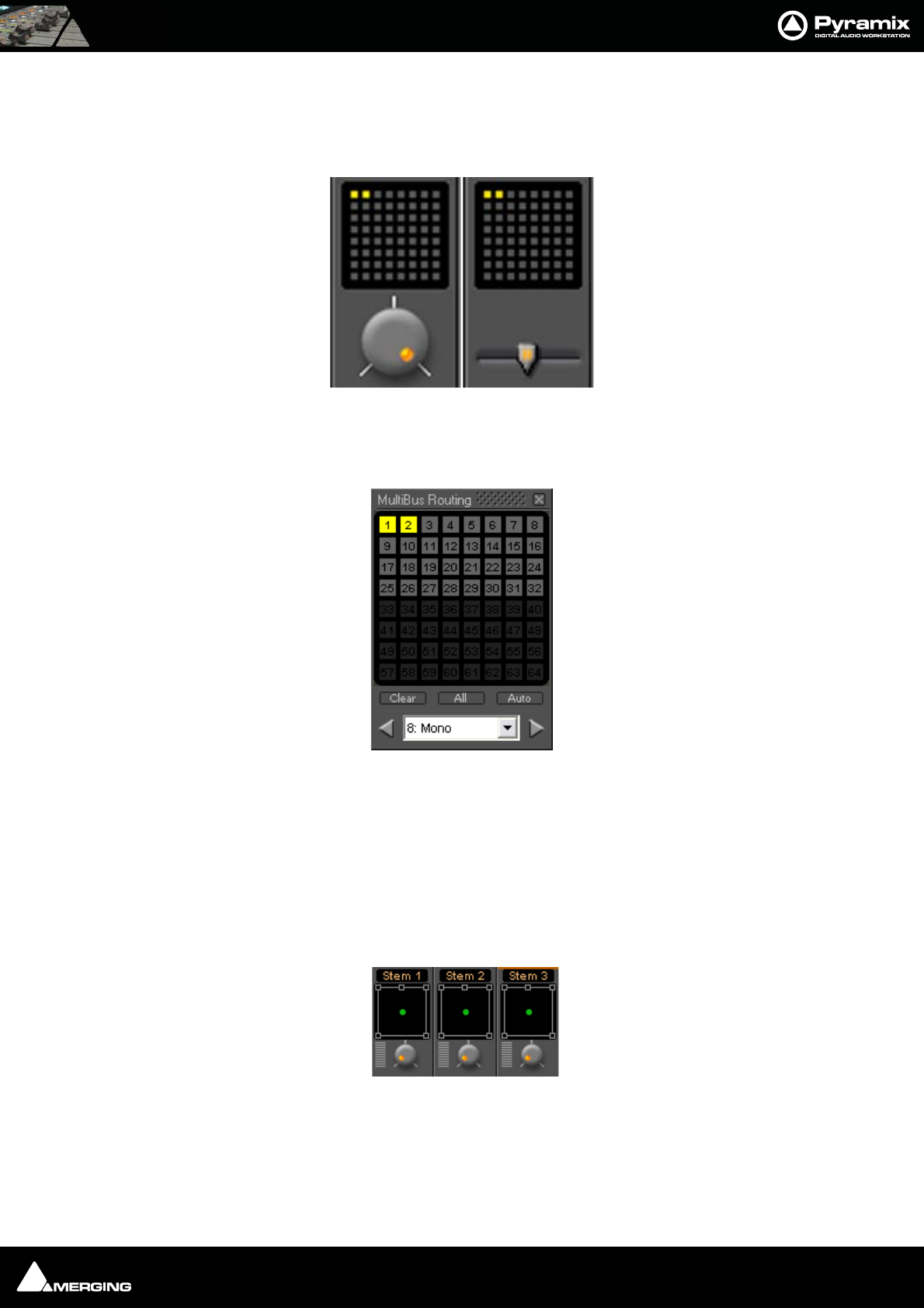
Mixer : Mixer Components 10 - 159
Multiple Mix Buses (Stems)
Mono / Stereo
When a mono or stereo multiple mix bus is added to the mixer a routing matrix box appears in the input strips
with a send level control (mono) or pan control (stereo).
The 8 by 8 matrix gives access to up to 64 output buses. Routing is shown by lit crosspoints.
Double-clicking the matrix in the strip opens the routing matrix window.
Valid choices are shown in gray. Once the window is open, other input channels can be route by either selecting
them from the drop-down list or using the < and > arrows to step across the mixer surface.
Surround
Up to 16 surround buses each with from six to nine channels may be added as a single Multiple Surround Mix
output strip. The principle use of these is for stem mixing where, for example, dialog, background effects, spot
effects, foley and music are recorded as separate recordings but monitored as a complete mix. Each surround bus
is identified by number. In this illustration, a Multiple Surround Mix strip has been added to the mixer with three
surround buses.
Clicking on the label above the Surround Panner pops up a list of the available stems. Simultaneously selecting
more than one on a strip is not possible.
Stereo Mix bus matrix
Mono Mix bus matrix
Mix bus routing matrix
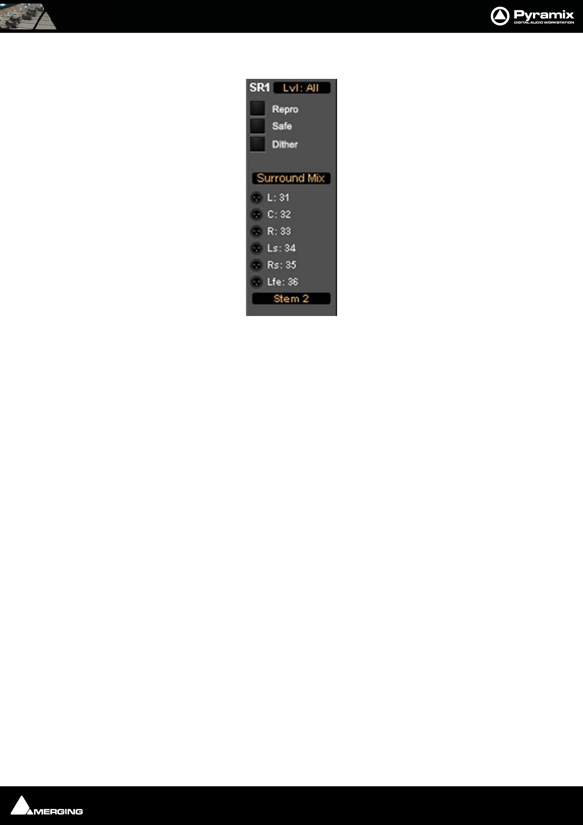
Mixer : Mixer Components 10 - 160
The associated Surround Mix output strip routing is shown below:
The top (SR1) box shows what the meters are displaying. Clicking on it cycles through each Stem and Lvl: All
which meters the sum of all the Stems The bottom box shows and selects which Stem the XLR icons refer to. Rout-
ing to physical outputs or Internal Return Buses is accomplished in the same way as other buses. I.e. right-click the
relevant XLR icon and select Connect > etc. from the menu.
Groups
Master Group Strips - allow the grouping of faders of several mixer strips. Analogous to VCA grouping. When a
group or groups are added (from the mixer contextual menu Settings > Add Strip > Group) A group button for
each group created will appear below the strip name box on each input strip. When selected, the associated
Group strip will control the grouped input strips if the On button is lit on the Group strip.
Multiple Surround Mix Output Routing
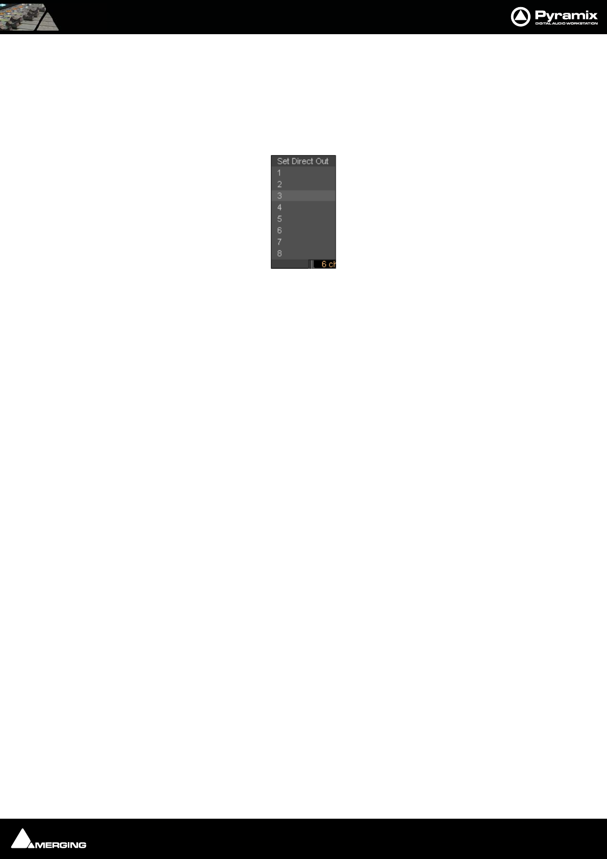
Mixer : Mixer Components 10 - 161
Channel Direct Outputs
All input strips can have Direct Outputs. The Direct Out connection is disabled by default. It can be enabled in
the Configuration Page by selecting the strip and clicking on the DO: Off box or disabled if the box shows DO:
On. Alternatively Direct Out can be set in the Route Page by clicking on the Strip Header.
The Direct Out can be routed by Channel to any output of the HDTDM or XDTDM bus. The Direct Out can be sent
Pre or Post Fader. Click on the DO: Post box in the Mixer I/O section to toggle. The Direct Out is currently always
Post Effects. For multi-channel strips clicking in the box above the DO: box pops-up a Set Direct Out list:
Highlight the required channel. This will be fed to the logical output assigned in the Mixer Route page or by click-
ing on the DO XLR icon in the Mix page.
Although there can be any number of Input Strips and Buses from 1 to 64 in HDTDM or 1 to 128 in XDTDM, there
is a limitation on the number of Direct Out connections: The sum of the Direct Out connections PLUS all Buses
channels can not exceed 64 in HDTDM or 128 in XDTDM.
Strip & Bus Channel Types
All Strips and Buses Channels have a custom type that can be manually set in the Configuration Page to:
•Left (L)
•Center (C)
•Right (R)
• Surround Left (Ls)
• Surround Right (Rs)
•LFE (Lfe)
•Left Center (Lc)
•Right Center (Rc)
• Surround Center (Cs)
• No particular type
Mono Strips are tagged by default to no particular type
Stereo Strips are tagged by default to L-R
MS strips are tagged by default to C-W
GPS Strip (General Purpose Strip):
GPS Strips can have from 1 to 8 channels
They can be used as Aux returns or for any kind of direct Input usage e.g. premixes or multi-channel record-
ings.(LCR, LCRS, etc…) By default a 2 channel GPS Strip is initialized to L-R and a 6 channel GPS Strip is initialized to
LCRLsRsLfe 5.1. This can be changed/customized in the Configuration Page.
GPS Strips feeding any buses (Aux or Mix) are routed by default by Channel Type (like any other strip) but this rout-
ing can be manually changed by clicking on the Channel Routing grid (like any other strip).
Set Direct Out
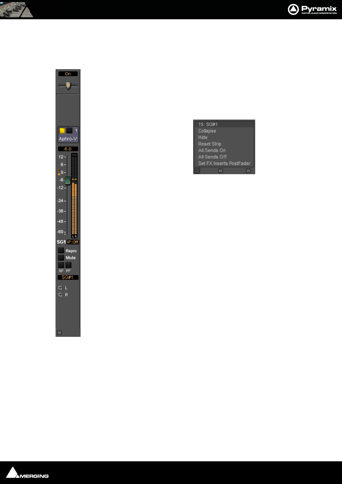
Mixer : Mixer Components 10 - 162
Aux Send Buses:
General Purpose Aux Send buses provide a way to create ‘auxiliary’ mixes which are used to provide headphone
or cue mixes for musicians etc.
SubGroup Buses
SubGroups are a special type of Aux bus which are automatically routed to buses,
in exactly the same way as normal input strips, instead of having output connec-
tions. SubGroup buses offer a quick and efficient means of managing effects chan-
nels (e.g. for Reverb plug-ins or any VST/VS3 plug-in used as Send FX). When using
SubGroups there is no longer any necessity to have additional corresponding
return strips. In addition, this also enables the use of post-fader effects. Hover over
the strip pop-up and select from the list:
SubGroups have Mute, Solo Safe and PF, Pre-Fader metering, buttons like input
strips and Repro buttons and In Place options like Aux Send buses.
Note: Please be aware that a SubGroup Bus will auto-take Inter-
nal Bus connection resources, starting from the last one. E.g. IB64-
IB63 for the first two SubGroup Channels added to a Mixer. This
means that you will no longer see IB63 and IB64 in the IB list.
Aux Send Bus Channels
Aux Send Buses are intended purely for folding back a mix to musicians etc. and can have from 1 to 8 channels.
Channels have a custom type that can be manually set in the Configuration Page to:
•Left (L)
•Center (C)
•Right (R)
• Surround Left (Ls)
• Surround Right (Rs)
•LFE (Lfe)
•Left Center (Lc)
•Right Center (Rc)
• Surround Center (Cs)
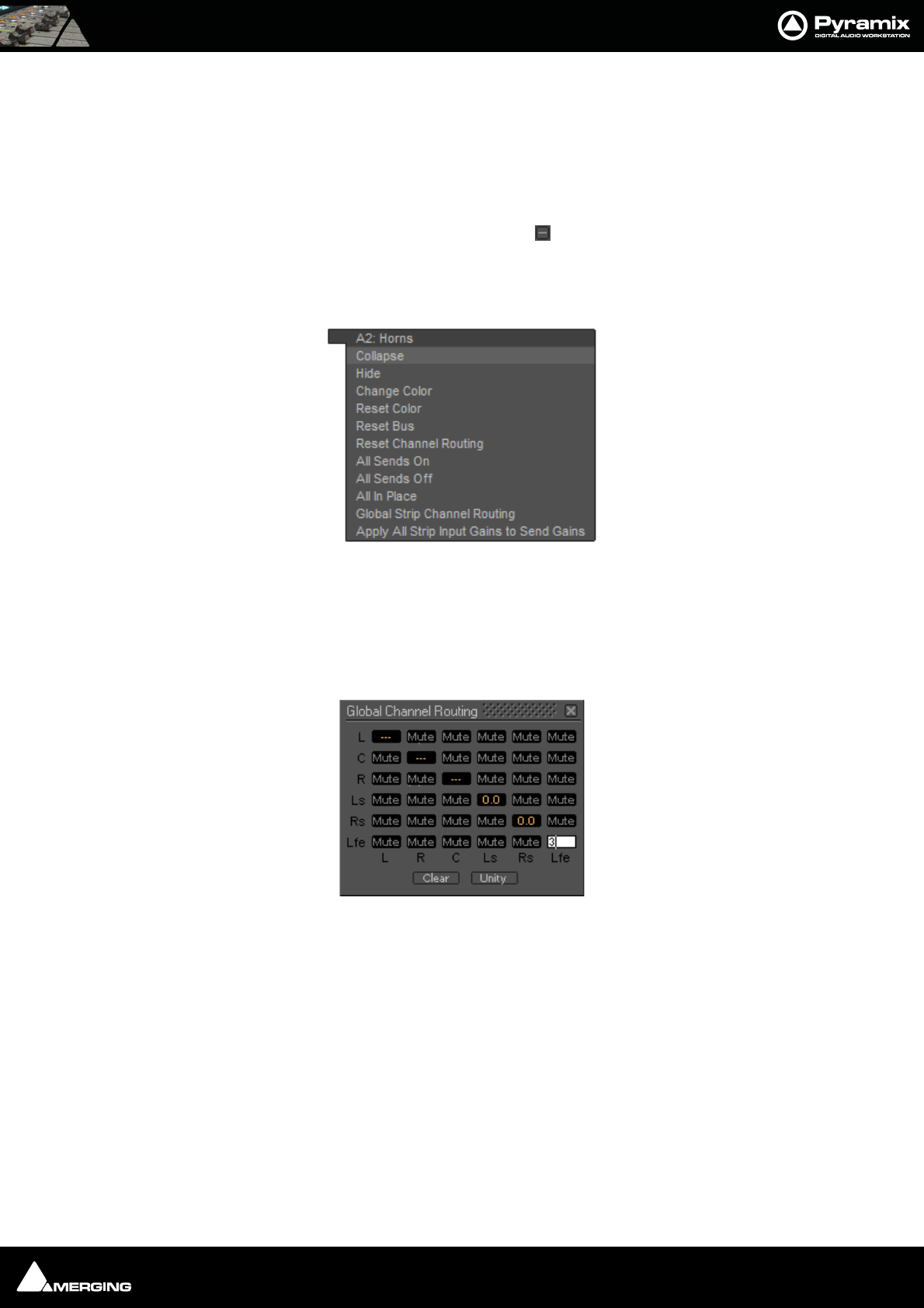
Mixer : Mixer Components 10 - 163
By Default a 2 channel Aux Send Bus is initialized to L-R and a 6 channel Aux Send Bus is initialized to 5.1. This
can be changed/customized in the Configuration Page.
Note: When an Aux Send bus is added it is important to ensure that the Type for each
channel of the Aux Send bus is set correctly.
Aux Send Bus Context Menu
As with other buses, Clicking on an Aux Send bus’s small gray box on the right-hand edge of the mixer window
Expands / Collapses the send display. When the cursor is above the box the Aux Send Bus pop-up context menu
opens:
Most of the entries are the same as other buses, but the last two entries are specific to Aux Send buses.
Global Strip Channel Routing
Opens the Global Channel Routing window for the Aux Send bus
This routing grid groups together the Channel Types of all the input Strips present in the current mixer, shown
horizontally (L, R, C, ...). The vertical channels are the Channel Types of this Aux Send bus. When a node’s value is
edited, the static aux send gain of all strips having this channel type is updated with the new value for this Aux
Send Bus. When some strips are already set to different values for a specific node “---” is displayed.
Clear Sets the entire grid to Mute
Unity Sets the entire grid to Mute
Note: Invoking either Clear or Unity will affect all Strips Aux Sends to this Aux Send Bus.
Apply All Strip Input Gains to Send Gain
The current input gain value of every strip in the mixer will be applied to all the Aux sends feeding this Aux Send
Bus.
Aux Send bus pop-up context menu
Global Channel Routing window
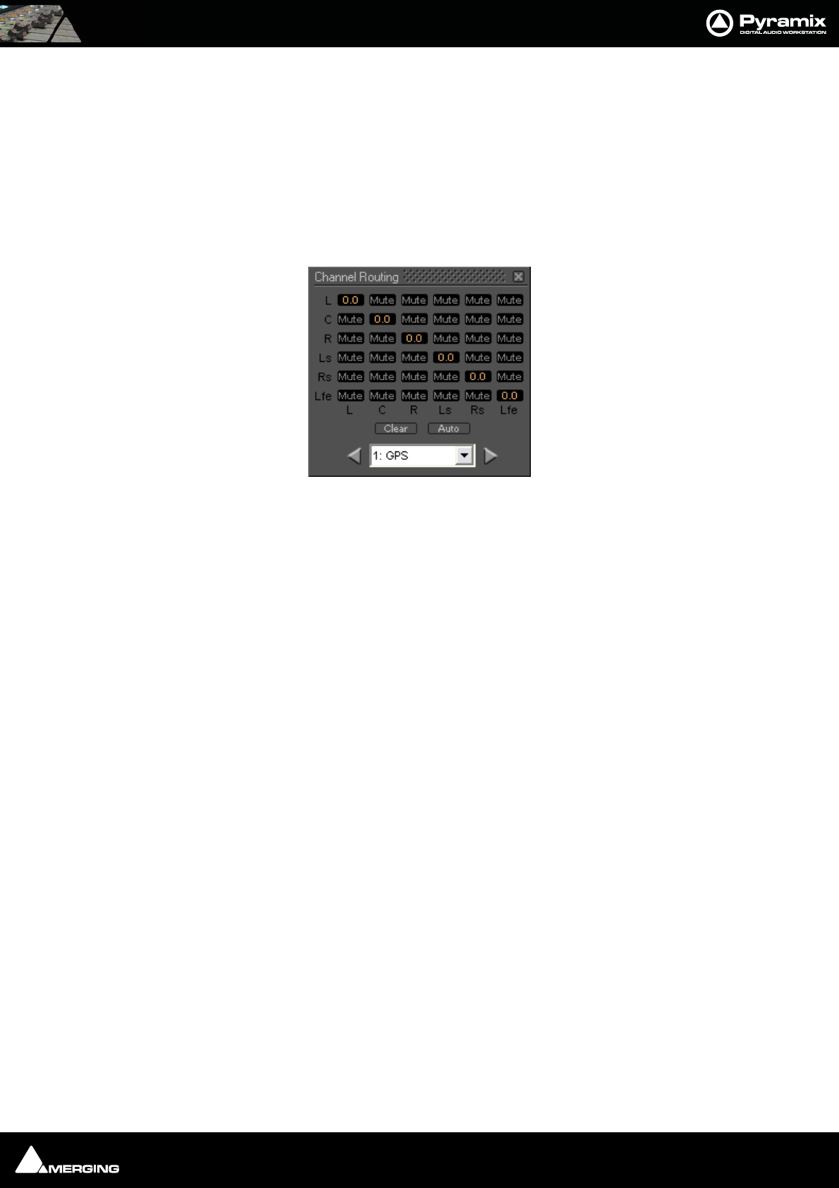
Mixer : Mixer Components 10 - 164
Aux Send Routing
When a Strip feeding an Aux Send Bus is of the same type as the Aux Send bus E.g. Stereo strip feeding stereo Aux
Send bus 5.1, Strip feeding a 5.1 Bus the sending Strip’s Channels are automatically routed to the corresponding
Aux Send bus Channel Type. (Left to Left, Right to Right, etc…).
Where the sending Strip differs in Type to the Aux Send Bus E.g. a Stereo Strip feeding a 5.1 Aux Send Bus, the rout-
ing must be made manually. The same method is used if you wish to alter auto-routed values.
Static Channel Routing
Aux Send Channel Routing is set by clicking on the little grid icon adjacent to the knob on the Aux Bus send in the
channel strip. This opens a Channel Routing window:
Shown here with a 5.1 channel feeding a 5.1 Aux Send Bus. Gain values can be entered for each node of the Strip/
Bus crossing. Just click on any node and enter a dB value. Enter nothing (no character) or -144.5 to reset the node
to Mute.
Clear Clears all nodes to Mute
Auto Sets a 1 : 1 flat routing as shown above
Channel Routing window
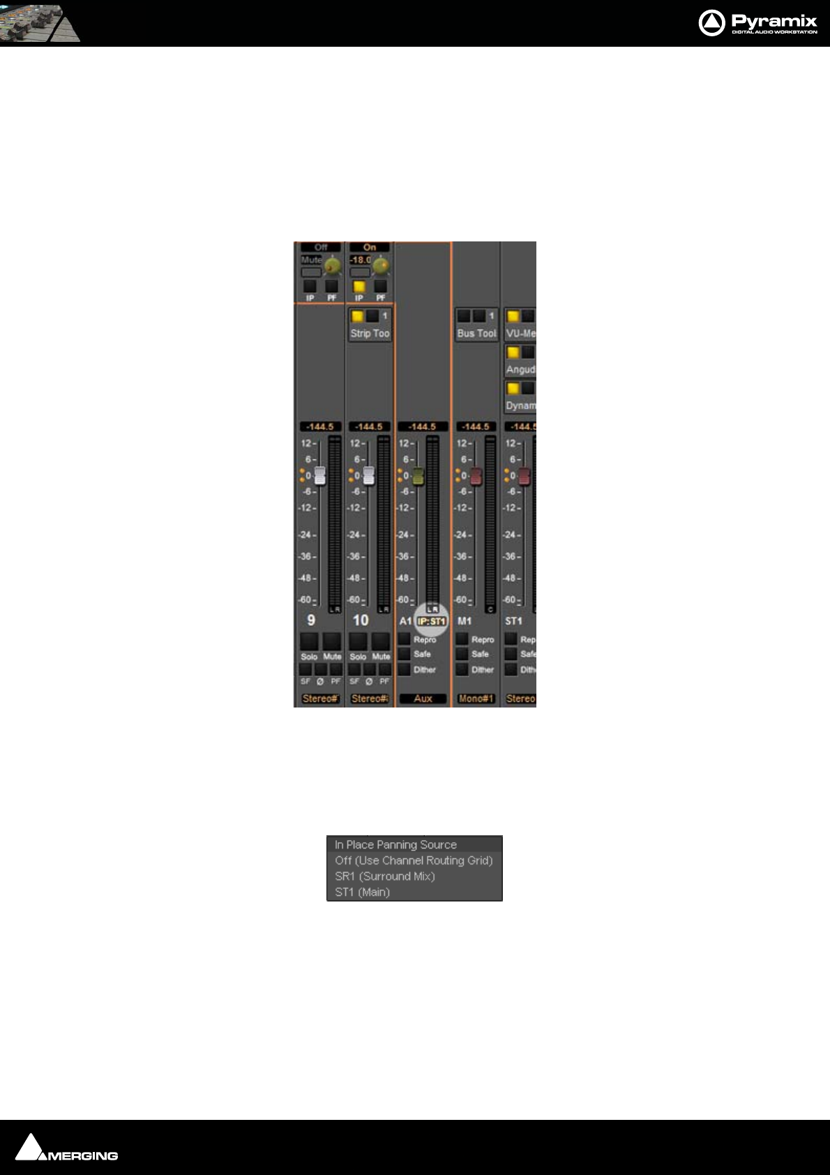
Mixer : Mixer Components 10 - 165
Aux Send Buses In-Place Panning
In-Place panning for each Aux Send bus is turned on with the IP button in Aux Send section(s) of each Input Strip.
In-Place Aux Sends take the ouput(s) of the appropriate panner at the same level(s) the panner is feeding its out-
put bus.
Note: Only corresponding Bus Types are fed in this way. Thus if you feed a Mono Aux
Send Bus typed Center from a 5.1 panner and there is no signal on the centre channel no
signal will be fed to the Aux Send Bus even if the signal on the left and right outputs is
identical creating a ‘phantom center’.
In-Place Panning Source
When an IP button is lit (yellow) on an Input Strip, the way in which the aux send channels are routed to an Aux
Send bus is determined in the Aux return strip. For example, in a mixer configuration with an Aux Send bus, a Sur-
round bus and a Stereo bus. Clicking on the highlighted box below the Aux master fader pops up a list of options:
These determine whether the Aux send will follow one of the output bus panners or the Static Channel Assign-
ment set in the Input Strip. E.g. for Aux Send bus 1:
Off (Use Channel Routing Grid) Aux pan follows Static Channel Routing assignment
SR1 (Surround Mix) Aux pan follows Surround Mix bus panners
ST1 (Stereo Mix) Aux pan follows Stereo Mix bus panners
To make all the Aux 1 sends follow the Mixer Strip Surround Panners, click on the box below the fader and select
SR1 (Surround Mix)
In-Place Panning Indicator/Selector
In-Place Panning Source pop-up
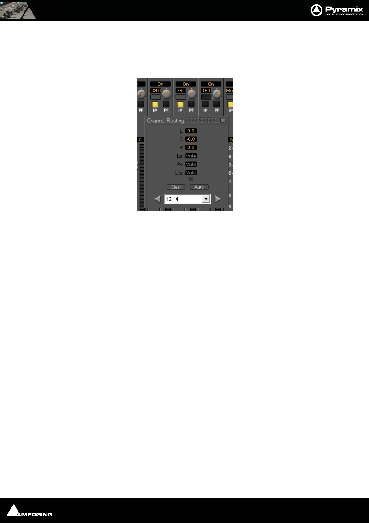
Mixer : Mixer Components 10 - 166
Note: When IP:Off is displayed in the Aux Send master strip I.e. no In-Place source is
selected, then the IP buttons in the input strips will be grayed out. Similarly, when an In-
Place source IS selected and the yellow IP button in the input strip is lit then the static
routing grid is grayed out and unavailable as in this illustration.
The three strips shown are 10, 11, and 12. Since the IP button is selected (Yellow) on strips 10 and 11 the static
routing grid is grayed out and thus unavailable. On strip 12 the IP button is deselected (dark) and the Static Chan-
nel Routing grid can be opened by clicking on the grid button next to the knob.
Note: The IP button defaults to On when the aux send is first turned on. If the send is
subsequently turned Off (muted) then the current setting of the IP button is remem-
bered when it is unmuted.
Strip Aux sends and Channel Routing dialog
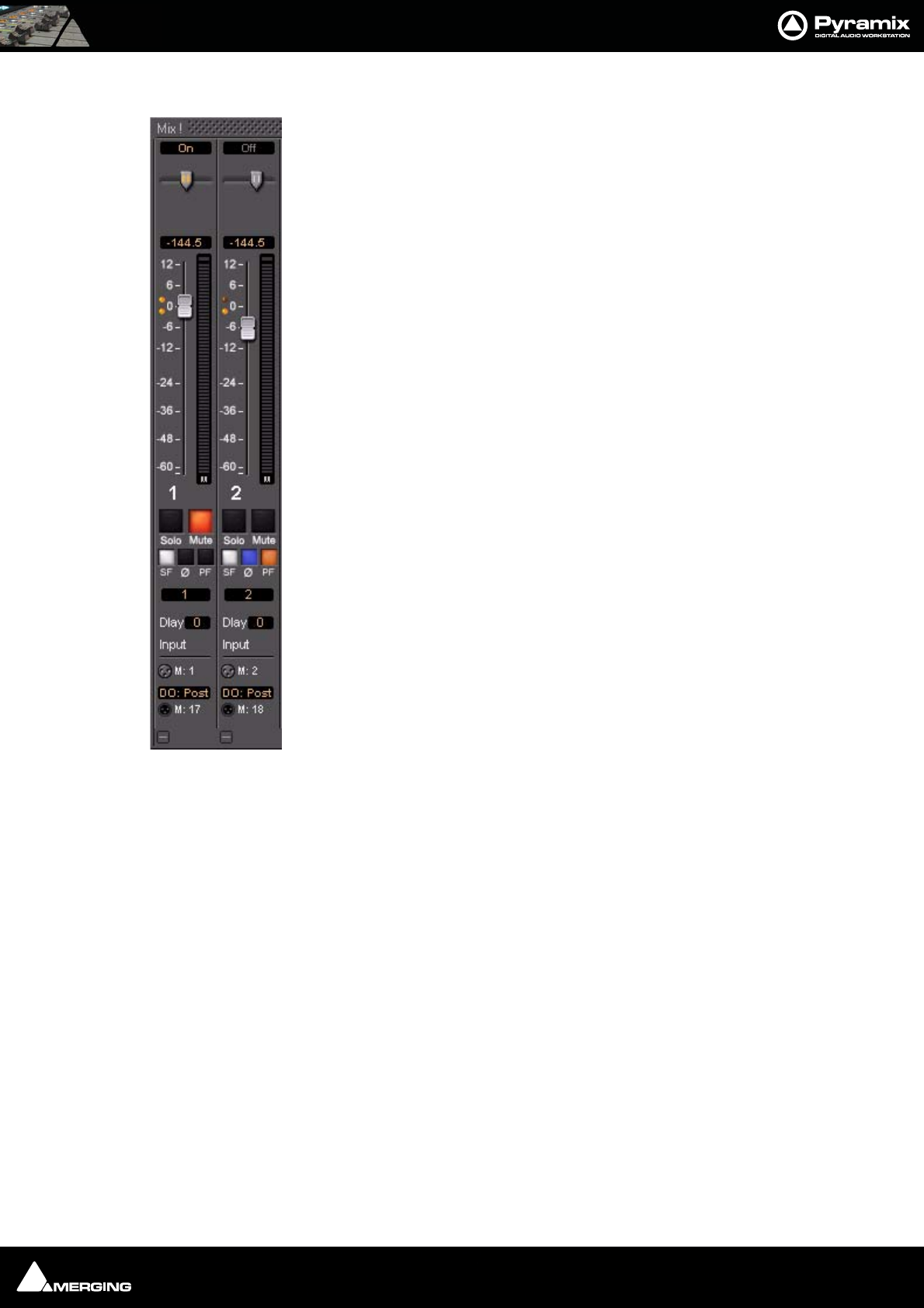
Mixer : Mixer Components 10 - 167
Basic Strip
A basic mono channel strip contains:
On /Off toggle switch
Pan slider to Main output bus. In this case there is just a single stereo mix bus.
Numeric display of fader output level value, if cursor is over a fader knob shows fader
gain. If cursor is over pan-slider, shows current pan position. May be clicked to directly
enter a fader gain value.
Level Bargraph Rotary Controls and Faders
Rotary Controls, sliders and Faders may be adjusted by grabbing them with the mouse
and dragging. Rotary controls and horizontal sliders are adjusted by dragging left or right
and faders by dragging up or down. Double-clicking a Fader or Rotary knob returns the
value to the default. E.g. unity gain on a channel strip fader. Bargraph shows peak level
Buttons
Buttons on the main mixer surface are black when inactive. When active they ‘light up’.
Solo solos the strip, Mute mutes the strip Ctrl + Solo cancels all other Solos
SAFE prevents the strip being muted by solo operations elsewhere. Ø reverses the chan-
nel phase. PF changes the metering position to Pre-Fader.
Delay A delay value (in samples) can be set in this box.
Input Clicking on Input pops-up a box with the choice of the strip taking its input from a
physical connection or any output bus.
Logical Input and Direct Output Assignment
Right-click on the XLR icons to pop-up a drop down list of valid assignments.
Note: Direct Outputs must first be enabled in the Configure page.
Please see: Channel Direct Outputs on page 161
Stereo Strips
In a Stereo Strip feeding a stereo bus the single bargraph meter is replaced by a pair and the simple pan pot is
replaced by a choice of Balance control, Dual Panner, Pan/Width or 5.x Legacy Stereo Panner accessible from
the right-click context menu. (See below)
Stereo Strips can reverse the Phase of both the Left and Right channels. The single button has four possible states:
Black: No phase inversion
White: Left channel inverted
Red: Right channel inverted
Blue: Both channels inverted
Basic Strip
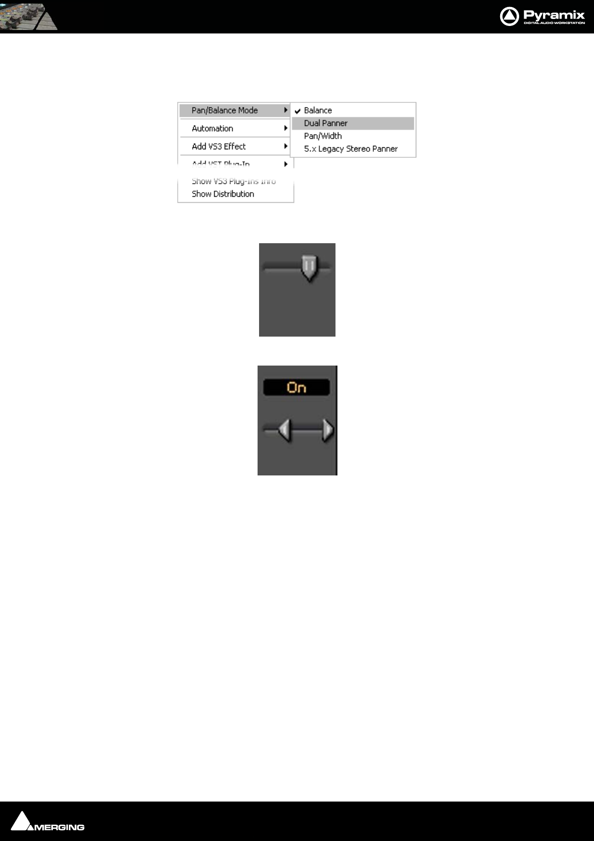
Mixer : Mixer Components 10 - 168
Stereo Panners
Pyramix offers a comprehensive choice of stereo panners which can be selected by right-clicking over the panner
to open the context menu:
•Mode 1: Balance
•Mode 2: Dual Panner
To adjust the pan (direction), left click and drag to right or left. To adjust the Width, Ctrl + Left-Click and
drag - The distance between the cursors represents the Width value.
Note: The Width value can be negative (-100% to +100% range), and the 2 channels are
then reversed. I.e. Right becomes Left and vice-versa.
Note: Since the Width range of values and Pan range of values are linked, adjusting the
Pan can cause the Width parameter to be updated, but the initial Width value is linearly
restored when moving the pan back to its former position, just like fader grouping on
some mixer desks. To avoid this (i.e. validate the current Width value), Ctrl + Left-Click
on the panner to reset the cached Width value.
Stereo Panner context menu
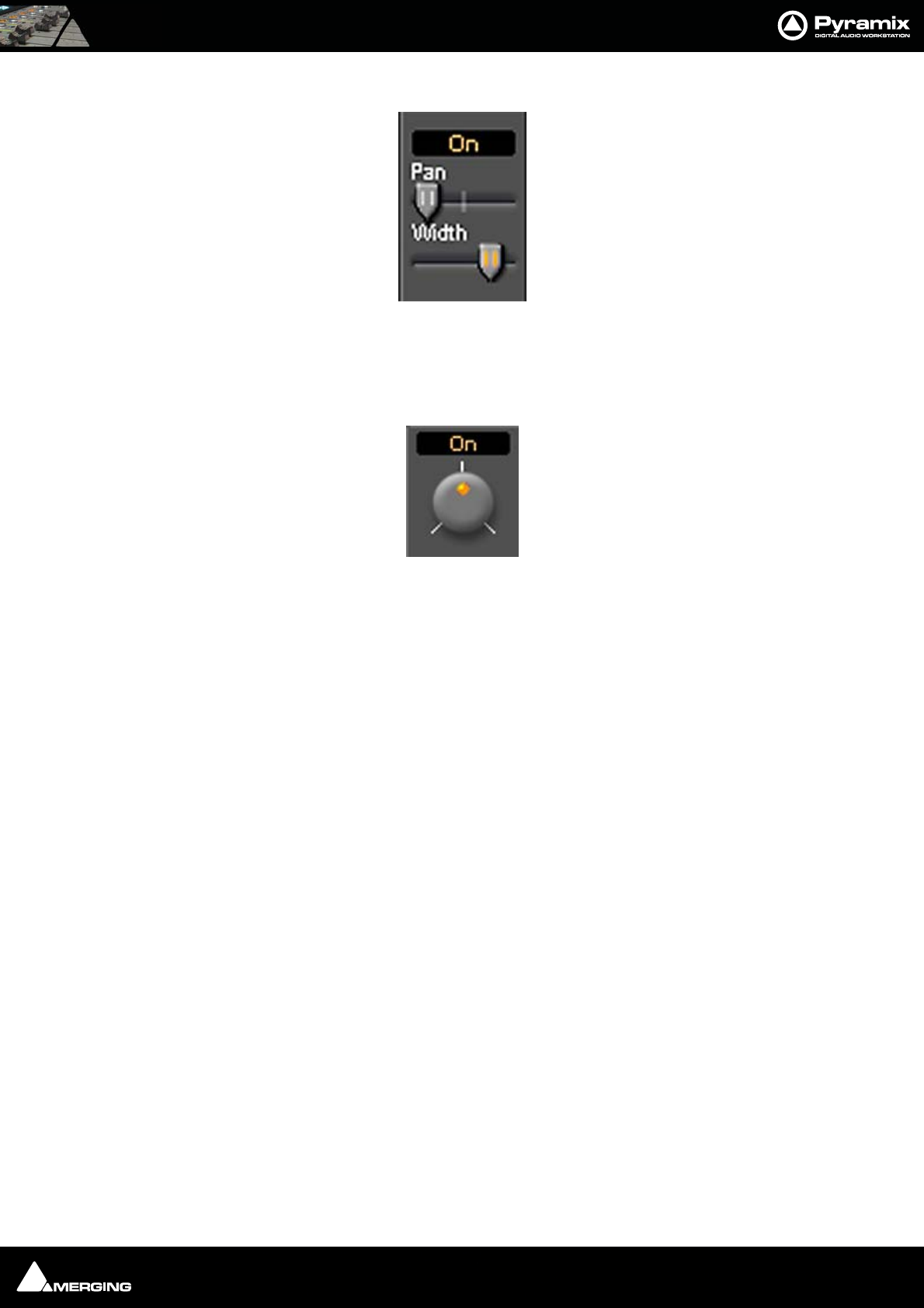
Mixer : Mixer Components 10 - 169
•Mode 3: Pan/Width
Pan slider acts like a normal balance control. Width alters the stereo image width from mono to 100%. If
the SHIFT key is held down while moving the Width slider the range is extended to 125%. I.e. Super wide.
This can be helpful with overly narrow images but should be used with caution.
•Mode 4: 5.x Legacy Stereo Panner Rotary
V5.x and V4.x legacy panner (for compatibility with older projects)
Default Position Indicators
Like other Pyramix mixer controls the panner knobs/pointers have an orange dot when at the default position.
Gearing
For finer adjustment hold down the Shift key whilst clicking and dragging.
Reset
To reset any of the panners to the default value simply double-click the knob/pointer.
Strip Meters
Characteristics
Meter ballistics and other parameters may be adjusted. Please see Level Meter on page 509
Peak Reset
To Reset Peak Hold and Overload for the entire mixer hold down P when the Mixer is activated.
To Reset the Peak Hold and Overload for a specific Strip or bus Click on the lit Overload LED.
To Reset the Peak hold and Overload of every Strip and Bus Ctrl + Click any Overload LED.
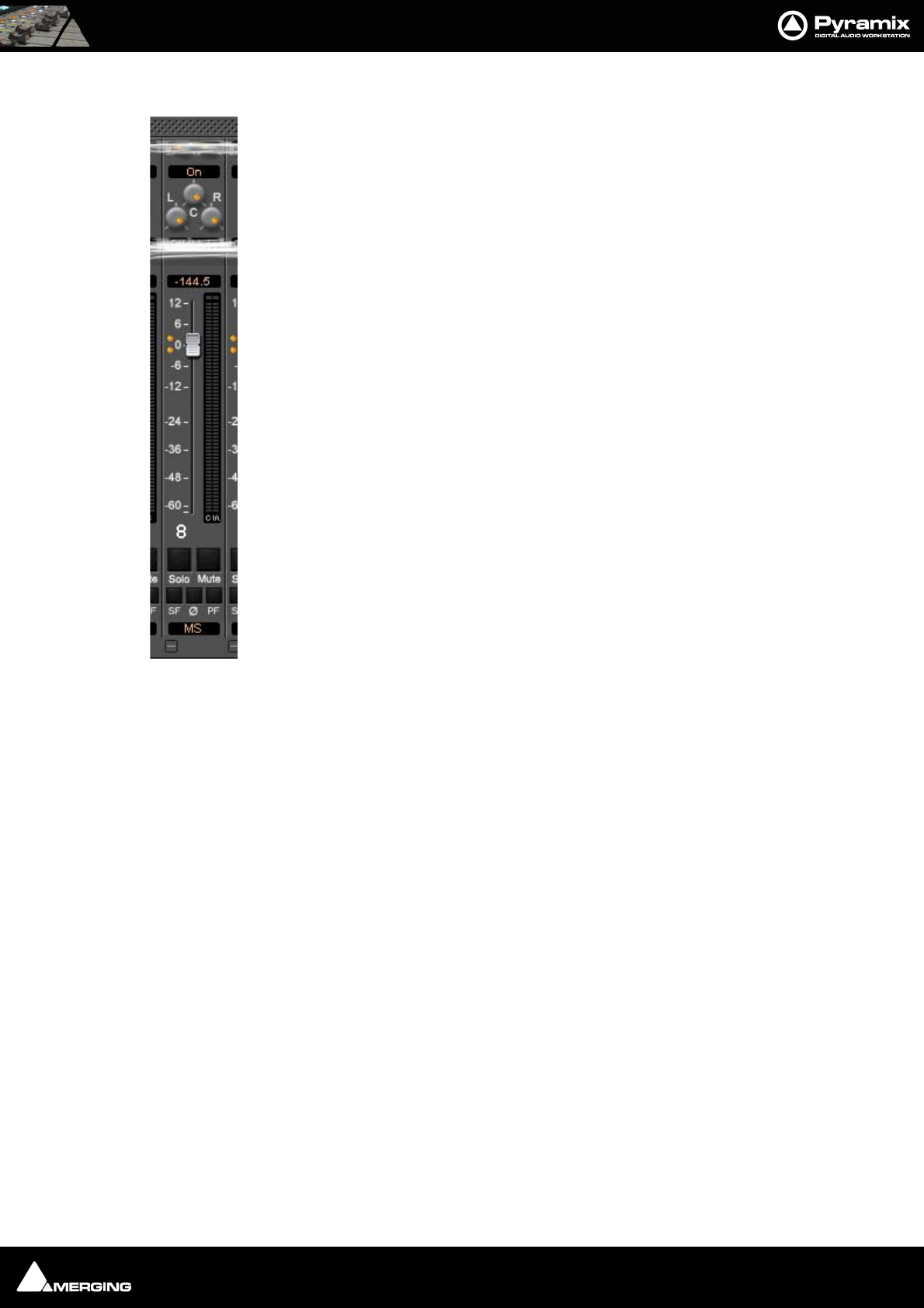
Mixer : Creating and Configuring Mixers 10 - 170
M&S Stereo Strips
What is M&S?
M&S stands for Middle and Side. M&S is a microphone technique which outputs Sum and Dif-
ference signals instead of Left and Right (also known as LR, AB or XY). These Sum and Differ-
ence signals are often known as M&S although this nomenclature is often a source of
confusion...
Sum and Difference signals can be created from a conventional Left, Right source. For example,
by using the Pyramix MS Encoder plug-in.(Please see: MS Encoder on page 228).
Decoding M&S
A Sum and Difference or M&S decoder reconstitutes Left and Right by adding the Difference
(S) signal to the Sum (M) signal to produce Left and adding the phase-reversed Difference (S)
signal to the Sum (M) signal to produce Right. This is often represented as:
L = M + S and R = M - S
Benefit of M&S
In mixing as opposed to recording, the main practical benefit of manipulating a signal in the
Sum and Difference domain is true control over the width of the image. Pyramix can handle
these signals directly thanks to the provision of M&S Stereo strips.
M&S Strip controls
An M&S strip stereo bus send has three controls. The center knob determines the Sum (M) con-
tribution to the Left and Right outputs. The L knob determines the in-phase Difference (S)
contribution to the Left output and the R knob determines the out-of-phase Difference (S) con-
tribution to the Right output. The L&R knobs are ganged by default. To move them indepen-
dently click and drag with the Ctrl key held down.
The Phase of both the Sum and Difference channels can be reversed. The single Ø button has
four possible states:
Black: No phase inversion
White: Sum (M) channel inverted
Red: Difference (S) channel inverted
Blue: Both channels inverted
Inverting either Sum or Difference results in the image being reversed left to right.
Note: If the Input meters consistently show S higher than M then either the image is
very wide and unlikely to be compatible for a mono listener or the M and S inputs have
become reversed at some point. Regrettably, this is extremely common when dealing
with location recordings in film and TV.
Creating and Configuring Mixers
If one of the numerous mixer presets does not quite suit your application it is simple to modify an existing mixer,
create one using the Mixer Wizard or design one from scratch. The Wizard can be started from an existing mixer by
right-clicking anywhere on the mixer surface and selecting Settings > Wizard...
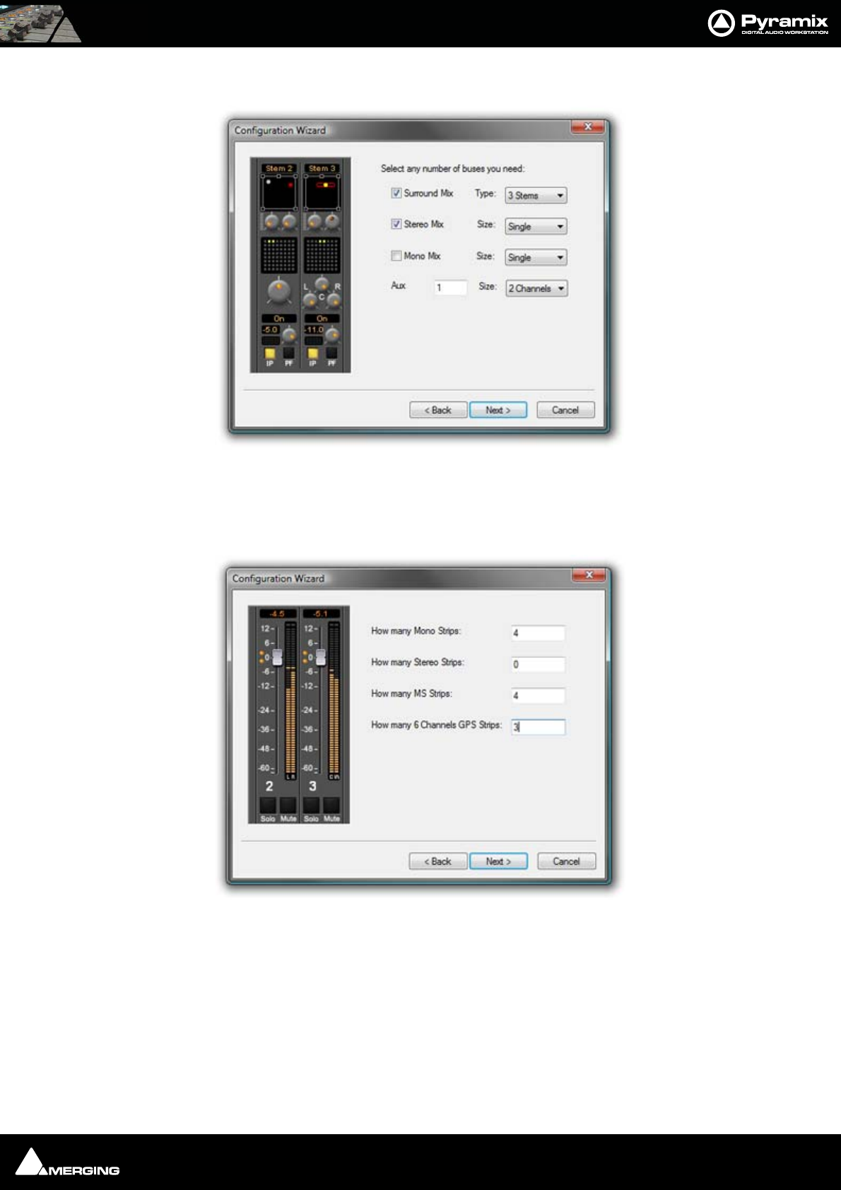
Mixer : Creating and Configuring Mixers 10 - 171
Mixer Configuration Wizard
Select the type(s) of buses required using the check boxes and the number needed from the drop
down lists on the right. Note that a single Mono or Stereo Mix Bus can consist of from 1 - 64 buses,
and a Surround Mix Bus can consist of from 1 - 16 multi-channel stems. Aux Send Buses and Sub-
Group Buses can have from 1 - 8 channels. Click the Next button to move on to the next page.
Select the type(s) of channel strips required using the check boxes and the number needed from the
drop down lists on the right. Click the Next button to move on to the next page.
Configuration Wizard buses dialog
Configuration Wizard strips dialog
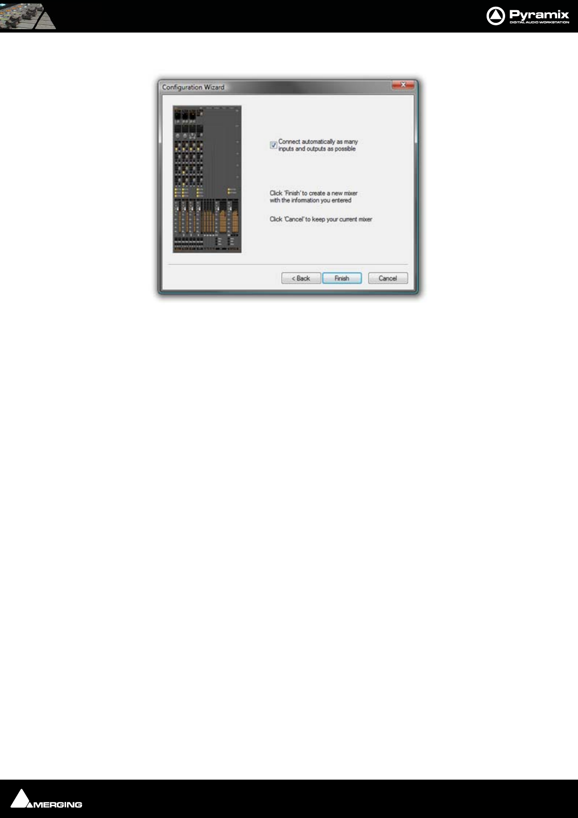
Mixer : Creating and Configuring Mixers 10 - 172
Checking the Connect automatically as many inputs and outputs as possible check-box will cre-
ate the same number and types of Tracks as there are Input Strips and connect as many as possible
to the available physical inputs in ascending order and output Buses to the physical I/O attached to
the Mykerinos board(s) and Track outputs to Mixer Input Strips, although you can easily reconfigure
this later. If the box is not ticked, the tracks will be created in the same way with Track outputs con-
nected to Mixer strips but no physical Inputs or Outputs will be connected.
Clicking Cancel opens the new Project with a Blank Mixer Window (See below)
I/O Buses Explained
The total number of available output buses, regardless of the number of Mykerinos cards, is 64 in HDTDM Mode
and 128 in XDTDM Mode. The maximum number of logical inputs and outputs to Pyramix is also 64 and 128
respectively. However, it is perfectly possible, and permissible, to have more than 128 physical inputs and outputs
connected to a Pyramix system. Routing to assign physical inputs and outputs to Pyramix logical inputs and out-
puts is made in the Settings > Hardware > HDTDM Routing or XDTDM pages. For example: a system containing
three Mykerinos boards, with MADI daughterboards has a total of 192. In HDTDM mode any 128 of these may be
routed to Pyramix logical inputs and any 128 Pyramix logical outputs (less the number of assigned Internal
Return Buses; see below), can be routed to physical outputs.
Note: In a MassCore system these limits are increased massively. In fact the only limita-
tion is the available power. For now the maximum number of buses is artificially limited
in code to 512 (at 1FS, 256@2FS, 128@4FS, 64@8FS).
Input Strip Types
To make is easier to work with a variety of source Formats Pyramix offers a number of different types of Input
Strip. These can control from one to 8 channels from a single set of controls. Please see: Input Strips on
page 157
Internal Return Buses
Some of the time slots on the HDTDM/XDTDM bus or within MassCore can be reserved to convey Aux Send or
Master Output Buses back to input strips. In effect, these are internal send/return paths. To change the number of
available Internal Return Buses, close all open Projects (if any) and go to:
Settings > All Settings > HDTDM Routing or HSR-HTDM if using HTDM mode.
Configuration Wizard auto connect dialog

Mixer : Mixer Delay Compensation 10 - 173
XDTDM Routing > PCM I/O routing or PCM-HSR I/O Routing if using XDTDM mode.
DXD Projects I/O Routing if you wish to use Internal Return Buses in a DXD Project.
The number of Internal Return Buses can be set using the Internal Buses combo box. Click on the OK button to
memorize the setting and exit.
The number of Internal Return Buses you assign here will be available as possible channel strip sources in the
mixer.
Mixer Delay Compensation
Summary
Mixer Delay Compensation offers a choice between:
Full Delay Compensation (including effects)
All but effects latencies
Off
This choice is made in the All Settings > Project > Mixer > Mixer Settings page along with a switch to turn Auto-
matic Compensation on or off and a slider to set the Maximum Mixer Delay Compensation.
Delay Compensation Switching
As detailed above, Compensation can be selected in the All Settings menu. It can also be toggled On/Off in the
Mixer context menu. Right click and select Settings then click on Enable Delay Compensation to toggle On or
Off.
Note: The Full Delay Compensation / All but effects latencies setting is retained when
Compensation is switched on and off from the mixer window.
With Mixer Delay Compensation turned On and All but effects latencies selected:
1. Input strip set as a (normal) Input: no compensation. If a Delay is applied manually the output signal of this
strip will be delayed by the applied value.
2. Input strip used as a Bus return, i.e. patched to an Internal Bus and set as a bus return (see Input Strip Mode
on page 176): all other Output Strips are automatically delayed by the amount equal to the Bus internal pro-
cessing delay.
3. Input strip used as a Bus return, i.e. where the bus signal is sent outside the workstation and returned to a
physical Input: All other Strips are automatically delayed by the amount equal to the Bus internal processing
delay providing the Input is set as a Bus (see Input Strip Mode on page 176). If a Delay is applied manually,
for example to compensate for the delay in an external processor, the signal of all other output strips will be
further delayed, according to the value entered.
When Full Delay Compensation is selected, Plug-in effects that correctly report their latency will also have their
delay compensated. Further, this delay will be maintained when the plug-in is in bypass mode.
Please see also Mixer Settings on page 512
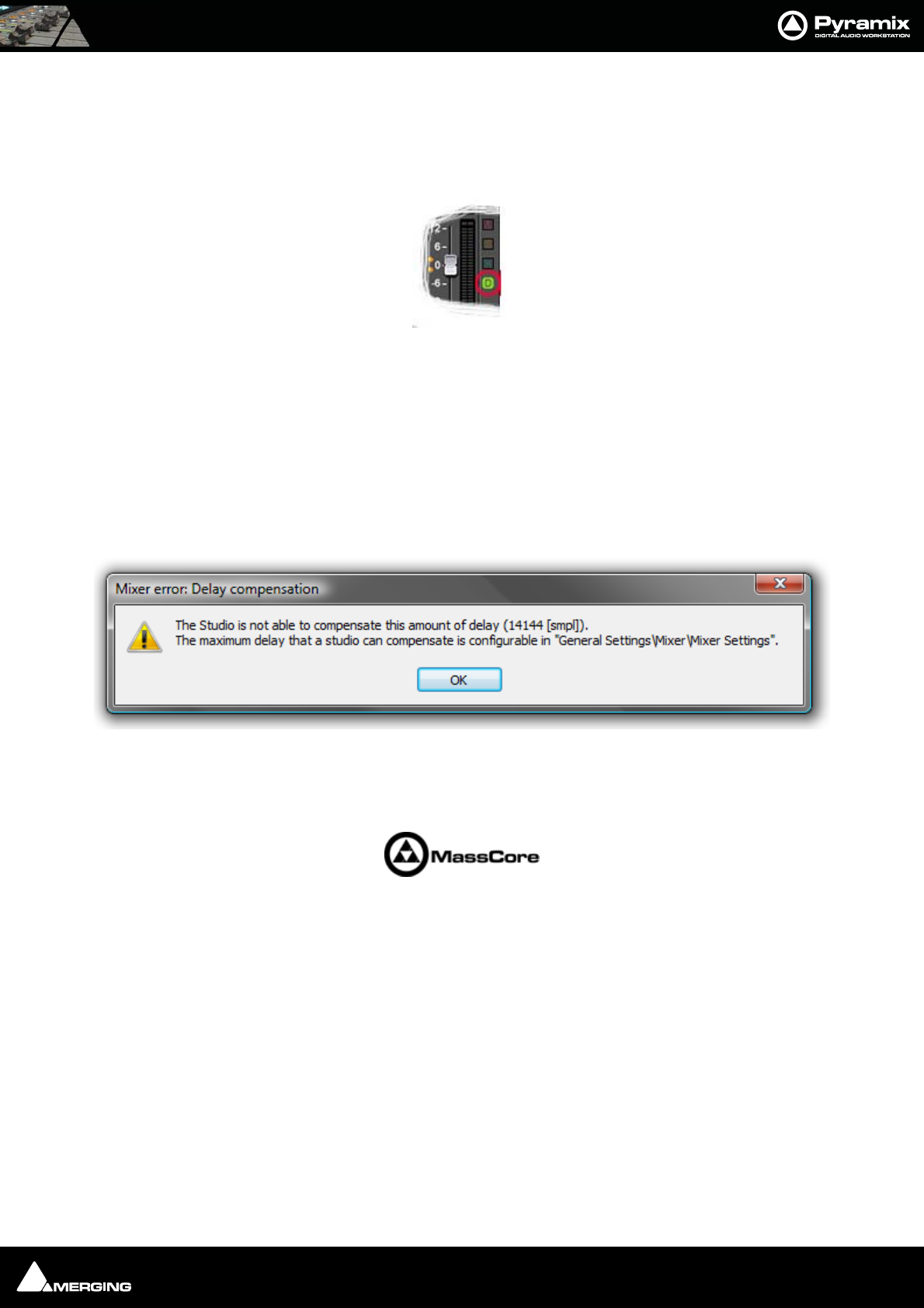
Mixer : Mixer Delay Compensation 10 - 174
Delay Compensation
Delay Compensation Indicator
A small button labeled D on the right-hand side of the mixer adjacent to the Fader line indicates the current state
of delay compensation in the mixer:
A stable green indicates that delays are compensated.
Stable red indicates that delays are not compensated.
Blinking red indicates that you need to adjust the maximum length of delay that can be compensated in order to
achieve proper compensation.
Maximum Delay Compensation
Pyramix sets a default value for the maximum number of samples of delay that can be compensated automati-
cally. As effects are added the required total delay value is calculated. If an Effect is instantiated that will exceed
this limit the Mixer error: Delay compensation dialog appears:
To deal with the problem either remove an effect or effects or go to Settings > All Settings > Project > Mixer >
Mixer Settings and increase the Max Mixer delay Compensation - Delay setting to a value slightly in excess of
that proposed in the dialog.
Note: Increasing the Delay value too much steals valuable memory from MassCore.
Outboard Latency
Typical latency in ms of outboard gear ranges from 2 to 5 ms. The following chart may help you to compute the
proper delay compensation values for outboard equipment:
Mixer : Mixer Delay Compensation 10 - 175
Delay Chart
Time Alignment of Recorded Clips
All recordings from Input Strips designated as Input are automatically time-aligned. E.g. recordings from live
inputs.
Recording Bus Returns
When recording the output of an input strip taking an Aux or Bus return, for example to “freeze” a reverb track, the
recorded media will be placed too early in the Timeline. In this situation it may therefore be desirable to designate
this Aux or Bus return as a normal Input in order to ensure correct time-alignment of the recorded clip.
Note: For Power Users the SABR debug windows show the delay values applied to each
bus / aux node and may prove useful. (Accessible by right-clicking on the Info Bar and
selecting from the Debug sub-menu.)
Delay Compensation Detail
All digital processing takes a finite amount of time. When Internal Return Buses are used to route Master output
buses back into channel inputs (by selecting an Internal Return Bus input from the routing pop-up for the Bus
output, and selecting an Internal Return Bus output as the return channel input) all other buses not so routed
must be delayed if the Mixer is to be ‘time-aligned’ I.e. If a signal is fed to two inputs, the first feeding the Main
Output direct and the second routed back to an input via (say) an Stereo Send bus with the return input strip
routed to the Main Output, then the second will be delayed with respect to the first. Selecting Settings > Enable
Delay Compensation from the mixer context pop-up menu will automatically ensure both signals remain in sync
by delaying the signals directly routed to the Main Output by an amount equivalent to the delay introduced by
the extra processing in the second path.
Note: For obvious reasons a strip fed by an Internal Bus or buses cannot be routed back
to the same internal buses.
Ms samples@4
4.1kHz
samples@4
8kHz
samples@8
8.2kHz
samples@9
6kHz
samples@1
76.4kHz
samples@1
92kHz
samples@3
52.8kHz
144 48 88 96 176 192 352
3132 144 265 288 529 576 1058
5221 240 441 480 882 960 1764
7309 336 617 672 1235 1344 2470
9397 432 794 864 1588 1728 3175
10 441 480 880 960 1764 1920 3528
12 529 576 1058 1152 2117 2304 4234
Max Delay
(Auto PLUS
Manual)
1216 1216 2432 2432 4864 4864 9728
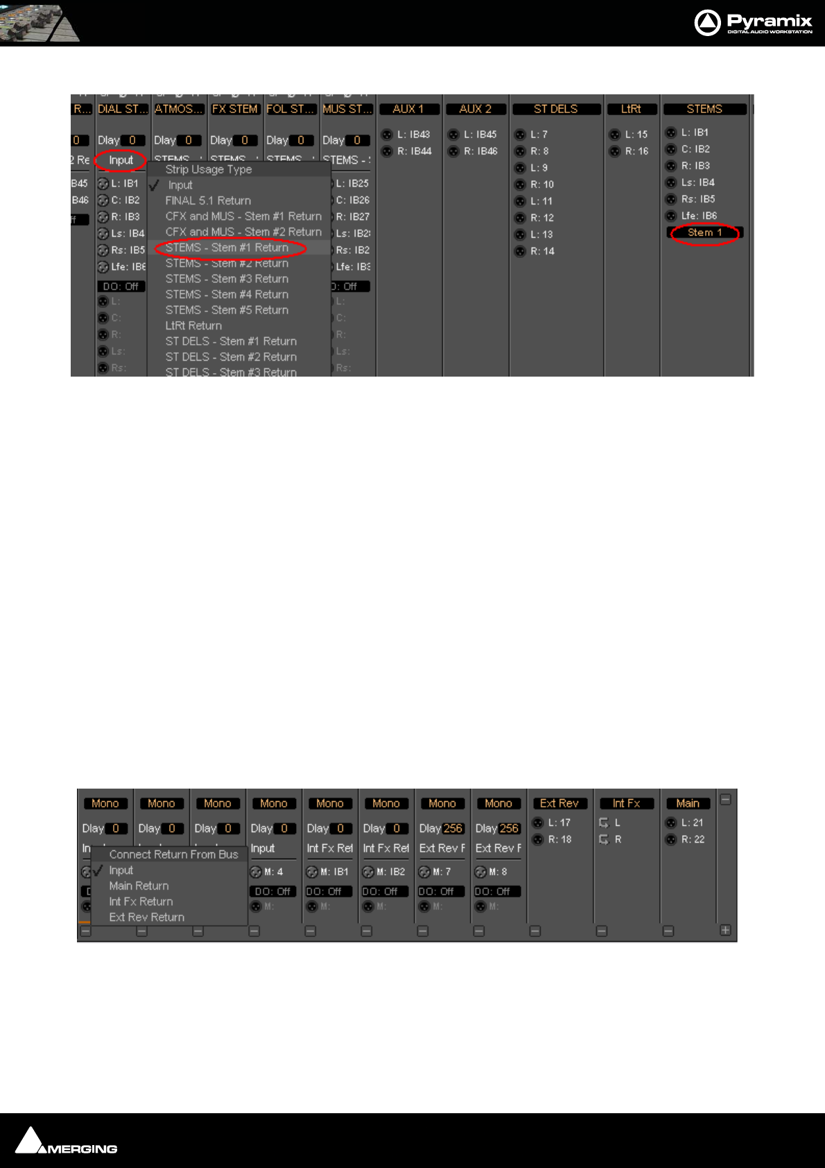
Mixer : Mixer Delay Compensation 10 - 176
Input Strip Mode
In order for Pyramix to correctly calculate the required delay you have to tell it which bus is the source for the
Internal Return Bus. Clicking on Input at the bottom of the strip, above the XLR icon, pops-up a list of all the out-
put buses and Input. Input is the default and means the strip is fed from a physical live input and no delay com-
pensation is required. If any Internal or External Return Bus is ticked and Automatic Delay Compensation is
turned on, Pyramix calculates the required delay and applies it to all Output buses not feeding a return bus.
Note: Since effect inserts on Multi-Stems buses are per Stem, it is necessary to select the
appropriate Stem when returning the output to an input channel or channels. Othewise
Pyramix has no means of determining the correct delay compensation.
Delay vs. Delay Compensation
When the Input Strip Mode is set to Input the delay setting affects the only the delay on the strip’s signal. When
{any Bus name} Return is selected as the Input Strip Mode the delay setting affects the delay on all other output
bus signals to ensure correct time-alignment.
Delay Compensation of External Inputs
Where an Output Bus is used to feed an external processor via a physical output and the external processor output
is fed back into Pyramix via an external live input, then the necessary delay compensation must be computed and
applied by the operator since Pyramix has no means of determining the delay of the external device. However, the
Input Strip Mode (Click on Input to pop-up the menu) should be set to the bus feeding the external processor (as
above) so that the input channel delay setting affects delay compensation rather than simply delaying the signal
through the input strip.
In the illustration, Group Bus Ext Rev feeds an external device via physical outputs 17 & 18. The outputs of the
external device are connected to physical inputs 7 & 8. The channels’ Mode has been set to Ext Rev Return and
delay compensation of 256 samples applied.
In contrast Int FX SubGroup bus has VS3 and VST plug-ins inserted in the strip and feeds the output buses
directly. There is, of course, no reason why an external insert cannot be used in a SubGroup instead of using an
Output bus for this purpose.
Input Type pop-up
Input Type pop-up
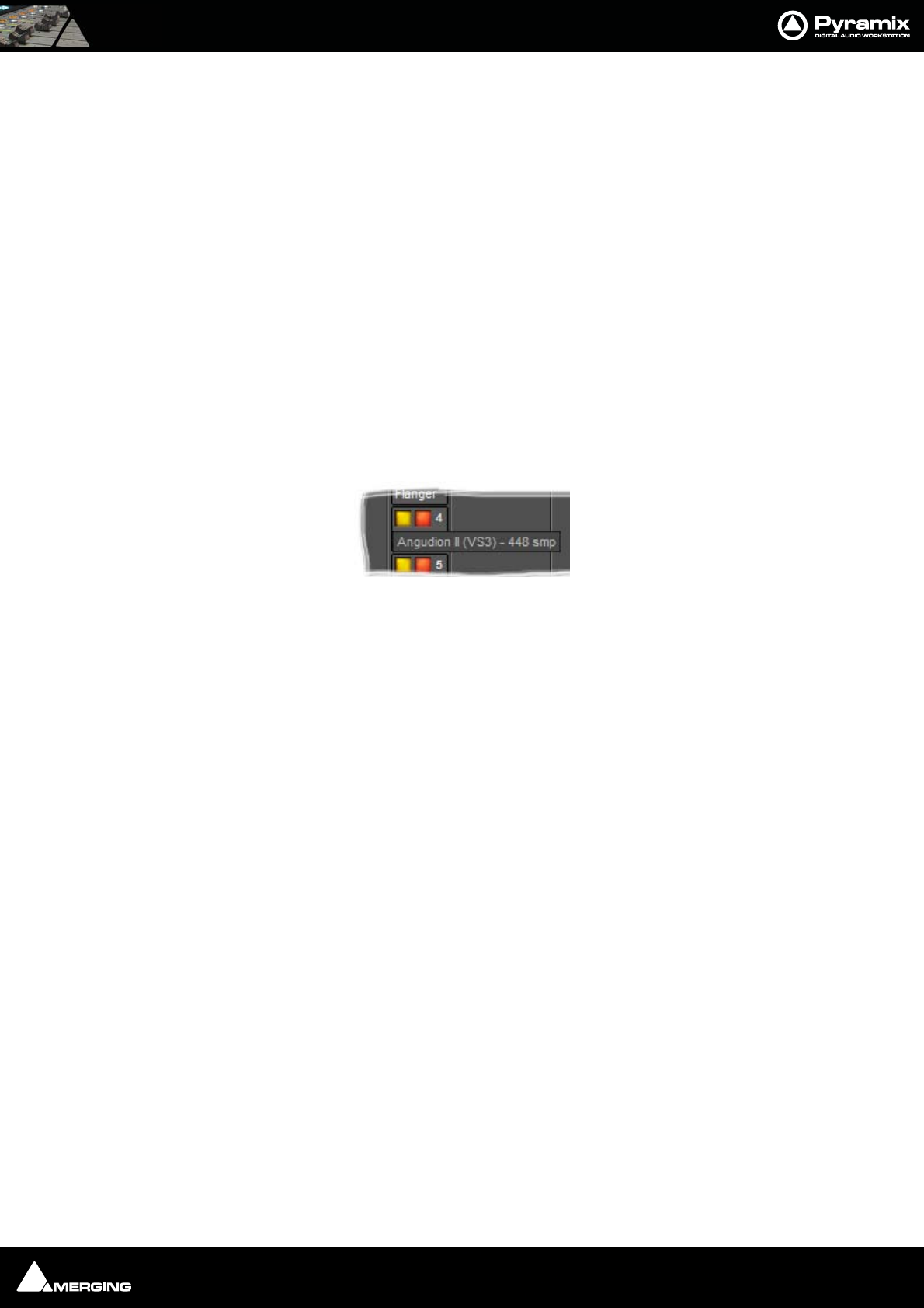
Mixer : Configuring a Blank or Existing Mixer 10 - 177
External Insert Plug-ins
Internal VS3 Engine latency is automatically compensated except for the daughter card I/O latency (for example a
Send/Return on AES/EBU takes 6 samples). Thus you have to manually set the delay of the external unit plus the I/
O latency. It is not possible to change the delay or change the bypass status during playback or recording.
Determining Delay Compensation for External Effects Loops
One strategy for achieving this is to route a signal directly to an Output Bus and, via a physical output from a sec-
ond Output Bus, to the external processor’s input. The processor’s output is connected to a physical Pyramix input
and routed to an input strip. The strip mode must be set to the Bus used as the source. Then you can use impulse
sounds, clicks, rimshots etc. to aid manual adjustment of the delay compensation by comparing the direct sound
with the sound returning from the external processor.
Determining Delay Compensation for External Insert Plug-ins
A similar strategy can be employed here. Route the signal you wish to treat with an External Insert Plug-in to two
input strips. Add the External Insert in one strip only, complete with the external processor in circuit. Delay the
untreated strip until the audio is in sync with the treated audio and note the delay value. Then apply this value in
the Ext. Unit Delay field in the External Insert window.
Effects Delay Indication
When the mouse cursor is hovered over a plug-in in a strip the required delay value is displayed:
Here you can see that Angudion II currently requires a 448 sample delay to be applied to the other output buses.
This will be applied automatically when Full Delay Compensation is switched on.
Configuring a Blank or Existing Mixer
Configuration of the mixer control surface is accomplished via the Configure Page, Route Page (Please
see: Configure Page on page 143 and Route Page on page 151) or contextual menus. The precise options
available will depend on where you click on the mixer. If you wish to affect the entire mixer, right-click on the top
bar of the Mixer window. To change options for a Bus, right-click on a blank area of the Bus strip. Similarly, for a
channel input strip, right click on a blank area of the Strip. Right-clicking within a function block adds menu
entries to the top of the list, relevant to the specific block.
Adding Strips
Right-click anywhere on the Faders, choose Strip > Add and select the appropriate type of strip to add or right-
click anywhere on the Faders, choose Bus > Add and select the appropriate type of bus to add.
Removing Strips
To remove a given input strip, bus or group, right-click directly on it and choose Strip > Remove (Strip, Bus or
Group) as appropriate.
Plug-in Name and Delay pop-up
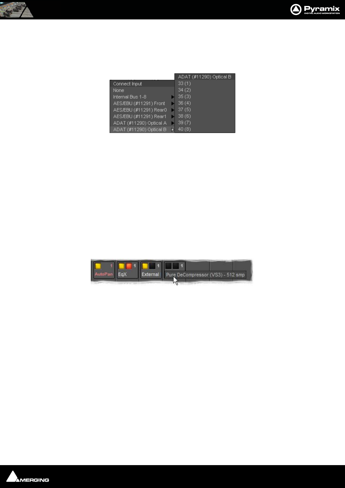
Mixer : Configuring a Blank or Existing Mixer 10 - 178
Mixer I/O Assignments
To or from physical I/O
To change I/O assignments to or from physical I/O or the Internal Return Buses, click on the appropriate XLR
icon. Choose Connect Input or Connect Output from the pop-up menu and choose the desired connection.
When connecting a multichannel strip clicking on the header (ADAT(#11290) Optical B in the above illustration)
will connect all channels consecutively.
From tracks
Note that several tracks may be routed to the same mixer input strip. Tracks are assigned to mixer input strips
either automatically or manually from the Track Header. See: Track Header Panel on page 73
Effects and Plug-ins
Please see also: Effects and Plug-Ins on page 217
Mixer Strip Controls
When Native VS3 Effects, VST Plug-ins and External Inserts are instantiated in mixer strips each instance has a
block of one or two buttons. The full Effect name, Plug-in name or External Insert pops-up along with the
required delay compensation when you hover the mouse pointer over each block:
Buttons
Each block has one or two buttons. The left-hand, yellow button is lit when the effect or insert is switched on.
Switching an effect or insert off removes it from the signal chain and this may well be audible.The right-hand, red
button indicates that the effect is bypassed when lit. Bypassing an effect retains the same delay as when the
effect is active. Further, well behaved effects will continue to calculate internal parameters when bypassed making
seamless switching possible.
When Full Delay Compensation is selected, Effects and Plug-ins that correctly report their latency will have their
delay compensated. This delay is maintained when the Effect or Plug-In is in bypass mode.
Please see also Mixer Delay Compensation on page 173
I/O assignment pop-up
Mixer Strip Plug-in Controls with Name and Delay pop-up
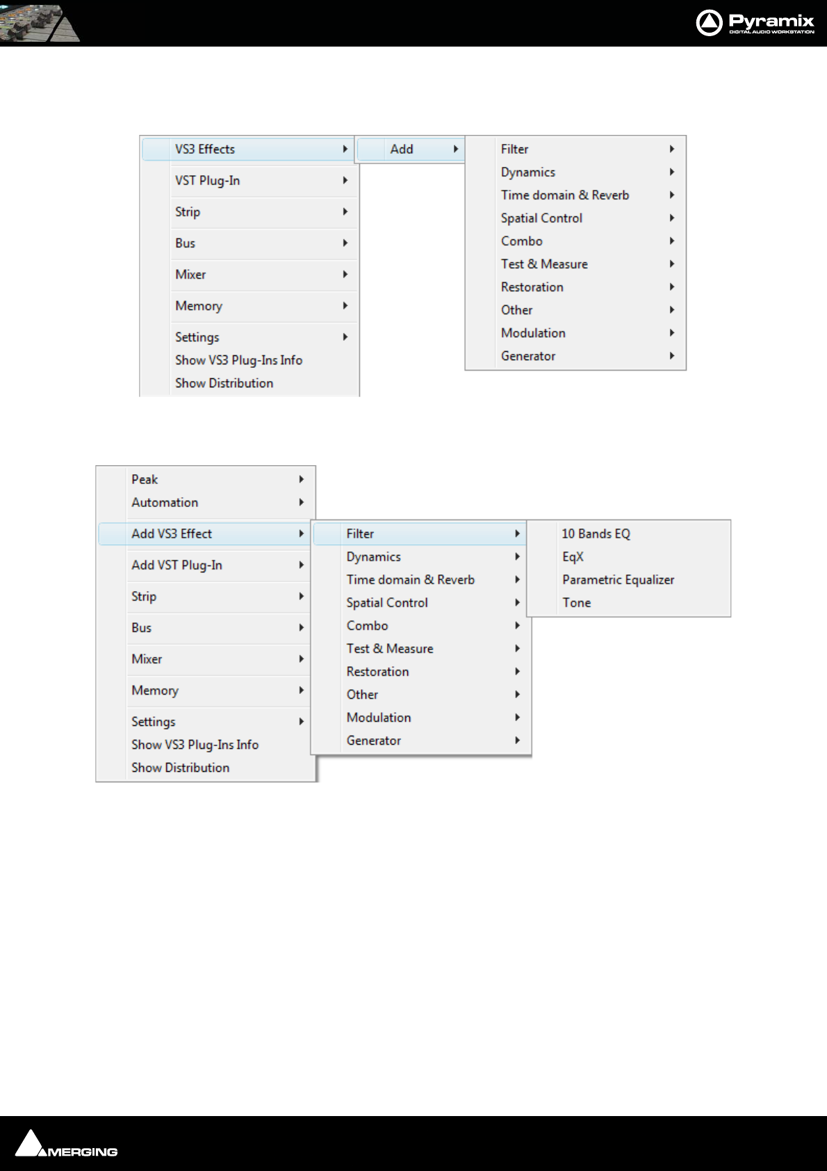
Mixer : Configuring a Blank or Existing Mixer 10 - 179
Native VS3 Plug-ins
These include the eq and dynamics found on a conventional hardware mixer’s channel strip. To add a native plug-
in when in Mix ! mode, right-click with the mouse cursor over the strip where the plug-in is to be added.
If you right-clicked in the effects area of the strip select VS3 Effects > Add.
If you clicked somewhere else, select Add VS3 Effect. Select an effect from the sub-menu. It will appear in the
strip.
VST Plug-ins
To add a VST plug-in the procedure is the same except select VST Plug-In or Add VST Plug-In.
Note: VST Plug-ins can be added at any time, even during playback, without rebuilding
the mixer.
Mixer Strip Context Menu
Mixer Strip Context Menu
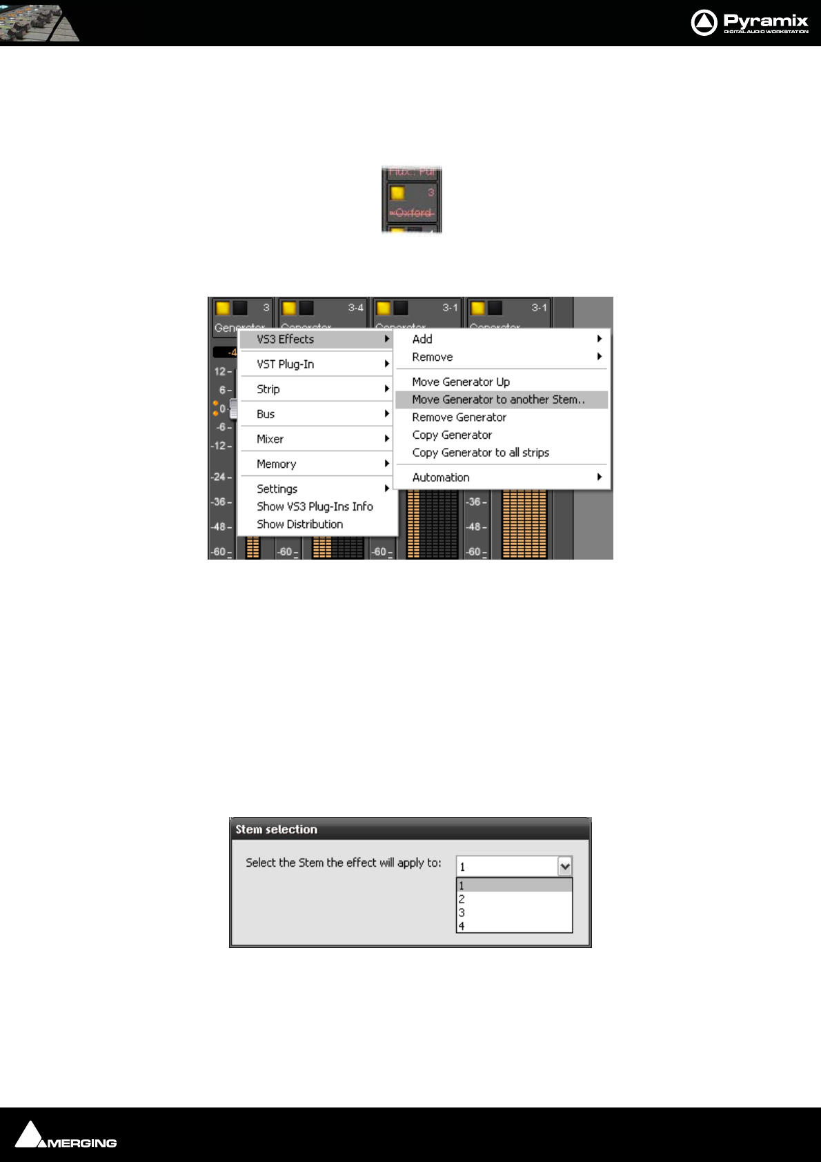
Mixer : Configuring a Blank or Existing Mixer 10 - 180
Ghost Effects and Plug-ins
Essentially, Ghost Effects or Plug-ins mean that if you load a project containing an effect or plug-in which is
unavailable on your machine, this plug-in will appear in the mixer strip as a Ghost plug-in. Subsequently saving
the project will not trash the missing Plug-in’s state information. When a plug-in is a Ghost its name appears
crossed out in the mixer :
Removing, Copying or Moving VS3 Effects and VST Plug-Ins
VS3
Right-click on an Effect in a Strip to open the context menu and hover the cursor over VS3 Effects. Here you can
make a number of changes to the Effects
Add Accesses the Effects list to add a further Effect to the Strip
Remove Accesses a list of all effects currently instantiated in the strip. You can select any of
them for removal.
Move “Effect Name” Up Moves the effect you right-clicked on Up the list.
Move “Effect Name” Down Moves the effect you right-clicked on Down the list.
Note: The Up and Down options are only shown when a move is possible.
Move “Effect Name” to another Stem
Pops up a dialog with all available stems for this bus. (Only present when the Effect
is in a Multi-Stem Bus) The Iteration and Stem numbers are then shown on the
VST Ghost Plug-in
Mixer Strip Context Menu
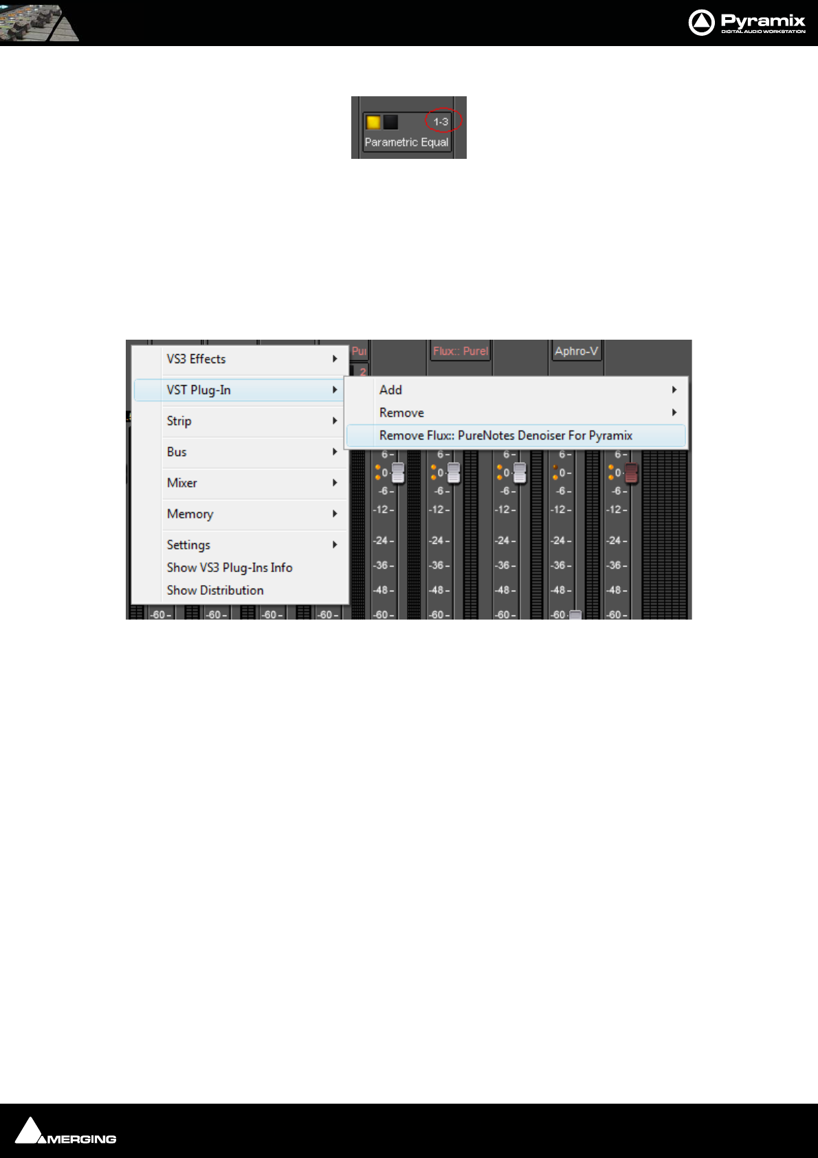
Mixer : Configuring a Blank or Existing Mixer 10 - 181
Effect:
Thus 1-3 means Iteration 1 on Stem 3
Remove “Effect Name” Removes the Effect you right-clicked on.
Copy Copies the effect for pasting into another Strip (Copy the Effect then right-click in
the target Strip and select Paste)
Copy “Effect Name” to all strips Copies the Effect you right-clicked on to all Input Strips, but not to any Buses,
regardless of whether the original effect is instantiated in an Input Strip or Bus
Automation Enables the Automation mode to be set for the entire Effect.
VST
As the image above shows, the options are simpler for VST Plug-Ins
Add Accesses the Plug-Ins list to add a further Plug-In to the Strip
Remove Accesses a list of all Plug-Ins currently instantiated in the strip. You can select any
of them for removal.
Remove “Effect Name” Removes the Plug-In you right-clicked on.
Mixer Strip Context Menu
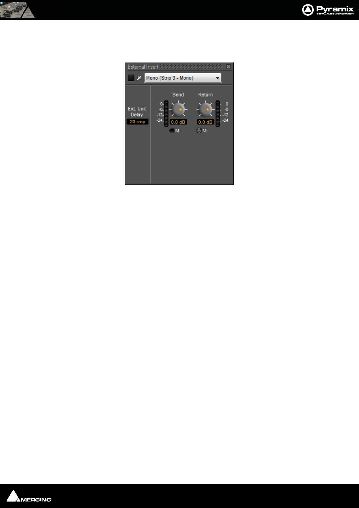
Mixer : Configuring a Blank or Existing Mixer 10 - 182
External Insert
To add an External Insert simply right-click over the strip where the plug-in is to be added and choose: VS3 Effects
> Add > Other > External Insert
Clicking on the External Input name in the strip opens the External Insert Control Window.
Send and Return Connections can be made by clicking on the XLR icons and levels set with the knobs. When you
have determined the delay introduced by the I/O loop including the external effect the value in samples should be
entered in the Ext. Unit Delay field.
Mixer Strip External Insert Plug-in Control Window
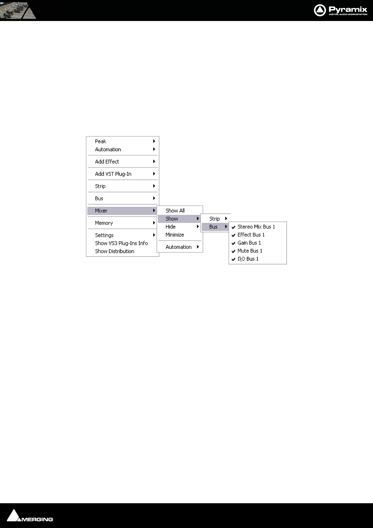
Mixer : Configuring a Blank or Existing Mixer 10 - 183
Further Mixer Configuration Options
Mixer Context Pop-up menu
The entries on this menu vary according to where you right-click on the mixer surface. At the top of the menu the
entries concern the specific mixer component under the mouse cursor when you right click. The next section of
the menu has entries which affect the Strip. Entries from Mixer to the end of the menu affect the entire mixer and
are available wherever the mouse is right-clicked.
Mixer > Show
Show All Makes all input strips and buses visible
Show / Hide > Selects Strips and Buses to be shown or hidden. When checked, the Buses or
strips are visible on the console surface. Both Show and Hide access the same lists.
Minimize When checked, Mixer window is minimized
Automation >
Isolate These menu choices toggle the Automation mode for the entire
Play mixer. Please see: Dynamic Automation Modes on page 260
Record
Auto-write
Memory > The choices here enable mixer presets to be saved loaded and managed.
Please see: Mixer Presets on page 185
Settings >
General... Opens the Mixer Settings window at the All Settings > Hardware > Hardware >
Formats & Sync page. Please see: Formats and Sync on page 480
Enable Delay Compensation Enables Delay Compensation for the mixer
Dithering Opens the Dithering window. Please see: below and Dither on page 288 for an
explanation of the need for dither
Remove Select All Strips, All Buses or All to remove groups of mixer components or every
component.
Auto-connect Automatically connects the Mixer inputs and outputs using the available inputs and
outputs of the installed daughter card (s) and the Mixers Preferred Monitoring Outputs
Wizard... Launches the Configuration Wizard. Please see: Mixer Configuration Wizard on
page 171
Show VS3 Plug-Ins Info Pops up the VS3 Plug-Ins Information window. Please see: VS3 Plug-Ins Information
on page 219
Mixer Show / Hide pop-up
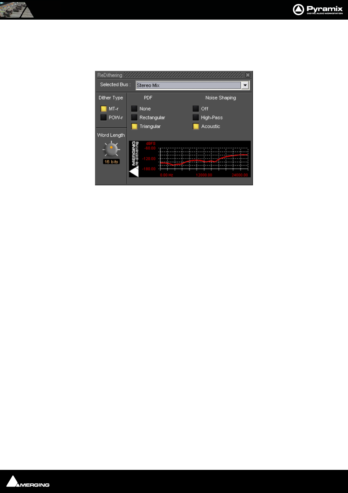
Mixer : Dithering Options 10 - 184
Show Distribution When checked, a narrow colored bar is inserted at the bottom of each input strip which
indicates which card (in a multi-board system) is providing the DSP for the strip.
Dithering Options
To open the ReDithering window, right-click anywhere on the mixer surface and select Settings > Dithering...
The Dithering window opens.
Selected Bus :
The combo box allows the choice of any of the Mixer’s buses.
Dither Type
The Pyramix Mixer offers a choice of dither algorithms. MT-r and POW-r click the box to choose. The bottom-right
hand panel changes to reflect the options available with the selected dither process.
Word Length
The output word length of the digital audio data can be varied from 8 bits to 24 bits. Click on the rotary knob and
drag left and right to adjust the value.
MT-r Options
PDF (Probability Density Function)
In basic terms, the addition of a dither signal (noise) into the digital audio streams improves linearity in the repro-
duction of low-level signals. In other words, as signal level drops (such as in a fade out) dithering helps to maintain
a smooth decay. There are three options:
None
No dither signal will be added to the data.
Rectangular
A rectangle shape dither signal will be added to the data.
Triangular
A triangle shape dither signal will be added to the data.
Noise Shaping
Noise shaping is a technique that is used to push quantization noise energy, which in linear digital systems is nor-
mally spread over the whole audio spectrum (0 Hz up to half the sampling frequency), into higher frequencies
where the human ear is less sensitive to its effects. There are three noise shaping options and the graph shows the
curve applied:
Dithering MT-r floating Window
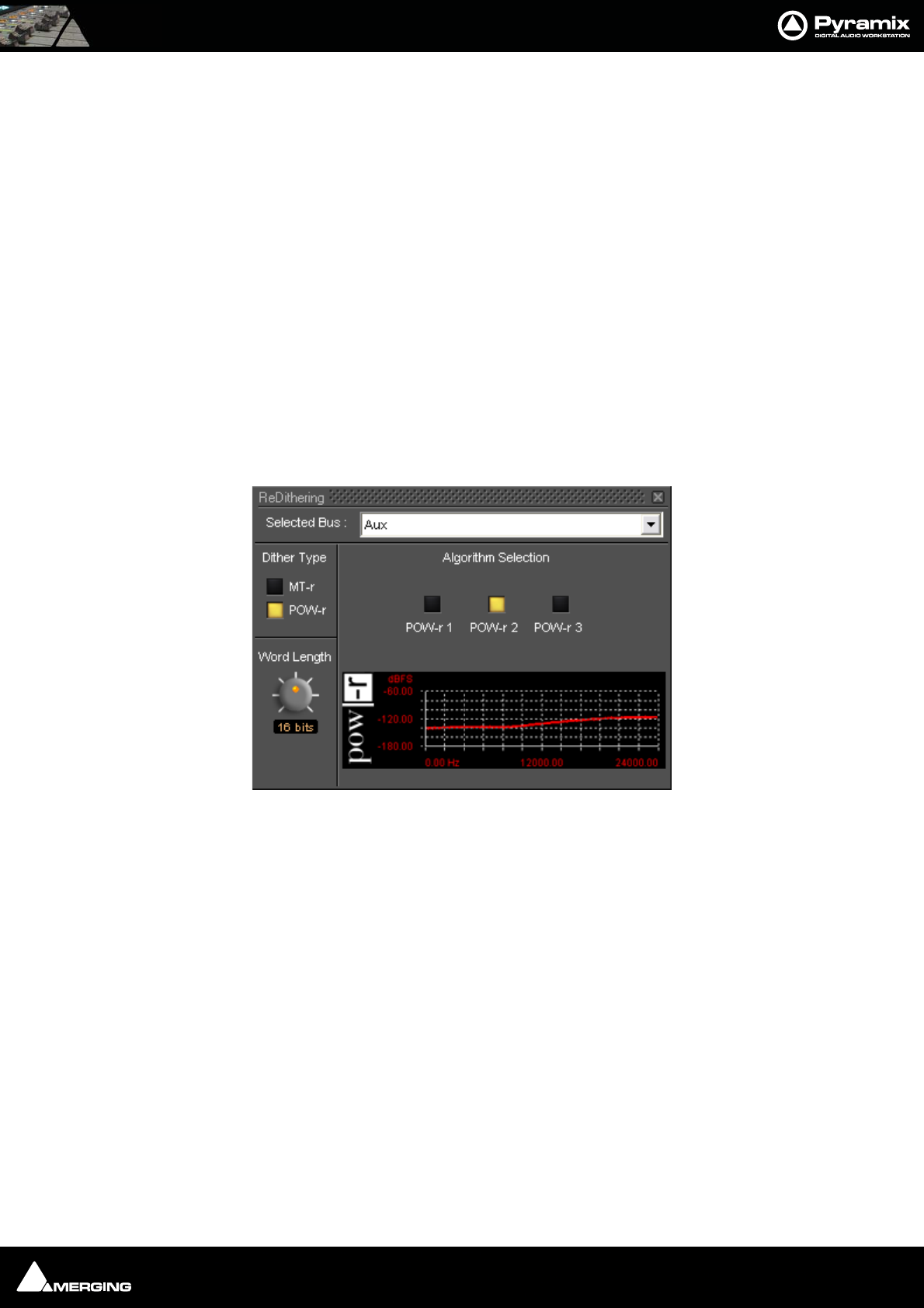
Mixer : Mixer Presets 10 - 185
Off
No noise shaping added.
Hi Pass
This provides a first-order high-pass filter for the noise transfer function. This type of noise shaping takes little
computational power to produce, but at the expense of not tracking the characteristics of the human ear very
accurately when compared with:
Acoustic
Psycho acoustically noise shaped dither inserts an FIR-filter in the feedback path. This shapes the noise as closely
as possible to the characteristics of the human ear. More taps in this type of filter allow a closer approximation to
the response curve of the ear, but each tap, of course, increases the computational instructions required. The filter
implemented here is a 9-tap FIR-filter, which closely approximates the curve of the human ear.
Note: As usual there is no “free lunch”. So Acoustic noise-shaping uses more resources
than Hi Pass.
POW-r
POW-r offers the choice of three settings, POW-r 1, POW-r 2 and POW-r 3. The graph indicates the effect of the
noise-shaping.
Mixer Presets
Mixer Presets can be saved in a user folder or added to the main Mixer Preset list either for the current user or all
users.
Default Mixer
To Save the current Mixer setup as the default Mixer, right click on the Mixing Console and select Memory > Pre-
sets > Store > Default.
Storing New Mixer Presets
To add a preset to the main list of available Mixer presets I.e. the list which appears when starting a new project,
right click on the Mixing Console, select Memory > Presets > Store > New… and enter a name for your Mixer Pre-
set. If the Global check box is checked then the preset will be available for any user logged on the current
machine, if not the preset will be available only for the user that created the new preset.
Removing Mixer Presets
To remove a preset from the main list, right-click on the Mixing Console, select Memory > Presets > Remove >
(preset you wish to remove). The Remove Preset dialog box appears with OK and Cancel options.
Dithering POW-r floating Window
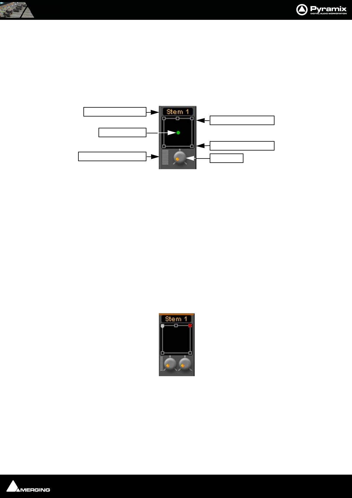
Mixer : Mixer Surround Components 10 - 186
Saving / Loading Mixer Presets
Mixer Presets can also be stored in Windows folders. Right-click on the Mixing Console, select Memory > Save. A
Windows Explorer window opens enabling the current Mixer Preset to be named and saved to any Windows
folder. Similarly, selecting Memory > Load enables a Mixer Preset to be loaded from any Windows folder.
Mixer Surround Components
When a Surround Bus is added to the mixer an surround panner appears at the top on the Input Strips
Speaker Controls
Double-clicking on any of the Speaker Controls toggles the mute on/off of the selected surround channel (also
muting any audio routed to that surround channel output). When a channel control is muted, it is no longer dis-
played on the Mixer Input Strip.
Joystick Panner
Determines the position of the source within the surround sound space. To position it, simply left-click on the con-
trol and move it to the desired location. Double-clicking on this control will automatically center it.
LFE Level
Determines the level sent to the LFE (.1) output.
Surround Stem select
If a Multiple Surround Bus has been added to the mixer Stem ‘X’ appears at the top of the strip. Click on the box to
select the stem you wish to route the strip to.
Stereo Input Strips.
The Surround Sound Panner Position control behaves slightly differently in a Stereo Input Strip. Notice there are
now two independent position controls and two independent LFE sends. One for each input channel.
Open Surround Control
The Surround Control window offers far more information and a greater degree of control over all the surround
panning parameters than could be shown on an individual Input strip. It can be opened and closed by clicking on
the appropriate area on the strip, from View > Windows / Tools > Surround Panner or the icon in the View Tool-
bar when an input strip with a Surround Panner is selected.
LFE Level
Joystick Panner
Surround Stem Select
Open Surround Control
Front Speaker controls
Rear Speaker controls
Strip Surround controls
Stereo strip surround controls
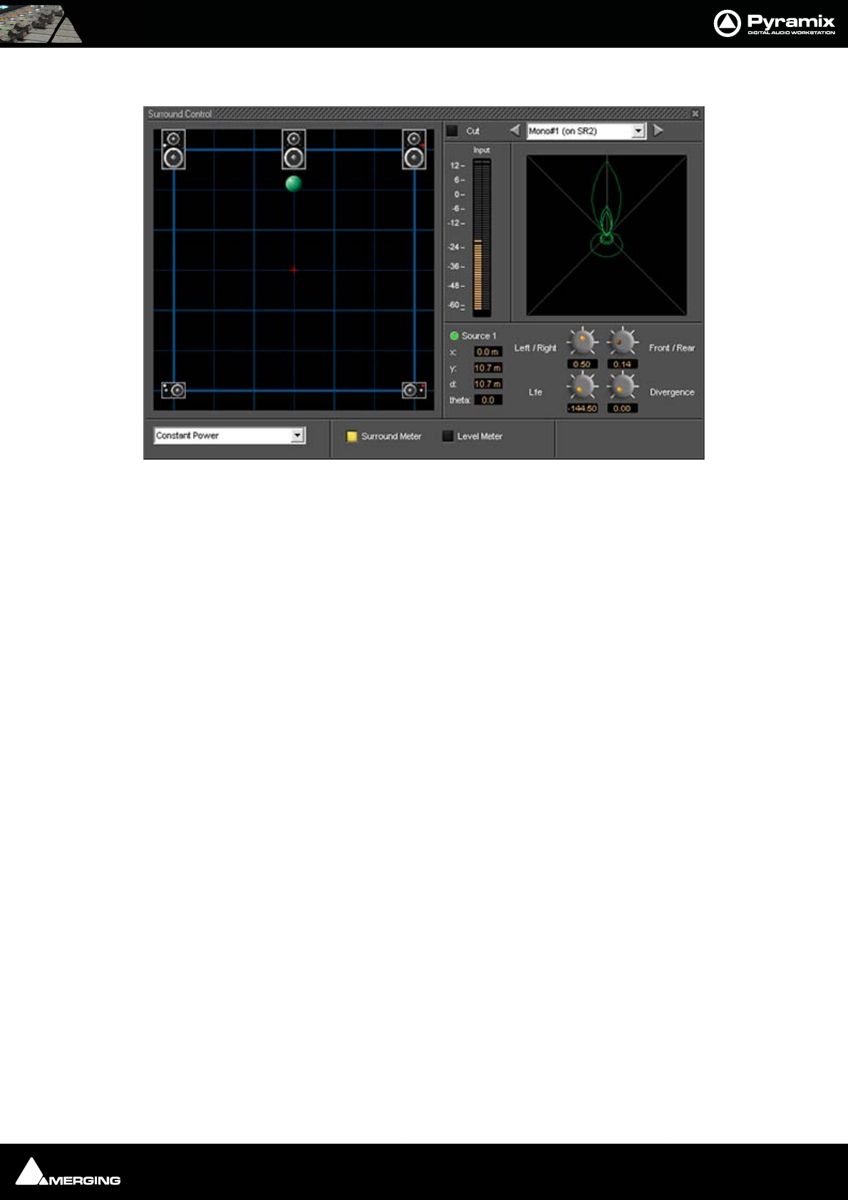
Mixer : Mixer Surround Components 10 - 187
Surround Control window
Options available will depend on whether the Mixer Channel is single source (mono) or 2 sources (stereo)
.Position/Speaker Control
When a single source is used, the Position Control is displayed as a green dot on a grid with 5 speaker icons. Each
speaker icon represents a Surround Speaker Position (L, C, R, SL, SR). The position of the Green Dot determines the
position of the source within the surround sound space. To position it, simply left-click anywhere within the sur-
round sound space. To position it, simply left-click on the control and move it to the desired location or use the
knobs. Double-clicking on the Green Dot automatically centers it.
Surround Panning Algorithm
The drop down list gives a choice of panning algorithms.
Constant Gain
Allows the surround panning to preserve a constant gain sum on all speakers wherever the Position Control is
placed.
Constant Power
Allows the surround panning to preserve a constant power sum on all speakers wherever the Position Control is
placed.
Surround Control floating Win-
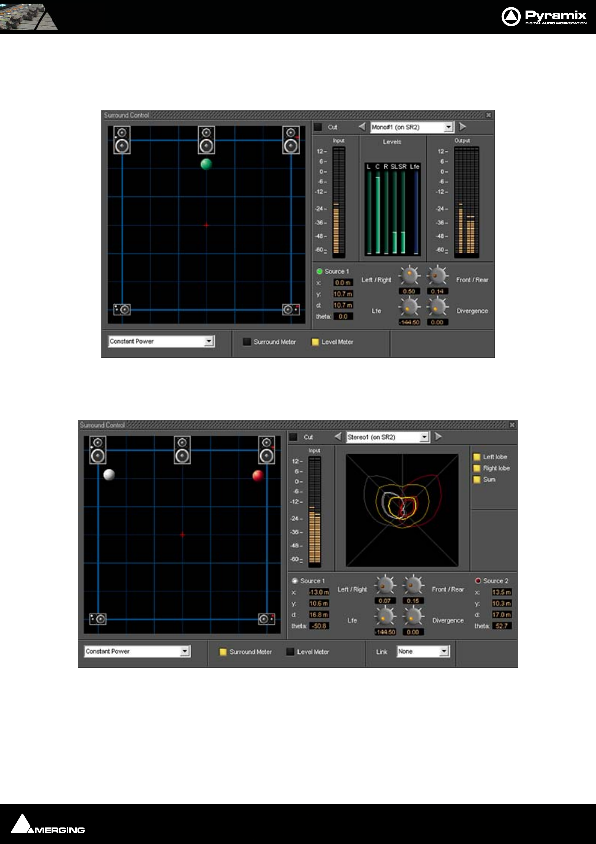
Mixer : Mixer Surround Components 10 - 188
Level Meter
Toggles the main display between the Surround Meter and Level Meter. This shows the send Levels to each sur-
round channel in the middle of the right-hand section and Output meters on the right:
Stereo Surround Control
Surround Meter
The Display can show static Left, Right and Summed Lobes in white, red and yellow, respectively when the buttons
are lit with the actual signal in bright red.
Surround Control floating Win-
Surround Control floating Win-
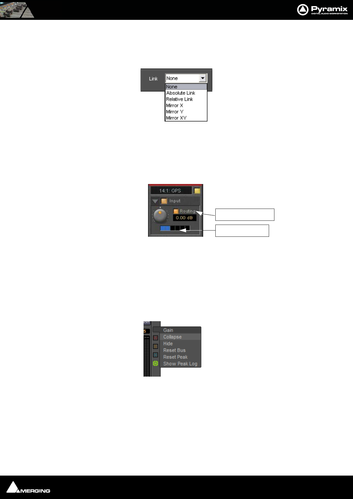
Mixer : Peak Logger 10 - 189
Link
Click and drag on the red and white balls is independent and the controls are switched between Source 1 and
Source 2 by clicking on the buttons. If a Link option is chosen from the combo box click and drag and the controls
will affect both sources depending on the chosen linking.
Strip and Bus Tools
In a multi-channel strip the clicking the show/hide Routing button displays the channel routing buttons. There
are as many routing buttons as there are channels in the strip. Strip and Bus Tools affect all channels whose rout-
ing buttons are lit blue. In Mono and Stereo strips the routing buttons are on by default. In GPS strips only chan-
nels 1 & 2 have their routing buttons on by default.
If more than one instance of Strip or Bus Tools is used in the strip this allows, for example, different settings to be
applied to Front L-R and Rear L-R.
Peak Logger
The Pyramix Mixer is equipped with a Peak Logger. This has obvious applications in Mastering.
Click on the Gain Pop-up to access the Gain options:
Surround Control Link combo box
Show/Hide Routing
Routing Buttons
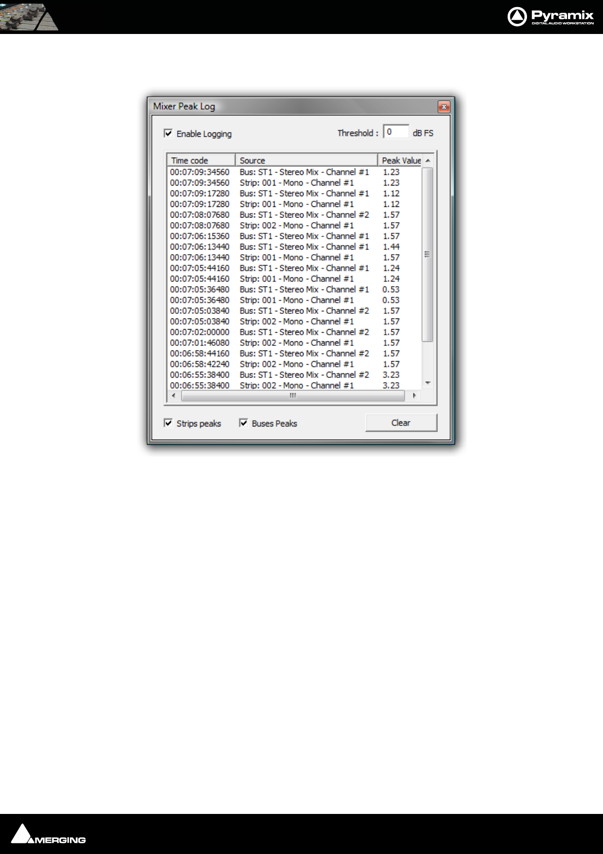
Mixer : Peak Logger 10 - 190
Mixer Peak Log Window
Click on Show Peak Log to open the Mixer Peak Log Window:
Enable Logging
Tick the box to enable Peak Logging
Threshold
Type a value here to determine the level above which peaks will be logged. Hit Enter on the keyboard to validate
the change.
Strips Peaks
Tick the box to record Strips Peaks
Buses Peaks
Tick the box to record Bus Peaks
Note: Both Strip and Bus Peaks can be recorded simultaneously.
Clear
Clicking on the Clear button erases all the recorded values since the last time it was pressed. (Or since Logging
was enabled.)
Mixer Peak Log Window
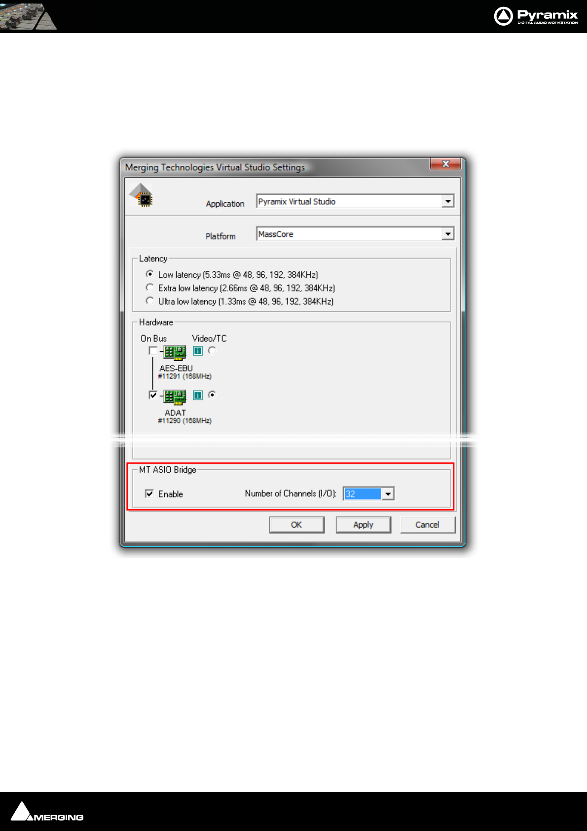
Mixer : MT ASIO Bridge 10 - 191
MT ASIO Bridge
Pyramix can merge an ASIO enabled application’s output into the MassCore engine and I/O and send audio to an
ASIO application.
The MT ASIO Bridge option must first be enabled in the VS3 Control Panel (to a maximum of 96 channels with the
extended Native Version) Pyramix must first be closed (if open) before the VS3 Control Panel is launched.
Once the MT ASIO Bridge option is enabled in the VS3 Control Panel new sources and destinations will show up in
the Input and Output drop-down lists just like any other source and destination.
Note: The number of ASIO Bridge channels available is, in part, determined by the
amount of physical memory in the machine. Please see: Memory on page 31
VS3 Control Panel

USER MANUAL
www.merging.com/Pyramix
Monitor
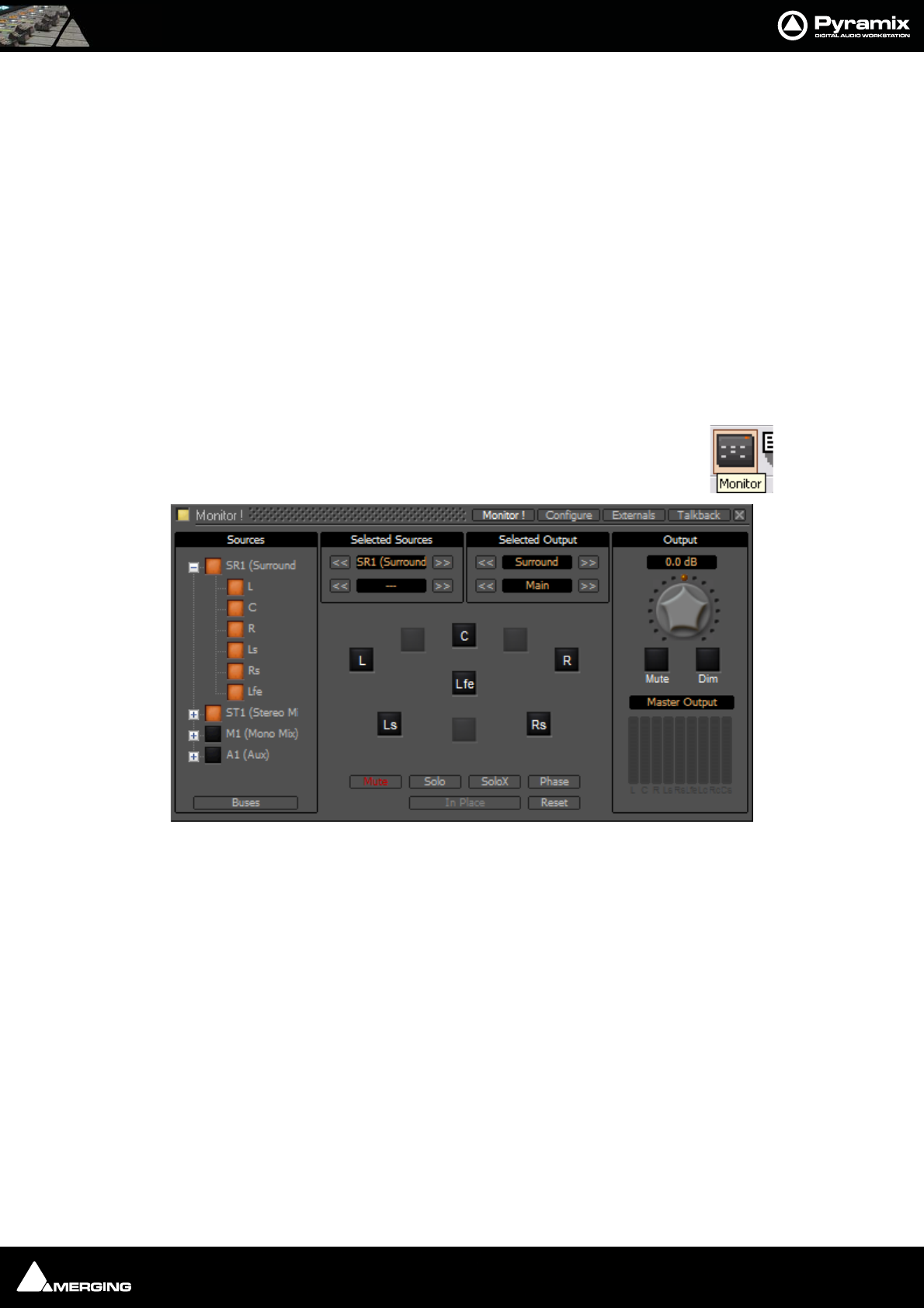
Monitor : Monitor ! Window 11 - 193
Monitor ! Window
Scope
Pyramix has a dedicated Monitor section. This extremely powerful tool offers comprehensive monitoring facilities
including summing and downmixing for all supported formats. External Machine Inputs, comprehesive Talkback,
Foldback and External Metering are also supported depending on your system specification.
The Monitor presents monitor outputs of all buses present in the current Mixer as sources. It is also possible to
configure external sources both for recorder returns and for talkback. Sources can be summed for monitoring
without affecting the Mixer bus outputs. This is useful, for example, when you need to listen to a guide track while
recording.
You do not have to use the Monitor and disabling it will save DSP power but, with complex Mixers and routing,
the Monitor helps to keep things logical.
The monitor is also used to output the audio signal from the audition function of the Media Manager and Libraries
as an unformatted input. (I.e. Routed to LRC in a Surround 5.1 Speaker Set and to LR in a Stereo one)
By default the Monitor window is hidden. It can be opened with View > Monitor or the icon in the
View Toolbar.
The Monitor has four pages: a Main Monitor ! page in normal operation, a Configure page for setting up and two
further pages for configuring Externals (machines) and Talkback.
Monitor ! page
The Monitor ! window is divided vertically into three sections.
Sources, left-hand section:
The button top-left of the title bar enables/disables the Monitor and lights yellow when enabled. This allows DSP
power to be saved when comprehensive monitoring control is not required. Below the Enable Monitoring but-
ton is a tree view of all buses used in the mixer. Clicking on the + and - boxes shows and hides branches in the
usual way. Click on any complete bus or any available stem or any bus/stem channel to select it for monitoring.
Selection is exclusive unless the Ctrl key held is down. Then selection is cumulative and clicking adds or subtracts
Sources according to their current state.
Monitor Main Monitor ! Window

Monitor : Monitor ! page 11 - 194
Buses / Externals button
Note: At bottom left in the screenshot above the button labelled Buses indicates which
sources are available for activation. Clicking on this button toggles through Buses,
Externals and Buses / Externals
Main, centre section:
Selected Sources
<< SR1 >>: Select previous/next Pyramix source. Only sources visible in the Sources section are available. I.e.
If the component channels of a bus or stem are collapsed this bus or stem is switched as a unit when the compo-
nent channels are visible in the Sources section then clicking on the << or >> buttons steps through each avail-
able channel in turn.
<< DA-88 >>: Select previous/next External Source. Only External Sources visible in the Sources section are
available.
Note: Clicking on any of the << or >> buttons cancels the selection made previously in
the Sources section.
Selected Output
<< Surround 5.1 >>: Select previous/next Speaker Set.
<< Main >>: Select the previous/next Downmix defined in the Configure page.
Main area
Speakers are inactive (grayed) if they are not connected in the Configure page.
The Mode buttons at the bottom determine the function of the active Speaker buttons.
Mute: Clicking on a speaker mutes it. Selections are cumulative.
Solo: Clicking on a speaker solos it. Selections are cumulative.
SoloX: Solo eXclusive on the clicked speaker. Selections toggle.
Phase: Clicking on a speaker reverses its phase. Selections are cumulative. Useful for quick imaging checks.
In Place Works in conjunction with Solo and SoloX. Toggles between In Place and Center.
Reset: Deselect all speakers.
In Place/Center: In Solo and SoloX, toggles between In Place and Center. Center routes the soloed channel(s) to
the Center speaker or equally to the L/R speakers if no center speaker is present. In Place mode is the normal Solo,
SoloX mode.
Output, right-hand area
Monitor Level box Displays the current output level. Output level can be entered numerically in the box after
clicking on it.
Volume Knob: sets all the output gains in a range from -144.5dB to +24dB. Double-click to set it to 0dB.
Note: Maximum permissible volume can be set in the Configure page.
Mute: button mute the outputs.
Dim: button reduces the output level by an amount set in the Configure page. Default value is -20dB.
Below these buttons is the
Peak Meter Selection: Indicator/Button. This indicates what the Peak Meter display below the button is looking
at. (The selection also affects External Metering if you are using it) Clicking on the button drops down a list of
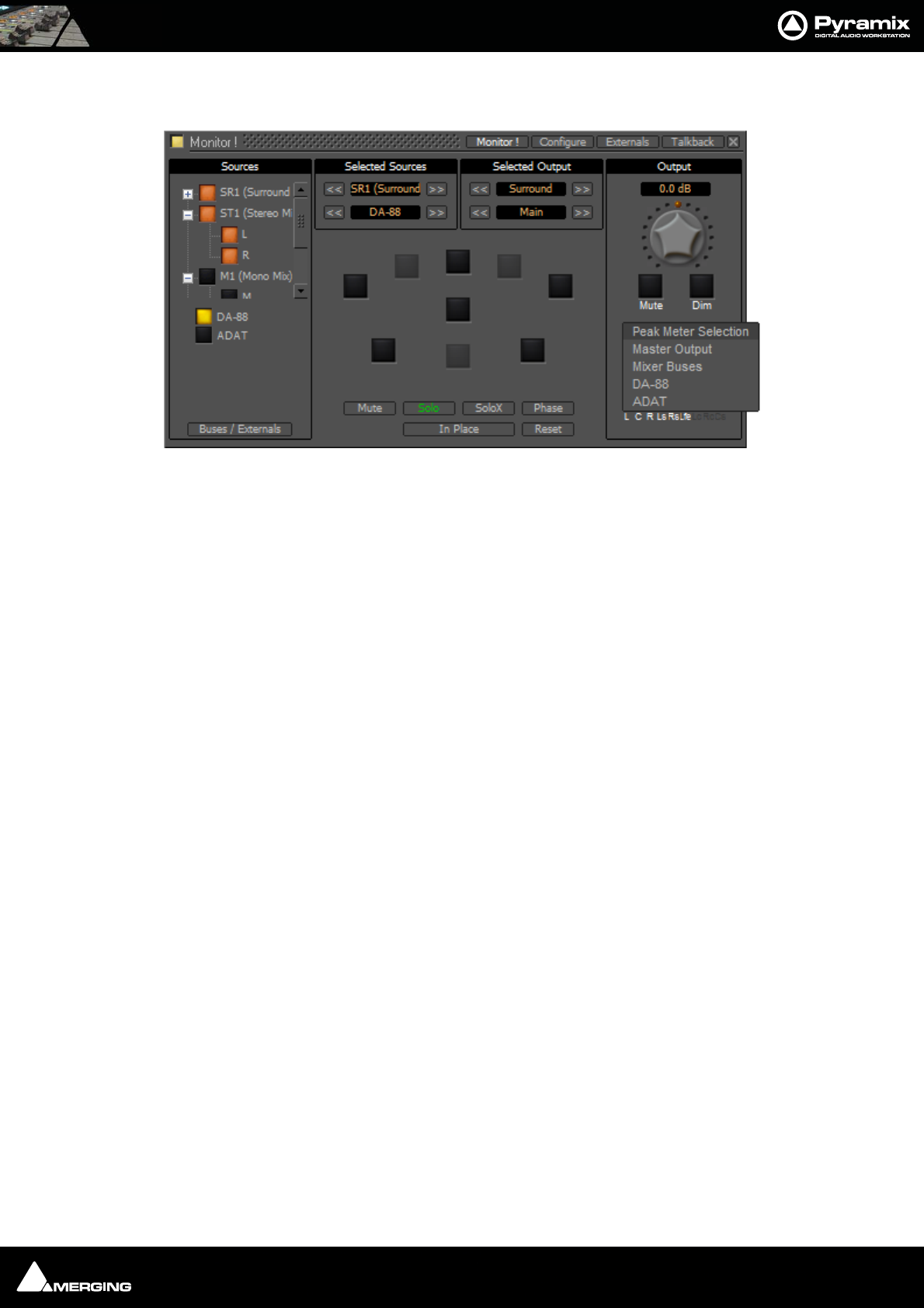
Monitor : Monitor ! page 11 - 195
sources that can be metered from a choice of Master Output I.e.Monitor Output, Mixer Buses and any available
Externals.
Speaker Sets
Speaker Sets are set-up in the Configure page.
A speaker set consists of:
A Patch: This connects signals to the physical outputs of the board(s). The number of connection will depend on
the number of speakers you want to connect. Since the number of available live outputs depends on the selected
sampling rate, the patch will differ for 1Fs, 2 Fs, 4Fs and 8 Fs sampling rates.
Monitor Main Monitor ! Window Peak Meter Selection drop-down
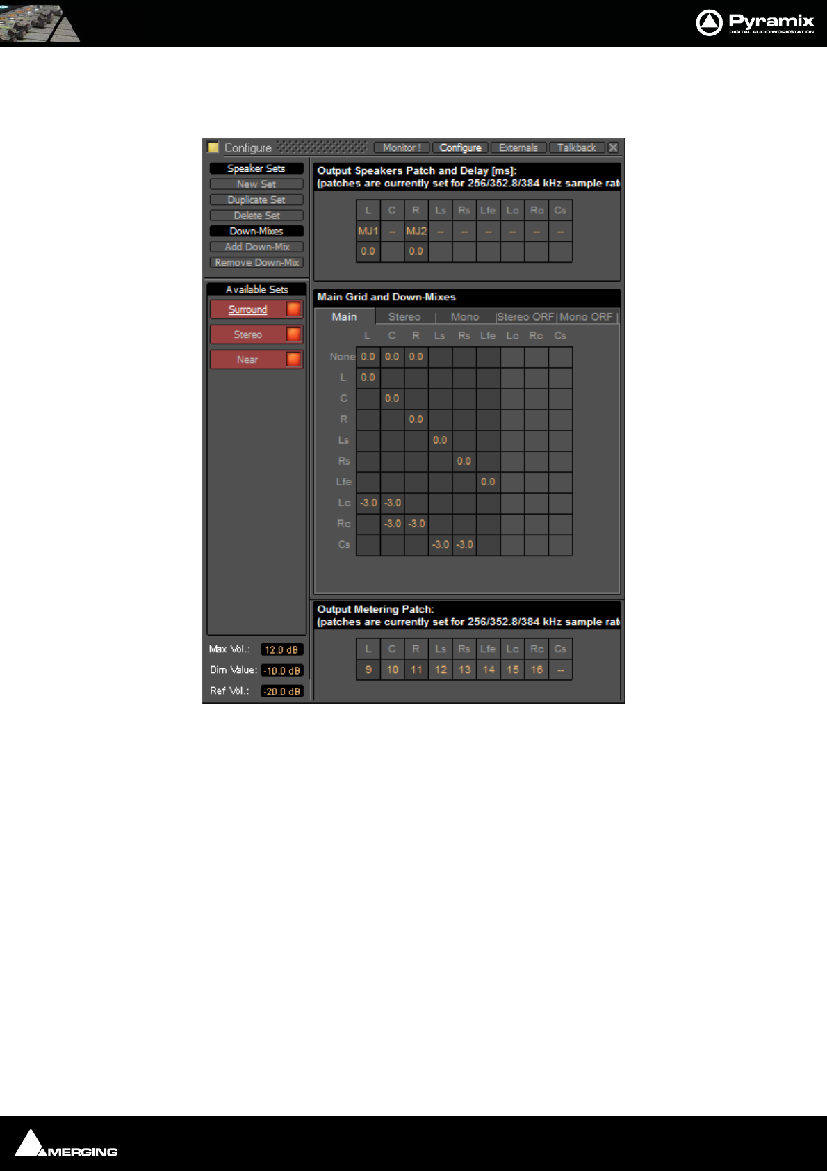
Monitor : Configure page 11 - 196
A Main grid: this matrix defines the relation between the Mixer’s buses output channel types and the monitor’s
output channel types (thus the monitor’s physical outputs). Typically, the main grid would show a diagonal for the
channel types patched:
A set of Downmixes (max: 4) : A downmix is a an alternative grid which uses the same patch as the main grid. In
this page you can patch the outputs of you monitor, add/remove downmixes, and defines the corresponding grids
in dB (only the channel types which are patched).
Configure page
The Configure page enables multiple Speaker Sets, each with multiple down-mixes, to be created and edited.
Two factory Speaker Sets (Stereo and Surround 5.1 labelled on a red background at the top of the Speaker Sets
list) are installed with Pyramix. Their Main channel to speaker Main Grid and Down-Mix assignments cannot be
changed, but their output Patches from speakers in the Monitor to physical outputs can.
Monitor Configure Window
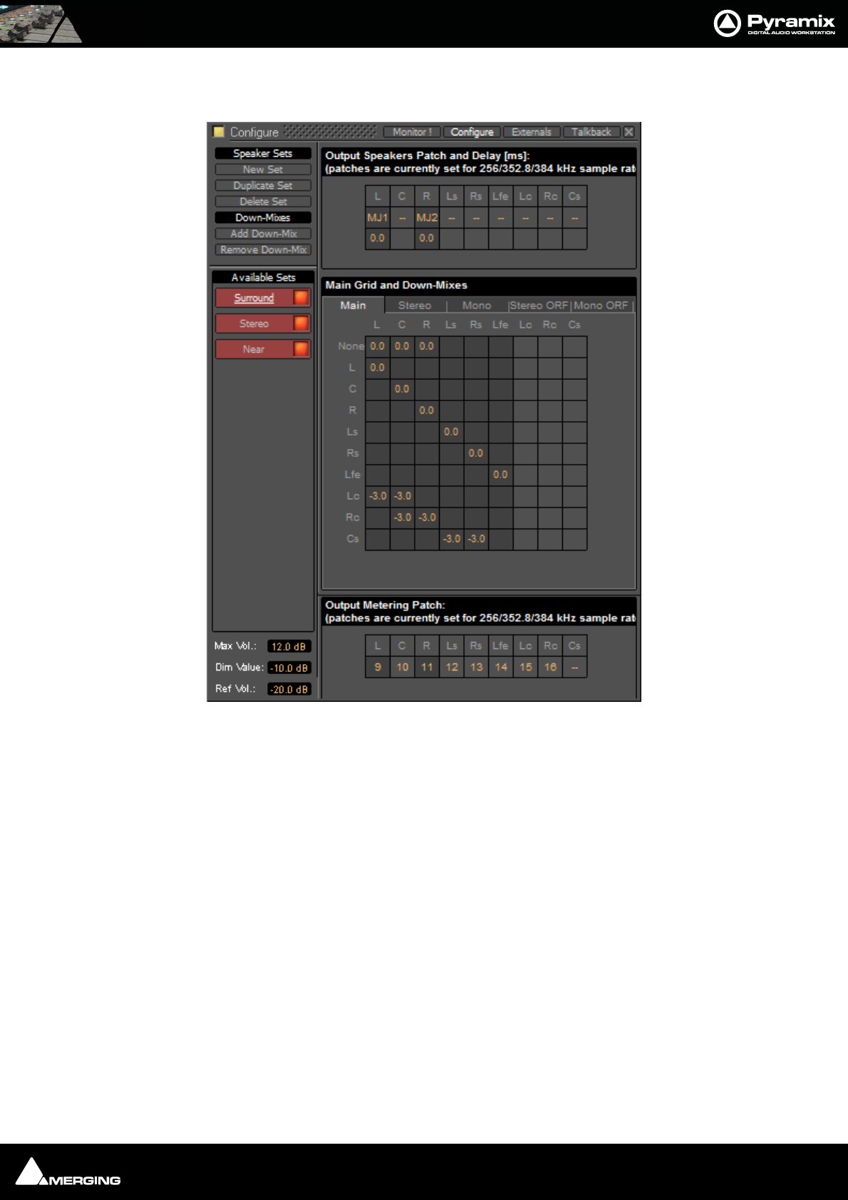
Monitor : Configure page 11 - 197
They and each of their down-mixes can be enabled/disabled in order to determine which ones are visible in the
main Monitor page.
The Configure page is divided into four main areas; Speaker Sets and Down-Mixes, Available Sets, Output
Speakers Patch and Delay[ms], Main Grid and Down-Mixes and Output Metering Patch.
Available Sets
To select an existing Speaker Set in order to view or alter its settings, click on its title in the Available Sets list. The
label will become underlined and the Set’s parameters will appear in the grid. If the Set has Down-Mixes already
defined there will be one or more tabs next to the Main Tab in the Main Grid and Down-Mixes area.
Two sets, Stereo and Surround 5.1 are factory defined and cannot be altered. New Sets and Down-Mixes can be
Created, Duplicated and Deleted using the Command buttons.
Max Vol
To set the maximum volume attainable click on the value box to highlight it and type the desired value then hit
Enter or click elsewhere on the window to save the change.
Dim Value
To change the Dim Level, click on the value box to highlight it and type the desired attenuation value then hit
Enter or click elsewhere on the window to save the change.
Note: Only negative values are accepted. Positive values revert to 0dB. I.e. Type “-15”
Monitor Configure Window
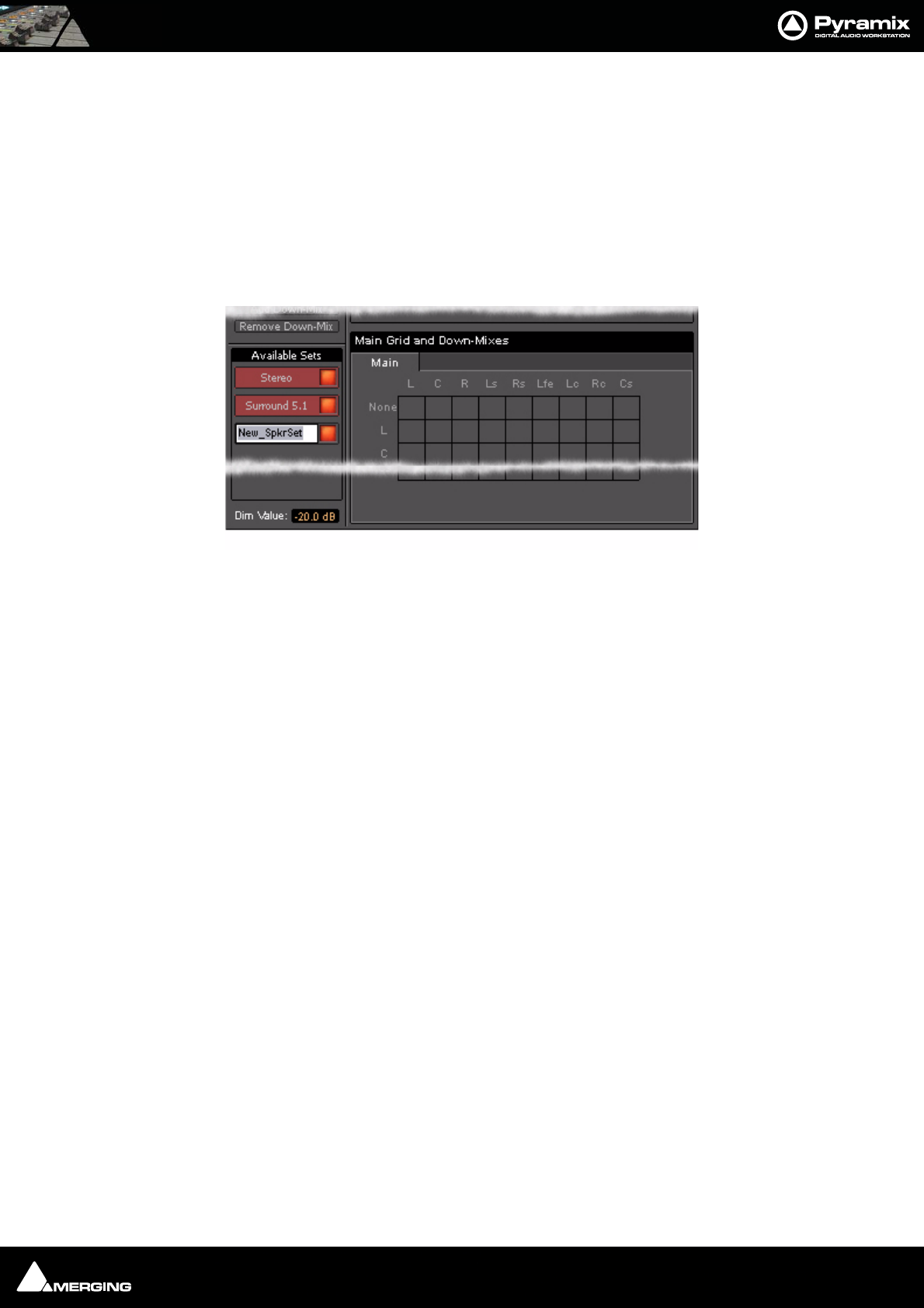
Monitor : Configure page 11 - 198
Ref Vol
To set the Reference Volume level click on the value box to highlight it and type the desired value in the range -
20dBfs to 0dBfs then hit Enter or click elsewhere on the window to save the change.
Commands
Speaker Sets
New Set
Clicking on New Set creates a new Speaker Set with a blank matrix Grid and adds a new entry to the Available
Sets list with the label highlighted ready for text entry:
Type a suitable name and click on a blank area or hit ENTER to accept the name.
Duplicate Set
Creates a new Speaker Set with a the same matrix Grid settings and Down-Mixes and settings as the set currently
selected (underlined) and displayed in the grid. The new label is highlighted ready for text entry.
Delete Set
Deletes the currently selected (underlined) Speaker Set.
Down-Mixes
Add Down-Mix
Creates a new Down-Mix associated with the currently selected Speaker Set with a new tab in the Main Grid and
Down-Mixes section.
Remove Down-Mix
Deletes the current Down-Mix
Monitor Configure New Speaker Set
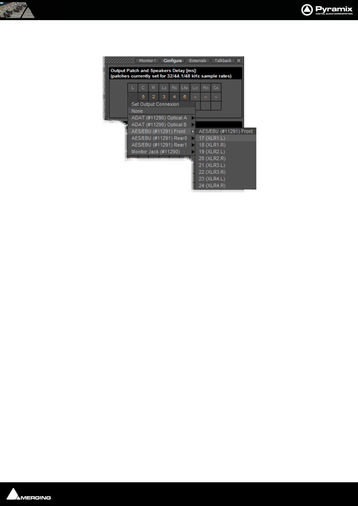
Monitor : Configure page 11 - 199
Output Patch:
This is where the Monitor’s Speaker Set outputs are patched to physical outputs.
Clicking on a cell pops up the Set Output Connection menu with all available physical outputs grouped by their
connectors. The sub-menus list the group and the individual channels. Select an individual channel to connect it
or select the group, e.g. AES/EBU (#11291) Front to connect the whole group in ascending order from the cell
clicked on.
Note: Each Speaker Set has its own Output Patch associated with it. This is useful where
different speakers are used for different formats. If there is only one set of speakers patch
all Speaker Sets to the same physical outputs.
Double Assignment
When an output of the Mixer and an output of the Monitor are connected to the same physical output then these
are summed and the Mixer displays the connection in orange as a warning.
Speaker Delays
Delay can be set per Speaker by clicking in the box below the Output Connection and typing in a value. Speaker
delays are typically used to compensate for the physical positioning of the loudspeakers for example where the
Left Centre and Right speakers are placed in a straight line, the Centre speaker will be nearer to the listening posi-
tion and should be delayed accordingly.
Saving Speaker Sets
Mixer to Monitor connection status is saved in the project.
The Speaker Set settings are saved when you leave the page to go back to the Monitor ! page; otherwise, modifi-
cations are not saved.
Monitor Configure Output Patch
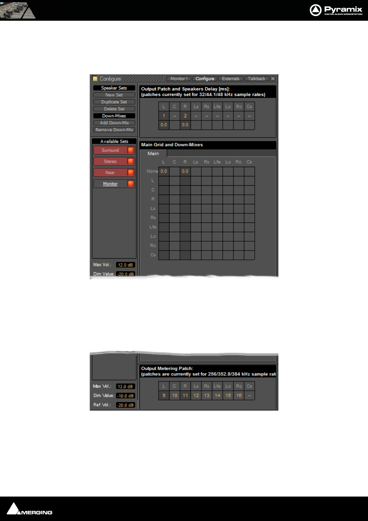
Monitor : Media Manager Monitoring 11 - 200
Media Manager Monitoring
Note: In order to be able to audition cues in the Media Manager the L and R None
entries in the Main Grid matrix must be set to a value, e.g. 0.0
External Metering
If you wish to use your favourite external hardware meters with Pyramix this can be achieved easily and conve-
niently.
At bottom right of the Monitor Configure page an extra set of nine patches is provided to configure external out-
puts specifically for metering.
Patches are made in exactly the same way as the Speaker Output Patches. Please see: Output Patch: on
page 199
Monitor Configure Media Manager
Monitor Configure Output Metering Patch
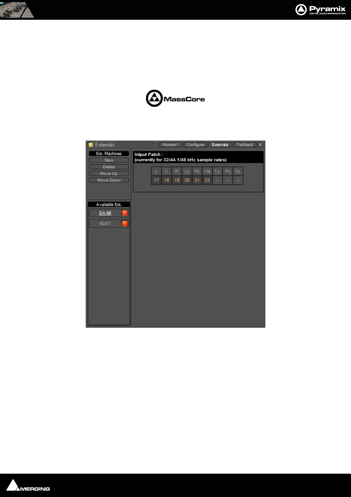
Monitor : External Inputs 11 - 201
External Inputs
External devices may be added in the Monitor panel. This is useful for connecting monitoring returns from the Stu-
dio’s fixed external audio devices such as recorders.
Note: This feature is currently available for Native, Mykerinos mono-board and MassCore
systems. It is not currently supported on Mykerinos multi-board non MassCore systems.
Adding an External Machine
Up to 8 new externals can be added.
Note: External machines will only be visible and available as monitor sources in the
Monitor ! page when the Buses /Externals button is set appropriately. Please see:
Buses / Externals button on page 194
Each external has a dedicated input Patch. Patches are set up by clicking in the boxes below the speaker letters
and choosing inputs from those available.
Talkback
Talkback facilities are provided in the Monitor section for studios without a separate talkback system.
These facilites are intended to be used with GPI/O external connections for physical talkback switches.
Please see: GPI / GPO Support on page 393 for information about setting up GPI/Os.
Monitor Externals page
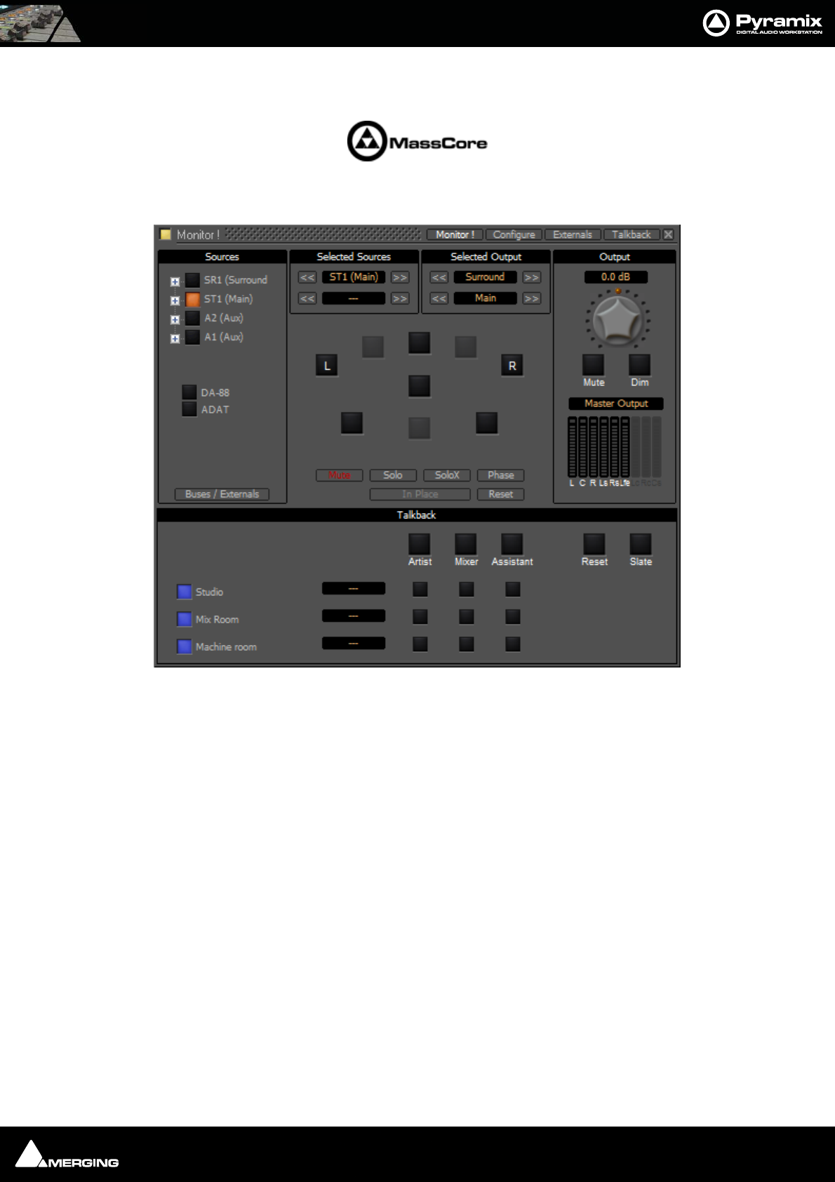
Monitor : Talkback 11 - 202
Note: Talkback is currently available for Native, Mykerinos mono-board and MassCore
systems. It is not currently supported on Mykerinos multi-board non MassCore systems.
When Talkback is set up and active the Talkback section appears at the bottom of the main Monitor ! page:
Monitor ! page with Talkback Section
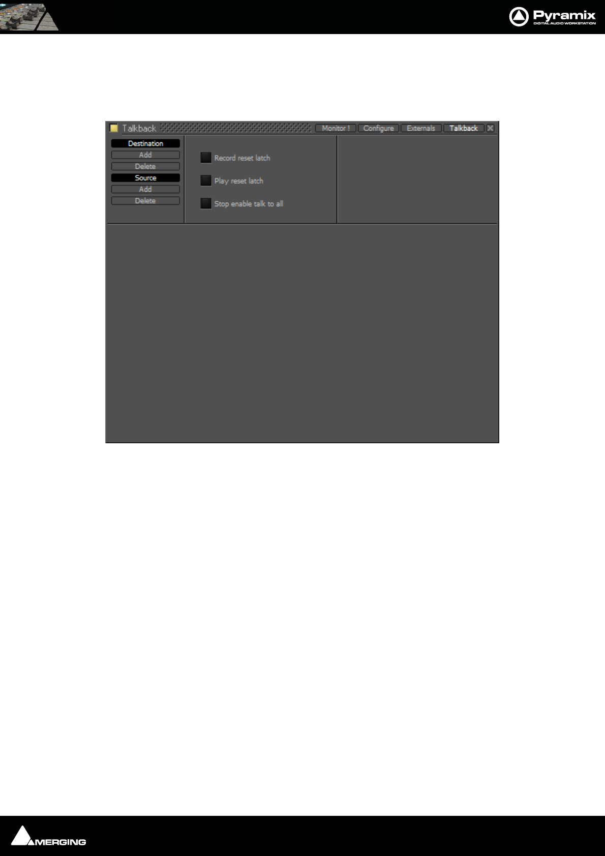
Monitor : Talkback 11 - 203
Setting Up
Talkback Page
You can add up 8 Studios (Destinations) and 3 Talkbacks (Sources) in the Talkback page:
Destination
Add Adds a Destination
Delete Deletes the selected Destination or the remaining one when there is only one shown.
Source
Add Adds a Source
Delete Deletes the selected Source or the remaining one when there is only one shown.
Record reset latch
When lit red all active conversations are muted when the transport is in Record.
Play reset latch
When lit green all active conversations are muted when the transport is in Play
Stop enable talk to all
When lit yellow the Talk To All function is activated when the transport is in Stop.
Example
This is how you would set up talkback for a simple facility with a Mix Room, Studio and Machine Room.
•The Mixer will be able to speak to the Vocal Booth or the Machine Room independently.
•The Assistant will only be able to speak to the Mix Room.
•The Vocal Booth will only be able to speak to the Mix Room.
Monitor Talkback page
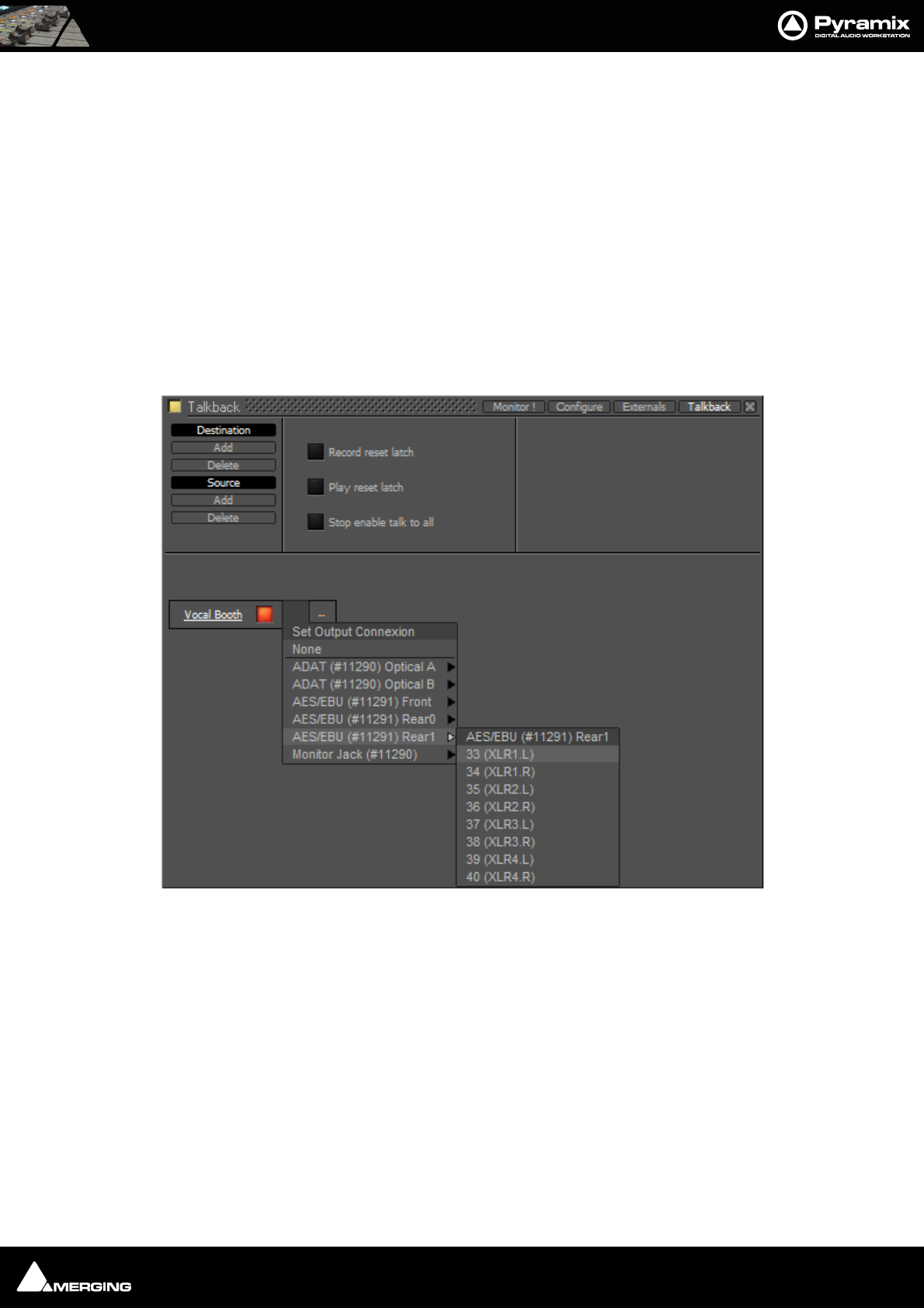
Monitor : Talkback 11 - 204
Note: If a seperate ‘Producer’ Talkback unit is required this can be achieved with a simple
parrallel physical connection of buttons that both activate the Mixer to Vocal Booth
GPI.
Setting Up
1. Click on Studio Add
A New Monitor Studio box appears. Type a suitable name for the Studio, in this case, Vocal Booth and press
the keyboard Enter key to confirm.
The red button indicates that the destination is active.
Note: The Talkback section will be shown at the bottom of the Monitor ! page if any
destinations are active in the Talkback page.
2. Notice the two boxes to the right of the name with orange dashes. Click on the left box to drop down the Set
Output Connection menu:
3. choose a suitable physical output to feed the Talkback amplifier/loudspeaker.
Note: If you only have digital outputs then you will need a converter.
4. If you wish to have stereo talkback/foldback repeat steps 2&3 for the right-hand box. Here only the Vocal
Booth is to be fed with Foldback so that is the only stereo destination.
5. Repeat steps 1 to 3 twice to add two more destinations.
6. Label these to suit, in this case, Mix Room and Machine Room.
Monitor Talkback page Destination Output Connection
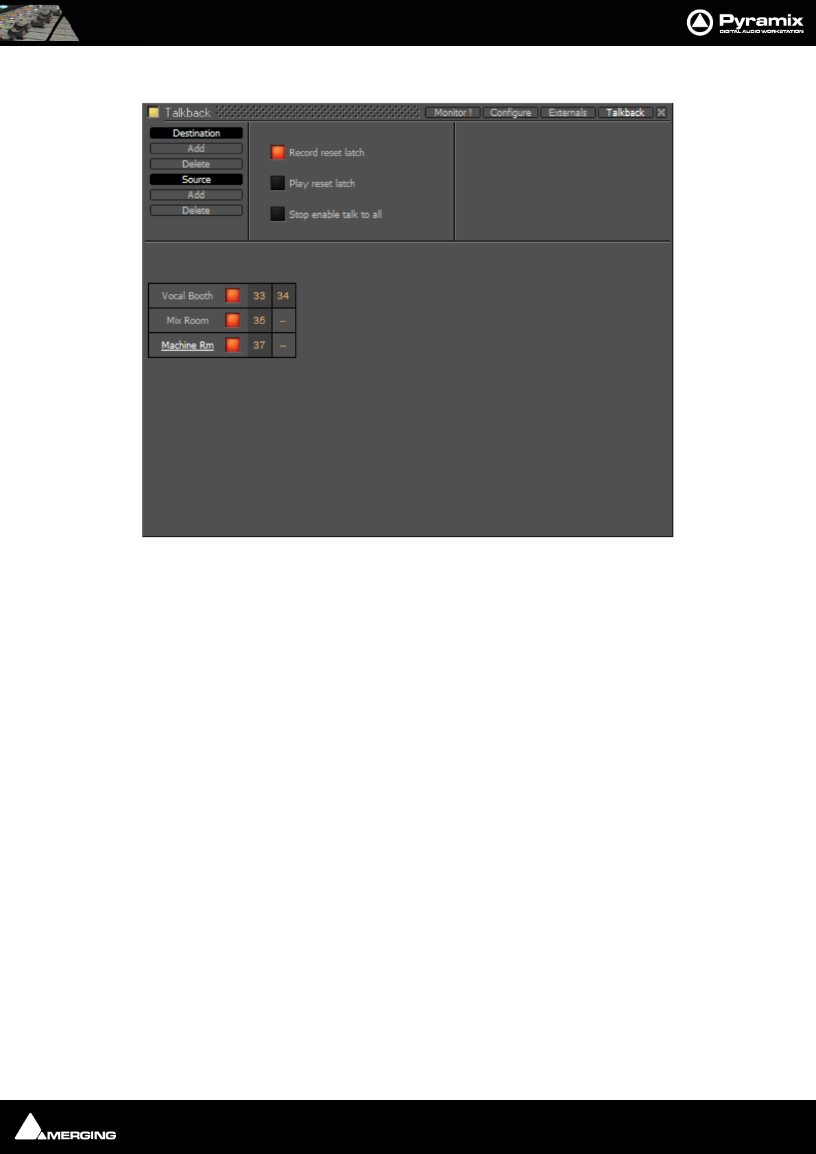
Monitor : Talkback 11 - 205
You should now have something like this on screen:
Note: Only the Vocal Booth has been set up as a stereo destination. If you want seperate
speaker and headphone feeds to the studio just add another destination and label it
appropriately. E.g Vocal Booth HP for maximum control.
7. Now set up the sources by clicking on Source Add
8. A column appears with New Talker highlighted in a box. Type a suitable name for the source. In this case
Mixer.
Monitor Talkback page with destinations
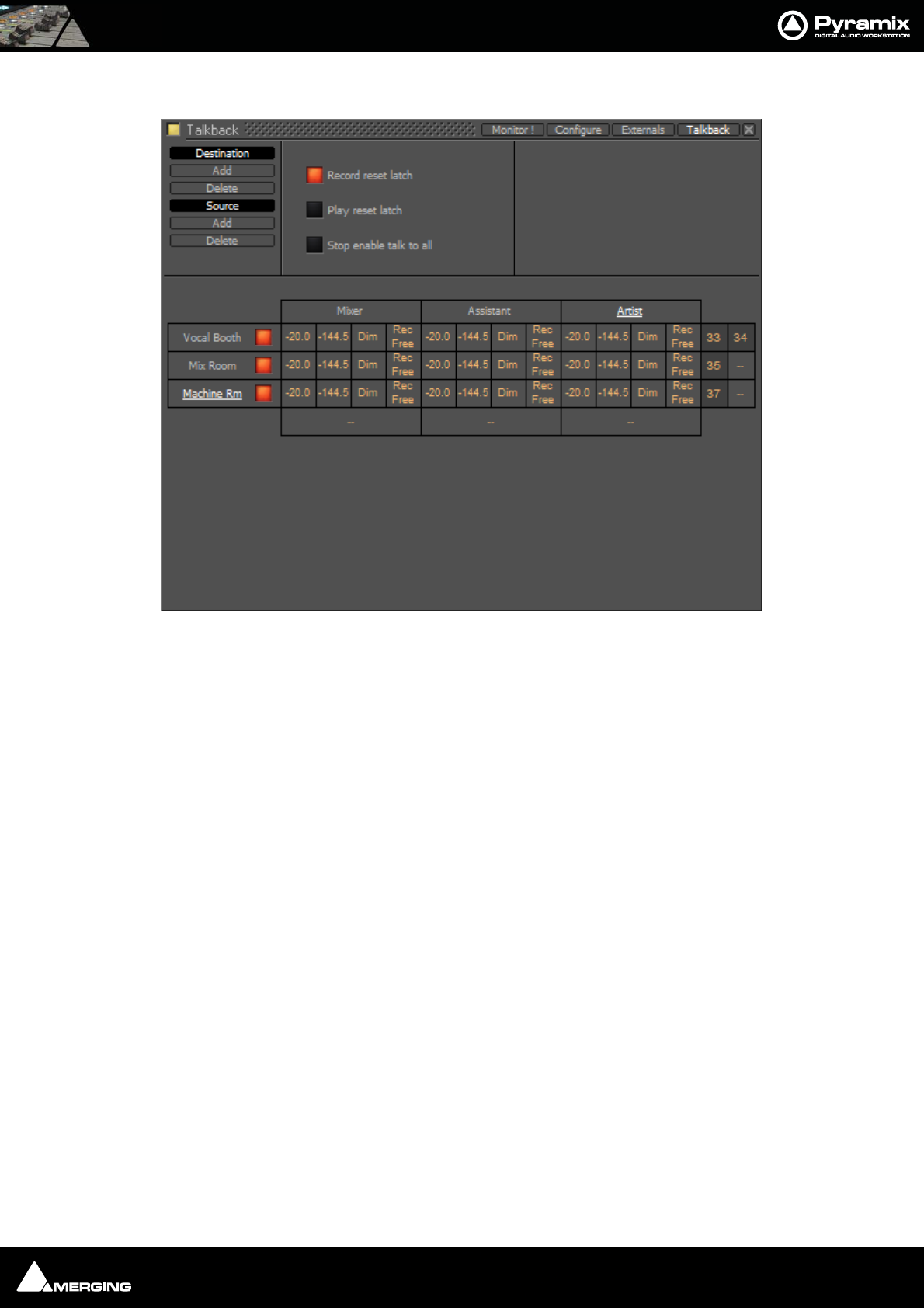
Monitor : Talkback 11 - 206
9. Add two more sources and label them Assistant and Artist
10. Click on the boxes with the orange dashes at the bottom of each source column to open the Set Input Con-
nection menu and choose a suitable input connection for each of the talkback microphones.
Note: If you only have line level analogue inputs you will need external mic pres and if
you only have digital inputs then you will need converters as well.
11. Now the levels, Dim and Mute switching must be set.
• The boxes in the first column of each Source set the attenuation that will be applied to the Destina-
tion output when Talkback is activated from each source.
• The second column sets the send level per Destination. You can type mute or a numeric value in
the box.
Note: If mute or -144.5 is entered this Destination will be grayed out and unavailable in
the Talkback section of the Monitor page. For example, it is illogical for the Mixer
Source to talk to the Mix Room Destination and so on.
• The third column offers the choice of Dim or None. Selecting Dim means that when this crosspoint
(Source to Destination) is activated by pressing the relevant Talk button, the Main Monitor Out-
put will be dimmed.
Note: This is essential when, for example, the Mix Room talks to the Vocal Booth with
the programme mic channel open to avoid howl-round and possible damage to loud-
speakers and hearing.
• The fourth and final column offers a choice between Rec Free and Rec Loc.
Rec Free means that talkback on this crosspoint can be initiated when the Transport is in Record and
the Record Reset Latch is set.
Rec Loc disables the crosspoint when when the Transport is in Record and the Record Reset Latch
is set.
Monitor Talkback page with Sources and Destinations
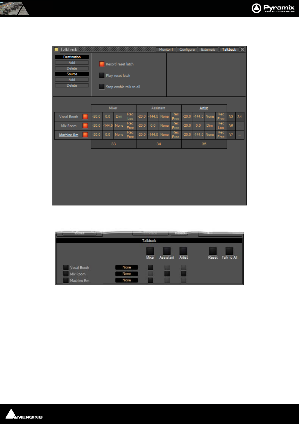
Monitor : Talkback 11 - 207
So, bearing in mind who is going to be allowed to talk to whom and given that it is illogical to use talkback to talk
to yourself, the levels should now look approximately like this:
Returning to the Monitor ! page you will see this in the Talkback section:
(If the buttons on the left are lit blue ignore them for now) The big buttons with the labels Mixer, Assistant and
Artist are Talk to All destinations (In this case only relevant to Mixer)
Monitor Talkback page with Sources and Destinations and levels set
Monitor ! page Talkback Section
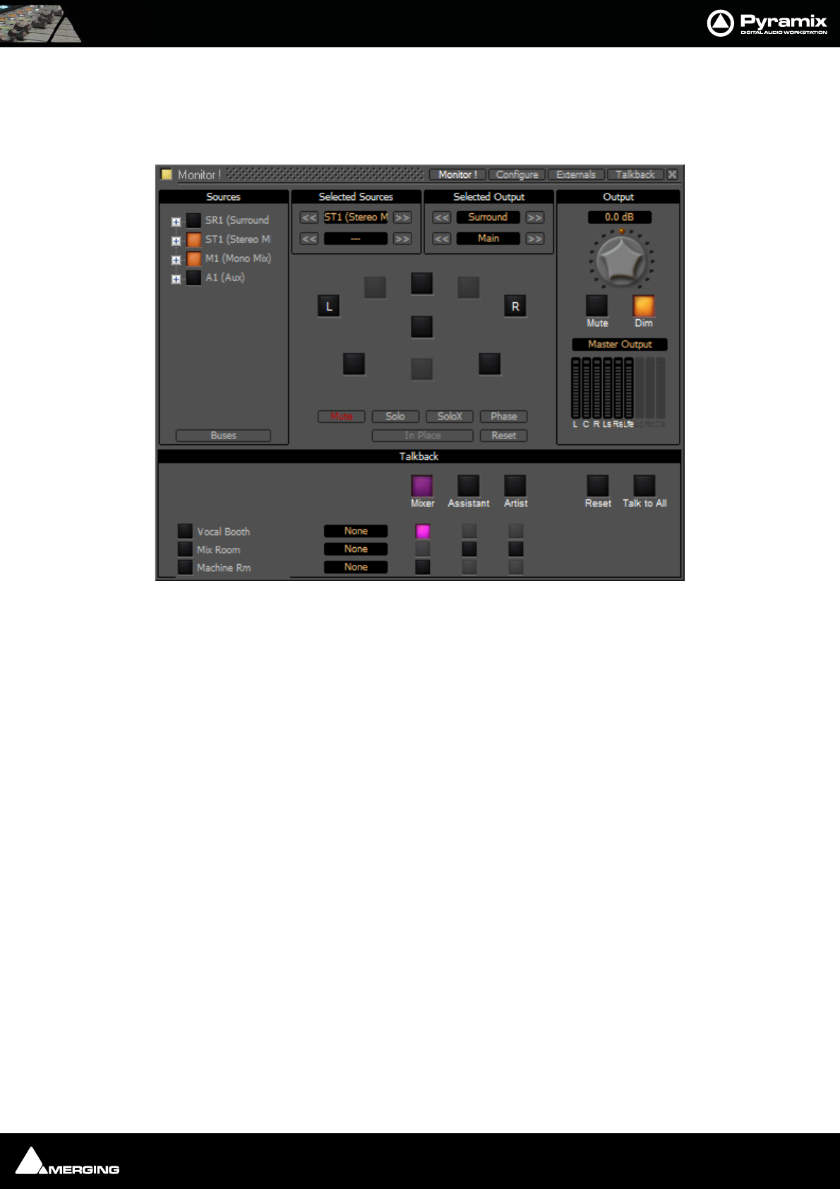
Monitor : Talkback 11 - 208
Operation
The smaller buttons vertically below the bigger, labelled Source buttons initiate talkback from the horizontal
sources to the vertical destinations. These are the buttons you are most likely to want to map to GPIs. For example
in the following screenshot the Mixer is talking to the Vocal Booth:
Note: Notice that, due to the settings made earlier, Mixer talking to Vocal Booth also
Dims the Main Monitor Output.
Talkback Button Operation
All the Talkback buttons are dual mode. A press of less than one second latches the Talkback open. A second press
cancels. A press of more than one second initiates Talkback on press and cancels when the button is released.
Reset cancels all latched talkbacks.
Talk to All initiates open Talkback between all enabled Sources and Destinations
Monitor Talkback page : Mixer talking to Vocal Booth
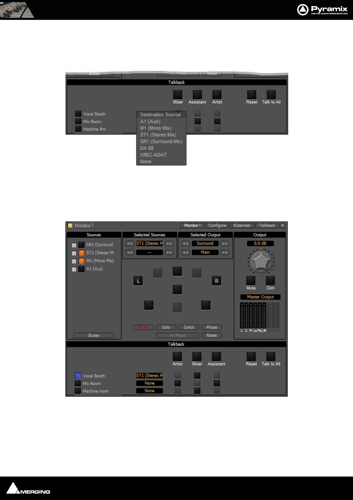
Monitor : Talkback 11 - 209
Foldback
Continuing the foregoing Talkback example it is also possible to add foldback to the Talkback outputs. To add
Foldback to the Vocal Booth Talkback outputs click on the black box to the right of the Vocal Booth label to drop-
down a list of available Foldback sources:
Select the required Foldback Studio Monitor Source.
Note: You can add a bus in the mixer specifically to produce a mix for Foldback.
The buttons on the left of the Vocal Booth label etc. toggles the foldback on and off per destination:
Here, the Vocal Booth is fed with ST1 (Main) bus output. The vocals are recorded clean on M1 (Mono Mix) and,
as can be seen above, the Mixer Room monitors are being fed with the sum of these buses.
Monitor Talkback page : Select Foldback Source
Monitor Talkback page : Foldback to Vocal Booth Active

USER MANUAL
www.merging.com/Pyramix
Meter Bridge
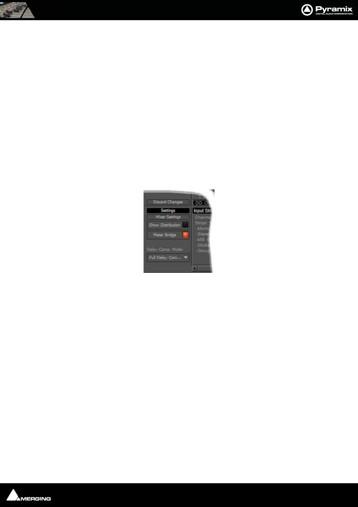
Meter Bridge : Meter Bridge 12 - 211
Meter Bridge
Scope
Pyramix has a dedicated Meter Bridge window.
The Meter Bridge can present a meter display for every Input strip and Bus present in the current Mixer and exter-
nal Machine configured in the Monitor : Externals page.
The Meter Bridge also indicates the currently selected mixer strip with a yellow outline, any strips in Record Ready
condition with a red outline, whether any strips are Muted or Soloed and optionally shows Ramses Groups and
Fader Automation mode per strip.
You do not have to use the Meter Bridge but, especially when used with Ramses MSC, it offers flexible metering
in one place. With complex Mixers and routing, the Meter Bridge can help to keep things logical.
Note: The Meter Bridge is displayed “Always On Top” of other windows.
Meter Bridge Switch
Before the Meter Bridge Window can be opened it must be switched on in the Settings section of the Mixer Con-
figure Page :
Meter Bridge Switch
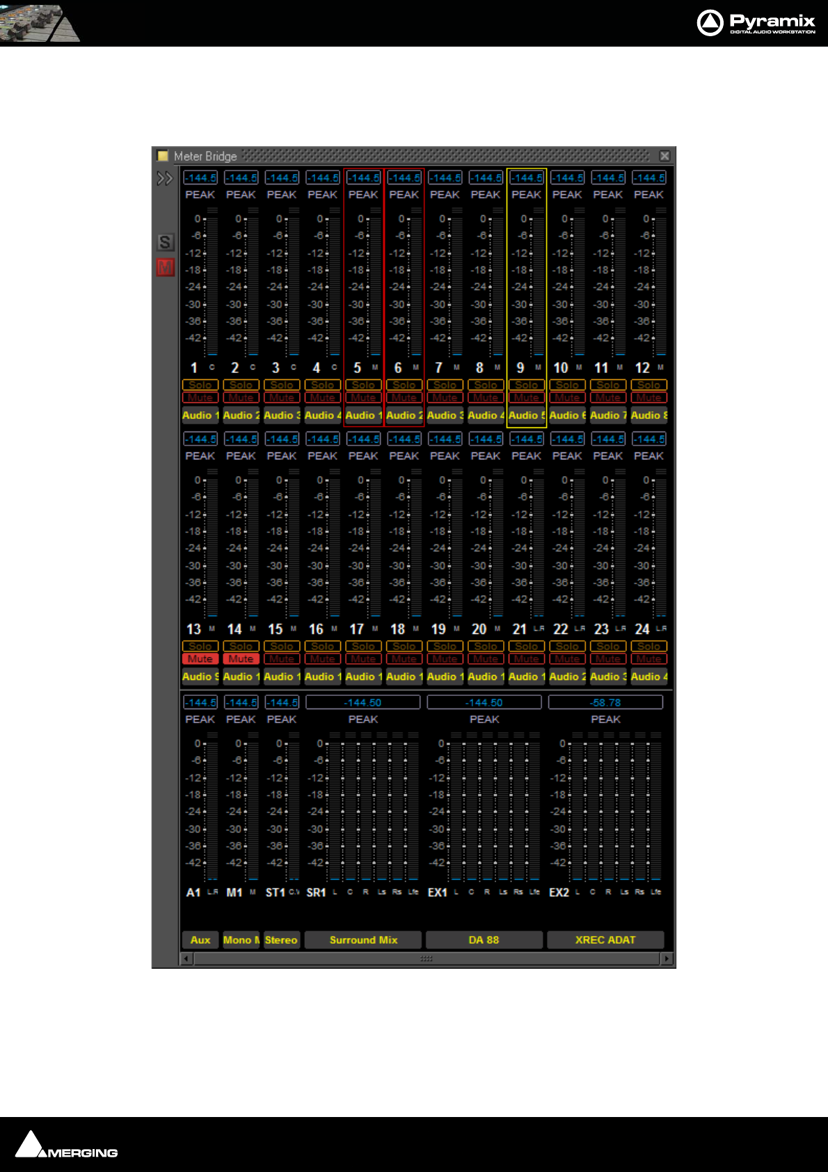
Meter Bridge : Meter Bridge 12 - 212
Meter Bridge Window
By default the Meter Bridge window is hidden. It can be opened with View > Meter Bridge or the icon in the
View Toolbar.
Resize
The Meter Bridge Window can be resized by clicking and dragging the edges. (Mouse cursor changes to double
arrow) Vertical resizing is limited to sensible display options. Scroll bars will appear when there is more informa-
tion to display than the window can accomodate.There is a separate auto-hide scrollbar for the Input Strips so you
Meter Bridge Window - Triple Row Mode
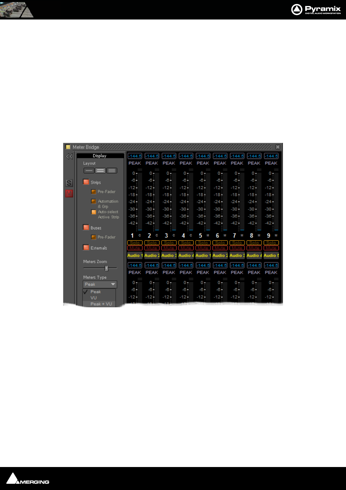
Meter Bridge : Meter Bridge 12 - 213
can keep all the Buses and Externals visible together with a contiguous section of the Input Strips of a very large
mixer. (This will appear when the mouse cursor is over the right-hand edge of the top two rows.)
Global Mute and Solo Indicators
If any strip is Muted or Soloed the global indicators in the left margin illuminate.
Selected Strip and Record Ready Status
The currently selected strip is shown with a yellow outline.
Any strips currently in Record Ready mode are shown outlined in red.
Configuring the Meter Bridge
When first opened the Mixer Bridge appears as above. clicking on the double arrow >> below the Yellow Activate
button opens the Display panel (a subsequent click on the << arrows closes):
Layout
The three buttons determine whether the meters are displayed as a single, double or triple row (default).
Meter Bridge Configuration : Display Section
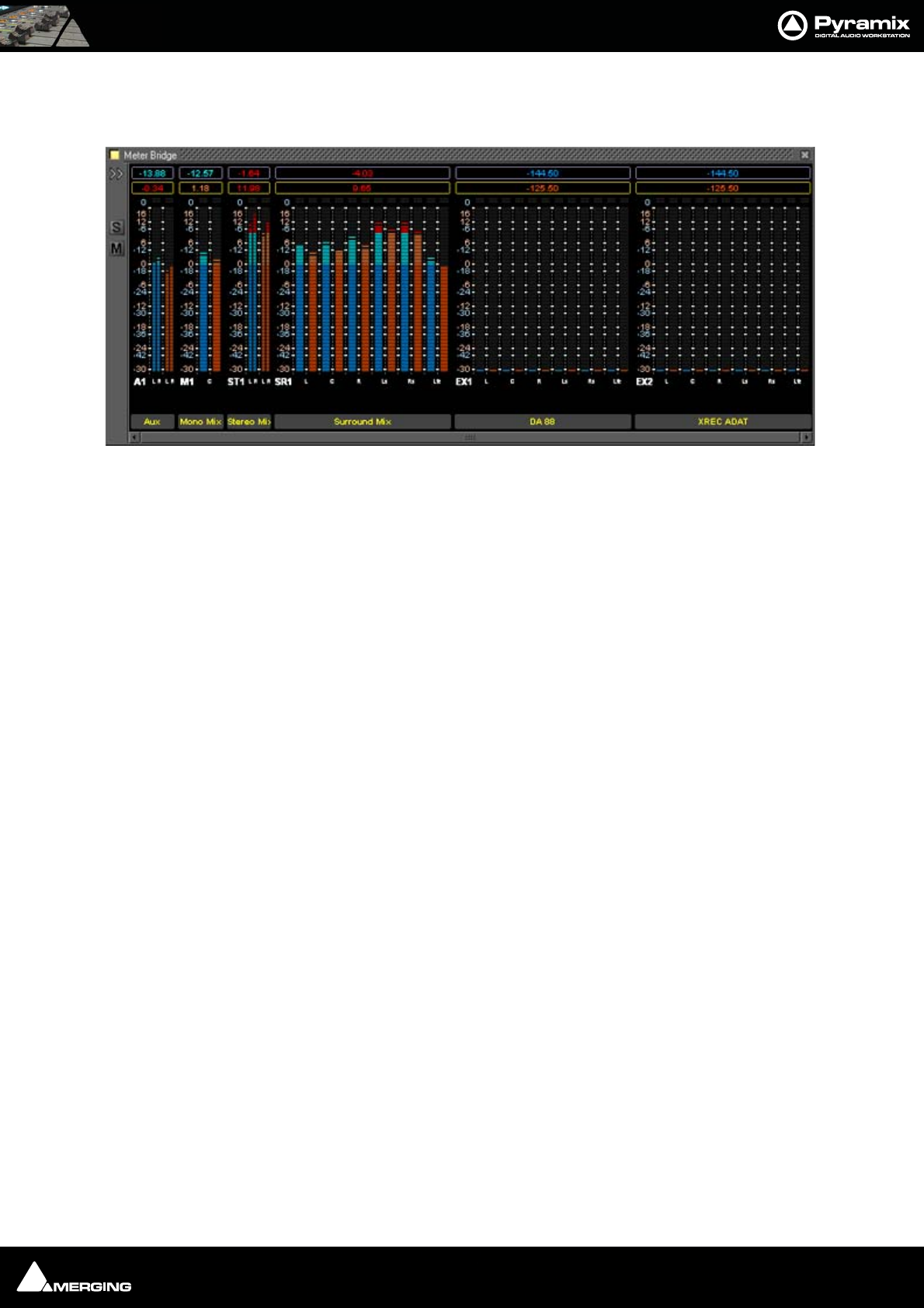
Meter Bridge : Meter Bridge 12 - 214
Single Row
Single row is useful if you only wish to display buses and or Externals (returns).
Strips
The red button shows/hides the Input Strip Meters (default is Show)
Note: Show/Hide for Input Strips is only available in ‘single row’ display mode. Useful in
applications where the Bus and External Machines are of more interest than the Inputs.
Pre-Fader
When lit, the Input Meters source is taken pre-fader. (default is post-fader)
Automation
When lit, four Fader Automation Mode indicators are shown in each Input Strip. (default is hidden)
Auto-select Active Strip
When lit, the active strip is highlighted in yellow
Buses
The red button shows/hides the Bus Strip Meters (default is Show)
Pre-Fader
When lit, the Buses Meters source is taken pre-fader. (default is post-fader)
Externals
The red button shows/hides the External Machines Meters (default is Show)
Note: Externals, External machine Returns, are set up in the Monitor : Externals page.
Please see: External Inputs on page 201
Meters Zoom
The slider adjusts the meter scaling. Range is from 0dB to -144.5dB maximum to 0dB to -10dB minimum. Double-
clicking on the slider ‘knob’ resets to default scaling.
Meter Bridge - Single Row Mode
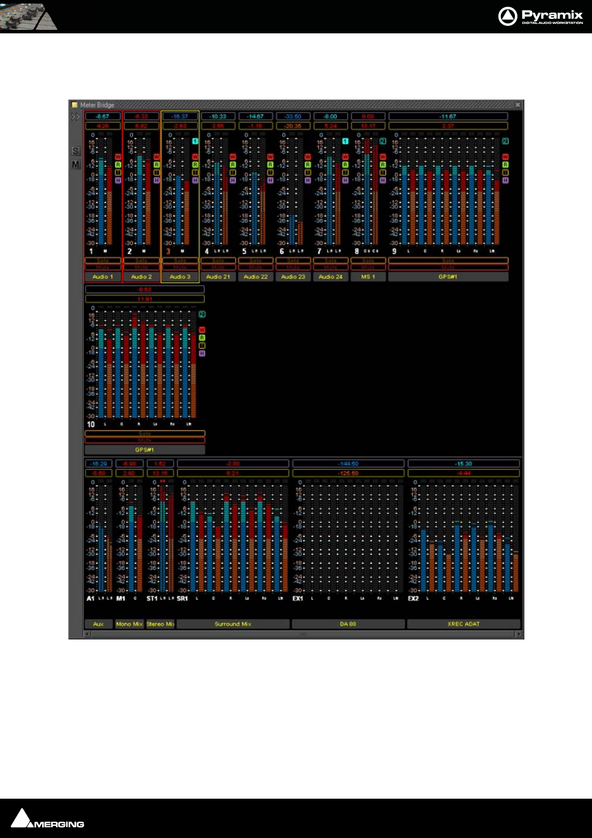
Meter Bridge : Meter Bridge 12 - 215
Meters Type
The drop-down offers a choice between Peak (default), VU or Peak + VU as seen here along with the Automation
Indicators:
Meter Bridge - Triple Row Mode
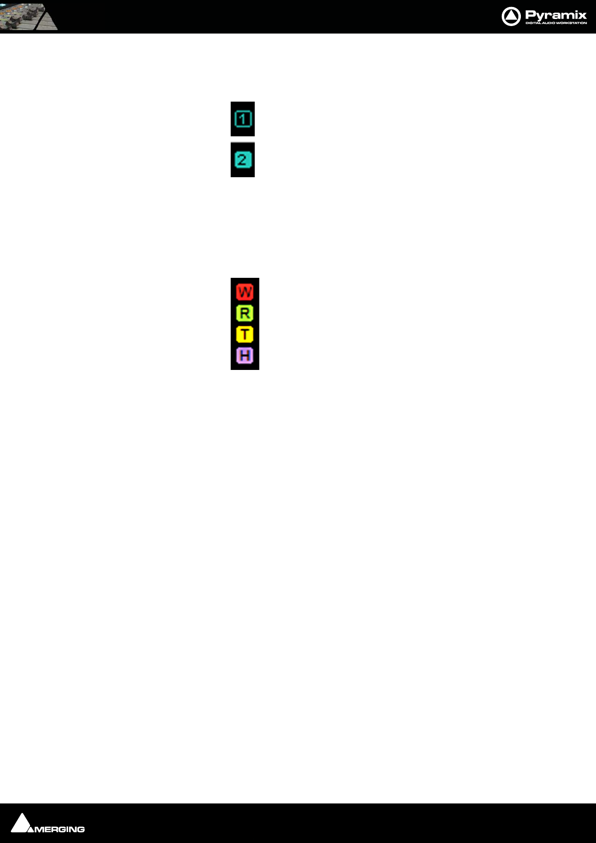
Meter Bridge : Meter Bridge 12 - 216
Automation Fader Mode and Group Indicators
Ramses Group
This indicator shows that the associated strip is a member of a Ramses MSC control Group. When in inverse video
(filled in) it also indicates that the associated strip is a member of the currently selected strip’s Group.
Note: These Ramses MSC Control Groups are currently completely independent of the
Pyramix grouping arrangements.
Automation Fader Mode
In the default, Auto-Write, mode only the Write and Read indicators are lit together.
As soon as a fader is touched with the transport in play the Read indicator extinguishes leaving only the red Write
indicator lit.
If an Automation Trim mode is selected the yellow Trim indicator will also be lit.
Similarly, if a Hold mode is selected the purple Hold indicator will be lit.
Thus, in the Meter Bridge screenshot above, the automation is in Auto-Write plus Trim & Hold modes.
Member of Group
Member of selected
Strip’s Group
Write
Read
Trim
Hold

USER MANUAL
www.merging.com/Pyramix
Effects and Plug-Ins
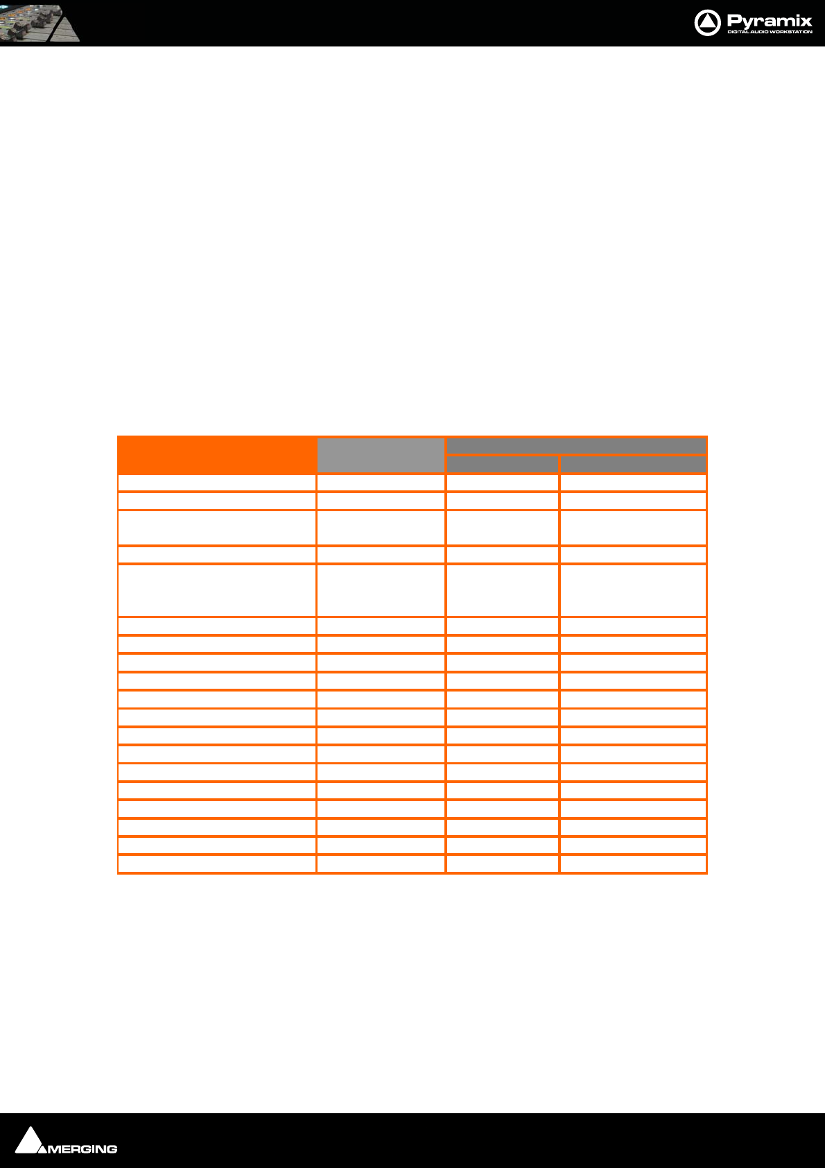
Effects and Plug-Ins : Effects and Plug-ins 13 - 218
Effects and Plug-ins
This chapter describes individual effects and their components as they are applied in the Pyramix Mixer.
For rendered effects please see : Effects Rack on page 294, Levelizer on page 296 Nova on page 296 and
Prosoniq MPEX3 on page 298
Adding and Managing Effects
Please see: Effect Management on page 147 and Native VS3 Effects and VST Plug-ins on page 179
Note: If a Plug-in is unregistered then (unregistered) will be appended to the name in
the list. For more detailed information about registration status open the VS3 Plug-ins
Information window.
VS3 Plug-In Support
Note1 : Please see:
www.vb-audio.com
(client area) for the latest information
Note2 : Compensated in Native but not in MassCore mode
VS3 Plu
g
-ins Su
pp
ort and Latenc
y
Compensated Not Compensated
Angudion I & II Yes -
Aphro Yes -
Other VB Audio Plug-ins In progress
(note1)
Bus Tools & Strip Tools Yes
A
DC
M
e
t
er,
Ph
ase-
O
sc
ill
o,
VU
Meter, Surround Meter,
Wordlength Meter Yes -
Delay Yes -
Dynamics Yes
A
EqX Yes -
External Insert Yes M
Flange
r
Yes -
Modulomete
r
Yes -
MS Encode
r
Yes -
Parametric Equalizer Yes -
Phase-Oscillo Yes -
Pure Series Yes
A
Solera Yes
A
Tone Yes -
DeNoiser-DeScratcher Yes
A
(note2) A (note2)
UpMix 5 Yes
A
A=Automatically M=Manually
VS3 Plug-ins
Supported in
Pyramix 6.0
Latency
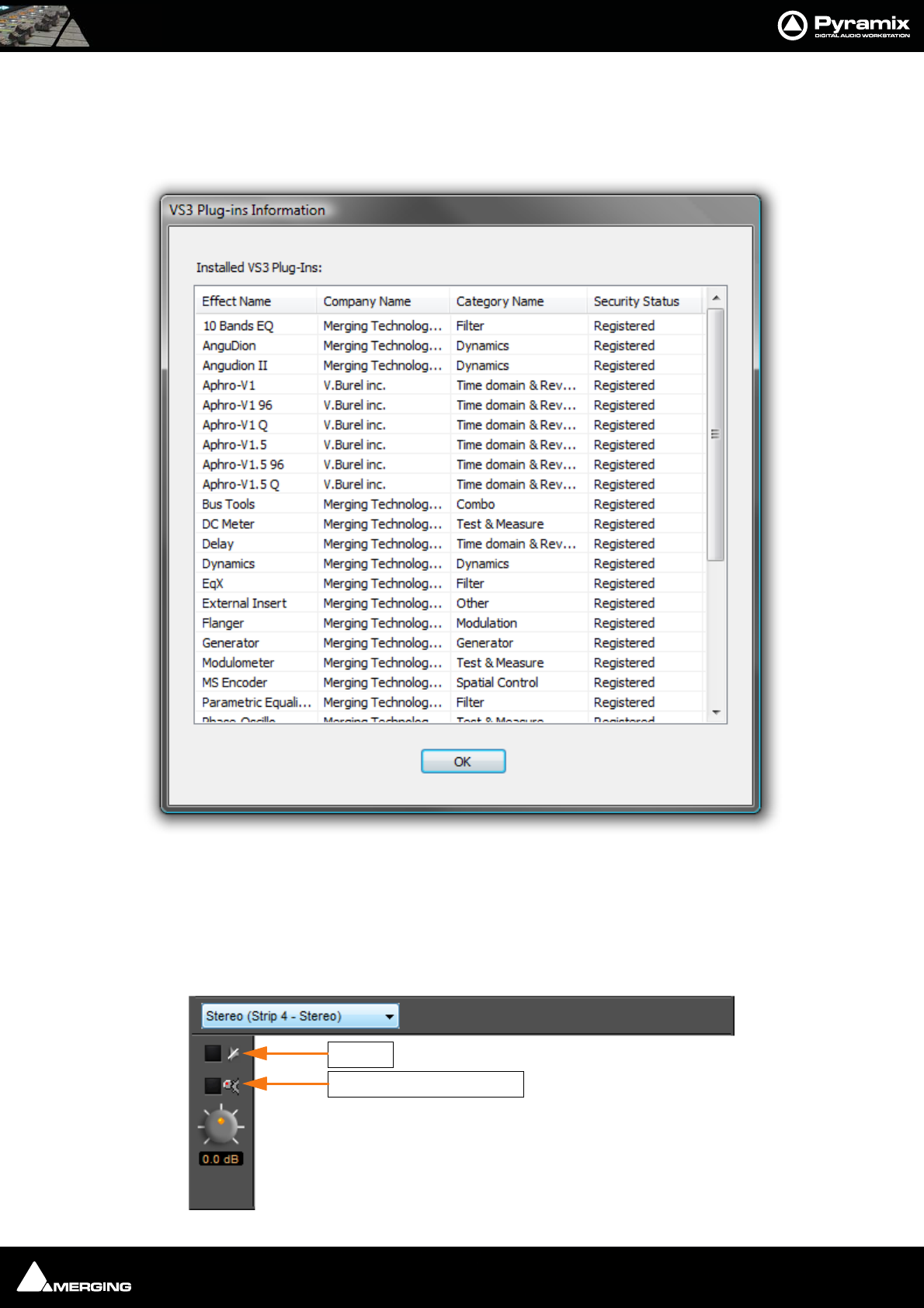
Effects and Plug-Ins : Adding and Managing Effects 13 - 219
Viewing Plug-in Information
VS3 Plug-Ins Information
The Mixer right-click context menu has an option to pop-up the VS3 Plug-Ins Information WindowT
This window shows all effects currently present on the machine. Fields show the Effect Name, the manufacturer/
developer Company Name, the Category Name and Security Status. I.e. if the plug-in is currently authorized.
Common Components
Several of the following Pyramix Effects share common components.
VS3 - Plug-Ins Information Window
Intelligent Gain Make-up
Bypass
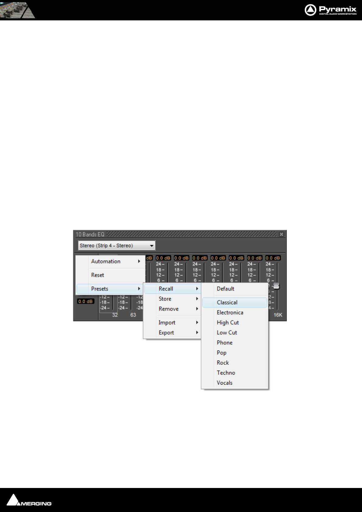
Effects and Plug-Ins : Adding and Managing Effects 13 - 220
Channel Combo Box
Shows which channel has the plug-in that the window is currently controlling. Clicking the arrow drops down a list
of all channels that have this plug-in assigned to them. Click on a name to selected a channel from the list. The
control values will change to reflect the current state of the plug-in on the selected channel. This feature enables
all instances of a particular plug-in to be controlled from the same interface window without opening duplicate
windows for each channel.
Bypass Switch
The On/Off (bypass) switch when lit red the effect is bypassed but remains “in circuit”. Well behaved effects will
maintain their internal parameters in this state so that they can be switched back in without artefacts.
Bypass all Effects
Clicking on a bypass button with Shift bypasses all effects in the strip.
Auto Gain Compensation
(Only where relevant) When this switch is lit Auto Gain Compensation is in circuit. The function is intended to
keep the output level of the plug-in approximately equal to the input level. The computed value varies as the
plug-in controls are adjusted and can be further adjusted using the knob.
Output Gain
Manually adjusts the gain applied at the output of the plug-in. The value is shown in dB.
Effects Presets
Right-clicking in the Plug-in window pops-up a contextual menu which enables the plug-in to be Reset to its
default values. Presets can be Recalled, Stored or Removed and Imported or Exported to and from libraries.
Choosing Presets
Click on the desired preset from the list. The plug-in's parameters will be set to the values stored in the preset.
Effects Presets context menu and recall sub-menu
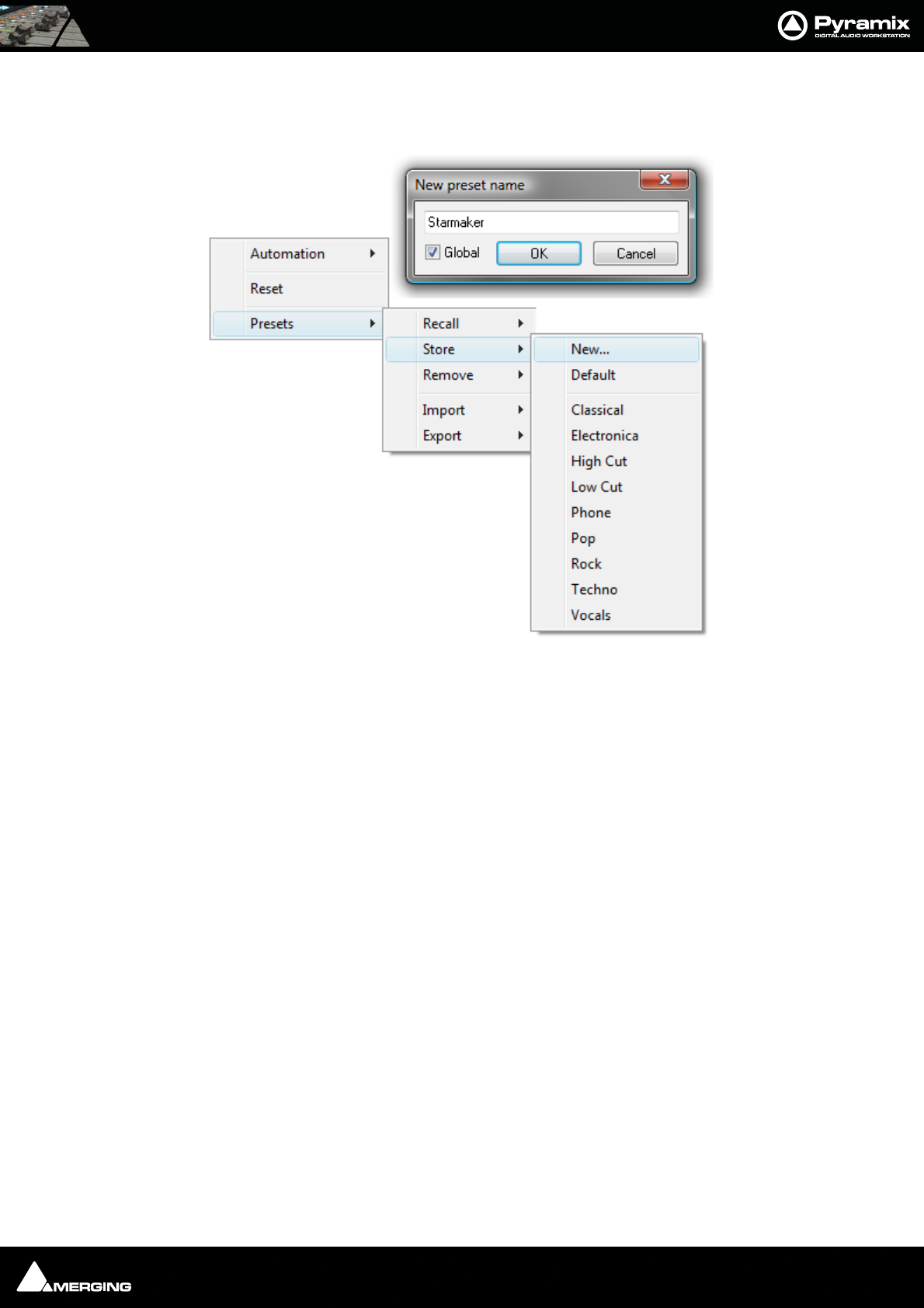
Effects and Plug-Ins : Adding and Managing Effects 13 - 221
Storing Presets
Creating a new preset stores a snapshot of the current values. Store > New opens the New Preset Name dialog
box.
If the Global box is checked, the Preset will be available in all future Projects.
Default
Choosing Presets > Store > Default makes the current parameters the default. These can be from new values or a
previously recalled Preset
Modifying an Existing Plug-in Preset
To modify or update an existing preset, set the effect's parameters to the desired new settings. Right-click and
select Presets > Store then choose the Preset name in the list to update or modify. A Store preset dialogue box
will appear asking if you wish to replace the chosen Preset. Click OK to accept or Cancel to reject. The new settings
will overwrite the previous preset parameter settings.
Deleting Presets
To delete the current preset, right click in the effects window. Then choose Presets > Remove then choose the
preset you wish to remove.
Effects Presets context
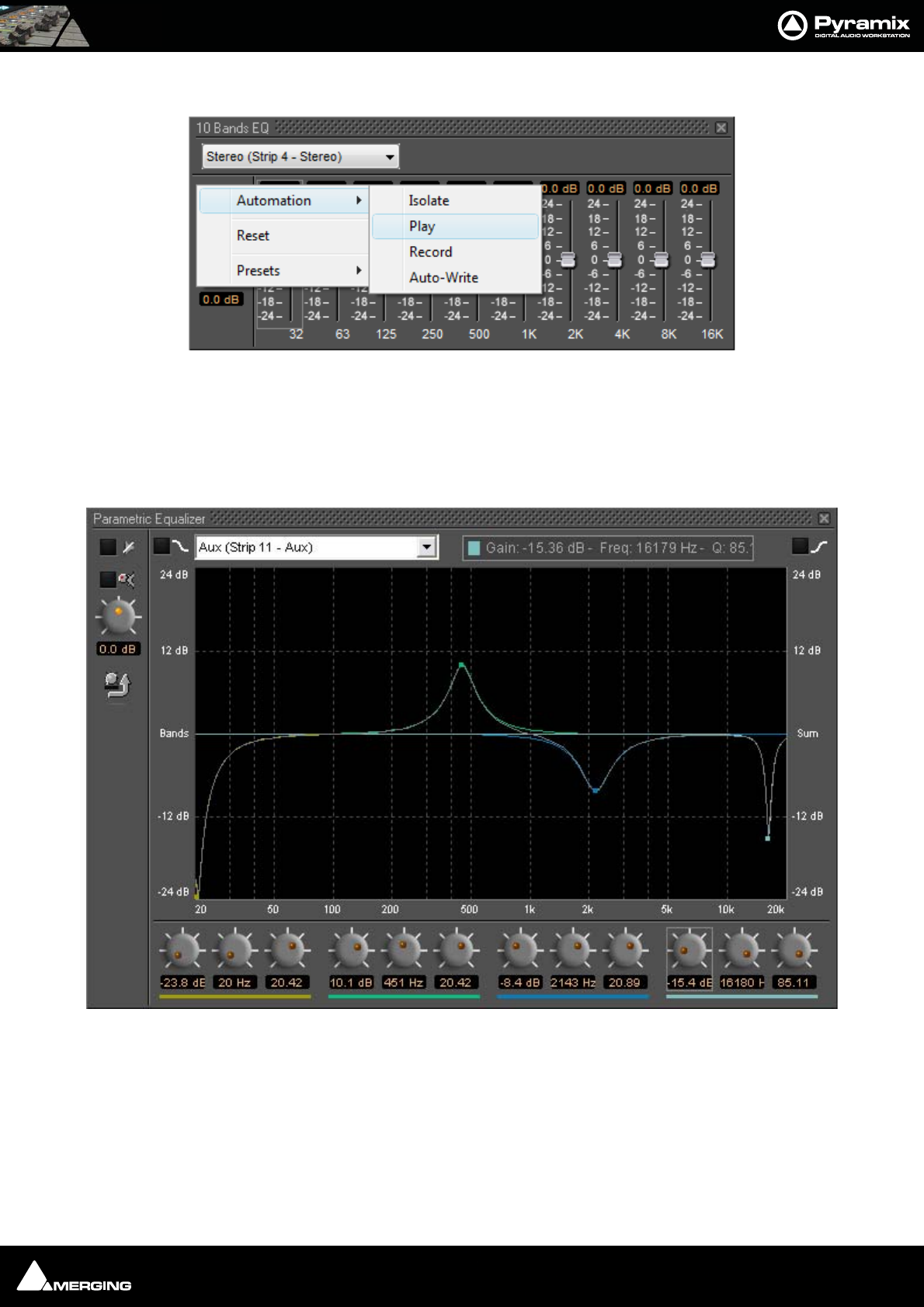
Effects and Plug-Ins : Parametric EQ 13 - 222
Effects Automation
Right-clicking over the effect controls gives access to Automation mode selection for the plug-in. VS3 Plug-in aut-
mation works in the same way as the Mixer automation.
Please see Automation on page 258
Parametric EQ
The Parametric Equalizer is a four band fully parametric EQ with independent control of boost and cut, frequency,
and bandwidth (Q factor) for each band. The common controls at the top of the window behaves as outlined ear-
lier. The equalizer can be operated using the rotary controls at the bottom (shown or hidden by the knob and
arrow icon on the left), by directly entering numerical parameters in the boxes below the knobs or by clicking and
dragging on one of the four colored nodes. Left-clicking enables level and frequency to be adjusted, right-clicking
then dragging left or right allows adjustment of Q.
Parametric EQ floating Window
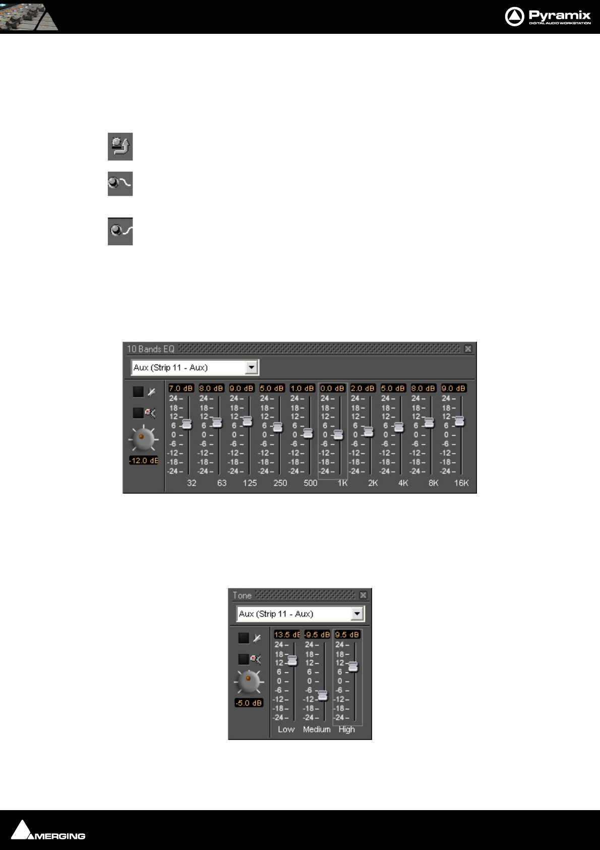
Effects and Plug-Ins : 10 Bands EQ 13 - 223
All bands are full range. Boost and cut of up to 24dB is available. Q can be set anywhere from 0.2 (wide) to 20 (nar-
row).
This button shows or hides the rotary controls.
Peaking / Shelving When lit, the lowest (red) band is switched to shelving response. In this
mode the Q control for the band is unavailable.
Peaking Shelving When lit, is switched to shelving response. In this mode the Q control is for
the band unavailable.
10 Bands EQ
This ten band graphic equalizer offers +/-24dB of boost or cut in any or all of ten bands, one band per octave, rang-
ing from 32Hz to 16kHz. Double-clicking on a slider knob restores it to zero.
Three Band Tone Control
A simple three band equalizer which offers a boost or cut of +/- 24dB in any or all of three bands.
10 Bands EQ floating Window
Tone Control floating Window
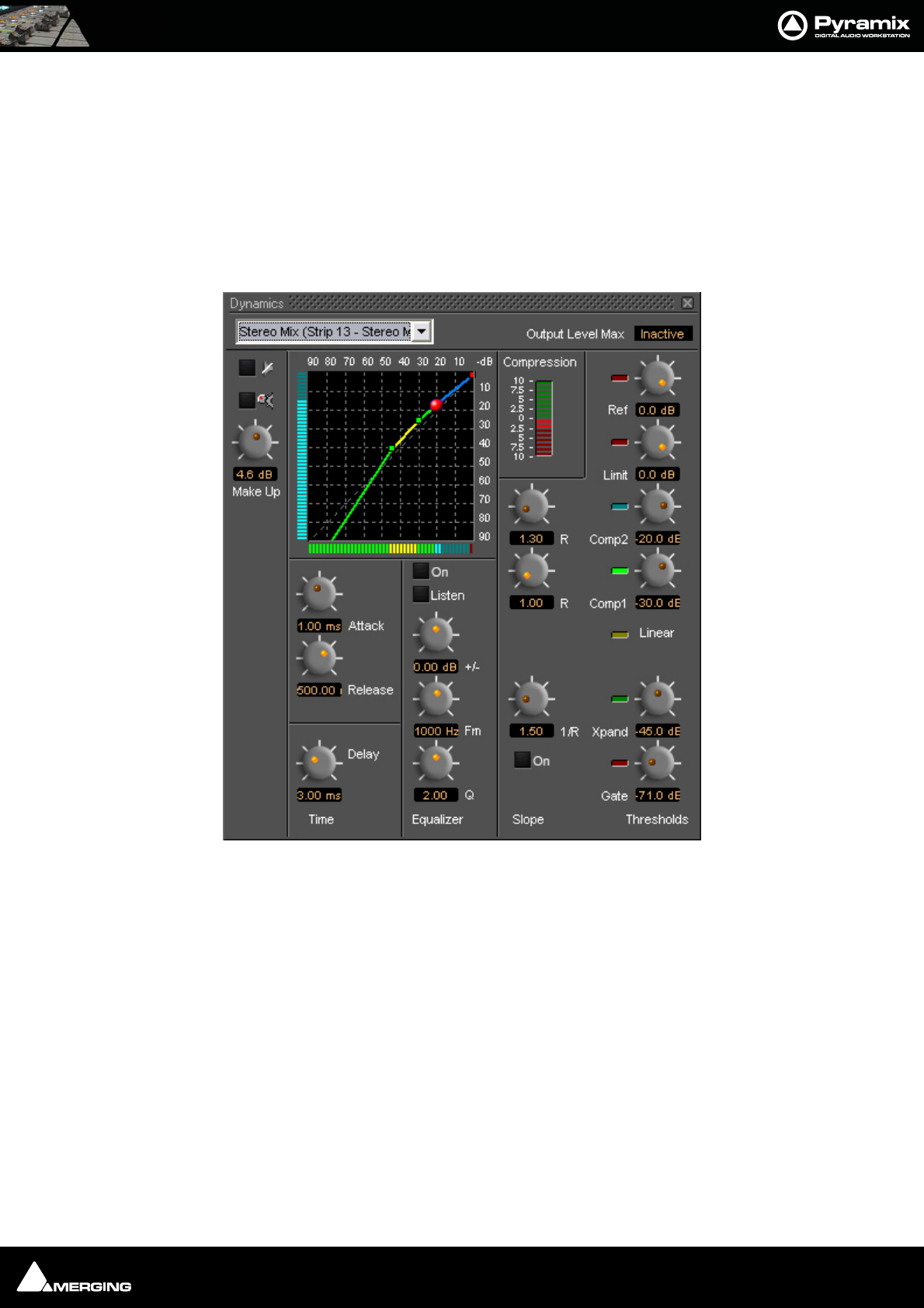
Effects and Plug-Ins : Dynamics Processing 13 - 224
The Low LPF is a shelving EQ with a slope of 6dB/Octave and a turnover frequency of 100 Hz, the Medium BPF has
a Q (bandwidth) of 0.8 with a center frequency of 2 kHz, and the High HPF is a shelving EQ with a slope of 6dB/
Octave and a turnover frequency of 8 kHz.
Dynamics Processing
A comprehensive dynamics processing module. Functions available include one gate, one expander, two com-
pressors, one limiter, and a de-esser. The operation of each of these effects is interrelated in this comprehensive
dynamics processor, and the user interface shows the operative dynamic range where each process takes effect.
Output Level Max
This box shows Inactive when auto-gain compensation is on.
Thresholds
Threshold controls set the level above or below which the plug-in will affect the dynamics of the input signal. All
the threshold settings are on the right of the window. From the bottom up, Gate, Expander, Compressor 1, Com-
pressor 2, Limiter, and Input Reference Level.
Reference Level
Sets the input level reference. E.g, setting the reference level to -20 would mean an input level of -20dB is consid-
ered to be the equivalent of unity gain for purpose of calculating the input threshold levels for all dynamics pro-
cesses except limiting. The reference level value is variable between 0dB (unity gain) to -30dB.
Limit
Sets the limit threshold (and ceiling).
Dynamics floating Window

Effects and Plug-Ins : Dynamics Processing 13 - 225
Ratios / Slope
Limit and Gate have fixed ratios, tending to infinity. Ratio settings for the Expander and Compressors are to the left
of their respective Threshold controls.
Compression Bar Graph Meter
The Compression bar graph indicator, above the ratio controls, shows the amount of overall gain reduction or
increase applied to the input signal. No change is in the middle of the scale. Green ‘leds’ above the middle indicate
gain increase, red ‘leds’ below indicate gain reduction. The display range of the indicator can be toggled between
+/-10dB, +/- 20dB, and +/-40dB by clicking on it.
Time
The speed at which the dynamics processor responds when signals go above or below any of the threshold set-
tings are in this section. Careful setting of these parameters make dynamics processing more subtle and less
obtrusive.
Delay
Allows the main program signal to be delayed by 0.01ms to 10ms. Allows ‘brick-wall’ limiting since the processor
has time to respond to fast transients.
Attack
Attack Time sets the response speed of the processor when a threshold level is reached within the range of .01 mil-
liseconds to 600 milliseconds.
Release
Release Time sets the rate at which applied gain change returns to unity after the threshold is no longer exceeded.
Range is 5 milliseconds to 5 seconds.
Equalizer
The equalizer is in the side-chain. I.e. it affects the key signal which triggers the effect of the dynamics processor,
but does not alter the tonal balance of the main signal. This enables the response of the processor to be made
more sensitive to certain frequencies than others. This is typically used to produce a de-essing effect, used to con-
trol excessive sibilance. E.g. boosting frequencies 3kHz to 8kHz range so that a compressor acts when the signal
has components in this range thus reducing signal level and making the sibilance less obtrusive.
Q
Sets the bandwidth of the eq.
Frequency
Sets the equalizer center frequency in the range 20Hz to 20kHz. 24dB of Boost/Cut are available. The Test button
toggles the output of the EQ between side and program chains. When On, the output of the EQ is heard. This can
be useful when identifying sibilance etc. On/Off toggles the equalizer on and off in the side chain. When Off, the
program material triggers the processor. When On, the signal is in effect, split. The portion sent via the equalizer is
used to trigger or ‘key’ the operation of the dynamics processor on the normal program material.
X/Y Dynamics Response Display
This shows the threshold and ratio settings for the gate, expander, compressor 1, compressor 2, and limiter pro-
cesses, and the Dynamics Processor's reference level. These are shown as a series of colored lines with control han-
dles on a grid representing input level in dB below unity gain (0dB) on the horizontal axis, and output gain in dB
below unity gain (0dB) on the vertical axis.
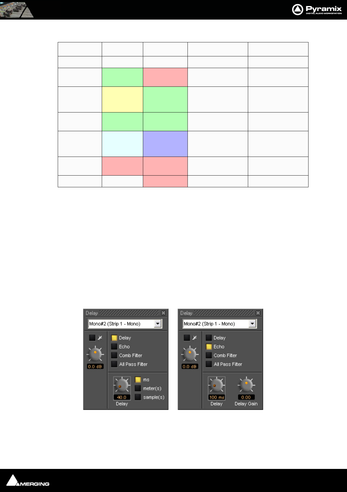
Effects and Plug-Ins : Delay 13 - 226
The legend for this display is as follows:
Adjusting Dynamics Parameters
Parameters can be altered by clicking and dragging on the control knobs or by clicking and dragging the control
handles in the graphic display. Handle controls are affected by other parameter settings. In some instances drag-
ging a handle will change more than one parameter.
Dancing Star Real-time Response Indicator
A red "dancing star" inside the graphic display gives a useful indication of how the processor is affecting program
material. It shows the output level in real-time when signal is present at the inputs.
Delay
The delay Plug-in provides four delay-based effects. ‘Plain-vanilla’ Delay, Echo, Comb Filter and All Pass Filter.
The interface is slightly different when Delay is selected.
uses a straight-through signal path at unity gain with no direct (un-delayed) signal present at the output. The
length of delay can be set in milliseconds, meters or samples. The range of delay available is 0 to 800 ms. Delay
time can be set with the knob, or by typing in the desired delay amount in the text box.
Process Line Color Handle Color Line Slope Function Handle Function
Gate Red *** Gate on/off ***
Expander Green Red Expander Ratio Gate Threshold,
Expander Ratio
Linear Yellow Green Linear response
between Expander
and Compress 1
Expander Threshold
Compressor 1 Green Green Compressor 1 Ratio Compressor 1 Thresh-
old
Compressor 2 Blue-Gray Blue Compressor 2 Ratio Compressor 2 Thresh-
old, Compressor 1
ratio
Limiter Red Red Shows Limit Limiter Threshold,
Compressor 2 Ratio
Reference Red *** Limiter Threshold
Delay floating Windows
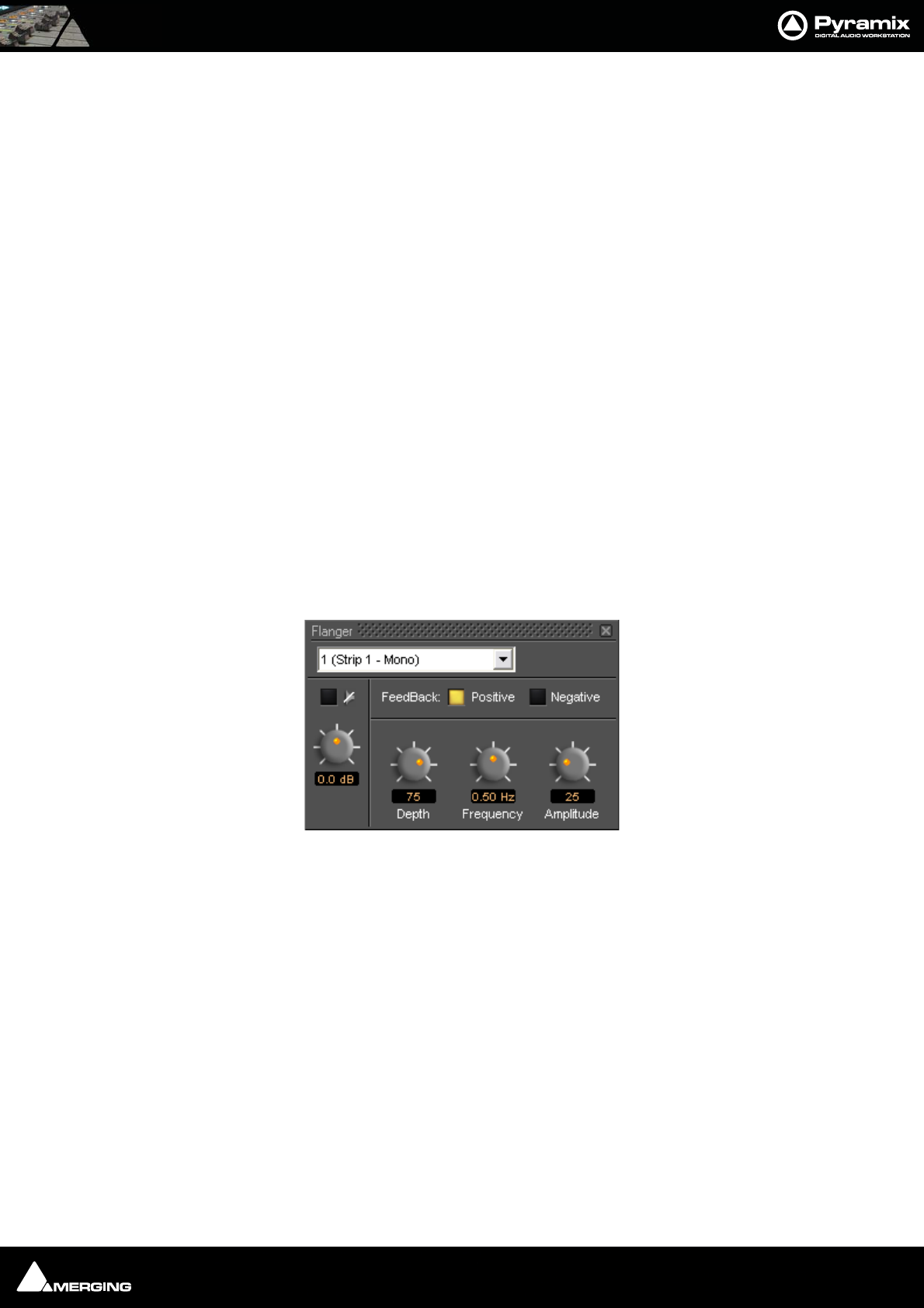
Effects and Plug-Ins : Flanger 13 - 227
Echo
Echo adds a set amount of delay to the signal passing through it and then mixes this delayed signal with the direct
audio source signal. The delayed signal is always at unity gain. The level of the direct signal relative to the delayed
signal is set by the Delay Gain control as a factor between 0 (full attenuation of the direct signal), 1 (unity gain of
the direct signal), and -1 (unity gain of the direct signal phase reversed).
Comb Filter
Delays the signal then feeds part of the delayed signal back to the input of the delay. Comb Filter has the same
control parameters as Echo, but the audible effect is quite different because it uses a feed backward rather than a
feed forward signal path. The name Comb Filter comes from the fact that signals with a wavelength which is an
odd multiple of half the delay time are canceled by the process. This result gives a frequency response chart which
looks like a comb, with some frequencies (depending on the delay time) missing, like the gaps between the teeth
of a comb.
All Pass Filter
Combines the processes used in the Echo and Comb Filter effects. The result is a multiple echoed signal with a flat
frequency response. The control parameters are again the same as in the Echo and Comb Filter effects. Delay Gain
has a quite different effect. It doesn’t affect the overall level of the output signal. It primarily affects the phase of
the signals at different frequencies. If set to 1, it inverts the phase of the input signal and there will be no echo.
With a gain of -1, the input signal there is no phase shift. A gain of 0 means that there is no direct signal compo-
nent and the delayed signals are phase shifted by an amount dependent on their respective frequencies.
Flanger
The flanger produces the characteristic sound which was first produced by playing two copies of something, in
sync but varying the speed of one copy by holding the flanges of the tape spool.
Pyramix Flanger plug-in simulates this effect by time modulating the signal and feeding it back to the input either
in phase (positive) or phase reversed (negative). Feedback type toggles between Positive and Negative. Depth of
modulation can be varied between 0 and 100%, Frequency between 0.05Hz and 5Hz and the Amplitude of the
modulation between 0 and 100%.
Flanger floating Window
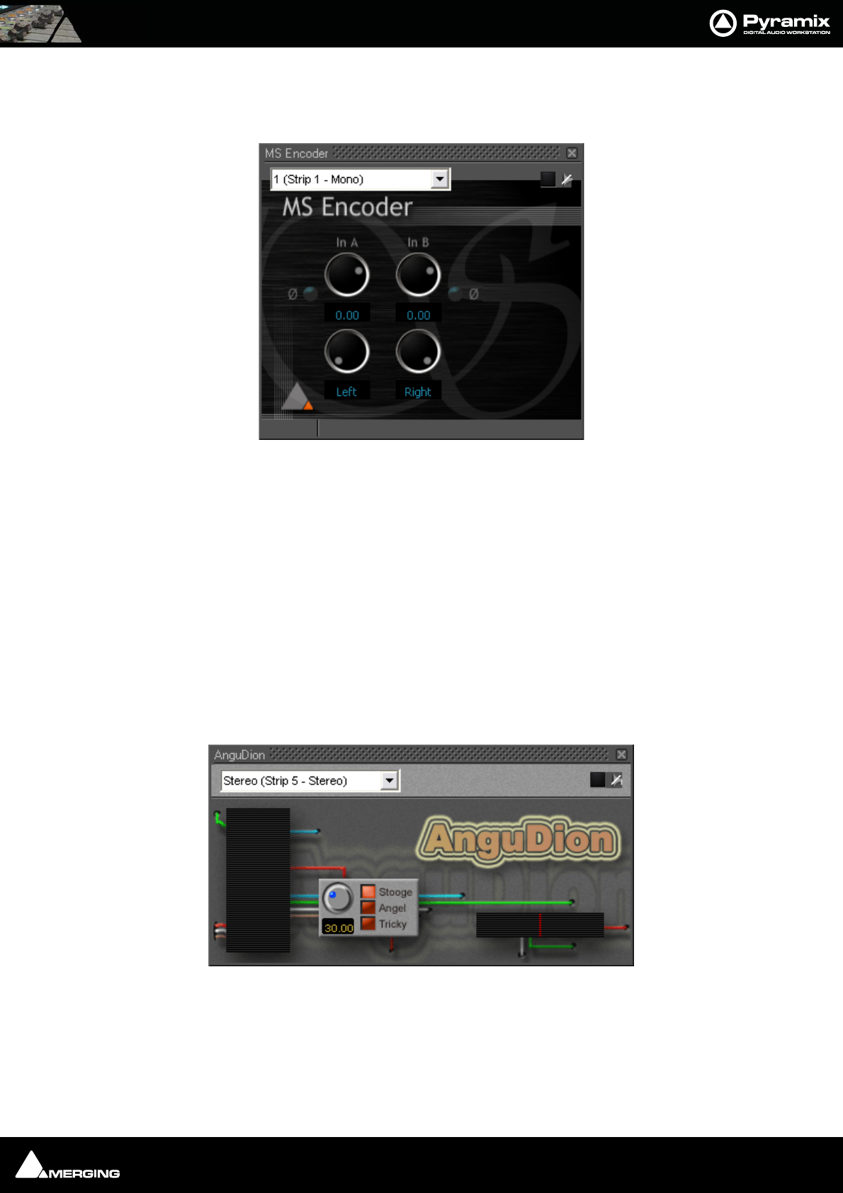
Effects and Plug-Ins : MS Encoder 13 - 228
MS Encoder
As it says on the tin.
Either input can be phase reversed, the input levels are adjustable and the both channels can be individually
panned anywhere between hard left and hard right.
Encode Levels
With the controls hard Left and Right and Unity gain applied signals are encoded in this way:
M = A + B - 3dB
S = A - B - 3dB
AnguDion
Interesting! Three buttons labeled Stooge, Angel, and Tricky, one knob calibrated from 0 - 100
You work out what it does!
MS Encoder floating Window
Angudion floating Window
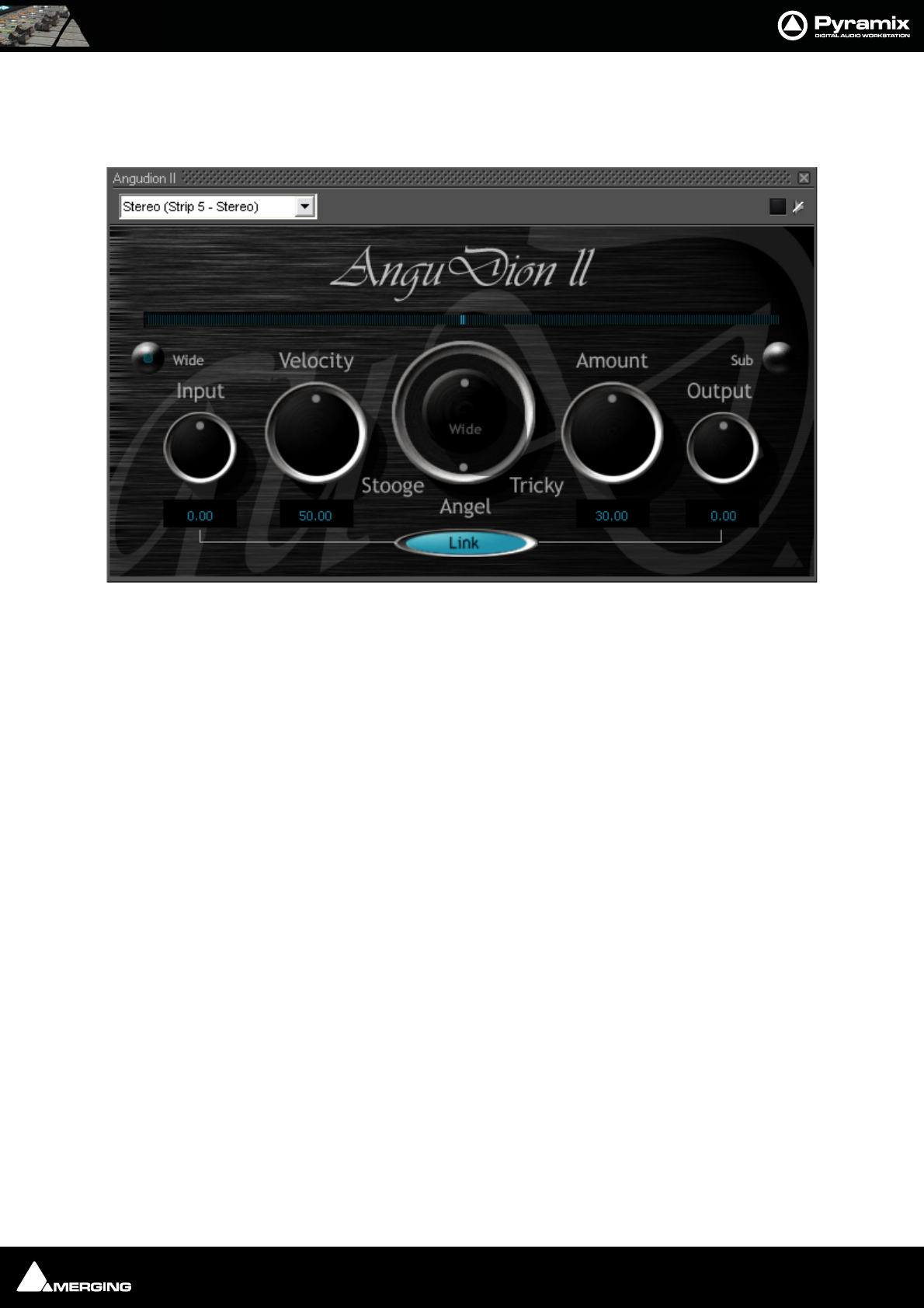
Effects and Plug-Ins : AnguDion II 13 - 229
AnguDion II
Even more interesting!
This time with Wide and Sub buttons and linkable Input and Output gain rotaries. Velocity and Amount rotaries
flank a rotary switch with Stooge, Angel and Tricky options. The concentric Wide pot becomes active when
AnguDion II is inserted in a stereo channel and the wide button is pressed. The Sub button can be selected when
AnguDion II is inserted in a surround strip.
If you have had a play and still want to know more, please see the separate Angudion PDF file.
Angudion II floating Window
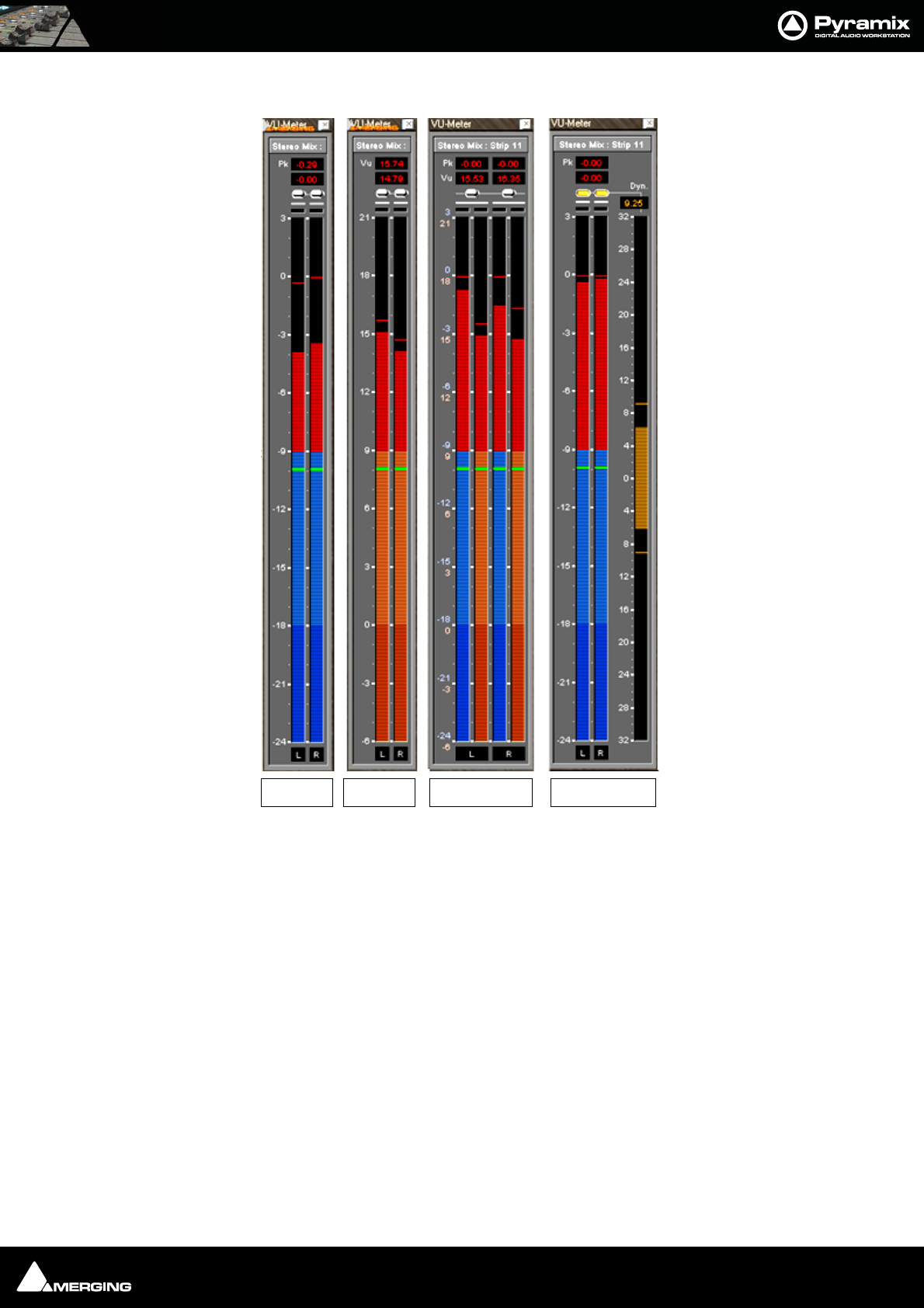
Effects and Plug-Ins : Mastering Peak/Vu Meters 13 - 230
Mastering Peak/Vu Meters
A precise measuring instrument. The VU meter displays the audio level on every strip where it is activated in a
common window. It can serve as a master level display replacing expensive external hardware metering units.
Clicking on a VU meter plug-in opens the meter window. The plug-in offers three different level displays, each with
the option of Dynamic range display.
Peak VU Both Both+Dynamic
Meter floating Windows
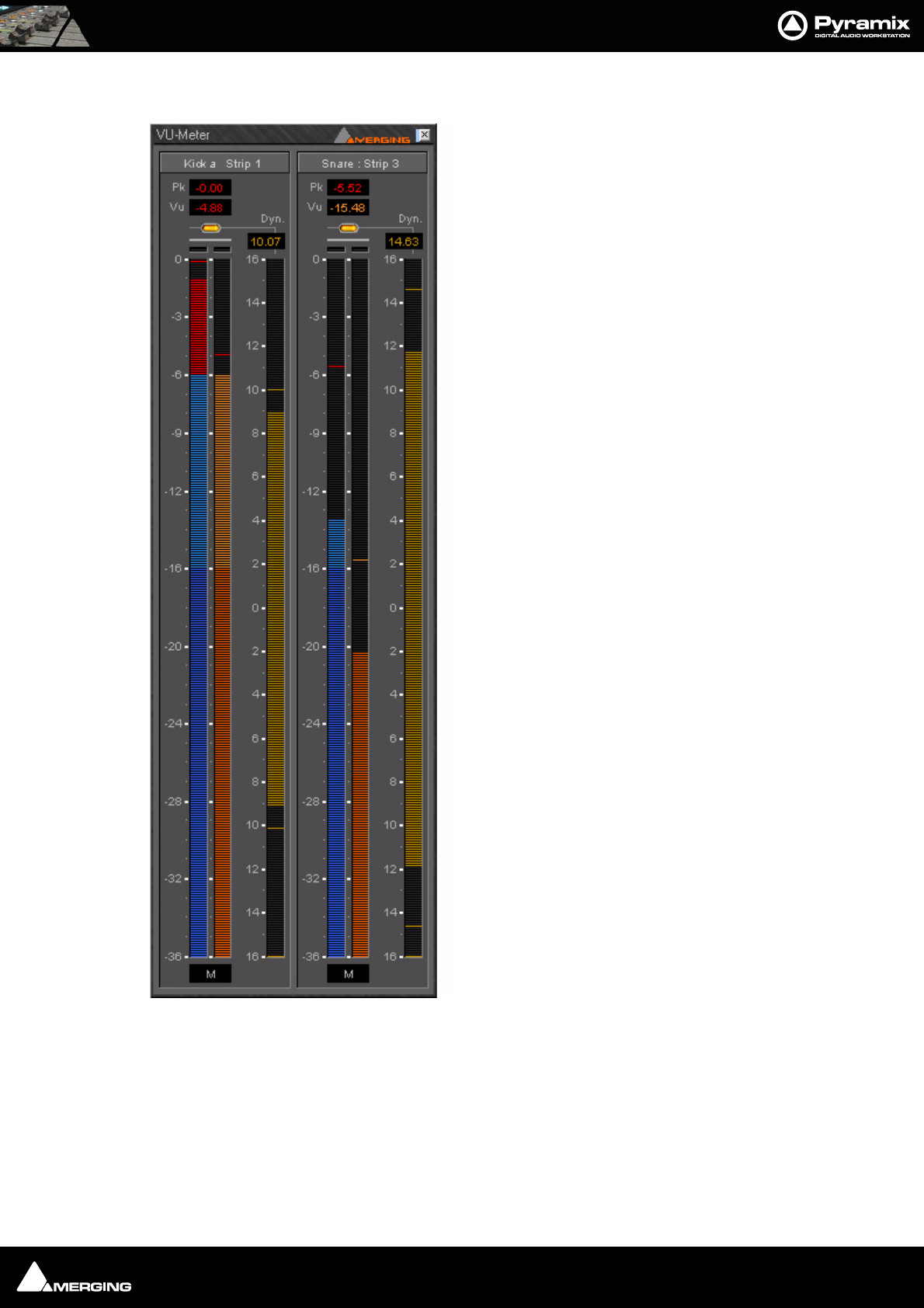
Effects and Plug-Ins : Mastering Peak/Vu Meters 13 - 231
Peak-Meter
This measures the peak value of the audio signal. Peak meter-
ing is very useful to check the absolute digital level of the
audio signal. The Peak meter bars are blue and it has a default
release time of 16 dB/second.
VU-Meter
The VU (Volume Unit) meter displays an average amplitude
level. The VU meter is displayed in orange/yellow color, has a
default integration time of 60 ms and a release time of 10 dB/
second.
Dynamic-Meter
This display measures the instantaneous dynamic range of the
audio signal. Basically this is the difference between the Peak
and the VU display. If a pure sine tone is measured, the
dynamics would be zero. The Dynamics meter is displayed in
yellow and has a default release time of 12 dB/second.
Activating the VU-Meter
The VU-Meter can be added like any other plug-in on any strip
by choosing Add Effect > VU-Meter from the context menu
within the mixer strip. The only difference compared to other
plug-ins is that when multiple instances of the VU-Meter are
activated they are always displayed within a single window
frame.
Display options
The Peak and the VU meter can be displayed individually with
a middle mouse click anywhere within the window area of the
VU meter. Each click with the middle mouse switches between
the options Peak and VU, only Peak and only VU.
The Dynamics display can be activated by clicking on the
switches at the top of the meter bargraphs. On multi-channel
meters (stereo strips, surround mixes, etc.), the dynamics are
summed together into one bargraph, allowing for example to
display the dynamics of the L, R and C channels of a surround
mix without the rear channels.
Peak Meter floating Window
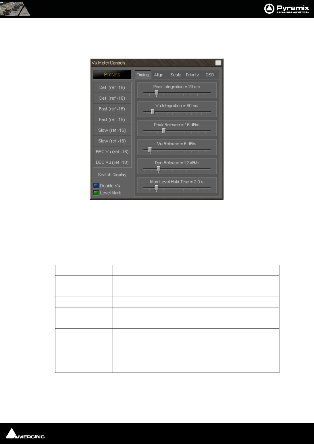
Effects and Plug-Ins : Mastering Peak/Vu Meters 13 - 232
VU-Meter controls
Most of the display parameters of the VU-meter can be adjusted individually. Click with the right mouse button
anywhere on the VU-meter to display a dialog allowing to control most parameters of the VU-meter.
The left side of the control window contains global settings and several predefined presets, while the right side
has four Tabs and a panel of controls specific to the selected tab.
Global Settings and Presets
Eight presets are defined which allow you to quickly select a set of parameters which fit best to your application.
Switch Display
Clicking on this large button cycles through VU, PEAK and BOTH.
Preset Name Description
Def. (ref -16) Default preset with a VU reference level of -16 dBFS
Def. (ref -18) Default preset with a VU reference level of -18 dBFS
Fast (ref -16) Preset with fast response times and a VU reference level of -16 dBFS
Fast (ref -18) Preset with fast response times and a VU reference level of -18 dBFS
Slow (ref -16) Preset with slow response times and a VU reference level of -16 dBFS
Slow (ref -18) Preset with slow response times and a VU reference level of -18 dBFS
BBC VU (ref -16) Preset with BBC standard settings (slower VU release time settings) and a
VU reference level of -16 dBFS
BBC VU (ref -18) Preset with BBC standard settings (slower VU release time settings) and a
VU reference level of -18 dBFS
Vu-Meter Controls Timing Tab
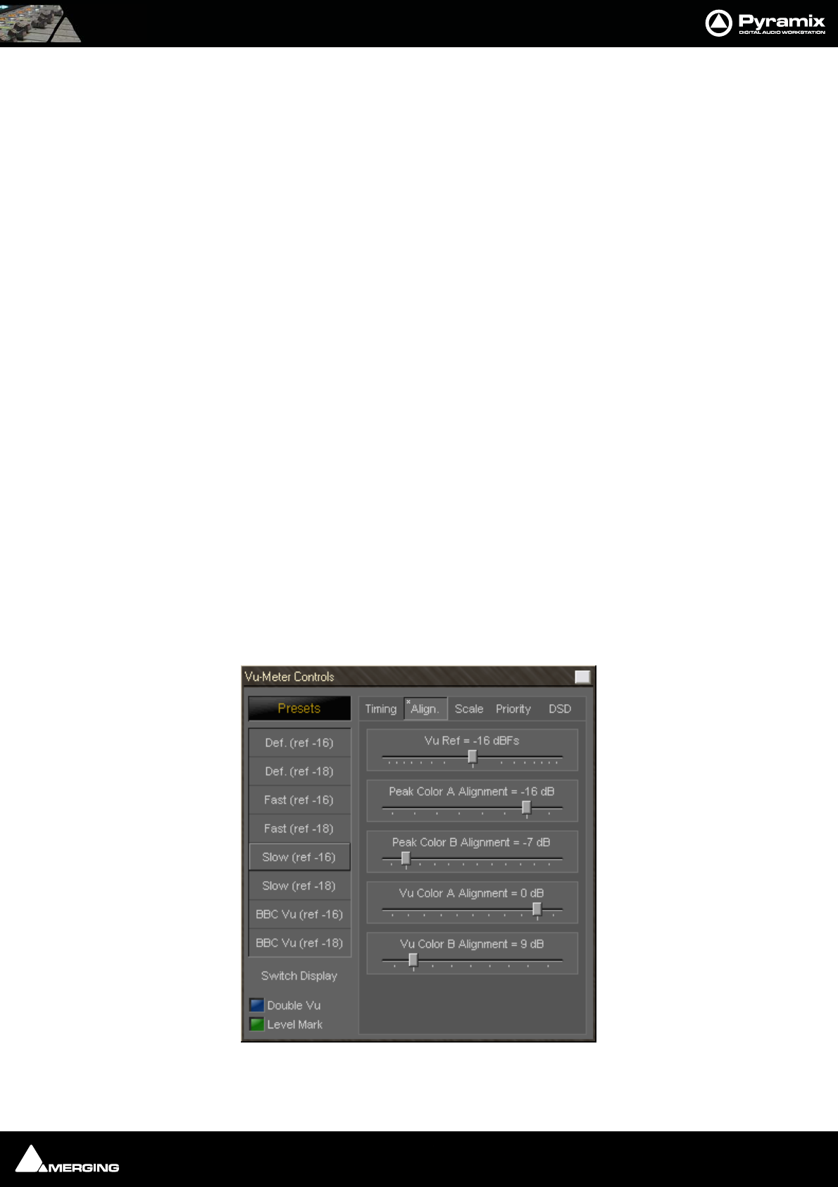
Effects and Plug-Ins : Mastering Peak/Vu Meters 13 - 233
Double VU
When this button is lit, the peak meter switches to VU characteristics, thus enabling you to run 2 VU-meters with
different settings at the same time.
Level Mark
When this button is lit, a mark at your desired “nominal” level (set in the Scale Tab), will be displayed as a gray bar.
When the input signal exceeds the mark level, the bar will become light green.
Timing Tab Settings
These parameters are accessed by clicking onto the Timing Tab at the right side of the settings pane (see also pic-
ture above).
Peak integration
This parameter adjusts the integration time of the peak meter for rising levels measured in milliseconds.
VU integration
This is the integration time of the VU meter for rising levels measured in milliseconds.
Peak Release
This is the speed at which the peak meter falls, when the level is decreasing, expressed in dB’s per second.
VU Release
This is the speed at which the VU meter falls, when the level is decreasing, expressed in dB’s per second.
Dyn Release
This is the fall time of the dynamics display. It is expressed in dB’s per second.
Max Level Hold Time
The highest segment reached will remain lit for a specified time after the level decreases, making it easy to see
what the maximum level was. This parameter adjusts the length of time the segment remains illuminated.
Alignment Tab Settings
The alignment parameters affect the scale of the peak and VU meter. They are accessed by clicking the Align Tab.
Vu-Meter Controls Align Tab
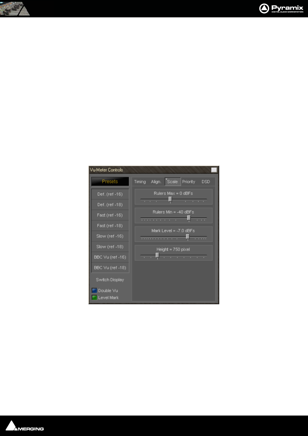
Effects and Plug-Ins : Mastering Peak/Vu Meters 13 - 234
VU Ref
This parameter sets the level of the 0 VU point in relation to 0 dBFS (0 dBFS is the value at which the maximum
value of a sample word is reached. Anything above this level means that the signal is clipped).
If, for example, the VU Reference level is set to -16 dBFS, the VU meter would display 0 dB when the signal is at -16
dBFS.
Peak Color A/B alignment
The peak meter uses three colors depending on the magnitude of the displayed level. Below the A point, the color
is blue. Between the A and B point, the color is a lighter blue, and above the B point, the color is red.
These two parameters adjust the level of the A and B points.
VU Color A/B alignment
The VU meter uses three colors depending on the magnitude of the displayed level. Below the A point, the color is
dark orange. Between the A and B point, the color is a lighter orange, and above the B point, the color is red.
These two parameters adjust the level of the A and B points.
Scale Tab Settings
These alignment parameters affect the rulers of the peak and the VU meter and also the dB range of the display.
They are accessed by clicking the Scale Tab.
Rulers Max
This sets the maximum level of the range displayed by the peak meter. Usually you would set this to 0 dBFs, such
that a digital full scale level would reach exactly the top of the scale. But since Pyramix uses Floating Point arith-
metic, you might theoretically have signal levels above 0 dBFs, so it may be useful to be able to display them (of
course, at the output of the mixer, such a signal has to be converted back to an integer number, and would cause
digital clipping, so care should be taken with signals at these levels).
Rulers Min
This sets the minimum level of the range displayed by the peak meter, and thus influences the accuracy and the
resolution of the peak and VU meter. Signals lower than the minimum are not visible on the meter.
Mark Level
Sets the position of the Level Mark. This is normally set to your desired “nominal” level.
Vu-Meter Controls Scale Tab
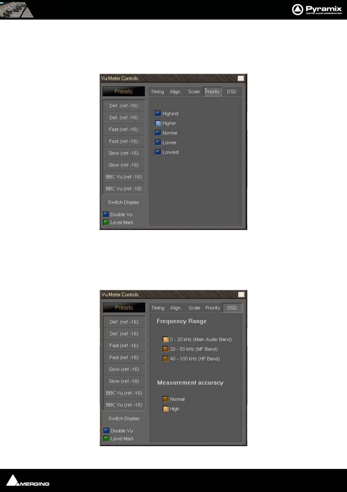
Effects and Plug-Ins : Mastering Peak/Vu Meters 13 - 235
Height
This modifies the height (in pixels) of the VU meter plug-in window as it is displayed on the screen.
Priority Settings Tab
The priority settings are accessed by clicking the Priority Tab.
The buttons select how much CPU time of the host PC can be consumed by the plug-in, and therefore influences
the redraw speed and accuracy of the VU-meter. The higher the priority, the more CPU time is assigned to the
plug-in and the better the meter performs.
DSD Settings Tab
For DSD sessions special meter settings are accessed via the DSD Tab.
Vu-Meter Controls Priority Tab
Vu-Meter Controls DSD Tab

Effects and Plug-Ins : Phase-Oscillo 13 - 236
DSD Filtering options
In the specific case of a DSD session the VU meter offers three filtering options which allow you to make sure that
your DSD signal is compatible to the AES recommendations concerning the high frequency dither noise content.
These radio buttons let you choose one of three possible filters which will be applied to the DSD signal before it is
measured by the level meter.
The 20k option applies a 20 kHz low pass filter to the signal, thus only the audible audio content is measured.
The 20k-50k option applies a band pass filter with a frequency range of 20 kHz to 40 kHz to the signal. According
to the AES recommendation the signal level in this frequency range should not exceed -28 dB.
The 40k-100k option applies a band pass filter with a frequency range of 50 kHz to 100kHz to the signal. Accord-
ing to the AES recommendation the signal level in this frequency range should not exceed -20 dB.
Measurement Accuracy
Where maximum accuracy is required select High. However, this setting does require extra processing.
Phase-Oscillo
This plug-in combines a phase meter and a X/Y oscilloscope.
Note: Phase-Oscillo cannot be used in a mono strip. If you do so, it will return an error
message.
The phase meter displays the phase of a stereo signal within the range of -1 to +1. a value of +1 means that the left
and right channel are completely in phase. A value of -1 means that the left and right channel are completely out
of phase causing complete cancellation when they would be summed into a mono signal. A good stereo mix
should be somewhere in between 0 and +1.
The oscilloscope gives you some information about the stereophony and the phasing of a stereo signal. A signal
which is completely mono appears as a vertical line. If only the right channel carries a signal, it is displayed as a
straight line at a 45° angle from the bottom left to the top right. If only the left channel carries a signal, it is dis-
played as a straight line at a 45° angle from the bottom right to the top left. If the left and right channel are out of
phase, this would result in a horizontal line.
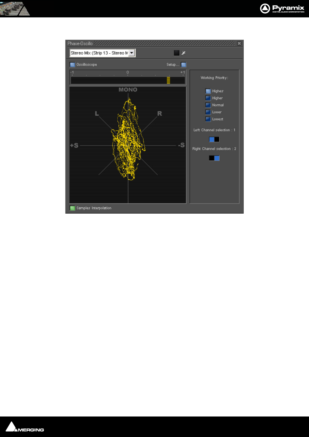
Effects and Plug-Ins : Phase-Oscillo 13 - 237
A decent stereo mix would appear as a vertically shaped cloud as shown in the example below:
Phase-Oscillo configuration
The Phase-Oscillo plug-in has several buttons to configure it’s operation.
Oscilloscope button
This switches the oscilloscope display on and off. If set to off, only the phase meter is displayed.
Sample interpolation
When this switch is on, the samples of the signals displayed on the oscilloscope are interconnected, resulting in an
increased readability of the display.
Setup
This button opens the set-up pane with further options
Working Priority
Choose one of these switches to select the amount of CPU time of the host PC which can be consumed
by the plug-in, and therefore influences the redraw speed and accuracy of the oscilloscope. The higher
the priority, the more CPU time is assigned to the plug-in
Drop frame display
Depending on the chosen working priority of the Phase-Oscillo plug-in might not get enough CPU time to contin-
uously redraw the display. The drop counter displays the amount of frames which could not be drawn because of
lack of CPU time since the start of the actual Pyramix session.
Left and Right channel selector
If the plug-in is inserted on a bus with more than two channels (e.g. a surround bus or a multiple stereo bus), these
two selectors allow you to select the appropriate channels for the left and right input of the plug-in. On a surround
bus, you might for example select the left front and right front channels to be displayed on the Phase-Oscillo
plug-in.
Phase-Oscillo floating Window
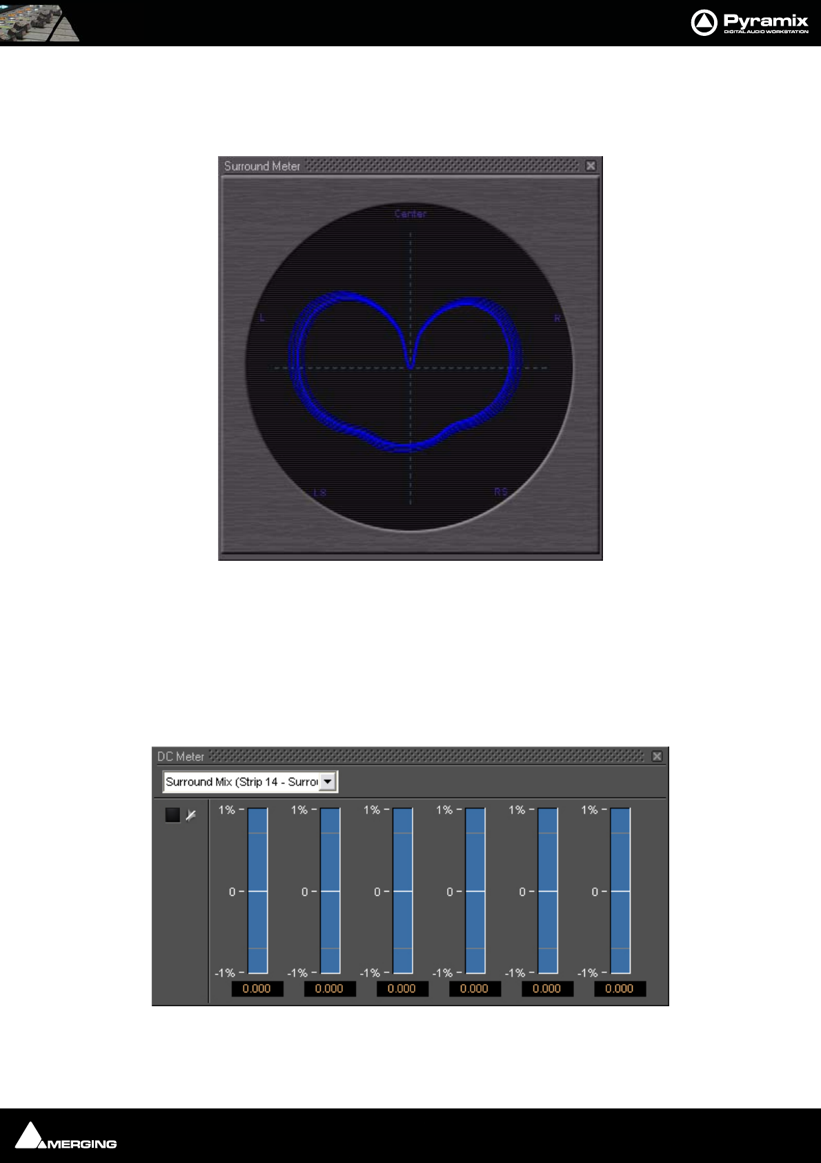
Effects and Plug-Ins : Surround Meter 13 - 238
Surround Meter
Gives a very useful indication of energy distribution in a surround sound field.
The Surround Meter incorporates automatic gain ranging which maintains a meaningful display for a wide range
of material. There are no settings to adjust!
DC Meter
Measures the DC content in the signal.
Surround Meter floating Window
DC Meter floating Window
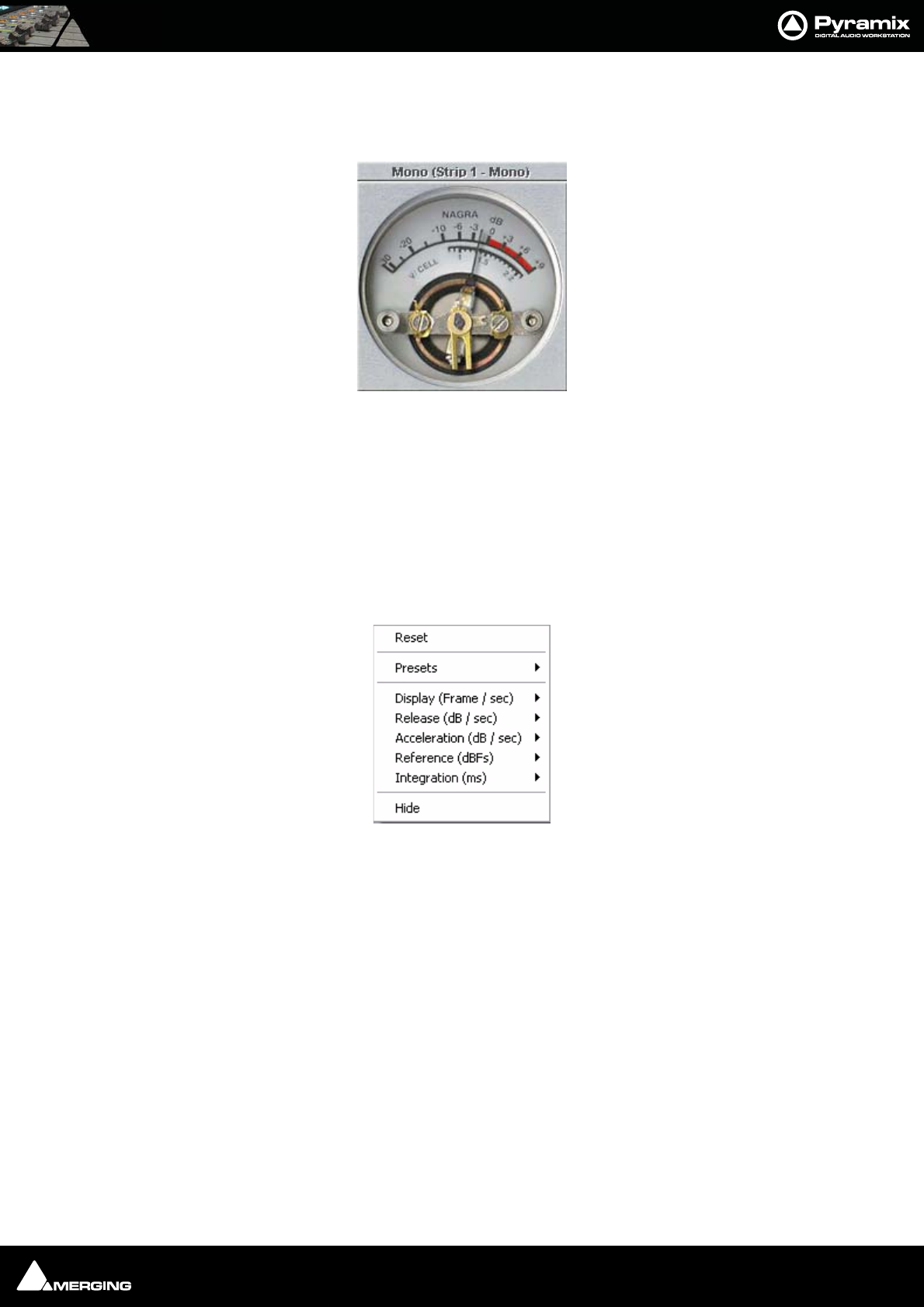
Effects and Plug-Ins : Modulometer 13 - 239
Modulometer
The Modulometer is a faithful reproduction of the classic meter fitted to Nagra portable Tape recorders.
Common operational practice to is set levels so the meter reads (average) - 8 when recording speech. This is partly
due to the modulometer's characteristics as a quasi peak meter (quasi because it has the ballistics of a mechanical
meter) and it also reflects the caution required in location dialogue recording where a lost take can represent
many thousands of dollars. Although not by any means desirable, a low level signal is better than one with distor-
tion from peak clipping.
Right-clicking anywhere on the window pops up a context menu. This has several options which control the
behavior of the Modulometer.
Reset
Restores the default settings
Presets
Offers the standard Preset options
Display (Frame / Sec)
Sets the display refresh rate
Release (dB / Sec)
Sets the Release time
Acceleration (dB / Sec)
Sets Acceleration rate
Reference (dBFS)
Sets the Reference level in DeciBels Full Scale
Modulometer floating Window
Modulometer menu
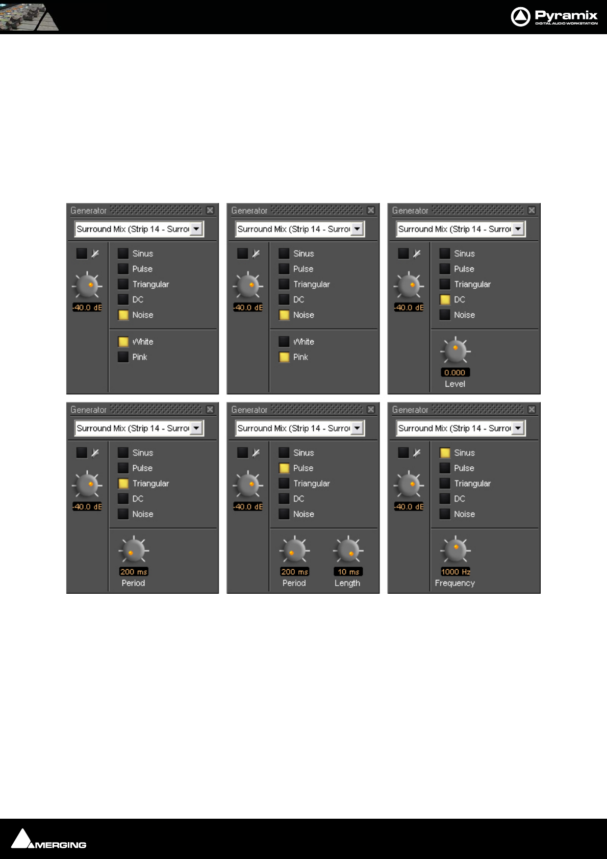
Effects and Plug-Ins : Function Generator 13 - 240
Integration (ms)
Sets the Integration time in milliseconds
Hide
Hides the Modulometer
Function Generator
This oscillator can produce a Sine wave, a Pulse wave, a Triangular (Sawtooth) wave, DC and White or Pink Noise.
Function Generator floating Windows
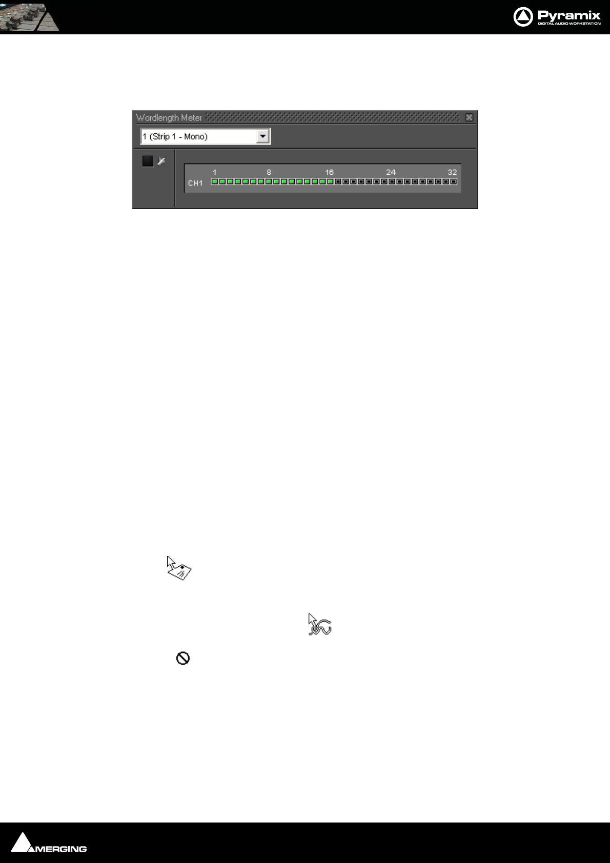
Effects and Plug-Ins : Wordlength Meter 13 - 241
Wordlength Meter
The Wordlength Meter (or Bit Meter) allows you to view the effective wordlength of a signal.
Bear in mind that, once you apply any gain adjustment (e.g. a fader set anywhere other than 0dB) the signal will
become 32 bit float data.
Effects and Plug-in Automation
All signal processing parameters in Pyramix VS3 Effects Plug-ins can be fully automated dynamically in the same
manner as the Mixer controls. Please see Dynamic Automation Modes on page 260.
Note: For information about differences when automating VST Plug-ins Please see: VST
Plug-in Automation on page 254
Effects Snapshots
Effect Settings can be easily stored and recalled by dragging them to/from libraries.
Creating Effects Snapshots
Hold Alt + Shift, then click and drag from the horizontal bar next to the Channel combo box in a Plug-in window
to the library where you want to store the settings, then release. A new item, of the type Mixer Snapshot, is stored
in the library. The snapshot is given the name of the plug-in by default. The new item is automatically highlighted
so, if you wish to change the default name, simply type the new name and hit Enter to confirm. The name of the
snapshot can be subsequently changed by clicking on the name in the library, then entering the new name.
Note: In some plug-ins Alt + Shift click and drag will work on any of the horizontal sec-
tion title bars and in others from anywhere on the plug-in window where the cursor
changes to .
Using Effects Snapshots
Simply click and drag a snapshot from a user library to a plug-in of the same type as the original and release any-
where on the surface where the cursor changes to
Anywhere the snapshot cannot be dropped, or if the snapshot plug-in type does not match the target plug-in, the
cursor changes to
Optional Plug-ins
Optional Pyramix plug-ins. For operating instructions please see each plug-in’s guide.
Wordlength Meter floating Window
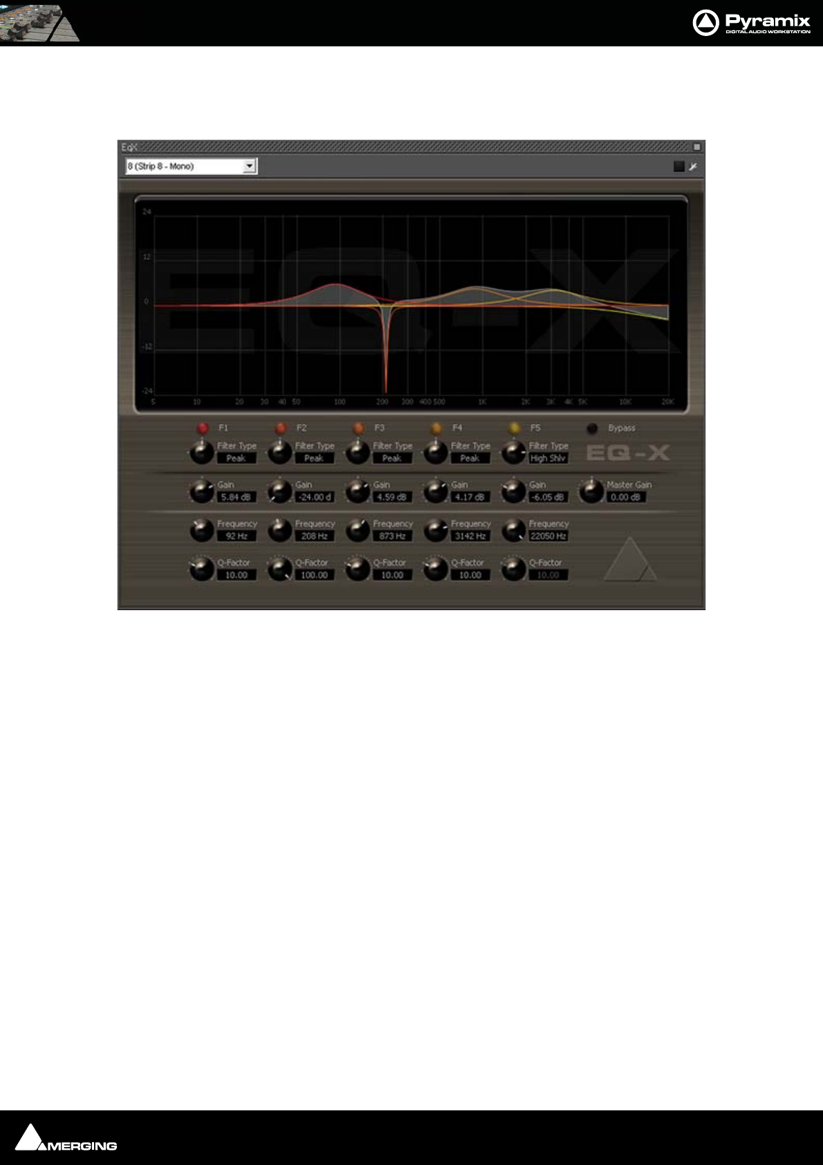
Effects and Plug-Ins : Optional Plug-ins 13 - 242
Merging Technologies
EQ-X
EQ-X builds on the existing and universally acclaimed quality of Pyramix EQ. It is backwards compatible. EQ-X
offers Extreme definition filtering at sampling frequencies up to DXD with notch, low pass, hi-pass, peak and shelv-
ing filter types available.
The state space filter design of this Extreme Definition Equalizer has been specifically optimized to deal with the
highest audio resolutions while still permitting very low noise & distortion, typically offering a THD+N of better
than -110dB, throughout the entire audible (and even non-audible) range. Of course, this new digital filter's
topography, while designed with high sample rate in mind, also offers the extra benefits and low noise to 1FS
equalization. However, since there is no such thing as a free lunch, EQ-X does "eat" about double the processing
DSP power of an equivalent "traditional" digital EQ instance in Pyramix.
EQ-X is a five band fully parametric EQ with independent control of Filter Type, Gain boost and cut, Frequency,
and Q factor (bandwidth) for each band. The equalizer can be operated using the rotary controls, by directly enter-
ing numerical parameters in the boxes beside the knobs or by clicking and dragging on one of the five colored
box nodes which appear when the mouse cursor is over the response graph. Left-clicking enables level and fre-
quency to be adjusted, right-clicking then dragging left or right allows adjustment of Q.
All bands are full range. Boost and cut of up to 24dB is available. Q can be set anywhere from 1.0 (wide) to 100 (nar-
row). Master Gain enables the overall level to be adjusted to suit the applied eq.
EQ-X floating Window
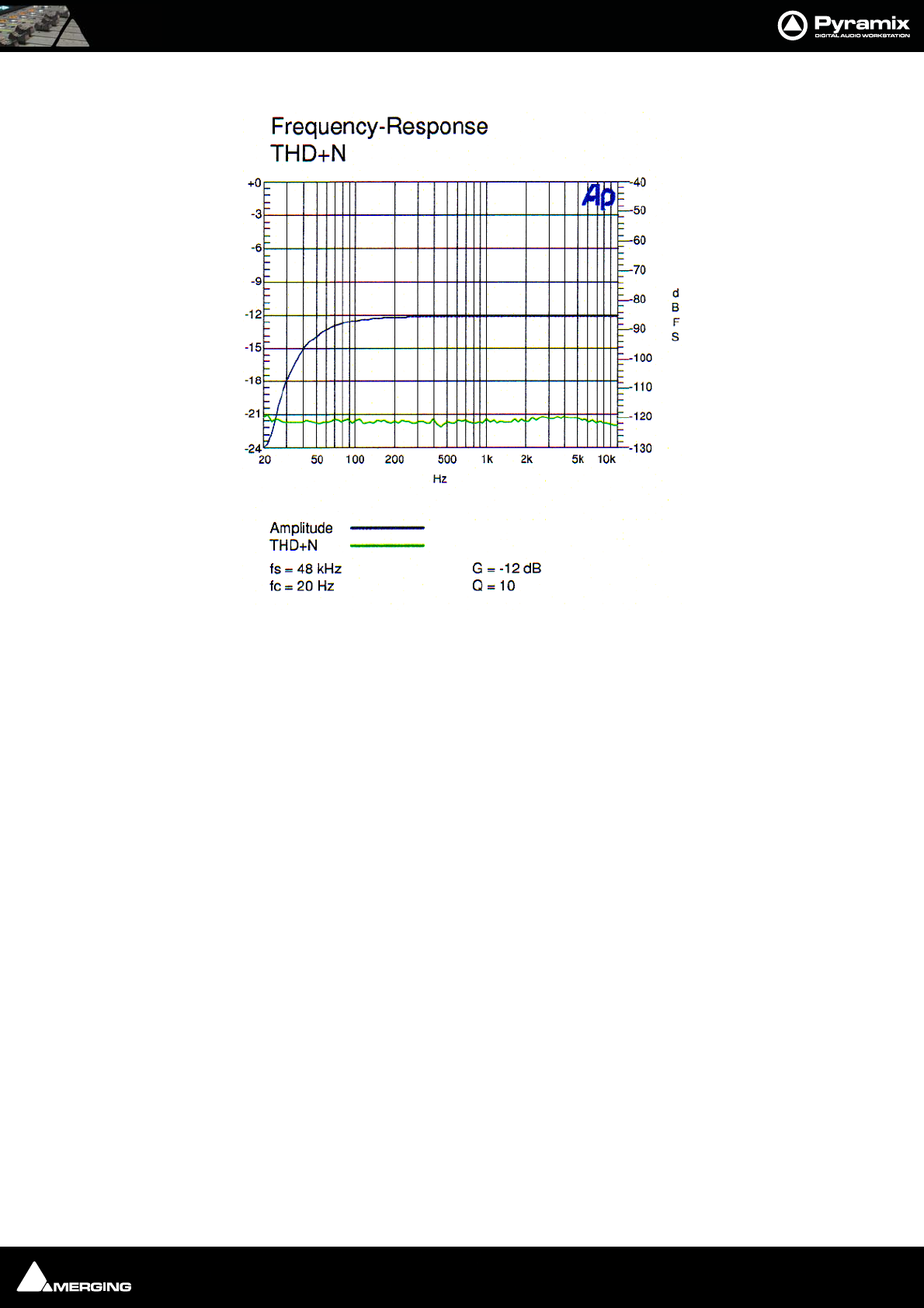
Effects and Plug-Ins : Optional Plug-ins 13 - 243
EQ-X Frequency Response THD+Noise
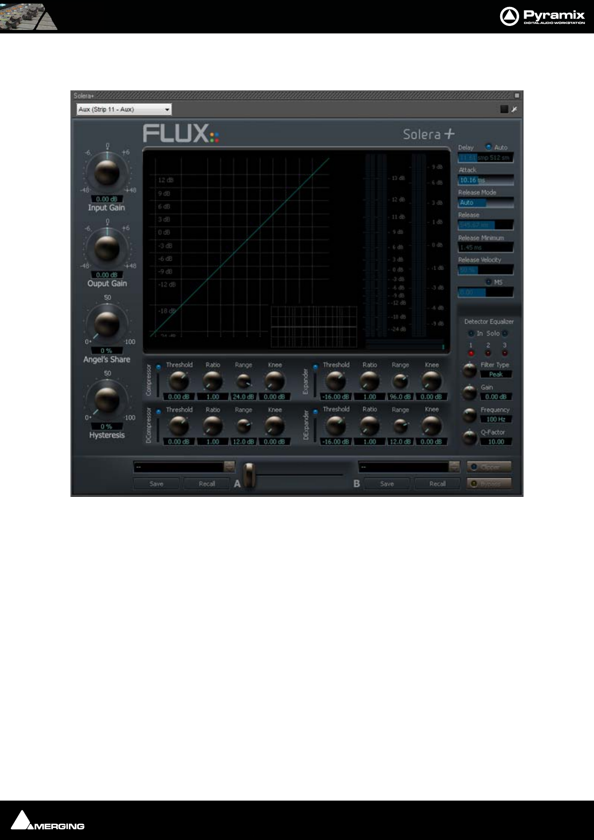
Effects and Plug-Ins : Optional Plug-ins 13 - 244
Flux
Solera +
Solera + is the flag ship of the range of Angel Class Dynamic Processors. It is primarily designed for mastering
and re-mastering applications. However, it can also be used as a regular dynamic processor for superior sonic
quality and distortion free operation.
Developed for Merging Technologies by Flux, every Angel Class Dynamic Processor plug-in uses some exclusive
algorithms that endows them with an incredibly clear and natural sound.
The Pure series uses the same technologies for specific dynamic processes.
Here are some of the key features that make our plug-in the best available for dynamic processing in the digital
domain:
1. Analog like metering. RMS values are more useful than dBfs when setting up a dynamic processor.
2. The Angel's Share parameter takes account of the signal for intelligent relaxation of the compressor action.
3. The Hysteresis parameter allows compressing and de-compressing independently of the sound level and
can be mixed with the standard compression scheme.
4. The Auto Release features an unique algorithm that avoids typical pumping effect.
5. A delay line can inserted in the signal path to produce a null attack time.
6. The A/B compare and Morphing section enables ultra-fast and precise operation.
The Angel Class Dynamic Processor family supports up to simultaneous 8 channels and DXD operations.
Solera floating Window

Effects and Plug-Ins : Optional Plug-ins 13 - 245
Note: Solera is a wine making technique: A Solera is method of fractional blending for wine,
closely paralleling the making of Sherry or Madeira. A solera consists of several rows of
stacked oak barrels with the oldest wine in the bottom row and the most recently made at
the top. At bottling, about one-third of the wine in the bottom row is removed and wine from
the row just above replaces it and soon, until reaching the top row, which is replenished with
new wine. The concept behind a Solera is to make a wine that remains consistent from year
to year.
Angel's Share is a term used for Armagnac, Cognac, Whisky; that part of the spirit that evap-
orates during the process of aging.
Full operating details can be found in the Angel Class Processors User Guide.
Pure Series
The Pure Series plug-ins are essentially the individual building blocks of Solera presented as individual plug-ins.
The advanced release mode is only available in Solera.
Pure Compressor
Pure Compressor is the compressor section of the Solera
Pure Expander
Pure Compressor is the expander section of the Solera
Pure DCompressor
Pure Compressor is the de-compressor section of the Solera
Pure DExpander
Pure Compressor is the de-expander section of the Solera
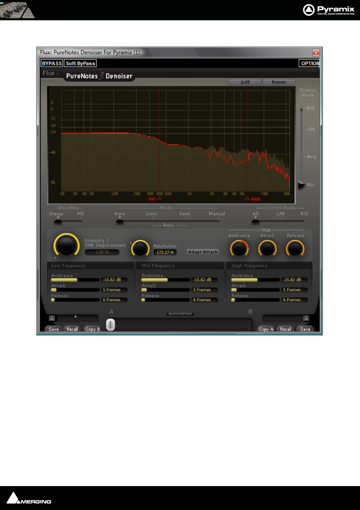

Effects and Plug-Ins : Optional Plug-ins 13 - 247
Algorithmix
DeNoiser
DeScratcher
DeNoiser + DeScratcher, Restoration Suite
Nova
Overview
The Nova™ plug-in for the Pyramix rendering interface is an impressive weapon in the battle for cleaner record-
ings. Coughs, chair scrapes even mobile phone tones are all in its sights.
The Nova™ Plug-In enables audio data in the frequency domain to be modified simply and quickly. These modifi-
cations include interpolation of selected areas over the time- and/or frequency line as well as gain modifications.
The interpolation can also be restricted to certain gain ranges within the selected area, which is very useful if only
a certain part of the data needs treatment (e.g. one specific harmonic etc.) which cannot otherwise be selected.
The Nova™ window is fully resizable for optimum compatibility with all screen resolutions.
Arkamys
UpMix5
Overview
UpMix5 is a plug-in for Pyramix Virtual Studio that upmixes a stereo source to a 5.1 multichannel output. From a
FFT analysis of the stereo signal, UpMix5 discriminates all the 5.1 components. UpMix5 doesn't use any reverb, nor
key compression to get a 5.1 surrounding. This plug-in is designed for Broadcast and Post Production applications
on any stereo material: movie or music.
UpMix5 discriminates mono, stereo and 'out of phase' components from the original stereo signal. The mono
component is played back in the center speaker (C) and the out of phase component is played in the rear speakers
(LsRs). User can choose the width of the final front LR and surround LsRs signals.
Vincent Burel
Aphro V1 Reverb / Aphro V1.5 Reverb
Aphro-V1.0/Aphro V1.5 are real time Digital Effects Processors. Elements of a high quality effects processor series
called Aphro-Vx, Aphro-V1 and V1.5 are specially created to simulate sonorous atmosphere and room effects, in a
realistic way.The handling philosophy is made simple and practical thanks to a wide range of presets, which
requires the user to select a preset matching the best desired effect, and then to use the different interfaces in
order to adjust it, according to his requirements. Grouping parameters by theme, gave us the idea of creating a
modular and ergonomic user interface.
C-Limiter
Stereo Manager
Striptool
Compressors
C10 Limiter
EQ Pro-pack
Tone-X
Chorus
GEQ
MultiTap Delay
VU-Meter + Cor

Effects and Plug-Ins : Optional Plug-ins 13 - 248
Frequencies Analyzer
Stereo Oscilloscope
Mono-Switcher
Cedar Audio Restoration Suite for Pyramix
Cedar’s range of restoration tools need no introduction here. The following processes are available for Pyramix:
Cedar dehiss for Pyramix
Cedar declick for Pyramix
Cedar manual declick for Pyramix
Cedar decrackle for Pyramix
Cedar dethump for Pyramix
Cedar Retouch for Pyramix
Prosoniq
MPEX3 Timestretch and pitch change
Overview
The MPEX3 algorithm for Pyramix has been developed with the German based company Prosoniq, well known for
their high quality digital audio algorithms.
MPEX stands for Minimum Perceived Loss Time Compression/EXpansion. Incorporating this technology into Pyra-
mix Virtual Studio enables users to adjust timing and pitch of existing material with outstanding results and ease
of use.
Algorithm
Time Scaling (also known as 'Time Stretching', 'Time Compression/Expansion' and 'Time Correction') is the process
of changing the length of a sound or sounds without changing its pitch. When a sound is transposed by playing it
back at a different speed, e.g. when slowing down the playback speed of a tape recorder, it will play back at a dif-
ferent tempo but also at a different pitch. While this may be fine when tuning drum loops to match the speed of a
recording it will make pitched sounds - like vocals - sound totally out of tune. Therefore it is desirable to provide a
process that enables the duration and pitch of a recording to be changed independently from each other.
Time Stretch and Pitch Change for Film Applications
There are three main categories of Cinema time stretching and pitch changing requirements:
1) Conversion of audio rushes from 24 to 25 or 25 to 24 when their associated video or film has to be sped up or
slowed down. The main reasons are:
a. The shooting has been done with film AND video, so one part of the rushes or the other have to be sped up
or slowed down.
b. The telecine process to bring the film rushes to video for editing didn't preserve the original speed, intention-
ally or by mistake.
c. The shooting has been done on video at 25fps (intentionally or by mistake) and has to go to film.
Pyramix provides various solutions to this problem:
Batch conversion
of a whole media folder. Just select all media to stretch/squeeze / pitch change and select the menu Quick Con-
vert > Prosoniq MPEX3 module. All media will be processed in one shot. Media will have to be re-synchronized in
time with their video equivalent by using the reference "Clap".
In the case where all the media are already synchronized in time with their video equivalent (either manually or
because they've been properly stamped while recording), then simply send all these media to their original Time-
Code (time stamp) in a Pyramix project and select the menu item Project > Stretch / Pitch. All media will be prop-
erly stretched/squeezed and their position will be also correctly updated. The new original TimeCode (time stamp)

Effects and Plug-Ins : Optional Plug-ins 13 - 249
can then be written back to the media by selecting the menu item Clips > Operations > Update Media Original
TC, so these new media can now be used exactly as if they've been recorded and stamped at that new speed,
allowing also auto-conformation or other TimeCode based processes. All information stored in the clips referenc-
ing these media in the Timeline (like fades, sync points, gain curve, ...) are also stretched/squeezed properly.
Optionally the media can be consolidated to convert only the required part
The two processes described above are necessary when a mix of different source material speed have to be "nor-
malized". In the case where it is known from the beginning that the whole editing and mix will have to be
stretched back to the other (original rushes) speed, Merging provides a very convenient solution in term of hard-
disk space, conversion time and finally sound quality. The Virtual Transport Video Player allows playing the video
editing at a different speed than the audio material allowing matching (for instance and in the majority of cases) a
video running at 24 frames per second with an audio editing stamped at 25 frames per seconds. This avoids com-
pressing the audio so it matches the video being played too fast (25fps instead of 24) but preferably run the video
at the correct speed (24fps) and therefore the audio also.
Surround Post-processing
Conversion of a final mix from 24 to 25 for DVD/Video distribution of a film or 25 to 24 for film distribution of a
video shot and edited movie.
Pyramix allows stretching/squeezing a whole surround mix by selecting the menu Project > Surround Post-pro-
cessing and choosing the Prosoniq MPEX3 24/25 Time Stretcher module. This function stretches/squeezes a
whole 5.1 mix without inter-channels phase artifacts thanks to the new Prosoniq MPEX3 algorithm. This function
allows processing multiple stem surround mixes stem by stem. Due to artefacts introduced by most time stretch-
ing algorithms available until now, the normal procedure was to separate the dialogue stem and the music/
effects/ambiance stems, time-stretch them separately and remix them afterward. Although the Surround Post-
processing function allows this methodology, this is no longer required due to the very high quality of the MPEX3
module. Therefore a complete mix can be stretched in one pass retaining maximum sound quality.
Time fit
Compression or expansion of a portion of audio to fit in a given time, generally dialogue, ADR, translation or Foley.
Pyramix provides three ways to stretch/squeeze a region of audio:
• Just select the region or clip to process and place the cursor at the position where the nearest region
boundary should be extended to and select Edit > Stretch. A dialog will then allow the boundaries to be
precisely adjusted with the help of TimeCode entries, or simply click OK or press the Enter key to confirm
the operation.
• Select the region or clip you want to process and copy it (Edit > Copy, or Ctrl C etc.). Select the region you
want the copied region to fit into then simply use the command Edit > Fit Selection.
• Select the region or clip to process, select the menu Project > Render and choose the Prosoniq MPEX3
module.
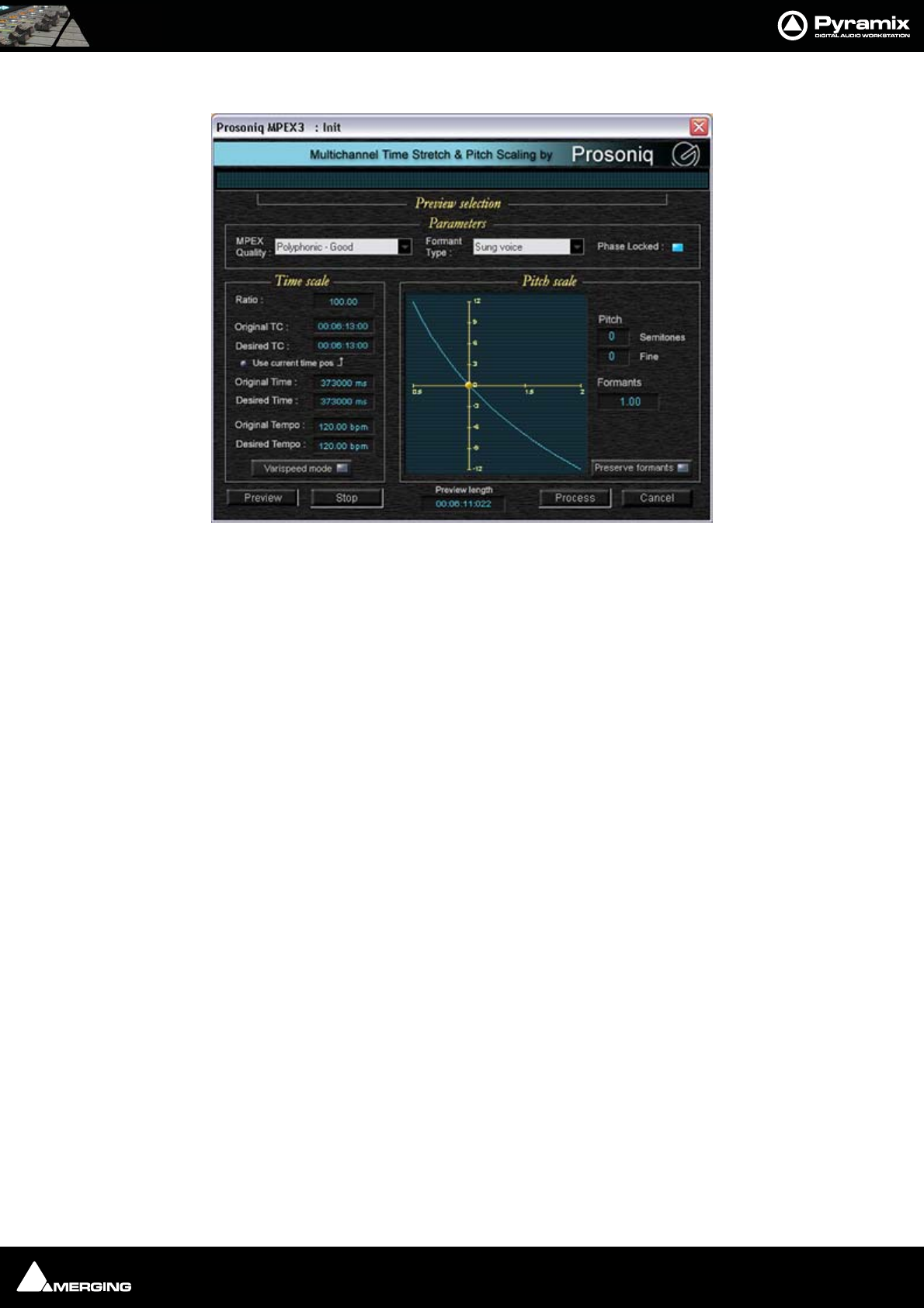
Effects and Plug-Ins : Optional Plug-ins 13 - 250
A comprehensive interface then enables the time-stretch parameters to be precisely adjusted. In addition to time-
stretching this interface also allows Pitch and Formant adjustments.
Quick Convert
The Prosonique MPEX3 process can also be accessed by the Quick Convert function (Media Management Tab Win-
dow, Menu Convert > Quick Convert > Prosonique MPEX3
Scopein
TimeZone Time Compression
Prosoniq MPEX3 dialog

Effects and Plug-Ins : VST Support 13 - 251
VST Support
VST Plug-ins
All well-behaved VST plug-ins can be used with Pyramix.
Multi-channel VST Plug-ins
Multi-channel VST plug-ins are supported on MassCore Systems only.
Routing
On all Pyramix platforms VST plug-ins are automatically routed according the Strip or Bus Channel types e.g. C, LR
etc. and the matching VST Speaker arrangement (typically, 5.1 Surround VST speaker arrangement uses the L-R-C-
Lfe-Ls-Rs mapping). If no VST Speaker arrangement can be found, the routing is straight.
For example, if for some strange reason you stamp a Stereo Aux as R-L, the left channel of a VST plug-in inserted
into it will be fed by the 2nd channel of the Aux, and the Right channel by the 1st one; and at the VST insert out-
put, the R-L routing is restored.
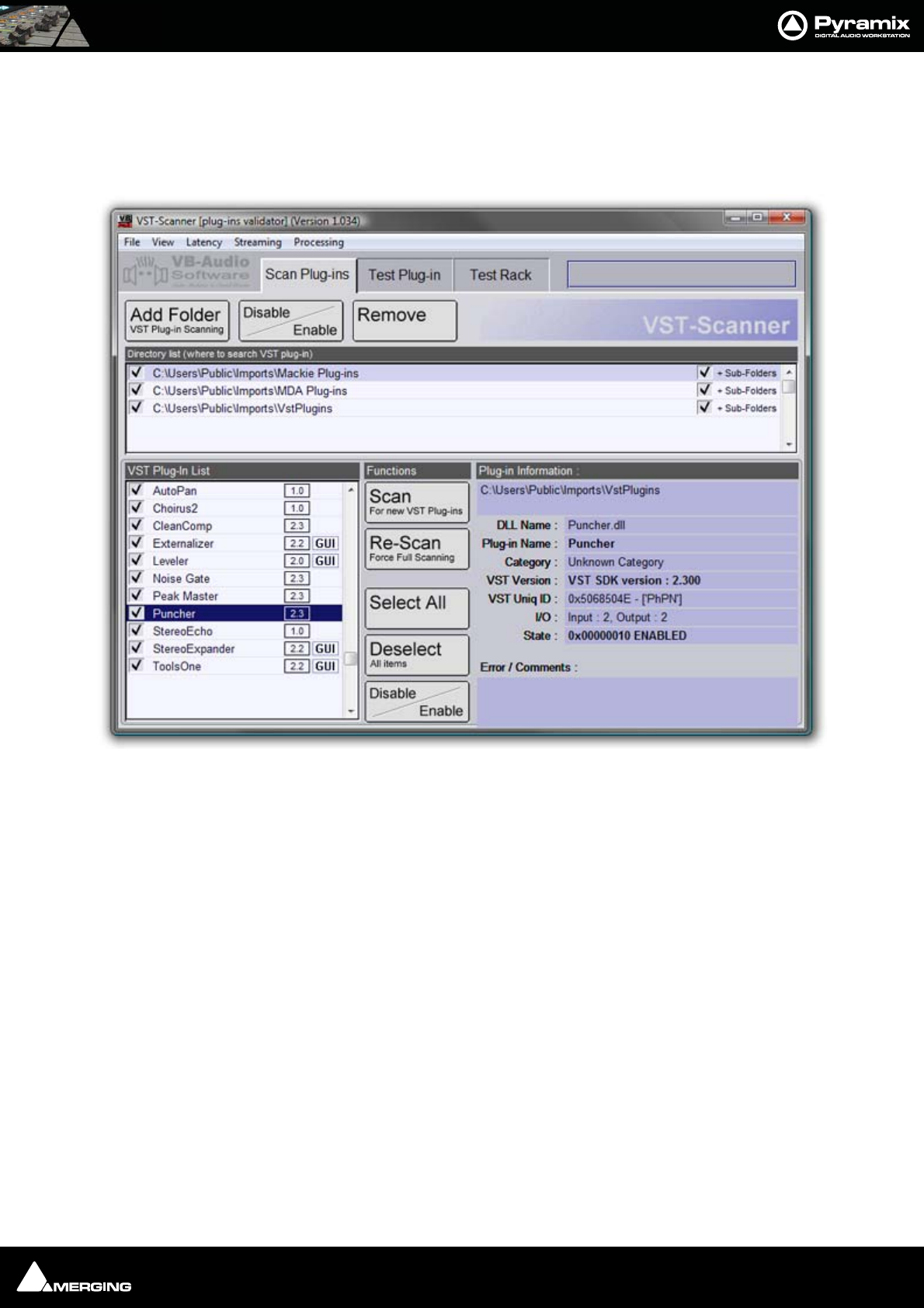
Effects and Plug-Ins : VST Support 13 - 252
VST Scanner
To Load VST plug-ins in Pyramix you first have to tell Pyramix where they are. Go to Start > Programs > Pyramix >
VST Scanner. If you have Cubase or any standard VST program you will see your VST plugs appear in the left win-
dow. Select the ones you want to use in Pyramix (including Waves VST and TC Powercore).
If nothing appears in the left window, you just need to have a folder containing all your VST plug-ins files (they are
.dll file type) somewhere on your disk, hit the Change button at the bottom of the VST Plug-Ins Chooser window,
browse your disks and select the folder containing the VST plug-ins. They will now be listed and recognized in
Pyramix.
Note: The VST plug-ins are processed by the host CPU. Therefore, if you are intending to
use VST plug-ins intensively, fast host processors are recommended.
The VST Scanner can be used as a validation tool. User instructions and the latest version can be found at its devel-
oper’s (VB Audio) website:
http://perso.wanadoo.fr/vb-audio/fr/resources/vst_scanner/vst_scanner.htm
VST Plug-ins Display Order
The list of VST Plug-ins that appears when adding a new instance of a plug-in can be ordered in two ways.
VST - Scanner Window
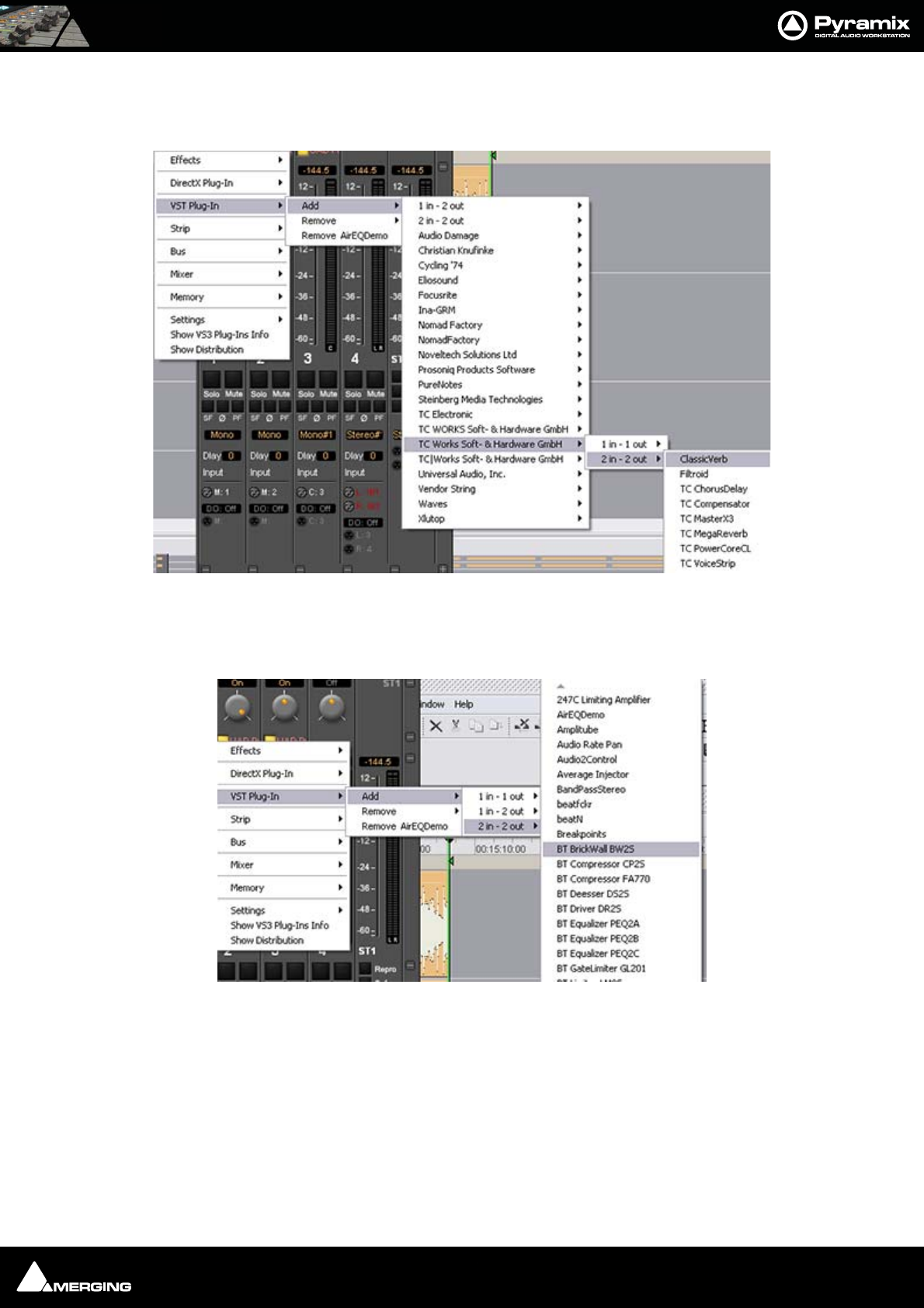
Effects and Plug-Ins : VST Support 13 - 253
If Company Name and I/O Configuration is chosen the list will be ordered by Company Name and the plug-in’s
grouped according to their I/O configuration. I.e. 1 in - 1 out, 1 in - 2 out, 2 in - 2 out and so on as shown here:
Alternatively, choosing I/O Configuration groups the Plug-ins by I/O Configuration and within each group lists
them alphabetically by name as shown here:
The alternative displays are chosen in the Settings > All Settings : Project > Mixer > Plug-ins Settings page.
Please see also: Plug-ins Settings on page 513
VST - Plug-Ins List by Manufacturer
VST - Plug-Ins list by I/O configuration
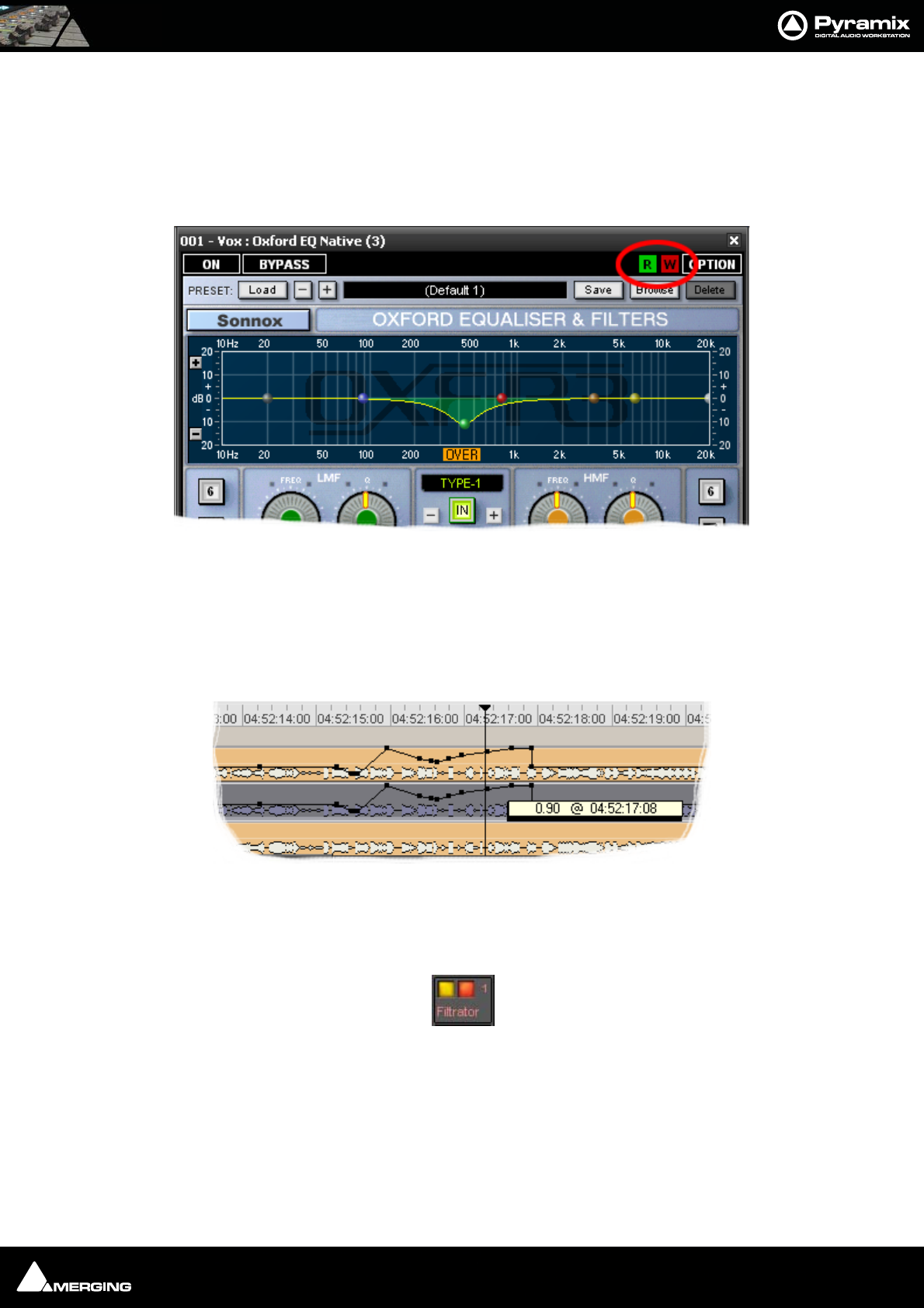
Effects and Plug-Ins : VST Support 13 - 254
VST Plug-in Automation
VST plug-in automation works in much the same way as VS3 plug-in and Pyramix Mixer automation. However,
there are a few differences:
Automation Mode
Read/Write, Auto-Write or Isolate status can only be set for an entire plug-in.
Automation mode is set using the R and W buttons to be found at top right of a VST Effect window as shown
above. (Unlike VS3 plug-ins individual controls cannot have independent Automation modes)
Automated Control Values
Control values are always expressed as zero to one. I.e. in the range 0.0 to 1.0 when editing automation points in
the Timeline. The exception is when the VST plug-in reports a control as a toggle switch.
On/Off and Bypass
Like VS3 plug-ins VST plug-ins have yellow On/Off and red bypass buttons on the mixer providing standard bypass
control.
The left-hand yellow button is lit when the effect is switched on. Switching an effect off removes it from the signal
chain and this may well be audible.The right-hand red button indicates that the effect is bypassed when lit.
Bypassing an effect retains the same delay as when the effect is active. Further, well behaved effects will continue
to calculate internal parameters when bypassed making seamless switching possible.
Note: Certain VST plug-ins such as UltraPitch do not have the standard VST internal
“soft” bypass function. In this case, Bypass simply acts as an ON/OFF button. One effect
of this is a change in Delay compensation scheme resulting in latency changes as the
VST - Plug-In Automation Read Write buttons
VST - Plug-In Automation node control value display
VST - Plug-In On/Off and Bypass
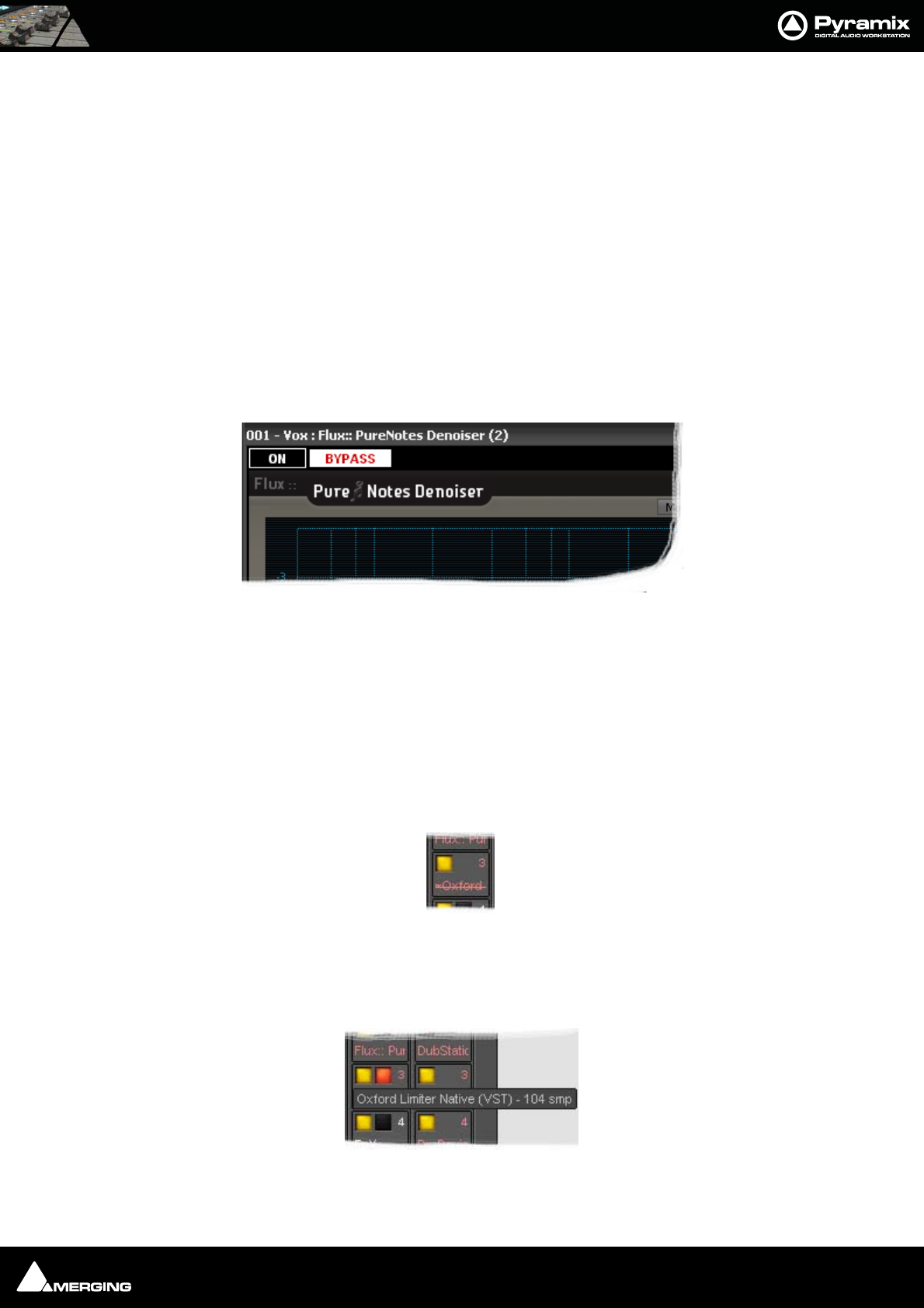
Effects and Plug-Ins : VST Support 13 - 255
plug-in is switched ON or OFF.
Changing the delay compensation on the fly during Playback or Record is not safe since
it will cause a glitch or playback stall, and therefore Pyramix postpones the delay com-
pensation recomputation until the transport switches back to stop. When you change
the bypass status of such a plug-in on the fly the DelayComp status LED turns red and,
on the next Stop, Delay compensation is recomputed and the status LED returns to
green.
Most VST plug-ins provide a private 'bypass', (inside the plug-in's own user interface),
which enables clean, click-free and state-safe bypassing, without latency change (i.e. the
plug-in maintains the same latency whether it is bypassed or not). Unfortunately, there is
no simple and effective bypass solution for plug-ins that do not have an internal bypass.
VST Effect User Interface labels
On the VST user interface windows themselves, the buttons have been renamed to ON/OFF (formerly BYPASS)
and BYPASS (formerly Soft Bypass).
Caption Bar
The Caption bar text of these windows shows the ID of the related Strip or Bus and its name, before the plug-in
name.
Ghost Plug-ins
As with VS3 plug-ins, the Ghost plug-in feature is implemented for VST plug-ins: essentially, this means that if you
load a project containing a VST plug-in which is unavailable on your machine, this plug-in will appear in the mixer
as a Ghost plug-in. Saving the project will not trash the missing plug-in’s state information.
When a plug-in is a Ghost its name appears crossed out in the mixer :
Processing Delay Display
At any time, you can view a VST plug-in’s processing delay in the VST plug-in name tooltip on the mixer (if non-
zero, the processing delay will be appended in smp (samples) after the plug-in name):
VST - Plug-In Caption Bar
VST - Plug-In Ghost
VST - Plug-In Tooltip with delay value

Effects and Plug-Ins : VST Support 13 - 256
Direct X Plug-ins
in Pyramix V6.1, DirectSound / DirectX plug-ins can only be used inside a suitable “VST Wrapper”. There are several
freely available, for example from Vincent Burel.
Important! Projects and templates created with previous versions of Pyramix may well contain
Direct X plug-ins. If a Project or Template is loaded which contains Direct X plug-ins then these
will be visible in the mixer but cannot be activated.
However, if such a Project is “Saved As” V5.1 then these plug-ins will be active if the Project is sub-
sequently opened in a system running V5.1.
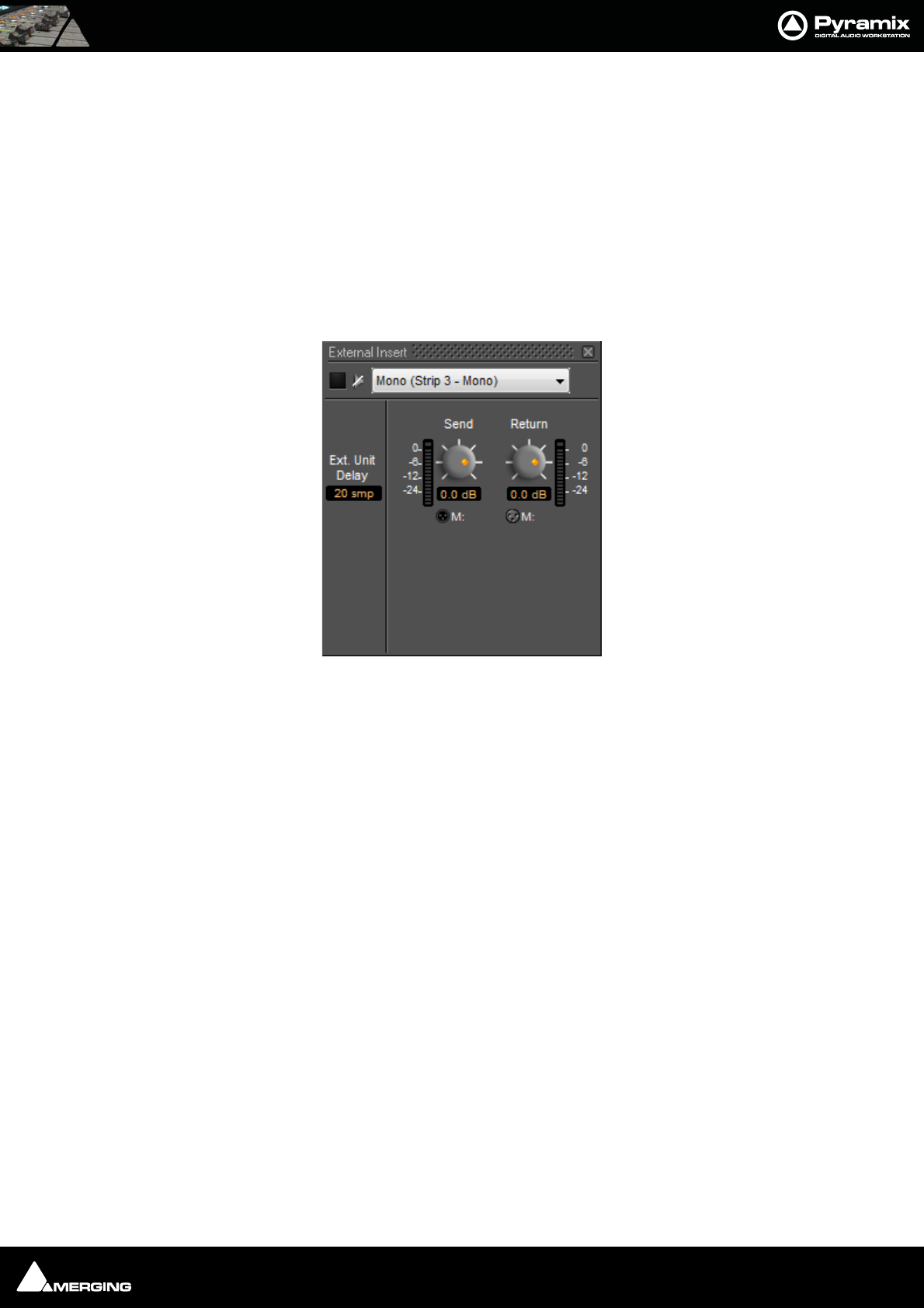
Effects and Plug-Ins : External Effects 13 - 257
External Effects
Any Pyramix Bus except sub-groups can be routed to any physical output. Thus, an Aux can be routed via a physi-
cal output to an external effect. The output of the external effect is simply brought back into Pyramix via one of
the physical inputs. However, a delay will be introduced by the external processor and the converters. If the return
needs to be time-aligned with other signals please see: Mixer Delay Compensation on page 173
External Insert
To add an External Insert simply right-click over the strip where the plug-in is to be added and choose: VS3 Effects
> Add > Other > External Insert
Clicking on the External Input name in the strip opens the External Insert Control Window.
Send and Return Connections can be made by clicking on the XLR icons and levels set with the knobs. When you
have determined the delay introduced by the I/O loop including the external effect the value in samples should be
entered in the Ext. Unit Delay field.
Mixer Strip External Insert Plug-in Control Window

USER MANUAL
www.merging.com/Pyramix
Automation
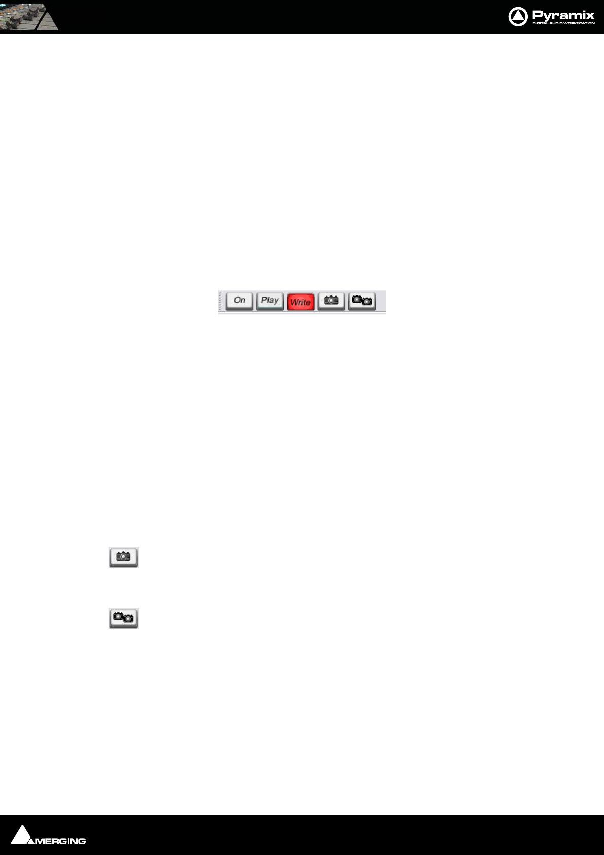
Automation : Scope 14 - 259
Scope
Pyramix Virtual Studio is equipped with an extremely powerful automation system, including both dynamic and
snapshot automation of levels, pans, effects, etc. This chapter covers internal control of automation. If you are
using a Ramses MSC or ISIS Controller, please see the relevant User Guides for further information.
Master Automation Controls
Global Dynamic Automation Modes
Set using the On/Off, Play and Write buttons in the Automation toolbar (or the Automation menu items) these
set the dynamic automation mode for the entire console. Individual controls will react according to their own cur-
rent mode.
The Global Automation Controls are in a dockable Tool Palette, by default located at the bottom right side of the
main Pyramix window. There are On/Off, Play and Write buttons plus two buttons with camera icons which deal
with Snapshot automation:.
On/Off button can only be used to turn dynamic automation Off. When it is Off, no existing automation data is
played back and no new data is recorded when controls are moved.
When the On/Off button is On, (by clicking on Play or Write), existing automation data is played back. New auto-
mation data can only be recorded when Write is lit and the controls to be automated are in an appropriate mode.
When the Play button is pressed it ‘lights’ green.
Controls set to Play, or Auto-Write, Read existing automation data, otherwise they maintain their default values.
Controls set to Isolate or Record maintain their current values and no new data is recorded.
When the Record button is pressed it ‘lights’ red. Controls set to Record write their current values. Controls set to
Auto-Write only record when they are moved. Controls set to Play, Read existing automation data (if any). Con-
trols set to Isolate maintain their current values.
Snapshot Automation
The Snapshot button inserts an automation event (key frame) which records the state of all
enabled controls at the current cursor position if their state has changed since the previous
Snapshot.
The Snapshot Range button inserts automation snapshot key frames of all enabled controls
at the Mark In and Mark Out cursor positions. In effect, this sets all enabled controls to the
current state throughout the range defined by the marks.
Note: If you wish the state of all enabled controls to be recorded regardless of whether
their state has changed then simply select Force automation point insertion in the Fil-
ter Automation Tracks to Snapshot dialog. (This opens when the Snapshot button is
pressed or Automation > Automation Snapshot is selected from the menu.)
Master Automation Controls dockable toolbar

Automation : Dynamic Automation Modes 14 - 260
Dynamic Automation Modes
Every control in the mixer can be set to one of four dynamic automation modes. The automation mode can be set
for individual controls, for channel strips, for buses, for groups of controls or for the whole mixer. The current mode
is shown by the absence, presence and color of small indicators.
Auto-Write
No indicator.
(This is the default for all controls)
With the transport in Play, and the Master Automation Controls in Play or Write modes, the control(s) Read
(play back) previously recorded automation data.
In Write mode When a control is moved new automation data is written until the control is released. Behavior
when the control is released, or the transport stopped, is governed by the choices made in the Automation menu
and in Automation > Automation Settings.
Write
Red triangle indicator.
With the transport in Play, and the Master Automation Controls in Write mode, the current state of all controls in
Record mode is recorded as automation data.
Read
Green triangle indicator.
The control(s) follow the last automation data recorded for them or maintain their default position where no previ-
ously recorded automation data exists.
Isolate
Black triangle indicator.
The control(s) are isolated from any automation moves already recorded. Controls can be moved without affecting
existing automation data.
Selecting Automation Modes
Default Mode
The defaullts mode is Auto-Write. Move a control and automation data is written automatically. Press a button
and the same applies.
Auto-Write Write Read Isolate
Dynamic Automation Mode Indicators
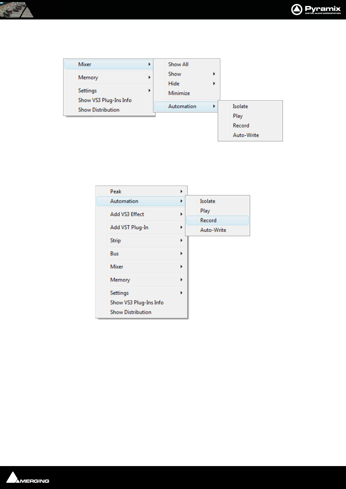
Automation : Selecting Automation Modes 14 - 261
Entire Mixer
The entire mixer can be set to the same mode by right-clicking in a blank area of mixer panel (E.g. under the bus
strips) and selecting the desired mode from the popup menu. Mixer > Automation > Isolate
Block, Strip, Bus or Entire Mixer
Right-clicking in a mixer channel strip function-block, e.g. as shown here in the fader area, pops up a contextual
menu. Selecting Automation opens a sub-menu offering a choice of the four automation modes:
This contextual menu also enables the automation mode for the whole strip, one or more buses or the entire
mixer to be set by choosing Strip, Bus or Mixer.
Mixer context menu Mixer Automation sub-menu
Automation sub-menu
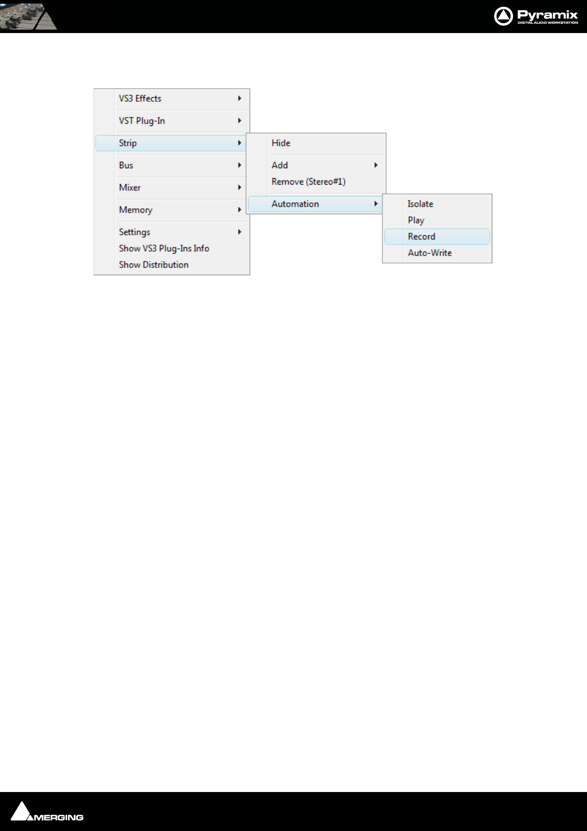
Automation : Selecting Automation Modes 14 - 262
Selecting one of these opens a sub-menu. The last choice in each case is Automation. selecting this opens a fur-
ther sub-menu offering a choice of the four automation modes:
Auto-Write and Release Modes
Behavior when a control is touched or released depends on settings in the Automation menu.
Auto-Write Mode - Write & Release The automation starts writing a new pass when the control is touched and stops writing
when the control is released.
Auto-Write Mode - Write & Hold The automation starts writing a new pass when the control is touched. The value when
the control is released will continue to be written until the transport stops.
Auto-Write Mode - Update & Release The automation starts updating the current pass when the control is touched and stops
updating when the control is released.
Auto-Write Mode - Update & Hold The automation starts updating when the control is touched but continues when the
control is released and stops only when the transport stops.
Release Mode - Snap A straight jump is made from the current control value to the value written in the previ-
ous pass.
Release Mode - Auto-Release An interpolation is created from the current value to the value written in the previous
pass. I.e. a fade. The length of this is defined in Automation Settings > Auto-Release
Time.
Release Mode - Write to Next The same value is kept after the last written point until the next point is found in the pre-
vious pass.
Release Mode - Write to End Writes the current value to the end, ignoring previously written points. (If any)
Maintain to Next Interpolate The current value(s) are maintained until the next interpolated point(s). This is potentially
useful when deleting automation points or when inserting a Snapshot to Cursor.
Release Auto-Writing Immediately releases all controls currently recording automation. This option is provided
for controllers without touch sensitive faders etc.
Note: Ctrl + Alt + Esc releases Auto-Write
Every control touched or released will follow these modes. Keyboard modifiers alter this behavior.
When Touching a Specific Control:
Ctrl : Forces the Write & Release Mode
Ctrl + Alt : Forces the Write & Hold Mode
Ctrl + Shift : Forces the Update & Release Mode
Strip Automation sub-menu
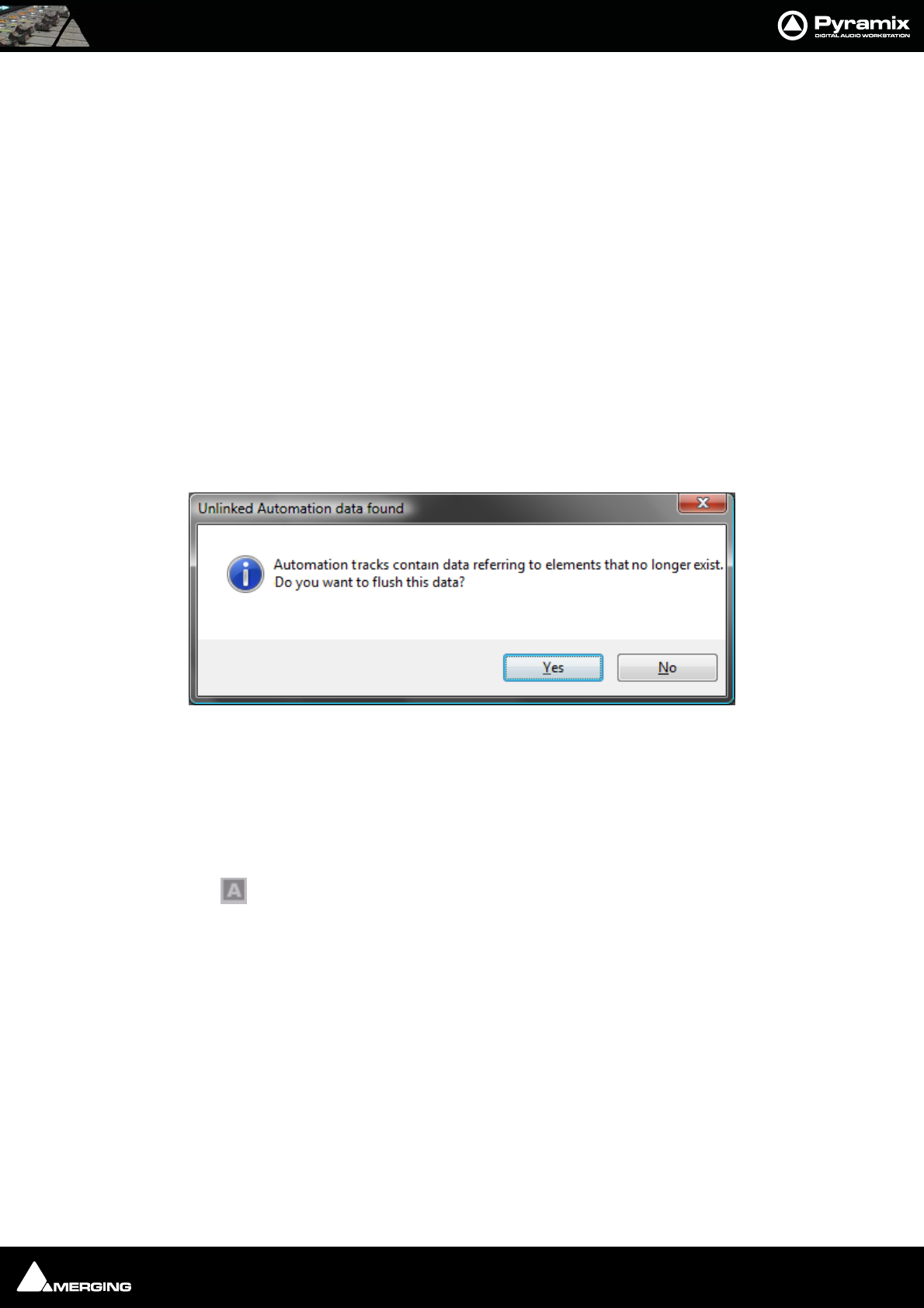
Automation : Projects With Existing Automation 14 - 263
Ctrl + Shift + Alt : Forces the Update & Hold Mode
When Releasing a Control:
Ctrl : Forces the Snap Mode
Shift : Forces the Auto-Release Mode
Ctrl + Shift : Forces the Write to Next Mode
Ctrl + Shift + Alt Forces the Hold & Write to Next Mode
Ctrl + Alt + Esc Releases Auto-Write
Hardware Remote Controllers
Devices offering external remote control such as the Merging Ramses MSC or OASIS and others will provide dif-
ferent modifiers to alter the Global Auto-Write and Release Modes depending on the specific hardware availability
(dedicated buttons, existing button combinations, special movements, etc…)
Projects With Existing Automation
When opening a Project that has existing dynamic automation and where a mixer element is no longer present or
when rebuilding a mixer where a previously automated element has been removed the following dialog appears:
Clicking on Ye s removes the redundant data. Clicking on No retains it giving the opportunity to re-instate the
missing element(s).
Display and Editing of Automation Data
The automation data recorded for any control can be viewed and edited on any track in the Timeline.
Clicking the Show/Hide Automation button in the Track Header displays or hides automation data as a black
line when being replayed and a red line when being written.
Note: If you wish to display automation on one track of a stereo pair (or multichannel
GPS) you can Ctrl + Click the Show/Hide button to toggle individual channels.
Right-clicking the Show/Hide Automation button pops up the automation menu for the track.
Note: This menu is modal. I.e. the options available depend on whether there is any pre-
existing automation data.
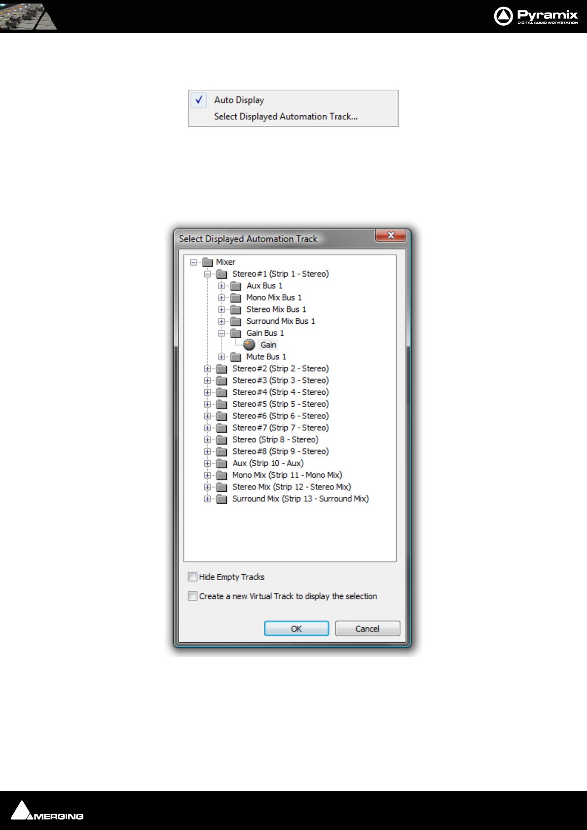
Automation : Display and Editing of Automation Data 14 - 264
Unwritten Track
If the track does not have any automation data written this menu opens:
Auto Display When Auto Display is checked the automation data to be displayed will be from
the last control associated with the track that has been adjusted or switched.
(Defaults is ON)
Select Displayed Automation Track
Opens the Select Displayed Automation Track dialog:
Every automatable parameter of every track and bus is available. Clicking on the plus sign next to a folder will
show the all automatable parameters associated with it. Simply choose the parameter you wish to have displayed.
Hide Empty Tracks
When ticked (default), Tracks with no automation data written are not shown in the tree.
Create a new Virtual Track to display the selection
When ticked, the selected parameter will be displayed in a newly created virtual track.
Track Automation Initial context menu
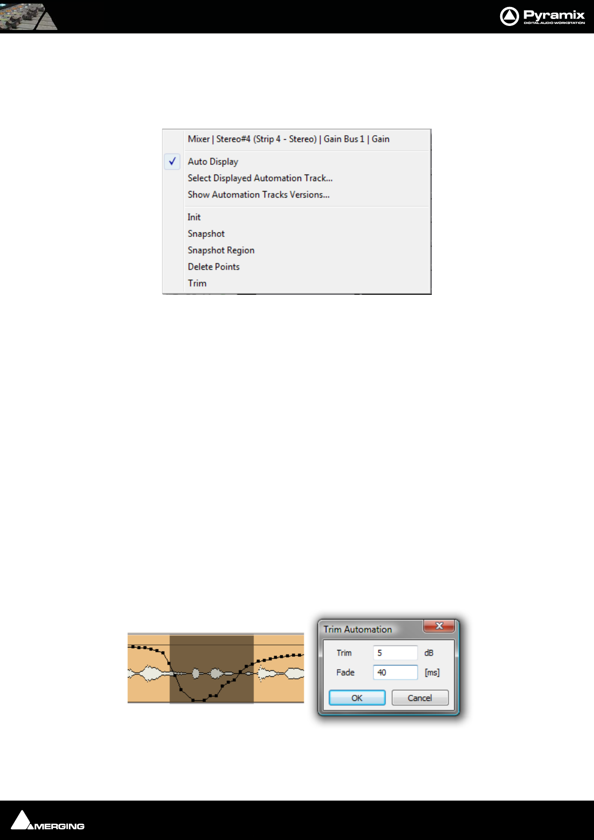
Automation : Display and Editing of Automation Data 14 - 265
Note: If you choose a Track AND a specific parameter to display in this dialog then you
should turn Auto Display OFF.
Track With Existing Automation Data
If the track has pre-existing automation data then right-clicking the Show/Hide Automation opens this menu.
Mixer The current parameter displayed is shown at the top of the menu
Auto Display When Auto Display is checked the automation data to be displayed will be from
the last control associated with the track that has changed state. (Defaults is ON)
Note: Auto Display should normally be off when any control not on the connected strip is displayed or you
wish to view automation data from a specific control.
Select Displayed Automation Track
Opens the Select Displayed Automation Track dialog as above.
Show Automation Track Versions
See next page.
Init Creates an initial automation track for mouse editing. The initial version is created
with the current state of the mixing console control.
Snapshot Creates a snapshot of the currently displayed control curve.
Snapshot Region Creates a snapshot of the control curve in the current region.
Delete Points Deletes all automation points from the control curve in the current region.
Trim See next page
Trim
When automation Trim is invoked a dialogue box opens which enables the automation points values in the cur-
rently selected range to be trimmed:
Track Automation context menu
Track Trim Automation dialog
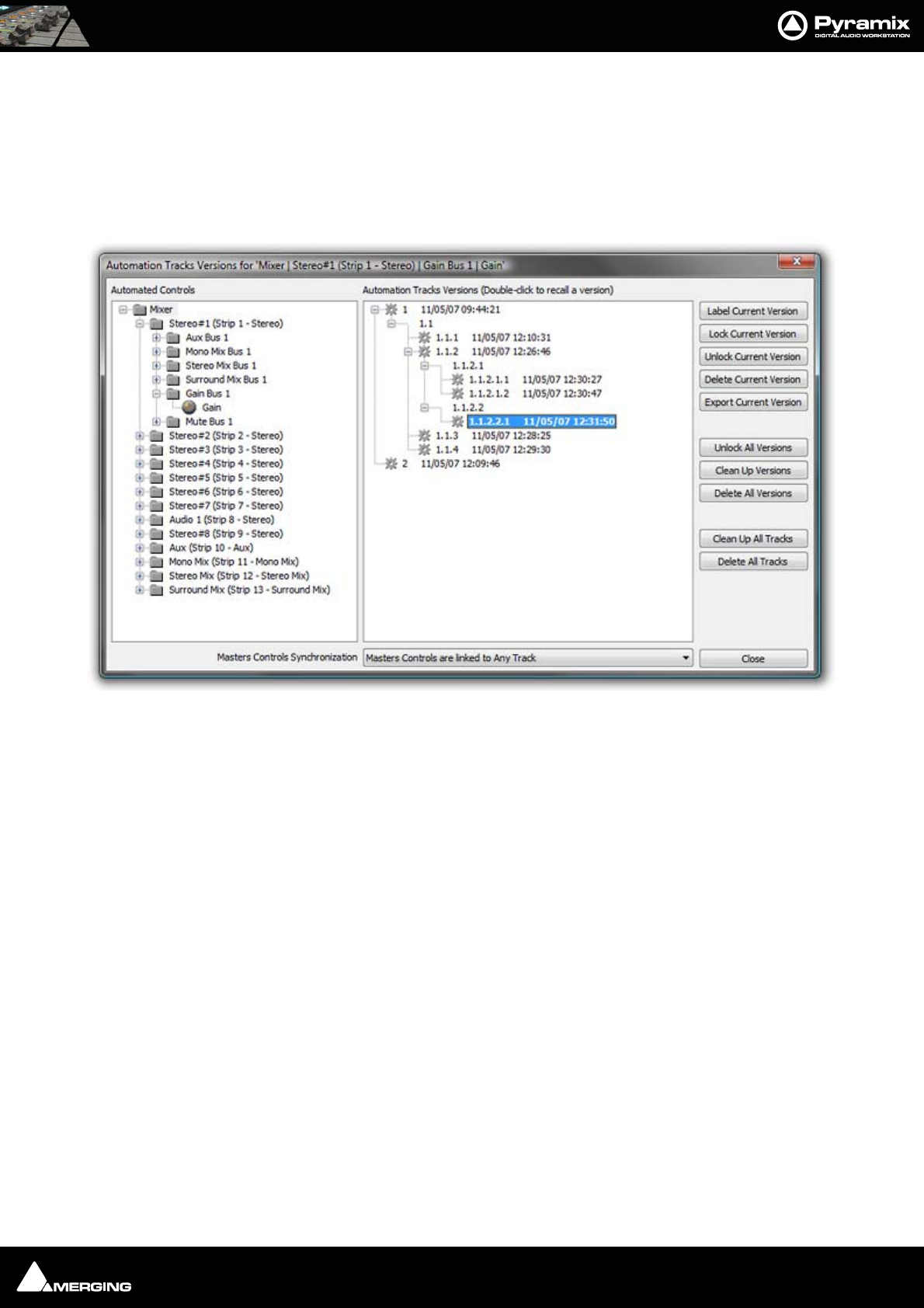
Automation : Display and Editing of Automation Data 14 - 266
Values can be increase by simply typing the number of dB required or decreased by typing - (minus) before the
number in the Trim box. The Fade box allows a value in ms to be entered. This defines the length of fade which is
automatically applied at the beginning and end of the selected range from and to the original values.
Note: dB applies to level changes. If the automation curve is displaying frequency, values will be in Hz and so on.
Show Automation Track Versions
Opens the Automation Tracks Versions window:
Automated Controls
The Automated Controls pane displays all the automatable controls in a tree structure. The last control written is
automatically selected. The Automation Tracks Versions pane shows all the automation passes for the selected
control in a tree structure. Double-clicking a version makes it current. If a previous version is made current and a
further automation path written, a sub-branch results. In the example above two passes were made then version 1
was recalled by double-clicking it. Four further passes were made labelled 1.1.1, 1.1.2, 1.1.3 and 1.1.4. Then ver-
sion 1.1.2 was recalled and two further passes made labelled 1.1.2.1 and 1.1.2.2. Then 1.1.2.1 was recalled and
two more passes made producing 1.1.2.1.1 and 1.1.2.1.2. We were still unhappy with the mix so recalled 1.1.2.2
and produced the final version, 1.1.2.2.1. The times when the passes were written reflects this.
Label Current Version creates a copy of the current version for the selected control or branch of controls,
gives it a name that will be displayed in the version Tree and locks it/them. This
makes it easy to recall a given and easily identifiable version of the automation for
the whole mixing console. A warning dialogue is shown if the item selected is any-
thing other than Mixer.
Lock Current Version Locks the current version
Unlock Current Version Unlocks the current version
Delete Current Version Deletes the current version. Subsequent passes are re-numbered as necessary.
Export Current Version Exports the current Track or Branch as an XML file.
Unlock All Versions Unlocks all versions in the tree.
Clean Up Versions Deletes all versions except the most recent.
Delete All Versions Deletes all the automation passes for the selected control.
Automation Tracks Window

Automation : Display and Editing of Automation Data 14 - 267
Clean Up All Tracks Deletes all versions except the current one for all tracks.
Delete All Tracks Deletes all automation information for all tracks.
Locked Versions
Locked versions will be preserved when:
• Clicking on the Clean Up Versions button
• Clicking on the Clean Up All Tracks button
• Saving with the “Keep only current and locked versions while saving” option in the Automation Settings
• The “Limit versions to the number of Undo/Redo” option is enabled in the Automation Settings
Locked versions will NOT be preserved when:
• Clicking on the Delete Current Version button
• Clicking on the Delete All Versions button
• Clicking on the Delete All Tracks button
Masters Controls Synchronization
The drop-down list enables you to select which Track(s) or Track Groups will, when edited, affect the position of
automation applied to Master controls, buses etc.
Like Markers or CD/SACD Markers, all Masters controls can be either:
• Independent (No action on any track will affect the Masters)
• Linked to Any Track (Any editing action requiring synchronization will affect the Masters controls)
• Linked to Any Track without a Group
• Link to Track Group A, B, C, etc…
View Several Parameters
To view more than one automation parameter for a track, create Virtual tracks for each parameter you wish to
view. Please see also Virtual Tracks on page 82
Undo/Redo
The menu item Edit > Undo/Redo also reacts to Automation actions providing a shortcut to the Automation
Tracks Window.

Automation : Editing Automation data 14 - 268
Editing Automation data
Automation data can be edited directly with the mouse. When the mouse is over the of automation curve, the cur-
sor changes into a hand. When the mouse is over a node of the automation curve, the value and timestamp of the
point is displayed.
The value can be adjusted by clicking on the node and dragging. If you click anywhere on the automation curve, a
new node will be inserted.
If you hold the Ctrl key while dragging on the automation curve, the mouse pointer will turn into a pencil. The
curve can then be drawn freehand.
If Ctrl + Shift + Alt are held, the cursor changes to an eraser and clicking on a point erases it.
Automation Menu Editing options
Delete Selected Points Deletes all automation points contained in the selected region
Cut Selected Points Cuts all automation points contained in the selected region
Copy Selected Points Copies all automation points contained in the selected region
Paste Points to Cursor Pastes all copied or cut automation points at the cursor on the selected track
Paste Points to Original TC Pastes all copied or cut automation points at the Original TimeCode on the selected track
Dragging an automation node
Drawing an automation curve
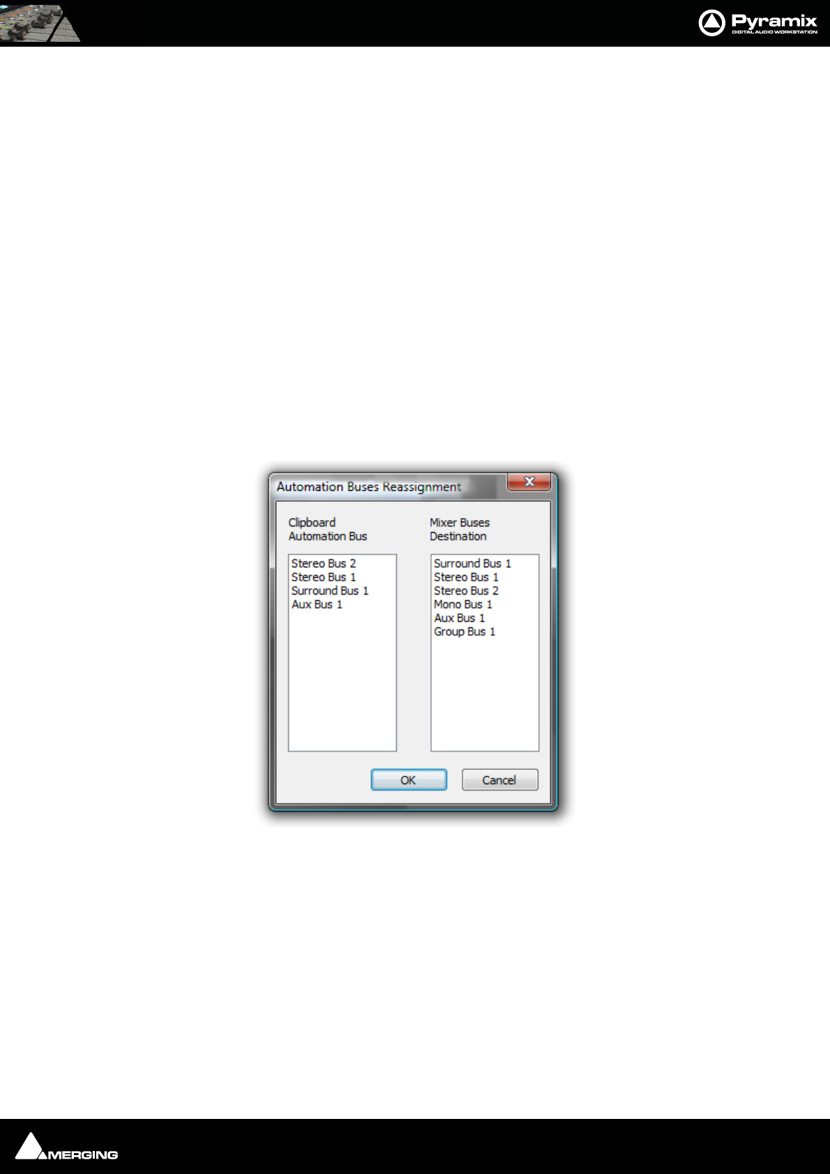
Automation : Editing Automation data 14 - 269
Automation Editing Between Strips/Projects
Automation data can be cut/copy/pasted between mixer strips with differing pan types and between projects. I.e.
a Pan automation track can be copied to a stereo track having a Balance control. This is only possible in the fol-
lowing cases :
• Pan -> Balance
• Balance -> Pan
• LeftRight mono surround panner -> Pan
• LeftRight mono surround panner -> Balance
• Pan -> LeftRight mono surround panner
• Balance -> LeftRight mono surround panner
Note: Only the left side of a Stereo strip’s Surround Panner is reassigned to/from a Pan/
Balance .
When Automation > Bus Reassignment on Paste is set on the following dialog will appear if some automated
bus elements of a strip are available in the automation clipboard.
When Automation > Bus Reassignment on Paste is set off following dialog will appear only when at least one
bus in the clipboard is not available in the target mixer.
The Bus Reassignment dialog left-hand pane shows the Clipboard Buses automation data of the contents.
The Bus Reassignment dialog right-hand pane shows the Destination Buses available in the current Project’s
Mixer.
By default, the Automation > Bus Reassignment dialog assigns buses together which match by Bus type in the
left and right panes.
In the screenshot, Surround Bus 1 is assigned to Surround Bus 1, Stereo Bus 1 is assigned to Stereo Bus 1 etc.
This dialog enables you to:
• Copy an automation track to or from different or similar Bus types of a strip. When bus types are, for exam-
ple: SR1 to ST1.
• Copy an automation track to or from different types of strip (mono, ms, stereo and GPS).
Automation Buses Reassignment dialog
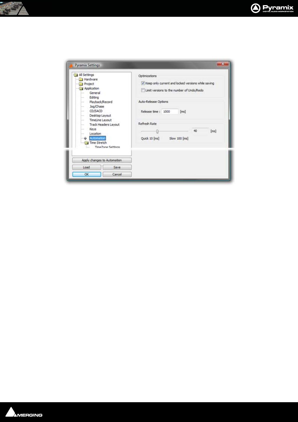
Automation : Automation Settings 14 - 270
Automation Settings
Select All Settings > Application > Automation. (Automation > Automation Settings also takes you to the
Automation page).
Optimizations
Offers a choice of options to enhance system performance when using automation.
Keep only current version while saving when checked, the system only saves the current version of all automa-
tion tracks. This looses the saved automation versions history, but dramatically shortens the save time for projects
with automation.
Limit versions to the number of Undo/Redo when checked the system only keeps a limited number of versions
in memory (the same as the number of Undo/Redos as defined in the Settings > All Settings > General Page).
This reduces the number of automation versions kept in the history but enhances performance.
Auto-Release Options
If Auto Release is enabled any control will, when released or when the transport is stopped, return to its value or
state in the previous automation pass or the default where no previous pass exists. This occurs either immediately
if the control only has two states (e.g. a button) or over a period of time if the control is a fader or knob. The time
period is determined by the value entered in the Release Time box in ms.
Refresh Rate
The Refresh Rate setting determines the rate at which the automation data is recorded. By default the refresh rate
is the same as the actual time code frame rate, e.g. 40 ms at a frame rate of 25 fps.
The possible range of the refresh rate is 10 to 100 milliseconds. Please note that your setting is rounded to entire
frames, so that the effective refresh rate will be either one, two or three times the actual frame rate.
One reason to choose a slower setting for the refresh rate would be to save processing power in complex mixes.
Note: This setting has no bearing on “smoothness” of dynamic automation changes.
Pyramix uses linear interpolation to avoid any possibility of zipper noise.
Automation Settings page

Automation : Automation in editing and libraries 14 - 271
Automation in editing and libraries
You can use the Automation menu Cut/Copy/Paste functions to copy data (even between projects). Just select a
region and select Automation > Copy Selected Points, then choose which list(s) to copy, then go into another
project (or the same) and select Automation > Paste Points to Cursor or Paste Points to Original TC.
If you enable the menu item Edit > Enable Automation Cut/Copy/Paste then any editing operation on clips also
applies to all associated automation data (cut/copy/paste, Auto-Ripple, etc…)
If you drag a clip(s) to a library, all automation over that clip(s) is copied/pasted as well.
Mixer and Plug-in Snapshots
Note: Mixer Snapshots as described here use the dynamic automation mechanism.
Mixer Snapshots
Snapshots of the entire state of the mixer surface may be easily and quickly saved and recalled.
Saving Mixer Snapshots
To save a Mixer snapshot hold down Alt and Shift then Click anywhere on the Mixer surface and drag to a user
library. A new item of the type Mixer Snapshot will appear in the library. The snapshot is named Mixer Snapshot
by default. To accept this name just hit Enter. Otherwise, type a suitable name then hit Return.
Recalling Mixer Snapshots
To recall a mixer snapshot simply click on it in the library, drag it over the mixer surface and release. All parameters
will be reset to the values stored in the snapshot.
Note: A Mixer Snapshot includes all Plug-in Parameters.
Effects Snapshots
Effect Settings can be easily stored and recalled by dragging them to/from libraries.
Creating Effects Snapshots
Hold Alt + Shift, then click and drag from a Plug-in window to the library where you want to store the settings,
then release. A new item, of the type Mixer Snapshot, is stored in the library. The snapshot is given the name of
the plug-in by default. The new item is automatically highlighted so, if you wish to change the default name, sim-
ply type the new name and hit Enter to confirm. The name of the snapshot can be subsequently changed by click-
ing on the name in the library, then entering the new name.

USER MANUAL
www.merging.com/Pyramix
Strip and Bus Tools
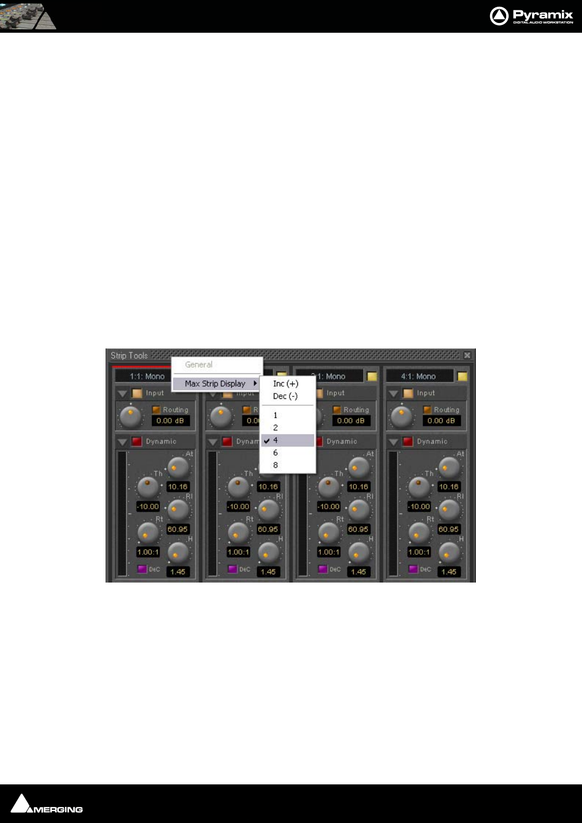
Strip and Bus Tools : Strip and Bus Tools 15 - 273
Strip and Bus Tools
Eq, Comp/Limiter/Expander
Strip and Bus Tools are a quick and efficient way of adding the Equalization and Dynamics (compression and
expansion) functions commonly found on hardware consoles to channels and buses. Strip and Bus Tools are par-
ticularly economical with DSP processing power. Each processing block may be switched ’into circuit’ individually.
Blocks which are not ‘in circuit’ do not use DSP resources.
Difference between Strip Tools and Bus Tools
There is only one major difference between Strip and Bus Tools. Bus Tools have a sophisticated Limiter with Look-
ahead and Delay Compensation where Strip Tools has a Compressor.
Both may be freely used in Strips or Buses if the need should arise for a limiter in an Input Strip or a Compressor in
a Bus.
Modules
The Strip and Bus Tools plug-ins consist of several Sections or modules. Each Section has a title bar at the top con-
taining an On/Off switch for the section and a control triangle which toggles between showing or hiding the sec-
tion.
Display Options
Multiple instances of the Bus Tools plug-in are displayed in one large window. Right-click onto the window title
bar of the plug-in to open a menu offering some general display options for the Strip Tools plug-ins:
This menu allows you to either directly select the number of strips displayed in the plug-in window, or to incre-
ment/decrement this number by one. The maximum number will vary depending on how many Strip Tools are
assigned.
Strip Tools - General Display Options
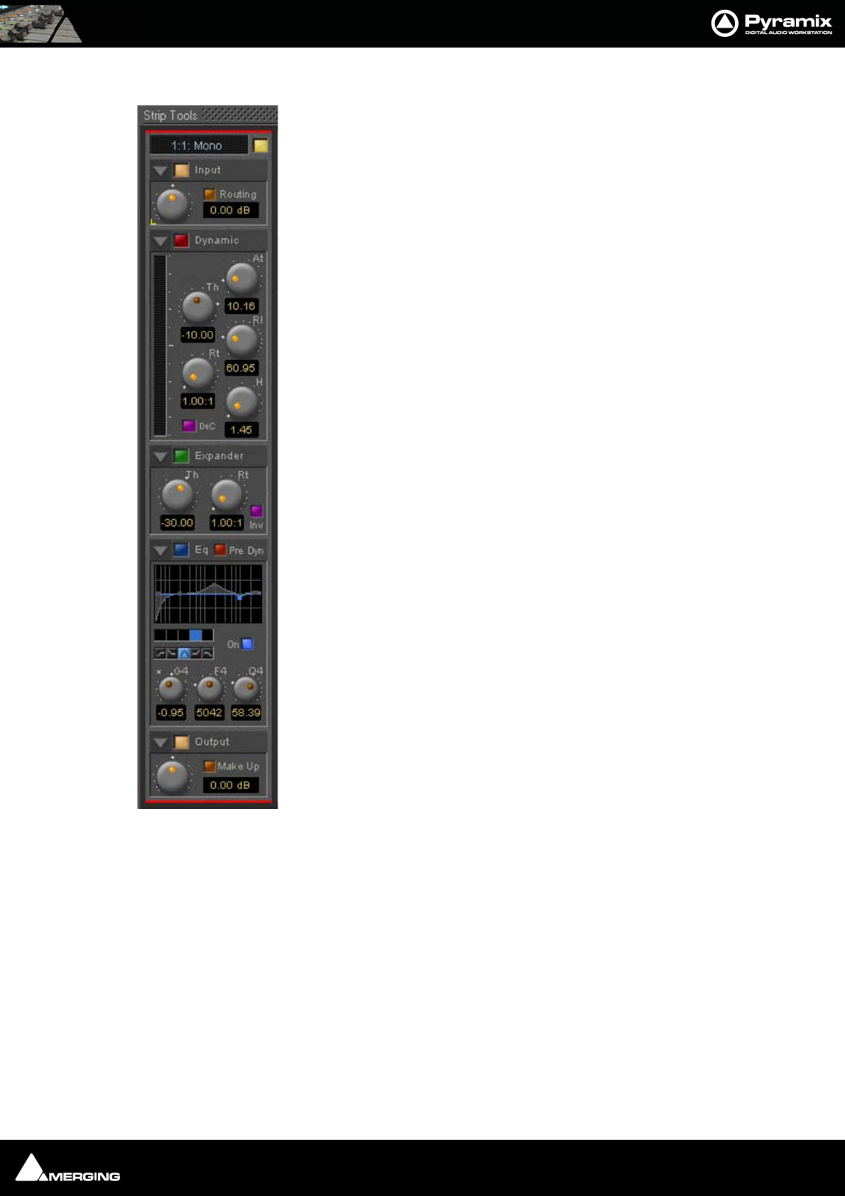
Strip and Bus Tools : Strip and Bus Tools 15 - 274
Sections
From top to bottom, Strip Tools contains the following Sections:
Input Level
This section contains the input level control and shows the name of the mixer strip
this instance of the plug-in is assigned to.
Dynamics
This section contains a compressor. It can be switched, as shown here, to act as a
decompressor.
Expander
This is a downwards expander. It can also be switched to act as an upwards expander.
Equalizer
This is a five band fully parametric equalizer. Each band can be switched to high or
low pass, shelving or peaking characteristics.
Output
This section controls the output level of the strip tool and also offers automatic gain
make up for the compressor.
Common Features
Each Section or module of Strip and Bus Tools has a number of controls in common.
Title Bar
A text description of Section’s function, e.g. Input, Dynamic etc. Also contains:
Show/Hide triangle
At top left of every Section a grey triangle toggles between showing or hiding the section. Clicking a triangle with
Shift held down opens the Section (If hidden) and hides all other Sections. Clicking a Section with Ctrl. held down
opens all Sections.
Note: Sections remain active when hidden.
Section On/Off Button
Between the Show/Hide triangle and the Section Title is the On/Off button for the Section.
Knobs
The position indicator dot lights orange when the control is at the default value. A white star appears top-left of
the scale of the last control ‘touched’.
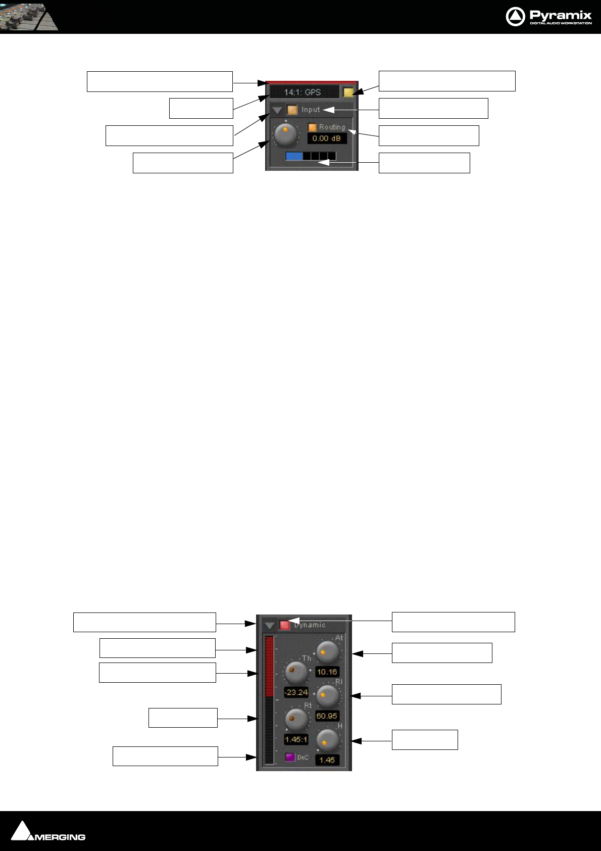
Strip and Bus Tools : Strip and Bus Tools 15 - 275
Input Section
Color Bar
Indicates strip is selected.
Strip Name
Displays the name of the strip the plug-in is assigned to. The name for the plug-in can be changed by double-click-
ing on the strip name, then typing in a name and hitting the Return key to confirm. If a plug-in name is changed in
this way, subsequent changes to the parent mixer-strip name do not affect the plug-in strip name. To recover the
name of the parent strip, simply remove the strip name.
The strip name is saved with presets and within Pyramix projects.
Activate/deactivate plug-in
This button switches the entire Strip plug-in on or off. Note that when the plug-in is switched off, it doesn’t con-
sume any DSP power.
Show/Hide input section
Input section on/off
Input level control
Adjusts the input level over a range of -48 dB to +48 dB.
Show/hide Routing
By default Routing buttons are hidden. This button toggles between Showing and Hiding the Routing Buttons.
Routing remains active when hidden.
Routing Buttons
Determine which audio streams running through the strip will be processed by the plug-in. The number of but-
tons depends on the number of steams controlled by the strip. This means one for a mono input channel or two
for a stereo input channel and so on up to 8 for a 7.1 input channel. Streams which are not selected will be left
untouched.
Dynamics Section
Strip Name
Show/Hide Input Section
Input Level Control
Activate/De-activate Plug-in
Input Section On/Off
Show/Hide Routing
Routing Buttons
Color bar indicates Selected
Show/Hide Dynamics Section
Gain Reduction Display
Threshold Level Control
Ratio Control
De-Compress Switch
Dynamics Section On/Off
Attack Time Control
Release Time Control
Hold Control

Strip and Bus Tools : Strip and Bus Tools 15 - 276
Show/Hide Dynamics section
Dynamics Section On/Off
Gain reduction display
The bar graph shows the gain reduction/increase generated by the Dynamics Section or by the Expander. The
range of the display can be switched between +-10 or 20 dB by clicking on the bar graph. Scale markings in 1dB
increments on the right-hand side of the bar graph make it easy to see if the range is 10 or 20 dB.
Colors are used to denote a gain reduction or increase generated by either the compressor or the expander:
• Gain reduction by the Compressor is displayed in Red from top to bottom.
• Gain increase by the De-Compressor is displayed in Pink from bottom to top.
• Gain reduction by the Expander (normal or inverse) is displayed in Green from bottom to top. With the
compressor in inverse mode, the gain reduction of the expander is displayed in Green from top to bottom
Threshold Level Control
Sets the level at which the compressor begins to act. If the input signal level exceeds the Threshold Level, the
gain is reduced (or increased in De-Compressor mode) in proportion to the setting of the ratio control.
Ratio Control
Determines the proportion of gain reduction (or increase) for signals above the threshold level. If, for example, the
ratio is set to 2.00:1, in Compressor mode, if the input level rises by 2dBs above the threshold level, the output
level will only rise by 1 dB.
Attack Time Control
Controls the time the compressor takes to react when the input level exceeds the Threshold Level. The lower the
attack time, the faster the reaction.
Release and Hold Time controls
These two parameters work together and control the amount of time the compressor takes to react when the
input level is above the threshold level and starts fall. During the hold time the gain of the compressor remains
constant. After the hold time the gain of the compressor is changed at the rate set by the release time. The lower
the release time, the faster the reaction.
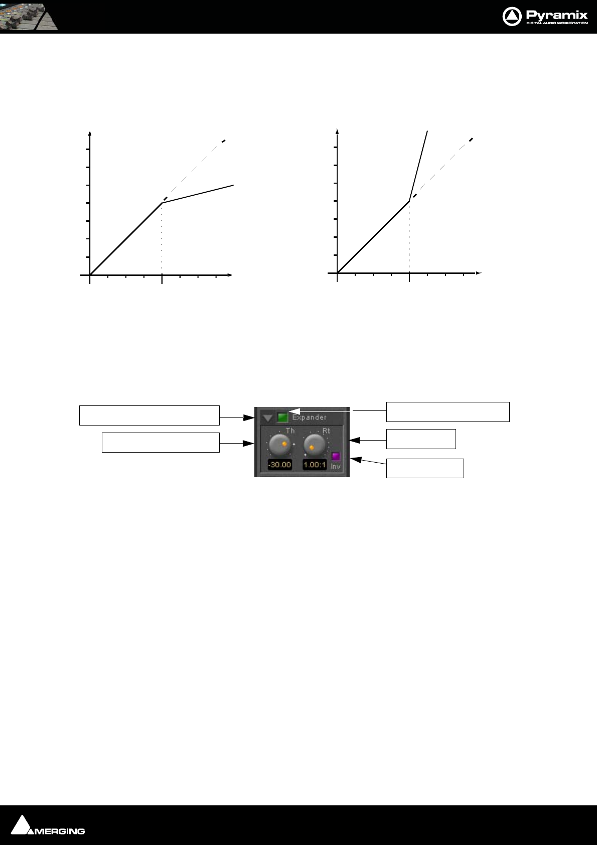
Strip and Bus Tools : Strip and Bus Tools 15 - 277
De-Compress Switch
Switches the compressor between the compress and the de-compress modes.
In compressor mode, when the input level exceeds the threshold level, the gain is reduced according to the set-
ting of the ratio control. In de-compressor mode, when the input level exceeds the threshold level, the gain is
increased according to the setting of the ratio control.
Expander Section
Show/hide Expander section
Dynamics section on/off
Threshold Level Control
If the input signal level falls below the threshold level, the gain of the expander is reduced (or increased in inverse
mode) according to the setting of the ratio control.
Ratio control
Determines the proportion of gain reduction (or increase) for signals below the threshold level. If, for example, the
ratio is set to 2.00:1, in normal mode the output level will be decreased by 2 dB if the input level is decreased by 1
dB below the threshold level.
Compressor and De-Compressor action
Threshold
Input level
Output level
Threshold
Input level
Output level
Compressor mode De-c ompressor mode
Show/Hide Expander Section
Threshold Level Control
Expander Section On/Off
Ratio Control
Inverse Switch
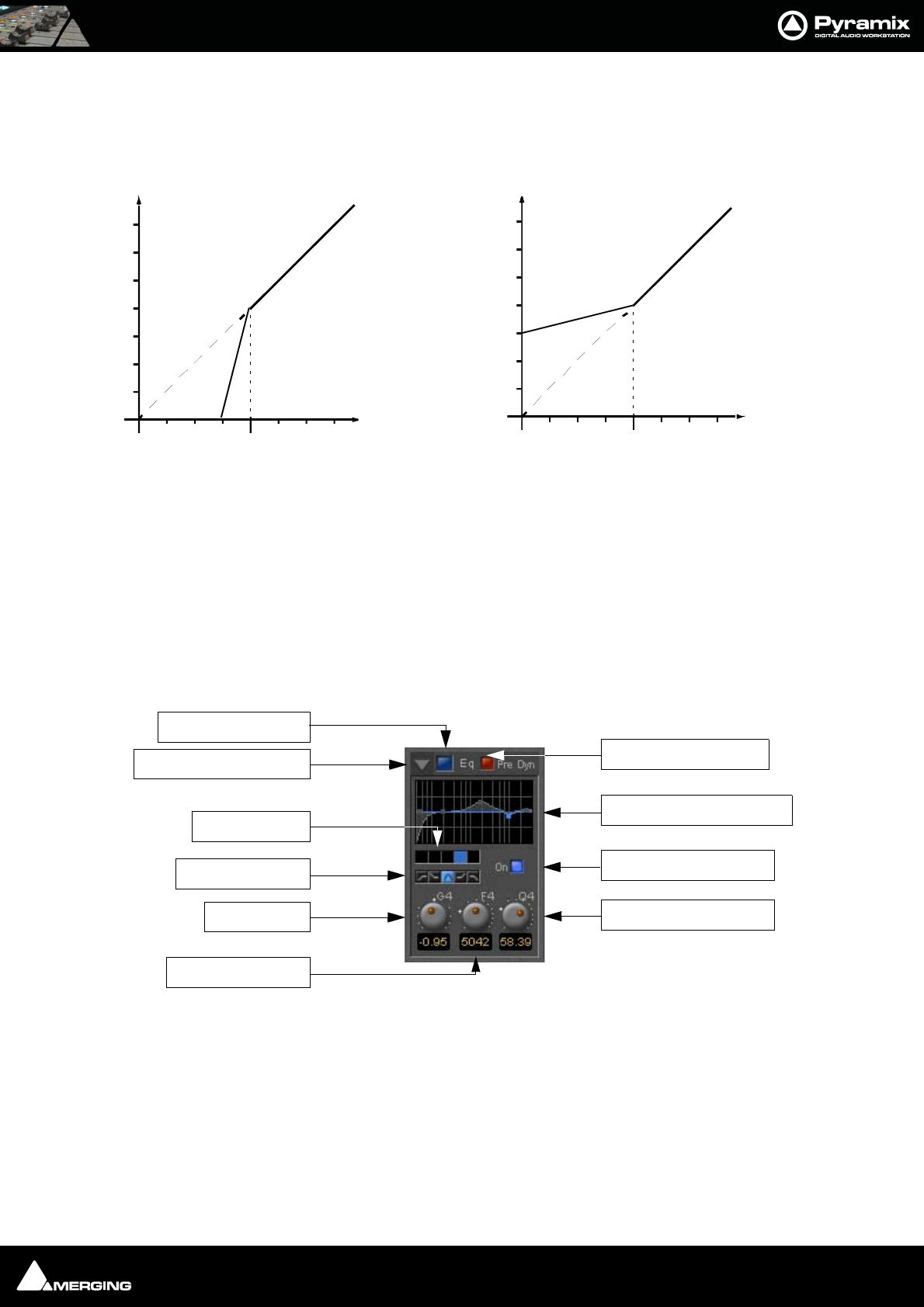
Strip and Bus Tools : Strip and Bus Tools 15 - 278
Inverse switch
Switches the between normal and inverse expander modes.
Attack/Release/Hold controls
The Expander Section uses the settings of the Attack/Release/Hold controls in the Dynamics Section to control
it’s timing.
Equalizer section
A fully parametric five band equalizer. Each band covers the entire frequency range from 20 Hz to 20 kHz (or
higher, depending on the sampling rate of the project) and can be switched between peaking, high or low shelv-
ing and low-pass or high-pass characteristics. Each of the five bands can be switched off. De-activated bands do
not consume DSP power.
Show/ Hide EQ Section
EQ section on/off
Pre Dynamics Switch
This switch offers the option to the switch the EQ before the dynamics section. By default the EQ is after the
dynamics section.
Threshold
Input level
Output level
Threshold
Input level
Output level
Expan der normal mode Inverse mode
Expander normal and Inverse mode action
EQ Section On/Off
Band Filter Type
Band Selector
Gain Control
Frequency Control
Show/Hide EQ Section Pre-Dynamics Switch
Graphic Display Window
Selected Band On/Off
Q (Bandwidth) Control
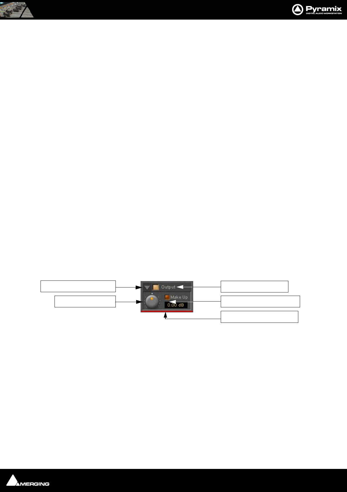
Strip and Bus Tools : Strip and Bus Tools 15 - 279
Graphic Display Window
This small window displays the settings of the currently selected EQ band in blue color and the resulting curve of
the whole EQ section in gray color. You can click and drag directly onto the handles (the small blue or gray points)
of the EQ bands to change the settings within the graph window.
Double-click anywhere in the window to open a bigger version. Please see The Big Graph Window on page 279.
Band Selector
Click onto one of these five buttons to select the band to be manipulated by the Gain, Frequency and Q control
underneath. A band gets also selected if it is manipulated in the small or big graph window.
Selected band characteristics
These five buttons determine the characteristics of the selected EQ band. The choices from left to right are High-
Pass Filter, Low Shelving, Peak, High Shelving and Low-Pass Filter.
Selected Band On/Off
Switches the selected EQ band on or off. By default the five bands are switched off in order to economize DSP
power, so don’t forget to switch an EQ band on before you can hear what it is doing.
Gain Control
-24 dB to +24 dB, boost and cut.
Frequency Control
The range for each band is depending on the sampling rate of the project:
• For sampling rates up to 48 kHz the frequency range of each band is 20 Hz to 20 kHz.
• For sampling rates up to 96 kHz the frequency range of each band is 20 Hz to 40 kHz.
• For sampling rates up to 384 kHz (e.g. DSD mixing) the frequency range of each band is 20 Hz to 80 kHz.
Q (bandwidth) Control
The range for the Q parameter is 0.2 up to 100. A Q of 0.2 results in a very wide bandwidth, a Q of 100 will give an
extremely narrow notch.
Output Section
Show/ Hide Output section
Output section on/off
Output Level control
Adjusts the output level over a range of -48 dB to +48 dB.
Automatic Gain Make Up switch
When lit, Output gain is automatically adapted according to the settings in the Dynamics Section. In this case the
Output Level Control will be grayed out and inaccessible.
The Big Graph Window
The big graph window opens when you double-click the small graph window inside the EQ Section. The current
settings of the selected EQ band are displayed as a blue line and the resulting overall EQ curve is displayed as a
gray shaded area. Frequency and Gain parameters of each of the five bands can be altered by clicking on a band’s
handle and dragging with the mouse.
Output Level Control
Show/Hide Output Section Output Section On/Off
Auto Gain Make-Up Switch
Color bar indicates Selected
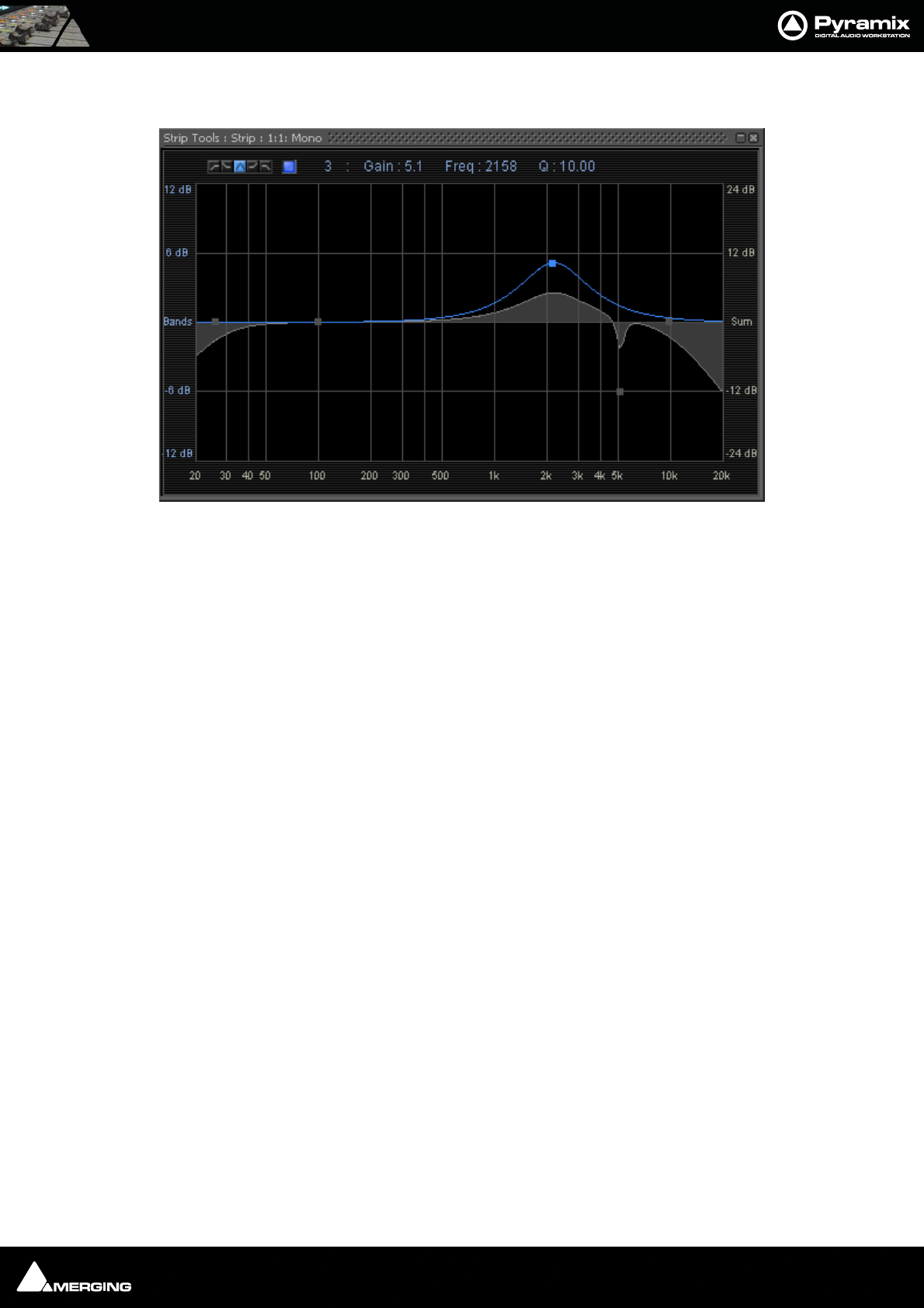
Strip and Bus Tools : Bus Tools 15 - 280
Handles of bands which are not selected are displayed as small gray squares. Grabbing and drag a handle selects
the band.
The frequency response display uses two separate gain scales. The left hand, blue scale shows the scale used for
individual bands. The right hand, gray scale shows the scale for the overall EQ curve. Both scales automatically
adapt their range according to the settings of the curves they apply to. The range of the left and the right scale my
be different. The ranges for the individual bands can be either +/- 6 dB, +/- 12 dB or +/- 24 dB, but the scale for the
overall curve may go up to +/- 72 dB.
The upper area of the Big Graph Window provides an On/Off switch and buttons to select and indicate the char-
acteristic (High-Pass, Low Shelf, Peak, High Shelf or Low-Pass) for the selected EQ band together with numeric dis-
plays of Gain, Frequency and Bandwidth.
Frequency and Bandwidth setting.
Shortcuts
• Double click on a handle to reset the gain of this band to unity.
•The Tab key switches between EQ bands.
• Clicking and dragging a handle with the right mouse button alters the Q (bandwidth) of this band.
•Hold the Ctrl key while dragging with the left mouse button to lock the gain parameter and only change
the frequency.
•Hold the Shift key while dragging with the left mouse button to lock the frequency parameter and only
change the gain.
Bus Tools
Bus Tools are very similar to Strip Tools but are specifically designed to be inserted into buses rather than chan-
nels. Bus Tools combine the most frequently used ‘mastering’ processing blocks you find on the output buses of a
mixing console in a single plug-in, including an advanced limiter. Like Strip Tools multiple instances of the Bus
Tools plug-in are displayed in one large window. The number of instances displayed is user selectable.
IMPORTANT! Pre-Anticipation (PA) and Delay Compensation (DC)
Delay compensation adds a delay determined by the Pre-Anticipation delay setting to all channels passing
through a Bus Tools plug-in NOT selected for processing.
If two or more Bus Tools are inserted in a Bus with PA & DC switched on, the delay times of each Bus Tools will add
together for all channels:
Big Graph floating Window
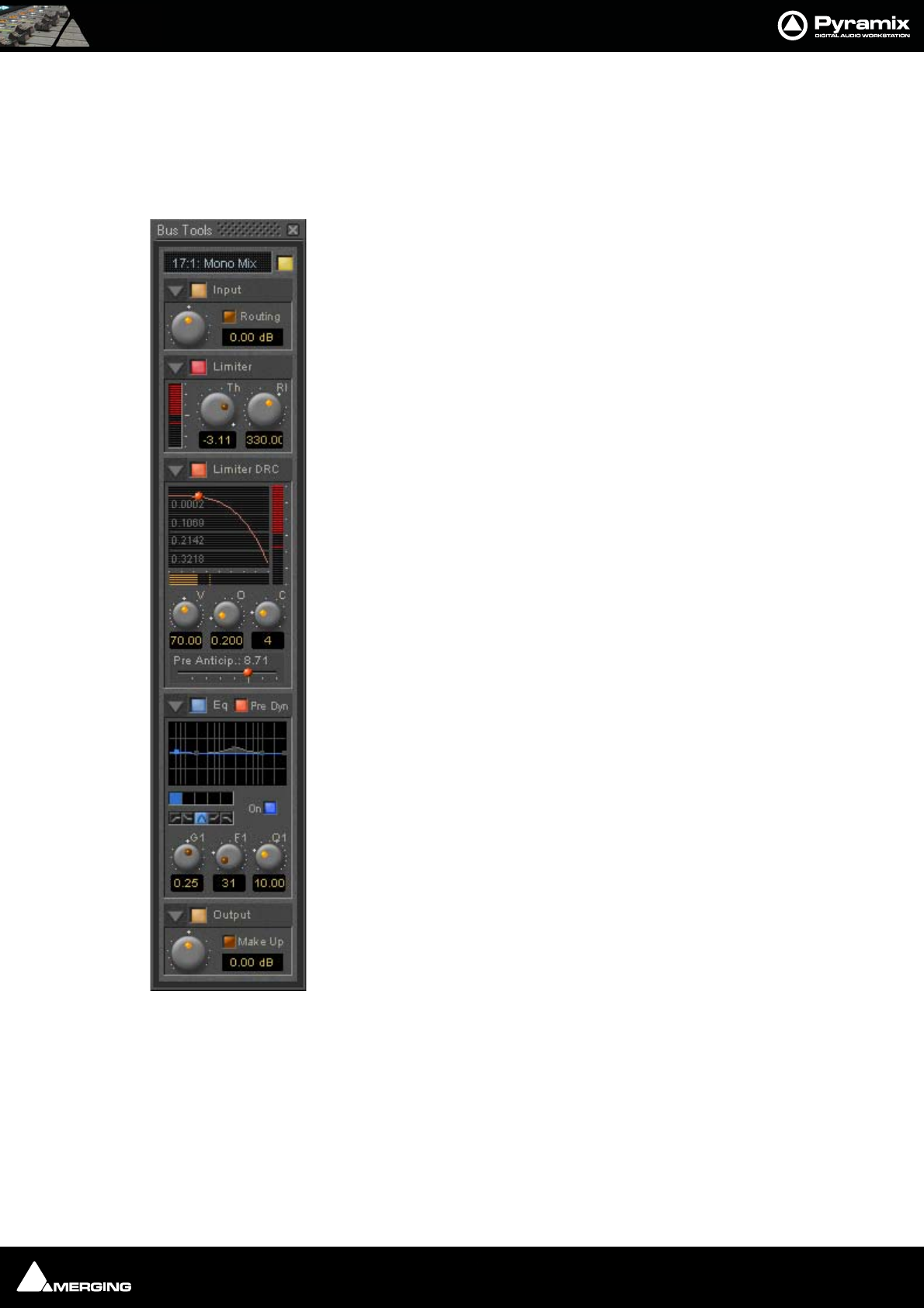
Strip and Bus Tools : Bus Tools 15 - 281
Sections
The Input, EQ, and Output sections are almost identical to the ones found in Strip Tools. Please see the relevant
paragraphs in the Strip Tools section for a full description. Where there are differences, these will be dealt with
here. Shortcuts, Linking and Automation functions are the same as Strip Tools.
From top to bottom, the Bus Tools plug-in contains the following sections:
Input Level
This section contains the input level control and shows the name of the mixer strip
this instance of the plug-in is assigned to.
Limiter
This section contains the limiter, which either acts as a standard limiter, but it can also
work in conjunction with Limiter DRC section below.
Limiter DRC
This section adds a Dynamic Release Compensation (DRC) to the Limiter section. This
enables very musical control of the release time of the limiter.
Equalizer
This is a five band fully parametric equalizer. Each band can be switched to high or
low pass, shelving or peaking characteristics.
Output
This section controls the output level of the Bus Tool and also offers automatic gain
make up for the Limiter.
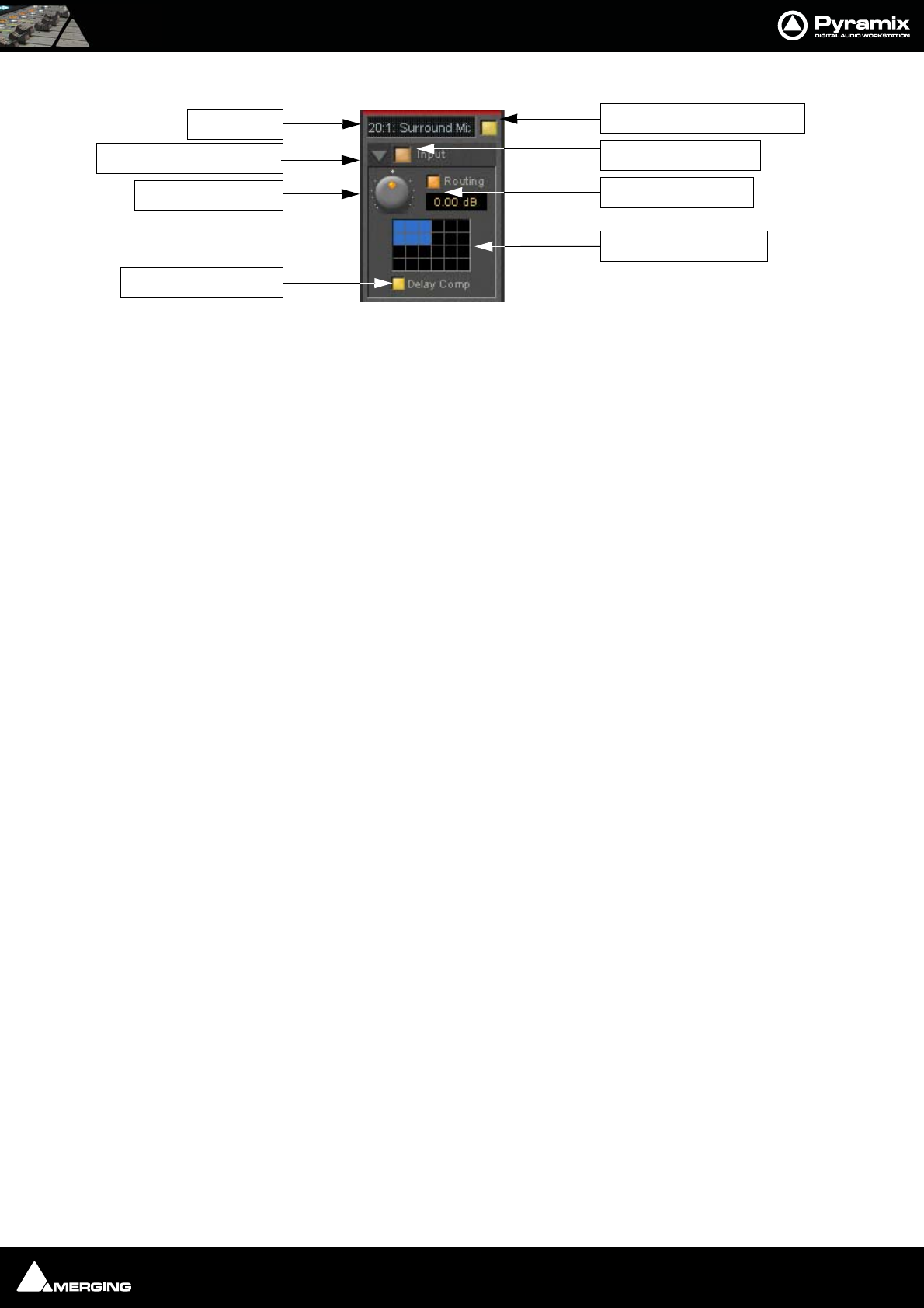
Strip and Bus Tools : Bus Tools 15 - 282
Main and Input Level Section
Strip Name
Displays the name of the strip the plug-in is assigned to. The name for the plug-in can be changed by double-click-
ing on the strip name, then typing in a name and hitting the Return key to confirm. If a plug-in name is changed in
this way, subsequent changes to the parent mixer-strip name do not affect the plug-in strip name. To recover the
name of the parent strip, simply remove the strip name.
Activate/Deactivate Plug-in
This button switches the entire Strip plug-in on or off. Note that when the plug-in is switched off, it doesn’t con-
sume any DSP power.
Show/Hide input Section
Input Section On/Off
Input level control
Adjusts the input level over a range of -48 dB to +48 dB.
Show/hide Routing
By default Routing buttons are hidden. This button toggles between Showing and Hiding the Routing Buttons.
Routing remains active when hidden.
Routing Button Matrix
The buttons determine which audio channels running through the Bus will be processed by the plug-in. The num-
ber of buttons shown depends on the number of channels controlled by the Bus. In the case of a multiple sur-
round Bus this may be up to 64. A single instance of Bus Tools can process up to 8 channels selected from this
matrix.
A 5.1 surround bus will have six buttons. The order of the channels selected by the buttons is (from left to right):
Left, Center, Right, Left Surround, Right Surround, Subwoofer.
This enables, for example, the Left, Center and Right channels of a surround Bus to be independently processed
from the surround channels by adding two Bus Tools plug-ins to the Bus and selecting L, C, R in the first and LS and
RS in the second.
Using Bus Tools on multiple surround buses
Although a single instance of Bus Tools can process 8 channels it is simple to use multiple instances to process
many more with linked parameters. E.g. with four surround Buses you could use 3 instances. Assign the L & R chan-
nels of each Bus to Bus Tools A, the Centers of each bus to Bus Tools B and the Surround Ls and Rs of each Bus to
Bus Tools C. The 3 Bus Tools can then be linked as you wish by right-clicking and creating control groups in the yel-
low matrix. If Delay Compensation (see below) is activated all channels will remain time-aligned, even when using
Pre-Anticipation.
Linking Bus -Tools controls
Any choice of Bus Tools controls can be linked together. When you move any of the controls which is a member of
a link group, all the other members of the group also move. There are 48 link groups for linear/rotary controls and
48 link groups for switches.
Strip Name
Show/Hide Input Section
Delay Compensation
Input Level Control
Activate/De-activate Plug-in
Input Section On/Off
Show/Hide Routing
Routing Button Matrix
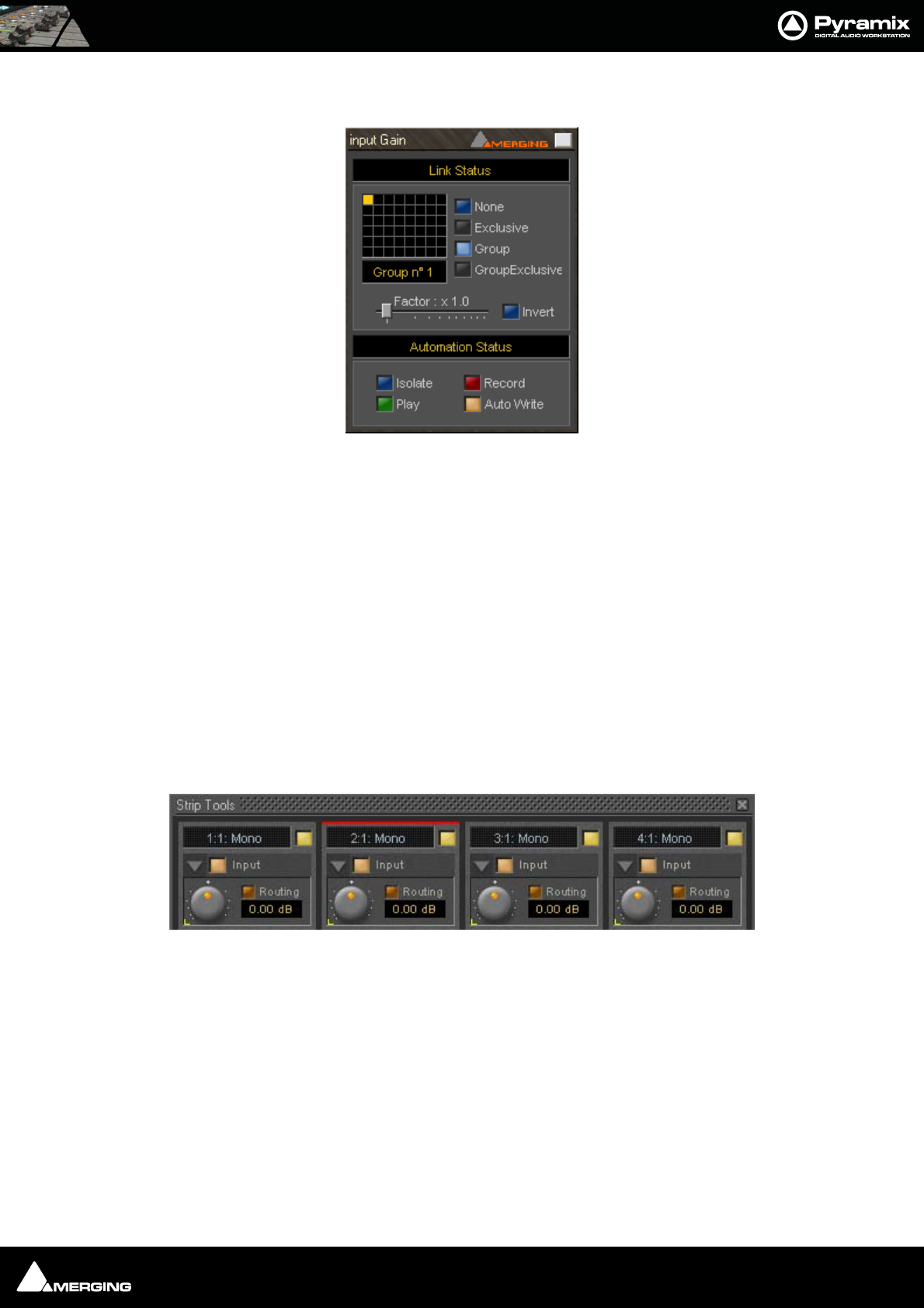
Strip and Bus Tools : Bus Tools 15 - 283
To add a control to a link group, right-click on the knob or button to display its Link Status and Automation Sta-
tus pop-up window. E.g. this is the pop-up for an input gain control.:
Group assignment mode buttons
These four buttons define the link mode of the control. Four choices are available:
None The control is not a member of any group.
Group The control is a member of the selected group. When you move (or switch) this con-
trol or any other control which is a member of this group, all the members of the
group will move (or switch) along with it.
Exclusive This mode is only available for switches. With this mode selected, when this switch is
on, all the other members of the group will be switched off.
Group Exclusive This is a mode which has a superior effect on all groups which are set to Group
Exclusive. When any of the groups which are set to Group Exclusive is switched on,
all the other groups set to Group Exclusive will be switched off.
Grouped controls are indicated by a yellow L in the corner of the control ‘block’.
Factor X Slider Works only on continuous (rotary or linear) controls. It determines the gearing of
this control in relation to other members of the group and vice versa. E.g, assume
the input gain of strip tools #1 and the input gain of strip tools #2 are both assigned
to group one. The scale factor of the gain of strip tools #2 is set to 2. Now when you
change the gain of strip tools #1 by 1 dB, the gain of strip tools #2 will change by 2
dB’s.
Invert Also works only on continuous controls. It inverts the effect of the movement for
this control caused by another group member or vice versa. E.g, assume the input
gain of strip tools #1 and the input gain of strip tools #2 are both assigned to group
one. The invert button of the gain of strip tools #2 is on. Now when you increase the
gain of strip tools #1 by 1 dB, the gain of strip tools #2 will diminished by 1 dB.
Strip Tools - Link and Automation Status
Strip Tools - Grouped Controls
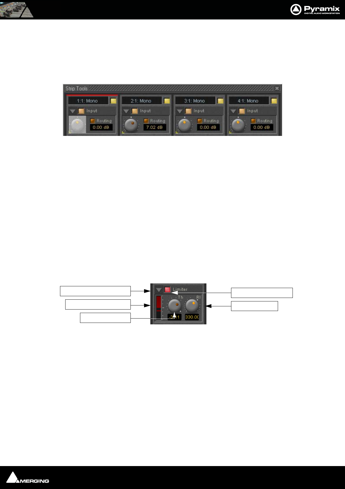
Strip and Bus Tools : Bus Tools 15 - 284
Automation mode switches
Please see: Dynamic Automation Modes on page 260 for a description of the automation mode switches.
When a grouped control is clicked, all other members of the group are shown with a yellow box around them.
Offset
If controls are offset when grouping is turned on, they retain the offset as shown here.
The red bar at the top of the strip indicates it is selected. The grayed out knob is the one which was right-clicked.
Delay Compensation
Delay Compensation
When the DRC section is active, the plug-in introduces a small delay to the audio signal. Since some signals of a
bus may not be selected for processing using the routing buttons, these signals would not be delayed, and there
would be a time misalignment at the output of the bus. When Delay Compensation is on, the same delay is
applied to all signals whether selected for processing or not. This results in correct time alignment for all the sig-
nals of a bus.
Limiter section
This is a straightforward ‘brick-wall’ limiter with simple Threshold and Release parameters. However, the DRC
(Dynamic Release Compensation) feature described in the next section can be activated to allow very musical
control of the release time.
A brickwall limiter is a limiter which guarantees that the output level will never exceed the threshold level. On a
normal limiter, a high level signal with very fast attack might cause an output higher than the threshold level, with
a brickwall limiter this will not happen.
Show/Hide Limiter section
Limiter section on/off
Gain reduction display
The bar graph shows the gain reduction generated by the Limiter Section. The range of the display can be
switched between 6 or 12 dB by clicking on the bar graph. Scale markings in 1dB increments on the right-hand
side of the bar graph make it easy to see if the range is 6 or 12 dB.
Threshold control
If the input signal level rises above the threshold level, the gain of the limiter is reduced. This limiter guarantees
that at no time will the level of the output signal exceed the threshold.
Release control
This parameter controls the amount of time the limiter takes to release. I.e remove the gain reduction) when the
input level was above the threshold level and starts fall. During the hold time the gain of the compressor remains
constant. The lower the release time, the faster the reaction.
Strip Tools - Grouped Knobs
Show/Hide Limiter Section
Gain Reduction Display
Threshold Control
Limiter Section On/Off
Release Control
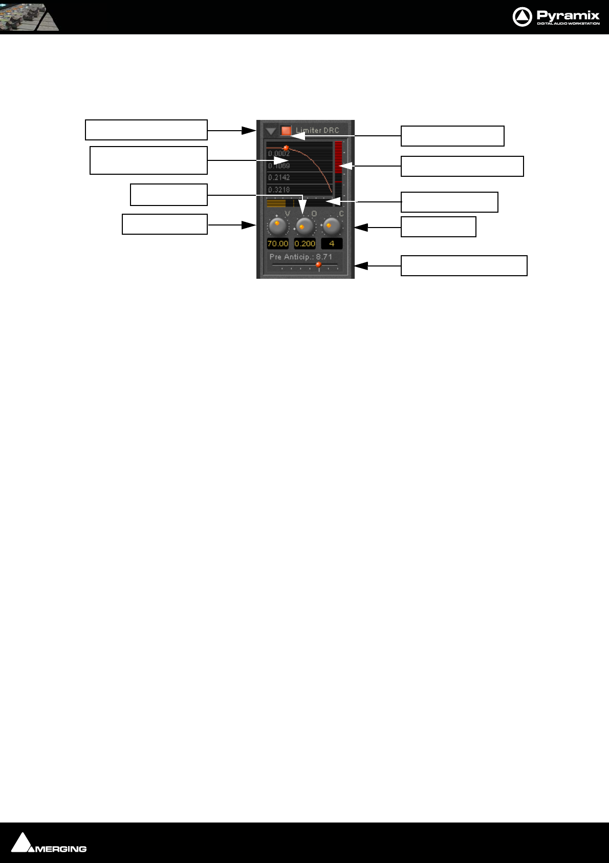
Strip and Bus Tools : Bus Tools 15 - 285
Limiter DRC Section
DRC stands for Dynamic Release Compensation. In short, this means the release time of the limiter is altered
depending on the dynamic nature of the signal routed through the processor.
Show/hide DRC section
DRC section on/off
Release Acceleration or Modification Display
Shows a curve which illustrates the relationship between the change in dynamics of the input signal and the vari-
ation of the release time. The curve can be adapted between linear and power function characteristics (see also
the description of the Curve Control parameter). During playback the display will also show a small red ball mov-
ing along the curve. This shows the range the algorithm is working in.
Gain reduction bargraph
Displays the gain reduction of the limiter while the DRC circuit is active. The scale is fixed at 6 dB.
Dynamics bargraph
Displays the dynamics of the input signal, which is the basis for the DRC algorithm.
Velocity control
Determines the speed of the DRC algorithm. The lower the value, the faster the algorithm reacts to changes of the
dynamics of the signal and the more it reacts to dynamics the more the release time will remain constant.
Offset control
This parameter basically sets the minimum release time. In this sense the release control of the limiter defines the
maximum release time, so the release time determined by the DRC algorithm will vary between these two times.
Curve control
This parameter controls the characteristics of the relationship between the dynamics of the signal and the result-
ing release time
Show/Hide DRC Section
Release Acceleration or
Modification Display
Velocity Control
DRC Section On/Off
Gain Reduction Bargraph
Dynamics Bargraph
Curve Control
Lookahead Delay Control
Offset Control
Strip and Bus Tools : Delay Compensation / Pre-Anticipation 15 - 286
Pre-Anticipation (Lookahead delay) control
This parameter changes the integration time for RMS detection and thus changes the effect of the DRC circuit.
The delay setting here also determines the delay that will be applied to signals passing through the plug-in NOT
not be selected for processing when Delay Compensation is switched ON
Note: Please note that this parameter delays the all signals running through the Bus
Tools plug-in, so phase or other timing errors may occur when the plug-in is used in
places other than the mix bus.
EQ and Output Sections
These are identical to the Strip Tools versions.
It is worth noting that, since the Limiter is in this case a brickwall design, the Automatic Gain Make-up function
compensates for the same amount as the value set by the Threshold Control of the Limiter. The resulting signal
will be close to, but never exceed 0dBfs. If Gain Make-up is Off the Output Level Control will act as a ‘ceiling’ con-
trol, setting the absolute level of the resulting output signal.
Delay Compensation / Pre-Anticipation
Example
In this table Bus Tools Instance 1 is IN circuit for the Left and Right channels of the mix and Bus Tools Instance 2 is
IN circuit for the Left Surround and Right Surround channels. For the Center and Sub-Woofer Channels both Bus
Tools are OUT of circuit. BUT Pre-Anticipation and Delay Compensation is switched ON for the channels selected
for processing. To ensure proper time alignment all channels are automatically delayed by the same total amount.
(the 8.71 and 5.8 figures are arbitrary)
If all channels are selected for processing (in circuit) with linked Pre-Anticipation then there is no need to activate
Delay Compensation.
5.1 Surround Mix Bus using two Bus Tools
Channel BUS 1 BUS 2 BUS 3 BUS 4 BUS 5 BUS 6
Routing L C R SL SR SW
Instance 1 IN OUT IN OUT OUT OUT
Delay 8,71 (PA) 8.71 (DC) 8,71 (PA) 8.71 (DC) 8.71 (DC) 8.71 (DC)
Instance 2 OUT OUT OUT IN IN OUT
Delay 5.8 (DC) 5.8 (DC) 5.8 (DC) 5.8 (PA) 5.8 (PA) 5.8 (DC)
Total Delay 14.51 ms 14.51 ms 14.51 ms 14.51 ms 14.51 ms 14.51 ms

USER MANUAL
www.merging.com/Pyramix
Project Processes

Project Processes : Dither 16 - 288
Dither
Whenever changes are made to digital audio signals such as mixing, altering gain, eq or reverb, the result is usually
an increase in the number of bits. These extra bits have to be removed to suit the requirements of delivery and
interconnect standards. If the bit depth is reduced by simply ignoring the extra bits (truncation) or even rounding
the least significant bit up or down, the resulting error can give rise to audible distortion of low signal levels. Obvi-
ously, there is also a permanent loss of resolution. These effects are cumulative. I.e. If the signal is repeatedly pro-
cessed and bit reduced to shorter word lengths, there will be a significant and audible loss of accuracy in subtle,
low level sounds. Human hearing makes use of this low level information in imaging and unless something is
done to avoid the problem, space and clarity will be adversely affected.
In Pyramix all processing takes place in 32 bit floating point so, if signals are kept within this environment, there is
no need for bit depth reduction until the final stage before output. Truncation or rounding are undesirable but a
single ‘dithering’ stage can reduce bit depth whilst maintaining low level linearity. This is achieved by adding a
controlled amount of low level noise to the signal. Since there is no such thing as a free lunch, the trade off is a
slightly increased level of noise. However, the noise can be ‘shaped’ to reduce its perceived audibility.
See also: Dithering Options on page 184
It is important dithering is only applied once.
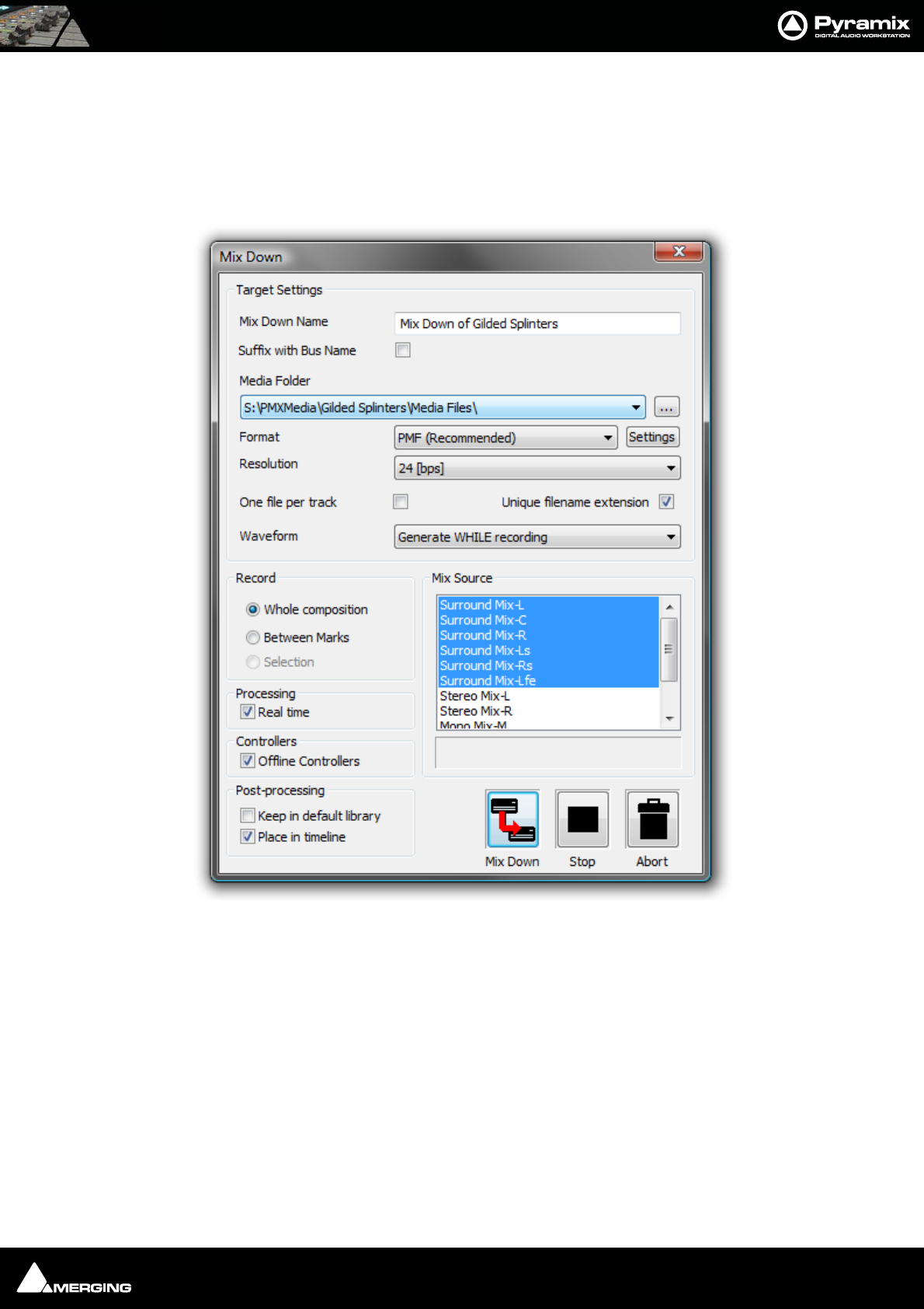
Project Processes : Mixing Down Projects 16 - 289
Mixing Down Projects
Exporting a Composition to a File
Once you have finished editing your Composition, the complete Composition or any selected area can be
exported to an audio file (or files). This is really the same as mixing down the Composition to a file instead of to an
audio output.
1. Choose Project > Mix Down to open the Mix Down dialog box.
2. In the Target Settings section, type in an appropriate file name under Record Name; choose the folder to
which the file will be saved from the Media Folder combo box (only previously mounted folders will be avail-
able as options); choose the bit depth/word length from the Resolution combo box; leave the One file per
track box unchecked to make a single multi-track audio file, or click it to generate separate audio files for
each Track and choose the appropriate export file type from the Format pop-up list. The Suffix with Bus
Name option will create files named like:
Terminator_Final-M&E-Stem1-L.wav
Terminator_Final-M&E-Stem1-C.wav
Terminator_Final-M&E-Stem1-R.wav
Note: These settings are completely independent of the settings for Recording and
Render.
Mix Down dialog

Project Processes : Archiving Projects 16 - 290
3. In the Record section, choose to export the Whole composition, or the area between the In and Out Markers
with Between Marks or a previously made Region with Selection by clicking the appropriate radio button.
4. Choose the appropriate output bus(es) as the source for the exported file. All output buses configured in your
Mixer will be available in the Mix Source list box.
Note: The names displayed will correspond to the labels in the mixer strips.
5. Click the Mix Down button to begin the process. Stop and Abort do what they say.
Options
Processing
Real Time When checked the Mix Down will take place in Real Time
Controllers
Offline Controllers When checked Hardware Controllers will be switched Offline automatically for the
duration of the Mix Down. If the box is left unchecked it is
possible to use the Hardware Controller for changing Monitor
volume etc. or to fade out.
Post-Processing
Keep in default library When checked the resultant mixed down file(s) will be placed in the Default Library
Place in timeline When checked the resultant mixed down file(s) will be placed in the Timeline
Non Real-Time Mixdown
Note: In Pyramix, non real-time mixdowns introduce no degradation whatsoever and
are a considerable aid to productivity since they are usually (much) faster than real-time.
Archiving Projects
Menu: Project > Archive This function copies the project and all used media to a single location. Optionally all
media can be Consolidated, and referenced libraries can be archived as well.
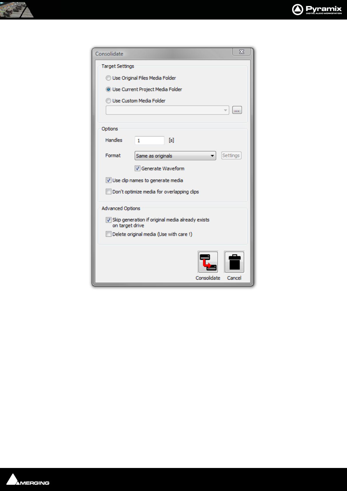
Project Processes : Consolidating Projects 16 - 291
Consolidating Projects
Consolidating a Composition is a method of reducing the storage space used by Media files and of bringing all ele-
ments of the Composition together to move it to another machine or storage medium. The Consolidate function
makes a selective backup of the media used in the Composition. Instead of backing up the whole of every media
file referenced by the clips in a composition, Consolidate backs up only those parts of the media files that are refer-
enced by the clip segments.
Target Settings
The Radio Buttons offer a choice of locations for the consolidated Composition.
Use Original Files Media Folder
The Consolidated Composition will be saved in the same location as the original files
Use Current Project Media Folder
The Consolidated Composition will be saved in the same location as the current Project Media
Use Custom Media Folder
The Consolidated Composition will be saved in a user selected location.
Options
Handles
Consolidate dialog

Project Processes : Converting Projects 16 - 292
To allow for limited further editing of the Consolidated Composition, changing fade durations etc. extra material
(if it exists), can be retained at each end of every clip, beyond that which is defined by the Composition EDL. Enter
a value in seconds.
Format
This drop down list enables the Consolidated Composition to be saved in the same format as the original or to be
converted to any supported format.
Generate Waveform
When checked, waveform files will be generated and saved with the Consolidated Composition
Use clip names to generate media
When checked, the original clip names are used for the newly generated media
Don’t optimize media for overlapping clips
Advanced Options
Skip generation if original media already exists on target drive
When checked new media will not be written where a version already exists on the target drive.
Delete original media (Use with care!)
When checked the original media files referenced by the consolidation are deleted after the consolidation is com-
plete. N.B. Destructive!
Converting Projects
Changing Project Length / Pitch
Processes whole Projects. Offers Time Compression or Pitch Reduction of 4% (24fps to 25fps) or Time Expansion or
Pitch Rise of 4.17% (25fps to 24fps)
Given an Origin Reference and a Ratio all clips of the project are stretched/squeezed and moved accordingly to
the stretch ratio and origin reference. Optionally all media can be consolidated to process only the part of audio
required by the clips. This function is available through the menu Project / Stretch and requires the Prosoniq
MPEX2 authorization key to be entered.
Reconforming a Project
Processes entire project. To be used where the existing project was created by Autoconforming material to a CMX
EDL.
Surround Post-Processing Projects
The Surround Source Stem can be selected from a list of available stems from all Surround buses.
Available processing plug-ins are:
• Multiple File Export
• Minnetonka AC3 (Dolby Digital) Encoder (to be purchased separately)
• MPEX3 Cinema 24fps to 25fps or 25fps to 24fps Multi-channel Time Stretcher by Prosoniq (optional)
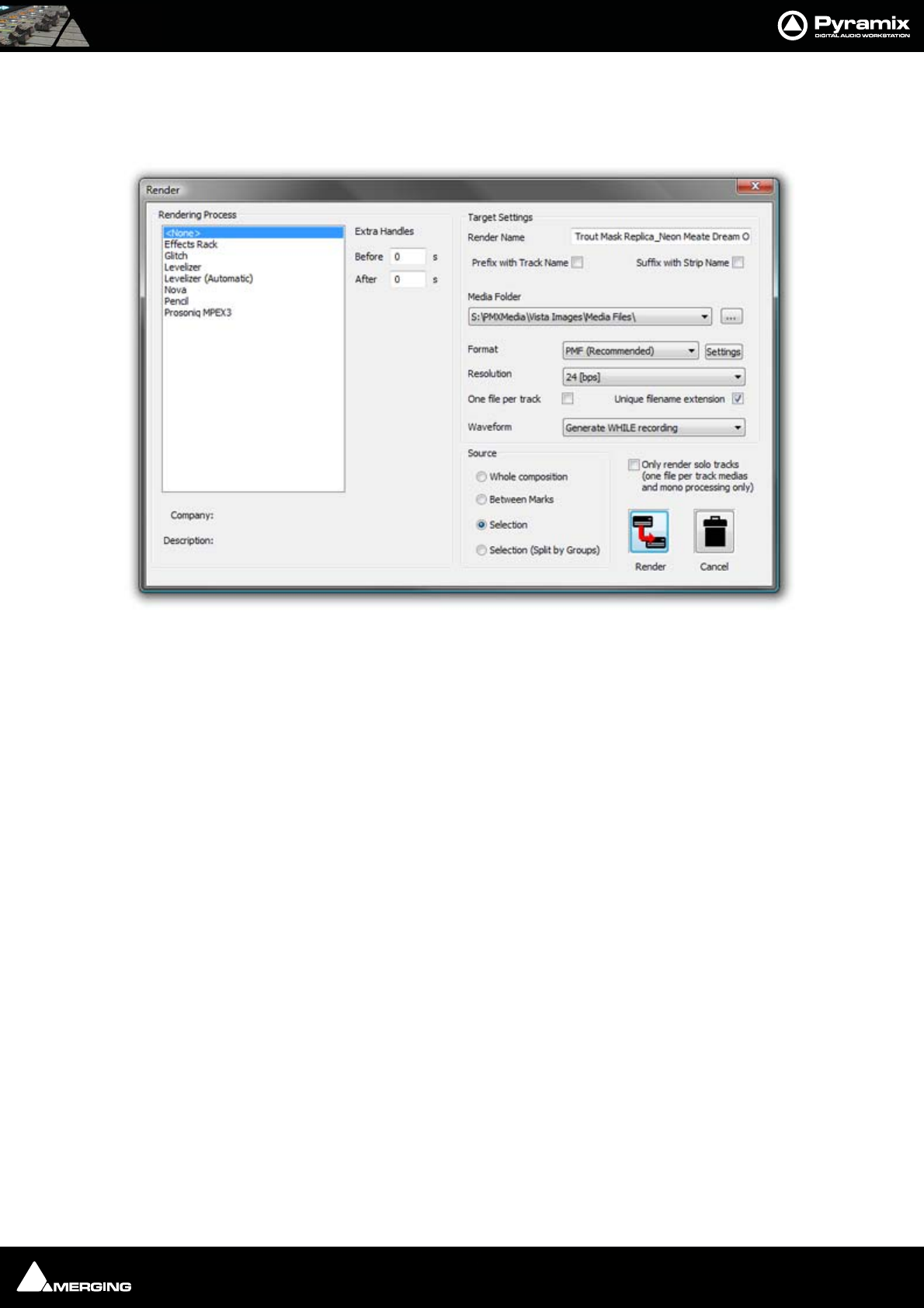
Project Processes : Rendering Projects 16 - 293
Rendering Projects
The Render function available in menu Project > Render offers a choice of Rendering plug-Ins.
Rendering Process Lists the currently authorized Rendering Processes and is where you select the one
required.
Extra Handles The before and after boxes allow a time value to be entered for extra material
(where available) to be included in the material used for analysis by the process
(where applicable).
Note: Handles added in the Render menu are not meant to be processed. They're only
used to give some extra material to processes that need analyzing before or after the
given portion of data.
Handles will NEVER be processed by any Render plug-ins.
Target Settings Affect the Output File.
Render Name A text entry box where any legal filename may be entered.
Media Folder The drop-down list allows mounted Drives/folders to be selected as the destina-
tion for the output file. The adjacent ... button opens a browser window if more
options or a new folder are required.
Resolution A drop down list with all valid choices of bit-depth for the output file(s)
One file per track When checked, multi-track sources will be rendered as separate files.
Unique filename extension When checked, ensures the output files have unique extensions.
Format The drop-down list allows a choice of output formats.
Settings If options are available for the chosen format, this button accesses them. If no
options are available the button is grayed out.
Waveform The drop-down list offers Waveform generation options. None, Generate AFTER
recording or Generate WHILE recording.
Note: These settings are completely independent of the settings for Recording and
Mix-down.
Render dialog
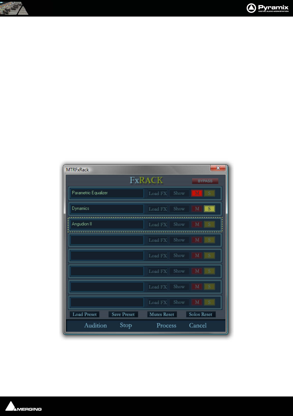
Project Processes : Process Plug-ins 16 - 294
Source Offers a mutually exclusive choice of sources between Whole composition, Between
Marks, Selection or Selection (Split by Groups)
Selection (Split by Groups) splits the rendering process into multiple renders for each selected Clip Group in the
timeline. In this case the Render Name text edit box is ignored and all renders take the name of the first clip in
time of each group.
Only render solo tracks (one file per track medias and mono processing only)
When checked, only soloed tracks will be rendered. Only media files with ‘one-file-per-track’ will be processed and
processing will be mono only.
Process Plug-ins
Effects Rack
Enables chains of up to eight VS3, VST and or Direct X plug-ins to be used as rendered processes. Select Effects
Rack in the Rendering Process list in the Render dialog, make other settings as required then click on Render to
open the Effects Rack Window
Note: Automatic Delay compensation is NOT available when using the Effects Rack.
Each of the eight slots can be loaded with one plug-in effect.
Most of the buttons are self explanatory.
Effects Rack Window

Project Processes : Process Plug-ins 16 - 295
Load FX
Opens a pop-up with lists of installed VS3 and VST plug-ins. Selecting None removes the currently loaded effect.
Show
Toggles the control Window for the currently loaded effect visible or hidden.
M
Mutes the effect in this slot
S
Solos the effect in this slot
Bypass
Bypasses all effects in the rack when lit
Audition
Plays the Timeline to audition the effects
Stop
Stops the Audition
Process
Closes the Effects Rack Window and initiates the Rendering Process
Cancel
Closes the Effects Rack Window and cancels the Render
Load Preset
Pops up a menu with Recall... >, Remove... > and Load From File options.
Hovering the mouse pointer over Recall... > reveals a list of all Presets present. Selecting one loads all its effects
and parameters into the Effects Rack.
Hovering the mouse pointer over Remove... > reveals a list of all Presets present. Selecting one erases it from the
Presets list.
Selecting Load From File opens a Browser Window to enable a previously written Preset File to be located and
loaded.
Save Preset
Opens a pop-up with two options: User > and Save To File.
Hovering the mouse pointer over User > reveals the option to Create New... and a list of all existing Presets.
Selecting an existing preset will overwrite the current contents of the selected Preset.
Selecting Save To File opens a Browser Window where you can name the Preset and navigate to a suitable loca-
tion for the file.
Mutes Reset
Resets all slots Mutes
Solos Reset
Resets all slots Solos
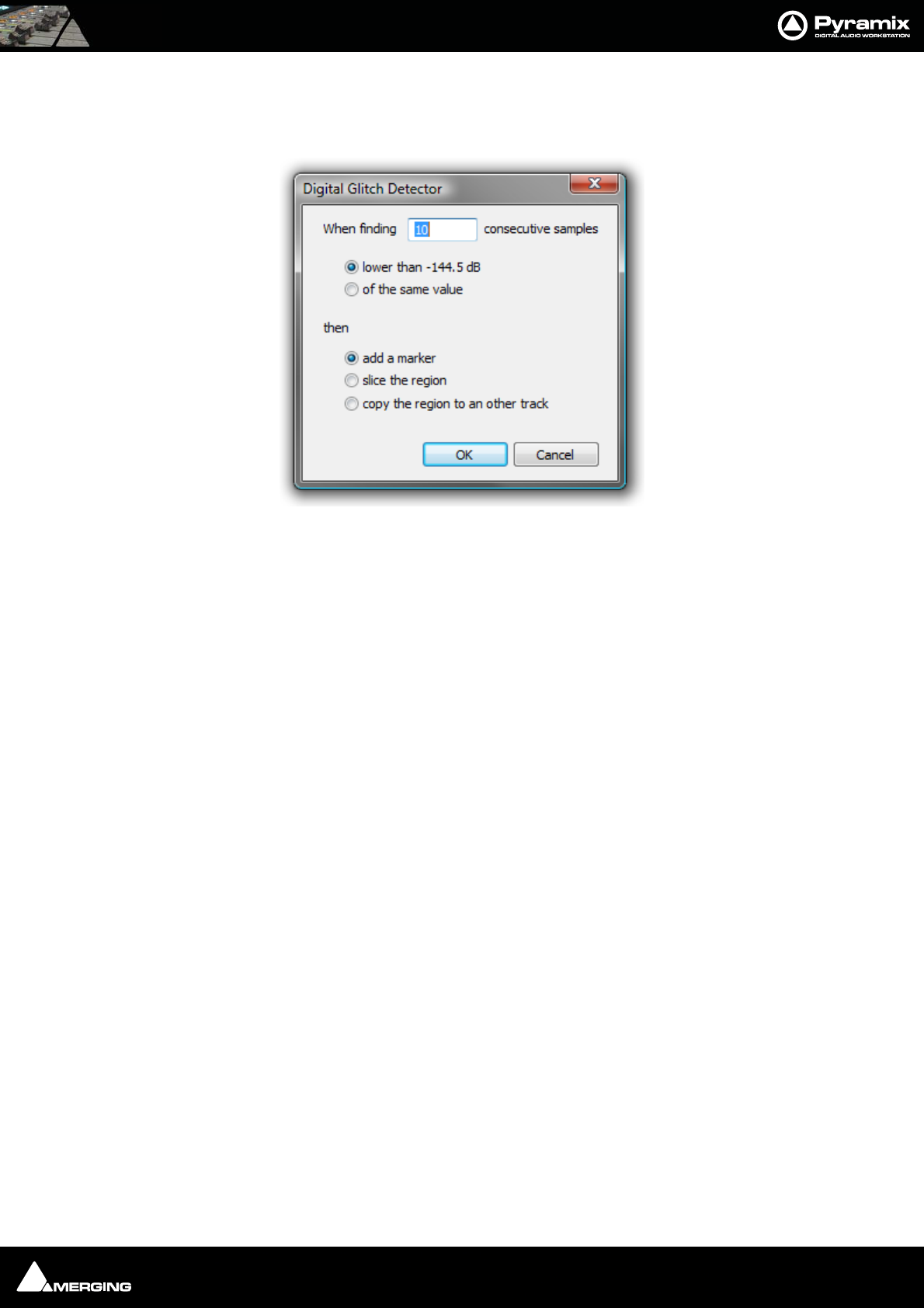
Project Processes : Process Plug-ins 16 - 296
Glitch Detector
Finds Glitches and Pops. Select Digital Glitch Detector in the Rendering Process list in the Render dialog, make
other settings as required then click on Render to open the Digital Glitch Detector dialog:
Type the number of consecutive samples to detect on in the When finding _____ consecutive samples box.
(Default is 10)
Choose detection method:
lower than -144.5dB
or
of the same value
Now select what you wish Pyramix to do when it detects the type of potential glitch chosen above:
add a marker
slice the region
copy the region to another track
Levelizer
Optional loudness analysis and correction plug-in.
Levelizer (Automatic)
Optional automatic version of the loudness correction plug-in.
Nova
An optional renovation suite plug-in by Algorithmix.
Digital Glitch Detector dialog
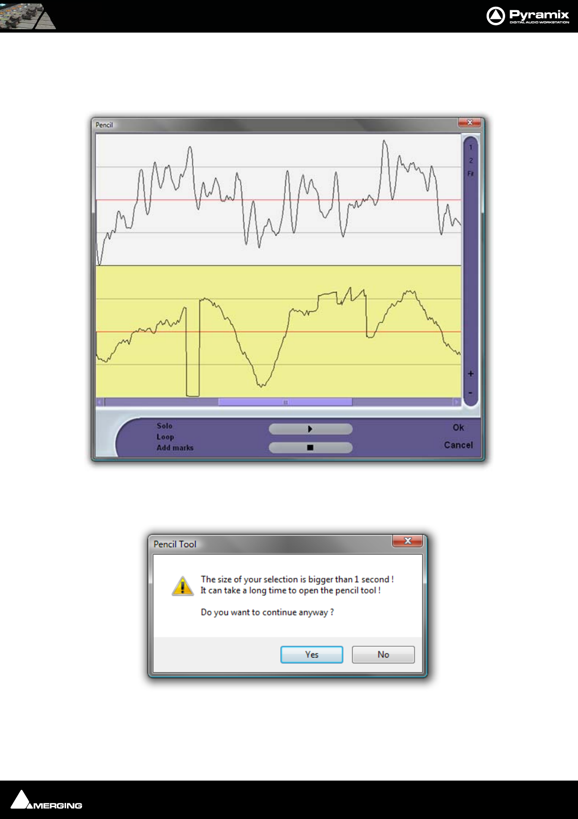
Project Processes : Process Plug-ins 16 - 297
Pencil
For retouching waveforms. To use the Pencil tool first select the section of audio containing the waveform you
wish to modify. Now select Pencil in the Rendering Process list in the Render dialog, make other settings as
required, then click on Render to open the Pencil window:
Note: If you select a section of audio longer than 1 second this Pencil Tool dialog will
appear:
The yellow track is the one currently selected for treatment.
The 1 and 2 buttons on the right determine whether one or both tracks of a two track selection are shown. Fit
shows all selected tracks.
Pencil Window
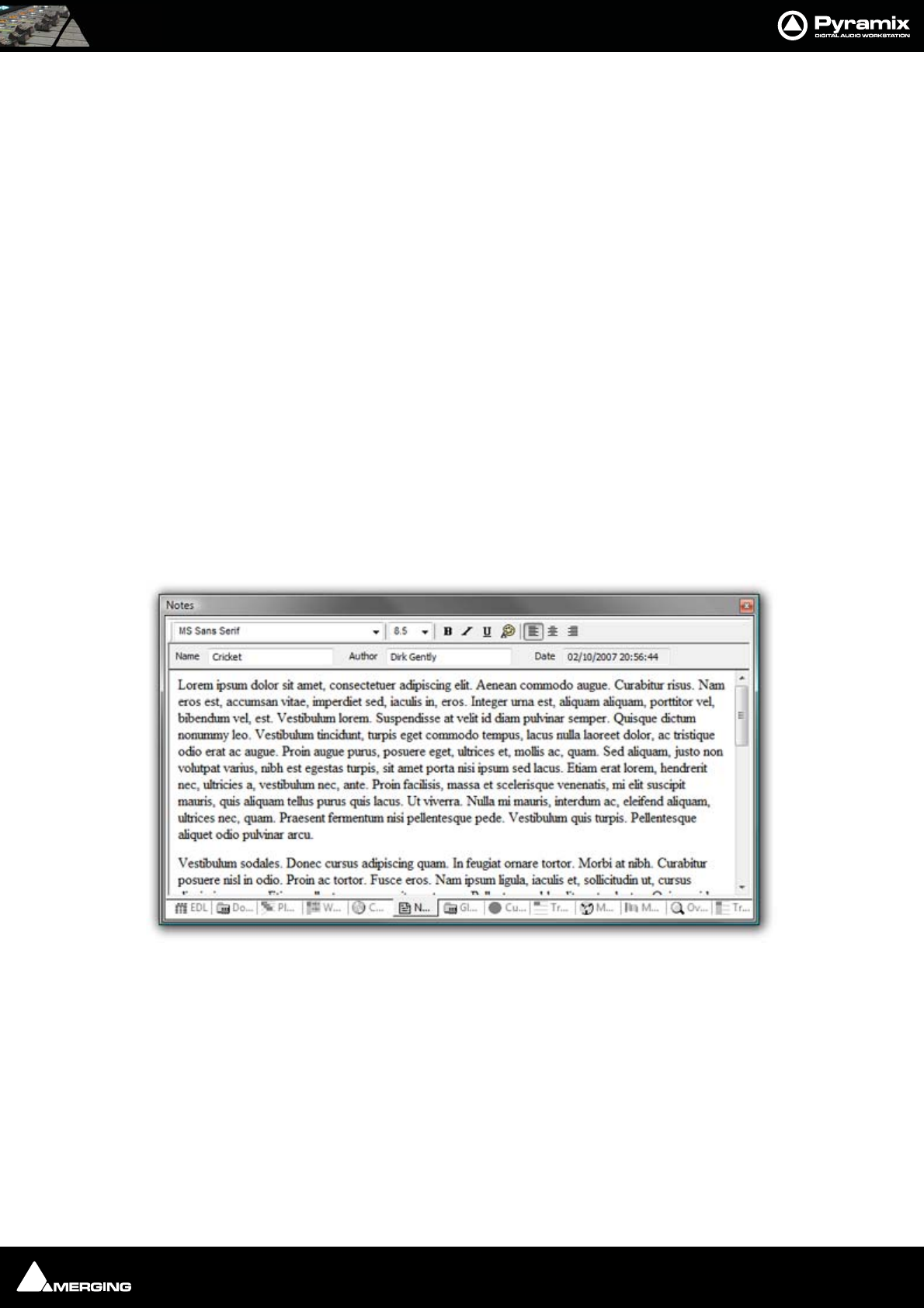
Project Processes : Cleaning Up Project media 16 - 298
The + and - buttons zoom in and out in time.
Solo When ticked solos the selected track
Loop When ticked preview playback will loop
Add Marks When ticked adds a Marker to the Timeline where the Pencil Render has taken
place
The > button initiates preview playback and the square stop button stops preview palyback.
Prosoniq MPEX3
An optional Multi-channel Time Stretch / Pitch Scaling with Formant plug-in.
Cleaning Up Project media
Deletes all Media files in the selected folder which is not used in, or referenced by the current Project.
N.B. This operation is NOT reversible. There is no UNDO!
Project Notes
Click on the Notes tab to add text notes to a project. Type or cut and paste text into the editor. Drop down list
boxes give a choice of font and size. Text can be emboldened, italicized, underlined and colored. Justification can
be left, centre or right.
Notes entered here are saved with the project. The notes can be reviewed, edited and copied into other applica-
tions by highlighting the text and copying with Ctrl + C.
Notes Tab Editor

USER MANUAL
www.merging.com/Pyramix
File and Project Interchange
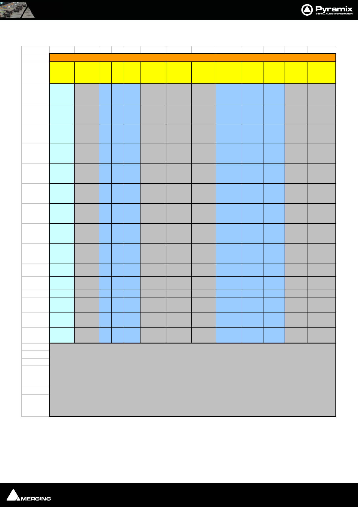
File and Project Interchange : File Interchange - Formats 17 - 300
File Interchange - Formats
http://forum.merging.com/viewtopic.php?f=23&t=1414
File Size Limitations
By design SD2 and legacy WAV or BWF files are limited to a maximum of 2GB, sometimes 4GB due to their 32bit
signed addressing (thus 31 available bits) formats, while 32bits unsigned addressing AIF files are limited to 4GB.
File
Formats
File
Extension Play Rec Export
Audio
Data
Format
Max # of
Channels
in a single
file
Interleave Max Bit
depth
Max
Sample
Rate
Max
File
Size
Unique
Identifier
(UID)
Data Chunk
(metadata)
format
PMF pmf yy y PMF
Virtually
Unlimited
(note1)
block 32bit f loat 384 kHz virtually
unlimited
in Name
& PMF
PMF
(Proprietary)
PMF ( DXD) pmf y y y PMF Currently
up to 48
block 32bit f loat 352.8 kHz virtually
unlimited
in Name
& PMF
PMF
(Proprietary)
WAV wav yy y WAV
Virtually
Unlimited
(note1)
y 32bit f loat 384 kHz 4GB in iXML iXML
BWF wav yy y WAV
Virtually
Unlimited
(note1)
y 32bit f loat 384 kHz 4Gb in BWF BWF & iXML
WAV wav yy y RIFF64
Virtually
Unlimited
(note1)
y 32bit f loat 384 kHz virtually
unlimited in iXML iXML
BWF wav yy y RIFF64
Virtually
Unlimited
(note1)
y 32bit f loat 384 kHz virtually
unlimited in BWF BWF & iXML
AIF aif yy y AIF
Virtually
Unlimited
(note1)
y 32bit f loat 384 kHz 4GB n n
SD2
(note 3) sd2 yy y SD2
Virtually
Unlimited
(note1)
y 24bit 48kHz 2GB n n
PMI pmi yyWAV
Virtually
Unlimited
(note1)
y 32bit f loat 384 kHz virtually
unlimited CD TOC
OMF omf yy y WAV
or AIF y 32bit f loat 384 kHz 2GB n n
MXF mxf yy y AES3
or WAV y 32bit f loat 384 kHz
AVI avi y WAV y 32bit float 384 kHz
QuickTime
(note 2) mov y PCM 32bit f loat 192 kHz
DSDIFF dff yy y DSD64
Currently
up to 16 y 1bit 2822 kHz virtually
unlimited nPMF
(Proprietary)
DSDIFF Em dff y y DSD64 Ty pic ally
2, 5 or 6 y 1bit 2822 kHz virtually
unlimited nPMF
(Proprietary)
n=not supported
y=supported
Pyramix Supported Audio Files
note 1: While both block interleaved and sample interleaved f ormats may theoretically accept an unlimited number of
channels, disk performance of multichannel sample interleaved files w ill degrade severely over 24 to 32 tracks
note 3: Bew are of the fragile data f ork / resource tw in file structure of (MacOS) SD2 file format, requiring special care to
be handled properly in a PC. More on this topic at the f ollow ing URL:
note 2: QuickTime Pro is required f or the QuickTime handler to w ork correctly.

File and Project Interchange : File Interchange - Formats 17 - 301
Please keep this in mind when recording and/or exporting to any of these formats, the 2GB/4GB limit might in fact
be quite close, particularly when working with high sample rate multitrack files.
Pyramix's WAV/BWF Media handler now accomodates RIFF64 removing the 2/4GB limitation. It does this in the fol-
lowing way: Up to 4GB Pyramix creates a regular (legacy) WAV/BWF, but when a recorded media exceeds 4GB, for
example during a recording/render or mixdown, Pyramix will automatically and transparently start creating a
RIFF64 instead of a regular WAV/BWF.
When performing file interchange please be aware that the destination workstation/software must be compatible
with RIFF64 WAV/BWF to be able to read RIFF64 WAV/BWF files.
Similarly, some "old" applications may only recognize WAV/BWF as proper files if their file size remains below the
2GB limit.
Hard Drive Limitations
A very similar 2GB/4GB* limit can also be encountered the hard way when attempting to write large files, even in
PMF format, onto storage units (hard drives, memory cards etc.) formatted using an old 32bit file system such as
FAT32 or HFS.
Yet another, higher, limitation also exists with IDE ATA/ATAPI drives. This will show up at around 137GB. This may
be caused by part of a system (drivers, controllers and/or old Windows version) only recognizing the 28bit
addressing of the original ATA specifications, and not the enhanced 48bits available on newer equipment. This is
usually solved by installing fresh and or updated Bios/Drivers/OS.
*The official limit is 4GB, but serious trouble can start at around 2GB.
PMF
PMF or Pyramix Media File is Merging Technologies native format. It carries a number of advantages when com-
pared with others, especially where multi-channel recordings are concerned.
• PMF has a 64bit addressing structure, so there is no 2GB limit.
• PMF can contain comprehensive proprietary metadata
Note: Please see: Appendix IX - Pyramix iXML Implementation on page 579 for fur-
ther information.
The advantages of using interleaved PMF for multi-channel files (One file per track not selected) are:
• Contiguous blocks on disk so, when reading the same block (same time position) for all the tracks at once,
the disk head does not have to do long and time-consuming seeks.
• It is not necessary to read samples for all tracks when only one track is required for replay. E.g. when using
a guide mix to edit a multitrack recording.
• Simpler Media Management, one file instead of say, 48 for a 48 track recording.
• Waveforms are embedded in the file."
The only time to consider using a different file format is when material must be exported to an application that
does not support PMF.
WAV and BWF
Wave and Broadcast Wave (BWF) files are supported by Pyramix. In Pyramix WAV/BWF is now RIFF64 compatible,
so the 2/4 GB file size limitation no longer applies.
The disadvantage of using WAV and BWF for interleaved multi-track recordings is that the audio is interleaved
sample by sample for all channels, which may adversely impact the overall throughput of hard drives or any other
storage media, particularly when only a subset of all channels present in such a file is being used on subsequent
playback.
Example: if, in a given Pyramix project, only channels 1 and 2 out of a 48 track BWF file are being played, the hard
drive's head will still have to spend the time scanning the entire data corresponding to all 48 tracks to just retrieve
the useful samples corresponding to those two channels. Alternatively, PMF with its much larger channel inter-

File and Project Interchange : File Interchange - Formats 17 - 302
leaving in blocks of typically 64 kB can instruct the hard drive's head to only seek to the corresponding blocks con-
taining the required data of channels 1 and 2.
Broadcast WAV file Tips.
File Types
There are two types of BWF file:
BWF P means polyphonic -> multitracks
BWF M means monophonic -> one file per track
The Cantar location recorder produces only BWF-M files, and some Avid people want BWF-P. To convert BWF M
BWF P mount the file in the Media Manager and select Convert > Quick Export, then do NOT check the One file
per Track option. (Uncheck it if necessary). All Scene and Takes information present in the original BWF file will be
also exported in the resulting BWF-P file.
Metadata
BWF files have a special chunk in the file that contains metadata; this is called the BEXT chunk or Broadcast Wave
File metadata.
The first field of this chunk is the Description. This is the field we display in the Name column for BWF files instead
of the file name. We do the same for PMF and OMF. We only display the real filename for Wave, AIFF and SDII that
have no metadata.
In v4.2.6 or higher you can add the FileName column to also display the real filename of all files. (Media Manager
window View > Options : Columns tab)
Once renamed in the Media Manager both the Description field and the filename of your BWF files should be
updated.
iXML
WAV files generated by Pyramix can also contain iXML information and as such carry similar information to data
chunk of a BWF.
The iXML metadata of a WAV file is available to any compatible application, if the application is not iXML aware,
the file will be seen as a regular WAV.
Quicktime
In order to enable the Quicktime handler you will need to purchase and install Quicktime Pro from Apple.
http://www.apple.com/quicktime/pro/
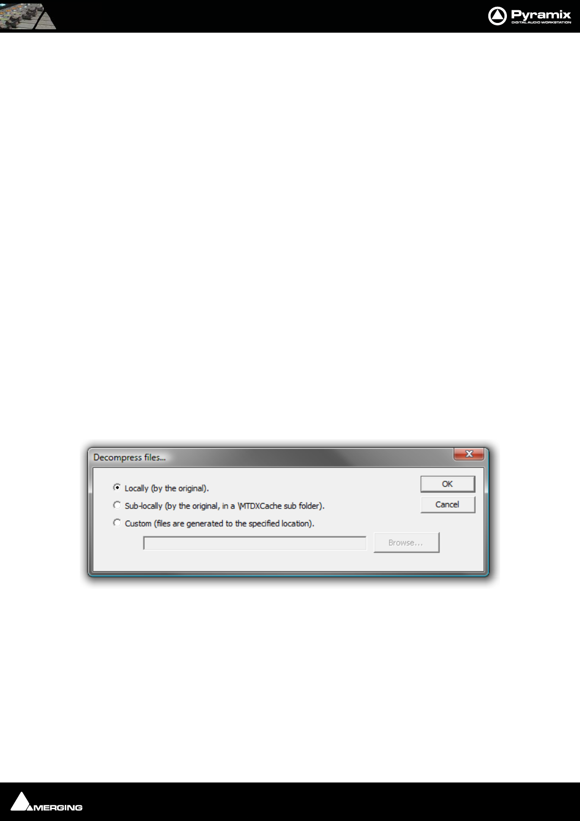
File and Project Interchange : File Interchange - Formats 17 - 303
Compressed Audio File Formats
Pyramix supports many compressed file formats including MP3.
Technology
The decompression is handled via Microsoft DirectShow technology. So the formats supported will depend on
which DirectShow codecs are installed. Default Windows installation should handle most of the common com-
pressed file formats (wma, mp3 and more), but a wide variety of codecs exist to support all the major compressed
formats (such as ogg-vorbis, flac, etc.).
Codecs
If you experience problems with the default Widows Installation or if you are in need of specific Codec, Merging
has a list of recommended third-party codecs available.
For more details please refer to the Merging Forum Pyramix Troubleshooting & Tips section
http://forum.merging.com/viewforum.php?f=16
How Compressed Audio Support Works
To enable sample accurate editing, the compressed files are first decompressed into a cache file. The file is format-
ted as follows:
originalFileName__DXC(tag)DCX_.wav
This file is a plain wav file.
Pyramix Setup
First, set up the Default decompression cache options in :
Settings > All Settings > Application > Location and click on Decompression Settings to open the Decom-
press files... dialog.
Here you specify where the media should be decompressed to when no Mounting Rules are specified :
Locally (by the original) File(s) will be created in the same location as the original file.
Sub-locally (by the original, in a \MTDXCache sub folder). File(s) will be created in a sub folder created by Pyra-
mix in the same location as the original file.
Custom (files are generated to the specified location). File(s) will be created in a user specified location. When
this option is selected the Browse... button is available to open a file browser window to set the user defined path.
Decompress files... dialog

File and Project Interchange : File & Project Interchange with Apple Macintosh 17 - 304
Mounting Rules
In addition to the general settings, Mounting Rules can be created to override the Default decompression cache
settings for a specific Mounting location:
Special rules for cache file decompression
Locally (by the original) File(s) will be created in the same location as the original file.
Sub-locally (by the original, in a \MTDXCache sub folder). File(s) will be created in a sub folder created by Pyra-
mix in the same location as the original file.
Custom (files are generated to the specified location). File(s) will be created in a user specified location. When
this option is selected the Browse... button is available to open a file browser window to set the user defined path.
Enable enables the rule.
Allow cache files mounting when ticked cache files can be mounted directly, otherwise they remain invisible.
MXF
The Pyramix MXF implementation can read and decode MXF files following specifications AS WELL as files coming
from Avid / Digidesign workstations.
Pyramix MXF can generate valid MXF files complying with MXF specifications and have passed the validations
tests provided by Snell&Wilcox.
As of today, supported MXF formats are OP1A and OPAtom, as well as potentially OP1B, OP1C, OP2A, but these
remain to be fully validated.
MXF Essences supported today are AES3 & Broadcast Wave audio files (conforming to SMPTE 382M).
For the latest MXF interchange information please see:
http://forum.merging.com/viewtopic.php?f=23&t=2094
File & Project Interchange with Apple Macintosh
Currently, the recommended Interchange Format when working with ProTools 7 is AAF / OMF, with BWF media
files. Please see: AAF on page 310 and OMF on page 320 for further information and also refer to the Pyramix
Interchange Forum in the Support Section (for registered users) for regularly updated information, as well as Inter-
change tips & tricks :
http://forum.merging.com/viewforum.php?f=23
History
SD2 & ProTools 5 Sessions and Legacy Apple File Formats
Old Macintosh files such as SD2 and PT4.x and PT5.x projects files have a Mac-binary, or double-fork structure that
the PC cannot handle directly. As opposed to interchange files, PC files or new Mac files (that do carry a simple sin-
gle file structure), SD2 and PT5 projects files are based on a Data fork (the one you see in every computer file) and
a Resource fork (a hidden, second file storing all the file info). While this binary structure was actually quite a clever
and convenient move, the fact that half of the file is hidden by design makes it a very fragile cross-platform media.
Mounting Rules dialog decompression rules section

File and Project Interchange : File & Project Interchange with Apple Macintosh 17 - 305
A sure sign that the resource fork has been lost is when the file appears with a generic icon and is present but
unreadable. A broken binary file cannot be rebuilt.
Note: For more info about the specific handling of "old" Apple files, please read the fol-
lowing entry in the Forum's Support Section (for registered users):
http://forum.merging.com/viewtopic.php?f=23&t=1414
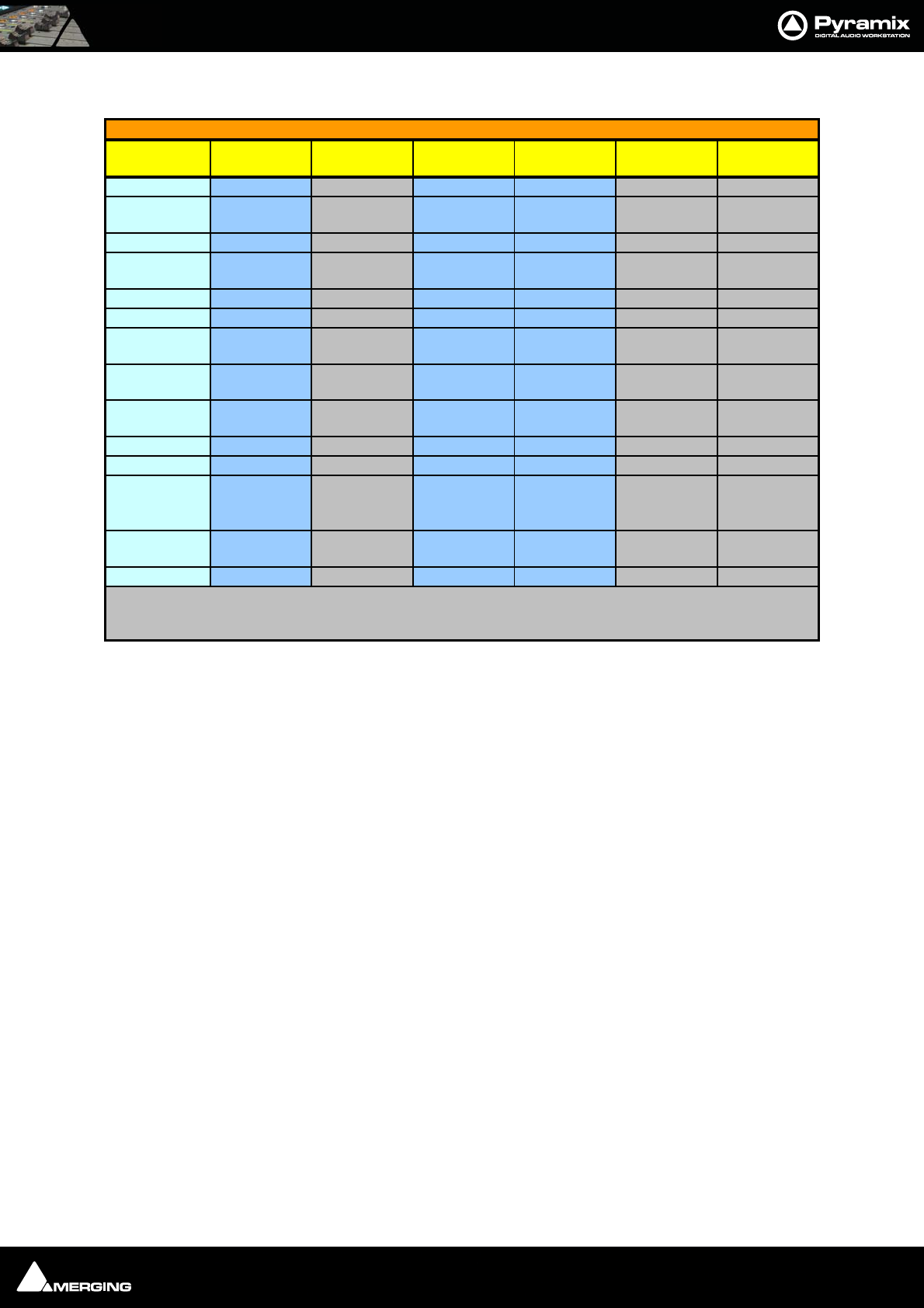
File and Project Interchange : Project Interchange 17 - 306
Project Interchange
Interchange
Format
Software
Key File Format(s) Import Export Max.
Sample Rate
Max. EDL
Duration
AAF PSO-AAF BWF y y
AES31 PSO-AES31 BWF y y
192khz /
DSD
AKAI DD/DR PSO-AKAI Proprietary y y
CD Import PSO-CDR
PMF, AIF,
WAV, etc. y
CMX-EDL - - y y
DAR PSO-DAR Proprietary y
OMF V1
unembedded PSO-OMF
OMF, AIF,
BWF/WAV y y 13h30
OMF V2
unembedded PSO-OMF
OMF, AIF,
BWF/WAV y y 13h30
OMF V2
embedded PSO-OMF
OMF, AIF,
BWF/WAV y y 13h30
OPEN TL PSO-OTL BWF/WAV y y
PT5 PSP-PT5 SD2 y y 48 kHz 13h30
SACD Edited
Master Import PSO-SAA
DSDIFF
Edited Master y 2822 kHz
Sonic
Solutions PSO-SONIC AIF y
XML EDL - - y y unlimited
n = Not supported
y = Supported
Pyramix Project Interchange Options
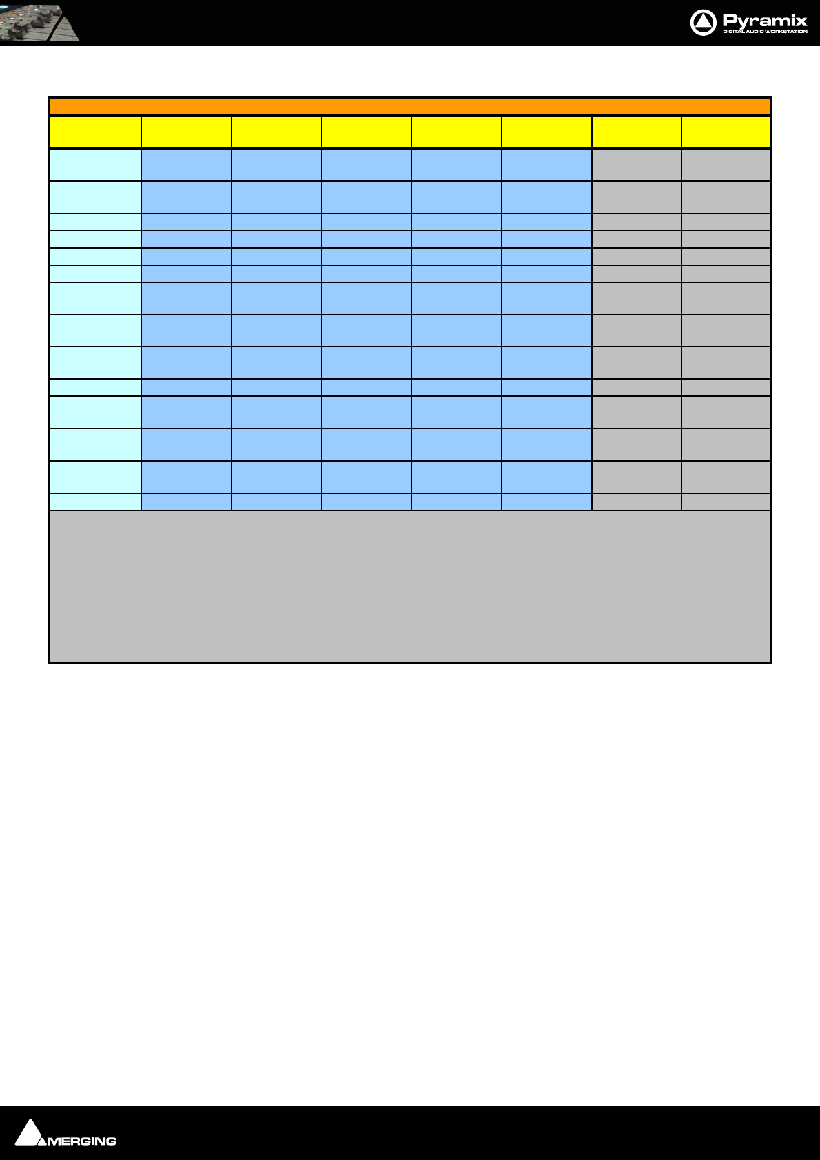
File and Project Interchange : Project Interchange 17 - 307
Import and Export are handled by InterChange. In the Project menu the Import and Export options each open a
window where a list of available InterChange plug-ins is presented.
Interchange
Format Clip Name Clip
Gain
Clip
Envelope
Clip
Fades
X-fade
Curves Markers CD/SACD
Markers
AAF yyyy
no
(note 1) nn
AES31 y y
y
(note 2) yynn
AKAI DD/DR
CD Import y
CMX-EDL
DAR y y n y y n n
OMF V1
unembedded ynny
no
(all to Power) nn
OMF V2
unembedded yyny
no
(all to Power) nn
OMF V2
embedded yy
y
(note 4) y
no
(all to Power) nn
OPEN TL y y n y basic n n
PT5 y
y
(note 3)
y
(note 3) yynn
SACD Edited
Master Import
em
name nnnn y
Sonic
Solutions
XML EDLyyyyyyy
n = Not supported
y = Supported
Note 1: currently being improved
Note 2: clip envelopes will be supported soon when specification is published by AES
Note 3: Protools only supports envelopes and does not have an additional clip gain.
On export, the volume automation can be set to represent the clip gain, the clip envelope or a combination of both.
Note 4: Export from Pyramix is feasible but not yet import. Currently import is only supported by PT
Pyramix Project Interchange Options Clip and Marker Support
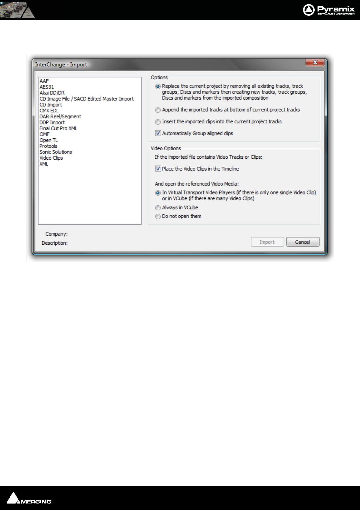
File and Project Interchange : Project Interchange 17 - 308
Import
Project > Import opens this window:
The Options radio buttons determine how the imported material will affect the current project.
Options
• Replace the current project by removing all existing tracks, track groups and markers then creating new
tracks, track groups and markers from the imported composition
• Append the imported tracks at bottom of current project tracks
• Insert the imported clips into the current project tracks
• Automatically Group aligned clips - When this option is chosen with one of the three above, stereo and
other multi-channel clips will be automatically grouped.
Video Options
If the imported file contains Video Tracks or Clips:
• Place the Video Clips in the Timeline.
If this option is checked then any Video Clips present in the imported file will be placed in the Timeline as black
Video Clips. These clips are usable only for reference and are not played back as such by Pyramix (see below for
playing them back). Audio in a Video Clip container is also imported and placed in the Timeline according to the
method chosen in the Options section of the dialog.
And open the referenced Video Media:
•In Virtual Transport Video Players (if there's only one single Video Clip) or in VCube (if there are
many Video Clips).
A single Video Clip present in the imported file is opened in the DirectShow Video Player or the QuickTime
Video Player (depending its type). Multiple Video Clips present in the imported file are opened in VCube.
Project Interchange - Import dialog
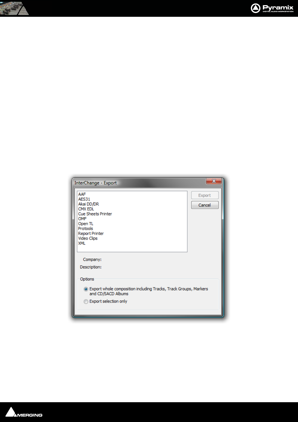
File and Project Interchange : Project Interchange 17 - 309
•Always in VCube.
Single or multiple Video Clips are opened in VCube.
•Don't open them.
Imported Video Clips are only placed in the timeline (optionally) but not opened in any Video Player.
Audio present in a Video Clip ‘container’ is also placed in the Timeline according to the rule(s) chosen in Options
above.
Imported Video Clips are saved in the project, so, when the project is opened, the Video Clips will again be present
on the timeline. The referenced Video Media will be automatically opened in either Virtual Transport Players or
VCube depending on the same options as above, but for general project opening that can be found in:
Settings > All Settings > Application > General : Project Opening Section
If the project contains references to Video Media, open them:
•In Virtual Transport Video Players (if there's only one single Video Clip) or in VCube (if there are
many Video Clips).
•Always in VCube
•Don't open them
Export
Project > Export opens this window:
Options
• Export whole composition including tracks, track groups, Discs and markers
• Export selection only
Note: The Export selection only choice will be grayed out if there is no selection in the
Project Timeline.
Project Interchange - Export dialog
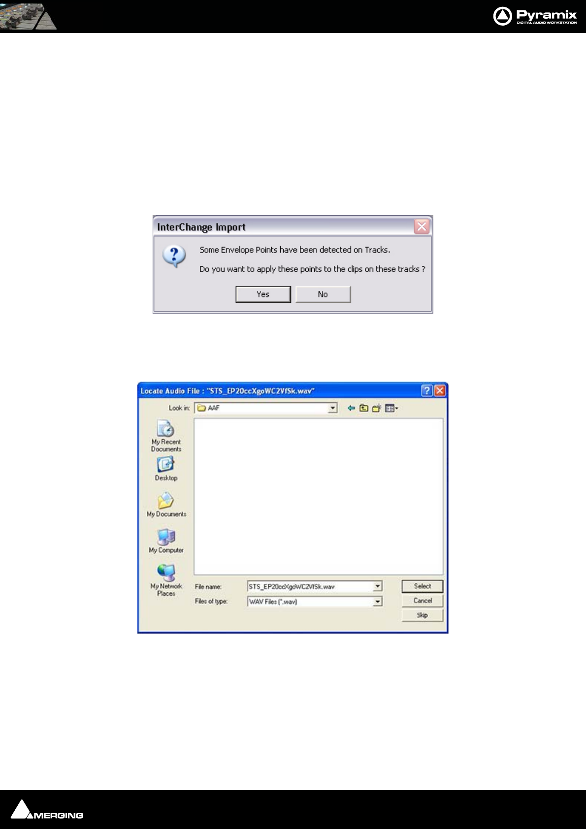
File and Project Interchange : Project Interchange 17 - 310
AAF
Pyramix can import and export projects in AAF (Advanced Authoring Format)
Note: Pyramix can also use MXF audio files and export MXF audio files. Please see: MXF
on page 304
Import
Select AAF in the Interchange Import dialog. Choose the appropriate import option and click on Import.
The Import AAF File window opens. Navigate to the required AAF file or type its name in the File name box and
click Open.
If the file contains envelope information this dialog opens:
Click Yes to apply envelope information or No to import the material without envelope information.
If a media file or files cannot be located, a browser window opens:
The browser enables the user to navigate to or search for the missing file. If the file cannot be found or is known to
be absent, click on the Skip button to ignore the file and continue or, if there are many files know to be absent,
Ctrl - Clicking the Skip button will ignore all subsequent missing files.
Interchange - Import dialog
Locate Audio File browser window
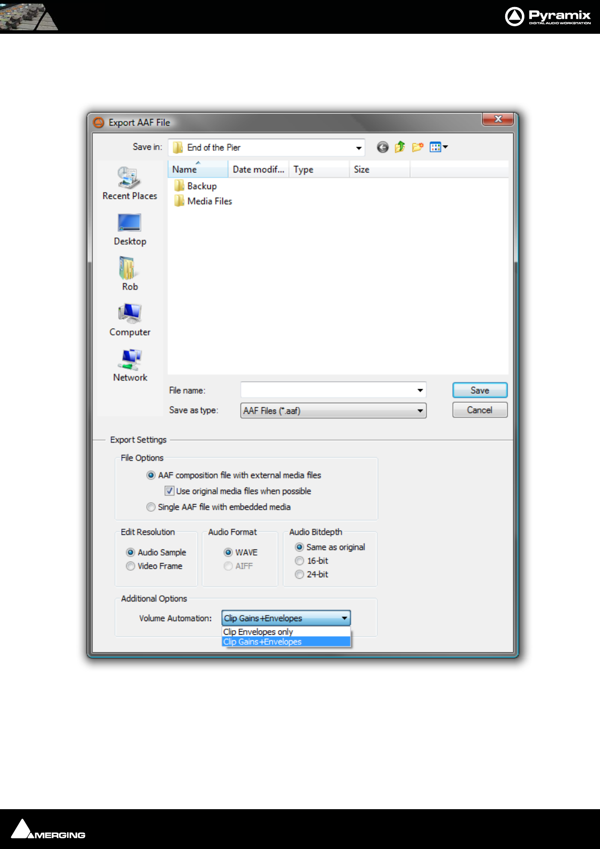
File and Project Interchange : Project Interchange 17 - 311
Export
Select AAF in the Interchange Export dialog. Choose the appropriate export option and click on Export. The
Export AAF File dialog opens:
Export AAF File dialog

File and Project Interchange : Project Interchange 17 - 312
Navigate to the required drive/folder, type a suitable filename in the File name text box, choose the appropriate
file type from the Save as type drop-down list. Make appropriate choices in the Export Settings section then
click Save to begin the export process. When the export is concluded this info box appears:
AAF Export Notes:
• When Clip Envelopes Only is selected, the Clip Envelope and Static Clip Gain will be exported separately.
This type of AAF file will import back into Pyramix with the original Clip Gains and Clip Envelope. However,
if it is imported into ProTools, the Clip Gains will probably be lost.
• When Clip Gains+Envelopes is selected, the Static Clip Gain will be combined with Envelope. When this
type of AAF file is imported back into Pyramix, all the Clip Gains will be at 0dB, but the original Clip Gain
will be incorporated in the Envelope.
Note: EMBEDDED MEDIA When exporting to AAF with embedded Media the Clip
names may change when the file is opened in Pro Tools. In order to avoid problems get-
ting AAF files into Protools there are some limitations to the structure of the AAF file and
where the clip name can be stored. For AAF files referencing external media, these
restrictions don't cause any noticeable differences. When exporting embedded AAF files,
the clip name basically needs to be associated directly with the Media. As the Media is
embedded in the file, its NOT possible to have multiple names referencing the same
piece of Media.
Fade Curves
The AAF specification includes only limited support for audio fades and crossfades - basically just allowing for lin-
ear or equal power fades.
• On export from Pyramix to Protools the fades/crossfades are retained, but the fade curve details will be
lost.
• On export from Protools to Pyramix, any fade regions will be rendered but will just appear as normal clips
in Pyramix.
About the AAF Format
•AAF Import will import Static Clip Gains as well as Clip Envelopes but remember that many other systems
(including Protools/Avid) do NOT support Static Clip Gains so files from these systems will only show a
Volume Envelope on Import.
• On AAF Export, if the Volume Automation option is set to Clip Envelopes Only, the Pyramix Clip Enve-
lope will be put into the AAF Clip Envelope and the Pyramix Clip Gain will be put into the AAF Static Clip
Gain (but again, remember that this Static Clip Gain will not be imported into systems such as Protools/
Avid).
If the Volume Automation is left on its default setting of Clip Gains+Envelopes, the Pyramix Clip Enve-
lope and Clip Gain will be combined into the AAF Clip Envelope and no Static Clip Gain will be saved in the
AAF file.
Interchange Export info box

File and Project Interchange : Project Interchange 17 - 313
AES-31
Straightforward Import and Export in AES-31 format.
Genex Cuepoint files are supported. If a .CPT file exists near the .ADL file, cue points will be converted to Pyramix
markers.
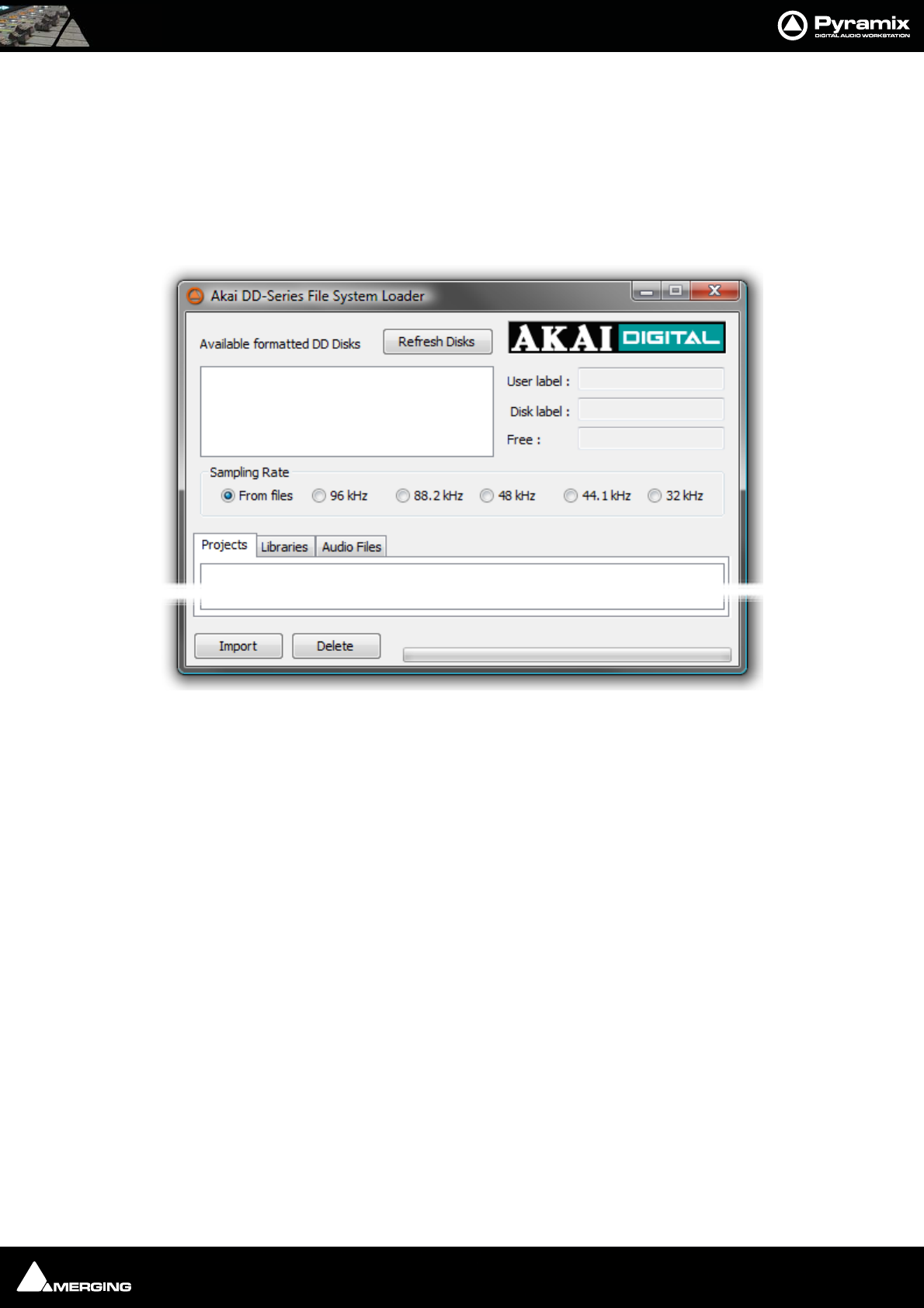
File and Project Interchange : Project Interchange 17 - 314
AKAI DD/DR
Pyramix is capable of recognizing disks recorded in the Akai DD-Series format and importing their data.
Preparing the system
Connect the Akai disk to your PC. Usually this will be a hard disk drive via a SCSI interface, but can also be a Mag-
neto-Optical or Jaz disk.
Project > Import or Export opens the appropriate Project Interchange dialog box. Choosing AKAI DD/DDR
from the list opens the AKAI DD-Series File System Loader dialog box
When the dialog is opened, Pyramix searches for available Akai disks and displays them in the upper left part of
the dialog box. Choose the disk you want to work with by selecting it with the mouse.
The Refresh Disks button restarts the search for available Akai disks.
The lower part of the dialog box shows the data found on the selected Akai disk. Following the data structure of
Akai disks this panel has three Tabs named Project, Libraries and Audio Files.
Import Button
To import the data into your Pyramix session, simply select the desired data and click the Import button. The
behavior is the same as ‘Quick Import’; All the files are imported and stored into a mounted media folder.When an
Akai library is imported, a new Pyramix project library will be created.
Delete Button
Deletes selected files from the Akai media providing this is not write protected.
Audio File import
Since Pyramix is capable of reading the audio data directly from an Akai disk, it is not necessary to import the
actual audio files into a local Windows drive. Thus, when you click the Import button, a dialog box is displayed: Do
you want to import the Audio Files used by this/those projects? If the answer is No, only references to the
audio files will be stored in the local Windows Media folder instead of copies of the actual audio data. The audio
will play correctly but no waveforms will be displayed.
Closing the Akai loader dialog
Akai DD-Series File System Loader dialog
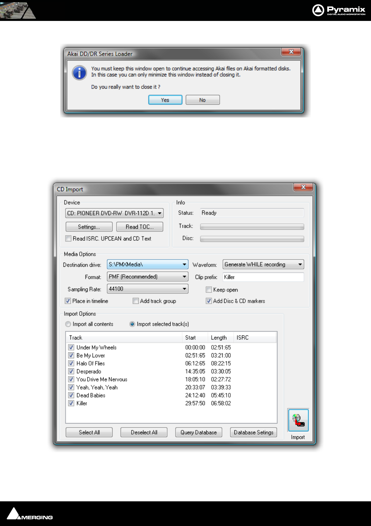
File and Project Interchange : Project Interchange 17 - 315
If you attempt to close the Akai DD-Series File System Loader the following dialog appears:
If you wish to continue to directly access Akai files click NO and minimize the window.
CD Import
Pyramix has comprehensive CD import functions. Project > Import opens the Interchange Import dialog box.
choose the appropriate destination option and choose CD Import
Device
The combo box shows all suitable drives on the machine.
Akai DD/DR-Series Loader dialog
CD Import dialog
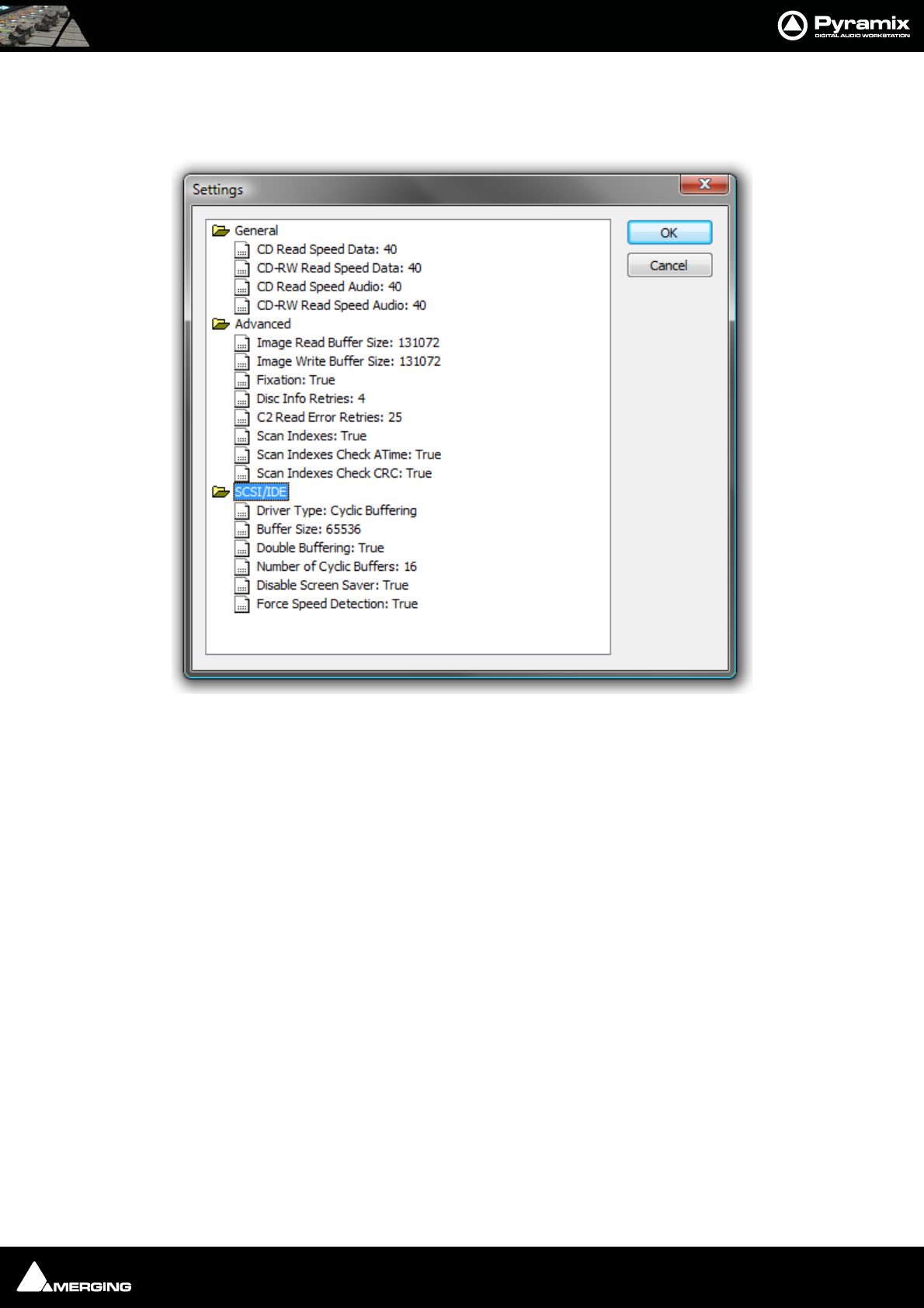
File and Project Interchange : Project Interchange 17 - 316
Settings
Settings pops up a dialog box with specific drive settings. These settings may be altered if required by clicking on
an entry and typing a new value in the box.
Read TOC reads the Table Of Contents on the CD and lists the tracks in the left hand pane.
If Read ISRC, UPCEAN and CD Text is checked this information will also be read if present.
Import Options
If Import all contents is checked the whole disc will be imported. If Import selected tracks is checked only the
tracks with a tick in their checkbox will be imported.
Select All and Deselect All do what they say.
CD Import Settings dialog
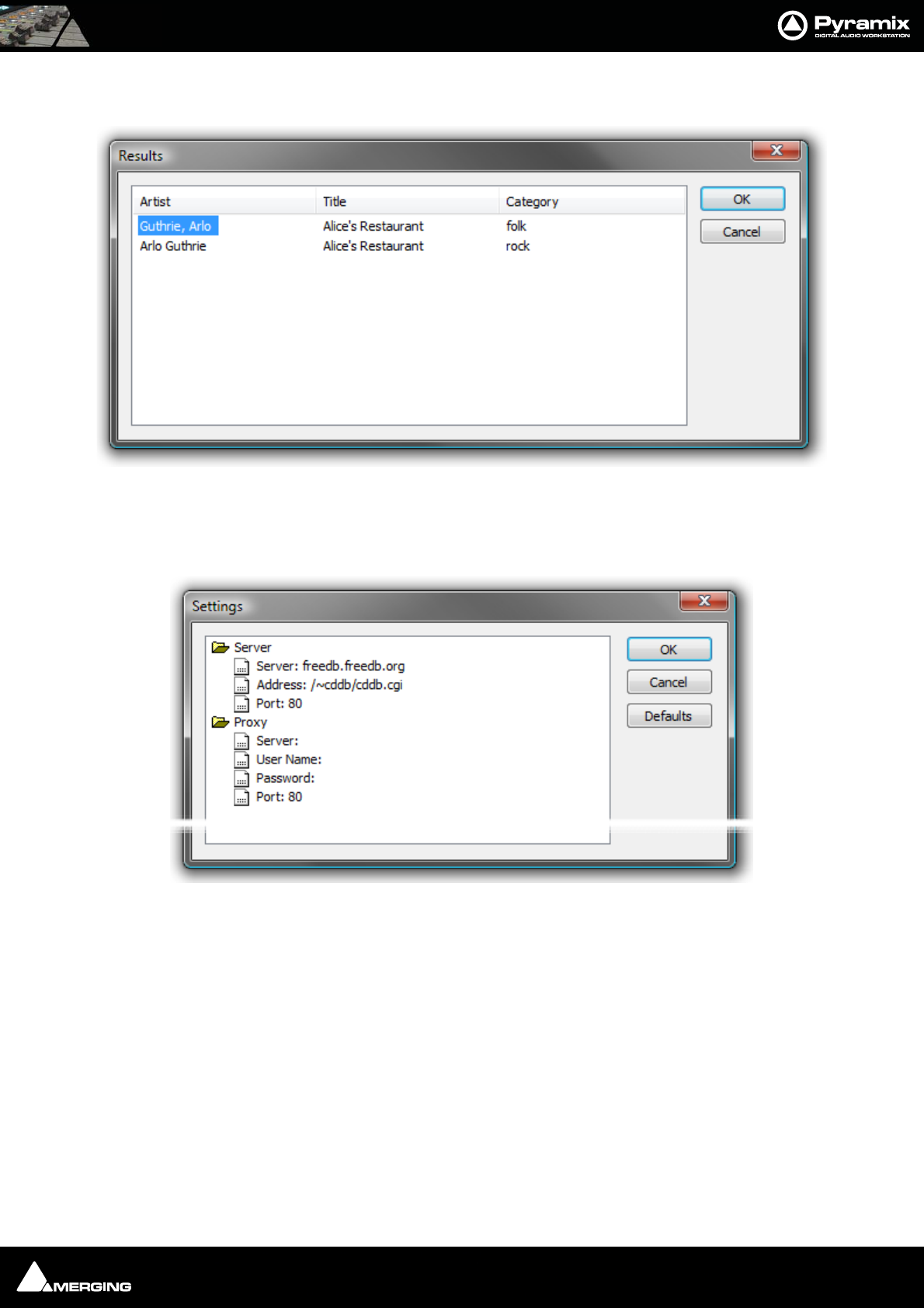
File and Project Interchange : Project Interchange 17 - 317
Query Database uses an online database to obtain track names and other data about commercial CDs results are
shown in a dialog:
If multiple disc entries are shown, click on the appropriate one to select it then click on OK to import the data. The
disc name is automatically entered in the Clip Prefix: field.
Database Settings allows the database address and other settings to be changed:
Default settings are shown above. To change a setting, click on the entry and type. Click OK to save the edited set-
tings. Defaults restores the default settings.
Info
The Status line shows useful information about the process as it proceeds. The Track and Disc lines are progress
meters. Track shows a growing gray bar as the track transfer proceeds and Disc shows progress of all selected
tracks.
Media Options has three drop-down list boxes to select the Destination Drive, the Format the CD audio will be
captured in and Waveform determines whether a waveform will be generated and, if so, WHILE recording or
AFTER. A text entry box allows a Clip Prefix to be set for all imported tracks. (default is CD Import) Checkboxes
determine if the resulting clips will be placed in the Timeline, whether CD Markers will be added in the Timeline
and whether a Track Group will be added.
Sampling Rate enables the import(s) to be sample rate converted as they are imported with a choice of rates in
the combo box.
CD Import Query Database results dialog
CD Import Database Settings dialog
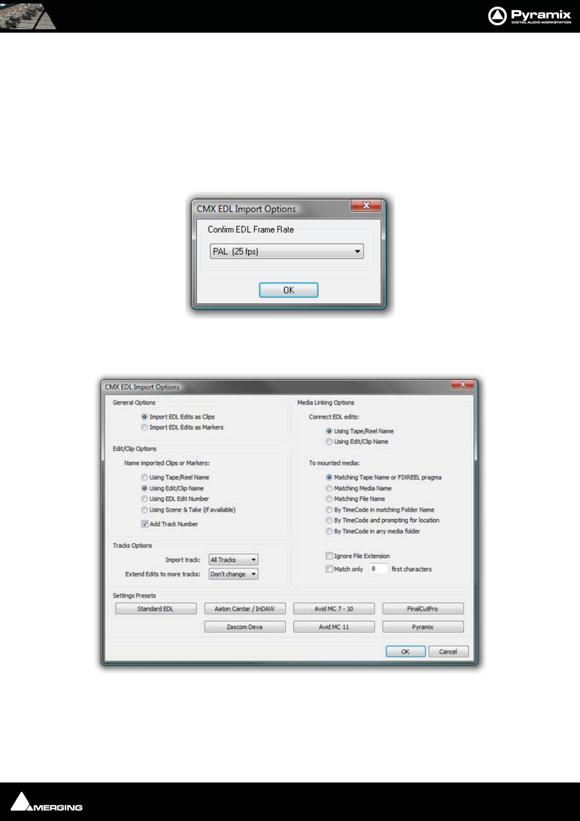
File and Project Interchange : Project Interchange 17 - 318
Keep open keeps the CD Import window open after the import is completed and grays out the Place in timeline,
Add Track Group and Add Disc & CD markers options.
Clicking on the Import icon initiates the process. Unless Keep open is checked, the window closes when the
import is complete.
CMX EDL
Importing a CMX EDL
Select Project > Import and choose CMX EDL in the InterChange-Import dialog then click on the Import but-
ton. Select the desired edl file in the Open file-browser window. The CMX EDL Import Options dialog opens:
If the EDL Frame Rate is correct, simply click the OK button. Otherwise, select the correct rate from the drop down
list and click the OK button. The CMX EDL Import Options main dialog opens.
The Settings Presets buttons at the bottom of the box set the options for a variety of common CMX variants. If
the edl you wish to import matches one of these, simply click the appropriate Preset button. The settings are
reflected in the rest of the dialog. Click the OK button to begin the Import.
If the edl is not one of the common variants or the intention is to perform a partial or re-conform, make the appro-
priate choices in the dialog before clicking on the OK button to begin the Import.
CMX EDL Import Options dialog
CMX EDL Import Options dialog
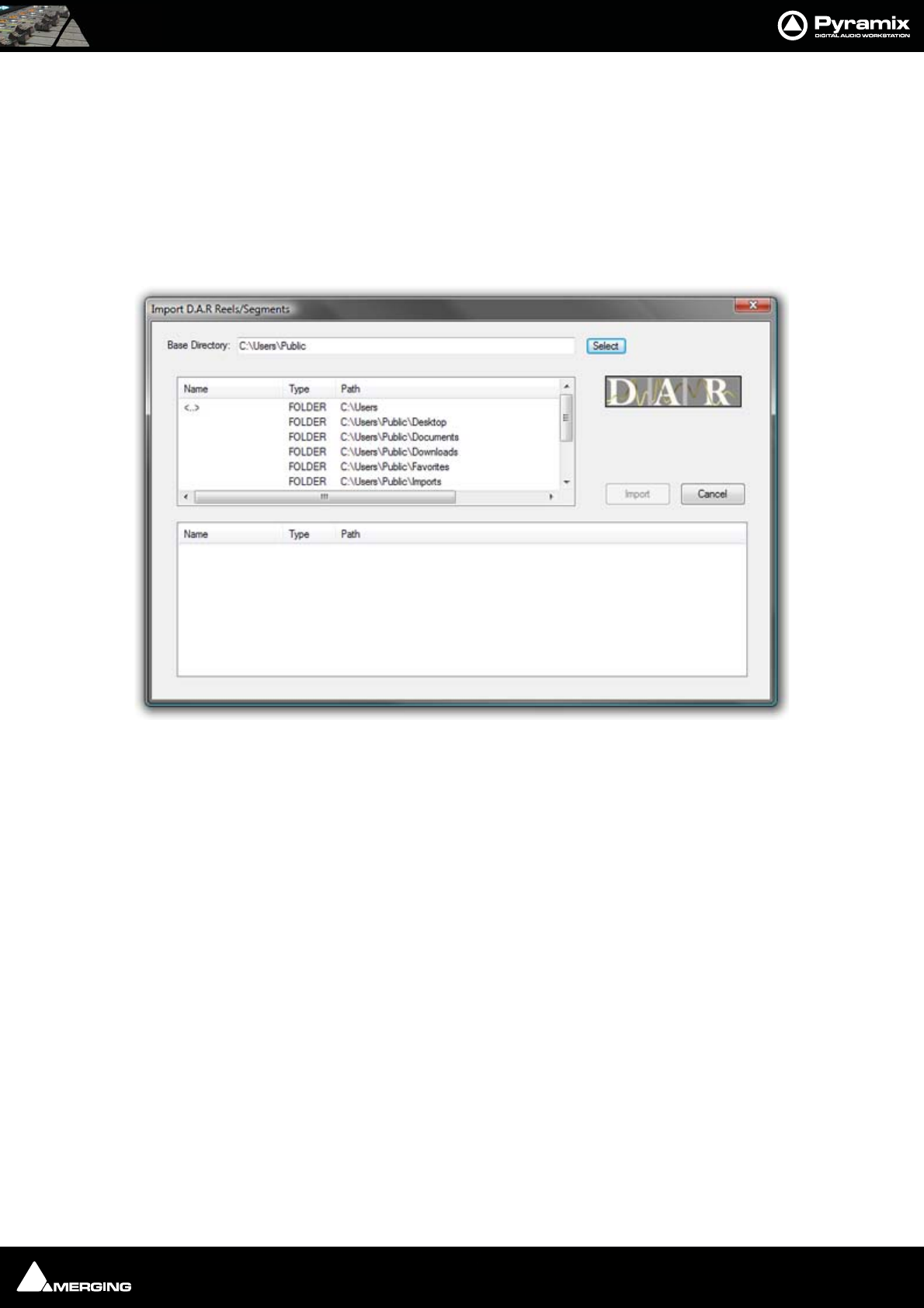
File and Project Interchange : Project Interchange 17 - 319
Cue Sheets Printer
The Cue Sheets Printer is a mini application for printing Cue Sheets from a Project. Full instructions can be found
at the end of this chapter. Please see: Cue Sheet Printer on page 324
DAR Reel/Segment
Importing a DAR Reel or Segment
Select Project > Import and choose DAR Reel/Segment. Make appropriate choices in the Options section of the
Interchange - Import dialog then click on the Import button. The Import D.A.R. Reels/Segments dialog opens:
Browse to and select the Reel(s) or Segment(s) you wish to import then click on Import to initiate the import.
Note: Please see also DAR WAV file Import on page 64
DDP Import
Import DDP file.
Final Cut Pro XML
Supports import and export of MasterClips, Bins, Sequences or Projects to and from Pyramix.
To export a FCP XML file from Final Cut Pro, either select a single Sequence or a full Project in Final Cut Pro and
select File > Export > XML. This will export either a single Sequence (with the choice of all referenced MasterClips
along with it) or a full Project including all Sequences and MasterClips contained in it.
To import a FCP XML file into Pyramix, create an empty project and select Project > Import and choose the Final
Cut Pro XML format.
Note: When importing in Pyramix a FCP XML file containing more than one Sequence or
MasterClip, Pyramix will prompt you to choose which of the available Sequences you
would like to import into the Timeline and will allow you to import all others into the
Default Library of the current project.
Import D.A.R. Reels/Segments dialog
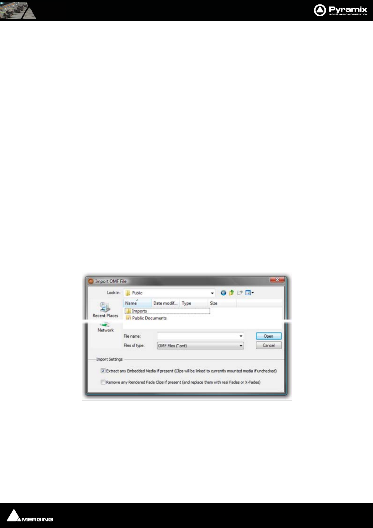
File and Project Interchange : Project Interchange 17 - 320
Scope
The following items are imported by Pyramix:
• Video and Audio Bins, Sequences and MasterClips
• Video and Audio Tracks Names
• Video and Audio Clips
•Audio Clips Fades
• Audio Clips Gain
• Audio Clips Envelopes (Key Frames)
•Clips Sync Points
• Clips Comments and Metadata (Master Comments, Clip Comments, Labels and Scene & Take)
• Links and Groups
• Clips colors
Known limitations
• FCP XML Export from Pyramix is not yet implemented
•Video Clips from HD compositions have length and positions truncated to an even number
OMF
OMF Import supports both OMF1 and OMF 2 format. Supports 10.5.3 / 11 sub-compositions.
When exporting OMF from another application, there is a choice of either embedding the audio files into the OMF
file, or keeping them external as a link. Pyramix supports both approaches.
Selecting Project > Import followed by OMF in the Interchange Import dialog opens the Import OMF File
browser window.
Import Settings
At the bottom of the browser window two import settings checkboxes offer the options to:
Extract any Embedded Media if present (Clips will be linked to currently mounted media if unchecked)
(default is ticked) and
Remove any Rendered Fade Clips if present (and replace them with real fades or X-Fades)
Default is un-ticked
Import OMF File browser window
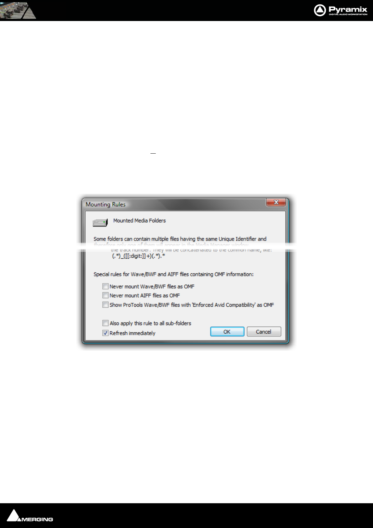
File and Project Interchange : Project Interchange 17 - 321
When importing an OMF file with embedded audio for the first time, leave the Extract option ticked to extract the
media files. Please untick the Extract any Embedded Media if present box on subsequent imports of the same
OMF file (because the media will already be present).
If the same file is imported a second time, there's no need to extract the audio twice, simply mount the folder
where it's been extracted to, prior to importing the OMF file. The OMF Media Handler generates an external Wave-
form (.pk) file when the file is first imported.
When importing an OMF file that references (links) to external audio files, the folder(s) that contain these files
must be Mounted in Pyramix before importing the OMF file. (This also applies to Sonic Solutions import).
Ticking the Remove any Rendered Fade Clips if present box converts any rendered fades or X-fades present in
the OMF file into normal Pyramix real-time fades. These can subsequently be manipulated in the usual Pyramix
manner.
OMF Mounting Rules
(Media Management Tab window, Media Folder > Mounting Rules)
AIFF files generated by Avid systems and BWF files generated by Protools with the option Enforce Avid Compati-
bility have a built-in OMF chunk and have always been recognized by Pyramix as an OMF Media. The Mounting
Rules dialog has some special Mounting Rules options for folders containing Wave/BWF and AIFF files that have
an OMF chunk These enable the default behaviour to be altered:
• Never mount Wave/BWF files as OMF (for files coming from Avid)
• Never mount AIFF files as OMF (for files coming from Avid)
• Show Protools Wave/BWF files with Enforced Avid Compatibility as OMF (the new default behavior is to
always show BWF files generated by Protools as BWF even if they have the OMF/Avid compatibility chunk.
This option allows forcing these files to be mounted "a la Avid" as in previous Pyramix versions)
Importing Avid and AudioVision bins
Avid and AudioVision bins may be imported as a library. In a library tab window select:
Library > Import OMF library (Avid bin)
Open TL
Straightforward Import and Export in Tascam Open TL format.
Mounting Rules dialog

File and Project Interchange : Project Interchange 17 - 322
ProTools
Note: Please see also: the PDF file ‘Protools 5 InterChange with Pyramix 5’ This file is
installed with Pyramix 6.0 or it can be downloaded from:-
http://www.merging.com
Protools 5 InterChange with Pyramix 6.0
Importing and exporting Protools 5 sessions in Pyramix is accomplished via the InterChange architecture. This
requires Pyramix 4.2 or higher and MacDrive 2000 or MacDrive 5 to be installed. MacDrive is a product of Medi-
afour Corporation, please see:-
www.mediafour.com
Importing a Protools session
Pyramix supports Protools version 5.0 or 4.x. If you're using are more recent version of Protools, first export your
session as a version 5.0 session in Protools with the menu "Save Session Copy in…". This will create a set of SDII
files along with the new session.
Bring your session with the audio files into the Pyramix station by mounting the Mac HFS disk or inserting the car-
tridge in the appropriate reader. Windows and MacDrive support all SCSI disks or removable storage like Jaz, MO,
removable hard-disks, CD-R, DVD, etc.
If your session comes on multiple CDs (or cartridges) you can copy all the files directly to a Pyramix workstation
disk. In this case the PC disk must be formatted as a NTFS volume. We recommend using NTFS for all disks.
Create an empty project in Pyramix or open an existing one.
Project > Import opens the Interchange - Import dialogue box. Select the appropriate import option from the
three choices at the bottom using the radio buttons.
These are:
1. Replace the current project by removing all existing tracks, track groups and markers then creating new
tracks, track groups and markers from the imported composition
2. Append the imported tracks at the bottom of current project tracks
3. Insert the imported tracks into the current project tracks
Then choose the ProTools module from the list. An explorer - style file dialog box Import ProTools Session will
open, browse to the disk containing the Protools session, select it and click Open.
The Protools session should appear in your project Timeline, creating new tracks if needed.
Create or load a mixing console, connect your tracks and work with your session.
Exporting a Protools session
Load the Pyramix project you wish to export as a Protools session and from the Project Menu select the appropri-
ate Export option and the Protools module and click OK.
Menu: Project > Export opens the Interchange - Export dialogue box. Select the appropriate export option from
the two choices at the bottom using the radio buttons.
These are:
1. .Export whole composition including tracks, track groups and markers
2. .Export selection only
The latter choice will only be available if there is a selection or selections in the Timeline.
Then choose the ProTools module from the list and click Export. A dialog box, Export ProTools Session File will
open. The top of this dialogue box is concerned with file saving and enables a suitable destination folder to be
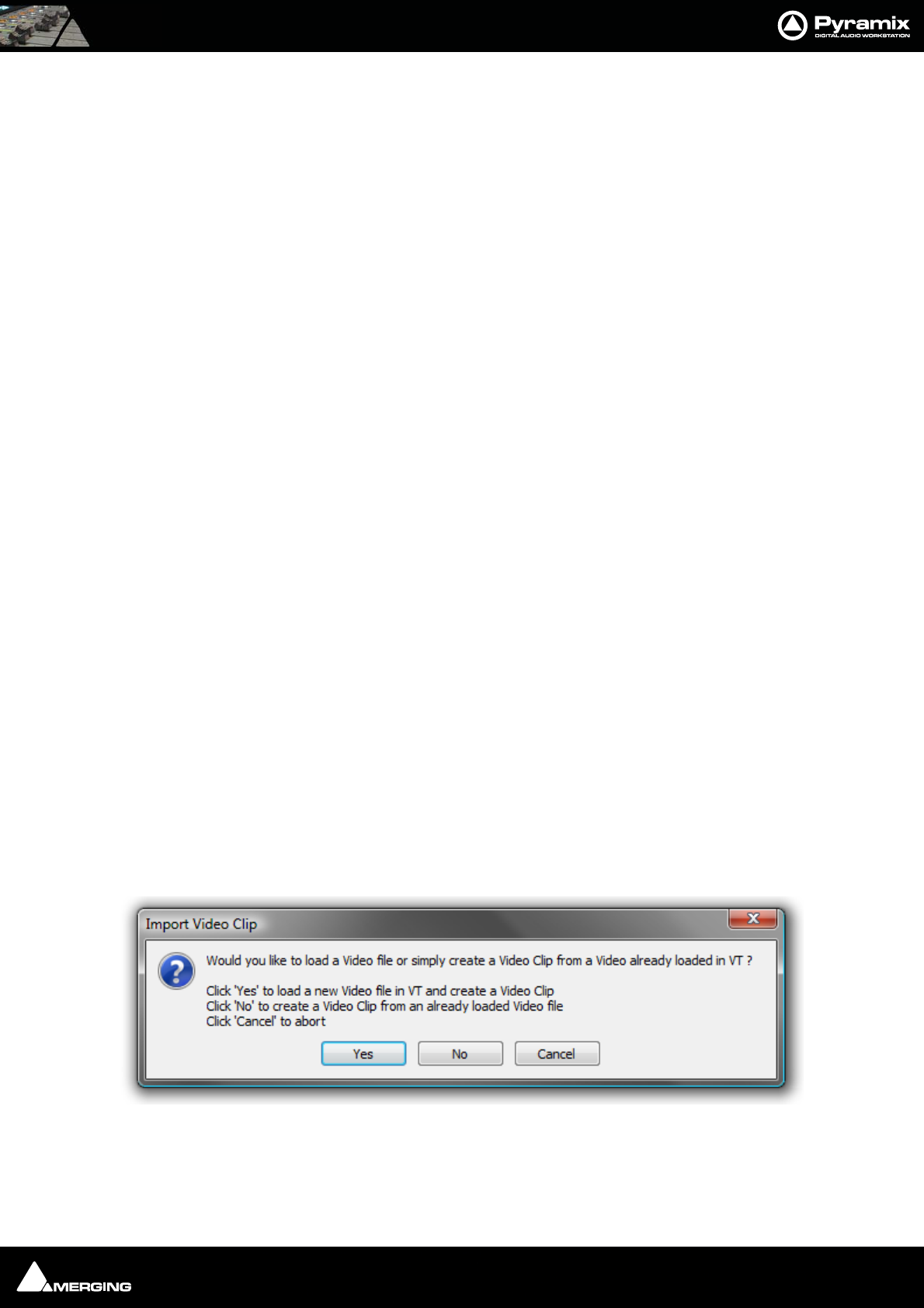
File and Project Interchange : Project Interchange 17 - 323
chosen or created, a file name to be entered and gives the choice of saving ProTools Session *.* or All files *.* By
default, the file name entry box contains the name of the Pyramix project.
At the bottom of the dialog box Export Settings choices are made. Drop down lists offer the choice of saving in
ProTools 5.0 or 4.* Session formats and 16 bits or 24 bits. If you wish to reduce the amount of data to be exported,
select the Consolidate checkbox. When this is checked, the 'handle' length can be selected in the Handle text
entry box from 0 to 999999 frames.
When you have selected the appropriate options and named the export file (or accept the default) click Save to
complete the export.
Please see also: File & Project Interchange with Apple Macintosh on page 304
Report Printer
(includes EDL, Markers, CD TOC report sheet)
This program really needs a printer. Here is a way to add a printer when no physical printer exists:
1. Start the add new printer wizard. Start > Settings > Printers > add Printer
2. In the wizard choose local printer and deactivate automatically detect
3. Under "Use the following port” choose File
4. Select the printer that you will eventually use to print the file
5. The rest of the installation is the same as a standard printer installation
If you print a page test, a dialog will open and ask you the name of the file. Enter the path where you want to write
the file.
SACD Edited Master Import
Import Edited Master file.
Sonic Solutions
Straightforward Import in Sonic Solutions format. When importing an Sonic Solutions file that references (links) to
external audio files, the folder(s) that contain theses files must be Mounted in Pyramix before importing the file.
Note: Sonic Solutions HD format is not currently supported.
Video Clips
Import
Select Video Clips in the Interchange Import dialog. The Import Video Clip dialog opens:
To load a new Video file in a Virtual Transport Video Player and create a Video Clip in the Pyramix Timeline click Yes
To create a Video Clip in the Pyramix Timeline from a Video file already loaded in a Virtual Transport Video Player
click No
Import Video Clips dialog

File and Project Interchange : Project Interchange 17 - 324
Cancel aborts the import operation.
Note: Audio tracks are also imported and placed in the Timeline. The method of place-
ment follows the Replace/Append/Insert rules as per other (composition based) for-
mats. Please see: Options on page 308
Export
Under Construction
XML
Straightforward Import and Export in XML format.
Cue Sheet Printer
The Cue Sheet Printer offers comprehensive options for printing out a graphic representation of the Timeline.
Cuesheets are frequently a contracted delivery requirement which takes much time and effort to produce.
Select Project > Export. This opens the Project Export dialog box. Select Cue Sheets printer and click on the
Export button. (or simply double-click the Cue sheets printer entry)
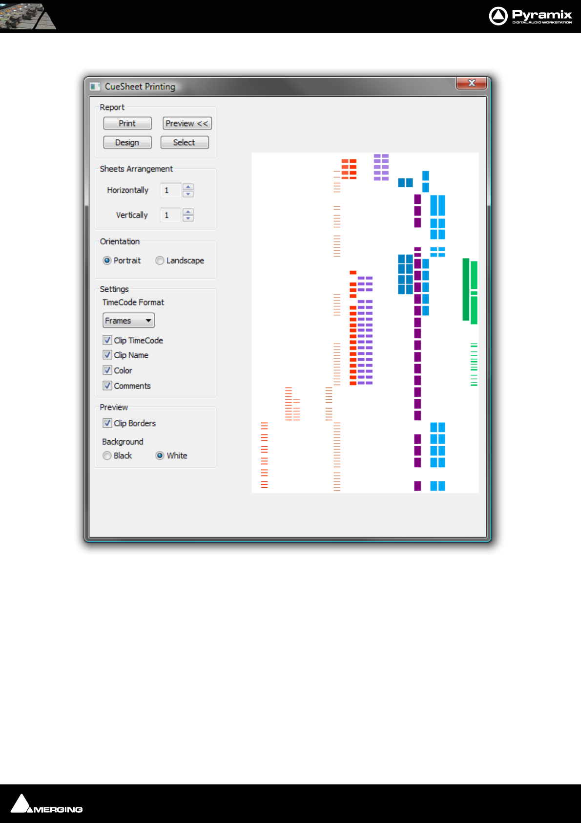
File and Project Interchange : Project Interchange 17 - 325
The CueSheet Printing window opens. (Shown with the Preview option selected.):
Report
Print
Click this button to print the cue sheet(s) with the selected options. This opens the Print Options dialog box
unless the Orientation selected is different from the printer’s default. If it is the Paper Orientation conflict dialog
box pops-up with buttons which offer a choice of Select other report, Change Orientation, Force or Cancel.
Force should make the printer change orientation for this print. Some printers will not accept this. If this is the
case, see below.
Print Options dialog box
Offers the choice of which pages to print and the number of copies. Allows any installed printer to be selected and
configured. If Force does not result in correct page orientation the printer page orientation can be changed by
clicking Change then Select in the next screen which should give access to the Printer’s set up dialog with
options dependant on the selected printer.
Preview
CueSheet Printing Window

File and Project Interchange : Project Interchange 17 - 326
Adds a graphic preview of the Cue-Sheet(s) to the right-hand side of the window
Design
Opens the design software used to create the Cue-sheets. Please see the on-line documentation
Select
Opens a file browser. Saved Cue-sheets can be loaded for printing.
Sheets Arrangement
Horizontally and Vertically set the number of pages with the increment / decrement buttons. This also controls
the time scaling.
Orientation
Portrait / Landscape
Toggle between vertical and horizontal page orientation.
Settings
TimeCode Format
Shows the TimeCode format which will be used on the cue-sheets from the choice in the drop-down list. Frames,
Samples, [ms] or CD Frames
Clip TimeCode
When checked, Clip TimeCodes will be printed
Clip Name
When checked, Clip Names will be printed
Color
When checked, the cue-sheets will be printed in the colors used in the original project. (With a color printer)
Comments
When checked, Comments will be printed
Preview
Clip Borders
When checked, clip borders are shown in the preview display.
Background
Black / White
Toggle the preview background color.

USER MANUAL
www.merging.com/Pyramix
Customizing Pyramix
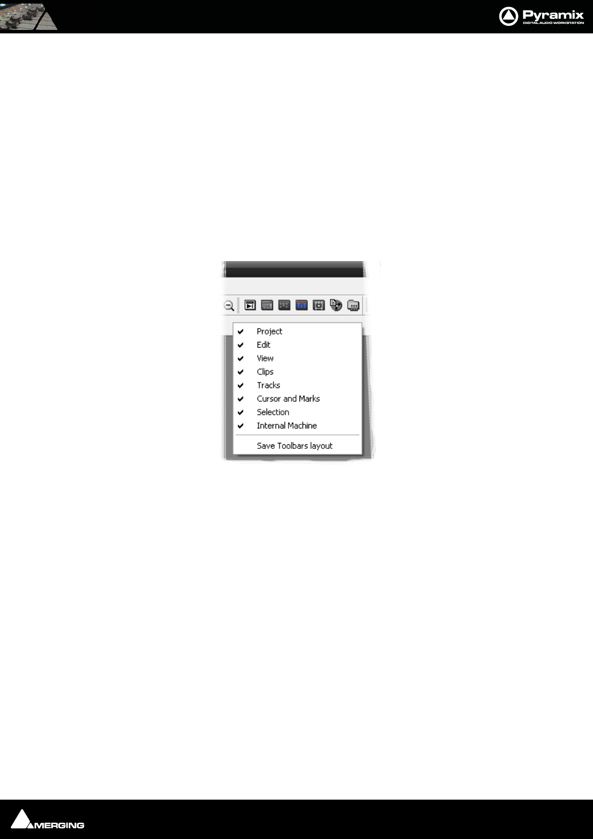
Customizing Pyramix : Customizing the User Interface 18 - 328
Customizing the User Interface
Pyramix Virtual Studio allows considerable customization of the user interface. Apart from the usual Windows
interface possibilities Pyramix has Interface Editors, user defined Workspaces, customizable Keyboard Short-
cuts and user defined Macros.
Desktop Layout, TimeLine Layout and Track Headers Layout are designed in Settings > All Settings > Appli-
cation
Toolbars and Menus
The Pyramix Toolbars and Menus are almost entirely customizable. Please see: Desktop Layout on page 525
Complete Toolbars can be managed by right-clicking anywhere in the blank space in the Toolbar dock to pop up
this menu:
Click on the Toolbar names to toggle Toolbars shown (ticked) or hidden.
Save Toolbars Layout Clicking on this entry saves the current Toolbar arrangement.
Workspaces
Workspaces are a method of saving many of the Pyramix Project Editing Panel settings, especially Track Header
switches layouts. Once saved a Workspace can be quickly recalled for future use.
Tollbar context menu
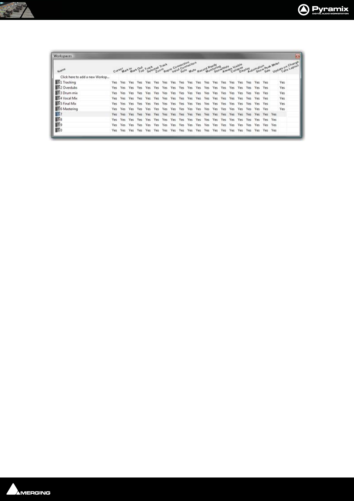
Customizing Pyramix : Workspaces 18 - 329
Workspaces can be accessed via the pull down menu on the Pyramix Virtual Studio Window toolbar or via the
Project Management Panel Tab.
New Workspaces can be added by clicking Click here to add a new Workspace on the first line of the Tab Win-
dow. A text entry box opens where you type a name for the new Workspace. Hitting Return places the new Work-
space at the bottom of the list.
Workspaces may be re-named by clicking the name.
Workspaces can be deleted by selecting them and pressing the 'Delete’ key.
Recalling a Workspace can be achieved by double-clicking on the Workspace icon to the left of the name.or select
the menu item Workspaces > Recall > Recall Workspace (X). However, the quickest metnod is to use keyboard
shortcuts. By default, Workspaces 1 to 10 are mapped to Shift + 1 to Shift + 0.
Parameters remembered by Workspaces are selectable per Workspace by clicking in the appropriate columns.
If the Update on change column is set to Yes. The current state of all selected parameters is saved to the current
Workspace when another Workspace is selected.
Note: Before using the Update on change feature it is strongly advised that you save
the Workspace using Workspaces > Save > Save Workspace {name of workspace} to
avoid undesired behaviour.
Macros Window
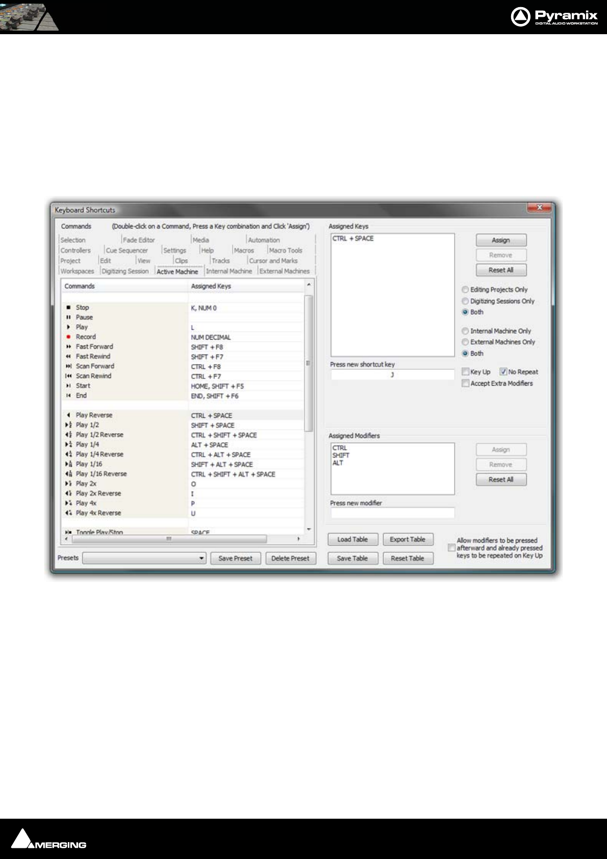
Customizing Pyramix : Customizing Keyboard Shortcuts 18 - 330
Customizing Keyboard Shortcuts
We strongly encourage you to learn the default Pyramix keyboard shortcuts. These have been used by audio pro-
fessionals for over a decade, and are powerful, quick and efficient for audio editing and device control. However, if
you are already familiar with another style of audio or video editing, you may wish to create your own Keyboard
Shortcuts for various Pyramix transport and editing functions.
To define your own Keyboard Shortcuts:
1. Choose View > Customize > Keyboard Shortcuts from the Toolbar. This opens the Keyboard Shortcuts
window:
2. All menu Commands are grouped together into Tabs within this window. Select the Tab with whichever
group of Command Functions you wish to add or change key assignments for.
3. Click on the appropriate Command so that it is highlighted.
4. Click in the Press new shortcut key box. The cursor will become a blinking bar.
5. Now press the desired Key or combination of Key and modifier (e.g. the Ctrl, Shift, Alt, etc.). These will appear
in the Press new shortcut key box. Note that Pyramix will warn you if the chosen Key or combination is
already assigned to another function.
6. Click the Assign button.
7. Continue assigning Keys to Commands until you are satisfied.
8. Any set of user defined Keyboard Shortcuts can be saved as a Preset. To do so, click the Save Preset button,
then name the Preset. Similarly, to recall a previously saved Preset, click in the Presets box and select it from
the pop-up list. Note that several common Presets are shipped with Pyramix Virtual Studio.The Table will be
saved in the system for the user currently logged in and will not affect any other user.
Keyboard Shortcuts Window

Customizing Pyramix : Customizing Keyboard Shortcuts 18 - 331
9. A table can be Saved or Loaded to a file so it can be taken to an other system. Just Click on the Save Table or
Load Table button.
10. A table can be exported as a Text File along with some comments about commands. This is very useful since it
enables you to print it as a command reference guide with your own keyboard shortcuts.
Example:
Many users with a video editing background will be familiar with the J, K and L keys assigned to Reverse Play, Stop
and Play respectively. To make these assignments:
1. Choose Settings > Keyboard Shortcut Editor or View > Customize > Keyboard Shortcut Editor
2. Select the Active Machine Tab
3. Click on the Play Reverse Command to select it.
4. Click in the Press new shortcut key box.
5. Type J (Notice J is not currently assigned to any function)
6. Click Assign
7. Click on the Stop Command to select it.
8. Double click the J in the Press new shortcut key box to highlight it.
9. Type K
10. Click Assign.
11. Repeat steps 7 to 10 substituting Play and L
12. Save the Preset. It is immediately active.
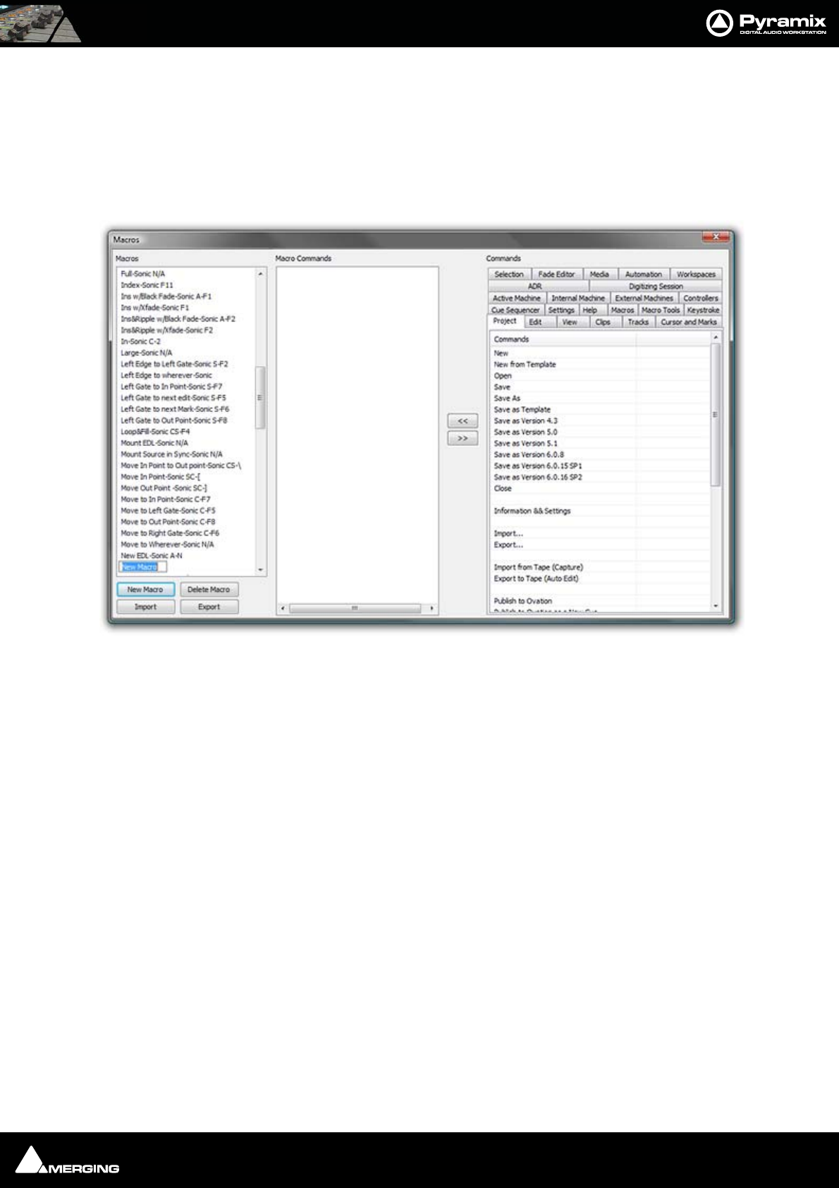
Customizing Pyramix : User Macros 18 - 332
User Macros
Macros are sequences of commands which can be invoked by a single keypress or combination. Macros can be a
very powerful aid to productivity.
To define a new Macro:
1. Choose Settings > Macro Editor or View > Customize > Macro Editor. This opens the Macros window:
1. Click the New Macro button, then name the Macro.
2. Various menu Command functions are grouped together into Tabs. Select the Tab with whichever group of
Command Functions you wish to add to the Macro.
3. Click on the appropriate Command so that it is highlighted.
4. Press the << button to add this command to the Macro.
5. Repeat steps 3 to 5 to assign further Commands to the Macro until it is complete.
A Keyboard Shortcut can now call the new Macro. Follow the instructions in the previous section for assigning
Keyboard Shortcuts. In this case, choose the Macro Tab within the Keyboard Shortcut window. Your new
Macro will appear as an option inside this window.
Note: macros can also contain keystrokes including: Enter, Shift, Tab, the Arrows (up,
down, left, right), Space Bar and ESC
Macros Window

USER MANUAL
www.merging.com/Pyramix
Applications
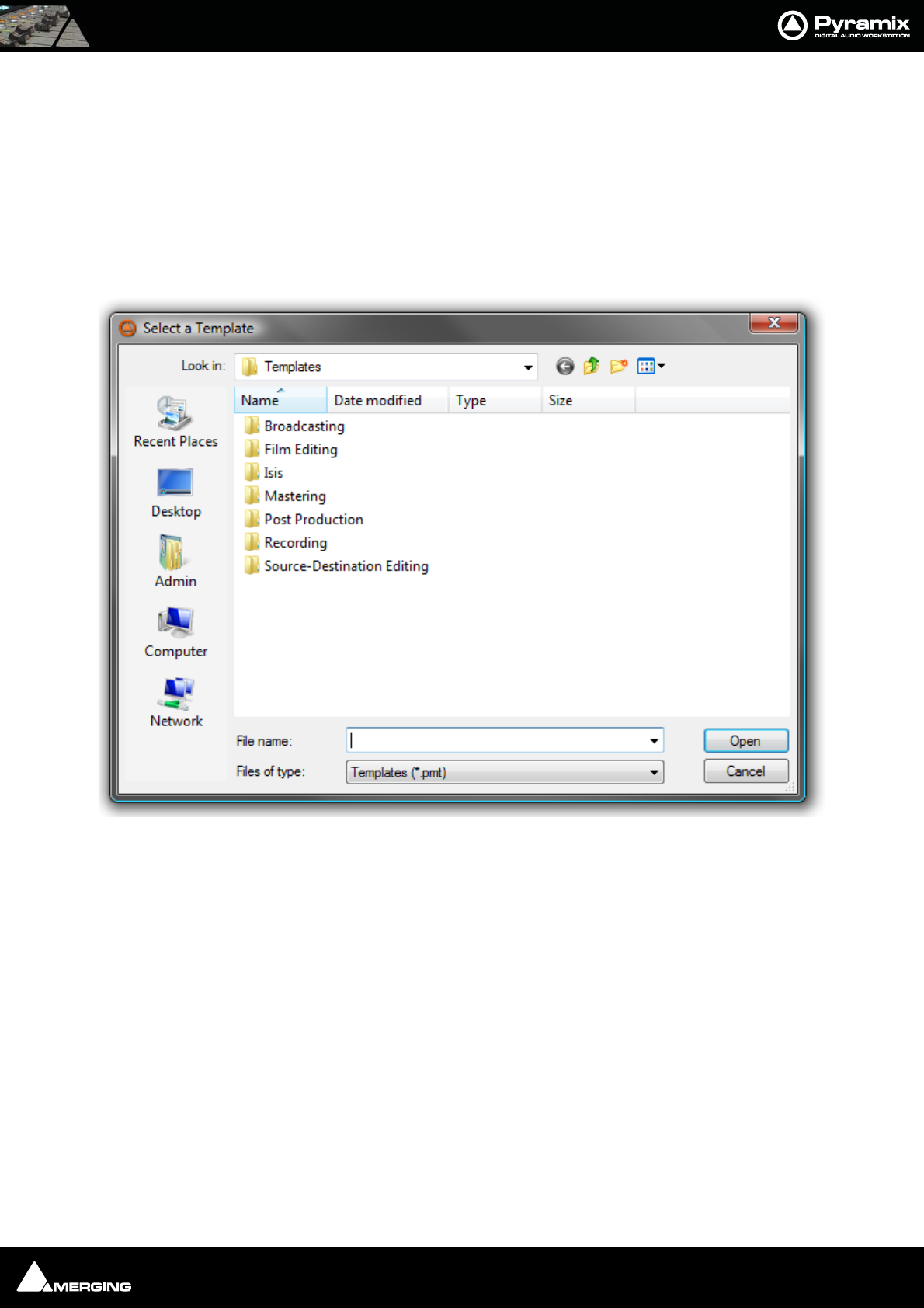
Applications : Project Templates 19 - 334
Project Templates
Pyramix provides the user with a number of Templates for various applications. A Template is a complete Pyramix
Project, without any associated audio, specially configured to suit a particular type of activity. Apart from configur-
ing the appearance of Pyramix, the track layout and mixer design, templates also include important optimizations
to suit the activity.
Please see: Optimizing Pyramix on page 432
These templates also offer a good starting point for creating your own customized templates. To begin a new
project using a template choose Project > New from Template which opens the Select a Template file browser.
When a template is opened a dialog box appears requesting the user to choose a Media Folder for the new
project. Unless the project is saved using the Save As option, the first time it is saved the Save As dialog will
appear.
Further Templates will be added as they are developed.
To save a new Template choose File > Save as Template, name and save.
Virtual Multi-track
A number of Templates suitable for multi-track recording are provided with Pyramix. These Templates have all
the required settings already in place. If none of the supplied Templates is exactly suitable for your task it will save
time if you modify the one closest to your needs and save it as a Template for future use.
Settings for Multi-track recording
Multi-track recording can be demanding on disk performance, DSP and the host CPU. In order to optimize Pyramix
for the purpose if not using one of the supplied Templates the following settings should be made in the Record
Page:
Select a Template dialog

Applications : Virtual Multi-track 19 - 335
•Flatten Track Numbers: OFF
• Quiet if creation failed: ON
• Prompt for name after recording: OFF
• Keep in default library: OFF (Should always be OFF)
Suggested Settings
• Group Recorded Clips: ON
• Increment Take Number: ON
•Prefix with Track Name: ON
To Record audio directly into the Tracks of a Project, using Pyramix Virtual Studio as if it were a
tape machine:
1. Set the Destination Drive, Resolution and Format.
2. Arm each Track on which you wish to record. In this case, set each Track to Record Ready mode (simple Red
Dot).
3. Check your input levels using the Mixer, and adjust as appropriate.
4. Position the Play Head Cursor in the Composition where you wish the recording to start.
5. Click the red Master Record button in the Transport Strip or Transport Window. The recording will begin,
and display a red bar in those Tracks you have armed for recording.
6. Press the Stop button in the Transport Strip or Transport Window to stop the recording. A Record Name
dialog box will appear.
If you are satisfied with the recording, type an appropriate name into the Record Name box and click the Good
Take button. This will save an audio Media File of the selected type onto the selected Media Drive, with the
name you just chose and place a clip in the Timeline, also with the same name. If you are not satisfied with the
recording, click the Delete Take button and the recording will not be saved. The third option is Bad Take. A Bad
Take is saved and a clip placed in the Timeline just like a Good Take, but the clip’s color is set to a specific color
(definable in the Settings > All Settings > Application > TimeLine Layout page) and are numbered the follow-
ing way: Take 1, Take 2, Take 3 (Bad 1), Take 3 (Bad 2), Take 3 (Bad 3), Take 3, Take 4, Take 5 (Bad1), Take 5, and so
on… This helps manage takes where there are mistake(s) but the user wishes to keep them anyway.
To Punch In audio directly into the Tracks of a Project, using Pyramix Virtual Studio as if it were a
tape machine with punch in capabilities:
1. Set the Destination Drive, Resolution and Format as above.
2. Arm each Track on which you wish to punch in. In this case, set each Track to Record Punch In mode (Red
Dot with 2 vertical bars). (alt-click on the round rec/play button in the track header.
3. Check the input levels using the Mixer, and adjust as appropriate.
4. Mark a punch in record In and Out point. This can be done either by marking a selection area on a Track, or by
setting a Mark In and Mark Out on the Time Scale bar. The simplest way to mark a selection area on a Track
is to click and drag in the Track: a darker gray rectangle indicates the selected area. The simplest way to set a
Mark In is to Shift-click on the Time Scale bar: a movable red triangle and vertical line indicates the Mark In.
The simplest way to set a Mark Out is to Ctrl-click on the Time Scale bar: a movable green triangle and verti-
cal line indicates the Mark Out. A selection takes precedence over Mark In and Out for punch in.
5. Position the Play Head Cursor before the marked In point or Selection area.
6. Press the red master Record button in the Transport Strip or Transport Window. The Play Head will begin
moving through the Composition, and Tracks will begin playback. Recording will begin on the armed Tracks
as soon as the selection area or Mark In point is reached during playback. A red bar will be displayed in those
Tracks which are recording.
7. The recording will stop automatically when the selection out or Mark Out point is reached. The Play Head
Cursor will continue playing through the Composition.
8. Press the Stop button in the Transport Strip or Transport Window to stop playback. A Record Name dialog
box will appear with the same options as a normal recording.

Applications : LTC sync 19 - 336
Player/Recorder Mode
Settings > All Settings > Project > Mixer > DSP Saving : Special modes section.
This mode allows big configurations (such as 48 x 48 channels) to run on a single board. Player/Recorder Mode is
intended for use with an external hardware console. When this mode is activated, the Pyramix mixer is relegated
to the role of signal router, there is no level control, no panning, no plug-ins and no inserts. This option is only
available in configurations with multiple mono mix buses.
The Pyramix Direct Out functionality provides an alternative, more user configurable, method of achieving similar
DSP savings. Please see: Channel Direct Outputs on page 161
Multitrack Editing
Pyramix is ideally suited for editing multitrack recordings. Grouping clips across all tracks used for the recording
allows edit decisions to be made while listening to a single track or several with the resulting edit changes
reflected in all the clips in the group. Track Grouping functions enable you to work in a way that suits you. The
Source - Destination editing model is just one possibility.
Please see the following sections:
Grouping Clips on page 112
Track Groups on page 80
Source - Destination Editing on page 130
Editing with Limited Hardware
Multi-track recordings with many tracks (E.g. 48 track 96kHz 24 bit music recordings) can be edited on hardware
which cannot support this number of tracks. (E.g. a laptop) Simply mute tracks that do not need to be heard using
the button in the Track Header. Tracks muted here, rather than in the mixer, no longer access the disk. Pro-
viding the Multitrack recording’s Clips are grouped across all tracks, then any editing changes made on the tracks
used for the editing guide sound will also be reflected in the muted tracks.
LTC sync
EXAMPLE - where a cinema projector must be the master
• Cinema projector follows mains (or is crystal controlled) and sends biphase signal to a Biphase -to
LTC converter. (E.g. the Rosendahl BIF)
• Converter’s LTC output is directly fed to Pyramix LTC input
• Pyramix is set to "LTC sync" mode and will adapt it's own internal clock to sync to LTC whenever the
Pyramix is set to lock and the external LTC is recognized to be playing at about 1x forward speed.
• Pyramix feeds it's own clock to the DA-88 (or similar machine used as an A/D converter) via Word-
clock.
• The DA-88 (or equivalent) is set to sync to external Wordclock
• The DA-88 in turn provides the Pyramix TDIF daughtercard input with digital audio data.
All LTC sync ballistics in the Pyramix software have been carefully designed to both allow a large locking range (-7
to +5%) while still exhibiting extremely low instantaneous jitter and more importantly a controlled maximum
speed change slope - not more than about 25 PPM per ms (25 Parts Per Million/millisecond) - in order to make sure
that any other digital audio equipment connected to it's Wordclock output is provided with a smoothly changing
clock speed (free of any abrupt speed changes). When used with Tascam digital multi-tracks such as the DA-88 this
in turn allows the TDIF input decoding circuitry in Pyramix to properly decode the digital audio data at all times
without disruptions while the complete system follows the actual master speed changes.
Driving the pyramix with the LTC output of the DA-88 is maybe possible in some situations but will demonstrate
several limitations which should not occur if you precisely follow the recommended setup as described above.

Applications : Dubbing Mode 19 - 337
Keep in mind that the DA-88 does exhibit big instantaneous 1000 PPM (0.1%) speed changes and this prohibits
proper TDIF decoding at the other end.
Dubbing Mode
This mode is provided principally for film re-recording. It allows tracks to be Armed or Disarmed for recording
while recording is taking place.
Dubbing Mode is selected via All Settings > Settings > Project > Record
Enable Dubbing
When checked, Dubbing Mode is engaged.
Confirm Track Arming
Only available when Dubbing Mode is selected in the adjacent check box. A check in this box means that any
changes to track arming made whilst recording must be confirmed by a new Record command before they will
take effect.
Example
When recording a final mix in stems (E.g. Dialogue, Effects and Music) you may well wish to retain a previous take
for, say Effects, until a certain point. This can be achieved by arming the Dialogue and Music Track Groups, playing
the transport and punching into record at the desired point. Once in record, the Effects Track Group can be
dropped straight into record at the appropriate moment by simply arming it, or if the Confirm Track Arming box
is checked, by arming it and, applying a second record command when you wish to begin recording. (either on
screen or via MMC, 9-pin etc.)
Virtual Tape Mode
This media format type / mode allows real destructive punches to be made directly into BWF files.
Virtual Tape Format
A separate application allows a Virtual Tape to be prepared.
Start > All Programs > Pyramix > VirtualTapeFormat
Before running the application, format a 10’000 RPM SCSI disk using FAT32 if you wish to plug the disk directly into
a Mac later or NTFS if you intend to copy the files to another disk at the end of the session.
Use 64K as the Sector Allocation Unit Size when formatting the disk.
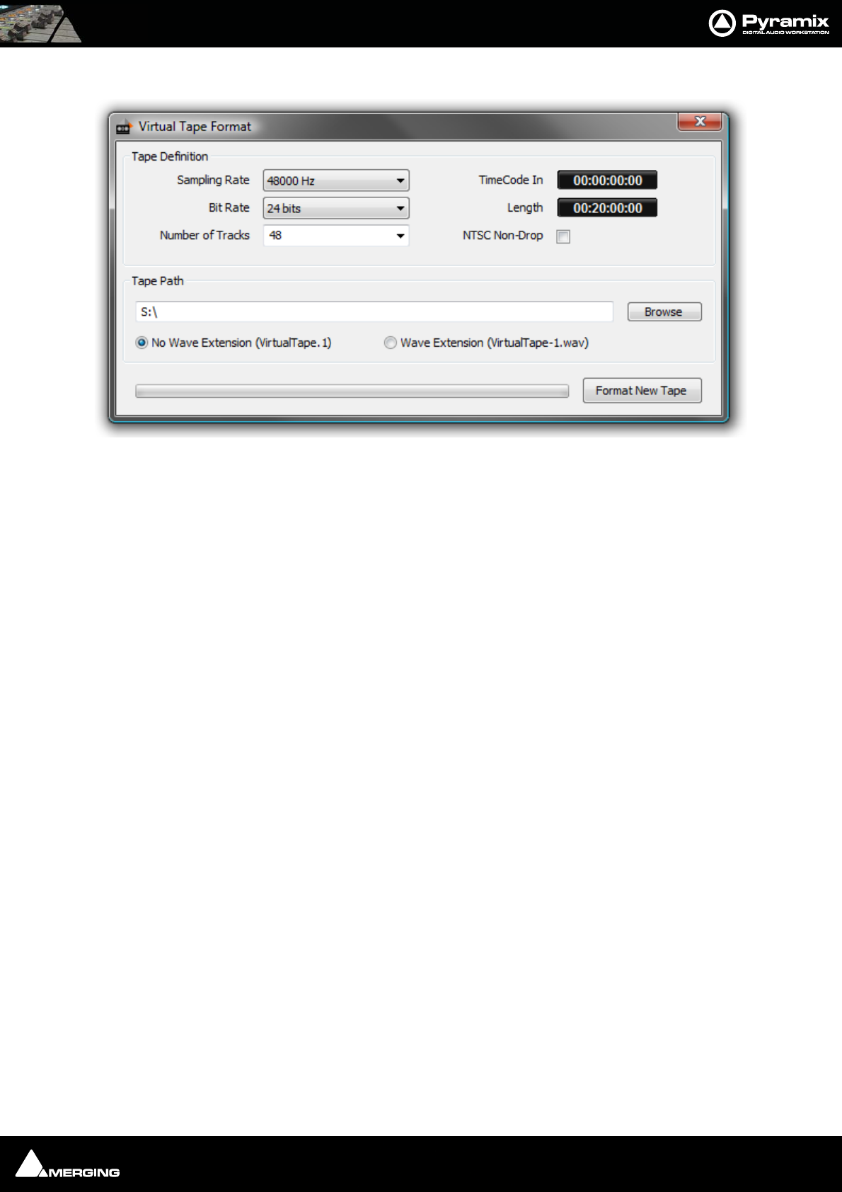
Applications : Dubbing Mode 19 - 338
Launch the Virtual Tape Format application and make the desired settings for these parameters:
Sampling Rate
Bit Rate
Number of Tracks
TimeCode In (Original TimeCode / TimeStamp)
Length of the tape
Check the ‘NTSC Non-Drop’ box if you wish to have a tape that will (virtually) run at 1001/1000 (this just ensures
the TimeStamp and Length will be correct)
Choose a location in the SCSI drive where you wish to create the tape
Click Format New Tape
A set of (slightly enhanced) BWF files will be created in the target folder (one per track).
There can be only one Virtual Tape per folder. The application will refuse to create a second tape in a folder where
one already exists.
Do not attempt to move or copy the tape once created as this would suppress the block interleaving on the disk
made by Virtual Tape Format. Even if you feel that copying a “template tape” from another disk would be quicker,
that wouldn’t align properly the tape blocks to the disk blocks.
The resultant files are standard BWF files and will be recognized as such by any other application.
Only Pyramix sees them as Virtual Tapes. In the future we will find a way to let Pyramix decide to see them as BWF
files instead of Tapes to allow editing them when the dubbing session is over. (Please see Known Limitations
below for a temporary solution)
Pyramix Settings for Virtual Tape Mode
Open Pyramix and go into the Settings > All Settings > Application > Playback/Record page.
• Enter the value ‘262144’ in the Playback Buffer Size entry box and click ‘Set’
• Select 96 KB in the Record Block Size box.
•In the Jog/Chase page you should uncheck ‘Silent Chasing’. Even if checking this setting would reduce
locking time, you would still have to wait for the Virtual Tape buffers to be filled after Pyramix is locked
before entering Record.
•In the Layout page Uncheck ‘Generate waveform automatically at clip insertion’
Virtual Tape Format Application Window

Applications : Discontinuous TimeCode 19 - 339
• Create a Pyramix recording project with the same number of tracks you specified in the VirtualTapeFor-
mat application.
• Ensure you select the correct sampling rate, corresponding to your ‘tape’.
• Mount the folder in which the tape has been created.
• Select the tape and in the Media Manager menu choose Edit > Place. Select ‘Place at Original Time-
Code on Original Track’ and click OK.
• Select the menu item View > Zoom > Fit in Window. Your tape should be at its proper location in the
Timeline.
•Now go into the Project > Information & Settings : Record Settings Page:
• Select the Media Folder where your tape resides
• Select the Resolution you specified for your tape
• Select ‘Virtual Tape’ in the Format box
•Enable Dubbing Mode
•Check One file per track
• Uncheck Flatten track numbers
•Check Don’t create Playlists
• Uncheck Name is Scene & Take
You should now be able to use Pyramix normally.
Note the Following:
• Any punch-ins will be destructively performed on the Virtual Tape. There is no undo!
• No new clips will be created for each punch-in, only the underlying tape will be modified.
• Any attempt to punch-in outside the tape will fail.
Known limitations:
• Punching in on fresh parts of the tape (still silent) may result in small clicks at the punch-in points for now.
Fades on Punch-ins in Virtual Tape Mode will be implemented soon.
• For now, there is no waveform support.
Discontinuous TimeCode
Auto-Punch mode allows a whole tape with discontinuous TimeCode to automatically be recorded.
• Set all desired tracks is auto-punch mode
• Place Mark In at 00:00:00:00 and Mark Out at 23:59:59:24 (default values for a new project)
• Plug LTC Out from the tape machine into Pyramix
• Set Chase mode to HARD CHASE
• Rewind the tape
• Press Play on the tape machine
Each time a valid TC is encountered Pyramix will lock and start recording a new clip, then stop when the timecode
jumps. A separate media file will be created for each continuous timecode on the tape.
Metronome / Click Track
To obtain an audible Metronome or Click-Track, first add a Bars & Beats ruler by going to:
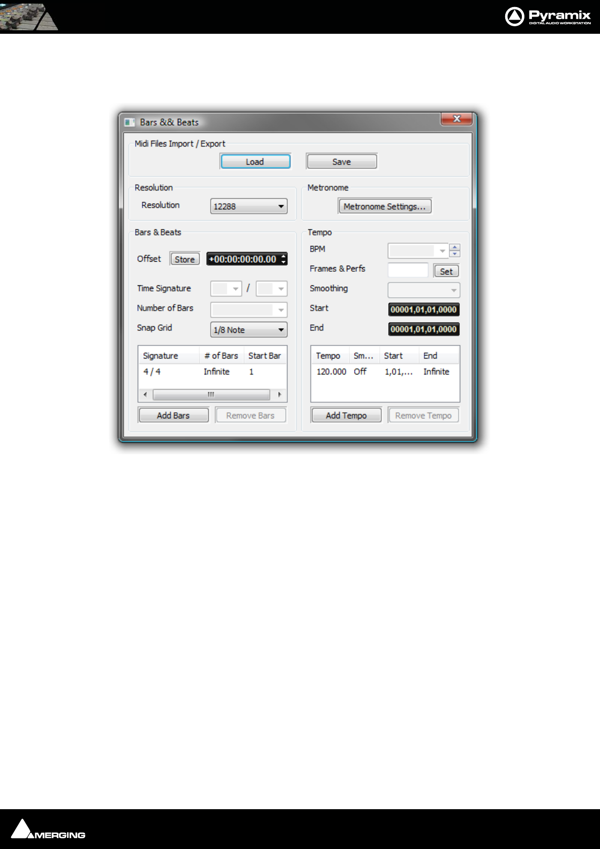
Applications : Metronome / Click Track 19 - 340
View > Scales / Toolbars and clicking on Bars & Beats
(Alternatively use the keyboard shortcut ALT + B)
Open the Bars & Beats Settings dialog in the same, View > Scales / Toolbars, sub-menu.
Set up a suitable Temp o for your needs by adding a new one. First choose a Tempo and Smoothing value then
set the Start and End times in bars and beats. Click on the Add Tempo button to add your new Tempo to the list.
You may wish to delete any others.
Tip: Select View > Scales / Toolbars > Tempo Map to see the new Tempo in the Timeline.
Tempo (bpm) Allows you to pick a tempo from the common values in the drop-down list, to
increment or decrement in 1bpm steps with the up and down buttons or to
directly type a value in the box.
Smoothing Smoothing is a ramp, used mainly when a tempo changes at some point in a
project. For example you could smooth up gradually the passing from a 120 bpm
to a 80 bpm tempo. Values can be selected between Note and 1/64 . (or OFF)
Start
End
The Information pane shows all currently defined Tempos. The Tempo, Smoothing, Start and End fields reflect
the values for the highlighted (selected) Tempo.
Add Tempo Adds another Tempo
Remove Tempo Removes the highlighted (selected Tempo) from the list.
Bars & Beats Settings dialog
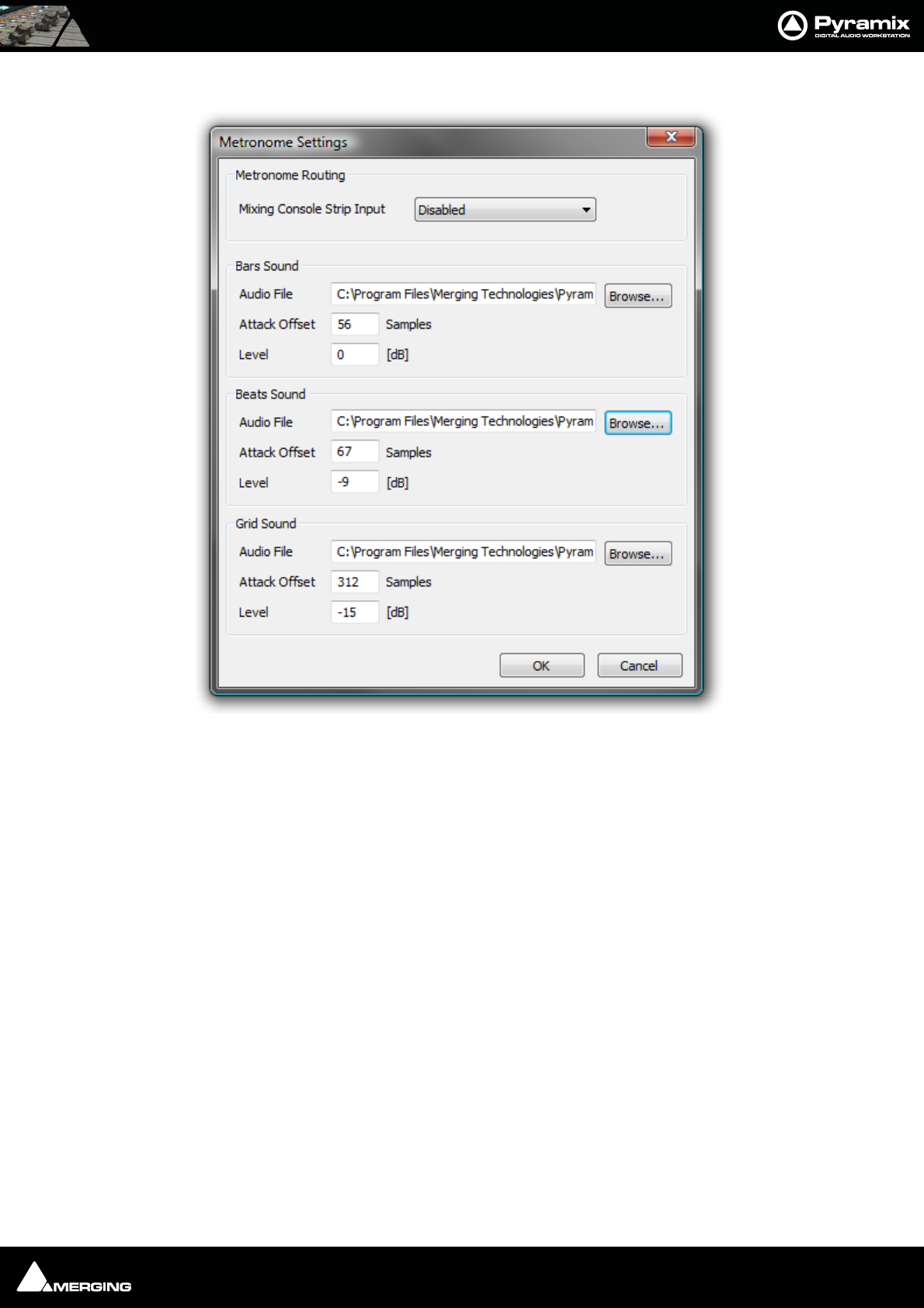
Applications : Reconforming to Original Media from Avid &/or OMF 19 - 341
Then click on the Metronome Settings...button
Choose a console strip for the Metronome sound from the drop-down list.
Any audio file can be used, for the Bars, Beats and Grid sounds. By default, some suitable WAV files are installed
with Pyramix in the same location where you installed the Pyramix software. By default. this will be:
C:\Program Files\Merging Technologies\Pyramix Virtual Studio\Metronome Bars.wav etc.
The Attack Offset parameters enable the timing to be adjusted and the values in the Level data input fields
determine the playback levels of the chosen sounds.
Midi Files Import / Export
Load
Save
Both buttons open a Browser Window to enable navigation to a file to load or a location to save to.
Currently, when midi files of type 2 are imported, only the tempo map and signature of track 1 is
imported.
Reconforming to Original Media from Avid &/or OMF
There are no specific rules for the detailed settings of the procedure described below. It may change from user to
user, project to project, etc… It really is up to the user to define a specific workflow including naming of the origi-
nal recording, importing the stereo/original version into the Avid and making sure that the Video Editor properly
Metronome Settings dialog

Applications : Digitizing a Tape with Discontinuous TimeCode 19 - 342
keeps track of the proper naming, metadata, etc… Once the method is properly defined and working, the rules
should then be communicated to all people involved in a given project, once and for all.
Philosophical Point
Reconforming to New Media always involves some delicate & dirty experimentations in the Relink to New Media
dialog. This usually requires comparisons of Clip information in Clip Properties and Media information in Pyramix
Media Manager. Once some kind of correspondence in the naming structure can be found, then all of a sudden
the whole process becomes incredibly simple, the entire TimeLine becomes populated by happy green clips and
an amazing feeling of personal achievement is yours forever.
The following example could and should be interpreted at will to match your specific needs and requirements
Procedure
• Import the OMF from the Avid (even without Avid media, it is not required)
• Mount the original Multitrack session media
• Select Project > Reconform > Relink to New Media
• Now the hard part: try to find, in the Clips imported from the OMF, any matching information (in Clip
Properties) that can also be found in the original media properties
• For instance, you may find that the Clip Names match the Original Media File Names, but you may very
well find that the Clip Names are in fact Scene & Takes and should rather match the Original Media Scene
& Take, etc…
(OMF is at this better than CMX since it can include information such as Clip Names, Metadata, TimeCodes, etc…)
It finally all depends on how the original media has been documented while recording (BWF metadata) and how
the Video Editor and Media “Ingester” have documented the Media and Clips in the Avid.
Again, as already stated above, there are no rules and it may change from user to user, project to project.
Suggested Procedure for Managing a Workflow
• Record the Original Media in BWF with TimeCode and name them Take1, Take2, Take3, etc… or any other
name that can easily be understood and searched.
• Create a BWF 16 bits Stereo Render of your Multitrack recording files WITH THE SAME NAME as the origi-
nal.
• Import these files into the Avid and make sure all clips created out of these Media keep the Media Name or
File Name.
• Export an OMF out of the video edit and import it back in Pyramix (Even without media).
• You should then be able to match the OMF Clip Name to the Original Media File Name, or at least, if the
Video Editor messed up with the Clip Names, the OMF Media Names with the Original Media Name or File
Name.
•- Once the Relink procedure has been successfully achieved, you should have all your Clips referencing
the Original Media’s first track(s).
•- Then go to Tracks > Extend, select all tracks you want to extend and choose Auto-Detect. This should
extend all your clips according to the number of tracks of your original multitrack recording.
Summary
If something goes wrong with Reconform (apart from SD2 files not recognized, Please see: File & Project Inter-
change with Apple Macintosh on page 304) please look for some sort of timing or wording mismatch between
Clips and Media and feel free to try several different settings in the Relink to New Media Dialog, till you find THE
ONE that matches your topology.
Digitizing a Tape with Discontinuous TimeCode
Pyramix can automatically record a whole tape where the TimeCode is not continuous:

Applications : Loop Recording With Simultaneous Playlist Creation 19 - 343
• Set all desired tracks in Auto-Punch mode
•Place Mark In at 00:00:00:00 and Mark Out at 23:59:59:24 (These are the default values for a new project)
• Plug LTC Out from the tape machine into Pyramix
•Set Chase mode to HARD CHASE (Settings > All Settings > Jog/Chase : Chase Settings -Chase Mode)
• Rewind the tape
• Press Play on the tape machine
• Each time a valid TC is encountered Pyramix will lock and start recording a new clip, then stop when the
TimeCode jumps. A separate media will thus be created for each continuous TimeCode on the tape.
Loop Recording With Simultaneous Playlist Creation
•Check the Create an Empty Playlist for each Recording option in the Settings > All Settings Project >
Record Page.
• Put the required tracks in Auto Punch mode (Alt + click the track arming, the track arming button will dis-
play )
•Place Mark In and Mark Out around the region to be recorded.
• Put Pyramix in Chase Mode (preferably Hard Chase) and chase an LTC input.
• Have the TimeCode that feeds Pyramix looping around two boundaries that start a little before the Mark
In and stop a little after the Mark out. (To make a Preroll Postroll. These should be big enough to let Pyra-
mix sync properly and lock to the incoming TimeCode).
• Pyramix will then, for each loop, sync and lock, enter in record at Mark In, stop recording at Mark Out and
create a new PlayList for each loop iteration.
N.B. This requires that an external TimeCode source/generator be used to generate the reference TC loop.
TimeCode Midnight
For those users with a requirement to sync/chase TimeCode with projects near or crossing the day barrier (be it
Zero or 24 hours) Pyramix has an Allow chasing across midnight option in the Settings > All Settings > Appli-
cation > Jog/Chase page.
If this setting remains unchecked (default) then the Pyramix cursor will always follow the exact given TimeCode
and therefore will remain strictly within "day zero" of the Pyramix timeline. For additional security and comfort, if
Pyramix is in locked state while crossing the midnight barrier, then even with this setting unchecked, there will
not be an immediate jump from midnight back to zero while playing or recording in sync. The playback or record-
ing will remain seamless, uninterrupted and cross the day barrier until an out-of-lock status is recognized. Only
then is re-chase triggered to whatever the incoming TimeCode currently is.
Editing Multitrack Recordings
To edit Multitrack recordings without listening to all of them just Mute the tracks and Hide them. All edits per-
formed on the remaining visible one will still occur on all others and only the audio from the visible one will be
played back for monitoring. (E.g. a stereo guide mix)
Film 24 to NTSC Sync
Here are some settings for the most common Scenarios for Film 24 to NTSC Sync. Presets for all of these can be
found in Settings > All Settings > Hardware > Formats & Sync.

Applications : Checking AC3 encoded files in Pyramix 19 - 344
Mix/Editing for TV shot in NTSC and 48 kHz and edited in sync with NTSC equipment:
• Set the Frame Rate to NTSC Drop
•Set the Video Format to NTSC
• Set the Sampling Rate to 48 kHz
• Set the Varispeed to Nominal
Result: FR = 29.97 SR = 48000 Video Input = 29.97 (Standard for TV, Audio at 48kHz in sync with 29.97 while Shoot-
ing, Post and Diffusion)
Mix/Editing for Film shot at 24 fps and 48kHz but edited in sync with NTSC equipment:
• Set the Frame Rate to Film (24 fps)
•Set the Video Format to NTSC
• Set the Sampling Rate to 48 kHz
• Set the Varispeed to Pull-Down
Result: FR = 23.98 SR = 47952 Video Input = 29.97 (Standard for Film, Audio at 48kHz in sync with Film 24fps for
Shooting and Diffusion, but at 47952 in sync with 29.97 for the Post with Film 24 running at 23.98)
Mix/Editing for Film shot at 24 but converted 3:2 to 30 frames and edited in sync with NTSC
equipment:
• Set the Frame Rate to SMPTE Non-Drop
•Set the Video Format to NTSC
• Set the Sampling Rate to 48 kHz
• Set the Varispeed to Pull-Down
Result: FR = 29.97 SR = 47952 Video Input = 29.97 (Standard for Film, Audio at 48kHz in sync with Film 24fps for
Shooting and Diffusion, but at 47952 in sync with 29.97 for the Post with Film converted to 30 running at 29.97)
Special case:
Mix/Editing for Film shot in High Def at 23.98 fps and 48kHz and edited in sync with HD NTSC
equipment like D5 or other:
• Set the Frame Rate to 23.98
• Set the Video Format to Trilevel 24/1.001
• Set the Sampling Rate to 48 kHz
• Set the Varispeed to Nominal
Result: FR = 23.98 SR = 48000 Video Input = 23.98 (For Film shot in HD 23.98, Audio at 48 kHz sync with Film 23.98
while Shooting and Post. Caution: The Audio needs a Pull-Up to run in sync with the Film if printed a real Roll)
Checking AC3 encoded files in Pyramix
Two types of AC3 encoded files can be played back in Pyramix:
If the file was generated as an .ac3 file, then Pyramix will automatically decode it on the fly and playback 6 chan-
nels of audio.
If the file was generated as a .wav file, then Pyramix will consider the file as Wave and simply play two channels of
digital encoded AC3 to its (digital) outputs to feed an external decoder.
Most AC3 encoders allow embedding of encoded AC3 signal into a Wave file while encoding, for easy playback.
For example, Minnetonka SurCode offers this feature.

Applications : Working with External Machines 19 - 345
Working with External Machines
Use Auto-chase
Auto-Chase is a convenient, one button press solution for situations where control must be frequently switched
between the Internal Machine I.e. Pyramix and an External Machine or machines.
If all enabled machines are set to Auto-Chase, when Ctrl is switched between machines the Active Machine is
automatically taken out of Chase mode and the previously Active Machine automatically enters Chase mode. To
activate Auto-Chase for all external machines, enable the menu setting:
Machines > External Machine > Auto-Chase
And, to activate Auto-Chase for the internal machine, enable the menu setting:
Machines > Internal machine > Auto-Chase
Using Freeze Mode
• If you are using Pyramix for sound-for-picture work, the Freeze Mode is a very powerful tool. For example,
to position an out of sync car-door slam do the following:
• Use the Transport controls with all machines on-line to position the picture on the point where the door
slams.
• Press the Freeze button to freeze the external machine(s).
• Select the clip that has the sound of the door slam.
• Position the Clip Sync Point at the beginning of the impact. (Click and drag the red Clip Sync Point or
position the Playhead Cursor and select Clips > Set Sync Point to Cursor (Ctrl + M)
• Press Freeze and the Playhead Cursor will jump to the point at which Freeze was activated.
•Now, select Clips > Send Sync Point to Cursor (Ctrl + Alt + M) and the clip will move so that its Sync Point
is at the Playhead Cursor position and the sound of the slam is synchronized with the picture.
Versioning
When making “promos” and commercials for radio, TV and film there is often a requirement to produce several dif-
ferent versions with, for example, different dates or times or different languages. The effects and music are often
the same for each version. Pyramix offers several ways of achieving this.
Probably the simplest method is to select all the clips you wish to move or copy to a new location in the Timeline
then select Cursor and Marks > Goto TimeCode, (NUM 6) type in the new TC location and then Cut and Paste or
Copy and Paste. If you have a lot of this work to do, you may want to build a couple of simple macros to to this
with the these commands: Cut / Paste to Cursor and Copy / Paste to Cursor.
As an alternative to typing in the new cursor TimeCode location, you could use the Nudge Cursor functions to off-
set it from where it is currently parked. Nudge to the left/right uses one of the 5 predetermined nudge settings.
Another method uses User Libraries. Copy the selected clips and paste to a library or (Shift + Alt Drag) then
place the Composition using any any tool you wish. This method has the advantage that you can save the library
and open it in another project.
USER MANUAL
www.merging.com/Pyramix
Conforming and Reconforming
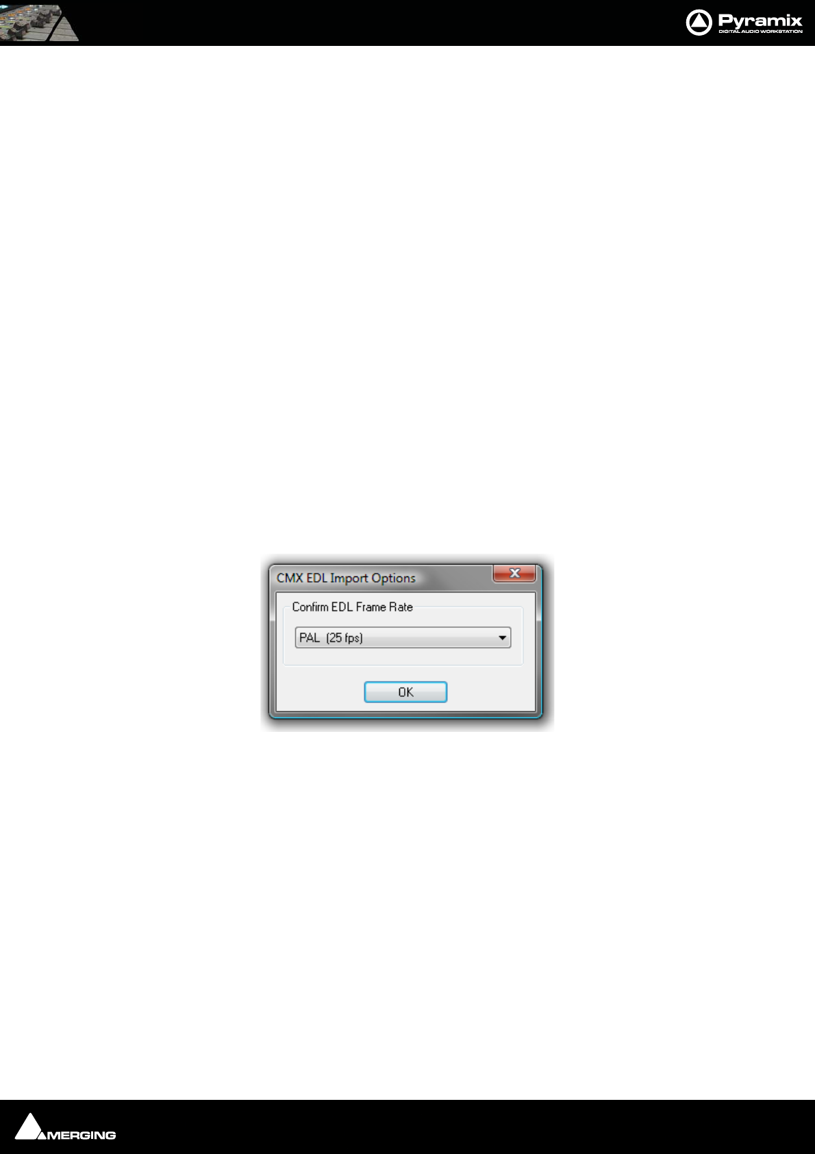
Conforming and Reconforming : Conforming 20 - 347
Conforming
Conform
Conforming is the process of making and positioning audio Cues in the Timeline from Audio media files already
present in a folder available to the Pyramix PC in conformity with an imported EDL (Edit Decision List.) or video
project, for example, AAF, Final Cut Pro or OMF.
Autoconform
Where the Audio media files associated with an EDL are not available to the Pyramix PC, Pyramix can control a
tape deck or other device to import the required audio.
Reconform
Pyramix can conform audio to match a several flavours of EDL and also reconform an existing project to match a
CMX change EDL.
Pyramix can also reconform an audio project by importing two versions of a video project, original and new.
CMX EDLs
CMX is one of the earliest types of EDL. The name comes from the company that developed it in the early 1970s
CBS Memorex eXperimental. Over the intervening decades other companies have extended the original format to
encompass, for example, more audio tracks. Although there are now several far more sophisticated alternatives,
CMX remains the lingua franca of EDLs.
Importing a CMX EDL
Select Project > Import choose CMX EDL in the InterChange-Import dialog then click on the Import button.
Select the desired edl file in the Open file-browser window. The CMX EDL Import Options dialog opens:
If the EDL Frame Rate is correct, simply click the OK button. Otherwise, select the correct rate from the drop down
list and click the OK button.
CMX EDL Import Options dialog
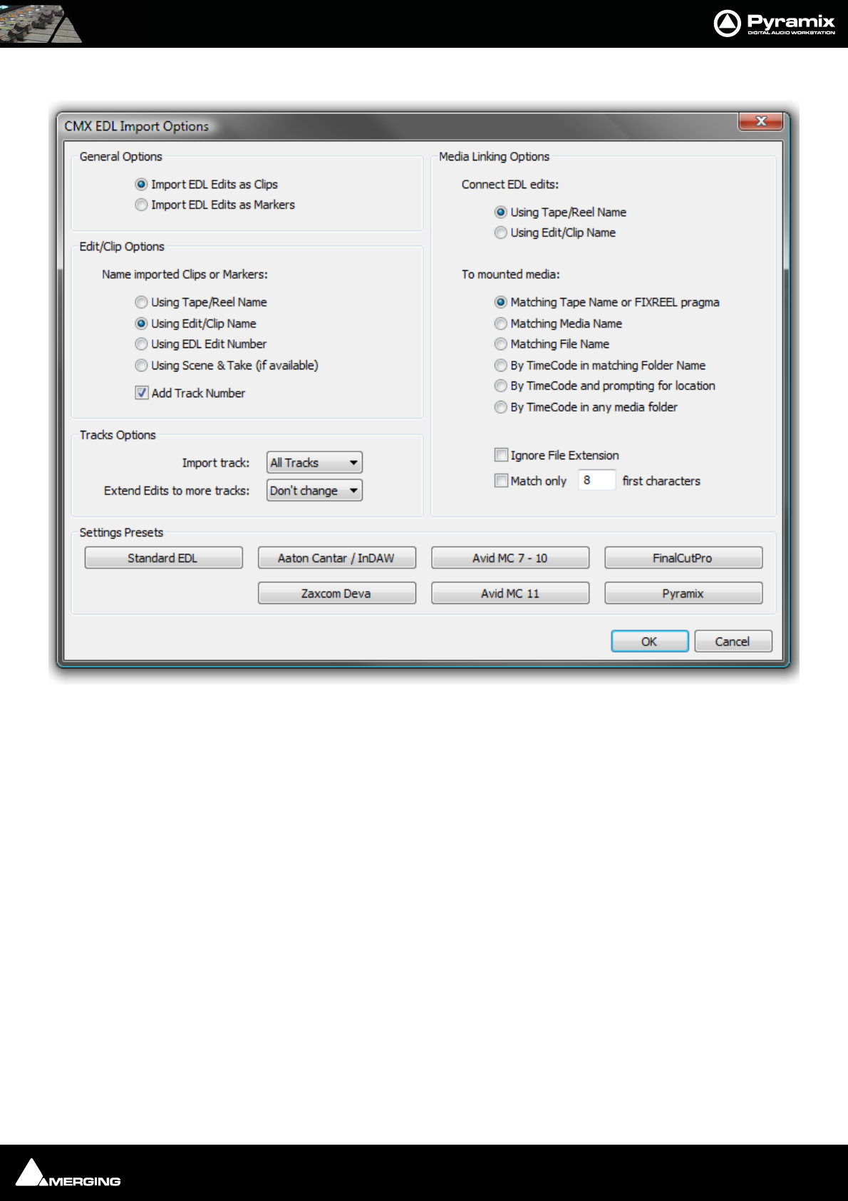
Conforming and Reconforming : Conforming 20 - 348
The CMX EDL Import Options main dialog opens:
Common CMX Variants
The Settings Presets buttons at the bottom of the box set the options for a variety of common CMX variants. If
the edl you wish to import matches one of these, simply click the appropriate Preset button. The settings are
reflected in the rest of the dialog. Click the OK button to begin the Import.
If the EDL is not one of the common variants or the intention is to perform a partial or re-conform, make the
appropriate choices in the dialog before clicking on the OK button to begin the Import.
CMX EDL import Options
General Options
Import EDL Edits as Clips
Import EDL Edits as Markers
Edit/Clip Options Choose to name created clips from either:
Using Tape/Reel Name
Using Edit/Clip Name
Using EDL Edit Number
Using Scene & Take (if available) of linked media file. (E.g. BWF PMF etc. files with information in the Scene &
Take fields)
Tracks Options
CMX EDL Import Options dialog

Conforming and Reconforming : Conforming 20 - 349
Import Track Drop-down list offering a choice of importing All Tracks (default) or any individual
track. Importing only the edits made on the first audio track. This can be useful
with projects edited on a MediaComposer where the TimeCode of all audio tracks
but the first one has been lost from files imported from a Deva recorder.
Extend Edits to more tracks Offers the choice of extending the edits to more tracks than the original list by
selecting the desired number of target tracks from the drop down list.
Media Linking Options
Connect EDL edits: Choose the way to relink the audio media to edits by either:
Using Tape/Reel Name
Using Edit/Clip Name
from the EDL...
To Mounted Media: … and match it to either
Matching Tape Name or FIXREEL pragma (the media original)
Matching Media Name (the media original)
Matching File Name (the media original)
By TimeCode in matching Folder name (the media Timestamp in a folder whose name matches the
Reel or Edit name)
By TimeCode and prompting for location (the media Timestamp in a given folder)
By TimeCode in any media folder (the media Timestamp in any mounted media folder)
Ignore File Extension When checked any file extension is ignored while comparing file names
Match only X first characters When checked only the given number of first characters in the file-
name are compared. (useful for matching files coming from Aaton Cantar
or InDAW recorders)
CMX EDL Format
CMX Edls are a set of statement lines which typically look like this:
TITLE: An example of CMX EDL
001 TEST AA C 00:00:24:24 00:00:25:00 00:59:58:00 00:59:58:01
AUD 3 4
* Sine on all tracks
002 DAT12 AA C 20:18:18:07 20:18:21:13 01:02:40:02 01:02:43:08
* Introduction
003 TAPE1 AA C 01:15:07:07 01:15:11:13 01:02:43:13 01:02:47:19
004 TAPE1 NONE C 01:15:14:02 01:15:16:04 01:02:47:19 01:02:49:21
AUD 3 4
005 TAPE1 NONE C 1000Hz 01:15:14:02 01:15:16:04 01:02:47:19 01:02:49:21
006 TAPE1 NONE C “A sound” 01:15:14:02 01:15:16:04 01:02:47:19 01:02:49:21
Pyramix will extract all the information regarding audio from these EDLs and then paste a set of clips into the cur-
rent composition’s Timeline.
There are many CMX formats which differ in details, Pyramix should be tolerant enough to accept most of them as
long as edit lines fields are well separated by spaces or TABs.

Conforming and Reconforming : Conforming 20 - 350
Any errors encountered while parsing an EDL file are stored and reported after loading as much of the file as pos-
sible. Any non valid lines, missing media or media sampling rate mismatches are reported.
Media Reconnection
The major problem encountered while importing an EDL is reconnecting to referenced media. Pyramix needs all
referenced media to be present (mounted) when the import occurs. After the import, the newly created composi-
tion MUST be saved as a Pyramix project to keep the connection between clips and media.
Media are searched while importing the EDL by Media Source name (or Reel name following the EDL terminol-
ogy), and Source In and Source Out TimeCodes. So, to be reconnected, a clip needs to find in any media folder a
media file with a Media Source name matching field #2 in the EDL, in the preceding example TEST, DAT12 or
TAPE1, and where the original TimeCode and length match the Source In and Source Out field.
Source Names - FIXREEL
It often happens that the media is generated with a different Source (Tape, Reel) name than the EDL referencing it.
For this purpose we have added a special keyword to the CMX language which allows Pyramix to replace one Reel
name with another while parsing the EDL.
FIXREEL: DAT12 DAT012 This preamble added at beginning of the file will replace all occurrences of the reel name
DAT12 by DAT012. The preamble can be preceded by the comment asterisk (and a space or TAB) so the EDL
remains compatible for import by other systems:
* FIXREEL: DAT12 DAT012
It is also possible to add the keyword MEDIANAME, FILENAME or FOLDERNAME at the end of this line to tell Pyra-
mix, instead of the Source (Tape, Reel) name, to search for the Media name or the Media Filename:
* FIXREEL: DAT12 Ambiance43b MEDIANAME
* FIXREEL: DAT12 d:\pmxmedia\dat12\ambiance43b.wav FILENAME
or to search by TimeCode in the given mounted media folder (this is kind of a conformation to existing digitized
material):
* FIXREEL: DAT12 d:\pmxmedia\dat12 FOLDERNAME
The keyword OFFSET followed by a TimeCode can be added at the end of the line to allow media without origin
(original TimeCode, source TimeCode, time stamp) to be referenced, for example WAVE files.
* FIXREEL: DAT12 Ambiance43b MEDIANAME OFFSET 08:45:32:00
* FIXREEL: DAT12 d:\pmxmedia\ambiance43b.wav FILENAME OFFSET 08:45:32:00
This covers most cases of media reconnection and should help solve special cases of EDLs exported by exotic sys-
tems.
Media Reconnection Failure
An imported clip whose media has not been retrieved or whose media is not at the same sampling rate as the cur-
rent project will be associated a ‘fake’ media.
It WILL NOT be possible to retrieve its media file after the import, but it will be possible to associate a new media
file in the standard way (Control key pressed while dragging a media file from a media folder).
CMX Autoconform
When a CMX EDL is not accompanied by audio files on disk an Autoconform can be performed. A Digitizing Ses-
sion is used to grab the audio referenced by the CMX EDL from an external machine (This may be operated under
9-pin control or simple time-code chase). The CMX EDL can then be imported into an Editing Project (as
described above) to link to the digitized media.
Please see also: Digitizing Sessions on page 106
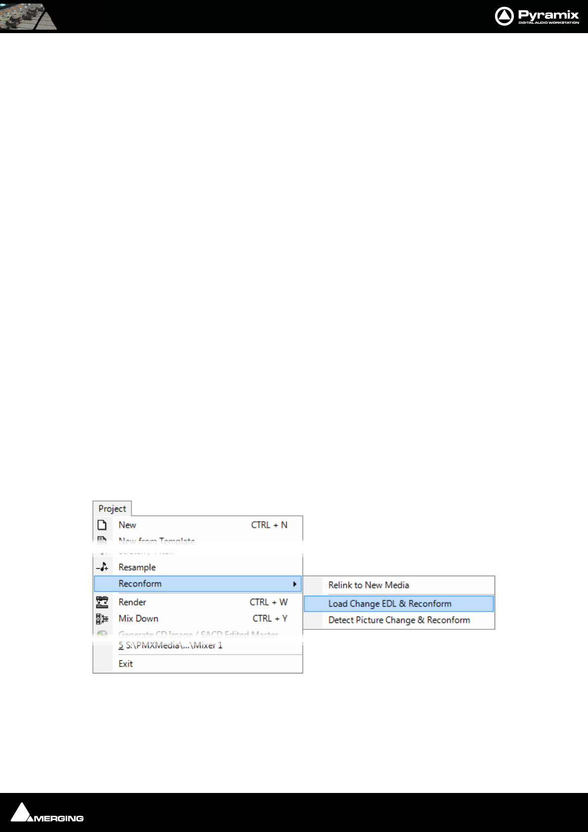
Conforming and Reconforming : Reconform 20 - 351
Reconform
Introduction
Reconform enables tracks in an existing project to be conformed to take account of changes in the picture edit.
Reconform > Relink to new Media can be used to link to new Media files when new Cues without previously
associated Media files are produced by the Reconform.
In Pyramix there are three routes to Reconforming. The first two make use of a so-called Change EDL. This EDL is a
standard CMX EDL generated from a “State 1 EDL” and a “State 2 EDL”.
In the first case, CMX Reconform, the change EDL is generated by a third party application. This may be the video
editing software, or a specialised EDL manager.
Please see: Reconform Using Pyramix with an Existing Change EDL below.
Where there is no existing Change EDL there are two possibilites:
For users with Pyramix and access to both the original and modified video EDLs Pyramix can load the original pic-
ture (Version1 if not already part of the project) plus the new picture (Version2) and generate the necessary
changes from these.
Please see: Reconforming Using Pyramix for Picture Change Detection on page 355
For users running VCube as well as Pyramix, VCube can be used to generate a Change EDL from the original
(Version1) and revised (Version2) EDLs.
Please see Reconforming Using VCube for Picture Change Detection on page 363
Reconforming with an Existing Change EDL
The Reconform function allows picture edit changes to be applied to a project by loading a so-called “Change
EDL”. T h e Reconform function rearranges Cues within the current project where necessary to reflect the change
from State 1 to State 2 by creating edits on all tracks of the project using the original material as sources and plac-
ing them to the new destination TimeCodes.
Step 1
With the Pyramix project you wish to conform open in Pyramix select:
Project > Reconform > Load Change EDL & Reconform
Project Menu - Reconform Sub-menu
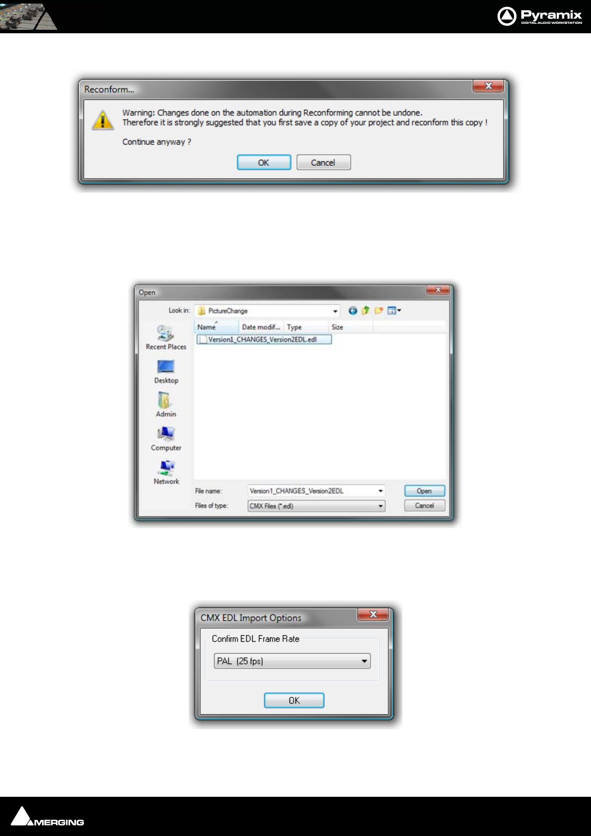
Conforming and Reconforming : Reconform 20 - 352
Opens the Reconform... dialog:
This Warning: gives good advice. It is good operational practice to retain the old Project (Version 1 in this case)
and to reconform a copy, saving this copy with a suitable filename matching the new Video composition version.
Assuming you have already done this, click on OK to close the dialog.
A file Open Browser Window opens:
Now, if necessary, navigate to the folder containing the Change EDL. In this case the required file is
Version1_CHANGES_Version2.EDL. Select this and Click on Open.
The CMX EDL Import Options, Confirm EDL Frame Rate dialog opens:
Check that the EDL Frame Rate matches the Pyramix Project Frame Rate. If the Frame Rate is incorrect, choose the
correct one from the drop-down list. Click on OK.
Reconform... dialog
Pyramix Open Browser Window
Pyramix CMX EDL Import Options dialog
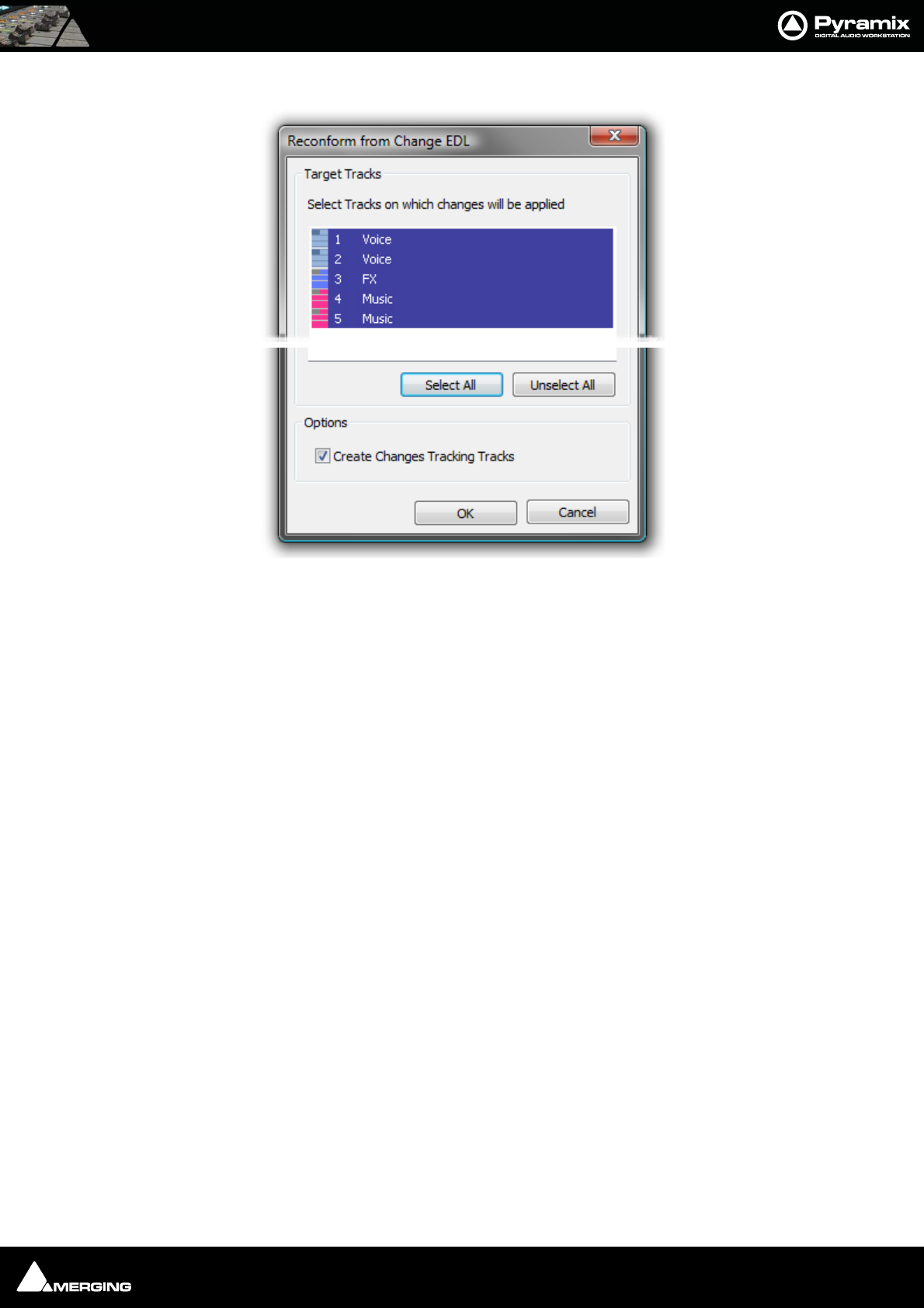
Conforming and Reconforming : Reconform 20 - 353
The Reconform from Change EDL dialog opens:
Select all tracks that will have to be reconformed (generally all tracks in the project).
Tick the Create Changes Tracking Tracks box if these are required.
Click on OK to perform the Reconform.
Reconform from Change EDL dialog

Conforming and Reconforming : Reconform 20 - 354
Step 2
Pyramix automatically conforms Version1 to Version2 on all tracks:
As can be seen in the above screenshot two new ‘fake’ tracks have been created and added at the bottom of the
Timeline to display the Change Tracking. These show in colour which sections of the Version1 Timeline have
been moved, sliced, diced and or squeezed etc. to become Version2
Step 3
Selecting Edit > Undo (Ctrl+Z) once will remove the Change Tracking Tracks.
Note: Once the Change Tracking Tracks have been removed they are NOT retrievable.
Pyramix Version 1 Project Reconformed with Change Tracks
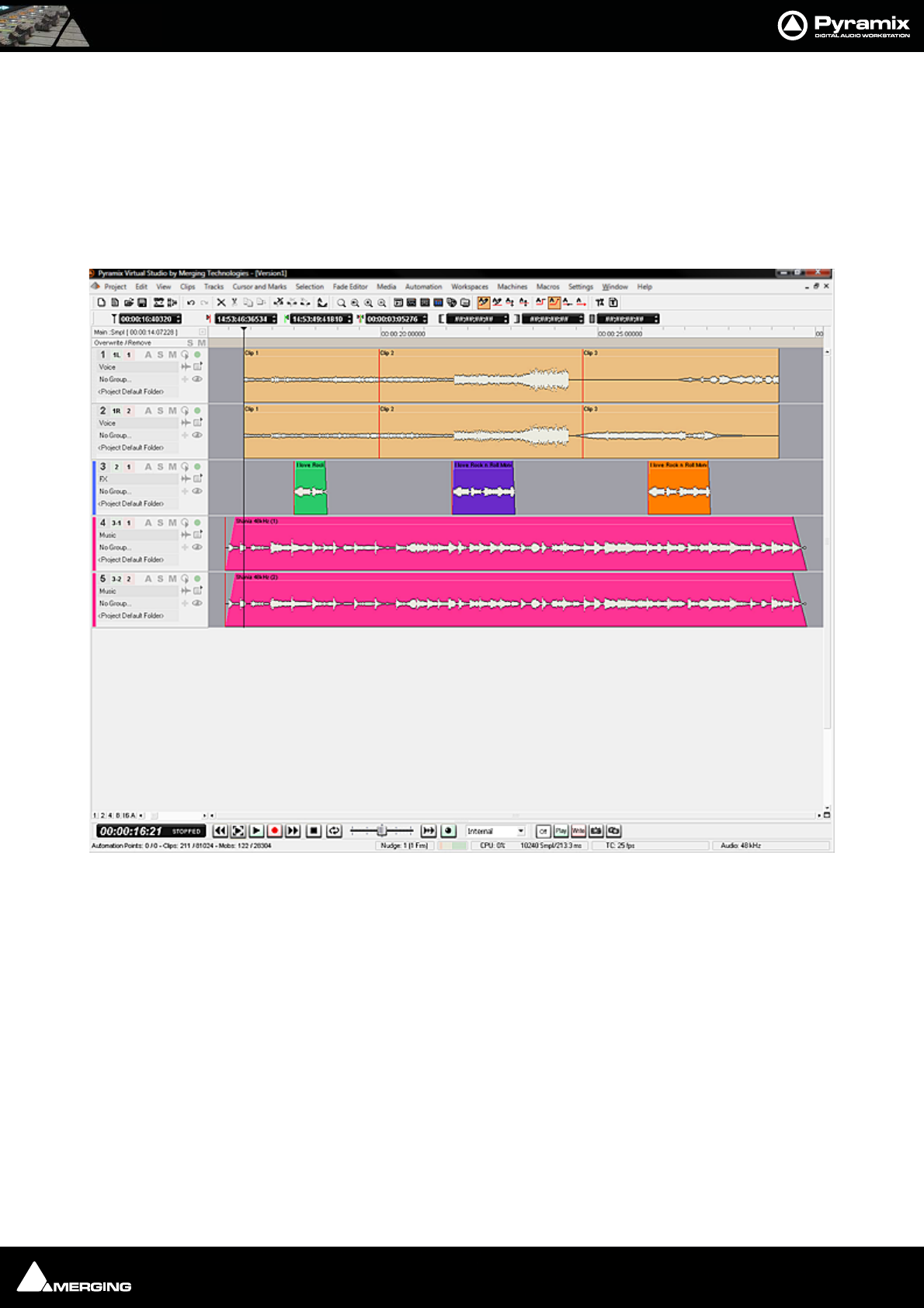
Conforming and Reconforming : Reconform 20 - 355
Reconforming Using Pyramix for Picture Change Detection
You can use Pyramix to perform a Reconform from two Video Projects.
Note: The precise details of subsequent Dialog boxes may vary from those shown below
depending on the specific format selected:
Step 1
Open the Pyramix Project you wish to reconform.
Pyramix Project Version1 requiring Reconform
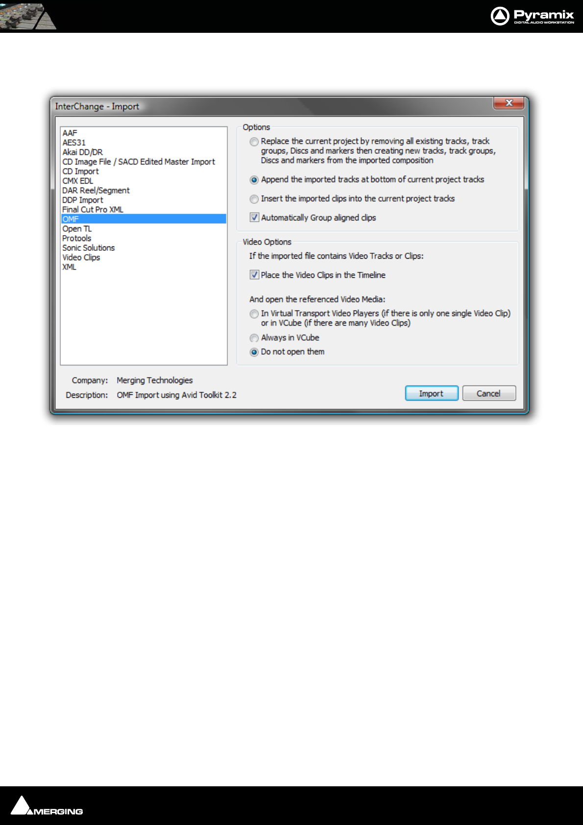
Conforming and Reconforming : Reconform 20 - 356
Step 2
Select Project > Import and choose the appropriate format. (in this case OMF)
Select the following options:
• Append the imported tracks at bottom of current project tracks
• Place the Video Clips in the Timeline
• Do not open them
Click on the Import button to open the Open File Browser Window:
Interchange Import dialog
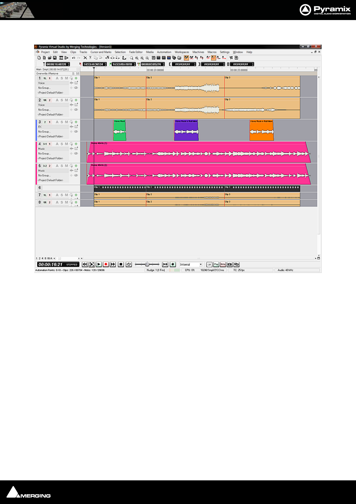
Conforming and Reconforming : Reconform 20 - 357
If necessary, navigate to the folder containing the Version1 Video Project file. Select the file and click on Open.
Notice that the Version1 Video and Audio tracks have been added at the bottom of the Timeline.
Pyramix Project Version1 with Version1 Video imported
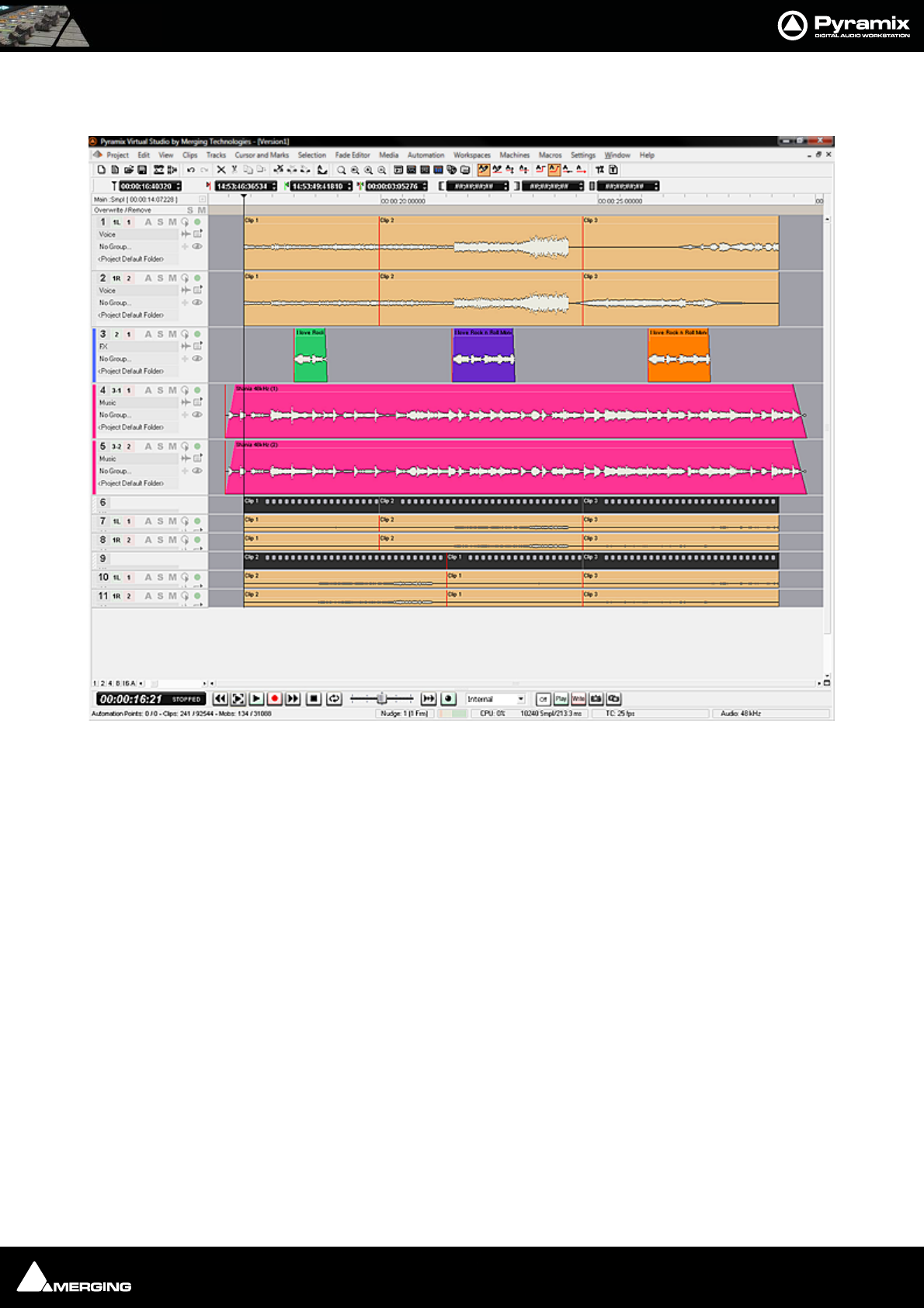
Conforming and Reconforming : Reconform 20 - 358
Step 3
Repeat Step2 with the same options, substituting Version2 when selecting the Video Project file.
Notice that the Version2 Video and Audio tracks have been added below the Version1 Video and Audio Tracks at
the bottom of the Timeline.
Pyramix Project Version1 with Version1and Version2 Video imported
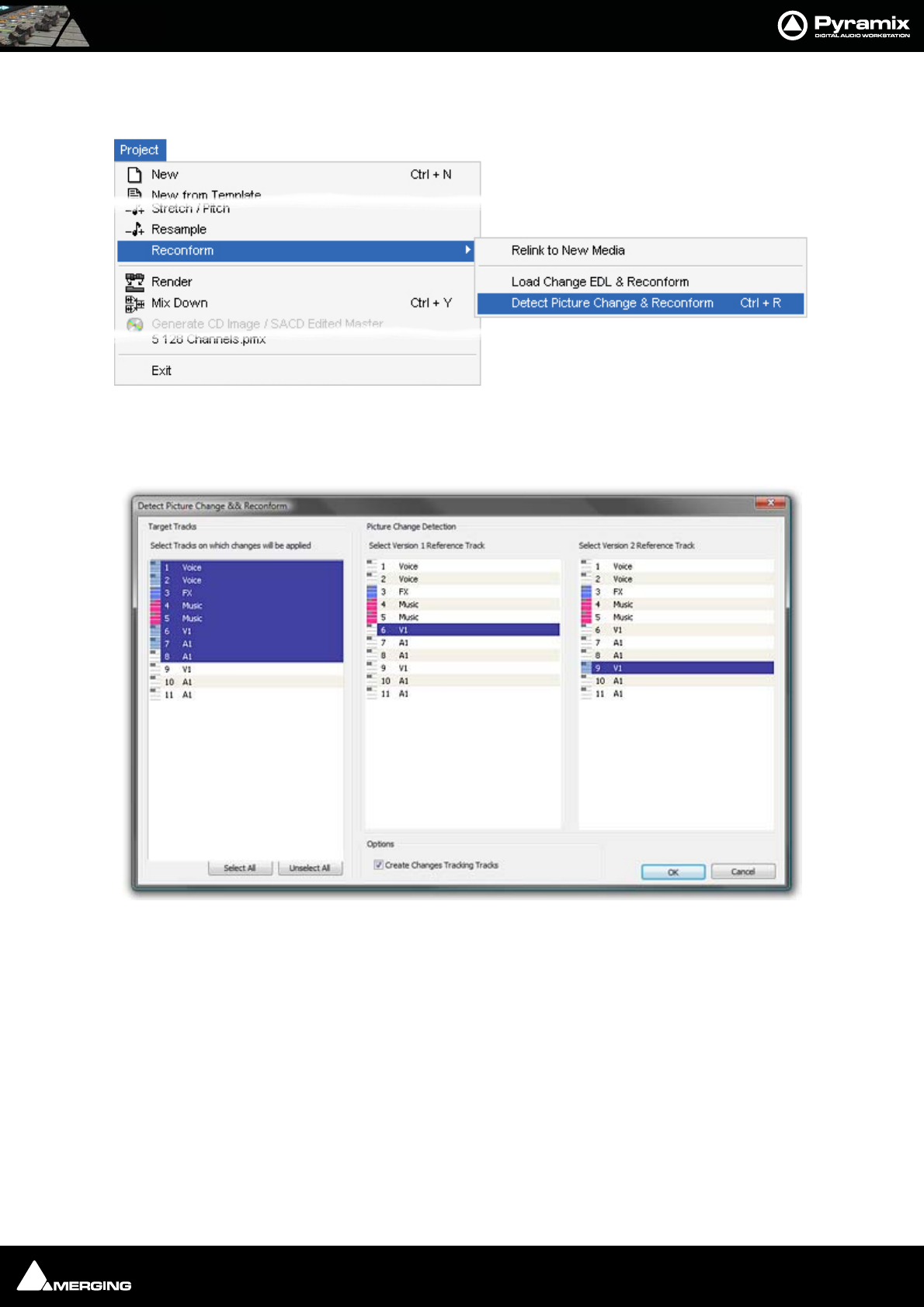
Conforming and Reconforming : Reconform 20 - 359
Step 4
Select, Project > Reconform > Detect Picture Changes & Reconform (Ctrl+R):
The Detect Picture Change & Reconform dialog opens.
Step 5
Select all tracks that will have to be reconformed (generally all tracks in the project except those belonging to the
Version2 Video project, but including Version1 Video and Audio tracks). Select the track that will be the Version1
Reference track for the picture change detection (generally the V1 track of the Version1 Video Project), then
Select the track that will be the Version2 Reference track for the picture change detection (generally the V1 track
of the Version2 Video Project).
Tick the Create Changes Tracking Tracks box if these are required.
When all the selections have been made click on OK to perform the Reconform:
Pyramix Project > Detect Picture Change & Reconform
Detect Picture Change & Reconform dialog

Conforming and Reconforming : Reconform 20 - 360
Step 6
The Pyramix Project has now been Reconformed:
Verifications can be made with the Change Tracking tracks, as well as comparing the Version1 Video tracks that
should now match the Version2 Video Tracks.
Pyramix Project Version1 and imported Video Project Version1 Conformed to match Version2 Video Project with Change Tracks
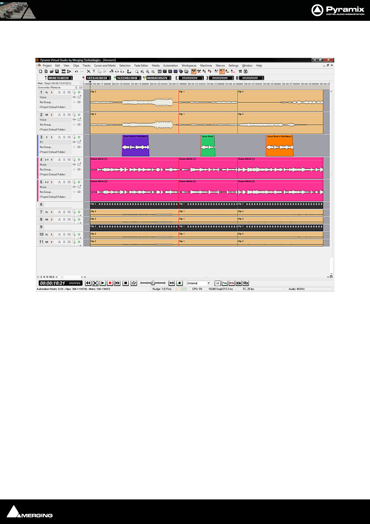
Conforming and Reconforming : Reconform 20 - 361
Step 7
Selecting Edit > Undo (Ctrl+Z) once will remove the Change Tracking Tracks.
Note: Once the Change Tracking Tracks have been removed they are NOT retrievable.
Pyramix Project Version1 Reconformed to Version2 with Change Tracking Tracks removed
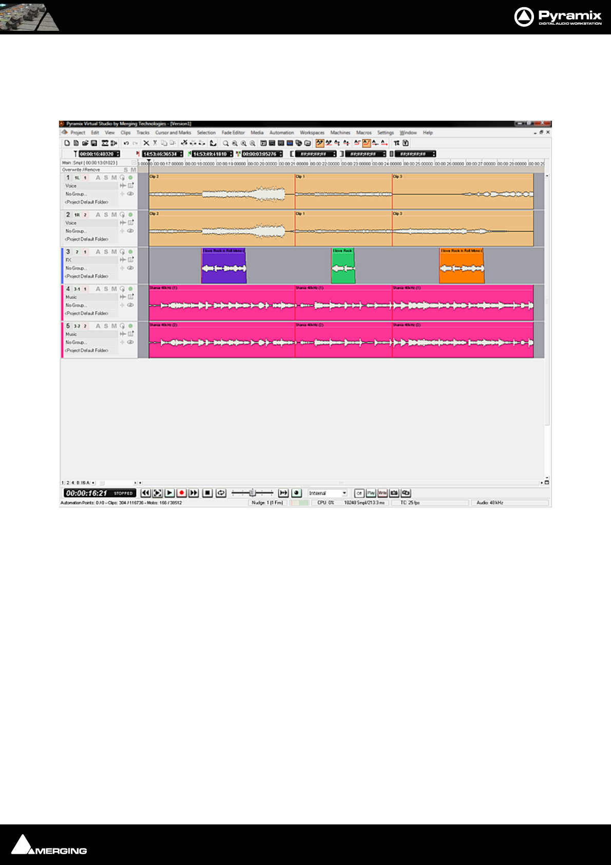
Conforming and Reconforming : Reconform 20 - 362
Step 8
The Video Reference Tracks (with their associated Audio Tracks) can be removed by right-clicking on the first Video
Track Header and selecting Delete To Last Track. The originl Pyramix Project is now reconformed and ready for
you to continue working on Version2.
Note: Where the Version2 project contains new material, it may well be appropriate to
move the relevant audio from the Version2 Audio Tracks up to the main Pyramix Project
tracks before deleting. A future Pyramix version may contain an option to carry out this
step automatically.
Pyramix Project Version1 Reconformed to Version2 with Imported Tracks removed.
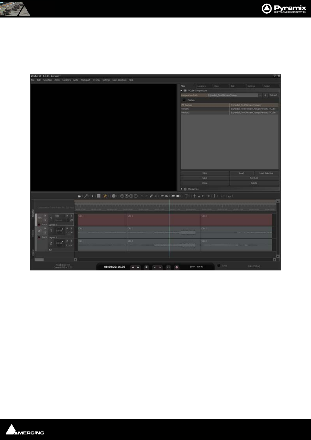
Conforming and Reconforming : Reconform 20 - 363
Reconforming Using VCube for Picture Change Detection
For users with VCube a Pyramix Project can be reconformed to match a new version of a Video Project quickly and
simply.
Step 1
Open the original version of the video in VCube and the Project with the matching audio in Pyramix:
VCube Original Version 1 Composition

Conforming and Reconforming : Reconform 20 - 364
Pyramix Version 1 Project with Audio matching Original VCube Version 1 Composition
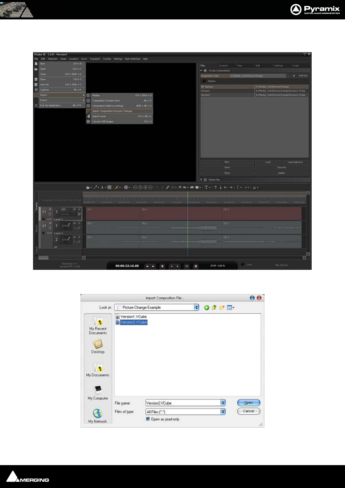
Conforming and Reconforming : Reconform 20 - 365
Step 2
In VCube select: File > Import > Import Composition and Export Changes:
This opens a Browser Window.
If necessary, navigate to the folder containing the changed version of the Video Composition. Select this and Click
on Open.
VCube New Version 2 Composition
VCube Import Composition File Browser Window
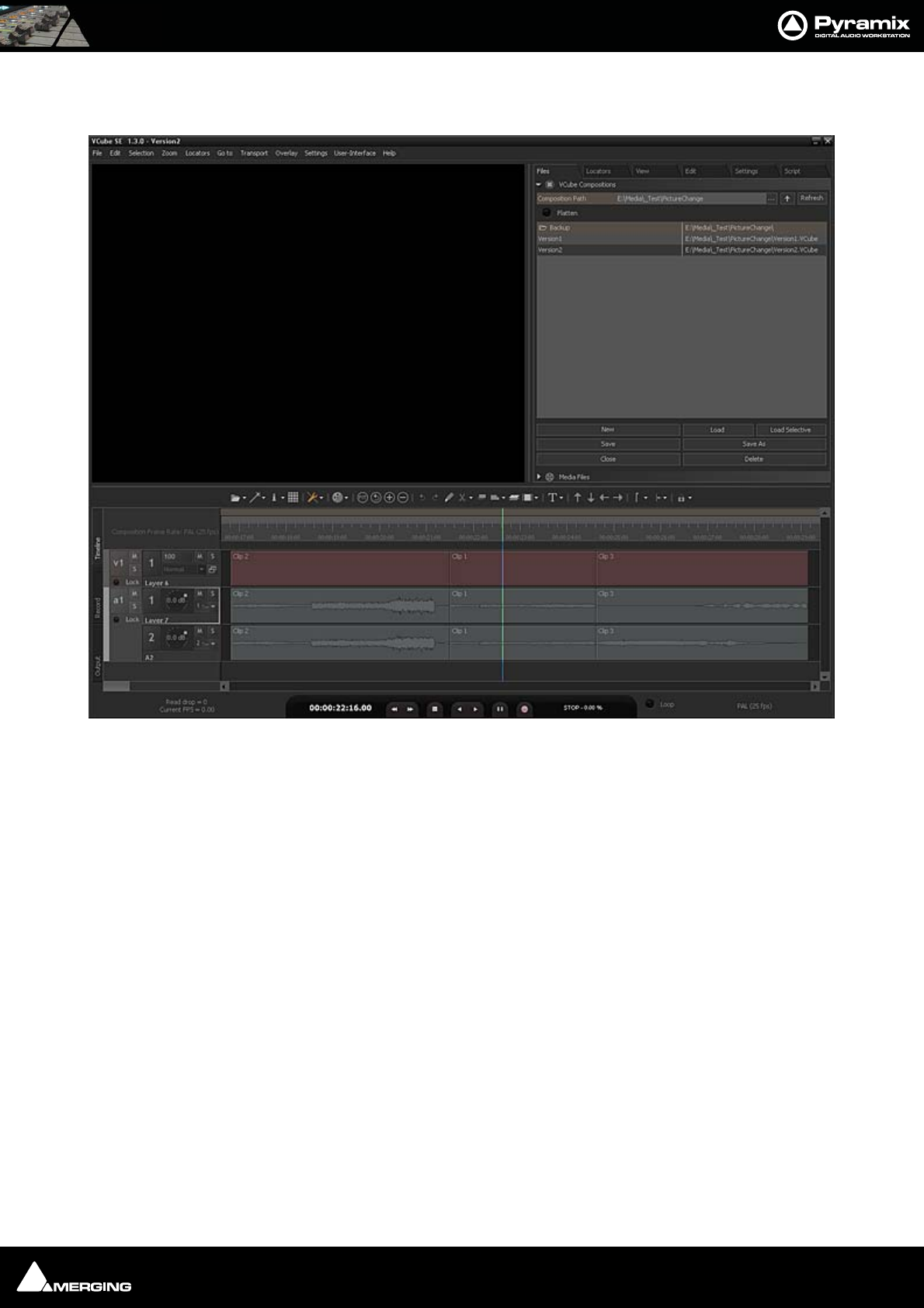
Conforming and Reconforming : Reconform 20 - 366
Step 3
The new video file, Version 2 is now displayed in the VCube Timeline:
The changes between the two versions will have been exported to a Change EDL file which will be found in the
same source folder.
VCube New Version 2 Composition
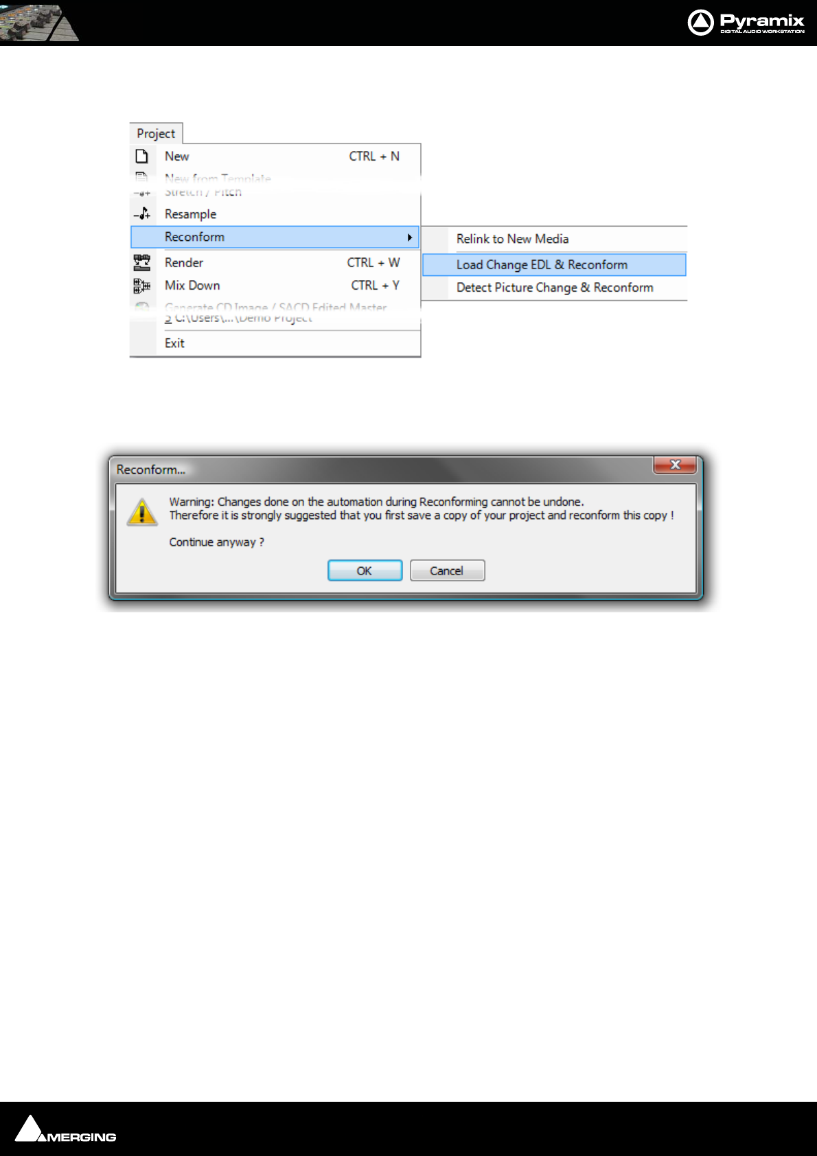
Conforming and Reconforming : Reconform 20 - 367
Step 4
Return to Pyramix, which is still displaying the original Version 1 audio Project:
Select Project > Reconform > Load Change EDL.
The Reconform... dialog opens:
This Warning: gives good advice. It is good operational practice to retain the old Project (Version 1 in this case)
and to reconform a copy, saving this copy with a suitable filename matching the new Video composition version.
Assuming you have already done this, click on OK to close the dialog.
Pyramix Menu - Project > Reconform > Load Change EDL & Reconform
Pyramix Reconform dialog
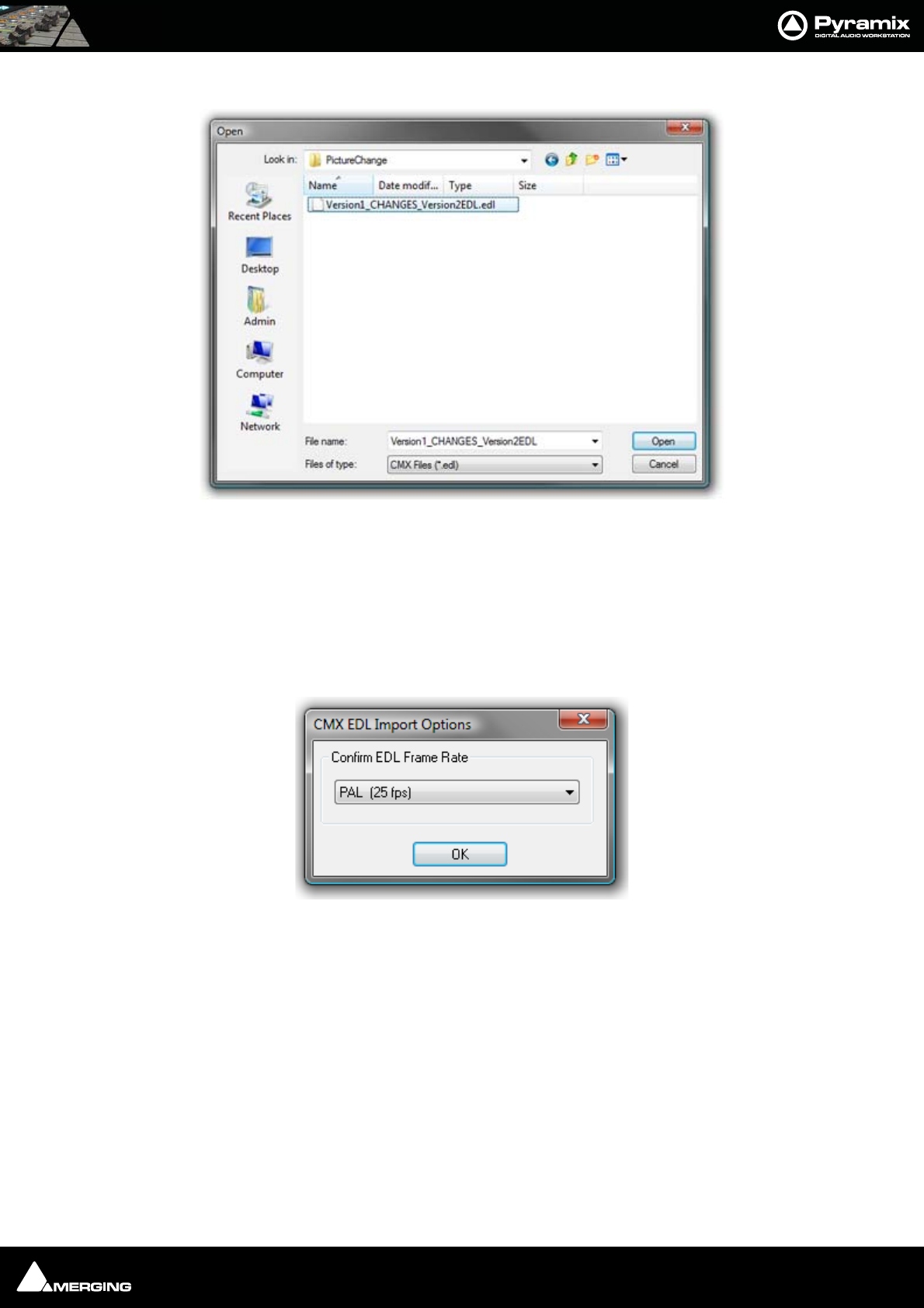
Conforming and Reconforming : Reconform 20 - 368
A file Open Browser Window opens:
Now, if necessary, navigate to the folder containing the Change EDL.
Note: This automatically generated file will be named in the form:
Original Composition name_CHANGES_New Composition name.EDL.
In this case the required file is Version1_CHANGES_Version2.EDL. Select this and Click on Open.
The CMX EDL Import Options, Confirm EDL Frame Rate dialog opens:
Check that the EDL Frame Rate matches the Pyramix Project Frame Rate. If the Frame Rate is incorrect, choose the
correct one from the drop-down list. Click on OK to confirm
Pyramix Open Browser Window
Pyramix CMX EDL Import Options dialog

Conforming and Reconforming : Reconform 20 - 369
The Reconform Project dialog opens proposing the creation of two new Change Tracking Tracks:
Select all tracks that will have to be reconformed (generally all tracks in the project).
Tick the Create Changes Tracking Tracks box if these are required.
Click on OK to perform the Reconform.
Pyramix Reconform from Change EDL dialog
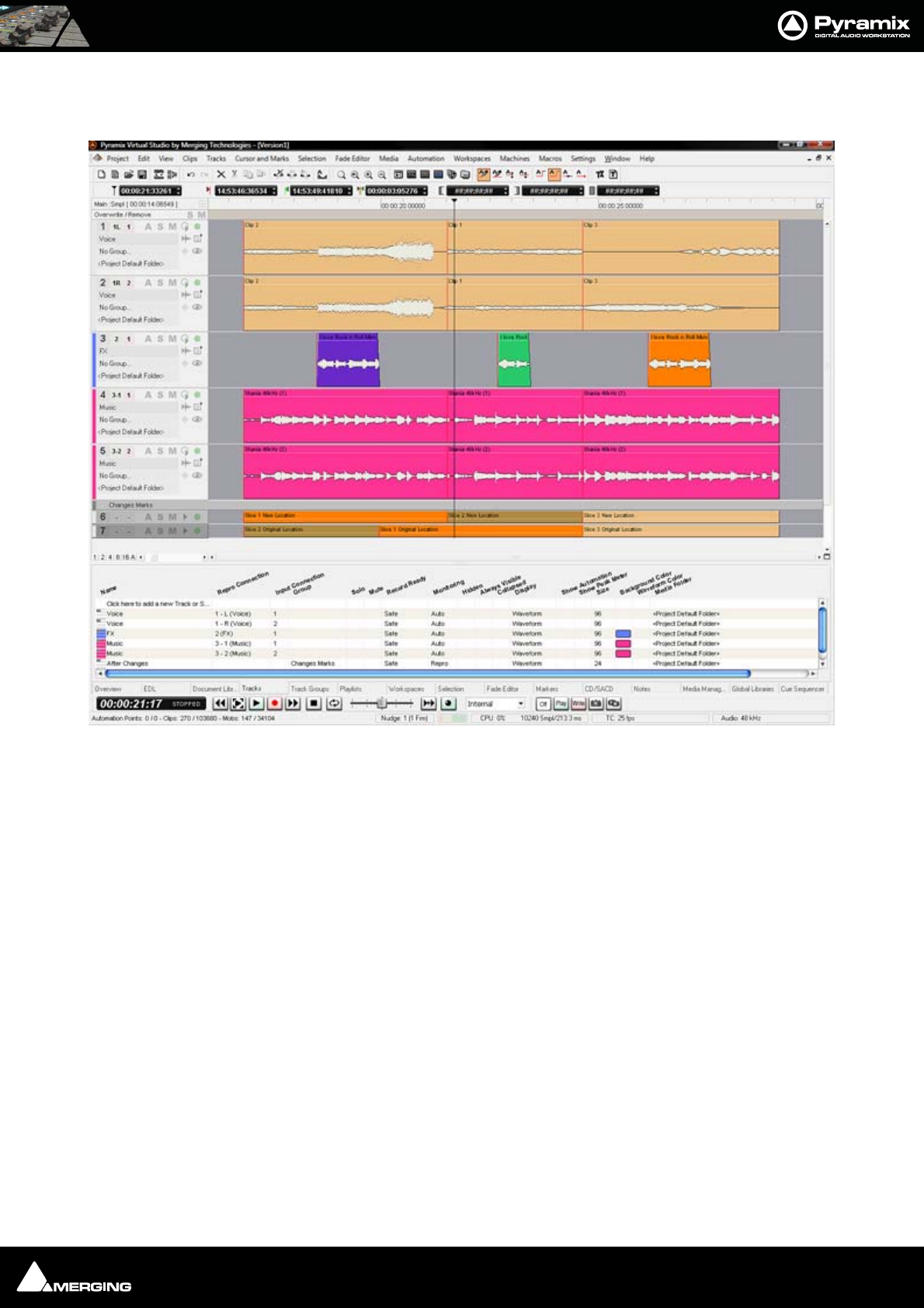
Conforming and Reconforming : Reconform 20 - 370
Step 5
Pyramix automatically conforms Version1 to Version2 on all tracks:
As can be seen in the above screenshot two new ‘fake’ tracks have been created and added at the bottom of the
Timeline to display the Change Tracking. These show in colour which sections of the Version1 Timeline have
been moved, sliced, diced and or squeezed etc. to become Version2
Pyramix Version 1 Project Reconformed with Change Tracks
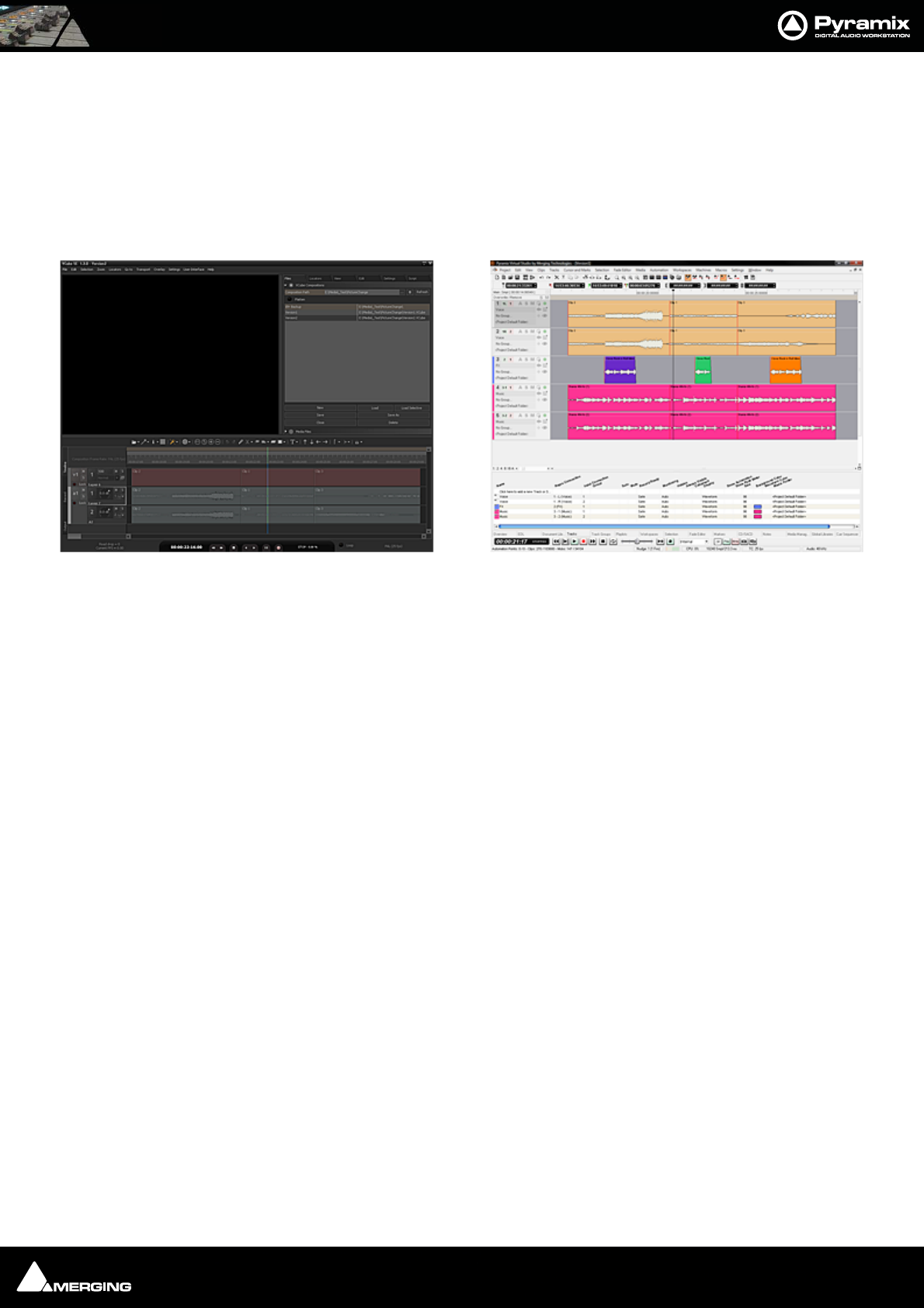
Conforming and Reconforming : Reconform 20 - 371
Step 6
Selecting Edit > Undo (Ctrl+Z) once will remove the Change Tracking Tracks.
Note: Once the Change Tracking Tracks have been removed they are NOT retrievable.
Now you will have both Pyramix and VCube Version2 displayed in the respective applications:
VCube displays the ‘real’ Version2 from the editing department and Pyramix displays Version2 Reconfomed auto-
matically from Version1.
Note: The above example used two VCube Projects for the Video. The procedure is iden-
tical when importing two AAF, OMF or Final Cut Pro Video Editing Projects.
VCube showing Version2 Project with Pyramix showing Version1 Reconfomed to match
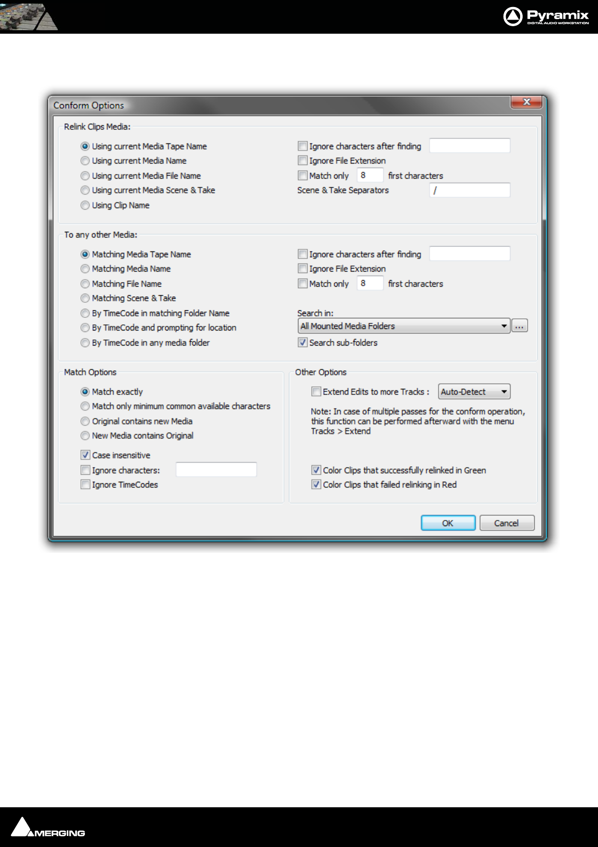
Conforming and Reconforming : Reconform 20 - 372
Relink to New Media
Opens a dialog offering various options similar to the Import CMX EDL function.
This allows relinking all or a selection of clips to new media. Typically. this is used for replacement of 16 bit versions
of audio files with 24 bit versions based on the clip name, media name, Scene & Take information or original Time-
Code.
Relink Clips Media Gives options to extract a string from the original clip:
Using current Media Tape Name
Using current Media Name
Using current Media File Name
Using current Media Scene & Take
Using Clip Name
With various options applicable to the above:
Ignore characters after finding… ignores the rest of the string after a given substring is found
Ignore File Extension ignores any characters after the last dot
Match only … first characters ignores all characters after a given number
Reconform Relink to New Media Options dialog

Conforming and Reconforming : Reconform 20 - 373
Scene & Take Separators gives a choice of characters to be used to separate a Scene name
and a Take name from the string.
Note: Note: this is relevant only for Tape, Media and Clip Name, as Scene & Take are
already properly separated in a Media Scene & Take tag.
To any other Media gives options to find which information to use from the Media that will be searched:
Matching Media Tape Name
Matching Media Name
Matching Media File Name
Matching Media Scene & Take
By TimeCode in matching Folder name Any Media with overlapping TimeCode in a folder with a
matching name
By TimeCode and prompting for location Any Media with overlapping TimeCode with prompting for
the folder name/ location
By TimeCode in any media folder Any Media with overlapping TimeCode
With various options:
Ignore characters after finding… ignores the rest of the string after a given substring is found
Ignore File Extension ignores any characters after the last dot
Match only … first characters ignores all characters after a given number of them
Search In allows the choice of which Media Folder to search in
Search sub-folders When checked sub-folders are searched
Match Options Offers options for the matching algorithm:
Match exactly both strings must be identical
Match only minimum common available characters
Take0001.new.01 will match with Take0001
Original contains new Media Take0001 will match with 0001
New Media contains Original 0001 will match with Take0001
Case insensitive TAKE0001 will match with Take0001
Ignore characters… if, for instance, /_+- are specified then 12-A/0001 will match with
12/A_0001
Ignore TimeCodes no checks are made on Original TimeCodes (timestamps). This
allows media with erroneous/lost timestamps to be replaced with
the correct ones or vice-versa.
Other Options
Extend Edits to more tracks When conforming a clip referencing multiple tracks to a clip refer-
encing a mono media file adds a new clip (with the same fades,
etc…) for all of these tracks as well.
Note: In the case of multiple passes for the conform operation, this function can be per-
formed afterwards with the menu item Tracks > Extend This automatically extends the num-
ber of tracks to accommodate all the Media channels of each of the clips of one or more timeline track(s)
Color Clips that successfully relinked in Green
Re-colors successfully linked clips in Green
Color Clips that failed relinking in Red
Re-colors Clips that failed to re-link in Red

USER MANUAL
www.merging.com/Pyramix
Machine Control

Machine Control : Control of External Device 21 - 375
Pyramix can control and be controlled by a wide variety of external hardware. This chapter, Machine Control
deals with situations where Pyramix is controlling and external machine or machines.
Control of External Device
If Pyramix is controlling another machine, (with the exception of GPO control) this device must be set up as an
External Machine.
External Machines
9-pin (Sony P2 protocol)
9-pin Control of External Machine
If you wish to control a 9-pin slave machine from Pyramix the target machine must be set up as an external
machine. If you wish to control Pyramix as a slave from an external 9-pin controller / synchronizer then the exter-
nal controller must be set up as a Remote Controller in Pyramix. Please see: Control by External Device on
page 388
Connection for the Sony 9-Pin protocol
Please see: Appendix VI 9 - Pin connection on page 573 for a description of the physical connection between
the PC's COM port and the RS-422 connector of the external machine.
Setting up an external machine
• Select the Settings > All Settings > Remote Control > Machine page
• Click the Add button.
• Enter a suitable name for the external machine in the Name field, such as “Betacam”.
• Choose the Driver for the machine from the drop-down list. Sony 9-pin
•Check the Enable field.
• Adjust the Driver Properties, the Port Properties and the Settings according to your needs. Please
see: Sony 9-Pin Protocol Configuration (Machine) on page 536
•Click OK to confirm all the entries and to add the new machine to the list.
Note: Since Merging Technologies products are based on hard disk and computer tech-
nology they do not need to take account of the color framing sequence. (Used to pro-
duce ‘legal’ picture editis). Therefore Sony P2 devices must have their Color Framing
mode disabled (2F), in order to synchronise correctly. Please see the device manufac-
turer’s documentation for the correct procedure to do this.

Machine Control : Chase Synchronizer 21 - 376
Linking Functions of External and Internal Machines
The following functions can be linked in the Settings > All Settings > Remote Control : Machines page by sim-
ply ticking the boxes:
• Play and Record
• Play-Record Toggle
• In / Out Points
•Offset
Please see also: Machine on page 534
Synchronizer
Pyramix will chase an external TimeCode source as a slave and external machines, capable of chasing TimeCode,
can follow Pyramix as slaves. However, a far more satisfactory way to work is with Pyramix as the master.
Chase Synchronizer
Pyramix can synchronize external 9-pin (Sony P2 protocol) machines including those that cannot chase TimeCode.
No TimeCode connection TO the machine from Pyramix is required. The Chase Synchronizer compares the Time-
Code coming FROM the external machine with the required position (including offset, if any) and sends transport
commands in order to synchronize the machine.
9-Pin Controller/Synchronizer Explained
The Host Pyramix system (the first machine shown in the Transport Control Panel) is the synchronizer. It may or
may not be the Master.
Therefore, when an External Machine is the Master, the Host Pyramix MUST chase it if a second External Machine is
to be synchronized. For Example, in a set-up with two External Machines Ext1 and Ext2.
If the Host is the master then either or both Ext 1 and Ext 2 can Chase.
If Ext 1 is the Master then Host and Ext 2 can Chase
If Ext 1 is the Master and the Host is offline then Ext 2 cannot chase.
I.e. whenever an Extenal Machine is in Chase it follows the Host Pyramix.
TimeCode Source
When the Host Pyramix is in Chase it follows either LTC or VITC or External TimeCode as determined by the settings
on the All Settings > Hardware > TimeCode page.

Machine Control : Transport Control Panel 21 - 377
Transport Control Panel
Pressing the Transport Control Panel button or [Alt T], or selecting View > Windows /
Tools > Transport opens a floating Transport Window displaying all available
machines with individual sets of buttons and status indicators.
Note: This Window contains a set of transport controls for each machine installed and
enabled with the Internal Transport (Pyramix) at the top. Below the machines are dis-
plays for LTC and VT (and VITC when applicable) TimeCode Sources and at the bottom of
the panel there are controls which affect hardware Remote Controllers.
Clicking on the black bar with the machine name toggles the individual area between
collapsed and full. For example, dvcam is collapsed in the above illustration.
Important! For details of machine installation and settings. Please see: Machine on page 534
Transport Control Panel floating Window
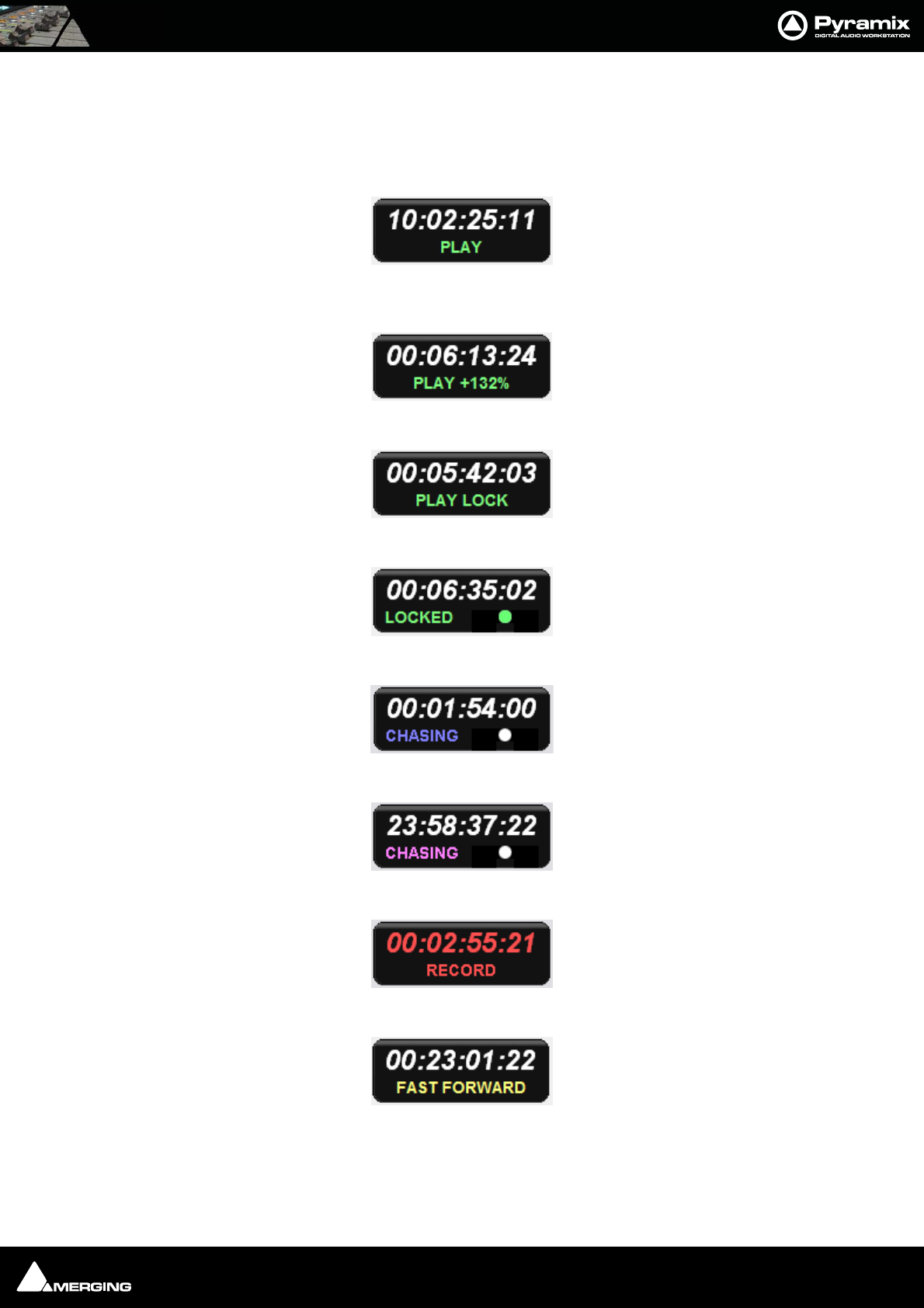
Machine Control : Transport Control Panel 21 - 378
Internal / External Machine panels - Features
Main Counter
In each machine panel the main counter shows the machine’s current position and status of Transport and Record.
The Master machine shows Play in green when running at sync speed:
The Master machine in jog or shuttle shows Play and the + or - percentage off sync speed or Play Still when sta-
tionary. If the speed exceeds 200% then Rewind or Fast Forward is shown in yellow :
An External Machine shows Play Lock in green when it is master and at sync speed:
An External Machine shows Locked in green when it is locked at sync speed:
A machine chasing shows Chase in blue:
If an offset is applied the status display and TimeCode registers are purple:
A machine in record shows Record in red and the main counter also turns red:
A machine in Fast Forward or Rewind shows this in yellow:
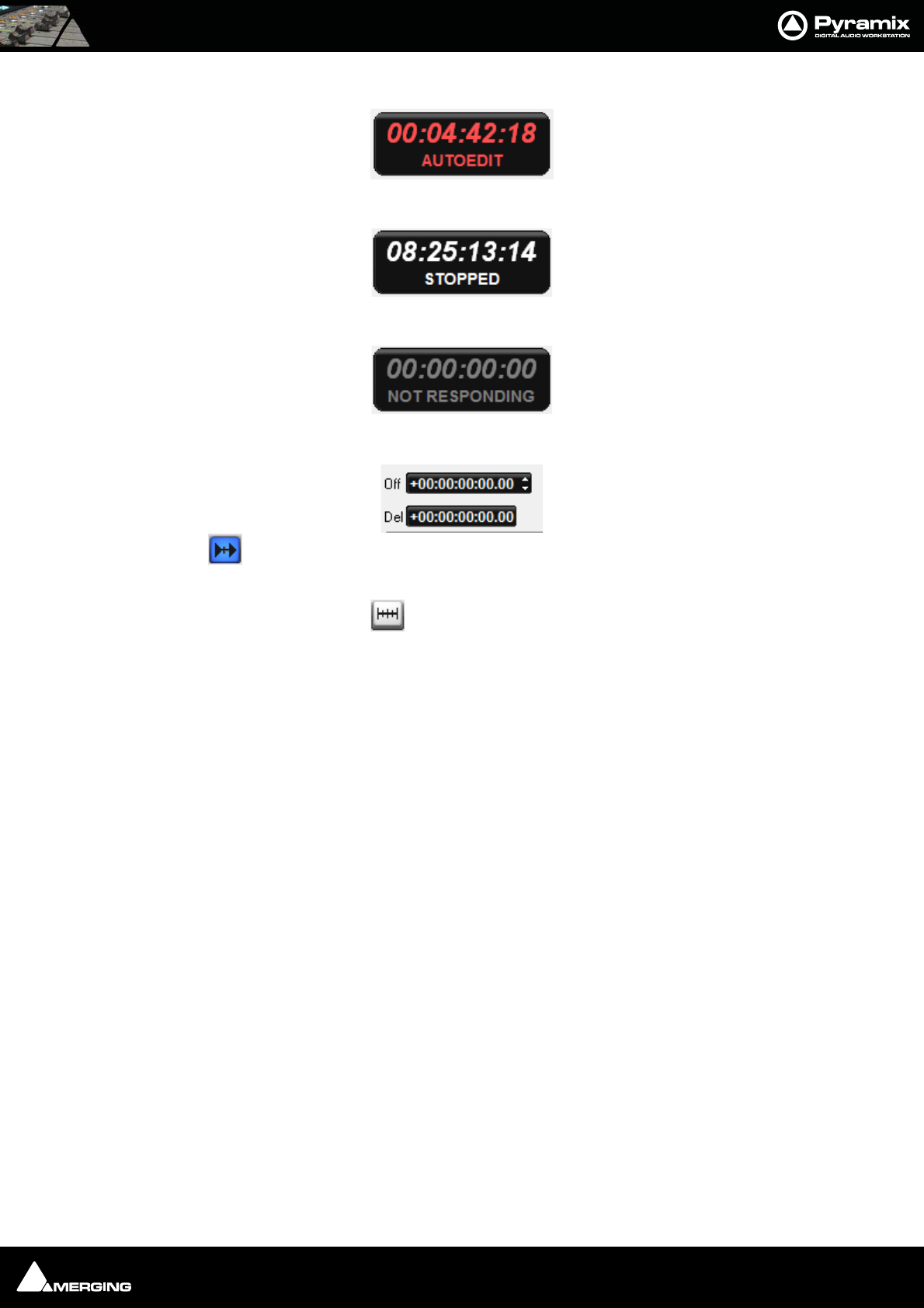
Machine Control : Transport Control Panel 21 - 379
A machine carrying out an Auto-Edit shows this in red:
A Stopped machine shows this in white:
If a machine is disconnected or there is a problem this is shown in gray:
Chase, Offset register, Capture Offset and Delta
When the button is lit the machine is in Chase Mode (see below)
The Offset Register shows the current Offset value.
An Offset can be captured with the Offset Capture button. The button lights when an Offset is set.
Offset values can also be typed directly into the register and trimmed with the increment/decrement buttons.
Note: A positive Offset Value makes the machine with the Offset later and a negative
Offset value makes it earlier. E.g. If you are sourcing picture from an external VCR and the
picture is arriving 3 seconds before the sound, enter a 3 second positive offset in the
video machine’s External Transport control panel.
Delta shows the current difference (error) value between where the machine should be and where it actually is.
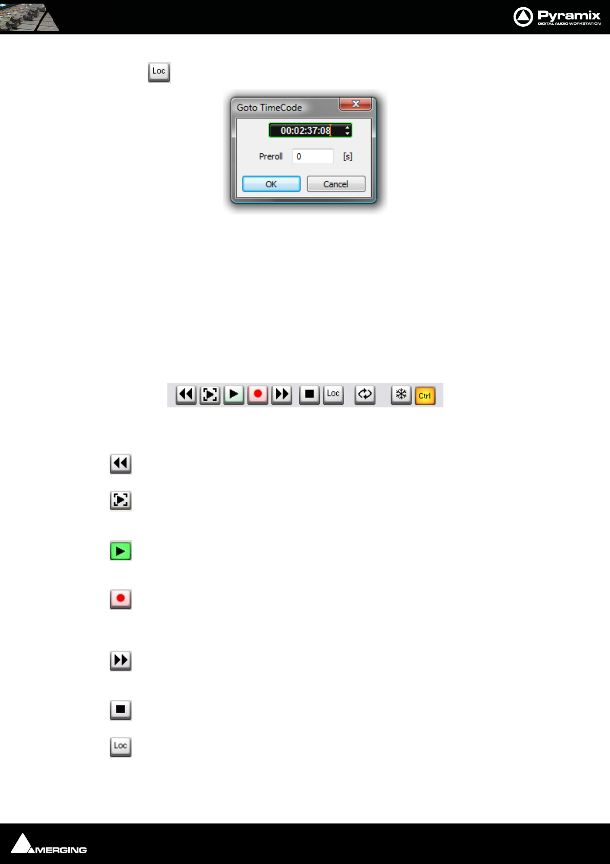
Machine Control : Transport Control Panel 21 - 380
Locate
Pressing the Locate button pops up the Goto Timecode dialog:
The register shows the machine’s current TimeCode position value and is highlighted, ready for typed input. The
value can also be adjusted with the increment/decrement buttons. Clicking the OK button sends the machine to
the TimeCode value in the register and closes the dialog.
A Preroll value can also be set. This value is retained and will be present when the dialog is next opened from any
Machine control panel.
Note: Goto TimeCode has no effect if it is invoked from a machine in Chase Mode.
Internal Machine panel - Features
Transport Controls
The Internal Machine panel has the same transport controls as the Transport Control Bar with some extras:
The Rewind button moves the Play Head at an accelerated speed backward through the
Composition. A second press doubles the speed.
The Play Selection button plays the current highlighted selection area.
The Play button plays the Composition at normal speed forward from the current position of
the Play Head. A subsequent press Pauses playback and another Restarts.
The Record button puts Pyramix into Record mode, and creates a new recording to the disk
on the Tracks previously armed for recording. The Play Head moves forward at normal Play
speed during the recording.
The Fast Forward button moves the Play Head at an accelerated speed forward through the
Composition while it is being pressed. A second press doubles the speed.
The Stop button stops playback.
Pops up the Goto Timecode dialog. See above in Internal / External Machine panels -
Common Features
Goto TimeCode dialog
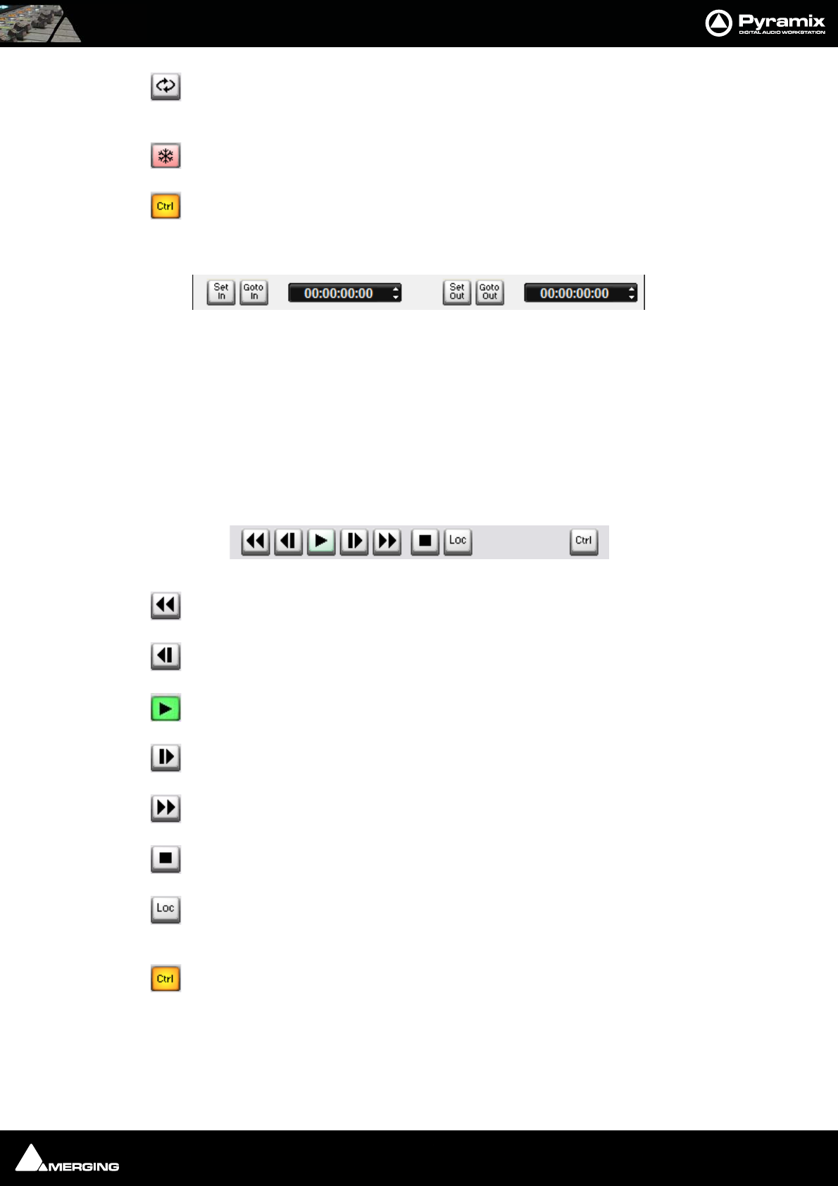
Machine Control : Transport Control Panel 21 - 381
The Loop Play toggle button puts Pyramix into a loop play mode, which continuously plays
through from beginning to end of the current selection.
The Freeze button stops all External Machines where they are. See Freeze Mode below.
Sets the Internal Machine (Pyramix) as the Active Machine. See Active Machine below.
Edit/Record In/Out
Set In and Set Out enter the current machine position in the adjacent registers.
TimeCode values can also be typed directly or adjusted using the increment/decrement buttons in the Panel Reg-
isters.
GoTo in and GoTo out locate the machine to the In and Out points respectively.
The In and Out points set for the Internal Machine are the main, red In and green Out, marker positions in the
Pyramix TimeLine.
External Machine panel - Features
Transport Controls
The Rewind button moves the External Machine at an accelerated speed backwards.
The - 1 Frame button nudges the External Machine backwards one frame per press.
The Play button starts the External Machine in Play mode.
The
+ 1 Frame button nudges the External Machine forwards one frame per press.
The Fast Forward button moves the External Machine at an accelerated speed forwards.
The Stop button sends a Stop command to the External Machine.
Pops up the Goto Timecode dialog. See above in Internal / External Machine panels -
Common Features
Sets the External Machine as the Active Machine. See Active Machine below.
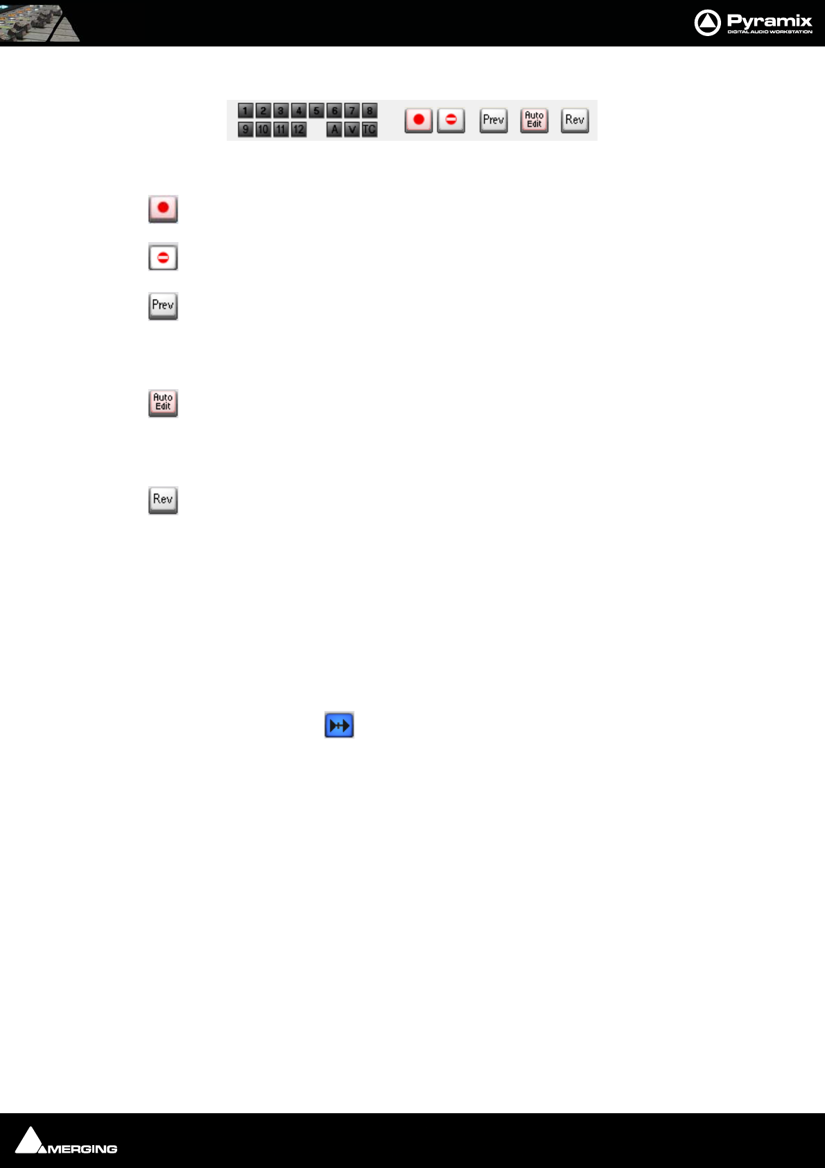
Machine Control : Transport Control Panel 21 - 382
Record and Edit controls
The first fifteen small buttons are arm audio tracks 1-12 and arm for Video and TimeCode. The A is Assemble mode
for machines that support it.
The Record button initiates and indicates recording on the External Machine
Inhibits recording on the External Machine
Preview Edit Initiates a preview of an edit. The External Machine (and any chasing
machines) go into play from the In point minus preroll and the output on all tracks armed for
record switches from replay to direct at the In point and back to replay at the Out point. The
machine Stops at the Out point plus post roll.
Auto Edit Initiates an edit. The External Machine (and any chasing machines) go into play
from the In point plus preroll and all tracks armed for record are punched into record at the In
point and back to replay at the Out point with the machine monitor outputs following. The
machine Stops at the Out point plus post roll.
Review Edit Initiates a review of the Auto Edit just performed. The External Machine (and
any chasing machines) go into play from the In point minus preroll and plays to the Out point
plus post roll.
Note: Pre and Post roll for the machine in question are set up in the dialog. This can be
found in the Settings > All Settings > Remote Control > Machine page by selecting
the machine and clicking on Properties. Further settings are to be found in the Sony 9-
Pin Protocol Configuration (Machine) dialog, accessed by clicking on the Properties
button in the Machine properties dialog.
Please see also: Machine Properties on page 535
Chase Mode
Each Machine has a Chase button. The choice of Hard, Soft and Vari Chase is available in the Settings > All
Settings > Application > Jog/Chase page. When Chase Mode is engaged the Internal Machine can chase LTC,
VITC, the selected External Machine or Virtual Transport inputs selected in the Settings > All Settings > Hard-
ware > TimeCode page in the TimeCode Source and Ext. TC Source combo boxes.
Hard When Hard Chase is active, Pyramix will only playback when valid TimeCode is
detected on the chosen TimeCode input port. If there is a jump in the incoming
TimeCode, Pyramix will adjust to the new TimeCode, re-synchronize and begin
playback from the new TimeCode position. Pyramix will run on its own internal
TimeCode for up to 1 frame if there is a drop out in the time code. If no valid Time-
Code is detected after that time, playback will stop.
Soft When Soft Chase is active, Pyramix will only playback when valid TimeCode is
detected on the chosen TimeCode input port. If there is a jump in the incoming
TimeCode, Pyramix will not adjust to the new TimeCode, but will continue play-
back with an offset from the incoming TimeCode position. Pyramix will continue to
run on its own internal TimeCode for up to 1 frame if there is a drop out in the
TimeCode. If no valid TimeCode is detected after that time, playback will stop.
Vari When the Vari Chase is active, Pyramix will Varispeed, I.e. alter its sampling rate to
follow fluctuations in an external TimeCode. (going back and forth, slowing down,
accelerating, playing normally or backwards, up to 8x nominal speed) while in
playback (not in record)
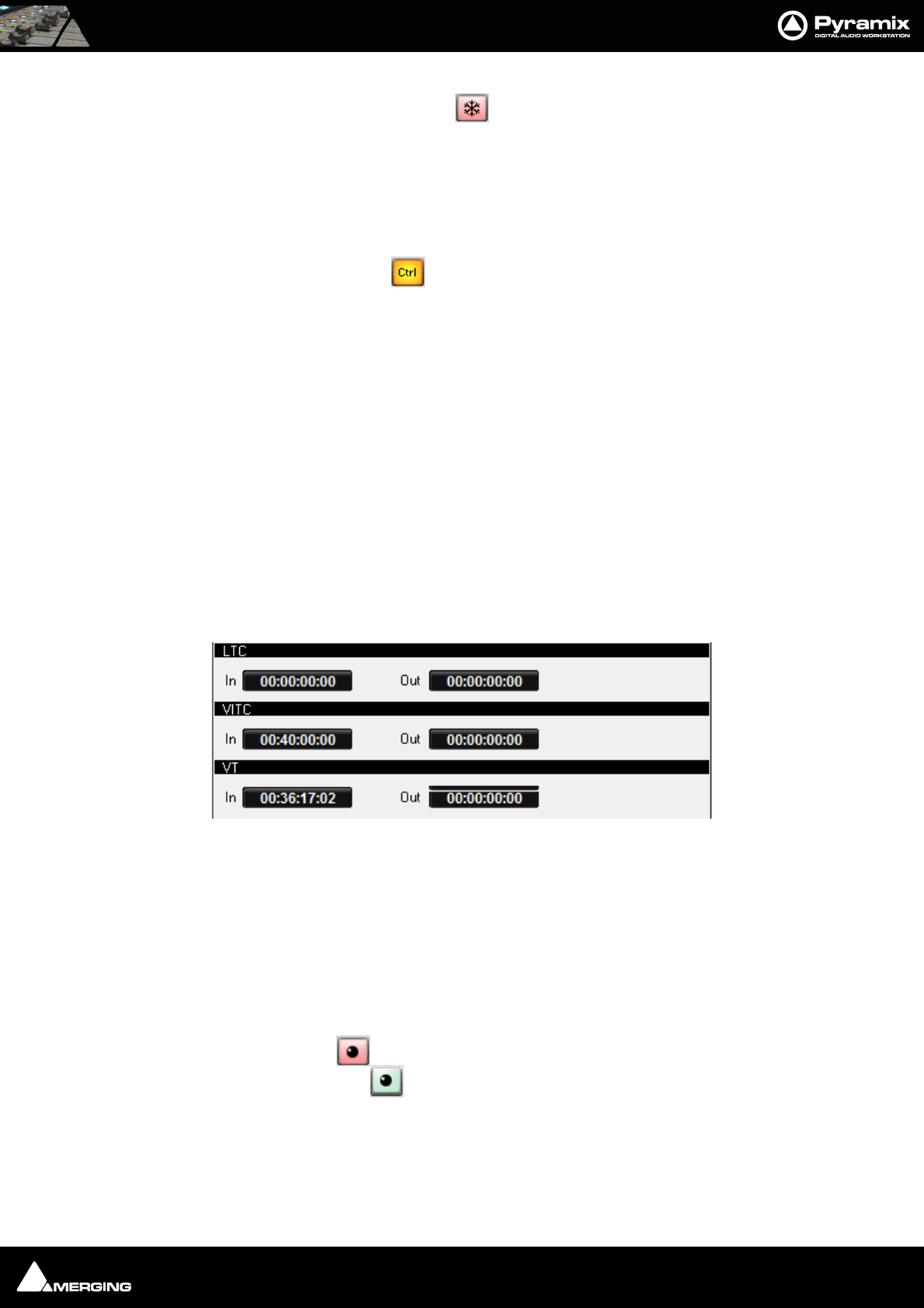
Machine Control : Transport Control Panel 21 - 383
Freeze Mode
The Internal Machine also has a Freeze button. When active, as shown here, all External Machines remain
where they are and the point in time at which Freeze was activated is kept in memory. Pyramix can be freely used
and moved while Freeze is active. When the Freeze button is cancelled, the Pyramix Playhead Cursor jumps to
the point where Freeze was activated and full control is restored.
This function has many uses. For example, it can be used to position an out of sync effect, say a car-door slam. For
detailed instructions please see: Using Freeze Mode on page 345
Active Machine
Each Machine’s Panel has a Ctrl button which sets it as the Active Machine. The Active Machine receives the
full input of the Active Machine mapped keyboard shortcuts, the Transport Control Bar and input from all avail-
able Remote Controllers.
The Machine combo-box in the Transport Control Bar shows the active machine and can be used to switch
between the installed and enabled machines. Alternatively you can toggle through the currently enabled
machines. Machines > Active Machine > Toggle machines
Auto-chase
If all enabled machines are set to Auto-Chase, when Ctrl is switched between machines the Active Machine is
automatically taken out of Chase mode and the previously Active Machine automatically enters Chase mode. To
activate Auto-Chase for all external machines, enable the menu setting:
Machines > External Machine > Auto-Chase
And, to activate Auto-Chase for the internal machine, enable the menu setting:
Machines > Internal machine > Auto-Chase
TimeCode Registers
Each TimeCode reference source has two registers:
In register shows show the current TimeCode incoming on the LTC, VITC physical inputs.
Out register shows the current TimeCode outgoing on the LTC or VITC physical outputs
In the case of VT, Virtual Transport, the Input Timecode is the VT TimeCode and the Output is the TimeCode
reported by Pyramix on the corresponding Pyramix VT client.
Controllers Section
Controllers Online/Offline
When the Controllers button is lit red all connected Controllers are set Offline
Press the button again to toggle to Online.
Offline ensures no External Commands can be sent to Pyramix while a maintenance or housekeeping operation
is in progress.
When performing a Mix-down, Generating a CD image, or during any Surround encoding operation, Pyramix
automatically sets all controllers offline to ensure the operation is not inadvertently interrupted and to prevent
exaggerated motor fader movements during non real-time processes.
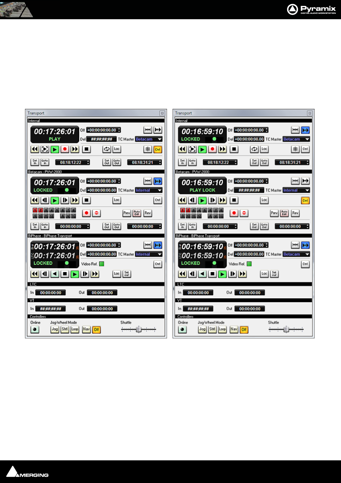
Machine Control : Transport Control Panel 21 - 384
Jog Wheel Mode
The buttons select the hardware Jog Wheel Mode from a choice of Jog, Shtl, Loop, Nav or Off. Many controllers
will have buttons either corresponding to these functions or mappable to them.
The Shuttle slider is provided for convenience when using the Transport Control Panel.
Examples:
In the following examples there are three machines. At the top of each window is the host Pyramix Internal
Machine. Below this is a BETACAM - PVW-2800 and the third machine is a BiPhase transport or transports. (Via the
MTUsbSync Board) Both External Machines are controlled via the Sony 9-pin P2 protocol.
In the left-hand example the Host Pyramix is Master and both External Machines are in Chase and Locked.
In the right-hand example the Betacam is now the Master and both the Internal Pyramix and External BiPhase
Machines are in Chase and Locked.
Note: Machines NOT in chase can be used independently of the Master while the Mas-
ter is in use by using their individual controls. So you can locate on a machine whilst con-
tinuing to mix using the Master and slaves.
Transport Control Examples

USER MANUAL
www.merging.com/Pyramix
Remote Control

Remote Control : Scope 22 - 386
Scope
Pyramix can control and be controlled by a wide variety of external hardware. This chapter, Remote Control deals
with situations where Pyramix is controlled by an external device such as a control surface or machine controller.
Ramses MSC
Ramses MSC with Pyramix is a great deal more than a simple control surface and workstation. Together they form
a synergistic new product that can be many things, a powerful digital mixing console with the latencies for live
use, a huge multitrack recorder and much, much more. For full details please contact your Merging Technologies
Sales Partner.
Hardware Control Surfaces
Hardware remote control is accomplished via the Merging Technologies Oasis protocol, Proprietary protocols,
Merging Technologies EMC (Enhanced MIDI Control) MIDI or the 9-pin (Sony P2 protocol). Templates are supplied
for some popular controllers or you can map your own MIDI control surface to Pyramix.
ISIS
The Merging Technologies ISIS and ISIS Expander are purpose designed for Pyramix and offer comprehensive
control for many applications. Notably, in conjunction with the Pyramix Fade Editor, editing is extremely quick.
For full details please contact your Merging Technologies Sales Partner.
Supported Controllers Table
Pyramix Virtual Studio supports controllers from many different manufacturers, as seen in the table below, in sev-
eral control modes. While JL Cooper products work with a proprietary protocol, Yamaha, Radikal Technologies,
and Mackie units need to be set to HUI mode to communicate with Pyramix. Finally the Sony DMX-R100 com-
municates via standard MIDI control and Sony 9-pin P-2 protocol commands.
Auto-mapping
Wherever auto-mapping is supported, our controller driver will automatically link active Pyramix parameters to all
available control surface items. With manual mapping, a drag & drop or menu dialog, depending on the driver, will
allow for any specific Pyramix parameter to be linked to any available control surface item.
Strip Cloning
Strip cloning will duplicate all parameter assignment for a dedicated strip to adjacent channel(s). Finally, MIDI
mapping will create links between Pyramix parameters and control surface items with a select and learn method.
Remote Control : Supported Controllers Table 22 - 387
Controllers Table
The following controllers and digital mixers are (or will be) supported (if the appropriate Pyramix option Keys are
present):
For the latest version of this table, the EMC User Guide and other downloadable User Guide documents about
supported controllers/consoles please go to:
www.merging.com
Manufac
turer
Supported
Protocol Key 1* Key 2 Supported
Model
Controlled
Items in
Pyramix
Mapping Supported
Since
Yamaha EMC (Enhanced
Midi Control)
PSO-RCTR PSO-RCT-EMC DM2000 Mixer + Transport +
Editor
Auto + XML 5.0 SP2
Yamaha EMC (Enhanced
Midi Control)
PSO-RCTR PSO-RCT-EMC DM1000 Mixer + Transport +
Editor
Auto + XML 5.0 SP2
Yamaha EMC (Enhanced
Midi Control)
PSO-RCTR PSO-RCT-EMC 02R96 Mixer + Transport +
Editor
Auto + XML 5.0 SP2
Yamaha EMC (Enhanced
Midi Control)
PSO-RCTR PSO-RCT-EMC 01V Mixer + Transport +
Editor
Auto + XML 6.0
Tascam EMC (Enhanced
Midi Control)
PSO-RCTR PSO-RCT-EMC US-2400 Mixer + Transport +
Editor
Auto + XML 5.0 SP2
Tascam EMC (Enhanced
Midi Control)
PSO-RCTR PSO-RCT-EMC FW-1884 Mixer + Transport +
Editor
Auto + XML 5.1
Tascam EMC (Enhanced
Midi Control)
PSO-RCTR PSO-RCT-EMC DM-3200 Mixer + Transport +
Editor
Auto + XML 6.0 SP1
Mackie EMC (Enhanced
Midi Control)
PSO-RCTR PSO-RCT-EMC Mackie Control / HUI
compatible models
Mixer + Transport +
Editor
Auto + XML 5.0 SP2
SSL EMC (Enhanced
Midi Control)
PSO-RCTR PSO-RCT-EMC AWS-900+ Mixer + Transport +
Editor
Auto + XML 5.1
Radikal Tech-
nologies
EMC (Enhanced
Midi Control)
PSO-RCTR PSO-RCT-EMC SAC2.2 / SAC2k Mixer + Transport +
Editor
Auto + XML 5.0 SP2
JL Cooper Proprietary / Midi PSO-RCTR MCS-3800 / 3000 /
3000x / Bridge
Mixer + Transport +
Editor
Graphical +
Cloning
< 5.0
Sea Level Proprietary Sea-
Level
PSO-RCTR PSO-GPIO SeaI/O 4xxU series GPI / GPO Events Manual 5.1
Sea Level Proprietary
SeaMax
PSO-RCTR PSO-GPIO SeaPort PLC16 GPI / GPO Events Manual 5.0
Sony Generic Midi
Control
PSO-RCTR DMX-R100 Mixer Manual Learn < 5.0
Any Generic Midi
control
PSO-RCTR Midi Controller Mixer Manual Learn < 5.0
Any Sony P2 PSO-RCTR Sony 9pin / P2 Con-
trollers
Transport Fixed < 5.0
Any Midi Machine
Control
PSO-RCTR MMC Compatible
devices
Transport Fixed < 5.0
Merging Tech-
nologies
OASIS ISIS PSO-RCTR ISIS-RC Mixer + Transport +
Editor
Auto + Manual 5.0
Merging Tech-
nologies
OASIS ISIS PSO-RCTR ISIS-FE Mixer Auto + Manual 5.0
Merging Tech-
nologies
OASIS PSO-RCTR PSO-OAS-FIR Ramses Mixer + Transport +
Advanced Editor
Full Auto 6.0
Euphonix OASIS PSO-RCTR PSO-OAS-FIR System 5 / MC Mixer + Transport +
Advanced Editor
Full Auto 5.0
Euphonix OASIS PSO-RCTR PSO-OAS-FIR S5 Fusion Mixer + Transport +
Advanced Editor
Full Auto 6.0
Euphonix OASIS PSO-RCTR PSO-OAS-ECO Artist Series Mixer + Transport +
Advanced Editor
Full Auto 6.1
Smart AV OASIS PSO-RCTR PSO-OAS-FIR Smart Consoles Elite
Series
Mixer + Transport +
Advanced Editor
Full Auto 5.0
Smart AV OASIS PSO-RCTR PSO-OAS-BUS Tango Mixer + Transport +
Advanced Editor
Full Auto 6.1
Harrison-GLW OASIS PSO-RCTR PSO-OAS-FIR “IKIS Direct” com-
patible consoles
Mixer + Transport +
Advanced Editor
Full Auto 5.0
AMS-Neve OASIS PSO-RCTR PSO-OAS-FIR “Encore Plus” com-
patible consoles
Mixer + Transport +
Advanced Editor
Full Auto 5.0

Remote Control : Control by External Device 22 - 388
Then select: Pyramix : Download : Documentation : Controllers, and choose the required document for down-
load.
For links to Controller and Console manufacturers go to:
www.merging.com
Then select: Pyramix : Controllers and choose the relevant manufacturers link.
Control by External Device
If Pyramix is to be controlled by another device or devices, these are installed via Settings > All Settings Remote
Control > Controller (See: Controller on page 539 ) and, where applicable, Pyramix functions are mapped to the
controller via the Settings > All Settings > Project > Controller Mapping page. (See: Controller Mapping on
page 508)
9-pin Configuration (Pyramix controlled by external device)
Please see: Sony 9 - Pin Protocol Configuration (Pyramix controlled by external device) on page 541
EMC
Scope
EMC includes HUI and Mackie Control Support.
The following controllers are supported and validated:
• Mackie MCU in HUI and MackieControl modes
• Yamaha DM1000 in HUI mode
• Yamaha DM2000 in HUI mode
• Raditec SAC2-k in HUI mode (MackieControl is not working properly)
• Tascam US-2400 in HUI mode (US-2400 MackieControl mode is specifically configured for other DAWs
than Pyramix)
Key
Valid Remote Control Support and Remote Control – Midi Enhanced Midi protocol keys are required to use EMC.
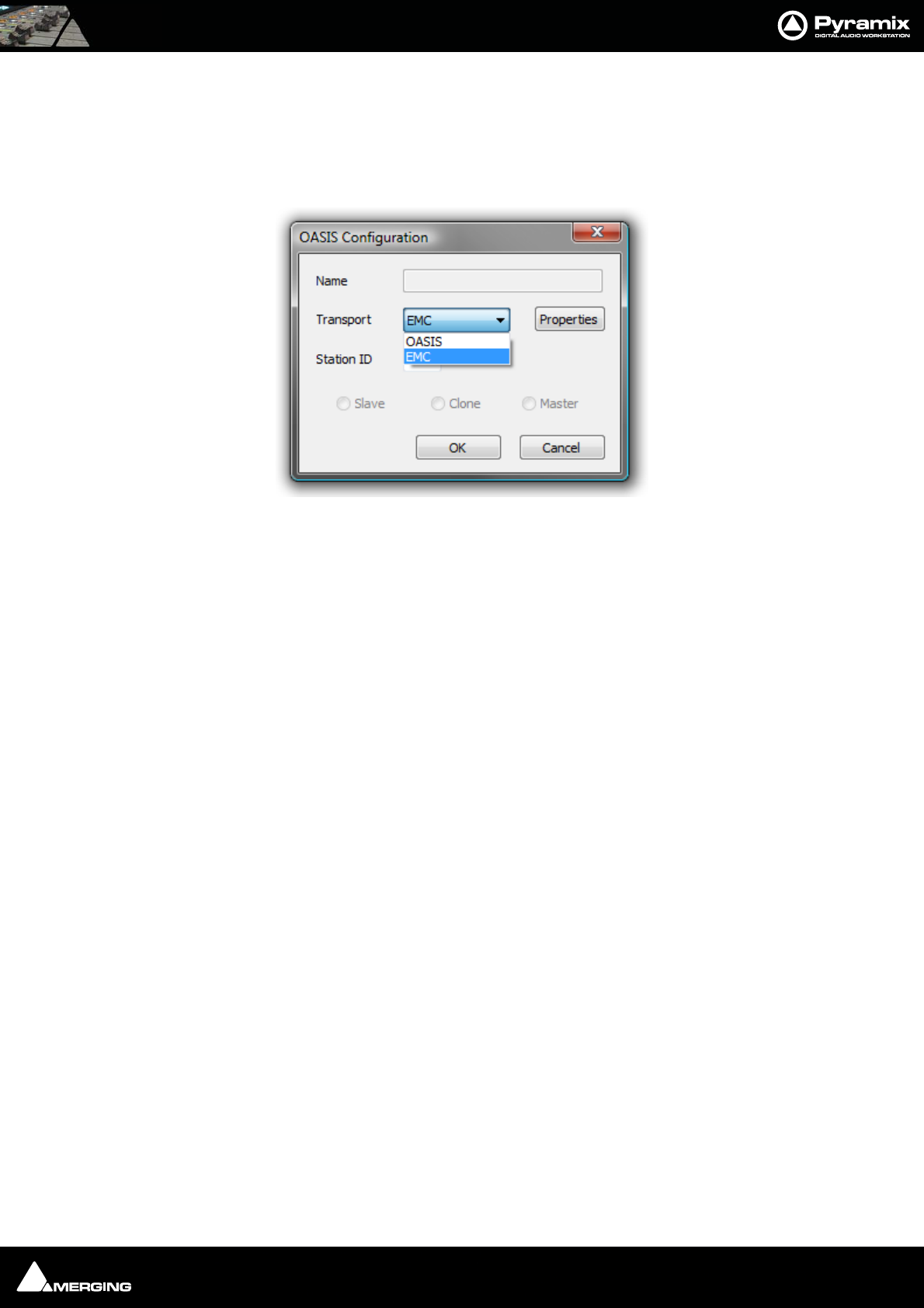
Remote Control : EMC 22 - 389
Configuration
Configuring a Remote EMC Connection
Since EMC is implemented as a subset of OASIS, to configure a remote connection, an OASIS controller must be
added in Settings > All Settings > Remote Control and then EMC must be chosen by clicking the Properties
button which opens the OASIS Configuration dialog:
Faders, Solo, Mute, Pan, Surround Panning, Auxes, Vu-Meter, Advance channel display, Strip tools,
transport (Internal and Externals machines), Bank switching and Jog are all fully supported. Please see the EMC
User Guide for full configuration details.
OASIS Configuration Dialog

Remote Control : OASIS Protocol 22 - 390
OASIS Protocol
OASIS is a generic TCP/IP based protocol for integrating disparate digital audio consoles and controllers with
Merging’s Pyramix digital audio workstation. Although Pyramix supports several other protocols OASIS is in a dif-
ferent league.
The Oasis Advantage
• Allows control surface mapping to faders, rotary encoders, keys, machine control functions etc.
•TCP/IP Network based
•High bandwidth
• Flexible connectivity from any unit to any other unit on a LAN/WAN
• Low delay transmission performance (provided there is adequate Network topology.)
• No additional hardware needed for a console/controller that has an Ethernet (IEEE 802.3) connection.
• Low cost and upgradeability of the Ethernet technologies
Overview of Pyramix Controls
Mixing:
The virtual Pyramix mixing console is fully exported over OASIS with a high degree of control precision.
Editing:
Everything that is available in the Pyramix menu is remote controllable
Machine Transport Control:
Internal Pyramix machine control and all connected machines (Sony P2, MMC) can be remote controlled over
OASIS in a unified protocol.
Multiple DAW Control:
• The virtual mixer power can be distributed on multiple mix engines
• The number of available Play/Record tracks may be expanded seamlessly without limits over any number
of Pyramix engines
Export of useful information to the console:
• “Units of” parameters (%, dB, ms...)
• The range of each specific control
• The default value of controls
• Mixer strips/bus names
• Floating point number based (32 bits)
• Possibility of choosing between the DAW and/or the Console Automation engine
OASIS In Practice
OASIS allows:
• 384 channel I/O multi-track player/recorder and dubber (Pyramix V6.1)
• Access to all the editing and processing functionality of Pyramix

Remote Control : OASIS Protocol 22 - 391
• The internal mixer can be configured as a 384 input into several buses types.
• Up to 16 surround simultaneous stems can be sent to the console as part of the main mix.
• Multi-layer mixing - switch between the DAW mixing layer and the main mix on the console retaining dis-
crete control over pre-mixed channels.
• With two or three Pyramix systems connected, as in a film dubbing environment, this allows for virtual,
non-destructive, pre-mixes and any changes to the pre-mix can be made instantly by simply switching to
the relevant layer.
Comparison with MIDI based Solutions
• MIDI vs. Ethernet… No comment!
• Peak-meter refresh rates of 25-30 times per seconds
• Pyramix evolution will enable the protocol to develop still further.
• All third party (VST, DirectX) plug-ins can be fully described and parameters can be exported over OASIS.

USER MANUAL
www.merging.com/Pyramix
GPI / GPO Control
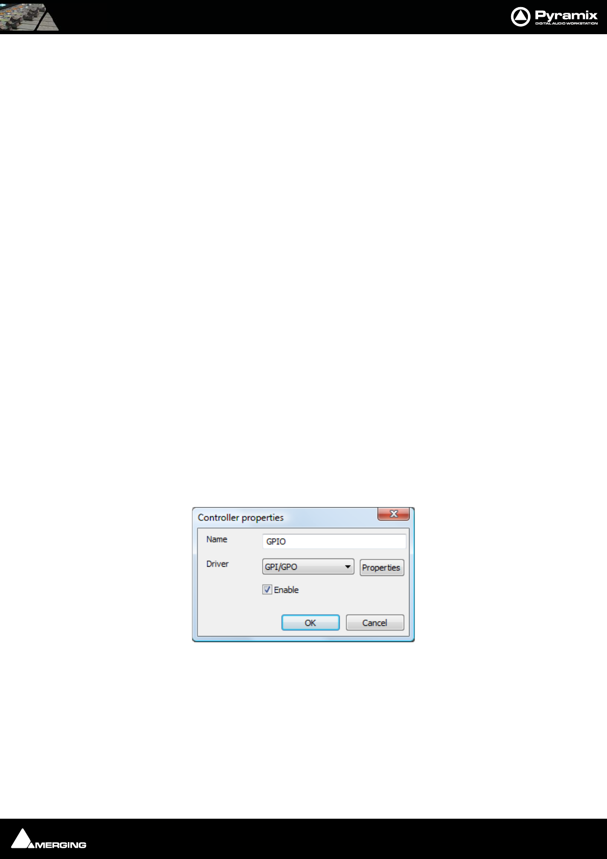
GPI / GPO Control : GPI / GPO Support 23 - 393
GPI / GPO Support
GPI/O support is available as a Remote Controller module.
Note: For the present the only supported GPI/O interfaces are the following models
manufactured by Sealevel:
• SeaPORT PLC-16 8 in 8 out
• SeaI/O-410U 16 in 16 out
• SeaI/O-420U* 16 in 8 out
• SeaI/O-430U* 32 in 0 out
• SeaI/O-440U* 0 in 32 out
• SeaI/O-450U* 0 in 16 out
* Obtainable on special order
Note: Note: USB drivers are included in the Pyramix Installer, there are no need to down-
load the driver from the supplier website. For more information about the specification
of the GPIO hardware device please see:
http://www.sealevel.com
Using the GPI/O controller
Add a GPI/O Controller
Before Pyramix can use the adaptor, it must be set up.
Select the Settings > All Settings > Remote Control > Controller page
Click the Add button. The Controller Properties dialog opens. Type a name for the Controller and select GPI/GPO
from the Driver drop down list. Click OK to close the dialog and click OK to close the Pyramix Settings window.
Note: Do not do this more than once. Only one GPI/GPO controller is allowed. However
this can control more than one physical GPI/GPO USB Module
Enable/Disable
The GPI/GPO controller may be disabled by unchecking the Enable box in the Controller Properties Dialog.
Some GPI/GPO USB Modules can be individually enabled or disabled by clicking on the Properties button to the
right of the Driver combo box.
Configuring the GPI/O controller for a specific project
Open the Settings > All Settings > Project > Controller Mapping page.
Select your GPI/O controller and click Properties. The GPI/O Controller Configuration Window will appear; On the
left you can browse the Remotes list. Next to this is the GPI/O Controllers list. To map a Remote to a GPI/O Input or
GPIO Controller Properties dialog
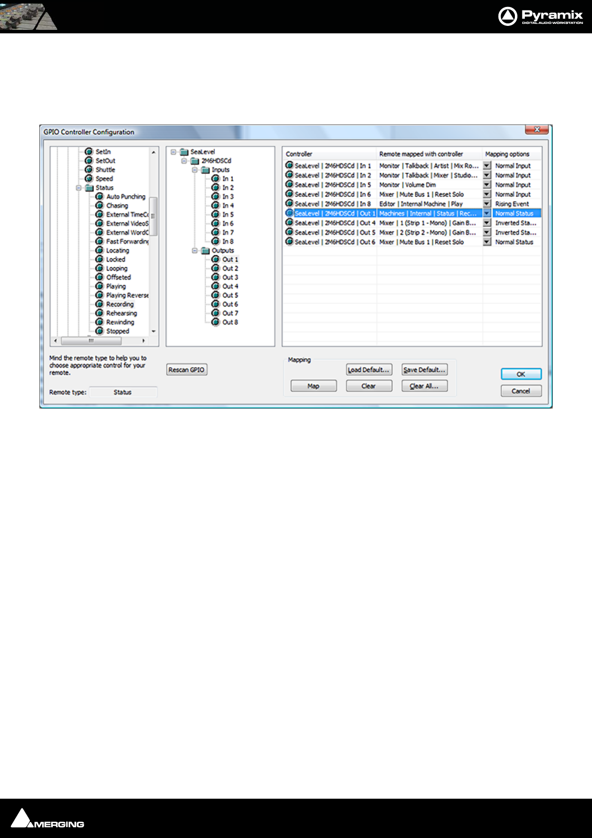
GPI / GPO Control : GPI / GPO Support 23 - 394
Output pin just drag the Remote onto the Controller pin; The right-hand pane is a list of all currently mapped Con-
troller pins. By clicking in the Mapping Options column you can configure how the pin works.
Click OK to accept the changes to the GPI/O configuration, or Cancel to abort.
Mapping Example
Mapping Description of Example Shown Above
Input triggering:
In 1 : Monitor | Talkback | Artist | Mix Room | On
The Artist opens the talkback circuit to the Mix Room
In 2 : Monitor | Talkback | Mixer | Studio | On
The Mixer (Engineer) opens the talkback circuit to the Studio
In 5 : Monitor | Volume Dim
Dim the Monitor output section
In 6 : Mixer | Mute Bus 1 | Reset Solo
Reset the solo in the Mixer
In 8 : Machines | Internal Machine | Play
Put Pyramix in playback. I.e when the Artist is ready.
Output are triggered by:
Out 1 : Machines | Internal | Status | Recording
Control of the Record Red light.
Out 4 : Mixer | 1 (Strip 1 - Mono) | Gain Bus 1 | Gain
Fader start of the first mixer fader. For dB value the threshold is -90 dB
Out 5 : Mixer | 2 (Strip 2 - Mono) | Gain Bus 1 | Gain
Fader start of the second mixer fader. For dB value the threshold is -90 dB
Out 6 : Mixer | Mute Bus 1 | Reset Solo
Control of an additional indicator in the mixer room when a mixer strip is soloed.
GPIO Controller Configuration dialog

GPI / GPO Control : GPI / GPO Support 23 - 395
GPI/O Remote types
There are 5 different types of Remote that can be used with GPI/O Input and/or Output pin:
•Toggle can be associated with both input and output pins.
•Range can be associated with both input and output pins and acts like a toggle 0 =off, other = on
•Event can only be associated with input pins.
•Event-Status can be associated with input and/or output pins;
•Status can be only associated with output pins.
The other Remotes cannot be mapped to GPI/O pins.
GPI/O Input and Output Pin Configuration
• Input pins mapped to Toggle or Range remotes can be configured as:
• Normal Input
•Inverted Input
• Rising Event
• Falling Event
Input pins mapped to Event or Event-Status remotes can be configured as:
• Rising Event
• Falling Event
Output pins mapped to Toggle or Range remotes can be configured as:
• Normal Status
• Inverted Status
Output pins mapped to Status or Event-Status remotes can be configured as:
• Normal Status
• Inverted Status

USER MANUAL
www.merging.com/Pyramix
CD/SACD Mastering
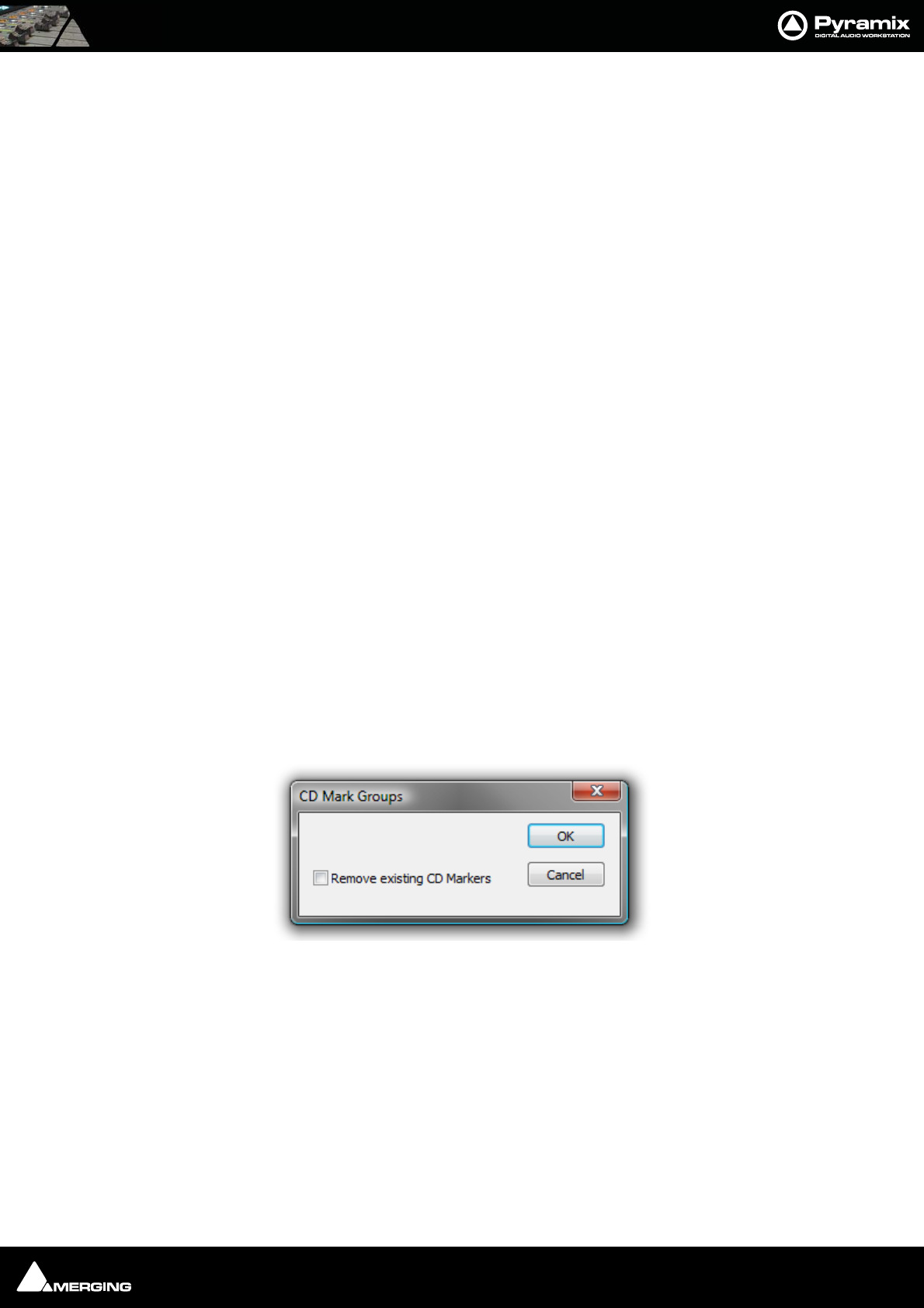
CD/SACD Mastering : Mastering a Composition to CD-R 24 - 397
Mastering a Composition to CD-R
Pyramix is used to set CD Track Start, Stop, and Index Markers for CD-R Mastering, and a separate application
called DiscWrite is provided to actually burn a CD-R or make a DDP.
One of the advantages to this way of working is that multiple ‘virtual discs’ can exist. This makes it simple to pro-
duce several different versions using the same material.
Note: For a step-by-step guide to producing a simple CD please see the Pyramix Quick
Start Guide, Page 70 Quick CD
IMPORTANT! - First Steps
Open the CD/SACD Tab Window and Double-click <New Disc> in the Album tab. Type a name for the CD then
proceed to add CD Markers
CD Markers
CD Markers are much like other User Flags or Markers.
To set a CD Start Marker (which indicates the beginning of a CD track), place the Play Head at an appropriate CD
track Start location and choose Cursors & Marks > Add CD Start Marker to Cursor; similarly, to set the CD Stop
Marker (which indicates the ending of a CD track), place the Play Head at the appropriate CD track End location
and choose Cursors & Marks > Add CD Stop Marker to Cursor. A named CD Index Marker can also be added
using Cursors & Marks > Add CD Index Marker to Cursor. These CD Markers can be examined, named and
changed in the CD/SACD Tab window.
Add CD Markers Automatically
CD track Start Markers and Stop Markers can be added automatically to Grouped Clips in a Composition. To
accomplish this, first create a CD in the CD/SACD Tab window and select it. Make an appropriate Group of Clips
which correspond to CD tracks. Then choose Cursors & Marks > CD Mark Groups from the CD/SACD Tab window
Markers menu or from the main Cursor and Marks menu to open the CD Mark Groups dialog:
The only option is a check box to Remove existing CD Markers. Click on OK to automatically create CD markers
for all grouped clips.
Note: If the gap between clips in the Pyramix TimeLine is less than one second only
Start Markers are placed or required. (There will always be a Stop Marker after the last
clip). Stop Markers can be useful where there is applause after a piece which may not be
wanted when broadcasting from a CD. Suitably equipped CD Players can be set to stop
when they find a Stop Marker.
CD Mark Groups dialog
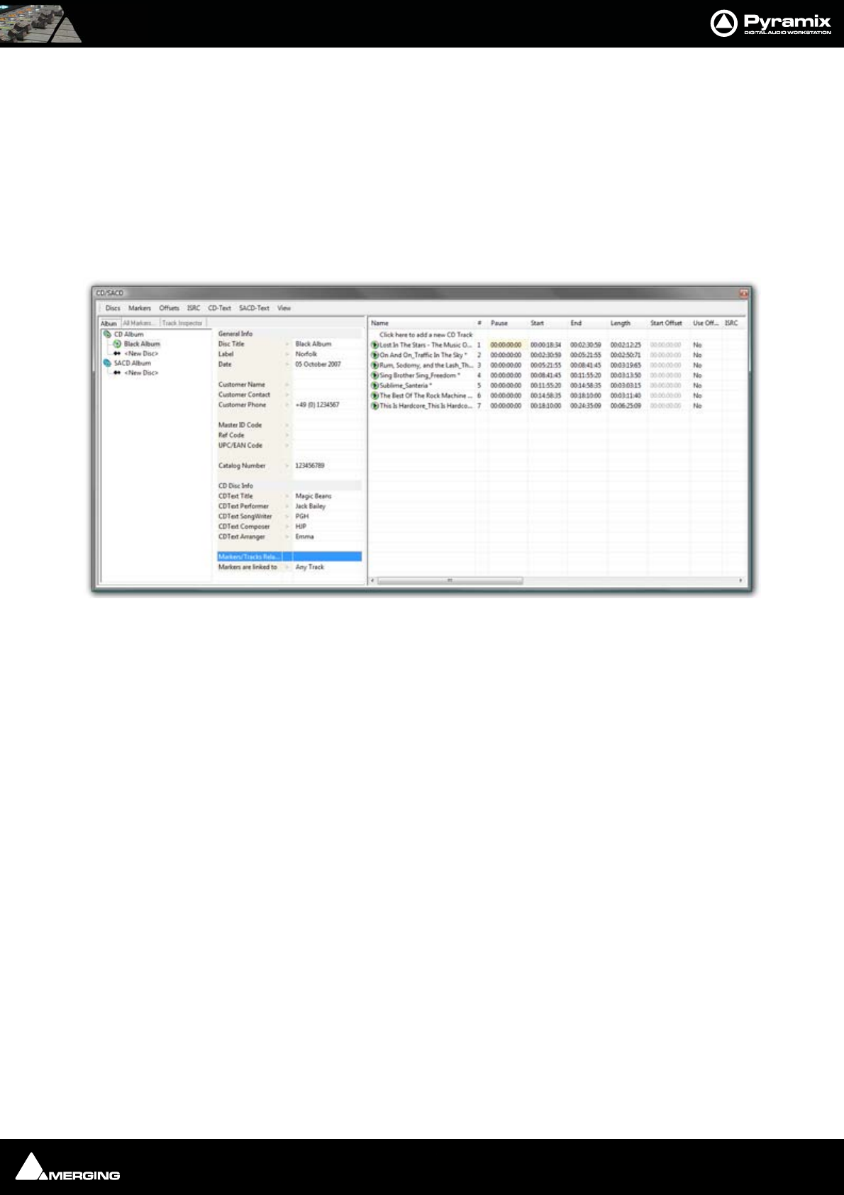
CD/SACD Mastering : CD/SACD Tab Window 24 - 398
Convert Text Markers to CD
Text Markers can be converted into a CD.
Simply right-click on a selection of Text Markers in the Markers Tab pane and choose Create CD Disc.
This will create a new CD disc and select it. A final Stop marker will be added at the end of the next Clip found (if
any) after the TimeCode of the last Start marker. (So it only creates CD Start Markers on the first and intermediate
Cues, but also creates a Stop Marker after the Cue that has the last Start Marker, in order for the CD to be valid).
CD/SACD Tab Window
All the mastering features are grouped in the CD View; in two sections.
In the Left Pane there are three window Tabs:
Album, All Markers and Track Inspector
The Right pane shows the track list fields. (see below)
Album:
The left-hand pane shows a tree view of CD and SACD Albums and Discs with <New Disc> entries to create new
discs. The right-hand pane allows CD properties and default parameters to be set for the selected disc.
General Info
•Disc Title CD Title
•Label CD Production Label
•Date CD Date
• Customer Name
•Customer Contact Customer Contact (name)
•Customer Phone Customer contact phone number
•Master ID Code CD Identifying code (if one is required)
•Ref Code CD Reference Code (if one is required)
CD/SACD Tab window
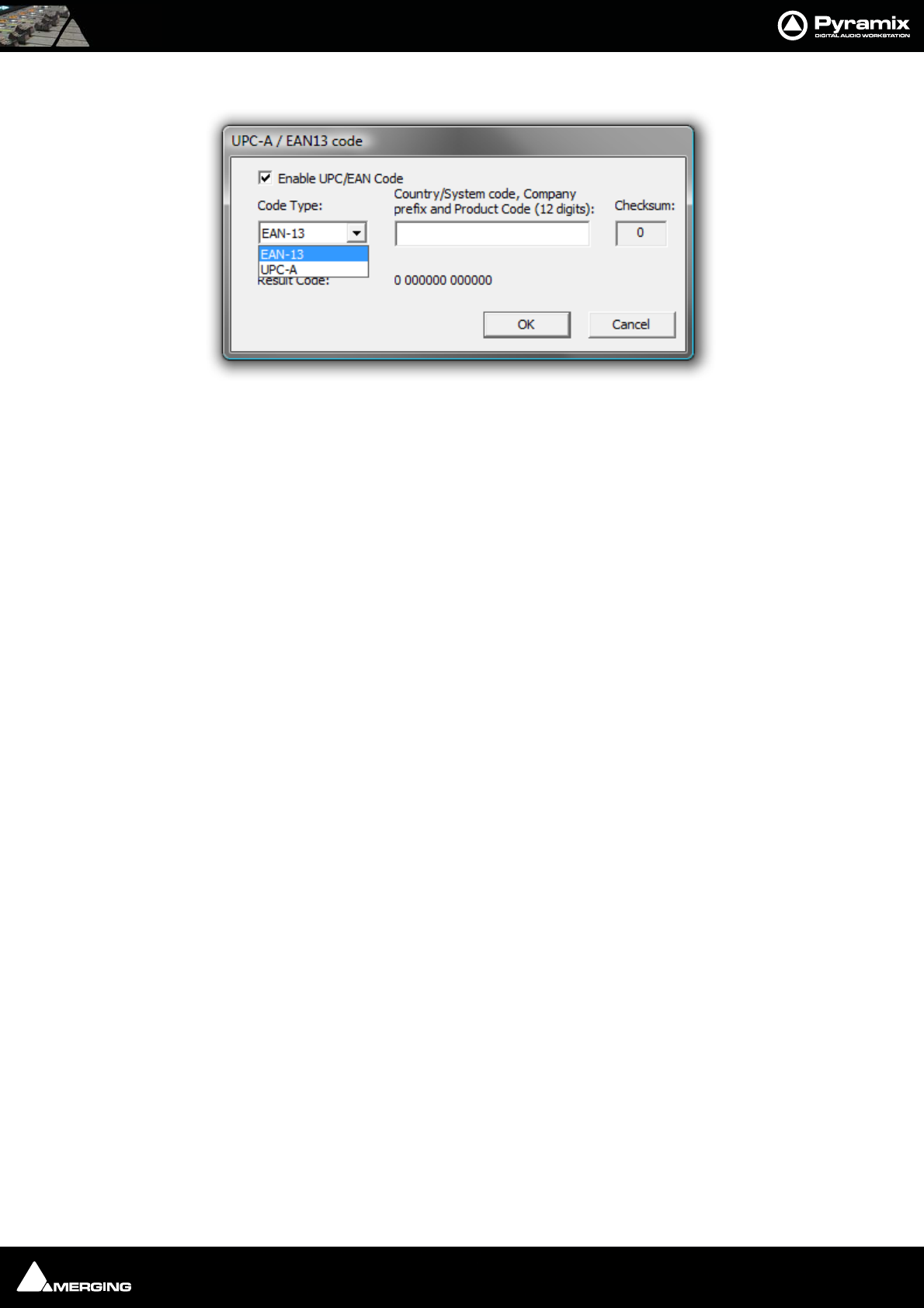
CD/SACD Mastering : CD/SACD Tab Window 24 - 399
•UPCEAN Code Clicking in this field opens the UPC-A / EAN13 code dialog box.
UPC/EAN capture for CD/SACD Albums, Discs and Areas is handled via this dialog box.
Enable UPC/EAN Code: When ticked UPC/EAN Code is enabled.
Code Type: offers a choice of UPC-A or EAN-13 barcode formats. Enter the 11 or 12 digit Company
prefix and Product Code. The Checksum is calculated automatically and the resulting code dis-
played. Click OK to enter the result in the field.
The number of digits is checked according the type of code and the CheckSum: digit (the last one) is
automatically calculated (to ensure its validity).
Moreover, the TOC information part of a Pyramix generated CDImage file (PMI) will always contain a
13 digits UPCEAN code (left 0-padded if UPC-A type code) or no UPCEAN code at all if the field is left
blank.
• Catalog Number
CD Disc Info
(Global – CD Header). In addition, there are similar fields for each track in the CD Track grid.
•Title CD Title
•Performer CD General Performer
•SongWriter CD General Song Writer
•Composer CD General Composer
•Arranger CD General Arranger
Markers/Tracks Relation
• Markers are linked to Clicking in the field shows a list of choices. These are the same as the Mark-
ers Tab window choices: <Independent>, Any Track or any Track without Group
All Markers...
Shows and allows editing of all the PQ markers. Here only the PQ is modified, not the audio edit. CD Markers can
be Cut / Copied / Pasted like standard Markers by right clicking an entry.
The CD Marker List is linked to the Disc (in the case of CD) and Area (in the case of SACD). There is no longer a CD
Marker List in the Track Group tab window or a Global CD Marker List. If necessary the CD Marker List in Disc/Area
can be linked to a Track Group to associate Audio content to a CD Marker List.
Name
Name of the PQ Marker. When the markers are automatically created with the function “CD Mark Group”, the stop
marker gets the same name as the start marker + a Stop suffix at the end. The “*” tells you that this marker was
auto generated.
# (Number)
(Read only) Number of the PQ Marker. The stop marker has the same number as the start. The index markers begin
at 2 then Inc… This is a Read only property; it depends on the position of the marker in relation to the others.
UPC-A / EAN-13 code dialog

CD/SACD Mastering : CD/SACD Tab Window 24 - 400
Type
Type of the Marker.
TimeCode
TimeCode position of the Marker.
Offset
Offset of the Marker. Grayed out when offset is disabled.
Use Offset
Enable or disable the Offset of a marker.
Track Inspector
Shows, and allows editing of, data pertaining to the track selected in the right-hand pane.
• Name Track Name.The “*” tells you that this name was auto generated.
•# (Number)
•Pause
•Start
•End
•Length
•Start Offset
• Use Offset Clicking in the field toggles between Yes and No
• ISRC Clicking in the field allows an ISRC code to be entered
• Copy Clicking in the field toggles between Yes and No
• Comment
CD Text Info
•Title
• Performer
•Song Writer
•Composer
•Arranger
Clicking in any of these fields enables text to be entered.
Right section
The right-hand pane is the CD Tracks List which enables viewing and editing the content of the CD; by track. All
modifications applied here automatically affect your edit. For example, if you modify a track pause from 4 to 6
seconds, all the clips (from the first one in the selected track to the last clip of the last track), markers and automa-
tion will be rippled to the right to add 2 seconds to the pause.
All operations can be undone.
The fields are:
Name
Name of the CD Track
# (Number)
Number of the Track. Click on the Value to display a drop-down list with all available track position numbers, then
you can select a new location for the track (E.g. Send track 9 to 2).

CD/SACD Mastering : CD/SACD Tab Window Menus 24 - 401
Pause
Pause of the CD Track: Time between the start of the track and the stop of the previous one. The pause of the first
track is always 0 (the 2 second pause required by the RED Book standard are automatically added for you in the
final TOC) except in case of a Ghost track (see the Ghost Track section for more detail).
Start
Start of the CD Track in the Timeline. Modify this value to ripple the track and all the tracks after.
End
Stop of the CD Track in the Timeline. Modify this value to ripple all the tracks after (performs a similar function to
Length).
Length
Length of the CD Track. Modify this value to increase or decrease the length of the track and ripple all the tracks
after.
Start Offset
Negative Offset for the start marker of the track.
Use Offset
Enable or disable the offsets of the track (start, stop, and index). To individually apply offset to start, stop and
index, go the All Markers page in the left-hand panel.
ISRC
International Standard Recording Code. See the CD Properties section in the left-hand panel to get a complete
description of this code. See the Extra Functions section to see how to automatically create this code. This field
has a validation routine. The code may be entered as you wish and will automatically be validated. (E.g. “(FR) W01 -
02 / 1” gives “FRW010200001”).
Copy
Toggles the Copy Protection bit.
Comment
General purpose comment. For ‘in house notes’.
CD Text fields
All the remaining fields can be copied from the CD Properties page, see the Extra functions section, after this:
CD Text Title
CD Text Performer
CD Text Song Writer
CD Text Composer
CD Text Arranger
CD/SACD Tab Window Menus
Discs
Delete
Cut
Copy
Paste
Copy Info

CD/SACD Mastering : CD/SACD Tab Window Menus 24 - 402
Paste Info
Validate PQ Validates the PQ for the disc. (Please see Red-Book Validation on page 406)
Markers
Cut
Copy
Paste
Delete Selected Track(s) Deletes selected track(s) complete with clip, Markers, Automation etc.
Clear All Markers Clear all the PQ markers
CD Mark Groups Generate PQ markers automatically from clips or clip groups.
Add Start Marker Add a Start Marker to the cursor position.
Add Stop Marker Add a Stop Marker to the cursor position.
Add Index Marker Add a Index Marker to the cursor position.
Validate name For a track selected in the right-hand pane: Removes the “*”, which is included in
the name of an auto-generated marker and copy the name of the Start Marker to
the Stop marker (if it is the last track in a disc), with a “stop” suffix added at the end
of the Stop Marker name.
Offsets
Show Offset Move the PQ marker to reflect the final position of the markers with offset. The
Table of Content page always displays the final PQ code with offset; so this func-
tion is useful to show the real position of the marker on the Timeline or when you
want simulate the final CD with the CD player.
Copy First Start Apply the Offset before first Track value.
Copy Last Stop Apply the Offset after last Stop value.
Copy Start Apply the Offset before start value.
Copy Stop Apply the Offset after stop value.
ISRC
Create Create ISRC for the selected track(s) using the ISRC default parameters in the CD
Properties page. If there is more than one selected track, the ISRCs are first created
on the first selected track then incremented for the other(s).
Inc. Selection Increment the designation code part of the ISRC for the selected track(s).
Validate ISRC Check if the ISRC code is correct and correct it if it’s bad.
CD-Text
Copy All Copy all the CD Disc information to the selected track(s) CD Text fields.
Copy Title Copy the CD Title to the selected track(s) CD Text Title field.
Copy Performer Copy the CD Performer to the selected track(s) CD Text Performer field.
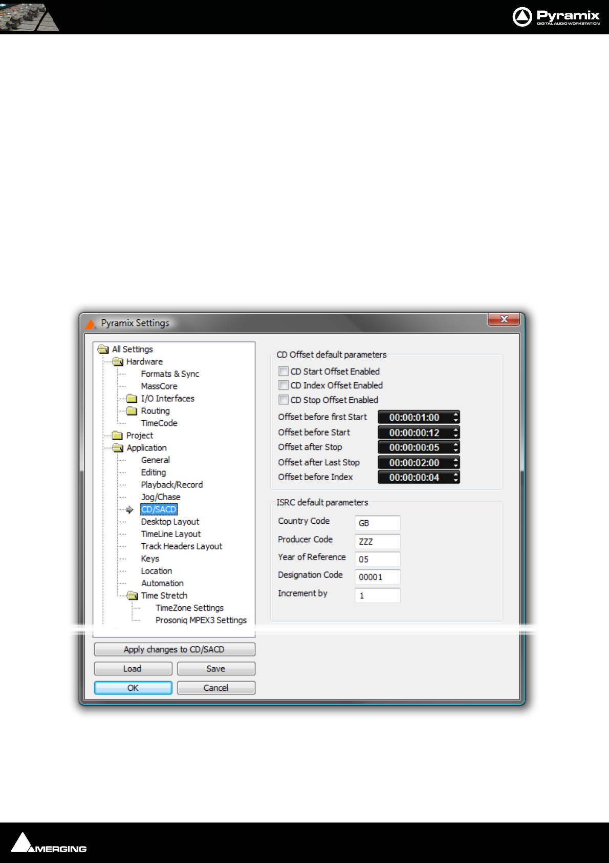
CD/SACD Mastering : Default Settings 24 - 403
Copy Song Writer Copy the CD Song Writer to the selected track(s) CD Text Song Writer field.
Copy Composer Copy the CD Composer to the selected track(s) CD Text Composer field.
Copy Arranger Copy the CD Arranger to the selected track(s) CD Text Arranger field.
Copy Title from Track Name Copy the Track Name to the CD Text Title for the selected track(s).
View
Show CD Player Opens the CD Player floating window Please see: Show CD Player on page 404
Display TOC... Opens the XToc dialog. The left hand pane shows all Discs in CD Albums and
SACD Albums associated with the current project. Click on a Disc to select it, then
click on the Display XTOC button to display the complete TOC for the Disc in the
right-hand pane.
Default Settings
CD Offset default parameters and ISRC default parameters are set in the Settings > All Settings > Application >
CD/SACD page.
CD Offset default parameters
These parameters are used when the offset of a PQ marker is set to zero and you enable them by ticking the boxes.
CD Start Offset Enabled
All Settings Application CD/SACD Page
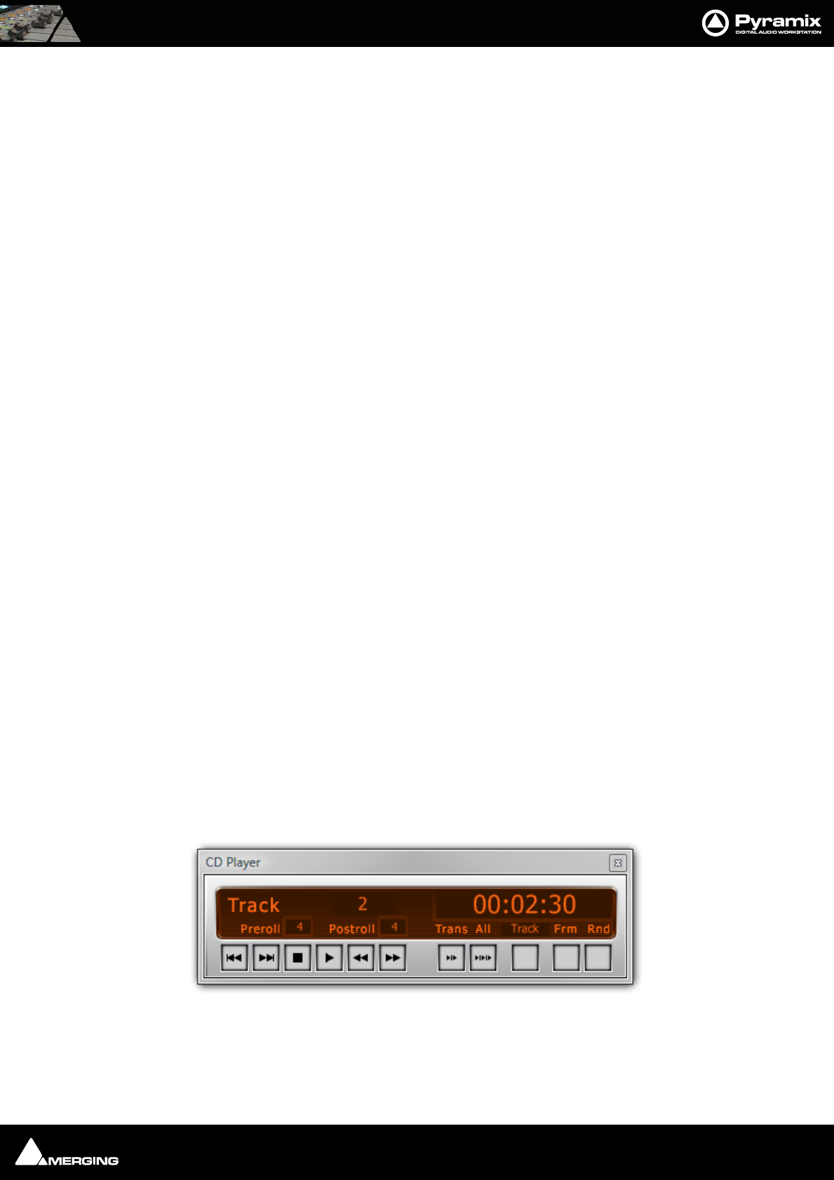
CD/SACD Mastering : Show CD Player 24 - 404
CD Index Offset Enabled
CD Stop Offset Enabled
Offset values can be typed and/or adjusted using the increment decrement buttons.
Offset before first Start
Negative offset applied to the first PQ start marker only.
Offset before Start
Negative offset applied to all PQ Start markers except the first one.
Offset after stop
Positive offset applied to PQ Stop marker except the last one.
Offset after last stop
Positive offset applied to the last PQ stop marker.
Offset before Index
Negative offset applied to PQ index marker.
ISRC default parameters
These parameters are used to automatically create or increment ISRC with the function ISRC > Create & ISRC > Inc
Selection are invoked from the Offsets and ISRC menus. (Right-click anywhere in the right-hand pane)
All these parameters are stored in the project. If you want to define the value as Default value, right click on the
value and select “Set as Default”.
Country Code
2 characters (GB, SW, FR etc…)
Producer
3 characters (W01).
Year of R efe rence
2 digits ( 02).
Designation Code
5 digits (00012, 80010).
Increment by
Used to auto increment the designation code part of the ISRC. The default value is “1”.
Show CD Player
View > Show CDPlayer in the CD/SACD Tab window displays an “always on top” small CD Player which enables
simulation of the CD playback (like a “real” CD player). The CD can be simulated with or without the markers offset.
CD Player floating Window
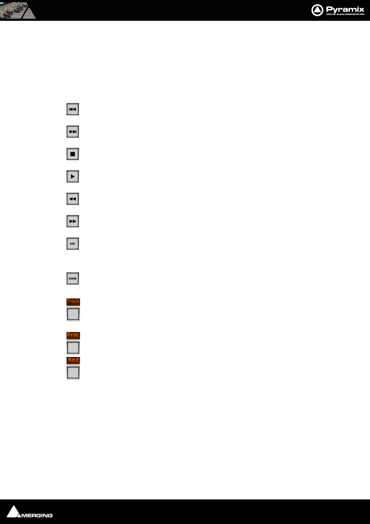
CD/SACD Mastering : Ghost Track 24 - 405
Choose Show Offset in the Track list pane pop-up menu to take care of the offset The player has standard play-
back functions (play, stop, next, previous, scan etc…) and some special functions:
Preroll
Clicking in the number box allows a value (in seconds) to be entered.
Postroll
Clicking in the number box allows a value (in seconds) to be entered.
Skip Track Backwards
Skip Track Forwards
Stop
Play
Rewind
Fast Forward
Play Transition Play the current track from the previous Stop marker minus pre-roll to the
current Start marker plus post-roll. Pre and Post roll can be edited directly on the CD player
interface.
Play All Transitions Has the same functionality as Play Transition but plays all transitions
between CD tracks.
Track Clicking on the third from the right button cycles through four different time display
options. Elapsed time from start of CD, Time remaining from the End of the CD. Elapsed time
of Track and Time remaining from end of Track
Frame Shows/hides the CD frames display
Rnd
Ghost Track
Normally a CD begins from the first track which has a 2 second pause. Pyramix allows you to modify this and create
a ghost track; a track before the first track. To accomplish this simply add a CD Index Marker at the beginning of
your ghost track, before the first start marker. You can also edit the pause of the first track then this will create or
move the ghost marker index for you.
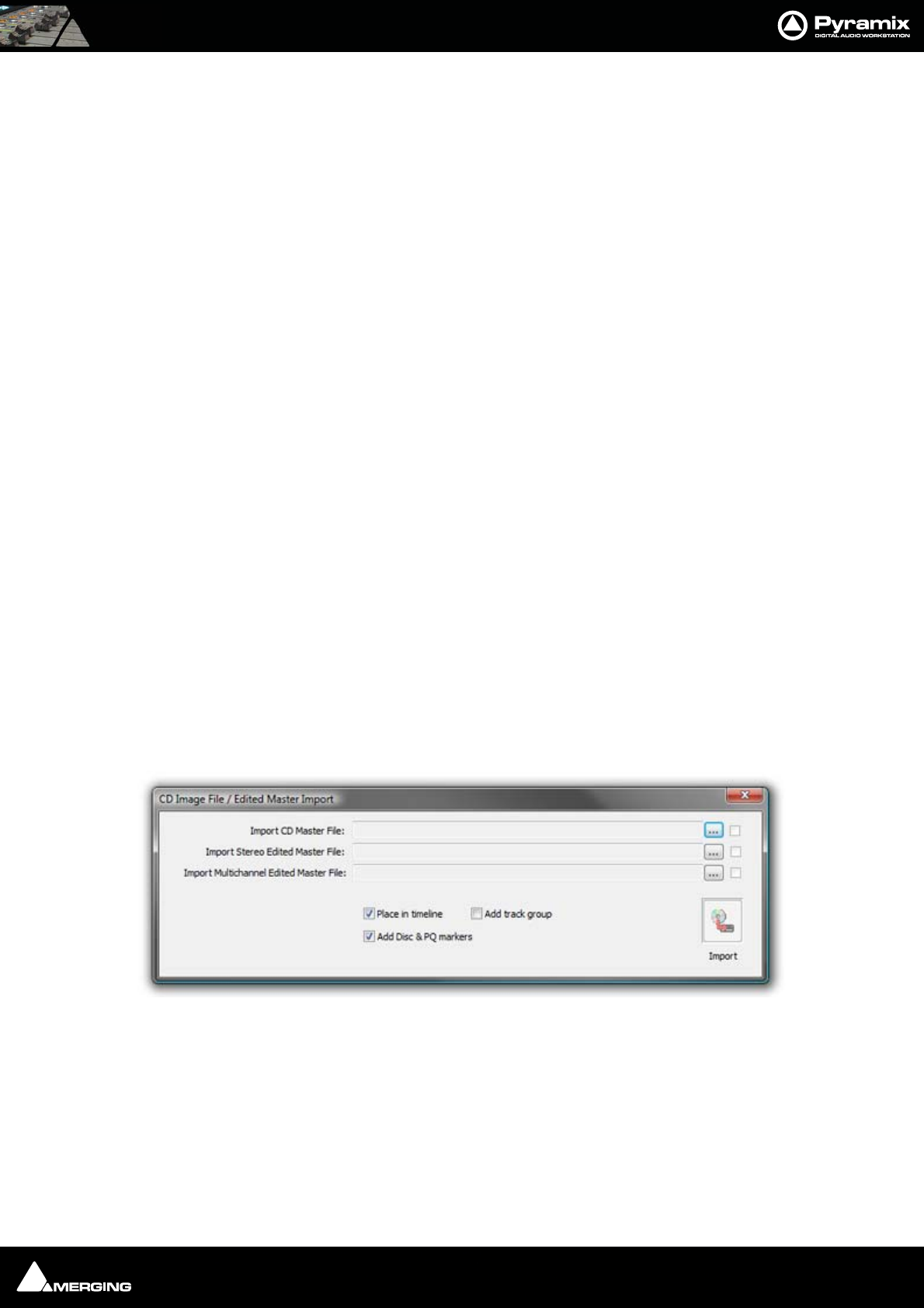
CD/SACD Mastering : Multiple CDs or versions in one Project 24 - 406
Multiple CDs or versions in one Project
All CD Information and CD Markers can be either "global" or per Track Group. Each Track Group that has the Desti-
nation type and Free Markers enabled has its own CD Information and CD Markers. This enables multiple versions
of PQ editing for an album to be handled and for multiple CD albums in the same document. The CD Info and
Markers displayed in the CD Tab Window follow the currently selected Track Group.
Red-Book Validation
Validate PQ: This function ensures that the PQ conforms to the Red Book specifications by carrying out the fol-
lowing checks and corrections.
• When a pause is less than 1 second, the pause is removed. (The offset is automatically dealt with).
• Track Length is set to 4 second if it is less. (The offset is automatically dealt with).
• Track count is reduced to 99 if greater
• ISRC is removed if it is incorrect
• UPC/EAN is removed if it is incorrect
This function an be undone if necessary.
DDP Import
You can use the DDP import function Project > Import > DDP Import to import a DDP tape or file and generate a
new CD image file. From this CD image file you can burn a CD or generate a new DDP tape.
CD Image File / SACD Edited Master Import
Import audio and PQ Markers from a CD Image file or SACD Edited Master. Project > Import > CD Image File /
SACD Edited Master Import.
Each ... button opens a File Browser Window to locate the desired file(s).
The boxes at ehe bottom of the screen determine how the data will be processed on import.
Place in Timeline When ticked the audio will be placed in the Timeline on an appropriate number of
tracks.
Add Track Group When ticked a Track Group will be created containing all the relevant audio tracks.
Add Disc & PQ markers When ticked Disc and PQ markers will be added to the Marker bar.
CD Image File / Edited master Import dialog
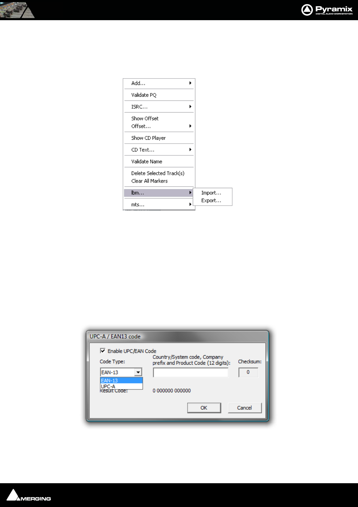
CD/SACD Mastering : SACD Functions 24 - 407
SACD Functions
Accessed from the right-click context menu:
lbm...
Import... / Export...
Opens a Windows browser window to save or load SACD text .lbm files.
mts...
Opens a Windows browser window to save or load SACD text .mts files.
Exporting Projects to CD Image Files
To export a previously Marked Composition to a CD-R image file and Cue Sheet text file:
Open the CD/SACD Tab window. Fill in CD information as appropriate. Clicking in the UPC/EAN Code field opens
the UPC-A / EAN13 code dialog:
UPC/EAN capture for CD/SACD Albums, Discs and Areas is handled via this dialog box.
Enable UPC/EAN Code: When ticked, UPC/EAN Code is enabled.
Code Type: offers a choice of UPC-A or EAN-13 barcode formats. Enter the 11 or 12 digit Company prefix and
lbm... sub-menu
UPC-A / EAN-13 code dialog
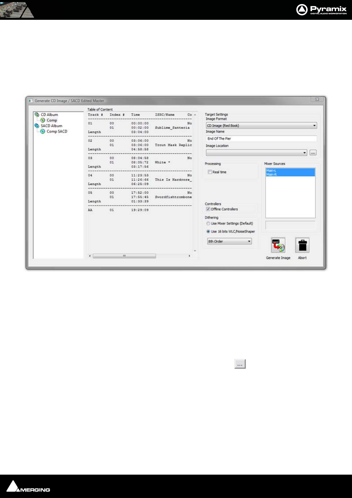
CD/SACD Mastering : Exporting Projects to CD Image Files 24 - 408
Product Code. The checksum is calculated automatically and the resulting code displayed. Click OK to enter the
result in the field.
The number of digits is checked according the type of code and the CheckSum: digit (the last one) is automatically
calculated (to ensure its validity).
Moreover, the TOC information part of a Pyramix generated CDImage file (PMI) will always contain a 13 digits
UPCEAN code (left 0-padded if UPC-A type code) or no UPCEAN code at all if the field is left blank.Choose Project
> Generate CD Image / SACD Edited Master. This opens the Generate CD Image dialog.
Select a CD-Disc from the left-hand pane.
Target Settings
Image Format
Choose the required format from the drop-down list.
Image Name
Type a suitable name for the image.
Image Location
The combo box has a list of all mounted media folders or you can use the button to open the Choose a
media folder to mount dialog.
Processing
Real Time
Tick the box if you want to generate in real time or if you wish to listen to the CD while the image is being gener-
ated.
Controllers
Offline Controllers
Untick the box if you want to use a Hardware Controller while generating the image in realtime for e.g. changing
Monitor volume etc. or to fade out.
Generate CD Image / SACD Edited Master
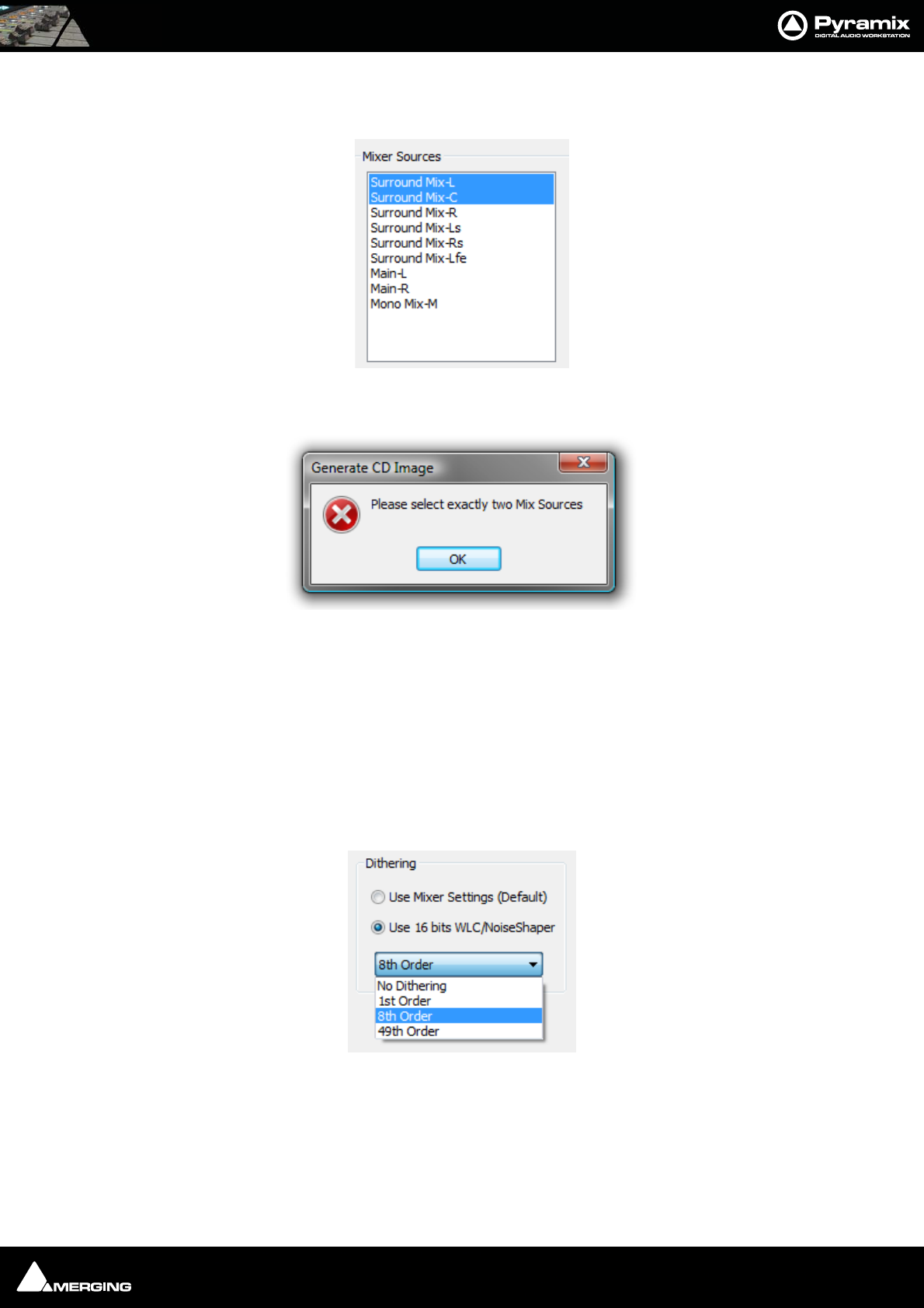
CD/SACD Mastering : Exporting Projects to CD Image Files 24 - 409
Mixer Sources
Pick two appropriate bus outputs from the list shown by Ctrl + Clicking them.
If more or less than two are chosen this error message appears when Generate Image is clicked:
Dithering
Note: There is no necessity to manually disable dither in the Mixer.
There is a choice between two dither processing units:
Use Mixer Settings (default)
Applies the same treatment as the Mixer's Dither (parameters are those selected in the Mixer) or
Use 16 bits WLC/Noise Shaper
This is the same as the dither in V4.2, available even if no SRC is applied. The combo box offers a choice of settings:
Select the required quality of Noise Shaping from the drop-down list.
1st Order is simple single order shaping with
8th Order and
49th Order offering improved quality.
A higher quality setting will produce better results, but the processing time will also increase.
Generate CD Image - Mixer Sources
Generate CD Image - Mixer Sources Error
Generate CD/SACD dialog - Dither options

CD/SACD Mastering : CD Cue Sheets 24 - 410
CD Cue Sheets
The CD Cue Sheet file is a metadata file which describes how the tracks of a CD or DVD are laid out. Cue sheets are
stored as plain text files and commonly have a .cue filename extension. CDRWIN first introduced cue sheets,
which are now supported by many optical disc authoring applications and media players.
For an Audio CD, a Cue Sheet specifies titles and performers for the disc and its tracks as well as the names of one
or more audio files to be used. MP3, WAV and BIN files are often used, although some programs support other for-
mats. Cue sheets are especially useful when burning or listening to live sets where all tracks are recorded in one
file.
Cue sheets are also used for many types of CDs in conjunction with an image file. The image file generally has a
".bin" extension. (.pmi extension in Pyramix and .cue for the Cue Sheet file.)
Cue Sheet file Contents
The Cue Sheet file will display information in this form when opened in a text editor:
REM COMMENT "Generated by Merging Technologies Pyramix Version 6.1.0"
REM Customer Name: Ricardo Ryan
REM Customer Contact: Merging Technologies
REM Customer Phone: +41219460444
REM DATE Wednesday, October 29, 2008
CATALOG 3466755435677
TITLE "Greatest Hits"
PERFORMER "U2"
SONGWRITER "Bono"
FILE "Album.pmi" WAVE
TRACK 01 AUDIO
TITLE "Pride"
INDEX 01 00:00:00
TRACK 02 AUDIO
TITLE "Unforgettable Fire"
INDEX 00 00:59:17
INDEX 01 01:56:57
TRACK 03 AUDIO
TITLE "Sweetest thing"
INDEX 00 03:08:5
INDEX 01 03:40:19
Export
CD Cue sheet file export is fully implemented in Pyramix 6.1 Beta 1 in compliance with the CDRWIN specifications.
The .cue file is generated at the same time as the .pmi disc image file. However, many CD burning applications do
not fully support the CDRWIN Cue Sheet specification.

CD/SACD Mastering : CD Cue Sheets 24 - 411
Audio CD Cue Sheet Compatibility
Note: * To import Audio CD Cue file in Roxio Toast v9 :
• PMI file has to be renamed with .BIN extension instead of .PMI
• Cue sheet file must be edited to match Source Filename’s extension change, and specify File type as BIN
instead of WAV
CD Burning
application
Tested Features
ImgBurn
v2.4.2.0
(freeware)
Ahead Nero
v6.3.1.15
Ahead Nero
v7.2.3.2
to Nero
v9.0.9.4
CDRDAO
(multi
platform
command line
app.
Roxio Toast
v9 (Mac)
Open CUE file OK OK Crash OK OK*
CD Text Disc Title OK OK - OK -
CD Text Disc Performer OK OK - OK -
CD Text Disc Songwriter ---?-
Catalog Number (UPC/EAN) OK - - OK OK
CD Text Track Title OK OK - OK OK
CD Text Track Performer OK OK - OK -
CD Text Songwriter ---?-
Track ISRC OK OK - OK OK
PreGap / Pauses OK OK - OK OK
Index markers OK OK - OK -
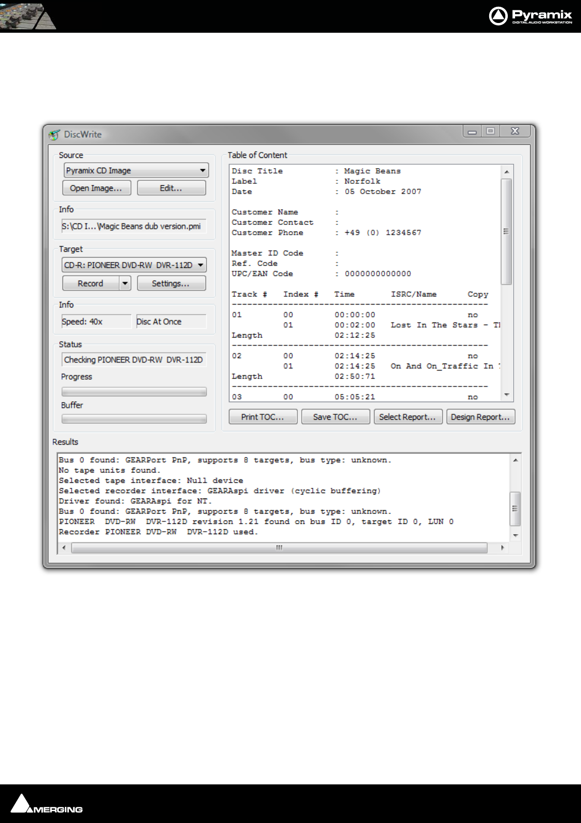
CD/SACD Mastering : DiscWrite 24 - 412
DiscWrite
DiscWrite is a separate application bundled with Pyramix Virtual Studio that is used to write the CD image out to
a CD-R disc or a DDP image file to a folder or DDP tape drive.
Source
The drop-down list enables the user to choose between a Pyramix CD Image, all installed optical drives, a U-
Matic Tape or an existing DDP master file as the source for the new CD-R or DDP file.
DiscWrite application window
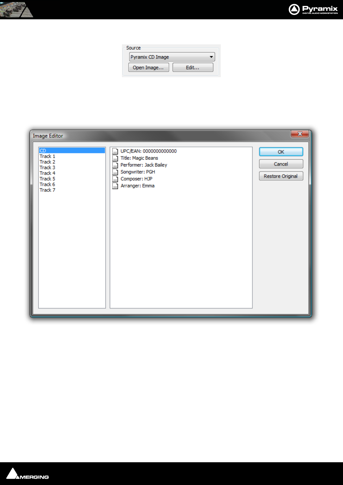
CD/SACD Mastering : DiscWrite 24 - 413
Source - Pyramix CD Image
When the chosen Source is Pyramix CD Image, the left-hand button below the Source drop-down list will be
Open Image... Clicking on Open Image... leads to a file browser window where you can navigate to the desired
image file. The right-hand button will be Edit...
Clicking on the Edit... button opens the Image Editor dialog:
CD-Text can be edited freely.
Restore Original
Undoes any changes made since the dialog was opened.
DiscWrite Source - CD Image
DiscWrite Image Editor dialog
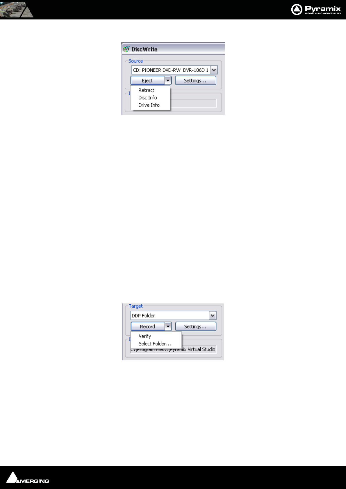
CD/SACD Mastering : DiscWrite 24 - 414
Source - CD Drive
When the chosen Source is CD: ...., the left-hand button below the Source drop-down list will be Eject and the
right-hand one Settings...
Eject
opens the loading tray of the selected optical disk drive (or ejects the disk if the drive is a slot-loader). Clicking on
the down arrow next to the Eject button drops down a list of other optical disk drive commands.
Retract Closes the loading tray on the source drive
Disk Info Reads the disc information and displays it in the Results box
Drive Info Interrogates the optical drive firmware and displays information about the drive in
the Results box
Source - U-Matic Tape
Sony PCM-1630 master tapes can be imported. Please see: Importing a U-Matic Tape on page 418
Info
The Info box shows either the read speed of the optical drive or the path to the image file.
Target
The drop-down list enables the user to choose between any installed CD-R or DDP drives or a DDP Folder
DDP Folder
When DDP folder is the selected target the button beside the Record button drops-down a list of options:
Verify Verifies the recording
Select Folder... Opens a Browser to enable a suitable folder to be chosen
Settings...
Opens a window with DDP settings information and options.
DiscWrite Source - CD Eject Drop-Down
DiscWrite Target - CD Eject Drop-Down

CD/SACD Mastering : DiscWrite 24 - 415
CD-R/CD-RW
When a CD-R(RW) is the selected target, the arrow beside the Record button drops-down a list of options:.
Eject Opens the loading tray on the target drive
Retract Closes the loading tray on the target drive
Disk Info Reads the target disc’s information and displays it in the Results box
Fix Disc Writes the information necessary to allow a Track at Once disc to be read by a CD
player.
Erase Disc Erases a re-writable disc
Drive Info Interrogates the optical drive firmware and displays information about the drive in
the Results box
Settings...
The Settings... button is grayed out unless a suitable optical drive or image file has been selected. When available,
clicking on Settings... opens a dialogue with access to all relevant settings. In particular, this is where you can
choose between Disc-at-Once and Track-at Once modes. Use Disc-at-Once for maximum compatibility.
Record
Clicking on the Record button initiates the recording process.
Detailed reporting about the progress of the process is shown in the Results box as the recording is made.
Info
Shows the Write speed of the target drive or the path if you are writing a DDP file to a folder. Also shows the cho-
sen record mode, e.g. Track At Once or Disk At Once.
Status
Shows the status of the recording device/process
Progress
A ‘thermometer’ bar graphically shows the progress of the recording.
Buffer
Another ‘thermometer’ showing the state of the record buffer.
Results
This box displays detailed information about various aspects of the process depending on what you are doing at
the time.
Table Of Content
Displays the TOC in detail.
Print TOC...
Opens a Print Options dialog. The actual options available will depend on the printer you have selected.
Save TOC...

CD/SACD Mastering : DiscWrite 24 - 416
Opens a File Browser dialog. Here, you can type a name for the TOC file and choose a suitable folder to save it in.
Select Report...
Opens a File Browser dialog where you can select a report style for the TOC
Design Report
Opens the Report Designer application. With this you can design your own report formats for TOCs.
Optical Drives - Important Note:
Most, if not all the issues you might encounter when working with optical drives, Windows and DiscWrite can be
solved by installing the latest firmware for your drive. This, together with installation instructions, should be avail-
able from the drive manufacturer’s website. This is true for CD-Text writing, write speed & buffer issues, as well as
for CD-Import.
CD Text
CD-Text has been successfully tested with several high quality DVD-R and CD-R drives. However, DiscWrite and its
CD-text functionality should work with most of the writers available on the market, provided care has been taken
to install the latest available firmware for the unit.
A warning will appear when a non CD-Text writer is intended to be used to write a Disc Image containing CD-Text.
Compatibility with CD-Text can be confirmed in the Target area by making sure the desired drive is selected and
choosing Drive Info from the Record drop down menu.
Writing CD-Text (audio, disc at once): Yes. Should be found in the Supported write methods: section of the list
in the Results window. (You will have to scroll the list to find this)
Burning a CD-R
Launch DiscWrite. (A normal Pyramix installation places a DiscWrite icon on the desktop) To burn a CD-R from a
previously created CD image file:
1. In the Source section, click the Open Image... button, then navigate to and select a previously created CD
Image file (an .img or .pmi file).
2. In the Target section, click in the drop-down menu to select a CD-R device. DiscWrite should recognize a pre-
viously configured CD-R device which is also recognized by the OS itself.
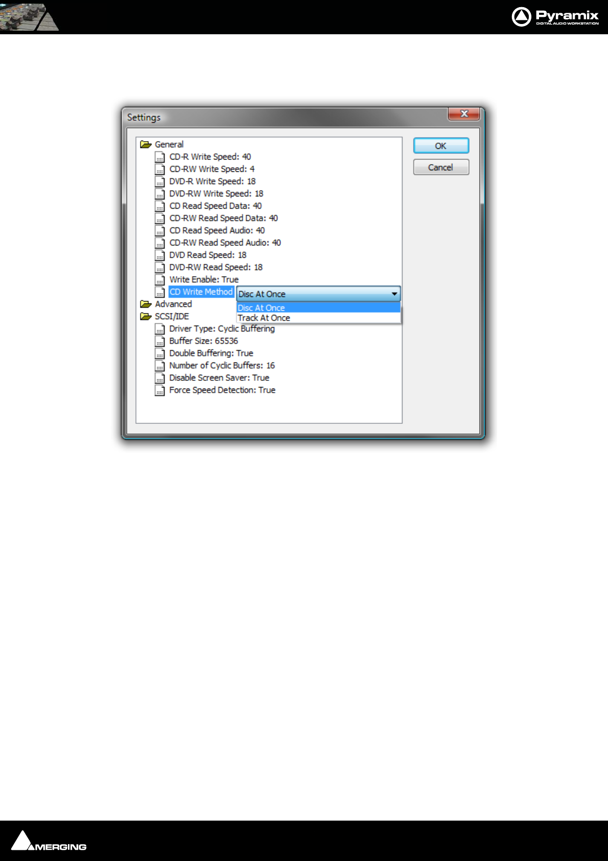
CD/SACD Mastering : DiscWrite 24 - 417
3. Also in the Target section, click on the Settings... button to open the CD-R Settings dialog box. Set these as
desired for the CD-R burning session. The default settings will usually be fine but it is worth checking that the
CD Write Method: entry is set to Disc At Once.
4. When all CD-R settings are adjusted as needed, click the Record button in the Target section to begin burn-
ing the CD-R.
DDP Masters
Note: As in the above example, Pyramix allows you to specify burning your DDP to a
folder (instead of an Exabyte tape) and from there on it may be transferred, copied,
duplicated, checked, archived or whatever else you want to do with it, such as sending it
over a secure FTP connection.
Red Book Compatible Masters
If the CD-R is to be used as a “Red Book” compatible master "Contiguous" MUST be selected.
CD Copy
Where suitable hardware is available, a CD may be directly copied by selecting a CD-ROM drive as the source and a
CD-R/RW drive as the destination.
TOCs
Print TOC... prints the current TOC in the currently selected report format.
Save TOC... opens a file save dialog to save the current TOC as a text (.txt) file.
Select Report... opens a file open dialog. Any previously designed TOC report format (*.lst) may be loaded.
DiscWrite General and Advanced Settings

CD/SACD Mastering : Importing a U-Matic Tape 24 - 418
Design Report... Opens the Report Designer. Please see the on-line documentation.
Importing a U-Matic Tape
These instructions assume the use of a Sony 1630-PCM Audio Processor and a Sony DMR-2000 Master Recorder
(U-Matic).
Requirements
The U-Matic machine must be under Sony 9-pin (P2 Protocol) control from Pyramix.
U-Matic Tape import requires a Mykerinos card with SDIF daughterboard and the appropriate key (PSO-1630). Cli-
ents who already have an external SDIF converter can use this with a daughtercard suitable for its output. E.g. The
AES-EBU or DUAL daughtercards.
Connections
1. Wordclock is used to sync the PCM-1630 (Sourced from the Mykerinos card)
2. DiscWrite controls the DMR-2000 transport using RS-422 (Sony 9-pin) via either the Pyramix workstation’s
MTCHIO card if fitted or from the RS-232 COM port via an RS232 to RS422 converter.
3. The DMR-2000 sends the composite digital stream to the PCM-1630. The PCM-1630 extracts the Audio signal
and, if required, the Sync signal.
4. The extracted digital audio signal is sent to DiscWrite via either an SDIF Mykerinos daughterboard input or to
an outboard SDIF to AES/EBU converter and thence to an AES/EBU Mykerinos daughterboard input.
5. The DMR-2000 reads the TimeCode signal from the tape and sends it via the analog AUX OUT CH2 XLR. This
information is used by DiscWrite.
6. The DMR-2000 reads the PQ Burst from the tape (this is also an analog signal) and sends it via the AUX OUT
CH1 XLR to DiscWrite either using an input of the DUAL daughter card or an input of another analogue
daughtercard or directly using the motherboard ANALOG LINE IN.
Note: NEVER use the MIC IN of the motherboard. (This may be equalised and is likely to
distort the PQ Burst rendering it unreadable.)
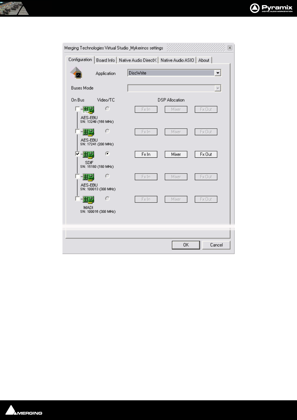
CD/SACD Mastering : Importing a U-Matic Tape 24 - 419
Procedure
1. Before launching DiscWrite, open the VS3 Control Panel:
2. Choose DiscWrite from the Application drop-down list. Then, choose your preferred daughter card (SDIF,
AES or DUAL depending on your hardware setup). The DiscWrite option will only appear with Pyramix V5.1
and higher.
3. Click on OK to make the changes and to close the VS3 Control Panel.
4. Open DiscWrite
5. Choose U-Matic Tape from the Source drop-down list.
6. Settings
VS3 Control Panel
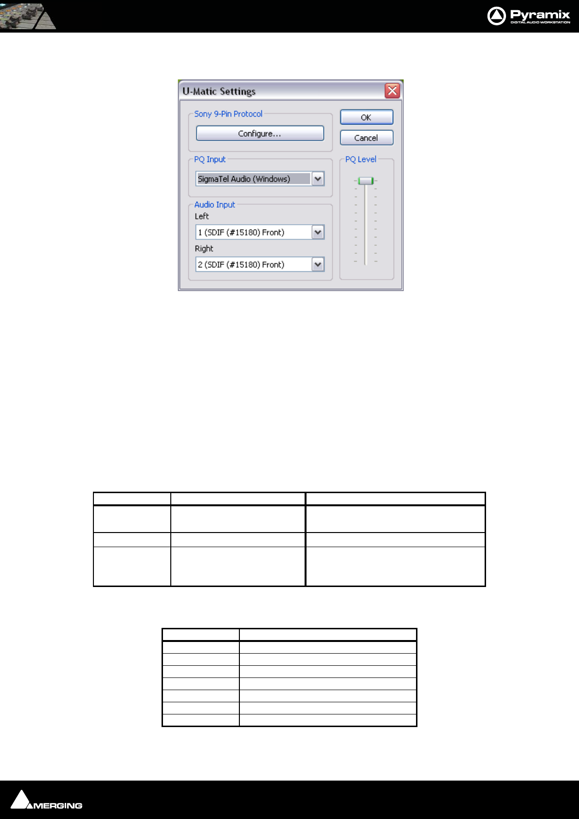
CD/SACD Mastering : Importing a U-Matic Tape 24 - 420
Click on Settings to open the U-Matic Settings dialog to configure DiskWrite for U-Matic Import.
Sony 9-Pin Protocol
To set up remote control for the U-Matic machine via the Sony 9-pin P2 protocol click on Configure... (Please see:
Sony 9-Pin Protocol Configuration (Machine) on page 536).
PQ Input
PQ input can be either a Mykerinos input or any sound-card live input.
PQ Level fader enables the level to be adjusted when using a Windows sound card.
Audio Input
The Audio Input MUST be Mykerinos inputs.
7. Make the following settings on the DMR-2000 front panel:
8. Make the following settings on the PCM-1630
9. Make the physical connections to match the choices made in U-Matic Settings.
DiscWrite U-Matic Settings Dialog
Switch Settings Notes
REMOTE REMOTE-1 REMOTE-2/LOCAL should be set
to enable the buttons on the front panel
TIMECODE AUTO STOP
HEADPHONE see note
CH-1 = Audio
CH-2 = Timecode
On the heaphones
Switch Settings
ENC IN DIGITAL
D.A. IN INT
MUTE AUTO
MONITOR PB
PB MODE A
SCALE NORMAL
PEAK
A
UTO
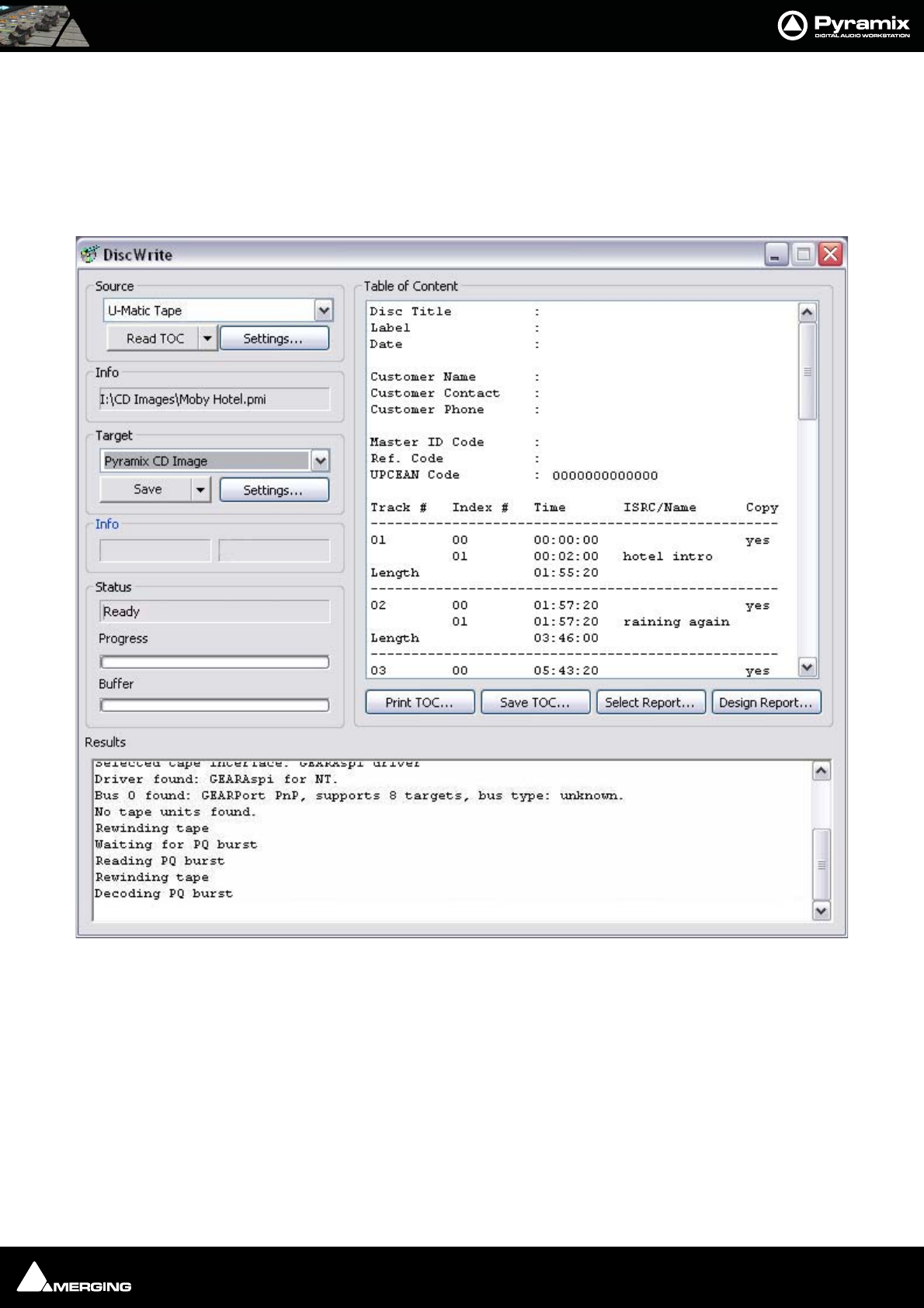
CD/SACD Mastering : Importing a U-Matic Tape 24 - 421
Note: Detailed connection diagrams for various scenarios can be found on the Merging
website:
http://www.merging.com
(Click on Support > Downloads > Documentation to find the diagrams)
10. When suitable settings have been made, click on OK to return to the main window:.
11. Click on Read TOC to start the U-Matic machine in replay to read in the Table Of Content from the tape.
DiscWrite application window
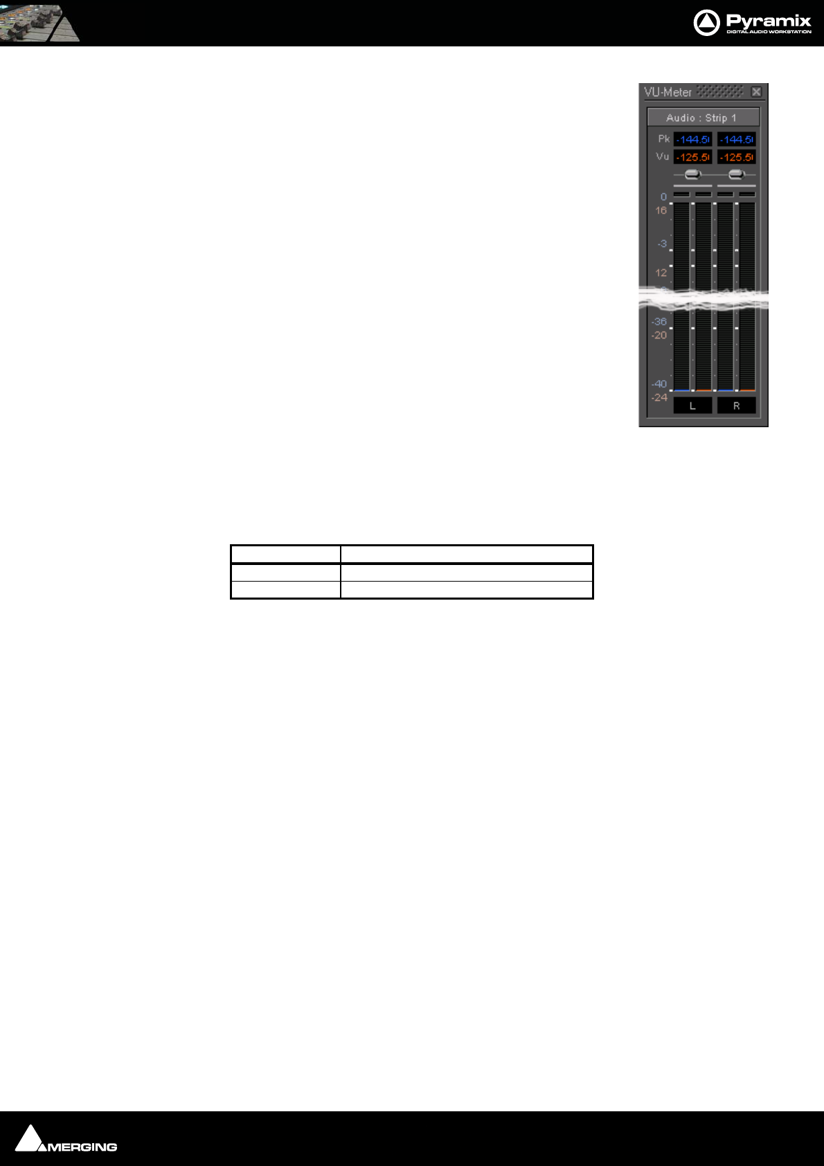
CD/SACD Mastering : Importing a U-Matic Tape 24 - 422
To check for an input signal, click on the down arrow adjacent to Read TOC and select
Show / Hide VU Meter to display a meter window.
12. If the TOC is as you expect, click on Save to read the TOC again and save the tape’s
contents in a .pmi CD Image file.
Note: if you already know the contents of your tape you can click on
Save without reading the TOC first.
Once recorded, this .pmi CD image can be used in exactly the same way as any other standard CD image.
Probox 3 Format Converter Settings
For any users who already have an Audio Design Probox 3, SDIF to AES-EBU converter, here are the settings:
Input Meter window
Switch Settings
MODE SIMULTANEOUS CONVERSION
INPUT SELECT EBU

USER MANUAL
www.merging.com/Pyramix
Productivity
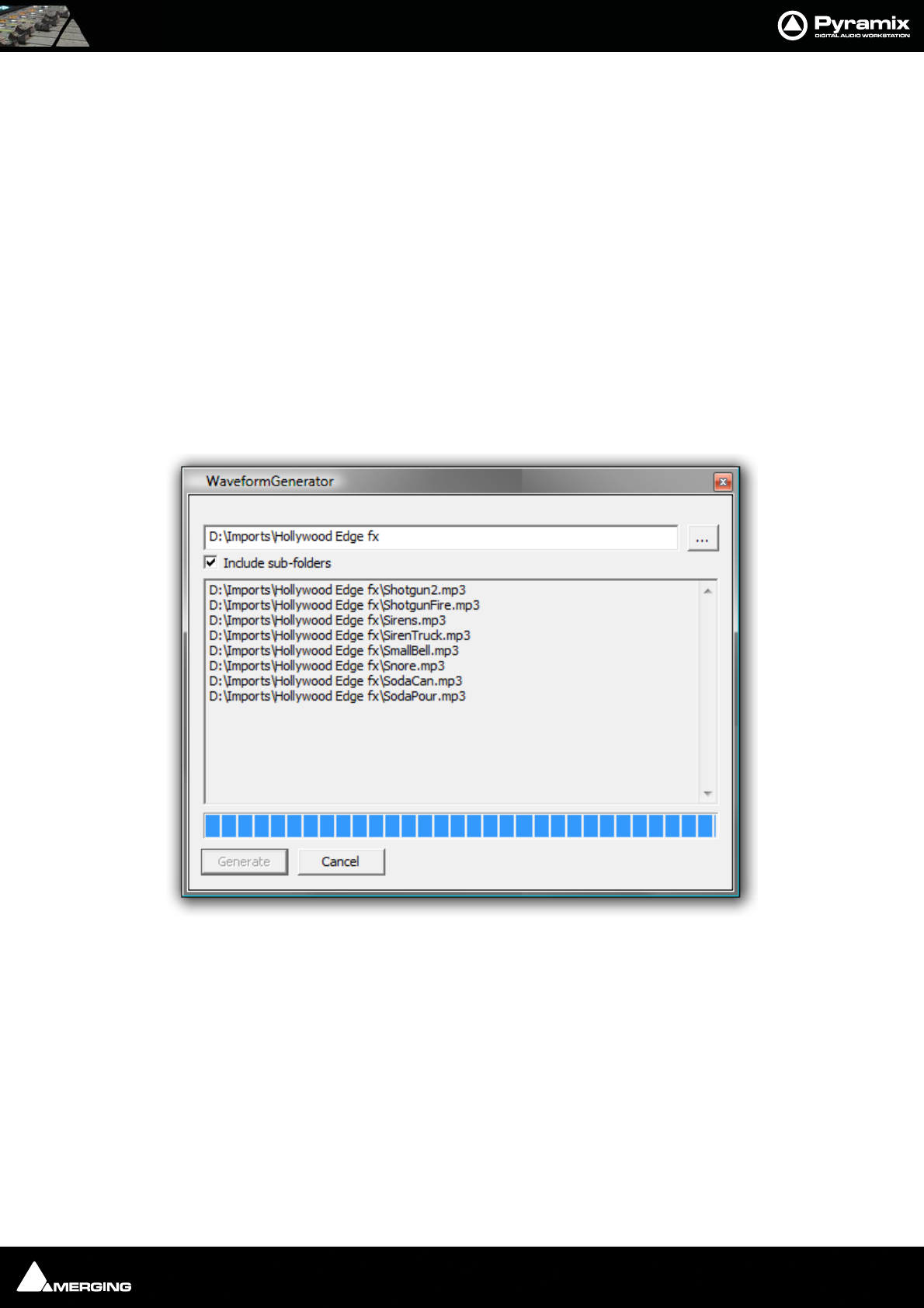
Productivity : Locating Clips 25 - 424
Locating Clips
In projects cantaining a large number of Clips it can be very helpful to be able to find where a particular Media file
or files are being used. For example if you wish to replace all instances of a particular sound effect.
The Media Manager Tab Window Edit Menu has two commands to assist:
Locate Locates the Playhead Cursor to the start of the first (or only instance) of a single item
selected in the Media Manager list and Selects it in the Timeline
Show Usage Selects all instances in the Timeline of the item(s) selected in the Media Manager list and
zooms the Timeline to show them.
Waveform Generator Utility
If you have to deal with large numbers of audio files consider using the Waveform Generator Utility to save on
valuable studio time. This can be set to generate Waveforms for audio media files in a folder (including sub-folders
if required). The utility can be run on any PC, it does not require Pyramix to be present.
Waveform Generator Application Window
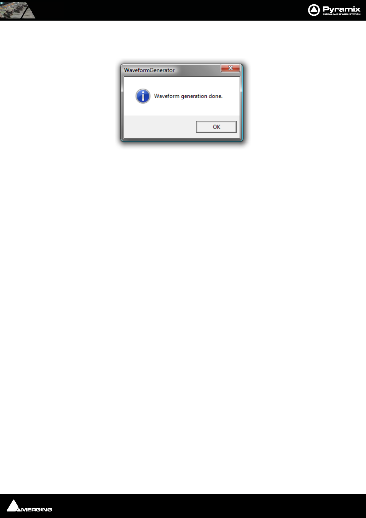
Productivity : Tab Windows 25 - 425
Simply launch the Waveform Generator application, click on the ... button to open a file browser, navigate to the
folder containing the audio media files and tick the Include sub-folders if you wish. Then click on Generate.
When Waveform generation is complete you will see this dialog box:
Click on OK to close the box and that’s it. It really is that simple.
Tab Windows
Tab Windows have long been a powerful aid to productivity in Pyramix. In Version 6 you can still use Tab Windows
in the same way as previous versions but you will miss out on some major ‘Power User’ features if that is all you do.
Just as before, clicking on a Tab opens the associated Window in the space below the Project Editing Panel and
double-clicking a Tab opens the associated Window floating. Double-clicking the title-bar of a floating Tab Win-
dow restores it to the space below the Project Editing panel.
Tab Behaviour
In Version 6 Tabs can be ‘torn away’ to open as floating Windows in blank screen space by simply clicking on the
Tab and dragging. clicking the X closes a floating Window and the Tab is removed from the Tab pool. This means
that the interface can be streamlined by removing Tabs you never use or which are inappropriate for the specific
task in hand. Tabs removed in this way can be restored by choosing View > Editor Tabs and clicking on the
required Tab or Show all Tabs to restore all closed Tabs.
Apart from this last feature, the ability to remove Tabs from the user interface, simple Tab behaviour is almost
identical to previous versions. However, there are many other things you can do with Tabs to enhance productiv-
ity.
Tab Arrangement
Hiding and Showing All Tabs
To quickly Close all Tabs, Show all Tabs, or Toggle Show/Close all Tabs and to find the other Tab display options
go to the menu View > Editor Tabs.
In the Project Editing pane, clicking on the Magnify/Maximise Timeline box at the junction of the vertical and
horizontal scroll bars also actuates Toggle Show/Close all Tabs.
Waveform Generator done dialog
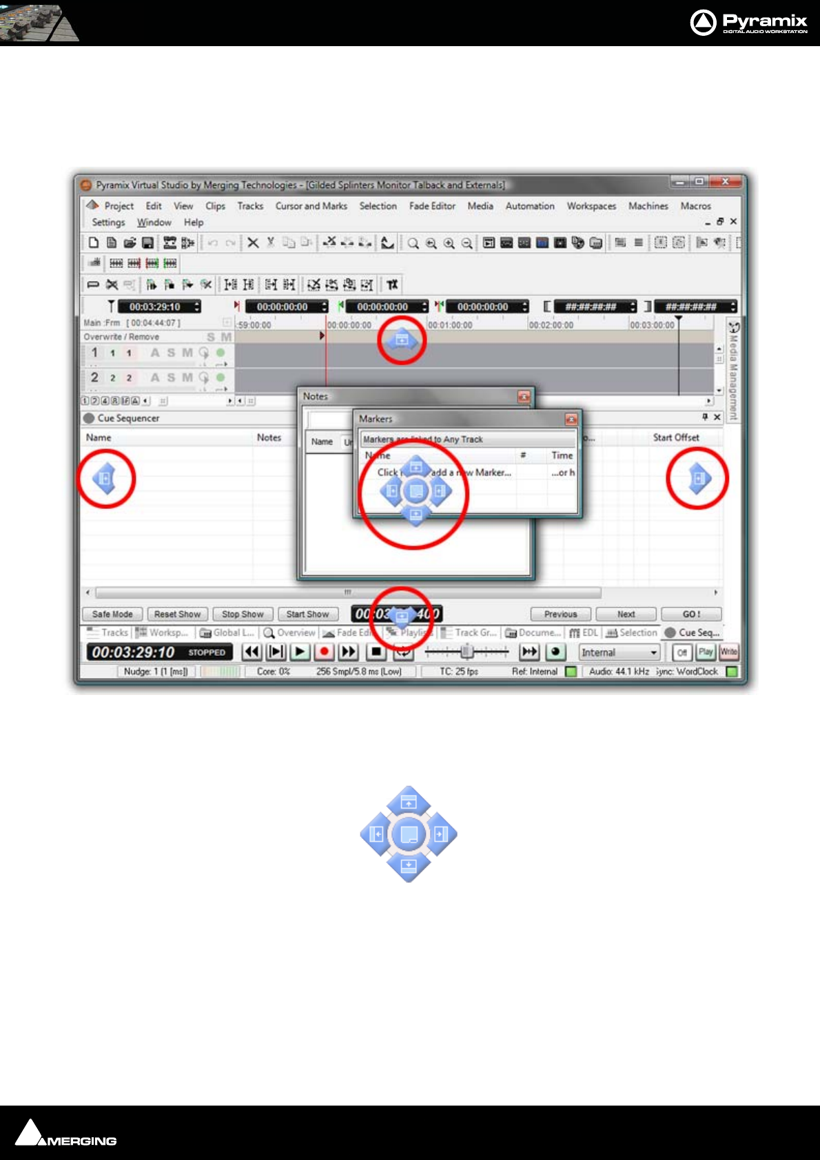
Productivity : Tab Windows 25 - 426
Tab Docking and Nesting
Floating Tab Windows can be nested or docked together in the Program Window or in floating Windows by simply
clicking and dragging. When a Tab Window or group of Windows is clicked and dragged, small blue “landing
lights” appear indicating where the Tab can be docked in the main Program Window with a center block of five
indicating where the Tab can be docked in the Window or panel it is currently being dragged over.
Thus, in the highly artificial screenshot above, it is the Markers Tab Window that has been clicked and dragged.
The peripheral blue landing lights indicate where in the main programme window it can be docked and the centre
landing lights indicate where in the Notes Tab Window it can be docked.
Tab Window “Landing Lights”
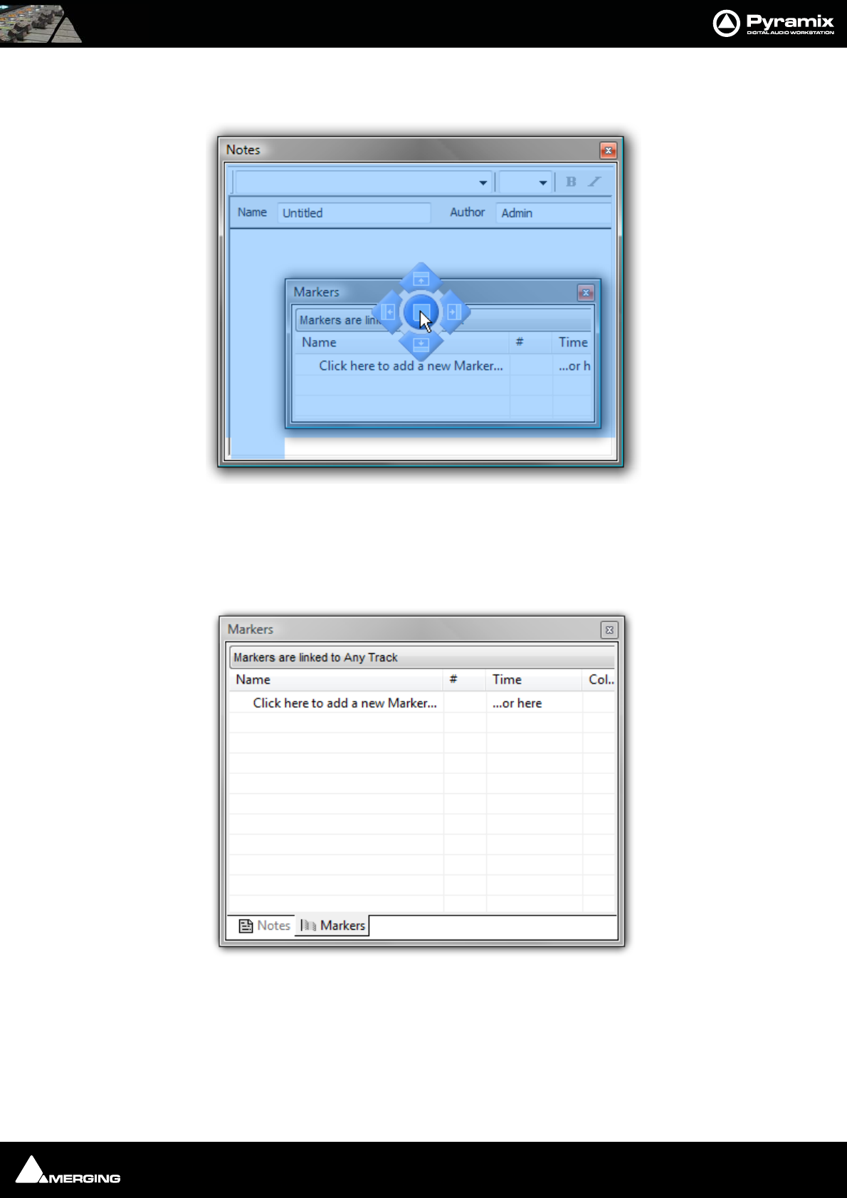
Productivity : Tab Windows 25 - 427
Note: The centre button is only available when the Tab can be docked as a Tab in
another Tab Window.
Placing the mouse cursor over a specific Landing Light determines what will happen when the mouse button is
released. In order to help avoid confusion blue “ghost images” appear showing where the Tab Window will land. In
the screenshot above, if the mouse button is released the Markers Tab Window will become nested with the
Notes floating Tab Window thus:
If a nested, floating Tab’s title bar is double-clicked all the nested Tabs are returned to the main Tab dock.
Tab Window “Landing Lights” and “Ghost Image”
Nested Tab Windows
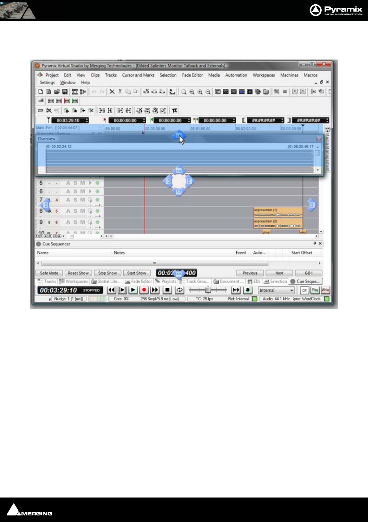
Productivity : Tab Windows 25 - 428
Layout Example
Here, the Overview Tab has been ‘torn off’ by clicking and dragging.
It is often useful to have the Overview above the Timeline and so that is the landing light used here.
When the mouse button is released, the Overview will be positioned above the Timeline and can then be re-sized
as required.
Main Project Window Tab Window with “Landing Lights” and “Ghost Image”
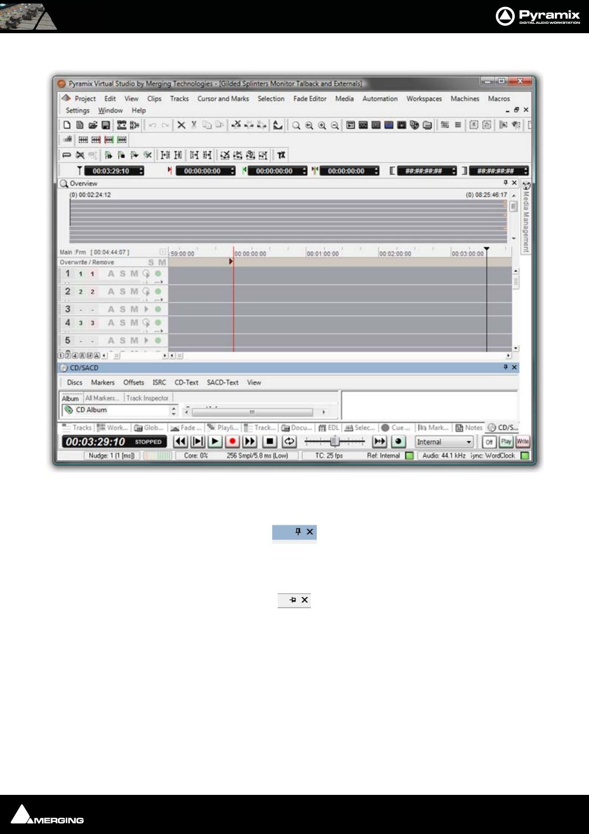
Productivity : Tab Windows 25 - 429
Pinned and Unpinned Tab Windows
By now you’ve probably noticed the small ‘pin’ icon next to the close box on the title bar of each Tab window:
With the Pin in the vertical position the Tab Window behaves as normal. Clicking on the Pin toggles between the
default ‘Pinned’ state and ‘Unpinned’ - Auto-Hide mode:
Note: The Pin is only present where the unpinned, Auto-Hide mode is available.
IMPORTANT: If there is only one Tab Window at the bottom of the main screen and you unpin it
you will lose access to all other Tabs until you open the Tab and unpin it.
Once a Tab Window is Unpinned it collapses down to a Tab a second or so after the mouse cursor leaves the Tab
Window. Hovering the mouse cursor over an Unpinned Tab opens the Tab Window which can then be used as nor-
mal until the mouse cursor leaves the Tab Window again. Clicking in the title bar ‘locks’ the Tab Window open as if
it were pinned. Alternatively, clicking on the Tab to open it does the same thing.
Overview Tab Window in place above Timeline
Pinned
Unpinned
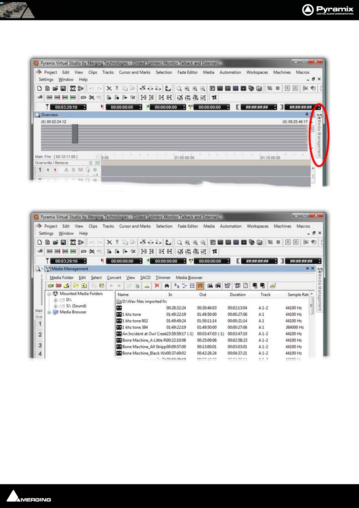
Productivity : Tab Windows 25 - 430
An unpinned Tab can be extremely useful, for example, to give near instant access to the Media Management Tab
Window without disturbing the layout. It is shown here first as a Tab and then with the Tab Window open (both
screenshots cut down to save space):
Note: Unpinned Tab Windows cannot be moved by clicking and dragging until they are
pinned once again.
Note: Once a Tab Wiindow has been unpinned, double clicking on the title bar will pin it,
a second double-click will open it as a floating Tab Window. A subsequent double-click
will now return it to the place it was unpinned from until it is manually returned to the
main Tab Dock.
Managing Tab Windows
The button at the bottom-right of the main timeline (at the conjunction of both scrollbars) Toggles Show/Close
all Tabs. This is extremely useful with big projects when screen space is at a premium.
Media Management Tab Unpinned with Mouse Cursor elsewhere
Media Management Tab Unpinned with Mouse Cursor in Tab Window
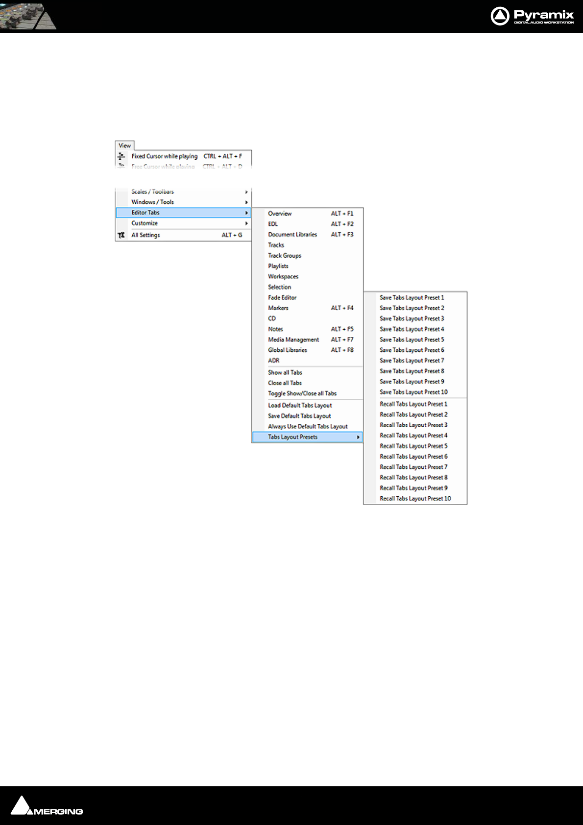
Productivity : Tab Windows 25 - 431
The All Settings > Timeline Layout > General : Display Timeline on Top/Left of Tab Windows setting is ren-
dered obsolete by the Tab enhancements, but can still be used for brand new projects to initially place Tabs as
before in the screen (to the right or at the bottom). But the following considerations demonstrate that employing
Project Templates makes for a more streamlined way of working.
The Default Tabs layout and up to ten Tab Layout Presets can be stored and recalled from the View > Editor
Tabs menu :
These presets can be bound to short-cut keys by using the Keyboard Shortcuts Editor (Settings > Keyboard
Shortcut Editor : View Tab
•The Default Tabs Layout and Tab Layout Presets are saved with the application. I.e. available in all
projects.
•View > Editor Tabs > Load Default Tabs Layout and Save Default Tabs Layout enable the complete
Tabs layouts to be saved and loaded. If you open a Project that does not have a suitable layout simply call
one of your Tab Layout Presets or you can Load Default Tabs Layout to invoke the Tabs Settings previ-
ously saved as your Default.
•If Always Use Default Tabs Layout mode is engaged (View > Editor Tabs > Always Use Default Tabs
Layout ticked), then the default layout is always used when loading any project, bypassing the layout
stored in the project, so your own familiar environment will always be properly displayed no matter what
layout has been saved in the project.
•Workspaces now include a new column called Tabs Layout. If ticked the Workspace stores and recalls a
complete Tabs Layout. Since the 10 first workspaces can have an associated keyboard shortcut, this is
very useful method for switch rapidly from one Tab Layout to another For example, Editing, Recording,
Browsing Media, etc. etc.
Please see also: Workspaces on page 328
View Menu - Editor Tabs >Tab Layout Presets sub-menu

Productivity : Optimizing Pyramix 25 - 432
Optimizing Pyramix
Use Templates
The supplied Templates have settings appropriate to their purpose and are the fastest way of optimizing Pyramix.
However, the following information should help when deciding what settings to use when creating your own
projects and templates.
Pyramix File Format .PMF
We strongly recommend the use of the native .PMF format for a number of reasons.
The first issue is the size limitation of the WAV and BWF formats. These are LIMITED TO 2 GB in size by design (they
use 32 bit signed, which gives a total of 2 to the power of 31 Bytes addressable = 2'147'483'648 Bytes precisely).
2GB may sound a lot but a little elementary arithmetic will show it is easy to exceed this limit when using higher
sample rates and bit depths for multi-track recordings of real-world durations.
AIFF is slightly better in the sense that it is "only" LIMITED TO 4 GB (it uses 32 bit unsigned, which gives a total of 2
to the power of 32 Bytes addressable = 4'294'967'296 Bytes precisely.
PMF uses 64 bit addressing which would probably allow 128 tracks to be recorded for about 10,000 years (If you
can afford the disks!), which should be more than enough for any practical applications.
The second advantage of the Pyramix File Format for large multitrack projects is that it is not "sample-interleaved"
but "block-interleaved". Which means that instead of (as with WAV, BWF and AIFF) recording on disk one sample of
channel 1, then 1 sample of channel 2, and so on to 1 sample of channel n, .pmf was designed from day one to
optimize disk access by recording a quite large block of samples for each channel in a sequence. Typically 64 kB of
channel 1, then 64 kB of channel 2, etc, finally 64 kB of channel n.
This setting (default 64 kB) can be changed by the user to one of four alternative values in the Record Block Size
section of the Playback/Record page of All Settings > Settings > Application. However, the alternatives are
really only applicable to certain RAID and Network-Attached-Storage set-ups and, unless you have considerable
knowledge and experience, the default setting should be used.
One File Per Track option
Found in the All Settings > Settings > Project > Record page, The One file per track option should always be
chosen (checked) whenever more than 2 tracks of recording are contemplated as there is a rather high potential
performance penalty that can occur with all the sample-interleaved file formats (E.g.WAV and AIFF) on playback,
when not all tracks of a multi-channel recording are used or played in their original sync relationship on the Time-
line. This is because with other, interleaved, formats the hard disk head will still have to go through all the bits of all
the channels, even if only 1 or 2 tracks of that file are used at a given point in time.
Reducing Unnecessary Disk Access
Track and Mixer Muting
There is a subtle difference between muting a Track Output (with the button in the Track Header) and muting
the same signal in it’s associated mixer input strip. Muting a track stops disk access for the track (There is a delay
before the sound stops while the replay buffer is emptied). Muting a mixer strip doesn't affect disk access but sim-
ply mutes the strip (Therefore muting is immediate). Muting track outputs enables multi-track recordings with
many tracks (E.g. 48 track music recordings) to be edited on hardware which cannot support this number of tracks.
(E.g. a laptop) Providing the Clips are grouped across all tracks, then any editing changes made on the tracks used
for the editing guide will also be reflected in the muted tracks. Track Grouping can be used to make operation
simpler and more convenient.
DSP optimization
At the core of the Mykerinos cards is a very powerful Trimedia VLIW (Very Long Instruction Word) processor. This
functions as a kind of DSP chip and can do a lot of things including implement quite large real-time audio mixer
topologies. However even this very powerful chip has its limits and while it is more than adequate in implement-
ing say a 48 input strips by 16 output bus configuration, it cannot be expected to implement a full "matrix mixer"

Productivity : Optimizing Pyramix 25 - 433
of say 64 inputs by 64 outputs with a full independent multiply/add + individual delay on each matrix node on
what would be a 64 x 64 = 4096 nodes, while also taking care of all the other housekeeping tasks such as locking
with ultra low jitter to external clocks, managing time code, record streams, playback streams, not to mention pos-
sible FX such as EQ, Dynamics, Reverb, etc.
Note: Although MassCore automatically optimizes DSP allocation between the TriMe-
dia processor and the host CPU certain large configurations may still benefit from the
following DSP husbandry strategies.
DSP Saving
DSP saving modes can be found in the All Settings > Settings > Project > Mixer > DSP Power Saving page:
Player / Recorder mode
Transforms the mixer's full nodal matrix topology into a "diagonal" topology where only the direct paths are com-
puted (i.e. Input 1 to Output 1, Input 2 to Output 2, Input n to Output n)
As one might expect, such a mixer topology optimization reduces the complexity of a 64 x 64 sized mixer from
4096 nodal computations down to just 64 computations, which is a dramatic DSP processing saving feature and
allows Pyramix to accommodate very large player/recorder track counts. It MUST be used with Multiple Mono Mix
buses. In Version 5 the channel count has been further increased to a maximum of 128.
Disable Punch in / Punch Out
is another DSP processing saving function that, as it name indicates, disables concurrent record stream manage-
ment whenever no Punch recordings are required during certain phases of a project's life. This might save another
couple of % of DSP load.
Disable Mixdown
is similar to the above. Disables concurrent Master outputs possible extra paths used for recording as mixdowns.

Productivity : Optimizing Pyramix 25 - 434
DSP Allocation
For non MassCore systems there is a degree of user control over DSP allocation in the VS3 control panel applica-
tion (Start > All Programs > Pyramix > VS3 Control Panel. To help make sensible choices this is what the DSP
processing blocks do:
Fx Out
• All output buses
• All VS3 plug-ins inserted on output buses,
• All active Output connections.
Note: All Fx Out calculations are inherently summing tasks so they need to be processed
in the same card - so only one card can be used for this.
Mixer
All internal calculations that are carried out in the background, allowing INs to be forwarded to OUT buses. It can
be seen as internal matrix.
In the Pyramix user interface, this is only reflected by the numbers of Ins routed to OUTs, no plug-ins, input strips
or output buses are calculated here.
Mixer can be calculated in a single DSP or can share DSP with Fx In or with Fx Out.
Fx In
•All input strips
• All VS3 plug-ins inserted on Input strips
• All active Input connections
Fx-INs can be spread across multiple DSP cards (since no summing is required at this stage).
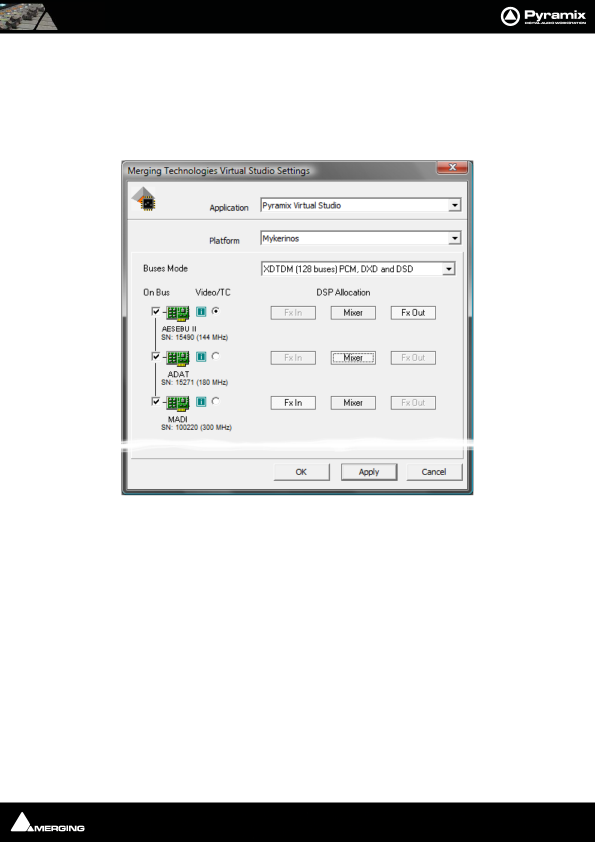
Productivity : Optimizing Pyramix 25 - 435
Allocating DSP
DSP allocation is set in the VS3 Settings Control Panel, for all available "On Bus" cards:
1. Choose the Video/TC card, typically the most powerful card available. The card selected as Video/TC will carry
all TimeCode/video ref/headphone jack connections. This card will be automatically dedicated to Fx-Out.
2. Select which card will be allocated to Mixer, by clicking the Mixer button on the chosen card
3. Remaining card(s) will be automatically dedicated to Fx In
Mykerinos VS3 Control Panel Settings Window
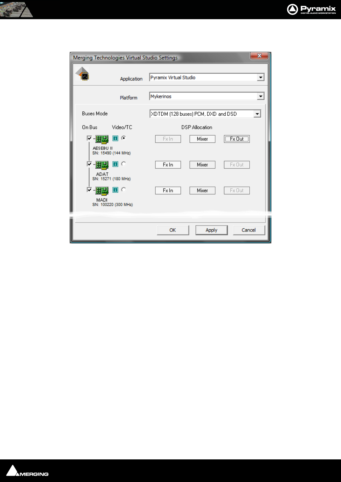
Productivity : Optimizing Pyramix 25 - 436
Note: If most of the DSP power is needed for Input strips, Mixer can also be assigned
concurrently with Fx Out on the same card:
DSP routing is totally independent of I/O routing, thanks to the HDTDM / XDTDM design for bussing (apart from
the headphone out…)
Physical I/O routing is available in All Settings > Settings > Hardware > HDTDM(XDTDM) PCM I/O Routing and
can be changed with Pyramix running, when there is no project open.
Mykerinos VS3 Control Panel Settings Window
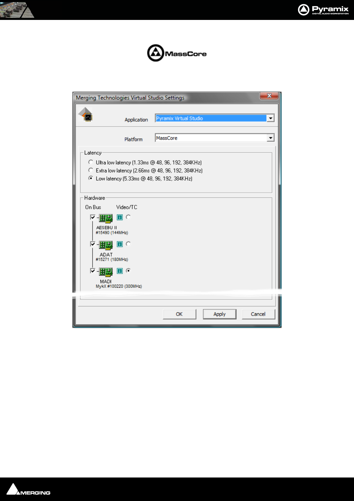
Productivity : Optimizing Pyramix 25 - 437
MassCore DSP Allocation
Note: MassCore DSP Allocation is automatic so when in MassCore mode the Virtual
Studio Settings window will look like this:
Mykerinos VS3 Control Panel Settings Window

Productivity : Optimizing Pyramix 25 - 438
Use Work Spaces
Workspaces provide a powerful means of storing and recalling the state of a number of parameters of the Project
Editing Panel, especially Track Header Panel switches. In effect a Workspace is a snapshot which enables the oper-
ator to quickly switch between set-ups for a variety of common tasks.
• New Workspaces can be added by clicking on the first line of the Tab Window and typing a name.
• Workspaces can be deleted by selecting them and pressing the ‘Delete’ key.
• Applying a Workspace is achieved by double-clicking on the Workspace icon.
• Parameters remembered by Workspaces are selectable per Workspace by clicking in the appropriate col-
umns.
The penultimate column Update on Change allows a stored Workspace to be automatically updated to the cur-
rent values before switching to another one and the last one, Tabs Layout stores the physical positions and sizes
etc. of all Tab Windows.
Creating tracks via paste
This is a fast way of creating tracks.
If a clip is dragged and dropped or copied and pasted from Media Management or a Library onto a blank area of
the TimeLine where no tracks exist, sufficient tracks will be created below the last existing track to accommodate
the number of channels in the clip.
Disable Skin
This option can be found on the All Settings > Application > Desktop layout page. It may improve performance
on certain older systems.

USER MANUAL
www.merging.com/Pyramix
Menus
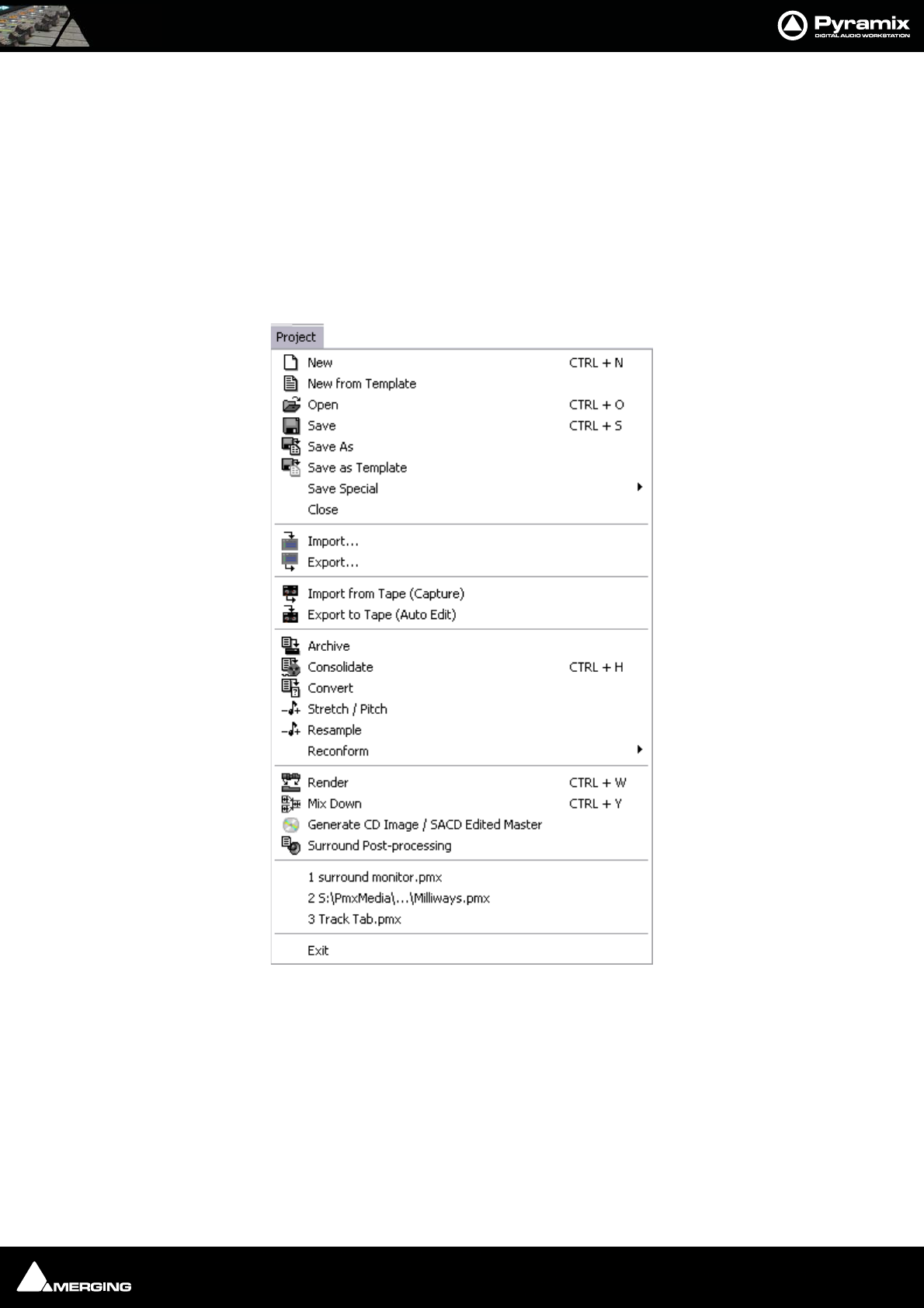
Menus : Pyramix Default Menus 26 - 440
Pyramix Default Menus
Menus are highly configurable in Pyramix. Commands can be hidden or added and entire menus shown or hid-
den. If a command cannot be found check if it is currently hidden in the relevant tab page of Settings > All Set-
tings > Application > Desktop Layout. Please see also Toolbars and Menus on page 328
Many Pyramix menu entries are self-explanatory. These are simply listed. Other menu entries are either described
here or elsewhere in this manual. Wherever menu options have Toolbar Icon alternatives, these are shown in the
menu screenshots.
Project
New Create a new Editing Project or Digitizing session
New from Template Create a new Project based on an existing factory or user Template
Open Open an existing Editing Project or Digitizing session
Save Save current Project. If the project has never been saved, the Save As dialog box will
appear
Save As Save current Project with a new name
Save as Template Save current Project as a Template
Save Special>
Project menu

Menus : Project 26 - 441
Save as Version 4.3 For compatibility
Save as Version 5.0
Save as Version 5.1
Save as Version 6.0.8
Save as Version 6.0.15 SP1
Save as Version 6.0.16 SP2
Etc.
Close Close the current Project. If the file has changed since last saved, the Save dialog box will
appeart
Import... Opens the InterChange Import Manager
Export... Opens the InterChange Export Manager
Import from Tape (Capture) Allows media on external devices to be captured into the current Project
Export to Tape (Auto Edit) Allows the current composition to be exported to an external device
Archive Creates a copy of the current project with all associated media to another location
Consolidate Create an optimized set of media for the current project
Convert Convert the whole project to an other sampling rate
Stretch / Pitch Stretch or Pitch the whole project from 24fps to 25fps (4% time compression or pitch
reduction) or 25fps to 24fps (4.17% time expansion or pitch rise)
Resample Opens the resampler
Reconform >
Relink to New Media Opens a dialog offering various options similar to the CMX Import function. This
allows relinking all or a selection of clips to new media. Typically. this is used for
replacement of 16 bit versions of audio files with 24 bit versions based on the clip
name, media name, Scene & Take information or original TimeCode.
Load Change EDL & Reconform Allows a so-called “Change EDL” generated from a “State 1 EDL” and a “State 2
EDL” to be loaded. Cues are rearranged within the current project to reflect the
change from State 1 to State 2
Detect Picture Change & Reconform You can use Pyramix to perform a Reconform from two Video Projects.
After loading the Video Projects select this option to begin the Reconform process.
Ovation Only Applicable to Ovation Systems. Please see the Ovation User Guide for details.
Render Render the project or current selection to a new Media File
Mix Down Mix the project or current selection down to a new Media File through the mixing con-
sole
Generate CD Image / SACD Edited Master Opens the Generate CD Image / SACD Edited Master Dialog:
DSD options are only available for DSD Projects
SACD Cutting Master Wizard Only applicable to SACD systems. Please see the SACD User Guide.
Surround Post-processing Enables the current composition to be encoded in different Surround format such as AC3
or DTS (if the appropriate optional encoder plug-in is installed)
“1 surround monitor.pmx” etc. The most recently opened Projects are listed at this position. Clicking on an entry opens
the Project.
Exit To quit the application, choose Exit from the File menu. If there have been changes since
the last time you saved the project, the system will prompt you to save your changes

Menus : Project 26 - 442
Note: The Stretch / Pitch menu selection requires the optional Prosoniq MPEX.
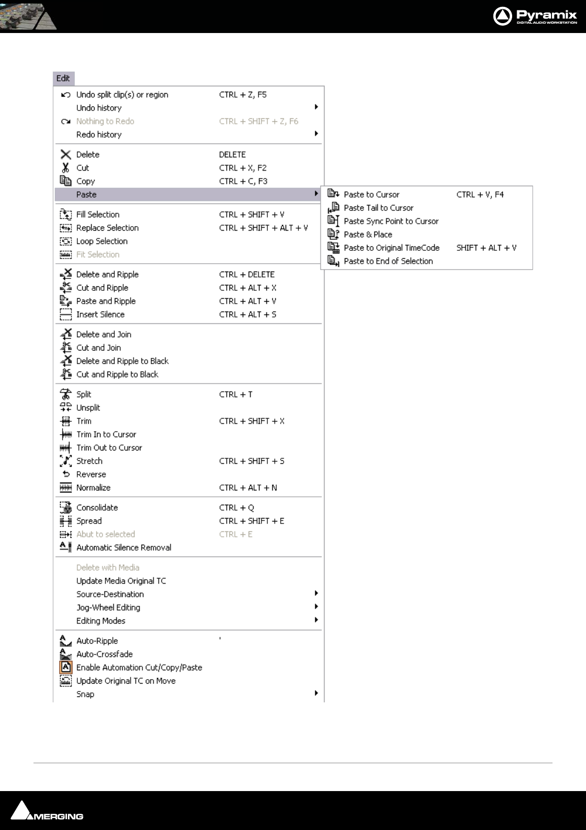
Menus : Edit 26 - 443
Edit
The Edit menu in Pyramix contains the conventional Delete, Cut and Copy commands, and a Paste sub-menu, also
options for Undo and Redo of previous edit operations and special edit commands for placing clips in the Pyramix
Composition Editor.
Paste Sub-menu
Edit menu

Menus : Edit 26 - 444
Undo clip(s) move Undo command changes to show the last edit action and cancels it when selected
Undo history > leads to a sub-menu with a list of all previous editing actions which can be undone
Redo clip(s) move Redo command changes to show the last action undone and cancels it when selected
Redo history > leads to a sub-menu with a list of all editing actions which have been undone and can be
redone
Delete Deletes the currently selected clip/selection
Cut Cuts the current selection from the project and saves it on the Clipboard
Copy Copies the current selection from the project and saves it on the Clipboard
Paste >
Paste to Cursor Inserts what's on the Clipboard to the current cursor position
Paste & Place This command opens the Placement Tool to allow for more extensive placement
options
Paste to Original TimeCode Inserts what's on the Clipboard to the pasted clip's original source time code posi-
tion
Paste to End of Selection Inserts what's on the Clipboard to the end point of the current selection
Fill Selection This command will substitute the Clipboard contents for the selected clip or region
Replace Selection This command will substitute the Clipboard contents for the selected clip or region and
ripple following clips if there's a length difference
Loop Selection This command will substitute a loop of the Clipboard contents for the selected clip or
region without changing sync on the track
Fit Selection This command allows inserted clips to be fit into specified regions on the Timeline. This
requires the Timezone Time compression/Expansion plug-in
Delete and Ripple Deletes the currently selected clip/selection, forcing a ripple to occur
Cut and Ripple Cuts the current selection from the project and saves it on the Clipboard, forcing a ripple
to occur
Paste and Ripple Inserts what's on the Clipboard to the current cursor position, forcing a ripple
Insert Silence This command will insert blank space (silence) into to the current selection
Delete and Join Deletes the currently selected clip/selection and ripples the end of the clip.
Cut and Join Cuts and saves to the clipboard the currently selected clip/selection and ripples the end
of the clip.
Delete and Ripple to Black Deletes the currently selected clip/selection and ripples all following butted or cross-
faded clips.
Cut and Ripple to Black Cuts and saves to the clipboard the currently selected clip/selection and ripples all fol-
lowing butted or crossfaded clips.
Split This command uses the play cursor as a razor blade to split selected clips into two clips at
the point where the play cursor crosses the selected clips
Unsplit Clips that have been Split, Cut or Crossfaded can now be joined back together providing
they are still in sync and referencing the same media
Trim The Trim handles allow you to shorten or extend the length of a clip by moving the head
or tail relative to the rest of the clip
Trim In to Cursor
Trim Out to Cursor
Stretch This allows a clip to be stretched or squeezed

Menus : Edit 26 - 445
Reverse This allows a clip to be fit into a selection on the Timeline. The values of the Timezone
plug-in will be set automatically to fit the clip into the selection
Normalize Apply the normalize process to the selected clip
Consolidate The Consolidate function will make a selective backup of the media segments in the
Composition
Spread This command allows a space (silence) to be inserted between selected clips
Abut to selected This command abuts all clips between the Mark In and Mark Out on a track to a selected
clip between the marks on the same track
Automatic Silence Removal This command opens the Automatic Silence Removal dialog box
Delete with Media Removes the current selected clip from the composition, and delete the associated
media file
Update Media Original TC Updates the Media Original TC for all selected clips with their TimeCode position in the
composition. This operation modifies the Media and is not reversible
Source-Destination >
Auto-Edit Source to Destination
Executes the appropriate Source/Destination 2, 3 or points editing operation
depending on the Gates status
Overwrite Source to Destination
Overwrites the content between the Destination Track Group Gates with the con-
tent between the Source Track Group Gates
Insert Source to Destination Inserts the content between the Source Track Group Gates to the Destination Track
Group Gates
Replace Source to Destination
Replaces the content between the Destination Track Group Gates with the content
between the Source Track Group Gates by rippling the Destination
Fit Source to Destination Replaces the content between the Destination Track Group Gates with the content
between the Source Track Group Gates by stretching the Source
Auto Set Destination Gate In after Edit
When this option is checked (enabled), the Destination Gate In point is automati-
cally set to the current Gate Out point after any Source-Destination operation
Auto Select Destination after Edit
When this option is checked (enabled), the Destination Track Group is automati-
cally selected after any Source-Destination operation
Limit 1 Gate Sources to End/Beginning of Clip
When this option is checked (enabled), then the Source material between the
Source Gate and the end of the clip under the Gate instead of the whole track is
copied to the Destination
3 Gates Auto-Edit does Overwrite
When this option is checked (enabled), then when 2 Gates are set in a Source and 1
is set in the Destination then AutoEdit performs an Overwrite operation
3 Gates Auto-Edit does Insert
When this option is checked (enabled), then when 2 Gates are set in a Source and 1
is set in the Destination then AutoEdit performs an Insert operation
Jog-Wheel Editing>
A number of editing actions may be undertaken on a selected clip or group of
clips using a jog-wheel on an external hardware controller.

Menus : Edit 26 - 446
First select the Clip or group of Clips, then select the desired Jog-Wheel Editing
Mode from the choice of:
Move
Move And XFade
Trim In
Trim Out
Trim Fade In
Trim Fade Out
Trim Fade In X (Symmetrically)
Trim Fade Out X (Symmetrically)
Trim Sync Point
Slide Media
Previous Clip Trim Out
Previous Clip Trim Fade Out
Previous Clip Trim Fade Out X (symmetrically)
Previous Clip Trim Source Out
Now simply move the jog wheel to Move, Trim, or Slide Media of the selected Clip(s)
Pressing the Spacebar or Enter confirms the change(s), Esc cancels.
Editing Modes > Insert Mode >
Overwrite When checked, any clip placed so that it overlaps an existing clip will overwrite the
part of that clip where the two overlap.
Insert Track When checked, any clip placed on a track will be inserted into the track and will rip-
ple all other material on the track later in time (to the right) by the length of the clip
being inserted.
Editing Modes > Remove Mode >
Remove When checked any selected material will simply be removed from the Timeline.
Everything else will be left intact and in the same place.
Remove and Ripple When checked any selected material will be removed from the Timeline. Everything
else to the right (after) the removed material will be Rippled (moved) to the left (earlier)
to take up the space left by the removed material.
Editing Modes > Snap Mode >
Don’t Snap No snap mode set. This mode doesn't affect the behavior of objects placed on a
track. Behavior follows the existing Insert and Remove modes.
Head to End This mode will cause the beginning of any clip placed on a track to snap to the end
of the last clip on the track, abutting the head of the new clip to the end (tail) of the last
clip.
Tail to Beginning This mode will cause any clip placed on a track to snap to the beginning of the first
clip on the track, abutting the tail of the new clip to the head of the first clip.
Head to Nearest This mode will cause any clip placed on a track to snap the head of the clip to the
nearest edit point or mark on the track. This includes the head or tail of existing clips on
the track, as well as the Play Head Cursor, Mark In, Mark Out, Named Markers, or CD
Marks. The clip will interact with existing clips according to the Insert Mode setting.
Tail to Nearest This mode will cause any clip placed on a track to snap the tail of the clip to the near-
est edit point or mark on the track. This include the head or tail of existing clips on the
track, as well as the Play Head Cursor, Mark In, Mark Out, Named Markers, or CD Marks.
The clip will interact with existing clips according to the Insert Mode setting.

Menus : Edit 26 - 447
Snap to Original TimeCode This mode will cause any clip placed on a track to snap the head of the clip to the
time location represented by the clips original TimeCode. The clip will interact with
existing clips according to the Insert Mode setting.
Auto-Ripple When this option is checked (enabled) all Insert or Remove operations ripple the rest of
the track
Auto-Crossfade When this option is checked (enabled) the default cross-fade (defined in the Fade Editor
Tab Window is applied to any Paste or Source-Destination operation
Enable Automation Cut/Copy/Paste
When this option is checked (enabled) all Cut / Copy / Paste operations also include
automation tracks
Update Original TC on Move When this option is checked (enabled) the original TimeCode stamp of any copied/move
selection is updated to the position it was in before the current move
Snap >
Snap Off When this option is checked (enabled), Snap mode is disabled
Snap to Edits When this option is checked (enabled), Snap mode is set to Edits
Snap to Scale When this option is checked (enabled), Snap mode is set to Scale
Snap to Feet Scale When this option is checked (enabled), Snap mode is set to Feet Scale
Snap to Bars & Beats Grid When this option is checked (enabled), Snap mode is set to Bars & Beats Grid
Snap Cursor When this option is checked (enabled), the Cursor is also snapped following the cur-
rent mode
Snap Region Selection When this option is checked (enabled), the Selection is also snapped following the
current mode
Snap Selection Head When this option is checked (enabled), Snap mode is set to Head of selection
Snap Selection Tail When this option is checked (enabled), Snap mode is set to Tail of selection
Snap Selection Sync Point When this option is checked (enabled), Snap mode is set to Sync Point of
selection
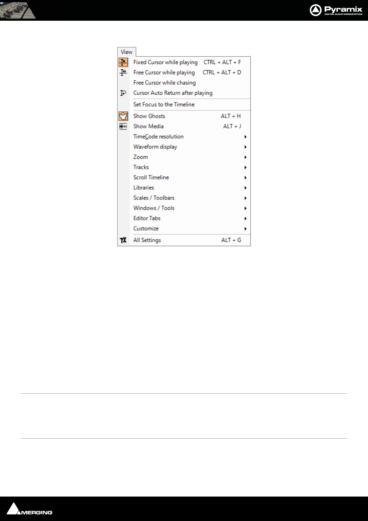
Menus : View Menu 26 - 448
View Menu
Fixed Cursor while playing When checked (enabled) Playhead Cursor remains stationary while playing at the posi-
tion set in the Settings > All Settings > Playback/Record page and the Tracks scroll
from right to left.
Free Cursor while playing When checked (enabled) Playhead Cursor disappears when the screen boundary is
reached. I.e. the Timeline is not redrawn.
Free Cursor while chasing When checked (enabled) in conjuction with either of the above options the Playhead
Cursor and Timeline position can be freely manipulated from the workstation whenever
the TimeCode Master machine is in Stop, Rew, FF, Play, Locate, etc. as well as while chas-
ing, but as soon as Pyramix has locked to incoming TimeCode, the cursor will "jump" to
current TC. This used to be the default behavior. When diabled, the Cursor will always be
locked to TimeCode when Pyramix is set to chase, whether in Stop, Rew, FF, Play, Locate,
etc. as well as while chasing.
Cursor Auto-Return after playing
When checked (enabled) Playhead Cursor returns to its starting position when playback
stops
Set Focus to the Timeline Most useful when mapped to a keyboard shortcut. When a floating Tab or other window
has been opened that keeps the focus and monopolizes some commands, typically the
Space Bar and Cursor buttons invoking this command is the direct equivalent of clicking
in the Timeline to restore the focus, but avoids having to grab the mouse and loosing any
selections.
Show Ghosts When checked (enabled) shows a ghost image of clips on related virtual tracks
Show Media When checked (enabled) shows the full extent of the underlying digital media for a
selected clip as a red line on the track above and below the selected clip with a grayed
out image of the waveform when this is on
View menu

Menus : View Menu 26 - 449
TimeCode Resolution >
Frames Sets the < 1 second Cursor TimeCode display resolution to frames
Samples Sets the < 1 second Cursor TimeCode display to samples
[ms] Sets the < 1 second Cursor TimeCode display to display milliseconds
CD frames Sets the < 1 second Cursor TimeCode display to display CD frames
Display as CD time Sets the TimeCode display to CD Track elapsed time (only available when CD Mark-
ers are present)
Alternate TimeCode Scale - Frames
Alternate TimeCode Scale - Samples
Alternate TimeCode Scale - [ms]
Alternate TimeCode Scale - CD Frames
Waveform Display >
Larger Increase the size of the current waveform display
Smaller Decrease the size of the current waveform display
x1 Sets the magnification factor of the current waveform display to 1x
x2 Sets the magnification factor of the current waveform display to 2x
x4 Sets the magnification factor of the current waveform display to 4x
x8 Sets the magnification factor of the current waveform display to 8x
x16 Sets the magnification factor of the current waveform display to 16x
x32 Sets the magnification factor of the current waveform display to 32x
x64 Sets the magnification factor of the current waveform display to 64x
dB Sets the current waveform display to decibels
Auto-Scale Individual Waveform Sets the current waveform display to automatically display an optimal wave-
form
Auto-Scale Visible Waveform Auto-scales the Waveform based on what is currently seen on screen
Show Full Waveform Sets the current waveform display to display a waveform that is fully colored even at
sample level (like peak display)
Show Waveform Origin Sets the current waveform display to display a waveform that show also at sample
level the 0dB origin
Show Dynamic Waveform
Sets the current waveform display to display a waveform that shows the dynamic
range for each pixel
Hide Clip Name when Waveform Shown
Hides the clip names when the waveform is displayed
Zoom >
Fit in window Adjusts the horizontal magnification (zoom level) of the Project Editor panel to
fit the selected clip or region
Previous zoom Restores the Project Editor Panel view to the previous zoom resolution and location
Zoom In Zooms in by a factor of 2x, centered around the middle of the Project Editor Panel
Zoom Out Zooms out by a factor of 2x, centered around the middle of the Project Editor Panel
Recall Preset >
Zoom 1 Recall Preset Zoom 1
Zoom 2 Recall Preset Zoom 2
Zoom 3 Recall Preset Zoom 3

Menus : View Menu 26 - 450
Zoom 4 Recall Preset Zoom 4
Zoom 5 Recall Preset Zoom 5
Set Preset >
Zoom 1 Set Preset Zoom 1
Zoom 2 Set Preset Zoom 2
Zoom 3 Set Preset Zoom 3
Zoom 4 Set Preset Zoom 4
Zoom 5 Set Preset Zoom 5
Auto Zoom Selection Project Editor Panel display automatically zooms-in to any selection made on the
Timeline
Tracks >
Show all Tracks Show (Unhide) all Tracks and Expand (Uncollapse) all Track Groups
Hide Tracks without selection Hide all tracks that have nothing selected
Fit View to >
Fit View to 1 Track Fit current View to 1 Track
Fit View to 2 Tracks Fit current View to 2 Tracks
Fit View to 4 Tracks Fit current View to 4 Tracks
Fit View to 8 Tracks Fit current View to 8 Tracks
Fit View to 16 Tracks Fit current View to 16 Tracks
Fit View to All Tracks Fit current View to All Tracks
Enlarge Track Size Enlarge current Track Size
Reduce Track Size Reduce current Track Size
Scroll Timeline
Scroll Timeline Left Scroll the whole Timeline to the left
Scroll Timeline Right Scroll the whole Timeline to the right
Scroll Timeline Up Scroll the whole Timeline up
Scroll Timeline Down Scroll the whole Timeline down
Libraries
Folders
Library Folders Up
Library Folders Down
Library Folders Collapse
Library Folders Expand / Focus on List
List
Library List Up
Library List Down
Library List Focus On Folders
Library List Focus On Trimmer
Trimmer
Library Trimmer Focus On List
Library Trimmer Play From In
Library Trimmer Play Form Start
Library Trimmer Stop
Library Trimmer Set In Point
Menus : View Menu 26 - 451
Library Trimmer Set Out Point
Library Trimmer Set Sync Point
Scales / Toolbars >
TimeCode Toolbar Shows/Hides the main TimeCode Toolbar
Alternate TimeCode Scale
Alternate TimeCode Scale Settings
Feet Adds a ruler calibrated in Feet below the Time ruler (if present)
Feet Settings Opens the Feet Settings dialog box
Bars&Beats Adds a ruler calibrated in Bars&Beats below the Time ruler (if present)
Bars&Beats Settings Opens the Bars&Beats Settings dialog box
Tempo Map Adds a Tempo map below the Time ruler (if present)
Source - Destination
Transport Toolbar Shows/Hides the Transport Toolbar
Automation Toolbar Shows/Hides the Automation Toolbar
Windows / Tools >
Transport Displays the Transport Large Control
Mixer Displays the Mixer
Monitor Displays the Monitor
Media Management Displays the Media Management folders
Global libraries Displays the Global Libraries
Fade Library Displays the Fade library
Information Displays the Information Window
On the Air Displays the On the Air Window
I/O Status Displays the I/O Status Window
Editor Tabs >
Overview Open Overview Tab window
EDL Open EDL Tab window
Document Libraries Open Document Libraries Tab window
Tracks Open Tracks Tab window
Track Groups Open Track Groups Tab window
Playlists Open Playlists Tab window
Workspaces Open Workspaces Tab window
Selection Open Selection Tab window
Fade Editor Open Fade Editor Tab window
Markers Open Markers Tab window
CD Open CD Tab window
Notes Open Notes Tab window
Machines Open Machines Tab window
Media Management Open Media Management Tab window
Global Libraries Open Global Libraries Tab window
ADR Open ADR Tab window
Log Open Log Tab window

Menus : View Menu 26 - 452
Show all Tabs Shows all Tabs in docking area
Close all Tabs Hides all Tabs
Toggle Show/Close all Tabs As it says. Mainly usefule when bound to keyboard shortcut.
Dock all Tabs Return all floating Tabs to the Tab dock
Load Default Tabs Layout As it says
Save Default Tabs Layout Saves the current Tabs Layout as the default
Always Use Default Tabs Layout Default Tabs Layout is used regardless of Tab layout saved with Project
Tabs layout Presets
Save Tabs Layout Preset 1
to
Save Tabs Layout Preset 10
Load Tabs Layout Preset 1
to
Load Tabs Layout Preset 10
Customize>
Keyboard Shortcut Editor Opens the Keyboard Shortcut Editor
Macro Editor Opens the Macros Window
All Settings Opens the Pyramix Settings Window
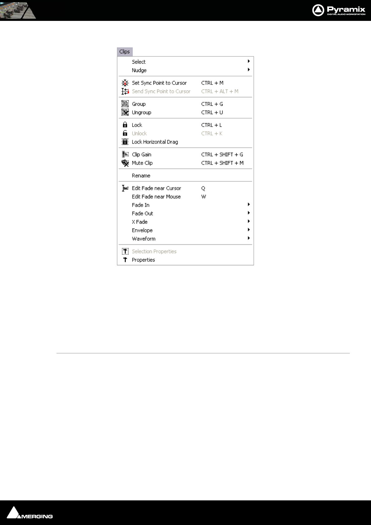
Menus : Clips 26 - 453
Clips
Select >
Select All Select all clips on Timeline
Select All to Mark In Select all clips on Timeline, to the current Mark In Point
Select All between Marks Select all clips on Timeline, between current In/Out Marks
Select All from Mark Out Select all clips on Timeline, from the current Mark Out Point
Select Source Select all clips on current audio track
Deselect All Deselect all currently selected clips
Select Previous Clip Select clip to left of currently selected clip
Select Next Clip Select clip to right of currently selected clip
Add Previous Clip to Selection
Apply selection to clip to left of currently selected clip
Add Next Clip to Selection Apply selection to clip to right of currently selected clip
Add all Preceding Clips to Selection
Apply selection to all clips preceding the currently selected clip
Add all Following Clips to Selection
Apply selection to all clips following the currently selected clip
Nudge >
Nudge to Previous Edit Nudges the selected clip to the left (earlier in time) to the previous edit points in
the track or marks in the editor
Clips menu

Menus : Clips 26 - 454
Nudge to Next Edit Nudges the selected clip to the right (later in time) to the next edit points in the
track or marks in the editor
Nudge to Left Nudges the selected clip to the left (earlier in time) by an amount equal to the cur-
rent Nudge setting
Nudge to Right Nudges the selected clip to the right (later in time) by an amount equal to the cur-
rent Nudge setting
Nudge to Left Custom Nudges the selected clip to the left (earlier in time) by an amount that can be
entered with the keyboard
Nudge to Right Custom Nudges the selected clip to the right (later in time) by an amount that can be
entered with the keyboard
Nudge to Left Custom in Bars/Beats
Nudges the selected clip to the left (earlier in time) by an amount that can be
entered in Bars/Beats with the keyboard
Nudge to Right Custom in Bars/Beats
Nudges the selected clip to the right (later in time) by an amount that can be
entered in Bars/Beats with the keyboard
Nudge In to Left (Pressing Control has the same effect as per moving with the mouse)
Nudge In to Right (Pressing Control has the same effect as per moving with the mouse)
Nudge Out to Left (Pressing Control has the same effect as per moving with the mouse)
Nudge Out to Right (Pressing Control has the same effect as per moving with the mouse)
Nudge Media to Left
Nudge Media to Right
Move Up Moves the selected clip or region up to the adjacent track above it
Move Down Moves the selected clip or region up to the adjacent track below it
Move Up with Fade Moves the selected clip or region up to the adjacent track above it. If there is
another clip on the adjacent track at that location, it will interact with it by cross-
fading
Move Down with Fade Moves the selected clip or region up to the adjacent track below it. If there is
another clip on the adjacent track at that location, it will interact with it by cross-
fading
Current Setting >
Nudge Setting 1Apply Nudge Setting 1
Nudge Setting 2Apply Nudge Setting 2
Nudge Setting 3Apply Nudge Setting 3
Nudge Setting 4Apply Nudge Setting 4
Nudge Setting 5Apply Nudge Setting 5
Set Sync Point to Cursor Sets the selected clip’s Sync Point at the current cursor position
Send Sync Point to Cursor Sends (moves) the currently selected clip so that its Sync Point is aligned with the current
position of the Play Cursor
Group Groups together all selected clips in the Timeline
Ungroup Ungroups members of a selected group clip in the Timeline
Lock Locks selected clips so that they can no longer be edited or moved in the Timeline
Unlock Unlocks selected locked clips so that they can be edited again
Lock Horizontal Drag When enabled, clips cannot be dragged horizontally (left to right)
Clip Gain Displays an audio fader to set the audio level for the selected clips
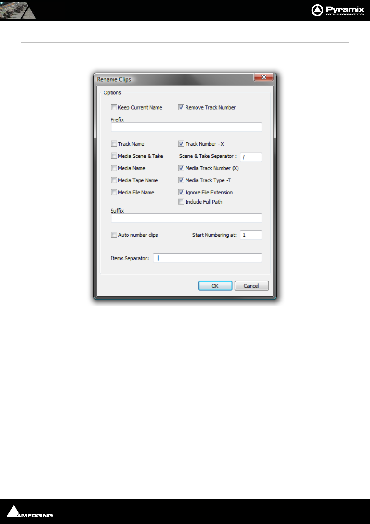
Menus : Clips 26 - 455
Mute Clip Mutes all selected clips
Rename Enables a selection of clips to be renamed with various combinable options chosen in the
Rename Clips dialog
Options
Keep Current Name When checked the current name is retained but with the choice of keeping or
removing the current track number in parenthesis
Remove Track Number Removes Track Number from the Clip Name
Prefix Text entry box where a new custom Prefix may be added adding a custom prefix
and suffix text to the automatic renaming and automatically renumbering all
clips.
Track Name
Track Number - X
Media Scene & Take (if available)
Media Name
Media Track Number (X)
Media Tape Name
Media File Name
Ignore File Extension
Include Full Path
Suffix Text entry box where a new custom Suffix may be added
Auto number clips When checked clips are numbered starting with the value in:
Rename Clips dialog

Menus : Clips 26 - 456
Starting Numbering at:
Items Separator Text entry box where a new custom Separator may be added
Edit Fade near Cursor Opens the Fade Editor with the audio fade located near the current Playhead cursor
position ready to be edited
Edit Fade near Mouse Opens the Fade Editor with the audio fade located near the current mouse cursor posi-
tion ready to be edited
Fade In >
Fade Out >
X Fade >
Note: Sub-menu options for Fade In, Fade Out, and X Fade are the same. For brevity,
only the Fade In sub-menu options are listed.
Fade In New Apply new Fade In
Fade In Edit
Default > Edit Fade In
Fade In Default Apply Fade In Default
Fade In Default Curve Apply Fade In Default Curve
Fade In Standard >
Fade In Power Linear Apply Fade In Power Linear
Fade In Tension Linear Apply Fade In Tension Linear
Fade In dB Linear Apply Fade In dB Linear
Fade In Cosine Apply Fade In Cosine
Fade In Root Cosine Apply Fade In Root Cosine
Envelope >
Envelope Reset Reset the gain envelope for the whole selection by deleting all envelope nodes
within the selection only on the track under the mouse cursor when Reset is cho-
sen.
Envelope Reset Selection Reset the gain envelope for the whole selection by deleting all envelope nodes
within the selection.
Envelope Copy to Selection Copies the values of all envelope nodes within the selection from the track
under the mouse cursor when Copy to Selection is chosen to all other tracks in the
selection
Envelope Punch Places four new envelope nodes at the bounds of the selection on the track under
the mouse cursor when Punch is chosen and opens the Punch Envelope dialog
box
Envelope Punch Selection Carries out the same operation as Punch but to all tracks in the current Selection.
Waveform >
Waveform follow Track Waveform display of the clip will always correspond to the setting for the entire
track in the Track information and Settings panel
Waveform force Waveform clip will always show the waveform display regardless of the waveform display set-
tings for the track
Waveform force Name clip will always show the clip name regardless of the waveform display settings for
the track
Generate Waveform Generate the waveform data in the background for the selected clip
Selection Properties Opens the Selection Properties display window, which shows details concerning the
current selection
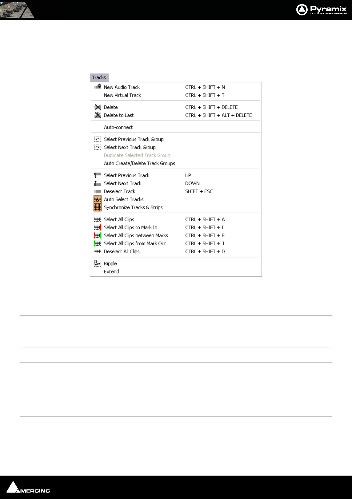
Menus : Tracks 26 - 457
Properties Opens the Selection Properties display window, which shows details concerning the
currently selected clip
Tracks
New Audio Track Allows new audio tracks to be created on the Composition Editor
New Virtual Track Allows new virtual tracks to be created on the Composition Editor
Delete Removes the currently selected track from the composition editor
Delete to Last Deletes all tracks between the currently selected tracks to the last track on the Composi-
tion Editor
Auto-connect Automatically connect all tracks sequentially to any available mixer input
Select Previous Track Group Selects the track group above the currently selected track group
Select Next Track Group Selects the track group below the currently selected track group
Duplicate Selected Track Group Duplicates the currently selected track group
Auto Create/Delete Track Groups When enabled allows Track Groups to be automatically created when clips insertion
requires creation of new tracks
Select Previous Track Selects the audio track above the currently selected track
Select Next Track Selects the audio track below the currently selected track
Deselect Track Deselects the currently selected audio track
Auto Select Tracks The audio track is automatically selected on any click / move in its content
Tracks menu

Menus : Tracks 26 - 458
Synchronize Tracks & Strips The audio track and its associated mixing console strip are always selected together
Select All Clips This command selects and highlights all clips on the selected track
Select All Clips to Mark In Selects all clips on the track from the beginning of the composition up to the mark in
Select All Clips between Marks Selects all clips on the track between the Mark In and Mark Out
Select All Clips from Mark Out Selects all clips on the track from the Mark Out to the end of the composition
Deselect All Clips Deselects all clips on the selected track
Ripple Launches the Ripple Tracks dialog box
Extend Automatically extends the number of tracks to accommodate all the Media channels of
each of the clips of one or more timeline track(s)
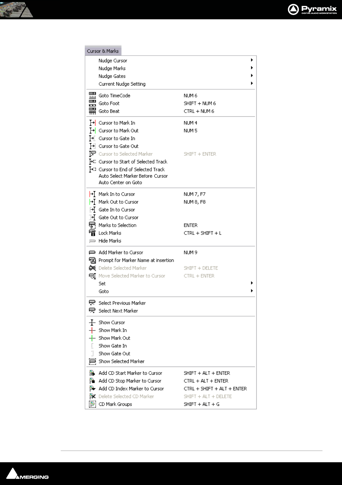
Menus : Cursors & Marks 26 - 459
Cursors & Marks
Nudge Cursor >
Nudge Cursor to Previous Edit Nudge Cursor to Previous Edit
Nudge Cursor to Next Edit Nudge Cursor to Next Edit
Cursors & Marks menu

Menus : Cursors & Marks 26 - 460
Nudge Cursor to Previous Clip Nudge Cursor to Previous Clips
Nudge Cursor to Next Clip Nudge Cursor to Next Clip
Nudge Cursor to Previous Clip Fade Nudge Cursor to Previous Clip Fade
Nudge Cursor to Next Clip Fade Nudge Cursor to Next Clip Fade
Nudge Cursor to Previous Marker Nudge Cursor to Previous Marker
Nudge Cursor to Next Marker Nudge Cursor to Next Marker
Nudge Cursor to Previous CD Marker Nudge Cursor to Previous CD Marker
Nudge Cursor to Next CD Marker Nudge Cursor to Next CD Marker
Nudge Cursor to Left Nudge Cursor to Left
Nudge Cursor to Right Nudge Cursor to Right
Nudge Cursor to Left with Region Nudge Cursor to Left and update the nearest selection
boundary to this location
Nudge Cursor to Right with Region Nudge Cursor to Right and update the nearest selection
boundary to this location
Nudge Cursor to Left Custom Nudge Cursor to Left by an amount entered with the Key-
board
Nudge Cursor to Right Custom Nudge Cursor to Right by an amount entered with the Key-
board
Nudge Cursor to Left Custom in Bars/Beats Nudge Cursor to Left by an amount entered in Bars/Beats
with the Keyboard
Nudge Cursor to Right Custom in Bars/Beats Nudge Cursor to Right by an amount entered in Bars/Beats
with the Keyboard
Nudge Cursor to Previous Foot Nudge Cursor to the Previous Foot
Nudge Cursor to Next Foot Nudge Cursor to the Next Foot
Nudge Cursor to Previous Foot Frame Nudge Cursor to the Previous Foot Frame
Nudge Cursor to Next Foot Frame Nudge Cursor to the Next Foot Frame
Nudge Cursor to Previous Bar Nudge Cursor to the Previous Bar
Nudge Cursor to Next Bar Nudge Cursor to the Next Bar
Nudge Cursor to Previous Beat Nudge Cursor to the Previous Beat
Nudge Cursor to Next Beat Nudge Cursor to the Next Beat
Nudge Cursor to Previous Grid Step Nudge Cursor to the Previous Grid Step
Nudge Cursor to Next Beat Grid Step Nudge Cursor to the Next Grid Step
Nudge Marks >
Nudge Mark In to Left Nudge Mark In to Left
Nudge Mark In to Right Nudge Mark In to Right
Nudge Mark In to Left Custom Nudge Mark In to Left by an amount entered with the Key-
board
Nudge Mark In to Right Custom Nudge Mark In to Right by an amount entered with the Key-
board
Nudge Mark In to Left Custom in Bars/Beats Nudge Mark In to Left by an amount entered in Bars/Beats
with the Keyboard
Nudge Mark In to Right Custom in Bars/Beats Nudge Mark In to Right by an amount entered in Bars/Beats
with the Keyboard
Nudge Mark Out to Left Nudge Mark Out to Left
Nudge Mark Out to Right Nudge Mark Out to Right

Menus : Cursors & Marks 26 - 461
Nudge Mark Out to Left Custom Nudge Mark Out to Left by an amount entered with the Key-
board
Nudge Mark Out to Right Custom Nudge Mark Out to Right by an amount entered with the
Keyboard
Nudge Mark Out to Left Custom in Bars/Beats Nudge Mark Out to Left by an amount entered in Bars/Beats
with the Keyboard
Nudge Mark Out to Right Custom in Bars/Beats Nudge Mark Out to Right by an amount entered in Bars/
Beats with the Keyboard
Nudge Gates >
Nudge Gate In to Left Nudge Gate In to Left
Nudge Gate In to Right Nudge Gate In to Right
Nudge Gate Out to Left Nudge Gate Out to Left
Nudge Gate Out to Right Nudge Gate Out to Right
Current Nudge Setting>
Nudge Setting 1
Nudge Setting 2
Nudge Setting 3
Nudge Setting 4
Nudge Setting 5
Goto TimeCode Opens the Goto TimeCode dialog box, which allows the Play Cursor to be positioned to a
specific TimeCode position
Goto Foot Allows the Play Cursor to be positioned to a specific Footage
Goto Beat Allows the Play Cursor to be positioned to a specific Beat
Cursor to Mark In Moves the Play Cursor to the Mark In
Cursor to Mark Out Moves the Play Cursor to the Mark Out
Cursor to Gate In Moves the Play Cursor to the selected track group Gate In
Cursor to Gate Out Moves the Play Cursor to the selected track group Gate Out
Cursor to Selected Marker Moves the Play Cursor to the Selected Marker
Cursor to Start of Selected Track Moves the Play Cursor to the start position of the first clip on the selected track
Cursor to End of Selected Track Moves the Play Cursor to the end position of the first clip on the selected track
Auto Center on Goto When enabled, the Project Editor will automatically center the display to the new Play
Cursor position when the Goto TimeCode command is used
Auto-Select Marker Before Cursor When enabled the Marker immediately before the Cursor will be selected. As the Cursor is
moved the selection will change as the next Marker is passed.
Mark In to Cursor Moves the Mark In to the Play Cursor
Mark Out to Cursor Moves the Mark Out to the Play Cursor
Gate In to Cursor Moves the selected track group Gate In to the Play Cursor
Gate Out to Cursor Moves the selected track group Gate Out to the Play Cursor
Marks to Selection Moves the Mark Out to the current selection
Lock Marks Prevents the Mark In/Out points from being changed
Hide Marks Removes the Mark In/Out cursors
Add Marker to Cursor Adds a new Marker to the current Play Cursor Position

Menus : Cursors & Marks 26 - 462
Prompt for Marker Name at insertion When ticked the Add New Marker dialog opens when a new marker is inserted
Delete Selected Marker Deletes the currently selected Marker
Move Selected Marker to Cursor Moves the selected Marker to the current Play Cursor Position
Set >
Set Marker 1 Set the Marker #1 to the current Play Cursor Position
Note: Set Markers 2 - 10 not shown
Goto>
Goto Marker 1 Set the Play Cursor position to Marker #1
Note: Goto Markers 2 - 10 not shown
Select Previous Marker Selects the previous Marker (left) of the currently selected Marker
Select Next Marker Selects the next Marker (right) of the currently selected Marker
Show Cursor Automatically centers the display of the Project Editor to the Play Cursor
Show Mark In Automatically centers the display of the Project Editor to Mark In current position
Show Mark Out Automatically centers the display of the Project Editor to Mark Out current position
Show Gate In Automatically centers the display of the Project Editor to the selected track group Gate In
Show Gate Out Automatically centers the display of the Project Editor to the selected track group Gate
Out
Show Selected Marker Automatically centers the display of the Project Editor to the currently selected Marker
Add CD Start Marker to Cursor Adds a CD Start marker at the Play Cursor position
Add CD Stop Marker to Cursor Adds a CD Stop marker at the Play Cursor position
Add CD Index Marker to Cursor Adds a CD Index marker at the Play Cursor position
Delete Selected CD Marker Deletes the currently selected CD Marker
CD Mark Groups Enables automatic creation of CD Markers Groups in the Project Editor
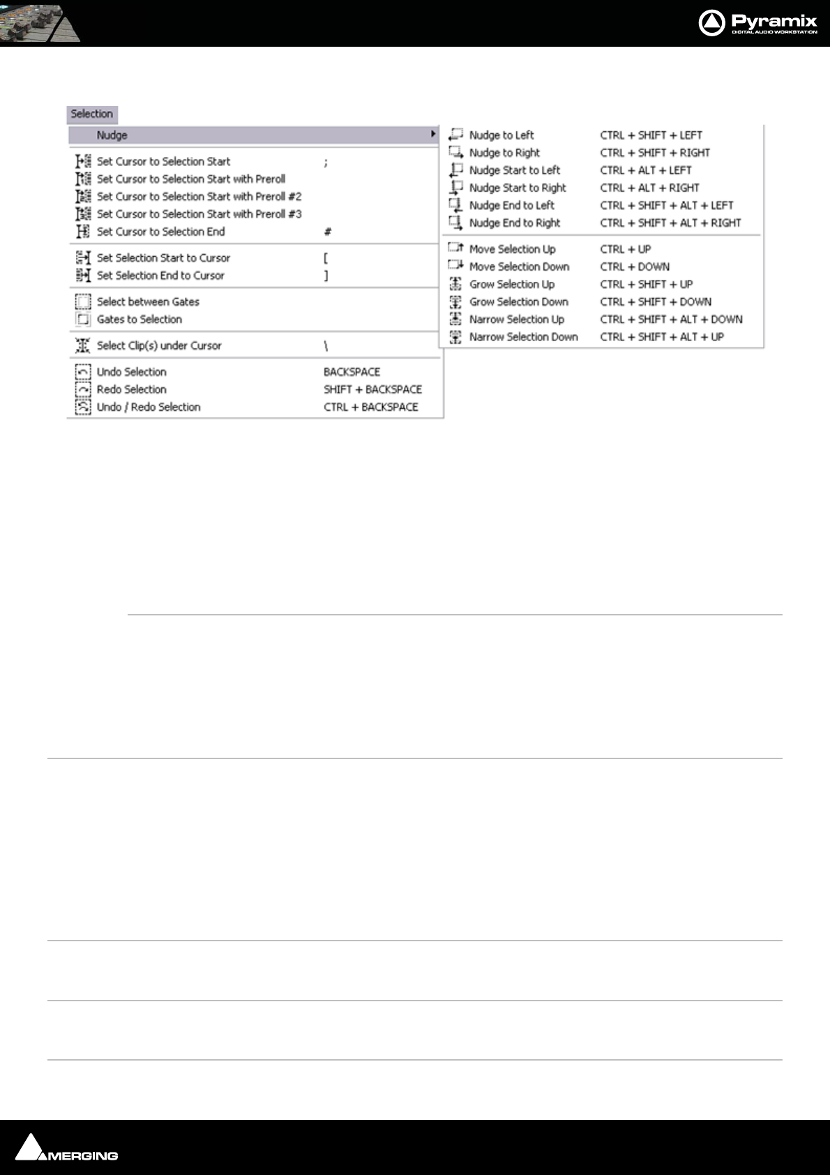
Menus : Selection 26 - 463
Selection
Nudge >
Nudge to Left Nudges the selection to the left
Nudge to Right Nudges the selection to the right
Nudge Start to Left Nudges the selection start to the right
Nudge Start to Right Nudges the selection start to the left
Nudge End to Left Nudges the selection end to the right
Nudge End to Right Nudges the selection end to the left
Move Selection Up Moves the current selection to the track above its current position
Move Selection Down Moves the current selection to the track below its current position
Grow Selection Up Applies the current selection to the track above its current position
Grow Selection Down Applies the current selection to the track below its current position
Narrow Selection Up Removes the current selection from the track above its current position
Narrow Selection Down Removes the current selection from the track below its current position
Set Cursor to Selection Start Positions the Play Cursor to the start point of the current selection
Set Cursor to Selection Start with PrerollPositions the Play Cursor to the start point of the current selection, adding the
defined Preroll value
Set Cursor to Selection Start with Preroll #2Positions the Play Cursor to the start point of the current selection, adding the
defined Preroll #2 value
Set Cursor to Selection Start with Preroll #3Positions the Play Cursor to the start point of the current selection, adding the
defined Preroll #3 value
Set Cursor to Selection End Positions the Play Cursor to the end point of the current selection
Set Selection Start to Cursor Positions the start point of the current selection to the Play Cursor position
Set Selection End to Cursor Positions the end point of the current selection to the Play Cursor position
Select between Gates Sets the Selection between the selected track group Gates
Gates to Selection Moves the Gates to the extremities of the current selection
Auto Select Clip(s) under Cursor Automatically Selects the clip(s) currently in contact with the Playhead Cursor
Cursors & Marks menu
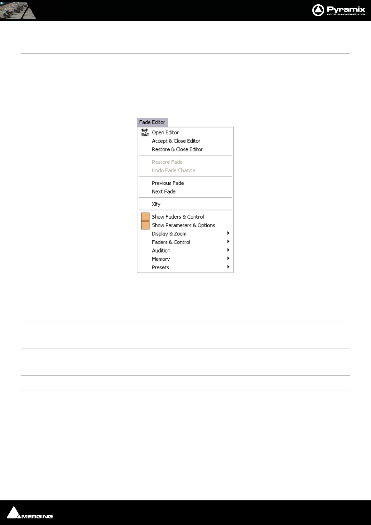
Menus : Fade Editor 26 - 464
Select Clip(s) under Cursor Selects the clip(s) currently in contact with the Playhead Cursor
Add/Remove Clip(s) under Cursor to Selection
Undo Selection Cancels the last selection command
Redo Selection Cancels (redo) the last Undo Selection command
Undo / Redo Selection Toggles between the last Undo / Redo Selection command
Fade Editor
Open Editor Opens the Fade Editor window
Accept & Close Editor Approve changes to the fade and close Fade Editor window
Restore & Close Editor Restore fade to original state and close Fade Editor window
Restore Fade Restore fade to original state
Undo Fade Change Undoes the last parameter change
Previous Fade Select / Edit previous fade
Next Fade Select / Edit net fade
Xify Reset the current fade to a standard Power X fade
Show Faders & Control Show the Faders and Control Section of the Fade Editor
Show Parameters & Options Show the Parameters and Options section of the Fade Editor
Display & Zoom >
Fit Fade Zoom around the current Fade (Reset Zoom)
Zoom In Zoom in on graphic display
Zoom Out Zoom out on graphic display
Display & Zoom Options >
No Auto-Center Auto-Centering off
Fade Editor menu

Menus : Fade Editor 26 - 465
Auto-Center Fade Auto-Centering on
Auto-Center Reference Point Auto Center on Reference Point
Free Zoom Follows only Zoom Reset, In and Out
Auto-Zoom Automatically Zooms around the current Fade after some operations
Auto-Zoom/Free Automatically Zooms around the current Fade but only when it enters the
Fade Editor, thereafter, the Zoom is Free
Timeline Zoom Follows the Timeline Zoom factor
Zoom Preset 1 Recall Preset Zoom #1
Zoom Preset 2 Recall Preset Zoom #2
Zoom Preset 3 Recall Preset Zoom #3
Zoom Preset 4 Recall Preset Zoom #4
Zoom Preset 5 Recall Preset Zoom #5
Faders & Control >
Nudge Out Gain Less
Nudge Out Gain More
Nudge In Gain Less
Nudge In Gain More
Nudge Intercept Less
Nudge Intercept More
Nudge Asymmetry Less
Nudge Asymmetry More
Nudge Out Length Less
Nudge Out Length More
Nudge In Length Less
Nudge In Length More
Nudge Out Position Left
Nudge Out Position Right
Nudge In Position Left
Nudge In Position Right
Nudge In Media Left
Nudge In Media Right
Nudge Out Media Left
Nudge Out Media Right
Faders & Control Options >
Link Length Links length of Fade Out & In
Mirror Length Length of Fade Out and In will be changed symmetrically (centered)
Link Position Links position of Fade Out & In
Fade Safe Ensures all following fades (to the right of the one being edited) are left
intact while editing the current fade.
Force Safe
Audition >
Audition X Fade
Audition X Fade with Ref

Menus : Fade Editor 26 - 466
Audition Out with Curve
Audition Out without Curve
Audition Out after Fade
Audition Out with Curve with Ref
Audition Out without Curve with Ref
Audition Out after Fade with Ref
Audition Out Original Material
Audition In with Curve
Audition In without Curve
Audition In before Fade
Audition In with Curve with Ref
Audition In without Curve with Ref
Audition In before Fade with Ref
Audition In Original Material
Audition Options >
Audition Pre-Roll 1
Audition Pre-Roll 2
Audition Pre-Roll 3
Audition Post-Roll 1
Audition Post-Roll 2
Audition Post-Roll 3
Audition Speed 100%
Audition Speed 50%
Audition Speed 25%
Audition Solo
Audition Loop
Audition After Nudge
Memory >
Set Memory 1
Set Memory 2
Set Memory 3
Set Memory 4
Set Memory 5
Recall Memory 1
Recall Memory 2
Recall Memory 3
Recall Memory 4
Recall Memory 5
Presets >
Load Default X Curve
Load Default X Preset
Save Default X Preset
Load Default Out Curve
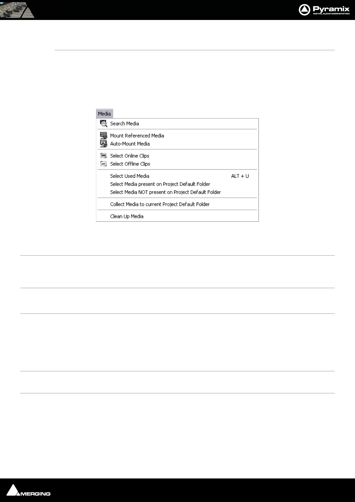
Menus : Media 26 - 467
Load Default Out Preset
Save Default Out Preset
Load Default In Curve
Load Default In Preset
Save Default In Preset
Media
Search Media Opens the Media Search Tool with the Query page displayed. (See User Manual :
Media Management Chapter for details)
Mount Referenced Media Mounts all media not already mounted and used in the current Project
Auto-Mount Media When selected, whenever a reference from an Offline library is placed in the current
Project, the Media will automatically be mounted.
Select Online Clips Selects all Clips in the Timeline whose Media files are currently mounted
Select Offline Clips Selects all Clips in the Timeline whose Media files are not currently mounted
Select Used Media Opens a floating Media Manager window containing all media used by the current
Project.
Select Media present on Project Default Folder Opens a floating Composition Library window with all Media present in the
Project Default folder selected (highlighted)
Select Media NOT present on Project Default Folder Opens a floating Composition Library window with all Media NOT
present in the Project Default folder selected (highlighted)
Collect Media to current Project Default Folder Copies all media files used in the current project (as shown when the previ-
ous Select Media not present ... is invoked to the current Project Default Folder.
Clean-Up Media Opens the Choose a Media Folder to Clean-Up window. Choose the folder from the list
and click OK. All media not referenced by the current Project will be permanently
removed from the selected folder.
Media menu
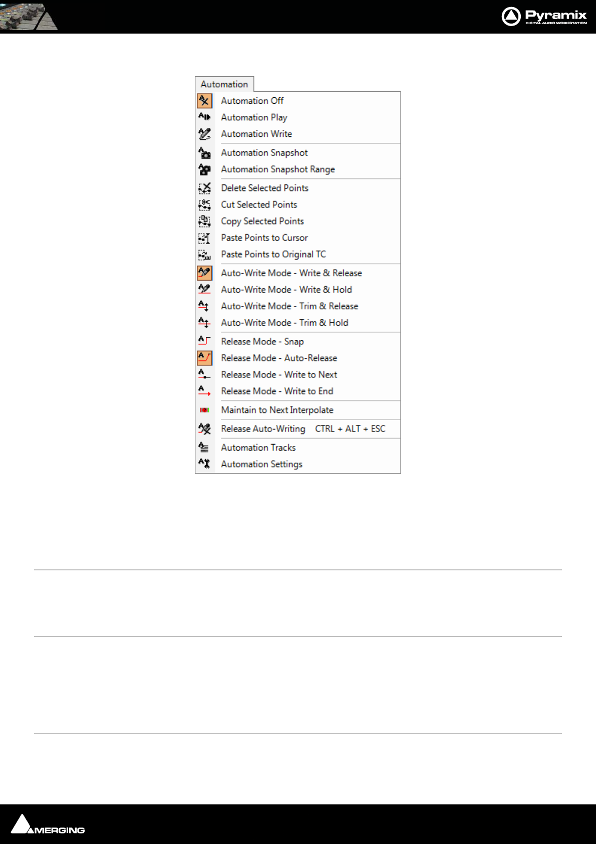
Menus : Automation 26 - 468
Automation
Automation Off Automation system is disabled
Automation Play Automation system is set to playback any previously recorded automation data
Automation Write Automation system is set to playback any previously recorded automation data and
record new automation data for all enabled controls
Automation Snapshot Creates an automation key frame at the current cursor position, for all currently armed
automation controls
Automation Snapshot Range Places automation key frames at the currently defined In / Out cursor positions, for all cur-
rently armed automation controls
Delete Selected Points Deletes all automation points contained in the selected region
Cut Selected Points Cuts all automation points contained in the selected region
Copy Selected Points Copies all automation points contained in the selected region
Paste Points to Cursor Pastes all copied or cut automation points at the cursor on the selected track
Paste Points to Original TC Pastes all copied or cut automation points at the Original TimeCode on the selected track
Auto-Write Mode - Write & Release The automation starts writing a new pass when the control is touched and stops writing
when the control is released.
Automation menu
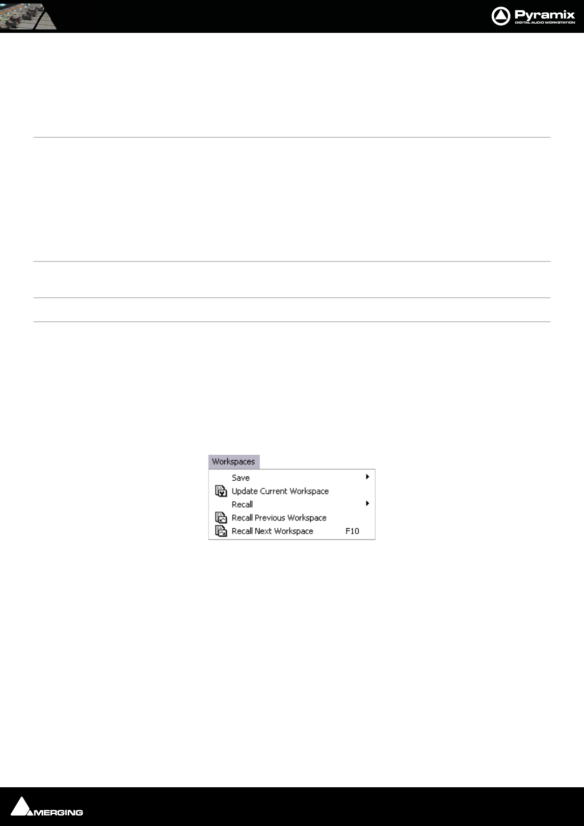
Menus : Workspaces 26 - 469
Auto-Write Mode - Write & Hold The automation starts writing a new pass when the control is touched. The value when
the control is released will continue to be written until the transport stops.
Auto-Write Mode - Trim & Release The automation starts updating the current pass when the control is touched and stops
updating when the control is released.
Auto-Write Mode - Trim & Hold The automation starts updating when the control is touched but continues when the
control is released and stops only when the transport stops.
Release Mode - Snap A straight jump is made from the current control value to the value written in the previ-
ous pass.
Release Mode - Auto-Release An interpolation is created from the current value to the value written in the previous
pass. I.e. a fade. The length of this is defined in Automation Settings > Auto-Release
Time.
Release Mode - Write to Next The same value is kept after the last written point until the next point is found in the pre-
vious pass.
Release Mode - Write to End Writes the current value to the end, ignoring previously written points. (If any)
Maintain to Next Interpolate The current value(s) are maintained until the next interpolated point(s). This is potentially
useful when deleting automation points or when inserting a Snapshot to Cursor.
Release Auto-Writing Immediately releases all controls currently recording automation
Automation Tracks Opens the Automation Tracks window. This view allows the automation versions for a
specific control to be displayed. Once the desired control has been located in the tree
view, simply double-clicking on the control will update the Automation Track Versions
window
Automation Settings Opens the Settings > All Settings > Application > Automation page which allows
automation parameters and settings to be defined
Workspaces
Save >
Save Workspace 1 Save Workspace 1
Note: Save Workspace 2 to 10 omitted
Update Current Workspace Updates the current Workspace with current settings
Recall >
Recall Workspace 1 Recall Workspace 1
Note: Recall Workspace 2 - 10 omitted
Recall Previous Workspace Toggles backwards through the list of available Workspaces
Recall Next Workspace Toggles forwards through the list of available Workspaces
Workspaces menu
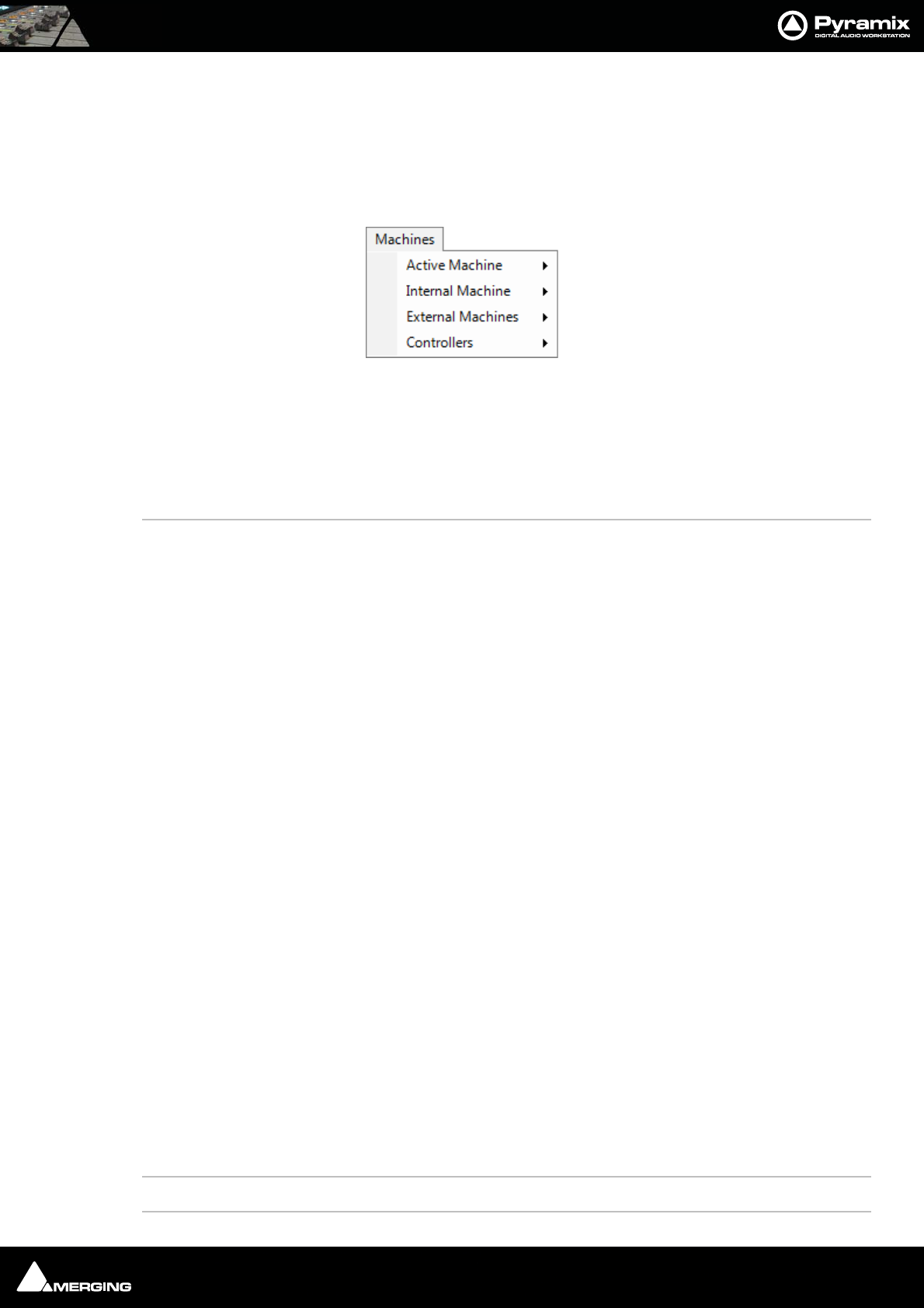
Menus : ADR 26 - 470
ADR
For details of the ADR Menu please see the ADR User Guide
Machines
Active machine >
Note: Active machine Sub-menus will reflect whichever machine is currently chosen as
the active machine.
Toggle machines Toggle between installed machines
Stop Stop
Pause Pause
Play Play
Play Special >
Play Reverse Play Reverse
Play 1/2 Play 1/2
Play 1/2 Reverse Play 1/2 Reverse
Play 1/4 Play 1/4
Play 1/4 Reverse Play 1/4 Reverse
Play 1/16 Play 1/16
Play 1/16 Reverse Play 1/16 Reverse
Play 2x Play 2x
Play 2x Reverse Play 2x Reverse
Play 4x Play 4x
Play 4x Reverse Play 4x Reverse
Toggle Play/Stop Toggle Play/Stop
Toggle Play/Pause Toggle Play/Pause
Toggle Play/Record Toggle Play/Record
Record Record
Fast Forward Fast Forward
Fast Rewind Fast Rewind
Scan Forward Scan Forward
Scan Rewind Scan Rewind
Start Goto Start
End Goto End
Goto TimeCode Goto TimeCode
Machines menu

Menus : Machines 26 - 471
Nudge +1 frame
Nudge -1 frame
Nudge to Right
Nudge to Left
Set Loop In At current Playhead Cursor position
Set Loop Out At current Playhead Cursor position
Goto Loop In
Goto Loop Out
Chase
Store Chase Offset
Internal Machine>
Stop Stop
Pause Pause
Play Play
Play Special >
Play Reverse Play Reverse
Play 1/2 Play 1/2
Play 1/2 Reverse Play 1/2 Reverse
Play 1/4 Play 1/4
Play 1/4 Reverse Play 1/4 Reverse
Play 1/16 Play 1/16
Play 1/16 Reverse Play 1/16 Reverse
Play 2x Play 2x
Play 2x Reverse Play 2x Reverse
Play 4x Play 4x
Play 4x Reverse Play 4x Reverse
Toggle Play/Stop Toggle Play/Stop
Toggle Play/Pause Toggle Play/Pause
Toggle Play/Record Toggle Play/Record
Toggle Play/Stop Record Safe
Note: This command toggles between Play and Stop (or other state) but has no effect
when recording. In this case the real Stop command has to be issued to stop a recording.
Play with Preroll
Play with Preroll #2
Play with Preroll #3
Record Record
Fast Forward Fast Forward
Fast Rewind Fast Rewind
Scan Forward Scan Forward
Scan Rewind Scan Rewind
Start Start

Menus : Machines 26 - 472
End End
Punch >
Punch Selection Punch Selection
Punch Selection with PrerollPunch Selection with Preroll
Punch Selection with Preroll #2Punch Selection with Preroll #2
Punch Selection with Preroll #3Punch Selection with Preroll #3
Auto-punch with Preroll Auto-punch with Preroll
Auto-punch with Preroll #2 Auto-punch with Preroll #2
Auto-punch with Preroll #3 Auto-punch with Preroll #3
Remake last Punch (In only)Repeat last Punch operation (Punch In only)
Remake last Punch (In - Out)Repeat last Punch operation
Safety Record When this mode is active the only way to stop a recording is to return to this menu and
de-activate it. (Or use an assigned keuyboard Shortcut)
Play Selection Play Selection
Loop Selection Loop Selection
Play between Marks Play between Marks
Loop between Marks Loop between Marks
Play between Gates Play between selected track group Gates
Loop between Gates Loop between selected track group Gates
Audition >
Audition Pre Audition Pre
Audition Pre (Preroll #2) Audition Pre (Preroll #2)
Audition Pre (Preroll #3) Audition Pre (Preroll #3)
Audition Audition
Audition (Pre/Postroll #2) Audition (Pre/Postroll #2)
Audition (Pre/Postroll #3) Audition (Pre/Postroll #3)
Audition Post Audition Post
Audition Post (Postroll #2) Audition Post (Postroll #2)
Audition Post (Postroll #3) Audition Post (Postroll #3)
Audition Gate In Pre Audition selected track groups Gate In Pre
Audition Gate In Pre (Preroll #2) Audition selected track groups Gate In Pre (Preroll #2)
Audition Gate In Pre (Preroll #3) Audition selected track groups Gate In Pre (Preroll #3)
Audition Gate In Audition selected track groups Gate In
Audition Gate In (Pre/Postroll #2) Audition selected track groups Gate In (Pre/Postroll #2)
Audition Gate In (Pre/Postroll #3) Audition selected track groups Gate In (Pre/Postroll #3)
Audition Gate In Post Audition selected track groups Gate In Post
Audition Gate In Post (Postroll #2) Audition selected track groups Gate In Post (Postroll #2)
Audition Gate In Post (Postroll #3) Audition selected track groups Gate In Post (Postroll #3)
Audition Gate Out Pre Audition selected track groups Gate Out Pre
Audition Gate Out Pre (Preroll #2) Audition selected track groups Gate Out Pre (Preroll #2)
Audition Gate Out Pre (Preroll #3) Audition selected track groups Gate Out Pre (Preroll #3)
Audition Gate Out Audition selected track groups Gate Out

Menus : Machines 26 - 473
Audition Gate Out (Pre/Postroll #2) Audition selected track groups Gate Out (Pre/Postroll #2)
Audition Gate Out (Pre/Postroll #3) Audition selected track groups Gate Out (Pre/Postroll #3)
Audition Gate Out Post Audition selected track groups Gate Out Post
Audition Gate Out Post (Postroll #2) Audition selected track groups Gate Out Post (Postroll #2)
Audition Gate Out Post (Postroll #3) Audition selected track groups Gate Out Post (Postroll #3)
Goto TimeCode Goto TimeCode
Nudge +1 frame
Nudge -1 frame
Set Loop In At current Playhead Cursor position
Set Loop Out At current Playhead Cursor position
Goto Loop In
Goto Loop Out
Loop On/Off Loop On/Off
Chase Hard Chase
Store Chase Offset Store Chase Offset
Auto Chase
Freeze External Machines
Cursor Auto-Return after playing Auto Return On/Off
External Machines>
Stop Stop
Pause Pause
Play Play
Play Special >
Play Reverse Play Reverse
Play 1/2 Play 1/2
Play 1/2 Reverse Play 1/2 Reverse
Play 1/4 Play 1/4
Play 1/4 Reverse Play 1/4 Reverse
Play 1/16 Play 1/16
Play 1/16 Reverse Play 1/16 Reverse
Play 2x Play 2x
Play 2x Reverse Play 2x Reverse
Play 4x Play 4x
Play 4x Reverse Play 4x Reverse
Toggle Play/Stop Toggle Play/Stop
Toggle Play/Pause Toggle Play/Pause
Toggle Play/Record Toggle Play/Record
Record Record
Fast Forward Fast Forward

Menus : Machines 26 - 474
Fast Rewind Fast Rewind
Scan Forward Scan Forward
Scan Rewind Scan Rewind
Start Goto Start
End Goto End
Goto TimeCode Goto TimeCode
Nudge +1 frame Nudge +1 frame
Nudge -1 frame Nudge -1 frame
Set Loop In At current Playhead Cursor position
Set Loop Out Out At current Playhead Cursor position
Goto Loop In Goto Loop In
Goto Loop Out Goto Loop Out
Chase
Store Chase Offset
Auto-Chase
Eject Eject
Preview
Auto Edit
Review
Enable Record On/Off Enable Record On/Off
Record Ready >
Record Ready V1 Record Ready V1
Record Ready A1 Record Ready A1
Record Ready A2 - A7 omitted
Record Ready A8 Record Ready A8
Locator >
Goto Locator 1 Goto Locator 1
Goto Locator 2 to 9 omitted
Goto Locator 10 Goto Locator 10
Set Locator 1 Set Locator 1
Set locator 2 to 9 omitted
Set Locator 10 Set Locator 10
Controllers>
Offline Controllers Toggle Controllers On/Off line
Jog-Wheel Mode - Jog
Jog-Wheel Mode - Shuttle
Jog-Wheel Mode - Loop repeats a short loop, starting at the cursor position
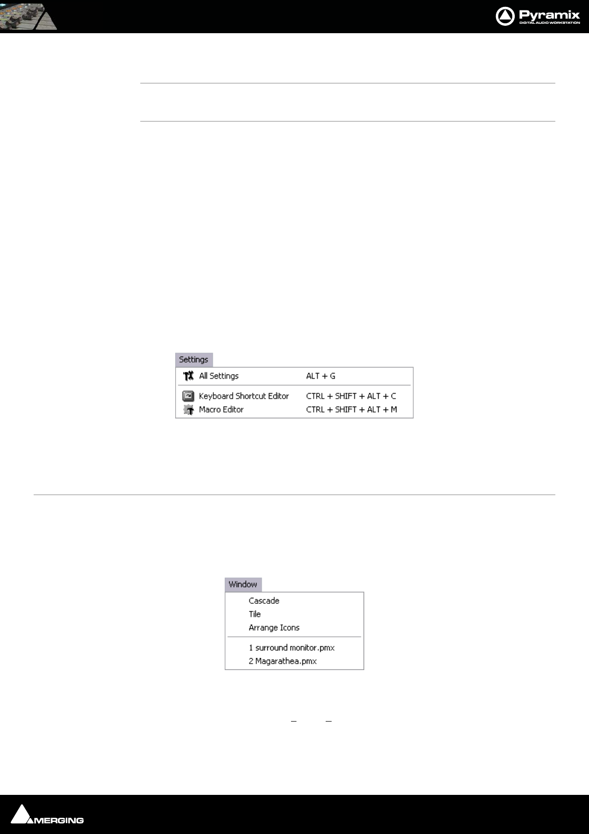
Menus : Macros 26 - 475
Jog-Wheel Mode - NavigateNavigate is silent jog mode
Jog-Wheel Mode - Off
Jog-Wheel Listen - Mix Listen to mix out when Jog is active
Jog-Wheel Listen - SelectionListen only to tracks included in the current Selection
Jog-Wheel Fine Change jog-wheel ‘gearing’ to the sensitivity factor set in Settings > All
Settings > Application > Jog/Chase : Fine Jog sensitivity factor (Default
0.25) I.e. a quarter of nominal sensitivity.
E.g. if nominal = 1.00 seconds per revolution then Fine will be a quarter of a
second per revolution.
Auto Show Plugins When selected Plugins parameters windows are automatically opened
when selected on the remote controller.
Macros
Macro Editor Opens the Macros Window
Please see User Macros on page 332
Settings
The Settings menu brings together access to the main All Settings window, the Keyboard Shortcut Editor and
the Macro Editor.
All Settings Opens the Pyramix Settings Window
Keyboard Shortcut Editor Opens the Keyboard Shortcuts Window
Macro Editor Opens the Macros Window
Window
The Window menu maintains a list of open projects and enables switching between them. It also enables multiple
open project windows to be arranged on screen, Tiled or Cascaded.
Settings menu
Window menu

Menus : Help 26 - 476
Help
The Help Menu gives quick on-line access to this manual and others. About pops up a Window with the Pyra-
mix logo and details about the registered user and software version.
Help menu

USER MANUAL
www.merging.com/Pyramix
Settings
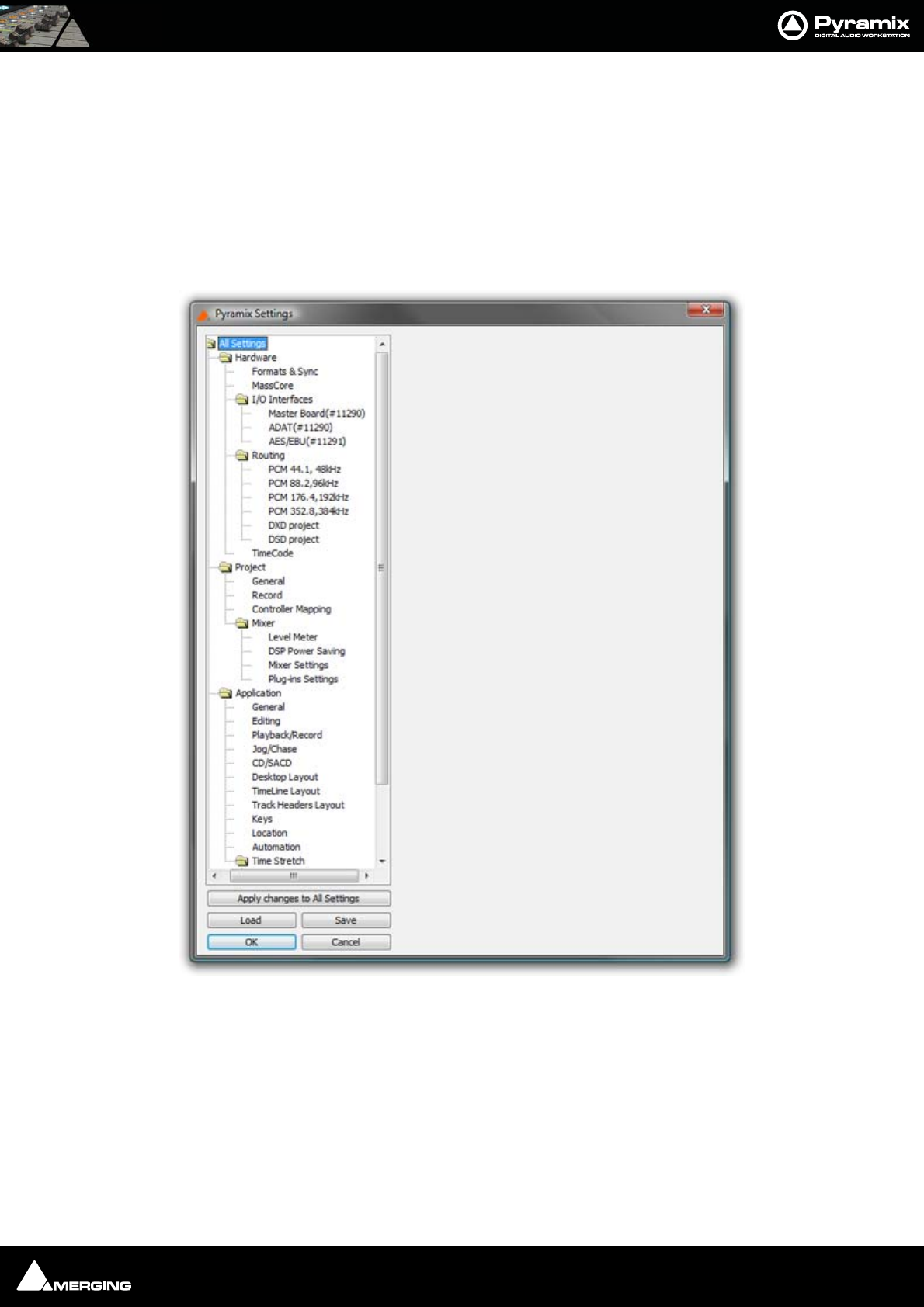
Settings : Configuration - The Settings Dialog Window 27 - 478
Overview
Pyramix is massively configurable to suit diverse applications and personal preferences. To keep the vast number
of parameters manageable, Pyramix has an intuitive Settings dialog window. The Pyramix Settings dialog win-
dow brings together all Pyramix settings apart from the Keyboard Shortcut Editor and the Macro Editor, both of
which can be accessed from the Settings menu. Although you will find information about individual pages else-
where in this document, all the Settings pages are detailed in this chapter.Settings can be accessed from a Tool
Bar icon, the menu Settings > All Settings or Alt + G.
Configuration - The Settings Dialog Window
The left-hand side of the window shows all available settings grouped in folders. Folders can be collapsed or
expanded by clicking on the folder icons. By default, all folders are open, displaying the settings pages they con-
tain by name. Clicking on a settings page opens it in the right-hand side of the window for viewing and editing.
Pyramix Settings Window - No folder open
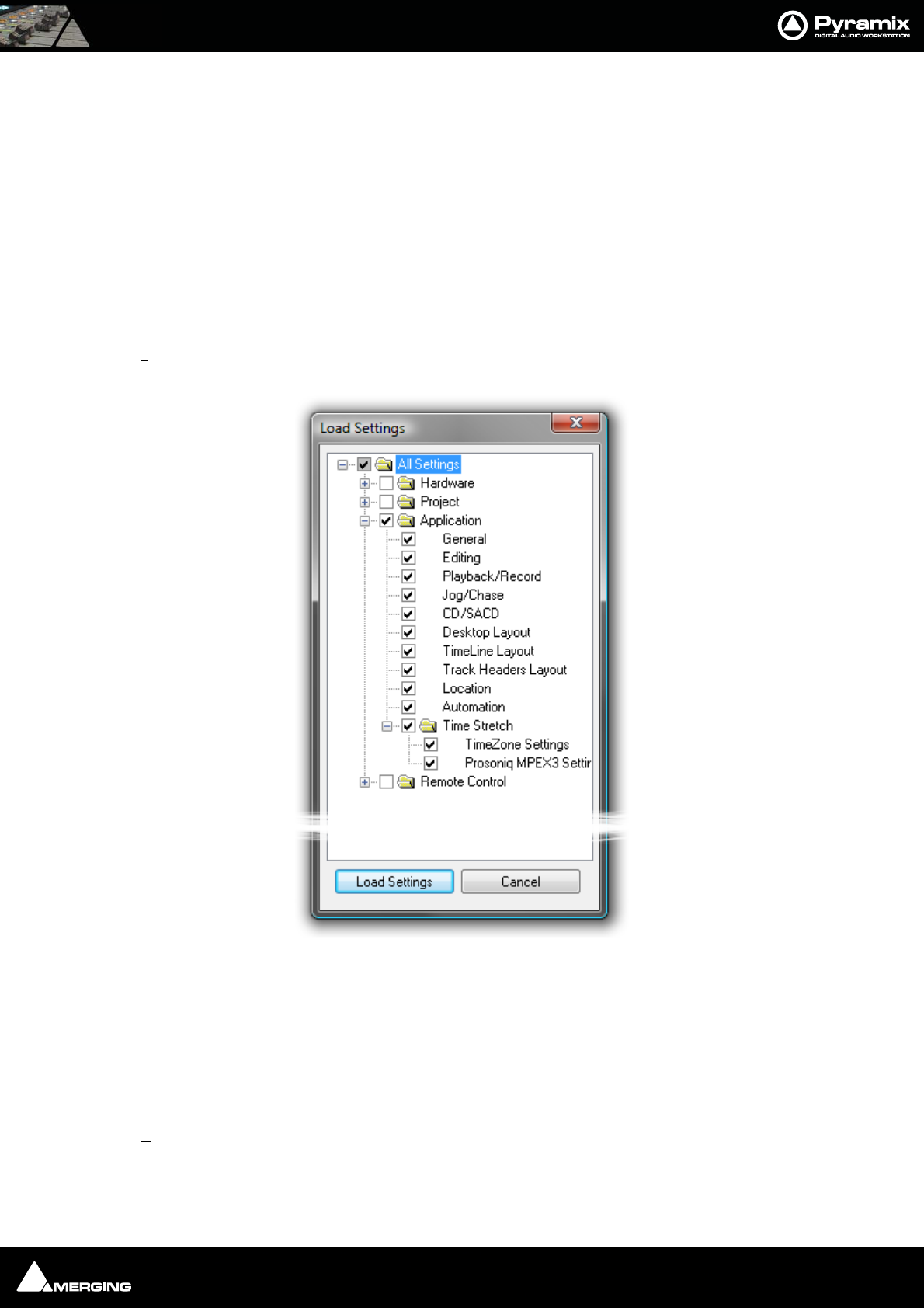
Settings : Configuration - The Settings Dialog Window 27 - 479
Settings Buttons
Apply changes to ...
Below the Settings folders tree view the first large button’s function and label changes to reflect the currently
open settings page (if any). Apply changes to ... does as it says without saving the changes to a Settings file. Set-
tings can be saved selectively or in their entirety for future use.
Save
To save all settings, Click on the: Save button to open a Save As browser window. If necessary, navigate to a suit-
able location for the file. Type a suitable name in the File name: box and click the Save button to save the file and
close the browser window.
Load
Load opens a Browser window to enable location of settings Profile (*.pms) files. When the required file has been
located clicking on the Open button loads the file and opens the Load Settings dialog.
Loading Settings Selectively
Load Settings loads only the settings with ticked boxes. The Load Settings dialog auto selects the currently
selected page. Clicking a folder check box checks the boxes of all the sub-folders and pages they contain. Thus,
clicking the All Settings box checks all the boxes.
OK
Saves any changes made to settings and exits the Pyramix Settings window.
Cancel
Cancels any changes made to settings and exits the Pyramix Settings window.
Load Settings dialog
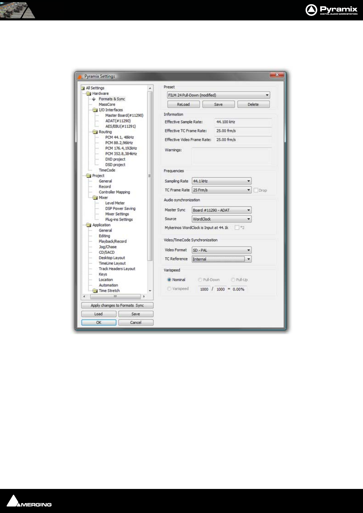
Settings : Hardware 27 - 480
Hardware
Formats and Sync
Preset
This section allows the user to Save and ReLoad or Delete Presets of all the parameters in this page. A variety of
All Settings Hardware Formats & Sync Page
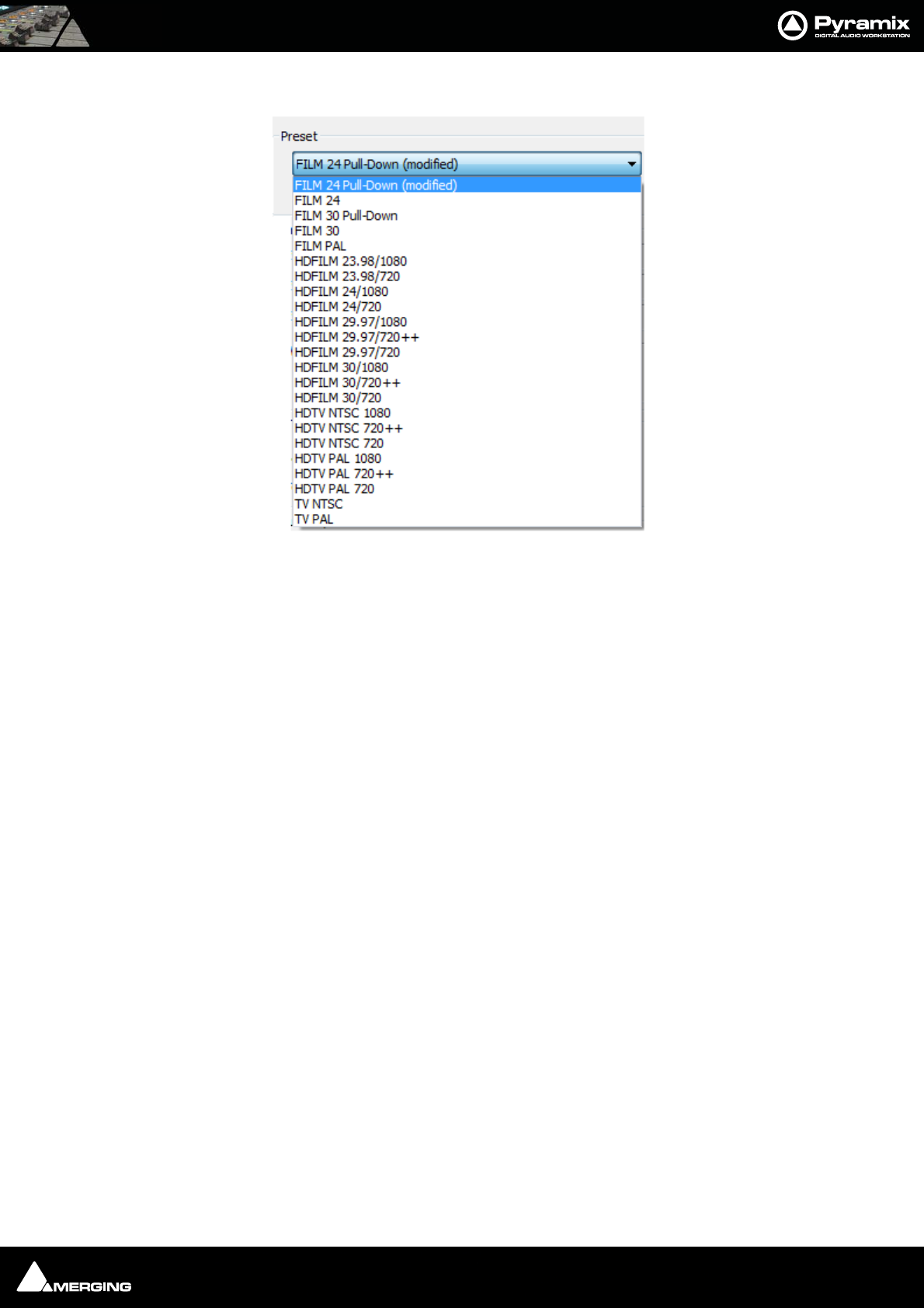
Settings : Hardware 27 - 481
common scenarios are covered in the supplied Presets:
Information
Effective Sampling Rate
Displays the sampling rate including the effect of any pull-up or down or Varispeed settings.
The sampling rate display in the Status Bar also displays the resulting sampling rate.
Effective TC Frame Rate
Displays the TC Frame Rate including the effect of any pull-up or down or Varispeed settings.
Effective Video Frame Rate
Displays the Video Frame including the effect of any pull-up or down or Varispeed settings.
Sampling Rate
Displays the rate set when the project was created or the default Mixer preset loaded. This can be changed from
the Sampling Rate drop-down list.
Warnings
Displays any caveats about the selected rates.
Frequencies
Sampling Rate
The drop-down list presents a choice of all available nominal sampling rates.
TC Frame Rate
The drop-down list presents a choice of all available TC Frame Rates
Drop
Only available for NTSC Frame Rates I.e. 29.97fps and 30fps. When checked drop frame counting is applied.
Board
In a multi-board system, use the drop down list to select the daughter-card for which you want to view or change
settings.
All Settings Hardware Formats & Sync Preset List

Settings : Hardware 27 - 482
Master
In a multi-board system, this check box determines which board is the source of digital audio sync. Only one board
can be selected as master.
Audio Syncronization
Master Sync
In an Multi-board system choose the board which will be the sync master from the drop-down list.
Source
This determines the sample clock source for the whole Pyramix system. If an external source is selected and no
valid signal is detected, the system reverts to Internal until the external signal is restored. The following choices
are available:
Internal
Selects the board’s internal oscillator as clock master.
Video
Selects an external video input as the reference. The card derives word clock from the video sync rate. A valid
video signal must be connected to the Mykerinos board chosen as the Video / TC master in the VS3 control panel.
Word Clock
Selects an external word clock source as the reference. The word clock must be connected to the Mykerinos board
chosen as video / TC master in the VS3 control panel. This option is grayed out if there is no valid source con-
nected.
Audio Input
Select this option if you want Pyramix to derive it’s clock from an external audio source connected to any of the
daughtercard(s) present. The correct audio input must also be selected.
LTC
In special situations this option enables word clock to be derived from Linear TimeCode
WordClock is Output at XXk *2
For sample rates above 48kHz WordClock is normally output at the standard fundamental rate. E.g. if 128KHz is
selected then WordClock is output at 32kHz unless the box is ticked, in which case the WordClock output rate is
doubled to 64kHz.
Video/TimeCode Synchronization
Video Format
The drop-down list presents all available Video Formats
TC Reference
The drop-down list presents all valid TimeCode reference sources.
Varispeed
Allows either choice of either a pull-up / pull-down sampling rate or running Pyramix in Varispeed mode by
adapting the sampling rate.
Important! Typical digital to analog or analog to digital converters (such as Merging Technologies Sph-
ynx or DUAII do not operate beyond +/- 0.15 ‰ (150 ppm) and therefore will mute in any Varispeed
mode. It is suggested to route the Mykerinos digital I/O’s through external real-time sampling rate con-
version circuitry or to use adequate external converters with built-in pull-up or pull-down support.
Note: Note: Locking to external NTSC video reference is limited to nominal and pull-
down sampling rates.

Settings : Hardware 27 - 483
Nominal
‘Normal’ mode. Uses the nominal sampling rate as set in the Sampling Rate pull-down menu.
Pull-Up
Increases the sampling rate by 0.1%. Most often used in audio post production for compatibility reasons between
NTSC frame rates of 30 fps and 29.97 fps.
Pull-Down
Decreases the sampling rate by 0.1%. Most often used in audio post production for compatibility reasons between
NTSC frame rates of 30 fps and 29.97 fps.
Varispeed
The speed of audio playback can be varied within the range of -12.5% to +12.5%. Select this option, then enter the
required speed change in tenths of percents into the adjacent entry field. Values entered outside of the allowed
range will be limited to the extent of the allowed range. E.g. if 1500 is entered, the value will be set to 1125.
Input
Format
Provides input format selection. This is varies, depending on which Mykerinos Daughter card is currently selected
by the Board drop-down menu.
Range
Shows the number of possible system inputs available depending on the Mykerinos Daughter
card currently selected Board drop-down menu.
Output
Mode
Provides output format selection. This is variable, depending on the Mykerinos Daughter card under consider-
ation.
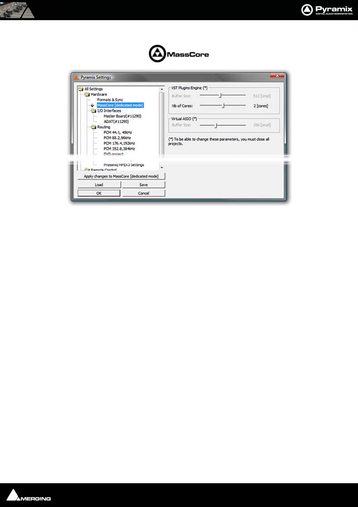
Settings : Hardware 27 - 484
MassCore
Note: The MassCore mode is indicated in brackets but is determined by the hardware
present in the PC.
VST Plugins Engine Latencies(*)
This sets the VST buffer size in samples. The smaller the buffer the lower the latency and vice-versa. Some third-
party VST plug-ins require very large buffer sizes. This setting is provided to give the user control over the required
value. Increasing the value can prevent clicks at the expense of increased latency.
Values up to 8192 samples may be set.
No of Cores:
On a Quad Core sets the number of VST cores used 1, 2 or 3.(one CPU is already dedicated to MassCore). This
option is necessary since some VST plug-ins do not like Multithreading processing.
Virtual ASIO
This sets the Virtual ASIO buffer size.
Note: (*) In order to adjust this setting all projects must be closed.
All Settings Hardware MassCore
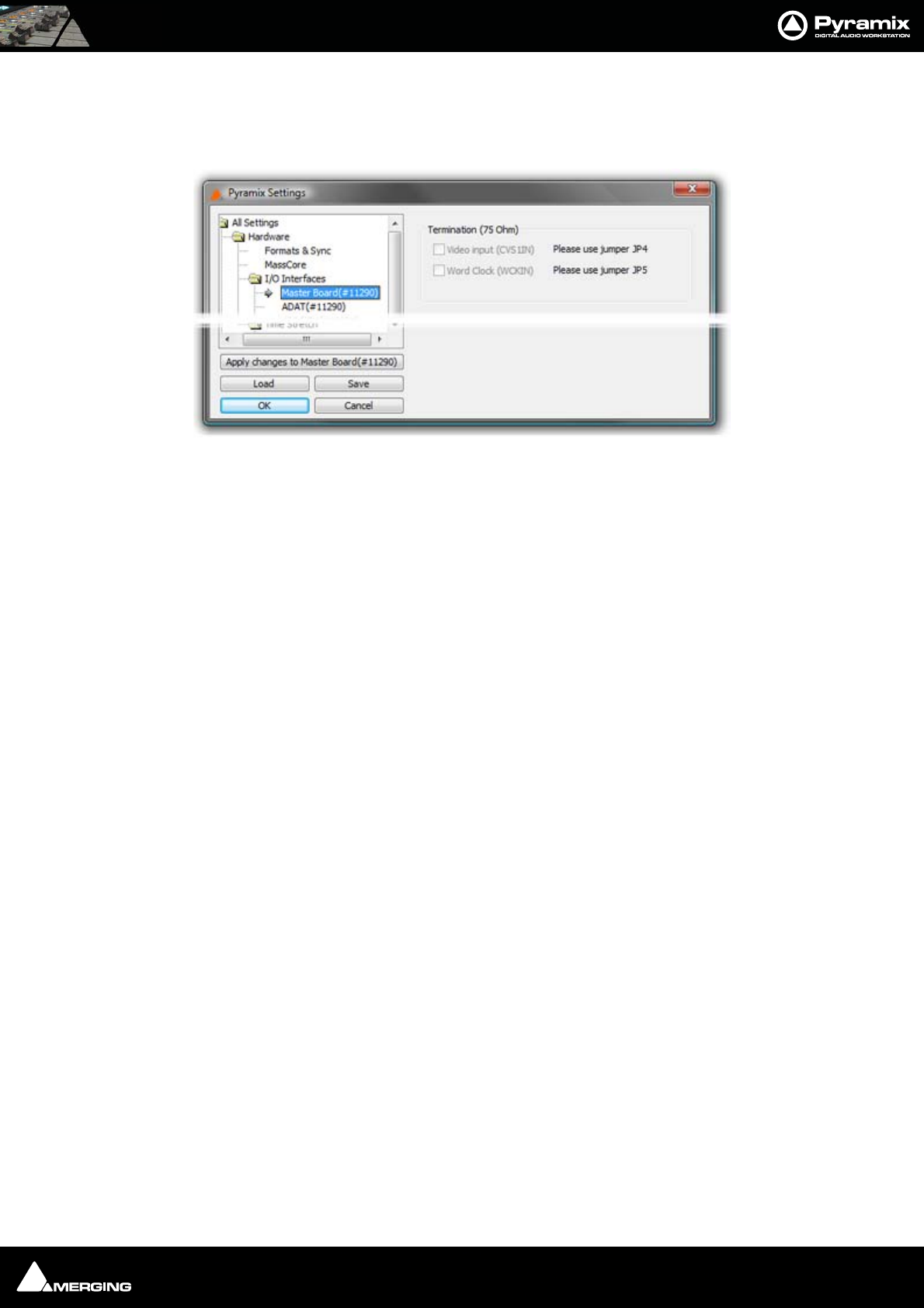
Settings : I/O Interfaces 27 - 485
I/O Interfaces
Master Board(#Serial No.)
Termination
Video Input (CVS1IN)Please use jumper JP4
Word Clock (WCKIN)Please use jumper JP5
Applicable only to Mykerinos X boards otherwise grayed out. Offers a choice between Video and Word Clock sync
input in conjunction with the board jumpers JP4 and JP5 (Please see Mykerinos X manual for full details)
Board(#Serial No.)
(Mykerinos Daughter Card Settings)
These settings provide hardware specific configuration for the currently installed Mykerinos daughter card(s).
Please see also the documentation supplied with the card.
Note: There will be separate entries under I/O Interfaces for each board installed and
On-Line (As selected in the VS-3 Control Panel)
All Settings Hardware I/O Interfaces Master Board(#Serial No.)
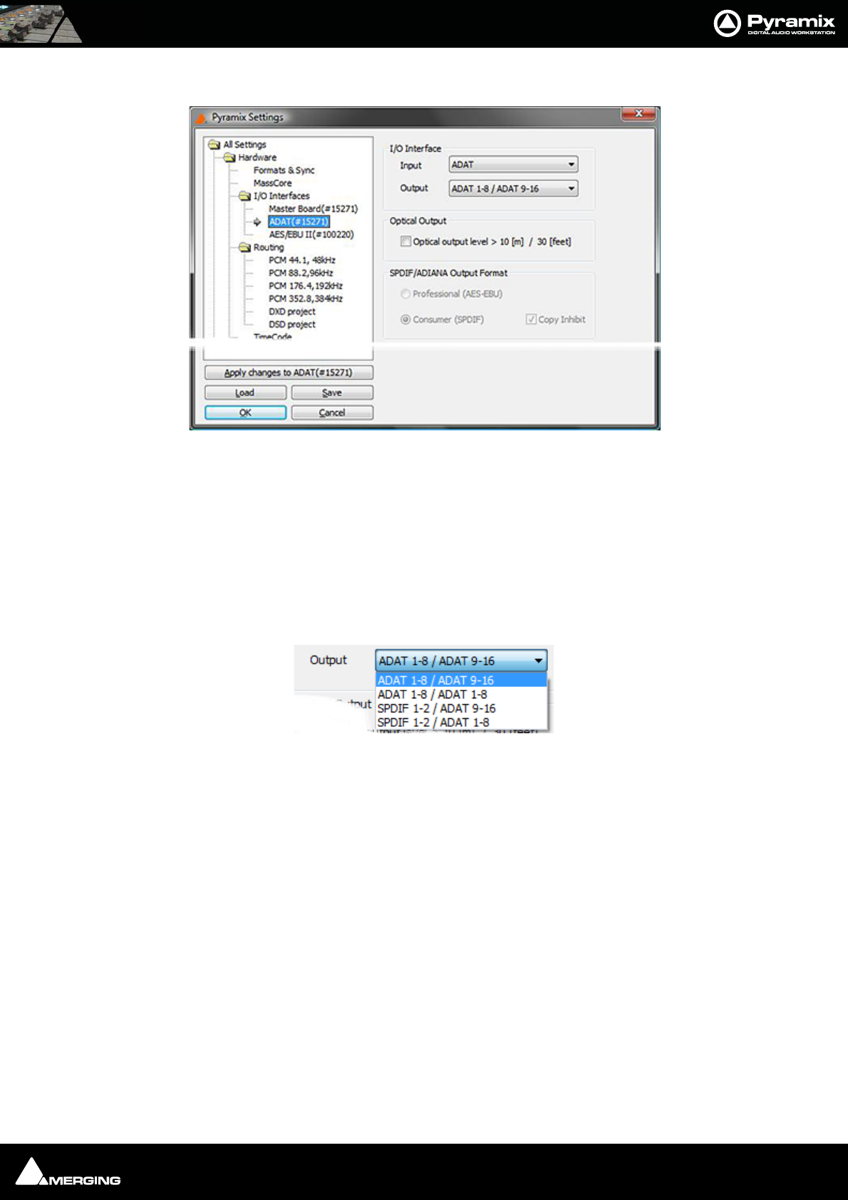
Settings : I/O Interfaces 27 - 486
ADAT Board Settings
Note: These settings can only be changed when all projects are closed. The page will
warn of this if any projects are open.
I/O Interface
Input
Offers the choice between ADAT and SPDIF
Output
Offers choices of output format:
ADAT 1-8 / ADAT 9/16: Channels 1-8 on optical A and channels 9-16 on optical B.
ADAT 1-8 / ADAT 1-8: Channels 1-8 on both optical A and B.
SPDIF 1-2 / ADAT 1-8: (Standalone mode only) Channels 1-2 on optical A, in SPDIF format and channels 1-8 on opti-
cal B.
SPDIF 1-2 / ADAT 9-16: (Standalone mode only) Channels 1-2 on optical A, in SPDIF format and channels 9-16 on
optical B
Optical Output
Check the Optical output level box if the fibre-optic cables are in excess of 10[m] / 30 [feet] in length.
SPDIF/ADIANA Output Format
The radio buttons set the Professional / Consumer flag and the check-box sets the Copy Inhibit flag when SPDIF
is the selected output format.
All Settings Hardware I/O Interfaces ADAT Board(#Serial No.)
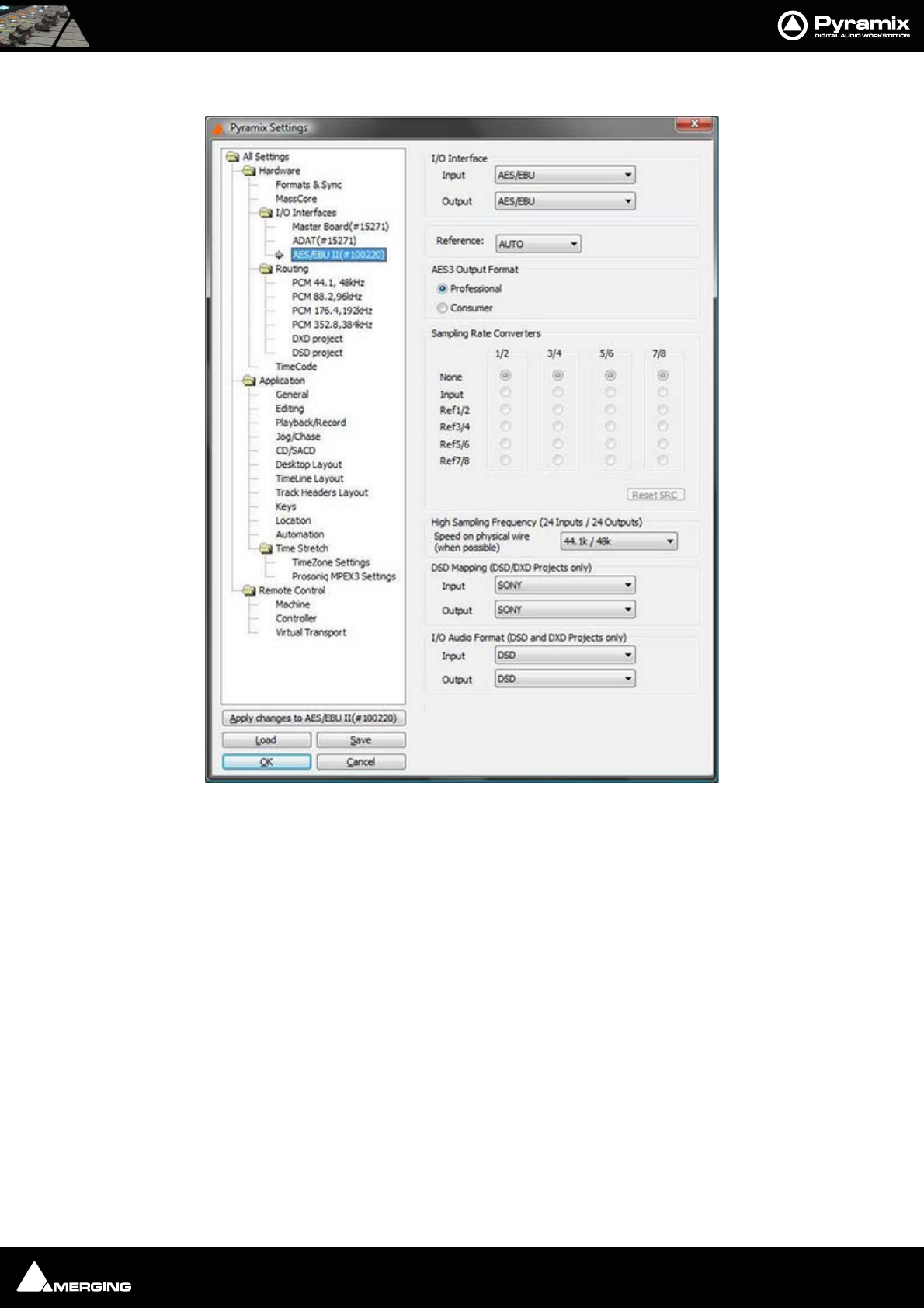
Settings : I/O Interfaces 27 - 487
AES II and AES II SRC Board Settings
I/O Interfaces
AES/EBU
Input
Output
Reference
Selects the input used as the clock reference when Pyramix sync is set to Audio Input.
When set to AUTO, Pyramix searches through all the inputs in ascending order and locks to the first valid source it
finds.
AES3 Output Format
The radio buttons toggle the Professional / Consumer bit in the AES data stream.
All Settings Hardware I/O Interfaces AES II Board(#Serial No.)

Settings : I/O Interfaces 27 - 488
Sampling Rate Converters
Grayed out if no SRCs are present. Each of the four uni-directional converters can be configured as Bypass, Input or
Output. On a specific in/out channel pair a sampling rate conversion can be applied only in one direction, either
input or output. The Speed on physical wire setting (see below) should be set to the project's sampling rate (aka
"single-wire mode") whenever the SRCs are used, since channel pairs that are spread over several wires will not
be sample rate converted properly.
Up to 192 kHz, each column represents one XLR connector (one pair of channels) with its associated SRC chip.
The following configurations can be selected:
•None: or bypass, the SRC is transparent
•Input: The SRC works on the input path and converts the incoming signal to the project's sampling rate
•Ref1/2 through Ref 7/8: The SRC is inserted in the output path and converts the output signal to the sam-
pling rate of the signal present at the input chosen as reference.
At 8FS (DXD/DSD), the AES II daughter card has a special mode that is enabled by selecting 8FS to nFS in the
Speed on physical wire field. This mode provides a fixed set of 2 input and 2 output paths and enables a real-time
conversion from 384kHz/352.8kHz down to 192kHz/44.1kHz and vice-versa. Only XLRs 1/2 and 3/4 are used. For
the outputs, the reference input for the sampling frequency is selectable in the Sampling Rate Converters array.
For further information and configuration examples please see: AES II with SRC on page 559
High Sampling Frequency (24 Inputs / 24 Outputs
Speed on physical wire (when possible)
Sets the rate of the AES stream on the I/Os.
44.1k / 48k: standard mode
88.2k / 96k: also called single wire at 96 kHz
176.4k / 192k: (only AES 2) also called single wire at 192 kHz
8 FS to nFS: (only AES 2 - SRC) special mode for the sampling rate converters for DXD/DSD projects (see explana-
tion of the sampling rate converters)
DSD mapping (DSD / DXD Projects only)
Sets the mapping for the DSD I/Os
Input
SONY
P3D
Output
SONY
P3D
I/O Audio Format (DSD / DXD Projects only)
Selects the I/O mode when a DSD or DXD project is opened.
Input
DSD
DXD
Output
DSD
DXD
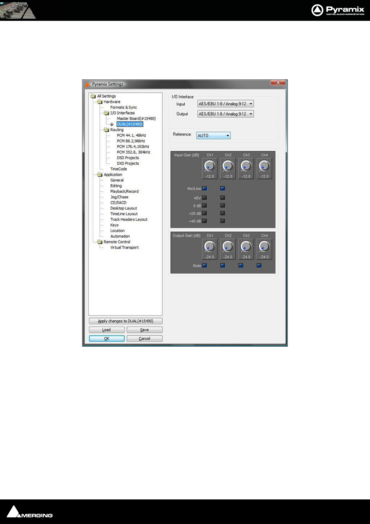
Settings : I/O Interfaces 27 - 489
AES Board Settings
The legacy, non SRC, AES board uses the same Settings Page as the AES II. However, the SRC settings will, of
course, be unavailable.
DUAL Board Settings
I/O Interface
Input
AES/EBU 1-8 / Analog 9-12: The first 8 inputs are in AES/EBU format and the four remaining inputs are analog.
Output
AES/EBU 1-8 / Analog 9-12: The first 8 outputs are in AES/EBU format and the four remaining outputs are analog.
Reference
Selects the digital (AES/EBU) input to be used as the clock reference when Pyramix sync is set to Audio Input.
When set to AUTO, Pyramix searches through all the inputs in ascending order and locks to the first valid source it
finds.
Input Gain (dB)
A gain setting of -12dB to +12dB can be selected for each one of the four analog inputs.
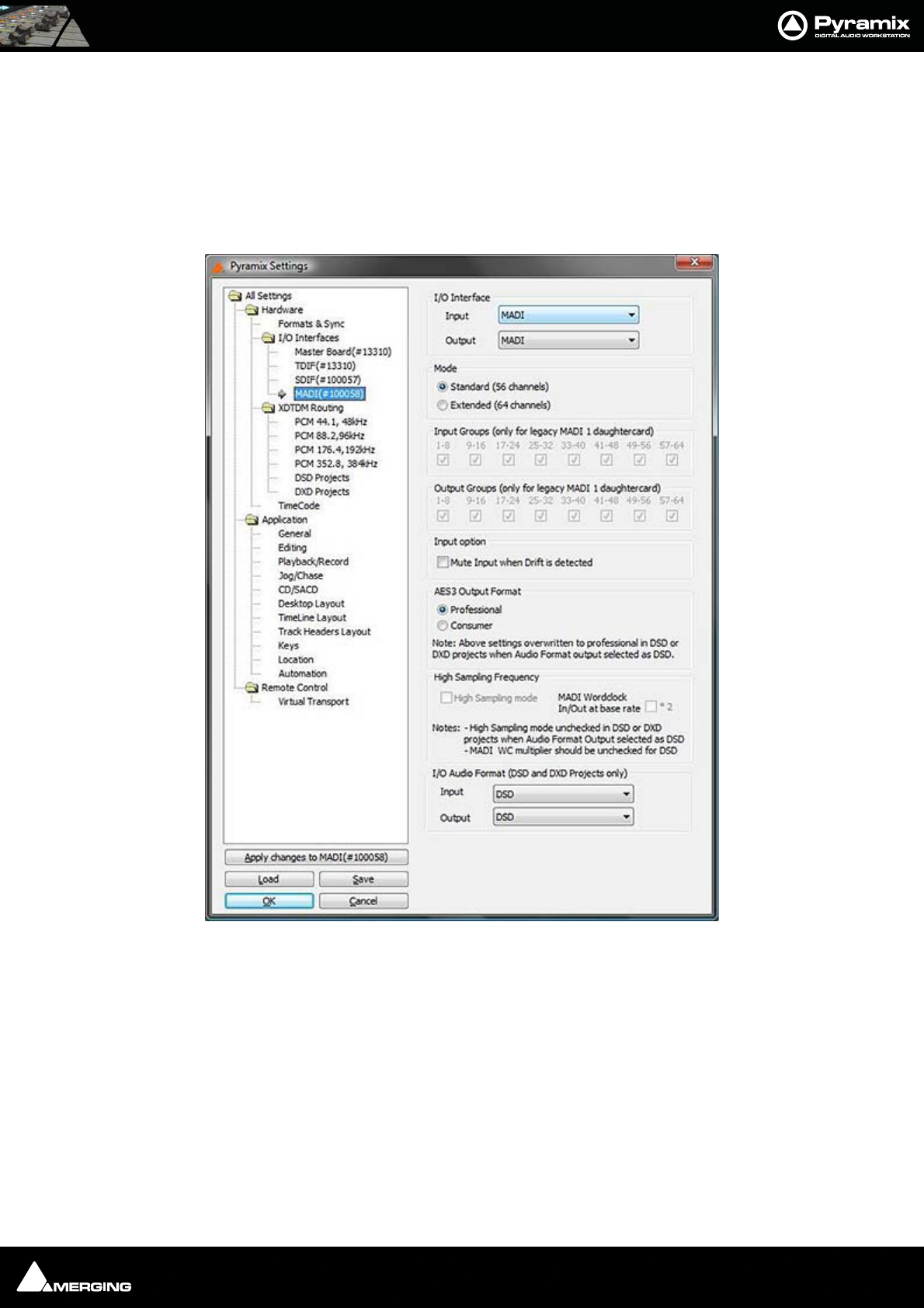
Settings : I/O Interfaces 27 - 490
Mic/Line On inputs 1 and 2 you can also enable the Mic preamp by ticking the box. When selected the buttons
below allow 48V phantom power to be enabled and additional gain added for 0dB, +20dB or +40dB
Output gain (dB)
A gain setting of from -24dB to 0dB can be selected for each of the four analog outputs. Each channel is also
equipped with a Mute check box.
MADI Board Settings
I/O Interface
Input
Output
Select MADI from the drop-down lists (if not already selected)
Mode
Standard (56 channels)
Extended (64 channels)
Choose the mode appropiate for the external device you are connecting.
Note: To change this setting all Projects must be closed
All Settings Hardware I/O Interfaces Master Board(#Serial No.)

Settings : I/O Interfaces 27 - 491
Input Groups
Output Groups
(These settings are only applicable to legacy MADI 1 daughtercards)
Input Option
Mute Input when Drift is detected
If the Input stream sample rate varies from nominal, Mutes the Input
AES Output Format
Professional
Consumer
Sets the AES Format bit.
Note: This setting is overridden to Professional in DSD or DXD Projects when DSD is
selected as the output format.
High Sampling Frequency
High Sampling Mode
When ticked, MADI carries high sample rate signals.
MADI Wordclock I/O at base rate * 2
When ticked MADI Wordclock is expected and output at base rate times two.
Note: High Sampling Mode setting is overridden in DSD or DXD Projects when DSD is
selected as the output format.
MADI Wordclock I/O at base rate * 2 should be unticked for DSD
I/O Audio Format (DSD and DXD Projects Only)
Input
Output
Select the required I/O format(s) from the drop-down lists.
Note: To change this setting all Projects must be closed
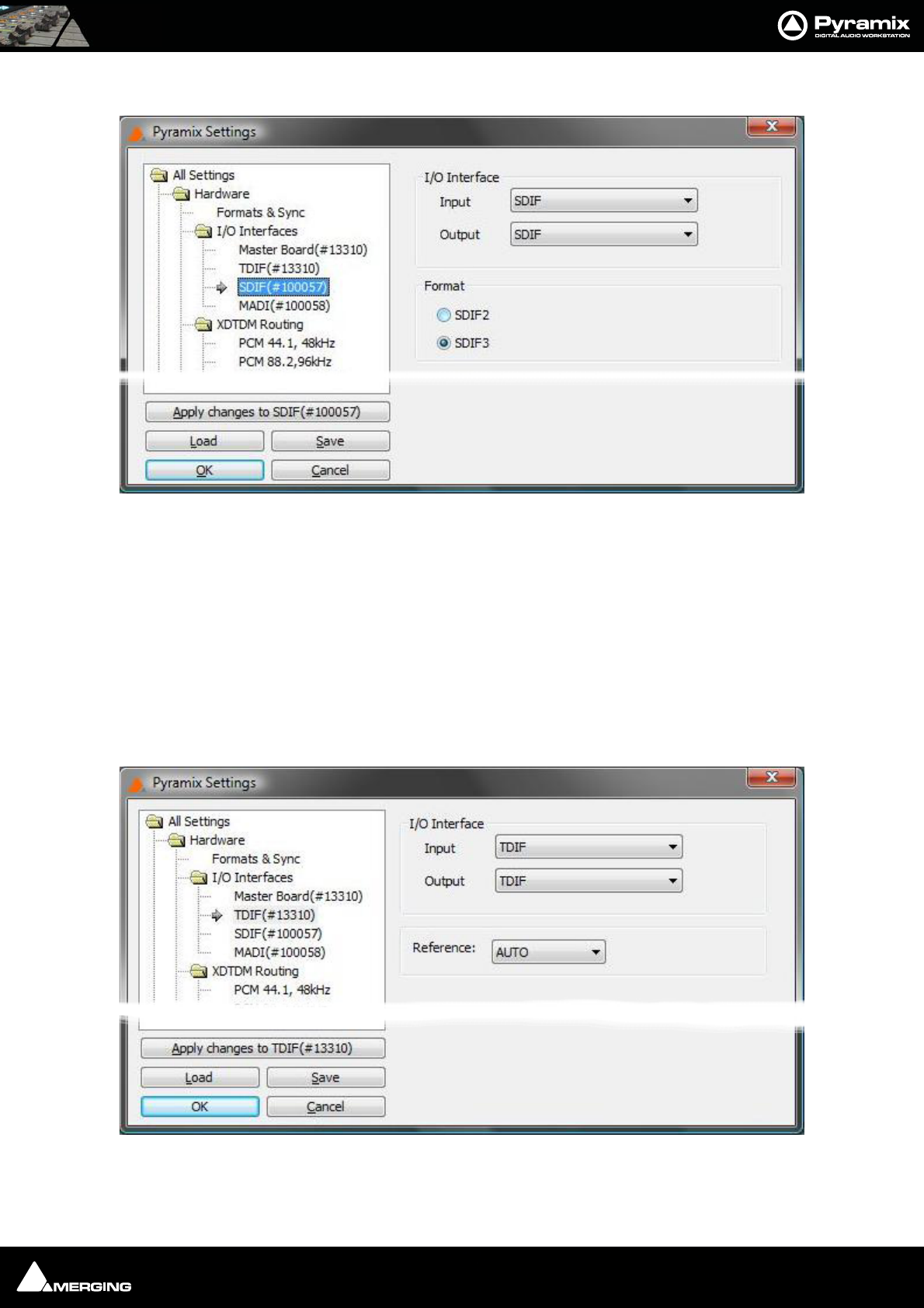
Settings : I/O Interfaces 27 - 492
SDIF Board Settings
I/O Interface
Input
SDIF
Output
SDIF
Format
The radio buttons toggle between the SDIF2 and SDIF3 formats.
TDIF Board Settings
I/O Interface
Input

Settings : I/O Interfaces 27 - 493
TDIF
Output
TDIF
Reference
Selects the input used as the clock reference when Pyramix sync is set to Audio Input. When set to AUTO, Pyramix
searches through the inputs and locks to the first valid source it finds.
The drop-down list offers the following choice of Clock reference sources:
AUTO
TDIF Front
TDIF Rear0
TDIF Rear1
When set to AUTO, Pyramix searches through all the inputs in ascending order and locks to the first valid source it
finds.

Settings : I/O Interfaces 27 - 494
HDTDM / XDTDM / MassCore Routing
There are several routing pages. Only pages appropriate for the currently selected mode, HDTDM, XDTDM or
MassCore are available/shown in the tree.
Where the routing is user selectable, independent routing assignmentss can be made for 1fs, 2fs, 4fs and 8fs sam-
ple rates.
Routing Physical I/O to Logical I/O
Routing can only be undertaken when there are no projects open.
Reset removes all patching
Autoroute connects all available inputs and outputs in ascending order.
Note: MassCore routing is currently automatic only and there is no need (and no means)
to set the required number of Internal Buses
AES/EBU
When an AES/EBU daughter-card is present, this routing page takes account of the HighSamplingRate setting
(from the AES/EBU (# ’card number’) page) to enable you to route 12 AES channels or 24 for the corresponding
daughtercard.
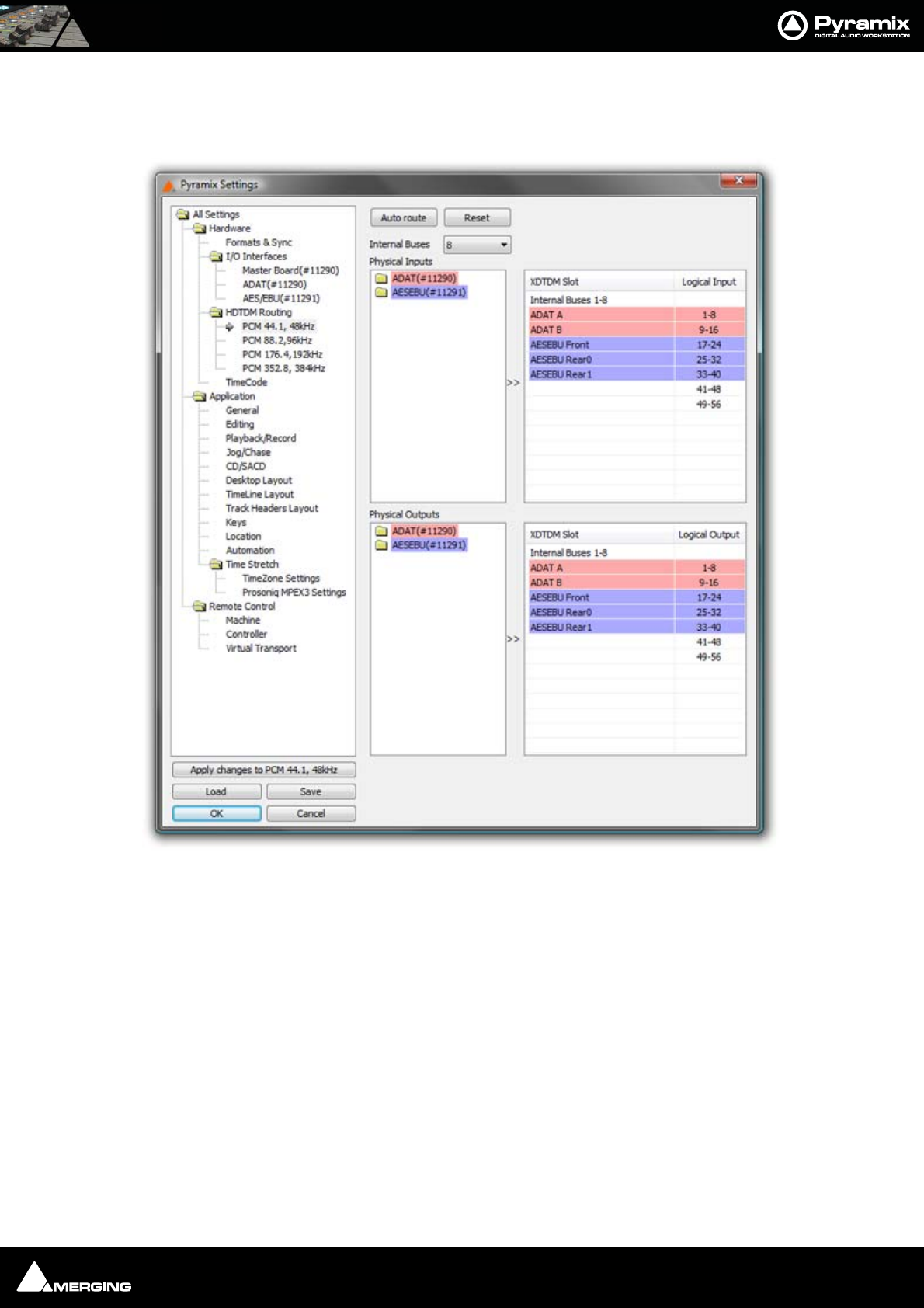
Settings : I/O Interfaces 27 - 495
HDTDM Routing
In the illustration below, Pyramix is in HDTDM mode and only PCM I/O Routing are available, with a total of 64
logical Inputs and Outputs including Internal Buses.
All Settings Hardware HDTDM PCM I/O Routing Page
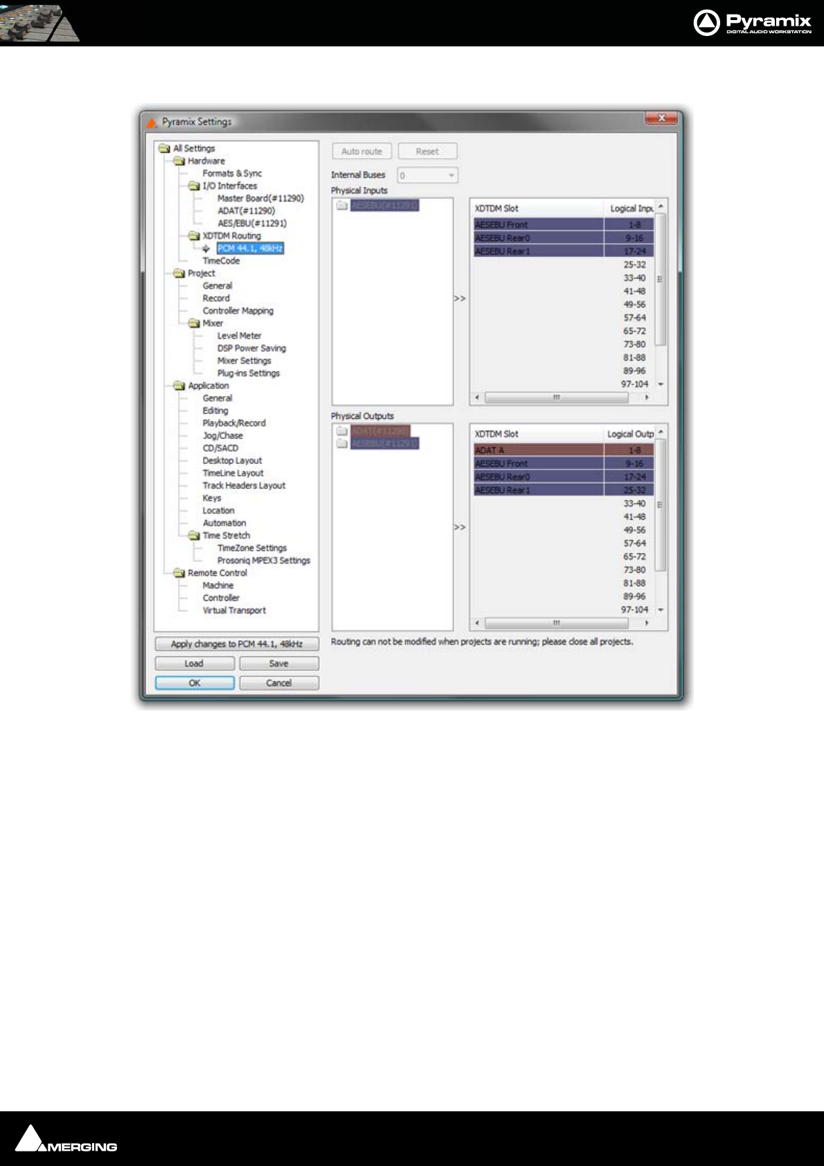
Settings : I/O Interfaces 27 - 496
XDTDM Routing
Here, Pyramix is in XDTDM mode with a project loaded. The maximum number of logical Inputs and Outputs is
doubled to 128 including Internal Buses.
Note: Routing changes can only made when there are no projects running. The dark col-
ors and written warning indicate this. Note also that only the sample rates possible for
the current project are displayed, in this case PCM 44.1, 48kHz.
All Settings Hardware XDTDM PCM I/O Routing Page
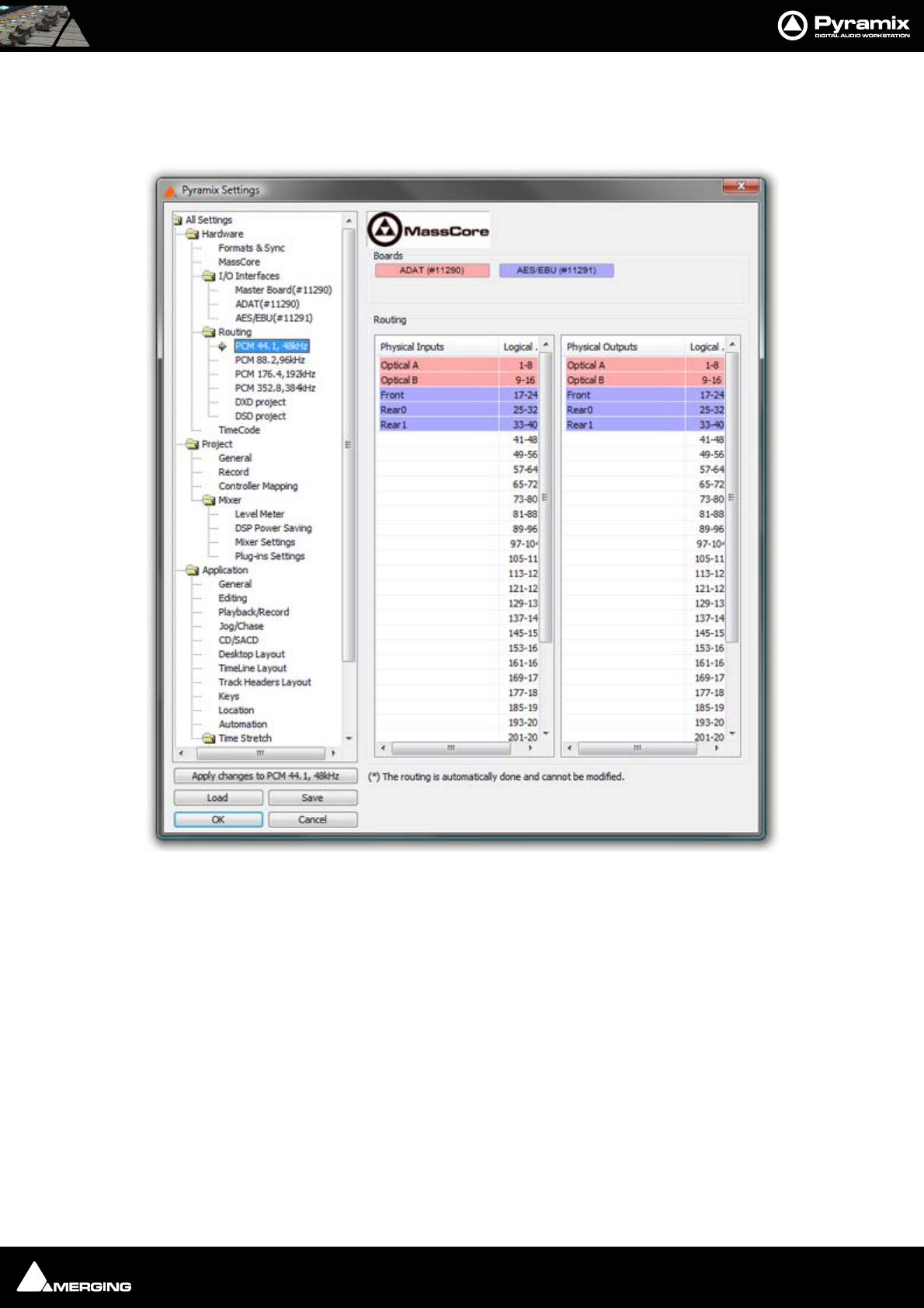
Settings : I/O Interfaces 27 - 497
MassCore
There are three levels of MassCore, depending on licence. The base level gives 48 logical Inputs and Outputs
(including internal buses). The next level is 128 and the top of the range offers 256 or more.
Note: Routing assignments are currently fixed when using MassCore. Note also that 384
Internal buses are currently available.
DXD Projects I/O Routing
Is used for DXD Editing projects. This is the same as the DSD Projects I/O Routing page except DXD audio data
format is supported.
Internal Buses
Set the required number of internal buses in the combo box. (If using MassCore the number of available buses is
fixed e.g. 48.
All Settings Hardware MassCore PCM I/O Routing Page
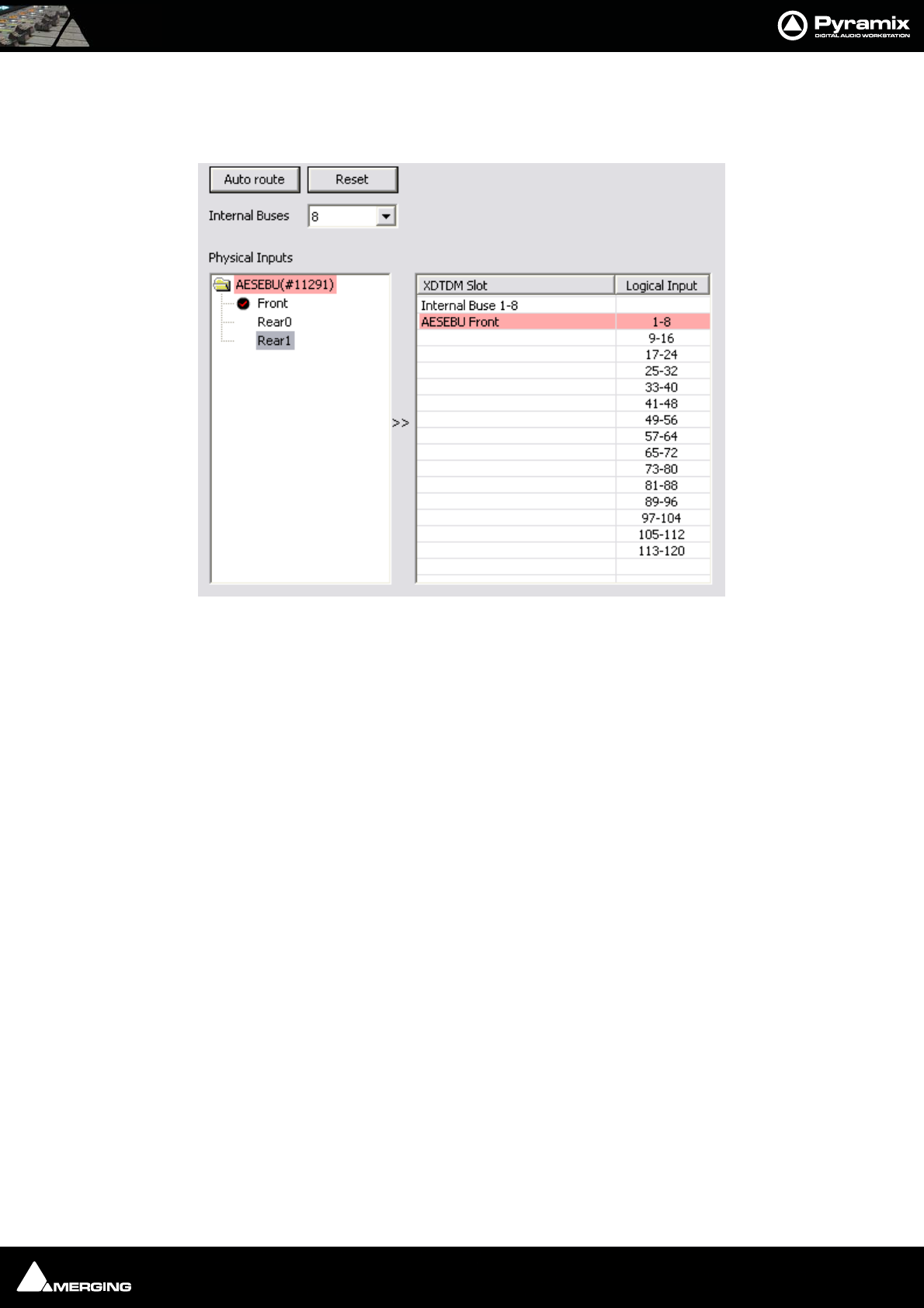
Settings : I/O Interfaces 27 - 498
Manual Routing
Double-clicking the folders in the left-hand frames opens them to show the separate physical connectors. A round
black mark with a red tick appears beside each connector entry when it is assigned.
Individual connectors or whole folders can be dragged and dropped onto the right-hand pane to patch.
Double clicking-entries in the XDTDM / HDTDM Slot pane removes the patch.
DSD Projects I/O routing
Is used for DSD Projects
The DSD Mapping of an AES/EBU daughter-card can be changed in the AES/EBU page with the DSD Mapping
setting.
The audio data format carried by MADI is selected in the MADI (# ‘card number’) page (I/O Audio Data Format
setting).
Note: DSD Projects only support DSD format.
XDTDM PCM I/O Routing
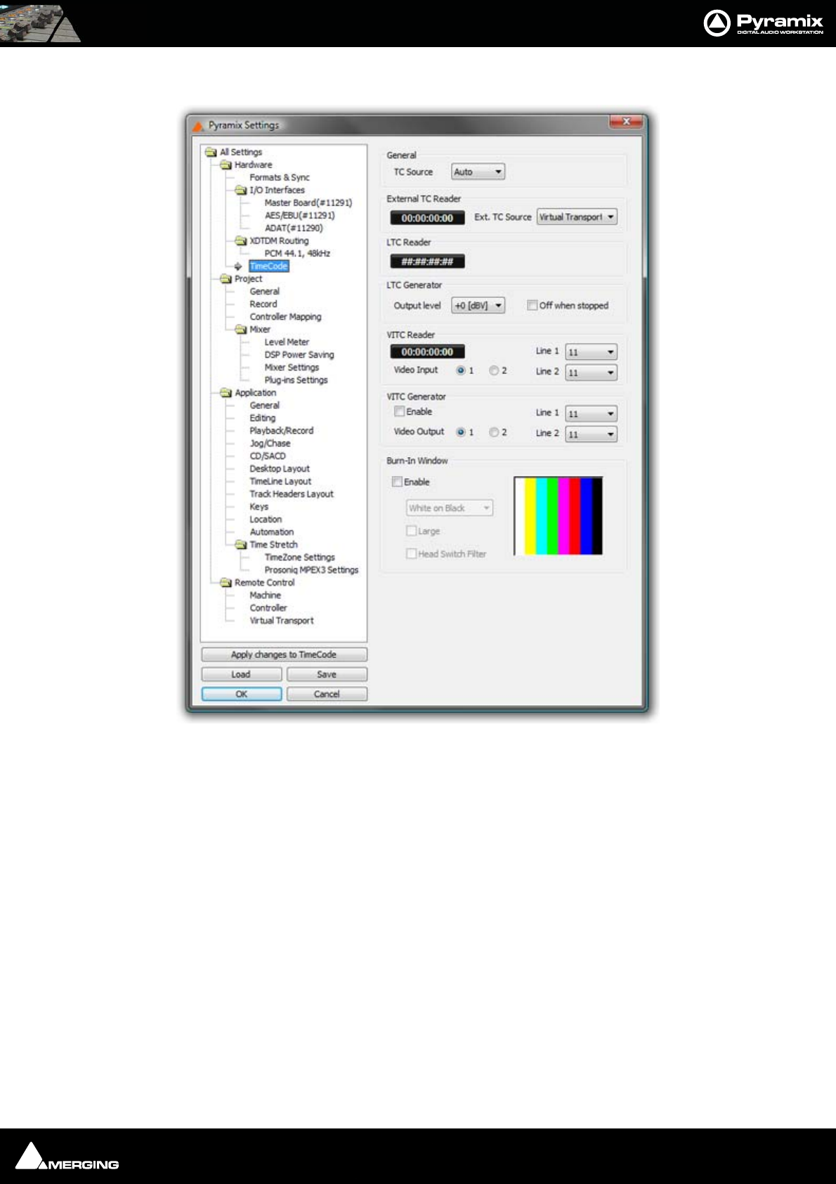
Settings : I/O Interfaces 27 - 499
TimeCode
If you are using the TimeCode input /output features of Pyramix, select the TimeCode page to configure the sys-
tem. Time code Format, Reference and Source. If an external time code source has been physically connected to
the Pyramix linear time code or video inputs, you should see the current value in the LTC or VITC Reader registers
General
These are the general settings on which all other time code parameters are based. The TC Source combo box
offers a choice of Auto, LTC, VITC or External.
Auto looks at all the sources and uses them in the order: LTC > STC > VITC
Format
Shows the current TimeCode format selected from the drop-down list. Pyramix supports the following formats:
Film 23.98 fps, Film 23.98 fps Drop, Film 24 fps, PAL 25 fps, NTSC 29.97 FPS, NTSC 29.97 fps Drop, SMPTE 30 fps,
SMPTE 30 fps Drop.
Reference
The Reference drop-down menu sets the time code source when TimeCode is selected as the digital audio Sync
Source in Settings > Mixer Settings : I/O page Sync Source.
The Reference pull-down list allows for choosing between clocking the system's audio engine to an Internal refer-
ence derived from the audio board's time code generator chip, or a clock derived from the time code input port on
All Settings Hardware TimeCode Page

Settings : I/O Interfaces 27 - 500
the optional Video/TC interface. To set the digital audio word clock source, see the I/O panel in the Virtual Studio
Settings window.
TC Source
Shows the source of time code that will be used to synchronize Pyramix playback or to generate the timestamp
when an audio file is digitized. A drop down list offers the following choices:
Internal uses the code from the internal time code chip on the audio board.
VITC uses code from the Vertical Interval Time Code (VITC) input on the optional Video/TC interface bracket /
breakout cable.
LT C uses the Linear Time Code (LTC) input on the Video/TC interface bracket to derive
Auto Pyramix automatically uses any valid time code location reference from an Internal, VITC, LTC or External
time code source.
External uses the code from the External TC reader source.
External TC reader
Shows the current value of the External Time Code reader. The drop-down list offers a choice of Virtual Transport
and all external machines installed and enabled in the Settings > All Settings > Remote Control > Machine
page.
LTC reader
Shows the current value of the Linear Time Code (LTC) reader chip. I.e. the external LTC input.
LTC G enerator
Mykerinos boards have a Linear Time Code generator.
Output Level (dBV)
Shows the current LTC output level in dBV. The drop-down list offers a choice of output level from -24dBV to
+9dBV in 3dBV increments, or it can be switched Off.
Off when stopped
When checked Pyramix mutes the LTC output when stopped. If not checked, it continues to output it’s actual posi-
tion. (static TimeCode) Certain video and audio machines cannot handle static TimeCode.
VITC Reader
Mykerinos boards are capable of reading Vertical Interval Time Code encoded in a lines of a video signal. VITC has
the advantage of being accurate and readable even when the video is stationary.
Video Input
These check buttons allow the choice of which of the two video inputs will be used for the VITC signal.
Line
Shows which lines will be decoded. Although VITC code fits into a single line, it is normally duplicated to provide
redundancy reducing read errors. The drop-down lists allow any two lines to be chosen. Different pairs of lines
often carry different code. E.g. Time-of-day and Absolute time.
VITC Generator
Mykerinos boards have a Vertical Interval Time Code generator.
Enable
When checked the output of the VITC generator is On.
Video Output
These check buttons allow the choice of which of the two video outputs will be used for the VITC.
Line
Show which lines will contain VITC.

Settings : I/O Interfaces 27 - 501
General
These controls are for setting the general format of the Video Sync signal.
Format
Shows the current video format. The drop-down list offers a choice of PAL, NTSC and a wide variety of TriLevel HD
(high-definition) formats.
Burn-in Window
Mykerinos boards can burn-in a Time-code display window into a composite video input signal.
Enable
When checked the TimeCode overlay is displayed
Color
Shows the current display scheme. The drop-down list offers a choice of:
•White on Black
•Black on White
• Black on Background
• White on Background
Large
When checked the TimeCode display will be the larger of the two possible sizes.
Head Switch Filter
When checked, the clamp circuit ignores head-switch transients and horizontal sync during the last six to seven
lines before the vertical front porch. Otherwise, the clamp circuit responds as always.
Burn-in Location
Simply drag the video burn-in window to the desired location within the color bars screen.
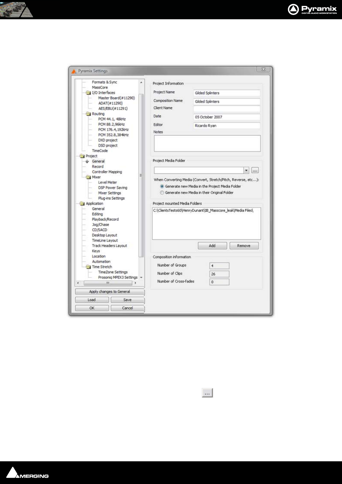
Settings : Project 27 - 502
Project
General
The General Page has fields for displaying and entering information concerning the current project. This informa-
tion is specific to the Project and will always be available in this display.
Project Media Folder
When a Project is created, either with Project > New or Project > New From Template and a Media Folder is cre-
ated or selected, the Project Media Folder, the Record : Target settings Media Folder, the Project > Render :
Target Settings Media Folder and the Project > Mix Down : Target Settings Media Folder all point to the same
folder.
The combo box has a list of all mounted Media Folders and the button opens the Choose a Media Folder to
Mount dialog where you can browse for and mount or create and mount any other Media Folder. Please
See: Housekeeping on page 40
When a Project operation will generate new Media Files, the radio buttons below the combo box offer the choice
of either:
• Generate new Media in the Project Media Folder
All Settings Project Information Page
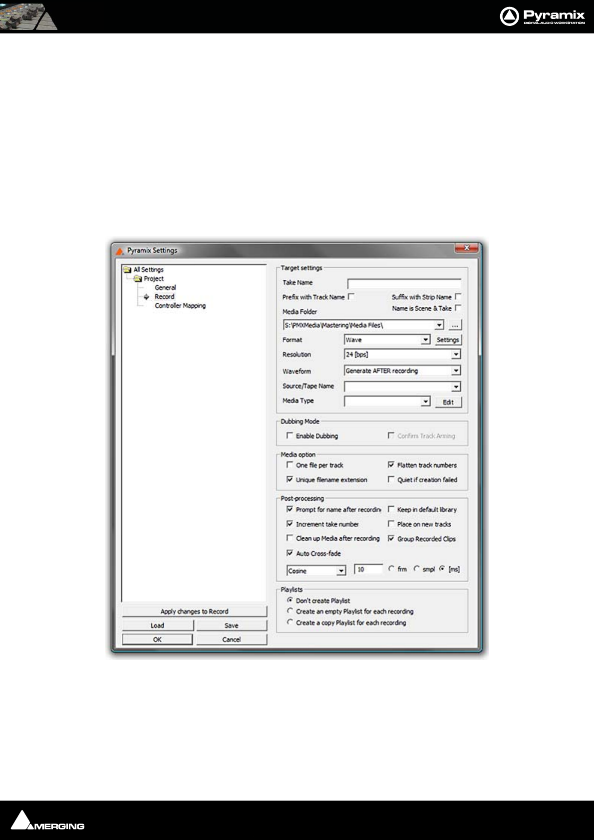
Settings : Project 27 - 503
• Generate New Media in their Original Folder
Project mounted Media Folders
All folders mounted by the Project are listed here. Further folders may be mounted or existing ones unmounted by
using the Add and Remove buttons.
Composition Information
Lists three categories of Composition data:
Number of Groups
Number of Clips
Number of Cross-fades
Record
Target Settings
Take Name
Type a ‘seed’ name here. This is used to begin the name of new recordings. E.g, if you type "Vocal" the next record-
ing you make into a track will be called "Vocal". This field works in conjunction with the "Increment take number"
function (see below). If you leave this field blank, Pyramix will apply the name "Untitled" as a default.
All Settings Project Record Page

Settings : Project 27 - 504
Prefix with Track Name
When checked the name of the recording will be prefixed by the name of the track it was recorded on, like:
Guitar-Take 001_##001##_.wav
Guitar-Take 002_##001##_.wav
Suffix with Strip Name
When checked allows Multitrack recording of typed sources, typically for archiving Film stems, or Render of Mixes/
Dubs:
With a set of multi-channels strips (GPS strips) properly named and typed, the Suffix with Strip Name option will
create files named like:
Episode3-M&E-Ls.wav
Episode3-M&E-Rs.wav
Episode3-LtRt-L.wav
Episode3-LtRt-R.wav
Name is Scene & Take
When checked, the name of a take recorded in Pyramix will be used as the source for the Scene and Take fields in
BWF and PMF audio files with the proper tag set. The last numeric digits of the name are used as the Take number
and any preceding characters are used as the Scene name.
E.g. 203/5 003 will be interpreted as SCENE = 203/5 TAKE = 003
Media Folder
Displays the selected Media Folder for recording. Clicking the adjacent button opens the Choose a Media Folder
to Mount window. This enables folders to be created mounted and managed. Please See: Housekeeping on
page 40
Format
Displays the current recording format from the choice available in the drop-down list. (PMF, SD2, AIFF, AVI, WAVE,
BWF, CD Image or OMF)
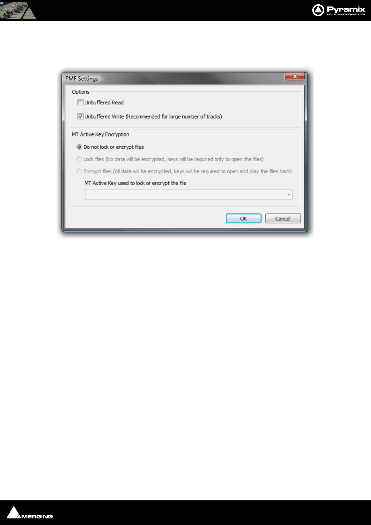
Settings : Project 27 - 505
Settings
If PMF is chosen as the Format then the Settings button becomes active. When clicked the PMF Settings dialog
appears:
Options
Unbuffered read Improves general Playback performance but may impact on waveform display and update.
Default = OFF
Unbuffered Write (Recommended for large number of tracks) Default = ON (may have a negative effec when
recording over a network. If you experience problems set this to OFF.
Both the above options enable/disable the Windows Disk Cache.
MT Active Key Encryption
Under Construction
Do not lock or encrypt files Default =ON
Lock files (No data will be encrypted, keys will be required only to open the files)
Encrypt files (All data will be encrypted, keys will be required to open and play the files back)
MT Active Key used to lock or encrypt the file
Copy and paste or type the appropriate key or choose from the drop-down list.
All Settings Project Record : Format PMF Settings dialog
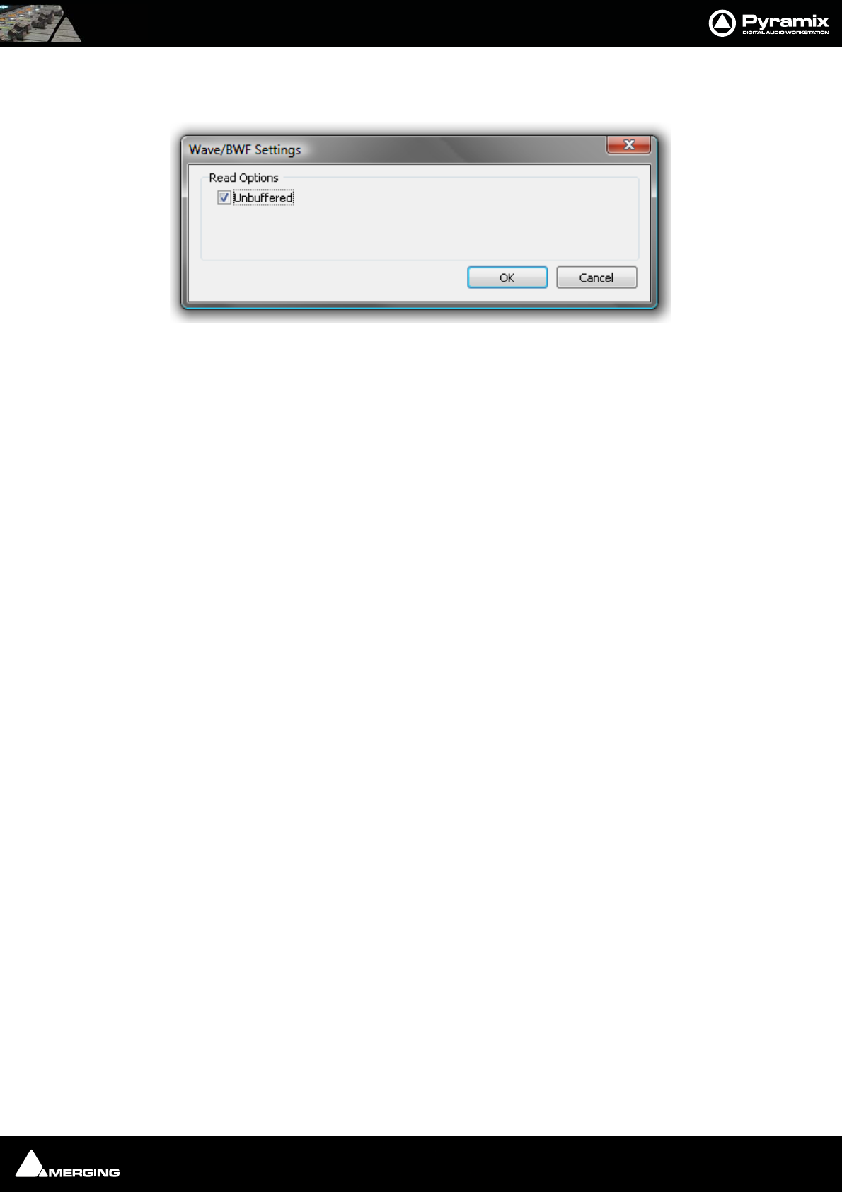
Settings : Project 27 - 506
If Wave is chosen as the Format then the Settings button becomes active. When clicked the Wave/BWF Settings
dialog appears:
The only option is Unbuffered, ticked by default. When files are read the Windows cache is not used. This
improves performance in most cases. Un-check the box to turn buffering on. The System Cache disk is then used
to buffer.
Resolution
Displays the number of bits per sample for recordings from the choice available in the drop-down list. (16bps,
24bps or 32bps)
Read Options
Unbuffered read Improves general Playback performance but may impact on waveform display and update.
Default = ON
This option enables/disables the Windows Disk Cache.
Request Size
The default value is 64kB. This can be increased to a maximum of 320kB if problems are experienced during play-
back.
Waveform
Displays the current Waveform generation mode from the choice available in the drop-down list. (None, Generate
AFTER recording or Generate WHILE Recording for all supported formats) (Default is WHILE)
Source Name
This field allows you to give a name to indicate the source of the material being recorded into Pyramix. For exam-
ple, you might enter "Reel #1" to indicate the first source reel, etc. If the MediaType field (see below) is set to
"None", the Source Name field will be grayed out and not available.
Media Type
Displays the type of media the source material came from, chosen from the drop-down list. Clicking on the EDIT
button allows existing names to be edited or new ones created. The media type chosen here and the source name
given in the previous field are saved with the media file created by the new recording. This information can then
be viewed by selecting a clip and displaying its Properties page.
Dubbing Mode
Please see also: Dubbing Mode on page 337
This mode is provided principally for film re-recording. It allows tracks to be Armed or Disarmed for recording
while recording is taking place.
Enable Dubbing
When checked, Dubbing Mode is engaged.
Confirm Track Arming
All Settings Project Record : Format Wave/BWF Settings dialog
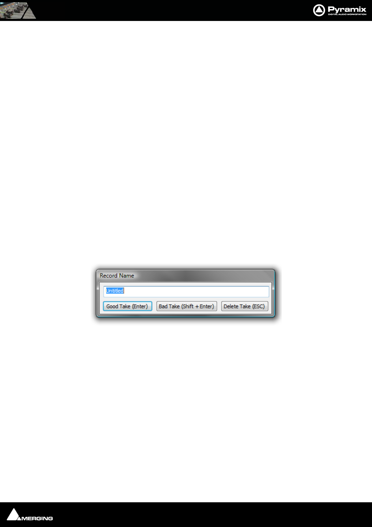
Settings : Project 27 - 507
Only available when Dubbing Mode is selected in the adjacent check box. A check in this box means that any
changes to track arming made whilst recording must be confirmed by a new Record command before they will
take effect.
Media option
One file per track
When checked, each recording on each track of a multi-track recording is recorded into a separate file. When this
option is off (which is the default), one single media file is created containing all the tracks.
Flatten track numbers
When a recording is made on a track, Pyramix always adds media number to it. When checked on (default), Pyra-
mix starts enumerating at one. E.g. If a recording is made on tracks 5 and 9 of a multitrack session simultaneously,
the media numbers will be 1 and 2. When this option is off, Pyramix adds the real track numbers to the media. In
the example above, this would be 5 and 9.
Unique filename extension
When checked, Pyramix will append a random number to the name of each new recording in order to avoid dupli-
cate file names.
Quiet if creation failed
Unless this box is checked, Pyramix displays a dialog with an error message when the creation of a media file fails.
This can be annoying if Pyramix is remotely controlled. Checking the box suppresses the error message.
Post Processing
These options determine what Pyramix will do after each recording is finished.
Prompt for name after recording
When checked, a Record Name dialog box will open immediately after recording is finished and playback of Pyra-
mix is stopped.
If a name was entered in the Take Name field (see above) it will automatically appear in the Record Name dialog
box when it opens. You can edit the existing name, or replace it completely with a new name.
Keep in default library
When checked, new recordings will automatically appear in the Default library of the current Project.
Increment take number
When checked, each successive recording will have the name in the Take Name field applied to it, plus a number
that will increment with each new recording. E.g, if the first recording is named "Take", the next recording will
automatically be named "Take 2", etc.
Place on new tracks
When checked, Pyramix will place the newly recorded clips on new tracks. These new tracks will be added to the
Project Editor as soon as playback is stopped following a punch in/punch out recording. When first created, these
tracks are not assigned to mixer channels, so it will be necessary to assign them when you want to output them. If
this item is not checked, the new clips will be placed on the track(s) set to record them.
Clean up Media after recording
Note: This option is automatically set OFF when a Project is opened.
Record Name dialog box
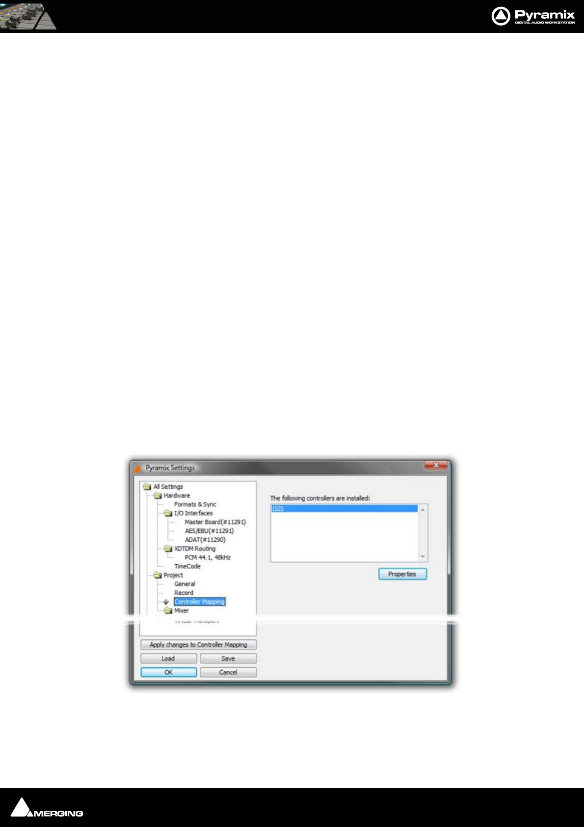
Settings : Project 27 - 508
This mode makes Pyramix work like an analog or DASH multitrack. I.e. All punch-ins are highly destructive !! With
modern, large hard drives, we would rather recommend:
View > Used Media > Invert selection > Delete media (after a good archive/consolidate/back-up has been
made) or:
b) Project > clean-up media, etc.
All these functions destroy media on the hard drive, but b & c offer more control over what is permanently
deleted.
Group Recorded Clips
When checked, clips in a multi-track recording are automatically grouped.
Auto Cross-fade
When checked a cross-fade is automatically applied when punching in or out. The current fade shape is displayed
form the choice available in the drop-down list (Power, Linear, dB, Cosine or Root-Cosine) Duration can be set in
frames, samples or milliseconds depending on which box is selected.
Playlists
These buttons toggle between three possible choices:
Don’t create Playlist
Create an empty Playlist for each recording
Create a copy Playlist for each recording
Please see: Playlists on page 122
Controller Mapping
Please see Guides for specific controllers. E.g. Merging Technologies Ramses MSC and ISIS and for Sony P-2 Proto-
col 9-pin controllers please see: Sony 9 - Pin Protocol Configuration (Pyramix controlled by external device)
on page 541
All Settings Project Controller Mapping Page
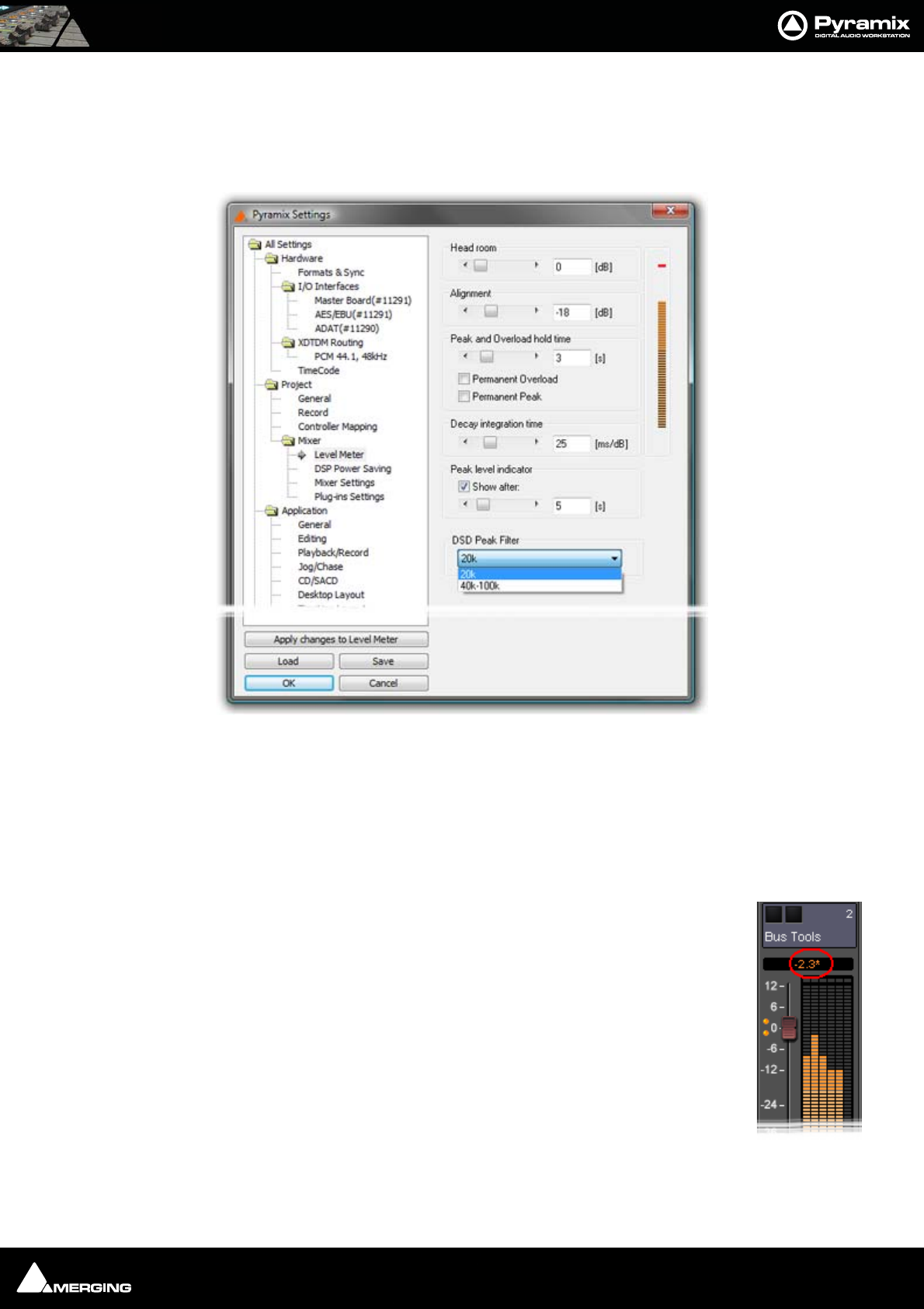
Settings : Mixer 27 - 509
Mixer
Level Meter
This page determines the appearance and behavior of the level meters in the Mixer and Track Headers.
These settings only apply to the current Mixer. This allows each Mixer to have its own custom General and Level
Meter settings.
To change any of the settings, click the left or right buttons or drag the horizontal scroll bar to increment or decre-
ment the selected parameter. Alternatively, type directly into the number field for each parameter (these fields will
only accept numbers within the permissible range for each parameter). The color graphic display of the level
meter will respond immediately to show the effect of Headroom and Alignment parameter changes.
Headroom
Sets the amount of headroom displayed as red meter segments before clipping. I.e. the num-
ber of dB below 0dBFs at which the red meter segments begin.
Note: This headroom value is only for the Mixer meter displays and will not
(and cannot) be reported to the Plug-in (VU Meter or Meter Bridge). The VU
meter Plug-in has it’s own headroom setting.
Note: If the mixer displays an * next to the Level field value it indicates that
a custom value was entered in the Headroom settings.
Alignment
Sets the alignment level. Displayed by the point on the scale at which the dark orange seg-
ments begin.
All Settings Project Mixer Level Meter Page

Settings : Mixer 27 - 510
Peak and Overload Hold Time
Sets the amount of time in seconds that the peak segment or overload segment (topmost red segment) of the
level meter remains illuminated.
Permanent Overload
When the box is checked, the red Overload LED above a track will remain lit, even after playback is stopped. To
clear the LED, double-click it. When not checked, the Overload LED will automatically clear itself after a few sec-
onds and remain off until the next overload occurrence.
Note: The overload LED will go on after one sample with the maximum level.
Permanent Peak
This parameter works in conjunction with the Peak Level Display. When this is on (checked), the Peak Level pop-up
display will show the value and location of the highest level reached on a track up to the time when the mouse
was clicked on the meter. The level display will not be updated until the next time playback is stopped and re-
started. If it is not on (unchecked), the Peak Level Popup Display will show the highest level reached in that track
from the last time the Popup Display is activated (while playback continues). For example, clicking a channel’s
meter while playing back will display the Peak Level Popup, which will show the peak level (and its location)
reached so far. Click away from the Popup, and it will disappear. Click on that meter again, and the Popup will
appear again, this time showing the peak level/location reached since the last time the Popup was displayed.
Decay integration time
This parameter sets the rate at which the level meter display decays after the level falls below the most recent
peak. The slope of the decay is given in terms of milliseconds per decibel (ms/dB).
Peak level indicator
Show After
When the box is checked, the Fader/Input Level displays located above the faders on each mixer strip display the
peak level of the signal running through the corresponding mixer strip. The value are updated at the interval set
by the slider below the check box. If the check box Show After is off, the Fader/Input Level displays always show
the setting of their corresponding fader.
DSD Peak Filter
For DSD projects this drop-down list offers the choice between two filtering options which will be applied to the
DSD signal before it is measured by the level meter.
This will help enable you to ensure that the DSD signal is compatible with the AES recommendations concerning
the high frequency dither noise content.
20k
Applies a 20 kHz low pass filter to the signal, thus only the audible audio content is measured.
40k-100k
Applies a band pass filter with a frequency range of 40 kHz to 100kHz to the signal. According to the AES recom-
mendation the signal level in this frequency range should not exceed -20 dB.
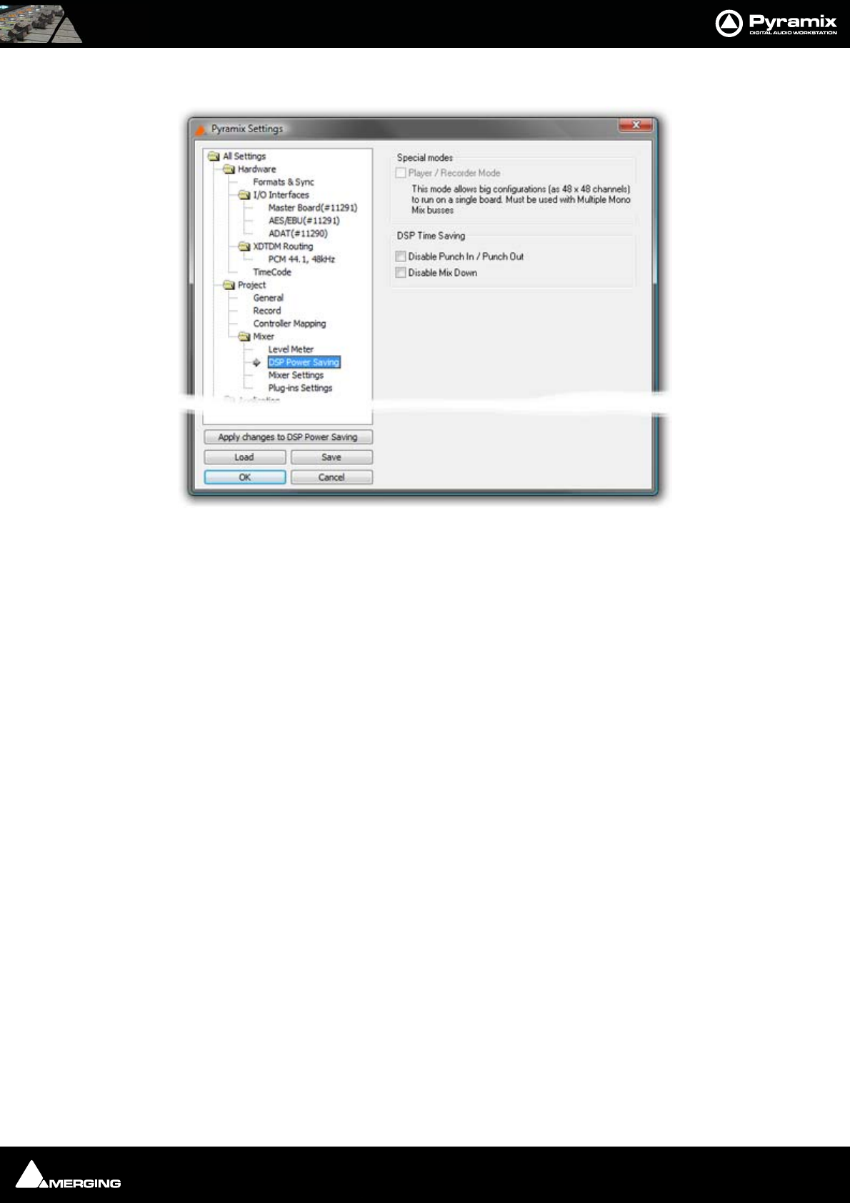
Settings : Mixer 27 - 511
DSP Power Saving
Special Modes
Player/Recorder Mode
This mode allows big configurations (such as 48 x 48 channels) to run on a single board. Player/Recorder Mode is
intended for use with an external hardware console. When this mode is activated, the Pyramix mixer is relegated
to the role of signal router, there is no level control, no panning, no plug-ins and no inserts. This option is only
available in configurations with multiple mono mix buses.
The Pyramix Direct Out functionality provides an alternative, more user configurable method of achieving similar
DSP savings. Please see: Channel Direct Outputs on page 161
DSP Time Saving
Disable the Punch in/out
When the box is checked, Punch-in and out recording capabilities are disabled.
Important! Pyramix still will allow you to arm tracks and to start the recording process, but the resulting
media file will contain digital nulls.
Disable Mix Down
When the box is checked, the digital mixdown function activated with the menu command Project->Mix Down is
disabled.
Important! Pyramix still will allow you to start the mixdown process, but the resulting media file will con-
tain digital nulls.
All Settings Mixer DSP Power Saving Page
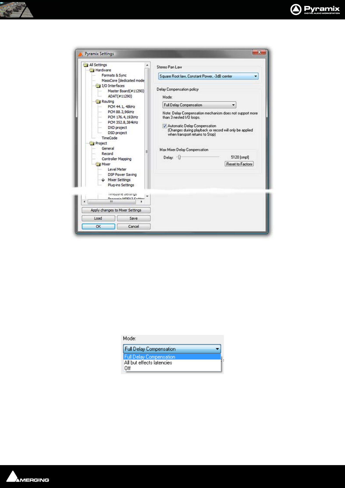
Settings : Mixer 27 - 512
Mixer Settings
Stereo Pan Law
The drop-down menu offers a choice between the default Sin/Cos law, Constant Power, -3dB center and Square
Root law, Constant Power, -3dB center.
Note: Existing projects will use the previous default Square Root law unless this setting
is changed.
Delay Compensation Policy
Mode
The drop-down menu offers a choice between:
Full Delay Compensation
All but effects latencies
Off
Note: Automatic Delay Compensation does not support more than 3 nested I/O loops.
Automatic Delay Compensation
When ticked, turns Automatic Delay Compensation On
All Settings Mixer Mixer Settings Page
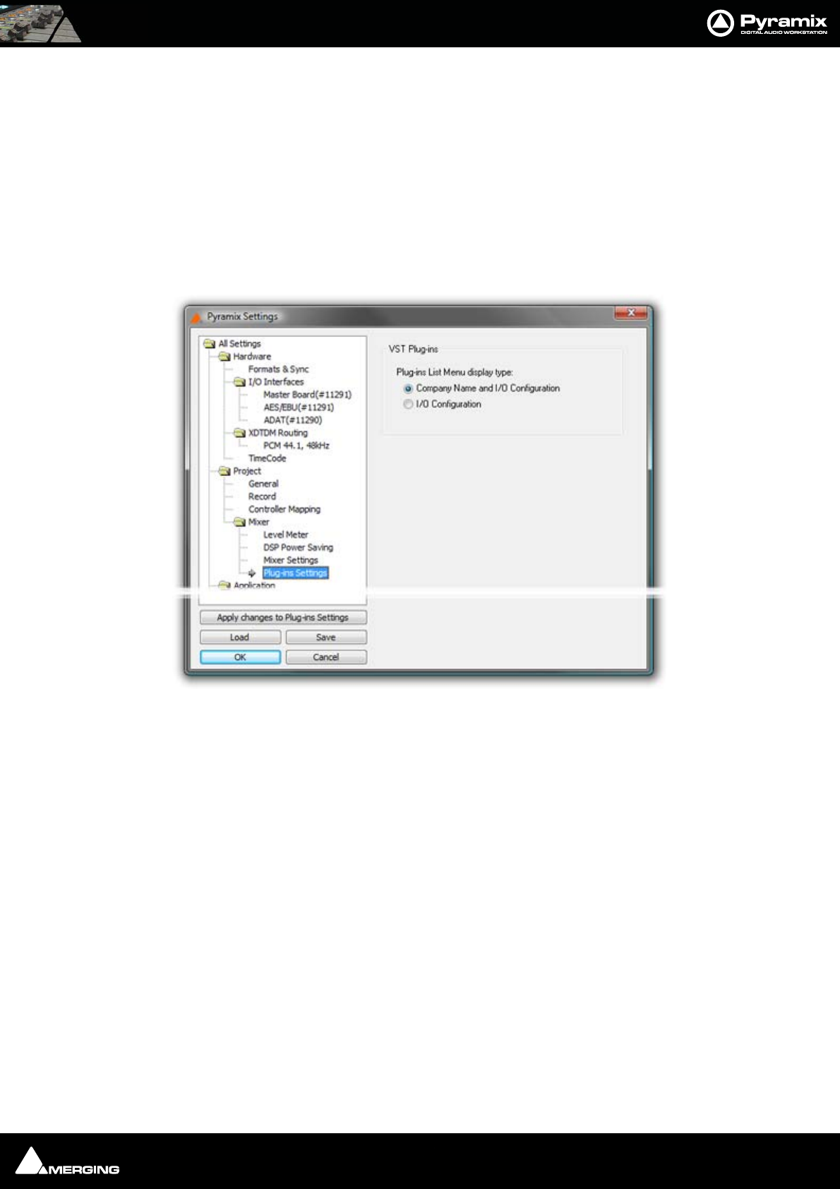
Settings : Mixer 27 - 513
Note: Any changes to the delay required that occur during playback or recording will
only be computed and applied when the Transport is next in Stop.
Max Mixer Delay Compensation
When required by the Mixer error: Delay compensation dialog the slider should be set to a value just above the
delay latency value requested.
Reset to Factory
Click the button to restore the factory computed maximum delay value.
Plug-ins Settings
VST Plug-ins
The buttons offer a choice of how the VST Plug-ins are ordered and grouped in the Plug-ins List Menu.
If Company Name and I/O Configuration is chosen the list will be ordered by Company Name and the plug-in’s
grouped according to their I/O configuration. I.e. 1 in - 1 out, 1 in - 2 out, 2 in - 2 out and so on.
Alternatively, choosing I/O Configuration groups the Plug-ins by I/O Configuration and within each group lists
them alphabetically by name.
Please see also: VST Plug-ins Display Order on page 252
All Settings Mixer DSP Plug-ins Settings Page
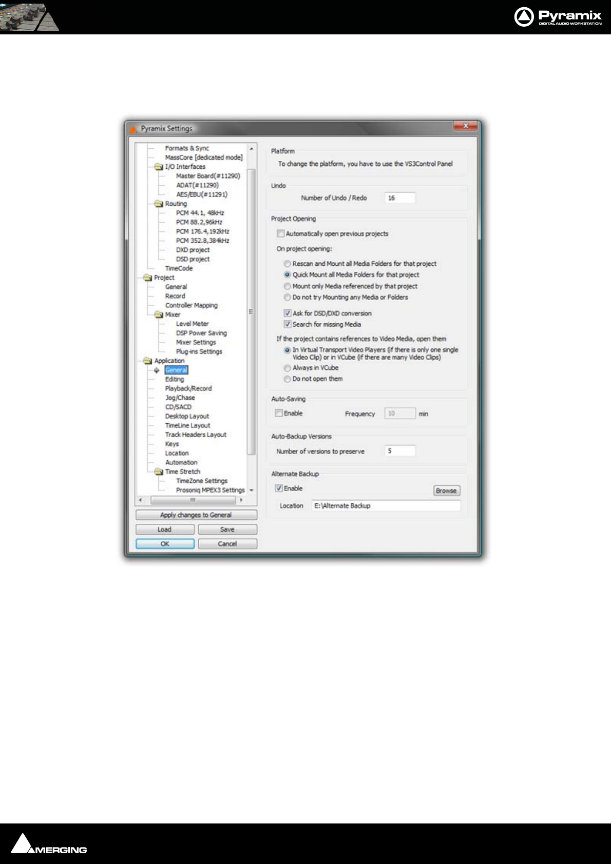
Settings : Application 27 - 514
Application
General
Platform
Audio processing
The drop down list, offers a choice of which audio device to use with Pyramix. The available choices are Mykeri-
nos Card or Native Processing. I.e. the computer’s host processor(s) & sound card, if you have purchased this
option.
Undo
Number of Undo / Redo
Sets the Number of Undo / Redo levels. Also sets the number of automation versions to be kept when the Auto-
mation tab option, Optimization : Limit versions to the number of Undo/Redo is enabled. The default is 32.
Note: Increasing this value uses more RAM.
Project Opening
This section determines Pyramix behavior when the application is launched.
All Settings Application General Page

Settings : Application 27 - 515
Automatically open previous projects
When checked, Pyramix opens all projects that were open when the application was last used.
On Project Opening:
Rescan and Mount all Media Folders for that project
Can result in long opening times when there are very large Media Folders
Quick Mount all Media Folders for that project
Default. Usually results in the fastest opening time.
Do not try Mounting any Media or Folders
Media must be mounted manually.
Ask for DSD/DXD conversion
When checked, Pyramix will open a dialog whenever a DSD or DXD Project is opened. This offers the opportunity
to convert to the opposite format.
Search for missing Media
When checked, Pyramix automatically searches for unmounted or missing media when a project is opened.
If the project contains references to Video Media, open them:
In Virtual Transport Video Players (if there's only one single Video Clip) or in VCube (if there are
many Video Clips).
A single Video Clip present in the Project is opened in the DirectShow Video Player or the QuickTime Video
Player (depending its type). Multiple Video Clips present in the Project are opened in VCube.
Always in VCube
Single or multiple Video Clips are opened in VCube.
Don't open them
Video Clips in the Project are only placed in the timeline (optionally) but not opened in any Video Player.
Auto-Saving
Pyramix can be set to automatically perform a save of all open projects at regular intervals. This does not create a
backup unless a value in excess of 1 is entered in Auto-Backup Versions (see below).
Enable
When checked the current Project will be automatically saved at the interval set by:
Auto-Saving. Frequency
Sets the time between saves between 1 and 60 minutes.
Auto-Backup Versions
Determines how many previous versions will be kept. This ensures that every Save operation (Automatic or Man-
ual) preserves at least one version of any projects being saved in their last stored state. The number of previously
saved versions to preserve can be set by the user. As said above, the minimum is one.
Alternate Backup
Enable
When enabled all projects saved (automatically or manually) are also saved to the chosen alternate location. The
Backup Versions are not saved to the alternate location. This offers increased security if another drive or network
drive is chosen.
Note: Only project files are stored into this directory, not the media files.
Location
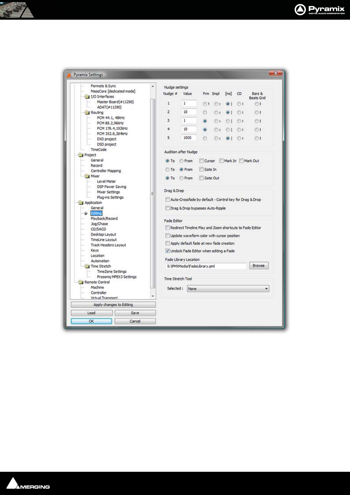
Settings : Application 27 - 516
Displays and sets the alternative location. The Browse button opens a Browser window to enable navigate to a
suitable location.
Editing
Nudge settings
These settings control the amount by which a cursor or clip will be nudged when using the left and right Arrow
keys. Five Nudge Settings can be stored. Any one of these can be selected as the current nudge setting using Clips
> Nudge > Current Setting or Cursors&Marks > Current Nudge Setting.
Nudge #1~Nudge #5
For each nudge preset, enter an numeric value and click the appropriate check box to set increments to frames,
samples, milliseconds, CD frames or the current Bars & Beats grid.
Audition after Nudge
These options set automatic Audition on for the selected actions.
Pyramix Settings Application Editing page

Settings : Application 27 - 517
To
When checked, the playback will start before the selected option and stop when this is reached (cursor, mark in or
mark out)
From
When checked, the rehearse will be performed from the selected option (cursor, mark in or mark out)
Separate To and From options are provided for Gate In and Gate Out
Drag & Drop
Auto-Crossfade by default - Control key for Drag & Drop
When checked, dragging a selection or clip over another results in a crossfade. (Cursor changes to a hand with an
X.) Otherwise, dragging a selection or clip over another overwrites it. (Cursor is a hand) Holding down the control
key when dragging selects the alternate function.
Fade Editor
Redirect Timeline Play and shortcuts to Fade Editor
When checked, the Timeline Zoom commands are redirected to the Fade editor. Also, the Active Machine > Tog-
gle Play/Stop command usually mapped to the Spacebar is replaced with the Fade Editor > Audition X Fade
command but only if the Fade Editor has been opened with the Fade Editor > Open Editor command.
Update waveform color with cursor position
When checked the waveform color will change from the default to the color set in Settings > All Settings >
Application > TimeLine Layout : Waveform Position Color whenever the Playhead cursor is on the right-hand
side of the Reference Point (default is centre fade position) in the Fade Editor.
Apply default fade at fade creation
When checked the default Fade In/Out default will be applied when a new fade is created.
Undock Fade Editor when editing a fade
On by default. When checked the Fade Editor Tab is automatically undocked when editing a fade.
Fade library location
This is the path for the fade library. The Browse button launches an Explorer window allowing any local or net-
work path to be set.
Time Stretch Tool
The Selected: combo box offers a choice of Time Stretch algorithms depending on which keys are installed.
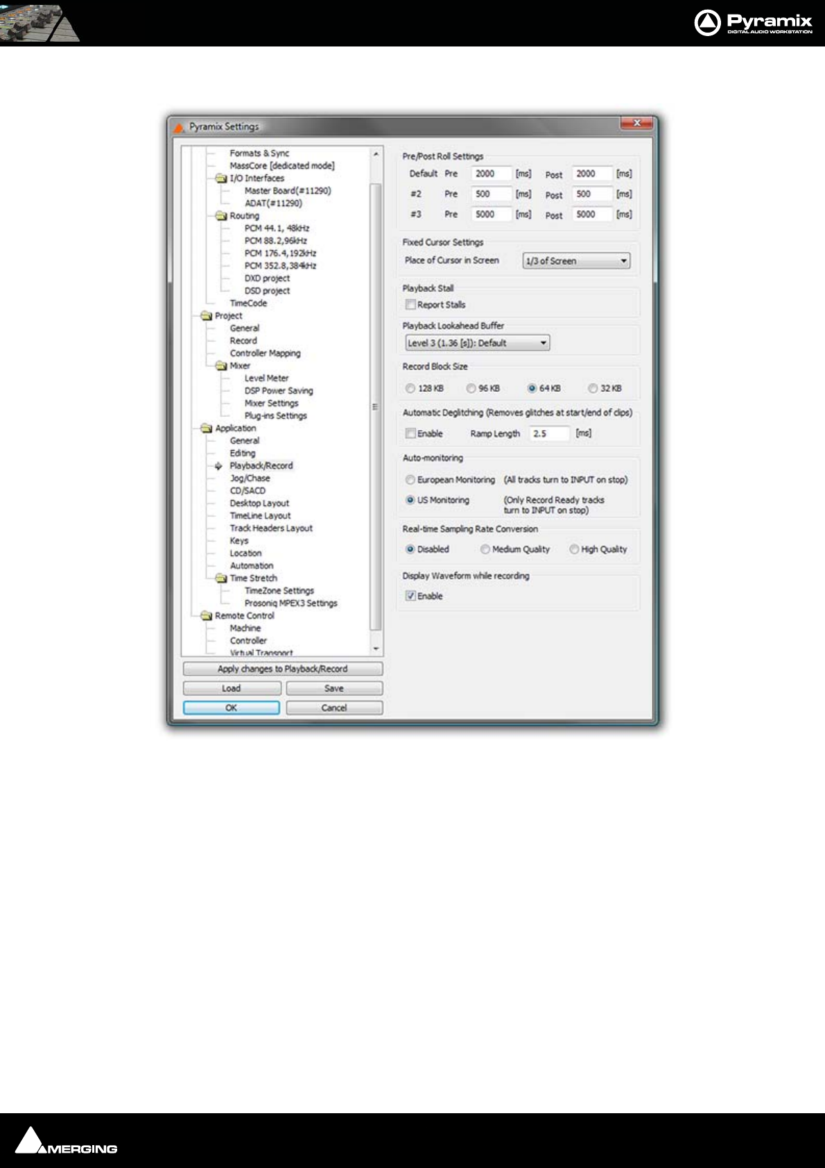
Settings : Application 27 - 518
Playback/Record
Pre/Post Roll Settings
Allows values to be set for the Default and two alternative Pre and Post-roll settings.
Fixed Cursor Settings
The drop-down list offers nine possible positions for the Playhead cursor position on screen when scrolling Time-
line with fixed cursor is selected. (View > Fixed Cursor while playing)
Playback Stall
When checked, interruptions to playback will pop-up a message box with details of when the stall occured.
All Settings Application Playback/Record Page
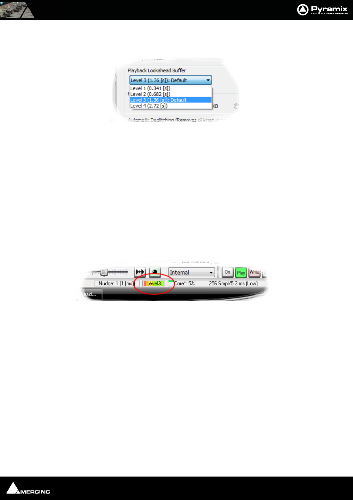
Settings : Application 27 - 519
Playback Lookahead Buffer
Sets the length of audio that will be pre-loaded into buffers prior to playback. Four levels are available in the drop-
down list:
• Level 1 (0.341 [s])
• Level 2 (0.682 [s])
• Level 3 (1.36 [s]): Default
• Level 4 (2.72 [s]
The default value is Level 3). A larger value may enable you to playback certain large projects. For example it can
improve track count with one file per track BWF on some projects. This value should be increased gradually until
behavior is as you wish.
Note: The higher the Level the longer the PreLoad Buffer will be. The longer the Preload
Buffer the greater the Memory consumption.
Note: The higher the PreLoad level the longer the Playback Cursor will pause before
playback commences.
The current Buffer Level is shown in the Pyramix Info bar during normal operation:
Record Block Size
Offers a choice of four possible values. Should be left at the default 64kB in most circumstances.
Automatic Deglitching (Removes glitches at start / end of Clips)
When Enable is checked, a short fade is applied to the start and end of every clip. Ramp Length sets the fade
duration.
Auto-Monitoring
Toggles between two options:
European Monitoring (All tracks turn to INPUT on stop) (default) or
US Monitoring (Only Record Ready tracks turn to INPUT on stop)
Real-time Sampling Rate Conversion
Toggles between three options:
Disabled No Real-time SRC will take place. Clips will be played back at the original sampling rate. I.e. if sampling
rate does not match Project sampling rate then the Clips will be played back at incorrect speed.
Medium Quality Clips will be played back at the correct speed. Conversion, if necessary, will be carried out at a
compromise quality between speed and quality.
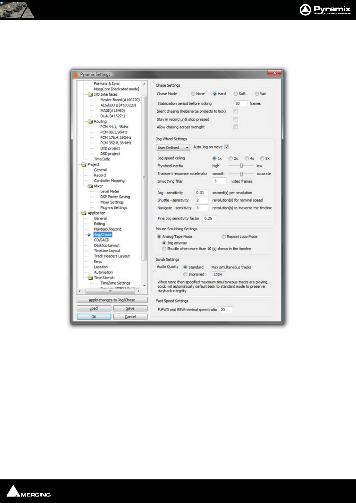
Settings : Application 27 - 520
High Quality Clips will be played back at the correct speed. Conversion, if necessary, will be carried out at a the
highest quality. This obviously requires more resources.
Jog/Chase
All Settings Application Jog/Chase Page

Settings : Application 27 - 521
Chase Settings
Chase Mode
The radio buttons give a choice of Chase Mode
None Pyramix does not chase external TimeCode
Hard When Hard Chase is active, Pyramix will only playback when valid TimeCode is
detected on the chosen TimeCode input port. If there is a jump in the incoming
TimeCode, Pyramix will adjust to the new TimeCode, re-synchronize and begin
playback from the new TimeCode position. Pyramix will run on its own internal
TimeCode for up to 1 frame if there is a drop out in the time code. If no valid Time-
Code is detected after that time, playback will stop.
Soft When Soft Chase is active, Pyramix will only playback when valid TimeCode is
detected on the chosen TimeCode input port. If there is a jump in the incoming
TimeCode, Pyramix will not adjust to the new TimeCode, but will continue play-
back with an offset from the incoming TimeCode position. Pyramix will continue to
run on its own internal TimeCode for up to 1 frame if there is a drop out in the
TimeCode. If no valid TimeCode is detected after that time, playback will stop.
Vari When the Vari Chase is active, Pyramix will Varispeed, I.e. alter its sampling rate to
follow fluctuations in an external TimeCode. (going back and forth, slowing down,
accelerating, playing normally or backwards, up to 8x nominal speed) while in
playback (not in record)
Stabilization period before locking
Although Pyramix is capable of locking to incoming TimeCode within 3 - 4 frames, there are cases where synchro-
nization is more stable if there is a longer waiting time. This is because some external devices take a considerable
time to stabilize their speed after playback is started. This parameter allows a waiting time to be defined before
Pyramix will start chasing the TimeCode. 30 frames is a good starting point if you experience problems with exter-
nal machines.
Silent Chasing (helps large projects to lock)
When checked Pyramix allows large projects to lock immediately while chasing. In this mode locking time does
not depend on the number of tracks. The drawback is that sound only appears one second after a lock is estab-
lished.
Stay in record until stop pressed
If this box is checked Pyramix will remain in record (once properly locked to TimeCode) regardless of disturbances
/ discontinuities in the code until the Pyramix Stop button is pressed.
Allow chasing across midnight
When this option is unchecked the Chase engine always locks between 00:00:00:00 and 23:59:59:2X of Day 0
When this option is checked the Chase engine allows locking anywhere in the Pyramix timeline (-1000 days to
+1000 days). The engine interprets the incoming timecode to be the nearest position to the current cursor posi-
tion, thus allowing chasing around midnight of any days of the timeline.
For additional security and comfort, if Pyramix is in the "locked" state while crossing the midnight barrier, then
even with this setting unchecked setting, there will not be an immediate jump from midnight back to zero while
playing or recording in sync. The playback or recording will remain seamless, uninterrupted and cross the day bar-
rier until an out-of-lock status is recognized. Only then is a re-chase triggered to whatever the incoming Timecode
value is at that point.

Settings : Application 27 - 522
Jog Wheel Settings
Preset
The combo box offers a choice of hardware controller presets including the Merging Technologies Ramses MSC
and ISIS. Choose your controller from the list or, if not shown User Defined
Auto Jog on move
When ticked moving the jog-wheel enters Jog mode. When Auto-Jog is enabled, all Jog Commands are pro-
cessed a slightly different way. Pyramix temporarily stops chasing and starts Jogging while sending Goto com-
mands to the External Machine. The audio is therefore perfectly scrubbed and the external machine follows the
audio as well as it possibly can. When the user stops Jogging, Pyramix automatically returns to chase mode.
Jog Speed ceiling
Sets the maximum jog speed from a choice of 1X, 2X, 4X or 8X play speed
Flywheel inertia
Low follows the actual movements as sent by the jog wheel. High passes the actual movement through a
smoothing filter. So, when the slider is set to Low the Smoothing Filter parameters have no effect.
For sound to picture work where tight sync to picture is required use a setting biased to Low. For a more pro-
nounced flywheel effect choose a Higher setting.
The Middle position is a good starting point.
Transient response accelerator
Optimizes Pyramix’s reactivity to jog moves, settings range from Smooth to Accurate.
When the slider approaches Accurate there may be some strange undesirable effects.
Smoothing Filter
The Smoothing Filter parameter determines the length of the “fade in” and “fade out” when beginning and end-
ing scrubbing. Enter the required value in the box expressed in video frames.
Jog - sensitivity [ ] second(s) per revolution
Sets the time moved in one revolution of the jog wheel. Type the required value in the box.
Shuttle - sensitivity [ ] revolution(s) for nominal speed
Sets the fraction of a revolution or number of revolutions required to maintain nominal speed. E.g. an entry of 0.25
will require a quarter of a turn clockwise to achieve nominal speed.
Navigate - sensitivity [ ] revolution(s) to traverse the timeline
Navigate is silent jog mode. Sets the number of revolutions of the jog wheel required to traverse the visible time-
line. I.e. the actual speed varies with the zoom setting.
Fine Jog sensitivity factor [ ]
Sets the fraction of the regular Jog Sensitivity Setting that will be invoked when Fine Jog is selected in the
Machines > Controllers menu
Mouse Scrubbing Settings
Gives a choice between Analog Tape Mode with two options or Repeat Loop Mode

Settings : Application 27 - 523
Analog Tape Mode gives a similar response to ‘reel-rocking’ on an analogue tape machine.
Jog anyway
When lit, Jog Mode is used regardless of how much audio is visi-
ble in the Timeline
Shuttle when more than 10 [s] is shown in the Timeline
When lit, if there is more than 10 seconds of audio visible in the
Timeline scrub will be in Shuttle Mode
Repeat Loop Mode continuously repeats a short loop starting at the cursor position.
Scrub Settings
Audio Quality
Offers a choice of Standard or Improved. The higher the quality chosen the greater the CPU load. Default is Stan-
dard.
Improved mode is more demanding in terms of system resources. This setting will be automatically overridden to
Standard mode if more tracks than the number specified in the Max simultaneous tracks field are scrubbed at
the same time.
Fast Speed Settings
F.FWD and REW nominal speed ratio
Type in the box to set the nominal F.FWD and REW speed. (I.e. a value of 20 means 20 times sync play speed)
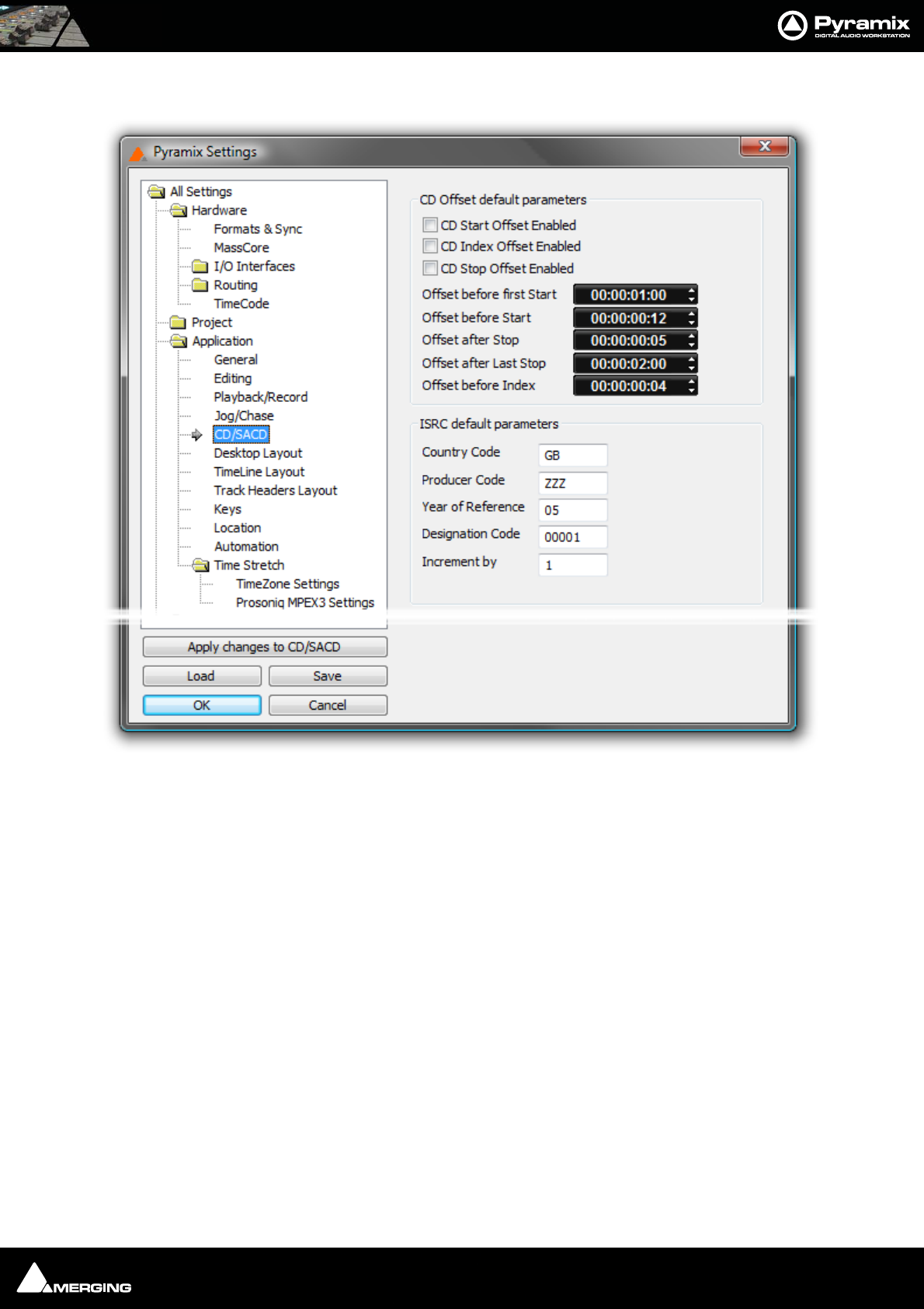
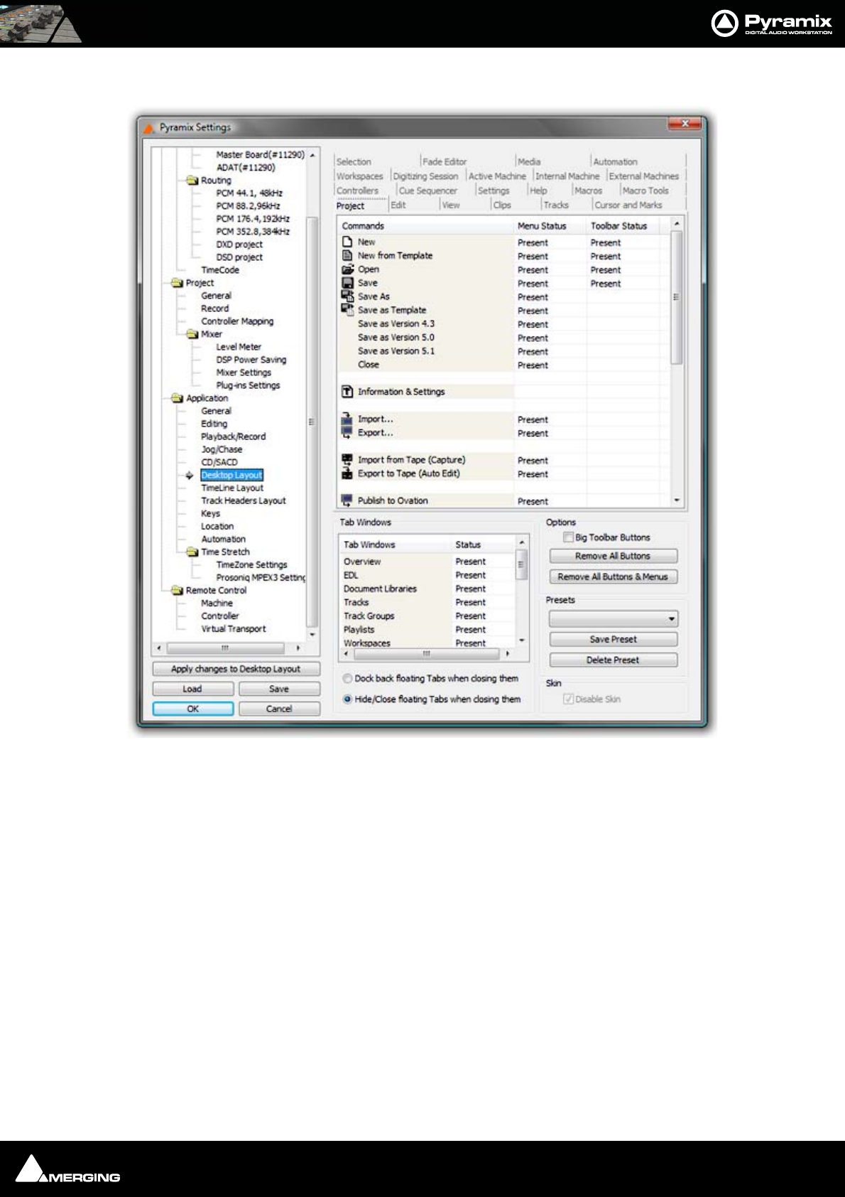
Settings : Application 27 - 525
Desktop Layout
This is where you can customize the content of Menus and Toolbars. Clicking in the Menu Status and Toolbar
Status cells toggles each entry Present or blank (absent). This can be used to tailor the user interface for specific
tasks or operators.
Tab Windows
Clicking in the Status cells toggles each Tab Window entry Present or blank (absent).
Options
Big Toolbar Buttons Doubles the size of the Toolbar buttons when checked.
Remove All Buttons As it says - use with extreme caution.
Remove all Buttons and Menus Likewise - leaves a limited number of essential menu entries
PresetsThe combo box offers a choice of previously saved Presets
Save Preset Pops up a simple Save Preset dialog
Delete Preset Deletes the preset currently shown in the Presets combo box above.
Skin
Disable Skin Only applicable to Windows XP based systems. When ticked, reverts to earlier
“look”. This may be useful to improve performance on certain (older) systems.
All Settings Application Desktop Layout Page
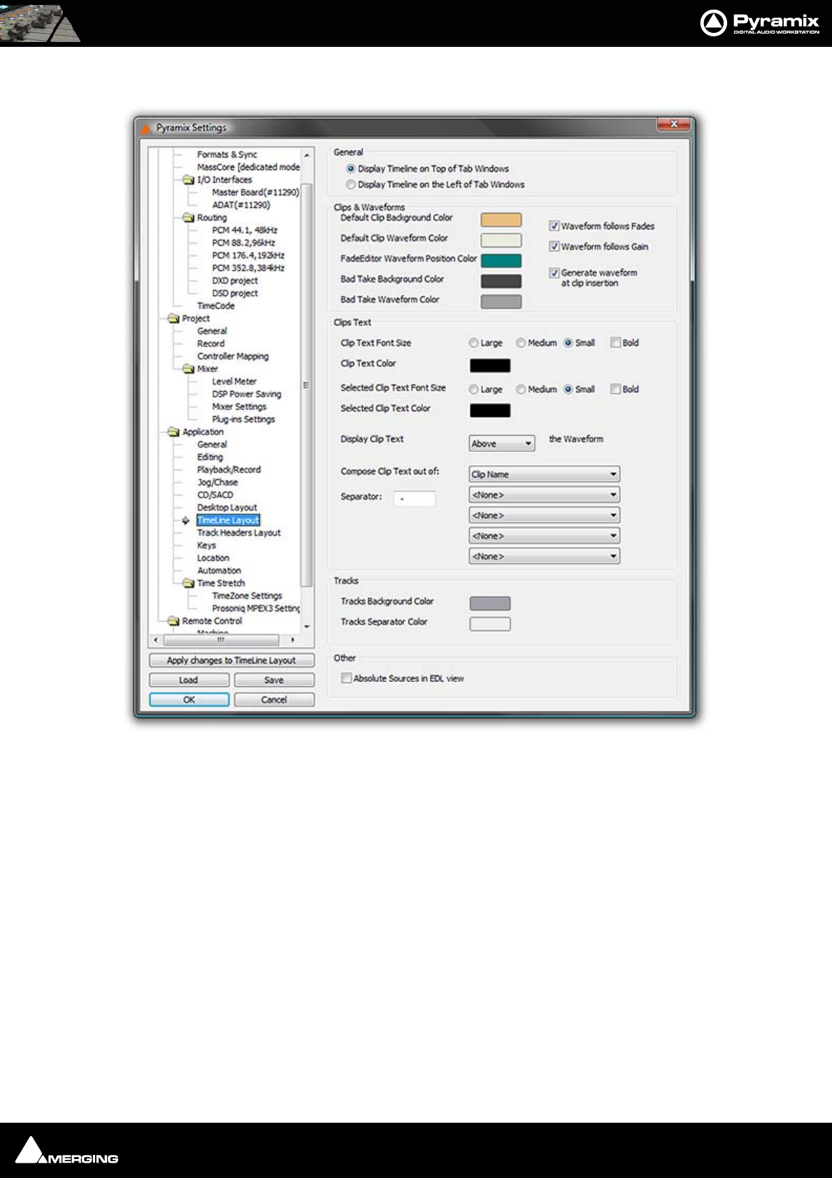
Settings : Application 27 - 526
TimeLine layout
For all the color options, clicking on the colored block pops up a list of defined colors. At the bottom of the list
selecting More Color... opens a full Color picker dialog.
General
Display Timeline on Top of Tab Windows as it says.
Display Timeline on the Right of Tab Windows allows good use of dual monitors. Check this box when using a
dual monitor set-up to enable the Timeline to be displayed on one screen and all
Tab Windows on the other one.
Clips & Waveforms
Default Clip Background Color
Default Clip Waveform Color
FadeEditor Waveform Position Color
Bad Take Background Color
Bad Take Waveform Color
Waveform follows Fades
When checked the waveform display is scaled in height during fades and crossfades. The original waveform is
shown grayed out.
All Settings Application Timeline Layout Page
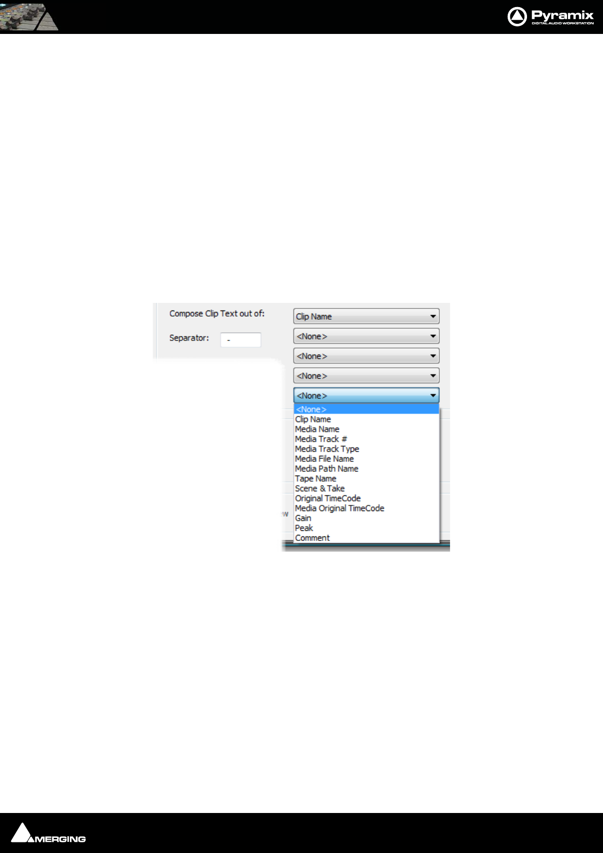
Settings : Application 27 - 527
Waveform follows Gain
When checked the waveform display is scaled in height in proportion to the gain adjustment applied.
Generate waveform automatically at clip insertion
When checked a waveform file is automatically generated in the background for any clip which does not already
have one when it is placed on the Timeline.
Clips Text
Clip Text Font Size The radio buttons offer a choice of Large, Medium or Small and the check box
emBoldens.
Clip Text Color
Selected Clip Text Font Size The radio buttons offer a choice of Large, Medium or Small and the check box
emBoldens.
Selected Clip Text Color
Display Clip Text The combo box offers a choice of Above, Below, In Front Of or Behind the Wave-
form
Compose Clip Text out of: The clip text displayed can consist of up to five elements chosen from the five
combo boxes, separated by the character typed in the Separator box:
Tracks
Tracks Background Color
Tracks Separator Color
Other
Absolute Sources in EDL view When Absolute Sources in EDL View is checked in the Settings > All Settings >
Application > TimeLine Layout page, the original Source In, Source Out and Sync Point times are shown in
Absolute Time in the EDL View. Absolute time is the incoming TimeCode recorded at the audio capture. When
this mode is disabled, the default start time of TimeCode for the captured clip is 00:00:00:00.
Compose Clip Text out of : combo box
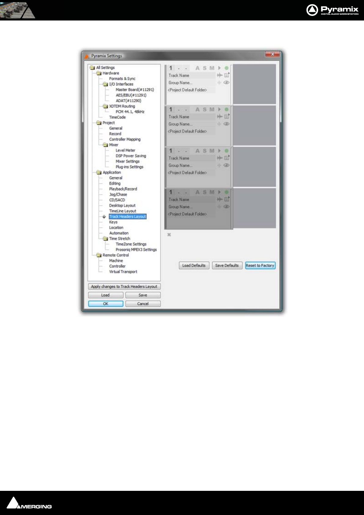
Settings : Application 27 - 528
Track Headers Layout
Here, the user can determine the items that appear in the Track Header.
Clicking on any of the ‘building blocks’ of the Track Header selects the block, indicated by a square red outline.
Blocks may be positioned anywhere in the Track Header by clicking and dragging. To remove a block from the
Track Header, double-click it. The block disappears from the Track Headers in the Interface Editor and appears in
the ‘Pool’ at the bottom. Double-clicking a block in the Pool places it in the Track Header.
Load Defaults loads the default Track Header design saved with:
Save Defaults saves the current design as the default.
Reset to Factory Resets Track Header Layout to the Factory default.
All Settings Application Track Headers Layout Page
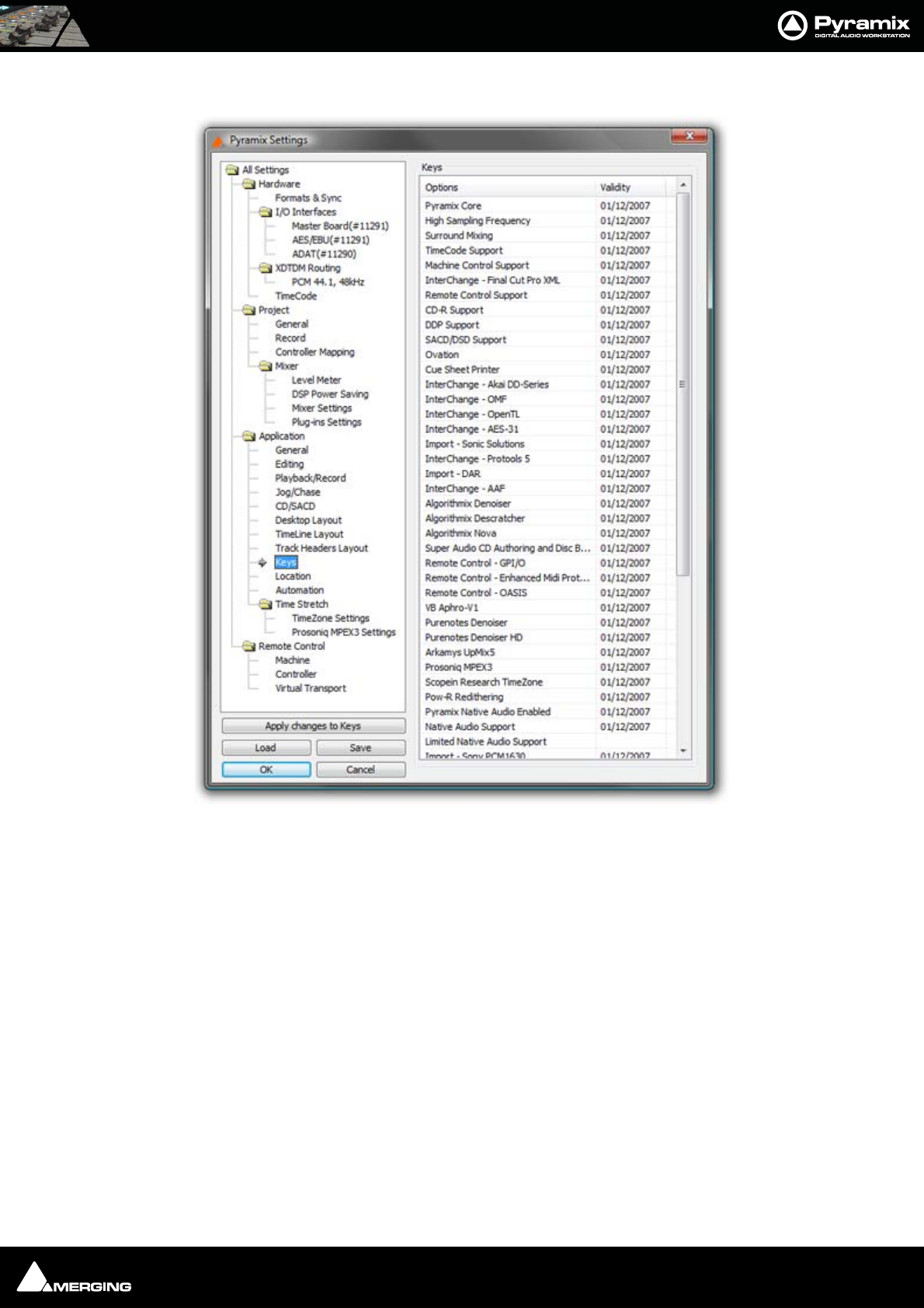
Settings : Application 27 - 529
Keys
Information only. Nothing can be changed here. Shows the Keys which are validated and the date they are vali-
dated to.
All Settings Application Keys Page
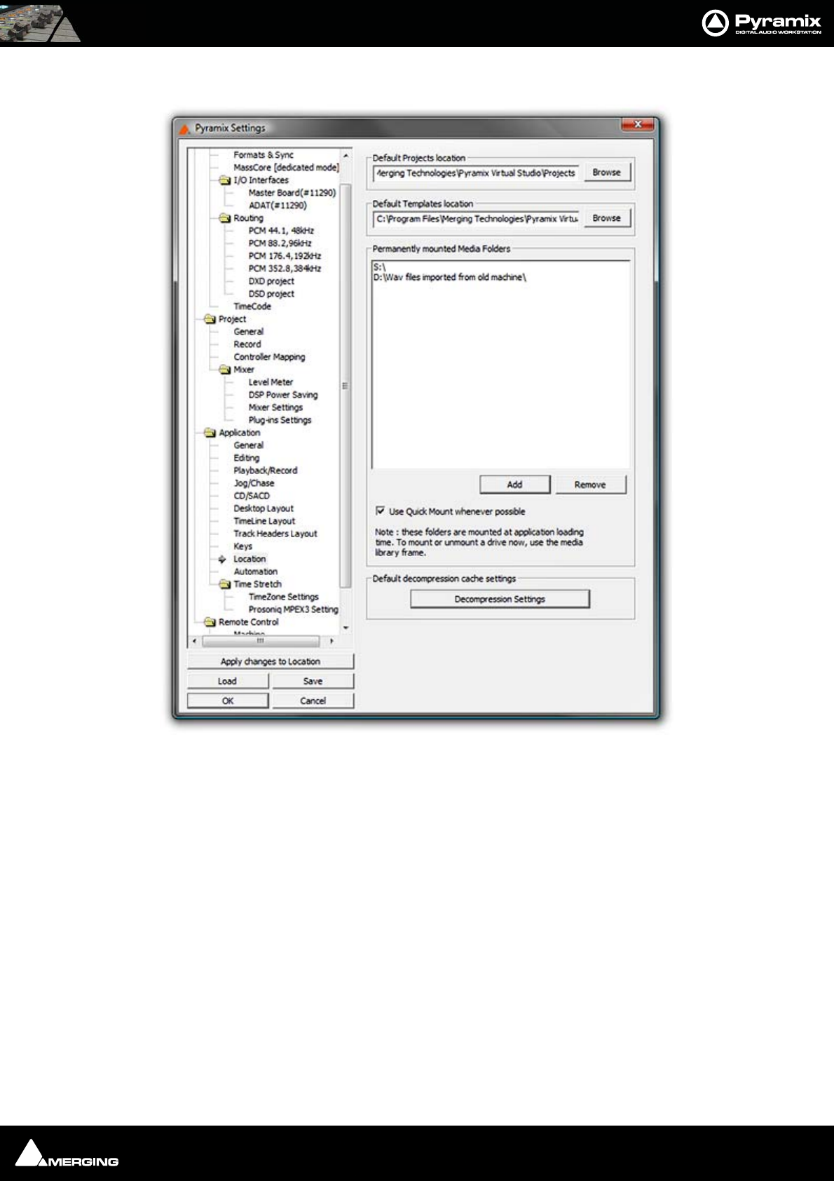
Settings : Application 27 - 530
Location
Default Projects Location
This path is set when a new Project Workspace is created. It can be changed here either by typing the path into the
box or browsing the Windows filing system using the Browse button
Default Templates Location
This path is set when Pyramix is installed. It can be change here in the ways described above.
Permanently Mounted Media Folders
Shows a list of Media Folders available to all projects. Clicking Add opens the Choose a Media Folder to Mount
window. Here you can browse for Folders or create new ones.
Folders are removed by highlighting their list entry and clicking the Remove button.
All Settings Application Location Page
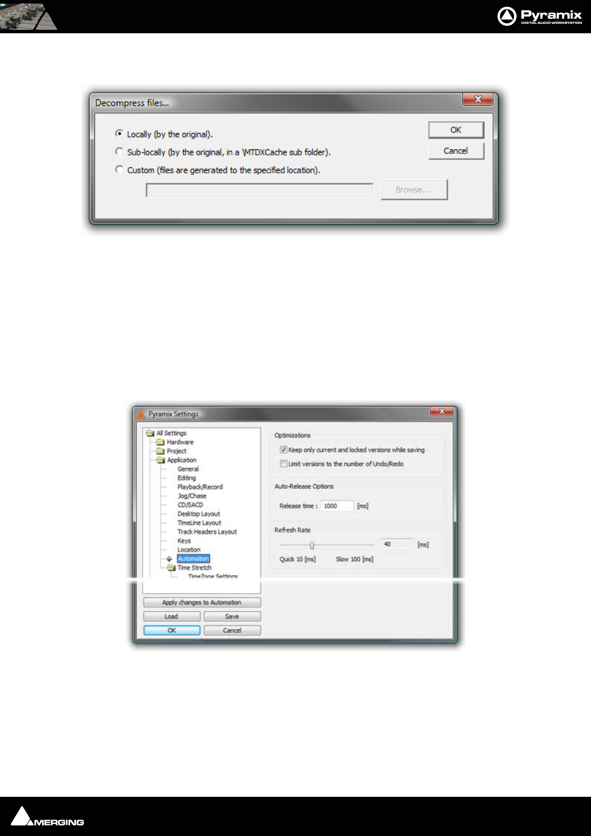
Settings : Application 27 - 531
Default decompression cache settings
Click on the Decompression Settings button to open the Decompression files... dialog :
When compressed audio files are mounted Pyramix creates an uncompressed WAV version of the file(s) in a cache.
The location of these cache files is determined by this dialog.
Locally (by the original) File(s) will be created in the same location as the original file.
Sub-locally (by the original, in a \MTDXCache sub folder). File(s) will be created in a sub folder created by Pyra-
mix in the same location as the original file.
Custom (files are generated to the specified location). File(s) will be created in a user specified location. When
this option is selected the Browse... button is available to open a file browser window to set the user defined path.
Automation
Optimizations
Keep only current version while saving when checked does as it says
Limit versions to the number of Undo/Redo when checked does as it says. Number of Undo/Redos is defined in
the Settings > All Settings > Application General page.
Auto-Release Options
Release time If Auto Release is enabled any control will, when released or when the transport is
stopped, return to its value or state in the previous automation pass or the default
Decompress files... dialog
All Settings Application Automation Page
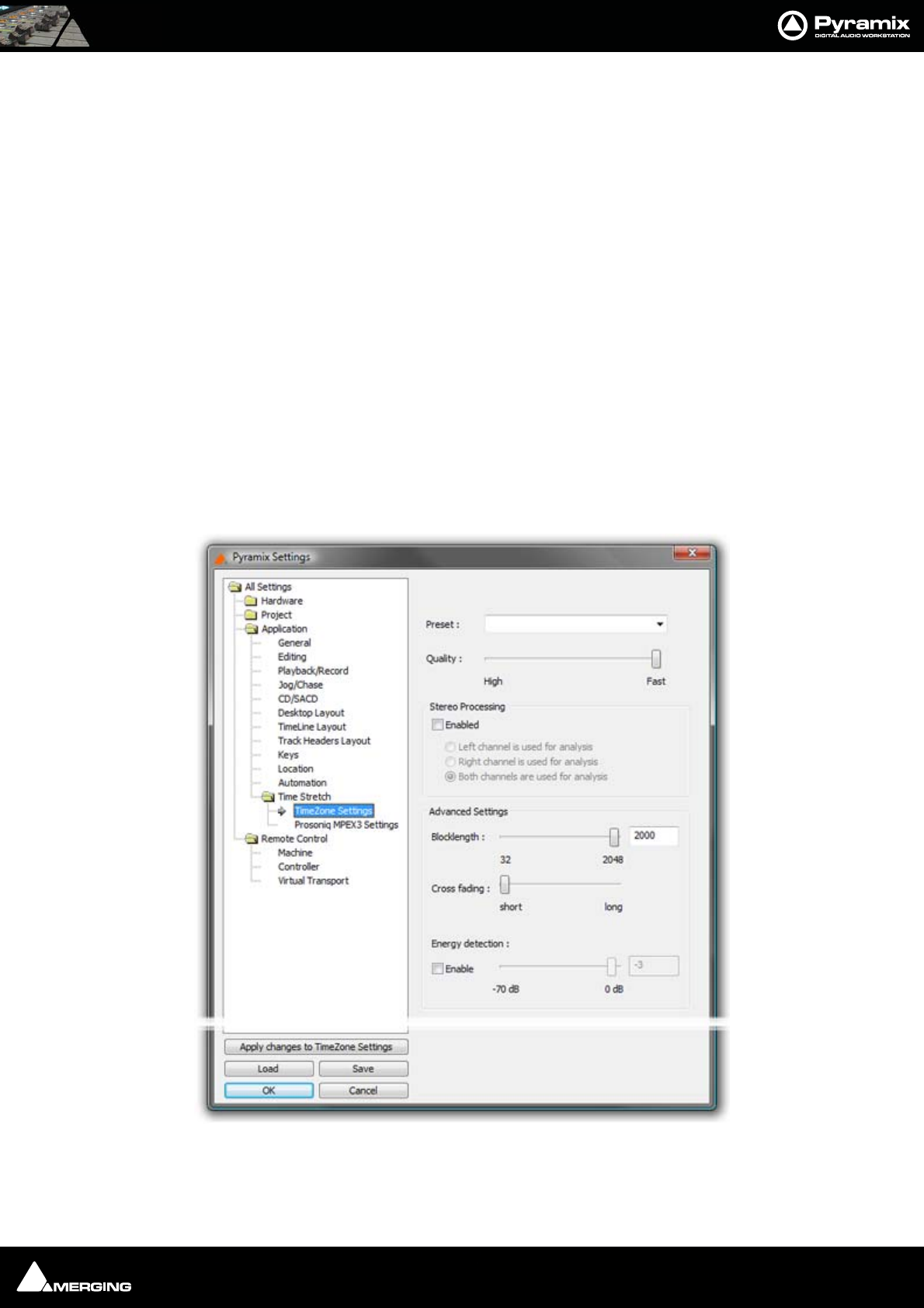
Settings : Time Stretch 27 - 532
where no previous pass exists. This occurs either immediately if the control only
has two states (e.g. a button) or over a period of time if the control is a fader or
knob. The time period is determined by the value entered in the Release Time box
in ms.
Refresh Rate
The Quick 10[ms] Slow 100[ms] slider allows the Refresh rate to be changed. (Or type a value in the box.) The
Refresh Rate setting determines the rate at which the automation data is recorded. By default the refresh rate is
the same as the actual time code frame rate, e.g. 40 ms at a frame rate of 25 fps.
The possible range of the refresh rate is 10 to 100 milliseconds. Please note that the setting is rounded to entire
frames, so that the effective refresh rate will be either one, two or three times the actual frame rate.
One reason to choose a slower setting for the refresh rate would be to save the processing power required to cal-
culate the automation movements in case of complex mixes.
Note: This setting has no bearing on “smoothness” of dynamic automation changes.
Pyramix uses linear interpolation to avoid any possibility of zipper noise.
Time Stretch
TimeZone Settings
Preset
The drop-down list offers a choice of algorithm presets for various sound types.
All Settings Application Time Stretch Timezone Settings Page
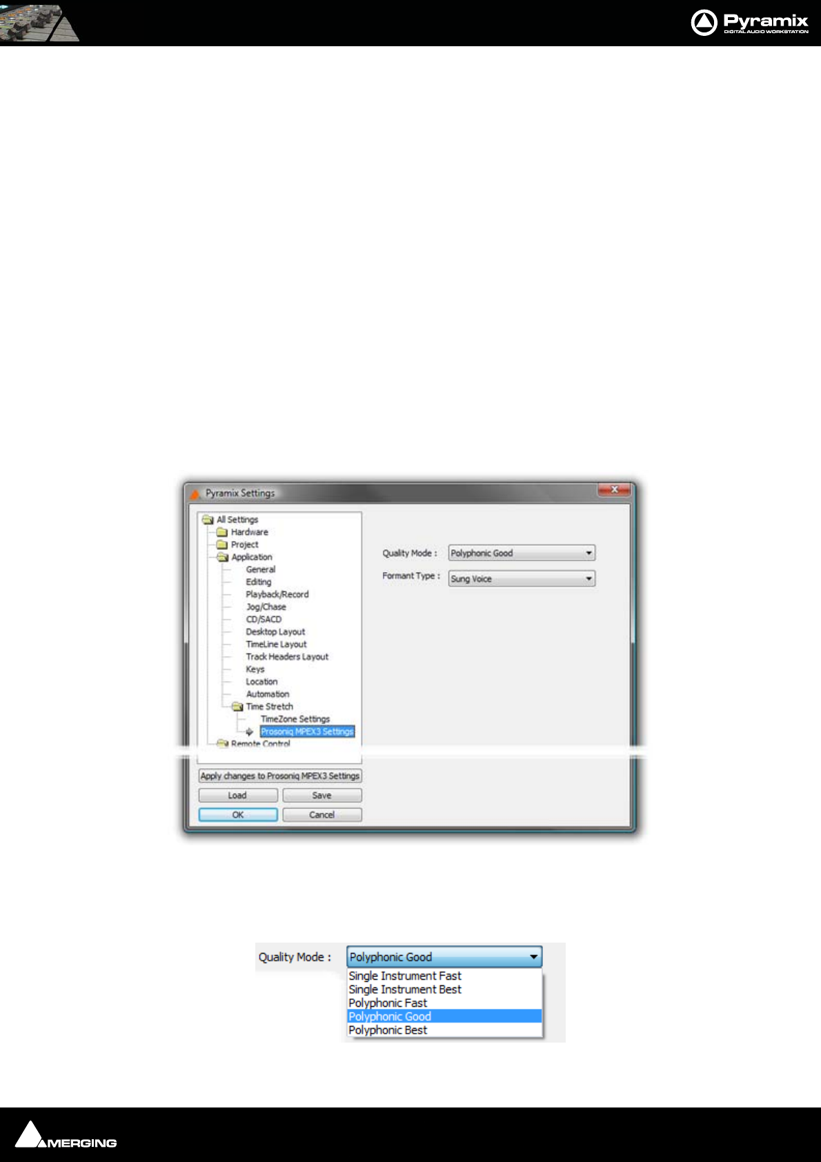
Settings : Time Stretch 27 - 533
Quality
The slider offers a choice between High Quality and Fast processing.
Stereo Processing
When the Enabled box is checked offers a choice of which channel(s) of a stereo media will be used for analysis.
Advanced Settings
Blocklength
Allows the user to determine the length of the blocks used for processing by entering a value between 32 and
2048 in the text box or by positioning the slider.
Cross fading
Allows the user to vary the length of the crossfades between blocks by positioning the slider
Energy Detection
When the Enable box is checked the user can set the threshold level by entering a value between -70dB and 0dB
in the text box or by positioning the slider.
These parameters affect the quantity and character of audible artifacts and allow fine tuning of the process to suit
specific material.
Prosoniq MPEX3 Settings
Optimize MPEX3 Settings by making appropriate choices from the Quality Mode and Formant Type combo
boxes.
Quality Mode
All Settings Application Time Stretch Prosoniq MPEX3 Settings Page
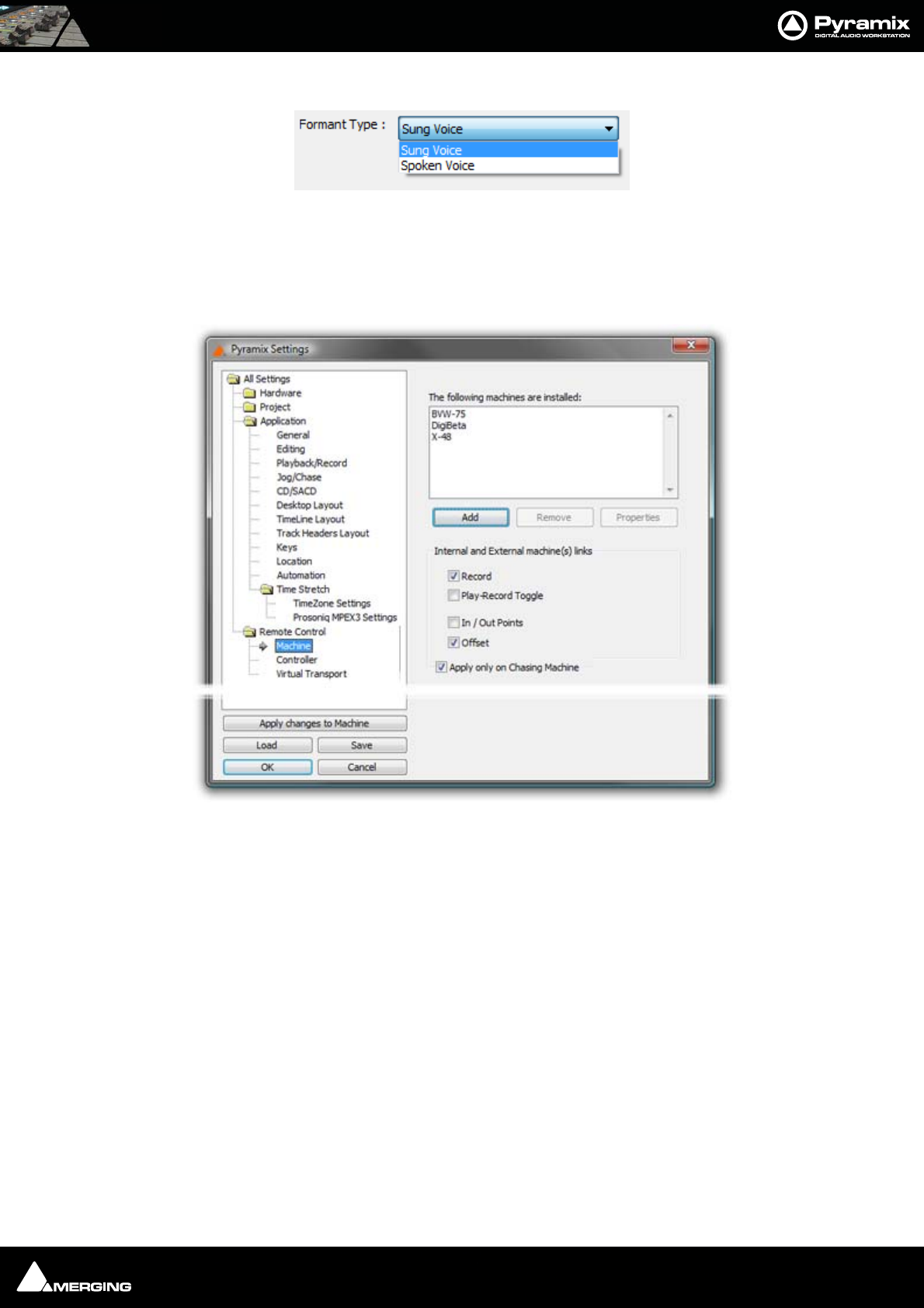
Settings : Remote Control 27 - 534
Formant Type
Remote Control
Machine
The following machines are installed:
Displays a list of all installed machines. Machines in this list will be available as possible machine choices in the
Transport Control.
Internal and External machines links
The buttons determine which machine functions will be linked. Simply tick the boxes to link any or all of the fol-
lowing functions for all active machines:
Play and Record
Play-Record Toggle
In / Out Points
Offset
Apply only on Chasing Machine When ticked the links are only apllicable to machines currently in
Chase mode.
Add
Clicking on the Add button opens the Machine Properties dialog box (see below)
Remove
All Settings Remote Control Machine Page
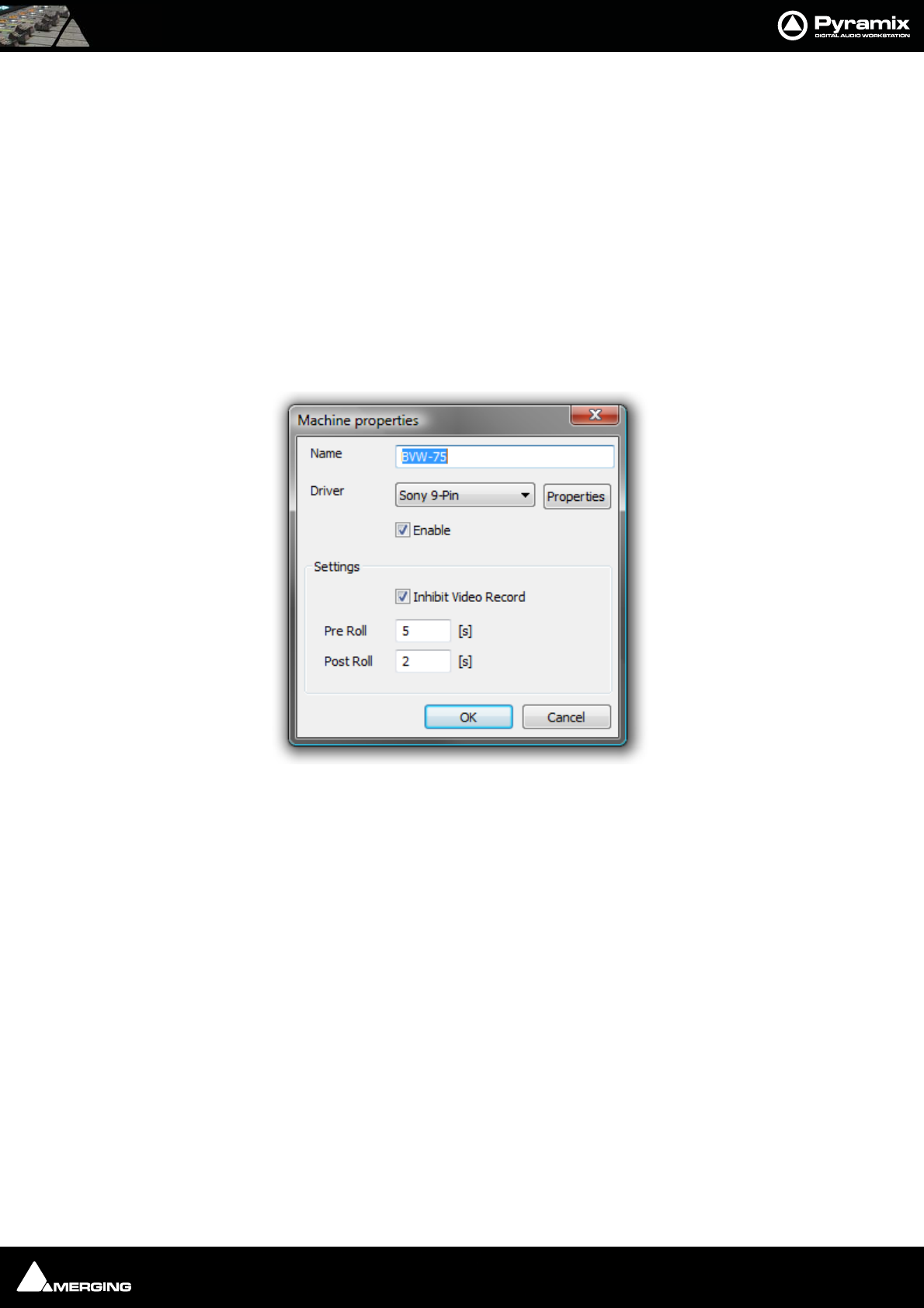
Settings : Remote Control 27 - 535
If a machine is selected (highlighted) in the list, clicking Remove uninstalls the machine and removes it from the
list.
Properties
Clicking on the Properties button opens the Machine Properties dialog box (see below)
OK
Click OK to accept changes (if any) and close the Machines page.
Cancel
Click Cancel to reject changes (if any) and close the Machines page.
Apply
Click Apply to apply changes without closing the Machines page.
Machine Properties
When the Machine Properties dialog is opened by the Add button, the Name, Protocol and Port displays are
blank. When the dialog is opened by the Properties button the displays reflect the name etc. for the selected
machine.
Name
Displays the name of the current selected machine. When adding a new machine, type a suitable name here.
Driver
Displays the current interface protocol Sony (9-pin P2 protocol) in the drop-down list. (Currently Sony only)
Driver - Properties
Opens the Sony 9 - Pin Protocol Configuration dialog box (see below) when SONY is selected. There are cur-
rently no options for MMC
Machine Properties dialog
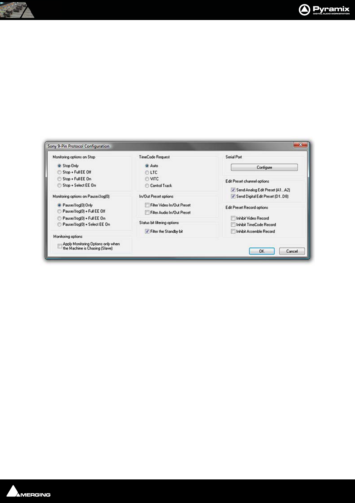
Settings : Remote Control 27 - 536
Settings
Inhibit Video Record
When checked prevents record arming of video in order to ensure video cannot be accidently overwritten.
Pre Roll
Shows the current Pre Roll time for the external machine. Type in the box to change the value.
Post Roll
Shows the current Post Roll time for the external machine. Type in the box to change the value.
Driver Properties
Sony 9-Pin Protocol Configuration (Machine)
This dialog determines Monitoring Options on Stop, Monitoring Options on Pause/Jog, Preset Channel and
Record Options the type of TimeCode Request, In/Out Preset options and gives access to the Serial Port con-
figuration dialog.
Sony 9-Pin Protocol Configuration dialog
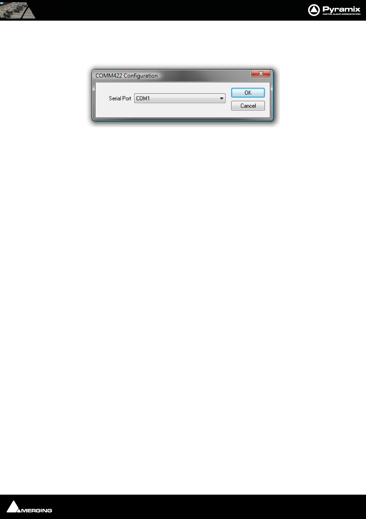
Settings : Remote Control 27 - 537
Serial Port
Configure
Clicking the Configure button opens the COMM422 Configuration dialog box:
Serial Port
Shows the current Serial Port selected from the drop-down list. If not already highlighted, select the desired serial
COM port. Standard choices are either COM1 or COM2.
Click OK to confirm the choice. This automatically sets the selected COM port with the proper parameters of the
Sony 9-pin communication protocol.
Monitoring options on Stop
After a Stop command the following command will be issued:
•Stop Only
• Stop + Full EE Off
• Stop + Full EE On
• Stop + Select EE On
Monitoring Options on Pause/Jog(0)
After a Pause/Jog command the following command will be issued:
• Pause/Jog(0) Only
• Pause/Jog(0) + Full EE Off
• Pause/Jog(0) + Full EE On
• Pause/Jog(0) + Select EE On
Monitoring options
Selecting:
• Apply Monitoring Options only when the Machine is Chasing (Slave)
ensures that the above options, Monitoring options on Stop and Monitoring options on Pause/Jog(0) are only
applied when the 9-pin external machine is chasing the Internal Machine (being synchronized, i.e. editing). When
the 9-pin external machine is Master (the Internal Machine is chasing it, typically for recording back to tape) then
the 9-pin external machine is in normal Input/Repro Auto mode.
TimeCode Request
•Auto
•LTC
•VITC
• Control Track
The radio buttons select the source of the TimeCode from the external machine. Sony machines usually respond
to all requests, so the Auto setting will probably be appropriate. If necessary E.g. where there are several different
TimeCodes present on a tape, you can specify a desired TimeCode source to override the automatic setting. U-
Matic machines do not respond to all requests, therefore you must specify the TimeCode source.
COMM422 Configuration dialog

Settings : Remote Control 27 - 538
Send In/Out Preset options
By default, Pyramix sends Edit Video In/Out and Edit Audio In/Out points when an In/Out point is set in the Trans-
port Control panel. These options enable these commands to filtered out if necessary.
• Filter In/Out Preset (video)
• Filter Audio In/Out Preset
Status Bit Filtering Options
Some SonyP2 devices do not report the Standby bit correctly (always in Standby). In this case the Pyramix Trans-
port Window reports Standby status continuously, thereby hiding the true status. You may wish to set filter if the
target machine fails to report standby correctly.
• Filter the Standby bit
Edit Preset channel options
Edit Preset in the 9-pin P2 protocol world means Track Arming.
These options enable Track Arming commands to be filtered out if required.
• Send Analog Edit Preset (A1..A2)
• Send Digital Edit Preset (D1..D8)
This feature is mostly relevant where a console or a third-party record/monitoring controller is used for record
commands.
Edit Preset Record Options
These 3 options Inhibit Recording when one of the Video/Timecode/Assemble Edit preset modes is checked and
the corresponding track is armed. In a typical TV workflow, when audio is layed back to the tape, it is essential to
prevent the video track entering record (edit) These options avoid nasty accidents.
• Inhibit Video Record
• Inhibit TimeCode Record
• Inhibit Assemble Record
This feature is mostly relevant where a console or a third-party record/monitoring controller is used for record
commands.
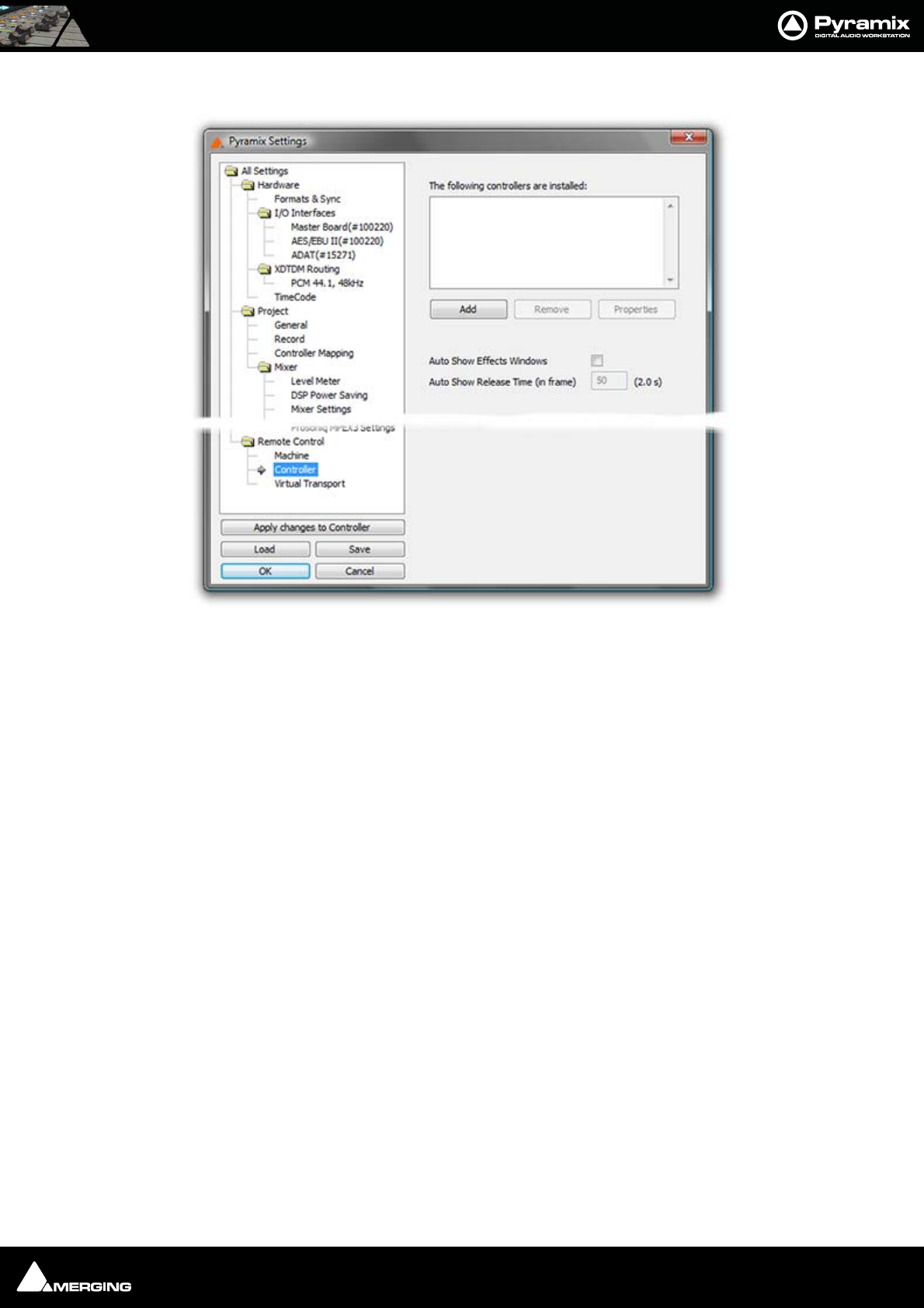
Settings : Remote Control 27 - 539
Controller
The Controller page shows a list of all external controllers currently installed (if any) in the The following control-
lers are installed pane.
All Settings Remote Control Controller Page
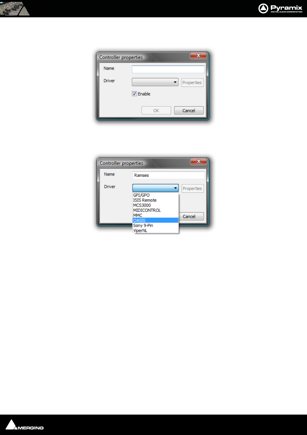
Settings : Remote Control 27 - 540
Add
Pops up the Controller properties dialog.
Type a suitable name for the controller you wish to add in the Name field. Click on the down arrow to drop down
the list of drivers.
Select the correct driver for the controller you are installing.
Clicking on Properties will open a configuration dialog specific to the driver.
Ensure that the Enable checkbox is ticked and Click on OK to add the controller.
Remove
Removes the Controller currently highlighted in the The following controllers are installed list (if any)
Properties
Pops up the configuration window for the selected controller.
Please see: Control by External Device on page 388 for further details.
Auto Show Effects Windows
When selected moving a control on the hardware controller mapped to an effect will open the relevant plug-in’s
window.
Auto Show Release Time (in frames)
Sets the amount of time an Auto Shown window persists after the last detected control move.
Controller properties dialog
Controller properties dialog
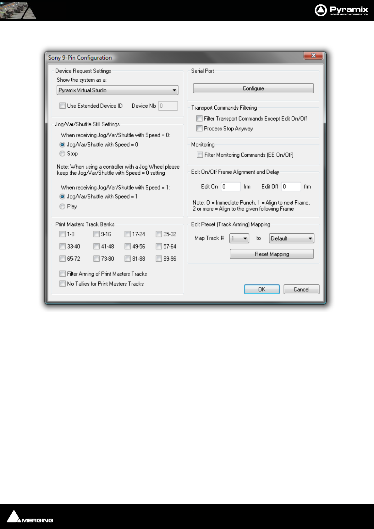
Settings : Remote Control 27 - 541
Sony 9 - Pin Protocol Configuration (Pyramix controlled by external device)
Device Request Settings
The Sony 9-pin P2 protocol transmits a code to identify the machine. Some machine controllers will do nothing or
exhibit aberrant behavior if they do not recognize the identifier code. Therefore, Pyramix can masquerade as
another device. The device identifier can be selected from a long list in the Show the system as a: combo box.
Jog/Var/Shuttle Still Settings
The radio buttons determine Pyramix behavior When receiving Jog/Var/Shuttle with speed = 0 commands:
• Jog/Var/Shuttle with Speed = 0 (default)
•Stop
Note: When using a controller with a jog wheel please keep the Jog/Var/Shuttle ...
Speed = 0 default setting.
Monitoring
Filter Monitoring Commands (EE On/Off) when ticked, E to E On and off commands are filtered out.
Print Masters Track Banks
The selected banks of 8 tracks are armed for recording when any OTHER track is armed. This is primarily useful
when recording a Print Master or Masters at the same time as stems. E.g. if you are recording Dialogue, Music and
Sony 9-Pin Configuration dialog

Settings : Remote Control 27 - 542
Effects stems it is common practice to update an element on one stem only. However, the final mix Print Master,
which is the sum of all the stems must be updated at the same time. Print Masters Track banks allow the user to
forget about arming the Print Master tracks and concentrate on the stems.
Filter Arming of Print Masters Tracks
When ticked, arming a Print Master track will not arm the other Print Master tracks.
No Tallies for Print Masters Tracks
When ticked, record tally commands are filtered out for the Print Masters tracks.
Serial Port
Configure
Opens the COMM422 Configuration dialog.
Please see: Serial Port on page 537
Transport Commands Filtering
• Filter Transport Commands Except Edit On/Off When ticked all transport commands apart from Edit On
or Edit Off are filtered out.
• Process Stop Anyway
Some controllers send a Chase Off command for Stop. If you need this command when filtering Transport Com-
mands, checking the box will allow it through.
Note: These filter settings are mainly relevant where multiple controllers are in use. E.g.
where a Mixing console controls monitoring and recording.
Edit On/Off Frame Alignment and Delay
Edit On and Edit Off boxes enable delays (in ms) to be entered.
Note: 0 = Immediate Punch, 1 = Align to next Frame boundary, 2 or more = Align to the
given following Frame boundary.
Edit Preset (Track Arming) Mapping
The Map Track # combo box allows you to select a track between 1 and 96 to be mapped to a choice made in the
second combo box from:
• Default
•No change
•Always Off
•Always On
or any track between 1 and 96
This function is useful if more than one Pyramix is to be controlled by the same controller. E.g. with two machines
set up to record 32 tracks each, Pyramix one is mapped 1 - 1 to 32 - 32 and Pyramix two is mapped 1 - 33 to 32 -
64
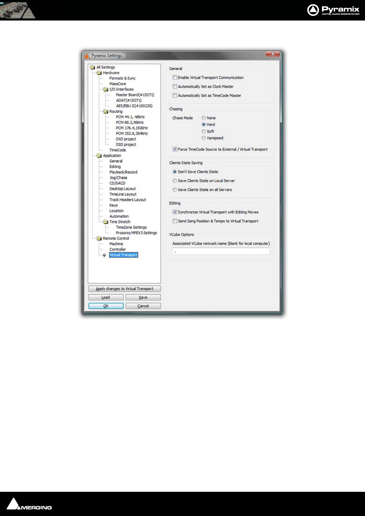
Settings : Remote Control 27 - 543
Virtual Transport
General
Enable Virtual Transport Communication
When checked, Pyramix communicates bi-directionally with Virtual Transport.
Automatically Set as Clock Master
When checked, the Pyramix Client is set as Clock Master. I.e. Pyramix is the master clock reference for all Clients
Automatically Set as TimeCode Master
When checked, the Pyramix Client is set as TimeCode Master. I.e. Pyramix provides the master TimeCode reference
for all Clients
Chasing
Chase Mode - None - Hard - Soft
These radio buttons toggle the Pyramix Chase Mode.
Force TimeCode Source to External / Virtual Transport
When checked, TimeCode source is External / Virtual Transport.
All Settings Remote Control Virtual Transport Page

Settings : Remote Control 27 - 544
Clients State Saving
Toggles between:
Don’t Save
Save Client’s State on Local Server
Save Client’s State on all Servers
Editing
When checked,
Synchronize Virtual Transport with Editing Moves
Send Song Position and Tempo to Virtual Transpor
VCube Options
Associated VCube network name (blank for local computer)
When you wish to use Pyramix in conjunction witha VCube, e.g. with the Merging Technologies ADR option, then
you must enter the network name of the machine running VCube here. If VCube is running on the same machine
as Pyramix the box can be left blank or with a . (period) in it.

USER MANUAL
www.merging.com/Pyramix
Troubleshooting

Troubleshooting : Keeping Up To Date 28 - 546
Troubleshooting is always a moving target as users discover ever more exotic ways to use Pyramix. Therefore, this
section is necessarily historic.
If the answer to your problem cannot be found here or elsewhere in the documentation, for the latest information
please consult the FAQ sections at:
http://www.merging.com
If you need further technical support, please e-mail
support@merging.com
Keeping Up To Date
Acquiring and installing regularly the latest Drivers/Firmware/Bios or Operating System available for equipment
such as: Graphic Cards, CD/DVD writers, Network Adapters, Motherboards, (but exercise especial caution), external
drives, RAID controllers and other third party hardware add-ons, will ensure that your system will always perform
as efficiently as possible. Always accept any ‘rollback’ options, just in case the driver updates have unforeseen con-
sequences.
Keeping Windows (and DirectX) up to date with latest service packs is also, in general, a positive move towards
maintaining a healthy system.
Note: These operations are not required for Mykerinos and Daughter cards simply
because the latest firmware for your hardware (if any) is automatically installed by the
most recent Pyramix installer.
Error Messages
PCI Bus Too Slow
PC motherboards are by no means equal. Real-time intensive activities such as those found in audio and video
workstations show up inadequacies unlikely to be noticed in more mundane applications. Even though one might
expect the newest, ever faster Pentium or AMD processors to give better performance this isn't always the case. At
least with respect to how well they handle the transfer of data over the PCI bus on which the Mykerinos board(s)
resides.
Audio is requested or handed over on the PCI bus every 1.3ms. When the request (interrupt) is delayed for more
than 20%, in this case 0.26ms, the first warning message will pop up, indicating a timing inconstancy of the PCI
sub-system. There are two levels of warning with “PCI Bus too Slow” messages; </= 20%, which relates to a serious
but not necessarily critical situation and the </= 50% which would result in drop outs in audio playback or record-
ing or other unwanted artifacts and you want to make absolutely sure you will not get any of these showing dur-
ing playback or record. But if you were to get a warning when opening a project, creating or rebuilding a mixer or
when launching Pyramix this, while still a sign of possible timing issue in the PCI communication at this very
moment, would only bring minor inconvenience at a non critical instant and would, nonetheless, allow you to
work perfectly safely.
Historically, we have observed the PCI Bus too slow messages to occur with the following hardware combinations:
• In the design of older firmware for the Southbridge 686B of VIA based motherboards.
• On non-Intel motherboards using the Intel 84x chipsets (in particular the Intel 845 series supporting the
Pentium 4 processors). The reason for this is that the 84x series gives absolute priority to PCI writes over
PCI reads.
• On some Dual Xeon motherboards, using multiple PCI controllers with PCI-X slots.
PCI performance can be affected by a combination of different parameters and add-on cards such as specific com-
binations of Raid adapters, Graphics adapters, Dual processors and PCI-X slots.
Upgrading a component's BIOS/driver/firmware or even the operating system will often fix some early limitations
or conflicts with a particular PC component. As an example switching from Windows 2000 to Windows XP Pro

Troubleshooting : Multi-channel Audio Files 28 - 547
totally fixed the PCI latency problems on a Dell Inspiron 8000 and installing a “Signed” graphic card driver did the
same for an Asus Dual PIII workstation.
Audio Engine Drops Warning
This message informs users about possible CPU delays leading to potential audio errors in record or playback.
Mykerinos sends or requests audio data to or from the CPU in “frames” of 26ms. If one of these frames is not given
to, or taken from, the Mykerinos driver in time, this will result in a loss of audio data, and the Audio Engine Drops
Warning will be shown.
Playback Stalls Warning
Playback Stall messages are triggered by access delays impacting either the VS3, resulting in audio drops while
preserving the synchronization of the tracks or the Mykerinos driver. In the latter case the stall may also endanger
the integrity of the synchronization between tracks being recorded.
MassCore Drops
Please see MassCore Overload Diagnosis and Cures on page 33
Multi-channel Audio Files
Wave, Broadcast Wave, AIFF or SDII multi-channel files are seen as mono files by the Pyramix Media Manager
unless their file names conform to Pyramix requirements.
Audio File Formats
Some audio file formats (like Pyramix native format, PMF and OMF) embed the track/channel number(s) in the file
itself. In this case, Pyramix recognizes the track as mono, stereo or multi-channel without problem even if the dif-
ferent audio tracks/channels of these files are actually stored in separate files.
Some other formats (like Wave, Broadcast Wave Format, AIFF or MacIntosh SDII) do not keep this information in
the file itself but in the filename. Unless the correct naming convention is followed, Pyramix will see files in these
formats as individual mono, regardless of whether they are part of a stereo pair or multi-channel recording.
Broadcast WAV Files
BWF-P means polyphonic. I.e. multitracks within the same file
BWF-M means monophonic. I.e. one file per track
Pyramix Requirements
In order for Pyramix to recognize that separate audio files in these formats are actually part of a stereo or multi-
channel recording, Pyramix requires the following naming convention:
The filename of the different tracks/channels must be the same except for one section containing the tracks/chan-
nels number as 3 digits surrounded by _## and ##_. For example: MyStereoSound_##001##_.wav and
MyStereoSound_##002##_.wav are seen by Pyramix as a single two track media named MyStereoSound.
Other systems, the Zaxcom DEVA portable recorder for example, do not use the same convention. They may name
the files they produce in this fashion: MyStereoSound-1.bwf and MyStereoSound-2.bwf. These files will be rec-
ognized by Pyramix as two mono media files.
Solution
MultiFileFixer is a small ‘tool’ application that automatically renames all files in a given folder and sub-folders,
that fit selected parameters, to follow the Pyramix convention.
In a normal Pyramix installation the MultiFileFixer application can be found on the Windows Start menu:
Start > Programs > Pyramix > MultiFileFixer

Troubleshooting : No Sound on Live Inputs 28 - 548
No Sound on Live Inputs
Please carefully check the following points if there is no sound present on live inputs:
None of the connected inputs are muted (MUTE ON).
None of the connected inputs are in SOLO mode. In this case, all other inputs are muted.
The DSP Load (displayed at the bottom the Pyramix window) should be in a range of 20% to 90%. A higher level
could produce clicks or occasionally mute the audio inputs.
In the I/O Status window (right click on the bottom of the Pyramix window):
• All Input LEDs (corresponding to physical connections) should be active (light green).
• The Lock LED (corresponding to the chosen Sync Source) should be active (light red) and not flashing.
In the Mixer Settings window (right click on the mixer and choose Settings):
In the General Tab page:
• The project's Sampling Rate must match the external studio equipment's settings sampling frequency.
In the I/O & Sync Tab page:
•The Sync Source must be chosen so there is only one Sync Master for all connected equipment.
•The Input Format must match the format of the incoming audio signal.
In the specific Tab page of each possible daughter card:
ADAT Tab: Only relevant for the outputs.
AES/EBU Tab:
• If the Reference is not in Auto mode and the Sync Source (in the I/O & Sync Tab page) is in Audio Input
mode, there should be a physical connection to the chosen reference.
• If the Sampling Rate Converters are set to Ref 1/2, 3/4, 5/6 or 7/8, the corresponding Inputs are muted.
Note: This is valid for the AES/EBU with SRC daughter card only.
DUAL Tab:
• If the Reference is not in Auto mode and the Sync Source (in the I/O & Sync Tab) is in Audio Input mode,
there should be a physical connection to the chosen reference.
• If the input level is simply too low, increase the Input Gain.
SDIF Tab:
• The Format (SDIF2 or SDIF3) must match the format of the incoming audio signal. Make certain the SDIF
daughter card is only connected to DSD.
TDIF tab:
• If the Reference is not in Auto mode and the Sync Source (in the I/O & Sync Tab) is in Audio Input mode,
there should be a physical connection to the chosen reference.
MADI (ver1 or ver2) Tab:
•Input Groups must be set accordingly to the used inputs.
• To activate the inputs 57 to 64, please set the MADI card to Extended Mode.
•In Audio Sync Source the outgoing MADI Word Clock should match the external equipment MADI Word
Clock.
•In MADI Word Clock Sync Source, the external incoming Word Clock should match the one set in the
MADI card.

Troubleshooting : Clip Display Problems 28 - 549
In the Input Check window (right click on the bottom of Pyramix window / Debug menu):
• The input frequency should match the frequency set in the Mixer Settings.
• The yellow bar must be slightly visible in the Deviation field.
• The amount of jitter should be within a range of 0 to 100 ns, although higher values are possible.
For each input connection in the mixer, there should be a corresponding physical connection.
All audio tracks in use should be in Live Input or Auto mode. If this is not the case, all tracks
which are set to Repro mode, will be muted.
Pyramix should not be in Play mode. In this case, all the audio tracks in Auto mode will
switch to Repro mode and the corresponding inputs will be muted.
Clip Display Problems
No Waveform Display
Symptoms
Files are dragged into the Timeline from a mounted folder but no waveform is generated. Manually invoking Gen-
erate Waveform doesn’t work.
Solution
This problem with Waveform Generation is likely to be due to the fact that the audio files are in Read Only mode.
This will often be the case when copying files from a CD-ROM. In Windows Explorer simply select all the tracks
from the CD, right click, select Properties and uncheck the Read Only box under Attributes.
Clip Names are Unreadable
Symptoms
With some color schemes, Clip Names are unreadable.
Solution
Simply choose a more suitable Windows color scheme to resolve this. You also can change the background and
waveform colors (right click) for individual clips and tracks in Pyramix.
Relaunch After Improper Exit
In the case of an ‘improper application exit’ (politically correct term for crash) the system does not attempt to
automatically open the last backed up project, since the most up to date version is the project itself in its last
saved state. All ProjectXXX (Backup).pmx, ProjectXXX (backup 2).pmx,etc… documents are older versions of Pro-
jectXXX.pmx which is now always the last one saved.
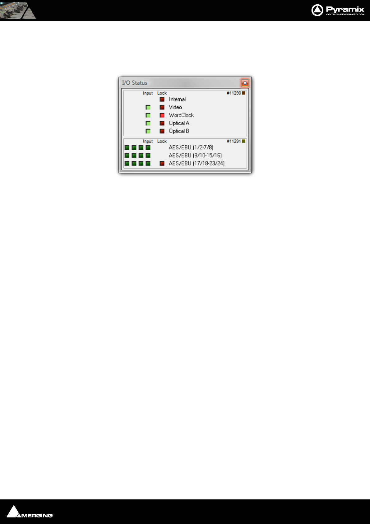
Troubleshooting : The I/O Status window 28 - 550
The I/O Status window
The I/O status window can be opened by clicking in the Sync: xxxxx section of the Status bar (bottom right of the
main Pyramix window. (the XXX’s are the current sync source)
This window shows useful information about the input and synchronization status of Pyramix.
Input sources
All the possible input sources are shown, each with an associated red and a green light. The green lights show the
presence of a valid digital signal (This does not necessarily mean, that the sampling rate of this input matches the
current clock source of Pyramix). When the red light is on and steady, Pyramix is using this input as it’s clock refer-
ence and is successfully locked up.
Default Clock Source
If Pyramix is set up to lock to an external clock source but cannot get a valid signal from this source, it will switch to
Internal clock. In this case the red light associated with Internal will be on, and the red light associated with the
intended clock source will be blinking.
Sampling Rate Mismatch
If Pyramix is set up to lock to an external clock source and the sampling rate set in the Virtual StudioMixer does not
match the sampling rate of the clock source, the green light associated with the clock source will be on, but the
red light will be blinking showing the sampling rate mismatch.
Debug Menu
Right-clicking on the Sync: section of the Status bar opens a context menu with a choice of Debug and I/O Status
(see below).
Selecting Debug opens a further sub-menu with a number of tools primarily intended for Merging Technologies
Support use. One option, Profiling is worth examining in detail.
I/O Status window
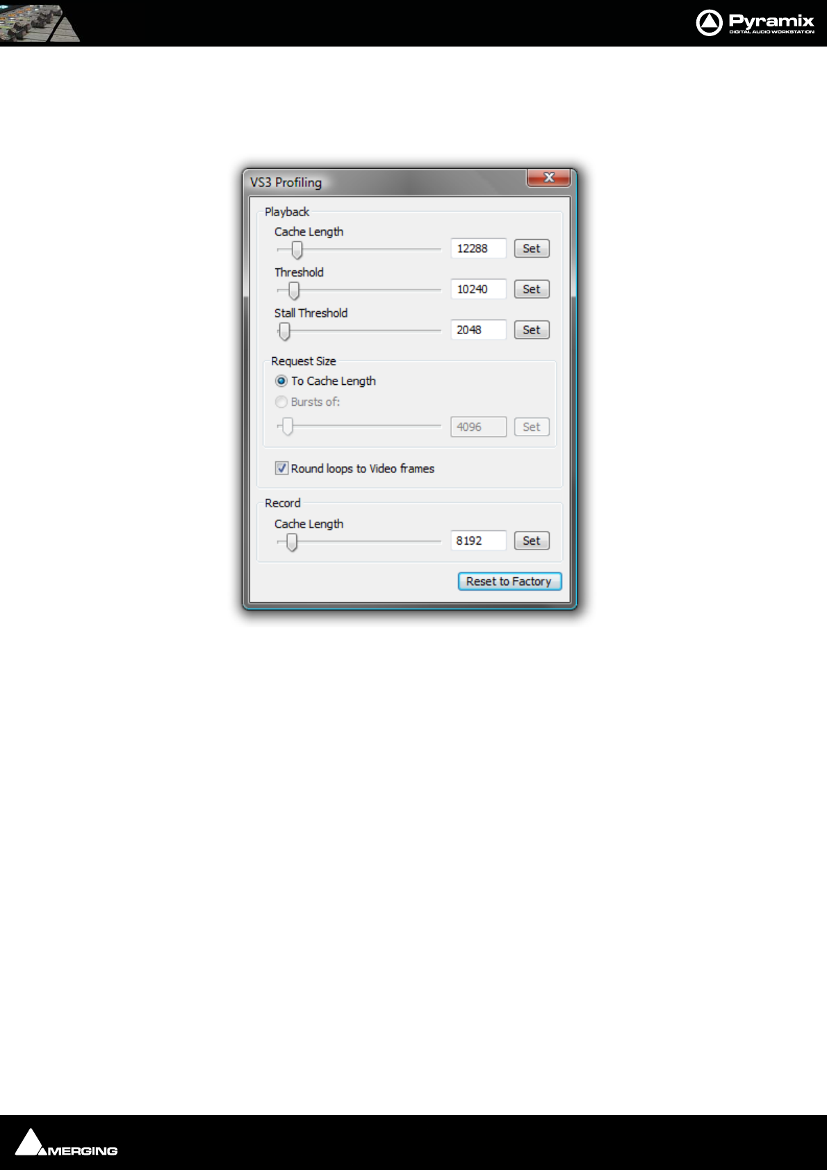
Troubleshooting : The I/O Status window 28 - 551
The Profiling Window
The profiling window contains the parameters used to fine-tune the performance of hard disk accesses for Pyra-
mix. These parameters are not intended for user modifications, and Merging cannot guarantee the proper func-
tionality of Pyramix when modifications are made in this window.
Cache length
This is the size of the playback buffers allocated in the host PC’s RAM. Pyramix allocates one buffer per track. When
the audio playback is started, all the buffers are completely loaded by reading the data from the hard disk before
the actual playback starts. Increasing the buffer size offers the benefit of a larger immunity against short term hard
disk access stalls and other operating system slow-downs at the cost of longer latency at initial playback start.
Threshold
During playback, the audio data is read from the playback buffers, which are thus progressively emptied. When
the amount of data in a buffer falls below the threshold value, new data is read from the hard disk to refill the
buffer.
Request size
This parameter determines how much data is read from the hard disk when the threshold level is reached. One
option is to completely fill (To Cache Length), the other option is to load a defined amount of data (Bursts of).
Stall Threshold
When the amount of data falls below the stall threshold, this means that the system has serious performance
problems. Playback will be temporarily stopped, while a stall warning is issued.
Round loops to Video Frames
This option, which is enabled by default, rounds the start and the end point of a playback loop to complete video
frames. The start point will always be rounded down, and the end point will always be rounded up, so that the
loop will always contain at least the initial range intended for the loop.
Record cache length
VS3 Profiling window

Troubleshooting : ADAT Daughterboard and XDTDM 28 - 552
This is the size of the buffer used while recording new data.
Reset to Factory
This button restores all the values to their factory default.
ADAT Daughterboard and XDTDM
The ADAT daughter card, despite the fact that its original design dates back to 1999, is still fully supported in Pyra-
mix V6.1 in legacy HDTDM mode (64 I/O channels)
However, the use of this daughter card in XDTDM mode (128 I/O channels) is not guaranteed without the upgrade
described below. The much higher transmission frequencies, employed in order to convey double the number of
audio channels over the XDTDM bus, require an improved ground plane, which is achieved with an additional con-
ductive shield:
• To work properly in XDTDM mode, the ADAT daughter card has to be retrofitted with a shield, tightly
screwed to the card in order to ensure proper grounding. Should you have an ADAT card, not yet retrofit-
ted with a Shield, that you wish to use in XDTDM Mode, please contact your Merging Sales Partner.
Note: In XDTDM mode, the ADAT daughterboard will only support 8 output channels
through optical output A, duplicated through optical output B. ADAT inputs are no
longer available in the XDTDM mode.

Troubleshooting : General Troubleshooting 28 - 553
General Troubleshooting
Things to check first - Windows XP
1. Make sure you have either "Administrator" rights or "Power User" rights for your Pyramix XP account.
2. Make sure you have latest drivers/firmware/Bios installed for your entire hardware system. This includes:
motherboard & motherboard's components (on-board audio card, network adapter, RAID controllers, etc),
optical drives and add-on cards.
3. Latest software is installed, for Operating System as well as for all Applications.
4. All hardware equipment is properly listed and shown as fully operational in Windows Device Manager (Con-
trol Panel > System > Hardware : Device Manager), including Mykerinos cards.
5. Keys for all Merging product and options are properly listed with a valid date either in: All Settings > Keys
(with Pyramix open) or in: Control Panel > MT Security Settings (when Pyramix is closed).
6. Support Section of the Forum has been checked here:
http://forum.merging.com/viewforum.php?f=33
7. Merging’s Worldwide network of knowledgeable and trained Sales Partners is a valuable source of informa-
tion. So please check with a local Merging representative in your country or time zone to find a solution to
your support, technical or commercial enquiry.
Should you then still need to contact support, please include the following information in your request:
8. Serial numbers as well as exact Software Versions of Merging products.
9. A detailed description of your hardware system. including PC, Audio card, Tape Machines, Controllers, as well
as any outboard equipment that could possibly be associated with the issue.
10. Then several files may also help us better understand you problem, so please send any combination of the fol-
lowing, depending on the nature of the issue:
11. Small files that can be sent by e-mail:
• Copy of the general Setting ".pms" files (Save in general Settings)
• In the event a reproducible crash, a copy of the crash log, generated by DrWatson, please see below
for activation of this.
• Example of the Pyramix ".pmx" Project where the potential issue has been witnessed.
• Interchange Project file (AAF, OMF, etc.)
• Small sample of media (Audio or video files)
12. Large files can be copied to a regular data CD or DVD and sent by post, courier or by ftp:
• DiskWrite ".pmi" Disk Images
• Audio files
•Video Files
• Complete interchange Projects including media (AAF, OMF, etc.)
DrWatson, Crash Log Activation:
1. Create a new folder named DrWatson at the root of C drive
2. Launch DrWatson 32bit exe, found in: C:\WINDOWS\system32\drwtsn32.exe
3. Set-it up as shown in ScreenShot 1 below
4. Activate DrWatson as the default debugger tool, as shown in ScreenShot 2 below
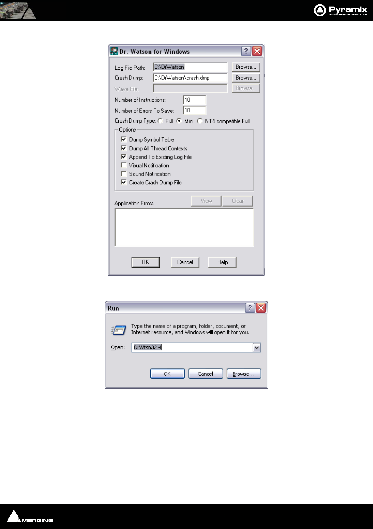
Troubleshooting : General Troubleshooting 28 - 554
Then, once a crash has happened, send us the log file that you will find in the C:\DrWatson folder. Please, also
remember that access to support is free, according to the following conditions:
With a valid ASM (Annual Software Maintenance) or:
Within the first year following the purchase of a new Pyramix Virtual Studio system.
Dr. Watson Screenshot 1
Dr. Watson Screenshot 2

USER MANUAL
www.merging.com/Pyramix
Appendices

Appendices : Appendix I - Mouse Modifier Keys 29 - 556
Appendix I - Mouse Modifier Keys
This table shows the valid modifier keys which can be used in conjunction with some mouse operations
Main Editor
Left Mouse Button
Click In the TimeCode Scale
Set Cursor to the mouse None
Set Mark In to the mouse Shift
Set Mark Out to the mouse Ctrl
Set New Marker to the mouse Ctrl + Shift
Click In the Bars & Beats Scale
Set Cursor to the mouse None
Adjust tempo to the end Shift
Adjust tempo for the current portion Ctrl
Adjust tempo for the current Beat Ctrl + Shift
Click In the Tempo Map
Create a new tempo portion Ctrl
Click In the Track headers zone
Repeat action for the same button on all tracks Shift
Click In the Clips zone (anywhere)
Draw a region to zoom in Alt
Dyna-Zoom Z
Draw a region to select None
Draw a region to select clips completely Shift
Extend/Reduce the current region to this track E
Invert No Selection mode for Track Groups Q
Invert Auto Select Tracks Q
Click In a Clip handle
Move only the clip handle under the mouse (no groups) Shift
Move only the envelope point under the mouse (no groups) Shift
Click In a Clip
Add remove clips to the selection Shift
Drag the selection (to a library) Shift + Alt
Move selected clips None
Move selected clips with auto-crossfade Ctrl
Slide the underlying media of a clip Ctrl + Shift
Slide a clip over its underlying media Ctrl + Alt
Move selected clips constrained in time Ctrl + Shift + Alt
Cutter C
Duplicate clip D
Duplicate clip constrained in time F

Appendices : Appendix I - Mouse Modifier Keys 29 - 557
While moving
Auto-crossfade while moving clips Ctrl
Force crossfade while moving clips lower handle Ctrl
Detach crossfade while moving clips middle handle Ctrl
Don't merge Envelope points Ctrl
Constrain Envelope in time V
Constrain Envelope in value H
Don't merge Automation points Ctrl
Constrain Automation in time V
Constrain Automation in value H
Select only what is under the mouse (no groups) Shift
Select all tracks Ctrl + Shift
Select and limit selection the clips boundaries Ctrl + Alt
Snap Sync Point S
Snap Head H
Snap Tail T
Audition while moving (Scrubbing) A
Double-click in a Clip
Selection Properties
Clip Properties Ctrl
Double-click in a fade
Edit the fade in the Fade Editor
Double-click in an envelope point
Reset the envelope point
Reset only the envelope point under the mouse (no groups) Shift
Middle Mouse Button
Edit crossfade Ctrl
Create & Edit crossfade Ctrl + Shift
Select between edits None
Enlarge selection between edits Shift
Click In the TimeCode Scale
Scrub Audio None
Right Mouse Button
Contextual Menu None
Clip Gain Ctrl
On dropping a fade or crossfade from a library
Apply to whole group Shift
Overview
Left Mouse Button
Draw a region to zoom in Alt
Drag the current composition (to a library) Shift + Alt

Appendices : Appendix I - Mouse Modifier Keys 29 - 558
Notes
Left Mouse Button
Drag the notes (to a library) Shift + Alt
Media Folder
Left Mouse Button
Replace media for target clip(s) Ctrl
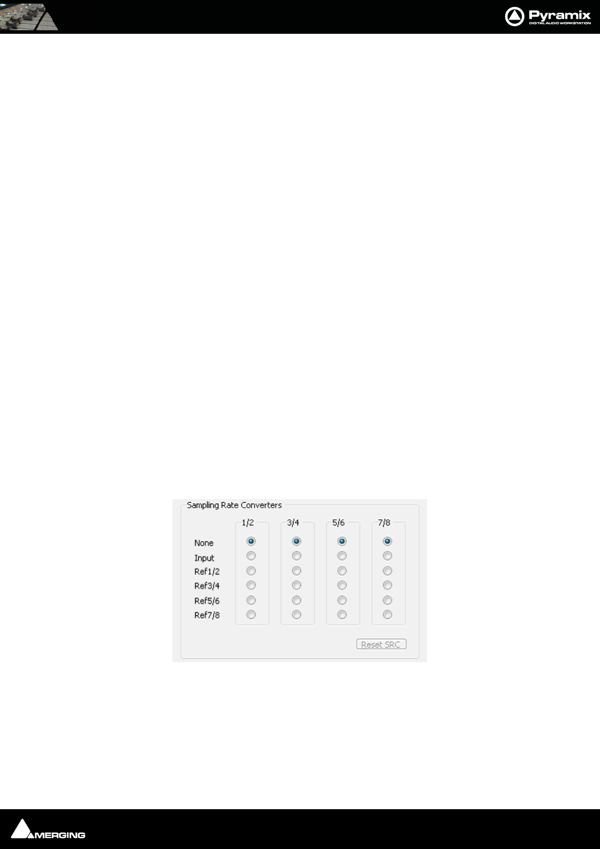
Appendices : Appendix II I/O Daughter-card Options 29 - 559
Appendix II I/O Daughter-card Options
ADAT Optical I/O
The ADAT Optical daughter card offers 16 channels of audio input and 16 channels of audio output, 8 channels per
optical connection. From top to bottom of the card, it has two digital optical input connectors (Inputs A and B) and
two digital optical output connectors (Outputs A and B).
The signal format of optical connectors Input A and Output A can be set inside the Pyramix software to operate in
either ADAT or S/PDIF mode. When in ADAT mode, there are 8 discrete audio channels carried per each optical
connector. S/PDIF mode has 2 channels per optical connector.
Note: in SPDIF mode the maximum sampling rate is limited to 48 kHz
Note that whilst the ADAT daughterboard continues to function normally in HDTDM (64 bus) mode it cannot be
used for input when in XDTDM (128 bus) mode and is only capable of 8 outputs via Optical Output A with the
same 8 duplicated on Optical Output B.
WARNING! The ADAT Daughterboard requires modification before attempting to use it with XDTDM mode. Fail-
ure to do this may result in data loss. Please contact your Merging Technologies Sales Partner to arrange a mod.
AES/EBU I/O
The AES/EBU daughter card offers 24 channels of I/O over 12 AES/EBU input and output pairs. Connection is via
three DB-25 connectors, One on the main card attached to the Mykerinos and two more on a separate bracket
connected via internal ribbon cable to the main card. An optional break-out cable can be ordered separately
which connects to the DB-25 connector and terminates in 8 XLR connectors which may be used to connect to
standard AES/EBU stereo inputs and outputs. AES daughter cards are available with or without 8 channels of SRC
(sample rate conversion)
AES II with SRC
The AES II daughter card is equipped with 4 unidirectional SRC chips. Each one can be configured as bypass, input
or output. On a specific in/out channel pair a sampling rate conversion can be applied only in one direction, either
input or output. The "Speed on physical wire" setting should be set to the project's sampling rate (aka "single-wire
mode") whenever the SRCs are used, since channel pairs that are spread over several wires will not be sample rate
converted properly. In Settings > All Settings > Hardware > I/O Interfaces, the I/O interface page corresponding
to each AES II daughter card in the system shows an array like this:
Up to 192 kHz, each column represents one XLR connector (one pair of channels) with its associated SRC chip.
The following configurations can be selected:
•None: or bypass, the SRC is transparent
•Input: The SRC works on the input path and converts the incoming signal to the project's sampling rate
•Ref1/2 through Ref 7/8: The SRC is inserted in the output path and converts the output signal to the sam-
pling rate of the signal present at the input chosen as reference.
AES II Settings
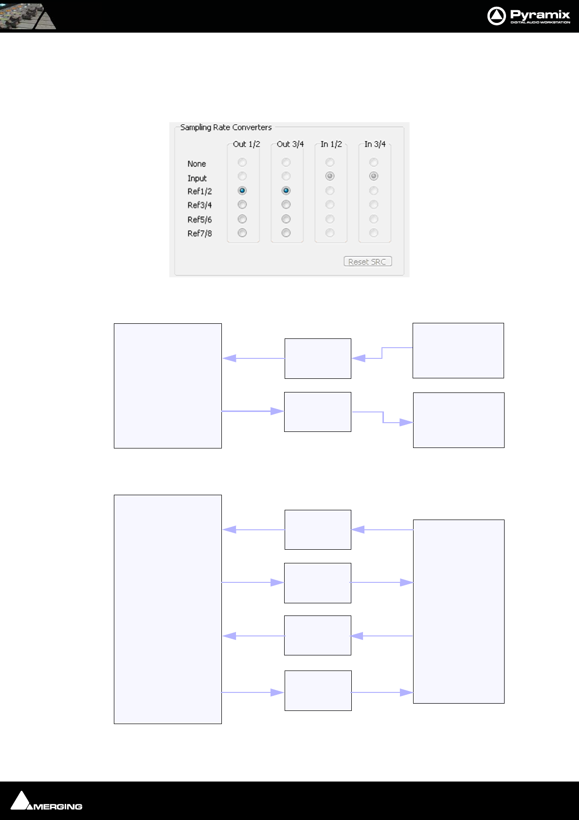
Appendices : Appendix II I/O Daughter-card Options 29 - 560
At 8FS (DXD/DSD), the AES II daughter card has a special mode that is enabled by selecting 8FS to nFS in the
Speed on physical wire field of the I/O interface page. This mode provides a fixed set of 2 input and 2 output
paths and enables a real-time conversion from 384kHz/352.8kHz down to 192kHz/44.1kHz and vice-versa. Only
XLRs 1/2 and 3/4 are used in this mode. For the outputs, the reference input for the sampling frequency is select-
able in the "Sampling Rate Converters" array.
Examples
Example 1: 2 channels up sampling from 48 kHz to 192 kHz and down sampling from 192 kHz to 48 kHz.
Example 2: 4 channels 96 kHz effect insert in a DXD project.
AES II Settings
Project @ 192kHz
AES II SRC
Sync: Internal
Speed on physical wire:
192kHz
SRC 1/2
Setting: Input
SRC 3/4
Setting: Ref 1/2
ADC
48kHz
Sync: Internal
DAC
48kHz
Sync: Audio
input
XLR 3/4
XLR 1/2
DXD Project
AES II SRC
Sync: Internal
Speed on physical wire:
8FS to nFS
SRC In 1
Setting: Input
SRC Out 1
Setting: Ref 1/2
Effect Box
96kHz
Sync: Internal
XLR 3/4
XLR 1/2
SRC In 2
Setting: Input
SRC Out 2
Setting: Input XLR 3/4
XLR 1/2
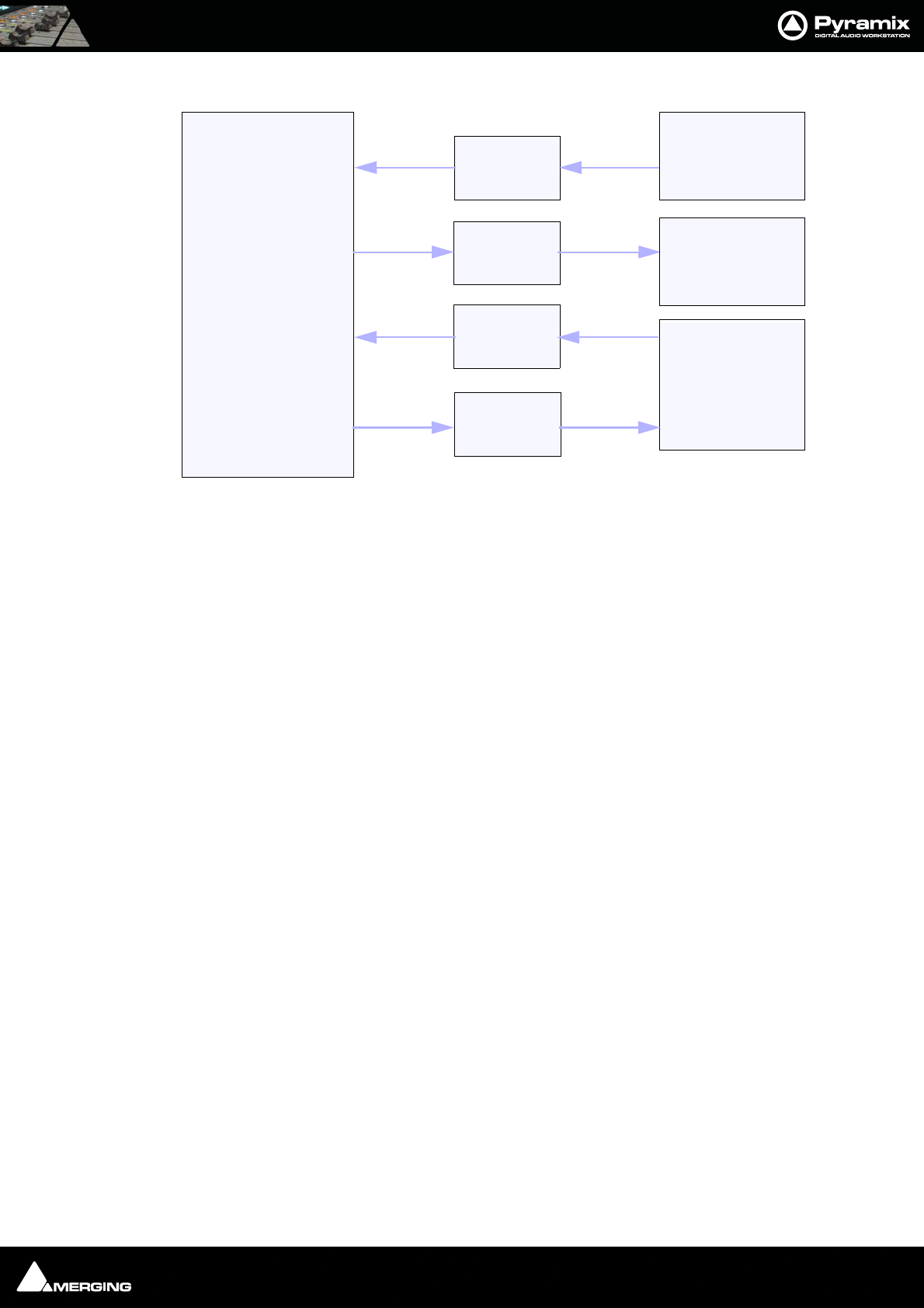
Appendices : Appendix II I/O Daughter-card Options 29 - 561
Example 3: 2 channels 44.1 kHz AD/DA and 96 kHz effect box insert in a 192 kHz project
Dual DC I/O
The Dual DC offers up to 12 inputs and outputs at 32kHz, 44.1kHz or 48kHz sampling rates on a single board. All
converters are 24 bit. Connection is via 2 DB-25 connectors. One, on the main card attached to the Mykerinos, car-
ries the analog I/O and the second, on a separate bracket, carries four AES/EBU Input and Output stereo pairs.
There are four analogue Line outputs and four analogue Line Inputs, two of which may be switched to accept Mic
or Line level inputs. These have Mic pre-amps and 48V phantom powering. The analogue Line level I/O is adjust-
able over a 24dB range to accommodate all standard studio levels. Optional break-out cables can be ordered sep-
arately which connect to the DB-25 connectors and terminate in 8 XLR connectors.
The Dual DC is the most cost-effective I/O daughter card for Pyramix users. It is an ideal I/O solution for mixed ana-
log/digital requirements, as encountered in Broadcast production, and Video post-production environments. It
allows direct connection of up to two dynamic or condenser microphones, typically for quick and easy voice-over
recording.
Note: the Dual DC I/O daughtercard is not HDTDM bus compatible and can not be used
in a multiboard setup.
MADI I/O
The MADI daughter card offers 56 channels of 24 bit bi-directional I/O, and up to 64 channels in MADI-X (MADI
Extended) format. It can be ordered either in a BNC coaxial version or an optical duplex SC version. Both versions
are fitted with a standard Wordclock BNC I/O connector, which can be programmed in the Pyramix software as a
Wordclock In or Out signal.
SDIF I/O
The Mykerinos SDIF daughter board is specially designed for multi-track DSD recording. It offers 8 channels of DSD
digital input over 8 unbalanced, 75 Ohm terminated BNC connectors and 8 channels of DSD digital output over 8
unbalanced, 75 Ohm BNC connectors.One channel of DSD signal is transported at the bit-rate of 2.82 MHz through
each BNC connector. SDIF-2 and SDIF-3 format are fully supported for DSD transport (selected under software
control)
Note: With one Mykerinos board, it is only possible to use one DSD Input and Output
channel. To have the full range of 8 I/O channels, either MassCore or a second Mykerinos
board is required to provide sufficient DSP power.
DXD Project
AES II SRC
Sync: Internal
Speed on physical wire:
8FS to nFS
SRC In 1
Setting: Input
SRC Out 1
Setting: Ref 1/2
Effect Box
96kHz
Sync: Internal
XLR 3/4
XLR 1/2
SRC 5/6
Setting: Input
SRC 7/8
Setting: Ref 5/6
ADC
44.1kHz
Sync: Internal
DAC
44.1kHz
Sync: Internal
XLR 5/6
XLR 7/8
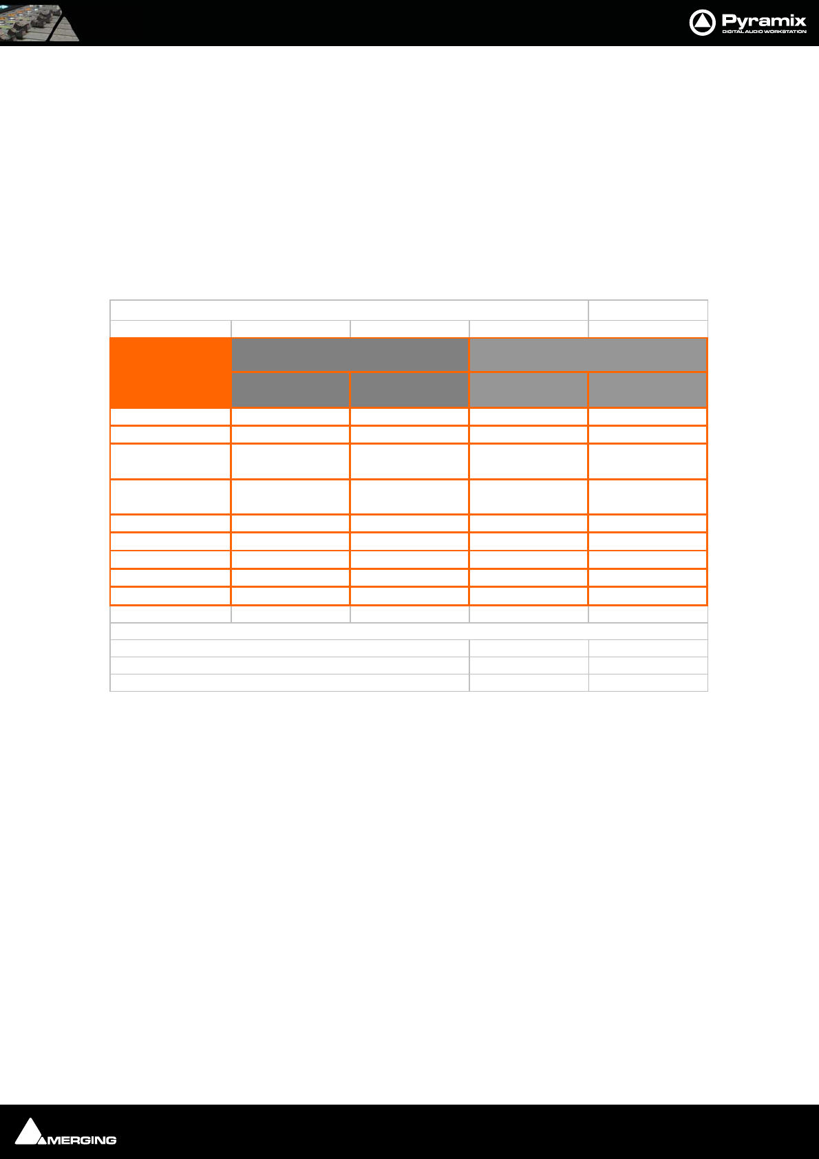
Appendices : Appendix II I/O Daughter-card Options 29 - 562
TASCAM TDIF
The TASCAM TDIF daughter card offers 24 channels of I/O over 3 Tascam TDIF connections. Connection is via three
DB-25 connectors, One on the main card attached to the Mykerinos and two more on a separate bracket con-
nected via internal ribbon cable to the main card.
TASCAM TDIF I/O Option
A TASCAM TDIF format option bracket may be added to the ADAT I/O daughtercard and provides is available for 8
channels of TDIF I/O. The TDIF bracket connects to a socket on the ADAT card only. This daughter card cannot be
used in multi-board systems (since it utilizes the HTDM connector).
Daughter Card Support in Pyramix 6.x
Dau
g
hter Cards su
pp
ort in P
y
ramix
6.x
MassCore &
Pmx 6.x
Non-Masscore &
Pmx 6.x
MassCore &
Pmx 6.x
Non-MassCore &
Pmx 6.x
MADI-I v v Not Supported Not Supported
MADI-II v v v v
ADAT (Serials
20000 to 20299) v v Not Supported Not Supported
ADAT (Serials
20300 and +) v (Note4) v (Note4) v (Note3) v (Note1)
AES-I v v v v
AES-II v v v v (Note2)
SDIFvvvv
TDIFvvvv
DUAL v v v Not Supported
Note 1: HDTDM = 16 ins and 16 outs supported. XDTDM = 0 in and 8 Outs
Note 2: Supported in XDTDM mode only
Note 3: 16 ADAT i/o supported. No SPDIF i/o.
Note 4: Full i/o of ADAT and SPDIF supported
Daughter Cards
Standalone-Mono-board Multi-board
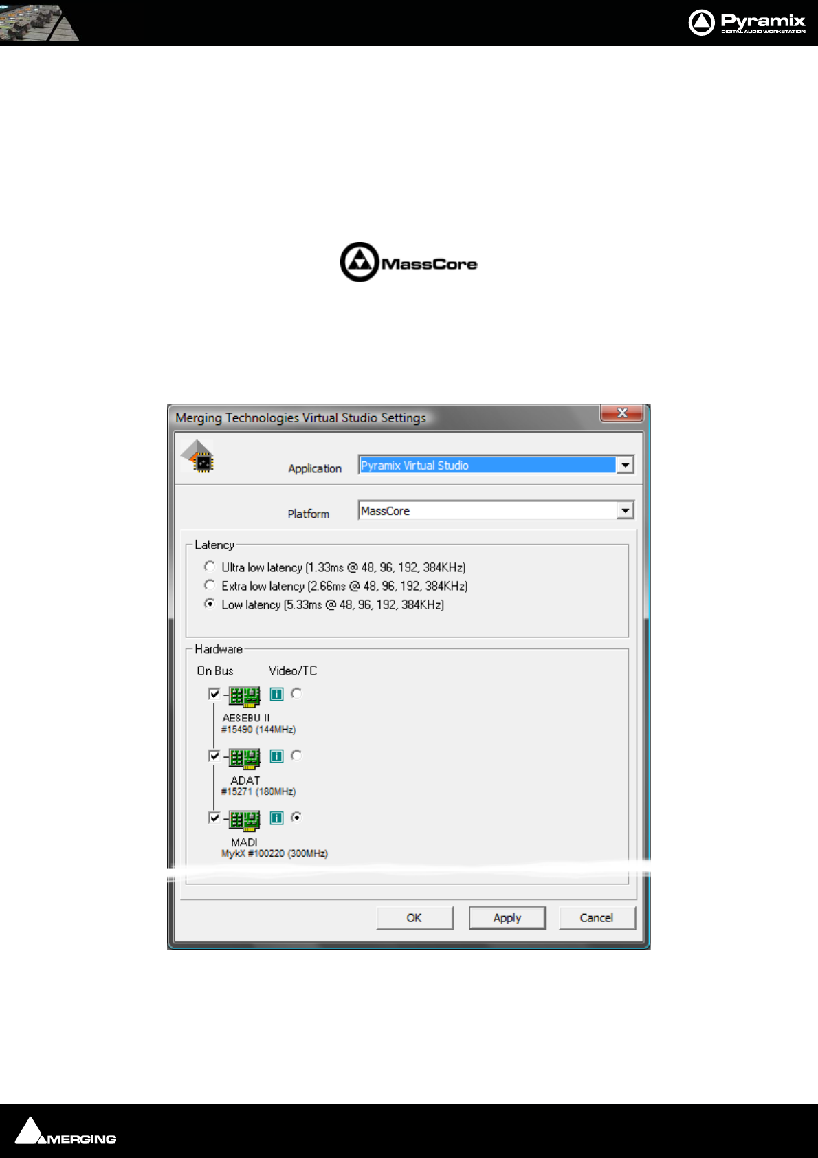
Appendices : Appendix III VS3 Control Panel 29 - 563
Appendix III VS3 Control Panel
The VS3 Control Panel is a separate application that should only be launched when Pyramix is not running. Here,
you can set various parameters relating to Merging Technologies hardware and software. For example, in a multi-
board system, this is where you determine which boards will be used, the Buses Mode and which board will han-
dle Video reference and TimeCode. If you are running both VCube and Pyramix on one system you can assign
boards to each application. In the case of a system running MassCore this is also where you can set global latency.
Please see: Appendix IV - HDTDM v XDTDM v MassCore on page 568 for detailed information about busing
and I/O capabilities.
Application
The drop-down list enables you to choose which Merging Technologies application the settings apply to. E.g.
Pyramix Virtual Studio, VCube, ASIO Mykerinos Driver etc.
The rest of the settings in the VS3 Control Panel Window update to reflect the current settings for the selected
application.
VS3 Control Panel Window MassCore Platform
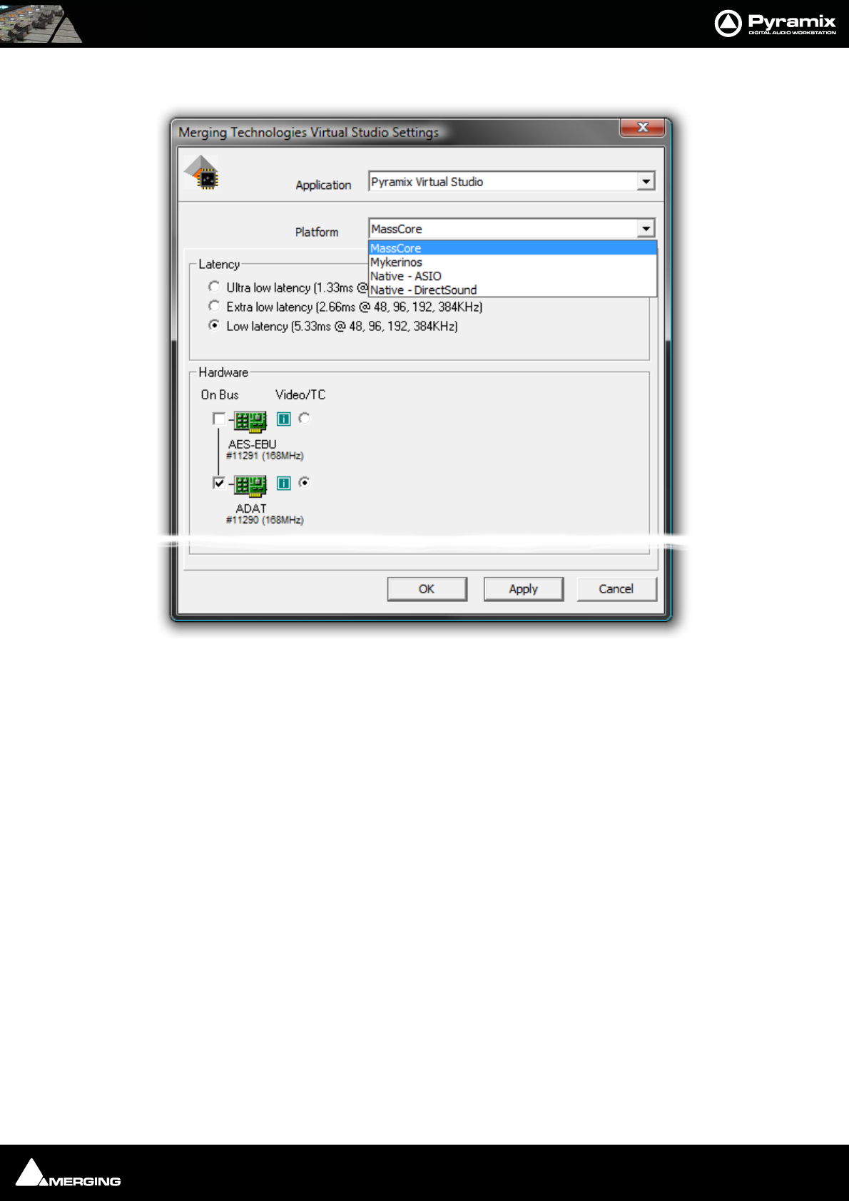
Appendices : Appendix III VS3 Control Panel 29 - 564
Platform
This drop-down list determines which processing platform mode will be used. Dependant on the options
installed these may include MassCore, Mykerinos, Native - ASIO and Native - DirectSound. If you choose Mykeri-
nos the Buses Mode drop-down appears. Please see: Buses Mode and DSP Allocation on page 566
Latency
These options are only available when MassCore is installed and chosen as the Platform and then only with cer-
tain Mykerinos cards. Please see: Pyramix V6 Latency Modes for MassCore on page 34
Hardware
All installed Mykerinos cards are shown here with checkboxes which determine if they are On Bus (I.e. will be
used), for the selected application and which On-Bus board will be used for Video/TC. In a multi-board system
with boards having different capabilities this will normally be the most powerful board available.
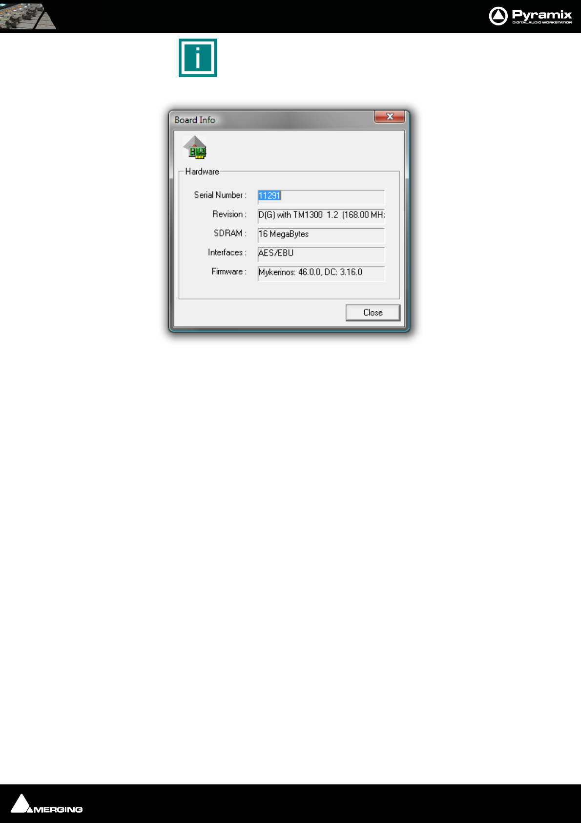
Appendices : Appendix III VS3 Control Panel 29 - 565
Clicking on the small icon next to the image of each board opens the Board Info pop-up for the
board:
Here you will find the Serial Number:, the Revision: detailing the processor type, SDRAM: showing how much
RAM is installed, Interfaces: describing the Daughterboard installed and Firmware: listing the current firmware
version.
Board Info pop-up
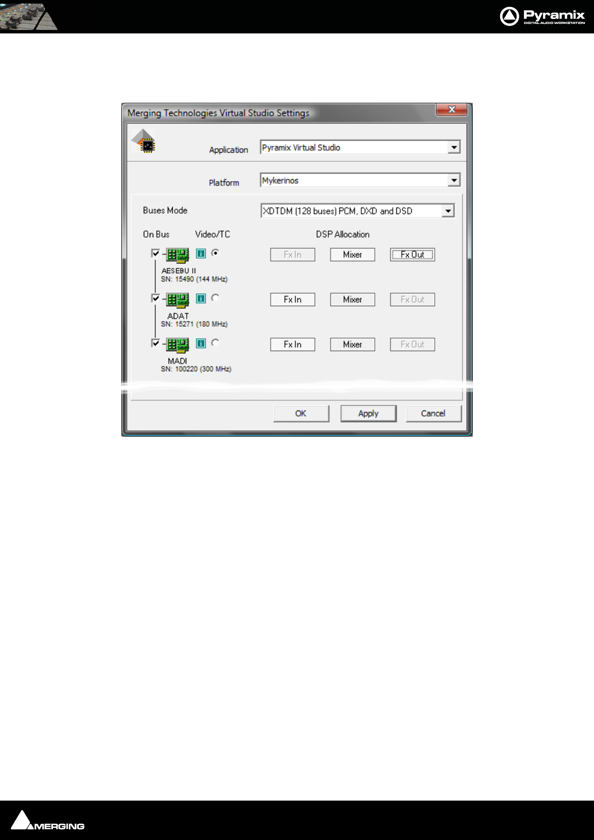
Appendices : Appendix III VS3 Control Panel 29 - 566
Buses Mode and DSP Allocation
When Platform is set to Mykerinos, Buses Mode and DSP Allocation options will be available in a multi board
system when more than one board is set On Bus:
Buses Mode
The drop-down offers the choice between XTDM (128 buses) PCM, DXD and DSD mode and HDTDM (64 buses)
PCM only mode.
DSP Allocation
The buttons offer a degree of user control over DSP allocation. To help make sensible choices this is what the DSP
processing blocks do:
Fx Out
• All output buses
• All VS3 plug-ins inserted on output buses,
• All active Output connections.
Note: All Fx Out calculations are inherently summing tasks so they need to be processed
in the same card - so only one card can be used for this.
Mixer
All internal calculations that are carried out in the background, allowing INs to be forwarded to OUT buses. It can
be seen as an internal matrix.
In the Pyramix user interface, this is only reflected by the numbers of Ins routed to OUTs, no plug-ins, input strips
or output buses are calculated here.
Mixer can be calculated in a single DSP or can share DSP with Fx In or with Fx Out.
VS3 Control Panel Window Mykerinos Platform
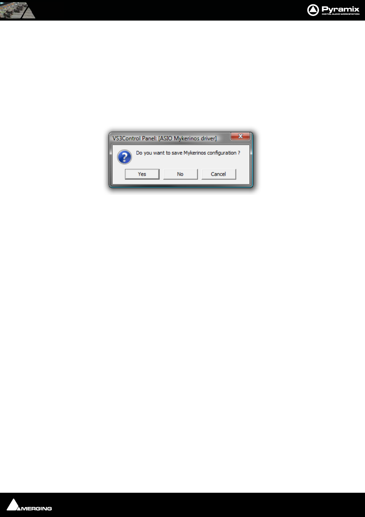
Appendices : Appendix III VS3 Control Panel 29 - 567
Fx In
•All input strips
• All VS3 plug-ins inserted on Input strips
• All active Input connections
Fx-INs can be spread across multiple DSP cards (since no summing is required at this stage).
Please see: Allocating DSP on page 435 for some tips on appropriate DSP allocation
Saving Settings
If you change any settings for a given application then clicking on Apply opens the Save Configuration dialog :
Click on Yes to save
Routing
Since V5 the routing functionality has been removed from the VS3 Control panel and is now more conveniently
accessed via Settings > All Settings > Hardware > Routing in the main Pyramix application.
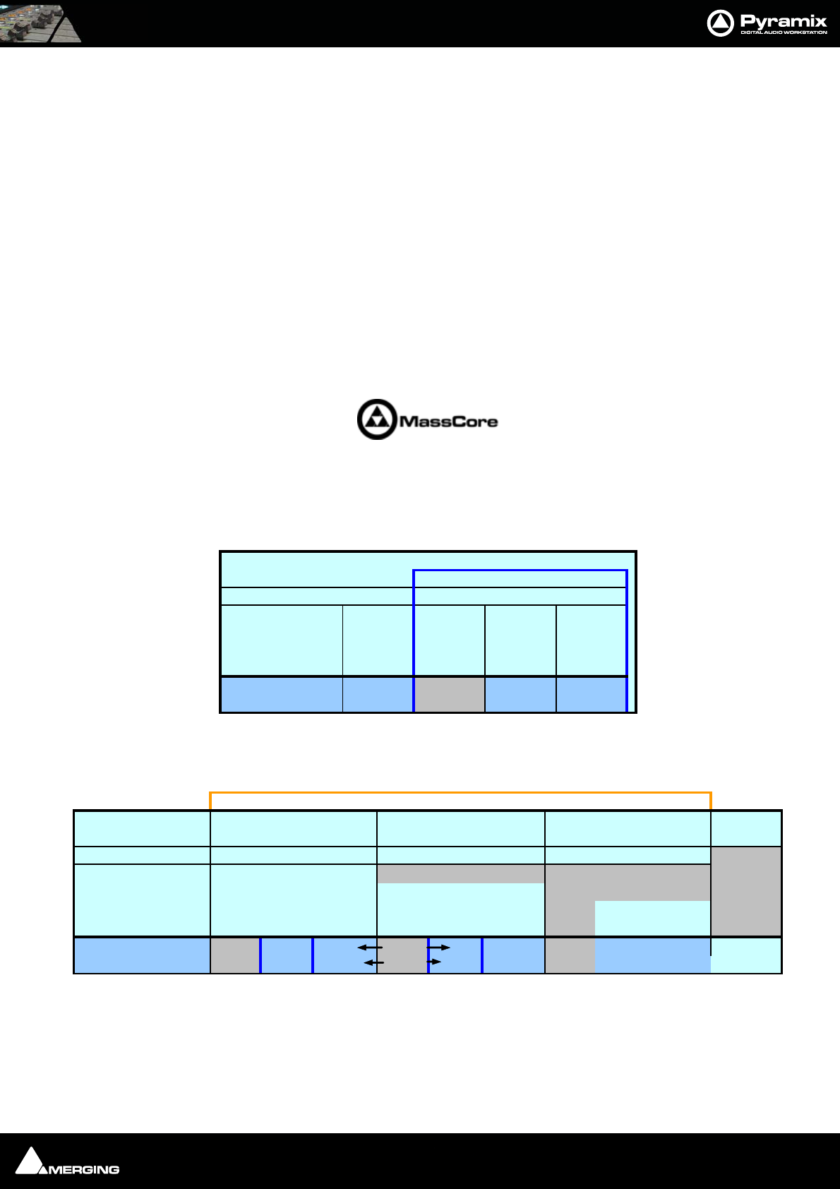
Appendices : Appendix IV - HDTDM v XDTDM v MassCore 29 - 568
Appendix IV - HDTDM v XDTDM v MassCore
Internal Bussing & I/O Capabilities
HDTDM mode offers a maximum of 64 buses
XDTDM mode offers a maximum of 128 buses
MassCore mode offers a maximum of 384 buses
In the upgrade from Pyramix V4 to V5, the number of channels was doubled. The inter-board bus was enhanced in
terms of bandwidth and renamed the XDTDM bus, for eXtreme Definition Time Domain Multiplex. Some exceptions
exist and these are discussed below.
Note: The HDTDM, XDTDM and MassCore bussing modes are selected in the VS3 Control
Panel Please see: Appendix III VS3 Control Panel on page 563
In the upgrade from Pyramix V5 to V6 MassCore was introduced. This multiplies all mix engine processing and allows
for higher bussing capabilities.
Bussing Capabilities
I/O Capabilities
AES and AES2 Daughterboards
Sample Rate Format HDTDM XDTDM MassCore
44.1/48 kHz 1FS 64 128 384
88.2/96 kHz 2FS 32 64 192
176.4/192 kHz 4FS 16 32 96
352.8/384 kHz 8FS 81648
DXD 8FS 16 48
DSD 64FS 16 48
Bussing capabilities
Note 1
HDTDM XDTDM MassCore HDTDM XDTDM MassCore HDTDM XDTDM MassCore
44.1/48 kHz 1FS 24 24 24
88.2/96 kHz 2FS 12 12 12 12 24 24
176.4/192 kHz 4FS 6 6 6 6 12 12 24 24
352.8/384 kHz 8FS 3 3 3 3 6 6 12 12
DXD 8FS 33 66 1212
DSD (Note 8) 64FS 8 or 6 8 or 6 8 or 6 8 or 6 8 or 6 8 or 6
Sample Rate Format
See Note 2
See Note 3
AES and AES2
AES/AES 2 Speed on Physical
Wire @ 44.1/48kHz
AES/AES 2 Speed on Physical
Wire @ 88.2/96kHz
A
ES 2 Speed on Physical Wire
@ 176.4/192kHz Notes
Note 5
Note 4
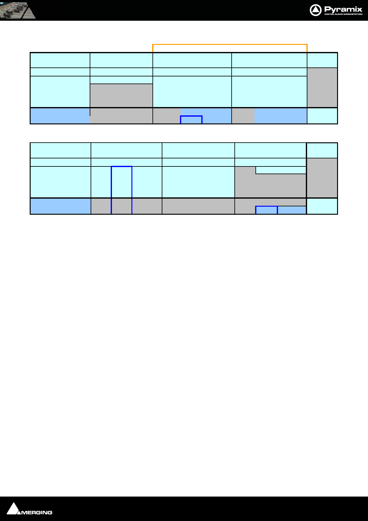
Appendices : Appendix IV - HDTDM v XDTDM v MassCore 29 - 569
Dual and MADI 2 Daughterboards
ADAT, TDIF and SDIF Daughterboards
Detailed notes and information :
1. The table Bussing capabilities indicates the maximum channel count available in a Pyramix system in V4.x
through V6.x modes:
•HDTDM mode is the V4.x compatibility mode and offers the same PCM channels count as previ-
ously, except that DSD/DXD modes are no longer supported in this mode since V5.x.
•XDTDM mode - V5.x and V6.x only - offers twice as many PCM and DSD/DXD channels compared
with Pyramix V4.x.
2. The greyed-out cells indicate that the corresponding mode does not exist for the corresponding daughter
cards.
3. DXD / DSD are only available in XDTDM and MassCore modes.
4. In DXD mode, the I/O count depends on the I/O format speed.
5. In DSD mode, I/O count depends on the AES I/O format (Sony or P3D respectively).
6. Although the theoretical maximum DSD channel count with a MADI daughter card is 24, the bus capability
has a maximum of 16 DSD channels.
7. The ADAT daughter card supports the XDTDM and MassCore modes ONLY with a hardware rework (shield).
In XDTDM mode, the ADAT daughter card offers 8 output channels through optical output A) replicated on
optical output B) but No Inputs.
The hardware rework consists of adding a shield to the ADAT similar to the one used for the DUAL daughter
card. If you have not already done so, please contact your Merging Sales Partner to order this retrofit kit.
8. In a mono-board SDIF system, only 2 DSD channels are available.
9. Dual offers 8 AES and 4 Analog channels of I/O per board.
10. In standalone, non-Masscore mode only 8 channels DSD are available.
Non-MassCore (Mykerinos mode) Multi-board hardware restrictions:
The MADI 1 daughter card does not work in Multi-board mode (This includes all MADI daughter cards with serial
numbers lower than 30051).
ADAT daughter cards with serial numbers lower than 20299 do not function in multi-board mode.
The DUAL daughter cards do not function in multi-board mode.
Stand Alone MassCore HDTDM XDTDM MassCore HDTDM XDTDM MassCore
44.1/48 kHz 1FS 8+4 8+4 56 56 56 64 64 64
88.2/96 kHz 2FS 28 28 28 32 32 32
176.4/192 kHz 4FS 14 14 14 16 16 16
352.8/384 kHz 8FS 77 7 88 8
DXD 8FS 77 8 8
DSD (Note 8) 64FS 16 16 16 16
MADI 2
MADI2 Standard Mode MADI2 Extended Mode Notes
See Note 2
See Note 3
Sample Rate Format
DUAL
Note 9
Note 6,10
HDTDM XDTDM MassCore HDTDM XDTDM MassCore HDTDM XDTDM MassCore
44.1/48 kHz 1FS 16 8 16 16 16 16 8 8
88.2/96 kHz 2FS 84 8 8 8 8
176.4/192 kHz 4FS 42 4 4 4 4
352.8/384 kHz 8FS 21 2 2 2 2
DXD 8FS
DSD (Note 8) 64FS 88
Notes
See Note 2
See Note 3
ADAT TDIF SDIF
Sample Rate Format
No
Note
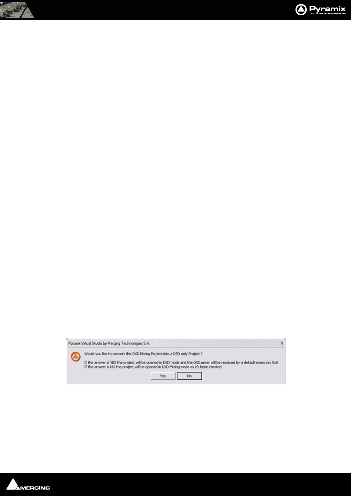
Appendices : Appendix V Optional Features 29 - 570
Appendix V Optional Features
Pyramix DSD / SACD
Hardware and Settings
Interfacing
DSD transmission works well with either AES-EBU or SDIF interfaces. Most converter manufacturers use SDIF. Only
dCS does SDIF and AES-EBU.
A further issue is the existence of two different AES-EBU supported DSD formats. The so called "Sony" and one
named "P3D." Merging Technologies support both of these. If you need to interface to both AES/EBU and SDIF two
cards will be required.
Wordclock settings.
In DSD mode it is imperative Pyramix wordclock settings correspond with the requirements of the converters
employed. To date all the DSD compatible converters we have tested generate and expect wordclock at the stan-
dard nominal rate. I.e. 44.1kHz.
Failure to set Pyramix to expect only 44.1kHz in DSD operation will prevent proper locking to the external source
and therefore prevent correct decoding of the DSD bitstreams, resulting in very loud noise on its outputs. Check
the setting via:
Settings > All Settings > Formats & Sync
make sure that the "Wordclock is Input at 44.1k x 2" checkbox is NOT checked when operating in DSD mode.
To verify Pyramix is correctly locked to incoming Word clock:
Left-click on the red 'LED' in the Sync: WordClock box (bottom right of Pyramix screen in the status bar). This will
open the I/O status window The green LEDs indicate active inputs and there will be a red LED in front of the cho-
sen sync source if this is locked.
Right-click on the same (Sync: WordClock) red 'LED'. Select, Debug > Input Check. This window will enable you
to check that Pyramix is effectively locked at the correct frequency.
Project Types
DXD Mixing Project
The DXD Mixing Project can be used use for recording, editing, mixing, processing and mastering DSD/SACD in
DXD format (352.8 kHz - 32 bits)
Opening a DXD Mixing Project
When an existing DXD Mixing Project is opened this dialog appears:
Would you like to convert this DXD Mixing Project into a DSD only Project?
If the answer is YES the project will be opened in DSD mode and the DXD mixer will be replaced by a default
mono mix 8x8.
If the answer is NO the project will be opened in DXD Mixing mode with the DXD Mixer in the same configuration
as it was when the Project was Saved.
DSD Project
Convert DXD Project to DSD Project mode? dialog

Appendices : Appendix V Optional Features 29 - 571
The DSD Project - can be used recording, editing and mastering DSD/SACD in DSD format (2.8 MHz - 1 bit) Project
for recording, editing and mastering DSD/SACD in DSD format (2.8 MHz - 1 bit
Opening a DSD Project
When an existing DSD Project is opened this dialog appears:)
Would you like to convert this DSD Project into a DXD Mixing Project ?
If the answer is YES the project will be opened in DXD Mixing mode. (Though all your media files will remain in
DSD IFF format)
If the answer is NO the project will be opened in DSD mode as it was when created.
Peak Values in DSD and DSDIFF Media Files
Peak Computations
For DXD audio media, the peak displayed in the media Properties page is computed from the audio without a
[20..20kHz] filter.
For DSD audio media (DSDIFF), the peak displayed in the media Properties page is computed from the audio after
a [20..20kHz] filter.
This could change the behavior of Auto-scale Waveform and Normalize.
For example:
A DXD file generated from a 1kHz sine @-10dB -> peak = -10dB
A DSDIFF file generated from a 1kHz sine @-10dB -> peak = -9.9dB
Time-code Sync
Required if you intend to use LTC (Linear TimeCode) or VITC (Vertical Interval TimeCode) to synchronize Pyramix to
external equipment.
Cue Sequencer
The Cue Sequencer is a live playout system
A Cue is defined as a Track Group and all the Tracks and clips it contains. All Track Groups in the composition
appear in the Cue Sequencer list and are called a Cue.
Cues can be re-ordered in the Cue Sequencer list view by drag and dropping lines or groups of lines.
Double-clicking on a Cue selects its first track in the Editor.
Cue Parameters
Cues have the following parameters:
Name: Same as the Track Group name
Notes: free notes typed by the user
Event: An event number (from 1 to 96) can be associated to any cue. This event number
can be mapped to a keyboard shortcut with the Keyboard Shortcut Editor or
mapped to a MIDI message with any Remote Controller. When triggered this event
Starts the Cue.
Convert DSD Project to DXD Mixing Project mode? dialog

Appendices : Appendix V Optional Features 29 - 572
Automation: A Cue can use automation on the mixer channels connected to its tracks. A mixer
channel can be controlled by only one Cue.
Start: To Play a Cue.
Pause: To pause the playback of a Cue.
Stop: To Stop the playback of a Cue.
Start Offset: An offset can be applied to a Cue so the starting point is not the beginning of the
first clip of the Cue but a point before (negative Start Offset value) or after (positive
Start Offset value).
Current Time: Elapsed time since the Cue as been started
Remaining Time: Remaining playback time of a Cue.
Cue Status
Cues have the following Status:
Disabled (White): The sequence has to be reset to enable all Cues.
Ready (Pink): The Cue is enabled and ready to play.
Playing (Green): The Cue is playing, it can be paused or stopped.
Paused (Yellow): The Cue is paused, it can be un-paused (return to playing from current position) or
stopped.
Done (Grey): The Cue finished playing. It can be played again without having to be reset.
Cue Sequencer Control
The Cue Sequencer is controlled the following way:
Safe Mode: When in safe mode, the Cue Sequencer window is maximized and all Keyboard
shortcuts except those related to the Cue Sequencer are disabled. The Cue
Sequencer TimeCode counter is colored in red when not in Safe Mode.
Reset Show: All Cues have to be reset before starting to play the sequence. When pressing this
button all Cues are reset to the Ready State (Pink Color) and the time is reset to
00:00:00:000.
Stop Show: To Stop the sequence playout
Start Show: To Start the sequence playout.
Previous: To set the focus to the previous Cue.
Next: To set the focus to the Next Cue.
GO !: To Start the currently selected Cue and select the next one.
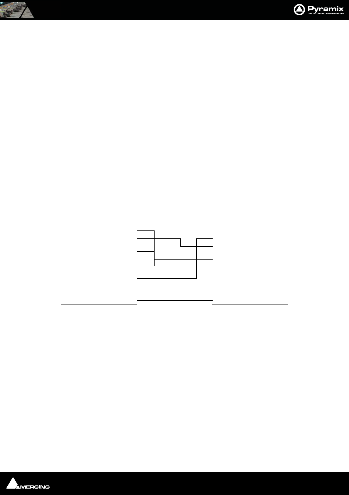
Appendices : Appendix VI 9 - Pin connection 29 - 573
Appendix VI 9 - Pin connection
PC RS-232 Serial Port to External Sony P2 RS-422 Controller
The RS-232 ports of a standard PC are slightly different from the RS-422 format used for the Sony P2 protocol. We
recommend the use of an external RS-232/RS-422 adapter. One example is the Antona ANC 6090 which can be
ordered from your Merging sales representative under the item number MRS422. This adapter is intended to be
connected directly to the serial port of your PC (either COM1 or COM2) with the other end used to connect a stan-
dard Sony P2 RS-422 cable. As both connectors on the adapter are Female DB9, beware of the orientation and
please check that the printed indication "RS-232" is connected to the PC COM port.
Connecting an RS422 device using a direct cable
(without RS-232 / RS-422 adapter)
For emergency use and for short distances, a direct cable may be used. However, Merging Technologies does not
guarantee the correct function of an external controller if this cable is used. Different cables are required depend-
ing on whether Pyramix is controlled by a master device or is controlling a slave device.
Direct Cable for a Master Device
This pinout should work in most of the cases where Pyramix is controlled by a Master device (check on your con-
troller if the RS422 connector has to be male or female). It has been tested with various mixers such as Sony DMX-
R100, Soundcraft Spirit, Soundtracs DPC II and DS3, and various other Sony P2 protocol capable controllers:
The RS422 standard is not implemented consistently on all devices, so the cable pinouts may differ. Please consult
your controller's user guide for appropriate connector cabling.
Function
GND
Pin #
1
Function
DCD/RLSD
Rx
Tx
DTR
GND
DSR
RTS
CTS
RI
2
3
4
5
6
7
8
9
Rcv -
Xmit +
GND
N.C.
GND
Rcv +
Xmit -
GND
Shield Shield
Pin #
1
2
3
4
5
6
7
8
9
RS422 Male (or Female) DB9 RS232 Female DB9
RS422 DIrect Cable for Master Device pinouts
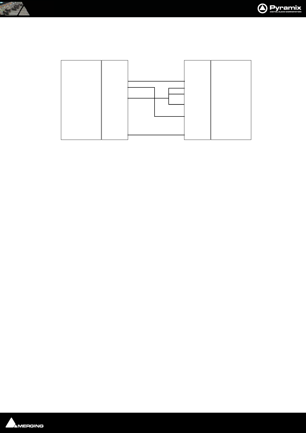
Appendices : Appendix VI 9 - Pin connection 29 - 574
Direct Cable for a Slave Device
This pinout should work in most of the cases where Pyramix is controlling a Slave device.
The RS422 standard is not implemented consistently on all devices, so the cable pinouts may differ. Please consult
your controller's user guide for appropriate connector cabling.
Function
GND
Pin #
1
2
3
4
5
6
7
8
9
Rcv -
Xmit +
GND
N.C.
GND
Rcv +
Xmit -
GND
Shield
Function
DCD/RLSD
Rx
Tx
DTR
GND
DSR
RTS
CTS
RI
Shield
Pin #
1
2
3
4
5
6
7
8
9
RS422 Male (or Female) DB9RS232 Female DB9
RS422 DIrect Cable for Slave Device pinouts
Appendices : Appendix VII - Mykerinos Latencies 29 - 575
Appendix VII - Mykerinos Latencies
FX IN
FX IN
FX IN
FX IN
FX IN
FX IN
FX IN
FX IN
FX IN
FX IN
MIX/FX OUT
MIX/FX OUT
MIX
MIX/FX OUT
MIX
FX OUT
FX OUT
2.7 ms
5.3 ms
5.3 ms
8 ms
5.3 ms
8 ms
128 samples = 128/(sampling rate) 128 samples = 128/(sampling rate) Latency at 48kHz
128 samples = 128/(sampling rate)

Appendices : Appendix IIX - Network Connections 29 - 576
Appendix IIX - Network Connections
Note: Direct Ethernet connection of Workstations (i.e.: 1x VCube and 1x Pyramix)
with standard factory default DHCP settings and without a proper DHCP server avail-
able in the network may lead to unexpected behaviour, E.g. software or system
freezes. (ISIS controller will default to a fixed IP address, if no DHCP server is avail-
able).
At all times proper, individual, TCP-IP addresses for each machine, assigned either
automatically (DHCP, if available) or manually (Fixed IP) are required, as described
below.
This caution is not relevant for machines operating without network connection.
Ethernet Connection & Settings
1. Create an Ethernet connection between the machines, via an Ethernet switch or using a direct, cross-wired,
Ethernet cable. (100Mbit for Sync/Control, 1000Mbit for file sharing recommended)
2. If, on your existing network, an Admin DHCP server is giving TCP/IP addresses to all connected clients, leave
all Pyramix, Isis and VCube machines with the default "DHCP" settings ("Obtain IP address automatically" in
the Local Area Connection Properties / Internet Protocol (TCP/IP) properties. (If you are connected to an exist-
ing network with no active DHCP server, please contact the (human) server administrator to obtain a range of
available IP address from him, and enter these as shown below).
3. If no admin DHCP server is available, manually give each of your machines a unique TCP/IP number, in the
Local Area Connection Properties / Internet Protocol (TCP/IP) properties. Typically, IP addresses can be,
respectively: 192.168.0.3 (PMX) 192.168.0.4 (VCube) and 192.168.0.5 (Isis), with a common Subnet mask being
255.255.255.0. No default gateway is necessary.
Set-up for Pyramix & VCube in: Control Panel > Network Connections > Local Area Connection > Proper-
ties / Internet Protocol TCP/IP / Properties.
Set-up for Isis: Press STOP key for 5 seconds during power up. Set-up address with left/right cursor and Track
keys 1 to 10, then Set key. See also ISIS User Manual page 14.
Fixed IP address range, examples:
*Use an address from column A or B, then stick to the selected range for all machines connected on a single
network.
Set subnet mask to 255.255.255.0
Checking IP Configuration
To check the IP Configuration of the machine you are working on do the following:
Choice A* Choice B* Typical use
192.168.0.1 10.0.0.1 Usually reserved (for Gateway or Server)
192.168.0.2 10.0.0.2 Usually reserved
192.168.0.3 10.0.0.3 Pyramix A
192.168.0.4 10.0.0.4 VCube A
192.168.0.5 10.0.0.5 ISIS A
192.168.0.6 10.0.0.6 Pyramix B
192.168.0.7 10.0.0.7 VCube B
192.168.0.8 10.0.0.8 ISIS B
192.168.0.9 10.0.0.9 Pyramix C
etc. etc. Increase only rightmost number (up to 254)
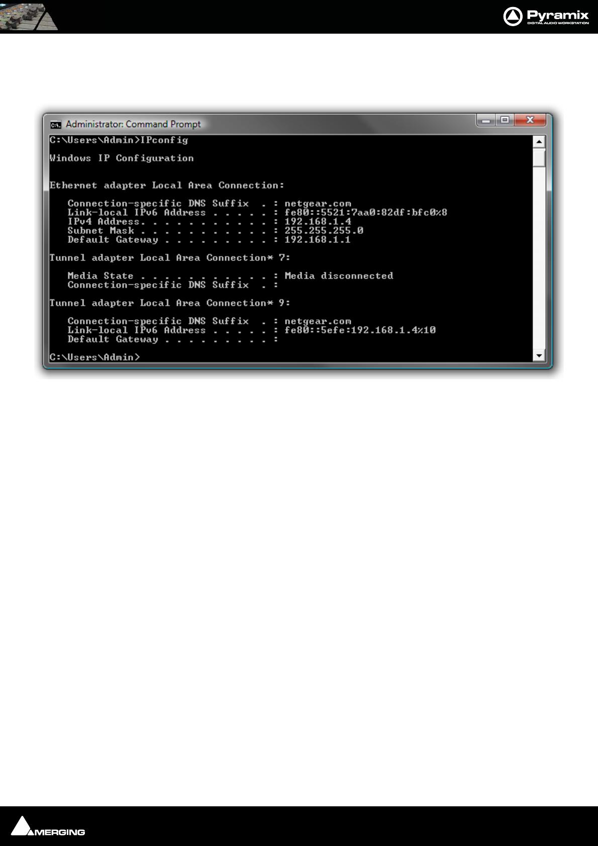
Appendices : Appendix IIX - Network Connections 29 - 577
Open a Command Prompt window. (Start > All programs > Accessories > Command Prompt) then type in
the following command:
IPCONFIG followed by Enter. The IP configuration for the machine will be shown like this:
Checking Network Connections
Using “Ping”
To check that the connections you have set up are operational do the following:
Open a Command Prompt window. (Start > All programs > Accessories > Command Prompt) then type in
the following command:
PING 192.168.0.3 (or whatever TCP/IP address is currently assigned to the workstation or device you wish to
check) followed by Enter then wait for the machine to reply. Repeat the process for all other connected work-
stations / controllers.
Using Windows Explorer
In a Windows Explorer window, right-click on My Network Places and choose Explore > Entire Network /
Microsoft Windows Network / Workgroup or Domain (choose whichever is appropriate) then verify that all
Pyramix and VCube workstations can search/see each other on the network, including shared hard drives and
folders. (Having all machines in the same “Workgroup” (default workgroup is “WORKGROUP”) helps.
Note: With Windows XP, it may take some time for the TCP/IP lists to be appropri-
ately updated to reflect the complete network topology on all machines. (Particu-
larly when additional computers are added to a large existing network). Please allow
for time for these operations to be properly carried out in the background. It may in
fact take something like 10 to 50 minutes depending on the size of the network. (In
certain situations, E.g. a small 2 machine peer-to-peer network, rebooting both
machines may speed up the process).
Synchronization with Virtual Transport
Open an authorized Virtual Transport, (versions MUST be identical version) on both machines and enable the
VT Network.
Command Prompt Window with IPCONFIG

Appendices : Appendix IIX - Network Connections 29 - 578
Create a VT Cluster by dragging a first machine from the right-hand column to the left-hand column, then,
drag a second or further machines onto the first one to finalize the cluster.
That's it, machines are now synchronized. However, in some situations you may find that the graphics in Virtual
Transport's Network page are not being updated properly and you might face difficulties dragging a machine
from the right-hand column to the left-hand column. If this occurs, please just sit back and relax, there is noth-
ing else you can do but wait till all the TCP/IP lists are updated at OS level, then all will be fine.
Nothing is wrong with the software, it just is a matter of taking and enjoying a short break while every network
list is being properly updated.
Appendices : Appendix IX - Pyramix iXML Implementation 29 - 579
Appendix IX - Pyramix iXML Implementation
Key: O = Supported X=Not Supported
VENDOR Merging Technologies DATE 21.03.2006
MODEL Pyramix Virtual Studio
V
ERSION 5
IXML MASTER TAG IXML SUB TAGS WRITTEN READ REMARKS
<PROJECT> X X
<SCENE> O O
<TAKE> O O
<TAPE> O O
<CIRCLED> X X
<FILE_UID> O O BWF like Originator Reference
<UBITS> X O
<NOTE> O O
<BEXT> O O
<USER>
X
X
<SPEED> X X
<SPEED> <NOTE> X X
<SPEED> <MASTER_SPEED> X X
<SPEED> <CURRENT_SPEED> X X
<SPEED> <TIMECODE_FLAG> X X
<SPEED> <TIMECODE_RATE>
X
X
<SYNC_POINT_LIST> X X
<SYNC_POINT> <SYNC_POINT_TYPE> X X
<SYNC_POINT> <SYNC_POINT_FUNCTION> X X
<SYNC_POINT> <SYNC_POINT_COMMENT> X X
<SYNC_POINT> <SYNC_POINT_LOW> X X
<SYNC_POINT> <SYNC_POINT_HIGH> X X
<SYNC_POINT> <SYNC_POINT_EVENT_DURATION>
X
X
<HISTORY> X X
<HISTORY> <ORIGINAL_FILENAME> X X
<HISTORY> <PARENT_FILENAME> X X
<HISTORY> <PARENT_UID>
X
X
<FILE_SET> O O
<FILE_SET> <TOTAL_FILES> O O
<FILE_SET> <FAMILY_UID> O O BWF like Originator Reference
<FILE_SET> <FAMILY_NAME> O O
<FILE_SET> <FILE_SET_INDEX> O O
<TRACK_LIST> O O
<TRACK_LIST> <TRACK_COUNT> O O
<TRACK> <CHANNEL_INDEX> O O
<TRACK> <INTERLEAVE_INDEX> O O
<TRACK> <NAME> O O
<TRACK> <FUNCTION> O O
XML Encoding UTF-8 O O
BWF Mono O O up to 128 channels
BWF Poly O O up to 128 channels
BWF Dual Poly O O up to 128 channels
NOTES:
USER MANUAL
www.merging.com/Pyramix
Index

Index : 30 - 581
Numerics
2,3 and 4 Point Edits 132
9-pin (Sony P2 protocol) 375
Color Framing 375
9-pin Configuration (Pyramix controlled by external device)
388
9-pin Control of External Machine 375
9-Pin Controller/Synchronizer Explained 376
9-Pin Machine Monitoring Options 536
A
AAF 310
About 312
Export 311
Fade Curves 312
Import 310
AAF Export Notes
312
Absolute Sources in EDL View 128
Absolute Sources in EDL view 527
Absolute Time 527
AC3 encoded files 344
Active Machine 383
ADAT Board Settings 486
ADAT Daughterboard 24
ADAT Daughterboard and XDTDM 552
ADAT Optical I/O 559
ADAT Optical output level 486
Add Bars 90
Adding Strips 177
Adding Tracks to a Selected Region 118
AES Board Settings 489
AES II Board Settings 487
AES II with SRC 559
AES-31 313
Akai DD / DR 312
AKAI disk import 314
Algorithmix 247
Allocating DSP 435
Allow chasing across midnight 521
Alternate Backup 515
Alternate Time Scale Bar 85
Angel Class Dynamic Processors 244
Angudion 228
AnguDion II 229
Apple Macintosh, File interchange 304
Apply default fade at fade creation 517
Archiving Projects 290
Arithmetic Timecode Entry 27
Arkamys 247
ASIO
Virtual 191
ASIO Bridge 191
Assumptions 23
Audio current sample rate & sync source 26
Audio Engine Drops Warning 547
Audio Syncronization 482
Audition after Nudge settings 516
Audition Play 40
Auto Cross-fade 27, 508, 517
By Default 119
Mode 118
Auto Deglitching 27, 115, 519
Auto Edit 382
Auto Gain Compensation 220
Auto Jog on move 94
Auto Return 91
Auto Silence Removal 127
Auto-chase 345, 383
Autoconforming 108
Auto-mapping 386
Automatic CD Markers 397
Automatic Delay Compensation 174, 280, 284, 294
Automation 259
Auto-Release Options 270
Auto-Write and Release Modes 262
Create a new Virtual Track 264
Hide Empty Tracks 264
Maintain to Next Interpolate 469
Menu Editing options 268
Off 96
Opening projects with existing automation 263
Play 96
TrackTrim 265
Write 96
Automation Editing Between Strips/Projects 269
Automation in editing and libraries 271
Automation Menu 468
Automation Modes
Auto-Write 260
Isolate 260
Read 260
Write 260
Automation Settings 270
Automation Track Versions 266
Auto-Monitoring 519
Auto-Mount Media 44, 467
AutoPunch Mode 103
AutoPunch Ready enable/disable 74
Auto-Release Options 270
Auto-Ripple 120
Auto-Saving 515
Auto-Select 154
Aux Send Bus Channels 162
Aux Send Buses 162
AUX Send Buses In-Place Panning 165
Aux Send Routing 164
Aux v SubGroup 142

Index : 30 - 582
B
Backward Compatibility 36
Bars & Beats Settings 340
Basic Strip 167
Bios 546
Bit-Depth 506
Board Info 565
Board Settings
AES 489
DUAL 489
Broadcast WAV file Tips 302
Burn-in Window 501
Burning a CD-R 416
Bus + - context menus 154
Bus Returns
Recording 175
Bus Tools 280
Bus Tools Sections 281
Buses
Aux Send 162
Mix 158
Multiple Mix 159
Repro button 157
Subgroup 162
Surround 159
Bussing Capabilities 568
Buttons 167
BWF 504
Bypass all Effects 220
C
CD
Album 398
Burning a CD-R 416
CD Text and optical drives 416
CD-Text 402
Convert Text Markers to CD 398
DDP Import 406
DDP Masters 417
DiscWrite 412
Target 414
Exporting Projects to CD Image Files 407
Generate CD Image / SACD Edited Master 408, 441
Ghost Track 405
Image File / SACD Edited Master Import 406
Importing a U-Matic tape 418
ISRC 402
Markers 397
Multiple CDs or versions in one Project 406
Red Book Compatible Masters 417
Red-Book Validation 406
Tab Window 398
Text fields 401
TOCs 417
Track Inspector 400
UPC/EAN 399
UPC/EAN code 407
CD Copy 417
CD Cue Sheet Compatibility 411
CD Cue Sheet Export 410
CD Import 315
Online database of track names 317
CD Player 404
CD Writer drivers 416
CD/SACD Tab Window Menus 401
CD-R First Steps 397
Cedar Audio Restoration Suite for Pyramix 248
Channel Direct Outputs 161
Chase 96
Settings 521
Chase Mode 382, 521
Hard 382, 521
Soft 382, 521
Vari 382, 521
Chase Synchronizer 376
Check Sync 101
Checking AC3 encoded files 344
Clean up Media after recording 507
Cleaning Up Project media 298
Clean-Up Media 44, 467
Click Track 339
Click-Track 339
Clip
Editing 113
Fade Handles 111
Gain 112
Head 111
Name 112
Sync Point 111
Tail 111
Trim Handle 111
Waveform Display 111
Clip Display Problems 549
Clip Fade Commands 119
Clip Information Only Fields 115
Media Offset 115
Original TimeCode 115
Peak Level 115
Clip Properties 113
Clip Selection 117
Clips
Default start time of captured Clips 527
Red 119
Clips and Compositions 110
Clips in a Composition 110
Clips Menu 453
Clips, Locating 424
CMX Autoconform 350
CMX EDL 318
CMX EDL Format 349
CMX EDL import 347
CMX EDLs 347

Index : 30 - 583
CMX Variants 348
Codecs 303
Collect Media to current Project Default Folder 44, 467
Composition Information 503
Composition Information and Settings Toolbar 92
Composition Library
Libraries
Composition 41
Compressed Audio File Formats 303
Compressed Audio Support 303
Configuration 478
Conforming and Reconforming 347
CMX Autoconform 350
CMX EDL Format 349
CMX EDL import Options 348
Common CMX Variants 348
Reconform from Change EDL 353
Reconforming Using Pyramix for Picture Change Detection
355
Reconforming Using VCube for Picture Change Detection 363
Reconforming With An Existing Change EDL 351
Relink to New Media 372
Consolidating Projects 291
Control by External Device 388
Control of External Device 375
Control Points 111
Controller
Sony 9 - Pin Protocol Configuration 541
Controller properties 540
Controllers 474
Automatically set offline 383
Controllers Online 96
Controllers Online/Offline 383
Controllers without touch sense 262
Conventions 23
Conversion processes 55
Convert 53
Convert Text Markers to CD 398
Converting Projects 292
Copy 123
Copy and Paste 117
Clip 118
Core 26
Core Load Indicators 32
Creating and Configuring Mixers 170
Creating Effects Snapshots 271
Creating tracks via paste 69, 438
Crossfade 119
Cue Sequencer 571
Cue Sequencer Control 572
Cue Sheet Printer 324
Cuepoint 313
Cursor, Playhead 91
Cursors & Marks Menu 459
Customizing the User Interface 328
Cut 123
Cut and Ripple 124
Cutter 121
D
DAR Reel/Segment 319
DAR WAV file import 64
Daughter Card Settings 485
DC Meter 238
DC Removal 60
DDP 319
DDP Import 406
DDP Masters 417
Debug Menu 550
Default Clock Source 101
Default decompression cache settings 531
Default Library 41
Default Menus 440
Default Mixer 185
Default Projects Location 530
Default Templates Location 530
Delay 167, 226
Delay Comp Mode 144
Delay Compensation 174, 280, 284
Delay Compensation Detail 175
Delay Compensation of External Inputs 176
Delay Compensation Policy 512
Delay vs Delay Compensation 176
Destination Wordlength 60
Detect Picture Change & Reconform 441
Determining Delay Compensation for External Effects Loops
177
Digitizing a Tape with Discontinuous TimeCode 342
Digitizing Sessions 106
Direct Monitoring Input Strips 157
Direct Output 167
Direct Outputs 144
Direct X Plug-ins 256
Disable Mix Down 511
Disable Punch in/out 511
Disable Skin 438
Discontinuous TimeCode 103, 339
DiscWrite 412
DiskWrite
U-Matic tape import 418
Display and Editing of Automation Data 263
Display Blocks 75
Display Envelope 75
Display Waveform 75
Dither 288
Noise shaping order 60
Dither Type 184
Dithering 61
Noise Shaping order 409
Dithering Window 184
Don’t Show too Large Media/Compositions 52

Index : 30 - 584
Don’t Snap 120
Drag and Drop Media Files 40
Dragging Clips into a Composition 117
Drivers 546
DSD Peak Filter 510
DSD Peak Values 571
DSD Project 570
DSD Projects I/O routing 498
DSDIFF Peak Values 571
DSP Allocation 434
DSP Allocation MassCore 437
DSP load and latency 26
DSP Power Saving 511
DSP Saving 433
DSP Time Saving 511
DST Encoder 61
DST Estimator 61
DUAL Board Settings 489
Dual Monitors 26
Dubbing Mode 337, 506
Duplicate Selection 121
DXD Mixing Project 570
DXD projects I/O routing 497
Dynamic Automation Modes 260
Dynamic Automation V Envelopes 259
Dynamic-Meter 231
Dynamics 224
E
Edit Commands 122
Edit Menu 443
Edit menu 443
Edit Modes Context Menu 120
Editing 110
Clip & Selection 113
Editing Automation data 268
Editing Modes 120
Editing Multitrack Recordings 343
EDL Tab Window 128
Effective Sampling Rate 481
Effective TC Frame Rate 481
Effective Video Frame Rate 481
Effects
Adding in Mix ! mode 179
on Stems 149
Removing, Copying or Moving VS3 Effects and VST Plug-Ins
180
Effects and Plug-in Automation 241
Effects and Plug-ins 178, 218
Effects Delay indication 177
Effects Rack 294
Effects Snapshots 241, 271
EMC 388
Eq, Comp/Limiter/Expander 273
EQ-X 242
Error Messages 546
Ethernet Connection & Settings 576
European Monitoring 519
Exit 441
Expand / Collapse 153
Export 324
Export to a File 289
Exporting Projects to CD Image Files 407
Extend Tracks 458
External Edit
Review Edit 382
External Effects 177, 257
External Effects Inserts 149
External Insert 182, 257
External Machine
Auto Edit 382
Fast Forward 381
Play 381
Preview Edit 382
Properties 535
Record button 382
Rewind 381
External machine
Stop 381
External Machine panel - Features 381
External Machines 345, 375
External Metering 200
External TC reader 500
F
F.FWD and REW nominal speed ratio 523
Fade Editor 134
Context Menu 136
Faders & Control Section 136
Parameters & Options Section 137
Settings 517
Waveform Color Change 136
Fade Editor Menu 464
Fade handles 111
Fade In 124
Fade library location 517
Fade Out 119
Fader 167
Fades and Crossfades
Automatic 27
Summary 27
Fast Forward 95, 380
Fast Speed Settings 523
File Format and Disk Limitations 101
File Formats 300
File Interchange 300
File Settings - Record 505
File Size Limitations 101, 300
Fill Selection 123
Film 24 to NTSC Sync 343
Film Feet Scale Bar 87

Index : 30 - 585
Filter 51
Final Cut Pro XML 319
Fit Selection 124
Fixed Cursor Settings 518
Fixed or Moving Playhead Cursor 91
FIXREEL 350
flac 303
Flanger 227
Flatten track numbers 507
Flywheel Inertia 522
Focus to Timeline 448
Foot Type 87
Format - file 504
Free Cursor while chasing 91
Freeze Mode 383
Using 345
Frequencies 481
Function Generator 240
G
Gain Window 112
Gain window 112
Gate colors 130
Generate new Media in the Project Media Folder 502
Generate New Media in their Original Folder 503
Ghost Effects and Plug-ins 180
Ghost Track 405
Glitch and Pops finder 296
Glitch finder 296
Global Dynamic Automation Modes 259
Global Libraries 41
Global Strip Channel Routing 163
GPI/O controller 393
GPI/O Input and Output Pin Configuration 395
GPI/O Remote types 395
Graphic Cards 546
Graphic EQ 223
Group Normalize 59
Group Recorded Clips 508
Grouping Clips 112
Groups 160
H
Hard Drive Size Limitations 102
Hardware Control Surfaces 386
Head to End 120
Head to Nearest 120
Headroom, Meter Settings 509
Help Menu 476
HUI 388
I
I/O Assignments 178
I/O Buses 172
I/O Capabilities 568
I/O Interfaces 487
I/O Status 550
I/O Status Window 101
Import 323
Importing a CMX EDL 318
Importing a DAR Reel or Segment 319
Importing Audio Files 104
improper application exi 549
Increment take number 507
In-Place Aux Panning Source 165
Input Assignment 167
Input Format 483
Input sources 101
Input Strip Mode 176
Input Strip Types 172
Input Strips 157, 177
Insert Silence 124
Inserts, External Effects 149
Internal / External Machine panels - Features 378
Internal and External machines links 534
Internal Buses 497
Internal Machine panel - Specific Features 380
Internal Return Buses 172
Introduction 20
IP address range 576
ISIS 386
ISRC 402
iXML 302
J
Jog / Shuttle 94
Jog Settings 94
Jog Shuttle
Auto Jog 94
Jog Speed ceiling 522
Jog Wheel Mode 384
Jog Wheel Sensitivity 522
Jog Wheel Settings 522
Jog-Wheel Editing 121
K
Keep in default library 507
Keep only current version while savin 270
Keeping Up To Date 546
Keyboard Shortcuts 330
Knobs 274
L
Length / Pitch, Changing 292
Level Meter 509
Levelizer 296
(Automatic) 296
Libraries 44

Index : 30 - 586
Closing 42
Default 41
Global 41
Offline / Reference 65
Project 41
Shelves 41
Shelves, deleting 42
Updating 67
User 41
Library Maintenance 42
Library Menus 48
Library, Tools 46
Limit versions to the number of Undo/Redo 270
Linking Functions of External and Internal Machines 376
Load Change EDL & Reconform 441
Locate 48, 424
Locating Clips 424
Locking Clips 112
Loop Play 96, 381
Loop Recording with simultaneous Playlist Creation 343
Loop Selection 124
LTC Generator 500
LTC reader 500
LTC sync 336
M
Machines function linking 534
Machines Menu 470
Macintosh File Interchange 304
Mackie Control 388
Macro Menu 475
Macros 332
MADI Board Settings 490
Managing Media Folders 61
Manual Digitizing 107
Markers 93
Auto Select Marker Before Cursor 461
Markers / Tracks Sync 94
MassCore 21
Core Load Indicators 32
Latency Modes 34
Memory 31
No of VST Cores 484
Overload Diagnosis and Cures 33
Windows Boot Choice 30
MassCore DSP Allocation 437
Master Automation Controls 259
Master Sync 482
Mastering Peak/Vu Meters 230
Mastering to CD-R 397
Maximum Delay Compensation 174
Media Browser 45
Menu 61
Media Folder
Browse... 62
Mount / Create 62
Permanent Mount 62
Quick Mount 62
Recursive 62
Reset List 62
Media Folder Menu 53
Media Information Only Fields 115
Author 116
File Creation Date 116
File Location 116
File Name 116
File Size 116
Format 115
Length 116
Name 115
Notes 116
Original TimeCode 116
Peak 116
Sample Rate 115
Scene 116
Take 116
Tape 116
Tracks 116
UBITS 116
Word Length 116
Media Management 40
Media Management and Library Fields 46
Media Management, tools 46
Media Manager Monitoring 200
Media Menu 43, 467
Media Offset 115
Media option 507
Media reconnection 350
Media Target Settings 40
Media Track Information Only Fields 116
File Name 116
Media Type 506
Menus
Automation 468
Clips 453
Cursors & Marks 459
Default 440
Edit 443
Fade Editor 464
Help 476
Machines 470
Controllers 474
Macro 475
Media 467
Project 440
Selection 463
Settings 475
Tracks 457
View 448
Window 475
Workspaces 469
Metadata 302
Meter Alignment level 509
Meter Bridge 211

Index : 30 - 587
Automation Fader Mode and Group Indicators 216
Configuration 213
Global Mute and Solo Indicators 213
Switch 211
Window 212
Meter Decay integration time 510
Meter Headroom setting 509
Meter Permanent Overload 510
Meter Permanent Peak 510
Meters 230
Alignment Tab Settings 233
DSD Settings Tab 235
Global Settings and Presets 232
Peak Hold and Overload Reset 169
Priority Settings Tab 235
Scale Tab Settings 234
Strip 169
Timing Tab Settings 233
Metronome 339
Metronome Settings... 90, 341
MIDI Files Import / Export 89, 341
Mix ! 153
Mix Bus 158
Mixdown - Disable 433
Mixdown - non real-time 290
Mixer
Bus Path Colors 155
Configure
Strip and Bus operations 145
Global Indicators / Buttons 156
Pages 142
Two Fader Row Display 156
Mixer and Plug-in Snapshots 271
Mixer Components 157
Mixer Configuration Further Options 183
Mixer Configuration Summaries 144
Mixer Configure 177
Mixer Context Pop-up menu 183
Mixer error
Delay compensation 174
Mixer Pages 170
Mixer Presets 185
Mixer Settings 512
Mixer Snapshots 271
Recalling 271
Saving 271
Mixer Surround Components 186
Mixing Down Projects 289
Mixing/Monitoring/Aux Send and SubGroup Buses 157
Modulometer 239
Monitor
Adding an External Machine 201
Available Sets 197
Buses / Externals button 194
Dim Value 197
External Inputs 201
Max Volume 197
Output Patch 199
Reference Volume 198
Talkback 201
Talkback Page 203
Monitor ! 193
Monitor Configure page 196
Mono Mix 158
Motherboards 546
Mount Referenced Media 44, 467
Mounting Media Drives 104
Mounting Rules 53, 63
Mouse Modifier Keys 556
Mouse Scrubbing Settings 95, 522
MP3 303
MPEX3 298
MPEX3 Timestretch and pitch change 248
MS Encoder 228
MT ASIO Bridge 191
MTInterchange Import/Export 48
Multi-channel Audio Files 547
Multi-channel VST Plug-ins 251
Multiple CDs or versions in one Project 406
Multiple Mix Buses (Stems) 159
Multiple Stereo Mix 158
Multiple Surround Mix 159
Multi-track Editing 336
MXF 304
Mykerinos 432
Mykerinos Daughter Card Settings 485
N
Navigation 84
Network Adapters 546
Network Connections 576
Network Recording - setting if problematic 505
New Project 36
No Sound on Live Inputs 548
Noise Shaping 60, 184
Non Real-time Mixdown 290
Non-MassCore (Mykerinos mode) Multi-board hardware re-
strictions 569
Normalize 125
according to the selection peak 125
Nova 296
Nudge 25
Nudge settings 516
O
OASIS Protocol 390
Offline / Reference Libraries 65
Ogg Vorbis 303
OMF 320
Import Settings 320
Mounting Rules 321

Index : 30 - 588
Operating System 546
Optical Drive drivers 416
Optional Plug-ins 241
Original Timecode 115
orphaned media 42
Output assignment shown in orange 199
Output Metering Patch - External Meters 197
Output Mode 483
Overview 99
Overwrite 120
P
Parametric EQ 222
Paste 123
Paste & Place 123
Paste and Ripple 124
Paste Sync Point to Cursor 123
Paste Tail to Cursor 123
Paste to Cursor 123
Paste to Original TC 123
Paste to Selection 123
PCI Bus Too Slow 546
PDF (Probability Density Function) 184
Peak and Overload Hold Time 510
Peak level indicator 510
Peak Logger 189
Peak Meter in Track Header 75
Peak/Vu Meters 230
Peak-Meter 231
Pencil 297
Pencil Tool 297
Permanently Mounted Media Folders 530
Phase Invert 115
Phase-Oscillo 236
Ping 577
Place on new tracks 507
Placement Tool 128
Play 76, 95, 102, 380
Play Head Position 91
Play Special 471
Playback Buffer Meter 25
Playback Lookahead Buffer setting 519
Playback Stall indication 518
Playback Stalls Warning 547
Player / Recorder mode 433
Player/Recorder Mode 336, 511
Playhead Cursor 91
Playhead Cursor Options 91
Playlist 75
Playlists 508
Plug-in and Effects Automation 241
Plug-Ins
adding in Mix ! mode 179
Plug-ins
adding in Mixer Configure page 147
Ghost 180
VST 179
Plug-Ins and Effects 218
Plug-ins and Effects 178
Plug-ins Settings 513
PMF 301
Position/Speaker Control 187
Post Processing 507
POW-r 185
Pre/Post Roll Settings 518
Pre-Anticipation 280, 286
Process Plug-ins 294
Profiling Window 551
Program and Project Settings 478
Program Window 24
Project 515
Project Editing Panel 26
Project Interchange 306
Project Libraries 41
Project Management Panel 26
Project Media Folder 502
Project Menu 440
Project mounted Media Folders 503
Project Notes 298
Project Record Settings 75
Project Window 25
Project, New 36
Prompt for name after recording 103
Prosoniq 248
Prosoniq MPEX2 Properties 60
Prosoniq MPEX3 298
Prosoniq MPEX3 Properties 57
ProTools Interchange 322
Pull-Down 483
Pull-Up 483
Punch in / Punch Out - Disable 433
Pure Series plug-ins 245
PureNotes Denoiser 246
Pyramix audio file format 102
Pyramix Guides 22
Pyramix Virtual Studio Overview 24
Q
Query Database 317
Query Page 43
Quick Convert 54, 55
Quick Export 54
Quick Import 53
Quicktime 302
Quiet if creation failed 507
R
RAID 546

Index : 30 - 589
Real-time Sampling Rate Conversion 519
Reconform 351
Reconforming a Project 292
Reconforming to Original Media from Avid &/or OMF 341
Record Block Size 519
Record button 95, 380
Record File Settings 505
Record Mode
Safety 104
Record Name 103, 507
Record Punch In (Auto) 76, 103
Record Ready (Manual) 76, 102
Recording Audio into a Pyramix Virtual Studio Project 102
Recording Bus Returns 175
Recording from a Tape with Discontinuous TimeCode 103
Red Book 417
Redirect Timeline Play and shortcuts to Fade Editor 517
Region Selection 117
Regions 41
Rel. box 112
Relative TimeCode Entry 27
Relaunch After Improper Exit 549
Release time 532
Relink to New Media 372, 441
Remote Controllers
Strip Cloning 386
Remove 120
Remove and Ripple 120
Remove Bars 90
Removing Mixer Presets 185
Removing Strips 177
Rename Clips 455
Renaming Clips 114
Render only solo tracks 294
Rendering 293
Replace 16 bit with 24 bit 441
Replace Selection 123
Report Printer 323
Repro button 157
Request Size (Wave file playback) 506
Resolution 506
Reverse 54
Reverse Play 84
Rewind 95, 380
Rotary Controls 167
Routing Physical I/O to Logical I/O 494
Rules for cache file decompression 64
Rules for Wave files 64
Rules for Wave/BWF and AIFF files containing OMF informa-
tion 64
S
SACD Edited Master - Import 323
SACD Edited Master Import 406
SACD Functions 407
SACD Media Management Menu 61
SACD Production Guide 23
Safety Record 104, 472
Sample and TC Rate Warnings 481
Sample Rate Conversion 28, 104
Sample Rate Mismatch 110
Samplerate Converter Properties 56
Sampling Rate Mismatch 101
Save Fade 140
Save X Fade 139
Saving / Loading Mixer Presets 186
Scene & Take 504
Scopein 250
Scroll Wheel 98
Scrub
Analog Tape Mode 95
Middle Mouse button 94
Repeat Loop Mode 95
Scrub Audio Quality 523
Scrub Settings 523
Audio quality 95
Search 51
Search Library 51
Search Media 43, 467
Search Media Tool
Query Page 43
Search Results 44
Sel. box 112
Select Media NOT present on Project Default Folder 44, 467
Select Media present on Project Default Folder 44, 467
Select Offline Clips 44, 467
Select Online Clips 44, 467
Selecting a Clip 117
Selecting Automation Modes 260
Selecting, Copying and Moving Effects 148
Selection
Track Groups 81
Selection and Clip Modifiable Fields 114
Auto Deglitching 115
Comment 115
Level 115
Mute 115
Name 114
Phase Invert 115
Selection Menu 463
Selection Operations 116
Selection Tab Window 114
Selection, adjusting 121
Selection, moving 121
Selection, splitting 121
Selections and Region Selections 116
Set All ON/OFF 154
Set All to 1st Stem 154
Set Focus to the Timeline 448
Settings 478

Index : 30 - 590
Application 514
(File) Location(s) 530
Automation 531
General Settings 514
Keys 529
Time Stretch 532
TimeLine layout 526
Track Headers Layout 528
Hardware 480
MassCore 484
TimeCode 499
HDTDM / XDTDM / MassCore Routing 494
HDTDM routing 495
I/O Interfaces 485
MADI 490
MassCore routing 497
Mixer 509
DSP Power Saving 511
Level Meter 509
Mixer Settings 512
Plug-ins Settings 513
Project 502
Controller Mapping 508
General 502
Record 503
Remote Control
Controller 539
Machine 534
Virtual Transport 543
XDTDM routing 496
Settings Menu 475
Shelves 41
Shift Order 148
Show Automation Track Versions 266
Show CD Player 404
Show Distribution 143
Show Usage 48, 424
Show Used Media 44, 467
Shuttle 94
Shuttle Control 96
Shuttle sensitivity 522
Silent Chasing 521
Silent Jog - sensitivity 522
Skin 525
Slip Clip Mode 119
Slip Media Mode 118
Smoothing Filter 522
Snap to Original TimeCode 121
Snapshot 96
Snapshot Automation 259
Force Automation Point Insertion 259
Snapshot Range 96
Solera + 244
Sonic Solutions 323
Sony 9 - Pin connection 573
Sony PCM-1630 414
Import 418
sound effects libraries 67
Source - Destination Editing 130
Source - Destination environment 130
Source Names - FIXREEL 350
Speaker Delays 199
Speaker Sets 195
Special Modes 511
Splitting Clips 121
Splitting Clips and Regions 121
Status Bar 25
stem mixing 159
Stems 159
Input Strip routing 158
Moving Effects between Stems 149
Stereo Mix 158
Stereo Pan Law 512
Stereo Panners 168
Stereo Strips 167
Stop 95, 380
Storing and Recalling Mixer Presets 185
Storing New Mixer Presets 185
Stretch 124
Strip & Bus Types 161
Strip and Bus Tools 273
Automation mode switches 284
Display Options 273
Group assignment mode buttons 283
Linking Strip-Tools controls 282
Modules 273
Routing Button Matrix 282
Sections 274
Strip Cloning 386
Strip Meters 169
Characteristics 509
Peak Hold and Overload Reset 169
SubGroup Buses 162
Supported Controllers Table 386
Surround Components (Mixer) 186
Joystick Panner 186
LFE Level 186
Speaker Controls 186
Stereo Input Strips Surround Panner 186
Strip and Bus Tools 189
Surround Stem select 186
Surround Control 186
Surround Control window 187
Level Meter 188
Link 189
Stereo Surround Control 188
Surround Meter 188
Surround Panning Algorithm 187
Surround Meter 238
Surround Mix - 5.1 158

Index : 30 - 591
Surround Post-Processing 292
Surround Post-processing 249
Sync & Format Preset 480
Synchroniser 376
T
Tab Windows 425
Tail to Beginning 120
Tail to Nearest 121
Talkback 201
Example 203
Reset 208
Talk to All 208
Talkback Page 203
Target Settings 291, 503
Tascam Open TL 321
TASCAM TDIF I/O Option 562
TC Source 499
Templates, User 38
Time fit 249
Time Scale Bars 84
Time Scale Zoom and Pan 98
Time Stretch and Pitch Change for Film Applications 248
Time Stretch Tool
Settings 517
TimeCode Entry 27
TimeCode Frame rate and reference source 26
TimeCode Midnight 343
TimeCode midnight 521
TimeLine layout 526
TimeZone Properties 58
TOC 417
Toggle Stop/Record Safe 471
Tone Control 223
Toolbars and Menus 328
Toolbars Layout 328
Track and Mixer Muting 432
Track Column Fields 78
Always Visible 78
Background Color 79
Collapsed 78
Display Mode 78
Group 78
Hidden 78
Input Connection 78
Monitoring 78
Mute 78
Name 78
Record Ready 78
Recording Media Folder 79
Repro Connection 78
Show Automation 78
Show Peak-Meter 79
Size 79
Solo 78
Waveform Color 79
Track Group Column Fields 80
Auto Collapse 81
Auto Hide 81
Auto Mute 81
Auto Record Ready 81
Auto Solo 81
Collapsed 80
Collapsed Display 80
Exclusive Show 81
Free Markers 81
Free Zoom 81
Keep Cursor 81
Markers Locked 81
Name 80
No Selection 81
Show Scale 81
Type 80
Track Groups 80
Track Header Components 74
Track Height Zoom 98
Track Inspector, CD 400
Track Record Modes 76, 102
Track Types 71
Tracks 69
Changing Repro or Input connections 78
Creating via paste or drag and drop 69, 438
Making Settings Changes to Multiple Tracks 78
Tracks Menu 457
Tracks Tab pop-up 77
Tracks Tab window 77
Tracks, Adding 69
Tracks, Deleting 72
Transient response accelerator 522
Transport Control 84
TimeCode Registers 383
Transport Control Panel 97, 377
Controllers Section 383
Edit/Record In/Out 381
Transport Controls 95
Trim Handles 111
Trimmer 46
Select/de-select tracks for playback 47
Trimmer Menu 52
Troubleshooting 553
Two Fader Row Display 156
U
U-Matic Tape Import into DiskWrite 418
Undo / Redo 514
Undock Fade Editor when editing a fade 517
Unique filename extension 507
UPC/EAN 399, 407
Update waveform color with cursor position 517
Updating Libraries
Adding new files 67
Orphaned Entries 67

Index : 30 - 592
UpMix5 247
US Monitoring 519
User Libraries 41
User Templates 38
V
Varispeed 482, 483
VCube Options 544
Versioning 345
Video Clips 323, 324
Video Import Options 308
Video/TimeCode Synchronization 482
View Automation 74
View Menu 448
Vincent Burel 247
Virtual Multi-track 334
Virtual Tape Format 337
Virtual Tape Mode 337
Virtual Transport
General 543
VITC Generator 500
VITC Reader 500
VS3 Control Panel 563
Routing 567
Saving Settings 567
VS3 Effects
Common Components 219
VS3 Native Effects 179
VST
Ghost Plug-ins 255
Multi-channel plug-in routing 251
Multi-channel plug-ins 251
Plug-in Automated Control Values 254
Plug-in Automation 254
Plug-in Automation Mode 254
Plug-in Caption Bar 255
Plugin clicks 484
Plug-in Processing Delay Display 255
Plug-ins 179, 251
Plug-ins Display Order 252
Plugins Engine Latencies MassCore 484
Plug-ins On/Off and Bypass 254
Scanner 252
Support 251
VU-Meter 231
VU-Meter controls 232
W
Warnings 546, 547
WAV and BWF 301
Wave/BWF file Record Settings 506
Waveform
Generate WHILE/AFTER Recording or None 506
Waveform Display 111
Waveform Generator Utility 424
Window Menu 475
With Video Media 515
WMA 303
wma 303
Word Length 184
Wordlength Converter Properties 60
Wordlength Meter 241
Work Spaces 438
Workspaces 328
Workspaces Menu 469
X
X Fade 119
Xify 135
XML 324
Z
Zooming and Panning the Track display 98
