VFE2500 LINEAR MECHANICAL R
User Manual: VFE2500 LINEAR MECHANICAL r
Open the PDF directly: View PDF ![]() .
.
Page Count: 29

MOVFE 2500
LINEAR DOOR OPERATOR
MECHANICAL MANUAL
GAL CANADA
6500 Gottardo Court
Mississauga, Ontario
L5T 2A2 Canada
1 (416) 747-7967
1 (800) 446-4850
http://www.galcanada.com
M
LINEAR
2500-3071
I
FOREWORD
It is the intent of this manual to give the reader certain key points of information critical to the
proper installation of the door operator. It is not intended to give comprehensive installation
procedures nor does it cover the installation of door headers, track, hangers, etcetera.
It is hoped that the procedures presented in this manual will reduce the installation and
adjustment time and result in a smooth, long lasting door operation.
When properly installed, GAL door operators will give many years of trouble free service.
COMMENTS:
All GAL door operators are factory adjusted and tested for the actual job requirements.
When installed correctly, they may require minor adjustments to suit actual job
conditions.
IMPORTANT NOTES:
All equipment must be installed, adjusted, tested and maintained to comply with all
Federal, State/Provincial, and Local codes.
Kinetic Energy and Stall Force must be adjusted to comply with ASME, A17.1,
Rule 112.4/5, and CSA/B44, Rule 2.13.4/5.
Before mounting the operator, check that the car door is plumb, free and moves
easily without bind. Check the attached standard measurement sheets.
Install the operator according to the measurements supplied.
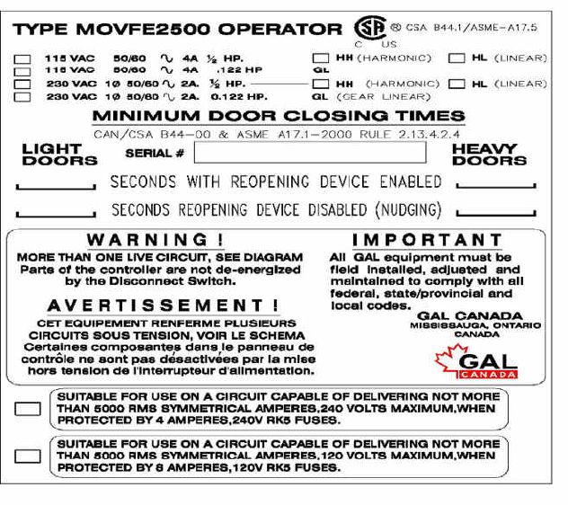
Contact GAL if the following label is missing from the door operator.
II
TABLE OF CONTENTS
Foreword
I
Comments & Important Notes
I
Table of Contents
II
ILLUSTRATIONS OF MOVFE2500 LINEAR DOOR OPERATORS
1
Left Hand Heavy Duty Linear Model
1
Right Hand Heavy Duty Linear Model
1
Center Parting Heavy Duty Linear Model
2
A Left Hand Light Duty Linear Model
2
DETERMINING THE HAND OF THE DOOR
3
Right Hand Door
3
Left Hand Door
3
MECHANICAL SETUP INSTRUCTIONS
4
KINETIC ENERGY, AND ASME A17.1 2000 FOR ELEVATOR DOOR SYSTEMS
8
Code Closing Distance / Time
8
Average Kinetic Energy (7.37 ft-lbs)
8
Actual (peak) Kinetic Energy (17ft-lbs)
8
Nudging Kinetic Energy (2.5 ft-lbs)
8
Non Standard Systems
8
2.13.4.2.4 Data Plate
8
2.13.4.2.1 Kinetic Energy
9
HEAVY DUTY LINEAR MODEL
MINIMUM CLOSING TIME FOR SINGLE SPEED S/O DOOR
10
MINIMUM CLOSING TIME FOR TWO SPEED S/O DOOR
11
MINIMUM CLOSING TIME FOR SINGLE SPEED C/P DOOR
12
MINIMUM CLOSING TIME FOR TWO SPEED C/P DOOR
13
LIGHT DUTY LINEAR MODEL
MINIMUM CLOSING TIME FOR SINGLE S/O DOOR
14
MINIMUM CLOSING TIME FOR TWO SPEED S/O DOOR
15
MINIMUM CLOSING TIME FOR SINGLE SPEED C/P DOOR
16
MINIMUM CLOSING TIME FOR TWO SPEED C/P DOOR
17

III
PARTS LIST
18
NOTES & COPYRIGHT
26
NOTES
1
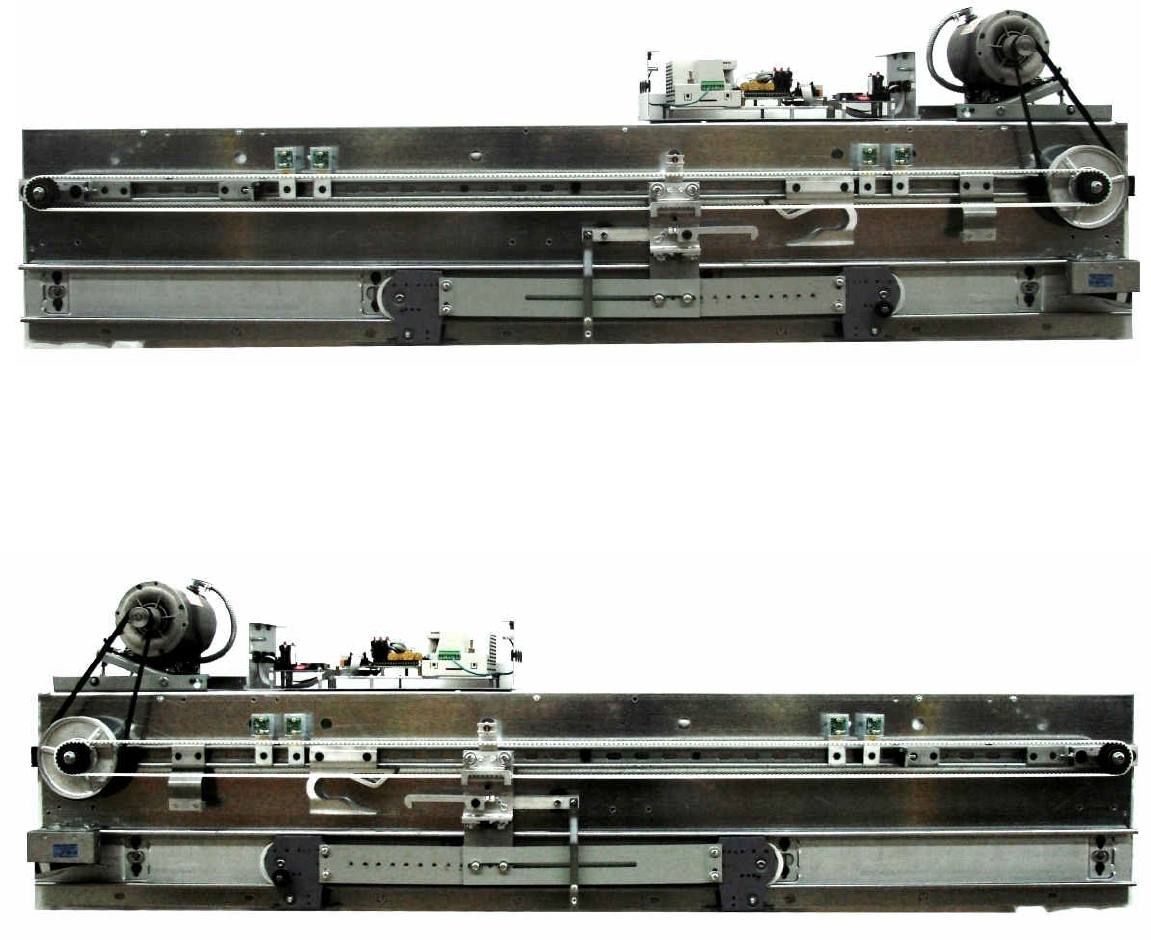
ILLUSTRATIONS OF THE MOVFE2500 LINEAR DOOR OPERATORS
MOVFE2500 linear door operator utilizes a ½ HP AC motor for the heavy duty models and 91W AC
geared motor for light duty models. The controller includes a closed-loop VVVF Drive, 3 basic hall-
effect sensor boards, 1 optional hall-effect sensor board for the narrower door, and an optional I/O
board for special jobs. The following illustrations show 3 available models for each type: Right hand,
Left hand and Center Parting.
RIGHT HAND HEAVY DUTY LINEAR MODEL
LEFT HAND HEAVY DUTY LINEAR MODEL
DOL
DOL
D
RRRRRR
DDDDD
AUX
AUX
DOL
DPM
DPM
DCLDCL
DPM
DCL
DCL
DPM
DPM
AUX
AUX
DOL
DOL
DPM
2
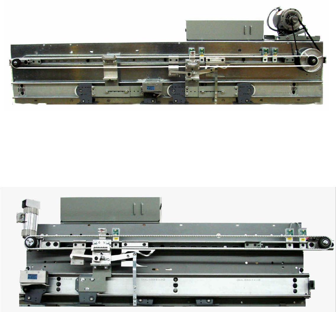
LEFT HAND 2 SPEED LIGHT DUTY LINEAR MODEL
CENTRE PARTING HEAVY DUTY LINEAR MODEL
DCL
DCL
DPM
DPM
AUX
AUX
DOL
DOL
DCL
DPM
AUX
DOL
3
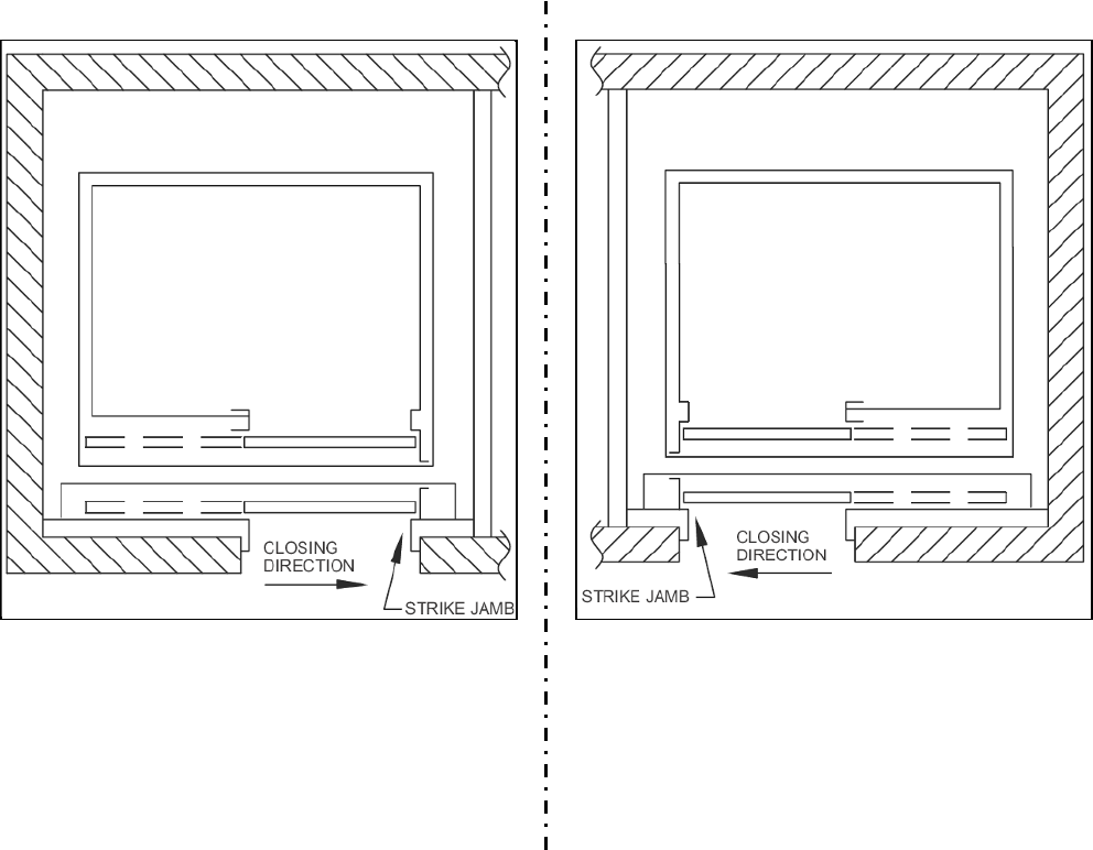
DETERMINING THE HAND OF THE DOOR
GAL door operators are available for Right hand doors, Left hand doors and Center Parting doors. To
determine the hand of the door, stand in the lobby facing the elevator door(s). If the door closes to the
Left, it is a Left hand door. If the door closes to the Right it is a Right hand door. The Left hand,
Center parting and Right hand operators are field interchangeable. Figures below illustrate the door
hand.
RIGHT HAND DOOR
LEFT HAND DOOR
4
MECHANICAL SETUP INSTRUCTIONS
Determine the door and hanger type of the system.
I. Side Opening (S/O), left or right hand, and single-piece hanger.
II. Side Opening (S/O), left or right hand, and two-piece hanger.
III. Center parting (C/P) door and a single piece hanger.
IV. Center parting (C/P) door and two piece hanger.
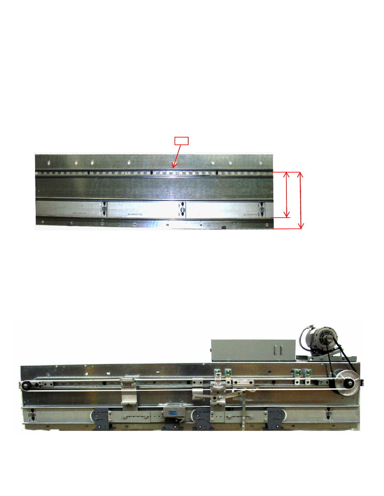
1. If the header has not yet been installed; mount the fixing strut # 19 onto the header before
installing the header assembly.
Fasten the header with five ½” bolts at a distance of 9¼” from the track rolling surface.
The fixing strut length should be equal to or longer than the header width, as shown in the
2. Check the distance from the door track centerline to the face of the header. Distance should be
1¼”. If the centerline of the track is farther than 1¼” from header, you need to shim the strut
by the difference. Misalignment would cause wear and noise to the belt.
11 1/4"
Figure 1
3. Install the car door hangers, if necessary.
Fig.1
9 1/4"
HEADER PLATE & TRACK
CENTRE PARTING
Center line
Top of track
19
DPM
DCL
AUX
DOL
DCL
DPM
AUX
DOL
5
4. Mount the universal plate # 1 or # 23 (C/P) with bend towards the door open side using four
5/16” bolts.
5. For the two-piece hanger system, mount the extension arm # 2 or # 24 (C/P) to the opposite
hanger and secure to the universal plate # 1 or # 23 with 5/16 bolts.
6. For the single-piece hanger system, mount the universal plate # 1 or # 23 directly to the hanger,
using at least two 5/16” bolts.
7. Install the belt bracket # 3 onto the top of the universal plate # 1 or # 23 with the clutch roller facing
the header. Use 3/8” bolts.
8. For the keeper clutch installation refer to Fig. 3 for S/O door, Or Fig. 4 for C/P doors. For the
standard clutch assemblies, item # 7 and hook are not used.
9. Insert the drive pulley # 18 and pulley # 4 at the extreme ends of the fixing strut or header plate.
For S/O doors, locate the motor control unit # 20 on the closing side, collinear with the header
plate. For the C/P doors, locate the motor control unit # 20 on the right side looking from the hall.
The two pulleys can be mounted reversed if the car top does not allow the space for the control
Box # 22 on the correct side.
10. Hang the motor belt # 19 loosely onto the large pulley.
11. Position the DCL, DPM, DOL, and AUX. hall-effect sensors. Header plate comes pre-drilled, with
7/8" holes, with plastic window bushings, Heyco # 2874, for best cable protection.
12. Feed the hall sensor cables to the back of the header. Later, these will be inserted into the
Signals transfer board inside the control box. # 22
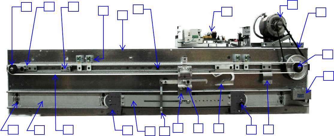
Figure 3
SINGLE SLIDE RH SHOWN
20
21
19
12
22
15
16
17
18
6
14
2
13
3
11
9
5
10
8
4
1
7
DCL
DPM
DOL
AUX
DOL
AUX
DPM
DCL
6
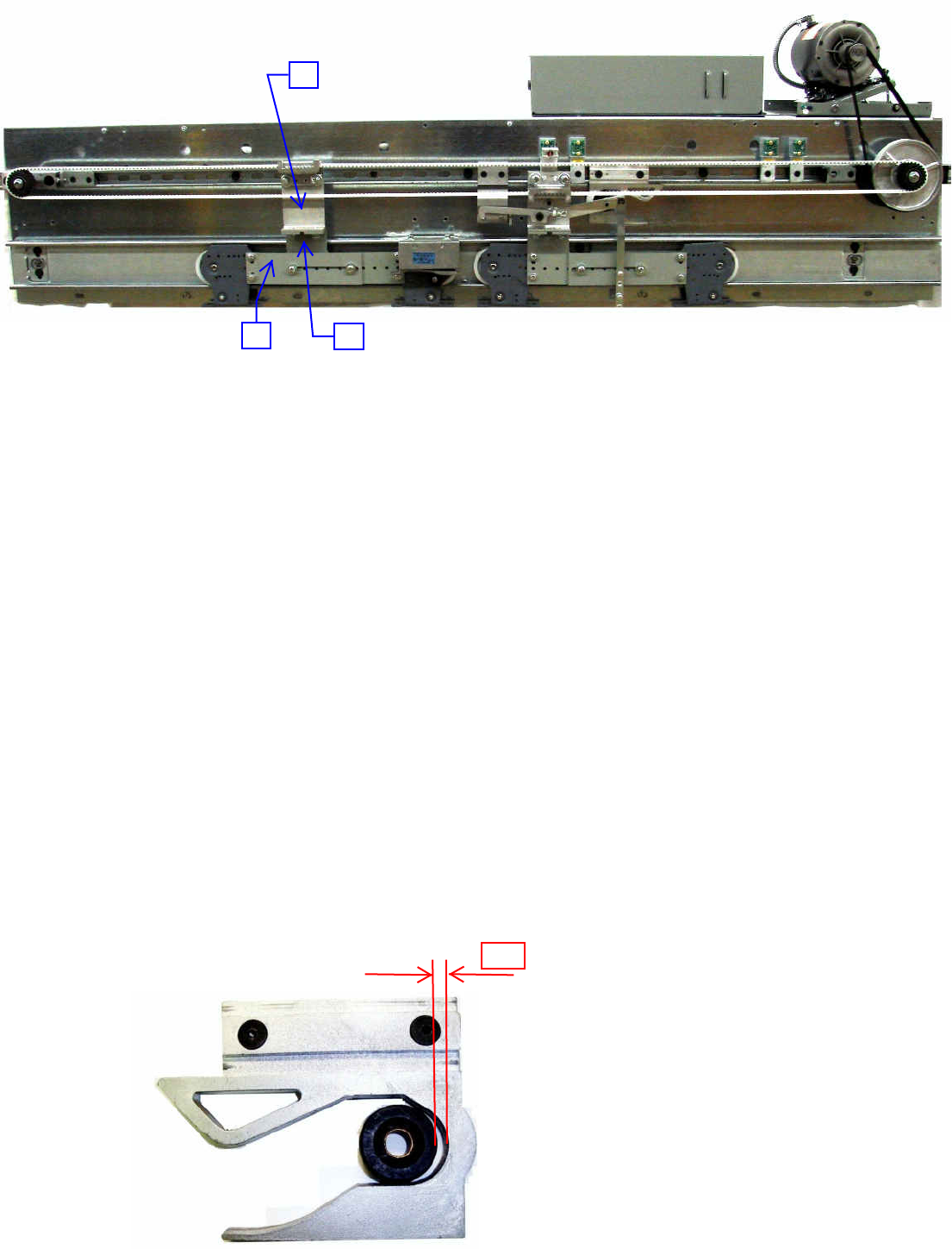
Figure 4
13. Mount the tension block # 5 to the fixing strut. Put the hex screw toward the take up pulley.
14. With the door in fully opened position, install the open door stop # 9 in contact with the lower belt
Bracket # 3. Firmly secure the stop.
15. Locate the gate switch assembly # 6 underneath large pulley at closed position.
For S/O doors refer to Fig. 3. For C/P doors refer to Fig. 4.The gate switch roller # 11 on the
Sheave bracket has to engage the flipper fully.
To install the gate switch on a single piece hanger you will have to drill an 11/32” hole in the
Hanger Tighten the gate switch assembly.
16. If the keeper style clutch is being used; mount the keeper bracket # 7 to the right for R.H. or
left, for L.H. (item # 3 on Fig. 3) Secure the keeper bracket assembly.
17. With the door in fully closed position, place the clutch cam # 8 as shown in Fig. 3. Adjust the
clutch cam so that the short release bar is fully retracted.
With the door slightly open, adjust the eccentric roller on the back of the belt bracket # 3 to keep
the roller in position. Use a 5/32” Allen key and 1/2” open-end wrench. Secure the clutch
assembly.
IMPORTANT: A minimum 1/4” space is required between the roller and the inside of the clutch
Cam #8.
CENTRE PARTING
23
25
24
1/4"
RIGHT HAND SHOWN
DPM
DCL
AUX
DOL
AUX
DOL
7
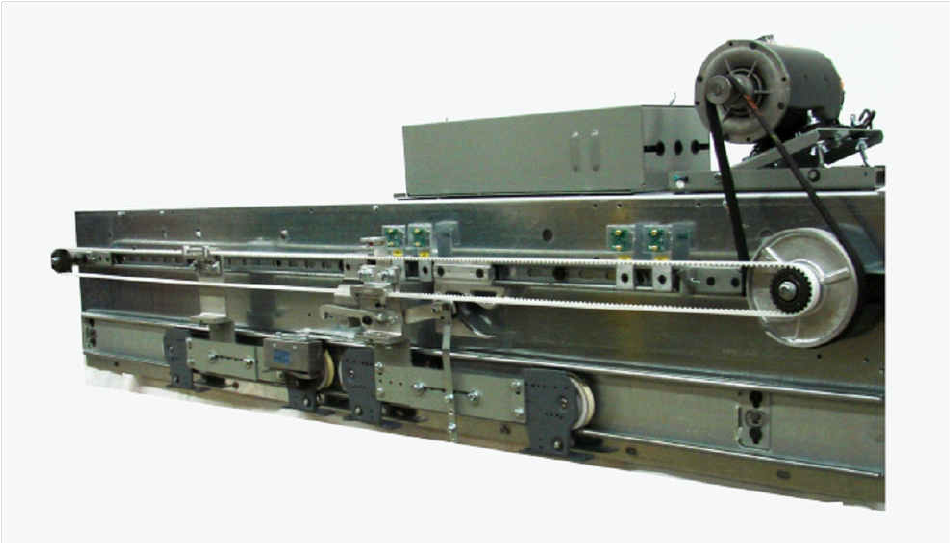
Figure 5
18. Install drive belt # 10 and clamp the two open ends equally in the lower belt bracket # 3, cutting
is required for desired length. C/P doors need clamping in upper belt bracket # 25, as well,
see Fig. 4. Move the doors from closed to open position and adjust the belt brackets so that belts
are parallel to each other looking from top.
19. Tension the drive belt with the tension block # 5 so that the upper and lower sides can be
Squeezed, together using moderate pressure. (A loose belt can jump teeth. An overly tightened
belt is noisy.)
20. Install the motor operator unit assembly # 20. It is extremely important that the motor axle is,
parallel to the drive pulley axle. Rubber pads are supplied to shim between, header
Angles, and drive unit box assembly. This will reduce noise and vibration.
21. Lower the motor mounting plate to its bottom position. Install the motor belt # 19
over the motor pulley and slide the motor control box into the correct position. Hand-tighten the
clamping bars. Correct the pulley alignment with a straight edge. This is the most critical part of
the installation to reduce belt wear, noise and vibration.
22. Tension the motor belt # 19 by means of adjusting the wing nuts on the motor mounting plate
equally. Do not over tighten the motor belt.
23. Secure the motor control box by tightening the clamps and doweling. Move the doors by hand to
verify proper operation.
24. Start the electrical set up.
CENTRE PARTING
DCL
DCL
DPM
DPM
AUXAUX
DOL
DOL
8
KINETIC ENERGY, AND ASME A17.1 2000 FOR ELEVATOR DOOR SYSTEMS
Requirement 2.13.4.2.4 of ASME A17.1 2000 stipulates that a data tag must be attached to the
door operator or car crosshead. If you are in a jurisdiction that has adopted the 2000 code, you
need to read and understand this requirement, and all of the related requirements. (see
attached)
The data tag is required to show:
- The minimum closing code time for the door system that will result in average kinetic
energy of less than 7.37 foot-pounds.
- The minimum code closing time for the door system, when in nudging, that will result
in average kinetic energy of less than 2.5 foot-pounds.
The attached data tables are designed to give GAL customers the information necessary to
comply with these requirements. If you use all GAL equipment, and follow GAL instructions,
these sheets will give you the minimum closing code time for all of the normal door
configurations, sizes, and operator models available.
Notes:
Code Closing Distance / Time
On side opening, the code distance starts 2” from the jamb and goes to 2” from full close.
(opening size – 4”) On center opening, code distance starts 1” from the jamb and goes to 1”
from full close. (still opening size – 4”) Times shown are minimums for the code closing
distance
Average Kinetic Energy (7.37 ft lbs)
This is the requirement for which the times shown on the data tables were calculated. The
rotational inertia of the motor and operator is included in these calculations. GAL’s calculations
include equipment rigidly connected thereto and accommodate all hangers, rollers, clutches,
closers, releases, and any normal reopening devices
Actual (peak) Kinetic Energy (17 ft lbs)
Using GAL equipment and following GAL instructions, you will not exceed the requirement for
actual (peak) KE.
Nudging Kinetic Energy (2.5 ft lbs)
If taking the minimum closing code time for your application and doubling it, you will have a
safe time to use for the requirement under nudging. (Note – this is a very conservative time, if
you want to close your door more quickly while in nudging, call GAL for an absolute minimum)
Non Standard Systems
A non-standard application, like three speed doors, or panels that are so heavy or light that
they fall outside the range shown on the data tables, you can call GAL and we will calculate
closing code time for your job.
The following paragraphs are excerpted from ASME 17.1 2000. They are provided here for
your convenience only.
9
2.13.4.2.4 Data Plate. A data plate conforming to 2.16.3.3 shall be attached to the
power door operator or to the car crosshead and shall contain the following information:
(a) minimum door closing time in seconds for the doors to travel the code zone distance
as specified in 2.13.4.2.2 corresponding to the kinetic energy limits specified in
2.13.4.2.1(b)(2);
(b) minimum door closing time in seconds for the doors to travel the Code zone distance
as specified in 2.13.4.2.2 corresponding to the kinetic energy limits specified in
2.13.4.2.1(c)(2), if applicable [see 2.27.3.1.6(e)];
(c) where heavier hoistway doors are used at certain floors, the minimum door closing
time in seconds corresponding to the kinetic energy limits specified in 2.13.4.2.1(b)(2)
and 2.13.4.2.1(c)(2), if applicable, for the corresponding floors shall be included on the
data plate.
2.13.4.2.1 Kinetic Energy…
(a) Where the hoistway door and the car door/gate are closed in such a manner that
stopping either one manually will stop both, the kinetic energy of the closing door
system shall be based upon the sum of the hoistway and the car door weights, as well
as all parts rigidly connected thereto, including the rotational inertia effects of the door
operator and the connecting transmission to the door panels.
(b)Where a reopening device conforming to 2.13.5 is used, the closing door system
shall conform to the following requirements.
(1) The kinetic energy computed for the actual closing speed at any point in the
Code zone distance defined by 2.13.4.2.2 shall not exceed 23 J (17 ft-lbf);
and
(2) The kinetic energy computed for the average closing speed as determined in
accordance with 2.13.4.2.2 shall not exceed 10 J (7.37 ft-lbf).
(c) Where a reopening device is not used, or has been rendered inoperative (see
2.13.5), the closing door system shall conform to the following requirements:
(1) The kinetic energy computed for the actual closing speed at any point in the
code zone distance defined by 2.13.4.2.2 shall not exceed 8 J (6 ft-lbf).
(2) The kinetic energy computed for the average closing speed within the code
zone distance (see 2.13.4.2.2), or in any exposed opening width, including
the last increment of door travel, shall not exceed 3.5 J (2.5 ft-lbf).
The following tables show the minimum closing code time for MOVFE2500 doors:
NOTE:
The term “Door Weight” in the tables refers to the combined weight of all doors, including all car
door (s) and all hoistway door(s) (of one floor only).
Also, note that if the weight of the hoistway door(s) varies by floor, different settings of the
code distance closing time must be used from the table.
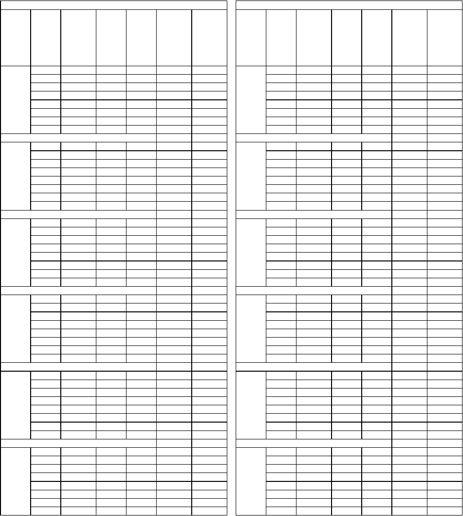
10
Heavy Duty Linear Operator
DOOR
WIDTH
(Inch)
Door
Weight
(lbs)
Equipment
Weight
(lbs)
Code
Distance
(Inch)
Average
Kinetic
Energy
(ft-lbs)
Minimum
Code Time
(seconds)
Minimum
Code Time
When Door
Protection
Disabled
(Nudging)
(seconds)
DOOR
WIDTH
(Inch)
Door
Weight
(lbs)
Equipment
Weight
(lbs)
Code
Distance
(Inch)
Average
Kinetic
Energy
(ft-lbs)
Minimum
Code Time
(seconds)
Minimum
Code Time
When Door
Protection
Disabled
(Nudging)
(seconds)
225 39 26 7.37 1.89 3.24 325 39 38 7.37 3.12 5.34
250 39 26 7.37 1.96 3.35 350 39 38 7.37 3.21 5.49
275 39 26 7.37 2.02 3.45 375 39 38 7.37 3.29 5.63
300 39 26 7.37 2.08 3.56 400 39 38 7.37 3.37 5.76
325 39 26 7.37 2.14 3.66 425 39 38 7.37 3.45 5.89
350 39 26 7.37 2.20 3.75 450 39 38 7.37 3.52 6.02
375 39 26 7.37 2.25 3.85 475 39 38 7.37 3.60 6.15
400 39 26 7.37 2.31 3.94 500 39 38 7.37 3.67 6.27
225 39 28 7.37 2.04 3.48 325 39 40 7.37 3.29 5.62
250 39 28 7.37 2.11 3.60 350 39 40 7.37 3.38 5.77
275 39 28 7.37 2.17 3.72 375 39 40 7.37 3.46 5.92
300 39 28 7.37 2.24 3.83 400 39 40 7.37 3.55 6.06
325 39 28 7.37 2.30 3.94 425 39 40 7.37 3.63 6.20
350 39 28 7.37 2.36 4.04 450 39 40 7.37 3.71 6.34
375 39 28 7.37 2.42 4.14 475 39 40 7.37 3.79 6.47
400 39 28 7.37 2.48 4.24 500 39 40 7.37 3.86 6.60
250 39 30 7.37 2.26 3.86 350 39 42 7.37 3.55 6.06
275 39 30 7.37 2.33 3.98 375 39 42 7.37 3.64 6.22
300 39 30 7.37 2.40 4.10 400 39 42 7.37 3.72 6.37
325 39 30 7.37 2.47 4.22 425 39 42 7.37 3.81 6.51
350 39 30 7.37 2.53 4.33 450 39 42 7.37 3.89 6.66
375 39 30 7.37 2.60 4.44 475 39 42 7.37 3.98 6.80
400 39 30 7.37 2.66 4.55 500 39 42 7.37 4.06 6.94
425 39 30 7.37 2.72 4.65 525 39 42 7.37 4.13 7.07
275 39 32 7.37 2.48 4.25 375 39 44 7.37 3.81 6.51
300 39 32 7.37 2.56 4.38 400 39 44 7.37 3.90 6.67
325 39 32 7.37 2.63 4.50 425 39 44 7.37 3.99 6.82
350 39 32 7.37 2.70 4.62 450 39 44 7.37 4.08 6.97
375 39 32 7.37 2.77 4.74 475 39 44 7.37 4.16 7.12
400 39 32 7.37 2.84 4.85 500 39 44 7.37 4.25 7.27
425 39 32 7.37 2.90 4.96 525 39 44 7.37 4.33 7.41
450 39 32 7.37 2.97 5.07 550 39 44 7.37 4.41 7.55
275 39 34 7.37 2.64 4.51 375 39 46 7.37 3.98 6.81
300 39 34 7.37 2.72 4.65 400 39 46 7.37 4.08 6.97
325 39 34 7.37 2.80 4.78 425 39 46 7.37 4.17 7.13
350 39 34 7.37 2.87 4.91 450 39 46 7.37 4.26 7.29
375 39 34 7.37 2.94 5.03 475 39 46 7.37 4.35 7.44
400 39 34 7.37 3.01 5.15 500 39 46 7.37 4.44 7.60
425 39 34 7.37 3.08 5.27 525 39 46 7.37 4.53 7.74
450 39 34 7.37 3.15 5.39 550 39 46 7.37 4.61 7.89
275 39 36 7.37 2.80 4.78 400 39 48 7.37 4.26 7.28
300 39 36 7.37 2.88 4.92 425 39 48 7.37 4.35 7.44
325 39 36 7.37 2.96 5.06 450 39 48 7.37 4.45 7.61
350 39 36 7.37 3.04 5.20 475 39 48 7.37 4.54 7.77
375 39 36 7.37 3.12 5.33 500 39 48 7.37 4.63 7.93
400 39 36 7.37 3.19 5.46 525 39 48 7.37 4.73 8.08
425 39 36 7.37 3.27 5.58 550 39 48 7.37 4.81 8.23
450 39 36 7.37 3.34 5.71 600 39 48 7.37 4.99 8.53
40"
52"
34"
46"
36"
48"
38"
50"
32"
44"
MINIMUM CLOSING TIME FOR SINGLE SPEED S/O DOOR
SINGLE SPEED SLIDING DOOR
SINGLE SPEED SLIDING DOOR
30"
42"
11
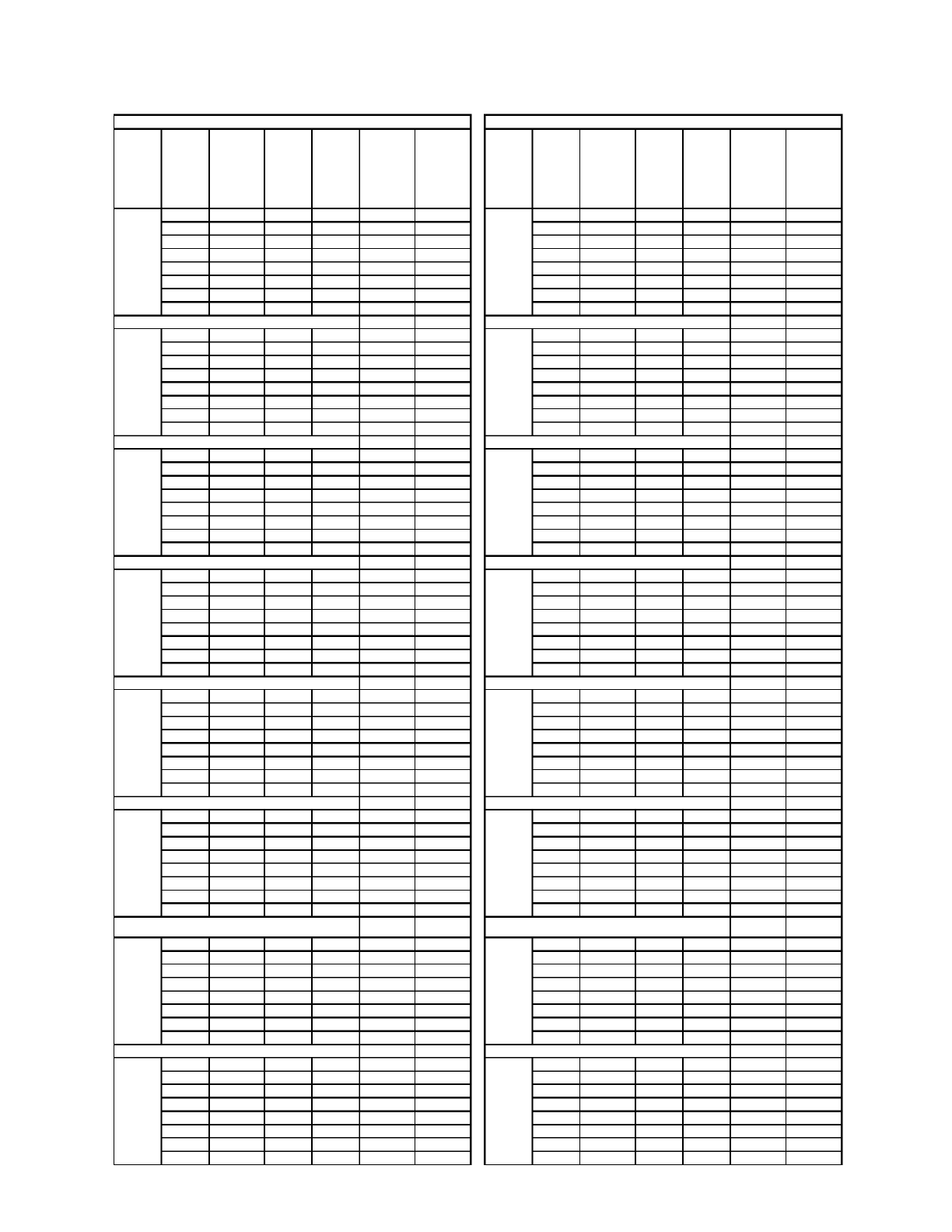
Heavy Duty Linear Operator
DOOR
WIDTH
(Inch)
Door
Weight
(lbs)
Equipment
Weight
(lbs)
Code
Distance
(Inch)
Average
Kinetic
Energy
(ft-lbs)
Minimum
Code Time
(seconds)
Minimum
Code Time
When Door
Protection
Disabled
(Nudging)
(seconds)
DOOR
WIDTH
(Inch)
Door
Weight
(lbs)
Equipment
Weight (lbs)
Code
Distance
(Inch)
Average
Kinetic
Energy
(ft-lbs)
Minimum
Code Time
(seconds)
Minimum
Code Time
When Door
Protection
Disabled
(Nudging)
(seconds)
225 50 26 7.37 1.69 2.89 350 50 42 7.37 3.08 5.26
250 50 26 7.37 1.73 2.97 375 50 42 7.37 3.14 5.37
275 50 26 7.37 1.78 3.04 400 50 42 7.37 3.21 5.48
300 50 26 7.37 1.82 3.12 425 50 42 7.37 3.27 5.59
325 50 26 7.37 1.86 3.19 450 50 42 7.37 3.33 5.69
350 50 26 7.37 1.90 3.26 475 50 42 7.37 3.39 5.80
375 50 26 7.37 1.94 3.33 500 50 42 7.37 3.45 5.90
400 50 26 7.37 1.98 3.39 525 50 42 7.37 3.51 6.00
225 50 28 7.37 1.82 3.11 375 50 44 7.37 3.29 5.63
250 50 28 7.37 1.87 3.19 400 50 44 7.37 3.36 5.74
275 50 28 7.37 1.92 3.28 425 50 44 7.37 3.42 5.85
300 50 28 7.37 1.96 3.35 450 50 44 7.37 3.49 5.96
325 50 28 7.37 2.01 3.43 475 50 44 7.37 3.55 6.07
350 50 28 7.37 2.05 3.51 500 50 44 7.37 3.61 6.18
375 50 28 7.37 2.09 3.58 525 50 44 7.37 3.67 6.28
400 50 28 7.37 2.14 3.65 550 50 44 7.37 3.73 6.38
250 50 30 7.37 2.00 3.42 375 50 46 7.37 3.44 5.88
275 50 30 7.37 2.05 3.51 400 50 46 7.37 3.51 6.00
300 50 30 7.37 2.10 3.59 425 50 46 7.37 3.58 6.12
325 50 30 7.37 2.15 3.68 450 50 46 7.37 3.65 6.23
350 50 30 7.37 2.20 3.76 475 50 46 7.37 3.71 6.35
375 50 30 7.37 2.24 3.84 500 50 46 7.37 3.78 6.46
400 50 30 7.37 2.29 3.92 525 50 46 7.37 3.84 6.57
425 50 30 7.37 2.33 3.99 550 50 46 7.37 3.90 6.67
275 50 32 7.37 2.19 3.74 400 50 48 7.37 3.66 6.26
300 50 32 7.37 2.24 3.83 425 50 48 7.37 3.73 6.39
325 50 32 7.37 2.29 3.92 450 50 48 7.37 3.80 6.51
350 50 32 7.37 2.34 4.01 475 50 48 7.37 3.87 6.62
375 50 32 7.37 2.39 4.09 500 50 48 7.37 3.94 6.74
400 50 32 7.37 2.44 4.18 525 50 48 7.37 4.01 6.85
425 50 32 7.37 2.49 4.26 550 50 48 7.37 4.07 6.96
450 50 32 7.37 2.54 4.34 575 50 48 7.37 4.14 7.07
275 50 34 7.37 2.33 3.98 400 50 50 7.37 3.82 6.53
300 50 34 7.37 2.38 4.07 425 50 50 7.37 3.89 6.65
325 50 34 7.37 2.44 4.17 450 50 50 7.37 3.96 6.78
350 50 34 7.37 2.49 4.26 475 50 50 7.37 4.03 6.90
375 50 34 7.37 2.54 4.35 500 50 50 7.37 4.10 7.02
400 50 34 7.37 2.59 4.44 525 50 50 7.37 4.17 7.14
425 50 34 7.37 2.65 4.52 550 50 50 7.37 4.24 7.25
450 50 34 7.37 2.69 4.61 575 50 50 7.37 4.31 7.37
300 50 36 7.37 2.52 4.31 400 50 52 7.37 3.97 6.79
325 50 36 7.37 2.58 4.41 425 50 52 7.37 4.05 6.92
350 50 36 7.37 2.64 4.51 450 50 52 7.37 4.12 7.05
375 50 36 7.37 2.69 4.60 475 50 52 7.37 4.20 7.17
400 50 36 7.37 2.75 4.70 500 50 52 7.37 4.27 7.30
425 50 36 7.37 2.80 4.79 525 50 52 7.37 4.34 7.42
450 50 36 7.37 2.85 4.88 550 50 52 7.37 4.41 7.54
475 50 36 7.37 2.90 4.97 575 50 52 7.37 4.48 7.66
325 50 38 7.37 2.72 4.66 425 50 54 7.37 4.20 7.18
350 50 38 7.37 2.78 4.76 450 50 54 7.37 4.28 7.32
375 50 38 7.37 2.84 4.86 475 50 54 7.37 4.36 7.45
400 50 38 7.37 2.90 4.96 500 50 54 7.37 4.43 7.58
425 50 38 7.37 2.96 5.06 525 50 54 7.37 4.51 7.71
450 50 38 7.37 3.01 5.15 550 50 54 7.37 4.58 7.83
475 50 38 7.37 3.07 5.24 575 50 54 7.37 4.65 7.96
500 50 38 7.37 3.12 5.33 600 50 54 7.37 4.72 8.08
325 50 40 7.37 2.87 4.90 450 50 55 7.37 4.36 7.45
350 50 40 7.37 2.93 5.01 475 50 55 7.37 4.44 7.59
375 50 40 7.37 2.99 5.12 500 50 55 7.37 4.52 7.72
400 50 40 7.37 3.05 5.22 525 50 55 7.37 4.59 7.85
425 50 40 7.37 3.11 5.32 550 50 55 7.37 4.67 7.98
450 50 40 7.37 3.17 5.42 575 50 55 7.37 4.74 8.10
475 50 40 7.37 3.23 5.52 600 50 55 7.37 4.81 8.23
500 50 40 7.37 3.28 5.62 625 50 55 7.37 4.88 8.35
40"
56"
42"
58"
44"
59"
34"
50"
36"
52"
38"
54"
32"
48"
MINIMUM CLOSING TIME FOR TWO SPEED S/O DOOR
TWO SPEED SLIDING DOOR
TWO SPEED SLIDING DOOR
30"
46"
12
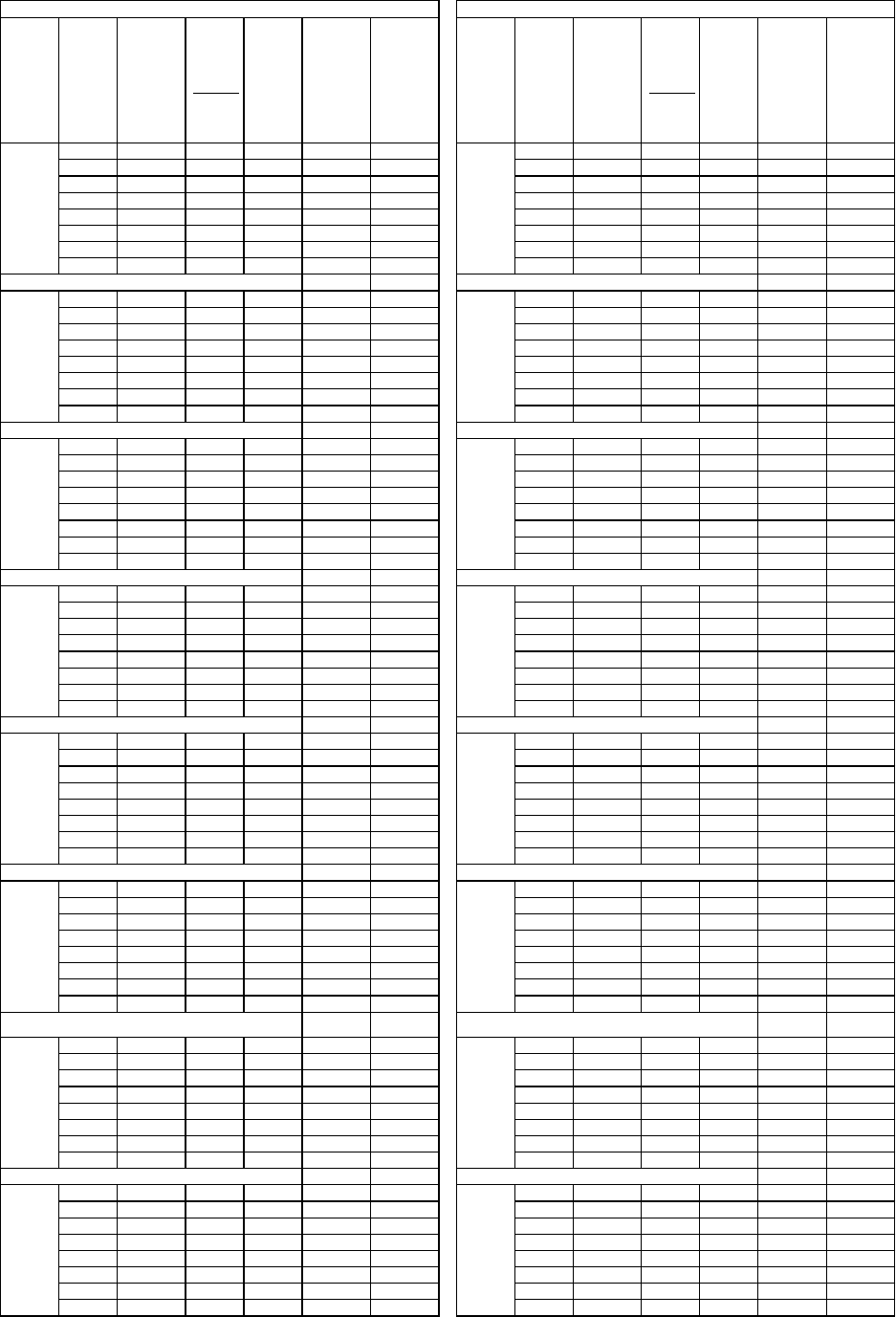
Heavy Duty Linear Operator
DOOR
WIDTH
(Inch)
Door
Weight
(lbs)
Equipment
Weight
(lbs)
Code
Distance
per side
(Inch)
Average
Kinetic
Energy
(ft-lbs)
Minimum
Code Time
(seconds)
Minimum
Code Time
When Door
Protection
Disabled
(Nudging)
(seconds)
DOOR
WIDTH
(Inch)
Door
Weight
(lbs)
Equipment
Weight (lbs)
Code
Distance
per side
(Inch)
Average
Kinetic
Energy
(ft-lbs)
Minimum
Code Time
(seconds)
Minimum
Code Time
When Door
Protection
Disabled
(Nudging)
(seconds)
225 50 13 7.37 0.96 1.64 350 50 21 7.37 1.79 3.07
250 50 13 7.37 0.99 1.70 375 50 21 7.37 1.84 3.14
275 50 13 7.37 1.02 1.75 400 50 21 7.37 1.88 3.22
300 50 13 7.37 1.05 1.80 425 50 21 7.37 1.92 3.29
325 50 13 7.37 1.08 1.85 450 50 21 7.37 1.96 3.36
350 50 13 7.37 1.11 1.90 475 50 21 7.37 2.01 3.43
375 50 13 7.37 1.14 1.94 500 50 21 7.37 2.05 3.50
400 50 13 7.37 1.16 1.99 525 50 21 7.37 2.08 3.56
225 50 14 7.37 1.03 1.77 375 50 22 7.37 1.92 3.29
250 50 14 7.37 1.07 1.83 400 50 22 7.37 1.97 3.37
275 50 14 7.37 1.10 1.88 425 50 22 7.37 2.01 3.45
300 50 14 7.37 1.13 1.94 450 50 22 7.37 2.06 3.52
325 50 14 7.37 1.16 1.99 475 50 22 7.37 2.10 3.59
350 50 14 7.37 1.20 2.04 500 50 22 7.37 2.14 3.66
375 50 14 7.37 1.22 2.09 525 50 22 7.37 2.18 3.73
400 50 14 7.37 1.25 2.14 550 50 22 7.37 2.22 3.80
250 50 15 7.37 1.14 1.96 375 50 23 7.37 2.01 3.44
275 50 15 7.37 1.18 2.02 400 50 23 7.37 2.06 3.52
300 50 15 7.37 1.21 2.08 425 50 23 7.37 2.11 3.60
325 50 15 7.37 1.25 2.13 450 50 23 7.37 2.15 3.68
350 50 15 7.37 1.28 2.19 475 50 23 7.37 2.20 3.76
375 50 15 7.37 1.31 2.24 500 50 23 7.37 2.24 3.83
400 50 15 7.37 1.34 2.30 525 50 23 7.37 2.28 3.90
425 50 15 7.37 1.37 2.35 550 50 23 7.37 2.32 3.98
275 50 16 7.37 1.26 2.15 400 50 24 7.37 2.15 3.68
300 50 16 7.37 1.30 2.22 425 50 24 7.37 2.20 3.76
325 50 16 7.37 1.33 2.28 450 50 24 7.37 2.25 3.84
350 50 16 7.37 1.37 2.34 475 50 24 7.37 2.29 3.92
375 50 16 7.37 1.40 2.39 500 50 24 7.37 2.34 4.00
400 50 16 7.37 1.43 2.45 525 50 24 7.37 2.38 4.07
425 50 16 7.37 1.47 2.51 550 50 24 7.37 2.43 4.15
450 50 16 7.37 1.50 2.56 575 50 24 7.37 2.47 4.22
275 50 17 7.37 1.34 2.29 400 50 25 7.37 2.24 3.83
300 50 17 7.37 1.38 2.35 425 50 25 7.37 2.29 3.92
325 50 17 7.37 1.41 2.42 450 50 25 7.37 2.34 4.00
350 50 17 7.37 1.45 2.48 475 50 25 7.37 2.39 4.08
375 50 17 7.37 1.49 2.54 500 50 25 7.37 2.43 4.16
400 50 17 7.37 1.52 2.60 525 50 25 7.37 2.48 4.24
425 50 17 7.37 1.56 2.66 550 50 25 7.37 2.53 4.32
450 50 17 7.37 1.59 2.72 575 50 25 7.37 2.57 4.40
300 50 18 7.37 1.46 2.49 400 50 26 7.37 2.33 3.98
325 50 18 7.37 1.50 2.56 425 50 26 7.37 2.38 4.07
350 50 18 7.37 1.54 2.63 450 50 26 7.37 2.43 4.16
375 50 18 7.37 1.57 2.69 475 50 26 7.37 2.48 4.25
400 50 18 7.37 1.61 2.76 500 50 26 7.37 2.53 4.33
425 50 18 7.37 1.65 2.82 525 50 26 7.37 2.58 4.41
450 50 18 7.37 1.68 2.88 550 50 26 7.37 2.63 4.49
475 50 18 7.37 1.72 2.94 575 50 26 7.37 2.67 4.57
325 50 19 7.37 1.58 2.70 425 50 27 7.37 2.47 4.23
350 50 19 7.37 1.62 2.77 450 50 27 7.37 2.53 4.32
375 50 19 7.37 1.66 2.84 475 50 27 7.37 2.58 4.41
400 50 19 7.37 1.70 2.91 500 50 27 7.37 2.63 4.50
425 50 19 7.37 1.74 2.98 525 50 27 7.37 2.68 4.58
450 50 19 7.37 1.78 3.04 550 50 27 7.37 2.73 4.67
475 50 19 7.37 1.81 3.10 575 50 27 7.37 2.78 4.75
500 50 19 7.37 1.85 3.16 600 50 27 7.37 2.83 4.83
325 50 20 7.37 1.66 2.85 450 50 27.5 7.37 2.57 4.40
350 50 20 7.37 1.71 2.92 475 50 27.5 7.37 2.63 4.49
375 50 20 7.37 1.75 2.99 500 50 27.5 7.37 2.68 4.58
400 50 20 7.37 1.79 3.06 525 50 27.5 7.37 2.73 4.67
425 50 20 7.37 1.83 3.13 550 50 27.5 7.37 2.78 4.75
450 50 20 7.37 1.87 3.20 575 50 27.5 7.37 2.83 4.84
475 50 20 7.37 1.91 3.27 600 50 27.5 7.37 2.88 4.92
500 50 20 7.37 1.95 3.33 625 50 27.5 7.37 2.93 5.00
40"
56"
42"
58"
44"
59"
34"
50"
36"
52"
38"
54"
32"
48"
MINIMUM CLOSING TIME FOR SINGLE SPEED C/P DOOR
SINGLE SPEED CENTER PARTING DOOR
SINGLE SPEED CENTER PARTING DOOR
30"
46"
13
Heavy Duty Linear Operator
DOOR
WIDTH
(Inch)
Door
Weight
(lbs)
Equipment
Weight
(lbs)
Code
Distance
per side
(Inch)
Average
Kinetic
Energy
(ft-lbs)
Minimum
Code Time
(seconds)
Minimum
Code Time
When Door
Protection
Disabled
(Nudging)
(seconds)
DOOR
WIDTH
(Inch)
Door
Weight
(lbs)
Equipment
Weight
(lbs)
Code
Distance
per side
(Inch)
Average
Kinetic
Energy
(ft-lbs)
Minimum
Code Time
(seconds)
Minimum
Code Time
When Door
Protection
Disabled
(Nudging)
(seconds)
275 84 16 7.37 1.15 1.97 375 84 23 7.37 1.80 3.07
300 84 16 7.37 1.18 2.01 400 84 23 7.37 1.83 3.13
325 84 16 7.37 1.20 2.05 425 84 23 7.37 1.86 3.18
350 84 16 7.37 1.23 2.10 450 84 23 7.37 1.89 3.24
375 84 16 7.37 1.25 2.14 475 84 23 7.37 1.93 3.29
400 84 16 7.37 1.27 2.18 500 84 23 7.37 1.96 3.35
425 84 16 7.37 1.30 2.21 525 84 23 7.37 1.99 3.40
450 84 16 7.37 1.32 2.25 550 84 23 7.37 2.02 3.45
275 84 17 7.37 1.22 2.09 400 84 24 7.37 1.91 3.26
300 84 17 7.37 1.25 2.14 425 84 24 7.37 1.94 3.32
325 84 17 7.37 1.28 2.18 450 84 24 7.37 1.98 3.38
350 84 17 7.37 1.30 2.23 475 84 24 7.37 2.01 3.44
375 84 17 7.37 1.33 2.27 500 84 24 7.37 2.04 3.49
400 84 17 7.37 1.35 2.31 525 84 24 7.37 2.07 3.55
425 84 17 7.37 1.38 2.35 550 84 24 7.37 2.11 3.60
450 84 17 7.37 1.40 2.39 575 84 24 7.37 2.14 3.65
300 84 18 7.37 1.32 2.26 425 84 25 7.37 2.02 3.46
325 84 18 7.37 1.35 2.31 450 84 25 7.37 2.06 3.52
350 84 18 7.37 1.38 2.36 475 84 25 7.37 2.09 3.58
375 84 18 7.37 1.41 2.40 500 84 25 7.37 2.13 3.64
400 84 18 7.37 1.43 2.45 525 84 25 7.37 2.16 3.69
425 84 18 7.37 1.46 2.49 550 84 25 7.37 2.19 3.75
450 84 18 7.37 1.48 2.53 575 84 25 7.37 2.23 3.81
475 84 18 7.37 1.51 2.58 600 84 25 7.37 2.26 3.86
325 84 19 7.37 1.43 2.44 425 84 26 7.37 2.10 3.60
350 84 19 7.37 1.46 2.49 450 84 26 7.37 2.14 3.66
375 84 19 7.37 1.48 2.54 475 84 26 7.37 2.18 3.72
400 84 19 7.37 1.51 2.58 500 84 26 7.37 2.21 3.78
425 84 19 7.37 1.54 2.63 525 84 26 7.37 2.25 3.84
450 84 19 7.37 1.56 2.68 550 84 26 7.37 2.28 3.90
475 84 19 7.37 1.59 2.72 575 84 26 7.37 2.31 3.96
500 84 19 7.37 1.62 2.76 600 84 26 7.37 2.35 4.01
325 84 20 7.37 1.50 2.57 450 84 27 7.37 2.22 3.80
350 84 20 7.37 1.53 2.62 475 84 27 7.37 2.26 3.87
375 84 20 7.37 1.56 2.67 500 84 27 7.37 2.30 3.93
400 84 20 7.37 1.59 2.72 525 84 27 7.37 2.33 3.99
425 84 20 7.37 1.62 2.77 550 84 27 7.37 2.37 4.05
450 84 20 7.37 1.65 2.82 575 84 27 7.37 2.40 4.11
475 84 20 7.37 1.67 2.86 600 84 27 7.37 2.44 4.17
500 84 20 7.37 1.70 2.91 625 84 27 7.37 2.47 4.23
350 84 21 7.37 1.61 2.75 450 84 27.5 7.37 2.26 3.87
375 84 21 7.37 1.64 2.80 475 84 27.5 7.37 2.30 3.94
400 84 21 7.37 1.67 2.86 500 84 27.5 7.37 2.34 4.00
425 84 21 7.37 1.70 2.91 525 84 27.5 7.37 2.38 4.06
450 84 21 7.37 1.73 2.96 550 84 27.5 7.37 2.41 4.13
475 84 21 7.37 1.76 3.01 575 84 27.5 7.37 2.45 4.19
500 84 21 7.37 1.79 3.05 600 84 27.5 7.37 2.48 4.25
525 84 21 7.37 1.81 3.10 625 84 27.5 7.37 2.52 4.31
375 84 22 7.37 1.72 2.94
400 84 22 7.37 1.75 2.99
425 84 22 7.37 1.78 3.04
450 84 22 7.37 1.81 3.10
475 84 22 7.37 1.84 3.15
500 84 22 7.37 1.87 3.20
525 84 22 7.37 1.90 3.25
550 84 22 7.37 1.93 3.30
46"
59"
48"
40"
54"
42"
56"
44"
58"
38"
52"
MINIMUM CLOSING TIME FOR TWO SPEED C/P DOOR
TWO SPEED CENTER PARTING DOOR
TWO SPEED CENTER PARTING DOOR
36"
50"
14
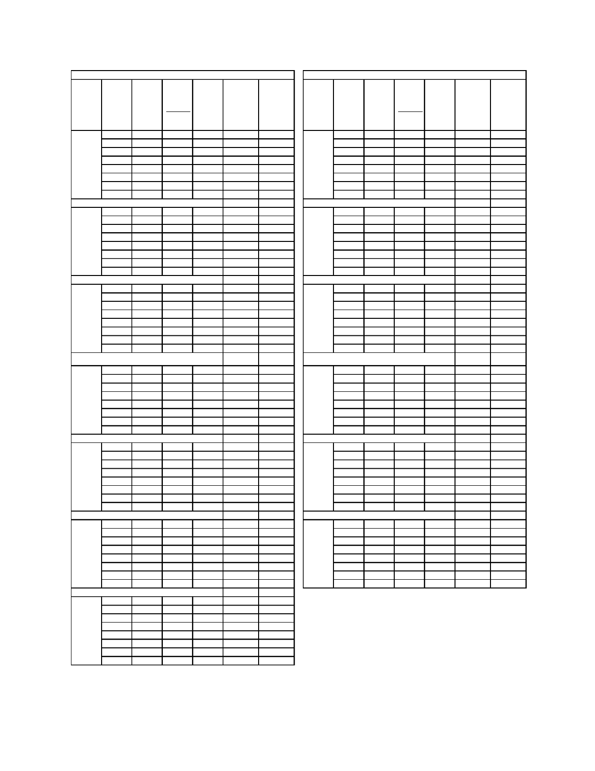
Light Duty Geared Linear Operator
DOOR
WIDTH
(Inch)
Door
Weight
(lbs)
Equipment
Weight
(lbs)
Code
Distance
(Inch)
Average
Kinetic
Energy
(ft-lbs)
Minimum
Code Time
(seconds)
Minimum
Code Time
When Door
Protection
Disabled
(Nudging)
(seconds)
DOOR
WIDTH
(Inch)
Door
Weight
(lbs)
Equipment
Weight
(lbs)
Code
Distance
(Inch)
Average
Kinetic
Energy
(ft-lbs)
Minimum
Code Time
(seconds)
Minimum
Code Time
When Door
Protection
Disabled
(Nudging)
(seconds)
225 39 26 7.37 1.67 2.85 325 39 38 7.37 2.84 4.85
250 39 26 7.37 1.74 2.97 350 39 38 7.37 2.93 5.01
275 39 26 7.37 1.81 3.09 375 39 38 7.37 3.02 5.16
300 39 26 7.37 1.88 3.21 400 39 38 7.37 3.10 5.31
325 39 26 7.37 1.94 3.32 425 39 38 7.37 3.19 5.45
350 39 26 7.37 2.00 3.43 450 39 38 7.37 3.27 5.59
375 39 26 7.37 2.06 3.53 475 39 38 7.37 3.35 5.73
400 39 26 7.37 2.12 3.63 500 39 38 7.37 3.43 5.86
225 39 28 7.37 1.80 3.07 325 39 40 7.37 2.99 5.11
250 39 28 7.37 1.87 3.20 350 39 40 7.37 3.08 5.27
275 39 28 7.37 1.95 3.33 375 39 40 7.37 3.18 5.43
300 39 28 7.37 2.02 3.46 400 39 40 7.37 3.27 5.59
325 39 28 7.37 2.09 3.58 425 39 40 7.37 3.36 5.74
350 39 28 7.37 2.16 3.69 450 39 40 7.37 3.44 5.89
375 39 28 7.37 2.22 3.80 475 39 40 7.37 3.53 6.03
400 39 28 7.37 2.29 3.91 500 39 40 7.37 3.61 6.17
250 39 30 7.37 2.01 3.43 350 39 42 7.37 3.24 5.54
275 39 30 7.37 2.09 3.57 375 39 42 7.37 3.34 5.70
300 39 30 7.37 2.17 3.70 400 39 42 7.37 3.43 5.87
325 39 30 7.37 2.24 3.83 425 39 42 7.37 3.52 6.03
350 39 30 7.37 2.31 3.95 450 39 42 7.37 3.61 6.18
375 39 30 7.37 2.38 4.07 475 39 42 7.37 3.70 6.33
400 39 30 7.37 2.45 4.19 500 39 42 7.37 3.79 6.48
425 39 30 7.37 2.52 4.30 525 39 42 7.37 3.87 6.62
275 39 32 7.37 2.23 3.81 375 39 44 7.37 3.49 5.98
300 39 32 7.37 2.31 3.95 400 39 44 7.37 3.59 6.15
325 39 32 7.37 2.39 4.09 425 39 44 7.37 3.69 6.31
350 39 32 7.37 2.47 4.22 450 39 44 7.37 3.79 6.47
375 39 32 7.37 2.54 4.35 475 39 44 7.37 3.88 6.63
400 39 32 7.37 2.61 4.47 500 39 44 7.37 3.97 6.79
425 39 32 7.37 2.68 4.59 525 39 44 7.37 4.06 6.94
450 39 32 7.37 2.75 4.71 550 39 44 7.37 4.14 7.09
275 39 34 7.37 2.37 4.05 375 39 46 7.37 3.65 6.25
300 39 34 7.37 2.45 4.20 400 39 46 7.37 3.76 6.43
325 39 34 7.37 2.54 4.34 425 39 46 7.37 3.86 6.60
350 39 34 7.37 2.62 4.48 450 39 46 7.37 3.96 6.77
375 39 34 7.37 2.70 4.62 475 39 46 7.37 4.06 6.93
400 39 34 7.37 2.78 4.75 500 39 46 7.37 4.15 7.10
425 39 34 7.37 2.85 4.88 525 39 46 7.37 4.24 7.25
450 39 34 7.37 2.93 5.00 550 39 46 7.37 4.33 7.41
275 39 36 7.37 2.51 4.28 400 39 48 7.37 3.92 6.71
300 39 36 7.37 2.60 4.44 425 39 48 7.37 4.03 6.89
325 39 36 7.37 2.69 4.60 450 39 48 7.37 4.13 7.06
350 39 36 7.37 2.77 4.75 475 39 48 7.37 4.23 7.24
375 39 36 7.37 2.86 4.89 500 39 48 7.37 4.33 7.40
400 39 36 7.37 2.94 5.03 525 39 48 7.37 4.43 7.57
425 39 36 7.37 3.02 5.17 550 39 48 7.37 4.52 7.73
450 39 36 7.37 3.10 5.30 600 39 48 7.37 4.70 8.04
40"
52"
34"
46"
36"
48"
38"
50"
32"
44"
MINIMUM CLOSING TIME FOR SINGLE SPEED S/O DOOR
SINGLE SPEED SLIDING DOOR
SINGLE SPEED SLIDING DOOR
30"
42"
16
Light Duty Geared Linear Operator
DOOR
WIDTH
(Inch)
Door
Weight
(lbs)
Equipment
Weight
(lbs)
Code
Distance
per side
(Inch)
Average
Kinetic
Energy
(ft-lbs)
Minimum
Code Time
(seconds)
Minimum
Code Time
When Door
Protection
Disabled
(Nudging)
(seconds)
DOOR
WIDTH
(Inch)
Door
Weight
(lbs)
Equipment
Weight
(lbs)
Code
Distance
per side
(Inch)
Average
Kinetic
Energy
(ft-lbs)
Minimum
Code Time
(seconds)
Minimum
Code Time
When Door
Protection
Disabled
(Nudging)
(seconds)
225 50 13 7.37 0.83 1.42 350 50 21 7.37 1.62 2.76
250 50 13 7.37 0.87 1.48 375 50 21 7.37 1.66 2.85
275 50 13 7.37 0.90 1.54 400 50 21 7.37 1.71 2.93
300 50 13 7.37 0.94 1.60 425 50 21 7.37 1.76 3.01
325 50 13 7.37 0.97 1.66 450 50 21 7.37 1.80 3.09
350 50 13 7.37 1.00 1.71 475 50 21 7.37 1.85 3.16
375 50 13 7.37 1.03 1.76 500 50 21 7.37 1.89 3.23
400 50 13 7.37 1.06 1.81 525 50 21 7.37 1.93 3.31
225 50 14 7.37 0.90 1.53 375 50 22 7.37 1.74 2.98
250 50 14 7.37 0.93 1.60 400 50 22 7.37 1.79 3.07
275 50 14 7.37 0.97 1.66 425 50 22 7.37 1.84 3.15
300 50 14 7.37 1.01 1.72 450 50 22 7.37 1.89 3.23
325 50 14 7.37 1.04 1.78 475 50 22 7.37 1.94 3.31
350 50 14 7.37 1.08 1.84 500 50 22 7.37 1.98 3.39
375 50 14 7.37 1.11 1.90 525 50 22 7.37 2.03 3.46
400 50 14 7.37 1.14 1.95 550 50 22 7.37 2.07 3.54
250 50 15 7.37 1.00 1.71 375 50 23 7.37 1.82 3.12
275 50 15 7.37 1.04 1.78 400 50 23 7.37 1.88 3.21
300 50 15 7.37 1.08 1.85 425 50 23 7.37 1.93 3.29
325 50 15 7.37 1.12 1.91 450 50 23 7.37 1.98 3.38
350 50 15 7.37 1.15 1.97 475 50 23 7.37 2.02 3.46
375 50 15 7.37 1.19 2.03 500 50 23 7.37 2.07 3.54
400 50 15 7.37 1.22 2.09 525 50 23 7.37 2.12 3.62
425 50 15 7.37 1.26 2.15 550 50 23 7.37 2.16 3.70
275 50 16 7.37 1.11 1.90 400 50 24 7.37 1.96 3.35
300 50 16 7.37 1.15 1.97 425 50 24 7.37 2.01 3.44
325 50 16 7.37 1.19 2.04 450 50 24 7.37 2.06 3.53
350 50 16 7.37 1.23 2.10 475 50 24 7.37 2.11 3.61
375 50 16 7.37 1.27 2.17 500 50 24 7.37 2.16 3.70
400 50 16 7.37 1.30 2.23 525 50 24 7.37 2.21 3.78
425 50 16 7.37 1.34 2.29 550 50 24 7.37 2.26 3.86
450 50 16 7.37 1.37 2.35 575 50 24 7.37 2.30 3.94
275 50 17 7.37 1.18 2.02 400 50 25 7.37 2.04 3.49
300 50 17 7.37 1.22 2.09 425 50 25 7.37 2.09 3.58
325 50 17 7.37 1.27 2.17 450 50 25 7.37 2.15 3.67
350 50 17 7.37 1.31 2.24 475 50 25 7.37 2.20 3.76
375 50 17 7.37 1.35 2.30 500 50 25 7.37 2.25 3.85
400 50 17 7.37 1.39 2.37 525 50 25 7.37 2.30 3.94
425 50 17 7.37 1.42 2.44 550 50 25 7.37 2.35 4.02
450 50 17 7.37 1.46 2.50 575 50 25 7.37 2.40 4.10
300 50 18 7.37 1.30 2.22 400 50 26 7.37 2.12 3.63
325 50 18 7.37 1.34 2.29 425 50 26 7.37 2.18 3.72
350 50 18 7.37 1.38 2.37 450 50 26 7.37 2.23 3.82
375 50 18 7.37 1.43 2.44 475 50 26 7.37 2.29 3.91
400 50 18 7.37 1.47 2.51 500 50 26 7.37 2.34 4.01
425 50 18 7.37 1.51 2.58 525 50 26 7.37 2.39 4.09
450 50 18 7.37 1.55 2.64 550 50 26 7.37 2.45 4.18
475 50 18 7.37 1.58 2.71 575 50 26 7.37 2.50 4.27
325 50 19 7.37 1.42 2.42 425 50 27 7.37 2.26 3.87
350 50 19 7.37 1.46 2.50 450 50 27 7.37 2.32 3.97
375 50 19 7.37 1.51 2.58 475 50 27 7.37 2.38 4.06
400 50 19 7.37 1.55 2.65 500 50 27 7.37 2.43 4.16
425 50 19 7.37 1.59 2.72 525 50 27 7.37 2.49 4.25
450 50 19 7.37 1.63 2.79 550 50 27 7.37 2.54 4.34
475 50 19 7.37 1.67 2.86 575 50 27 7.37 2.59 4.43
500 50 19 7.37 1.71 2.93 600 50 27 7.37 2.64 4.52
325 50 20 7.37 1.49 2.55 450 50 27.5 7.37 2.36 4.04
350 50 20 7.37 1.54 2.63 475 50 27.5 7.37 2.42 4.14
375 50 20 7.37 1.59 2.71 500 50 27.5 7.37 2.48 4.24
400 50 20 7.37 1.63 2.79 525 50 27.5 7.37 2.53 4.33
425 50 20 7.37 1.68 2.86 550 50 27.5 7.37 2.59 4.42
450 50 20 7.37 1.72 2.94 575 50 27.5 7.37 2.64 4.51
475 50 20 7.37 1.76 3.01 600 50 27.5 7.37 2.69 4.60
500 50 20 7.37 1.80 3.08 625 50 27.5 7.37 2.74 4.69
40"
56"
42"
58"
44"
59"
34"
50"
36"
52"
38"
54"
32"
48"
MINIMUM CLOSING TIME FOR SINGLE SPEED C/P DOOR
SINGLE SPEED CENTER PARTING DOOR
SINGLE SPEED CENTER PARTING DOOR
30"
46"
17
Light Duty Geared Linear Operator
DOOR
WIDTH
(Inch)
Door
Weight
(lbs)
Equipment
Weight
(lbs)
Code
Distance
per side
(Inch)
Average
Kinetic
Energy
(ft-lbs)
Minimum
Code Time
(seconds)
Minimum
Code Time
When Door
Protection
Disabled
(Nudging)
(seconds)
DOOR
WIDTH
(Inch)
Door
Weight
(lbs)
Equipment
Weight
(lbs)
Code
Distance
per side
(Inch)
Average
Kinetic
Energy
(ft-lbs)
Minimum
Code Time
(seconds)
Minimum
Code Time
When Door
Protection
Disabled
(Nudging)
(seconds)
275 84 16 7.37 0.99 1.69 375 84 23 7.37 1.58 2.70
300 84 16 7.37 1.02 1.74 400 84 23 7.37 1.62 2.77
325 84 16 7.37 1.05 1.79 425 84 23 7.37 1.66 2.83
350 84 16 7.37 1.07 1.83 450 84 23 7.37 1.69 2.89
375 84 16 7.37 1.10 1.88 475 84 23 7.37 1.73 2.95
400 84 16 7.37 1.13 1.93 500 84 23 7.37 1.76 3.01
425 84 16 7.37 1.15 1.97 525 84 23 7.37 1.80 3.07
450 84 16 7.37 1.18 2.01 550 84 23 7.37 1.83 3.13
275 84 17 7.37 1.05 1.79 400 84 24 7.37 1.69 2.89
300 84 17 7.37 1.08 1.85 425 84 24 7.37 1.73 2.95
325 84 17 7.37 1.11 1.90 450 84 24 7.37 1.77 3.02
350 84 17 7.37 1.14 1.95 475 84 24 7.37 1.80 3.08
375 84 17 7.37 1.17 2.00 500 84 24 7.37 1.84 3.14
400 84 17 7.37 1.20 2.05 525 84 24 7.37 1.87 3.20
425 84 17 7.37 1.22 2.09 550 84 24 7.37 1.91 3.26
450 84 17 7.37 1.25 2.14 575 84 24 7.37 1.94 3.32
300 84 18 7.37 1.14 1.96 425 84 25 7.37 1.80 3.08
325 84 18 7.37 1.18 2.01 450 84 25 7.37 1.84 3.14
350 84 18 7.37 1.21 2.06 475 84 25 7.37 1.88 3.21
375 84 18 7.37 1.24 2.12 500 84 25 7.37 1.91 3.27
400 84 18 7.37 1.27 2.17 525 84 25 7.37 1.95 3.34
425 84 18 7.37 1.30 2.22 550 84 25 7.37 1.99 3.40
450 84 18 7.37 1.32 2.26 575 84 25 7.37 2.02 3.46
475 84 18 7.37 1.35 2.31 600 84 25 7.37 2.06 3.52
325 84 19 7.37 1.24 2.12 425 84 26 7.37 1.87 3.20
350 84 19 7.37 1.27 2.18 450 84 26 7.37 1.91 3.27
375 84 19 7.37 1.31 2.23 475 84 26 7.37 1.95 3.34
400 84 19 7.37 1.34 2.29 500 84 26 7.37 1.99 3.41
425 84 19 7.37 1.37 2.34 525 84 26 7.37 2.03 3.47
450 84 19 7.37 1.40 2.39 550 84 26 7.37 2.07 3.54
475 84 19 7.37 1.43 2.44 575 84 26 7.37 2.10 3.60
500 84 19 7.37 1.46 2.49 600 84 26 7.37 2.14 3.66
325 84 20 7.37 1.31 2.23 450 84 27 7.37 1.99 3.40
350 84 20 7.37 1.34 2.29 475 84 27 7.37 2.03 3.47
375 84 20 7.37 1.37 2.35 500 84 27 7.37 2.07 3.54
400 84 20 7.37 1.41 2.41 525 84 27 7.37 2.11 3.60
425 84 20 7.37 1.44 2.46 550 84 27 7.37 2.15 3.67
450 84 20 7.37 1.47 2.52 575 84 27 7.37 2.19 3.74
475 84 20 7.37 1.50 2.57 600 84 27 7.37 2.22 3.80
500 84 20 7.37 1.53 2.62 625 84 27 7.37 2.26 3.87
350 84 21 7.37 1.41 2.41 450 84 27.5 7.37 2.02 3.46
375 84 21 7.37 1.44 2.47 475 84 27.5 7.37 2.06 3.53
400 84 21 7.37 1.48 2.53 500 84 27.5 7.37 2.11 3.60
425 84 21 7.37 1.51 2.58 525 84 27.5 7.37 2.15 3.67
450 84 21 7.37 1.54 2.64 550 84 27.5 7.37 2.19 3.74
475 84 21 7.37 1.58 2.70 575 84 27.5 7.37 2.23 3.81
500 84 21 7.37 1.61 2.75 600 84 27.5 7.37 2.26 3.87
525 84 21 7.37 1.64 2.80 625 84 27.5 7.37 2.30 3.94
375 84 22 7.37 1.51 2.59
400 84 22 7.37 1.55 2.65
425 84 22 7.37 1.58 2.71
450 84 22 7.37 1.62 2.77
475 84 22 7.37 1.65 2.82
500 84 22 7.37 1.69 2.88
525 84 22 7.37 1.72 2.94
550 84 22 7.37 1.75 2.99
46"
59"
48"
40"
54"
42"
56"
44"
58"
38"
52"
MINIMUM CLOSING TIME FOR TWO SPEED C/P DOOR
TWO SPEED CENTER PARTING DOOR
TWO SPEED CENTER PARTING DOOR
36"
50"
18
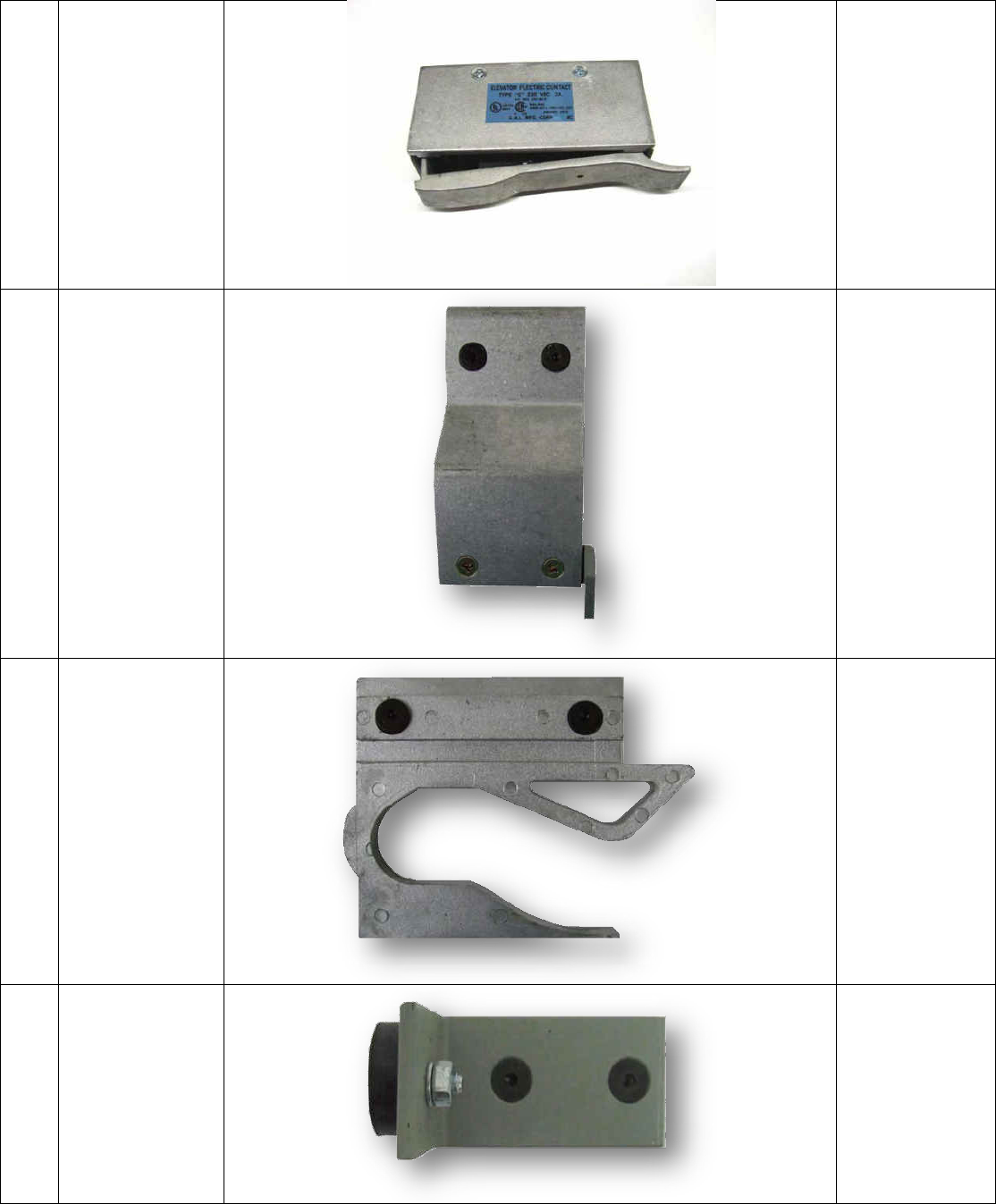
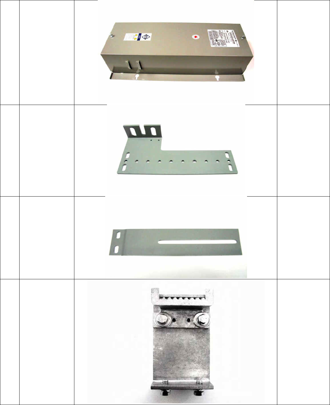
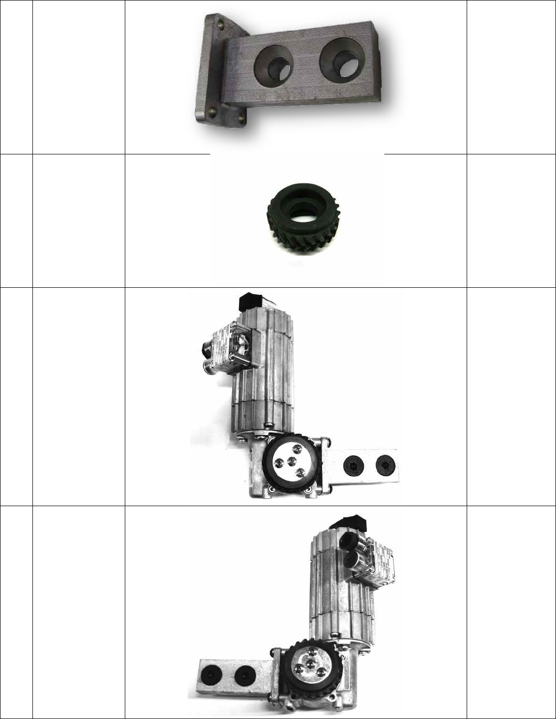
PARTS LIST
The following parts can be purchased from GAL
Note: GAL reserves the right to replace any items in this list at any time without notice.
Item
Description
Picture
GAL Par No.
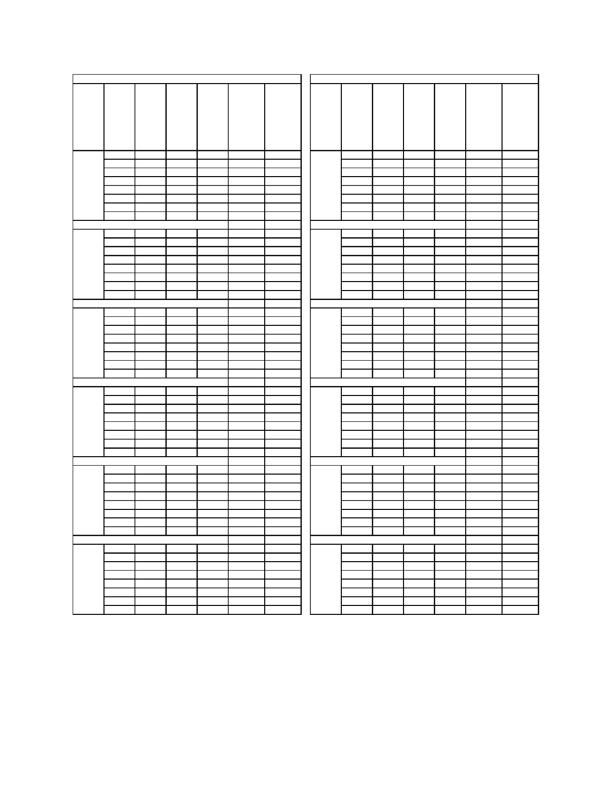
1
SINGLE SIDE SLIDE
UNIVERSAL PLATE
(RH, LH)
2000-1031-R
2000-1031-L
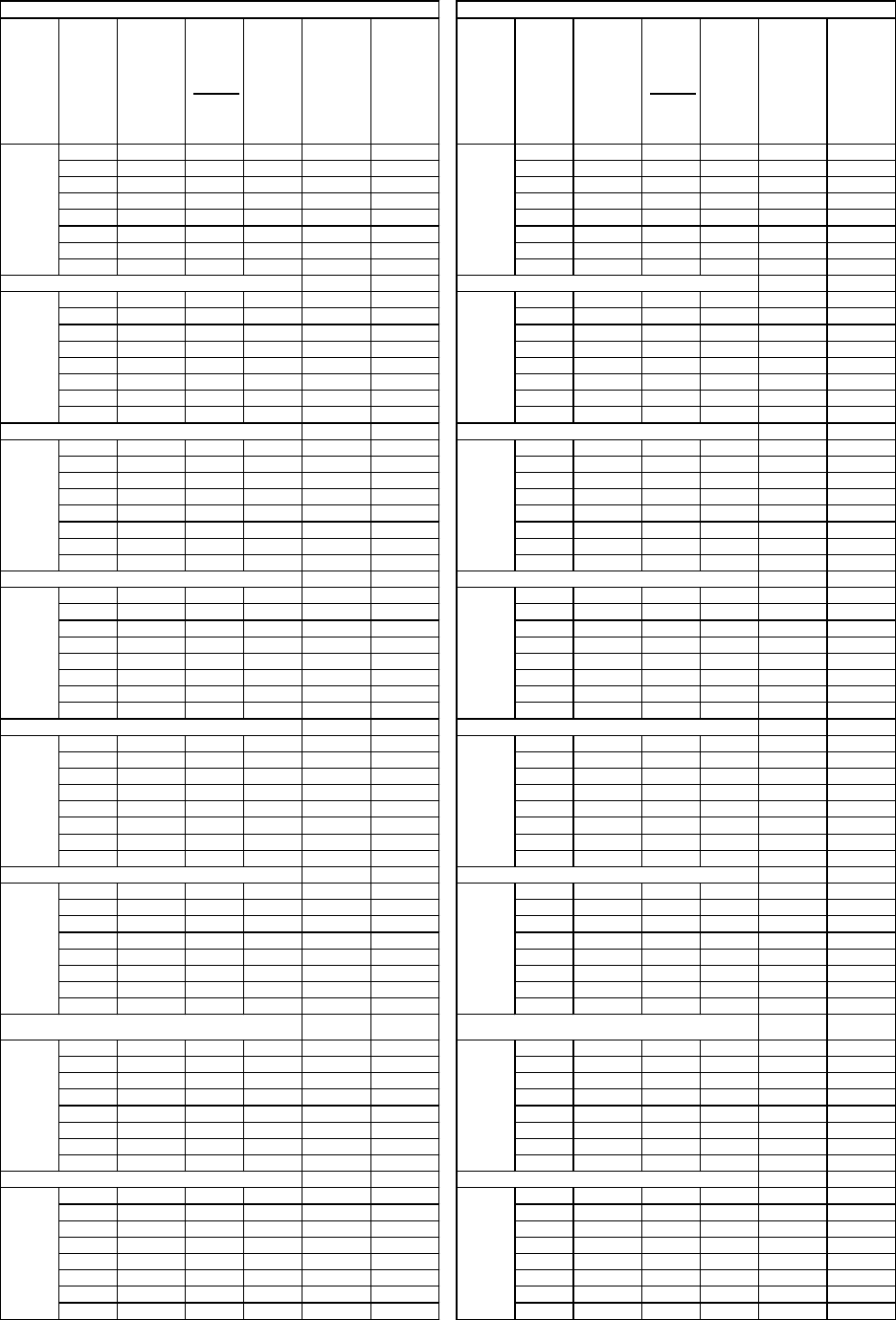
2
SINGLE SIDE SLIDE
EXTENSION ARM
(18”, 30”, 39”)
2000-1037-A
2000-1038-A
2000-1039-A
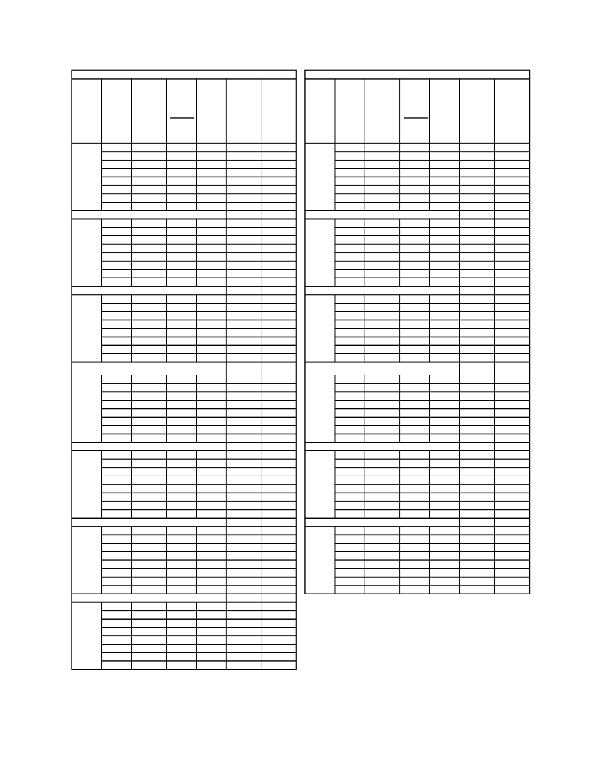
3
LOWER BELT
BRACKET KEEPER
ASSEMBLY
R.H.SHOWN
2500-3068- L
L.H.
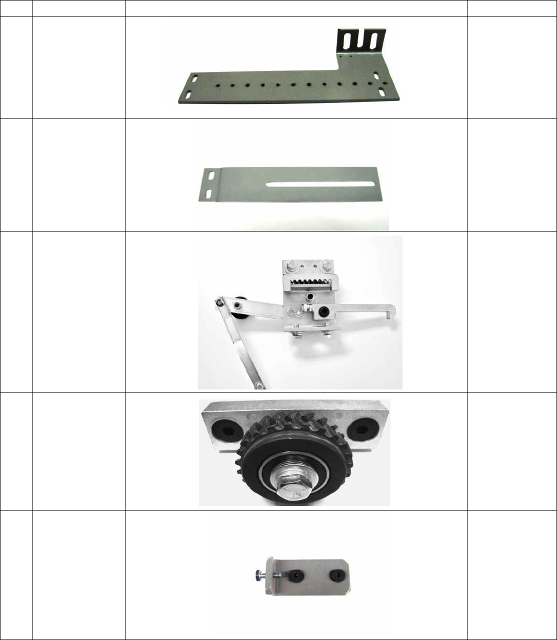
4
TAKE-UP PULLEY
ASSEMBLY
2500-3075
5
LINEAR BELT
TENSION BLOCK
ASSEMBLY
2500-3080
2500-3068-R
RH.
19
6
GATE SWITCH
ASSEMBLY
SW1-0001N
7
LEFT HAND
SHOWN
KEEPER BRACKET
ASSEMBLY
2500-3092-L
L.H.
2500-3092-R
R.H.
8
CLUTCH CAM
ASSEMBLY
2500-3084
9
FIXING STRUT
OPEN DOOR STOP
2500-3088
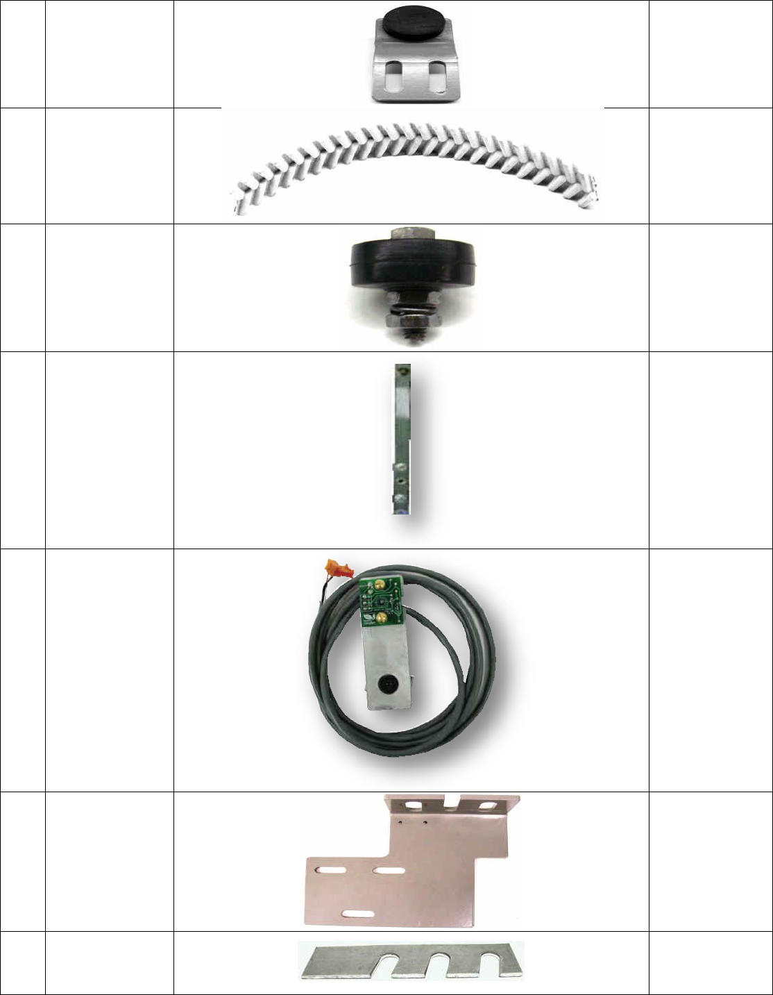
20
10
2-SPEED SIDE
SLIDE
OPEN-CLOSED
DOOR STOP
2500-3089
11
LINEAR DRIVE
BELT
2500-5009
12
GATE SWITCH
ROLLER
SW1-0007N
13
CLUTCH LINKAGE
ARM
ASSEMBLY
2000-3085
14
DCL & DOL
SENSOR BLOCK
ASSEMBLY
2500-5019
15
2-SPEED
UNIVERSAL
BRACKET SIDE
SLIDE
2000-1040-2S
16
TRACK SHIM
HH1-0032N
21
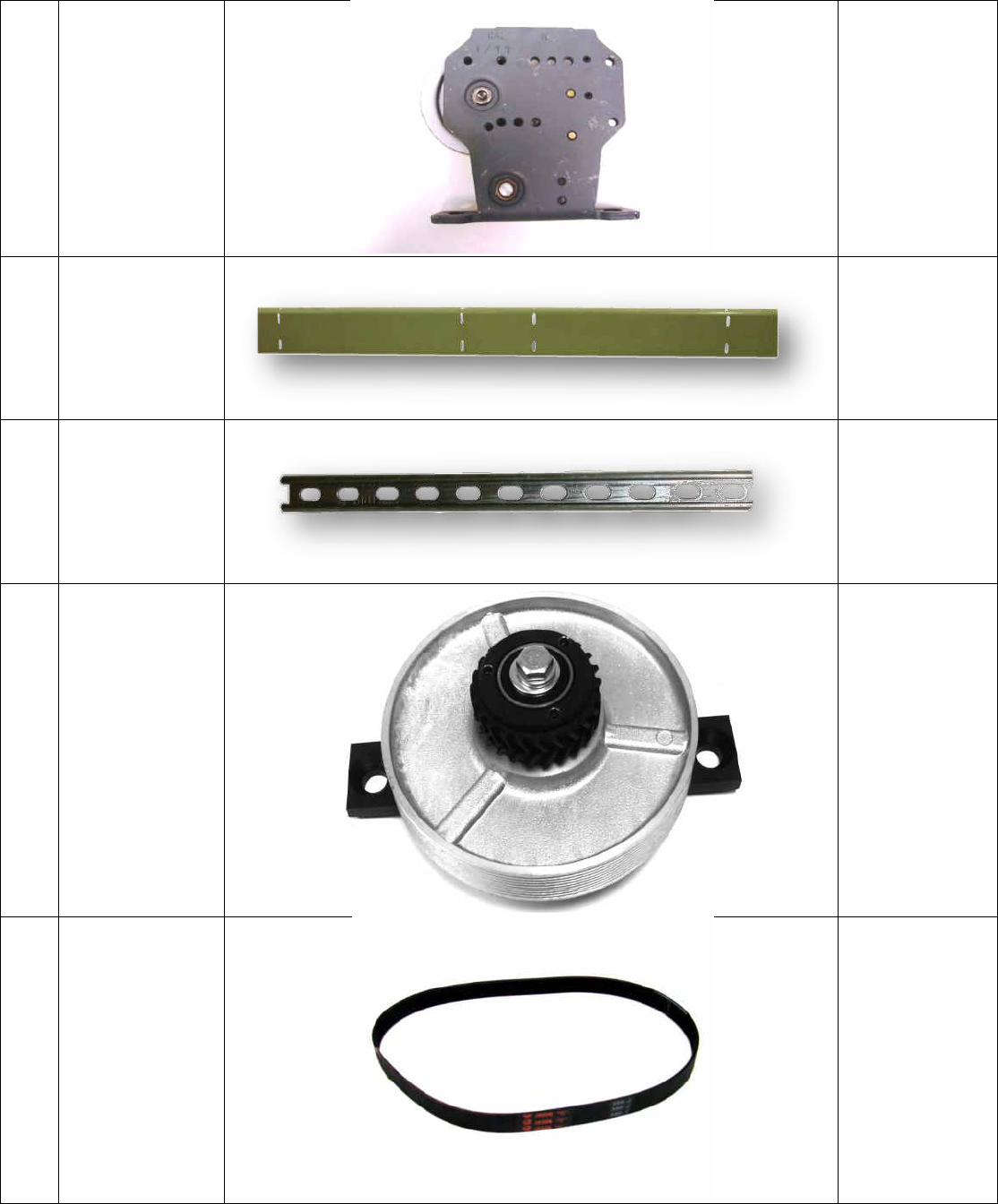
17
DOOR SHEAVE
ASSEMBLY
INQUIRE WITH
GAL/ECI
FOR APROPRIATE
SHEAVES FOR
YOUR
APPLICATION
18
HEADER ANGLE-
SSL/CP
909-SERIES
19
FIXING STRUT
2000-3066 (SSL)
2000-3067 (2 SP)
20
DRIVE PULLEY
ASSEMBLY
2500-3074
21
MULTI “V”
MOTOR BELT
2500-2075-1(8')
2500-2075-2 (8'-6")
2500-2075-3 ( 9')
2500-2075-4 ( 9'-6")
2500-2075-5 (10')
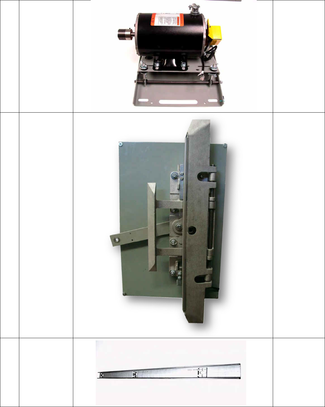
22
22
½ HP 3-PH
MOTOR
ASSEMBLY +
PIVOT
AND BASE PLATE
2500-3059
23
KEEPER CLUTCH
ASSEMBLY
892-5008
&
892-2007
24
TRACK
INQUIRE WITH
GAL/ECI
FOR APROPRIATE
APLLICATION
23
25
COMPLETE DRIVE
UNIT BOX
ASSEMBLY
2500-3054
26
UNIVERSAL
PLATE-CP
2000-1040-D-4
27
EXTENSION ARM-
CP (10”, 14”)
2000-1041-A
2000-1042-A
28
UPPER BELT
BRACKET
USE ON C/P ONLY
2000-3069
24
29
MOVFE2500
GEARED MOTOR
MOUNTING
2500-5024
30
HEAVY DUTY
LINEAR BELT
PULLEY
2500-1012
31
GEARED MOTOR
ASSEMBLY – LEFT
HAND
2500-3072-L
32
GEARED MOTOR
ASSEMBLY –
RIGHT HAND
2500-3072-R

25
NOTES
Copyright © 2013 GAL
All rights reserved.
No part of this document may be reproduced in any form,machine or natural without the
express written consent of GAL.
Canada

26
