VISHAY Leaded Solid Electrolyte Tantalex Caps INTERACTIVE
User Manual: VISHAY-Leaded-Solid-Electrolyte-Tantalex-Caps-INTERACTIVE
Open the PDF directly: View PDF ![]() .
.
Page Count: 153 [warning: Documents this large are best viewed by clicking the View PDF Link!]

LEADED SOLID ELECTROLYTE
TANTALE X® CAPACITORS
VISHAY
Notes:
1. To navigate:
a) Click on the Vishay logo on any datasheet to go to the Contents
page for that section. Click on the Vishay logo on any Contents
page to go to the main Table of Contents page.
b) Click on the products within the Table of Contents to go directly
to the datasheet.
c) Use the scroll or page up/page down functions.
d) Use the Adobe® Acrobat® page function in the browser bar.
2. To search the text of the catalog use the Adobe® Acrobat® search
function.
VSE-DB0029-0805
INTERACTIVE
VISHAY INTERTECHNOLOGY, INC.
data book
Discrete Semiconductors and Passive Components
One of the World’s Largest Manufacturers of

SEMICONDUCTORS
PASSIVE COMPONENTS
PRODUCT LISTINGS
RECTIFIERS
Schottky (single, dual)
Standard, Fast, and Ultra-Fast Recovery
(single, dual)
Bridge
Superectifier®
Sinterglass Avalanche Diodes
HIGH-POWER DIODES AND THYRISTORS
High-Power Fast-Recovery Diodes
Phase-Control Thyristors
Fast Thyristors
SMALL-SIGNAL DIODES
Schottky and Switching (single, dual)
Tuner/Capacitance (single, dual)
Bandswitching
PIN
ZENER AND SUPPRESSOR DIODES
Zener (single, dual)
TVS (TRANSZORB®, Automotive, ESD, Arrays)
FETs
Low-Voltage TrenchFET® Power MOSFETs
High-Voltage TrenchFET® Power MOSFETs
High-Voltage Planar MOSFETs
JFETs
RF TRANSISTORS
Bipolar Transistors (AF and RF)
Dual Gate MOSFETs
MOSMICs®
OPTOELECTRONICS
IR Emitters and Detectors,
and IR Receiver Modules
Optocouplers and Solid-State Relays
Optical Sensors
LEDs and 7-Segment Displays
Infrared Data Transceiver Modules
Custom Products
ICs
Power ICs
Analog Switches
RF Transceivers and Receiver Modules
ICs for Optoelectronics
MODULES
Power Modules (contain power diodes,
thyristors, MOSFETs, IGBTs)
DC/DC Converters
RESISTIVE PRODUCTS
Foil Resistors
Film Resistors
Metal Film Resistors
Thin Film Resistors
Thick Film Resistors
Metal Oxide Film Resistors
Carbon Film Resistors
Wirewound Resistors
Power Metal Strip® Resistors
Chip Fuses
Variable Resistors
Cermet Variable Resistors
Wirewound Variable Resistors
Conductive Plastic Variable Resistors
Networks/Arrays
Non-Linear Resistors
NTC Thermistors
PTC Thermistors
Varistors
MAGNETICS
Inductors
Transformers
CAPACITORS
Tantalum Capacitors
Molded Chip Tantalum Capacitors
Coated Chip Tantalum Capacitors
Solid Through-Hole Tantalum Capacitors
Wet Tantalum Capacitors
Ceramic Capacitors
Multilayer Chip Capacitors
Disc Capacitors
Film Capacitors
Power Capacitors
Heavy-Current Capacitors
Aluminum Capacitors
Silicon RF Capacitors
STRAIN GAGE TRANSDUCERS
AND STRESS ANALYSIS SYSTEMS
PhotoStress®
Strain Gages
Load Cells
Force Transducers
Instruments
Weighing Systems
Specialized Strain Gage Systems
Leaded Solid Electrolyte
TANTALEX® Capacitors
Vishay Sprague, Inc.
15 Daigle Lane
Suite 103
Sanford, ME 04073
U. S. A.
Phone: +1 207 490 7205
Fax: +1 207 490 7213
www.vishay.com
NOTICE
Specifications of the products displayed herein are subject to change without notice. Vishay Intertechnology, Inc.,
or anyone on its behalf, assumes no responsibility or liability for any errors or inaccuracies.
Information contained herein is intended to provide a product description only. No license, express or implied, by
estoppel or otherwise, to any intellectual property rights is granted by this document. Except as provided in
Vishay's terms and conditions of sale for such products, Vishay assumes no liability whatsoever, and disclaims any
express or implied warranty, relating to sale and/or use of Vishay products including liability or warranties relating to
fitness for a particular purpose, merchantability, or infringement of any patent, copyright, or other intellectual
property right.
The products shown herein are not designed for use in medical, life-saving, or life-sustaining applications.
Customers using or selling these products for use in such applications do so at their own risk and agree to fully
indemnify Vishay for any damages resulting from such improper use or sale.

www.vishay.com
Revision: 12-Feb-08 1
Table of Contents
Vishay Sprague
Leaded Solid Electrolyte TANTALEX® Capacitors
Military Style to Commercial Equivalent Product Index ..................................................................................................... 2
Parameter Comparison Guide, Solid Tantalum Leaded Capacitors .................................................................................. 3
Introduction, Solid Tantalum Capacitors ............................................................................................................................ 4
AC Ripple Application Notes, Solid Tantalum Capacitors.................................................................................................. 7
Mounting for Through-hole Components ........................................................................................................................... 11
Total Quality Commitment, Tantalum Capacitors .............................................................................................................. 13
Quick Reference Guide, Solid Tantalum Leaded Capacitors ............................................................................................ 14
SOLID TANTALUM LEADED CAPACITORS
METAL CASE
150D Solid Electrolyte TANTALEX® Capacitors, Hermetic Seal, Axial Leaded ......................... 18
152D Solid Electrolyte TANTALEX® Capacitors, Hermetic Seal, Axial Leaded,
Extended Capacitance ................................................................................................... 27
550D Solid Electrolyte TANTALEX® Capacitors, Hermetic Seal, Axial Leaded,
For High Frequency Power Supplies .............................................................................. 31
M39003/01/03/09 Styles CSR13, 21, 23, Solid Electrolyte TANTALEX® Capacitor
MIL-PRF-39003 Qualified, Hermetic Seal, Axial Leaded, Tubular.................................. 39
CTS1, CTS13, 749DX Solid Electrolyte TANTALEX® Capacitors
CECC30201Qualified, Hermetic Seal, Axial Leaded, Tubular
30201-002, Style CTS1
30201-005, Style CTS13
30201-001/011/012/029, Style 749DX............................................................................ 54
SUBMINIATURE CASE
CX06 Solid Leaded TANTALEX® Capacitors .............................................................................. 64
CX16 Solid Leaded TANTALEX® Capacitors .............................................................................. 67
HA Solid Leaded TANTALEX® Capacitors, Polar or Non-Polar............................................... 70
SHA Solid Leaded TANTALEX® Capacitors, Polar or Non-Polar............................................... 78
TC Solid Leaded TANTALEX® Capacitors, Polar or Non-Polar............................................... 84
STC Solid Leaded TANTALEX® Capacitors, Polar or Non-Polar............................................... 91
RESIN COATED
173D Solid Electrolyte TANTALEX® Capacitors, Molded Case, Axial Leaded............................ 98
790D Solid Electrolyte TANTALEX® Capacitors, Molded Case, Radial Leaded,
European Style ............................................................................................................... 104
199D Solid Electrolyte TANTALEX® Capacitors, Resin Coated, Radial Leaded......................... 111
299D Solid Electrolyte TANTALEX® Capacitors, Resin Coated, Tripole Triple Leaded .............. 117
489D, 499D Solid Electrolyte TANTALEX® Capacitors, Resin Coated, Radial Leaded,
European Style ............................................................................................................... 123
ETPW Solid Electrolyte TANTALEX® Capacitors, Resin Coated, Radial Leaded,
VISHAY Roederstein Type ............................................................................................. 131
ETQW Solid Electrolyte TANTALEX® Capacitors, Resin Coated, Radial Leaded,
High Reliability,VISHAY Roederstein Type..................................................................... 138
All Military Products are manufactured with DSCC
approved designs, processes and testing.
Commercial products are manufactured to be in
compliance with EIA Industry Standards

www.vishay.com
2Revision: 12-Feb-08
Military Style to Commercial Equivalent Product Index
Military Product Index
Vishay Sprague
SOLID TANTALUM LEADED CAPACITORS
M39003/01/03/09 Styles CSR13, 21, 23, Solid Electrolyte TANTALEX® Capacitors,
MIL-PRF-39003 Qualified, Metal Case Hermetic Seal, Axial, Tubular ........................... 39
M39003/01 Military Style CSR13, Standard Ratings Chart ............................................................... 39
M39003/03 Military Style CSR21, Standard Ratings Chart .............................................................. 39
M39003/09 Military Style CSR23, Standard Ratings Chart .............................................................. 39
MILITARY STYLE COMMERCIAL TYPE EQUIVALENT
CSR13 150D, Solid Electrolyte TANTALEX® Capacitors, Hermetic Seal, Axial............................. 18
CSR23 152D, Solid Electrolyte TANTALEX® Capacitors, Hermetic Seal, Axial,
Extended Capacitance.................................................................................................... 27
CSR21 550D, Solid Electrolyte TANTALEX® Capacitors, Hermetic Seal, Axial,
For High Freqency Power Supplies ................................................................................ 31
CX05* 173D, Solid Electrolyte TANTALEX® Capacitors, Molded Case, Axial .............................. 98
CX02*, CX12* 199D, Solid Electrolyte TANTALEX® Capacitors, Resin Coated, Radial ........................... 111
CX06, CX16 TC, Subminiature, Leaded Solid Tantalum Capacitors................................................... 84
Note:
* Military Style CX-MIL-C-49137 not available
All Military Products are manufactured with DSCC
approved designs, processes and testing.
Commercial products are manufactured to be in
compliance with EIA Industry Standards

Document Number: 40033 For technical questions, contact: tantalum@vishay.com www.vishay.com
Revision: 18-Apr-08 3
Parameter Comparison Guide
Vishay Sprague
Notes:
• All Axial Polar capacitors are available tape and reeled per EIA RS-296
• Model 199D/299D capacitors are available tape and reeled per EIA RS-468
SOLID TANTALUM LEADED CAPACITORS - HERMETIC SEAL, METAL CASE
MODEL MIL SPEC/
TYPE OUTLINE DRAWING
CAPACITANCE
RANGE
(µF)
WORKING
VOLTAGES
AT 85 °C
CASE
SIZES PAG E
150D - Polar MIL-PRF-39003/01
(CSR13) 0.056 - 330 6 - 125 VDC A, B, R, S 18
152D - Polar MIL-PRF-39003/03
(CSR23) 1.2 - 1000 6 - 50 VDC A, B, R, S 27
550D - Polar MIL-PRF-39003/09
(CSR21) 5.6 - 330 6 - 50 VDC R, S 31
Military Parts
CSR13 - Metal Case Axial
CSR21 - Metal Case Axial
CSR23 - Metal Case Axial
MIL-PRF-39003/01
MIL-PRF-39003/09
MIL-PRF-39003/03
0.056 - 330 6 - 100 VDC
6 - 50 VDC
6 - 50 VDC
A, B, C, D
C, D
A, B, C, D
39
To CECC 30201
CTS1 - Metal Case Axial
CTS13 - Metal Case Axial
749DX - Metal Case Axial
30201 - 002
30201 - 005
30201 - 001/
011/012/029
0.1 - 330
0.1 - 330
0.068 - 1000
6 - 125 VDC
6 - 63 VDC
6 - 63 VDC
A, B, C, D
A, B, C, D
A, B, C, D
54
SOLID TANTALUM LEADED CAPACITORS - NON-HERMETIC SEAL, MOLDED CASE, RESIN COATED
MODEL MIL SPEC/
TYPE OUTLINE DRAWING CAPACITANCE
RANGE
(µF)
WORKING
VOLTAGES
AT 85 °C
CASE
SIZES PAG E
173D - Molded Axial 0.10 - 330 2 - 50 VDC U, V, W,
X, Y 98
199D - Dipped Radial 0.1 - 680 3 - 50 VDC A, B, C, D,
E, F 111
299D - Dipped Radial 0.1 - 680 3 - 50 VDC A, B, C, D,
E, F 117
489D, 499D - Dipped
Radial 0.1 - 680 3 - 50 VDC
A, B, C, D,
E, F, H, M,
N, R
123
790D - Molded Radial 0.1 - 330 6 - 50 VDC A, B, C, D 104
ETPW - Dipped Radial
Vishay Roederstein Type 0.1 - 330 3 - 50 VDC P1A to
P6R 131
ETQW - Dipped Radial
Vishay Roederstein Type,
High Reliability
0.1 - 330 3 - 50 VDC Q1A to
Q6R 138

Introduction
Vishay Sprague
Solid Tantalum Capacitors
www.vishay.com For technical questions, contact: tantalum@vishay.com Document Number: 40058
4Revision: 18-Apr-08
Tantalum electrolytic capacitors are the preferred choice in
applications where volumetric efficiency, stable electrical
parameters, high reliability and long service life are primary
considerations. The stability and resistance to elevated
temperatures of the tantalum/tantalum oxide/manganese
dioxide system make solid tantalum capacitors an
appropriate choice for today’s surface mount assembly
technology. Vishay Sprague has been a pioneer and leader
in this field, producing a large variety of tantalum capacitor
types for consumer, industrial, automotive, military and
aerospace electronic applications.
Tantalum is not found in its pure state. Rather, it is commonly
found in a number of oxide minerals, often in combination
with Columbium ore. This combination is known as “tantalite”
when its contents are more than one-half tantalum. Important
sources of tantalite include Australia, Brazil, Canada, China
and several African countries. Synthetic tantalite
concentrates produced from tin slags in Thailand, Malaysia
and Brazil are also a significant raw material for tantalum
production.
Electronic applications and particularly capacitors consume
the largest share of world tantalum production. Other
important applications for tantalum include cutting tools
(tantalum carbide), high temperature super alloys, chemical
processing equipment, medical implants and military
ordnance.
Vishay Sprague is a major user of tantalum materials in the
form of powder and wire for capacitor elements and rod and
sheet for high temperature vacuum processing.
THE BASICS OF TANTALUM CAPACITORS
Most metals form crystalline oxides which are
non-protecting, such as rust on iron or black oxide on copper.
A few metals form dense, stable, tightly adhering, electrically
insulating oxides. These are the so-called “valve” metals and
include titanium, zirconium, niobium, tantalum, hafnium and
aluminum. Only a few of these permit the accurate control of
oxide thickness by electrochemical means. Of these, the
most valuable for the electronics industry are aluminum and
tantalum.
Capacitors are basic to all kinds of electrical equipment from
radios and television sets to missile controls and automobile
ignitions. Their function is to store an electrical charge for
later use.
Capacitors consist of two conducting surfaces, usually metal
plates, whose function is to conduct electricity. They are
separated by an insulating material or dielectric. The
dielectric used in all tantalum electrolytic capacitors is
tantalum pentoxide.
Tantalum pentoxide compound possesses high dielectric
strength and a high dielectric constant. As capacitors are
being manufactured, a film of tantalum pentoxide is applied
to their electrodes by means of an electrolytic process. The
film is applied in various thicknesses and at various voltages
and although transparent to begin with, it takes on different
colors as light refracts through it. This coloring occurs on the
tantalum electrodes of all types of tantalum capacitors.
Rating for rating, tantalum capacitors tend to have as much
as three times better capacitance/volume efficiency than
aluminum electrolytic capacitors. An approximation of the
capacitance/volume efficiency of other types of capacitors
may be inferred from the following table, which shows the
dielectric constant ranges of the various materials used in
each type. Note that tantalum pentoxide has a dielectric
constant of 26, some three times greater than that of
aluminum oxide. This, in addition to the fact that extremely
thin films can be deposited during the electrolytic process
mentioned earlier, makes the tantalum capacitor extremely
efficient with respect to the number of microfarads available
per unit volume. The capacitance of any capacitor is
determined by the surface area of the two conducting plates,
the distance between the plates and the dielectric constant
of the insulating material between the plates.
COMPARISON OF CAPACITOR
DIELECTRIC CONSTANTS
DIELECTRIC K
DIELECTRIC CONSTANT
Air or Vacuum 1.0
Paper 2.0 - 6.0
Plastic 2.1 - 6.0
Mineral Oil 2.2 - 2.3
Silicone Oil 2.7 - 2.8
Quartz 3.8 - 4.4
Glass 4.8 - 8.0
Porcelain 5.1 - 5.9
Mica 5.4 - 8.7
Aluminum Oxide 8.4
Tantalum Pentoxide 26
Ceramic 12 - 400 000
Document Number: 40058 For technical questions, contact: tantalum@vishay.com www.vishay.com
Revision: 18-Apr-08 5
Introduction
Solid Tantalum Capacitors Vishay Sprague
In the tantalum electrolytic capacitor, the distance between
the plates is very small since it is only the thickness of the
tantalum pentoxide film. As the dielectric constant of the
tantalum pentoxide is high, the capacitance of a tantalum
capacitor is high if the area of the plates is large:
where
C = capacitance
e = dielectric constant
A = surface area of the dielectric
t = thickness of the dielectric
Tantalum capacitors contain either liquid or solid
electrolytes. The liquid electrolyte in wet slug capacitors -
generally sulfuric acid - forms the cathode (negative) plate.
In solid electrolyte capacitors, a dry material,
manganese dioxide, forms the cathode plate. The anode
lead wire from the tantalum pellet consists of two pieces. A
tantalum lead embedded in, or welded to the pellet, which is
in turn connected to a termination or lead wire. The drawings
clearly show the construction details of the frequently used
types of tantalum capacitors.
VISHAY'S LINE OF HIGH QUALITY LEADED
TANTALUM CAPACITORS
Vishay manufactures two categories of leaded tantalum
capacitors:
1. Solid electrolyte, sintered anode leaded tantalum
capacitors as shown in this data book
2. Wet electrolyte, sintered anode leaded tantalum
capacitors - see Vishay data book, Wet Tantalum
Capacitors (VSE-DB0030)
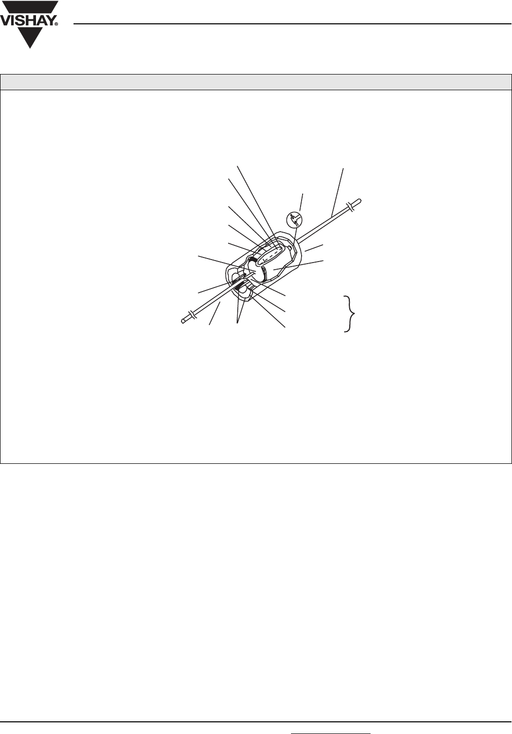
150D AND MIL STYLE CSR13
HERMETICALLY-SEALED, SOLID ELECTROLYTE
(MILITARY SPECIFICATION NO. MIL-PRF-39003)
Voltage Range:
6 WVDC to 125 WVDC
Capacitance Range:
0.056 µF to 330 µF
Size Range:
0.125" [3.175 mm] Ø x 0.250" [6.350 mm] long to
0.341" [8.661 mm] Ø x 0.750" [19.050 mm] long
Primary Applications:
Industrial and military equipment where reliability, low leakage current, low dissipation factor and stability with time and temperature are
required.
LOWER END OF CASE
FILLED WITH SOLDER
GLASS
SOLDER
SINTERED TANTALUM
PELLET (ANODE)
TANTALUM PENTOXIDE
(DIELECTRIC)
MANGANESE DIOXIDE
(SOLID ELECTROLYTE, CATHODE)
GRAPHITE
SILVER
TANTALUM WIRE WELDED TO OR
IMBEDDED IN TANTALUM PELLET
WELD
NICKEL LEAD (POSITIVE) METAL RING
METAL EYELET GLASS FUSED TO
METAL EYELET
AND METAL RING
FOR HERMETIC SEAL
LEAD SWAGGED TO
BOTTOM OF CASE
NICKEL LEAD (NEGATIVE)
METAL CASE
CeA
t
-------
=
Introduction
Vishay Sprague Solid Tantalum Capacitors
www.vishay.com For technical questions, contact: tantalum@vishay.com Document Number: 40058
6Revision: 18-Apr-08
SOLID ELECTROLYTE TANTALUM CAPACITORS
Solid electrolyte, sintered anode tantalum capacitors in their
original hermetically-sealed designs differ from the wet
versions in their electrolyte. Here, the electrolyte is
manganese dioxide, which is formed on the tantalum
pentoxide dielectric layer by impregnating the pellet with a
solution of manganous nitrate. The pellets are then heated in
an oven and the manganous nitrate is converted to
manganese dioxide.
The pellet is next coated with graphite followed by a layer of
metallic silver, which provides a solderable surface between
the pellet and the can in which it will be enclosed.
The pellets, with lead wire and header attached, are inserted
into the can where the pellet is held in place by solder. The
can cover is also soldered into place.
After assembly, the capacitors are tested and inspected to
assure long life and reliability. Another variation of the solid
electrolyte tantalum capacitor encases the element in plastic
resins, such as epoxy materials. It offers excellent reliability
and high stability for consumer and commercial electronics
with the added feature of low cost.
Surface mount designs of “Solid Tantalum” capacitors use
leadframes or leadframeless designs as shown in the
accompanying drawings.
TANTALUM CAPACITORS FOR ALL DESIGN CONSIDERATIONS
In choosing between the two basic types of tantalum
capacitors, the circuit designer customarily uses wet sintered
anode capacitors, or wet “slug” tantalum capacitors, where
the lowest DC leakage is required. The conventional silver
can design will not tolerate any reverse voltages. However,
in military or aerospace applications, tantalum cases are
used in place of silver cases where utmost reliability is
desired. The tantalum cased wet slug units will withstand
reverse voltages up to 3 V, will operate under higher ripple
currents and can be used at temperatures up to + 392 °F
(+ 200 °C).
Solid electrolyte designs, which are the least expensive for a
given rating, are used in many applications where their very
small size for a given unit of capacitance is of
importance.
They will typically withstand up to about 10 % of the rated DC
working voltage in a reverse direction. Also important are
their good low temperature performance characteristics and
freedom from corrosive electrolytes.
Vishay Sprague patented the original solid electrolyte
capacitors and was the first to market them in 1956. (Vishay
has the broadest line of tantalum capacitors and has
continued its position of leadership in this field.) Datasheets
covering the various types and styles of Vishay tantalum
capacitors for consumer and entertainment electronics, for
industrial and for military applications are available where
detailed performance characteristics must be
specified.
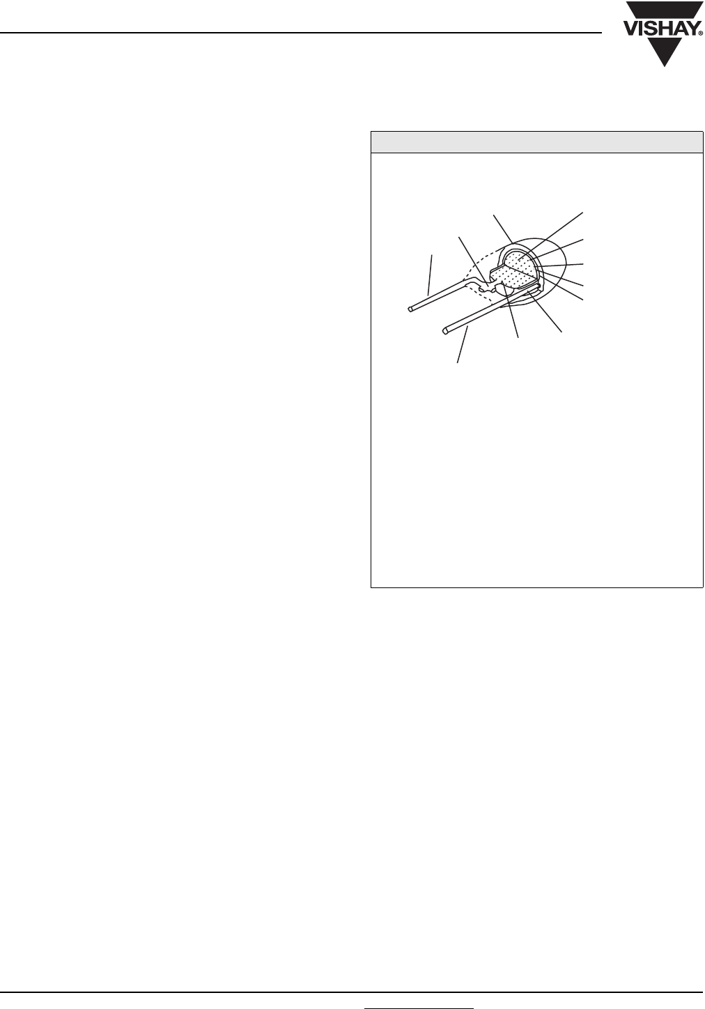
199D
EPOXY-DIPPED, SOLID ELECTROLYTE
Voltage Range:
3 WVDC to 50 WVDC
Capacitance Range:
0.10 µF to 680 µF
Size Range:
0.177" [4.496 mm] diameter x 0.340" [8.636 mm] high to
0.380" [9.652 mm] diameter x 0.710" [18.034 mm] high
Primary Applications:
On printed circuit boards in entertainment, commercial and
industrial equipment where low cost, small size, high stability,
low DC leakage and low dissipation factor are important.
WELD
NICKEL LEAD
NICKEL LEAD
(NEGATIVE)
(POSITIVE)
GRAPHITE
PELLET (ANODE)
EPOXY COATING
TANTALUM
WIRE WELDED
TO TANTALUM
PELLET
CATHODE LEAD SOLDERED
TO SILVERED AREA OF
CAPACITOR SECTION
SINTERED TANTALUM
TANTALUM PENTOXIDE
(DIELECTRIC)
MANGANESE DIOXIDE
(SOLID ELECTROLYTE)
SILVER
Document Number: 40057 For technical questions, contact: tantalum@vishay.com www.vishay.com
Revision: 26-Nov-07 7
AC Ripple Current Calculations
Application Notes
Vishay Sprague
INTRODUCTION
Solid tantalum capacitors are preferred for filtering
applications in small power supplies and DC/DC converters
in a broad range of military, industrial and commercial
systems including computers, telecommunications,
instruments and controls and automotive equipment. Solid
tantalum capacitors are preferred for their high reliability,
long life, extended shelf life, exceptional stability with
temperature and their small size. Their voltage range is 4 to
50 V for the most common types. Tantalum chip capacitors
for surface mount applications are manufactured in very
small sizes and are compatible with standard pick-and-place
equipment.
The electronics industry has moved to smaller and smaller
power supplies and higher switching frequencies, with an
increased requirement for capacitors with smaller size and
operating characteristics better suited to high frequencies.
This application note briefly describes the construction of
solid tantalum capacitors, the concept of Equivalent Series
Resistance (ESR) and presents calculations for power
dissipation and voltage limitations for both low and high
frequency applications.
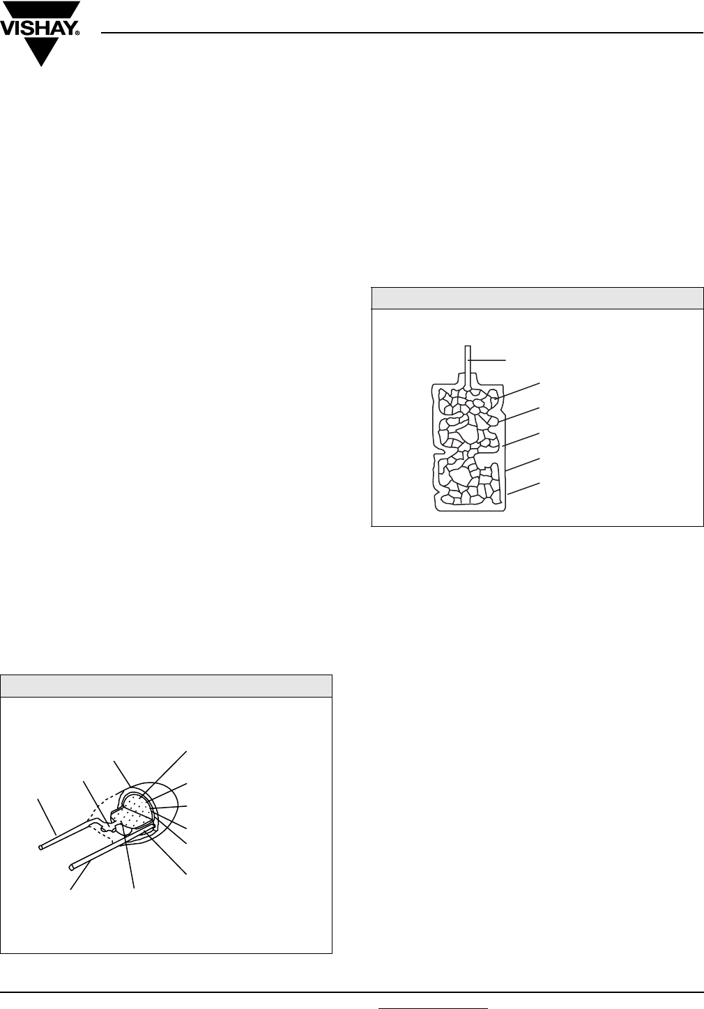
CONSTRUCTION
The solid tantalum capacitor consists of a sintered tantalum
pellet, the anode, on which a tantalum oxide dielectric is
formed by electrolysis. The pellet is then coated with
manganese dioxide for the cathode. Positive and negative
terminations are attached to this pellet and the assembly
may be conformally coated, molded or sealed in a metal
case.
Looking closely at the internal structure of the pellet, we see
that it is made of grains of tantalum powder sintered to each
other. A solid tantalum capacitor is equivalent to many small
capacitors in parallel, one for each grain of powder. This
configuration produces a very large surface area, therefore a
large capacitance in a relatively small volume.
EQUIVALENT SERIES RESISTANCE (ESR)
A capacitor offers internal resistance to AC current, called
the Equivalent Series Resistance (ESR). At lower
frequencies, this is mainly the resistance of the dielectric. At
higher frequencies, the resistance of the manganese dioxide
in the voids between the grains is predominant. Because the
resistivity of manganese dioxide is inversely proportional to
temperature, the ESR of solid tantalum capacitors at high
frequencies decreases as temperature increases.
POWER DISSIPATION LIMITATION
When AC current is applied to a solid tantalum capacitor, the
resistance (ESR) that opposes the flow of current results in
heat generation, according to the formula:
(1)
The power (P) dissipated in the capacitor results in an
elevation of temperature. The allowable temperature rise of
a capacitor due to power dissipation is determined by
experience. For example, this value is + 20 °C maximum for
molded chip capacitors. This in turn limits the power that the
capacitor can dissipate.
SOLID DIPPED TANTALUM CAPACITOR
CROSS SECTION
WELD
EPOXY COATING
TANTALUM WIRE
WELDED TO
TANTALUM PELLET
CATHODE LEAD SOLDERED
TO SILVERED AREA OF
CAPACITOR SECTION
SINTERED TANTALUM
PELLET (ANODE)
NICKEL LEAD
(NEGATIVE)
NICKEL LEAD
(POSITIVE)
TANTALUM PENTOXIDE
(DIELECTRIC)
MANGANESE DIOXIDE
(SOLID ELECTROLYTE)
GRAPHITE
SILVER
TANTALUM PELLET
SIMPLIFIED VIEW
METALLIZED OUTER
ELECTRODE
CARBON
MnO2
Ta2O5
TANTALUM
TANTALUM ANODE LEAD
PI
2ESR×=
Application Notes
Vishay Sprague AC Ripple Current Calculations
www.vishay.com For technical questions, contact: tantalum@vishay.com Document Number: 40057
8Revision: 26-Nov-07
VOLTAGE LIMITATION
The power a capacitor can dissipate is also limited by the
applied DC voltage. The operating voltage should not be
allowed to rise above the rated voltage (nor should it drop
below zero, since the solid tantalum capacitor is a polarized
component). Assuming the capacitor is biased at half the
rated voltage, which is the optimum use condition, the
limiting value of the voltage is, for a sinusoidal waveform:
(2)
Vrms for each value of RV (Rated voltage) are:
CURRENT LIMITATION (LOW FREQUENCY)
To find the limiting current Irms, we divide Vrms by the
impedance at the desired frequency.
(3)
using the formula:
(4)
where X is 1/Cw + Lw (w = 2πf)
Since inductance of a solid tantalum capacitor is usually in
the nanohenry range, the Lw factor becomes important only
when the frequency is higher than a few megahertz. For
filtering applications at 100 kHz and lower, the inductance
factor will generally be ignored in the calculation. At 120 Hz,
the impedance can be determined by calculation.
(5)
At 120 Hz, DF2 is relatively small compared with 1 and the
formula can be simplified to:
(6)
More generally, DF values of less than 10 % will not affect
the final result by more than 1 %. It is important to use the
lowest value for C, including the capacitance tolerance. At
120 Hz, the formula can be simplified to:
(7)
where Irms is the maximum permissible rms current in
milliamperes, C the capacitance minus the capacitance
tolerance in microfarads and V the rated voltage in volts. All
above calculations assume the capacitor is properly biased
at half the rated voltage. If this is not the case, Vrms becomes
(8)
where VP = Vrated - Vbias or Vbias, whichever is lower.
CURRENT LIMITATION (HIGH FREQUENCY)
At frequencies in the 10 kHz to several 100 kHz range, the
power dissipation becomes the limiting factor. The following
formula gives the maximum permissible ripple current for a
sinusoidal wave form:
(9)
Pmax. is the maximum power dissipation the capacitor can
tolerate. The ESR value in the formula is the maximum ESR
of the capacitor at the required frequency. This can be
determined by measuring capacitors and determining a
maximum value by using the mean value and adding 3 or
more standard deviations. Some manufacturers specify the
maximum impedance at 100 kHz or 1 MHz. Either value may
be used in ripple current calculations.
Power dissipation limits calculated for the most popular
surface mount types of solid tantalum capacitors are:
1. Hermetic Axial (150D, CSR13):
2. Dipped Tantalum (199D, 299D):
3. Molded Case Chip (293D):
As a general guideline, it is also worth mentioning that
rectangular pellets for large case size ratings have lower
ESR than cylindrical ones. Since cylindrical pellets are
widely used in leaded capacitors and rectangular pellets for
surface mount chips, it is safe to assume that a tantalum chip
will have the same or lower ESR than the same capacitance/
voltage capacitor in a leaded package.
RATED VOLTAGE Vrms MAXIMUM
4
10
20
25
35
40
50
1.42
5.30
7.07
8.84
12.37
14.14
17.68
Vrms Vpp 22⁄RV22⁄==
Irms Vrms Z⁄=
ZX
2ESR2
+=
Z12πfC⁄()
2DF 2πfC⁄()
2
+12πfC⁄()1DF
2
+()==
Z12πfC⁄=
Irms 0.266 CV×=
CASE SIZE MAXIMUM POWER AT + 25 °C (W)
A
B
C
D
0.115
0.145
0.185
0.225
CASE SIZE MAXIMUM POWER AT + 25 °C (W)
199D 299D
A
B
C
D
E
F
0.080
0.090
0.100
0.120
0.140
0.180
0.140
0.160
0.180
0.210
0.240
0.270
VP2⁄
Irms Pmax. ESR⁄=
Document Number: 40057 For technical questions, contact: tantalum@vishay.com www.vishay.com
Revision: 26-Nov-07 9
Application Notes
AC Ripple Current Calculations Vishay Sprague
ESR SCREENING
For parallel operation, the ESR spread can be minimized by
screening. This reduces the risk of excess ripple current
exposure to any one of the capacitors.
Some equipment will only measure impedance. An
impedance limit can be caluclated to insure that the ESR
stays in the required range. Use the formula:
(10)
Impedance can be measured using an impedance meter and
a fixture that is appropriate for the task. With the most
sophisticated fixtures, several capacitors may be tested at
the same time, reducing the test cycle time.
CORRECTIVE FACTORS
The calculations for high frequency ripple current are shown
in formula (9) for a sinusoidal waveform and an ambient
temperature of + 25 °C. If the waveform is not sinusoidal, the
ripple current limitations may differ. Generally speaking, the
ripple current limit calculated by formula (9) can be divided by
the duty cycle of the signal. If the temperature is higher than
+ 25 °C, the ripple current limit should also be multiplied by
the factors shown:
RIPPLE CURRENT/VOLTAGE
CALCULATIONS EXAMPLE
As an example, we will determine the ripple voltage and
power dissipation capability for a 1 µF, ± 20 % tolerance,
35 V, dipped tantalum capacitor.
At 120 Hz:
If we used
With
At 120 Hz, the voltage is the limiting factor.
At 100 kHz:
At 100 kHz, the typical ESR for a 1 µF/35 V tantalum is:
If we now look at the maximum ripple voltage, the above
limitation translates into:
At 100 kHz, the power dissipation is the limiting factor.
TEMPERATURE °C MULTIPLYING FACTOR
+ 55 °C
+ 85 °C
+ 125 °C
0.9
0.8
0.4
Zmax. Xc2ESR2
⁄=
Xc 1 Cω⁄=
Vrms RV22⁄12.37 V==
Irms Vrms Z⁄=
12.37 2×3.14×120×0.8×10 6–0.007 A=×=
Irms Pmax. ESR⁄=
ESR DF 2πfC⁄=
04 2 3.14×120×0.8 10 6– 66 Ω=××⁄=
Irms Pmax. ESR ⁄0.080 66⁄0.035 A===
Irms Pmax. ESR⁄=
ESR 1.5 Ω Z3 Ω=()=
Irms 0.080 1.5⁄0.231 A==
Vrms ZI
rms 3 0.231 0.69 V=×=×=
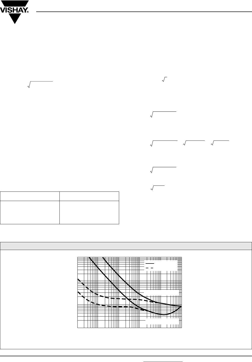
TYPICAL CURVES OF IMPEDANCE AND ESR VS. FREQUENCY
100
10
1
0.1
100 1K 10K 100K 1M 10M
FREQUENCY
IMPEDANCE
ESR
1 µF, 35 V, A CASE
4.7 µF, 35 V, C CASE

Application Notes
Vishay Sprague AC Ripple Current Calculations
www.vishay.com For technical questions, contact: tantalum@vishay.com Document Number: 40057
10 Revision: 26-Nov-07
CONCLUSIONS
The industry is moving towards smaller and smaller power
supplies and DC/DC converters operating at higher
frequencies. The three factors shown become more and
more important in capacitor selection.
1. Higher Switching Frequencies: The switching frequency of
power supplies has increased from the 10 kHz range a
decade ago to the 100 kHz range and up today. The ESR
of solid tantalum capacitors is either the same or lower at
higher frequencies and impedance is at a minimum in the
100 kHz to megahertz range. Higher switching
frequencies and the need for smaller sizes will increase
the use of solid tantalum capacitors.
2. Surface Mount Technology: The application of surface
mount technology not only reduces the size of power
supplies and converters but also uses the substrate on
which the components are mounted to dissipate some of
the heat generated by the switching elements. Solid
tantalum chip capacitors are well suited for this
application. They have superior operating characteristics,
do not leak electrolyte and are compatible with common
automated surface assembly equipment.
3. Tighter High Frequency Parameters: The reduction of the
maximum ESR of a solid tantalum capacitor may produce
tradeoffs in size or DC characteristics. Rather than looking
at lower ESR in terms of process average, it may be
advisable to try to reduce ESR variation, producing a
lower maximum ESR with a tighter distribution. This
improvement may be achieved by using statistical
process control, an approach already being implemented
at Vishay Sprague Solid Tantalum manufacturing
facilities.

VISHAY SPRAGUE
Leaded Tantalum Capacitors Technical Note
Mounting for Through-Hole Components
TECH NOTE
Document Number: 40108 For technical questions, contact: tantalum@vishay.com www.vishay.com
Revision: 27-Nov-07 11
General
All through-hole or leaded styles fall into two general
classes. The first is provided with leads extending from
opposite ends of the body, generally along the principle axis
of the body (“axial leads”). The second is provided with
parallel leads extending from one side or face of the body
(“radial leads”). With both type, mounting points are
normally provided by the leads themselves.
Axial leads may be used for point-to-point wiring,
but usually, the wires are bent at 90° from the capacitor axis
for insertion through printed circuit (PC) boards. Axial
capacitors supplied on reels for machine insertion will
withstand the mechanical stresses of bending and inserting.
The Vishay axial series may be supplied on reels to feed
such machines. Radial leads are intended to plug directly
into holes of PC boards. Auto-insertion machines will insert
compatible radial capacitor designs, and most Vishay
capacitors may be supplied in appropriate reeled forms.
With either axial or radial types, attention should be paid to
treatment of the capacitors during mounting and afterward
under service conditions. Difficulty during mounting usuall
y arises from lead damage or from overheating. The hand
soldering technique or more often, wave-soldering
machines can cause overheating. The internal cathode
connection on most solid tantalum through-hole series is
made between solder and a silver-pigmented paint. If too
much heat is applied, this solder may reflow and degrade the
silver-solder interface or cause a direct short circuit.
Vishay’s hermetically-sealed series has an internal space
into which molten cathode solder may run, depriving the
cathode connection and possibly flowing across
the terminals to short circuit the capacitor from the inside. It
is also possible to remelt or reflow the solder which bonds
the rim of the glass-metal seal, causing loss of hermeticity
and possibly a short circuit. Finally, solder at the exit point
of the positive wire may be re-melted withsimilar effect.
This solder however, is a high-temperature alloy, and it is
much less likely to be melted. Redipping of leadwires is
practiced by some users, introducing another hazard of
re-melting this solder. Vishay recommends that redipping or
hot solder dipping of any tantalum capacitor be performed
by our factories under controlled conditions.
Molded series have only one site of solder, the internal
cathode connection. The rate of heat transfer through the
plastic is lower than through the metal can of our hermetic
styles. However the opportunity for temperature transfer or
conduction along the negative lead-wire to re-melt
this solder is very similar. There is little internal void
within molded cased capacitors, so re-melted solder tends to
remain in its original location and solidify when heat is
removed. Short circuiting is very unlikely, but reliability of
the internal connection may be compromised by leaching of
silver from the paint into the molten solder. The latter effect
degrades the cathode connection in hermetic parts as well.
Lead Forming
While we will provide some general guidelines for bending
leads, more specific details are outlined in J-STD-001. The
positive or anode lead bend must be a minimum of 0.050"
from the case or from the external weld connection. If the
part has a hermetic (glass-to-metal) seal, do not bend, cut, or
disturb the tube between the weld and the glass seal. The
cathode lead bend must be a minimum of 0.050" from the
case.
Solder Heat Test
All through-hole capacitors will pass the Resistance
to Soldering Heat Test of MIL-STD-202, Method 210,
Condition B. This test dips each lead-wire into
molten solder at + 260 °C for 10 s while the capacitor
body is held vertically above the solder. Vishay capacitors
will pass this test when the depth of immersion brings the
capacitor body (or closest external solder joint, if it is closer
as in some hermetic styles) to a minimum distance of 0.100"
from the solder surface. This demonstration of resistance to
solder heat is in accordance with what is believed to be
the industry standard. More severe treatment must be
considered reflective of an improper soldering process.

Mounting for Through-Hole Components
Technical Note
Vishay Sprague
www.vishay.com For technical questions, contact: tantalum@vishay.com Document Number: 40108
12 Revision: 27-Nov-07
TECH NOTE
Solder Profile
Shown below is a recommended solder wave profile for both axial and radial through-hole solid tantalum capacitors.
25
45
65
85
105
125
145
165
185
205
225
245
265
012 3456
TIME (MINUTES)
TEMPERATURE (°C)
TIME AT PEAK ~ 4 s
TOP SIDE
TEMPERATURE PROFILE
150 °C
LEADED SOLDER WAVE PROFILE
MAX. PEAK TEMPERATURE FOR LEAD (Pb)-FREE SOLDERING: 260 °C
BOTTOM SIDE
TEMPERATURE PROFILE
260 °C MAX.

Document Number: 40059 For technical questions, contact: wettants@vishay.com www.vishay.com
Revision: 23-May-05 13
Total Quality Commitment
Vishay Sprague
“We are dedicated to partnership with our customers...
assuring continuously improved quality of the products and
services we offer...”
About the manufacture of tantalum capacitors at Vishay ...
Attention to customer requirements-to your requirements keeps
us on the leading edge of the quality revolution. We maintain
total quality commitments throughout our operations.
The scope of our Quality System encompasses:
1. Product and Materials Development
2. Process Control
3. Training
4. Outgoing Quality Improvement
5. Customer Partnerships
6. Ship-To-Stock Programs.
7. Our Quality System is Registered to ISO/QS 9000
PRODUCT AND MATERIALS DEVELOPMENT
The work in our research and development facilities is focused
on new materials and designs. Our scientists and engineers are
recognized for their experience in this technology. Vishay
Sprague, a pioneer in the field of tantalum capacitors, has
introduced many important advances over the years.
SUPPLIER PARTNERSHIPS
We are continuously working with suppliers to assure a
thorough understanding of our quality requirements and the use
of statistical methods as a tool for process control. We expect
our suppliers to be dedicated to the improvement of quality of
our incoming materials, taking rigorous action to investigate and
correct non-conformance whenever required.
Our suppliers are considered extensions of our tantalum
processes.
PROCESS CONTROL
Vishay ships millions of tantalum capacitors each month for
aerospace and defense electronics, for computers and
communications as well as for a virtually unlimited range of
high-performance military, industrial and commercial
equipment.
We are dedicated to defect prevention in all aspects of design
and manufacturing. Rigorous action is taken to investigate the
root cause of non-conformances and/or variation and to correct
such situations.
Vishay is committed to the use of statistical techniques to
reduce variation, independent of specification limit. This is one
of the tools used to improve performance.
We perform a thorough analysis of critical process elements
using statistical methods at key points. More and more process
steps are being automated to assure consistency in
manufacturing and conformance to design specifications.
TRAINING
A disciplined procedures approach is an essential part of our
quality improvement program. This requires a commitment to
provide all personnel with the skills and tools necessary to
produce quality at the source. Employees are trained in
company philosophy, statistical process control, capability
studies, application of procedures and equipment operation.
Our training includes the analysis of statistical data from our
processes to help us understand and control variations. As we
train our operators in SPC and automate our processes, the rate
of quality improvement accelerates accordingly.
PARTS PER MILLION (PPM) PROGRAMS
The collection of quality data and reporting of outgoing quality in
PPM is not new to Vishay Sprague. In fact, Vishay Sprague
provided leadership for the committee developing the EIA
Standard for PPM measurement. And long before reporting
outgoing quality in "Parts Per Million" was fashionable, Vishay
Sprague had defined a program, was collecting data and
reporting internally to assure quality improvement.
PPM performance, by product, is calculated by Quality
Assurance from end-of-the-line electrical performance data.
These data include all variations, whether minor or catastrophic,
from internal standards that are stricter than those used by our
customers. The result is that our customers' measurement of
as-received quality in PPM is always more favorable than our
own measurement.
Today, not all suppliers are using a standard method of PPM
calculation. Consequently, when comparing reported PPM
levels, it is essential that the method of calculation be
understood. For example, calculations that include only
catastrophic failures may produce very low reported PPM
levels.
CUSTOMER PARTNERSHIPS
We are currently involved with many major Ship-to-Stock
programs. These programs rely on our history of providing
materials that meet customer quality expectations, are delivered
on time and at competitive prices.
This history, plus our proven dedication to continuous quality
improvement and the use of statistical techniques to identify and
reduce variation in our processes, provides customer
confidence to eliminate incoming inspection, thereby reducing
costs.
Our partnership also extends to in-depth applications
engineering support. Our engineers work with customers to
review their designs and in the selection of the most appropriate
Vishay Sprague tantalum capacitors.
SHIP-TO-STOCK PROGRAMS
Vishay Sprague provides a program for those customers who
may not have identified their own Ship-to-Stock program. This
program may be modified to suit specific needs.
QUARTERLY PPM REPORTS
These reports express outgoing quality of each product type
purchased and may be used for monitoring quality
improvement.
SHIPPING CONTAINER ID
We identify each container to assure that material proceeds
directly to your stockroom and is not inspected when received.
Vishay Sprague is responsible for its quality.
VISHAY SPRAGUE
SHIP TO
STOCK
INSP. BY DATE

www.vishay.com For technical questions, contact: tantalum@vishay.com Document Number: 40037
14 Revision: 12-Feb-08
Quick Reference Guide
Vishay Sprague
SOLID TANTALUM CAPACITORS HERMETIC SEAL, METAL CASE
SOLID TANTALUM LEADED CAPACITORS
PICTORIAL MODEL CASE
CODES DESCRIPTION PAGE
150D A, B, R, S
Solid Tantalum Capacitor - Solid-Electrolyte TANTALEX®:
Axial lead, hermetically sealed, high performance,
high capacitance, low DCL, lLow dissipation factor.
Excellent operating stability/reliability.
Supplied with plastic film insulation. Terminals are
solid, tinned nickel wire leads. Commercial, industrial
and military applications.
18
152D A, B, R, S
Solid Tantalum Capacitor - Solid-Electrolyte TANTALEX®:
Axial lead, hermetically sealed, extended capacitance,
small size, low leakage current, low dissipation factor,
Exceptional operating stability. Proven reliability in a
wide variety of high performance commercial,
industrial and military applications.
27
550D R, S
Solid Tantalum Capacitor - Solid-Electrolyte TANTALEX®:
Axial lead, hermetically sealed, small size, long life.
Designed for power supply filtering applications at
above 100 kHz. Extremely low equivalent series
resistance with the capability to handle high ripple
currents in switching regulators and high frequency
power supplies.
31
MIL-PRF-39003
CSR13
M39003/01
CSR21
M39003/09
CSR23
M39003/03
A, B, C, D
C, D
A, B, C, D
Solid Tantalum Capacitor - Solid-Electrolyte T
ANTALEX®
:
Axial lead, tubular, hermetically sealed.
Capacitors are qualified to MIL-PRF-39003 -
Exponential and Weibull distribution.
Capacitors are furnished to the requirements of the
military specification, including marking, testing and
inspection.
Also, MIL-PRF-39003 establishes failure rates
(expressed in percent per 1000 h) based on
exponential and Weibull distribution. Exponential
failure rates are identified as levels M, P, R and S.
Weibull failure rates are B, C and D. Levels M, P, R and
S are inactive for new designs.
39
CECC30201
CTS1
CTS13
749DX
A, B, C, D
The CTS1, CTS13, and 749DX series are qualified to
the European standard CECC30201.
These are hermetically sealed, metal case, axial
leaded capacitors with long life and high performance.
They have high capacitance, with low DF (dissipation
factor), and low DCL (DC Leakage).
The CTS1, CTS13, and 749DX have excellent
operating stability and reliability.
All units are supplied with plastic film isolation. The
standard terminations are tin/lead plated nickel wire,
but 100 % tin (RoHS compliant) terminations are
available.
54

Document Number: 40037 For technical questions, contact: tantalum@vishay.com www.vishay.com
Revision: 12-Feb-08 15
Quick Reference Guide
Vishay Sprague
SOLID TANTALUM CAPACITORS
NON-HERMETIC SEAL, MOLDED CASE AND RESIN COATED
SOLID TANTALUM LEADED CAPACITORS
PICTORIAL MODEL CASE
CODES DESCRIPTION PAGE
173D U, V, W,
X, Y
Solid Tantalum Capacitor - Solid-Electrolyte TANTALEX®:
Axial lead, miniature, molded case, precision molded
in gold colored, flame retardant, thermosetting epoxy
resin. Units are laser marked for improved legibility.
The tapered end of the case provides easy
identification of the positive terminal. Tape and reel
98
199D A, B, C,
D, E, F
Solid Tantalum Capacitor - Solid-Electrolyte TANTALEX®:
Radial lead, resin-coated, miniature, rugged and
reliable. High performance, economical, low leakage
current and dissipation factor. Two lead styles. Tape
and reel packaging. Suitable for a broad range of
commercial and industrial equipment applications.
111
299D A, B, C,
D, E, F
Solid Tantalum Capacitor - Solid-Electrolyte TANTALEX®:
Tripole®, triple lead, resin-coated - conformal coating,
miniature, high performance. The anole lead is in the
center while both outside leads are cathode leads. The
three-lead design makes backwards insertion
impossible. Tape and reel packaging per EIA-468.
117
489D
499D A, B, C, D
The 489D and 499D are solid tantalum resin coated
radial leaded capacitors built to conform to the
European standards for ratings and case sizes. They
are available in many ratings, sizes and lead
configurations. They are the economical choice for a
variety of applications, with low DF (disspation factor)
and low DCL (DC Leakage). The units are laser
marked for improved marking legibility.
Standard terminations are tin/lead plated, but they are
now also available with 100 % tin (RoHS compliant)
terminations. Tape and reel packaging is available.
123
790D A, B, C, D
Solid Tantalum Capacitor - precisely molded with a
flame retardant expoxy resin coating. Four case sizes
with stand-off leads. Low leakage current, low
impedance and extended value ranges available
104
ETPW
1A, 1B, 2C,
2D, 2E, 3F,
3G, 4H, 5J,
5K, 5L, 6M,
6N, 6P, 6R
Solid Tantalum Capacitor - resin coated with flame
retardant encapsulation, practically without expoxy run
down. Radial lead. Improved humidity class and low
leakage current. Very high CV product, low failure rate
and high operational stability.
131
ETQW 1, 2, 3,
4, 5, 6
Solid Tantalum Capacitor - resin coated with flame
retardant encapsulation, practically without expoxy run
down. Radial lead. Improved humidity class and low
leakage current. Very high CV product, low failure rate
and high operational stability.
138


www.vishay.com For technical questions, contact: tantalum@vishay.com Document Number: 40015
18 Revision: 16-Jan-08
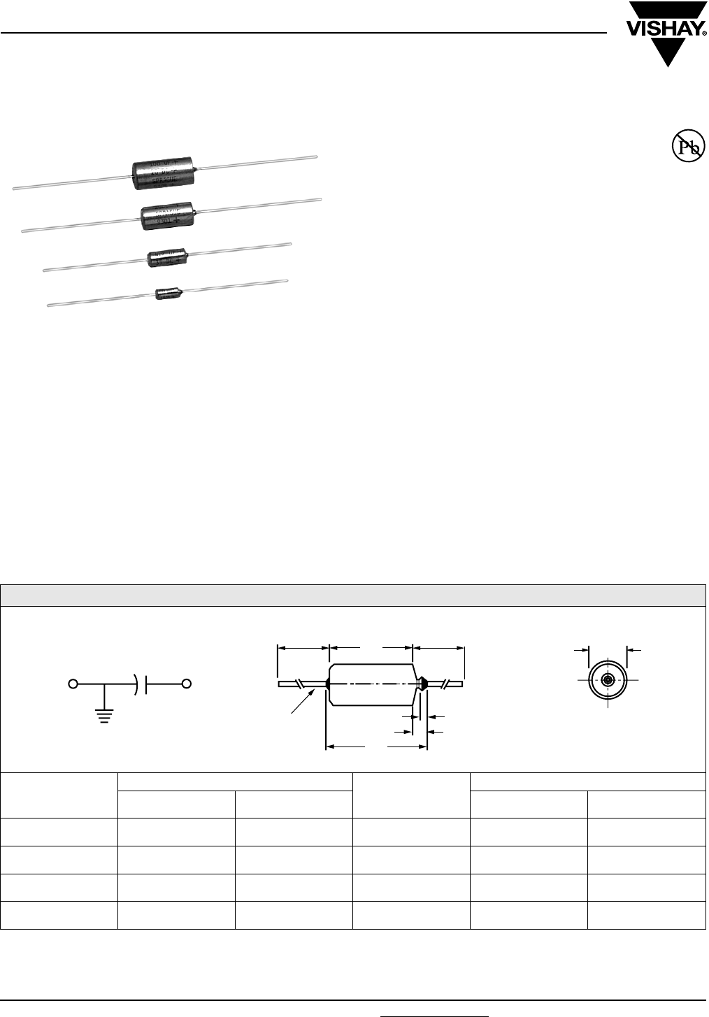
150D
Vishay Sprague
Solid-Electrolyte TANTALEX® Capacitors
Hermetically-Sealed, Axial-Lead
FEATURES
•Terminations: Tin/lead (SnPb), 100 % Tin
(RoHS compliant)
•These high performance, hermetically-sealed
TANTALEX® capacitors have set the standard for
solid-electrolyte tantalum capacitors for more
than three decades.
•High capacitance, low DCL, low dissipation factor and
exceptional operating stability.
•Performance and reliability have been proven in
commercial, industrial and military applications.
•Available in four case codes and capacitors and are
supplied with plastic-film insulation.
•Terminals are solid, tinned nickel wire leads.
•The Military equivalent to the 150D is the CSR13 which is
qualified to MIL-C-39003/01.
PERFORMANCE CHARACTERISTICS
Operating Temperature: - 55 °C to + 85 °C
(To + 125 °C with voltage derating)
Capacitance Tolerance: At 120 Hz, + 25 °C. ± 20 %,
± 10 % standard. ± 5 % available as special.
Dissipation Factor: At 120 Hz, + 25 °C. Dissipation factor,
as determined from the expression 2πfRC, shall not exceed
the values listed in the Standard Ratings Tables.
DC Leakage Current (DCL Max.):
At + 25 °C: Leakage current shall not exceed the values
listed in the Standard Ratings Tables.
At + 85 °C: Leakage current shall not exceed 10 times the
values listed in the Standard Ratings Tables.
At +125 °C: Leakage shall not exceed 15 times the values
listed in the Standard Ratings Tables.
Life Test: Capacitors shall withstand rated DC voltage
applied at + 85 °C for 2000 h or derated DC voltage applied
at + 125 °C for 1000 h
Following the life test:
1. DCL shall not exceed 125 % of the initial requirement
2. Dissipation Factor shall meet the initial requirement
3. Change in capacitance shall not exceed ± 5 %
Note:
(1) When a shrink-fitted insulation is used, it shall lap over the ends of the capacitor body
* Pb containing terminations are not RoHs compliant, exemptions may apply
Available
RoHS*
COMPLIANT
DIMENSIONS in inches [millimeters]
CASE CODE
WITH INSULATING SLEEVE (1)
J (MAXIMUM)
LEAD SIZE
D L AWG
NO.
NOMINAL
DIAMETER
A 0.135 ± 0.016
[3.43 ± 0.41]
0.286 ± 0.031
[7.26 ± 0.79]
0.422
[10.720] 24 0.020
[0.51]
B 0.185 ± 0.016
[4.70 ± 0.41]
0.474 ± 0.031
[12.04 ± 0.79]
0.610
[15.490] 24 0.020
[0.51]
R 0.289 ± 0.016
[7.34 ± 0.41]
0.686 ± 0.031
[17.42 ± 0.79]
0.822
[20.880] 22 0.025
[0.64]
S 0.351 ± 0.016
[8.92 ± 0.41]
0.786 ± 0.031
[19.96 ± 0.79]
0.922
[23.420] 22 0.025
[0.64]
0.125 [3.18] MAX.
SOLID TINNED
NICKEL LEADS
L
J
MAX..
D
DIA.
1.500 ± 0.250
[38.10 ± 6.35]
1.500 ± 0.250
[38.10 ± 6.35]
0.047 [1.19] MAX.
-+

Document Number: 40015 For technical questions, contact: tantalum@vishay.com www.vishay.com
Revision: 16-Jan-08 19
150D
Solid-Electrolyte TANTALEX® Capacitors
Hermetically-Sealed, Axial-Lead
Vishay Sprague
ORDERING INFORMATION
150D 224 X0 006 A 2 T E3
MODEL CAPACITANCE CAPACITANCE
TO L E RA N C E
DC
VOLTAGE RATING
CASE
CODE
STYLE
NUMBER
PACKAGING ROHS
COMPLIANT
This is expressed
in picofarads. The
first two digits are
the significant
figures. The third
is the number of
zeros to follow.
X0 = ± 20 %
X9 = ± 10 %
*X5 = ± 5 %
*Special Order
This is expressed in volts.
To complete the
three-digit block, zeros
precede the voltage
rating.
See
Ratings
and Case
Codes
Ta b l e.
0 = No Sleeve
2 = Insulated
sleeve
B = Bulk
T = Tape and
Reel
E3 = 100 % Tin
termination
(RoHS compliant)
Blank = SnPb
termination
STANDARD RATINGS
CAPACITANCE (µF) CASE CODE PART NUMBER
CAP. TOL. ± 20 %
PART NUMBER
CAP. TOL. ± 10 %
MAX. DCL
AT + 25 °C
(µA)
MAX. DF
AT + 25 °C
120 Hz (%)
6 WVDC AT + 85 °C, SURGE = 8 V . . . 4 WVDC AT + 125 °C, SURGE = 5 V
0.22 A 150D224X0006A2 150D224X9006A2 0.5 2
0.27 A - 150D274X9006A2 0.5 2
0.33 A 150D334X0006A2 150D334X9006A2 0.5 2
0.39 A - 150D394X9006A2 0.5 2
0.47 A 150D474X0006A2 150D474X9006A2 0.5 2
0.56 A - 150D564X9006A2 0.5 2
0.68 A 150D684X0006A2 150D684X9006A2 0.5 2
0.82 A - 150D824X9006A2 0.5 2
1.0 A 150D105X0006A2 150D105X9006A2 0.5 2
1.2 A - 150D125X9006A2 0.5 4
1.5 A 150D155X0006A2 150D155X9006A2 0.5 4
1.8 A - 150D185X9006A2 0.5 4
2.2 A 150D225X0006A2 150D225X9006A2 0.5 4
2.7 A - 150D275X9006A2 0.5 4
3.3 A 150D335X0006A2 150D335X9006A2 0.5 4
3.9 A - 150D395X9006A2 0.5 4
4.7 A 150D475X0006A2 150D475X9006A2 0.5 4
5.6 A - 150D565X9006A2 0.5 4
6.8 A 150D685X0006A2 150D685X9006A2 0.5 6
8.2 B - 150D825X9006B2 0.5 6
10.0 B 150D106X0006B2 150D106X9006B2 0.5 6
12.0 B - 150D126X9006B2 0.5 6
15.0 B 150D156X0006B2 150D156X9006B2 1.0 6
18.0 B - 150D186X9006B2 1.0 6
22.0 B 150D226X0006B2 150D226X9006B2 1.0 6
27.0 B - 150D276X9006B2 1.0 6
33.0 B 150D336X0006B2 150D336X9006B2 1.0 6
39.0 B - 150D396X9006B2 1.0 6
47.0 B 150D476X0006B2 150D476X9006B2 2.0 6
56.0 B - 150D566X9006B2 2.0 6
68.0 R 150D686X0006R2 150D686X9006R2 3.0 6
82.0 R - 150D826X9006R2 3.0 6
100.0 R 150D107X0006R2 150D107X9006R2 3.0 6
120.0 R 150D127X0006R2 150D127X9006R2 3.0 6
150.0 R 150D157X0006R2 150D157X9006R2 6.0 6
180.0 R 150D187X0006R2 150D187X9006R2 6.0 6
220.0 S 150D227X0006S2 150D227X9006S2 6.0 8
270.0 S 150D277X0006S2 150D277X9006S2 6.0 8
330.0 S 150D337X0006S2 150D337X9006S2 10.0 8

150D
Vishay Sprague Solid-Electrolyte TANTALEX® Capacitors
Hermetically-Sealed, Axial-Lead
www.vishay.com For technical questions, contact: tantalum@vishay.com Document Number: 40015
20 Revision: 16-Jan-08
STANDARD RATINGS
CAPACITANCE (µF) CASE CODE PART NUMBER (1)
CAP. TOL. ± 20 %
PART NUMBER (1)
CAP. TOL. ± 10 %
Max. DCL
AT+ 25 °C
(µA)
Max. DF
AT + 25 °C
120 Hz (%)
10 WVDC AT + 85 °C, SURGE = 13 V . . . 7 WVDC AT + 125 °C, SURGE = 9 V
0.22 A 150D224X0010A2 150D224X9010A2 0.5 2
0.27 A - 150D274X9010A2 0.5 2
0.33 A 150D334X0010A2 150D334X9010A2 0.5 2
0.39 A - 150D394X9010A2 0.5 2
0.47 A 150D474X0010A2 150D474X9010A2 0.5 2
0.56 A - 150D564X9010A2 0.5 2
0.68 A 150D684X0010A2 150D684X9010A2 0.5 2
0.82 A - 150D824X9010A2 0.5 2
1.0 A 150D105X0010A2 150D105X9010A2 0.5 2
1.2 A - 150D125X9010A2 0.5 4
1.5 A 150D155X0010A2 150D155X9010A2 0.5 4
1.8 A - 150D185X9010A2 0.5 4
2.2 A 150D225X0010A2 150D225X9010A2 0.5 4
2.7 A - 150D275X9010A2 0.5 4
3.3 A 150D335X0010A2 150D335X9010A2 0.5 4
3.9 A - 150D395X9010A2 0.5 4
4.7 A 150D475X0010A2 150D475X9010A2 0.5 4
5.6 B - 150D565X9010B2 0.5 4
6.8 B 150D685X0010B2 150D685X9010B2 1.0 6
8.2 B - 150D825X9010B2 1.0 6
10.0 B 150D106X0010B2 150D106X9010B2 1.0 6
12.0 B - 150D126X9010B2 1.0 6
15.0 B 150D156X0010B2 150D156X9010B2 1.0 6
18.0 B - 150D186X9010B2 1.0 6
22.0 B 150D226X0010B2 150D226X9010B2 2.0 6
27.0 B - 150D276X9010B2 2.0 6
33.0 B 150D336X0010B2 150D336X9010B2 2.0 6
39.0 B - 150D396X9010B2 2.0 6
47.0 R 150D476X0010R2 150D476X9010R2 3.0 6
56.0 R - 150D566X9010R2 3.0 6
68.0 R 150D686X0010R2 150D686X9010R2 3.0 6
82.0 R - 150D826X9010R2 3.0 6
100.0 R 150D107X0010R2 150D107X9010R2 6.0 6
120.0 R 150D127X0010R2 150D127X9010R2 6.0 6
150.0 S 150D157X0010S2 150D157X9010S2 10.0 6
180.0 S 150D187X0010S2 150D187X9010S2 10.0 6
220.0 S 150D227X0010S2 150D227X9010S2 10.0 8
15 WVDC AT + 85 °C, SURGE = 20 V . . . 10 WVDC AT + 125 °C, SURGE = 12 V
0.22 A 150D224X0015A2 150D224X9015A2 0.5 2
0.27 A - 150D274X9015A2 0.5 2
0.33 A 150D334X0015A2 150D334X9015A2 0.5 2
0.39 A - 150D394X9015A2 0.5 2
0.47 A 150D474X0015A2 150D474X9015A2 0.5 2
0.56 A - 150D564X9015A2 0.5 2
0.68 A 150D684X0015A2 150D684X9015A2 0.5 2
0.82 A - 150D824X9015A2 0.5 2
1.0 A 150D105X0015A2 150D105X9015A2 0.5 2
1.2 A - 150D125X9015A2 0.5 4
1.5 A 150D155X0015A2 150D155X9015A2 0.5 4
1.8 A - 150D185X9015A2 0.5 4
2.2 A 150D225X0015A2 150D225X9015A2 0.5 4
2.7 A - 150D275X9015A2 0.5 4
3.3 A 150D335X0015A2 150D335X9015A2 0.5 4
3.9 B - 150D395X9015B2 0.5 4
4.7 B 150D475X0015B2 150D475X9015B2 1.0 4
Note:
(1) Insert capacitance tolerance code “X5” for ± 5 % units (special order)

Document Number: 40015 For technical questions, contact: tantalum@vishay.com www.vishay.com
Revision: 16-Jan-08 21
150D
Solid-Electrolyte TANTALEX® Capacitors
Hermetically-Sealed, Axial-Lead
Vishay Sprague
STANDARD RATINGS
CAPACITANCE (µF) CASE CODE PART NUMBER (1)
CAP. TOL. ± 20 %
PART NUMBER (1)
CAP. TOL. ± 10 %
Max. DCL
AT + 25 °C
(µA)
Max. DF
AT + 25 °C
120 Hz (%)
15 WVDC AT + 85 °C, SURGE = 20 V . . . 10 WVDC AT + 125 °C, SURGE = 12 V
5.6 B - 150D565X9015B2 1.0 4
6.8 B 150D685X0015B2 150D685X9015B2 1.0 6
8.2 B - 150D825X9015B2 1.0 6
10.0 B 150D106X0015B2 150D106X9015B2 1.0 6
12.0 B - 150D126X9015B2 1.0 6
15.0 B 150D156X0015B2 150D156X9015B2 2.0 6
18.0 B - 150D186X9015B2 2.0 6
22.0 B 150D226X0015B2 150D226X9015B2 3.0 6
27.0 R - 150D276X9015R2 3.0 6
33.0 R 150D336X0015R2 150D336X9015R2 3.0 6
39.0 R - 150D396X9015R2 3.0 6
47.0 R 150D476X0015R2 150D476X9015R2 6.0 6
56.0 R - 150D566X9015R2 6.0 6
68.0 R 150D686X0015R2 150D686X9015R2 6.0 6
82.0 S - 150D826X9015S2 6.0 6
100.0 S 150D107X0015S2 150D107X9015S2 6.0 6
120.0 S 150D127X0015S2 150D127X9015S2 6.0 6
150.0 S 150D157X0015S2 150D157X9015S2 10.0 6
20 WVDC AT + 85 °C, SURGE = 26 V . . . 13 WVDC AT + 125 °C, SURGE = 16 V
0.027 A - 150D273X9020A2 0.1 2
0.033 A 150D333X0020A2 150D333X9020A2 0.1 2
0.039 A - 150D393X9020A2 0.1 2
0.047 A 150D473X0020A2 150D473X9020A2 0.1 2
0.056 A - 150D563X9020A2 0.1 2
0.068 A 150D683X0020A2 150D683X9020A2 0.1 2
0.082 A - 150D823X9020A2 0.1 2
0.10 A 150D104X0020A2 150D104X9020A2 0.5 2
0.12 A - 150D124X9020A2 0.5 2
0.15 A 150D154X0020A2 150D154X9020A2 0.5 2
0.18 A - 150D184X9020A2 0.5 2
0.22 A 150D224X0020A2 150D224X9020A2 0.5 2
0.27 A - 150D274X9020A2 0.5 2
0.33 A 150D334X0020A2 150D334X9020A2 0.5 2
0.39 A - 150D394X9020A2 0.5 2
0.47 A 150D474X0020A2 150D474X9020A2 0.5 2
0.56 A - 150D564X9020A2 0.5 2
0.68 A 150D684X0020A2 150D684X9020A2 0.5 2
0.82 A - 150D824X9020A2 0.5 2
1.0 A 150D105X0020A2 150D105X9020A2 0.5 2
1.2 A - 150D125X9020A2 0.5 4
1.5 A 150D155X0020A2 150D155X9020A2 0.5 4
1.8 A - 150D185X9020A2 0.5 4
2.2 A 150D225X0020A2 150D225X9020A2 0.5 4
2.7 B - 150D275X9020B2 0.5 4
3.3 B 150D335X0020B2 150D335X9020B2 0.5 4
3.9 B - 150D395X9020B2 1.0 4
4.7 B 150D475X0020B2 150D475X9020B2 1.0 4
5.6 B - 150D565X9020B2 1.0 4
6.8 B 150D685X0020B2 150D685X9020B2 1.0 6
8.2 B - 150D825X9020B2 1.0 6
10.0 B 150D106X0020B2 150D106X9020B2 1.0 6
12.0 B - 150D126X9020B2 1.0 6
15.0 B 150D156X0020B2 150D156X9020B2 2.0 6
Note:
(1) Insert capacitance tolerance code “X5” for ± 5 % units (special order)

150D
Vishay Sprague Solid-Electrolyte TANTALEX® Capacitors
Hermetically-Sealed, Axial-Lead
www.vishay.com For technical questions, contact: tantalum@vishay.com Document Number: 40015
22 Revision: 16-Jan-08
STANDARD RATINGS
CAPACITANCE (µF) CASE CODE PART NUMBER (1)
CAP. TOL. ± 20 %
PART NUMBER (1)
CAP. TOL. ± 10 %
Max. DCL
AT + 25 °C
(µA)
Max. DF
AT + 25 °C
120 Hz (%)
20 WVDC AT + 85 °C, SURGE = 26 V . . . 13 WVDC AT + 125 °C, SURGE = 16 V
18.0 R - 150D186X9020R2 3.0 6
22.0 R 150D226X0020R2 150D226X9020R2 3.0 6
27.0 R - 150D276X9020R2 3.0 6
33.0 R 150D336X0020R2 150D336X9020R2 3.0 6
39.0 R - 150D396X9020R2 3.0 6
47.0 R 150D476X0020R2 150D476X9020R2 6.0 6
56.0 S - 150D566X9020S2 6.0 6
68.0 S 150D686X0020S2 150D686X9020S2 6.0 6
82.0 S - 150D826X9020S2 6.0 6
100.0 S 150D107X0020S2 150D107X9020S2 10.0 6
35 WVDC AT + 85 °C, SURGE = 46 V . . . 23 WVDC AT + 125 °C, SURGE = 28 V
0.027 A - 150D273X9035A2 0.1 2
0.033 A 150D333X0035A2 150D333X9035A2 0.1 2
0.039 A - 150D393X9035A2 0.1 2
0.047 A 150D473X0035A2 150D473X9035A2 0.1 2
0.056 A - 150D563X9035A2 0.1 2
0.068 A 150D683X0035A2 150D683X9035A2 0.1 2
0.082 A - 150D823X9035A2 0.1 2
0.10 A 150D104X0035A2 150D104X9035A2 0.5 2
0.12 A - 150D124X9035A2 0.5 2
0.15 A 150D154X0035A2 150D154X9035A2 0.5 2
0.18 A - 150D184X9035A2 0.5 2
0.22 A 150D224X0035A2 150D224X9035A2 0.5 2
0.27 A - 150D274X9035A2 0.5 2
0.33 A 150D334X0035A2 150D334X9035A2 0.5 2
0.39 A - 150D394X9035A2 0.5 2
0.47 A 150D474X0035A2 150D474X9035A2 0.5 2
0.56 A - 150D564X9035A2 0.5 2
0.68 A 150D684X0035A2 150D684X9035A2 0.5 2
0.82 A - 150D824X9035A2 0.5 2
1.0 A 150D105X0035A2 150D105X9035A2 0.5 2
1.2 B - 150D125X9035B2 0.5 4
1.5 B 150D155X0035B2 150D155X9035B2 0.5 4
1.8 B - 150D185X9035B2 0.5 4
2.2 B 150D225X0035B2 150D225X9035B2 1.0 4
2.7 B - 150D275X9035B2 1.0 4
3.3 B 150D335X0035B2 150D335X9035B2 1.0 4
3.9 B - 150D395X9035B2 1.0 4
4.7 B 150D475X0035B2 150D475X9035B2 1.0 4
5.6 B - 150D565X9035B2 1.0 4
6.8 B 150D685X0035B2 150D685X9035B2 2.0 4
8.2 R - 150D825X9035R2 3.0 4
10.0 R 150D106X0035R2 150D106X9035R2 3.0 4
12.0 R - 150D126X9035R2 3.0 4
15.0 R 150D156X0035R2 150D156X9035R2 3.0 4
18.0 R - 150D186X9035R2 3.0 4
22.0 R 150D226X0035R2 150D226X9035R2 6.0 4
27.0 S - 150D276X9035S2 6.0 4
33.0 S 150D336X0035S2 150D336X9035S2 6.0 4
39.0 S - 150D396X9035S2 6.0 4
47.0 S 150D476X0035S2 150D476X9035S2 10.0 4
Note:
(1) Insert capacitance tolerance code “X5” for ± 5 % units (special order)

Document Number: 40015 For technical questions, contact: tantalum@vishay.com www.vishay.com
Revision: 16-Jan-08 23
150D
Solid-Electrolyte TANTALEX® Capacitors
Hermetically-Sealed, Axial-Lead
Vishay Sprague
STANDARD RATINGS
CAPACITANCE (µF) CASE CODE PART NUMBER (1)
CAP. TOL. ± 20 %
PART NUMBER (1)
CAP. TOL. ± 10 %
Max. DCL
AT + 25 °C
Max. DF
AT + 25 °C
50 WVDC AT + 85 °C, SURGE = 65 V . . . 33 WVDC AT + 125 °C, SURGE = 40 V
0.056 A - 150D563X9050A2 0.1 2
0.068 A 150D683X0050A2 150D683X9050A2 0.1 2
0.082 A - 150D823X9050A2 0.1 2
0.10 A 150D104X0050A2 150D104X9050A2 0.5 2
0.12 A - 150D124X9050A2 0.5 2
0.15 A 150D154X0050A2 150D154X9050A2 0.5 2
0.18 A - 150D184X9050A2 0.5 2
0.22 A 150D224X0050A2 150D224X9050A2 0.5 2
0.27 A - 150D274X9050A2 0.5 2
0.33 A 150D334X0050A2 150D334X9050A2 0.5 2
0.39 A - 150D394X9050A2 0.5 2
0.47 A 150D474X0050A2 150D474X9050A2 0.5 2
0.56 A - 150D564X9050A2 0.5 2
0.68 A 150D684X0050A2 150D684X9050A2 0.5 2
0.82 A - 150D824X9050A2 0.5 2
1.0 A 150D105X0050A2 150D105X9050A2 0.5 2
1.2 B - 150D125X9050B2 0.5 4
1.5 B 150D155X0050B2 150D155X9050B2 0.5 4
1.8 B - 150D185X9050B2 0.5 4
2.2 B 150D225X0050B2 150D225X9050B2 1.0 4
2.7 B - 150D275X9050B2 1.0 4
3.3 B 150D335X0050B2 150D335X9050B2 2.0 4
3.9 B - 150D395X9050B2 2.0 4
4.7 B 150D475X0050B2 150D475X9050B2 3.0 4
5.6 R - 150D565X9050R2 3.0 4
6.8 R 150D685X0050R2 150D685X9050R2 3.0 4
8.2 R - 150D825X9050R2 3.0 4
10.0 R 150D106X0050R2 150D106X9050R2 3.0 4
12.0 R - 150D126X9050R2 3.0 4
15.0 R 150D156X0050R2 150D156X9050R2 6.0 4
18.0 R - 150D186X9050R2 6.0 4
22.0 S 150D226X0050S2 150D226X9050S2 6.0 4
60 WVDC AT + 85 °C, SURGE = 78 V … 40 WVDC AT +125 °C, SURGE = 49 V
0.1 A 150D104X0060A2 150D104X9060A2 0.5 4.0
0.12 A 150D124X0060A2 150D124X9060A2 0.5 4.0
0.15 A 150D154X0060A2 150D154X9060A2 0.5 4.0
0.18 A 150D184X0060A2 150D184X9060A2 0.5 4.0
0.22 A 150D224X0060A2 150D224X9060A2 0.5 4.0
0.27 A 150D274X0060A2 150D274X9060A2 0.5 4.0
0.33 A 150D334X0060A2 150D334X9060A2 0.5 4.0
0.39 A 150D394X0060A2 150D394X9060A2 0.5 4.0
0.47 A 150D474X0060A2 150D474X9060A2 0.5 4.0
0.56 A 150D564X0060A2 150D564X9060A2 0.5 4.0
0.68 A 150D684X0060A2 150D684X9060A2 0.5 4.0
1.0 B 150D105X0060A2 150D105X9060A2 0.5 4.0
2.2 B 150D225X0060A2 150D225X9060A2 1.0 4.0
4.7 R 150D475X0060A2 150D475X9060A2 3.0 6.0
5.6 R 150D565X0060A2 150D565X9060A2 3.0 6.0
6.8 R 150D685X0060A2 150D685X9060A2 4.0 6.0
8.2 R 150D825X0060A2 150D825X9060A2 5.0 6.0
10 R 150D106X0060A2 150D106X9060A2 6.0 6.0
12 S 150D126X0060A2 150D126X9060A2 6.0 6.0
15 S 150D156X0060A2 150D156X9060A2 9.0 6.0
18 S 150D186X0060A2 150D186X9060A2 10.0 6.0
22 S 150D226X0060A2 150D226X9060A2 12.0 6.0
Note:
(1) Insert capacitance tolerance code “X5” for ± 5 % units (special order)

150D
Vishay Sprague Solid-Electrolyte TANTALEX® Capacitors
Hermetically-Sealed, Axial-Lead
www.vishay.com For technical questions, contact: tantalum@vishay.com Document Number: 40015
24 Revision: 16-Jan-08
STANDARD RATINGS
CAPACITANCE (µF) CASE CODE PART NUMBER (1)
CAP. TOL. ± 20 %
PART NUMBER (1)
CAP. TOL. ± 10 %
Max. DCL
AT + 25 °C
(µA)
Max. DF
AT + 25 °C
120 Hz (%)
75 WVDC AT + 85 °C, SURGE = 98 V . . . 50 WVDC AT + 125 °C, SURGE = 64 V
0.033 A 150D333X0075A2 150D333X9075A2 0.5 2
0.039 A - 150D393X9075A2 0.5 2
0.047 A 150D473X0075A2 150D473X9075A2 0.5 2
0.056 A - 150D563X9075A2 0.5 2
0.068 A 150D683X0075A2 150D683X9075A2 0.5 2
0.082 A - 150D823X9075A2 0.5 2
0.10 A 150D104X0075A2 150D104X9075A2 0.5 2
0.12 A - 150D124X9075A2 0.5 2
0.15 A 150D154X0075A2 150D154X9075A2 0.5 2
0.18 A - 150D184X9075A2 0.5 2
0.22 A 150D224X0075A2 150D224X9075A2 0.5 2
0.27 A - 150D274X9075A2 0.5 2
0.33 A 150D334X0075A2 150D334X9075A2 0.5 2
0.39 A - 150D394X9075A2 0.5 2
0.47 A 150D474X0075A2 150D474X9075A2 0.5 2
0.56 A - 150D564X9075A2 0.5 2
0.68 A 150D684X0075A2 150D684X9075A2 0.5 2
0.82 B - 150D824X9075B2 0.5 2
1.0 B 150D105X0075B2 150D105X9075B2 0.5 2
1.2 B - 150D125X9075B2 0.5 4
1.5 B 150D155X0075B2 150D155X9075B2 1.0 4
1.8 B - 150D185X9075B2 1.0 4
2.2 B 150D225X0075B2 150D225X9075B2 1.0 4
2.7 B - 150D275X9075B2 1.0 4
3.3 B 150D335X0075B2 150D335X9075B2 2.0 4
3.9 B - 150D395X9075B2 2.0 4
4.7 R 150D475X0075R2 150D475X9075R2 4.0 4
5.6 R - 150D565X9075R2 4.0 4
6.8 R 150D685X0075R2 150D685X9075R2 6.0 4
8.2 R - 150D825X9075R2 6.0 4
10.0 R 150D106X0075R2 150D106X9075R2 8.0 4
12.0 S - 150D126X9075S2 10.0 4
15.0 S 150D156X0075S2 150D156X9075S2 12.0 4
100 WVDC AT + 85 °C, SURGE = 130 V . . . 67 WVDC AT + 125 °C, SURGE = 86 V
0.033 A 150D333X0100A2 150D333X9100A2 0.5 2
0.039 A - 150D393X9100A2 0.5 2
0.047 A 150D473X0100A2 150D473X9100A2 0.5 2
0.056 A - 150D563X9100A2 0.5 2
0.068 A 150D683X0100A2 150D683X9100A2 0.5 2
0.082 A - 150D823X9100A2 0.5 2
0.10 A 150D104X0100A2 150D104X9100A2 0.5 2
0.12 A - 150D124X9100A2 0.5 2
0.15 A 150D154X0100A2 150D154X9100A2 0.5 2
0.18 A - 150D184X9100A2 0.5 2
0.22 A 150D224X0100A2 150D224X9100A2 0.5 2
0.27 A - 150D274X9100A2 0.5 2
0.33 A 150D334X0100A2 150D334X9100A2 0.5 2
0.39 A - 150D394X9100A2 0.5 2
0.47 A 150D474X0100A2 150D474X9100A2 0.5 2
0.56 A - 150D564X9100A2 0.5 2
0.68 B 150D684X0100B2 150D684X9100B2 0.5 2
0.82 B - 150D824X9100B2 0.5 2
Note:
(1) Insert capacitance tolerance code “X5” for ± 5 % units (special order)

Document Number: 40015 For technical questions, contact: tantalum@vishay.com www.vishay.com
Revision: 16-Jan-08 25
150D
Solid-Electrolyte TANTALEX® Capacitors
Hermetically-Sealed, Axial-Lead
Vishay Sprague
STANDARD RATINGS
CAPACITANCE (µF) CASE CODE PART NUMBER (1)
CAP. TOL. ± 20 %
PART NUMBER (1)
CAP. TOL. ± 10 %
Max. DCL
AT + 25 °C
(µA)
Max. DF
AT + 25 °C
120 Hz (%)
100 WVDC AT + 85 °C, SURGE = 130 V . . . 67 WVDC AT + 125 °C, SURGE = 86 V
1.0 B 150D105X0100B2 150D105X9100B2 0.5 2
1.2 B - 150D125X9100B2 0.5 3
1.5 B 150D155X0100B2 150D155X9100B2 0.6 3
1.8 B - 150D185X9100B2 0.6 3
2.2 B 150D225X0100B2 150D225X9100B2 0.6 3
2.7 B - 150D275X9100B2 0.6 3
3.3 R 150D335X0100R2 150D335X9100R2 2.5 3
3.9 R - 150D395X9100R2 3.0 3
4.7 R 150D475X0100R2 150D475X9100R2 4.0 3
5.6 R - 150D565X9100R2 4.0 3
6.8 R 150D685X0100R2 150D685X9100R2 6.0 3
8.2 S 150D825X0100S2 150D825X9100S2 6.0 3
10 S 150D106X0100S2 150D106X9100S2 6.0 3
125 WVDC AT + 85 °C, SURGE = 140 V . . . 82 WVDC AT + 125 °C, SURGE = 94 V
0.027 A - 150D273X9125A2 1.0 2
0.033 A 150D333X0125A2 150D333X9125A2 1.0 2
0.039 A - 150D393X9125A2 1.0 2
0.047 A 150D473X0125A2 150D473X9125A2 1.0 2
0.056 A - 150D563X9125A2 1.0 2
0.068 A 150D683X0125A2 150D683X9125A2 1.0 2
0.082 A - 150D823X9125A2 1.0 2
0.10 A 150D104X0125A2 150D104X9125A2 1.0 2
0.12 A - 150D124X9125A2 1.0 2
0.15 A 150D154X0125A2 150D154X9125A2 1.0 2
0.18 A - 150D184X9125A2 1.0 2
0.22 A 150D224X0125A2 150D224X9125A2 1.0 2
0.27 A - 150D274X9125A2 1.0 2
0.33 A 150D334X0125A2 150D334X9125A2 1.0 2
0.39 A - 150D394X9125A2 1.5 2
0.47 A 150D474X0125A2 150D474X9125A2 1.5 2
0.56 B - 150D564X9125B2 1.6 2
0.68 B 150D684X0125B2 150D684X9125B2 1.8 2
0.82 B - 150D824X9125B2 2.0 2
1.0 B 150D105X0125B2 150D105X9125B2 2.0 2
1.2 B - 150D125X9125B2 2.0 3
1.5 B 150D155X0125B2 150D155X9125B2 2.0 3
1.8 B - 150D185X9125B2 2.0 3
2.2 B 150D225X0125B2 150D225X9125B2 2.0 3
Note:
(1) Insert capacitance tolerance code “X5” for ± 5 % units (special order).
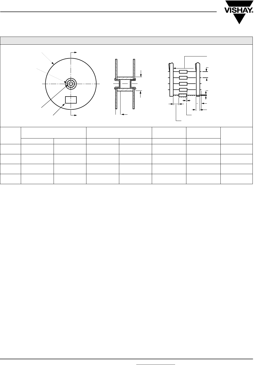
150D
Vishay Sprague Solid-Electrolyte TANTALEX® Capacitors
Hermetically-Sealed, Axial-Lead
www.vishay.com For technical questions, contact: tantalum@vishay.com Document Number: 40015
26 Revision: 16-Jan-08
STANDARD REEL PACKAGING INFORMATION
1. Component Leads:
a. Component leads shall not be bent beyond 0.047"
[1.19 mm] maximum from their nominal position when
measured from the leading edge of the component lead
at the inside tape edge and at the lead egress from the
component.
b. The “C” dimension shall be governed by the overall
length of the reel packaged component. The distance
between flanges shall be 0.125" to 0.250" [3.18 mm to
6.35 mm] greater than the overall component length.
2. Orientation:
All polarized components must be oriented to one
direction. The cathode lead tape shall be a color and the
anode lead tape shall be white.
3. Reeling:
a. Components on any reel shall not represent more than
two date codes when date code identification is required.
b. Component leads shall be positioned between pairs of
0.250" [6.35 mm] tape.
c. The disposable reels have hubs and corrugated
fibreboard flanges and core or equivalent.
d. A minimum of 12.0" [304.8 mm] leader of tape shall be
provided before the first and after the last component on
the reel.
e. 50 or 60 lb. Kraft paper must be wound between layer of
components as far as necessary for component
protection. Width of paper to be 0.062" to 0.250"
[1.57 mm to 6.35 mm] less than the “C” dimension
of the reel. Solid-Electrolyte TANTALEX® Capacitors
Hermetically- Sealed, Axial-Lead.
f. A row of components must be centered between tapes
± 0.047" [1.19 mm]. In addition, individual components
may deviate from center of component row ± 0.031"
[0.79 mm].
g. Staples shall not be used for splicing. Not more than
4 layers of tape shall be used in any splice area and no
tape shall be offset from another by more than 0.031"
[0.79 mm] non-cumulative. Tape splices shall overlap at
least 6.0" [152.4 mm] for butt joints and at least 3.0"
[76.2 mm] for lap joints and shall not be weaker than
unspliced tape. Universal splicing clips may also be used.
h. Quantity per reel shall be controlled so that tape
components and cover shall not extend beyond the
smallest dimension of the flange (either across flats or
diameter). Once the quantity per reel for each part
number has been established, future orders for that part
number shall be packaged in that quantity. When order or
release quantity is less than the established quantity, a
standard commercial pack is to be used.
i. A maximum of 0.25 % of the components per reel
quantity may be missing without consecutive missing
components.
j. Adequate protection must be provided to prevent
physical damage to both reel and components during
shipment and storage.
4. Marking:
Minimum reel and carton marking shall consist of the
following: Customer Part Number, Purchase Order No.,
Quantity, Package Date, Manufacturer's Name, Electrical
Value, Date Code, Vishay Sprague Part Number and
Country of Origin.
STANDARD REEL PACKAGING SPECIFICATIONS - MEETS EIA STANDARD RS-296 in inches [millimeters]
CASE
CODE
TYPE 150D UNITS WITH
INSULATING SLEEVE LEAD SIZE COMPONENT
SPACING TAPE SPACING UNITS
PER REEL
D L AWG NO. NOM. DIA. A B
A 0.135 ± 0.016
[3.43 ± 0.41]
0.286 ± 0.031
[7.26 ± 0.79] 24 0.020
[0.51]
0.200 ± 0.015
[5.08 ± 0.38]
2.500 ± 0.062
[63.5 ± 1.57] 1000
B 0.185 ± 0.016
[4.70 ± 0.41]
0.474 ± 0.031
[12.04 ± 0.79] 24 0.020
[0.51]
0.200 ± 0.015
[5.08 ± 0.38]
2.500 ± 0.062
[63.5 ± 1.57] 1000
R 0.289 ± 0.016
[7.34 ± 0.41]
0.686 ± 0.031
[17.42 ± 0.79] 22 0.025
[0.64]
0.400 ± 0.015
[10.16 ± 0.38]
2.875 ± 0.062
[73.03 ± 1.57] 500
S 0.351 ± 0.016
[8.92 ± 0.41]
0.786 ± 0.031
[19.96 ± 0.79] 22 0.025
[0.64]
0.400 ± 0.015
[10.16 ± 0.38]
2.875 ±0.062
[73.03 ± 1.57] 500
1.126 to 3.07
[28.6 to 78.0]
I. D. REEL HUB
13.0 [330.2]
STANDARD REEL
THRU HOLE
LABEL (4. a)
1.374 to 3.626
[34.9 to 92.1]
SECTION “A” - “A”
A
TAPE SPACING
B
BOTH SIDES (3. f)
COMPONENT
SPACING
0.031 [0.79] MAX.
OFF CENTER (1. a)
0.125 [3.18] MAX.
0.250 [6.35] (3. b)
0.031 [0.79] (3. f)
0.750 [19.05]
0.625 ± 0.0062 DIA.
[15.88 ± 1.575]
“A”
“A”

Document Number: 40016 For technical questions, contact: tantalum@vishay.com www.vishay.com
Revision: 18-Jan-08 27
Solid-Electrolyte TANTALEX® Capacitors Extended
Capacitance Values, Hermetically-Sealed
152D
Vishay Sprague
FEATURES
•Terminatons: Tin/lead (SnPb), 100 % Tin
(RoHS compliant)
•High capacitance and small size
•Low leakage current and low dissipation factor
•Exceptional operating stability
•Hermetically-sealed, cylindrical, metal-case
•The military equivalent to the 152D is the CSR23 which is
qualified to MIL-C-39003/03
•Provide proven reliability in a wide variety of high
performance military, industrial and commercial markets
PERFORMANCE CHARACTERISTICS
Operating Temperature: - 55 °C to + 85 °C
(To + 125 °C with voltage derating)
Capacitance Tolerance: At 120 Hz, + 25 °C ± 20 % and
± 10 % standard, ± 5 % available as special
Dissipation Factor: At 120 Hz, + 25 °C. Dissipation factor,
as determined from the expression 2πfRC, shall not exceed
the values listed in the Standard Ratings Tables
DC Leakage Current (DCL Max.):
At + 25 °C: Leakage current shall not exceed the values
listed in the Standard Ratings Tables
At + 85 °C: Leakage current shall not exceed 10 times the
values listed in the Standard Ratings Tables
At + 125 °C: Leakage shall not exceed 12 times the values
listed in the Standard Ratings Tables.
Life Test: Capacitors shall withstand rated DC voltage
applied at + 85 °C for 2000 h or derated DC voltage applied
at + 125 °C for 1000 h.
Following the life test:
1.DCL shall not exceed 125 % of the initial requirements. In
no case need the leakage current be less than 2 µA.
2.Dissipation Factor shall meet the initial requirement
3.Change in capacitance shall not exceed ± 5 %
Notes:
(1) When a shrink-fitted insulation is used, it shall lap over the ends of the capacitor body
* Pb containing terminations are not RoHS compliant, exemptions may apply
Available
RoHS*
COMPLIANT
ORDERING INFORMATION
152D 106 X0 006 A 2 T E3
MODEL CAPACITANCE CAPACITANCE
TOLERANCE
DC VOLTAGE RATING
AT + 85 °C
CASE
CODE
STYLE
NUMBER
PACKAGING ROHS
COMPLIANT
This is expressed in
picofarads. The first
two digits are the
significant figures. The
third is the number of
zeros to follow.
X0 = ± 20 %
X9 = ± 10 %
*X5 = ± 5 %
*Special Order
This is expressed in volts.
To complete the
three-digit block, zeros
precede the voltage
rating.
See Ratings
and Case
Codes
Table.
2 =
Insulated
sleeve.
T = Tape and
Reel
E3 = 100 % tin
termination
(RoHS compliant)
Blank = SnPb
termination
DIMENSIONS in inches [millimeters]
CASE
CODE
WITH INSULATING SLEEVE (1) J (MAXIMUM) LEAD SIZE
D L AWG NO. NOMINAL DIA.
A 0.135 ± 0.016 [3.43 ± 0.41] 0.286 ± 0.031 [7.26 ± 0.79] 0.422 [10.72] 24 0.020 [0.51]
B 0.185 ± 0.016 [4.70 ± 0.41] 0.474 ± 0.031 [12.04 ± 0.79] 0.610 [15.49] 24 0.020 [0.51]
R 0.289 ± 0.016 [7.34 ± 0.41] 0.686 ± 0.031 [17.42 ± 0.79] 0.822 [20.88] 22 0.025 [0.64]
S 0.351 ± 0.016 [8.92 ± 0.41] 0.786 ± 0.031 [19.96 ± 0.79] 0.922 [23.42] 22 0.025 [0.64]
D
DIA.
L
J
MAX.
.
SOLID TINNED
LEADS
1.500 ± 0.250
[38.10 ± 6.35]
1.500 ± 0.250
[38.10 ± 6.35]
0.047 [1.19] MAX.
0.125 [3.18] MAX.
-+

152D
Vishay Sprague Solid-Electrolyte TANTALEX® Capacitors Extended
Capacitance Values, Hermetically-Sealed
www.vishay.com For technical questions, contact: tantalum@vishay.com Document Number: 40016
28 Revision: 18-Jan-08
STANDARD RATINGS
CAPACITANCE (µF) CASE CODE PART NUMBER (1)
CAP. TOL. ± 20 %
PART NUMBER (1)
CAP. TOL. ± 10 %
Max. DCL
AT+ 25 °C
(µA)
Max. DF
AT + 25 °C
120 Hz (%)
6 WVDC AT + 85 °C, SURGE = 8 V . . . 4 WVDC AT + 125 °C, SURGE = 5 V
10 A 152D106X0006A2 152D106X9006A2 1.0 6
12 A - 152D126X9006A2 1.0 6
15 A 152D156X0006A2 152D156X9006A2 1.0 6
68 B 152D686X0006B2 152D686X9006B2 3.0 6
82 B - 152D826X9006B2 3.0 6
100 B 152D107X0006B2 152D107X9006B2 6.0 6
330 R 152D337X0006R2 152D337X9006R2 10.0 8
390 R - 152D397X9006R2 10.0 8
470 R 152D477X0006R2 152D477X9006R2 10.0 8
560 S - 152D567X9006S2 20.0 10
680 S 152D687X0006S2 152D687X9006S2 20.0 10
820 S - 152D827X9006S2 20.0 10
1000 S 152D108X0006S2 152D108X9006S2 20.0 10
10 WVDC AT + 85 °C, SURGE = 13 V . . . 7 WVDC AT + 125 °C, SURGE = 9 V
5.6 A - 152D565X9010A2 1.0 4
6.8 A 152D685X0010A2 152D685X9010A2 1.0 6
8.2 A - 152D825X9010A2 1.2 6
10 A 152D106X0010A2 152D106X9010A2 1.2 6
47 B 152D476X0010B2 152D476X9010B2 4.0 6
56 B - 152D566X9010B2 5.0 6
68 B 152D686X0010B2 152D686X9010B2 6.0 6
82 B - 152D826X9010B2 7.0 6
150 R 152D157X0010R2 152D157X9010R2 8.0 8
180 R - 152D187X9010R2 8.0 8
220 R 152D227X0010R2 152D227X9010R2 12.0 8
270 R - 152D277X9010R2 13.0 8
330 S 152D337X0010S2 152D337X9010S2 16.0 8
390 S - 152D397X9010S2 16.0 10
470 S 152D477X0010S2 152D477X9010S2 16.0 10
560 S - 152D567X9010S2 20.0 10
15 WVDC AT + 85 °C, SURGE = 20 V . . . 10 WVDC AT + 125 °C, SURGE = 12 V
3.9 A - 152D395X9015A2 1.0 4
4.7 A 152D475X0015A2 152D475X9015A2 1.0 4
5.6 A - 152D565X9015A2 1.3 4
6.8 A 152D685X0015A2 152D685X9015A2 1.3 6
27 B - 152D276X9015B2 3.0 6
33 B 152D336X0015B2 152D336X9015B2 5.0 6
39 B - 152D396X9015B2 5.0 6
82 R - 152D826X9015R2 8.0 6
100 R 152D107X0015R2 152D107X9015R2 10.0 8
120 R - 152D127X9015R2 10.0 8
150 R 152D157X0015R2 152D157X9015R2 15.0 8
180 R - 152D187X9015R2 15.0 8
220 S 152D227X0015S2 152D227X9015S2 20.0 8
270 S - 152D277X9015S2 20.0 8
330 S 152D337X0015S2 152D337X9015S2 20.0 8
Note:
(1) Insert capacitance tolerance code “X5” for ± 5 % units (special order).

Document Number: 40016 For technical questions, contact: tantalum@vishay.com www.vishay.com
Revision: 18-Jan-08 29
152D
Solid-Electrolyte TANTALEX® Capacitors Extended
Capacitance Values, Hermetically-Sealed Vishay Sprague
STANDARD RATINGS
CAPACITANCE (µF) CASE CODE PART NUMBER (1)
CAP. TOL. ± 20 %
PART NUMBER (1)
CAP. TOL. ± 10 %
Max. DCL
AT + 25 °C
(µA)
Max. DF
AT + 25 °C
120 Hz (%)
20 WVDC AT + 85 °C, SURGE = 26 V . . . 13 WVDC AT + 125 °C, SURGE = 16 V
2.7 A - 152D275X9020A2 0.8 4
3.3 A 152D335X0020A2 152D335X9020A2 1.0 4
3.9 A - 152D395X9020A2 1.2 4
4.7 A 152D475X0020A2 152D475X9020A2 1.2 4
18 B - 152D186X9020B2 3.0 4
22 B 152D226X0020B2 152D226X9020B2 3.0 4
27 B - 152D276X9020B2 4.0 4
56 R - 152D566X9020R2 7.0 6
68 R 152D686X0020R2 152D686X9020R2 8.0 6
82 R - 152D826X9020R2 10.0 6
100 R 152D107X0020R2 152D107X9020R2 12.0 6
120 R -152D127X9020R2 12.0 6
150 S 152D157X0020S2 152D157X9020S2 15.0 8
180 S -152D187X9020S2 15.0 8
220 S 152D227X0020S2 152D227X9020S2 15.0 8
30 WVDC AT + 85 °C, SURGE = 39 V . . . 20 WVDC AT + 125 °C, SURGE = 26 V
2.2 A 152D225X0030A2 152D225X9030A2 1.0 4
2.7 A - 152D275X9030A2 1.0 4
12 B - 152D126X9030B2 3.0 4
15 B 152D156X0030B2 152D156X9030B2 3.0 4
18 B - 152D186X9030B2 3.0 4
56 R - 152D566X9030R2 7.0 6
68 R 152D686X0030R2 152D686X9030R2 7.0 6
82 S - 152D826X9030S2 10.0 8
100 S 152D107X0030S2 152D107X9030S2 10.0 8
35 WVDC AT + 85 °C, SURGE = 46 V . . . 23 WVDC AT + 125 °C, SURGE = 28 V
1.2 A - 152D125X9035A2 0.6 4
1.5 A 152D155X0035A2 152D155X9035A2 0.8 4
1.8 A - 152D185X9035A2 1.0 4
8.2 B - 152D825X9035B2 3.0 4
10 B 152D106X0035B2 152D106X9035B2 3.0 4
27 R - 152D276X9035R2 7.0 6
33 R 152D336X0035R2 152D336X9035R2 8.0 6
39 R - 152D396X9035R2 10.0 6
47 R 152D476X0035R2 152D476X9035R2 10.0 6
56 S - 152D566X9035S2 12.0 6
68 S 152D686X0035S2 152D686X9035S2 12.0 6
82 S - 152D826X9035S2 30.0 8
100 S 152D107X0035S2 152D107X9035S2 30.0 8
50 WVDC AT + 85 °C, SURGE = 65 V . . . 33 WVDC AT + 125 °C, SURGE = 40 V
1.2 A - 152D125X9050A2 0.6 4
1.5 A 152D155X0050A2 152D155X9050A2 0.8 4
5.6 B - 152D565X9050B2 2.5 4
6.8 B 152D685X0050B2 152D685X9050B2 2.5 4
22 R 152D226X0050R2 152D226X9050R2 7.0 6
27 R - 152D276X9050R2 8.0 6
33 S 152D336X0050S2 152D336X9050S2 10.0 6
39 S - 152D396X9050S2 10.0 6
47 S 152D476X0050S2 152D476X9050S2 10.0 6
60 WVDC AT + 85 °C, SURGE = 78 V . . . 39 WVDC AT + 125 °C, SURGE = 49 V
22 R 152D226X0060R2 - 7 6
Note:
(1) Insert capacitance tolerance code “X5” for ± 5 % units (special order).

152D
Vishay Sprague Solid-Electrolyte TANTALEX® Capacitors Extended
Capacitance Values, Hermetically-Sealed
www.vishay.com For technical questions, contact: tantalum@vishay.com Document Number: 40016
30 Revision: 18-Jan-08
STANDARD REEL PACKAGING INFORMATION
1. Component Leads:
a. Component leads shall not be bent beyond 0.047"
[1.19 mm] maximum from their nominal position when
measured from the leading edge of the component lead
at the lead egress from the component.
b. The “C” dimension shall be governed by the overall
length of the reel packaged component. The distance
between flanges shall be 0.125" to 0.250" [3.18 mm to
6.35 mm] greater than the overall component length.
2. Orientation:
a. All polarized components must be oriented to one
direction. The cathode lead tape shall be a color and the
anode lead tape shall be white.
3. Reeling:
a. Components on any reel shall not represent more than
two date codes when date code identification is required.
b. Component leads shall be positioned between pairs of
0.250" [6.35 mm] tape.
c. The disposable reels have hubs and corrugated
fibreboard flanges and core or equivalent.
d. A minimum of 12" [304.8 mm] leader of tape shall be
provided before the first and after the last component on
the reel.
e. 50 or 60 lb. Kraft paper must be wound between layer of
components as far as necessary for component
protection. Width of paper to be 0.062" to 0.250" [1.57
mm to 6.35 mm] less than the “C” dimension of the reel.
f. A row of components must be centered between
tapes ± 0.047" [1.19 mm]. In addition, individual
components may deviate from center of component row
± 0.031" [0.79 mm].
g. Staples shall not be used for splicing. Not more than
4 layers of tape shall be used in any splice area and no
tape shall be offset from another by more than 0.031"
[0.79 mm] non-cumulative. Tape splices shall overlap at
least 6" [152.4 mm] for butt joints and at least 3"[76.2 mm]
for lap joints and shall not be weaker than unspliced tape.
Universal splicing clips may also be used.
h. Quantity per reel shall be controlled so that tape
components and cover shall not extend beyond the
smallest dimension of the flange (either across flats or
diameter). Once the quantity per reel for each part
number has been established, future orders for that part
number shall be packaged in that quantity. When order or
release quantity is less than the established quantity, a
standard commercial pack is to be used.
i. A maximum of 0.25 % of the components per reel
quantity may be missing without consecutive missing
components.
j. Adequate protection must be provided to prevent
physical damage to both reel and components during
shipment and storage.
4. Marking:
Minimum reel and carton marking shall consist of the
following: Customer Part Number, Purchase Order No.,
Quantity, Package Date, Manufacturer's Name, Electrical
Value, Date Code, Vishay Sprague Part Number and
Country of Origin.
STANDARD REEL PACKAGING SPECIFICATIONS - MEETS EIA STANDARD RS-296 in inches [millimeters]
CASE
CODE
TYPE 152D UNITS WITH
INSULATING SLEEVE J (MAX.) LEAD SIZE COMPONENT
SPACING TAPE SPACING UNITS
PER REEL
D L AWG NO. NOM. DIA. A B
A 0.135 ± 0.016
[3.43 ± 0.41]
0.286 ± 0.031
[7.26 ± 0.79]
0.422
[10.72] 24 0.020
[0.51]
0.200 ± 0.015
[5.08 ± 0.38]
2.500 ± 0.062
[63.5 ± 1.57] 1000
B 0.185 ± 0.016
[4.70 ± 0.41]
0.474 ± 0.031
[12.04 ± 0.79]
0.610
[15.49] 24 0.020
[0.51]
0.200 ± 0.015
[5.08 ± 0.38]
2.500 ± 0.062
[63.5 ± 1.57] 1000
R 0.289 ± 0.016
[7.34 ± 0.41]
0.686 ± 0.031
[17.42 ± 0.79]
0.822
[20.88] 22 0.025
[0.64]
0.400 ± 0.015
[10.16 ± 0.38]
2.875 ± 0.062
[73.03 ± 1.57] 500
S 0.351 ± 0.016
[8.92 ± 0.41]
0.786 ± 0.031
[19.96 ± 0.79]
0.922
[23.42] 22 0.025
[0.64]
0.400 ± 0.015
[10.16 ± 0.38]
2.875 ±0.062
[73.03 ± 1.57] 500
1.126 to 3.07
[28.6 to 78.0]
I. D. REEL HUB
13.0 [330.2]
STANDARD REEL
DIA. THRU HOLE
LABEL (4.a)
1.374 to 3.626
[34.9 to 92.1]
SECTION "A" - "A"
A
TAPE SPACING
B
BOTH SIDES (3. f)
COMPONENT
SPACING
0.031 [0.79] MAX.
OFF CENTER (1. a)
0.125 [3.18] MAX.
0.250 [6.35] (3. b)
0.031 [0.79] (3. f)
0.750 [19.05]
0.625 ± 0.0062 DIA.
[15.88 ± 1.575]
“A”
“A”

Document Number: 40017 For technical questions, contact: tantalum@vishay.com www.vishay.com
Revision: 28-Nov-07 31
550D
Vishay Sprague
Solid-Electrolyte TANTALEX® Capacitors
for High Frequency Power Supplies
FEATURES
•Terminatons: Tin/lead (SnPb), 100 % Tin
(RoHS compliant)
•Hermetically-sealed, axial-lead solid tantalum
capacitors
•Small size and long life
•Exceptional capacitance stability and excellent resistance
to severe environmental conditions
•The military equivalent is the CSR21 which is qualified to
MIL-C-39003/09
APPLICATIONS
Designed for power supply filtering applications at above
100 kHz
PERFORMANCE CHARACTERISTICS
Operating Temperature: - 55 °C to + 85 °C,
(To + 125 °C with voltage derating.)
Capacitance Tolerance: At 120 Hz, + 25 °C. ± 20 %,
± 10 % standard. ± 5 % available as special
Dissipation Factor: At 120 Hz, + 25 °C. Dissipation factor,
as determined from the expression 2πRC, shall not exceed
the values listed in the Standard Ratings Tables
DC Leakage Current (DCL Max.):
At + 25°C: Leakage current shall not exceed the values
listed in he Standard Ratings Tables
At + 85°C: Leakage current shall not exceed 10 times the
values listed in the Standard Ratings Tables.
At +125°C: Leakage shall not exceed 15 times the values
listed in the Standard Ratings Tables.
Life Test: Capacitors shall withstand rated DC voltage
applied at + 85 °C for 2000 h or derated DC voltage applied
at + 125 °C for 1000 h.
Following the life test:
1. DCL shall not exceed 125 % of the initial requirements.
2. Dissipation Factor shall meet the initial requirement.
3. Change in capacitance shall not exceed ± 5 %
Notes:
(1) When a shrink-fitted insulation is used, it shall lap over the ends of the capacitor body
* Pb containing terminations are not RoHS compliant, exemptions may apply
Available
RoHS*
COMPLIANT
ORDERING INFORMATION
550D 157 X0 006 R 2 T E3
MODEL CAPACITANCE CAPACITANC
E TOLERANCE
DC VOLTAGE RATING
AT + 85 °C
CASE
CODE
STYLE
NUMBER
PACKAGING ROHS
COMPLIANT
This is expressed in picofarads.
The first two digits are the
significant figures. The third is the
number of zeros to follow.
Standard capacitance ratings are
in accordance with EIA preferred
number series wherever possible.
X0 = ± 20 %
X9 = ± 10 %
X5 = ± 5 %
* Special order
This is expressed in
volts.
To complete the
three-digit block, zeros
precede the voltage
rating.
See
Ratings
and
Case
Codes
Ta b l e.
2 =
Insulated
sleeve
T = Tape and
Reel
E3 = 100 %
tin termination
(RoHS
compliant)
Blank = SnPb
termination
DIMENSIONS in inches [millimeters]
CASE
CODE
WITH INSULATING SLEEVE (1)
J (MAX.) LEAD SIZE
D L AWG NO. NOMINAL DIA.
R 0.289 ± 0.016 [7.34 ± 0.41] 0.686 ± 0.031 [17.42 ± 0.79] 0.822 [20.880] 22 0.025 [0.64]
S 0.351 ± 0.016 [8.92 ± 0.41] 0.786 ± 0.031 [19.96 ± 0.79] 0.922 [23.420] 22 0.025 [0.64]
D
DIA.
L
J
MAX.
SOLID TINNED
LEADS
0.047 [1.19] MAX.
0.125 [3.18] MAX.
1.500 ± 0.250
[38.10 ± 6.35]
1.500 ± 0.250
[38.10 ± 6.35]

550D
Vishay Sprague Solid-Electrolyte TANTALEX® Capacitors
for High Frequency Power Supplies
www.vishay.com For technical questions, contact: tantalum@vishay.com Document Number: 40017
32 Revision: 28-Nov-07
STANDARD RATINGS
CAPACITANCE
(µF)
CASE
CODE
PART NUMBER (1)
CAP. TOL. ± 20 %
PART NUMBER (1)
CAP. TOL. ± 10 %
Max. DCL
at + 25 °C
(µA)
Max. DF
at + 25 °C
120 Hz (%)
Max. ESR
at + 25 °C
100 kHz (Ω)
6 WVDC AT + 85 °C, SURGE = 8 V . . . 4 WVDC AT + 125 °C, SURGE = 5 V
150 R 550D157X0006R2 550D157X9006R2 9 10 0.065
180 R 550D187X0006R2 550D187X9006R2 11 10 0.060
220 S 550D227X0006S2 550D227X9006S2 12 10 0.055
270 S 550D277X0006S2 550D277X9006S2 13 10 0.050
330 S 550D337X0006S2 550D337X9006S2 15 12 0.045
10 WVDC AT + 85 °C, SURGE = 13 V . . . 7 WVDC AT + 125 °C, SURGE = 9 V
82 R 550D826X0010R2 550D826X9010R2 8 8 0.085
100 R 550D107X0010R2 550D107X9010R2 10 8 0.075
120 R 550D127X0010R2 550D127X9010R2 12 8 0.070
150 S 550D157X0010S2 550D157X9010S2 15 8 0.065
180 S 550D187X0010S2 550D187X9010S2 18 8 0.060
220 S 550D227X0010S2 550D227X9010S2 20 10 0.055
15 WVDC AT + 85 °C, SURGE = 20 V . . . 10 WVDC AT + 125 °C, SURGE = 12 V
56 R 550D566X0015R2 550D566X9015R2 8 6 0.100
68 R 550D686X0015R2 550D686X9015R2 10 6 0.095
82 S 550D826X0015S2 550D826X9015S2 12 6 0.085
100 S 550D107X0015S2 550D107X9015S2 15 8 0.075
120 S 550D127X0015S2 550D127X9015S2 18 8 0.070
150 S 550D157X0015S2 550D157X9015S2 20 8 0.065
20 WVDC AT + 85 °C, SURGE = 26 V . . . 13 WVDC AT + 125 °C, SURGE = 16 V
27 R 550D276X0020R2 550D276X9020R2 5 5 0.145
33 R 550D336X0020R2 550D336X9020R2 7 5 0.130
39 R 550D396X0020R2 550D396X9020R2 8 5 0.120
47 R 550D476X0020R2 550D476X9020R2 9 6 0.110
56 S 550D566X0020S2 550D566X9020S2 11 6 0.100
68 S 550D686X0020S2 550D686X9020S2 14 6 0.095
82 S 550D826X0020S2 550D826X9020S2 16 6 0.085
100 S 550D107X0020S2 550D107X9020S2 20 8 0.075
35 WVDC AT + 85 °C, SURGE = 46 V . . . 23 WVDC AT + 125 °C, SURGE = 28 V
8.2 R 550D825X0035R2 550D825X9035R2 3 4 0.250
10 R 550D106X0035R2 550D106X9035R2 4 4 0.230
12 R 550D126X0035R2 550D126X9035R2 4 4 0.210
15 R 550D156X0035R2 550D156X9035R2 5 4 0.190
18 R 550D186X0035R2 550D186X9035R2 6 4 0.175
22 R 550D226X0035R2 550D226X9035R2 8 4 0.160
27 S 550D276X0035S2 550D276X9035S2 9 4 0.145
33 S 550D336X0035S2 550D336X9035S2 11 5 0.130
39 S 550D396X0035S2 550D396X9035S2 14 5 0.120
47 S 550D476X0035S2 550D476X9035S2 16 5 0.110
50 WVDC AT + 85 °C, SURGE = 65 V . . . 33 WVDC AT + 125 °C, SURGE = 40 V
5.6 R 550D565X0050R2 550D565X9050R2 4 3 0.300
6.8 R 550D685X0050R2 550D685X9050R2 4 3 0.275
8.2 R 550D825X0050R2 550D825X9050R2 5 3 0.250
10.0 R 550D106X0050R2 550D106X9050R2 5 3 0.230
12.0 R 550D126X0050R2 550D126X9050R2 6 3 0.210
15.0 R 550D156X0050R2 550D156X9050R2 8 3 0.190
18.0 R 550D186X0050R2 550D186X9050R2 9 4 0.175
22.0 S 550D226X0050S2 550D226X9050S2 11 4 0.160
Note:
(1) Insert capacitance tolerance code “X5”; for ± 5 % units (special order).

Document Number: 40017 For technical questions, contact: tantalum@vishay.com www.vishay.com
Revision: 28-Nov-07 33
550D
Solid-Electrolyte TANTALEX® Capacitors
for High Frequency Power Supplies
Vishay Sprague
STANDARD REEL PACKAGING INFORMATION
1. Component Leads:
a. Component leads shall not be bent beyond 0.047"
[1.19 mm] maximum from their nominal position when
measured from the leading edge of the component lead
at the inside tape edge and at the lead egress from the
component.
b. The “C” dimension shall be governed by the overall
length of the reel packaged component. The distance
between flanges shall be 0.125" to 0.250" [3.18 mm to
6.35 mm] greater than the overall component length.
2. Orientation:
a. All polarized components must be oriented to one
direction. The cathode lead tape shall be a color and the
anode lead tape shall be white.
3. Reeling:
a. Components on any reel shall not represent more than
two date codes when date code identification is required.
b. Component leads shall be positioned between pairs of
0.250" [6.35 mm] tape.
c. The disposable reels have hubs with corrugated
fibreboard flanges and core or equivalent.
d. A minimum of 12" [304.8 mm] leader of tape shall be
provided before the first and after the last component on
the reel.
e. 50 or 60 lb. Kraft paper must be wound between layer
of components as far as necessary for component
protection. Width of paper to be 0.062" to 0.250"
[1.57 mm to 6.35 mm] less than the “C” dimension of the
reel.
f. A row of components must be centered between tapes
± 0.047" [1.19 mm]. In addition, individual components
may deviate from center of component row ± 0.031"
[0.79 mm].
g. Staples shall not be used for splicing. Not more than
4 layers of tape shall be used in any splice area and no
tape shall be offset from another by more than 0.031"
[0.79 mm] non-cumulative. Tape splices shall overlap at
least 6" [152.4 mm] for butt joints and at least 3"
[76.2 mm] for lap joints and shall not be weaker than
unspliced tape. Universal splicing clips may also be used.
h. Quantity per reel shall be controlled so that tape
components and cover shall not extend beyond the
smallest dimension of the flange (either across flats or
diameter). Once the quantity per reel for each part
number has been established, future orders for that part
number shall be packaged in that quantity. When order or
release quantity is less than the established quantity, a
standard commercial pack is to be used.
i. A maximum of 0.25 % of the components per reel
quantity may be missing without consecutive missing
components.
j. Adequate protection must be provided to prevent
physical damage to both reel and components during
shipment and storage.
4. Marking:
a. Minimum reel and carton marking shall consist of the
following: Customer Part Number, Purchase Order No.,
Quantity, Package Date, Manufacturer's name, Electrical
Value, Date Code, Vishay Sprague Part Number and
Country of Origin.
TAPE AND REEL PACKAGING in inches [millimeters]
CASE
CODE
TYPE 550D UNITS WITH
INSULATING SLEEVE J (MAX.) LEAD SIZE COMPONENT
SPACING TAPE SPACING UNITS
PER REEL
D L AWG NO. NOM. DIA. A B
R 0.289 ± 0.016
[7.34 ± 0.41]
0.686 ± 0.031
[17.42 ± 0.79]
0.822
[20.88] 22 0.025
[0.64]
0.400 ± 0.015
[10.16 ± 0.38]
2.875 ± 0.062
[73.03 ± 1.57] 500
S 0.351 ± 0.016
[8.92 ± 0.41]
0.786 ± 0.031
[19.96 ± 0.79]
0.922
[23.42] 22 0.025
[0.64]
0.400 ± 0.015
[10.16 ± 0.38]
2.875 ±0.062
[73.03 ± 1.57] 500
1.126 to 3.07
[28.6 to 78.0]
I. D. REEL HUB
13.0 [330.2]
STANDARD REEL
DIA. THRU HOLE
LABEL (4. a)
1.374 to 3.626
[34.9 to 92.1]
SECTION "A" - "A"
A
TAPE SPACING
B
BOTH SIDES (3. f)
COMPONENT
SPACING
0.047 [1.19] MAX.
OFF CENTER (1. a)
0.125 [3.18] MAX.
0.250 [6.35] (3. b)
0.031 [0.79] (3. f)
0.750 [19.05]
0.625 ± 0.0062 DIA.
[15.88 ± 1.575]
“A”
“A”

www.vishay.com For technical questions, contact: tantalum@vishay.com Document Number: 40017
34 Revision: 28-Nov-07
550D
Vishay Sprague Solid-Electrolyte TANTALEX® Capacitors
for High Frequency Power Supplies
TYPICAL CURVES AT + 25 °C, IMPEDANCE AND ESR VS. FREQUENCY
1
0.1
0.01
FREQUENCY IN Hz
100 1K 10K 100K 1M 10M
10
Ω
IMPEDANCE
ESR
180 µF, 6 V
330 µF, 6 V
150 µF, 6 V
180 µF, 6 V
1
0.1
0.01
FREQUENCY IN Hz
100 1K 10K 100K 1M 10M
10
Ω
IMPEDANCE
ESR
220 µF, 10 V
220 µF, 10 V
120 µF, 10 V 120 µF, 10 V
1
0.1
0.01
FREQUENCY IN Hz
100 1K 10K 100K 1M 10M
10
Ω
68 µF, 15 V 68 µF, 15 V
150 µF, 15 V
150 µF, 15 V
IMPEDANCE
ESR
1
0.1
0.01
FREQUENCY IN Hz
100 1K 10K 100K 1M 10M
10
Ω
IMPEDANCE
ESR
100 µF, 20 V
100 µF, 20 V
47 µF, 20 V
47µF, 20 V
1
0.1
0.01
FREQUENCY IN Hz
100 1K 10K 100K 1M 10M
10
Ω
47 µF, 35 V
47 µF, 35 V
22 µF, 35 V22 µF, 35 V
IMPEDANCE
ESR
1
0.1
0.01
FREQUENCY IN Hz
100 1K 10K 100K 1M 10M
10
Ω
IMPEDANCE
ESR
22 µF, 50 V
22 µF, 50 V
18 µF, 50 V
18 µF, 50 V

Document Number: 40017 For technical questions, contact: tantalum@vishay.com www.vishay.com
Revision: 28-Nov-07 35
550D
Solid-Electrolyte TANTALEX® Capacitors
for High Frequency Power Supplies
Vishay Sprague
PERFORMANCE CHARACTERISTICS
•Operating Temperature: Capacitors are designed to
operate over the temperature range of
- 55 °C to + 85 °C with no derating.
•Capacitors may be operated up to + 125 °C with voltage
derating to two-thirds the + 85 °C rating.
2. DC Working Voltage: The DC working voltage is the
maximum operating voltage for continuous duty at the
rated temperature.
3. Surge Voltage: The surge DC rating is the maximum
voltage to which the capacitors may be subjected
under any conditions, including transients and peak
ripple at the highest line voltage.
3.1 Surge Voltage Test: Capacitors shall withstand the
surge voltage applied in series with a 33 Ω ± 5 %
resistor at the rate of 1.5 min on, 1.5 min off at
+ 85 °C, for 1000 successive test cycles.
3.2 Following the surge voltage test, the dissipation factor
and the leakage current shall meet the initial
requirements; the capacitance shall not have
changed more than ± 10 %.
4. Capacitance Tolerance: The capacitance of all
capacitors shall be within the specified tolerance
limits of the nominal rating.
4.1 Capacitance measurements shall be made by means
of polarized capacitance bridge. The polarizing
voltage shall be of such magnitude that there shall be
no reversal of polarity due to the AC component. The
maximum voltage applied to capacitors during
measurement shall be 2 Vrms at 1000 Hz at
+ 25 °C. If the AC voltage applied is less than one-half
volt rms, no DC bias is required. Measurement
accuracy of the bridge shall be within ± 2 %.
5. Capacitance Change With Temperature: The
capacitance change with temperature shall not
exceed the following percentage of the capacitance
measured at + 25 %
6. Dissipation Factor: The dissipation factor,
determined from the expression 2πfRC, shall not
exceed values listed in the Standard Ratings Table.
6.1 Measurements shall be made by the bridge method
at, or referred to, a frequency of 1000 Hz and a
temperature of + 25 °C.
7. Leakage Current: Capacitors shall be stabilized at
the rated temperature for 30 min. Rated voltage shall
be applied to capacitors for 5 min using a steady
source of power (such as a regulated power supply)
with 1000 Ω resistor connected in series with the
capacitor under test to limit the charging current.
Leakage current shall then be measured.
Note that the leakage current varies with temperature and
applied voltage. See graph below for the appropriate
adjustment factor.
+ 85 °C RATING + 125 °C RATING
Working
Volt age
(V)
Surge
Vol tage
(V)
Working
Volt age
(V)
Surge
Voltage
(V)
6845
10 13 7 9
15 20 10 12
20 26 13 16
35 46 23 28
50 65 33 40
- 55 °C + 85 °C + 125 °C
- 10 % + 8 % + 12 %
TYPICAL LEAKAGE CURRENT FACTOR
RANGE AT + 25 °C
1.0
0.8
0.7
0.6
0.5
0.4
0.3
0.2
0.1
0.08
0.07
0.06
0.05
0.04
0.03
0.02
0.01
0.008
0.007
0.006
0.005
0.004
0.003
0.002
0.001
LEAKAGE CURRENT FACTOR
0
PERCENT OF RATED VOLTAGE
10 3020 9040 50 60 70 80 100

550D
Vishay Sprague Solid-Electrolyte TANTALEX® Capacitors
for High Frequency Power Supplies
www.vishay.com For technical questions, contact: tantalum@vishay.com Document Number: 40017
36 Revision: 28-Nov-07
PERFORMANCE CHARACTERISTICS (Continued)
7.1 At + 25 °C, the leakage current shall not exceed the
value listed in the Standard Ratings Table.
7.2 At + 85 °C, the leakage current shall not exceed
10 times the value listed in the Standard Ratings
Table.
7.3 At + 125 °C, the leakage current shall not exceed
15 times the value listed in the Standard Ratings
Table.
8. Life Test: Capacitors shall withstand rated DC voltage
applied at + 85 °C for 2000 h or rated DC voltage
applied at + 125 °C for 1000 h.
8.1 Following the life test, the dissipation factor shall
meet the initial requirement; the capacitance change
shall not exceed ± 2 %; the leakage current shall not
exceed 125 % of the original requirement.
9. Shelf Test: Capacitors shall withstand a shelf test for
5000 h at a temperature of + 85 °C, with no voltage
applied.
9.1 Following the shelf test, the leakage current shall
meet the initial requirement; the dissipation factor
shall not exceed 150 % of the initial requirement; the
capacitance change shall not exceed ± 5 %.
10 Vibration Tests: Capacitors shall be subjected to
vibration tests in accordance with the following
criteria.
10.1 Capacitors shall be secured for test by means of a
rigid mounting using suitable brackets.
10.2 Low Frequency Vibration: Vibration shall consist of
a simple harmonic motion having an amplitude of
0.03" [0.76] and a maximum total excursion of 0.06"
[1.52], in a direction perpendicular to the major axis of
the capacitor.
10.2.1 Vibration frequency shall be varied uniformly between
the approximate limits of 10 Hz to 55 Hz during a
period of approximately one minute, continuously for
1 and 1.5 h.
10.2.2 A cathode ray oscilloscope or other comparable
means shall be used in determining electrical
intermittency during the final 30 minutes of the test.
The AC voltage applied shall not exceed 2 volts rms.
10.2.3 Electrical tests shall show no evidence of intermittent
contacts, open circuits or short circuits during these
tests.
10.2.4 Following the low frequency vibration test, capacitors
shall meet the original requirements for leakage
current and dissipation factor; capacitance change
shall not exceed ± 5 % of the original measured
value.
10.3 High Frequency Vibration: Vibration shall consist of
a simple harmonic motion having an amplitude of
0.06" [1.52] ± 10 % maximum total excursion or 20 g
peak, whichever is less.
10.3.1 Vibration Frequency shall be varied logarithmically
from 50 Hz to 2000 Hz and return to 50 Hz during a
cycle period of 20 minutes.
10.3.2 The vibration shall be applied for 4 h in each of
2 directions, parallel and perpendicular to the major
axis of the capacitors.
10.3.3 Rated DC voltage shall be applied during the
vibration cycling.
10.3.4 A cathode ray oscilloscope or other comparable
means shall be used in determining electrical
intermittency during test. The AC voltage applied
shall not exceed 2 Vrms.
10.3.5 Electrical tests shall show no evidence of intermittent
contacts, open circuits or short circuits during these
tests.
10.3.6 There shall be no mechanical damage to these
capacitors as a result of these tests.
10.3.7 Following the high frequency vibration test,
capacitors shall meet the original limits for
capacitance, dissipation factor and leakage current.
11. Acceleration Test:
11.1 Capacitors shall be rigidly mounted by means of
suitable brackets.
11.2 Capacitors shall be subjected to a constant
acceleration of 100 g for a period of 10 s in each of 2
mutually perpendicular planes.
11.2.1 The direction of motion shall be parallel to and
perpendicular to the cylindrical axis of the capacitors.
11.3 Rated DC voltage shall be applied during
acceleration test.
11.3.1 A cathode ray oscilloscope or other comparable
means shall be used in determining electrical
intermittency during test. The AC voltage applied
shall not exceed 2 Vrms.
11.4 Electrical tests shall show no evidence of intermittent
contacts, open circuits or short circuits during these
tests.
11.5 There shall be no mechanical damage to these
capacitors as a result of these tests.
11.6 Following the acceleration test, capacitors shall meet
the original limits for capacitance, dissipation factor
and leakage current.
12. Shock Test:
12.1 Capacitors shall be rigidly mounted by means of
suitable brackets. The test load shall be distributed
uniformly on the test platform to minimize the effects
of unbalanced loads.

Document Number: 40017 For technical questions, contact: tantalum@vishay.com www.vishay.com
Revision: 28-Nov-07 37
550D
Solid-Electrolyte TANTALEX® Capacitors
for High Frequency Power Supplies
Vishay Sprague
PERFORMANCE CHARACTERISTICS (Continued
)
12.1.1 Test equipment shall be adjusted to produce a shock
of 100 g peak with a duration of 6 ms and a sawtooth
waveform at a velocity change of 9.7 ft./s.
12.2 Capacitors shall be subjected to 3 shocks applied in
each of 3 directions corresponding to the 3 mutually
perpendicular axes of the capacitors.
12.3 Rated DC voltage shall be applied to capacitors
during test.
12.3.1 A cathode ray oscilloscope or other comparable
means shall be used in determining electrical
intermittency during test. The AC voltage applied
shall not exceed 2 Vrms.
12.4 Electrical tests shall show no evidence of intermittent
contacts, open circuits or short circuits during these
tests.
12.5 There shall be no mechanical damage to these
capacitors as a result of these tests.
12.6 Following the shock test, capacitors shall meet the
original limits for capacitance, dissipation factor and
leakage current.
13. Moisture Resistance:
13.1 Capacitors shall be subjected to temperature
cycling at 90 % to 98 % relative humidity, in a test
chamber constructed of non-reactive materials
(non-resiniferous and containing no formaldehyde or
phenol). Steam or distilled, demineralized or
deionized water having a pH value between 6.0 and
7.2 at + 23 °C shall be used to obtain the required
humidity. No rust, corrosive contaminants or dripping
condensate shall be imposed on test specimens.
13.1.1 Capacitors shall be mounted by their normal
mounting means in a normal mounting position and
placed in a test chamber so that uniform and thorough
exposure is obtained.
13.1.2 No conditioning or initial measurements will be
performed prior to temperature cycling. Polarization
and load voltages are not applicable.
13.1.3 Capacitors shall be subjected to temperature cycling
from + 25 °C to + 65 °C to + 25 °C (+ 10 °C, - 2 °C)
over a period of 8 h, at 90 % to 98 % relative humidity,
for 20 cycles.
13.1.4 Temperature cycling shall be stopped after an even
number of cycles 5 times during the first 18 cycles,
and the capacitor shall be alloweed to stabilize at high
humidity for 1 to 4 h.
13.1.5 After stabilization, capacitors shall be removed from
the humidity chamber and shall be conditioned for 3 h
at - 10 °C ± 2 °C.
13.1.6 After cold conditioning, capacitors shall be subjected
to vibration cycling consisting of a simple harmonic
vibration having an amplitude of 0.03" [0.76] and a
maximum total excursion of 0.06" [1.52] varied
uniformly from 10 Hz to 55 Hz to 10 Hz over a period
of 1 min, for 15 cycles.
13.1.7 Capacitors shall then be returned to temperature/
humidity cycling.
13.2 After completion of temperature cycling, capacitors
shall be removed from the test chamber and
stabilized at room temperature for 2 to 6 h.
13.3 Capacitors shall show no evidence of harmful or
extensive corrosion, obliteration or marking or other
visible damage.
13.4 Following the moisture resistance test, capacitors
shall meet the original limits for capacitance,
dissipation factor and leakage current.
14. Insulating Sleeves:
14.1 Capacitors with insulating sleeves shall withstand a
2000 VDC potential applied for 1 min between the
case and a metal “V” block in intimate contact with the
insulating sleeve.
14.2 Capacitors with insulating sleeves shall have the
insulation resistance measured between the case
and a metal “V” block in intimate contact with the
insulating sleeve. The insulation resistance shall be
at least 1000 MΩ
15. Thermal Shock And Immersion Cycling:
15.1 Capacitors shall be conditioned prior to temperature
cycling for 15 min at + 25 °C, at less than 50 %
relative humidity and a barometric pressure at 28 to
31".
15.2 Capacitors shall be subjected to thermal shock in a
cycle of exposure to ambient air at
- 65 °C (+ 0 °C, - 5 °C) for 30 min, then,
+ 25 °C (+ 10 °C, - 5 °C) for 5 min, then
+ 125 °C (+ 3 °C, - 0 °C) for 30 min, then
+ 25 °C (+ 10 °C, - 5 °C) for 5 min, for 5 cycles.
15.3 Between 4 and 24 h after temperature cycling,
capacitors shall be subjected to immersion in a bath
of fresh tap water with the non-corrosive dye
Rhodamine B added, at + 65 °C (+ 5 °C, - 0 °C) for
15 min, then, within 3 s, immersed in a saturated
solution of sodium chloride and water with
Rhodamine B added, at a temperature of + 25 °C
(+ 10 °C, - 5 °C) for 15 min, for 2 cycles.
15.3.1 Capacitors shall be thoroughly rinsed and wiped or
air-blasted dry immediately upon removal from
immersion cycling.
15.4 Capacitors shall show no evidence of harmful or
extensive corrosion, obliteration of marking or other
visible damage.

550D
Vishay Sprague Solid-Electrolyte TANTALEX® Capacitors
for High Frequency Power Supplies
www.vishay.com For technical questions, contact: tantalum@vishay.com Document Number: 40017
38 Revision: 28-Nov-07
PERFORMANCE CHARACTERISTICS (Continued)
15.5 Following the thermal shock immersion cycling test,
capacitors shall meet the original requirements for
leakage current and dissipation factor; capacitance
change shall not exceed ± 5 % of the original
measured value.
15.6 Capacitors shall be opened and examined. There
shall be no evidence of dye penetration.
16. Reduced Pressure Test:
16.1 Capacitors shall be stabilized at a reduced pressure
of 0.315" [8.0] of mercury, equivalent to an altitude of
100 000 feet [30.480 m], for a period of 5 min.
16.2 Rated DC voltage shall be applied for 1 min.
16.3 Capacitors shall not flash over nor shall end seals be
damaged.
16.4 Following the reduced pressure test, the capacitance,
equivalent series resistance and leakage current
shall meet the original requirements.
17. Lead Pull Test: Leads shall withstand a tensile
stress of 3 pounds (1.4 kg) applied in any direction for
30 s.
18. Marking: Capacitors shall be marked with Sprague
or (2); the type number 550D; rated capacitance and
tolerance, rated DC working voltage and the standard
EIA date code.
18.1 Capacitors shall be marked on one end with a plus
sign (+) to identify the positive terminal.
18.2 Vishay Sprague reserves the right to furnish
capacitors of higher working voltages than those
ordered, where the physical size of the higher voltage
units is identical to that of the units ordered.
GUIDE TO APPLICATION
1. A-C Ripple Current: The maximum allowable ripple
current shall be determined from the formula:
where,
P = Power Dissipation in W at + 25 °C as given in the
table in Paragraph Number 5
(Power Dissipation)
RESR = The capacitor Equivalent Series
Resistance at the specified frequency.
2. A-C Ripple Voltage: The maximum allowable ripple
voltage shall be determined from the formula:
or, from the formula:
where,
P = Power Dissipation in W at + 25 °C as given
in the table in Paragraph Number 5 (Power
Dissipation).
RESR = The capacitor Equivalent Series
Resistance at the specified frequency.
Z = The capacitor Impedance at the specified
frequency.
2.1 The sum of the peak AC voltage plus the DC voltage
shall not exceed the DC voltage rating of the
capacitor.
2.2 The sum of the negative peak AC voltage plus the
applied DC voltage shall not allow a voltage reversal
exceeding 15 % of the DC working voltage at + 25 °C.
3. Reverse Voltage: These capacitors are capable of
withstanding peak voltages in the reverse direction
equal to 15 % of the DC rating at + 25 °C, 10 % of the
DC rating at + 55 °C; 5 % of the DC rating at + 85 °C.
4. Temperature Derating: If these capacitors are to be
operated at temperatures above + 25 °C, the
permissible rms ripple current or voltage shall be
calculated using the derating factors as shown:
5. Power Dissipation: The figures shown relate to an
approximate + 20 °C rise in case temperature
measured in free air. Power dissipation will be
affected by the heat sinking capability of the mounting
surface. Non-sinusoidal ripple current may produce
heating effects which differ from those shown. It is
important that the equivalent Irms value be
established when calculating permissable operating
levels.
Irms
P
RESR
----------------=
Temperature Derating Factor
+ 25 °C 1.0
+ 55 °C 0.8
+ 85 °C 0.6
+ 125 °C 0.4
Case Code
Maximum Permissible
Power Dissipation at
+ 25 °C (W in free air)
R 0.185
S 0.225
Vrms ZP
RESR
----------------=
Vrms Irms Z×=

Document Number: 40018 For technical questions, contact: tantalum@vishay.com www.vishay.com
Revision: 20-Nov-07 39
M39003/01/03/09
Vishay Sprague
Solid-Electrolyte TANTALEX® Capacitors,
Military MIL-PRF-39003 Qualified, Styles CSR13, 21, 23
FEATURES
•Hermetically sealed
•Metal cased
•Axial lead
•Tubular
STYLE, DOCUMENT/DETAIL SPEC.
Style CSR13, M39003/01
Style CSR23, M39003/03
Style CSR21, M39003/09
Solid-Electrolyte TANTALEX® Capacitors to Military
Specification MIL-PRF-39003 - Exponential and Weibull
Distribution: Hermetically sealed, metal cased, axial leaded
tubular capacitors manufactured as Military Styles CSR13,
CSR21 and CSR23. These capacitors are furnished to the
requirements of the military specification, including marking,
testing and inspection.
In accordance with the specification, all capacitors are
marked with the Military Part Number (M39003/xx-xxxx)
rather than the older Style designation (CSRxxxxxxxx) and
should be ordered as such. All capacitors covered by
MIL-PRF-39003 are now ordered with the Military Part
Number as illustrated in the Part Numbering System chart.
Capacitors must not be ordered using the Style number
identification.
MIL-PRF-39003 establishes failure rates (expressed in
percent per 1000 h) based on exponential and Weibull
distribution. Care must be exercised in ordering to insure the
part number correctly identifies the desired failure rate level.
Exponential failure rates are identified as levels M, P, R and
S; Weibull failure rates are B, C and D. Failure rate levels M,
P, R and S are inactive for new designs.
In addition, each order for Military Style CSR13, CSR23
capacitors requiring government inspection must state
whether inspection is to be at the destination or at the Vishay
Sprague Plant. Orders requiring source inspection cannot be
shipped until this has been accomplished.
Style CS13 capacitors previously shown in MIL-C-26655 are
directly replaced by Style CSR13 and Style CSR23
capacitors are extended capacitance range versions of
Military Style CSR13.
For information on the performance characteristics of these
capacitors, please refer to the latest issue of the military
specification.
Note:
(1) The material in this section has been abstracted from MIL-PRF-39003. If questions about optional surge current testing or high temperature
solder, please see MIL-PRF-39003, paragraph 1.2, table II.
MILITARY SPECIFICATION MIL-PRF-39003 PART NUMBERING SYSTEM INFORMATION
M39003 /01 -2254 A (1)
BASIC DOCUMENT NUMBER DETAIL
SPECIFICATION
DASH NUMBER SURGE CURRENT OPTION CODE
Indicates the Basic Specification;
in this case MIL-PRF-39003
Indicates the Detail
Specification of
the Basic Military
Specification
Taken from Standard/
Extended Ratings
Tables
Blank = Standard (no surge current)
A = + 25 °C, after Weibull
B = - 55 °C and + 85 °C, before Weibull
C = - 55 °C and + 85 °C, before Weibull
D = + 25 °C, after Weibull, High Temperature solder
E = - 55 °C and + 85 °C, after Weibull,
High Temperature solder
F = - 55 °C and + 85 °C, after Weibull,
High Temperature solder
H = High Temperature solder only (no surge)
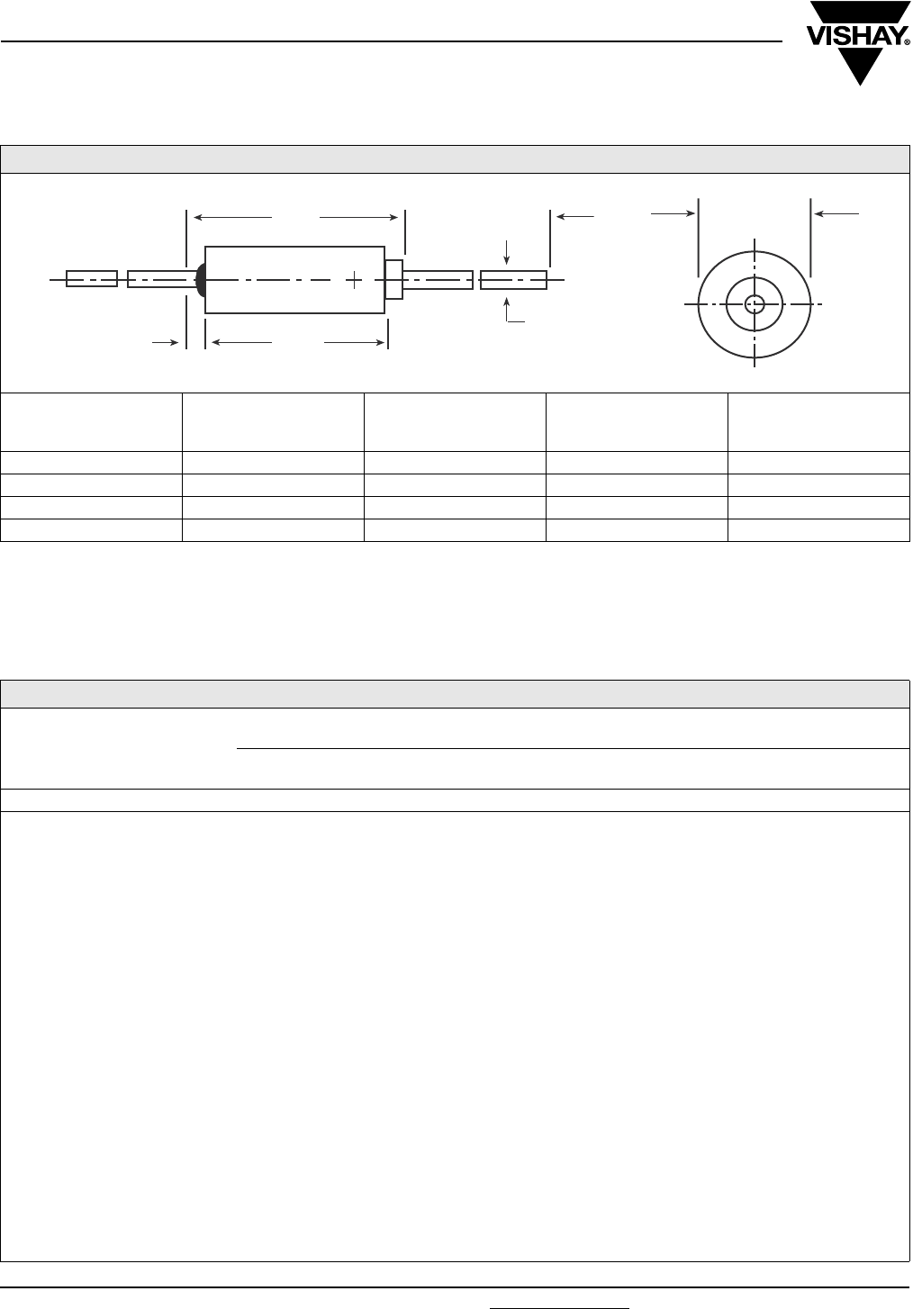
M39003/01/03/09
Vishay Sprague Solid-Electrolyte TANTALEX® Capacitors,
Military MIL-PRF-39003 Qualified, Styles CSR13, 21, 23
www.vishay.com For technical questions, contact: tantalum@vishay.com Document Number: 40018
40 Revision: 20-Nov-07
DIMENSIONS in inches [millimeters]
CASE
CODE
L
± 0.031 [0.79]
D
+ 0.016 [0.41]
- 0.015 [0.38]
M
± 0.002 [0.05]
J
(MAX.)
A 0.286 [7.26] 0.135 [3.43] 0.020 [0.51] 0.422 [10.72]
B 0.474 [12.04] 0.185 [4.70] 0.020 [0.51] 0.610 [15.49]
C 0.686 [17.42] 0.289 [7.34] 0.025 [0.64] 0.822 [20.88]
D 0.786 [19.96] 0.351 [8.92] 0.025 [0.64] 0.922 [23.42]
Notes:
(1) The case insulation shall extend 0.015" [0.38 mm] minimum beyond each end. However, when a shrink-fitted insulation is used, it shall lap
over the ends of the capacitor body.
(2) A minimum lead length of 1.0" [2.54 mm] for use with tape and reel automatic insertion equipment is available upon request.
(3) Failure Rate levels M, P, R and S are inactive for new design. Insulation is used, it shall lap over the ends of the capacitor body.
M
0.094 [2.4]
Max.
J1.500 ± 0.250
[38.10 ± 6.35]
L
D
STANDARD RATINGS: CSR13, M39003/01-XXXX
CAPACITANCE
(µF)
CASE
CODE
CAP.
TOL.
(± %)
PART NO. M39003/01-
FAILURE RATE LEVEL (%/1000 h) MAX. DCL (µA) AT MAX. DF (%) AT
M
1.0
P
0.1
R
0.01
S
0.001
B
0.1
C
0.01
D
0.001 + 25 °C + 85 °C + 125 °C - 55 °C
+ 25 °C
+ 85 °C
+ 125 °C
6 WVDC AT + 85 °C, SURGE = 8 V . . . 4 WVDC AT + 125 °C, SURGE = 5 V
5.6 A 5 5001 5201 5401 5601 6001 7001 8001 0.3 6.0 7.5 4 4
5.6 A 10 2241 2481 2721 2961 6002 7002 8002 0.3 6.0 7.5 4 4
6.8 A 5 5002 5202 5402 5602 6003 7003 8003 0.3 6.0 7.5 6 6
6.8 A 10 2242 2482 2722 2962 6004 7004 8004 0.3 6.0 7.5 6 6
6.8 A 20 2243 2843 2723 2963 6005 7005 8005 0.3 6.0 7.5 6 6
47.0 B 5 5003 5203 5403 5603 6006 7006 8006 1.5 24.0 30.0 6 6
47.0 B 10 2244 2484 2724 2964 6007 7007 8007 1.5 24.0 30.0 6 6
47.0 B 20 2245 2485 2725 2965 6008 7008 8008 1.5 24.0 30.0 6 6
56.0 B 5 5004 5204 5404 5604 6009 7009 8009 1.5 24.0 30.0 6 6
56.0 B 10 2246 2486 2726 2966 6010 7010 8010 1.5 24.0 30.0 6 6
150.0 C 5 5005 5205 5405 5605 6011 7011 8011 4.5 90.0 113.0 8 8
150.0 C 10 2247 2487 2727 2967 6012 7012 8012 4.5 90.0 113.0 8 8
150.0 C 20 2248 2488 2728 2968 6013 7013 8013 4.5 90.0 113.0 8 8
180.0 C 5 5006 5206 5406 5606 6014 7014 8014 5.5 110.0 138.0 8 8
180.0 C 10 2249 2489 2729 2969 6015 7015 8015 5.5 110.0 138.0 8 8
270.0 D 5 5007 5207 5407 5607 6016 7016 8016 6.5 130.0 163.0 8 8
270.0 D 10 2250 2490 2730 2970 6017 7017 8017 6.5 130.0 163.0 8 8
330.0 D 5 5008 5208 5408 5608 6018 7018 8018 7.5 150.0 188.0 8 8
330.0 D 10 2251 2491 2731 2971 6019 7019 8019 7.5 150.0 188.0 8 8
330.0 D 20 2252 2492 2732 2972 6020 7020 8020 7.5 150.0 188.0 8 8
STYLE CSR13
STYLE CSR21
STYLE CSR23

Document Number: 40018 For technical questions, contact: tantalum@vishay.com www.vishay.com
Revision: 20-Nov-07 41
M39003/01/03/09
Solid-Electrolyte TANTALEX® Capacitors,
Military MIL-PRF-39003 Qualified, Styles CSR13, 21, 23
Vishay Sprague
STANDARD RATINGS: CSR13, M39003/01-XXXX
CAPACITANCE
(µF)
CASE
CODE
CAP.
TOL.
(± %)
PART NO. M39003/01-
FAILURE RATE LEVEL (%/1000 h) MAX. DCL (µA) AT MAX. DF (%) AT
M
1.0
P
0.1
R
0.01
S
0.001
B
0.1
C
0.01
D
0.001 + 25 °C + 85 °C + 125 °C - 55 °C
+ 25 °C
+ 85 °C
+ 125 °C
10 WVDC AT + 85 °C, SURGE = 13 V . . . 7 WVDC AT + 125 °C, SURGE = 9 V
3.9 A 5 5009 5209 5409 5609 6021 7021 8021 0.3 6.0 7.5 4 4
3.9 A 10 2253 2493 2733 2973 6022 7022 8022 0.3 6.0 7.5 4 4
4.7 A 5 5010 5210 5410 5610 6023 7023 8023 0.4 7.0 8.8 4 4
4.7 A 10 2254 2494 2734 2974 6024 7024 8024 0.4 7.0 8.8 4 4
4.7 A 20 2255 2495 2735 2975 6025 7025 8025 0.4 7.0 8.8 4 4
27.0 B 5 5011 5211 5411 5611 6026 7026 8026 2.0 40.0 50.0 6 6
27.0 B 10 2256 2496 2736 2976 6027 7027 8027 2.0 40.0 50.0 6 6
33.0 B 5 5012 5212 5412 5612 6028 7028 8028 2.5 50.0 63.0 6 6
33.0 B 10 2257 2497 2737 2977 6029 7029 8029 2.5 50.0 63.0 6 6
33.0 B 20 2258 2498 2738 2978 6030 7030 8030 2.5 50.0 63.0 6 6
39.0 B 5 5013 5213 5413 5613 6031 7031 8031 2.5 50.0 63.0 6 6
39.0 B 10 2259 2499 2739 2979 6032 7032 8032 2.5 50.0 63.0 6 6
82.0 C 5 5014 5214 5414 5614 6033 7033 8033 4.0 80.0 100.0 6 6
82.0 C 10 2260 2500 2740 2980 6034 7034 8034 4.0 80.0 100.0 6 6
100.0 C 5 5015 5215 5415 5615 6035 7035 8035 5.0 100.0 125.0 8 8
100.0 C 10 2261 2501 2741 2981 6036 7036 8036 5.0 100.0 125.0 8 8
100.0 C 20 2262 2502 2742 2982 6037 7037 8037 5.0 100.0 125.0 8 8
120.0 C 5 5016 5216 5416 5616 6038 7038 8038 6.0 120.0 150.0 8 8
120.0 C 10 2263 2503 2743 2983 6039 7039 8039 6.0 120.0 150.0 8 8
180.0 D 5 5017 5217 5417 5617 6040 7040 8040 9.0 180.0 226.0 8 8
180.0 D 10 2264 2504 2744 2984 6041 7041 8041 9.0 180.0 226.0 8 8
220.0 D 5 5018 5218 5418 5618 6042 7042 8042 10.0 200.0 250.0 8 8
220.0 D 10 2265 2505 2745 2985 6043 7043 8043 10.0 200.0 250.0 8 8
220.0 D 20 2266 2506 2746 2986 6044 7044 8044 10.0 200.0 250.0 8 8
15 WVDC AT + 85 °C, SURGE = 20 V . . . 10 WVDC AT + 125 °C, SURGE = 12 V
2.7 A 5 5019 5219 5419 5619 6045 7045 8045 0.3 6.0 7.5 4 4
2.7 A 10 2267 2507 2747 2987 6046 7046 8046 0.3 6.0 7.5 4 4
3.3 A 5 5020 5220 5420 5620 6047 7047 8047 0.4 8.0 10.0 4 4
3.3 A 10 2268 2508 2748 2988 6048 7048 8048 0.4 8.0 10.0 4 4
3.3 A 20 2269 2509 2749 2989 6049 7049 8049 0.4 8.0 10.0 4 4
18.0 B 5 5021 5221 5421 5621 6050 7050 8050 2.0 35.0 44.0 6 6
18.0 B 10 2270 2510 2750 2990 6051 7051 8051 2.0 35.0 44.0 6 6
22.0 B 5 5022 5222 5422 5622 6052 7052 8052 2.0 40.0 50.0 6 6
22.0 B 10 2271 2511 2751 2991 6053 7053 8053 2.0 40.0 50.0 6 6
22.0 B 20 2272 2512 2752 2992 6054 7054 8054 2.0 40.0 50.0 6 6
56.0 C 5 5023 5223 5423 5623 6055 7055 8055 4.0 80.0 100.0 6 6
56.0 C 10 2273 2513 2753 2993 6056 7056 8056 4.0 80.0 100.0 6 6
68.0 C 5 5024 5224 5424 5624 6057 7057 8057 5.0 100.0 125.0 6 6
68.0 C 10 2274 2514 2754 2994 6058 7058 8058 5.0 100.0 125.0 6 6
68.0 C 20 2275 2515 2755 2995 6059 7059 8059 5.0 100.0 125.0 6 6
120.0 D 5 5025 5225 5425 5625 6060 7060 8060 9.0 180.0 226.0 8 8
120.0 D 10 2276 2516 2756 2996 6061 7061 8061 9.0 180.0 226.0 8 8
150.0 D 5 5026 5226 5426 5626 6062 7062 8062 10.0 200.0 250.0 8 8
150.0 D 10 2277 2517 2757 2997 6063 7063 8063 10.0 200.0 250.0 8 8
150.0 D 20 2278 2518 2758 2998 6064 7064 8064 10.0 200.0 250.0 8 8
20 WVDC AT + 85 °C, SURGE = 26 V . . . 13 WVDC AT + 125 °C, SURGE = 16 V
1.2 A 5 5027 5227 5427 5627 6065 7065 8065 0.3 6.0 7.5 4 4
1.2 A 10 2279 2519 2759 2999 6066 7066 8066 0.3 6.0 7.5 4 4
1.5 A 5 5028 5228 5428 5628 6067 7067 8067 0.3 6.0 7.5 4 4
1.5 A 10 2280 2520 2760 3000 6068 7068 8068 0.3 6.0 7.5 4 4
1.5 A 20 2281 2521 2761 3001 6069 7069 8069 0.3 6.0 7.5 4 4
1.5 A 5 5029 5229 5429 5629 6070 7070 8070 0.3 6.0 7.5 4 4
1.8 A 10 2282 2522 2762 3002 6071 7071 8071 0.3 6.0 7.5 4 4
M39003/01/03/09
Vishay Sprague Solid-Electrolyte TANTALEX® Capacitors,
Military MIL-PRF-39003 Qualified, Styles CSR13, 21, 23
www.vishay.com For technical questions, contact: tantalum@vishay.com Document Number: 40018
42 Revision: 20-Nov-07
STANDARD RATINGS: CSR13, M39003/01-XXXX
CAPACITANCE
(µF)
CASE
CODE
CAP.
TOL.
(± %)
PART NO. M39003/01-
FAILURE RATE LEVEL (%/1000 h) MAX. DCL (µA) AT MAX. DF (%) AT
M
1.0
P
0.1
R
0.01
S
0.001
B
0.1
C
0.01
D
0.001 + 25 °C + 85 °C + 125 °C - 55 °C
+ 25 °C
+ 85 °C
+ 125 °C
20 WVDC AT + 85 °C, SURGE = 26 V . . . 13 WVDC AT + 125 °C, SURGE = 16 V
2.2 A 5 5030 5230 5430 5630 6072 7072 8072 0.4 8.0 10.0 4 4
2.2 A 10 2283 2523 2763 3003 6073 7073 8073 0.4 8.0 10.0 4 4
2.2 A 20 2284 2524 2764 3004 6074 7074 8074 0.4 8.0 10.0 4 4
8.2 B 5 5031 5231 5431 5631 6075 7075 8075 1.0 20.0 25.0 6 6
8.2 B 10 2285 2525 2765 3005 6076 7076 8076 1.0 20.0 25.0 6 6
10.0 B 5 5032 5232 5432 5632 6077 7077 8077 1.5 30.0 38.0 6 6
10.0 B 10 2286 2526 2766 3006 6078 7078 8078 1.5 30.0 38.0 6 6
10.0 B 20 2287 2527 2767 3007 6079 7079 8079 1.5 30.0 38.0 6 6
12.0 B 5 5033 5233 5433 5633 6080 7080 8080 1.8 35.0 44.0 6 6
12.0 B 10 2288 2528 2768 3008 6081 7081 8081 1.8 35.0 44.0 6 6
15.0 B 5 5034 5234 5434 5634 6082 7082 8082 2.0 40.0 50.0 6 6
15.0 B 10 2289 2529 2769 3009 6083 7083 8083 2.0 40.0 50.0 6 6
15.0 B 20 2290 2530 2770 3010 6084 7084 8084 2.0 40.0 50.0 6 6
27.0 C 5 5035 5235 5435 5635 6085 7085 8085 2.5 50.0 63.0 6 6
27.0 C 10 2291 2531 2771 3011 6086 7086 8086 2.5 50.0 63.0 6 6
33.0 C 5 5036 5236 5436 5636 6087 7087 8087 3.5 70.0 88.0 6 6
33.0 C 10 2292 2532 2772 3012 6088 7088 8088 3.5 70.0 88.0 6 6
33.0 C 20 2293 2533 2773 3013 6089 7089 8089 3.5 70.0 88.0 6 6
39.0 C 5 5037 5237 5437 5637 6090 7090 8090 4.0 80.0 100.0 6 6
39.0 C 10 2294 2534 2774 3014 6091 7091 8091 4.0 80.0 100.0 6 6
47.0 C 5 5038 5238 5438 5368 6092 7092 8092 4.5 90.0 113.0 6 6
47.0 C 10 2295 2535 2775 3015 6093 7093 8093 4.5 90.0 113.0 6 6
47.0 C 20 2296 2536 2776 3016 6094 7094 8094 4.5 90.0 113.0 6 6
56.0 D 5 5039 5239 5439 5639 6095 7095 8095 5.5 110.0 138.0 6 6
56.0 D 10 2297 2537 2777 3017 6096 7096 8096 5.5 110.0 138.0 6 6
68.0 D 5 5040 5240 5440 5640 6097 7097 8097 7.0 140.0 175.0 6 6
68.0 D 10 2298 2538 2778 3018 6098 7098 8098 7.0 140.0 175.0 6 6
68.0 D 20 2299 2539 2779 3019 6099 7099 8099 7.0 140.0 175.0 6 6
82.0 D 5 5041 5241 5441 5641 6100 7100 8100 8.0 160.0 200.0 6 6
82.0 D 10 2300 2540 2780 3020 6101 7101 8101 8.0 160.0 200.0 6 6
100.0 D 5 5042 5242 5442 5642 6102 7102 8102 10.0 200.0 250.0 8 8
100.0 D 10 2301 2541 2781 3021 6103 7103 8103 10.0 200.0 250.0 8 8
100.0 D 20 2302 2542 2782 3022 6104 7104 8104 10.0 200.0 250.0 8 8
35 WVDC AT + 85 °C, SURGE = 46 V . . . 23 WVDC AT + 125 °C, SURGE = 28 V
5.6 B 5 5043 5243 5443 5643 6105 7105 8105 1.3 25.0 32.0 4 4
5.6 B 10 2303 2543 2783 3023 6106 7106 8106 1.3 25.0 32.0 4 4
6.8 B 5 5044 5244 5444 5644 6107 7107 8107 1.5 30.0 38.0 6 6
6.8 B 10 2304 2544 2784 3024 6108 7108 8108 1.5 30.0 38.0 6 6
6.8 B 20 2305 2545 2785 3025 6109 7109 8109 1.5 30.0 38.0 6 6
22.0 C 5 5045 5245 5445 5645 6110 7110 8110 4.0 80.0 100.0 6 6
22.0 C 10 2306 2546 2786 3026 6111 7111 8111 4.0 80.0 100.0 6 6
22.0 C 20 2307 2547 2787 3027 6112 7112 8112 4.0 80.0 100.0 6 6
27.0 D 5 5046 5246 5446 5646 6113 7113 8113 4.5 90.0 113.0 6 6
27.0 D 10 2308 2548 2788 3028 6114 7114 8114 4.5 90.0 113.0 6 6
33.0 D 5 5047 5247 5447 5647 6115 7115 8115 5.5 110.0 138.0 6 6
33.0 D 10 2309 2549 2789 3029 6116 7116 8116 5.5 110.0 138.0 6 6
33.0 D 20 2310 2550 2790 3030 6117 7117 8117 5.5 110.0 138.0 6 6
39.0 D 5 5048 5248 5448 5648 6118 7118 8118 7.0 140.0 175.0 6 6
39.0 D 10 2311 2551 2791 3031 6119 7119 8119 7.0 140.0 175.0 6 6
47.0 D 5 5049 5249 5449 5649 6120 7120 8120 8.0 160.0 200.0 6 6
47.0 D 10 2312 2552 2792 3032 6121 7121 8121 8.0 160.0 200.0 6 6
47.0 D 20 2313 2553 2793 3033 6122 7122 8122 8.0 160.0 200.0 6 6

Document Number: 40018 For technical questions, contact: tantalum@vishay.com www.vishay.com
Revision: 20-Nov-07 43
M39003/01/03/09
Solid-Electrolyte TANTALEX® Capacitors,
Military MIL-PRF-39003 Qualified, Styles CSR13, 21, 23
Vishay Sprague
STANDARD RATINGS: CSR13, M39003/01-XXXX
CAPACITANCE
(µF)
CASE
CODE
CAP.
TOL.
(± %)
PART NO. M39003/01-
FAILURE RATE LEVEL (%/1000 h) MAX. DCL (µA) AT MAX. DF (%) AT
M
1.0
P
0.1
R
0.01
S
0.001
B
0.1
C
0.01
D
0.001 + 25 °C + 85 °C + 125 °C - 55 °C
+ 25 °C
+ 85 °C
+ 125 °C
50 WVDC AT + 85 °C, SURGE = 65 V . . . 33 WVDC AT + 125 °C, SURGE = 40 V
0.056 A 5 5063 5263 5463 5663 6156 7156 8156 0.3 5.0 6.3 2 4
0.056 A 10 2334 2574 2814 3054 6157 7157 8157 0.3 5.0 6.3 2 4
0.068 A 5 5064 5264 5464 5664 6158 7158 8158 0.3 5.0 6.3 2 4
0.068 A 10 2335 2575 2815 3055 6159 7159 8159 0.3 5.0 6.3 2 4
0.068 A 20 2336 2576 2816 3056 6160 7160 8160 0.3 5.0 6.3 2 4
0.082 A 5 5065 5265 5465 5665 6161 7161 8161 0.3 5.0 6.3 2 4
0.082 A 10 2337 2577 2817 3057 6162 7162 8162 0.3 5.0 6.3 2 4
0.10 A 5 5066 5266 5466 5666 6163 7163 8163 0.3 5.0 6.3 2 4
0.10 A 10 2338 2578 2818 3058 6164 7164 8164 0.3 5.0 6.3 2 4
0.10 A 20 2339 2579 3819 3059 6165 7165 8165 0.3 5.0 6.3 2 4
0.12 A 5 5067 5267 5467 5667 6166 7166 8166 0.3 5.0 6.3 2 4
0.12 A 10 2340 2580 2820 3060 6167 7167 8167 0.3 5.0 6.3 2 4
0.15 A 5 5068 5268 5468 5668 6168 7168 8168 0.3 5.0 6.3 2 4
0.15 A 10 2341 2581 2821 3061 6169 7169 8169 0.3 5.0 6.3 2 4
0.15 A 20 2342 2582 2822 3062 6170 7170 8170 0.3 5.0 6.3 2 4
0.18 A 5 5069 5269 5469 5669 6171 7171 8171 0.3 5.0 6.3 2 4
0.18 A 10 2343 2583 2823 3063 6172 7172 8172 0.3 5.0 6.3 2 4
0.22 A 5 5070 5270 5470 5670 6173 7173 8173 0.3 5.0 6.3 2 4
0.22 A 10 2344 2584 2824 3064 6174 7174 8174 0.3 5.0 6.3 2 4
0.22 A 20 2345 2585 2825 3065 6175 7175 8175 0.3 5.0 6.3 2 4
0.27 A 5 5071 5271 5471 5671 6176 7176 8176 0.3 5.0 6.3 2 4
0.27 A 10 2346 2586 2826 3066 6177 7177 8177 0.3 5.0 6.3 2 4
0.33 A 5 5072 5272 5472 5672 6178 7178 8178 0.3 5.0 6.3 2 4
0.33 A 10 2347 2587 2827 3067 6179 7179 8179 0.3 5.0 6.3 2 4
0.33 A 20 2348 2588 2828 3068 6180 7180 8180 0.3 5.0 6.3 2 4
0.39 A 5 5073 5273 5473 5673 6181 7181 8181 0.3 5.0 6.3 2 4
0.39 A 10 2349 2589 2829 3069 6182 7182 8182 0.3 5.0 6.3 2 4
0.47 A 5 5074 5274 5474 5674 6183 7183 8183 0.3 5.0 6.3 2 4
0.47 A 10 2350 2590 2830 3070 6184 7184 8184 0.3 5.0 6.3 2 4
0.47 A 20 2351 2591 2831 3071 6185 7185 8185 0.3 5.0 6.3 2 4
0.56 A 5 5075 5275 5475 5675 6186 7186 8186 0.3 5.0 6.3 2 4
0.56 A 10 2352 2592 2832 3072 6187 7187 8187 0.3 5.0 6.3 2 4
0.68 A 5 5076 5276 5476 5676 6188 7188 8188 0.3 5.0 6.3 2 4
0.68 A 10 2353 2593 2833 3073 6189 7189 8189 0.3 5.0 6.3 2 4
0.68 A 20 2354 2594 2834 3074 6190 7190 8190 0.3 5.0 6.3 2 4
0.82 A 5 5077 5277 5477 5677 6191 7191 8191 0.3 5.0 6.3 2 4
0.82 A 10 2355 2595 2835 3075 6192 7192 8192 0.3 5.0 6.3 2 4
1.0 A 5 5078 5278 5478 5678 6193 7193 8193 0.4 8.0 10.0 4 4
1.0 A 10 2356 2596 2836 3076 6194 7194 8194 0.4 8.0 10.0 4 4
1.0 A 20 2357 2597 2837 3077 6195 7195 8195 0.4 8.0 10.0 4 4
1.2 B 5 5079 5279 5479 5679 6196 7196 8196 0.4 9.0 11.0 4 4
1.2 B 10 2358 2598 2838 3078 6197 7197 8197 0.4 9.0 11.0 4 4
1.5 B 5 5080 5280 5480 5680 6198 7198 8198 0.6 12.0 15.0 4 4
1.5 B 10 2359 2599 2839 3079 6199 7199 8199 0.6 12.0 15.0 4 4
1.5 B 20 2360 2600 2840 3080 6200 7200 8200 0.6 12.0 15.0 4 4
1.8 B 5 5081 5281 5481 5681 6201 7201 8201 0.7 14.0 18.0 4 4
1.8 B 10 2361 2601 2841 3081 6202 7202 8202 0.7 14.0 18.0 4 4
2.2 B 5 5082 5282 5482 5682 6203 7203 8203 0.8 17.0 22.0 4 4
2.2 B 10 2362 2602 2842 3082 6204 7204 8204 0.8 17.0 22.0 4 4
2.2 B 20 2363 2603 2843 3083 6205 7205 8205 0.8 17.0 22.0 4 4
2.7 B 5 5083 5283 5483 5683 6206 7206 8206 1.0 20.0 25.0 4 4
2.7 B 10 2364 2604 2844 3084 6207 7207 8207 1.0 20.0 25.0 4 4
3.3 B 5 5084 5284 5484 5684 6208 7208 8208 1.2 25.0 32.0 4 4
3.3 B 10 2365 2605 2845 3085 6209 7209 8209 1.2 25.0 32.0 4 4

M39003/01/03/09
Vishay Sprague Solid-Electrolyte TANTALEX® Capacitors,
Military MIL-PRF-39003 Qualified, Styles CSR13, 21, 23
www.vishay.com For technical questions, contact: tantalum@vishay.com Document Number: 40018
44 Revision: 20-Nov-07
STANDARD RATINGS: CSR13, M39003/01-XXXX
CAPACITANCE
(µF)
CASE
CODE
CAP.
TOL.
(± %)
PART NO. M39003/01-
FAILURE RATE LEVEL (%/1000 h) MAX. DCL (µA) AT MAX. DF (%) AT
M
1.0
P
0.1
R
0.01
S
0.001
B
0.1
C
0.01
D
0.001 + 25 °C + 85 °C + 125 °C - 55 °C
+ 25 °C
+ 85 °C
+ 125 °C
50 WVDC AT + 85 °C, SURGE = 65 V . . . 33 WVDC AT + 125 °C, SURGE = 40 V
3.3 B 20 2366 2606 2846 3086 6210 7210 8210 1.2 25.0 32.0 4 4
3.9 B 5 5085 5285 5485 5685 6211 7211 8211 1.5 30.0 38.0 4 4
3.9 B 10 2367 2607 2847 3087 6212 7212 8212 1.5 30.0 38.0 4 4
4.7 B 5 5086 5286 5486 5686 6213 7213 8213 1.7 35.0 44.0 4 4
4.7 B 10 2368 2608 2848 3088 6214 7214 8214 1.7 35.0 44.0 4 4
4.7 B 20 2369 2609 2849 3089 6215 7215 8215 1.7 35.0 44.0 4 4
5.6 C 5 5087 5287 5487 5687 6216 7216 8216 2.2 45.0 56.0 4 4
5.6 C 10 2370 2610 2850 3090 6217 7217 8217 2.2 45.0 56.0 4 4
6.8 C 5 5088 5288 5488 5688 6218 7218 8218 2.2 45.0 56.0 6 6
6.8 C 10 2371 2611 2851 3091 6219 7219 8219 2.2 45.0 56.0 6 6
6.8 C 20 2372 2612 2852 3092 6220 7220 8220 2.2 45.0 56.0 6 6
8.2 C 5 5089 5289 5489 5689 6221 7221 8221 2.5 50.0 63.0 6 6
8.2 C 10 2373 2613 2853 3093 6222 7222 8222 2.5 50.0 63.0 6 6
10.0 C 5 5090 5290 5490 5690 6223 7223 8223 2.5 50.0 63.0 6 6
10.0 C 10 2374 2614 2854 3094 6224 7224 8224 2.5 50.0 63.0 6 6
10.0 C 20 2375 2615 2855 3095 6225 7225 8225 2.5 50.0 63.0 6 6
12.0 C 5 5091 5291 5491 5691 6226 7226 8226 3.0 60.0 75.0 6 6
12.0 C 10 2376 2616 2856 3096 6227 7227 8227 3.0 60.0 75.0 6 6
15.0 C 5 5092 5292 5492 5692 6228 7228 8228 4.0 80.0 100.0 6 6
15.0 C 10 2377 2617 2857 3097 6229 7229 8229 4.0 80.0 100.0 6 6
15.0 C 20 2378 2618 2858 3098 6230 7230 8230 4.0 80.0 100.0 6 6
18.0 C 5 5093 5293 5493 5693 6231 7231 8231 4.5 90.0 113.0 6 6
18.0 C 10 2379 2619 2859 3099 6232 7232 8232 4.5 90.0 113.0 6 6
22.0 D 5 5094 5294 5494 5694 6233 7233 8233 5.5 110.0 138.0 6 6
22.0 D 10 2380 2620 2860 3100 6234 7234 8234 5.5 110.0 138.0 6 6
22.0 D 20 2381 2621 2861 3101 6235 7235 8235 5.5 110.0 138.0 6 6
75 WVDC AT + 85 °C, SURGE = 98 V . . . 50 WVDC AT + 125 °C, SURGE = 64 V
0.1 A 5 5095 5295 5495 5695 6236 7236 8236 0.3 5.0 6.3 2 4
0.1 A 10 2382 2622 2862 3102 6237 7237 8237 0.3 5.0 6.3 2 4
0.1 A 20 2383 2623 2863 3103 6238 7238 8238 0.3 5.0 6.3 2 4
0.12 A 5 5096 5296 5496 5696 6239 7239 8239 0.3 5.0 6.3 2 4
0.12 A 10 2384 2624 2864 3104 6240 7240 8240 0.3 5.0 6.3 2 4
0.15 A 5 5097 5297 5497 5697 6241 7241 8241 0.3 5.0 6.3 2 4
0.15 A 10 2385 2625 2865 3105 6242 7242 8242 0.3 5.0 6.3 2 4
0.15 A 20 2386 2626 2866 3106 6243 7243 8243 0.3 5.0 6.3 2 4
0.18 A 5 5098 5298 5498 5698 6244 7244 8244 0.3 5.0 6.3 2 4
0.18 A 10 2387 2627 2867 3107 6245 7245 8245 0.3 5.0 6.3 2 4
0.22 A 5 5099 5299 5499 5699 6246 7246 8246 0.3 5.0 6.3 2 4
0.22 A 10 2388 2628 2868 3108 6247 7247 8247 0.3 5.0 6.3 2 4
0.22 A 20 2389 2629 2869 3109 6248 7248 8248 0.3 5.0 6.3 2 4
0.27 A 5 5100 5300 5500 5700 6249 7249 8249 0.3 5.0 6.3 2 4
0.27 A 10 2390 2630 2870 3110 6250 7250 8250 0.3 5.0 6.3 2 4
0.33 A 5 5101 5301 5501 5701 6251 7251 8251 0.3 5.0 6.3 2 4
0.33 A 10 2391 2631 2871 3111 6252 7252 8252 0.3 5.0 6.3 2 4
0.33 A 20 2392 2632 2872 3112 6253 7253 8253 0.3 5.0 6.3 2 4
0.39 A 5 5102 5302 5502 5702 6254 7254 8254 0.3 5.0 6.3 2 4
0.39 A 10 2393 2633 2873 3113 6255 7255 8255 0.3 5.0 6.3 2 4
0.47 A 5 5103 5303 5503 5703 6256 7256 8256 0.3 5.0 6.3 2 4
0.47 A 10 2394 2634 2874 3114 6257 7257 8257 0.3 5.0 6.3 2 4
0.47 A 20 2395 2635 2875 3115 6258 7258 8258 0.3 5.0 6.3 2 4
0.56 A 5 5104 5304 5504 5704 6259 7259 8259 0.3 5.0 6.3 2 4
0.56 A 10 2396 2636 2876 3116 6260 7260 8260 0.3 5.0 6.3 2 4

Document Number: 40018 For technical questions, contact: tantalum@vishay.com www.vishay.com
Revision: 20-Nov-07 45
M39003/01/03/09
Solid-Electrolyte TANTALEX® Capacitors,
Military MIL-PRF-39003 Qualified, Styles CSR13, 21, 23
Vishay Sprague
STANDARD RATINGS: CSR13, M39003/01-XXXX
CAPACITANCE
(µF)
CASE
CODE
CAP.
TOL.
(± %)
PART NO. M39003/01-
FAILURE RATE LEVEL (%/1000 h) MAX. DCL (µA) AT MAX. DF (%) AT
M
1.0
P
0.1
R
0.01
S
0.001
B
0.1
C
0.01
D
0.001 + 25 °C + 85 °C + 125 °C - 55 °C
+ 25 °C
+ 85 °C
+ 125 °C
75 WVDC AT + 85 °C, SURGE = 98 V . . . 50 WVDC AT + 125 °C, SURGE = 64 V
0.68 A 5 5105 5305 5505 5705 6261 7261 8261 0.3 5.0 6.3 2 4
0.68 A 10 2397 2637 2877 3117 6262 7262 8262 0.3 5.0 6.3 2 4
0.68 A 20 2398 2638 2878 3118 6263 7263 8263 0.3 5.0 6.3 2 4
0.82 B 5 5106 5306 5506 5706 6264 7264 8264 0.3 5.0 6.3 2 4
0.82 B 10 2399 2879 2879 3119 6265 7265 8265 0.3 5.0 6.3 2 4
1.0 B 5 5107 5307 5507 5707 6266 7266 8266 0.3 5.0 6.3 2 4
1.0 B 10 2400 2410 2880 3120 6267 7267 8267 0.3 5.0 6.3 2 4
1.0 B 20 2401 2641 2881 3121 6268 7268 8268 0.3 5.0 6.3 2 4
1.2 B 5 5108 5308 5508 5708 6269 7269 8269 0.3 5.0 6.3 4 4
1.2 B 10 2402 2642 2882 3122 6270 7270 8270 0.3 5.0 6.3 4 4
1.5 B 5 5109 5309 5509 5709 6271 7271 8271 0.6 10.0 13.0 4 4
1.5 B 10 2403 2643 2883 3123 6272 7272 8272 0.6 10.0 13.0 4 4
1.5 B 20 2404 2664 2884 3124 6273 7273 8273 0.6 10.0 13.0 4 4
1.8 B 5 5110 5310 5510 5710 6274 7274 8274 0.7 10.0 13.0 4 4
1.8 B 10 2405 2645 2885 3125 6275 7275 8275 0.7 10.0 13.0 4 4
1.8 B 10 2405 2645 2885 3125 6275 7275 8275 0.7 10.0 13.0 4 4
2.2 B 5 5111 5311 5511 5711 6276 7276 8276 0.8 15.0 19.0 4 4
2.2 B 10 2406 2646 2886 3126 6277 7277 8277 0.8 15.0 19.0 4 4
2.2 B 20 2407 2647 2887 3127 6278 7278 8278 1.0 15.0 19.0 4 4
2.7 B 5 5112 5312 5512 5712 6279 7279 8279 1.0 15.0 19.0 4 4
2.7 B 10 2408 2648 2888 3128 6280 7280 8280 1.2 15.0 19.0 4 4
3.3 B 5 5113 5313 5513 5713 6281 7281 8281 1.2 20.0 25.0 4 4
3.3 B 10 2409 2649 2889 3129 6282 7282 8282 1.2 20.0 25.0 4 4
3.3 B 20 2410 2650 2890 3130 6283 7283 8283 1.5 20.0 25.0 4 4
3.9 B 5 5114 5314 5514 5714 6284 7284 8284 1.5 20.0 25.0 4 4
3.9 B 10 2411 2651 2891 3131 6285 7285 8285 3.0 20.0 25.0 4 4
4.7 C 5 5115 5315 5515 5715 6286 7286 8286 3.0 60.0 75.0 4 4
4.7 C 10 2412 2652 2892 3132 6287 7287 8287 3.0 60.0 75.0 4 4
4.7 C 20 2413 2653 2893 3133 6288 7288 8288 3.0 60.0 75.0 4 4
5.6 C 5 5116 5316 5513 5716 6289 7289 8289 3.0 60.0 75.0 4 4
5.6 C 10 2414 2654 2894 3134 6290 7290 8290 5.0 60.0 75.0 4 4
6.8 C 5 5117 5317 5517 5717 6291 7291 8291 5.0 100.0 125.0 6 6
6.8 C 10 2415 2655 2895 3135 6292 7292 8292 5.0 100.0 125.0 6 6
6.8 C 20 2416 2656 2896 3136 6293 7293 8293 5.0 100.0 125.0 6 6
8.2 C 5 5118 5318 5518 5718 6294 7294 8294 5.0 100.0 125.0 6 6
8.2 C 10 2417 2657 2897 3137 6295 7295 8295 5.0 100.0 125.0 6 6
10.0 C 5 5119 5319 5519 5719 6296 7296 8296 5.0 100.0 125.0 6 6
10.0 C 10 2418 2658 2898 3138 6297 7297 8297 5.0 100.0 125.0 6 6
10.0 C 20 2419 2659 2899 3139 6298 7298 8295 5.0 100.0 125.0 6 6
12.0 D 5 5120 5320 5520 5720 6299 7299 8299 5.0 100.0 125.0 6 6
12.0 D 10 2420 2660 2900 3140 6300 7300 8300 5.0 100.0 125.0 6 6
15.0 D 5 5121 5321 5521 5721 6301 7301 8301 7.0 140.0 175.0 6 6
15.0 D 10 2421 2661 2901 3141 6302 7302 8302 7.0 140.0 175.0 6 6
15.0 D 20 2422 2662 2902 3142 6303 7303 8303 7.0 140.0 175.0 6 6

M39003/01/03/09
Vishay Sprague Solid-Electrolyte TANTALEX® Capacitors,
Military MIL-PRF-39003 Qualified, Styles CSR13, 21, 23
www.vishay.com For technical questions, contact: tantalum@vishay.com Document Number: 40018
46 Revision: 20-Nov-07
STANDARD RATINGS: CSR13, M39003/01-XXXX
CAPACITANCE
(µF)
CASE
CODE
CAP.
TOL.
(± %)
PART NO. M39003/01-
FAILURE RATE LEVEL (%/1000 h) MAX. DCL (µA) AT MAX. DF (%) AT
M
1.0
P
0.1
R
0.01
S
0.001
B
0.1
C
0.01
D
0.001 + 25 °C + 85 °C + 125 °C - 55 °C
+ 25 °C
+ 85 °C
+ 125 °C
100 WVDC AT + 85 °C, SURGE = 130 V . . . 67 WVDC AT + 125 °C, SURGE = 86 V
0.056 A 5 5135 5335 5535 5735 6337 7337 8337 0.3 5.0 6.3 2 4
0.056 A 10 2443 2683 2923 3163 6338 7338 8338 0.3 5.0 6.3 2 4
0.068 A 5 5136 5336 5536 5736 6339 7339 8339 0.3 5.0 6.3 2 4
0.068 A 10 2444 2684 2924 3164 6340 7340 8340 0.3 5.0 6.3 2 4
0.068 A 20 2445 2685 2925 3165 6341 7341 8341 0.3 5.0 6.3 2 4
0.082 A 5 5137 5337 5537 5737 6342 7342 8342 0.3 5.0 6.3 2 4
0.082 A 10 2446 2686 2926 3166 6343 7343 8343 0.3 5.0 6.3 2 4
0.1 A 5 5138 5338 5538 5738 6344 7344 8344 0.3 5.0 6.3 2 4
0.1 A 10 2447 2687 2927 3167 6345 7345 8345 0.3 5.0 6.3 2 4
0.1 A 20 2448 2688 2928 3168 6346 7346 8346 0.3 5.0 6.3 2 4
0.12 A 5 5139 5339 5539 5739 6347 7347 8347 0.3 5.0 6.3 2 4
0.12 A 10 2449 2689 2929 3169 6348 7348 8348 0.3 5.0 6.3 2 4
0.15 A 5 5140 5340 5540 5740 6349 7349 8349 0.3 5.0 6.3 2 4
0.15 A 10 2450 2690 2930 3170 6350 7350 8350 0.3 5.0 6.3 2 4
0.15 A 20 2451 2691 2931 3171 6351 7351 8351 0.3 5.0 6.3 2 4
0.18 A 5 5141 5341 5541 5741 6352 7352 8352 0.3 5.0 6.3 2 4
0.18 A 10 2452 2692 2932 3172 6353 7353 8353 0.3 5.0 6.3 2 4
0.22 A 5 5142 5342 5542 5742 6354 7354 8354 0.3 5.0 6.3 2 4
0.22 A 10 2453 2693 2933 3173 6355 7355 8355 0.3 5.0 6.3 2 4
0.22 A 20 2454 2694 2934 3174 6356 7356 8356 0.3 5.0 6.3 2 4
0.27 A 5 5143 5343 5543 5743 6357 7357 8357 0.3 5.0 6.3 2 4
0.27 A 10 2455 2695 2935 3175 6358 7358 8358 0.3 5.0 6.3 2 4
0.33 A 5 5144 5344 5544 5744 6359 7359 8359 0.3 5.0 6.3 2 4
0.33 A 10 2456 2696 2936 3176 6360 7360 8360 0.3 5.0 6.3 2 4
0.33 A 20 2457 2697 2937 3177 6361 7361 8361 0.3 5.0 6.3 2 4
0.39 A 5 5145 5345 5545 5745 6362 7362 8362 0.3 5.0 6.3 2 4
0.39 A 10 2458 2698 2938 3178 6363 7363 8363 0.3 5.0 6.3 2 4
0.47 A 5 5146 5436 5546 5746 6364 7364 8364 0.3 5.0 6.3 2 4
0.47 A 10 2459 2699 2939 3179 6365 7365 8365 0.3 5.0 6.3 2 4
0.47 A 20 2460 2700 2940 3180 6366 7366 8366 0.3 5.0 6.3 2 4
0.56 A 5 5147 5347 5547 5747 6367 7367 8367 0.3 5.0 6.3 2 4
0.56 A 10 2461 2701 2941 3181 6368 7368 8368 0.3 5.0 6.3 2 4
0.68 B 5 5148 5348 5548 5748 6369 7369 8369 0.3 5.0 6.3 2 4
0.68 B 10 2462 2702 2942 3182 6370 7370 8370 0.3 5.0 6.3 2 4
0.68 B 20 2463 2703 2943 3183 6371 7371 8371 0.3 5.0 6.3 2 4
0.82 B 5 5149 5349 5549 5749 6372 7372 8372 0.4 5.0 6.3 2 4
0.82 B 10 2464 2704 2944 3184 6373 7373 8373 0.4 5.0 6.3 2 4

Document Number: 40018 For technical questions, contact: tantalum@vishay.com www.vishay.com
Revision: 20-Nov-07 47
M39003/01/03/09
Solid-Electrolyte TANTALEX® Capacitors,
Military MIL-PRF-39003 Qualified, Styles CSR13, 21, 23
Vishay Sprague
STANDARD RATINGS: CSR13, M39003/01-XXXX
CAPACITANCE
(µF)
CASE
CODE
CAP.
TOL.
(± %)
PART NO. M39003/01-
FAILURE RATE LEVEL (%/1000 h) MAX. DCL (µA) AT MAX. DF (%) AT
M
1.0
P
0.1
R
0.01
S
0.001
B
0.1
C
0.01
D
0.001 + 25 °C + 85 °C + 125 °C - 55 °C
+ 25 °C
+ 85 °C
+ 125 °C
100 WVDC AT + 85 °C, SURGE = 130 V . . . 67 WVDC AT + 125 °C, SURGE = 86 V
1.0 B 5 5150 5350 5550 5750 6374 7374 8374 0.5 5.0 6.3 2 4
1.0 B 10 2465 2705 2945 3185 6375 7375 8375 0.5 5.0 6.3 2 4
1.0 B 20 2466 2706 2946 3186 6376 7376 8376 0.5 5.0 6.3 2 4
1.2 B 5 5151 5351 5551 5751 6377 7377 8377 0.5 5.0 6.3 4 4
1.2 B 10 2467 2707 2947 3187 6378 7378 8378 0.5 5.0 6.3 4 4
1.5 B 5 5152 5352 5552 5752 6379 7379 8379 0.7 10.0 13.0 4 4
1.5 B 10 2468 2708 2948 3188 6380 7380 8380 0.7 10.0 13.0 4 4
1.5 B 20 2469 2709 2949 3189 6381 7381 8381 0.7 10.0 13.0 4 4
1.8 B 5 5153 5353 5553 5753 6382 7382 8382 0.7 10.0 13.0 4 4
1.8 B 10 2470 2710 2950 3190 6383 7383 8383 0.7 10.0 13.0 4 4
2.2 B 5 5154 5354 5554 5754 6384 7384 8384 0.9 15.0 19.0 4 4
2.2 B 10 2471 2711 2951 3191 6385 7385 8385 0.9 15.0 19.0 4 4
2.2 B 20 2472 2712 2952 3192 6386 7386 8386 0.9 15.0 19.0 4 4
2.7 B 5 5155 5355 5555 5755 6387 7387 8387 1.1 15.0 19.0 4 4
2.7 B 10 2473 2713 2953 3193 6388 7388 8388 1.1 15.0 19.0 4 4
3.3 C 5 5156 5356 5556 5756 6389 7389 8389 1.5 30.0 38.0 6 6
3.3 C 10 5157 5357 5557 5757 6390 7390 8390 1.5 30.0 38.0 6 6
3.3 C 20 5158 5358 5558 5758 6391 7391 8391 1.5 30.0 38.0 6 6
3.9 C 5 5159 5359 5559 5759 6392 7392 8392 1.5 30.0 38.0 6 6
3.9 C 10 5160 5360 5560 5760 6393 7393 8393 1.5 30.0 38.0 6 6
4.7 C 5 5161 5361 5561 5761 6394 7394 8394 2.5 50.0 63.0 6 6
4.7 C 10 5162 5362 5562 5762 6395 7395 8395 2.5 50.0 63.0 6 6
4.7 C 20 5163 5363 5563 5763 6396 7396 8396 2.5 50.0 63.0 6 6
5.6 C 5 5164 5364 5564 5764 6397 7397 8397 2.5 50.0 63.0 6 6
5.6 C 10 5165 5365 5565 5765 6398 7398 8398 2.5 50.0 63.0 6 6
6.8 C 5 5166 5366 5566 5766 6399 7399 8399 2.5 50.0 63.0 6 6
6.8 C 10 5167 5367 5567 5767 6400 7400 8400 2.5 50.0 63.0 6 6
6.8 C 20 5168 5368 5568 5768 6401 7401 8401 2.5 50.0 63.0 6 6

M39003/01/03/09
Vishay Sprague Solid-Electrolyte TANTALEX® Capacitors,
Military MIL-PRF-39003 Qualified, Styles CSR13, 21, 23
www.vishay.com For technical questions, contact: tantalum@vishay.com Document Number: 40018
48 Revision: 20-Nov-07
STANDARD RATINGS: CSR21, M39003/09-XXXX
CAPACITANCE
(µF)
CASE
CODE
CAP.
TOL.
(± %)
PART NO. M39003/09-
FAILURE RATE LEVEL (%/1000 h)
MAX. DCL
(µA) AT
MAX.
DF AT
+ 25 °C
1 kHz
(%)
MAX.
ESR AT
+ 25 °C
100 kHz
(Ω)
DERATED
MAX.
RIPPLE
CURRENT
AT + 25 °C
(A)
M
1.0
P
0.1
R
0.01
S
0.001
B
0.1
C
0.01
D
0.001 + 25 °C + 85 °C + 125 °C 40
kHz
1
kHz
6 WVDC AT + 85 °C, SURGE = 8 V . . . 4 WVDC AT + 125 °C, SURGE = 5 V
150.0 C 5 0001 0101 0201 0301 2001 3001 4001 4.5 90.0 113.0 10 0.065 3.3 2.0
150.0 C 10 0002 0102 0202 0302 2002 3002 4002 4.5 90.0 113.0 10 0.065 3.3 2.0
150.0 C 20 0003 0103 0203 0303 2003 3003 4003 4.5 90.0 113.0 10 0.065 3.3 2.0
180.0 C 5 0004 0104 0204 0304 2004 3004 4004 5.5 110.0 138.0 10 0.060 3.4 2.4
180.0 C 10 0005 0105 0205 0305 2005 3005 4005 5.5 110.0 138.0 10 0.060 3.4 2.4
270.0 D 5 0006 0106 0206 0306 2006 3006 4006 6.5 130.0 163.0 10 0.050 4.1 3.4
270.0 D 10 0007 0107 0207 0307 2007 3007 4007 6.5 130.0 163.0 10 0.050 4.1 3.4
330.0 D 5 0008 0108 0208 0308 2008 3008 4008 7.5 150.0 188.0 12 0.045 4.3 3.8
330.0 D 10 0009 0109 0209 0309 2009 3009 4009 7.5 150.0 188.0 12 0.045 4.3 3.8
330.0 D 20 0010 0110 0210 0310 2010 3010 4010 7.5 150.0 188.0 12 0.045 4.3 3.8
10 WVDC AT + 85 °C, SURGE = 13 V . . . 7 WVDC AT + 125 °C, SURGE = 9 V
82.0 C 5 0011 0111 0211 0311 2011 3011 4011 4.0 80.0 100.0 8 0.085 2.9 1.8
82.0 C 10 0012 0112 0212 0312 2012 3012 4012 4.0 80.0 100.0 8 0.085 2.9 1.8
100.0 C 5 0013 0113 0213 0313 2013 3013 4013 5.0 100.0 125.0 8 0.075 3.0 2.2
100.0 C 10 0014 0114 0214 0314 2014 3014 4014 5.0 100.0 125.0 8 0.075 3.0 2.2
100.0 C 20 0015 0115 0215 0315 2015 3015 4015 5.0 100.0 125.0 8 0.075 3.0 2.2
120.0 C 5 0016 0116 0216 0136 2016 3016 4016 6.0 120.0 150.0 8 0.070 3.2 2.5
120.0 C 10 0017 0117 0217 0317 2017 3017 4017 6.0 120.0 150.0 8 0.070 3.2 2.5
180.0 D 5 0018 0118 0218 0318 2018 3018 4018 9.0 180.0 226.0 8 0.060 3.7 3.4
180.0 D 10 0019 0119 0219 0319 2019 3019 4019 9.0 180.0 226.0 8 0.060 3.7 3.4
220.0 D 5 0020 0120 0220 0320 2020 3020 4020 10.0 200.0 250.0 10 0.055 3.9 3.4
220.0 D 10 0021 0121 0221 0321 2021 3021 4021 10.0 200.0 250.0 10 0.055 3.9 3.4
220.0 D 20 0022 0122 0222 0322 2022 3022 4022 10.0 200.0 250.0 10 0.055 3.9 3.4
15 WVDC AT + 85 °C, SURGE = 20 V . . . 10 WVDC AT + 125 °C, SURGE = 12 V
56.0 C 5 0023 0123 0223 0323 2023 3023 4023 4.0 80.0 100.0 6 0.100 2.6 1.8
56.0 C 10 0024 0124 0224 0324 2024 3024 4024 4.0 80.0 100.0 6 0.100 2.6 1.8
68.0 C 5 0025 0125 0225 0325 2025 3025 4025 5.0 100.0 125.0 6 0.095 2.7 2.2
68.0 C 10 0026 0126 0226 0326 2026 3026 4026 5.0 100.0 125.0 6 0.095 2.7 2.2
68.0 C 20 0027 0127 0227 0327 2027 3027 4027 5.0 100.0 125.0 6 0.095 2.7 2.2
120.0 D 5 0028 0128 0228 0328 2028 3028 4028 9.0 180.0 226.0 8 0.070 3.5 2.8
120.0 D 10 0029 0129 0229 0329 2029 3029 4029 9.0 180.0 226.0 8 0.070 3.5 2.8
150.0 D 5 0030 0130 0230 0330 2030 3030 4030 10.0 200.0 250.0 8 0.065 3.6 3.1
150.0 D 10 0031 0131 0231 0331 2031 3031 4031 10.0 200.0 250.0 8 0.065 3.6 3.1
150.0 D 20 0032 0132 0232 0332 2032 3032 4032 10.0 200.0 250.0 8 0.065 3.6 3.1
20 WVDC AT + 85 °C, SURGE = 26 V . . . 13 WVDC AT + 125 °C, SURGE = 16 V
27.0 C 5 0033 0133 0233 0333 2033 3033 4033 2.5 50.0 63.0 5 0.145 2.2 1.2
27.0 C 10 0034 0134 0234 0334 2034 3034 4034 2.5 50.0 63.0 5 0.145 2.2 1.2
33.0 C 5 0035 0135 0235 0335 2035 3035 4035 3.5 70.0 88.0 5 0.130 2.3 1.4
33.0 C 10 0036 0136 0236 0336 2036 3036 4036 3.5 70.0 88.0 5 0.130 2.3 1.4
33.0 C 20 0037 0137 0237 0337 2037 3037 4037 3.5 70.0 88.0 5 0.130 2.3 1.4
39.0 C 5 0038 0138 0238 0338 2038 3038 4038 4.0 80.0 100.0 5 0.120 2.4 1.7
39.0 C 10 0039 0139 0239 0339 2039 3039 4039 4.0 80.0 100.0 5 0.120 2.4 1.7
47.0 C 5 0040 0140 0240 0340 2040 3040 4040 4.5 90.0 113.0 6 0.110 2.5 1.8
47.0 C 10 0041 0141 0241 0341 2041 3041 4041 4.5 90.0 113.0 6 0.110 2.5 1.8
47.0 C 20 0042 0142 0242 0342 2042 3042 4042 4.5 90.0 113.0 6 0.110 2.5 1.8
56.0 D 5 0043 0143 0243 0343 2043 3043 4043 5.5 110.0 138.0 6 0.100 2.9 2.2
56.0 D 10 0044 0144 0244 0344 2044 3044 4044 5.5 110.0 138.0 6 0.100 2.9 2.2

Document Number: 40018 For technical questions, contact: tantalum@vishay.com www.vishay.com
Revision: 20-Nov-07 49
M39003/01/03/09
Solid-Electrolyte TANTALEX® Capacitors,
Military MIL-PRF-39003 Qualified, Styles CSR13, 21, 23
Vishay Sprague
STANDARD RATINGS: CSR21, M39003/09-XXXX
CAPACITANCE
(µF)
CASE
CODE
CAP.
TOL.
(± %)
PART NO. M39003/09-
FAILURE RATE LEVEL (%/1000 h)
MAX. DCL
(µA) AT
MAX. DF
AT
+ 25 °C
1 kHz
(%)
MAX.
ESR AT
+ 25 °C
100 kHz
(Ω)
DERATED
MAX. RIPPLE
CURRENT
AT + 25 °C
(A)
M
1.0
P
0.1
R
0.01
S
0.001
B
0.1
C
0.01
D
0.001 + 25 °C + 85 °C + 125 °C 40 kHz 1 kHz
20 WVDC AT + 85 °C, SURGE = 26 V . . . 13 WVDC AT + 125 °C, SURGE = 16 V
68.0 D 5 0045 0145 0245 0345 2045 3045 4045 7.0 140.0 175.0 6 0.095 3.0 2.4
68.0 D 10 0046 0146 0246 0346 2046 3046 4046 7.0 140.0 175.0 6 0.095 3.0 2.4
68.0 D 20 0047 0147 0247 0347 2047 3047 4047 7.0 140.0 175.0 6 0.095 3.0 2.4
82.0 D 5 0048 0148 0248 0348 2048 3048 4048 8.0 160.0 200.0 6 0.085 3.1 2.5
82.0 D 10 0049 0149 0249 0349 2049 3049 4049 8.0 160.0 200.0 6 0.085 3.1 2.5
100.0 D 5 0050 0150 0250 0350 2050 3050 4050 10.0 200.0 250.0 8 0.075 3.3 2.5
100.0 D 10 0051 0151 0251 0351 2051 3051 4051 10.0 200.0 250.0 8 0.075 3.3 2.5
100.0 D 20 0052 0152 0252 0352 2052 3052 4052 10.0 200.0 250.0 8 0.075 3.3 2.5
35 WVDC AT + 85 °C, SURGE = 46 V . . . 23 WVDC AT + 125 °C, SURGE = 28 V
22.0 C 5 0053 0153 0253 0353 2053 3053 4053 4.0 80.0 100.0 4 0.160 2.1 1.5
22.0 C 10 0054 0154 0254 0354 2054 3054 4054 4.0 80.0 100.0 4 0.160 2.1 1.5
22.0 C 20 0055 0155 0255 0355 2055 3055 4055 4.0 80.0 100.0 4 0.160 2.1 1.5
27.0 D 5 0056 0156 0256 0356 2056 3056 4056 4.5 90.0 113.0 4 0.145 2.4 1.9
27.0 D 10 0057 0157 0257 0357 2057 3057 4057 4.5 90.0 113.0 4 0.145 2.4 1.9
33.0 D 5 0058 0158 0258 0358 2058 3058 4058 5.5 110.0 138.0 5 0.130 2.5 1.9
33.0 D 10 0059 0159 0259 0359 2059 3059 4059 5.5 110.0 138.0 5 0.130 2.5 1.9
33.0 D 20 0060 0160 0260 0360 2060 3060 4060 5.5 110.0 138.0 5 0.130 2.5 1.9
39.0 D 5 0061 0161 0261 0361 2061 3061 4061 7.0 140.0 175.0 5 0.120 2.6 2.0
39.0 D 10 0062 0162 0262 0362 2062 3062 4062 7.0 140.0 175.0 5 0.120 2.6 2.0
47.0 D 5 0063 0163 0263 0363 2063 3063 4063 8.0 160.0 200.0 5 0.110 2.7 2.2
47.0 D 10 0064 0164 0264 0364 2064 3064 4064 8.0 160.0 200.0 5 0.110 2.7 2.2
47.0 D 20 0065 0165 0265 0365 2065 3065 4065 8.0 160.0 200.0 5 0.110 2.7 2.2
50 WVDC AT + 85 °C, SURGE = 65 V . . . 33 WVDC AT + 125 °C, SURGE = 40 V
5.6 C 5 0066 0166 0266 0366 2066 3066 4066 2.2 45.0 56.0 3 0.300 1.5 0.6
5.6 C 10 0067 0167 0267 0367 2067 3067 4067 2.2 45.0 56.0 3 0.300 1.5 0.6
6.8 C 5 0068 0168 0268 0368 2068 3068 4068 2.2 45.0 56.0 3 0.275 1.6 0.7
6.8 C 10 0069 0169 0269 0369 2069 3069 4069 2.2 45.0 56.0 3 0.275 1.6 0.7
6.8 C 20 0070 0170 0270 0370 2070 3070 4070 2.2 45.0 56.0 3 0.275 1.6 0.7
8.2 C 5 0071 0171 0271 0371 2071 3071 4071 2.5 50.0 63.0 3 0.250 1.6 0.9
8.2 C 10 0072 0172 0272 0372 2072 3072 4072 2.5 50.0 63.0 3 0.250 1.6 0.9
10.0 C 5 0073 0173 0273 0373 2073 3073 4073 2.5 50.0 63.0 3 0.230 1.7 1.1
10.0 C 10 0074 0174 0274 0374 2074 3074 4074 2.5 50.0 63.0 3 0.230 1.7 1.1
10.0 C 20 0075 0175 0275 0375 2075 3075 4075 2.5 50.0 63.0 3 0.230 1.7 1.1
12.0 C 5 0076 0176 0276 0376 2076 3076 4076 3.0 60.0 75.0 3 0.210 1.8 1.3
12.0 C 10 0077 0177 0277 0377 2077 3077 4077 3.0 60.0 75.0 3 0.210 1.8 1.3
15.0 C 5 0078 0178 0278 0378 2078 3078 4078 4.0 80.0 100.0 3 0.190 1.9 1.4
15.0 C 10 0079 0179 0279 0379 2079 3079 4079 4.0 80.0 100.0 3 0.190 1.9 1.4
15.0 C 20 0080 0180 0280 0380 2080 3080 4080 4.0 80.0 100.0 3 0.190 1.9 1.4
18.0 C 5 0081 0181 0281 0381 2081 3081 4081 4.5 90.0 113.0 4 0.175 2.0 1.4
18.0 C 10 0082 0182 0282 0382 2082 3082 4082 4.5 90.0 113.0 4 0.175 2.0 1.4
22.0 D 5 0083 0183 0283 0383 2083 3083 4083 5.5 110.0 138.0 4 0.160 2.3 1.7
22.0 D 10 0084 0184 0284 0384 2084 3084 4084 5.5 110.0 138.0 4 0.160 2.3 1.7
22.0 D 20 0085 0185 0285 0385 2085 3085 4085 5.5 110.0 138.0 4 0.160 2.3 1.7

M39003/01/03/09
Vishay Sprague Solid-Electrolyte TANTALEX® Capacitors,
Military MIL-PRF-39003 Qualified, Styles CSR13, 21, 23
www.vishay.com For technical questions, contact: tantalum@vishay.com Document Number: 40018
50 Revision: 20-Nov-07
STANDARD RATINGS: CSR23, M39003/03-XXXX
CAPACITANCE
(µF)
CASE
CODE
CAP.
TOL.
(± %)
PART NO. M39003/03-
FAILURE RATE LEVEL (%/1000 h) MAX. DCL (µA) AT MAX. DF (%) AT
M
1.0
P
0.1
R
0.01
S
0.001
B
0.1
C
0.01
D
0.001 + 25 °C + 85 °C + 125 °C - 55 °C
+ 25 °C
+ 85 °C
+ 125 °C
6 WVDC AT + 85 °C, SURGE = 8 V . . . 4 WVDC AT + 125 °C, SURGE = 5 V
10.0 A 10 0101 0201 0301 0401 2001 3001 4001 0.9 9.0 11.0 6 6
10.0 A 20 0102 0202 0302 0402 2002 3002 4002 0.9 9.0 11.0 6 6
12.0 A 10 0103 0203 0303 0403 2003 3003 4003 1.0 10.0 12.5 6 6
100.0 B 10 0104 0204 0304 0404 2004 3004 4004 6.0 60.0 75.0 8 8
100.0 B 20 0105 0205 0305 0405 2005 3005 4005 6.0 60.0 75.0 8 8
330.0 C 10 0106 0206 0306 0406 2006 3006 4006 15.0 150.0 188.0 8 8
330.0 C 20 0107 0207 0307 0407 2007 3007 4007 15.0 150.0 188.0 8 8
390.0 C 10 0108 0208 0308 0408 2008 3008 4008 15.0 150.0 188.0 10 10
470.0 C 10 0109 0209 0309 0409 2009 3009 4009 15.0 150.0 188.0 10 10
470.0 C 20 0110 0210 0310 0410 2010 3010 4010 15.0 150.0 188.0 10 10
680.0 D 10 0111 0211 0311 0411 2011 3011 4011 20.0 200.0 250.0 10 10
680.0 D 20 0112 0212 0312 0412 2012 3012 4012 20.0 200.0 250.0 10 10
820.0 D 10 0113 0213 0313 0413 2013 3013 4013 20.0 200.0 250.0 10 10
1000.0 D 10 0114 0214 0314 0414 2014 3014 4014 30.0 300.0 375.0 10 10
1000.0 D 20 0115 0215 0315 0415 2015 3015 4015 30.0 300.0 375.0 10 10
10 WVDC AT + 85 °C, SURGE = 13 V . . . 7 WVDC AT + 125 °C, SURGE = 9 V
6.8 A 10 0116 0216 0316 0416 2016 3016 4016 1.0 10.0 12.5 6 6
6.8 A 20 0117 0217 0317 0417 2017 3017 4017 1.0 10.0 12.5 6 6
8.2 A 10 0118 0218 0318 0418 2018 3018 4018 1.2 12.0 15.0 6 6
47.0 B 10 0119 0219 0319 0419 2019 3019 4019 5.0 50.0 63.0 6 6
47.0 B 20 0120 0220 0320 0420 2020 3020 4020 5.0 50.0 63.0 6 6
56.0 B 10 0121 0221 0321 0421 2021 3021 4021 6.0 60.0 75.0 6 6
68.0 B 10 0122 0222 0322 0422 2022 3022 4022 7.0 70.0 88.0 6 6
68.0 B 20 0123 0223 0323 0423 2023 3023 4023 7.0 70.0 88.0 6 6
82.0 B 10 0124 0224 0324 0424 2024 3024 4024 8.0 80.0 100.0 6 6
220.0 C 10 0125 0225 0325 0425 2025 3025 4025 15.0 150.0 188.0 8 8
220.0 C 20 0126 0226 0326 0426 2026 3026 4026 15.0 150.0 188.0 8 8
270.0 C 10 0127 0227 0327 0427 2027 3027 4027 15.0 150.0 188.0 8 8
390.0 D 10 0128 0228 0328 0428 2028 3028 4028 20.0 200.0 250.0 10 10
470.0 D 10 0129 0229 0329 0429 2029 3029 4029 20.0 200.0 250.0 10 10
470.0 D 20 0130 0230 0330 0430 2030 3030 4030 20.0 200.0 250.0 10 10
560.0 D 10 0131 0231 0331 0431 2031 3031 4031 30.0 300.0 375.0 10 10
15 WVDC AT + 85 °C, SURGE = 20 V . . . 10 WVDC AT + 125 °C, SURGE = 12 V
4.7 A 10 0132 0232 0332 0432 2032 3032 4032 1.0 10.0 12.5 4 4
4.7 A 20 0133 0233 0333 0433 2033 3033 4033 1.0 10.0 12.5 4 4
5.6 A 10 0134 0234 0334 0434 2034 3034 4034 1.3 13.0 16.5 4 4
33.0 B 10 0135 0235 0335 0435 2035 3035 4035 6.0 60.0 75.0 6 6
33.0 B 20 0136 0236 0336 0436 2036 3036 4036 6.0 60.0 75.0 6 6
39.0 B 10 0137 0237 0337 0437 2037 3037 4037 6.0 60.0 75.0 6 6
150.0 C 10 0138 0238 0338 0438 2038 3038 4038 15.0 150.0 188.0 8 8
150.0 C 20 0139 0239 0339 0439 2039 3039 4039 15.0 150.0 188.0 8 8
180.0 C 10 0140 0240 0340 0440 2040 3040 4040 15.0 150.0 188.0 8 8
220.0 D 10 0141 0241 0341 0441 2041 3041 4041 20.0 200.0 250.0 8 8
220.0 D 20 0142 0242 0342 0442 2042 3042 4042 20.0 200.0 250.0 8 8
270.0 D 10 0143 0243 0343 0443 2043 3043 4043 20.0 200.0 250.0 8 8
330.0 D 10 0144 0244 0344 0444 2044 3044 4044 20.0 200.0 250.0 8 8
330.0 D 20 0145 0245 0345 0445 2045 3045 4045 20.0 200.0 250.0 8 8
Document Number: 40018 For technical questions, contact: tantalum@vishay.com www.vishay.com
Revision: 20-Nov-07 51
M39003/01/03/09
Solid-Electrolyte TANTALEX® Capacitors,
Military MIL-PRF-39003 Qualified, Styles CSR13, 21, 23
Vishay Sprague
STANDARD RATINGS: CSR23, M39003/03-XXXX
CAPACITANCE
(µF)
CASE
CODE
CAP.
TOL.
(± %)
PART NO. M39003/03-
FAILURE RATE LEVEL (%/1000 h) MAX. DCL (µA) AT MAX. DF (%) AT
M
1.0
P
0.1
R
0.01
S
0.001
B
0.1
C
0.01
D
0.001 + 25 °C + 85 °C + 125 °C - 55 °C
+ 25 °C
+ 85 °C
+ 125 °C
20 WVDC AT + 85 °C, SURGE = 26 V . . . 13 WVDC AT + 125 °C, SURGE = 16 V
2.7 A 10 0146 0246 0346 0446 2046 3046 4046 0.8 8.0 10.0 4 4
3.3 A 10 0147 0247 0347 0447 2047 3047 4047 1.0 10.0 12.5 4 4
3.3 A 20 0148 0248 0348 0448 2048 3048 4048 1.0 10.0 12.5 4 4
3.9 A 10 0149 0249 0349 0449 2049 3049 4049 1.2 12.0 15.0 4 4
18.0 B 10 0150 0250 0350 0450 2050 3050 4050 4.0 40.0 50.0 6 6
22.0 B 10 0151 0251 0351 0451 2051 3051 4051 4.0 40.0 50.0 6 6
22.0 B 20 0152 0252 0352 0452 2052 3052 4052 4.0 40.0 50.0 6 6
27.0 B 10 0153 0253 0353 0453 2053 3053 4053 5.0 50.0 63.0 6 6
56.0 C 10 0154 0254 0354 0454 2054 3054 4054 9.0 90.0 110.0 6 6
68.0 C 10 0155 0255 0355 0455 2055 3055 4055 10.0 100.0 125.0 6 6
68.0 C 20 0156 0256 0356 0456 2056 3056 4056 10.0 100.0 125.0 6 6
82.0 C 10 0157 0257 0357 0457 2057 3057 4057 10.0 100.0 125.0 6 6
100.0 C 10 0158 0258 0358 0458 2058 3058 4058 15.0 150.0 188.0 6 6
100.0 C 20 0159 0259 0359 0459 2059 3059 4059 15.0 150.0 188.0 6 6
120.0 C 10 0160 0260 0360 0460 2060 3060 4060 15.0 150.0 188.0 6 6
150.0 D 10 0161 0261 0361 0461 2061 3061 4061 20.0 200.0 250.0 8 8
150.0 D 20 0162 0262 0362 0462 2062 3062 4062 20.0 200.0 250.0 8 8
180.0 D 10 0163 0263 0363 0463 2063 3063 4063 20.0 200.0 250.0 8 8
35 WVDC AT + 85 °C, SURGE = 46 V . . . 23 WVDC AT + 125 °C, SURGE = 28 V
1.8 A 10 0164 0264 0364 0464 2064 3064 4064 1.0 10.0 12.5 4 4
8.2 B 10 0165 0265 0365 0465 2065 3065 4065 3.5 35.0 44.0 6 6
10.0 B 10 0166 0266 0366 0466 2066 3066 4066 4.0 40.0 50.0 6 6
10.0 B 20 0167 0267 0367 0467 2067 3067 4067 4.0 40.0 50.0 6 6
33.0 C 10 0168 0268 0368 0468 2068 3068 4068 10.0 100.0 125.0 6 6
33.0 C 20 0169 0269 0369 0469 2069 3069 4069 10.0 100.0 125.0 6 6
39.0 C 10 0170 0270 0370 0470 2070 3070 4070 10.0 100.0 125.0 6 6
47.0 C 10 0171 0271 0371 0471 2071 3071 4071 10.0 100.0 125.0 6 6
47.0 C 20 0172 0272 0372 0472 2072 3072 4072 10.0 100.0 125.0 6 6
56.0 D 10 0173 0273 0373 0473 2073 3073 4073 15.0 150.0 188.0 6 6
68.0 D 10 0174 0274 0374 0474 2074 3074 4074 15.0 150.0 188.0 6 6
68.0 D 20 0175 0275 0375 0475 2075 3075 4075 15.0 150.0 188.0 6 6
50 WVDC AT + 85 °C, SURGE = 65 V . . . 33 WVDC AT + 125 °C, SURGE = 40 V
1.2 A 10 0176 0276 0376 0476 2076 3076 4076 0.9 9.0 11.0 4 4
1.5 A 10 0177 0277 0377 0477 2077 3077 4077 1.2 12.0 15.0 4 4
1.5 A 20 0178 0278 0378 0478 2078 3078 4078 1.2 12.0 15.0 4 4
5.6 B 10 0179 0279 0379 0479 2079 3079 4079 4.5 45.0 56.0 4 4
6.8 B 10 0180 0280 0380 0480 2080 3080 4080 4.5 45.0 56.0 6 6
6.8 B 20 0181 0281 0381 0481 2081 3081 4081 4.5 45.0 56.0 6 6
22.0 C 10 0182 0282 0382 0482 2082 3082 4082 10.0 100.0 125.0 6 6
22.0 C 20 0183 0283 0383 0483 2083 3083 4083 10.0 100.0 125.0 6 6
27.0 C 10 0184 0284 0384 0484 2084 3084 4084 10.0 100.0 125.0 6 6
33.0 D 10 0185 0285 0385 0485 2085 3085 4085 10.0 100.0 125.0 6 6
33.0 D 20 0186 0286 0386 0486 2086 3086 4086 10.0 100.0 125.0 6 6
39.0 D 10 0187 0287 0387 0487 2087 3087 4087 10.0 100.0 125.0 6 6

M39003/01/03/09
Vishay Sprague Solid-Electrolyte TANTALEX® Capacitors,
Military MIL-PRF-39003 Qualified, Styles CSR13, 21, 23
www.vishay.com For technical questions, contact: tantalum@vishay.com Document Number: 40018
52 Revision: 20-Nov-07
WEIBULL DISTRIBUTION METHOD FOR DETERMINING FAILURE RATE, MIL-PRF-39003
The current issue of Military Specification MIL-PRF-39003
incorporates Weibull distribution techniques as a means for
calculating failure rates for solid tantalum capacitors. The
exponential failure rates (M, P, R and S) are inactive for new
designs. Weibull graded failure rate level “B“ capacitors
supersede exponential failure rates M, P, R and S.
Increasingly, more stringent quality measurement systems
are being used in the electronics industry. AQL sample plans
are being replaced by programs measuring component
quality in PPM (Parts Per Million). Product quality
specifications seemingly approach perfection. Procedures
used to calculate PPM quality levels are based on
manufacturers in-process controls and final inspection
results and by users data at incoming inspection and
equipment assembly.
Initial quality requirements are only part of a good product
specification. Reliability and useful life should be considered
as well - to fit the reliability and useful life requirements of end
equipment.
Reliability is a measure of the expected failure rate during the
useful life of the capacitor. When plotted the failure rate
follows a characteristic “bathtub“ curve, covering three
periods in the typical capacitor life cycle.
The bathtub curve shows the early time period called infant
failure period, the uniform failure rate period or useful life and
a period of increasing failure rate due to wearout.
The Weibull shape parameter beta (β) is shown as less than
one (β < 1) during infant mortality, one (β = 1) during the
useful life and greater than one (β > 1) during the wearout
period. Since Weibull distribution works well on units with a
beta less than 1, solid tantalum capacitors can use this
method for determining failure rates. Solid tantalum
capacitors fail early in life (normally during the aging or
burnin cycles) and show a slightly decreasing failure rate
with time - however, there is no known wearout failure mode.
The processing of solid tantalum capacitors is not “perfectly
clean”. Impurities in the tantalum powders along with
microscopic dust particles can cause flaws in the dielectric
tantalum oxide. These flaws in the dielectric can cause
failure sites which are normally found during the in-process
aging or burn-in cycles. A very large percentage of failures
occur during these burn-ins. Since the worst flaws are
presumed to fail first, we eventually arrive at flaw sizes which
are presumably too small to cause further degradation.
Weibull states that the failure rate of a component that shows
a decreasing failure rate with time can be predicted within a
short period of time under accelerated conditions.
Accelerated conditions for solid tantalum capacitors can be
imposed by means of either voltage or temperature stress.
Since temperatures above + 125 °C can cause degradation
of the solid manganese dioxide electrolyte, voltage
acceleration is performed instead.
The Navy's Crane NAD facility completed testing on solid
tantalum capacitors from several manufacturers in late 1981.
During testing, acceleration factors (A.F.) were derived from
life test results and the following formula used:
A.F. = 7.034 x 10⁻⁹ e (18.7724 Vs/Vr)
Vs = Voltage stress
Vr = Rated voltage of unit under test
The acceleration factors used in MIL-C-39003 are as shown:
Vs/Vr A.F.
1.0 1.0
1.1 6.53
1.2 42.7
1.3 279.0
1.4 1824.0
1.5 -
1.527 11 923.0
FOR EXAMPLE: 20 000.00
If a 15 µF, 20 V part is placed on test for 1 h at + 85 °C and
26 V (Vs/Vr = 1.3), this is equivalent to 279 hours of testing at
+ 85 °C and 20 V (exponential grading).
To explain the Weibull analysis, several formulas must be
shown. The basic Weibull formula is as shown:
F(x) = Cumulative fraction failed (P) at time (t)
t = Actual test time
β = Weibull shape parameter (beta)
α = Weibull scale parameter (alpha)
To calculate Weibull failure rates, special burn-in ovens must
be used which will record an actual time to failure for each of
the units on test.
To perform the test, 100 % of the units (or 500 pieces
whichever is less) are placed in the Weibull oven and taken
to test conditions (+ 85 °C and voltage stress per the
acceleration factors chosen). For lots over 500 pieces, the
balance of the lot is placed in a standard burn-in oven at the
same Weibull conditions. Failures that occur during the
start-up are not used in the calculation. After test conditions
are reached (< 5 min), the start time is considered to be t0.
A count of good pieces is taken at no later than 15 minutes
after t0. This will be the sample size. At least two hours after
t0, the number of failures are counted. If no failures occur, the
lot must be put back on test and recounted after 10 h.
RELIABILITY LIFE CYCLE -
TYPICAL “BATHTUB“ CURVE
USEFUL LIFE PERIOD
FAILURE RATE
TIME
INFANT
FAILURE
PERIOD
WEAROUT
PERIOD
Fx() 1e
tβ
α
-----
⎝⎠
⎛⎞
–=
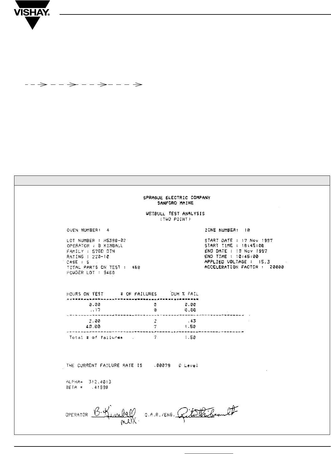
Document Number: 40018 For technical questions, contact: tantalum@vishay.com www.vishay.com
Revision: 20-Nov-07 53
M39003/01/03/09
Solid-Electrolyte TANTALEX® Capacitors,
Military MIL-PRF-39003 Qualified, Styles CSR13, 21, 23
Vishay Sprague
WEIBULL DISTRIBUTION METHOD FOR DETERMINING FAILURE RATE, MIL-PRF-39003
(Cont’d)
If no failures occur, the lot can be re-started at a higher stress
level only once. If no failures occur at the higher stress level,
the lot is not suitable for Weibull analysis.
t0 15 min 2 h ≤ t1 ≤ 10 h 40 h
After a minimum of 40 h, the failure count is again taken. If
no further failures occur, one is added to the count. Failure
rate is calculated by the following:
Z (t) = [- β 1n (1 - P2)105]/t2 A.F.
Where
Z(t) = Failure Rate
β = Weibull shape parameter (slope of the line
between t1 and t2 graphed on paper with a 1n (t)
abscissa and 1n 1n (1/(1-P)) ordinate
P = Ratio of failures to units on test at stop time
t2 = Number of hours on test
A.F. = Acceleration Factor
The failure rate can be calculated from the previous formula
as follows:
Z (t) = [- β 1n (1 - P)105]/t A.F.
Z (t) = [- 0.2119 1n (1 - 0.0326) 105]/40 (17356)
Z (t) = [- 0.2119 (- 0.0331) 105]/6.9424 (105)
Z (t) = [0.0070/6.9424]
Z (t) = 0.0010 %/1000 h
ACTUAL WEIBULL TEST ANALYSIS FOR THE VISHAY SPRAGUE EQUIPMENT
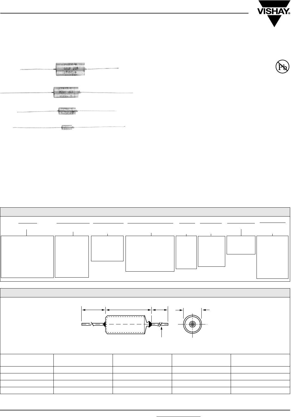
www.vishay.com For technical questions, contact: eurotant@vishay.com Document Number: 42073
54 Revision: 23-Jan-08
CTS1, CTS13, 749DX
Vishay Sprague
Hermetically Sealed, Axial-Lead,
to CECC Specifications
FEATURES
•Terminations: Tin/lead (SnPb), 100 % Tin
(RoHS compliant)
•Hermetically sealed metal case with plastic film
insulation
•Extended capacitance range (type 749DX)
•High operational stability with both time and temperature
•Low leakage current
•Low dissipation factor
APPLICATIONS
Performance and reliability has been proven in a wide range
of applications such as: filtering, by-pass, coupling, energy
storage, timing circuits.
PERFORMANCE CHARACTERISTICS
Operating Temperature:
- 55 °C to + 85 °C (types CTS13)
- 55 °C to + 125 °C (types CTS1, 749DX)
SPECIFICATIONS
CECC BS
30201-001 749DX 9073-N001 749DX
30201-002 CTS1
30201-005 CTS13
30201-011/012 749DX IECQ
30201-029 749DX
* Pb containing terminations are not RoHS compliant, exemptions may apply
Available
RoHS*
COMPLIANT
ORDERING INFORMATION
CTS13 105 X0 040 A 2 P E3
TYPE CAPACITANCE CAPACITANCE
TO L E R A N C E
DC VOLTAGE RATING
AT + 85 °C
CASE
CODE
STYLE
NUMBER
PACKAGING ROHS
COMPLIANT
Identifies the Basic
Capacitor Design
CTS1 = CECC 30201-002
CTS13 = CECC
30201-005
749DX = CECC
30201-001/011/012/029
Expressed in
picofarads. First
two digits are
significant. Third
digit is the
number of zeros
following.
X0 = ± 20 %
X9 = ± 10 %
X5 = ± 5 %
(Special Order)
Expressed in volts.
Where necessary, zeros
precede the voltage
rating to complete the
3 digit block
6R3 = 6.3 V
See
Ta b l e
Ratings
and
Case
Codes.
0 = Bare
Case
2 =
Plastic-Film
Insulation
See Taping
and
Packaging
E3 = 100 %
Tin
termination
(RoHS
compliant)
Blank = SnPb
termination
DIMENSIONS in millimeters
CASE
CODE
BS
D MAX.
NF
D MAX. L MAX.
+ 10 %
Ø d - 0.05
A 3.6 3.8 10.2 0.5
B 4.9 5.1 15.0 0.5
C 7.5 7.7 20.5 0.6
D 9.1 9.3 24.0 0.6
30 MIN. *
D MAX.
30 MIN.
d
* 23 mm MAX. FOR TAPED CAPACITORS
Ø
L MAX.
Document Number: 42073 For technical questions, contact: eurotant@vishay.com www.vishay.com
Revision: 23-Jan-08 55
CTS1, CTS13, 749DX
Hermetically Sealed, Axial-Lead,
to CECC Specifications
Vishay Sprague
TYPE CTS1: STANDARD RATINGS AND CASE CODES
CR
µF
RATED VOLTAGE UR (+ 85 °C)
6.3 V 10 V 16 V 25 V 40 V 50 V 53 V 80 V 100 V 125 V
CATEGORY VOLTAGE UC (+ 125 °C)
4 V 6.3 V 10 V 13 V 25 V 33 V 40 V 50 V 67 V 82 V
0.10 AAAA
0.12 AAAA
0.15 AAAA
0.18 AAAA
0.22 AAAA
0.27 AAAAA
0.33 AAAAA
0.39 AAAAB
0.47 AAAAAB
0.56 AAAAAB
0.68 AAAABB
0.82 AABBBB
1.0 AABBBB
1.2 ABBBBB
1.5 ABBBBBB
1.8 A BBBBBB
2.2 A BBBBBB
2.7 A BBBBB
3.3 A BBBBC
3.9 A BBBBC
4.7 A BBCCC
5.6 A B C C C C
6.8 A BCCCC
8.2 B C C C C
10 BCCCC
12 B C C D D
15 B C C D D
18 B C C D
22 B C D
27 B C D
33 B C D
39 B C D
47 B C D
56 B C D
68 C D
82 C D
100 C D
120 C D
150 C D
180 D
220 D
270 D
330 D
Note:
Preferred ratings are in bold characters. Non-preferred ratings are available only with a capacitance tolerance of ± 10 % or ± 5 % (special order).
CTS1, CTS13, 749DX
Vishay Sprague Hermetically Sealed, Axial-Lead,
to CECC Specifications
www.vishay.com For technical questions, contact: eurotant@vishay.com Document Number: 42073
56 Revision: 23-Jan-08
TYPE CTS13: STANDARD RATINGS AND CASE CODES
CR
µF
RATED VOLTAGE UR (+ 85 °C )
6.3 V 10 V 16 V 20 V 25V 40 V 50 V 63 V
0.10 A A A
0.12 A A A
0.15 A A A
0.18 A A A
0.22 A A A
0.27 A A A
0.33 A A A
0.39 A A A
0.47 A A A
0.56 A A A
0.68 A A A
0.82 A A B
1.0 A A B
1.2 A A B B
1.5 A B B B
1.8 A B B B
2.2 A B B B
2.7 A B B B
3.3 A B B B
3.9 A B B B
4.7 A B B C
5.6 A B C C
6.8 A B C C
8.2 B C C C
10 B C C C
12 B C C D
15 B C C D
18 B C C D
22 B C D
27 B C D
33 B C D
39 B C D
47 B C D
56 B C D
68 C D
82 C D
100 C D
120 C D
150 C D
180 D
220 D
270 D
330 D
Note:
Preferred ratings are in bold characters. Non-preferred ratings are available only with a capacitance tolerance of ± 10 % or ± 5 % (special order).
Document Number: 42073 For technical questions, contact: eurotant@vishay.com www.vishay.com
Revision: 23-Jan-08 57
CTS1, CTS13, 749DX
Hermetically Sealed, Axial-Lead,
to CECC Specifications Vishay Sprague
TYPE 749DX: STANDARD RATINGS AND CASE CODES
CR
µF
RATED VOLTAGE UR ( + 85 °C )
6.3 V 10 V 16 V 20 V 25 V 35 V 40 V 50 V 63 V
CATEGORY VOLTAGE UC ( + 125 °C )
4 V 6.3 V 10 V 13 V 16 V 23 V 25 V 33 V 40 V
0.068 A
0.085 A
0.10 A A A
0.12 A A A
0.15 A A A
0.18 A A A
0.22 A A A
0.27 A A A
0.33 A A A
0.39 A A A
0.47 A A A
0.56 A A A
0.68 A A A
0.82 A A A B
1.0 A A A B
1.2 A B B B B
1.5 A B B B B
1.8 A B B B B
2.2 A B B B B
2.7 A B B B B
3.3 A B B B B
3.9 A B B B B
4.7 A B B
(1) C
5.6 A B B C C
6.8 A (1) (1) C C
8.2 B C C C C
10 B C C C C
12 B C C C D
15 B C C C D
18 B C C C D
22 B C C D
27 B C D D
33 B C D D
39 B C D D
47 B C D
56 B C D (1)
68 C D
82 C D
100 C D
120 C D
150 C D
180 C D
220 D
270 D
330 D
Note:
(1) See extended range page
Preferred ratings are in bold characters. Non-preferred ratings are available only with a capacitance tolerance of ± 10 % or ± 5 % (special order).

CTS1, CTS13, 749DX
Vishay Sprague Hermetically Sealed, Axial-Lead,
to CECC Specifications
www.vishay.com For technical questions, contact: eurotant@vishay.com Document Number: 42073
58 Revision: 23-Jan-08
TYPE 749DX: EXTENDED RATINGS AND CASE CODES
CR
µF
RATED VOLTAGE UR ( + 85 °C )
6.3 V 10 V 16 V 20 V 25 V 35 V 50 V
CATEGORY VOLTAGE UC ( + 125 °C )
4 V 6.3 V 10 V 13 V 16 V 23 V 32 V
1.2 A A
1.5 A A
1.8 A
2.2 A
2.7 A
3.3 A
3.9 A A
4.7 A A B
5.6 A B
6.8 A B
8.2 A B
10 A
12 A B
15 A B
18 B B
22 B C
27 B C D
33 B C D
39 B C D
47 B C
56 B C D
68 B C D
82 B D
100 B C C D
120 B C C D
150 C D
180 C D
220 C D D
270 C D
330 C D D
390 C D
470 C D
560 D
680 D
820 D
1000 D
Note:
Preferred ratings are in bold characters. Non-preferred ratings are available only with a capacitance tolerance of ± 10 % or ± 5 % (special order).
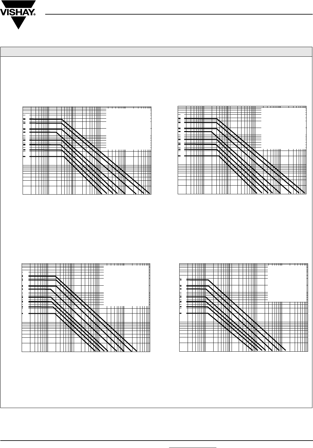
Document Number: 42073 For technical questions, contact: eurotant@vishay.com www.vishay.com
Revision: 23-Jan-08 59
CTS1, CTS13, 749DX
Hermetically Sealed, Axial-Lead,
to CECC Specifications Vishay Sprague
TYPICAL CURVES RIPPLE VOLTAGE AT + 25 °C
100
10
1
0.1
1K 10K 100K 10 100 1M
FREQUENCY IN Hz
V
RMS
50
0.5
30
2
40
20
5
4
3
0.4
0.2
0.3
CASE “B” CAPACITORS
2
3
4
5
6
7
8
1
1 = 100 V and 125 V
2 = 80 V
3 = 50 V and 63 V
4 = 35 V and 40 V
5 = 20 V and 25 V
6 = 16 V
7 = 10 V
8 = 6.3 V
100
10
1
0.1
1K 10K 100K 10 100 1M
FREQUENCY IN Hz
V
RMS
50
0.5
30
2
40
20
5
4
3
0.4
0.2
0.3
CASE “D” CAPACITORS
2
3
4
5
6
7
1 = 80 V
2 = 50 V and 63 V
3 = 35 V and 40 V
4 = 20 V and 25 V
5 = 16 V
6 = 10 V
7 = 6.3 V
1
100
10
1
0.1
1K 10K 100K 10 100 1
M
FREQUENCY IN Hz
V
RMS
50
0.5
30
2
40
20
5
4
3
0.4
0.2
0.3
CASE “A” CAPACITORS
2
3
4
5
6
7
8
1
1 = 100 V and 125 V
2 = 80 V
3 = 50 V and 63 V
4 = 35 V and 40 V
5 = 20 V and 25 V
6 = 16 V
7 = 10 V
8 = 6.3 V
100
10
1
0.1
1K 10K 100K 10 100 1M
FREQUENCY IN Hz
V
RMS
50
0.5
30
2
40
20
5
4
3
0.4
0.2
0.3
CASE “C” CAPACITORS
2
3
4
5
6
7
8
1
1 = 100 V and 125 V
2 = 80 V
3 = 50 V and 63 V
4 = 35 V and 40 V
5 = 20 V and 25 V
6 = 16 V
7 = 10 V
8 = 6.3 V

CTS1, CTS13, 749DX
Vishay Sprague Hermetically Sealed, Axial-Lead,
to CECC Specifications
www.vishay.com For technical questions, contact: eurotant@vishay.com Document Number: 42073
60 Revision: 23-Jan-08
PERFORMANCE CHARACTERISTICS
1. Operating Temperature:
- 55 °C to + 85 °C with rated DC voltage UR applied,
+ 85 °C to + 125 °C with linear voltage derating
to category voltage UC (only for types CTS1, 749DX).
2. Capacitance and Tolerance:
Capacitance measured at 100 Hz and + 25 °C shall be
within the specified tolerance limits of the nominal rating.
Capacitance measurement shall be made by means of a
polarized capacitance bridge. The polarizing voltage shall
be of 2.2 V. The maximum voltage applied during
measurements shall be 1.0 Vrms at 100 Hz and + 25 °C.
3. Reverse Voltage:
These capacitors are capable of withstanding peak
voltage in the reverse direction equal to: 15 % of the rated
DC voltage at + 25 °C, 5 % of the rated DC voltage at
+ 85 °C.
4.Surge Voltage:
Table 1
Capacitors shall withstand the surge voltage applied in
series with a 1000 W resistor, at the rate of 1.5 minute on,
5.5 minute off, for 1000 successive test cycles at + 85 °C
or at + 125 °C. After test, dissipation factor and leakage
current shall meet the initial requirements at + 25 °C (see
below), capacitance change shall not exceed ± 10 % of
initial value at + 25 °C.
5. Leakage current:
Rated voltage UR shall be applied to capacitors during five
minutes with a resistor of 1000 Ω in series with each
capacitor, before making DC leakage current
measurements. The leakage current shall not exceed the
following limits:
Table 2
6. Dissipation factor:
The dissipation factor, when measured at 100 Hz, shall not
exceed the values below:
Table 3
7. Stability at low and high temperature:
Capacitance change with temperature shall not exceed
the limits of the following table, leakage current and
dissipation factor shall be within the limits specified in
Tables 2 and 3.
Table 4
8. Impedance:
The impedance measured at 100 kHz and 25 °C shall not
exceed the following values:
Table 5
9. Life test:
After 2000 h at + 85 °C with rated DC voltage applied,
or after 2000 h at + 125 °C with category DC voltage
applied (for types CTS1, 749DX only) capacitors shall
meet the requirements in table 6.
Table 6
PRODUCT
TYPE
SURGE VOLTAGE
AT + 85 °C
SURGE VOLTAGE
AT + 125 °C
CTS13 1.30 UR -
749DX/CTS1 1.30 UR 1.30 UC
TEMPERATURE CTS1/CTS13/749DX
+ 25 °C 0.01 CR x UR or
1 µA whichever is greater
+ 85 °C 0.1 CR x UR or
10 µA whichever is greater
+ 125 °C 0.125 CR x UR or
12.5 µA whichever is greater
TEMP. CTS1/CTS13 749DX
CRUR ≤ 1900 CRUR > 1900 CR ≤ 100 CR > 100
- 55 °C 9 % 11 % 8 % 10 %
+ 25 °C 6 % 8 % 6 % 8 %
+ 85 °C 9 % 11 % - -
+ 125 °C (1) 12 % 14 % 10 % 11 %
Note: (1) not applicable for CTS13
TEMPERATURE CTS1/CTS13/749DX
- 55 °C - 10 %
+ 85 °C + 12 %
+ 125 °C (2) + 15 %
Note: (2) not applicable for CTS13
CASE CODE Z (Ω)(3)
A10
B5
C2
D1
Note: (3) not applicable for CR ≤ 0.68 μF
PRODUCT
TYPE
CAPACITANCE
CHANGE
DISSIPATION
FACTOR
DC LEAKAGE
CURRENT
CTS1
CTS13
749DX
Within
± 10 % of
initial value
at + 25 °C
Within
initial
requirement
at + 25 °C
Within 125 %
of initial
requirements
at + 25 °C

Document Number: 42073 For technical questions, contact: eurotant@vishay.com www.vishay.com
Revision: 23-Jan-08 61
CTS1, CTS13, 749DX
Hermetically Sealed, Axial-Lead,
to CECC Specifications Vishay Sprague
PERFORMANCE CHARACTERISTICS
(Continued)
10. Humidity test:
After 56 days (1350 h) at + 40 °C, 90 to 95 % of relative
humidity (per IEC 68-2-3) with no voltage applied,
capacitors shall meet the requirements in table 7 below.
Table 7
Table 8
Typical values of charge-discharge current (per above test
conditions).
12. Insulation test:
For capacitors with insulating sleeves, a DC voltage of
100 V shall be applied for one minute between the case of
the capacitor and a metal “V” block in intimate contact with
the insulating sleeve. The insulating resistance measured
in these conditions shall be at least 100 MΩ.
13. Lead pull test:
Leads shall withstand the following test (IEC 68 - 2 - 2):
Tensile stress of 5N (cases A and B) or 10N
(cases C and D) for 10 s in any direction
One bend in each direction
Two cosecutive rotations of 180°
GUIDE TO APPLICATION
1. A-C Ripple Current:
The maximum allowable ripple current shall be
determined from the formula:
where,
P = Power Dissipation in W at + 25 °C as given below
RESR = The capacitor Equivalent Series resistance at the
specified frequency.
2. A-C Ripple Voltage:
The maximum allowable ripple voltage shall be
determined from the formula:
where,
Z = The capacitor Impedance at the specified
frequency.
The calculations are summarized on the graphs page 59
giving the maximum available ripple voltage as a function
of frequency.
However, the sum of the peak AC voltage plus the DC
voltage shall not exceed the rated DC voltage at + 85 °C
of the capacitor. The sum of the negative peak AC voltage
plus the DC voltage shall not allow a voltage reversal
exceeding 15 % of the rated DC voltage.
3. AC Ripple Current or Voltage Derating Factor:
If these capacitors are to be operated at temperatures
above + 25° C, the permissible rms ripple current or
voltage shall be calculated using the derating factors in the
table below:
4. Power Dissipation:
Power dissipation will be affected by the heat sinking
capability of the mounting surface. Non-sinusoidial ripple
current may produce heating effects which differ from
those shown in the following table. It is important that the
equivalent Irms value be established when calculating
permissible operating levels.
CAPACITANCE CHANGE Within ± 3 % of initial value
DC LEAKAGE CURRENT Within initial requirement
at + 25 °C -Table 2
DISSIPATION FACTOR Within initial requirement
at + 25 °C - Table 3
CAPACITANCE CHANGE Within ± 5 % of initial value
at + 25 °C
DC LEAKAGE CURRENT Within initial requirement
at + 25 °C - Table 2
DISSIPATION FACTOR Within initial requirement
at + 25 °C - Table 3
RATED VOLTAGE
UR (V)
CHARGE-DISCHARGE CURRENT
(A)
6.3 13
10 20
16 32
25 50
40 80
50 100
63 126
TEMPERATURE DERATING FACTOR
+ 25 °C 1.0
+ 55 °C 0.8
+ 85 °C 0.6
+ 125 °C 0.4
CASE CODE POWER DISSIPATION
AT + 25 °C (W)
A 0.115
B 0.145
C 0.185
D 0.225
Irms
P
RESR
----------------=
Vrms
P
RESR
----------------- Z×=

CTS1, CTS13, 749DX
Vishay Sprague Hermetically Sealed, Axial-Lead,
to CECC Specifications
www.vishay.com For technical questions, contact: eurotant@vishay.com Document Number: 42073
62 Revision: 23-Jan-08
MARKING
Capacitors shall be marked with SPRAGUE and/or the registered trademark 2 at vendor‘s option; the type number; rated
capacitance and tolerance (with a letter code, if different from ± 20 %, K = ± 10 % ; J = ± 5 %) ; rated DC voltage at + 85 °C and
the date code of manufacture.
Capacitors shall be marked on one end with a “plus” sign (+) to identify the positive terminal.
TAPE AND REEL PACKING
DIMENSIONS in millimeters
CASE
SIZE
REEL AND
AMMO
S
REEL PACK AMMO PACK BULK
OPTION P OPTION R QTY PER
REEL
OPTION G QTY PER
BOX
QTY PER
PACK
b c
MAX.
b c
MAX.
b c
MAX.
A 5.0 ± 0.3 63 ± 2 78 53 ± 2 68 1000 53 ± 2 68 500 100
B 5.0 ± 0.3 63 ± 2 78 53 ± 2 68 1000 53 ± 2 68 500 75
C 10.0 ± 0.3 63 ± 2 78 63 ± 2 78 500 53 ± 2 68 250 50
D 10.0 ± 0.3 63 ± 2 78 63 ± 2 78 500 53 ± 2 68 250 25
PACKAGING CODE PR GB
L
1
L
2
b
c
S
1.5 max.
0.2 ± 0.3
MEETS IEC 286-1
L1 - L2 = 1.5 mm max.
S = component spacing (cumulative tolerance on 20 units = 4 mm)
b = tape spacing
c = overall length


www.vishay.com For technical questions, contact: tantalum@vishay.com Document Number: 43007
64 Revision: 04-Dec-07
CX06
Vishay Sprague
Subminiature, Leaded Solid Tantalum Capacitors
FEATURES
•Rectangular case with radial leads
•2 to 35 VDC
•0.1 µF to 220 µF
•Operating temperature range: - 55 °C to + 85 °C
•Qualified to MIL-PRF-49137
ORDERING INFORMATION
CX 06 A 474 M
MODEL LEAD
CONFIGURATION
VOLTAGE CAPACITANCE CAPACITANCE
TOLERANCE
0 = Radial M = ± 20 %
K = ± 10 %
DIMENSIONS in inches [millimeters]
CASE
CODE
T
MAX.
W
MAX.
H
MAX.
M ± 0.002
[± 0.051] S
A 0.040 [1.02] 0.050 [1.27] 0.100 [2.54] 0.007 [0.18] 0.030 ± 0.015 [0.76 ± 0.38]
B 0.040 [1.02] 0.070 [1.78] 0.125 [3.18] 0.010 [0.25] 0.050 ± 0.015 [1.27 ± 0.38]
C 0.070 [1.78] 0.120 [3.05] 0.165 [4.19] 0.010 [0.25] 0.100 ± 0.020 [2.54 ± 0.51]
D 0.075 [1.91] 0.185 [4.70] 0.225 [5.72] 0.010 [0.25] 0.150 ± 0.020 [3.81 ± 0.51]
E 0.110 [2.79] 0.220 [5.59] 0.290 [7.37] 0.016 [0.41] 0.180 ± 0.025 [4.57 ± 0.64]
F 0.130 [3.30] 0.230 [5.84] 0.310 [7.87] 0.016 [0.41] 0.200 ± 0.025 [5.08 ± 0.64]
G 0.150 [3.81] 0.375 [9.53] 0.475 [12.07] 0.016 [0.41] 0.300 ± 0.025 [7.62 ± 0.64]
W
(-)
S
(+)
M
T
H
ANODE IDENTIFICATION
PLACED OVER POSITIVE LEAD
IN READ OR IN CONTRASTING COLOR
0.75
[19.5]
MIN.
1.00
[25.4]
MIN.
Example: CX06A474M
RADIAL

Document Number: 43007 For technical questions, contact: tantalum@vishay.com www.vishay.com
Revision: 04-Dec-07 65
CX06
Subminiature, Leaded Solid Tantalum Capacitors Vishay Sprague
Note:
(1) Add suffix to indicate capacitance tolerance K = ± 10 % or M = ± 20 %
STANDARD RATINGS
CAPACITANCE
(µF)
MAX.
DF (%)
MAX. DCL
AT + 25 °C (µA)
CASE
CODE
PART
NUMBER
2 WVDC AT + 85 °C
0.47 10 0.5 A
CX06A474-(1)
2.2 10 0.5 B
CX06A225-(1)
10 10 0.5 C
CX06A106-(1)
3 WVDC AT + 85 °C
1.5 10 0.5 B
CX06B155-(1)
6.8 10 0.5 C
CX06B685-(1)
22 10 1 D
CX06B226-(1)
220 15 9 G
CX06B227-(1)
4 WVDC AT + 85 °C
0.33 10 0.5 A
CX06C334-(1)
1 8 0.5 B
CX06C105-(1)
4.7 8 0.5 C
CX06C475-(1)
15 8 1 D
CX06C156-(1)
47 8 2 E
CX06C476-(1)
68 8 3 F
CX06C686-(1)
6 WVDC AT + 85 °C
0.22 10 0.5 A
CX06D224-(1)
0.68 6 0.5 B
CX06D684-(1)
3.3 6 0.5 C
CX06D335-(1)
10 6 1 D
CX06D106-(1)
33 6 2 E
CX06D336-(1)
47 6 3 F
CX06D476-(1)
150 10 9 G
CX06D157-(1)
10 WVDC AT + 85 °C
0.15 10 0.5 A
CX06F154-(1)
0.47 6 0.5 B
CX06F474-(1)
2.2 6 0.5 C
CX06F225-(1)
6.8 6 1 D
CX06F685-(1)
22 6 2 E
CX06F226-(1)
33 6 3 F
CX06F336-(1)
100 8 9 G
CX06F107-(1)
15 WVDC AT + 85 °C
0.10 10 0.5 A
CX06H104-(1)
0.33 6 0.5 B
CX06H334-(1)
1.5 6 0.5 C
CX06H155-(1)
15 6 2 E
CX06H156-(1)
22 6 3 F
CX06H226-(1)
68 8 9 G
CX06H686-(1)

CX06
Vishay Sprague Subminiature, Leaded Solid Tantalum Capacitors
www.vishay.com For technical questions, contact: tantalum@vishay.com Document Number: 43007
66 Revision: 04-Dec-07
Note:
(1) Add suffix to indicate capacitance tolerance K = ± 10 % or M = ± 20 %
STANDARD RATINGS
CAPACITANCE
(µF)
MAX.
DF (%)
MAX. DCL
AT + 25 °C (µA)
CASE
CODE
PART
NUMBER
20 WVDC AT + 85 °C
0.10 6 0.5 B
CX06J104-(1)
0.15 6 0.5 B
CX06J154-(1)
0.22 6 0.5 B
CX06J224-(1)
1 6 0.5 C
CX06J105-(1)
3.3 6 1 D
CX06J335-(1)
4.7 6 1 D
CX06J475-(1)
10 6 2 E
CX06J106-(1)
15 6 3 F
CX06J156-(1)
47 8 9 G
CX06J476-(1)
25 WVDC AT + 85 °C
0.68 6 0.5 C
CX06K684-(1)
2.2 6 1 D
CX06K225-(1)
6.8 6 2 E
CX06K685-(1)
10 6 3 F
CX06K106-(1)
33 6 9 G
CX06K336-(1)
35 WVDC AT + 85 °C
0.10 6 0.5 C
CX06M104-(1)
0.15 6 0.5 C
CX06M154-(1)
0.22 6 0.5 C
CX06M224-(1)
0.33 6 0.5 C
CX06M334-(1)
0.47 6 0.5 C
CX06M474-(1)
0.68 6 1 D
CX06M684-(1)
1 6 1 D
CX06M105-(1)
1.5 6 1 D
CX06M155-(1)
2.2 6 2 E
CX06M225-(1)
3.3 6 2 E
CX06M335-(1)
4.7 6 2 E
CX06M475-(1)
6.8 6 3 F
CX06M685-(1)
10 6 9 G
CX06M106-(1)
15 6 9 G
CX06M156-(1)
22 6 9 G
CX06M226-(1)

Document Number: 43018 For technical questions, contact: tantalum@vishay.com www.vishay.com
Revision: 05-Dec-07 67
CX16
Vishay Sprague
Subminiature, Leaded Solid Tantalum Capacitors
FEATURES
•Axial leads
•2 to 35 VDC
•0.1 µF to 220 µF
•Operating temperature range: - 55 °C to + 85 °C
•Qualified to MIL-PRF-49137
ORDERING INFORMATION
CX 06 A 474 M
MODEL LEAD
CONFIGURATION
VOLTAGE CAPACITANCE CAPACITANCE
TOLERANCE
1 = Axial M = ± 20 %
K = ± 10 %
DIMENSIONS in inches [millimeters]
CASE
CODE
T
MAX.
W
MAX.
H
MAX.
M ± 0.002
[± 0.051]
A 0.040 [1.02] 0.050 [1.27] 0.100 [2.54] 0.007 [0.18]
B 0.040 [1.02] 0.070 [1.78] 0.125 [3.18] 0.010 [0.25]
C 0.070 [1.78] 0.120 [3.05] 0.165 [4.19] 0.010 [0.25]
D 0.075 [1.91] 0.185 [4.70] 0.225 [5.72] 0.010 [0.25]
E 0.110 [2.79] 0.220 [5.59] 0.290 [7.37] 0.016 [0.41]
F 0.130 [3.30] 0.230 [5.84] 0.310 [7.87] 0.016 [0.41]
G 0.150 [3.81] 0.375 [9.53] 0.475 [12.07] 0.016 [0.41]
ANODE IDENTIFICATION
PLACED OVER POSITIVE LEAD
IN RED OR IN CONTRASTING COLOR
W
(-)
(+)
M
T
H
0.75
[19.05]
MIN.
0.75
[19.05]
MIN.
Example: CX16A474M
AXIAL

CX16
Vishay Sprague Subminiature, Leaded Solid Tantalum Capacitors
www.vishay.com For technical questions, contact: tantalum@vishay.com Document Number: 43018
68 Revision: 05-Dec-07
Note:
(1) Add suffix to indicate capacitance tolerance K = ± 10 % or M = ± 20 %
STANDARD RATINGS
CAPACITANCE
(µF)
MAX
DF (%)
MAX. DCL
AT + 25 °C (µA)
CASE
CODE
PART
NUMBER
2 WVDC AT + 85 °C
0.47 10 0.5 A
CX16A474-(1)
2.2 10 0.5 B
CX16A225-(1)
10 10 0.5 C
CX16A106-(1)
3 WVDC AT + 85 °C
1.5 10 0.5 B
CX16B155-(1)
6.8 10 0.5 C
CX16B685-(1)
22 10 1 D
CX16B226-(1)
220 15 9 G
CX16B227-(1)
4 WVDC AT + 85 °C
0.33 10 0.5 A
CX16C334-(1)
1 8 0.5 B
CX16C105-(1)
4.7 8 0.5 C
CX16C475-(1)
15 8 1 D
CX16C156-(1)
47 8 2 E
CX16C476-(1)
68 8 3 F
CX16C686-(1)
6 WVDC AT + 85 °C
0.22 10 0.5 A
CX16D224-(1)
0.68 6 0.5 B
CX16D684-(1)
3.3 6 0.5 C
CX16D335-(1)
10 6 1 D
CX16D106-(1)
33 6 2 E
CX16D336-(1)
47 6 3 F
CX16D476-(1)
150 10 9 G
CX16D157-(1)
10 WVDC AT + 85 °C
0.15 10 0.5 A
CX16F154-(1)
0.47 6 0.5 B
CX16F474-(1)
2.2 6 0.5 C
CX16F225-(1)
6.8 6 1 D
CX16F685-(1)
22 6 2 E
CX16F226-(1)
33 6 3 F
CX16F336-(1)
100 8 9 G
CX16F107-(1)
15 WVDC AT + 85 °C
0.10 10 0.5 A
CX16H104-(1)
0.33 6 0.5 B
CX16H334-(1)
1.5 6 0.5 C
CX16H155-(1)
15 6 2 E
CX16H156-(1)
22 6 3 F
CX16H226-(1)
68 8 9 G
CX16H686-(1)

Document Number: 43018 For technical questions, contact: tantalum@vishay.com www.vishay.com
Revision: 05-Dec-07 69
CX16
Subminiature, Leaded Solid Tantalum Capacitors Vishay Sprague
Note:
(1) Add suffix to indicate capacitance tolerance K = ± 10 % or M = ± 20 %
STANDARD RATINGS
CAPACITANCE
(µF)
MAX
DF (%)
MAX. DCL
AT + 25 °C (µA)
CASE
CODE
PART
NUMBER
20 WVDC AT + 85 °C
0.10 6 0.5 B
CX16J104-(1)
0.15 6 0.5 B
CX16J154-(1)
0.22 6 0.5 B
CX16J224-(1)
1 6 0.5 C
CX16J105-(1)
3.3 6 1 D
CX16J335-(1)
4.7 6 1 D
CX16J475-(1)
10 6 2 E
CX16J106-(1)
15 6 3 F
CX16J156-(1)
47 8 9 G
CX16J476-(1)
25 WVDC AT + 85 °C
0.68 6 0.5 C
CX16K684-(1)
2.2 6 1 D
CX16K225-(1)
6.8 6 2 E
CX16K685-(1)
10 6 3 F
CX16K106-(1)
33 6 9 G
CX16K336-(1)
35 WVDC AT + 85 °C
0.10 6 0.5 C
CX16M104-(1)
0.15 6 0.5 C
CX16M154-(1)
0.22 6 0.5 C
CX16M224-(1)
0.33 6 0.5 C
CX16M334-(1)
0.47 6 0.5 C
CX16M474-(1)
0.68 6 1 D
CX16M684-(1)
1 6 1 D
CX16M105-(1)
1.5 6 1 D
CX16M155-(1)
2.2 6 2 E
CX16M225-(1)
3.3 6 2 E
CX16M335-(1)
4.7 6 2 E
CX16M475-(1)
6.8 6 3 F
CX16M685-(1)
10 6 9 G
CX16M106-(1)
15 6 9 G
CX16M156-(1)
22 6 9 G
CX16M226-(1)
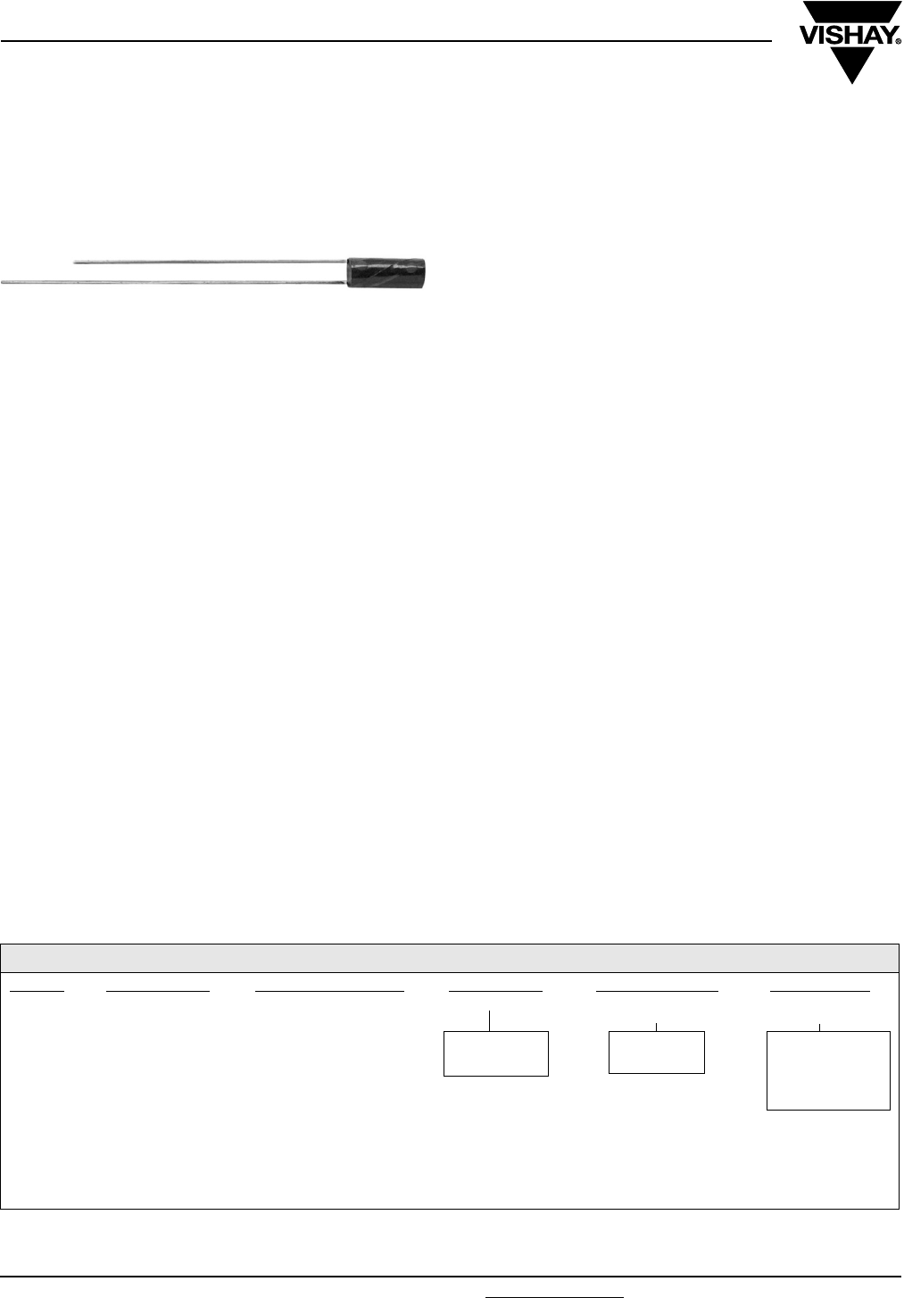
www.vishay.com For technical questions, contact: tantalum@vishay.com Document Number: 43003
70 Revision: 05-Dec-07
HA
Vishay Sprague
Subminiature, Leaded Solid Tantalum Capacitors
Polar or Non-Polar
FEATURES
•Subminiature package size and light weight
•Cylindrical case with axial or radial leads
•2 to 50 VDC
•0.001 µF to 68 µF
•Operating temperature range: - 55 °C to + 125 °C
•High stability and reliability
•Tested in accordance with MIL-PRF-49137
•Unique and comprehensive custom design capability
ELECTRICAL CHARACTERISTICS
Operating temperature range: - 55 °C to + 125 °C
Capacitance: Measured at 120 Hz and 25 °C with a
maximum of 2.2 VDC bias and 1.0 Vrms signal.
Capacitance Tolerance: Standard tolerance is ± 20 % for
ratings 0.1 µF and above, and + 40, - 20 % for ratings below
0.1 µF. Special tolerances are also available.
Dissipation Factor: When measured simultaneously with
capacitance, DF shall not exceed the value shown in the
ratings tables.
DC Leakage Current (DCL Max):
When measured with DC voltage applied through a 1000 Ω
resistor for 5 min, DC leakage (µA) shall not exceed:
At 25 °C: Leakage current shall not exceed the values listed
in the Standard Ratings Tables
At 85 °C: Leakage current shall not exceed 10 times the
values listed in the Standard Ratings Tables
At 125 °C and 66 % of rated voltage: Leakage current shall
not exceed 15 times the values listed in the Standard Ratings
Tables.
Operating Voltage: Full working voltage up to 85 °C. From
85 °C to 125 °C working voltage derates linearly to 66 % of
the 85 °C working voltage.
APPLICATIONS
•Hearing aids
•Portable communications
•Space/avionics
•Laptop computers
MECHANICAL SPECIFICATIONS
Solder coated nickel leads (type N32 per MIL-STD-1276) are
standard on all case sizes.
Leads are weldable and/or solderable.
Special leads are available on request (e.g. bare nickle, gold
plated nickle or ribbon leads).
Lead length is 1 1/2" [38.1 mm] minimum on nonpolar parts.
On polar parts the negative lead is 1 1/4" [31.8 mm] minimum
and the positive lead is 1 1/2" [38.1 mm] minimum.
ORDERING INFORMATION
HA 1.0 35 C7 A* M
MODEL CAPACITANCE
IN µF
DC VOLTAGE RATING
AT + 85 °C
CASE CODE LEAD
CONFIGURATION
CAPACITANCE
TOLERANCE
C = Polar
N = Non-polar
A = Axial
R = Radial
E = + 40, - 20 %
M = ± 20 %
K = ± 10 %
J = ± 5 %
Example of Part Number Code: HA1.0-35C7AM
* To complete part number in rating tables, add A or R.
Change suffix if special capacitance tolerance is required.
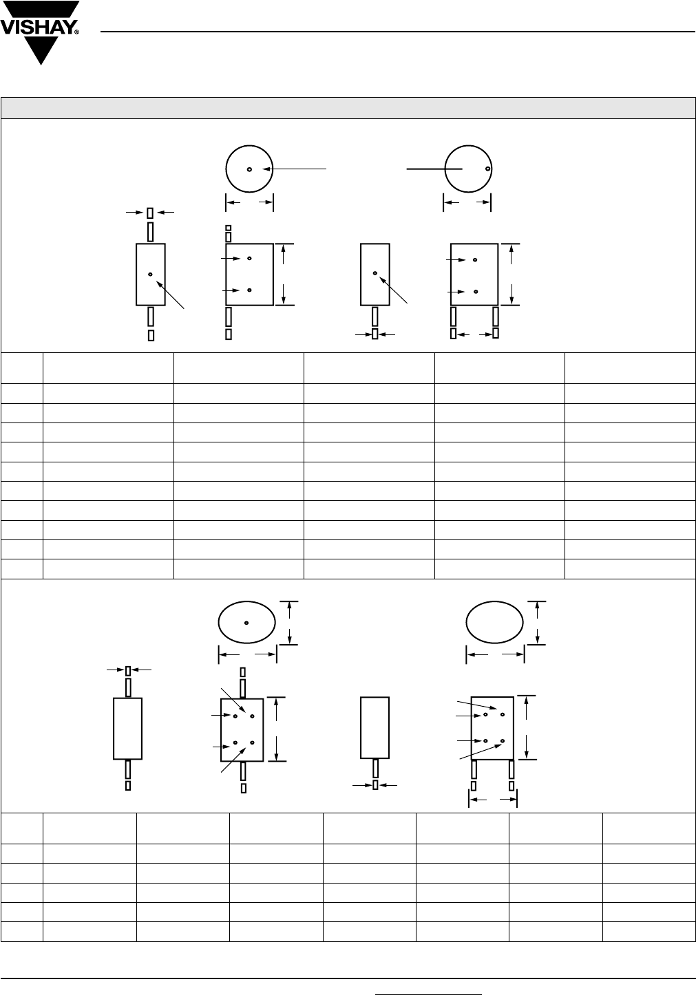
Document Number: 43003 For technical questions, contact: tantalum@vishay.com www.vishay.com
Revision: 05-Dec-07 71
HA
Subminiature, Leaded Solid Tantalum Capacitors
Polar or Non-Polar
Vishay Sprague
DIMENSIONS in inches [millimeters]
CASE
CODE
MAX.
L
MAX.
D
MAX.
E
E TOL.
± d
C0 0.100 [2.54] 0.057 [1.45] 0.030 [0.76] 0.015 [0.38] 0.007[0.18]
C1 0.110 [2.80] 0.067 [1.70] 0.050 [1.27] 0.015 [0.38] 0.010 [0.25]
C2 0.125 [3.18] 0.067 [1.70] 0.050 [1.27] 0.015 [0.38] 0.010 [0.25]
C3 0.145 [3.68] 0.067 [1.70] 0.050 [1.27] 0.015 [0.38] 0.010 [0.25]
C4 0.160 [4.06] 0.070 [1.78] 0.050 [1.27] 0.015 [0.38] 0.010 [0.25]
C5 0.160 [4.06] 0.077 [1.96] 0.050 [1.27] 0.015 [0.38] 0.010 [0.25]
C6 0.190 [4.83] 0.077 [1.96] 0.050 [1.27] 0.015 [0.38] 0.010 [0.25]
C7 0.200 [5.08] 0.080 [2.03] 0.050 [1.27] 0.015 [0.38] 0.010 [0.25]
C8 0.225 [5.72] 0.100 [2.54] 0.070 [1.78] 0.020 [0.51] 0.010 [0.25]
C9 0.250 [6.35] 0.150 [3.81] 0.120 [3.05] 0.025 [0.64] 0.016 [0.41]
CASE
CODE
MAX.
LA
MAX.
LR
MAX.
W
MAX.
T E E TOL.
± d
N1 0.175 [4.45] 0.135 [3.43] 0.120 [3.05] 0.070 [1.78] 0.100 [2.54] 0.020 [0.51] 0.010 [0.25]
N2 0.210 [5.33] 0.160 [4.06] 0.120 [3.05] 0.070 [1.78] 0.100 [2.54] 0.020 [0.51] 0.010 [0.25]
N3 0.240 [6.10] 0.200 [5.08] 0.140 [3.56] 0.080 [2.03] 0.100 [2.54] 0.020 [0.51] 0.010 [0.25]
N4 0.275 [6.99] 0.235 [5.97] 0.190 [4.83] 0.105 [2.67] 0.125 [3.18] 0.020 [0.51] 0.010 [0.25]
N5 0.310 [7.87] 0.270 [6.86] 0.290 [7.37] 0.155 [3.94] 0.200 [5.08] 0.025 [0.64] 0.016 [0.41]
E
TOLERANCE
DOT
RADIAL
d
d
AXIAL
DD
LL
(+)
(+)
(-)
3RD DOT AND POLARITY
2ND DOT
1
ST DOT 1ST DOT
2ND DOT
TOLERANCE
DOT
(-)
AXIAL RADIAL
T
W
d
E
LR
LA
TOLERANCE
DOT
1ST DOT
3RD DOT
1ST DOT
3RD DOT
(+)
(-)
2ND DOT
TOLERANCE
DOT
2ND DOT
W
d
T
POLAR STYLE
NON POLAR STYLE

HA
Vishay Sprague Subminiature, Leaded Solid Tantalum Capacitors
Polar or Non-Polar
www.vishay.com For technical questions, contact: tantalum@vishay.com Document Number: 43003
72 Revision: 05-Dec-07
Note:
(1) Add for axial, R for radial
STANDARD RATINGS - POLAR CAPACITORS
CAPACITANCE
(µF)
MAX
DF (%)
MAX. DCL
AT + 25 °C (µA)
CASE
CODE
PART
NUMBER
2 WVDC AT + 85 °C
0.47 10 0.5 C0
HA.47-2C0 (1)M
1.5 10 0.5 C1
HA1.5-2C1 (1)M
2.2 10 0.5 C2
HA2.2-2C2 (1)M
3.3 10 0.5 C3
HA3.3-2C3 (1)M
4.7 10 0.5 C4
HA4.7-2C4 (1)M
6.8 10 0.5 C5
HA6.8-2C5 (1)M
10 10 0.5 C6
HA10-2C6 (1)M
15 10 0.5 C7
HA15-2C7 (1)M
22 10 1.0 C8
HA22-2C8 (1)M
68 10 1.5 C9
HA68-2C9 (1)M
3 WVDC AT + 85 °C
1.0 10 0.5 C1
HA1.0-3C1 (1)M
1.5 10 0.5 C2
HA1.5-3C2 (1)M
2.2 10 0.5 C3
HA2.2-3C3 (1)M
3.3 10 0.5 C4
HA3.3-3C4 (1)M
4.7 10 0.5 C5
HA4.7-3C5 (1)M
6.8 10 0.5 C6
HA6.8-3C6 (1)M
10 10 0.5 C7
HA10-3C7 (1)M
15 10 1.0 C8
HA15-3C8 (1)M
47 10 1.5 C9
HA47-3C9 (1)M
4 WVDC AT + 85 °C
0.33 10 0.5 C0
HA.33-4C0 (1)M
0.68 8 0.5 C1
HA.68-4C1 (1)M
1.0 8 0.5 C2
HA1.0-4C2 (1)M
1.5 8 0.5 C3
HA1.5-4C3 (1)M
2.2 8 0.5 C4
HA2.2-4C4 (1)M
3.3 8 0.5 C5
HA3.3-4C5 (1)M
4.7 8 0.5 C6
HA4.7-4C6 (1)M
6.8 8 0.5 C7
HA6.8-4C7 (1)M
10 8 1.0 C8
HA10-4C8 (1)M
33 8 1.5 C9
HA33-4C9 (1)M
6 WVDC AT + 85 °C
0.22 10 0.5 C0
HA.22-6C0 (1)M
0.47 6 0.5 C1
HA.47-6C1 (1)M
0.68 6 0.5 C2
TC.68-6C2 (1)M
1.0 6 0.5 C3
HA1.0-6C3 (1)M
1.5 6 0.5 C4
HA1.5-6C4 (1)M
2.2 6 0.5 C5
HA2.2-6C5 (1)M
3.3 6 0.5 C6
HA3.3-6C6 (1)M
4.7 6 0.5 C7
HA4.7-6C7 (1)M
6.8 6 1.0 C8
HA6.8-6C8 (1)M
22 6 1.5 C9
HA22-6C9 (1)M

Document Number: 43003 For technical questions, contact: tantalum@vishay.com www.vishay.com
Revision: 05-Dec-07 73
HA
Subminiature, Leaded Solid Tantalum Capacitors
Polar or Non-Polar Vishay Sprague
Note:
(1) Add for axial, R for radial
STANDARD RATINGS - POLAR CAPACITORS
CAPACITANCE
(µF)
MAX
DF (%)
MAX. DCL
AT + 25 °C (µA)
CASE
CODE
PART
NUMBER
10 WVDC AT + 85 °C
0.0010 10 0.5 C0
HA.0010-10C0 (1)E
0.0010 10 0.5 C1
HA.0010-10C1 (1)E
0.0015 10 0.5 C0
HA.0015-10C0 (1)E
0.0015 10 0.5 C1
HA.0015-10C1 (1)E
0.0022 10 0.5 C0
HA.0022-10C0 (1)E
0.0022 10 0.5 C1
HA.0022-10C1 (1)E
0.0033 10 0.5 C0
HA.0033-10C0 (1)E
0.0033 10 0.5 C1
HA.0033-10C1 (1)E
0.0047 10 0.5 C0
HA.0047-10C0 (1)E
0.0047 10 0.5 C1
HA.0047-10C1 (1)E
0.15 10 0.5 C0
HA.15-10C0 (1)M
0.33 6 0.5 C1
HA.33-10C1 (1)M
0.47 6 0.5 C2
HA.47-10C2 (1)M
0.68 6 0.5 C3
HA.68-10C3 (1)M
1.0 6 0.5 C4
HA1.0-10C4 (1)M
1.5 6 0.5 C5
HA1.5-10C5 (1)M
2.2 6 0.5 C6
HA2.2-10C6 (1)M
3.3 6 0.5 C7
HA3.3-10C7 (1)M
4.7 6 1.0 C8
HA4.7-10C8 (1)M
15 6 1.5 C9
HA15-10C9 (1)M
15 WVDC AT + 85 °C
0.10 10 0.5 C0
HA.10-15C0 (1)M
0.22 6 0.5 C1
HA.22-15C1 (1)M
0.33 6 0.5 C2
HA.33-15C2 (1)M
0.47 6 0.5 C3
HA.47-15C3 (1)M
0.68 6 0.5 C4
HA.68-15C4 (1)M
1.0 6 0.5 C5
HA1.0-15C5 (1)M
1.5 6 0.5 C6
HA1.5-15C6 (1)M
2.2 6 0.5 C7
HA2.2-15C7 (1)M
3.3 6 1.0 C8
HA3.3-15C8 (1)M
10 6 1.5 C9
HA10-15C9 (1)M
20 WVDC AT + 85 °C
0.0068 10 0.5 C0
HA.0068-0C0 (1)E
0.0068 10 0.5 C1
HA.0068-0C1 (1)E
0.010 10 0.5 C0
HA.010-20C0 (1)E
0.015 10 0.5 C0
HA.015-20C0 (1)E
0.022 10 0.5 C0
HA.022-20C0 (1)E
0.033 10 0.5 C0
HA.033-20C0 (1)E
0.047 10 0.5 C0
HA.047-20C0 (1)E
0.068 10 0.5 C0
HA.068-20C0 (1)E
0.15 6 0.5 C1
HA.15-20C1 (1)M
0.22 6 0.5 C2
HA.22-20C2 (1)M

HA
Vishay Sprague Subminiature, Leaded Solid Tantalum Capacitors
Polar or Non-Polar
www.vishay.com For technical questions, contact: tantalum@vishay.com Document Number: 43003
74 Revision: 05-Dec-07
Note:
(1) Add A for axial, R for radial
STANDARD RATINGS - POLAR CAPACITORS
CAPACITANCE
(µF)
MAX
DF (%)
MAX. DCL
AT + 25 °C (µA)
CASE
CODE
PART
NUMBER
20 WVDC AT + 85 °C (Contd)
0.33 6 0.5 C3
HA.33-20C3(1)M
0.47 6 0.5 C4
HA.47-20C4(1)M
0.68 6 0.5 C5
HA.68-20C5(1)M
1.0 6 0.5 C6
HA1.0-20C6(1)M
1.5 6 0.5 C7
HA1.5-20C7(1)M
2.2 6 1.0 C8
HA2.2-20C8(1)M
4.7 6 1.5 C9
HA4.7-20C9(1)M
6.8 6 1.5 C9
HA6.8-20C9(1)M
35 WVDC AT + 85 °C
0.010 6 0.5 C1
HA.010-35C1 (1)E
0.015 6 0.5 C1
HA.015-35C1 (1)E
0.022 6 0.5 C1
HA.022-35C1 (1)E
0.033 6 0.5 C1
HA.033-35C1 (1)E
0.047 6 0.5 C1
HA.047-35C1 (1)E
0.068 6 0.5 C1
HA.068-35C1 (1)E
0.10 6 0.5 C1
HA.10-35C1 (1)M
0.15 6 0.5 C2
HA.15-35C2 (1)M
0.22 6 0.5 C3
HA.22-35C3 (1)M
0.33 6 0.5 C4
HA.33-35C4 (1)M
0.47 6 0.5 C5
HA.47-35C5 (1)M
0.68 6 0.5 C6
HA.68-35C6 (1)M
1.0 6 0.5 C7
HA1.0-35C7 (1)M
1.5 6 0.5 C8
HA1.5-35C8 (1)M
3.3 6 1.5 C9
HA3.3-35C9 (1)M
50 WVDC AT + 85 °C
0.10 6 0.5 C2
HA.10-50C2 (1)M
0.15 6 0.5 C3
HA.15-50C3 (1)M
0.22 6 0.5 C4
HA.22-50C4 (1)M
0.33 6 0.5 C5
HA.33-50C5 (1)M
0.47 6 0.5 C6
HA.47-50C6 (1)M
0.68 6 0.5 C7
HA.68-50C7 (1)M
1.0 6 1.0 C8
HA1.0-50C8 (1)M
1.5 6 1.5 C9
HA1.5-50C9 (1)M
2.2 6 1.5 C9
HA2.2-50C9 (1)M

Document Number: 43003 For technical questions, contact: tantalum@vishay.com www.vishay.com
Revision: 05-Dec-07 75
HA
Subminiature, Leaded Solid Tantalum Capacitors
Polar or Non-Polar Vishay Sprague
Note:
(1) Add for axial, R for radial
STANDARD RATINGS - NON-POLAR CAPACITORS
CAPACITANCE
(µF)
MAX
DF (%)
MAX. DCL
AT + 25 °C (µA)
CASE
CODE
PART
NUMBER
2 WVDC AT + 85 °C
1.0 10 0.5 N1
HA1.0-2N1 (1)M
2.2 10 0.5 N2
HA2.2-2N2 (1)M
4.7 10 0.5 N3
HA4.7-2N3 (1)M
10 10 1.0 N4
HA10-2N4 (1)M
33 10 1.5 N5
HA33-2N5 (1)M
3 WVDC AT + 85 °C
0.68 10 0.5 N1
HA.68-3N1 (1)M
1.5 10 0.5 N2
HA1.5-3N2 (1)M
3.3 10 0.5 N3
HA3.3-3N3 (1)M
6.8 10 1.0 N4
HA6.8-3N4 (1)M
22 10 1.5 N5
HA22-3N5 (1)M
4 WVDC AT + 85 °C
0.47 8 0.5 N1
HA.47-4N1 (1)M
1.0 8 0.5 N2
HA1.0-4N2 (1)M
2.2 8 0.5 N3
HA2.2-4N3 (1)M
4.7 8 1.0 N4
HA4.7-4N4 (1)M
15 8 1.5 N5
HA15-4N5 (1)M
6 WVDC AT + 85 °C
0.33 6 0.5 N1
HA.33-6N1 (1)M
0.68 6 0.5 N2
HA.68-6N2 (1)M
1.5 6 0.5 N3
HA1.5-6N3 (1)M
3.3 6 1.0 N4
HA3.3-6N4 (1)M
10 6 1.5 N5
HA10-6N5 (1)M
10 WVDC AT + 85 °C
0.22 6 0.5 N1
HA.22-10N1 (1)M
0.47 6 0.5 N2
HA.47-10N2 (1)M
1.0 6 0.5 N3
HA1.0-10N3 (1)M
2.2 6 1.0 N4
HA2.2-10N4 (1)M
6.8 6 1.5 N5
HA6.8-10N5 (1)M
15 WVDC AT + 85 °C
0.15 6 0.5 N1
HA.15-15N1 (1)M
0.33 6 0.5 N2
HA.33-15N2 (1)M
0.68 6 0.5 N3
HA.68-15N3 (1)M
1.5 6 1.0 N4
HA1.5-15N4 (1)M
4.7 6 1.5 N5
HA4.7-15N5 (1)M
20 WVDC AT + 85 °C
0.010 6 0.5 N1
HA.010-20N1 (1)M
0.015 6 0.5 N1
HA.015-20N1 (1)M
0.022 6 0.5 N1
HA.022-20N1 (1)M

HA
Vishay Sprague Subminiature, Leaded Solid Tantalum Capacitors
Polar or Non-Polar
www.vishay.com For technical questions, contact: tantalum@vishay.com Document Number: 43003
76 Revision: 05-Dec-07
Note:
(1) Add for axial, R for radial
STANDARD RATINGS - NON-POLAR CAPACITORS
CAPACITANCE
(µF)
MAX
DF (%)
MAX. DCL
AT + 25 °C (µA)
CASE
CODE
PART
NUMBER
20 WVDC AT + 85 °C (Contd.)
0.033 6 0.5 N2
HA.033-20N2 (1)M
0.047 6 0.5 N2
HA.047-20N2 (1)M
0.068 6 0.5 N2
HA.068-20N2 (1)M
0.10 6 0.5 N1
HA.10-20N1 (1)M
0.22 6 0.5 N2
HA.22-20N2 (1)M
0.47 6 0.5 N3
HA.47-20N3 (1)M
1.0 6 1.0 N4
HA1.0-20N4 (1)M
2.2 6 1.5 N5
H2.2-20N5 (1)M
3.3 6 1.5 N5
HA3.3-20N5 (1)M
35 WVDC AT + 85 °C
0.10 6 0.5 N2
HA.10-35N2 (1)M
0.15 6 0.5 N2
HA.15-35N2 (1)M
0.22 6 0.5 N3
HA.22-35N3 (1)M
0.33 6 0.5 N3
HA.33-35N3 (1)M
0.47 6 1.0 N4
HA.47-35N4 (1)M
0.68 6 1.0 N4
HA.68-35N4 (1)M
1.0 6 1.5 N5
HA1.0-35N5 (1)M
1.5 6 1.5 N5
HA1.5-35N5 (1)M
50 WVDC AT + 85 °C
0.068 6 0.5 N3
HA.068-50N3 (1)M
0.15 6 0.5 N3
HA.15-50N3 (1)M
0.33 6 1.0 N4
HA.33-50N4 (1)M
0.68 6 1.5 N5
HA.68-50N5 (1)M
MARKING
HA Capacitors case sizes N4 and N5 are print
marked:
- Capacitance is in picofarads
- 1st and 2nd digits are significant figures
- 3rd digit indicates the number of zeros.
All other case sizes have color dot marking:
Capacitance Color Digit
In picofarads, indicated by 3 dots.
1st and 2nd dot give the significant
digits. 3rd dot indicates the number
of zeros. Color dot location is shown
on the dimensional sketches. Black
dot is omitted on black sleeve.
Black 0
Brown 1
Red 2
Orange 3
Ye l l ow 4
Green 5
Capacitance Tolerance Color Tolerance Blue 6
Is indicated by a dot on
the side of the case.
Black dot is omitted.
Gold ± 5 % Violet 7
Silver ± 10 % Grey 8
None ± 20 % White 9
None + 40 %/- 20 %
The positive lead is indicated by a color dot of red
epoxy on the unit.
e.g. Yellow-Violet-Green = 4 700 000 pf
= 4.7 µF
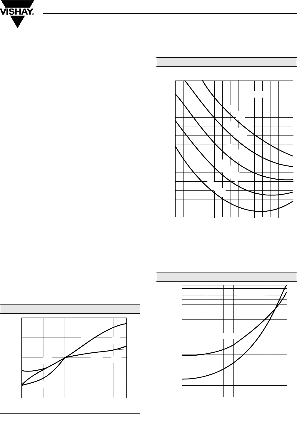
Document Number: 43003 For technical questions, contact: tantalum@vishay.com www.vishay.com
Revision: 05-Dec-07 77
HA
Subminiature, Leaded Solid Tantalum Capacitors
Polar or Non-Polar Vishay Sprague
PERFORMANCE AND RELIABILITY
The capacitors are tested in accordance with
MIL-PRF-49137, with specific requirements as follows:
Temperature Stability: When tested per MIL-PRF-49137/6,
capacitance shall be within ±15 % at - 55 °C and 85 °C, and
±10 % at 25 °C after exposure to temperature extremes. DF
shall be within 200 % of initial limit at - 55 °C, 150 % of initial
limit at 85 °C, and meet the initial at 25 °C. DCL shall be
within 10 x initial limit at 85 °C, and meet the initial limit at
25 °C.
Moisture Resistance: (per Method 106 of MIL-STD-202)
After 10 cycles of 24 h at 25 °C to 65 °C and 80-98 % RH;
capacitance shall be within ± 15 % of initial value, DF within
1.5 x initial limit and leakage within 3 x initial limit.
Life: (per Method 108 of MIL-STD-202) after 1000 h at 85 °C
and rated voltage; capacitance shall be within ± 10 % of
initial limit, DF within initial limits, and leakage within
200 % of initial limit.
Surge Voltage: (per MIL-PRF-49317) After 1000 cycles at
85 °C and 1.3 x WVDC; capacitance shall be within ± 10 %
of initial limit, DF and leakage within initial limits.
Resistance to Soldering Heat: (per Method 210 0f
MIL-STD-202, Condition B) After immersion in 260 °C molten
solder to within a 1/4" of the body of the unit, there shall be
no evidence of mechanical or electrical degradation.
Solderability: (per Method 208 of MIL-STD-202) After
dipping leads in 235 °C molten solder to within 0.125" of the
body of the unit, the solder shall cover 95 % of the lead
surface.
Terminal Strength: (per Method 211 of MIL-STD-202) After
the following test there shall be no loosening of the terminals
or permanent damage to the terminals. Test Condition A:
(Pull Test) 0.010" leads withstand 1 pound, 0.016" leads 2
pounds and 0.007" leads 1/2 pound. Test Condition C: (Bend
Test) All leads shall withstand 3 - 90° bends with a 1/2 pound
applied force.
CAPACITANCE VS. TEMPERATURE
IMPEDANCE VS. FREQUENCY
LEAKAGE CURRENT - TEMPERATURE
+ 10
+ 5
0
- 5
- 10
- 40 - 10 + 25 + 100
+ 85
(MFD-WVDC)
SPECIFICATION
SPECIFICATION
TYPICAL
CHANGE IN CAPACITANCE %
100 µF - 10 V
100 µF - 10 V
1 µH - 20 V
TEMPERATURE °C
100 500 1 2 5 10 20 50 100 500 1 2 5 10
Hz kHz FREQUENCY kHz MHz
IMPEDANCE Ω
(MFD-WVDC)
0.1
0.2
0.5
1.0
2.0
5.0
10
20
50
100
200
500
1K
2K
5K
10K
0.047 µF-20 V
0.047 µF-20 V
0.047 µF-35 V
0.047 µF-35 V
4.7 µF-10 V
4.7 µF-20 V
0.047 µF-50 V
4.7 µF-20 V
1.0
0.1
0.01
- 40 - 10 0 + 85+ 20
(MFD-WVDC)
D.C. LEAKAGE CURRENT (µA)
TEMPERATURE °C
1 µF-20 V
100 µF-10 V
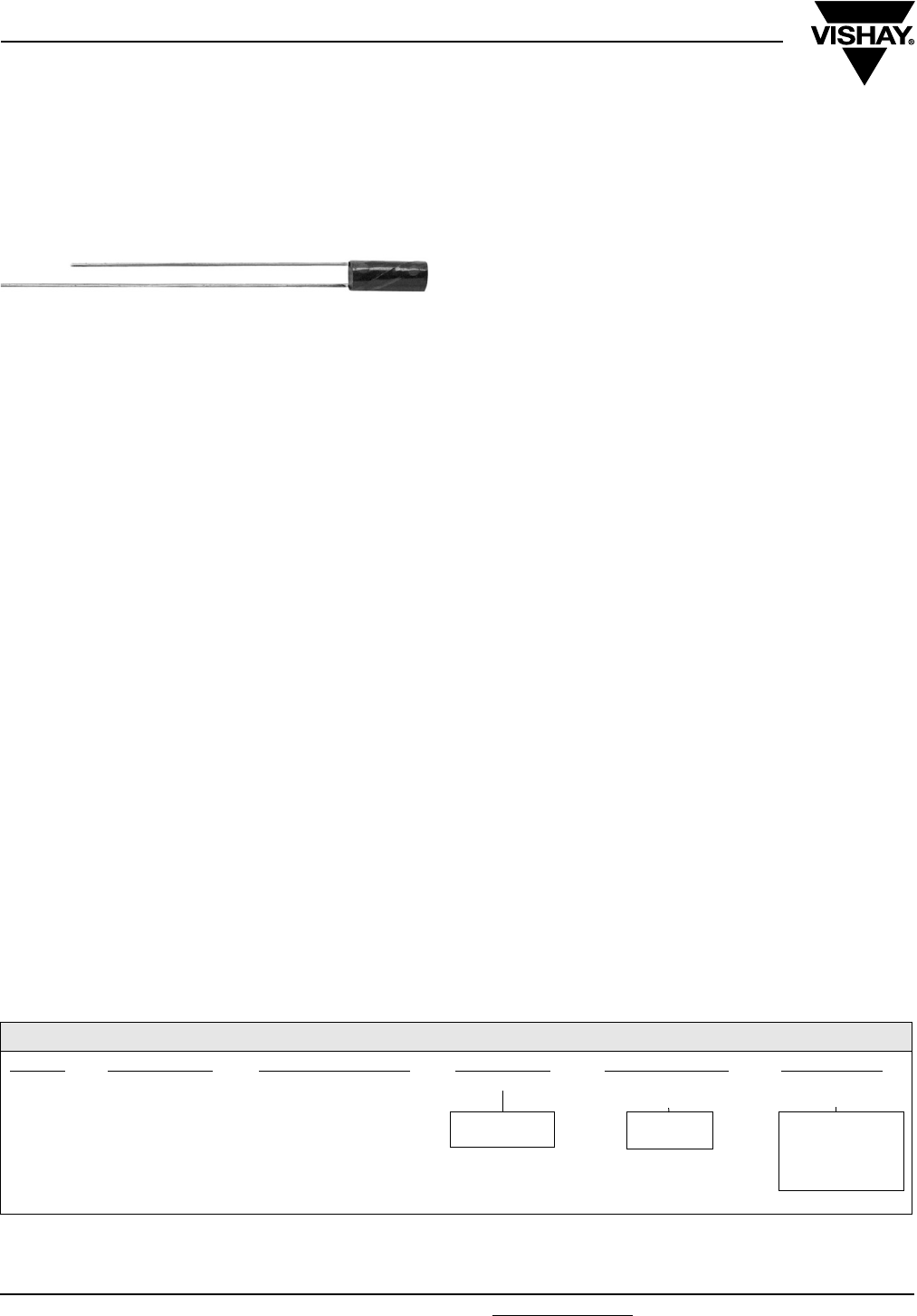
www.vishay.com For technical questions, contact: tantalum@vishay.com Document Number: 43004
78 Revision: 06-Dec-07
SHA
Vishay Sprague
Subminiature, Leaded Solid Tantalum Capacitors
Polar or Non-Polar
FEATURES
•Subminiature package size and light weight
•Cylindrical case with axial or radial leads
•2 to 35 VDC
•0.22 µF to 68 µF
•Operating temperature range: - 55 °C to + 125 °C
•High stability and reliability
•Tested in accordance with MIL-PRF-49137
•Utilize high CV technology to extend the range of
capacitance values in each size
•Unique and comprehensive custom design capability
ELECTRICAL CHARACTERISTICS
Operating Temperature Range: - 55 °C to + 125 °C
Capacitance: Measured at 120 Hz and 25 °C with a
maximum of 2.2 VDC bias and 1.0 Vrms signal.
Capacitance Tolerance: Standard tolerance is ± 20 % for
ratings 0.1 µF and above, and + 40, - 20 % for ratings below
0.1 µF. Special tolerances are also available.
Dissipation Factor: When measured simultaneously with
capacitance, DF shall not exceed the value shown in the
ratings tables.
DC Leakage Current (DCL Max):
When measured with DC voltage applied through a 1000 W
resistor for 5 min, DC leakage (µA) shall not exceed:
At 25 °C: Leakage current shall not exceed the values listed
in the Standard Ratings Tables
At 85 °C: Leakage current shall not exceed 10 times the
values listed in the Standard Ratings Tables
At 125 °C and 66 % of Rated Voltage: Leakage current
shall not exceed 15 times the values listed in the Standard
Ratings Tables.
Operating Voltage: Full working voltage up to 85 °C. From
85 °C to 125 °C working voltage derates linearly to 66 % of
the 85 °C working voltage.
APPLICATIONS
•Hearing aids
•Portable communications
•Space/avionics
•Laptop computers
MECHANICAL SPECIFICATIONS
Solder coated nickel leads (type N32 per MIL-STD-1276) are
standard on all case sizes.
Leads are weldable and/or solderable.
Special leads are available on request (e.g. bare nickel, gold
plated nickle or ribbon leads).
Lead length is 1 1/2" [38.1 mm] minimum on non-polar parts.
On polar parts the negative lead is 1 1/4" [31.8 mm] minimum
and the positive lead is 1 1/2" [38.1 mm] minimum.
Note:
(1) To complete part number in rating tables, add A or R.
Change suffix if special capacitance tolerance is required.
ORDERING INFORMATION
SHA 1.0 35 C7 A (1) M
MODEL CAPACITANCE
(µF)
DC VOLTAGE RATING
at + 85 °C
CASE CODE LEAD
CONFIGURATION
CAPACITANCE
TOLERANCE
C = Polar
N = Non-polar
A = Axial
R = Radial
E = + 40, - 20 %
M = ± 20 %
K = ± 10 %
J = ± 5 %
EXAMPLE OF PART NUMBER CODE: SHA1.0-35C7AM
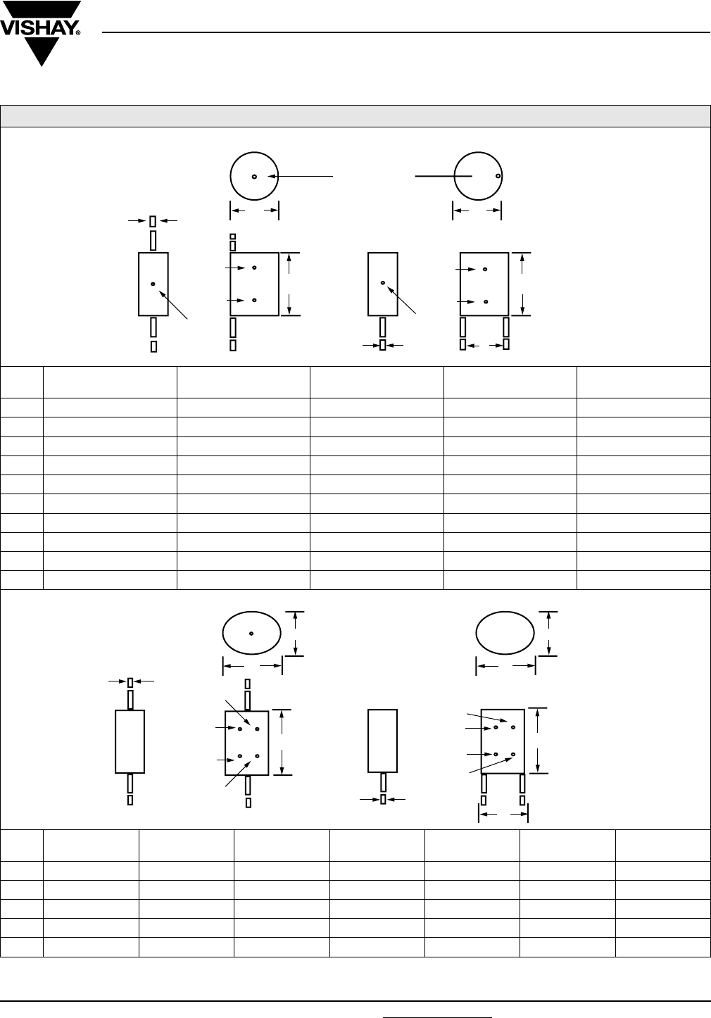
Document Number: 43004 For technical questions, contact: tantalum@vishay.com www.vishay.com
Revision: 06-Dec-07 79
SHA
Subminiature, Leaded Solid Tantalum Capacitors
Polar or Non-Polar
Vishay Sprague
DIMENSIONS in inches [millimeters]
CASE
CODE
MAX.
L
MAX.
D
MAX.
E
E TOL.
± d
C0 0.100 [2.54] 0.057 [1.45] 0.030 [0.76] 0.015 [0.38] 0.007[0.18]
C1 0.110 [2.80] 0.067 [1.70] 0.050 [1.27] 0.015 [0.38] 0.010 [0.25]
C2 0.125 [3.18] 0.067 [1.70] 0.050 [1.27] 0.015 [0.38] 0.010 [0.25]
C3 0.145 [3.68] 0.067 [1.70] 0.050 [1.27] 0.015 [0.38] 0.010 [0.25]
C4 0.160 [4.06] 0.070 [1.78] 0.050 [1.27] 0.015 [0.38] 0.010 [0.25]
C5 0.160 [4.06] 0.077 [1.96] 0.050 [1.27] 0.015 [0.38] 0.010 [0.25]
C6 0.190 [4.83] 0.077 [1.96] 0.050 [1.27] 0.015 [0.38] 0.010 [0.25]
C7 0.200 [5.08] 0.080 [2.03] 0.050 [1.27] 0.015 [0.38] 0.010 [0.25]
C8 0.225 [5.72] 0.100 [2.54] 0.070 [1.78] 0.020 [0.51] 0.010 [0.25]
C9 0.250 [6.35] 0.150 [3.81] 0.120 [3.05] 0.025 [0.64] 0.016 [0.41]
CASE
CODE
MAX.
LA
MAX.
LR
MAX.
W
MAX.
T E E TOL.
± d
N1 0.175 [4.45] 0.135 [3.43] 0.120 [3.05] 0.070 [1.78] 0.100 [2.54] 0.020 [0.51] 0.010 [0.25]
N2 0.210 [5.33] 0.160 [4.06] 0.120 [3.05] 0.070 [1.78] 0.100 [2.54] 0.020 [0.51] 0.010 [0.25]
N3 0.240 [6.10] 0.200 [5.08] 0.140 [3.56] 0.080 [2.03] 0.100 [2.54] 0.020 [0.51] 0.010 [0.25]
N4 0.275 [6.99] 0.235 [5.97] 0.190 [4.83] 0.105 [2.67] 0.125 [3.18] 0.020 [0.51] 0.010 [0.25]
N5 0.310 [7.87] 0.270 [6.86] 0.290 [7.37] 0.155 [3.94] 0.200 [5.08] 0.025 [0.64] 0.016 [0.41]
E
TOLERANCE
DOT
RADIAL
d
d
AXIAL
DD
LL
(+)
(+)
(-)
3RD DOT AND POLARITY
2ND DOT
1
ST DOT 1ST DOT
2ND DOT
TOLERANCE
DOT
(-)
AXIAL RADIAL
T
W
d
E
LR
LA
TOLERANCE
DOT
1ST DOT
3RD DOT
1ST DOT
3RD DOT
(+)
(-)
2ND DOT
TOLERANCE
DOT
2ND DOT
W
d
T
POLAR STYLE
NON POLAR STYLE

SHA
Vishay Sprague Subminiature, Leaded Solid Tantalum Capacitors
Polar or Non-Polar
www.vishay.com For technical questions, contact: tantalum@vishay.com Document Number: 43004
80 Revision: 06-Dec-07
Note:
(1) Add A for axial, R for radial
STANDARD RATINGS - POLAR CAPACITORS
CAPACITANCE
(µF)
MAX
DF (%)
MAX. DCL
AT + 25 °C (µA)
CASE
CODE
PART
NUMBER
2 WVDC AT + 85 °C
3.3 10 0.5 C1
SHA3.3-2C1 (1)M
15 10 0.5 C5
SHA15-2C5 (1)M
22 10 1.0 C6
SHA22-2C6 (1)M
68 10 1.5 C8
SHA68-2C8 (1)M
3 WVDC AT + 85 °C
2.2 10 0.5 C1
SHA2.2-3C1 (1)M
3.3 10 0.5 C2
SHA3.3-3C2 (1)M
4.7 10 0.5 C3
SHA4.7-3C3 (1)M
6.8 10 0.5 C4
SHA6.8-3C4 (1)M
10 10 0.5 C5
SHA10-3C5 (1)M
15 10 1.0 C6
SHA15-3C6 (1)M
22 10 1.0 C7
SHA22-3C7 (1)M
47 10 1.5 C8
SHA47-3C8 (1)M
68 10 5.0 C9
SHA68-3C9 (1)M
4 WVDC AT + 85 °C
1.5 8 0.5 C1
SHA1.5-4C1 (1)M
2.2 8 0.5 C2
SHA2.2-4C2 (1)M
3.3 8 0.5 C3
SHA3.3-4C3 (1)M
4.7 8 0.5 C4
SHA4.7-4C4 (1)M
6.8 8 0.5 C5
SHA6.8-4C5 (1)M
10 8 1.0 C6
SHA10-4C6 (1)M
15 8 1.0 C7
SHA15-4C7 (1)M
33 8 1.5 C8
SHA33-4C8 (1)M
47 8 5.0 C9
SHA47-4C9 (1)M
6 WVDC AT + 85 °C
1.0 6 0.5 C1
SHA1.0-6C1 (1)M
1.5 6 0.5 C2
SHA1.5-6C2 (1)M
2.2 6 0.5 C3
SHA2.2-6C3 (1)M
3.3 6 0.5 C4
SHA3.3-6C4 (1)M
4.7 6 0.5 C5
SHA4.7-6C5 (1)M
6.8 6 1.0 C6
SHA6.8-6C6 (1)M
10 6 1.0 C7
SHA10-6C7 (1)M
22 6 1.5 C8
SHA22-6C8 (1)M
33 6 5.0 C9
SHA33-6C9 (1)M
10 WVDC AT + 85 °C
0.68 6 0.5 C1
SHA.68-10C1 (1)M
1.0 6 0.5 C2
SHA1.0-10C2 (1)M
1.5 6 0.5 C3
SHA1.5-10C3 (1)M
2.2 6 0.5 C4
SHA2.2-10C4 (1)M
3.3 6 0.5 C5
SHA3.3-10C5 (1)M
4.7 6 1.0 C6
SHA4.7-10C6 (1)M
6.8 6 1.0 C7
SHA6.8-10C7 (1)M
15 6 1.5 C8
SHA15-10C8 (1)M
22 8 5.0 C9
SHA22-10C9 (1)M

Document Number: 43004 For technical questions, contact: tantalum@vishay.com www.vishay.com
Revision: 06-Dec-07 81
SHA
Subminiature, Leaded Solid Tantalum Capacitors
Polar or Non-Polar Vishay Sprague
Note:
(1) Add A for axial, R for radial
Note
(1) Add A for axial, R for radial
STANDARD RATINGS - POLAR CAPACITORS
CAPACITANCE
(µF)
MAX
DF (%)
MAX. DCL
AT + 25 °C (µA)
CASE
CODE
PART
NUMBER
15 WVDC AT + 85 °C
0.47 6 0.5 C1
SHA.47-15C1 (1)M
0.68 6 0.5 C1
SHA.68-15C1 (1)M
1.0 6 0.5 C3
SHA1.0-15C3 (1)M
1.5 6 0.5 C4
SHA1.5-15C4 (1)M
2.2 6 0.5 C5
SHA2.2-15C5 (1)M
3.3 6 1.0 C6
SHA3.3-15C6 (1)M
4.7 6 1.0 C7
SHA4.7-15C7 (1)M
15 8 5.0 C9
SHA15-15C9 (1)M
20 WVDC AT + 85 °C
0.33 6 0.5 C1
SHA.33-20C1 (1)M
0.47 6 0.5 C2
SHA.47-20C2 (1)M
0.68 6 0.5 C3
SHA.68-20C3 (1)M
1.0 6 0.5 C4
SHA1.0-20C4 (1)M
1.5 6 0.5 C5
SHA1.5-20C5 (1)M
2.2 6 1.0 C6
SHA2.2-20C6 (1)M
3.3 6 1.0 C7
SHA3.3-20C7 (1)M
10 8 5.0 C9
SHA10-20C9 (1)M
25 WVDC AT + 85 °C
2.2 6 1.0 C7
SHA2.2-25C7 (1)M
3.3 6 1.5 C8
SHA3.3-25C8 (1)M
6.8 8 5.0 C9
SHA6.8-25C9 (1)M
35 WVDC AT + 85 °C
0.22 6 0.5 C1
SHA.22-35C1 (1)M
0.33 6 0.5 C2
SHA.33-35C2 (1)M
0.47 6 0.5 C3
SHA.47-35C3 (1)M
0.68 6 0.5 C4
SHA.68-35C4 (1)M
1.0 6 0.5 C5
SHA1.0-35C5 (1)M
1.5 6 0.5 C6
SHA1.5-35C6 (1)M
1.5 6 1.0 C7
SHA1.5-35C7 (1)M
2.2 6 1.5 C8
SHA2.2-35C8 (1)M
STANDARD RATINGS - NON-POLAR CAPACITORS
CAPACITANCE
(µF)
MAX
DF (%)
MAX. DCL
AT + 25 °C (µA)
CASE
CODE
PART
NUMBER
2 WVDC AT + 85 °C
3.3 10 0.5 N2
SHA3.3-2N2 (1)M
6.8 10 0.5 N3
SHA6.8-2N3 (1)M
15 10 1.0 N4
SHA15-2N4 (1)M
47 10 2.5 N5
SHA47-2N5 (1)M
4 WVDC AT + 85 °C
2.2 8 0.5 N2
SHA2.2-4N2 (1)M
4.7 8 0.5 N3
SHA4.7-4N3 (1)M
10 8 1.0 N4
SHA10-4N4 (1)M
33 8 2.5 N5
SHA33-4N5 (1)M

SHA
Vishay Sprague Subminiature, Leaded Solid Tantalum Capacitors
Polar or Non-Polar
www.vishay.com For technical questions, contact: tantalum@vishay.com Document Number: 43004
82 Revision: 06-Dec-07
Note
(1) Add A for axial, R for radial
STANDARD RATINGS - NON-POLAR CAPACITORS
CAPACITANCE
(µF)
MAX
DF (%)
MAX. DCL
AT + 25 °C (µA)
CASE
CODE
PART
NUMBER
6 WVDC AT + 85 °C
1.5 6 0.5 N2
SHA1.5-6N2 (1)M
3.3 6 1.0 N3
SHA3.3-6N3 (1)M
6.8 6 1.0 N4
SHA6.8-6N4 (1)M
22 6 2.5 N5
SHA22-6N5 (1)M
10 WVDC AT + 85 °C
1.0 6 0.5 N2
SHA1.0-10N2 (1)M
2.2 6 1.0 N3
SHA2.2-10N3 (1)M
4.7 6 1.5 N4
SHA4.7-10N4 (1)M
15 6 2.5 N5
SHA15-10N5 (1)M
15 WVDC AT + 85 °C
0.68 6 0.5 N2
SHA.68-15N2 (1)M
1.5 6 1.0 N3
SHA1.5-15N3 (1)M
3.3 6 1.5 N4
SHA3.3-15N4 (1)M
10 6 2.5 N5
SHA10-15N5 (1)M
20 WVDC AT + 85 °C
0.47 6 0.5 N2
SHA.47-20N2 (1)M
1.0 6 1.0 N3
SHA1.0-20N3 (1)M
2.2 6 1.5 N4
SHA2.2-20N4 (1)M
6.8 6 2.5 N5
SHA6.8-20N5 (1)M
35 WVDC AT + 85 °C
0.33 6 0.5 N2
SHA.33-35N2 (1)M
0.68 6 1.0 N3
SHA.68-35N3 (1)M
1.5 6 1.5 N4
SHA1.5-35N4 (1)M
MARKING
SHA Capacitors case sizes N4 and N5 are print marked:
- Capacitance is in picofarads
- 1st and 2nd digits are significant figures
- 3rd digit indicates the number of zeros.
All other case sizes have color dot marking:
Capacitance Color Digit
In picofarads, indicated by 3 dots. 1st
and 2nd dot give the significant
digits. 3rd dot indicates the number
of zeros. Color dot location is shown
on the dimensional sketches.
Black dot is omitted on black sleeve.
Black 0
Brown 1
Red 2
Orange 3
Ye l l o w 4
Green 5
Capacitance Tolerance Color Tolerance Blue 6
Is indicated by a dot on the
side of the case.
Black dot is omitted.
Gold ± 5 % Violet 7
Silver ± 10 % Grey 8
None ± 20 % White 9
None + 40 %/- 20 %
The positive lead is indicated by a color dot of red epoxy
on the unit.
Radial lead style is marked with brown epoxy on the top.
Axial lead style is marked with brown epoxy on the
cathode end
e.g. Yellow-Violet-Green = 4 700 000 pf
= 4.7 µF
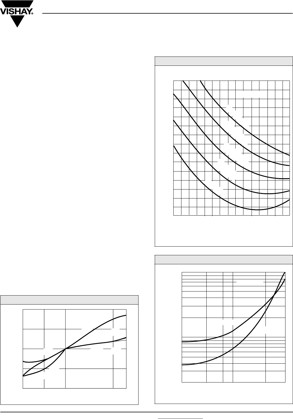
Document Number: 43004 For technical questions, contact: tantalum@vishay.com www.vishay.com
Revision: 06-Dec-07 83
SHA
Subminiature, Leaded Solid Tantalum Capacitors
Polar or Non-Polar Vishay Sprague
PERFORMANCE AND RELIABILITY
The capacitors are tested in accordance with
MIL-PRF-49137, with specific requirements as follows:
Temperature Stability: When tested per MIL-PRF-49137/6,
capacitance shall be within ± 15 % at - 55 °C and 85 °C, and
± 10 % at 25 °C after exposure to temperature extremes. DF
shall be within 200 % of initial limit at - 55 °C, 150 % of initial
limit at 85 °C, and meet the initial at 25 °C. DCL shall be
within 10 x initial limit at 85 °C, and meet the initial limit at
25 °C.
Moisture Resistance: (per Method 106 of MIL-STD-202)
After 10 cycles of 24 h at 25 °C to 65 °C and 80-98 % RH;
capacitance shall be within ± 15 % of initial value, DF within
1.5 x initial limit and leakage within 3 x initial limit.
Life: (per Method 108 of MIL-STD-202) after 1000 h at 85 °C
and rated voltage; capacitance shall be within ± 10 % of
initial limit, DF within initial limits, and leakage within
200 % of initial limit.
Surge Voltage: (per MIL-PRF-49317) After 1000 cycles at
85 °C and 1.3 x WVDC; capacitance shall be within ± 10 %
of initial limit, DF and leakage within initial limits.
Resistance to Soldering Heat: (per Method 210 of
MIL-STD-202, Condition B) After immersion in 260 °C molten
solder to within a 1/4" of the body of the unit, there shall be
no evidence of mechanical or electrical degradation.
Solderability: (per Method 208 of MIL-STD-202) After
dipping leads in 235 °C molten solder to within 0.125" of the
body of the unit, the solder shall cover 95 % of the lead
surface.
Terminal Strength: (per Method 211 of MIL-STD-202) After
the following test there shall be no loosening of the terminals
or permanent damage to the terminals. Test Condition A:
(Pull Test) 0.010" leads withstand 1 pound, 0.016" leads 2
pounds and 0.007" leads 1/2 pound. Test Condition C: (Bend
Test) All leads shall withstand 3 - 90° bends with a 1/2 pound
applied force.
CAPACITANCE VS. TEMPERATURE
+ 10
+ 5
0
- 5
- 10
- 40 - 10 + 25 + 100
+ 85
(MFD-WVDC)
SPECIFICATION
SPECIFICATION
TYPICAL
CHANGE IN CAPACITANCE %
100 µF - 10 V
100 µF - 10 V
1 µH - 20 V
TEMPERATURE °C
IMPEDANCE VS. FREQUENCY
LEAKAGE CURRENT - TEMPERATURE
100 500 1 2 5 10 20 50 100 500 1 2 5 10
Hz kHz FREQUENCY kHz MHz
IMPEDANCE Ω
(MFD-WVDC)
0.1
0.2
0.5
1.0
2.0
5.0
10
20
50
100
200
500
1K
2K
5K
10K
0.047 µF-20 V
0.047 µF-20 V
0.047 µF-35 V
0.047 µF-35 V
4.7 µF-10 V
4.7 µF-20 V
0.047 µF-50 V
4.7 µF-20 V
1.0
0.1
0.01
- 40 - 10 0 + 85+ 20
(MFD-WVDC)
D.C. LEAKAGE CURRENT (µA)
TEMPERATURE °C
1 µF-20 V
100 µF-10 V
www.vishay.com For technical questions, contact: tantalum@vishay.com Document Number: 43005
84 Revision: 12-Sep-07
TC
Vishay Sprague
Subminiature, Leaded Solid Tantalum Capacitors
Polar or Non-Polar
FEATURES
•Subminiature package size and light weight
•Rectangular case with axial or radial leads
•2 to 50 VDC
•0.1 µF to 470 µF
•Operating temperature range: - 55 °C to + 125 °C
•High stability and reliability
•Tested in accordance with MIL-PRF-49137
•Unique and comprehensive custom design capability
ELECTRICAL CHARACTERISTICS
Operating temperature range: - 55 °C to + 125 °C
Capacitance: Measured at 120 Hz and 25 °C with a
maximum of 2.2 VDC bias and 1.0 Vrms signal.
Capacitance Tolerance: Standard tolerance is ± 20 % for
ratings 0.1 µF and above, and + 40, - 20 % for ratings below
0.1 µF. Special tolerances are also available.
Dissipation Factor: When measured simultaneously with
capacitance, DF shall not exceed the value shown in
theratings tables.
DC Leakage Current (DCL Max):
When measured with DC voltage applied through a 1000 Ω
resistor for 5 minutes, DC leakage (µA) shall not exceed:
At 25 °C: Leakage current shall not exceed the values listed
in the Standard Ratings Tables
At 85 °C: Leakage current shall not exceed 10 times the
values listed in the Standard Ratings Tables
At 125 °C and 66 % of Rated Voltage: Leakage current
shall not exceed 15 times the values listed in the Standard
Ratings Tables.
Operating Voltage: Full working voltage up to 85 °C. From
85 °C to 125 °C working voltage derates linearly to 66 % of
the 85 °C working voltage.
APPLICATIONS
•Hearing aids
•Portable communications
•Space/avionics
•Laptop computers
MECHANICAL SPECIFICATIONS
Solder coated nickel leads (type N32 per MIL-STD-1276) are
standard on all case sizes.
Leads are weldable and/or solderable.
Special leads are available on request (e.g. bare nickel, gold
plated nickel or ribbon leads).
Lead length is 1 1/2" [38.1 mm] minimum on nonpolar parts.
On polar parts the negative lead is 1 1/4" [31.8 mm] minimum
and the positive lead is 1 1/2" [38.1 mm] minimum.
Note:
(1) To complete part number in rating tables, add A or R.
Change suffix if special capacitance tolerance is required.
ORDERING INFORMATION
TC 1.0 35 C3 A (1) M
MODEL CAPACITANCE
IN µF
DC VOLTAGE RATING
AT + 85 °C
CASE CODE LEAD
CONFIGURATION
CAPACITANCE
TOLERANCE
C = Polar
N = Non-polar
A = Axial
R = Radial
E = + 40, - 20 %
M = ± 20 %
K = ± 10 %
J = ± 5 %
Example of Part Number Code: TC1.0-35C3AM
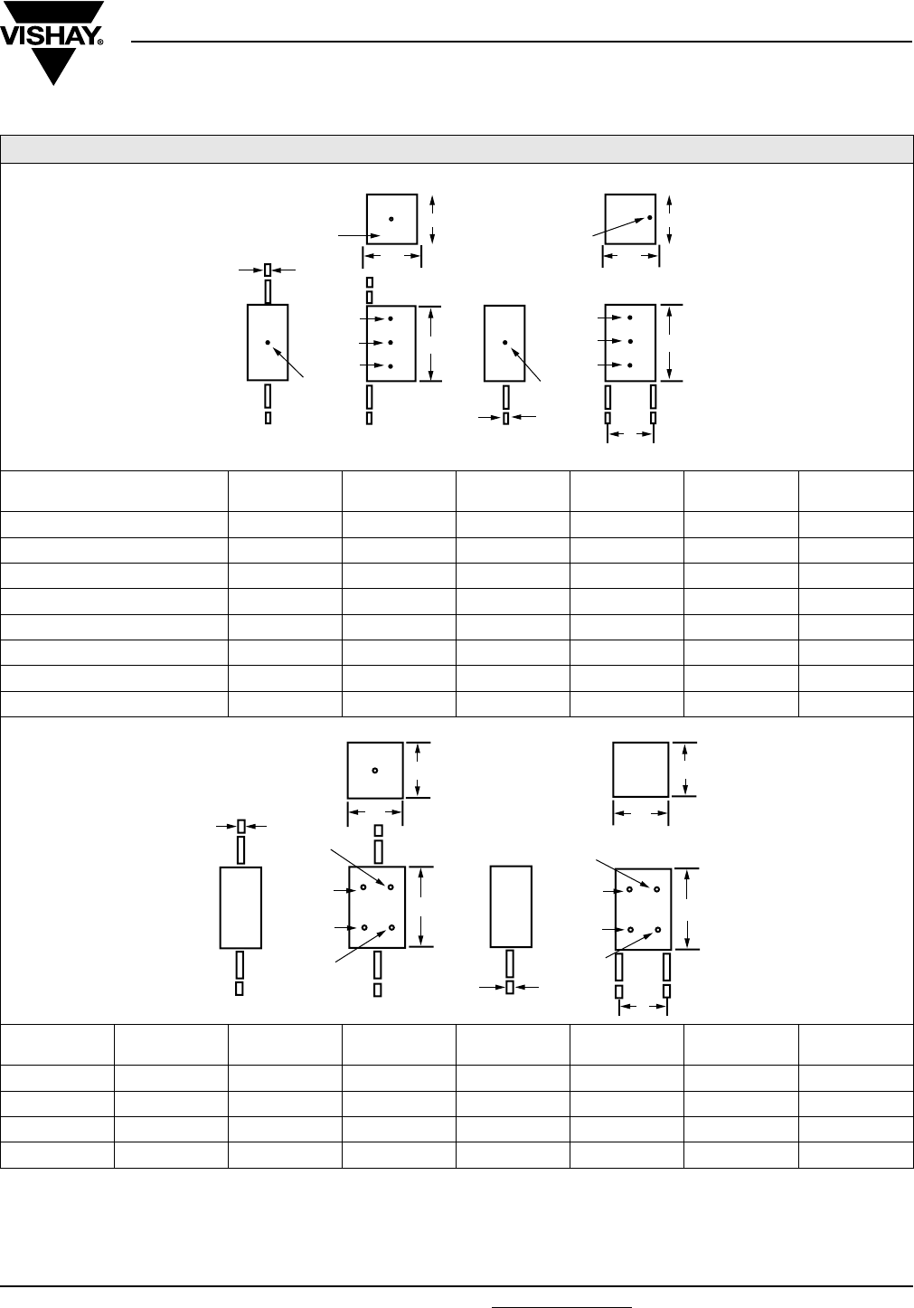
Document Number: 43005 For technical questions, contact: tantalum@vishay.com www.vishay.com
Revision: 12-Sep-07 85
TC
Subminiature, Leaded Solid Tantalum Capacitors
Polar or Non-Polar
Vishay Sprague
DIMENSIONS in inches [millimeters]
CASE CODE L
MAX.
W
MAX.
T
MAX. EE TOL.
±d
CX 0.075 [1.91] 0.050 [1.27] 0.040 [1.02] 0.030 [0.76] 0.015 [0.38] 0.007 [0.18]
C0 0.100 [2.54] 0.050 [1.27] 0.040 [1.02] 0.030 [0.76] 0.015 [0.38] 0.007 [0.18]
C1 0.125 [3.18] 0.070 [1.78] 0.040 [1.02] 0.050 [1.27] 0.015 [0.38] 0.010 [0.25]
C2 0.165 [4.19] 0.120 [3.05] 0.070 [1.78] 0.100 [2.54] 0.020 [0.51] 0.010 [0.25]
C3 0.225 [5.72] 0.185 [4.70] 0.075 [1.91] 0.150 [3.81] 0.020 [0.51] 0.010 [0.25]
C4 0.290 [7.37] 0.220 [5.59] 0.110 [2.79] 0.180 [4.57] 0.025 [0.64] 0.016 [0.41]
C5 0.310 [7.87] 0.230 [5.84] 0.130 [3.30] 0.200 [5.08] 0.025 [0.64] 0.016 [0.41]
C6 0.475 [12.07] 0.375 [9.53] 0.150 [3.81] 0.300 [7.62] 0.025 [0.64] 0.016 [0.41]
CASE CODE LA
MAX.
LR
MAX.
W
MAX.
T
MAX.
E
MAX.
E TOL.
±d
N1 0.220 [5.59] 0.180 [4.57] 0.125 [3.18] 0.125 [3.18] 0.100 [2.54] 0.020 [0.51] 0.010 [0.25]
N2 0.280 [7.11] 0.240 [6.10] 0.140 [3.56] 0.180 [4.57] 0.100 [2.54] 0.025 [0.64] 0.010 [0.25]
N3 0.370 [9.40] 0.315 [8.00] 0.180 [4.57] 0.220 [5.59] 0.150 [3.81] 0.025 [0.64] 0.016 [0.41]
N4 0.390 [9.91] 0.335 [8.51] 0.230 [5.84] 0.230 [5.84] 0.180 [4.57] 0.025 [0.64] 0.016 [0.41]
d
(+)
(+)
(-)
RED EPOXY POLARITY DOT
3RD DOT
2ND DOT
1ST DOT
3RD DOT
2ND DOT
1ST DOT
THE 3RD DOT IS ON THE END OF THE CX SIZE
AXIAL RADIAL
TOLERANCE
DOT
TOLERANCE
DOT
TT
WW
LL
d
d
E
AXIAL
E
RADIAL
TOLERANCE
DOT
2ND DOT
1ST DOT
3RD DOT
TOLERANCE
DOT
2ND DOT
1ST DOT
3RD DOT
LA LR
TT
d
d
WW
POLAR STYLE
NON POLAR STYLE
TC
Vishay Sprague Subminiature, Leaded Solid Tantalum Capacitors
Polar or Non-Polar
www.vishay.com For technical questions, contact: tantalum@vishay.com Document Number: 43005
86 Revision: 12-Sep-07
STANDARD RATINGS - POLAR CAPACITORS
CAPACITANCE
(µF)
MAX.
DF (%)
MAX. DCL
AT + 25 °C (µA)
CASE
CODE
PART
NUMBER
2 WVDC AT + 85 °C
0.47 10 0.5 C0
TC.47-2C0 (1)M
0.68 10 0.5 C0
TC.68-2C0 (1)M
1.0 10 0.5 C0
TC1.0-2C0 (1)M
2.2 10 0.5 C1
TC2.2-2C1 (1)M
10 10 0.5 C2
TC10-2C2 (1)M
33 10 1.0 C3
TC33-2C3 (1)M
100 15 2.0 C4
TC100-2C4 (1)M
150 15 3.0 C5
TC150-2C5 (1)M
470 20 9.0 C6
TC470-2C6 (1)M
3 WVDC AT + 85 °C
1.5 10 0.5 C1
TC1.5-3C1 (1)M
6.8 10 0.5 C2
TC6.8-3C2 (1)M
22 10 1.0 C3
TC22-3C3 (1)M
68 10 2.0 C4
TC68-3C4 (1)M
100 10 3.0 C5
TC100-3C5 (1)M
330 20 9.0 C6
TC330-3C6 (1)M
4 WVDC AT + 85 °C
0.33 10 0.5 C0
TC.33-4C0 (1)M
1.0 8 0.5 C1
TC1.0-4C1 (1)M
4.7 8 0.5 C2
TC4.7-4C2 (1)M
15 8 1.0 C3
TC15-4C3 (1)M
47 8 2.0 C4
TC47-4C4 (1)M
68 8 3.0 C5
TC68-4C5 (1)M
220 15 9.0 C6
TC220-4C6 (1)M
6 WVDC AT + 85 °C
0.22 10 0.5 C0
TC.22-6C0 (1)M
0.68 6 0.5 C1
TC.68-6C1 (1)M
3.3 6 0.5 C2
TC3.3-6C2 (1)M
10 6 1.0 C3
TC10-6C3 (1)M
33 6 2.0 C4
TC33-6C4 (1)M
47 6 3.0 C5
TC47-6C5 (1)M
150 10 9.0 C6
TC150-6C6 (1)M
10 WVDC AT + 85 °C
0.0010 10 0.5 C0
TC.0010-10C0 (1)E
0.0010 10 0.5 C1
TC.0010-10C1 (1)E
0.0015 10 0.5 C0
TC.0015-10C0 (1)E
0.0015 10 0.5 C1
TC.0015-10C1 (1)E
0.0022 10 0.5 C0
TC.0022-10C0 (1)E
0.0022 10 0.5 C1
TC.0022-10C1 (1)E
0.0033 10 0.5 C0
TC.0033-10C0 (1)E
0.0033 10 0.5 C1
TC.0033-10C1 (1)E
0.0047 10 0.5 C0
TC.0047-10C0 (1)E
0.0047 10 0.5 C1
TC.0047-10C1 (1)E
0.15 10 0.5 C0
TC.15-10C0 (1)M
0.47 6 0.5 C1
TC.47-10C1 (1)M
2.2 6 0.5 C2
TC2.2-10C2 (1)M
6.8 6 1.0 C3
TC6.8-10C3 (1)M
22 6 2.0 C4
TC22-10C4 (1)M
33 6 3.0 C5
TC33-10C5 (1)M
100 8 9.0 C6
TC100-10C6 (1)M
Note:
(1) Add A for axial, R for radial
Document Number: 43005 For technical questions, contact: tantalum@vishay.com www.vishay.com
Revision: 12-Sep-07 87
TC
Subminiature, Leaded Solid Tantalum Capacitors
Polar or Non-Polar Vishay Sprague
STANDARD RATINGS - POLAR CAPACITORS
CAPACITANCE
(µF)
MAX.
DF (%)
MAX. DCL
AT + 25 °C (µA)
CASE
CODE
PART
NUMBER
15 WVDC AT + 85 °C
0.10 10 0.5 C0
TC.10-15C0 (1)M
0.33 6 0.5 C1
TC.33-15C1 (1)M
1.5 6 0.5 C2
TC1.5-15C2 (1)M
15 6 2.0 C4
TC15-15C4 (1)M
22 6 3.0 C5
TC22-15C5 (1)M
68 8 9.0 C6
TC68-15C6 (1)M
20 WVDC AT + 85 °C
0.033 10 0.5 C0
TC.033-20C0 (1)E
0.033 6 0.5 C1
TC.033-20C1 (1)E
0.047 10 0.5 C0
TC.047-20C0 (1)E
0.047 6 0.5 C1
TC.047-20C1 (1)E
0.068 10 0.5 C0
TC.068-20C0 (1)E
0.068 6 0.5 C1
TC.068-20C1 (1)E
0.10 6 0.5 C1
TC.10-20C1 (1)M
0.15 6 0.5 C1
TC.15-20C1 (1)M
0.22 6 0.5 C1
TC.22-20C1 (1)M
1.0 6 0.5 C2
TC1.0-20C2 (1)M
3.3 6 1.0 C3
TC3.3-20C3 (1)M
4.7 6 1.0 C3
TC4.7-20C3 (1)M
10 6 2.0 C4
TC10-20C4 (1)M
15 6 3.0 C5
TC15-20C5 (1)M
47 8 9.0 C6
TC47-20C6 (1)M
25 WVDC AT + 85 °C
0.68 6 0.5 C2
TC.68-25C2 (1)M
2.2 6 1.0 C3
TC2.2-25C3 (1)M
6.8 6 2.0 C4
TC6.8-25C4 (1)M
10 6 3.0 C5
TC10-25C5 (1)M
33 6 9.0 C6
TC33-25C6 (1)M
35 WVDC AT + 85 °C
0.22 6 0.5 C2
TC.22-35C2 (1)M
0.33 6 0.5 C2
TC.33-35C2 (1)M
0.47 6 0.5 C2
TC.47-35C2 (1)M
0.68 6 1.0 C3
TC.68-35C3 (1)M
1.0 6 1.0 C3
TC1.0-35C3 (1)M
1.5 6 1.0 C3
TC1.5-35C3 (1)M
2.2 6 2.0 C4
TC2.2-35C4 (1)M
3.3 6 2.0 C4
TC3.3-35C4 (1)M
4.7 6 2.0 C4
TC4.7-35C4 (1)M
6.8 6 3.0 C5
TC6.8-35C5 (1)M
10 6 9.0 C6
TC10-35C6 (1)M
15 6 9.0 C6
TC15-35C6 (1)M
22 6 9.0 C6
TC22.35C6 (1)M
50 WVDC AT + 85 °C
0.15 6 0.5 C2
TC.15-50C2 (1)M
4.7 6 3.0 C5
TC4.7-50C5 (1)M
6.8 6 9.0 C6
TC6.8-50C6 (1)M
Note:
(1) Add A for axial, R for radial

TC
Vishay Sprague Subminiature, Leaded Solid Tantalum Capacitors
Polar or Non-Polar
www.vishay.com For technical questions, contact: tantalum@vishay.com Document Number: 43005
88 Revision: 12-Sep-07
STANDARD RATINGS - NON-POLAR CAPACITORS
CAPACITANCE
(µF)
MAX.
DF (%)
MAX. DCL
AT + 25 °C (µA)
CASE
CODE
PART
NUMBER
2 WVDC AT + 85 °C
4.7 10 0.5 N1
TC4.7-2N1 (1)M
15 10 1.0 N2
TC15-2N2 (1)M
47 15 2.0 N3
TC47-2N3 (1)M
68 15 3.0 N4
TC68-2N4 (1)M
3 WVDC AT + 85 °C
3.3 10 0.5 N1
TC3.3-3N1 (1)M
10 10 1.0 N2
TC10-3N2 (1)M
33 10 2.0 N3
TC33-3N3 (1)M
47 10 3.0 N4
TC47-3N4 (1)M
4 WVDC AT + 85 °C
2.2 8 0.5 N1
TC2.2-4N1 (1)M
6.8 8 1.0 N2
TC6.8-4N2 (1)M
22 8 2.0 N3
TC22-4N3 (1)M
33 8 3.0 N4
TC33-4N4 (1)M
6 WVDC AT + 85 °C
1.5 6 0.5 N1
TC1.5-6N1 (1)M
4.7 6 1.0 N2
TC4.7-6N2 (1)M
15 6 2.0 N3
TC15-6N3 (1)M
22 6 3.0 N4
TC22-6N4 (1)M
10 WVDC AT + 85 °C
1.0 6 0.5 N1
TC1.0-10N1 (1)M
3.3 6 1.0 N2
TC3.3-10N2 (1)M
10 6 2.0 N3
TC10-10N3 (1)M
15 6 3.0 N4
TC15-10N4 (1)M
15 WVDC AT + 85 °C
0.68 6 0.5 N1
TC.68-15N1 (1)M
6.8 6 2.0 N3
TC6.8-15N3 (1)M
10 6 3.0 N4
TC10-15N4 (1)M
20 WVDC AT + 85 °C
0.47 6 0.5 N1
TC.47-20N1 (1)M
1.5 6 1.0 N2
TC1.5-20N2 (1)M
2.2 6 1.0 N2
TC2.2-20N2 (1)M
4.7 6 2.0 N3
TC4.7-20N3 (1)M
6.8 6 3.0 N4
TC6.8-20N4 (1)M
25 WVDC AT + 85 °C
0.33 6 0.5 N1
TC.33-25N1 (1)M
1.0 6 1.0 N2
TC1.0-25N2 (1)M
3.3 6 2.0 N3
TC3.3-25N3 (1)M
4.7 6 3.0 N4
TC4.7-25N4 (1)M
35 WVDC AT + 85 °C
0.10 6 0.5 N1
TC.10-35N1 (1)M
0.15 6 0.5 N1
TC.15-35N1 (1)M
0.22 6 0.5 N1
TC.22-35N1 (1)M
0.33 6 1.0 N2
TC.33-35N2 (1)M
0.47 6 1.0 N2
TC.47-35N2 (1)M
0.68 6 1.0 N2
TC.68-35N2 (1)M
1.0 6 2.0 N3
TC1.0-35N3 (1)M
50 WVDC AT + 85 °C
2.2 6 3.0 N4
TC2.2-50N4 (1)M
Note:
(1) Add A for axial, R for radial

Document Number: 43005 For technical questions, contact: tantalum@vishay.com www.vishay.com
Revision: 12-Sep-07 89
TC
Subminiature, Leaded Solid Tantalum Capacitors
Polar or Non-Polar
Vishay Sprague
MARKING
TC Capacitors case sizes C3 - C6 and N2 - N4 are
print marked:
- Capacitance is in picofarads
- 1st and 2nd digits are significant figures
- 3rd digit indicates the number of zeros.
All other case sizes have color dot marking:
Capacitance Color Digit
In picofarads, indicated by 3 dots.
1st and 2nd dot give the significant
digits.
3rd dot indicates the number of zeros.
Color dot location is shown on the
dimensional sketches.
Black dot is omitted on black sleeve.
Black 0
Brown 1
Red 2
Orange 3
Ye l l o w 4
Green 5
Capacitance Tolerance Color Tolerance Blue 6
Is indicated by a dot on
the side of the case.
Black dot is omitted.
Gold ± 5 % Violet 7
Silver ± 10 % Grey 8
None ± 20 % White 9
None + 40 %/- 20 %
The positive lead is indicated by a color dot of red
epoxy on the unit.
e.g. Yellow-Violet-Green = 4 700 000 pF
= 4.7 µF
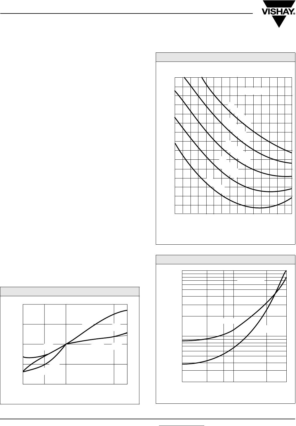
TC
Vishay Sprague Subminiature, Leaded Solid Tantalum Capacitors
Polar or Non-Polar
www.vishay.com For technical questions, contact: tantalum@vishay.com Document Number: 43005
90 Revision: 12-Sep-07
PERFORMANCE AND RELIABILITY
The capacitors are tested in accordance with
MIL-PRF-49137, with specific requirements as follows:
Temperature Stability: When tested per MIL-PRF-49137/6,
capacitance shall be within ± 15 % at - 55 °C and 85 °C, and
± 10 % at 25 °C after exposure to temperature extremes. DF
shall be within 200 % of initial limit at - 55 °C, 150 % of initial
limit at 85 °C, and meet the initial at 25 °C. DCL shall be
within 10 x initial limit at 85 °C, and meet the initial limit at
25 °C.
Moisture Resistance: (per Method 106 of MIL-STD-202)
After 10 cycles of 24 h at 25 °C to 65 °C and 80 - 98 % RH;
capacitance shall be within ± 15 % of initial value, DF within
1.5 x initial limit and leakage within 3 x initial limit.
Life: (per Method 108 of MIL-STD-202) after 1000 h at 85 °C
and rated voltage; capacitance shall be within ± 10 % of
initial limit, DF within initial limits, and leakage within
200 % of initial limit.
Surge Voltage: (per MIL-PRF-49317) After 1000 cycles at
85 °C and 1.3 x WVDC; capacitance shall be within ± 10 %
of initial limit, DF and leakage within initial limits.
Resistance to Soldering Heat: (per Method 210 of
MIL-STD-202, Condition B) After immersion in 260 °C molten
solder to within a 1/4" of the body of the unit, there shall be
no evidence of mechanical or electrical degradation.
Solderability: (per Method 208 of MIL-STD-202) After
dipping leads in 235 °C molten solder to within 0.125" of the
body of the unit, the solder shall cover 95 % of the lead
surface.
Terminal Strength: (per Method 211 of MIL-STD-202) After
the following test there shall be no loosening of the terminals
or permanent damage to the terminals. Test Condition A:
(Pull Test) 0.010" leads withstand 1 pound, 0.016" leads
2 pounds and 0.007" leads 1/2 pound. Test Condition C:
(Bend Test) All leads shall withstand 3 - 90° bends with a
1/2 pound applied force.
CAPACITANCE VS. TEMPERATURE
+ 10
+ 5
0
- 5
- 10
- 40 - 10 + 25 + 100
+ 85
(MFD-WVDC)
SPECIFICATION
SPECIFICATION
TYPICAL
CHANGE IN CAPACITANCE %
100 µF - 10 V
100 µF - 10 V
1 µH - 20 V
TEMPERATURE °C
IMPEDANCE VS. FREQUENCY
LEAKAGE CURRENT - TEMPERATURE
1.0
0.1
0.01
- 40 - 10 0 + 85+ 20
(MFD-WVDC)
D.C. LEAKAGE CURRENT (µA)
TEMPERATURE °C
1 µF-20 V
100 µF-10 V
100 500 1 2 5 10 20 50 100 500 1 2 5 10
Hz kHz FREQUENCY kHz MHz
IMPEDANCE Ω
(MFD-WVDC)
0.1
0.2
0.5
1.0
2.0
5.0
10
20
50
100
200
500
1K
2K
5K
10K
0.047 µF-20 V
0.047 µF-20 V
0.047 µF-35 V
0.047 µF-35 V
4.7 µF-10 V
4.7 µF-20 V
0.047 µF-50 V
4.7 µF-20 V
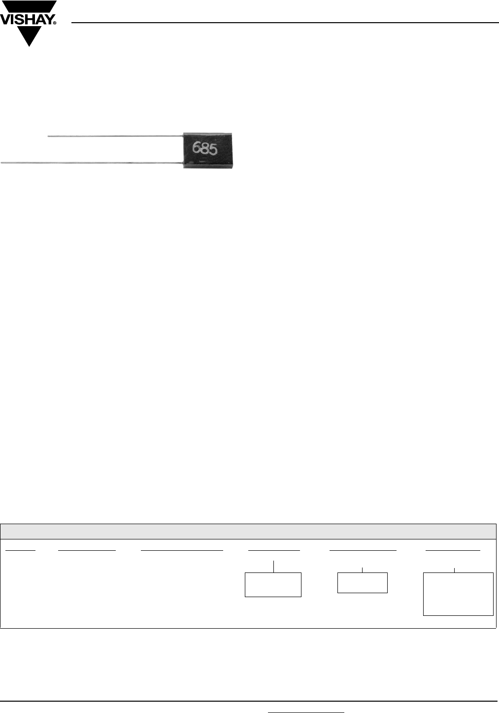
Document Number: 43006 For technical questions, contact: tantalum@vishay.com www.vishay.com
Revision: 10-Dec-07 91
STC
Vishay Sprague
Subminiature, Leaded Solid Tantalum Capacitors
Polar or Non-Polar
FEATURES
•Subminiature package size and light weight
•Rectangular case with axial or radial leads
•2 to 35 VDC
•0.1 µF to 470 µF
•Operating temperature range: - 55 °C to + 125 °C
•High stability and reliability
•Tested in accordance with MIL-PRF-49137
•Unique and comprehensive custom design capability
ELECTRICAL CHARACTERISTICS
Operating temperature range: - 55 °C to + 125 °C
Capacitance: Measured at 120 Hz and 25 °C with a
maximum of 2.2 VDC bias and 1.0 Vrms signal.
Capacitance Tolerance: Standard tolerance is ± 20 % for
ratings 0.1 µF and above, and + 40, - 20 % for ratings below
0.1 µF. Special tolerances are also available.
Dissipation Factor: When measured simultaneously with
capacitance, DF shall not exceed the value shown in the
ratings tables.
DC Leakage Current (DCL Max.):
When measured with DC voltage applied through a 1000 Ω
resistor for 5 min, DC leakage (µA) shall not exceed:
At 25 °C: Leakage current shall not exceed the values listed
in the Standard Ratings Tables
At 85 °C: Leakage current shall not exceed 10 times the
values listed in the Standard Ratings Tables
At 125 °C and 66 % of Rated Voltage: Leakage current
shall not exceed 15 times the values listed in the Standard
Ratings Tables
Operating Voltage: Full working voltage up to 85 °C. From
85 °C to 125 °C working voltage derates linearly to 66 % of
the 85 °C working voltage
APPLICATIONS
•Hearing aids
•Portable communications
•Space/avionics
•Laptop computers
MECHANICAL SPECIFICATIONS
Solder coated nickel leads (type N32 per MIL-STD-1276) are
standard on all case sizes
Leads are weldable and/or solderable
Special leads are available on request (e.g. bare nickel, gold
plated nickel or ribbon leads)
Lead length is 1 1/2" [38.1 mm] minimum on nonpolar parts
On polar parts the negative lead is 1 1/4" [31.8 mm] minimum
and the positive lead is 1 1/2" [38.1 mm] minimum
Note:
(1) To complete part number in rating tables, add A or R.
Change suffix if special capacitance tolerance is required.
ORDERING INFORMATION
STC 1.0 35 C2 A (1) M
MODEL CAPACITANCE
IN µF
DC VOLTAGE RATING
AT + 85 °C
CASE CODE LEAD
CONFIGURATION
CAPACITANCE
TOLERANCE
C = Polar
N = Non-polar
A = Axial
R = Radial
E = + 40, - 20 %
M = ± 20 %
K = ± 10 %
J = ± 5 %
Example of Part Number Code: STC1.0-35C2AM
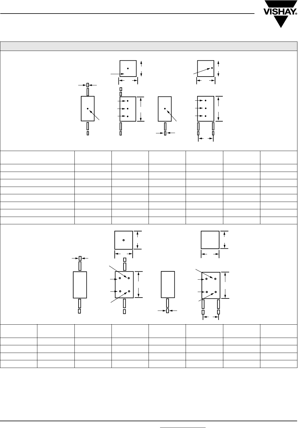
STC
Vishay Sprague Subminiature, Leaded Solid Tantalum Capacitors
Polar or Non-Polar
www.vishay.com For technical questions, contact: tantalum@vishay.com Document Number: 43006
92 Revision: 10-Dec-07
DIMENSIONS in inches [millimeters]
CASE CODE L
MAX.
W
MAX.
T
MAX. EE TOL.
±d
CX 0.075 [1.91] 0.050 [1.27] 0.040 [1.02] 0.030 [0.76] 0.015 [0.38] 0.007 [0.18]
C0 0.100 [2.54] 0.050 [1.27] 0.040 [1.02] 0.030 [0.76] 0.015 [0.38] 0.007 [0.18]
C1 0.125 [3.18] 0.070 [1.78] 0.040 [1.02] 0.050 [1.27] 0.015 [0.38] 0.010 [0.25]
C2 0.165 [4.19] 0.120 [3.05] 0.070 [1.78] 0.100 [2.54] 0.020 [0.51] 0.010 [0.25]
C3 0.225 [5.72] 0.185 [4.70] 0.075 [1.91] 0.150 [3.81] 0.020 [0.51] 0.010 [0.25]
C4 0.290 [7.37] 0.220 [5.59] 0.110 [2.79] 0.180 [4.57] 0.025 [0.64] 0.016 [0.41]
C5 0.310 [7.87] 0.230 [5.84] 0.130 [3.30] 0.200 [[5.08] 0.025 [0.64] 0.016 [0.41]
C6 0.475 [12.07] 0.375 [9.53] 0.150 [3.81] 0.300 [7.62] 0.025 [0.64] 0.016 [0.41]
CASE CODE LA
MAX.
LR
MAX.
W
MAX.
T
MAX.
E
MAX.
E TOL.
±d
N1 0.220 [5.59] 0.180 [4.57] 0.125 [3.18] 0.125 [3.18] 0.100 [2.54] 0.020 [0.51] 0.010 [0.25]
N2 0.280 [7.11] 0.240 [6.10] 0.140 [3.56] 0.180 [4.57] 0.100 [2.54] 0.025 [0.64] 0.010 [0.25]
N3 0.370 [9.40] 0.315 [8.00] 0.180 [4.57] 0.220 [5.59] 0.150 [3.81] 0.025 [0.64] 0.016 [0.41]
N4 0.390 [9.91] 0.335 [8.51] 0.230 [5.84] 0.230 [5.84] 0.180 [4.57] 0.025 [0.64] 0.016 [0.41]
d
(+)
(+)
(-)
RED EPOXY POLARITY DOT
3RD DOT
2ND DOT
1ST DOT
3RD DOT
2ND DOT
1ST DOT
THE 3RD DOT IS ON THE END OF THE CX SIZE
AXIAL RADIAL
TOLERANCE
DOT
TOLERANCE
DOT
TT
WW
LL
d
d
E
AXIAL
E
RADIAL
TOLERANCE
DOT
2ND DOT
1ST DOT
3RD DOT
TOLERANCE
DOT
2ND DOT
1ST DOT
3RD DOT
LA LR
TT
d
d
WW
NON POLAR STYLE
POLAR STYLE

Document Number: 43006 For technical questions, contact: tantalum@vishay.com www.vishay.com
Revision: 10-Dec-07 93
STC
Subminiature, Leaded Solid Tantalum Capacitors
Polar or Non-Polar
Vishay Sprague
STANDARD RATINGS - POLAR CAPACITORS
CAPACITANCE
(µF)
MAX
DF (%)
MAX. DCL
AT + 25 °C (µA)
CASE
CODE
PART
NUMBER
2 WVDC AT + 85 °C
0.0022 10 0.5 CX
STC.0022-2CX (1)E
0.0033 10 0.5 CX
STC.0033-2CX (1)E
0.0047 10 0.5 CX
STC.0047-2CX (1)E
0.0068 10 0.5 CX
STC.0068-2CX (1)E
0.10 10 0.5 CX
STC.10-2CX (1)M
0.15 10 0.5 CX
STC.15-2CX (1)M
0.22 10 0.5 CX
STC.22-2CX (1)M
0.33 10 0.5 CX
STC.33-2CX (1)M
0.47 10 0.5 CX
STC.47-2CX (1)M
0.68 10 0.5 CX
STC.68-2CX (1)M
1.0 10 0.5 CX
STC1.0-2CX (1)M
1.5 10 0.5 CX
STC1.5-2CX (1)M
2.2 10 0.5 CX
STC2.2-2CX (1)M
2.2 10 0.5 C0
STC2.2-2C0 (1)M
6.8 10 0.5 C1
STC6.8-2C1 (1)M
100 10 2.0 C3
STC100-2C3 (1)M
3 WVDC AT + 85 °C
1.5 10 0.5 C0
STC1.5-3C0 (1)M
22 10 1.0 C2
STC22-3C2 (1)M
68 10 2.0 C3
STC68-3C3 (1)M
100 10 3.0 C4
STC100-3C4 (1)M
4 WVDC AT + 85 °C
1.0 10 0.5 C0
STC1.0-4C0 (1)M
4.7 10 0.5 C1
STC4.7-4C1 (1)M
10 8 1.0 C2
STC10-4C2 (1)M
15 8 1.0 C2
STC15-4C2 (1)M
47 8 2.0 C3
STC47-4C3 (1)M
68 8 3.0 C4
STC68-4C4 (1)M
220 15 9.0 C5
STC220-4C5 (1)M
470 15 10.0 C6
STC470-4C6 (1)M
6 WVDC AT + 85 °C
0.68 10 0.5 C0
STC.68-6C0 (1)M
3.3 8 0.5 C1
STC3.3-6C1 (1)M
33 6 2.0 C3
STC33-6C3 (1)M
47 6 3.0 C4
STC47-6C4 (1)M
150 10 9.0 C5
STC150-6C5 (1)M
330 15 10.0 C6
STC330-6C6 (1)M
10 WVDC AT + 85 °C
0.47 10 0.5 C0
STC.47-10C0 (1)M
1.5 6 0.5 C1
STC1.5-10C1 (1)M
2.2 6 0.5 C1
STC2.2-10C1 (1)M
6.8 6 1.0 C2
STC6.8-10C2 (1)M
22 6 2.0 C3
STC22-10C3 (1)M
33 6 3.0 C4
STC33-10C4 (1)M
100 8 9.0 C5
STC100-10C5 (1)M
220 6 0.5 C6
STC220-10C6 (1)M
15 WVDC AT + 85 °C
1.0 6 0.5 C1
STC1.0-15C1 (1)M
4.7 6 1.0 C2
STC4.7-15C2 (1)M
15 6 2.0 C3
STC15-15C3 (1)M
22 6 3.0 C4
STC22-15C4 (1)M
68 6 6.0 C5
STC68-15C5 (1)M
150 10 10.0 C6
STC150-15C6 (1)M
Note:
(1) Add A for axial, R for radial

STC
Vishay Sprague Subminiature, Leaded Solid Tantalum Capacitors
Polar or Non-Polar
www.vishay.com For technical questions, contact: tantalum@vishay.com Document Number: 43006
94 Revision: 10-Dec-07
STANDARD RATINGS - POLAR CAPACITORS
CAPACITANCE
(µF)
MAX
DF (%)
MAX. DCL
AT+ 25 °C (µA)
CASE
CODE
PART
NUMBER
20 WVDC AT + 85 °C
0.68 6 0.5 C1
STC.68-20C1 (1)M
3.3 6 1.0 C2
STC3.3-20C2 (1)M
6.8 6 2.0 C3
STC6.8-20C3 (1)M
10 6 2.0 C3
STC10-20C3 (1)M
15 6 3.0 C4
STC15-20C4 (1)M
47 6 6.0 C5
STC47-20C5 (1)M
100 10 10.0 C6
STC100-20C6 (1)M
25 WVDC AT + 85 °C
0.47 6 0.5 C1
STC.47-25C1 (1)M
2.2 6 1.0 C2
STC2.2-25C2 (1)M
3.3 6 2.0 C3
STC3.3-25C3 (1)M
4.7 6 2.0 C3
STC4.7-25C3 (1)M
10 6 3.0 C4
STC10-25C4 (1)M
15 6 6.0 C5
STC15-25C5 (1)M
22 6 6.0 C5
STC22-25C6 (1)M
33 6 6.0 C5
STC33-25C5 (1)M
68 6 10.0 C6
STC68-25C6 (1)M
35 WVDC AT + 85 °C
0.33 6 0.5 C1
STC.33-35C1 (1)M
0.68 6 1.0 C2
STC.68-35C2 (1)M
1.0 6 1.0 C2
STC1.0-35C2 (1)M
1.5 6 1.0 C2
STC1.5-35C2 (1)M
Note:
(1) Add A for axial, R for radial
STANDARD RATINGS - NON-POLAR CAPACITORS
CAPACITANCE
(µF)
MAX
DF (%)
MAX. DCL
AT + 25 °C (µA)
CASE
CODE
PART
NUMBER
2 WVDC AT + 85 °C
10 10 1.0 N1 STC10-2N1*M
3 WVDC AT + 85 °C
33 10 2.0 N2 STC33-3N2*M
47 8 3.0 N3 STC47-3N3*M
100 10 6.0 N4 STC100-3N4*M
4 WVDC AT + 85 °C
6.8 8 1.0 N1 STC6.8-4N1*M
22 8 2.0 N2 STC22-4N2*M
33 8 3.0 N3 STC33-4N3*M
68 8 6.0 N4 STC68-4N4*M
6 WVDC AT + 85 °C
4.7 6 1.0 N1 STC4.7-6N1*M
15 6 2.0 N2 STC15-6N2*M
22 6 3.0 N3 STC22-6N3*M
47 6 6.0 N4 STC47-6N4*M
10 WVDC AT + 85 °C
3.3 6 1.0 N1 STC3.3-10N1*M
10 6 2.0 N2 STC10-10N2*M
15 6 3.0 N3 STC15-10N3*M
33 6 6.0 N4 STC33-10N4*M
Note:
(1) Add A for axial, R for radial
Document Number: 43006 For technical questions, contact: tantalum@vishay.com www.vishay.com
Revision: 10-Dec-07 95
STC
Subminiature, Leaded Solid Tantalum Capacitors
Polar or Non-Polar
Vishay Sprague
STANDARD RATINGS - NON-POLAR CAPACITORS
CAPACITANCE
(µF)
MAX.
DF (%)
MAX. DCL
AT + 25 °C (µA)
CASE
CODE
PART
NUMBER
15 WVDC AT + 85 °C
2.2 6 1.0 N1 STC2.2-15N1*M
6.8 6 2.0 N2 STC6.8-15N2*M
10 6 3.0 N3 STC10-15N3*M
22 6 6.0 N4 STC22-15N4*M
20 WVDC AT + 85 °C
1.5 6 1.0 N1 STC1.5-20N1*M
4.7 6 2.0 N2 STC4.7-20N2*M
6.8 6 3.0 N3 STC6.8-20N3*M
15 6 6.0 N4 STC15-20N4*M
25 WVDC AT + 85 °C
1.0 6 1.0 N1 STC1.0-25N1*M
2.2 6 2.0 N2 STC2.2-25N2*M
3.3 6 2.0 N2 STC3.3-25N2*M
4.7 6 3.0 N3 STC4.7-25N3*M
10 6 6.0 N4 STC10-25N4*M
35 WVDC AT + 85 °C
0.68 6 1.0 N1 STC.68-35N1*M
Note:
(1) Add A for axial, R for radial
MARKING
STC Capacitors case sizes C3 - C6 and N2 - N4 are
print marked:
- Capacitance is in picofarads
- 1st and 2nd digits are significant figures
- 3rd digit indicates the number of zeros.
All other case sizes are have color dot marking:
Capacitance Color Digit
In picofarads, indicated by 3 dots.
1st and 2nd dot give the significant
digits.
3rd dot indicates the number of
zeros.
Color dot location is shown on the
dimensional sketches.
Black dot is omitted on black sleeve.
Black 0
Brown 1
Red 2
Orange 3
Ye l l o w 4
Green 5
Capacitance Tolerance Color Tolerance Blue 6
Is indicated by a dot on
the side of the case.
Black dot is omitted.
Gold ± 5 % Violet 7
Silver ± 10 % Grey 8
None ± 20 % White 9
None + 40 %/- 20 %
The positive lead is indicated by a color dot of red
epoxy on the unit.
e.g. Yellow-Violet-Green = 4 700 000 pf
= 4.7 µF
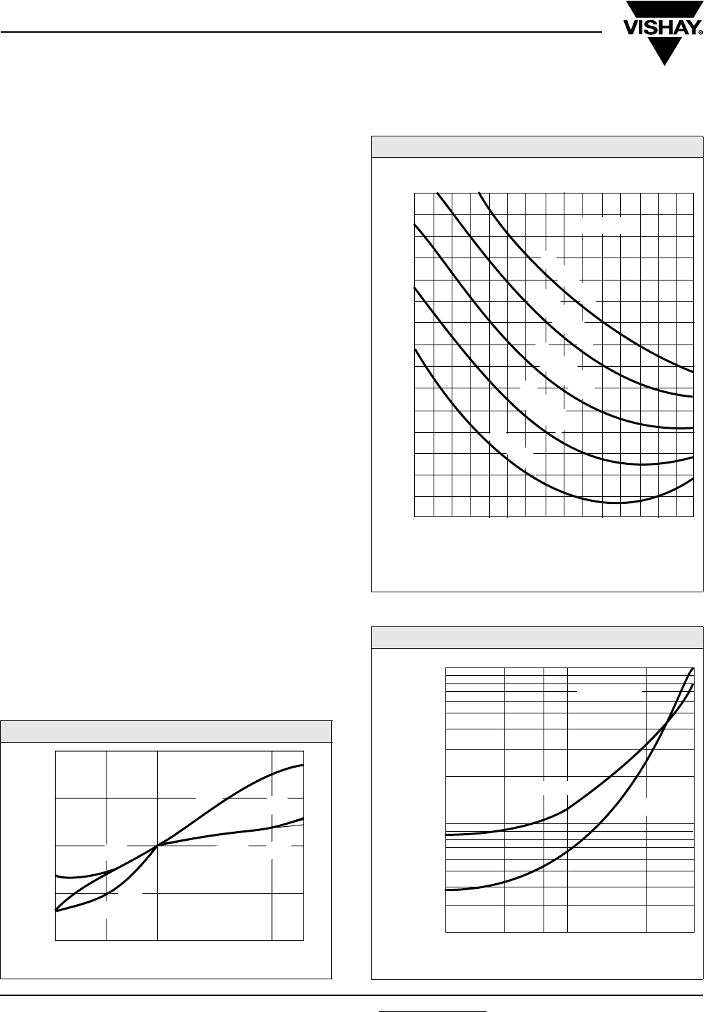
STC
Vishay Sprague Subminiature, Leaded Solid Tantalum Capacitors
Polar or Non-Polar
www.vishay.com For technical questions, contact: tantalum@vishay.com Document Number: 43006
96 Revision: 10-Dec-07
PERFORMANCE AND RELIABILITY
The capacitors are tested in accordance with MIL-PRF-
49137, with specific requirements as follows:
Temperature Stability: When tested per MIL-PRF-49137/
6, capacitance shall be within ± 15 % at - 55 °C and 85 °C,
and ± 10 % at 25 °C after exposure to temperature extremes.
DF shall be within 200 % of initial limit at - 55 °C, 150 % of
initial limit at 85 °C, and meet the initial at 25 °C. DCL shall
be within 10 x initial limit at 85 °C, and meet the initial
limit at 25 °C.
Moisture Resistance: (per Method 106 of MIL-STD-202)
After 10 cycles of 24 h at 25 °C to 65 °C and 80 - 98 % RH;
capacitance shall be within ± 15 % of initial value, DF within
1.5 x initial limit and leakage within 3 x initial limit.
Life: (per Method 108 of MIL-STD-202) after 1000 h at 85 °C
and rated voltage; capacitance shall be within ± 10 % of
initial limit, DF within initial limits, and leakage within
200 % of initial limit.
Surge Voltage: (per MIL-PRF-49317) After 1000 cycles at
85 °C and 1.3 x WVDC; capacitance shall be within ± 10 %
of initial limit, DF and leakage within initial limits.
Resistance to Soldering Heat: (per Method 210 of
MIL-STD-202, Condition B) After immersion in 260 °C molten
solder to within a 1/4” of the body of the unit, there shall be
no evidence of mechanical or electrical degradation.
Solderability: (per Method 208 of MIL-STD-202) After
dipping leads in 235 °C molten solder to within 0.125" of the
body of the unit, the solder shall cover 95 % of the lead
surface.
Terminal Strength: (per Method 211 of MIL-STD-202) After
the following test there shall be no loosening of the terminals
or permanent damage to the terminals. Test Condition A:
(Pull Test) 0.010" leads withstand 1 pound, 0.016"
leads 2 pounds and 0.007" leads 1/2 pound. Test Condition
C: (Bend Test) All leads shall withstand 3 - 90° bends with a
1/2 pound applied force.
CAPACITANCE VS. TEMPERATURE
IMPEDANCE VS. FREQUENCY
LEAKAGE CURRENT - TEMPERATURE
1.0
0.1
0.01
- 40 - 10 0 + 85+ 20
(MFD-WVDC)
D.C. LEAKAGE CURRENT (µA)
TEMPERATURE °C
1 µF-20 V
100 µF-10 V
+ 10
+ 5
0
- 5
- 10
- 40 - 10 + 25 + 100
+ 85
(MFD-WVDC)
SPECIFICATION
SPECIFICATION
TYPICAL
CHANGE IN CAPACITANCE %
100 µF - 10 V
100 µF - 10 V
1 µH - 20 V
TEMPERATURE °C
100 500 1 2 5 10 20 50 100 500 1 2 5 10
Hz kHz FREQUENCY kHz MHz
IMPEDANCE Ω
(MFD-WVDC)
0.1
0.2
0.5
1.0
2.0
5.0
10
20
50
100
200
500
1K
2K
5K
10K
0.047 µF-20 V
0.047 µF-20 V
0.047 µF-35 V
0.047 µF-35 V
4.7 µF-10 V
4.7 µF-20 V
0.047 µF-50 V
4.7 µF-20 V

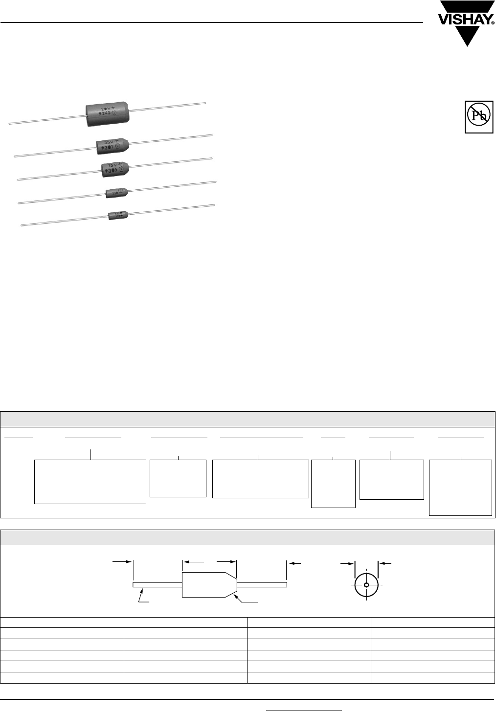
www.vishay.com For technical questions, contact: tantalum@vishay.com Document Number: 40019
98 Revision: 15-Jan-08
173D
Vishay Sprague
Solid-Electrolyte TANTALEX® Capacitors,
Axial-Leaded, Molded-Case
FEATURES
•Terminations: Tin/lead (SnPb), 100 % Tin
(RoHS compliant)
•Miniature axial-lead capacitors available in
5 sizes
•Precision molded in gold colored, flame
retardant, thermosetting epoxy resin
•Laser marked for improved legibility and tapered end of
case provides easy identification of positive terminal
•Standard orders are lead taped and reeled; orders under
500 are taped only
APPLICATIONS
•Designed for high performance automotive, industrial and
commercial electronic equipment
PERFORMANCE CHARACTERISTICS
Operating Temperature: - 55 °C to + 85 °C
(To + 125 °C with voltage derating)
Capacitance Tolerance: At 120 Hz, + 25 °C. ± 20 %,
± 10 % standard ± 5 % available as special
Dissipation Factor: At 120 Hz, + 25 °C. Dissipation factor,
as determined from the expression 2πfRC, shall not exceed
the values listed in the Standard Ratings Tables
DC Leakage Current (DCL Max.):
At + 25 °C: Leakage current shall not exceed the values
listed in the Standard Ratings Tables
At + 85 °C: Leakage current shall not exceed 10 times the
values listed in the Standard Ratings Tables
At + 125 °C: Leakage shall not exceed 15 times the values
listed in the Standard Ratings Tables
Life Test: Capacitors shall withstand rated DC voltage
applied at + 85 °C for 2000 h and for 1000 h applied
at + 25 °C derated voltage
Following the life test:
1. DCL shall not exceed 125 % of the initial requirements
2. Dissipation Factor shall meet the initial requirement
3. Change in capacitance shall not exceed ± 10 %
* Pb containing terminations are not RoHS compliant, exemptions may apply
ORDERING INFORMATION
173D 335 X9 006 U W E3
MODEL CAPACITANCE CAPACITANCE
TO L E RA N C E
DC VOLTAGE RATING
AT + 85 °C
CASE
CODE
PACKAGING ROHS
COMPLIANT
This is expressed in picofarads.
The first two digits are the
significant figures. The third is
the number of zeros to follow.
X0 = ± 20 %
X9 = ± 10 %
*X5 = ± 5 %
*special order
This is expressed in volts.
To complete the three-digit
block, zeros precede the
voltage rating.
See
Ratings
and Case
Codes
Ta b l e
W = Tape and
Reel
Blank =Ammo
Pack
E3 = 100 %
tin termination
(RoHS
compliant)
Blank = SnPb
termination
DIMENSIONS in inches [millimeters]
CASE CODE D (MAX.) L (MAX.) LEAD DIAMETER
U 0.095 [2.41] 0.260 [6.60] 0.020 [0.51]
V 0.110 [2.79] 0.290 [7.37] 0.020 [0.51]
W 0.180 [4.57] 0.345 [8.76] 0.020 [0.51]
X 0.180 [4.57] 0.420 [10.67] 0.020 [0.51]
Y 0.280 [7.11] 0.550 [13.97] 0.025 [0.64]
(-) (+)
0.875 [22.23]
MIN.
TINNED SOLID
LEADS
TAPERED END
IDENTIFIES ANODE
L
MAX.
D
MAX.
0.875 [22.23]
MIN.
Available
Pb-free
RoHS*
COMPLIANT

Document Number: 40019 For technical questions, contact: tantalum@vishay.com www.vishay.com
Revision: 15-Jan-08 99
173D
Solid-Electrolyte TANTALEX® Capacitors,
Axial-Leaded, Molded-Case
Vishay Sprague
STANDARD RATINGS
CAPACITANCE
(µF)
CASE
CODE
PART NUMBER (1)
CAP. TOL. ± 20 %
PART NUMBER (1)
CAP. TOL. ± 10 %
MAX. DCL
AT + 25 °C
(µA)
MAX. DF
AT + 25 °C
120 Hz (%)
2 WVDC AT + 85 °C, SURGE = 2.5 V . . . 1.5 WVDC AT + 125 °C, SURGE = 1.8 V
6.8 U 173D685X0002U 173D685X9002U 0.5 10
8.2 U - 173D825X9002U 0.5 10
10.0 U 173D106X0002U 173D106X9002U 0.5 10
12.0 V - 173D126X9002V 0.5 10
15.0 V 173D156X0002V 173D156X9002V 0.5 10
18.0 V - 173D186X9002V 0.5 10
22.0 V 173D226X0002V 173D226X9002V 0.5 10
27.0 V - 173D276X9002V 0.5 10
33.0 V 173D336X0002V 173D336X9002V 0.5 10
39.0 W - 173D396X9002W 0.6 10
47.0 W 173D476X0002W 173D476X9002W 0.8 10
56.0 W - 173D566X9002W 0.9 10
68.0 W 173D686X0002W 173D686X9002W 1.1 10
4 WVDC AT + 85 °C, SURGE = 5 V . . . 2.5 WVDC AT + 125 °C, SURGE = 3 V
4.7 U 173D475X0004U 173D475X9004U 0.5 8
5.6 U - 173D565X9004U 0.5 8
6.8 U 173D685X0004U 173D685X9004U 0.5 8
8.2 V - 173D825X9004V 0.5 8
10.0 V 173D106X0004V 173D106X9004V 0.5 8
12.0 V - 173D126X9004V 0.5 8
15.0 V 173D156X0004V 173D156X9004V 0.5 8
18.0 V - 173D186X9004V 0.6 8
22.0 V 173D226X0004V 173D226X9004V 0.7 8
27.0 W - 173D276X9004W 0.9 8
33.0 W 173D336X0004W 173D336X9004W 1.1 8
39.0 W - 173D396X9004W 1.2 8
47.0 W 173D476X0004W 173D476X9004W 1.5 8
56.0 X - 173D566X9004X 1.5 8
68.0 X 173D686X0004X 173D686X9004X 2.2 8
6 WVDC AT + 85 °C, SURGE = 8 V . . . 4 WVDC AT + 125 °C, SURGE = 5 V
3.3 U 173D335X0006U 173D335X9006U 0.5 4
3.9 U - 173D395X9006U 0.5 4
4.7 U 173D475X0006U 173D475X9006U 0.5 4
5.6 V - 173D565X9006V 0.5 4
6.8 V 173D685X0006V 173D685X9006V 0.5 6
8.2 V - 173D825X9006V 0.5 6
10.0 V 173D106X0006V 173D106X9006V 0.5 6
12.0 V - 173D126X9006V 0.6 6
15.0 V 173D156X0006V 173D156X9006V 0.7 6
18.0 W - 173D186X9006W 0.9 6
22.0 W 173D226X0006W 173D226X9006W 1.1 6
27.0 W - 173D276X9006W 1.3 6
33.0 W 173D336X0006W 173D336X9006W 1.5 6
39.0 X - 173D396X9006X 1.9 6
47.0 X 173D476X9006X 173D476X9006X 2.3 6
56.0 X - 173D566X9006X 2.7 6
68.0 X 173D686X0006X 173D686X9006X 3.3 6
82.0 Y - 173D826X9006Y 3.9 8
100.0 Y 173D107X0006Y 173D107X9006Y 4.8 8
120.0 Y - 173D127X9006Y 5.0 8
150.0 Y 173D157X0006Y 173D157X9006Y 5.0 8
180.0 Y - 173D187X9006Y 8.6 8
220.0 Y 173D227X0006Y 173D227X9006Y 10.0 8
270.0 Y - 173D277X9006Y 10.0 8
330.0 Y 173D337X0006Y 173D337X9006Y 10.0 8
Note:
(1) Part number should include “X5”; for ± 5 % units (special order)

173D
Vishay Sprague Solid-Electrolyte TANTALEX® Capacitors,
Axial-Leaded, Molded-Case
www.vishay.com For technical questions, contact: tantalum@vishay.com Document Number: 40019
100 Revision: 15-Jan-08
STANDARD RATINGS
CAPACITANCE
(µF)
CASE
CODE
PART NUMBER (1)
CAP. TOL. ± 20 %
PART NUMBER (1)
CAP. TOL. ± 10 %
MAX. DCL
AT + 25 °C
(µA)
MAX. DF
AT+ 25 °C
120 Hz (%)
10 WVDC AT + 85 °C, SURGE = 13 V . . . 7 WVDC AT + 125 °C, SURGE = 9 V
2.2 U 173D225X0010U 173D225X9010U 0.5 4
2.7 U - 173D275X9010U 0.5 4
3.3 U 173D335X0010U 173D335X9010U 0.5 4
3.9 V - 173D395X9010V 0.5 4
4.7 V 173D475X0010V 173D475X9010V 0.5 4
5.6 V - 173D565X9010V 0.5 4
6.8 V 173D685X0010V 173D685X9010V 0.5 6
8.2 V - 173D825X9010V 0.7 6
10.0 V 173D106X0010V 173D106X9010V 0.8 6
12.0 W - 173D126X9010W 1.0 6
15.0 W 173D156X0010W 173D156X9010W 1.2 6
18.0 W - 173D186X9010W 1.4 6
22.0 W 173D226X0010W 173D226X9010W 1.5 6
27.0 X - 173D276X9010X 2.2 6
33.0 X 173D336X0010X 173D336X9010X 2.6 6
39.0 X - 173D396X9010X 3.1 6
47.0 X 173D476X0010X 173D476X9010X 3.8 6
56.0 Y - 173D566X9010Y 4.4 6
68.0 Y 173D686X0010Y 173D686X9010Y 5.0 6
82.0 Y - 173D826X9010Y 5.0 8
100.0 Y 173D107X0010Y 173D107X9010Y 8.0 8
120.0 Y - 173D127X9010Y 9.6 8
150.0 Y 173D157X0010Y 173D157X9010Y 10.0 8
180.0 Y - 173D187X9010Y 10.0 8
220.0 Y 173D227X0010Y 173D227X9010Y 10.0 8
15 WVDC AT + 85 °C, SURGE = 20 V . . . 10 WVDC AT + 125 °C, SURGE = 12 V
1.5 U 173D155X0015U 173D155X9015U 0.5 4
1.8 U - 173D185X9015U 0.5 4
2.2 U 173D225X0015U 173D225X9015U 0.5 4
2.7 V - 173D275X9015V 0.5 4
3.3 V 173D335X0015V 173D335X9015V 0.5 4
3.9 V - 173D395X9015V 0.5 4
4.7 V 173D475X0015V 173D475X9015V 0.6 4
5.6 V - 173D565X9015V 0.7 4
6.8 V 173D685X0015V 173D685X9015V 0.8 6
8.2 W - 173D825X9015W 1.0 6
10.0 W 173D106X0015W 173D106X9015W 1.2 6
12.0 W - 173D126X9015W 1.4 6
15.0 W 173D156X0015W 173D156X9015W 1.5 6
18.0 X - 173D186X9015X 2.2 6
22.0 X 173D226X9015X 173D226X9015X 2.6 6
27.0 X - 173D276X9015X 3.2 6
33.0 X 173D336X0015X 173D336X9015X 4.0 6
39.0 Y - 173D396X9015Y 4.7 6
47.0 Y 173D476X0015Y 173D476X9015Y 5.0 6
56.0 Y - 173D566X9015Y 6.7 6
68.0 Y 173D686X0015Y 173D686X9015Y 8.2 6
82.0 Y - 173D826X9015Y 9.8 8
100.0 Y 173D107X0015Y 173D107X9015Y 10.0 8
120.0 Y - 173D127X9015Y 10.0 8
150.0 Y 173D157X0015Y 173D157X9015Y 10.0 8
Note:
(1) Part number should include “X5”; for ± 5 % units (special order)

Document Number: 40019 For technical questions, contact: tantalum@vishay.com www.vishay.com
Revision: 15-Jan-08 101
173D
Solid-Electrolyte TANTALEX® Capacitors,
Axial-Leaded, Molded-Case
Vishay Sprague
STANDARD RATINGS
CAPACITANCE
(µF)
CASE
CODE
PART NUMBER (1)
CAP. TOL. ± 20 %
PART NUMBER (1)
CAP. TOL. ± 10 %
MAX. DCL
AT+ 25 °C
(µA)
MAX. DF
AT + 25 °C
120 Hz (%)
20 WVDC AT + 85 °C, SURGE = 26 V . . . 13 WVDC AT + 125 °C, SURGE = 16 V
1.0 U 173D105X0020U 173D105X9020U 0.5 4
1.2 U - 173D125X9020U 0.5 4
1.5 U 173D155X0020U 173D155X9020U 0.5 4
1.8 V - 173D185X9020V 0.5 4
2.2 V 173D225X0020V 173D225X9020V 0.5 4
2.7 V - 173D275X9020V 0.5 4
3.3 V 173D335X0020V 173D335X9020V 0.5 4
3.9 V - 173D395X9020V 0.6 4
4.7 V 173D475X0020V 173D475X9020V 0.8 4
5.6 W - 173D565X9020W 0.9 4
6.8 W 173D685X0020W 173D685X9020W 1.1 6
8.2 W - 173D825X9020W 1.3 6
10.0 W 173D106X0020W 173D106X9020W 1.6 6
12.0 X - 173D126X9020X 1.9 6
15.0 X 173D156X0020X 173D156X9020X 2.4 6
18.0 X - 173D186X9020X 2.9 6
22.0 X 173D226X0020X 173D226X9020X 3.5 6
27.0 Y - 173D276X9020Y 4.3 6
33.0 Y 173D336X0020Y 173D336X9020Y 5.0 6
39.0 Y - 173D396X9020Y 6.2 6
47.0 Y 173D476X0020Y 173D476X9020Y 7.5 6
56.0 Y - 173D566X9020Y 8.9 6
68.0 Y 173D686X0020Y 173D686X9020Y 10.0 6
82.0 Y - 173D826X9020Y 10.0 6
100.0 Y 173D107X0020Y 173D107X9020Y 10.0 6
25 WVDC AT + 85 °C, SURGE = 32 V . . . 17 WVDC AT + 125 °C, SURGE = 21 V
0.47 U 173D474X0025U 173D474X9025U 0.5 3
0.56 U - 173D564X9025U 0.5 3
0.68 U 173D684X0025U 173D684X9025U 0.5 3
0.82 U - 173D824X9025U 0.5 3
1.0 U 173D105X0025U 173D105X9025U 0.5 3
1.2 V - 173D125X9025V 0.5 3
1.5 V 173D155X0025V 173D155X9025V 0.5 3
1.8 V - 173D185X9025V 0.5 3
2.2 V 173D225X0025V 173D225X9025V 0.5 3
2.7 V - 173D275X9025V 0.5 3
3.3 V 173D335X0025V 173D335X9025V 0.7 3
3.9 W - 173D395X9025W 0.8 3
4.7 W 173D475X0025W 173D475X9025W 0.9 4
5.6 W - 173D565X9025W 1.1 4
6.8 W 173D685X0025W 173D685X9025W 1.4 4
8.2 W - 173D825X9025W 1.5 4
10.0 W 173D106X0025W 173D106X9025W 1.5 4
12.0 X - 173D126X9025X 2.4 4
15.0 X 173D156X0025X 173D156X9025X 3.0 4
18.0 Y - 173D186X9025Y 3.6 6
22.0 Y 173D226X9025Y 173D226X9025Y 4.4 6
27.0 Y - 173D276X9025Y 5.4 6
33.0 Y 173D336X0025Y 173D336X9025Y 6.6 6
39.0 Y - 173D396X9025Y 7.8 6
47.0 Y 173D476X0025Y 173D476X9025Y 9.4 6
Note:
(1) Part number should include “X5”; for ± 5 % units (special order)
173D
Vishay Sprague Solid-Electrolyte TANTALEX® Capacitors,
Axial-Leaded, Molded-Case
www.vishay.com For technical questions, contact: tantalum@vishay.com Document Number: 40019
102 Revision: 15-Jan-08
STANDARD RATINGS
CAPACITANCE
(µF)
CASE
CODE PART NUMBER (1)
CAP. TOL. ± 20 %
PART NUMBER (1)
CAP. TOL. ± 10 %
MAX. DCL
AT+ 25 °C
(µA)
MAX. DF
AT + 25 °C
120 Hz (%)
35 WVDC AT + 85 °C, SURGE = 46 V . . . 23 WVDC AT + 125 °C, SURGE = 28 V
0.10 U 173D104X0035U 173D104X9035U 0.5 3
0.12 U - 173D124X9035U 0.5 3
0.15 U 173D154X0035U 173D154X9035U 0.5 3
0.18 U - 173D184X9035U 0.5 3
0.22 U 173D224X0035U 173D224X9035U 0.5 3
0.27 U - 173D274X9035U 0.5 3
0.33 U 173D334X0035U 173D334X9035U 0.5 3
0.39 U - 173D394X9035U 0.5 3
0.47 U 173D474X0035U 173D474X9035U 0.5 3
0.56 V - 173D564X9035V 0.5 3
0.68 V 173D684X0035V 173D684X9035V 0.5 3
0.82 V - 173D824X9035V 0.5 3
1.0 V 173D105X0035V 173D105X9035V 0.5 3
1.2 V - 173D125X9035V 0.5 3
1.5 V 173D155X0035V 173D155X9035V 0.5 3
1.8 W - 173D185X9035W 0.5 3
2.2 W 173D225X0035W 173D225X9035W 0.6 3
2.7 W - 173D275X9035W 0.8 3
3.3 W 173D335X0035W 173D335X9035W 0.9 4
3.9 W - 173D395X9035W 1.1 4
4.7 W 173D475X0035W 173D475X9035W 1.3 4
5.6 X - 173D565X9035X 1.6 4
6.8 X 173D685X0035X 173D685X9035X 1.9 4
8.2 X - 173D825X9035X 2.3 4
10.0 X 173D106X0035X 173D106X9035X 2.8 4
12.0 Y - 173D126X9035Y 3.3 4
15.0 Y 173D156X0035Y 173D156X9035Y 4.2 6
18.0 Y - 173D186X9035Y 5.0 6
22.0 Y 173D226X0035Y 173D226X9035Y 6.2 6
27.0 Y - 173D276X9035Y 7.5 6
33.0 Y 173D336X0035Y 173D336X9035Y 9.2 6
39.0 Y - 173D396X9035Y 10.0 6
47.0 Y 173D476X0035Y 173D476X9035Y 10.0 6
50 WVDC AT + 85 °C, SURGE = 65 V . . . 33 WVDC AT + 125 °C, SURGE = 40 V
0.10 U 173D104X0050U 173D104X9050U 0.5 3
0.12 U - 173D124X9050U 0.5 3
0.15 U 173D154X0050U 173D154X9050U 0.5 3
0.18 U - 173D184X9050U 0.5 3
0.22 U 173D224X0050U 173D224X9050U 0.5 3
0.27 U - 173D274X9050U 0.5 3
0.33 V 173D334X0050V 173D334X9050V 0.5 3
0.39 V - 173D394X9050V 0.5 3
0.47 V 173D474X0050V 173D474X9050V 0.5 3
0.56 V - 173D564X9050V 0.5 3
0.68 V 173D684X0050V 173D684X9050V 0.5 3
0.82 V - 173D824X9050V 0.5 3
1.0 V 173D105X0050V 173D105X9050V 0.5 3
1.2 W - 173D125X9050W 0.5 3
1.5 W 173D155X0050W 173D155X9050W 0.6 4
1.8 W - 173D185X9050W 0.7 4
2.2 W 173D225X0050W 173D225X9050W 0.9 4
2.7 X - 173D275X9050X 1.1 4
3.3 X 173D335X0050X 173D335X9050X 1.3 4
3.9 X - 173D395X9050X 1.6 4
4.7 X 173D475X0050X 173D475X9050X 1.9 4
5.6 Y - 173D565X9050Y 2.2 4
6.8 Y 173D685X0050Y 173D685X9050Y 2.7 4
8.2 Y - 173D825X9050Y 3.2 4
10.0 Y 173D106X0050Y 173D106X9050Y 4.0 6
12.0 Y - 173D126X9050Y 5.0 6
15.0 Y 173D156X0050Y 173D156X9050Y 6.0 6
18.0 Y - 173D186X9050Y 6.0 6
Note:
(1) Part number should include “X5”; for ± 5 % units (special order)
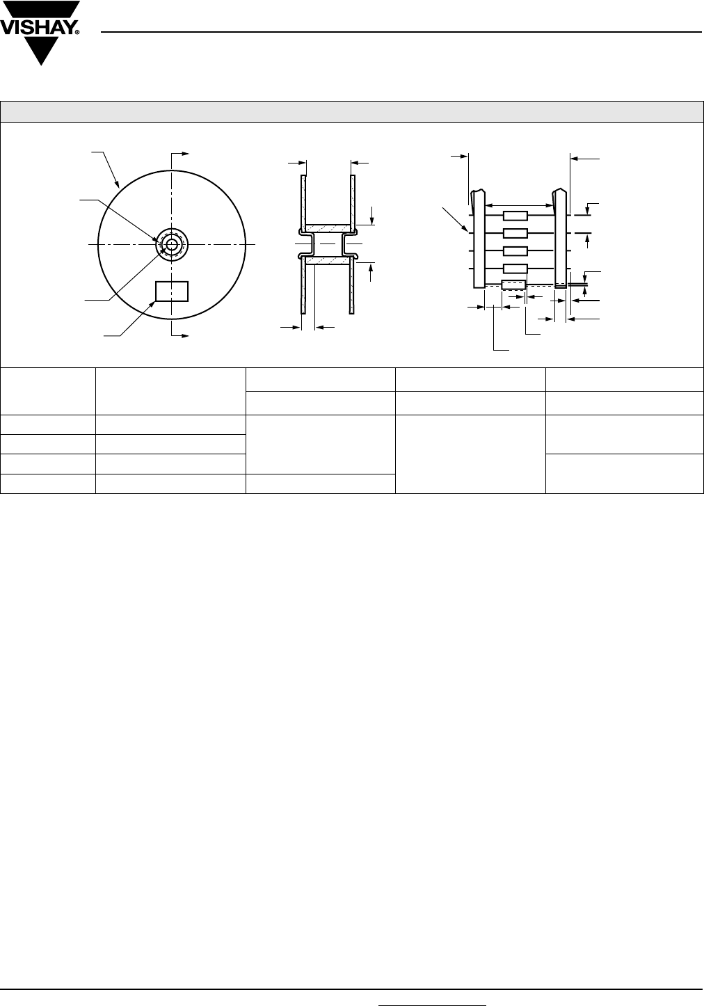
Document Number: 40019 For technical questions, contact: tantalum@vishay.com www.vishay.com
Revision: 15-Jan-08 103
173D
Solid-Electrolyte TANTALEX® Capacitors,
Axial-Leaded, Molded-Case
Vishay Sprague
STANDARD REEL PACKAGING INFORMATION
1. Component Leads:
a. Component leads shall not be bent beyond 0.047"
[1.19 mm] maximum from their nominal position when
measured from the leading edge of the component lead
at the inside tape edge and at the lead egress from the
component.
b. The “C” dimension shall be governed by the overall
length of the reel packaged component. The distance
between flanges shall be 0.125" to 0.250" [3.18 mm to
6.35 mm] greater than the overall component length.
2. Orientation:
a. All polarized components must be oriented to one
direction. The cathode lead tape shall be a color and the
anode lead tape shall be white.
3. Reeling:
a. Components on any reel shall not represent more than
two date codes when date code identification is required.
b. Component leads shall be positioned between pairs of
0.250" [6.35 mm] tape.
c. The disposable reels have hubs with corrugated
fibreboard flanges and core.
d. A minimum of 12" [304.8 mm] leader of tape shall be
provided before the first and after the last component on
the reel.
e. 50 to 60 lb. Kraft paper must be wound between layers of
components as far as necessary for component
protection. Width of paper to be 0.062" to 0.250"
[1.57 mm to 6.35 mm] less than the “C” dimension of the
reel.
f. Row components must be centered between tapes
± 0.047" [1.19 mm]. In addition, individual components
may deviate from center of component row ± 0.031"
[0.79].
g. Staples shall not be used for splicing. Not more than
4 layers of tape shall be used in any splice area and no
tape shall be offset from another by more than 0.031"
[0.79 mm] non-cumulative. Tape splices shall overlap at
least 6" [152.4 mm] for butt joints and at least 3"
[76.2 mm] for lap joints and shall not be weaker than
unspliced tape. Universal splicing clips may also be used.
h. Quantity per reel shall be controlled so that tape
components and cover shall not extend beyond the
smallest dimension of the flange (either across flats or
diameter). Once the quantity per reel for each part
number has been established, future orders for that part
number shall be packaged in that quantity. When order
release quantity is less than the established quantity, a
standard commercial pack is to be used.
i. A maximum of 0.25 % of the components per reel
quantity may be missing without consecutive missing
components.
j. Adequate protection must be provided to prevent
physical damage to both reel and components during
shipment and storage.
4. Marking:
a. Minimum reel and carton marking shall consist of the
following: Customer Part Number, Purchase Order No.,
Quantity, Package Date, Manufacturer's name, Electrical
Value, Date Code, Vishay Sprague Part Number and
Country of Origin.
TAPE AND REEL PACKAGING in inches [millimeters]
CASE CODE UNITS PER REEL
COMPONENT SPACING TAPE SPACING UNITS PER AMMOPACK
AB
U 4500
0.200 ± 0.015
[5.08 ± 3.81] 2.062 ± 0.062
[2.37 ± 1.57]
1000
V 4000
W, X 2500 500
Y 500 0.400 ± 0.015
“A”
“A”
0.750
[19.05] 0.750 [19.05]
C
(1.b)
SECTION “A” - ”A”
0.250 [6.35] (3.b)
COMPONENT OVERALL
LENGTH (1.b)
A
0.031 [0.79] (3.f)
(BOTH SIDES) (3.f)
(1.a)
0.047 [1.19] MAX.
OFF CENTER (1.a)
0.125 [3.18] MAX.
B
TAPE
SPACING
COMPONENT
SPACING (4.b)
13 [330.2] DIA.
STANDARD REEL
1.126 TO 3.07
[28.6 TO 78.0]
I. D. REEL HUB
0.625 ± 0.062
[15.88 ± 1.57]
DIA. THRU HOLE
LABEL (4.a)
1.374 TO 3.626
[34.9 TO 92.1]
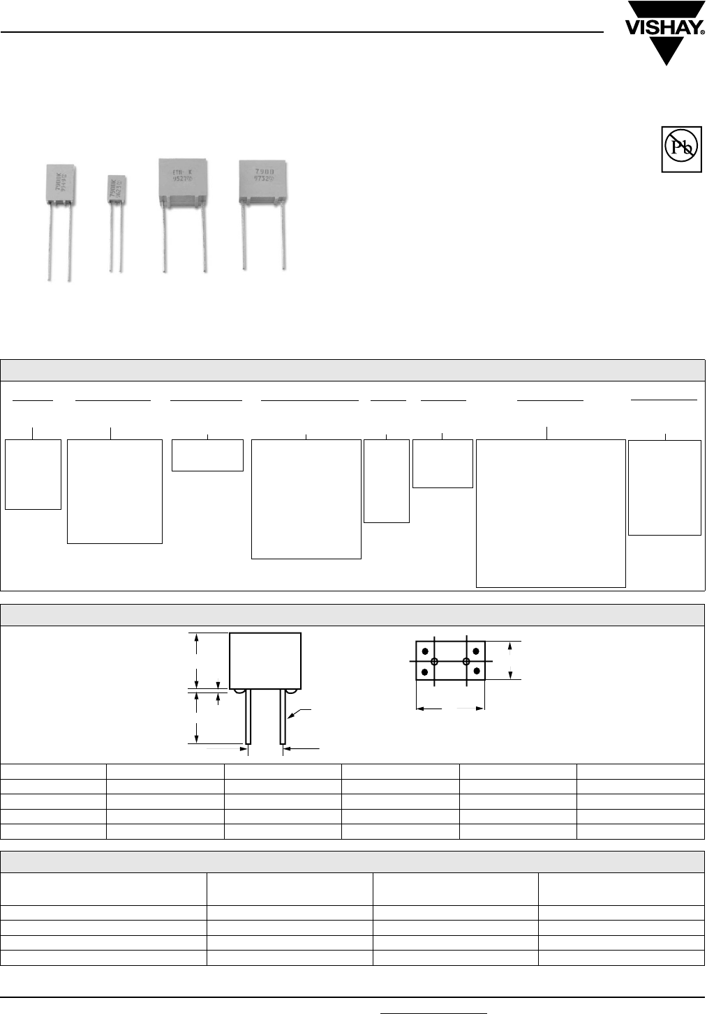
www.vishay.com For technical questions, contact: eurotant@vishay.com Document Number: 42072
104 Revision: 10-Dec-07
790D
Vishay Sprague
Resin-Molded, Radial-Lead Solid Tantalum Capacitors
FEATURES
•Terminations: Tin/lead (SnPb), 100 % Tin (Sn)
•Four case sizes precisely molded with a
flame retardant epoxy resin
•Stand off on all case sizes
•Available on tape for automatic insertion equipment
(only A- and B-case, C- and D-case on request)
•Low leakage current
•Low impedance
•Extended value ranges available
PERFORMANCE CHARACTERISTICS
Operating Temperature: - 55 °C to + 125 °C
* Pb containing terminations are not RoHS compliant, exemptions may apply
Available
Pb-free
RoHS*
ORDERING INFORMATION
790D 157 X0 006 R 2 P E3
MODEL CAPACITANCE CAPACITANCE
TOLERANCE
DC VOLTAGE
RATING
AT + 85 °C
CASE
CODE
STYLE
NUMBER
PACKAGING ROHS
COMPLIANT
790D =
Standard
and
Extended
Range
Expressed in
picofarads. The
first two digits are
the significant
figures. The third
is the number of
zeros following.
X0 = ± 20 %
X9 = ± 10 %
Expressed in volts.
To complete the
three-digit block,
zeros precede the
voltage rating. A
decimal point is
indicated by an “R”
(6R3 = 6.3 V)
See
Ratings
and
Case
Codes
Tabl e
Insulated
Case
(Standard)
See Taping Specification
B : Bulk
G : Ammopack H = 16.5 mm
H : Ammopack H = 18.5 mm
I : Ammopack Shouldered
Leads (A case)
X : Reel Pack H = 16.5 mm
Y : Reel Pack H = 18.5 mm
Z : Reel Pack Shouldered
Leads (A case)
E3 = 100 %
tin
termination
(RoHS
compliant)
Blank = SnPb
termination
DIMENSIONS in millimeters
CASE CODE H MAX. (mm) A MAX. (mm) B MAX. (mm) E ± 0.15 (mm) Ø 0.05 (+ 10 %) (mm)
A 7.3 4.7 4.2 2.54 0.5
B 10.5 7.3 4.8 5.08 0.5
C 10.5 12.3 7.3 10.16 0.6
D 10.5 12.3 12.3 10.16 0.6
12 Min.
e
B
A
0.3
MIN.
H
Ø
+
PACKAGING QUANTITIES
CASE CODE REEL
X/Y
AMMO
G/H
BULK
B
A 1000 1000 500
B 1000 1000 250
C 300* 300* 100
D 200* 200* 50
Document Number: 42072 For technical questions, contact: eurotant@vishay.com www.vishay.com
Revision: 10-Dec-07 105
790D
Resin-Molded, Radial-Lead
Solid Tantalum Capacitors
Vishay Sprague
RATINGS AND CASE CODES
CR
µF
RATED VOLATAGE UR AT + 85 °C
6.3 V 10 V 16 V 20 V 25 V 35 V 40 V 50 V
CATEGORY VOLTAGE UC AT + 125 °C
4.0 V 6.3 V 10 V 13 V 16 V 23 V 25 V 32 V
Std. Ext. Std. Ext. Std. Ext. Std. Ext. Std. Ext. Std. Ext. Std. Ext. Std. Ext.
0.10 AA
0.15 A
0.22 A
0.33 A
0.47 A
0.68
1.0 A
1.5 ABA
2.2 AA BB
3.3 AABB
4.7 AABB
6.8 AABB
10 ABBCC
15 AB B B C C
22 ABBBCC
33 BBCC
47 BBCC
68 BBC C
100 CDCD
150 CC
220 CD
330 D

790D
Vishay Sprague Resin-Molded, Radial-Lead
Solid Tantalum Capacitors
www.vishay.com For technical questions, contact: eurotant@vishay.com Document Number: 42072
106 Revision: 10-Dec-07
STANDARD/EXTENDED RATINGS
CAPACITANCE
CR (µF) CASE CODE PART NUMBER
MAX. DCL
AT + 25 °C
(µA)
MAX. DF
120 Hz, AT + 25 °C
(%)
MAX. IMPEDANCE
100 kHz, AT + 25 °C
(Ω)
UR = 6.3 V AT + 85 °C, SURGE = 8 V . . . UC = 4 V AT + 125 °C, SURGE = 5 V
6.8
22.0
47.0
68.0
150.0
220.0
330.0
A
A
B
B
C
C
D
790D685X(*)6R3A2(#)
790D226X(*)6R3A2(#)
790D476X(*)6R3B2(#)
790D686X(*)6R3B2(#)
790D157X(*)6R3C2(#)
790D227X(*)6R3C2(#)
790D337X(*)6R3D2(#)
1.0
1.3
2.9
4.2
9.4
13.8
20.7
6
6
6
6
6
6
8
4.0
2.1
1.3
1.3
0.6
0.6
0.4
UR = 10 V AT + 85 °C, SURGE = 13 V . . . UC = 6.3 V AT + 125 °C, SURGE = 8 V
4.7
15.0
33.0
47.0
68.0
100.0
150.0
220.0
A
A
B
B
B
C
C
D
790D475X(*)010A2(#)
790D156X(*)010A2(#)
790D336X(*)010B2(#)
790D476X(*)010B2(#)
790D686X(*)010B2(#)
790D107X(*)010C2(#)
790D157X(*)010C2(#)
790D227X(*)010D2(#)
1.0
1.5
3.3
4.7
6.8
10.0
15.0
22.0
6
6
6
6
6
6
6
8
4.0
2.5
1.3
1.4
1.3
0.6
0.6
0.4
UR = 16 V AT + 85 °C, SURGE = 20 V . . . UC = 10 V AT + 125 °C, SURGE = 13 V
2.2
3.3
10.0
15.0
22.0
33.0
47.0
68.0
100.0
100.0
A
A
A
B
B
B
C
C
C
D
790D225X(*)016A2(#)
790D335X(*)016A2(#)
790D106X(*)016A2(#)
790D156X(*)016B2(#)
790D226X(*)016B2(#)
790D336X(*)016B2(#)
790D476X(*)016C2(#)
790D686X(*)016C2(#)
790D107X(*)016C2(#)
790D107X(*)016D2(#)
1.0
1.0
1.6
2.4
3.5
5.2
7.5
10.8
16.0
16.0
6
6
6
6
6
6
6
6
6
6
5.5
4.4
2.7
1.6
1.3
1.6
0.8
0.6
0.7
0.5
UR = 20 V AT + 85 °C, SURGE = 26 V . . . UC = 13 V AT + 125 °C, SURGE = 16 V
2.2
6.8
15.0
22.0
47.0
68.0
100.0
A
A
B
B
C
C
D
790D225X(*)020A2(#)
790D685X(*)020A2(#)
790D156X(*)020B2(#)
790D226X(*)020B2(#)
790D476X(*)020C2(#)
790D686X(*)020C2(#)
790D107X(*)020C2(#)
1.0
1.3
3.0
4.4
9.4
13.6
20.0
6
6
6
6
6
6
6
5.5
3.5
1.5
2.1
0.7
0.8
0.7
Note:
Extended Ratings in bold print
(*) Insert 0 for ± 20 % tolerance or 9 for ± 10 %
(#) See order information, packaging code

Document Number: 42072 For technical questions, contact: eurotant@vishay.com www.vishay.com
Revision: 10-Dec-07 107
790D
Resin-Molded, Radial-Lead
Solid Tantalum Capacitors Vishay Sprague
STANDARD/EXTENDED RATINGS
CAPACITANCE
CR (µF) CASE CODE PART NUMBER
MAX. DCL
AT + 25 °C
(µA)
MAX. DF
120 Hz, AT + 25 °C
(%)
MAX. IMPEDANCE
100 kHz, AT + 25 °C
(Ω)
UR = 25 V AT + 85 °C, SURGE = 32 V . . . UC = 16 V AT + 125 °C, SURGE = 20 V
1.5
4.7
10.0
15.0
22.0
33.0
A
A
B
B
B
C
790D155X(*)025A2(#)
790D475X(*)025A2(#)
790D106X(*)025B2(#)
790D156X(*)025B2(#)
790D226X(*)025B2(#)
790D336X(*)025C2(#)
1.0
1.1
2.5
3.7
5.5
8.2
6
6
6
6
6
6
6.0
4.5
1.6
2.4
2.1
0.8
UR = 35 V AT + 85 °C, SURGE = 45 V . . . UC= 23 V AT + 125×C, SURGE = 29 V
3.3
10.0
33.0
A
B
C
790D335X(*)035A2(#)
790D106X(*)035B2(#)
790D336X(*)035C2(#)
1.2
3.5
11.6
6
6
6
6.0
2.6
1.3
UR = 40 V AT + 85 °C, SURGE = 52 V . . . UC = 25 V AT + 125 °C, SURGE = 32 V
0.10
0.33
0.47
1.0
1.5
2.2
3.3
4.7
6.8
10.0
15.0
22.0
A
A
A
A
B
B
B
B
B
C
C
C
790D104X(*)040A2(#)
790D334X(*)040A2(#)
790D474X(*)040A2(#)
790D105X(*)040A2(#)
790D155X(*)040B2(#)
790D225X(*)040B2(#)
790D335X(*)040B2(#)
790D475X(*)040B2(#)
790D685X(*)040B2(#)
790D106X(*)040C2(#)
790D156X(*)040C2(#)
790D226X(*)040C2(#)
1.0
1.0
1.0
1.0
1.0
1.0
1.3
1.8
2.7
4.0
6.0
8.8
6
6
6
6
6
6
6
6
6
6
6
6
30
14
11
6.5
5.2
4.0
2.8
2.0
1.6
1.3
1.0
0.8
UR = 50 V AT + 85 °C, SURGE = 65 V . . . UC = 32 V AT + 125 °C, SURGE = 41 V
0.10
0.15
0.22
1.0
1.5
2.2
3.3
4.7
6.8
10.0
15.0
A
A
A
A
B
B
B
B
C
C
C
790D104X(*)050A2(#)
790D154X(*)050A2(#)
790D224X(*)050A2(#)
790D105X(*)050A2(#)
790D155X(*)050B2(#)
790D225X(*)050B2(#)
790D335X(*)050B2(#)
790D475X(*)050B2(#)
790D685X(*)050C2(#)
790D106X(*)050C2(#)
790D156X(*)050C2(#)
1.0
1.0
1.0
1.0
1.0
1.1
1.6
2.3
3.4
5.0
7.5
6
6
6
6
6
6
6
6
6
6
6
30
24
18
6.5
5.2
4.0
2.8
2.0
1.6
1.3
1.0
Note:
Extended Ratings in bold print
(*) Insert 0 for ± 20 % tolerance or 9 for ± 10 %
(#) See order information, packaging code
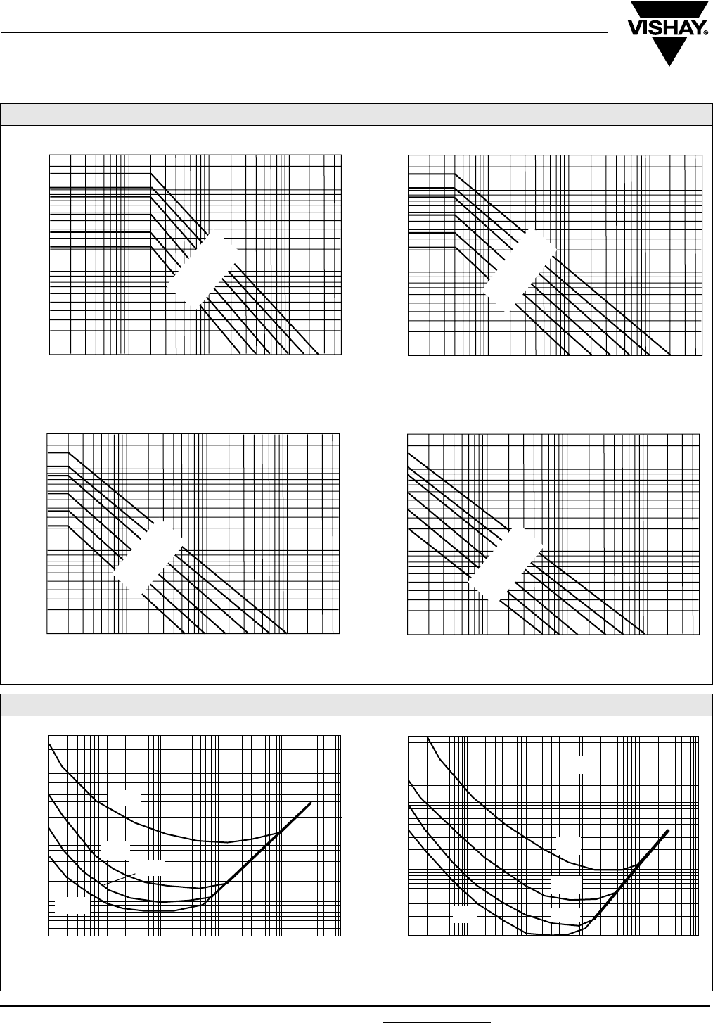
790D
Vishay Sprague Resin-Molded, Radial-Lead
Solid Tantalum Capacitors
www.vishay.com For technical questions, contact: eurotant@vishay.com Document Number: 42072
108 Revision: 10-Dec-07
MAXIMUM PERMISSIBLE RIPPLE VOLTAGE AT + 25 °C
10
1
0.1
Urms
30
20
2
5
0.7
7
3
0.5
0.2
0.3
50 V
10 V
25 V
6.3 V
16 V
35/40 V
0.1K 0.5 1K 5 10K 50 100K 500
FREQUENCY IN Hz
CASE SIZE “A”
10
1
0.1
Urms
30
20
2
5
0.7
7
3
0.5
0.2
0.3
0.1K 0.5 1K 5 10K 50 100K 500
FREQUENCY IN Hz
CASE SIZE “B”
50 V
10 V
25 V
6.3 V
16 V
35/40 V
10
1
0.1
U
rms
30
20
2
5
0.7
7
3
0.5
0.2
0.3
0.1K 0.5 1K 5 10K 50 100K 500
FREQUENCY IN Hz
CASE SIZE “C”
50 V
10 V
25 V
6.3 V
16 V
35/40 V
10
1
0.1
Urms
30
20
2
5
0.7
7
3
0.5
0.2
0.3
0.1K 0.5 1K 5 10K 50 100K 500
FREQUENCY IN Hz
CASE SIZE “D”
50 V
10 V
25 V
6.3 V
16 V
35/40 V
TYPICAL CURVES OF IMPEDANCE VS FREQUENCY
FREQUENCY IN Hz
10
1
0.1
1K 10K 100K 1M 10M 100M
47 µF
6.3 V
6.8 µF
30
330 µF
150 µF
Ω
FREQUENCY IN Hz
1K 10K 100K 1M 10M 100M
Ω
100
10
1
0.1
47 µF
6.8 µF
1µF
22 µF
35 V
Document Number: 42072 For technical questions, contact: eurotant@vishay.com www.vishay.com
Revision: 10-Dec-07 109
790D
Resin-Molded, Radial-Lead
Solid Tantalum Capacitors Vishay Sprague
PERFORMANCE CHARACTERISTICS
1. Operating Temperature: - 55 °C to + 85 °C with rated
voltage UR applied. + 85 °C to 125 °C with linear
voltage derating to category voltage UC(see general
information) applied.
2. Capacitance and Tolerance:
Capacitance measured at 100 Hz and + 25 °C shall be
within the specified tolerance limits of the nominal
rating
3. Reverse Voltage: 15 % of rated voltage at + 25 °C
5 % of rated voltage at + 85 °C
4. Surge Voltage: 130 % of UR at + 85 °C
130 % of UC at + 125 °C
5. Impedance at 100 kHz: Measured at + 20 °C ± 5 °C,
impedance shall not exceed the values listed in data
sheet.
6. Stability at low and high temperatures:
Capacitance change with temperature, dissipation
factor and DC leakage current shall not exceed the
limits of the following table.
7. Life Test: 2000 h at + 85 °C with rated voltage applied
2000 h at + 125 °C. with category voltage applied
ΔC/C ≤ 10 % of initial value
IL ≤ 1.25 initial limit
DF ≤ initial limit
8. Humidity Test: 56 days at + 40 °C, 90 % relative
humidity
ΔC/C ≤ 8 % of initial value
IL ≤ initial limit
DF ≤ initial limit
•Charge and Discharge Test:
1 million cycles at + 85 °C,
0.5 s charge at UR
0.5 s discharge
Series resistance < 0.5 Ω
ΔC/C ≤ 5 % of initial value
IL ≤ initial limit
DF ≤ initial limit
10. Marking:
Top: Rating and polarity
Front: Type, date code, Sprague trademark
TEMP.
CAPACITANCE
CHANGE
CRUR ≤ 1900
CRUR > 1900
DISSIPATION
FACTOR
IL
LEAKAGE
CURRENT
- 55 °C - 10 % 9 % -
11 %
+ 25 °C -
6 % 0.01 CR x UR or
1 µA whichever is
greater
8 %
+ 85 °C + 12 %
9 % 0.1 CR x UR or
10 µA whichever is
greater
11 %
+ 125 °C + 15 %
12 % 0.125 CR x UR or
12.5 µA whichever is
greater
14 %
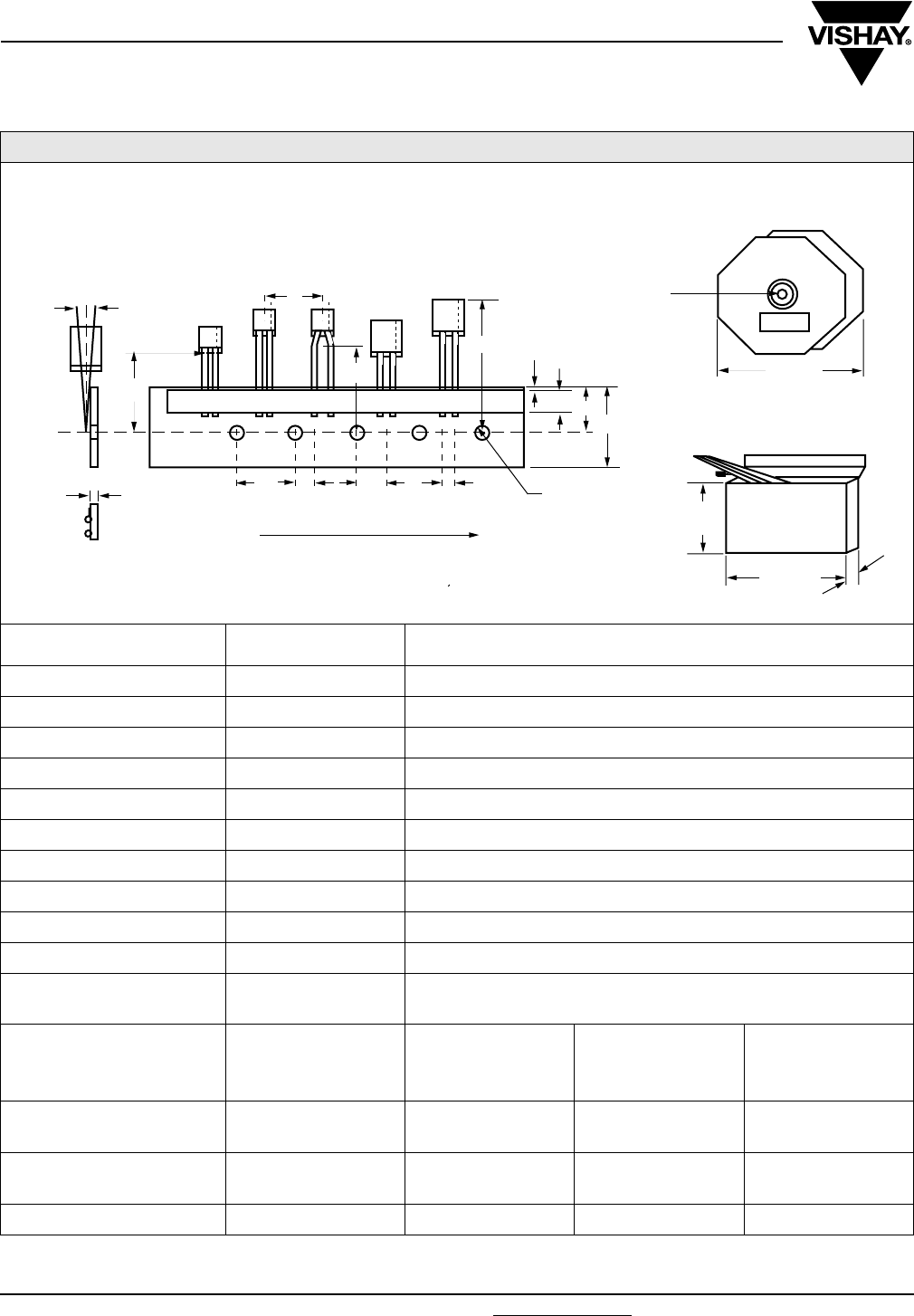
790D
Vishay Sprague Resin-Molded, Radial-Lead
Solid Tantalum Capacitors
www.vishay.com For technical questions, contact: eurotant@vishay.com Document Number: 42072
110 Revision: 10-Dec-07
TAPE AND REEL PACKING
CASE CODE TAPE WIDTH DIMENSIONS (mm)/UNITS PER REEL
Pitch of component P [mm] 12.7 ± 1.0
Feed hole pitch P0 [mm] 12.7 ± 0.3
Tape width W [mm] 18 (+ 1/- 0.5)
Hold down tape width W0 [mm] 5.0
Hole position W1 [mm] 9 (+ 0.75/-0.5)
Hold down tape position W2 [mm] 0 (+ 3/-0)
Feed hole diameter D0 [mm] 4.0 ± 0.3
Tape thickness T [mm] 0.5 ± 0.2
Component alignment Δh [mm] 0 ± 2
Lead clinch height H0 [mm] 16.0 ± 0.5
Hole center to component
center P2 [mm] 6.35 ± 1.3
Lead wire spacing
Feed hole center to wire center
F [mm]
P1 [mm]
Case A
2.5 + 0.6, - 0.1
5.1 ± 0.7
Case B
5 + 0.6, - 0.1
3.85 ± 0.7
Case B
5 + 0.6, - 0.1
3.85 ± 0.7
Reel pack options H = 16.5 mm
H = 18.5 mm
X
Y Z X
Y
Ammopack options H = 16.5 mm
H = 18.5 mm
G
H I G
H
Quantity per reel/box 1000 1000 1000
REEL P ACKING
AMMOP ACKING
W2
W0W1W
H0
h
30 MAX.
H
p
t
P2
P1FP0 Ø D
DIRECTION OF UNREEL
SPRAGUE
191
201
320 - 330
329 - 331
Ø 20
41 - 45
Δ
“A” AND “B” CASES ONLY (MEETS IEC 286-2)
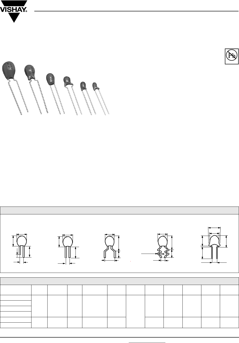
199D
Vishay Sprague
Solid-Electrolyte TANTALEX® Capacitors,
Resin-Coated, Radial-Lead
Document Number: 40020 For technical questions, contact: tantalum@vishay.com www.vishay.com
Revision: 18-Mar-08 111
FEATURES
•Terminations: Tin/lead (SnPb), 100 % tin (Sn)
•Economy and high performance are combined
in these radial-lead, solid-electrolyte TANTALEX®
capacitor
•Rugged, reliable capacitors featuring low
leakage current and low dissipation factor
•Six miniature case sizes and five lead styles. All case sizes
are available in standard tape and reel packaging per
EIA-RS-468
•Standard ratings include replacements for Type 196D
capacitors
•Lead (Pb)-free capacitors have “L” in body marking
APPLICATIONS
•Suitable for a broad range of consumer, commercial and
industrial equipment
PERFORMANCE CHARACTERISTICS
Operating Temperature: - 55 °C to + 85 °C
(To + 125 °C with voltage derating)
Capacitance Tolerance: At 120 Hz, + 25 °C, ± 20 %,
± 10 % standard. ± 5 % available as special
Dissipation Factor: At 120 Hz, + 25 °C. Dissipation factor,
shall not exceed the values listed in the Standard Ratings
Tables.
DC Leakage Current (DCL Max.):
At + 25 °C: Leakage current shall not exceed the values
listed in the Standard Ratings Tables.
At + 85 °C: Leakage current shall not exceed 10 times the
values listed in the Standard Ratings Tables.
At + 125 °C: Leakage shall not exceed 15 times the values
listed in the Standard Ratings Tables.
Life Test: Capacitors shall withstand rated DC voltage
applied at + 85 °C for 1000 h with a circuit resistance not
greater than 3 Ω.
Following the life test:
1. DCL shall not exceed 125 % of the initial requirements
2. Dissipation Factor shall meet the initial requirement
3. Change in capacitance shall not exceed ± 10 %
* Pb containing terminations are not RoHS compliant, exemptions may apply
Available
Pb-free
RoHS*
COMPLIANT
LEAD STYLE CONFIGURATIONS AND DIMENSIONS** (LL = Lead Length)
AVAILABLE LEAD STYLES AND PACKAGING TYPES PER CASE SIZE
LEAD
STYLE/CASE 123 4 5679XYZ
A
Bulk
V1
Bulk
V1
Reel
B1
Ammo
A1
Bulk
V1
Reel
B1
Ammo
A1
Bulk
V1
Reel
B1
Ammo
A1
Bulk
V1
Reel
B1
Ammo
A1
Bulk
V1
Reel
B1
Ammo
A1
Bulk
V1
Reel
B1
Ammo
A1
Bulk
V1
Bulk
V1
Reel
B1
Ammo
A1
B
C
D
EBulk
V1
Bulk/Reel
Ammo
F
“LONG/SHORT” LL
1, 3 and Y
+
+
L
D
H
3 ± 1
P
+
+
L
D
H
P
EVEN LL
2, 4 and 5
“OUTSIDE HOCKEYSTICK”
6 and 7
D
H1
P
L
+
+
“SNAP-IN”
9
H
L
D
1.1 ± 0.05
P
+
+
“HAIRPIN” X, Z
H1
D
H
L
P
6.35 max.
(1) - WIRE DIAMETER (NOMINAL) 0.020" [0.51 mm]
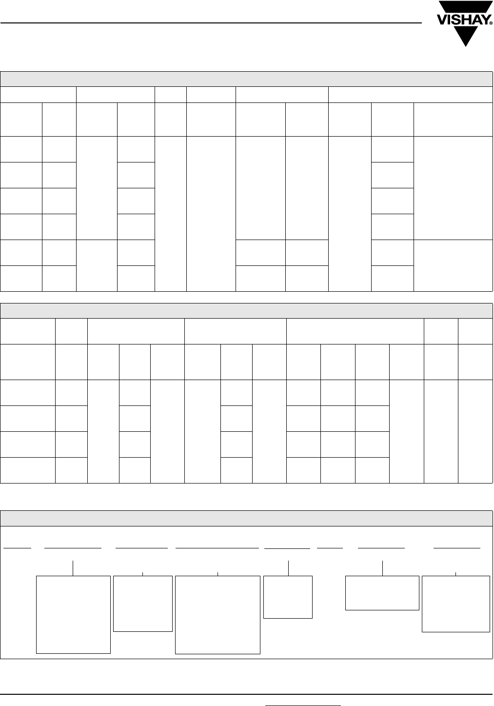
www.vishay.com For technical questions, contact: tantalum@vishay.com Document Number: 40020
112 Revision: 18-Mar-08
199D
Vishay Sprague Solid-Electrolyte TANTALEX® Capacitors,
Resin-Coated, Radial-Lead
Note:
• Lead space measured within 0.05 [1.27] of the body of the capacitor or from the bottom of the crimp
Note:
(1) see lead styles table
DIMENSIONS in inches [millimeters]
LEAD STYLE 1, 2, 3, 4 1, 2, 3 2, 4 5, Y 6
CASE D
max.
P
± 0.024
[0.60]
H
max.
L
min.
L
± 0.118
[3.0]
P
± 0.03
[0.76]
L
± 0.118
[3.0]
P
± 0.024
[0.60]
H1
max. L
A0.173
[4.40]
0.100
[2.54]
0.280
[7.11]
0.591
[15.0]
0.748
[19.0]
0.125
[3.18]
0.748
[19.0]
0.200
[5.08]
0.378
[9.61]
0.240 ± 0.030
[6.1 ± 0.76]
B0.197
[5.00]
0.300
[7.62]
0.398
[10.12]
C0.217
[5.50]
0.360
[9.14]
0.458
[11.64]
D0.236
[6.00]
0.400
[10.16]
0.498
[12.66]
E0.339
[8.60] 0.200
[5.08]
0.492
[12.50] -- 0.591
[15.00] 1 ± 0.122
[25.4 ± 3.1]
F0.378
[9.60]
0.650
[16.50] -- 0.748
[19.00]
DIMENSIONS in inches [millimeters]
LEAD
STYLE 7, 9 7 9 X, Z X Z
CASE D
max.
P
± 0.024
[0.60]
H1
max.
L
± 0.03
[0.76]
P
± 0.024
[0.60]
H1
max.
L
± 0.03
[0.76]
D
max.
H
max.
H1
max.
L
± 0.125
P
± 0.024
P
± 0.024
A0.173
[4.40]
0.25
[6.35]
0.378
[9.61]
0.240
[6.10]
0.200
[5.08]
0.398
[10.11]
0.240
[6.10]
0.173
[4.40]
0.280
[7.11]
0.340
[8.64]
0.750
[19.05]
0.100
[2.54]
0.125
[3.175]
B0.197
[5.00]
0.398
[10.12]
0.418
[10.62]
0.197
[5.00]
0.300
[7.62]
0.360
[9.14]
C0.217
[5.50]
0.458
[11.64]
0.478
[12.14]
0.217
[5.50]
0.360
[9.14]
0.420
[10.67]
D0.236
[6.00]
0.498
[12.66]
0.518
[13.16]
0.236
[6.00]
0.400
[10.16]
0.460
[11.68]
ORDERING INFORMATION
199D 475 X9 003 A 1 (1) V1 E3
MODEL CAPACITANCE CAPACITANCE
TOLERANCE
DC VOLTAGE RATING
AT + 85 °C
CASE CODE LEAD
STYLE
PACKAGING RoHS
COMPLIANT
This is expressed in
picofarads. The first
two digits are the
significant figures.
The third is the
number of zeros to
follow.
X0 = ± 20 %
X9 = ± 10 %
** X5 = ± 5 %
** Special
Order
This is expressed in V.
To complete the
three-digit block, zeros
precede the voltage
rating. A decimal point
is indicated by an “R”
(6R3 = 6.3 V).
See Ratings
and
Case Codes
table.
V1 = Bulk
B1 = Tape and reel
A1 = Ammo
E3 = 100 %
tin termination
(RoHS compliant)
Blank = Tin/lead
termination
199D
Solid-Electrolyte TANTALEX® Capacitors,
Resin-Coated, Radial-Lead
Vishay Sprague
Document Number: 40020 For technical questions, contact: tantalum@vishay.com www.vishay.com
Revision: 18-Mar-08 113
199D OBSOLETE VS. CURRENT ORDERING CROSS REFERENCE
OBSOLETE NEW DESCRIPTION
A1 1V1 0.100 SP, UNEVEN STRAIGHT LL, BULK CASES A - D
A1 3V1 0.200 SP, UNEVEN STRAIGHT LL, BULK, CASES E, F
A1 2V1 0.100 SP, EVEN STRAIGHT LL, BULK, CASES A - D
A6 2B1 0.100 SP, EVEN STRAIGHT LL, REEL POSITIVE LEADER, CASES A - D
A6 2A1 0.100 SP, EVEN STRAIGHT LL, AMMO, CASES A - D
A1 4V1 0.200 SP, EVEN STRAIGHT LL, BULK, CASES E, F
A6 4B1 0.200 SP, EVEN STRAIGHT LL, REEL POSITIVE LEADER, CASES E, F
A6 4A1 0.200 SP, EVEN STRAIGHT LL, AMMO, CASES E, F
A2 5V1 0.125 SP, EVEN STRAIGHT LL, BULK, CASES A - D
A7 5B1 0.125 SP, EVEN STRAIGHT LL, REEL POSITIVE LEADER, CASES A - D
A7 5A1 0.125 SP, EVEN STRAIGHT LL, AMMO, CASES A - D
A2 YV1 0.125 SP, UNEVEN STRAIGHT LL, BULK, CASES A - D
B1 XV1 0.100 SP, HAIRPIN LL, BULK CASES A - D
B6 XB1 0.100 SP, HAIRPIN LL, REEL POSITIVE LEADER, CASES A - D
B6 XA1 0.100 SP, HAIRPIN LL, AMMO, CASES A - D
B2 ZV1 0.125 SP, HAIRPIN LL, BULK, CASES A - D
B7 ZB1 0.125 SP, HAIRPIN LL, REEL POSITIVE LEADER, CASES A - D
B7 ZA1 0.125 SP, HAIRPIN LL, AMMO, CASES A - D
E2 6V1 0.200 SP, HOCKEY STICK LL, BULK, CASES A - F
E7 6B1 0.200 SP, HOCKEY STICK LL, REEL POSITIVE LEADER, CASES A - F
E7 6A1 0.200 SP, HOCKEY STICK LL, AMMO, CASES A - F
E3 7V1 0.250 SP, HOCKEY STICK LL, BULK, CASES A - D
E8 7B1 0.250 SP, HOCKEY STICK LL, REEL POSITIVE LEADER, CASES A - D
E8 7A1 0.250 SP, HOCKEY STICK LL, AMMO, CASES A - D
E4 OBSOLETE
G2 9V1 0.200 SP, SNAP-IN LL, BULK, CASES A - D
G7 9B1 0.200 SP, SNAP-IN LL, REEL POSITIVE LEADER, CASES A - D
G7 9A1 0.200 SP, SNAP-IN LL, AMMO, CASES A - D

www.vishay.com For technical questions, contact: tantalum@vishay.com Document Number: 40020
114 Revision: 18-Mar-08
199D
Vishay Sprague Solid-Electrolyte TANTALEX® Capacitors,
Resin-Coated, Radial-Lead
STANDARD RATINGS
CAPACITANCE
(µF) CASE CODE PART NUMBER*
MAX. DCL
at + 25 °C
(µA)
MAX. DF
at + 25 °C
120 Hz (%)
3 WVDC AT + 85 °C, SURGE = 3.6 V . . . 2 WVDC AT + 125 °C, SURGE = 2.4 V
4.7 A 199D475(1)003A(2)(3) 0.5 6
6.8 A 199D685(1)003A(2)(3) 0.5 6
10.0 A 199D106(1)003A(2)(3) 0.5 8
15.0 A 199D156(1)003A(2)(3) 0.5 8
22.0 B 199D226(1)003B(2)(3) 0.6 8
33.0 B 199D336(1)003B(2)(3) 1.0 8
47.0 C 199D476(1)003C(2)(3) 1.4 8
68.0 C 199D686(1)003C(2)(3) 2.0 8
100.0 D 199D107(1)003D(2)(3) 3.0 10
150.0 D 199D157(1)003D(2)(3) 4.0 10
220.0 E 199D227(1)003E(2)(3) 5.0 10
330.0 E 199D337(1)003E(2)(3) 6.0 10
470.0 F 199D477(1)003F(2)(3) 8.0 10
680.0 F 199D687(1)003F(2)(3) 10.0 10
6.3 WVDC AT + 85 °C, SURGE = 8 V . . . 4 WVDC AT + 125 °C, SURGE = 5 V
4.7 A 199D475(1)6R3A(2)(3) 0.5 6
6.8 A 199D685(1)6R3A(2)(3) 0.5 6
10.0 B 199D106(1)6R3B(2)(3) 0.6 8
15.0 B 199D156(1)6R3B(2)(3) 0.9 8
22.0 C 199D226(1)6R3C(2)(3) 1.3 8
33.0 C 199D336(1)6R3C(2)(3) 2.0 8
47.0 D 199D476(1)6R3D(2)(3) 2.9 8
68.0 D 199D686(1)6R3D(2)(3) 4.0 8
100.0 D 199D107(1)6R3D(2)(3) 5.0 10
150.0 E 199D157(1)6R3E(2)(3) 6.0 10
220.0 E 199D227(1)6R3E(2)(3) 7.0 10
330.0 F 199D337(1)6R3F(2)(3) 8.0 10
10 WVDC AT + 85 °C, SURGE = 13 V . . . 7 WVDC AT + 125 °C, SURGE = 9 V
3.3 A 199D335(1)010A(2)(3) 0.5 6
4.7 A 199D475(1)010A(2)(3) 0.5 6
6.8 B 199D685(1)010B(2)(3) 0.6 6
10.0 B 199D106(1)010B(2)(3) 1.0 8
15.0 C 199D156(1)010C(2)(3) 1.5 8
22.0 C 199D226(1)010C(2)(3) 2.0 8
33.0 D 199D336(1)010D(2)(3) 3.0 8
39.0 D 199D339(1)010D(2)(3) 3.9 8
47.0 D 199D476(1)010D(2)(3) 4.0 8
68.0 D 199D686(1)010D(2)(3) 5.0 8
100.0 E 199D107(1)010E(2)(3) 6.0 10
150.0 E 199D157(1)010E(2)(3) 7.0 10
220.0 F 199D227(1)010F(2)(3) 8.0 10
16 WVDC AT + 85 °C, SURGE = 20 V . . . 10 WVDC AT + 125 °C, SURGE = 12 V
2.2 A 199D225(1)016A(2)(3) 0.5 6
3.3 A 199D335(1)016A(2)(3) 0.5 6
4.7 B 199D475(1)016B(2)(3) 0.7 6
6.8 B 199D685(1)016B(2)(3) 1.0 6
10.0 C 199D106(1)016C(2)(3) 1.5 8
15.0 C 199D156(1)016C(2)(3) 2.4 8
22.0 D 199D226(1)016D(2)(3) 3.5 8
33.0 D 199D336(1)016D(2)(3) 4.0 8
47.0 E 199D476(1)016E(2)(3) 5.0 8
68.0 E 199D686(1)016E(2)(3) 6.0 8
100.0 F 199D107(1)016F(2)(3) 7.0 10
150.0 F 199D157(1)016F(2)(3) 8.0 10
Notes:
* (1) For capacitance tolerance: (X0 = ± 20 %), (X9 = ± 10 %) or (X5 = 5 %)
(2) To specify Lead Style/Spacing/Packaging insert the last three characters in the Part Number. Use the appropriate code shown in the
Current Ordering Cross Reference table and explained in the Ordering Information and Lead Styles table.
(3) E3 = RoHS compliant 100 % tin leads. Blank or no suffix = standard tin/lead termination.

199D
Solid-Electrolyte TANTALEX® Capacitors,
Resin-Coated, Radial-Lead
Vishay Sprague
Document Number: 40020 For technical questions, contact: tantalum@vishay.com www.vishay.com
Revision: 18-Mar-08 115
20 WVDC AT + 85 °C, SURGE = 26 V . . . 13 WVDC AT + 125 °C, SURGE = 16 V
3.3 B 199D335(1)020B(2)(3) 0.8 6
4.7 B 199D475(1)020B(2)(3) 1.0 6
6.8 C 199D685(1)020C(2)(3) 1.5 6
10.0 C 199D106(1)020C(2)(3) 2.0 8
15.0 D 199D156(1)020D(2)(3) 2.5 8
22.0 D 199D226(1)020D(2)(3) 3.0 8
33.0 E 199D336(1)020E(2)(3) 4.0 8
47.0 E 199D476(1)020E(2)(3) 5.0 8
68.0 F 199D686(1)020F(2)(3) 6.0 8
100.0 F 199D107(1)020F(2)(3) 7.0 10
25 WVDC AT + 85 °C, SURGE = 33 V . . . 17 WVDC AT + 125 °C, SURGE = 21 V
1.0 A 199D105(1)025A(2)(3) 0.5 4
1.5 A 199D155(1)025A(2)(3) 0.5 6
2.2 A 199D225(1)025A(2)(3) 0.5 6
3.3 B 199D335(1)025B(2)(3) 0.8 6
4.7 B 199D475(1)025B(2)(3) 1.0 6
6.8 C 199D685(1)025C(2)(3) 1.5 6
10.0 C 199D106(1)025C(2)(3) 2.5 8
15.0 D 199D156(1)025D(2)(3) 3.0 8
22.0 D 199D226(1)025D(2)(3) 4.0 8
33.0 E 199D336(1)025E(2)(3) 5.0 8
47.0 E 199D476(1)025E(2)(3) 6.0 8
68.0 F 199D686(1)025F(2)(3) 7.0 8
35 WVDC AT + 85 °C, SURGE = 46 V . . . 23 WVDC AT + 125 °C, SURGE = 28 V
0.1 A 199D104(1)035A(2)(3) 0.5 4
0.15 A 199D154(1)035A(2)(3) 0.5 4
0.22 A 199D224(1)035A(2)(3) 0.5 4
0.33 A 199D334(1)035A(2)(3) 0.5 4
0.47 A 199D474(1)035A(2)(3) 0.5 4
0.68 A 199D684(1)035A(2)(3) 0.5 4
1.0 A 199D105(1)035A(2)(3) 0.5 4
1.5 A 199D155(1)035A(2)(3) 0.5 6
1.8 B 199D185(1)035B(2)(3) 0.7 6
2.2 B 199D225(1)035B(2)(3) 0.7 6
3.3 B 199D335(1)035B(2)(3) 1.0 6
4.7 C 199D475(1)035C(2)(3) 1.5 6
6.8 D 199D685(1)035D(2)(3) 2.3 6
10.0 D 199D106(1)035D(2)(3) 3.5 8
15.0 E 199D156(1)035E(2)(3) 4.0 8
22.0 E 199D226(1)035E(2)(3) 5.0 8
33.0 F 199D336(1)035F(2)(3) 6.0 8
47.0 F 199D476(1)035F(2)(3) 7.0 8
50 WVDC AT + 85 °C, SURGE = 65 V . . . 33 WVDC AT + 125 °C, SURGE = 40 V
0.1 A 199D104(1)050A(2)(3) 0.5 4
0.15 A 199D154(1)050A(2)(3) 0.5 4
0.22 A 199D224(1)050A(2)(3) 0.5 4
0.33 A 199D334(1)050A(2)(3) 0.5 4
0.47 A 199D474(1)050A(2)(3) 0.5 4
0.68 A 199D684(1)050A(2)(3) 0.5 4
1.0 B 199D105(1)050B(2)(3) 0.5 4
1.5 C 199D155(1)050C(2)(3) 0.7 6
2.2 C 199D225(1)050C(2)(3) 1.1 6
3.3 D 199D335(1)050D(2)(3) 1.5 6
4.7 D 199D475(1)050D(2)(3) 2.0 6
6.8 F 199D685(1)050F(2)(3) 3.0 6
10.0 F 199D106(1)050F(2)(3) 4.0 8
15.0 F 199D156(1)050F(2)(3) 5.0 8
22.0 F 199D226(1)050F(2)(3) 6.0 8
Notes:
* (1) For capacitance tolerance: (X0 = ± 20 %), (X9 = ± 10 %) or (X5 = 5 %)
(2) To specify Lead Style/Spacing/Packaging insert the last three characters in the Part Number. Use the appropriate code shown in the
Current Ordering Cross Reference table and explained in the Ordering Information and Lead Styles table.
(3) E3 = RoHS compliant 100 % tin leads. Blank or no suffix = standard tin/lead termination.
STANDARD RATINGS
CAPACITANCE
(µF) CASE CODE PART NUMBER*
MAX. DCL
at + 25 °C
(µA)
MAX. DF
at + 25 °C
120 Hz (%)
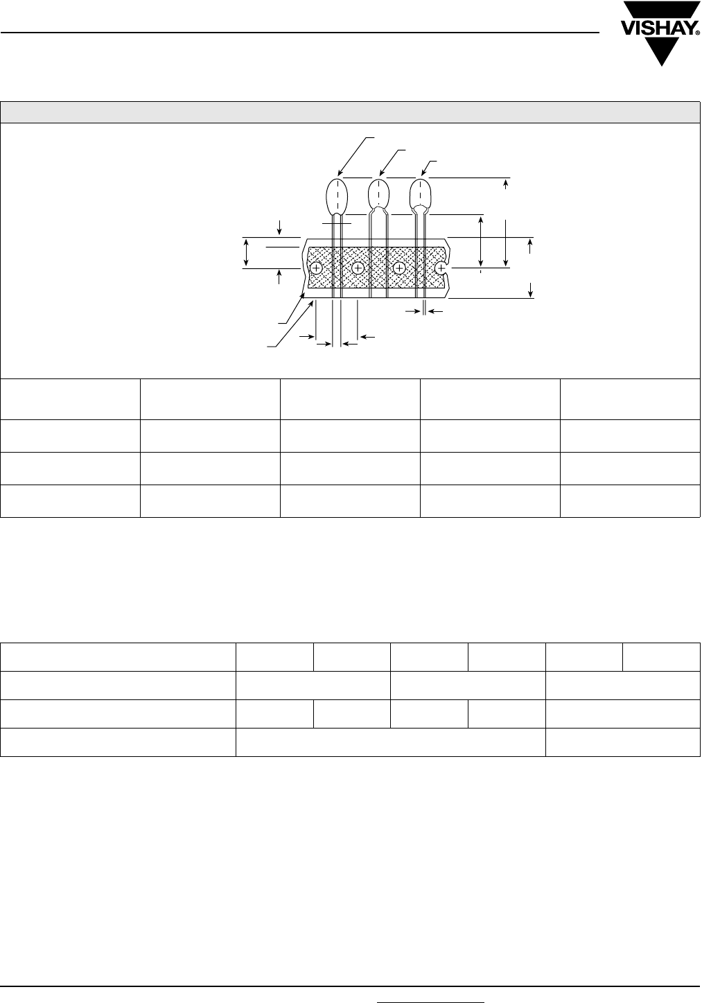
www.vishay.com For technical questions, contact: tantalum@vishay.com Document Number: 40020
116 Revision: 18-Mar-08
199D
Vishay Sprague Solid-Electrolyte TANTALEX® Capacitors,
Resin-Coated, Radial-Lead
Note:
• Lead space measured within 0.05 [1.27] of the body of the capacitor, or from the bottom of the crimp. Lead Style ‘A’ may be supplied with
0.59 [15] anode lead and 0.47 [12] cathode lead.
Tape and Reel Packaging: Type 199D radial-leaded tantalum capacitors, all lead styles exept 1, 3 and Y are available taped
and reeled per EIA-468.
STANDARD REEL PACKAGING SPECIFICATIONS PER EIA RS-468 in inches [millimeters]
CASE CODE OBSOLETE LEAD STYLE LEAD SPACING LL MIN.
(BULK)
A, B, C, D A1, A6 1V1 (Bulk),
2B1 (T and R)
0.100 + 0.024 - 0.016
[2.54 + 0.60 - 0.40] 0.187 [4.7]
A, B, C, D B1, B6 XV1 (Bulk),
XB1 (T and R)
0.100 + 0.024 - 0.016
[2.54 + 0.60 - 0.40] 0.187 [4.7]
A, B, C,
D, E, F E2, E7 6V1 (Bulk),
6B1 (T and R)
0.200 + 0.024 - 0.016
[5.08 + 0.06 - 0.40] 0.187 [4.7]
0.118 [3.0]
MAX.
0.0354 + 0.030 - 0.020
[8.99 + 0.762 - 0.508]
0.500
±
0.012
[12.70 ± 0.305]
0.728 ± 0.020
[18.49 ± 0.508]
LEAD CONFIGURATION 2, 4, 5
1.270 [32.26]
MAX.
CARRIER TAPE
ADHESIVE TAPE
SEE LEAD STYLE/SPACING
TABLE FOR LEAD SPACING
0.630 ± 0.020
[16.0 ± 0.508]
LEAD CONFIGURATION 6.7
LEAD DIAMETER
LEAD CONFIGURATION X, Z
CASE CODE A B C D E F
Quantity per box bulk 1000 500 100
Quantity per box ammopack 2500 2000 1500 1000 500
Quantity per reel 1000 500
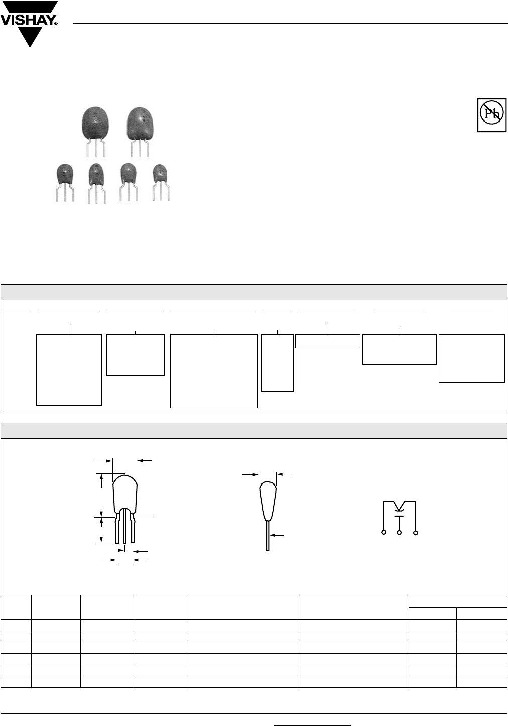
299D
Vishay Sprague
Document Number: 40044 For technical questions, contact: tantalum@vishay.com www.vishay.com
Revision: 15-May-06 117
Solid-Electrolyte TANTALEX® Capacitors,
Tripole Triple-Lead, Resin-Coated
FEATURES
Terminations: Tin/lead (SnPb), 100 % Tin (Sn)
•Easy Installation, economical, high performance
•Triple-Lead design allows reverse installations
•6 Miniature Case Codes available
•EIA Standard Case Sizes
PERFORMANCE CHARACTERISTICS
Operating Temperature: - 55 °C to + 85 °C
(to + 125 °C with voltage derating)
Capacitance Range: 0.10 µF to 680 µF
Capacitance Tolerance: ± 20 %, ± 10 % standard
± 5 % available as special
Voltage Rating: 3 WVDC to 50 WVDC
* Pb containing terminations are not RoHS compliant, exemptions may apply
ORDERING INFORMATION
299D 227 X 003 A B 1 E3
MODEL CAPACITANCE CAPACITANCE
TOLERANCE
DC VOLTAGE RATING
AT + 85 °C
CASE
CODE
LEAD STYLE PACKAGING ROHS
COMPLIANT
This is expressed
in picofarads. The
first two digits are
the significant
figures. The third
is the number of
zeros to follow.
X0 = ± 20 %
X9 = ± 10 %
*X5 = ± 5 %
*special order
Expressed in volts.
To complete the 3-digit
block, zeros precede
the voltage rating.
A decimal point is
indicated by an “R”
(6R3 = 6.3 V).
See
Ratings
and
Case
Codes
Ta b l e
B = Hockey Stick 1 = Bulk
6 = Tape and Reel
13" [330 mm] Reel
E3 = 100 %
tin termination
(RoHS compliant)
Blank = SnPb
termination
DIMENSIONS in inches [millimeters]
CASE W (MAX.) T (MAX.) H (MAX.) L S LEAD SIZE
AWG NO. NOM. DIA.
A 0.280 [7.1] 0 .190 [4.82] 0.360 [9.14] 0.187 ± 0.032 [4.75 ± 0.82] 0.100 ± 0.015 [2.54 ± 0.38] 24 0.020 [0.51]
B 0.280 [7.1] 0.200 [5.08] 0.360 [9.14] 0.187 ± 0.032 [4.75 ± 0.82] 0.100 ± 0.015 [2.54 ± 0.38] 24 0.020 [0.51]
C 0.280 [7.1] 0 .230 [5.84] 0.380 [9.65] 0.187 ± 0.032 [4.75 ± 0.82] 0.100 ± 0.015 [2.54 ± 0.38] 24 0.020 [0.51]
D 0.280 [7.1] 0 .270 [6.85] 0.440 [11.17] 0.187 ± 0.032 [4.75 ± 0.82] 0.100 ± 0.015 [2.54 ± 0.38] 24 0.020 [0.51]
E 0.340 [8.63] 0 .340 [8.63] 0.560 [14.22] 0.187 ± 0.032 [4.75 ± 0.82] 0.100 ± 0.015 [2.54 ± 0.38] 24 0.020 [0.51]
F 0.360 [9.14] 0 .360 [9.14] 0.620 [15.74] 0.187 ± 0.032 [4.75 ± 0.82] 0.100 ± 0.015 [2.54 ± 0.38] 24 0.020 [0.51]
W
MAX.
H
MAX.
L
SEATING
PLANE
S
0.200 [5.08]
REF.
TINNED
SOLDERABLE
LEADS
T
MAX.
--
+
Available
Pb-free
RoHS*
COMPLIANT

299D
Vishay Sprague Solid-Electrolyte TANTALEX® Capacitors,
Tripole Triple-Lead, Resin-Coated
www.vishay.com For technical questions, contact: tantalum@vishay.com Document Number: 40044
118 Revision: 15-May-06
STANDARD RATINGS
CAPACITANCE (µF) CASE CODE PART NUMBER (1)
CAP. TOL. ± 20 %, ± 10 %
Max. DCL
at + 25 °C
(µA)
Max. DF
at + 25 °C
120 Hz (%)
3 WVDC AT + 85 °C, SURGE = 3.6 V . . . 2 WVDC AT + 125 °C, SURGE = 2.4 V
4.7 A 299D475X_003AB_ 0.5 6
6.8 A 299D685X_003AB_ 0.5 6
10.0 A 299D106X_003AB_ 0.5 8
15.0 A 299D156X_003AB_ 0.5 8
22.0 B 299D226X_003BB_ 0.6 8
33.0 B 299D336X_003BB_ 1.0 8
47.0 C 299D476X_003CB_ 1.4 8
68.0 D 299D686X_003DB_ 2.0 8
100.0 D 299D107X_003DB_ 3.0 10
150.0 D 299D157X_003DB_ 4.0 10
220.0 E 299D227X_003EB_ 5.0 10
330.0 E 299D337X_003EB_ 6.0 10
470.0 F 299D477X_003FB_ 8.0 10
680.0 F 299D687X_003FB_ 10.0 10
6.3 WVDC AT + 85 °C, SURGE = 8 V . . . 4 WVDC AT + 125 °C, SURGE = 5.0 V
3.3 A 299D335X_6R3AB_ 0.5 6
4.7 A 299D475X_6R3AB_ 0.5 6
6.8 A 299D685X_6R3AB_ 0.5 6
10.0 B 299D106X_6R3BB_ 0.6 8
15.0 B 299D156X_6R3BB_ 0.9 8
22.0 C 299D226X_6R3CB_ 1.3 8
33.0 C 299D336X_6R3CB_ 2.0 8
47.0 D 299D476X_6R3DB_ 2.9 8
68.0 D 299D686X_6R3DB_ 4.0 8
100.0 D 299D107X_6R3DB_ 5.0 10
150.0 E 299D157X_6R3EB_ 6.0 10
220.0 F 299D227X_6R3FB_ 7.0 10
330.0 F 299D337X_6R3FB_ 8.0 10
10 WVDC AT + 85 °C, SURGE = 13 V . . . 7 WVDC AT + 125 °C, SURGE = 9.0 V
2.2 A 299D225X_010AB_ 0.5 6
3.3 A 299D335X_010AB_ 0.5 6
4.7 A 299D475X_010AB_ 0.5 6
6.8 B 299D685X_010BB_ 0.6 6
10.0 B 299D106X_010BB_ 1.0 8
15.0 C 299D156X_010CB_ 1.5 8
22.0 C 299D226X_010CB_ 2.0 8
33.0 D 299D336X_010DB_ 3.0 8
47.0 D 299D476X_010DB_ 4.0 8
68.0 D 299D686X_010DB_ 5.0 8
100.0 E 299D107X_010EB_ 6.0 10
150.0 F 299D157X_010FB_ 7.0 10
220.0 F 299D227X_010FB_ 8.0 10
16 WVDC AT + 85 °C, SURGE = 20 V . . . 10 WVDC AT + 125 °C, SURGE = 12 V
1.5 A 299D155X_016AB_ 0.5 6
2.2 A 299D225X_016AB_ 0.5 6
3.3 A 299D335X_016AB_ 0.5 6
4.7 B 299D475X_016BB_ 0.7 6
6.8 B 299D685X_016BB_ 1.0 6
10.0 C 299D106X_016CB_ 1.5 8
15.0 C 299D156X_016CB_ 2.4 8
22.0 D 299D226X_016DB_ 3.5 8
33.0 D 299D336X_016DB_ 4.0 8
47.0 E 299D476X_016EB_ 5.0 8
68.0 E 299D686X_016EB_ 6.0 8
100.0 F 299D107X_016FB_ 7.0 10
150.0 F 299D157X_016FB_ 8.0 10
Note:
(1) Insert capacitance tolerance code “X5”; for ± 5 % units (special order)

Document Number: 40044 For technical questions, contact: tantalum@vishay.com www.vishay.com
Revision: 15-May-06 119
299D
Solid-Electrolyte TANTALEX® Capacitors,
Tripole Triple-Lead, Resin-Coated
Vishay Sprague
STANDARD RATINGS
CAPACITANCE (µF) CASE CODE PART NUMBER (1)
CAP. TOL. ± 20 %, ± 10 %
Max. DCL
at + 25 °C
(µA)
Max. DF
at + 25 °C
120 Hz (%)
20 WVDC AT + 85 °C, SURGE = 26 V . . . 13 WVDC AT + 125 °C, SURGE = 16 V
1.0 A 299D105X_020AB_ 0.5 4
1.5 A 299D155X_020AB_ 0.5 6
2.2 A 299D225X_020AB_ 0.5 6
3.3 B 299D335X_020BB_ 0.8 6
4.7 B 299D475X_020BB_ 1.0 6
6.8 C 299D685X_020CB_ 1.5 6
10.0 C 299D106X_020CB_ 2.0 8
15.0 D 299D156X_020DB_ 2.5 8
22.0 D 299D226X_020DB_ 3.0 8
33.0 E 299D336X_020EB_ 4.0 8
47.0 E 299D476X_020EB_ 5.0 8
68.0 F 299D686X_020FB_ 6.0 8
100.0 F 299D107X_020FB_ 7.0 10
25 WVDC AT + 85 °C, SURGE = 33 V . . . 17 WVDC AT + 125 °C, SURGE = 21 V
1.0 A 299D105X_025AB_ 0.5 4
1.5 A 299D155X_025AB_ 0.5 6
2.2 A 299D225X_025AB_ 0.5 6
3.3 B 299D335X_025BB_ 0.8 6
4.7 B 299D475X_025BB_ 1.0 6
6.8 C 299D685X_025CB_ 1.5 6
10.0 C 299D106X_025CB_ 2.5 8
15.0 D 299D156X_025DB_ 3.0 8
22.0 D 299D226X_025DB_ 4.0 8
33.0 E 299D336X_025EB_ 5.0 8
47.0 F 299D476X_025FB_ 6.0 8
68.0 F 299D686X_025FB_ 7.0 8
35 WVDC AT + 85 °C, SURGE = 46 V . . . 23 WVDC AT + 125 °C, SURGE = 28 V
0.10 A 299D104X_035AB_ 0.5 4
0.15 A 299D154X_035AB_ 0.5 4
0.22 A 299D224X_035AB_ 0.5 4
0.33 A 299D334X_035AB_ 0.5 4
0.47 A 299D474X_035AB_ 0.5 4
0.68 A 299D684X_035AB_ 0.5 4
1.0 A 299D105X_035AB_ 0.5 4
1.5 A 299D155X_035AB_ 0.5 6
2.2 B 299D225X_035BB_ 0.7 6
3.3 B 299D335X_035BB_ 1.0 6
4.7 C 299D475X_035CB_ 1.5 6
6.8 D 299D685X_035DB_ 2.2 6
10.0 D 299D106X_035DB_ 3.5 8
15.0 E 299D156X_035EB_ 4.0 8
22.0 E 299D226X_035EB_ 5.0 8
33.0 F 299D336X_035FB_ 6.0 8
47.0 F 299D476X_035FB_ 7.0 8
50 WVDC AT + 85 °C, SURGE = 65 V . . . 33 WVDC AT + 125 °C, SURGE = 40 V
0.10 A 299D104X_050AB_ 0.5 4
0.15 A 299D154X_050AB_ 0.5 4
0.22 A 299D224X_050AB_ 0.5 4
0.33 A 299D334X_050AB_ 0.5 4
0.47 A 299D474X_050AB_ 0.5 4
0.68 A 299D684X_050AB_ 0.5 4
1.0 B 299D105X_050BB_ 0.5 4
1.5 C 299D155X_050CB_ 0.7 6
2.2 C 299D225X_050CB_ 1.1 6
3.3 D 299D335X_050DB_ 1.5 6
4.7 D 299D475X_050DB_ 2.0 6
6.8 F 299D685X_050FB_ 3.0 6
10.0 F 299D106X_050FB_ 4.0 8
15.0 F 299D156X_050FB_ 5.0 8
22.0 F 299D226X_050EB_ 6.0 8
Note:
(1) Insert capacitance tolerance code "X5"; for ± 5 % units (special order)
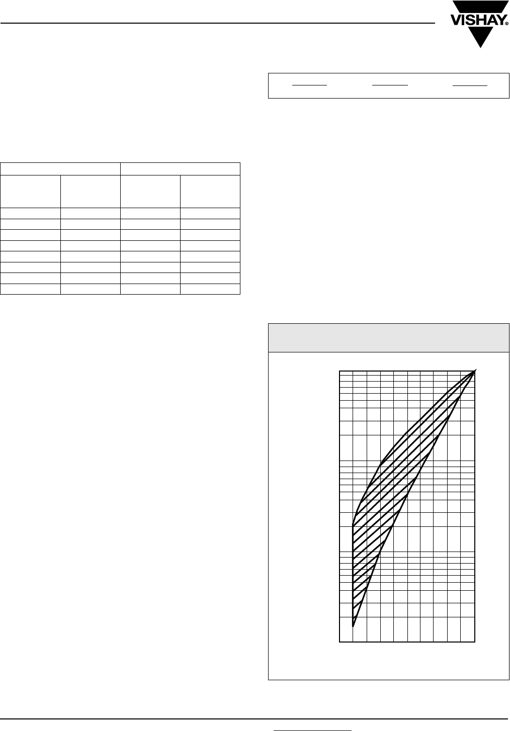
299D
Vishay Sprague Solid-Electrolyte TANTALEX® Capacitors,
Tripole Triple-Lead, Resin-Coated
www.vishay.com For technical questions, contact: tantalum@vishay.com Document Number: 40044
120 Revision: 15-May-06
PERFORMANCE CHARACTERISTICS
1. Operating Temperature: Capacitors are designed to
operate over the temperature range of - 55 °C to
+ 85 °C
1.1 Capacitors may be operated to + 125 °C with voltage
derating to two-thirds the + 85 °C rating.
2. DC Working Voltage: The DC working voltage is the
maximum operating voltage for continuous duty at the
rated temperature.
3. Surge Voltage: The surge DC rating is the maximum
voltage to which the capacitors may be subjected
under any conditions, including transients and peak
ripple at the highest line voltage.
3.1 Surge Voltage Test: Capacitors shall withstand the
surge voltage applied in series with a 33 Ω ± 5 %
resistor at the rate of o1.5 min on, 1.5 minute off, at
+ 85 °C, for 1000 successive test cycles.
3.2 Following the surge voltage test, the dissipation factor
and the leakage current shall meet the initial
requirements; the capacitance shall not have changed
more than ± 5 %.
4. Capacitance Tolerance: The capacitance of all
capacitors shall be within the specified tolerance limits
of the nominal rating.
4.1 Capacitance measurements shall be made by means
of polarized capacitance bridge. The polarizing
voltage shall be of such magnitude that there shall be
no reversal of polarity due to the AC component. The
maximum voltage applied to capacitors during
measurement shall be 2 Vrms at 120 Hz at + 25 °C. If
the AC voltage applied is less than one-half volt rms,
no DC bias is required. Measurement accuracy of the
bridge shall be within ± 2 %.
5. Capacitance Change With Temperature: The
capacitance change with temperature shall not
exceed the following percentage of the capacitance
measured at + 25 % at:
6. Dissipation Factor: The dissipation factor,
determined from the expression 2πfRC, shall not
exceed values listed in the Standard Ratings Table.
6.1 Measurements shall be made by the bridge method at,
or referred to, a frequency of 120 Hz and a
temperature of + 25 °C.
7. Leakage Current: Capacitors shall be stabilized at
the rated temperature for 30 min. Rated voltage shall
be applied to capacitors for 5 minutes using a steady
source of power (such as a regulated power supply)
with 1000 Ω resistor connected in series with the
capacitor under test to limit the charging current.
Leakage current shall then be measured.
Note that the leakage current varies with temperature and applied
voltage. See graph below for the appropriate adjustment factor.
+ 85 °C RATING + 125 °C RATING
WORKING
VOLTAGE
(V)
SURGE
VOLTAGE
(V)
WORKING
VOLTAGE
(V)
SURGE
VOLTAGE
(V)
33.62.02.4
6.3 8.0 4.0 5.0
10 13 7.0 9.0
16 20 10 12
20 26 13 16
25 33 17 21
35 46 23 28
50 65 33 40
- 55 °C + 85 °C + 125 °C
- 10 % + 10 % + 12 %
LEAKAGE AS A FUNCTION OF VOLTAGE
AND TEMPERATURE
1.0
0.8
0.7
0.6
0.5
0.4
0.3
0.2
0.1
0.08
0.07
0.06
0.05
0.04
0.03
0.02
0.01
0.008
0.007
0.006
0.005
0.004
0.003
0.002
0.001
LEAKAGE CURRENT FACTOR
0
10 3020 9040 50 60 70 80 100
PERCENT OF RATED VOLTAGE
Document Number: 40044 For technical questions, contact: tantalum@vishay.com www.vishay.com
Revision: 15-May-06 121
299D
Solid-Electrolyte TANTALEX® Capacitors,
Tripole Triple-Lead, Resin-Coated
Vishay Sprague
PERFORMANCE CHARACTERISTICS
(Continued)
7.1 At + 25 °C, the leakage current shall not exceed the
value listed in the Standard Ratings Table.
7.2 At + 85 °C, the leakage current shall not exceed
10 times the value listed in the Standard Ratings
Table.
7.3 At + 125 °C, the leakage current shall not exceed
15 times the value listed in the Standard Ratings
Table.
8. Life Test: Capacitors shall withstand rated DC
voltage applied at + 85 °C for 1000 hours, with a
circuit resistance no greater than 3 Ω.
8.1 Following the life test, the dissipation factor shall
meet the initial requirement; the capacitance change
shall not exceed - 10 % to + 10 %; the leakage current
shall not exceed 125 % of the initial requirement.
9. Lead Strength:
9.1 Capacitors shall withstand a force of 2 pounds (9N)
applied axially to the leads for 10 seconds, without
failure.
9.2 Capacitor leads shall withstand 2 bends through 90°
at the point of egress from the case, without failure.
9.3 No stress shall be applied to the capacitor case
during the preceding tests.
10. Flammability: Encapsulant materials meet UL94 VO
with an oxygen index of 32 %.
11. Capacitor Failure Mode: The predominant failure
mode for solid tantalum capacitors is increased
leakage current resulting in a shorted circuit.
Capacitor failure may result from excess forward or
reverse DC voltage, surge current, ripple current,
thermal shock or excessive temperature. The
increase in leakage is caused by a breakdown of the
Ta2O5 dielectric. For additional information on
leakage failure of solid tantalum chip capacitors, refer
to Vishay Sprague Technical Paper, “Leakage Failure
Mode in Solid Tantalum Chip Capacitors.”
12. Humidity Test: Capacitors shall withstand 1000
hours at + 55 °C, 90 % to 95 % relative humidity, with
no voltage applied.
12.1 Following the humidity test, capacitance change shall
not exceed - 10 % to + 10 % of the initial value,
dissipation factor shall not exceed 150 % of the initial
requirement; leakage current shall not exceed 200 %
of the initial requirement.
Guide To Application
1. A-C Ripple Current: The maximum allowable ripple
current shall be determined from the formula:
where,
P = Power Dissipation in Watts at + 25 °C as
given in the table in Paragraph Number 6
(Power Dissipation)
RESR = The capacitor Equivalent Series
Resistance at the specified frequency.
2. A-C Ripple Voltage: The maximum allowable ripple
voltage shall be determined from the formula:
or, from the formula:
where,
P = Power Dissipation in Watts at + 25 °C as given in
the table in Paragraph Number 6 (Power Dissipation).
RESR = The capacitor Equivalent Series
Resistance at the specified frequency.
Z = The capacitor Impedance at the specified
frequency.
2.1 The sum of the peak AC voltage plus the DC voltage
shall not exceed the DC voltage rating of the
capacitor.
2.2 The sum of the negative peak AC voltage plus the
applied DC voltage shall not allow a voltage reversal
exceeding 10 % of the DC working voltage at + 25 °C.
2.3 Temperature Derating: If these capacitors are to be
operated at temperatures above + 25 °C, the
permissible rms ripple current or voltage shall be
calculated using the derating factors as shown:
3. Reverse Voltage: These capacitors are capable of
withstanding peak voltages in the reverse direction
equal to 10 % of the DC rating at + 25 °C, 5 % of the
DC rating at + 85 °C and 1 % of the DC rating at
+ 105 °C
TEMPERATURE DERATING FACTOR
+ 25 °C 1.0
+ 55 °C 0.8
+ 85 °C 0.6
+ 125 °C 0.4
Irms
P
RESR
----------------=
Vrms Z* P
RESR
----------------=
Vrms Irms Z×=
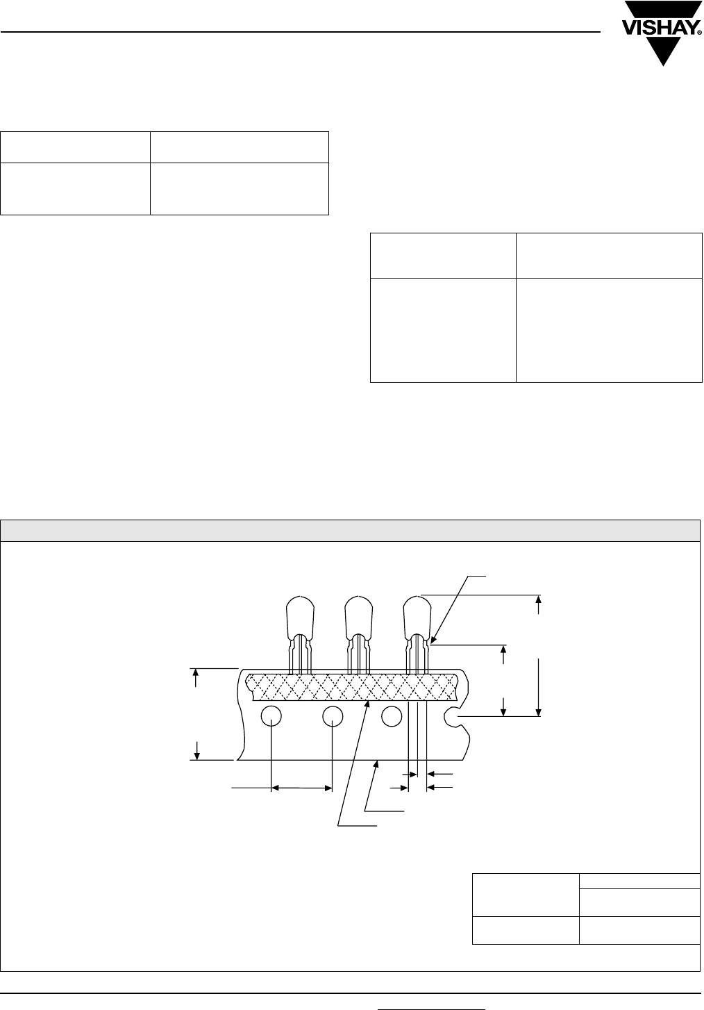
299D
Vishay Sprague Solid-Electrolyte TANTALEX® Capacitors,
Tripole Triple-Lead, Resin-Coated
www.vishay.com For technical questions, contact: tantalum@vishay.com Document Number: 40044
122 Revision: 15-May-06
4. Recommended rated working voltage guidelines:
5. Solvent Resistance: Type 299D capacitors are
conformally coated with thermosetting resin.
Markings are either laser imprinted or are a heat
cured black epoxy ink conforming to EIA Standard
RS-327A. Marked units are compatible with Class 1
(Alcohols), Class 2 (Aromatic Hydrocarbons), Class 3
(Mineral Spirits), Class 4 (Chlorinated Hydrocarbons)
and Class 5 (Fluorocarbon Methylene Chloride
Azeotropes) solvents.
6. Wave Soldering Compatibility: Capacitor leads
may be subjected to immersion in molten solder at
+ 260 °C, to a distance of not less than 0.1" [2.54]
from the capacitor body, for up to 10 seconds. The
physical integrity of the capacitor shall not be
impaired and the leakage current, dissipation factor
and capacitance shall remain within the initial
requirements after such exposure.
7. Power Dissipation: Power dissipation will be
affected by the heat sinking capability of the mounting
surface. Non-sinusoidal ripple current may produce
heating effects which differ from those shown. It is
important that the equivalent Irms value be
established when calculating permissible operating
levels. (Power Dissipation calculated using + 25 °C
temperature rise).
APPLICATION VOLTAGE
(V)
RECOMMENDED CAPACITOR
VOLTAGE RATING (V)
2.5 4.0
4.0 6.3
6.0 10.0
CASE CODE
MAXIMUM PERMISSIBLE POWER
DISSIPATION AT
+ 25 °C (W) IN FREE AIR
A 0.140
B 0.160
C 0.180
D 0.210
E 0.240
F 0.270
TAPE AND REEL PACKAGING in inches [millimeters]
Tape and Reel Specifications: Type 299D radial-leaded
tantalum capacitors are available taped and reeled per EIA-468.
Quantity of components per reel as follows:
CASE CODE
UNITS PER REEL
Requirements for non-standard configurations may be
submitted to a Vishay Sales Office or representative for evaluation.
13" [330]
REEL (MAX.)
A, B, C, D
E, F
1000
500
+++ +
0.020 ± 0.002
[0.508 ± 0.051]
LEAD DIA. TYP.
0.500 ± 0.012
[12.70 ± 0.305]
ADHESIVE TAPE
0.728 ± 0.020
[18.49 ± 0.508]
CARRIER TAPE
0.630 ± 0.020
[16.0 ± 0.508
0.100 [2.54] TYP.
0.200 [5.08] TYP.
1.270 [32.26]
MAX.
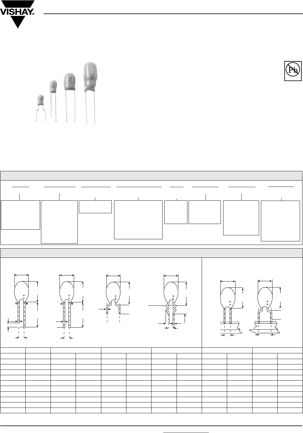
Document Number: 42070 For technical questions, contact: eurotant@vishay.com www.vishay.com
Revision: 12-Jun-06 123
489D, 499D
Vishay Sprague
Resin-Coated, Radial-Lead
Solid Tantalum Capacitors
FEATURES
•Terminations: standard SnPb, 100 % Tin available
•Large capacitance range
•Encapsulated in a hard orange epoxy resin
•Large variety of lead styles available
•Supplied on tape and reel or ammopack
•Low impedance and ESR at high frequencies
ELECTRICAL CHARACTERISTICS
Operating Temperature: - 55 °C to + 85 °C: Type 489D
- 55 °C to + 125 °C: Type 499D
APPLICATIONS
•Offer a very cost effective solution in the consumer,
industrial and professional electronics markets. The
capacitors are intended for high volume applications.
* Pb containing terminations are not RoHS compliant, exemptions may apply
Available
Pb-free
RoHS*
COMPLIANT
ORDERING INFORMATION
489D 686 X0 6R3 D 2 A E3
TYPE CAPACITANCE CAPACITANCE
TO L E R A N CE
DC VOLTAGE RATING
AT + 85 °C
CASE
CODE
LEAD STYLE PACKAGING RoHS
COMPLIANT
489D
Standard + 85 °C
499D
Standard + 125 °C
Low IL
Expressed in
picofarads. The
first two digits are
the significant
figures. The third
is the number of
zeros following.
X0 = ± 20 %
X9 = ± 10 %
Expressed by zeros if
needed to complete
the 3 digit block. A
decimal point is
indicated by an “R”
(6R3 = 6.3 V).
See Table
Ratings
and Case
Codes
1, 2, 3, 4, 6, 9
See
description on
next page
A = Ammopack
B = Reel pack,
positive leader
C = Reel pack,
negative leader
V = Bulk Pack
E3 = 100 % tin
termination
(RoHS compliant
design)
Blank = SnPb
termination
(standard design)
LEAD STYLE CONFIGURATIONS AND DIMENSIONS (MAX) in millimeters
LEAD STYLES 1-2-3-4 STYLE 6 STYLE 9 STYLES 2-4 STYLE 6
CASE D P H P H1 P H2 P H3 P H4
A 3.7 2.5 7.0 5 11.0 5 10.0 2.5 7.0 5 11.0
B 4.0 2.5 7.5 5 11.5 5 10.5 2.5 7.5 5 11.5
C 4.5 2.5 8.0 5 12.0 5 11.0 2.5 8.0 5 12.0
D 5.0 2.5 9.0 5 13.0 5 12.0 2.5 9.0 5 13.0
E 5.5 2.5 10.0 5 14.0 5 13.0 2.5 10.0 5 14.0
F 6.0 2.5 11.0 5 15.0 5 14.0 2.5 11.0 5 15.0
H 6.5 2.5 12.0 5 16.0 5 15.0 2.5 12.0 5 16.0
M 10.0 5.0 14.5 - - 5 18.0 5.0 14.5 - -
N 11.0 5.0 16.0 - - 5 19.0 - - - -
R 12.0 5.0 19.0 - - 5 22.0 - - - -
D MAX.
0.5¯
3
H
Max.
15 Min.
20 Max.
D MAX.
H2
MAX.
Upper edge
of Printed
Circuit Board
0.5¯
D MAX.
H1
MAX.
0.5¯
15 Min.
20 Max.
H
MAX.
D MAX.
P
0.5¯
1 and 3 2 and 4 6 9
P ± 0.5 P ± 0.5
P ± 0.5
P ± 0.5
1.1 ± 0.05
4.5 ± 1.55.5 ± 0.5
D MAX.
H3
MAX.
P ± 0.5
D MAX.
P ± 0.5
H4
MAX.
2 & 4 6
BULK : CODE V REEL/AMMO : CODE A, B, C
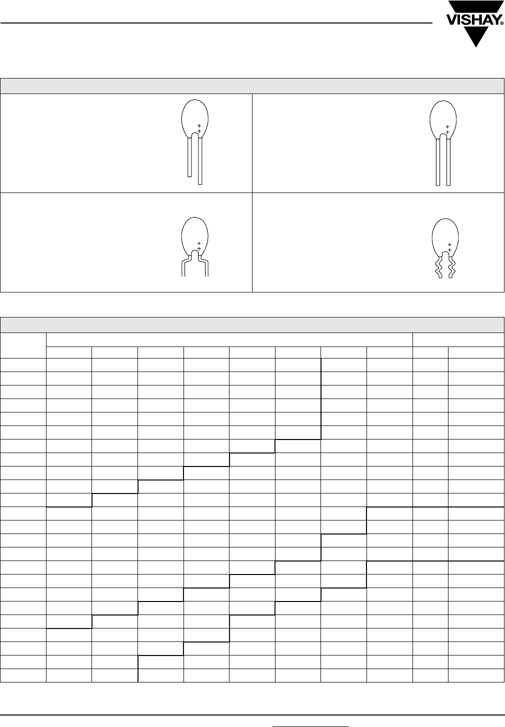
489D, 499D
Vishay Sprague Resin-Coated, Radial-Lead
Solid Tantalum Capacitors
www.vishay.com For technical questions, contact: eurotant@vishay.com Document Number: 42070
124 Revision: 12-Jun-06
LEAD STYLE
STANDARD RATINGS, CASE CODES AND LEAD STYLE
CR
µF
RATED VOLTAGE UR AT + 85 °C LEAD STYLE
3.0 V 6.3 V 10 V 16 V 20 V 25 V 35 V 50 V BULK AMMO/REEL
0.10 A A
0.15 A A
0.22 A A
0.33 A B
0.47 A B 1 - 2
0.68 B C 6 - 9 2 - 6
1.0 A B D
1.5 A B C E
2.2 A B B C F
3.3 A B C C D F
4.7 A A B C C D H
6.8 A A B C D D E N
10 B B B C D D F N 3 - 4 - 9 4
15 B B C D E E M N
22 C C C D F H M N
33 C C D E H M N
47 D D D F M M N
68 D D E M N N
100 E E M N N
150 H M M N
220 M M N R
330 N N R
470 N R
680 R R
LEAD STYLE 1:
Straight leads,
2.5 mm Lead Space,
Uneven Length
LEAD STYLE 3:
Straight leads,
5 mm Lead Space,
Uneven Length
LEAD STYLE 2:
Straight leads,
2.5 mm Lead Space,
Even Length
LEAD STYLE 4:
Straight leads,
5 mm Lead Space,
Even Length
LEAD STYLE 6:
Shouldered leads,
5 mm Lead Space
LEAD STYLE 9:
Snap-In leads,
5 mm Lead Space
Document Number: 42070 For technical questions, contact: eurotant@vishay.com www.vishay.com
Revision: 12-Jun-06 125
489D, 499D
Resin-Coated, Radial-Lead
Solid Tantalum Capacitors Vishay Sprague
STANDARD RATINGS
CR (µF) CASE CODE TYPE
PART NUMBER
489D
MAX. DCL
AT + 25 °C
(µA)
499D
MAX. DCL
AT + 25 °C
(µA)
489D, 499D
MAX. DF, 100 Hz
AT + 25 °C
(%)
UR = 3 V AT + 85 °C, SURGE = 4 V . . . UC = 2 V AT + 125 °C, SURGE = 2.6 V (ONLY 499D)
6.8 A 489D685X(*)003A_ _ 1.0 0.5 6
10.0 B 489D106X(*)003B_ _ 1.0 0.5 8
15.0 B 489D156X(*)003B_ _ 1.0 0.5 8
22.0 C 489D226X(*)003C_ _ 1.0 0.5 8
33.0 C 489D336X(*)003C_ _ 1.4 0.7 8
47.0 D 489D476X(*)003D_ _ 2.1 1.1 8
68.0 D 489D686X(*)003D_ _ 3.0 1.6 8
100.0 E 489D107X(*)003E_ _ 4.5 2.4 10
150.0 H 489D157X(*)003H_ _ 6.7 3.6 10
220.0 M 489D227X(*)003M_ _ 9.9 5.2 10
330.0 N 489D337X(*)003N_ _ 14.8 7.9 10
470.0 N 489D477X(*)003N_ _ 21.1 11.2 12
680.0 R 489D687X(*)003R_ _ 30.6 16.3 12
UR = 6.3 V AT + 85 °C, SURGE = 8 V . . . UC = 4 V AT + 125 °C, SURGE = 5.2 V (ONLY 499D)
4.7 A 489D475X(*)6R3A_ _ 1.0 0.5 6
6.8 A 489D685X(*)6R3A_ _ 1.0 0.5 6
10.0 B 489D106X(*)6R3B_ _ 1.0 0.5 8
15.0 B 489D156X(*)6R3B_ _ 1.4 0.7 8
22.0 C 489D226X(*)6R3C_ _ 2.0 1.1 8
33.0 C 489D336X(*)6R3C_ _ 3.1 1.6 8
47.0 D 489D476X(*)6R3D_ _ 4.4 2.3 8
68.0 D 489D686X(*)6R3D_ _ 6.4 3.4 8
100.0 E 489D107X(*)6R3E_ _ 9.4 5.0 10
150.0 M 489D157X(*)6R3M_ _ 14.1 7.5 10
220.0 M 489D227X(*)6R3M_ _ 20.7 11.0 10
330.0 N 489D337X(*)6R3N_ _ 31.1 16.6 10
470.0 R 489D477X(*)6R3R_ _ 44.4 23.6 12
680.0 R 489D687X(*)6R3R_ _ 64.2 34.2 12
UR = 10 V AT + 85 °C, SURGE = 13 V . . . UC = 7 V AT + 125 °C, SURGE = 8.6 V (ONLY 499D)
3.3 A 489D335X(*)010A_ _ 1.0 0.5 6
4.7 A 489D475X(*)010A_ _ 1.0 0.5 6
6.8 B 489D685X(*)010B_ _ 1.0 0.5 6
10.0 B 489D106X(*)010B_ _ 1.5 0.8 8
15.0 C 489D156X(*)010C_ _ 2.2 1.2 8
22.0 C 489D226X(*)010C_ _ 3.3 1.7 8
33.0 D 489D336X(*)010D_ _ 4.9 2.6 8
47.0 D 489D476X(*)010D_ _ 7.0 3.7 8
68.0 E 489D686X(*)010E_ _ 10.2 5.4 8
100.0 M 489D107X(*)010M_ _ 15.0 8.0 10
150.0 M 489D157X(*)010M_ _ 22.5 12.0 10
220.0 N 489D227X(*)010N_ _ 33.0 17.6 10
330.0 R 489D337X(*)010R_ _ 49.5 26.4 10
Note:
489D Type part number 489D, 499D
(*) Insert 0 for ± 20 % tolerance or 9 for ± 10 %
_ _ Case code/lead style see case code table
PACKAGING QUANTITIES
CASE CODE ABCDEFHMNR
BULK 500 100
AMMOPACK 2500 2000 1500 500
REEL PACK 2500 2000 1500 500

489D, 499D
Vishay Sprague Resin-Coated, Radial-Lead
Solid Tantalum Capacitors
www.vishay.com For technical questions, contact: eurotant@vishay.com Document Number: 42070
126 Revision: 12-Jun-06
STANDARD RATINGS
CR (µF) CASE CODE TYPE
PART NUMBER
489D
MAX. DCL
AT + 25 °C
(µA)
499D
MAX. DCL
AT + 25 °C
(µA)
489D, 499D
MAX. DF, 100 Hz
AT + 25 °C
(%)
UR = 16 V AT + 85 °C, SURGE = 20 V . . . UC = 10 V AT + 125 °C, SURGE = 13 V (ONLY 499D)
2.2 A 489D225X(*)016A_ _ 1.0 0.5 6
3.3 B 489D335X(*)016B_ _ 1.0 0.5 6
4.7 B 489D475X(*)016B_ _ 1.1 0.6 6
6.8 C 489D685X(*)016C_ _ 1.6 0.8 6
10.0 C 489D106X(*)016C_ _ 2.4 1.2 8
15.0 D 489D156X(*)016D_ _ 3.6 1.9 8
22.0 D 489D226X(*)016D_ _ 5.2 2.8 8
33.0 E 489D336X(*)016E_ _ 7.9 4.2 8
47.0 F 489D476X(*)016F_ _ 11.2 6.0 8
68.0 M 489D686X(*)016M_ _ 16.3 8.7 8
100.0 N 489D107X(*)016N_ _ 24.0 12.8 10
150.0 N 489D157X(*)016N_ _ 36.0 19.2 10
220.0 R 489D227X(*)016R_ _ 52.8 28.1 10
UR = 20 V AT + 85 °C, SURGE = 26 V . . . UC = 13 V AT + 125 °C, SURGE = 16 V (ONLY 499D)
1.5 A 489D155X(*)020A_ _ 1.0 0.5 4
2.2 B 489D225X(*)020B_ _ 1.0 0.5 6
3.3 C 489D335X(*)020C_ _ 1.0 0.5 6
4.7 C 489D475X(*)020C_ _ 1.4 0.7 6
6.8 D 489D685X(*)020D_ _ 2.0 1.0 6
10.0 D 489D106X(*)020D_ _ 3.0 1.6 8
15.0 E 489D156X(*)020E_ _ 4.5 2.4 8
22.0 F 489D226X(*)020F_ _ 6.6 3.5 8
33.0 H 489D336X(*)020H_ _ 9.9 5.2 8
47.0 M 489D476X(*)020M_ _ 14.1 7.5 8
68.0 N 489D686X(*)020N_ _ 20.4 10.8 8
100.0 N 489D107X(*)020N_ _ 30.0 16.0 10
UR = 25 V AT + 85 °C, SURGE = 32 V . . . UC = 17 V AT + 125 °C, SURGE = 21 V (ONLY 499D)
1.0 A 489D105X(*)025A_ _ 1.0 0.5 4
1.5 B 489D155X(*)025B_ _ 1.0 0.5 4
2.2 B 489D225X(*)025B_ _ 1.0 0.5 6
3.3 C 489D335X(*)025C_ _ 1.2 0.6 6
4.7 C 489D475X(*)025C_ _ 1.7 0.9 6
6.8 D 489D685X(*)025D_ _ 2.5 1.3 6
10.0 D 489D106X(*)025D_ _ 3.7 2.0 8
15.0 E 489D156X(*)025E_ _ 5.6 3.0 8
22.0 H 489D226X(*)025H_ _ 8.2 4.4 8
33.0 M 489D336X(*)025M_ _ 12.3 6.6 8
47.0 M 489D476X(*)025M_ _ 17.6 9.4 8
68.0 N 489D686X(*)025N_ _ 25.5 13.6 8
Note:
489D Type part number 489D, 499D
(*) Insert 0 for ± 20 % tolerance or 9 for ± 10 %
_ _ Case code/lead style see case code table

Document Number: 42070 For technical questions, contact: eurotant@vishay.com www.vishay.com
Revision: 12-Jun-06 127
489D, 499D
Resin-Coated, Radial-Lead
Solid Tantalum Capacitors Vishay Sprague
STANDARD RATINGS
CR (µF) CASE CODE TYPE
PART NUMBER
489D
MAX. DCL
AT + 25 °C
(µA)
499D
MAX. DCL
AT + 25 °C
(µA)
489D, 499D
MAX. DF, 100 Hz
AT + 25 °C
(%)
UR = 35 V AT + 85 °C, SURGE = 46 V . . . UC= 23 V AT + 125 °C, SURGE = 28 V (ONLY 499D)
0.10 A 489D104X(*)035A_ _ 1.0 0.5 4
0.15 A 489D154X(*)035A_ _ 1.0 0.5 4
0.22 A 489D224X(*)035A_ _ 1.0 0.5 4
0.33 A 489D334X(*)035A_ _ 1.0 0.5 4
0.47 A 489D474X(*)035A_ _ 1.0 0.5 4
0.68 B 489D684X(*)035B_ _ 1.0 0.5 4
1.0 B 489D105X(*)035B_ _ 1.0 0.5 4
1.5 C 489D155X(*)035C_ _ 1.0 0.5 4
2.2 C 489D225X(*)035C_ _ 1.1 0.6 6
3.3 D 489D335X(*)035D_ _ 1.7 0.9 6
4.7 D 489D475X(*)035D_ _ 2.4 1.3 6
6.8 E 489D685X(*)035E_ _ 3.5 1.9 6
10.0 F 489D106X(*)035F_ _ 5.2 2.8 8
15.0 M 489D156X(*)035M_ _ 7.8 4.2 8
22.0 M 489D226X(*)035M_ _ 11.5 6.1 8
33.0 N 489D336X(*)035N_ _ 17.3 9.2 8
47.0 N 489D476X(*)035N_ _ 24.6 13.1 8
UR = 50 V AT + 85 °C, SURGE = 65 V . . . UC = 33 V AT + 125 °C, SURGE = 40 V (ONLY 499D)
0.10 A 489D104X(*)050A_ _ 1.0 0.5 4
0.15 A 489D154X(*)050A_ _ 1.0 0.5 4
0.22 A 489D224X(*)050A_ _ 1.0 0.5 4
0.33 B 489D334X(*)050B_ _ 1.0 0.5 4
0.47 B 489D474X(*)050B_ _ 1.0 0.5 4
0.68 C 489D684X(*)050C_ _ 1.0 0.5 4
1.0 D 489D105X(*)050D_ _ 1.0 0.5 4
1.5 E 489D155X(*)050E_ _ 1.1 0.6 4
2.2 F 489D225X(*)050F_ _ 1.6 0.8 6
3.3 F 489D335X(*)050F_ _ 2.4 1.3 6
4.7 H 489D475X(*)050H_ _ 3.5 1.8 6
6.8 N 489D685X(*)050N_ _ 5.1 2.7 6
10.0 N 489D106X(*)050N_ _ 7.5 4.0 8
15.0 N 489D156X(*)050N_ _ 11.2 6.0 8
22.0 N 489D226X(*)050N_ _ 16.5 8.8 8
Note:
489D Type part number 489D, 499D
(*) Insert 0 for ± 20 % tolerance or 9 for ± 10 %
_ _ Case code/lead style see case code table
489D, 499D
Vishay Sprague Resin-Coated, Radial-Lead
Solid Tantalum Capacitors
www.vishay.com For technical questions, contact: eurotant@vishay.com Document Number: 42070
128 Revision: 12-Jun-06
PERFORMANCE CHARACTERISTICS
1. Operating Temperature: - 55 °C to + 85 °C with
rated DC voltage UR applied. + 85 °C to + 125° C with
linear voltage derating to category voltage UC for
499D only (see general information)
2. Capacitance and Tolerance: Capacitance
measured at 100 Hz and + 25 °C shall be within the
specified tolerance limits of the nominal rating.
Capacitance measurement shall be made by means
of a polarized capacitance bridge. No polarizing
voltage is required. The maximum voltage applied
during measurements shall be 0.5 Vrms at 100 Hz
and + 25 °C.
3. Reverse Voltage: These capacitors are capable of
withstanding peak voltage in the reverse direction
equal to:
15 % of the rated DC voltage at + 20 °C
10 % of the rated DC voltage at + 25 °C
5 % of the rated DC voltage at + 85 °C
4. Surge Voltage:
Capacitors shall withstand the surge voltage applied
in series with a 1000 Ω (± 5 %) resistor, at the rate of
1.5 minute on, 5.5 minute off for 1000 successive test
cycles at + 85 °C. After test, capacitance change shall
not exceed 10 % of initial value, dissipation factor and
DC leakage current shall meet initial requirements at
+ 25 °C - Table 2.
6. Life Test: After 2000 hours at + 85 °C with rated DC
voltage applied, or after 1000 hours at + 125 °C. With
derated DC voltage*, capacitors shall meet the
requirements in table below. (*only for 499D)
7. Humidity Test: After 21 days (504 hours) (1) at
+ 40 °C, 90 to 95 % of relative humidity (per IEC
68-2-3) with no voltage applied, capacitors shall meet
the requirements in table below.
8. Marking: The capacitors shall be marked with the
rated capacitance and the rated DC working voltage.
A code may be used for both capacitance and
voltage. Units rated at 6.3 volts are usually marked as
6 volts. The package shall be marked with full Vishay
Sprague part number, date code and quantity.
5. Stability at low and high temperatures:
489D - Table 2A
DC rated voltage at + 85 °C (V) 3 6.3 10 16 20 25 35 50
DC surge voltage at + 85 °C (V) 4 8 13 20 26 32 46 65
DC rated voltage at + 125 °C (V) (1) 2 4 7 10 13 17 23 33
DC surge voltage at + 125 °C (V) (1) 2.6 5.2 8.6 13 16 21 28 40
Note: (1) for 499D
Capacitance change Within ± 10 % of initial value
DC leakage current Within initial requirements at + 25 °C
Dissipation factor Within initial requirements at + 25 °C
Capacitance change Within ± 5 % of initial value
DC leakage current Within initial requirements at + 25 °C - Table 2
Dissipation factor Within initial requirements at + 25 °C - Table 2
Note: (1) Humidity test is 56 days (1350 hours) for 499D
TEMP. CAPACITANCE CHANGE
DC LEAKAGE CURRENT (1) DISSIPATION FACTOR AT 100 Hz
- 55 °C - 10 % of initial value ----------- CR ≤ 1.5 µF
1.5 µF < CR < 10 µF
10 µF < CR < 100 µF
100 µF ≤ CR ≤ 330 µF
330 µF < CR
4 % max
6 % max
8 % max
10 % max
12 % max
+ 25 °C ------------- 0.015 CR x UR or 1 µA,
whichever is greater
+ 85 °C + 10 % of initial value 0.15 CR x UR or 10 µA,
whichever is greater
TEMP. CAPACITANCE CHANGE
DC LEAKAGE CURRENT (1) DISSIPATION FACTOR AT 100 Hz
- 55 °C - 10 % of initial value ------------- CR ≤ 1.5 µF
1.5 µF < CR < 10 µF
10 µF < CR < 100 µF
100 µF ≤ CR ≤ 330 µF
330 µF < CR
4 % max
6 % max
8 % max
10 % max
12 % max
+ 25 °C ------------ 0.008 CR x UR or 0.5 µA,
whichever is greater
+ 85 °C + 10 % of initial value 0.08 CR x UR or 5 µA, whichever
is greater
+ 125 °C (2) + 10 % of initial value 0.1 CR x UR or 6.25 µA,
whichever is greater
Notes:
(1) Rated voltage applied for 5 minutes with a series resistor of 1000 Ω
(2) Only for 499 D
Document Number: 42070 For technical questions, contact: eurotant@vishay.com www.vishay.com
Revision: 12-Jun-06 129
489D, 499D
Resin-Coated, Radial-Lead
Solid Tantalum Capacitors Vishay Sprague
GUIDE TO APPLICATION
1. A-C Ripple Current: The maximum allowable ripple
current shall be determined from the formula:
where,
P = Power Dissipation in Watts at + 25 °C as
given below
RESR = The capacitor Equivalent Series
Resistance at the specified frequency.
2. A-C Ripple Voltage: The maximum allowable ripple
voltage shall be determined from the formula:
where,
Z = The capacitor Impedance at the specified
frequency.
3. AC ripple current or voltage derating factor: If
these capacitors are to be operated at temperatures
above + 25 °C, the permissible rms ripple current or
voltage shall be calculated using the derating factors
in the table below:
4. Power dissipation: Power dissipation will be
affected by the heat sinking capability of the mounting
surface. Non-sinusoidal ripple current may produce
heating effects which differ from those shown in the
following table. It is important that the equivalent IRMS
value be established when calculating permissible
operating levels.
5. Cleaning: These capacitors are compatible with all
commonly used solvents, such as TES, TMS, Prelete
and Chloretane. Solvents containing methylene
chloride or other epoxy solvents should be avoided
since these will attack the epoxy encapsulation
material.
TEMPERATURE DERATING FACTOR
+ 25 °C 1.0
+ 55 °C 0.9
+ 85 °C 0.8
+ 125 °C 0.4
Irms
P
RESR
----------------=
Vrms
P
RESR
----------------- Z×=
CASE CODE POWER DISSIPATION
AT + 25 °C (W)
A 0.080
B 0.090
C 0.100
D 0.110
E 0.120
F 0.130
H 0.140
M 0.150
N 0.160
R 0.180
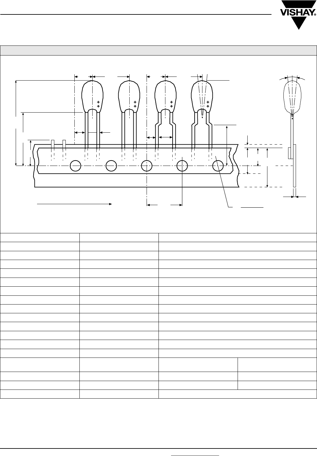
489D, 499D
Vishay Sprague Resin-Coated, Radial-Lead
Solid Tantalum Capacitors
www.vishay.com For technical questions, contact: eurotant@vishay.com Document Number: 42070
130 Revision: 12-Jun-06
TAPE AND REEL PACKAGING in millimeters
DESIGNATION SYMBOL DIMENSIONS (mm)
Pitch of component P 12.7 ± 1.0
Feed hole pitch P0 12.7 ± 0.3
Tape width W 18 (+ 1/- 0.5)
Hold down tape width W0 5.0
Hole position W1 9 (+ 0.75/- 0.5)
Hold down tape position W2 0 (+ 3/- 0)
Overall component height H1 32 max.
Component alignment ΔP ± 1.3 max.
Feed hole diameter D0 4.0 ± 0.3
Tape thickness t 0.5 ± 0.2
Component alignment ΔH 0 ± 2
Lengh of snipped leads L 11 max.
Lead clinch height H0 16.0 ± 0.5
Lead wire spacing F 2.5 5
Feed hole center to wire center P1 5.1 ± 0.7 3.65 ± 0.7
Hole center to component center P2 6.35 ± 1.3 6.35 ± 1.3
Component height H 18 ± 1
Δh
W2
D0
H0
W0
W1W
t
P1
P2
H2
F
PΔP
P2P
P1F
P0
L
H
UNREELING DIRECTION
Dimensions for components on tape and tolerances:
(meets IEC 286-2)
+ 0.6
- 0.1
+ 0.6
- 0.1
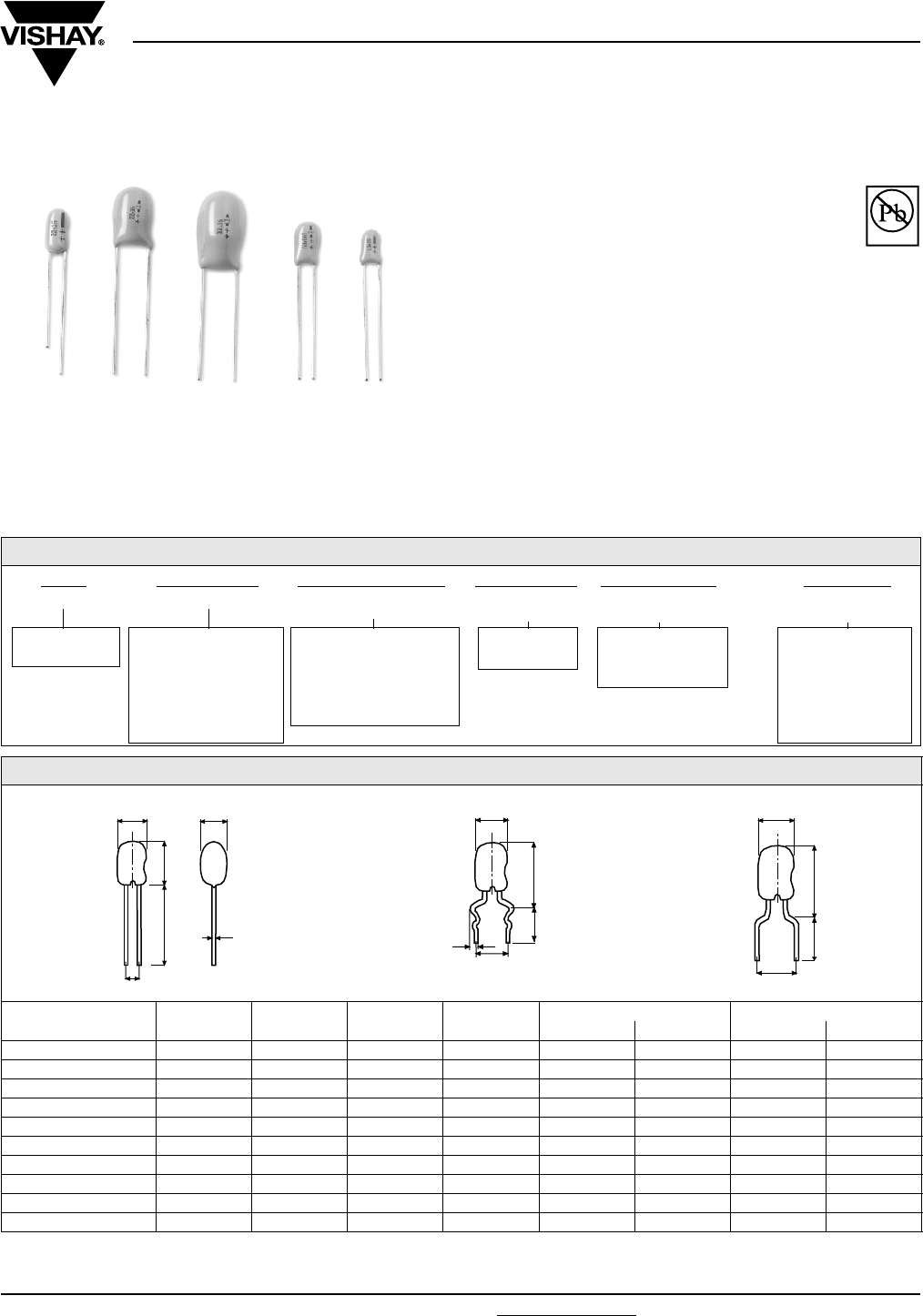
Document Number: 42074 For technical questions, contact: eurotant@vishay.com www.vishay.com
Revision: 12-Jun-06 131
ETPW
Vishay Sprague
Resin-Coated, Radial-Leaded
Solid Tantalum Capacitors
FEATURES
•RoHS Compliant design available
•Flame retardant encapsulation
•Very high temperature range
•Improved humidity class
•Low leakage current
•Very high CV product
•Low failure rate
MECHANICAL SPECIFICATIONS
Color: Gold
Laser Marked: Capacity and voltage in clear text;
Plus pole marked
Leads: Standard (Tin/Lead), RoHS compliant (100 % Tin)
Tantalum capacitors with sintered anode and solid
semiconductor electrolyte with flame retardant fluidized bed
coating. The type ETPW is characterized by very favorable
electrical values even at higher ambient temperatures. The
capacitors comply with DIN 45910 part 146 and they are also
available as a radially taped version.
Available
Pb-free
RoHS*
COMPLIANT
ORDERING INFORMATION
P1A 686 603 M 00 D E3
TYPE CAPACITANCE DC VOLTAGE RATING
AT + 85 °C
CAPACITANCE
TO L E R A N C E
LEAD STYLE AND
PA CK A G I N G
RoHS
COMPLIANT
ETPW 1A ....
ETPW 6R
Expressed in
picofarads. The first
two digits are
significant figures. The
third is the number of
zeros following.
Expressed by zeros if
needed to complete the 3
digit block. A decimal
point is indicated by an
“0“ (603 = 6.3 Volts)
M = ± 20 %
K = ± 10 %
See Lead styles
and packaging
table
E3 = 100 % tin
termination (RoHS
compliant design)
Blank = SnPb
termination
(standard design)
DIMENSIONS in millimeters
MODEL D MAX. H MAX. RM
± 0.5 Ø D ± 0.05 FORM DS FORM L
H2 MAX. RM H2 MAX. RM
ETPW - 1 A,B 4.0 7.1 2.5 0.5 10.5 5 10.5 5
ETPW - 2 C,D 4.5 8.0 2.5 0.5 11.0 5 11.0 5
ETPW - 2 E 5.0 9.5 2.5 0.5 12.5 5 12.5 5
ETPW - 3 F 5.0 9.5 2.5 0.5 12.5 5 12.5 5
ETPW - 3 G 5.5 10.0 2.5 0.5 13.0 5 13.0 5
ETPW - 4 H 6.0 10.0 2.5 0.5 13.0 5 13.0 5
ETPW - 5 J,K (1) 8.6 12.5 2.5 0.5 15.5 5 15.5 5
ETPW - 5 J,K,L 8.6 12.5 5.0 0.5 15.5 5 - -
ETPW - 6 M,N 9.5 15.0 5.0 0.5 18.0 5 - -
ETPW - 6 P,R 9.5 16.0 5.0 0.5 19.0 5 - -
Note: (1) J,K with RM 2.5 mm : 100 µF - 6.3 V, 68 µF - 10 V, 47 µF - 16 V, 22 µF - 25 V
* Pb containing terminations are not RoHS compliant, exemptions may apply
BASIC VERSION
H
DD
Ø d
RM ± 0.5
15 ± 0.5
FORM DS
H2
D
1.1 ± 0.1
4.5 ± 1.5
RM ± 0.5
FORM L
H
2
D
RM ± 0.5
5.5 ± 0.5
ETPW
Vishay Sprague Resin-Coated, Radial-Leaded
Solid Tantalum Capacitors
www.vishay.com For technical questions, contact: eurotant@vishay.com Document Number: 42074
132 Revision: 12-Jun-06
STANDARD RATINGS AND CASE CODES
CR
µF
RATED VOLTAGE UR at + 85 °C
3.0 V 6.3 V 10 V 16 V 25 V 35 V 50 V
0.10 1A 1A
0.15 1A 1A
0.22 1A 1A
0.33 1A 1B
0.47 1A 1B
0.68 1A 2C
1.0 1A 1A 2D
1.5 1A 1B 2E
2.2 1A 1B 2C 3F
3.3 1A 1B 2C 2D 3G
4.7 1A 1B 2C 2D 2E 4H
6.8 1A 1B 2C 2D 2E 3F 5J
10 1A 2C 2D 2E 3F 3G 5L
15 1B 2D 2E 3F 4H 5J 6M
22 2C 2E 3F 3G 5J 5L 6P
33 2D 3F 3G 4H 5K 6M
47 2E 3G 4H 5K 6M 6P
68 3F 4H 5J 5L 6N
100 3G 5J 5L 6N
150 4H 5L 6N 6R
220 5J 6M 6P
330 5L 6P
470
STANDARD RATINGS
CR
(µF)
CASE
CODE PART NUMBER
DIMENSIONS MAX. DCL
AT
+ 20 °C,
(µA)
MAX. Z AT
100 kHz
(Ω)
MAX. DF
AT 120 Hz
+ 20 °C
D MAX.
(mm)
H MAX.
(mm)
H2 MAX.
(mm)
RM
± 0.05
d
± 0.05
UR = 3 V AT + 85 °C, Surge = 3.9 V . . . UC = 2 V AT + 125 °C
6.8 1A P1A685003(*)_ _D 4.0 7.1 10.5 2.5 0.5 0.5 6.0 0.06
10.0 1A P1A106003(*)_ _D 4.0 7.1 10.5 2.5 0.5 0.5 5.0 0.08
15.0 1B P1B156003(*)_ _D 4.0 7.1 10.5 2.5 0.5 0.5 4.0 0.08
22.0 2C P2C226003(*)_ _D 4.5 8.0 11.0 2.5 0.5 0.7 3.2 0.08
33.0 2D P2D336003(*)_ _D 4.5 8.0 11.0 2.5 0.5 1.0 2.5 0.08
47.0 2E P2E476003(*)_ _D 5.0 9.5 12.5 2.5 0.5 1.4 2.0 0.08
68.0 3F P3F686003(*)_ _D 5.0 9.5 12.5 2.5 0.5 2.0 1.6 0.08
100.0 3G P3G107003(*)_ _D 5.5 10.0 13.0 2.5 0.5 3.0 1.2 0.10
150.0 4H P4H157003(*)_ _D 6.0 10.0 13.0 2.5 0.5 4.5 1.0 0.10
220.0 5J P5J227003(*)_ _D 8.6 12.5 15.5 5.0 0.5 6.6 0.8 0.10
330.0 5L P5L337003(*)_ _D 8.6 12.5 15.5 5.0 0.5 9.9 0.6 0.10
Note: (*) Insert M for ± 20 % tolerance or K for ± 10 %
_ _ Lead style and packaging code, see lead style and packaging
Document Number: 42074 For technical questions, contact: eurotant@vishay.com www.vishay.com
Revision: 12-Jun-06 133
ETPW
Resin-Coated, Radial-Leaded
Solid Tantalum Capacitors Vishay Sprague
STANDARD RATINGS
CR
(µF)
CASE
CODE PART NUMBER
DIMENSIONS MAX. DCL
AT
+ 20 °C,
(µA)
MAX. Z AT
100 kHz
(Ω)
MAX. DF
AT 120 Hz
+ 20 °C
D MAX.
(mm) H MAX.
(mm) H2 MAX.
(mm)
RM
± 0.05 d
± 0.05
UR = 6.3 V AT + 85 °C, Surge = 7.8 V . . . UC = 4 V AT + 125 °C
4.7 1A P1A475603(*)_ _D 4.0 7.1 10.5 2.5 0.5 0.5 6.0 0.06
6.8 1B P1B685603(*)_ _D 4.0 7.1 10.5 2.5 0.5 0.5 5.0 0.06
10.0 2C P2C106603(*)_ _D 4.5 8.0 11.0 2.5 0.5 0.6 4.0 0.08
15.0 2D P2D156603(*)_ _D 4.5 8.0 11.0 2.5 0.5 0.9 3.2 0.08
22.0 2E P2E226603(*)_ _D 5.0 9.5 12.5 2.5 0.5 1.4 2.5 0.08
33.0 3F P3F336603(*)_ _D 5.0 9.5 12.5 2.5 0.5 2.1 2.0 0.08
47.0 3G P3G476603(*)_ _D 5.5 10.0 13.0 2.5 0.5 3.0 1.6 0.08
68.0 4H P4H686603(*)_ _D 6.0 10.0 13.0 2.5 0.5 4.3 1.2 0.08
100.0 5J P5J107603(*)_ _D 8.6 12.5 15.5 2.5 0.5 6.3 1.0 0.10
150.0 5L P5L157603(*)_ _D 8.6 12.5 15.5 5.0 0.5 9.5 0.8 0.10
220.0 6M P6M227603(*)_ _D 9.5 15.0 18.0 5.0 0.5 13.9 0.6 0.10
330.0 6P P6P337603(*)_ _D 9.5 16.0 19.0 5.0 0.5 20.8 0.5 0.10
UR = 10 V AT + 85 °C, Surge = 13 V . . . UC = 6.3 V AT + 125 °C
3.3 1A P1A335010(*)_ _D 4.0 7.1 10.5 2.5 0.5 0.5 6.5 0.06
4.7 1B P1B475010(*)_ _D 4.0 7.1 10.5 2.5 0.5 0.5 5.0 0.06
6.8 2C P2C685010(*)_ _D 4.5 8.0 11.0 2.5 0.5 0.7 4.0 0.06
10.0 2D P2D106010(*)_ _D 4.5 8.0 11.0 2.5 0.5 1.0 3.2 0.08
15.0 2E P2E156010(*)_ _D 5.0 9.5 12.5 2.5 0.5 1.5 2.5 0.08
22.0 3F P3F226010(*)_ _D 5.0 9.5 12.5 2.5 0.5 2.2 2.0 0.08
33.0 3G P3G336010(*)_ _D 5.5 10.0 13.0 2.5 0.5 3.3 1.6 0.08
47.0 4H P4H476010(*)_ _D 6.0 10.0 13.0 2.5 0.5 4.7 1.2 0.08
68.0 5J P5J686010(*)_ _D 8.6 12.5 15.5 2.5 0.5 6.8 1.0 0.08
100.0 5L P5L107010(*)_ _D 8.6 12.5 15.5 5.0 0.5 10.0 0.8 0.10
150.0 6N P6N157010(*)_ _D 9.5 15.0 18.0 5.0 0.5 15.0 0.6 0.10
220.0 6P P6P227010(*)_ _D 9.5 16.0 19.0 5.0 0.5 22.0 0.5 0.10
UR = 16 V AT + 85 °C, Surge = 20.8 V . . . UC = 10 V AT + 125 °C
2.2 1A P1A225016(*)_ _D 4.0 7.1 10.5 2.5 0.5 0.5 7.0 0.06
3.3 1B P1B335016(*)_ _D 4.0 7.1 10.5 2.5 0.5 0.5 6.0 0.06
4.7 2C P2C475016(*)_ _D 4.5 8.0 11.0 2.5 0.5 0.8 4.5 0.06
6.8 2D P2D685016(*)_ _D 4.5 8.0 11.0 2.5 0.5 1.1 3.2 0.06
10.0 2E P2E106016(*)_ _D 5.0 9.5 12.5 2.5 0.5 1.6 2.5 0.08
15.0 3F P3F156016(*)_ _D 5.0 9.5 12.5 2.5 0.5 2.4 2.0 0.08
22.0 3G P3G226016(*)_ _D 5.5 10.0 13.0 2.5 0.5 3.5 1.6 0.08
33.0 4H P4H336016(*)_ _D 6.0 10.0 13.0 2.5 0.5 5.3 1.2 0.08
47.0 5K P5K476016(*)_ _D 8.6 12.5 15.5 2.5 0.5 7.5 1.0 0.08
68.0 5L P5L686016(*)_ _D 8.6 12.5 15.5 5.0 0.5 10.9 0.8 0.08
100.0 6N P6N107016(*)_ _D 9.5 15.0 18.0 5.0 0.5 16.0 0.6 0.10
150.0 6R P6R157016(*)_ _D 9.5 16.0 19.0 5.0 0.5 24.0 0.5 0.10
UR = 25 V AT + 85 °C, Surge = 32.5 V . . . UC = 16 V AT + 125 °C
1.0 1A P1A105025(*)_ _D 4.0 7.1 10.5 2.5 0.5 0.5 8.5 0.04
1.5 1A P1A155025(*)_ _D 4.0 7.1 10.5 2.5 0.5 0.5 7.5 0.04
2.2 1B P1B225025(*)_ _D 4.0 7.1 10.5 2.5 0.5 0.6 6.0 0.06
3.3 2C P2C335025(*)_ _D 4.5 8.0 11.0 2.5 0.5 0.8 4.5 0.06
4.7 2D P2D475025(*)_ _D 4.5 8.0 11.0 2.5 0.5 1.2 3.2 0.06
6.8 2E P2E685025(*)_ _D 5.0 9.5 12.5 2.5 0.5 1.7 2.5 0.06
10.0 3F P3F106025(*)_ _D 5.0 9.5 12.5 2.5 0.5 2.5 2.0 0.08
15.0 4H P4H156025(*)_ _D 6.0 10.0 13.0 2.5 0.5 3.8 1.6 0.08
22.0 5J P5J226025(*)_ _D 8.6 12.5 15.5 2.5 0.5 5.5 1.2 0.08
33.0 5K P5K336025(*)_ _D 8.6 12.5 15.5 5.0 0.5 8.3 1.0 0.08
47.0 6M P6M476025(*)_ _D 9.5 15.0 18.0 5.0 0.5 11.8 0.8 0.08
68.0 6N P6N686025(*)_ _D 9.5 15.0 18.0 5.0 0.5 17.0 0.6 0.08
Note:
(*) Insert M for ± 20 % tolerance or K for ± 10 %
_ _ Lead style and packaging code, see lead style and packaging
ETPW
Vishay Sprague Resin-Coated, Radial-Leaded
Solid Tantalum Capacitors
www.vishay.com For technical questions, contact: eurotant@vishay.com Document Number: 42074
134 Revision: 12-Jun-06
STANDARD RATINGS
CR
(µF)
CASE
CODE PA RT NUM BER
DIMENSIONS MAX. DCL
AT
+ 20 °C,
(µA)
MAX. Z AT
100 kHz
(OHMS)
MAX. DF
AT 120 Hz
+ 20 °C
D MAX.
(mm)
H MAX.
(mm)
H2 MAX.
(mm)
RM
± 0.05
d
± 0.05
UR = 35 V AT + 85 °C, Surge = 45.5 V . . . UC = 23 V AT + 125 °C
0.1 1A P1A104035(*)_ _D 4.0 7.1 10.5 2.5 0.5 0.5 38.0 0.04
0.15 1A P1A154035(*)_ _D 4.0 7.1 10.5 2.5 0.5 0.5 30.0 0.04
0.22 1A P1A224035(*)_ _D 4.0 7.1 10.5 2.5 0.5 0.5 23.0 0.04
0.33 1A P1A334035(*)_ _D 4.0 7.1 10.5 2.5 0.5 0.5 18.0 0.04
0.47 1A P1A474035(*)_ _D 4.0 7.1 10.5 2.5 0.5 0.5 14.0 0.04
0.68 1A P1A684035(*)_ _D 4.0 7.1 10.5 2.5 0.5 0.5 10.0 0.04
1.0 1A P1A105035(*)_ _D 4.0 7.1 10.5 2.5 0.5 0.5 8.0 0.04
1.5 1B P1B155035(*)_ _D 4.0 7.1 10.5 2.5 0.5 0.5 6.5 0.04
2.2 2C P2C225035(*)_ _D 4.5 8.0 11.0 2.5 0.5 0.8 5.0 0.06
3.3 2D P2D335035(*)_ _D 4.5 8.0 11.0 2.5 0.5 1.2 3.5 0.06
4.7 2E P2E475035(*)_ _D 5.0 9.5 12.5 2.5 0.5 1.6 2.5 0.06
6.8 3F P3F685035(*)_ _D 5.0 9.5 12.5 2.5 0.5 2.4 2.0 0.06
10.0 3G P3G106035(*)_ _D 5.5 10.0 13.0 2.5 0.5 3.5 1.6 0.08
15.0 5J P5J156035(*)_ _D 8.6 12.5 15.5 5.0 0.5 5.3 1.2 0.08
22.0 5L P5L226035(*)_ _D 8.6 12.5 15.5 5.0 0.5 7.7 1.0 0.08
33.0 6M P6M336035(*)_ _D 9.5 15.0 18.0 5.0 0.5 11.6 0.8 0.08
47.0 6P P6P476035(*)_ _D 9.5 16.0 19.0 5.0 0.5 16.5 0.8 0.08
UR = 50 V AT + 85 °C, Surge = 65 V . . . UC = 33 V AT + 125 °C
0.1 1A P1A104050(*)_ _D 4.0 7.1 10.5 2.5 0.5 0.5 38.0 0.04
0.15 1A P1A154050(*)_ _D 4.0 7.1 10.5 2.5 0.5 0.5 30.0 0.04
0.22 1A P1A224050(*)_ _D 4.0 7.1 10.5 2.5 0.5 0.5 23.0 0.04
0.33 1B P1B334050(*)_ _D 4.0 7.1 10.5 2.5 0.5 0.5 18.0 0.04
0.47 1B P1B474050(*)_ _D 4.0 7.1 10.5 2.5 0.5 0.5 14.0 0.04
0.68 2C P2C684050(*)_ _D 4.5 8.0 11.0 2.5 0.5 0.5 10.0 0.04
1.0 2D P2D105050(*)_ _D 4.5 8.0 11.0 2.5 0.5 0.5 8.0 0.04
1.5 2E P2E155050(*)_ _D 5.0 9.5 12.5 2.5 0.5 0.8 6.5 0.04
2.2 3F P3F225050(*)_ _D 5.0 9.5 12.5 2.5 0.5 1.1 5.0 0.06
3.3 3G P3G335050(*)_ _D 5.5 10.0 13.0 2.5 0.5 1.7 3.5 0.06
4.7 4H P4H475050(*)_ _D 6.0 10.0 13.0 2.5 0.5 2.4 2.5 0.06
6.8 5J P5J685050(*)_ _D 8.6 12.5 15.5 5.0 0.5 3.4 2.0 0.06
10.0 5L P5L106050(*)_ _D 8.6 12.5 15.5 5.0 0.5 5.0 1.6 0.08
15.0 6M P6M156050(*)_ _D 9.5 15.0 18.0 5.0 0.5 7.5 1.2 0.08
22.0 6P P6P226050(*)_ _D 9.5 16.0 19.0 5.0 0.5 11.0 1.0 0.08
Note:
(*) Insert M for ± 20 % tolerance or K for ± 10 %
_ _ Lead style and packaging code, see lead style and packaging
Document Number: 42074 For technical questions, contact: eurotant@vishay.com www.vishay.com
Revision: 12-Jun-06 135
ETPW
Resin-Coated, Radial-Leaded
Solid Tantalum Capacitors Vishay Sprague
PERFORMANCE CHARACTERISTICS
1. Climatic Category: 55/125/56 acc. to IEC
2. Temperature Range: - 55 °C up to + 125 °C with
linear voltage derating to category voltage UC
3. Rated Voltage, Category Voltage: 3 V to 50 V;
2 V to 33 V
4. Surge Voltage: 1.3 times of rated voltage at + 85 °C
5. Reverse Voltage (Temporary):
15 % of the rated DC voltage at + 20 °C
10 % of the rated DC voltage at + 55 °C
5 % of the rated DC voltage at + 85 °C
6. Rated Capacitance: 0.1 µF to 330 µF
7. Capacitance Tolerance: ± 20 %, ± 10 %,
8. Leakage Current in µA: Measured at + 20 °C after
5 minutes: ≤ 0.01 x CR x UR or 0.5 µA, whichever is
greater
9. Dissipation Factor: at 120 Hz and + 20 °C
See table
10. Impedance: Measured at 100 kHz and + 20 °C
See table
11. Permissible AC Voltage Stress: The highest
permissible AC voltage for the respective frequency
may be taken from the brochure “General
information”.
The values apply for + 20 °C For higher temperatures,
the values have to be multiplied with the following
factors:
Intermediate values can be obtained by linear
interpolation.
For further notes on AC voltage stress: See general
information
12. Service life: > 300 000 h (2)
13. Failure percentage: ≤ 0.6 % within 100 000 h (2)
14. Failure rate (λ): ≤ 0.6 10- 7/h = ≤ 60 fit (2)
15. Failure criteria: Catastrophic failure: Short circuit or
interruption
Drift failure: DC/C > + 5 - 15 %
Z > 3 times initial limit value
IR > 5 times initial value + 5 µA
Note: (2) related to UR, + 40 °C and a circuit resistance of ≥ 3 W/V
16. Characteristics at high and low temperatures (the values shall not exceed the following limits)
Note:
(1) Measured at category voltage
TEMPERATURE FACTOR
+ 50 °C 0.7
+ 85 °C 0.5
+ 125 °C 0.3
TEST TEMPERATURE - 55 °C + 20 °C + 85 °C + 125 °C
ΔC/C <
tanδ
≤ 1.5 µF
< 10 µF
< 100 µF
≥ 100 µF
- 10 %
0.04
0.06
0.08
0.10
-
0.04
0.06
0.08
0.10
+ 12 %
0.04
0.06
0.08
0.10
+ 15 %
0.06
0.08
0.08
0.10
Leakage current IR -
≤ 0.01 x CR x UR
or 0.5 µA
whichever is greater
≤ 0.1 x CR x UR
or 10 µA
whichever is greater
≤ 0.125 x CR x UR
or 12.5 µA
whichever is greater (1)
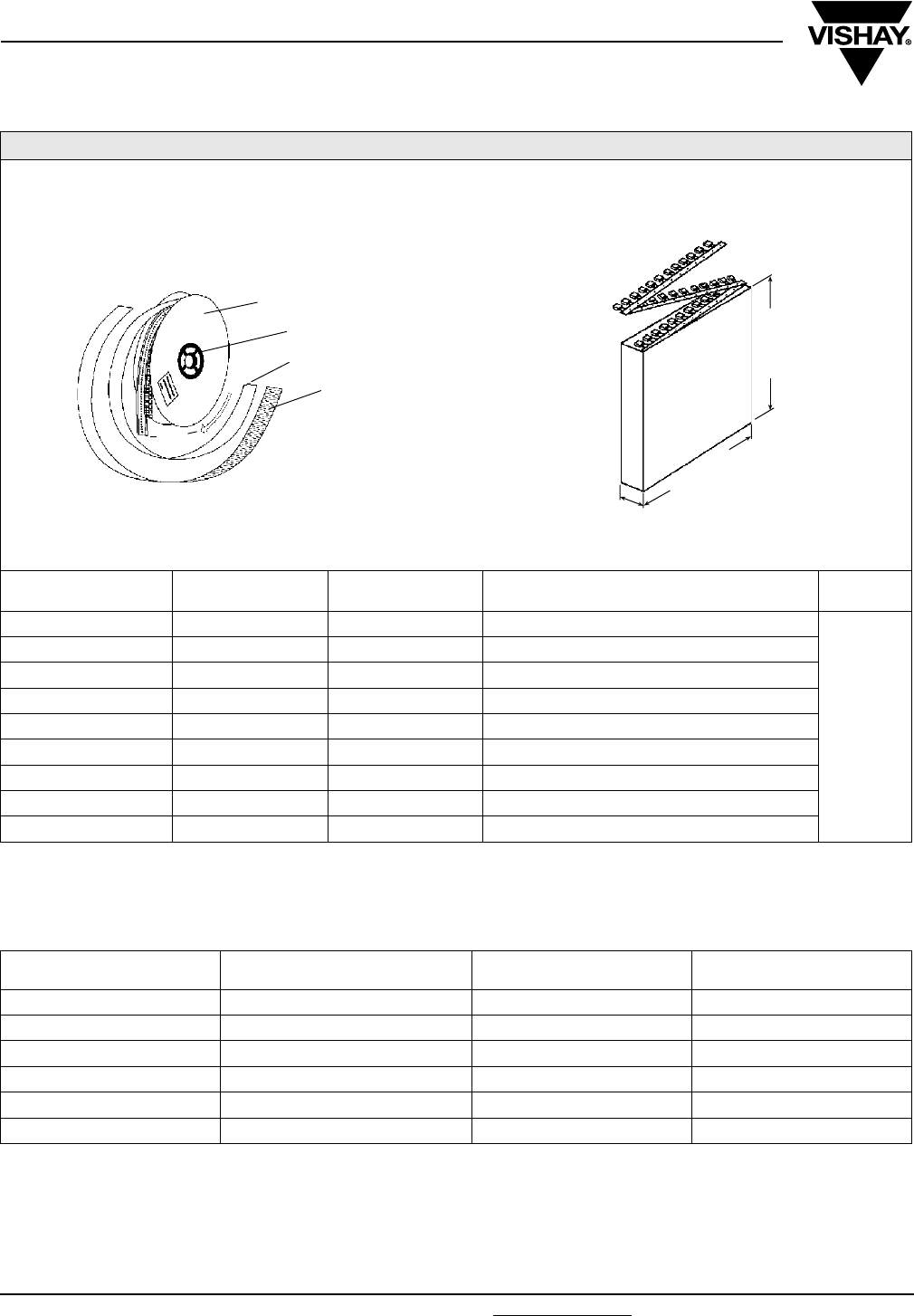
ETPW
Vishay Sprague Resin-Coated, Radial-Leaded
Solid Tantalum Capacitors
www.vishay.com For technical questions, contact: eurotant@vishay.com Document Number: 42074
136 Revision: 12-Jun-06
LEAD STYLES AND PACKAGING
CASE SIZE CODE RM in mm
± 0.5 SPECIFICATION REMARKS
1 - 6 00 2.5 / 5 Bulk
Reel with
positive pole
in tape run
direction in
front is
standard
1 - 4 (1) C0 5 Form L, Bulk
1 - 6 V0 5 Form DS, Bulk
1 - 4 (1) W0 2.5 Reel, positive pole in front of unreeling direction
1 - 4 (1) T0 2.5 Reel, negative pole in front of unreeling direction
1 - 4 (1) H0 2.5 Ammo
1 - 5 V2 5 Reel, positive pole in front of unreeling direction
1 - 5 R0 5 Reel, negative pole in front of unreeling direction
1 - 5 08 5 Ammo
Note:
(1) 100 µF - 6.3 V, 68 µF - 10 V, 47 µF - 16 V, 22 µF - 25 V
CASE
SIZE
BULK
00, V0, C0
REEL
W0, T0, V2, R0
AMMO
H0, O8
ETPW 1 A,B 500 2500 2500
ETPW 2 C,D,E 500 2000 2000
ETPW 3 F,G 500 1500 1500
ETPW 4 H 500 1500 1500
ETPW 5 J,K,L 100 500 500
ETPW 6 M,N,P, R 100 - -
REEL PACKING
CARD BOARD
PROTECTIVE TAPE
INNERLAYER PAPER
CLAMP
TAPED
PARTS
AMMO PACKAGING (mm)
191 - 201
41 - 45
320 - 330
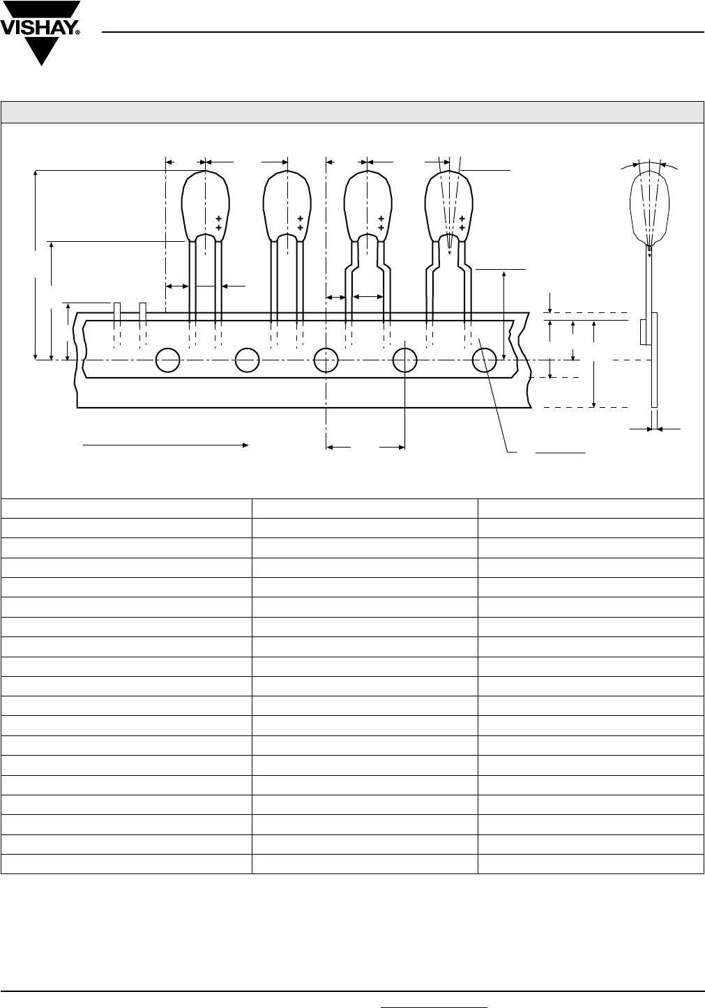
Document Number: 42074 For technical questions, contact: eurotant@vishay.com www.vishay.com
Revision: 12-Jun-06 137
ETPW
Resin-Coated, Radial-Leaded
Solid Tantalum Capacitors Vishay Sprague
TAPING ACCORDING TO IEC 286-2
DESIGNATION SYMBOL DIMENSIONS (mm)
Holding tape width W 18.0 (+ 1/- 0.5)
Adhesive tape width W0 Min. 5.0
Distance of components P 12.7 ± 1
Hole center to component center P2 6.35 ± 1.3
Hole center to lead P1 5.1/3.8 ± 0.7
Distance of body to hole center H (1) 18.0 (+ 2/- 0)
Distance of lead to hole center H0 16.0 ± 0.5
Component upper edge to hole center H1 Max. 32.0
Adhesive tape location W2 Max. 3.0
Hole location W1 9.0 (+ 0.75/- 0.5)
Distance of holes P0 12.7 ± 0.3
Hole diameter D0 4.0 ± 0.3
Lead diameter d 0.5 ± 0.05
Component alignment Δh Max. ± 2.0
Pitch F 2.5/5.0 (+ 0.6/- 0.1)
Holding tape thickness t 0.5 ± 0.2
Component alignment ΔP Max. ± 1.3
Length of snipped leads L Max. 11.0
Note:
(1 ) also available: 16 mm and 20 mm taping according to DIN-IEC 286 part 2
Δh
W2
D0
H0
W0
W1W
t
P1
P2
H2
F
PΔP
P2P
P1F
P0
L
H
UNREELING DIRECTION
Dimensions for components on tape and tolerances:
(meets IEC 286-2)
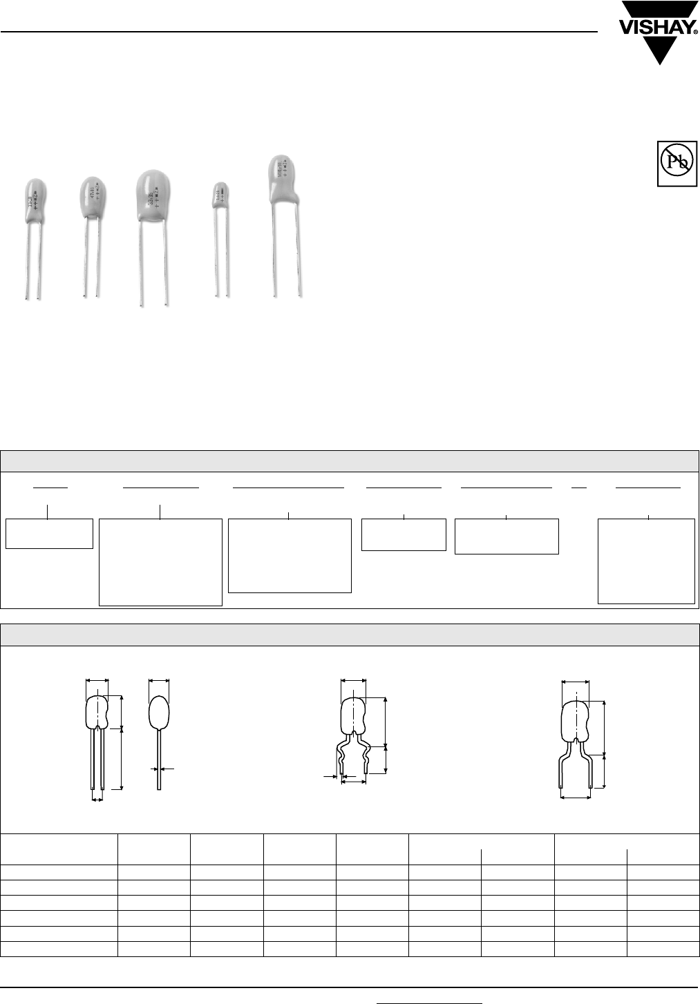
www.vishay.com For technical questions, contact: eurotant@vishay.com Document Number: 42075
138 Revision: 12-Jun-06
ETQW
Vishay Sprague
Resin-Coated, Radial-Lead
Tantalum Capacitors
FEATURES
•RoHS Compliant design available
•Flame retardant encapsulation
•Very high temperature range
•Improved humidity class
•Very low leakage current
•Very high CV product
•Very low leakage current
•Very low failure rate
•Preaged under temperature and voltage
Available
Pb-free
RoHS*
COMPLIANT
MECHANICAL SPECIFICATIONS
Colour: Gold
Laser Marked: Capacity and voltage in clear text; Plus pole
marked, Date code (year/month) according to DIN IEC 62
Leads: Standard (Tin/Lead), RoHS Compliant (100 % Tin)
Tantalum capacitors with sintered anode and solid
semiconductor electrolyte with flame retardant fluidized bed
coating. The type ETQW is characterized by very favorable
electrical values even at higher ambient temperatures. The
capacitor complies with DIN 45910 part 147. This type is also
available as a radially taped version.
ORDERING INFORMATION
Q1B 685 603 M 00 D E3
TYPE CAPACITANCE DC VOLTAGE RATING
AT + 85 °C
CAPACITANCE
TOLERANCE
LEAD STYLE AND
PA CK A G I N G
RoHS
COMPLIANT
ETQW 1A ....
ETQW 6R
Expressed in
picofarads. The first two
digits are significant
figures. The third is the
number of zeros
following.
Expressed by zeros if
needed to complete the
3 digit block. A decimal
point is indicated by an
“0“ (603 = 6.3 V)
M = ± 20 %
K = ± 10 %
See Lead styles and
packaging table
E3 = 100 % tin
termination (RoHS
compliant design)
Blank = SnPb
termination
(standard design)
* Pb containing terminations are not RoHS compliant, exemptions may apply
DIMENSIONS in millimeters
MODEL D MAX. H MAX. RM Ø D ± 0.05 FORM DS FORM L
H2 MAX. RM H2 MAX. RM
ETQW - 1 4.5 7.5 2.5 0.5 10.5 5 10.5 5
ETQW - 2 5.0 9.5 2.5 0.5 12.5 5 12.5 5
ETQW - 3 6.0 10.5 2.5 0.5 13.5 5 13.5 5
ETQW - 4 6.5 11.5 2.5 0.5 14.5 5 14.5 5
ETQW - 5 9.0 14.0 5.0 0.5 17.0 5 - -
ETQW - 6 9.5 17.0 5.0 0.5 20.0 5 - -
BASIC VERSION
H
RM ± 0.5
D
15 ±
5
D
Ø d
FORM DS
H2
D
1.1 ± 0.1
4.5 ± 1.5
RM ± 0.5
FORM L
H
2
D
RM ± 0.5
5.5 ± 0.5
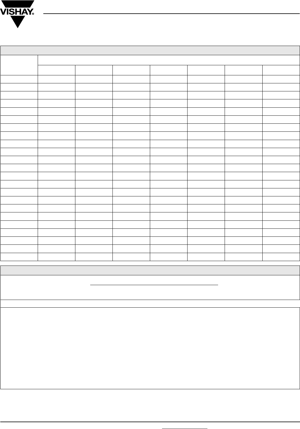
Document Number: 42075 For technical questions, contact: eurotant@vishay.com www.vishay.com
Revision: 12-Jun-06 139
ETQW
Resin-Coated, Radial-Leaded
Tantalum Capacitors Vishay Sprague
STANDARD RATINGS AND CASE CODES
CR
µF
RATED VOLTAGE UR at + 85 °C
3.0 V 6.3 V 10 V 16 V 25 V 35 V 50 V
0.10 1A 1A
0.15 1A 1A
0.22 1A 1A
0.33 1A 1B
0.47 1A 1B
0.68 1A 2C
1.0 1A 1A 2D
1.5 1A 1B 2E
2.2 1A 1B 2C 3F
3.3 1A 1B 2C 2D 3G
4.7 1A 1B 2C 2D 2E 4H
6.8 1A 1B 2C 2D 2E 3F 5J
10 1A 2C 2D 2E 3F 3G 5L
15 1B 2D 2E 3F 4H 5J 6M
22 2C 2E 3F 3G 5J 5L 6P
33 2D 3F 3G 4H 5K 6M
47 2E 3G 4H 5K 6M 6P
68 3F 4H 5J 5L 6N
100 3G 5J 5L 6N
150 4H 5L 6N 6R
220 5J 6M 6P
330 5L 6P
470
STANDARD RATINGS
CR
(µF)
CASE
CODE PART NUMBER
DIMENSIONS MAX. DCL
AT
+ 20 °C,
(µA)
MAX. Z AT
100 kHz
(Ω)
MAX. DF
AT 120 Hz
+ 20 °C
D MAX.
(mm)
H MAX.
(mm)
H2 MAX.
(mm)
RM
± 0.05
d
± 0.05
UR = 3 V AT + 85 °C, Surge = 3.9 V . . . UC = 2 V AT + 125 °C
6.8 1A Q1A685003(*)_ _D 4.5 7.5 10.5 2.5 0.5 0.5 5.4 0.06
10.0 1A Q1A106003(*)_ _D 4.5 7.5 10.5 2.5 0.5 0.5 4.5 0.06
15.0 1B Q1B156003(*)_ _D 4.5 7.5 10.5 2.5 0.5 0.5 3.6 0.06
22.0 2C Q2C226003(*)_ _D 5.0 9.5 12.5 2.5 0.5 0.5 2.9 0.06
33.0 2D Q2D336003(*)_ _D 5.0 9.5 12.5 2.5 0.5 0.8 2.3 0.06
47.0 2E Q2E476003(*)_ _D 5.0 9.5 12.5 2.5 0.5 1.1 1.8 0.06
68.0 3F Q3F686003(*)_ _D 6.0 10.5 13.5 2.5 0.5 1.6 1.4 0.06
100.0 3G Q3G107003(*)_ _D 6.0 10.5 13.5 2.5 0.5 2.4 1.1 0.08
150.0 4H Q4H157003(*)_ _D 6.5 11.5 14.5 2.5 0.5 3.6 0.9 0.08
220.0 5J Q5J227003(*)_ _D 9.0 14.0 17.0 5.0 0.5 5.3 0.7 0.08
330.0 5L Q5L337003(*)_ _D 9.0 14.0 17.0 5.0 0.5 7.9 0.6 0.08
Note:
(1) Insert M for ± 20 % tolerance or K for ± 10 %
_ _ Lead style and packaging code, see lead style and packaging

ETQW
Vishay Sprague Resin-Coated, Radial-Leaded
Tantalum Capacitors
www.vishay.com For technical questions, contact: eurotant@vishay.com Document Number: 42075
140 Revision: 12-Jun-06
STANDARD RATINGS
CR
(µF)
CASE
CODE PART N UMB ER
DIMENSIONS MAX. DCL
AT
+ 20 °C,
(µA)
MAX. Z AT
100 kHz
(Ω)
MAX. DF
AT 120 Hz
+ 20 °C
D MAX.
(mm)
H MAX.
(mm)
H2 MAX.
(mm)
RM
± 0.05
d
± 0.05
UR = 6.3 V AT + 85 °C, Surge = 7.8 V . . . UC = 4 V AT + 125 °C
4.7 1A Q1A475603(*)_ _D 4.5 7.5 10.5 2.5 0.5 0.5 5.4 0.06
6.8 1B Q1B685603(*)_ _D 4.5 7.5 10.5 2.5 0.5 0.5 4.5 0.06
10.0 2C Q2C106603(*)_ _D 5.0 9.5 12.5 2.5 0.5 0.5 3.6 0.06
15.0 2D Q2D156603(*)_ _D 5.0 9.5 12.5 2.5 0.5 0.8 2.9 0.06
22.0 2E Q2E226603(*)_ _D 5.0 9.5 12.5 2.5 0.5 1.1 2.3 0.06
33.0 3F Q3F336603(*)_ _D 6.0 10.5 13.5 2.5 0.5 1.7 1.8 0.06
47.0 3G Q3G476603(*)_ _D 6.0 10.5 13.5 2.5 0.5 2.4 1.7 0.06
68.0 4H Q4H686603(*)_ _D 6.5 11.5 14.5 2.5 0.5 3.4 1.1 0.06
100.0 5J Q5J107603(*)_ _D 9.0 14.0 17.0 5.0 0.5 5.0 0.9 0.08
150.0 5L Q5L157603(*)_ _D 9.0 14.0 17.0 5.0 0.5 7.6 0.7 0.08
220.0 6M Q6M227603(*)_ _D 9.5 17.0 20.0 5.0 0.5 11.1 0.6 0.08
330.0 6P Q6P337603(*)_ _D 9.5 17.0 20.0 5.0 0.5 16.6 0.5 0.08
UR = 10 V AT + 85 °C, Surge = 13 V . . . UC = 6.3 V AT + 125 °C
3.3 1A Q1A335010(*)_ _D 4.5 7.5 10.5 2.5 0.5 0.5 5.9 0.06
4.7 1B Q1B475010(*)_ _D 4.5 7.5 10.5 2.5 0.5 0.5 4.5 0.06
6.8 2C Q2C685010(*)_ _D 5.0 9.5 12.5 2.5 0.5 0.5 3.6 0.06
10.0 2D Q2D106010(*)_ _D 5.0 9.5 12.5 2.5 0.5 0.8 2.9 0.06
15.0 2E Q2E156010(*)_ _D 5.0 9.5 12.5 2.5 0.5 1.2 2.3 0.06
22.0 3F Q3F226010(*)_ _D 6.0 10.5 13.5 2.5 0.5 1.8 1.8 0.06
33.0 3G Q3G336010(*)_ _D 6.0 10.5 13.5 2.5 0.5 2.6 1.4 0.06
47.0 4H Q4H476010(*)_ _D 6.5 11.5 14.5 2.5 0.5 3.8 1.1 0.06
68.0 5J Q5J686010(*)_ _D 9.0 14.0 17.0 5.0 0.5 5.4 0.9 0.06
100.0 5L Q5L107010(*)_ _D 9.0 14.0 17.0 5.0 0.5 8.0 0.7 0.08
150.0 6N Q6N157010(*)_ _D 9.5 17.0 20.0 5.0 0.5 12.0 0.6 0.08
220.0 6P Q6P227010(*)_ _D 9.5 17.0 20.0 5.0 0.5 17.6 0.5 0.08
UR = 16 V AT + 85 °C, Surge = 20.8 V . . . UC = 10 V AT + 125 °C
2.2 1A Q1A225016(*)_ _D 4.5 7.5 10.5 2.5 0.5 0.5 6.3 0.06
3.3 1B Q1B335016(*)_ _D 4.5 7.5 10.5 2.5 0.5 0.5 5.4 0.06
4.7 2C Q2C475016(*)_ _D 5.0 9.5 12.5 2.5 0.5 0.6 4.1 0.06
6.8 2D Q2D685016(*)_ _D 5.0 9.5 12.5 2.5 0.5 0.9 2.9 0.06
10.0 2E Q2E106016(*)_ _D 5.0 9.5 12.5 2.5 0.5 1.3 2.3 0.06
15.0 3F Q3F156016(*)_ _D 6.0 10.5 13.5 2.5 0.5 1.9 1.8 0.06
22.0 3G Q3G226016(*)_ _D 6.0 10.5 13.5 2.5 0.5 2.8 1.4 0.06
33.0 4H Q4H336016(*)_ _D 6.5 11.5 14.5 2.5 0.5 4.2 1.1 0.06
47.0 5K Q5K476016(*)_ _D 9.0 14.0 17.0 5.0 0.5 6.0 0.9 0.06
68.0 5L Q5L686016(*)_ _D 9.0 14.0 17.0 5.0 0.5 8.7 0.7 0.06
100.0 6N Q6N107016(*)_ _D 9.5 17.0 20.0 5.0 0.5 12.8 0.6 0.08
150.0 6R Q6R157016(*)_ _D 9.5 17.0 20.0 5.0 0.5 19.2 0.5 0.08
UR = 25 V AT + 85 °C, Surge = 32.5 V . . . UC = 16 V AT + 125 °C
1.0 1A Q1A105025(*)_ _D 4.5 7.1 10.5 2.5 0.5 0.5 7.7 0.04
1.5 1A Q1A155025(*)_ _D 4.5 7.5 10.5 2.5 0.5 0.5 6.8 0.04
2.2 1B Q1B225025(*)_ _D 4.5 7.5 10.5 2.5 0.5 0.5 5.4 0.06
3.3 2C Q2C335025(*)_ _D 5.0 9.5 12.5 2.5 0.5 0.7 4.1 0.06
4.7 2D Q2D475025(*)_ _D 5.0 9.5 12.5 2.5 0.5 0.9 2.9 0.06
6.8 2E Q2E685025(*)_ _D 5.0 9.5 12.5 2.5 0.5 1.4 2.3 0.06
10.0 3F Q3F106025(*)_ _D 6.0 10.5 13.5 2.5 0.5 2.0 1.8 0.06
15.0 4H Q4H156025(*)_ _D 6.5 11.5 14.5 2.5 0.5 3.0 1.4 0.06
22.0 5J Q5J226025(*)_ _D 9.0 14.0 17.0 5.0 0.5 4.4 1.1 0.06
33.0 5K Q5K336025(*)_ _D 9.0 14.0 17.0 5.0 0.5 6.6 0.9 0.06
47.0 6M Q6M476025(*)_ _D 9.5 17.0 20.0 5.0 0.5 9.4 0.7 0.06
68.0 6N Q6N686025(*)_ _D 9.5 17.0 20.0 5.0 0.5 13.6 0.6 0.06
Note:
(*) Insert M for ± 20 % tolerance or K for ± 10 %
_ _ Lead style and packaging code, see lead style and packaging

Document Number: 42075 For technical questions, contact: eurotant@vishay.com www.vishay.com
Revision: 12-Jun-06 141
ETQW
Resin-Coated, Radial-Leaded
Tantalum Capacitors Vishay Sprague
STANDARD RATINGS
CR
(µF)
CASE
CODE PART N UM BER
DIMENSIONS MAX. DCL
AT
+ 20 °C,
(µA)
MAX. Z AT
100 kHz
(Ω)
MAX. DF
AT 120 Hz
+ 20 °C
D MAX.
(mm)
H MAX.
(mm)
H2 MAX.
(mm)
RM
± 0.05
d
± 0.05
UR = 35 V AT + 85 °C, Surge = 45.5 V . . . UC = 23 V AT + 125 °C
0.1 1A Q1A104035(*)_ _D 4.5 7.5 10.5 2.5 0.5 0.5 34.2 0.04
0.15 1A Q1A154035(*)_ _D 4.5 7.5 10.5 2.5 0.5 0.5 27.0 0.04
0.22 1A Q1A224035(*)_ _D 4.5 7.5 10.5 2.5 0.5 0.5 20.7 0.04
0.33 1A Q1A334035(*)_ _D 4.5 7.5 10.5 2.5 0.5 0.5 16.2 0.04
0.47 1A Q1A474035(*)_ _D 4.5 7.5 10.5 2.5 0.5 0.5 12.6 0.04
0.68 1A Q1A684035(*)_ _D 4.5 7.5 10.5 2.5 0.5 0.5 9.0 0.04
1.0 1A Q1A105035(*)_ _D 4.5 7.5 10.5 2.5 0.5 0.5 7.2 0.04
1.5 1B Q1A155035(*)_ _D 4.5 7.5 10.5 2.5 0.5 0.5 5.9 0.04
2.2 2C Q2C225035(*)_ _D 5.0 9.5 12.5 2.5 0.5 0.6 4.5 0.06
3.3 2D Q2D335035(*)_ _D 5.0 9.5 12.5 2.5 0.5 0.9 3.2 0.06
4.7 2E Q2E475035(*)_ _D 5.0 9.5 12.5 2.5 0.5 1.3 2.3 0.06
6.8 3F Q3F685035(*)_ _D 6.0 10.5 13.5 2.5 0.5 1.9 1.8 0.06
10.0 3G Q3G106035(*)_ _D 6.0 10.5 13.5 2.5 0.5 2.8 1.4 0.06
15.0 5J Q5J156035(*)_ _D 9.0 14.0 17.0 5.0 0.5 4.2 1.1 0.06
22.0 5L Q5L226035(*)_ _D 9.0 14.0 17.0 5.0 0.5 6.2 0.9 0.06
33.0 6M Q6M336035(*)_ _D 9.5 17.0 20.0 5.0 0.5 9.2 0.7 0.06
47.0 6P Q6P476035(*)_ _D 9.5 17.0 20.0 5.0 0.5 13.2 0.6 0.06
UR = 50 V AT + 85 °C, Surge = 65 V . . . UC = 33 V AT + 125 °C
0.1 1A Q1A104050(*)_ _D 4.5 7.5 10.5 2.5 0.5 0.5 34.2 0.04
0.15 1A Q1A154050(*)_ _D 4.5 7.5 10.5 2.5 0.5 0.5 27.0 0.04
0.22 1A Q1A224050(*)_ _D 4.5 7.5 10.5 2.5 0.5 0.5 20.7 0.04
0.33 1B Q1B334050(*)_ _D 4.5 7.5 10.5 2.5 0.5 0.5 16.2 0.04
0.47 1B Q1B474050(*)_ _D 4.5 7.5 10.5 2.5 0.5 0.5 12.6 0.04
0.68 2C Q2C684050(*)_ _D 5.0 9.5 12.5 2.5 0.5 0.5 9.0 0.04
1.0 2D Q2D105050(*)_ _D 5.0 9.5 12.5 2.5 0.5 0.5 7.2 0.04
1.5 2E Q2E155050(*)_ _D 5.0 9.5 12.5 2.5 0.5 0.6 5.9 0.04
2.2 3F Q3F225050(*)_ _D 6.0 10.5 13.5 2.5 0.5 0.9 4.5 0.06
3.3 3G Q3G335050(*)_ _D 6.0 10.5 13.5 2.5 0.5 1.3 3.2 0.06
4.7 4H Q4H475050(*)_ _D 6.5 11.5 14.5 2.5 0.5 1.9 2.3 0.06
6.8 5J Q5J685050(*)_ _D 9.0 14.0 17.0 5.0 0.5 2.7 1.8 0.06
10.0 5L Q5L106050(*)_ _D 9.0 14.0 17.0 5.0 0.5 4.0 1.4 0.06
15.0 6M Q6M156050(*)_ _D 9.5 17.0 20.0 5.0 0.5 6.0 1.1 0.06
22.0 6P Q6P226050(*)_ _D 9.5 17.0 20.0 5.0 0.5 8.8 0.9 0.06
Note:
(*) Insert M for ± 20 % tolerance or K for ± 10 %
_ _ Lead style and packaging code, see lead style and packaging

ETQW
Vishay Sprague Resin-Coated, Radial-Leaded
Tantalum Capacitors
www.vishay.com For technical questions, contact: eurotant@vishay.com Document Number: 42075
142 Revision: 12-Jun-06
PERFORMANCE CHARACTERISTICS
1. Climatic Category: 55/125/56 acc. to IEC
2. Temperature Range: - 55 °C up to + 125 °C with
linear voltage derating to category voltage UC
3. Rated Voltage, Category Voltage: 3 V to 50 V;
2 V to 33 V
4. Surge Voltage: 1.3 times of rated voltage at + 85 °C
5. Reverse Voltage (Temporary):
15 % of the rated DC voltage at + 20 °C
10 % of the rated DC voltage at + 55 °C
5 % of the rated DC voltage at + 85 °C
6. Rated Capacitance: 0.1 µF to 330 µF
7. Capacitance Tolerance: ± 20 %, ± 10 %,
8. Leakage Current in µA: Measured at + 20 °C after
5 minutes: ≤ 0.008 x CR x UR or 0.5 µA, whichever is
greater
9. Dissipation Factor: at 120 Hz and + 20 °C
See table
10. Impedance: Measured at 100 kHz and + 20 °C
See table.
11. Permissible AC Voltage Stress: The highest
permissible AC voltage for the respective frequency
may be taken from the brochure “General
information”.
The values apply for + 20 °C. For higher
temperatures, the values have to be multiplied with
the following factors:
Intermediate values can be obtained by linear
interpolation.
For further notes on AC voltage stress: See general
information
12. Service life: > 300.000 h (2)
13. Failure percentage: ≤ 0.3 % within 100 000 h (2)
14. Failure rate (l): ≤ 0.3 10- 7/h = ≤ 30 fit (2)
15. Failure criteria: Catastrophic failure: Short circuit or
interruption
Drift failure: DC/C > + 5 - 15 %
Z > 3 times initial limit value
IR > 5 times initial value + 5 µA
Note: (2) related to UR, + 40 °C and a circuit resistance of ≥ 3 Ω/V
16. Characteristics at high and low temperatures (the values shall not exceed the following limits)
Note:
(1) Measured at category voltage
TEMPERATURE FACTOR
+ 50 °C 0.7
+ 85 °C 0.5
+ 125 °C 0.3
TEST TEMPERATURE - 55 °C + 20 °C + 85 °C + 125 °C
ΔC/C <
tanδ
≤ 1.5 µF
< 10 µF
< 100 µF
≥ 100 µF
- 10 %
0.04
0.06
0.08
0.10
-
0.04
0.06
0.06
0.08
+ 12 %
0.04
0.06
0.08
0.10
+ 15 %
0.04
0.06
0.08
0.10
Leakage current IR -
≤ 0.008 x CR x UR
or 0.5 µA
whichever is greater
≤ 0.08 x CR x UR
or 5.0 µA
whichever is greater
≤ 0.1 x CR x UR
or 6.25 µA
whichever is greater (1)
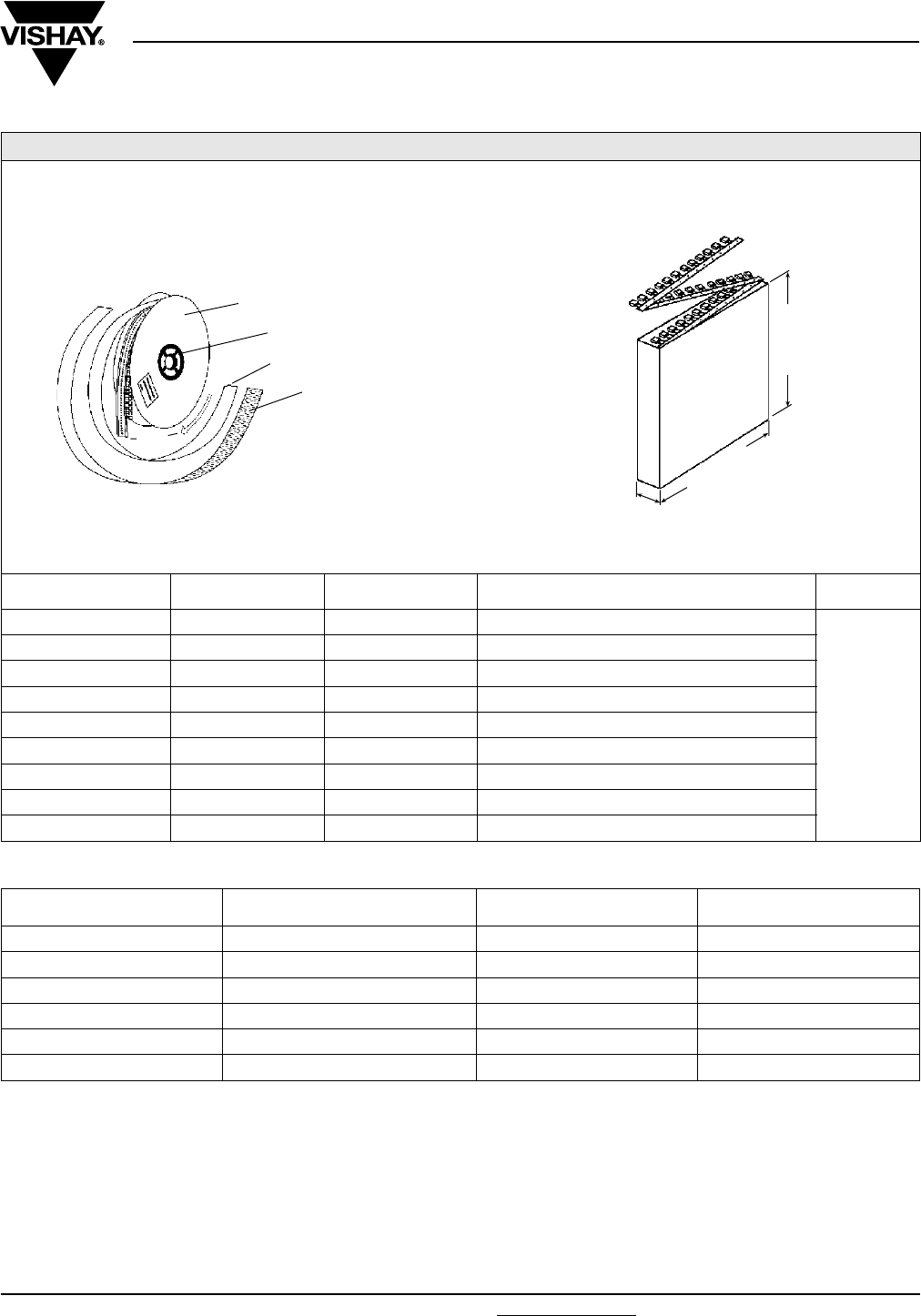
Document Number: 42075 For technical questions, contact: eurotant@vishay.com www.vishay.com
Revision: 12-Jun-06 143
ETQW
Resin-Coated, Radial-Leaded
Tantalum Capacitors Vishay Sprague
LEAD STYLES AND PACKAGING
CASE SIZE CODE RM in mm
± 0.5 SPECIFICATION REMARKS
1 - 6 00 2.5 / 5 Bulk
Reel with
positive pole
in tape run
direction in
front is
standard!
1 - 6 V0 5 Form DS, Bulk
1 - 4 W0 2.5 Reel, positive pole in front of unreeling direction
1 - 4 T0 2.5 Reel, negative pole in front of unreeling direction
1 - 4 H0 2.5 Ammo
1 - 5 V2 5 Reel, positive pole in front of unreeling direction
1 - 5 R0 5 Reel, negative pole in front of unreeling direction
1 - 5 O8 5 Ammo
1 - 4 C0 5 Style “L“ Bulk
REEL PACKING
CARD BOARD
PROTECTIVE TAPE
INNERLAYER PAPER
CLAMP
TAPED
PARTS
AMMO PACKAGING (mm)
191 - 201
41 - 45
320 - 330
CASE
SIZE
BULK
00, V0, C0
REEL
W0, T0, V2, R0
AMMO
H0, 08
ETQW 1 A,B 500 2500 2500
ETQW 2 C,D,E 500 2000 2000
ETQW 3 F,G 500 1500 1500
ETQW 4 H 500 1500 1500
ETQW 5 J,K,L 100 500 500
ETQW 6 M,N,P,R 100 - -
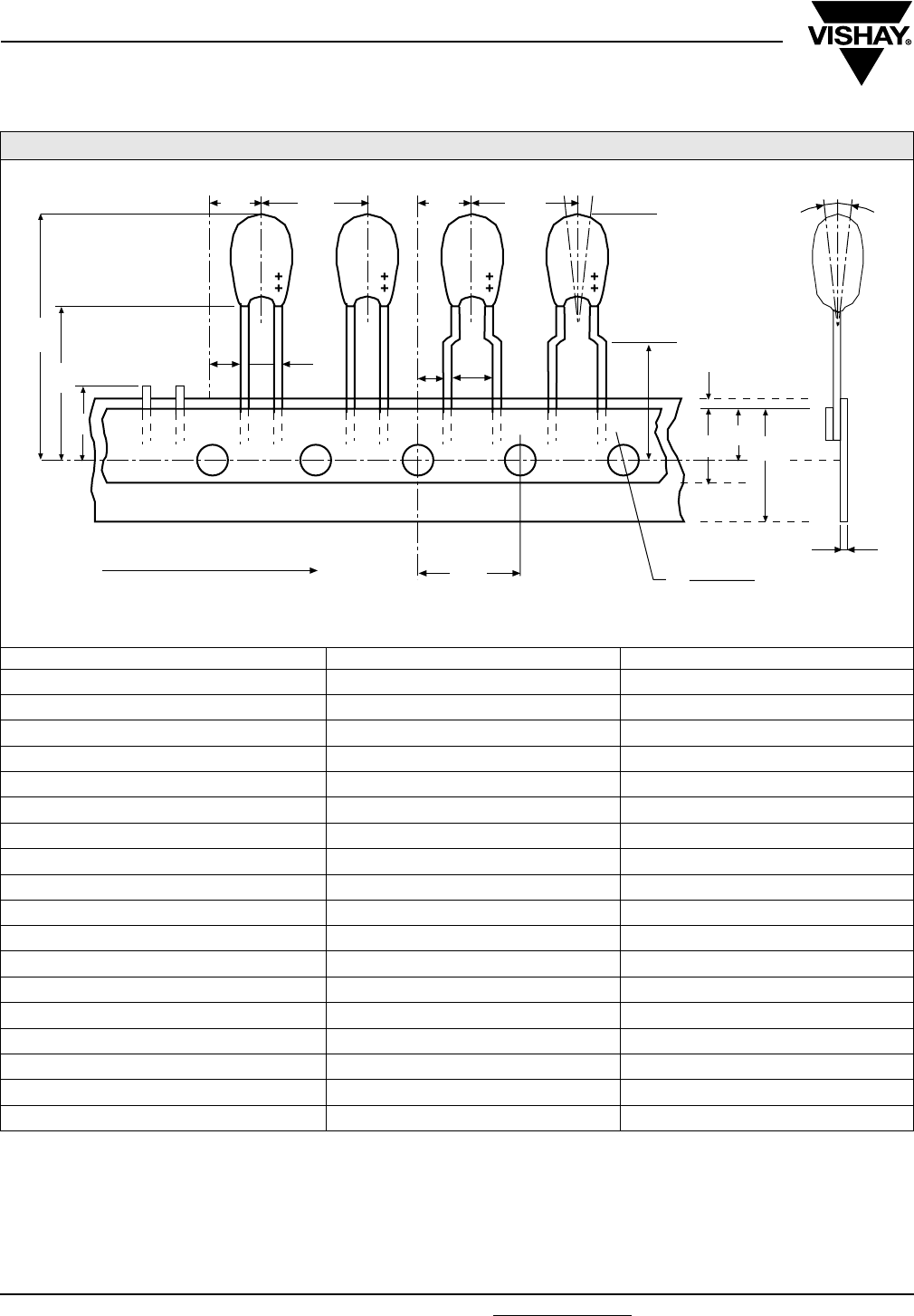
ETQW
Vishay Sprague Resin-Coated, Radial-Leaded
Tantalum Capacitors
www.vishay.com For technical questions, contact: eurotant@vishay.com Document Number: 42075
144 Revision: 12-Jun-06
TAPING ACCORDING TO IEC 286-2
DESIGNATION SYMBOL DIMENSIONS (mm)
Holding tape width W 18.0 (+ 1/- 0.5)
Adhesive tape width W0 Min. 5.0
Distance of components P 12.7 ± 1
Hole center to component center P2 6.35 ± 1.3
Hole center to lead P1 5.1/3.8 ± 0.7
Distance of body to hole center H (1) 18.0 (+ 2/- 0)
Distance of lead to hole center H0 16.0 ± 0.5
Component upper edge to hole center H1 Max. 32.0
Adhesive tape location W2 Max. 3.0
Hole location W1 9.0 (+ 0.75/- 0.5)
Distance of holes P0 12.7 ± 0.3
Hole diameter D0 4.0 ± 0.3
Lead diameter d 0.5 ± 0.05
Component alignment Δh Max. ± 2.0
Pitch F 2.5/5.0 (+ 0.6/- 0.1)
Holding tape thickness t 0.5 ± 0.2
Component alignment ΔP Max. ± 1.3
Length of snipped leads L Max. 11.0
Note:
(1) also available: 16 mm and 20 mm taping according to DIN-IEC 286 part 2
Δh
W2
D0
H0
W0
W1W
t
P1
P2
H2
F
PΔP
P2P
P1F
P0
L
H
UNREELING DIRECTION
Dimensions for components on tape and tolerances:
(meets IEC 286-2)


ONLINE INFORMATION
For product information and a current list of sales ofces,
representatives and distributors, visit our website:
www.vishay.com
THE AMERICAS
UNITED STATES
VISHAY AMERICAS
ONE GREENWICH PLACE
SHELTON, CT 06484
UNITED STATES
PH: +1-402-563-6866
FAX: +1-402-563-6296
ASIA
SINGAPORE
VISHAY INTERTECHNOLOGY
ASIA PTE LTD.
25 TAMPINES STREET 92
KEPPEL BUILDING #02-00
SINGAPORE 528877
PH: +65-6788-6668
FAX: +65-6788-0988
P.R. CHINA
VISHAY TRADING (SHANGHAI) CO., LTD.
15D, SUN TONG INFOPORT PLAZA
55 HUAI HAI WEST ROAD
SHANGHAI 200030
P.R. CHINA
PH: +86-21-5258-5000
FAX: +86-21-5258-7979
JAPAN
VISHAY JAPAN CO., LTD.
MG IKENOHATA BLDG. 4F
1-2-18, IKENOHATA
TAITO-KU
TOKYO 110-0008
JAPAN
PH: +81-3-5832-6210
FAX: +81-3-5832-6260
EUROPE
GERMANY
VISHAY EUROPE SALES GMBH
GEHEIMRAT-ROSENTHAL-STR. 100
95100 SELB
GERMANY
PH: +49-9287-71-0
FAX: +49-9287-70435
FRANCE
VISHAY S.A.
199, BLVD DE LA MADELEINE
06003 NICE, CEDEX 1
FRANCE
PH: +33-4-9337-2920
FAX: +33-4-9337-2997
UNITED KINGDOM
VISHAY LTD.
PALLION INDUSTRIAL ESTATE
SUNDERLAND SR4 6SU
UNITED KINGDOM
PH: +44-191-514-4155
FAX: +44-191-567-8262
WORLDWIDE SALES CONTACTS
Discrete Semiconductors and Passive Components
One of the World’s Largest Manufacturers of

Copyright © 2008 by Vishay Intertechnology, Inc.
Registered Trademarks of Vishay Intertechnology, Inc.
All rights reserved. Printed in Germany.
Specifications subject to change without notice.
World Headquarters
Vishay Intertechnology, Inc.
63 Lancaster Avenue
Malvern, PA 19355-2143
United States
www.vishay.com
DATA BOOK
VSE-DB0029-0805
LEADED SOLID ELECTROLYTE TANTALEX® CAPACITORS
Discrete Semiconductors and Passive Components
One of the World’s Largest Manufacturers of
