EX5 Videx Keypad Technical Manual
EX5 EX5
User Manual: Videx EX5 Keypad Technical manual
Open the PDF directly: View PDF ![]() .
.
Page Count: 8
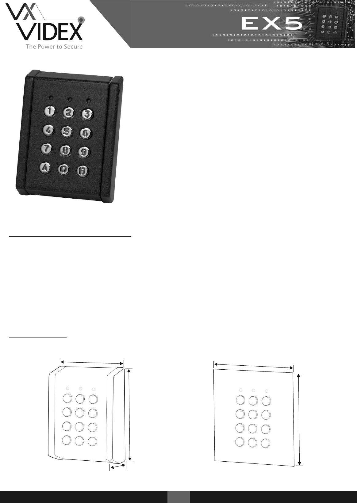
These robust IP rated standalone keypads are designed to
operate in both internal and external environments.
EX5 Keypads include backlit metallic or plastic keys with a
choice of plastic or metal housings (surface or flush).
They incorporate an easy to follow programming menu
allowing up to 99 unique codes and the setting of relay
output times. The units also include inputs to trigger the
relay from a push to exit button.
Both audible and visual indication is standard indicating
that a code is correct or incorrect while also helping to
navigate through the programming menu.
Technical Characteristics
Codes: 99 User Codes (1 - 8 digits)
Relays: 2 Relays - R1: (10A @ 24v DC / 120v AC) R2: (2A @ 24v AC/DC)
Relay Time: 1 - 99 Seconds or latching (00)
IP Rating IP65
Power: 12/24v AC/DC
Current: Standby 30mA / Maximum 130mA
Dimensions
105mm
140mm
90mm
120mm
40mm
102
43
52/72
1EX5
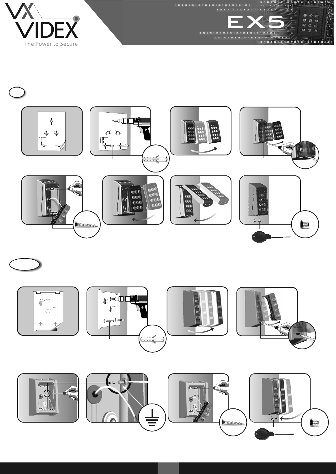
Installation Instructions
2EX5
1. 2. 4.
Cable
Ø6.0
30mm
Cable
Ø6.0
30mm
43
3.
7.5.
3 (8 x 30 CSK)
6. 8.
2 (M3 x 6mm)
security screw
1. 2. 3. 4.
5
5
52/ 72
6.
3 (8 x 30mm CSK)
5. 7.
2 (M3 x 6mm)
ABS Housing Surface
Metal Housing Surface
1. 2. 3. 4.
102
30m m
Ø6.0
Cable
5. 6. 7.
3 (8 x 30mm CSK)
4 (M3 x 6mm)
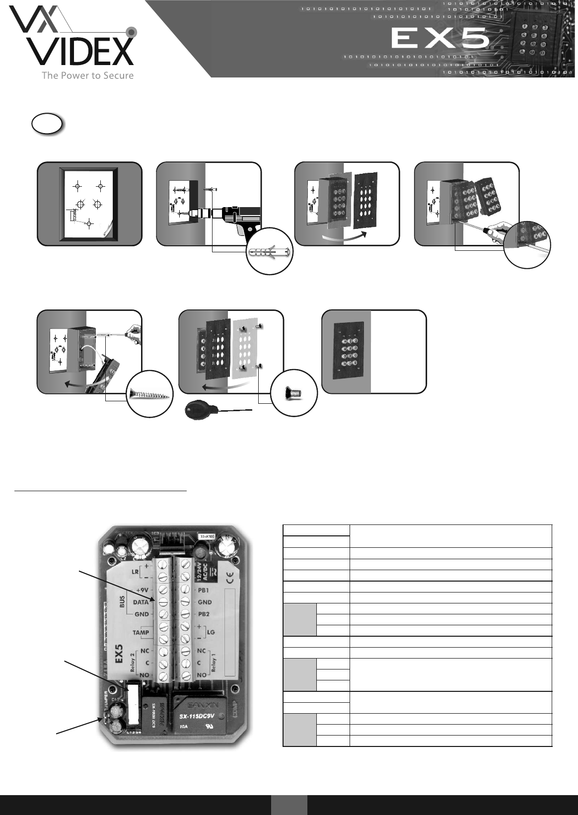
Terminal Connections
Tamper switch
Master code reset
jumper
Terminals
12/24V AC/DC
Voltage in
12/24V AC/DC
PB1
Push to exit input 1 (Active GND)
GND
Push to exit ground
PB2
Push to exit input 2 (Active GND)
+LG
+ Green LED
-LG
- Green LED
Relay 1
NC
Normally closed
C
Common
NO
Normally open
+LR
+ Red LED
-LR
- Red LED
CODIX
BUS
+9V
Connections for CODIX peripherals
DATA
GND
TAMP
Tamper switch output (Normally closed)
TAMP
Relay 2
NC
Normally closed
C
Common
NO
Normally open
3EX5
Metal Housing Flush
4EX5
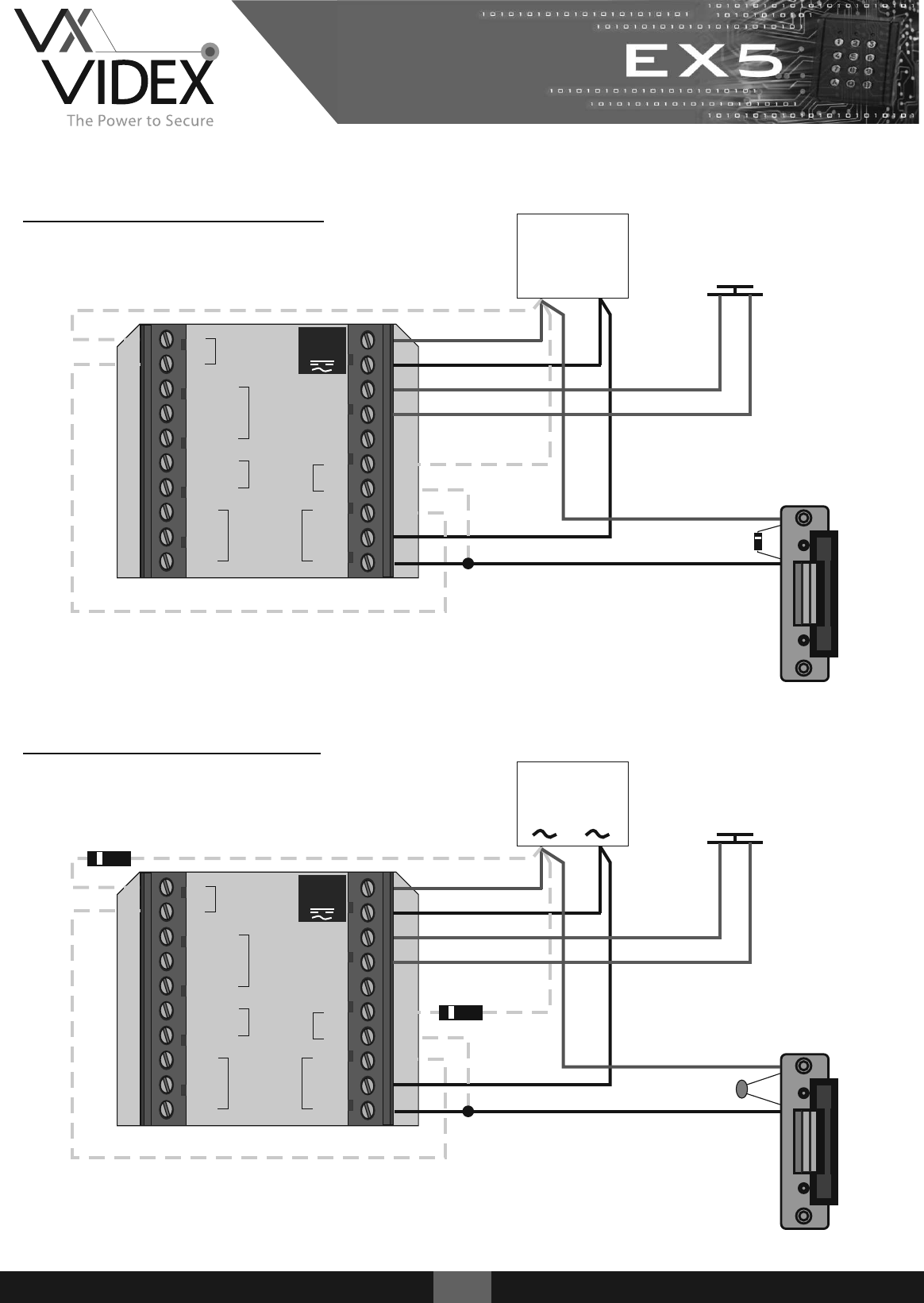
+
-
+9V
DATA
GND
TAMP
TAMP
NC
C
NO NO
C
NC
+
-
PB2
GND
PB1
12/24V
AC/DC
Relay 2
Relay 1
BUS
LR
LR
12 DC
PSU
+
-
IN4002
+
-
+9V
DATA
GND
TAMP
TAMP
NC
C
NO NO
C
NC
+
-
PB2
GND
PB1
12/24V
AC/DC
Relay 2
Relay 1
BUS
LR
LR
12 AC
PSU
100nF
IN4002
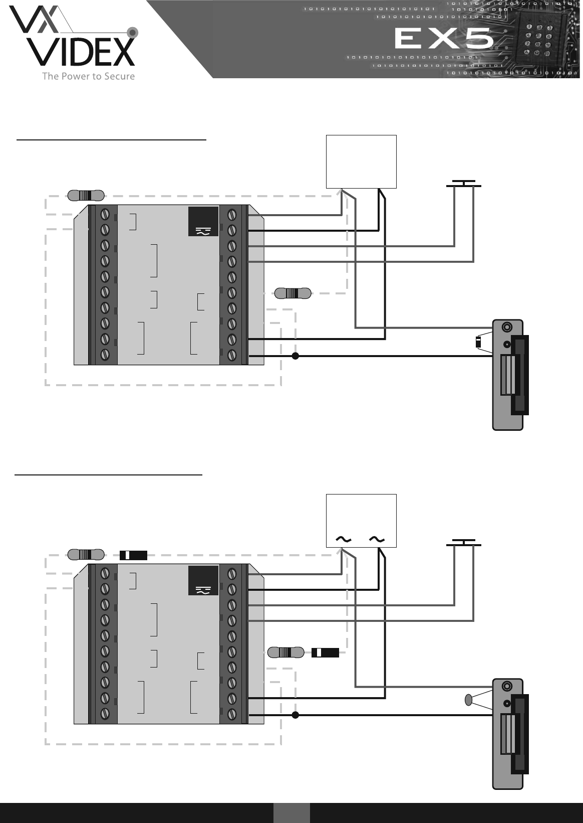
12v DC Wiring Diagram
12v AC Wiring Diagram
IN4002
PTE
(Normally Open)
PTE
(Normally Open)
5EX5
+
-
+9V
DATA
GND
TAMP
TAMP
NC
C
NO NO
C
NC
+
-
PB2
GND
PB1
12/24V
AC/DC
Relay 2
Relay 1
BUS
LR
LR
24 DC
PSU
+
-
PTE
(Normally Open)
IN4002
24v DC Wiring Diagram
24v AC Wiring Diagram
+
-
+9V
DATA
GND
TAMP
TAMP
NC
C
NO NO
C
NC
+
-
PB2
GND
PB1
12/24V
AC/DC
Relay 2
Relay 1
BUS
LR
LR
24 AC
PSU
100nF
IN4002
1K / 1WΩ
IN4002
1K / 1WΩ
1K / 1WΩ
1K / 1WΩ
PTE
(Normally Open)
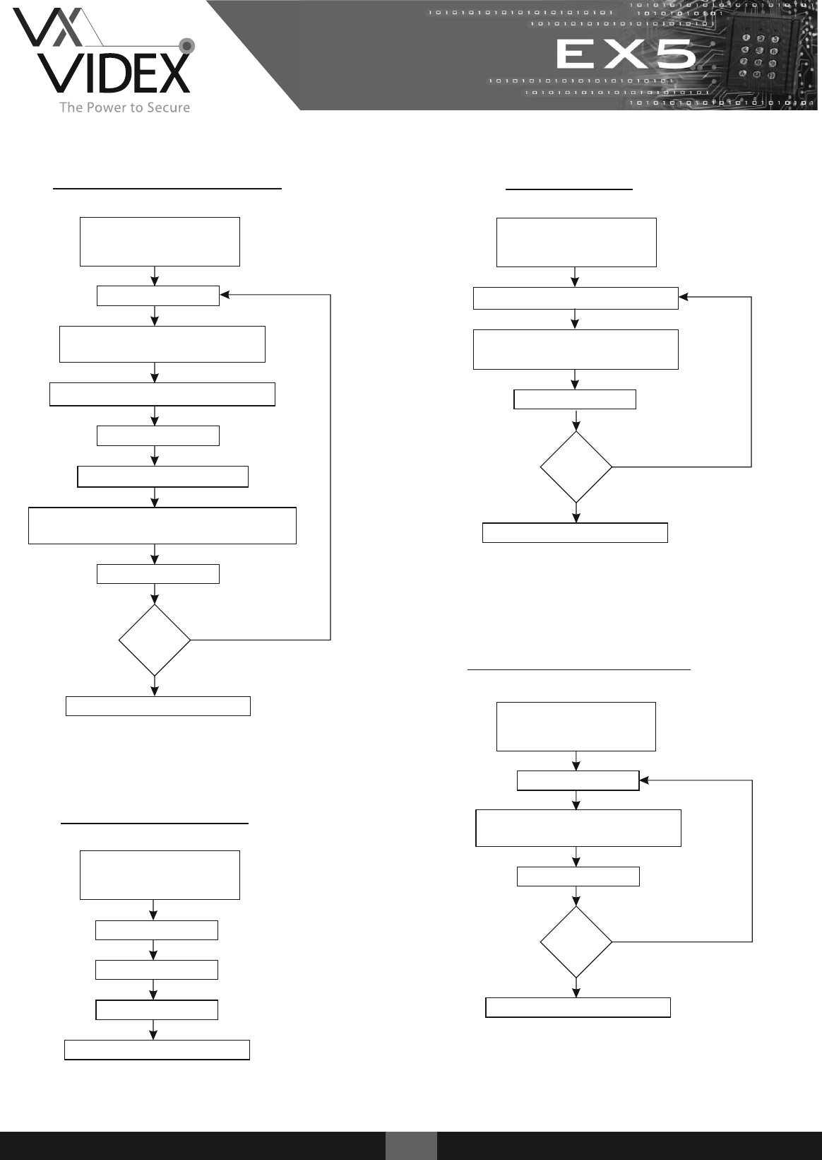
Adding a User Code
Enter Master Code
(Factory Default = 000)
Followed by B
Press 0
Enter <user number> (01-99)
(Up to 99 codes may be added)
Enter <new user code> (1-8 digits)
Press 3 + <user number>
Press A
Enter <relay number> to be triggered
[1=Relay 1] [2=Relay 2] [12=Relays 1 & 2]
Press A
Press B to exit programming
Relay Time
Enter <relay number> (1 or 2)
Enter <relay time> (01-99)
(Enter 00 if latch mode required)
Press A
Press B to exit programming
Delete a User Code
Press 9
Enter <user number> (01-99)
to delete
Press A
Press B to exit programming
Delete All Codes
Press 8
Press A
Press B to exit programming
Press 99
6EX5
More
codes?
Yes
No
Enter Master Code
(Factory Default = 000)
Followed by B
Enter Master Code
(Factory Default = 000)
Followed by B
More
relays?
Yes
No
More
codes?
Yes
No
Enter Master Code
(Factory Default = 000)
Followed by B
Yellow LED on
Yellow LED off
Yellow LED on
Yellow LED off
Yellow LED on
Yellow LED on
Yellow LED off
Yellow LED off
7EX5
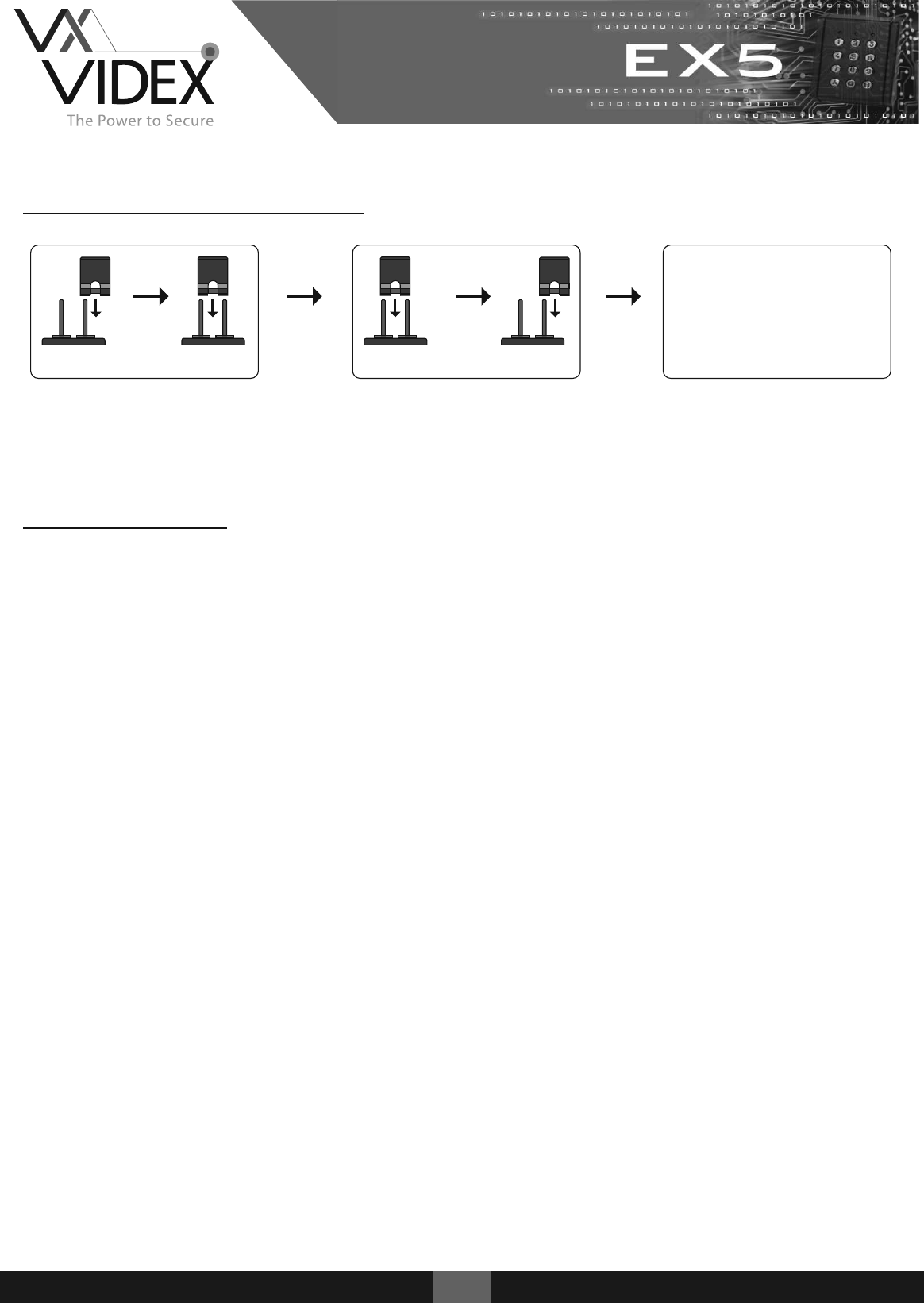
Resetting the Master Code
(P 3) (P 3) (P 3) (P 3)
Disconnect power and close jumper P3.
Reconnect power.
Beep Beep + Yellow LED blinks
Remove jumper P3.
Yellow LED switches on + Long beep
Enter the default master code 000
Enter the new master code e.g 2578
Press A followed by Beep Beep
Press B and the yellow LED switches off
000
2578
A
B
Troubleshooting
Keypad does not respond to key presses
1. Check the correct voltage is present on the input terminals (12/24v ac/dc).
Keypad is not accepting default master code 000
1. Perform master code reset.
Keypad no longer accepts user code
1. Check master code has been changed from the default.
2. Check back EMF protection across lock release.
Keypad accepts user code but no longer releases lock
1. Check the correct relay output is assigned to user code.
2. Check all push to exit buttons are normally open.
3. Check for continuity across relay contacts when user code is entered.
4. Check lock wiring for continuity.
5. Check the correct voltage is present on the input terminals (12/24v ac/dc).
Red / Green LED not functioning
1. Check LR & LG wiring
2. Check a resistor / diode is present if required.
Relay triggers and does not return back to its previous state
1. Check relay is not set up to latch

8EX5
Northern Office
Videx Security Ltd
Unit 4-7 Chillingham ind Est
Newcastle Upon Tyne
NE6 2XX
Tel: 0870 300 1240
Fax: 0191 224 5678
Southern Office
1 Osprey
Trinity Park
Trinity Way
London
E4 8TD
Fax: 0208 523 5825
Technical Support
Tel: 0191 224 3174
Fax: 0191 224 4938
http://www.videx-security.com
tech@videx-security.com
