SL 2 Technical Practice Viking LED Strobe/Beacon Visual Indicator Information Strobe Beacon Tech Info
User Manual: Viking SL-2 LED Strobe/Beacon Visual Indicator Technical Information VIKING System Other Products
Open the PDF directly: View PDF ![]() .
.
Page Count: 4
P
Pr
ra
ac
ct
ti
ic
ce
e
T
TE
EL
LE
EC
CO
OM
MS
SO
OL
LU
UT
TI
IO
ON
NS
SF
FO
OR
RT
TH
HE
E2
21
1S
ST
TC
CE
EN
NT
TU
UR
RY
Y
TECHNICAL
TECHNICAL
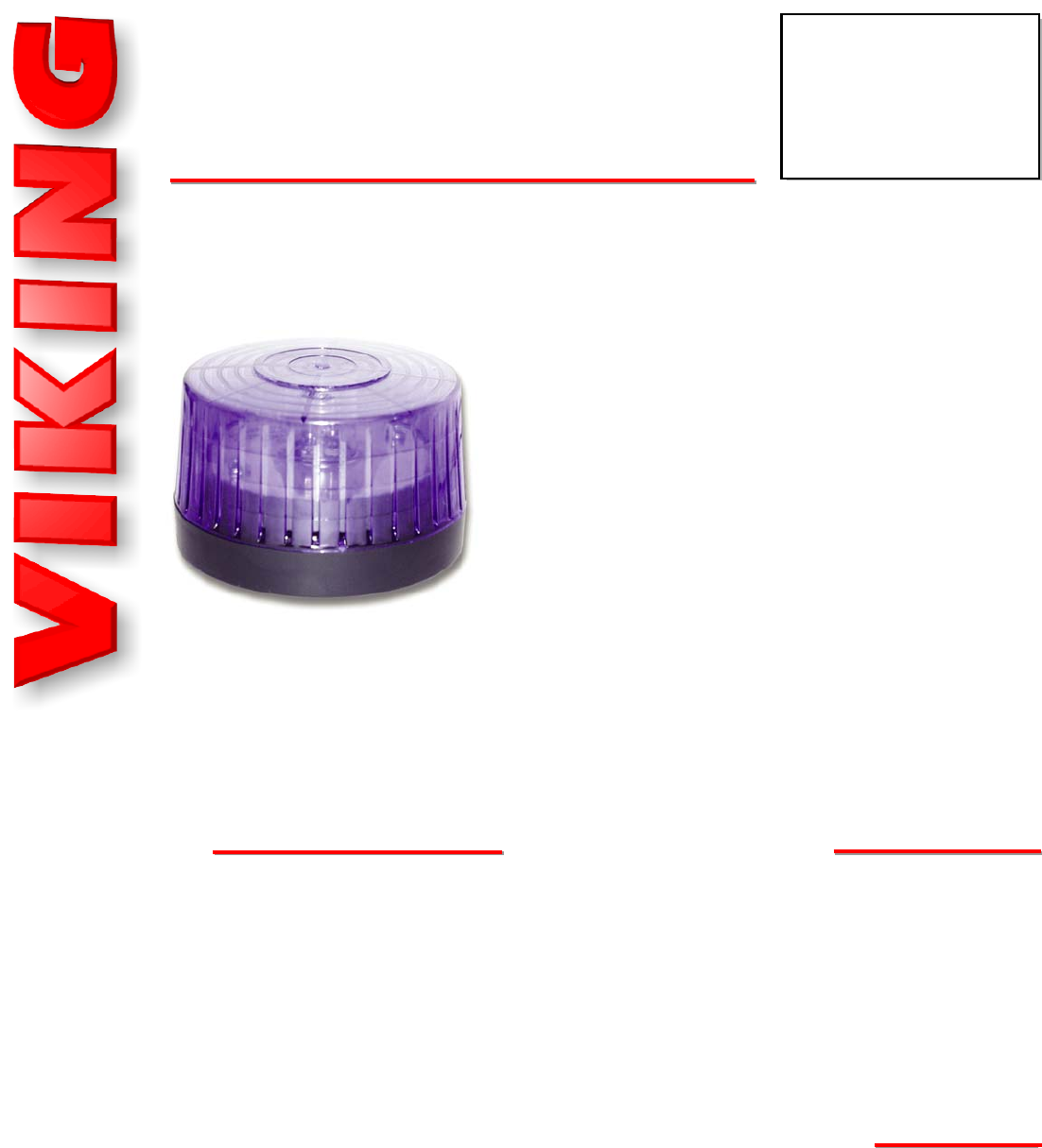
The SL-2 is a 360° LED Strobe and/or Beacon visual indicator.
LED’s not only are more efficient and last longer than standard
flash tubes but are also immune to shock and vibration. The
LED’s are internally positioned to allow a 360° viewing angle
when the unit is mounted vertically and a 120° viewing angle
when side mounted.
The SL-2 can be user programmed to output 4 different flash
patterns: Single Flash, Double Flash, Quad Flash or Flicker
Flash. The unit can also be programmed as a continuous-On
Beacon only, Strobe only or Beacon/Strobe allowing a lower
intensity beacon to remain on and a high intensity strobe to be
activated by a contact closure. 6 different brightness levels are
also programmable for the Beacon and the Strobe. All program-
ming is stored in non-volatile memory so you won’t lose the programming when the unit is powered down,
allowing you to program units prior to installation.
The SL-2 is designed for indoor applications and comes standard with a Blue shatter resistant polycar-
bonate lens. Optional Red, Amber and Clear lenses are sold separately (go to www.vikingelectronics.com
and click on spare parts). Unit surface mounts to wall, post, panel, 4” electrical box or wet location elec-
trical box round lamp holder cover.
LED Strobe and/or Beacon Visual Indicator with
Programmable Brightness and Flash Patterns
Power: 10- 15VDC 0.90 Amp (Peak), 0.15 Amp (Avg) @ 15VDC
Dimensions: 112mm diameter x 70mm (4.41" diameter x 2.76")
Shipping Weight: 0.25 kg (0.6 lbs)
Environmental: -40°C to 60°C (-40°F to 125°F)
Strobe Intensity: xxxx Lumen (max. setting)
Strobe Flash Rate: 60 flashes per minute (default) see Strobe
Flash Patterns page 4
Beacon Intensity: xxxx Lumen (maximum setting)
LED Life: >57,000 hours to 70% LED light output
Connections: Three 9" (22.9 cm) long leads, 26 AWG
S
Sp
pe
ec
ci
if
fi
ic
ca
at
ti
io
on
ns
s
SL-2
SL-2
LED Strobe/Beacon
Visual Indicator
April 2, 2012
• Over 57,000 hour (6.5 year) light source life to
70% light output
• 4 Programmable Flash Patterns
• 6 Programmable Beacon and Strobe brightness
settings
• Immune to shock and vibration
• Low current draw
• Shatter resistant polycarbonate lens
• High noise level area’s where visual status is
required
• Signal personnel of equipment malfunctions
• Warn personnel they are entering a restricted
area
P
Ph
ho
on
ne
e.
..
..
.7
71
15
5.
.3
38
86
6.
.8
88
86
61
1
i
in
nf
fo
o@
@v
vi
ik
ki
in
ng
ge
el
le
ec
ct
tr
ro
on
ni
ic
cs
s.
.c
co
om
m
h
ht
tt
tp
p:
:/
//
/w
ww
ww
w.
.v
vi
ik
ki
in
ng
ge
el
le
ec
ct
tr
ro
on
ni
ic
cs
s.
.c
co
om
m
F
Fe
ea
at
tu
ur
re
es
sA
Ap
pp
pl
li
ic
ca
at
ti
io
on
ns
s
I
In
ns
st
ta
al
ll
la
at
ti
io
on
n
IF YOU HAVE A PROBLEM WITH A VIKING PRODUCT, PLEASE CONTACT: VIKING TECHNICAL SUPPORT AT (715) 386-8666
Our Technical Support Department is available for assistance Monday 8am - 4pm, Tuesday to Friday 8am - 5pm central time. So that we can give you better service, before you call please:
1. Know the model number, the serial number and what software version you have (see serial label).
2. Have your Technical Practice in front of you.
3. It is best if you are on site.
RETURNING PRODUCT FOR EXCHANGE
The following procedure is for equipment that has failed out-of-box (within 10 days of purchase):
1. Customer must contact Viking’s Technical Support at 715-386-8666 to determine possible causes for the problem. The
customer MUST be able to step through recommended tests for diagnosis.
2. If the Technical Support Product Specialist determines that the equipment is defective based on the customer's input
and troubleshooting, a Return Authorization (R.A.) number will be issued. This number is valid for fourteen (14)
calendar days from the date of issue.
3. After obtaining the R.A. number, return the approved equipment to your distributor, referencing the R.A. number. Your
distributor will then replace the product over the counter at no charge. The distributor will then return the product to
Viking using the same R.A. number.
4. The distributor will NOT exchange this product without first obtaining the R.A. number from you. If you haven't
followed the steps listed in 1, 2 and 3, be aware that you will have to pay a restocking charge.
RETURNING PRODUCT FOR REPAIR
The following procedure is for equipment that needs repair:
1. Customer must contact Viking's Technical Support Department at 715-386-8666 to obtain a Return Authorization (RA)
number. The customer MUST have a complete description of the problem, with all pertinent information regarding the
defect, such as options set, conditions, symptoms, methods to duplicate problem, frequency of failure, etc.
2. Packing: Return equipment in original box or in proper packing so that damage will not occur while in transit. Static
sensitive equipment such as a circuit board should be in an anti-static bag, sandwiched between foam and individual-
ly boxed. All equipment should be wrapped to avoid packing material lodging in or sticking to the equipment. Include
ALL parts of the equipment. C.O.D. or freight collect shipments cannot be accepted. Ship cartons prepaid to:
Viking Electronics, 1531 Industrial Street, Hudson, WI 54016
3. Return shipping address: Be sure to include your return shipping address inside the box. We cannot ship to a PO Box.
4. RA number on carton: In large printing, write the R.A. number on the outside of each carton being returned.
LIMITED WARRANTY
Viking warrants its products to be free from defects in the workmanship or materials, under normal use and service, for a period of one year from the date of purchase from any authorized Viking distributor or 18 months from the date manu-
factured, which ever is greater. If at any time during the warranty period, the product is deemed defective or malfunctions, return the product to Viking Electronics, Inc., 1531 Industrial Street, Hudson, WI., 54016. Customer must contact Viking's
Technical Support Department at 715-386-8666 to obtain a Return Authorization (R.A.) number.
This warranty does not cover any damage to the product due to lightning, over voltage, under voltage, accident, misuse, abuse, negligence or any damage caused by use of the product by the purchaser or others. This warranty does not cover
non-EWP products that have been exposed to wet or corrosive environments.
NO OTHER WARRANTIES. VIKING MAKES NO WARRANTIES RELATING TO ITS PRODUCTS OTHER THAN AS DESCRIBED ABOVE AND DISCLAIMS ANY EXPRESS OR IMPLIED WARRANTIES OR MERCHANTABILITY OR FIT-
NESS FOR ANY PARTICULAR PURPOSE.
EXCLUSION OF CONSEQUENTIAL DAMAGES. VIKING SHALL NOT, UNDER ANY CIRCUMSTANCES, BE LIABLE TO PURCHASER, OR ANY OTHER PARTY, FOR CONSEQUENTIAL, INCIDENTAL, SPECIAL OR EXEMPLARY DAM-
AGES ARISING OUT OF OR RELATED TO THE SALE OR USE OF THE PRODUCT SOLD HEREUNDER.
EXCLUSIVE REMEDY AND LIMITATION OF LIABILITY. WHETHER IN AN ACTION BASED ON CONTRACT, TORT (INCLUDING NEGLIGENCE OR STRICT LIABILITY) OR ANY OTHER LEGAL THEORY, ANY LIABILITY OF VIKING SHALL
BE LIMITED TO REPAIR OR REPLACEMENT OF THE PRODUCT, OR AT VIKING'S OPTION, REFUND OF THE PURCHASE PRICE AS THE EXCLUSIVE REMEDY AND ANY LIABILITY OF VIKING SHALL BE SO LIMITED.
IT IS EXPRESSLY UNDERSTOOD AND AGREED THAT EACH AND EVERY PROVISION OF THIS AGREEMENT WHICH PROVIDES FOR DISCLAIMER OF WARRANTIES, EXCLUSION OF CONSEQUENTIAL DAMAGES, AND EXCLU-
SIVE REMEDY AND LIMITATION OF LIABILITY, ARE SEVERABLE FROM ANY OTHER PROVISION AND EACH PROVISION IS A SEPARABLE AND INDEPENDENT ELEMENT OF RISK ALLOCATION AND IS INTENDED TO BE ENFORCED
AS SUCH.
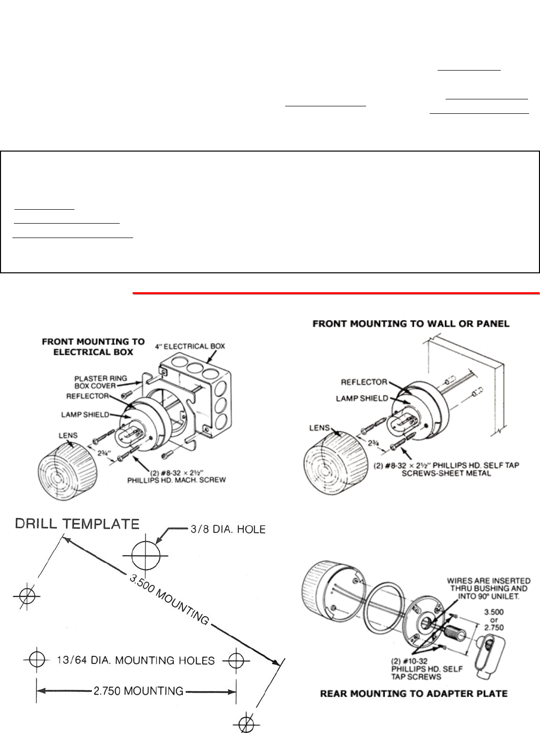
(Drill Template shown at actual size.)
A. Mounting the SL-2
Red
Black
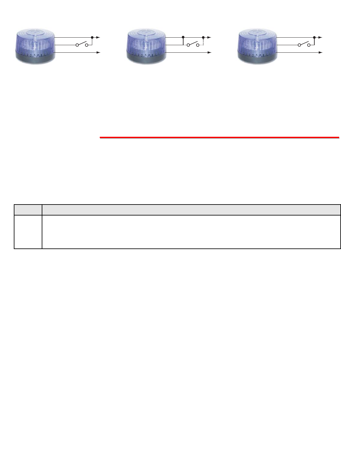
Strobe Only
Green
+ 12VDC
- GND
In programming, select programming feature 2
(strobe only). When the switch/contact is
activated, the strobe will flash for the duration of
the contact closure.
Red
Black
Beacon Only
Green
+ 12VDC
- GND
In programming, select programming feature 3
(beacon only). With the green wire connected to
the red wire, when power is applied the steady-
on beacon will turn on. An optional low current
switch or contact can be used between the
green and red wire to turn the beacon on or off.
Red
Black
Beacon / Strobe
Green
+ 12VDC
- GND
In programming, select programming feature 1
(beacon/strobe, factory default). When power is
applied the lower intensity steady-on beacon
will light. When the switch/contact is activated,
the beacon will turn off and the strobe will flash
for the duration of the contact closure.
or
***
* Note: Switch / dry contact closure with a
minimum contact rating of 25mA @ 15VDC.
P
Pr
ro
og
gr
ra
am
mm
mi
in
ng
g
Select the Feature: Momentarily touch the Green (Control) wire to the Black (-) wire 1 to 10 times to select which fea-
ture to program (see Programming Features List, section C). The strobe should momentarily flash each time the Green
(Control) wire has touched the Black (-) wire.
Features 1-3 & 6-10: After selecting Programming Features 1-3 or 6-10, wait 3 seconds and the strobe should flash
2 times indicating that feature has been programmed. You can now exit programming or move on to programming the
Beacon or Strobe brightness settings.
Setting Strobe Brightness (factory set to 6/Brightest): After selecting Programming Feature 4 (Strobe Brightness),
wait 3 seconds and the strobe should begin flashing in the preprogrammed flash pattern. Touch and hold the Green
(Control) wire to the Black (-) wire. The SL-2 will begin flashing the strobe cycling through 6 different brightness set-
tings from lowest to highest. When the SL-2 flashes at the desired brightness level immediately remove the Green wire
from the Black. The SL-2 should flash twice indicating the selected brightness level has been set.
Setting Beacon Brightness (Factory set to 6/Brightest): After selecting Programming Feature 5 (Beacon Brightness),
wait 3 seconds and the beacon will light at its preprogrammed beacon brightness setting. Touch and hold the Green
(Control) wire to the Black (-) wire. The SL-2 will begin stepping through 6 different beacon brightness settings from
lowest to highest. When the SL-2 lights at the desired beacon brightness level immediately remove the Green wire
from the Black. The SL-2 should flash twice indicating the selected brightness level has been set.
Exiting Programming: To exit programming simply wait 20 seconds from the last programming command and the unit
will flash 3 times. This indicates the SL-2 has exited the programming mode and is now in the Run mode. Note: To
eliminate waiting 20 seconds, you can also exit programming after the last programming command by touching and
holding the Green (Control) wire to the Black (-) for 3 seconds. The strobe will flash 3 times indicating the unit has exit-
ed the programming mode and is now in the Run mode.
The SL-2 can be user programmed as a Beacon only, Strobe only or Beacon/Strobe. The brightness setting can be pro-
grammed separately for the Strobe or Beacon and one of 4 different Flash Patterns can be programmed for the Strobe (See
Strobe Flash Patterns, section D).
A. Accessing the Programming Mode
(Optional, the SL-2 is factory programmed to the Beacon/Strobe Mode and brightest Beacon/Strobe settings).
Step 1. Apply 10-15 VDC power to the Red (+) and Black (-) wires.
Step 2.
Touch and hold the Green (Control) wire to the Black (-) wire for 3 seconds. The strobe should flash twice.
You are now in Programming mode. Note: Once in the programming mode, if a programming command
has not been entered for 20 seconds the strobe will flash 3 times indicating the unit has exited program-
ming and returned to the Run Mode.
B. Programming Desired Features (after accessing Programming Mode above)
B. Wiring the SL-2
Repeat
ON
ON ONOFF
ON OFF ON ON ONOFF OFF
OFF
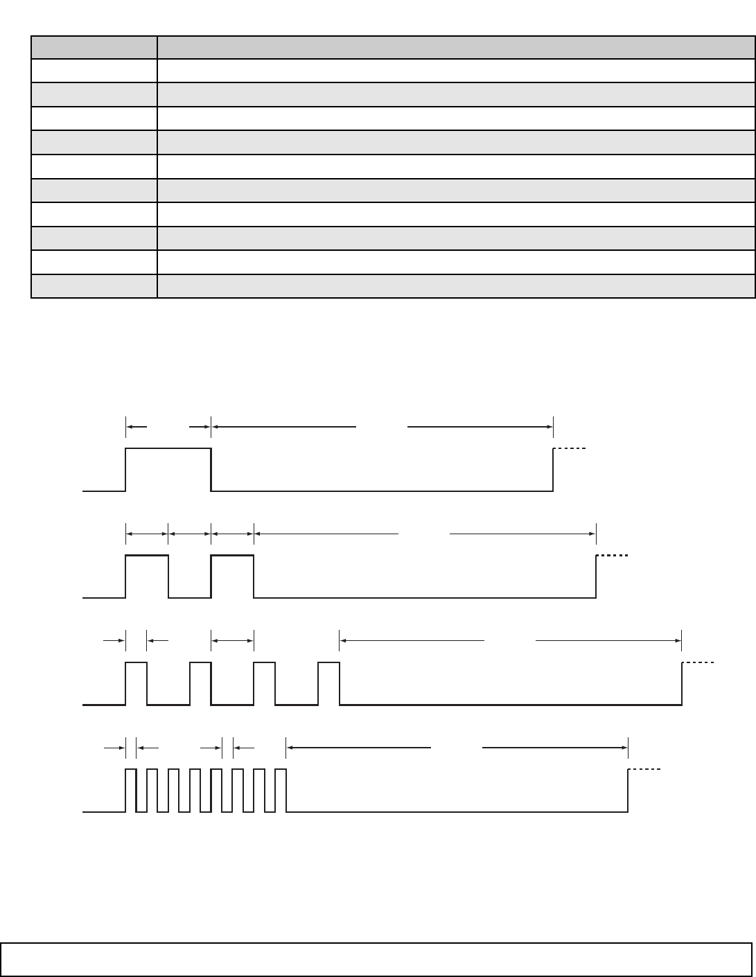
0.10
sec
0.10
sec
0.10
sec
0.20 sec
0.10
sec
0.05
sec
0.025
sec
Typ.
0.025
sec
Typ.
8 Pulses
ON
OFF
ON
OFF
ON
OFF
ON
OFF
ON
OFF
ON
OFF
ON
OFF
ON
0.80 sec
OFF
0.80 sec
OFF
0.80 sec
OFF
0.80 sec
Repeat
Repeat
Repeat
Single
Flash:
Double
Flash:
Quad
Flash:
Flicker
Flash:
Due to the dynamic nature of the product design, the information contained in this document is subject to change without notice. Viking Electronics, and its affiliates and/or subsidiaries
assume no responsibility for errors and omissions contained in this information. Revisions of this document or new editions of it may be issued to incorporate such changes.
DOD# XXX ZF303300 Rev 4Printed in the U.S.A.
P
Pr
ro
od
du
uc
ct
tS
Su
up
pp
po
or
rt
tL
Li
in
ne
e.
..
..
.7
71
15
5.
.3
38
86
6.
.8
86
66
66
6F
Fa
ax
xB
Ba
ac
ck
kL
Li
in
ne
e.
..
..
.7
71
15
5.
.3
38
86
6.
.4
43
34
45
5
Feature # : Description:
1Beacon/Strobe (factory default)
2Strobe Only
3Beacon Only
4Strobe Brightness 1-6 (factory default = 6/Brightest setting)
5Beacon Brightness 1-6 (factory default = 6/Brightest setting)
6Single Flash Strobe (factory default)
7Double Flash Strobe
8Quad Flash Strobe
9Flicker Flash Strobe
10 Reset to Factory Default Settings
C. Programming Features List
D. Strobe Flash Patterns
