Copper Pak Water Heater Brochure
User Manual: Copper-Pak
Open the PDF directly: View PDF ![]() .
.
Page Count: 52
Water Heater
Product Line
Brochure
Lochinvar Corporation
300 Maddox Simpson Pkwy
Lebanon, TN 37090
615-889-8900 / Fax: 615-547-1000
www.Lochinvar.com
From the tiny 2 gallon Jr. Electric to the innovative Intelli-Fin, Lochinvar
water heaters are noted for their range of features and application flexibility.
Collectively, they represent the most complete product line in the industry, from
a company with a long history of innovation and a reputation for excellence.
You’ll find there’s a Lochinvar product for any application imaginable—
from standard residential units to the advanced Copper-Fin II with proportional
firing. And with selection, comes opportunity.
In fact, the diversity and performance of our product line is surpassed only
by its quality—in design, construction, and training. Lochinvar quality is re-
inforced by our world class manufacturing plant, commitment to research and
development and unparalleled industry training available at Lochinvar Univer-
sity.
Quality, efficiency, features, service, and selection. For more than 85 years,
these have been the hallmarks of Lochinvar products. Lochinvar... the innovator
in water heating technology.
Contents
1 ARMOR®
3 SHIELD®
5 Intelli-Fin®
7 Power-Fin®
9 Copper-Fin II®
11 Copper-Fin
13 Efficiency+
14 Efficiency Pac®
15 Copper-Fin® “Better Idea”
17 Copper-Pak®
18 Charger
19 Super Charger
20 TurboCharger®
21 Charger Power DV
22 Custom Hi-Power®
23 Standard Hi-Power®
24 Compact ASME Hi-Power®
25 Light Duty Commercial
26 Explosion-Resistant
27 Space-Saver Electric Boosters
28 Round Jacketed Storage Tanks
29 Square Jacketed Storage Tanks
30 Bare Storage Tanks
31 Hot Water Generators
33 Squire Indirect Water Heater
34 Energy Saver Indirect
35 Residential Electric
36 Junior Electric
37 Residential Gas
38 Power-Vented FVIR
39 Power-Vented
40 Power Direct Vent
41 Balanced Flue
42 Double Duty
43 Manufactured Home
44 Solar
45 Multi-Stack
This catalog is designed to provide a convenient, condensed overview of the entire Lochinvar water heater line.
For a complete list of features, specifications and technical data on a particular product, see your manufacturer’s representative
or contact Lochinvar.
Every Lochinvar product is designed and built to meet or exceed the fuel efficiency and safety standards of one or more of these
agencies, wherever applicable.
The Innovator In Water Heating Technology
This ingot means the Multi-Stack Frame is
available for use with that product. See
page 45 & 46 for details.
This ingot means a product has a NOx
rating which exceeds the requirements of
the South Coast Air Quality Management
District and Texas National Resource
Conservation Commission.
1
The Intelligent Approach to Water Heating
There are several tank-type commercial water heaters on the
market with thermal efficiencies of 95% or higher. They all
promise tremendous savings on operating costs compared to
standard-efficiency units, but none of them truly measures up to
the Lochinvar ARMORTM.
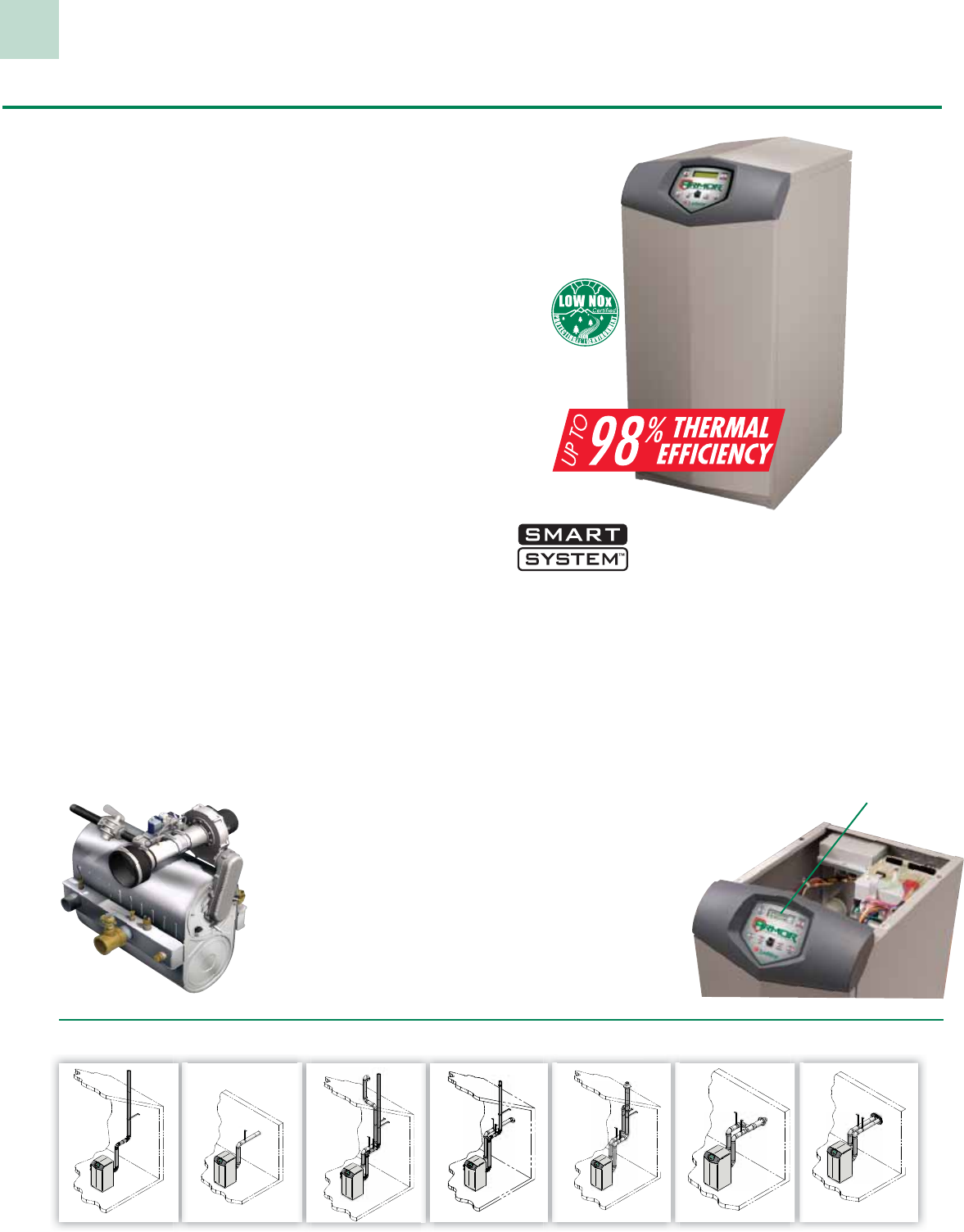
ARMOR is a fully condensing commercial gas water heater. Available
in eight models with inputs ranging from 150,000 to 800,000 Btu/hr,
the ARMOR achieves thermal efficiencies up to 98%.
ARMOR delivers long-lasting life-cycle efficiency surpassing any
commercial unit in its class. When you look beyond the numbers
you’ll discover the many ways that ARMOR technology is in a
class by itself!
Fully Modulating with 5:1 Turndown
ARMOR features advanced Negative Regulation (Neg/Reg)
sealed combustion technology, permitting fan speed to constantly
adjust the volume of fuel and air entering the burner. This ensures
that ARMOR can safely and reliably operate with supply gas
pressure as low as 4 inches water column.
ARMOR is equipped with fully modulating combustion with
5:1 turndown. This means ARMOR can fire as low as 20%
of maximum input when water heating demand is lowest, and
increase the firing rate up to 100% as demand increases. The result
is better overall efficiency and less cycling, compared to all other
tank-type units which are “on-off,” which means they can only fire
at 100% of maximum input.
Stainless Steel Condensing Heat Exchanger
The ARMOR’s stainless steel heat exchanger is built to
ASME Section IV requirements. Its design provides superior
resistance to corrosion caused by
condensation from low entering
water temperatures. Traditional
commercial water heaters will
fail early with low entering water
temperatures; however, with the
ARMOR the lower the supply
water temperature the more
efficiently it performs throughout
the life of the heater.
The Ultimate Water Heater
Operating Control
• Easy to use – makes setup and service a breeze
• 2-line 16-character lcd display of setup, system status
and diagnostic data in words, not codes
• Water heater pump control:
> Pump delay with freeze protection
> Pump exercise
• High-voltage terminal strip:
> 110 Vac input to water heater
> 110 Vac output to pump
• Low-voltage terminal strip with
• 22 points of connection
• Built-in cascading sequencer controls
up to 8 Armor units
without the added
cost of a separate
third-party sequencer
• Interface for optional
smart system
PC software for
advanced setup
and diagnostics
7 Venting Options - Easy, Flexible Installation and Service
Armor®150,000 to 800,000 Btu/hr Models
Room Air Vertical Direct Vent Vertical Direct Vent Vertical*
Room Air Sidewall Direct Vent Sidewall
Direct Vent Sidewall*
D
*Optional Concentric Vent Kit Sold Separately
Vertical w/Sidewall Air
2-line 16-character
LCD display of setup,
system status and
diagnostic data in
words, not codes
Dimensions & Specifications
2
Armor®150,000 to 800,000 Btu/hr Models
Optional Equipment
> Adjustable High Limit w/ Manual Reset
> Alarm Bell
> Condensate Neutralization Kit
> High & Low Gas Pressure Switches
(AW 500-800)
> Concentric Vent Kit
(3” & 4” PVC/CPVC only)
> SMART SYSTEM PC Software
> Room Air Vent Kits
> Multi-Stack Frame
Firing Control Systems
>M9 Standard Construction
>M7 California Code
(AW 285-800)
>M13 CSD1 / FM / GE Gap
(AW 500-800)
Registered under U.S. Patent # 7,506,617
Standard Features
> Up to 98% Thermal Efficiency
> Modulating Burner with 5:1 Turndown
> Direct-Spark Ignition
> Low NOx Operation
> Sealed Combustion
> Low Gas Pressure Operation
> Vertical & Horizontal Direct-Vent
> PVC, CPVC or SS Venting up to 100 Feet
> PVC/CPVC Sidewall Vent Termination
> Stainless Steel Heat Exchanger
> All Welded Construction, Gasketless Design
> 160 psi Working Pressure
> ASME Construction (AW 285-800)
> Natural to L.P. Conversion Kit
> All Bronze Circulating Pump
> On/Off Switch
> Flow Switch
> ASME Temperature & Pressure Relief Valve
> Temperature & Pressure Gauge (AW 500-800)
> Downstream Test Valves (AW 500-800)
> Adjustable Leveling Legs
> Tank Sensor
> Manual Reset High Limit
> Condensate Trap
> Zero Clearances to Combustible Material
> 5 Year Limited Warranty (See Warranty for Details)
> 1 Year Parts Warranty (See Warranty for Details)
Smart System Features
> SMART SYSTEM Digital Operating Control
> 2 line, 16 Character Display
> Dual Level Password Security
> Built in Cascading Sequencer
for up to 8 Water Heaters
> Building Management System Integration
with 0-10 VDC Input
> Low Water Flow Safety Control & Indication
> Inlet & Outlet Temperature Sensors & Readout
> Flue Temperature Sensor
> Water Heater Pump Control
> Pump Delay with Freeze Protection
> Pump Exercise
> Night Setback
> Time Clock
> Service Reminder
> High Voltage Terminal Strip
> 120 VAC / 60 Hertz / 1 Phase Power Supply
> Pump Control Contacts
> Low Voltage Terminal Strip
> 24 VAC Auxiliary Device Relay
> Auxiliary Proving Switch Contacts
> Flow Switch Contacts
> Alarm on Any Failure Contacts
> Runtime Contacts
> Tank Sensor Contacts
> Cascade Contacts
> 0-10 VDC BMS External Control Contact
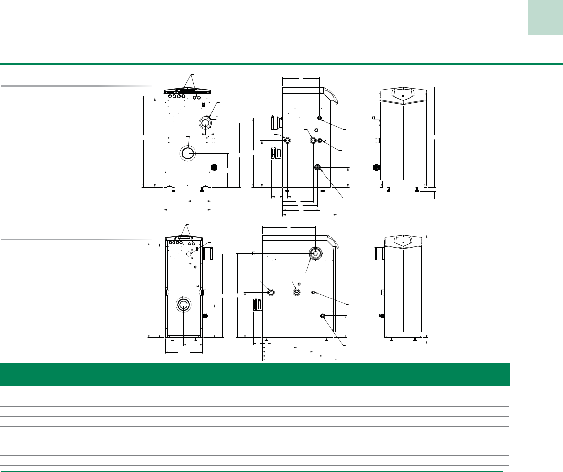
Models 150-199
Models 285-800
TNORF
"
4
/3 7
"
2
/1
51
"4/1 11
H
"4/3 92
"4/1 03 J
"2/1 51
I
K
"4/3 3 GFE
DC
"2/1 6
A
"4/1 1 - "4/1 ELBATSUJDA
TELNI RIA
EULF
LACIRTCELE SNOITCENNOC
SAG
TELNI TELTUO
NIARD TPN "4/3
ETASNEDNOC NIARD
TNORF
K
CAB
"8
"2/1 51
"
93
"2/1 93
"4/3 31
I
K
"4/3 81
H
J
"4/3 3 G FDEC
"9
A
"4/1 1 - "4/1 ELBATSUJDA
TELNI R
I
A
EULF
LACIRTCELE SN
OI
TCE
N
NO
C
S
A
G
TELNI TELTU
O
NIARD TPN "4/3
ETASNEDNOC NIARD
Model Btu/hr GPH @ Gas Water Air Vent Shipping
Number Input 100° Rise A C D E F G H I J K Conn. Conn. Inlet Size Wt. (lbs.)
AWN150PM 150,000 174 33-1/4” 18” 12-1/4” 11-1/2” 10” 1-1/2” 21-1/4” 23” 1-3/4” 12” 1/2” 1-1/4” 3” 3” 165
AWN199PM 199,999 235 33-1/4” 22-1/4” 16-1/2” 15-3/4” 14-1/4” 5-1/4” 21-1/4” 23” 1-3/4” 16-1/4” 1/2” 1-1/4” 3” 3” 185
AWN285PM 285,000 339 42-1/2” 19-3/4” 12-3/4” 13-1/2” 6” 2” 34” 31” 11-3/4” 4-1/4” 3/4” 2” 4” 4” 235
AWN399PM 399,999 475 42-1/2” 27” 21” 20-3/4” 14” 3-1/2” 34” 34” 18-3/4” 2” 1” 2” 4” 4” 295
AWN500PM 500,000 594 42-1/2” 31-1/4” 21” 25” 14” 3-1/2” 35” 35” 22” 5-3/4” 1” 2” 4” 4” 335
AWN600PM 600,000 713 42-1/2” 36-1/4” 25” 21” 14” 3-1/2” 36” 32-3/4” 19-1/2” 5-1/2” 1-1/2” 2” 4” 4” 380
AWN700PM 700,000 832 42-1/2” 40-1/4” 29” 23” 17” 3-1/2” 36” 32-3/4” 23-1/2” 3-1/4” 1-1/2” 2” 4” 6” 461
AWN800PM 800,000 950 42-1/2” 45-1/4” 33-1/4” 23” 17” 3-1/2” 36” 32-3/4” 27-3/4” 3-1/4” 1-1/2” 2” 4” 6” 527
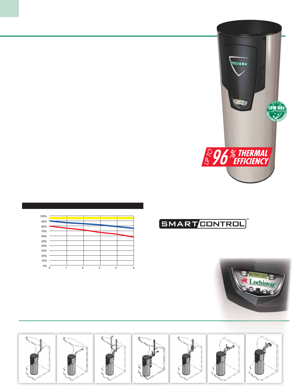
96 % Thermal Efficiency for Life
The SHIELD™ commercial water heater delivers best-in-class
innovation from Lochinvar. It operates at 96% thermal efficiency,
with inputs up to 500,000 Btu/hr, and provides a 100% effective
defense against a water heater’s worst enemy—lime scale buildup
inside the tank.
SHIELD uses the industry’s most advanced stainless steel heat
transfer system. Sealed combustion technology delivers a quiet
and environmentally friendly supply of heat to the system. Plus,
with drawdown capacity as much as 15% higher than typical
tank-type heaters, you get more usable hot water than any
other competing models. The result is quiet, long-lasting green
performance…life cycle efficiency that keeps saving money,
year after year.
Long-Lasting Life Cycle Efficiency
High-efficiency tank-type water heaters have one thing that
SHIELD does not, energy-robbing lime scale buildup. This
insulates the water from the heat source, decreasing thermal
efficiency, which increases operating costs. Additionally, the rate
of scaling increases with temperature and usage. Just a ¼” of lime
scale buildup will cause increased fuel consumption and raise
operating costs as much as 25%. Lime scale buildup also requires
periodic acid washes in the tank that will simply result in a shorter
useful life of the equipment.
Because Shield has no flue tubes inside the tank, the impact
of lime scale is eliminated, ensuring high efficiency and low
operating costs throughout its life cycle. The chart below illustrates
SHIELD’s consistent “life cycle efficiency” compared to both
standard and high-efficiency tank-type units which utilize flue
tubes for heat transfer.
Fully Modulating
Burner with 5:1
Turndown
SHIELD can fire as low
as 20% of maximum
input when water heating
demand is lowest, and
increase to 100% for
peak-demand periods.
This results in better overall
efficiency and less cycling
compared to “on-off” tank-
type units that can
only fire at 100%.
‘Neg/Reg’ Sealed
Combustion
Technology
SHIELD utilizes
an advance
combustion system
which provides
NOx ratings compatible with
the most stringent air quality
standards. Additionally, the NEG/REG sealed combustion
technology allows the unit to operate with inlet gas pressure
as low as 4 inches water column.
Advanced Electronic Control
SHIELD features the ultimate water heater control which
makes system setup, service and operation a breeze. A 2-line,
16-character backlit LCD display gives readouts of setup, system
status and diagnostic information in words, not codes.
SMART CONTROL™
also includes:
> Night Setback
> Time Clock
> Alarm Contacts
> Runtime Contacts
> Service Mode
> Last 10 Lock-Outs
3
Shield ® 150,000 to 500,000 Btu/hr Models
7 Venting Options - Easy, Flexible Installation and Service
Room Air Vertical Direct Vent Vertical Direct Vent Vertical*
Room Air Sidewall
D
*Optional Concentric Vent Kit Sold Separately
Vertical w/Sidewall Air
Y
Yea
rs
of
Ope
rat
io
on
%
% E
ffi
cie
e
ncy ov
er
r
Heater
L
Li
fe
Efficiency Loss Due to Lime Scale Buildup
SHIELD
S
SH
H
IELD
High-
Efficiency
Tank Types
Standard
Tank Types
Ope
at
ra
ing
Ef
fic
en
ie
cy
Ad
Ad
Ad
Ad
Ad
Ad
va
va
va
va
va
nc
nc
nc
nc
nc
d
ed
ed
ed
ed
ed
E
E
E
E
E
E
l
le
le
le
le
le
t
ct
ct
ct
ct
ct
ro
ro
ro
ro
ro
i
ni
ni
ni
ni
ni
c
c
c
c
c
C
Co
Co
Co
Co
Co
t
nt
nt
nt
nt
nt
ro
ro
ro
ro
ro
l
l
l
l
l
l
SH
SH
SH
SH
IE
IE
IE
IE
LD
LD
LD
LD
f
f
f
f
f
ea
ea
ea
t
tu
tu
tu
re
re
re
s
s
s
h
th
th
th
th
e
e
e
l
l
ul
ul
ul
i
ti
ti
ti
ti
ma
ma
ma
t
te
te
te
w
w
w
t
at
at
at
er
er
er
h
h
h
h
h
ea
ea
ea
t
te
te
te
r
r
r
co
co
nt
nt
r
ro
Kit Sold Separately
Kit S
Direct Vent Sidewall* Direct Vent Sidewall
4
Shield ® 150,000 to 500,000 Btu/hr Models
> Low Gas Pressure Operation
> Direct-Spark Ignition
> Certified for Installation on Combustible Floors
> ASME Temperature and Pressure Relief Valve
> 8-Foot Power Cord
> 3-Year Limited Warranty
> 1-Year Parts Warranty
Optional Equipment
> Alarm Bell
> Concentric Vent Kit
> Condensate Neutralization Kit
> Low Water Cutoff
Standard Features
> 96% Thermal Efficiency
> Modulating Burner with 5:1 Turndown
> Operates at Temperatures up to 180˚F for
Sanitizing Applications
> Stainless Steel Heat Exchanger
> Glass-Lined Steel Tank
> 150 PSI Working Pressure
> ASME Tank Construction (SNA285–500)
> Zero Clearances to Combustible Material
> PVC, CPVC and Stainless Steel Venting
up to 100 Equivalent Feet
> Direct-Vent Sealed Combustion
> Brass Drain Valve
> Rooftop and Sidewall Venting
> Sidewall Vent Terminal
> Room Air Venting up to 100 Equiv. Feet
> Advanced Electronic Control, with:
- 2-Line, 16-Character LCD Display
- Time Clock
- Night Setback
- Alarm Contacts
- Runtime Contacts
- Manual Reset High Limit
- 3 Temperature Sensors
- Flue Temperaure Sensor
> Low-NOx Operation
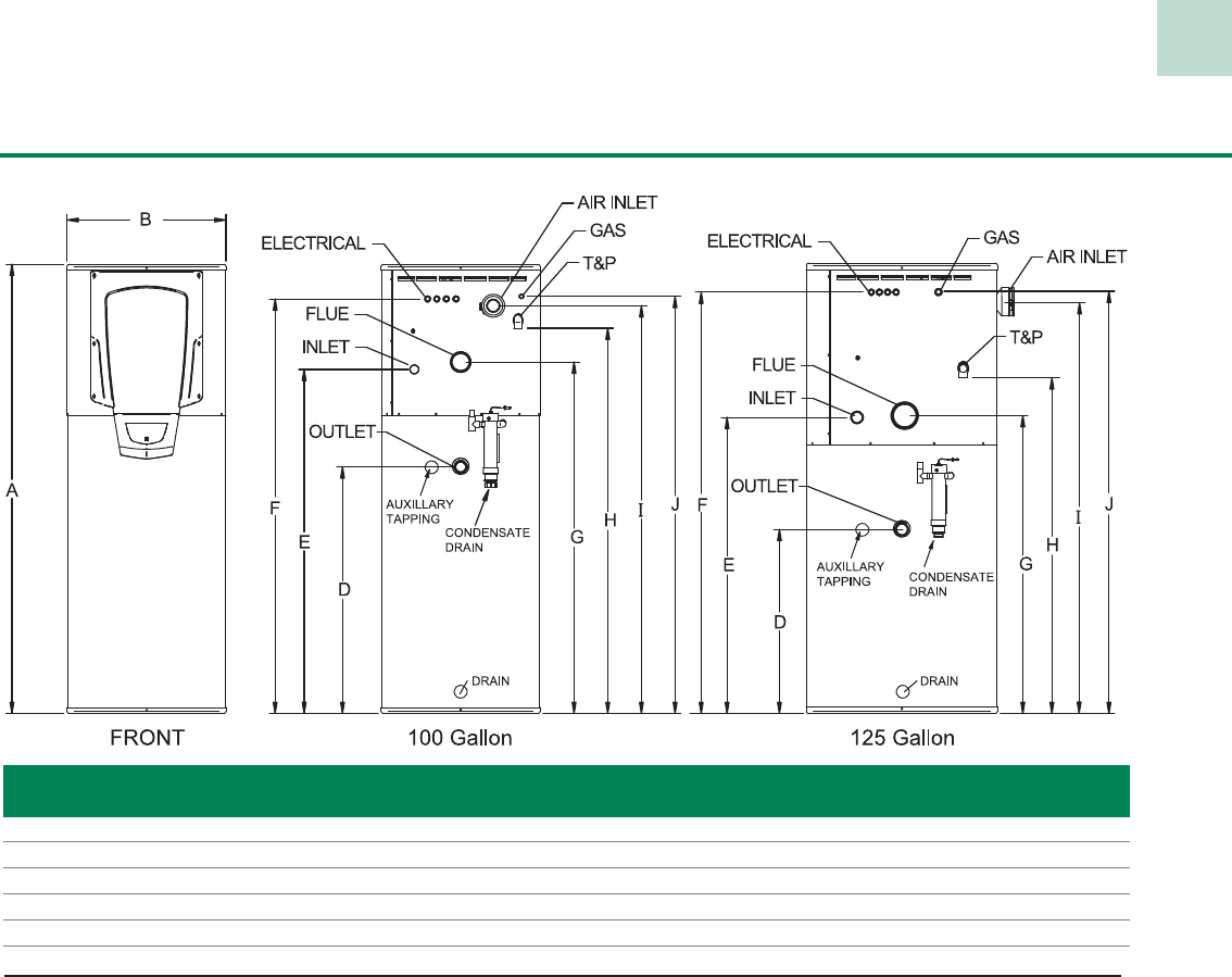
Model Btu/hr Capacity GPH @ First Gas Water Air Vent Shipping
Number Input (Gal) 100° Rise Hour A B D E F G H I J Conn. Conn. Inlet Size Wt. (lbs.)
SNR150-100 150,000 93 175 249 80" 28" 44" 61-1/4" 73-3/4" 62-1/2" 68-3/4" 72-3/4" 74-1/4" 1/2" 1-1/2" 3" 3" 620
SNR200-100 199,999 93 233 307 80" 28" 44" 61-1/4" 73-3/4" 62-1/2" 68-3/4" 72-3/4" 74-1/4" 1/2" 1-1/2" 3" 3" 640
SNA285-125 285,000 125 332 432 80" 34" 32-3/4" 52-3/4" 75" 53" 59-3/4" 73-1/4" 70-1/2" 3/4" 2" 4" 4" 835
SNA400-125 399,999 125 465 565 80" 34" 32-3/4" 52-3/4" 75" 53" 59-3/4" 73-1/4" 73-1/4" 1" 2" 4" 4" 855
SNA500-125 500,000 125 582 682 80" 34" 32-3/4" 52-3/4" 75" 53" 59-3/4" 72" 75" 1" 2" 4" 4" 895
Change "N" to "L" for LP Gas. All information is subject to change.
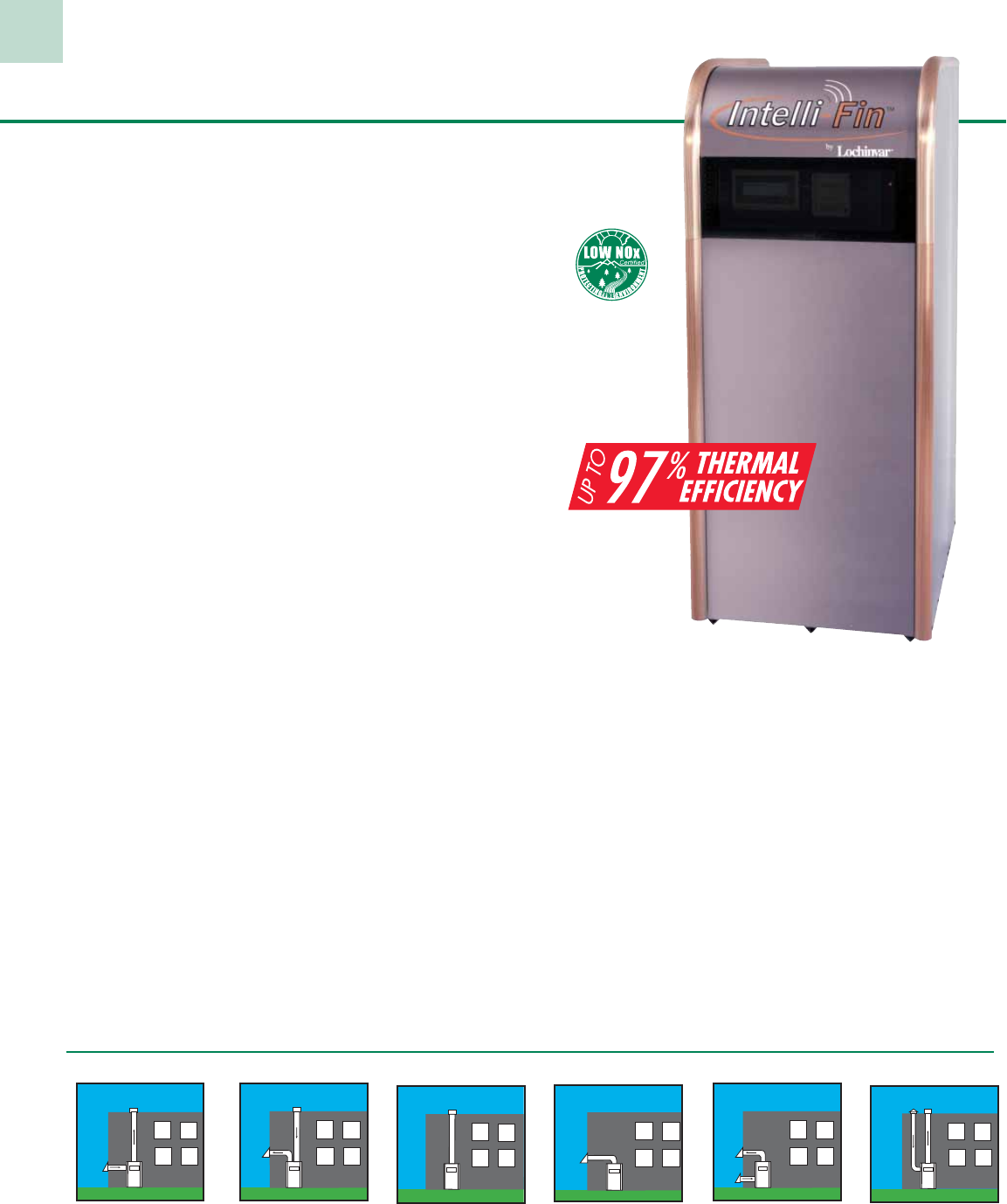
The Intelligent Approach to Water Heating
Our 1.5 million, 1.7 million, and 2 million-Btu/hr Intelli-Fin
water heaters are whisper quiet. They are engineered to take
advantage of the power of digital communications. That’s
a powerful advantage, because this capability, along with
Lochinvar’s engineering, means Intelli-Fin provides you with
the lowest total cost of water heater operation.
Pushing the Upper Limits of Efficiency
Independent testing shows that Intelli-Fin reaches up to 97%
thermal efficiency. That means for every energy dollar, 97
cents is converted into useable heat. To achieve this higher
efficiency, Lochinvar utilizes a dual heat exchanger arrangement
to create a heat trap. One heat exchanger surrounds the unit’s
burner, absorbing heat at the point of combustion. A second
heat exchanger captures additional heat as the spent gases are
extracted from the combustion chamber. The position of this
second heat exchanger forces the products of combustion to flow
over it’s entire surface allowing the remaining heat to be absorbed
and transferred to the water.
Intelligent Enough to Speak Your Language
Intelli-Fin is the first water heater designed to be compatible
with LonWorks®, the interoperability language that is fast
becoming the language standard for building management
systems. To enhance this LonWorks performance Lochinvar has
developed a new control, which provides a remarkable amount of
information and the ability to customize equipment for a specific
application. This control along with the Command Display
allows local monitoring of 21 diagnostic points and adjustment
of 6 operational characteristics. If remote system management is
desired, all Intelli-Fin functionality can be accessed, reviewed and
adjusted via a phone line and personal computer.
Adjust Output to Match Demand
Intelli-Fin utilizes variable frequency drive technology to control
gas and air input to the burner, ensuring complete combustion
and enabling infinitely proportional adjustment of Btu/hr output.
In fact, Intelli-Fin can reduce output from 100% to 25% of rated
capacity and efficiently provide heat at any fraction of the load
in between. This variable combustion process combined with
Lochinvar’s new temperature control, accurate to with in 1°F,
enables Intelli-Fin to track the heating load precisely.
Flexibility in Water and Gas Supplies
Intelli-Fin can operate with a minimum inlet gas pressure as low as
4 inches of water column. This reduced input requirement prevents
nuisance operational problems in areas of varying gas supply
pressures. Additionally, the sophisticated heat transfer system of
Intelli-Fin integrates dual heat exchangers with a full automatic
pumped bypass. This design allows Intelli-Fin to operate with return
water temperatures as low as 50°F, providing increased installation
flexibility in applications such as heat pump, snow melting and
radiant floor systems.
An Intelligent Use of Space
Intelli-Fin’s chassis has been engineered so that it makes use of
vertical rather than horizontal space. This allows the smaller
footprint, but the unit is still so compact that it fits in spaces no
higher than 80 inches. For even more convenience, Intelli-Fin offers
several venting options. If your project demands high efficiency,
Intelli-Fin delivers. In fact, it’s virtually impossible to be any better.
Venting Options – Using Category IV approved venting material
Intelli-Vent
Vertical
Vents vertically up to 100
equivalent feet. Directly
draws combustion air 100
equivalent feet from a side
wall.
Intelli-Vent
Horizontal
Vents horizontally up to 100
equivalent feet. Directly
draws combustion air 100
equivalent feet from the
roof top.
Vertical
Vents vertically using
Category IV approved
vent material.
Sidewall
Vents horizontally up to
100 equivalent feet.
Direct Vent
Horizontal
Vents horizontally up
to 100 equivalent feet.
Directly draws combustion
air 100 equivalent feet
from a side wall.
Direct Vent
Vertical
Vents vertically up to 100
equivalent feet. Directly
draws combustion air 100
equivalent feet from the
roof top.
Intelli-Fin®1.5, 1.7 & 2.0 MBH Models
5
Dimensions & Specifications
Intelli-Fin® 1.5, 1.7 & 2.0 MBH Models
Model Btu/hr GPH @ Air Inlet Vent Shipping
Number Input 100°F Rise A D E F Size Size Weight
IWN1500 1,500,000 1,700 67-3/4” 52-3/4” 40-3/4” 4-1/2” 6” 6” 1,475
IWN1700 1,700,000 1,927 72-1/4” 57-1/4” 45-1/4” 4-1/2” 6” 7” 1,545
IWN2000 2,000,000 2,267 79” 64” 52” 6-1/2” 8” 8” 1,610
Notes: Change ‘N’ to ‘L’ for LP Gas Models. No deration on LP models. Performance data is based on manufacturer test results.
All gas connections are 1 1/2” NPT. All water connections are 3”.
Standard Features
• Up to 97% Thermal Efficiency
• 4:1 Turndown
• LonMark Building Management System Compatibility
• Command Display - 21 Point Diagnostic Control (One per Job Site)
• Variable Frequency Drive
• Digital Temperature Control Accurate to 1ºF
• Alcromesh Burner with 5-Year Limited Warranty
• Low NOx Operation Exceeds the most
Stringent Air Quality Requirements
• ASME Copper Finned Tube Heat Exchanger
• 160 psi Working Pressure
• Gasketless Heat Exchanger Design
• All Bronze Circulating Pump-Mounted and Wired
• Pump Delay
• Glass-Lined Water Surfaces
• Internal Stainless Steel Jacket
• Internal Corrosion Protection
• Low Gas Pressure Operation
• Zero Clearance to Combustible Materials
• Alarm Contacts on any Failure
• Contacts for Air Louver
• ASME Temperature & Pressure Relief Valve
• Down Stream Test Valve
• Adjustable High Limit w/ Manual Reset
• Manual Control Override
• Flow Switch
• Small Footprint
• Whisper Quiet Operation
• 24 Volt Circuit Breaker
• Freeze Protection
• Construction Air Filter
• 5 Year Limited Warranty on Heat Exchanger
(See warranty for details)
Optional Equipment
• 4-20 mA VDC Signal
• Additional Command Display
• Alarm Bell
• Cupro-Nickel Heat Exchanger
• High Gas Pressure Switch
• Low Gas Pressure Switch
• Horizontal Air Intake Cap
• Horizontal Vent Cap
• Low Water Cut-Off
• Neutralization Kit
MONITORING
• Local Monitoring via Personal Computer
-includes serial LonTalk adapter & serial cable
• Remote Monitoring via Personal Computer
-includes serial LonTalk adapter, approved
network modem and adapter cable
SEQUENCING
• Standard Sequencing Package:
First On/Last Off
First On/First Off with Lead-Lag
• Custom Sequencing Package:
Efficiency Optimization
Efficiency Optimization with Run Time Equalization
First On/Last Off
First On/First Off with Lead-Lag
Firing Control Systems
• M9 HSI (Standard)
• M7 California Code
Registered under U.S. Patent # 6,428,312, 6,619,951 & 6,694,926
6
Venting Options
7
Power-Fin® 500,000 - 2,000,000 Btu/hr Models
Vertical Vent
Vertical venting using Category
I or Category IV
vent materials. Draws
combustion air from
the room.
DirectAire Horizontal
Vents horizontally up to 50
equivalent feet using Category IV
vent materials. Draws combustion
air up to 50 ft. from a different
pressure zone.
Sidewall Venting
Horizontal venting up to 50
equivalent feet using Category
IV vent materials. Draws
combustion air from the room.
Direct Venting
Horizontal or vertical venting up to 50
equivalent feet using Category IV vent
materials. Draws combustion air from
the same pressure zone. This option
only available with 5:1 (M) firing code
models.
Common Venting
Vents multiple units vertically through
one vent termination with Category II
vent materials and draws combustion
air from the room, roof or sidewall.
Vent kit and Category IV to II
conversion kit required.
DirectAire Vertical
Vertical venting up to 50 equivalent
feet using Category I or IV vent
materials. Draws combustion air up
to 50 ft. from a different pressure
zone.
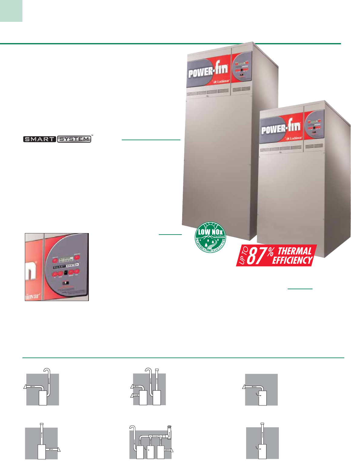
The Next Generation
The latest generation of Power-Fin continues to evolve, with
new “Built-in Advantages” from Lochinvar Corporation®. These
include expanded burner modulation and the advanced SMART
SYSTEM™ operating control, including a built-in cascading
sequencer for up to eight water heaters. Power-Fin water heaters
can be installed with Lochinvar’s advanced Lock-Temp® storage
tanks, in a wide variety of combinations to meet system sizing
requirements. “Factory packaged” water heater/storage tank
systems can be built to your specifications, with all piping
installed, and shipped on I-beam skids.
Control
• Built-in cascading sequencer controls up to 8 units
• 2-line 16-character LCD readout of setup, system status
and diagnostic data in words, not codes.
• Password security
• Pump control for operation of water heater pump
• Pump delay w/freeze protection
• Low NOx operation
• 0-10 Vdc BMS input for easy integration into Building
Management Systems
• Optional smart system PC software for advanced setup
and diagnostics
Infinite Modulation
With thermal efficiencies up to 87%,
Power-Fin water heaters feature
infinitely modulating burner firing
rates (turndown), precisely matching
the firing rate to domestic water load
requirements. The result is better
overall efficiency and less cycling.
Power-Fin water heaters may be
specified as either 5:1 turndown
(502 - 2001), 2:1 turndown (1501 - 2001), or ON/OFF
(502 - 1302). With 5:1 turndown the burner fires as low as
20% of maximum input when demand is lowest and increases
the firing rate up to 100% as demand increases. Models with
2:1 turndown modulate from 50% to 100% of maximum input.
Gasketless Heat Exchanger
The Power-Fin heat exchanger features an array of 20
or 24 copper-finned tubes surrounding the burner for
maximum heat transfer. Lochinvar also pioneered the
“gasketless” heat exchanger, which eliminates the use
of O-rings and gaskets. Because of the time-proven
reliability of this design, the Power-Fin heat exchanger
is backed by a 5 year limited warranty.
8
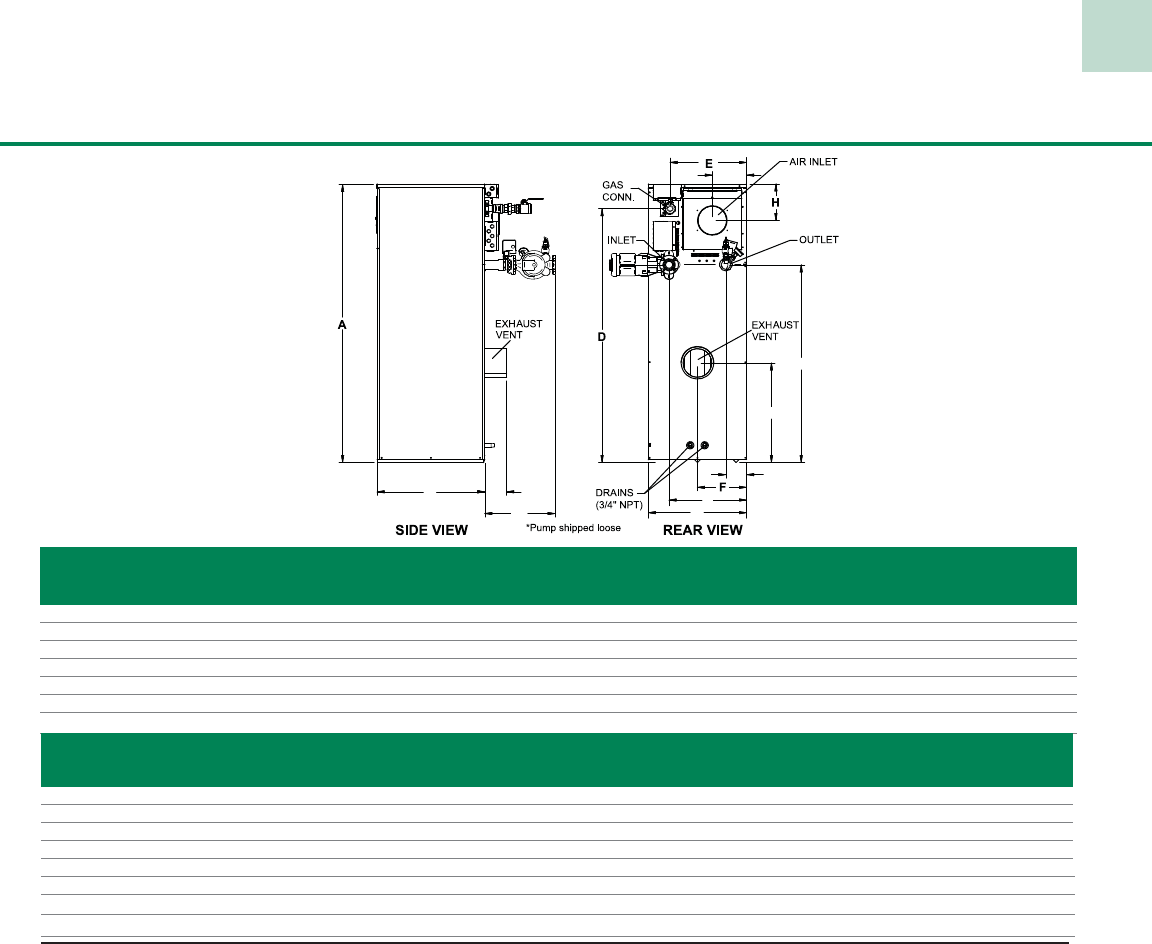
Dimensions & Specifications
Power-Fin® 500,000 - 2,000,000 Btu/hr Models
> Low Voltage Terminal Strip
> 24 VAC Auxiliary Device Relay
> Auxiliary Proving Switch Contacts
> Flow Switch Contacts
> Alarm on Any Failure Contacts
> Runtime Contacts
> Cascade Contacts
> 0-10 VDC BMS External Control Contact
Firing Control Systems
> M# Indicates 5:1 Turndown, Category IV
> B# Indicates 2:1 Turndown, Category I
> F# Indicates 100% On/Off Fire, Category I
> M9 Standard
> B9 or F9 Special Order, Factory Trimmed
> M7, B7 or F7 California Code
Optional Equipment
> Alarm Bell on Any Failure
> Copper-Nickel Heat Exchanger
> High & Low Gas Pressure Switches
w/ Manual Reset
> Low Water Cutoff w/Manual Reset & Test
> SMART SYSTEM PC Software
> Vent Kits:
- Horizontal Exhaust Cap
- Horizontal Air Intake Cap
- Horizontal Direct Vent Kit
- Category IV to Category II Conversion Kit
Registered under U.S. Patent # 7,506,617
Standard Features
> Up to 87% Thermal Efficiency (M#)
> Modulating Burner with 5:1 Turndown
> Up to 84% Thermal Efficiency (B#/F#)
> Modulating Burner with 2:1 Turndown (B#)
> On/Off Burner (F#)
> Fan Assisted Sealed Combustion
> Direct-Spark Ignition
> Low NOx Operation
> Low Gas Pressure Operation
> Venting Flexibility
> Category I (B# & F#)
> Category IV Venting (M#)
> Optional Combined Venting Cat. II (M#)
> ASME Copper-Finned Tube Heat Exchanger
> ASME Certified, “HLW” Stamped
> 150 psi ASME T & P Relief Valve
> Gasketless design
> 160 psi working pressure
> On/Off Switch
> Adjustable High Limit w/ Manual Reset
> Flow Switch
> Low Air Pressure Switch
> Flue Temperature Sensor
> Downstream Test Cocks
> Combustion Air Filtration
> All Bronze Circulating Pump
> Zero Clearances to Combustible Material
> 1 Year Warranty on Parts
> 5 Year Limited Warranty
(See Warranty for Details)
Smart System Features
> SMART SYSTEM Operating Control
> 2 line, 16 Character Display
> Dual Level Password Security
> Built in Cascading Sequencer for
up to 8 Water Heaters
> Building Management System Integration
with 0-10 VDC Input
> Low Water Flow Safety Control & Indication
> Inlet & Outlet Temperature Readout
> Product Service Indicator
> Freeze Protection
> Service Reminder
> Time Clock
> Data Logging
> Hours Running, Space Heating
> Hours Running, Domestic Hot Water
> Ignition Attempts
> Last 10 Lockouts
> Programmable System Efficiency Optimizers
> Night Setback
> Anti-Cycling
> Outdoor Air Reset Curve
> Ramp Delay
> Boost Temperature & Time
> Pump Control
> Domestic Hot Water Pump
> High Voltage Terminal Strip
> 120 VAC/ 50-60 Hertz/ 1 Phase Power Supply
> Pump Contacts with Pump Relays
GPH @
Model Btu/Hr 100°F Rise E E
Number Input F9 M9 A B C D B9/F9 M9 F G H J
PFN0502PM 500,000 515 527 44-1/2” 28-1/2” 23-1/4” 34” 17-3/4” 19-1/2” 6-1/2” 6” 8” 7-3/4”
PFN0752PM 750,000 773 791 52” 28-1/2” 23-1/4” 41-1/2” 17-3/4” 19-1/2” 6-3/4” 6” 8” 7-3/4”
PFN1002PM 999,999 1,030 1,054 59-1/4” 28-1/2” 23-1/4” 48-3/4” 17-3/4” 19-1/2” 7-1/4” 6” 8” 7-3/4”
PFN1302PM 1,300,000 1,323 1,371 67-3/4” 28-1/2” 23-1/4” 57-1/4” 17-3/4” 19-1/2” 8-1/4” 6” 8” 7-3/4”
PFN1501PM 1,500,000 1,527 1,582 65-1/2” 29-3/4” 27-1/4” 58-3/4” 21” 21” 13-1/2” 8” 10” 9-1/2”
PFN1701PM 1,700,000 1,731 1,793 70” 29-3/4” 27-1/4” 63-1/4” 21” 21” 13-1/2” 8” 10” 9-1/2”
PFN2001PM 2,000,000 2,036 2,109 76-3/4” 29-3/4” 27-1/4” 70” 21” 21” 13-1/2” 8” 10” 9-1/2”
Vent Sizes
Model P P Gas Air Cat I Cat II Cat IV Wt.
Number K L M N B9/F9 M9 Conn. Inlet B9/F9 M9 M9 (lbs)
PFN0502PM 23” 11-1/2” 11-1/4” 17-1/2” 15-1/4” 15-1/4” 1” 5” 7” 7” 4” 571
PFN0752PM 30-1/2” 11-1/2” 11-1/4” 17-1/2” 15-1/4” 15-1/4” 1-1/4” 5” 9” 9” 5” 620
PFN1002PM 37-3/4” 11-1/2” 11-1/4” 17-1/2” 15-1/4” 15-1/4” 1-1/4” 6” 10” 10” 6” 669
PFN1302PM 46-1/4” 11-1/2” 19-1/2” 17-1/2” 15-1/4” 15-1/4” 1-1/4” 6” 12” 12” 8” 718
PFN1501PM 43-1/2” 5-3/4” 22-1/4” 21-1/2” 24-1/2” 19-1/2” 1-1/2” 6” 12” 8” 6” 1,115
PFN1701PM 48” 5-3/4” 25” 21-1/2” 24-1/2” 19-1/2” 1-1/2” 7” 14” 9” 7” 1,150
PFN2001PM 54-3/4” 5-3/4” 27-1/2” 21-1/2” 24-1/2” 19-1/2” 1-1/2” 8” 14” 10” 8” 2,045
Notes: Change ‘N’ to ‘L’ for LP Gas Model. No deration on LP models. Temperature rise calculations based on firing rate of 100% All water connections are 2-1/2”
BG
PC
J
K
M
L
N
9
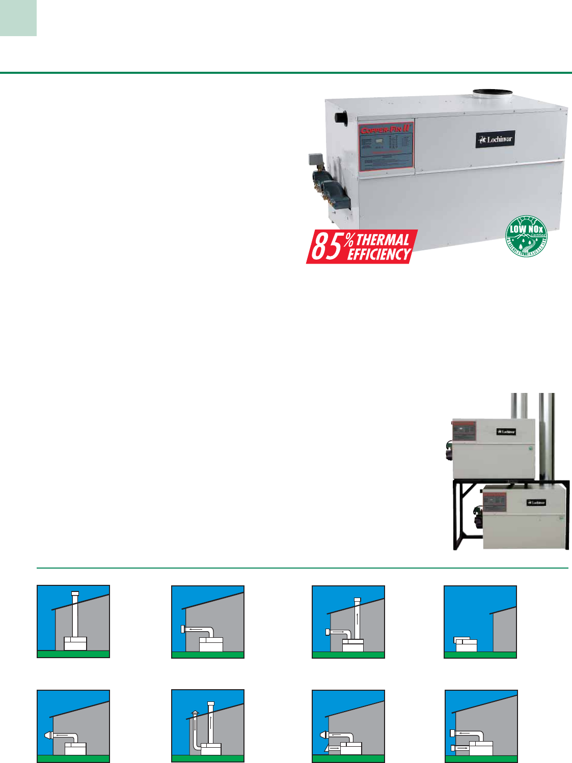
Thermal Efficiency Is Higher...
While Footprint And Vent Sizes Are Smaller
Lochinvar’s Copper-Fin II® line of high efficiency
commercial gas water heaters gives you all the
advantages of lime scale-free, copper-finned tube heat
exchanger technology plus the benefits of a sealed
combustion system. Every Copper-Fin II model offers
four major advantages: higher efficiency, smaller
footprint, smaller vent diameters and a wide variety of
venting options.
Outstanding Thermal Efficiency
Copper-Fin II water heaters offer a remarkably high 85%
thermal efficiency. This means that 85¢ out of every fuel
dollar goes into heating the water, dramatically reducing
the operating cost of the equipment. Copper-Fin II
achieves this efficiency through the combination of an
advanced fan assisted combustion system and exclusive
gasketless copper fin tube heat exchanger. A time tested
and proven combination.
Proportional Firing
The Copper-Fin II’s proportional firing lowers your
energy costs and delivers more consistent water
temperatures. Multiple gas valves supply gas to the
burners in stages, and multiple blowers maintain the
proper airflow to ensure the most efficient combustion
at each level of use. Our built-in sequencer controls each
of these functions. With digital accuracy, the sequencer
carefully monitors the need for heat, and as demand
increases or decreases, it automatically adjusts the blower
output and gas valves. As the demand is met, the system
lowers performance gradually, turning off gas valves and
reducing combustion air in direct proportion.
Copper-Fin II® 400,000 to 2,070,000 Btu/hr Models
Meets The Toughest Air Quality Standards
Because of our unique fan-assisted combustion process,
the Copper-Fin II exceeds today’s toughest NOx emissions
requirements. An independent certification laboratory test
gave us a rating of less than 30 ppm — corrected to 3% O2.
And less NOx means a cleaner environment.
Compact Design - For Installation Ease
The Copper-Fin II is compact
enough to fit through standard
36” doorways with ease.
Even our 2 million Btu/hr
model is only 33-1/2” wide.
This space-saving design
frees up more space in the
mechanical room. And our
optional Multi-Stack™ frame
lets you put two units in the
footprint of just one
Venting Options
Vents into
conventional
flue or vent
breaching using
Type B double
wall vent.
Vents directly
through the outside
wall using an
optional powered
sidewall cap. Ideal
when a vent stack
is not practical.
Requires optional
outdoor vent cap.
Use when indoor
space is a problem
or if outdoor
location gives
better access.
Draws fresh air
from outside and
vents through
conventional
vertical flue.
Draws fresh air
from outside and
vents through
sidewall using
optional powered
vent cap.
Draws fresh air
50 equivalent feet
from a sidewall.
Vents horizontally
up to 50 equivalent
feet through the
sidewall.
Draws fresh air from
inside the room. Vents
up to 50 equivalent
feet
directly through
the outside wall
without the need for a
powered sidewall cap.
Draws fresh
air from
outside and
vents through
conventional
vertical flue.
Conventional
Powered Sidewall DirectAire Vertical Power DirectAire Horizontal Aire-Lock Direct Vent
Sidewall (CF 401-751) DirectAire Vertical w/ Sidewall Inlet Outdoor
10
Copper-Fin II® 400,000 to 2,070,000 Btu/hr Models
Standard Features
• 85% Thermal Efficiency
• ASME Copper Finned Tube Heat Exchanger
• Gasketless Heat Exchanger Design
• Proportional Firing with up to
4 Stages of Operation
• Digital Operator Interface Panel
• Sealed Combustion Chamber
• Stainless Steel Burners
• Low NOx Operation Exceeds the
most Stringent Air Quality Requirements
• 160 PSI Working Pressure
• All Bronze Circulating Pump
• Pump Delay
• Glass-Lined Water Surfaces
• Loch-Heat Ceramic Tile
Combustion Chamber
• Hot Surface Ignition
• ASME Temperature & Pressure Relief Valve
• Inlet & Outlet Temperature Gauges
• Referenced Gas Valves
• Field Convertible Air Inlet Connection
• Adjustable High Limit w/ Manual Reset
• Combustion Air Filter
• Freeze Protection
• Complete System Redundancy
• Flow Switch
• 24 Volt Control System
• BMS Terminal Strip
• 5 Year Limited Warranty on Heat Exchanger
(See warranty for details)
Optional Equipment
• Alarm Bell
• Contacts for Air Louvers
• Contacts on any Failure
• Cupro-Nickel Heat Exchanger
• High Gas Pressure Switch
w/ Manual Reset
• Low Gas Pressure Switch
w/ Manual Reset
• Low Water Cut-Off
• MP2 Sequencer
• Multi-Stack Frame
• Combustible Floor Shield (CF 401-751)
Firing Controls
M9 Hot Surface Ignition
with Electronic
Supervision (Standard)
M7 California Code
Registered under U.S. Patent # 5,989,020
Model Btu/hr GPH @ Vent Air Gas Shipping
Number Input 100°F Rise A B C D E F G H J K L P Size Inlet Conn Weight
CFN401PM 399,999 412 31-1/2” 37-3/4” 22-1/4” 12-1/2” 7” 7” 29” 23-1/2” 8” 6-1/2” 30-3/4” 18-1/2” 6” 6” 1-1/4” 430
CFN501PM 500,000 515 31-1/2” 45-1/2” 22-1/4” 12-1/2” 7” 7” 29” 23-1/2” 8” 6-1/2” 30-3/4” 18-1/2” 6” 6” 1-1/4” 480
CFN651PM 650,000 670 31-1/2” 56-3/4” 22-1/4” 12-1/2” 8-1/2” 8-1/4” 29” 23-1/2” 8” 6-1/2” 30-3/4” 18-1/2” 8” 8” 1-1/4” 550
CFN751PM 750,000 773 31-1/2” 64” 22-1/4” 12-1/2” 8-1/2” 8-1/4” 29” 23-1/2” 8” 6-1/2” 30-3/4” 18-1/2” 8” 8” 1-1/4” 605
CFN0991PM 990,000 1,020 36” 48-1/4” 33-1/2” 15-3/4” 8” 9-1/4” 33-3/4” 27” 9-1/4” 9” 41-3/4” 20-1/2” 10” 10” 2” 930
CFN1261PM 1,260,000 1,298 36” 58-1/2” 33-1/2” 15-3/4” 9” 10-1/4” 33-3/4” 27” 9-1/4” 9” 41-3/4” 20-1/2” 12” 12” 2” 995
CFN1441PM 1,440,000 1,484 36” 68-3/4” 33-1/2” 15-3/4” 9” 10-1/4” 33-3/4” 27” 9-1/4” 9” 41-3/4” 20-1/2” 12” 12” 2” 1,130
CFN1801PM 1,800,000 1,855 36” 82-1/4” 33-1/2” 15-3/4” 10” 11-1/2” 33-3/4” 27” 9-1/4” 9” 41-3/4” 20-1/2” 14” 12” 2” 1,285
CFN2071PM 2,070,000 2,133 36” 92-1/2” 33-1/2” 15-3/4” 10” 11-1/2” 33-3/4” 27” 9-1/4” 9” 41-3/4” 20-1/2” 14” 12” 2” 1,400
Notes: Change ‘N’ to ‘L’ for LP gas models. No deration on LP models.
Water connections for models (CF 401-751) are 2” NPT on 6-1/2” centers. Water connections for models (CF 0991-2071) are 2-1/2” NPT on 11-1/4” centers.
Performance data is based on manufacturer test results.
11
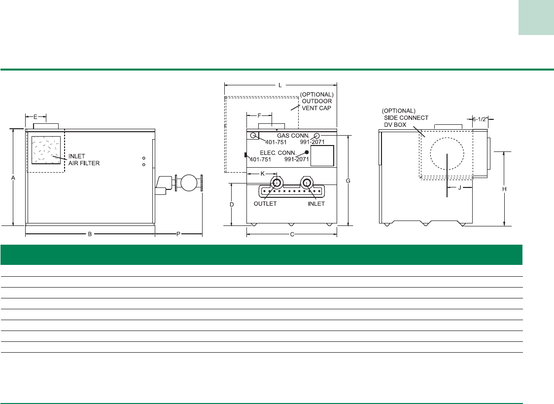
Copper-Fin® 495,000 to 2,065,000 Btu/hr Models
Installation Flexibility and Cost-Savings
With compact sizes that use less floor space than ever before, all
Copper-Fin units are narrow enough to fit through a standard 36”
doorway–an ad van tage most commercial boilers can’t provide.
Plus, thanks to special insulating materials,
Copper-Fin units require only 3” clearance
from combustible walls. What’s more, our
Multi-Stack frame allows you to install two
units in the area normally required for one.
This makes it easier to fit multiple Copper-Fin water heaters into
cramped me chan i cal rooms. And you can even use a smaller
diameter vent stack - up to 8” smaller than typically required for
comparable atmospheric boilers - so it saves money as well as
valuable mechanical room space
Unique Copper-Fin Heat Ex chang er
The Lochinvar Copper-Fin water heater design uses a two-pass
heat ex chang er. Water is circulated through a row of high-
ly-efficient, finned copper tubes. The high rate of water flow
creates a scour ing action that prevents sed i ment and lime-scale
buildup so common in conventional water heaters, and the
finned copper tubes allow maximum heat transfer efficiency.
To create this special heat capability, Lochinvar extrudes the fins
from thick wall copper tubing to precise specifications -ex act ly 7
fins per inch. The result is an integrally-finned
tube with a heat transfer ratio 9 times
greater than a plain copper
tube.
Heavy-
Duty
Gasketless
Design
What’s more,
advanced casting processes allowed Lochinvar to develop
a unique one-piece header system. This gasketless design
provides enhanced reliability, improved durability and optimizes
performance - but without the problems or failures so common
to O-rings and gaskets.
Meets The Toughest Air Quality Standards
Because of our unique fan-assisted combustion process,
the Copper-Fin exceeds today’s toughest NOx emissions
requirements. An independent certification laboratory test gave
us a rating of less than 30 ppm —corrected to 3% O2. And less
NOx means a cleaner environment.
Enhanced to Provide Performance
and Serviceability
Our newly enhanced Copper-Fin models offer the same reliable
operation, and feature a more service friendly design. The
referenced gas valves are in the upper deck for easy access, and
the electrical and EMS connections have all been repositioned
toward the front of the unit for easier service access.
The gas valves are referenced to the sealed combustion chamber
to improve operational performance by monitoring the pressure
in the sealed combustion chamber and adjusting gas flow to
maintain the optimum air/fuel mixture. And the built-in air
inlet filter reduces maintenance and improves performance by
trapping dust and airborne particulates that can foul the burners
and blowers. With duel sight glasses (one on each end), you
can easily monitor burner performance and flame characteristics
throughout the entire combustion chamber.
The operator interface panel provides electronic temperature
control and comprehensive diagnostic status, without opening
the control panel. Its user friendly design simplifies service while
providing additional diagnostic information through a series of
LEDs.
Vent Cost Savings
Btu/hr CONVENTIONAL COPPER-FIN
INPUT VENT SIZE VENT SIZE $ S
AVINGS*
495,000 10” 6” $ 657
645,000 12” 8” $ 731
745,000 14” 8” $ 1,450
985,000 16” 10” $ 1,790
1,225,000 16” 12” $ 1,463
1,435,000 18” 12” $ 2,432
1,795,000 20” 14” $ 3,526
2,065,000 22” 14” $ 3,738
*Comparison based on 25´ vent system using Type “B” double wall vent material,
storm collar and vent cap.
12
Copper-Fin® 495,000 to 2,065,000 Btu/hr Models
Model Btu/hr GPH @ Vent Gas Shipping
Number Input 100°F Rise A B C D E F G H J Size Conn. Weight
CWN0495PM 495,000 486 33-1/4” 45-1/4” 22-1/4” 18-1/2” 12-1/2” 9-1/2” 30-3/4” 9-1/2” 22-3/4” 6” 1-1/4” 490
CWN0645PM 645,000 633 33-1/4” 56-3/4” 22-1/4” 18-1/2” 12-1/2” 9-1/2” 30-3/4” 16” 22-1/4” 8” 1-1/4” 555
CWN0745PM 745,000 731 33-1/4” 64” 22-1/4” 18-1/2” 12-1/2” 9-1/2” 30-3/4” 16” 31-1/4” 8” 1-1/4” 610
CWN0986PM 985,000 967 36” 48-1/4” 33-1/2” 20-1/2” 15-3/4” 9-1/2” 33-3/4” 18-1/4” 9-1/2” 10” 2” 900
CWN1256PM 1,255,000 1,232 36” 58-1/2” 33-1/2” 20-1/2” 15-3/4” 10-1/2” 33-3/4” 20-1/4” 10-1/2” 12” 2” 1,020
CWN1436PM 1,435,000 1,409 36” 68-3/4” 33-1/2” 20-1/2” 15-3/4” 10-1/2” 33-3/4” 20-1/4” 10-1/2” 12” 2” 1,065
CWN1796PM 1,795,000 1,762 36” 82-1/4” 33-1/2” 20-1/2” 15-3/4” 11” 33-3/4” 22-1/4” 11” 14” 2” 1,265
CWN2066PM 2,065,000 2,027 36” 92-1/2” 33-1/2” 20-1/2” 15-3/4” 11” 33-3/4” 22-1/4” 11” 14” 2” 1,400
Change ‘N’ to ‘L’ for LP gas models.
Performance data is based on manufacturer test results.
Water connections for models (CW 0495-0745) are 2” NPT on 6-1/2” centers. Water connections for models (CW 0986-2066) are 2-1/2” NPT on 11-1/4” centers.
Standard Features
• 81% Thermal Efficiency
• Electronic Temperature Control
• Fan Assisted Combustion
• Sealed Combustion Chamber
• Stainless Steel Burners
• Low NOx Operation Exceeds the most
Stringent Air Quality Requirements
• ASME Copper Finned Tube Heat Exchanger
• 160 psi Working Pressure
• Gasketless Heat Exchanger Design
• All Bronze Circulating Pump
• Pump Delay
• Remote Tank Thermostat
• Glass-Lined Water Surfaces
• Redundant Gas Valves
• Loch-Heat Ceramic Tile Combustion Chamber
• Hot Surface Ignition
• ASME Temperature & Pressure Relief Valve
• Adjustable High Limit w/ Automatic Reset
• Inlet/Outlet Temperature Gauges
• Flow Switch
• 24 Volt Control System
• BMS Terminal Strip
• Freeze Protection
• Combustion Air Filter
• 5 Year Limited Warranty on
Heat Exchanger
(See warranty for details)
Optional Equipment
• Alarm Bell
• Contacts on any Failure
• Contacts for Air Louvers
• Cupro-Nickel Heat Exchanger
• Low Gas Pressure Switch
w/ Manual Reset
• High Gas Pressure Switch
w/ Manual Reset
• Low Water Cut-Off
• MP2 Sequencer
• Multi-Stack Frame
Available Firing Systems
F9 HSI (Standard)
F13 GE GAP/FM/IRI
F7 California Code
Venting Options
• Outdoor Vent Cap and Pump Cover
• Intelligent Venting Solutions
Registered under U.S. Patent # 5,989,020
Efficiency+® 150,000 to 300,000 Btu/hr Models
Efficiency+ delivers unsurpassed performance, reliability and energy
savings - year after year. While most competitive models peak at 80%
thermal efficiency, the Efficiency+ delivers a remarkable 85% thermal
efficiency, which means that 85¢ out of each fuel dollar goes toward
heating the water, and not up the flue! When you combine the outstanding
thermal efficiency with the scale free operation of the copper-fin tube heat
exchanger and the convenience and safety of direct venting you have a
product that is simply the smartest choice in water heating.
Moreover, when you package the Efficiency+ with a Lock-Temp storage
tank, you get a system that provides high efficiency and high delivery.
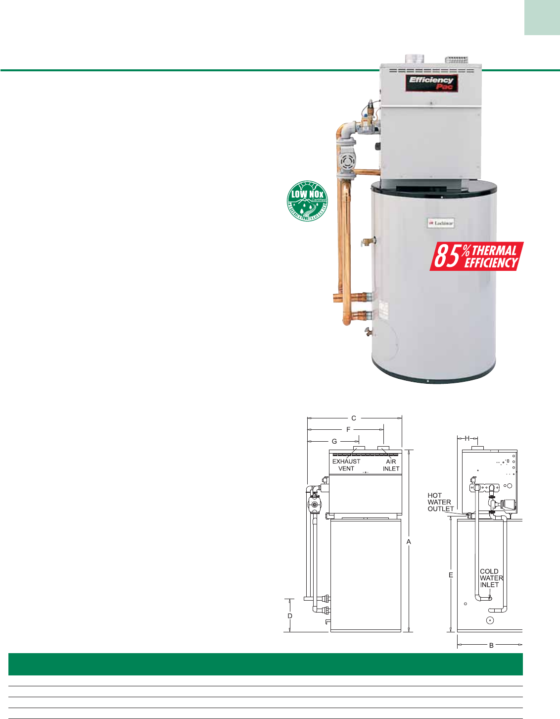
The EfficiencyPac is a powerful combination that lowers operating
costs, provides high delivery rates, and offers longer equipment life than
traditional tank type water heaters.
Dimensions & Specifications
Registered under U.S. Patent No. 5,989,020
Model Btu/hr GPH @ Vent Gas Shipping
Number Input 100°F Rise B D E G Size* Conn. Weight
EWN150PM 150,000 155 19-3/4” 16” 7-1/4” 11-3/4” 5” 3/4” 300
EWN200PM 199,999 206 23-3/4” 20” 9-1/4” 11-3/4” 5” 3/4” 315
EWN250PM 250,000 258 27-1/2” 23-3/4” 11” 11-3/4” 6” 3/4” 355
EWN300PM 300,000 309 31-1/4” 27-1/2” 13” 11-3/4” 6” 3/4” 360
Notes: Change ‘N’ to ‘L’ for LP gas models. Water connections for models (EW 150-300) are 2” NPT on 6-1/4” centers.
Air inlet equals vent diameter.
Performance data based on manufacturer test results. * Vent size is for conventional venting, venting options require 1” smaller vent diameter.
Standard Features
• 85% Thermal Efficiency
• Sealed Combustion Chamber
• Stainless Steel Burners
• Low NOx Operation Exceeds the most Stringent
Air Quality Requirements
• ASME Copper Finned Tube Heat Exchanger
• 160 psi Working Pressure
• Gasketless Heat Exchanger Design
• All Bronze Circulating Pump
• Pump Delay w/Freeze Protection
• Remote Tank Thermostat
• Automatic Reset High Limit
• Manual Reset High Limit
• Glass-Lined Water Surfaces
• Loch-Heat Ceramic Tile Combustion Chamber
• Hot Surface Ignition
• ASME Temperature & Pressure Relief Valve
• 24 Volt Control System
• 3 Year Limited Warranty on Heat Exchanger
(See warranty for details)
Available Firing Systems
F9 Hot Surface Ignition with
Electronic Supervision
F7 California Code
Optional Equipment
• Adjustable High Limit
w/ Manual Reset
• Alarm Bell
• Contacts on any Failure
• Cupro-Nickel Heat Exchanger
• Flow Switch
• Low Water Cut-Off
• MP2 Sequencer
• Multi-Stack Frame
• Outdoor Installation Kit
Conventional
Vents into conventional flue or vent
breaching using Type B double wall
vent.
* E+ DirectAire Vent with
Sidewall Inlet
Draws fresh combustion air from an
outside wall horizontally, and vents
combustion by-products through a
vertical flue.
* Outdoor
Use when indoor space is a problem or if
outdoor location gives better access.
Direct Vent Vertical
Draws fresh combustion air from out-
side, and vents combustion by-products
through a vertical flue.
* Direct Vent Horizontal
Draws fresh combustion air from out-
side and vents combustion
by-products through a side wall.
* Requires factory supplied vent kit.
Venting Options
13
14
EfficiencyPac® Water Heater
Model Btu/hr Gallon GPH @ Vent Shipping
Number Input Capacity 100°F Rise A B C D E F G Size Weight
EPN150-085 150,000 85 155 78-1/2” 28” 38” 14-1/2” 50-1/4” 28” 19” 5” 735
EPN200-085 199,999 85 206 78-1/2” 28” 38” 14-1/2” 50-1/4” 32” 21” 5” 770
EPN200-100 199,999 100 206 75” 32” 43” 16-1/2” 47” 32” 21” 5” 895
EPN250-100 250,000 100 258 75” 32” 43” 16-1/2” 47” 35-1/2” 23” 6” 895
EPN300-100 300,000 100 309 75” 32” 43” 16-1/2” 47” 35-1/2” 25” 6” 930
Note: Change ‘N’ to ‘L’ for LP gas models. (no deration for LP).
Vent size denotes conventional vent. Performance data is based on manufacturer test results.
Note: Cold water inlet is 2” copper.
Hot water outlet is 1 -1/2” copper.
When you depend on hot water to stay in business, you should expect your water
heater to work “smarter,” not harder! Traditional tank-type water heaters build
up lime scale deposits when they heat water. This makes the water heater work
harder, which leads to reduced efficiency, increased fuel costs, and shorter tank life.
Lime scale build-up can cause a typical tank-type unit to fail in as few as 4–5 years.
Sometimes less!
The Efficiency Pac from Lochinvar combines the high efficiency of an Efficiency+
(EW series) water heater with the durability of a Lock-Temp baffled storage tank to
create a water heating system that performs at peak efficiency year after year.
• Thermal Efficiency – the Efficiency Pac delivers a remarkable
85% thermal efficiency. Most tank-type units peak at 80%.
• No Lime Scale Build-up – the Efficiency Pac limits lime scale build-up with
the scrubbing action of water flow through the solid copper-tube heat exchanger.
• Unsurpassed Delivery – the Lock-Temp storage tank employs a baffle that allows
80% tank draw down without a drop in temperature. When combined with an
85% efficient water heater, the results are a First Hour Delivery that can’t be beat
- 274 gallons for an EPN200-85.
• Direct-Venting Convenience – The Efficiency Pac can draw its combustion air
directly from outdoors. This feature prevents contamination from airborne dirt
particles and chemicals, while isolating the water heater from negative air
pressures often found in restaurants and mechanical rooms.
Standard Features
• 85% Thermal Efficiency
• Sealed Combustion Chamber
• Stainless Steel Burners
• Low NOx Operation Exceeds the most
Stringent Air Quality Requirements
• ASME Copper Finned Tube
Heat Exchanger
• 160 psi Working Pressure
• Gasketless Heat Exchanger Design
• All Bronze Circulating Pump
• Pump Delay w/ Freeze Protection
• Manual Reset High Limit
• Automatic Reset High Limit
• Glass-Lined Water Surfaces
• Loch-Heat Ceramic Tile Combustion Chamber
• Hot Surface Ignition
• ASME Pressure Relief Valve (Heater)
• Foam Insulated, Glass-Lined Storage Tank
• 24 Volt Control System
• ASME Temperature & Pressure
Relief Valve (Tank)
• Brass Drain Valve (Tank)
• 3 Year Limited Warranty on Heat Exchanger
• 5 Year Limited Warranty on Tank
Optional Equipment
• Adjustable High Limit
w/ Manual Reset
• Alarm Bell
• Contacts on any Failure
• Cupro-Nickel Heat Exchanger
• Flow Switch
• Low Water Cut-Off
15
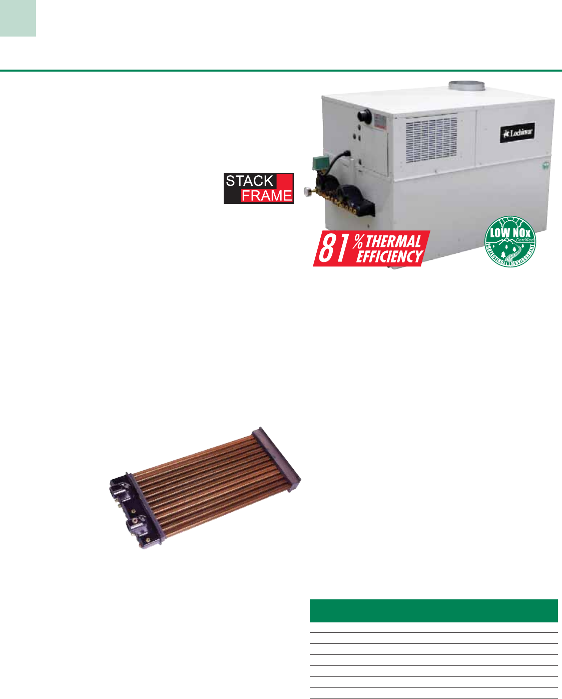
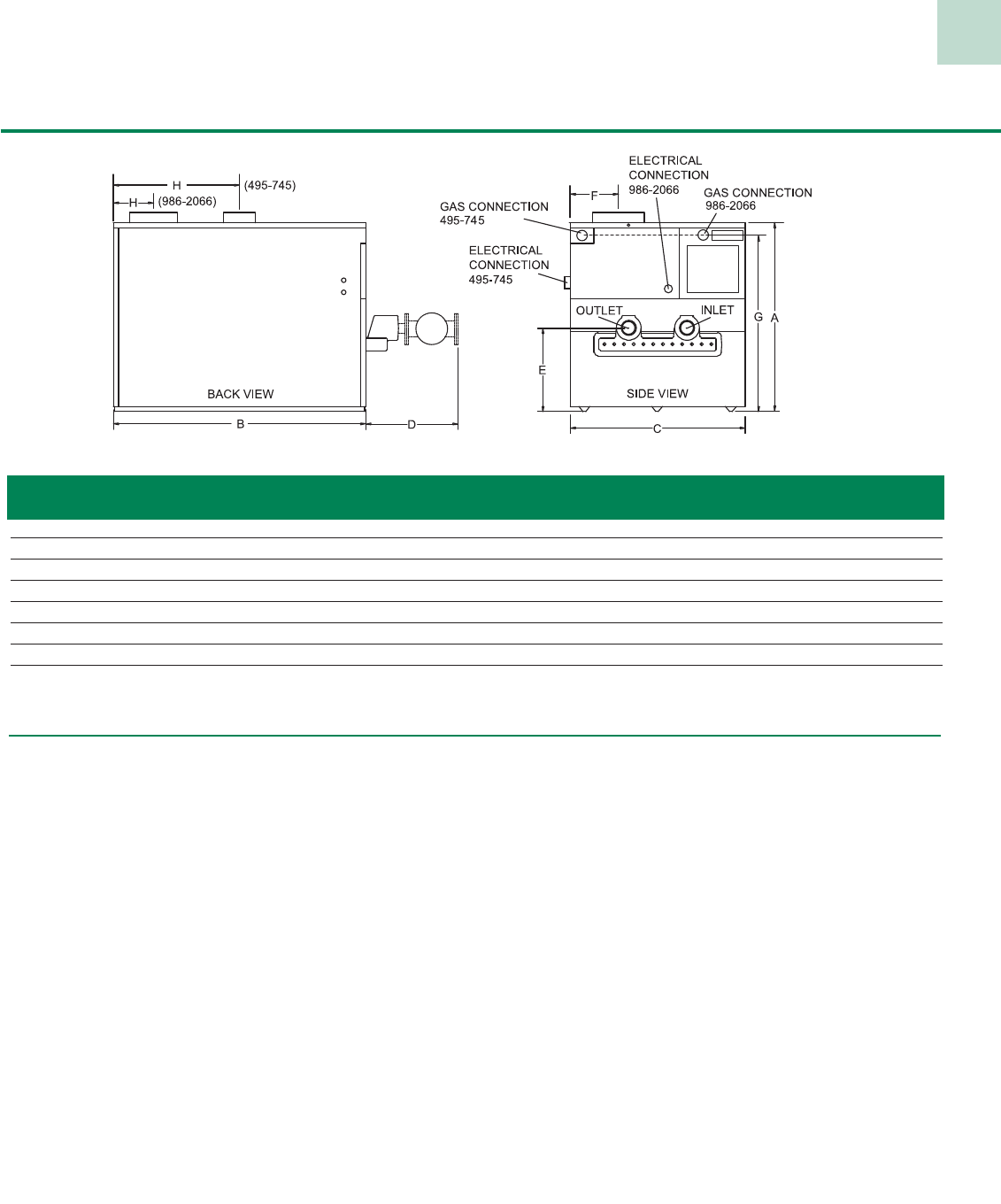
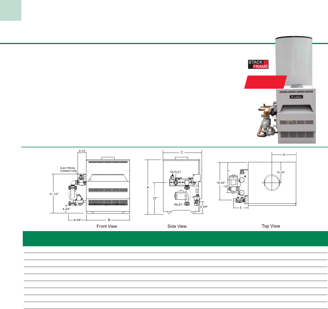
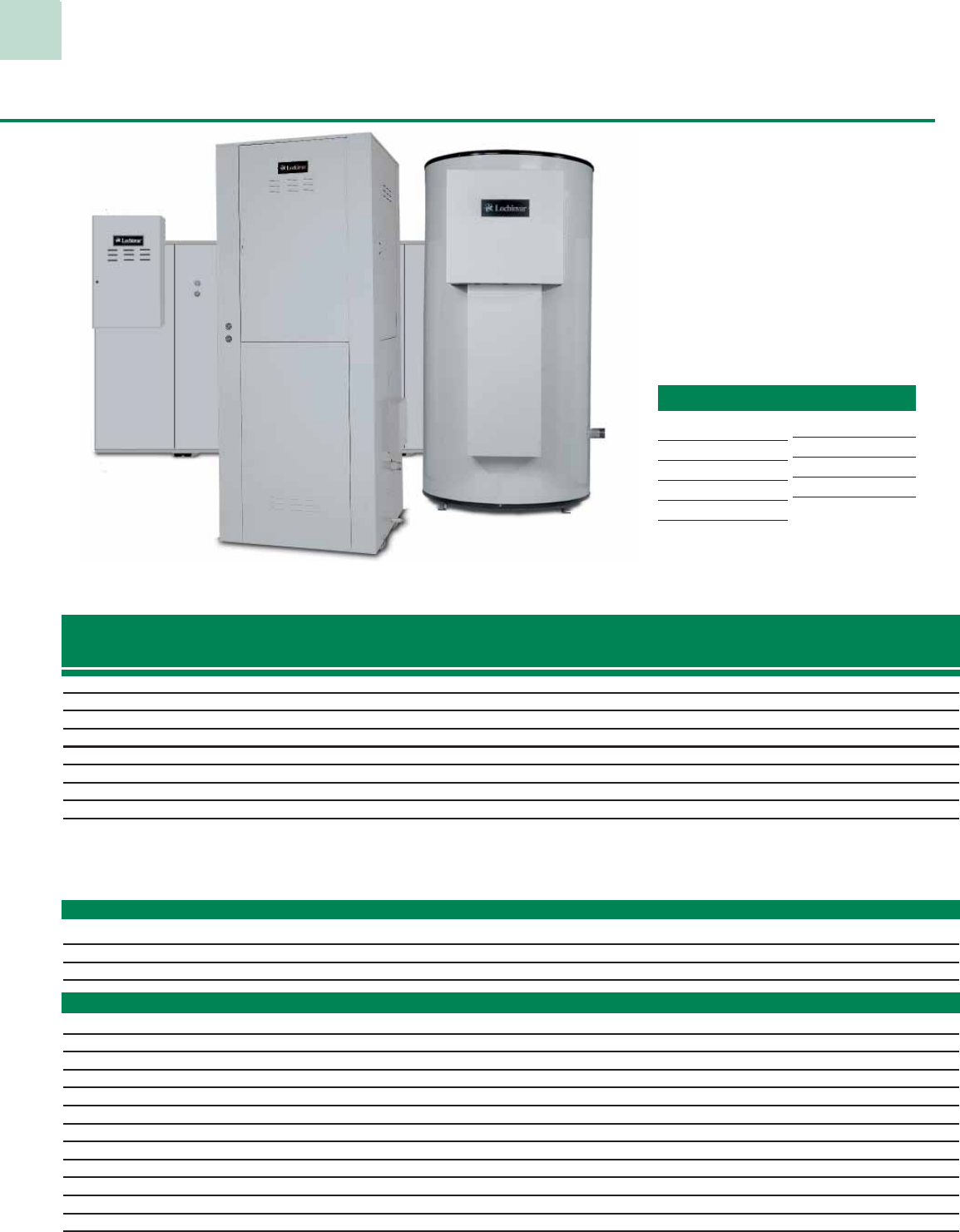
Copper-Fin® 90,000 to 500,000 Btu/hr Models
High efficiency Copper-Fin water heaters combine the benefits of a copper finned tube heat
exchanger with the simplicity of atmospheric combustion to provide a durable, trouble-free
design with quick and easy component removal for service simplicity.
And with the Lochinvar “Better Idea” system, you combine the highly efficient Copper-Fin
water heater with a separate Lock-Temp storage tank and manifold piping. By separating
the water heater and storage tank, stand-by losses are virtually eliminated and operating
efficiency is enhanced.
For additional flexibility, the Copper-Pak starts with a Lock-Temp storage tank and places
a Copper-Fin water heater directly on top in a unique space saving design. The circulator
pump and piping are all in place and the unit is ready to be installed as a single package.
82
%
THERMAL
EFFICIENCY
Model Btu/Hr GPH @ Vent Gas Shipping
Number Input 100ºF Rise A B C D E Size Conn. Weight
CWN090PM 90,000 89 29-1/2” 15-1/2” 21-1/2” 7-3/4” 6-3/4” 5” 1/2” 175
CWN135PM 135,000 134 29-1/2” 19-1/2” 21-1/2” 9-3/4” 6-3/4” 6” 1/2” 195
CWN180PM 180,000 179 29-1/2” 23-1/2” 21-1/2” 11-3/4” 6-3/4” 7” 3/4” 220
CWN199PM 199,999 198 29-1/2” 26-1/2” 21-1/2” 13-1/4” 6-3/4” 7” 3/4” 230
CWN225PM 225,000 224 29-1/2” 26-1/2” 21-1/2” 13-1/4” 6-3/4” 7” 3/4” 235
CWN270PM 270,000 268 29-1/2” 29 1/2” 21 1/2” 14 3/4” 6-3/4” 8” 3/4” 240
CWN315PM 315,000 313 29-1/2” 32-1/2” 21-1/2” 16-1/4” 6-3/4” 8” 3/4” 250
CWN360PM 360,000 358 29-1/2” 35-1/2” 21-1/2” 17-3/4” 6-3/4” 9” 1” 270
CWN399PM 399,999 397 29-1/2” 44-1/2” 22” 22-1/4” 16-3/4” 10” 1” 340
CWN500PM 500,000 497 34-1/2” 52-1/2” 22” 26-1/4” 16-3/4” 10” 1” 365
Notes: Change ‘N’ to ‘L’ to denote L.P. gas models
Water connections are 2” NPT on 6-1/4” centers Electrical Requirements: 120 VAC / 2.5 AMP
Approved for indoor installation only Performance data based on manufacturer test results
Standard Features
• 82% Thermal Efficiency
• Built-In Draft Diverter
• Stainless Steel Burners
• ASME Copper Finned Tube Heat Exchanger
• 160 psi Working Pressure
• Gasketless Heat Exchanger Design
• All Bronze Circulating Pump
• Pump Delay/Freeze Protection
• Remote Tank Thermostat
• Glass-Lined Water Surfaces
• Loch-Heat Ceramic Tile Combustion Chamber
• ASME Temperature & Pressure Relief Valve
• Automatic Reset High Limit
• 24 Volt Control System
• CSA Design Certified for Installation on Combustible Floors
• Terminal Strip
• 3 Year Limited Warranty on Heat Exchanger
Firing Controls
• F1 - Standing Pilot
(Standard CW 90-270)
• F9 - Intermittent Spark Ignition
(Standard CW 315-500)
• F13 - GE GAP/FM/IRI
• F7 - California Code (CW 225-500)
Optional Equipment
• Adjustable High Limit w/ Manual Reset
• Contacts on any Failure
(CW 315-500)
• Contacts for Air Louvers
(CW 315-500)
• Cupro-Nickel Heat Exchanger
• Flow Switch
• Low Water Cut-Off
• Multi-Stack Frame
• CPVC Vent Kit (CW 90-135)
• Better Idea Manifold KIt
16
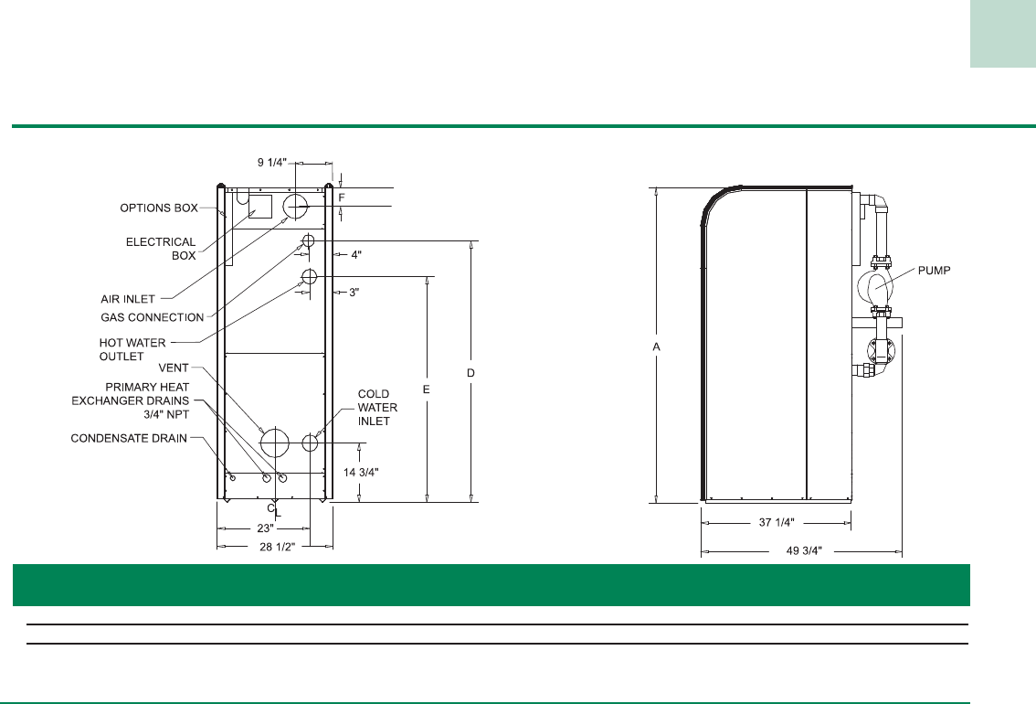
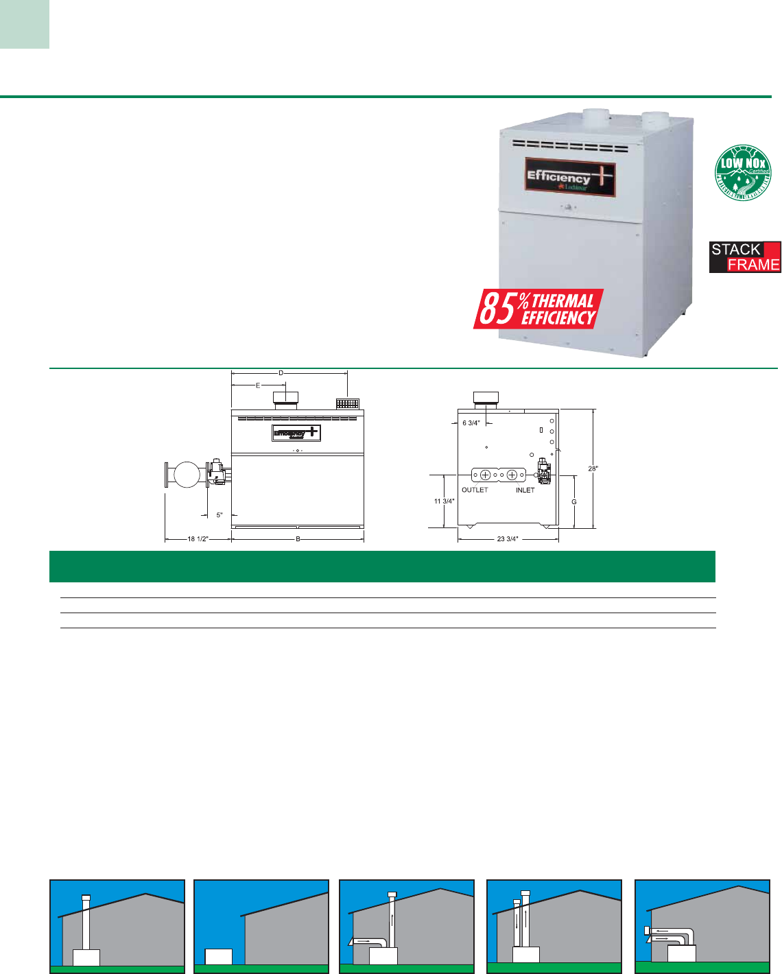
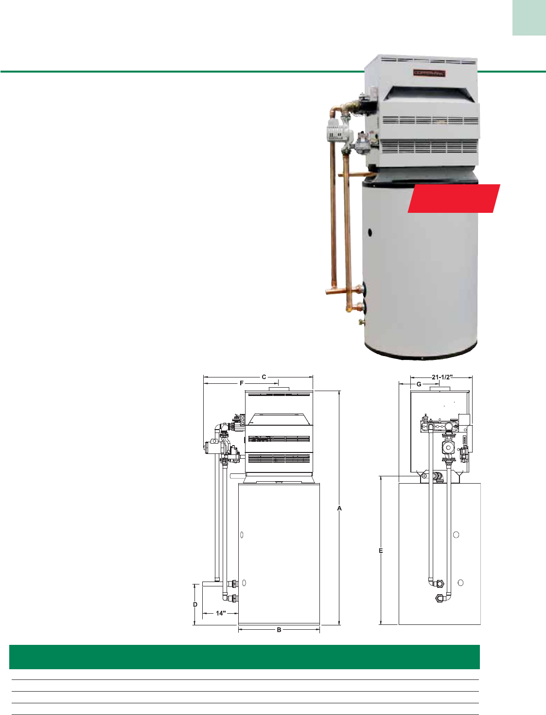
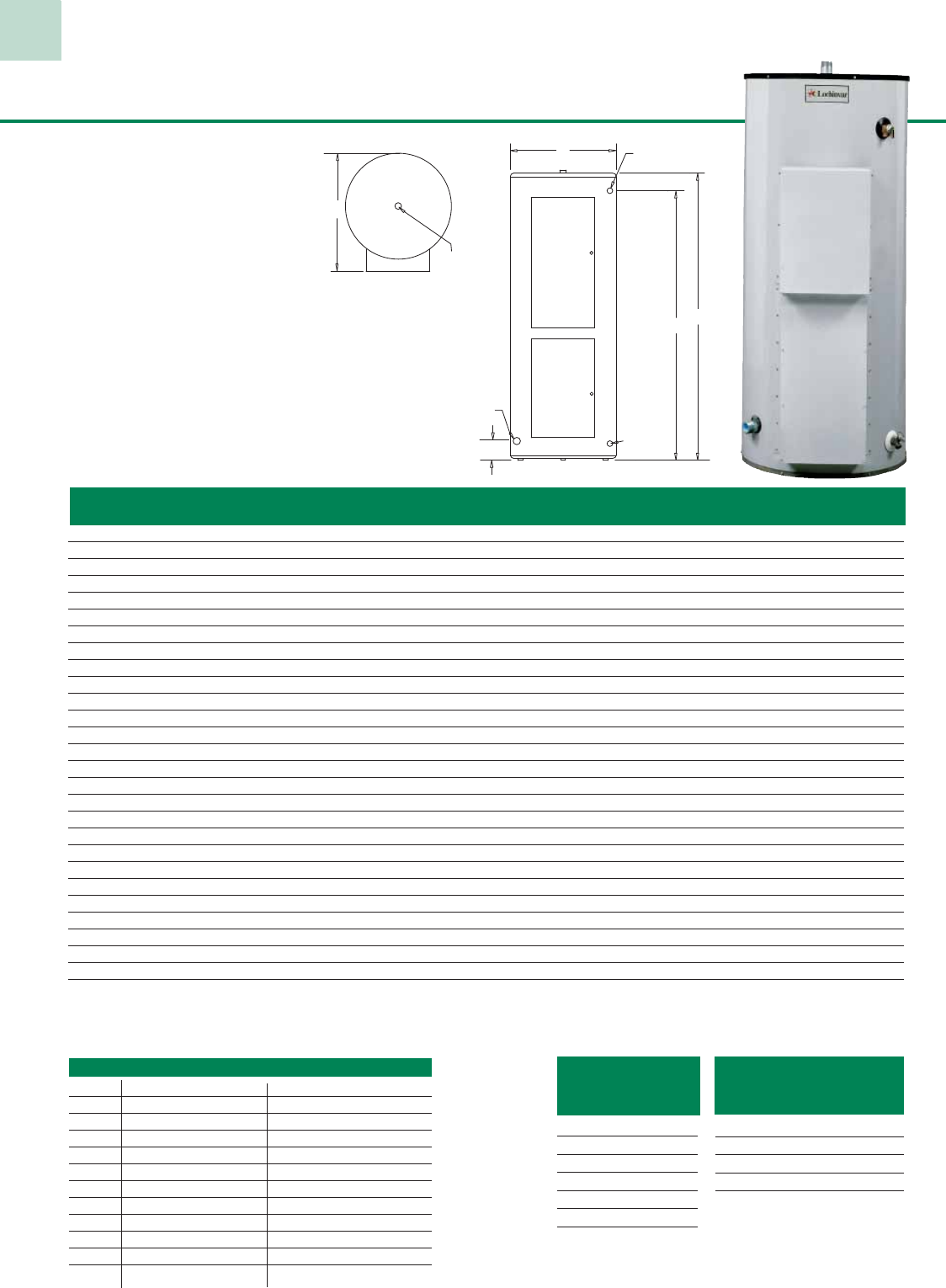
Copper-Pak® Water Heater
82%
THERMAL
EFFICIENCY
Model Btu/hr Gallon GPH @ Vent Gas Shipping
Number Input Capacity 100°F Rise A B C D E F G Size Conn. Weight
CPN180-85 180,000 85 179 80” 28” 35-1/2” 14 -1/4“ 50-1/4 “ 22-3/4” 14-1/4” 7” 3/4” 700
CPN199-85 199,999 85 198 80” 28” 38-1/2” 14-1/4” 50-1/4 “ 25-1/4” 14-1/4” 7” 3/4” 710
CPN199-100 199,999 100 198 76-1/2” 32” 38-1/2” 16-1/4” 47” 25-1/4” 16” 7” 3/4” 815
CPN270-100 270,000 100 268 76-1/2” 32” 41-1/2” 16-1/4” 47” 26-3/4” 16” 8” 3/4” 850
CPN360-100 360,000 100 358 76-1/2” 32” 47-1/2” 16-1/4” 47” 29-3/4” 16” 9” 1” 880
Note: Water connections are 1-1/2” copper on all models. Change “N to “L” for LP gas models. Performance data is based on manufacturer’s test results.
Standard Features
• 82% Thermal Efficiency
• Built-In Draft Diverter
• Stainless Steel Burners
• ASME Copper Finned Tube Heat Exchanger
• 160 psi Working Pressure
• Gasketless Heat Exchanger Design
• All Bronze Circulating Pump
• Pump Delay w/Freeze Protection
• Glass-Lined Water Surfaces
• Loch-Heat Ceramic Tile Combustion Chamber
• ASME Temperature & Pressure Relief Valve
(Heater Only)
• Automatic Reset High Limit
• 24 Volt Control System
• Foam Insulated, Glass-Lined Storage Tank
• Brass Drain Valve (Tank Only)
• Terminal Strip
• 5 Year Limited Warranty on Tank
• 3 Year Limited Warranty on Heat Exchanger
The Copper-Pak packs the high efficiency of the Copper-Fin water heater into
a unique space-saving design. It’s an excellent alternative to traditional tank-
type water heaters. Shipped complete in one box, with all piping included and
ready for installation.
Think of the Copper-Pak as two separate units stacked on top of each other–a
highly efficient Copper-Fin (CW series) water heater and a dedicated hot water
storage tank. By combining the two in one unique design, we’ve reduced the
footprint. That makes it easier to install in place of conventional tank-type
water heaters.
Plus, thanks to copper finned-tube technology, the Copper-Pak has efficiencies
up to a remarkable 82% – far exceeding most tank type water heaters. In fact,
our 85 gallon - 180,000 Btu/hr model performs as well as most 100 gallon -
200,000 Btu/hr tank-type water heaters. It produces just as much hot water, but
at a much lower cost.
Optional Equipment
• Cupro-Nickel Heat Exchanger
• Flow Switch
• Low Water Cut-Off
• Adjustable High Limit w/ Manual
Reset
17
65,000 - 85,000 Btu/hr 125,000 - 500,000 Btu/hr
LP Inputs
Model Btu/hr GPH @
Number Input 100°F Rise
CLR160-075-DF9 155,000 147
CLR200-080-DF9 190,000 184
CLR250-100-DF9 235,000 228
CLR400-080-DF9 375,000 364
CLR500-080-DF9 475,000 461
CLA251-100-DF9 235,000 228
CLA401-080-DF9 375,000 364
CLA501-080-DF9 475,000 461
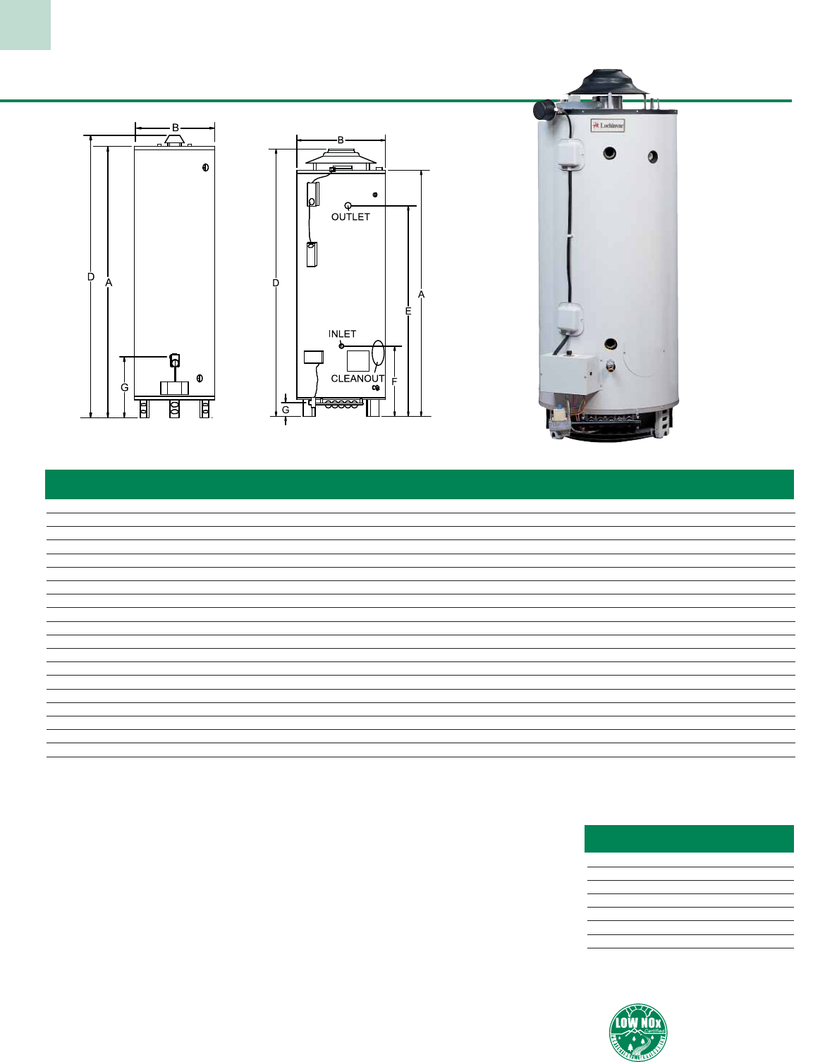
Charger Gas Models
Standard Equipment:
• Multi-Flue Tank Design—for increased efficiency
and energy conservation
• Durable Fused Glass Lining—prolongs tank life
• Non-CFC Foam Insulation—up to 2” for max. heat
retention and lower standby losses
• Magnesium Tank Saver Anodes—inhibit corrosion
• 150 psi Working Pressure
• ASME Temperature & Pressure Relief Valve
• Automatic Vent Damper
• Heavy Steel Jacket with Baked Enamel Finish
• Immersion Thermostat and Limit Controls
• Low Silhouette Draft Hood
• Cleanout—permits easy access for cleaning
• Standing Pilot
(65,000 76,000, and 85,000 Btu/hr models)
• Spark Ignition with Supervised Pilot (Models 125,000
Btu/hr and larger)
• Approved for 180°F Operation
• Slide Out Burner Tray—for easy servic-
ing (125,000 Btu/hr and larger)
• 3 Year Limited Tank Warranty
• 1 Year Limited Parts Warranty
(See warranty for details)
Optional Equipment:
•
Temperature and
Pressure Gauge
•
NSF Construction
Low NOx models
are available.
Consult factory.
Model Tank Btu/hr Gallon GPH @ A B D E F G Vent Gas Water Nipple Shipping
Number Const. Input Cap. 100°F Rise Size Conn Conn Spread Weight
LNR065-050* STD 65,000 48 60 56-1/4” 22” 59-1/4” – – 13” 4” 1/2” 3/4” T 11” 160
CNR076-075* STD 76,000 75 74 59” 26” 62-1/4” – – 15” 4” 1/2” 1” T 11” 247
CNR085-100* STD 85,000 100 82 65-1/4” 28-1/4” 68-3/4” – – 15-1/2” 4” 1/2” 1-1/4” T 16 ” 420
CNR125-075-DF9* STD 125,000 75 121 65” 28-1/4” 72-1/4” 54-1/2” 34” 4-3/4” 5” 3/4” 1-1/2” T/F 14-1/2” 520
CNR155-035-DF9* STD 155,000 38 150 43” 28-1/4” 51” 34-3/2” 19-1/2” 4-3/4” 6” 3/4” 1-1/2” T/F 19” 438
CNR160-075-DF9* STD 160,000 75 155 65” 28-1/4” 72-1/4” 54-1/2” 34” 4-3/4” 6” 3/4” 1-1/2” T/F 14-1/2” 520
CNR180-080-DF9 STD 180,000 80 175 64-1/2” 28-1/4” 72-1/2” 56” 19-1/2” 4-3/4” 6” 3/4” 1-1/2” T/F 19” 540
CNR200-080-DF9 STD 199,999 80 194 64-1/2” 28-1/4” 72-1/2” 56” 19-1/2” 4-3/4” 6” 3/4” 1-1/2” T/F 19” 540
CNR199-100-DF9 STD 199,999 100 194 65” 30-1/4” 75” 56-1/2” 23-1/2” 4-1/2” 6” 3/4” 1-1/2” T/F, 2” B 23” 725
CNR200-100-DF9 STD 199,999 98 194 75-1/2” 28-1/4” 83-1/2” 67” 19-1/2” 4-3/4” 6” 3/4” 1-1/2” T/F 19” 610
CNR250-100-DF9 STD 250,000 98 242 75-1/2” 28-1/4” 83-1/2” 67” 19-1/2” 4-3/4” 6” 3/4” 1-1/2” T/F 19” 610
CNR300-075-DF9 STD 300,000 75 291 64-1/2” 28-1/4” 73” 54-1/4” 29” 10-1/2” 7” 3/4” 1-1/2” F 19” 590
CNR370-065-DF9 STD 370,000 65 359 64-1/2” 28-1/4” 73-1/2” 54-1/4” 29” 10-1/2” 8” 1”, 3/4”LP 1-1/2” F 19” 665
CNR400-080-DF9 STD 399,999 80 388 60” 30-1/4” 71-1/2” 51-1/2” 23-1/2” 10-1/2” 8” 1”, 3/4”LP 1-1/2” F, 2” B 23” 800
CNR500-080-DF9 STD 505,000 80 496 60” 30-1/4” 69-1/2” 51-1/2” 23-1/2” 10-1/2” 10” 1”, 3/4”LP 1-1/2” F, 2” B 23” 800
CNA251-100-DF9 ASME 250,000 98 242 75-1/2” 28-1/4” 83-1/2” 67” 19-1/2” 4-3/4” 6” 3/4” 1-1/2” T/F 19” 690
CNA301-075-DF9 ASME 300,000 75 291 64-1/2” 28-1/4” 73” 54-1/4” 29” 10-1/2” 7” 3/4” 1-1/2” F 19” 645
CNA371-065-DF9 ASME 370,000 65 359 64-1/2” 28-1/4” 73-1/2” 54-1/4” 29” 10-1/2” 8” 1”, 3/4”LP 1-1/2” F 19” 720
CNA401-080-DF9 ASME 399,999 80 388 60” 30-1/4” 71-1/2” 51-1/2” 23-1/2” 10-1/2” 8” 1”, 3/4”LP 1-1/2” F, 2” B 23” 835
CNA501-080-DF9 ASME 505,000 80 496 60” 30-1/4” 69-1/2” 51-1/2” 23-1/2” 10-1/2” 10” 1”, 3/4”LP 1-1/2” F, 2” B 23” 835
Indicates
LP Inputs
* These models have one aquastat.
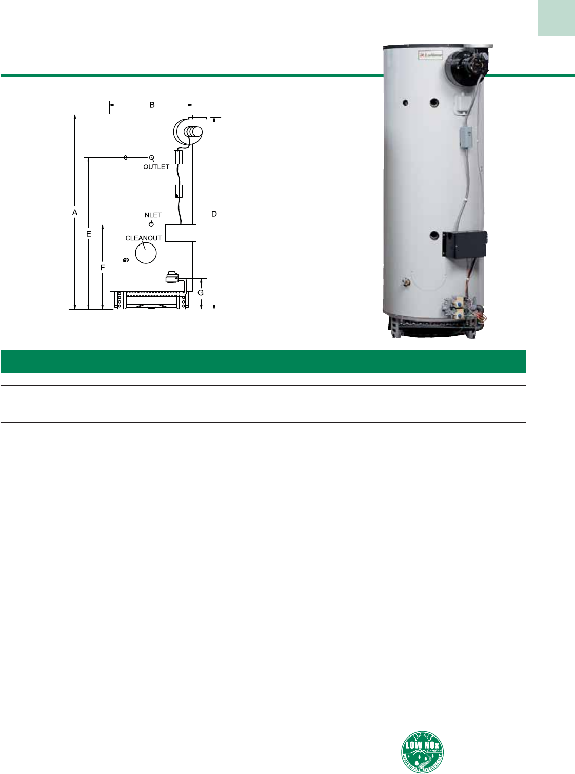
Super Charger
Model Tank Btu/hr Gallon GPH @ A B D E F G Vent Gas Water Shipping
Number Const. Input Cap. 100°F Rise Size Conn Conn Weight
CNR625-065 STD 625,000 65 606 69-1/2” 28-1/4” 69” 54-1/4” 29” 10-1/2” 8” 1”, 3/4” LP 1-1/2” F 720
CNR725-080 STD 725,000 80 703 79-3/4” 28-1/4” 79-1/4” 64-1/4” 29” 10-1/2” 8” 1”, 3/4” LP 1-1/2” F 800
CNA626-065 ASME 625,000 65 606 69-1/2” 28-1/4” 69” 54-1/4” 29” 10-1/2” 8” 1”, 3/4” LP 1-1/2” F 775
CNA726-080 ASME 725,000 80 703 79-3/4” 28-1/4” 79-1/4” 64-1/4” 29” 10-1/2” 8” 1”, 3/4” LP 1-1/2” F 880
Notes: Change “N” to “L” for LP gas models. Performance data is based on manufacturer test results.
Super Charger Gas Models
Standard Equipment:
• Multi-Flue Tank Design—for increased efficiency and
energy conservation
• Durable Fused Glass Lining—prolongs tank life
• Non-CFC Foam Insulation—up to 2” for max. heat
retention and lower standby losses
• Magnesium Tank Saver Anodes—inhibit corrosion
• 150 psi Working Pressure
• ASME Temperature & Pressure Relief Valve
• Heavy Steel Jacket with Baked Enamel Finish
• Immersion Thermostat and Limit Controls
• Cleanout—permits easy access for cleaning
• Spark Ignition with Supervised Pilot
• Approved for 180°F Operation
• Slide Out Burner Tray
• Combustible Floor Approved
• Fan Induced Combustion System
• Simple 120 VAC Control Circuitry
• 4-Second Main Gas Shutdown
• High Btu/hr Input/Recovery
• 3 Year Limited Tank Warranty
• 1 Year Limited Parts Warranty
(See warranty for details)
Optional Equipment:
•
NSF Construction
•
Temperature and
Pressure Gauge
18
Low NOx models
are available.
Consult factory.
19
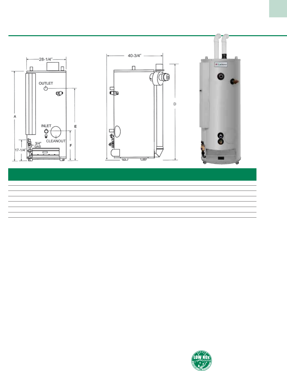
TurboChargerTM High Efficiency Gas Models
Standard Equipment
• Up to 98% Thermal Efficiency - Fully condensing design maximizes efficiency for lower
operational cost.
• Direct Vent / Sealed Combustion - Draws all combustion air from outside and vents all
byproducts outdoors.
• Electronic Controls - Electronic thermostat adjustable up to 180°F.
• Premix Power Burner - Fires into a submerged combustion chamber resulting in precise
mixing of gas and air for optimum efficiency.
• Submerged Combustion Chamber - Reduces radiant heat loss and increases efficiency.
• Triple Pass Flue System - Unique triple bypass flue design, efficiently extracts available
heat from the flue gases, increasing the rate of heat transfer.
• Glass Lined Steel Tank - Fused to the tank at 1600°F, the durable glass lining ensures
lasting protection against rust and corrosion while providing clean, clear hot water.
• Tank Saver Anodes - Provides lasting protection from the effects of electrolytic corrosion.
• Zero Clearance to Combustible Materials
• Non-CFC Foam Insulation - Meets ASHRAE standby loss requirements.
• Low NOx Operation Exceeds the most Stringent Air Quality Requirements
• Built-In Power Cord - 6 feet in length for installation ease.
• Handhole Cleanout - Provides easy access for inspection and cleaning of the tank interior.
• Dielectric Nipples -Protects tank from corrosive action between dissimilar metals
and reduce installed cost.
• Brass Drain Valve
• ASME Temperature & Pressure Relief Valve
• 3 Year Limited Tank Warranty
• 1 Year Limited Parts Warranty
(See warranty for details)
Optional Equipment
• NSF Construction
• ASME Construction
• Concentric Vent Kit
Maximum Vent Lengths:
3” Vent (PVC or CPVC)
TNR125-060 = 120 Equivalent Ft.
TNR150-060 = 100 Equivalent Ft.
TNR200-060 = 80 Equivalent Ft.
TNR150-100 = 120 Equivalent Ft.
TNR200-100 = 100 Equivalent Ft.
TNR250-100 = 80 Equivalent Ft.
TNR300-100 = 60 Equivalent Ft.
TNR400-100 = 50 Equivalent Ft.
4” Vent (PVC or CPVC)
TNR125-060 = 170 Equivalent Ft.
TNR150-060 = 150 Equivalent Ft.
TNR200-060 = 130 Equivalent Ft.
TNR150-100 = 170 Equivalent Ft.
TNR200-100 = 150 Equivalent Ft.
TNR250-100 = 130 Equivalent Ft.
TNR300-100 = 110 Equivalent Ft.
TNR400-100 = 100 Equivalent Ft.
Model Tank Btu/hr Gal. GPH @ Shipping
Number Const. Input Cap. 100°F Rise A B D E F G H Weight
TNR125-060 *STD 125,000 60 148 57” 28-1/4” 13” 42-1/2” 52-1/2” 53-1/2” 40” 570
TNR150-060 *STD 150,000 60 178 57” 28-1/4” 13” 42-1/2” 52-1/2” 53-1/2” 40” 570
TNR200-060 *STD 199,999 60 238 57” 28-1/4” 13” 42-1/2” 52-1/2” 53-1/2” 40” 570
TNR150-100 *STD 150,000 100 178 77-3/4” 28-1/4” 13” 62-1/2” 73-1/4” 74-3/4” 60” 900
TNR200-100 *STD 199,999 100 238 77-3/4” 28-1/4” 13” 62-1/2” 73-1/4” 74-3/4” 60” 900
TNR250-100 STD 250,000 100 297 77-3/4” 28-1/4” 13” 62-1/2” 73-1/4” 74-3/4” 60” 900
TNR300-100 STD 300,000 100 342 77-3/4” 28-1/4” 13” 62-1/2” 73-1/4” 74-3/4” 60” 900
TNR400-100 STD 399,999 100 446 77-3/4” 28-1/4” 13” 62-1/2” 73-1/4” 73-1/4” 60” 950
TNA251-100 ASME 250,000 100 297 77-3/4” 28-1/4” 13” 62-1/2” 73-1/4” 74-3/4” 60” 900
TNA301-100 ASME 300,000 100 342 77-3/4” 28-1/4” 13” 62-1/2” 73-1/4” 74-3/4” 60” 900
TNA401-100 ASME 399,999 100 446 77-3/4” 28-1/4” 13” 62-1/2” 73-1/4” 73-1/4” 60” 950
Notes: *ASME Construction available upon request. Consult factory for details. Change N to L for LP gas models.
Gas Connection is 3/4” NPT. (1” on 400 KBtu models) Water Connections are 1-1/2” NPT.
Performance data is based on Manufacturer’s test results.
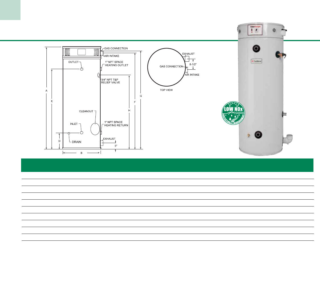
Charger Power DV Power Direct Vent Gas Models
Model Tank Gal. Btu/hr GPH @ Vent Water Connections Shipping
Number Const. Cap. Input 100°F Rise A D E F Size Top Front Rear Weight
PNR150-080 STD 80 150,000 145 63-1/2” 68-1/4” 51-1/4” 20-3/4” 3” 1-1/2“ 1-1/2” 2” 645
PNR150-100 STD 100 150,000 145 72” 77-1/4” 60-1/4” 20-3/4” 3” 1-1/2” 1-1/2” 2” 735
PNR200-080 STD 80 199,999 194 63-1/2” 68-1/4” 51-1/4” 20-3/4” 3” 1-1/2“ 1-1/2” 2” 645
PNR200-100 STD 100 199,999 194 72” 77-1/4” 60-1/4” 20-3/4” 3” 1-1/2“ 1-1/2” 2” 735
PNR250-080 STD 80 250,000 242 63-1/2” 73” 51-1/4” 20-3/4” 4” 1-1/2“ 1-1/2” 2” 645
PNR250-100 STD 100 250,000 242 72” 82” 60-1/4” 20-3/4” 4” 1-1/2“ 1-1/2” 2” 735
PNA251-080 ASME 80 250,000 242 63-1/2” 73” 51-1/4” 20-3/4” 4” 1-1/2“ 1-1/2” 2” 720
PNA251-100 ASME 100 250,000 242 72” 82” 60-1/4” 20-3/4” 4” 1-1/2“ 1-1/2” 2” 815
Notes: Change ‘N’ to ‘L’ to denote LP models. Gas Connections are 3/4” NPT
115 Volt AC required
20
Standard Equipment
• Independent PVC Venting - The stand alone vent exhausts
the byproducts of combustion and the separate air intake
provides fresh combustion air to the unit. Vents up to 40 feet
to an outside wall, with one 90 degree elbow, using 3” PVC
or CPVC pipe. Vents up to 55 feet to an outside wall,
with one 90 degree elbow, using 4” PVC or CPVC pipe.
• Glass-Lined Steel Tank - 300 PSI test pressure, 150 PSI
working pressure.
• Magnesium Tank Saver Anode - Large diameter anode rod
for longer tank life and greater protection.
• Electronic Ignition - Spark-to-pilot ignition system
eliminates the need for a continuously burning pilot light,
which saves energy, by providing pilot gas only when the
system calls for heat.
• Approved for Operation at 180°F Outlet Temperature.
• Temperature & Pressure Relief Valve - Factory installed.
• Cleanout - Provides easy access.
• Dielectric Fittings - Factory installed and designed to
provide additional protection for longer tank life.
• Brass Drain Valve
• Automatic Induced-Draft Blower - Provides balanced flue
operation for direct vent applications.
• Non-CFC Foam Insulation - Meets ASHRAE standby
loss requirements.
• Warranty - 3 year limited tank warranty.
1 year limited warranty on parts.
(See warranty for details)
Optional Equipment
• ASME Tank Construction
(250,000 BTU models only)
• NSF Construction
• Low NOx Construction
Low NOx models
are available.
Consult factory.
21
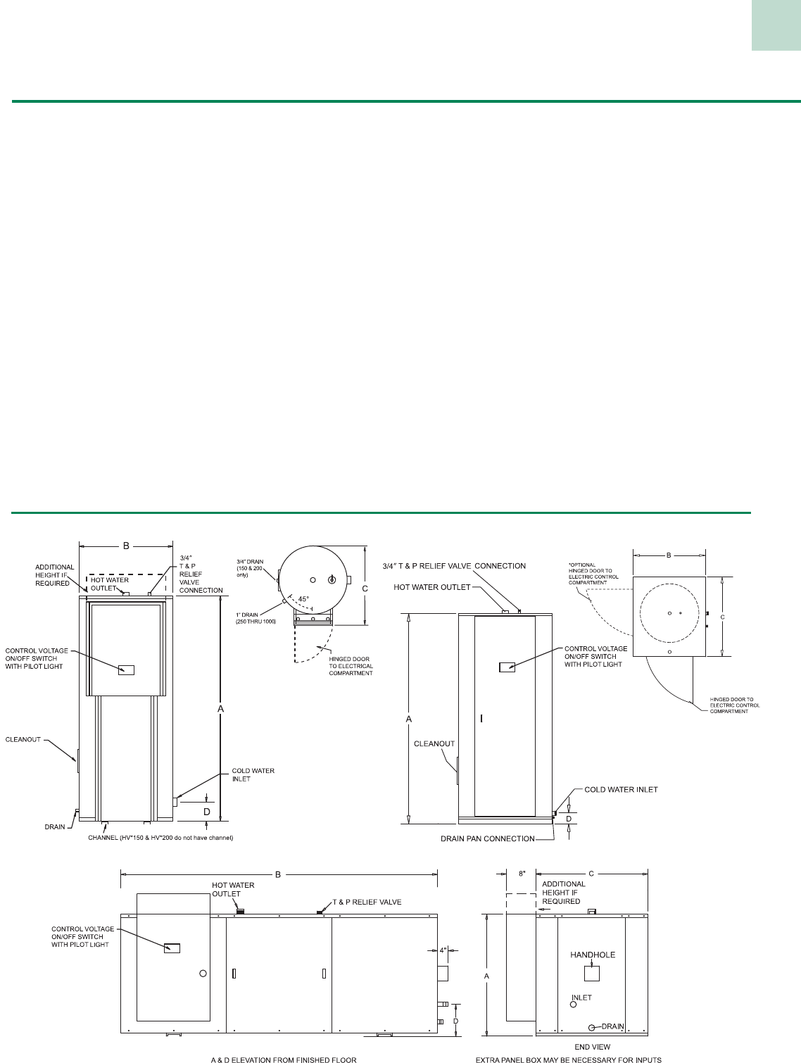
Custom Hi-Power®Vertical And Horizontal Models
= Voltage
kW = Kilowatt
*
Max. Gal. Water Shipping
Model KW Cap. A B C D Conn. Weight
Vertical Round Inlet Outlet (.lbs)
HV*kW-150 135 150 65-1/2” 32” 38-3/4” 7-3/4” 1-1/2” 1-1/2” 650
HV*kW-200 180 200 78” 32” 38-3/4” 7-3/4” 1-1/2 ” 1-1/2” 750
HV*kW-250 216 250 92” 34” 40-3/4” 19-1/2” 1-1/2 ” 1-1/2” 1,165
HV*kW-300 270 300 80” 40” 46-3/4” 21” 2” 2” 1,350
HV*kW-400 360 400 80” 46” 52-3/4” 22-1/2” 2” 2” 1,590
HV*kW-500 396 500 92” 46” 52-3/4” 22-1/2” 2” 2” 1,700
HV*kW-600 396 600 92” 52” 60-3/4” 24-1/2” 2-1/2” 2-1/2” 2,010
HV*kW-800 396 750 104” 52” 60-3/4” 24-1/2” 2-1/2” 2-1/2” 2,450
HV*kW-1000 396 950 128” 52” 60-3/4” 24-1/2” 2-1/2” 2-1/2” 3,160
Vertical Square
HV*kW-1250 900 1,250 132-1/2” 64-1/2” 64-1/2” 23-1/4” 3” 3” 3,560
HV*kW-1500 900 1,500 128-1/2” 70-1/2” 70-1/2” 25-1/4” 3” 3” 4,120
HV*kW-2000 900 2,000 140-1/2” 76-1/2” 76-1/2” 27-1/4” 3” 3” 4,350
HV*kW-2500 900 2,500 146-1/2” 82-1/2” 82-1/2” 29” 3” 3” 5,750
Horizontal Square
HH*kW-150 135 150 37” 68-1/2” 34-1/4” 12” 2” 2” 1,180
HH*kW-200 180 200 37” 78” 34-1/4” 12” 2” 2” 1,370
HH*kW-250 225 250 39” 90-1/4” 36-1/4” 13” 2” 2” 1,450
HH*kW-300 270 300 45” 78-1/4” 42-1/4” 14-3/4” 2” 2” 1,530
HH*kW-400 360 400 52” 78-1/4” 48-1/4” 16” 2” 2” 1,750
HH*kW-500 450 500 52” 90-3/4” 48-1/4” 16” 2” 2” 1,860
HH*kW-600 540 600 58” 90-3/4” 54-1/4” 13-1/2” 2-1/2” 2” 2,340
HH*kW-800 720 750 58” 102-1/4” 54-1/4” 13-1/2” 2-1/2” 2” 2,850
HH*kW-1000 900 950 58” 126-1/4” 54-1/4” 13-1/2” 2-1/2” 2” 3,040
HH*kW-1250 900 1,250 64” 130-1/4” 60-1/4” 15” 3” 3” 3,750
HH*kW-1500 900 1,500 70” 126-1/4” 66-1/4” 16” 3” 3” 4,340
HH*kW-2000 900 2,000 76” 137-1/4” 72-1/4” 17-1/2” 3” 3” 4,580
HH*kW-2500 900 2,500 82” 144-1/4” 78-1/4” 16-1/2” 3” 3” 6,060
NOTES: Vertical Round models above 90 kW at 208V, 240V or 380V, and 162 kW at 415V, 480V, or 600V exceed the capacity of a single control box and may require multiple control panels.
Consult the factory for specific details and optional construction.
Vertical Square construction is available as an option for models that exceed the listed kW limits.
Control panel height on Vertical Round models may exceed tank height – consult factory for specific heights on models with inputs above 72 kW.
J—208V 1ø
K—208V 3ø
A—240V 1ø
B—240V 3ø
W—277V 1ø
Y—380V 3ø
Z—415V 3ø
X—480V 3ø
N—600V 3ø
VOLTAGE SCHEDULE
22
Vertical Round 150-1000 Vertical Square 1250-2500
Horizontal Square 150 - 2500
Custom Hi-Power®Commercial Electric Models
• Glass Lined Steel Tank
• Incoloy Heating Elements
• Internal Fusing (above 120 amps)
• Enamel Finished Galvanized Steel Jacket
• Magnesium Tank Saver Anodes
• Immersion Thermostat
• Manual Reset High Limit
• Full Length Hinged Doors with Key Lock
• Terminal Block Connections
• ASME Temperature and Pres sure Relief Valve
(Supplied, not installed)
• Channel Iron Skid Base
(except 150 & 200 gallon round or larger)
• Approved for 180°F Temperature Operation
• ASME Construction and Na tion al Board Listed
• All models meet or exceed ASHRAE
energy efficiency standards
• 125 psi Working Pressure
• Handhole or Cleanout
• UL Listed (U.S. & Canada)
• Safety Drain Pan (Square Models)
• Control Voltage on/off Switch w/ Pilot Light
• 3 Year Limited Tank Warranty
• 1 Year Limited Parts Warranty
• Low Water Cut-Off
• Pilot Lights
• Manual Limiting Switches
• Alarm Bell
• Shunt Trip Disconnect*
• Low or High Water Pressure Switch
• Lifting Lugs
• Time Clock (7 day or 24 hour)
• Safety Door Interlock
• BMS Enable/Disable Contacts
• Temperature and Pressure Gauges
• Manway
• 150 psi or 160 psi Working Pressure
• Electronic Step Controller
• Seismic attachment points (Must have seismic
zone or city and state of install)
*Field Installed
Optional Equipment
Standard Features
23
Standard Hi-Power®
COLD
WATER
INLET
7" DRAIN
DA
B3/4" T & P
RELIEF VALVE
Standard Features
• Heavy Duty Glass-Lined Tank
• Magnesium Tank Saver Anode
• Low Watt Density Element
• High Limit Cut-Off
• Internal Fusing
• Approved for 180°F Operation
(Immersion models)
• Factory-Installed Temperature and
Pressure Relief Valve
• Two Temperature Operation Available
• Full 3” Foam Insulation
• Hinged Door Access
• Two Thermostat Control Types
• U.L. Listed
• 3 Year Limited Tank Warranty
• 1 Year Limited Parts Warranty
(See warranty for details)
Electric Models
HOT WATER
OUTLET
C
Model Gallon GPH @ Number of Shipping
Number KW Capacity 100°F Rise Elements A B C D Weight
HS*09-052 9 50 37 3 47-3/4” 24” 30-1/2” 41” 270
HS*12-052 12 50 50 3 47-3/4” 24” 30-1/2” 41” 270
HS*15-052 15 50 62 3 47-3/4” 24” 30-1/2” 41” 270
HS*18-052 18 50 74 3 47-3/4” 24” 30-1/2” 41” 270
HS*24-052 24 50 99 6 47-3/4” 24” 30-1/2” 41” 270
HS*27-052 27 50 112 6 47-3/4” 24” 30-1/2” 41” 270
HS*30-052 30 50 124 6 47-3/4” 24” 30-1/2” 41” 270
HS*36-052 36 50 149 6 47-3/4” 24” 30-1/2” 41” 270
HS*09-082 9 80 37 3 60-1/4” 26” 32-1/2” 52-1/2” 335
HS*12-082 12 80 50 3 60-1/4” 26” 32-1/2” 52-1/2” 335
HS*15-082 15 80 62 3 60-1/4” 26” 32-1/2” 52-1/2” 335
HS*18-082 18 80 74 3 60-1/4” 26” 32-1/2” 52-1/2” 335
HS*24-082 24 80 99 6 60-1/4” 26” 32-1/2” 52-1/2” 335
HS*27-082 27 80 112 6 60-1/4” 26” 32-1/2” 52-1/2” 335
HS*30-082 30 80 124 6 60-1/4” 26” 32-1/2” 52-1/2” 335
HS*36-082 36 80 149 6 60-1/4” 26” 32-1/2” 52-1/2” 335
HS*45-082 45 80 186 9 60-1/4” 26” 32-1/2” 52-1/2” 335
HS*54-082 54 80 223 9 60-1/4” 26” 32-1/2” 52-1/2” 335
HS*09-120 9 119 37 3 64-1/2” 30-1/4” 37-1/4” 55” 430
HS*12-120 12 119 50 3 64-1/2” 30-1/4” 37-1/4” 55” 430
HS*15-120 15 119 62 3 64-1/2” 30-1/4” 37-1/4” 55” 430
HS*18-120 18 119 74 3 64-1/2” 30-1/4” 37-1/4” 55” 430
HS*24-120 24 119 99 6 64-1/4” 30-1/4” 37-1/4” 55” 430
HS*27-120 27 119 112 6 64-1/2” 30-1/4” 37-1/4” 55” 430
HS*30-120 30 119 124 6 64-1/2” 30-1/4” 37-1/4” 55” 430
HS*36-120 36 119 149 6 64-1/2” 30-1/4” 37-1/4” 55” 430
HS*45-120 45 119 186 9 64-1/4” 30-1/4” 37-1/4” 55” 430
HS*54-120 54 119 223 9 64-1/2” 30-1/4” 37-1/4” 55” 430
Notes: S = Surface-Mounted Thermostat C = Immersion Thermostat w/ Contactors
Change “S” to “C” for Immersion Thermostat model. 1-1/2” NPT Water Connections
IMMERSION THERMOSTAT
w/ CONTACTORS
VOLTAGE SCHEDULE
J—208V 1ø W—277V 1ø
K—208V 3ø Y—380V 3ø
A—240V 1ø Z—415V 3ø
B—240V 3ø X—480V 3ø
AMPERAGE TABLE
Single Phase Three Phase
KW 208V 240V 277V 208V 240V 480V
9 43 38 32 25 22 11
12 58 50 43 33 29 14
15 72 63 54 42 36 18
18 87 75 65 50 43 22
24 115 100 87 67 58 29
27 130 113 97 75 65 32
30 144 125 108 83 72 36
36 173 150 130 100 87 43
45 216 188 162 125 108 54
54 260 225 195 150 130 65
SURFACE MOUNTED
THERMOSTAT
VOLTAGE SCHEDULE
T— 208V 1ø or 3ø
P— 240V 1ø or 3ø
W—277V 1ø
Y–– 380V 3ø
Z—415V 3ø
X—480V 3ø
* = Voltage - See voltage schedule
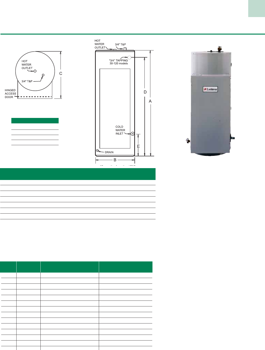
24
Model Max Gal. Water Shipping
Number kW Cap. A B C D E Conn. Weight
HC*kW-06A 3 6 17-1/2” 16” 21” N/A 6-1/4” 3/4” 83
HC*kW-12A 9 12 28” 16” 21” N/A 6-1/4” 3/4” 118
HC*kW-20A 18 20 27-1/2” 20” 24-1/2” N/A 6-1/4” 3/4” 145
HC*kW-30A 36 30 38” 20” 24-1/4” N/A 6-1/4” 3/4” 180
HC*kW-40A 36 40 48-1/4” 20” 24-1/2” N/A 6-1/4” 3/4” 220
HC*kW-50A 81 50 47-3/4” 24” 30-1/2” 41” 6” 1-1/2” 270
HC*kW-80A 81 80 60-1/4” 26” 30-1/2” 52-1/2” 6” 1-1/2” 335
HC*kW-120A 81 120 64-1/2” 30-1/4” 30-1/2” 55” 6” 1-1/2” 430
Amperage Table
VOLTAGE SCHEDULE
J—208V 1ø W—277V 1ø
K—208V 3ø Y—380V 3ø
A—240V 1ø Z—415V 3ø
B—240V 3ø X—480V 3ø
= Voltage see voltage schedule
Compact ASME Hi-Power
Standard Features
• ASME Code Construction HLW
• Heavy-Duty Glass-Lined Tank–150 psi work-
ing pressure.
• Magnesium Tank Saver–large diameter
for longer tank life, greater protection.
• Heating Element–Low watt incoloy construc-
tion for long life.
• Energy Cut-Off–Shuts off electrical power
should the water temperature in the tank ex-
ceeds 200°F.
• Internal Fusing–All elements and controls are
fused in accordance with U.L. requirements.
• Approved for 180 °F outlet temperature
• Temperature and Pressure
Relief Valve–Included
• Insulation–Full 3” of foam insulation on the top
and around the sides. Meets ASHRAE Energy
Efficiency Standards.
• Hinged Access Door–Provides easy access to
electrical controls.
• Immersion Thermostats and Contactors
• Cleanout–20 - 120 gallon models.
• 3 Year Limited Tank Warranty
• 1 Year Limited Parts Warranty
(See warranty for details)
Optional Equipment
• Low Water Cut-Off
• Safety Door Interlock
• High and/or Low Water Pressure
Limit Switches
• Alarm Bell
• Temperature & Pressure Gauge
• Time Delay Step Sequences
(24 kW & Above)
• NSF Construction
Electric Models
GPH@ SINGLE PHASE THREE PHASE
KW 100°F RISE 208V 240V 277V 208V 240V 480V
3 12 14 13 11 – – –
6 25 30 25 22 17 14 7
9 37 43 38 32 25 22 11
12 50 58 50 43 33 29 14
15 62 72 63 54 42 36 18
18 74 87 75 64 50 43 22
24 99 115 100 87 68 58 29
27 112 130 113 97 75 65 33
30 124 144 125 108 83 72 36
36 149 173 150 130 100 87 43
45 186 216 188 162 125 108 54
54 223 260 225 195 150 130 65
81 335 389 338 292 225 195 97
Note: Models with an amp draw in excess of 120 amps require factory installed internal fusing.
*
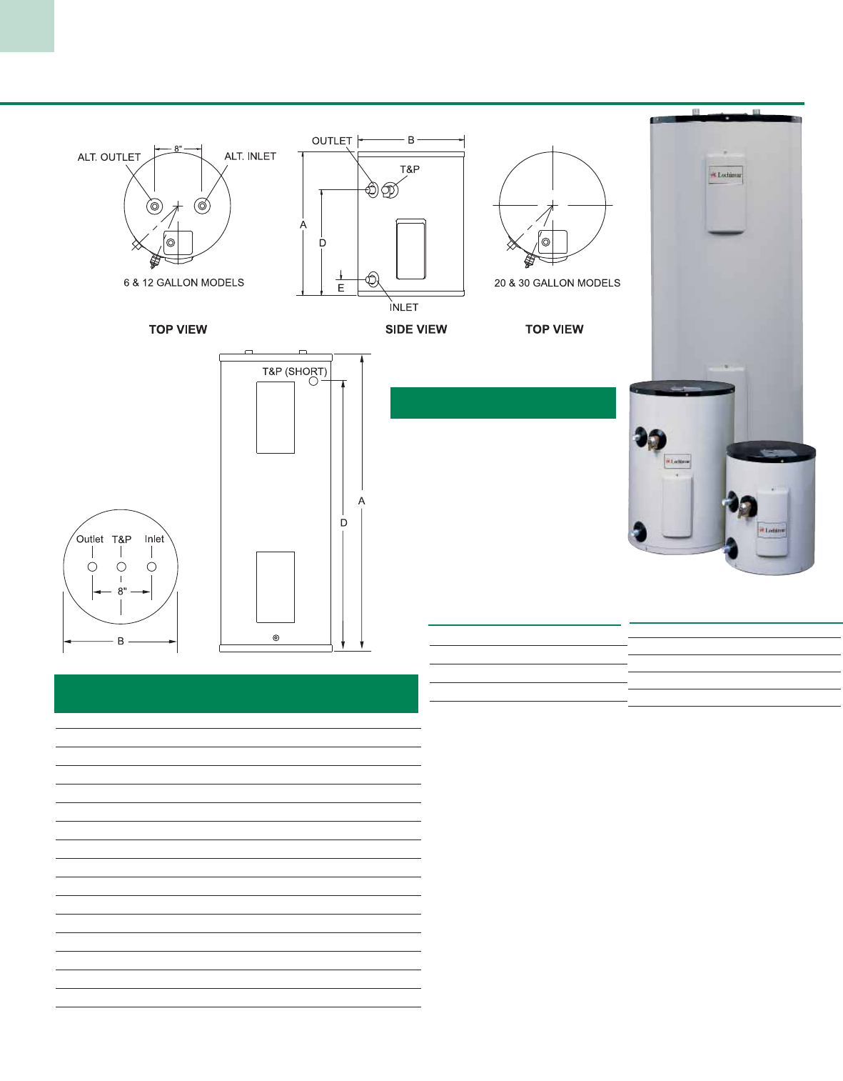
25
Light Duty Commercial Electric Models
Standard Features
• Energy Saving Design–All models meet the latest NAECA
and ASHRAE Energy Efficiency Standards.
• Glass–Lined Steel Tank–300 psi test pressure, 150 psi
working pressure.
• Non-CFC Foam Insulation–Surrounds the tank surface to
minimize standby heat loss. Exceeds ASHRAE 90.1 standard.
• Adjustable Thermostats–Adjustable, accurate control provides
easy means of selecting most desirable temperature.
• Automatic Overheat Protection–Provides automatic overheat
safety control with manual reset high limit feature.
• Magnesium Tank Saver Anode–Large diameter magnesium anode
prolongs tank life and inhibits corrosion.
• Dip Tube–Withstands temperatures of 400ºF.
• ASME Temperature & Pressure Relief Valve–Included
• Warranty – 3 year limited tank warranty.
1 year limited parts warranty.
(See warranty for details)
Element Availability
INPUT VOLTAGE
(WATT) 208V 240V 277V 480V
E- 1500 Y Y Y Y
F- 2000 Y Y Y Y
G- 2500 Y Y Y Y
H- 3000 Y Y Y Y
J- 3500 Y Y Y Y
L- 4000 Y Y Y Y
K- 4500 Y Y Y Y
M- 5000 Y Y Y Y
P- 6000 Y Y Y Y
Notes: Max. wattage Jr models 6 & 12 = 3000W
Max wattage Jr. models 20 & 31 = 6000W
Wattage Limits w/
Simultaneous Operation
208V - 10,000W (5,000W/5,000W)
240V - 10,000W (5,000W/5,000W)
277V - 12,000W (6,000W/6,000W)
480V - 12,000W (6,000W/6,000W)
Model Gallon Shipping
Number Capacity A B D E Weight
Junior Models
JRW006E 6 16-1/2” 14” 10-1/4” 3” 33
JRW012E 12 27-3/4” 14” 21-1/4” 3” 48
JRW020E 19 24-3/4” 18” 18-1/4” 3” 59
JRW031E 30 30” 22” 23-1/2” 4-1/2” 92
Tall Models
LTX030KK 30 47” 18” - - 85
LTX040KK 40 47” 20” - - 103
LTX052KK-T 50 57-1/2” 20” - - 123
LTX052KK 50 46-1/2” 22” - - 130
LTX066KK 65 59-1/4” 22” - - 156
LTX082KK 80 59” 24” - - 183
LTX120KK 119 63-3/4” 28” - - 305
Short Models -
LSX030KK 30 29-3/4” 22” 24” - 96
LSX040KK 40 31-3/4” 24” 24-1/4” - 125
LSX050KK 47 31-3/4” 26” 24-1/4” - 153
Notes: Water connections 3/4” NPT on all models.
(LTX120 is standard with 1” water connections)
Standard wattage and voltage: 4500W/480V 3ø
Standard wattage and voltage Jr. models: 1500W/277V 1ø
Junior models
Tall & Short models
Voltage Schedule
J - 208V 1ø W - 277V 1ø
K - 208V 3ø Y - 380V 3ø
A - 240V 1ø Z - 415V 3ø
B - 240V 3ø V - 480V 1ø
X - 480V 3ø
Note: Jr models available in 1
ø and 480V 1ø only.
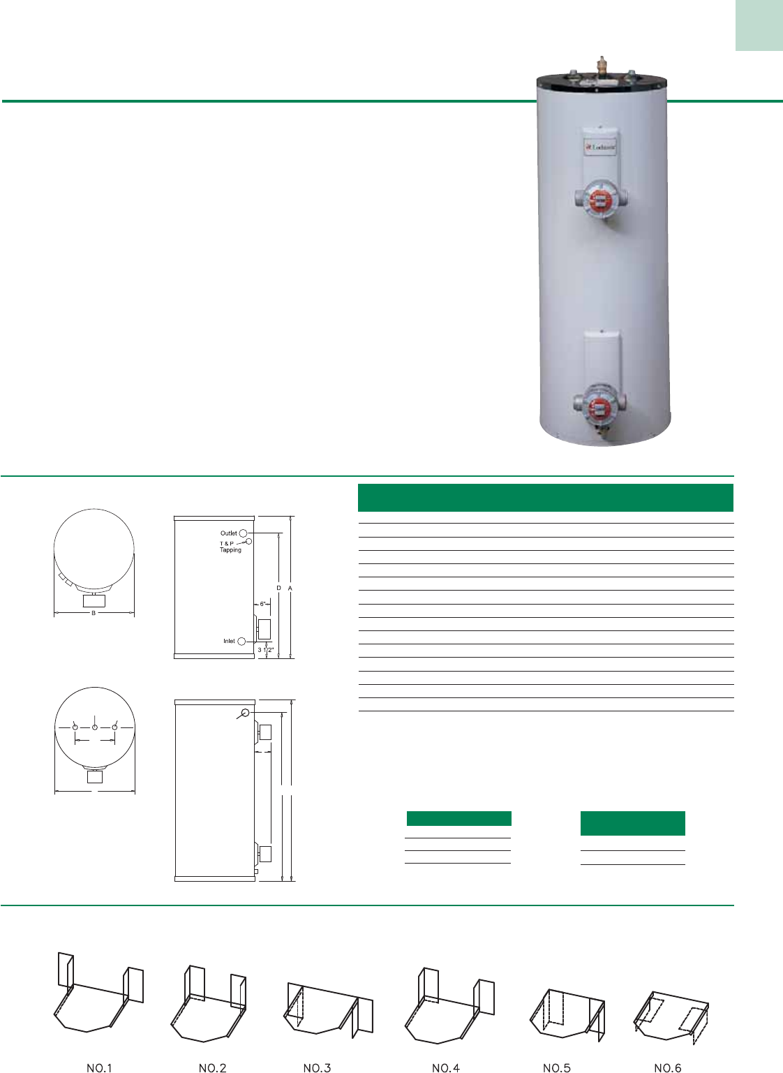
26
Explosion-Resistant Element
• Thermostat Enclosure
-
moisture-tight and explosion resistant.
• Large Terminal Enclosure
-
for easy access, cool terminations and simple installation.
• Rugged High Conductivity Elements
-
compacted MgO for maximum efficiency and durability
• Complies with NEC
Class I (Groups C, D)
Class II (Groups E,F,G)
Class III
• Complies with U.L. Standard 886
• Enclosure meets NEMA requirements for hazardous atmosphere (consult factory for specific applications)
Six Way Shelf Mounting - For six and twelve gallon models only. (JKT 3004)
WATTAGE SCHED-
ULE
E – 1500
K – 4500
P – 6000
VOLTAGE SCHEDULE
C – 120V 1ø
J – 208V 1ø
A – 240V 1ø
X – 480V 1ø
Junior Models
Tall & Short Models
Explosion-Resistant Electric Models
Short Series
Have Optional
Side T & P
Valve Tapping
Note: Diagram above depicts
optional double element
availability. (Short and
Tall models only).
Standard Features
• Energy Saving Design - All models meet the latest
NAECA and ASHRAE Energy Efficiency Standards.
• Glass-Lined Steel Tank - Fused to the tank at
1600°F to assure lasting protection against rust and
corrosion while providing clean, clear hot water. 300
psi test pressure provides 150 psi working pressure.
• Non-CFC Foam Insulation - The polyurethane
closed cell foam minimizes standby heat loss and
maximizes heat retention.
• Cold Water Inlet Tube - withstands temperatures
of 400ºF
• High Quality Thermostats - Adjustable, accurate
control provides easy means of selecting most
desired temperature.
• Magnesium Tank Saver Anode -
Large diameter magnesium anode prolongs tank
life and inhibits corrosion.
• ASME Temperature & Pressure
Relief Valve - Included with all models.
• Heat Traps - Factory installed, minimizes heat
loss through piping.
• Dielectric Nipples - Provides protection from
corrosive action between dissimilar metals while
reducing installed costs.
• Warranty - 3 year limited tank warranty.
1 year limited parts warranty.
(See warranty for details)
8"
B
6"
A
Outlet Inlet
T&P
D
T&P (Optional)
Model Gallon Shipping
Number Capacity A B D Weight
Junior Models
RJC006E 6 16-1/2” 14” 10-1/4” 43
RJC012E 12 27-3/4” 14” 21-1/4” 58
RJC020E 19 24-3/4” 18” 18-1/4” 69
Tall Models
RTA030K 30 47” 18” – 95
RTA040K 40 47” 20” – 113
RTA052K-T 50 57-1/2” 20” – 133
RTA052K 50 46-1/2” 22” – 140
RTA066K 65 59-1/4” 22” – 166
RTA082K 80 59” 24” – 193
RTA120K 119 63-3/4” 28” – 315
Short Models
RSA030K 30 29-3/4” 22” 24” 106
RSA040K 40 31-3/4” 24” 24-1/4” 135
RSA050K 50 31-3/4” 26” 24-1/4” 163
Notes: Water connections are 3/4” NPT on all models.
Standard for Short and Tall models: 4500 watts, 240V 1ø.
Junior models: 1500 watts, 120V 1ø.
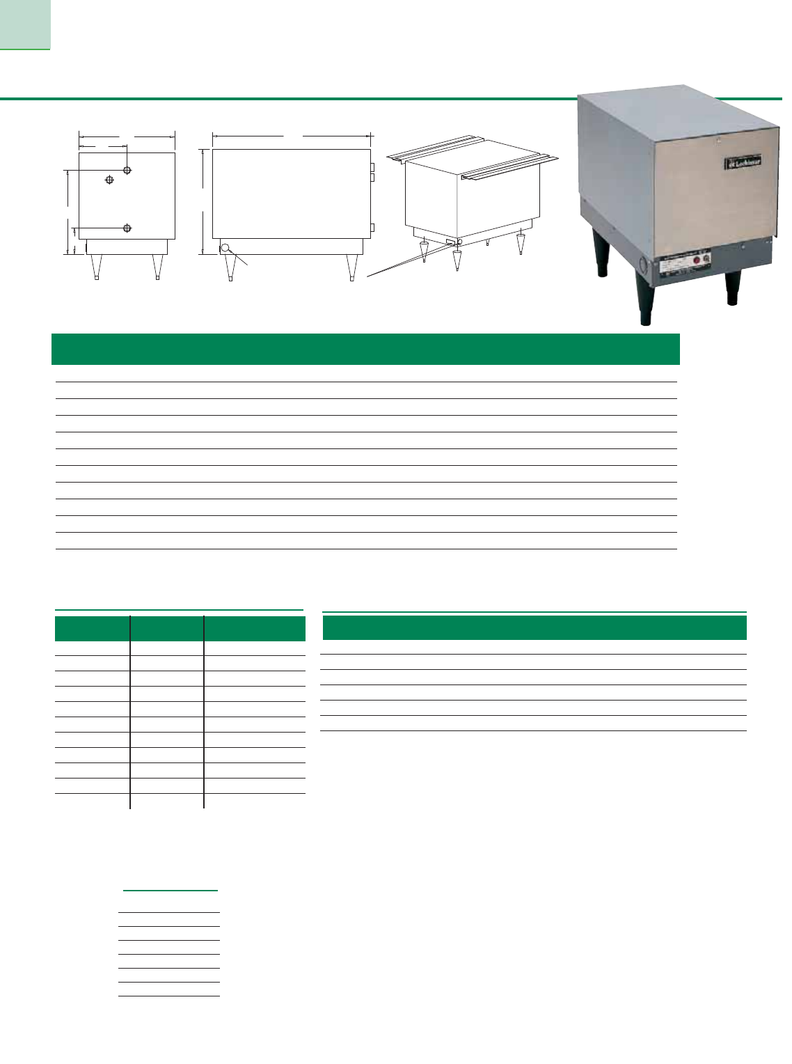
27
Space-Saver Electric Boosters
BACK
C
D
E
OUTLET
RELIEF
VALVE
INLET
A
B
SIDE FRONT
F
Elec tri cal Connection
From either side (6-18), left side (24-58)
or from bottom (all models)
Sizing Guide
Voltage
Schedule
Note: Maximum water pressure 20 psi for proper operation.
Model Recovery (GPH @) Btu/hr A B C D E F Weight
Number kW 40°F 70°F Input
SB*006 6 62 35 20,478 13-3/4” 20-3/4” 13” 3-1/2” 11-1/2” 6-1/2” 118
SB*009 9 93 53 30,717 13-3/4” 20-3/4” 13” 3-1/2” 11-1/2” 6-1/2” 118
SB*012 12 124 71 40,956 13-3/4” 20-3/4” 13” 3-1/2” 11-1/2” 6-1/2” 118
SB*015 15 155 89 51,195 13-3/4” 20-3/4” 13” 3-1/2” 11-1/2” 6-1/2” 118
SB*018 18 186 106 61,434 13-3/4” 20-3/4” 13” 3-1/2” 11-1/2” 6-1/2” 118
SB*024 24 248 142 81,912 12” 24” 18” 2” 10” 8” 158
SB*030 30 310 177 102,390 12” 24” 18” 2” 10” 8” 158
SB*036 36 372 213 122,868 12” 24” 18” 2” 10” 8” 158
SB*045 45 465 266 153,585 12” 24” 18” 2” 10” 8” 158
SB*054 54 558 316 184,302 12” 24” 18” 2” 10” 8” 158
SB*058 58 600 343 198,128 12” 24” 18” 2” 10” 8” 158
Model Single Phase Three Phase
No. kW 208V 240V 208V 240V 480V
SB*006 6 29 25 25 22 11
SB*009 9 43 38 38 33 16
SB*012 12 58 50 33 29 14
SB*015 15 72 63 42 36 18
SB*018 18 83 72 48 42 21
SB*024 24 116 100 67 58 29
SB*030 30 144 125 83 72 36
SB*036 36 173 150 100 87 43
SB*045 45 216 188 125 109 54
SB*054 54 259 229 150 130 65
SB*058 58 279 242 161 141 71
Amperage Draw
J – 208V 1ø
K – 208V 3ø
T
–
208V 1
ø
or 3
ø
A – 240V 1ø
B – 240V 3ø
P
–
240V 1
ø
or 3
ø
X – 480V 3ø
Booster Model No. Booster Model No.
Dishwashing Machine Classification 40° F Rise 70° F Rise
16” x 16” Single Tank (69 GPH) Stationary Rack, Door SB*009 SB*012
18” x 18” Single Tank (87 GPH) Stationary Rack, Door SB*009 SB*015
20” x 20” Single Tank (104 GPH) Stationary Rack, Door SB*012 SB*018
Multiple Tank (277 GPH) Conveyor, Dishes inclined SB*030 SB*054
Multiple Tank (347 GPH) Conveyor, Dishes flat SB*036 (2) SB*030
Single Tank (416 GPH) Conveyor SB*045 (2) SB*036
Notes: * Indicates voltage. 6 and 9 kW models wired for 1ø or 3ø operation in 208 or 240 volt. Six (6) gallon capacity for all models.
Outlets and inlets are 8
”
center-to-center. Water connections are all 3/4
”
NPT.
* Indicates Voltage
Standard Features
• Adjustable Thermostat—for operation at 180°F
• Pilot Switch—turns unit off when dishwasher is not
in use for maximum energy savings
• Under-Counter Design—saves valuable floor space
• Installation Flexibility—use with standard 6”
adjustable legs or under-counter, slide-out mounting
(available upon request)
• Wide Range of Capacities—to meet the requirements
of even the largest commercial dishwashers
• Durable Cement-Lined, Steel Tank—for longer life
• Heavy Duty Construction—pressure tested to 300 psi
and approved for 150 psi working pressure
• Low Watt Density Elements—copper-sheathed,
tin-coated design rated at 75 watts/in2
• Pilot Indicator Light and High Limit Control—
for safe, economical operation
• Built-In Temperature-Pressure Gauge
• Pressure Reducing Valve with Bypass Check
• ASME Temperature and Pressure Relief Valve
• Stainless Steel Jacket
• Full Blanket of Insulation
• Magnesium Anode Rod—inhibits corrosion
• Instantaneous Response—no temperature lag,
no standby losses
• Economical Operation
• Hinged Access Door—for easy servicing and
adjustment of electric controls
• 120 Volt Circuit Control
• Low Water Cut-Off
• 3 Year Limited Tank Warranty
• 1 Year Limited Parts Warranty
(See warranty for details)
Optional Equipment
• Slide-Out Mounting Bracket for Under-Counter
Installation
• Stainless Steel Legs
• 3/4” Shock Absorber (water hammer arrestor)
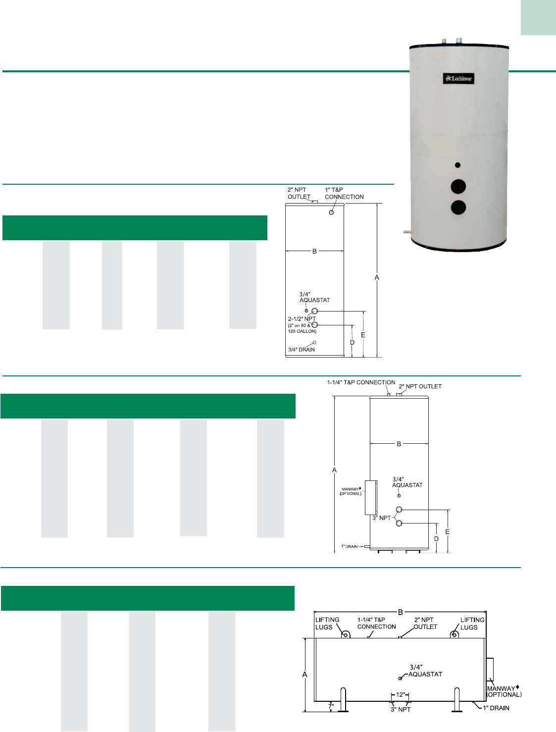
28
Lock-Temp® Round Jacketed Storage Tanks
500 Gallon Jacketed Tank.
Model Gal. Shipping Weight
Number Cap. A B D E 125 psi 150 psi
RJS080 78 58-3/4” 24” 9-1/4” 14-1/4” - 192
RJS120 119 62-1/2” 28” 9-1/2” 14-1/2” - 345
RJA120 119 62-1/2” 28” 9-1/2” 14-1/2” - 365
RJA175 175 67-1/4” 32” 11-1/4” 17-1/4” - 525
RJA200 200 77-1/4” 32” 11-1/4” 17-1/4” - 600
Glass Lined Only
Vertical Round Jacketed Glass Lined Tanks
Vertical Round Jacketed ASME Tanks
Model Gal. Shipping Weight
Number Cap. A B D E 125 psi 150 psi
R*A0257 257 91” 34” 18” 26” 1,108 1,108
R*A0318 318 80” 40” 19-1/2” 27-1/2” 1,290 1,290
R*A0432 432 80” 46” 21” 29” 1,512 1,626
R*A0504 504 92” 46” 21” 29” 1,623 1,765
R*A0650 650 92” 52” 23-1/2” 31-1/2” 1,911 1,911
R*A0752 752 104” 52” 23-1/2” 31-1/2” 2,330 2,330
R*A0940 940 128” 52” 23-1/2” 31-1/2” 3,010 3,010
* Indicates tank lining.
G=Glass Lined C=Cement
Standard Features
• Energy Saving Performance - meet the requirements of the latest ASHRAE Energy Efficiency Standards.
• Five-Year Limited Warranty - against tank failure resulting from defects in materials or workmanship.
• Lock-Temp Baffle - creates nearly perfect stratification.
• Magnesium Anode - provide additional protection against corrosion.
• ASME Construction - in accordance with ASME standards and labeled for 125 psi working pressure
(standard) or 150 psi working pressure (optional). (RJS080 & RJS120 are non-ASME construction)
• Galvanized Jacket - Heavy gauge jacket is and finished in durable acrylic enamel combining attractive
appearance with maximum protection.
Model Gallon Shipping Weight
Number Capacity A B Diameter 125 psi 150 psi
R*A0250H 250 41” 88” 34” 1,157 1,157
R*A0300H 300 47” 76” 40” 1,355 1,355
R*A0400H 400 53” 76” 46” 1,587 1,701
R*A0500H 500 53” 88” 46” 1,711 1,853
R*A0600H 600 59” 88” 52” 2,053 2,053
R*A0700H 700 59” 100” 52” 2,399 2,399
R*A1000H 1000 59” 124” 52” 3,114 3,114
* Indicates tank lining.
G=Glass Lined C=Cement
Horizontal Round Jacketed ASME Tanks
MANWAY IS STANDARD ON CEMENT TANKS.
MANWAY IS STANDARD ON CEMENT TANKS.
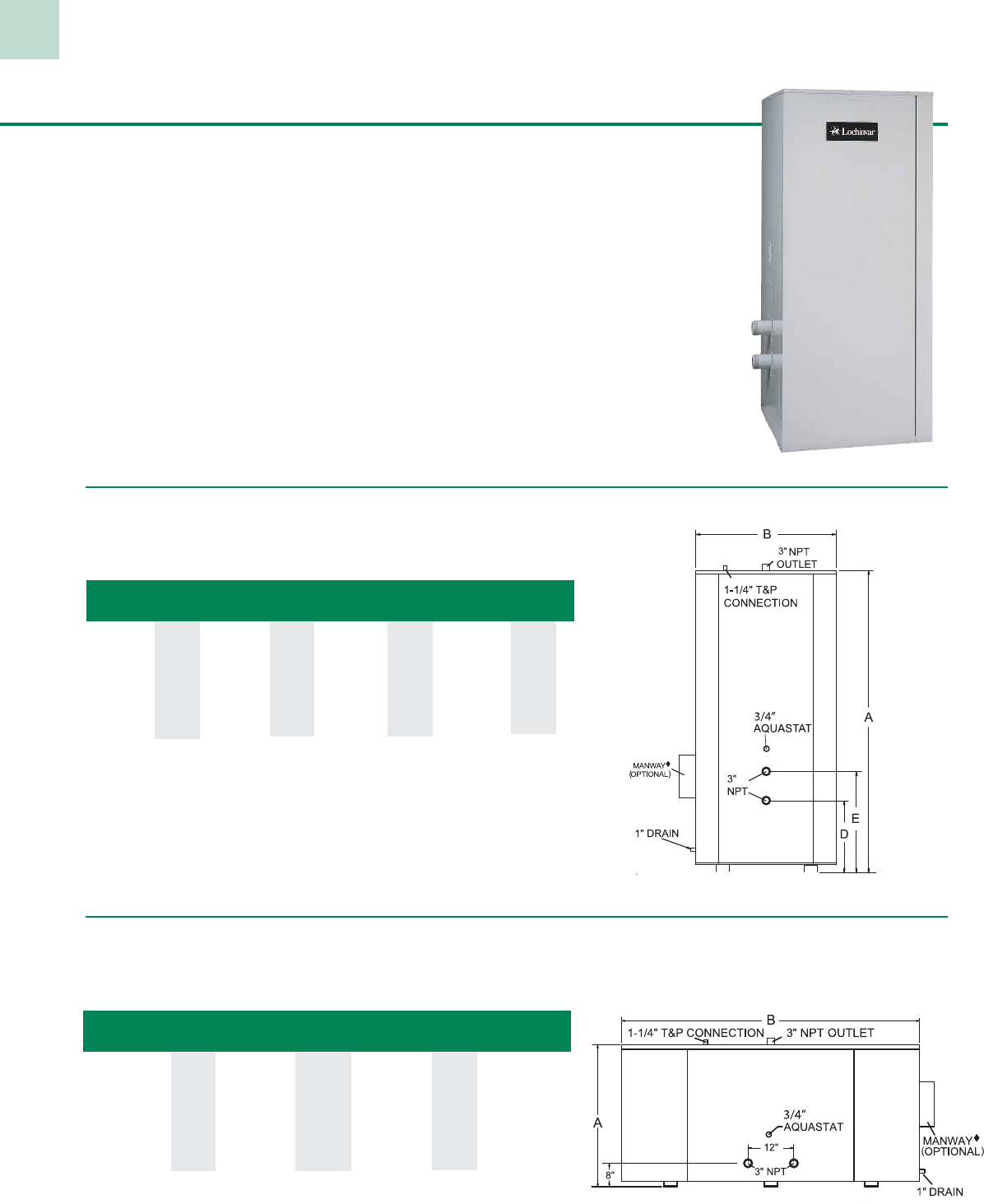
29
Standard Features
• Energy Saving Performance - meet the requirements of the latest ASHRAE Energy Efficiency Standards.
• Five-Year Limited Warranty - against tank failure resulting from defects in materials or workmanship.
• Lock-Temp Baffle - creates nearly perfect stratification.
• Magnesium Anode - provide additional protection against corrosion.
• ASME Construction - in accordance with ASME standards and labeled for 125 psi working pressure
(standard) or 150 psi working pressure (optional).
• Galvanized Jacket - Heavy gauge jacket is and finished in durable acrylic enamel combining attractive
appearance with maximum protection.
• Built-In Safety Drain Pan System - Sealed base assembly with 3/4” drain connection to protect against water damage
from gasket or component leakage.
• Channel Iron Skid - Square jacket models furnished with skid for easy handling and installation.
Lock-Temp® Square Jacketed Storage Tanks
Model Gallon Shipping Weight
Number Capacity A B Depth 125 psi 150 psi
TH*1250J 1250 68-1/2” 130-1/4” 60-1/4” 5,126 5,466
TH*1500J 1500 77 1/2” 126-1/4” 66-1/4” 6,820 7,257
TH*2000J 2000 80-1/2” 138-1/4” 72-1/4” 8,140 8,650
TH*2500J 2500 86-1/2” 144-1/4” 78-1/4” 9,900 10,532
* Indicates tank lining.
G=Glass Lined C=Cement
Horizontal Square Jacketed ASME Tanks
Model Gal. Shipping Weight
Number Cap. A B D E 125 psi 150 psi
TV*1250J 1250 132-1/2” 64-1/2” 29-1/4” 21-1/4” 4,660 5,000
TV*1500J 1500 128 1/2” 70-1/2” 31-3/4” 25-3/4” 6,200 6,637
TV*2000J 2000 140-1/2” 76-1/2” 33-1/2” 25-1/2” 7,400 7,910
TV*2500J 2500 146-1/2” 82-1/2” 35-1/4” 28” 9,000 9,632
* Indicates tank lining.
G=Glass Lined C=Cement
Vertical Square Jacketed ASME Tanks
MANWAY IS STANDARD ON CEMENT TANKS.
MANWAY IS STANDARD ON CEMENT TANKS.
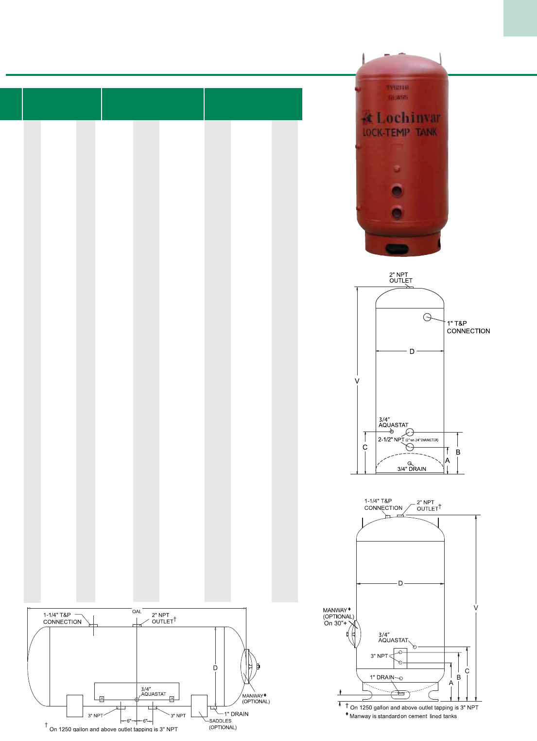
30
Lock-Temp® Bare Storage Tanks
4” (on 30”+)
(28” only)
Dimensions Weights Tappings
Gal. D V H Glass-Lined Cement
Cap. Dia. Ht. Lgth. 125 psi 150 psi Lined A B C
118 24” 64” - 368 368 - 13-1/2” 21-1/2” 29-1/2”
141 24” 76” - 428 428 - 13-1/2” 21-1/2” 29-1/2”
188 24” 100” - 556 556 - 13-1/2” 21-1/2” 29-1/2”
235 24” 124” - 684 684 - 13-1/2” 21-1/2” 29-1/2”
175 28” 65” - 353 353 - 11” 17” 16”
200 28” 76” - - 488 - 11” 17-1/2” 16”
147 30” 52” 48” 400 400 695 15-3/4” 23-3/4” 31-3/4”
184 30” 64” 60” 468 468 812 15-3/4” 23-3/4” 31-3/4”
220 30” 76” 72” 548 548 958 15-3/4” 23-3/4” 31-3/4”
257 30” 87” 83” 628 628 1,103 15-3/4” 23-3/4” 31-3/4”
294 30” 100” 96” 701 701 1,242 15-3/4” 23-3/4” 31-3/4”
367 30” 124” 120” 868 868 1,540 15-3/4” 23-3/4” 31-3/4”
265 36” 64” 60” 577 577 995 17-1/2” 25-1/2” 33-1/2”
318 36” 76” 72” 673 673 1,173 17-1/2” 25-1/2” 33-1/2”
370 36” 87” 83” 770 770 1,343 17-1/2” 25-1/2” 33-1/2”
423 36” 100” 96” 866 866 1,513 17-1/2” 25-1/2” 33-1/2”
528 36” 124” 120” 1,058 1,058 1,861 17-1/2” 25-1/2” 33-1/2”
432 42” 76” 72” 795 909 1,385 18-3/4” 26-3/4” 34-3/4”
504 42” 88” 84” 908 1,050 1,587 18-3/4” 26-3/4” 34-3/4”
576 42” 100” 96” 1,020 1,190 1,790 18-3/4” 26-3/4” 34-3/4”
720 42” 124” 120” 1,245 1,470 2,195 18-3/4” 26-3/4” 34-3/4”
864 42” 148” 144” 1,470 1,751 2,601 18-3/4” 26-3/4” 34-3/4”
1,008 42” 172” 168” 1,695 2,031 3,006 18-3/4” 26-3/4” 34-3/4”
658 48” 88” 84” 1,346 1,346 2,124 20-3/4” 28-3/4” 36-3/4”
752 48” 100” 96” 1,507 1,507 2,392 20-3/4” 28-3/4” 36-3/4”
940 48” 124” 120” 1,828 1,828 2,918 20-3/4” 28-3/4” 36-3/4”
1,128 48” 148” 144” 2,150 2,150 3,444 20-3/4” 28-3/4” 36-3/4”
1,315 48” 172” 168” 2,471 2,471 3,970 20-3/4” 28-3/4” 36-3/4”
1,503 48” 196” 192” 2,793 2,793 4,505 20-3/4” 28-3/4” 36-3/4”
951 54” 100” 96” 1,721 1,972 2,729 22-3/4” 30-3/4” 38-3/4”
1,189 54” 124” 120” 2,083 2,423 3,320 22-3/4” 30-3/4” 38-3/4”
1,427 54” 148” 144” 2,451 2,881 3,919 22-3/4” 30-3/4” 38-3/4”
1,665 54” 172” 168” 2,807 3,326 4,511 22-3/4” 30-3/4” 38-3/4”
1,903 54” 196” 192” 3,168 3,777 5,102 22-3/4” 30-3/4” 38-3/4”
2,141 54” 220” 216” 3,530 4,228 5,701 22-3/4” 30-3/4” 38-3/4”
1,469 60” 124” 120” 2,784 3,221 4,177 24-3/4” 32-3/4” 40-3/4”
1,763 60” 148” 144” 3,267 3,823 4,913 24-3/4” 32-3/4” 40-3/4”
2,056 60” 172” 168” 3,749 4,425 5,658 24-3/4” 32-3/4” 40-3/4”
2,350 60” 196” 192” 4,231 5,026 6,394 24-3/4” 32-3/4” 40-3/4”
2,644 60” 220” 216” 4,713 5,628 7,130 24-3/4” 32-3/4” 40-3/4”
2,115 72” 124” 120” 3,416 3,904 5,104 27-3/4” 35-3/4” 43-3/4”
2,538 72” 148” 144” 3,995 4,627 5,995 27-3/4” 35-3/4” 43-3/4”
2,961 72” 172” 168” 4,575 5,350 6,885 27-3/4” 35-3/4” 43-3/4”
3,384 72” 196” 192” 5,154 6,073 7,767 27-3/4” 35-3/4” 43-3/4”
3,807 72” 220” 216” 5,733 6,795 8,658 27-3/4” 35-3/4” 43-3/4”
24” DIAMETER TANKS
28” DIAMETER AND LARGER TANKS
MANWAY IS STANDARD ON CEMENT TANKS.
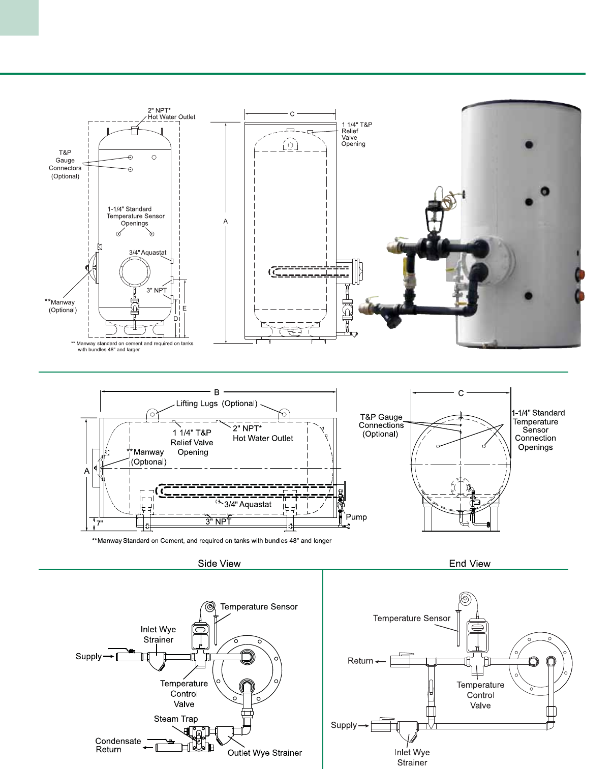
31
NOTE: Unit shown with optional
water-to-water control package
Hot Water Generators Water to Water & Steam to Water
Vertical Tanks
Steam to Water Optional Control Package
Horizontal Tanks
Left hand or right hand configurations available.
Water to Water Optional Control Package

32
Hot Water Generators Vertical and Horizontal Models
Model Gallon Maximum Minimum Shipping
Number Capacity A B C Coil Length Coil Length Weight
GH*250JR 250 41” 88” 34” 84” 54” 1,600
GH*300JR 300 47” 76” 40” 72” 48” 1,800
GH*400JR 400 53” 76” 46” 72” 48” 2,250
GH*500JR 500 53” 88” 46” 84” 54” 2,500
GH*600JR 600 59” 88” 52” 84” 54” 3,600
GH*700JR 700 59” 100” 52” 96” 66” 4,200
GH*1000JR 1000 59” 124” 52” 120” 78” 5,000
Horizontal Tanks Round Jacketed
Non-Jacketed Tanks
Model Gallon Maximum Shipping
Number Capacity A C D E Coil Length Weight
GV*0200JR 200 77-1/4” 32” 11-1/4” 17-1/4” 30” 600
GV*0257JR 257 92” 34” 18” 26” 36” 902
GV*0318JR 318 82” 40” 19-1/2” 27-1/2” 42” 993
GV*0432JR 432 82” 46” 21” 29” 48” 1269
GV*0504JR 504 92” 46” 21” 29” 48” 1373
GV*0650JR 650 93” 54-1/2” 23-1/2” 31-1/2” 54” 1966
GV*0752JR 752 105” 54-1/2” 23-1/2” 31-1/2” 54” 2030
GV*0940JR 940 129” 54-1/2” 23-1/2” 31-1/2” 54” 2376
Vertical Tanks Round Jacketed
Maximum Minimum Maximum
Gallon Length** Diameter Coil Length Coil Length Coil Length Shipping
Model Capacity (Height) (Width) D E (Horizontal) (Horizontal) (Vertical) Weight
GV*147 147 48” 30” 15 3/4” 23 3/4” 36” 30” 36” 400
GV*184 184 60” 30” 15 3/4” 23 3/4” 48” 42” 36” 468
GV*220 220 72” 30” 15 3/4” 23 3/4” 60” 48” 36” 548
GV*257 257 84” 30” 15 3/4” 23 3/4” 72” 54” 36” 628
GV*294 294 96” 30” 15 3/4” 23 3/4” 84” 66” 36” 701
GV*367 367 120” 30” 15 3/4” 23 3/4” 108” 78” 36” 868
GV*265 265 60” 36” 17 1/2” 25 1/2” 48” 42” 42” 577
GV*318 318 72” 36” 17 1/2” 25 1/2” 60” 48” 42” 673
GV*370 370 84” 36” 17 1/2” 25 1/2” 72” 54” 42” 770
GV*423 423 96” 36” 17 1/2” 25 1/2” 84” 66” 42” 866
GV*528 528 120” 36” 17 1/2” 25 1/2” 108” 78” 42” 1,058
GV*432 432 72” 42” 18 3/4” 26 3/4” 60” 48” 48” 909
GV*504 504 84” 42” 18 3/4” 26 3/4” 72” 54” 48” 1,050
GV*576 576 96” 42” 18 3/4” 26 3/4” 84” 66” 48” 1,190
GV*720 720 120” 42” 18 3/4” 26 3/4” 108” 78” 48” 1,470
GV*864 864 144” 42” 18 3/4” 26 3/4” 120” 96” 48” 1,751
GV*658 658 84” 48” 20 3/4” 28 3/4” 72” 54” 54” 1,346
GV*752 752 96” 48” 20 3/4” 28 3/4” 84” 66” 54” 1,507
GV*940 940 120” 48” 20 3/4” 28 3/4” 108” 78” 54” 1,828
GV*1128 1,128 144” 48” 20 3/4” 28 3/4” 120” 96” 54” 2,150
GV*951 951 96” 54” 22 3/4” 30 3/4” 84” 66” 60” 1,972
GV*1189 1,189 120” 54” 22 3/4” 30 3/4” 108” 78” 60” 2,423
GV*1427 1,427 144” 54” 22 3/4” 30 3/4” 120” 96” 60” 2,881
GV*1469 1,469 120” 60” 24 3/4” 32 3/4” 108” 78” 66” 3,221
GV*1763 1,763 144” 60” 24 3/4” 32 3/4” 120” 96” 66” 3,823
GV*2115 2,115 120” 72” 27 3/4” 35 3/4” 108” 78” 78” 3,904
GV*2538 2,538 144” 72” 27 3/4” 35 3/4” 120” 96” 78” 4,627
* Indicates Tank Lining – G=Glass C=Cement .
NOTE: Manway required on tanks with tube bundles 48” and longer.
* Indicates Tank Lining – G=Glass C=Cement
Note: Change “V” to “H” for Horizontal Configuration
* Indicates Tank Lining G= Glass C=Cement
**Add 4” to Length (Height) for Vertical Configuration
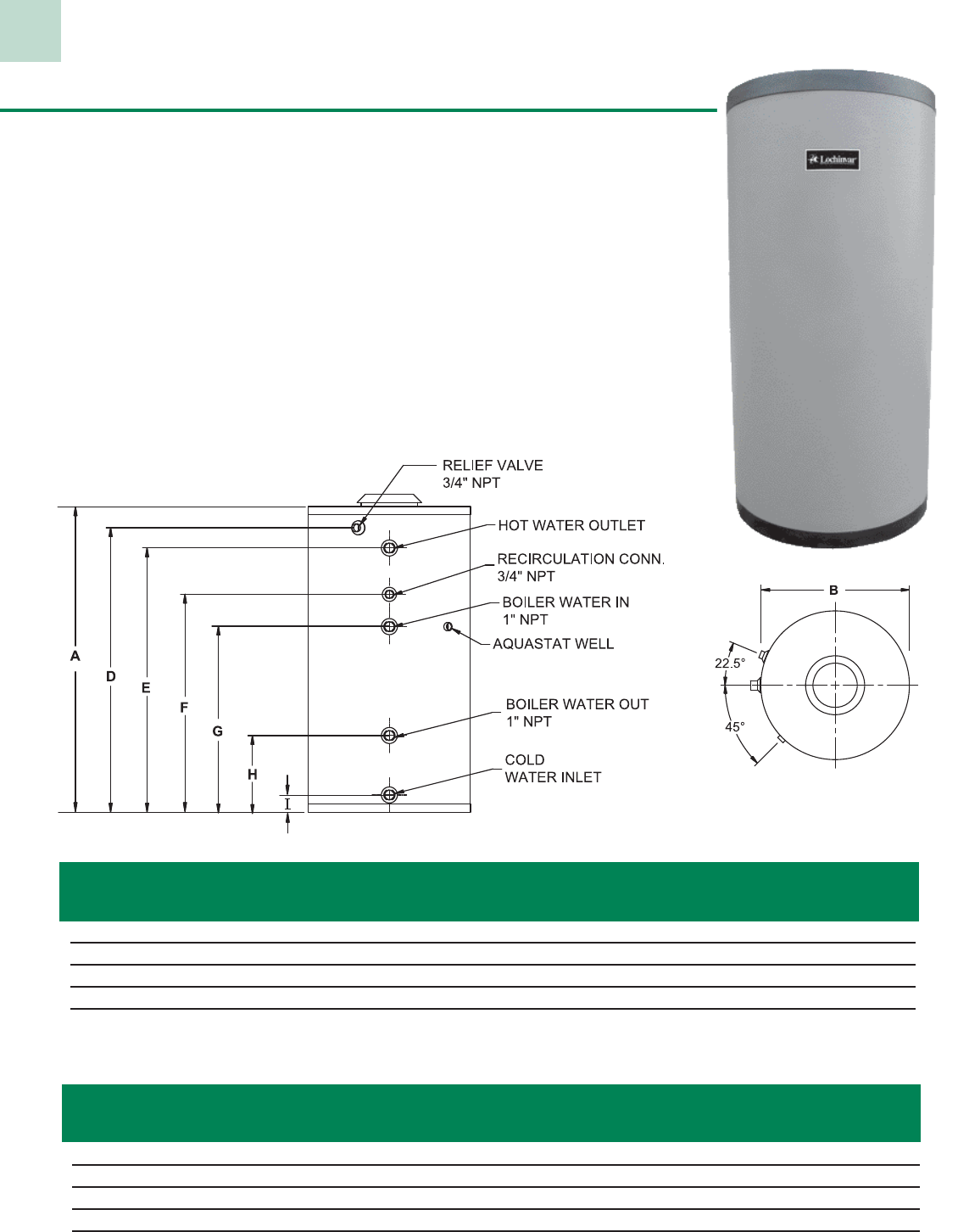
33
SquireTM Indirect Water Heater Models
The Squire uses the power and efficiency of the boiler that heats the home to generate domes-
tic hot water for showers, dishwashing, clothes washing…any hot water demand required. The
efficiency of the boiler used to heat the home can be as much as 20% higher than a direct-fired
tank-type water heater. So why not use that efficiency to “indirectly” provide hot water for all
domestic applications.
Domestic
Water Shipping
Model A B D E F G H I Conn. Weight
SSS031 38-3/4” 20” 32-3/4” 32-3/4” 27” 22” 9-1/2” 2-1/4” 1” 60
SSS041 54-3/4” 20” 48” 48” 29-1/4” 25-1/4” 9-1/2” 2-1/4” 1” 80
SSS051 47-3/4” 24” 40-1/4” 39-3/4” 30” 26” 10” 2” 1” 105
SSS081 68-3/4” 24” 62-3/4” 59-1/2” 34-1/2” 29-1/2” 10-3/4” 2” 1-1/2” 205
SSS119 64-3/4” 29” 58-3/4” 52-1/2” 44-1/2” 40-3/4” 12-1/4” 2” 1-1/2” 220
Note: Heat Exchanger connections are 1” male NPT
First Hour Rate Max Coil Flow Pressure Continuous Rate
Gallon (Gallons) Load Rate Drop (GPH)
Model Capacity 140°F 115°F BTU/hr GPM Ft. Hd 140°F 115°F
SSS031 27 154 204 99,000 4.6 0.8 132 183
SSS041 40 228 303 146,900 6.9 1.8 196 271
SSS051 52 238 313 146,900 6.9 1.8 196 271
SSS081 80 356 468 218,600 10.4 4.9 292 404
SSS119 117 485 636 293,700 13.6 11.5 392 542
Note: Based on incoming cold water temperature of 50°F and boiler water temperature of 200°F.
Dimensions
Specifications
Standard Features
• Durable Rustproof Jacket
• Large Capacity 444L Passivated Stainless Steel Tank
• High Output 304 Stainless Steel Heat Exchanger Coil
• 5 Different Models and Sizes
• Maintenance-Free Operation
• Energy Efficient Operation
• Limited Lifetime Warranty
TOP VIEW
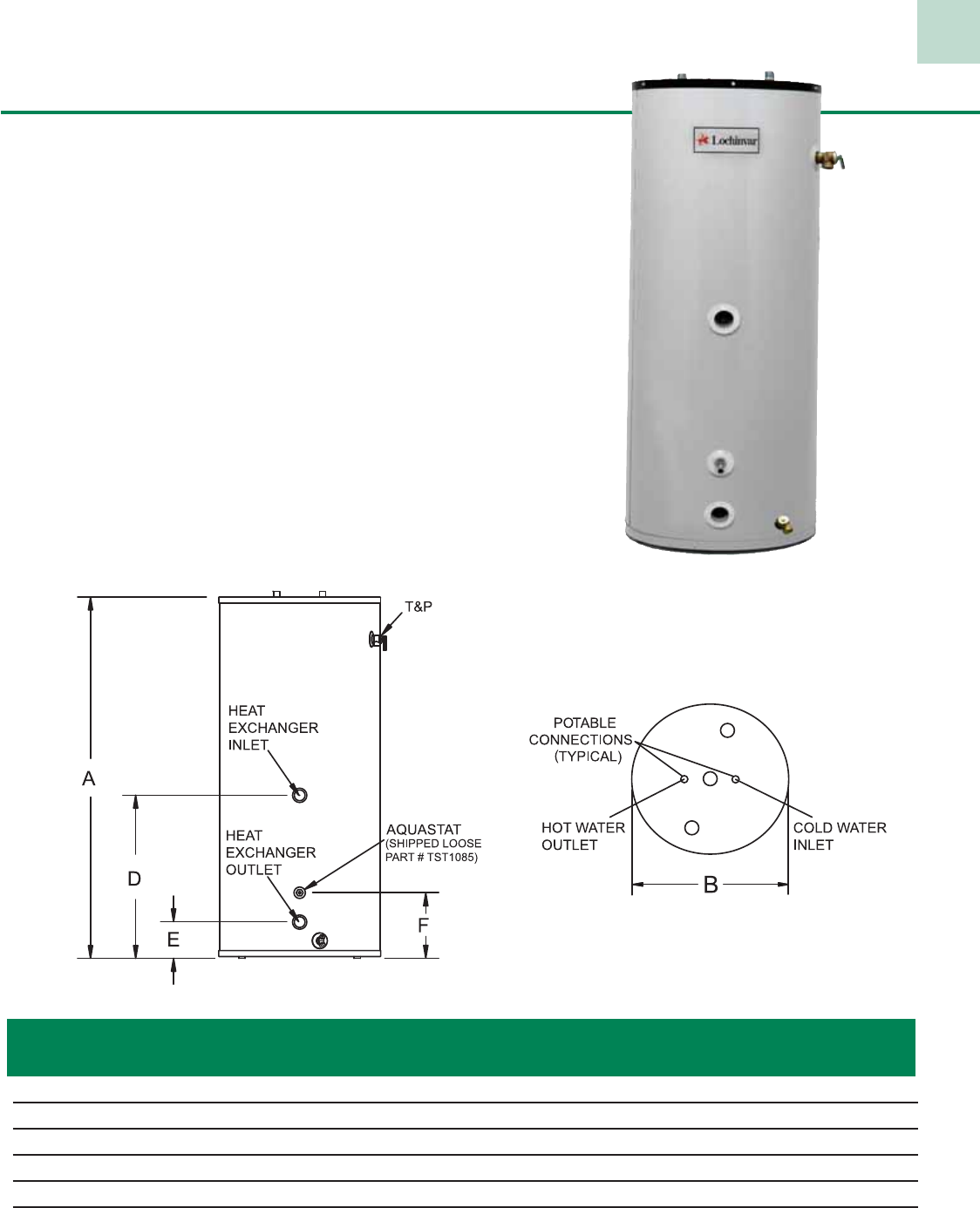
34
Energy Saver Indirect Models
Make your money work for you! By choosing an Energy Saver Indirect
Water Heater, the same energy spent to hydronically heat your home can heat
your domestic hot water. The Energy Saver Indirect Water Heater is a smart
answer to the question of how to keep your fuel costs down.
The Energy Saver Indirect is an indirect-fired, potable water storage vessel.
It accepts heat from an external heat source, such as a Solution or KNIGHT
Heating Boiler. By sharing heat for two purposes, efficiency results.
Standard Features
• Non-CFC Foam Insulation
• Glass-Lined Steel Tank
• Large Capacity Glass Lined Heat Exchanger Coil
• Aluminum Tank Saver Anode Rods
• Dielectric Nipples
• Adjustable Aquastat
• Temperature and Pressure Relief Valve
• Brass Drain Valve
• Warranty
1st Hour 1st Hour
Gal. Rating Rating Shipping
Model Cap. @140°F @115°F A B D E F Weight
EGS030 30 204 313 33-3/4” 22” 27-1/2” 5-1/4” 11-1/2” 140
EGS040T 40 210 320 41-1/4” 22” 27-1/2” 5-1/4” 11-1/2” 176
EGS050T 50 217 326 46-1/4” 22” 27-1/2” 5-1/4” 11-1/2” 189
EGS065 60 223 333 59-1/4” 22” 27-1/2” 5-1/4” 11-1/2” 196
EGS080 75 234 343 59” 24” 27-1/2” 5-1/4” 11-1/2” 224
EGS120 116 261 370 62-1/2” 28-1/4” 28-1/4” 6-1/4” 11-1/2” 355
Notes: All water connections are 3/4” NPT on 8” centers. Aquastat, relief valve, and drain valve connections are 3/4” NPT.
All heat exchanger connections are 1” NPT.
All ratings are based on 180°F boiler water temperature, 50°F potable water inlet temperature and an approximate boiler output of 220,000 Btu/Hr.
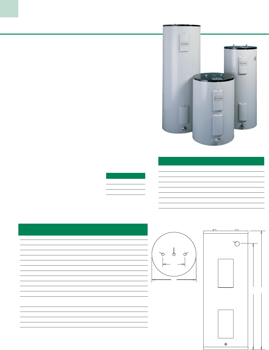
35
Tall & Short Models
VOLTAGE SCHEDULE
C – 120V 1ø
J – 208V 1ø
A – 240V 1ø
RECOVERY RATE (GPH @ °F RISE)
ELEMENT WATTAGE 40 50 60 70 80 90 100
E 1500 16 12 10 9 8 7 6
F 2000 21 17 14 12 10 9 8
G 2500 26 21 17 15 13 11 10
H 3000 31 25 21 18 16 14 12
J 3500 36 29 24 21 18 16 14
L 4000 41 33 28 24 21 18 17
K 4500 47 37 31 27 23 21 19
M 5000 52 41 34 30 26 23 21
P 6000 62 50 41 35 31 28 25
Residential Electric Models
A
D
OPTIONAL
T&P
8"
B
T&P
INLETOUTLET
Short Series
Have Optional
Side T & P Valve
Tapping
Optional Features
• Voltages Available—120, 208, 240 volts
For 277, 380, 415 & 480 volts, and simultaneous thermostat
operation see EX Special Electric Water Heaters
Standard Features
•
All models meet or exceed the NAECA & ASHRAE
Energy Efficiency Standards
• Non-CFC Foam Insulation - reduces standby heat loss
• Immersion Type Heating Elements - tin-coated, copper sheath
design for longer life in hard, aggressive water
• Screw-In Element Mounting - for easy replacement and service
• Adjustable Thermostat and Automatic Overheat Safety Limit -
for accurate, easy control of water temperature and safe operation
• Glass-lined Steel Tank - fused to the interior of the tank to assure a long
life providing clean, clear hot water
• Magnesium Tank Saver Anode - high capacity anode provides
protection from the effects of electrolytic corrosion
• Dielectric Nipples - provides an extra measure of tank protection and
piping convenience
• Temperature & Pressure Relief Valve - included
• Heat Traps - Factory installed, minimizes heat loss through piping.
• Relief Valve Tapping - top/center location for installation flexibility
and convenience
• Brass Drain Valve
• Warranty - 6 or 10 year limited tank warranty
Six year warranty on parts (See warranty for details)
Model Gallon Input 1st Hr. Energy Shipping
Number Capacity Watts (Gal.) Factor A B D Weight
Tall Models
LTA030KK 30 4500 43 0.93 47” 18” - 85
LTA040KK 40 4500 53 0.92 47” 20” - 103
LTA052KK-T 50 4500 63 0.90 57-1/2” 20” - 123
LTA052KK 50 4500 59 0.90 46-1/2” 22” - 130
LTA066KK 65 4500 72 0.88 59-1/4” 22” - 156
LTA082KK 80 4500 87 0.87 59” 24” - 183
LTA120KK 119 4500 105 0.84 63-3/4” 28” - 305
Short Models
LSA030KK 30 4500 40 0.93 29-3/4” 22” 24” 96
LSA040KK 40 4500 47 0.92 31-3/4” 24” 24-1/2” 125
LSA050KK 47 4500 52 0.90 31-3/4” 26” 24-1/2” 153
High Efficiency Models
LTA041KK 40 4500 53 0.93 48” 20” - 109
LTA051KK 50 4500 63 0.93 47-1/2” 22” - 136
LTA065KK 65 4500 72 0.91 61-1/4” 22” - 162
LTA081KK 80 4500 87 0.91 60” 24” - 189
Notes:
3/4” NPT water connections.
Change “L” to “X” for 10 year limited warranty model.
Standard Voltage and Wattage: 240v – 4500w.
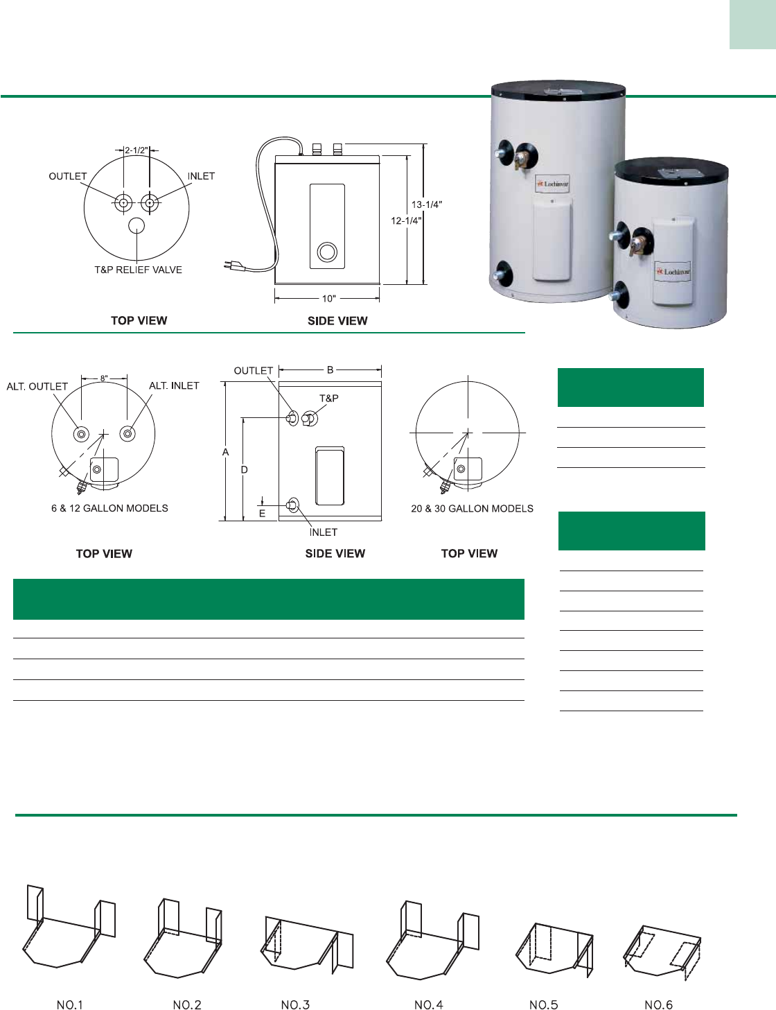
Junior Electric Models
6 - 30 gallon models
2 gallon models
Model Gal. Shipping
Number Cap. A B D E Weight
JRCOO2E* 2 12-1/4” 10” 13-1/4” 13-1/4” 14
JRC006E 6 16-1/2” 14” 10-1/4” 3” 33
JRC012E 12 27-3/4” 14” 21-1/4” 3” 48
JRC020E 19 24-3/4” 18” 18-1/4” 3” 59
JRC031E 30 30” 22” 23-1/2” 4-1/2” 82
Notes: Standard wattage and voltage: 1500w / 120v. Water connections are 3/4” NPT.
Maximum wattage for 6 and 12 gallon is 3000w.
Maximum wattage for 19 and 30 gallon is 6000w.
* 2 gallon is available in 1500w / 120v only.
For 277v 1ø and 480v 1ø, see Light Duty Commercial Electric Water Heaters
VOLTAGE SCHED-
ULE
C – 120V 1ø
J – 208V 1ø
A – 240V 1ø
WATTAGE
SCHEDULE
E – 1500
F – 2000
G – 2500
H – 3000
J – 3500
L – 4000
K – 4500
M – 5000
P – 6000
Six Way Shelf Mountings
– 2, 6 and 12 Gallon Models Only. (Part number JKT 3004)
NOTE: Max wattage @120V is 3000W.
36
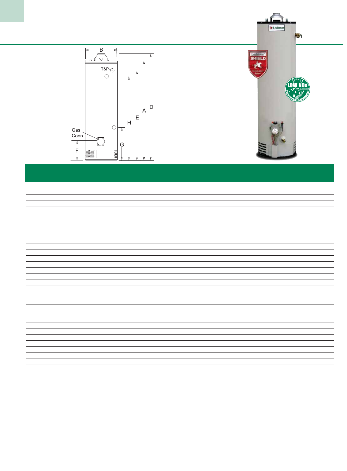
37
Residential Gas Models
Standard Features
· All Models Meet or Exceed the NAECA &
ASHRAE Energy Efficiency Standards
· Shield Combustion System
· Piezo Ignitor
· Sight Glass
· Temperature & Pressure Relief Valve
· Low NOx Burner
· Magnesium Tank Saver Anode
· Adjustable Thermostat
· Non-CFC Foam Insulation
· Heat Traps (not avaialable ETN076 & ETN100)
· Glass-Lined Steel Tank
· Dielectric Nipples
· Side Connections for Space Heating
(Select Models)
· Brass Drain Valve
· Six or Ten Year Limited Tank Warranty
· Six Year Warranty on Parts
Natural Gas LP Gas
Model Gal. Input GPH @ Input GPH @ Energy Water Vent Ship.
Number Cap. Btu/Hr 90°F Rise Btu/Hr 90°F Rise Factor A B D E F G H I Conn. Size Wt.
Energy Saver Series - Short Models
LSN030G 30 30,000 31 26,000 27 0.61 45-3/4” 18” 48-1/2” 38-3/4” 13” - - 8” 3/4” 3” 100
LSN041G 40 40,000 41 38,000 39 0.59 47-1/4” 20” 50” 41” 13” - - 8” 3/4” 3” 128
Energy Saver Series - Tall Models
LTN030G 30 32,000 33 31,000 32 0.61 56-1/4” 16” 59-1/4” 49-3/4” 13” - - 8” 3/4” 3” 105
LTN040G 40 34,000 35 34,000 35 0.59 56-1/2” 18” 59-1/2” 50” 13” - - 8” 3/4” 3” 120
LTN041G 40 40,000 41 38,000 39 0.59 57-1/4” 18” 61” 50” 13” - - 8” 3/4” 3” 121
LTN050G 50 40,000 42 36,000 38 0.58 57” 20” 59-3/4” 50” 13” - - 8” 3/4” 3” 145
LTN065G†* 65 65,000 68 63,000 66 0.55 59-3/4” 24” 63” 53-1/2” 12-1/4” 13-1/2” 53-1/2” 11” 3/4” 4” 202
ETN076† 75 76,000 82 76,000 82 N/A 59” 24” 62-1/2” 51-3/4” 15” 16-1/2” 51-3/4” 11” 1” 4” 238
ETN100†* 100 85,000 92 88,000 95 N/A 65” 28-1/4” 68-3/4” 59-1/4” 15-3/4” 17-3/4” 50-3/4” 16” 1-1/4” 4” 420
High Input Models
LTN040G-4 40 50,000 53 48,000 50 0.59 57-1/2” 18” 60-3/4” 51-1/2” 13” - - 8” 3/4” 4” 127
LTN050G-4 50 50,000 53 48,000 50 0.58 56” 20” 58-1/2” 50” 13” - - 8” 3/4” 4” 150
LTN051G†* 48 65,000 67 61,000 63 0.58 56” 22” 59-1/4” 50” 13” 13-1/2” 50” 11” 3/4” 4” 164
High Efficiency Models
LTN030G-EF 30 32,000 34 31,000 33 0.62 56-1/4” 18” 58” 49-3/4” 13” - - 8” 3/4” 3” 114
LTN040G-EF 40 40,000 43 36,000 38 0.62 58-1/4” 20” 60” 51-1/2” 13” - - 8” 3/4” 3” 128
LTN050G-EF 50 40,000 43 36,000 38 0.62 58-1/4” 22” 60” 50” 13” - - 8” 3/4” 3” 157
Ultra Low NOx Series - 6 Year Limited Warranty
USN030G 30 30,000 31 - - 0.61 45-1/2” 18” 48-1/2” 38-3/4” 11-3/4” - - - 3/4” 3” 110
USN041G 40 40,000 42 - - 0.59 47-1/2” 20” 50” 41” 11-3/4” - - - 3/4” 3” 137
USN050G 48 40,000 42 - - 0.58 47” 22” 49-3/4” 40-1/2” 11-3/4” - - - 3/4” 3” 163
UTN030G 30 32,000 33 - - 0.61 56-1/4” 16” 59-1/4” 49-3/4” 11-3/4” - - - 3/4” 3” 113
UTN041G 40 40,000 42 - - 0.59 57-1/4” 18” 61 50” 11-3/4” - - - 3/4” 3” 137
UTN050G 50 40,000 42 - - 0.58 56-3/4” 20” 59-3/4” 50” 11-3/4” - - - 3/4” 3” 154
High-Efficiency Models Ultra Low NOx Series - 6 Year Limited Warranty
UTN030G-EF † 30 32,000 34 - - 0.62 56-1/4” 18” 59-1/4” 49-3/4” 13” - - - 3/4” 3” 123
UTN040G-EF † 40 40,000 43 - - 0.62 56-1/2” 20” 59-1/2” 50” 13” - - - 3/4” 3” 137
UTN050G-EF † 50 40,000 43 - - 0.62 57” 22” 59-3/4” 50” 13” - - - 3/4” 3” 160
High Input Models Ultra Low NOx Series - 6 Year Limited Warranty-
UTN040G-4 40 50,000 53 - - 0.59 57-1/2” 18” 60-3/4” 51-1/2” 11-3/4” - - - 3/4” 4” 137
UTN050G-4 50 50,000 53 - - 0.59 56” 20” 58-1/2” 50” 11-3/4” - - - 3/4” 4” 160
Notes: “N” indicates Natural gas, replace “N” with “L” to indicate LP gas model.
All gas connections are 1/2” NPT
† Indicates models equipped with side tappings for space heating applications.
* Indicates models with 2” of foam insulation (ETN076 has 1 1/4” insulation)
Models fired above 75,000 Btu/Hr are certified to ANSI Z21.10.3. and are not required to meet the NAECA or FVIR standard.
Performance data is based on manufacturer’s test results.
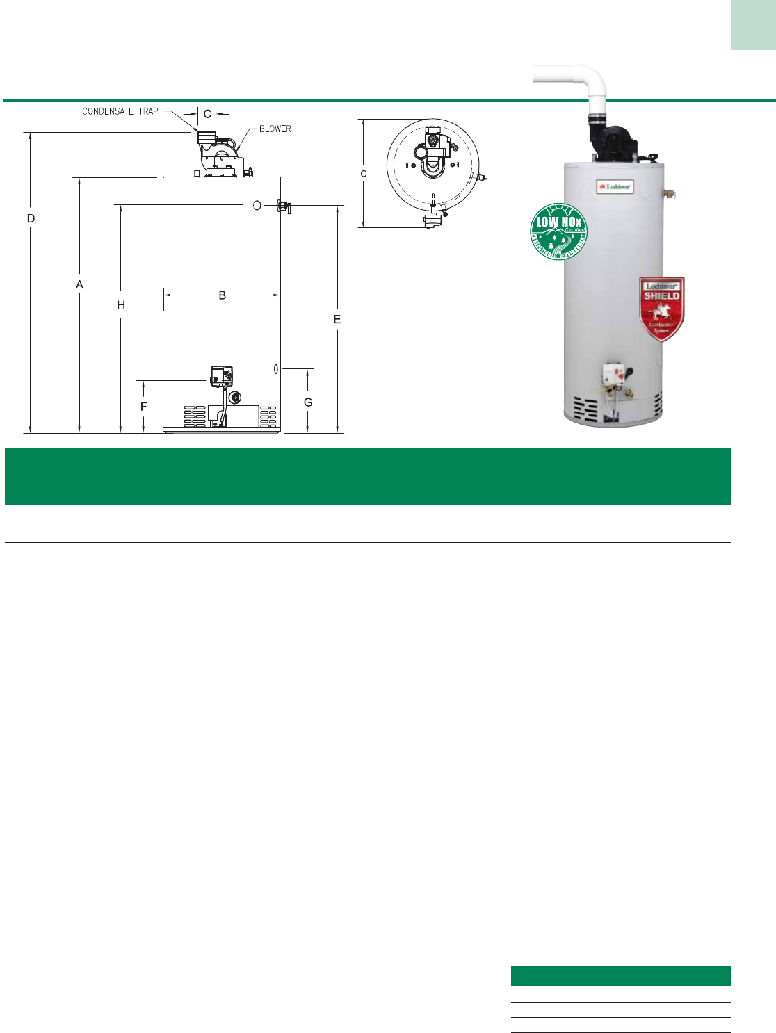
Power-Vented FVIR Gas Models
38
Natural Gas LP Gas
Model Gal. Btu/hr GPH @ Btu/hr GPH @ Vent Ship.
Number Cap. EF Input 90°F Rise Input 90°F Rise A B C D E F G H Size Wt.
LVN041G 40 0.62 40,000 43 38,000 41 46-1/2” 20” 25” 56-1/2” 40-1/2” 11-3/4” - - 2” 140
LVN051G 50 0.62 40,000 43 38,000 41 47-1/4” 22“ 26-3/4” 57-1/2” 41” 11-3/4” - - 2” 165
LVN052G†* 48 0.65 67,000 70 60,000 65 56-1/2” 22“ 26-3/4” 66” 50-1/4” 11-3/4” 13-1/2” 50-1/4” 3” 180
LVN065G†* 65 0.65 70,000 70 63,000 68 59-1/2” 24“ 26-3/4” 69” 53-1/2” 11-3/4” 13-1/2” 53-1/2” 3” 185
Notes: Replace “N” with “L” to indicate LP gas model “L” prefix indicates 6 year tank warranty.
† Indicates side tapping for space heating. All water connections are 3/4” NPT.
* Indicates models with 2” of polyurethane foam insulation. All gas connections are 1/2”.
Performance data is based on manufacturer test results.
2” 3” 4”
LVN041G 50’ 120’ -
LVN051G 50’ 120’ -
LVN052G - 60’ 180’
LVN065G - 60’ 180’
Max. Vent Length (Total equiv. feet)
TOP VIEW
Standard Features
· Shield Combustion System - Corrosion
resistant chamber redirects air through a
stainless steel flame arrestor plate to
prevent flame rollout and flammable vapor
ignition. A resettable thermal switch shuts
down the burner and pilot operation in the
event of a flammable vapor ignition and
also protects against lint, dust and oil
buildup by shutting down when it detects
significant air restriction.
· Power Vented Exhaust System - The
120 VAC blower fan exhausts the by-
products of combustion directly to the
outside the building through PVC style
pipe, eliminating the need for conventional
chimneys or roof penetrations.
· Side Wall or Vertical Venting - can be
vented horizontally with 2”, 3” or 4” PVC
or CPVC vent pipe, depending on the
model. (See vent chart for max. vent lengths)
· Electronic Spark Ignition - Eliminates
nuisance pilot outages and saves fuel by
eliminating the continuously burning pilot,
while providing solid-state ignition.
· Low NOx Burner - This whisper quiet,
360° burner incorporates aluminized steel
into its die-formed design. The large
burner diameter transfers more heat,
while providing clean and efficient
combustion. Satisfies local codes and
emissions standards.
· Non-CFC Foam Insulation - This
non-CFC polyurethane closed cell foam
minimizes standby losses and maximizes
heat retention.
· Glass-Lined Steel Tank - The tank is
automatically formed, rolled, and welded
to ensure a continuous seam for the glass
lining. The durable glass lining is fused to
the interior of the tank at 1600°F to
assure lasting protection against rust and
corrosion while providing clean hot water.
· Magnesium Tank Saver Anode - High
capacity anode rod provides protection
from the effects of electrolytic corrosion.
· Electronic Thermostat - This accurate
control provides an easy way to reset
water temperature for best economy.
Automatic over-heat safety device is
standard. LED status indicator
simplifies setup and adjustments.
· Heat Trap Nipples - Factory
installed waterways reduce heat loss
in piping, while providing piping
convenience.
· Side Connections for Space
Heating - select models are equipped
with side tappings for space heating
applications.
· Temperature & Pressure Relief Valve
· Brass Drain Valve
· Warranty - Six or Ten year limited
tank warranty. Six year warranty on
parts. (See warranty for details)
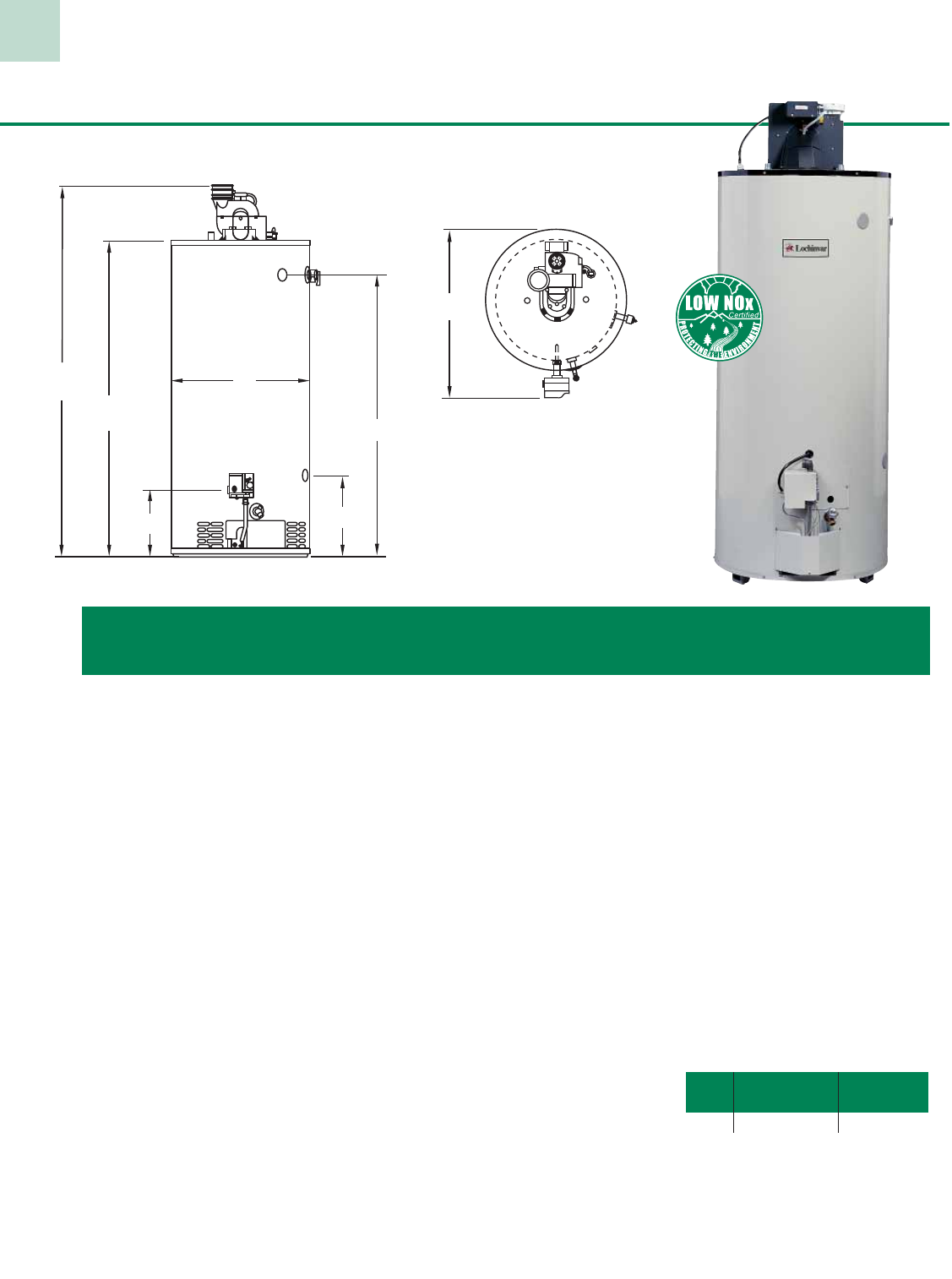
39
Standard Features
· Power Vented Exhaust System - The 120
VAC blower fan exhausts the by-products of
combustion directly to the outside the
building through PVC style pipe, eliminating
the need for conventional chimneys or roof
penetrations.
· Side Wall Venting - can be vented
horizontally with 3” or 4” PVC or
CPVC vent pipe, depending on the model.
(See vent chart for max. vent lengths)
· Vertical Venting - can be vented vertically
with 3” or 4” PVC or CPVC vent pipe,
depending on the model.
(See vent chart for max. vent lengths)
· Electronic Spark Ignition - Eliminates
nuisance pilot outages and saves fuel by
eliminating the continuously burning pilot,
while providing solid-state ignition.
· Low NOx Burner - This whisper quiet, 360°
burner incorporates aluminized steel into its
die-formed design. The large burner diameter
transfers more heat, while providing clean and
efficient combustion. Satisfies local codes and
emissions standards.
· Non-CFC Foam Insulation - Improved
formulation provides uniform tank coverage
with a thick blanket of insulating foam.
This non-CFC polyurethane closed cell foam
minimizes standby losses and maximizes
heat retention.
· Glass-Lined Steel Tank - The tank is
automatically formed, rolled, and welded
to ensure a continuous seam for the glass
lining. The durable glass lining is fused to
the interior of the tank at 1600°F to assure
lasting protection against rust and corrosion
while providing clean hot water.
· Magnesium Tank Saver Anode - High
capacity anode rod provides protection from
the effects of electrolytic corrosion.
· Adjustable Thermostat - This accurate
control provides an easy way to reset water
temperature for best economy. Automatic
over-heat safety device is standard.
· Dielectric Nipples - Factory installed
waterways protect the tank from the
corrosive action between dissimilar metals,
while providing piping convenience.
· Side Connections for Space Heating -
models are equipped with side tappings
for space heating applications.
· Temperature & Pressure Relief Valve
· Brass Drain Valve
· Warranty - Six or Ten year limited
tank warranty. Six year warranty on
parts. (See warranty for details)
Power-Vented Gas Models
Natural Gas LP Gas
Model Gal. Btu/hr GPH @ Btu/hr GPH @ Vent Ship.
Number Cap. Input 90°F Rise Input 90°F Rise A B D E F G H Size Wt.
LVN076 75 76,000 82 75,100 82 59” 26” 68-1/2” 51-3/4” 14” 16-3/4” 31” 3” 246
Notes: Replace “N” with “L” to indicate LP gas model “L” prefix indicates 6 year tank warranty.
. All gas connections are 1/2”. All water connections are 3/4” NPT.
This model is certified to ANSI Z21.10.3 This model is not required to meet the NAECA or FVIR standard.
Horizontal Vertical
3” 4” 3” 4”
LVN076 60’ 180’ 60’ 180’
Max. Vent Length total equiv. feet
D
A
FG
B
E
H
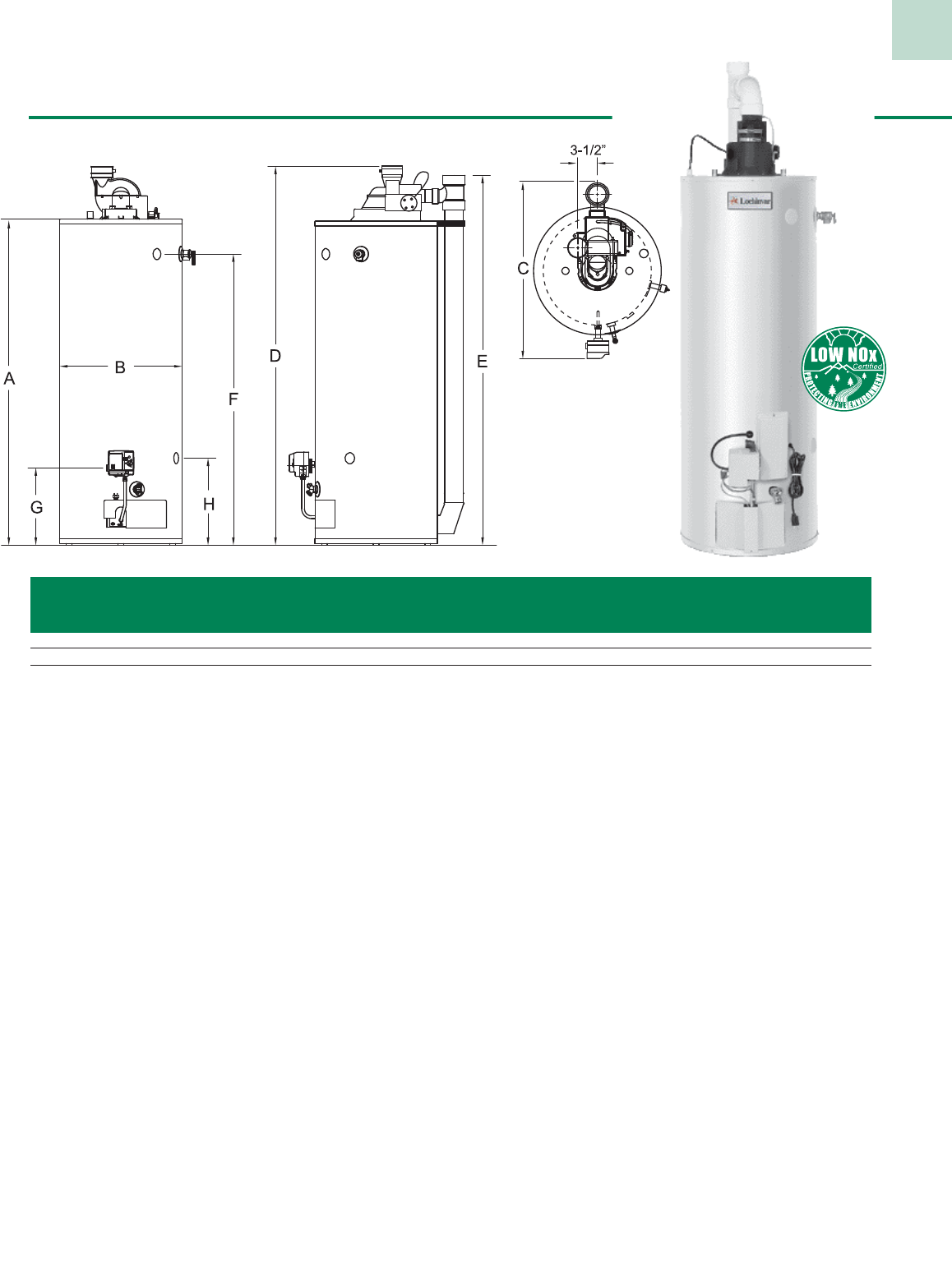
40
Power Direct Vent Gas Models
Natural Gas LP Gas
Model Gal. Btu/hr GPH @ Btu/hr GPH @ 1st Energy Vent Ship.
Number Cap. Input 90ºF Rise Input 90ºF Rise Hour Factor A B C D E F G H Size Wt.
PRN050G 48 60,000 65 60,000 65 100 0.60 58-34” 22” 30-1/2” 68-1/2” 67” 52-1/4” 14” 15-3/4” 3” 196
PRN065G 65 65,000 70 60,000 65 114 0.59 62” 24” 33-1/4” 71-1/2” 69” 55-3/4” 13-3/4” 15-3/4” 3” 230
PRN075G 75 70,000 75 70,000 75 132 0.58 59” 26” 35-1/2” 69-1/2” 68-1/2” 51-3/4” 13-3/4” 16-3/4” 3” 262
Notes: “P” prefix indicates 6 year tank warranty. Replace “P” with “S” for 10 year tank warranty.
All LP heaters are equipped with a cast iron burner. Replace “N” with “L” to indicate LP gas model.
* indicates models with 2” of polyurethane foam insulation.
All gas connections are 1/2”.
All water connections are 3/4” NPT on 11” centers.
110 VAC, 60 HZ, 2.1 AMP is required for power venting.
Maximum Horizontal & Vertical Vent Length is 25 feet (40 equivalent feet,
with 3 - 90º elbows), when using 3” pipe.
Maximum Horizontal & Vertical Vent Length is 60 feet (75 equivalent feet,
with 3 - 90º elbows), when using 4” pipe.
Standard Features
• Power Direct Venting System - This 2-pipe closed
combustion system utilizes a stand alone vent to exhaust
the byproducts of combustion, and a separate air intake to
provide fresh combustion air to the unit. Vents up to 25 feet
to an outside wall, using 3” PVC or CPVC pipe. Vents
up to 60 feet to an outside wall, using 4” PVC or CPVC pipe.
• Electronic Spark Ignition - Eliminates nuisance pilot
outages and saves fuel by eliminating the continuously
burning pilot while providing reliable solid state ignition.
• Low NOx Burner - This whisper quiet, 360° burner
incorporates aluminized steel into its die-formed design.
The large burner diameter transfers more heat, while
providing clean and efficient combustion. Satisfies local
codes and emission standards.
• Non-CFC Foam Insulation - Improved formulation
provides uniform tank coverage with a thick blanket of
insulating foam. This non-CFC polyurethane closed cell
foam minimizes standby losses and maximizes heat retention.
• Glass-Lined Steel Tank - The durable glass lining assures
lasting protection against rust and corrosion while providing
clean, clear hot water. This tank is automatically formed,
rolled, and welded to assure a continuous seam for the glass
lining. Each tank is triple-tested to ensure quality.
• Heat Traps - Factory installed, minimizes heat loss
through piping.
• Adjustable Thermostat - This accurate control provides
an easy way to reset water temperature for best economy.
Automatic over-heat safety device is standard.
• Dielectric Nipples - Factory installed waterways protect the
tank from corrosive action between dissimilar metals, while
providing piping convenience.
• Side Tappings- Provided for space heating applications.
• Six Foot Power Cord - Included for installation ease.
• Temperature & Pressure Relief Valve - Included.
• Brass Drain Valve
• Warranty - Six or ten year limited tank warranty.
Six year warranty on parts. (See warranty for details)
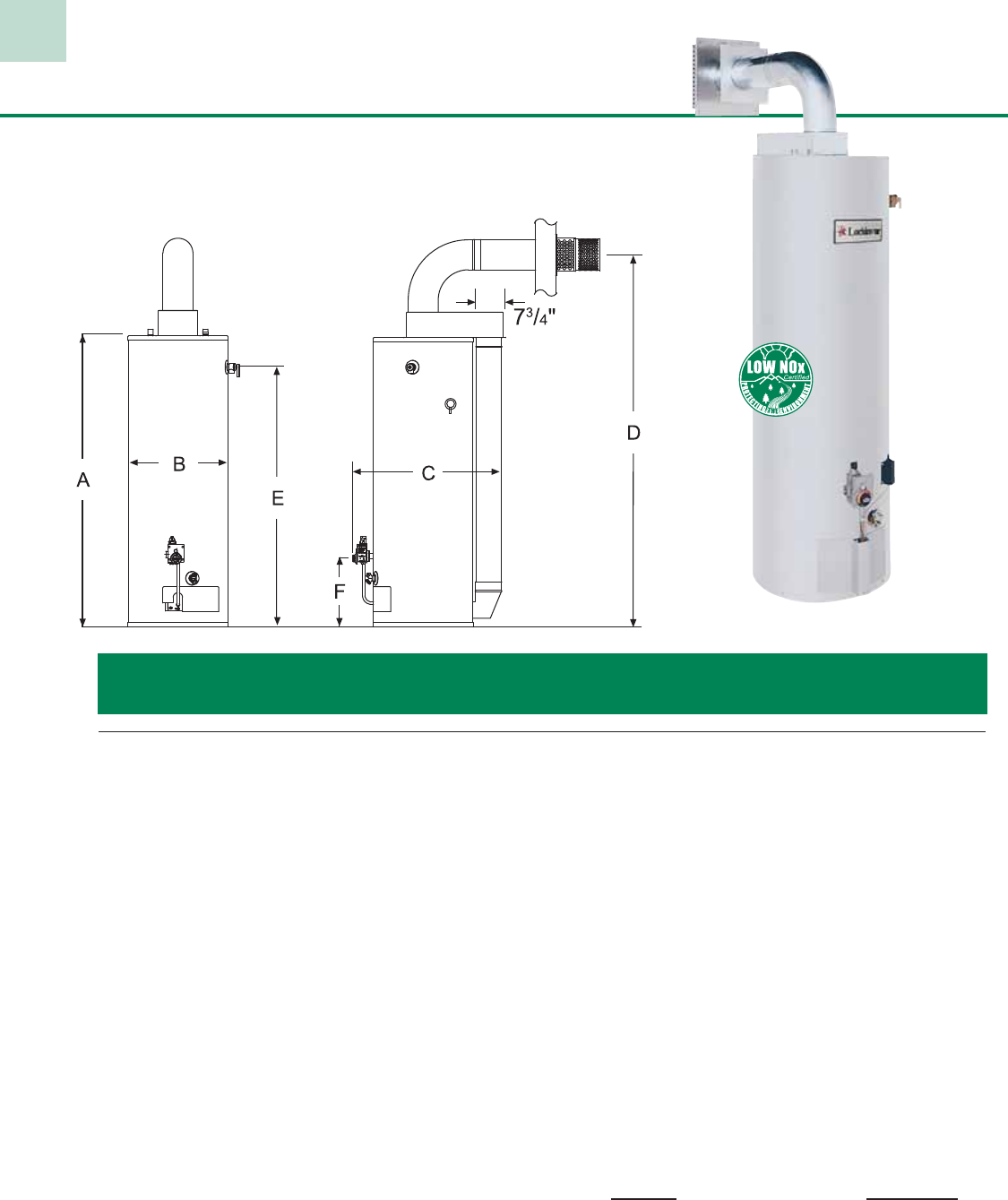
41
Balanced Flue Gas Models
· Heat Traps - Factory installed, minimizes heat loss through piping.
· Adjustable Thermostat - This accurate control provides an
easy way to reset water temperature for best economy.
Automatic over-heat safety device is standard.
· Dielectric Nipples - Factory installed waterways protect the
tank from the corrosive action between dissimilar metals,
while providing piping convenience.
· Temperature & Pressure Relief Valve - Included.
· Brass Drain Valve
· Warranty - *Six year limited tank warranty.
Six year warranty on parts. (See warranty for details)
*Ten year limited warranty upgrade available
Optional Equipment
Vent Kits Part Number
4-8 FT Extension DRH1145
4-3/4” - 5-11/16” Extension DRH1148
6-1/2” - 9-3/16” Extension DRH1149
14” - 24” Extension DRH1150
Standard Features
· Sealed Combustion / Direct Vent System - The co-axial vent rotates
360° providing installation flexibility. The concentric vent system draws
all combustion air from outside the building through the outer pipe and
exhausts the by-products of combustion through the inner pipe, of the
two-pipe system, directly outdoors.
· Piezo Ignitor - provides easy pilot ignition with the push of a button.
· Low NOx Burner - This whisper quiet, 360° burner incorporates
aluminized steel into its die-formed design. The large burner diameter
transfers more heat, while providing clean and efficient combustion.
Satisfies local codes and emissions standards.
· Non-CFC Foam Insulation - Improved formulation provides uniform
tank coverage with a thick blanket of insulating foam. This non-CFC
polyurethane closed cell foam minimizes standby losses and maximizes
heat retention.
· Glass-Lined Steel Tank - The tank is automatically formed, rolled,
and welded to ensure a continuous seam for the glass lining. The durable
glass lining is fused to the interior of the tank at 1600°F to assure lasting
protection against rust and corrosion while providing clean, clear hot water.
· Magnesium Tank Saver Anode - High capacity anode rod provides
protection from the effects of electrolytic corrosion.
Natural Gas LP Gas
Model Gal. Btu/hr GPH @ Input GPH @ Vent Ship.
Number Cap. Input 90°F Rise Btu/hr 90°F Rise A B C D E F Size* Wt.
LBN040G 40 38,000 41 36,000 39 49-1/4” 20” 31-1/4” 63-1/4” 43-1/2” 15” 3”/5” 169
LBN050G 50 42,000 45 40,000 43 58-3/4” 20” 31” 72-1/4” 52-1/4” 15” 3”/5” 186
Notes: Replace “N” with “L” for LP gas models. “L” prefix indicates 6 year tank warranty
All LP models are equipped with a cast iron burner *Internal exhaust vent is 3” diameter All gas connections are 1/2”.
*External air intake is 5” diameter. All water connections are 3/4” NPT.
Performance data is based on manufacturer test results.
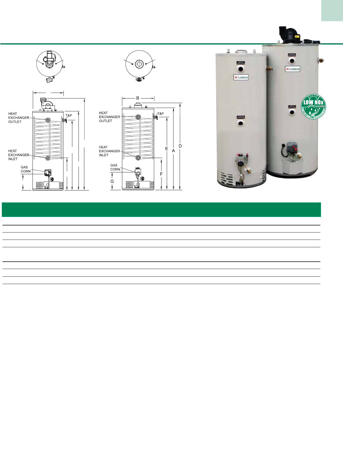
Double Duty Gas Models
Standard Features
• Domestic Hot Water & Space Heating
• Non CFC Foam Insulation
• High First Hour Delivery
• Double Wall, Glass Coated Heat Exchanger
• Heavy-Gauge, Glass-Lined Steel Tank
• Magnesium Tank Saver Anode
• Factory Installed Dielectric Nipples
• Brass Drain Valve
• T&P Relief Valve Factory Supplied
• 10 Year Limited Tank Warranty
• 6 Year Limited Warranty on Parts
(See Warranty for Details)
Additional Features for Power Vented Models:
• Vertical or Sidewall Venting
• Vents up to 60 equivalent feet. with 3” PVC
• Vents up to 180 equivalent feet. with 4” PVC
NOTE: 90° elbows = 5 eq. ft.
HOT
WATER
OUTLET
COLD
WATER
INLET
HOT
WATER
OUTLET
COLD
WATER
INLET
B
D
A
G
F
E
Power Vented
Top Top
Atmospheric XDN051G
XPN075
42
Model Gal. Btu/hr GPH @ Space Heating Vent Shipping
Number Cap. Input 90°F Rise AFUE (Btu/Hr) A B D E F G Size Weight
Atmospheric Models
XDN051G* 45 65,000 70 80.0 55,000 56-1/2” 22” 59-1/4” 50” 28” 13” 4” 238
XDL051G (LP)* 45 61,000 66 80.0 54,000 56-1/2” 22” 59-1/4” 50” 28” 13” 4” 238
XDN075 72 76,000 81 82.0 55,000 60-1/2” 26” 63-3/4” 53” 31” 16” 4” 328
XDL075 (LP) 72 76,000 81 82.0 54,000 60-1/2” 26” 63-3/4” 53” 31” 16” 4” 328
Power Vented Models
XPN051G* 45 67,000 72 82.0 55,000 56-1/2” 22” 66” 50” 28” 11-3/4” 3” 245
XPL051G (LP)* 45 60,000 65 82.0 54,000 56-1/2” 22” 66” 50” 28” 11-3/4” 3” 245
XPN075 72 76,000 82 82.0 55,000 59” 26” 68-1/2” 51-3/4” 29-1/2” 13-3/4” 3” 301
XPL075 (LP) 72 75,500 81 82.0 54,000 60-1/4” 26” 69-3/4” 53” 31” 15” 3” 335
Notes: All water connections are 3/4” NPT 110 VAC 60 HRZ 2.1 AMPS required for Power Vented models.
All gas connections are 1/2” NPT. Models fired above 75,000 Btu/Hr are certified to ANSI Z21.10.3
Performance data is based on manufacturer’s test results. and are not required to meet the NAECA or FVIR standard.
* Indicates models equipped with Shield Combustion System.
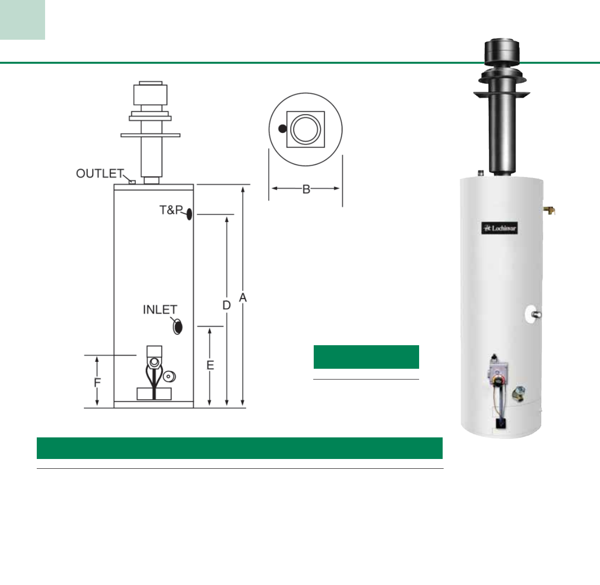
43
Manufactured Home Gas Models
Model Gal. Btu/hr GPH @ Vent Shipping
Number Cap. Input 90°F Rise A B D E F Size Weight
MDN030G 30 30,000 31 57-1/2” 16” 50” 22-1/2” 13-3/4” 3” 111
MDN040G 40 30,000 31 58” 18” 50” 22-1/2” 13-3/4” 3” 131
Notes: “M” prefix indicates 6 year tank warranty Replace “M” with “S” for 10 year tank warranty.
Field Convertible from Natural Gas to LP gas. Three year limited warranty on all models when installed in a commercial application.
All gas connections are 1/2”. All water connections are 3/4” NPT.
Performance data is based on manufacturer test results.
DRH1070 12”
DRH1071 18”– 32”
DRH1072 32”– 60”
DRH 1173 48”– 95”
Roof Jack Kits
Kit Number Dimensions
Standard Features:
· Low NOx Burner
· Non-CFC Foam Insulation
· Natural Gas to LP Gas Conversion Kit
· Adjustable Thermostat
· Glass-Lined Steel Tank
· Magnesium Tank Saver Anode
· Factory Installed Dielectric Nipples
· Temperature & Pressure Relief Valve
· Brass Drain Valve
· Warranty
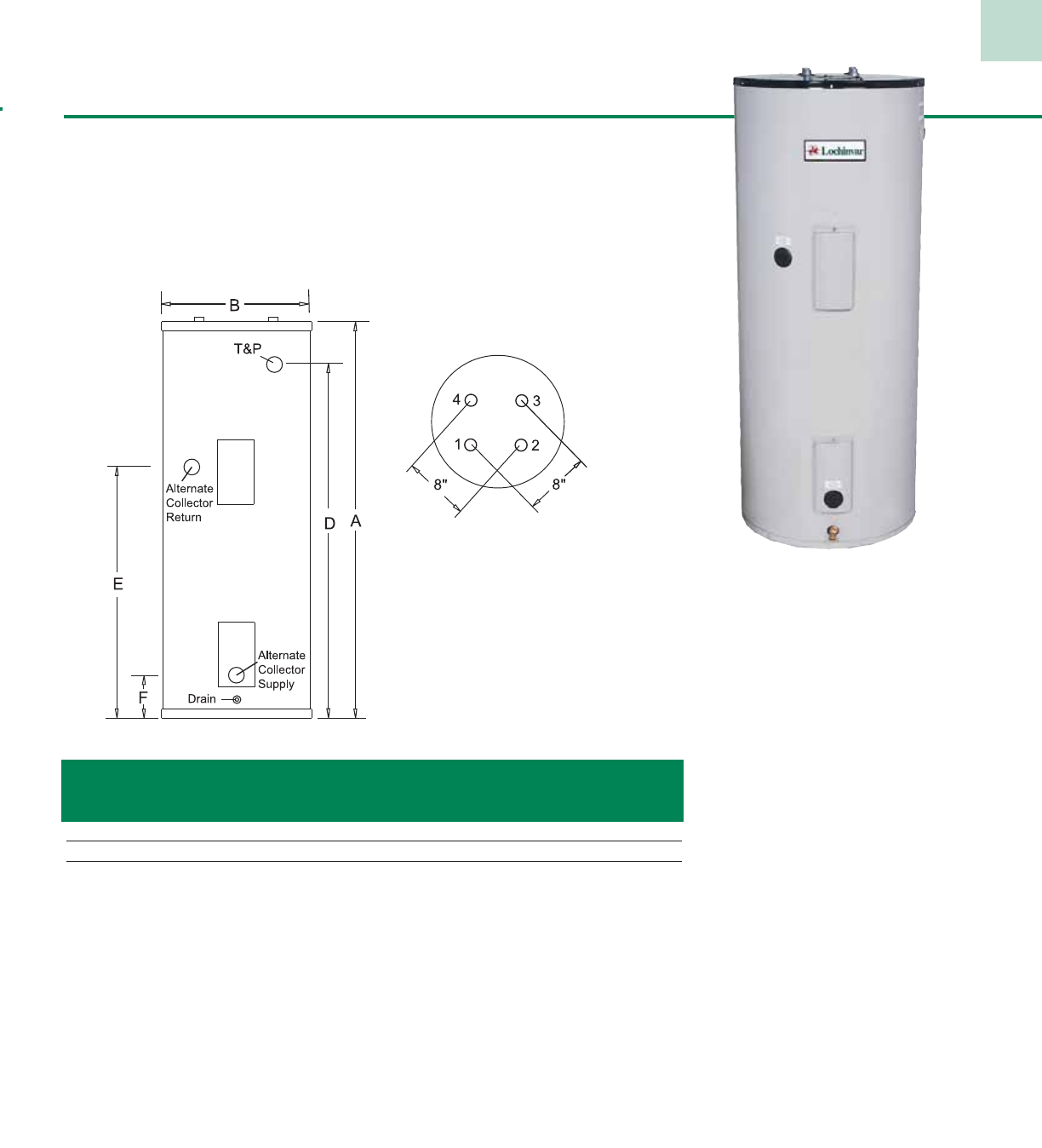
Solar Models
#1 – 3/4” Pump Suction
#2 – 3/4” Cold Inlet
#3 – 3/4” Collector Return
#4 – 3/4” Hot Outlet
TOP VIEW
Notes: *Models feature alternate collector supply and return connections.
Alt. Coll. Alt. Coll.
Model Gal. Return Supply Ship
Number Cap. A B D E F Weight
FTA066K 65 59” 22” 52-1/2” – – 165
FTA082K* 80 59” 24” 52-1/2” 38” 8” 210
FTA120K* 119 62-3/4” 28” 56” 38-1/4” 8” 310
Standard Features
• Foam Insulation
• Glass-Lined Steel Tank
• Magnesium Tank Saver Anode
• Dielectric Nipples
• Side Relief Valve Tapping
• Pre-Wired Tank Sensor Lead
• Heating Element
• Certified at 300 psi Test Pressure
• Brass Drain Valve
• Warranty
44
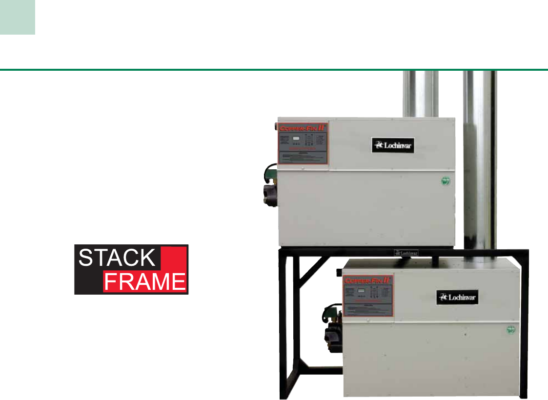
45
Multi-Stack Frame
Another Innovation from Lochinvar
Lochinvar’s Copper-Fin technology not only makes our water
heaters and boilers more efficient, it means they also have a
smaller footprint. So they save space as well as operating costs.
And now there is a way to get greater flexibility and reliability,
save even more space, and get a system that is perfectly
matched to a facility — thanks to the Multi-Stack System from
Lochinvar.
Match Load and Capacity
With this versatile stand, you can stack almost any combination
of our Copper-Fin, Copper-Fin II, and Efficiency+ water
heaters and boilers. So you can achieve the perfect Btu/hr
capacity for each application.
For example, a facility needs a Copper-Fin II water heater with
a total capacity of 1.6 million Btu/hr. Instead of installing an
oversized 1801 unit or a smaller 1441 model, now you can
combine two units—991 and 651 models — to exactly match
the facility’s needs.
Plus, the total footprint of this combined system is just over
10 inches wider than the 651 unit alone, making it smaller than
either the 1801 or 1441 model. All thanks to the Lochinvar
Multi-Stack Frame.
Added System Benefits
This modular design provides two other important benefits.
First, it allows for system turndown for greater efficiency when
demand is lower. And second, it ensures against system failure
by utilizing two independent but complementary units.
For indoor residential and light commercial needs or
commercial applications up to 4 million Btu/hr, the Multi-Stack
Frame gives greater flexibility without a significant increase in
stack size or overall system dimensions.
Once you have determined a facility’s requirements and the
exact models needed, utilize the charts provided to calculate
total system dimensions.
Pre-Assembled
Heavy Duty
Factory Welded
Construction
Note: Indoor Installation Only
Two Lochinvar 990,000 Btu/hr Copper-Fin II® water heaters
stacked for a total capacity of almost 2 million Btu/hr.
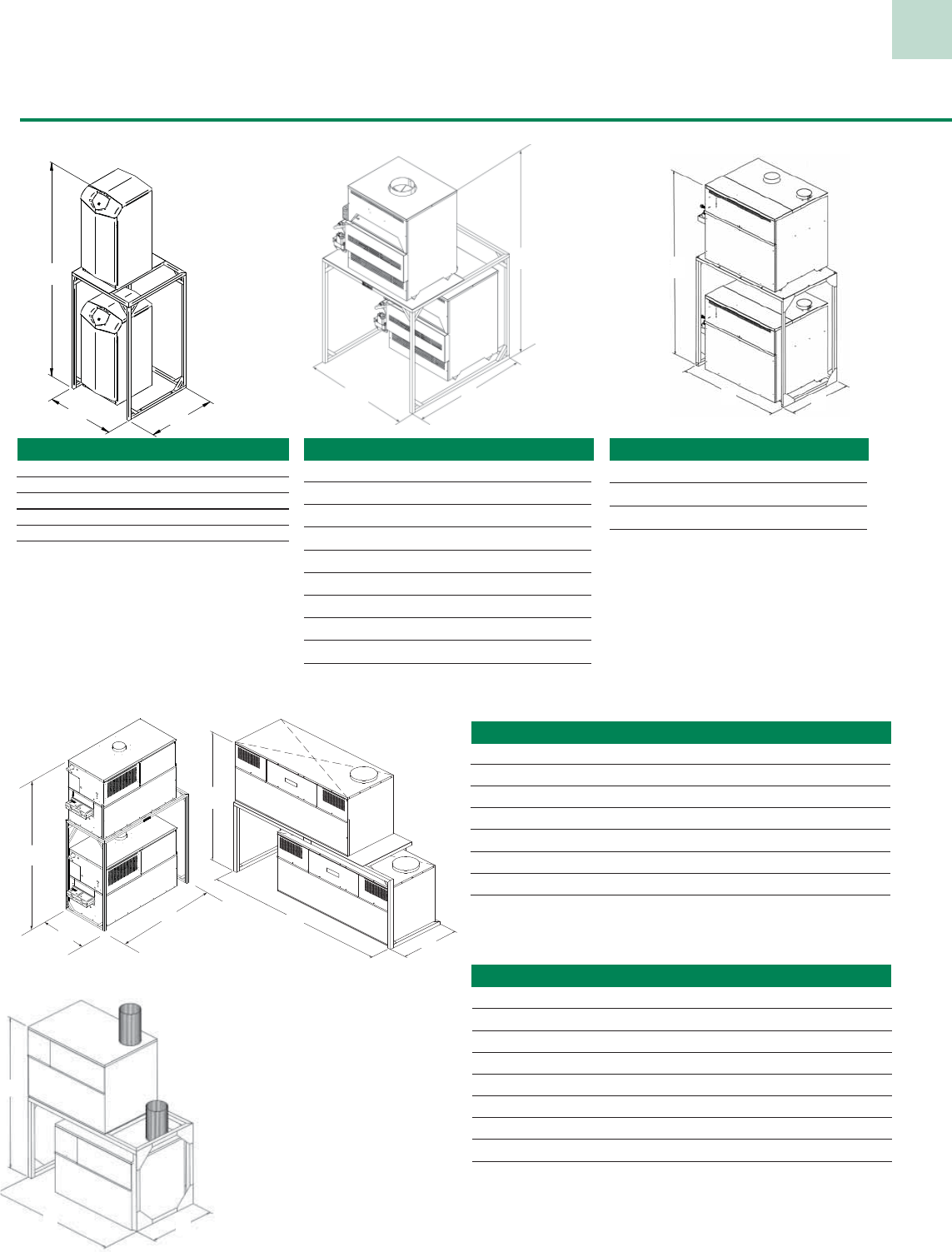
46
Multi-Stack Frame
Efficiency+® Water Heaters
(Models 150-300)
Copper-Fin II® Water Heaters
B
A
C
B
A
C
B
A
C
B
A
C
Copper-Fin® Water Heaters
(Models 495-745) (Models 986-2066)
MODEL # PART # A* B** C
EW 150 MSF3021 71-1/4” 37” 24”
EW 200 MSF3021 71-1/4” 37” 24”
EW 250 MSF3021 71-1/4” 37” 24”
EW 300 MSF3021 71-1/4” 37” 24”
Note: Heater height is 28” on all models.
MODEL # PART # A* B** C
CW 495 MSF3002 81-1/2” 51” 24-1/2”
CW 645 MSF3003 84-1/2” 70” 26”
CW 745 MSF3003 84-1/2” 70” 26”
CW 986 MSF3007 80” 68 “ 36”
CW1256 MSF3008 80” 88” 36”
CW1436 MSF3008 80” 88” 36”
CW1796 MSF3009 80” 114” 36”
CW 2066 MSF3009 80” 114” 36”
Note: Heater Height is 33-1/4” (495-745) & 36” (986-2066)
MODEL # PART # A* B** C
CF 0401 MSF3022 67-1/2” 59” 24-1/2”
CF 0501 MSF3022 67-1/2” 59” 24-1/2”
CF 0651 MSF3023 67-1/2” 80” 24-1/2”
CF 0751 MSF3023 67-1/2” 80” 24-1/2”
CF 0991 MSF3007 80” 68” 36”
CF 1261 MSF3008 80” 88” 36”
CF 1441 MSF3008 80” 88” 36”
CF 1801 MSF3009 80” 114” 36”
CF 2071 MSF3009 80” 114” 36”
Note: Heater height is 31-1/2” (401-751) & 36” (991-2071)
* To vent connection
** Allow space for plumbing connections
B
A
C
Copper-Fin® Water Heaters
(Models 090-500)
MODEL # PART # A* B** C
CW 090 MSF 3034 65-1/2” 36” 39”
CW 135 MSF 3034 65-1/2” 36” 39”
CW 180 MSF 3034 65-1/2” 36” 39”
CW 199 MSF 3035 65-1/2” 48” 39”
CW 225 MSF 3035 65-1/2” 48” 39”
CW 270 MSF 3035 65-1/2” 48” 39”
CW 315 MSF 3035 65-1/2” 48” 39”
CW 360 MSF 3035 65-1/2” 48” 39”
CW 399 MSF 3036 65-1/2” 65” 39”
CW 500 MSF 3036 70-1/2” 65” 39”
BC
A
B
A
C
ARMOR® Water Heaters (Models 150-800)/
KNIGHT® Heating Boilers (Models 080-800)
MODEL # PART # A* B** C Wt. (.lbs)
AW 150-199 MSF3043 90-1/2” 26” 26” 60
AW 285-500 MSF3044 109” 26” 34” 72
AW 600-800 MSF30002 109” 26” 43” 94
KB 080-210 MSF3043 90-1/2” 26” 26” 60
KB 285-500 MSF3044 109” 26” 34” 72
KB 600-800 MSF30002 109” 26” 43” 94
Note: Heater height is 33-1/4” KB 80-120
and AW 150-199 models.
Heater height is 42-1/2” KB 285-800
and AW 285-800 models.

NOTES

We hope this catalog displaying our water heater products has helped you find what you’re looking
for. And we’d like to remind you that Lochinvar is much more than a Water Heater manufacturer.
Lochinvar Corporation also manufactures a complete line of high efficiency Boilers, Pool Heaters
and ASME Storage Vessels. Simply stated, we have a product for every application. Whether it’s
residential, commercial or industrial using gas, electric, steam or solar, we have a product to meet
your needs. And when it’s time to select the right product for your application, we have a staff of
highly trained professionals ready to assist you. So look to Lochinvar’s quality products and expert
support for all your water heating needs!
Thank you for considering Lochinvar and taking a moment to review our line of high efficiency
water heaters.
www.Lochinvar.com

Lochinvar Corporation • 300 Maddox Simpson Pkwy • Lebanon, TN 37090 • 615-889-8900 / Fax: 615-547-1000
www.Lochinvar.com
PDP-10M - 10/09–Printed in U.S.A.
