Wire Rope Inspection
User Manual: Wire-Rope-Inspection Grove Rough Terrain Crane
Open the PDF directly: View PDF ![]() .
.
Page Count: 34
®
Wire Rope Inspection
and Examination

1
R. Verreet & W. Lindsay, Wire Rope Inspection and Examination, 1996
Wire Rope Inspection
and Examination
FOREWORD
In the UK two Codes of Practice deal with the Inspection and Examination
of steel wire ropes, B.S.7121: Part 1 1989 „Safe use of Cranes“ and B.S.
6570 : 1986 „The selection, care and maintenance of steel wire ropes“.
B.S. 7121 deals specifically with cranes, much of the information it contains
relating to ropes has been taken from B.S.6570. However, B.S.7121 does
have additional useful information about the discard criteria to be applied
when assessing the condition of a rope.
B.S.6570 is a comprehensive Code of Practice and gives information on the
selection, care, maintenance, inspection and examination of general pur-
pose ropes.
by Dipl.-Ing. Roland Verreet
and William Lindsay
1. Why must wire ropes be inspected and examined? ............ page 2
2. What is Inspection, what is Examination? ......................... page 3
3. When must wire ropes be inspected? ................................ page 4
4. When must wire ropes be examined? ................................ page 4
5. Survey for removal criteria ................................................ page 6
6. Where must wire ropes be inspected or examined? ............ page 10
7. Discard number of wire breaks ......................................... page 12
8. Rope examination procedure ............................................. page 13
8.1 Equipment ........................................................................ page 13
8.2 Locating of wire breaks ..................................................... page 13
8.3 Determination of the rope diameter ................................... page 15
8.4 Measuring rope lay ........................................................... page 17
8.5 Checking the stability of the rope ...................................... page 18
8.6 Changes in rope structure ................................................ page 18
8.7 Inspecting sheaves and drums .......................................... page 18
9. Electro-magnetic wire rope examination ............................ page 20

2R. Verreet & W. Lindsay, Wire Rope Inspection and Examination, 1996
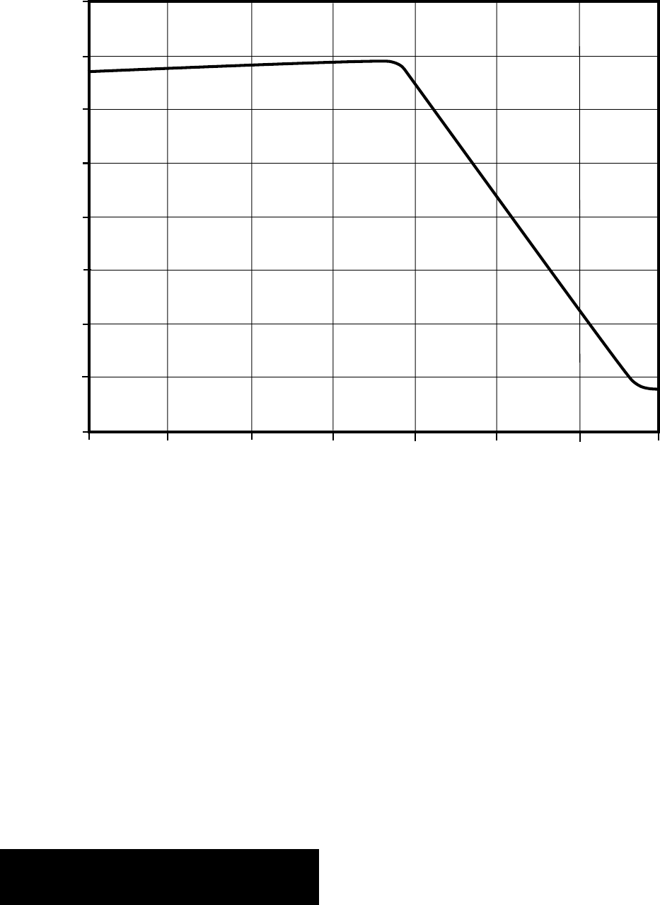
100
~100%
breakdiscard
number of cylces [ % ]
actual breaking load [ % ]
0
0
1. Why must wire ropes be
inspected and examined?
Wire ropes are consumable items
with a limited life. During service
the physical properties of a wire
rope will change.
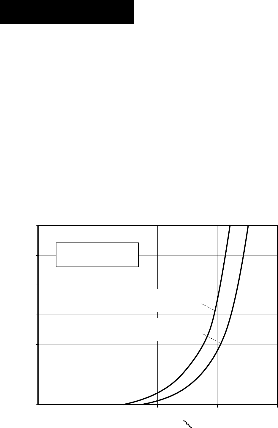
At the commencement of service,
the individual wires and strands
settle into position and the rope
breaking strength increases. Af-
ter reaching a maximum it de-
creases rapidly (Fig. 1).
This decrease in breaking
strength is caused by the pro-
gressive loss of the metallic
cross-section due to abrasion
and corrosion, by wire breaks
Fig. 1
and by changes in the structure
of the rope.
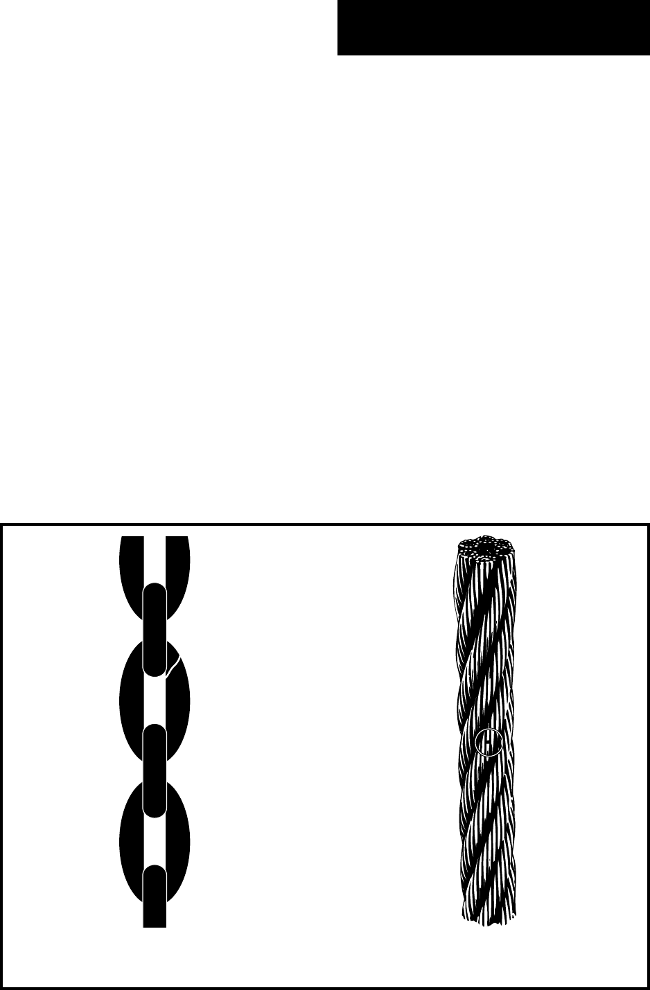
A chain represents a series con-
nection of load bearing elements.
If only one link in the chain
breaks, the whole lifting device
will fail completely. A wire rope
represents a parallel connection
of load bearing elements and con-
sequently it can still be operated
safely after one or more wire
breaks.
Generally, there is a steady rate
of increase in the number of wire
breaks during the life of the rope.
Fig. 3 shows the increasing num-
ber of wire breaks as a function of
the number of cycles in a bending
fatigue test.
3
R. Verreet & W. Lindsay, Wire Rope Inspection and Examination, 1996
2. What is Inspection,
what is Examination?
An inspection is a careful and cri-
tical assessment of the rope and
fittings carried out without dis-
mantling.
An examination is a careful and
critical assessment of the rope
and fittings carried out by a com-
petent person. This should in-
clude, where necessary, a visual
assessment of the internal condi-
tion of the rope, supplemented by
other means such as measure-
ment and non destructive test-
ing. In order for end fittings to be
examined properly they may
need to be dismantled.
Fig. 2
chain, one
element broken
One of the objectives of inspect-
ing and examining a wire rope is
to supervise the normal process
of deterioration so that the rope
can be removed from service be-
fore becoming a hazard to safety.
Another benefit of the inspection
and examination procedures is to
detect unexpected damage or
corrosion.
Inspections and examinations,
properly carried out, ensure the
discard of a rope before failure. In
addition, precautions can be ta-
ken to avoid a recurrence of dam-
age or excessive wear to future
ropes.
rope, one
element broken
4R. Verreet & W. Lindsay, Wire Rope Inspection and Examination, 1996
When a rope has been removed
from equipment and later fitted
to the same or different equip-
ment, it should be inspected after
fitting but before resuming serv-
ice.
If at any time a change in the rope
condition is suspected, it should
be reported immediately and the
equipment taken out of service
until the rope has been examined
by a competent person. As a re-
sult of this examination it may be
prudent to review and amend the
scope and frequency of the in-
spections.
3. When must wire ropes
be inspected?
Wire ropes should be inspected at
the start of each shift, work pe-
riod or more frequently, depend-
ing upon past experience. Usu-
ally this inspection will be carried
out by the operator of the indi-
vidual piece of equipment or pos-
sibly by a member of the work
force specially appointed.
The inspection should be a visual
assessment of the condition of as
much of the rope length as possi-
ble, including the points of at-
tachment to the equipment.
Fig. 3
30
25
20
15
10
5
0
0 30.000 60.000 90.000 120.000
number of broken wires on 30 x d [ – ]
tensile strength 180 kp/mm2
load 100 %
tensile strength 200 kp/mm2
load 111 %
number of cycles [ – ]
D/d = 20
load proportional to
minimum breaking load

5
R. Verreet & W. Lindsay, Wire Rope Inspection and Examination, 1996
4. When must wire ropes
be examined?
The Factories Act 1961 Section
26, The Construction (Lifting Op-
erations) Regulations No. 1581
and the Offshore Installations
(Operational Safety, Health and
Welfare) Regulations 1976 No.
1019 all require a thorough rope
examination at least once in eve-
ry period of six months.
The Shipbuilding and Ship-re-
pairing Regulations 1960 requi-
res a thorough examination every
three months or monthly after
the first broken wire has been
discovered.
One of the statutory regulations
listed above will apply to the loca-
tion and type of rope using equip-
ment being examined.
It is the responsibility of the indi-
vidual to institute and maintain a
programme of periodic examina-
tion which satisfies the require-
ments of the appropriate regula-
tions and the specific operating
conditions of the equipment.
Examination should be carried
out at regular intervals. The in-
tervals should be scheduled so
that any damage will be detected
early.
According to B.S. 6570 examina-
tions should be carried out “at
regular intervals, the frequency
of which will be influenced by the
following:
a) statutory requirements
b) type of appliance and/or
design of the system
c) operational environmental
conditions
d) method and frequency of
operation
e) manufacturer’s recommen-
dations
f) results of previous inspec-
tions and examinations
g) experience with previous
ropes on the appliance or
system”
During the first few weeks after
the installation of a new rope the
daily inspection can be used to
monitor performance as the rope
might have been fitted incorrectly
or the type of rope might not be
suited to the equipment.
The intervals between the exami-
nations should also be reduced
after the first broken wire or
other damage has been detected.
If the rope has been overloaded or
if non- visible damage is sus-
pected, the intervals between ex-
aminations should be reduced
accordingly.
Moreover, the examinations
should be carried out when the
rope is put back into service after
long periods of standstill.
If a lifting device has been dis-
mantled and re assembled, the
rope must be examined before it
is allowed to operate again.

6R. Verreet & W. Lindsay, Wire Rope Inspection and Examination, 1996
5. Survey of removal
criteria
A wire rope must be removed if
one or more of the following crite-
ria can be satisfied:
1) Broken wires.
A wire rope must be discarded if
the permissible number of wire
breaks is reached or exceeded. It
must also be replaced when local
concentrations of wire breaks oc-
cur.
Chapter 7 covers in detail the
subject of the permissible num-
ber of wire breaks according to
British Standard 6570 and the
statutory requirements.
2) Reduction in diameter.
Reduction in diameter can be
caused by abrasion, corrosion or
a local failure of the rope core.
According to B.S. 6570 a wire
rope should be discarded „when
the rope diameter anywhere is re-
duced to 90% of the nominal di-
ameter in the case of six and
eight strand ropes“. Considering
the fact that a rope is allowed to
have an oversize of 4% when new,
this figure would allow for a di-
ameter reduction of 14%, which
seems to be excessive.
For multi- strand ropes B.S.
6570 recommends a detailed ex-
amination “if the rope diameter
falls to 97% of the nominal, or
rises to 105% of the nominal”,
because “discard may be neces-
sary”.
3) Corrosion.
Corrosion may be external or in-
ternal, general or localized. Ac-
cording to BS 6570, a wire rope
should be discarded “when the
surface of the wires is severely
roughened or pitted, or if the
wires are slack within the
strands due to wastage”.
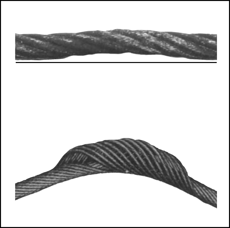
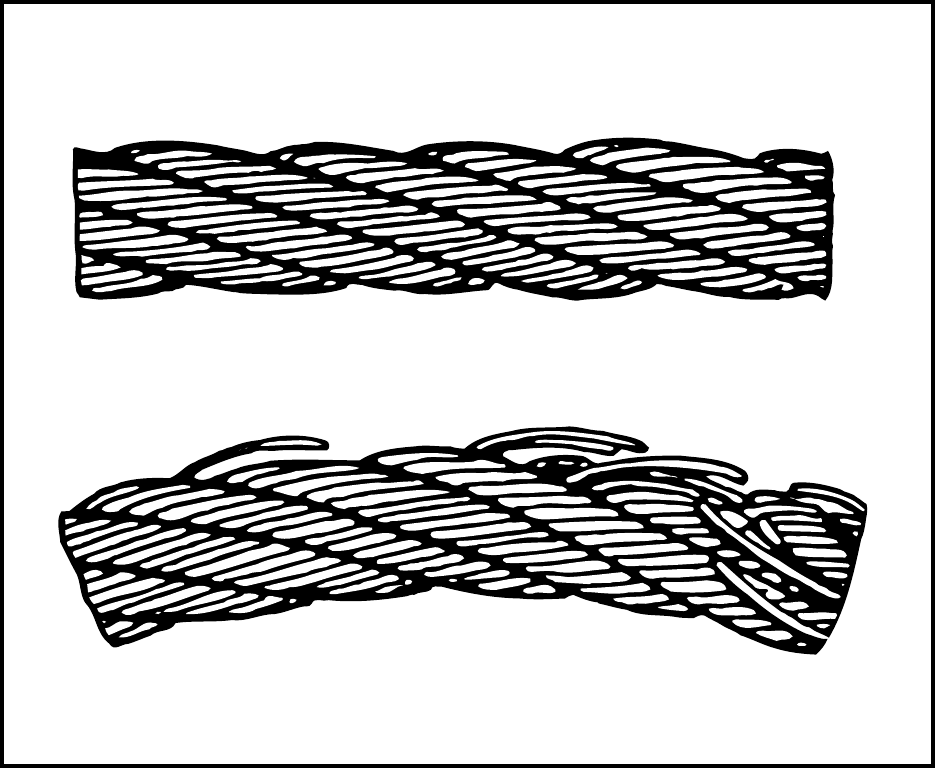
4) Rope deformation
a) Waviness (Fig. 4a). This defor-
mation, while it may not neces-
sarily affect the strength of the
rope, can transmit pulsation and
produce uneven rope wear. When
the rope is laid on a level surface
under no load, the maximum
height of the “wave” should not
be greater than the nominal rope
diameter + 1/3, otherwise the
rope should be removed from
service.
b) Birdcage (Basket Deformation)
A birdcage (Fig. 4b) develops
when the outer layer of strands
be comes longer than the inner
layer or layers. The condition
may occur as a result of incorrect
fitting, tight sheaves, shock load-
ing, incorrect use of a swivel or
the application of a heavy load to
a new rope before the strands
have settled into position. Ropes
with a birdcage should be dis-
carded.
7
R. Verreet & W. Lindsay, Wire Rope Inspection and Examination, 1996
a
Fig. 4
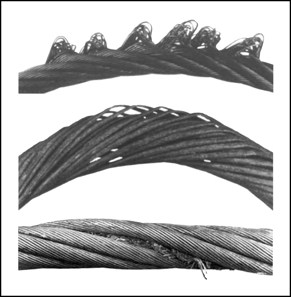
c) Loop Formations. Wires or
groups of wires may form a line of
loops parallel to the axis of the
rope (Fig. 5a). This deformation is
often caused by shock- loading.
Loop formations are a justifica-
tion for discard.
d) Loose Wires. Where loose outer
wires (Fig. 5b) are found without
any adjacent mechanical dam-
age, the most likely cause will be
corrosion and the rope should be
removed from service. Where
loose wires have been caused by
mechanical damage, a full exami-
nation will decide if the rope can
remain in use.
e) Nodes (Fig. 5c). A node is a
local increase in rope diameter
with the core easily visible be-
tween several covering strands. It
can be caused by shock loading
or, in the case of fibre main core
ropes, by the absorption of mois-
ture. A node is a justification for
discard.
b
8R. Verreet & W. Lindsay, Wire Rope Inspection and Examination, 1996
Fig. 5
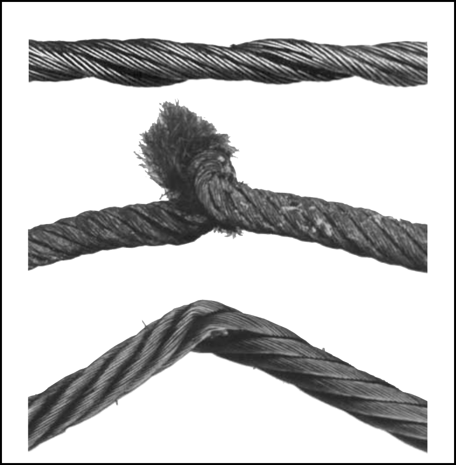
f) Thinning of the rope (Fig. 6a).
Thinning is a reduction in the di-
ameter of the rope over a short
length. It is often associated with
older fibre cored ropes usually in
areas of sustained heavy loads
over sheaves. The disintegration
and loss of the core can allow one
of the covering strands to take
the place of the core. When this
condition occurs in ropes with
IWRC the distortion will most of-
ten be in the vicinity of the termi-
nation away from drum. The
most likely cause is rope rotation
which has allowed the rope to
unlay, resulting in the overload
and reduction in diameter or fail-
ure of the IWRC.
g) Misplaced Outer Wires. Mis-
placed outer wires are wires
forced out of position along the
line of the rope to form small flat-
c
a
b
9
R. Verreet & W. Lindsay, Wire Rope Inspection and Examination, 1996
tened loops. This can be caused
by bad drum spooling or by the
rope being drawn across a sharp
edge. Langs lay ropes are often
worst affected. Misplaced outer
wires are a justification for dis-
card.
h) Kinks (Fig. 6b). Deformation
caused by a loop in a rope being
tightened when the rope cannot
rotate about its axis to release the
torque. The tight bend or kink
thus formed can result in a seri-
ous loss of strength due to un-
balance in the lay lengths. Ropes
with kinks must be discarded.
i) Flat areas (Fig. 6c). A flattening
can be caused by bending the
rope severely over the rim of a
sheave or any sharp object with
the wires on the inside of the
bend being forced out of position.
Fig. 6
a
b
c
10 R. Verreet & W. Lindsay, Wire Rope Inspection and Examination, 1996
220
180
160
120
100
80
60
0 100 200 300 400 500 600 700
temperature [ °C ]
tensile strength [ kp/mm
2
]
140
200
Ropes with flat areas should be
discarded.
5) Damage caused by heat.
Heating rope wires to approxi-
mately 300° C and over will lead
to considerable reduction in ten-
sile strength of the wires (Fig.7).
Wire ropes which have been sub-
jected to excessive heat must be
discarded.
6. Where must wire ropes be
inspected or examined?
During an inspection or a peri-
odic examination by a competent
person, the full length of the rope
should be checked.
The following areas may require
more detailed attention:
a) Rope zones with the highest
number of cycles. During normal
day to day operations some sec-
tions of a rope length will suffer a
greater number of bends over
sheaves and drums than others.
It is in these areas where the
greatest number of fatigue wire
breaks can be expected.
b) Pick- up points. When a lifting
device picks up or releases a load
with the same sections of rope
regularly in contact with sheaves
and drums, those sections of the
rope are subjected to increased
Fig. 7
11
R. Verreet & W. Lindsay, Wire Rope Inspection and Examination, 1996
stress.
c) End fittings. At, or closely adja-
cent to, terminal fittings the elas-
ticity of the rope is restricted and
the geometry “frozen”.
Depending upon the type of fit-
ting, there will be additional pres-
sure on the rope and the section
close to the area of contact be-
tween rope and fitting is often the
focal point for increased stress
caused by vibration.
The danger of corrosion is also
increased by the retention of
moisture in the area of contact
between rope and fitting.
d) Equalising sheaves. Ropes
which are often considered to be
stationary around equalising
sheaves can be subjected to high
numbers of bend cycles caused
by the uneven spooling of two
drums, by swinging loads or by
frequency vibrations. As the rope
might never leave the equalising
sheave, moisture can be trapped
in the area of contact between
rope and sheave and cause corro-
sion.
e) Zones of maximum wear on
drums. Pick- up points and
cross- over points on the drum
are subjected to increased wear
and therefore require special at-
tention. Misplaced and broken
wires caused by scrubbing can be
expected at cross- over points.
The damage can be severe where
the fleet angle is excessive.
With multiple layer spooling, the
first layer of rope on the drum
should be tightly wound to pro-
vide a firm base for subsequent
layers. This applies in particular
to plain drums and parallel
grooved drums, e. g. Lebus. Slack
winding or lateral movement be-
tween turns of rope will affect the
spooling of subsequent layers
and can cause damage.
The point where the rope is
squeezed between the drum
flange and the previous turn as it
rises to commence the next layer,
is an area of accelerated wear and
should be given special attention.
f) Sheaves. Sheaves should be ex-
amined for general condition and
tested for freedom of movement.
Using a groove gauge the tread
radius can be measured.
The radius of the grooves should
be equal to the nominal rope di-
ameter plus + 6% to + 10%.
Undersize grooves will seriously
reduce the service life of the rope
due to the effects of crushing.
Oversize grooves reduce the serv-
ice life due to premature fatigue
caused by insufficient support in
the groove area.
Where the rope surface pattern is
imprinted into the sheave tread,
the sheave should be replaced.

12 R. Verreet & W. Lindsay, Wire Rope Inspection and Examination, 1996
g) Rope sections working in a
hostile environment. High tempe-
rature can considerably reduce
the breaking load of a wire rope.
Temperatures of up to 250°C will
not affect the tensile strength of
the wire, but temperatures of
only 50°C can cause leaching of
the rope lubricant.
The consequent severe wire to
wire friction will result in a mar-
ked reduction of rope perform-
ance. The exposure of rope to
chemical action can greatly in-
crease the effect of corrosion.
In each of the areas where wire
breaks or other defects are found,
the number and description
along with the location, must be
recorded.
7. Discard number of
wire breaks
The Construction (Lifting Ope-
rations) Regulations requires a
rope to be replaced when the
number of broken wires reaches
5% of the total number of wires in
the rope in 10 x d.
The Factories Act, The Shipbuild-
ing and Ship-repairing Regula-
tions and the Offshore Installa-
tions Regulations do not specify a
particular number of broken
wires for discard and leaves this
decision to the discretion of the
examiner.
The Health and Safety at Work
Act requires the provision and
maintenance of plant and sys-
tems of work that are, so far as is
reasonably practical, safe and
without risks to health.
The table on Page 25 shows the
recommended number of discard
wire breaks for CASAR special
wire ropes. For the number of
discard wire breaks in other
types of multi-strand ropes the
user is advised to contact the
rope manufacturer.
Depending on the factor of safety,
the assessment of broken wires
in 6 and 8 strand ropes working
over steel sheaves is divided into
two groups :
1) Factor of safety less than 5 :
5% of the number of outer strand
wires excluding Filler wires.
2) Factor of safety greater than 5 :
10% of the number of outer
strand wires excluding Filler
wires.
When broken wires are detected,
the number and position, along
with the examiner’s opinion of
the general rope condition, will
decide whether or not the rope
should be discarded.
If local concentrations or groups
of broken wires are found, the
rope should be discarded when:

13
R. Verreet & W. Lindsay, Wire Rope Inspection and Examination, 1996
should be available:
a list of the discard criteria
(this manual)
a rope caliper or vernier gauge
a steel tape
a piece of white chalk
a wax pencil (dark coloured)
a roll of adding machine paper
a sheet of typing carbon paper
a screwdriver
a magnifying glass
a pencil
a roll of marking tape
two sets of groove gauges
a piece of cleaning cloth
a wire brush
a pair of gloves
a note book or an inspection form
the previous inspection records
8.2 Locating of wire breaks
Identification of wire breaks can
be by visual and physical exami-
nation or by the use of electroma-
gnetical equipment (see sec-
tion 9).
The first step in wire rope exami-
nation is to find the rope section
with the greatest concentration of
wire breaks. This is normally
done by first visually inspecting
the full length of the rope.
In some cases it can be helpful to
spool the rope slowly through the
hand. Special attention has to be
paid and strong protective gloves
must be worn.
a) three or more broken wires are
found in the close proximity of
the termination,
b) three or more broken wires are
found in one strand or
c) five broken wires are found be-
tween two adjacent strands
within a length of 10 x rope
diameter.
If the number of broken wires
does not justify discard, the posi-
tion and number of all broken
wires found must be recorded in
the rope examination Log Book.
When broken wires are found in
close proximity to a permanent
termination, such as a white me-
tal or resin secured socket and
the general condition of the re-
mainder of the rope is acceptable,
it may be decided to cut the rope
and re make the termination. In
such cases it is recommend that
the socket is submitted for N.D.T.
and heat treatment. Care must
be taken to ensure sufficient
turns of “dead” rope remain on
the drum after the termination
has been remade.
8. Rope examination
procedure
8.1 Equipment
In order to carry out a proper in-
spection, the following tools
14 R. Verreet & W. Lindsay, Wire Rope Inspection and Examination, 1996
A piece of wood held on the sur-
face of a moving rope will be de-
flected by the protuding ends of
broken wires. In the same way, a
soft cotton or similar type cloth
held against a moving rope will be
caught by protruding ends and
thus detect the broken wires.
Smooth synthetic material is less
suitable for this purpose.
The detection of broken wires in
the strand valleys can be diffi-
cult. The use of a scraper or piece
of shaped wood will help clean
out the valleys. The use of a wire
brush on a dirty, heavily lubri-
cated rope can loosen, but not
Fig. 8
always remove, old lubricant and
the brush may have to be cleaned
frequently with a solvent.
Where solvents are used to clean
the rope surface, they should be
used sparingly and the rope sec-
tion should be thoroughly lubri-
cated afterwards. A light lubricat-
ing oil used with a wire brush is
preferred for softening old lubri-
cant which can then be wiped off
with a cloth. When the worst af-
fected sections of rope have been
found, their boundaries should
be marked by chalk or tape for
further examination.

15
R. Verreet & W. Lindsay, Wire Rope Inspection and Examination, 1996
A gauge should be set to a length
of 10 x d. This can now be moved
within the boundaries to locate
the section with the maximum
number of wire breaks. The
breaks in 10 x d should be coun-
ted and entered in the records.
With thin ropes, valley breaks
can be detected by strongly flex-
ing the unloaded rope (Fig. 8).
8.3 Determination of the
rope diameter
The rope diameter should be
measured on receipt for conform-
ity with the specification. British
Standard (B.S. 302:1987, Stran-
ded steel wire ropes, Part 1.
Clause 5.1) allows for a tolerance
of - 1% to + 4% of the nominal
rope diameter.
The generally accepted method of
measuring rope diameter for
compliance with the Standard is
to use a caliper with jaws broad
enough to cover not less than two
adjacent strands. The measure-
ments must be taken on a
straight portion of rope at two
points at least 1 metre apart. At
each point two diameters at right
angles should be measured. The
average of the four measure-
ments is the actual diameter.
After the rope has made the first
few cycles under low load, the
rope diameter should be meas-
ured at several points. The aver-
age value of all the measure-
ments at each point must be re-
corded and will form the basis of
comparison for all future meas-
urements.
The measurement of the rope di-
ameter is an essential part of all
inspections and examinations. It
ensures the maximum diameter
reduction does not exceed the
recommended figure. As stated in
5.2. British Standard 6570 re-
commends that a wire rope
should be discarded when the di-
ameter of the rope is reduced to
90% of the nominal diameter.
A comparison of the measured
data with the recorded previous
values can detect an abnormal
rate of reduction in diameter.
Coupled with assessment of pre-
vious rope examination data, the
probable date of rope renewal can
be predicted.
If we examine the cross-section of
a six-strand wire rope, we will
find that measuring the thick-
ness of the rope over the crowns
(Fig. 9a) will produce a higher va-
lue than measuring it over the
valleys (Fig. 9b). The actual diam-
eter of the rope is defined as the
diameter of the circumscribing
circle.
When using a conventional ca-
liper, wire ropes with an even
number of outer strands (four-,
six-, eight-, ten-, and multi-
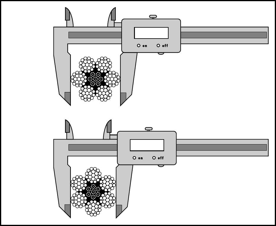
16 R. Verreet & W. Lindsay, Wire Rope Inspection and Examination, 1996
strand) ropes must be measured
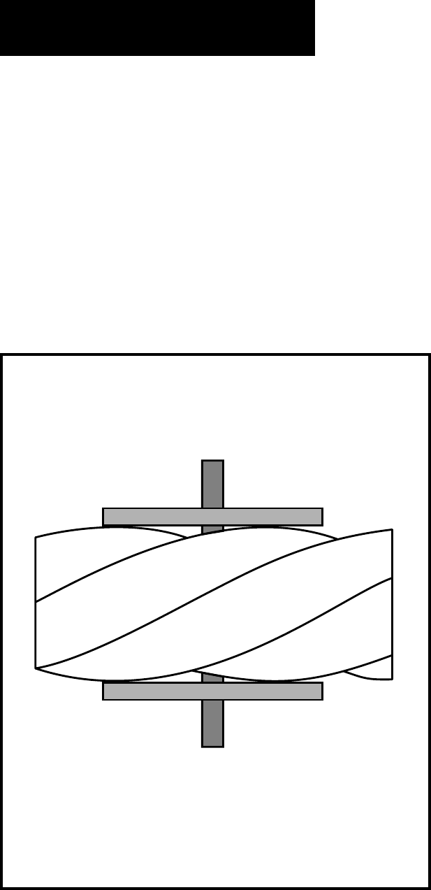
from crown to crown. The advan-
tage of a proper wire rope caliper
with measuring plates is that
even if the measurement is car-
ried out “incorrectly”, adjacent
crowns are always included, so
that the actual diameter is deter-
mined at any section (Fig. 10).
Measuring the diameter of wire
ropes with an uneven number of
outer strands (three-, five-, se-
ven, or nine-strand ropes) is mo-
re complicated: a crown on the
one side of the wire rope always
has a valley as a counterpart on
the other side of the wire rope. A
Fig. 9
conventional caliper, therefore,
has to be applied diagonally to
the axis of the rope, so that at any
time a crown adjacent to a valley
is covered. Again a wire rope ca-
liper with measuring plates is
definitely to be preferred as it al-
ways includes strand crowns.
In all cases during periodic ex-
aminations where the measure-
ments are to be recorded, the
rope should be measured as al-
ready described. Where the
„roundness“ is being checked to
detect potential faults, two diam-
eters, one at right angles to the
other can be taken and noted in
b
a
18,30 mm
20,00 mm
17
R. Verreet & W. Lindsay, Wire Rope Inspection and Examination, 1996
Fig. 10
the records. The entry into the
records might read „Rope diam-
eter : 20.4/20.5mm“.
8.4 Measuring rope lay
After a rope has been fitted to the
appliance, its length cannot be
measured again accurately with-
out a great deal of trouble. The
purpose of measuring the length
of lay is to detect any increase in
the rope length which may have
been caused by corrosion, core
deterioration or rope rotation
(unlaying). With a new rope the
wires and strands should be al-
lowed to settle into their perma-
nent position. Six or seven lifting
cycles with a light to medium
load are recommended before
measuring the lay of the rope. To
minimise error, the measurement
should be made over four lays
and the length divided by four to
find the average lay length.
On eight strand ropes the eight,
sixteenth, twentyfourth and
thirtysecond strands must be
marked. Using a straight length
of the rope and with the rope un-
der no load, first mark any strand
on the crown with a piece of
chalk: this strand
now becomes “crown
zero”. Excluding this
strand, count the
next eight strands
and mark the eighth
strand with chalk.
Exclude the eighth
strand and repeat
this procedure a fur-
ther two times. The
measured length be-
tween the outer
chalk marks is then
divided by four to
give the lay length.
As a rough check on
the overall accuracy
of the chalk mark-
ing, the length of lay
for eight strand
ropes is approxima-

18 R. Verreet & W. Lindsay, Wire Rope Inspection and Examination, 1996
The unskilled use of a screw-
driver or Marlin Spike to examine
the rope core can cause serious
damage to the rope.
8.6 Changes in rope
structure
In addition to the examination
areas detailed in section 4, defor-
mation caused at any point in the
main working area can move
along the rope. Waviness, and in
particular, a birdcage can be
moved along the rope by the ac-
tion of the sheaves. A degree of
slackness in the outer cover of a
multi- strand rope may not be
sufficient to form an immediate
birdcage. However, slackness can
be “squeezed” along the rope.
With the normal length of rope
out any slackness in the outer
cover will usually be found at the
end termination or where the
rope meets the drum.
8.7 Inspecting sheaves
and drums
Remarks in this section are in-
tended to apply equally to
sheaves and drums.
A tight groove in a sheave or
drum will subject the rope to
enormous radial pressure. Rapid
deterioration and premature wire
failure, particularly in the valleys
tely between 6.25 and 6.5 x the
diameter of the rope e.g. using a
lay length of 6.5 x rope diameter,
four lay lengths of a 32mm diam-
eter rope will be 32mm x 6.5 x 4 =
832mm.
An alternative method of meas-
uring the rope lay is to secure the
free end of the roll of adding ma-
chine paper to the rope with ad-
hesive tape. The paper is rolled
out over the rope and simultane-
ously the wax pencil is drawn
over the paper, providing a clear
print of the outer wires of the
rope. The finished print can be
filed for comparison with later
measurements.
A third method is to wrap typing
carbon papers round the rope
under the roll of paper. By rub-
bing along the paper with a piece
of cardboard, the carbon mark-
ing on the underside of the paper
can be confined to the tops of the
strand crowns.
8.5 Checking the stability
of the rope
A rope in good condition will have
all strands tightly laid. A screw-
driver inserted between strands
when twisted, should meet with
stiff resistance. If the screwdriver
can be twisted between different
pairs of strands without much
resistance, a full examination
should be carried out.
19
R. Verreet & W. Lindsay, Wire Rope Inspection and Examination, 1996
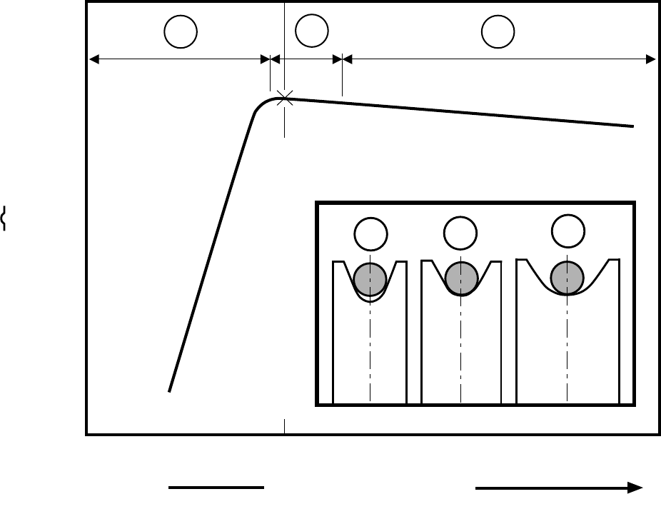
ABC
A B
nominal rope diameter + 6%
groove diameter
groove diameter =
C
max.
number of cycles [ – ] until discard
optimum
Fig. 11
between strands, can be expected
(Fig. 11, A).
On the other hand a wide groove
will not provide essential support
to a rope under load. Oval shaped
deformation is produced result-
ing in uneven distribution of the
load between individual wires
with consequent early failure
(Fig. 11, C).
Sheaves can be checked with
gauges which are available on the
open market. The use of specially
made circular templates is pre-
ferred.
The recommend size for a sheave
gauge is the nominal rope diam-
eter + 6% to +10% (Fig. 11, B). In
order to establish the size of a
sheave groove, templates for the
sizes above and below the recom-
mended size will be required.
The sides and tread of sheaves
which have been in use for some
time are often heavily coated with
old lubricant, some of which may
first have to be removed with a
scraper. By inserting the tem-
plate as far as possible and draw-
ing it through the remaining lu-
bricant, the fit of the template re-
lative to the sheave tread can be
assessed.
The correct template should be in
contact with the sheave tread for
about 130°. If the template only
touches the side flanges, the
20 R. Verreet & W. Lindsay, Wire Rope Inspection and Examination, 1996
groove is too tight. If the template
touches only the bottom part of
the tread, the groove is too wide.
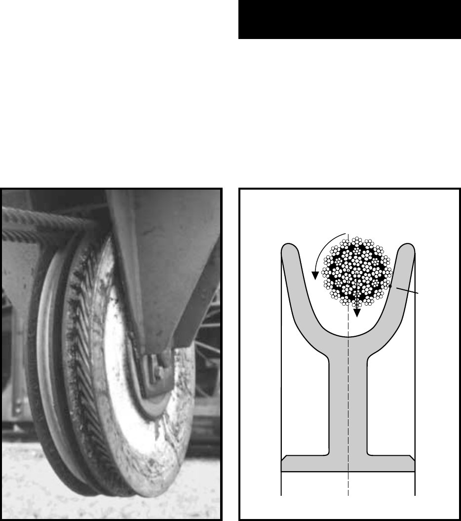
Attention should also be given to
the flanges of the sheaves. Ab-
sence of lubricant, scratching or
unexpected wear on one side will
indicate (a) misalignment of the
sheave and (b) the danger of
torque being induced into the
rope due to the rope rolling down
the flange into the tread.
The tread should be cleaned and
carefully examined for any sign of
ridging or imprinting. In the case
of imprinting with the rope profile
the rope in service may have
caused the damage and is un-
likely to be seriously affected. A
Fig. 13
Fig. 12
replacement rope will not fit ex-
actly into the imprint and will
suffer serious damage during the
early part of its service.
When a rope change is made, the
sheaves should be checked for
eccentricity and the bearing for
wear and free running.
9. Electro-magnetic
wire rope examination
After a period in service surface
wear and/or a number of wire
breaks will indicate the rope con-
dition has deteriorated and dis-
card may be imminent. Specific
working conditions however, may
Point of
contact
21
R. Verreet & W. Lindsay, Wire Rope Inspection and Examination, 1996
lead to internal wire breaks and
to internal loss of metallic area. It
may be surprising to learn that
this applies in particular to ropes
which, for safety reasons, are op-
erated with large diameter
sheaves and high factors of
safety.
Dynamically loaded ropes or
ropes which are subjected to
torque when working, can suffer
from internal wire breaks caused
by overstrained interior rope ele-
ments. In addition, when the ree-
ving system includes sheaves
lined with plastic or all plastic
sheaves, these sheaves offer
more elastic support than steel
sheaves. The pressure between
outer wires and the sheave
grooves can be reduced to such
an extent that with some rope
constructions the first wire
breaks will occur, not on the sur-
face, but within the rope. In all
these cases electro- magnetic tes-
ting will allow non-destructive
examination and appraisal of the
rope’s internal condition.
Electro-magnetic testing equip-
ment available on the market al-
lows - depending on individual
design - indication or continuous
recording of localised damage
such as single broken wires,
breaks of strands, soldered and
welded joints as well as wire pit-
ting and even detection of re-
duced metallic area caused by
corrosion and abrasion over the
whole rope length.
The data are plotted as a function
of the rope length, which is con-
tinually measured either during
the inspection or, if a recording is
done, during the following analy-
sis. In this way every signal on
the recording can unmistakably
be related to a zone on the rope.
This method allows a more pre-
cise visual inspection of those
sections of the rope which
showed exceptional inconsisten-
cies during the electro-magnetic
inspection. Furthermore, record-
ing the data during regular elec
tro-magnetic inspections makes
it possible to compare the results
with previous recordings. In this
way the advance of the deteriora-
tion of the rope can be ascer-
tained.
Electro-magnetic testing equip-
ment for wire ropes was already
being developed at the beginning
of the 20th century. Only very few
specialists could use the equip-
ment properly but over the past
few years the use of these instru-
ments has been greatly improved
so that they are now at the com-
mand of a much wider range of
users.
It is likely that within a few years
there will be equipment on offer
which not only records measured
data but also - by means of a mi-
cro computer - will process the
data with regard to amplitude
and frequency. In this way the
equipment will provide the exam-
iner with data such as frequency
22 R. Verreet & W. Lindsay, Wire Rope Inspection and Examination, 1996
Fig. 14
curves and the accurate assess-
ment of the reduction in breaking
strength.
At the moment instruments are
being developed which, apart
from the data mentioned above,
can also record the rope diameter
and the lay length of the rope.
This will enable them to register
out-of-roundness of the rope di-
ameter, corkscrew-like deforma-
tions or changes of the lay
lengths along the rope length.
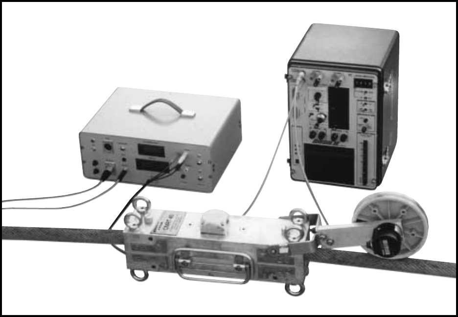
For inspection a test head is
clamped around the rope. Then
the whole length of the rope is
pulled through the test head. If
this is not possible, as in the case
of suspended ropes of rope ways,
the test head is drawn along the
wire rope. During this procedure
all test data are transmitted via
cable or radio to an amplifier. The
test data are indicated either op-
tically or acoustically, recorded
on magnetic tape or represented
graphically during the test. An
electro-magnetic test instrument
is shown in Fig. 14.
Calibration of the testing equip-
ment requires great care. A re-
commended method of checking
the function and accuracy of the
equipment is to attach lengths of
wire, having diameters equal to
the largest and smallest sizes in
the rope, along the first metres of
rope length. By means of sello-
tape these wires can be secured
in the strand valleys. At the be-
ginning of the recording strip
23
R. Verreet & W. Lindsay, Wire Rope Inspection and Examination, 1996
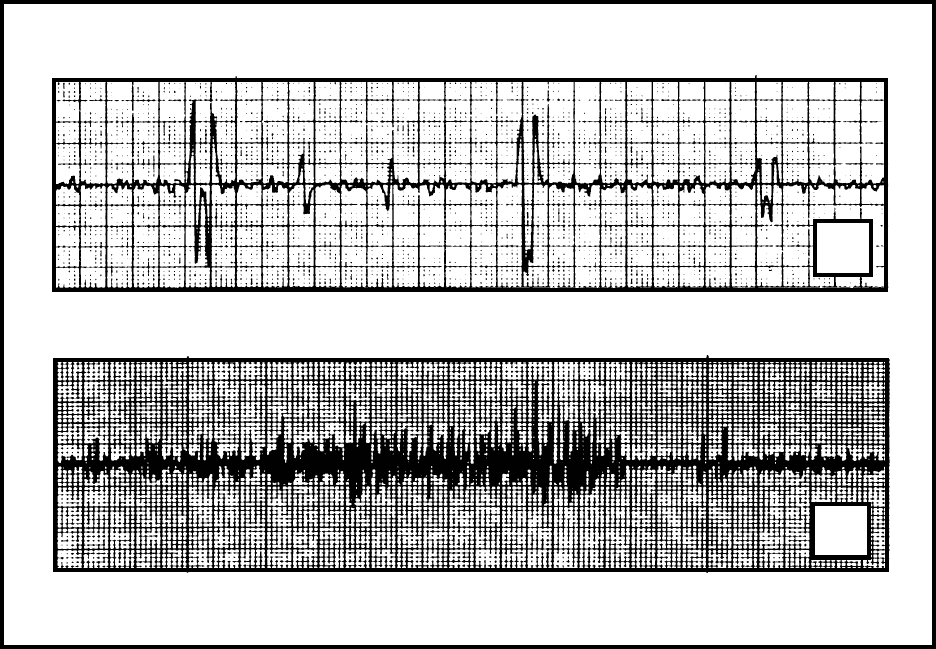
Fig. 15
a
b
chart the examiner will obtain
reference data indicating the size
of the amplitudes of the test
wires.
Fig. 15a illustrates a typical dia-
gram of a rope section with wire
breaks. Fig. 15b shows the recor-
ding of a rope section affected by
corrosion.
Selecting the suitable test instru-
ment, competent handling and
the correct interpretation of the
data require a lot of experience
and expert knowledge. Various
universities, test institutes as
well as commercial firms, render
electro-magnetic inspection of
wire ropes as a service.
The discard numbers of wire
breaks specified in the Standards
refer solely to external wire
breaks. Appraising the condition
of the wire rope with regard to in-
ternal wire breaks is therefore left
to the inspector; he would be well
advised to discard a wire rope
when the total number of exter-
nal and internal wire breaks,
added together, reaches the dis-
card number of wire breaks spe-
cified in the Standards.
Electro-magnetic tests can not,
and must not, totally replace vi-
sual inspections. Yet, they pro-
vide valuable additional informa-
tion on the conditions of wire
ropes and must be regarded as a
useful addition to the visual in-
spection.
24 R. Verreet & W. Lindsay, Wire Rope Inspection and Examination, 1996
machine: application:
left hand lay right hand lay
regular lay langs lay
ungalvanized galvanized
location
measured
no. of broken
wires
on 10 x d
abrasion corrosion
diameter/
ø-reduction mm/%
other
** **
date/ signaturefinal evaluation
type of end fitting:
type of rope:
nominal diameter [mm]:
tensile strength [N/mm ]:
rope length [m]:
date of installation: working hours to date:
* description, e.g. no, little, etc.
** comments, e.g. description of a rope deformation
eff. Ø of new rope
2
allowed no.:
®

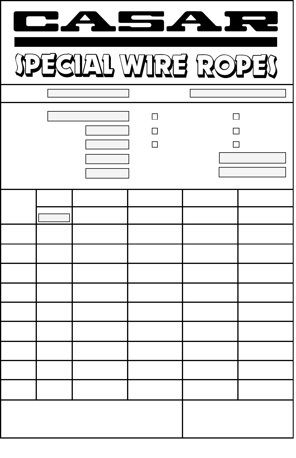
25
R. Verreet & W. Lindsay, Wire Rope Inspection and Examination, 1996
®
rotation resistant
compacted strands
plastic infill
number of bearing wires
in the outer strands**
factor of safety greater than 5:
discard number of wire breaks
factor of safety less than 5:
discard number of wire breaks
average fill factor
total number of wires
spin factor*
average weight factor
0,653
0,748
0,710
0,608
0,661
0,688
0,660
0,730
0,755
0,650
0,755
0,660
0,655
0,627
0,663
0,566
0,477
0,684
0,90
0,86
0,91
0,92
0,87
0,86
0,89
0,85
0,85
0,89
0,85
0,90
0,90
0,90
0,85
0,90
0,94
0,86
0,77
0,79
0,84
0,87
0,86
0,84
0,86
0,84
0,84
0,86
0,84
0,88
0,90
0,82
0,83
0,86
0,85
0,84
245
280
358
319
327
344
303
311
307
303
307
119
145
319
180
126
96
140
4
4
4
10
10
12
10
10
10
10
10
3
3
10
5
5
5
7
8
8
22
20
20
24
20
20
20
20
20
6
6
20
10
10
10
14
112
126
126
152
208
260
152
208
205
152
205
56
72
152
126
126
96
140
* up to approx. 40 mm Ø, 1770 N/mm2
** up to approx. 40 mm Ø
Discard Number of Wire Breaks
according to the criteria of BS 6570

26 R. Verreet & W. Lindsay, Wire Rope Inspection and Examination, 1996
Additional CASAR literature
•
A
l
l
e
U
r
h
e
b
e
r
-
u
n
d
L
e
i
s
t
u
n
g
s
s
c
h
u
t
z
r
e
c
h
t
e
v
o
r
b
e
h
a
l
t
e
n
-
K
e
i
n
V
e
r
l
e
i
h
!
K
e
i
n
e
u
n
e
r
l
a
u
b
t
e
V
e
r
v
i
e
l
f
ä
l
t
i
g
u
n
g
e
n
,
A
u
f
f
ü
h
r
u
n
g
,
S
e
n
d
u
n
g
•
A
l
l
C
o
p
y
r
i
g
h
t
s
i
n
r
e
c
o
r
d
p
e
r
f
o
r
m
a
n
c
e
s
r
e
s
e
r
v
e
d
-
N
o
l
e
n
d
i
n
g
!
U
n
a
u
t
h
o
r
i
z
e
d
d
u
p
l
i
c
a
t
i
o
n
,
l
e
a
s
e
,
p
u
b
l
i
c
p
e
r
f
o
r
m
a
n
c
e
a
n
d
b
r
o
a
d
c
a
s
t
®
Handling, Installation
and Maintenance of
Steel Wire Ropes
®
Wire Rope End Connections
®
®
The rotation characteristics
of steel wire ropes
®
TECHNICAL
DOCUMENTATION
®
CASAR CD-ROM
The first CASAR CD-ROM is an interactive tool with
the intention to inform the user about wire ropes.
It offers many detailed information referring to:
• technical features
• end connections
• handling
• installation
• maintenance
• inspection
The CD-ROM is available at no cost.
For Macintosh and Windows.
Which rope for my crane?
27
R. Verreet & W. Lindsay, Wire Rope Inspection and Examination, 1996
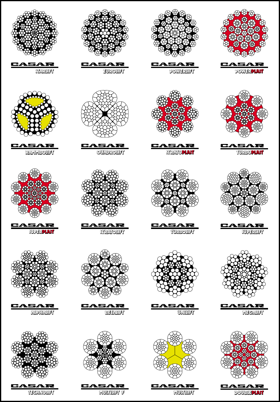
The CASAR product line
®®
® ®
®
® ® ® ®
®
®®®
® ® ®
®
®
®®

28 R. Verreet & W. Lindsay, Wire Rope Inspection and Examination, 1996
3,47
4,53
5,63
7,04
8,45
10,16
11,92
13,83
15,89
18,11
20,35
22,64
25,52
28,24
31,15
34,27
37,28
40,73
43,93
47,71
51,69
55,81
59,57
63,77
72,25
81,75
92,15
102,26
113,08
125,50
137,56
149,89
163,53
176,94
186,35
200,99
217,76
232,42
249,75
266,76
284,67
302,93
322,77
339,31
360,57
34,1
44,5
55,4
69,2
83,1
99,9
117,3
135,9
156,3
178,1
200,1
222,6
250,9
277,7
306,3
337,0
366,5
400,5
431,9
469,2
508,3
548,8
585,8
627,1
710,5
803,9
906,1
1005,5
1111,9
1234,1
1352,7
1473,9
1608,1
1740,0
1832,5
1976,4
2141,3
2285,4
2455,9
2623,1
2799,3
2978,8
3173,9
3336,5
3545,6
1770 N/mm21960 N/mm21770 N/mm21960 N/mm2
(180 kp/mm2) (200 kp/mm2) (180 kp/mm2) (200 kp/mm2)
3,86
5,03
6,26
7,82
9,39
11,29
13,25
15,36
17,66
20,12
22,61
25,15
28,35
31,38
34,61
38,08
41,42
45,26
48,81
53,01
57,44
62,01
66,19
70,85
80,28
90,84
102,39
113,62
125,64
139,44
152,85
166,54
181,70
196,61
207,06
223,32
241,95
258,24
277,50
296,40
316,31
336,59
358,64
377,01
400,64
37,8
49,3
61,3
76,6
92,1
110,7
129,8
150,5
173,0
197,2
221,6
246,5
277,8
307,5
339,2
373,2
405,9
443,5
478,3
519,5
562,9
607,7
648,6
694,4
786,7
890,2
1003,4
1113,5
1231,3
1366,6
1497,9
1632,1
1780,7
1926,7
2029,2
2188,5
2371,1
2530,8
2719,5
2904,7
3099,8
3298,5
3514,6
3694,7
3926,2
7 25,0 22,5 44,2 4,51 49,0 4,99
8 32,8 29,5 58,1 5,92 64,3 6,56
9 40,8 36,7 72,2 7,37 80,0 8,16
10 51,7 46,5 91,5 9,33 101,3 10,33
11 62,2 56,0 110,2 11,23 122,0 12,44
12 73,9 66,5 130,9 13,34 144,9 14,78
13 86,9 78,2 153,7 15,68 170,2 17,36
14 100,4 90,4 177,7 18,13 196,8 20,07
15 116,0 104,4 205,3 20,94 227,4 23,19
16 132,3 119,0 234,1 23,87 259,3 26,44
17 147,8 133,0 261,5 26,67 289,6 29,53
18 165,5 149,0 293,0 29,88 324,4 33,08
19 186,6 167,9 330,3 33,68 365,7 37,30
20 205,0 184,5 362,9 37,00 401,8 40,98
21 226,7 204,0 401,2 40,91 444,3 45,30
22 250,0 225,0 442,5 45,12 490,0 49,96
23 271,2 244,1 480,0 48,94 531,5 54,20
24 296,0 266,4 523,8 53,42 580,1 59,15
25 319,9 287,9 566,2 57,74 627,0 63,94
26 347,0 312,3 614,2 62,63 680,2 69,36
27 372,9 335,6 660,0 67,30 730,9 74,53
28 402,1 361,9 711,7 72,57 788,1 80,36
29 432,5 389,2 765,5 78,06 847,7 86,44
30 464,7 418,3 822,6 83,88 910,9 92,89
32 526,4 473,7 931,7 95,00 1031,7 105,20
34 591,2 532,1 1046,4 106,71 1158,8 118,16
36 661,5 595,3 1170,8 119,39 1296,5 132,21
38 742,5 668,3 1314,2 134,01 1455,3 148,40
40 818,1 736,3 1448,0 147,66 1603,5 163,51
42 902,7 812,4 1597,8 162,93 1769,3 180,42
44 994,4 895,0 1760,1 179,48 1949,1 198,75
46 1083,6 975,3 1918,0 195,58 2123,9 216,58
48 1186,5 1067,8 2100,1 214,15 2325,5 237,14
50 1286,3 1157,7 2276,8 232,17 2521,2 257,09
52 1391,7 1252,5 2463,3 251,18 2727,7 278,15
54 1501,4 1351,2 2657,4 270,98 2942,7 300,07
56 1610,3 1449,3 2850,3 290,65 3156,3 321,85
58 1727,4 1554,7 3057,5 311,78 3385,7 345,25
60 1848,6 1663,7 3272,0 333,65 3623,3 369,47
62 1973,9 1776,5 3493,8 356,27 3868,8 394,51
64 2103,3 1893,0 3722,8 379,62 4122,5 420,37
66 2236,8 2013,1 3959,1 403,72 4384,1 447,06
68 2374,4 2137,0 4202,7 428,56 4653,9 474,56
70 2516,2 2264,5 4453,6 454,14 4931,7 502,89
72 2662,0 2395,8 4711,7 480,46 5217,5 532,04
mm mm2 kg/%m kN t kN t kN t kN t
®
Calculated aggregate breaking load
with tensile strength of wire
Minimum breaking load
Nominal
diameter Weight
Metallic
area

29
R. Verreet & W. Lindsay, Wire Rope Inspection and Examination, 1996
9,86
11,98
14,16
16,73
19,31
22,21
25,20
28,39
32,13
35,70
39,64
43,60
47,76
51,94
57,08
61,67
66,52
72,02
77,47
83,07
88,84
101,48
114,44
127,74
142,90
157,90
169,83
185,75
202,65
222,75
9,14
11,11
13,30
15,60
18,30
20,80
23,50
26,32
30,00
33,50
36,90
40,20
45,00
48,14
53,50
57,90
62,70
66,75
72,70
77,00
83,40
94,90
106,60
120,90
134,50
149,10
164,41
180,20
197,40
215,64
8,33
10,12
12,10
14,14
16,50
18,80
21,29
23,99
27,15
30,30
33,49
36,84
40,60
43,88
48,30
52,30
56,60
60,85
65,60
70,19
75,30
85,74
96,69
109,10
121,50
138,00
147,97
162,80
178,30
194,30
97,4
118,4
139,9
165,4
190,9
219,5
249,1
280,6
317,5
352,8
391,7
430,9
472,0
513,2
564,1
609,4
657,4
711,7
765,6
821,0
877,9
1002,8
1130.9
1262,3
1412,2
1560,4
1667,4
1823,7
1989,7
2187,0
89,6
108,8
130,8
152,7
179,1
204,0
230,6
257,9
293,9
329,0
362,2
396,1
441,4
471,8
524,3
567,9
614,9
654,2
712,9
754,6
817,4
930,0
1045,0
1185,0
1319,0
1462,0
1611,2
1767,0
1935,0
2113,3
81,9
99,5
118,2
139,0
161,7
184,5
209,4
235,9
266,9
297,1
329,3
362,3
398,5
431,5
474,3
512,8
555,0
598,3
643,7
690,2
738,1
843,4
950,8
1070,0
1191,0
1360,0
1455,0
1596,0
1748,0
1908,4
1770 N/mm21960 N/mm22160 N/mm21770 N/mm21960 N/mm22160 N/mm2
(180 kp/mm2) (200 kp/mm2) (220 kp/mm2) (180 kp/mm2) (200 kp/mm2) (220 kp/mm2)
mm mm2 kg/%m kN t kN t kN t kN t kN t kN t
10 56,9 49,0 100,8 10,28 111,6 11,38 123,0 12,54
11 69,0 59,3 122,1 12,45 135,2 13,79 149,0 15,19
12 82,0 70,5 145,1 14,79 160,7 16,38 177,0 18,05
13 95,4 82,1 168,9 17,22 187,0 19,07 206,1 21,02
14 110,4 94,9 195,4 19,93 216,4 22,06 238,5 24,32
15 126,8 109,1 224,5 22,89 248,6 25,35 274,0 27,94
16 146,2 125,7 258,8 26,39 286,6 29,22 315,8 32,20
17 163,5 140,6 289,4 29,51 320,5 32,68 353,2 36,02
18 186,2 160,1 329,5 33,60 364,9 37,21 402,1 41,01
19 205,6 176,8 363,8 37,10 402,9 41,08 444,0 45,28
20 227,5 195,6 402,6 41,06 445,9 45,47 491,4 50,11
21 249,1 214,2 440,9 44,96 488,3 49,79 538,1 54,87
22 276,0 237,3 488,5 49,81 540,9 55,16 596,1 60,78
23 303,3 260,9 536,9 54,75 594,5 60,62 655,2 66,81
24 327,1 281,3 578,9 59,03 641,1 65,37 706,5 72,04
25 357,6 307,6 633,0 64,55 701,0 71,48 772,5 78,78
26 382,0 328,5 676,1 68,94 748,6 76,34 825,0 84,13
27 410,5 353,0 726,5 74,08 804,5 82,03 886,6 90,41
28 447,3 384,6 791,7 80,73 876,6 89,39 966,1 98,51
29 472,3 406,2 835,9 85,24 925,7 94,39 1020,1 104,02
30 505,4 434,7 894,6 91,23 990,6 101,02 1091,7 111,33
32 582,7 501,1 1031,3 105,16 1142,0 116,45 1258,5 128,33
34 655,9 564,0 1160,9 118,38 1285,5 131,08 1416,7 144,46
36 735,7 632,7 1302,1 132,78 1441,9 147,03 1589,0 162,04
38 823,3 708,1 1457,3 148,60 1613,7 164,55 1778,4 181,34
40 910,5 783,1 1611,7 164,34 1784,7 181,98 1966,8 200,55
42 1004,2 863,6 1777,5 181,25 1968,3 200,71 2169,1 221,19
44 1098,4 944,6 1944,1 198,24 2152,8 219,53 2372,5 241,93
46 1198,3 1030,6 2121,0 216,29 2348,7 239,50 2588,4 263,94
48 1317,2 1132,7 2331,4 237,73 2581,6 263,25 2845,0 290,11
®
Minimum breaking loadCalculated aggregate breaking load
with tensile strength of wire
Nominal
diameter Metallic
area Weight
Further diameters upon request.

30 R. Verreet & W. Lindsay, Wire Rope Inspection and Examination, 1996
mm mm2kg/%m kN t kN t kN t kN t
1770 N/mm21960 N/mm21770 N/mm21960 N/mm2
(180 kp/mm2) (200 kp/mm2) (180 kp/mm2) (200 kp/mm2)
®
5,34
6,78
8,37
10,00
12,05
14,18
16,34
18,79
21,36
23,90
27,09
29,89
33,36
36,63
40,25
43,71
47,84
52,47
57,03
60,54
65,10
69,83
75,28
80,03
85,50
91,48
96,46
102,35
107,62
121,02
133,46
147,85
1691,60
175,90
191,27
209,12
227,54
245,80
264,94
283,49
296,21
318,17
338,99
361,39
379,39
401,44
423,92
52,3
66,4
82,0
98,0
118,0
138,9
160,1
184,1
209,3
234,2
265,5
292,9
327,0
359,0
394,5
428,3
468,9
514,2
558,8
593,3
638,0
684,3
737,8
784,3
837,9
896,5
945,3
1003,0
1054,7
1186,0
1307,9
1448,9
1583,7
1723,8
1874,5
2049,4
2229,9
2408,8
2596,5
2778,2
2902,9
3118,0
3322,1
3541,6
3718,0
3934,1
4154,4
47,2
60,0
74,0
88,5
106,6
125,5
144,6
166,3
189,0
211,5
239,8
264,5
295,3
324,2
356,2
386,8
423,4
464,3
504,7
535,8
576,2
618,0
666,3
708,3
756,7
809,6
853,7
905,8
952,4
1071,1
1181,1
1308,5
1430,1
1556,7
1692,8
1850,7
2013,7
2175,3
2344,8
2508,9
2621,5
2815,8
3000,1
3198,3
3357,6
3552,7
3751,7
4,80
6,10
7,53
9,00
10,84
12,76
14,71
16,91
19,22
21,51
24,38
26,90
30,03
32,97
36,23
39,34
43,06
47,22
51,32
54,49
58,59
62,85
67,76
72,03
76,95
82,33
86,82
92,12
96,86
108,92
120,11
133,06
145,44
158,31
172,15
188,21
204,78
221,22
238,45
255,14
266,59
286,35
305,10
325,25
341,45
361,29
381,53
8 30,8 28,3 54,5 5,56 60,3 6,15
9 39,5 36,3 69,9 7,12 77,4 7,89
10 48,3 44,4 85,4 8,71 94,6 9,65
11 60,0 55,2 106,3 10,84 117,7 12,00
12 69,9 64,3 123,7 12,62 137,0 13,97
13 81,1 74,6 143,6 14,64 159,0 16,22
14 93,9 86,4 166,2 16,95 184,1 18,77
15 109,4 100,7 193,7 19,75 214,5 21,87
16 123,9 114,0 219,3 22,37 242,9 24,77
17 139,5 128,4 247,0 25,18 273,5 27,89
18 156,1 143,7 276,4 28,18 306,0 31,21
19 177,5 163,3 314,2 32,04 347,9 35,48
20 195,8 180,2 346,6 35,34 383,8 39,14
21 217,3 199,9 384,6 39,22 425,9 43,43
22 237,6 218,6 420,6 42,89 465,7 47,49
23 258,6 237,9 457,6 46,67 506,8 51,68
24 280,3 257,9 496,1 50,59 549,4 56,02
25 302,0 277,8 534,5 54,51 591,9 60,36
26 326,8 300,6 578,4 58,98 640,4 65,31
27 353,2 324,9 625,1 63,75 692,2 70,59
28 375,9 345,8 665,3 67,84 736,7 75,12
29 407,7 375,1 721,6 73,59 799,1 81,48
30 435,8 400,9 771,4 78,66 854,2 87,10
31 464,3 427,1 821,8 83,80 910,0 92,79
32 495,4 455,8 876,9 89,42 971,1 99,02
33 526,4 484,3 931,7 95,01 1031,7 105,21
34 556,8 512,3 985,5 100,50 1091,3 111,29
35 585,9 539,1 1037,1 105,76 1148,4 117,11
36 626,5 576,4 1108,9 113,08 1227,9 125,21
38 705,1 648,7 1248,0 127,26 1382,0 140,92
40 779,4 717,0 1379,5 140,67 1527,6 155,77
42 859,3 790,6 1521,0 155,10 1684,3 171,75
44 942,5 867,1 1668,2 170,11 1847,3 188,37
46 1031,5 949,0 1825,8 186,18 2021,8 206,17
48 1123,1 1033,3 1987,9 202,71 2201,3 224,47
50 1212,7 1115,7 2146,5 218,88 2376,9 242,38
52 1309,7 1204,9 2318,2 236,39 2567,0 261,76
54 1410,5 1297,7 2496,7 254,59 2764,7 281,92
56 1508,1 1387,4 2669,3 272,19 2955,9 301,41
58 1581,2 1454,7 2798,7 285,39 3099,1 316,02
60 1707,4 1570,8 3022,1 308,17 3346,5 341,25
62 1845,1 1697,5 3265,9 333,03 3616,4 368,77
64 1966,1 1808,8 3480,0 354,86 3853,5 392,95
66 2090,9 1923,6 3700,9 377,38 4098,1 417,89
68 2183,5 2008,8 3864,8 394,10 4279,6 436,40
70 2352,0 2163,8 4163,0 424,51 4609,9 470,08
72 2488,3 2289,3 4404,3 449,12 4877,1 497,33
Metallic
area
Nominal
diameter Weight
Calculated aggregate breaking load
with tensile strength of wire
Minimum breaking load

31
R. Verreet & W. Lindsay, Wire Rope Inspection and Examination, 1996
Acknowledgement
The authors and the publisher are pleased to acknowledge the
valuable help received from Mr. M. J. McEntee, C. Eng., F. I. Mech. E.,
F. I. Plant E., H. M. Principal Specialist Inspector (Engineering).
Readers Comments
For reasons of space, this booklet can only deal with general aspects
of wire rope inspection and examination. However, the publisher and
the authors are always pleased to give their opinions on specific
problems.
For future editions of this booklet, the authors look forward to re-
ceiving readers’ suggestions for improvements or general comments.
These should be addressed to:
Wire Rope Technology
Dipl.-Ing. Roland Verreet
Grünenthaler Straße 40a
52072 Aachen
Germany
Telephone + 49 241 - 17 31 47
Fax + 49 241 - 1 29 82
e-mail R.Verreet@t-Online.de
or
William Lindsay
Wire Rope Consultancy
10 Poplar Drive
Lenzie, Glasgow, G66 4DN
UK
Telephone 041-776 1696
32 R. Verreet & W. Lindsay, Wire Rope Inspection and Examination, 1996
The material presented in this publication has been prepared in accordance with recognized
engineering principles and is for general information only. This information should not be used
without first securing competent advice with respect to its suitability for any given application. The
publication of the material contained herein is not intended as a representation or warranty of the
part of Casar Drahtseilwerk Saar GmbH or the authors that this information is suitable for any
general or particular use or of freedom from infringements of any patent or patents. Anyone making
use of this information assumes all liability arising from such use.
Permission to reproduce or quote any portion of this book as editorial reference is hereby granted.
When making such reproductions or quotations, the title and the author of this publication must
be mentioned.
This brochure is published by
Casar Drahtseilwerk Saar GmbH,
manufacturers of the famous
Setting, Layout and Production: PR GmbH Werbeagentur und Verlag,
Grünenthaler Straße 40a, 52072 Aachen, Germany
© 1989/1998 Casar Drahtseilwerk Saar GmbH
®

®
CASAR DRAHTSEILWERK SAAR GMBH
Casarstraße 1 •D-66 459 Kirkel
Postfach 187 •D-66 454 Kirkel
Phone ++49-68 41/80 91-0
Fax ++ 49-68 41/ 86 94
Sales Dept.
Phone ++49-68 41/80 91-39/44
Fax ++ 49-68 41/80 91-29
http://www.casar.de
