LT 0757 WD 4 05 XR 2500F Wiring Diagram
User Manual: XR-2500F Wiring Diagram AlarmHow.net Library
Open the PDF directly: View PDF ![]() .
.
Page Count: 1
AC
1 2 3 4 5 6 7 8 10 11 12 13 14 15 16 17 18 199 20 21 22 23 24 25 26 27 28
+B BELL GND SMK GNDRED YEL GRN BLK Z1 Z2 Z3 Z4 Z5 Z6 Z7 Z8 Z9+ Z9– Z10+ Z10–AC –B GND GND GNDGND
K6 K7
Output 1 Output 2
J3
Phone
Line
J10
J22
Battery
Start
J23
J21
RS-232
Power
LED
J8
PROG
J4
Tamper
J16
Reset
Out1 Out2
Outputs 3-6
J1
3
4
5
6
J2
J1
Ethernet
R
L
X
Link LED
Power LED
OVC
XR2500F
Command
Processor™
Panel
J6 Expansion
Card Slot
TYPES OF SERVICE
Central Station DACT service
may be provided.
Suitable for Remote Station
PPU DACT Service. Suitable
for manual fire alarm,
automatic fire alarm,
sprinkler supervisory, or
water flow alarm.
Suitable for Grade AA High
Line Central Station with NET
communication.
Suitable for Proprietary, PPU,
other technologies, local.
Suitable for manual fire
alarm, automatic fire alarm,
sprinkler supervisory, or
water flow alarm.
Suitable for Grade AA Central
Station with NET
communications.
NFPA 72
This equipment should be
installed in accordance with
Chapter 11 of the National
Fire Alarm Code, ANSI/NFPA
72-2002, (National Fire
Protection Association,
Batterymarch Park, Quincy,
MA 02269). Printed
information describing proper
installation, operation,
testing, maintenance,
evacuation planning, and
repair service is to be
provided with this equipment.
Zones 9, 10, and all expanded zones are suitable for Class B (as applicable
for the initiating and signaling line circuits per UL 864 Table 48.2 or 48.3).
Installation limits under local Authority Having Jurisdiction (AHJ).
Control Unit
Delay
13.6 sec.
Smoke
Model
______
Detector
Delay
____sec.
Verification
Zones
______
WARNING
THIS UNIT MAY BE PROGRAMMED TO USE AN ALARM VERIFICATION FEATURE THAT
RESULTS IN DELAY OF THE SYSTEM ALARM SIGNAL FROM THE INDICATED CIRCUITS.
THE TOTAL DELAY (CONTROL UNIT PLUS SMOKE DETECTORS) SHALL NOT EXCEED 60
SECONDS. NO OTHER SMOKE DETECTOR SHALL BE CONNECTED TO THESE CIRCUITS
UNLESS APPROVED BY THE LOCAL AUTHORITY HAVING JURISDICTION (AHJ).
Wire into a 120 VAC 60 Hz
outlet not controlled by a
switch with at least 1.85
Amps of available current.
See LT-0759, 893A
Dual Phone Line
Module section
for complete 893A
information.
Refer to LT-0759, Standby
Battery Selection section
for battery standby times and
numbers of batteries to use.
See LT-0759, Two 866
NAC Modules section for
complete 866 information.
See LT-0759, 504-12 Power
Supply section for complete
504-12 information.
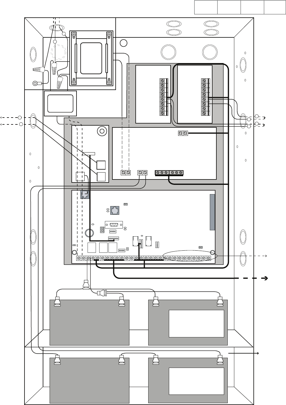
Model XR2500F Wiring Diagram
Refer to XR2500F Installation Guide (LT-0759) for a complete description of wiring connections.
Refer to XR500 Series Programming Guide (LT-0679) for complete programming instructions.
Refer to XR2500F User's Guide (LT-0760) for complete user instructions.
LT-0757 (4/05) © 2005
Digital Monitoring Products, Inc.
866
Module
#1
866
Module
#2
+ -
+-
+
+-
Two 12 VDC batteries
connected in series with the
included Series Connecting
Strap. See Secondary
Power Supply section.
12 VDC battery
12 VDC battery
12 VDC battery
Two 12 VDC batteries
connected in parallel with a
Model 318 Dual Battery
Harness. See Secondary
Power Supply section.
504-24 Secondary Power Supply
1.5 Amps maximum charge current.
Use only 24 VDC rechargeable batteries
or Two 12 VDC batteries with a Series
Connecting Strap.
Replace every 3 to 5 years.
XR2500F Secondary Power Supply
1 Amp maximum charge current.
Use only 12 VDC rechargeable batteries.
Replace every 3 to 5 years.
12 VDC battery
24 VDC
Circuit
Black
Red
To Fire Command Center on enclosure door
From XR2500F
panel to 12 VDC.
Black
Red
56 VA Transformer
charges 4 batteries
GREEN
WHITE
BLACK
GREEN
WHITE
BLACK
WHITE
BLACK
28 VAC
Transformer
+ DC -
+ Bat -
Red wire to positive
battery terminal. Black wire to negative
battery terminal.
AC
AC TRBL BATT TRBL
504-24
Power Supply
893A
P10
To Telco S
To Notification
Appliances
S
S
S
S
S= Supervised Wire
S
S
S
Battery Compartment
From 504-24 Power Supply to 24 VDC.
10K EOL
10K EOL
16 VAC
Transformer
Expansion Zones
