MA_H250_M40_en_4000640704_R04 Y5 1 Krohne H250 M40 Manual
User Manual:
Open the PDF directly: View PDF ![]() .
.
Page Count: 84
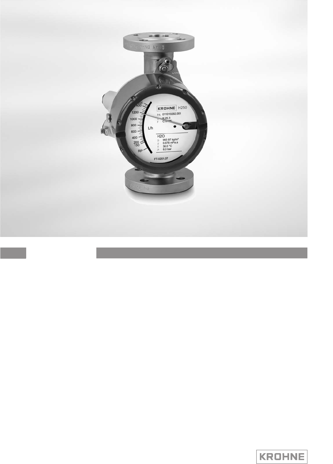
Variable area flowmeter
H250 M40
H250 M40H250 M40
H250 M40 Handbook
HandbookHandbook
Handbook
© KROHNE 07/2016 - 4000640704 - MA H250-M40 R04 en

All rights reserved. It is prohibited to reproduce this documentation, or any part thereof, without
the prior written authorisation of KROHNE Messtechnik GmbH.
Subject to change without notice.
2
www.krohne.com 07/2016 - 4000640704 - MA H250-M40 R04 en
Copyright 2016 by
KROHNE Messtechnik GmbH - Ludwig-Krohne-Str. 5 - 47058 Duisburg (Germany)
:
IMPRINT
:::::::::::::::::::::::::::::::::::::::

CONTENTS
3
www.krohne.com07/2016 - 4000640704 - MA H250-M40 R04 en
H250 M40
1 Safety instructions 5
1.1 Intended use ..................................................................................................................... 5
1.2 Certifications .................................................................................................................... 6
1.3 Pressure equipment directive.......................................................................................... 6
1.4 Safety instructions from the manufacturer ..................................................................... 8
1.4.1 Copyright and data protection ................................................................................................ 8
1.4.2 Disclaimer ............................................................................................................................... 8
1.4.3 Product liability and warranty ................................................................................................ 9
1.4.4 Information concerning the documentation........................................................................... 9
1.4.5 Warnings and symbols used................................................................................................. 10
1.5 Safety instructions for the operator............................................................................... 10
2 Device description 11
2.1 Scope of delivery............................................................................................................. 11
2.2 Device version................................................................................................................. 12
2.2.1 Indicator versions ................................................................................................................. 13
2.2.2 Float damping ....................................................................................................................... 15
2.2.3 Pointer damping.................................................................................................................... 15
2.3 Nameplate ...................................................................................................................... 16
2.4 Description code............................................................................................................. 17
2.5 Electronic revision.......................................................................................................... 18
3 Installation 19
3.1 Notes on installation ......................................................................................................19
3.2 Storage ........................................................................................................................... 19
3.3 Installation conditions ....................................................................................................20
3.3.1 Tightening torques................................................................................................................ 22
3.3.2 Magnetic filters ..................................................................................................................... 22
3.3.3 Heat insulation ...................................................................................................................... 23
4 Electrical connections 24
4.1 Security information.......................................................................................................24
4.2 Electrical connection indicator M40............................................................................... 25
4.2.1 Limit switches K1/K2 ............................................................................................................ 25
4.2.2 ESK4 / ESK4A current output ............................................................................................... 28
4.2.3 ESK4-T limit outputs............................................................................................................. 31
4.2.4 ESK4-T pulse output ............................................................................................................. 33
4.2.5 ESK4-T binary input .............................................................................................................. 34
4.2.6 ESK4-FF / ESK4-PA fieldbus communication...................................................................... 35
4.2.7 Harting HAN 7D connection.................................................................................................. 36
4.3 Grounding connections................................................................................................... 37
4.4 Ingress protection .......................................................................................................... 37

CONTENTS
4
www.krohne.com 07/2016 - 4000640704 - MA H250-M40 R04 en
H250 M40
5 Start-up 38
5.1 Standard device .............................................................................................................. 38
5.2 Indicator ESK4-T ............................................................................................................ 38
6 Operation 39
6.1 ESK4 / ESK4A - Loop Check Mode................................................................................. 39
6.2 Operating elements ESK4-T........................................................................................... 40
6.3 Basic principles of operation ESK4-T ............................................................................ 41
6.3.1 Description of the operating keys......................................................................................... 41
6.3.2 Navigation within the menu structure.................................................................................. 41
6.3.3 Change the settings in the menu..........................................................................................42
6.4 Overview of the units ESK4-T......................................................................................... 43
6.5 Error messages ESK4-T................................................................................................. 44
6.6 ESK4-T menu.................................................................................................................. 46
6.6.1 Factory settings .................................................................................................................... 46
6.6.2 Menu structure ..................................................................................................................... 47
6.6.3 Menu description .................................................................................................................. 49
7 Service 56
7.1 Maintenance ................................................................................................................... 56
7.2 Replacement and retrofitting......................................................................................... 56
7.2.1 Replacing floats .................................................................................................................... 56
7.2.2 Retrofitting float damping..................................................................................................... 57
7.2.3 Retrofitting limit switch ........................................................................................................ 57
7.2.4 Replacement - Retrofitting ESK4 / ESK4A ........................................................................... 58
7.2.5 Replacement - Retrofitting add-on module ESK4-T / PA / FF............................................. 59
7.3 Spare parts availability...................................................................................................59
7.3.1 List of spare parts................................................................................................................. 59
7.4 Availability of services .................................................................................................... 63
7.5 Returning the device to the manufacturer..................................................................... 63
7.5.1 General information.............................................................................................................. 63
7.5.2 Form (for copying) to accompany a returned device............................................................ 64
7.6 Disposal .......................................................................................................................... 64
8 Technical data 65
8.1 Functional principle........................................................................................................ 65
8.2 Technical data................................................................................................................. 66
8.3 Dimensions and weights ................................................................................................ 73
8.4 Measuring ranges...........................................................................................................76
SAFETY INSTRUCTIONS
1
5
H250 M40
www.krohne.com07/2016 - 4000640704 - MA H250-M40 R04 en
1.1 Intended use
The variable area flowmeters are suitable for measuring clean gases, vapours and liquids.
Intended use:
•The product may not contain any ferromagnetic particles or solids. It may be necessary to
install magnetic filters or mechanical filters.
•The product must be sufficiently liquid and free of deposits.
•Avoid pressure surges and pulsing flows.
•Open valves slowly. Do not use solenoid valves.
Use suitable measures to eliminate compression vibrations during gas
measurements:
•Short pipeline lengths to next restriction
•Nominal pipe size not greater than nominal device size
•Use of floats with damping
•Increase in operating pressure (while taking into account the resulting change in density and
thus change in scale)
Observe installation conditions according to VDI/VDE 3513-3.
CAUTION!
Responsibility for the use of the measuring devices with regard to suitability, intended use and
corrosion resistance of the used materials against the measured fluid lies solely with the
operator.
INFORMATION!
This device is a Group 1, Class A device as specified within CISPR11:2009. It is intended for use in
industrial environment. There may be potential difficulties in ensuring electromagnetic
compatibility in other environments, due to conducted as well as radiated disturbances.
INFORMATION!
The manufacturer is not liable for any damage resulting from improper use or use for other than
the intended purpose.
DANGER!
For devices used in hazardous areas, additional safety notes apply; please refer to the Ex
documentation.
CAUTION!
Do not use any abrasive media containing solid particles or highly viscous media.

1
SAFETY INSTRUCTIONS
6
H250 M40
www.krohne.com 07/2016 - 4000640704 - MA H250-M40 R04 en
1.2 Certifications
The device fulfils all applicable statutory requirements of the EU directives:
•Pressure equipment directive
•For devices with electrical installations: EMC directive
•Devices for use in hazardous areas: ATEX directive
as well as
•NAMUR recommendations NE 21, NE 43 and NE 107
The manufacturer certifies successful testing of the product by applying the CE mark.
A EU declaration of conformity regarding the directives in question and the associated
harmonised standards can be downloaded from our website.
1.3 Pressure equipment directive
A conformity assessment in accordance with pressure equipment directive has been carried out
for the devices described. Conformity is certified by applying the CE mark. The number of the
notified body is also stated.
The PED key describes the rating of the devices:
The PED key identification can be found on the nameplate of the device (for details refer to
Nameplate
on page 16).
CE marking
Example: PED/G1/III/H
G Gases and vapours
1Fluid group 1
III Category III
H Conformity assessment method according to Module H
INFORMATION!
The stated pressures (PS) and temperatures (TS) only apply as refers to the pressure resistance
of the sensor body. As regards the functionality of the entire device, further restrictions of the
maximum temperature may need to be observed (e.g. ATEX approval). Devices rated below
category I due to their size, do not receive the CE mark in the scope of the PED. These devices
are subject to applicable sound engineering practice (SEP).

SAFETY INSTRUCTIONS
1
7
H250 M40
www.krohne.com07/2016 - 4000640704 - MA H250-M40 R04 en
Residual risk
A risk analysis in accordance with the pressure equipment directive has been carried out for the
devices . The residual risk is described as follows:
•The devices are designed according to the valid and applicable rules and standards for static
operation and their pressure resistance is calculated for the declared maximum pressure
and temperature (no calculation for cyclical change).
•Responsibility for the use of the measuring devices with regard to corrosion resistance of the
used materials against the measured fluid lies solely with the operator.
•Avoid abrasion.
•Avoid pulsation and cavitation.
•Protect devices from vibration and high-frequency oscillation.
•Draining (backflow) may be delayed due to the float in the measuring tube.
•Implement appropriate measures to counteract external fire hazards

1
SAFETY INSTRUCTIONS
8
H250 M40
www.krohne.com 07/2016 - 4000640704 - MA H250-M40 R04 en
1.4 Safety instructions from the manufacturer
1.4.1 Copyright and data protection
The contents of this document have been created with great care. Nevertheless, we provide no
guarantee that the contents are correct, complete or up-to-date.
The contents and works in this document are subject to copyright. Contributions from third
parties are identified as such. Reproduction, processing, dissemination and any type of use
beyond what is permitted under copyright requires written authorisation from the respective
author and/or the manufacturer.
The manufacturer tries always to observe the copyrights of others, and to draw on works created
in-house or works in the public domain.
The collection of personal data (such as names, street addresses or e-mail addresses) in the
manufacturer's documents is always on a voluntary basis whenever possible. Whenever
feasible, it is always possible to make use of the offerings and services without providing any
personal data.
We draw your attention to the fact that data transmission over the Internet (e.g. when
communicating by e-mail) may involve gaps in security. It is not possible to protect such data
completely against access by third parties.
We hereby expressly prohibit the use of the contact data published as part of our duty to publish
an imprint for the purpose of sending us any advertising or informational materials that we have
not expressly requested.
1.4.2 Disclaimer
The manufacturer will not be liable for any damage of any kind by using its product, including,
but not limited to direct, indirect or incidental and consequential damages.
This disclaimer does not apply in case the manufacturer has acted on purpose or with gross
negligence. In the event any applicable law does not allow such limitations on implied warranties
or the exclusion of limitation of certain damages, you may, if such law applies to you, not be
subject to some or all of the above disclaimer, exclusions or limitations.
Any product purchased from the manufacturer is warranted in accordance with the relevant
product documentation and our Terms and Conditions of Sale.
The manufacturer reserves the right to alter the content of its documents, including this
disclaimer in any way, at any time, for any reason, without prior notification, and will not be liable
in any way for possible consequences of such changes.

SAFETY INSTRUCTIONS
1
9
H250 M40
www.krohne.com07/2016 - 4000640704 - MA H250-M40 R04 en
1.4.3 Product liability and warranty
The operator shall bear responsibility for the suitability of the device for the specific purpose.
The manufacturer accepts no liability for the consequences of misuse by the operator. Improper
installation or operation of the devices (systems) will cause the warranty to be void. The
respective "Standard Terms and Conditions" which form the basis for the sales contract shall
also apply.
1.4.4 Information concerning the documentation
To prevent any injury to the user or damage to the device it is essential that you read the
information in this document and observe applicable national standards, safety requirements
and accident prevention regulations.
If this document is not in your native language and if you have any problems understanding the
text, we advise you to contact your local office for assistance. The manufacturer can not accept
responsibility for any damage or injury caused by misunderstanding of the information in this
document.
This document is provided to help you establish operating conditions, which will permit safe and
efficient use of this device. Special considerations and precautions are also described in the
document, which appear in the form of icons as shown below.
1
SAFETY INSTRUCTIONS
10
H250 M40
www.krohne.com 07/2016 - 4000640704 - MA H250-M40 R04 en
1.4.5 Warnings and symbols used
Safety warnings are indicated by the following symbols.
• HANDLING
HANDLINGHANDLING
HANDLING
This symbol designates all instructions for actions to be carried out by the operator in the
specified sequence.
iRESULT
RESULTRESULT
RESULT
This symbol refers to all important consequences of the previous actions.
1.5 Safety instructions for the operator
DANGER!
This warning refers to the immediate danger when working with electricity.
DANGER!
This warning refers to the immediate danger of burns caused by heat or hot surfaces.
DANGER!
This warning refers to the immediate danger when using this device in a hazardous atmosphere.
DANGER!
These warnings must be observed without fail. Even partial disregard of this warning can lead to
serious health problems and even death. There is also the risk of seriously damaging the device
or parts of the operator's plant.
WARNING!
Disregarding this safety warning, even if only in part, poses the risk of serious health problems.
There is also the risk of damaging the device or parts of the operator's plant.
CAUTION!
Disregarding these instructions can result in damage to the device or to parts of the operator's
plant.
INFORMATION!
These instructions contain important information for the handling of the device.
LEGAL NOTICE!
This note contains information on statutory directives and standards.
WARNING!
In general, devices from the manufacturer may only be installed, commissioned, operated and
maintained by properly trained and authorized personnel.
This document is provided to help you establish operating conditions, which will permit safe and
efficient use of this device.
DEVICE DESCRIPTION
2
11
H250 M40
www.krohne.com07/2016 - 4000640704 - MA H250-M40 R04 en
2.1 Scope of delivery
INFORMATION!
Inspect the packaging carefully for damages or signs of rough handling. Report damage to the
carrier and to the local office of the manufacturer.
INFORMATION!
Do a check of the packing list to make sure that you have all the elements given in the order.
INFORMATION!
Look at the device nameplate to ensure that the device is delivered according to your order.
Check for the correct supply voltage printed on the nameplate.
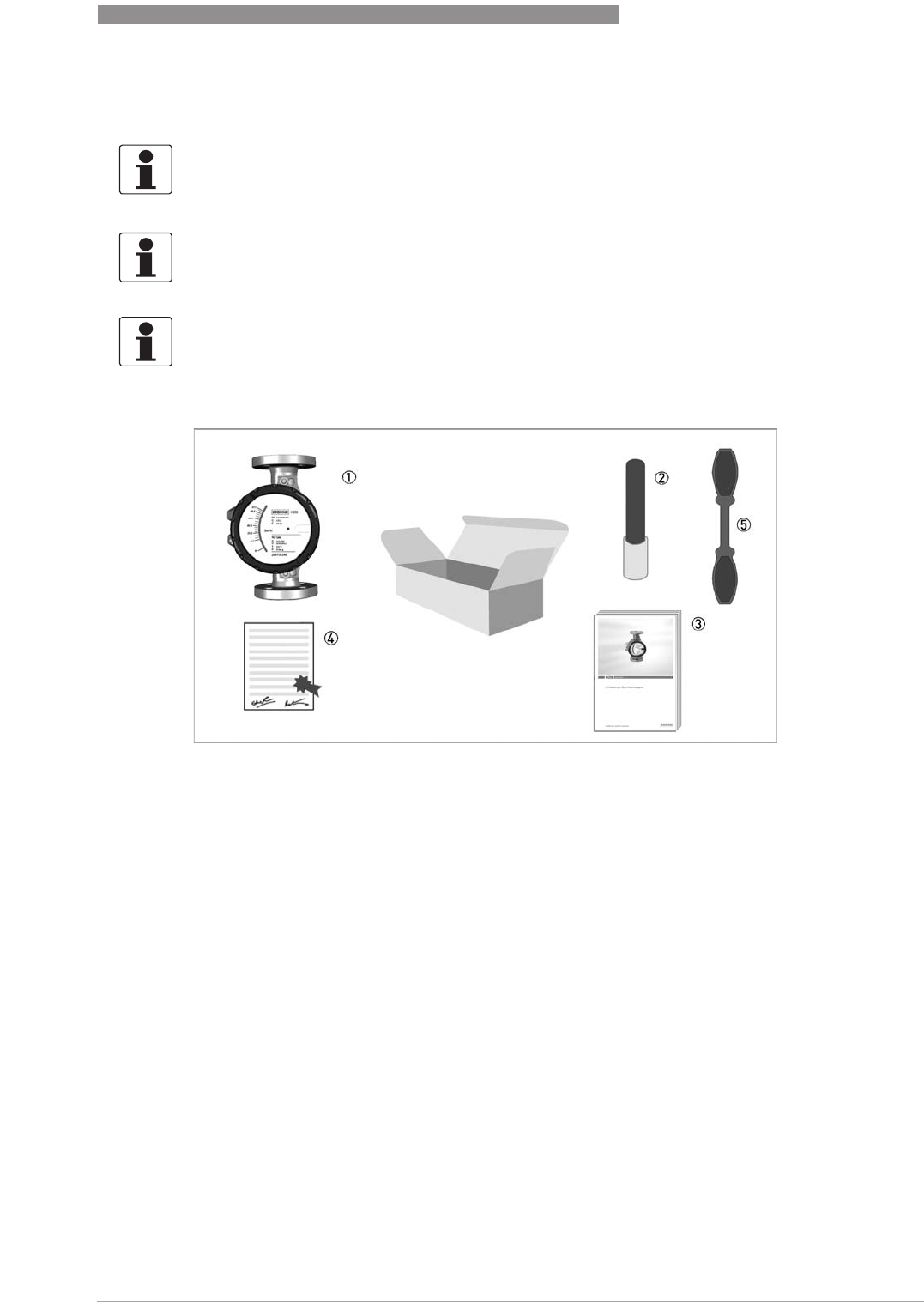
Figure 2-1: Scope of delivery
1 Measuring device in ordered version
2 For the ESK4-T version - bar magnet
3 Documentation
4 Certificates, calibration report (supplied to order only)
5 Wrench
2
DEVICE DESCRIPTION
12
H250 M40
www.krohne.com 07/2016 - 4000640704 - MA H250-M40 R04 en
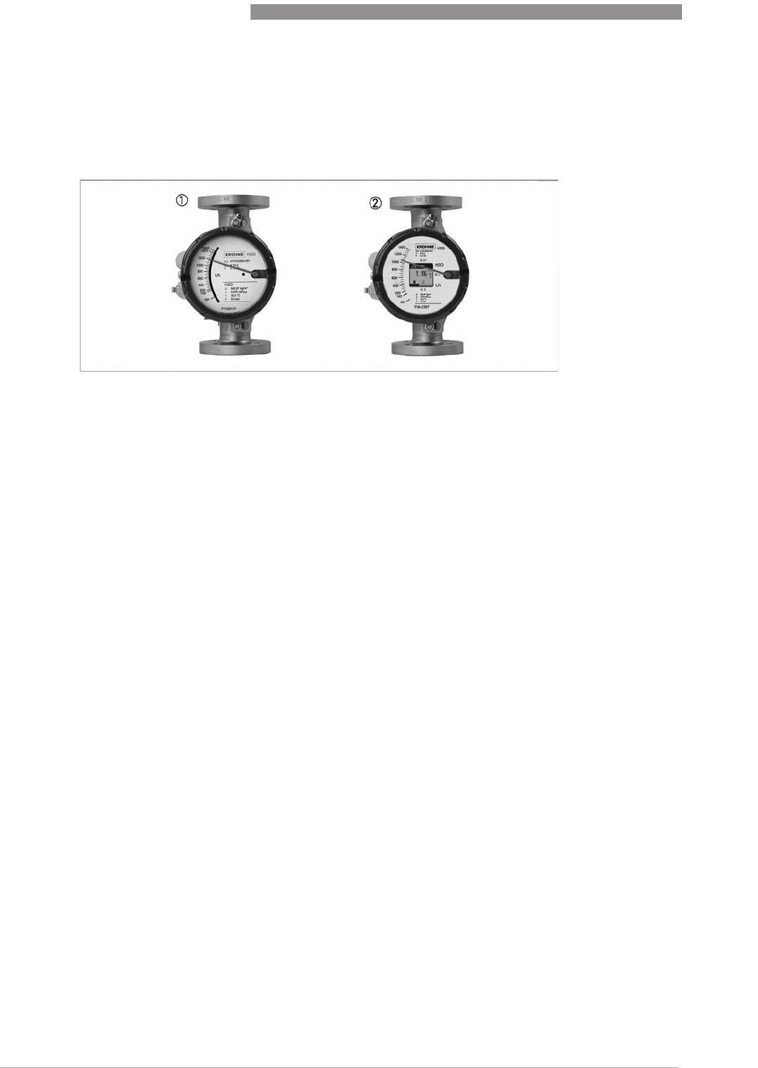
2.2 Device version
•H250 with indicator M40
•H250 with M40 indicator with display cut-out for ESK4-T
1. H250/RR/M40
•Local indicator without auxiliary power
•Max. 2 limit switches, type NAMUR, NAMUR safety-oriented or transistor (3-wire)
•Electrical signal output 4...20 mA, HART
®
or Fieldbus communication
•Intrinsically safe (Ex i) or in explosion-proof enclosure (Ex d)
2. H250/RR/M40
•Additional LCD, measured value and/or flow counter
•2 configurable binary outputs, limit value or pulse output
•1 binary input, Start / Stop / Reset flow counter
•2-wire current output 4…20 mA, HART
®
communication
•Intrinsically safe (Ex i) or in explosion-proof enclosure (Ex d)
Optional versions:
•H250 with indicator M40 as high temperature version HT
•H250 with indicator M40 with increased corrosion protection (special paint finish)
•H250H for use in horizontal pipelines
•H250U for use in vertical fall pipes
•H250F with hygienic measuring tube design for Food & Pharma
•H250C with PTFE / TFM liner for aggressive media
Display options
•M40 - Aluminium, single-layer powder coating (polyester)
•M40S - Aluminium, two-layer powder coating (epoxy / polyester)
•M40R - Stainless steel without coating
Offshore wet coating for aluminium or stainless steel on request
DEVICE DESCRIPTION
2
13
H250 M40
www.krohne.com07/2016 - 4000640704 - MA H250-M40 R04 en
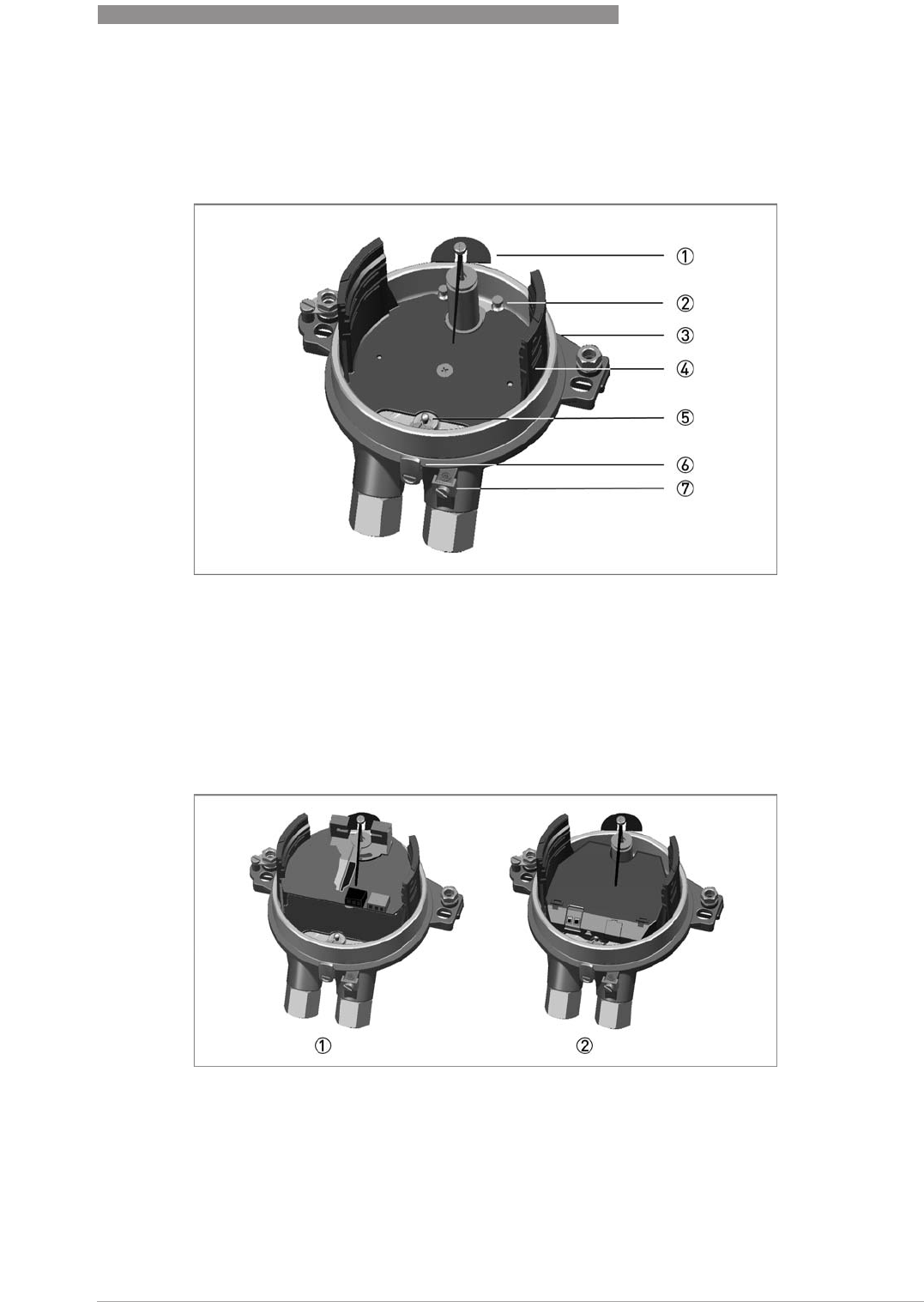
2.2.1 Indicator versions
The M40 indicator can be fitted with various modules.
Both versions can be combined with one another.
Basic version
1 Pointer module
2 Bolts for ESK4 / ESK4A attachment
3 Baseplate
4 Module profile
5 Pressure piece for ESK4 / ESK4A attachment
6 Housing cover locking device
7 Earth terminal external
Versions K1 / K2 and ESK4 / ESK4A
1 Indicator with K2 contact module
2 Indicator with ESK4 / ESK4A current output 4...20 mA
2
DEVICE DESCRIPTION
14
H250 M40
www.krohne.com 07/2016 - 4000640704 - MA H250-M40 R04 en
For more details see the supplementary instructions "H250 M40 Foundation Fieldbus"
and "H250 M40 Profibus PA"
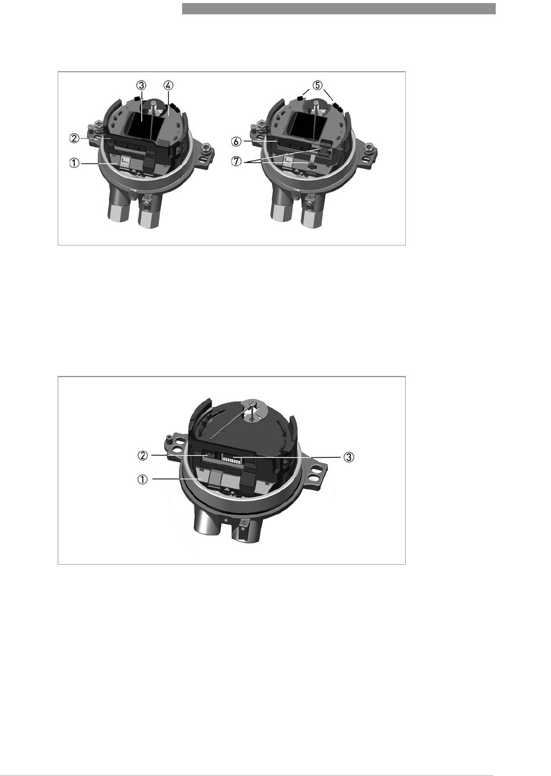
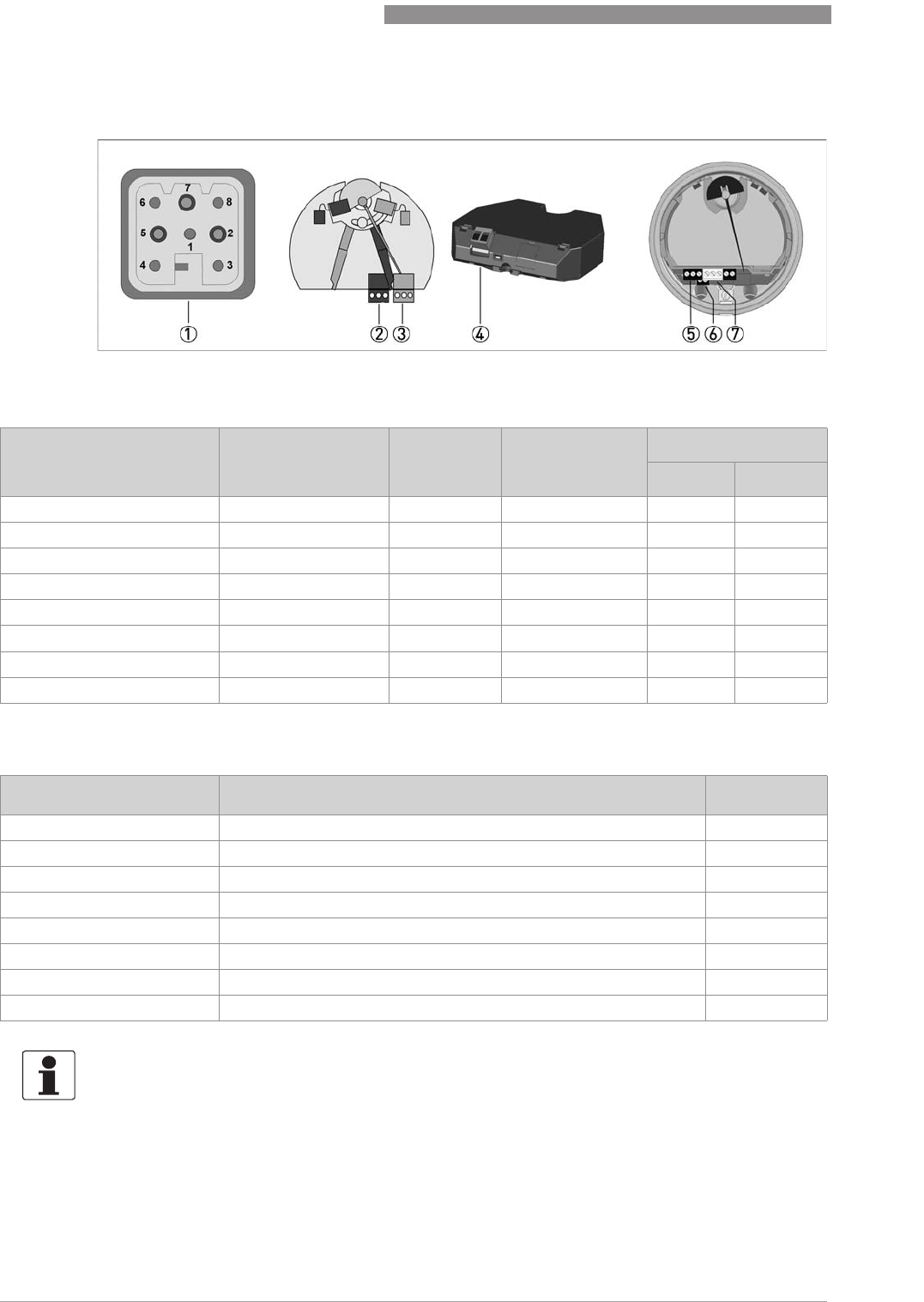
Version ESK4-T
1 ESK4 / ESK4A connection
2 Module cover
3 Display
4 Display module ESK4-IO
5 Operating keys ^ ↑
6 Connection binary outputs and reset input
7 Module connection cable
Version Fieldbus ESK4-FF / ESK4-PA
1 Basic module with electronic magnet sensors ESK4 / ESK4A
2 Connection bus module
3 DIP switch for bus settings
DEVICE DESCRIPTION
2
15
H250 M40
www.krohne.com07/2016 - 4000640704 - MA H250-M40 R04 en
2.2.2 Float damping
Float damping is characterised by high standstill times and self-centering. The damping sleeve
is made of high performance ceramic or PEEK, depending on the medium and the application.
Float damping can also be retrofitted for the user (refer to "Service").
Use of damping
•Generally when CIV and DIV floats are used for gas measurement.
•For TIV floats (H250/RR and H250/HC only) with an operating primary pressure:
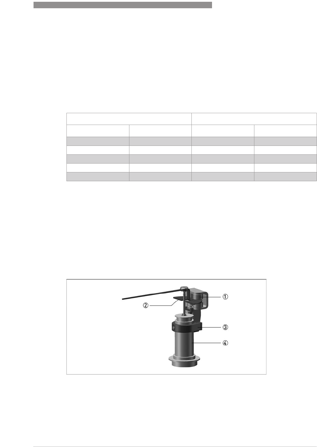
2.2.3 Pointer damping
In principle, the indicating element with its magnetic system contains indicator damping. An
additional eddy current brake is advantageous in the event of fluctuating or pulsing flows. The
magnets on the eddy current brake surround the pointer vane without touching it, damping its
movement. The result is a much steadier pointer position, without distorting the measured
value. A turnbuckle ensures a proper fit. The eddy current brake can be retrofitted during
operation without recalibrating (refer to "Service").
Nominal size acc. to Operating primary pressure
EN 1092-1 ASME B16.5 [bar] [psig]
DN 50 ½"≤0.3 ≤4.4
DN25 1" ≤0.3 ≤4.4
DN50 2" ≤0.2 ≤2.9
DN80 3" ≤0.2 ≤2.9
DN 100 4" ≤0.2 ≤2.9
1 Eddy current brake
2 Pointer vane
3 Bracket
4 Pointer cylinder
2
DEVICE DESCRIPTION
16
H250 M40
www.krohne.com 07/2016 - 4000640704 - MA H250-M40 R04 en
2.3 Nameplate
Additional markings on the indicator
•SN - serial number
•SO - sales order / item
•PA - production order
•Vx - product configurator code
•AC - article code
INFORMATION!
Check on the device nameplates, that the device is supplied according to your order.
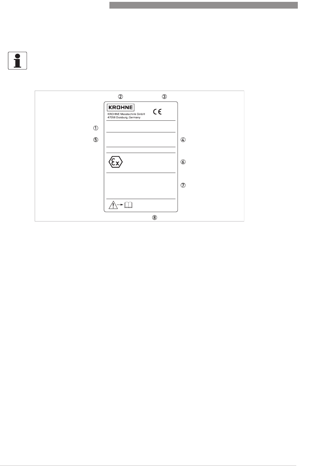
Figure 2-2: Nameplate on the indicator
1 Device type
2 Manufacturer
3 Notified body ATEX & PED
4 Rating data: temperature & pressure rating
5 PED data
6 Ex data
7 Electrical connection data
8 Internet site
www.krohne.com
Tag-No.:
ESK...
Kmin1
Kmin2
Ui = xxV Ii = xxmA Pi = xW
Ci = xxnF Li = xuH
Ui = xxV Ii = xxmA Pi = xW
Ci = xxnF Li = xuH
Ui = xxV Ii = xxmA Pi = xW
Ci = xxnF Li = xuH
PTB 11 ATEX 2012 X
II2G Ex ia IIC T6
T
amb
: -20°C... +60°C (T6: +40°C)
H250/.././M40/..-Ex
P/A: 011123456.001
PED/G1/II/H
PTmax: xxx bar
MD:201x
PS: xxx bar
TS: xx °C
0035
0102
IECEx PTB 11.0069 X

DEVICE DESCRIPTION
2
17
H250 M40
www.krohne.com07/2016 - 4000640704 - MA H250-M40 R04 en
2.4 Description code
The description code* consists of the following elements:
* positions which are not needed are omitted (no blank positions)
1 Device type
H250 - standard version
H250H - horizontal flow direction
H250U - flow direction from top to bottom
2 Materials / versions
RR - stainless steel
C - PTFE or PTFE/ceramics
HC - Hastelloy
®
Ti - Titanium
Mo - Monel
F - aseptic version (food)
3 Heating jacket version
B - with heating jacket
4 Type series of indicators
M40 - Indicator M40
M40S - indicator with increased corrosion protection
M40R - indicator in stainless steel housing
5 High temperature version
HT - version with HT extension
6 Electrical signal output
ESK - electrical signal output 4...20 mA (ESK4 / ESK4A)
- optionally available with counter, I/O module and display (ESK4-T) or
- Foundation Fieldbus (ESK4-FF) or
- Profibus PA (ESK4-PA)
7 Limit switches
K1 - one limit switch
K2 - two limit switches
8 Explosion protection
Ex -explosion proof equipment
9 SIL version
SE - SIL compliant electronic signal output
SK - SIL compliant limit switch

2
DEVICE DESCRIPTION
18
H250 M40
www.krohne.com 07/2016 - 4000640704 - MA H250-M40 R04 en
2.5 Electronic revision
The electronic revision (sticker on the base module ESK4 / ESK4A) indicates the respective
hardware/software status of the electronics. All add-on modules (ESK4-T, ESK4-FF and ESK4-
PA) have an additional sticker indicating their respective firmware version.
Electronic revision Explanations
ER 1.1.x Basic version (cannot be combined with other indicator versions):
ESK4 / current output 4…20 mA with HART
®
communication
(ESK4 HART DD 01.01. AMS10x AMS11x
ESK4 HART DD 01.01. PDM6.0
ESK4 HART DTM 1.0.3 FDT1.2)
ER 2.0.x Functional add-on to ER 1.1.x:
can be combined with indicator version ESK4 FF / Foundation Fieldbus;
(Firmware version FF module from 1.0.2)
ER 2.1.x Functional add-on to ER 2.0.x
can be combined with indicator version ESK4-PA / Profibus PA
(Firmware version PA module from 1.0.0)
can be combined with indicator version ESK4-T / LCD, binary inputs/outputs
(Firmware version T module from 1.1.0)
ER 2.2.x Functional add-on to ER 2.1.x:
Support of failure signal (low) according to NE 43
for the ESK4 current output module
ER 3.0.x Functional add-on:
Update for HART
®
communication from 5.9 to 7.4 including new DD/DTM
can be combined with ESK4-FF (Firmware version FF module from 1.0.2)
Firmware Version ESK4-PA (... PA module from 1.0.0)
Firmware Version ESK4-T (... T module from 1.2.0)

INSTALLATION
3
19
H250 M40
www.krohne.com07/2016 - 4000640704 - MA H250-M40 R04 en
3.1 Notes on installation
3.2 Storage
•Store the device in a dry, dust-free location.
•Avoid lasting direct exposure to the sun.
•Store the measuring device in the original packaging.
•The permissible storage temperatures for standard devices are: -40...+80°C / -40...+176°F
INFORMATION!
Inspect the packaging carefully for damages or signs of rough handling. Report damage to the
carrier and to the local office of the manufacturer.
INFORMATION!
Do a check of the packing list to make sure that you have all the elements given in the order.
INFORMATION!
Look at the device nameplate to ensure that the device is delivered according to your order.
Check for the correct supply voltage printed on the nameplate.

3
INSTALLATION
20
H250 M40
www.krohne.com 07/2016 - 4000640704 - MA H250-M40 R04 en
3.3 Installation conditions
CAUTION!
When installing the device in the piping, the following points must be observed:
•
The variable area flowmeter must be installed vertically (measuring principle). Flow direction
from bottom to top. For installation recommendations please refer also to directive
VDI/VDE 3513, sheet 3.
H250Hs are installed horizontally and H250U devices are installed vertically with the flow
direction from top to bottom.
•
A straight unimpeded inlet run of ≥5 DN upstream of the device and a straight outlet run of
≥3 DN downstream of the device are recommended.
•
Screws, bolts and gaskets are to be provided by the customer and must be selected in
accordance with the pressure rating of the connection or the operating pressure.
•
The inside diameter of the flange deviates from the standard dimensions. Flange seal
standard DIN 2690 can be applied without any limitation.
•
Align the gaskets. Tighten the nuts with the tightening torques of the appropriate pressure
rating.
For devices with PTFE liner or ceramic liner and PTFE raised faces, refer to chapter
"Tightening torques".
•
Control devices are to be positioned downstream of the measuring device.
•
Shutoff devices are preferably to be positioned upstream of the measuring device.
•
Before connecting, blow or flush out the pipes leading to the device.
•
Pipes for gas flow need to be dried before the device is installed.
•
Use connectors suitable for the particular device version.
•
Align the pipes centrically with the connection bores on the measuring device so they are free
of stresses.
•
If necessary, the piping has to be supported to reduce the vibrations transmitted to the
measuring device.
•
Do not lay signal cables directly next to cables for the power supply.
INSTALLATION
3
21
H250 M40
www.krohne.com07/2016 - 4000640704 - MA H250-M40 R04 en
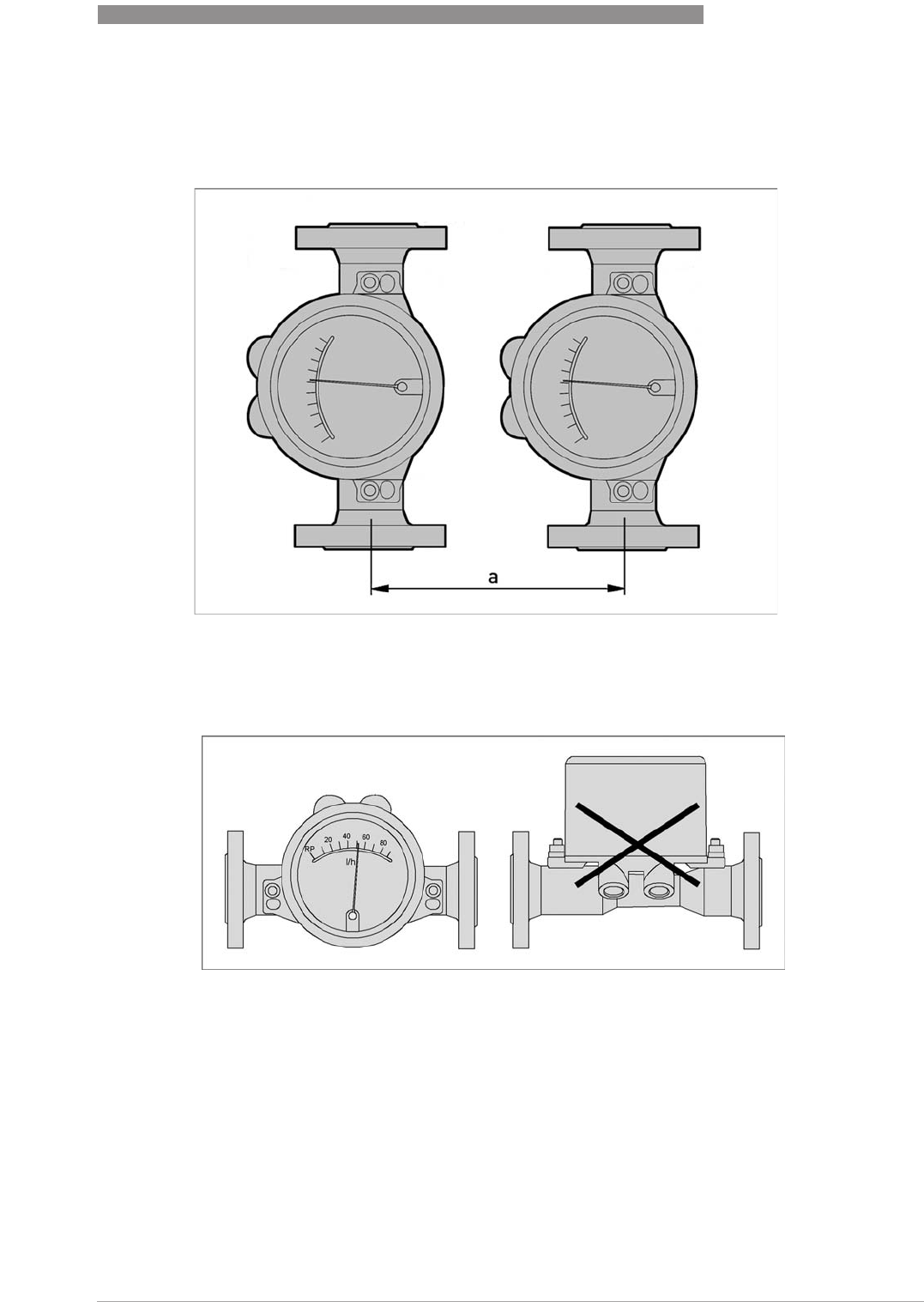
Minimum distance between devices
When several devices are installed next to one another, a minimum distance of a > 300 mm /
11.8" between the devices is necessary.
Take special note of the installation position for the H250H with horizontal flow
direction:
In order to comply with thermal parameters and measuring accuracy, H250H flowmeters for
horizontal installation are to be installed in the pipeline so that the display is located on the side
of the measuring tube. The maximum product and ambient temperatures indicated as well as
the measuring accuracy are based on lateral installation of the display.
3
INSTALLATION
22
H250 M40
www.krohne.com 07/2016 - 4000640704 - MA H250-M40 R04 en
3.3.1 Tightening torques
For measuring devices with PTFE liner or ceramic liner and PTFE raised face, tighten the flange
threads with the following torques:
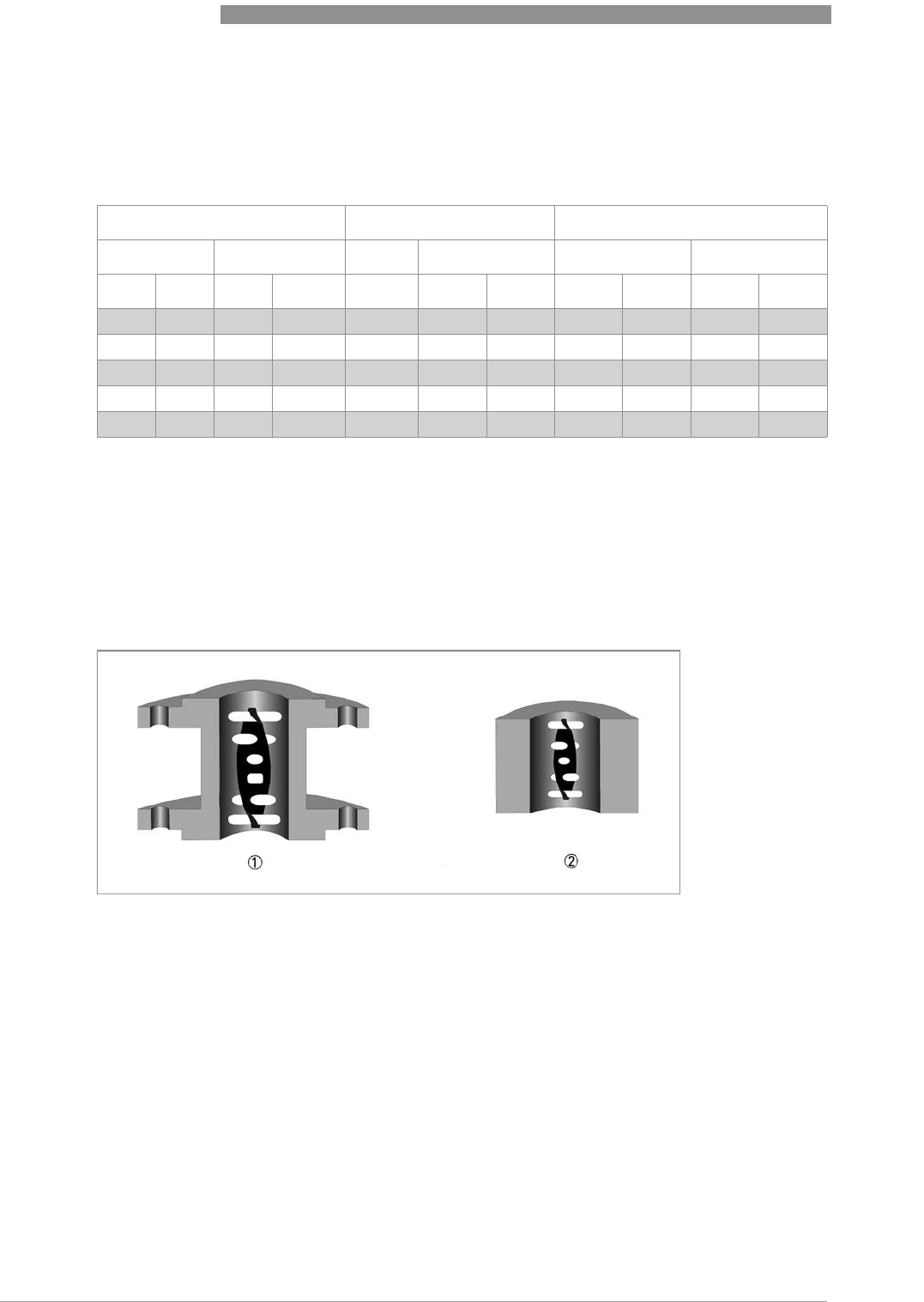
3.3.2 Magnetic filters
The use of magnetic filters is recommended when the medium contains particles which can be
influenced magnetically. The magnetic filter is to be installed in the flow direction upstream of
the flowmeter. Bar magnets are positioned helically in the filter to provide optimal efficiency at
low pressure loss. All of the magnets are coated individually with PTFE to protect against
corrosion. Material: 1.4404/316L
Nominal size acc. to Stud bolts Max. torque
EN 1092-1 ASME B16.5 EN ASME EN 1092-1 ASME 150 lb
DN PN Inch lb 150 lb 300 lb Nm ft*lbf Nm ft*lbf
15 40 ½"150/300 4x M12 4x ½"4x ½"9.8 7.1 5.2 3.8
25 40 1" 150/300 4x M12 4x ½"4x 5/8" 21 15 10 7.2
50 40 2" 150/300 4x M16 4x 5/8" 8x 5/8" 57 41 41 30
80 16 3" 150/300 8x M16 4x 5/8" 8x ¾"47 34 70 51
100 16 4" 150/300 8x M16 8x 5/8" 8x ¾"67 48 50 36
Magnetic filters
1 Type F - fitting part with flange - overall length 100 mm / 4"
2 Type FS - fitting part without flange - overall length 50 mm / 2"
INSTALLATION
3
23
H250 M40
www.krohne.com07/2016 - 4000640704 - MA H250-M40 R04 en
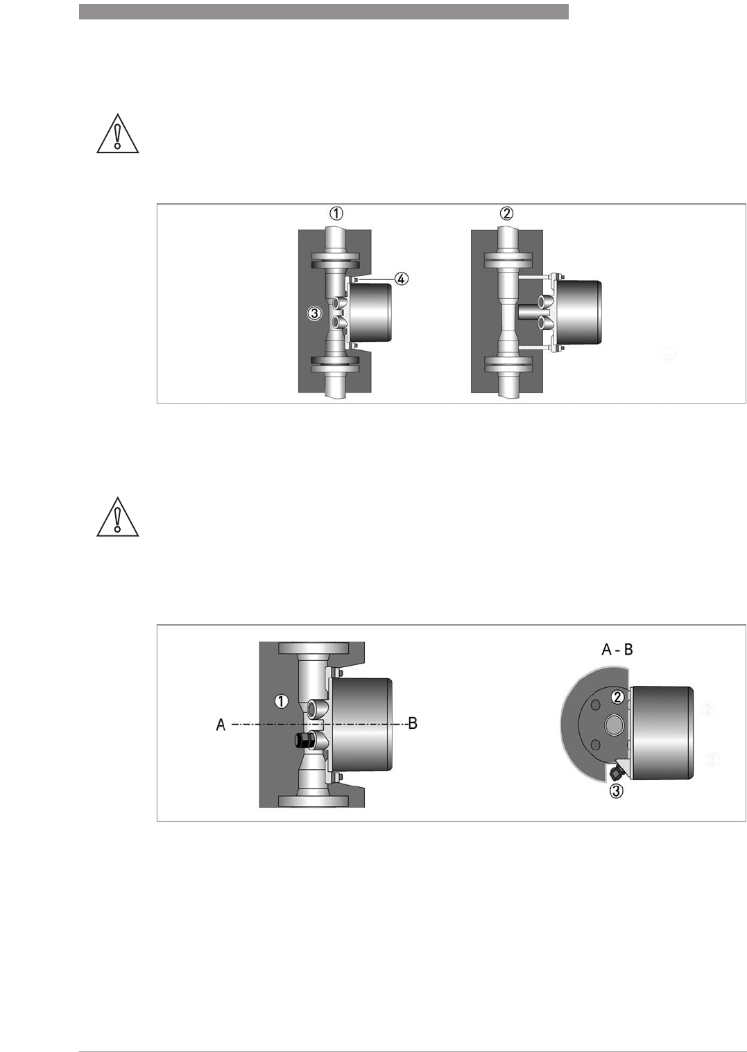
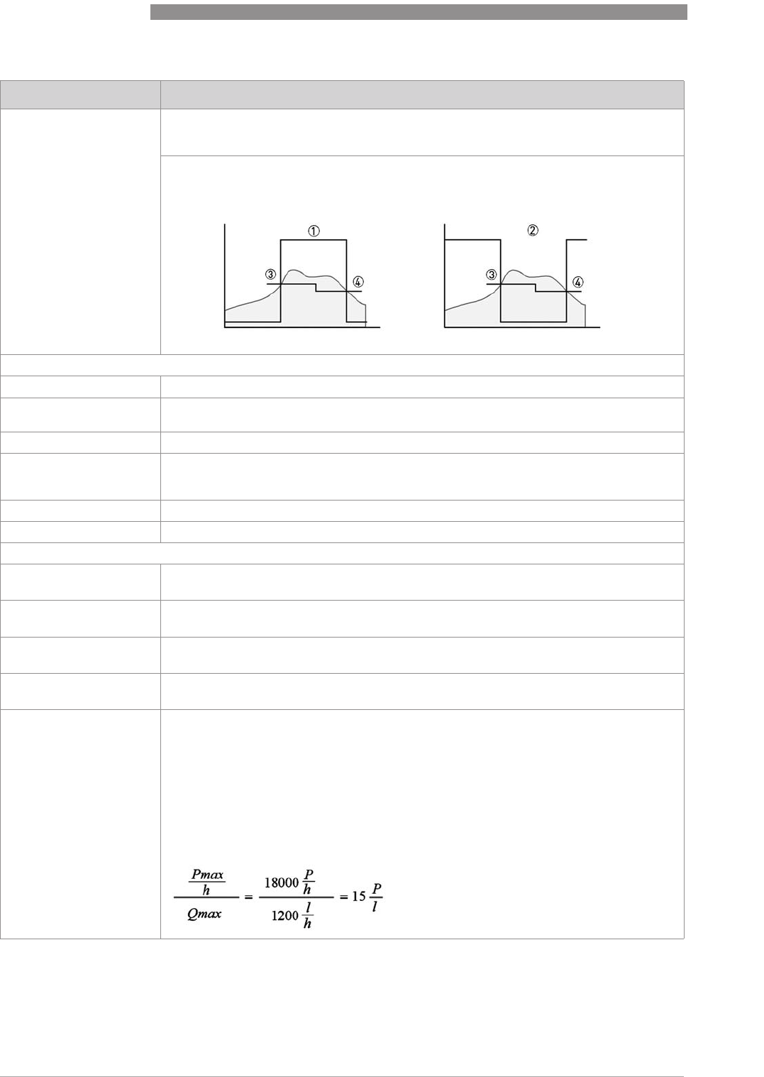
3.3.3 Heat insulation
CAUTION!
The indicator housing may not be heat-insulated.
The heat insulation 3 may only reach to the housing mounting 4.
1 Standard indicator M40
2 Indicator with HT extension
CAUTION!
The heat insulation 1 may only reach to the rear of the housing 2. The area around the cable
entries 3 must be freely accessible.
Figure 3-1: Insulation - cross section
4
ELECTRICAL CONNECTIONS
24
H250 M40
www.krohne.com 07/2016 - 4000640704 - MA H250-M40 R04 en
4.1 Security information
DANGER!
All work on the electrical connections may only be carried out with the power disconnected. Take
note of the voltage data on the nameplate!
DANGER!
Observe the national regulations for electrical installations!
DANGER!
For devices used in hazardous areas, additional safety notes apply; please refer to the Ex
documentation.
WARNING!
Observe without fail the local occupational health and safety regulations. Any work done on the
electrical components of the measuring device may only be carried out by properly trained
specialists.
INFORMATION!
Look at the device nameplate to ensure that the device is delivered according to your order.
Check for the correct supply voltage printed on the nameplate.
ELECTRICAL CONNECTIONS
4
25
H250 M40
www.krohne.com07/2016 - 4000640704 - MA H250-M40 R04 en
4.2 Electrical connection indicator M40
4.2.1 Limit switches K1/K2
The M40 indicator can be fitted with a maximum of two limit switches. The limit switch works as
a slot sensor which is inductively activated via the semi-circular metal vane of the pointer. The
switching points are set using the contact pointers. The position of the contact pointers is
indicated on the scale.
The connection terminals have a pluggable design and can be removed to connect the cables.
The built-in limit switch types are shown on the nameplate of the indicator.
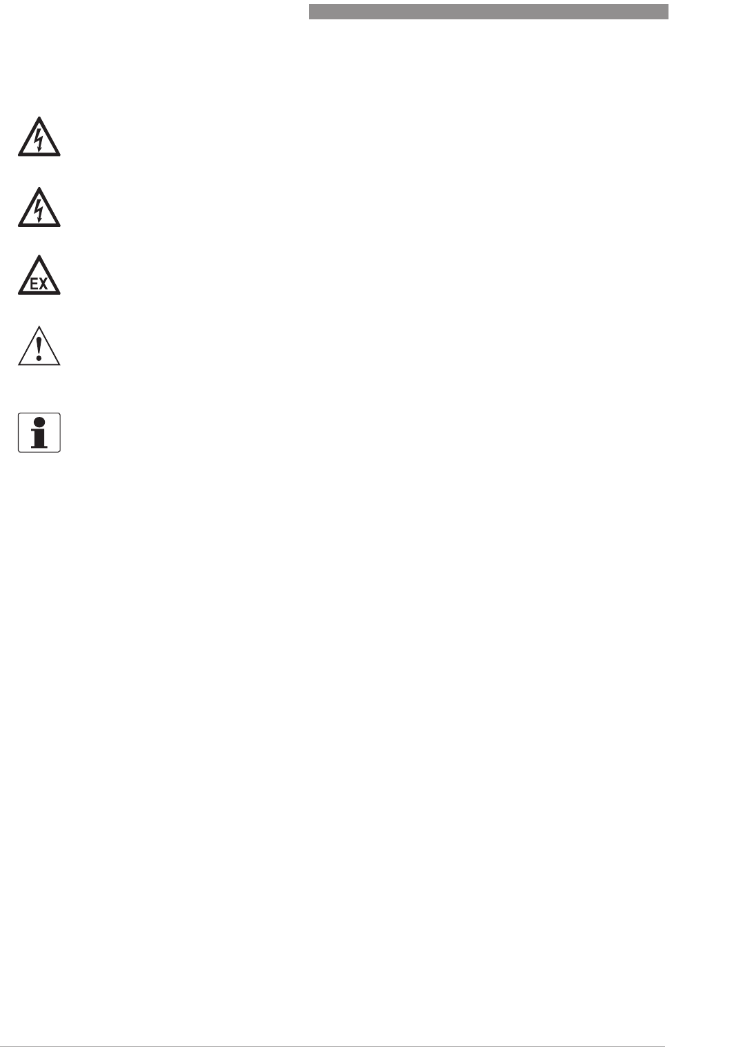
Electrical connection of the limit switches
Limit switch module
1 Min. contact
2 Max. contact
3 Locking screw
4 Maximum pointer
5 Connection terminal
Contact MIN MAX
Terminal no. 123456
Connection 2-wire NAMUR - + - +
Connection 3-wire + - + -
Connection Reed SPST + - + -
4
ELECTRICAL CONNECTIONS
26
H250 M40
www.krohne.com 07/2016 - 4000640704 - MA H250-M40 R04 en
Setting is carried out directly via contact pointers 1 and 2:
• Slide the scale aside.
• Loosen the locking screw 3 slightly.
• Slide the scale back to the latching point.
• Set contact pointers 1 and 2 to the desired switching point.
After setting:
After setting:After setting:
After setting: Fix the contact pointers with the locking screw 3.
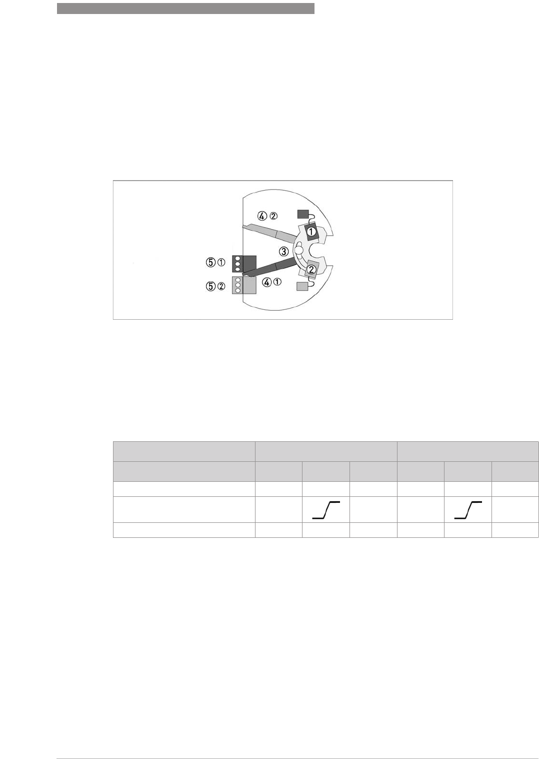
Limit switch connection terminals
1 2-wire limit switch NAMUR
2 3-wire limit switch
3 Limit switch Reed SPST
4 Terminal connection of Min. contact
5 Terminal connection of Max. contact
6 3-wire load
7 NAMUR isolated switching amplifier
8 3-wire power supply
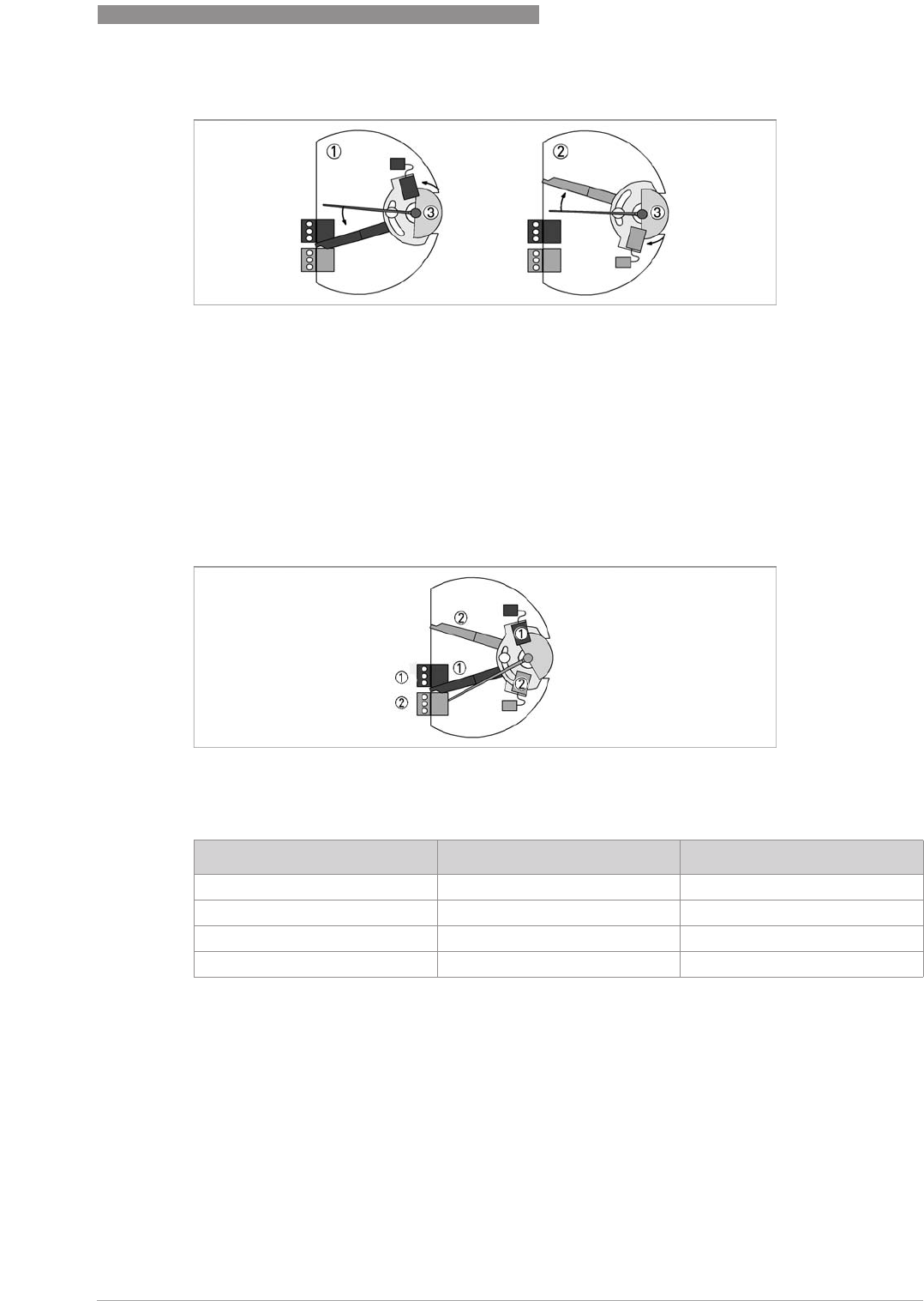
Limit setting
Figure 4-1: Limit switch settings
1 Contact pointer MAX
2 Contact pointer MIN
3 Locking screw
ELECTRICAL CONNECTIONS
4
27
H250 M40
www.krohne.com07/2016 - 4000640704 - MA H250-M40 R04 en
If the pointer vane goes into the slot, an alarm is triggered. If the pointer vane is outside of the
proximity switch, a wire break in a NAMUR contact also triggers the alarm.
The 3-wire limit switch does not have any wire break detection.
Current consumption in the position shown:
Switch contact definition
1 MIN contact
2 MAX contact
3 Pointer vane with switching vane
Definition MinMin - MaxMax
1 MIN 2 contact or MAX 1 contact
2 MIN 1 contact or MAX 2 contact
Contact Type Current
MIN 1 NAMUR ≤ 1mA
MIN 2 NAMUR ≤ 1mA
MAX 1 NAMUR ≥ 3mA
MAX 2 NAMUR ≥ 3mA
4
ELECTRICAL CONNECTIONS
28
H250 M40
www.krohne.com 07/2016 - 4000640704 - MA H250-M40 R04 en
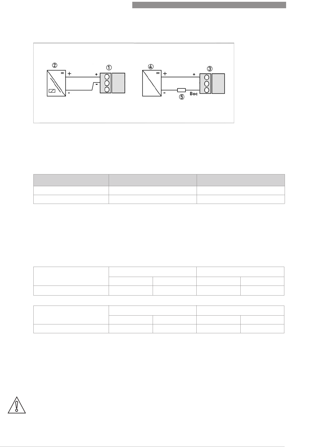
4.2.2 ESK4 / ESK4A current output
The connecting terminals of the ESK4 / ESK4A have a pluggable design and can be removed in
order to connect the cables.
Power supply M40 with galvanic isolation
Power supply M40 with galvanic isolationPower supply M40 with galvanic isolation
Power supply M40 with galvanic isolation
Wiring must be planned with great care when it comes to connecting other devices such as
evaluation units or process control. Internal connections in these devices (e.g. GND with PE,
mass loops) may lead to non-permitted voltage potentials which could negatively affect the
function of the converter itself or that of a device connected to it. In such cases a protected extra-
low voltage (PELV) is recommended.
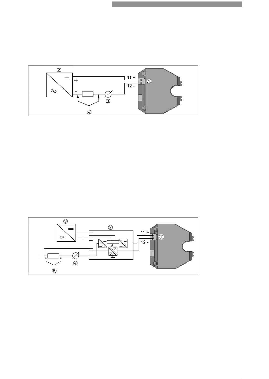
ESK4 / ESK4A connection
1 Current output of ESK4 / ESK4A
2 Power supply 14...30 VDC
3 Measuring signal 4...20 mA
4 External load, HART
®
communication
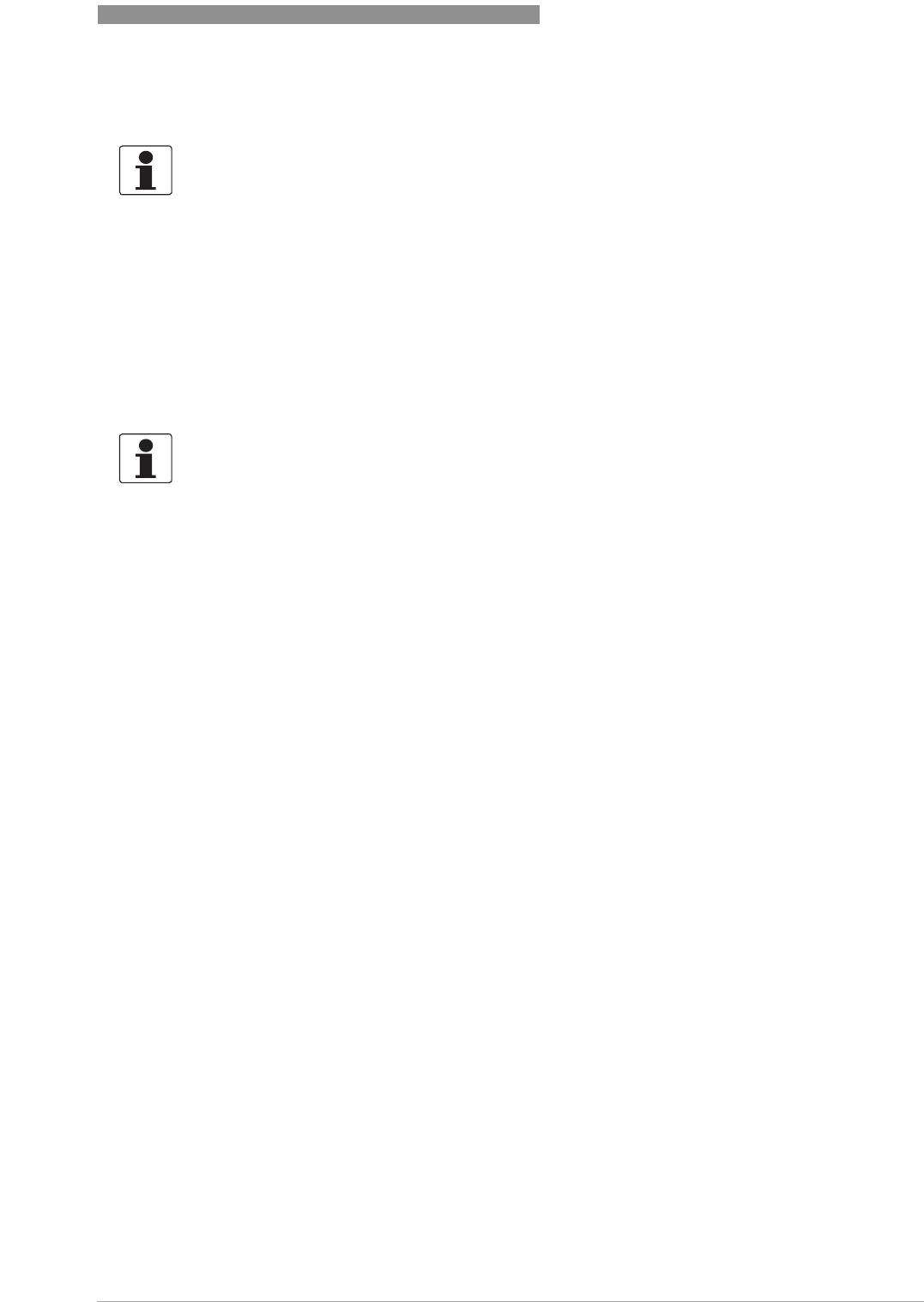
1 Terminal connection
2 Converter isolator with galvanic isolation
3 Power supply (refer to isolator information)
4 Measuring signal 4...20 mA
5 External load, HART
®
communication
ELECTRICAL CONNECTIONS
4
29
H250 M40
www.krohne.com07/2016 - 4000640704 - MA H250-M40 R04 en
Power supply
Power supplyPower supply
Power supply
The required supply voltage can be calculated using the formula below:
U
ext.
= R
L
* 24 mA + 14 V
with
U
ext.
= minimum supply voltage
R
L
= total measuring loop resistance
HART
HARTHART
HART® communication
When HART
®
communication is carried out with the ESK4, the analogue measured data
transmission (4...20 mA) is not impaired in any way.
Exception for multidrop operation. In multidrop operation a maximum of 15 devices with HART
®
function can be operated in parallel, whereby their current outputs are switched to inactive
(I approx. 4 mA per device).
INFORMATION!
The supply voltage has to be between 14 VDC and 30 VDC. This is based on the total resistance of
the measuring loop. To calculate this, the resistance of each component in the measuring loop
(not including the device) must be added together.
INFORMATION!
The power supply has to be able to supply a minimum of 30 mA.
4
ELECTRICAL CONNECTIONS
30
H250 M40
www.krohne.com 07/2016 - 4000640704 - MA H250-M40 R04 en
Load for HART® communication
The maximum load resistance is calculated as follows:
Configuration
The ESK can be configured via HART
®
communication. DD (Device Description) for AMS and PDM
as well as a DTM (Device Type Manager) for PACTware
TM
are available for configuration. They
can be downloaded free of charge from the website of the manufacturer.
The current flow rate can be transmitted using the integrated HART
®
communication. A flow
counter can be configured. Two limit values can be monitored. The limit values are assigned
either to flow values or to the counter overflow.
Self monitoring - Diagnostics
During both start-up and operation, a wide variety of diagnostic functions are performed
cyclically in the ESK4 / ESK4A in order to guarantee function reliability. When an error is
detected, a failure signal (high) is activated (current > 21 mA, typically 22 mA) via the analogue
output. In addition more detailed information can be requested via HART
®
(CMD#48). The failure
signal is not activated for information and warnings.
Diagnostic functions (Monitoring):
•Plausibility of FRAM data
•Plausibility of ROM data
•Working range of internal reference voltages
•Signal detection of the measuring range of the internal sensors
•Temperature compensation of the internal sensors
•Calibration based on the application
•Plausibility of counting value
•Plausibility of physical unit, system and selected unit
For ESK4A (HART
®
7) the diagnosis is reported in compliance with NE 107.
INFORMATION!
For HART
®
communication a load of at least 230 Ω is required.
DANGER!
Use a twisted two-core cable to prevent electrical interference from impeding the DC output
signal.
In some cases a shielded cable may be necessary, e.g if noise levels higher than the NE 21
specification are anticipated.
ELECTRICAL CONNECTIONS
4
31
H250 M40
www.krohne.com07/2016 - 4000640704 - MA H250-M40 R04 en
4.2.3 ESK4-T limit outputs
Once the housing cover has been unscrewed, the scale can be removed. The connection
terminals have a pluggable design and can be removed to connect the cables.
The binary inputs/outputs are electrically isolated from each other and from the ESK4 / ESK4A
current output.
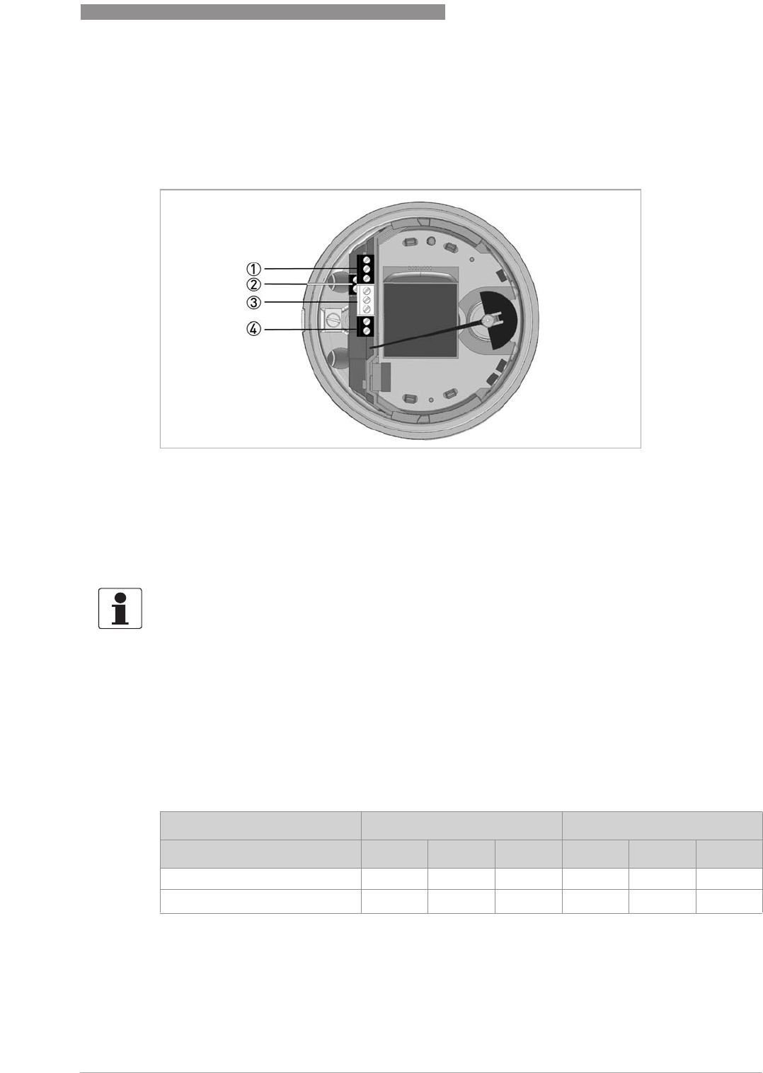
Connection binary outputs
Connection binary outputsConnection binary outputs
Connection binary outputs
In accordance with the desired signal transmission, select one of the following connection types
for binary outputs B1 and B2:
•NAMUR (DC interface acc. to EN 60947-5-6)
•Transistor output (passive, Open Collector)
1 Binary output 1
2 ESK4 / ESK4A power supply / current output
3 Binary output 2
4 Binary input
INFORMATION!
The binary inputs/outputs can only be operated if the power supply is applied to ESK4 / ESK4A
terminal 11+ and 12-. The binary inputs/outputs are inactive by default and must thus be
activated prior to first use (for details refer to ESK4-T menu on page 46
).
Binary output B1 B2
Terminal no. 123456
Connection NAMUR + - + -
Connection transistor output + B
OC
+ B
OC
4
ELECTRICAL CONNECTIONS
32
H250 M40
www.krohne.com 07/2016 - 4000640704 - MA H250-M40 R04 en
Value range for NAMUR
Value range applies only when connected to a switching amplifier with the following
reference values:
•Open-circuit voltage U
0
= 8.2 VDC
•Internal resistance R
i
= 1 kΩ
Value range for transistor output
To ensure the value ranges, a load R
L
between 250 Ω and 1 kΩ is recommended for the passive
transistor output with a nominal voltage of 24 VDC.
If other loads are used, caution is advised as the range of values of the signal voltages then no
longer corresponds to the range of values for the inputs of process control systems and controls
(DIN IEC 946).
1 NAMUR terminal connection
2 Isolated switching amplifier
3 OC switch output terminal connection
4 Power supply U
ext.
5 Load R
L
NC contact NO contact
Switching value reached < 1 mA > 3 mA
Switching value not reached > 3 mA < 1 mA
Signal voltages U
L
[V] U
H
[V]
lower limit upper limit lower limit upper limit
via load R
L
0 2 16 30
Signal currents I
L
[mA] I
H
[mA]
lower limit upper limit lower limit upper limit
Category 2 0 2 20 110
CAUTION!
The upper limit of the signal current must not be exceeded as this may damage the transistor
output.
ELECTRICAL CONNECTIONS
4
33
H250 M40
www.krohne.com07/2016 - 4000640704 - MA H250-M40 R04 en
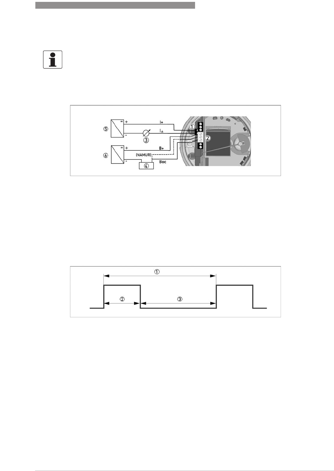
4.2.4 ESK4-T pulse output
The pulse output B2 is a passive "open collector" output which is electrically isolated from the
current output and output B1. It can be operated as a low-resistance output or as a NAMUR
output.
The pulse width t
on
can be configured from 50...500 ms in the indicator menu.
INFORMATION!
The binary outputs can also be operated as pulse outputs. When using the binary outputs as a
pulse output, two separate signal circuits are required. Each signal circuit requires its own
power supply.
The total resistance 4 must be adapted so that the total current I
tot
does not exceed 100 mA.
Electrical connection of pulse output
1 Terminal for power supply - current output
2 Terminal B2
3 Flow measurement 4...20 mA
4 Pulse output load e.g. counter
5 Power supply for ESK4
6 Power supply for pulse output
Figure 4-2: Data for pulse output
1 f
max
= 10 Hz
2 t
on
3 t
off
4
ELECTRICAL CONNECTIONS
34
H250 M40
www.krohne.com 07/2016 - 4000640704 - MA H250-M40 R04 en
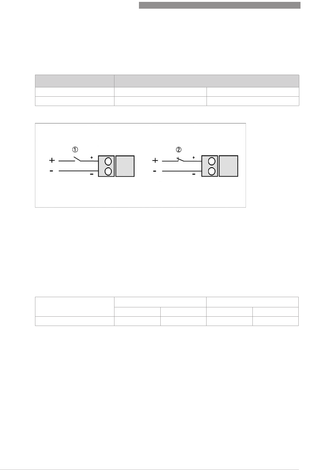
4.2.5 ESK4-T binary input
The binary input can be used to control the internal flow counter (start/stop/reset).
Value range for NAMUR
This binary input can be activated in the menu of the indicator and can be configured to ACTIVE
HI or ACTIVE LO.
If the input is set as ACTIVE LO, an interruption causes the counter to be reset.
For further information on configuration of each function refer to
ESK4-T menu
on page 46.
Value range
The binary input has an internal resistance R
i
of 20 kΩ.
Binary input B3
Terminal no. 7 8
Connection + -
Binary input
1 Function active HI
2 Function active LO
Input voltage U
L
[V] U
H
[V]
lower limit upper limit lower limit upper limit
Terminal (7) (8) 0 2 16 30
ELECTRICAL CONNECTIONS
4
35
H250 M40
www.krohne.com07/2016 - 4000640704 - MA H250-M40 R04 en
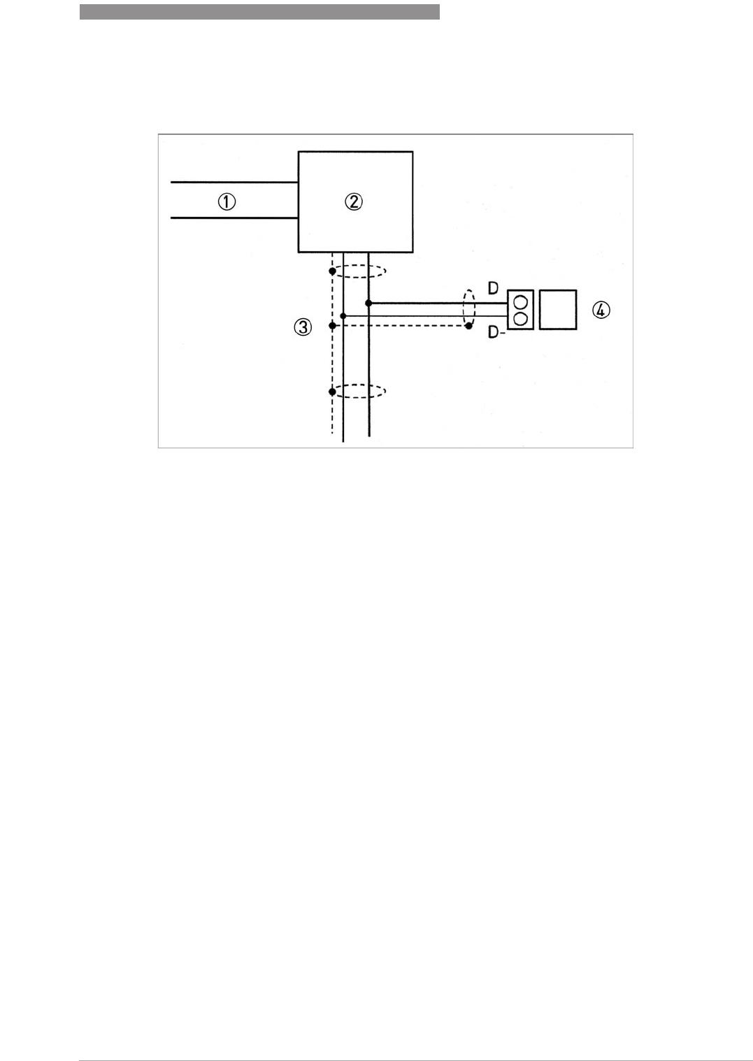
4.2.6 ESK4-FF / ESK4-PA fieldbus communication
ESK4-FF / ESK4-PA
•2-wire, bus-supplied
•Polarity protected
•Bus voltage 9...32 VDC
•Nominal current 16 mA
1 FF HSE Bus / Profibus DP
2 Linking device / bus coupler
3 FF H1 Bus / Profibus PA, 2-wire with shielding
4 H250/M40/ESK4-FF / H250/M40/ESK4-PA
4
ELECTRICAL CONNECTIONS
36
H250 M40
www.krohne.com 07/2016 - 4000640704 - MA H250-M40 R04 en
4.2.7 Harting HAN 7D connection
1 Terminal pin assignment of HAN
®
7D - View of plug connection
Combinations of K1 / K2 and ESK4 / ESK4A are possible.
1 Pin no. HAN
®
7D K1/K2: NAMUR
contacts
R1/R2 Reed
contacts
ESK4/ESK4A Terminal no.
NAMUR Reed
12 NAMUR MIN (-) 2 Reed MIN - 1 1
22 NAMUR MIN (+) 2 Reed MIN - 2 3
33 NAMUR MAX (-) 3 Reed MAX - 4 4
43 NAMUR MAX (+) 3 Reed MAX - 5 6
5 - - 4 4...20mA (+) 11
6 - - 4 4...20mA (-) 12
7 - - -
8 - - -
1 Pin no. HAN
®
7D ESK4-T Terminal no.
15 Binary output B1 open coll. (+) 1
25 Binary output B1 open coll. (-) 3
37 Binary output B2 open coll. (+) 4
47 Binary output B2 open coll. (-) 6
56 4...20mA (+) 11
66 4...20mA (-) 12
7 -
8 -
INFORMATION!
No Harting connection for module ESK4-FF/PA is provided and is only available on request.
ELECTRICAL CONNECTIONS
4
37
H250 M40
www.krohne.com07/2016 - 4000640704 - MA H250-M40 R04 en
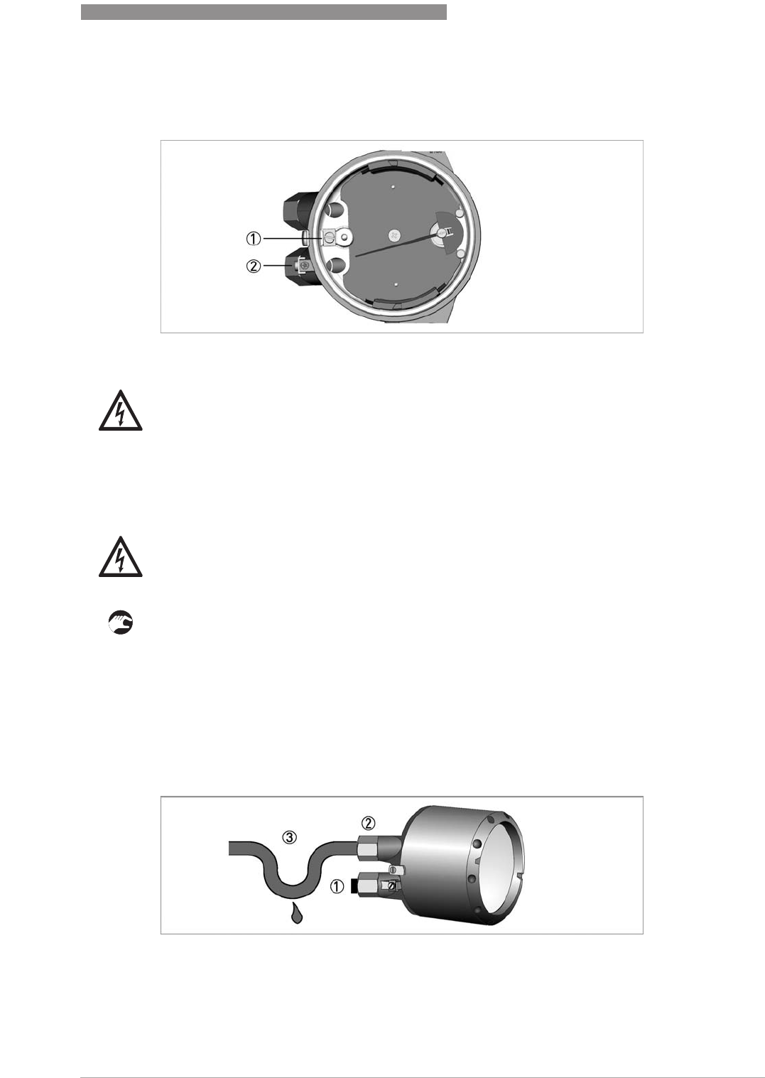
4.3 Grounding connections
4.4 Ingress protection
The measuring device meets all requirements of ingress protection IP66/68.
Therefore it is essential to observe the following points.
• Use only original gaskets. They must be clean and free of any damage. Defective gaskets must
be replaced.
• The electrical cables must be undamaged and must comply with regulations.
• The cables must be laid with a loop 3 upstream of the measuring device to prevent water
from getting into the housing.
• The cable feedthroughs 2 must be tightened.
• Close the unused cable feedthroughs using blanking plugs 1.
1 Grounding connection in the indicator
2 Grounding connection outside
DANGER!
The grounding wire may not transfer any interference voltage.
Do not use this grounding cable to ground any other electrical devices.
DANGER!
After all servicing and maintenance work on the measuring device, the specified protection class
must be ensured again.
1 Use blanking plugs if no cable is routed through
2 Tighten cable feedthrough firmly
3 Lay the cable in a loop
5
START-UP
38
H250 M40
www.krohne.com 07/2016 - 4000640704 - MA H250-M40 R04 en
5.1 Standard device
A minimum operating pressure (primary pressure) is necessary to operate the device:
5.2 Indicator ESK4-T
Start
After the device is switched on, the display shows
•"INITIALISING"
•Firmwareversion IO-Modul
The device first performs a self-test. Here, all of the parameters preset for the customer are
analysed and checked for plausibility. The device then switches to measuring mode and indicates
the current measured value.
Operation
CAUTION!
When starting up the device, the following points must be observed:
•
Compare the actual operating pressure and the product temperature of the system with the
specifications on the nameplate (PS and TS). These specifications may not be exceeded.
•
Make sure materials are compatible.
•
Slowly open the shut-off valve.
•
When measuring liquids ensure that the pipelines are carefully evacuated.
•
When measuring gases, increase pressure slowly.
•
Avoid float impact (e.g. caused by solenoid valves), as this is likely to damage the measuring
unit or float.
Medium Pressure loss : operating pressure
Liquids 1 : 2
Gases without float damping 1 : 5
Gases with float damping 1 : 2
INFORMATION!
The device is always preset for the user and his application.
INFORMATION!
The device is low-maintenance
Comply with the application limits with regard to temperature of the medium and ambient
temperature.
OPERATION
6
39
H250 M40
www.krohne.com07/2016 - 4000640704 - MA H250-M40 R04 en
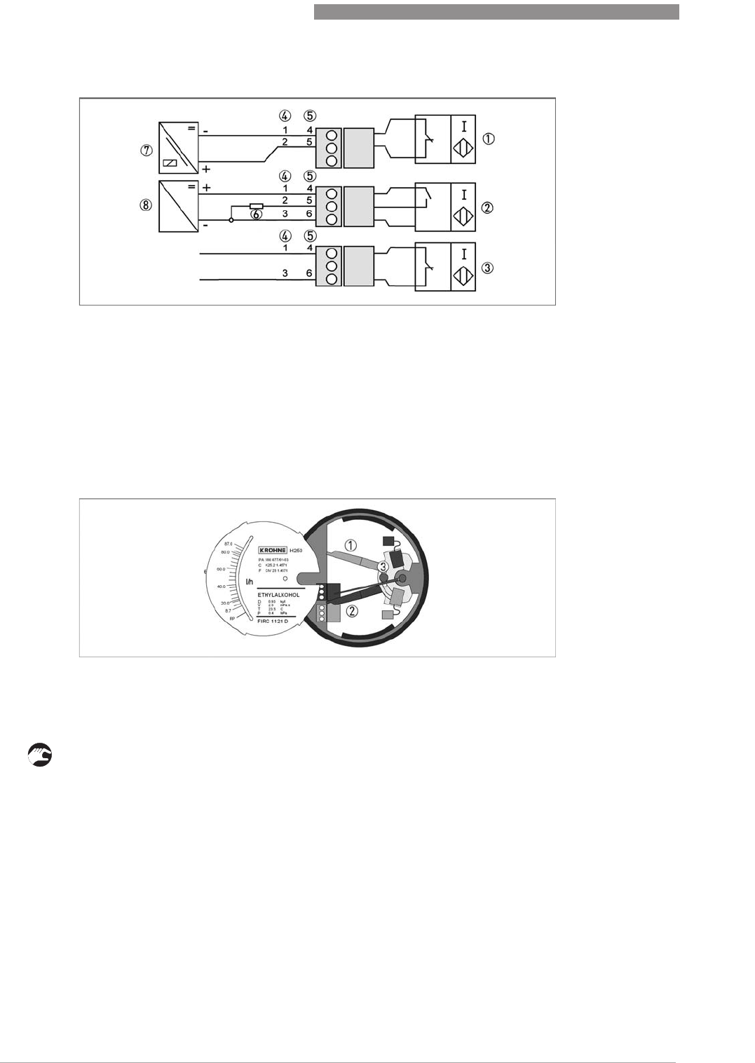
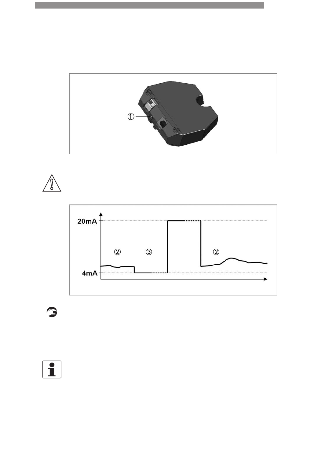
6.1 ESK4 / ESK4A - Loop Check Mode
The ESK4 / ESK4A is equipped with a loop check function, enabling a simple test of the entire
4…20 mA current loop.
It is activated and operated using a microswitch 1.
• Press and hold the microswitch 1 for more than 6 seconds to activate the loop check mode 3.
The current output jumps to constant 4 mA.
• Change the current output from constant 4 mA to constant 20 mA as often as you like by briefly
pressing it (less than 6 seconds) to check the function of the measuring circuit.
• Exit loop check mode by holding down the microswitch (longer than 6 seconds). The current
output jumps back to measuring mode 2.
CAUTION!
When activating the loop check mode, ensure that no alarms are unintentionally triggered in the
downstream system components.
INFORMATION!
If the microswitch has not been pressed for longer than 60 seconds, the ESK4 / ESK4A
automatically returns to measuring mode 2.
6
OPERATION
40
H250 M40
www.krohne.com 07/2016 - 4000640704 - MA H250-M40 R04 en
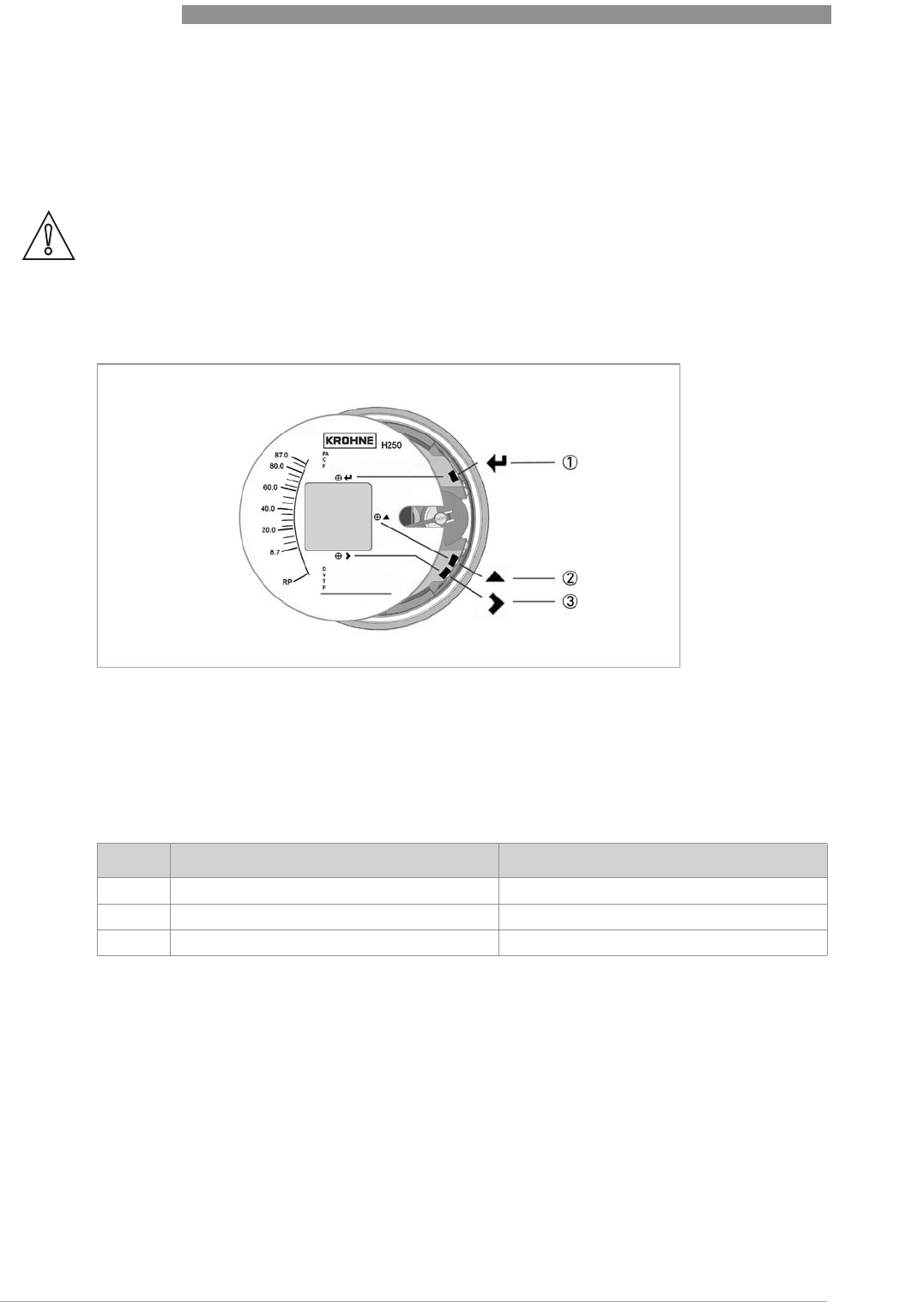
6.2 Operating elements ESK4-T
The device is operated with the cover on the front open, using the mechanical keys
keyskeys
keys, or with the
cover closed using a bar magnet
bar magnetbar magnet
bar magnet.
The mechanical keys and keys for the bar magnet have the same functionality. In this
documentation the keys are represented as symbols to describe the operating functions:
CAUTION!
The switching point of the magnetic sensors is directly at the height of the corresponding circle
(see figure). Only touch the circle vertically and from the front using the bar magnet. Touching it
from the side may cause an error in the measurement as the float position is recorded by the
magnetic field sensors.
Figure 6-1: Display and operating elements
1 Enter button (circuit for bar magnet)
2 Up button (circuit for bar magnet)
3 Right button (circuit for bar magnet)
Key Symbol
1Enter ^
^^
^
2up ↑
3right →
Table 6-1: ESK4-T operation keys

OPERATION
6
41
H250 M40
www.krohne.com07/2016 - 4000640704 - MA H250-M40 R04 en
6.3 Basic principles of operation ESK4-T
6.3.1 Description of the operating keys
6.3.2 Navigation within the menu structure
Navigate through the menu using the →, ↑ and ^
^^
^ keys. Pressing the → key takes you one menu
lower. Using the ↑ key takes you one menu item higher (e.g. from 1 to 2). Pressing the ^
^^
^ key
takes you one menu higher.
If you are already at the lowest level (function level), the key takes you to the change mode,
where you can set data and values.
If you are at the first level (main menu), you can use the ^
^^
^ key to exit the menu mode and return
to the measuring mode.
If settings were changed, the query whether they should be saved will appear. Confirm this query
with the → key or cancel it with the ^
^^
^ key.
→Switch from measuring mode to menu mode
Switch to one menu level lower
Open menu item and activate change mode
Confirm query whether data should be accepted
In change mode:
In change mode:In change mode:
In change mode: Move the input cursor one position to the right. After the last digit the
input cursor jumps back to the beginning.
↑Change between the menu items within a menu level
In measuring mode:
In measuring mode:In measuring mode:
In measuring mode: Switch between measured values and error messages
In change mode:
In change mode:In change mode:
In change mode: Changing parameters or settings. Run through the available characters
(including decimal point.
^
^^
^In measuring mode:
In measuring mode:In measuring mode:
In measuring mode: Switch between measured value display and error messages /
warnings
Switch to one menu level higher
Return to measuring mode with a query whether the data should be accepted
Cancel the query, whether data should be accepted
Table 6-2: Description of the operating keys
Measuring
mode
→Main menu
↑
→Submenu
↑
→Function
↑
→Edit
→
↑
^
^^
^
^
^^
^ ^
^^
^ ^
^^
^ ^
^^
^
Table 6-3: Navigation in menu structure
6
OPERATION
42
H250 M40
www.krohne.com 07/2016 - 4000640704 - MA H250-M40 R04 en
6.3.3 Change the settings in the menu
Starting operation
Operation is started using the → key.
If an operation lock is set, the code (→ → → ^ ^ ^ ↑ ↑ ↑) must be entered. The code can be set
in menu 3.13. The code shown here is set at the factory but not activated. If no key is activated
within 5 seconds or an incorrect code is entered, a warning message is displayed and the
indication returns to measuring mode.
Exit operation
Operation is exited by pressing the ^
^^
^ key several times.
If data have been changed:
Example: Changing the flow unit from m3/h to l/h
Save Yes →Changes are accepted. An update is carried out and the display returns to
measuring mode.
Save No ^
^^
^Changes are discarded and the display returns to measuring mode.
CAUTION!
Each time parameters or settings are changed, the measuring device carries out an internal
plausibility check.
If inplausible entries were made, a warning message is shown. If this warning is confirmed with
the ^
^^
^ key, the display returns to the respective menu item without saving the relevant change. A
new entry can now be made.
Display Display
Example: 7.2
m
3
/h
1x →Fct. 3.11.1
11
1
MEAS'D VALUE
1x →Fct. 1
11
1
OPERATION 1x →10.0000
m
3
/h
2x ↑Fct. 3
33
3
INSTALLATION 4x ↑10000
l/h
1x →Fct 3.1
11
1
LANGUAGE Confirm with →
deny ^
10x ↑Fct 3.11
1111
11
FS&UNIT 3x ^
^^
^7200
l/h

OPERATION
6
43
H250 M40
www.krohne.com07/2016 - 4000640704 - MA H250-M40 R04 en
6.4 Overview of the units ESK4-T
Volume units can either represent real operating volumes (no prefix before the unit) or standard
volumes virtually converted to reference statuses.
In addition to the predefined units shown here, a user-defined unit can be activated in Menu 3.12
by entering a conversion factor and a unit designation as free text.
Prefix Volume definition
None Operating volume flow e.g. m
3
/h or ft
3
/h
NVolume flow at standard (norm.) conditions (0°C - 1.013 bara) acc. to DIN 1343 e.g. Nm
3
/h
SVolume flow at standard (std.) conditions (15°C - 1.013 bara) acc. to ISO 13443 e.g. Sft
3
/h
Measured variables Units
Operating
volume flow m
3
/s m
3
/min m
3
/h m
3
/d
L/s L/min L/h -
ft
3
/s ft
3
/min ft
3
/h ft
3
/d
gal/s gal/min gal/h gal/d
bbl/s bbl/min bbl/h bbl/d
ImpGal/s ImpGal/min ImpGal/h ImpGal/d
Standard (norm.)
volume flow Nm
3
/s Nm
3
/min Nm
3
/h Nm
3
/d
NL/s NL/min NL/h -
Standard (std.)
volume flow Sm
3
/s Sm
3
/min Sm
3
/h Sm
3
/d
SL/s SL/min SL/h -
Sft
3
/s Sft
3
/min Sft
3
/h Sft
3
/d
Mass flow g/s g/min g/h -
kg/s kg/min kg/h kg/d
- t/min t/h t/d
lb/s lb/min lb/h lb/d
-STon/min STon/h STon/d
- - LTon/h LTon/d
Operating
volume totalizer m
3
lhl ft
3
ImpGal gallon bbl bbl (liq)
Standard (norm.)
volume totalizer Nm
3
NL
Standard (std.)
volume totalizer Sft
3
SL Sm
3
Mass totalizer kg g t lb
STon LTon
Temperature °C°F K
6
OPERATION
44
H250 M40
www.krohne.com 07/2016 - 4000640704 - MA H250-M40 R04 en
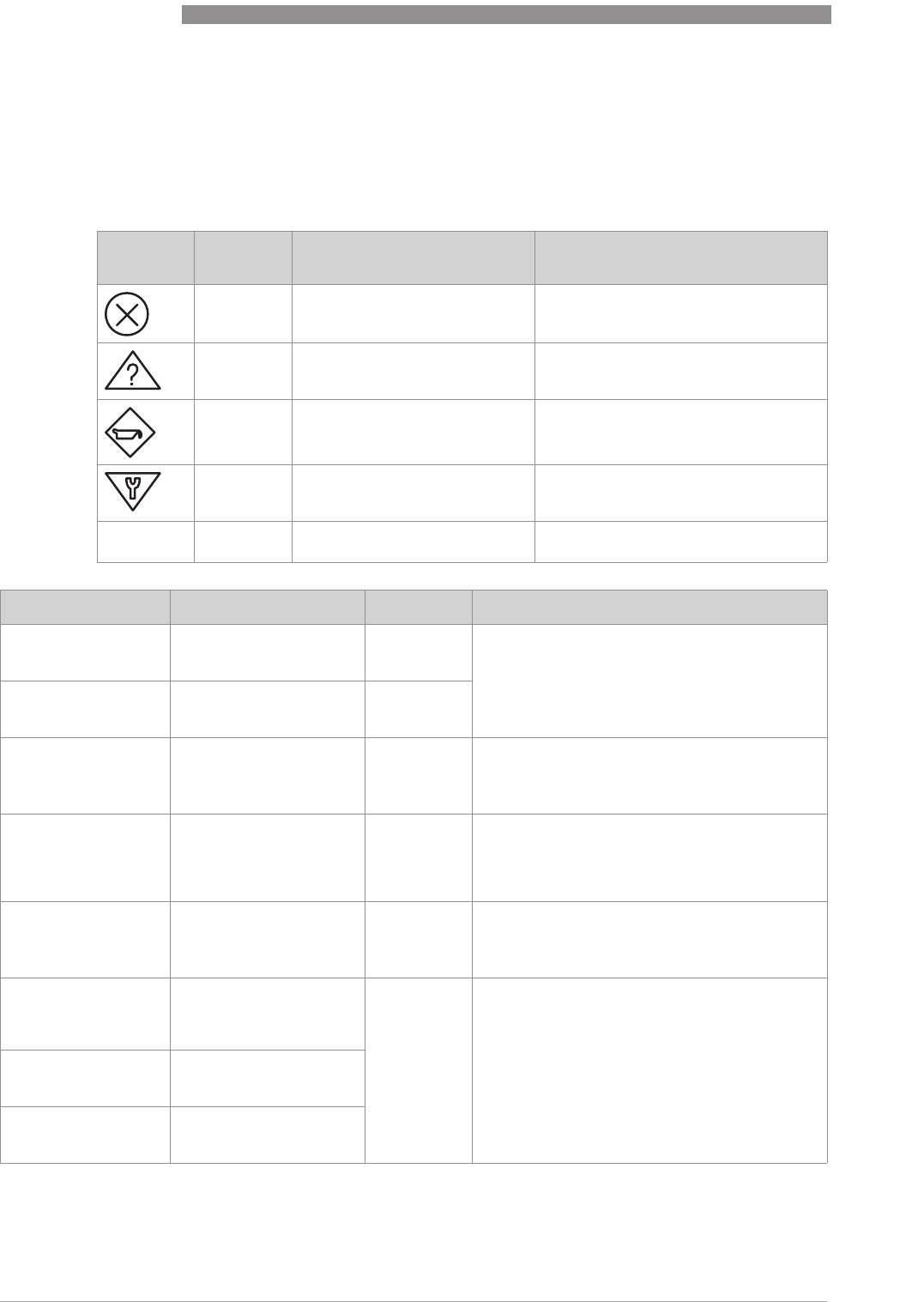
6.5 Error messages ESK4-T
Error messages and warnings are indicated by one of the following symbols in the bottom left
corner of the display. The ^
^^
^ key switches from the measured value display to the display of
current errors / warnings. The table below contains a description of possible error messages.
Symbol NE107
Category
Description Consequence
F
FF
FFailure No measured value available
Output signal invalid
Error current signal is output.
SOut of specification Measurement available but increasing
measurement uncertainty. Device must
be checked.
MMaintenance required Measurement still sufficiently accurate
but maintenance required.
CFunction check Device is in test or linearization mode.
The output signal temporarily does not
correspond to the measurement.
IInformation No influence on the measurement,
information only.
Error message Description Category Remedy
NOT LINEARIZED Linearization faulty or not
activated = measuring
error
SActivate linearization or carry it out again (HART
®
communication and linearization software are
required; the original calibration values must be
known), or send the device back to the
manufacturer for linearization.
NEW LINEARI. TABLE
BAD Faulty or missing data in
the linearization table =
measuring error
S 1
LINEARIZATIO UNDER
CONFIG The device is in
linearization mode =
measuring error
SComplete the linearization and activate it (HART
®
communication and linearization software are
required), or send the device back to the
manufacturer for linearization.
UNIT SYSTEM
CONFLICT The unit for the
linearization flow is
incompatible with the
selected flow type
(mass/volume)
SCorrect error, carry out linearization again if
necessary (HART
®
communication and
linearization software are required), or send the
device back to the manufacturer for linearization.
TOO FEW ENTRIES The linearization table has
too few data points SCarry out linearization at at least 5 points (HART
®
communication and linearization software are
required), or send the device back to the
manufacturer for linearization.
NOT MONOTONOUS The sequence of the
linearization values is not
strictly monotonic
increasing
SCheck linearization and/or carry it out again
(HART
®
communication and linearization
software are required), or send the device back to
the manufacturer for linearization.
FIRST NOT 0 % The first flow value if the
linearization table is not
0%
LAST NOT 100 % The last flow value if the
linearization table is not
100%

OPERATION
6
45
H250 M40
www.krohne.com07/2016 - 4000640704 - MA H250-M40 R04 en
NO ZERO CAL
OF AO The current output zero
point 4.00 mA is not
calibrated = poss.
measuring error in the
process control system
SPerform calibration using ammeter and menu
3.10 or using standard HART
®
tools/process
control system and poss. external ammeter.
Caution: during calibration, switch the measuring
point to manual control.
NO F.SC. CAL
OF AO The current output 100% =
20.00 mA is not calibrated
= poss. measuring error in
the process control
system
SPerform calibration using ammeter and menu
item 3.11 or using standard HART
®
tools and
external ammeter if necessary. Caution: during
calibration, switch the measuring point to manual
control.
NO TEMP.
COMPENSATION The sensor temperature
compensation of the
device is faulty or was not
carried out = possible
measuring error
SThe device, together with an indication of the
error, must be sent back to the manufacturer for
checking.
WRONG ELEC.REV. The ER revision of the
ESK4 / ESK4A is not
compatible with the add-
on module, or the ribbon
cable connection is not
connected properly.
SCheck that the ribbon cable fits properly. Check
module compatibility (for details refer to
Electronic revision
on page 18).
OUTPUT NOT
LINEARIZED Linearization is not
activated = measuring
error
SActivate linearization or carry it out again (HART
®
communication and linearization software are
required; the original calibration values must be
known), or send the device back to the
manufacturer for linearization.
COUNTER LOST Totalizer value was reset
by error/overflow S 1 Because the reset time is not known: Controlled
reset of the counter using menu item 1.6.1 or
using HART
®
tools/process control system.
FRAM WRITE FAULT Internal communication
error FCheck whether the display is plugged in correctly
and restart the device. If the error occurs again:
send the device back to the manufacturer with an
indication of the error.
ROM/FLASH ERROR Memory error detected
during self-test. FRestart device. If the error occurs again: send the
device back to the manufacturer with an
indication of the error.
RESTART OF DEVICE A device restart has taken
place IThe device has been restarted using menu item
1.6.2 since the last time the error messages were
reset.
MULTIDROP MODE The HART
®
multidrop
mode is activated. The
current output is set to a
fixed value of 4.5 mA.
IThe HART
®
multidrop mode is activated with
selection of a polling address not equal to 0 using
menu item 3.7. Polling address 0 reactivates the
current output.
CRYSTAL OSC FAULT Internal error in device FThe device must be sent back to the manufacturer
with an indication of the error.
REF VOLTAGE FAULT Internal error in device
SENSOR A FAULT Internal error in device F 1
SENSOR B FAULT Internal error in device
MEMORY
CORRUPTION Internal memory error,
caused by a hardware or
software problem
FRestart the device; if the error occurs again the
device must be sent back to the manufacturer
with an indication of the error.
AO FIXED The current output is set
to a fixed value. IThe current output is fixed and does not reflect
the measured value. This is the case in multidrop
mode, with current output test/calibration using
the menu or HART
®
.
AO SATURATED Current output saturated IThe current output is saturated at >20.4 mA and is
no longer linked to the measurement.
Error message Description Category Remedy

6
OPERATION
46
H250 M40
www.krohne.com 07/2016 - 4000640704 - MA H250-M40 R04 en
6.6 ESK4-T menu
6.6.1 Factory settings
ERROR TIMEOUT Data not transferred, or
transferred incorrectly
from the ESK to the
counter module
FConfirm menu item "1.6.3 WRITE INFO I/O".
WARNING TIMEOUT I
1Category can be changed by user
Error message Description Category Remedy
Function Setting
1.1.1 OUTPUT B1 INACTIVE
1.2.1 OUTPUT B2 INACTIVE
1.3.1 PULSEWDTH 50ms
1.3.2 PULSE/UNIT 1 Pulse/Unit
1.4 DISPLAY MEAS’D VALUE
1.4.2 ROTATION 0°
1.5 TIME CONST. 1.0s
1.6.1 COUNTER NO
1.6.2 ERROR NO
1.6.3 RE-INIT I/O NO
3.1 LANGUAGE ENGLISH
3.2 FUNCTION B1 INACTIVE
3.3 CONTACT B1 NORM.OPEN
3.4 FUNCTION B2 INACTIVE
3.5 CONTACT B2 NORM.OPEN
3.6 FUNCTION B3 INACTIVE
3.7 MULTIDROP POLLING ADD: 00
3.8 4mA CALIBR. 4.000mA
3.9 20mA CALIBR. 20.000mA
3.10 ALARM CURR. ALARM HIGH
3.11 FS&UNIT Application specific
3.11.2 COUNTER Application specific
3.12 EDIT UNIT User defined unit / factor
3.13 L.FL.CUTOFF 4% ON; 6% OFF
3.14 DESCRIPTOR Free text
3.15 ENTRY CODE OFF
3.16 DEFAULT VAL. NO
INFORMATION!
The measuring device has been preset at the factory in accordance with the customer order.
Therefore subsequent configuration via the menu is only necessary if the intended use of the
device is changed.

OPERATION
6
47
H250 M40
www.krohne.com07/2016 - 4000640704 - MA H250-M40 R04 en
6.6.2 Menu structure
Main menu Submenu 1 Submenu 2
1 OPERATION 1.1 OUTPUT B1 1.1.1 INACTIVE, MEAS.VAL. B1, CNT. VAL. B1, PULSE WIDTH
1.1.2 HYST. B1, PULSE/UNIT
1.2 OUTPUT B2 1.2.1 INACTIVE, MEAS.VAL. B2, CNT. VAL. B2, PULSE WIDTH
1.2.2 HYST. B2, PULSE/UNIT
1.3 PULSE OUTP. 1.3.1 PULSE WIDTH
1.3.2 PULSE/UNIT
1.4 DISPLAY 1.4.1 MEAS'D VALUE, COUNTER, MV/COUNTER, MV&COUNTER,
PERCENT
1.4.2 ROTATION
1.5 TIME CONST -
1.6 RESET 1.6.1 COUNTER
1.6.2 ERROR
1.6.3 WRITE INFO IO
2 TEST & INFO 2.1 4-20mA OUTP 2.1.1 NORMAL OP
2.1.2 4.0mA
2.1.3 5.6mA
2.1.4 7.2mA
2.1.5 8.8mA
2.1.6 10.4mA
2.1.7 12.0mA
2.1.8 13.6mA
2.1.9 15.2mA
2.1.10 16.8mA
2.1.11 18.4mA
2.1.12 20.0mA
2.1.13 21.6mA
2.2 ALARM CURR. ALARM HIGH, ALARM LOW
2.3 OUTPUT B1 2.3.1 NORMAL OP
2.3.2 OPEN
2.3.3 CLOSED
2.4 OUTPUT B2 2.4.1 NORMAL OP
2.4.2 OPEN
2.4.3 CLOSED
2.5 INPUT B3 ACTIVE HI, ACTIVE LO, ON, OFF
2.6 DEV. IDENT. 2.6.1 ELEC. REV.
2.6.2 SERIAL ESK4
2.6.3 PROD. ORDER
2.6.4 DEV. SN.

6
OPERATION
48
H250 M40
www.krohne.com 07/2016 - 4000640704 - MA H250-M40 R04 en
2 TEST & INFO 2.7 SOFT.VERSION 2.7.1 FW. ESK4
2.7.2 FW. ESK4 I/O
2.8 TAG NB. 8 characters
2.9 LONG TAG 32 characters
3 INSTALLATION 3.1 LANGUAGE 3.1.1 ENGLISH
3.1.2 DEUTSCH
3.1.3 FRANCAIS
3.1.4 ITALIANO
3.1.5 ESPANOL
3.1.6 CESKY
3.1.7 POLSKI
3.1.8 NEDERLANDS
3.1.9 DANSK
3.2 FUNCTION B1 INACTIVE, SWITCH POINT, COUNT. LIMIT, PULSE OUTP.
3.3 CONTACT B1 NORM.OPEN, NORM.CLOSED
3.4 FUNCTION B2 INACTIVE, SWITCH POINT, COUNT. LIMIT, PULSE OUTP.
3.5 CONTACT B2 NORM.OPEN, NORM.CLOSED
3.6 FUNCTION B3 INACTIVE, ACTIVE HI, ACTIVE LO, STARTH STOPL, STARTL STOPH
3.7 MULTIDROP POLLING ADD.
3.8 4mA CALIBR. 4.000mA
3.9 20mA CALIBR. 20.000mA
3.10 ALARM CURR. OFF, ALARM HIGH, ALARM LOW
3.11 FS&UNIT 3.11.1 MEAS'D VALUE
3.11.2 COUNTER
3.12 EDIT UNIT 3.12.1 MEAS'D VALUE
3.12.2 COUNTER
3.13 L.FL.CUTOFF 3.13.1 CONTROL ON, CONTROL OFF
3.13.2 ON VALUE
3.13.3 OFF VALUE
3.14 DESCRIPTOR Free text
3.15 ENTRY CODE OFF, ON
3.16 DEFAULT VAL. SET ALL
Main menu Submenu 1 Submenu 2
OPERATION
6
49
H250 M40
www.krohne.com07/2016 - 4000640704 - MA H250-M40 R04 en
6.6.3 Menu description
1 OPERATION
Selection / Input Explanation
1.1 OUTPUT B1
1.1 OUTPUT B11.1 OUTPUT B1
1.1 OUTPUT B1 Output B1 is a binary switching output. In Fct. 3.2, one of the following functions can be
selected for this output:
INACTIVE, SWITCH POINT, COUNT. LIMIT, PULSE OUTP.
One of the following functions can be selected as contact type in Fct. 3.3:
NORM.OPEN 1 / NORM.CLOSED 2
1.1.1
INACTIVE -
MEAS.VAL. B1 Switching point of flow value
Value range: 0.0…full scale range
The switching point is entered in flow units.
If the current flow value exceeds this pre-determined switching point, output B1 changes
its binary state 3.
In Fct. 1.1.2 a hysteresis can be specified additionally.
CNT. VAL. B1 Switching point of totaliser value
Value range: 0.0…counter limit
The switching point is entered in volume or mass units.
If the the current counter value exceeds this pre-determined switching point, output B1
changes its binary state 3.
There is no hysteresis setting for the switching point of the counter value.
PULSE WIDTH Pulse weight (pulse/unit)
The weight is only displayed here.
A configuration takes place in Fct. 1.3.1 PULSE WIDTH, 1.3.2 PULSE/UNIT and 3.11.2
COUNTER.
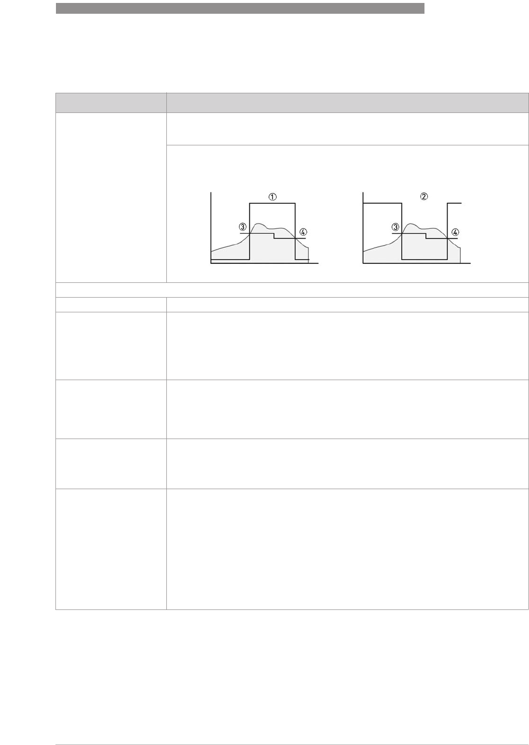
1.1.2 HYST. B1 Hysteresis for the switching point of the flow value
Value range: 0.0…switching point
If the current flow value exceeds the pre-determined switching point from Fct. 1.1.1,
output B1 changes its binary state 3.
In order for output B1 to change its binary state back to the initial setting, the switching
point made smaller by the hysteresis must be undershot 4.
Example:
Example:Example:
Example:
In 1.1.1, a switching point of 200 L/h is set.
The possible value range for the hysteresis is then 0.0…200 L/h.
With a hysteresis value of 0, the switching point has no hysteresis (3=4).
If a hysteresis value of 20 L/h is entered, output B1 changes its binary state to the initial
setting, if it drops below 180 L/h 4.
6
OPERATION
50
H250 M40
www.krohne.com 07/2016 - 4000640704 - MA H250-M40 R04 en
1.2 OUTPUT B2
1.2 OUTPUT B21.2 OUTPUT B2
1.2 OUTPUT B2 Output B2 is a binary switching output. In Fct. 3.4, one of the following functions can be
selected for this output:
INACTIVE, SWITCH POINT, COUNT. LIMIT, PULSE OUTP.
One of the following functions can be selected as contact type in Fct. 3.5:
NORM.OPEN 1 / NORM.CLOSED 2
1.2.1
INACTIVE -
MEAS.VAL. B2 Refer to MEAS.VAL. B1
In Fct. 1.2.2 a hysteresis can be specified additionally.
CNT. VAL. B2 Refer to CNT. VAL. B1
PULSE WIDTH B2 Refer to PULSE WIDTH B1
A configuration takes place in Fct. 1.3.1 PULSE WIDTH, 1.3.2 PULSE/UNIT and 3.11.2
COUNTER.
1.2.2 HYST. B2 Refer to HYST. B1
1.3 PULSE OUTP.
1.3 PULSE OUTP.1.3 PULSE OUTP.
1.3 PULSE OUTP. -
1.3.1 PULSE WIDTH
50ms T
i
= 50 ms; f
max
= 10 Hz
max. pulses/h = 36000
100ms T
i
= 100 ms; f
max
= 5 Hz
max. pulses/h = 18000
200ms T
i
= 200 ms; f
max
= 2.5 Hz
max. pulses/h = 9000
500ms T
i
= 500 ms; f
max
= 1 Hz
max. pulses/h = 3600
1.3.2 PULSE/UNIT 0.001...1000
Pulse per volume or mass unit of counter (setting in Fct. 3.11.2), which can be output via
one of the binary outputs. The maximum frequency for the pulse output (refer to Fct 1.3.1)
cannot be exceeded, even at maximum flow rate (full scale).
Example:
Example:Example:
Example:
Final value Q
max
= 1200 L/h; volume unit of counter = Litre; pulse width = 100ms;
If the factor 1 is entered, 1 pulse/litre = 1200 pulses are generated in one hour at maximum
flow rate.
Number of max. permissible pulses:
Selection / Input Explanation

OPERATION
6
51
H250 M40
www.krohne.com07/2016 - 4000640704 - MA H250-M40 R04 en
1.4 DISPLAY
1.4 DISPLAY1.4 DISPLAY
1.4 DISPLAY Different measured values can be selected for permanent or alternating display.
The reading on the display can be rotated.
1.4.1
MEAS’D VALUE Permanent display of flow in flow units
COUNTER Permanent display of totalizer
MEAS.VAL/CTN Alternating display of flow value in flow units and totalizer
MEAS.VAL&CTN Simultaneous display of flow value and totalizer
PERCENT Permanent display of flow value in percent
1.4.2 ROTATION
0°The reading is not rotated.
90°The reading on the display is rotated by 90°.
180°The reading on the display is rotated by 180°.
270°The reading on the display is rotated by 270°.
1.5 TIME CONST
1.5 TIME CONST1.5 TIME CONST
1.5 TIME CONST 0.0...20.0s
Given in seconds
The output variables (value of the current loop and indicated flow value) follow the current
process by the value set here (in seconds) with a time delay.
Note:
Note:Note:
Note:
If the current flow is polled via HART
®
communication, the transferred measured value is
also played back with a delay.
1.6 RESET
1.6 RESET1.6 RESET
1.6 RESET Local resetting of totalizer and acknowledgement of warnings.
There is always a safety prompt ("YES / NO"), to avoid accidental resetting.
Note:
Note:Note:
Note:
External resetting of the totalizer can be installed with the binary input B3.
1.6.1 COUNTER Confirming with "YES" resets the value of the totalizer to 0.0.
1.6.2 ERROR Confirming with "YES" acknowledges all existing warnings.
Note:
Note:Note:
Note:
Confirming with "YES" acknowledges existing errors and warnings.
1.6.3 RE-INIT IO As a general rule, data is transferred from the counter module to the ESK4 and vice versa
when the device starts. For safety, another data transmission can be performed by
selecting this menu item and confirming with "YES".

6
OPERATION
52
H250 M40
www.krohne.com 07/2016 - 4000640704 - MA H250-M40 R04 en
2 TEST & INFO
Selection / Input Explanation
2.1 4-20mA OUTP
2.1 4-20mA OUTP2.1 4-20mA OUTP
2.1 4-20mA OUTP Testing the current loop by setting various current values.
Note:
Note:Note:
Note:
The test is not available in HART
®
multi-drop mode (refer to Fct. 3.7)
Attention:
Attention:Attention:
Attention:
During the test, the value of the current loop does not follow the current process.
2.1.1 NORMAL OP The value of the current loop follows the current process.
2.1.2 4.0mA The value of the current loop no longer follows the current process.
It is set to the selected current value.
2.1.3 5.6mA
2.1.4 7.2mA
2.1.5 8.8mA
2.1.6 10.4mA
2.1.7 12.0mA
2.1.8 13.6mA
2.1.9 15.2mA
2.1.10 16.8mA
2.1.11 18.4mA
2.1.12 20.0mA
2.1.13 21.6mA
2.2 OUTPUT B1
2.2 OUTPUT B12.2 OUTPUT B1
2.2 OUTPUT B1 <3.6 / >21 mA
Testing the alarm current HIGH/LOW according to the settings in Fct. 3.10.
2.3 ALARM CURR.
2.3 ALARM CURR.2.3 ALARM CURR.
2.3 ALARM CURR. Testing the binary switching output B1 by changing its binary status.
Attention:
Attention:Attention:
Attention:
During the test, the binary status does not correspond to the current process.
2.3.1 NORMAL OP The binary status of the switching output corresponds to the current process.
2.3.2 OPEN The binary status of the switching output no longer corresponds to the current process.
The selected status is tested.
2.3.3 CLOSED
2.4 OUTPUT B2
2.4 OUTPUT B22.4 OUTPUT B2
2.4 OUTPUT B2 Refer to 2.2 OUTPUT B1
2.4.1 NORMAL OP
2.4.2 OPEN
2.4.3 CLOSED
2.5 INPUT B3
2.5 INPUT B32.5 INPUT B3
2.5 INPUT B3 The current binary status of the binary input B3 is displayed. External switching of the
voltage applied to input B3 activates a change of the displayed binary status.
Note:
Note:Note:
Note:
A reaction to the switching of the voltage applied to input B3 only occurs if the function B3
is activated (refer to Fct. 3.6).
2.6 DEV. IDENT.
2.6 DEV. IDENT.2.6 DEV. IDENT.
2.6 DEV. IDENT. Information for device identification
2.6.1 ELEC. REV. Electronic revision
2.6.2 SN ESK4 Serial number ESK4
2.6.3 PROD. ORDER Production order for the complete flowmeter
2.6.4 DEV. SN. Serial number for the complete flowmeter
2.7 SOFT.VERSION
2.7 SOFT.VERSION2.7 SOFT.VERSION
2.7 SOFT.VERSION Information about software revision status
2.7.1 FW. ESK4 Software revision status for device insert ESK4-Basic
2.7.2 FW. ESK4 I/O Software revision status for optional add-on module ESK4-T

OPERATION
6
53
H250 M40
www.krohne.com07/2016 - 4000640704 - MA H250-M40 R04 en
3 INSTALLATION
2.8 TAG NB.
2.8 TAG NB.2.8 TAG NB.
2.8 TAG NB. 8 digits
Measuring point identifier
Alphanumerical characters. Up to eight digits are possible.
2.9 LONG TAG 32 digits
Measuring point identifier
Alphanumerical characters. Up to 32 digits are possible.
Selection / Input Explanation
3.1 LANGUAGE
3.1 LANGUAGE3.1 LANGUAGE
3.1 LANGUAGE Language selection for the displayed menu texts.
3.1.1 ENGLISH The menu texts are displayed in the selected language.
3.1.2 DEUTSCH
3.1.3 FRANCAIS
3.1.4 ITALIANO
3.1.5 ESPANOL
3.1.6 CESKY
3.1.7 POLSKI
3.1.8 NEDERLANDS
3.1.9 DANSK
3.2 FUNCTION B1
3.2 FUNCTION B13.2 FUNCTION B1
3.2 FUNCTION B1 -
INACTIVE The binary switching output B1 has no function.
SWITCHING POINT The binary switching point B1 acts as a limit switch depending on the current flow value.
Configuration of the switching point is in Fct. 1.1.1 MEAS.VAL. B1.
COUNT. LIMIT The binary switching point B1 acts as a limit switch depending on the current counter
value.
Configuration of the switching point is in Fct. 1.1.1 MEAS.VAL. B1.
PULSE OUTP. The binary switching point B1 acts as a pulse output depending on the current flow value.
Pulses of a maximum of up to 10 Hz can be generated. The configuration is in Fct. 1.3.1
PULSE WIDTH and 1.3.2 PULSE/UNIT.
Note:
Note:Note:
Note:
The configuration in Fct. 1.3.1 and Fct. 1.3.2 applies to both pulse outputs. If both B1 and B2
are configured as pulse outputs, both binary outputs behave in exactly the same way.
3.3 CONTACT B1
3.3 CONTACT B13.3 CONTACT B1
3.3 CONTACT B1 -
NORM.OPEN The contact type of the binary switching output B1 is "normally open".
NORM.CLOSED The contact type of the binary switching output B1 is "normally closed".
3.4 FUNCTION B2
3.4 FUNCTION B23.4 FUNCTION B2
3.4 FUNCTION B2 -
INACTIVE Refer to FUNCTION B1
SWITCHING POINT Refer to FUNCTION B1
Configuration of the switching point is in Fct. 1.2.1 MEAS.VAL. B2.
COUNT. LIMIT Refer to FUNCTION B1
Configuration of the switching point is in Fct. 1.2.1 MEAS.VAL. B2.
PULSE OUTP. Refer to FUNCTION B1
The configuration is in Fct. 1.3.1 PULSE WIDTH and 1.3.2 PULSE/UNIT.
3.5 CONTACT B2
3.5 CONTACT B23.5 CONTACT B2
3.5 CONTACT B2 -
NORM.CLOSED Refer to CONTACT B1
Selection / Input Explanation

6
OPERATION
54
H250 M40
www.krohne.com 07/2016 - 4000640704 - MA H250-M40 R04 en
NORM.OPEN Refer to CONTACT B1
3.6 FUNCTION B3
3.6 FUNCTION B33.6 FUNCTION B3
3.6 FUNCTION B3 -
INACTIVE The binary switching input B3 has no function.
ACTIVE HI The internal flow counter is reset to 0.0 if there is an H level at input B3 for at least 100 ms.
ACTIVE LO The internal flow counter is reset to 0.0 if there is an L level at input B3 for at least 100 ms.
STARTH STOPL The counter is started by creating an H level at input B3 and stopped by creating an L level
at input B3.
STARTL STOPH The counter is started by creating an L level at input B3 and stopped by creating an H level
at input B3.
3.7 MULTIDROP
3.7 MULTIDROP3.7 MULTIDROP
3.7 MULTIDROP 0…15
Polling address for HART
®
multi-drop mode
When the address is 0, the HART
®
multi-drop mode is disabled.
Attention:
Attention:Attention:
Attention:
When the HART
®
multi-drop mode (Address 1…15) is activated, the current loop is inactive
(fixed current value of "4.5mA") and no longer follows the current process.
3.8 4mA CALIBR.
3.8 4mA CALIBR.3.8 4mA CALIBR.
3.8 4mA CALIBR. D/A calibration for lower range value (4mA)
Note:
Note:Note:
Note:
This function is not available in HART
®
multi-drop mode.
Attention:
Attention:Attention:
Attention:
During calibration, the value of the current loop does not follow the current process.
If an ampere meter detects in the 4...20 mA loop a deviation from the desired value of
"4.000mA", the measured value must be entered. The correction value is accepted
following the query to save and confirm with yes.
3.9 20mA CALIBR.
3.9 20mA CALIBR.3.9 20mA CALIBR.
3.9 20mA CALIBR. D/A calibration for the full scale value (20 mA)
Note:
Note:Note:
Note:
This function is not available in HART
®
multi-drop mode.
Attention:
Attention:Attention:
Attention:
During calibration, the value of the current loop does not follow the current process.
If an ampere meter detects in the 4...20 mA loop a deviation from the desired value of
"20.000mA", the measured value must be entered. The correction value is accepted
following the query to save and confirm with yes.
3.10 ALARM CURR.
3.10 ALARM CURR.3.10 ALARM CURR.
3.10 ALARM CURR. -
OFF Error indication via the current loop is deactivated. The current loop follows the current
process.
Note:
Note:Note:
Note:
This function is not available in HART
®
multi-drop mode.
ALARM HIGH Error indication via the current loop is activated (failure signal "high" acc. to NE43).
Note:
Note:Note:
Note:
This function is not available in HART
®
multi-drop mode.
ALARM LOW Error indication via the current loop is activated (failure signal "low" acc. to NE43).
Note:
Note:Note:
Note:
1) This function is not available in HART
®
multi-drop mode.
2) This function is supported from ER 2.2.x.
3.11 END&UNIT
3.11 END&UNIT3.11 END&UNIT
3.11 END&UNIT By changing the unit, the respective final value is scaled accordingly. Depending on
calibration, either units for volume or mass flow measurement are available for selection.
3.11.1 MEAS'D VALUE For units for volume flow or mass flow, refer to
Overview of the units ESK4-T
on page 43.
3.11.2 COUNTER For units for volume counter or mass counter and pulse output, refer to
Overview of the
units ESK4-T
on page 43.
Selection / Input Explanation
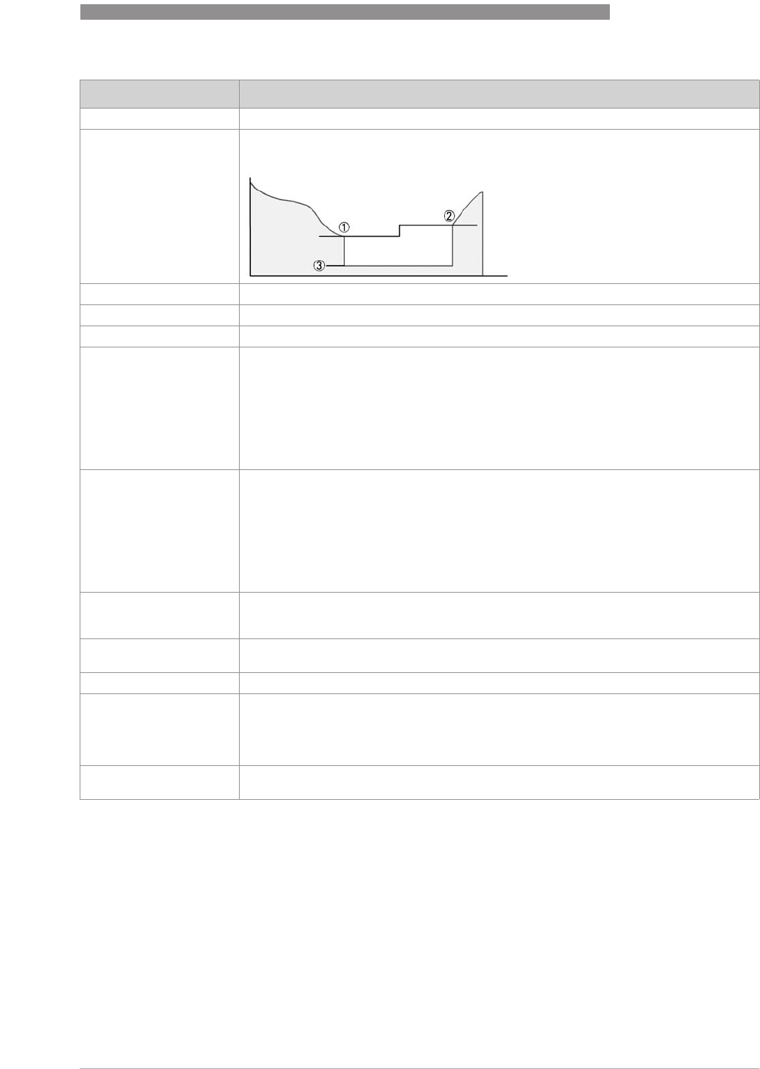
OPERATION
6
55
H250 M40
www.krohne.com07/2016 - 4000640704 - MA H250-M40 R04 en
3.12 EDIT UNIT
3.12 EDIT UNIT3.12 EDIT UNIT
3.12 EDIT UNIT User-defined unit with conversion to calibrated unit.
3.13 L.FL.CUTOFF
3.13 L.FL.CUTOFF3.13 L.FL.CUTOFF
3.13 L.FL.CUTOFF L.FL.CUTOFF stands for low flow cutoff.
To ensure a stable zero point of the current output, the current output can be set to a
stable value of "4.00mA" 3 in a selectable range.
3.13.1
CONTROL OFF LFC function is not active.
CONTROL ON L.FL.CUTOFF function is active.
3.13.2 LFC ON VAL Switch-on value 1:
Value range 1…19% (of full scale range)
The flow is greater than the switch-on value. The current output corresponds to this.
If the flow rate falls, the current output follows until the switch-on value 1.
If the flow value continues to fall, the current output is switched to "4.00mA" 3.
Note:
Note:Note:
Note:
The switch-on value to be set must be smaller than the previously selected switch-off
value.
3.13.3 OFF VALUE Switch-off value 2:
Value range 2…20% (of full scale range)
The flow rate is 0. The current output is "4.00mA" 3.
If the flow rate increases, the current output remains at "4.00mA" until it has reached the
switch-off value 2.
Note:
Note:Note:
Note:
The switch-off value to be set must be greater than the previously selected switch-on
value.
3.14 DESCRIPTOR
3.14 DESCRIPTOR3.14 DESCRIPTOR
3.14 DESCRIPTOR 12 digits
Free text input for header in LCD
3.15 ENTRY CODE
3.15 ENTRY CODE3.15 ENTRY CODE
3.15 ENTRY CODE Entry code for the local operating menu.
The entry code is not active by default.
3.15.1 OFF The use of an entry code is not activated.
3.15.2 ON If "YES" is selected, the last code that was entered has to be typed in.
Factory code: → → → ^ ^ ^ ↑ ↑ ↑
If, after confirmation with "YES", the → key is pressed additionally, then a new, individual,
nine digits code can be typed in.
The display shows the required key combination.
3.16 DEFAULT VAL.
3.16 DEFAULT VAL.3.16 DEFAULT VAL.
3.16 DEFAULT VAL. Resetting parameters to factory default.
There is always a safety prompt ("YES / NO"), to avoid accidental resetting.
Selection / Input Explanation
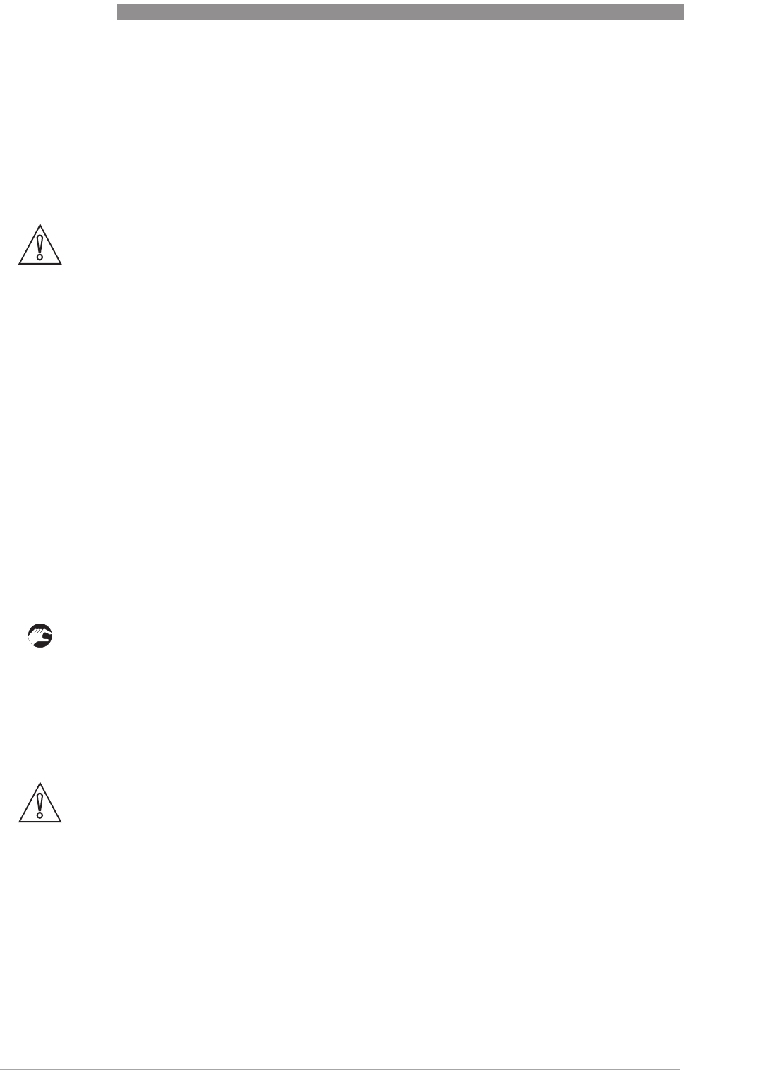
7
SERVICE
56
H250 M40
www.krohne.com 07/2016 - 4000640704 - MA H250-M40 R04 en
7.1 Maintenance
Within the scope of routine maintenance of the system and pipelines, the flowmeter should also
be inspected for signs of fouling, corrosion, mechanical wear and leaks, as well as damage to
the measuring tube and the indicator.
We advise that inspections are carried out at least once per year.
The device must be removed from the pipeline before cleaning.
7.2 Replacement and retrofitting
Some components of the variable area flowmeter can be retrofitted:
•Float damping
Indicator M40:
Indicator M40:Indicator M40:
Indicator M40:
•Limit switch module K1 / K2
•Current output 4..20 mA ESK4 / ESK4A
•Counter module with LCD and I/O ESK4-T
•Fieldbus interface ESK4-PA / FF
7.2.1 Replacing floats
• Remove the device from the pipeline.
• Take the upper snap ring out of the measuring unit.
• Take the upper float stop and float out of the measuring unit.
• Insert the new float into the centre hole of the lower float stop and push into the measuring
unit along with the upper float stop. While doing this, the float's upper guide rod must be
guided through the middle hole of the float stop.
• Insert the snap ring into the measuring unit.
• Fit the device back into the pipeline.
CAUTION!
Pressurised pipes have to be depressurised before removing the device.
Empty the pipelines as completely as possible.
In the case of devices used for measuring aggressive or hazardous media, appropriate safety
precautions must be taken with regard to residual liquids in the measuring unit.
New gaskets have to be used when re-installing the device in the pipeline.
Avoid electrostatic charges when cleaning the surfaces (e.g. sight window)!
CAUTION!
Without a recalibration an additional measuring error is to be expected.
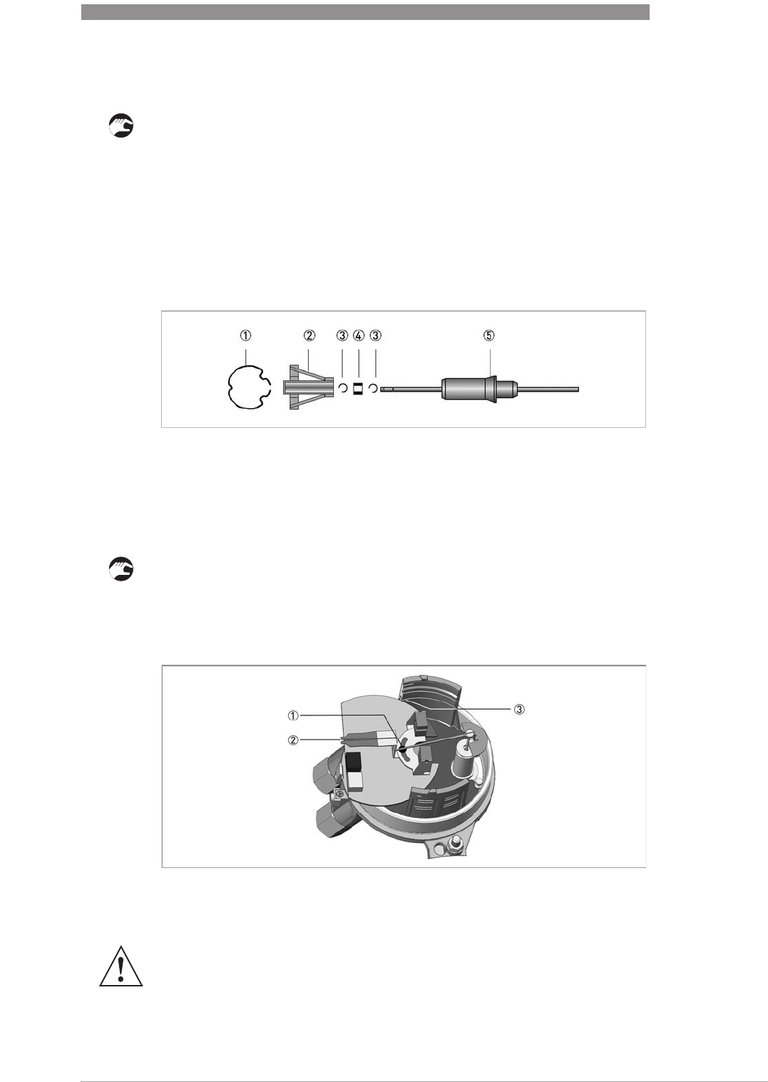
SERVICE
7
57
H250 M40
www.krohne.com07/2016 - 4000640704 - MA H250-M40 R04 en
7.2.2 Retrofitting float damping
• Take the upper snap ring 1 out of the measuring unit.
• Take the upper float stop 2 and float 5 out of the measuring unit.
• Fasten the retaining ring 3 into the lower slot of the float's guide rod.
• Slide ceramic sleeve 4 on to the float's guide rod and attach it to the top slot using the
retaining ring 3.
• Insert float into the lower float guide in the measuring unit.
• Retrofit the supplied damping cylinder with the integrated float stop 2 into the measuring
unit.
• Insert upper snap ring 1.
7.2.3 Retrofitting limit switch
• Remove ESK4 / ESK4A add-on module (if available).
• Merge contact pointer 2 in the middle.
• Loosen the locking screw 1 on the contact pointer.
• Insert the contact module into slot 3 of the bracket until the semi-circle 1 on the contact
board surrounds the pointer cylinder.
The contact module connecting terminals feature a pluggable design and can be removed in
order to connect the cables.
1 Snap ring
2 Float stop
3 Locking ring
4 Ceramic sleeve
5 Float
WARNING!
Do not damage the indicating element!
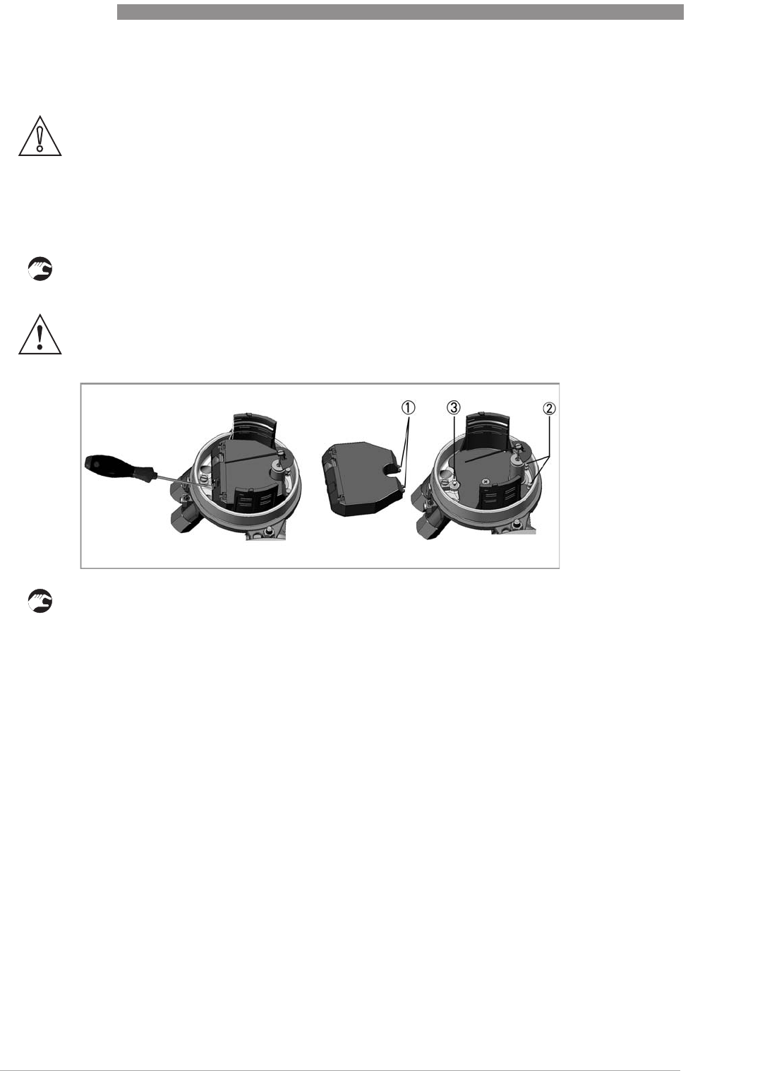
7
SERVICE
58
H250 M40
www.krohne.com 07/2016 - 4000640704 - MA H250-M40 R04 en
7.2.4 Replacement - Retrofitting ESK4 / ESK4A
The ESK4 / ESK4A is factory calibrated, making it possible to replace it or retrofit it without
recalibrating.
• De-energise the ESK4 / ESK4A.
• Lift and remove the ESK4 / ESK4A with a screwdriver.
• The ESK4 / ESK4A plug-in tongues 1 are plugged in under the two bolts 2 on the base plate.
• Slight pressure is used to press the ESK4 / ESK4A onto the spring pins 3 until it stops, firmly
attaching the ESK4 / ESK4A.
If a change in measuring range, product temperature, product, density, viscosity or pressure is
desired, this can be done with the help of a variable area calculation program and with a HART
®
modem.
However, each measuring unit is subject to its own physical limits, which the variable area
calculation program correctly calculates, and may thus reject the desired change. If a change is
performed using the program, the new data is also transmitted to the ESK4 / ESK4A:
•Device identification
•Device address
•Serial number
•Measuring point identifier
•Digital measured value query in flow units, % and mA
•Test / setting functions
•Calibration 4.00 and 20.00 mA
•Set current output to any desired value
CAUTION!
When replacing or retrofitting an ESK4 / ESK4A, it is mandatory to indicate the serial number
(SN) or sales order (SO) when ordering.
This information can be found on the indicator nameplate.
WARNING!
Do not damage the indicating element!

SERVICE
7
59
H250 M40
www.krohne.com07/2016 - 4000640704 - MA H250-M40 R04 en
7.2.5 Replacement - Retrofitting add-on module ESK4-T / PA / FF
The add-on module for the ESK4 / ESK4A can be replaced or retrofitted on-site without removing
the device from the process control.
•ESK4-T (Display module with LCD and I/O)
•ESK4-PA (Profibus PA interface)
•ESK4-FF (Foundation Fieldbus interface)
More detailed information can be found in the service manual included with each retrofit or
replacement set.
7.3 Spare parts availability
The manufacturer adheres to the basic principle that functionally adequate spare parts for each
device or each important accessory part will be kept available for a period of 3 years after
delivery of the last production run for the device.
This regulation only applies to spare parts which are subject to wear and tear under normal
operating conditions.
7.3.1 List of spare parts
Spare part Order number
DN15
DN15DN15
DN15
Float CIV 15, 1.4404 X251041000
Float DIV 15, 1.4404 X251042000
Float TIV 15, 1.4404 X251043000
Float DIVT 15, 1.4404 X251044000
Float TIV 15, Aluminium X251043100
Float TIV 15, Titanium X251043200
Set float stop; standard (1 float stop, 1 span ring) X251050100
Set float stop; gas damping (ZrO
2
)X251050200
Set of float stop; gas damping (PEEK) X251050300
Damping bush (7x8) ZrO
2
incl. 2 retaining rings X251053100
Damping bush (7x8) PEEK incl. 2x retaining rings X251053200
DN25
DN25DN25
DN25
Float CIV 15, 1.4404 X252041000
Float DIV 25, 1.4404 X252042000
Float TIV 25, 1.4404 X252043000
Float DIVT 25, 1.4404 X252044000
Set float stop; standard (1 float stop, 1 span ring) X252050100
Set float stop; gas damping (ZrO
2
)X252050200
Set of float stop; gas damping (PEEK) X252050300
Damping bush (12x8) ZrO
2
incl. 2x retaining ring X252053100
Damping bush (12x8) PEEK incl. 2x retaining ring X252053200

7
SERVICE
60
H250 M40
www.krohne.com 07/2016 - 4000640704 - MA H250-M40 R04 en
DN50
DN50DN50
DN50
Float CIV 55, 1.4404 X253041000
Float DIV 55, 1.4404 X253042000
Float TIV55, 1.4404 X253043000
Float DIVT 55, 1.4404 X253044000
Set float stop; standard (1 float stop, 1 span ring) X253050100
Set float stop; gas damping (ZrO
2
)X253050200
Set of float stop; gas damping (PEEK) X253050300
Damping bush (14x10) ZrO
2
incl. 2x retaining rings X253053100
Damping bush (14x10) PEEK incl. 2x retaining rings X253053200
DN80
DN80DN80
DN80
Float CIV 85, 1.4404 X254041000
Float DIV 85, 1.4404 X254042000
Float TIV 85, 1.4404 X254043000
Float DIVT 85, 1.4404 X254044000
Set float stop; standard (1 float stop, 1 span ring) X254050100
Set float stop; gas damping (ZrO
2
)X254050200
Set of float stop; gas damping (PEEK) X254050300
Damping bush (18x14) ZrO
2
incl. 2x retaining rings X254053100
Damping bush (18x14) PEEK incl. 2x retaining rings X254053200
DN100
DN100DN100
DN100
Float CIV 105, 1.4404 X255041000
Float DIV 105, 1.4404 X255042000
Float DIVT 105, 1.4404 X255044000
Set float stop; standard (1 float stop, 1 span ring) only for bottom! X255050100
Set float stop; gas damping (ZrO
2
)X255050200
Set of float stop; gas damping (PEEK) X255050300
Damping bush (18x14) ZrO
2
incl. 2x retaining rings X254053100
Damping bush (18x14) PEEK incl. 2x retaining rings X254053200
Indicator M40
Indicator M40Indicator M40
Indicator M40
Housing components
Housing componentsHousing components
Housing components
Standard indicator housing M40 complete, no scale * X251110000
Standard indicator housing M40R complete, no scale* (stainless steel, non-coated) X251111000
Standard indicator housing M40S complete, no scale * (2-layer coating) X251112000
Standard cover M40 X251110100
Standard cover M40S (2-layer coating) X251110200
Standard cover M40R (stainless steel, non-coated) X251110400
Cover seal X251112100
M40 standard base plate X251120100
M40S standard base plate (2-layer coating) * X251120200
M40R standard base plate (stainless steel, non-coated) * X251120300
Standard = not pressure-tight
Standard = not pressure-tightStandard = not pressure-tight
Standard = not pressure-tight
Spare part Order number

SERVICE
7
61
H250 M40
www.krohne.com07/2016 - 4000640704 - MA H250-M40 R04 en
Housing components indicator M40
Housing components indicator M40Housing components indicator M40
Housing components indicator M40
Retrofit kit HT extension X251021000
Module carrier (profile rail) X251121100
Set housing attachment parts X251121300
Pointer system, complete * X251122100
Magnetic brake for indicating element X251122200
* Accuracy loss without recalibration
NAMUR 2-wire limit module
NAMUR 2-wire limit moduleNAMUR 2-wire limit module
NAMUR 2-wire limit module
Contact module K1 min I7S23,5-N X251135100
Contact module K1 max I7S23,5-N X251135200
Contact module K2 min / max I7S23,5-N X251135300
Contact module K1 min SC3,5 N0 X251133100
Contact module K1 max SC3,5 N0 X251133200
Contact module K2 min / max SC3,5 N0 X251133300
Contact module K2 min / min min - SJ3,5 S1N / SJ 3,5 SN X251133400
Contact module K2 max / max max - SJ3,5 S1N / SJ 3,5 SN X251133500
Contact module K1 min SJ3,5 SN X251133600
Contact module K1 max SJ3,5 SN X251133700
Contact module K1 min / max SJ3,5 SN X251133800
3-wire limit module, normally closed
3-wire limit module, normally closed3-wire limit module, normally closed
3-wire limit module, normally closed
Contact module K1 min SB3,5 E2 - act.Low X251133900
Contact module K1 max SB3,5 E2 - act.Low X251134000
Contact module K1 min / max SB3,5 E2 - act.Low X251134100
3-wire limit module, normally open
3-wire limit module, normally open3-wire limit module, normally open
3-wire limit module, normally open
Contact module K1 min SB3,5 E2 - act.High X251134200
Contact module K1 max SB3,5 E2 - act.High X251134300
Contact module K1 min / max SB3,5 E2 - act.High X251134400
Electronic modules
Electronic modulesElectronic modules
Electronic modules
ESK4, ESK4-FF, ESK4-PA, ESK4-FF (serial number required)
Cover for add-on modules X251121500
Connection cable ESK4 to add-on modules X251121600
Plugs (10 pcs) for ESK4 connection for bus modules X251132500
Replacement connector
Replacement connectorReplacement connector
Replacement connector
Replacement connector 11/12 for ESK4 X251121700
Replacement connector D/D+ for ESK4-FF or ESK4-PA X251121800
Replacement connectors 1/2/3, 4/5/6, 7/8 for ESK4-T X251121900
Spare part Order number

7
SERVICE
62
H250 M40
www.krohne.com 07/2016 - 4000640704 - MA H250-M40 R04 en
Replacement cable gland
Replacement cable glandReplacement cable gland
Replacement cable gland
Single cable gland M20x1.5 black, plastic - for non-Ex / Ex-i X251150300
Single cable gland M20x1.5 blue, plastic - for non-Ex / Ex-i X251150100
Single cable gland M20x1.5 brass - for non-Ex / Ex-i / Ex-nA X251151000
Single cable gland M20x1.5 brass Ex-d/t - for Ex-d / Ex-t X251152000
Single plug M20x1.5 brass Ex-d/t - for Ex-d / Ex-t X251153000
Single cable gland M20x1.5 stainless steel Ex-d/t - for Ex-d / Ex-t X251154000
Single plug M20x1.5 stainless steel Ex-d/t - for Ex-d / Ex-t X251155000
Spare part Order number
INFORMATION!
Other spare parts on request.
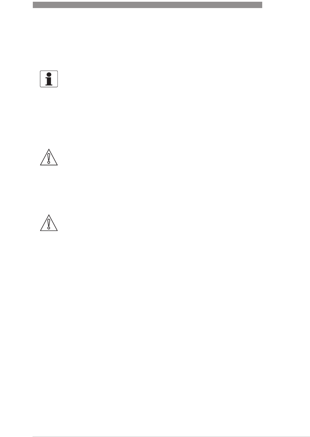
SERVICE
7
63
H250 M40
www.krohne.com07/2016 - 4000640704 - MA H250-M40 R04 en
7.4 Availability of services
The manufacturer offers a range of services to support the customer after expiration of the
warranty. These include repair, maintenance, technical support and training.
7.5 Returning the device to the manufacturer
7.5.1 General information
This device has been carefully manufactured and tested. If installed and operated in accordance
with these operating instructions, it will rarely present any problems.
INFORMATION!
For more precise information, please contact your local sales office.
CAUTION!
Should you nevertheless need to return a device for inspection or repair, please pay strict
attention to the following points:
•
Due to statutory regulations on environmental protection and safeguarding the health and
safety of the personnel, the manufacturer may only handle, test and repair returned devices
that have been in contact with products without risk to personnel and environment.
•
This means that the manufacturer can only service this device if it is accompanied by the
following certificate (see next section) confirming that the device is safe to handle.
CAUTION!
If the device has been operated with toxic, caustic, radioactive, flammable or water-endangering
products, you are kindly requested:
•
to check and ensure, if necessary by rinsing or neutralising, that all cavities are free from
such dangerous substances,
•
to enclose a certificate with the device confirming that is safe to handle and stating the
product used.
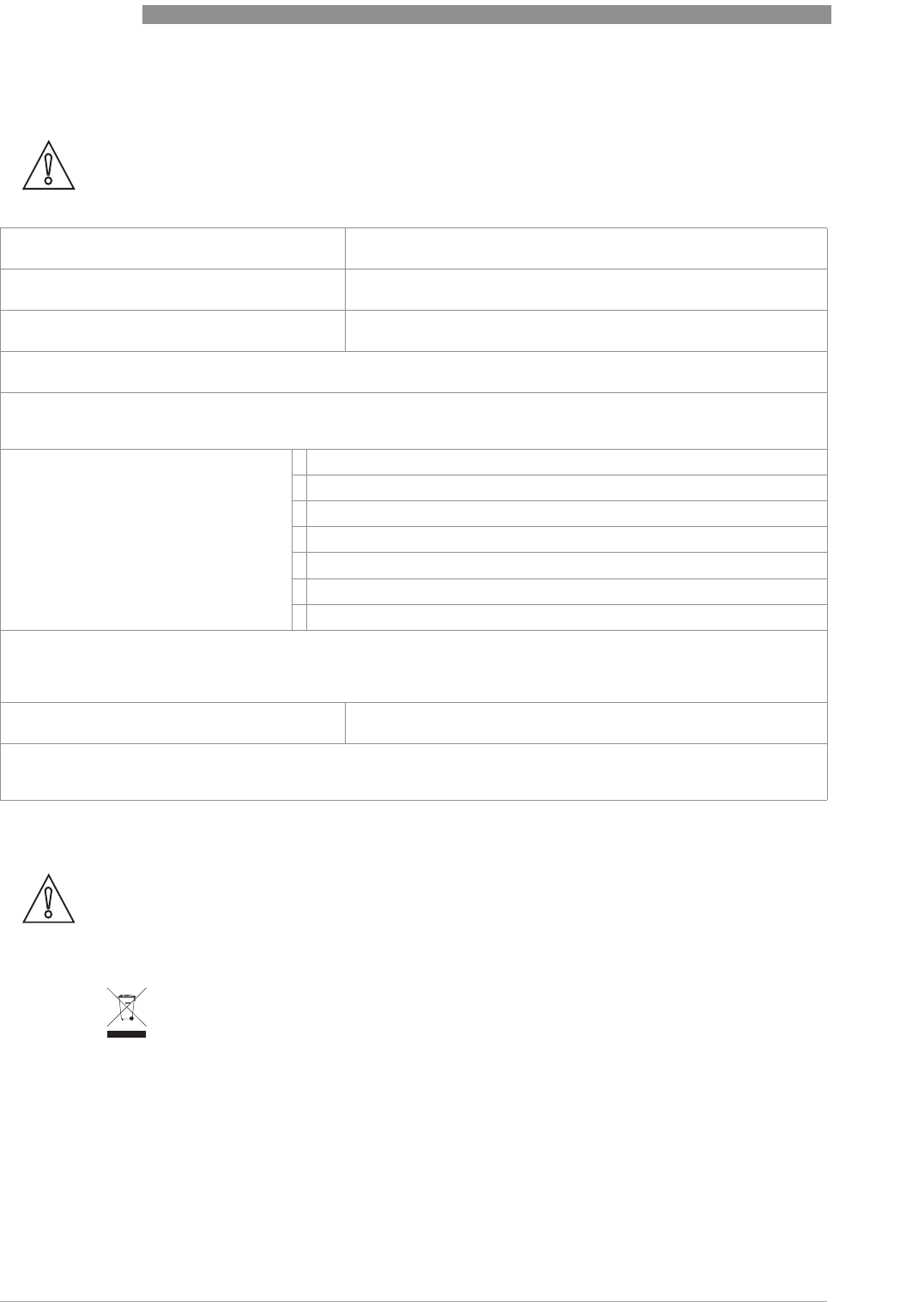
7
SERVICE
64
H250 M40
www.krohne.com 07/2016 - 4000640704 - MA H250-M40 R04 en
7.5.2 Form (for copying) to accompany a returned device
7.6 Disposal
CAUTION!
To avoid any risk for our service personnel, this form has to be accessible from outside of the
packaging with the returned device.
Company: Address:
Department: Name:
Tel. no.: Fax no. and/or Email address:
Manufacturer's order no. or serial no.:
The device has been operated with the following medium:
This medium is: radioactive
water-hazardous
toxic
caustic
flammable
We checked that all cavities in the device are free from such substances.
We have flushed out and neutralized all cavities in the device.
We hereby confirm that there is no risk to persons or the environment through any residual media contained in the
device when it is returned.
Date: Signature:
Stamp:
CAUTION!
Disposal must be carried out in accordance with legislation applicable in your country.
Separate collection of WEEE (Waste Electrical and Electronic Equipment) in the European Union:
Separate collection of WEEE (Waste Electrical and Electronic Equipment) in the European Union:Separate collection of WEEE (Waste Electrical and Electronic Equipment) in the European Union:
Separate collection of WEEE (Waste Electrical and Electronic Equipment) in the European Union:
According to the directive 2012/19/EU, the monitoring and control instruments marked with the
WEEE symbol and reaching their end-of-life must not be disposed of with other waste
must not be disposed of with other wastemust not be disposed of with other waste
must not be disposed of with other waste.
The user must dispose of the WEEE to a designated collection point for the recycling of WEEE or
send them back to our local organisation or authorised representative.
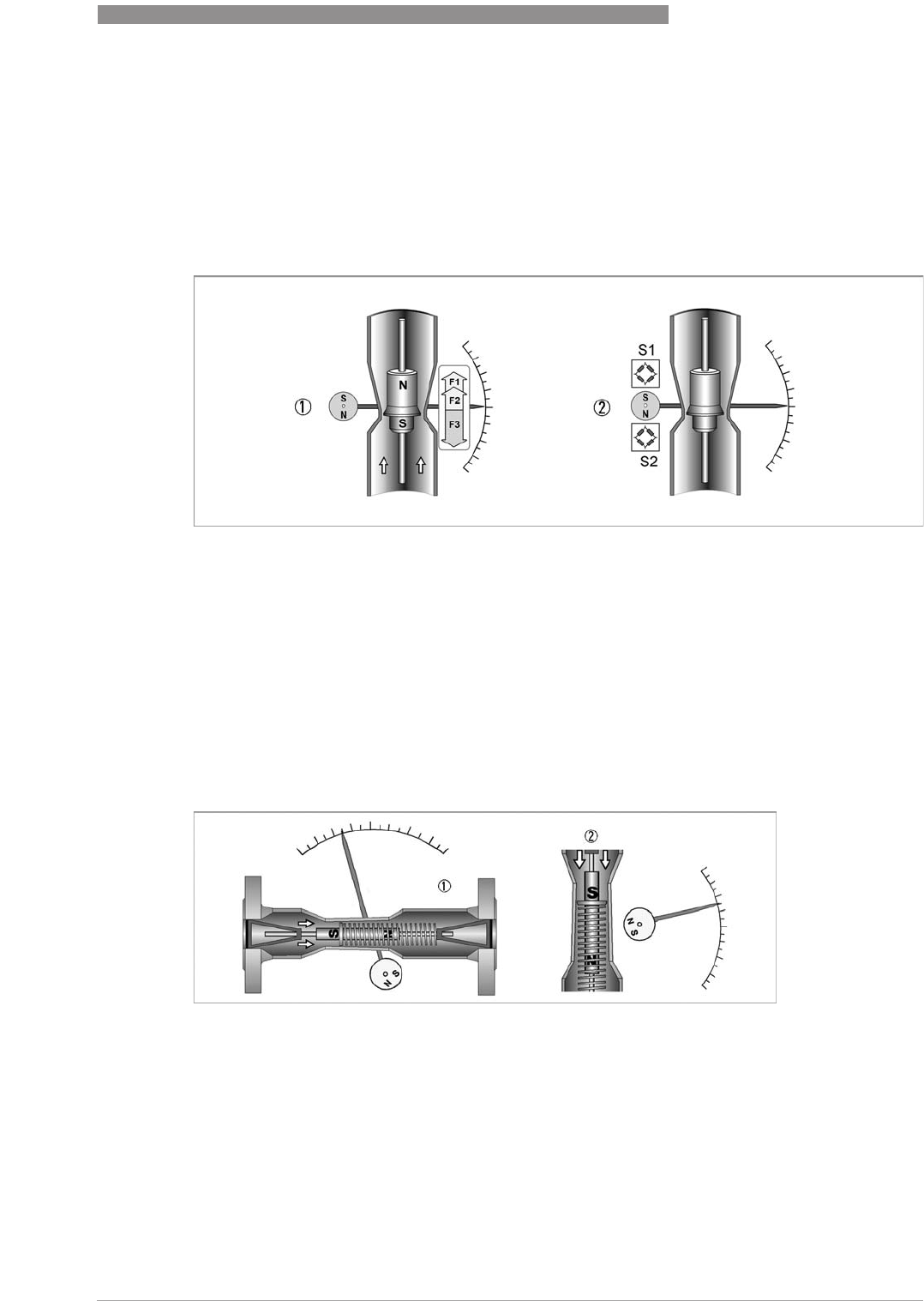
TECHNICAL DATA
8
65
H250 M40
www.krohne.com07/2016 - 4000640704 - MA H250-M40 R04 en
8.1 Functional principle
The H250 flowmeter operates in accordance with the float measuring principle. The measuring
unit consists of a metal cone in which a float can move freely up and down. The flow goes from
bottom to top. The float changes position so that the lifting force acting on it F1 is in equilibrium
with the form drag F2 and its weight F3: F3 = F1 + F2
1 For the indicator, the flow-dependent height of the float in the measuring unit is transmitted
by means of a magnetic coupling and displayed on a scale.
2 For a built-in signal converter (ESK4 / ESK4A), the flow-dependent height of the float in the
measuring unit is detected by the S1 and S2 magnetic field sensors and electronically
processed.
The flowmeter operates in accordance with a modified float measuring principle.
The guided float adjusts itself so that the flow force acting on it is in equilibrium with the
opposing spring force. The flow-dependent position of the float in the measuring unit is
displayed on a scale by means of a magnetic coupling.
1 Indication principle M40 magnetic coupling
2 Magnetic coupling sensors
Operating principle of H250H and H250U
Figure 8-1: Operating principle H250H and H250U
1 H250H - horizontal flow direction
2 H250U - flow direction from top to bottom
8
TECHNICAL DATA
66
H250 M40
www.krohne.com 07/2016 - 4000640704 - MA H250-M40 R04 en
8.2 Technical data
INFORMATION!
•
The following data is provided for general applications. If you require data that is more
relevant to your specific application, please contact us or your local sales office.
•
Additional information (certificates, special tools, software,...) and complete product
documentation can be downloaded free of charge from the website (Downloadcenter).
Measuring system
Application range Flow measurement of liquids, gases and vapours
Function / Measuring principle Variable area measuring principle
Measured value
Primary measured value Float position
Secondary measured value Operating and standard volume flow
Measuring accuracy
Directive VDI/VDE 3513, sheet 2 (q
G
= 50%)
H250 /RR /HC /F 1.6%
H250/C (Ceramic, PTFE)
H250H, H250U, H250 (100 : 1) 2.5%
Precision (repeatability)
Precision (repeatability)Precision (repeatability)
Precision (repeatability)
H250 /RR /HC /F 0.25%
H250H, H250U, H250 (100 : 1) 0.5%
Operating conditions
Temperature
TemperatureTemperature
Temperature
Max. operating temperature TS -196..+300°C / -321...+572°F
Depending on the version (refer to nameplate)
Pressure
PressurePressure
Pressure
Max. operating pressure PS Depending on the version (refer to nameplate)
Max. test pressure PT Depending on the version (refer to nameplate)
Min. required operating pressure 2 times greater than pressure loss (refer to measuring
ranges)
Protection category
Protection categoryProtection category
Protection category
M40, M40S, M40R IP66/68 acc. to EN 60529, NEMA 4/4X/6 acc. to NEMA 250
M40R IP69K acc. to DIN 40050-9
Float damping during gas measurement recommended:
Float damping during gas measurement recommended:Float damping during gas measurement recommended:
Float damping during gas measurement recommended:
DN15...25 / ½"...1" Operating pressure <0.3 barg / 4.4 psig
DN50...100 / 2"...4" Operating pressure <0.2 barg / 2.9 psig
Installation conditions acc. to VDI/VDE 3513, sheet 3
Inlet section ≥ 5 x DN
Outlet section ≥ 3 x DN
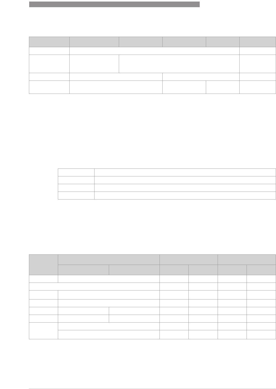
TECHNICAL DATA
8
67
H250 M40
www.krohne.com07/2016 - 4000640704 - MA H250-M40 R04 en
Materials
Other options on request:
•Special materials: e.g. SMO 254/6Mo/1.4547, Titan Grade 2, Hastelloy
®
C276/2.4819,
Monel
®
/2.4360, Inconel
®
/2.4856 a.o.
•Float damping: ceramic or PEEK
•Standard gasket for devices with female thread as insert: O-ring FPM / FKM, others optional
e.g. FFKM, EPDM
Temperatures
TemperaturesTemperatures
Temperatures
For devices to be used in hazardous areas, special temperature ranges apply. These can be
found in the Ex supplementary instructions.
Temperatures H250/M40 - mechanical indicator without auxiliary power
Device Flange Measuring tube Float Float guide Ring orifice
H250/RR Stainless steel CrNi 1.4404 / 316L
H250/HC Hastelloy
®
C4
(2.4610) solid or
plated
Hastelloy
®
C4
H250/F - Food CrNi steel 1.4435 CrNi-steel 1.4435 / 1.4404
H250/C -
Ceramic/PTFE 1
CrNi steel 1.4571 with TFM/PTFE 2 PTFE or Al
2
O
3
with
FFKM gasket
Al
2
O
3
and
PTFE
Al
2
O
3
1DN100/4" only PTFE
2TFM/PTFE liner (electrically non-conductive), conductive PTFE on request
M40 Aluminium, single-layer powder coating (polyester)
M40S Aluminium, two-layer powder coating (epoxy / polyester)
M40R Stainless steel without coating 1.4408 / CF8M
Offshore Wet coating on request
Material Product temperature Ambient temperature
Float Liner [°C] [°F] [°C] [°F]
H250/RR Stainless steel -196...+300 -321...+572 -40...+120 -40…+248
H250/RR screw fitting FPM/FKM -20...+200 -4...+392 -20…+120 -4…+248
H250/HC Hastelloy
®
-196...+300 -321...+572 -40...+120 -40…+248
H250/C PTFE -196...+70 -321...+158 -40...+70 -40…+158
H250/C Ceramic PTFE -196...+150 -321...+302 -40...+70 -40…+158
H250/C Ceramic TFM / Ceramic -196...+250 -321...+482 -40...+120 -40…+248
H250 H/U Spring material stainless steel 1.4301 -40...+100 -40…+212 -40…+120 -40…+248
Spring material Hastelloy
®
2.4610 -40...+200 -40...+392 -40…+120 -40…+248
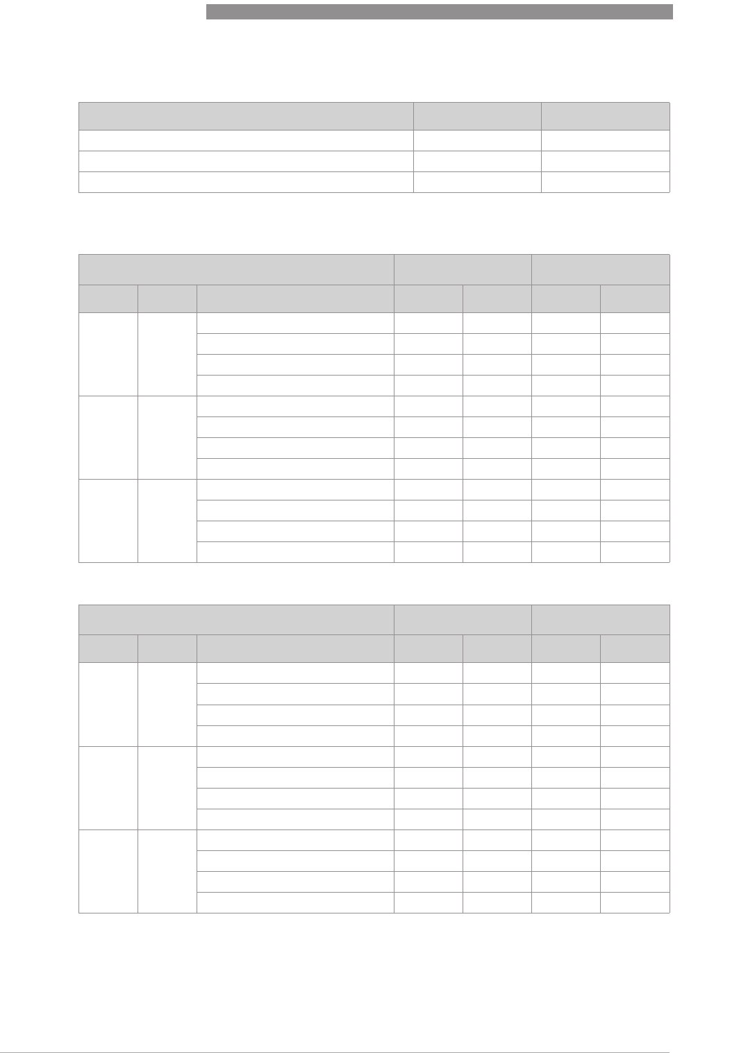
8
TECHNICAL DATA
68
H250 M40
www.krohne.com 07/2016 - 4000640704 - MA H250-M40 R04 en
Ambient temperatures Tamb with electrical components
Maximum product temperatures H250/M40 - with electrical components [°C]
Maximum product temperatures H250/M40 - with electrical components [°F]
1 if there are no heat insulation measures, a heat-resistant cable is necessary (continuous
operating temperature of the cable to be used: +100°C / 212°F)
Version [°C] [°F]
ESK4, ESK4A, ESK4-FF, ESK4-PA 1 -40...+70 -40...+158
Limit switches SJ3,5-SN / I7S23,5-N / Reed SPST -40...+70 -40...+158
Limit switches SC3,5-N0 / SJ3,5-S1N / SB3,5-E2 -25...+70 -13...+158
1Display contrast out of the temperature range 0...+60°C / +32...+140°F decreasing.
T
amb
< +40°C T
amb
< +60°C 1
EN ASME Version with Standard HT Standard HT
DN15,
DN25 ½", 1" ESK4 / ESK4A, -FF, -PA +200 +300 +180 +300
ESK4-T +200 +300 +140 +290
NAMUR limit switch +200 +300 +200 +300
3-wire limit switch +200 +300 +130 +295
DN50 2" ESK4 / ESK4A, -FF, -PA +200 +300 +165 +300
ESK4-T +200 +300 +140 +290
NAMUR limit switch +200 +300 +200 +300
3-wire limit switch +200 +300 +120 +195
DN80,
DN100 3", 4" ESK4 / ESK4A, -FF, -PA +200 +300 +150 +250
ESK4-T +200 +300 +130 +270
NAMUR limit switch +200 +300 +200 +300
3-wire limit switch +190 +300 +110 +160
T
amb
< +104 °F T
amb
< +140 °F 1
EN ASME Version with Standard HT Standard HT
DN15,
DN25 ½", 1" ESK4 / ESK4A, -FF, -PA 392 572 356 572
ESK4-T 392 572 284 554
NAMUR limit switch 392 572 392 572
3-wire limit switch 392 572 266 563
DN50 2" ESK4 / ESK4A, -FF, -PA 392 572 165 572
ESK4-T 392 572 284 554
NAMUR limit switch 392 572 392 572
3-wire limit switch 392 572 248 383
DN80,
DN100 3", 4" ESK4 / ESK4A, -FF, -PA 392 572 302 482
ESK4-T 392 572 266 518
NAMUR limit switch 392 572 392 572
3-wire limit switch 374 572 230 320
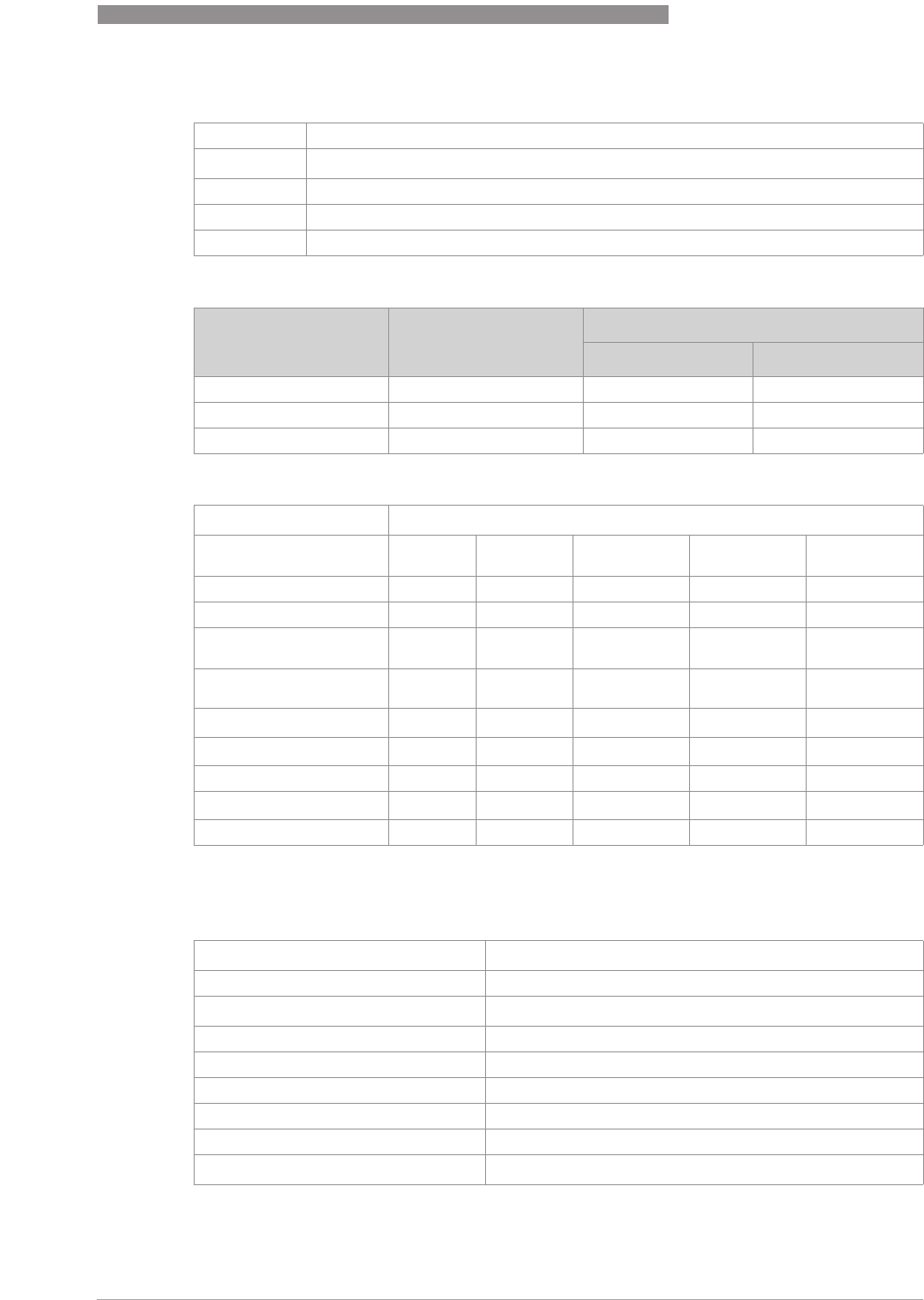
TECHNICAL DATA
8
69
H250 M40
www.krohne.com07/2016 - 4000640704 - MA H250-M40 R04 en
Abbreviation
Cable glands
Limit switches K1/K2
Current output ESK4 / ESK4A
HT High-temperature version
ESK4 / ESK4A 2-wire current output 4…20 mA with HART 5
®
/ HART 7
®
ESK4-T ESK4 with LCD, binary status outputs, digital counter and pulse output
ESK4-FF FOUNDATION FIELDBUS interface
ESK4-PA PROFIBUS PA interface
Material Cable diameter
[mm] [Inch]
M20x1.5 Standard PA 8...13 0.315...0.512
M20x1.5 Nickel-plated brass 10...14 0.394...0.552
M20x1.5 Stainless steel 10...14 0.394...0.552
Terminal connection 2.5 mm
2
Limit switches I7S23,5-N
SC3,5-N0 SJ3,5-SN 1 SJ3,5-S1N 1 SB3,5-E2 Reed
NAMUR (IEC 60947-5-6) Yes Yes Yes No No
Connection type 2-wire 2-wire 2-wire 3-wire 2-wire
Switching element
function NC NC NO PNP NO NC SPST
Nominal voltage U
0
8.2 VDC 8.2 VDC 8.2 VDC 10...30 VDC max. 32 VDC
2
Pointer vane not detected ≥ 3mA ≥ 3mA ≤ 1mA ≤ 0.3 VDC U
0
Pointer vane detected ≤ 1mA ≤ 1mA ≥ 3mA U
B
-3 VDC 0VDC
Continuous current - - - Max. 100 mA Max. 100 mA
No load current I
0
- - - ≤ 15 mA -
Switching cycles - - - - 100000
1safety oriented
2no inductances
Terminal connection 2.5 mm
2
Power supply 14...30 VDC (12...30 VDC without ESK4-T)
Min. power supply for HART
®
20 VDC at 250 Ω load
Measuring signal 4.00...20.00 mA = 0...100% flow value in 2-wire technology
Power supply influence <0.1%
External resistance dependency <0.1%
Temperature influence <5 µA/K
Max. external resistance / load 650 Ω at 30 VDC
Min. load for HART
®
250 Ω

8
TECHNICAL DATA
70
H250 M40
www.krohne.com 07/2016 - 4000640704 - MA H250-M40 R04 en
ESK4-FF
For more details refer to the supplementary instructions "H250 M40 Foundation Fieldbus".
ESK4-PA
For more details refer to the supplementary instructions "H250 M40 Profibus PA".
ESK4 HART® configuration
Manufacturer name (code) KROHNE Messtechnik (0x45 = 69)
Model name / HART
®
revision ESK4 (214 = 0xD6) / HART 5.9
ESK4A (17854 = 0x45BE) / HART 7.4
Physical layer FSK
ESK4 / ESK4A process variable
Values [%] from full scale
range Signal output [mA]
Over range +102.5 (±1%) 20.24...20.56
Device error identification > 106.25 >21.00
Max. current consumption 131.25 25
Multidrop operation 4.5
Physical layer IEC 61158-2 and FISCO model
Communication standard H1 FOUNDATION Fieldbus protocol
ITK version 5.2
Power supply Bus supply
Nominal current 16 mA
Error current 23 mA
Boot-up current after 10 ms < Nominal current
Physical layer IEC 61158-2 and FISCO model
Communication standard Profibus PA profile 3.02
PNO ID 4531 HEX
Power supply Bus supply
Nominal current 16 mA
Error current 23 mA
Boot-up current after 10 ms < Nominal current

TECHNICAL DATA
8
71
H250 M40
www.krohne.com07/2016 - 4000640704 - MA H250-M40 R04 en
ESK4-T with LCD, binary inputs and outputs and digital counter
Binary output
Two binary outputs Galvanically isolated; passive
Mode Switching output NAMUR or transistor (OC)
Configurable as switch contact or pulse output NC / NO or max. 10 pulses/s
NAMUR switch output
Power supply 8.2 VDC
Signal current > 3 mA switching value not reached; < 1 mA switching value reached
Switching output transistor (Open Collector)
Power supply Nominal 24 VDC, maximal 30 VDC
P
max
500 mW
Continuous current Max. 100 mA
No load current I
0
≤ 2mA
Pulse output
T
on
Configurable from 50...500 ms
T
off
Depending on flow rate
Pulse weight Configurable in flow units e.g. 5 pulses/m
3
Binary input
Input Galvanically isolated
Mode Reset counters or Start / Stop
Configurable as active HI / active LO
H signal 16...30 VDC
Internal resistance R
i
Typ. 20 kΩ
T
on
(active) ≥ 500 ms
LC display
Technology Passive graphic LCD
Display Measurement with units and/or counter reading with units. Counter reading
max. 11-digit with power failure proof storage.
Binary flags for limit value status. 0...100% bargraph for measurement.
NE 107 diagnostic status symbols. Plain text menu for configuration.
Configuration Local plain text menu navigation via microswitch or bar magnet or using
DD/DTM software

8
TECHNICAL DATA
72
H250 M40
www.krohne.com 07/2016 - 4000640704 - MA H250-M40 R04 en
Approvals
Standard Display Marking
ATEX / IECEx M40 mechanical II2GD IIC
II3GD IIC
M40 electrical II2G Ex ia IIC T6 Gb
II2G Ex d IIC T6 Gb
II3G Ex nA IIC T6 Gc
II2D Ex t IIIC T70°C Db
II2D Ex ia IIIC T85°C Db
FM (USA) NEC500
FM (Canada)
NEC505
M40 electrical IS Class I Div 1
XP Class I Div 1
NI Class I Div 2
DIP Class II / III Div 1
NEPSI M40 electrical Ex ia, Ex d, Ex nA, Ex t
CCOE/PESO M40 electrical Ex ia, Ex d
EAC/GOST M40 electrical Ex ia, Ex d
INMETRO M40 electrical Ex ia, Ex d, Ex nA, Ex t
KGS M40 electrical Ex ia, Ex d, Ex nA, Ex t
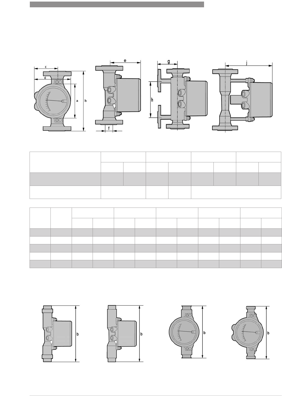
TECHNICAL DATA
8
73
H250 M40
www.krohne.com07/2016 - 4000640704 - MA H250-M40 R04 en
8.3 Dimensions and weights
Dimensions H250/M40
1 without cable gland; 2 Ex d, Ex t, Ex nA +10 mm / 0.39"
Front view Side view with heating High-temperature
a b d h
[mm] ["] [mm] ["] [mm] ["] [mm] ["]
H250/RR Flange
H250/F Clamp connection
141 5.56 250 9.85 150 5.91 150 5.91
H250/RR from 2" 600 lb
ISO 228 / ASME B1.20.1 / SMS
300 11.82
EN ASME c 1e 2Ø f g j
[mm] ["] [mm] ["] [mm] ["] [mm] ["] [mm] ["]
DN15 ½"94 3.70 114 4.49 20 0.80 97 3.82 197 7.76
DN25 1" 94 3.70 127 5.00 32 1.28 109 4.27 209 8.23
DN50 2" 107 4.22 141 5.55 65 2.57 125 4.90 222 8.74
DN80 3" 107 4.22 157 6.18 89 3.51 143 5.61 238 9.37
DN100 4" 107 4.22 167 6.57 114 4.50 150 5.91 248 9.76
ISO 228 / ASME B1.20.1
Female thread screwed
ISO 228 / ASME B1.20.1
Female thread welded
H250/F 1 Clamp
connection
H250/F screw connection
DIN 11851
1 Stainless steel 1.4435 - EHEDG tested - wetted surfaces Ra ≤ 0.8 / 0.6 µm

8
TECHNICAL DATA
74
H250 M40
www.krohne.com 07/2016 - 4000640704 - MA H250-M40 R04 en
Weights
WeightsWeights
Weights
Process connections
Process connectionsProcess connections
Process connections
Higher pressure ratings and other connections on request
H250 Heating
Nominal size EN 1092-1 with flange connection with Ermeto connection
EN ASME [kg] [lb] [kg] [lb] [kg] [lb]
DN15 ½"3.5 7.7 5.6 12.6 3.9 8.6
DN25 1" 511 7.5 16.5 5.8 12.8
DN50 2" 8.2 18.1 11.2 24.7 9.5 21
DN80 3" 12.2 26.9 14.8 32.6 13.1 28.9
DN100 4" 14 30.9 17.4 38.4 15.7 34.6
H250/C [Ceramic / PTFE] Screw connection
Nominal size EN 1092-1 ASME 150 lb ASME 300 lb DIN 11864-1
EN ASME [kg] [lb] [kg] [lb] [kg] [lb] [kg] [lb]
DN15 ½“ 3.5 7.7 3.2 7.1 3.5 7.7 24.4
DN25 1“511 5.2 11.5 6.8 15 3.5 7.7
DN50 2“10 22.1 10 22.1 11 24.3 511
DN80 3“13 28.7 13 28.7 15 33.1 7.6 16.8
DN100 4“15 33.1 16 35.3 17 37.5 10.3 22.7
Standard Conn. dim. Pressure rating
Flanges (H250/RR /HC /C) EN 1092-1 DN15...150 PN16...250
ASME B16.5 ½...6" 150...2500 lb
JIS B2220 15…100 10...20K
Clamp connections (H250/RR /F) DIN 32676 DN15...100 10...16 bar
ISO 2852 Size 25...139.7 10...16 bar
Screw connections (H250/RR /HC /F) DIN 11851 DN15...100 25...40 bar
SMS 1146 1...4" 6barg/ 88.2psig
Female thread welded (H250/RR /HC) ISO 228 G½...G2" ≥ 50 barg / 735 psig
ASME B1.20.1 ½…2" NPT
Female thread (H250/RR /HC) with insert, FPM
gasket and union nut ISO 228 G½…2" ≤ 50 barg / 735 psig
ASME B1.20.1 ½…2" NPT
Thread connection aseptic (H250/F) DIN 11864-1 DN15…50 PN40
DN80…100 PN16
Flange aseptic (H250/F) DIN 11864-2 DN15…50 PN40
DN80…DN100 PN16
Measuring device (H250/RR /HC) with heating:
Measuring device (H250/RR /HC) with heating:Measuring device (H250/RR /HC) with heating:
Measuring device (H250/RR /HC) with heating:
Heating with flange connection EN 1092-1 DN15 PN40
ASME B16.5 ½"150 lb / RF
Heating pipe connection for Ermeto -E12 PN40
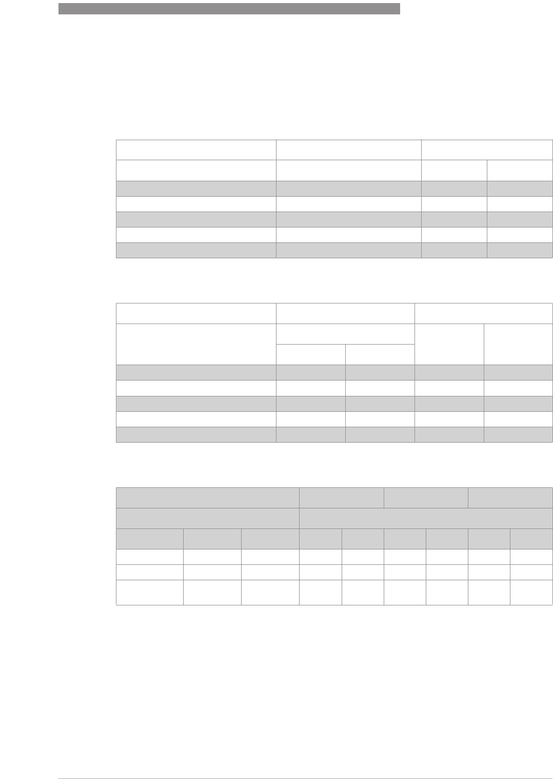
TECHNICAL DATA
8
75
H250 M40
www.krohne.com07/2016 - 4000640704 - MA H250-M40 R04 en
Bolts and tightening torques
For measuring devices with PTFE liner or ceramic liner and PTFE raised face, tighten the flange
threads with the following torques:
Nominal sizes EN
Nominal size ASME
Pressure tightness (vacuum) H250/C
Stud bolts Tightening torques
Nominal size acc. to EN 1092-1 Quantity x size [Nm] [lb-ft]
DN15 PN40 1 4x M12 9.8 7.1
DN25 PN40 1 4x M12 21 15
DN50 PN40 1 4x M16 57 41
DN80 PN16 1 8x M16 47 34
DN100 PN16 1 8x M16 67 48
1standard connections; other connections on request
Stud bolts Tightening torques
Nominal size acc. to ASME B16.5 Quantity x size [Nm] [lb-ft]
150 lb 300 lb
½" 150 lb / 300 lb 1 4x ½"4x ½"5.2 3.8
1" 150 lb / 300 lb 1 4x ½"4x 5/8" 10 7.2
2" 150 lb / 300 lb 1 4x 5/8" 8x 5/8" 41 30
3" 150 lb / 300 lb 1 4x 5/8" 8x ¾"70 51
4" 150 lb / 300 lb 1 8x 5/8" 8x ¾"50 36
1standard connections; other connections on request
Max. process temperature +70°C / +158°F+150°C / +302°F+250°C / +482°F
Min. operating pressure
Nominal size Float Liner [mbara] [psia] [mbara] [psia] [mbara] [psia]
DN15...100 PTFE PTFE 100 1.45 ----
DN15...80 Ceramic PTFE 100 1.45 250 3.63 - -
DN15...80 Ceramic TFM /
Ceramic 100 1.45 100 1.45 100 1.45
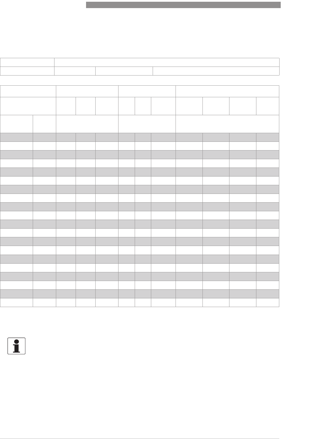
8
TECHNICAL DATA
76
H250 M40
www.krohne.com 07/2016 - 4000640704 - MA H250-M40 R04 en
8.4 Measuring ranges
H250/RR - Stainless Steel, H250/HC - Hastelloy®
Reference condition for gas measurements:
Reference condition for gas measurements:Reference condition for gas measurements:
Reference condition for gas measurements:
Flow measurements for gases are attributed to
Nl/h or Nm
3
/h: Volume flow at standard (norm.) conditions 0°C - 1.013 bara (DIN 1343)
Measuring span: 10 : 1
Flow values: Values = 100% Water: +20°C/ +68°FAir: +20°C/ +68°F, 1.013 bara / 14.7 psia
Water Air Max. pressure loss
Float TIV CIV DIV TIV
Alu.
TIV DIV TIV
Alu.
TIV CIV DIV
Nominal
size
Cone [l/h] [Nm
3
/h] [mbar]
DN15, ½"K 15.1 18 25 -0.42 0.65 -12 21 26 -
K 15.2 30 40 -0.7 1 - 12 21 26 -
K 15.3 55 63 - 1 1.5 -12 21 26 -
K 15.4 80 100 -1.7 2.2 -12 21 26 -
K 15.5 120 160 -2.5 3.6 -12 21 26 -
K 15.6 200 250 -4.2 5.5 -12 21 26 -
K 15.7 350 400 700 6.7 10 18 1 12 21 28 38
K 15.8 500 630 1000 10 14 28 1 13 22 32 50
K 15.8 - - 1600 2 - - 50 2 - - - 85
DN25, 1" K 25.1 480 630 1000 9.5 14 -11 24 32 72
K 25.2 820 1000 1600 15 23 -11 24 33 74
K 25.3 1200 1600 2500 22 35 -11 25 34 75
K 25.4 1700 2500 4000 37 50 110 1 12 26 38 78
K 25.5 3200 4000 6300 62 95 180 1 13 30 45 103 3
DN50, 2" K 55.1 2700 6300 8400 58 80 230 1 813 74 60
K 55.2 3600 10000 14000 77 110 350 1 813 77 69
K 55.3 5100 16000 25000 110 150 700 1 913 84 104
DN80, 3" K 85.1 12000 25000 37000 245 350 1000 1 816 68 95
K 85.2 16000 40000 64000 280 400 1800 1 916 89 125
DN100, 4" K105.1 19000 63000 100 000 -550 2800 1 - - 120 220
1P >0.5 bar
2with TR float
3300 mbar with damping (gas measurement)
INFORMATION!
The operating pressure should be at least double the pressure loss for liquids and five times for
gases. The indicated pressure losses are valid for water and air at maximum flow rate. Other
flow ranges on request. Conversion of other media or operating data is performed using the
calculation method in accordance with VDI/VDE directive 3513.
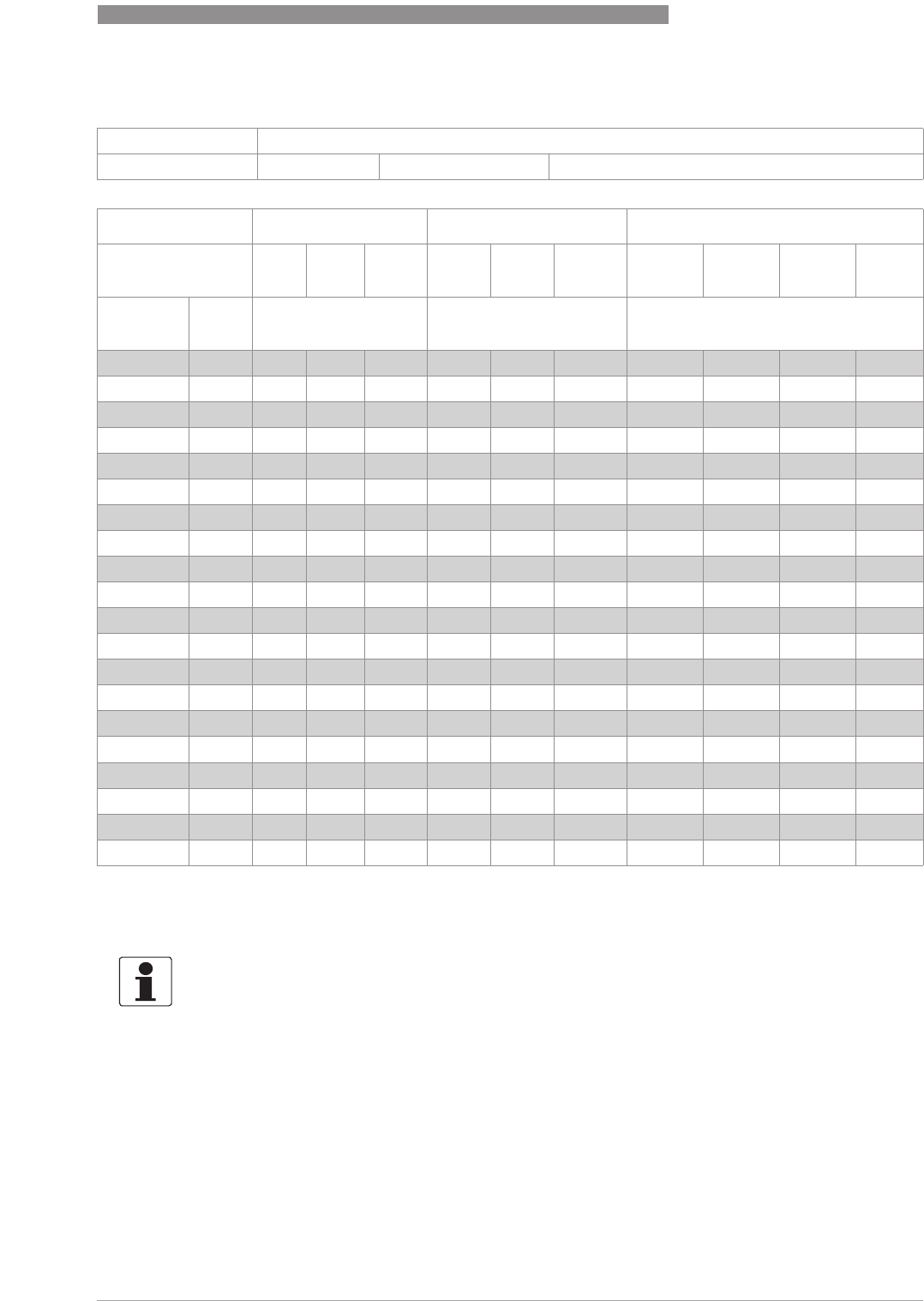
TECHNICAL DATA
8
77
H250 M40
www.krohne.com07/2016 - 4000640704 - MA H250-M40 R04 en
H250/RR - stainless steel, H250/HC - Hastelloy®
Reference condition for gas measurements:
Reference condition for gas measurements:Reference condition for gas measurements:
Reference condition for gas measurements:
Flow measurements for gases are attributed to
SCFM or SCFH: Volume flow at standard (std.) conditions 15°C - 1.013 bara (ISO 13443)
Measuring span: 10 : 1
Flow values: Values = 100% Water: +20°C/ +68°FAir: +20°C/ +68°F, 1.013 bara / 14.7 psia
Water Air Max. pressure loss
Float TIV CIV DIV TIV
Alu.
TIV DIV TIV
Alu.
TIV CIV DIV
Nominal
size
Cone [GPH] [SCFM] [psig]
DN15, ½"K 15.1 4.76 6.60 -0.26 0.40 -0.18 0.31 0.38 -
K 15.2 7.93 10.6 -0.43 0.62 -0.18 0.31 0.38 -
K 15.3 14.5 16.6 -0.62 0.93 -0.18 0.31 0.38 -
K 15.4 21.1 26.4 -1.05 1.36 -0.18 0.31 0.38 -
K 15.5 31.7 42.3 -1.55 2.23 -0.18 0.31 0.38 -
K 15.6 52.8 66.0 -2.60 3.41 -0.18 0.31 0.38 -
K 15.7 92.5 106 185 4.15 6.20 11.2 1 0.18 0.31 0.41 0.56
K 15.8 132 166 264 6.20 8.68 17.4 1 0.19 0.32 0.47 0.74
K 15.8 - - 423 2 - - 31.0 2 ---1.25
DN25, 1" K 25.1 127 166 264 5.89 8.68 -0.16 0.35 0.47 1.06
K 25.2 217 264 423 9.30 14.3 -0.16 0.35 0.49 1.09
K 25.3 317 423 660 13.6 21.7 -0.16 0.37 0.50 1.10
K 25.4 449 660 1057 22.9 31.0 68.2 1 0.18 0.38 0.56 1.15
K 25.5 845 1057 1664 38.4 58.9 111 1 0.19 0.44 0.66 1.51 3
DN50, 2" K 55.1 713 1664 2219 36.0 49.6 143 1 0.12 0.19 1.09 0.88
K 55.2 951 2642 3698 47.7 68.2 217 1 0.12 0.19 1.13 1.01
K 55.3 1347 4227 6604 68.2 93.0 434 1 0.13 0.19 1.23 1.53
DN80, 3" K 85.1 3170 6604 9774 152 217 620 1 0.12 0.24 1.00 1.40
K 85.2 4227 10567 16907 174 248 1116 1 0.13 0.24 1.31 1.84
DN100, 4" K105.1 5019 16643 26418 -341 1736 1 -1.76 3.23
1P >7.4 psig
2with TR float
34.4 psig with damping (gas measurement)
INFORMATION!
The operating pressure should be at least double the pressure loss for liquids and five times for
gases. The indicated pressure losses are valid for water and air at maximum flow rate. Other
flow ranges on request. Conversion of other media or operating data is performed using the
calculation method in accordance with VDI/VDE directive 3513.
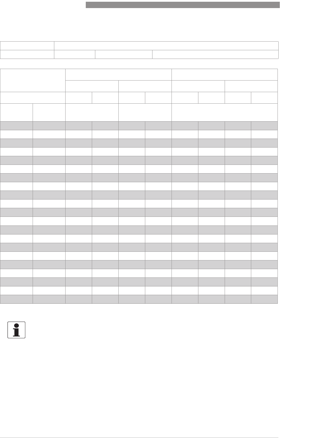
8
TECHNICAL DATA
78
H250 M40
www.krohne.com 07/2016 - 4000640704 - MA H250-M40 R04 en
H250/C - Ceramic/PTFE
Reference condition for gas measurements:
Reference condition for gas measurements:Reference condition for gas measurements:
Reference condition for gas measurements:
Flow measurements for gases are attributed to
Nl/h or Nm
3
/h: Volume flow at standard (norm.) conditions 0°C - 1.013 bara (DIN 1343)
Measuring span: 10 : 1
Flow values: Values = 100% Water: +20°C/ +68°FAir: +20°C/ +68°F, 1.013 bara / 14.7 psia
Flow Max. pressure loss
Water Air Water Air
Liner / Float PTFE Ceramic PTFE Ceramic PTFE Ceramic PTFE Ceramic
Nominal
size
Cone [l/h] [Nm
3
/h] [mbar]
DN15, ½"E 17.2 25 30 0.7 -65 62 65 62
E 17.3 40 50 1.1 1.8 66 64 66 64
E 17.4 63 70 1.8 2.4 66 66 66 66
E 17.5 100 130 2.8 468 68 68 68
E 17.6 160 200 4.8 6.5 72 70 72 70
E 17.7 250 250 7 9 86 72 86 72
E 17.8 400 -10 -111 -111 -
DN25, 1" E 27.1 630 500 16 18 70 55 70 55
E 27.2 1000 700 30 22 80 60 80 60
E 27.3 1600 1100 45 30 108 70 108 70
E 27.4 2500 1600 70 50 158 82 158 82
E 27.5 4000 1 2500 120 75 290 100 194 100
DN50, 2" E 57.1 4000 4500 110 140 81 70 81 70
E 57.2 6300 6300 180 200 110 80 110 80
E 57.3 10000 11000 250 350 170 110 170 110
E 57.4 16000 1 ---284 - - -
DN80, 3" E 87.1 16000 16000 - - 81 70 - -
E 87.2 25000 25000 - - 95 85 - -
E 87.3 40000 1 ---243 - - -
DN100, 4" E 107.1 40000 ---100 - - -
E 107.2 60000 1 ---225 - - -
1special float
INFORMATION!
The operating pressure should be at least double the pressure loss for liquids and five times for
gases. The indicated pressure losses are valid for water and air at maximum flow rate. Other
flow ranges on request. Conversion of other media or operating data is performed using the
calculation method in accordance with VDI/VDE directive 3513.
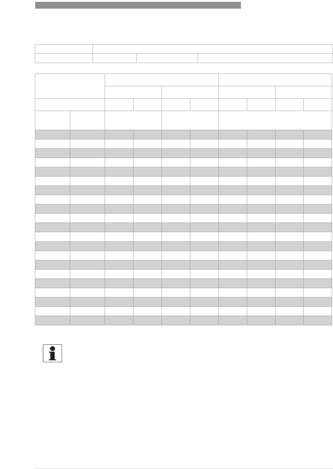
TECHNICAL DATA
8
79
H250 M40
www.krohne.com07/2016 - 4000640704 - MA H250-M40 R04 en
H250/C - Ceramic/PTFE
Reference condition for gas measurements:
Reference condition for gas measurements:Reference condition for gas measurements:
Reference condition for gas measurements:
Flow measurements for gases are attributed to
SCFM or SCFH: Volume flow at standard (std.) conditions 15°C - 1.013 bara (ISO 13443)
Measuring span: 10 : 1
Flow values: Values = 100% Water: +20°C/ +68°FAir: +20°C/ +68°F, 1.013 bara / 14.7 psia
Flow Max. pressure loss
Water Air Water Air
Liner / Float PTFE Ceramic PTFE Ceramic PTFE Ceramic PTFE Ceramic
Nominal
size
Cone [GPH] [SCFM] [psig]
DN15, ½"E 17.2 6.60 7.93 0.43 -0.94 0.90 0.94 0.90
E 17.3 10.6 13.2 0.68 1.12 0.96 0.93 0.96 0.93
E 17.4 16.6 18.5 1.12 1.49 0.96 0.96 0.96 0.96
E 17.5 26.4 34.3 1.74 2.48 0.99 0.99 0.99 0.99
E 17.6 42.3 52.8 2.98 4.03 1.04 1.02 1.02 1.02
E 17.7 66.0 66.0 4.34 5.58 1.25 1.04 1.25 1.04
E 17.8 106 -6.2 -1.61 -1.61 -
DN25, 1" E 27.1 166 132 9.92 11.2 1.02 0.80 1.02 0.80
E 27.2 264 185 18.6 13.6 1.16 0.87 1.16 0.87
E 27.3 423 291 27.9 18.6 1.57 1.02 1.57 1.02
E 27.4 660 423 43.4 31.0 2.29 1.19 2.29 1.19
E 27.5 1056 1 660 74.4 46.5 4.21 1.45 2.81 1.45
DN50, 2" E 57.1 1057 1189 68.2 86.8 1.18 1.02 1.18 1.02
E 57.2 1664 1664 111.6 124 1.60 1.16 1.60 1.16
E 57.3 2642 2906 155 217 2.47 1.60 2.47 1.60
E 57.4 4226 1 ---4.12 - - -
DN80, 3" E 87.1 4227 4227 - - 1.18 1.02 - -
E 87.2 6604 6604 - - 1.38 1.23 -
E 87.3 10567 1 ---3.55 - -
DN100, 4" E 107.1 10567 ---1.45 - -
E 107.2 15850 1 ---3.29 - -
1special float
INFORMATION!
The operating pressure should be at least double the pressure loss for liquids and five times for
gases. The indicated pressure losses are valid for water and air at maximum flow rate. Other
flow ranges on request. Conversion of other media or operating data is performed using the
calculation method in accordance with VDI/VDE directive 3513.
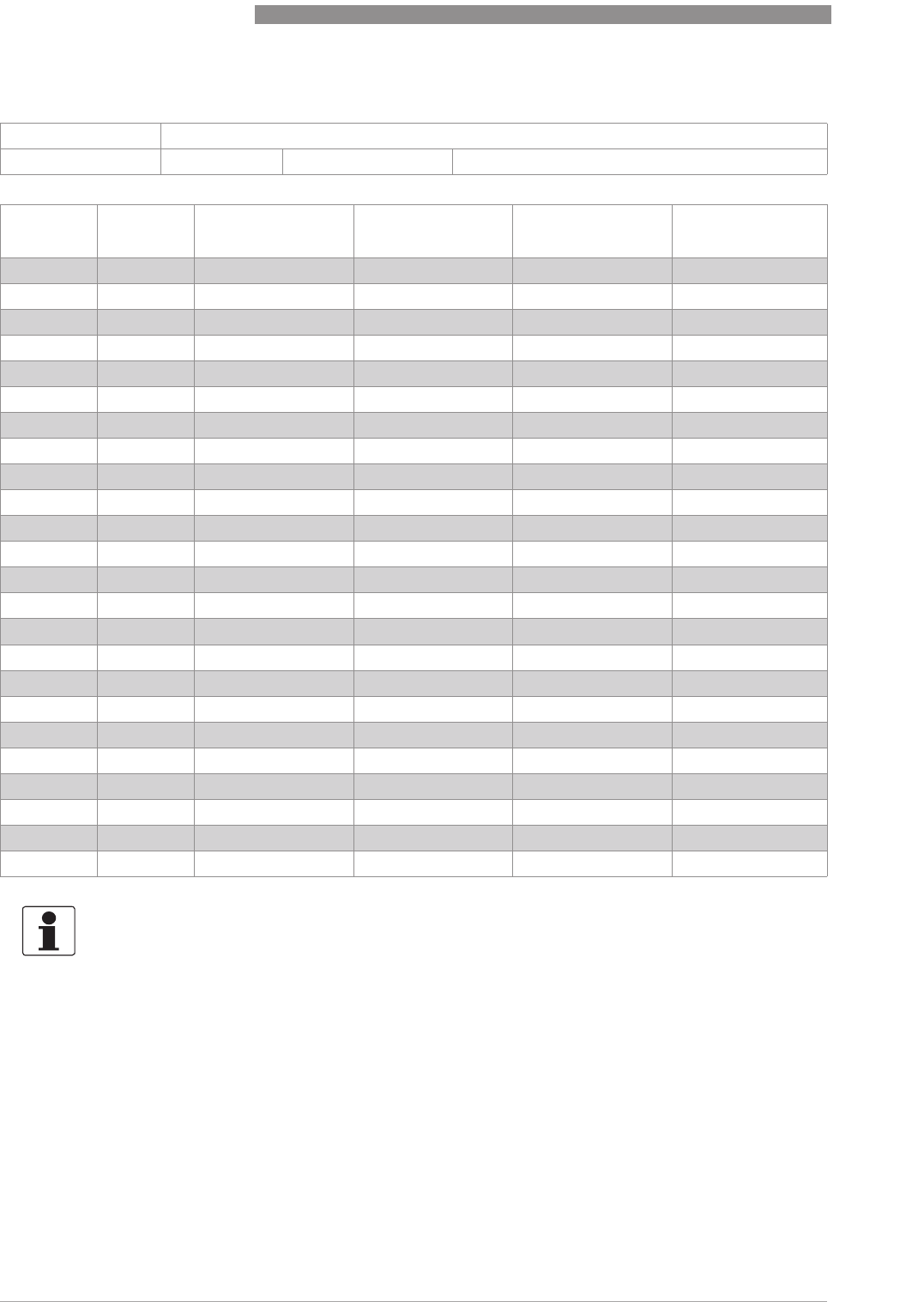
8
TECHNICAL DATA
80
H250 M40
www.krohne.com 07/2016 - 4000640704 - MA H250-M40 R04 en
H250H - Horizontal installation position
Reference condition for gas measurements:
Reference condition for gas measurements:Reference condition for gas measurements:
Reference condition for gas measurements:
Flow measurements for gases are attributed to
Nl/h or Nm
3
/h: Volume flow at standard (norm.) conditions 0°C - 1.013 bara (DIN 1343)
Measuring span: 10 : 1
Flow values: Values = 100% Water: +20°C/ +68°FAir: +20°C/ +68°F, 1.013 bara / 14.7 psia
EN ASME Cone Water [l/h] Air [Nm
3
/h] Pressure loss
[mbar]
DN15 ½K 15.1 70 1.8 195
K 15.2 120 3204
K 15.3 180 4.5 195
K 15.4 280 7.5 225
K 15.5 450 12 250
K 15.6 700 18 325
K 15.7 1200 30 590
K 15.8 1600 40 950
K 15.8 2400 60 1600
DN25 1" K 25.1 1300 35 122
K 25.2 2000 50 105
K 25.3 3000 80 116
K 25.4 5000 130 145
K 25.5 8500 220 217
K 25.5 10000 260 336
DN50 2" K 55.1 10000 260 240
K 55.2 16000 420 230
K 55.3 22000 580 220
K 55.3 34000 900 420
DN80 3" K 85.1 25000 650 130
K 85.2 35000 950 130
K 85.2 60000 1600 290
DN100 4" K 105.1 80000 2200 250
K 105.1 120000 3200 340
INFORMATION!
The operating pressure should be at least double the pressure loss for liquids and five times for
gases. The indicated pressure losses are valid for water and air at maximum flow rate. Other
flow ranges on request. Conversion of other media or operating data is performed using the
calculation method in accordance with VDI/VDE directive 3513.
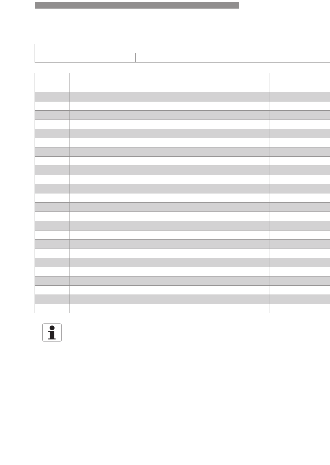
TECHNICAL DATA
8
81
H250 M40
www.krohne.com07/2016 - 4000640704 - MA H250-M40 R04 en
H250H - Horizontal installation position
Reference condition for gas measurements:
Reference condition for gas measurements:Reference condition for gas measurements:
Reference condition for gas measurements:
Flow measurements for gases are attributed to
SCFM or SCFH: Volume flow at standard (std.) conditions 15°C - 1.013 bara (ISO 13443)
Measuring span: 10 : 1
Flow values: Values = 100% Water: +20°C/ +68°FAir: +20°C/ +68°F, 1.013 bara / 14.7 psia
EN ASME Cone Water [GPH] Air [SCFM] Pressure loss
[psig]
DN15 ½K 15.1 18.5 1.12 2.87
K 15.2 31.7 1.86 3.00
K 15.3 47.6 2.79 2.87
K 15.4 74.0 4.65 3.31
K 15.5 119 7.44 3.68
K 15.6 185 11.2 4.78
K 15.7 317 18.6 8.68
K 15.8 423 24.8 14.0
K 15.8 634 37.2 23.5
DN25 1" K 25.1 343 21.7 1.79
K 25.2 528 31.0 1.54
K 25.3 793 49.6 1.71
K 25.4 1321 80.6 2.13
K 25.5 2245 136 3.19
K 25.5 2642 161 4.94
DN50 2" K 55.1 2642 161 3.53
K 55.2 4227 260 3.38
K 55.3 5812 360 3.23
K 55.3 8982 558 6.17
DN80 3" K 85.1 6604 403 1.91
K 85.2 9246 589 1.91
K 85.2 15851 992 4.26
DN100 4" K 105.1 21134 1364 3.68
K 105.1 31701 1984 5.00
INFORMATION!
The operating pressure should be at least double the pressure loss for liquids and five times for
gases. The indicated pressure losses are valid for water and air at maximum flow rate. Other
flow ranges on request. Conversion of other media or operating data is performed using the
calculation method in accordance with VDI/VDE directive 3513.
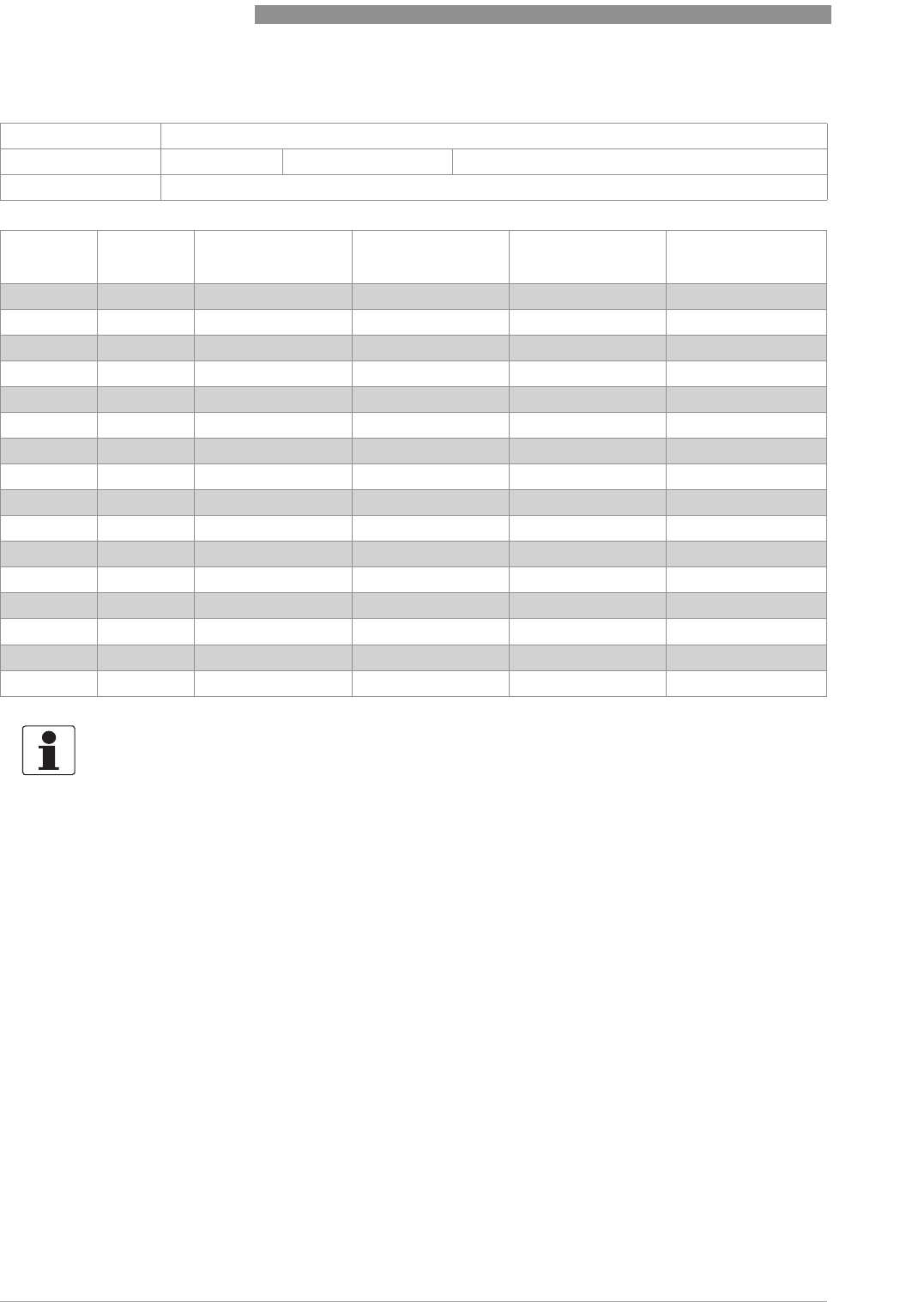
8
TECHNICAL DATA
82
H250 M40
www.krohne.com 07/2016 - 4000640704 - MA H250-M40 R04 en
H250U - Vertical installation position
Reference condition for gas measurements:
Reference condition for gas measurements:Reference condition for gas measurements:
Reference condition for gas measurements:
Flow measurements for gases are attributed to
Nl/h or Nm
3
/h: Volume flow at standard (norm.) conditions 0°C - 1.013 bara (DIN 1343)
Measuring span: 10 : 1
Flow values: Values = 100% Water: +20°C/ +68°FAir: +20°C/ +68°F, 1.013 bara / 14.7 psia
Flow direction Vertical downwards
EN ASME Cone Water [l/h] Air [Nm
3
/h] Pressure loss
[mbar]
DN15 ½"K 15.1 65 1.6 175
K 15.2 110 2.5 178
K 15.3 170 4180
K 15.4 260 6200
K 15.5 420 10 220
K 15.6 650 16 290
K 15.7 1100 28 520
K 15.8 1500 40 840
DN25 1" K 25.1 1150 30 97
K 25.2 1800 45 85
K 25.3 2700 70 92
K 25.4 4500 120 115
K 25.5 7600 200 172
DN50 2" K 55.1 9000 240 220
K 55.2 15000 400 230
K 55.3 21000 550 240
INFORMATION!
The operating pressure should be at least double the pressure loss for liquids and five times for
gases. The indicated pressure losses are valid for water and air at maximum flow rate. Other
flow ranges on request. Conversion of other media or operating data is performed using the
calculation method in accordance with VDI/VDE directive 3513.
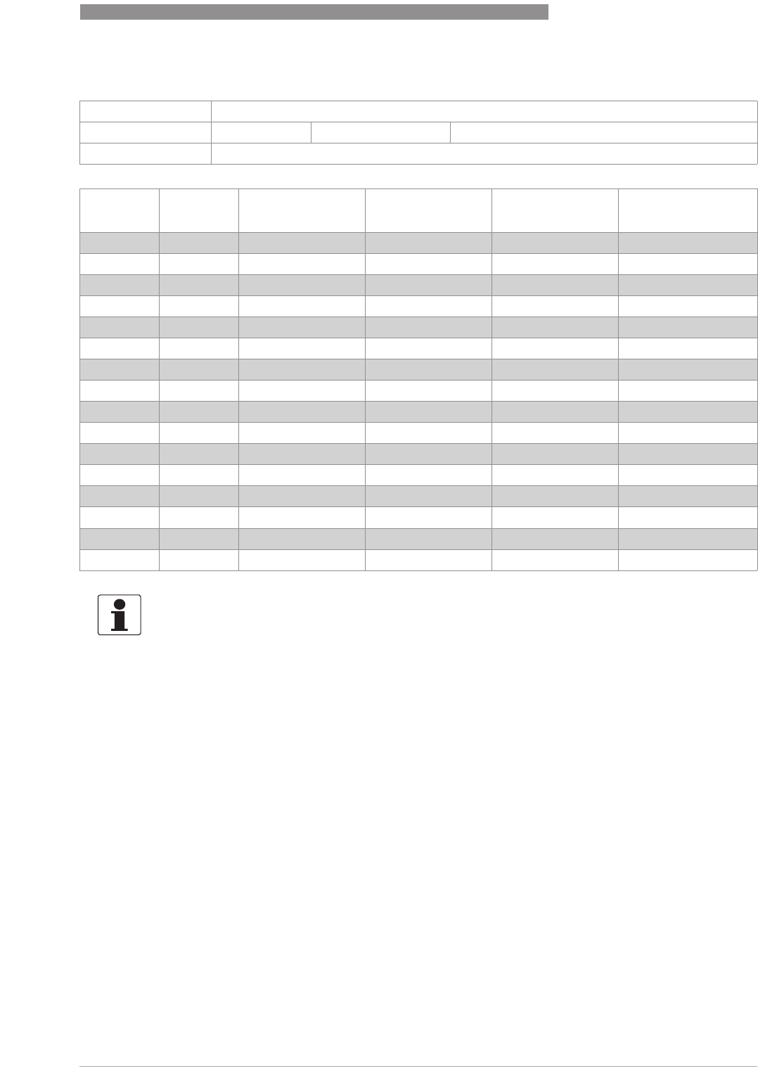
TECHNICAL DATA
8
83
H250 M40
www.krohne.com07/2016 - 4000640704 - MA H250-M40 R04 en
H250U - Vertical installation position
Reference condition for gas measurements:
Reference condition for gas measurements:Reference condition for gas measurements:
Reference condition for gas measurements:
Flow measurements for gases are attributed to
SCFM or SCFH: Volume flow at standard (std.) conditions 15°C - 1.013 bara (ISO 13443)
Measuring span: 10 : 1
Flow values: Values = 100% Water: +20°C/ +68°FAir: +20°C/ +68°F, 1.013 bara / 14.7 psia
Flow direction Vertical downwards
EN ASME Cone Water [GPH] Air [SCFM] Pressure loss
[psig]
DN15 ½"K 15.1 17.2 0.99 2.57
K 15.2 29.1 1.55 2.62
K 15.3 44.9 2.48 2.65
K 15.4 68.7 3.72 2.94
K 15.5 111 6.20 3.23
K 15.6 172 9.92 4.26
K 15.7 291 17.4 7.64
K 15.8 396 24.8 12.3
DN25 1" K 25.1 304 18.6 1.42
K 25.2 476 27.9 1.25
K 25.3 713 43.4 1.35
K 25.4 1189 74.4 1.69
K 25.5 2008 124 2.53
DN50 2" K 55.1 2378 149 3.23
K 55.2 3963 248 3.38
K 55.3 5548 341 3.53
INFORMATION!
The operating pressure should be at least double the pressure loss for liquids and five times for
gases. The indicated pressure losses are valid for water and air at maximum flow rate. Other
flow ranges on request. Conversion of other media or operating data is performed using the
calculation method in accordance with VDI/VDE directive 3513.

KROHNE – Process instrumentation and measurement solutions
•
Flow
•
Level
•
Temperature
•
Pressure
•
Process Analysis
•
Services
Head Office KROHNE Messtechnik GmbH
Ludwig-Krohne-Str. 5
47058 Duisburg (Germany)
Tel.: +49 203 301 0
Fax: +49 203 301 10389
info@krohne.com
© KROHNE 07/2016 - 4000640704 - MA H250-M40 R04 en - Subject to change without notice.
The current list of all KROHNE contacts and addresses can be found at:
www.krohne.com
