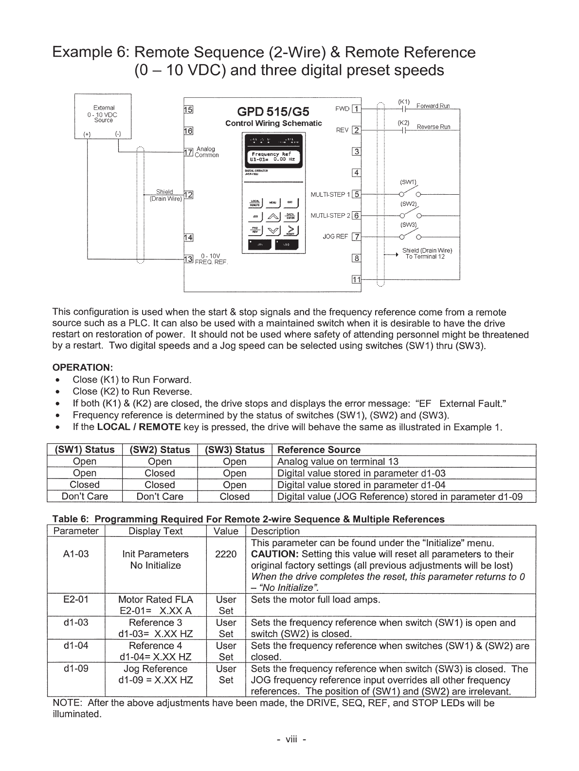
SWV2563 Yaskawa G5 Drive Manual 2 15 12
User Manual: SWV2563
Open the PDF directly: View PDF ![]() .
.
Page Count: 297 [warning: Documents this large are best viewed by clicking the View PDF Link!]
- Cover
- Contents
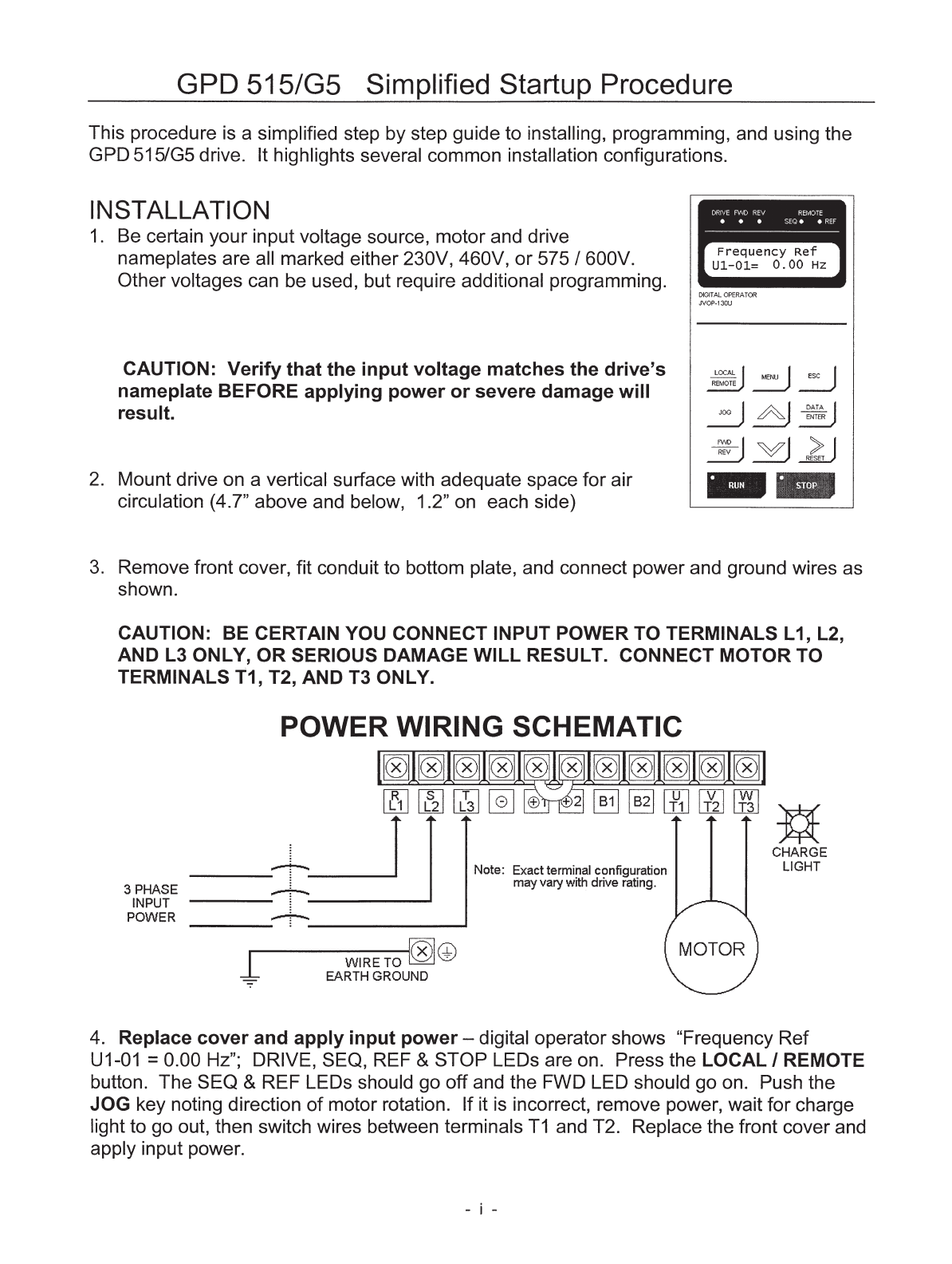
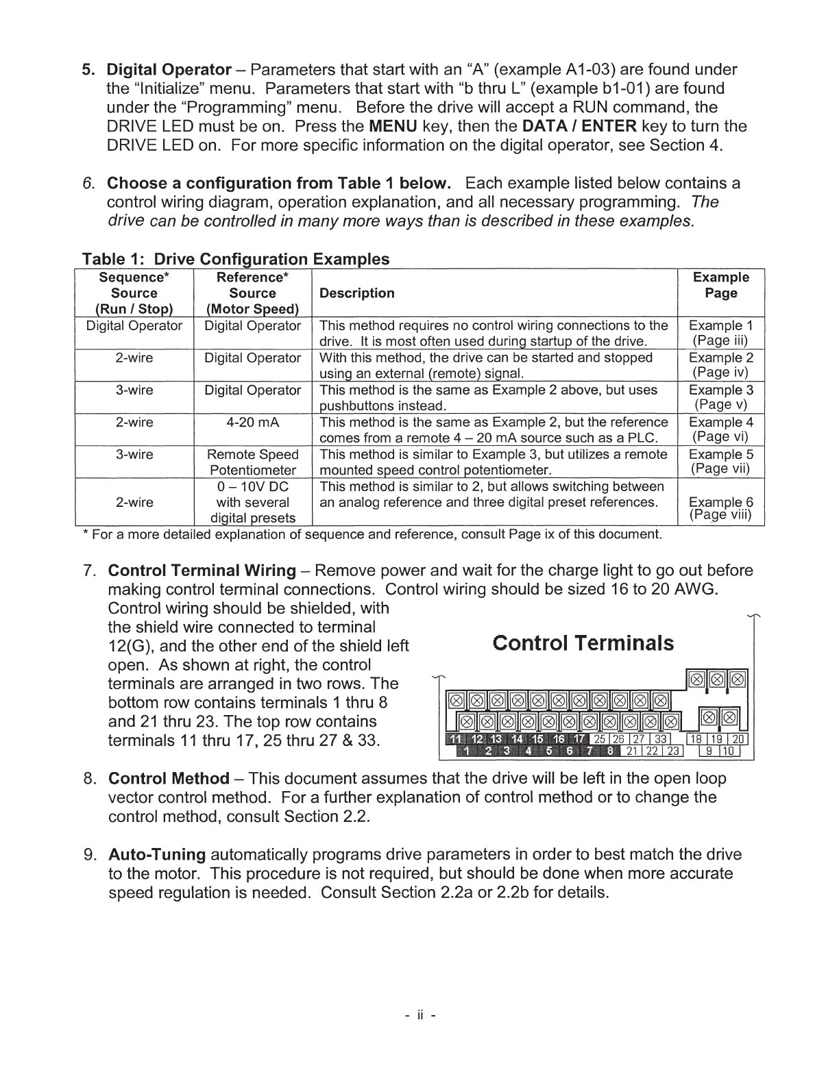
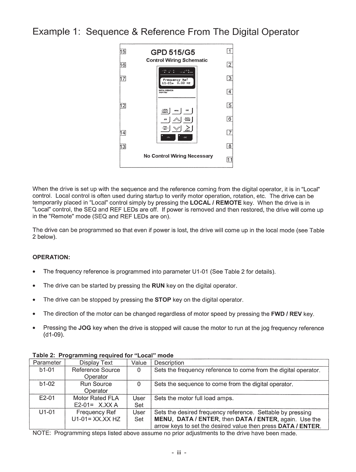
- GPD 515/G5 SIMPLIFIED START-UP PROCEDURE
- QUICK REFERENCE FOR GPD 515/G5 PARAMETERS
- CURRENT RATINGS & HORSEPOWER RANGE
- WARNING/CAUTION STATEMENTS
- 1 - RECEIVING AND INSTALLATION
- 2 - INITIAL START-UP (“LOCAL” CONTROL)
- 3 - OPERATION AT LOAD
- 4 - DIGITAL OPERATOR
- 5 - PROGRAMMABLE FEATURES
- 5.1 General
- 5.2 Accel/Decel Time
- 5.3 Accel/Decel: S-Curve Characteristics
- 5.4 Access Level
- 5.5 Auto-restart
- 5.6 Automatic Frequency Regulator (AFR) Gain
- 5.7 Automatic Speed Regulator (ASR)
- 5.8 Carrier Frequency
- 5.9 Critical Frequency Rejection
- 5.10 DC Injection Braking
- 5.11 Digital Operator Display Selection
- 5.12 Display – Monitor (at Power-up) Selection
- 5.13 Droop
- 5.14 Dwell
- 5.15 Encoder (PG) Parameters
- 5.16 Energy Saving Operation
- 5.17 External Fault Inputs
- 5.18 Frequency Reference Bias/Gain
- 5.19 Frequency Reference Input Signals (Auto/Manual)
- 5.20 Frequency Reference Loss Detection
- 5.21 Frequency Reference Retention
- 5.22 Frequency Reference Upper & Lower Limits
- 5.23 Hunting Prevention
- 5.24 Jog Reference
- 5.25 Local/Remote and Reference Selection
- 5.26 Miscellaneous Parameters
- 5.27 Miscellaneous Protective Functions
- 5.28 MODBUS Control
- 5.29 Momentary Power Loss Ride-thru
- 5.30 Multi-function Analog Inputs (Term. 14 & 16 )
- 5.31 Multi-function Analog Monitor Output (Term. 21-23)
- 5.32 Multi-function Input Terminals (Term. 3-8)
- 5.33 Multi-function Output Terminals (Term. 9 & 10; 25-27)
- 5.34 Phase Loss Detection – Input
- 5.35 Phase Loss Detection – Output
- 5.36 PID Control
- 5.37 Reset Codes; 2-Wire, 3-Wire Initialization
- 5.38 Slip Compensation
- 5.39 Stall Prevention
- 5.40 Stopping Method
- 5.41 Thermal Overload Protection
- 5.42 Torque Compensation
- 5.43 Torque Control (Command)
- 5.44 Torque Detection
- 5.45 Torque Limit
- 5.46 User Parameters
- 5.47 V/f Pattern - Standard
- 5.48 V/f Pattern - Custom
- 5.49 Zero-Servo Control
- 5.50 Zero Speed Control
- 6 - FAULT INDICATION & TROUBLESHOOTING
- Appendix 1 - LISTING OF PARAMETERS
- Appendix 2 - SPECIFICATIONS
- Appendix 3 - CAPACITY & CONTROL METHOD RELATED PARAMETERS
- Appendix 4 - GPD 515 /G5 SPARE PARTS
- Appendix 5 - GPD 515/G5 DIMENSIONS
- Appendix 6 - DYNAMIC BRAKING CONNECTIONS
- Index
- Rear Cover
GPD 515/G5 Technical Manual 04/01/02 SWV: 01114
GPD 515/G5 Drive
Technical Manual
Models: GPD515C- and CIMR-G5M Document Number: TM 4515
GPD 515/G5 Drive
YASKAWA ELECTRIC AMERICA, INC.
Drives Division 16555 W. Ryerson Rd., New Berlin, WI 53151, U.S.A.
Phone: (800) YASKAWA (800-927-5292) Fax: (262) 782-3418
Internet: http://www.drives.com
YASKAWA ELECTRIC AMERICA, INC.
Chicago-Corporate Headquarters
2121 Norman Drive South, Waukegan, IL 60085, U.S.A.
Phone: (800) YASKAWA (800-927-5292) Fax: (847) 887-7310
Internet: http://www.yaskawa.com
MOTOMAN INC.
805 Liberty Lane, West Carrollton, OH 45449, U.S.A.
Phone: (937) 847-6200 Fax: (937) 847-6277
Internet: http://www.motoman.com
YASKAWA ELECTRIC CORPORATION
New Pier Takeshiba South Tower, 1-16-1, Kaigan, Minatoku, Tokyo, 105-0022, Japan
Phone: 81-3-5402-4511 Fax: 81-3-5402-4580
Internet: http://www.yaskawa.co.jp
YASKAWA ELETRICO DO BRASIL COMERCIO LTDA.
Avenida Fagundes Filho, 620 Bairro Saude Sao Paolo-SP, Brasil CEP: 04304-000
Phone: 55-11-5071-2552 Fax: 55-11-5581-8795
Internet: http://www.yaskawa.com.br
YASKAWA ELECTRIC EUROPE GmbH
Am Kronberger Hang 2, 65824 Schwalbach, Germany
Phone: 49-6196-569-300 Fax: 49-6196-888-301
MOTOMAN ROBOTICS AB
Box 504 S38525, Torsas, Sweden
Phone: 46-486-48800 Fax: 46-486-41410
MOTOMAN ROBOTEC GmbH
Kammerfeldstrabe 1, 85391 Allershausen, Germany
Phone: 49-8166-900 Fax: 49-8166-9039
YASKAWA ELECTRIC UK LTD.
1 Hunt Hill Orchardton Woods Cumbernauld, G68 9LF, Scotland, United Kingdom
Phone: 44-12-3673-5000 Fax: 44-12-3645-8182
YASKAWA ELECTRIC KOREA CORPORATION
Paik Nam Bldg. 901 188-3, 1-Ga Euljiro, Joong-Gu, Seoul, Korea
Phone: 82-2-776-7844 Fax: 82-2-753-2639
YASKAWA ELECTRIC (SINGAPORE) PTE. LTD.
Head Office: 151 Lorong Chuan, #04-01, New Tech Park Singapore 556741, Singapore
Phone: 65-282-3003 Fax: 65-289-3003
TAIPEI OFFICE (AND YATEC ENGINEERING CORPORATION)
10F 146 Sung Chiang Road, Taipei, Taiwan
Phone: 886-2-2563-0010 Fax: 886-2-2567-4677
YASKAWA JASON (HK) COMPANY LIMITED
Rm. 2909-10, Hong Kong Plaza, 186-191 Connaught Road West, Hong Kong
Phone: 852-2803-2385 Fax: 852-2547-5773
BEIJING OFFICE
Room No. 301 Office Building of Beijing International Club,
21 Jianguomanwai Avenue, Beijing 100020, China
Phone: 86-10-6532-1850 Fax: 86-10-6532-1851
SHANGHAI OFFICE
27 Hui He Road Shanghai 200437 China
Phone: 86-21-6553-6600 Fax: 86-21-6531-4242
SHANGHAI YASKAWA-TONJI M & E CO., LTD.
27 Hui He Road Shanghai 200437 China
Phone: 86-21-6533-2828 Fax: 86-21-6553-6677
BEIJING YASKAWA BEIKE AUTOMATION ENGINEERING CO., LTD.
30 Xue Yuan Road, Haidian, Beijing 100083 China
Phone: 86-10-6232-9943 Fax: 86-10-6234-5002
SHOUGANG MOTOMAN ROBOT CO., LTD.
7, Yongchang-North Street, Beijing Economic & Technological Development Area,
Beijing 100076 China
Phone: 86-10-6788-0551 Fax: 86-10-6788-2878
YEA, TAICHUNG OFFICE IN TAIWAIN
B1, 6F, No.51, Section 2, Kung-Yi Road, Taichung City, Taiwan, R.O.C.
Phone: 886-4-2320-2227 Fax:886-4-2320-2239
Document Number: TM4515 (Supercedes: YEA-TOA-S616-10.11 and 10.12) 04/01/2002 Software Version: 01114
Data subject to change without notice.

GPD 515/G5 SIMPLIFIED START-UP PROCEDURE ............. i
QUICK REFERENCE FOR GPD 515 PARAMETERS ............... xiv
CURRENT RATINGS & HORSEPOWER RANGE .................... xvii
WARNING/CAUTION STATEMENTS ..................................... xviii
WARRANTY REGISTRATION .................................................. xxi
1 INSTALLATION ....................................................................... 1-1
1.1 General ....................................................................................... 1-1
1.2 Receiving .................................................................................... 1 -1
1.3 Physical Installation .................................................................... 1 - 1
1.4 Electrical Installation .................................................................. 1- 2
1.4.1 Main Circuit Input/Output ..................................................... 1- 2
1.4.2 Grounding ............................................................................. 1-11
1.4.3 Auxiliary Input and Output Power Option Devices ............... 1-11
1.4.3a Conformance to European EMC Directive ............................ 1-13
1.4.4 Control Circuit ...................................................................... 1-15
1.4.5 Interconnection - 2-Wire Control (Fig. 1-3) ........................ 1-20
1.4.6 Interconnection - 3-Wire Control (Fig. 1-4) ........................ 1-22
1.4.7 Encoder/PG-X2 Connections ................................................ 1-24
2 INITIAL START-UP (“LOCAL” CONTROL) ......................... 2-1
2.1 Pre-power Checks ...................................................................... 2-1
2.2 Control Method Selection ........................................................... 2-2
2.2a Power On and Preliminary Checks – Open Loop
Vector Control ............................................................. 2 - 3
2.2b Power On and Preliminary Checks – Flux Vector Control ...... 2-6
2.2c Power On and Preliminary Checks – V/f Control .................. 2-11
2.2d Power On and Preliminary Checks – V/f with PG
Feedback Control ....................................................... 2-14
2.3 Changing the Language on the Digital Operator ...................... 2-19
2.4 Calculating Motor Parameters ................................................... 2-20
2.5 Test Run Using Digital Operator ("Local" Control) ................... 2-24
2.6 Pre-operation Considerations .................................................... 2-27
2.7 Storage Function ...................................................................... 2-27
3 OPERATION AT LOAD ........................................................... 3-1
4 DIGITAL OPERATOR ............................................................... 4- 1
4.1 General ....................................................................................... 4-1
4.2 Display and Keypad .................................................................... 4-1
4.3 Digital Operator Menu Trees ...................................................... 4-4
4.4 Basic Programming ..................................................................... 4 - 8
4.5 Modes of Operation ................................................................... 4-9
Release Date 4/01/2002
xi
CONTENTS
SUBJECT PAGE
PARAGRAPH

xii
5 PROGRAMMABLE FEATURES ................................................ 5- 1
5.1 General ....................................................................................... 5-1
5.2 Accel/Decel Time ....................................................................... 5 - 3
5.3 Accel/Decel: S-Curve Characteristics ........................................ 5 - 6
5.4 Access Level .............................................................................. 5-7
5.5 Auto-restart ............................................................................... 5-7
5.6 Automatic Frequency Regulator (AFR) Gain .............................. 5- 8
5.7 Automatic Speed Regulator (ASR) ............................................ 5-9
5.8 Carrier Frequency ...................................................................... 5-12
5.9 Critical Frequency Rejection ..................................................... 5-13
5.10 DC Injection Braking .................................................................. 5-14
5.11 Digital Operator Display Selection ............................................ 5-17
5.12 Display – Monitor (at Power-up) Selection ............................... 5-19
5.13 Droop ........................................................................................ 5-19
5.14 Dwell ......................................................................................... 5-20
5.15 Encoder (PG) Parameters ......................................................... 5-21
5.16 Energy Saving Operation ........................................................... 5-26
5.17 External Fault Inputs ................................................................. 5-28
5.18 Frequency Reference Command Bias/Gain ............................... 5-29
5.19 Frequency Reference Input Signals (Auto/Manual) .................. 5-31
5.20 Frequency Reference Loss Detection ....................................... 5-33
5.21 Frequency Reference Retention ................................................ 5-33
5.22 Frequency Reference Upper & Lower Limits ............................ 5-34
5.23 Hunting Prevention ................................................................... 5-35
5.24 Jog Reference ........................................................................... 5-36
5.25 Local Remote and Reference Selection .................................... 5-39
5.25 A Local Remote Selection ....................................................... 5-39
5.25 B Multiple Speed Reference Configuration [Multi-step
Speed Operation] .......................................................... 5-40
5.26 Miscellaneous Parameters ......................................................... 5-44
5.27 Miscellaneous Protective Features ............................................ 5-46
5.28 MODBUS Control ....................................................................... 5-48
5.29 Momentary Power Loss Ride-thru ............................................. 5-50
5.30 Multi-function Analog Inputs (Term. 14 & 16 ) ....................... 5-53
5.31 Multi-function Analog Monitor Output (Term. 21-23) .............. 5-57
5.32 Multi-function Input Terminals (Term. 3-8) .............................. 5-58
• Local/Remote ................................................................... 5-62
• External Base Block .......................................................... 5-63
• Speed Search .................................................................... 5-64
• Timer Function .................................................................. 5-66
• Sample/Hold Command .................................................... 5-66
• Up/Down Frequency Setting ............................................ 5-67
• Trim Control ...................................................................... 5-69
SUBJECT PAGE
CONTENTS - Continued
PARAGRAPH

5.33 Multi-function Output Terminals (Term. 9 & 10; 25-27) ......... 5-70
• Frequency or Speed Detection Output Signals ................ 5-73
5.34 Phase Loss Detection – Input ................................................... 5-77
5.35 Phase Loss Detection – Output ................................................ 5-77
5.36 PID Control ................................................................................ 5-78
5.37 Reset Codes; 2-Wire, 3-Wire Initialization ................................ 5-83
5.38 Slip Compensation .................................................................... 5-84
5.39 Stall Prevention ......................................................................... 5-86
5.40 Stopping Method ....................................................................... 5-88
5.41 Thermal Overload Protection .................................................... 5-90
5.42 Torque Compensation ............................................................... 5-93
5.43 Torque Control (Command) ...................................................... 5-95
5.44 Torque Detection ...................................................................... 5-98
5.45 Torque Limit ............................................................................ 5-101
5.45.1 Two Motor Operation ............................................................... 5-104
5.46 User Parameters ...................................................................... 5-106
5.47 V/f Pattern - Standard ............................................................ 5-106
5.48 V/f Pattern - Custom .............................................................. 5-108
5.49 Zero-Servo Control ................................................................... 5-110
5.50 Zero Speed Control .................................................................. 5-112
6 FAULT INDICATION & TROUBLESHOOTING ....................... 6-1
6.1 General ....................................................................................... 6-1
6.2 Auto-Tuning Faults and Corrective Actions ............................... 6-6
6.3 Displaying Faults ........................................................................ 6- 7
6.4 Troubleshooting Flowcharts ...................................................... 6-10
6.5 Diode and IGBT (Transistor) Module Resistance Test .............. 6-27
6.6 Checking Encoder Pulses .......................................................... 6-29
App. 1 LISTING OF PARAMETERS .................................................... A1-1
App. 2 SPECIFICATIONS .................................................................... A2-1
App. 3 CAPACITY & CONTROL METHOD
RELATED PARAMETERS ....................................................... A3-1
App. 4 GPD 515/G5 SPARE PARTS ............................................... A4-1
App. 5 GPD 515/G5 DIMENSIONS .................................................. A5-1
App. 6 DYNAMIC BRAKING CONNECTIONS ................................... A6-1
Index ..................................................................................................... I-1
xiii
SUBJECT PAGE
CONTENTS - Continued
PARAGRAPH

QUICK REFERENCE FOR GPD 515/G5 PARAMETERS (FACTORY SET)
PARAMETER FACTORY USER PARA.
NUMBER (7) SETTING SETTING REF.
A1-00 0 2.3
A1-01 2 5.4
A1-02 2 2.2
A1-03 0 5.37
A1-04 0000 p. A1-1
A2-01
thru (1) (1) (1)
A2-32
b1-01 1 5.25 A
b1-02 1 5.25 A
b1-03 0 5.40
b1-04 0 p. A1-2
b1-05 0 5.50
b1-06 1 p. A1-2
b1-07 0 p. A1-2
b1-08 0 5.26
b2-01 0.5 5.10
b2-02 50 5.10
b2-03 0.00 5.10
b2-04 0.00 5.10
b2-08 0 5.10B
b3-01 0 (6) 5.32 D
b3-02 100 5.32 D
b3-03 2.0 5.32 D
b4-01 0.0 5.32 E
b4-02 0.0 5.32 E
b5-01 0 5.36
b5-02 1.00 5.36
b5-03 1.0 5.36
b5-04 100.0 5.36
b5-05 0.00 5.36
b5-06 100.0 5.36
b5-07 0.0 5.36
b5-08 0.00 5.36
b5-09 0 5.36D
b5-10 1.0 5.36D
b5-11 0 5.36D
b5-12 0 5.36E
b5-13 0 5.36E
b5-14 1.0 5.36E
b6-01 0.0 5.14
b6-02 0.0 5.14
b6-03 0.0 5.14
b6-04 0.0 5.14
b7-01 0.0 5.13
b7-02 0.05 5.13
b8-01 80 5.16A
b8-02 0.0 5.16A
b8-03 0 5.16B
b8-04 Note 2 5.16B
b8-05 Note 2 5.16B
b9-01 5 5.49
b9-02 10 5.49
C1-01 10.0 5.2
C1-02 10.0 5.2
C1-03 10.0 5.2
C1-04 10.0 5.2
C1-05 10.0 5.2
C1-06 10.0 5.2
xiv
PARAMETER FACTORY USER PARA.
NUMBER (7) SETTING SETTING REF.
C1-07 10.0 5.2
C1-08 10.0 5.2
C1-09 10.0 5.2
C1-10 1 5.2
C1-11 0.00 5.2
C2-01 0.20 5.3
C2-02 0.20 5.3
C2-03 0.20 5.3
C2-04 0.00 5.3
C3-01 1.0 (6) 5.38
C3-02 200 (6) 5.38
C3-03 200 5.38
C3-04 0 5.38
C3-05 0 5.38
C3-06 0 5.38
C4-01 1.00 5.42
C4-02 20 (6) 5.42
C4-03 0.0 5.42
C4-04 0.0 5.42
C4-05 10 5.42
C5-01 20.00 (6) 5.7
C5-02 0.500 (6) 5.7
C5-03 20.00 (6) 5.7
C5-04 0.500 (6) 5.7
C5-05 5.0 p. A1-8
C5-06 0.004 5.7
C5-07 0.0 5.7
C5-08 400 p. A1-8
C6-01 10.0 (5) 5.8
C6-02 10.0 (5) 5.8
C6-03 0 (5) 5.8
C7-01 1 5.23
C7-02 1.00 5.23
C8-08 1.00 5.6
C8-09 50 5.6
C8-30 2 p. A1-9
d1-01 0.0 5.25 B
d1-02 0.0 5.25 B
d1-03 0.0 5.25 B
d1-04 0.0 5.25 B
d1-05 0.0 5.25 B
d1-06 0.0 5.25 B
d1-07 0.0 5.25 B
d1-08 0.0 5.25 B
d1-09 6.0 5.25 B
d2-01 100.0 5.22
d2-02 0.0 5.22
d3-01 0.0 5.9
d3-02 0.0 5.9
d3-03 0.0 5.9
d3-04 1.0 5.9
d4-01 0 5.21
d4-02 10 5.32 H
d5-01 0 5.43
d5-02 0 5.43
d5-03 1 5.43
d5-04 0 5.43
d5-05 10 5.43
d5-06 0 5.43
PARAMETER FACTORY USER PARA.
NUMBER (7) SETTING SETTING REF.
230V,
E1-01 460V or 5.48
575V (5)
E1-02 0 5.41
E1-03 F 5.47
E1-04 60.0 5.48
230.0V,
E1-05 460.0V or 5.48
575.0V (5)
E1-06 60.0 5.48
E1-07 3.0 (6) 5.48
E1-08 (2) (6) 5.48
E1-09 0.5 (6) 5.48
E1-10 (2) (6) 5.48
E1-11 0.0 5.48
E1-12 0.0 5.48
E1-13 0.0 5.48
E2-01 (5) 5.41
E2-02 (5) 2.4
E2-03 (5) 2.4
E2-04 4 2.4
E2-05 (5) 2.4
E2-06 (5) 2.4
E2-07 0.50 (5) 2.4
E2-08 0.75 (5) 2.4
E2-09 0.0 (5) 2.4
E2-10 (See Note 3) p. A1-13
E3-01 2 5.45.1
E4-01 60.0 230.0V, 5.45.1
E4-02 460.0V or 5.45.1
E4-03 60.0 575.0V (5) 5.45.1
E4-04 3.0 (6) 5.45.1
E4-05 (2) (6) 5.45.1
E4-06 0.5 (6) 5.45.1
E4-07 (2) (6) 5.45.1
E5-01 (5) 5.45.1
E5-02 (5) 5.45.1
E5-03 (5) 5.45.1
E5-04 4 5.45.1
E5-05 (5) 5.45.1
E5-06 (5) 5.45.1
F1-01 1024 5.15 A
F1-02 1 5.15 B
F1-03 1 5.15 C
F1-04 3 5.15 D
F1-05 0 5.15 E
F1-06 1 (8)
F1-07 0 5.15 F
F1-08 115 5.15 C
F1-09 0.0 (6) 5.15 C
F1-10 10 5.15 D
F1-11 0.5 5.15 D
F1-12 0 5.15 G
F1-13 0 5.15 G
F1-14 2.0 5.15 B
F2-01 0 (9)
F3-01 0 (10)

QUICK REFERENCE FOR GPD 515/G5 PARAMETERS (FACTORY SET)
xv
PARAMETER FACTORY USER PARA.
NUMBER (7) SETTING SETTING REF.
F4-01 2 (11)
F4-02 1.00 (11)
F4-03 3 (11)
F4-04 0.50 (11)
F4-05 0.0 (11)
F4-06 0.0 (11)
F5-01 0 (12)
F5-02 1 (12)
F6-01 0 (13)
F7-01 1 (14)
F8-01 1
p. A1-17
F9-01 0 p. A1-17
F9-02 0 p. A1-17
F9-03 1 p. A1-17
F9-04 0 p. A1-17
F9-05 1 p. A1-17
F9-06 1 p. A1-17
H1-01 24 5.32
H1-02 14 5.32
H1-03 3 (0) (3) 5.32
H1-04 4 (3) (3) 5.32
H1-05 6 (4) (3) 5.32
H1-06 8 (6) (3) 5.32
H2-01 0 5.33
H2-02 1 5.33
H2-03 2 5.33
H3-01 0 5.19
H3-02 100.0 5.18
H3-03 0.0 5.18
H3-04 0 5.19
H3-05 0 5.30
H3-06 100.0 5.18
H3-07 0.0 5.18
H3-08 2 5.19
H3-09 1F 5.30
H3-10 100.0 5.18
H3-11 0.0 5.18
H3-12 0.00
p. A1-19
PARAMETER FACTORY USER PARA.
NUMBER (7) SETTING SETTING REF.
H4-01 2 5.31
H4-02 1.00 5.31
H4-03 0.0 5.31
H4-04 3 5.31
H4-05 0.50 5.31
H4-06 0.0 5.31
H4-07 0 5.31
H5-01 1F 5.28
H5-02 3 5.28
H5-03 0 5.28
H5-04 3 5.28
H5-05 1 5.28
L1-01 1 5.41
L1-02 8.0 5.41
L2-01 0 5.29
L2-02 0.7 (5) 5.29
L2-03 0.5 (5) 5.32 D
L2-04 (5) 190, 5.29
L2-05 190 380, or 5.29
L2-06 0.0 546 (5)
p. A1-21
L3-01 1 5.39
L3-02 150 5.39
L3-03 50 5.39
L3-04 1 5.39
L3-05 1 5.39
L3-06 160 5.39
L4-01 0.0 5.33
L4-02 2.0 5.33
L4-03 0.0 5.33
L4-04 2.0 5.33
L4-05 0 5.20
L5-01 0 5.5
L5-02 0 5.5
L6-01 0 5.44
L6-02 150 5.44
L6-03 0.1 5.44
PARAMETER FACTORY USER PARA.
NUMBER (7) SETTING SETTING REF.
L6-04 0 5.44
L6-05 150 5.44
L6-06 0.1 5.44
L7-01 200 5.45
L7-02 200 5.45
L7-03 200 5.45
L7-04 200 5.45
L8-01 0 5.27
L8-02 (5) 5.27
L8-03 3 5.27
L8-05 0 5.34
L8-07 1 5.35
L8-10 1 5.27
L8-17 1 5.27
L8-19 0 5.27
o1-01 6 5.12
o1-02 1 5.12
o1-03 0 5.11
o1-04 0 5.11
o1-05 0 5.11
o2-01 1 5.26
o2-02 1 5.26
o2-03 0 5.46
o2-04 (5) p. A3-1
o2-05 0 5.26
o2-06 1 5.26
o2-07 00000 5.26
o2-08 0 5.26
o2-09 1
p. A1-26
U1-01
thru (4) —— (4)
U1-34
U2-01
thru (4) —— (4)
U2-14
U3-01
thru (4) —— (4)
U3-08
(1) To establish a custom User Access Level, refer to paragraph 5.4.
(2) Initial value is related to V/f curve selected by E1-03 setting.
(3) Settings in parentheses reflect 3-wire control initialization values.
(4) Monitor displays ( UX-XX ) are display or output selections, rather than parameter setup; therefore, user setting is not
possible.
(5) Factory setting depends on drive rating. See Table A3-1.
(6) Factory setting depends on Control Method ( A1-02 ).
(7) Not all parameters are accessible in all Access Levels ( A1-01 ) and Control Methods ( A1-02 ); see Section 5.
(8) Only effective with PG-D2 or PG-B2 option card; see instruction sheet 2Y25-396.
(9) Only effective with AI-14B or AI-14U option card; see instruction sheet 2Y25-296 or -295.
(10) Only effective with DI-08 or DI-16H2 option card; see instruction sheet 2Y25-294 or -400.
(11) Only effective with AO-08, AO-12 or AO-12B2 option card; see instruction sheet 2Y25-297 or -438.
(12) Only effective with DO-02C option card; see instruction sheet 2Y25-402.
(13) Only effective with DO-08 option card; see instruction sheet 2Y25-350.
(14) Only effective with PO-36F option card; see instruction sheet 2Y25-298.

xvii
Current Ratings & Horsepower Range
NEW DRIVE OLD DRIVE
RATED CURRENT NOMINAL HORSEPOWER MODEL NO. MODEL NO.
INPUT RATING (AMPS) (150% OL) CIMR-G5M GPD515C-
3.2 0.75 20P41F A003
6 1 & 1.5 20P71F A006
8 2 21P51F A008
11 3 22P21F A011
17.5 5 23P71F A017
2 25 7.5 25P51F A025
3 33 10 27P51F A033
0 49 15 20111F A049
V 64 20 20151F A064
80 25 & 30 20181F A080
96 30 20221F A096
130 40 & 50 20300F A130
160 60 20370F A160
224 75 20550F A224
300 100 20750F A300
1.8 0.75 40P41F B001
3.4 1 & 2 40P71F B003
4.8 3 41P51F B004
8 5 43P71F B008
11 7.5 44P01F B011
14 10 45P51F B014
21 15 47P51F B021
27 20 40111F B027
4 34 25 40151F B034
6 41 30 40181F B041
0 52 40 40221F B052
V 65 50 40301F B065
80 60 40371F B080
96 75 40451F B096
128 100 40551F B128
165 125 40750F B165
224 150 41100F B224
302 200 & 250 41600F B302
340 300 41850F B340
450 350 42200F B450
605 400 & 500 43000F B605
3.5 2 51P51F C003
4.1 3 52P21F C004
6.3 5 53P71F C006
9.8 7.5 55P51F C010
12.5 10 57P51F C012
6 17 15 50111F C017
0 22 20 50151F C022
0 27 25 50181F C027
V 32 30 50221F C032
41 40 50301F C041
52 50 50371F C052
62 60 50451F C062
77 75 50551F C077
99 100 50751F C099
130 125 50900F C130
172 150 51100F C172
200 200 51600F C200
xviii
Data subject to change without notice.
WARNING
Do not touch circuit components until main input power has been turned off and
“CHARGE” lamp is extinguished. The capacitors are still charged and can be quite
dangerous.
Do not connect or disconnect wires and connectors while power is applied to the
circuit.
CAUTION
Know your application before using either Initialization function of A1-03 . This
parameter must be set to " 0 " for Drive mode operation.
" 1110 " = User Default Parameter Initialization
" 2220 " = Factory 2-Wire Control Initialization (Maintained RUN Contact)
" 3330 " = Factory 3-Wire Control Initialization (Momentary START/STOP
Contact)
Entering any Initialization code resets all parameters, and automatically returns
A1-03 setting to " 0 ". If the GPD 515 is connected for 3-Wire control and this param-
eter is set to " 2220 " (2-Wire Control Initialization), the motor may run in reverse
direction WITHOUT A RUN COMMAND APPLIED. Equipment damage or personal
injury may result.
CAUTION
When drive is programmed for auto-restart ( L5-02 = " 1 " thru " 10 "), the motor may
restart unexpectedly — personal injury may result.

IMPORTANT
Wiring should be performed only by qualified personnel.
Always ground the drive using ground terminal ( ). See paragraph 1.4.3, "Grounding".
Verify that the rated voltage of the drive matches the voltage of the incoming power.
Never connect main circuit output terminals T1, T2, and T3 to AC main circuit power supply.
All parameters have been factory set. Do not change their settings unnecessarily.
Do not perform a “HIPOT” or withstand voltage test on any part of the drive. Equipment
uses semi-conductors and is vulnerable to high voltage.
The Control PCB employs CMOS ICs which are easily damaged by static electricity. Use prop-
er electrostatic discharge (ESD) procedures when handling the Control PCB.
Any modification of the product by the user is not the responsibility of Yaskawa, and will
void the warranty.
xix

It is important that users of our products have a
totally satisfying ownership experience.
Training is one of the most effective ways to ensure
that satisfaction. Because of this conviction,
Yaskawa Electric has operated a full-time professional
training department since 1965.
Our trainers are full-time instructors, with a
wealth of “real-life” product experience gained
through field service at customer facilities. This
experience, combined with backgrounds in engineer-
ing and education, has earned national recognition
for our technical training programs.
Courses are conducted at the headquarters training
facility, in selected cities, and at customer sites.
Courses are available to cover all the issues of
concern to product users: application, theory of
operation, troubleshooting and repair, adjustment
and startup, operation, programming, network communication, and optimizing the functions of Yaskawa drives.
We work hard to make all of our products user-friendly, and our owner manuals easy to use.
In spite of that, the simple fact is that you will learn better and faster in a class environment combined with hands-on practice,
than by self-teaching when under the stress of a maintenance or operations problem.
On-Site Training and Customized Courses
Training courses are also provided at the user’s site. Course content can be customized to the specific installation and applica-
tion if requested. For further information about on-site training and courses specific to your installation and application, visit our
website at www.drives.com.
Please send training information on:
Name ______________________________________________________________________________________________
Position/Title ________________________________________________________________________________________
Company ___________________________________________________________________________________________
Address ____________________________________________________________________________________________
City _______________________________________________State _______________Zip __________________________
Phone______________________________________________________________________________________________
Fax ________________________________________________________________________________________________
Representative (if known): ______________________________________________________________________________
FAX this completed form to (847) 887-7185
Technical Training
Technical Training
TM 4515

The GPD 515/G5, hereafter referred to as the drive, is a general purpose sine-coded pulse
width modulated AC motor drive which generates an adjustable voltage/frequency three
phase output for complete speed control of most conventional squirrel cage induction
motors. Automatic stall prevention and voltage boost prevents nuisance tripping during load
or line side transient conditions. The drive will not induce any voltage line notching distortion
back to the utility line and maintains a displacement power factor of not less than 0.98
throughout its speed range.
When properly installed, operated and maintained, the drive will provide a lifetime of
service. It is mandatory that the person who operates, inspects, or maintains this
equipment thoroughly read and understand this manual before proceeding.
This manual primarily describes the GPD 515/G5, but contains basic information for the
operator control station as well. This manual is equally applicable to drives labelled
GPD 515 or G5.
The drive is thoroughly tested at the factory. After unpacking, verify the part numbers
with the purchase order (invoice). Any damages or shortages evident when the equipment
is received must be reported immediately to the commercial carrier who transported the
equipment. Assistance, if required, is available from your sales representative.
If the drive will be stored after receiving, keep it in its original packaging and store
according to storage temperature specifications in Appendix 2.
Location of the drive is important to achieve proper performance and normal operating life.
The unit should be installed in an area where it will be protected from:
• Direct sunlight, rain or moisture.
• Corrosive gases or liquids.
• Vibration, airborne dust or metallic particles.
When preparing to mount the drive, lift it by its base, never by the front cover. For
effective cooling as well as proper maintenance, the drive must be installed on a flat, non-
flammable vertical surface (wall or panel) using four mounting screws. There MUST be a
MINIMUM 4.7 in. clearance above and below the drive to allow air flow over the heat sink
fins. A minimum 1.2 in. clearance is required on each side on the drive.
A GPD 515/G5 in a free-standing floor-mount cabinet must be positioned with enough
clear-ance for opening the door of the cabinet; this will ensure sufficient air space for
cooling. Make sure air entering the drive is below 113°F (45°C) (for protected chassis
drives), or below 104°F (40°C) (for NEMA 1 drives), by adding a fan or other cooling
device, if needed. See environmental specifications in Appendix 2.
1-1
Section 1. RECEIVING AND INSTALLATION
1.1 GENERAL
1.2 RECEIVING
1.3 PHYSICAL INSTALLATION

All basic interconnections (using the Digital Operator) are shown in Figures 1-3 and 1-4.
1.4.1 Main Circuit Input/Output
Complete wire interconnections according to Table 1-2, Figure 1-3 and Figure 1-4. Be sure to
observe the following:
• Use 600V vinyl-sheathed wire or equivalent. Wire size and type should be determined by local
electrical codes.
• Avoid routing power wiring near equipment sensitive to electrical noise.
• Avoid running input and output wiring in the same conduit.
• NEVER connect AC main power to output terminals T1(U), T2(V), and T3(W).
• NEVER allow wire leads to contact metal surfaces. Short-circuit may result.
• NEVER connect power factor correction capacitors to the drive output. Consult
Yaskawa when connecting noise filters to the drive output.
• WIRE SIZING MUST BE SUITABLE FOR CLASS I CIRCUITS.
• When connecting motor to drive’s output terminals, include a separate ground wire. Attach ground
wire solidly to motor frame and to drive’s ground terminal.
• When using armored or shielded cable for connection between drive and motor, solidly connect
armor or shield to motor frame, and to drive’s ground terminal.
• Motor lead length should NOT EXCEED 164 feet (50 meters), and motor wiring should be run in
a separate conduit from other power wiring. If lead length must exceed this distance, reduce
carrier frequency (see paragraph 5.8) and consult factory for proper installation procedures.
• Use UL listed closed loop connectors or CSA certified ring connectors sized for the selected wire
gauge. Install connectors using the correct crimp tool recommended by the connector
manufacturer.
1-2
1.4 ELECTRICAL INSTALLATION
WIRE SIZE TERMINAL CLOSED-LOOP CLAMPING TORQUE
AWG mm2SCREW CONNECTOR STEEL COPPER
lb-in N-m lb-in N-m
20 0.5 M3.5 1.25 - 3.5 7.8 0.9 7.0 0.8
18 0.75 M4 1.25 - 4 13.0 1.5 10.4 1.2
16 1.25 M4 1.25 - 4 13.0 1.5 10.4 1.2
M4 2 - 4 13.0 1.5 10.4 1.2
14 2 M5 2 - 5 26.1 20.9 3.1 2.4
M4 3.5 - 4 13.0 1.5 10.4 1.2
12 3.5 M5 3.5 - 5 26.1 20.9 3.1 2.4
M4 5.5 - 4 13.0 1.5 10.4 1.2
10 5.5 M5 5.5 - 5 26.1 20.9 3.1 2.4
M5 8 - 5 26.1 20.9 3.1 2.4
88 M6 8 - 6 40.9 34.8 4.8 4.1
6 14 M6 14 - 6 40.9 34.8 4.8 4.1
4 22 M8 22 - 8 100.0 82.6 11.7 10.7
M8 38 - 8 100.0 82.6 11.7 10.7
238 M10 38 - 10 182.6 156.5 21.4 18.4
1/0 60 M10 60 - 10 182.6 156.5 21.4 18.4
3/0 80 M10 80 - 10 182.6 156.5 21.4 18.4
M10 100 - 10 182.6 156.5 21.4 18.4
4/0 100 M12 100 - 12 313.0 191.3 36.7 23.1
MCM300 150 M12 150 - 12 313.0 191.3 36.7 23.1
MCM400 200 M12 200 - 12 313.0 191.3 36.7 23.1
M12 325 - 12 313.0 191.3 36.7 23.1
MCM650 325 M16 325 - 16 313.0 191.3 36.7 23.1
1-3
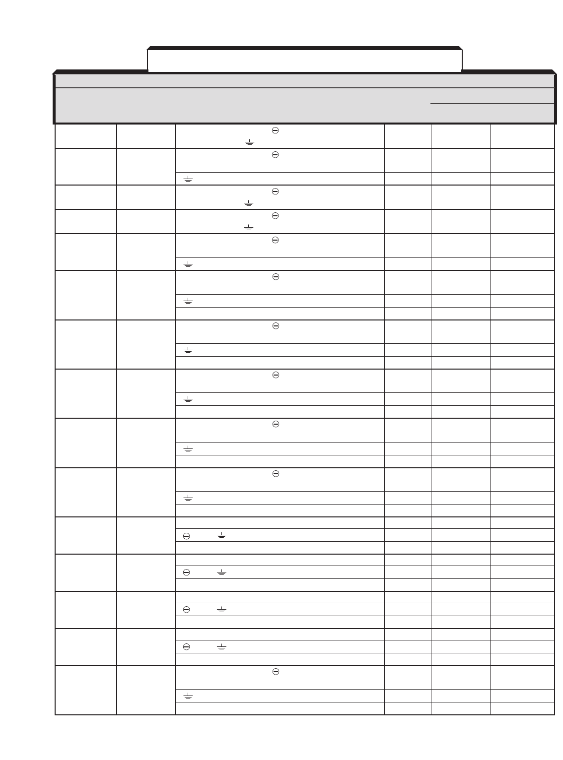
HP TERMINAL WIRE SIZE
RATING TERMINAL SYMBOL SCREW AWG MM2
20P41F A003, L1 (R), L2 (S), L3 (T), , ⊕1, ⊕2, B1, B2, M4 14 - 10 2 - 5.5
20P71F A006 T1 (U), T2 (V), T3 (W),
21P51F A008 L1 (R), L2 (S), L3 (T), , ⊕1, ⊕2, B1, B2, T1 (U), M4 14 - 10 2 - 5.5
T2 (V), T3 (W)
M4 12 - 10 3.5 - 5.5
22P21F A011 L1 (R), L2 (S), L3 (T), , ⊕1, ⊕2, B1, B2, T1 (U), M4 12 - 10 3.5 - 5.5
T2 (V), T3 (W),
23P71F A017 L1 (R), L2 (S), L3 (T), , ⊕1, ⊕2, B1, B2, T1 (U), M4 10 5.5
T2 (V), T3 (W),
25P51F A025, L1 (R), L2 (S), L3 (T), , ⊕1, ⊕2, B1, B2, T1 (U), M5 8 8
27P51F A033 T2 (V), T3 (W)
M5 10 - 8 5.5 - 8
20111F A049 L1 (R), L2 (S), L3 (T), , ⊕1, ⊕2, ⊕3, T1 (U), M6 4 22
T2 (V), T3 (W)
M6 8 8
20151F A064 L1 (R), L2 (S), L3 (T), , ⊕1, ⊕2, ⊕3, T1 (U), M8 3 30
T2 (V), T3 (W)
M6 8 8
20181F A080, L1 (R), L2 (S), L3 (T), , ⊕1, ⊕2, ⊕3, T1 (U), M8 3 30
20221F A096 T2 (V), T3 (W)
M8 6 14
l
1 (r),
l
2 (
s
) M4 20 - 10 0.5 - 5.5
20300F A130 L1 (R), L2 (S), L3 (T), T1 (U), T2 (V), T3 (W) M10 4/0 100
, ⊕3, M8 4 22
l
1 (r),
l
2 (
s
) M4 20 - 10 0.5 - 5.5
20370F A160 L1 (R), L2 (S), L3 (T), T1 (U), T2 (V), T3 (W) M10 1/0 x 2P 60 x 2P
, ⊕3, M8 4 22
l
1 (r),
l
2 (
s
) M4 20 - 10 0.5 - 5.5
20550F A224 L1 (R), L2 (S), L3 (T), T1 (U), T2 (V), T3 (W) M10 1/0 x 2P 60 x 2P
, ⊕3, M8 3 30
l
1 (r),
l
2 (
s
) M4 20 - 10 0.5 - 5.5
20750F A300 L1 (R), L2 (S), L3 (T), T1 (U), T2 (V), T3 (W) M12 4/0 x 2P 100 x 2P
, ⊕3, M8 1 50
l
1 (r),
l
2 (
s
) M4 20 - 10 0.5 - 5.5
SECTION A. 230V
NEW DRIVE OLD DRIVE
TERMINAL
WIRE SIZE
MODEL NO. MODEL NO. TERMINAL SYMBOL
CIMR-G5M GPD515C– SCREW AWG mm2
Table 1-1. Typical Wire Sizing For Main Circuit*
* Consult local electrical codes for wire sizing requirements.
1-4
DRIVE TERMINAL WIRE SIZE
MODEL NO. TERMINAL SYMBOL SCREW AWG mm2
40P41F B001 L1 (R), L2 (S), L3 (T), , ⊕1, ⊕2, B1, B2, T1 (U), M4 14 - 10 2 - 5.5
T2 (V), T3 (W),
40P71F B003, L1 (R), L2 (S), L3 (T), , ⊕1, ⊕2, B1, B2, T1 (U), M4 14 - 10 2 - 5.5
41P51F B004, T2 (V), T3 (W)
43P71F B008 M4 12 - 10 3.5 - 5.5
44P01F B011, L1 (R), L2 (S), L3 (T), , ⊕1, ⊕2, B1, B2, T1 (U), M4 12 - 10 3.5 - 5.5
45P51F B014 T2 (V), T3 (W),
47P51F B021 L1 (R), L2 (S), L3 (T), , ⊕1, ⊕2, B1, B2, T1 (U), M4 8 - 6 8 - 14
T2 (V), T3 (W),
40111F B027, L1 (R), L2 (S), L3 (T), , ⊕1, ⊕2, B1, B2, T1 (U), M5 8 - 6 8 - 14
40151F B034 T2 (V), T3 (W)
M6 8 8
40181F B041 L1 (R), L2 (S), L3 (T), , ⊕1, ⊕2, ⊕3, T1 (U), M6 6 14
T2 (V), T3 (W)
M8 8 8
l
1 (r),
l
2 (
s
) M4 20 - 10 0.5 - 5.5
40221F B052 L1 (R), L2 (S), L3 (T), , ⊕1, ⊕2, ⊕3, T1 (U), M6 4 22
T2 (V), T3 (W)
M8 8 8
l
1 (r),
l
2 (
s
) M4 20 - 10 0.5 - 5.5
40301F B065 L1 (R), L2 (S), L3 (T), , ⊕1, ⊕2, ⊕3, T1 (U), M8 4 22
T2 (V), T3 (W)
M8 8 8
l
1 (r),
l
2 (
s
) M4 20 - 10 0.5 - 5.5
40371F B080 L1 (R), L2 (S), L3 (T), , ⊕1, ⊕2, ⊕3, T1 (U), M8 3 30
T2 (V), T3 (W)
M8 6 14
l
1 (r),
l
2 (
s
) M4 20 - 10 0.5 - 5.5
40451F B096 L1 (R), L2 (S), L3 (T), , ⊕1, ⊕2, ⊕3, T1 (U), M8 1 50
T2 (V), T3 (W)
M8 6 14
l
1 (r),
l
2 (
s
) M4 20 - 10 0.5 - 5.5
40551F B128 L1 (R), L2 (S), L3 (T), T1 (U), T2 (V), T3 (W) M10 4/0 100
, ⊕3, M8 4 22
l
1 (r),
l
2 200 (
s
200),
l
2 400 (
s
400) M4 20 - 10 0.5 - 5.5
40750F B165 L1 (R), L2 (S), L3 (T), T1 (U), T2 (V), T3 (W) M10 1/0 x 2P 60 x 2P
, ⊕3, M8 4 22
l
1 (r),
l
2 200 (
s
200),
l
2 400 (
s
400) M4 20 - 10 0.5 - 5.5
41100F B224 L1 (R), L2 (S), L3 (T), T1 (U), T2 (V), T3 (W) M10 1/0 x 2P 60 x 2P
, ⊕3, M8 3 30
l
1 (r),
l
2 200 (
s
200),
l
2 400 (
s
400) M4 20 - 10 0.5 - 5.5
41600F B302 L1 (R), L2 (S), L3 (T), T1 (U), T2 (V), T3 (W) M12 4/0 x 2P 100 x 2P
, ⊕3, M8 1 50
l
1 (r),
l
2 200 (
s
200),
l
2 400 (
s
400) M4 20 - 10 0.5 - 5.5
41850F B340, L1 (R), L2 (S), L3 (T), , ⊕1, ⊕3, T1 (U), T2 (V), M16
MCM650 x 2P
325 x 2P
42200F B450, T3 (W)
43000F B605 M8 1/0 60
l
1 (r),
l
2 200 (
s
200),
l
2 400 (
s
400) M4 20 - 10 0.5 - 5.5
Section B. 460V
NEW DRIVE OLD DRIVE
TERMINAL
WIRE SIZE
MODEL NO. MODEL NO. TERMINAL SYMBOL
CIMR-G5M GPD515C– SCREW AWG mm2
Table 1-1. Typical Wire Sizing For Main Circuit - Continued*
* Consult local electrical codes for wire sizing requirements.

1-5
DRIVE TERMINAL WIRE SIZE
MODEL NO.TERMINAL SYMBOL SCREW AWG mm2
51P51F C003, L1 (R), L2 (S), L3 (T), , ⊕1, ⊕2, B1, B2, T1 (U), M4 14-10 2 - 5.5
52P21F C004 T2 (V), T3 (W)
53P71F C006 L1 (R), L2 (S), L3 (T), , ⊕1, ⊕2, B1, B2, T1 (U), M4 14-10 2 - 5.5
T2 (V), T3 (W)
12-10 3.5-5.5
55P51F C010 L1 (R), L2 (S), L3 (T), , ⊕1, ⊕2, B1, B2, T1 (U), M4 12-10 3.5-5.5
T2 (V), T3 (W)
57P51F C012 L1 (R), L2 (S), L3 (T), , ⊕1, ⊕2, B1, B2, T1 (U), M4 10 5.5
T2 (V), T3 (W)
12-10 3.5-5.5
50111F C017 L1 (R), L2 (S), L3 (T), , ⊕1, ⊕2, B1, B2, T1 (U), M5 10-6 5.5-14
T2 (V), T3 (W)
M6
50151F C022 L1 (R), L2 (S), L3 (T), , ⊕1, ⊕2, B1, B2, T1 (U), M5 8-6 8-14
T2 (V), T3 (W)
M6 10-6 5.5-14
50181F C027 L1 (R), L2 (S), L3 (T),
,
⊕1, B1, B2, T1 (U), M6 8-6 8-14
50221F C032 T2 (V), T3 (W)
◆10-6 5.5-14
l
1 (r),
l
2(
s
) M4 14 - 10 2 - 5.5
50301F C041 L1 (R), L2 (S), L3 (T),
,
⊕1, T1 (U), T2 (V), T3 (W) M8 6-1/0 14-50
◆8-2 8-30
l
1 (r),
l
2(
s
) M4 14 - 10 2 - 5.5
50371F C052 L1 (R), L2 (S), L3 (T),
,
⊕1, T1 (U), T2 (V), T3 (W) M8 4-1/0 22-50
◆8-2 8-30
l
1 (r),
l
2(
s
) M4 14 - 10 2 - 5.5
50451F C062 L1 (R), L2 (S), L3 (T),
,
⊕1, T1 (U), T2 (V), T3 (W) M8 3-1/0 30-50
◆8-2 8-30
l
1 (r),
l
2(
s
) M4 14 - 10 2 - 5.5
50551F C077 L1 (R), L2 (S), L3 (T),
,
⊕1, T1 (U), T2 (V), T3 (W) M8 2-1/0 30-50
◆6-2 22-30
l
1 (r),
l
2(
s
) M4 14 - 10 2 - 5.5
50751F C099 L1 (R), L2 (S), L3 (T),
,
⊕1, T1 (U), T2 (V), T3 (W) M8 2/0-1/0 50-60
◆4-2 22-30
l
1 (r),
l
2(
s
) M4 14 - 10 2 - 5.5
50900F C130 L1 (R), L2 (S), L3 (T),
,
⊕1, T1 (U), T2 (V), T3 (W) M10 3/0-300 80-150
◆4-2/0 22-60
l
1 (r),
l
2(
s
) M4 14 - 10 2 - 5.5
51100F C172 L1 (R), L2 (S), L3 (T),
,
⊕1, T1 (U), T2 (V), T3 (W) M12 300-400 150-200
◆4-2/0 22-60
l
1 (r),
l
2(
s
) M4 14 - 10 2 - 5.5
51600F C200 L1 (R), L2 (S), L3 (T),
,
⊕1, T1 (U), T2 (V), T3 (W) M12 350-400 180-200
◆3-2/0 30-60
l
1 (r),
l
2(
s
) M4 14 - 10 2 - 5.5
Section C. 600V
NEW DRIVE OLD DRIVE
TERMINAL
WIRE SIZE
MODEL NO. MODEL NO. TERMINAL SYMBOL
CIMR-G5M GPD515C– SCREW AWG mm2
◆Indicates terminal uses a pressure lug.
* Consult local electrical codes for wire sizing requirements.
Table 1-1. Typical Wire Sizing For Main Circuit - Continued*
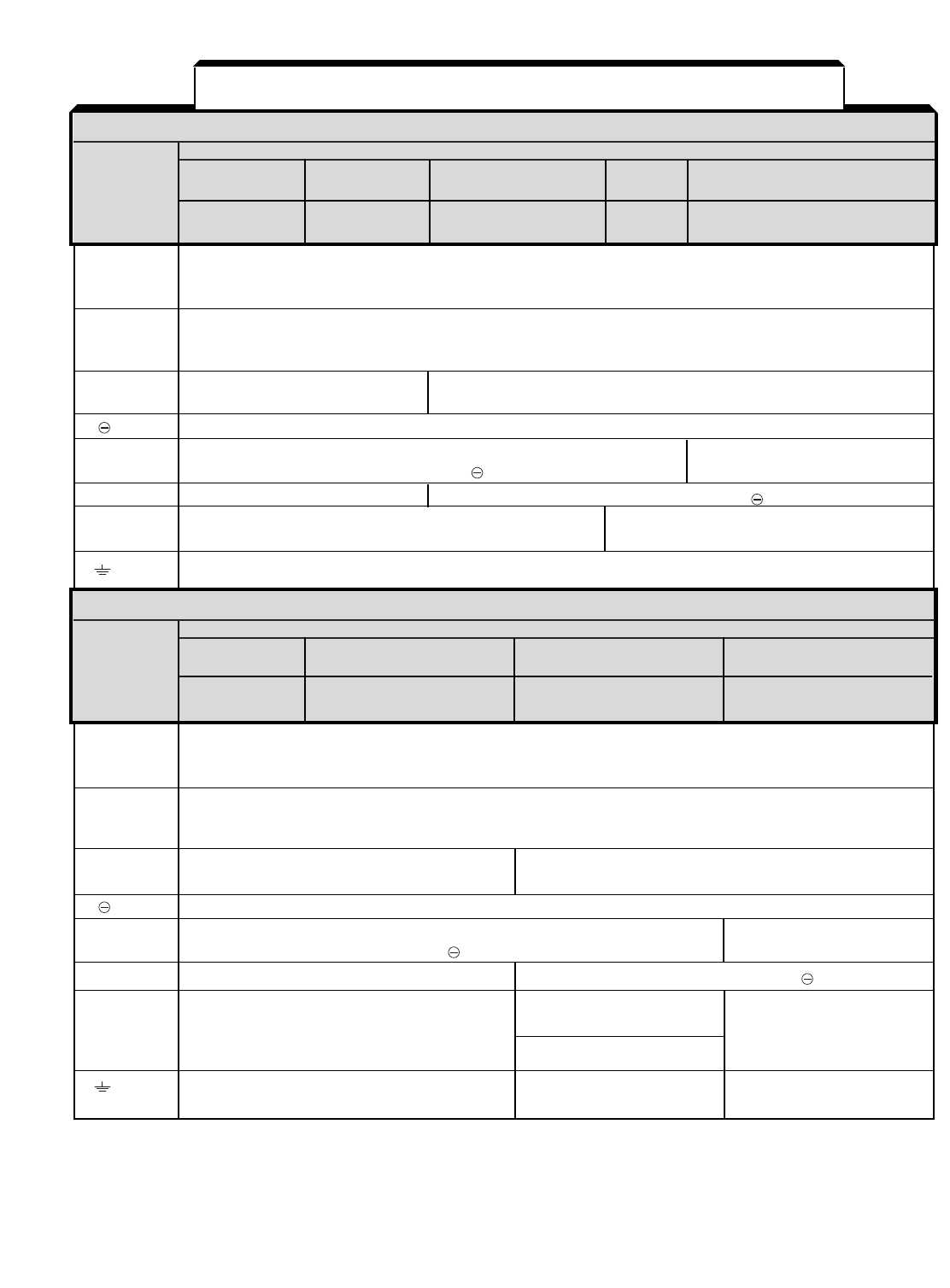
SECTION A. 230V
TERMINAL FUNCTION
1 HP 3 TO 40 HP
L1 (R) Three phase Main circuit input power supply
L2 (S) 200 / 208 / 220V at 50 Hz; 200 / 208 / 220 / 230V at 60 Hz
L3 (T)
T1 (U) Three phase AC output to motor
T2 (V) 0V to max. input voltage level
T3 (W)
B1
B2 DB Resistor terminals (B1 & B2) – – – – – –
⊕1 DC Reactor terminals (⊕1 & ⊕2)
⊕2 DC Bus terminals (⊕1 & ) – – – – – –
⊕3 – – – – – – DB Unit terminals (⊕3 & )
l
1(r) Power for heat sink fan:
l
2(
s
) – – – – – –
l
1to
l
2: 230 VAC
Ground terminal (100 ohms or less)
SECTION B. 460V
TERMINAL FUNCTION 1 TO 60 HP
L1 (R) Three phase Main circuit input power supply
L2 (S) 380 / 400 / 415 / 460V at 50/60 Hz
L3 (T)
T1 (U) Three phase AC output to motor
T2 (V) 0V to max. input voltage level
T3 (W)
B1
B2 DB Resistor terminals (B1 & B2) – – – – – –
⊕1 DC Reactor terminals (⊕1 & ⊕2)
⊕2 DC Bus terminals (⊕1 & ) – – – – – –
⊕3 – – – – – – DB Unit terminals (⊕3 & )
l
1(r) Power for heat sink fan: Power for heat sink fan:
l
2(
s
)
l
1to
l
2: 230 VAC
l
1to
l
2200: 230 Vac
l
2200 (
s
200) – – – – – –
l
1to
l
2400: 460 Vac
l
2400 (
s
400) – – – – – –
Ground terminal
SECTION A. 230V
FUNCTION
New Model No. 20P41F - 20111F - 20151F 20181F 20300F - 20750F
TERMINAL CIMR-G5M 27P51F 20221F
Old Model No. A003 - A033 A049 - A064 A080, - A130 - A300
GPD515C- A096
1-6
Table 1-2. Terminal Functions and Voltages of Main Circuit
– – – – – indicates that terminals are not present.
SECTION B. 460V
FUNCTION
New Model No. 40P41F - 40151F 40181F - 40451F 40551F - 43000F
TERMINAL CIMR-G5M
Old Model No. B001 - B034 B041 - B096 B128 - B605
GPD515C-
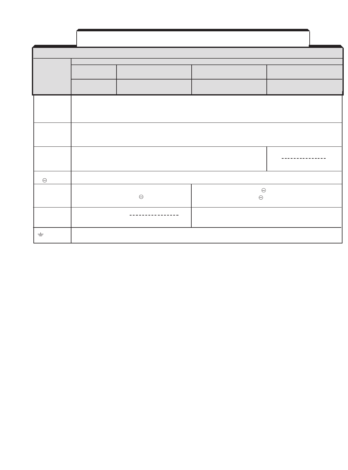
L1 (R) Three phase Main circuit input power supply
L2 (S) 500 / 575 / 600V at 50 Hz / 60HZ
L3 (T)
T1 (U) Three phase AC output to motor
T2 (V) 0V to max. input voltage level
T3 (W)
B1
B2 DB Resistor terminals (B1 & B2)
⊕1
⊕2
l
1(r) Power for heat sink fan:
l
2(
s
)
l
1to
l
2: 600 VAC
DB Units terminals (⊕1 & ) (C041 to C200 only)
DC Bus terminals (⊕1 & )
DC Reactor terminals (⊕1 & ⊕2)
DC Bus terminals (⊕1 & )
Ground terminal (100 ohms or less)
SECTION C. 600V
FUNCTION
New Model No. 51P51F - 50151F 50181F - 50221F 50301F - 51600F
TERMINAL CIMR-G5M
Old Model No. C003 - C022 C027 - C032 C041 - C200
GPD515C-
1-7
Table 1-2. Terminal Functions and Voltages of Main Circuit
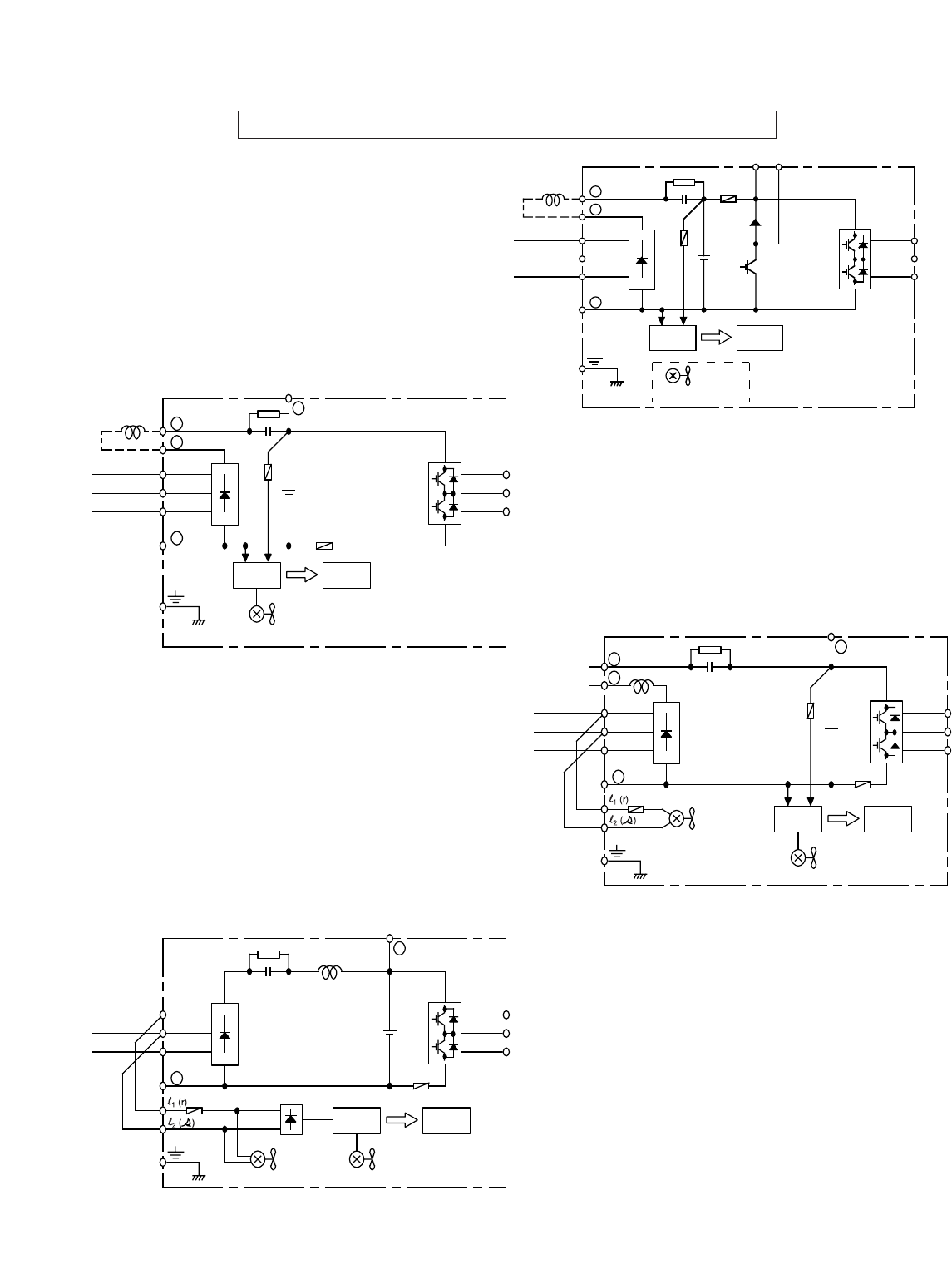
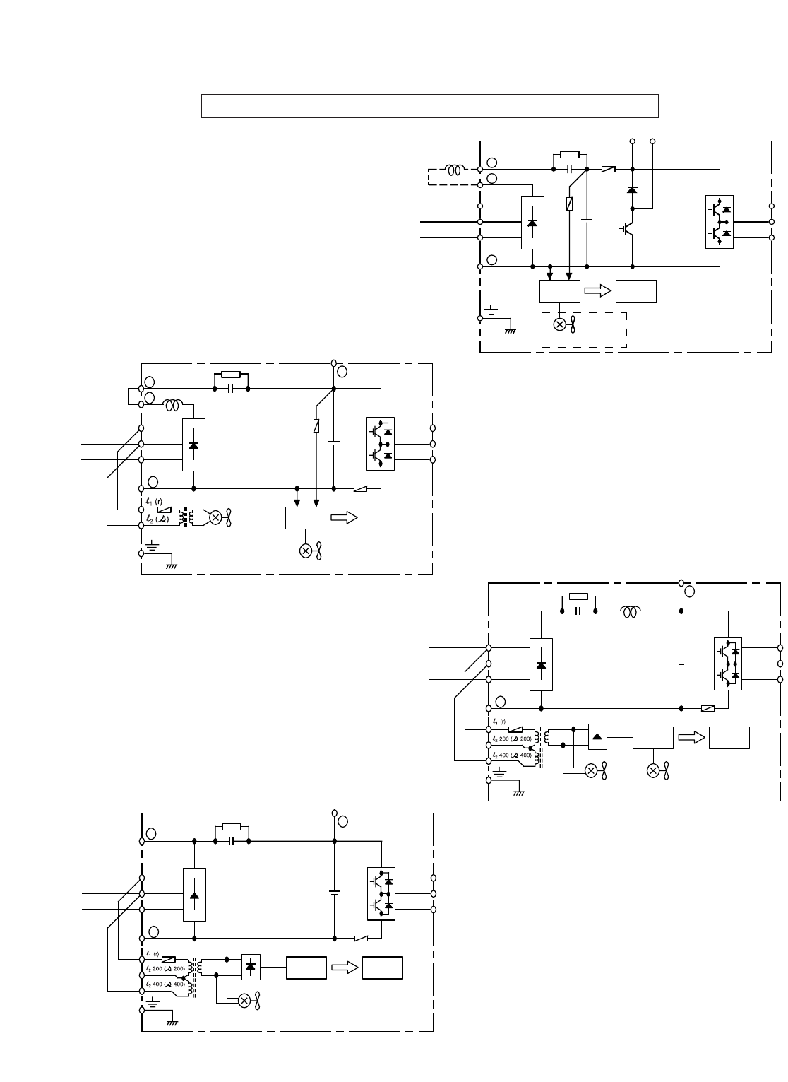
Main Circuit Configuration Block Diagrams 230V
CIMR-G5M20P41F to 27P51F
GPD515C-A003 to -A033
CIMR-G5M20111F to 20151F
GPD515C-A049 to -A064
CIMR-G5M20181F, 20221F
GPD515C-A080, -A096
CIMR-G5M20300F to 20750F
GPD515C-A130 to -A300
1-8
+
1
+
2
_
L1 (R)
L2 (S)
L3 (T)
+
Power
Supply
Control
Circuit
Cooling Fan
(A011 to A033 only)
(RCC)
U (T1)
V (T2)
W (T3)
B1
B2
(DCL
Option)
+1
+2
_
L1 (R)
L2 (S)
L3 (T)
+
Power
Supply
Control
Circuit
Cooling Fan
(RCC)
U (T1)
V (T2)
W (T3)
(DCL
Option)
+3
_
L1 (R)
L2 (S)
L3 (T)
+
Power
Supply
Control
Circuit
Internal
Cooling Fan
(RCC)
U (T1)
V (T2)
W (T3)
+3
Cooling Fan
+2
+1
_
L1 (R)
L2 (S)
L3 (T)
+
Power
Supply
Control
Circuit
Internal
Cooling Fan
(RCC)
U (T1)
V (T2)
W (T3)
+3
Cooling Fan
When using DC input as main circuit
power, connect 230Vac to control power
transformer terminals l(r) and l(s).
When using DC input as main circuit
power, connect 230Vac to control power
transformer terminals l(r) and l(s).
1-9
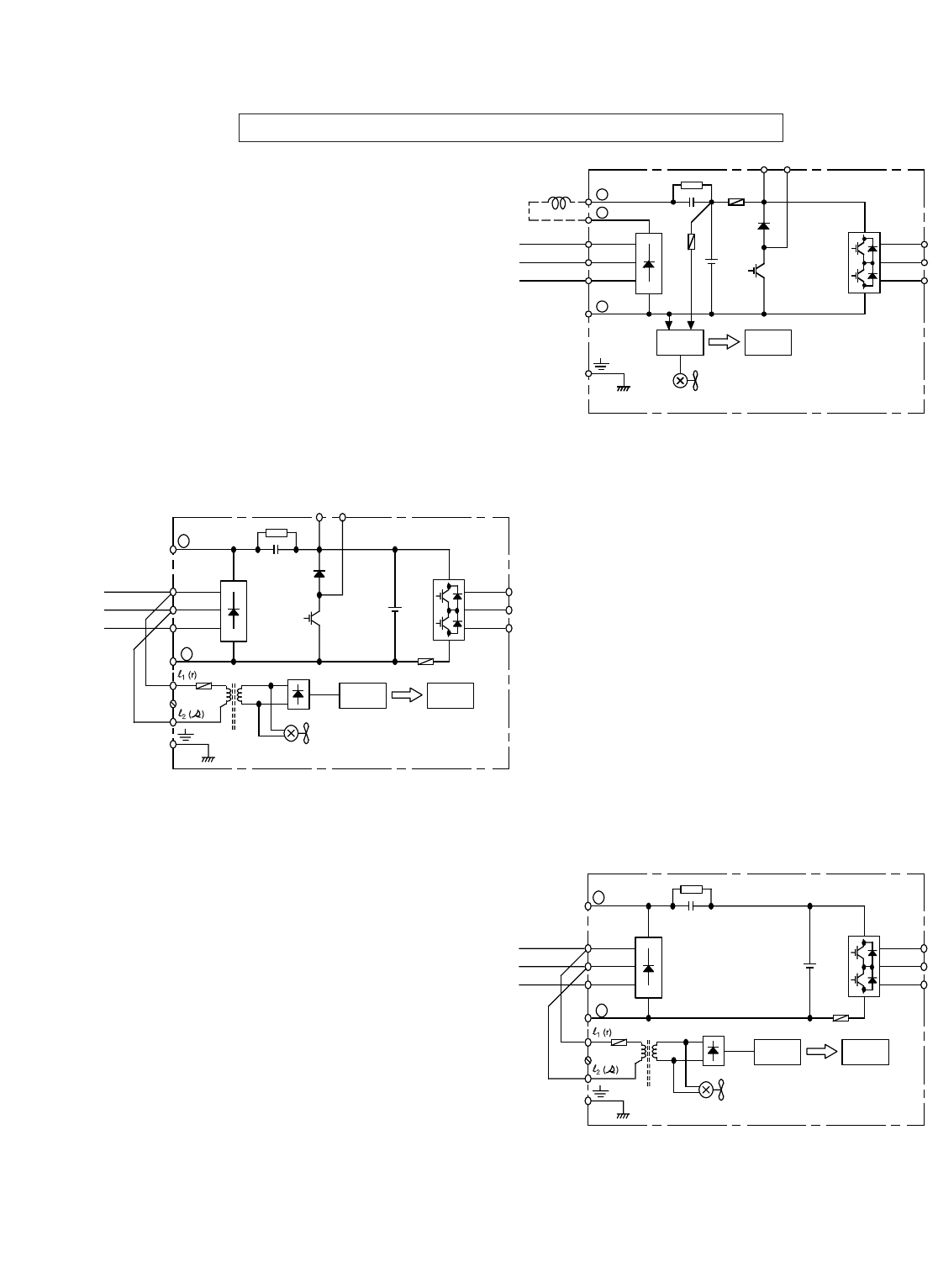
Main Circuit Configuration Block Diagrams 460V
CIMR-G5M40P41F to 40151F
GPD515C- B001 to - B034
CIMR-G5M40181F to 40451F
GPD515C- B041 to - B096
CIMR-G5M40551F to 41600F
GPD515C- B128 to - B302
CIMR-G5M41850F to 43000F
GPD515C- B340 to - B605
_
L1 (R)
L2 (S)
L3 (T)
+
Power
Supply
Control
Circuit
Internal
Cooling Fan
(RCC)
U (T1)
V (T2)
W (T3)
+3
Cooling Fan
+2
+1
+
1
+
2
_
L1 (R)
L2 (S)
L3 (T)
+
Power
Supply
Control
Circuit
Cooling Fan
(B008 to B034 only)
(RCC)
U (T1)
V (T2)
W (T3)
B1
B2
(DCL
Option)
_
L1 (R)
L2 (S)
L3 (T)
+
Power
Supply
Control
Circuit
Internal
Cooling Fan
(RCC)
U (T1)
V (T2)
W (T3)
+3
Cooling Fan
_
L1 (R)
L2 (S)
L3 (T)
+
Power
Supply
Control
Circuit
(RCC)
U (T1)
V (T2)
W (T3)
+3
Cooling Fan
+1
When using DC input as main circuit
power, connect 460Vac to control power
transformer terminals l1(r) and l2(s).
When using DC input as main circuit
power, connect 460Vac to control
power transformer terminals l1(r) and
l2400 (s400).
When using DC input as main
circuit power, connect 460Vac to
control power transformer
terminals l1(r) and l2400 (s400).
1-10
Main Circuit Configuration Block Diagrams 600V
+
1
+
2
_
L1 (R)
L2 (S)
L3 (T)
+
Power
Supply
Control
Circuit
Cooling Fan
(RCC)
U (T1)
V (T2)
W (T3)
B1
B2
(DCL
Option)
_
L2 (S)
L3 (T)
+
Power
Supply
Control
Circuit
(RCC)
U (T1)
V (T2)
W (T3)
Cooling Fan
+1
L1 (R)
B2B1
_
L1 (R)
L2 (S)
L3 (T)
+
Power
Supply
Control
Circuit
(RCC)
U (T1)
V (T2)
W (T3)
Cooling Fan
+1
CIMR-G5M51P51F to 50151F
GPD515C- C003 to - C022
CIMR-G5M50181F to 50221F
GPD515C-C027 to -C032
CIMR-G5M50301F to 51600F
GPD515C-C041 to -C200
When using DC input as main circuit
power, connect 600Vac to control
power transformer terminals r and s.
When using DC input as main circuit
power, connect 600Vac to control
power transformer terminals r and s.
When using DC input as main
circuit power, connect 600Vac to
control power transformer
terminals r and s.
1.4.2 Grounding
•The drive must be solidly grounded using the main circuit ground terminal.
•If Drive is installed in a cabinet with other equipment, ground leads for all equipment should be
connected to a common low-impedance ground point within the cabinet.
•The supply neutral should be connected to the ground point within the cabinet.
•Select appropriate ground wire size from Table 1-1.
•Make all ground wires as short as practical.
•NEVER ground the drive in common with welding machines or other high power electrical
equipment.
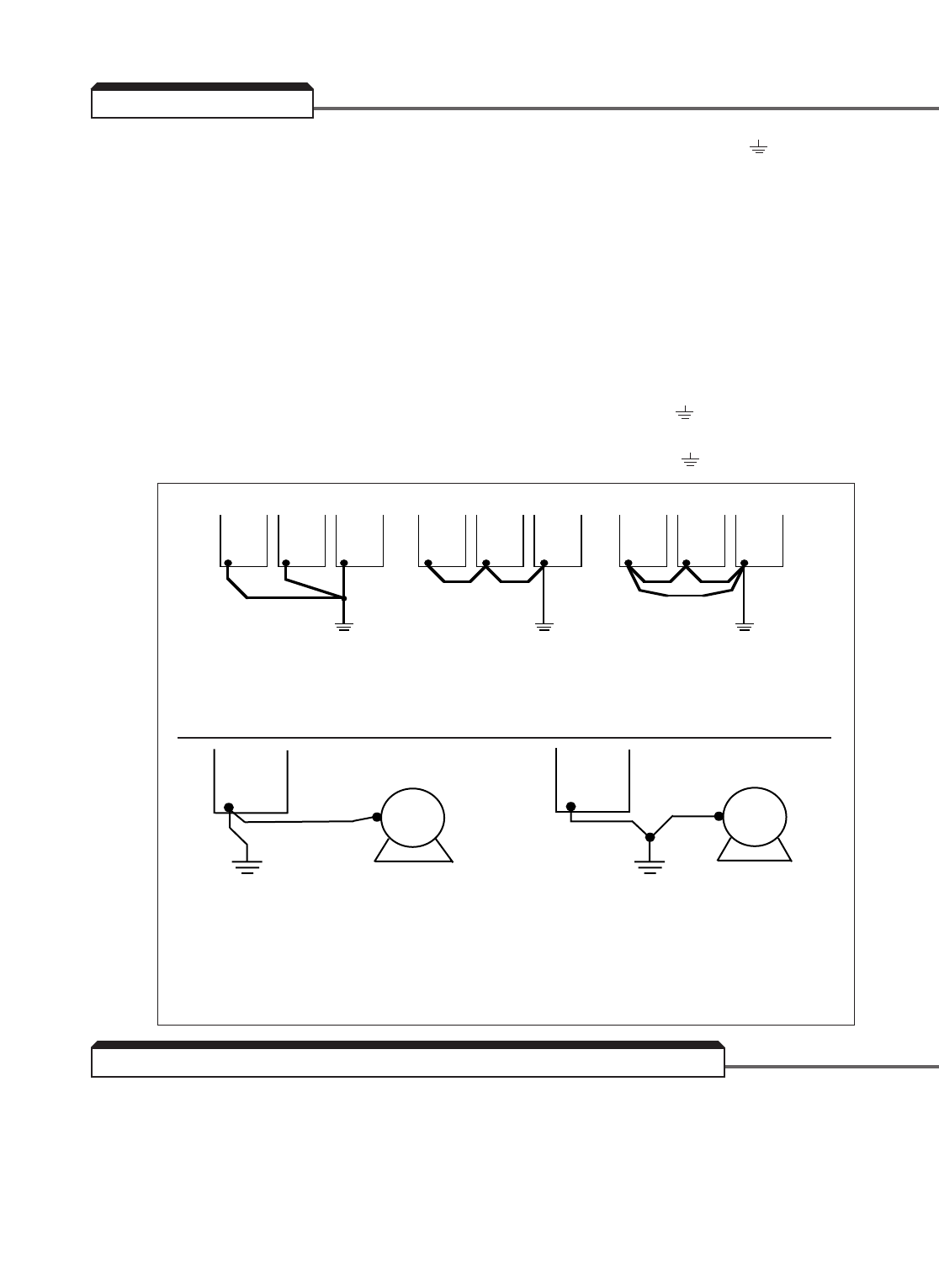
•Where several drives are used, ground each directly to the ground point (see Figure 1-1). DO
NOT FORM A LOOP WITH THE GROUND LEADS.
•When connecting a motor to the drive’s output terminals, include a separate ground wire. Attach
ground wire solidly to motor frame and to drive’s ground terminal.
•When using armored or shielded cable for connection between drive and motor, solidly connect
armor or shield to motor frame, and to the drive’s ground terminal.
A disconnect device (circuit breaker, contactor, disconnect switch, etc.) should NOT be used as a
means of starting and stopping the drive or motor.
A disconnect device can be installed for emergency stop purposes, but when that disconnect
device is opened, there may be loss of electrical braking.
1-11
Figure 1-1. Grounding
A. Grounding of Three Drives
B. Grounding of Drive & Vector Control Motor (VCM)
PREFERRED NOT RECOMMENDED NOT
ACCEPTABLE
CORRECT NOT RECOMMENDED
1.4.3 Auxiliary Input and Output Power Option Devices
1-12
TRANSFORMER
INPUT
REACTOR
INPUT
RFI FILTER
L3
L2
L1
H3
H2
H1
X3
X2
X1
C1
B1
A1
C2
B2
A2
C1(L3)
B1(L2)
A1(L1)
(L3)C2
(L2)B2
(L1)A2
L
I
N
E
L
O
A
D
CUSTOMER'S
3Ø A.C. LINE
POWER
SUPPLY
PANEL GROUND
SEE NOTE 2
(G)
RF NOISE
FILTER
SEE NOTE 5
SEE NOTE 3
L3L2L1
T2T1
INPUT
OUTPUT
Drive
PANEL GROUND
SEE NOTE 1 SEE NOTES 3, 4
OUTPUT
REACTOR
OUTPUT
RFI FILTER
SEE NOTES 3, 4
A.C. MOTOR
123
456
IN
OUT
T3T2T1
C1B1A1
C2B2A2
PANEL GROUND
SEE NOTE 2
SEE NOTE 6
DC
REACTOR
+ 1
+ 2
PANEL
GROUND
SEE NOTE 2
ISOLATION
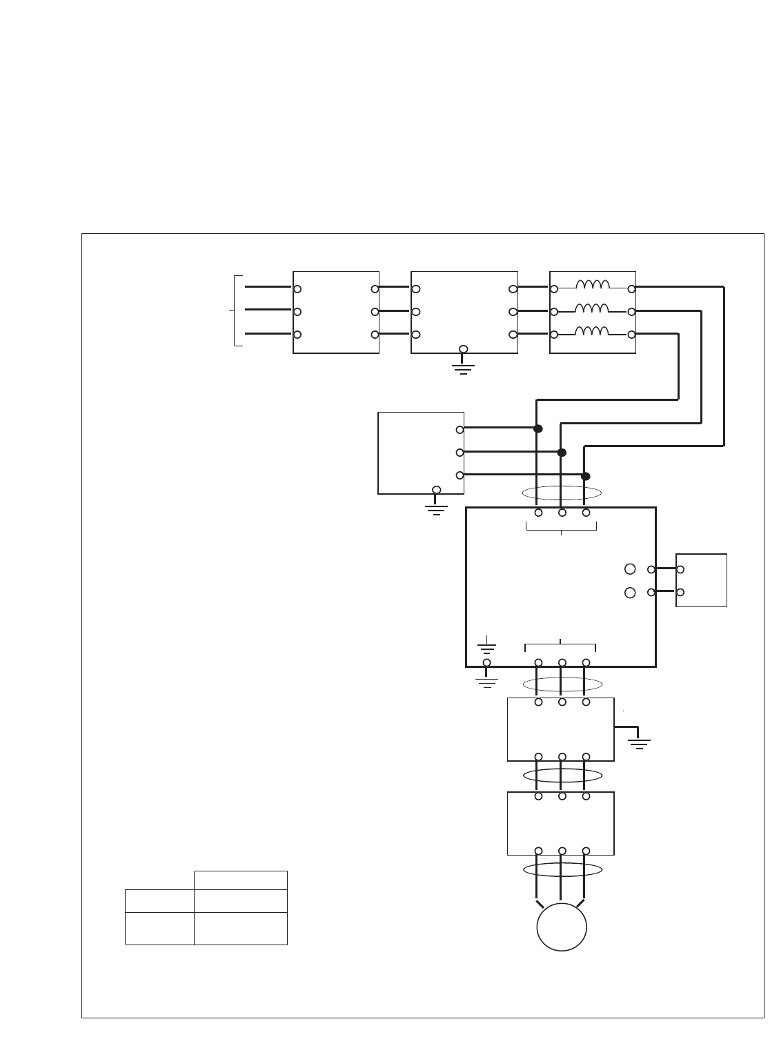
Figure 1-2. Customer Connection Diagram For Isolation Transformers, Input
Reactors, Input RFI Filters, DC Reactors, Output Reactors and Output RFI FIlters
NOTES
1. Connect drive ground terminal or panel to
earth ground. Always use low impedance
paths and connections.
2. Mount input and output RFI filters
physically
as close to the drive as possible (on the same
panel, if possible). Filters should have a solid
connection from filter ground terminal to the
cabinet ground point. If multiple input or
output RFI filters are used, they must be
wired in parallel.
3. Shield individual conductors with metallic
conduit, or use armored or shielded cable.
4. Connect output conduit armored cable or
shielded cable in a manner that allows it to
act as an unbroken shield from the drive
panel to the motor casing.
5. RF noise filter (different from RFI filter) part
no. 05P00325-0023 is a delta wye capacitor
network which is wired in parallel with the
drive input terminals. On the smaller drives
with die cast chassis, it must be mounted
externally. On the larger drives with sheet
metal chassis, it may be mounted inside the
area where the input power wiring enters the
drive. On units equipped with bypass, it may
be wired to the primary side of the circuit
breaker and mounted to the bypass panel or
sidewall.
6. Connection points:
Drive Terminals
Input
Power L1, L2, L3
Output Power
T1, T2, T3
Figure 1-2 is a factory guideline for proper wiring practices and relative locations within the electrical
path from the line to the load. It does not imply what devices are needed for a particular
application, nor does it show what devices were shipped with a particular order. Therefore,
disregard those items in the diagram which are not being used in your installation. However, it is
recommended that an input or DC reactor be used with models GPD515C-A003 thru -A064
(CIMR-G5M20P41F thru 20151F), -B001 thru -B034 (40P41F thru 40151F) , and -C003 thru -C062
(51P51F thru 51451F) when wired to a source of 600 kVA or greater. Mount all optional power
devices close to the drive, and keep electrical connections as short as possible.

1.4.3a Conformance to European EMC Directive
In order to conform to EMC standards, the following methods are required for line filter
application, cable shielding and drive installation. The following explains the outline of the
methods.
The line filter and the drive must be mounted on the same metal plate. The filter should
be mounted as close to the drive as practical. The cable must be kept as short as possible
and the metal plate should be securely grounded. The ground of the line filter and the
drive must be bonded to the metal plate with as much bare-metal contact as possible.
For main circuit input cables, a screened cable is recommended within the panel, and is
also suggested for external connections. The screen of the cable should be connected to
a solid ground. For the motor cables, a screened cable (max. 20 m) must be used and the
screen of the motor cable should be connected to ground at both ends by a short
connection, again using as much bare-metal contact as possible.
For more detailed explanation, refer to document EZZ006543, “Installation Guidelines For EMC
Directive using Yaskawa AC Drive Products.”
Table 1-2.1 and Figure 1-2A show the line filter list for EMC standards and the
installation/wiring of the drive and line filter.
Table 1-2.1. Line Filters for Drive
New Drive Model Old Drive Model Line Filter
Number Number Part Number Rated Mass Dimensions in mm(1)
CIMR-G5M GPD 515C- 05P00325- Current (A) (kg) L x W x D (2)
40P41F, B001,
40P71F B003 0106 8 1.8 320 x 143 x 46
41P51F, B004,
43P71F, B008, 0103 20 1.8 320 x 143 x 46
44P01F B011
45P51F, B014, 0104 30 3.0 350 x 213 x 51
47P51F B021
40111F, B027, 0105 60 5.3 435 x 268 x 56
40151F B034
40181F, B041, 0107 80 7.5 350 x 180 x 90
40221F B052
40301F B065 0108 100 13.8 420 x 200 x 130
40371F B080 0109 150 13.8 480 x 200 x 160
40451F B096 0110 160 25 480 x 200 x 160
40551F B128 0111 180 25 480 x 200 x 160
40750F, B165, 0112 300 25 480 x 200 x 160
41100F B224
41600F B302 0113 400 45 588 x 250 x 200
41850F B340 0119 500
42200F B450 0120 600
43000F B605 0121 900
1-13
(1) 1mm = 0.0394 inches
(2) D is the distance the filter will extend outward from the surface of the metal plate.
Consult Factory
1-14
Motor Cable
max. 20m
Cable Length
max. 40cm
L2 PEL1 L3
LINE
LOAD
FILTER
GPD
515/G5
T2 PET1 T3L1 L3PE L2
Ground Bonds (remove any paint)
Ground Bonds (remove any paint)
Metal Plate
IM
3~
Figure 1-2A. Installation of Line Filter and GPD 515/G5
1.4.4 Control Circuit
All basic control circuit (signal) interconnections are shown in the appropriate diagram:
•Interconnections for external two-wire control in combination with the Digital Operator are
shown in Figure 1-3.
•Interconnections for external three-wire control in combination with the Digital Operator
are shown in Figure 1-4.
Make wire connections according to Figures 1-3, 1-4 and Table 1-3; observe the following:
•Signal Leads: Terminals 1-8 & 11; 12-17 & 33; and 21-27.
•Control Leads: Terminals 9 & 10 and 18-20.
•Use twisted shielded or twisted-pair shielded wire (20-16 AWG [0.5 – 1.25mm2]) for
control and signal circuit leads. The shield sheath MUST be connected at the drive end
ONLY (terminal 12). The other end should be dressed neatly and left unconnected
(floating). See Figure 1-2B.
•Signal leads and feedback leads (PG) must be separated from control leads
main circuit leads and any other power cables to prevent erroneous operation caused
by electrical noise.
•Lead length should NOT EXCEED 164 feet (50 meters). Wire sizes should be determined
considering the voltage drop.
•All AC relays, contactors and solenoids should have RC surge supressors installed across
their coils.
•All DC relays, contactors and solenoids should have diodes installed across their coils.
1-15
TO GPD 515
SIGNAL
TERMINALS
TO SHIELD
SHEATH
TERMINAL
(TERM. 12)
WRAP BOTH ENDS
OF SHEATH WITH
INSULATING TAPE
CRIMP
CONNECTION
SHIELD SHEATH
OUTER JACKET
DO NOT
CONNECT
TO
EXTERNAL
CIRCUIT
Figure 1-2B. Shielded Sheath Termination

1-16
1-17
TERMINAL FUNCTIONS LEVELS
12-WIRE CONTROL: Forward Run / Stop signal Run at closed, stop at open (See NOTE 2)
(See NOTE 1)
3-WIRE CONTROL: Run signal Run at closed (See NOTE 2)
22-WIRE CONTROL: Reverse Run / Stop signal Run at closed, stop at open (See NOTE 2)
(See NOTE 1)
3-WIRE CONTROL: Stop signal Stop at open (See NOTE 2)
3External fault input Fault at closed (see NOTES 2 & 3). When the
External Fault input is applied, the drive’s Fault
relay trips (shutdown) and the motor coasts to a
stop. The Digital Operator displays “ EF3 ” failure.
4Fault Reset input (external) Fault Reset at closed (see NOTES 2 & 3). The
Fault Reset input will reset the Fault relay, if the
drive is in “stopped” condition. Both Forward
Run/Stop signal and Reverse Run/Stop signal
must be OPEN.
5Multi-step Speed Reference 1 Effective when closed (See NOTES 2 & 3)
6Multi-step Speed Reference 2 Effective when closed (See NOTES 2 & 3)
7Jog Reference Run at preset jog frequency when closed
8External baseblock Drive output stops when closed
9, 10 Multi-function contact output (N.O.). Contact capacity:
One of 18 functions are available, by setting 250 Vac at 1A or less
of parameter H2-01 . 30 Vdc at 1A or less
11 Sequence control input common Sequence control input 0 V
for terminals 1-8.
12 Connection for shield sheath of signal leads – – – –
13 Frequency reference analog input (voltage); 0 to +10V (20K ohms)
auto input – can be changed to manual by –10 to +10V (20K ohms)
setting of parameter H3-01 .
14 Frequency reference analog input (current); 4-20mA (250 ohms)
can be changed to voltage input by setting of
parameter H3-08 and cutting jumper J1.
15 Frequency reference power supply +15V (Control power supply for frequency setting:
max 20 mA)
17 Frequency reference analog input common 0 V
18 Multi-function contact output Closed at fault
(N.O./N.C.). Contact capacity:
19 Open at fault 250 Vac at 1A or less
30 Vdc at 1A or less
20 Common
TERMINAL FUNCTIONS DESCRIPTION / SIGNAL LEVELS
Table 1-3. Terminal Functions and Signals of Control Circuit

1-18
TERMINAL FUNCTIONS LEVELS
21 Multi-function analog monitor 1 (+) Output current Type of analog signal (operation parameter) to be
22 Multi-function analog monitor (–) or output output is selected by setting of parameters H4-01
frequency is and H4-04 .
23 Multi-function analog monitor 2 (+) selectable Monitor output: 0 to +11V; 2 mA maximum
25 Multi-function open collector One of 18 functions Photocoupler insulation output: +48V, 50 mA
output 1 available, by setting maximum
26 Multi-function open collector of parameters H2-02
output 2 and H2-03 .
27 Multi-function open collector output common 0V
33 Frequency reference power supply –15V Control power supply for frequency setting:
max 20 mA
TERMINAL FUNCTIONS DESCRIPTION / SIGNAL LEVELS
NOTES:
1. When Forward Run and Reverse Run inputs are both closed for more than 500 ms, the Digital
Operator displays a blinking “ EF ”alarm code and the motor (if rotating) is decelerated by the
drive to a stop. This stop condition is not stored by the drive (on Digital Operator, red LED at
STOP key does not light); IF ONE OF THE INPUTS IS OPENED, THE MOTOR WILL
IMMEDIATELY START UP AGAIN.
2. Terminals 1-8 source +24 Vdc (8mA max.) and operate in a Low = True (ON) configuration when
connected to terminal 11.
When using relays for input to terminals 1-8, use relays with highly reliable contacts (for very
small current) with a capacity of 30 Vdc or more and rated current of 100mA or higher. When
using transistor (open collector) input, use transistors with rated voltage of 35 Vdc or more and
rated current of 100mA or more.
3. These terminals are multi-function inputs. The indicated functions are their settings, based on a
2-Wire reset. For 3-Wire reset definitions, and other settings, see descriptions for “Multi-
Function Input Terminals”, parameters H1-01thru H1-06, in paragraph 5.32.
Table 1-3. Terminal Functions and Signals of Control Circuit - Continued

1-19

1-20
1.4.5 Interconnection – 2-Wire Control Operation - Figure 1-3.
Notes referred to in figure 1-3.
✱– Indicates components not supplied.
✱✱– Branch circuit protection (circuit breaker or input fuses) must be supplied by customer.
■■– Indicates customer connection terminal. Wire only to terminals shown. Note that not all terminals
shown are available in all ratings – see Tables 1-1 and 1-2.
( ) – Indicates alternate terminal marking, i.e., (R) and L1.
▲– Function labels shown for these terminals are determined by factory settings of parameters
H1-01 through H1-06 . See paragraph 5.32.
●– Function labels shown for these terminals are determined by factory settings of parameters
H2-01 through H2-03 . See paragraph 5.33.
♦– Function labels shown for these terminals are determined by factory settings of parameters
H3-01, -04, -05, -08, & -09. See paragraphs 5.19 & 5.30.
■– Function labels and signal levels shown for these terminals are determined by factory settings
of parameters H4-01 & H4-04. See paragraph 5.31.
1. If only a remote Manual Speed pot (1RH) is used, 3SS is not needed; in that case, a jumper must be
added between terminals 5 and 11. This jumper will override both the Auto and Digital Operator
frequency references, regardless of the programming of parameter b1-01. If you are using a remote
speed command or the Digital Operator, DO NOT install this jumper. See paragraph 5.19.
2. The Drive Electronic Thermal Overload function (parameters L1-01, L1-02 ) meets standards set by
UL and cUL for motor thermal overload protection. If local code requires separate mechanical overload
protection, an overload relay should be installed, interlocked with the drive as shown. It should be the
manual reset type to prevent automatic restart following a motor fault and subsequent contact
reclosure after cool down.
3. Insulated twisted shielded wire is required.
2-conductor #18 GA. (Belden #8760 or equivalent). 3-conductor #18 GA. (Belden #8770 of equivalent).
Connect shield ONLY AT DRIVE END. Stub and isolate other end.
4. Digital Operator is standard on every drive. Remote operators, as shown, may not be required.
5. Customer to connect terminal to earth ground (100 Ωor less, 230V; 10 Ωor less, 460V and 600V).
6. Wire only one of the inputs as an Auto Reference. If H3-09 is set to “ 1F “, terminals 13 and 14 are
added for the internal frequency reference.
7. If the Dynamic Braking (DB) option is used, wire per Appendix 6 instructions.
8. An optional DC reactor may be added for harmonic attenuation, if needed; see separate instruction sheet
for wiring.
9. If application does not allow reverse operation, b1-04, Reverse Run Prohibit, should be set to “ 1 ”
(Reverse Run Disabled), and the Reverse Run/Stop input can be eliminated.
10. If supplying the drive with DC voltage instead of 3ø AC, remove jumpers from terminals l1 and l2
and connect a separate 1ø AC supply to l1 and l2 instead.
11 . Use l1 (R) and l2 (S) for single-phase input. Note that for drives up through GPD515C-A064, -B034, and
-C032 (CIMR-G5M20151F, 40151F, and 50221F) must be derated by 50%. Consult factory for derating
of larger drives.
1-21
380V
400/
415V 440V 460V
Voltage Selector
3ø POWER SUPPLY (SEE NAMEPLATE DATA)
1ø POWER SUPPLY (SEE NOTE 11)
1CB ✱✱
GPD 515/G5
L1 L2 L3
15
16
17
12
14
13
+15Vdc
(20mA MAX)
MAN REF. IN
(0 TO ±10Vdc)
FWD
▲
▲
▲
▲
●
●
●
FWD
RUN/STOP
COM
SHIELD
4-20mA
(250
0 TO ±10Vdc
(20K
SEE
NOTE 4
4-20mA
0-10V
ISOLATED
AUTO
REFERENCE ✱
SEE NOTE 6
1OL ✱
SEE
NOTE
2
EXT. FAULT ✱
EXT. FAULT RESET
1PB ✱
SEE
NOTE 3
TO
TERM. 12
1R ✱
MAN SPEED
1RH ✱
SEE NOTE 1
AUTO
MAN
3SS ✱
1SS ✱
SEE
NOTE 1
1
2
3
4
5
6
7
8
11
9
REV
EXT. FAULT
FAULT RESET
AUTO/MAN
MULTI-STEP
FREQ SELECT
JOG
SPEED
COAST STOP
(BASE BLOCK)
0 VOLTS
RUN CONTACT
RY1
10
FAULT CONTACTS
RY2
RY2
18
19
20
ANALOG
OUTPUT
OPEN
COLLECTOR
CIRCUIT
OPEN
COLLECTOR
CIRCUIT
21
22
25
26
27
RY CONTACTS
CAPACITY:
1A AT 250Vac
1A AT 30Vdc
MULTI-FUNCTION
MONITOR OUTPUT
0 to +10V or
–10 to +10V,
2mA MAX.
MULTI-
FUNCTION
OPEN
COLLECTOR
OUTPUTS
CAPACITY:
50mA AT 48Vdc MAX.
AC MOTOR ✱
(T2)
(T1) (T3)
G T1 T2 T3
(GPD515C-B041 thru -B096)
FACTORY SET FOR 460V
EARTH
GROUND
SEE NOTE 5
1OL ✱
SEE NOTE 2
L1 L2 L3
BASIC INTERCONNECT DIAGRAM FOR 2-WIRE CONTROL
(R) (S) (T) (r)
(E) (U) (V) (W)
2SS ✱
REV
RUN/STOP
■
♦
TERMINALS 1-8:
IF INPUT FROM RELAY CONTACTS:
RATED 30Vdc OR MORE,
100mA OR MORE
IF OPEN COLLECTOR INPUT:
RATED 35Vdc OR MORE,
100mA OR MORE
B1
B2
FOR WIRING
DYNAMIC
BRAKING
OPTION
SEE NOTE 7
12
COOLING
FAN
POWER
(GPD515C-A080 [CIMR-G5M20151F] AND ABOVE;
GPD515C-B041 [CIMR-G5M40151F] AND ABOVE;
GPD515C-C027 [CIMR-G5M50221F] AND ABOVE)
SEE NOTE 10
♦
+ 1
+ 2
▲
▲
SEE
NOTE 9
ANALOG
OUTPUT
23
FOR OPTIONAL
DC REACTOR
SEE NOTE 8
+
+
–
■
■
♦
SEQ REF
DRIVE FWD REV REMOTE
DIGITAL OPERATOR
JVOP-130
DATA
ENTER
FWD
REV RESET
RUN STOP
JOG
LOCAL
REMOTE MENU ESC
T1 T2 T3
(U) (V) (W)
AC MOTOR ✱
(T2)
(T1) (T3)
ALTERNATE
MOTOR CONNECTION
33 –15Vdc
(20mA MAX)
+ 3
–
OR
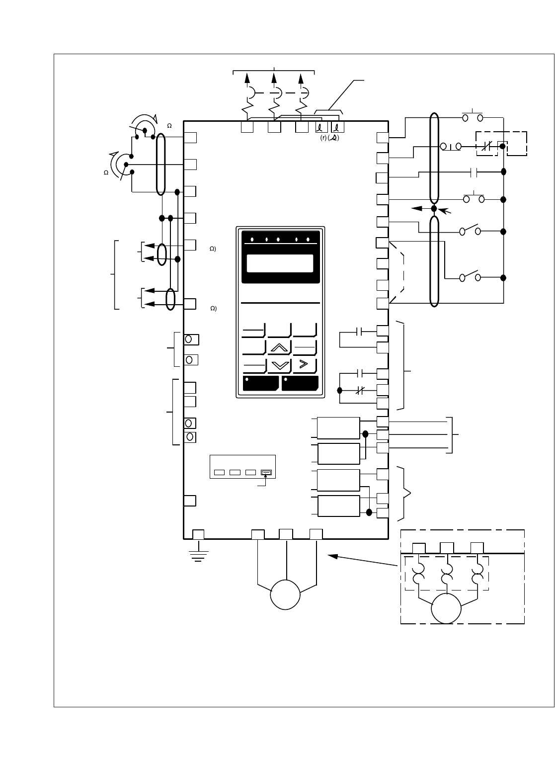
Figure 1-3. 230, 460 or 600V Interconnections - 2-Wire Control
(with parameters b1-01 = 1, b1-02 = 1, H1-01 = 24, H1-02 = 14, H1-03 = 3,
H1-04 = 4, H1-05 = 6, and H1-06 = 8 )
See Figure 1-5 for Closed-loop PG connections

1-22
1.4.6 Interconnection – 3-Wire Control Operation Figure 1-4.
Notes referred to in figure 1-4.
✱– Indicates components not supplied.
✱✱– Branch circuit protection (circuit breaker or input fuses) must be supplied by customer.
■■– Indicates customer connection terminal. Wire only to terminals shown. Note that not all terminals
shown are available in all ratings – see Tables 1-1 and 1-2.
( ) – Indicates alternate terminal marking, i.e., (R) and L1.
▲– Function labels shown for these terminals are determined by factory settings of parameters H1-01
through H1-06 : H1-01= 24, H1-02= 14, H1-03= 0, H1-04= 3, H1-05= 4, H1-06 = 6.
See paragraph 5.32.
●– Function labels shown for these terminals are determined by factory settings of parameters
H2-01 through H2-03 . See paragraph 5.33.
♦– Function labels shown for these terminals are determined by factory settings of parameters
H3-01, -04, -05, -08, & -09. See paragraphs 5.19 & 5.30.
■– Function labels and signal levels shown for these terminals are determined by factory settings
of parameters H4-01 & H4-04. See paragraph 5.31.
1. If only a remote Manual Speed pot (1RH) is used, 2SS is not needed; in that case, a jumper must be
added between terminals 6 and 11. This jumper will override both the Auto and Digital Operator
frequency references, regardless of the programming of parameter b1-01. If you are using a
remote speed command or the Digital Operator, DO NOT install this jumper. See paragraph 5.19.
2. The Drive Electronic Thermal Overload function (parameters L1-01, L1-02 ) meets standards set
by UL and cUL for motor thermal overload protection. If local code requires separate mechanical
overload protection, an overload relay should be installed, interlocked with the drive as shown. It
should be the manual reset type to prevent automatic restart following a motor fault and subsequent
contact reclosure after cool down.
3. Insulated twisted shielded wire is required.
2-conductor #18 GA. (Belden #8760 or equivalent). 3-conductor #18 GA. (Belden #8770 of equivalent).
Connect shield ONLY AT DRIVE END. Stub and isolate other end.
4. Digital Operator is standard on every drive. Remote operators, as shown, may not be required.
5. Customer to connect terminal to earth ground (100 Ωor less, 230V; 10 Ωor less, 460V and 600V).
6. Wire only one of the inputs as an Auto Reference. If H3-09 is set to “ 1F “, terminals 13 and 14 are
added for the internal frequency reference.
7. If the Dynamic Braking (DB) option is used, wire per Appendix 6 instructions.
8. An optional DC reactor may be added for harmonic attenuation, if needed; see separate instruction sheet
for wiring.
9. If application does not allow reverse operation, b1-04, Reverse Run Prohibit, should be set to “ 1 ”
(Reverse Run Disabled), and the Forward/Reverse input can be eliminated.
10. If supplying the drive with DC voltage instead of 3ø AC, remove jumpers from terminals l1 and l2
and connect a separate 1ø AC supply to l1 and l2 instead.
11 . Use l1 (R) and l2 (S) for single-phase input. Note that for drives up through GPD515C-A064, -B034, and
-C032 (CIMR-G5M20151F, 40151F, and 50221F) must be derated by 50%. Consult factory for derating
of larger drives.
CAUTION
Before running, parameter A1-03 must be set to " 0 ". Resetting drive constant A1-03
to " 2220 " may cause the motor to run in the reverse direction WITHOUT A RUN
COMMAND, and possibly result in damage to the equipment or personal injury.
1-23
380V
400/
415V 440V 460V
Voltage Selector
3ø POWER SUPPLY (SEE NAMEPLATE DATA)
1CB ✱✱
GPD 515/G5
L1 L2 L3
15
16
17
12
14
13
+15Vdc
(20mA MAX)
MAN REF. IN
(0 TO ±10Vdc)
RUN
▲
▲
▲
▲
●
●
●
RUN
COM
SHIELD
4-20mA
(250
0 TO ±10Vdc
(20K
SEE
NOTE 4
4-20mA
0-10V
ISOLATED
AUTO
REFERENCE ✱
SEE NOTE 6
1OL ✱SEE
NOTE
2
EXT. FAULT ✱
EXT. FAULT RESET
3PB ✱
SEE
NOTE 3
TO
TERM. 12
1R ✱
2K
MAN SPEED
1RH ✱
2K / 2.5K
SEE NOTE 1
FWD
REV
1SS ✱
1PB ✱
SEE
NOTE 1
1
2
3
4
5
6
7
8
11
9
STOP
EXT. FAULT
FAULT RESET
AUTO/MAN
MULTI-STEP
FREQ SELECT
JOG
SPEED
0 VOLTS
RUN CONTACT
RY1
10
FAULT CONTACTS
RY2
RY2
18
19
20
ANALOG
OUTPUT
OPEN
COLLECTOR
CIRCUIT
OPEN
COLLECTOR
CIRCUIT
21
22
25
26
27
RY CONTACTS
CAPACITY:
1A AT 250Vac
1A AT 30Vdc
MULTI-FUNCTION
MONITOR OUTPUT
0 to +10V or
–10 to +10V,
2mA MAX.
MULTI-
FUNCTION
OPEN
COLLECTOR
OUTPUTS
CAPACITY:
50mA AT 48Vdc MAX.
AC MOTOR ✱
(T2)
(T1) (T3)
G T1 T2 T3
(GPD515C-B041 thru -B096)
FACTORY SET FOR 460V
EARTH
GROUND
SEE NOTE 5
L1 L2 L3
BASIC INTERCONNECT DIAGRAM FOR 3-WIRE CONTROL
(R) (S) (T)
(E) (U) (V) (W)
2PB ✱
STOP
■
♦
TERMINALS 1-8:
IF INPUT FROM RELAY CONTACTS:
RATED 30Vdc OR MORE,
100mA OR MORE
IF OPEN COLLECTOR INPUT:
RATED 35Vdc OR MORE,
100mA OR MORE
FOR WIRING
DYNAMIC
BRAKING
OPTION
SEE NOTE 7
12
COOLING
FAN
POWER
(GPD515C-A080 [CIMR-G5M20151F] AND ABOVE;
GPD515C-B041 [CIMR-G5M40151F] AND ABOVE;
GPD515C-C027 [CIMR-G5M50221F] AND ABOVE)
SEE NOTE 10
♦
+ 1
+ 2
▲
▲
SEE NOTE 9
ANALOG
OUTPUT
23
FOR OPTIONAL
DC REACTOR
SEE NOTE 8
+
+
–
■
■
♦
SEQ REF
DRIVE FWD REV REMOTE
DIGITAL OPERATOR
JVOP-130
DATA
ENTER
FWD
REV RESET
RUN STOP
JOG
LOCAL
REMOTE MENU ESC
FWD/REV
AUTO
MAN
2SS ✱
1OL ✱
SEE NOTE 2
T1 T2 T3
(U) (V) (W)
AC MOTOR ✱
(T2)
(T1) (T3)
ALTERNATE
MOTOR CONNECTION
B1
B2
33 –15Vdc
(20mA MAX)
+ 3
–
OR
Figure 1-4. 230, 460 or 600V Interconnections - 3-Wire Control
(with parameters b1-01 = 1, b1-02 = 1, H1-01 = 24, H1-02 = 14, H1-03 = 0,
H1-04 = 3, H1-05 = 4, and H1-06 = 6 )
See Figure 1-5 for Closed-loop PG connections
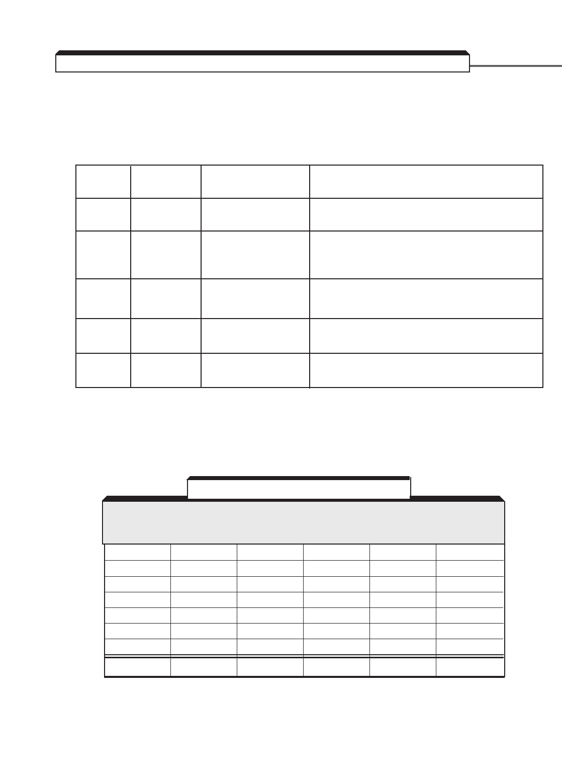
1-24
1.4.7 Encoder Feedback
If either the Flux Vector (A1-02 = 3) or Volts Per Hertz with Encoder (A1-02 = 1) control method is
desired, an encoder feedback board for the drive is required.
The drive can accept many types of encoder feedback. Table 1-4 shows which option board is
needed for each type of encoder.
Table 1-4. Encoder feedback option board types.
The PG-X2 card also has a connector TA2 which provides processed PG signal output for
use by an external pulse monitor. This connection can be made according to Figure 1-5.
+12V (200mA) 1 White D D 6
0V 2 Black F F 1
+5V 3 No Connection No Connection No Connection No Connection
A+ 4 Red A A 3
A–5 Green H H 8
B+ 6 Brown B B 2
B–7 Yellow I I 7
SHIELD TA3 Shield E No Connection 10
PG-X2 EPC (1) DYNAPAR DYNAPAR LAKESHORE/
FUNCTION TERMINAL MODEL H-20 (2) HS-35 NORTHSTAR
TA1 755A (Pin #) SL-56
Table 1-5. Encoder (PG) Connection
(1) For PG, EPC Model 755A, Orange and Blue wires are not used.
(2) For PG, Dynapar H-20, pins C, G, and J are not used.
Option
Board
PG-X2
PG-W2*
PG-B2
PG-D2
PG-A2
Control
Method(s)
ALL
ALL
ALL
All, Except
Flux Vector
All, Except
Flux Vector
Electrical Input
Scheme
Quadrature,
Line Driver
Dual Input,
Quadrature, Line
Driver
Quadrature,
Single Ended
Line Driver
Single Ended
Required Signals From Encoder
A+, A-, B+, & B- (Z+, Z- optional)
A+, A-, B+, B-, (Z+, Z- optional)
A, B, & Common
A+ & A-
A & Common
*Accepts inputs from two encoders. Primarily used with custom software.
The most common encoder used with the drive is the Quadrature, Line Driver style
encoder. When an encoder of this type is used, a PG-X2 option board must be
mounted onto the drive. The encoder then wires to the PG-X2 option board.
Table 1-5 and Figure 1-5 show connections for the PG-X2 and some typical encoders.
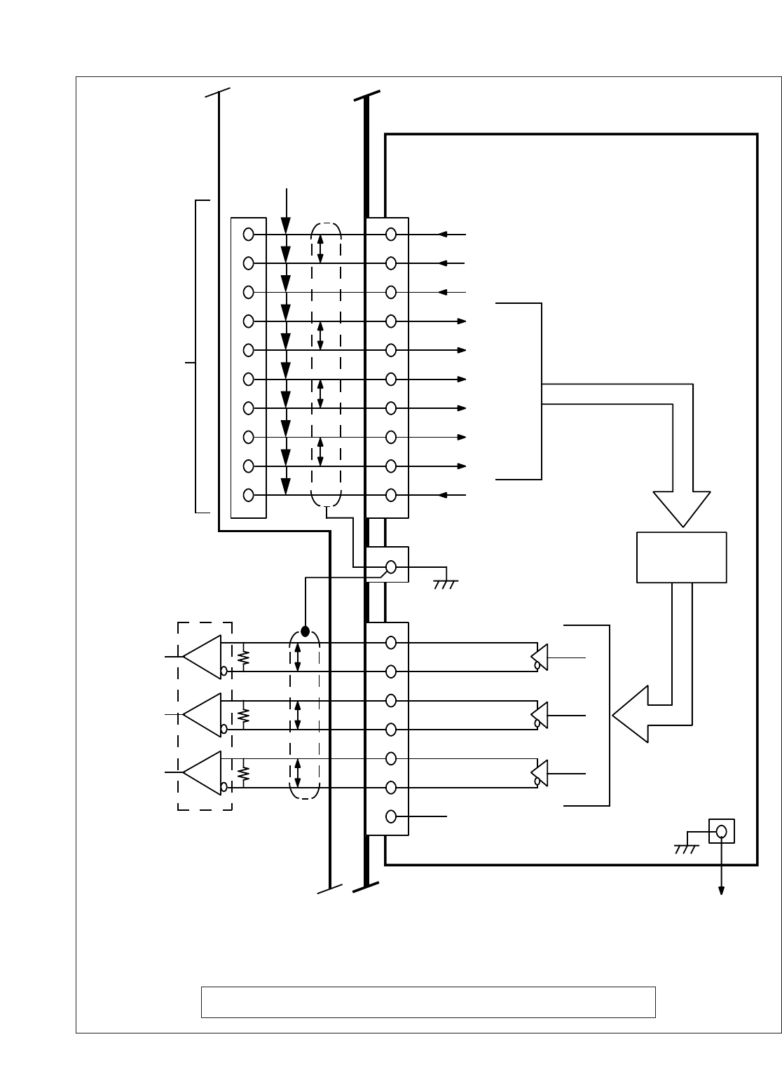
1-25
TA1
GPD 515/G5
GPD 515/G5
panel or
enclosure
PG-X2 Card
TA2
TB1
PG input
per
Table 1-9
1
2
3
4
5
6
7
8
9
10
1
2
3
4
5
6
7
8
9
10
Factory wiring —
TB1 to TA1
P
P
P
P
Isolated Power Supply
+12V
0V
+5V
A+
A-
B+
B-
Z+
Z-
0V
TA3
N/C
Line Driver
Pulse
A
Pulse
B
Pulse
Z
1
2
3
4
5
6
7
E
Factory Connection
(to control terminal 12)
Shield
P
P
P
Line Receiver
120 ‰
120 ‰
120 ‰
Pulse
Optical
Isolation
Monitor
Ouptut
RS422
Compatible
300kHz
ouptut max.
Customer supplied.
Refer to Section 2.2b or 2.2d (PG-X2) to calculate frequency.
NOTE:
Wiring distance from GPD 515/G5
to pulse monitor: 100m or less.
(3)
(3)
300 KHz
input max.
(2)
(1)
(2)
(1)
(2)
Z pulses not requred for most applications.
(3)
A+
A-
B+
B-
Z+
Z-
Figure 1-5. PG-X2 Card Input/Output Connections
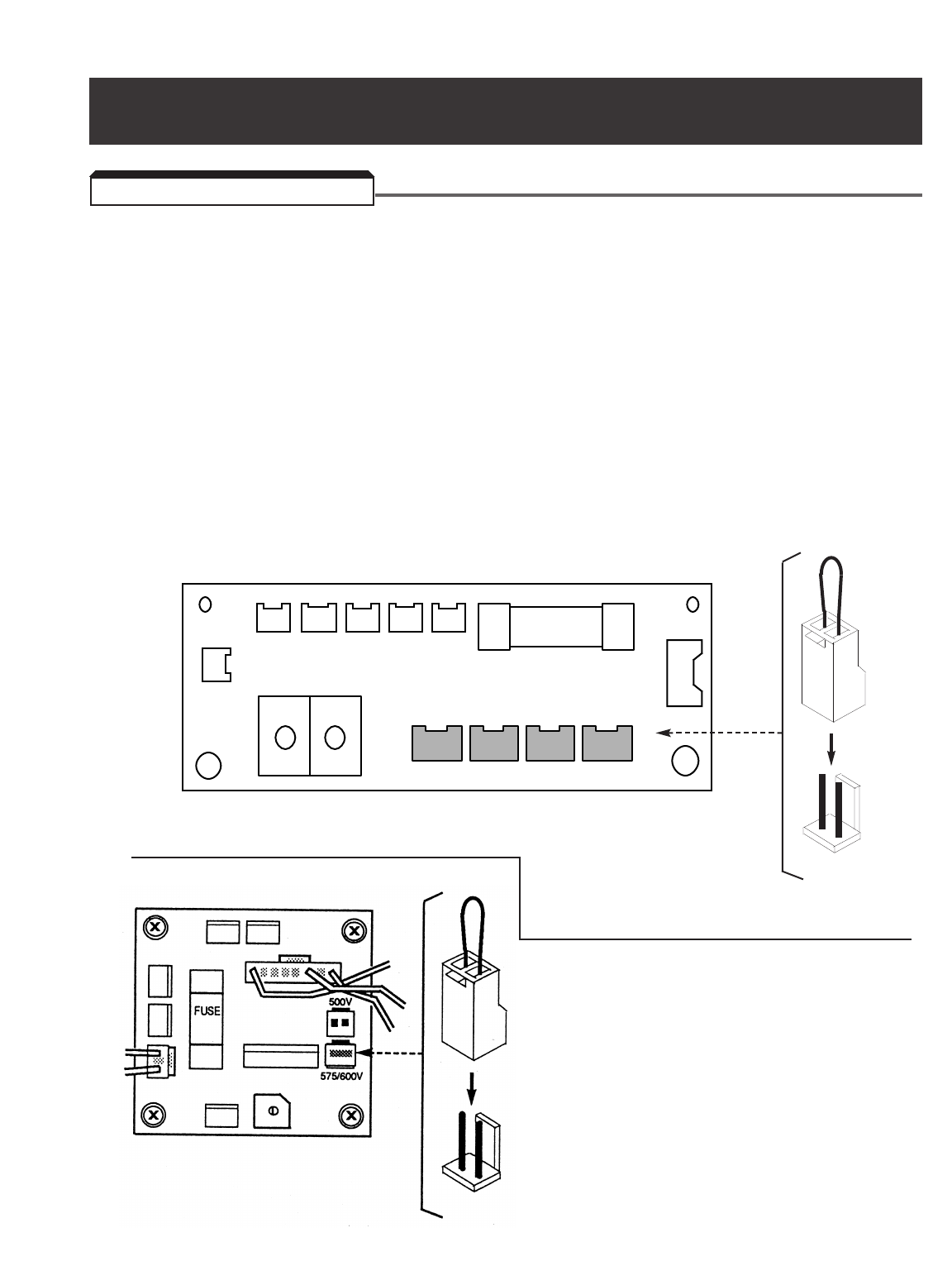
• Verify wires are properly connected and no erroneous grounds exist.
• Remove all debris from the drive enclosure. Check for loose wire clippings.
• Verify all mechanical connections inside the drive are tight.
• Verify motor is not connected to load.
• Apply input power only after the front cover is in place. DO NOT remove the front
cover or Digital Operator while input power is on.
• For 460V, GPD515C-B041 thru -B096 (CIMR-G5M40P41F thru 40451F):
Verify that the drive power voltage select connector, located at lower left corner inside
drive chassis (see Figure 2-1), is positioned correctly for the input power line voltage.
Voltage is preset to 460V at the factory. Reposition, if required, to match nominal line
voltage.
23CN 24CN 25CN 26CN 22CN FU2
21CN
sr
TB1
++
380V 400/415V 440V 460V
20CN
•
••
•
Figure 2-1a. Power Voltage Selection in 460V drive
2.1 PRE-POWER CHECKS
Section 2. INITIAL START-UP ("LOCAL" CONTROL)
For 600V, GPD515C-C027 thru -C200
(CIMR-G5M50181F thru 51600F).
Verify that the drive power voltage select
connector, located at lower left corner
inside drive chassis (see Figure 2-1b), is
positioned correctly for the input power line
voltage. Voltage is preset to 600V at the
factory. Reposition, if required, to match
nominal line voltage.
Figure 2-1b.
Power Voltage Selection
in 600V Drive
2-1
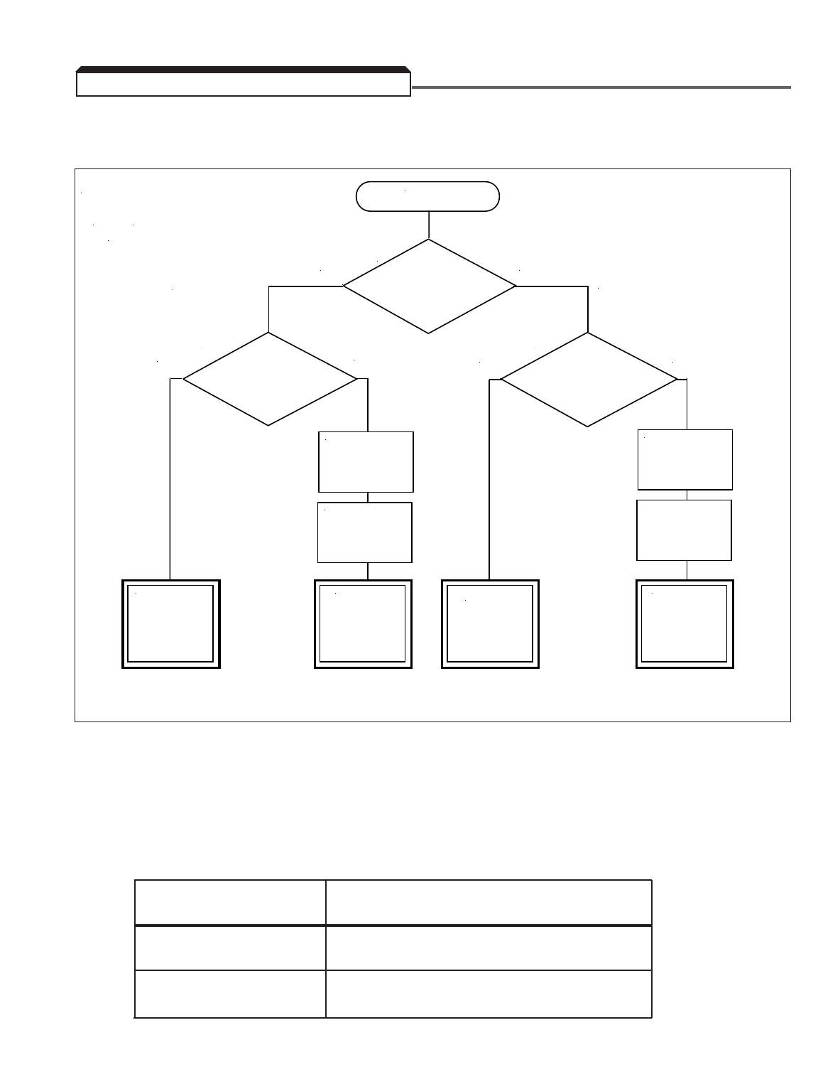
2-2
• Determine the proper control method for the application using Figure 2-2.
NOTE: For a more complete determination of control method, consult factory.
• If the selected control method requires a PG encoder on the motor, verify that a PG-X2
card is installed in the drive (see separate option installation sheet for details) and that all
encoder wiring is correct.
• Proceed to the correct Power On and Preliminary Checks procedure:
POWER ON AND PRELIMINARY CHECKS
Control Method Section
Open Loop Vector 2.2a
Flux Vector 2.2b
V/ f 2.2c
V/f with PG Feedback 2.2d
START
Is the load
Variable Torque?
(Pump or Fan)
NO
YES
High
Starting Torque
and/or Zero Speed
Control?
Speed
Regulation
Better than
± 3%?
YES
YES
Vector Control
V/F Control
PG (Encoder)
Required
On Motor
NO
NO
PG (Encoder)
Required
On Motor
PG-X2
Option Card
Required
PG-X2
Option Card
Required
Use Open
Loop Vector
Control
Method
Use Flux
Vector
Control
Method
Use V/f
Control
Method
Use V/f
w/ PG Fdbk
Control
Method
Figure 2-2. Control Method Selection Flowchart
2.2 CONTROL METHOD SELECTION
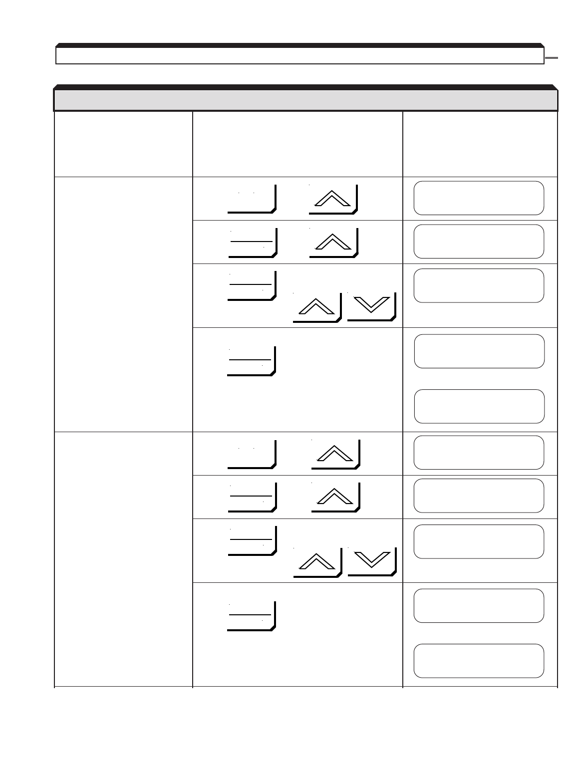
2-3
Apply input power to the drive.
If the display is not in English,
go to section 2.3, “CHANGING
THE LANGUAGE ON THE
DIGITAL OPERATOR”.
Set the control method of the Press , then
drive to Open Loop Vector.
(Set A1-02 to 2.)
NOTE: The drive leaves Press , then twice
the factory set for
Open Loop Vector
control — this step
may not be required. Press , then set drive to Open Loop
Vector using:
Write value to memory by pressing
briefly, then
Set parameter access level to Press , then
Advanced. This allows all
parameters to be viewed and
modified.
Press , then
Press , then set drive to Advanced
using:
Write value to memory by pressing:
briefly, then
2.2a POWER ON AND PRELIMINARY CHECKS - OPEN LOOP VECTOR CONTROL
DESCRIPTION KEY SEQUENCE DIGITAL OPERATOR DISPLAY
** Main Menu **
Initialize
Control Method
V/F Control
A1-02= 2
Open Loop Vector
MENU
MENU
DATA
ENTER
DATA
ENTER
DATA
ENTER
DATA
ENTER
DATA
ENTER
DATA
ENTER
Control Method
Open Loop Vector
Entry Accepted
** Main Menu **
Initialize
Access Level
Quick Start
A1-01= 4
Advanced Level
Access Level
Advanced Level
Entry Accepted
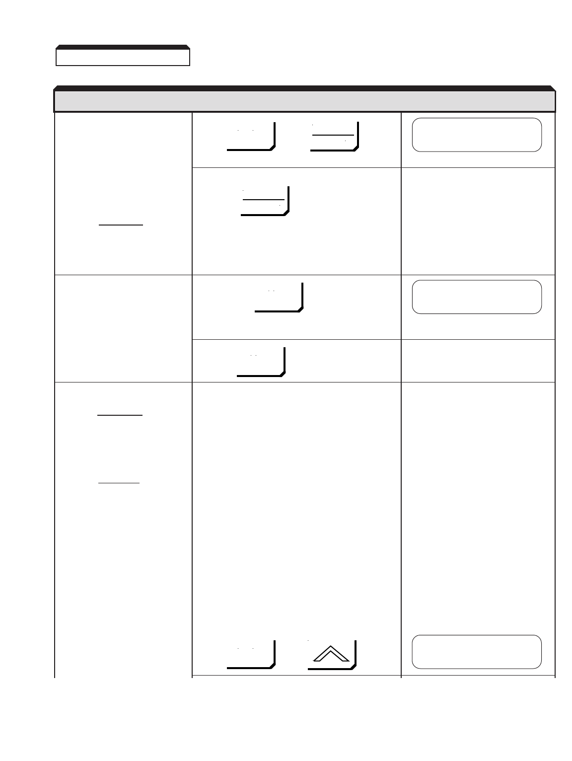
2-4
Check the motor rotation using Press , then
the JOG function.
NOTE: The frequency
reference for this
operation comes If either or both of the SEQ and REF lights are
from d1-09 and is on, press
factory set to 6 Hz.
WARNING
THE NEXT KEY-PRESS
WILL CAUSE THE MOTOR
TO MOVE; TAKE APPRO-
PRIATE PRECAUTIONS.
Press & hold
The motor should ramp up to
speed, and rotation should be
counter-clockwise if the FWD
light is on. Rotation should be RUN light will illuminate
clockwise if the REV light is on.
If rotation is incorrect, reverse Release
any two motor leads, then
repeat the motor rotation check.
Run the Auto-Tuning routine:
WARNING
THE MOTOR WILL MOVE
WHEN AUTO-TUNING IS
EXECUTED! TAKE
PROPER PRECAUTIONS!
CAUTION
Motor should be discon-
nected from the load before
executing the auto-tuning
routine.
NOTE: If the motor cannot be
disconnected from the
load, or if Auto-Tuning
fails, motor parameters
should be entered
manually. See section
2.4 for the procedure.
Enter the motor nameplate Press , then 3 times
values needed to perform Auto-
tuning
2.2a (continued)
DESCRIPTION KEY SEQUENCE DIGITAL OPERATOR
MENU
JOG
JOG
DATA
ENTER
Frequency Ref
U1-01= 0.00 HZ
Frequency Ref
U1-01= 6.00 HZ
LOCAL
REMOTE
MENU
** Main Menu **
Auto-Tuning

2-5
Press twice
Set the correct Nameplate voltage of the motor,
using:
Write the value to memory by pressing
briefly, then
Enter the current and the rest of the parameters
following a similar procedure to that of the motor
nameplate voltage.
When all of the parameters Press
are entered, execute Auto-
Tuning.
The drive will first output Press
current to the motor, then run
the motor at a high speed.
During tuning, the following
message will appear:
If no problems are encountered,
the following message will
appear:
• If a problem occurs during
Auto-Tuning execution,
see section 6.2, AUTO
TUNING FAULTS AND
CORRECTIVE ACTIONS.
Proceed to section 2.5,
“TEST RUN USING DIGITAL
OPERATOR”
2.2a (continued)
DESCRIPTION KEY SEQUENCE DIGITAL OPERATOR
Rated Voltage
400.0 VAC
Rated Voltage
460.0 VAC
Rated Voltage
460.0 VAC
Tuning Ready ?
Press RUN key
Tune Proceeding
XX HZ X.XX A
Tune Successful
Tune Aborted
"Reason"
DATA
ENTER
DATA
ENTER
RUN
RESET
Entry Accepted
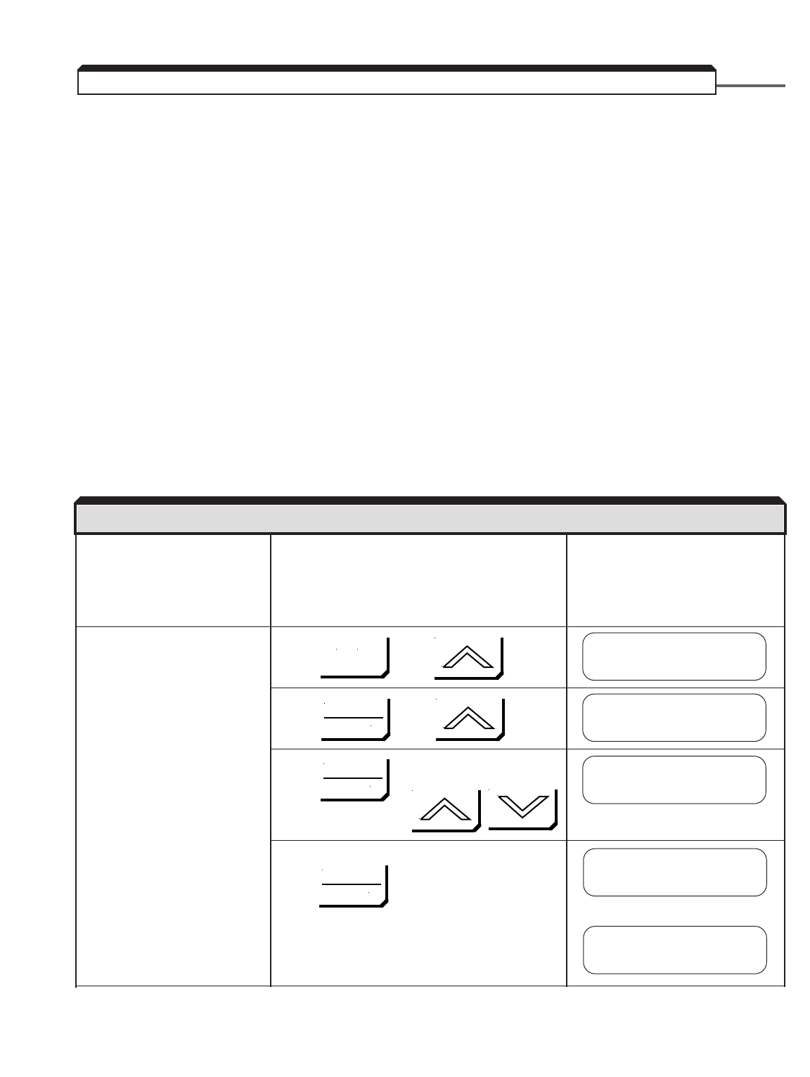
2-6
•Ensure motor is disconnected from load. To assure safety, disconnect the coupling or
belt which connects the motor with the machine, so that motor operation is isolated
prior to test operation.
•Verify the encoder to be used meets the following criteria: Line driver type (8830,
88C30), output pulse levels of 5-12V, and quadrature (A+, A–, B+, B–). Power supply
for the encoder from the PG-X2 card is capable of 200mA @ 12VDC or 200mA @ 5VDC.
Do not use both of these power supplies simultaneously.
•Verify that the encoder PPR (pulses per revolution) and expected motor speed do not
exceed the bandwidth of the PG-X2 card, using the following formula:
300,000 Hz ≥1.2 x (Max Speed in RPM / 60) x PPR of encoder
NOTE: Speed in RPM = 120 x frequency / number of motor poles
Example: Encoder PPR = 1024, Maximum speed = 1750 RPM
300,000 Hz ≥1.2 x (1750 / 60) x 1024
300,000 Hz ≥35,840 Hz – Acceptable
Apply input power to the drive.
If the display is not in English,
go to section 2.3, “CHANGING
THE LANGUAGE ON THE
DIGITAL OPERATOR”.
Set the control method of the Press , then
drive to Flux Vector (Set
A1-02 to 3.)
Press , then twice
Press , then set drive to Flux
Vector using:
Write value to memory by pressing
briefly, then
2.2b POWER ON AND PRELIMINARY CHECKS - FLUX VECTOR CONTROL
DESCRIPTION KEY SEQUENCE DIGITAL OPERATOR DISPLAY
** Main Menu **
Initialize
Control Method
Open Loop Vector
A1-02= 3
Flux Vector
MENU
DATA
ENTER
DATA
ENTER
DATA
ENTER
Control Method
Flux Vector
Entry Accepted
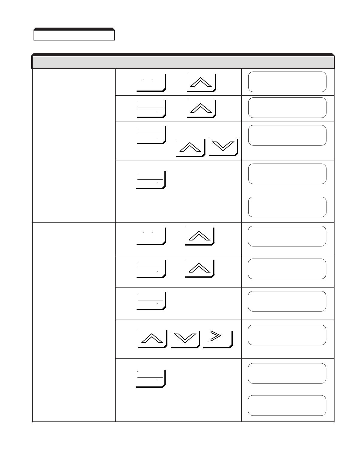
2-7
Set parameter access level to Press , then
Advanced. This allows all
parameters to be viewed and
modified.
Press , then
Press , then set drive to Advanced
using:
Write value to memory by pressing:
briefly, then
Set PG Pulses/Rev to the Press , then twice
correct value. (NOTE: For a
Yaskawa vector motor, the
correct value is 1024.)
Press , then 4 times
Press 3 times
Set the correct PPR, using:
Write value to memory by pressing:
briefly, then
2.2b (continued)
DESCRIPTION KEY SEQUENCE DIGITAL OPERATOR DISPLAY
MENU
MENU
DATA
ENTER
DATA
ENTER
DATA
ENTER
DATA
ENTER
DATA
ENTER
DATA
ENTER
** Main Menu **
Initialize
** Main Menu **
Programming
Access Level
Quick Start
A1-01= 4
Advanced Level
Access Level
Advanced Level
Group F
Options
PG Pulses/Rev
00600
PG Pulses/Rev
01024
PG Pulses/Rev
F1-01= 1024
Entry Accepted
RESET
Entry Accepted

2-8
Display motor speed. Press , then ,
then
Press , then 4 times
Rotate the motor shaft counter-
clockwise by hand (as viewed
from the load end of the motor).
• As the shaft is turned
counter-clockwise, a low
positive speed should be
indicated.
• As the shaft is turned
clockwise, a low negative
speed should be indicated.
• If the speed doesn’t change
when the motor shaft is
rotated, check encoder
wiring and connections.
The pulses from the encoder
can also be checked; see
section 6.6, “CHECKING
ENCODER PULSES.”
• If the polarity is wrong,
switch the channels on the
input to the PG-X2 card
(on terminal block TA1,
swap wires at terminals
4 & 6 and swap wires at
terminals 5 & 7).
2.2b (continued)
DESCRIPTION KEY SEQUENCE DIGITAL OPERATOR DISPLAY
MENU
DATA
ENTER
DATA
ENTER
Function U1
Monitor
Motor Speed
U1-05= 0.00 HZ
Motor Speed
U1-05= 2.38 HZ
Motor Speed
U1-05=- 1.47 HZ
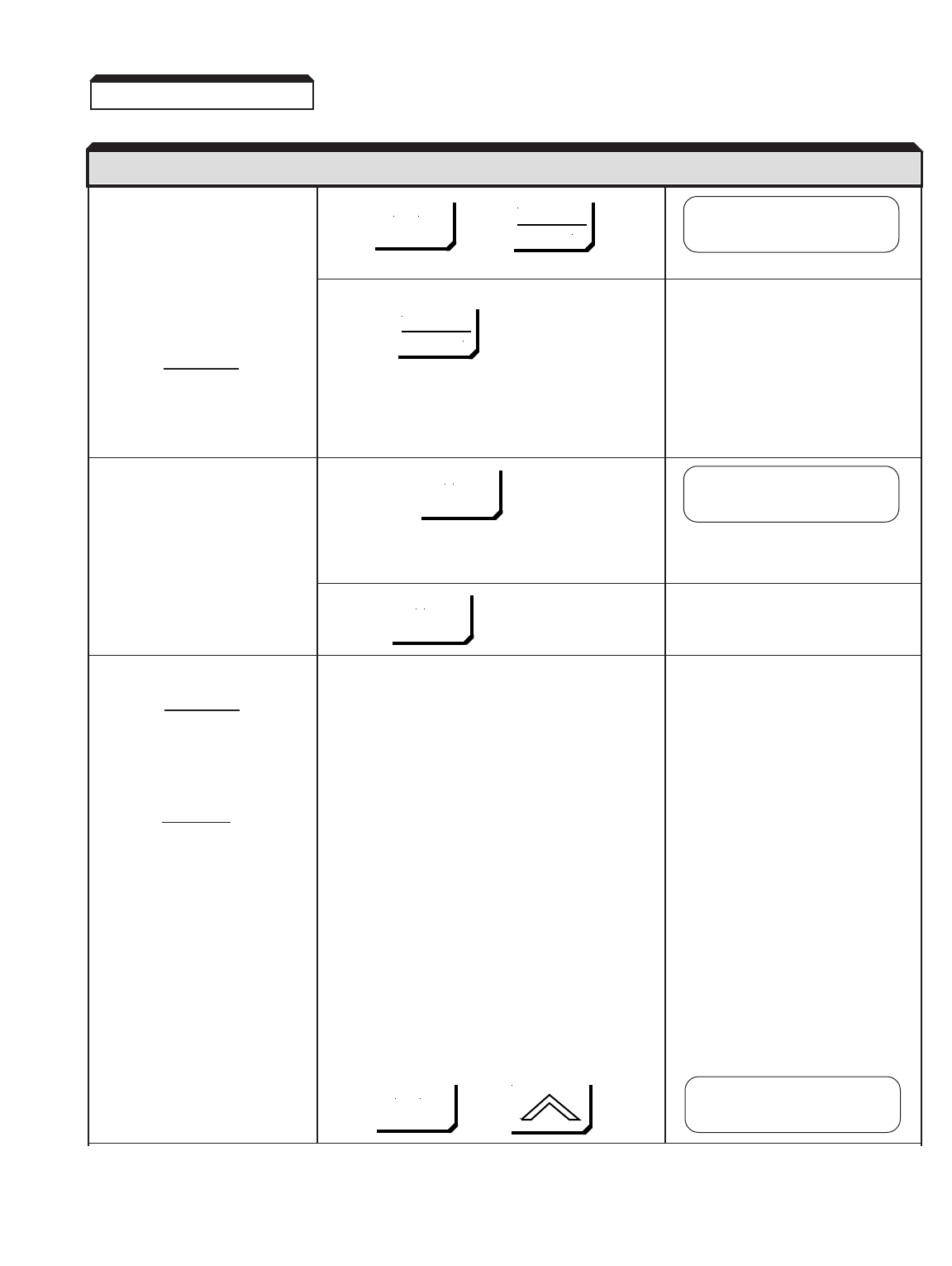
2-9
Check the motor rotation using Press , then
the JOG function.
NOTE: The frequency
reference for this
operation comes If either or both of the SEQ and REF lights are
from d1-09 and is on, press
factory set to 6 Hz.
WARNING
THE NEXT KEY-PRESS
WILL CAUSE THE MOTOR
TO MOVE; TAKE APPRO-
PRIATE PRECAUTIONS.
Press & hold
The motor should ramp up to
speed, and rotation should be
counter-clockwise if the FWD
light is on. Rotation should be RUN light will illuminate
clockwise if the REV light is on.
If the motor does not accelerate
smoothly or oscillates, reverse Release
any two motor leads, then
repeat the motor rotation check.
Run the Auto-Tuning routine:
WARNING
THE MOTOR WILL MOVE
WHEN AUTO-TUNING IS
EXECUTED! TAKE
PROPER PRECAUTIONS!
CAUTION
Motor should be discon-
nected from the load before
executing the auto-tuning
routine.
NOTE: If the motor cannot be
disconnected from the
load, or if Auto-Tuning
fails, motor parameters
should be entered
manually. See section
2.4 for the procedure.
Enter the motor nameplate Press , then 3 times
values needed to perform Auto-
tuning
2.2b (continued)
DESCRIPTION KEY SEQUENCE DIGITAL OPERATOR DISPLAY
MENU
JOG
JOG
DATA
ENTER
Frequency Ref
U1-01= 0.00 HZ
Frequency Ref
U1-01= 6.00 HZ
LOCAL
REMOTE
MENU
** Main Menu **
Auto-Tuning
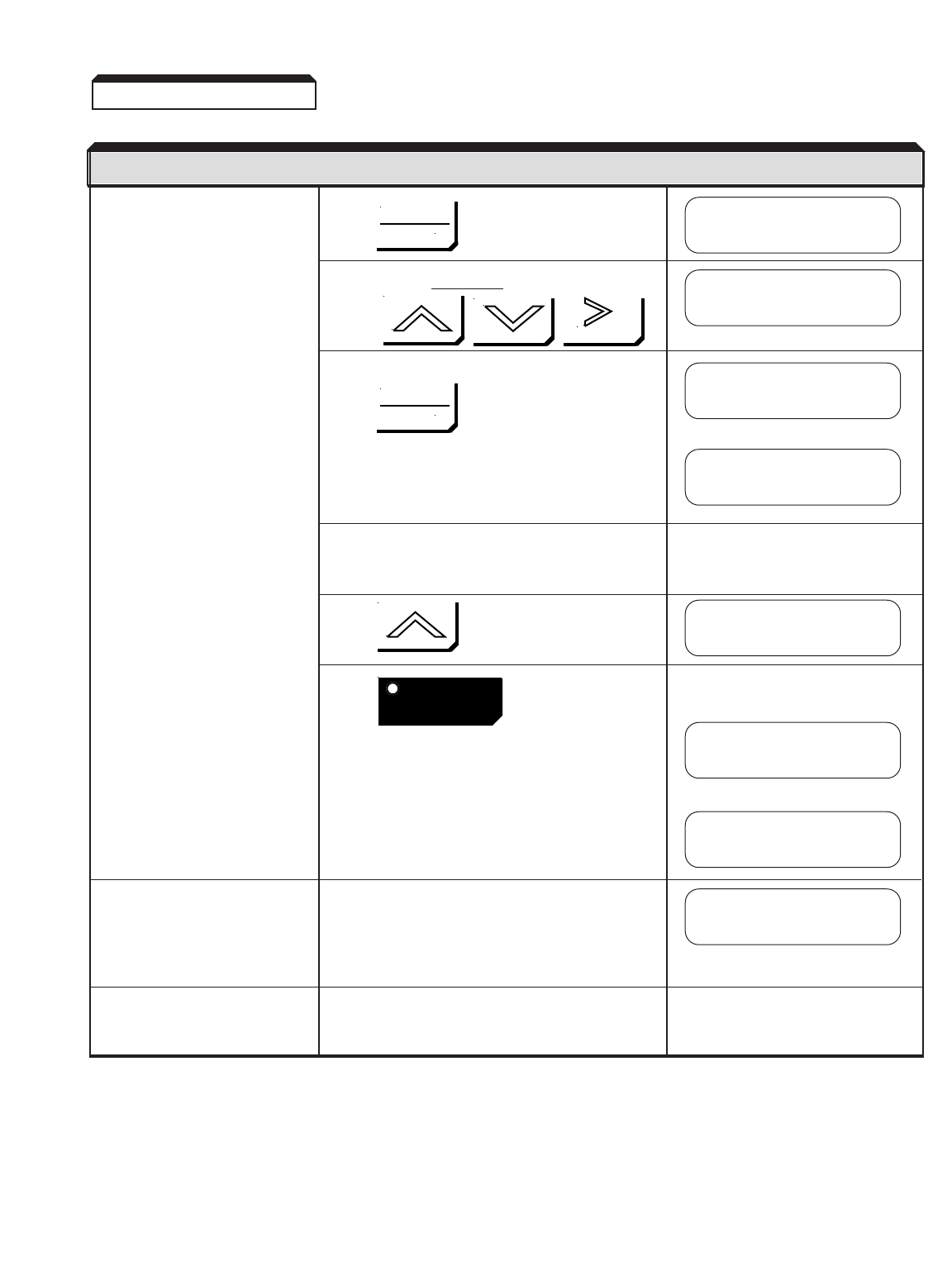
2-10
Press twice
Set the correct Nameplate voltage of the motor,
using:
Write the value to memory by pressing
briefly, then
Enter the current and the rest of the parameters
following a similar procedure to that of the motor
nameplate voltage.
When all of the parameters Press
are entered, execute Auto-
Tuning.
The drive will first output Press
current to the motor, then run
the motor at a high speed.
During tuning, the following
message will appear:
If no problems are encountered,
the following message will
appear:
• If a problem occurs during
Auto-Tuning execution, see
section 6.2, AUTO TUNING
FAULTS & CORRECTIVE
ACTIONS .
Proceed to section 2.5,
“TEST RUN USING DIGITAL
OPERATOR”
2.2b (continued)
DESCRIPTION KEY SEQUENCE DIGITAL OPERATOR DISPLAY
Rated Voltage
400.0 VAC
Rated Voltage
460.0 VAC
Rated Voltage
460.0 VAC
Tuning Ready ?
Press RUN key
Tune Proceeding
XX HZ X.XX A
Tune Successful
Tune Aborted
"Reason"
DATA
ENTER
DATA
ENTER
RUN
RESET
Entry Accepted
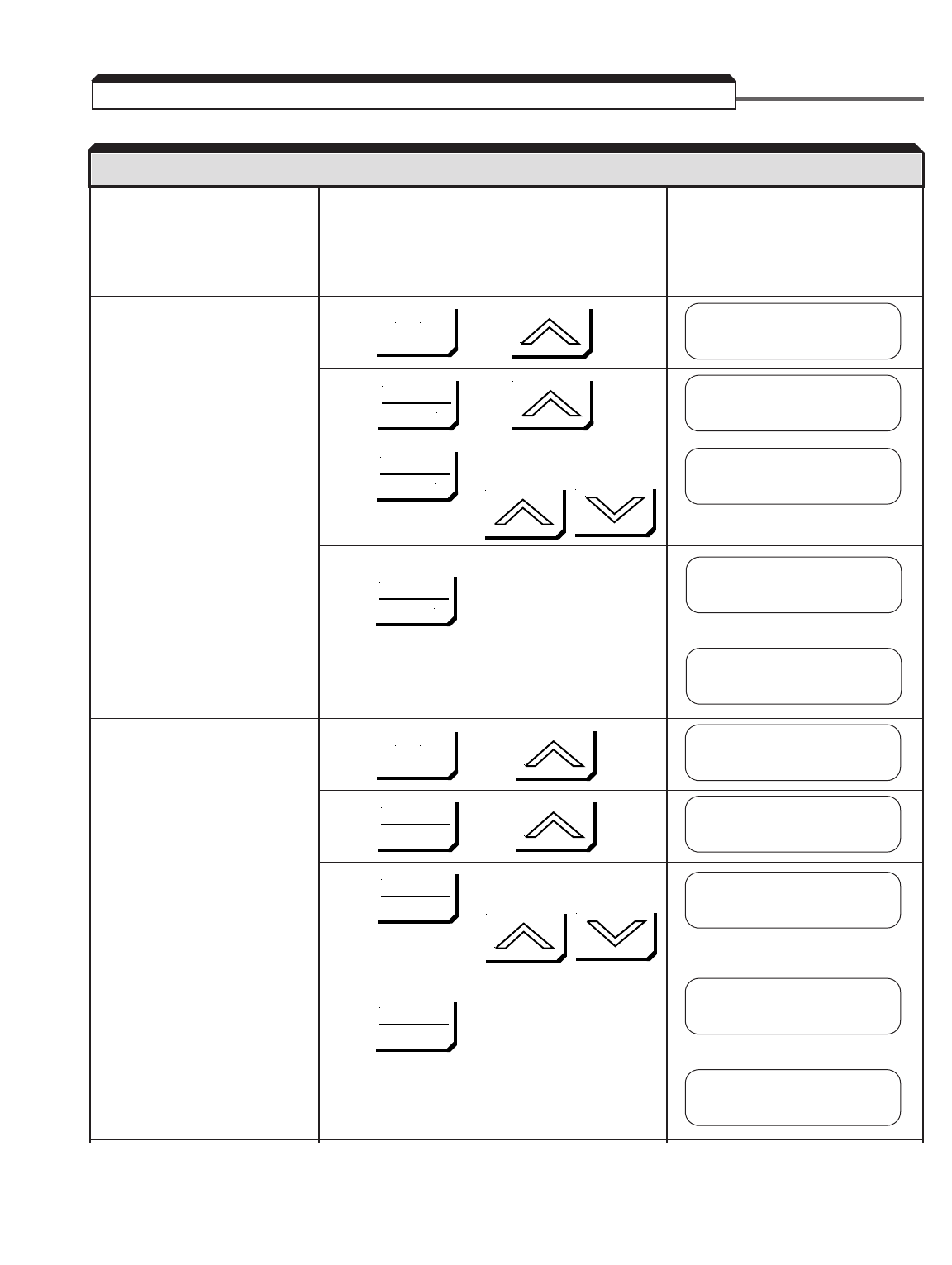
2-11
Apply input power to the drive.
If the display is not in English,
go to section 2.3, “CHANGING
THE LANGUAGE ON THE
DIGITAL OPERATOR”.
Set the control method of the Press , then
drive to V/f Control.
(Set A1-02 to 0.)
Press , then twice
Press , then set drive to V/f
Control using:
Write value to memory by pressing
briefly, then
Set parameter access level to Press , then
Advanced. This allows all
parameters to be viewed and
modified.
Press , then
Press , then set drive to Advanced
using:
Write value to memory by pressing:
briefly, then
2.2c POWER ON AND PRELIMINARY CHECKS - V/f CONTROL
DESCRIPTION KEY SEQUENCE DIGITAL OPERATOR DISPLAY
** Main Menu **
Initialize
Control Method
Open Loop Vector
A1-02= 0
V/F Control
MENU
MENU
DATA
ENTER
DATA
ENTER
DATA
ENTER
DATA
ENTER
DATA
ENTER
DATA
ENTER
Control Method
V/F Control
Entry Accepted
** Main Menu **
Initialize
Access Level
Quick Start
A1-01= 4
Advanced Level
Access Level
Advanced Level
Entry Accepted

2-12
Select the drive input voltage, Press , then twice
then select an appropriate V/f
pattern. Refer to section 5.38,
“V/F PATTERN – STANDARD”
or 5.39, “V/F PATTERN –
CUSTOM”. Press , then 3 times
NOTE: A standard V/f pattern
for a 60 HZ motor is
pattern 1 (60 HZ
Saturation). Press
Press twice, then set the drive to the
nominal input line
voltage using:
Write to memory by pressing:
briefly, then
Press twice, then
Then set the drive to desired V/F pattern
using:
Write to memory by pressing:
briefly, then
2.2c (continued)
DESCRIPTION KEY SEQUENCE DIGITAL OPERATOR DISPLAY
MENU
DATA
ENTER
DATA
ENTER
DATA
ENTER
DATA
ENTER
DATA
ENTER
DATA
ENTER
** Main Menu **
Programming
Group E
Motor
Function E1
V/F Pattern
Entry Accepted
Input Voltage
460 VAC
Input Voltage
E1-01= 460 VAC
E1-03= F***
User Defined V/F
E1-03= 1
60 HZ Saturation
V/F Selection
60 HZ Saturation
Entry Accepted

2-13
Check the motor rotation using Press , then
the JOG function.
NOTE: The frequency
reference for this
operation comes If either or both of the SEQ and REF lights are
from d1-09 and is on, press
factory set to 6 Hz.
WARNING
THE NEXT KEY-PRESS
WILL CAUSE THE MOTOR
TO MOVE; TAKE APPRO-
PRIATE PRECAUTIONS.
Press & hold
The motor should ramp up to
speed, and rotation should be
counter-clockwise if the FWD
light is on. Rotation should be RUN light will illuminate
clockwise if the REV light is on.
If rotation is incorrect, reverse Release
any two motor leads, then
repeat the motor rotation check.
Proceed to section 2.5,
“TEST RUN USING DIGITAL
OPERATOR”
2.2c (continued)
DESCRIPTION KEY SEQUENCE DIGITAL OPERATOR DISPLAY
MENU
JOG
JOG
DATA
ENTER
Frequency Ref
U1-01= 0.00 HZ
Frequency Ref
U1-01= 6.00 HZ
LOCAL
REMOTE
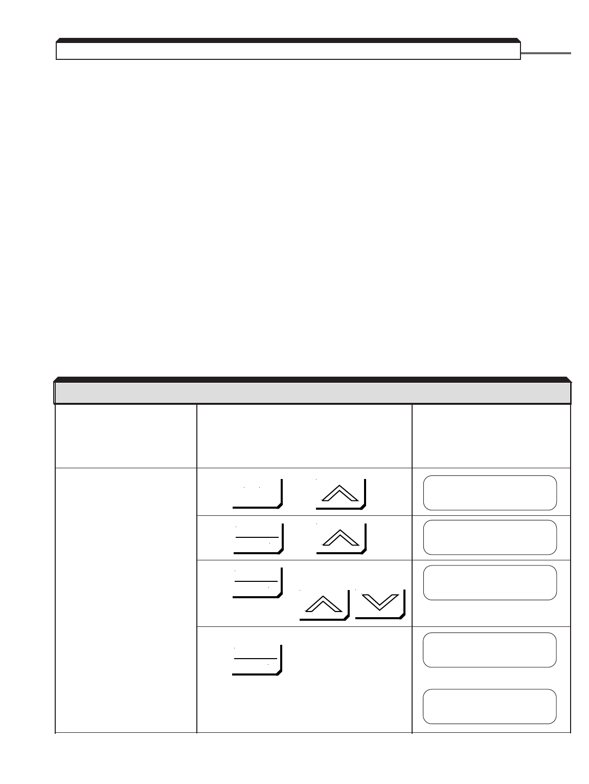
2-14
•Ensure motor is disconnected from load. To assure safety, disconnect the coupling or
belt which connects the motor with the machine so that motor operation is isolated,
prior to test operation.
•Verify the encoder to be used meets the following criteria: Line driver type (8830,
88C30), output pulse levels of 5-12V, and quadrature (A+, A–, B+, B–). Power supply
for the encoder from the PG-X2 card is capable of 200mA @ 12VDC or 200mA @ 5VDC.
Do not use both of these power supplies simultaneously.
•Verify that the encoder PPR (pulses per revolution) and expected motor speed do not
exceed the bandwidth of the PG-X2 card, using the following formula:
300,000 Hz ≥1.2 x (Max Speed in RPM / 60) x PPR of encoder
NOTE: Speed in RPM = 120 x frequency / # of motor poles
Example: Encoder PPR = 1024, Maximum speed = 1750 RPM
300,000 Hz ≥1.2 x (1750 / 60) x 1024
300,000 Hz ≥35,840 Hz – Acceptable
Apply input power to the drive.
If the display is not in English,
go to section 2.3, “CHANGING
THE LANGUAGE ON THE
DIGITAL OPERATOR”.
Set the control method of the Press , then
drive to V/f w/PG Feedback
(Set A1-02 to 1.)
Press , then twice
Press , then set drive to V/F w/PG
Fdbk using:
Write value to memory by pressing
briefly, then
2.2d POWER ON AND PRELIMINARY CHECKS - V/f WITH PG FEEDBACK
DESCRIPTION KEY SEQUENCE DIGITAL OPERATOR DISPLAY
** Main Menu **
Initialize
Control Method
Open Loop Vector
A1-02= 1
V/F w/PG Fdbk
MENU
DATA
ENTER
DATA
ENTER
DATA
ENTER
Control Method
V/F w/PG Fdbk
Entry Accepted

2-15
Set parameter access level to Press , then
Advanced. This allows all
parameters to be viewed and
modified.
Press , then
Press , then set drive to Advanced
using:
Write value to memory by pressing:
briefly, then
Set PG Pulses/Rev to the Press , then twice
correct value. (NOTE: For a
Yaskawa vector motor, the
correct value is 1024.)
Press , then 4 times
Press 3 times
Set the correct PPR, using:
Write value to memory by pressing:
briefly, then
2.2d (continued)
DESCRIPTION KEY SEQUENCE DIGITAL OPERATOR DISPLAY
MENU
MENU
DATA
ENTER
DATA
ENTER
DATA
ENTER
DATA
ENTER
DATA
ENTER
DATA
ENTER
** Main Menu **
Initialize
** Main Menu **
Programming
Access Level
Quick Start
A1-01= 4
Advanced Level
Access Level
Advanced Level
Group F
Options
PG Pulses/Rev
00600
PG Pulses/Rev
01024
PG Pulses/Rev
F1-01= 1024
Entry Accepted
RESET
Entry Accepted
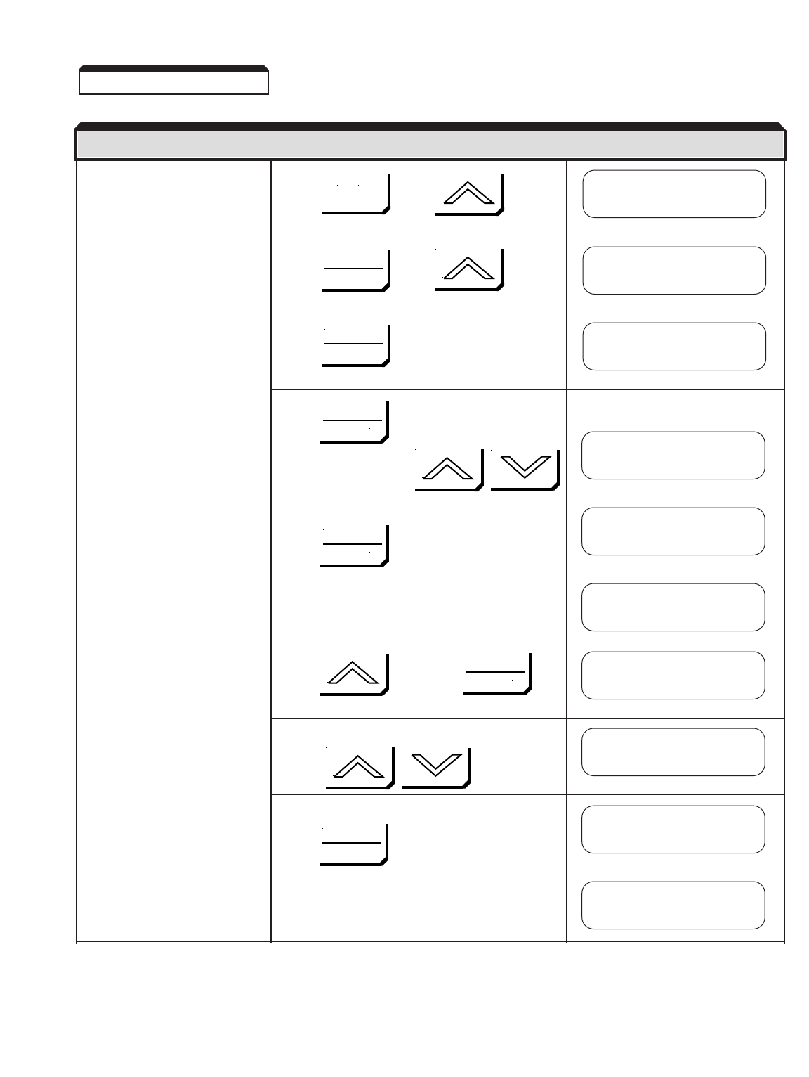
2-16
Select the drive input voltage, Press , then twice
then select an appropriate V/F
pattern. Refer to section 5.38,
“V/F PATTERN – STANDARD”
or 5.39, “V/F PATTERN –
CUSTOM”. Press , then 3 times
NOTE: A standard V/F pattern
for a 60 HZ motor is
pattern 1 (60 HZ
Saturation). Press
Press twice, then set the drive to the
nominal input line
voltage using:
Write to memory by pressing:
briefly, then
Press twice, then
Then set the drive to desired V/F pattern
using:
Write to memory by pressing:
briefly, then
2.2d (continued)
DESCRIPTION KEY SEQUENCE DIGITAL OPERATOR DISPLAY
MENU
DATA
ENTER
DATA
ENTER
DATA
ENTER
DATA
ENTER
DATA
ENTER
DATA
ENTER
** Main Menu **
Programming
Group E
Motor
Function E1
V/F Pattern
Entry Accepted
Input Voltage
460 VAC
Input Voltage
E1-01= 460 VAC
E1-03= F***
User Defined V/F
E1-03= 1
60 HZ Saturation
V/F Selection
60 HZ Saturation
Entry Accepted
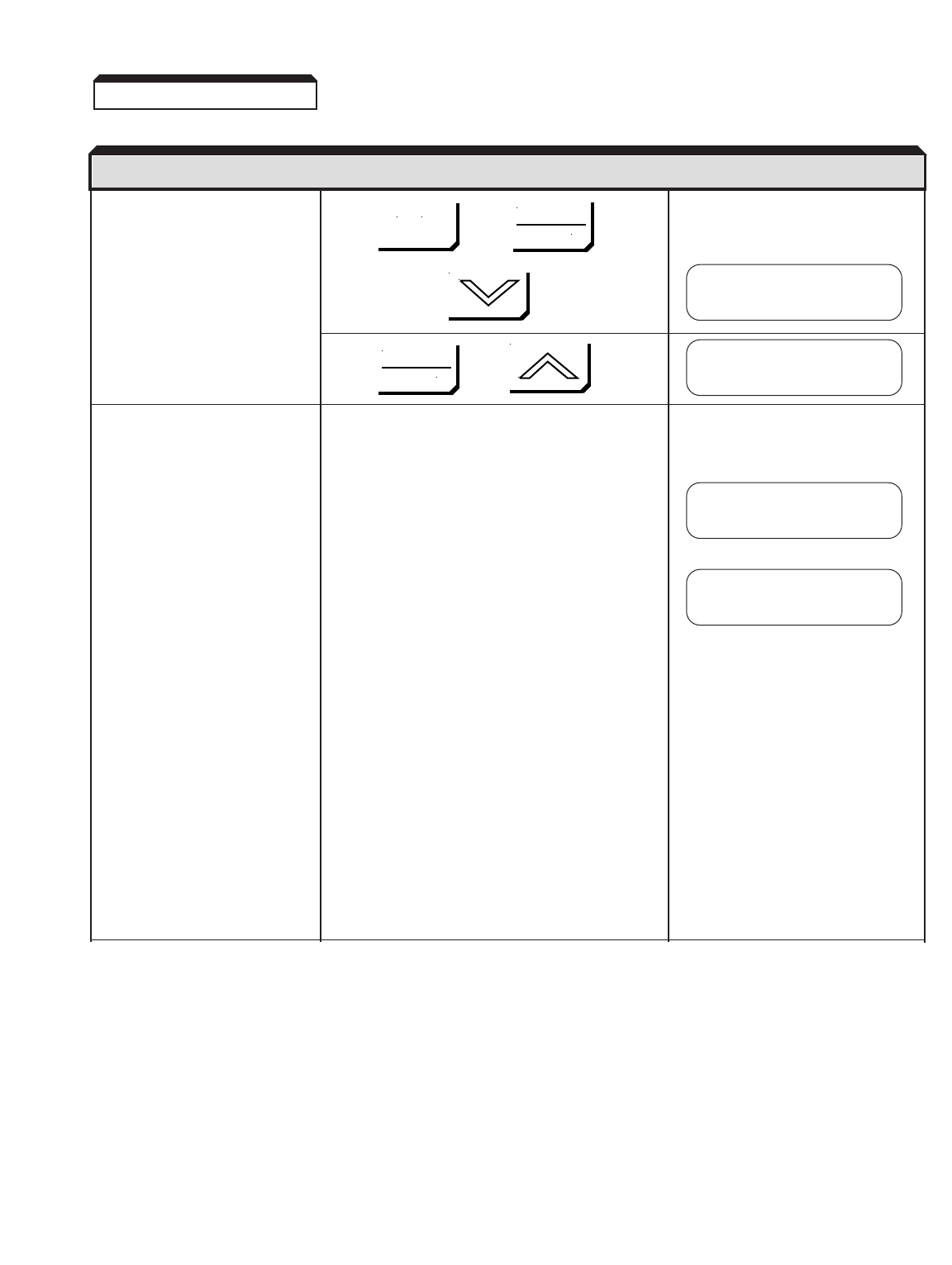
2-17
Display motor speed. Press , then ,
then
Press , then 4 times
Rotate the motor shaft counter-
clockwise by hand (as viewed
from the load end of the motor).
• As the shaft is turned
counter-clockwise, a low
positive speed should be
indicated.
• As the shaft is turned
clockwise, a low negative
speed should be indicated.
• If the speed doesn’t change
when the motor shaft is
rotated, check encoder
wiring and connections.
The pulses from the encoder
can also be checked; see
section 6.6, “CHECKING
ENCODER PULSES.”
• If the polarity is wrong,
switch the channels on the
input to the PG-X2 card
(on terminal block TA1,
swap wires at terminals
4 & 6 and swap wires at
terminals 5 & 7).
2.2d (continued)
DESCRIPTION KEY SEQUENCE DIGITAL OPERATOR DISPLAY
MENU
DATA
ENTER
DATA
ENTER
Function F1
Monitor
Motor Speed
U1-05= 0.00 HZ
Motor Speed
U1-05= 2.38 HZ
Motor Speed
U1-05=- 1.47 HZ
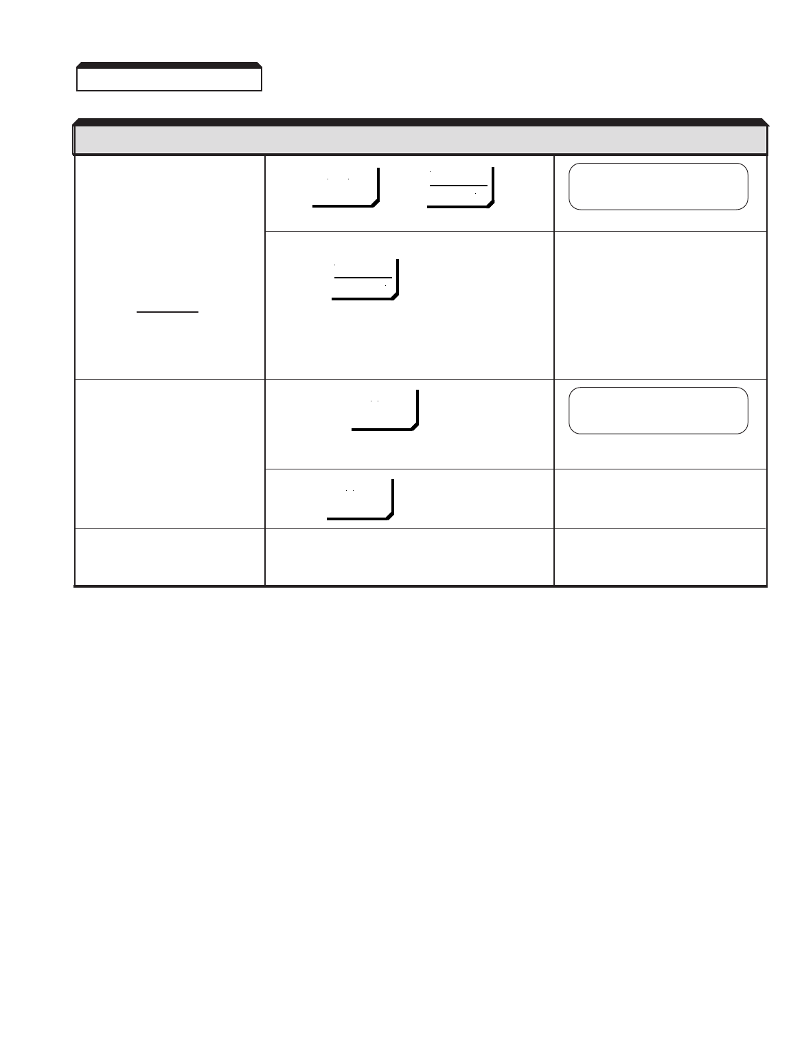
2-18
Check the motor rotation using Press , then
the JOG function.
NOTE: The frequency
reference for this
operation comes If either or both of the SEQ and REF lights are
from d1-09 and is on, press
factory set to 6 Hz.
WARNING
THE NEXT KEY-PRESS
WILL CAUSE THE MOTOR
TO MOVE; TAKE APPRO-
PRIATE PRECAUTIONS.
Press & hold
The motor should ramp up to
speed, and rotation should be
counter-clockwise if the FWD
light is on. Rotation should be RUN light will illuminate
clockwise if the REV light is on.
If rotation is incorrect, reverse Release
any two motor leads, then
repeat the motor rotation check.
Proceed to section 2.5,
“TEST RUN USING DIGITAL
OPERATOR”
2.2d (continued)
DESCRIPTION KEY SEQUENCE DIGITAL OPERATOR DISPLAY
MENU
JOG
JOG
DATA
ENTER
Frequency Ref
U1-01= 0.00 HZ
Frequency Ref
U1-01= 6.00 HZ
LOCAL
REMOTE
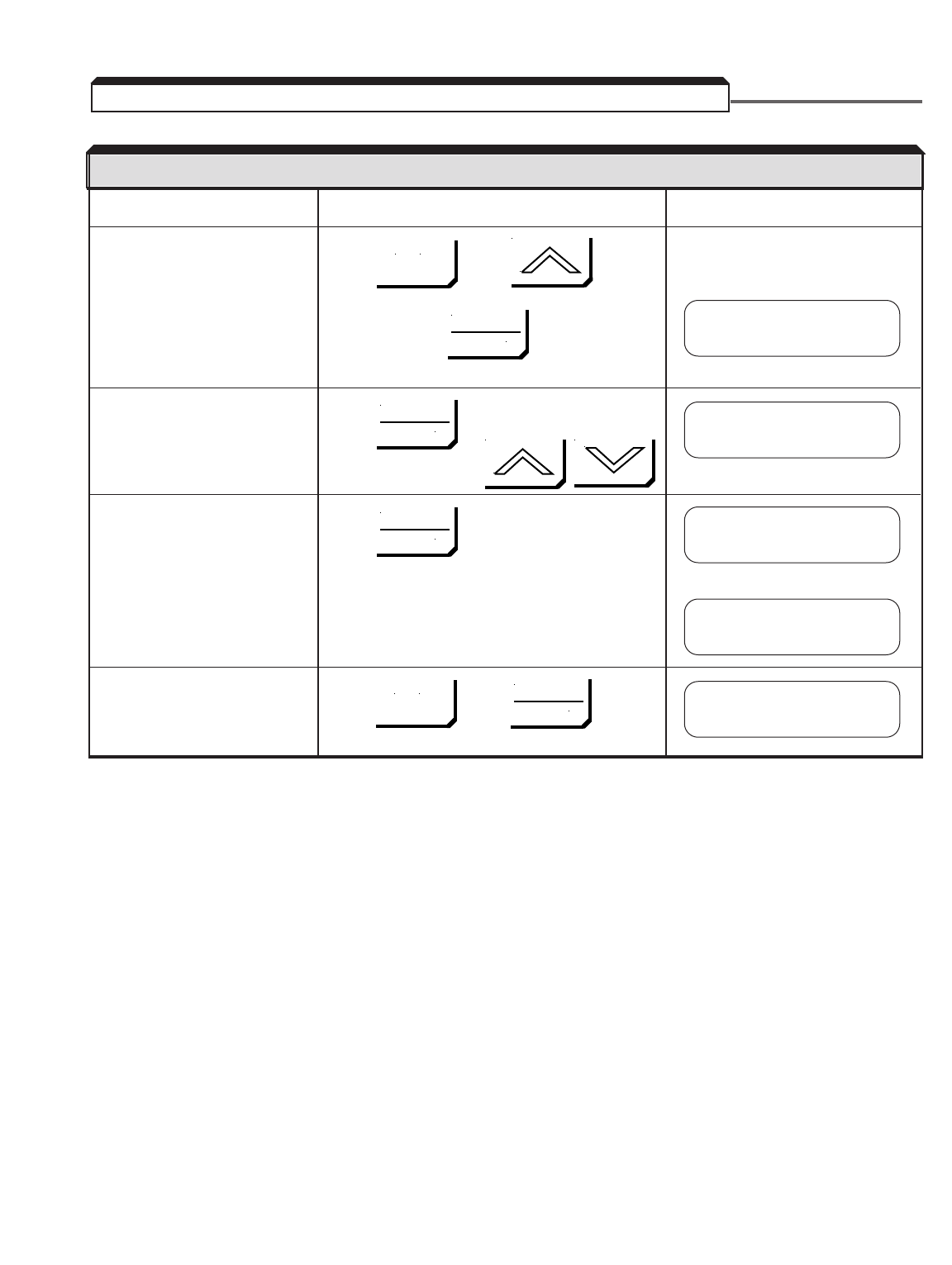
2-19
Power ON
Bring up the Main Menu and Press , then ,
go to Initialize mode.
then
Change the language. Press , then select the correct
language using:
Write value to memory. Press
briefly, then
Return to operating mode. Press , then
2.3 CHANGING THE LANGUAGE ON THE DIGITAL OPERATOR
DESCRIPTION KEY SEQUENCE DIGITAL OPERATOR DISPLAY
MENU
MENU
DATA
ENTER
[ Display in Wrong
Language ]
A1-00= 0
English
Select Language
English
DATA
ENTER
DATA
ENTER
DATA
ENTER
Entry Accepted
Frequency Ref
U1-01= 0.00 HZ
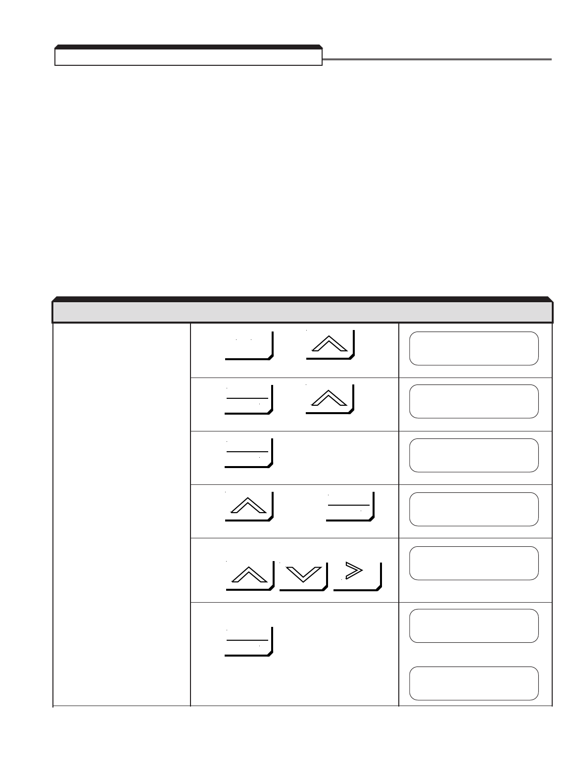
2-20
This procedure can be used as an alternative to auto-motor tuning. If the motor being used
with the drive did not pass motor auto-tuning or if the motor cannot be disconnected from
the load, the motor parameters need to be calculated and entered manually.
This procedure only applies to the Open Loop Vector Control method & the
Flux Vector Control method.
The following information used in the calculation formulas is usually listed on the motor
nameplate. If no-load current is not marked on the nameplate and the motor manufacturer
is not able to supply it, use the default value of (0.3 x IFLA) = INLA.
Motor Voltage (V) Vm
Motor Rated Speed (RPM) NR
Motor Rated Frequency (Hz) fR
Motor Synchronous Speed (RPM) NS(NS= f
R*120 / number of motor poles)
Full Load Amps (FLA) IFLA
No-Load Amps (NLA) INLA
Enter the Maximum frequency Press , then twice
( E1-04 ). For constant torque
applications, set to motor
nameplate frequency. For
constant horsepower
applications, set to maximum Press , then 3 times
frequency desired.
Press twice
Press twice, then
Set the maximum frequency using:
Write value to memory by pressing
briefly, then
2.4 CALCULATING MOTOR PARAMETERS
DESCRIPTION KEY SEQUENCE DIGITAL OPERATOR DISPLAY
MENU
** Main Menu **
Programming
Group E
Motor
Input Voltage
E1-01= 460 VAC
Max. Frequency
0060.0 HZ
Max. Frequency
0060.0 HZ
Max. Frequency
E1-04= 60.0 HZ
DATA
ENTER
DATA
ENTER
DATA
ENTER
DATA
ENTER
RESET
Entry Accepted
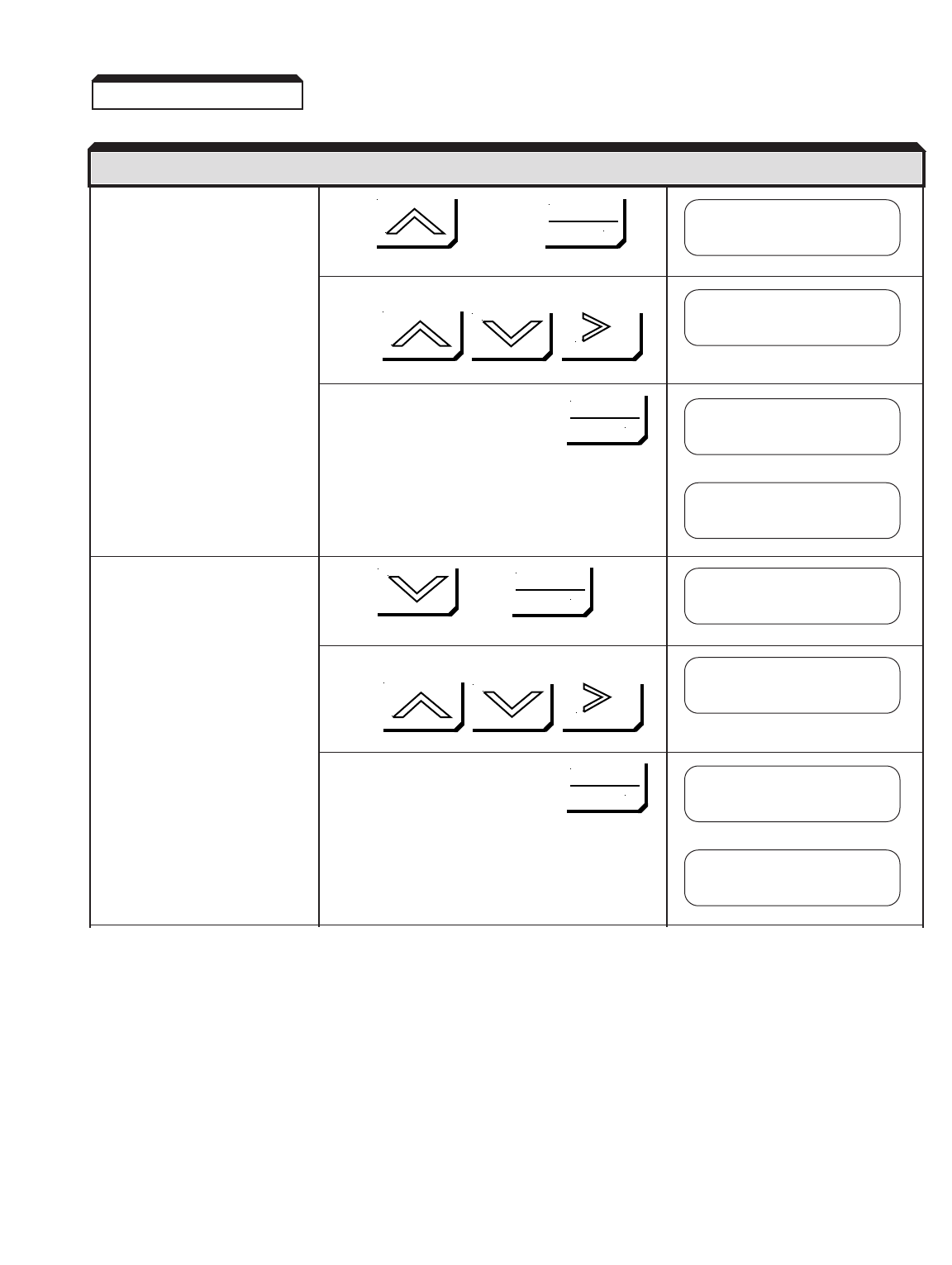
2-21
Enter the Base frequency Press twice , then
( E1-06 ). This value can be
obtained from the motor
nameplate (rated
frequency).
Set the base frequency using:
Write value to memory by pressing
briefly, then
Enter the maximum motor Press , then
voltage ( E1-05 ). This value
can be obtained from the
motor nameplate (rated
voltage).
Set the maximum voltage using:
Write value to memory by pressing
briefly, then
2.4 (continued)
DESCRIPTION KEY SEQUENCE DIGITAL OPERATOR DISPLAY
DATA
ENTER
Base Frequency
0060.0 HZ
Base Frequency
0060.0 HZ
Max. Voltage
400.0 VAC
Max. Voltage
460.0 VAC
DATA
ENTER
DATA
ENTER
DATA
ENTER
RESET
RESET
Base Frequency
E1-06= 60.0 HZ
Entry Accepted
Max. Voltage
E1-05= 460.0 VAC
Entry Accepted
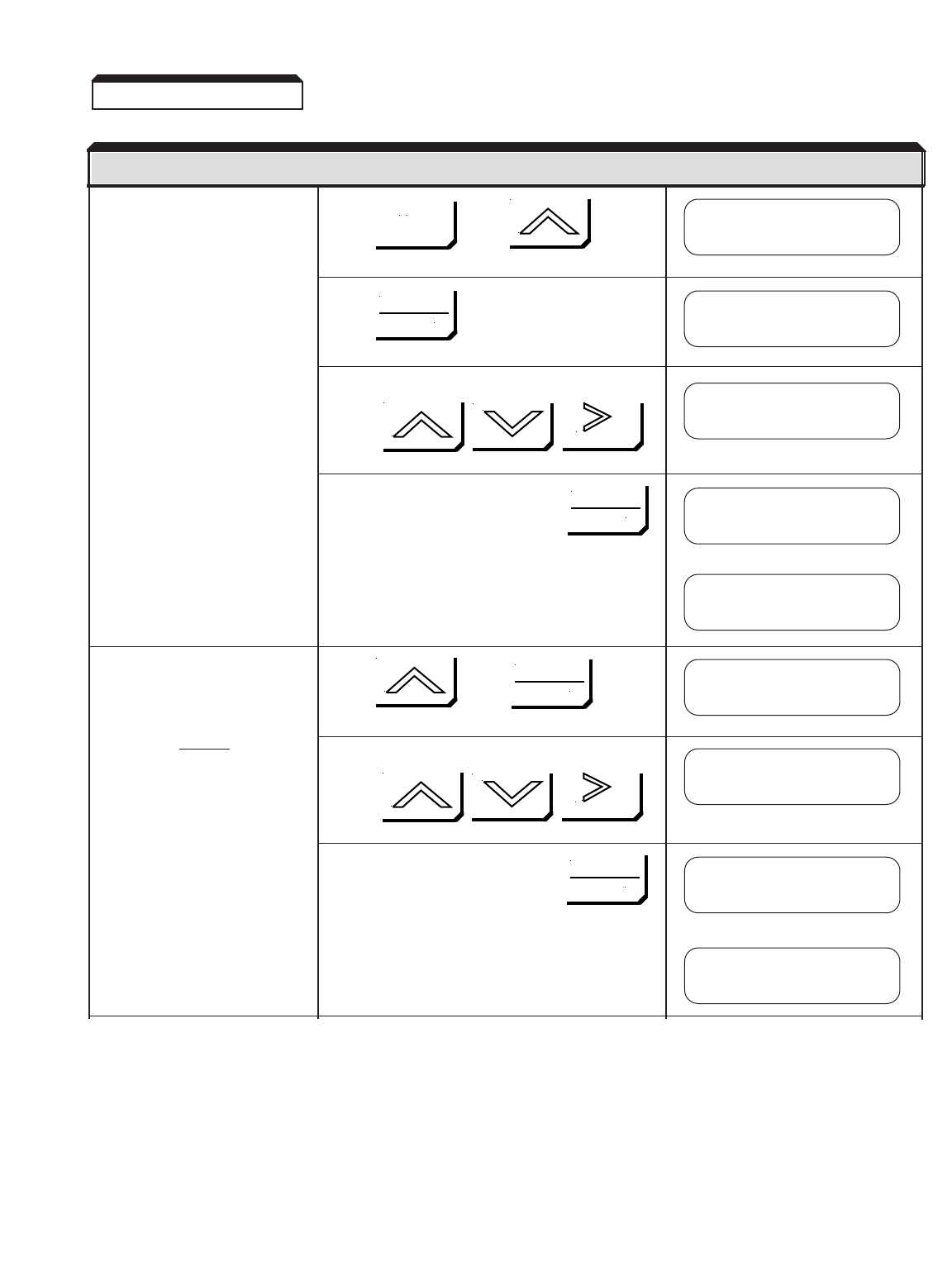
2-22
Enter the motor rated full load Press , then
amps ( E2-01 ). This value can
be obtained from the motor
nameplate (motor full load
amps).
Press twice
Set the FLA using:
Write value to memory by pressing
briefly, then
Enter the motor rated slip Press , then
( E2-02 ). This value can be
calculated using the following
formula:
E2-02 = (Ns - Nr) x 60 x 0.7
Ns
Set motor rated slip using:
Nr = nameplate rated speed
Ns = synchronous speed
Ns = fRx 120 / # of motor poles
Write value to memory by pressing
briefly, then
2.4 (continued)
DESCRIPTION KEY SEQUENCE DIGITAL OPERATOR DISPLAY
Function E2
Motor Setup
Motor Rated FLA
001.00 A
Motor Rated FLA
E2-01= 1.20 A
Motor Rated FLA
001.20 A
ESC
DATA
ENTER
DATA
ENTER
RESET
Entry Accepted
Motor Rated Slip
02.90 HZ
Motor Rated Slip
1.08 HZ
DATA
ENTER
DATA
ENTER
RESET
Motor Rated Slip
E2-02= 1.08 Hz
Entry Accepted

2-23
Enter the motor no-load current Press , then
( E2-03 ). This value can some-
times be obtained from the
motor nameplate. If it is
unavailable, use the following
formula to calculate it: Set motor no load current using:
1-5 HP:
INLA = IFLA x 0.50
5-15 HP:
INLA = IFLA x 0.40
> 15 HP:
INLA = IFLA x 0.30 Write value to memory by pressing
briefly, then
Enter number of motor poles Press , then
( E2-04 ).
(Assuming an fRof 50 or 60 Hz)
Rated Speed Set number of motor poles using:
(RPM) # of motor poles
2400-3600 2
1300-1800 4
900-1200 6
660-900 8
Write value to memory by pressing
briefly, then
Parameters E2-05 to E2-09 :
Factory set values are
acceptable.
2.4 (continued)
DESCRIPTION KEY SEQUENCE DIGITAL OPERATOR DISPLAY
No-Load Current
000.60 A
No-Load Current
000.32 A
DATA
ENTER
DATA
ENTER
RESET
No-Load Current
E2-03= 0.32A
Entry Accepted
Number of Poles
04
Number of Poles
04
DATA
ENTER
DATA
ENTER
RESET
Number of Poles
E2-04= 4
Entry Accepted
Note:
This step is not required for
Open Loop Vector Control
method (A1-02=0).
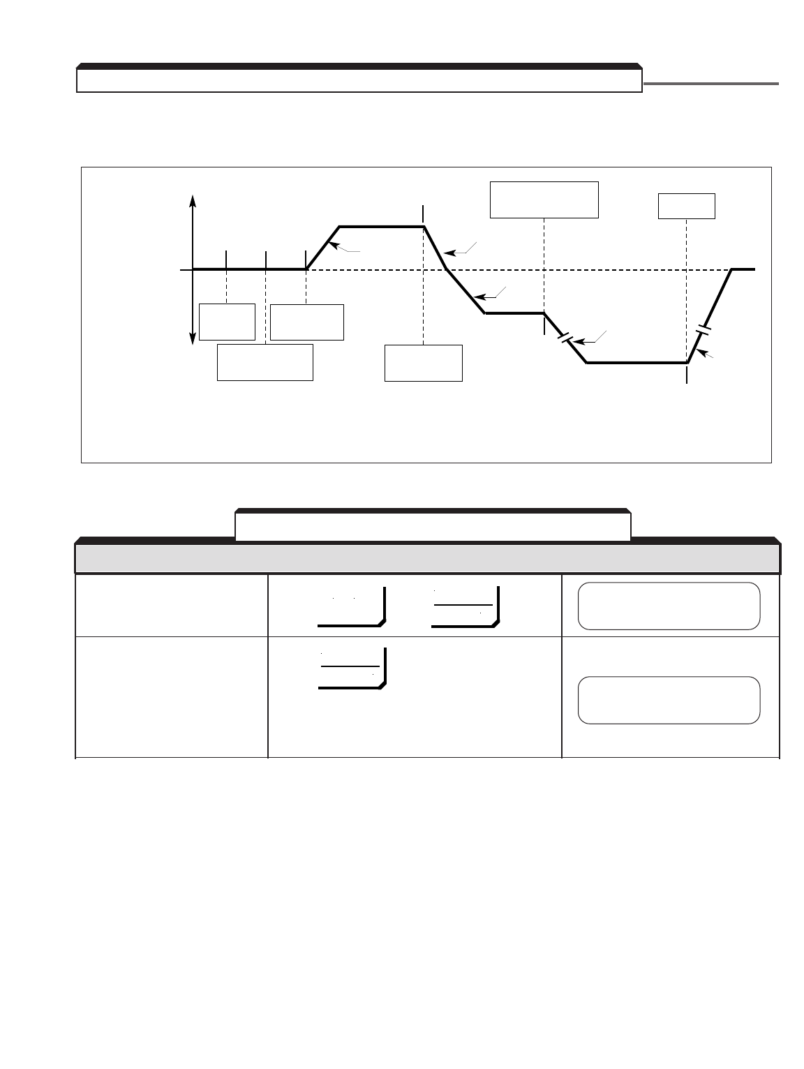
2-24
The operation shown in Figure 2-3 and described in Table 2-5 is for a standard 60 Hz
motor.
Power ON Press , then
If either the SEQ or REF lights Press SEQ and REF lights are off,
are on, they should be turned DRIVE and FWD lights are on.
off by pressing the LOCAL/
REMOTE key. This will set the
drive so it can be completely
controlled by the Digital
Operator.
Table 2-5. Test Run With Digital Operator
+
OUTPUT
FREQUENCY
0
–
REVERSE
RUN
CHANGE FREQ.
REFERENCE
POWER
ON
FREQUENCY
SETTING
FORWARD
RUN
STOP
FWD
ROTATION
AT 15HZ
REV
ROTATION
AT 60HZ
REV
ROTATION
AT 15HZ
ACCEL
ACCEL
ACCEL
DECEL
DECEL
➀➁➂
➃
➄
➅
Figure 2-3. Example of Simple Operation
2.5 TEST RUN USING DIGITAL OPERATOR ("LOCAL" CONTROL)
DESCRIPTION KEY SEQUENCE DIGITAL OPERATOR DISPLAY
Frequency Ref
U1-01= 0.00 HZ
Frequency Ref
U1-01= 0.00 HZ
LOCAL
REMOTE
DATA
ENTER
MENU
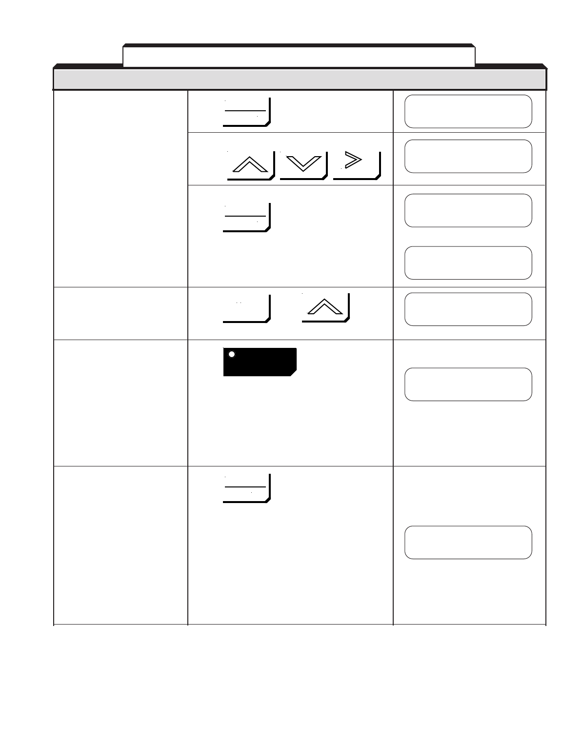
2-25
Set a run frequency of 15 Hz. Press
Set the frequency to 15 using:
Write the value to memory by pressing
briefly, then
Display the output frequency. Press , then
Run the motor in the forward Press RUN light comes on and motor
direction. ramps up to speed.
NOTE: Output frequency may be
slightly higher than the
frequency reference,
depending on the control
method selected.
Run the motor in the reverse Press RUN light remains on. FWD light
direction. goes out and REV light comes on.
The motor ramps down to zero
speed, then ramps up in the
opposite direction.
NOTE: output frequency may be
slightly higher than the
frequency reference,
depending on the control
method selected.
Table 2-5. Test Run With Digital Operator - Continued
DESCRIPTION KEY SEQUENCE DIGITAL OPERATOR DISPLAY
Frequency Ref
000.00 HZ
Frequency Ref
015.00 HZ
Frequency Ref
015.00 HZ
Output Freq
U1-02= 0.00 HZ
Output Freq
U1-02= 15.00 HZ
Output Freq
U1-02= -15.00 HZ
DATA
ENTER
DATA
ENTER
Entry Accepted
RESET
ESC
FWD
REV
RUN
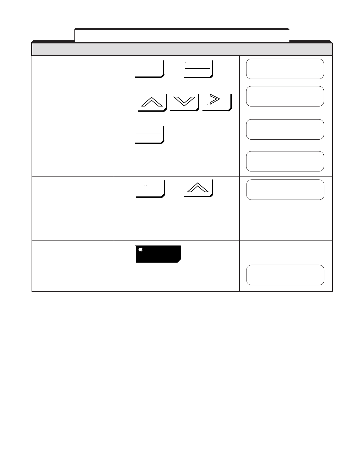
2-26
Change the frequency Press , then twice
reference from 15 Hz to
60 Hz.
Change the frequency using:
Write the value to memory by pressing
briefly, then
Display the output frequency. Press , then
NOTE: Output frequency may be
slightly higher than the
frequency reference,
depending on the control
method selected.
Stop the motor. Press The STOP light turns on, and the
RUN light blinks during the decel-
eration of the motor.
Table 2-5. Test Run With Digital Operator - Continued
DESCRIPTION KEY SEQUENCE DIGITAL OPERATOR DISPLAY
Frequency Ref
015.00 HZ
Frequency Ref
060.00 HZ
Frequency Ref
060.00 HZ
MENU
DATA
ENTER
DATA
ENTER
Entry Accepted
RESET
Output Freq
U1-02= -60.00 HZ
Output Freq
U1-02= 0.00 HZ
ESC
STOP

2-27
• After completing the Test Run, connect the motor to the load.
• Additional control circuit wiring can be added, and parameters in the drive can be
programmed to configure the drive system to your specific application, including “Remote”
(2-wire or 3-wire) Control. See Section 5 for description of programmable features, and
also see instruction sheets for any options included with the drive.
• Record all parameter values (see Quick Reference sheets at the front of this manual).
The drive uses internal NV-RAM to store information when power is removed or in the event
of a power failure. Therefore, when power is reapplied, operation will begin at the same
state as when power was removed.
The following information is stored:
• Last Main Speed Reference setting and forward/reverse selection from Digital
Operator.
• The sequence of failure conditions that occurred before power was removed
(including content of a " CPF " failure).
2.6 PRE-OPERATION CONSIDERATIONS
2.7 STORAGE FUNCTION

2-28

3-1
After completing the start-up, and programming of parameters, turn off the AC main
circuit power. Make additional wiring connections required for the external control
functions selected by the parameter programming. Connect the driven machine to the
motor. Verify that the driven machine is in running condition, and that no dangerous
conditions exist around the drive system.
CAUTION
When starting and stopping the motor, use the operation signals (RUN/STOP,
FWD/REV), NOT the magnetic contactor on the power supply side (if present).
Run the motor under load with control by the Digital Operator using the same procedure
as for the Test Run (Table 2-5). If the Digital Operator is used in combination with
external commands or external commands only are used, the procedure must be altered
accordingly.
For preset starting (one-touch operation after setting the frequency), perform the
following:
1. Set the speed and press RUN. Motor accelerates, at the rate corresponding to the
preset accel time, to the preset speed. The accel time ( C1-01 ) is set too short
relative to the load if the RPM of the accelerating motor does not increase
smoothly, or if a fault is displayed on the Digital Operator.
2 . Press STOP. Unless coast to stop operation has been selected (by programming
of b1-03 ), the motor decelerates, at the rate corresponding to the preset decel
time ( C1-02 ), to a stop.
Section 3. OPERATION AT LOAD

3-2
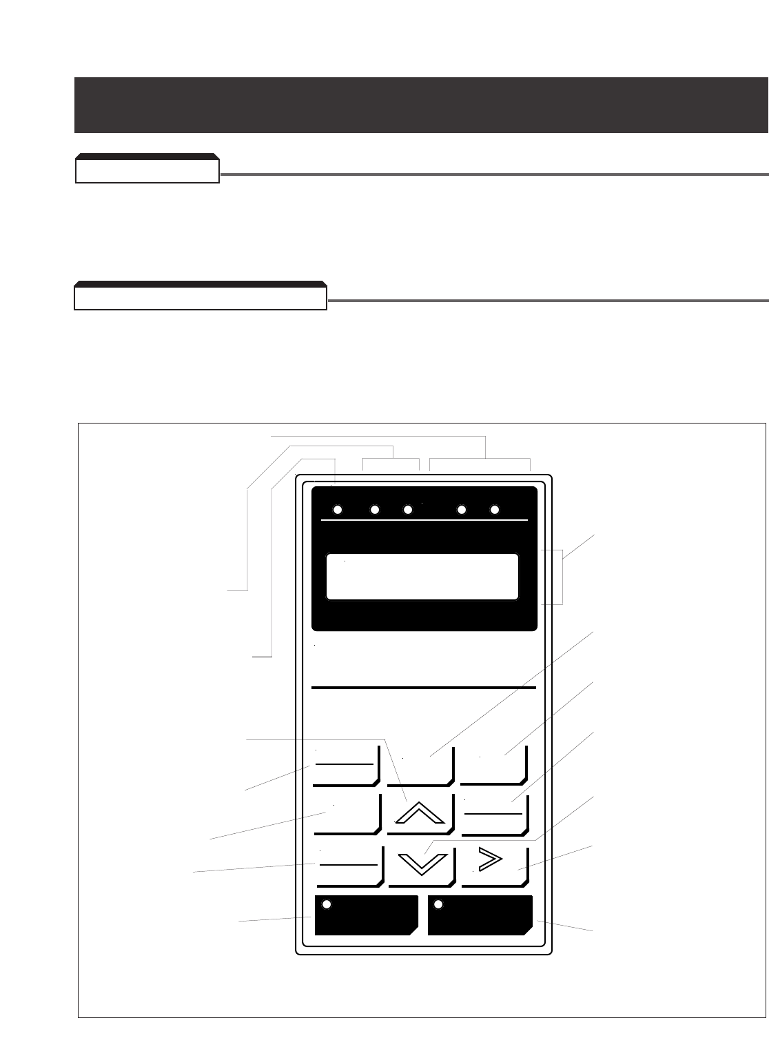
4-1
All functions of the GPD 515/G5 are accessed using the Digital Operator. In addition to
controlling motor operation, the operator can enter information into the drive memory to
configure the drive to the application by entering the Program mode.
The Digital Operator has a 2 line by 16 character LCD display. Both numeric and alpha-
numeric data can appear on the display.
Indicator lamps and keys on the Digital Operator are described in Figure 4-1.
Figure 4-1. Digital Operator
JOG
ESC
DIGITAL OPERATOR
JVOP-130
REMOTE
SEQ
REF
RUN
STOP
FWD
REV
Frequency Ref
U1-01 = 0.00 Hz
FWD
REV
DRIVE
DATA
ENTER
LOCAL
REMOTE
RESET
MENU
4.1 GENERAL
4.2 DISPLAY AND KEYPAD
Section 4. DIGITAL OPERATOR
Indicates which direction
the motor is being
commanded to run.
Lights when the GPD 515/G5
is in Drive (operation) mode.
Increase parameter number
or value of blinking digit.
Switch between LOCAL and
REMOTE operation modes.
Initiates Jog function.
Selects forward or
reverse operation.
Run the motor. LED lights
when drive is controlling
motor speed.
2 line, 16 character
alphanumeric LCD display;
shows selected operation
status, fault code, or
parameter data.
Displays the main menu for
mode selection.
Returns to previous status
or menu level.
Displays data to be
changed, and enters new
data.
Decrease parameter number
or value of blinking digit.
Resets a drive fault, or
selects digit of a set value to
be changed. The selected
digit will blink.
Stop the motor. LED lights
when drive is in stopped
condition.
REMOTE Mode indication LEDs.
The LEDs light when REMOTE
Mode has been selected,
either for Start/Stop (SEQ)
control or Frequency
Reference (REF).

A. INDICATOR LAMPS
NAME FUNCTION
DRIVE Lights when the drive is in the Drive mode of operation.
FWD Lights when Forward motor run has been selected.
REV Lights when Reverse motor run has been selected.
REMOTE Lights when the drive is programmed to operate from external RUN and STOP
SEQ signals.
REMOTE Lights when the drive is programmed to operate by an external frequency
REF reference signal.
RUN Off when drive is in stopped condition; lights steadily when Run signal is
active; blinks after Stop signal has been received and drive output is ramping
down. (See Figure 4-2.)
STOP Lights steadily at initial power-up; blinks after Run signal becomes active but
frequency reference is zero; off when drive output is controlling motor speed.
(See Figure 4-2.)
B. KEYPAD KEYS
NAME FUNCTION
LOCAL Pressing this key toggles between the Local (Digital Operator) and Remote (Termin-
REMOTE als) modes of operation. Active only when the drive is in stopped condition.
JOG IN DRIVE MODE: Pressing and holding this key will initiate Jog function: drive
output goes to programmed Jog Frequency ( d1-09 ) to check motor operation, or
to position machine. When key is released, output returns to zero and motor stops.
If the motor is already running, pressing this key will have no effect.
NOTE: Disabled if the drive is programmed
to use an external JOG input.
FWD IN DRIVE MODE: Each press of this key will toggle between Forward and Reverse
REV motor run direction. The selected direction is indicated by the FWD or REV lamp
being lit. If the selection is made while the drive is stopped, it determines the
direction the motor will run when started. If the selection is changed during running,
the drive will ramp the motor to zero speed and then ramp it up to set speed in
the opposite (i.e. newly selected) direction.
RUN IN DRIVE MODE: If the drive is not programmed to operate by external RUN
and STOP signals (as indicated by REMOTE SEQ lamp being lit), pressing this key
will produce a Run command to initiate drive output to the motor. However,
output frequency will be zero if the frequency reference is zero at the time this key
is pressed.
STOP IN DRIVE MODE: Pressing this key will produce a Stop command. The drive
will decelerate the motor in the programmed stopping manner, then drive output
will be disconnected from the motor.
Table 4-1. Digital Operator Controls
A. INDICATOR LAMPS
NAME FUNCTION
B. KEYPAD KEYS
LABEL FUNCTION
4-2
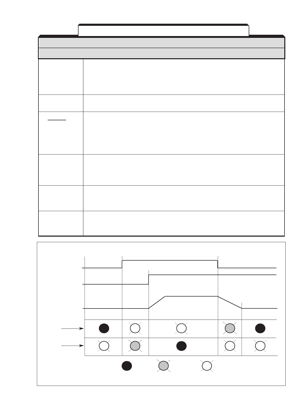
4-3
B. KEYPAD PADS – Continued
NAME FUNCTION
MENU IN DRIVE MODE: Pressing this key will display the top level of the menu tree for
selecting and reading parameters. The drive will change to Program mode.
IN PROGRAM MODE: Pressing this key will display the top level of the menu tree
for returning to the Drive mode. Pressing the MENU & DATA/ENTER keys in
succession will change to Drive mode and display the frequency reference setting.
ESC Each time this key is pressed the display returns to the previous level in the menu
tree or to the status prior to pressing DATA/ENTER.
DATA IN DRIVE MODE OR PROGRAM MODE: When a parameter number is being
ENTER displayed, pressing this key will display the parameter’s set value which is
presently in memory.
IN PROGRAM MODE ONLY: After the displayed set value has been changed as
desired, pressing this key will write the new set value into the drive memory to
replace the old value.
>
IN DRIVE MODE OR PROGRAM MODE: When a changeable data value is being
RESET displayed, pressing this key moves the blinking (i.e. "changeable") position to the
next digit to the right. If at the right-most position, this will wrap-around to the first
position on the left side of the display.
^
IN DRIVE MODE OR PROGRAM MODE: Pressing this key will increase the value
(up arrow) of the blinking digit in the display by 1. Pressing this key will increase a parameter
number by 1.
v
IN DRIVE MODE OR PROGRAM MODE: Pressing this key will decrease the value
(down arrow) of the blinking digit in the display by 1. Pressing this key will decrease a parameter
number by 1.
Table 4-1. Digital Operator Controls - Continued
B. KEYPAD KEYS – Continued
LABEL FUNCTION
POWER PRESS PRESS
ON RUN KEY STOP KEY
RUN
COMMAND
FREQUENCY
REFERENCE
OUTPUT
FREQUENCY
RUN
LAMP
STOP
LAMP
= Off = Blinking = Lighted Steady
Figure 4-2. Functioning of RUN and STOP Lamps
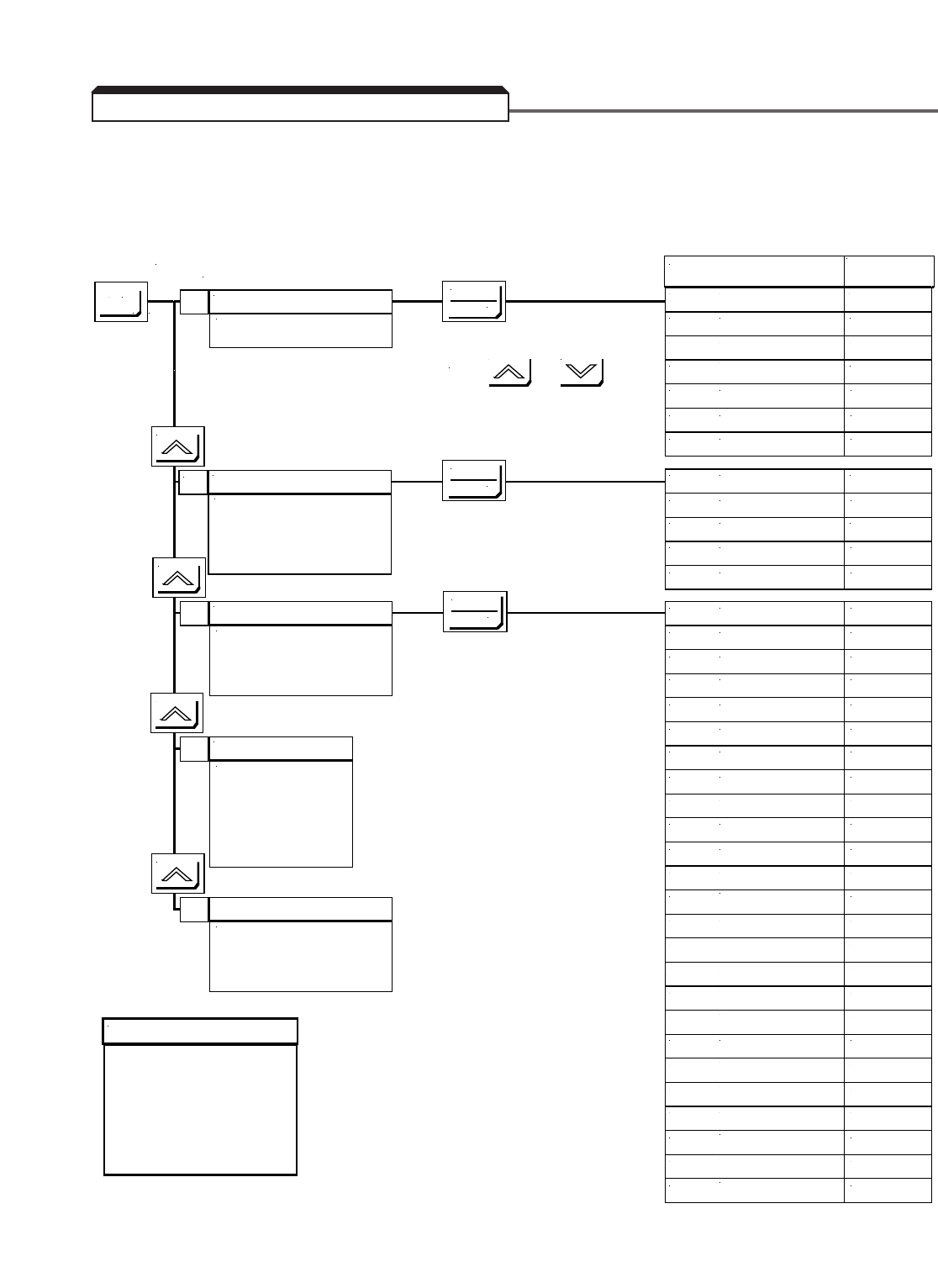
4-4
A. Quick-start Access Level
The flowchart tree below illustrates the process of accessing drive parameters when the
Access Level is set to Quick Start ( A1-01 = 2).
4.3 DIGITAL OPERATOR MENU TREES
Operation
Drive operation is enabled.
Drive status is displayed.
Initialize
( Initialize )
LCD language display is selected.
Parameter access levels, control
method selection and initialize
passwords are set.
A
Programming
( Programming )
Parameters are set/read. Items to be
set/read vary depending on the access
level setting.
Modified Constants
( Modified Parameters )
Only parameters that have been
changed from the factory settings are
set/read.
MENU
DATA
ENTER
DATA
ENTER
DATA
ENTER
U1-01
Frequency Reference
Parameter
Display
Function (1) or
Parameter
U1-02
Output Frequency
Parameter
U1-03
Output Current
Parameter
U1-06
Output Voltage (2)
Parameter
U2
Fault Trace
Function
U3
Fault History
Function
U1
Monitor
Function
A1-00
Select Language
Parameter
A1-01
Access Level
Parameter
A1-02
Control Method
Parameter
A1-03
Init Parameters
Parameter
A1-04
Enter Password
Parameter
Auto-tuning
( Auto-tuning )
Motor parameters are
automatically set by entering
tuning data (motor nameplate
values) when using Open
Loop or Flux Vector control
method ( A1-02 = 2 or 3).
NOTES
(1) A Function is a “sub-menu”
containing many parameters.
Use the DATA/ENTER key to
access these parameters.
(2) This parameter is user
selectable according to the
setting of o1-01 .
(3) Not available for all Control
Methods.
b1-01
Reference Source
Parameter
b1-02
Run Source
Parameter
b1-03
Stopping Method
Parameter
C1-01
Accel Time 1
Parameter
C1-02
Decel Time 1
Parameter
d1-01
Reference 1
Parameter
d1-02
Reference 2
Parameter
d1-03
Reference 3
Parameter
d1-04
Reference 4
Parameter
d1-09
Jog Reference
Parameter
E1-01
Input Voltage
Parameter
E1-02
Motor Selection
Parameter
E1-03
V/F Selection (3)
Parameter
E1-04
Max Frequency
Parameter
E1-05
Max Voltage
Parameter
E1-06
Base Frequency
Parameter
E1-07
Mid Frequency A (3)
Parameter
E1-08
Mid Voltage A (3)
Parameter
E1-09
Min Frequency
Parameter
E1-10
Min Voltage (3)
Parameter
E1-13
Base Voltage (3)
Parameter
E2-01
Motor Rated FLA
Parameter
E2-02
Motor Rated Slip (3)
Parameter
E2-03
No-Load Current (3)
Parameter
E2-04
Number of Poles (3)
Parameter
Use the and keys to
scroll through the Functions and Parameters.
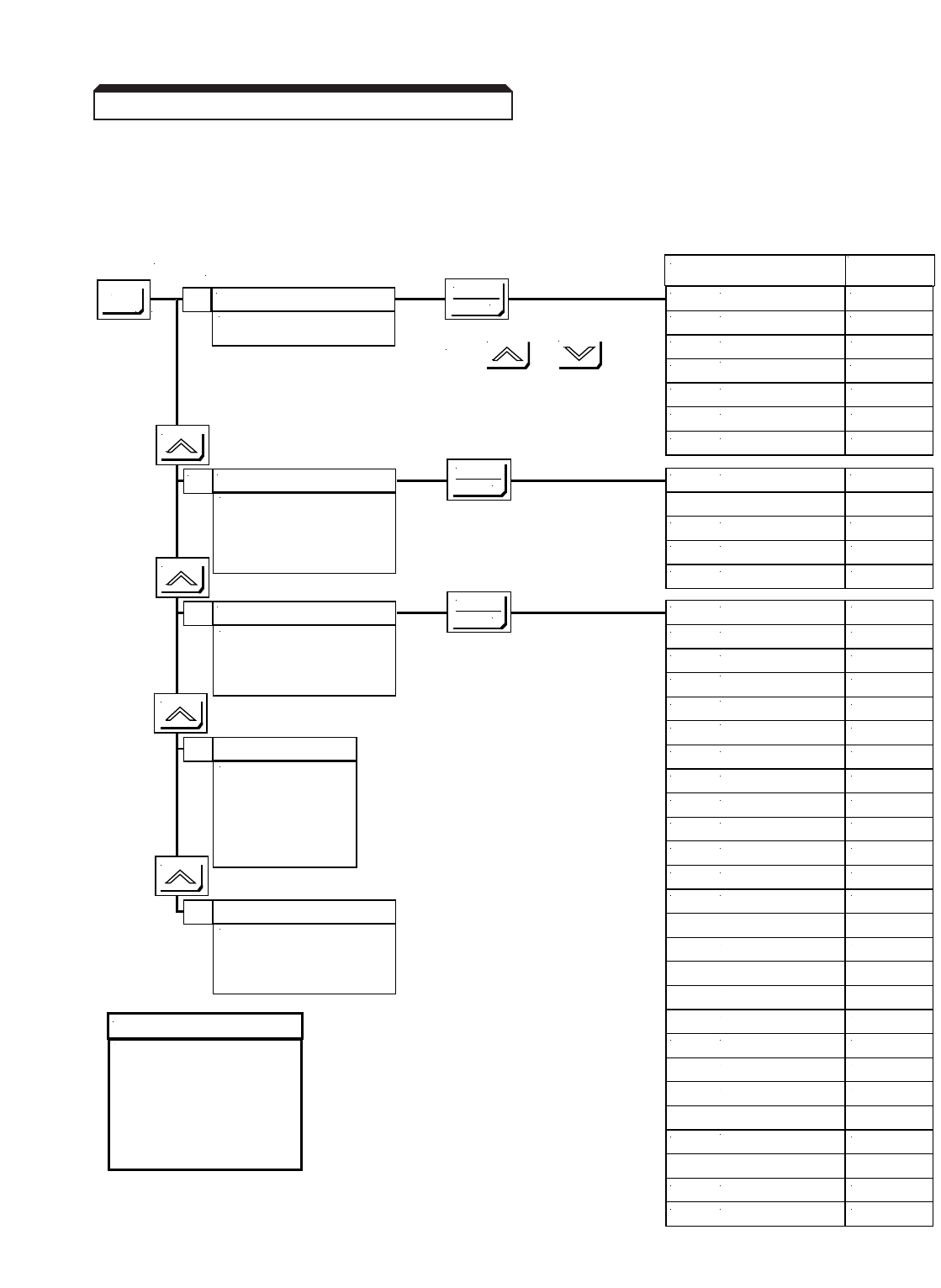
4-5
Continued
B. Basic Access Level
The flowchart tree below illustrates the process of accessing drive parameters when the
Access Level is set to Basic ( A1-01 = 3).
4.3 DIGITAL OPERATOR MENU TREES
Operation
Drive operation is enabled.
Drive status is displayed.
Initialize
( Initialize )
LCD language display is selected.
Parameter access levels, control
method selection and initialize
passwords are set.
A
Programming
( Programming )
Parameters are set/read. Items to be
set/read vary depending on the access
level setting.
Modified Constants
( Modified Parameters )
Only parameters that have been
changed from the factory settings are
set/read.
MENU
DATA
ENTER
DATA
ENTER
DATA
ENTER
U1-01
Frequency Reference
Parameter
Display
Function (1) or
Parameter
U1-02
Output Frequency
Parameter
U1-03
Output Current
Parameter
U1-06
Output Voltage (2)
Parameter
U2
Fault Trace
Function
U3
Fault History
Function
U1
Monitor
Function
A1-00
Select Language
Parameter
A1-01
Access Level
Parameter
A1-02
Control Method
Parameter
A1-03
Init Parameters
Parameter
A1-04
Enter Password
Parameter
NOTES
(1) A Function is a “sub-menu”
containing many parameters.
Use the DATA/ENTER key to
access these parameters.
(2) This parameter is user
selectable according to the
setting of o1-01 .
(3) Not available for all Control
Methods.
Auto-tuning
( Auto-tuning )
Motor parameters are
automatically set by entering
tuning data (motor nameplate
values) when using Open
Loop or Flux Vector control
method ( A1-02 = 2 or 3).
b1
Sequence
Function
b2
DC Braking
Function
C1
Accel/Decel
Function
C3
Motor-Slip Comp (3)
Function
C4
Torque Comp (3)
Function
C5
ASR Tuning (3)
Function
C6
Carrier Freq.
Function
d1
Preset Reference
Function
d2
Reference Limits
Function
d3
Jump Frequencies
Function
E1
V/F Patern
Function
E2
Motor Setup
Function
H1
Digital Inputs
Function
H2
Digital Outputs
Function
H3
Analog Inputs
Function
H4
Analog Outputs
Function
L1
Motor Overload
Function
L2
PwrLoss Ridethru
Function
L3
Stall Prevention
Function
L4
Ref Detection
Function
L5
Fault Reset
Function
L6
Torque Detection
Function
L7
Torque Limit (3)
Function
L8
Hdwe Protection
Function
o1
Monitor Select
Function
o2
Key Selection
Function
Use the and keys to
scroll through the Functions and Parameters.
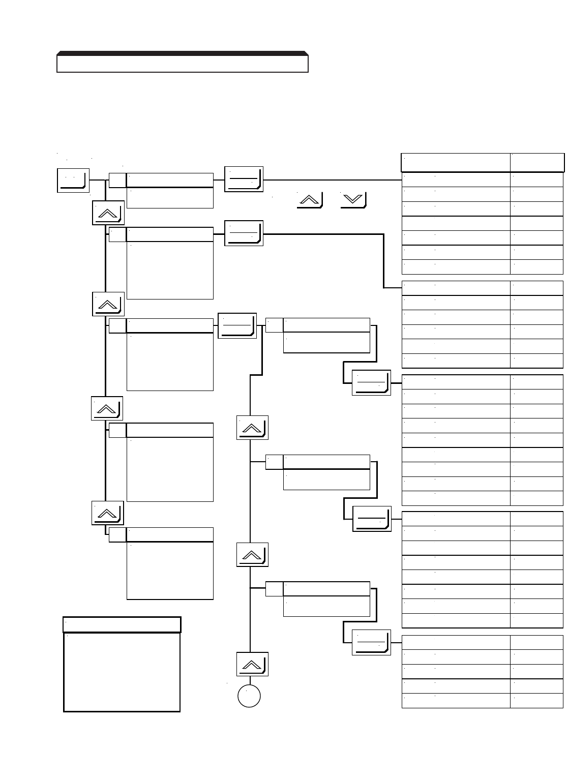
Continued
C. Advanced Access Level
The flowchart tree below illustrates the process of accessing drive parameters when the
Access Level is set to Advanced ( A1-01 = 4).
4-6
Operation
Drive operation is enabled.
Drive status is displayed.
Initialize
( Initialize )
LCD language display is
selected. Parameter access
levels, control method
selection and initialize
passwords are set.
U1-01
Frequency Reference
Parameter
Display
Function (1) or
Parameter
U1-02
Output Frequency
Parameter
U1-03
Output Current
Parameter
Application
Application
b
A
Programming
( Programming )
Parameters are set/read.
Items to be set/read vary
depending on the access
level setting.
Auto-tuning
( Auto-tuning )
Motor parameters are
automatically set by entering
tuning data (motor nameplate
values) when using Open
Loop or Flux Vector control
method ( A1-02 = 2 or 3).
Modified Constants
( Modified Parameters )
Only parameters that have
been changed from the
factory settings are set/read.
Tuning
Tuning
C
NOTES
(1) A Function is a “sub-menu”
containing many parameters.
Use the DATA/ENTER key to
access these parameters.
(2) This parameter is user
selectable according to the
setting of o1-01 .
(3) Not available for all Control
Methods.
Reference
Reference
d
A
To
MENU
DATA
ENTER
DATA
ENTER
U1-06
Output Voltage (2)
Parameter
U2
Fault Trace
Function
U3
Fault History
Function
U1
Monitor
Function
A1-00
Select Language
Parameter
A1-01
Access Level
Parameter
A1-02
Control Method
Parameter
A1-03
Init Parameters
Parameter
A1-04
Enter Password
Parameter
A2
User Constants
Function
b1
Sequence
Function
b2
DC Braking
Function
b3
Speed Search
Function
b4
Delay TImers
Function
b5
PID Control
Function
b6
Reference Hold
Function
b7
Droop Control (3)
Function
b8
Energy Saving (3)
Function
b9
Zero Servo (3)
Function
DATA
ENTER
DATA
ENTER
C1
Accel/Decel
Function
C2
S-Curve Acc/Dec
Function
C3
Motor-Slip Comp (3)
Function
C4
Torque Comp (3)
Function
C5
ASR Tuning (3)
Function
C6
Carrier Freq
Function
C7
Hunting Prev (3)
Function
C8
Factory Tuning (3)
Function
d1
Preset Reference
Function
d2
Reference Limits
Function
d3
Jump Frequencies
Function
d4
Sequence
Function
d5
Torque Control (3)
Function
DATA
ENTER
DATA
ENTER
Use the and keys to
scroll through the Functions and Parameters.
4.3 DIGITAL OPERATOR MENU TREES
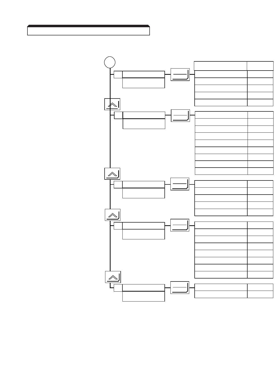
Continued
C. Advanced Access Level (Continued)
4-7
4.3 DIGITAL OPERATOR MENU TREES
Motor Parameters
Motor
E
A
From
Display Function
(1)
or
Parameter
DATA
ENTER E1 V/f Pattern Function
E2 Motor Setup Function
E3 Control Method (Motor 2) Function
E4 v/f Pattern (Motor 2) Function
E5 Motor Setup (Motor 2) Function
Options
Options
FDATA
ENTER F1 PG Speed Setup
(3)
Function
F2 AI-14 Setup Function
F3 DI-08, 16 Setup Function
F4 AO-08, 12 Setup Function
F5 DO-02 Setup Function
F6 DO-08 Setup Function
F7 PO-36F Setup Function
Control Circuit Terminals
Terminal
H
Protection
Protection
L
Digital Operator
Operator
o
DATA
ENTER
DATA
ENTER
DATA
ENTER
H1 Digital Inputs Function
H2 Digital Outputs Function
H3 Analog Inputs Function
H4 Analog Outputs Function
H5 Serial Com Setup Function
L1 Motor overload Function
L2 PwrLoss Ridethru Function
L3 Stall Prevention Function
L4 Ref Detection Function
L5 Fault Restart Function
L6 Torque Detection Function
L7 Torque Limit
(3)
Function
L8 Hdwe Protection Function
o1 Monitor Select Function
o2 Key Functions Function
F8 SI-F/G Setup Function
F9 CP-916 Setup Function
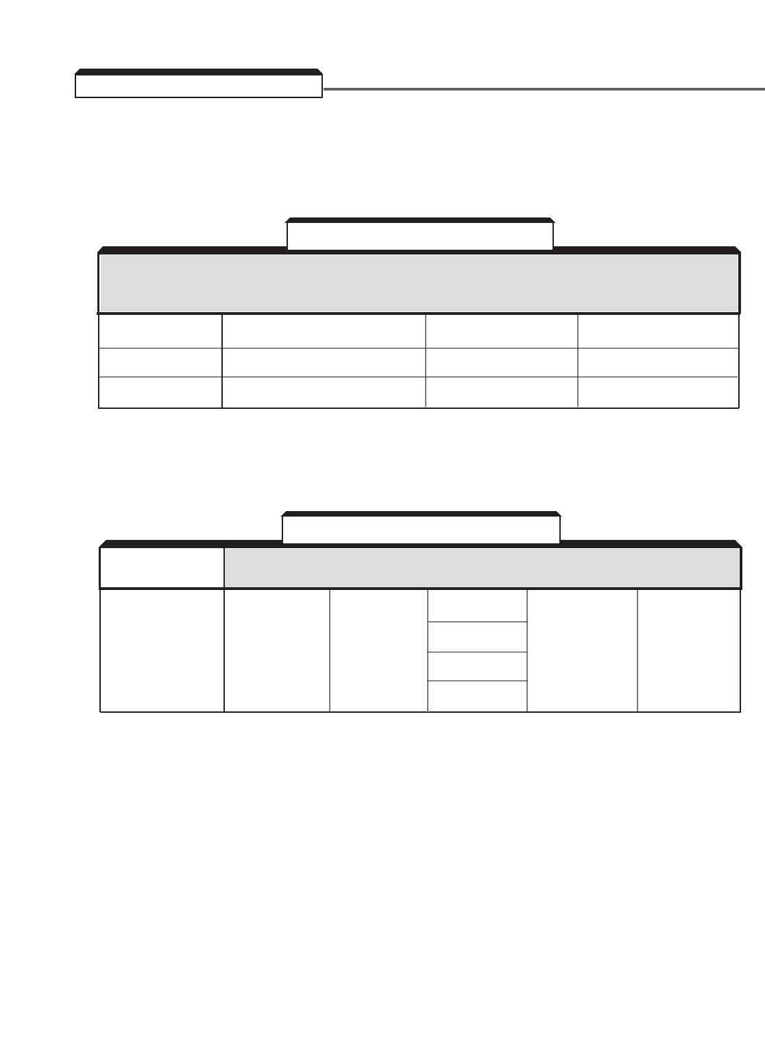
4-8
All parameters are set by accessing them through a menu tree with multiple access levels.
The setting of the Access Level in the Initialization Menu determines which parameters
appear on the Digital Operator. To see Example 1 and 2 in detail, refer to Tables 4-5, 4-6
and 4-7.
Level 1 Digital Operator Mode Programming Initialize
Level 2 Parameter Group C – Tuning —
Level 3 Parameter Function C1 Accel/Decel —
Level 4 Parameter Name Decel Time 1 Control Method
Level 5 Parameter Number C1-02 A1-02
Level 6 Parameter Setting Value 10.0 sec V/F Control
The parameters are arranged by groups. The following table shows which Parameter
Group(s) appear under which Mode.
Digital Operator
Modes
U – Monitor A – Initialize b – Application No Group Name No Group Name
C – Tuning
d– Reference
Parameter E – Motor
Groups List *F– Options
H – Terminals
L– Protection
o– Operator
* For a complete listing of parameters, see Appendix 1.
4.4 BASIC PROGRAMMING
Table 4-2. Parameter Menu
Menu Level Digital Operator Digital Operator
(Advanced Reference Name Display Display
Access) Example 1 Example 2
Table 4-3. Parameter Groups
Operation Initialize Programming Auto-Tuning Modified
Constants
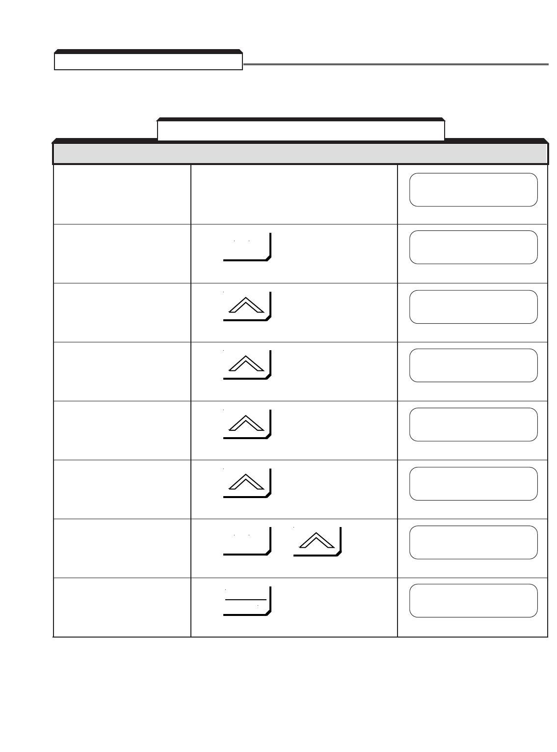
4-9
The procedure for choosing a mode is shown in Table 4-4.
Top of Main Menu Press
• Displays Operation Mode
(drive changes to Program
mode).
• Displays Initialize Mode. Press
• Displays Programming Press
Mode.
• Displays Auto-Tuning Mode Press
(displayed only when Vector
Control Method is selected).
• Displays Modified Press
Parameter Menu.
Top of Main Menu Press or
• Return to Operation.
• Select Operation Mode. Press
• Displays frequency
reference setting (changes
to Drive mode).
4.5 MODES OF OPERATION
Table 4-4. Digital Operator Mode Selection
DESCRIPTION KEY SEQUENCE DIGITAL OPERATOR DISPLAY
Frequency Ref
U1-01= 0.00 HZ
Frequency Ref
U1-01= 0.00 HZ
** Main Menu **
Operation
** Main Menu **
Operation
** Main Menu **
Initialize
** Main Menu **
Programming
** Main Menu **
Auto-Tuning
** Main Menu **
Modified Constants
MENU
MENU
DATA
ENTER
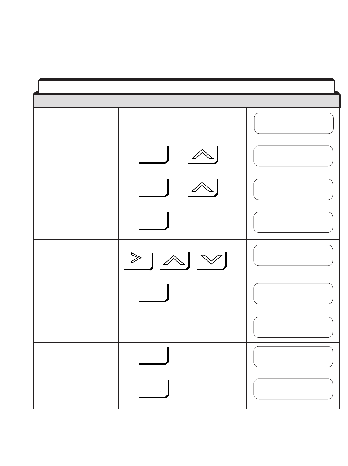
4-10
Parameters are changed by pressing the MENU key to enter the Program mode, then
advancing through the levels of the menu to access the parameter that is desired to be
changed. Only the parameters listed in Table A1-11 (Appendix 1) may be changed while
the drive is running.
• Select Programming Mode. Press , then twice
• Select the Parameter Name. Press , then 4 times
• Select the Decel Time 1 Press
parameter setting. (The first
digit of the value to be set
blinks.)
• Change reference value. Change value by pressing
• Write into memory. Press
briefly, then
Top of Main Menu Press
• Return to Operation.
• Select Operation Mode Press
(changes to Drive mode).
Table 4-5. Example 1A: Changing a Parameter in Quick-start Access Level
DESCRIPTION KEY SEQUENCE DIGITAL OPERATOR DISPLAY
Frequency Ref
U1-01= 0.00 HZ
Frequency Ref
U1-01= 0.00 HZ
** Main Menu **
Programming
** Main Menu **
Operation
Decel Time 1
C1-02= 10.0 sec
Decel Time 1
C1-02= 1.0 sec
Decel Time 1
0010.0 sec
Decel Time 1
0001.0 sec
Entry Accepted
MENU
MENU
DATA
ENTER
DATA
ENTER
DATA
ENTER
DATA
ENTER
RESET
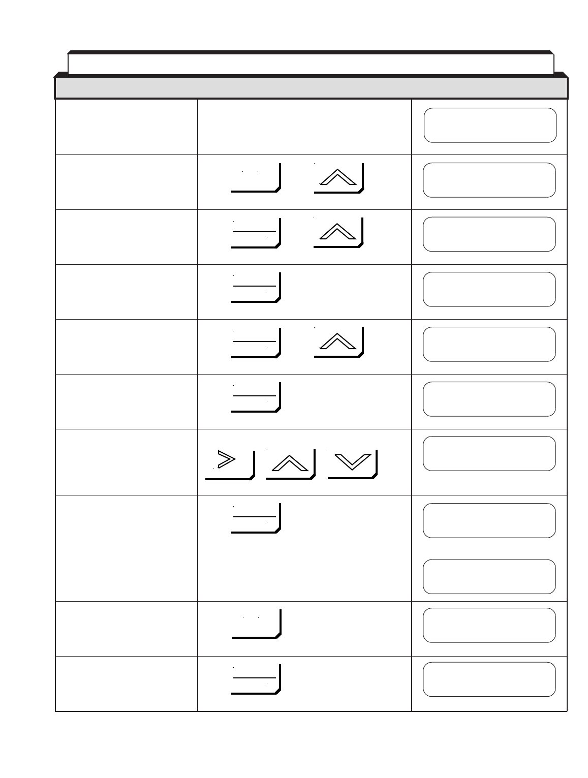
4-11
• Select Programming Mode. Press , then twice
• Select Tuning Parameter Press , then
Group.
• Select the Accel/Decel Press
Function.
• Select the Parameter Name. Press , then
• Select the Decel Time 1 Press
parameter setting. (The first
digit of the value to be set
blinks.)
• Change reference value. Change value by pressing
• Write into memory. Press
briefly, then
Top of Main Menu Press
• Return to Operation.
• Select Operation Mode Press
(changes to Drive mode).
DESCRIPTION KEY SEQUENCE DIGITAL OPERATOR DISPLAY
Frequency Ref
U1-01= 0.00 HZ
Frequency Ref
U1-01= 0.00 HZ
** Main Menu **
Programming
** Main Menu **
Operation
Group C
Tuning
Function C1
Accel/Decel
Decel Time 1
C1-02= 10.0 sec
Decel Time 1
0010.0 sec
Decel Time 1
0001.0 sec
MENU
MENU
DATA
ENTER
DATA
ENTER
DATA
ENTER
DATA
ENTER
DATA
ENTER
DATA
ENTER
Decel Time 1
C1-02= 1.0 sec
Entry Accepted
RESET
Table 4-6. Example 1B: Changing a Parameter in Advanced Access
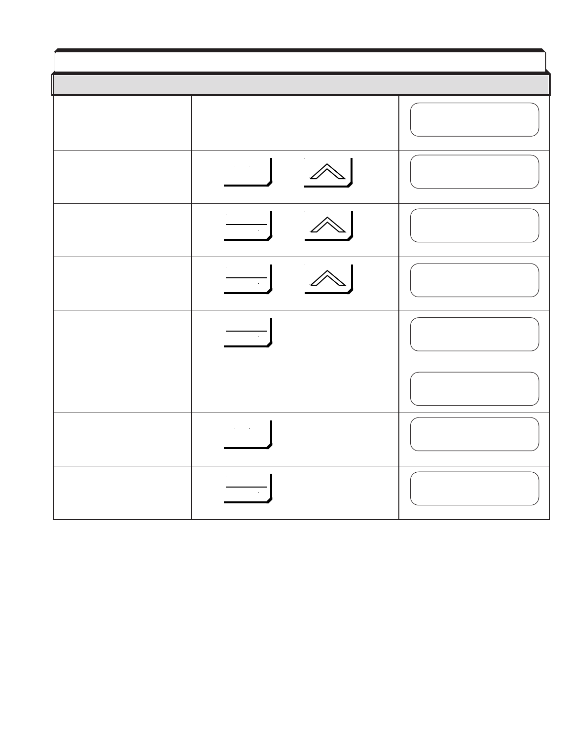
4-12
• Select Initialize Mode. Press , then
• Select the Parameter Name. Press , then twice
• Change data value. Press , then twice
• Write into memory. Press
briefly, then
Top of Main Menu Press
• Return to Operation.
• Select Operation Mode Press
(changes to Drive mode).
DESCRIPTION KEY SEQUENCE DIGITAL OPERATOR DISPLAY
Frequency Ref
U1-01= 0.00 HZ
Frequency Ref
U1-01= 0.00 HZ
** Main Menu **
Initialize
** Main Menu **
Operation
Control Method
Open Loop Vector
A1-02= 0
V/F Control
MENU
MENU
DATA
ENTER
DATA
ENTER
DATA
ENTER
DATA
ENTER
Table 4-7. Example 2: Changing Control Method in Quick-start Access Level
Control Method
V/F Control
Entry Accepted

5-1
This section describes features of the GPD 515/G5 which are defined by programmed
settings in the various parameters in memory. Since most features use more than one
parameter, the descriptions appear in alphabetical order by the function name. In Table
5-1, the functions are grouped into operational categories. To cross reference a
particular parameter to the features to which it applies, see the listings in Appendix 1, or
the Index.
SET-UP
Initialization (Reset), 2-Wire or 3-Wire 5.37 A1-03
Access Level 5.4 A1-01
Control Method Selection 2.2 A1-02
Drive Capacity, Parameters Affected By Table A3-1 ———
Volts/Hertz Patterns, Standard 5.47 E1-03
Volts/Hertz Pattern, Custom 5.48 E1-04 thru -10
Input Voltage Setting 5.37 E1-01
Encoder (PG) Parameters 5.15 F1-10 thru F1-14
Thermal Motor Overload Protection 5.41 E1-02;E2-01;L1-01, L1-02
Digital Operator Display, Re-scaling 5.11 o1-03, o1-04
Input Phase Loss Detection 5.34 L8-05
Output Phase Loss Detection 5.35 L8-07
User Parameters 5.46 A2-01 thru -32;o2-03
Miscellaneous Parameters 5.26 o2-01,-02,-05,-06,-07,-08
STARTING
Accel Time 5.2 C1-01,-03,-05,-07,-11
S-Curve Characteristics 5.3 C2-01,-03
Dwell 5.14 b6-01 thru -04
DC Injection Braking at Start 5.10 b2-01,-02,-03
STOPPING
Stopping Method 5.40 b1-03
Decel Time 5.2 C1-02,-04,-06,-08,-09,-11
Dwell 5.14 b6-01 thru -04
DC Injection Braking at Stop 5.10 b2-01,-02,-04
SPEED CONTROL
Frequency Ref. Input Signals (Auto/Manual) 5.19 H3-01 thru -12
(Term. 13, 16)
Frequency Reference, Upper & Lower Limits 5.22 d1-01 thru -08
Jog Reference 5.24 d1-09
Speed Reference Selection (Local/Remote) 5.25 A b1-01,-02;H1-01 thru -06
Multi-step Speed Setting 5.25 B d1-01 thru -09;H1-01 thru -06
Sample/Hold 5.32 F H1-01 thru -06
Up/Down Frequency Setting 5.32 G H1-01 thru -06
Table 5-1. List of Features Defined By Parameters
FUNCTION PARAGRAPH PARAMETER(S)
REFERENCE
Section 5. PROGRAMMABLE FEATURES
5.1 GENERAL

5-2
SPEED CONTROL - continued
Automatic Frequency Regulator (AFR) Gain 5.6 C8-08
Automatic Speed Regulator (ASR) 5.7 C5-01 thru -04,-06;H1-01 thru -06
Frequency Reference Retention 5.20 d4-01
MODBUS Control 5.28 b1-01,-02;H5-01 thru -04
PID Control 5.36 b1-01;b5-01 thru -08
Zero-Servo Control 5.49 b2-01;b9-01;H5-01 thru -04
Zero Speed Control 5.50 b1-05;E1-09
REVERSE
Reverse Run Disabled Table A1-2 b1-04
RUNNING
Critical Frequency Rejection 5.9 d3-01 thru -04
Carrier Frequency 5.8 C6-01,-02,-03
Speed Search 5.32 D b2-01,-02,-03;
H1-01 thru -06;L2-03,-04
Speed Coincidence 5.33 A
Energy Saving 5.16 b8-01,-02;H1-01 thru -06
Slip Compensation 5.38 C3-01 thru -04
RUNNING IMPROVEMENTS
Torque Compensation 5.42 C4-01,-02
Stall Prevention 5.39 L3-01 thru -06
Droop 5.13 b7-01,-02
Hunting Prevention 5.23 C7-01,-02
PROTECTIVE FEATURES
Momentary Power Loss Ride-thru 5.29 H1-01 thru -06;L2-01,-02
Auto Restart 5.5 L5-01,-02
Frequency Reference Loss Detection 5.20 L4-05
Overtorque Detection 5.42 L6-01 thru -06
Miscellaneous Protective Functions 5.27 L8-01,-02
DRIVE CONTROLS, INPUT
Multi-function Analog Inputs (Term. 16, 14) 5.29 H3-05,-09
Frequency Reference Bias and Gain 5.17 H3-03,-07,-11;H3-02,-06,-10
Multi-function Input Terminals (Term. 3-8) 5.31 H1-01 thru -06
External Fault Terminals 5.31 H1-01 thru -06
DRIVE OUTPUT
Multi-function Output Terminals (Term. 9 & 10; 25-27) 5.32 H2-01,-02,-03
Analog Monitor Output (Multi-function) (Term. 21-23) 5.30 H4-01 thru -07
MONITOR DISPLAY
Digital Operator Display Selection 5.11 o1-03
Display – Monitor (at Power-up) Selection 5.12 o1-02
Table 5-1. List of Features Defined By Parameters - Continued
FUNCTION PARAGRAPH PARAMETER(S)
REFERENCE
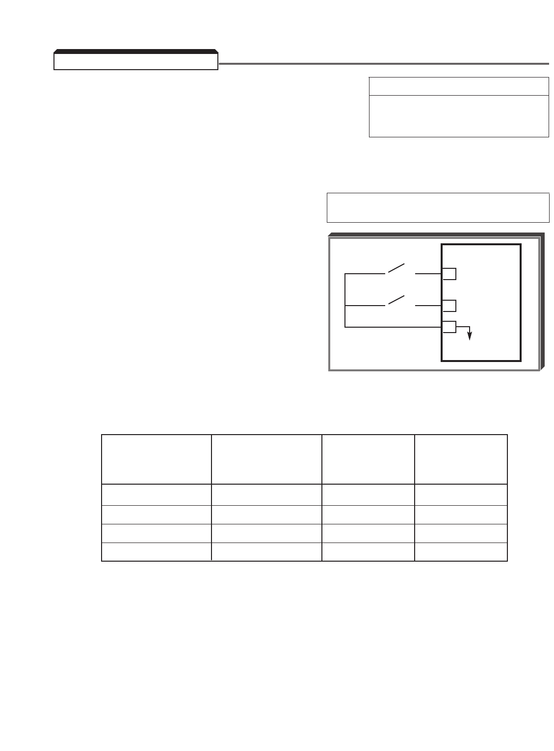
5-3
A. C1-01 : Accel Time 1 C1-06 : Decel Time 3 Factory setting (each): 10.0
C1-02 : Decel Time 1 C1-07 : Accel Time 4 Range* (each): 0.0 to 6000.0
C1-03 : Accel Time 2 C1-08 : Decel Time 4 seconds
C1-04 : Decel Time 2 C1-09 : Fast Stop (* Note: see para. 5.2 E)
C1-05 : Accel Time 3 Decel Time
The drive incorporates four sets of individually programmable acceleration and deceleration
times.
B. H1-01 thru H1-06 : Multi- Data 7: Accel/Decel Time Selection 1
function Inputs (Term. 3 thru 8) Data 1A: Accel/Decel Time Selection 2
By programming data " 7 " into one of the
multi-function parameters ( H1-01 thru
H1-06 ), the corresponding multi-function input
terminal (3 thru 8) becomes the Time Selection 1
input. When the input terminal (i.e. external
contact) is open, Time 1 ( C1-01 / C1-02 ) is
selected. When the input terminal is closed,
Time 2 ( C1-03 / C1-04 ) is selected. By
programming data " 1A " into another of the
multi-function parameters, the corresponding
multi-function input terminal becomes the Time
Selection 2 input. When the input terminal is
open, Time 1 or 2 is selected based on the setting of the Time Selection 1 input. When
the input is closed, Time 3 ( C1-05 / C1-06 ) or Time 4 ( C1-07 / C1-08 ) is selected
based on the status of the Time Selection 1 input.
Accel/Decel Accel/Decel
Selection 2 Selection 1 Accel Time Decel Time
H1-06 = 1A H1-05 = 07
Open Open C1-01 C1-02
Open Closed C1-03 C1-04
Closed Open C1-05 C1-06
Closed Closed C1-07 C1-08
TIME SELECTION 1
o
o o
TIME SELECTION 2
o
o o
GPD 515/G5
7
8
11
0V
5.2 ACCEL/DECEL TIME
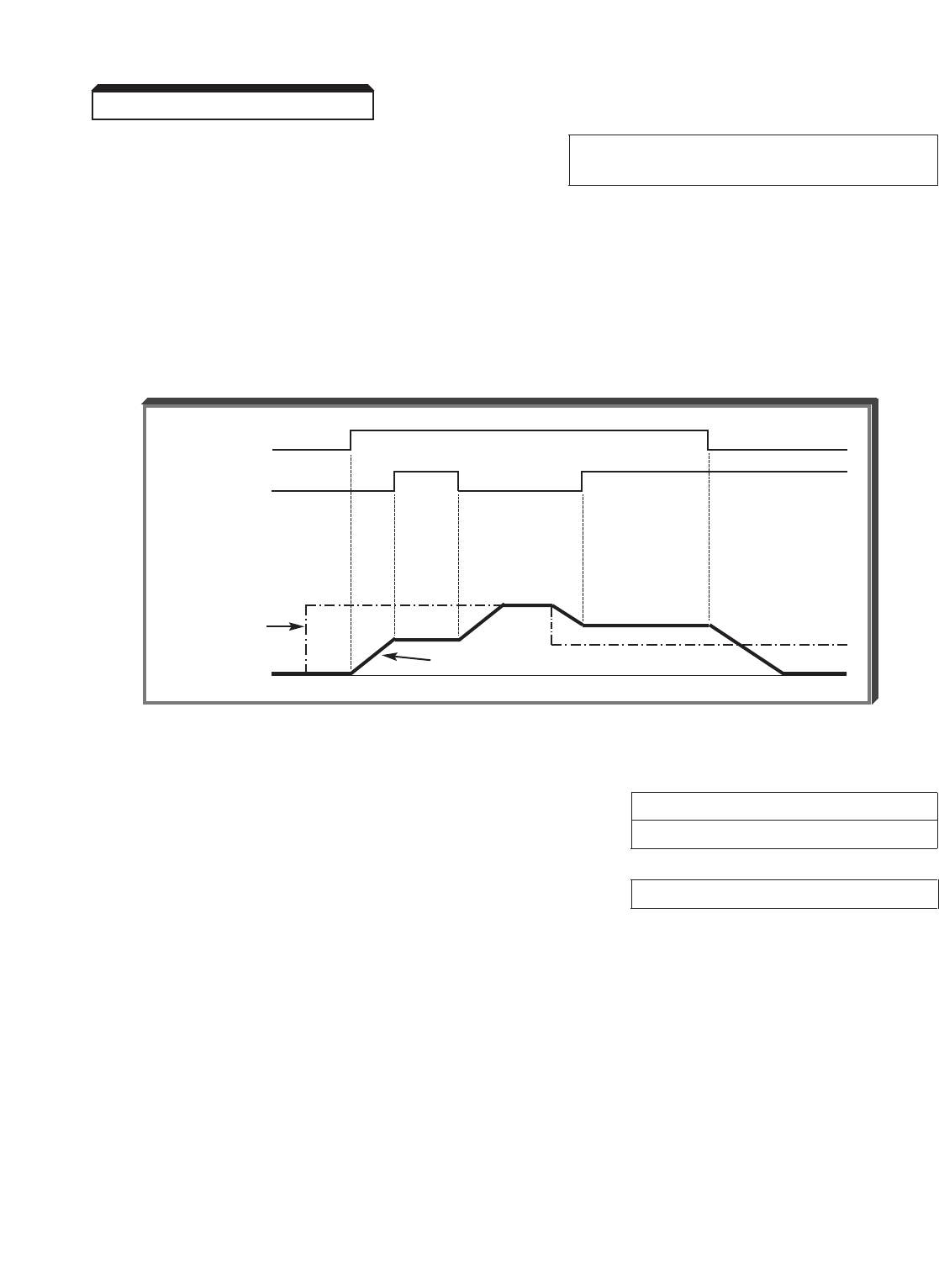
5-4
Continued
B. (Continued) Data A: Accel/Decel Hold (Speed
HOLD Command)
By programming data " A " into one of the multifunction input parameters ( H1-01 thru
H1-06 ), one of the multi-function input terminals (3 thru 8) becomes a HOLD command
input. As long as the HOLD command is present, accel and decel are in a prohibit state,
and the output speed is held at the level it was at the time the HOLD command was input.
When the HOLD command is removed while the system is still in Run condition, accel or
decel will again become active to allow output to reach set speed. If Stop is initiated
while the HOLD command is present, the prohibit state is cancelled and the system enters
stop operation.
C. C1-09 : Fast-Stop Decel Time Factory setting: 10.0
Range: 0.0 to 6000.0 seconds
H1-01 thru H1-06 : Multi-function Inputs Data 15 : Fast-Stop
(Term. 3 thru 8)
The Fast-Stop Decel Time is used instead of the selected Decel Time ( C1-02 , -04, -06
or -08) if:
1 ) It has been selected as the decel time for a specific fault ( H5-04 ,
L8-03 , etc.), or
2 ) One of the multi-function inputs has been programmed for Fast-Stop,
and the corresponding input is closed.
5.2 ACCEL/DECEL TIME
HOLD Function Timing
FWD RUN
HOLD CMD
SPEED REF.
OUTPUT SPEED
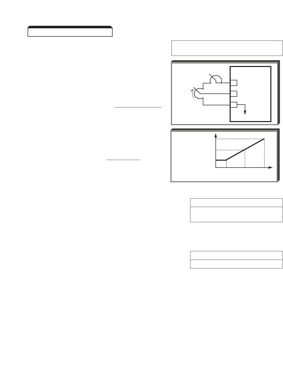
5-5
Continued
D. H3-05 : Multi-Function Analog Data 5: Accel/Decel Time
Input (Term. 16) Coefficient
The multi-function analog input at terminal 16
may be configured to allow analog control or the
Accel/Decel time. The input voltage, in the range
of 1 to 10V, determines the coefficient by which
the Accel/Decel time is reduced:
Actual Accel/Decel Time = Accel/Decel Time
Coefficient
EXAMPLE:
Accel/Decel Time = 10 sec *
Voltage Ref. at Term. 16 = 5V
Actual Accel/ =10 sec = 2 sec
Decel Time 5 (coefficient)
* C1-01 or C1-02 setting, or
selected accel/decel setting.
E. C1-10 : Accel/Decel Time Setting Unit Factory setting: 1
Range: 0 = 0.01 seconds
1 = 0.1 seconds
In addition to determining the setting resolution, this parameter controls the range of
C1-01 thru C1-09 ; if the resolution is 0.01 sec., the range is 0.000 to 600.00 sec. If
the resolution is set to 0.1 sec., the range is 0.0 to 6000.0 sec.
F. C1-11 : Accel/Decel Switching Frequency Factory setting: 0.0
Range: 0.0 to 400.0 Hz
By using C1-11 , the Accel and Decel times can be automatically switched from Time 1
to Time 4. If the output frequency is greater than or equal to the C1-11 frequency, the
C1-01 and C1-02 times are used. If the output frequency is below C1-11 , C1-07
and C1-08 are used instead.
NOTE: If used in conjunction with a multi-function input ( H1-01 thru H1-06
set to "A" or "1A"), the multi-function input has priority over the C1-11
switching frequency.
5.2 ACCEL/DECEL TIME
ACCEL/
DECEL
COEFFICIENT
1R GPD 515/G5
15 +15V
16 0-10V (20K Ω)
17
C
10
5
COEFFICIENT
1
01510
VOLTAGE
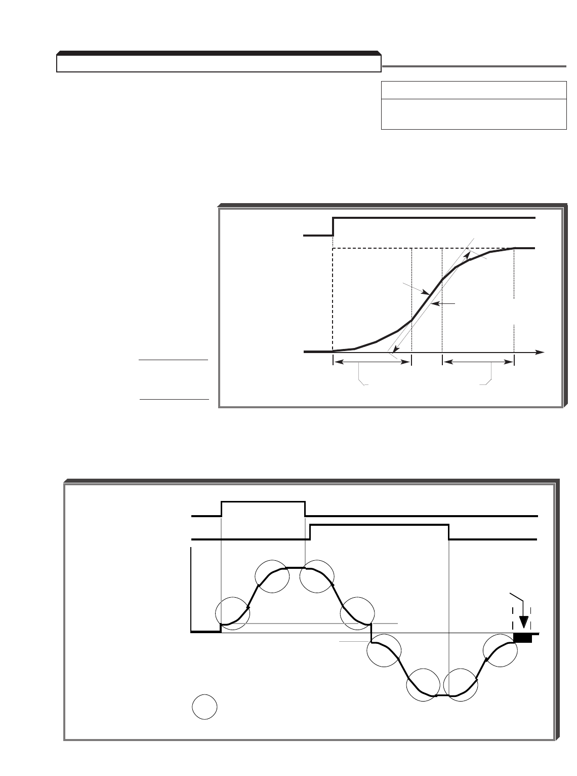
5-6
C2-01 : S-Curve Characteristic Time Factory setting (each): 0.20
at Accel Start Range (each): 0.00 to 2.50
C2-02 : S-Curve Characteristic Time seconds
at Accel End
C2-03 : S-Curve Characteristic Time
at Decel Start
C2-04 : S-Curve Characteristic Time
at Decel End
Setting of these
parameters determine the
S-curve (starting and
ending) characteristics
of the acceleration and
deceleration ramp.
Each is set in increments of
0.01 seconds.
NOTE: Actual accel time =
Set accel time + C2-01+C2-02
2
Actual decel time =
Set decel time + C2-03+C2-04
2
The following figure shows FWD/REV switching and acceleration & deceleration to a stop
with S-curve active.
RUN
FREQ
COMMAND
0
TIME
S-Curve Characteristic
Time (TSC)
OUTPUT
FREQUENCY Accel ramp per
selected Accel Time
5.3 ACCEL/DECEL: S-CURVE CHARACTERISTICS
OUTPUT FREQUENCY
FORWARD RUN COMMAND
= S-CURVE CHARACTERISTIC
REVERSE RUN COMMAND
MIN. OUTPUT
FREQUENCY
E1-09
E1-09
ACCELERATION DECELERATION
ACCELERATION
DC INJECTION
TIME AT STOP
b2-03
DECELERATION
C2-01
C2-01
C2-02
C2-02
C2-03
C2-03
C2-04
C2-04
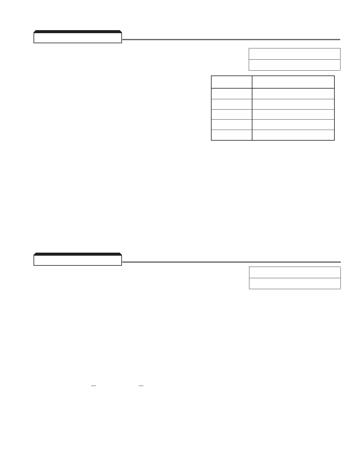
5-7
A. A1-01 : Parameter Access Level Factory setting: 2
Range: 0 to 4
This setting determines which parameters are
accessible, which are also dependent upon the
setting of the Control Method ( A1-02 ).
The default setting is for Quick-start Access Level,
which accesses 32 parameters. Basic Access
Level allows access to 90 additional parameters.
Advanced Level accesses all parameters available
for a given Control Method setting. The User
Program Access Level will only be available if one
or more parameters are programmed into A2-01 through A2-32.
See paragraph 4.3 for menu trees for each of the Access Levels, and paragraph 4.5,
Examples 1A and 1B, for programming examples in different Access Levels.
B. User Program. Parameters A2-01 through A2-32 can each be set by the user
to allow a customized Access Level. The drive must first be temporarily set to Advanced
Access Level ( A1-04 = 4); then use the “up arrow”, “down arrow” and “right arrow” keys
to set A2-01 to the first parameter to which access is desired, A2-02 to the next, etc.
Only the parameters entered into A2-01 through A2-32 will be available for monitoring
and modifying if A1-01 is then set to "1".
A. L5-01 : Number of Auto-Restart Attempts Factory setting: 0
Range: 0 to 10
When a fault occurs during operation, the drive can be programmed for an auto-restart
operation to automatically reset the fault. Auto-restart operation will use the number of
reset attempts set in this parameter, up to the maximum of 10. When set to " 0 ", no
auto-restarts will be attempted.
• The following faults can be automatically reset:
OC: Overcurrent GF: Ground fault
OV: Overvoltage UV1: Undervoltage (Power UV)
OL3: Overtorque Detect
• The following conditions WILL NOT initiate auto-restart:
1. OL, EF , PUF or CPF fault.
2. When OC or UV occurs during deceleration.
3. When L2-01 is programmed to stop during momentary power failure (data =
" 0 "). (See paragraph 5.29, MOMENTARY POWER LOSS RIDE-THRU.)
• The number of restart attempts available will be reset to the L5-01 setting when:
1. 10 minutes has elapsed without a fault occurring.
2. The RESET key, or external Fault Reset push button, is pressed.
3. Power is removed from the Drive.
5.4 ACCESS LEVEL
Setting Description
0 Monitor Only
1 User Program
2 Quick-start
3 Basic
4 Advanced
5.5 AUTO-RESTART
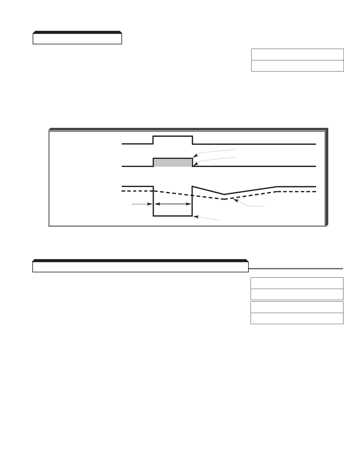
5-8
Continued
B. L5-02 : Fault Contact Status During Auto-Restart Factory setting: 0
Range: 0 or 1
This digit controls how the fault contact responds to a drive fault during the auto-restart
operation.
0= Fault contact will not actuate during auto-restart attempts
1= Fault contact actuates during auto-restart attempts
Auto-Restart Operation Timing
C8-08 : AFR Gain Factory setting: 1.00
Range: 0.00 to 10.00
C8-09 : AFR Time Factory setting: 50
Range: 0 to 1000 msec
Useable only in Open Loop Vector Control Method ( A1-02 = 2), these parameters affect
the speed response or prevent the motor from hunting. To improve the speed response,
increase C8-08 and/or decrease C8-09 . To stop the motor from hunting, decrease
C8-08 and/or increase C8-09 .
FAULT DETECTION
FAULT CONTACT
OUTPUT FREQUENCY
L5-01 = 1
L5-01 = 0
MOTOR RPM
100 ms
AUTOMATIC FAULT RESET
Time from fault detection
to reset attempt, or time
between reset attempts
5.5 AUTO-RESTART
5.6 AUTOMATIC FREQUENCY REGULATOR (AFR) GAIN
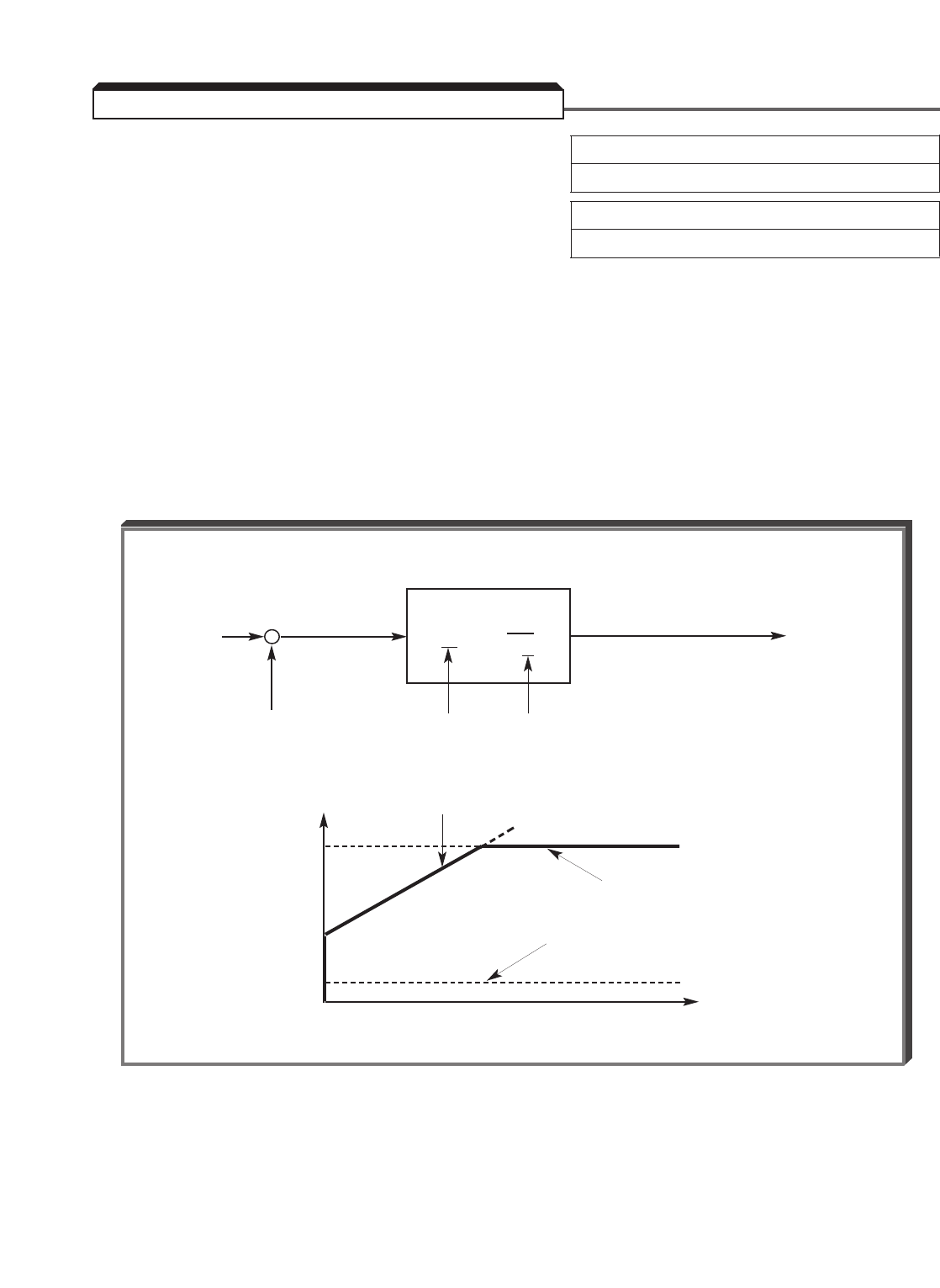
5-9
A. C5-01 : ASR Proportional Gain 1 Factory setting: 20.00
(ASRP1) Range: 0.00 to 300.00
C5-02 : ASR Integral Time 1 Factory setting: 0.500
(ASRI1) Range: 0.000 to 10.000 seconds
Parameters C5-01 and C5-02 provide adjustments to enable the optimum
performance during load disturbances. The proportional gain ( C5-01 ) adjusts the
amount of instantaneous droop as a function of loss, and provides damping from load
disturbances such as speed reference change, or a change in load. The integral time (
C5-02 ) adjusts the response time of the drive to the load disturbances.
NOTE: Speed control response is increased by increasing the proportional gain
setting and decreasing the integral time. However, instability or hunting may occur
between the drive and the load if C5-01 (ASR Proportional Gain) is set too
high, or C5-02 (ASR Integral Time) is set too low.
5.7 AUTOMATIC SPEED REGULATOR (ASR)
ASR CIRCUIT
(INPUT) (OUTPUT)
ERROR 1TORQUE
K ( 1 + s T ) REF.
SPEED C5-01 C5-02
FEEDBACK
OUTPUT (TORQUE REF.)
INTERNAL
LIMITER
INPUT (ERROR)
0
TIME
SPEED +
REF. –
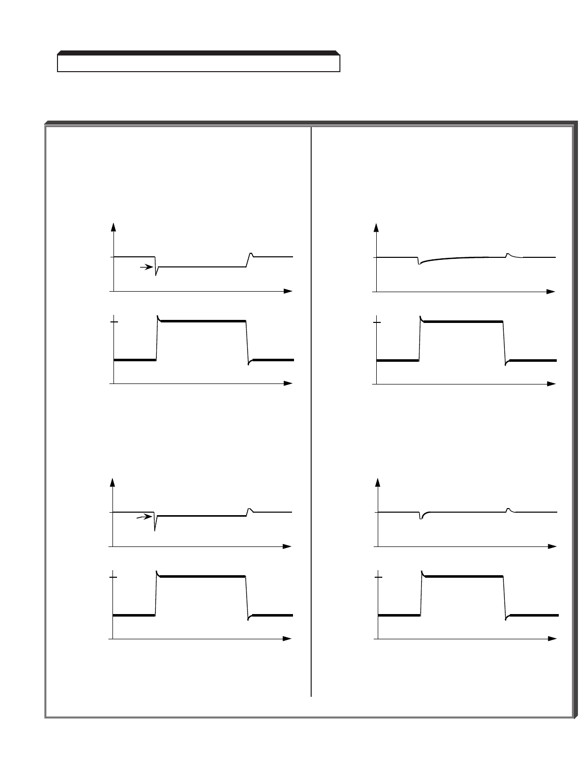
5-10
Continued
EXAMPLES OF C5-01 AND C5-02 ADJUSTMENTS
5.7 AUTOMATIC SPEED REGULATOR (ASR)
ASR Gain ( C5-01 ) Adjustment Only ASR Integral Time ( C5-02 ) Adjustment Only
0%
10%
SPEED
0%
100%
LOAD
6.9%
t
t
Speed Ref. = 10% of max.
C5-01 = 30.00
C5-02 = 0 .000
0%
10%
SPEED
0%
100%
LOAD
8.4%
t
t
Speed Ref. = 10% of max.
C5-01 = 60.00
C5-02 = 0 .000
0%
10%
SPEED
0%
100%
LOAD
t
t
Speed Ref. = 10% of max.
C5-01 = 30.00
C5-02 = 10.000
0%
10%
SPEED
0%
100%
LOAD
t
t
Speed Ref. = 10% of max.
C5-01 = 30.00
C5-02 = 1.000
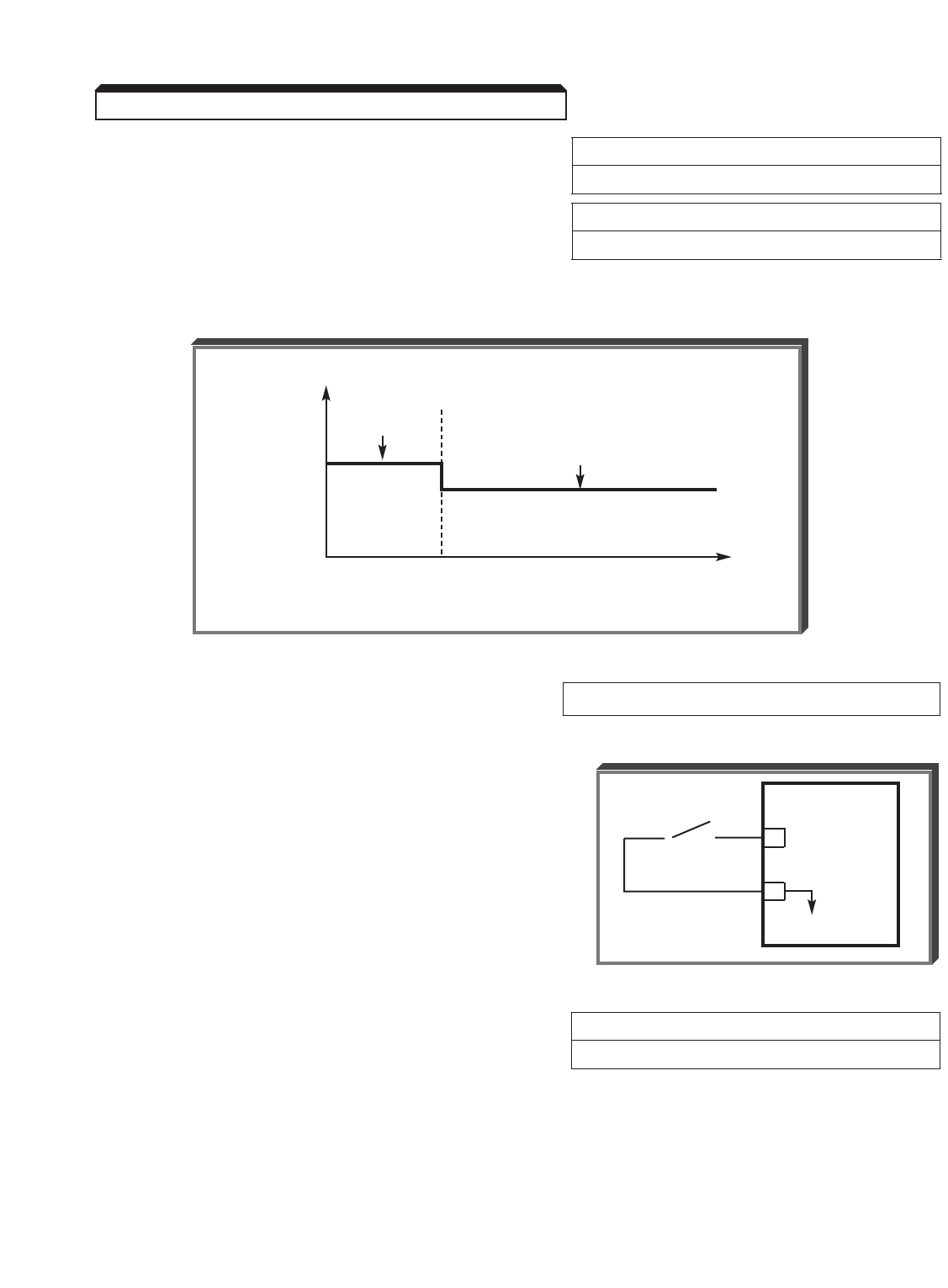
5-11
Continued
B. C5-03 : ASR Proportional Gain 2 Factory setting: 20.00
(ASRP2) Range: 0.00 to 300.00
C5-04 : ASR Integral Time 2 Factory setting: 0.500
(ASRI2) Range: 0.000 to 10.000 seconds
Parameter C5-03 is used as an additional proportional gain adjustment, and parameter
C5-04 determines the response time for Proportional Gain 2 ( C5-03 ).
C. H1-01 thru H1-06: Multi-function Data E: ASR Integral Reset (IRST)
Input Terminal Function
Selection (Term. 3 thru 8)
By programming data " E " into one of the
multi-function input parameters ( H1-01 thru
H1-06 ), one of the multi-function input terminals
(3 thru 8) becomes an ASR integral reset. When
there is a long time lag between the applying of
control power and actual run operation, output
voltage may be produced due to the integrator
offset. In such cases, the integral reset function
should be ON until the start of run operation.
D. C5-06 : ASR Output Lag Time Factory setting: 4
Range: 0 to 500 msec
This function is used as a filter for mechanical problems such as mechanical backlash, play,
etc., which may prevent the ASR proportional gain from being increased as adjusted.
5.7 AUTOMATIC SPEED REGULATOR (ASR)
SPEED
GAIN
C5-01
0
C5-03
C5-07
oo
GPD 515/G5
8
11
0V
ASR
I-RESET
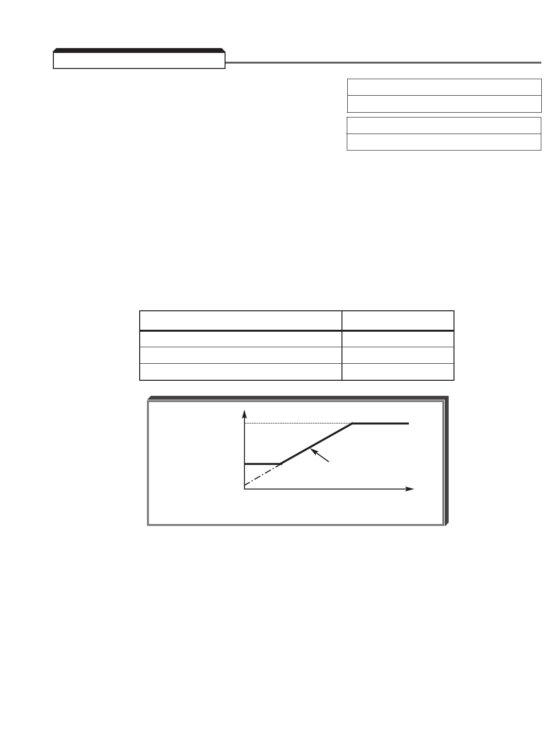
5-12
C6-01 : Carrier Frequency Upper Limit Factory Setting: See Table A3-1
C6-02 : Carrier Frequency Lower Limit Range (each): 0.4 to 15.0 kHz
C6-03 : Carrier Frequency Proportional Gain Factory Setting: See Table A1-3
Range: 0 to 99
The relationship between output frequency and carrier frequency is determined from the set
values of C6-01 to C6-03 .
(a) For constant carrier frequency (set value of C6-01 ):
Set C6-03 = 0 , and set the same value in both C6-01 and C6-02 .
(b) For synchronous mode (only with proportional section):
Set C6-03 = 12, 24, 36, or 48. These setting values establish carrier
frequencies of 12f, 24f, 36f, or 48f, respectively, where f = output frequency.
(c) In Vector Control mode, ONLY C6-01 is effective.
CARRIER FREQUENCY UPPER LIMIT K
C6-01 ≥10.0 kHz 3
10.0 kHz > C6-01 ≥5.0 kHz 2
C6-01 < 5.0 kHz 1
NOTE: Fault code " oPE11 " is displayed if either of the following conditions
is detected:
1. C6-03 > 6, and C6-02 > C6-01
2. C6-01 > 5.0 kHz, and C6-02 ≤5.0 kHz
C6-01
CARRIER
FREQUENCY
C6-02 Fout x C6-03 x K
0
OUTPUT FREQUENCY
5.8 CARRIER FREQUENCY
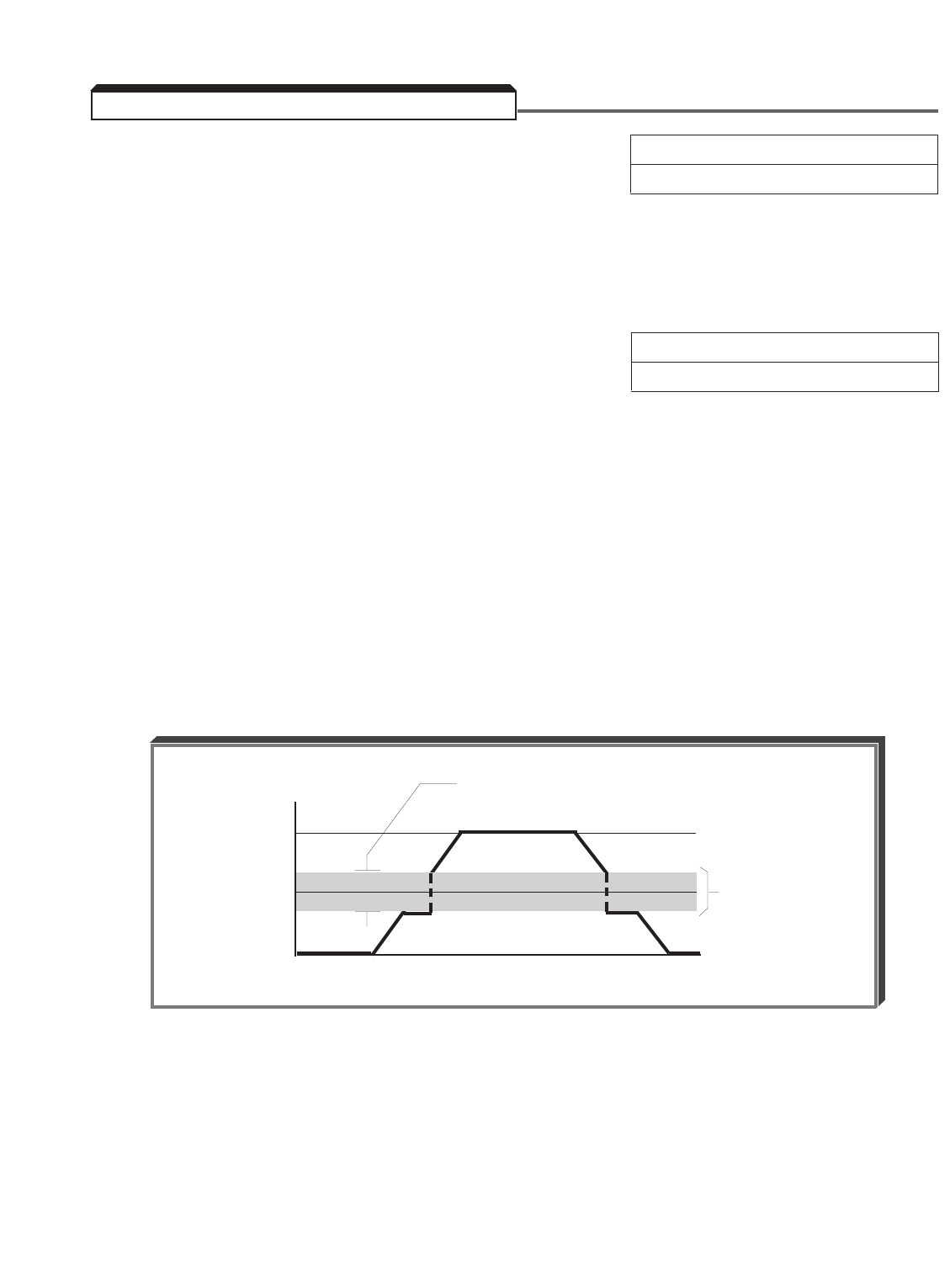
5-13
A. d3-01 : Prohibited Frequency 1 Factory setting (each): 0.0
d3-02 : Prohibited Frequency 2 Range (each): 0.0 to 400.0 Hz
d3-03 : Prohibited Frequency 3
These parameters allow programming of up to three prohibited frequency points for
eliminating problems with resonant vibration of the motor/machine. This feature does not
actually eliminate the selected frequency values, but will accelerate and decelerate the
motor through the prohibited bandwidth.
B. d3-04 : Prohibited Frequency Deadband Factory setting: 1.0
Range: 0.0 to 20.0 Hz
This parameter determines the width of the deadband around each selected prohibited
frequency point. The factory setting is " 1.0 ", which establishes a deadband of ±1.0 Hz.
EXAMPLE:
Vibration encountered between 30.0 and 36.0 Hz.
SOLUTION: Set d3-01 = 33.0. This is the center of the problem
frequency band.
Set d3-04 = 3.0. This will cause the drive to reject all
frequency command values between 30.0 and 36.0 Hz.
A frequency command in the deadband will be converted to the bottom
value of the deadband, e.g. a command of 33 Hz would result in a run
frequency of 30 Hz.
FREQ. CMD
36 Hz
d3-01 = 33 Hz
30 Hz
0
Total Deadband = 6.0 Hz
±d3-04 (3.0 Hz)
OUTPUT FREQUENCY (Hz)
5.9 CRITICAL FREQUENCY REJECTION
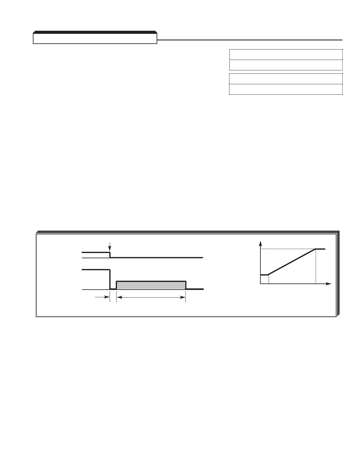
5-14
A. b1-03 : Motor Stopping Method Selection Factory setting: 0
Range: 0 to 3
b2-04 : DC Injection Time at Stop Factory setting: 0.50
Range: 0.00 to 10.00 seconds
When full range DC injection braking stop is enabled ( b1-03 = 2), DC injection braking is
used to stop a motor more quickly than normal coast to stop, without the need for
braking resistors. When a STOP command is issued, there is a 0.5 second time delay to
apply DC to two phases of the motor’s stator winding. Then DC injection current is
applied. The duration of DC braking is a time period proportional to b2-04 (at 10%
output frequency) and the level of output frequency at the time the STOP command is
issued.
Braking torque is 50-70% of full load motor torque.
EXAMPLE:
b2-04 = 0.5 sec (at 10% output)
Braking time at Fmax (100% output frequency) = 10 x 0.5 = 5 seconds
Full Range DC Injection Braking Stop Sequence
5.10 DC INJECTION BRAKING
RUN CMD
OUTPUT
FREQUENCY
STOP
0.5 sec
COASTING DC BRAKING TIME
b2-04 x 10
DC
INJECTION
BRAKING
TIME b2-04
0 10% 100%
OUTPUT FREQUENCY
AT TIME OF STOP COMMAND
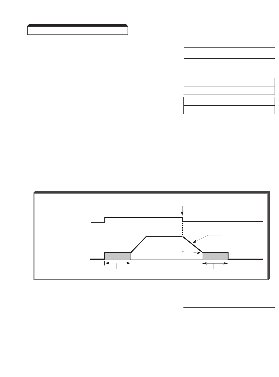
Continued
B. b2-01 : DC Inj. Braking Start Frequency Factory Setting: 0.5
Range: 0.1 to 10.0 Hz
b2-02 : DC Injection Braking Current Factory setting: 50
(% of Drive Rated Current) Range: 0 to 100 %
b2-03 : DC Injection Time at Start Factory setting: 0.00
Range: 0.00 to 10.00 seconds
b2-04 : DC Injection Time at Stop Factory setting: 0.00
Range: 0.00 to 10.00 seconds
DC injection can be used to stop a motor whose rotational direction is uncertain at start-up.
For this operation, application of DC injection braking current is controlled by a multi-
function input (see paragraph 5.8.D).
With ramp to stop enabled ( b1-03 = 0 ), after a STOP command is received the drive
controls motor deceleration according to the Decel Time setting, until output frequency
reaches the DC Injection Braking Start Frequency ( b2-01 setting). Then the drive output
is turned off and DC injection current is applied to the motor. The effective DC injection
time and current should be set to provide adequate stopping without excessive motor
heating. The DC injection voltage is determined by the DC injection braking current and
motor impedance.
DC Braking Sequence
b2-08 : Field Compensation Factory setting: 0
At Start Range: 0 to 500%
This parameter adjusts the amount of motor current during DC Injection at start. A setting
of 0% disables this feature. A setting of 100% equals motor no-load current (E2-03). This
current level will be applied until the DC Injection Time at Start (b2-03) expires. This
parameter is useful when starting motors that are relatively higher in horsepower than the
drive, due to the requirement for increased magnetizing current. This parameter may also
compensate for reduced starting torque due to motor circuit inefficiencies.
5-15
5.10 DC INJECTION BRAKING
RUN COMMAND
OUTPUT FREQUENCY
STOP
RAMP TO STOP
DC DC
DC INJECTION TIME AT
START ( b2-03 )
DC INJ. BRK. START
FREQUENCY ( b2-01 )
DC INJECTION TIME AT
STOP ( b2-04 )
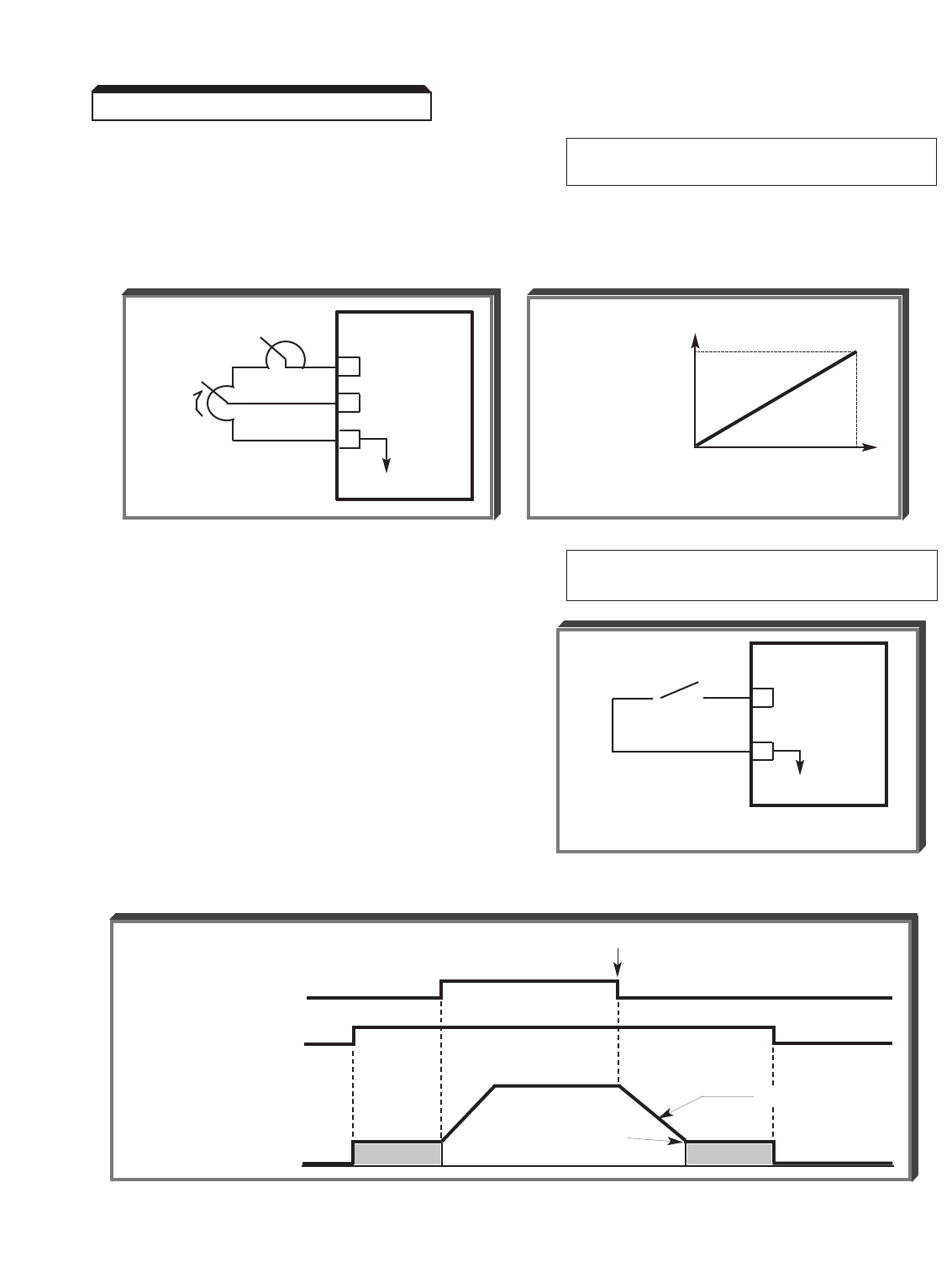
5-16
Continued
C. H3-05 : Multi-function Analog Input Data 6: DC Injection Braking Current
(Term. 16) Adjust
The multi-function analog input at terminal 16 may be configured to allow analog control of
the amount of DC injection braking current (from 0% to 100% of the current level set in
b2-02 ), which directly controls the amount of DC injection voltage applied to the motor.
D. H1-01 thru H1-06 : Multi-function Inputs Data 60 : DC Injection Braking
(Term. 3 thru 8) Command
Any multi-function input terminal can be utilized
to control DC injection braking. When used, DC
injection current will be applied until the input is
removed, provided that the drive output
frequency is below the DC Braking Start
Frequency ( b2-01 ).
EXAMPLE:
H1-06 = 60
Contact input at Terminal 8 is
the DC Injection Braking Command
DC Braking Sequence
5.10 DC INJECTION BRAKING
o
oo
GPD 515/G5
8DC INJ. BRK.
COMMAND
11
0V
RUN COMMAND
DC INJECTION
BRAKING COMMAND
OUTPUT FREQUENCY
STOP
RAMP TO STOP
DC DC
DC INJ. BRK. START
FREQUENCY ( b2-01 )
BRAKING
CURRENT
ADJUST
1R GPD 515/G5
15 +15V
16 0-10V (20K
Ω)
17
C
100
BRAKING
CURRENT
(%)
( b2-02 )
010
ANALOG VOLTAGE
5-17
o1-03 : Display Scaling Factory setting: 0
Range: 0 to 39999
This parameter determines the scaling of the Digital Operator display, for both Output
Frequency and all Frequency References.
DATA DISPLAY
0Output frequency, in increments of 0.01 Hz.
(factory
setting)
1Output frequency, in increments of 0.01 %.
2to 39 Motor synchronous speed (P = )
(no. of motor in increments of 1 RPM *
poles) (39999 max).
P = no. of motor poles
F = Frequency
Ns= motor synchronous speed
NOTE: If motor synchronous speed exceeds
39999 RPM, display holds at " 39999 ".
00040 Line speed or other parameter. Setting must be
t o 5 digits.
39999
X X X X X
Display value at maximum
frequency ( E1-04 )(include
leading zeroes if necessary)
Location of decimal point:
0= X X X X
1= X X X .X
2= X X .X X
3= X .X X X
(See CAUTION on next page)
EXAMPLE:
To display Line Speed, based on
54.32 FPM at 60 Hz:
o1-03 setting = 25432
* Ineffective when in Flux Vector Control mode.
DATA DISPLAY
120 x F
Ns
5.11 DIGITAL OPERATOR DISPLAY SELECTION

5-18
Continued
Exceptions to the general format are as follows: o1-03 DISPLAY
" 10000 " = 1000.0
" 20000 " = 100.00
" 30000 " = 10.000
CAUTION
When setting a value in o1-03, the decimal point position
selected will automatically affect all of the Frequency Reference
Memory Settings ( d1-01 thru d1-09; see Table A1-4).
EXAMPLE:
o1-03 factory setting: 00000
d1-09 (Jog) factory setting: 006.00 (6 Hz)
o1-03 changed to 10600
Decimal point at X X X.X
d1-09 setting becomes 0060.0
Therefore, for 10.00 Hz Jog frequency, d1-09 must
be reprogrammed to " 001.0 0" .
o1-04 : Digital Operator Display Units Factory setting: 0
Range: 0 or 1
This parameter sets the frequency units for Flux
Vector mode.
The setting of o1-04 affects the following
parameters:
E1-04 : Maximum Frequency
E1-06 : Base Frequency
E1-07 : Mid Frequency A
E1-09 : Minimum Frequency
E1-11 : Mid Frequency B
o1-05 : Parameter/Address Display Selection Factory setting: 0
Range: 0 or 1
This parameter selects whether the parameter
addresses are displayed on the Digital Operator
by parameter number, or by its corresponding
MODBUS address number.
5.11 DIGITAL OPERATOR DISPLAY SELECTION
Setting Description
0 Hertz
1 RPM
Setting Description
0 Parameter Number
1 MODBUS Address
5-19
o1-02 : Monitor Selection After Power-up Factory setting: 1
Range: 1 to 4
This parameter determines which monitor display will appear on the Digital Operator when
the drive is powered up. The number programmed into o1-02 corresponds to the
appropriate U1-XX parameter, which determines monitor status.
1 U1-01 — Frequency Reference
2 U1-02 — Output Frequency
3 U1-03 — Output Current
4 U1-XX — Monitor parameter selected by o1-01
o1-01 : Monitor Selection Factory setting: 6
Range: 4 to 38
This setting allows the user to select an item to be displayed in the monitored parameters
list. The o1-01 parameter corresponds to the o1-02 setting "4 - Selected Monitor".
For example, to display DC bus voltage in the monitored parameters list, set parameter
o1-01 to "7" for monitor selection U1-07 .
b7-01 : Droop Control Gain Factory setting: 0.0
Range: 0.0 to 100.0%
When active, the speed decreases or increases in proportion to load torque. As the load
increases, the speed droops according to the percentage set in b7-01 . As the load
decreases, the speed increases.
Maximum droop is reached at full load. Maximum speed is based on the maximum output
frequency setting ( E1-04 ). Excessive droop, which results in a significant difference
between the speed reference and the speed feedback, may activate a Speed Deviation
( DEV ) fault. The deviation detection level is an adjustable value, which can be set in
parameter F1-10 .
b7-02 : Droop Control Delay Time Factory setting: 0.05
Range: 0.03 to 2.00 seconds
The setting of this parameter determines the drive’s droop response time to a load
change.
NOTE
Only available in the Flux Vector Control Method ( A1-02 = 3).
5.12 DISPLAY – MONITOR ( A T POWER-UP) SELECTION
o1-02 MONITOR SELECTION
SETTING
5.13 DROOP
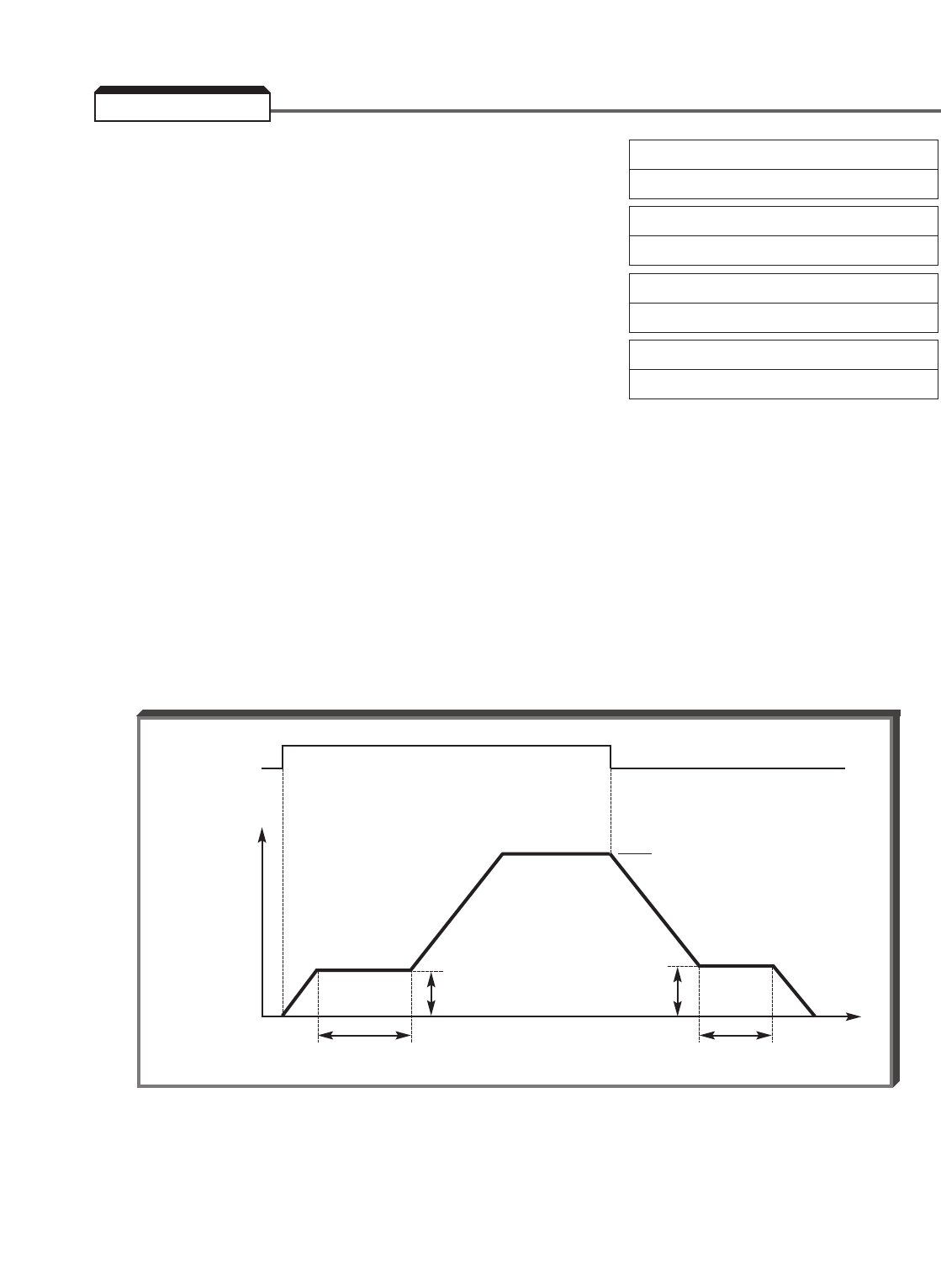
5-20
b6-01 : Dwell Frequency at Start Factory setting: 0.0
Range: 0.0 to 400.0 Hz
b6-02 : Dwell Time at Start Factory setting: 0.0
Range: 0.0 to 10.0 seconds
b6-03 : Dwell Frequency at Stop Factory setting: 0.0
Range: 0.0 to 400.0 Hz
b6-04 : Dwell Time at Stop Factory setting: 0.0
Range: 0.0 to 10.0 seconds
This function allows the drive to temporarily suspend acceleration or deceleration and
remain at a desired output frequency for a specified length of time.
After receiving a run command, the drive accelerates to the designated dwell start
frequency ( b6-01 ). The output is then held at that frequency for the duration of the
dwell time at start ( b6-02 ). After that length of time the drive continues to accelerate
to the set frequency.
When the run command is removed the drive decelerates to the designated dwell stop
frequency ( b6-03 ). The output is then held at that frequency for the duration of the
dwell time at stop ( b6-04 ). After that length of time the drive continues to decelerate
until the output frequency is zero.
5.14 DWELL
RUN
SET FREQUENCY
OUTPUT
FREQ.
b6-01 b6-03
t
b6-02 b6-04

5-21
A. F1-01 : Encoder (PG) Constant Factory setting: 1024
Range: 0 to 60000 ppr
This parameter is set to the Pulses Per Revolution (ppr) to the encoder used with the motor.
B. F1-02 : Operation Selection at PG Factory setting: 1
Open Circuit Range: 0 : Ramp to Stop
1 : Coast to Stop
2 : Fast-stop
3 : Alarm Only
F1-14 : PG Open Circuit Detection Factory setting: 2.0
Delay Time Range: 0.0 to 10.0 seconds
The setting of F1-02 determines the stopping method when a PG Open Circuit ( PGo ) is
detected. A PG open circuit is detected when no pulses are received from the pulse
generator within the time specified by F1-14 . (Note: The PG Open fault is disabled when
zero speed is commanded.)
NOTE
Only available in the V/f w/PG and the Flux Vector Control Methods
( A1-02 = 1 or 3).
5.15 ENCODER (PG) PARAMETERS

5-22
Continued
C. F1-08 : Overspeed Detection Level Factory setting: 115
Range: 0 to 120 %
F1-09 : Overspeed Detection Delay Time Factory setting: See Table A3-2
Range: 0.0 to 2.0 seconds
F1-03 : Operation Selection at Factory setting: 1
Overspeed Range: 0 : Ramp to Stop
1 : Coast to Stop
2 : Fast-stop
3 : Alarm Only
Parameters F1-08 and F1-09 work together to determine when an overspeed ( oS )
fault will occur. Parameter F1-08 sets the desired overspeed level as a percentage of
the maximum output frequency ( E1-04 ), and F1-09 determines how long the
overspeed condition will be allowed to exist before a fault will occur. Parameter F1-03
determines the stopping method when an overspeed fault ( oS ) occurs.
EXAMPLE:
A given application requires that if motor speed were to ever reach 1980 RPM,
an overspeed fault would occur and the motor should coast to stop. The motor
has 4 poles, and maximum frequency ( E1-04 ) = 60Hz.
( E2-04 )
F1-08 = Desired Overspeed Level x Number of Motor Poles x 100%
120 x Maximum Frequency
( E1-04 )
F1-08 = 1980 x 4 x 100% = 110 %
120 x 60
F1-03 = 1Coast to Stop
NOTE
Only available in the V/f w/PG and Flux Vector Control Methods
( A1-02 = 1 or 3).
5.15 ENCODER (PG) PARAMETERS
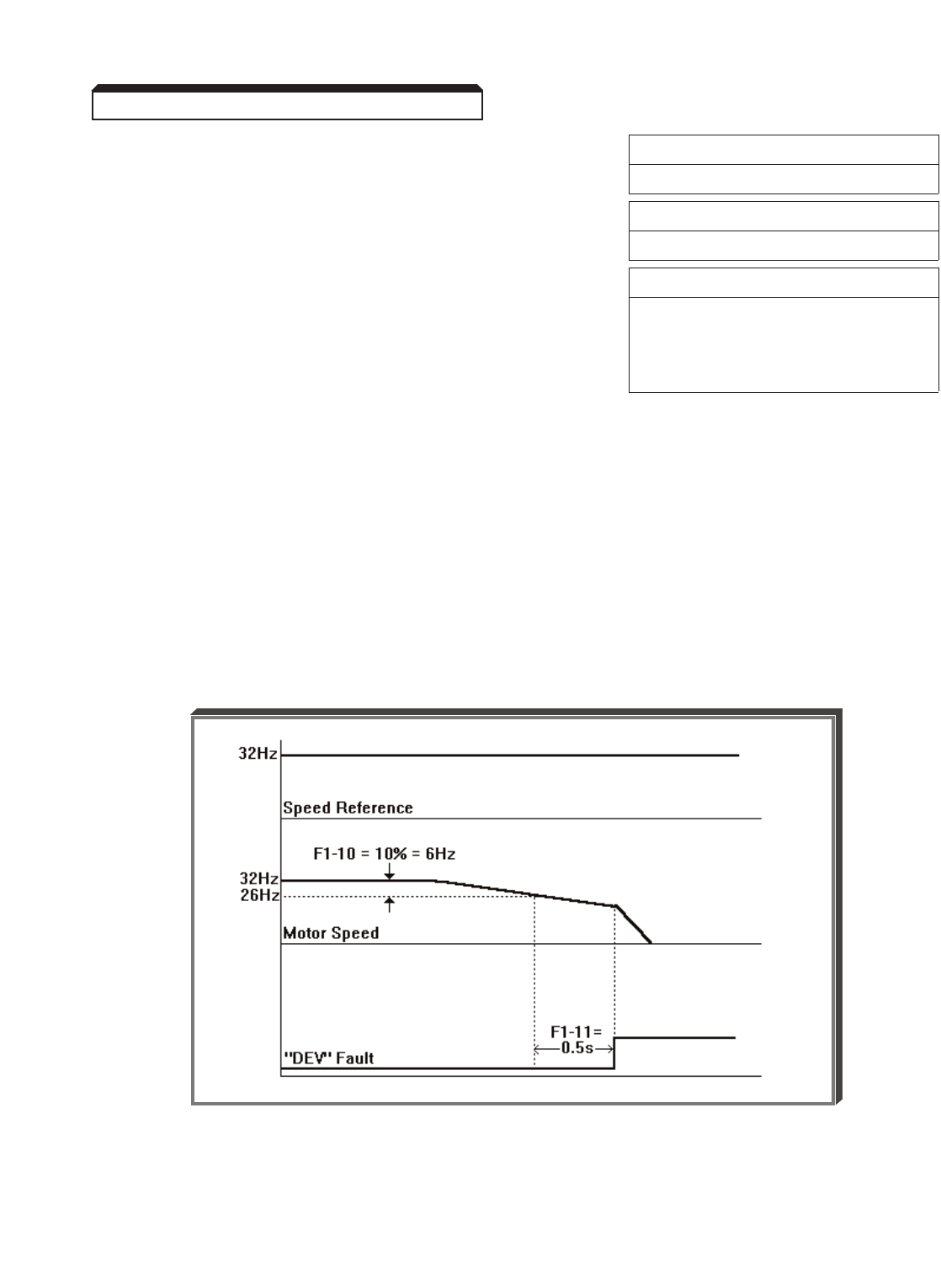
5-23
Continued
D. F1-10 : Excessive Speed Deviation Factory setting: 10
Detection Level Range: 0 to 50 %
F1-11 : Excessive Speed Deviation Factory setting: 0.5
Detection Delay Time Range: 0.0 to 10.0 seconds
F1-04 : Operation Selection at Factory setting: 3
Speed Deviation Range: 0 : Ramp to Stop
1 : Coast to Stop
2 : Fast-stop
3 : Alarm Only
Parameters F1-10 and F1-11 work together to determine when a Speed Deviation
( DEV ) fault will occur. Parameter F1-10 determines how far the motor speed has to
differ from the speed reference (set as a percentage of E1-04 ), and F1-11 determines
how long the speed has to deviate before a fault will occur. Use F1-04 to determine
stopping method if a speed deviation fault occurs.
EXAMPLE:
F1-10 = 10 %, F1-11 = 0.5 sec, F1-04 = 1, and E1-04 (Max
Frequency) = 60 Hz. As can be seen below, the motor speed must drop
over 10% below the speed reference for 0.5 seconds before a fault occurs.
10% speed = E1-04 x 0.1 = 60 x 0.1 = 6Hz
NOTE
Only available in the V/f w/PG and Flux Vector Control Methods
( A1-02 = 1 or 3).
5.15 ENCODER (PG) PARAMETERS

5-24
Continued
E. F1-05 : PG Rotation Factory setting: 0
Range: 0 : Counter-clockwise
1 : Clockwise
The setting of F1-05 determines how the drive interprets the incoming pulses from the
pulse generator. It can be used to change direction of the motor without having to change
encoder wiring.
EXAMPLE:
To run a particular machine “forward” requires the motor shaft to turn in
a clockwise direction when viewed from the output shaft end of the motor.
The motor/encoder that is installed is running counter-clockwise as forward.
in order to change the direction of the motor, two of the motor leads need
to be swapped, and F1-05 needs to be changed to a 1.
NOTE
Only available in the V/f w/PG and Flux Vector control modes
( A1-02 = 1 or 3).
F. F1-07 : Integral Value During Accel/Decel Factory setting: 0
Selection Range: 0 : Disabled
1 : Enabled
The setting of F1-07 determines whether the automatic speed regulator (ASR) integral
operation is performed during accel/decel.
NOTE
Only available in the V/f w/PG Control Method ( A1-02 = 1).
5.15 ENCODER (PG) PARAMETERS
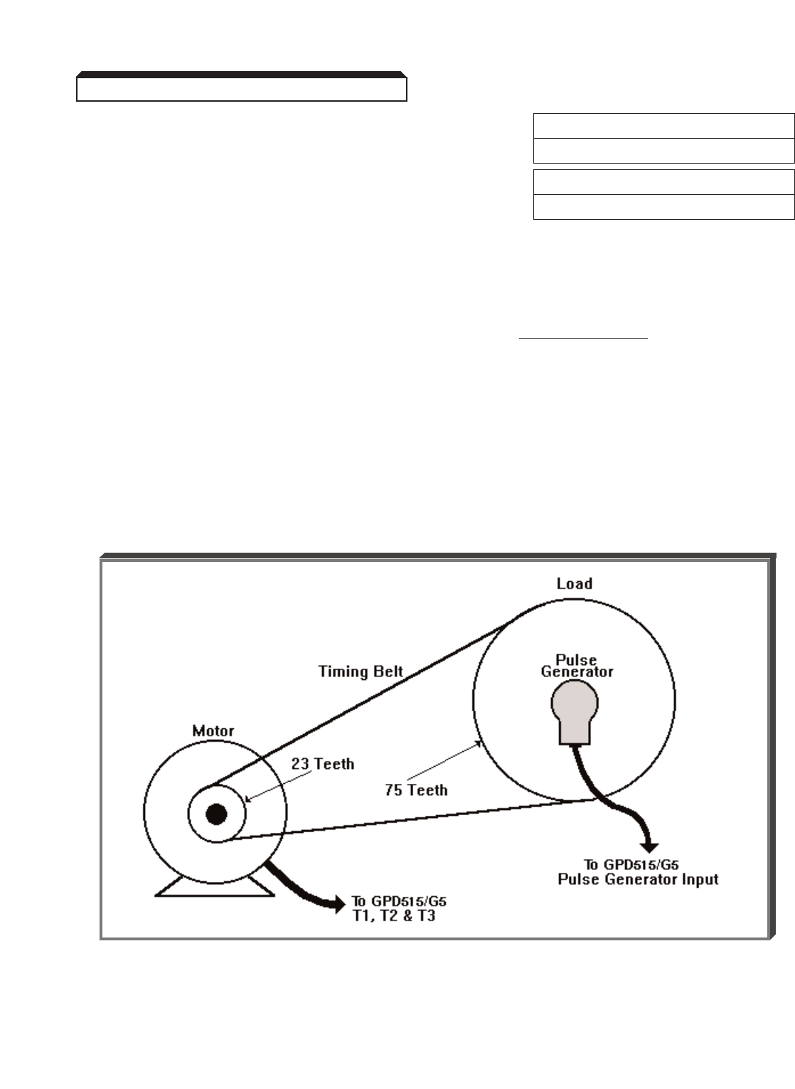
5-25
Continued
G. F1-12 : Number of PG Gear Teeth 1 Factory setting: 0
Range: 0 to 1000
F1-13 : Number of PG Gear Teeth 2 Factory setting: 0
Range: 0 to 1000
Parameters F1-12 and F1-13 are used to set the gear ration when there is a gear
ratio between the motor and the pulse generator. This function is disabled when F1-12
and F1-13 are set to 0.
( F1-13 )
Motor Speed (RPM) = Load Speed (RPM) x PG Gear Teeth 2
PG Gear Teeth 1
( F1-12 )
EXAMPLE:
A motor is connected to a load through a toothed timing belt. The sheave
on the motor has 23 teeth, and the sheave on the load had 75 teeth. The
only mechanically practical place to mount a pulse generator for speed feed-
back is on the same shaft as the load sheave. In order to correctly scale the
encoder feedback, F1-12 needs to be set to 23, and F1-13 needs to
be set to 75.
NOTE
Only available in the V/f w/PG Control Method ( A1-02 = 1).
5.15 ENCODER (PG) PARAMETERS
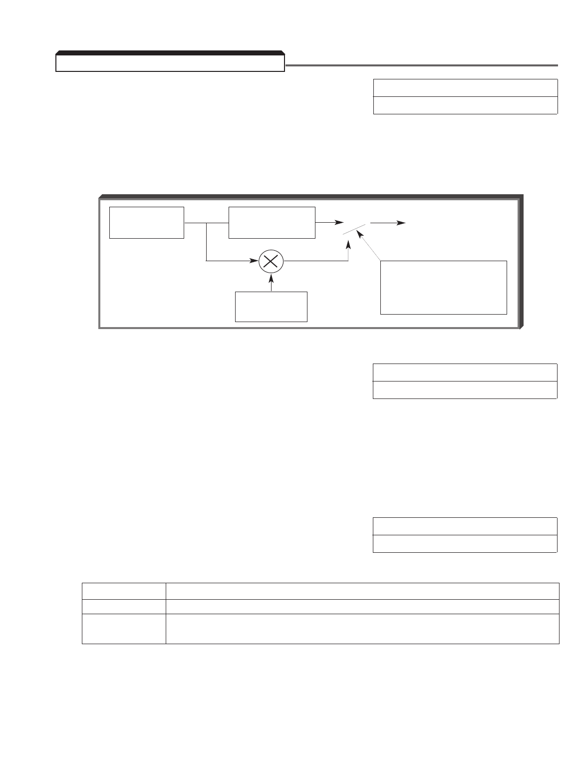
5-26
A. Energy Saving V/f Control Methods Factory setting: 0
Range: 0 to 100 %
b8-01 : Energy Saving Gain
This parameter is only available in the V/f or V/f w/PG Control Methods (A1-02 = 0 or 1).
This parameter sets, in increments of 1%, the level to which the output voltage is reduced
during the energy-saving operation.
Output Voltage During Energy-Saving Operation
b8-02 : Energy Saving Frequency Factory setting: 0.0
Range: 0 to 400 Hz
This parameter is only available in the V/f or V/f w/PG control methods (A1-02 = 0 or 1).
The energy saving function will only activate if all of the following conditions are met: a
multi-function input is activated which is set to energy savings (data 63), output frequency
is above the Energy Saving Frequency b8-02, and the drive is up to its set speed (output
frequency = frequency reference).
B. Energy Saving – Open Loop Vector & Factory setting: 0
Flux Vector Control Methods Range: 0 or 1
b8-03 : Automatic Energy Saving Selection
Setting Description
0 Disabled – Energy saving mode will not be activated under light loads.
1 Enabled – The energy saving mode will automatically be activated
under light loads.
This parameter is only available when in the open loop vector or flux vector control methods
(A1-02 = 2 or 3). When b8-03 is set to a 1, a multi-function contact input is not required
to activate energy saving mode. This function is separate and should not be confused with
parameters b8-01 and b8-02. When the drive detects a lightly loaded motor, the output
voltage will automatically be reduced.
5.16 ENERGY SAVING OPERATION
V/f
CONVERSION
TORQUE
COMPENSATION VOLTAGE COMMAND
ENERGY-
SAVING GAIN
CLOSE AT
SET FREQUENCY
AND ENERGY-SAVING
ENABLED
O O
O
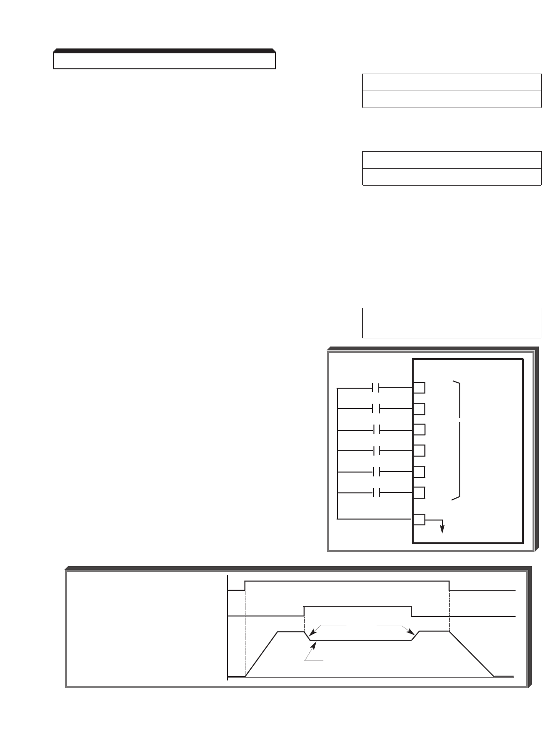
5-27
Continued
b8-04 : Automatic Energy Saving Factory setting: 0.7*
Control Gain Range: 0.0 to 10.0
*Factory setting becomes 1.0 when A1-02 = 3
b8-05 : Automatic Energy Saving Factory setting: 0.50**
Control Time Constant Range: 0.00 to 10.0 sec.
**Factory setting becomes 0.01 when A1-02 = 3
These parameters are only available when in the open loop vector or flux vector control
methods (A1-02 = 2 or 3). Parameters b8-04 and b8-05 adjust the energy savings
voltage regulator. Increasing the gain (b8-04) and/or decreasing the time constant (b8-
05) will increase the responsiveness of the energy savings function. If the response is set
too fast, the drive may become unstable. If the response is set too slow, the drive may
respond incorrectly when the motor load is re-applied.
H1-01 thru H1-06 : Multi-function Data 63 : Energy Saving
Inputs (Term. 3 thru 8) Operation
A multi-function input must be used to
command energy saving operation.
When the external Energy-Saving Operation
command is closed at set frequency, the energy-
saving operation shown below is enabled. In the
energy saving operation, the output voltage is the
value of the energy saving gain ( b8-01; factory
set to 80%) multiplied by the V constants defined
by E1-05, -08and -10.
NOTE
If energy saving operation is enabled before accel
time is complete, output V/Hz is not affected until
set frequency is reached; then output voltage is
reduced by energy-saving gain ( b8-01) setting.
Energy-Saving Run Timing
EXTERNAL
CONTACTS GPD 515/G5
3H1-01
4H1-02 MULTI-
> FUNCTION
5H1-03 INPUT
6H1-04
7H1-05
8H1-06
11
0V
RUN COMMAND
ENERGY-SAVING COMMAND
L2-04
V (of E1-05, -08 & -10 ) x
OUTPUT VOLTAGE Energy-Saving Gain ( b8-01 )
5.16 ENERGY SAVING OPERATION
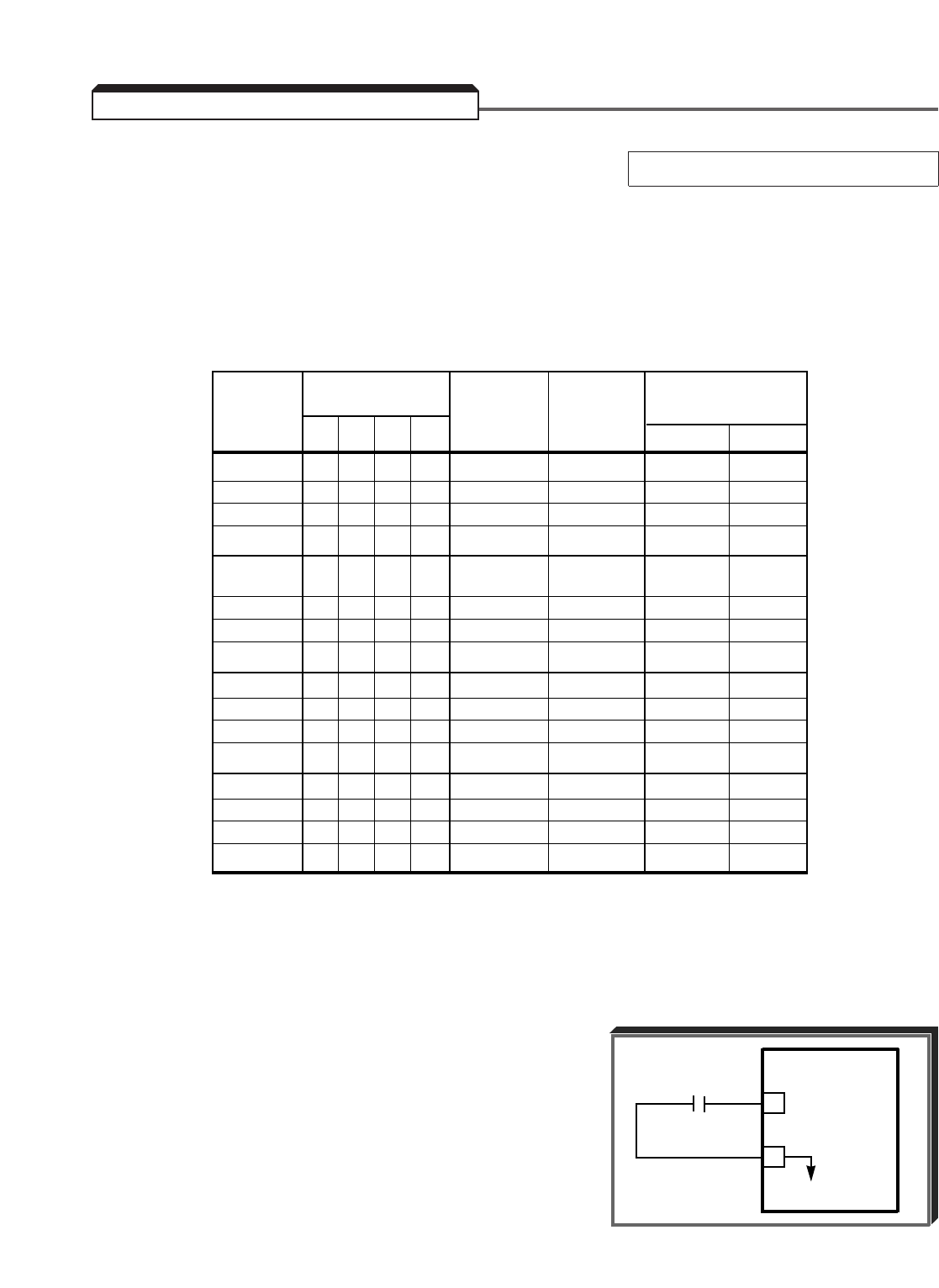
H1-01 thru H1-06 : Multi-function Data 20-2F : External Fault
Inputs (Term. 3 thru 8)
The multi-function input terminals can be used to define various modes of external faults.
When the External Faults 1-4 are inputted, " EF3 " to " EF8 " are displayed on the Digital
Operator (steady for a major fault situation, blinking for a minor fault situation). The second
digit of the H1-01 thru H1-06 setting is entered in hexadecimal values which defines what
type of external fault contact is used and how the drive will react to the fault input.
EXAMPLE:
To program External Fault 3 (Terminal 3)
for a N.C. contact, always detected, and
drive to continue operation:
H1-01 = 2D
5-28
5.17 EXTERNAL FAULT INPUTS
H1-0X Mode (Note 2) Always During Terminal
Data: Input (Note 1)
2 __ 0 1 2 3 Detected Operation N.O. N.C.
0XX
1X
X
X
X
X
2XX
3X
X
X
X
X
X
X
X
X
X
4XX X
(Factory Set)
5XX
6XX
7XX
8XX
9X
X
XX
AXX
BXX
CXX
DX
X
XX
EXX
FXX
NOTES
1. N.O. = normally open contact; N.C. = normally closed contact.
2. Mode 0 = Ramp to Stop (decel time per C1-02);
Mode 1 = Coast Stop;
Mode 2 = Emergency Stop (decel time per C1-09);
Mode 3 = Continuous operation (minor fault).
EXTERNAL
FAULT
CONTACT
GPD 515
3
11
0V
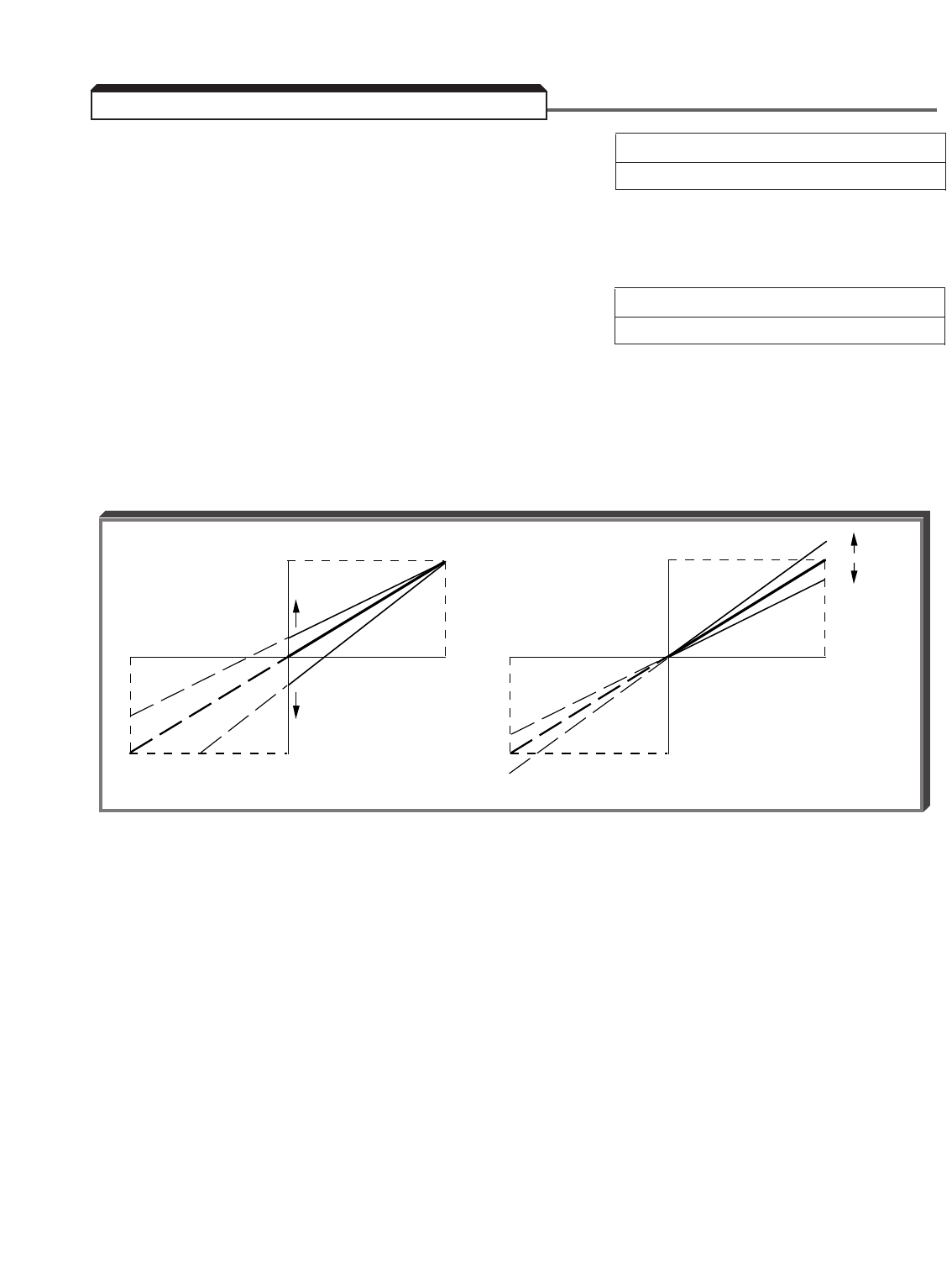
5-29
H3-02 : Frequency Reference Gain (Term. 13) Factory setting (each): 100.0
H3-06 : Frequency Reference Gain (Term. 16) Range (each): 0.0 to 1000.0 %
H3-10 : Frequency Reference Gain (Term. 14)
These parameters can be used to set the frequency command gain, in increments of 0.1%,
for its respective terminal.
H3-03 : Frequency Reference Bias (Term. 13) Factory setting (each): 0.0
H3-07 : Frequency Reference Bias (Term. 16) Range (each): –100.0 to 100.0 %
H3-11 : Frequency Reference Bias (Term. 14)
These parameters can be used to set the frequency command bias, in increments of 0.1%,
for its respective terminal.
NOTE: If H3-09 = 1F, H3-10 and H3-11 have no effect. Gain and bias for
terminal 14 are set by H3-02 and H3-03 , respectively.
ADJUSTMENT PROCEDURE:
A. For 0-10 Vdc input (term. 13 or 16)
1. With no input, adjust Bias ( H3-03 or H3-07 setting) until an output
of 0.0 Hz is obtained.
2. With full scale input, adjust Gain ( H3-02 or H3-06 setting) until an
output of 60.0 Hz (or other desired max. output frequency) is obtained.
B. For 4-20mA input (term. 14)
1. With 4mA input, adjust Bias ( H3-11 setting) until an output of 0.0 Hz
is obtained.
2. With 20mA input, adjust Gain ( H3-10 setting) until an output of
60.0 Hz (or other desired max. output frequency) is obtained.
NOTE
Follow the same adjustment procedure for other desired frequency setpoints.
10V
FREQ. REF.
INPUT (V)
FREQ. REF.
INPUT (V)
FREQ.
REF.
(%)
FREQ.
REF.
(%)
BIAS
GAIN
(+)
(–)
110
110
100
100
90
90
0V
100%
0%
–100%
–10V
10V
0V
100%
0%
–100%
–10V
(+)
(–)
BIAS GAIN
5.18 FREQUENCY REFERENCE BIAS/GAIN
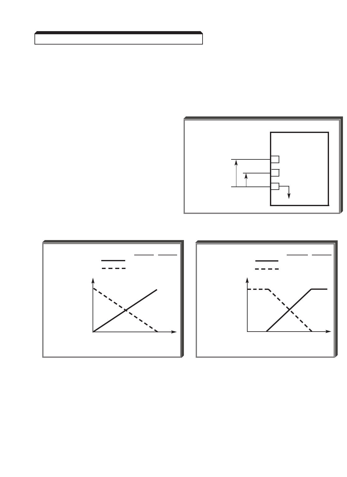
5-30
Continued
ADJUSTMENT PROCEDURE (continued) :
C. For inverse-acting frequency reference
1. Begin with H3-02 & H3-03 settings as shown below.
2. Fine tune as indicated in A or B above.
Frequency reference inputs:
terminals 13 & 17 — 0-10 VDC
terminals 14 & 17 — 4-20 mA
5.18 FREQUENCY REFERENCE BIAS/GAIN
GPD 515/G5
13 0-10V (20K Ω)
14 4-20 mA (250 Ω)
17
C
FREQUENCY
REFERENCE
H3-02 H3-03
= 100.0 0.0
= 0.0 100.0
100%
FREQ
REF.
0% 4mA 20mA
INPUT CURRENT (TERM. 14)
H3-02 H3-03
= 100.0 0.0
= 0.0 100.0
100%
FREQ
REF.
0% 0V 10V
INPUT VOLTAGE (TERM. 13)

5-31
H3-01 : Auto Speed Reference Signal Factory setting: 0
Level Selection (Term. 13) Range: 0 or 1
To change the control circuit terminal 13 input level, program H3-01 .
Setting Terminal 13 Input Level
0 0 to 10 V
1–10 to 10 V
H3-04 : Multi-function Analog Input 1 Signal Factory setting: 0
Level Selection (Term. 16) Range: 0 or 1
To change the control circuit terminal 16 input level, program H3-04 .
Setting Terminal 16 Input Level
0 0 to 10 V
1–10 to 10 V
H3-08 : Multi-function Analog Input 2 Signal Factory setting: 2
Level Selection (Term. 14) Range: 0 to 2
To change the control circuit terminal 14 input level, program H3-08 .
Setting Terminal 14 Input Level
0 0 to 10 V
1–10 to 10 V
2 4 to 20 mA
IMPORTANT
In addition to setting parameter H3-08 = 0 or 1 for a voltage input,
jumper J1 on the drive’s Control PCB must be cut.
Examples of wiring the drive for frequency references from various sources are shown on
the next page.
5.19 FREQUENCY REFERENCE INPUT SIGNALS (AUTO/MANUAL)
NOTE
If parameter H3-09 = 1F terminals 13 and 14 are added and used as the internal
frequency reference.
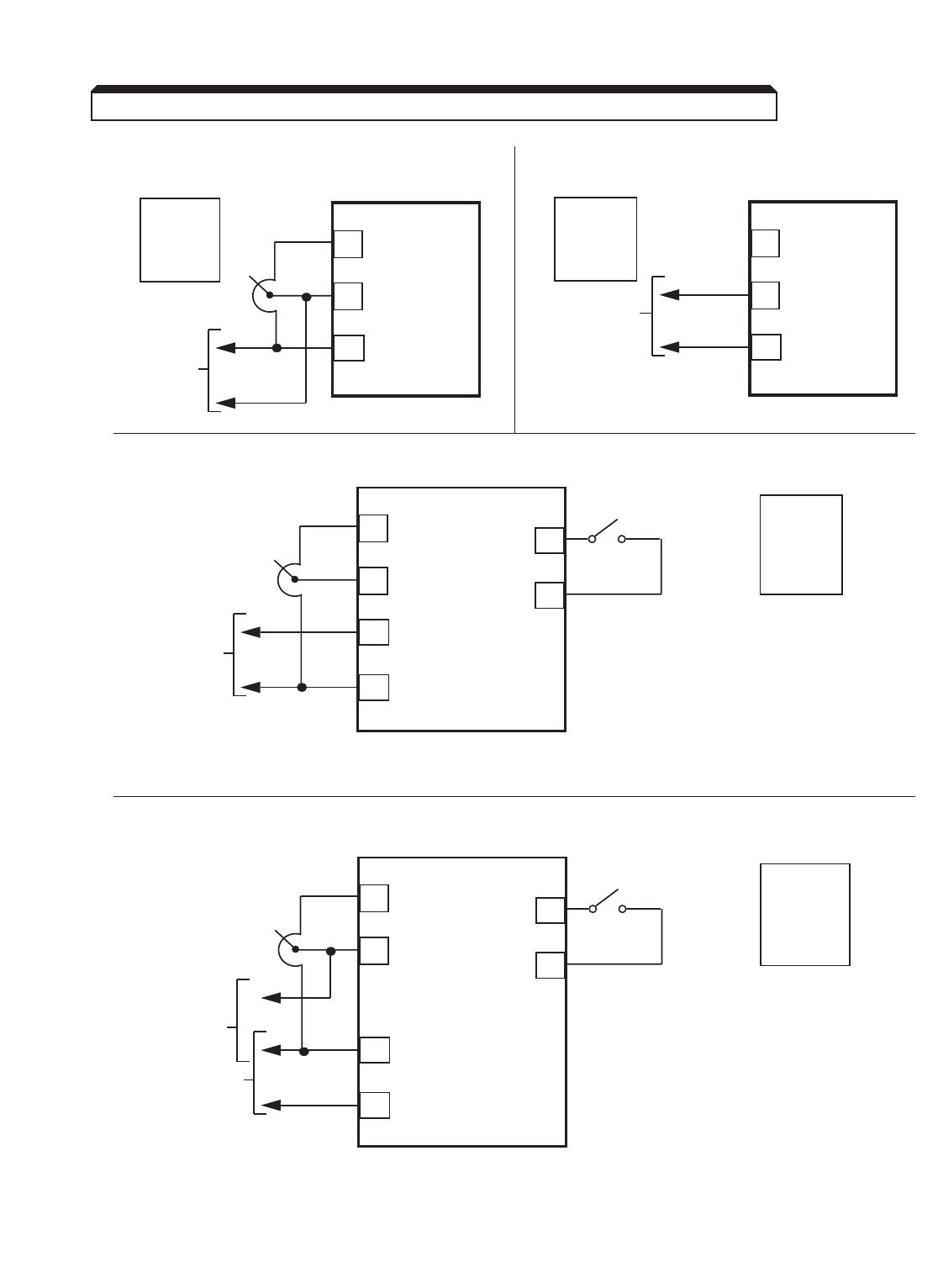
5-32
Continued
A. Speed pot or 0-10VDC signal only: B. 4-20mA signal only:
C. 0-10VDC signal (auto) and speed pot (manual):
For a bidirectional speed pot, set H3-04 = 1 and connect the low side to
terminal 33 instead of terminal 17.
D. 4-20mA DC signal (auto) and 0-10VDC signal or speed pot (manual):
For a –10 to +10V input instead of 0-10V at terminal 13, set H3-01= 1.
5.19 FREQUENCY REFERENCE INPUT SIGNALS (AUTO/MANUAL)
b1-01 = 1
H3-01 = 0
H3-04 = 0
H3-08 = 2
15
13
17
—
+
+15V
AUTO REF.
0-10VDC
0V
0-10VDC
GPD515/G5
b1-01 = 1
H3-01 = 0
H3-04 = 0
H3-08 = 2
H1-03 = 3
15
16
—
+
5V
MANUAL REF.
0-10VDC
0V
0-10VDC
17
13 AUTO REF.
0-10VDC
11
5
COM
AUTO/
MAN
AUTO
MANUAL
GPD515/G5
b1-01 = 1
H3-01 = 0
H3-04 = 0
H3-08 = 2
H1-03 = 3
15
16
—
+
+15V
MANUAL REF.
0-10VDC
AUTO REF.
4-20mA DC
14
17 0V
11
5
COM
AUTO/
MAN
AUTO
MANUAL
+
0-10VDC
GPD515/G5
b1-01 = 1
H3-01 = 0
H3-04 = 0
H3-08 = 2
15
14
17
—
+
+15V
AUTO REF.
4-20mA
0V
4-20mA DC
GPD515/G5
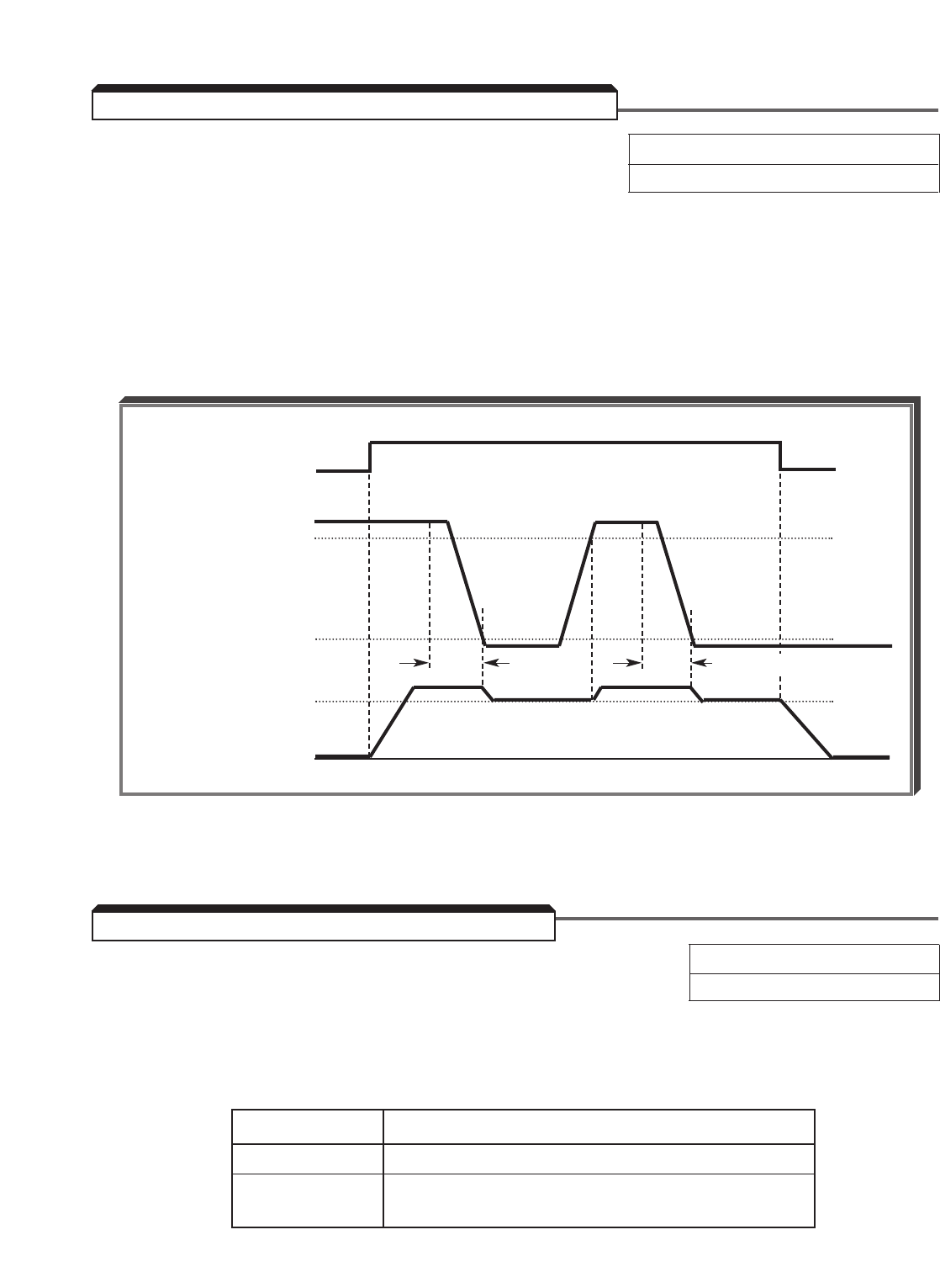
5-33
L4-05 : Frequency Reference Loss Detection Factory setting: 0(disabled)
Range: 0 or 1
The reference loss detection function is either enabled or disabled, based on the setting
of L4-05 . When enabled (data " 1 "), the reference loss detection compares the change
in reference with respect to time. If the reference decreases by 90% in more than 0.4
seconds, the drive will decelerate to the set reference; if the reference decreases by 90%
in less than 0.4 seconds, the drive will continue to operate at 80% of the output
frequency. To regain control of output frequency, either exceed the set reference (80%
of reference) or initiate a STOP command. If Auto Reference is less than Fmax ( E1-04 )
x .05, this function is not performed.
d4-01 : Frequency Reference Retention Factory setting: 0
Range: 0 or 1
This parameter can be used to retain the held frequency reference in U1-01 when
power is removed. Set d4-01 = 1 if this is desired when using Up/Down or Sample/Hold
commands as a multi-function contact input.
Setting Description
0 Not retained
1 Held reference retained in Frequency
Reference 1 ( U1-01 )
FWD RUN
COMMAND
AUTO
REFERENCE
drive
OUTPUT
FREQUENCY
80%
REF
10%
80%
FREQ.
0.4 SEC 0.4 SEC
Timing Chart
5.20 FREQUENCY REFERENCE LOSS DETECTION
5.21 FREQUENCY REFERENCE RETENTION
Note: This function applies only to frequency references at terminal 13 or 14. Frequency reference
loss detection does not function at terminal 16.
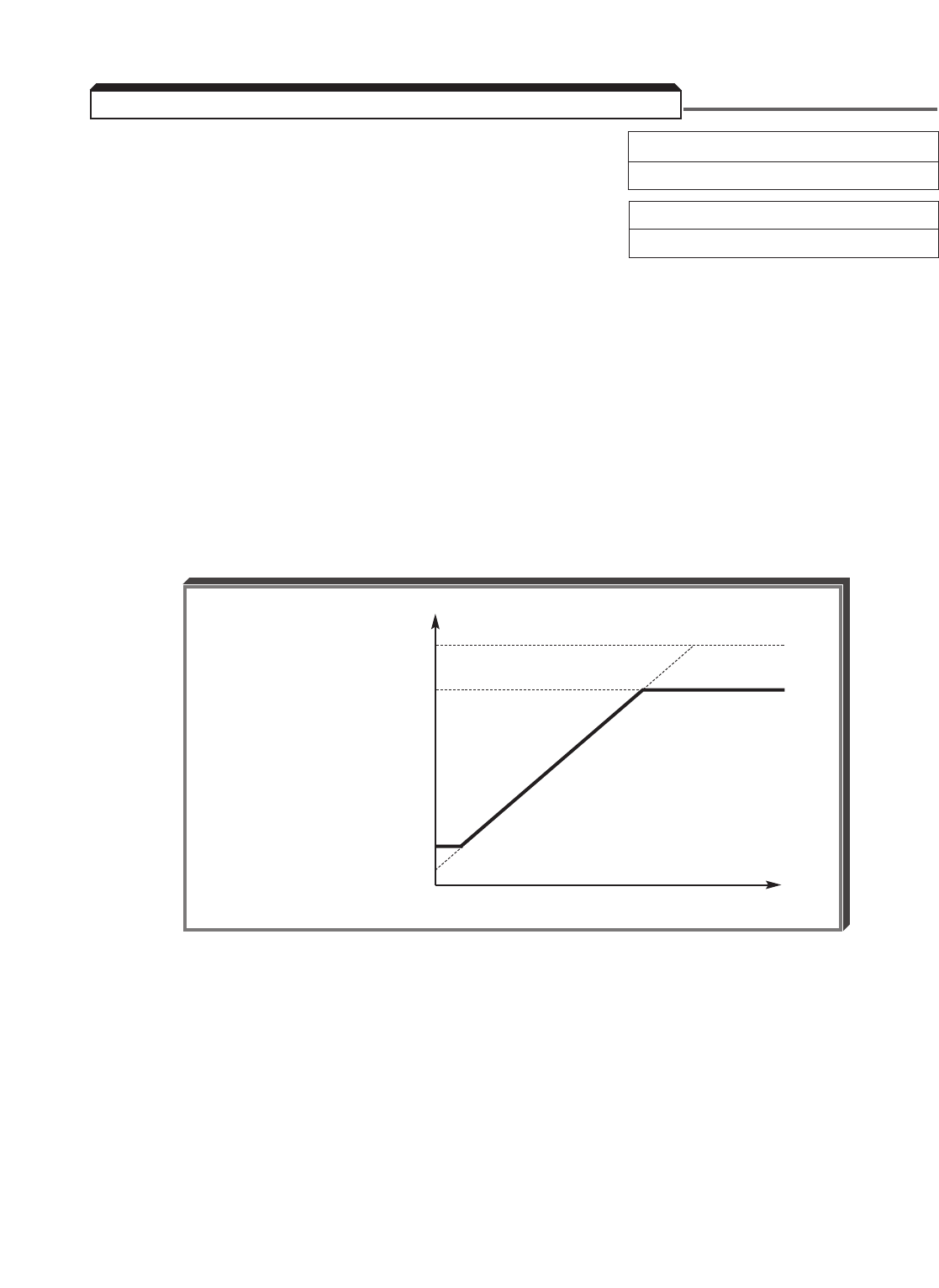
5-34
d2-01 : Frequency Reference Upper Limit Factory setting: 100.0
Range: 0.0 to 110.0 %
d2-02 : Frequency Reference Lower Limit Factory setting: 0.0
Range: 0.0 to 109.0 %
These two parameters set the range for the frequency command signal. Each is set, in
increments of 0.1%, as a percentage of maximum frequency (Fmax; E1-04 ) as
established by either the selected standard V/f pattern or custom V/f pattern.
NOTE: All references are affected by the upper and lower limit points.
EXAMPLE:
E1-04 = " 60 " Hz (100%)
d2-01 = " 80.0 " % = 48Hz – Max. speed
d2-02 = " 10.0 " % = 6Hz – Min. speed
100%
d2-01 80.0%
OUTPUT
FREQ.
( % )
d2-02 10.0%
2.5%
t
5.22 FREQUENCY REFERENCE UPPER & LOWER LIMITS
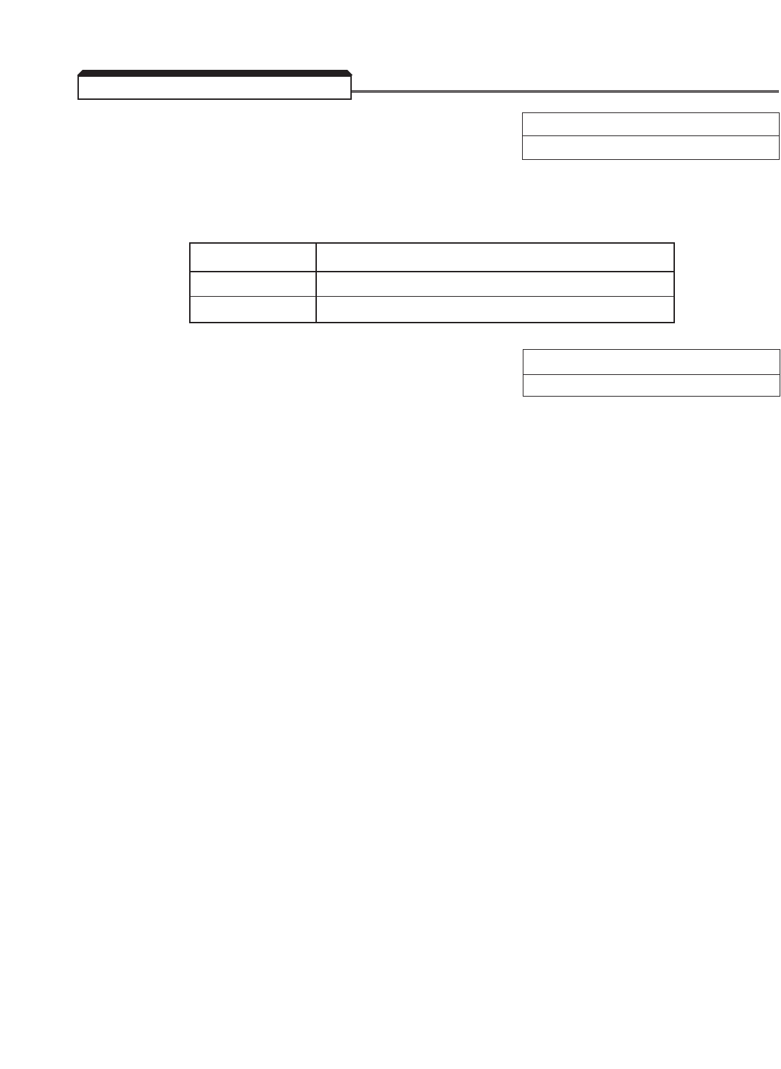
5-35
C7-01 : Hunt Prevent Selection Factory setting: 1
Range: 0 or 1
Hunting often occurs following a load change, but may also occur when the motor is in the
process of settling to a steady operating frequency. Setting C7-01 = 1 enables the
anti-hunt feature, which will reduce or suppress oscillation.
Setting Description
0 Disabled
1 Enabled
C7-02 : Hunt Prevent Gain Factory setting: 1.00
Range: 0.00 to 2.50
This parameter adjusts the hunt prevent gain. It should be decreased for a vibrating
condition under heavy loads, and increased for hunting under light loads.
NOTE
This function is only available in the Volts/Hertz Control Method, both
with and without PG feedback ( A1-02 = 0 or 1).
5.23 HUNTING PREVENTION
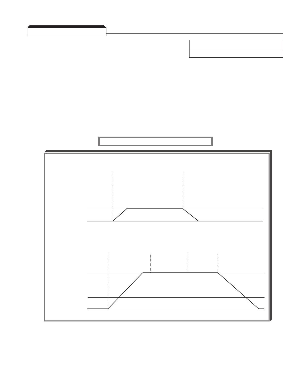
5-36
d1-09 : Jog Reference Factory setting: 6.00
Range: 0.00 to 400.00 Hz
When jog operation is selected (either by the Digital Operator JOG key, or by external Jog
and Run signals), the drive output will ramp to the output level set by this parameter.
When the Digital Operator is used, Jog can only be initiated from the stopped condition.
When the drive is running, the JOG key will have no effect on drive output.
When an external Jog signal is present, it will override the existing operation mode and the
drive will ramp to the level set by this parameter.
EXAMPLES:
OPERATION FROM DIGITAL OPERATOR
5.24 JOG REFERENCE
FREQ. CMD
d1-09 JOG
REF.
0
FREQ. CMD
d1-09 JOG
REF.
0
Press and Release
Hold JOG JOG
Press Press and Release Press
RUN Hold JOG JOG STOP
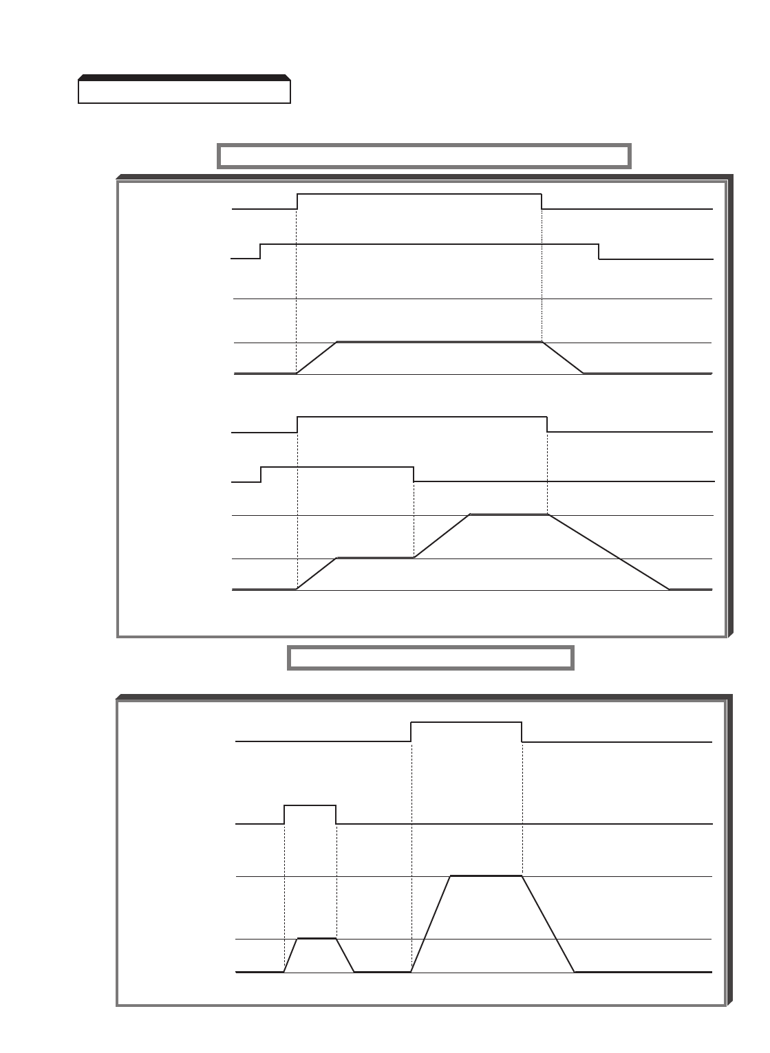
5-37
Continued
EXAMPLES:
OPERATION BY REMOTE SIGNAL INPUT (RUN & JOG1)
JOG2 — 2-WIRE CONFIGURATION
b1-02 =1 (Remote Control)
5.24 JOG REFERENCE
*Or FWD
FREQ. CMD
d1-09 JOG
REF.
0
FREQ. CMD
d1-09 JOG
REF.
0
RUN *
JOG1
RUN *
JOG1
FWD
COMMAND
(EXTERNAL)
JOG2
(FWD OR REV)
FREQ. CMD
d1-09 JOG
REF.
0
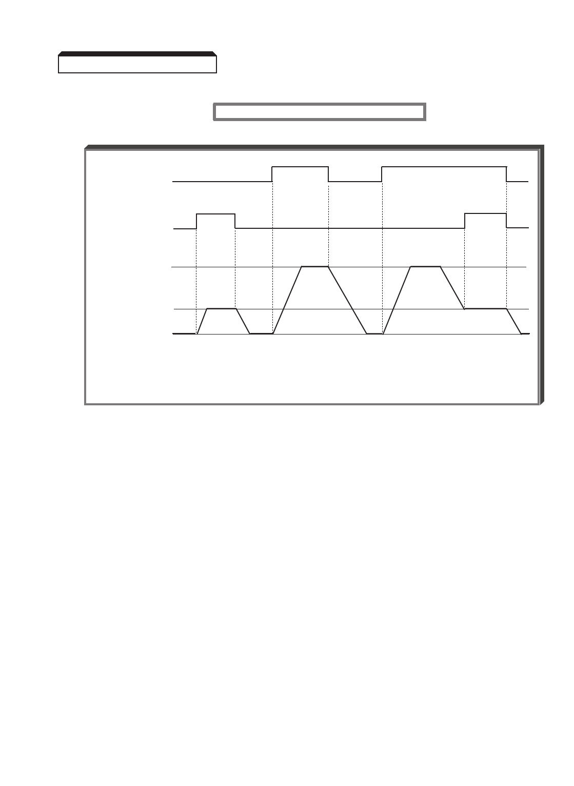
5-38
Continued
EXAMPLES:
JOG2 — 3-WIRE CONFIGURATION
b1-02 = 1 (Remote Control)
NOTES:
1. Use of external Jog input is selected by setting data " 6 ", " 12 ", or " 13 "
in one of the parameters H1-01 thru H1-06 .
•The factory configuration for 2-wire control is H1-05 = 6,
for JOG1 input at terminal 7.
•The factory configuration for 3-wire control is H1-06 = 6,
for JOG1 input at terminal 8.
•To select JOG2 - FWD, set data " 12 " into one of these parameters.
To select JOG2 - REV, set data " 13 " into one of these parameters.
JOG2 does not require an active RUN command to allow Jog operation.
2. JOG2 (FWD or REV) has priority over FWD and REV Run in the 2-wire control
configuration, and priority over RUN, STOP, and FWD/REV commands in
3-wire control configuration.
3. JOG2 - FWD and JOG2 - REV can be selected independently.
4. b1-04 = 1 (Reverse Run disabled) will override JOG2- REV.
Also see descriptions of MULTI-FUNCTION INPUT TERMINALS and RESET CODES.
5.24 JOG REFERENCE
RUN *
COMMAND
(EXTERNAL)
JOG2
(FWD OR REV)
FREQ. CMD
d1-09 JOG
REF.
0
**
*Momentary contact.
** When JOG2 command is released, a STOP command
is issued.

d1-01 : Memory 1 d1-06 : Memory 6 Factory setting:
d1-02 : Memory 2 d1-07 : Memory 7 d1-01 thru d1-08 : 0.00
d1-03 : Memory 3 d1-08 : Memory 8 d1-09 : 6.00
d1-04 : Memory 4 d1-09 : Jog Reference Range (all): 0.00 to 400.00 Hz
d1-05 : Memory 5 (See paragraph 5.24)
H3-05 : Multi-function Analog Input (Term. 16) (See paragraph 5.30)
b1-02 : Operation Method Selection
H1-03 thru H1-06 : Multi-function Input Terminals; data " 3 ", " 4 ", " 5 ", and
" 6 " [ or " C " ], respectively, for Reference Select 1, 2, 3 and Jog [ or
Multi-function Analog Input at Term. 16 ] (See paragraph 5.31).
For Local/Remote select, see paragraph 5.31, data " 1 " description.
b1-01 : Reference Selection (See below, or separate Option Instruction Sheet).
The drive allows selection of one of twelve references. Two are analog inputs, nine are
stored in memory, and one can be from an option card, either analog or digital. In most
configurations either the local reference ( d1-01 ) or the remote AUTO reference will be
utilized.
NOTE
The range and resolution of the d1-XX parameters is dependent on
the setting of o1-03 (see paragraph 5.11).
5.25 A Local/Remote Reference Selection
b1-01 : Reference Selection Data: 0= Local (Digital Operator) frequency
reference
1= Remote (terminals) frequency
reference
By programming b1-01 = 1, the external Auto reference input will be used. If b1-01 is
programmed to " 0 ", the value in d1-01 will be used as a frequency command.
IMPORTANT
d1-01 will change each time the operator enters a new frequency command
from the Digital Operator’s " U1-01 = XX.XX " prompt. Another way to
think of this is that when the drive is first powered up, the Digital
Operator displays " Frequency Reference U1-01 = XX.XX HZ ". The
value displayed is the current setting of d1-01 . If the operator changes
the display, then d1-01 will also be changed.
5.25 LOCAL/REMOTE AND REFERENCE SELECTION
5-39
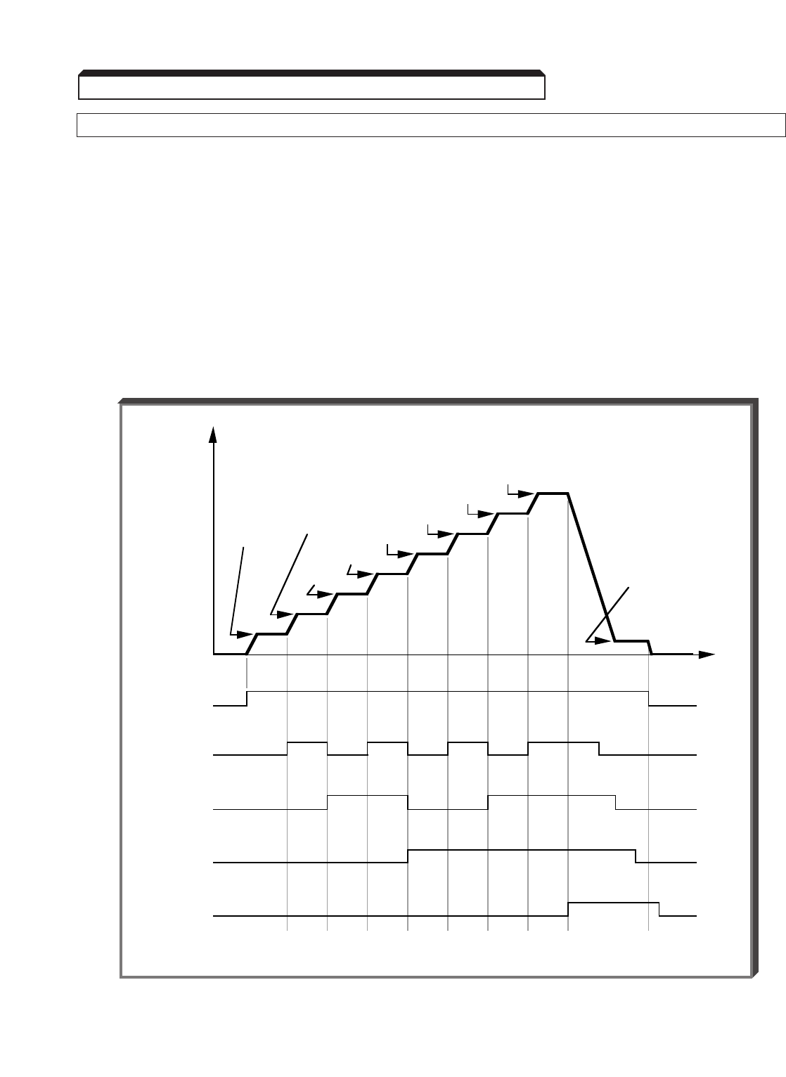
5-40
Continued
5.25 B Multiple Speed Reference Configuration [Multi-step Speed Operation]
In a multiple reference configuration, four modes may be selected.
NOTE
In the descriptions of Mode 1 thru Mode 4, the external terminal listings differ
depending on whether the drive is set for 2-wire or 3-wire control. For 3-wire
control, one of these terminals is dedicated to the FWD/REV selection; therefore,
multiple reference operation will use fewer of the memory settings and is a more
limited function.
Depending on the control wiring configuration and the multi-step mode chosen, the motor
can be operated at up to nine different speeds.
5.25 LOCAL/REMOTE AND REFERENCE SELECTION
Typical Multi-step Speed Operation
t
OUTPUT
SPEED
RUN
Auto
Speed
Ref. (ext.)
OR
Speed
Ref. 1
(d1-01 )
Manual
Speed
Ref. (ext.)
OR
Speed
Ref. 2
(d1-02 )
d1-03
d1-04
d1-05
d1-06
d1-07
d1-08
Jog
Speed
(d1-09 )
Multi-step
Select 1
(Term. 5)
Multi-step
Select 2
(Term. 6)
Multi-step
Select 3
(Term. 7)
Multi-step
Select 4
(JOG1)
(Term. 8)
CLOSED
CLOSED
CLOSED
CLOSED
CLOSED

5-41
Continued
Mode 1 (Memory Data Only) uses only memory locations d1-01 thru d1-09 .
The input commands at terminals 3 thru 8 are a
combination of 1's and 0's, which are received as
an on or off condition at each terminal. Every
combination selects a specific speed reference.
b1-01 = local/remote operation
(frequency reference);
H1-03 = frequency reference select 1 at
terminal 5;
H1-04 = frequency reference select 2 at
terminal 6;
H1-05 = frequency reference select 3 at
terminal 7;
H1-06 = JOG reference select at terminal 8;
H3-05 = manual reference at terminal 16.
2-WIRE CONTROL 3-WIRE CONTROL
b1-01 = 0 b1-01 = 0
H1-03 = 3 H1-03 = 0
H1-04 = 4 H1-04 = 3
H1-05 = 5 H1-05 = 4
H1-06 = 6 H1-06 = 6
H3-05 =* H3-05 =*
* H3-05 selects the function of the multi-function analog input. If data value " 0 " is
entered, the analog input represents manual reference. If d1-02 is to be utilized,
then H3-05 MUST NOT be set to " 0 ". Set H3-05 to " 1F " when Multi-function
Analog Input (terminal 16) is not being used.
5.25 LOCAL/REMOTE AND REFERENCE SELECTION
GPD 515
5( H1-03 )
6( H1-04 )
7( H1-05 )
8( H1-06 )
Freq. External Terminal
Ref. 8765
d1-01 0 0 0 ■
d1-02 * 0 0 1 ■
d1-03 0 1 0 ■
d1-04 0 1 1 ■
d1-09 1 X X ■
Freq. External Terminal
Ref. 8765
d1-01 0000
d1-02 * 0001
d1-03 0010
d1-04 0011
d1-05 0100
d1-06 0101
d1-07 0110
d1-08 0111
d1-09 1 X X X
1 = Closed; 0 = Open;
X = No effect; ■= FWD/REV
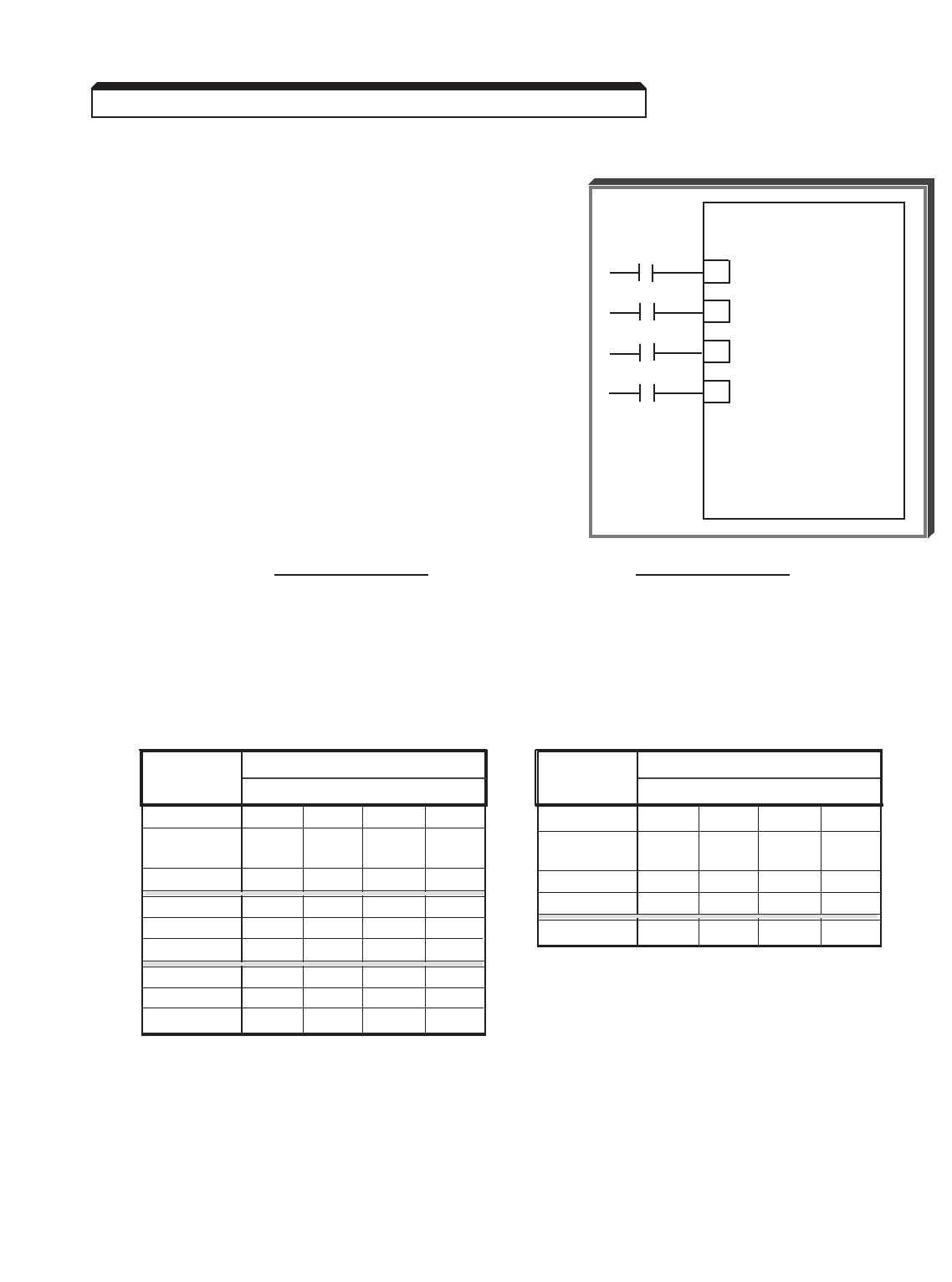
5-42
Continued
Mode 2 (Memory, Auto, Manual) uses Auto, Manual and d1-03 thru d1-09 .
The input commands at terminals 3 thru 8 are a
combination of 1's and 0's, which are received as
an on or off condition at each terminal. Every
combination selects a specific speed reference.
b1-01 = remote operation;
H1-03 = frequency reference select 1 at
terminal 5 (Auto/Manual);
H1-04 = frequency reference select 2 at
terminal 6;
H1-05 = frequency reference select 3 at
terminal 7;
H1-06 = JOG reference select at terminal 8;
H3-05 = manual reference at terminal 16.
2-WIRE CONTROL 3-WIRE CONTROL
b1-01 = 1 b1-01 = 1
H1-03 = 3 H1-03 = 0
H1-04 = 4 H1-04 = 3
H1-05 = 5 H1-05 = 4
H1-06 = 6 H1-06 = 6
H3-05 = 0 H3-05 = 0
5.25 LOCAL/REMOTE AND REFERENCE SELECTION
GPD 515/G5
5( H1-03 )
6( H1-04 )
7( H1-05 )
8( H1-06 )
Freq. External Terminal
Ref. 8765
Auto 0 0 0 ■
Manual 0 0 1 ■
(Multi-func.)
d1-03 0 1 0 ■
d1-04 0 1 1 ■
d1-09 1 X X ■
Freq. External Terminal
Ref. 8765
Auto 0000
Manual 0001
(Multi-func.)
d1-03 0010
d1-04 0011
d1-05 0100
d1-06 0101
d1-07 0110
d1-08 0111
d1-09 1 X X X
1 = Closed; 0 = Open;
X = No effect; ■= FWD/REV
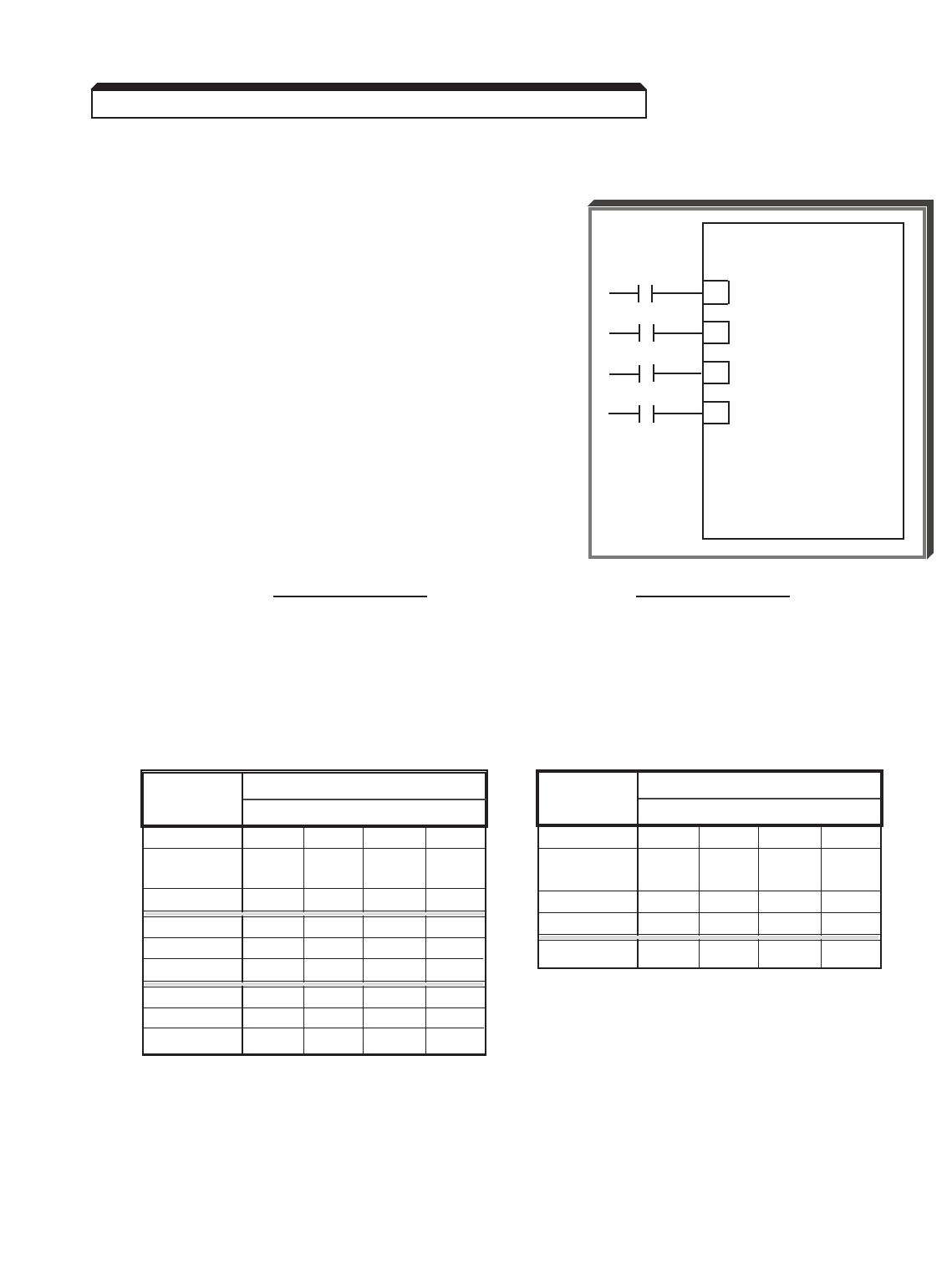
5-43
Continued
Mode 3 ( d1-01, Manual, d1-03 thru d1-09) uses d1-01, Manual and d1-03
thru d1-09 .
The input commands at terminals 3 thru 8 are a
combination of 1's and 0's, which are received as
an on or off condition at each terminal. Every
combination selects a specific speed reference.
b1-01 = local operation;
H1-03 = frequency reference select 1 at
terminal 5 (Auto/Manual);
H1-04 = frequency reference select 2 at
terminal 6;
H1-05 = frequency reference select 3 at
terminal 7;
H1-06 = JOG reference select at terminal 8;
H3-05 = manual reference at terminal 16.
2-WIRE CONTROL 3-WIRE CONTROL
b1-01 = 0 b1-01 = 0
H1-03 = 3 H1-03 = 0
H1-04 = 4 H1-04 = 3
H1-05 = 5 H1-05 = 4
H1-06 = 6 H1-06 = 6
H3-05 = 0 H3-05 = 0
5.25 LOCAL/REMOTE AND REFERENCE SELECTION
GPD 515/G5
5( H1-03 )
6( H1-04 )
7( H1-05 )
8( H1-06 )
Freq. External Terminal
Ref. 8765
d1-01 0 0 0 ■
Manual 0 0 1 ■
(Multi-func.)
d1-03 0 1 0 ■
d1-04 0 1 1 ■
d1-09 1 X X ■
Freq. External Terminal
Ref. 8765
d1-01 0000
Manual 0001
(Multi-func.)
d1-03 0010
d1-04 0011
d1-05 0100
d1-06 0101
d1-07 0110
d1-08 0111
d1-09 1 X X X
1 = Closed; 0 = Open;
X = No effect; ■= FWD/REV
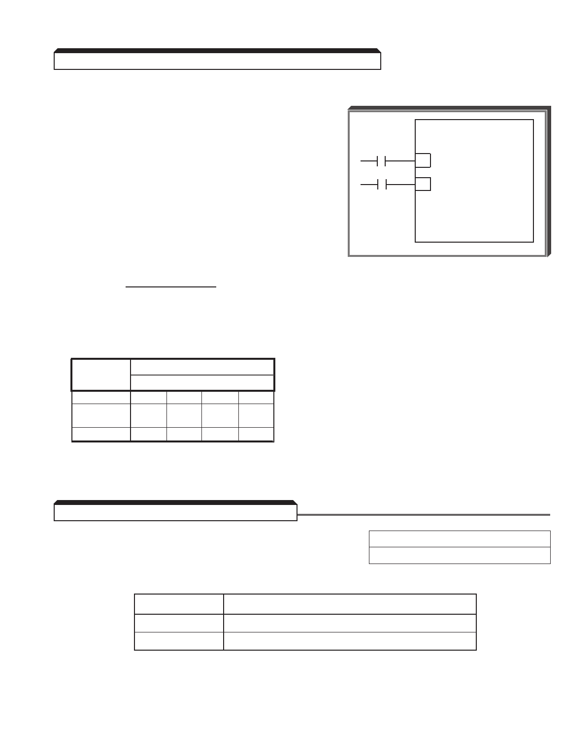
5-44
Continued
Mode 4
The final consideration for multiple frequency
command configuration modes is that any
combination of reference values may be configured
for operation. As an example, if only three speed
references are required, then the following example
will work.
b1-01 = local operation;
H1-03 = frequency select 1 at terminal 5;
H1-04 = frequency select 2 at terminal 6;
H3-05 = manual reference at terminal 16.
2-WIRE CONTROL
b1-01 = 0
H1-03 = 3
H1-04 = 5
H3-05 = 0
o2-01 : LOCAL/REMOTE Key Selection Factory setting: 1
Range: 0 or 1
This parameter determines if the LOCAL/REMOTE key is operative.
Setting Description
0 Disabled
1 Enabled
5.25 LOCAL/REMOTE AND REFERENCE SELECTION
Freq. External Terminal
Ref. 8765
d1-01 0000
Manual 0001
(Multi-func.)
d1-03 0010
GPD 515/G5
5( H1-03 )
6( H1-04 )
5.26 MISCELLANEOUS PARAMETERS

5-45
Continued
o2-02 : STOP Key Function Factory setting: 1
Range: 0 or 1
This parameter determines if the STOP key is operative during remote run.
Setting Description
0 Disabled
1 Enabled
o2-05 : Digital "Motor Operated Pot" Factory setting: 0
Range: 0 or 1
Setting this parameter to " 1 " allows the setting of the frequency reference to imitate a
motor operated pot reference.
Setting Description
0 Drive accepts frequency command after ENTER
is pressed
1 Drive accepts frequency reference immediately
o2-06 : Operator Detection Selection Factory setting: 1
Range: 0 or 1
Setting this parameter to " 0 " allows the drive to continue to run when the Digital
Operator is disconnected from the drive.
Setting Description
0 Disabled (operation continues)
1 Enabled (motor coasts to stop and fault is displayed)
o2-07 : Elapsed Timer Setting Factory setting: 0
Range: 0 or 65535
This parameter allows the user to preset a starting value for the elapsed timer. Elapsed
time is accumulated according to the setting of o2-08 .
5.26 MISCELLANEOUS PARAMETERS

5-46
Continued
o2-08 : Elapsed Timer Selection Factory setting: 0
Range: 0 or 1
This parameter determines whether the timer is active whenever power is applied to the
drive or whenever the drive is in run mode.
Setting Description
0 Timer active whenever power is applied to the drive
1 Timer active whenever drive is in “run” mode
b1-08 : Run Command Selection Factory setting: 0
During Program Range: 0 or 1
This parameter determines if the drive will accept a run command while in the “program”
mode. The drive is in the “program” mode whenever the drive light is off.
Setting Description
0 Disabled – If a run is commanded while the drive
is in the “program” mode (drive light is off), it will not run.
1 Enabled – If a run is commanded while the drive is in the
“program” mode (drive light off), it will operate normally.
L8-01 : Internal Dynamic Braking (Heatsink) Factory setting: 0
Resistor Protection Range: 0 or 1
Set this parameter to " 1 " only if a heatsink-mount resistor will be used with the drive.
Set L8-01 to " 0 " if not using Dynamic Braking, or if using a remote DB resistor.
Setting Description
0 Not provided
1 Provided
L8-02 : OH (Overheat) Protection Factory setting: See Table A3-1
Alarm Level Range: 50 to 130 °C
This parameter sets the temperature at which the heatsink thermostat will indicate an
overtemperature condition. The corresponding action the drive will take is dependent upon
the setting of L8-03 (see below).
L8-03 : Operation Selection After OH Factory setting: 3
(Overheat) Pre-alarm Range: 0 to 3
Setting Description
0 Ramp to Stop (using C1-02 )
1 Coast to Stop (base block)
2 Fast-stop (using C1-09 )
3 Alarm Only (operation continues)
5.27 MISCELLANEOUS PROTECTIVE FUNCTIONS
5.26 MISCELLANEOUS PARAMETERS

5-47
Continued
L8-10 : Output Ground Fault Factory setting: 1
Detection Selection Range: 0 or 1
L8-17 : IGBT Protection Selection Factory setting: 1
at Low Frequency Range: 0 or 3
Parameter L8-17 assists in protecting the output transistors (IGBTs) from overheating
when the output current is high and the output frequency is low.
L8-19 : OL2 Selection At Low Speed Factory setting: 0
Range: 0 or 1
This parameter allows the selection of normal or quick Drive Overload (OL2) protection
below 6 Hz. It is recommended that this parameter be enabled at all times. In some
instances quick drive overload protection (L8-19=1) may not be desired, such as when
operating in flux vector at zero speed. If L8-19 is set to 0 (disabled) L8-17 must be set
to 1, 2, or 3.
Caution: When disabling OL2 protection at low speeds (L8-19=0), set the carrier
frequency (C6-01 & C6-02) equal to or less than 2 kHz.
5.27 MISCELLANEOUS PROTECTIVE FUNCTIONS
Setting Description
0 Disabled – The drive will not detect a ground fault condition
1 Enabled – The drive will detect a ground fault condition
Setting Description
0 Drive relies on L8-19 protection.
1 Lower fc – When output current is greater than 100%, and output
frequency is less than or equal to 10 Hz, the carrier frequency is
automatically decreased to between 8 kHz and 2 kHz depending on
the drive size. The carrier will automatically return to the normal
value after the load is reduced.
2 Short term OL2 – OL2 occurs in 2 seconds when output frequency is
6 Hz or less and in current limit (approx. 175% of drive rated current).
3 I-Limit=150% – Current is limited to 150% of drive rated current.
Setting Description
0 Disabled – Drive Overload (OL2) protection is the same at low
speed as it is at high speed.
1 Enabled – Drive Overload (OL2) protection responds more quickly
when output frequency is 6 Hz or less.

5-48
The drive can perform serial communication by using a programmable controller (PLC) and
MODBUSprotocol. MODBUS is composed of one master PLC and 1 to 31 (maximum)
slave units (GPD 515/G5). In serial communication between the master and slaves, the
master always starts transmission and the slaves respond to it.
The master communicates with one slave at a time. Address numbers are assigned to each
slave in advance, and the master specifies an address to communicate with. The slave
which receives the command from the master executes the function, and then responds to
the master.
A. Communication Specifications
• Interface : RS-232C (standard); RS-485, RS-422 (option -
requires communication interface card CM085)
• Synchronization : Asynchronous
• Transmission parameters : Baud rate — Selectable from 1200, 2400,
4800, 9600 BPS ( H5-02 )
Data length — Fixed to 8 bits
Parity — Parity / no parity, even / odd
selectable ( H5-03 )
Stop bit — Fixed to 1 bit
• Protocol : MODBUS
• Maximum number to units
to be connected : 31 units (when RS-485 is used)
B. Sending/Receiving Data
Data that can be sent and received are run/stop commands, frequency reference, fault
reset, drive status, and setting and reading of parameters.
b1-01 : Reference Selection Factory setting (each): 1
b1-02 : Operation Method Selection Range (each): 0 to 4
Select the run command and frequency reference input method in b1-01 and
b1-02 . To provide a run command and frequency reference by communication,
set this data to " 2 ". Monitoring of run status, parameter setting/reading, fault
reset and multi-function input command from the PLC are enabled. The multi-function
input command is OR’ed with the command input from control circuit terminals 3-8.
EXAMPLE: b1-01 and b1-02 settings are " 3 ".
Open : Run by frequency reference from control circuit terminal 13 or 14
and run command from control circuit terminal 1 or 2.
Closed : Run by frequency reference and run command from serial
communication.
5.28 MODBUS CONTROL

5-49
Continued
H5-01 : Serial Communication Station Address Factory setting: 1F
Range: 1 to 1F (Hex)
(= 1 to 31 decimal)
Each slave on the same transmission line must be given a unique address.
H5-02 : Serial Communication Baud Rate Factory setting: 3
Range: 0 to 4
Selects the baud rate, as indicated by the following table:
Setting Baud Rate (BPS)
0 1200
1 2400
2 4800
3 9600
4 19.2 K
H5-03 : Serial Communication Parity Selection Factory setting: 0
Range: 0 to 2
Selects the parity, as indicated by the following table:
Setting Parity
0 None
1 Even
2 Odd
NOTE: To change the values set in H5-01 thru H5-03 and enable
the new settings, it is necessary to turn OFF power to the Drive, then
turn it ON again.
H5-05 : Serial Communication Error ( CE ) Factory setting: 1
Detection Range: 0 or 1
This parameter determines whether or not the drive will detect a CE condition. The
corresponding action the drive will take is dependent upon the setting of H5-04 .
Setting Description
0 Disabled
1 Enabled
5.28 MODBUS CONTROL

5-50
Continued
H5-04 : Stopping Method After Serial Factory setting: 3
Communication Error ( CE )Range: 0 to 3
Setting Description
0 Ramp to Stop (using C1-02 )
1 Coast to Stop (base block)
2 Fast-stop (using C1-09 )
3 Alarm Only (operation continues)
L2-01 : Momentary Power Loss Ride-thru 0= Disabled (Factory setting)
Protection 1= Enabled – 2 sec. power loss
ride-thru
2= Enabled – indefinite power loss
ride-thru, provided control
power is maintained
The setting of this parameter either enables or disables the ride-thru feature of the
drive. If disabled, the unit will stop immediately whenever a power loss occurs. If enabled,
the drive will continue to operate during a momentary power loss of up to 80%, but if the
loss exceeds the identified time period, the drive will stop.
L2-02 : Power Loss Ride-Thru Factory setting: See Table A3-1
Deactivation Time Range: 0.0 to 2.0 seconds
If the loss exceeds the length of time identified by L2-02 , the drive will stop. The
factory setting of this parameter, in 0.1 second increments, is related to the drive’s
capacity rating (see Appendix 3).
Note that the RUN command must be maintained throughout the ride-thru period. If
L2-01 is set to " 2 ", a " UV " alarm is displayed during power loss, and no fault signal is
output at any multi-function output that is programmed for a fault.
5.29 MOMENTARY POWER LOSS RIDE-THRU
5.28 MODBUS CONTROL

5-51
Continued
L2-03 : Momentary Power Loss Minimum Factory setting: See Table A3-1
Base Block Time Range: 0.0 to 5.0 seconds
When a power loss is detected, the output is baseblocked for the amount of time set in
L2-03 . During this time, residual voltage in the motor is allowed to diminish. This guards
against faults resulting from the drive output turning on while the motor still has residual
voltage.
If the minimum baseblock time ( L2-03 ) is greater than the power loss ride-thru time
( L2-02 ), drive operation resumes after the minimum baseblock time. If the minimum
baseblock time is less than the power loss ride-thru time, drive operation resumes after
recovery of input power.
L2-04 : Momentary Power Loss Recovery Factory setting: 0.3
Ramp Time Range: 0.0 to 2.0 seconds
After recovery from a momentary power loss, the drive performs a speed search. The ramp
recovery time ( L2-04 ) is the time is takes the output voltage to return to the preset V/f
pattern.
L2-05 : Undervoltage Detection Level Factory setting: 190 (230V ratings)
380 (460V ratings)
Range: 150 to 210 VDC (230V ratings)
300 to 420 VDC (460V ratings)
The setting of this parameter determines the DC bus undervoltage trip point. When the
voltage level on the DC bus drops below this value, a UV (undervoltage) fault will occur.
5.29 MOMENTARY POWER LOSS RIDE-THRU
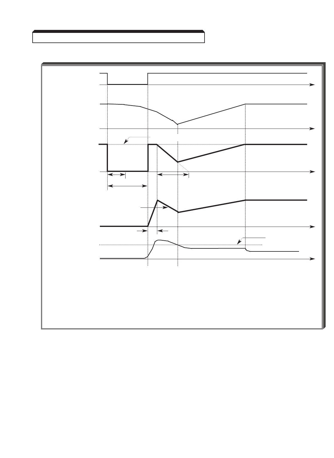
5-52
Continued
5.29 MOMENTARY POWER LOSS RIDE-THRU
UNDERVOLTAGE
DETECTION
MOTOR
RPM
OUTPUT
FREQUENCY
OUTPUT
VOLTAGE
OUTPUT
CURRENT
L2-03
L2-02
L2-04
b3-03
b3-02
(150%)
b3-04
L2-03 : Minimum Baseblock Time
L2-02 : Power Loss Ride-thru Time
L2-04 : Voltage Recovery Time
b3-02 : Speed Search Current
b3-03 : Speed Search Decel Time
b3-04 : V/f Reduction During Speed Search
Momentary Power Loss Ride-thru, With Speed Search
SET FREQUENCY
t
t
t
t
t
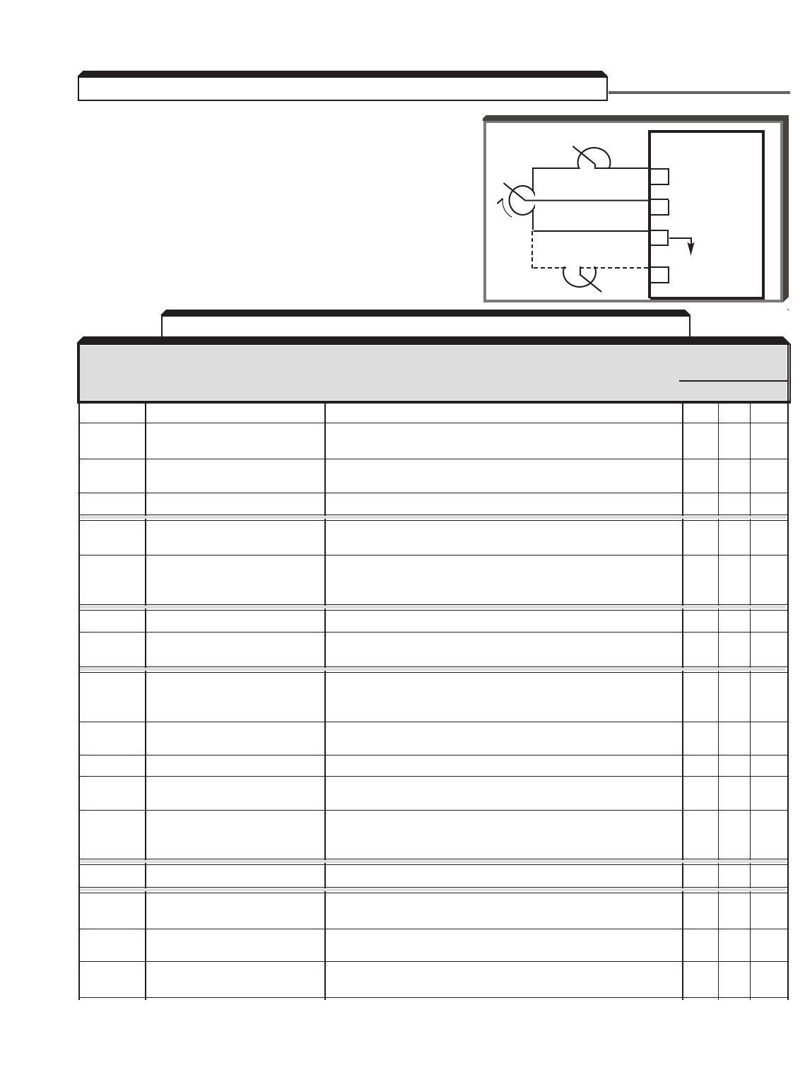
5-53
H3-05 : Multi-function Analog Input 1
Selection (Term. 16)
H3-09 : Multi-function Analog Input 2
Selection (Term. 14)
Programming H3-05 or H3-09 per the chart
below configures terminal 16 or 14 for analog
control. The figures following the chart show how
each setting configures the analog input.
AVAILABILITY
DATA FUNCTION REMARKS (SEE NO
0, 1 2 3
0Manual reference External reference input X X X
1Frequency reference gain Total gain = Internal gain ( H3-02 ) x FGAIN X X X
(FGAIN)
2Frequency reference bias Total bias = Internal bias ( H3-03 ) + FBIAS; X X
(FBIAS) FBIAS is based on Fmax ( E1-04 )
4VBIAS Voltage boost after V/f conversion X — —
5Accel/decel time Accel/decel time varied by analog input X X X
coefficient
6DC injection braking DC injection braking current varied by analog input X X —
current adjust (10V/drive rated current); internal setting ( b2-02 )
ineffective
7Overtorque detection level Internal overtorque detection level ( C6-02 ) disabled X X X
8Stall prevention level Stall prevention level ( L3-06 = 100% level) varied by X — —
during running analog input
9Frequency reference Frequency reference lower limit is set by analog input. X X X
lower limit Either d2-02 setting value or analog input, whichever
is greater, becomes effective.
ASetting prohibited Analog input sets a fourth prohibited frequency, in X X X
frequency 4 addition to those set by d3-01 thru d3-03
BPID feedback Provides feedback signal for use with PID control ( b5-01 ) X X X
CPID Set Point Provides a setpoint signal for use with PID control. X X X
(Frequency reference no longer acts as PID setpoint.)
DFrequency Reference Additional frequency reference bias input. Total bias = X X
Bias 2 (FBIAS2) Internal bias (H3-03) + FBIAS + FBIAS2. FBIAS2 is based
on Fmax (E1-04).
E - F Not Used — — —
10 FWD torque limit 10V = 100% of motor rated torque (forward direction) — X X
Quadrant 1 (See Note 3)
11 REV torque limit 10V = 100% of motor rated torque (reverse direction) — X X
Quadrant 3 (See Note 3)
12 Regenerative torque limit 10V = 100% of motor rated torque (forward & reverse — X X
(TLG) regeneration) Quadrants 2 & 4 (See Note 3)
5.30 MULTI-FUNCTION ANALOG INPUTS (Term. 14 & 16)
1R
2R
GPD 515/G5
15 +15V
0-10V
(20KΩ)
–15V
C
See Note 1
•
AVAILABILITY
DATA FUNCTION DESCRIPTION (See Note 2)
0,1 2 3
17
16
33
TABLE 5-1; H3-05 and H3-09 Data Settings
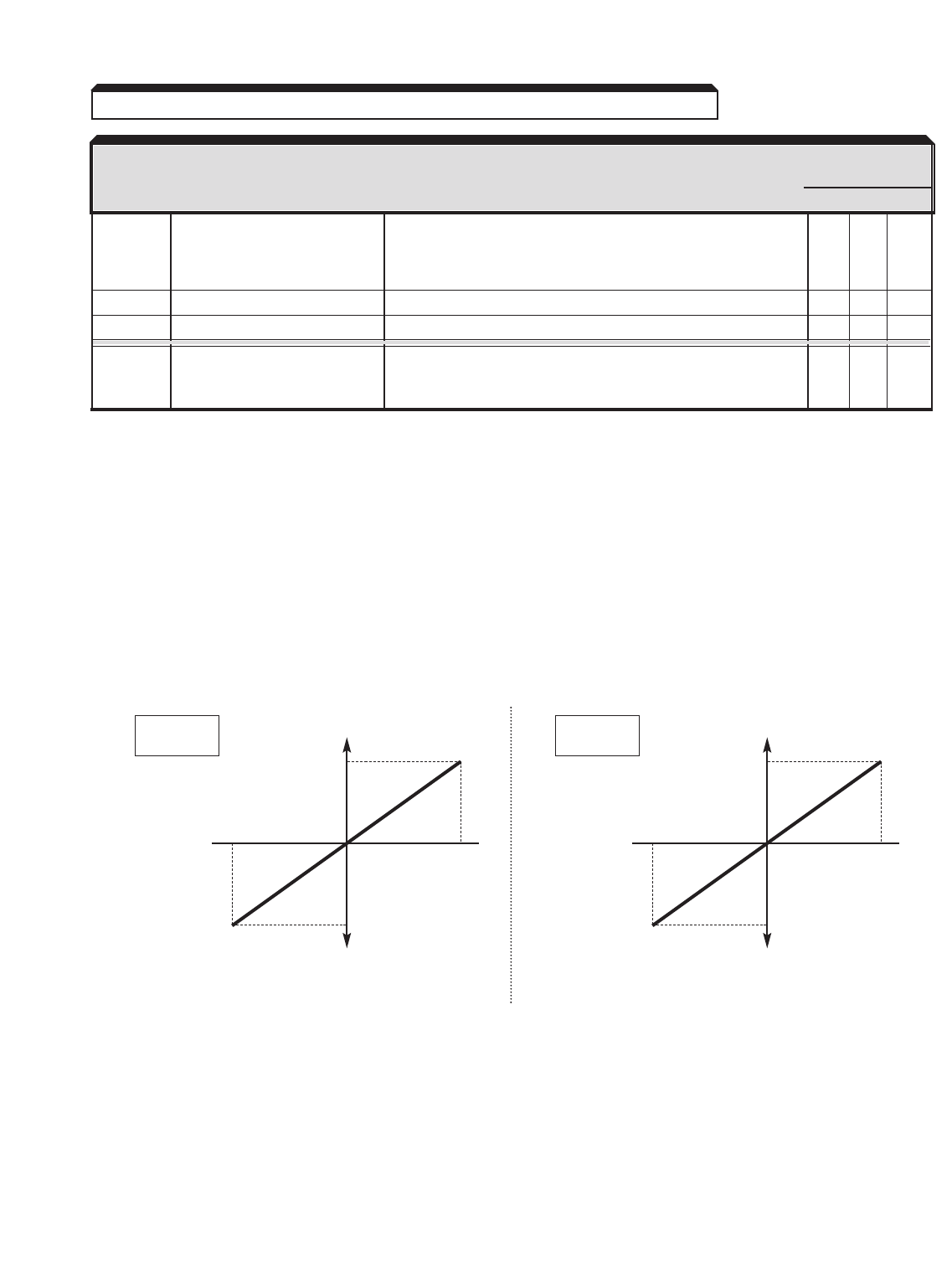
5-54
Continued
AVAILABILITY
DATA FUNCTION REMARKS (SEE NO
0, 1 2 3
13 Torque reference (in 10V = 100% of motor rated torque (forward & reverse) — — X
Torque Control); Quadrants 1, 2, 3, & 4 (See Note 3)
Torque limit (in Speed
Control)
14 Torque compensation See paragraph 5.43. — — X
15 Torque limit — X X
1F “Not Used” When programmed in H3-05, terminal 16 input has no effect. X X X
When programmed in H3-09, terminal 14 input is added to
the terminal 13 frequency reference.
NOTES:
1. For a bidirectional pot input instead of 0-10V, set H3-04 = 1 (for terminal 16) or
H3-08= 1 (for terminal 14), and connect the low (negative) side of the pot to
terminal 33. If using a –10 to +10V input, connect the positive side to terminal 16
or 14, and the negative side to terminal 17.
2. Column headings refer to set value of A1-02, Control Method; 0 = V/f,
1 = V/f w/PG, 2 = Open Loop Vector, 3 = Flux Vector. "X" in column indicates
Available, "—" indicates Not Available.
3. Quadrant 1 is forward motor rotation, torque in forward direction;
Quadrant 2 is forward motor rotation, torque in reverse direction (regeneration);
Quadrant 3 is reverse motor rotation, torque in reverse direction;
Quadrant 4 is reverse motor rotation, torque in forward direction (regeneration).
5.30 MULTI-FUNCTION ANALOG INPUTS (Term. 14 & 16)
H3-05 = 0
H3-09 = 0
100%
FREQUENCY
REF.
–10V 0%
0V 10V
–100%
MULTI-FUNCTION ANALOG INPUT
H3-05 = 1
H3-09 = 1
100%
FGAIN
–10V 0%
0V 10V
–100%
MULTI-FUNCTION ANALOG INPUT
AVAILABILITY
DATA FUNCTION DESCRIPTION (See Note 2)
0,1 2 3
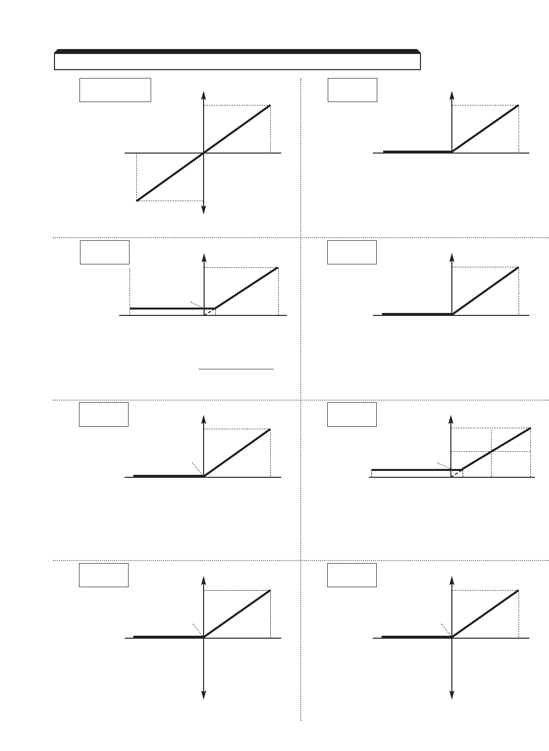
5-55
Continued
5.30 MULTI-FUNCTION ANALOG INPUTS (Term. 14 & 16)
H3-05 = 2 or C
H3-09 = 2 or C
100%
FBIAS &
FBIAS2
–10V 0%
0V 10V
–100%
MULTI-FUNCTION ANALOG INPUT
H3-05 = 4
H3-09 = 4
100V
VBIAS
–10V 0V 10V
MULTI-FUNCTION ANALOG INPUT
H3-05 = 5
H3-09 = 5
10
REDUCTION
COEFFI-
CIENT 1
–10V 0V 1V 10V
MULTI-FUNCTION ANALOG INPUT
Actual accel or decel time = Accel or decel time
Coefficient
H3-05 = 6
H3-09 = 6
100%
DC INJECTION
BRAKING
CURRENT
–10V 0%
0V 10V
MULTI-FUNCTION ANALOG INPUT
H3-05 = 7
H3-09 = 7
200%
OVERTORQUE
DETECTION
LEVEL 0%
–10V 0V 10V
MULTI-FUNCTION ANALOG INPUT
H3-05 = 8
H3-09 = 8
STALL 100%
PREVENTION
LEVEL DURING 50%
RUNNING 30%
(PERCENT
OF L3-06 –10V 0V 3V 5V
10V
SETTING)
MULTI-FUNCTION ANALOG INPUT
H3-05 = 9
H3-09 = 9 Max. Output Freq.
( E1-04 )
FREQUENCY
REFERENCE
LOWER LIMIT 0 Hz
–10V 0V 10V
MULTI-FUNCTION ANALOG INPUT
H3-05 = A
H3-09 = A Max. Output Freq.
( E1-04 )
SETTING
PROHIBITED
FREQUENCY 4 0 Hz
–10V 0V 10V
MULTI-FUNCTION ANALOG INPUT
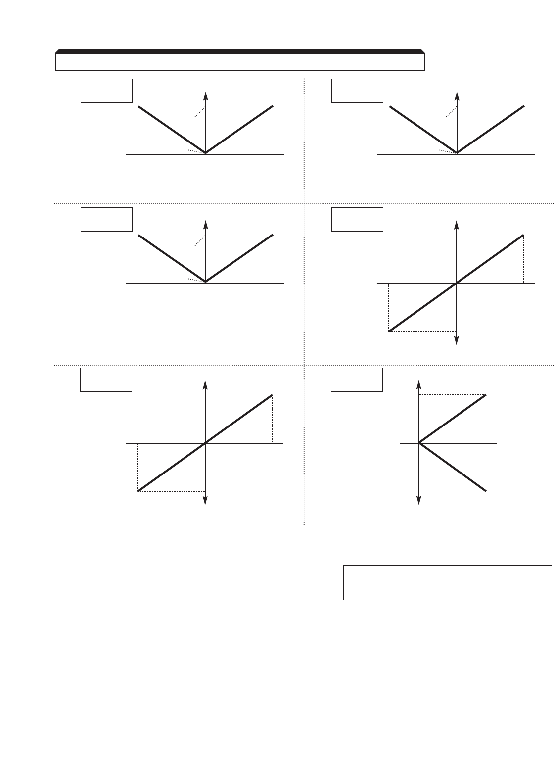
5-56
Continued
H3-12 : Analog Input Filter Time Factory setting: 0.00
Constant Range: 0.00 to 2.00 seconds
This parameter adjusts the time it takes to process the analog input signal. The signal
that comes into the drive on terminals 13, 14 and 16 goes through an analog to digital
converter, and then to the control circuit. This filter time constant determines the time
between converting and processing.
For cases when there is noise on the analog signal, this time constant may be increased.
Extending the processing time can help prevent erratic performance of the drive.
5.30 MULTI-FUNCTION ANALOG INPUTS (Term. 14 & 16)
H3-05 = 10
H3-09 = 10
FWD 100%
TORQUE
LIMIT
0%
–10V 0V 10V
MULTI-FUNCTION ANALOG INPUT
H3-05 = 11
H3-09 = 11
REV 100%
TORQUE
LIMIT
0%
–10V 0V 10V
MULTI-FUNCTION ANALOG INPUT
H3-05 = 12
H3-09 = 12
REGEN 100%
TORQUE
LIMIT
0%
–10V 0V 10V
MULTI-FUNCTION ANALOG INPUT
H3-05 = 13
H3-09 = 13
100%
TORQUE
REFERENCE
–10V 0%
0V 10V
–100%
MULTI-FUNCTION ANALOG INPUT
H3-05 = 15
H3-09 = 15
100%
TORQUE
LIMIT
0%
0V 10V
–100%
MULTI-FUNCTION ANALOG INPUT
H3-05 = 14
H3-09 = 14
100%
TORQUE
COMPEN-
SATION
–10V 0%
0V 10V
–100%
MULTI-FUNCTION ANALOG INPUT
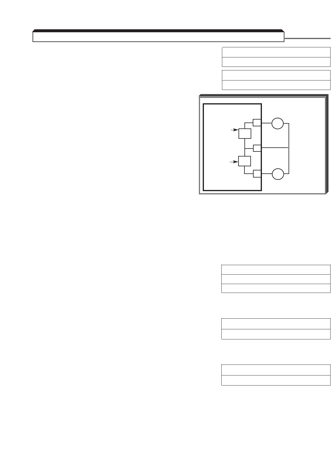
5-57
H4-01 : Multi-function Analog Monitor Factory setting: 2
Output 1 Selection Range: 1 to 38
H4-04 : Multi-function Analog Monitor Factory setting: 3
Output 2 Selection Range: 1 to 38
The analog monitor outputs provides a 0 to ±1 0
Vdc signal between terminals 21 & 22 (or 23 &
22), proportional to the value of the U1-XX
parameter identified by the setting of H4-01 (or
H4-04 ). (See Appendix 1 for listing of U1-XX
parameters.)
Factory setting, monitor output 1 =
H4-01=2 (U1-02) : Output Frequency
(10V = Fmax)
Factory setting, monitor output 2 =
H4-04=3 (U1-03) : Drive output
current
(5V = continuous rated current)
NOTE
This output is suitable for metering, but SHOULD NOT be used for external
control circuits. To produce an output signal for use by external control
circuits, an Analog Monitor option card (AO-08 or AO-12) must be installed
in the drive.
H4-02 : Multi-function Analog Monitor 1 Gain Factory Setting : 1.00
H4-05 : Multi-function Analog Monitor 2 Gain Factory Setting : 0.50
Range (each): 0.00 to 2.50
The settings of these parameters, in increments of 0.01, are used to calibrate the output at
terminals 21 & 22 or 23 & 22.
H4-03 : Multi-function Analog Monitor 1 Bias Factory Setting (each): 0.0 %
H4-06 : Multi-function Analog Monitor 2 Bias Range (each): –10.0 to +10.0 %
The settings of these parameters, in increments of 0.1 %, are used to calibrate the output
at terminals 21 & 22 or 23 & 22.
H4-07 : Multi-function Analog Monitor Signal Factory Setting: 0
Level Selection Range: 0 or 1
This function allows the analog monitor output(s) to have a unipolar output signal (0-10V),
or a bipolar output signal (0 to ±10V).
0 : Analog output is + voltage only (absolute value).
1 : Analog output is ± voltage according to sign (direction).
5.31 MULTI-FUNCTION ANALOG MONITOR OUTPUT (Term. 21-23)
GPD 515/G5
Analog 21
Monitor 1
(±10 VDC
output)
22
Analog
Monitor 2
(±10 VDC 23
output)
MULTI-
FUNCTION
MONITOR
OUTPUT 1
+ –
●
●
FREQUENCY/ CURRENT
METER
(1MA FULL SCALE)
MULTI-
FUNCTION
MONITOR
OUTPUT 2
+ –
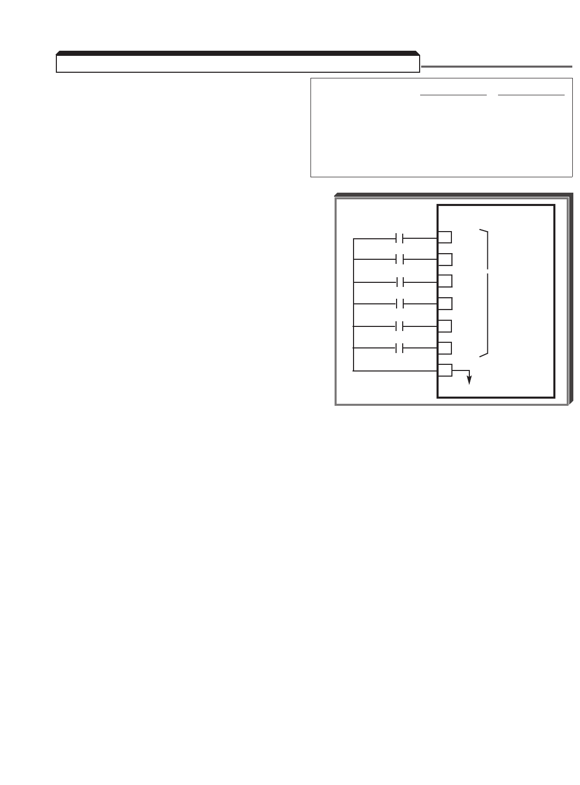
5-58
H1-01 : Terminal 3 Function Factory settings:
2-Wire control 3-Wire control
H1-02 : Terminal 4 Function H1-01 24 24
H1-03 : Terminal 5 Function H1-02 14 14
H1-04 : Terminal 6 Function H1-03 3 0
H1-05 : Terminal 7 Function H1-04 4 3
H1-06 : Terminal 8 Function H1-05 6 4
H1-06 8 6
These six parameters select the input signal
functions for terminals 3 thru 8, and can be
independently set.
Parameter settings are checked whenever
power is applied to the drive, or upon
exiting Program mode. A parameter set
value failure ( oPE3 ) will occur if any of
the following conditions are detected among
these six parameters:
(1) Two or more of the parameters contain the same value (except for External
Fault, data " 2X ").
(2) Two or three Speed Search functions (data " 61 ", " 62 ", or " 64 ") have
been selected.
(3) Any Speed Search function (data " 61 ", " 62 ", or " 64 ") has been entered
into any parameter other than H1-06 .
(4) Both the Sample/Hold (data " A ") and Up/Down (data " 10 " & " 11 ")
functions have been selected.
(5) The Up function (data " 10 ") and the Down function (data " 11 ") have
not both been selected.
(6) The Trim Control Increase (Data "1C") AND Trim Control Decrease (Data "1D")
Functions have not both been selected.
Table 5-2 lists the possible data setting values for these parameters, with the function and
a brief description for each one.
For a few of the data settings, a more detailed description is given on the following pages;
for others, the description is given in other PROGRAMMABLE FEATURES paragraphs.
EXTERNAL
CONTACTS
GPD 515/G5
3H1-01
4H1-02 MULTI-
> FUNCTION
5H1-03 INPUT
6H1-04
7H1-05
8H1-06
11
0V
•
•
•
•
•
5.32 MULTI-FUNCTION INPUT TERMINALS (Term. 3-8)

5-59
Continued
DESCRIPTION
DATA FUNCTION Signal Levels: 0= state; 1= pulse
0Forward/Reverse selection Redefines terminals to: X X X X
for 3-wire control 1 = Run; 2 = Stop; corresponding
terminal (3-8) = FWD/REV select
1Local/Remote selection Open = Operates according to setting of X X X X
b1-01and b1-02
Closed = Operates from keys of the Digital
Operator
See Data description following this table
2Option / drive reference Open = Operates from Digital Operator and or X X X X
selection external terminals
Closed = Operates from installed option
3Multi-step reference X X X X
select 1
4Multi-step reference See paragraph 5.25 B XXXX
select 2
5Multi-step reference X X X X
select 3
6Jog frequency reference Closed = Jog selected X X X X
See paragraph 5.24 & 5.25 B
7Accel/decel time Open = Accel/decel by C1-01/ C1-02 XXXX
selection 1 Closed = Accel/decel by C1-03/ C1-04
See paragraph 5.2 B
8External base block Closed = Shuts off drive output X X X X
(N.O. contact input) (speed reference is held)
See Data description following this table
9External base block Open = Shuts off drive output X X X X
(N.C. contact input) (speed reference is held)
See Data description following this table
AAccel/decel ramp hold Closed = Hold X X X X
(speed hold command) See paragraph 5.2 B
BExternal overheat alarm Closed = " oH2 " blinks on the Digital Operator, X X X X
signal and operation continues (minor fault)
CMulti-function analog input Open = Analog inputs (terms. 14 & 16) are X X X X
selection disabled
Closed = Analog inputs (terms. 14 & 16) are
enabled
DSpeed control disable Open = Speed control enabled — X — X
Closed = Speed control disabled
EASR integral reset (IRST) Closed = Integral reset —X —X
See paragraph 5.7 C
FTerminal Not Used Drive does not react to input XXXX
AVAILABILITY
DATA FUNCTION DESCRIPTION (See Note 1)
0 1 2 3
Table 5-2. H1-01 thru H1-06 Data Settings
5.32 MULTI-FUNCTION INPUT TERMINALS (Term. 3-8)

5-60
Continued
5.32 MULTI-FUNCTION INPUT TERMINALS (Term. 3-8)
DESCRIPTION
DATA FUNCTION Signal Levels: 0= state; 1= pulse
10 Up function
See Data description following this table
XXXX
11 Down function XXXX
12 Forward jog (Jog2) See paragraph 5.24 XXXX
13 Reverse jog (Jog2) X X X X
14 Fault Reset Resets a fault, only if RUN command is X X X X
not present
15 Fast-Stop (N.O.) Open = No Effect X X X X
Closed = Ramp to stop by Fast-Stop Decel
Time ( C1-09)
16 Motor 2 Select Switches between two different sets of motor X X X X
parameters
Open = Use parameter A1-02,
E1 Parameter & E2 Parameters.
Closed = Use parameter E3-01, E4
Parameters & E5 Parameters.
17 Fast Stop (N.C.) Closed = No Effect X X X X
Open = Ramp to stop by Fast-Stop Decel Time
(C1-09)
18 Timer function
See Data description following this table
XXXX
(ON or OFF delay)
19 PID control disable Closed = PID control is disabled – setpoint X X X X
becomes frequency reference
1A Accel/decel time Open = Accel/decel by C1-01thru C1-04 XXXX
selection 2 Closed = Accel/decel by C1-05thru C1-08
See paragraph 5.2 B
1B Program lockout Open = Programming from Digital Operator X X X X
is disabled
Closed = Programming from Digital Operator
is enabled
1C Trim control increase Closed = Increase analog frequency reference X X X X
by d4-02 value
See Data description following this table
1D Trim control decrease Closed = Decrease analog frequency reference X X X X
by d4-02 value
See Data description following this table
1E Analog reference sample/ Open = Hold frequency reference X X X X
hold Closed = Sample frequency reference
See Data description following this
table
1F Frequency reference Open = Freq. ref. from term. 13 X X X X
selection Closed = Freq. ref. from term. 14
AVAILABILITY
DATA FUNCTION DESCRIPTION (See Note 1)
0 1 2 3
Table 5-2. H1-01 thru H1-06 Data Settings - Continued

5-61
Continued
NOTES:
* All contact closures must be maintained, except for speed search (Data " 61 ",
" 62", & ' 64 "), which may be momentary (see paragraph 5.32 D).
1. Column headings refer to set value of A1-02, Control Method; 0 = V/f,
1 = V/f w/PG, 2 = Open loop vector, 3 = Flux vector.
DESCRIPTION
DATA FUNCTION Signal Levels: 0 = state; 1 = pulse
20 External fault Second digit of setting is a hexadecimal value X X X X
thru which defines what type of external contact is
2F used and how the drive will react when the
signal input is active. See paragraph 5.17
30 PID integral reset Closed = Set calculated integral time X X X X
value to 0. See paragraph 5.36F
31 PID Integral Hold Closed = Hold integrator at its present level X X X X
(PID Control). See paragraph 5.36F
60 DC injection braking Closed = DC injection braking active X X X X
command See paragraph 5.10 D
61 Speed Search 1 Closed * = Speed Search operation from X — X —
maximum frequency
See Data description following this table
62 Speed Search 2 Closed * = Speed Search operation from set X — X —
frequency
See Data description following this table
63 Energy saving operation Closed = Energy saving X X — —
See paragraph 5.16
64 Speed Search 3 Closed * = Speed Search operation from X — X —
output frequency
See Data description following this table
65 Kinetic energy braking Closed = KEB ride-thru is disabled X X X X
ride-thru NC
66 Kinetic energy braking Closed = KEB ride-thru is enabled X X X X
ride-thru NO
71 Speed / torque control Open = Speed control operation — — — X
selection Closed = Torque control operation
See paragraph 5.43
72 Zero-Servo command Open = Zero-Servo OFF — — — X
Closed = Zero-Servo ON
See paragraph 5.49 A
77 ASR gain selection Closed = ASR proportional gain is set — — — X
according to C5-03
Table 5-2. H1-01 thru H1-06 Data Settings - Continued
5.32 MULTI-FUNCTION INPUT TERMINALS (Term. 3-8)
AVAILABILITY
DATA FUNCTION DESCRIPTION (See Note 1)
0 1 2 3

5-62
Continued
A. Data 1: Local/Remote
Set b1-01 and b1-02 to data " 1 " to select external inputs as the source for
frequency reference and operation commands. The use of a Local/Remote command input
allows switching between Digital Operator control and the external terminal input signals,
without the need to re-program b1-01 and b1-02 . If the status of the Local/Remote
command input is changed while the drive is running, the Local/Remote operation selection
is not completed until the next time the drive is stopped.
Closed = Controlled locally (Digital Operator)
Open = Controlled according to the setting of b1-01 and b1-02
NOTE
If manual speed is selected
– by the external Auto/Manual switch (3SS [2-wire] or 2SS [3-wire]),
– by jumper from terminal 5 to 11 (2-wire control),
or – by jumper from terminal 6 to 11 (3-wire control),
the drive speed reference will be controlled by manual speed reference
regardless of the state of the Local/Remote input.
b1-07: Local / Remote Run Selection
When switching from local (digital operator) back into remote (terminals) and a remote
run command is present, parameter b1-07 determines how the drive will react. With a
setting of "1", the drive will start running as soon as remote mode is selected. A setting
of " 0 " will require the run command to be removed and re-applied after the remote
mode is selected.
5.32 MULTI-FUNCTION INPUT TERMINALS (Term. 3-8)
Setting
0
1
Description
Cycle External Run
Accept External Run
Factory Setting: 0
Range: 0 to 1
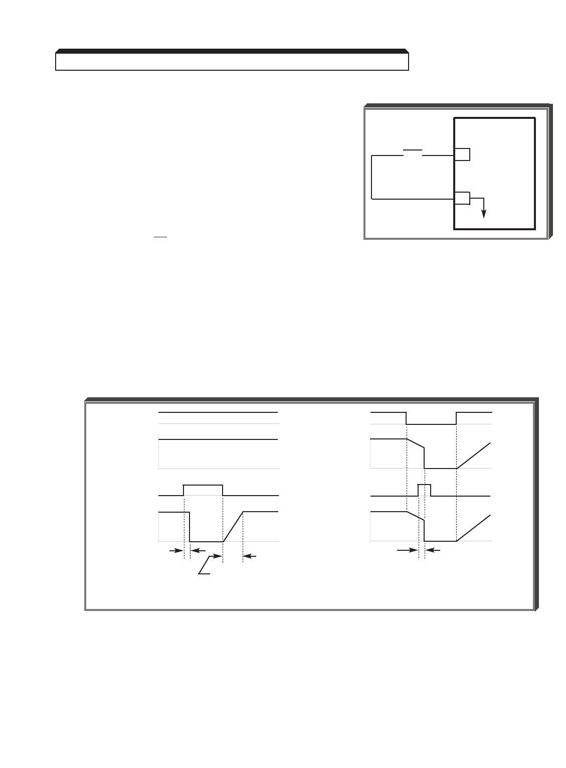
5-63
Continued
B. Data 8: External Base Block by N.O. Contact
• When either the Forward Run command or
Reverse Run command is present, and the
external Base Block command is applied
(i.e. contact closed), coast stop is accom-
plished (after a 20 msec delay), while the
frequency command is maintained.
When the Base Block command is removed,
the drive will recover in a manner similar
to that of Speed Search operation, except that
it searches up from 0 Hz, and supersedes a
Speed Search command.
• When both the Forward Run command and
Reverse Run command are open, and the
external Base Block command is applied (i.e. contact closed), coast stop is accom-
plished and after a 20 msec delay the frequency command is changed to 0Hz.
When the Base Block command is removed, the drive will remain in stopped
condition until Forward Run command or Reverse Run command is again applied.
• When external Base Block command is active, a blinking " BB " will be displayed
on the Digital Operator.
C. Data 9: External Base Block by N.C. Contact
Base block operation is the same as described above, except that the Base Block contact
must be open to be recognized.
GPD 515/G5
8
11
0V
EXTERNAL
BASE BLOCK
o o
RUN RUN
Freq. Cmd Freq. Cmd
00
Base Block Base Block
V out V out
00
20msec 20msec
t = L2-04 setting
(A) Base Block With Run Active (B) Base Block After Stop Com
5.32 MULTI-FUNCTION INPUT TERMINALS (Term. 3-8)
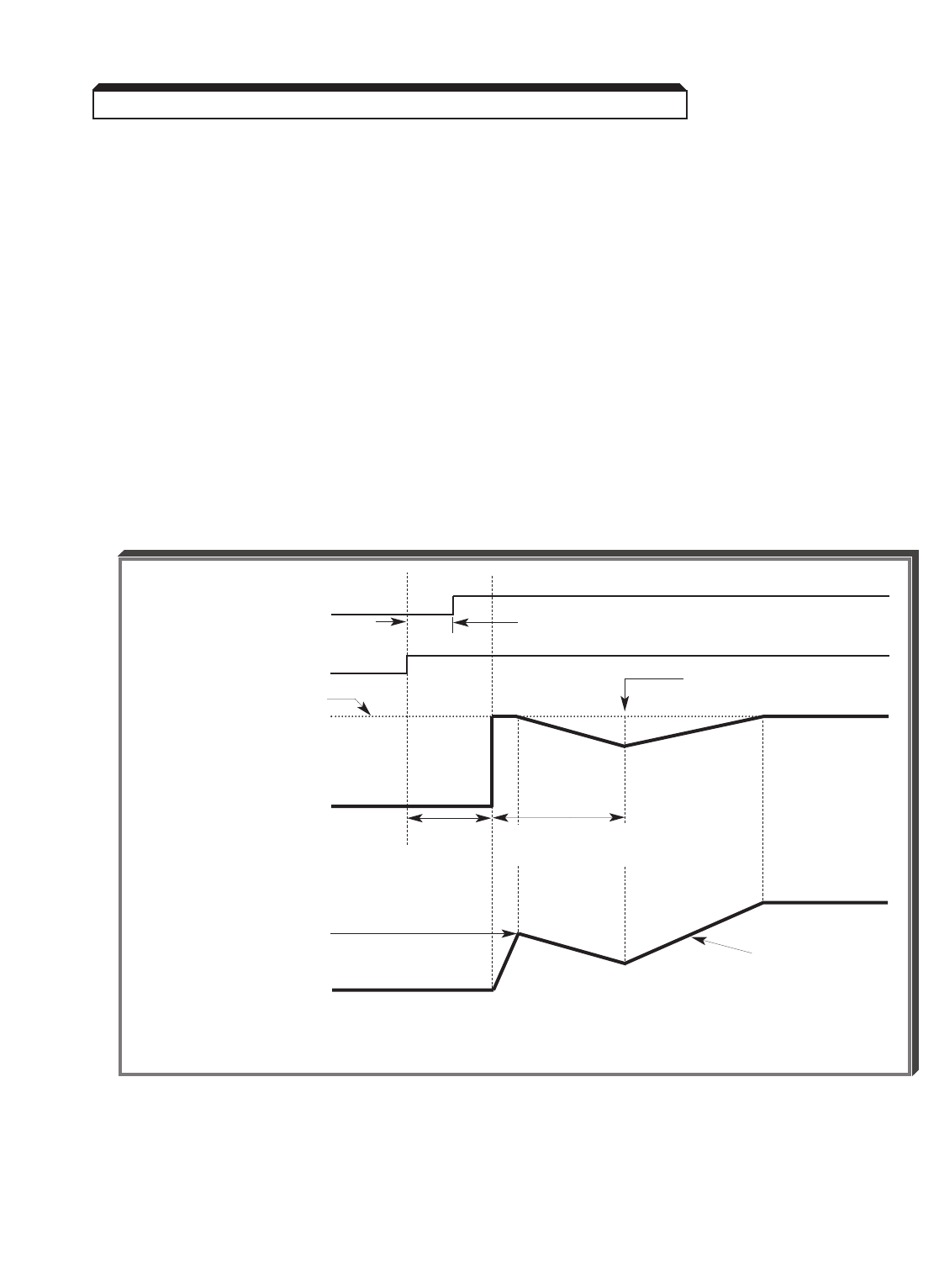
5-64
Continued
D. Data 61 : Speed Search From Max Frequency
Data 62: Speed Search From Set Frequency
Data 64: Speed Search From Output Frequency
A multi-function input terminal is utilized to activate speed search. When the external
speed search command is closed, the base is blocked for the min. base block time,
L2-03 , then the speed search is made. The operation depends on the set value.
IMPORTANT
Set values 61, 62& 64 CANNOT be selected in combination.
• When 61 is set, the speed search begins with the maximum frequency.
• When 62 is set, the speed search begins with the frequency command
that has been set after the search command was received.
• When 64 is set, the speed search begins with the last output frequency
before the speed search command was received.
RUN
SIGNAL
SPEED SEARCH
MAX FREQ., FREQ.
REF., OR OUTPUT
FREQ. WHEN SPEED
SEARCH IS INPUTTED
OUTPUT FREQUENCY
VOLTAGE AT
SPEED SEARCH
OUTPUT VOLTAGE
MIN.
BASE
BLOCK
TIME
( L2-03 )
SPEED SEARCH
OPERATION
WITHIN 0.5 SEC
NOTE: When momentary power loss ride-thru function is selected ( L2-01 = 1 or 2),
the Speed Search command must be enabled.
Speed Search Operation Timing
SPEED COINCIDENCE
POINT
NORMAL V/f
OUTPUT
( E1=03 )
5.32 MULTI-FUNCTION INPUT TERMINALS (Term. 3-8)
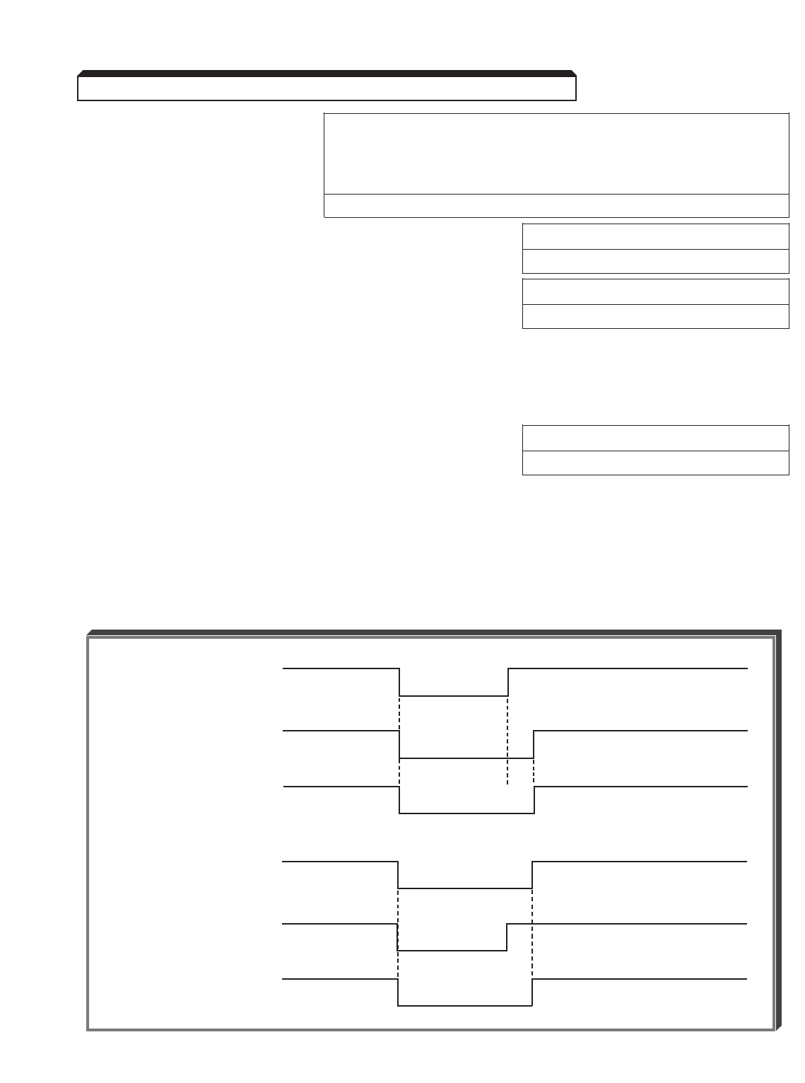
5-65
Continued
b3-01 : Speed Factory setting: 0= Disabled (when V/f control or Open
Search Loop Vector control has been selected)
Selection 1= Enabled (when V/f w/PG control or
Flux Vector control has been selected)
Range: 0 or 1
b3-02 : Speed Search Deactivation Current Factory setting: 150
Level Range: 0 to 200 %
b3-03 : Speed Search Deceleration Time Factory setting: 2.0
Range: 0.0 to 10.0 sec.
After power recovery, if the drive output current is larger than the set value of
b3-02 , speed search is started, using a decel rate per the setting of b3-03 . When
drive output current is lower than the set value of b3-02 , speed search is complete and
acceleration or deceleration is continued at the normal rate ( C1-XX ) to set frequency.
L2-03 : Minimum Baseblock Time Factory setting: See Table A3-1
Range: 0.1 to 5.0 sec.
When a momentary power loss is detected, the drive output transistors are disabled for a
period of time determined by the setting of L2-03 . The L2-03 setting should represent
the time required for the motor residual voltage to go to zero.
When the momentary power loss time exceeds the minimum base block time, the speed
search operation is started immediately after power recovery.
WHEN MIN. BASEBLOCK TIME IS LONGER THAN MOMENTARY POWER LOSS TIME
MOMENTARY POWER
LOSS TIME
MIN.
BASEBLOCK TIME
DRIVE
BASEBLOCK TIME
WHEN MIN. BASEBLOCK TIME IS SHORTER THAN MOMENTARY POWER LOSS TIME
MOMENTARY POWER
LOSS TIME
MIN.
BASEBLOCK TIME
DRIVE
BASEBLOCK TIME
5.32 MULTI-FUNCTION INPUT TERMINALS (Term. 3-8)
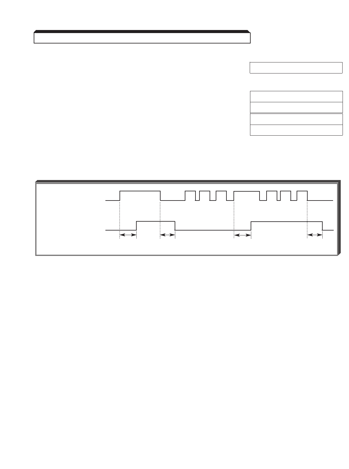
5-66
Continued
E. Data 18 : Timer Input Function
H2-01 : Multi-function Output Terminals (9 & 10) Data 12 : Timer Function
H2-02 : Multi-function Output Terminals (25 & 27)
H2-03 : Multi-function Output Terminals (26 & 27)
b4-01 : On-delay Timer Factory setting: 0.0
Range: 0.0 to 300.0 sec.
b4-02 : Off-delay Timer Factory setting: 0.0
Range: 0.0 to 300.0 sec.
When the timer function input is “closed” for longer than On-delay Timer ( b4-01 ), the
timer function output closes.
When the timer input is “open” for longer than Off-delay Timer ( b4-02 ), the timer function
output opens.
As can be seen, the timer function must be programmed as both a multi-function input and
an output to be effective.
F. Data 1E : Sample/Hold Command
This function applies only to an analog voltage or current input used as a frequency
reference at terminals 13 or 14.
If the Sample/Hold command is present (contact is closed) for more than 0.1 sec., the
frequency reference will follow (sample) the analog signal, e.g. if 5V corresponds to 50%
frequency, a 5V analog signal will produce 50% frequency reference if the Sample/Hold
command is present.
If the Sample/Hold command is removed (contact is opened) while the Drive is still in Run
condition, the frequency reference is held at the level it was at the time the Sample/Hold
command was removed, e.g. the frequency reference would remain at 50%, even though
the analog signal increased to 8V.
5.32 MULTI-FUNCTION INPUT TERMINALS (Term. 3-8)
Multi-function Contact
Input: Timer Function
Multi-function Contact
Output: Timer Function
b4-01 b4-02
ON
ON ON
ON
b4-01
ON
ON ON
b4-02
ON ON ON
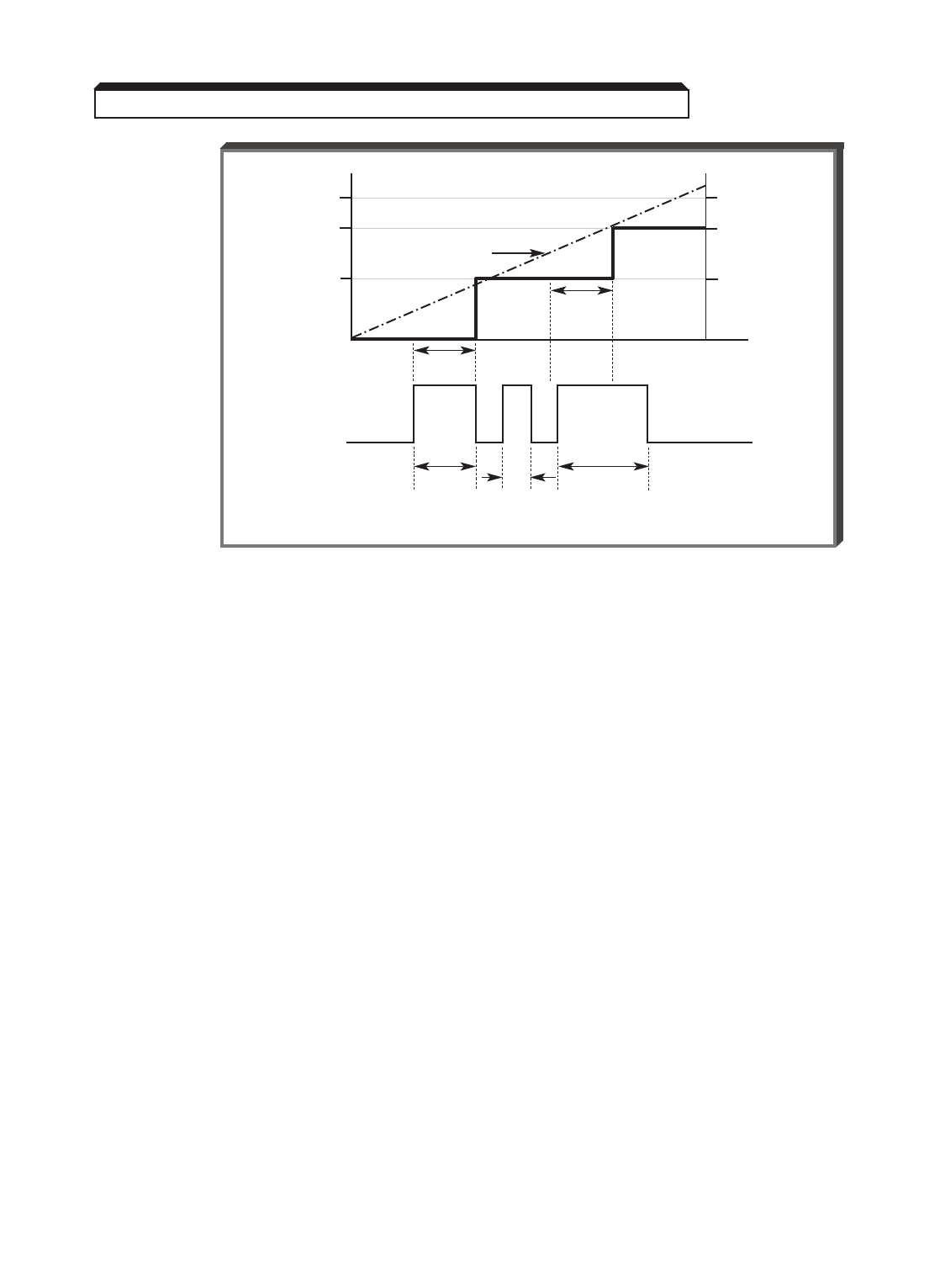
5-67
Continued
G. Data 10 : Up Function
Data 11 : Down Function
d4-01 : Frequency Reference Hold Factory setting: 0
Function Selection Data: 0 = Disabled
1 = Enabled
Programming data " 10 " and " 11 " for two of the six multi-function input terminals allows
those inputs to be used for Up/Down frequency setting by simulating the action of a MOP
(motor operated potentiometer).
NOTES:
1. Set parameter b1-02 = 1.
2. OPE3 fault will occur if " 10 " and " 11 " data settings are not used together.
3. OPE3 fault will occur if " 10 " and " 11 " data settings are programmed at the
same time as setting " A " (Accel/decel ramp hold).
4. Jog has priority over Up/Down function.
5. Up/Down has priority over Multi-step Speed inputs.
6. Up/Down is ineffective when operation is from the Digital Operator.
(NOTES continued on next page)
Sample/Hold Function Timing
SAMPLE/
HOLD CMD Open
10V 100%
80%
50%
8V
5V
t1
0.11
sec.
0.1
sec.
t2
0.05
sec.
t3
0.15
sec.
Closed
ANALOG INPUT
5.32 MULTI-FUNCTION INPUT TERMINALS (Term. 3-8)
FREQ. REF.
0.1
sec.
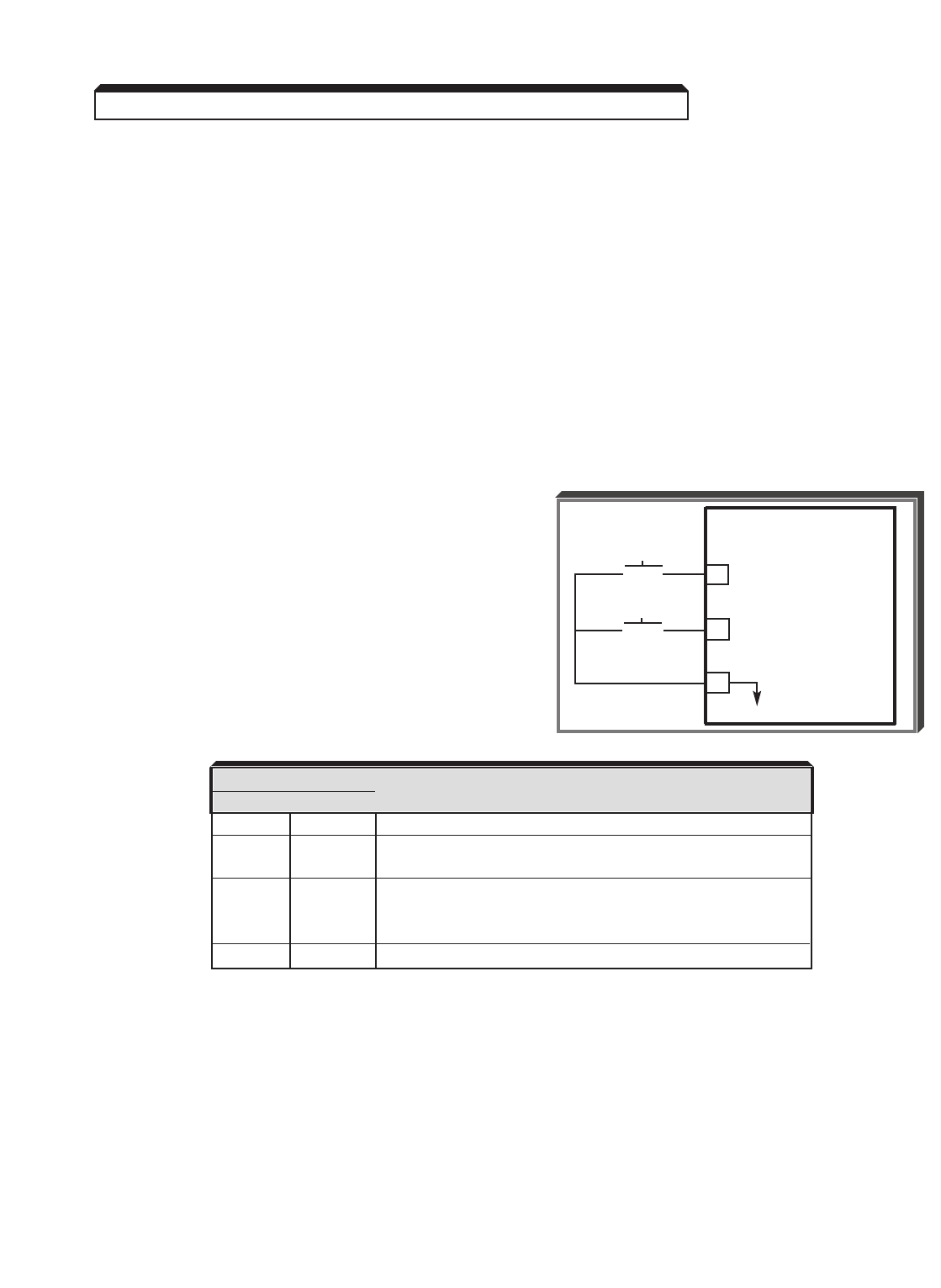
5-68
Continued
G. (Continued)
NOTES (Continued):
7. Upper limit speed is set by the formula:
E1-04 (Fmax) x d2-01 (Freq. Ref. Upper Limit)
8. Lower limit speed is either the reference from external terminals 13 or 14,
or from d2-01 , Frequency Reference Lower Limit.
9. If d4-01 = " 0 ", Frequency Reference will be reset to 0 Hz if the stop
command is given, or if input power is removed and reapplied.
10. If d4-01 = " 1 ", the drive will retain the last valid Frequency Reference
if a stop command is given or if input power is removed, and will accelerate
to that reference upon reapplication of a run command.
EXAMPLE:
H1-05 Data 10 : Up function
H1-06 Data 11 : Down function
5.32 MULTI-FUNCTION INPUT TERMINALS (Term. 3-8)
GPD 515/G5
7UP
8DOWN
11
0V
UP
o o
DOWN
o o
INPUT SIGNAL FUNCTION
UP DOWN
Open Open HOLD
Closed Open UP (Frequency command approaches frequency
command upper limit)
Open Closed DOWN (Frequency command approaches minimum
output frequency or frequency command lower limit,
whichever is larger)
Closed Closed HOLD
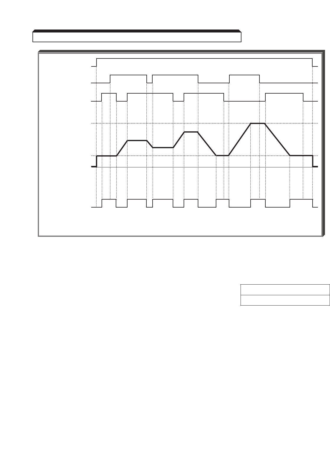
5-69
Continued
H. Data 1C : Trim Control Increase
Data 1D : Trim Control Decrease
d4-02 : Trim Control Level Factory setting: 10
Range: 0 to 100 %
The value of d4-02 is a percentage of the maximum output frequency ( E1-04 ).
When the trim control increase input is closed, the value of d4-02 gets added to the
analog frequency reference.
When the trim control decrease input is closed, the value of d4-02 gets subtracted
from the analog frequency reference.
FWD RUN
UP
COMMAND
DOWN
COMMAND
UPPER
LIMIT SPEED
LOWER
LIMIT SPEED
OUTPUT
FREQUENCY*
"SPEED AT SET
FREQUENCY"
MULTI-FUNCTION
OUTPUT SIGNAL * U= UP (Accel) status; D= DOWN (Decel) status; H= HOLD (constant speed) status;
U1 = At Upper Limit Speed; D1 = At Lower Limit Speed
Up/Down Frequency Setting Timing
D1 D D DHHHHHH HU1UU U
D1 D1
5.32 MULTI-FUNCTION INPUT TERMINALS (Term. 3-8)
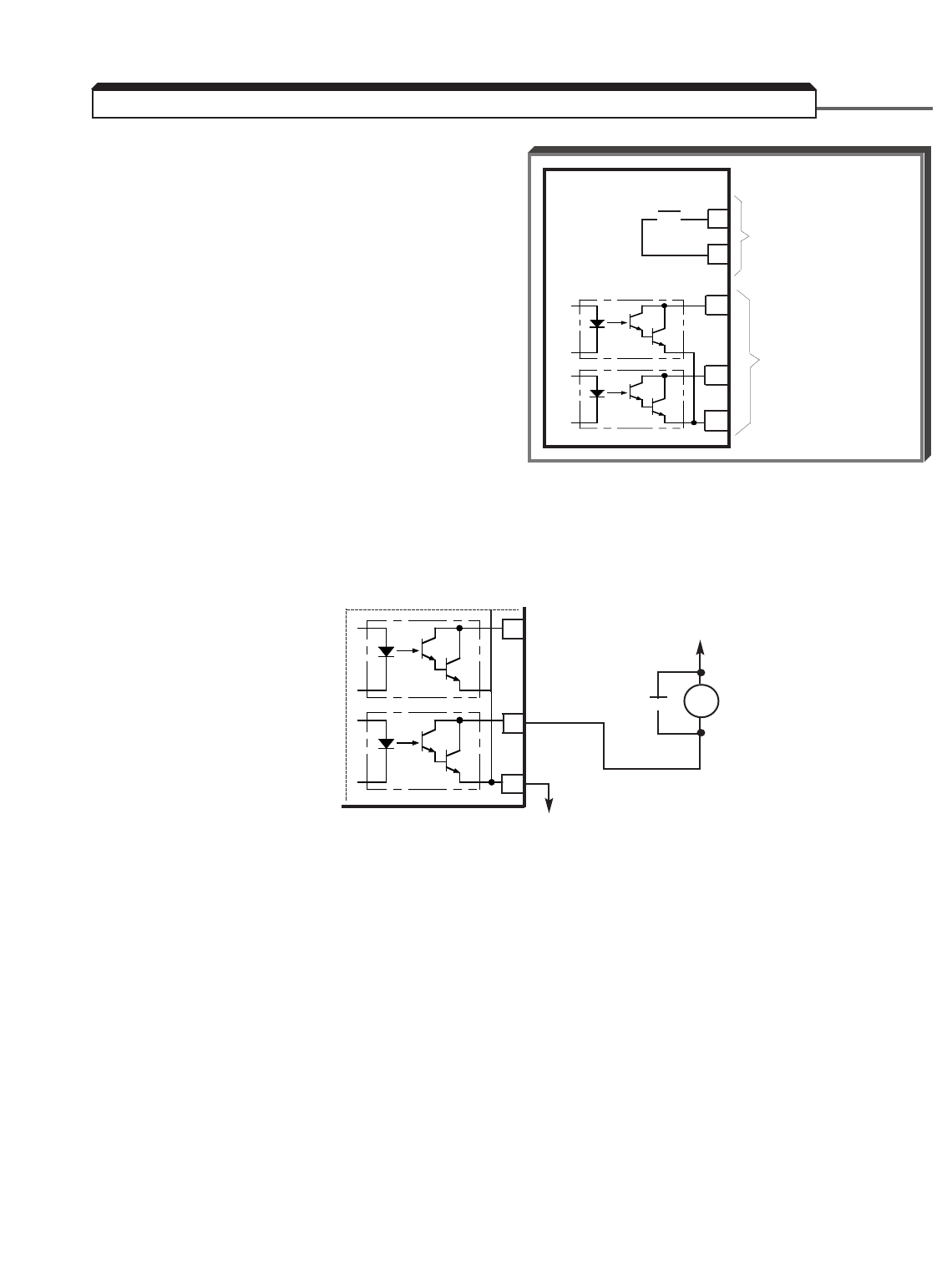
5-70
H2-01 : Contact Output (external
terminals 9 & 10)
H2-02 : Open Collector Output
(external terminals 25 & 27)
H2-03 : Open Collector Output
(external terminals 26 & 27)
A contact, or two different open collector
outputs, can be programmed to change states
during any of the conditions indicated in Table
5-3.
IMPORTANT
If an open collector output is applied to a DC relay, the relay MUST be diode
protected, as shown in the recommended configuration below.
5.33 MULTI-FUNCTION OUTPUT TERMINALS (Term. 9 & 10; 25-27)
25
26
27
GPD 515/G5
o o 9
10
MULTI-FUNCTION
CONTACT OUTPUT
250Vac 1A OR LESS
30Vdc 1A OR LESS
(FACTORY SETTING
IS FOR SIGNAL
DURING OPERATION)
MULTI-
FUNCTION
OPEN
COLLECTOR
OUTPUTS
48Vdc AT
50mA MAX.
Recommended
Configuration for
DC Relays
25
26
27
C
▲
DC
RELAY
DIODE
48Vdc MAX. *
**
* Customer
supplied
•

5-71
Continued
5.33 MULTI-FUNCTION OUTPUT TERMINALS (Term. 9 & 10; 25-27)
DESCRIPTION
DATA FUNCTION Signal Levels: 0= state; 1= pulse
0During Operation Closed = Drive is operating X X X
1Zero speed Closed = Drive is at 0Hz X X X
2Speed at set frequency 1 Closed = Freq. Ref. – L4-02 ≤output X X X
freq ≤Freq. Ref. + L4-02
See Data description following this table
3Speed coincidence 1 Closed = Speed at set frequency and X X X
L4-01– L4-02 ≤output
freq. ≤L4-01 + L4-02
See Data description following this table
4Frequency detection 1 – low Closed = Output frequency ≤L4-01 XXX
See Data description following this table
5Frequency detection 1 – high Closed = Output frequency ≥L4-01 XXX
See Data description following this table
6Operation ready Closed = Drive is ready for operation X X X
7During undervoltage detection Closed = Undervoltage detected X X X
8During base block Closed = Drive output base block is X X X
active; motor is coasting
9Frequency reference mode Open = Command by external input X X X
Closed = Command by Digital Operator
ARun reference mode Open = Run by external input X X X
Closed = Run by Digital Operator
BOvertorque detection 1 Closed = Overtorque detected X X X
CFrequency reference missing Closed = Frequency reference is missing X X X
DBraking resistor fault Closed = Braking resistor is overheating or X X X
has faulted
EFault Closed = Drive fault has occurred XXX
(except CPF00 , CPF01 )
FNot Used
10 Alarm (minor fault) Closed = Alarm condition is present X X X
11 During fault reset Closed = Drive is performing fault reset X X X
12 Timer output function See paragraph 5.32 E XXX
AVAILABILITY
DATA CONDITION SIGNAL LEVEL (See Note 1)
0, 1 2 3
Table 5-3. H2-01 thru H2-03 Data Settings

5-72
Continued
5.33 MULTI-FUNCTION OUTPUT TERMINALS (Term. 9 & 10; 25-27)
DESCRIPTION
DATA FUNCTION Signal Levels: 0= state; 1= pulse
13 Speed at set frequency 2 Closed = Freq. Ref. – L4-04 ≤output X X X
freq ≤Freq. Ref. + L4-04
See Data description following this table
14 Speed coincidence 2 Closed = Speed at set frequency and X X X
L4-03– L4-04 ≤output
freq. ≤L4-03 + L4-04
See Data description following this table
15 Frequency detection 2 – low Open = Output freq. ≥L4-03+ L4-04 XXX
Closed = Output frequency ≤L4-03
See Data description following this table
16 Frequency detection 2 – high Open = Output freq. ≤L4-03+ L4-04 XXX
Closed = Output frequency > L4-03
See Data description following this table
17 Overtorque detection 1 Open = Overtorque 1 detected according to X X X
(N.C.) settings of L6-01thru L6-03
18 Overtorque detection 2 Closed = Overtorque 2 detected according to X X X
(N.O.) settings of L6-04thru L6-06
19 Overtorque detection 2 Open = Overtorque 2 detected according to X X X
(N.C.) settings of L6-04thru L6-06
1A During reverse run Closed = Drive operation in reverse X X X
1B During base block 2 Open = Drive output base block is active; X X X
motor is coasting
1C Motor 2 Selected Closed = Motor 2 is selected X X X
1D Regenerating Closed = Regenerating mode [ only when A1- ——X
02 is set for Flux Vector Control ]
1E During restart Closed = Retry operation after a fault X X X
1F OL1 pre-alarm Closed = Thermal overload level exceeds X X X
90% of fault detection level
20 OH pre-alarm Closed = Cooling fin temperature exceeds X X X
L8-02 level
21 – 2F Not Used
30 During torque limit Closed = Torque limit — X X
31 During speed limit Closed = Speed limit reached [ only when A1- ——X
02 is set for Flux Vector Control ]
AVAILABILITY
DATA CONDITION SIGNAL LEVEL (See Note 1)
0, 1 2 3
Table 5-3. H2-01 thru H2-03 Data Settings - Continued
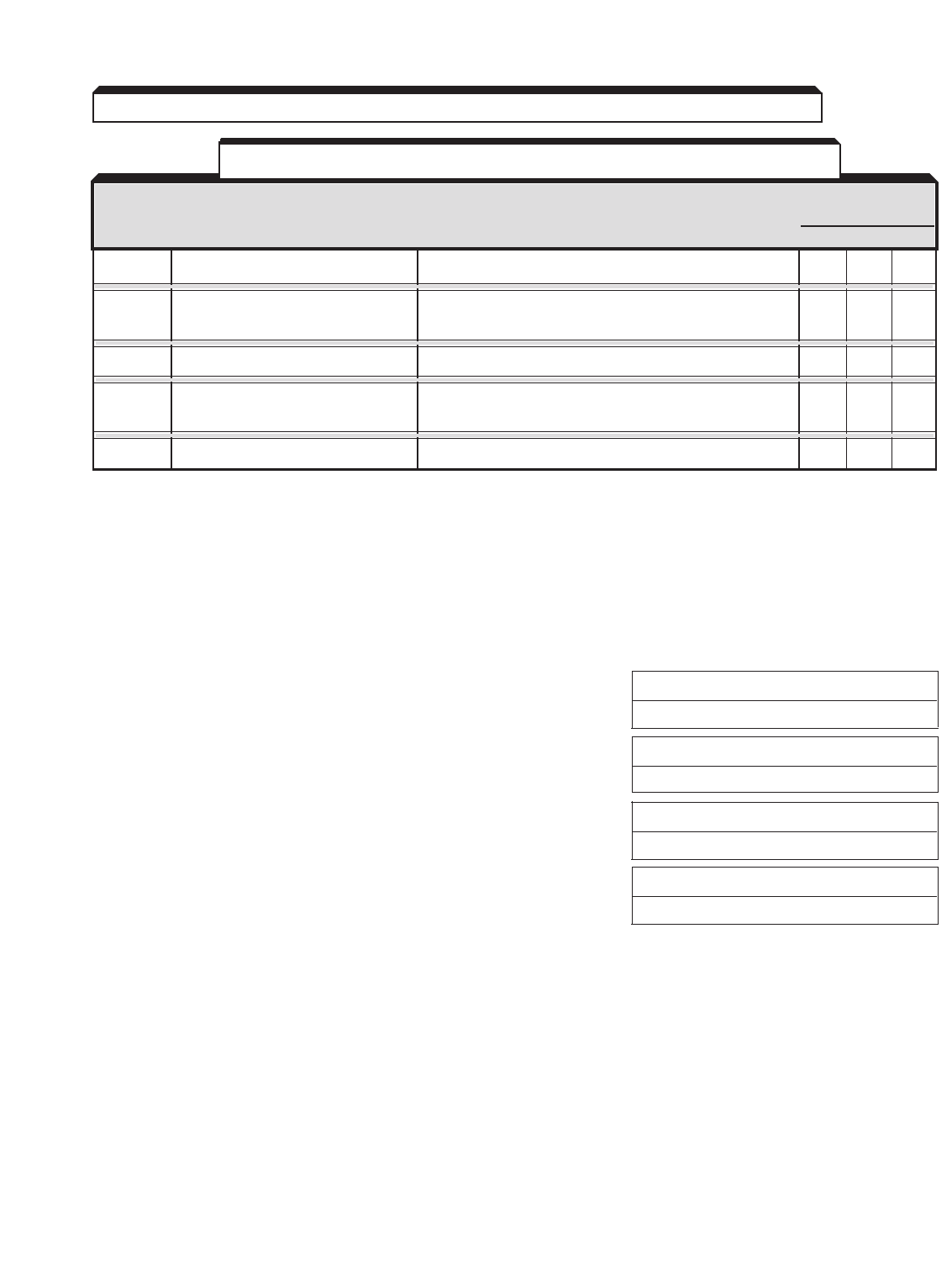
5-73
NOTES:
1. Column headings refer to set value of A1-02, Control Method; 0 = V/f,
1 = V/f w/PG, 2 = Open loop vector, 3 = Flux vector.
A. Data 2–5, 13–16 : Frequency or Speed Detection Output Signals
L4-01 : Speed Coincidence Detection Level Factory setting: 0.0
Range: 0.0 to 400.0 Hz
L4-02 : Speed Coincidence Detection Width Factory setting: 2.0
Range: 0.0 to 20.0 Hz
L4-03 : Speed Coincidence Detection Factory setting: 0.0
Level (+/–) Range: –400.0 to +400.0 Hz
L4-04 : Speed Coincidence Detection Factory setting: 2.0
Width (+/–) Range: 0.0 to 20.0 Hz
These speed coincidence parameters are used to control contact output at terminals 9 &
10, or one of the open collector outputs at terminals 25 & 26 (with respect to terminal
27), when selected by H1-01 thru H1-03 . Both L4-01 and L4-02 are insensitive to
motor direction.
The output contact will close, or the open collector output will go low, when the
acceleration or deceleration is completed, or output frequency or speed is within the
detection width for the selected output function. See the timing diagrams on the following
pages.
Continued
5.33 MULTI-FUNCTION OUTPUT TERMINALS (Term. 9 & 10; 25-27)
DESCRIPTION
DATA FUNCTION Signal Levels: 0= state; 1= pulse
32 Not Used
33 Zero-Servo complete Closed = Zero-Servo is complete — — X
See paragraph 5.49 C
34 – 36 Not Used
37 During operation Closed = Drive is operating (except during X X X
base block or injection braking)
38 – 3F Not Used
AVAILABILITY
DATA CONDITION SIGNAL LEVEL (See Note 1)
0, 1 2 3
Table 5-3. H2-01 thru H2-03 Data Settings - Continued
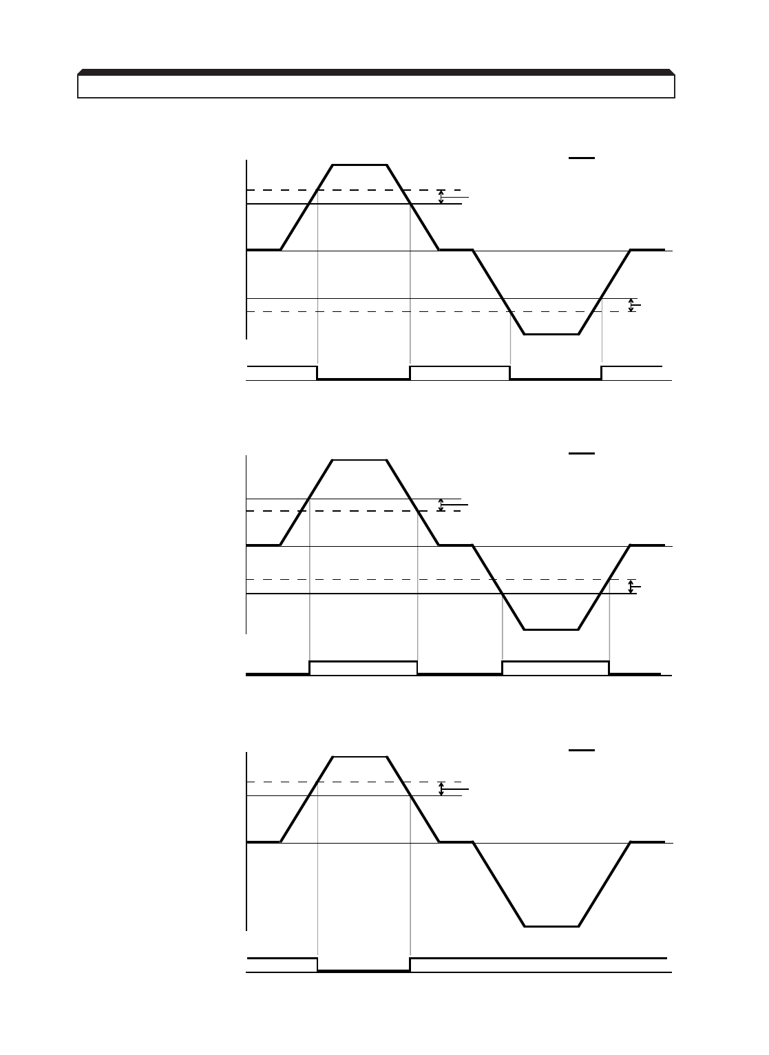
5-74
Continued
Frequency detection 1 – low
Frequency detection 1 – high
Frequency detection 2 – low
5.33 MULTI-FUNCTION OUTPUT TERMINALS (Term. 9 & 10; 25-27)
H2-01 = 4 L4-01 = 30 Hz L4-02 = 5 Hz
35 Hz
30 Hz
30 Hz
35 Hz
L4-01 =
L4-02
: Output Freq. or
Motor Speed
L4-02
Contact
Closure
L4-01 =
H2-01 = 5 L4-01 = 30 Hz L4-02 = 5 Hz
25 Hz
30 Hz
30 Hz
25 Hz
L4-01 =
L4-02
: Output Freq. or
Motor Speed
L4-02
Contact
Closure
L4-01 =
H2-01 = 15 L4-03 = 30 Hz L4-04 = 5 Hz
35 Hz
30 Hz
L4-03 =
L4-04
: Output Freq. or
Motor Speed
Contact
Closure
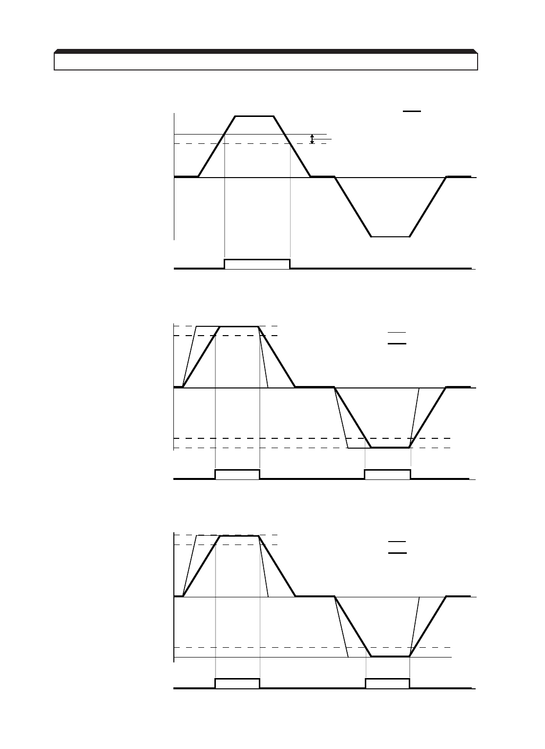
5-75
Continued
Frequency detection 2 – high
Speed at set frequency 1
Speed at set frequency 2
5.33 MULTI-FUNCTION OUTPUT TERMINALS (Term. 9 & 10; 25-27)
H2-01 = 16 L4-03 = 30 Hz L4-04 = 5 Hz
25 Hz
30 Hz
L4-03 =
L4-04
: Output Freq. or
Motor Speed
Contact
Closure
H2-01 = 2 L4-02 = 10 Hz
60 Hz
50 Hz
50 Hz
60 Hz
: Speed Reference
Contact
Closure
: Output Freq. or
Motor Speed
H2-01 = 13 L4-04 = 10 Hz
60 Hz
50 Hz
: Speed Reference
Contact
Closure
: Output Freq. or
Motor Speed
50 Hz
60 Hz
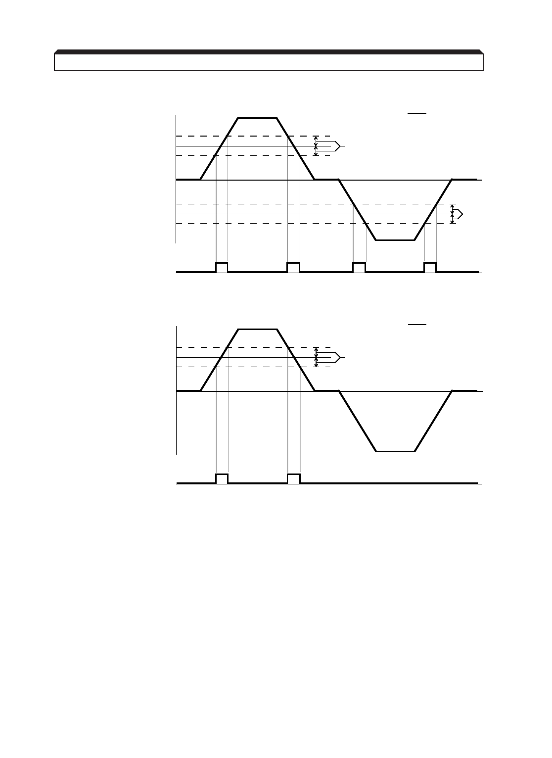
5-76
Continued
Speed coincidence 1
Speed coincidence 2
5.33 MULTI-FUNCTION OUTPUT TERMINALS (Term. 9 & 10; 25-27)
H2-01 = 3 L4-01 = 30 Hz L4-02 = 5 Hz
35 Hz
30 Hz
30 Hz
35 Hz
L4-01 =
L4-02
: Output Freq. or
Motor Speed
L4-02
Contact
Closure
25 Hz
25 Hz
L4-01 =
H2-01 = 14 L4-03 = 30 Hz L4-04 = 5 Hz
35 Hz
30 Hz
L4-03 =
L4-04
: Output Freq. or
Motor Speed
Contact
Closure
25 Hz
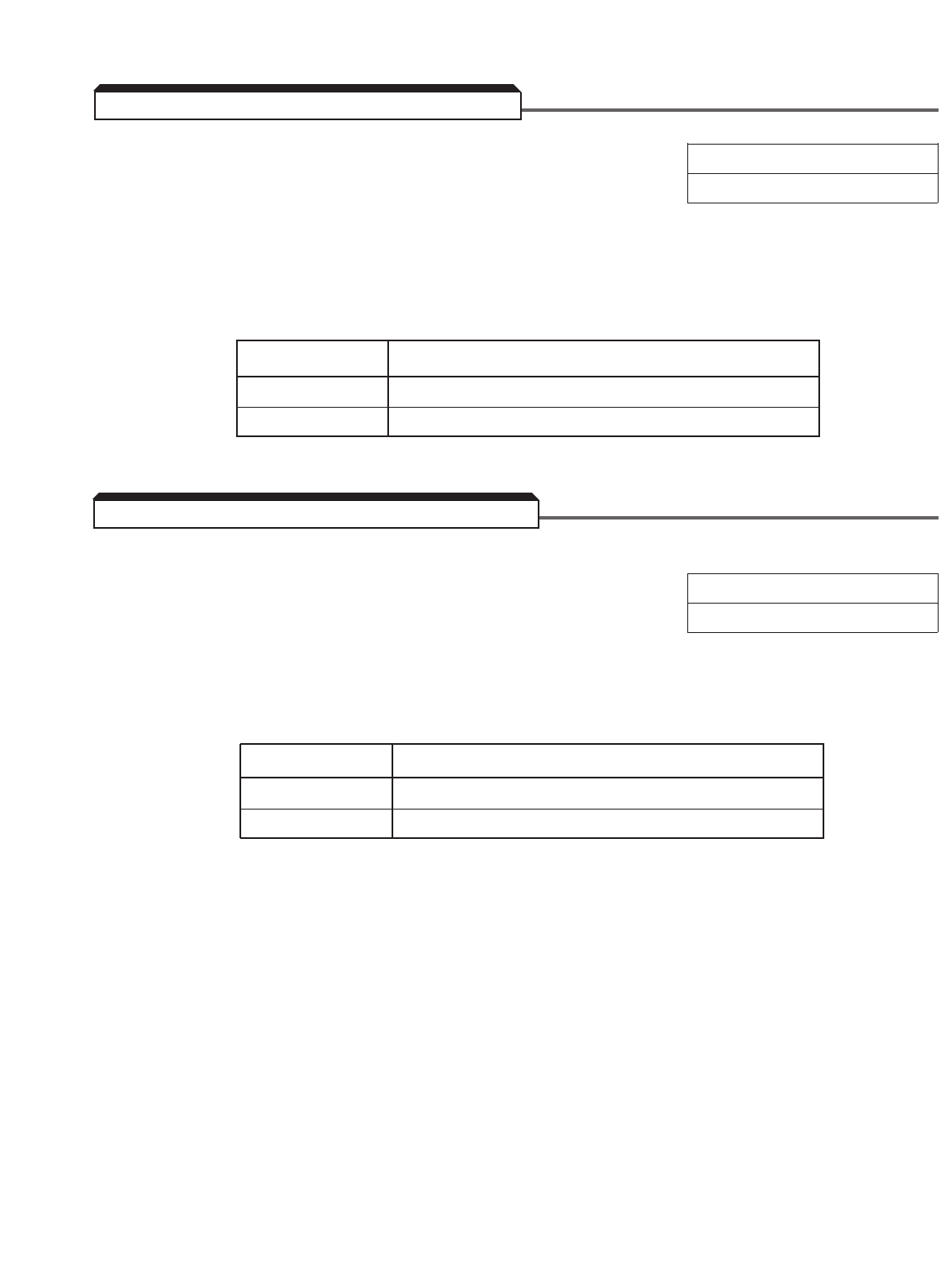
5-77
L8-05 : Input Phase Loss Detection Selection Factory setting: 0
Range: 0 or 1
The input phase loss detection circuit monitors the DC bus current ripple and activates
when one of the input phases is lost. This causes a " PF " fault to occur and the motor to
coast to a stop.
Setting Description
0 Input phase loss detection disabled
1 Input phase loss detection enabled
L8-07 : Output Phase Loss Detection Selection Factory setting: 1
Range: 0 or 1
The output phase loss detection circuit monitors the DCCT's and activates when one of the
output phases is lost. This causes a " LF " fault to occur and the motor to coast to a stop.
Setting Description
0 Output phase loss detection disabled
1 Output phase loss detection enabled
5.34 PHASE LOSS DETECTION, INPUT
5.35 PHASE LOSS DETECTION, OUTPUT
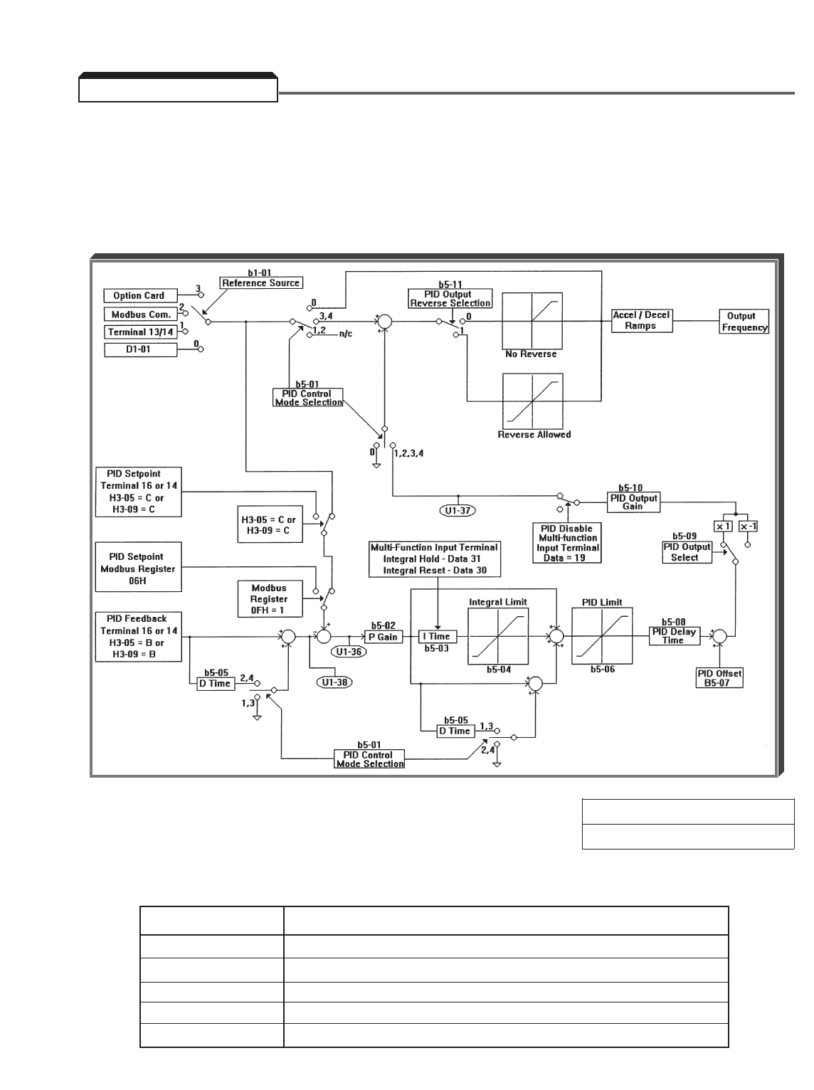
5-78
The Proportional, Integral and Derivative control function provides closed-loop control, or
regulation, of a system process variable (pressure, temperature, etc.). This regulation is
accomplished by comparing a feedback signal to a setpoint reference, which results in an
error signal. The PID control algorithm then performs calculations, based upon the PID
parameter settings ( b5-01 thru b5-14 ), on this error signal. The result of the PID
algorithm is then used as the new frequency reference, or is added to the existing speed
reference.
A. b5-01 : PID Selection Factory setting: 0
Range: 0 to 4
Using this parameter, PID control can be enabled, and the type of PID control can be
selected.
Setting Description
0 PID Disabled
1 PID Enabled (D = Feedback)
2 PID Enabled (D = Feed forward)
3 PID Enabled, Reference + PID (D = Feedback)
4 PID Enabled, Reference + PID (D = Feedback forward)
5.36 PID CONTROL

Continued
B. Setpoint Reference Selection
b1-01 : Reference Selection Factory setting: 1
Range: 0 to 4
d1-01 thru d1-09 : Multi-step Frequency Factory settings: d1-09 = 6.0
Presets all others = 0.0
Range (each): 0.0 to 400.0 Hz
H3-01 : Auto Speed Reference Signal Factory setting: 0
Level Selection (Term. 13) Range: 0 or 1
H3-04 : Multi-Function Analog Input 1 Factory setting: 0
Level Selection (Term. 16) Range: 0 or 1
H3-05 : Multi-Function Analog Input 1 Factory setting: 0
Selection (Term. 16) Range: 0 to 1F
H3-08 : Multi-Function Analog Input 2 Factory setting: 2
Level Selection (Term. 14) Range: 0 to 2
H3-09 : Multi-Function Analog Input 2 Factory setting: 1F
Selection (Term. 14) Range: 0 to 1F
The PID setpoint can come from the frequency reference (terminal 13 for 0 – 10 VDC or the
multi-step speed parameters d1-01 thru d1-09) or a Multi-Function Analog Input.
PID Setpoint examples:
• External Terminal 13: Set b1-01 to data " 1 " or
• Multi-step speed parameters: Set b1-01 to data " 0 " (See Multi-step
Speed Setting, paragraph 5.25B) or
• External Terminal 16: Set H3-05 to data " C " or
• External Terminal 14: Set H3-09 to data " C "
C. Feedback Signal Selection
H3-05 : Multi-function Analog Input 1 Factory setting: 0
Selection (Term. 16) Range: 0 to 1F
H3-09 : Multi-function Analog Input 2 Factory setting: 1F
Selection (Term. 14) Range: 0 to 1F
Select the PID control Feedback Signal from external terminal 14 for a current signal
(4-20mA DC) or from terminal 16 for a voltage (0-10 VDC or –10 to +10 VDC).
PID Feedback examples:
• Current signal (4-20mA): Set H3-09 to data " B " and H3-08 to data " 2 ".
• Voltage signal (0-10 VDC): Set H3-05 to data " B " and H3-04 to data " 0 ".
• Voltage signal (–10 to 10 VDC): Set H3-05 to data " B " and H3-04 to
data " 1 ".
5-79
5.36 PID CONTROL

5-80
Continued
D. PID Settings
b5-02 : Proportional Gain Factory setting: 1.00
Range: 0.00 to 10.00
Proportional gain is the value by which the error signal is multiplied to generate a new
PID controller output. A higher setting will result in a more responsive system. A lower
setting will result in a more stable system.
b5-03 : Integral Time Factory setting: 1.0
Range: 0.0 to 360.0 seconds
This parameter determines how fast the PID controller will seek to eliminate any
steady-state error. The smaller the setting, the faster the error will be eliminated. To
eliminate the integral function entirely, set this parameter to 0.0 seconds. A lower
setting will result in a more responsive system. A higher setting will result in a more
stable system.
b5-04 : Integral Value Limit(1) Factory setting: 100.0
Range: 0.0 to 100.0 %
This parameter will limit the effect that the integrator can have. It works whether the
PID controller output is positive or negative. It can also be used to prevent integrator
“wind-up.”
b5-05 : Derivative Time Factory setting: 0.00
Range: 0.0 to 10.00 seconds
This parameter can be adjusted to increase system response to fast load or reference
changes, and to reduce overshoot upon startup. To eliminate the differential function
entirely, set this parameter to 0.00 seconds.
b5-06 : PID Output Limit(1) Factory setting: 100.0
Range: 0.0 to 100.0 %
Parameter b5-06 can be used to set the maximum effect the PID controller will have
on the system. It also will limit the PID output when it is either positive or negative.
NOTE: When the PID output limit is reached, the integrator will hold and not change in
value until the PID output is less than the PID output limit.
b5-07 : PID Offset Adjustment(1) Factory setting: 0.0
Range: -100.0 to 100.0 %
This parameter will add a fixed percentage to the PID output. It can be used to tune
out small system offsets. NOTE: This parameter is set as a percentage of maximum
output frequency (E1-04).
(1) These parameters are factory set for optimum results for most applications,
and generally do not need to be changed.
5.36 PID CONTROL

5-81
Continued
b5-08 : Output Lag Filter Time(1) Factory setting: 0.00
Range: 0.00 to 10.00 seconds
This parameter adds a filter to the PID output to keep it from changing too quickly.
The higher the setting, the slower the PID output will change.
b5-09 : PID Output Selection Factory setting: 0
Range: 0 or 1
b5-10 : PID Output Selection(1) Factory setting: 1.0
Range: 0.0 to 25.0
This parameter is a multiplier in the output of the PID controller. Increasing this parameter
will make the PID controller more responsive. Be careful not to increase this parameter too
much or the drive/system will become unstable.
b5-11 : PID Output Reverse Selection Factory setting: 0
Range: 0 or 1
All of these parameters are interactive, and will need to be adjusted until the control loop is
properly tuned, i.e. stable with minimal steady-state error. A general procedure for tuning
these parameters is as follows:
1. Adjust Proportional Gain until continuous oscillations in the Controlled
Variable are at a minimum.
2. The addition of Integral Time will cause the steady-state error to approach
zero. The time should be adjusted so that this minimal error is attained as
fast as possible, without making the system oscillate.
3. If necessary, adjust derivative time to reduce overshoot during startup.
The drive’s accel and decel rate times can also be used for this purpose.
(1) These parameters are factory set for optimum results for most applications,
and generally don’t need to be changed.
Setting Description
0The output of the PID controller will decrease when there is an
(Not Inverted) increase in feedback level.
1The output of the PID controller will increase when there is an
(Inverted) increase in the feedback level.
Setting Description
0If the PID controller calls for a “negative” speed (reverse), the
drive/motor will stop.
1If the PID controller calls for a “negative” speed (reverse), the
drive/motor will run in reverse.
5.36 PID CONTROL

5-82
Continued
E. Feedback Loss Detection
b5-12 : Feedback Loss Detection Selection
b5-13 : Feedback Loss Detection Level (PID) Factory setting: 0
Range: 0 to 100 %
b5-14 : Feedback Loss Detection Factory setting: 1.0
Delay Time (PID) Range: 0.0 to 25.5
When feedback loss detection is enabled (b5-12 = data “1” or “2”), the drive will detect if
the feedback signal falls below the b5-13 level for more than the b5-14 delay time and
respond according to the setting of b5-12.
F. Multi-Function Input Terminals
H1-01 thru H1-06 : Multi-function Inputs Data 30: PID Integral Reset
(Term. 3 thru 8)
By programming data “30” into one of the multi-function parameters (H1-01 thru H1-
06), the corresponding multi-function input terminal (3 thru 8) will reset the integrator’s
value to zero.
H1-01 thru H1-06 : Multi-function Inputs Data 31: PID Integral Hold
(Term. 3 thru 8)
By programming data “31” into one of the multi-function parameters (H1-01 thru H1-
06), the corresponding multi-function input terminal (3 thru 8) will hold the integrator’s
output value. When the contact is closed (on the Multi-Function Input Terminal), whatever
value the integrator is outputting will remain the same until the contact is opened.
5.36 PID CONTROL
Setting Description
0Feedback loss detection is disabled
1Feedback loss detection is enabled - alarm only
(drive continues running).
2Feedback loss detection is enabled - fault (drive coasts to stop)
Factory setting: 0
Range: 0 to 2

A1-03 : Parameter Selection / Factory setting: 0
Initialization Data: 0= No Initialization
1110= User Default Parameter
Initialization
2220= 2-Wire Control Initialization
3330= 3-Wire Control Initialization
By entering either " 2220 " or " 3330 " into this parameter, a reset to factory
configuration (parameter initialization) is accomplished. The parameters which are NOT
affected are:
A1-00 : Language Selection E1-03 : V/f Pattern Selection
A1-02 : Control Method o2-04 : GPD 515 Capacity
Selection
Factory Configuration for
Parameter
Terminal
2-Wire Control 3-Wire Control
H1-01 3 " 24 " = External Fault " 24 " = External Fault
H1-02 4 " 14 " = Fault Reset " 14 " = Fault Reset
H1-03 5 " 3 " = Multi-step Ref. Select 1 " 0 " = FWD/REV Command
H1-04 6 " 4 " = Multi-step Ref. Select 2 " 3 " = Multi-step Ref. Select 1
H1-05 7 " 6 " = Jog Freq. Ref. " 4 " = Multi-step Ref. Select 2
H1-06 8 " 8 " = External Base Block " 6 " = Jog Freq. Ref.
(N.O. contact)
CAUTION
Know your application before using either Initialization function of A1-03 . This
parameter must be set to " 0 " for Drive mode operation.
" 1110 " = User Default Parameter Initialization
" 2220 " = Factory 2-Wire Control Initialization (Maintained RUN Contact)
" 3330 " = Factory 3-Wire Control Initialization (Momentary START/STOP
Contact)
Entering either Initialization code resets all parameters to factory settings (except
for A1-00, A1-02, o2-04, & E1-03), and automatically returns A1-03 setting to " 0 "
(No Initialization). If the GPD 515 is connected for 3-Wire control and this parameter
is set to " 2220 " (2-Wire Control Initialization), the motor may run in reverse
direction WITHOUT A RUN COMMAND APPLIED. Equipment damage or personal
injury may result.
When o2-03 = 1, the existing parameter settings become default user settings and the
" 1110 " initialization option appears in A1-03 . When o2-03 is not set to " 1 ", this
option is not available. Anytime the A1-03 parameter is set to " 1110 ", all parameter
settings that have been changed return to the default user settings (only 50 parameters
may be stored as default settings). This is NOT a Factory Initialization.
5.37 RESET CODES: 2-WIRE, 3-WIRE INITIALIZATION
5-83

C3-01 : Slip Compensation Gain Factory setting: 0.0 *
Range: 0.0 to 2.5
* Note: Factory setting changes to
" 1.0" for Flux Vector and Open
Loop Vector control methods.
C3-02 : Slip Compensation Primary Delay Factory setting: 2000 *
Time Range: 0 to 10000 ms
* Note: Factory setting changes to
" 200" for Flux Vector and Open
Loop Vector control methods.
C3-03 : Slip Compensation Limit Factory setting: 200
Range: 0 to 250 %
C3-04 : Slip Compensation Selection Factory setting: 0
During Regeneration Data: 0= Disabled
1= Enabled
C3-05 : Flux Select Factory setting: 0
Range: 0 or 1
This parameter is only available in the open loop vector control method (A1-02 = 2).
When C3-05 is set to 0, the motor will enter the constant horsepower range when motor
speed exceeds motor rated synchronous speed. When C3-05 = 1, the motor will enter the
constant horsepower range when output frequency is equal to the motor rated frequency.
C3-06 : Output Voltage Limit Factory setting: 0
Range: 0 or 1
When the control method is set to open loop vector (A1-02 = 2), this parameter enables
and disables slip compensation when operating in the constant horsepower region (output
frequency is equal to or greater than motor rated frequency). In order to achieve proper
slip compensation, output voltage is reduced slightly starting at 90% of motor rated
frequency.
When the control method is set to flux vector (A1-02 = 3), a C3-06 setting of “1” will
improve torque linearity at and above base speed.
5.38 SLIP COMPENSATION
Setting Description
0Slip Included - Flux is calculated after slip compensation is applied.
1Slip Excluded - Flux is calculated after slip compensation is applied.
Setting Description
0Disabled - Output voltage limit and slip compensation are disabled
above base speed.
1Enabled - Output voltage limit and slip compensation are enabled
above base speed.
5-84

5-85
Continued
C3-01 Slip Compensation is used to increase motor speed to account for slip; this is
accomplished by boosting output frequency, with a corresponding boost in output voltage.
Sets the slip compensation gain, in increments of 0.1%. When the gain is " 1.0 ", the
output frequency is increased by 1% of the E1-06 setting at rated current. A setting of
" 0.0 " results in no slip compensation. C3-02 & C3-03 affect this gain as shown in the
block diagram. C3-04 determines whether the slip compensation gain will be enabled or
disabled during regeneration.
EXAMPLE
Desired frequency is 45 Hz
Motor slip = 2% at full load
C3-01 = 2.0
Actual output frequency at
full load = 45x1.02 = 45.90 Hz
Fref
d2-01
d2-02
Limit
E1-04 x C3-03
E1-06
C3-03
E1-06 E1-04
Output Frequency
+
+
–
+
400 Hz
SFS
Delay
C3-02
SOFT STARTER
C3-01
INTERNAL
FREQUENCY
REFERENCE
20%
K
CURRENT
DETECTOR
NOTE: When Fref is less than E1-09 setting, this function is disabled.
Slip Compensation Block Diagram
V
f
45.90 Hz actual output
2% frequency
boost
corresponding
voltage boost
45 Hz command
5.38 SLIP COMPENSATION
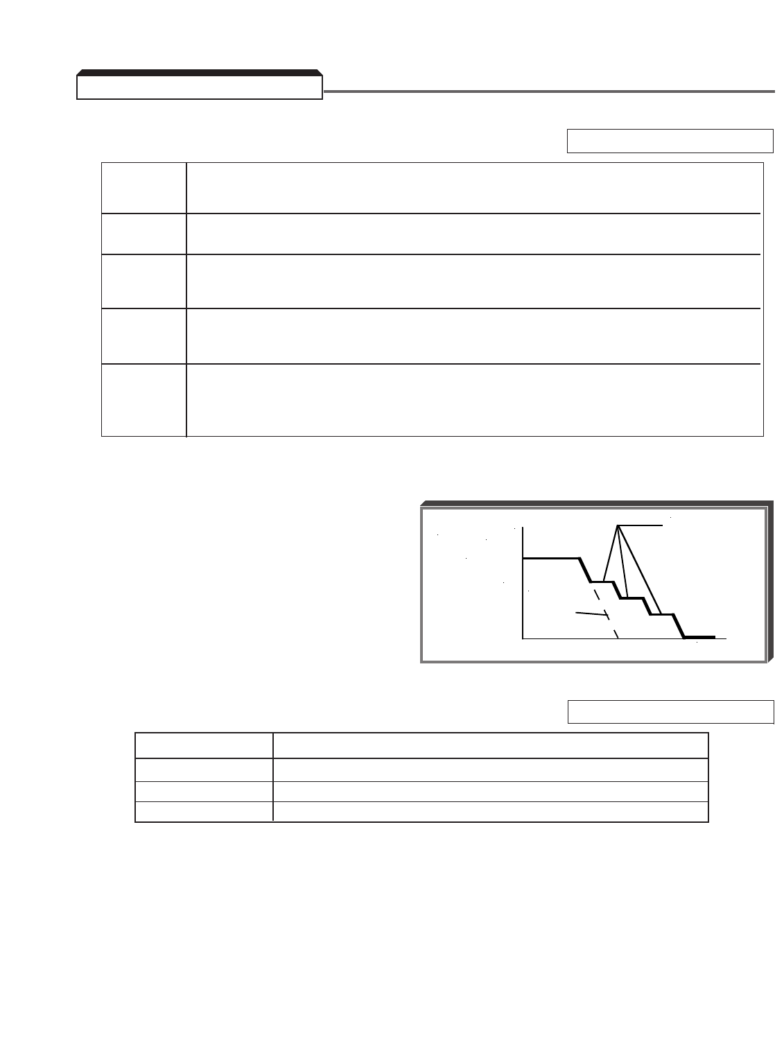
5-86
A. L3-04 : Stall Prevention Selection During Decel Factory setting: 1
Stall prevention during deceleration
automatically adjusts the deceleration rate
while monitoring the DC bus voltage to
prevent overvoltage during deceleration.
When the motor load is large or decel time
is short, actual decel time may be longer
than the set value because of
stall prevention.
B. L3-01 : Stall Prevention Selection During Accel Factory setting: 1
Setting Function
0 Stall prevention during acceleration disabled
1 Stall prevention during acceleration enabled
2 Stall prevention during acceleration enabled, auto adjust
5.39 STALL PREVENTION
TIME
FREQUENCY
SET
DECEL
TIME
Controls the
deceleration
time needed to
prevent over-
voltage fault.
L3-04 Function
Setting
0 Stall prevention during deceleration disabled. An excessively short deceleration time will
generate an overvoltage fault (OV) and the drive will stop.
1 Stall prevention during deceleration enabled (General Purpose). The DC bus voltage level
is monitored, and the deceleration rate is automatically extended to prevent an
overvoltage condition. This deceleration rate may be longer than the set value (C1-02).
2 Stall prevention during deceleration enabled, auto adjust (Intelligent). By monitoring DC
bus voltage, the deceleration rate is automatically adjusted so that deceleration can be
completed in the shortest amount of time, regardless of the set deceleration time.
3 Stall prevention during deceleration enabled, with DB resistor. This setting lengthens
decel ramp time whenever the drive goes into current limit during a deceleration.
Intended to be used when dynamic braking is installed.
Note: Not available in the flux vector control method (A1-02 = 3).
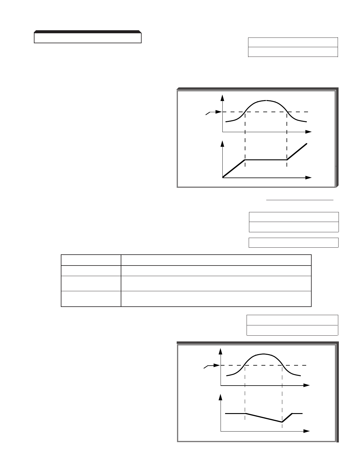
5-87
Continued
L3-02 : Stall Prevention Level During Accel
This parameter determines the actual drive output current level during an acceleration
condition. Set in percent of drive rated output current (see Appendix 2). A setting of
" 200 " will disable stall prevention during acceleration.
During acceleration, if the output
current exceeds the value in L3-02 ,
acceleration stops and frequency is
maintained. When the output current
goes below the value set in L3-02 ,
acceleration resumes.
In the constant horsepower region
[actual output frequency ≥max.
voltage frequency ( E1-06 )], the stall
prevention level during acceleration is
changed by the following formula:
Stall prevention level during
=
Stall prevention level during accel (CHP)
x
Max. voltage frequency
accel (constant horsepower) (L3-03) Actual output frequency
L3-03 : Stall Prevention Limit During Accel (CHP) Factory setting: 50
Range: 0 to 100 %
C. L3-05 : Stall Prevention Selection During Running Factory setting: 1
Setting Function
0 Stall prevention during running disabled
1 Stall prevention during running enabled;
uses Decel time 1 ( C1-02 )
2 Stall prevention during running enabled;
uses Decel time 2 ( C1-04 )
L3-06 : Stall Prevention Level During Running Factory setting: 160
Range: 30 to 200 %
This parameter determines the actual
drive output current level while operating
at set speed (frequency). Set in percent
of drive rated output current (see
Appendix 2). A setting of " 200 " will
disable stall prevention during running.
During running at set speed, if the
output current exceeds the value set in
L3-06 , the drive will begin to
decelerate. When the output current
goes below the value set in L3-06 ,
acceleration begins, up to the set
frequency.
5.39 STALL PREVENTION
t
t
MOTOR
CURRENT
OUTPUT
FREQ.
L3-06
setting
t
t
MOTOR
CURRENT
OUTPUT
FREQ.
L3-02
setting
Factory setting: 150
Range: 0 to 200 %
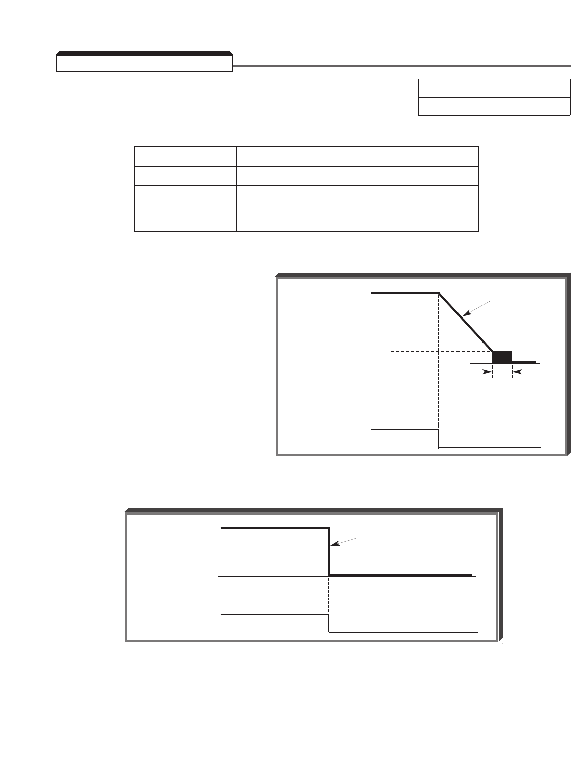
5-88
b1-03 : Stopping Method Selection Factory setting: 0
Range: 0 to 3
Selects the stopping method suitable for the application.
Setting Description
0 Deceleration (ramp) to stop
1 Coast to stop
2 Full range DC injection to stop
3 Coast to stop with timer
A. Data 0: Deceleration to Stop
Upon removal of the FWD (REV) Run
command, the motor decelerates at
the deceleration rate determined by
the time set in Decel Time 1
( C1-02 ), and DC injection braking
is applied immediately before stop.
If the decel time is too short or the
load inertia is too large, an
overvoltage ( OV ) fault may occur
on a stop command — the decel
time must be increased.
B. Data 1: Coast to Stop
Upon removal of the FWD (REV) Run command, the motor coasts to rest.
5.40 STOPPING METHOD
Output Frequency
Run Command ON OFF
Decel Time 1
( C1-02 )
Min. Output Frequency
(Frequency at DC Injection
Braking Start) ( b2-01 )
(Factory setting: 0.5 Hz) DC Injection Braking
Time at Stop ( b2-04 )
(Factory setting: 0.5 s)
Output Frequency
Run Command ON OFF
Drive output is shut OFF
when stop command is input
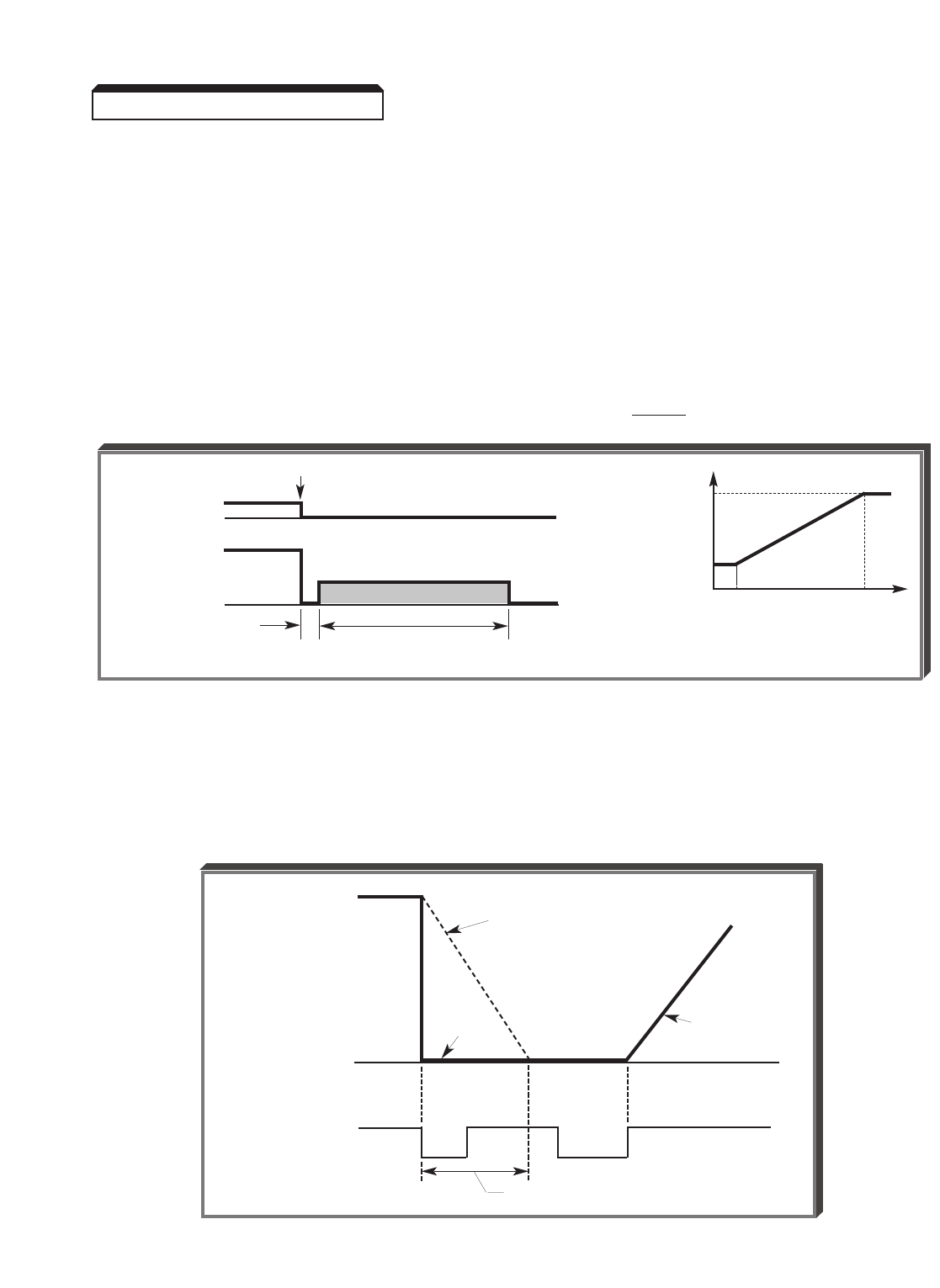
5-89
Continued
C. Data 2: Full-range DC Injection Stop
When a STOP command is issued, there is a 0.5 second time delay, before a DC injection
current is applied to two phases of the motor’s stator winding. The duration of DC braking
is a time period proportional to b2-04 (at 10% output frequency) and the level of output
frequency at the time the STOP command is issued.
Braking torque is 50-70% of full load motor torque.
EXAMPLE
b2-04 = 0.5 sec (at 10% output)
100%
Braking time at Fmax (100% output frequency) = 10% x 0.5 = 5 sec.
Full Range DC Injection Braking Stop Sequence
D. Data 3: Coast to Stop With Timer
When programmed for coast to stop with timer, a Run command is ignored if issued during
the time the motor would normally be decelerating ( C1-02 ), or for the minimum base
block time ( L2-03 ), whichever is longer.
5.40 STOPPING METHOD
Output Frequency
Run Command
Run Command ignored
ON ON ONOFF OFF
Decel Time 1
( C1-02 )
Coasting Accel Time 1
( C1-01 )
RUN CMD
OUTPUT
FREQUENCY
STOP
0.5 sec
COASTING DC BRAKING TIME
b2-04 x 10
DC IN-
JECTION
BRAKING
TIME b2-04
0 10% 100%
OUTPUT FREQUENCY
AT TIME OF STOP COMMAND

5-90
E2-01 : Motor Rated Current Factory setting: See Table A3-1
Range: 0.01 to 1500.0 A
This parameter should be set according to the rated current value shown on the motor
nameplate; this value must be within 10-120% percent of the drive rated current (refer to
Specifications in Appendices 2 & 3 of this manual).
L1-01 : Motor Overload Protection Selection Factory setting: 1
Setting Electronic Thermal Characteristics
0 Electronic thermal overload protection disabled
1 Electronic thermal overload protection enabled
L1-02 : Motor Overload Protection Time Factory setting: 8.0
Constant Range: 0.1 to 20.0 min.
This parameter sets the electronic thermal overload relay protection time. Actual overload
time can be calculated using the time from the overload characteristics curves then
multiplying that time by L1-02 /8.
The drive protects against motor overload with a UL-recognized, built-in electronic thermal
overload relay.
The electronic thermal overload function monitors motor temperature, based on drive
output current and time, to protect the motor from overheating. When the electronic
thermal overload relay is enabled, an " OL1 Motor Overloaded " fault occurs, shutting
OFF the drive output and preventing excessive overheating of the motor.
When operating with one drive connected to only one motor, an external thermal relay is
not needed. When operating several motors with one drive, install a thermal overload relay
on each motor.
5.41 THERMAL OVERLOAD PROTECTION
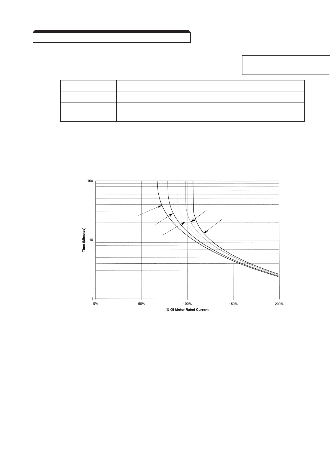
5-91
Continued
E1-02 : Motor Selection Factory setting: 0
Range: 0 to 2
Setting Electronic Thermal Characteristics
0 General-purpose motor (TEFC)
1 Blower cooled or totally enclosed non-ventilated (TEBC or TENV)
2 Vector Motor
This parameter sets whether a general-purpose or a blower-cooled motor is used. The
motor overload detection function operates differently, as shown, for each of these two
motor types.
Standard Fan Cooled Motor Overload Curve
L1-01 = 0 & L2-01 = 8.0 Minutes
0 Hz
10 Hz
20 Hz
60 Hz
40 Hz
5.41 THERMAL OVERLOAD PROTECTION
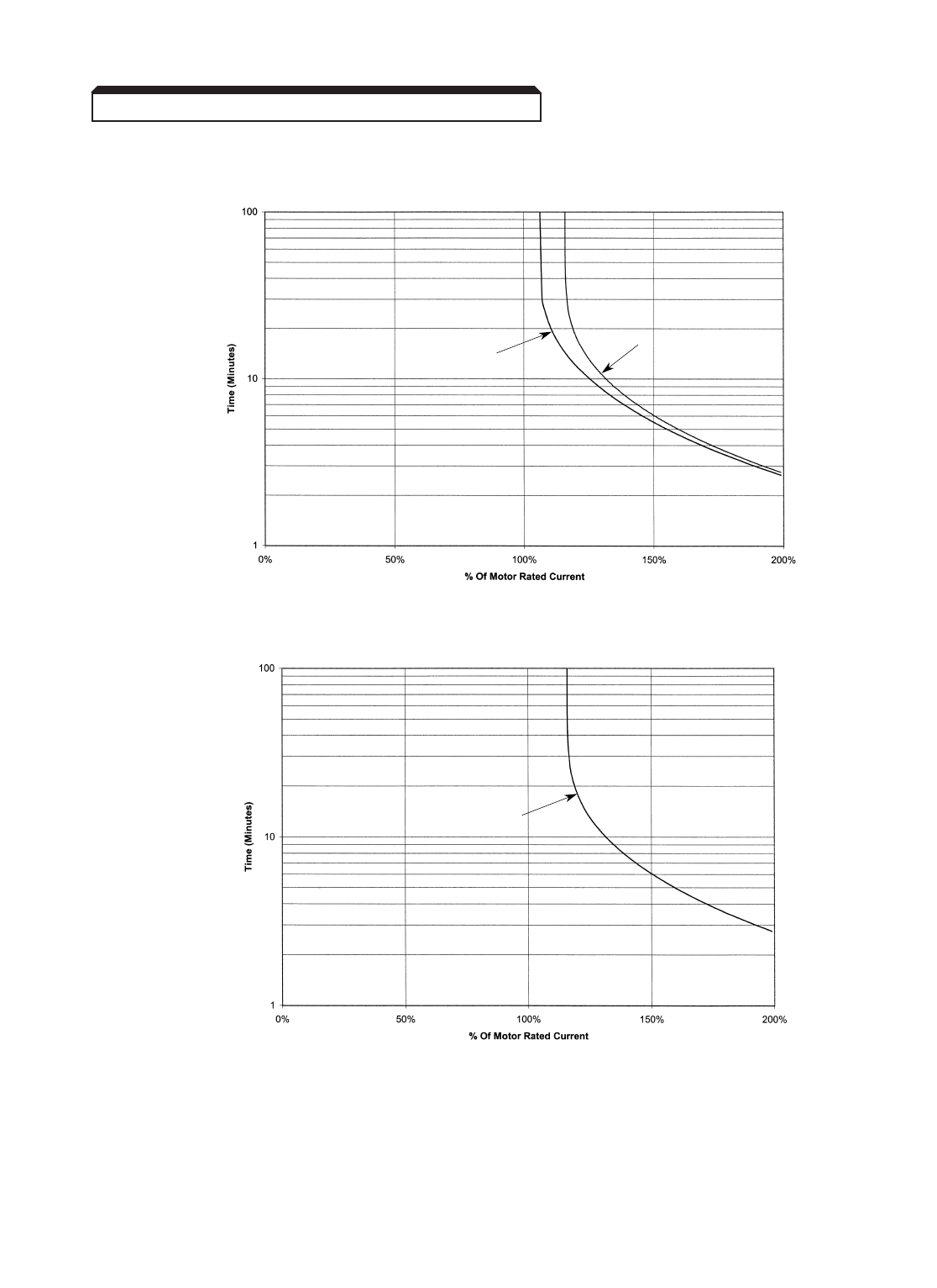
5-92
Continued
Standard Blower Cooled Motor Overload Curve
L1-01 = 1 & L1-02 = 8.0 Minutes
Vector Motor Overload Curve
L1-01 = 2 & L1-02 = 8.0 Minutes
NOTE: If a TEFC motor is going to be run at or near 100% of rated current at
frequencies below 30 Hz for an extended period of time, select the blower cooled
curve ( E1-02 = 1).
All
Frequencies
0 Hz
5.6 Hz
≥
5.41 THERMAL OVERLOAD PROTECTION
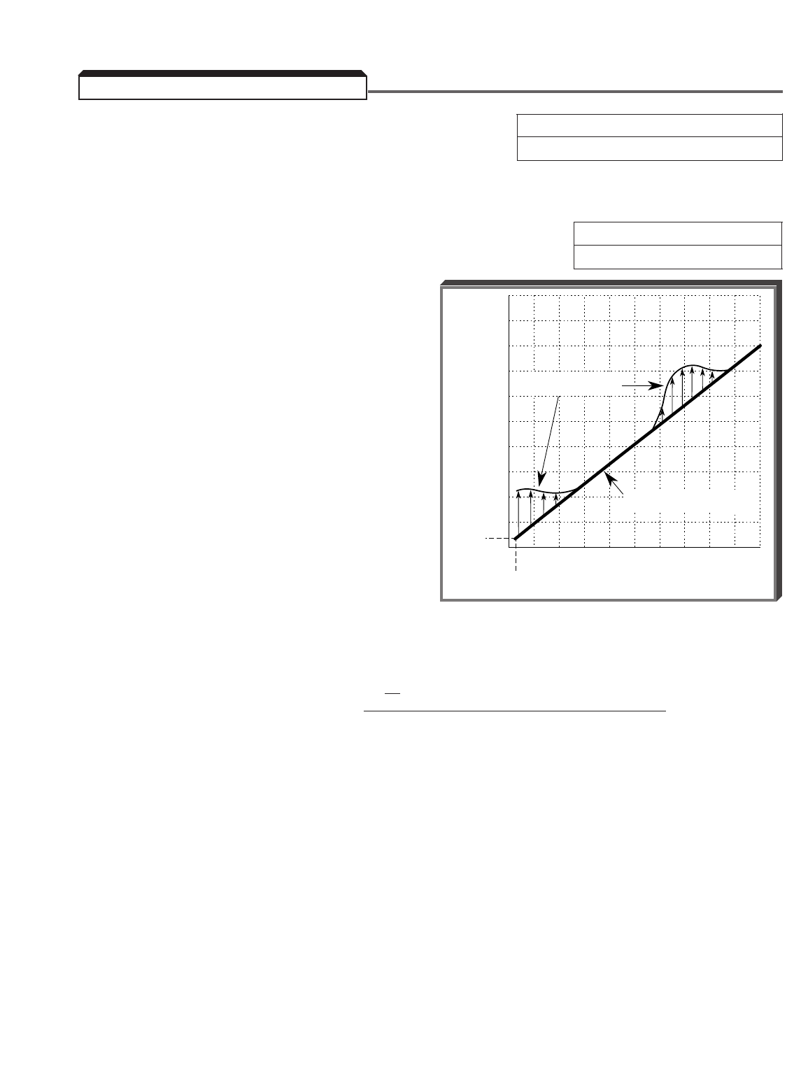
5-93
C4-02 : Torque Compensation Time Factory setting: See Table A3-2
Constant Range: 0 to 10000 ms
This parameter adjusts a time delay for the torque compensation gain. Increase to add
torque stability, decrease to improve torque response.
C4-01 : Torque Compensation Gain [ KT] Factory setting: 1.00
Range: 0.00 to 2.50
Sets the torque compensation, in increments
of 0.1. When the motor has the same
capacity as that of the drive, the gain is 1.0.
When a smaller motor is used, the gain should
be set to 1.5 (typical).
This parameter, in conjunction with E2-05
(Motor Line-to-Line Resistance) and E2-07
& E2-08 (Motor Iron Core Saturation
Coefficient 1 & 2), is used by the drive’s
automatic torque boost function to match the
drive’s output voltage boost to the motor
load. Except for the most demanding of high
starting torque applications, the factory
settings of these parameters will be
adequate. The factory settings are
programmed to match the performance
characteristics of typical AC motors.
The calculation of compensated torque
uses the following formula:
(
√3
•Vac •Iac •Cos Φ) – WI – Rcable
Compensated Value ≈Frequency x KT
Where
* WI = E2-07, E2-08
Rcable = E2-05
KT= C4-01
Φ= Power Factor (calculated by the drive)
* Adjusted by Auto-tune feature.
OUTPUT FREQUENCY
( HZ )
OUTPUT VOLTAGE
( VAC )
460
345
230
115
14 V
0
0
1.5 HZ
30 60
PROGRAMMED V/F PATTERN
(NO LOAD)
AUTO TORQUE BOOST
V/F PATTERN
Example of Torque Compensation
Operation
5.42 TORQUE COMPENSATION

5-94
Continued
C4-03 : Forward Torque Compensation At Start Factory setting: 0.0
(Open Loop Vector Only) Range: 0.0 to 200.0 %
C4-04 : Reverse Torque Compensation At Start Factory setting: 0.0
(Open Loop Vector Only) Range: -200.0 to 0.0 %
C4-05 : Torque Compensation At Start Time Factory setting: 10
Constant (Open Loop Vector Only) Range: 0 to 200 ms
Parameters C4-03 thru C4-05 help to improve the starting / breakaway torque response
when using the open loop vector control method (A1-02 = 2). The amount of torque
applied at start when a forward run is commanded is set by parameter C4-03. The amount
of torque applied at start when a reverse run is commanded is set by parameter C4-04.
The amount of time that the torque is applied is controlled by parameter C4-05.
5.42 TORQUE COMPENSATION

5-95
NOTE: This function can only be used in Flux Vector control method ( A1-02 = 3 ).
One of two methods may be used to run the drive in torque control.
A1. Torque control can be set by programming parameter d5-01 .
d5-01 : Torque Control Selection Factory setting: 0
Setting Control Method
0 Speed Control
1 Torque Control
OR
A2. Torque control can be set by programming a multi-function input terminal for Speed /
Torque Control Selection (Data 71). The drive will be in torque control when the
corresponding input terminal is closed. This selection can be delayed by programming
d5-06 for a delay time.
H1-01 thru H1-06 : Multi-function Input Data 71: Speed / Torque
(Term. 3 thru 8) Control Selection
d5-06 : Speed/Torque Control Selection Timer Factory setting: 0
Range: 0 to 100 ms
B. Regardless of which way torque control is selected, the torque reference will be input
to the drive at terminals 16 & 17 (Multi-function analog input).
H3-05 : Multi-function Analog Input Data 13: Torque
(Term. 16) Reference
The scaling (with factory defaults for gain & bias) is 10V on terminal 16 = 100% of the
motor rated torque.
5.43 TORQUE CONTROL (COMMAND)
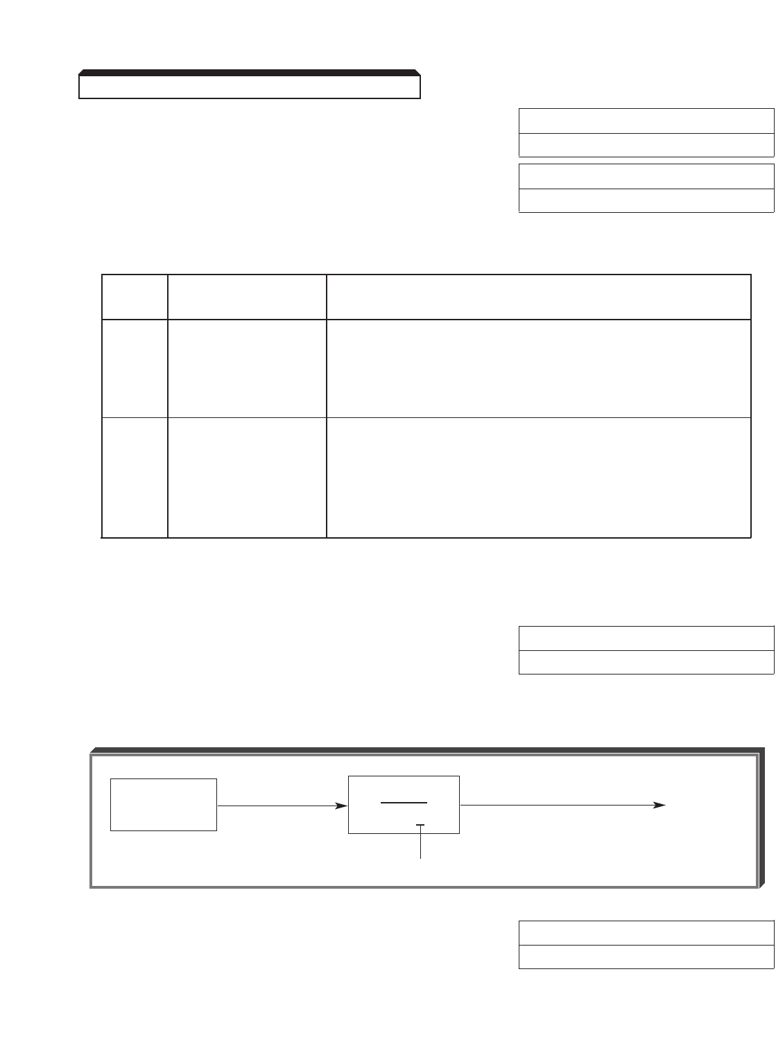
5-96
Continued
C. d5-03 : Speed Limit Selection Factory setting: 1
Range: 1 or 2
d5-04 : Speed Limit Factory setting: 0
Range: –120 to +120 %
When setting the drive for torque control, a speed limit is required. This speed limit can
come from either a programmed value ( d5-04 ), or an analog input (Term. 13 or 14).
d5-03
Setting Speed Limit Source Programming Required
1Analog Input Reference source needs to be set for terminals ( b1-01 = 1 )
(Term. 13 or 14) AND the drive needs to be set for “Remote”reference
(REF light on the Digital Operator needs to be on).
and
d5-03 (Speed Limit Selection) must be set to “Analog Input”.
2Programmed d5-04 is set as a percentage of the maximum frequency.
Value (NOTE: this value can be set to a negative value by pressing
( d5-04 ) the “up arrow”or “down arrow”keys while the left-most zero is
flashing on the Digital Operator display.
and
d5-03 (Speed Limit Selection) must be set to “Program Setting”.
D. Torque compensation can be utilized by programming terminal 14 for Torque
Compensation ( H3-09 = 14). The analog voltage present on terminal 14 will determine
torque compensation value.
E. d5-02 : Torque Reference Delay Time Factory setting: 0
Range: 0 to 1000 ms
This function is used to avoid excessive changes in torque, which may be caused by
abnormal resonance when the torque reference changes rapidly.
F. d5-05 : Speed Limit Bias Factory setting: 10
Range: 0 to 120 %
Sets bias value for speed limit (torque control mode only) as a percentage of maximum
frequency.
5.43 TORQUE CONTROL (COMMAND)
TORQUE REF.
(from Term. 16)
1
1 + sT
TORQUE
REF.
d5-02
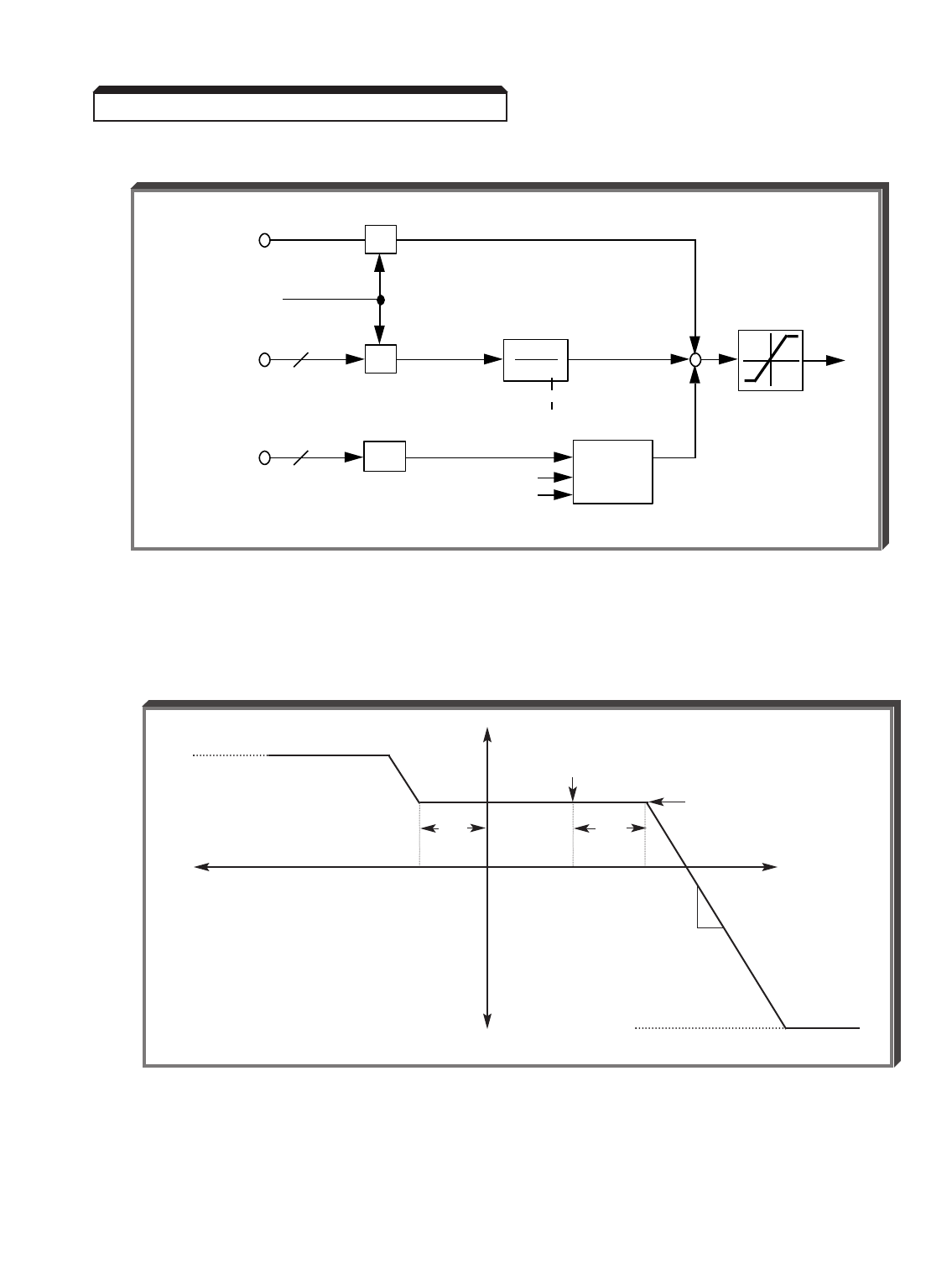
5-97
Continued
G. Simplified block diagram:
5.43 TORQUE CONTROL (COMMAND)
TORQUE
COMPENSATION
(TCMP)
TORQUE
REFERENCE
(TREF)
TORQUE LIMIT
+
++
SPEED
LIMIT
(SLIM)
SFS
1
1 + ST
T = d5-02
SPEED
LIMITING
CIRCUIT
Iq
Φ
MOTOR SPEED
Term. 14
d5-05
Term. 16
H3-01 or H3-09 = 14
Programmed
Value ( d5-04 )
or
Term. 13
H3-05 or H3-09 = 14
The figure below shows the relationship between speed, speed limit, torque, and
torque limit.
(-) Speed
Reverse Regenerative Torque Limit
L7-04
(+) Torque
d5-05
Speed Limit
Bias
d5-05
Speed Limit
Bias
(-) Torque
Slope is proportional
to C5-01
Forward Regenerative Torque Limit
L7-03
(+) Speed
Torque Reference
Speed
Limit
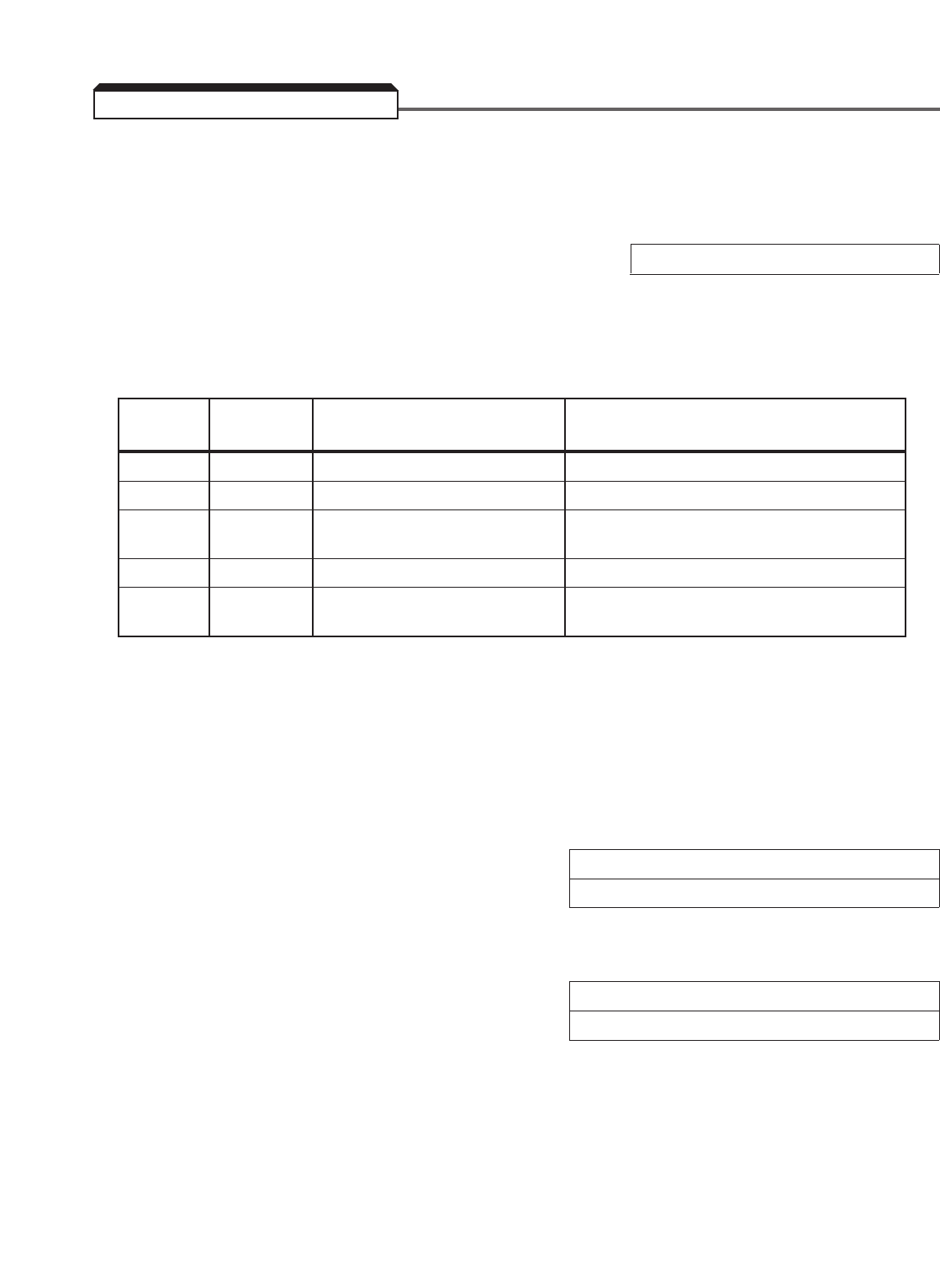
5-98
Torque detection is used to compare drive rated output current with the overtorque
detection level. When the output current is equal to or greater than the defined level, an
overtorque condition exists. This will be indicated as an " OL3 " fault on the Digital
Operator. This feature can be selected to operate over a wide range of conditions.
A. L6-01 : Torque Detection Selection 1 Factory setting (each): 0
L6-04 : Torque Detection Selection 2
These parameters determine whether the torque detection function of the drive is
enabled, under what conditions it will detect for overtorque, and what operation it will
perform after detecting an overtorque.
Torque Operation After Detection
Setting Detection Overtorque Detection Condition
0 Disabled —— ——
1 Enabled Continues Only at set frequency
2 Enabled Continues At all times except during stopping
or DC injection braking
3 Enabled Coast to stop Only at set frequency
4 Enabled Coast to stop At all times except during stopping
or DC injection braking
—For overtorque detection during accel or decel, set to " 2 " or " 4 ".
—For continuous operation after overtorque detection, set to " 1 " or
" 2 ". During detection, the Digital Operator displays and “ OL3 ”
alarm (blinking).
—To stop the drive at an overtorque detection fault, set to " 3 " or
" 4 ". At detection, the Digital Operator displays an " OL3 " fault.
B. L6-02 : Overtorque Detection Level 1 Factory setting (each): 150
L6-05 : Overtorque Detection Level 2 Range (each): 0 to 300 %
These are the reference points for determining that an overtorque condition exists. Set as
a percent of drive rated current (see Appendix 2).
C. L6-03 : Overtorque Detection Time 1 Factory setting (each): 0.1
L6-06 : Overtorque Detection Time 2 Range (each): 0.0 to 10.0 seconds
Determines how long an overtorque condition must exist before another event will occur,
e.g. coast to stop, multi-function output change of state, or " OL3 " warning or fault
display.
5.44 TORQUE DETECTION
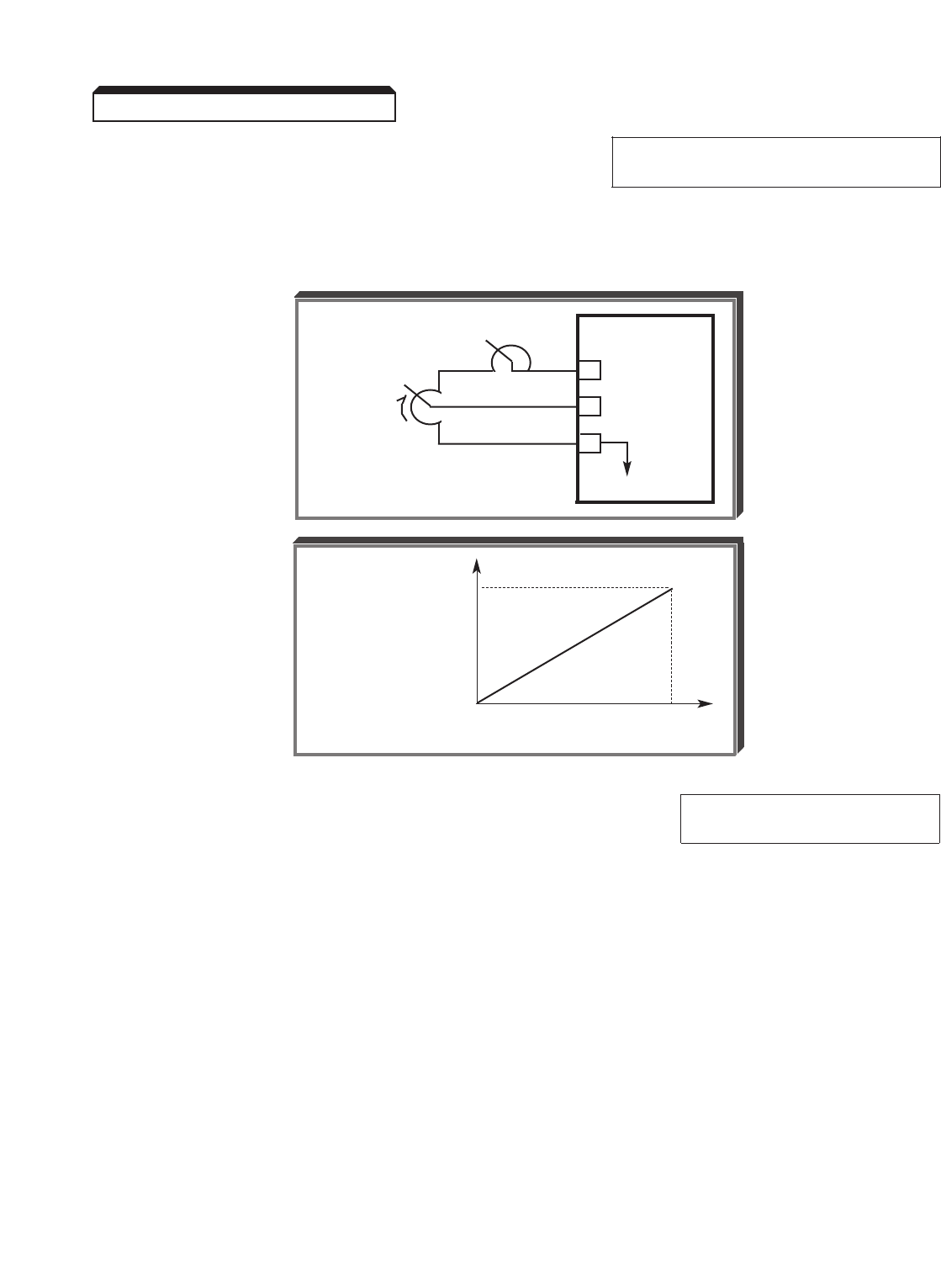
5-99
Continued
D. H3-05 : Multi-function Analog Input Data 7: External Overtorque
(Term. 16) Detection Level Adjustment
The multi-function analog input at terminal 16 may be configured to allow analog control
of the overtorque detection level. When this function is programmed into H3-05 , the
internal overtorque detection level ( L6-02 ) is disabled.
E. H2-01 : Multi-function Output (Term. 9 & 10) Data B: Overtorque
H2-02 : Multi-function Output (Term. 25-27) Detection
H2-03 : Multi-function Output (Term. 26-27)
A contact, or two open collector outputs, can be programmed to change states during an
overtorque detection condition.
5.44 TORQUE DETECTION
1R drive/G5
15 +15V
16 0-10V (20 KΩ)
17
C
OVERTORQUE
DETECTION
LEVEL
200%
OVERTORQUE
DETECTION
LEVEL
0%
0V 10V
VOLTAGE REFERENCE

5-100
Continued
EXAMPLE OF OVERTORQUE DETECTION
L6-01 setting: 2— Detect during run, energize multi-function output, display alarm
L6-02 setting: 110 % — Level at which torque detection is sensed
L6-03 setting: 1.0 s — Time delay before overtorque event occurs
H2-01 setting: B— "Torque Detection 1" multi-function output (normally open)
110%
TORQUE 100%
REFERENCE
00.5 sec 1 sec
60 Hz
MOTOR
SPEED
0
RUN
SIGNAL
CONTACT
OUTPUT
(TORQUE
DETECTION 1)
TERM. 9 & 10
Torque Detection Timing Diagram
5.44 TORQUE DETECTION
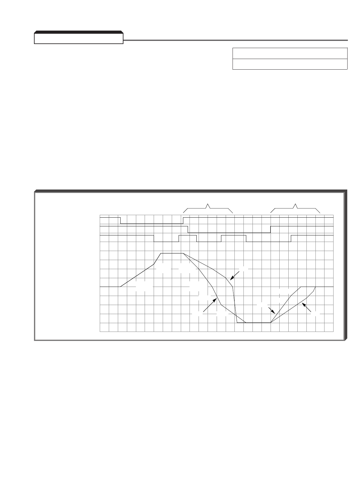
A. L7-01 : Forward Torque Limit Factory setting (each): 200
L7-02 : Reverse Torque Limit Range (each): 0 to 300 %
L7-03 : Forward Regenerative Torque Limit
L7-04 : Reverse Regenerative Torque Limit
These parameters provide the ability to limit the amount of torque produced by the motor
in all four quadrants of operation: FWD motoring, REV motoring, FWD regen, and REV regen.
The torque limit functions as a torque current reference limit. Torque limit is active in both
speed mode and torque mode.
EXAMPLE:
L7-01 Forward Torque Limit = 150 %
L7-02 Reverse Torque Limit = 150 %
L7-03 Forward Regenerative Torque Limit = 20 %
L7-04 Reverse Regenerative Torque Limit = 20 %
During regeneration, the regeneration torque limits have been exceeded, thus the actual
speed (Sfb) doesn’t follow the speed reference (Sref). This example also demonstrates the
accel/decel selection 1 ( H1-06 data 7).
5.45 TORQUE LIMIT
C1-02
C1-02
(10 sec)
C1-04
(7.5 sec)
C1-01
C1-04
FWD. RUN
REV. RUN
H1-06 : 7
(Accel/Decel
Time Selection 1)
SPEED FEEDBACK: Sfb.
SPEED REFERENCE: Sref.
C1-01
(15 sec)
C1-03
(5 sec)
Sfb.
Sref.
Sref.
Sfb.
C1-03
FWD Regen Torque Lim. = 20%
REV Regen Torque Lim. = 20%
5-101
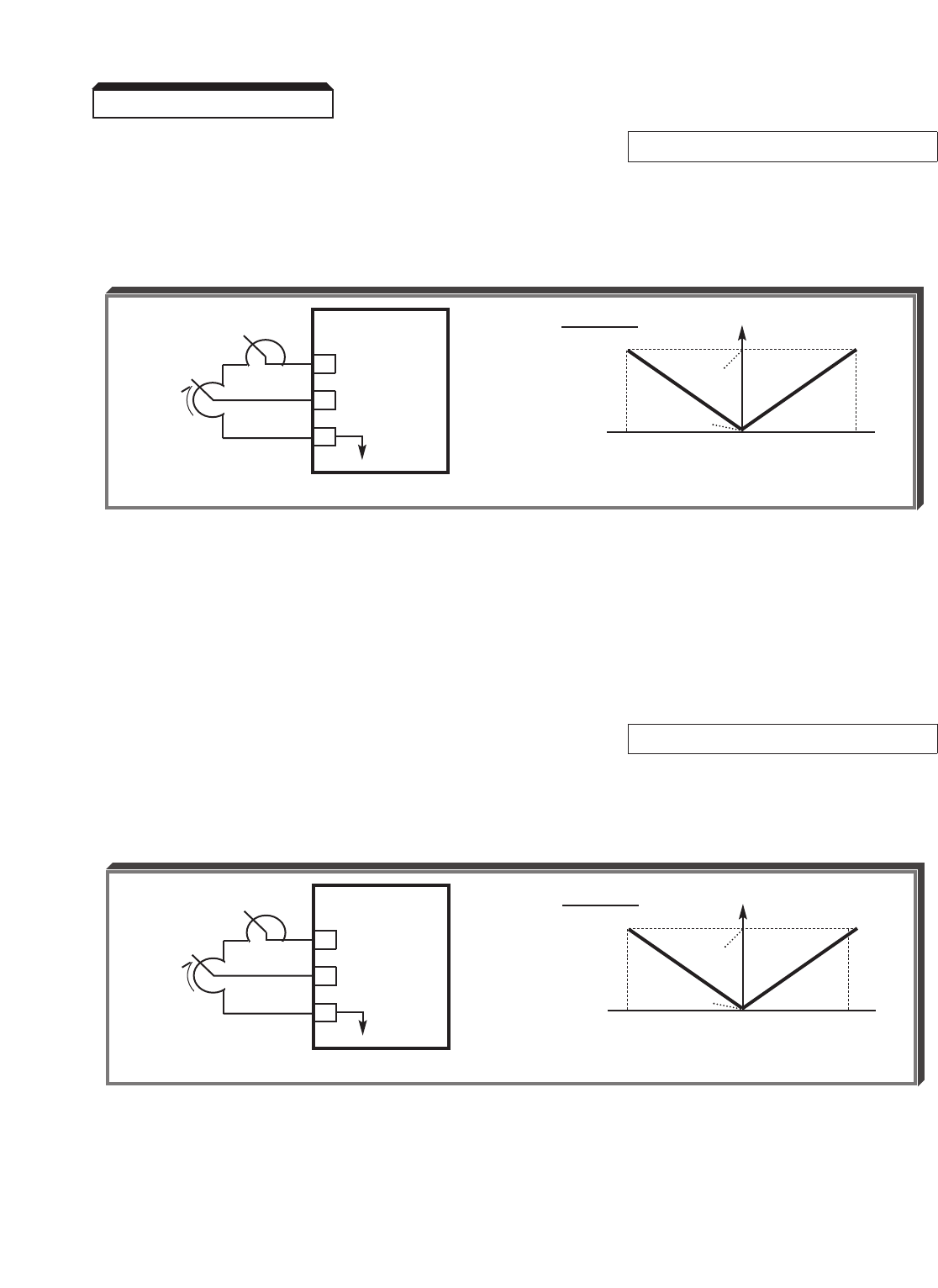
Continued
B. H3-05 : Multi-function Analog Input 1 Selection Data 10: FWD Torque Limit
(Term. 16)
The multi-function analog input at terminal 16 may be configured to allow analog control of
the torque limit for both FWD & REV modes. However, the analog reference controls both
FWD torque limit & REV regen torque limit.
NOTE: A minimum priority circuit is associated with the torque limit function,
which means that the lowest value torque limit setting will have priority.
EXAMPLE:
Forward Torque Limit L7-01 = 80 %
FWD Torque Limit (Term. 16) = 100% (10V)
The L7-01 value will have priority over the analog reference value.
Data 11: REV Torque Limit
The multi-function analog input at terminal 16 may be configured to allow analog control of
the torque limit for both FWD & REV modes. However, the analog reference controls both
REV torque limit & FWD regen torque limit.
NOTE: A minimum priority circuit is associated with the torque limit function,
which means that the lowest value torque limit setting will have priority.
5.45 TORQUE LIMIT
TORQUE
LIMIT
1R
1R is a calibration pot only.
GPD 515/G5
15 +15V
16 0-10V (20K Ω)
17
C
*
*
TORQUE
LIMIT
1R
1R is a calibration pot only.
GPD 515/G5
15 +15V
16 0-10V (20K Ω)
17
C
*
*
H3-05 = 10
FWD 100%
TORQUE
LIMIT
0%
–10V 0V 10V
MULTI-FUNCTION ANALOG INPUT
H3-05 = 11
REV 100%
TORQUE
LIMIT
0%
–10V 0V 10V
MULTI-FUNCTION ANALOG INPUT
5-102
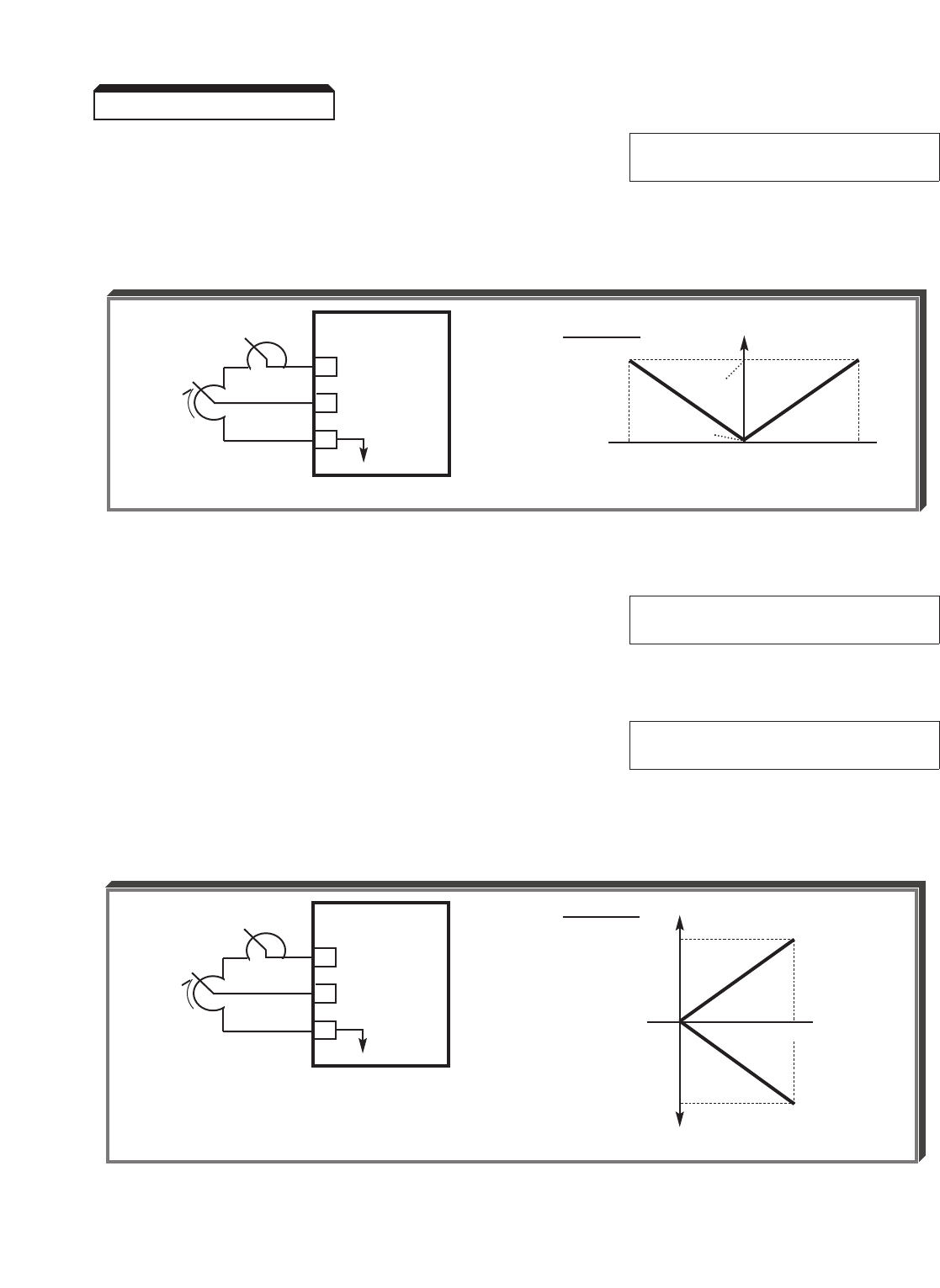
5-103
Continued
Data 12: Regenerative Torque
Limit
The multi-function analog input at terminal 16 may be configured to allow analog control of
the torque limit for both FWD & REV modes. However, the analog reference controls both
FWD torque limit & REV regenerative torque limits.
NOTE: A minimum priority circuit is associated with the torque limit function,
which means that the lowest value torque limit setting will have priority.
Data 13* : FWD & REV Torque
Limit
* NOTE: When H3-05 is set for " 13", Terminal 16 is a torque limit ONLY if speed
mode is selected ( d5-01 = 0 ). If d5-01 = 1 (torque mode), Terminal 16 will be
a torque reference.
Data 15: FWD & REV Torque
Limit
The multi-function analog input at terminal 16 may be configured to allow analog control of
the torque limit for both FWD & REV modes. However, the analog reference controls both
FWD & REV torque limits, and the FWD & REV regenerative torque limits.
NOTE: A minimum priority circuit is associated with the torque limit function,
which means that the lowest value torque limit setting will have priority.
5.45 TORQUE LIMIT
TORQUE
LIMIT
1R
1R is a calibration pot only.
GPD 515/G5
15 +15V
16 0-10V (20K Ω)
17
C
*
*
TORQUE
LIMIT
1R
1R is a calibration pot only.
GPD 515/G5
15 +15V
16 0-10V (20K Ω)
17
C
*
*
H3-05 = 12
REGEN 100%
TORQUE
LIMIT
0%
–10V 0V 10V
MULTI-FUNCTION ANALOG INPUT
H3-05 = 15
100%
TORQUE
LIMIT
0%
0V 10V
–100%
MULTI-FUNCTION ANALOG INPUT
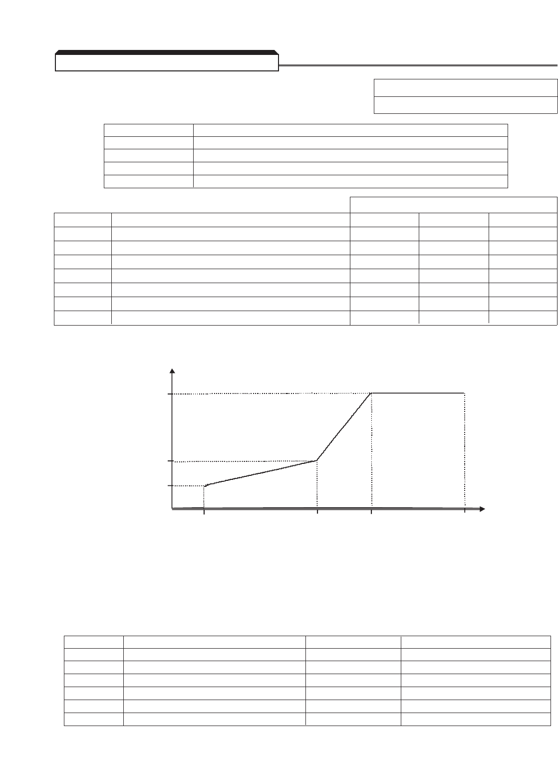
E3-01: Control Method Selection (Motor 2) Factory setting : 2
Range : 0 to 4
These seven parameters define the V/f pattern for motor 2. The illustration below shows
how these parameters relate to each other in establishing the V/f pattern.
Parameter E3-01 determines which control method the drive will use when motor 2 is
selected. If E3-01 is set to a 2 or a 3, the second motor needs to be auto-tuned. First
select motor 2 (via a multi-function input) then run the auto-tuning routine as described in
Section 2.2A or 2.2B. Parameters E4-01 thru E4-07 and E5-01 thru E5-06 are set
when an auto-tune is executed on motor 2. If auto-tuning is not possible, use section 2.4
and the table below to manually calculate and enter the motor parameters.
5-104
5.45.1 TWO MOTOR OPERATION
Vmax
(E4-02)
Va
(E4-05)
Vmin
(E4-07)
OUTPUT
VOLTAGE
Fmin
(E4-06)
Fa
(E4-04)
Fbase
(E4-03)
Fmax
(E4-01)
OUTPUT FREQUENCY
Parameter Description Set by Auto-Tune? Equivalent Motor 1 Parameter
E5-01 Motor Rated Current (Motor 2) Yes E2-01
E5-02 Motor Rated Slip (Motor 2) Yes E2-02
E5-03 Motor No-load Current (Motor 2) Yes E2-03
E5-04 Number of Motor Poles (Motor 2) Yes E2-04
E5-05 Motor Line-to-line Resistance (Motor 2) Yes E2-05
E5-06 Motor Leakage Inductance (Motor 2) Yes E2-06
Setting Description
0 V/f control
1 V/f with PG feedback
2 Open loop vector
3 Flux vector
Factory Settings
Parameter Description 230V Ratings 460V Ratings 600V Ratings
E4-01 Maximum Output Frequency (Motor 2) 60.0 Hz 60.0 Hz 60.0 Hz
E4-02 Maximum Voltage (Motor 2) 230.0 V460.0 V575.0 V
E4-03 Base Frequency (Motor 2) 60.0 Hz 60.0 Hz 60.0 Hz
E4-04 Mid. Output Frequency (Motor 2) 3.0 Hz 3.0 Hz 3.0 Hz
E4-05 Mid. Output Voltage (Motor 2) 12.6 V25.3 V36.6 V
E4-06 Min. Output Frequency (Motor 2) 0.5 Hz 0.5 Hz 0.5 Hz
E4-07 Min. Output Voltage (Motor 2) 2.3 V4.6 V6.5 V
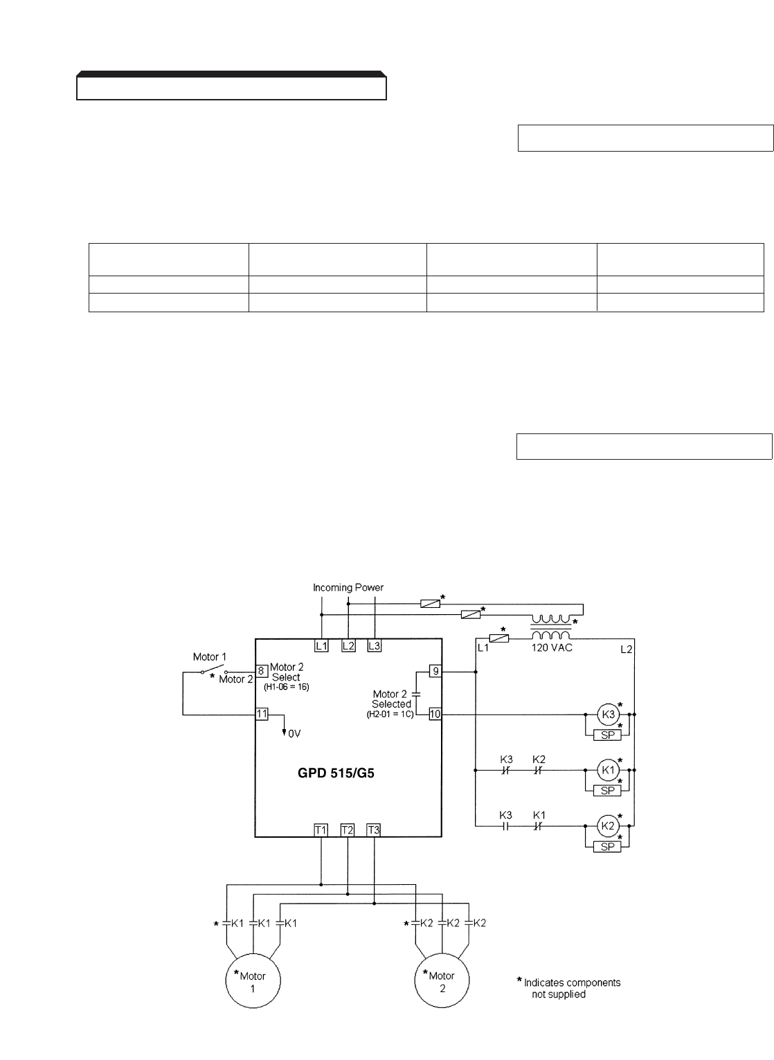
Continued
H1-01 thru H1-06 : Multi-function Inputs Data 16: Motor 2 Select
(Term. 3 thru 8)
This function allows the drive to control two different motors at different times. When a
multi-function input is set to a data of “16”, two different sets of motor parameters can
be selected with a contact closure.
The table above illustrates which parameters are used when motor 1 or motor 2 is
selected.
The drive needs to be in the stop condition before the multi-function input is opened or
closed, otherwise a “Motor Running” warning will be displayed.
H2-01 thru H2-03 : Multi-function Outputs Data 1C : Motor 2 Selected
(Term. 9 & 10, 25,
26, & 27)
When a multi-function output terminal is programmed to a data of “1C”, that output will
close whenever motor 2 is selected. As shown in the example below, a multi-function input
selects between motor 1 and motor 2. The multi-function output will only change states
when the drive is in the stopped condition in order to prevent internal drive damage.
Multi-Function Input Control Method Setting V/f Pattern Motor
Term. Parameter Parameters Parameters
Open (Motor 1) A1-02 E1-04 thru E1-13 E2-01 thru E2-09
Closed (Motor 2) E3-01 E4-01 thru E4-07 E5-01 thru E5-06
5-105
5.45.1 TWO MOTOR OPERATION
5-106
A2-01 thru A2-32 : User Select Parameters Data: Programmable
(see below)
This function allows the user to select an exclusive list of parameters, providing a
customized access level.
When the Access Level ( A1-01 ) is set to "Advanced", the "Function A2 User
Constants" option will appear in the top level of the menu. The parameters desired for
custom access are entered into A2-XX parameters.
After any parameters have been programmed, the "User Program" option appears in the
choice of Access Levels. Choosing this option will allow only those parameters
programmed in A2-XX to be accessed in "Programming". Up to 32 parameters may be
programmed. To add parameters to or delete parameters from A2-XX , change the
Access Level back to Advanced.
o2-03 : User Parameter Default Value Factory setting: 0
Range: 0 to 2
Setting Description
0 Disabled
1 Set Default
2 Clears all
This parameter is used to store settings as initialization values. Set all parameters to the
user-defined default values, then set o2-03 to "1"; each changed parameter value is
then accepted and stored as its initialization value. Up to 50 parameters may have data
stored as their new (user-defined) initialization value.
"User Initialize" becomes available in the Initialize Parameter option ( A1-03 ). Setting
this parameter to "1110" resets all settings to the user-defined defaults, rather than to
factory defaults.
E1-03 : V/f Pattern Selection
This parameter is factory preset to " F". Table 5-4 describes 14 other preset patterns,
one of which may be better suited for your specific application and load characteristics.
However, if none of these patterns are suitable, this parameter can be set to " F" (V/f
pattern - custom). The exact pattern is then defined by the settings of E1-04 thru
E1-10 , described in paragraph 5.48, V/f Pattern – Custom.
5.46 USER PARAMETERS
5.47 V/f PATTERN - STANDARD
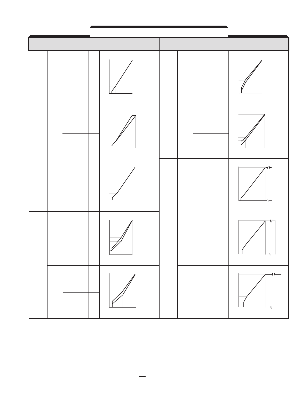
5-107
APPLI- Sn-02 V/f PATTERN APPLI- Sn-02 V/f PATTERN
CATION SPECIFICATION DATA (NOTE 3 CATION SPECIFICATION DATA (NOTE 3)
Starting
50Hz 050Hz Torque 8
Low
Starting
Torque 9
High
60Hz Starting
60Hz Satura- 160Hz Torque A
tion Low
50Hz Starting
Satura- 2Torque B
tion High
72Hz 390Hz C
Variable
50Hz Torque 4120Hz D
1
Variable
Torque 5
2
Variable
60Hz Torque 6180Hz E
1
Variable
Torque 7
2
NOTES:
✵ Consult Yaskawa for assistance when these settings are desired (typically used for blowers, centrifugal pumps, and fans).
1. The following conditions must be considered when selecting a V/f pattern:
– Pattern matches the voltage-frequency characteristics of the motor.
– Maximum motor speed.
2. V/f pattern for high starting torque should be selected for:
– Wiring distance.
– Large voltage drop at start.
– AC reactor connected to drive input or output.
– Use of motor rated below drive max. output.
3. Patterns shown are for 230V input; for other input, multiply all (V) values by (VIN/230). i.e., for 460V input, multiply
by 460/230 = 2. For 575V input, multiply by 575=2.5
GP
EU
NR
EP
RO
AS
LE
HT
IO
GR
HQ
U
SE
T
A
R
T
I
N
G
VT
AO
RR
IQ
AU
BE
L
E❋
CO
OP
NE
SR
TA
AT
NI
TO
N
H
O
R
S
E
P
O
W
E
R
(V)
230
57.5
40.2
11.5
9.2
0 1.5 25 60 (Hz)
7
6
(V)
230
34.5
28.9
0 4.5 6 60 (Hz) 180
(V)
230
40.2
20.7
0 3 6 60 120 (Hz)
(V)
230
57.5
40.2
11.5
9.2
0 1.3 25 50 (Hz)
5
4
(V)
230
17.2
11.5
0 2.3 4.5 60 90 (Hz)
(V)
230
17.2
11.5
0 1.8 3.6 60 72(Hz)
(V)
230
26.4
20.7
14.9
0 1.5 3 60 (Hz)
b
A
(V)
230
26.4
20.7
16.1
13.8
0 1.3 2.5 50 (Hz)
9
8
(V)
230
17.2
11.5
0 1.5 3 50 60 (Hz)
2
1,
F
(V)
230
17.2
11.5
0 1.3 2.5 50 (Hz)
APPLI- E1-03 V/f PATTERN APPLI- E1-03 V/f PATTERN
CATION SPECIFICATION DATA (NOTE 3) CATION SPECIFICATION DATA (NOTE 3)
Table 5-4. Standard (Preset) V/f Patterns
230
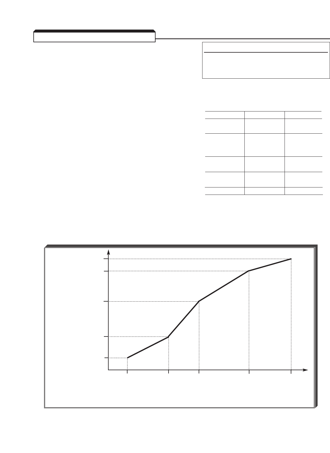
5-108
A. E1-01 : Input Voltage Setting
This parameter should be set to match the rated (nominal) input voltage.
Initial Voltage Values
230V RATINGS 460V RATINGS 600V RATINGS
B. E1-04 : Maximum Output Frequency
E1-05 : Maximum Voltage . . . . . . . . . . . . . 230.0 V460.0 V575.0 V
E1-06 : Base Frequency
E1-07 : Mid. Output Frequency A
E1-08 : Mid. Output Voltage A . . . . . . . . . . 12.6 V25.3 V36.6 V
E1-09 : Min. Output Frequency
E1-10 : Min. Output Voltage. . . . . . . . . . . . 2.3 V4.6 V6.5 V
E1-11 : Mid. Output Frequency B
E1-12 : Mid. Output Voltage B . . . . . . . . . . 0.0 V0.0 V0.0 V
E1-13 : Base Voltage . . . . . . . . . . . . . . . . . 0.0 V0.0 V0.0 V
These ten parameters define the custom V/f pattern, only if E1-03 is set to " F "
(see paragraph 5.47). The illustration below shows how these constants relate to each
other in establishing the custom V/f pattern.
5.48 V/f PATTERN - CUSTOM
V/f Characteristics Set by E1-04 thru E1-10
Vmax
( E1-05 )
VB
( E1-12 )
Vbase
( E1-13 )
OUTPUT
VOLTAGE
VA
( E1-08 )
Vmin
( E1-10 )
Fmin FAFbase FBFmax
( E1-09 )( E1-07 ) ( E1-06 )( E1-11 )( E1-04 )
OUTPUT FREQUENCY
Factory Setting: 230, 460or 575V
Range: 155 to 255 V (230V ratings)
310 to 510 V (460V ratings)
445 to 733 V (600V ratings)

5-109
Continued
NOTE: To establish a V/f pattern with a straight line from Fmin to Fbase, set
FA= Fmin, FB= 0.0 Hz, and Vbase = 0.0 V. The settings of VA, VBand Vbase
are then disregarded and do not affect the V/f pattern.
IMPORTANT
The parameter settings are checked whenever power is applied to
the drive, or each time the ENTER key is pressed while in the
Program mode. A parameter set value failure ( OPE5 ) will occur if
any part of the following relationship among E1-04 thru E1-13
is not TRUE:
Fmax ≥FB≥Fbase ≥FA≥Fmin (unless FAor FB= 0.0)
5.48 V/f PATTERN - CUSTOM
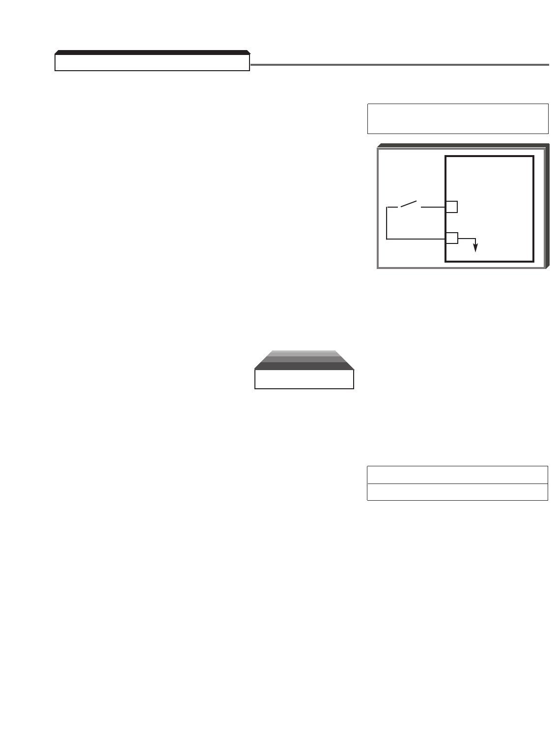
5-110
NOTE: This function can only be used in Flux Vector control method ( A1-02 = 3 ).
A. H1-01 thru H1-06 : Multi-function Input Data 72: Zero Servo Command
(Term. 3 thru 8) (for Speed control mode only)
By programming data " 72 " into one of the multi-function
input parameters ( H1-01 thru H1-06 ), one of the multi-
function input terminals (3 thru 8) becomes a zero-servo
control selection input. When the input terminal (i.e.
external contact) is open, the zero-servo function is
disabled, and when the contact is closed, the zero-servo
function is enabled.
The purpose of the zero-servo function is to provide
position control capability at zero speed. When zero-servo
is enabled, and the actual speed is less than the DC Injection Start Frequency ( b2-01 ),
the shaft position is maintained by monitoring the PG feedback pulses, and correcting the
position error. However, this function doesn’t have the same capabilities of a position
controller, because there is no marker pulse feedback. Therefore, it will not stop in the
same position every time the servo function is enabled.
CAUTION
Applications that require decelerating large inertia loads in very short decel times
may cause overshoots, and a possible runaway condition, causing equipment
damage. Adjustment of zero-servo gain ( b9-01) may be required. Setting b9-01
to " 0 " may correct a runaway condition.
b2-01 : DC Injection Braking Start Frequency Factory setting: 0.5
Range: 0.0 to 10.0 Hz
The speed level at which the zero-servo function is enabled is determined by b2-01 (DC
Injection Braking Start Frequency), and the closure of the multi-function input. This
function also determines operation at zero speed.
5.49 ZERO-SERVO CONTROL
GPD 515/G5
8
11
0V
o o
ZERO
SERVO
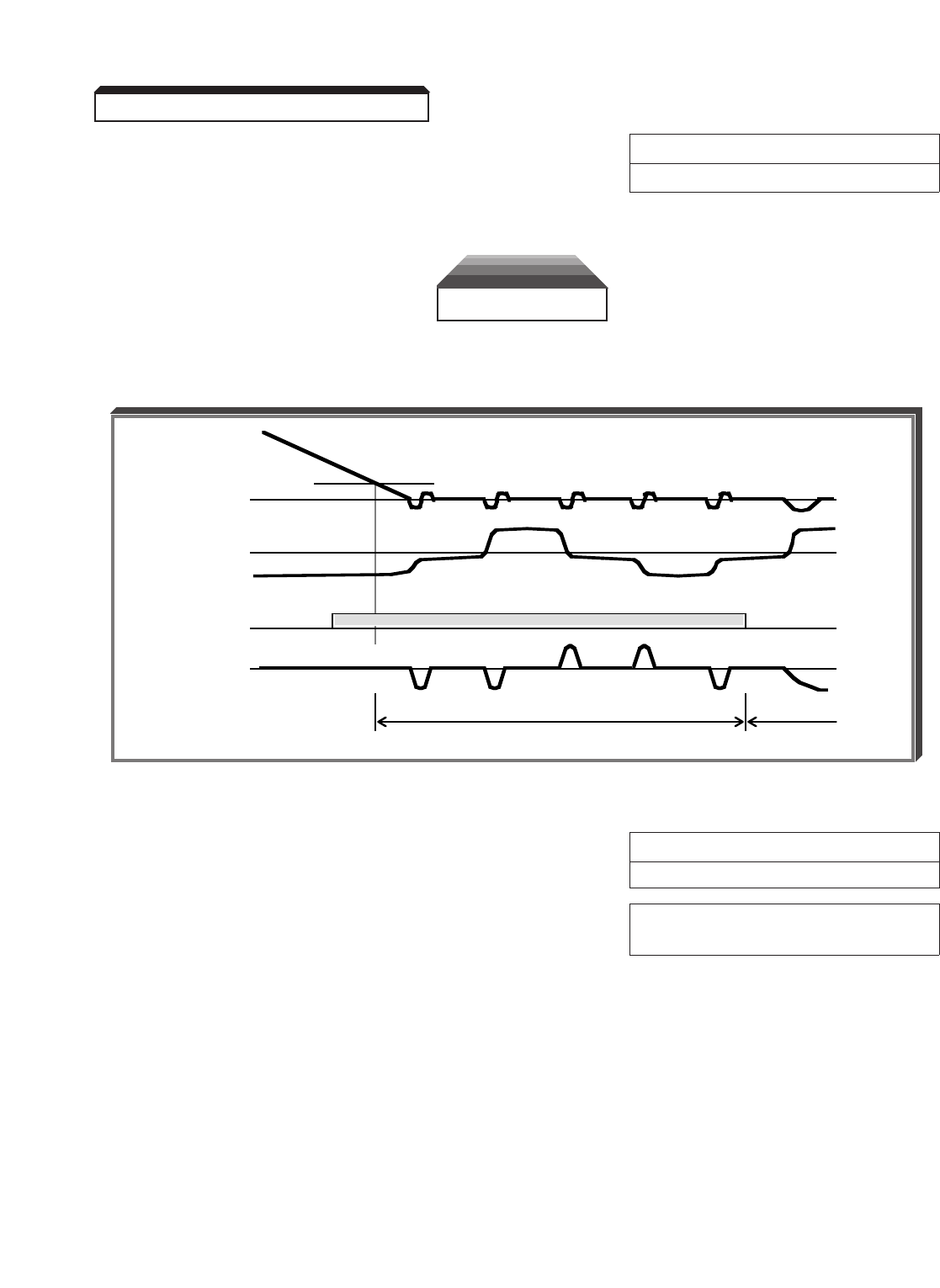
5-111
Continued
B. b9-01 : Zero-Servo Gain Factory setting: 5
Range: 0 to 100
This function provides an adjustment for the position loop gain.
CAUTION
The higher the gain, the better the response. However, too high a gain can cause
hunting or overshoot, and possible runaway condition.
Zero-Servo Timing
C. b9-02 : Zero-Servo Completion Width Factory setting: 10
Range: 0 to 16383 pulses
H2-01 thru H2-03 : Multi-function Output Data 33: Zero-Servo
(Term. 9 & 10; 25; 26) Completed
(See paragraph 5.33)
The function of b9-02 is to set the number of pulses used for the multi-function output
terminals. During zero-servo, the multi-function output will be closed (ON) until the
number set into b9-02 has been completed. After the number of pulses have been
completed, the multi-function output changes to the open (OFF) state.
5.49 ZERO-SERVO CONTROL
DC Injection Braking Start Freq. ( b2-01 )
on
position loop
(zero-servo)
speed loop
Speed
Load
Zero Servo
Position Error
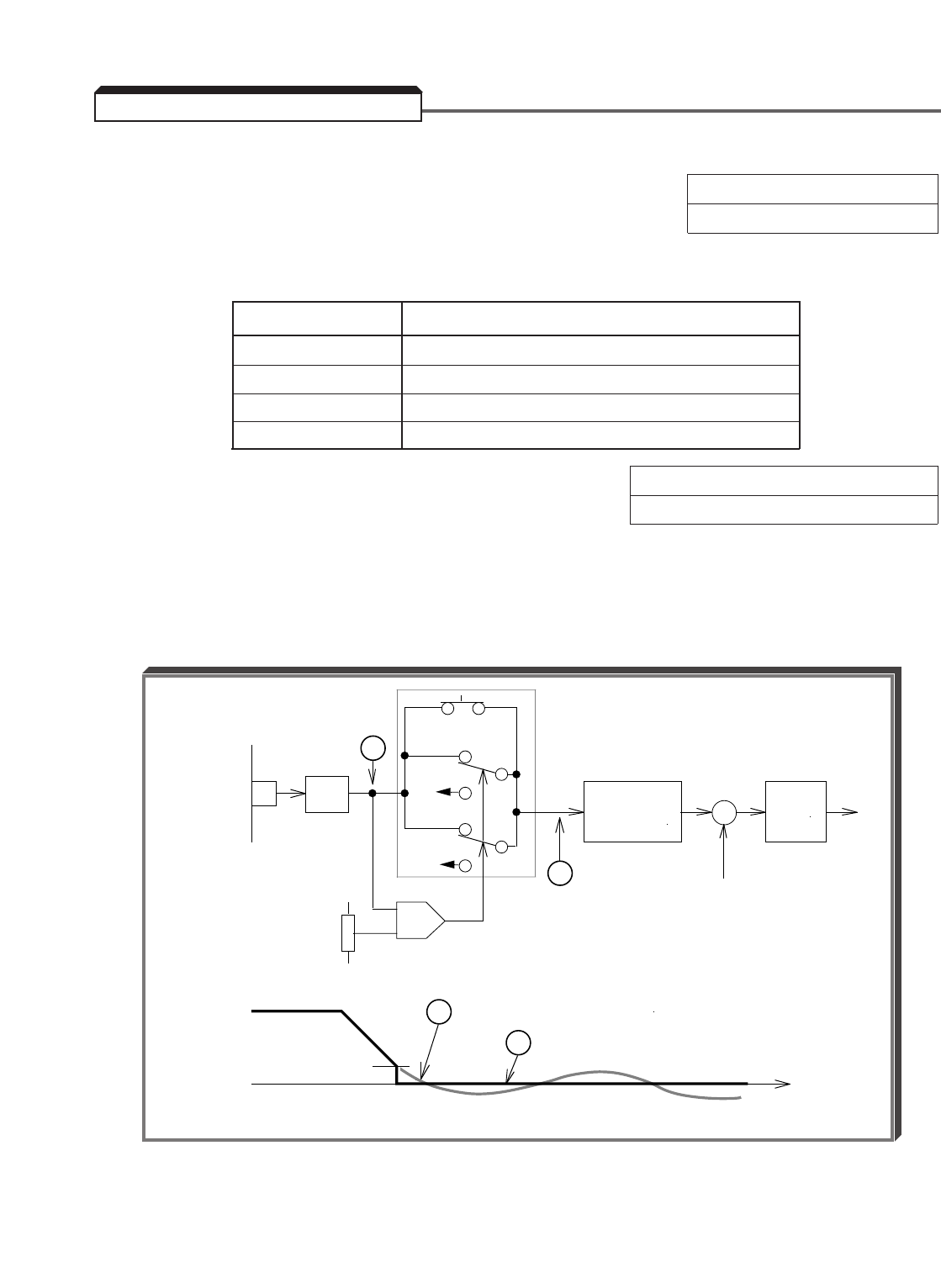
5-112
NOTE: This function can only be used in Flux Vector control method ( A1-02 = 3 ).
A. b1-05 : Zero Speed Operation Factory setting: 0
Range: 0 to 3
The setting of this parameter determines which Zero Speed mode is enabled (see figures
on following pages).
Setting Description
0 Run at Frequency Reference
1 STOP
2 Run at Minimum Frequency
3 Run at Zero RPM
E1-09 : Minimum Output Frequency Factory setting: 0.0 *
Range: 0.0 to 400.0 Hz
* Note: If control method is anything other than Flux
Vector ( A1-02= 3 ), the Factory Setting is 0.5
This parameter sets the speed reference level at which Zero Speed mode operation will
activate, in accordance with the selection programmed in b1-05 (see figures on following
pages).
When the Speed Reference input is an analog signal, Zero Speed mode operation over long
periods of time will cause the output to drift.
5.50 ZERO SPEED CONTROL
SPEED
REF.
A/D
E1-09
b1-05 = 0
SPEED
FEEDBACK
INPUT TO S-CURVE
OUTPUT OF A/D CONVERTER
+
–
B
SOFT START
(S-CURVE)
+
–
ASR
TIME
E1-09
A
B
SPEED
REF.
A
ASR OUTPUT WITH ANALOG INPUT
b1-05 = 2
b1-05 = 1 or 3
0V
E1-09
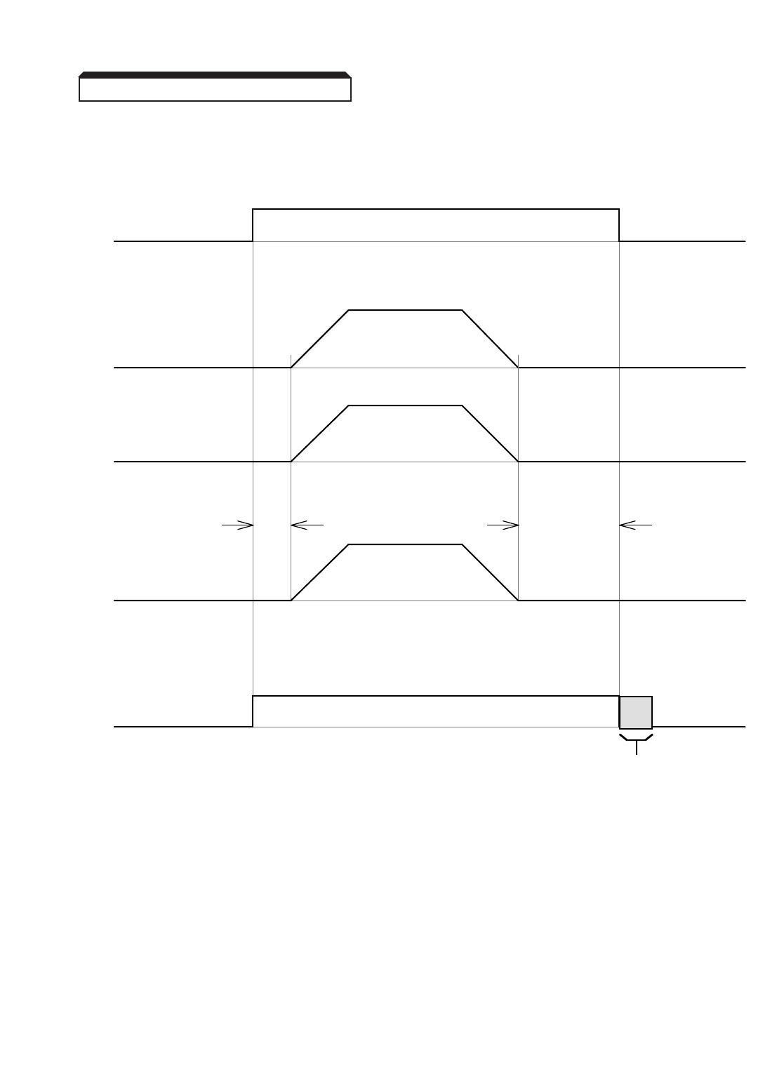
5-113
Continued
b1-05 : 0Run at Frequency Reference
E1-09 : (Minimum Output Frequency) ineffective
5.50 ZERO SPEED CONTROL
RUN / STOP
SPEED
REFERENCE
ACTUAL
SPEED
INTERNAL
RUN
RUN
STOP
ZERO SPEED
CONTROL
ZERO SPEED
CONTROL
RUN
STOP
INTERNAL
SPEED REF
b2-04
DC Injection Braking Time at Stop
b1-05 : 1STOP
E1-09 : (Minimum Output Frequency) effective

5-114
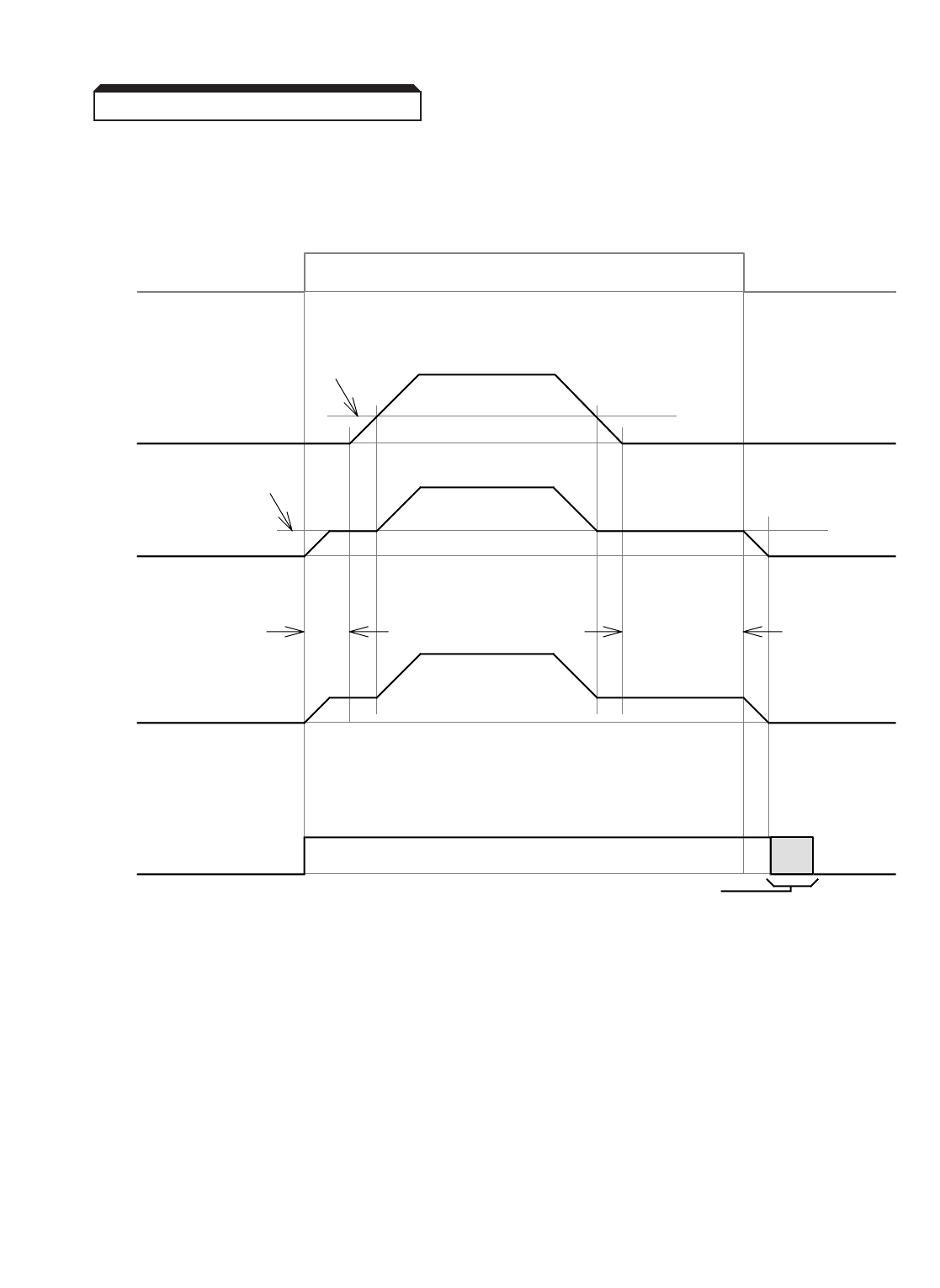
5-115
Continued
b1-05 : 2Run at Minimum Frequency
E1-09 : (Minimum Output Frequency) effective
5.50 ZERO SPEED CONTROL
RUN / STOP
SPEED
REFERENCE
ACTUAL
SPEED
INTERNAL
RUN
RUN STOP
ZERO SPEED
CONTROL
ZERO SPEED
CONTROL
RUN STOP
INTERNAL
SPEED REF
E1-09
E1-09
b2-04
DC Injection Braking Time at Stop
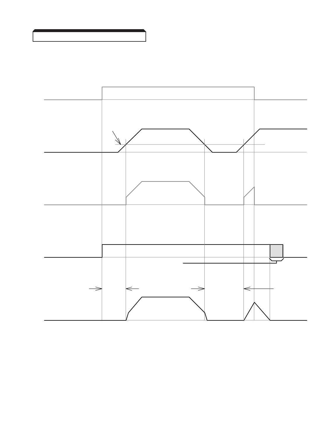
5-116
Continued
b1-05 : 3Run at Zero RPM
E1-09 : (Minimum Output Frequency) effective
5.50 ZERO SPEED CONTROL
RUN / STOP
SPEED
REFERENCE
INTERNAL
RUN
RUN STOP
ZERO SPEED
CONTROL
ZERO SPEED
CONTROL
RUN STOP
E1-09
INTERNAL
SPEED REF
ACTUAL
SPEED
b2-04
DC Injection Braking
Time at Stop

6-1
A failure in the GPD 515/G5 can fall into one of two categories, Alarm or Fault.
A blinking "Alarm" indication is a warning that a drive trouble condition will soon occur, or
that a programming error has been made. The drive will continue to operate during an
"Alarm" indication.
A blinking "Minor Fault" indication is displayed during less serious faults, or when a
problem exists in the external circuitry. The drive will continue to operate, and a "Minor
Fault" contact will be closed if a multi-function output is programmed for the condition.
A steady "Major Fault" indication is displayed when the drive’s Fault relay has tripped.
The motor coasts to a stop, and a fault signal output is present at control circuit
terminals 18 - 20.
INDICATION
(DISPLAY) FAILURE INDICATION ITEM DESCRIPTION
Communication Communication error while drive is set for A
Option Card error Run Command and/or Frequency Reference (Note 2)
from Serial Communication card.
SI-B communication Control data was not received when power supply A
error was turned on.
Communication error Control data was not received for 2 seconds after M
initial communication.
Motor out of control Drive cannot determine speed of motor – M
Open Loop Vector Control Method ( A1-02 = 2)
only. (Note 3)
Control circuit fault 1 Communication between Digital Operator and M
drive was not established within 5 seconds
after power was applied, or an internal hardware or
software fault was detected on power-up. (Note 3)
Control circuit fault 2 Communication errors between the Digital Operator M
and drive occurred for over 2 seconds after
communication was last established, or an internal
hardware or software fault occurred after power-up.
(Note 3)
Table 6-1. Fault Indication and Details
DIGITAL OPERATOR TYPE
DISPLAY DESCRIPTION DETAILS (Note 1)
6.1 GENERAL
Section 6. FAULT INDICATION
& TROUBLESHOOTING
CALL
Serial Com Call
BUS
Option Com Err
CE
Memobus Com Err
CF
Out of Control
CPF00
COM-ERR (OP & INV)
CPF01
COM-ERR (OP & INV)

6-2
Table 6-1. Fault Indication and Details – Continued
DIGITAL OPERATOR TYPE
DISPLAY DESCRIPTION DETAILS (Note 1)
CPF02
BB Circuit Failure
Baseblock circuit fault Drive failure.
(Note 3)
Replace Control card.
M
CPF03
EPROM Error
CPF04
Internal A/D Err
CPF05
External A/D Err
EPROM fault
Internal A/D fault
External A/D fault
CPF06
Option Error
Option card
connection failure
Check option card connection.
Option card failure.
(Note 3)
M
CPF20
Option A/D Error
A/D converter fault in
Analog Speed
Reference card
Option card (AI-14B) A/D converter malfunction.
(Note 3)
M
CPF21
Option CPU down
Communication option card
self-diagnostic error.
Communication option card failure. M
CPF22
Option Type Err
Communication option card
Model code error.
CPF23
Option DPRAM Err
Communication option card
DPRAM error.
DEV
Speed Deviation
Speed deviation Deviation between speed reference and speed
feedback exceeded the deviation level ( F1-10
& F1-11 ). Stop mode selection possible ( F1-04 ).
m
(Note2)
EF
External Fault
Both FWD and REV
commands were applied
simultaneously
Drive is in “temporary” Ramp to Stop condition; one
input command must be removed to resume
operation.
m
EF0
Opt External Flt
External fault input from
Communication option card.
Check communication option card connection and
signal.
M
(Note 2)
EF3
External Fault 3
External fault signal at
terminal 3
Stop mode selection possible ( H1-01 thru H1-06 ).
(See Section 5.17)
M
(Note 2)
EF4
External Fault 4
External fault signal at
terminal 4
(Note 3)
E - 15
SI - F/G Com Err
SI - F/G Communications
Error
A communications error occurred and b1-01=3
and/or b1-02=3.
M
(Note2)
A fault condition has occurred in the external
circuit(s) monitored by the contact providing input to
the indicated terminal.

6-3
DIGITAL OPERATOR TYPE
DISPLAY DESCRIPTION DETAILS (Note 1)
EF6
External Fault 6
External fault signal at
terminal 6
A fault condition has occurred in the external
circuit(s) monitored by the contact providing input to
the indicated terminal.
Stop mode selection possible ( H1-01 thru H1-06).
(See Section 5.17)
(Note 3)
EF7
External Fault 7
EF8
External Fault 8
ERR
EPROM R/W Err
External fault signal
at terminal 7
External fault signal at
terminal 8
EPROM write-in fault m
GF
Ground Fault
Ground fault Drive output ground current exceeded 50% of
driverated current.
M
LF
Output Pha Loss
Drive output has open
phase
Problem in drive-to-motor wiring. Enable/disable
with L8-07.
M
OC
Overcurrent
Overcurrent M
OH
Heatsnk Overtemp
Cooling fin overheat Heatsink fin temperature exceeded the setting of
L8-02 .(Note 3)
m
(Note 2)
OH1
Heatsnk MAX Temp
Drive overheat Heatsink fin temperature exceeded 105˚C (221˚F)
(Note 3), or internal cooling fan has failed.
M
OH2
Over Heat 2
Drive overheat Pre-alarm A multi-function input (H1-01 to H1-06) is
programmed for OH2 Alarm Signal (data “B”) and
the corresponding input terminal is closed.
A
OL1
Motor Overloaded
Motor overload Protects the motor. Motor thermal overload
protection has tripped. L1-02 has been exceeded
(initial value: 150% for 60 sec.). (Note 3)
M
drive failure.
Cycle power, then attempt to initialize.
Replace Control card.
Drive output current exceeded 200% of drive rated
current. (Note 3)
Table 6-1. Fault Indication and Details – Continued
EF5
External Fault 5
External fault signal at
terminal 5
M
(Note 2)
FbL
Feedback Loss
PID Feedback Reference
Loss
m
(Note 2)
PID feedback reference loss detection is enabled
(b5-12 = 1 or 2) and the PID feedback input is less than
the PID feedback loss detection level (b5-13) for longer
than the PID feedback loss detection time (b5-14).
E-10
SI-F / G CPU Down
SI-F / G Communications
Error
M
(Note 2)
A communications error occurred and
b1-03 = 3 and/or b1-02 = 3.

6-4
DIGITAL OPERATOR TYPE
DISPLAY DESCRIPTION DETAILS (Note 1)
OPE01
kVA Selection
Drive capacity
selection fault
o2-04 has been changed from the correct factory
setting value. Refer to Table A3-1.
A
OPE02
Limit
OPE03
Terminal
OPE05
Sequence Select
Parameter set out of range
Multi-function input
setting fault
Option card
selection error
A
OPE06
PG Opt Missing
PG-X2 card not installed Control method set to Flux Vector or V/F with PG,
and no PG-X2 card is installed.
A
A
A
OPE07
Analog Selection
Multi-function analog
input selection error
Both multi-function analog inputs (H3-05 and H3-09) have
been programmed for the same data (except 1F) OR an
AI-14B option card is connected, the drive is programmed
for 3-channel individual (F2-01=0), and a multi-function
input is programmed for Option/Inverter Selection (H1-01
to H1-06=2).
A
OPE08
Terminal
Selection Parameter error A parameter has been changed that is not available
in the present Control Method. Example: H1-08=72
(Zero Servo Command) is set while the drive is in
Flux Vector Control (A1-02=3), then the Control
Method is changed to Open Loop Vector (A1-02=2).
OPE10
V/F Ptrn Setting
V/f data setting fault Occurs when the custom V/f pattern does not meet
the following criteria:
( E1-04 ) ≥( E1-06 )> ( E1-07 ) ≥( E1-09 )
A
OPE11
CarrFrq/ON-Delay
Carrier frequency
parameter(s) set out
of range
Occurs when the carrier frequency parameters are
set as follows: ( C6-01 ) > 5 kHz and ( C6-02 ) ≤5
kHz;( C6-03 ) > 6 and ( C6-01 ) < ( C6-02 )
A
OPR
Oper Disconnect
Operator disconnected Digital Operator has been disconnected from drive
while in Run mode.
M
(Note 2)
Frequency reference and/or run source is set for
option card (b1-01=3 and/or b1-02=3), but no
option card is connected.
H1-01 thru H1-06 (multi-function input)-2 or
more parameters are set to the same data (other
than " F " and " FF ").
See paragraph 5.32.
One or more parameter values are not within the
allowable setting range.
A
Table 6-1. Fault Indication and Details – Continued
OL4
Overtorque Det 2
Overtorque detect 2 Output current exceeds Overtorque Detection
Level 2 ( L6-05 ).
(Note 2)
OL2
Inv Overloaded
Drive overload Protects the drive. Drive overload protection has
tripped.
M
OL3
Overtorque Det 1
Overtorque detect 1 Output current exceeds Overtorque Detection
Level 1 ( L6-02 ).
(Note 2)

6-5
DIGITAL OPERATOR TYPE
DISPLAY DESCRIPTION DETAILS (Note 1)
PGO
PG Open
PG cable wires are
disconnected
Pulse generator is disconnected from the PG-X2
card (Terminal TA1).
M
(Note 2)
PUF
DC Bus Fuse Open
RH
DynBrk Resistor
RR
DynBrk Transistor
Fuse blown
Braking resistor overheat
Braking transistor failure
M
SC
Short Circuit
Short circuit on drive output
terminals
Very low impedance on output of drive.
Check for correct motor wiring / capacity.
M
M
M
SVE
Zero Servo Fault
Zero Servo fault Shaft position changed by more than 500,000
revolutions during zero servo operation.
M
UV
DC Bus Undervolt
Momentary power loss Low voltage has been detected, but momentary
power loss ride-thru is enabled ( L2-01 ), and
momentary power loss ride-thru time ( L2-02 )
has not yet been exceeded. (Note 3)
m
UV1
DC Bus Undervolt
Main circuit undervoltage A
UV2
CTL PS Undervolt
Control circuit
undervoltage
Control circuit voltage is low during operation. A
UV3
MC Answerback
Main contactor fault Main circuit magnetic contactor (soft charge
contactor) does not operate correctly.
A
Braking transistor failure.
Braking resistor unit temperature exceeds the
allowable value. (Heatsink-mount resistor only,
and only if L8-01=1).
DC fuse has cleared. Check for short circuit in
output circuitry. (Note 3)
Occurs 2 seconds after detection of low voltage.
Detection level: approx 190VDC for 230V rated unit;
approx 380VDC for 460V rated unit; approx 546
VDC for 600V rated unit. (Note 3)
Table 6-1. Fault Indication and Details – Continued
PF
Input Pha Loss
drive input phase missing Incoming power supply has an open phase, or a
large imbalance exists between L1, L2 &
L3.Enable/disable with L8-05 .
M
NOTES:
1. A= Alarm; m= Minor Fault; M= Major Fault.
2. The stop mode, and therefore the fault type (alarm, minor or major), is selectable.
3. See section 6.4 for flowcharts to use in troubleshooting these fault conditions.
OS
Overspeed
Motor overspeed Motor speed exceeds overspeed level ( F1-08 &
F1-09 ). Stop mode selection possible ( F1-03 ).
(Note 3)
M
(Note 2)
OV
DC Bus Overvolt
Overvoltage Detection level: Approx. 400VDC for 230V rated
unit; Approx. 800V for 460VDC rated unit; approx
1050 VDC for 600V rated unit. (Note 3)
M
6-6
INDICATION
Motor data is not correct • Check the input data.
• Check the drive and motor capacities.
Line-to-line resistance not
within tolerance
• Check the input data.
• Check the motor wiring.
No-load current (magnetizing
current) not within tolerance
Iron core saturation
coefficient 1 not within
tolerance
Iron core saturation
coefficient 2 not within
tolerance
Rated slip not within
tolerance
Motor did not accelerate in • Increase acceleration time ( C1-01 ).
the specified time • Increase torque limit values ( L7-01 , -02 ) if they
are reduced from factory settings.
• Uncouple the motor from the load.
Encoder phasing opposite • Swap two motor leads.
that of motor phasing OR
• Swap channels on the input to the PG-X2 card
(on terminal block TA1, swap wires at terminals
4 & 6 and swap wires at terminals 5 & 7).
Torque reference exceeded • Uncouple motor from load.
100% during auto-tuning • Increase acceleration time ( C1-01 ).
• Check input data, especially the encoder PPR
( F1-01 ).
Torque reference exceeded
20% during auto-tuning
A minor drive fault occurred • Check Table 6-1 for specific minor
fault indicated by “XXX.”
PG cable wires are • Pulse generator is disconnected from
disconnected the PG-X2 card (Terminal TA1).
Check PG wiring.
6.2 AUTO-TUNING FAULTS & CORRECTIVE ACTIONS
DIGITAL OPERATOR
DISPLAY DESCRIPTION CORRECTIVE ACTION
Tune Aborted
Data Invalid
Tune Aborted
Resistance
Tune Aborted
No-Load Current
Tune Aborted
Sat Coef 1
Tune Aborted
Sat Coef 2
Tune Aborted
Rated Slip
Tune Aborted
Accelerate
Tune Aborted
PG Direction
Tune Aborted
Motor Speed
Tune Aborted
Over Load
(Displayed after completion of tuning)
Tune Aborted
Minor Fault : XXX
Tune Aborted
PG Circuit
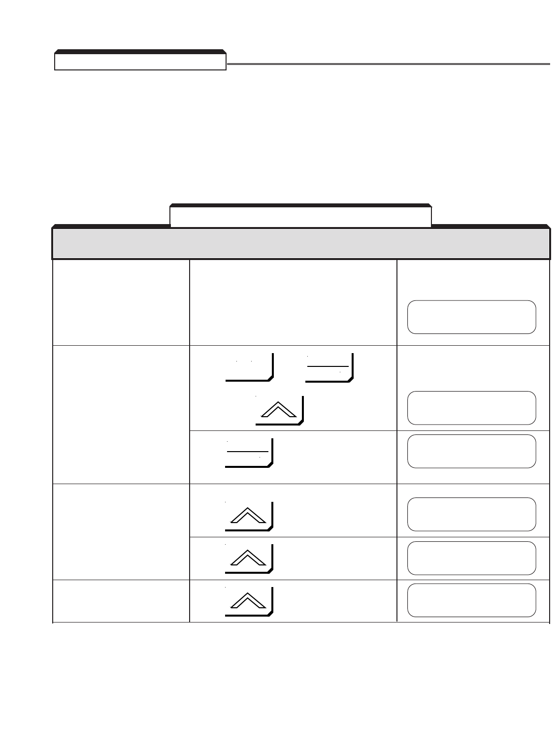
6-7
A . Displaying Fault Conditions
Whenever the fault relay trips (drive shutdown), the fault that caused the trip (except for
Illegal Constant or Control Function Hardware) is entered into non-volatile RAM. The drive
also retains the operating conditions when the fault occurred.
These conditions can only be displayed when the drive is in the Drive mode (DRIVE light is
on).
If a major fault has just The DRIVE and STOP lights are
occurred, but the drive illuminated, and the FWD, REV,
has not been reset, SEQ, & REF lights are flashing.
proceed directly to Step A.
If the drive has been reset, Press , then ,
the conditions at the last
fault can still be displayed:
then 4 times
Press
Proceed to Step A.
Step A
Display the frequency reference Press
that was present when the fault
occurred.
Press
Display the output frequency Press
that was present when the
fault occurred.
DESCRIPTION KEY SEQUENCE DIGITAL OPERATOR DISPLAY
(See Note 1)
Table 6-2. Displaying Fault Conditions
6.3 DISPLAYING FAULTS
EF3
External Fault 3
Function U2
Fault Trace
Current Fault
None
Last Fault
External Fault 3
Frequency Ref
U2-03= 10.00 Hz
Output Freq
U2-04= 10.00 Hz
MENU
DATA
ENTER
DATA
ENTER
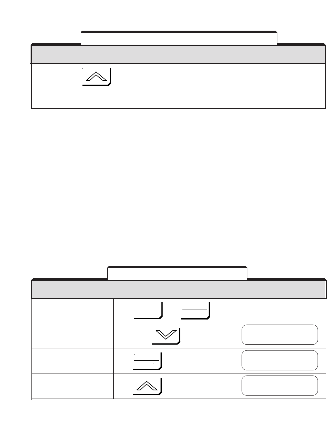
6-8
Continue pressing to cycle through all of the condition displays. These include: output current,
output voltage, DC bus voltage, kWatts, input terminal status, output terminal
status, operation status, and elapsed time.
NOTE: To decode the input terminal status, output terminal status, and operation status displays, refer to Appendix 1,
Table A1-10, U1-10 to U1-12.
NOTES:
1. Actual displays will differ depending on the recorded fault and the operating conditions.
If the FWD, REV, SEQ, & REF lights are flashing, enter a RESET command (from the Digital
Operator or external signal) to prepare the drive for restart of operation.
IMPORTANT: In 2-wire control, any RUN/STOP command must be removed before
the RESET will be accepted.
B. Displaying Fault History
Whenever the fault relay trips (drive shutdown), the fault that caused the trip (except for
Illegal Constant or Control Function Hardware) is entered into non-volatile RAM. The drive
retains the last four faults and the operating conditions when the last fault occurred.
(NOTE: Time is in operating hours.)
These faults can only be displayed when the drive is in the Drive mode (DRIVE light is on).
The drive can be stopped or running.
Display the fault history Press , then ,
function menu.
then twice
Display the last fault that Press
occurred (most recent in time)
Display the second from the Press
last fault that occurred.
DESCRIPTION KEY SEQUENCE DIGITAL OPERATOR DISPLAY
(See Note 1)
Table 6-2. Displaying Fault Conditions – Continued
DESCRIPTION KEY SEQUENCE DIGITAL OPERATOR DISPLAY
(See Note 1)
Table 6-3. Displaying Fault History
Function U3
Fault History
Last Fault
External Fault 3
Fault Message 2
Motor Overloaded
MENU
DATA
ENTER
DATA
ENTER
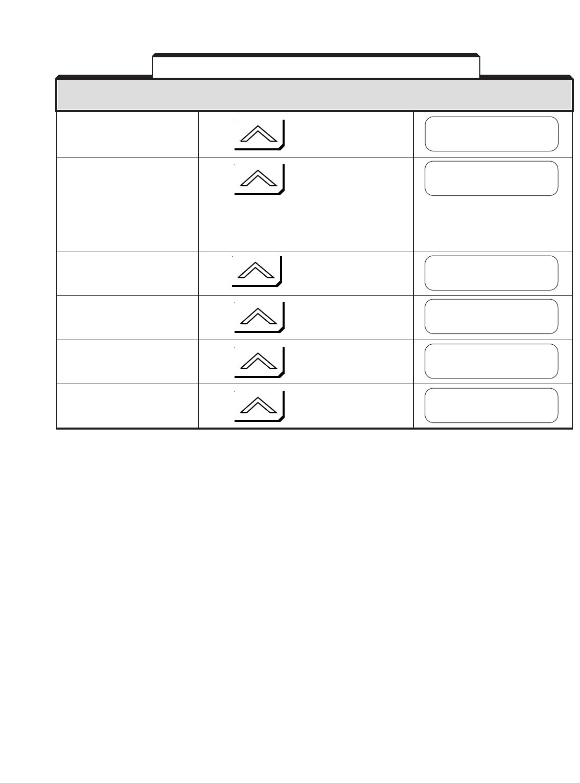
6-9
Display the third from the Press
last fault that occurred.
Display the fourth from the Press
last fault that occurred.
NOTE: If less than four faults
have occurred since the drive
was initialized, "None" will appear
on the Digital Operator.
Display the operating hours Press
when the last fault occurred.
Display the operating hours Press
when the second from the last
fault occurred.
Display the operating hours Press
when the third from the last
fault occurred.
Display the operating hours Press
when the fourth from the last
fault occurred.
NOTES:
1. Actual displays will differ depending on the recorded fault and the operating conditions.
DESCRIPTION KEY SEQUENCE DIGITAL OPERATOR DISPLAY
(See Note 1)
Table 6-3. Displaying Fault History – Continued
Fault Message 3
DC Bus Undervolt
Fault Message 4
None
Elapsed Time 1
U3-05= 57 H
Elapsed Time 2
U3-06= 41 H
Elapsed Time 3
U3-07= 5 H
Elapsed Time 4
U3-08= 0 H

6-10
If the drive malfunctions, locate the cause and take corrective action by following the
flowcharts given in this section.
A. TROUBLESHOOTING MOTOR SYMPTOMS
Motor Does Not Rotate................................................................................ Chart 6.1
Motor Stalls During Acceleration.................................................................. Chart 6.2
Motor Does Not Rotate at Set Speed.......................................................... Chart 6.3
Motor Hunting .............................................................................................. Chart 6.4
B. TROUBLESHOOTING FOR FAULT CONDITIONS
oV – Overvoltage ........................................................................................ Chart 6.5
PUF – DC Bus Fuse Open ............................................................................. Chart 6.6
oC – Overcurrent ......................................................................................... Chart 6.7
oL1 – Motor Overload ................................................................................. Chart 6.8
UV – Undervoltage ...................................................................................... Chart 6.9
oH – Heatsink Overtemp ............................................................................. Chart 6.10
CPFXX – Control Function Error ................................................................... Chart 6.11
EFX – External Fault .................................................................................... Chart 6.12
oS – Overspeed ........................................................................................... Chart 6.13
CF – Out of Control ..................................................................................... Chart 6.14
WARNING
Oscilloscope chassis may be at voltages potentially hazardous to
life if not properly grounded. If oscilloscope is used to measure
high voltage waveforms, use only a dual channel oscilloscope in
the differential mode with X100 probes. Always connect
oscilloscope chassis to earth ground.
WARNING
Voltages dangerous to life exist when equipment is open and
energized. Do not work alone.
CAUTION
To prevent equipment damage always remove incoming three-
phase power before test equipment is connected or removed.
Never disconnect or connect the wiring while the power is applied.
6.4 TROUBLESHOOTING FLOWCHARTS
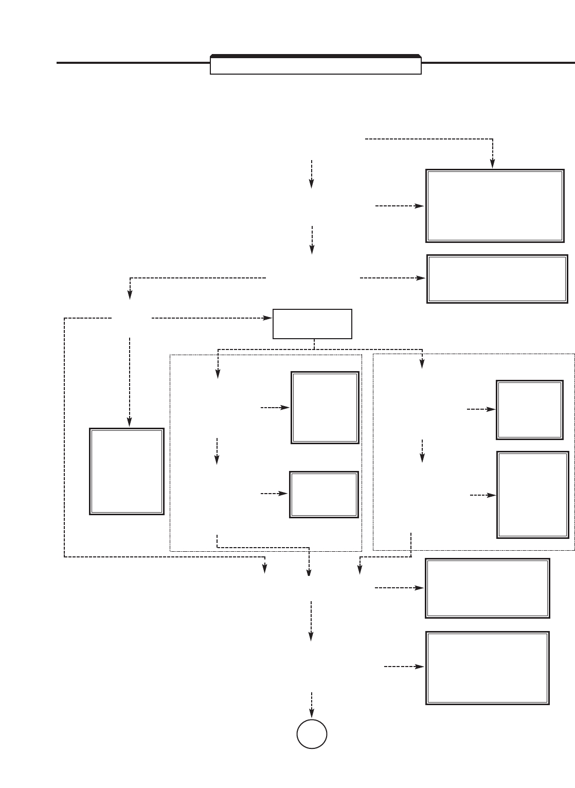
6-11
TROUBLESHOOTING CHART 6.1
MOTOR DOES NOT ROTATE
"CHARGE" LAMP
ON MAIN PC BOARD
LIT?
CHECK CIRCUIT
BREAKER, MAGNETIC
CONTACTOR AND
INPUT POWER.
NO
NO
3-WIRE CONTROL 2-WIRE CONTROL
NO
NO
NO
(CONTROL BY
EXT. INPUTS)
NO
(CONTROL
BY DIGITAL
OPERATOR)
NO
NO
YES
YES
YES
YES
YES
YES
YES
RATED VOLTAGE
ACROSS TERMINALS
L1(R), L2(S), AND L3(T)?
FAULT
SHOWN ON
ALPHA-NUMERIC
DISPLAY?
GO TO APPROPRIATE
CHART, 6.5 THRU 6.13.
RUN
LAMP
ON?
STOP COMMAND
STILL ON?
(OPEN CIRCUIT
BETWEEN
TERMINALS 11 AND 2)
RUN
COMMAND ON?
(CLOSED CIRCUIT
[MOMENTARY INPUT]
BETWEEN
TERMINALS 11 AND 1)
CLOSE
STOP
COMMAND
INPUT.
INPUT RUN
COMMAND.
NO
NO
YES
YES
FWD RUN/STOP
& REV RUN/STOP
BOTH OFF?
(OPEN CIRCUITS FROM
TERMINAL 11 TO
TERMINALS 1 AND 2)
FWD RUN/STOP
& REV RUN/STOP
BOTH ON?
(CLOSED CIRCUITS FROM
TERMINAL 11 TO
TERMINALS 1 AND 2)
RELEASE
ONE
RUN/STOP
COMMAND
INPUT.
INPUT A
RUN/STOP
COMMAND.
DRIVE'S
CONTROL POWER
CIRCUIT IS FAULTY.
APPROX. 15VDC FROM
TERMINAL 15(+) TO 17?
ATO NEXT
PAG E
DIGITAL
OPERATOR
ASSEMBLY
IS FAULTY.
REPLACE.
PROPER FREQUENCY
REFERENCE INPUT?
(TERMINAL 17(–) TO 13 ( U1-15 ),
14 ( U1-16 ), OR 16 ( U1-17 ) )
NO
CHECK EXTERNAL
CIRCUITS FOR
PROBLEM AND
REPAIR.
YES
DISPLAY U1-10,
INPUT STATUS
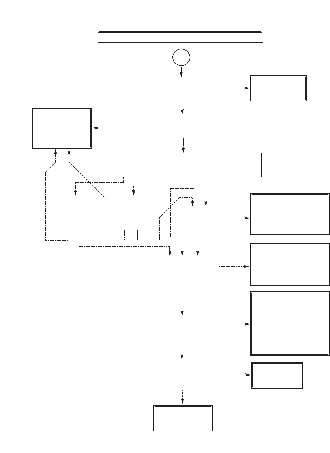
6-12
TROUBLESHOOTING CHART 6.1 (Continued)
AFROM
PRECEDING
PAG E
PROPER CONNECTIONS
FROM DRIVE TO
MOTOR?
TORQUE LIMIT
SETTING
CORRECT?
CONTROL METHOD?
V/F w/ PG Flux Vector V/F Open Loop Vector
NO
NO
NO
NO
NO
NO
CHECK CON-
NECTIONS FOR
PROBLEM AND
REPAIR. YES
PROPER
CONNECTIONS
FROM DRIVE
TO PG
(ENCODER)?
PROPER
CONNECTIONS
FROM DRIVE
TO PG
(ENCODER)?
NO
YES
NO YES YES
VOLTAGE PRESENT ACROSS
OUTPUT TERMINALS
T1(U), T2(V) AND T3(W)?
VOLTAGE PRESENT AT
MOTOR TERMINALS
T1(U), T2(V) AND T3(W)?
VOLTAGE BALANCED
(WITHIN 2%)
BETWEEN PHASES, AT
T1(U), T2(V) AND T3(W)?
DRIVE
IS FAULTY.
YES
YES
YES
YES
CHECK FOR
PROBLEM IN MOTOR,
MECHANICAL
SYSTEM OR BRAKE.
SET TORQUE LIMIT
(ANALOG INPUT, OR
L7-01 & L7-02 ) TO
PROPER VALUE.
DRIVE
IS FAULTY.
LOAD TORQUE
TOO LARGE?
- REDUCE LOAD
TORQUE (DISCON-
NECT LOAD).
- REPLACE DRIVE
WITH ONE OF
LARGER CAPACITY.
MOTOR
IS FAULTY.
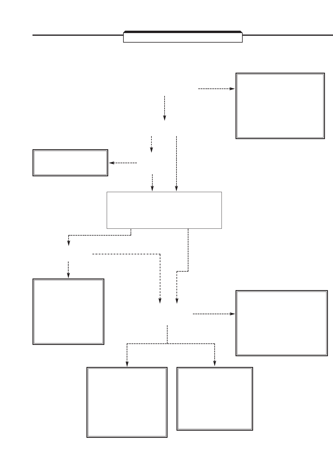
6-13
TROUBLESHOOTING CHART 6.2
MOTOR STALLS DURING ACCELERATION
ACCELERATION TIME
TOO SHORT?
YES
YES
YES
YES
WITH DRIVE IN
STOPPED CONDITION,
EXTEND ACCELER-
ATION TIME BY
REPROGRAMMING
C1-01, C1-03, C1-05,
OR C1-07 .
WITH DRIVE
IN STOPPED
CONDITION, SET
OPTIMUM V/f
PATTERN BY
REPROGRAMMING
E1-03 .
NO
NO
NO
NO
LOAD TORQUE
TOO HIGH?
LOAD
INERTIA
LARGE?
CHECK IF SPECIAL
MOTOR IS USED.
LARGE MOTOR
TERMINAL
VOLTAGE DROP?
- USE LARGER WIRE
BETWEEN DRIVE
AND MOTOR.
- SHORTEN WIRING
DISTANCE BETWEEN
DRIVE AND MOTOR.
- DECREASE LOAD
INERTIA.
- EXTEND ACCEL-
ERATION TIME BY
REPROGRAMMING
C1-01, C1-03, C1-05,
OR C1-07 .
- DECREASE LOAD
TORQUE.
- REPLACE DRIVE
WITH ONE OF
LARGER
CAPACITY.
CONTROL METHOD?
V/F Flux Vector
or or
V/F w/ PG Open Loop Vector
NO
YES
V/f SELECTION
APPROPRIATE?
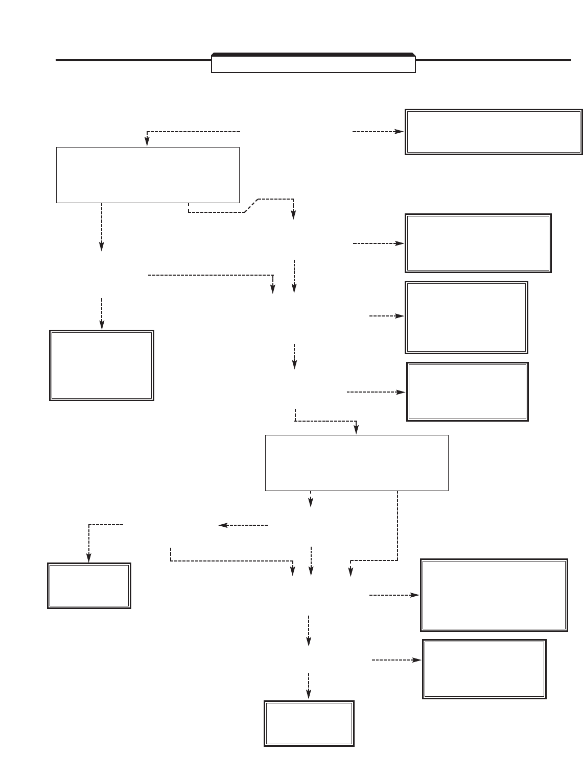
6-14
TROUBLESHOOTING CHART 6.3
MOTOR DOES NOT ROTATE AT SET SPEED
CORRECT MOTOR FOR
USE WITH DRIVE?
YES CONSULT YASKAWA
ABOUT MOTOR SELECTION.
NO
PROPER CONNECTIONS
FROM DRIVE TO
MOTOR AND PG?
NO CHECK CONNECTIONS
FOR PROBLEM AND
REPAIR.
YES
YES
NO
NO CHECK EXTERNAL
CIRCUITS FOR
PROBLEM AND
REPAIR.
YES
ALL GROUP bPARAMETER
SETTINGS PROPER
FOR APPLICATION?
NO
NO
CHECK SETTINGS;
REPROGRAM
AS REQUIRED.
YES
IS PG OUTPUT
SIGNAL NORMAL?
(See Section 6.6)
IS PG
POWER SUPPLY
NORMAL?
YES
YES
NO
EXCESSIVE
MECHANICAL SYSTEM
CHATTER?
YES
CHECK FOR
PROBLEM IN MOTOR,
MECHANICAL SYSTEM
OR BRAKE.
NO
YES
DRIVE'S
CONTROL POWER
CIRCUIT IS FAULTY.
APPROX. 15VDC FROM
TERMINAL 15(+) TO 17?
DRIVE
IS FAULTY.
CONSULT
YASKAWA.
NO
CONTROL METHOD?
Flux Vector V/F
or or
V/F w/ PG Open Loop Vector
CONTROL METHOD?
V/F Flux Vector
or or
Open Loop Vector V/F w/ PG
PROPER
CONNECTIONS
FROM DRIVE
TO MOTOR?
CHECK CON-
NECTIONS FOR
PROBLEM AND
REPAIR.
PROPER FREQUENCY
REFERENCE INPUT?
(TERMINAL 17(–) TO 13 ( U1-15 ),
14 ( U1-16 ), OR 16 ( U1-17 ) )
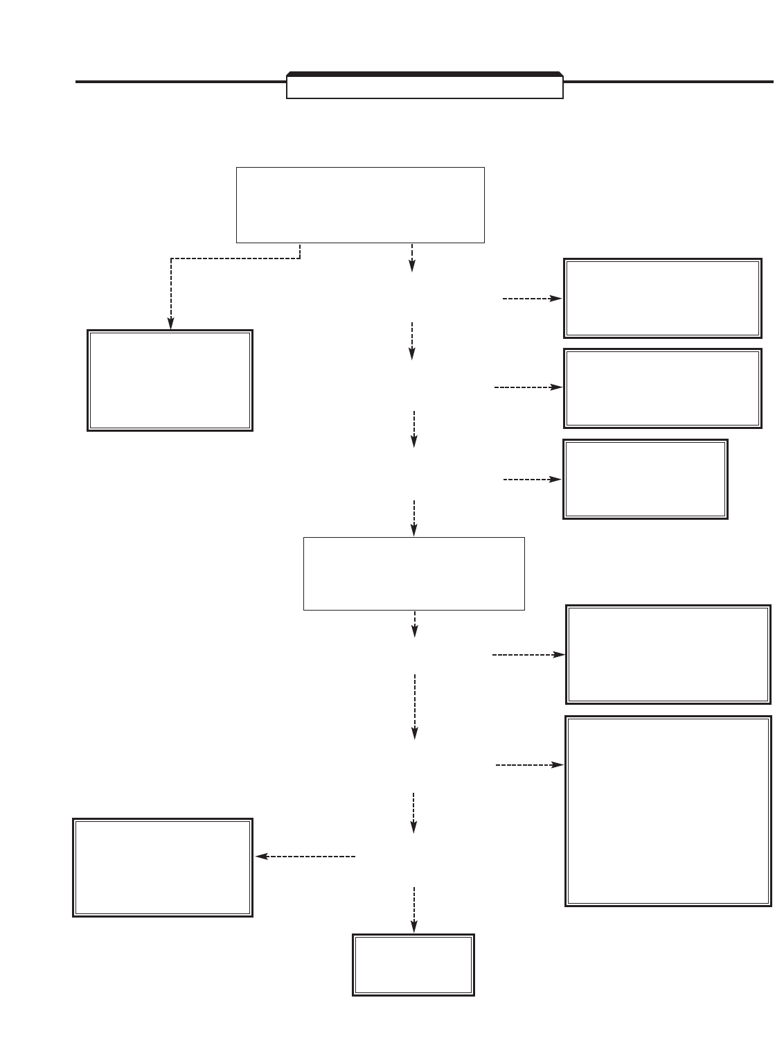
6-15
TROUBLESHOOTING CHART 6.4
MOTOR HUNTING
PROPER PHASE SEQUENCE
OF CONNECTIONS FROM
DRIVE TO MOTOR?
NO CHECK CONNECTIONS
FOR PROBLEM AND
REPAIR.
YES
PROPER CONNECTIONS
FROM DRIVE TO
PG (ENCODER)?
NO CHECK CONNECTIONS
FOR PROBLEM AND
REPAIR.
CHECK STALL
PREVENTION
SETTINGS
( L3-01 OR L3-06 ).
YES
ALL PARAMETER SETTINGS
RELATED TO ASR PROPER
FOR APPLICATION?
DOES MOTOR STILL
HUNT?
WITH DRIVE IN STOPPED
CONDITION, REDUCE APPLICABLE
ASR PROPORTIONAL GAIN
( C5-01 OR C5-03 ) SETTING.
NO
NO
CHECK SETTINGS;
REPROGRAM
AS REQUIRED.
DETERMINE THE
OPTIMUM SETTING FOR
WHICH THE MOTOR
WILL NOT HUNT.
REFER TO PARA. 2.2
AND VERIFY NOISE
PROBLEM, THEN
CORRECT.
YES
YES
NO
EXCESSIVE
MECHANICAL SYSTEM
CHATTER?
NO
ERRONEOUS
OPERATION DUE
TO NOISE?
YES
CHECK FOR
PROBLEM IN MOTOR,
MECHANICAL SYSTEM
OR BRAKE.
REDUCE ASR OUTPUT
LAG TIME ( C5-06 ) BY
SMALL AMOUNTS UNTIL
AMOUNT OF CHATTER
IS ACCEPTABLE.
YES
DRIVE
IS FAULTY.
CONTROL METHOD?
V/F Flux Vector
or or
Open Loop Vector V/F w/ PG
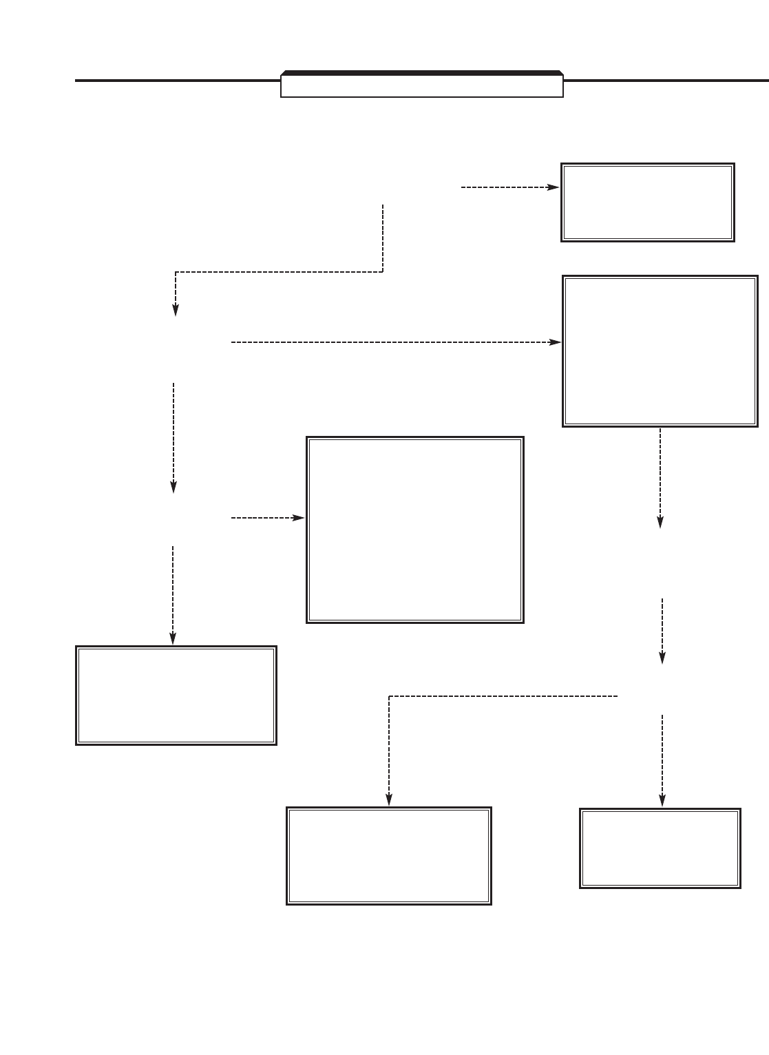
6-16
TROUBLESHOOTING CHART 6.5
" oV – Overvoltage " FAULT INDICATION
IS INPUT AC SUPPLY
VOLTAGE CORRECT?
NO
NO
NO
NO
DECREASE TO
PROPER VOLTAGE
RANGE.
YES
YES
YES
YES
YES
DOES OV TRIP
OCCUR ONLY
DURING DECEL-
ERATION?
DOES OV TRIP
STILL OCCUR
DURING DECEL-
ERATION?
WITH DRIVE IN
STOPPED CONDITION,
INCREASE DECELER-
ATION TIME BY
REPROGRAMMING
C1-02, C1-04, C1-06,
OR C1-08 .
REMOVE NOISE SOURCE:
• CONNECT SURGE
SUPPRESSOR TO RELAY
AND MAGNETIC CON-
TACTOR COILS.
• PROVIDE LINE FILTER
TO REMOVE NOISE ON
INPUT POWER LINE.
ERRONEOUS
OPERATION DUE
TO NOISE?
CONTROL SIGNALS TO
GATE DRIVE PCB ARE
FAULTY. REPLACE
CONTROL PCB.
IS BRAKING
OPTION
INSTALLED?
ADD BRAKING OPTION,
OR REPLACE DRIVE
WITH ONE OF LARGER
CAPACITY.
CHECK LOAD
INERTIA
REQUIREMENTS.
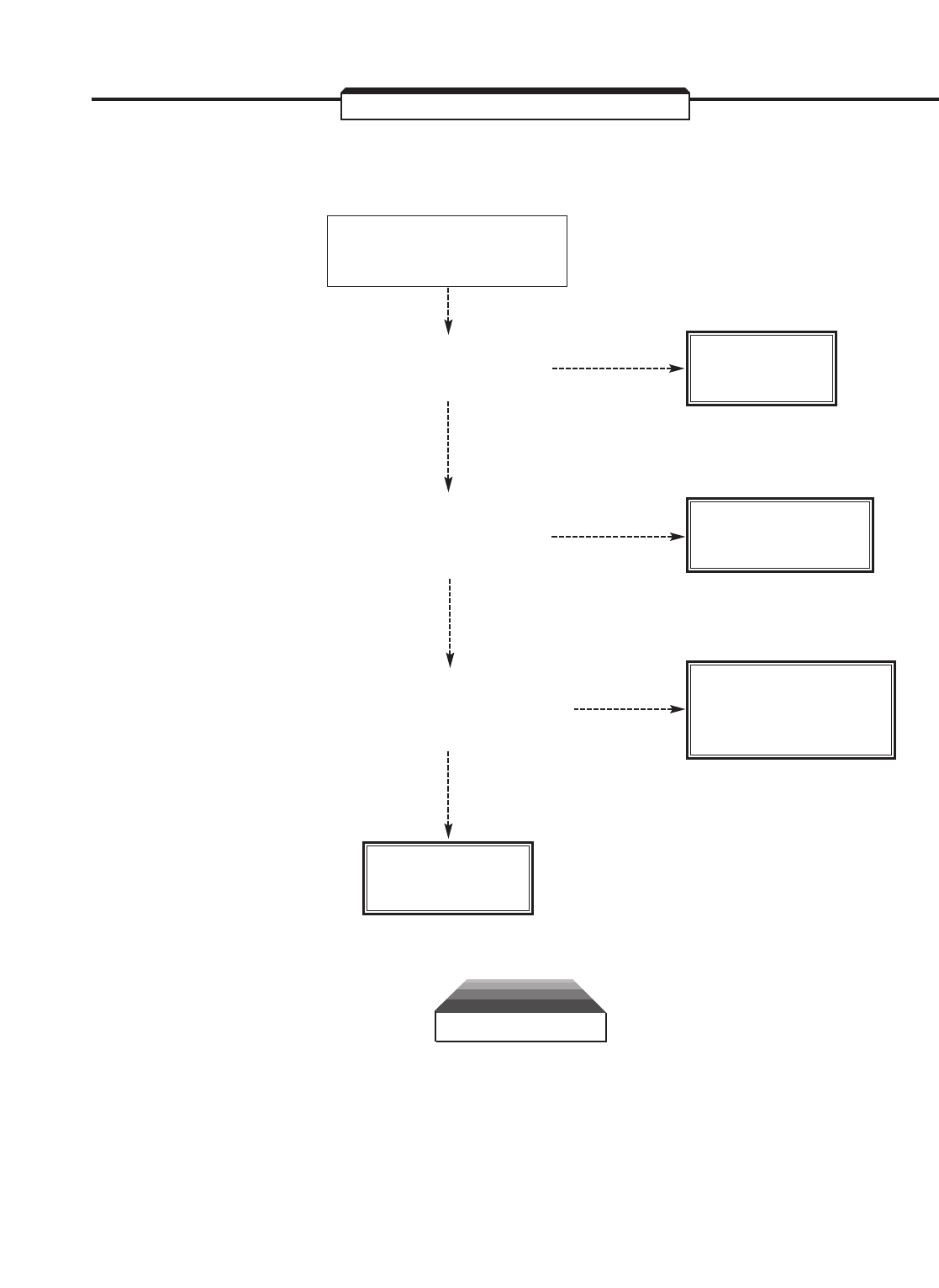
6-17
TROUBLESHOOTING CHART 6.6
" PUF – DC Bus Fuse Open " FAULT INDICATION
CAUTION
DO NOT REPLACE DC BUS FUSE WITHOUT
FIRST CHECKING OUTPUT TRANSISTORS.
DISCONNECT LEADS FROM
OUTPUT TERMINALS
T1(U), T2(V) AND T3(W).
ARE MOTOR WINDINGS
SHORTED (T1 TO T2,
T2 TO T3, OR T3 TO T1)?
MOTOR
IS FAULTY.
LOCATE AND
REMOVE SHORT.
REPLACE
DAMAGED POWER
TRANSISTORS.
YES
YES
YES
NO
NO
NO
ARE DRIVE
OUTPUT PHASES
SHORTED TO GROUND?
T1(U), T2(V), T3(W) TO G(E).
CHECK POWER TRANSISTORS
(SEE PARAGRAPH 6.5).
ARE TRANSISTORS
DAMAGED?
DRIVE
IS FAULTY.
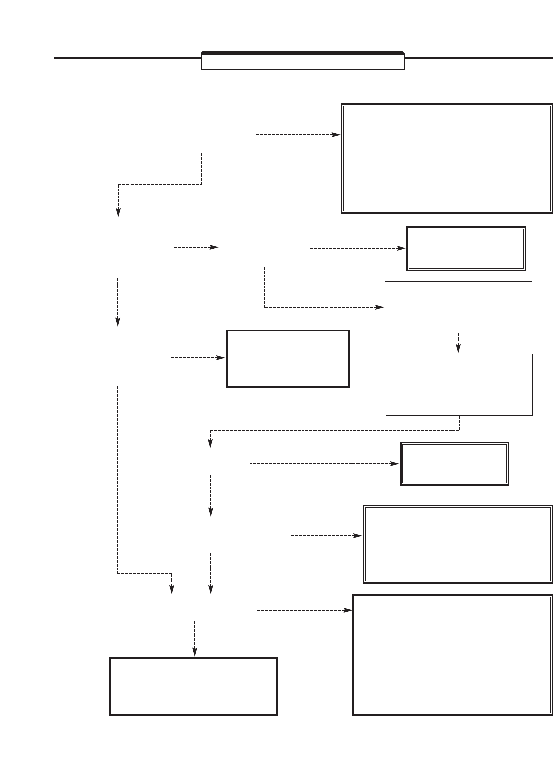
6-18
TROUBLESHOOTING CHART 6.7
" oC – Overcurrent " FAULT INDICATION
DOES OUTPUT
CURRENT EXCEED
200% OF RATING?
WITH DRIVE IN STOPPED CON-
DITION, INCREASE ACCELERATION
TIME BY REPROGRAMMING C1-01,
C1-03, C1-05, OR C1-07 , IF OC
TRIP OCCURS ONLY DURING
ACCELERATION.
OTHERWISE, REDUCE LOAD.
YES
YES
YES
YES
YES
YES
YES
NO
NO
NO
NO
NO
NO
NO
DOES OC TRIP
OCCUR, OR MC
ANSWERBACK
TRIP, WHEN POWER
IS TURNED ON?
MACHINE JAMMED
OR MOTOR
FAILURE?
CLEAR JAM, OR
REPLACE MOTOR.
DISCONNECT WIRING
FROM OUTPUT TERMINALS
T1, T2 AND T3 AND
CHECK LOAD IMPEDANCE.
CHECK POWER
TRANSISTORS
(SEE PARAGRAPH 6.5).
ARE TRANSISTORS
DAMAGED?
REPLACE
DAMAGED POWER
TRANSISTORS. WITH DRIVE IN STOPPED
CONDITION, INCREASE
ACCELERATION TIME BY
REPROGRAMMING C1-01,
C1-03, C1-05, OR C1-07 .
DOES OC TRIP
STILL OCCUR? DECREASE
LOAD INERTIA.
MOTOR STARTED BY CONTACTS
WIRED BETWEEN DRIVE
AND MOTOR?
- REWIRE TO ELIMINATE MOTOR
FULL VOLTAGE STARTING.
- REPLACE DRIVE WITH
ONE OF LARGER CAPACITY.
ERRONEOUS OPERATION
DUE TO NOISE? REMOVE NOISE SOURCE:
• CONNECT SURGE SUPPRESSOR
TO RELAY AND MAGNETIC CON-
TACTOR COILS.
• PROVIDE LINE FILTER TO
REMOVE NOISE ON INPUT
POWER LINE.
CONTROL PCB OR GATE
DRIVE PCB IS FAULTY.
REPLACE FAULTY BOARD.
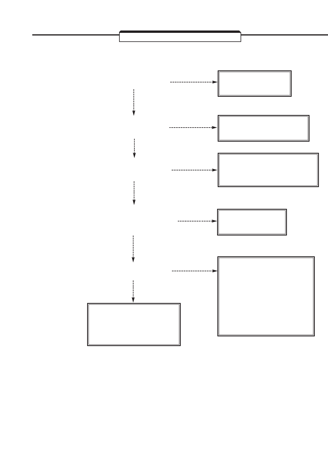
6-19
TROUBLESHOOTING CHART 6.8
" oL1 – Motor Overload " FAULT INDICATION
LOAD TOO LARGE
(MOTOR OVERHEATED)?
YES
YES
YES
YES
YES
DECREASE LOAD
WITHIN RATING.
CHECK MOTOR
AND LOAD.
SET ACCORDING TO
APPENDIX 3, TABLE A3-1.
NO
NO
NO
NO
NO
WITH DRIVE IN
STOPPED CONDITION,
REPROGRAM L1-01 & L1-02 .
IS DRIVE CAPACITY
( o2-04 ) FACTORY SET
CORRECTLY?
IS ELECTRONIC THERMAL
OVERLOAD ( L1-01 & L1-02 )
SET CORRECTLY?
DISCONNECT WIRING FROM
OUTPUT TERMINALS T1(U),
T2(V) AND T3(W). IS OL
STILL INDICATED?
REMOVE NOISE SOURCE:
• CONNECT SURGE
SUPPRESSOR TO RELAY
AND MAGNETIC CON-
TACTOR COILS.
• PROVIDE LINE FILTER
TO REMOVE NOISE ON
INPUT POWER LINE.
PG-X2 PCB, CONTROL
PCB, OR GATE DRIVE
PCB IS FAULTY.
REPLACE FAULTY BOARD.
ERRONEOUS OPERATION
DUE TO NOISE?
6-20
TROUBLESHOOTING CHART 6.9
" UV – Undervoltage " FAULT INDICATION
IS INPUT AC
SUPPLY
CORRECT?
NO
NO
YES
YES
NO
YES
IS THERE
AT LEAST 450VDC
(FOR 460V DRIVE) OR
225VDC (FOR 230V DRIVE)
ON THE DC BUS?
(SELECT MONITOR DISPLAY
U1-07 TO CHECK VOLTAGE)
- INCREASE VOLTAGE
WITHIN PROPER RANGE.
- CHECK WIRING BETWEEN
MAIN AC CONTACTOR
AND DRIVE.
DRIVE
IS FAULTY.
REMOVE NOISE SOURCE:
• CONNECT SURGE
SUPPRESSOR TO RELAY
AND MAGNETIC CON-
TACTOR COILS.
• PROVIDE LINE FILTER
TO REMOVE NOISE ON
INPUT POWER LINE.
ERRONEOUS OPERATION
DUE TO NOISE?
CONTROL PCB OR GATE
DRIVE PCB IS FAULTY.
REPLACE FAULTY BOARD.
6-21
TROUBLESHOOTING CHART 6.10
" oH – Heatsink Overtemp " FAULT INDICATION
IS AMBIENT
TEMPERATURE
45°C (113°F)
OR GREATER?
REDUCE AMBIENT
TEMPERATURE.
YES
YES
YES
YES
NO
NO
NO
NO
IS HEAT SINK
CLEAN?
COOLING FAN
STOPPED?
CLEAN HEAT
SINK.
REPLACE
COOLING FAN.
ERRONEOUS OPERATION
DUE TO NOISE?
CONTROL PCB OR GATE
DRIVE PCB IS FAULTY.
REPLACE FAULTY BOARD.
REMOVE NOISE SOURCE:
• CONNECT SURGE
SUPPRESSOR TO RELAY
AND MAGNETIC CON-
TACTOR COILS.
• PROVIDE LINE FILTER
TO REMOVE NOISE ON
INPUT POWER LINE.

6-22
TROUBLESHOOTING CHART 6.11
" CPFXX – " CONTROL FUNCTION ERROR FAULT INDICATION
1. CHECK THAT ALL DRIVE
HARNESS CONNECTORS,
AND CONTROL BOARD
MOUNTED PCB's, ARE
FIRMLY SEATED.
2.CHECK THAT NO NOISE
SOURCE IS PRESENT.
3. REPROGRAM A1-03 USING
FACTORY RESET CODES.
OBSERVE CAUTION
ON PAGE vii.
4. CHECK o2-04 FOR PROPER
VALUE.
TURN OFF POWER. AFTER
"CHARGE" LAMP ON MAIN
PC BOARD GOES OUT,
TURN POWER BACK ON.
IS CPF STILL
INDICATED?
IS CPF STILL
INDICATED?
YES
YES
NO
NO
SELF-DIAGNOSIS FUNCTION
HAS DETECTED FAILURE IN
THE CPU OR PERIPHERAL
COMPONENTS.
REPLACE THE CONTROL PCB,
OR APPROPRIATE CONTROL
MOUNTED PCB.
DRIVE IS OK.
RETURN TO NORMAL
OPERATION.
6-23
TROUBLESHOOTING CHART 6.12
" EFX – " EXTERNAL FAULT INDICATION
IS AN EXTERNAL FAULT SIGNAL
PRESENT (CLOSED CIRCUIT
BETWEEN TERMINAL 3 AND
11; OR OPEN CIRCUIT
BETWEEN TERMINAL 11
AND WHICHEVER TERMINAL
(4-8) HAS BEEN PROGRAMMED
FOR EXT. FAULT INPUT)?
YES FAULT HAS OCCURRED
IN CIRCUITS OUTSIDE
THE DRIVE.
TROUBLESHOOT AND
CORRECT.
NO
CONTROL PCB IS
FAULTY. REPLACE.
6-24
TROUBLESHOOTING CHART 6.13
" oS – Overspeed " FAULT INDICATION
CORRECT ENCODER PPR
VALUE PROGRAMMED
IN F1-01 ?
RE-PROGRAM
F1-01 SETTING.
CONSULT YASKAWA
ABOUT SPECIFICATIONS OF
USER-SUPPLIED ENCODER.
ENCODER
PROBLEM.
NO
YES
YES
YES
NO
NO
EXCESSIVE NOISE
ON ENCODER
SIGNAL INPUTS TO
THE DRIVE?
(See Section 6.6)
FORWARD DIRECTION OK,
BUT TRACKING PROBLEM
IN REVERSE DIRECTION?
CONSULT
YASKAWA.
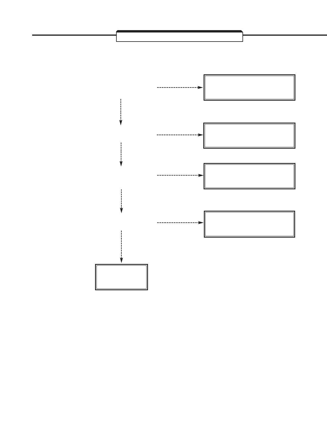
6-25
TROUBLESHOOTING CHART 6.14
" CF – Out of Control " FAULT INDICATION
ARE REGENERATIVE
TORQUE LIMITS SET
HIGH ENOUGH?
INCREASE L7-03 AND
L7-04 .
INCREASE C1-02 (OR
C1-04 , C1-06 , OR C1-08 )
REPROGRAM E2-02
TO PROPER SETTING.
NO
YES
NO
YES
NO
YES
CAN DECELERATION
TIME BE EXTENDED?
INCREASE E1-09
(TYPICALLY TO 1.5 Hz )
YES
NO
CAN MINIMUM
FREQUENCY BE
INCREASED?
IS MOTOR RATED SLIP
SET PROPERLY?
CONSULT
YASKAWA.
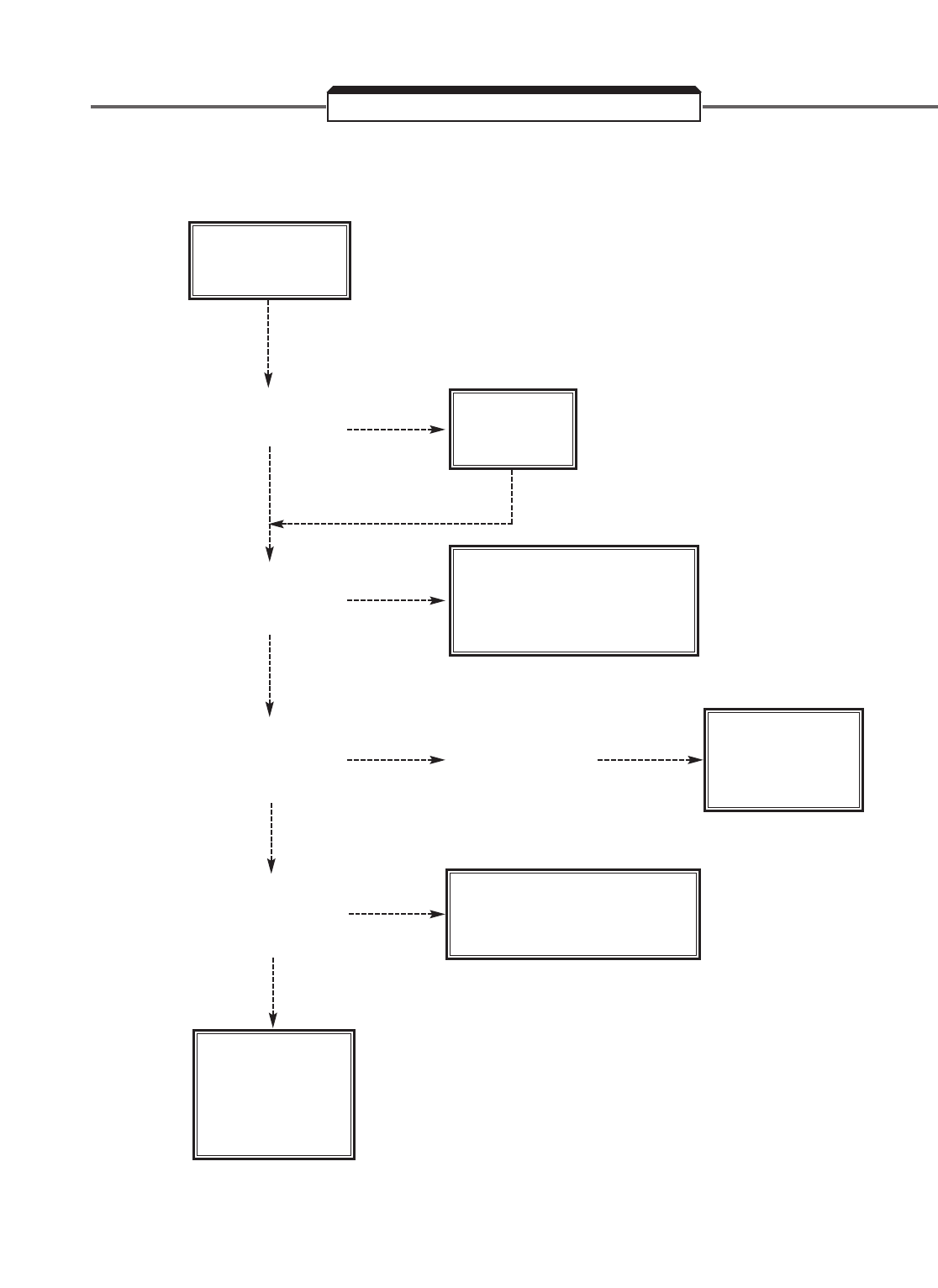
6-26
NO DIGITAL OPERATOR DISPLAY
TROUBLESHOOTING CHART 6.15
230/460
ON
L1, L2, L3?
YES
YES
YES
CHARGE
LAMP
ON?
APPLY
POWER
EITHER CONTROL CARD
OR GATE DRIVE IS
FAULTY
REPLACE
GATE DRIVE
BOARD
NO
DISPLAY
IS VOLTAGE
BETWEEN
TERM. 1 & 11
≈24 VDC?
IS VOLTAGE
BETWEEN
OR TERM. 15/17
+15 VDC?
CHECK ALL
CONNECTORS,
EXCHANGE
OPERATOR /
CABLE
DAMAGED PRECHARGE
RESISTOR, INPUT
DIODES, OR OUTPUT
TRANSISTORS
NO
YES
IS VOLTAGE
BETWEEN
TERM. 15 & 17
+15 VDC?
NO
NO
NO
NO
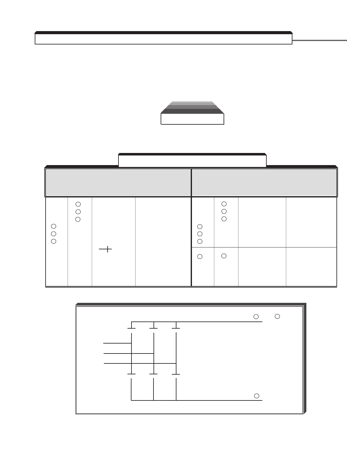
6-27
A . DIODE MODULE
Measure the resistance across the module terminals with a volt-ohm meter. Set the meter
at the X1 range. The measured resistance should be within the values listed in Table 6-4.
NOTE: If the DC bus fuse is blown (PUF), the values shown below may not be accurate.
WARNING
Power should be removed from L1, L2, & L3 and the CHARGE light
should be out prior to conducting these tests.
RESISTANCE TEST FOR 3Ø CONVERTER MODULES (BRIDGE RECT)
VOM RESISTANCE SCALE R x 1
+ IS THE POSITIVE POLARITY LEAD *
– IS THE NEGATIVE POLARITY LEAD
* The VOM red lead is not necessarily the positive potential in the resistance mode. For these tests the + lead
refers to the positive potential. Make sure you know which polarity you have on your VOM.
+ – NORMAL ABNORMAL
READING READING
ON ON (OHMS) (OHMS)
L1 + 1
L2 + 1
L3 + 1 2.5 to 50 Ω0 Ω
– L1 or or INFINITE
– L2 0.25 to 0.7
– L3 if using
scale
+ – NORMAL ABNORMAL
READING READING
ON ON (OHMS) (OHMS)
+ – NORMAL ABNORMAL
READING READING
ON ON (OHMS) (OHMS)
L1 –
L2 – LESS
L3 – INFINITE THAN
+ 2 L1 1M Ω
+ 2 L2
+ 2 L3
+ 2 – MAGNITUDE 0 Ω
OF CAP or INFINITE
CHARGE TO
INFINITE
+ – NORMAL ABNORMAL
READING READING
ON ON (OHMS) (OHMS)
▲▲▲
▲▲▲
L1
L2
L3
+ 2 or + 1
–
●
●
●
●
●●
●
Table 6-4. Diode Module Resistances
▲
6.5 DIODE AND IGBT (TRANSISTOR) MODULE RESISTANCE TEST
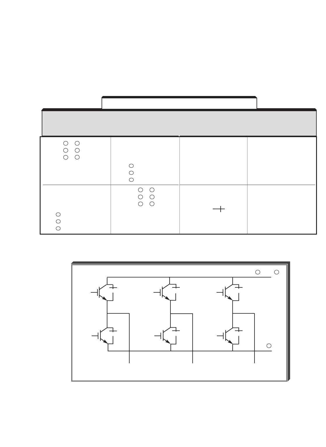
B. TRANSISTOR MODULE
Measure the resistance across the module terminals with a volt-ohm meter. Set the meter
to the X1 range. The measured resistance should be within the values listed in Table 6-5.
NOTE: If the DC bus fuse is blown (PUF), the values shown below may not be
accurate.
RESISTANCE TEST FOR 3Ø TRANSISTOR MODULES
VOM RESISTANCE SCALE R x 1
+ IS THE POSITIVE POLARITY LEAD *
- IS THE NEGATIVE POLARITY LEAD
* The VOM red lead is not necessarily the positive potential in the resistance mode. For these tests the + lead
refers to the positive potential. Make sure you know which polarity you have on your VOM.
6-28
▲▲▲
▲▲▲
●●
●●
●
●
●
T1 or
U
T2 or
V
T3 or
W
B1, + 1 or + 3
–
Table 6-5. Transistor Module Resistances
▲
T1/U
T2/V
T3/W
T1
T2
T3
2.5 to 50 Ωor
0.3 to 0.7 if
using
scale
INFINITE
0 Ωor
INFINITE
0 Ω
NORMAL
READING
(OHMS)
ABNORMAL
READING
(OHMS)
–
–
–
B1/ + 3/ +1
B1/ + 3/ +1
B1/ + 3/ +1
T1/U
T2/V
T3/W
T1/U
T2/V
T3/W
–
–
–
B1/ + 3/ +1
B1/ + 3/ +1
B1/ + 3/ +1
+
ON
–
ON

6-29
In order to check the encoder pulses, an oscilloscope is needed. The pulses can be
checked after they have been processed by the PG-X2 card or at the motor.
WARNING
The following tests require power to be applied to the drive while
the front cover is off. Proper precautions should be taken to
prevent electric shock and damage to the equipment.
A . Checking Encoder Pulses at Test Points on the PG-X2 Card
1. Remove power from L1, L2, & L3 and wait for the CHARGE light to go out.
2. Connect the common of the oscilloscope to the test point labeled GND.
3. Connect one channel of the scope to PA. (If the scope is two channel, connect the
second channel to PB).
4. Set the scope for 2V/div, 50ms/div, normal trigger, and rising edge trigger.
5. Apply power to the GPD 515, but do NOT apply a run command.
6. Turn the motor shaft by hand. As Figure 6-1 shows, there should be pulses on both
channels at a +5V level, 50% duty cycle, and they should be separated by 90
electrical
degrees (half a pulse).
7. If one or both channels do not have the correct pulses present (i.e. missing pulses,
incorrect duty cycle, improper voltage, etc.), go to procedure B.
B. Checking the Pulses at the Input to the PG-X2 Card
1. Remove power from L1, L2, & L3 and wait for the CHARGE light to go out.
2. Connect the common of the scope to terminal 2 of TA1.
3. Connect one channel of the scope to terminal 4 of TA1. (If the scope is two channel,
connect the second channel to terminal 5 of TA1.)
4. Set the scope for 5V/div, 50ms/div, normal trigger, and rising edge trigger.
5. Apply power to the drive, but do NOT apply a run command.
6. Turn the motor shaft by hand. As Figure 6-1 shows, there should be pulses on both
channels, 50% duty cycle, and they should be the inverse of each other (separated by
180 electrical degrees).
7. Disconnect the two scope channels, and reconnect them to terminals 6 and 7 of TA1.
6.6 CHECKING ENCODER PULSES
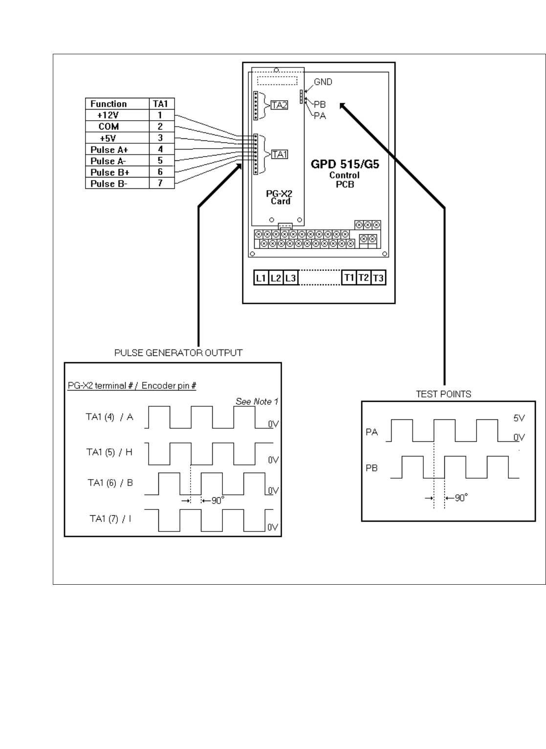
6-30
8. Turn the motor shaft by hand. As Figure 6-1 shows, there should be pulses on both
channels, 50% duty cycle, and they should be the inverse of each other (separated by
180 electrical degrees.
9. If one or both channels do not have the correct pulses present (i.e. missing pulses,
incorrect duty cycle, improper voltage, etc.), go to procedure C.
Figure 6-1. PG-X2 Card Inputs / Test Points
NOTE 1: Encoder output voltage should be at or near the encoder power supply voltage.

6-31
C. Checking the Pulses at a VCM Motor
1. Remove power from L1, L2, & L3 and wait for the CHARGE light to go out.
2. Take apart the military style connector at the motor.
3. Connect the common of the scope to pin F.
4. Connect one channel of the scope to pin A. (If the scope is two channel, connect the
second channel to pin H.)
5. Set the scope for 5V/div, 50ms/div, normal trigger, and rising edge trigger.
6. Apply power to the drive, but do NOT apply a run command.
7. Turn the motor shaft by hand. As Figure 6-1 shows, there should be pulses on both
channels, 50% duty cycle, and they should be the inverse of each other (separated by
180 electrical degrees).
8. Disconnect the two scope channels, and reconnect them to pins B and I.
9. Turn the motor shaft by hand. As Figure 6-1 shows, there should be pulses on both
channels, 50% duty cycle, and they should be the inverse of each other (separated by
180 electrical degrees).
10. If no pulses can be seen on any of the four pins (A, B, H, & I), check the power supply
between pins D and F. If it is not at or near 12VDC, check the power supply back at
the PG-X2 card on TA1 terminals 1 & 2. If the power supply is not good at TA1,
replace the PG-X2 card.

6-32

A1-1
The GPD 515/G5 control circuits use various parameters to select functions and
character-istics of the drive. For methods of changing of parameter settings, see Section
4.
The following tables list all parameters in numerical order. For each parameter, reference
paragraph(s) in Section 2 or 5 are listed (if applicable) where the features of the drive
affected by that parameter are described.
A1-00 Language 0 : English 1 0 - 6 0 Q Q Q Q 2.3
Selection 1 : Japanese (See Note 1)
2 : German
3 : French
4 : Italian
5 : Spanish
6 : Portuguese
A1-01 Parameter 0 : Operation only 1 0 - 4 2 Q Q Q Q 5.4
Access 1 : User program See
Level 2 : Quick-start Note
3 : Basic 2
4 : Advanced
A1-02 Control 0 : V/f control 1 0 - 3 2 Q Q Q Q 2.2
Method 1 : V/f with PG feedback (See Note 1)
Selection 2 : Open loop vector
3 : Flux vector
A1-03 Initialize 0 : No initialize 1 0000 - 0000 Q Q Q Q 5.37
Parameters 1110 : User initialize 9999
2220 : 2-wire initialize
3330 : 3-wire initialize
A1-04 Enter 1 0000 - 0000 Q Q Q Q
Password 9999
A2-01 User Program Select parameters to be 1 b1-01 - - - - - A A A A 5.4
thru Access available in User Program o2-09
A2-32 Parameters Access Level
NOTES:
1. Settings of these parameters will not be initialized by programming A1-03 to
“ 1110 ”, “ 2220 ”, or “ 3330 ”.
2. Capability to view and set specific parameters is dependent upon the Access Level
( A1-01) and Control Method ( A1-02; 0 = V/f, 1 = V/f w/PG, 2 = Open Loop
Vector, 3 = Flux Vector) the drive is programmed for. Each column represents the
Access Level for a given Control Method: Q = Quick-start; B = Basic; A = Advanced;
— = not available.
Table A1-1. Drive AX-XX Parameters
PARAMETER
FUNCTION
INCRE-
SETTING FACTORY ACCESS LEVEL PARA.
DESCRIPTION (See Note 2)
NUMBER NAME
MENT
RANGE SETTING 0 1 2 3 REF .
Appendix 1. LISTING OF PARAMETERS

A1-2
b1-01 Reference 0 : Digital Operator 1 0 - 4 1 Q Q Q Q 5.25 A,
Selection 1 : Terminal 5.28,
2 : Serial communication 5.36
3 : Option PCB
4 : EWS
b1-02 Operation 0 : Digital Operator 1 0 - 4 1 Q Q Q Q 5.25 A,
Method 1 : Terminal 5.28
Selection 2 : Serial communication
3 : Option PCB
4 : EWS
b1-03 Stopping 0 : Ramp to stop 1 0 - 3 0 Q Q Q Q 5.10,2
Method 1 : Coast to stop (See Note 1) 5.40
Selection 2 : DC injection to stop
3 : Coast with timer
b1-04 Reverse 0 : Enable reverse operation 1 0, 1 0 B B B B
Operation 1 : Disable reverse operation
Prohibit
b1-05 Zero-Speed 0 : Run at frequency reference 1 0 - 3 0 — — — A 5.50
Operation 1 : Stop
(level 2 : Run at min. freq. ( E1-09 )
determined 3 : Run at zero speed
by E1-09 )
b1-06 Logic Input 0 : 2ms – 2 scans 1 0, 1 1 A A A A
Scan Rate 1 : 5ms – 2 scans
b1-07 Local/Remote 0 : Cycle external Run 1 0, 1 0 A A A A 5.32A
Run Selection 1 : Accept external Run
b1-08 Run Command 0 : Run command is disabled 1 0 - 1 0 A A A A 5.26
Selection during program mode
During 1 : Run command enabled
Program during program mode
b2-01 DC Injection 0.1 Hz 0.0 - 10.0 0.5 B B B B 5.10,
Braking Start 5.32
Frequency
b2-02 DC Injection 1 % 0 - 100 50 B B B — 5.10
Braking
Current
b2-03 DC Injection 0.01 0.00 - 10.00 0.00 B B B B 5.10
Braking Time sec
at Start
b2-04 DC Injection 0.01 0.00 - 10.00 0.00 B B B B 5.10
Braking Time sec
at Stop
b2-08 Field 100% is no load current value 1% 0 - 500 0 — — A A 5.10B
Compensation at Min. frequency (E1-09).
At Start
Table A1-2. Drive bX-XX Parameters
PARAMETER
FUNCTION
INCRE-
SETTING FACTORY ACCESS LEVEL PARA.
DESCRIPTION (See Note 3)
NUMBER NAME
MENT
RANGE SETTING 0 1 2 3 REF .

A1-3
b3-01 Speed Search 0 : Disabled 1 0, 1 0 A A A A 5.32 D
Selection 1 : Enabled (See Note 2)
b3-02 Speed Search 1 % 0 - 200 100 A — A — 5.32 D
Deactivation (See Note 2)
Current Level
b3-03 Speed Search 0.1 0.0 - 10.0 2.0 A — A — 5.32 D
Deceleration sec
Time
b4-01 Timer 0.1 0.0 - 300.0 0.0 A A A A 5.32 E
Function sec
ON-Delay
Time
b4-02 Timer 0.1 0.0 - 300.0 0.0 A A A A 5.32 E
Function sec
OFF-Delay
Time
b5-01 PID Control 0 : Disabled 1 0 - 4 0 A A A A 5.36
Mode 1 : D=Feedback
Selection 2 : D=Feed forward
3 : Reference + PID
(D=Feedback)
4 : Reference + PID
(D=Feed Forward)
b5-02 PID 0.01 0.00 - 25.00 1.00 A A A A 5.36
Proportional
Gain
b5-03 PID Integral 0.1 0.0 - 360.0 1.0 A A A A 5.36
Time sec
b5-04 PID Integral 0.1 % 0.0 - 100.0 100.0 A A A A 5.36
Limit
b5-05 PID 0.01 0.00 - 10.00 0.00 A A A A 5.36
Differential sec
Time
b5-06 PID Output 0.1 % 0.0 - 100.0 100.0 A A A A 5.36
Limit
b5-07 PID Offset 0.01 % –100.0 - 0.0 A A A A 5.36
Adjustment 100.0
b5-08 PID Primary 0.01 0.00 - 10.00 0.00 A A A A 5.36
Delay Time sec
Constant
b5-09 PID Output 0 : Not Inverted 1 0, 1 0 A A A A 5.36D
Selection 1 : Inverted
Table A1-2. Drive bX-XX Parameters – Continued
PARAMETER
FUNCTION
INCRE-
SETTING FACTORY ACCESS LEVEL PARA.
DESCRIPTION (See Note 3)
NUMBER NAME
MENT
RANGE SETTING 0 1 2 3 REF .

A1-4
b5-10 PID Output 0.1 0.0 - 25.0 1.0 A A A A 5.36D
Gain
b5-11 PID Output 0 : If PID output tries to go 1 0, 1 0 A A A A 5.36D
Reverse negative, it will be limited
Selection to 0 (motor stops)
1 : PID output is allowed to go
negative (motor runs in
reverse)
b5-12 Feedback Loss 0 : Detection is disabled 1 0 - 2 0 A A A A 5.36E
Detection 1 : Detection is enabled -
Selection (PID) alarm only
2 : Detection is enabled - fault
b5-13 Feedback 1% 0 - 100 0 A A A A 5.36E
Loss Detection
Level (PID)
b5-14 Feedback 0.1 0.0 - 25.5 1.0 A A A A 5.36E
Loss Detection sec
Delay Time
(PID)
b6-01 Dwell 0.1 Hz 0.0 - 400.0 0.0 A A A A 5.14
Frequency
at Start
b6-02 Dwell Time 0.1 0.0 - 10.0 0.0 A A A A 5.14
at Start sec
b6-03 Dwell 0.1 Hz 0.0 - 400.0 0.0 A A A A 5.14
Frequency
at Stop
b6-04 Dwell Time 0.1 0.0 - 10.0 0.0 A A A A 5.14
at Stop sec
b7-01 Droop Control 0.1 % 0.0 - 100.0 0.0 — — — A 5.13
Level
b7-02 Droop Control 0.01 0.03 - 2.00 0.05 — — — A 5.13
Delay Time sec
b8-01 Energy-saving 1 % 0 - 100 80 A A — — 5.16A
Gain
b8-02 Energy-saving 0.1 Hz 0.0 - 400.0 0.0 A A — — 5.16A
Frequency
b8-03 Automatic 0 : Disabled 1 0, 1 0 — — A A 5.16B
Energy-saving 1 : Enabled
Selection
b8-04 Automatic 0.1 0.0 - 10.0 Note 2 — — A A 5.16B
Energy-saving
Gain
Table A1-2. Drive bX-XX Parameters – Continued
PARAMETER
FUNCTION
INCRE-
SETTING FACTORY ACCESS LEVEL PARA.
DESCRIPTION (See Note 3)
NUMBER NAME
MENT
RANGE SETTING 0 1 2 3 REF .

A1-5
b8-05 Automatic 0.01 0.0 - 10.0 Note 2 — — A A 5.16B
Energy-saving sec
Time Constant
b9-01 Zero-Servo 1 0 - 100 5 — — — A 5.49
Gain
b9-02 Zero-Servo 1 0 - 16383 10 — — — A 5.49
Completion
Width
Table A1-2. Drive bX-XX Parameters – Continued
PARAMETER
FUNCTION
INCRE-
SETTING FACTORY ACCESS LEVEL PARA.
DESCRIPTION (See Note 3)
NUMBER NAME
MENT
RANGE SETTING 0 1 2 3 REF .
NOTES:
1. Setting range is only 0 and 1 when control method is set to Flux Vector control
( A1-02 = 3).
2. Will change with control method. See Appendix 3, Table A3-2.
3. Capability to view and set specific parameters is dependent upon the Access Level
( A1-01) and Control Method ( A1-02; 0 = V/f, 1 - V/f w/PG, 2 = Open Loop
Vector, 3 = Flux Vector) the drive is programmed for. Each column represents the
Access Level for a given Control Method: Q = Quick-start; B = Basic; A = Advanced;
— = not available.

A1-6
C1-01 Acceleration 0.01 0.00 - 600.00 10.00 Q Q Q Q 5.2
Time 1 sec. or or
C1-02 Deceleration or 0.0 - 6000.0 10.0 Q Q Q Q 5.2
Time 1 0.1
C1-03 Acceleration sec. (Dependent (Dependent B B B B 5.2
Time 2
(Depen-
upon C1-10 upon C1-10
C1-04 Deceleration
dent
setting) setting) BB BB 5.2
Time 2
upon
C1-05 Acceleration C1-10 AA AA 5.2
Time 3
setting)
C1-06 Deceleration AAAA 5.2
Time 3
C1-07 Acceleration AAAA 5.2
Time 4
C1-08 Deceleration AAAA 5.2
Time 4
C1-09 Fast-Stop BBBB 5.2
Decel. Time
C1-10 Accel/Decel 0 : 0.01 seconds 1 0, 1 1 A A A A 5.2
Time Setting 1 : 0.1 seconds
Unit
C1-11 Accel/Decel 0.1 Hz 0.0 - 400.0 0.00 A A A A 5.2
Time Switching
Frequency
C2-01 S-Curve 0.01 0.0 - 2.50 0.20 A A A A 5.3
Characteristic sec
at Accel. Start
C2-02 S-Curve 0.01 0.0 - 2.50 0.20 A A A A 5.3
Characteristic sec
at Accel. End
C2-03 S-Curve 0.01 0.0 - 2.50 0.20 A A A A 5.3
Characteristic sec
at Decel. Start
C2-04 S-Curve 0.01 0.0 - 2.50 0.00 A A A A 5.3
Characteristic sec
at Decel. End
Table A1-3. Drive CX-XX Parameters
PARAMETER
FUNCTION
INCRE-
SETTING FACTORY ACCESS LEVEL PARA.
DESCRIPTION (See Note 3)
NUMBER NAME
MENT
RANGE SETTING 0 1 2 3 REF .

A1-7
C3-01 Slip 0.1 0.0 - 2.5 (See Note 1) B — B B 5.38
Compensation
Gain
C3-02 Slip 1 ms 0 - 10000 (See Note 1) A — A — 5.38
Compensation
Primary Delay
Time
C3-03 Slip 1 % 0 - 250 200 A — A — 5.38
Compensation
Limit
C3-04 Slip 0 : Disabled 1 0, 1 0 A A A — 5.38
Compensation 1 : Enabled
Selection
During
Regeneration
C3-05 Flux Select 0 : Slip Included - Flux is 1 0, 1 0 — — A — 5.38
calculated after slip
compensation is applied
1 : Slip Excluded - Flux is
calculated before slip
compensation is applied
C3-06 Output Voltage 0 : Disabled - Output voltage 1 0, 1 0 — — A A 5.38
Limit limit and slip compensation
are disabled above base
speed
1 : Enabled - Output voltage
limit and slip compensation
are enabled above base
speed
C4-01 Torque 0.01 0.00 - 2.50 1.00 B B B — 5.42
Compensation
Gain
C4-02 Torque 1 ms 0 - 10000 (See Note 1) A A A — 5.42
Compensation
Time Constant
C4-03 Forward Torque 0.1% 0.0 - 200.0 0.0 — — A — 5.42
Compensation
At Start
C4-04 Reverse Torque 0.1% -200.0 - 0.0 0.0 — — A — 5.42
Compensation
At Start
C4-05 Torque 1 ms 0 - 200 10 — — A — 5.42
Compensation
At Start Time
Constant
Table A1-3. Drive CX-XX Parameters – Continued
PARAMETER
FUNCTION
INCRE-
SETTING FACTORY ACCESS LEVEL PARA.
DESCRIPTION (See Note 3)
NUMBER NAME
MENT
RANGE SETTING 0 1 2 3 REF .

A1-8
C5-01 ASR 0.01 0.00 - 300.00 (See Note 1) — B — B 5.7
Proportional
Gain 1
C5-02 ASR Integral 0.001 0.000 - (See Note 1) — B — B 5.7
Time 1 sec 10.000
C5-03 ASR 0.01 0.00 - 300.00 (See Note 1) — B — B 5.7
Proportional
Gain 2
C5-04 ASR Integral 0.001 0.000 - (See Note 1) — B — B 5.7
Time 2 sec 10.000
C5-05 ASR Limit 0.1 % 0.0 - 20.0 5.0 — A — —
C5-06 ASR Primary 0.001 0.000 - 0.500 0.004 — — — A 5.7
Delay Time sec
C5-07 ASR 0.1 Hz 0.0 - 400.0 0.0 — — — A 5.7
Switching
Frequency
C5-08 ASR Integral 1 % 0 - 400 400 — — — A
Limit
C6-01 Carrier 0.1 0.4 - 15.0 10.0 B B B B 5.8
Frequency kHz (See Note 2) (See Note 2)
Upper Limit
C6-02 Carrier 0.1 0.4 - 15.0 10.0 A A — — 5.8
Frequency kHz (See Note 2) (See Note 2)
Lower Limit
C6-03 Carrier 1 00 - 99 00 A A — — 5.8
Frequency (See Note 2) (See Note 2)
Proportional
Gain
C7-01 Hunting 0 : Disabled 1 0, 1 1 A A — — 5.23
Prevention 1 : Enabled
Selection
C7-02 Hunting 0.01 0.00 - 2.50 1.00 A A — — 5.23
Prevention
Gain
Table A1-3. Drive CX-XX Parameters – Continued
PARAMETER
FUNCTION
INCRE-
SETTING FACTORY ACCESS LEVEL PARA.
DESCRIPTION (See Note 3)
NUMBER NAME
MENT
RANGE SETTING 0 1 2 3 REF .

A1-9
C8-08 AFR Gain 0.01 0.00 - 10.00 1.00 — — A — 5.6
C8-09 AFR Time 1 ms 0 - 2000 50 — — A — 5.6
C8-30 Carrier 0 : Fc = 2 kHz 1 0, 1 2 — — A —
Frequency 1 : Fc = C6-01
During Auto- 2 : Fc = 5 kHz
Tuning
NOTES:
1. Factory setting differs depending on the control method ( A1-02).
2. Setting range and factory setting differ depending on drive capacity and the control
method.
3. Capability to view and set specific parameters is dependent upon the Access Level
( A1-01) and Control Method ( A1-02; 0 = V/f, 1 = V/f w/PG, 2 = Open Loop
Vector, 3 = Flux Vector) the drive is programmed for. Each column represents the
Access Level for a given Control Method: Q = Quick-start; B = Basic; A = Advanced;
— = not available.
Table A1-3. Drive CX-XX Parameters – Continued
PARAMETER
FUNCTION
INCRE-
SETTING FACTORY ACCESS LEVEL PARA.
DESCRIPTION (See Note 3)
NUMBER NAME
MENT
RANGE SETTING 0 1 2 3 REF .

A1-10
d1-01 Frequency 0.1 Hz 0.00 - 400.0 0.00 Q Q Q Q 5.25 B
Reference 1
d1-02 Frequency 0.1 Hz 0.00 - 400.0 0.00 Q Q Q Q 5.25 B
Reference 2
d1-03 Frequency 0.1 Hz 0.00 - 400.0 0.00 Q Q Q Q 5.25 B
Reference 3
d1-04 Frequency 0.1 Hz 0.00 - 400.0 0.00 Q Q Q Q 5.25 B
Reference 4
d1-05 Frequency 0.1 Hz 0.00 - 400.0 0.00 B B B B 5.25 B
Reference 5
d1-06 Frequency 0.1 Hz 0.00 - 400.0 0.00 B B B B 5.25 B
Reference 6
d1-07 Frequency 0.1 Hz 0.00 - 400.0 0.00 B B B B 5.25 B
Reference 7
d1-08 Frequency 0.1 Hz 0.00 - 400.0 0.00 B B B B 5.25 B
Reference 8
d1-09 Jog Frequency 0.1 Hz 0.00 - 400.0 6.00 Q Q Q Q 5.24,
Reference 5.25 B
d2-01 Frequency 0.1 % 0.0 - 110.0 100.0 B B B B 5.22,
Reference 5.32 G
Upper Limit
d2-02 Frequency 0.1 % 0.0 - 109.0 0.0 B B B B 5.22
Reference
Lower Limit
d3-01 Critical 0.1 Hz 0.0 - 400.0 0.0 B B B B 5.9
Frequency
Rejection 1
d3-02 Critical 0.1 Hz 0.0 - 400.0 0.0 B B B B 5.9
Frequency
Rejection 2
d3-03 Critical 0.1 Hz 0.0 - 400.0 0.0 B B B B 5.9
Frequency
Rejection 3
d3-04 Critical 0.1 Hz 0.0 - 20.0 1.0 B B B B 5.9
Frequency
Rejection
Width
d4-01 Frequency 0 : Disabled 1 0, 1 0 A A A A 5.21,
Reference 1 : Enabled 5.32 G
Hold
Function
Selection
Table A1-4. Drive dX-XX Parameters
PARAMETER
FUNCTION
INCRE-
SETTING FACTORY ACCESS LEVEL PARA.
DESCRIPTION (See Note 1)
NUMBER NAME
MENT
RANGE SETTING 0 1 2 3 REF .

A1-11
d4-02 Trim Control 1 % 0 - 100 10 A A A A 5.32 H
Level
d5-01 Torque Control 0 : Speed Control 1 0, 1 0 — — — A 5.43
Selection 1 : Torque Control
d5-02 Torque 1 ms 0 - 1000 0 — — — A 5.43
Reference
Delay Time
d5-03 Speed Limit 1 : Analog input 1 1, 2 1 — — — A 5.43
Selection (term. 13 & 14)
2 : d5-04 setting
d5-04 Speed Limit 1 % –120 - +120 0 — — — A 5.43
d5-05 Speed Limit 1 % 0 - 120 10 — — — A 5.43
Bias
d5-06 Speed/Torque 1 ms 0 - 1000 0 — — — A 5.43
Control
Switching
Timer
NOTES:
1. Capability to view and set specific parameters is dependent upon the Access Level
( A1-01) and Control Method ( A1-02; 0 = V/f, 1 = V/f w/PG, 2 = Open Loop
Vector, 3 = Flux Vector) the drive is programmed for. Each column represents the
Access Level for a given Control Method: Q = Quick-start; B = Basic; A = Advanced;
— = not available.
Table A1-4. Drive dX-XX Parameters – Continued
PARAMETER
FUNCTION
INCRE-
SETTING FACTORY ACCESS LEVEL PARA.
DESCRIPTION (See Note 1)
NUMBER NAME
MENT
RANGE SETTING 0 1 2 3 REF .

A1-12
E1-01 Input Voltage 1 V 155 - 255 230 Q Q Q Q 5.48
Setting (230V ratings) (230V ratings)
310 - 510 460
(460V ratings) (460V ratings)
445 - 733 575
(600V ratings) (600V ratings)
E1-02 Motor 0 : General Purpose motor 1 0 - 2 0 Q Q Q Q 5.41
Selection (TEFC)
1 : Blower Cooled motor
(TENV or TEBC)
2 : Vector Motor
E1-03 V/f Pattern 0 to E : 15 preset V/f patterns 1 H 0 - F F Q Q - - 5.47
Selection F : Custom pattern using E1-04
thru E1-10
E1-04 Maximum 0.1 Hz 40.0 - 400.0 60.0 Q Q Q Q 2.4,
Output 5.48
Frequency
E1-05 Maximum 0.1 V 0.0 - 255.0 230.0 Q Q Q Q 2.4,
Voltage (230V ratings) (230V ratings) 5.48
0.0 - 510.0 460.0
(460V ratings) (460V ratings)
0.0 - 733.1 575.0
(600V ratings) (600V ratings)
E1-06 Base 0.1 Hz 0.0 - 400.0 60.0 Q Q Q Q 2.4,
Frequency 5.48
E1-07 Mid. Output 0.1 Hz 0.0 - 400.0 (See Note 1) Q Q A - 5.48
Frequency A
E1-08 Mid. Output 0.1 V (See Note 1) Q Q A - 5.48
Voltage A 0.0 - 255.0 12.6
(230V ratings) (460V ratings)
0.0 - 510.0 25.3
(460V ratings) (460V ratings)
0.0 - 733.1 36.3
(600V ratings) (600V ratings)
E1-09 Min. Output 0.1 Hz 0.0 - 400.0 (See Note 1) Q Q A A 5.48
Frequency
E1-10 Min. Output 0.1 V (See Note 1) Q Q A - 5.48
Voltage A 0.0 - 255.0 2.3
(230V ratings) (460V ratings)
0.0 - 510.0 4.6
(460V ratings) (460V ratings)
0.0 - 733.1 6.5
(600V ratings) (600V ratings)
E1-11 Mid. Output 0.1 Hz 0.0 - 400.0 0.0 A A A A 5.48
Frequency B
E1-12 Mid. Output 0.1 V 0.0 - 255.0 0.0 A A Q Q 5.48
Voltage B (230V ratings)
0.0 - 510.0
(460V ratings)
0.0 - 733.1
(600V ratings)
E1-13 Base Voltage 0.1 V 0.0 - 255.0 0.0 A A Q Q 5.48
(230V ratings)
0.0 - 510.0
(460V ratings)
0.0 - 733.1
(600V ratings)
Table A1-5. Drive EX-XX Parameters
PARAMETER
FUNCTION
INCRE-
SETTING FACTORY ACCESS LEVEL PARA.
DESCRIPTION (See Note 1)
NUMBER NAME
MENT
RANGE SETTING 0 1 2 3 REF .

A1-13
E2-01 Motor Rated (
See
0.00 - 1500.0 (See Note 3) Q Q Q Q 2.4,
Current
Note 2
)5.41
E2-02 Motor Rated 0.01 0.00 - 20.00 (See Note 3) A A Q Q 2.4
Slip Hz
E2-03 Motor No-load 0.01 A 0.00 - 1500.0 (See Note 3) A A Q Q 2.4
Current
E2-04 Number of 1 2 - 48 4 — Q — Q 2.4
Motor Poles pole
E2-05 Motor 0.001 0.000 - (See Note 3) A A A A 2.4
Line-to-line Ω65.000
Resistance
E2-06 Motor Leakage 0.1 % 0.0 - 40.0 (See Note 3) — — A A 2.4
Inductance
E2-07 Motor 0.01 0.00 - 0.50 0.50 — — A A 2.4
Iron-core
Saturation
Coefficient 1
E2-08 Motor 0.01 0.50 - 0.75 0.75 — — A A 2.4
Iron-core
Saturation
Coefficient 2
E2-09 Motor 0.1 % 0.0 - 10.0 0.0 — — — A 2.4
Mechanical
Loss
E2-10 Torque 1 W 0 - 65535 (See A A — —
Compensation Note 3)
Iron Loss
Table A1-5. Drive EX-XX Parameters – Continued
PARAMETER
FUNCTION
INCRE-
SETTING FACTORY ACCESS LEVEL PARA.
DESCRIPTION (See Note 4)
NUMBER NAME
MENT
RANGE SETTING 0 1 2 3 REF .
Control
Method
Selection
(Motor 2)
0 : V/f control
1 : V/f with PG feedback
2 : Open loop vector
3 : Flux vector
10 - 3 2
(See Note 5)
QQQQ5.45.1
E3-01
Maximum
Output
Frequency
(Motor 2)
0.1 Hz 40.0 - 400.0 60.0 QQQQ5.45.1
E4-01
Maximum
Voltage
(Motor 2)
0.1 V 0.0 - 255.0
(230V ratings)
0.0 - 510.0
(460V ratings)
0.0 - 733.1
(600V ratings)
230.0
(230V ratings)
460.0
(460V ratings)
575.0
(600V ratings)
QQQQ5.45.1
E4-02
Base
Frequency
(Motor 2)
0.1 Hz 0.0 - 400.0 60.0 QQQQ5.45.1
E4-03
Mid. Output
Frequency
(Motor 2)
0.1 Hz 0.0 - 400.0 (See Note 1) QQQQ5.45.1
E4-04

A1-14
E4-05 Mid. Output 0.1 Hz (See Note 1) Q Q Q Q 5.45.1
Voltage 0.0 - 255.0 12.6
(Motor 2) (230V ratings) (230V ratings)
0.0 - 510.0 25.3
(460V ratings) (460V ratings)
0.0 - 733.1 36.3
(600V ratings) (600V ratings)
E4-06 Min. Output 0.1 Hz 0.0 - 400.0 (See Note 1) Q Q Q A 5.45.1
Frequency
(Motor 2)
E4-07 Min. Output 0.1 V (See Note 1) Q Q Q Q 5.45.1
Voltage 0.0 - 255.0 2.3
(Motor 2) (230V ratings) (230V ratings)
0.0 - 510.0 4.6
(460V ratings) (460V ratings)
0.0 - 733.1 6.5
(600V ratings) (600V ratings)
E5-01 Rated (See 0.00 - 1500.0 (See Note 3) Q Q Q Q 5.45.1
Current Note 2) (See Note 3)
(Motor 2)
E5-02 Rated 0.01 0.00 - 20.00 (See Note 3) A A Q Q 5.45.1
Slip Hz
(Motor 2)
E5-03 No-load (See 0.00 - 1500.0 (See Note 3) A A Q Q 5.45.1
Current Note 2)
(Motor 2)
E5-04 Number of 2 2 - 48 4 — A — A 5.45.1
Motor Poles poles
(Motor 2)
E5-05 Line-to-line 0.001 0.000 - (See Note 3) A A A A 5.45.1
Resistance Ω65.000
(Motor 2)
E5-06 Leakage 0.1% 0.0 - 40.0 (See Note 3) — — A A 5.45.1
Inductance
(Motor 2)
Table A1-5. Drive EX-XX Parameters – Continued
PARAMETER
FUNCTION
INCRE-
SETTING FACTORY ACCESS LEVEL PARA.
DESCRIPTION (See Note 4)
NUMBER NAME
MENT
RANGE SETTING 0 1 2 3 REF .
NOTES: 1 . Factory setting differs depending on the selected Control Method ( A1-02).
2. Setting increment is 0.01A for models GPD515C-A003 thru -A033 (CIMR-G5M20P41F thru
27P51F), -B001 thru -B021 (40P41F thru 47P51F), and -C003 thru -C012 (51P51F thru
57P51F).
Setting increment is 0.1A for models GPD515C-A049 thru -A300 (CIMR-G5M20111F thru
20750F), -B001 thru -B011 (40111F thru 43000F), and -C017 thru -C200 (50111F thru
51600F).
3. Factory setting differs depending on drive capacity.
4. Capability to view and set specific parameters is dependent upon the Access Level
( A1-01) and Control Method ( A1-02; 0 = V/f, 1 = V/f w/PG, 2 = Open Loop
Vector, 3 = Flux Vector) the drive is programmed for. Each column represents the
Access Level for a given Control Method: Q = Quick-start; B = Basic; A = Advanced;
— = not available.
5. Settings of these parameters will not be initialized by programming A1-03 to
“1110”, “2220”, or “3330”.

A1-15
F1-01 Encoder (PG) 1 ppr 0 - 60000 1024 — Q — Q 2.2 B,D,
Constant 5.15 A
F1-02 Operation 0 : Ramp to stop 1 0 - 3 1 — B — B 5.15 B
Selection at 1 : Coast to stop
PG Open 2 : Fast-stop
Circuit 3 : Alarm only
F1-03 Operation 0 : Ramp to stop 1 0 - 3 1 — B — B 5.15 C
Selection at 1 : Coast to stop
Overspeed 2 : Fast-stop
3 : Alarm only
F1-04 Operation 0 : Ramp to stop 1 0 - 3 3 — B — B 5.15 D
Selection at 1 : Coast to stop
Speed 2 : Fast-stop
Deviation 3 : Alarm only
F1-05 PG Rotation 0 : Counter-clockwise 1 0, 1 0 — B — B 5.15 E
1 : Clockwise
F1-06 PG Division Effective only with control 1 1 - 132 1 — B — B
Separate
Rate (PG circuit board PG-B2
Opt. Instr.
Pulse Monitor
Sheet
F1-07 Integral Value 0 : Disabled 1 0, 1 0 — B — — 5.15 F
During 1 : Enable
Accel/Decel
Selection
F1-08 Overspeed 1 % 0 - 120 115 — A — A 5.15 C
Detection
Level
F1-09 Overspeed 0.1 0.0 - 2.0 (See Note 1) — A — A 5.15 C
Detection sec
Delay Time
F1-10 Excessive 1 % 0 - 50 10 — A — A 5.15 D
Speed
Deviation
Detection
Level
F1-11 Excessive 0.1 0.0 - 10.0 0.5 — A — A 5.15 D
Speed sec
Deviation
Detection
Delay Time
F1-12 Number of PG 1 0 - 1000 0 — A — — 5.15 G
Gear Teeth 1
F1-13 Number of PG 1 0 - 1000 0 — A — — 5.15 G
Gear Teeth 2
F1-14 PGo Detect 0.1 0.0 - 10.0 2.0 — A — A 5.15 B
Time sec
Table A1-6. Drive FX-XX Parameters
PARAMETER
FUNCTION
INCRE-
SETTING FACTORY ACCESS LEVEL PARA.
DESCRIPTION (See Note 2)
NUMBER NAME
MENT
RANGE SETTING 0 1 2 3 REF .

A1-16
F2-01 AI-14 Bi-polar 0 : 3-channel individual 1 0, 1 0 B B B —
Separate
or Uni-polar 1 : 3-channel addition
Option
Input
Instr.
Selection
Sheet
F3-01 DI-16 Digital 0 :
BCD 1%
5 :
BCD 0.01 Hz
1 0 - 7 0 BB BB
Separate
Input Option 1 :
BCD 0.1 %
6 :
BCD (5DG)
Option
2 :
BCD 0.01 % 0.01 Hz
Instr.
3 :
BCD 1 Hz
7 :
Binary
Sheet
4 :
BCD 0.1 Hz
F4-01 AO-08 / AO-12 1 1 - 38 2 B B B B
Separate
Channel 1
Option
Monitor
Instr.
Selection
Sheet
F4-02 AO-08 / AO-12 0.01 0.00 - 2.50 1.00 B B B B
Separate
Channel 1
Option
Gain
Instr.
Sheet
F4-03 AO-08 / AO-12 1 1 - 38 3 B B B B
Separate
Channel 2
Option
Monitor
Instr.
Selection
Sheet
F4-04 AO-08 / AO-12 0.01 0.00 - 2.50 0.50 B B B B
Separate
Channel 2
Option
Gain
Instr.
F4-05 AO-08 / AO-12 0.1% -10.0 - 10.0 0.0 B B B B
Separate
Channel 1
Option
Bias
Instr.
Sheet
F4-06 AO-08 / AO-12 0.1% -10.0 - 10.0 0.0 B B B B
Separate
Channel 2
Option
Bias
Instr.
Sheet
F5-01 DO-02 1 0 - 37 0 B B B B
Separate
Channel 1
Option
Output
Instr.
Selection
Sheet
F5-02 DO-02 1 0 - 37 1 B B B B
Separate
Channel 2
Option
Output
Instr.
Selection
Sheet
F6-01 DO-08 Output 0 : 8-channel individual 1 0, 1 0 B B B B
Separate
Mode 1 : Binary output
Option
Selection
Instr.
Sheet
F7-01 PO-36F 0 : 1 x Output frequency 1 0 - 4 1 B B B B
Separate
Frequency 1 : 6 x Output frequency
Option
Multiple 2 : 10 x Output frequency
Instr.
Selection 3 : 12 x Output frequency
Sheet
4 : 36 x Output frequency
Table A1-6. Drive FX-XX Parameters – Continued
PARAMETER
FUNCTION
INCRE-
SETTING FACTORY ACCESS LEVEL PARA.
DESCRIPTION (See Note 2)
NUMBER NAME
MENT
RANGE SETTING 0 1 2 3 REF .

A1-17
F8-01 Communication 0 : Rampt to Stop 1 0, 1 1 B B B —
Error (E-15) 1 : Coast to Stop
Detection 2 : Fast Stop
Selection 3 : Alarm Only
F9-01 Option 0 : Normally Open 1 0, 1 0 A A A A
External Fault 1 : Normally Closed
(EFO)
Selection
F9-02 Option 0 : Always Detected 1 0, 1 0 A A A A
External Fault 1 : Only During Run
(EFO)
Detection
F9-03 Option 0 : Ramp to Stop 1 0 - 3 1 A A A A
External Fault 1 : Coast to Stop
(EFO) 2 : Fast Stop
Action 3 : Alarm Only
F9-04 Trace 1 0 - 60,000 0 A A A A
Sample
Time
F9-05 Torque 0 : Disabled 1 0, 1 1 — — — A
Reference 1 : Enabled
Limit
Selection
F9-06 DP-RAM 0 : Ramp to Stop 1 0 - 3 1 A A A A
Communication 1 : Coast to Stop
(BUS) Fault 2 : Fast Stop
Selection 3 : Alarm Only
Table A1-6. Drive FX-XX Parameters – Continued
PARAMETER
FUNCTION
INCRE-
SETTING FACTORY ACCESS LEVEL PARA.
DESCRIPTION (See Note 2)
NUMBER NAME
MENT
RANGE SETTING 0 1 2 3 REF .
NOTES:
1. Factory setting differs depending on the selected Control Method ( A1-02) - see
Table A3-2.
2. Capability to view and set specific parameters is dependent upon the Access Level
( A1-01) and Control Method ( A1-02; 0 = V/f, 1 = V/f w/PG, 2 = Open Loop
Vector, 3 = Flux Vector) the drive is programmed for. Each column represents the
Access Level for a given Control Method: Q = Quick-start; B = Basic; A = Advanced;
— = not available.

A1-18
H1-01 Multi-function 1 0 - 77 24 B B B B 5.16,
Input 5.25,
(Terminal 3) 5.32
H1-02 Multi-function 1 0 - 77 14 B B B B 5.16,
Input 5.25,
(Terminal 4) 5.32
H1-03 Multi-function 1 0 - 77 3 (0) B B B B 5.16,
Input (See Note 1) 5.25,
(Terminal 5) 5.32
H1-04 Multi-function 1 0 - 77 4 (3) B B B B 5.16,
Input (See Note 1) 5.25,
(Terminal 6) 5.32
H1-05 Multi-function 1 0 - 77 6 (4) B B B B 5.16,
Input (See Note 1) 5.25,
(Terminal 7) 5.32
H1-06 Multi-function 1 0 - 77 8 (6) B B B B 5.16,
Input (See Note 1) 5.25,
(Terminal 8) 5.32
H2-01 Multi-function 1 0 - 37 0 B B B B 5.33
Output
(Term. 9 & 10)
H2-02 Multi-function 1 0 - 37 1 B B B B 5.33
Output
(Term. 25-27)
H2-03 Multi-function 1 0 - 37 2 B B B B 5.33
Output
(Term. 26-27)
H3-01 Auto Speed 0 : 0 to 10 VDC 1 0, 1 0 B B B B 5.19
Reference 1 : ±10 VDC
Signal Level
Selection
(Terminal 13)
H3-02 Auto Speed 0.1 % 0.0 - 1000.0 100.0 B B B B 5.18
Reference
Signal Gain
(Terminal 13)
H3-03 Auto Speed 0.1 % –100.0 - 0.0 B B B B 5.18
Reference +100.0
Signal Bias
(Terminal 13)
Table A1-7. Drive HX-XX Parameters
PARAMETER
FUNCTION
INCRE-
SETTING FACTORY ACCESS LEVEL PARA.
DESCRIPTION (See Note 2)
NUMBER NAME
MENT
RANGE SETTING 0 1 2 3 REF .

A1-19
H3-04 Multi-function 0 : 0 to 10 VDC 1 0, 1 0 B B B B 5.19
Analog Input 1 1 : ±10 VDC
Signal Level
Selection
(Terminal 16)
H3-05 Multi-function 1 0 - 1F 0 B B B B 5.30
Analog
Input 1
Selection
(Terminal 16)
H3-06 Multi-function 0.1 % 0.0 - 1000.0 100.0 B B B B 5.18
Analog
Input 1 Gain
(Terminal 16)
H3-07 Multi-function 0.1 % –100.0 - 0.0 B B B B 5.18
Analog +100.0
Input 1 Bias
(Terminal 16)
H3-08 Multi-function 0 : 0 to 10 VDC 1 0 - 2 2 A A A A 5.19
Analog Input 2 1 : ±10 VDC
Signal Level 2 : 4-20 mA
Selection
(Terminal 14)
H3-09 Multi-function 1 0 - 1F 1F A A A A 5.30
Analog
Input 2
Selection
(Terminal 14)
H3-10 Multi-function 0.1 % 0.0 - 1000.0 100.0 A A A A 5.18
Analog
Input 2 Gain
(Terminal 14)
H3-11 Multi-function 0.1 % –100.0 - 0.0 A A A A 5.18
Analog +100.0
Input 2 Bias
(Terminal 14)
H3-12 Analog Input 0.01 0.00 - 2.00 0.00 A A A A
Filter Time sec
Constant
H4-01 Multi-function 1 1 - 38 2 B B B B 5.31
Analog
Monitor 1
Selection
(Terminal 21)
H4-02 Multi-function 0.01 0.00 - 2.50 1.00 B B B B 5.31
Analog
Monitor 1 Gain
(Terminal 21)
Table A1-7. Drive HX-XX Parameters – Continued
PARAMETER
FUNCTION
INCRE-
SETTING FACTORY ACCESS LEVEL PARA.
DESCRIPTION (See Note 2)
NUMBER NAME
MENT
RANGE SETTING 0 1 2 3 REF .

A1-20
H4-03 Multi-function 0.1 % –10.0 - +10.0 0.0 B B B B 5.31
Analog
Monitor 1 Bias
(Terminal 21)
H4-04 Multi-function 1 1 - 38 3 B B B B 5.31
Analog
Monitor 2
Selection
(Terminal 23)
H4-05 Multi-function 0.01 0.00 - 2.50 0.50 B B B B 5.31
Analog
Monitor 2 Gain
(Terminal 23)
H4-06 Multi-function 0.1 % –10.0 - +10.0 0.0 B B B B 5.31
Analog
Monitor 2 Bias
(Terminal 23)
H4-07 Multi-function 0 : 0 to 10 VDC 1 0, 1 0 B B B B 5.31
Analog Monitor 1 : ±10 VDC
Signal Level
Selection
(Term. 21 & 23)
H5-01 Serial Comm. 1 0 - 1F 1F A A A A 5.28
Station
Address
H5-02 Serial Comm. 0 : 1200 baud 1 0 - 4 3 A A A A 5.28
Baud Rate 1 : 2400 baud
2 : 4800 baud
3 : 9600 baud
4 : 19.2 kbaud
H5-03 Serial Comm. 0 : No parity 1 0 - 2 0 A A A A 5.28
Parity Select 1 : Even parity
2 : Odd parity
H5-04 Stopping 0 : Ramp to stop 1 0 - 3 3 A A A A 5.28
Method After 1 : Coast to stop
Serial Comm. 2 : Fast-stop
Error 3 : Alarm only
H5-05 Serial Comm. 0 : Disabled 1 0, 1 1 A A A A 5.28
Fault Detect 1 : Enabled
NOTES:
1. Factory settings in the parentheses are values obtained at a 3-wire initialization.
2. Capability to view and set specific parameters is dependent upon the Access Level
( A1-01) and Control Method ( A1-02; 0 = V/f, 1 = V/f w/PG, 2 = Open Loop
Vector, 3 = Flux Vector) the drive is programmed for. Each column represents the
Access Level for a given Control Method: Q = Quick-start; B = Basic; A = Advanced;
— = not available.
Table A1-7. Drive HX-XX Parameters – Continued
PARAMETER
FUNCTION
INCRE-
SETTING FACTORY ACCESS LEVEL PARA.
DESCRIPTION (See Note 2)
NUMBER NAME
MENT
RANGE SETTING 0 1 2 3 REF .

A1-21
L1-01 Motor 0 : Disabled 1 0, 1 1 B B B B 5.41
Overload 1 : Enabled (Coast to Stop)
Protection
Selection
L1-02 Motor 0.1 0.1 - 20.0 8.0 B B B B 5.41
Overload min
Protection
Time Constant
L2-01 Momentary 0 : Disabled 1 0 - 2 0 B B B B 5.29
Power Loss 1 : Power loss ride-thru
Detection 2 : CPU power active
Selection
L2-02 Momentary 0.1 0.0 - 2.0 (See Note 1) B B B B 5.29
Power Loss sec
Ride-thru Time
L2-03 Momentary 0.1 0.1 - 5.0 (See Note 1) B B B B 5.32 D
Power Loss sec
Minimum Base
Block Time
L2-04 Momentary 0.1 0.0 - 5.0 (See Note 1) A A A A 5.32 D
Power Loss sec
Recovery
Ramp Time
L2-05 Undervoltage 1 V A A A A 5.29
Detection sec
Level
L2-06 KEB 0.1 % 0.0 - 100.0 0.0 A A A A
Frequency
L3-01 Stall 0 : Disabled 1 0 - 2 1 B B B — 5.39
Prevention 1 : General-purpose
Selection 2 : Intelligent (See Note 2)
During Accel
L3-02 Stall 1 % 0 - 200 150 B B B — 5.39
Prevention
Level During
Accel
L3-03 Stall 1 % 0 - 100 50 A A A — 5.39
Prevention
Level During
Accel (CHP)
L3-04 Stall 0 : Disabled 1 0 - 3 1 B B B B 5.39
Prevention 1 : General-purpose
Selection 2 : Intelligent (See Note 2)
During Decel 3 : Stall Prevent w/Resistor
Table A1-8. Drive LX-XX Parameters
PARAMETER
FUNCTION
INCRE-
SETTING FACTORY ACCESS LEVEL PARA.
DESCRIPTION (See Note 4)
NUMBER NAME
MENT
RANGE SETTING 0 1 2 3 REF .
150 -210
(230V ratings)
300 - 420
(460V ratings)
431 - 603
(600V ratings)
190
(230V ratings)
380
(460V ratings)
546
(600V ratings)

A1-22
L3-05 Stall 0 : Disabled 1 0 - 2 1 B B — — 5.39
Prevention 1 : Decel time 1
Selection 2 : Decel time 2
During
Running
L3-06 Stall 1 % 30 - 200 160 B B — — 5.39
Prevention
Level During
Running
L4-01 Speed 0.1 Hz 0.0 - 400.0 0.0 B B B B 5.33
Coincidence
Frequency
L4-02 Speed 0.1 Hz 0.0 - 20.0 2.0 B B B B 5.33
Coincidence
Width
L4-03 Speed 0.1 Hz –400.0 - 0.0 A A A A 5.33
Coincidence +400.0
Frequency (±)
L4-04 Speed 0.1 Hz 0.0 - 20.0 2.0 A A A A 5.33
Coincidence
Width (±)
L4-05 Frequency 0 : Stop 1 0, 1 0 A A A A 5.20
Reference 1 : Run at 80% of frequency
Loss reference
Detection
Selection
L5-01 Number of 1 0 - 10 0 B B B B 5.5
Auto Restart time
Attempts
L5-02 Auto Restart 0 : No fault relay 1 0, 1 0 B B B B 5.5
Operation 1 : Fault relay active
Selection
L6-01 Torque 0 : Disabled 1 0 - 4 0 B B B B 5.44
Detection 1 : Detected during speed
Selection 1 agree, and operation
continues after detection
2 : Detected during running,
and operation continues
after detection
3 : Detected during speed
agree, and drive faults
4 : Detected during running,
and drive faults
Table A1-8. Drive LX-XX Parameters – Continued
PARAMETER
FUNCTION
INCRE-
SETTING FACTORY ACCESS LEVEL PARA.
DESCRIPTION (See Note 4)
NUMBER NAME
MENT
RANGE SETTING 0 1 2 3 REF .

A1-23
L6-02 Torque 1 % 0 - 300 150 B B B B 5.44
Detection
Level 1
L6-03 Torque 0.1 0.0 - 10.0 0.1 B B B B 5.44
Detection sec
Time 1
L6-04 Torque 0 : Disabled 1 0 - 4 0 A A A A 5.44
Detection 1 : Detected during speed
Selection 2 agree, and operation
continues after detection
2 : Detected during running,
and operation continues
after detection
3 : Detected during speed
agree, and drive faults
4 : Detected during running,
and drive faults
L6-05 Torque 1 % 0 - 300 150 A A A A 5.44
Detection
Level 2
L6-06 Torque 0.1 0.0 - 10.0 0.1 A A A A 5.44
Detection sec
Time 2
L7-01 Forward 1 % 0 - 300 200 — — B B 5.45
Torque Limit
L7-02 Reverse 1 % 0 - 300 200 — — B B 5.45
Torque Limit
L7-03 Forward 1 % 0 - 300 200 — — B B 5.45
Regenerative
Torque Limit
L7-04 Reverse 1 % 0 - 300 200 — — B B 5.45
Regenerative
Torque Limit
L8-01 Internal 0 : Not provided 1 0, 1 0 B B B B 5.27
Dynamic 1 : Provided
Braking
Resistor
Protection
L8-02 OH (Overheat) 1 °C 50 - 130 (See Note 1) A A A A 5.27
Protection
Alarm Level
Table A1-8. Drive LX-XX Parameters – Continued
PARAMETER
FUNCTION
INCRE-
SETTING FACTORY ACCESS LEVEL PARA.
DESCRIPTION (See Note 4)
NUMBER NAME
MENT
RANGE SETTING 0 1 2 3 REF .

A1-24
L8-03 Operation 0 : Ramp to stop 1 0 - 3 3 A A A A 5.27
Selection After 1 : Coast to stop
OH (Overheat) 2 : Fast-stop
Pre-alarm 3 : Alarm only
L8-05 Input 0 : Disabled 1 0, 1 0 A A A A 5.34
Open-phase 1 : Enabled
Protection
Selection
L8-07 Output 0 : Disabled 1 0, 1 1 A A A A 5.35
Open-phase 1 : Enabled
Protection
Selection
L8-10 Output Ground 0 : Disabled 1 0, 1 1 A A A A 5.27
Fault Detection 1 : Enabled
Selection
L8-17 IGBT 0 : Conventional 1 0 - 3 1 A A A — 5.27
Protection 1 : Lower carrier frequency
at Low when I > 100% and
Frequency Fout < 10.0 Hz
2 : Short Term OL2
(2 seconds if Fout
< 6.0 Hz and I > 175%
3 : Limit current to 150%
L8-19 OL2 Selection 0 : Low frequency OL2 1 0, 1 0 A A A A 5.27
at Low Speed disabled
1 : Low frequency OL2
enabled
NOTES:
1. Factory setting differs depending on drive capacity.
2. When Vector control ( A1-02= 2 or 3) is selected, set value 2 (Intelligent) cannot
be set.
3. Factory setting differs depending on the Control Method selected by ( A1-02).
4. Capability to view and set specific parameters is dependent upon the Access Level
( A1-01) and Control Method ( A1-02; 0 = V/f, 1 = V/f w/PG, 2 = Open Loop
Vector, 3 = Flux Vector) the drive is programmed for. Each column represents the
Access Level for a given Control Method: Q = Quick-start; B = Basic; A = Advanced;
— = not available.
Table A1-8. Drive LX-XX Parameters – Continued
PARAMETER
FUNCTION
INCRE-
SETTING FACTORY ACCESS LEVEL PARA.
DESCRIPTION (See Note 4)
NUMBER NAME
MENT
RANGE SETTING 0 1 2 3 REF .

A1-25
o1-01 Monitor 1 4 - 38 6 B B B B 5.12
Selection
o1-02 Monitor 1 : Frequency reference 1 1 - 4 1 B B B B 5.12
Selection 2 : Output frequency
After Power-up 3 : Output current
4 : Selected monitor
o1-03 Digital 1 0 - 39999 0 B B B B 5.11
Operator
Display
Selection
o1-04 Digital 0 : Hz 1 0, 1 0 — — — B 5.11
Operator 1 : RPM
Display Units
o1-05 Parameter / 0 : Parameter number 1 0, 1 0 A A A A 5.11
Address 1 : MODBUS address
Display
Selection
o2-01 LOCAL/ 0 : Disabled 1 0, 1 1 B B B B 5.26
REMOTE Key 1 : Enabled
Selection
o2-02 STOP Key 0 : Disabled 1 0, 1 1 B B B B 5.26
Function 1 : Enabled
During
Remote Run
o2-03 User 0 : Disabled 1 0 - 2 0 B B B B 5.46
Parameter 1 : Set default
Default Value 2 : Clear all
o2-04 kVA Selection 1 0 - FF (See Note 1) B B B B Table
(Drive Model A3-1
No.)
o2-05 Digital 0 : Drive accepts frequency 1 0, 1 0 A A A A 5.26
Operator command after ENTER
"Motor is pressed
Operated Pot" 1 : Drive accepts frequency
command immediately
o2-06 Operation 0 : Disabled (operation 1 0, 1 1 A A A A 5.26
Selection continues)
When Digital 1 : Enabled (motor coasts to
Operator is stop and fault is displayed
Disconnected
o2-07 Elapsed 1 0 - 65535 — A A A A 5.26
Operating hour
Hour Timer
Set
Table A1-9. Drive oX-XX Parameters
PARAMETER
FUNCTION
INCRE-
SETTING FACTORY ACCESS LEVEL PARA.
DESCRIPTION (See Note 2)
NUMBER NAME
MENT
RANGE SETTING 0 1 2 3 REF .

A1-26
o2-08 Elapsed 0 : Timer active whenever 1 0, 1 0 A A A A 5.26
Operating power is applied to drive
Hour Timer 1 : Timer active whenever
Selection drive is in "run" mode
o2-09 Initial Mode 0 : Japanese Spec. 1 0 - 2 1 A A A A
Selection 1 : American Spec.
2 : European Spec.
NOTES:
1. Not initialized. Factory setting differs depending on the drive capacity.
2. Capability to view and set specific parameters is dependent upon the Access Level
( A1-01) and Control Method ( A1-02; 0 = V/f, 1 = V/f w/PG, 2 = Open Loop
Vector, 3 = Flux Vector) the drive is programmed for. Each column represents the
Access Level for a given Control Method: Q = Quick-start; B = Basic; A = Advanced;
— = not available.
Table A1-9. Drive oX-XX Parameters – Continued
PARAMETER
FUNCTION
INCRE-
SETTING FACTORY ACCESS LEVEL PARA.
DESCRIPTION (See Note 2)
NUMBER NAME
MENT
RANGE SETTING 0 1 2 3 REF .
A1-27
U1-01 Frequency (See 10V / max. O O O O
Reference Note 1) output freq.
( E1-04 )
U1-02 Output (See 10V / max. O O O O
Frequency Note 1) output freq.
( E1-04 )
U1-03 Output Current (See 10V / drive O O O O
Note 2) rated current
U1-04 Control Method 0 : V/f control — — O O O O
(4) 1 : V/f with PG feedback
2 : Open loop vector
3 : Flux vector
U1-05 Motor Speed 0.01 Hz 10V / max. — O O O
(4) output freq.
( E1-04 or
E4-01 )
U1-06 Output Voltage 0.1 V O O O O
U1-07 DC Bus Voltage 0.1 V O O O O
(4)
U1-08 Output Power 0.1 kW 10V / drive O O O O
(4) capacity (kW)
U1-09 Torque 0.1 % 10V / motor — — O O
(4) Reference rated torque
(internal)
U1-10 Input Terminal — — O O O O
(4) Status
Control circuit terminal 1 : "Closed"
Control circuit terminal 2 : "Closed"
Control circuit terminal 3 : "Closed"
Control circuit terminal 4 : "Closed"
Control circuit terminal 5 : "Closed"
Control circuit terminal 6 : "Closed"
Control circuit terminal 7 : "Closed"
Control circuit terminal 8 : "Closed"
U1-11 Output Terminal — — O O O O
(4) Status
Control circuit terminals 9-10 : "Closed"
Control circuit terminal 25 : "Closed"
Control circuit terminal 26 : "Closed"
Not Used
Not Used
Not Used
Not Used
Fault contact output active
Table A1-10. Drive UX-XX Parameters
PARAMETER
DISPLAY
ANALOG MONITOR
ACCESS LEVEL
MONITOR ITEM DESCRIPTION (See Note 3)
NUMBER UNIT OUTPUT LEVEL 0 1 2 3
11111111
10V / 230V or
10V / 460V or
10V / 575V
10V / 400V or
10V / 800V or
10V / 1150V
10000111

A1-28
U1-12 Operation Status — — O O O O
(4)
During run
During zero-speed
During reverse run
During reset signal input
During speed agree
Drive operation ready
Minor fault
Major fault
U1-13 Elapsed 1 hour — O O O O
(4) Operation
Time
U1-14 Software No. EXAMPLE: 01114 — — OOOO
(4) (Flash ID No.)
U1-15 Control Circuit 0.1 % 10V / 10V B B B B
(4) Terminal 13
Input Voltage
U1-16 Control Circuit 0.1 % 10V / 10V or B B B B
(4) Terminal 14 10V / 20mA
Input Voltage
U1-17 Control Circuit 0.1 % 10V / 10V B B B B
(4) Terminal 16
Input Voltage
U1-18 Motor Secondary 0.1 % 10V / motor B B B B
(4) Current (Iq) rated primary
current
( E2-01 )
U1-19 Motor Exciting 0.1 % 10V / motor — — B B
(4) Current rated primary
current
( E2-01 )
U1-20 Output 0.01 Hz 10V / max. A A A A
(4) Frequency output freq.
After Soft-start ( E1-04 )
U1-21 Automatic 0.01 % 10V / max. — A — A
(4) Speed output freq.
Regulator Input ( E1-04 )
U1-22 Automatic Analog monitor output level becomes 0.01 % 10V / motor — A — A
(4) Speed 10V / max output frequency with V/F rated primary
Regulator control. current
Output ( E2-01 )
Table A1-10. Drive UX-XX Parameters – Continued
PARAMETER
DISPLAY
ANALOG MONITOR
ACCESS LEVEL
MONITOR ITEM DESCRIPTION (See Note 3)
NUMBER UNIT OUTPUT LEVEL 0 1 2 3
11111111

A1-29
U1-23 Speed Deviation 0.01 % 10V / max. — A — A
(4) Regulator Input output freq.
( E1-04 )
U1-24 PID Feedback 0.01 % 10V / max. A A A A
(4) Amount output freq.
( E1-04 )
U1-25 DI-16H Input Displays an input value according to the — — A A A A
(4) Status setting of F3-01 .
U1-26 Output Voltage 0.1 V 10V / 230V or — — A A
(4) Reference Vq 10V / 460V or
10V / 575V
U1-27 Output Voltage 0.1 V 10V / 230V or — — A A
(4) Reference Vd 10V / 460V or
10V / 575V
U1-28 CPU ID No. EXAMPLE: 00110 — — AAAA
(4)
U1-32 ACR (q-Axis) 0.1 % — — A A
(4) Output
U1-33 ACR (d-Axis) 0.1 % — — A A
(4) Output
U1-34 OPE Detected — — A A A A
(4)
U1-35 Zero-Servo Only available with Zero-Servo 1 pulse — — — — A
(4) Pulse Count function in Flux Vector control.
U1-36 PID Input Displays PID Error 0.01% 10V / 100% A A A A
(Setpoint minus Feedback)
U1-37 PID Output Displays PID Output 0.01% 10V / 100% A A A A
(100% = E1-04)
U1-38 PID Setpoint 0.01% 10V / 100% A A A A
U2-01 Current Fault — — O O O O
U2-02 Last Fault — — O O O O
U2-03 Frequency At time of most recent fault 0.01 Hz — O O O O
Reference
U2-04 Output At time of most recent fault 0.01 Hz — O O O O
Frequency
U2-05 Output Current At time of most recent fault (See — O O O O
Note 2)
Table A1-10. Drive UX-XX Parameters – Continued
PARAMETER
DISPLAY
ANALOG MONITOR
ACCESS LEVEL
MONITOR ITEM DESCRIPTION (See Note 3)
NUMBER UNIT OUTPUT LEVEL 0 1 2 3
A1-30
U2-14 Elapsed Time At time of most recent fault 1 hour — O O O O
U3-01 Last Fault Most recent fault — — O O O O
U3-02 Fault 2nd most recent fault — — O O O O
Message 2
Table A1-10. Drive UX-XX Parameters – Continued
PARAMETER
DISPLAY
ANALOG MONITOR
ACCESS LEVEL
MONITOR ITEM DESCRIPTION (See Note 3)
NUMBER UNIT OUTPUT LEVEL 0 1 2 3
11111111
Control circuit terminal 1 : "Closed"
Control circuit terminal 2 : "Closed"
Control circuit terminal 3 : "Closed"
Control circuit terminal 4 : "Closed"
Control circuit terminal 5 : "Closed"
Control circuit terminal 6 : "Closed"
Control circuit terminal 7 : "Closed"
Control circuit terminal 8 : "Closed"
Control circuit terminals 9-10 : "Closed"
Control circuit terminal 25 : "Closed"
Control circuit terminal 26 : "Closed"
Not Used
Not Used
Not Used
Not Used
Fault contact output active
10000111
During run
During zero-speed
During reverse run
During reset signal input
During speed agree
Drive operation ready
Minor fault
Major fault
11111111
U2-06 Motor Speed At time of most recent fault 0.01 Hz — O O O O
U2-07 Output Voltage At time of most recent fault 0.1 V — O O O O
U2-08 DC Bus Voltage At time of most recent fault 1 V — O O O O
U2-09 Output kWatts At time of most recent fault 0.1 kW — O O O O
U2-10 Torque At time of most recent fault 0.1 % — — — — O
Reference
U2-11 Input Terminal At time of most recent fault — — O O O O
Status
U2-12 Output Terminal At time of most recent fault — — O O O O
Status
U2-13 Inverter Status At time of most recent fault — — O O O O
A1-31
U3-03 Fault Message 3 3rd most recent fault — — O O O O
U3-04 Fault Message 4 4th most recent (oldest) fault — — O O O O
U3-05 Elapsed Time 1 Of most recent fault 1 hour — O O O O
U3-06 Elapsed Time 2 Of 2nd most recent fault 1 hour — O O O O
U3-07 Elapsed Time 3 Of 3rd most recent fault 1 hour — O O O O
U3-08 Elapsed Time 4 Of oldest fault 1 hour — O O O O
Table A1-10. Drive UX-XX Parameters – Continued
PARAMETER
DISPLAY
ANALOG MONITOR
ACCESS LEVEL
MONITOR ITEM DESCRIPTION (See Note 3)
NUMBER UNIT OUTPUT LEVEL 0 1 2 3
NOTES:
1. Display unit differs depending on setting of o1-03.
2. Display unit = 0.01A for models GPD515C-A003 thru -A033 (CIMR-G5M20P41F thru 27P51F),
-B001 thru -B021 (40P41F thru 47P51F), and -C003 thru -C012 (51P51F thru 57P51F).
Display unit = 0.1A for models GPD515C-A049 thru -A300 (CIMR-G5M20111F thru 20750F),
-B001 thru -B011 (40111F thru 43000F), and -C017 thru -C200 (50111F thru 51600F).
3. Capability to view and set specific parameters is dependent upon the Access Level
( A1-01) and Control Method ( A1-02; 0 = V/f, 1 = V/f w/PG, 2 = Open Loop
Vector, 3 = Flux Vector) the drive is programmed for. Each column represents the
Access Level for a given Control Method: Q = Quick-start; B = Basic; A = Advanced;
— = not available.
4. Monitor items U1-04,U1-05,and U1-07through U1-35can only be viewed from
within the U1 Monitor Parameter function (i.e. press “down arrow” key, then
DATA / ENTER, then scroll up or down to view the desired monitor item). See
paragraph 4.3, Digital Operator Menu Trees for more details.

A1-32
A1-00 Language Selection 2.3
A1-01 Parameter Access Level Table A1-1
b5-02 Proportional Gain 5.36
b5-03 Integral Time 5.36
b5-04 Integral Value Limit 5.36
b5-05 Derivative Time 5.36
b5-06 PID Limit 5.36
b5-07 Offset 5.36
b5-08 Output Lag Filter Time 5.36
C1-01 Acceleration Time 1 5.2
C1-02 Deceleration Time 1 5.2
C1-03 Acceleration Time 2 5.2
C1-04 Deceleration Time 2 5.2
C1-10 Accel/Decel Time Setting Unit 5.2
C3-01 Slip Compensation Time 5.38
C4-01 Torque Compensation Gain 5.42
C5-01 ASR Proportional Gain 1 5.7
C5-02 ASR Integral Time 1 5.7
C5-03 ASR Proportional Gain 2 5.7
C5-04 ASR Integral Time 2 5.7
d1-01 Frequency Reference 1 5.23, 5.25 B
d1-02 Frequency Reference 2 5.23, 5.25 B
d1-03 Frequency Reference 3 5.23, 5.25 B
d1-04 Frequency Reference 4 5.23, 5.25 B
d1-05 Frequency Reference 5 5.23, 5.25 B
d1-06 Frequency Reference 6 5.23, 5.25 B
d1-07 Frequency Reference 7 5.23, 5.25 B
d1-08 Frequency Reference 8 5.23, 5.25 B
d1-09 Jog Frequency Reference 5.23, 5.25 B
F4-02 AO-08 / AO-12 Channel 1 Gain Option Instr. Sheet
F4-04 AO-08 / AO-12 Channel 2 Gain Option Instr. Sheet
H3-02 Auto Speed Reference Signal Gain (Term. 13) 5.18
H3-03 Auto Speed Reference Signal Bias (Term. 13) 5.18
H3-06 Multi-function Analog Input 1 Gain (Term. 16) 5.18
H3-07 Multi-function Analog Input 1 Bias (Term. 16) 5.18
H3-10 Multi-function Analog Input 2 Gain (Term. 14) 5.18
H3-11 Multi-function Analog Input 2 Bias (Term. 14) 5.18
H4-02 Multi-function Analog Monitor 1 Gain (Term. 21) 5.31
H4-03 Multi-function Analog Monitor 1 Bias (Term. 21) 5.31
H4-05 Multi-function Analog Monitor 2 Gain (Term. 23) 5.31
H4-06 Multi-function Analog Monitor 2 Bias (Term. 23) 5.31
o1-01 Monitor Selection 5.12
o1-02 Monitor Selection After Power-up 5.12
Table A1-11. Run Operative Parameters
PARAMETER FUNCTION NAME PARA. REF.
NUMBER

A2-1
208 / 230V Class drive
Input Power Voltage : 3 Phase 200 / 208 / 220 / 230 VAC + 10%, – 15%
Frequency : 50 / 60 Hz ± 5%
Output Power Voltage : 0 - 230V (proportional to input voltage)
Frequency: 0 - 400 Hz (V/Hz pattern selectable)
NEW DRIVE OLD DRIVE 100% CONT. RATED RECOMMENDED
RECOMMENDED
MODEL NO. MODEL NO. RATED NOMINAL OUTPUT INPUT MCCB
INPUT
CIMR-G5M GPD515C- kVA HP AMPS AMPS RATING
(1)
(AMPS) FUSING (AMPS)(2)
20P41F A003 1.2 0.75 3.2 3.9 7 5.6
20P71F A006 2.3 1 & 1.5 6 7.2 15 10
21P51F A008 3.0 2 8 9.6 15 12
22P21F A011 4.2 3 11 13.2 30 17.5
23P71F A017 6.7 5 17.5 21 30 30
25P51F A025 9.5 7.5 25 30 50 45
27P51F A033 13 10 33 40 50 60
20111F A049 19 15 49 59 75 90
20151F A064 24 20 64 77 100 100
20181F A080 30 25 & 30 80 88 150 125
20221F A096 37 30 96 106 150 175
20300F A130 50 40 & 50 130 143 250 200
20370F A160 61 60 160 176 250 250
20550F A224 85 75 224 247 400 400
20750F A300 110 100 300 330 400 400
380 / 415 / 460V Class drive
Input Power Voltage : 3 Phase 380 / 400 / 415 / 440 / 460 VAC + 10%, – 15%
Frequency : 50 / 60 Hz ± 5%
Output Power Voltage : 0 - 460V (proportional to input voltage)
Frequency: 0 - 400 Hz (V/Hz pattern selectable)
NEW DRIVE OLD DRIVE 100% CONT. RATED RECOMMENDED
RECOMMENDED
MODEL NO. MODEL NO. RATED NOMINAL OUTPUT INPUT MCCB
INPUT
CIMR-G5M GPD515C- kVA HP AMPS AMPS RATING
(1)
(AMPS) FUSING (AMPS)(2)
40P41F B001 1.4 0.75 1.8 2.2 3 3
40P71F B003 2.6 1 & 2 3.4 4.1 7 6
41P51F B004 3.7 3 4.8 5.8 7 8
43P71F B008 6.1 5 8 9.6 15 12
44P01F B011 8.6 7.5 11 13.2 30 17.5
45P51F B014 11 10 14 16.8 30 20
47P51F B021 14 15 21 26 30 30
40111F B027 21 20 27 33 50 45
40151F B034 26 25 34 40 50 50
40181F B041 31 30 41 46 75 70
40221F B052 40 40 52 58 75 90
40301F B065 50 50 65 72 100 100
40371F B080 61 60 80 88 150 125
40451F B096 73 75 96 106 150 150
40551F B128 98 100 128 141 250 200
40750F B165 130 125 165 182 250 250
41100F B224 170 150 224 247 400 400
41600F B302 230 200 & 250 302 330 400 400
41850F B380 290 300 380 456 600 600
42200F B450 340 300 & 350 450 540 800 400 (3)
43000F B605 460 400 & 500 605 726 1000 450 (3)
SECTION A.
Input Voltage Related Specifications
Table A2-1. Standard Specifications
( 1 ) Molded-case circuit breaker must be rated for at least 18,000 RMS symmetrical amperes interrupting capacity.
(2 ) Fuses should be of the current-limiting time-delay type offering protection for semi-conductor devices.
( 3 ) Two fuses of this rating are required for each phase.
Appendix 2. SPECIFICATIONS
(table continued on next page)

A2-2
600V Class drive
Input Power Voltage : 3 Phase 500/ 575/ 600 VAC +/– 10%
Frequency : 50 / 60 Hz ± 5%
Output Power Voltage : 0 - 575V (proportional to input voltage)
Frequency: 0 - 400 Hz (V/Hz pattern selectable)
NEW DRIVE OLD DRIVE 100% CONT. RATED RECOMMENDED
RECOMMENDED
MODEL NO. MODEL NO. RATED NOMINAL OUTPUT INPUT MCCB
INPUT
CIMR-G5M GPD515C- kVA HP AMPS AMPS RATING
(1)
(AMPS) FUSING (AMPS)(2)
51P51F C003 2 2 3.5 4.3 10 10
52P21F C004 3 3 4.1 5.1 10 10
53P71F C006 5 5 6.3 7.7 20 15
55P51F C010 7.5 7.5 9.8 12.1 20 25
57P51F C012 10 10 12.5 15.4 20 30
50111F C017 15 15 17 21 30 40
50151F C022 20 20 22 28 50 50
50181F C027 25 25 27 33 60 60
50221F C032 30 30 32 40 60 70
50301F C041 40 40 41 51 100 100
50371F C052 50 50 52 64 100 125
50451F C062 60 60 62 76 100 156
50551F C077 75 75 77 95 150 200
50751F C099 100 100 99 122 225 250
50900F C130 125 125 130 160 225 300
51100F C172 150 150 172 211 300 400
51600F C200 200 200 200 246 400 500
SECTION A.
Input Voltage Related
Table A2-1. Standard Specifications (Continued)
( 1 ) Molded-case circuit breaker must be rated for at least 18,000 RMS symmetrical amperes interrupting capacity.
(2 ) Fuses should be of the current-limiting time-delay type offering protection for semi-conductor devices.

A2-3
SECTION C. ALL drives
Control Method Sine-coded PWM (Digital flux vector)
Frequency/Speed Range 100:1 (including at stall) (1000:1 possible with PG)
Control
Precision Digital ref.: ± 0.01% (–10 to 40°C, +14 to +140°F)
Analog ref.: ± 0.1% (25 ±10° C, 77 ±50°F)
Frequency Control Range 0.1 to 400 Hz
Speed Control Accuracy ± 0.2% (± 0.02% with PG)
Frequency/Speed Reference Digital Operator reference: 0.01 Hz (12 bits)
Setting Resolution (0.1 Hz @ 100 Hz and above)
Analog reference: 0.03 Hz/60 Hz (11 bits)
Control Starting Torque 150% / 1 Hz (150% / 0 RPM with PG)
Characteristics
Output Frequency Resolution 0.01 Hz
Auto Speed Reference Signal ± 10 VDC (20K Ohms), or 4-20mA (250 Ohms)
Accel / Decel Time 0 to 6000 sec (resolution: 0.1 sec)
(Accel / Decel times set independently, 4 steps available)
Torque Limit 4 types available
Braking Torque Approximately 20%
V/F Pattern Selection 15 Standard Patterns:
4 for general purpose; 4 for high starting torque;
4 for fans and pumps; 3 for constant horsepower.
1 Custom Pattern: defined by parameter settings.
Selectable Functions Multi-step speed operation (9 steps max.), S-curve accel/decel,
zero speed control, servo lock, arbitrary torque detection, etc.
Motor Overload Protection Electronic thermal overload relay
Instantaneous Overcurrent Motor coasts to a stop at approximately 200% rated current.
Fuse Blown Protection Motor coasts to a stop by blown fuse.
Overload Motor coasts a stop after 60 sec. at 150% of rated output
current.
Protective
Functions Overvoltage Motor coasts to a stop if drive DC bus voltage exceeds
400 VDC (230V unit), or 800VDC (460V unit), or 1050VDC
(600V unit).
Undervoltage Motor coasts to a stop if drive DC bus voltage drops to
190 VDC or below (230V unit), 380 VDC or below (460V unit),
546VDC or below (600V unit).
Momentary Power Failure Factory setting provides for motor to coast to a stop after
momentary power failure of more than 15 ms. Can be
reprogrammed to allow continuous operation (ride-through)
during power failure of up to 2 seconds or longer (see Note 2).
Heatsink Overheat Thermistor
SECTION C. ALL drives
Table A2-1. Standard Specifications (Continued)
(table continued on next page)
A2-4
SECTION C. ALL drives (CONTINUED)
Stall Prevention Stall prevention at acceleration/deceleration and constant
Protective speed operation.
Functions
(continued) Ground Fault Provided by electronic circuit.
Power Charge Indication "CHARGE" lamp remains lit until bus voltage drops below 50 V.
Location Indoor (protected from corrosive gases and dust)
Ambient Temperature –10 to 40°C (+14 to 104°F) for NEMA 1;
–10 to 45°C (+14 to 113°F) for protected chassis
Environmental
Conditions Storage Temperature (Note 3) –20 to 60°C (–4 to 140°F)
Humidity 95% RH (no condensation)
Vibration 1 G at less than 20 Hz, up to 0.2 G at 20 to 50 Hz
Elevation 3300 ft (1000 m) or less
SECTION D
Rated speed 1750 rpm (4 poles, 60Hz)
Pulse Generator 1024 ppr
Thermistor Standard
Load Connection Direct coupling or belt drive
Insulation Type Class F
Ambient Temperature –20 to +40°C (–4 to +104°F)
Location Indoor
SECTION C. ALL drives (Continued)
NOTES:
1. Overload capacity: 150% of rated for 60 sec.
2. See paragraph 5.29 for detailed information.
3. Temperature during shipping. Storing in this temperature for a long period may deteriorate main circuit capacitor.
4. 1HP motor VMB001C is an inverter-duty foot mount with C-Face.
Table A2-1. Standard Specifications (Continued)
SECTION D. All VCMs

A3-1
Parameter o2-04 (Drive Capacity Selection) is factory preset per the input voltage and
output current ratings of the drive, although the drive displays the voltage and kW rating.
This parameter setting determines the factory settings for the parameters listed in the
table below. If the Control PCB has been replaced, the new board MUST have o2-04
programmed to the appropriate set value BEFORE again operating the drive in the Drive
mode.
2 3 0 V
20P41F A003 0.75 3.2 0 15.0 15.0 1.90 2.90 1.20 9.842 18.2 0.7 0.5 0.3 95 14
20P71F A006 1 & 1.5 6 1 15.0 15.0 3.30 2.50 1.80 5.156 13.8 1.0 0.5 0.3 95 26
21P51F A008 2 8 2 15.0 15.0 6.20 2.60 2.80 1.997 18.5 1.0 0.5 0.3 95 53
22P21F A011 3 11 3 15.0 15.0 8.50 2.90 3.00 1.601 18.4 1.0 0.5 0.3 95 77
23P71F A017 5 17.5 4 15.0 15.0 14.00 2.73 4.50 0.771 19.6 2.0 0.5 0.3 95 112
25P51F A025 7.5 25 5 15.0 15.0 19.60 1.50 5.10 0.399 18.2 2.0 0.7 0.3 95 172
27P51F A033 10 33 6 15.0 15.0 26.60 1.30 8.00 0.288 15.5 2.0 0.7 0.3 95 262
20111F A049 15 49 7 15.0 15.0 39.7 1.70 11.2 0.230 19.5 2.0 0.7 0.3 95 245
20151F A064 20 64 8 15.0 15.0 53.0 1.60 15.2 0.138 17.2 2.0 0.7 0.3 95 272
20181F A080 25 & 30 80 9 15.0 15.0 65.8 1.67 15.7 0.101 20.1 2.0 1.0 0.6 95 505
20221F A096 30 96 A 10.0 10.0 77.2 1.70 18.5 0.079 19.5 2.0 1.0 0.6 95 538
20300F A130 40 & 50 130 b 10.0 10.0 105.0 1.80 21.9 0.064 20.8 2.0 1.0 0.6 95 699
20370F A160 60 160 C 10.0 10.0 131.0 1.33 38.2 0.039 18.8 2.0 1.0 0.6 95 823
20550F A224 75 224 E 10.0 10.0 190.0 1.43 45.6 0.022 20.5 2.0 1.0 1.0 95 852
20750F A300 100 300 F 10.0 10.0 260.0 1.39 72.0 0.023 20.0 2.0 1.0 1.0 95 960
4 6 0 V
40P41F B001 0.75 1.8 20 10.0 10.0 1.00 2.90 0.60 38.198 18.2 1.0 0.5 0.3 95 14
40P71F B003 1 & 2 3.4 21 10.0 10.0 1.60 2.60 0.80 22.459 14.3 1.0 0.5 0.3 95 26
41P51F B004 3 4.8 22 10.0 10.0 3.10 2.50 1.40 10.100 18.3 1.0 0.5 0.3 95 53
43P71F B008 5 8 24 10.0 10.0 7.00 2.70 2.30 3.333 19.3 2.0 0.5 0.3 95 130
44P01F B011 7.5 11 25 10.0 10.0 7.00 2.70 2.30 3.333 19.3 2.0 0.7 0.3 95 130
45P51F B014 10 14 26 10.0 10.0 9.80 1.50 2.60 1.595 18.2 2.0 0.7 0.3 95 193
47P51F B021 15 21 27 10.0 10.0 13.30 1.30 4.00 1.152 15.5 2.0 0.7 0.3 95 263
40111F B027 20 27 28 10.0 10.0 19.9 1.70 5.6 0.922 19.6 2.0 0.7 0.3 95 385
40151F B034 25 34 29 10.0 10.0 26.5 1.60 7.6 0.550 17.2 2.0 0.7 0.3 95 440
40181F B041 30 41 2A 10.0 10.0 32.9 1.67 7.8 0.403 20.1 2.0 1.0 0.6 95 508
40221F B052 40 52 2b 8.0 8.0 38.6 1.70 9.2 0.316 23.5 2.0 1.0 0.6 95 586
40301F B065 50 65 2C 8.0 8.0 52.3 1.80 10.9 0.269 20.7 2.0 1.0 0.6 95 750
Appendix 3. CAPACITY & CONTROL METHOD
RELATED PARAMETERS
(table continued on next page)
Table A3-1. Parameters Related to GPD 515 Capacity
PARAMETER
NEW OLD NOMINAL OUTPUT
DRIVE
DRIVE
MODEL MODEL
HP AMPS
NO. NO.
CIMR-G5M GPD515C–
o2-04 C6-01 C6-02 E2-01 E2-02 E2-03 E2-05 E2-06 L2-02 L2-03 L2-04 L8-02
&&&&&
E5-01 E5-02 E5-03 E5-05 E5-06 E2-10
(kHz) (kHz) (Amps) (Hz) (Amps) (ohms) (%) (sec.) (sec.) (sec.) (sec.) (watts)
4 6 0 V – Continued
40371F
B080 60 80 2d 6.0 6.0 65.6 1.33 19.1 0.155 18.8 2.0 1.0 0.6 95 925
40451F
B096 75 96 2E 6.0 6.0 79.7 1.60 22.0 0.122 19.9 2.0 1.0 0.6 95 1125
40551F
B128 100 128 2F 6.0 6.0 95.0 1.46 24.0 0.088 20.0 2.0 1.0 1.0 100 1260
40750F
B165 125 165 30 6.0 6.0 130.0 1.39 36.0 0.092 20.0 2.0 1.0 1.0 95 1600
41100F
B224 150 224 32 5.0 5.0 190.0 1.40 49.0 0.046 20.0 2.0 2.0 1.0 110 2150
41600F
B302 200 & 250 302 34 5.0 5.0 270.0 1.35 70.0 0.029 20.0 2.0 2.0 1.0 100 2850
41850F
B380 300 380 35 2.0 * 2.0 310.0 1.30 81.0 0.025 20.0 2.0 2.0 1.0 95 3200
42200F
B450 300 & 350 450 36 2.0 * 2.0 370.0 1.30 96.0 0.020 20.0 2.0 2.0 1.0 95 3700
43000F
B605 400 & 500 605 37 2.0 * 2.0 500.0 1.25 130.0 0.014 20.0 2.0 2.0 1.0 95 4700
NOTES:
* 2.5 kHz is maximum carrier frequency.
PARAMETER
NEW OLD NOMINAL OUTPUT
DRIVE
DRIVE
MODEL MODEL
HP AMPS
NO. NO.
CIMR-G5M GPD515C–
A3-2
6 0 0 V
51P51F
C003 2 3.5 42 10.0 10.0 2.70 2.50 0.90 13.720 18.3 1.0 0.5 0.3 95 53
52P21F
C004 3 4.1 43 10.0 10.0 3.90 3.00 1.20 8.825 18.7 1.0 0.5 0.3 95 77
53P71F
C006 5 6.3 44 10.0 10.0 6.10 2.70 1.90 4.939 19.3 2.0 0.5 0.3 95 130
55P51F
C010 7.5 9.8 45 10.0 10.0 9.00 1.50 2.70 2.601 18.2 2.0 0.5 0.3 95 193
57P51F
C012 10 12.5 46 10.0 10.0 11.00 1.30 3.30 1.446 15.5 2.0 0.5 0.3 95 263
50111F
C017 15 17 47 10.0 10.0 17.0 1.70 5.1 1.171 19.6 2.0 0.5 0.3 95 385
50151F
C022 20 22 48 10.0 10.0 22.0 1.60 6.6 0.896 17.2 2.0 0.5 0.3 95 440
50181F
C027 25 27 49 10.0 10.0 27.0 1.67 8.1 0.658 20.1 2.0 0.5 0.6 95 508
50221F
C032 30 32 4A 10.0 10.0 32.0 1.70 9.6 0.518 23.5 2.0 0.5 0.6 95 586
50301F
C041 40 41 4B 10.0 10.0 41.0 1.80 12.3 0.438 20.7 2.0 1.0 0.6 95 750
50371F
C052 50 52 4C 10.0 10.0 52.0 1.33 15.6 0.267 18.8 2.0 1.0 0.6 95 925
50451F
C062 60 62 4D 10.0 10.0 62.0 1.60 18.6 0.210 19.9 2.0 1.0 0.6 95 1125
50551F
C077 75 77 4E 10.0 10.0 77.0 1.46 23.1 0.150 20.0 2.0 1.0 1.5 95 1260
50751F
C099 100 99 4F 2.0 1.0 99.0 1.39 29.7 0.099 20.0 2.0 1.0 1.5 95 1600
50900F
C130 125 130 50 2.0 1.0 125.0 1.39 38.5 0.079 20.0 2.0 2.0 1.5 95 2150
51100F
C172 150 172 51 2.0 1.0 144.0 1.40 43.2 0.060 20.0 2.0 2.0 1.5 95 2150
51600F
C200 200 200 52 2.0 1.0 192.0 1.35 57.6 0.037 20.0 2.0 2.0 1.5 95 2850
NOTES:
*2.5 kHz is maximum carrier frequency.
Table A3-1. Parameters Related to GPD 515 Capacity
o2-04 C6-01 C6-02 E2-01 E2-02 E2-03 E2-05 E2-06 L2-02 L2-03 L2-04 L8-02
&&&&&
E5-01 E5-02 E5-03 E5-05 E5-06 E2-10
(kHz) (kHz) (Amps) (Hz) (Amps) (ohms) (%) (sec.) (sec.) (sec.) (sec.) (watts)
Table A3-1. Parameters Related to GPD 515 Capacity
PARAMETER
NEW OLD NOMINAL OUTPUT
DRIVE
DRIVE
MODEL MODEL
HP AMPS
NO. NO.
CIMR-G5M GPD515C–
o2-04 C6-01 C6-02 E2-01 E2-02 E2-03 E2-05 E2-06 L2-02 L2-03 L2-04 L8-02
&&&&&
E5-01 E5-02 E5-03 E5-05 E5-06 E2-10
(kHz) (kHz) (Amps) (Hz) (Amps) (ohms) (%) (sec.) (sec.) (sec.) (sec.) (watts)

A3-3
b3-01 Speed Search Selection 1 0, 1 0 1 0 1
b3-02 Speed Search Deactivation 1 % 0 - 200 150 — 100 —
Current Level
b8-04 Automatic 0.1 0.0 - 10.0 — — 0.7 1.0
Energy-Saving Gain
b8-05 Automatic 0.01 0.00 - 10.00 — — 0.50 0.01
Energy-Saving Time Constant sec
C3-01 Slip Compensation Gain 0.1 0.0 - 2.5 0.0 — 1.0 1.0
C3-02 Slip Compensation Primary 1 ms 0 - 10000 2000 — 200 —
Delay Time
C4-02 Torque Compensation Time 1 ms 0 - 10000 200 200 20 —
Constant
C5-01 ASR Proportional Gain 1 0.01 0.00 - 300.00 — 0.20 — 20.00
C5-02 ASR Integral Time 1 0.001 0.000 - — 0.200 — 0.500
sec 10.000
C5-03 ASR Proportional Gain 2 0.01 0.00 - 300.00 — 0.02 — 20.00
C5-04 ASR Integral Time 2 0.001 0.000 - — 0.050 — 0.500
sec 10.000
E1-07, Mid. Output Frequency A 0.1 Hz 0.0 - 400.0 3.0 3.0 3.0 —
E4-04
E1-08, Mid. Output Voltage A V 0.0 - 250.0 17.2 17.2 12.6 —
E4-05 0.0 - 510.0 (1) 34.5 (1) 34.5(1) 25.3(1)
0.0 - 733.1 (2) 49.5 (2) 49.5 (2) 36.3 (2)
E1-09, Min. Output Frequency 0.1 Hz 0.0 - 400.0 1.5 1.5 0.5 0.0
E4-06
E1-10, Min. Output Voltage 0.1 V 0.0 - 250.0 10.3 10.3 2.3 —
E4-07 0.0 - 510.0 (1) 20.7(1) 20.7(1) 4.6(1)
0.0 - 733.1 (2) 29.6 (2) 29.6 (2) 6.5 (2)
F1-09 Overspeed Detection 0.1 0.0 - 2.0 — 1.0 — 0.0
Delay Time sec
NOTES:
1. Values are for 460V ratings.
2. Values are for 600V ratings.
Table A3-2. Parameters Related to Control Method ( A1-02 )
FACTORY SETTING
PARAMETER INCRE-
SETTING
V / F Open Loop
NUMBER FUNCTION NAME
MENT
RANGE
V/F with PG Vector Flux Vector
A1-02 = 0 A1-02 = 1 A1-02 = 2 A1-02 = 3

A3-4

A4-1
1. Record all parameters that have been changed from their factory settings, by writing
down all settings that appear under the “Modified Constants” menu.
2. Record the Control Method (“Initialize” menu, A1-02 ).
3. Record the drive’s kVA selection ( o2-04 ). This parameter is available only when
the Access Level is set to “Advanced” ( A1-01 = 4).
4. Remove power, remove the old control board, and install the new control board.
5. Reapply power to the drive. An “ oPE01 KVA Selection ” fault may appear –
if so, step 7 will correct it.
6. Set the Access Level to “Advanced” from the “Initialize” menu ( A1-01 = 4).
7. Program the new control board for the correct drive size by setting parameter
o2-04 to the value that was recorded in step 3.
8. Set parameter o2-09 to “American Spec” to ensure that all parameters are reset
to the “American” values when the initialization is performed in step 10.
9. Set the new control board to the correct Control Method under the “Initialize” menu
( A1-02 ).
10. Reset the drive from the “Initialize” menu using the “Init Parameters” function
( A1-03 ). Entering “ 2220” will reset the drive for 2-wire control. Entering
“ 3330” will reset the drive for 3-wire control. NOTE: After a successful
initialization, the “Init Parameters” display will return to “ No Initialize ”.
11. Program all parameter settings with the data that was recorded in step 1.
Appendix 4. GPD 515/G5 SPARE PARTS
PROCEDURE FOR INSTALLING REPLACEMENT CONTROL PCB
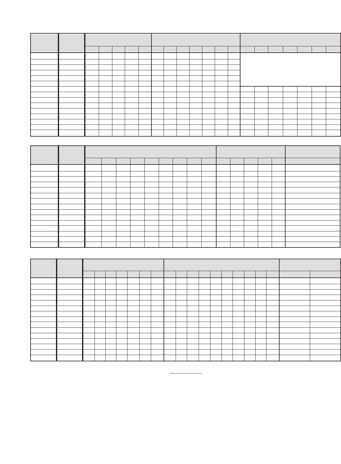
A4-2
Old Drive
Model No.
GPD515C–
Power Module
Part No.
5P30– Transistor Module
Part No.
5P30– Diode Module
Part No.
5P50–
A003
A006
A008
A011
A017
A025
A033
A049
A064
A080
A096
A130
A160
A224
A300
New Drive
Model No.
CIMR-G5M
20P41F
20P71F
21P51F
22P21F
23P71F
25P51F
27P51F
20111F
20151F
20181F
20221F
20300F
20370F
20550F
20750F
1
0174
1
1
0175
1
0178
1
1
0154
1
0155
3
0156
3
0157
3
3
0180
6
0160
6
0161
6
0176
1
0477
1
0478
1
1
1
0479
6
0480
6
6
0481
6
0482
12
0177
Power PCB
Part No.
5P90– Gate Drive PCB
Part No.
5P90– Control PCB
1
0423
1
0422
1
0424
1
0425
1
0426
1
0427
1
0428
1
0429
1
0430
1
1
0410
1
0414
1
0416
1
0417
1
1
1
1
1
1
1
1
1
1
1
1
1
1
1
Part No.
5P90–0535
1
0415
Cooling Fan
Part No.
5P16– DC Bus Fuse
Part No.
5P17–
Control Fuse Part No.
5P17–
1
1
1
2
0057
2
2
0058
1
1
0059
1
1
0061
3
3
3
0050
1
1
1
1
0062
3
0051
1
1
0504
1
0505
1
0488
1
1
0481
1
0482
1
1
1
1
0501
1
0480
1
0483
1
1
0484
3
0487
1
1
1
1
1
1
1
1
1
1
1
0500
3
3
3
0485
IMPORTANT
Numbers represent total quantity used in one Drive. To determine adequate inventory of spare parts, Yaskawa suggests using listed
value for quantities 2 and below. If listed value is greater than 2, factory suggests 1/3 of total listed.
No Diode Module in these
Drive Model No's; diodes are
contained in Power Module.
0490
A003
A006
A008
A011
A017
A025
A033
A049
A064
A080
A096
A130
A160
A224
A300
Old Drive
Model No.
GPD515C–
New Drive
Model No.
CIMR-G5M
20P41F
20P71F
21P51F
22P21F
23P71F
25P51F
27P51F
20111F
20151F
20181F
20221F
20300F
20370F
20550F
20750F
A003
A006
A008
A011
A017
A025
A033
A049
A064
A080
A096
A130
A160
A224
A300
Old Drive
Model No.
GPD515C–
New Drive
Model No.
CIMR-G5M
20P41F
20P71F
21P51F
22P21F
23P71F
25P51F
27P51F
20111F
20151F
20181F
20221F
20300F
20370F
20550F
20750F

A4-3
Power Module
Part No.
5P30– Transistor Module
Part No.
5P30– Diode Module
Part No.
5P50–
1
1
1
0171
1
1
0162
1
0163
1
0164
3
3
0165
3
3
0166
3
0167
3
3
0181
6
0150
6
0151
1
1
1
0483
1
1
0484
1
1
0485
1
1
6
6
0486
6
6
0488
6
6
9
0496
12
12
0152
3
0289
3
0290
0153
Power PCB Gate Drive PCB Control PCB
1
1
1
1
1
1
1
1
1
1
1
1
1
1
1
1
1
1
1
1
1
Part No.
5P90– 0535
0491 0492
No Diode Module in these
Drive Model No's; diodes are
contained in Power Module.
IMPORTANT
Numbers represent total quantity used in one Drive. To determine adequate inventory of spare parts, Yaskawa suggests using listed
value for quantities 2 and below. If listed value is greater than 2, factory suggests 1/3 of total listed.
X
str/Heatsink
Assy
Part
No
.
5P30–
0487
0288
3
Consult
Yaskawa
Consult
Yaskawa
Old Drive
Model No.
GPD515C–
B001
B003
B004
B008
B011
B014
B021
B027
B034
B041
B052
B065
B080
B096
B128
B165
B224
B302
B380
B450
B605
40P41F
40P71F
41P51F
43P71F
44P01F
45P51F
47P51F
40111F
40151F
40181F
40221F
40301F
40371F
40451F
40551F
40750F
41100F
41600F
41850F
42200F
43000F
New Drive
Model No.
CIMR-G5M
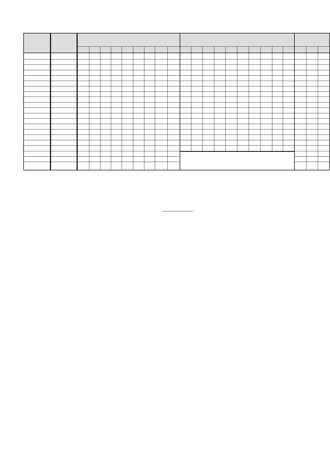
A4-4
Cooling Fan
Part No.
5P16– DC Bus Fuse
Part No.
5P17–
Control Fuse
Part No.
5P17–
1
1
1
2
0057
2
2
0058
1
1
0059
1
1
1
1
1
0061
3
3
3
0050
1
1
1
1
0062
3
0051
3
3
3
0064
1
1
1
0504
2
2
2
0060
1
1
0488
1
0489
1
1
1
0490
1
1
1
1
1
1
1
1
1
1
1
1
1
1
1
1
1
1
1
1
1
0500 0503 0502
1
0480
1
0491
1
1
1
0492
3
0478
3
0479
3
3
0477
IMPORTANT
Numbers represent total quantity used in one Drive. To determine adequate inventory of spare parts, Yaskawa suggests using listed
value for quantities 2 and below. If listed value is greater than 2, factory suggests 1/3 of total listed.
No DC Bus Fuse in these Drive Model No's;
fuses are contained in Transistor/Heatsink Assembly.
Old Drive
Model No.
GPD515C–
B001
B003
B004
B008
B011
B014
B021
B027
B034
B041
B052
B065
B080
B096
B128
B165
B224
B302
B380
B450
B605
40P41F
40P71F
41P51F
43P71F
44P01F
45P51F
47P51F
40111F
40151F
40181F
40221F
40301F
40371F
40451F
40551F
40750F
41100F
41600F
41850F
42200F
43000F
New Drive
Model No.
CIMR-G5M
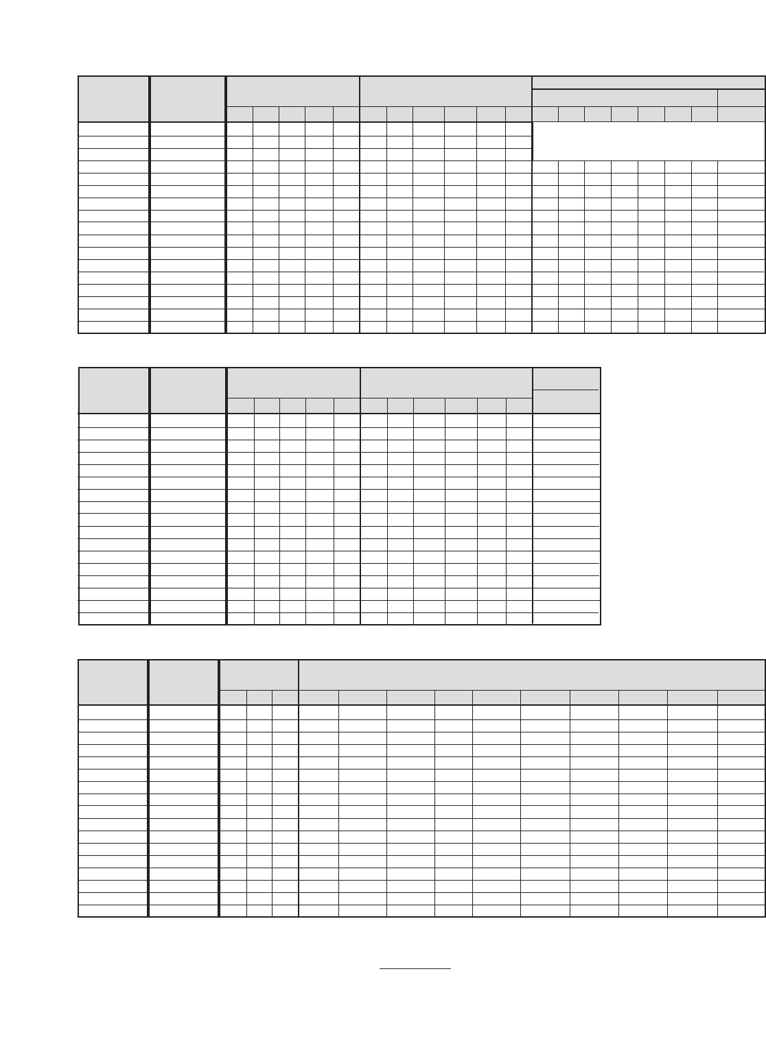
A4-5
Power Module
Part No. 5P30-
Diode Module
1
1
0179
1
0162
1
0163
1
0164
3
3
1217 1219
3
1220 1221 1200
0165 1201 0484 0485
1
1
0483 0491 0492
3
0488 SID30470487
1
1
3
3
3
3
6
6
6
Transistor Module
Part No. STR___ Part No. 5P50- Part No.
No Diode in these Drive Model Nos.; diodes are
contained in Power Module.
1
1
1
1
1
1
1
3
6
9
9
Power PCB
Part No. ETP615___
1
1
860
1
880
1
890
1
1
1
900 910 920 930 940
900 960 5P90-
0535
Control PCB
1
1
1
1
Gate Drive PCB
Part No. ETC615___
870
1
1
1
1
1
1
1
1
1
1
1
1
1
1
1
1
1
1
1
1
1
1
1
Cooling Fan
Part No. 5P16-
1
1
1
2
2
0057
2
2
0059
1
1
2
2
2
2
2
2
2
2
FU2067
1
1
1
1
50208016 50208017
1
1
1
1
1
1
DC Bus Fuse
Part No.
0058
1
1
1
FU2068 50205052 50205053 50205054 50208018 50208019 50208020
1
1
1
1
IMPORTANT
Numbers represent total quantity used in one Drive. To determine adequate inventory of spare parts, Yaskawa suggests
using listed value for quantities 2 and below. If listed value is greater than 2, factory suggests 1/3 of total listed.
51P51F
52P21F
53P71F
55P51F
57P51F
50111F
50151F
50181F
50221F
50301F
50371F
50451F
50551F
50751F
50900F
51100F
51600F
New Drive
Model No.
CIMR-G5M
C003
C004
C006
C010
C012
C017
C022
C027
C032
C041
C052
C062
C077
C099
C130
C172
C200
Old Drive
Model No.
GPD515C-
51P51F
52P21F
53P71F
55P51F
57P51F
50111F
50151F
50181F
50221F
50301F
50371F
50451F
50551F
50751F
50900F
51100F
51600F
New Drive
Model No.
CIMR-G5M
C003
C004
C006
C010
C012
C017
C022
C027
C032
C041
C052
C062
C077
C099
C130
C172
C200
Old Drive
Model No.
GPD515C-
51P51F
52P21F
53P71F
55P51F
57P51F
50111F
50151F
50181F
50221F
50301F
50371F
50451F
50551F
50751F
50900F
51100F
51600F
New Drive
Model No.
CIMR-G5M
C003
C004
C006
C010
C012
C017
C022
C027
C032
C041
C052
C062
C077
C099
C130
C172
C200
Old Drive
Model No.
GPD515C-

A4-6

NEW DRIVE OLD DRIVE
PHYSICAL DIMENSIONS MOUNTING
HEAT LOSS
MODEL MODEL
NOMINAL ENCLOSURE
(IN.) DIM. (IN.)
WEIGHT
(Watts)
VOLTS NO. NO. HP TYPE (LB)
CIMR-G5M GPD515C– H W D H1 W1
Heatsink Internal
Total
20P41F A003 0.75 11.02 5.51 6.30 10.47 4.96 7 15 50 65
20P71F A006 1 &1.5 NEMA 1 11.02 5.51 6.30 10.47 4.96 7 25 65 90
21P51F A008 2 11.02 5.51 6.30 10.47 4.96 7 40 80 120
22P21F A011 3 NEMA 1 11.02 5.51 7.09 10.47 4.96 10 80 60 140
23P71F A017 5 11.02 5.51 7.09 10.47 4.96 10 135 80 215
225P51F A025 7.5 NEMA 1 11.81 7.87 8.07 11.22 7.32 12 210 90 300
327P51F A033 10 11.81 7.87 8.07 11.22 7.32 13 235 110 725
0 20111F A049 15 14.96 9.84 8.86 14.37 9.29 24 425 160 585
20151F A064 20 NEMA 1 15.75 9.84 8.86 14.37 9.29 24 525 200 725
20181F A080 25 & 30 24.02 12.99 11.22 17.13 10.83 71 655 230 885
20221F A096 30 NEMA 1 26.57 12.99 11.22 17.13 10.83 71 830 280 1110
20300F A130 40 & 50 Protected 26.57 16.73 13.78 25.59 12.60 134 930 440 1370
20370F A160 60 Chassis 26.57 16.73 13.78 25.59 12.60 137 1110 620 1730
20550F A224 75 Protected 31.50 18.70 13.78 30.51 14.57 176 1740 890 2630
20750F A300 100 Chassis 36.42 22.64 15.75 35.24 17.52 298 2050 1160 3210
40P41F B001 0.75 11.02 5.51 6.30 10.47 4.96 7 10 50 60
40P71F B003 1 & 2 NEMA 1 11.02 5.51 6.30 10.47 4.96 7 20 65 85
41P51F B004 3 11.02 5.51 7.09 10.47 4.96 9 30 80 110
43P71F B008 5 11.02 5.51 7.09 10.47 4.96 10 80 65 145
44P01F B011 7.5 NEMA 1 11.02 5.51 7.09 10.47 4.96 10 120 80 200
45P51F B014 10 11.81 7.87 8.07 11.22 7.32 13 135 85 220
47P51F B021 15 11.81 7.87 8.07 11.22 7.32 13 240 120 360
40111F B027 20 NEMA 1 14.96 9.84 8.86 14.37 9.29 24 305 150 455
440151F B034 25 14.96 9.84 8.86 14.37 9.29 24 390 180 570
6 40181F B041 30 24.02 12.99 11.22 17.13 10.83 68 465 195 660
0 40221F B052 40 NEMA 1 24.02 12.99 11.22 17.13 10.83 68 620 260 880
40301F B065 50 30.91 12.99 11.22 24.02 10.83 106 705 315 1020
40371F B080 60 NEMA 1 30.91 12.99 11.22 24.02 10.83 106 875 370 1245
40451F B096 75 33.46 12.99 11.22 24.02 10.83 106 970 415 1385
40551F B128 100 32.28 17.91 13.78 31.30 13.78 174 1110 710 1820
40750F B165 125 Protected 32.28 17.91 13.78 31.30 13.78 176 1430 890 2320
41100F B224 150 Chassis 36.42 22.64 14.76 35.24 17.52 298 1870 1160 3030
41600F B302 200& 250 36.42 22.64 15.75 35.24 17.52 320 2670 1520 4190
41850F B380 300 57.09 37.40 17.13 55.12 * 794 3400 1510 4910
42200F B450 350 Protected 57.09 37.40 17.13 55.12 * 794 4740 2110 6850
43000F B605 400 & 500 Chassis 62.99 37.80 17.91 61.02 * 926 6820 2910 9730
A5-1
Table A5-1. Drive Size and Weight
Table A5-1 lists dimensions for the drive in its standard enclosure. For information on
other types of enclosures available, consult your Yaskawa representative.
Appendix 5. GPD 515/G5 DIMENSIONS

A5-2
51P51F C003 2 NEMA 1 11.02 5.51 7.08 10.47 4.96 9 35 55 90
52P21F C004 3 NEMA 1 11.02 5.51 7.08 10.47 4.96 9 45 60 105
53P71F C006 5 NEMA 1 11.81 7.87 8.07 11.22 7.32 13 65 75 140
55P51F C010 7.5 NEMA 1 11.81 7.87 8.07 11.22 7.32 14 100 105 205
57P51F C012 10 NEMA 1 11.81 7.87 8.07 11.22 7.32 14 130 90 220
50111F C017 15 NEMA 1 14.96 9.84 8.85 14.37 9.29 29 180 150 330
50151F C022 20 NEMA 1 14.96 9.84 8.85 14.37 9.29 29 250 210 460
50181F C027 25 NEMA 1 29.53 15.75 11.22 28.74 11.81 97 310 230 540
50221F C032 30 NEMA 1 29.53 15.75 11.22 28.74 11.81 97 380 340 720
50301F C041 40 NEMA 1 33.47 22.64 11.81 32.48 18.70 159 430 390 820
50371F C052 50 NEMA 1 33.47 22.64 11.81 32.48 18.70 159 680 540 1220
50451F C062 60 NEMA 1 33.47 22.64 11.81 32.48 18.70 159 900 750 1650
50551F C077 75 NEMA 1 41.34 22.64 12.80 40.35 18.70 198 1000 750 1750
50751F C099 100 NEMA 1 41.97 22.64 12.80 40.35 18.70 198 1100 1150 2250
50900F C130 125 Protected 49.21 22.64 12.99 48.23 18.70 267 1150 1200 2350
51100F C172 150 62.99 22.64 13.98 61.81 18.70 324 1400 1800 3200
51600F C200 200 Chassis 62.99 22.64 13.98 61.81 18.70 335 1870 2830 4700
6
0
0
NEW DRIVE OLD DRIVE
PHYSICAL DIMENSIONS MOUNTING
HEAT LOSS
MODEL MODEL
NOMINAL ENCLOSURE
(IN.) DIM. (IN.)
WEIGHT
(Watts)
VOLTS NO. NO. HP TYPE (LB)
CIMR-G5M GPD515C– H W D H1 W1
Heatsink Internal
Total
Table A5-1. Drive Size and Weight
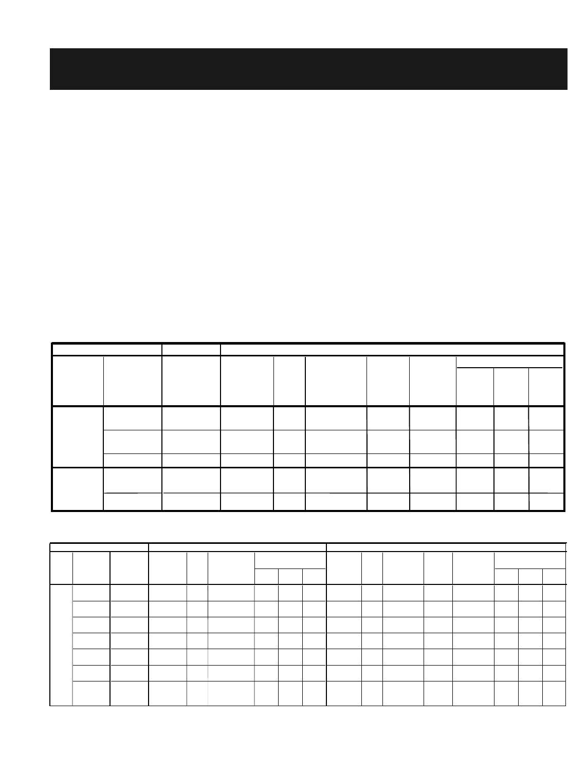
A6-1
GENERAL. Dynamic braking (DB) enables the motor to be brought to a smooth and
rapid stop. This is achieved by dissipating the regenerative energy of the AC motor
across the resistive components of the Dynamic Braking option. For further details on
dynamic braking operation, see the instruction sheet shipped with dynamic braking
components.
The GPD515C-A003 thru -A033 (CIMR-G5M20P41F thru 27P51F), -B001 thru -B034
(40P41F thru 40151F), and -C003 thru -C032 (51P51F thru 50221F) have an integral
braking transistor and require the addition of a Remote Mount Resistor Unit or a Heat Sink
Mount Resistor. All higher rated drives require the use of a Braking Transistor Unit and a
Remote Mount Resistor Unit.
Remote Mount Resistor Units typically mount outside of an electrical enclosure. Braking
Transistor Units mount inside of an electrical enclosure. Heat Sink Mount Resistors mount
to the back of the drive, attaching directly to the heat sink.
Available dynamic braking components are listed in Table A6-1 through A6-4.
Appendix 6. DYNAMIC BRAKING CONNECTIONS
Height Width Depth
20P41F 50185430 1 200 150 220 7.16 1.73 0.51
20P71F 50185430 1 200 150 220 7.16 1.73 0.51
21P51F 50185431 1 100 150 125 7.16 1.73 0.51
22P21F 50185432 1 70 150 120 7.16 1.73 0.51
23P71F 50185433 1 62 150 100 7.16 1.73 0.51
230 V
Part No.
Table A6-1. D
y
namic Brakin
g
- 3% Dut
y
C
y
cle - 230V
Rated
Input Model No.
CIMR-G5M
Drive
Dimensions
(
Inches
)
Heat Sink Mount Resistor
Qty
Reqd
Resistance
(Ohms)
(Each)
Power
(Watts)
(Each)
Approx.
Braking.
Torque
(%)
40P41F 50185530 1 750 150 165 7.16 1.73 0.51
40P71F 50185531 1 400 150 120 7.16 1.73 0.51
41P51F
A003
A006
A008
A011
A017
Model No.
Old Drive New Drive
GPD515C-
B001
B003
B004 50185531 1 200 150 150 7.16 1.73 0.51
460 V
Height Width Depth Height Width Depth
20P41F - - - - 48 - - - - - - 0825 1 200 250 150 5.00 14.00 4.00
20P71F - - - - 48 - - - - - - 0826 1 100 250 150 5.00 14.00 4.00
21P51F - - - - 16 - - - - - - 0826 1 100 250 115 5.00 14.00 4.00
22P21F - - - - 16 - - - - - - 0827 1 70 250 110 5.00 14.00 4.00
23P71F - - - - 16 - - - - - - 0828 1 40 846 115 5.00 14.00 7.00
25P51F - - - - 9.6 0829 1 3 824 105 5.00 14.00 7.00
27P51F - - - - 9.6 0830 1 20 1260 115 5.00 14.00 10.00
20111F 0010 1 9.6 11.00 5.53 5.91 0831 1 13.6 1500 115 5.00 14.00 13.00
20151F 0020 1 6.3 11.00 5.53 5.91 0832 1 10 1920 115 5.00 14.00 13.00
20181F 0020 1 6.3 11.00 5.53 5.91 0833 1 8 2592 100 5.00 21.00 10.00
20221F 0020 2 6.3 11.00 5.53 5.91 0834 2 6.8 2760 150 5.00 21.00 10.00
20300F 0020 2 6.3 11.00 5.53 5.91 0834 2 6.8 2760 135 5.00 21.00 10.00
20370F 0020 2 6.3 11.00 5.53 5.91 0834 2 6.8 2760 115 5.00 21.00 10.00
20550F 0020 3 6.3 11.00 5.53 5.91 0834 3 6.8 2760 135 5.00 21.00 10.00
20750F 0020 3 6.3 11.00 5.53 5.91 0834 3 6.8 2760 105 5.00 21.00 10.00
Table A6-2. Dynamic Braking - 10% Duty Cycle - 230V
Dimensions
(Inches)
Drive Remote Mount Resistor Unit
Rated
Input Model No.
CIMR-G5M
Approx
Braking
Torque (%)
Qty
Reqd
Part No.
5P41-
Dimensions
(Inches)
230V
Resistance
(Ohms)
(Each)
Power
(Watts)
(Each)
Brakin
g
Transistor Unit
Minimum
Connectable
Resistance
Each (Ohms)
Qty
Reqd
Part No.
46S03331-
0
A003
A006
A008
A011
A017
A025
A033
A049
A064
A080
A096
A130
A160
A224
A300
Model No.
Old Drive New Drive
GPD515C-
- - - - - -
- - - - - -

A6-2
Height Length Depth Height Length Depth
40P41F - - - - 96 - - - - - - 0835 1 750 600 150 5.00 14.00 7.00
40P71F - - - - 96 - - - - - - 0836 1 400 500 115 5.00 14.00 4.00
41P51F - - - - 64 - - - - - - 0837 1 250 500 125 5.00 14.00 4.00
43P71F - - - - 32 - - - - - - 0838 1 150 500 125 5.00 14.00 4.00
44P01F - - - - 32 - - - - - - 0839 1 100 975 125 5.00 14.00 7.00
45P51F - - - - 32 - - - - - - 0840 1 75 1050 125 5.00 14.00 10.00
47P51F - - - - 32 - - - - - - 0841 1 50 1600 125 5.00 14.00 13.00
40111F
B001
B003
B004
B008
B011
B014
B021
B027 - - - - 20 - - - - - - 0842 1 40 2050 120 5.00 21.00 10.00
40151F - - - - 20 - - - - - - 0843 1 32 2340 120 5.00 21.00 10.00
40181F 0050 1 20 11.00 5.53 5.91 0844 1 27 3000 115 5.00 21.00 13.00
40221F 0060 1 12.7 11.00 5.53 5.91 0845 1 20 3850 120 5.00 21.00 13.00
40301F 0060 1 12.7 11.00 5.53 5.91 0846 1 16 5440 120 5.00 28.00 13.00
40371F 0060 1 12.7 11.00 5.53 5.91 0847 1 13.6 5715 115 5.00 28.00 13.00
40451F
B034
B041
B052
B065
B080
B096 0060 2 12.7 11.00 5.53 5.91 0845 2 20 3850 125 5.00 21.00 13.00
40551F 0060 2 12.7 11.00 5.53 5.91 0847 2 13.6 5715 135 5.00 28.00 13.00
40750F 0060 2 12.7 11.00 5.53 5.91 0847 2 13.6 5715 110 5.00 28.00 13.00
41100F 0090 1 3 14.50 10.63 7.25 0848 1 5.2 17,280 120 14.00 29.00 18.00
41600F 0090 1 3 14.50 10.63 7.25 0849 1 4 19,600 95 14.00 29.00 18.00
0090 1 3 14.50 10.63 7.25 0849 1 4 19,600 80 14.00 29.00 18.00
42200F 0090 1 3 14.50 10.63 7.25 0849 1 4 19,600 70 14.00 29.00 18.00
43000F
41850F
41850F
0090 2 3 14.50 10.63 7.25 0849 2 4 19,600 95 14.00 29.00 18.00
Resistance
(Ohms)
(Each)
Power
(Watts)
(Each)
460 V
Brakin
g
Transistor Module
Minimum
Connectable
Resistance
Each (Ohms)
Qty
Reqd
Part No.
46S03331-
Table A6-3. D
y
namic Brakin
g
- 10% Dut
y
C
y
cle - 460V
Dimensions
(Inches)
Drive Remote Mount Resistor Unit
Rated
Input Model No.
New Drive
CIMR-G5M
Model No.
Old Drive
GPD515C-
Approx
Braking
Torque (%)
Qty
Reqd
Part No.
5P41-
Dimensions
(Inches)
0090 1 3 14.50 10.63 7.25 0849 1 4 19,600 80 14.00 29.00 18.00
- -
- -
0090 1 3 14.50 10.63 7.25 0849 1 4 19,600 70 14.00 29.00 18.00
B128
B165
B224
B302
B380
B450
B605
B380
B506
B675 0090 2 3 14.50 10.63 7.25 0849 2 4 19,600 95 14.00 29.00 18.00
460 V
GPD506V-B041 thru GPD506V-B302 cannot be connected for D
y
namic Brakin
g
.
Height Length Depth Height Length Depth
51P51F - - - - 150 - - - - - - 0851 1 150 840 150 5.00 14.00 7.00
52P21F - - - - 150 - - - - - - 0851 1 150 840 150 5.00 14.00 7.00
53P71F
C003
C004
C006 - - - - 130 - - - - - - 0851 1 150 840 150 5.00 14.00 7.00
55P51F - - - - 90 - - - - - - 0851 1 150 840 130 5.00 14.00 7.00
57P51F - - - - 65 - - - - - - 0852 1 100 1400 145 5.00 14.00 10.00
50111F - - - - 44 - - - - - - 0853 1 75 1680 130 5.00 14.00 13.00
50151F - - - - 32 - - - - - - 0854 1 50 2520 145 5.00 21.00 10.00
50181F - - - - 26 - - - - - - 0855 1 40 3000 145 5.00 21.00 10.00
50221F
C010
C012
C017
C022
C027
C032 - - - - 26 - - - - - - 0856 1 38 3248 130 5.00 21.00 13.00
50301F 0080 1 24 11.00 5.53 5.91 0857 1 33 3800 110 5.00 21.00 13.00
50371F 0080 1 24 11.00 5.53 5.91 0858 1 27 4464 110 5.00 28.00 13.00
50451F 0080 2 24 11.00 5.53 5.91 0858 2 27 4464 150 5.00 28.00 13.00
50551F 0080 2 24 11.00 5.53 5.91 0858 2 27 4464 145 5.00 28.00 13.00
50751F 0080 2 24 11.00 5.53 5.91 0858 2 27 4464 110 5.00 28.00 13.00
50900F 0080 3 24 11.00 5.53 5.91 0858 3 27 4464 130 5.00 28.00 13.00
51100F 0080 3 24 11.00 5.53 5.91 0858 3 27 4464 110 5.00 28.00 13.00
51600F
C041
C052
C062
C077
C099
C130
C172
C200 0080 4 24 11.00 5.53 5.91 0858 4 27 4464 110 5.00 28.00 13.00
Dimensions
(Inches) Resistance
(Ohms)
(Each)
Power
(Watts)
(Each)
Brakin
g
Transistor Module
Minimum
Connectable
Resistance
Each (Ohms)
Qty
Reqd
Part No.
46S03331-
Table A6-4. D
y
namic Brakin
g
- 10% Dut
y
C
y
cle - 600V
600V
Dimensions
(Inches)
Drive Remote Mount Resistor Unit
Rated
Input Model No.
New Drive
CIMR-G5M
Model No.
Old Drive
GPD515C-
Approx
Braking
Torque (%)
Qty
Reqd
Part No.
5P41-
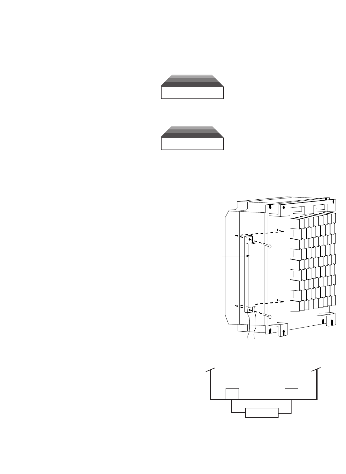
A6-3
INSTALLATION
This option should only be installed by a TECHNICALLY QUALIFIED INDIVIDUAL who is
familiar with this type of equipment and the hazards involved.
WARNING
Hazardous voltage can cause severe injury or death. Lock all power
sources feeding the drive in the "OFF" position.
CAUTION
Failure to follow these installation steps may cause equipment damage or
personnel injury.
Preliminary Procedures
1. Disconnect all electrical power to the
drive.
2. Remove drive front cover.
3. Use a voltmeter to verify that voltage
is disconnected from incoming power
terminals.
Heat Sink Mount Resistor Installation
1. Remove the drive from its mounting for
access to the rear of the heat sink.
2. Attach the Heat Sink Mount Resistor on
the back of the drive’s heat sink, as
shown in Figure A6-1.
3. Reinstall the drive in its mounting
position.
4. Connect the leads from the Heat Sink
Mount Resistor to drive terminals
according to Figure A6-2.
5. Proceed to "ADJUSTMENTS" on page
A6-7.
Figure A6-1. Attaching Heat Sink Mount Resistor
on Heat Sink
HEAT SINK
MOUNT
RESISTOR
Figure A6-2. Lead Connections For Heat Sink
Mount Resistor
B1 B2
HEAT SINK MOUNT
RESISTOR
PB
GPD 515/G5
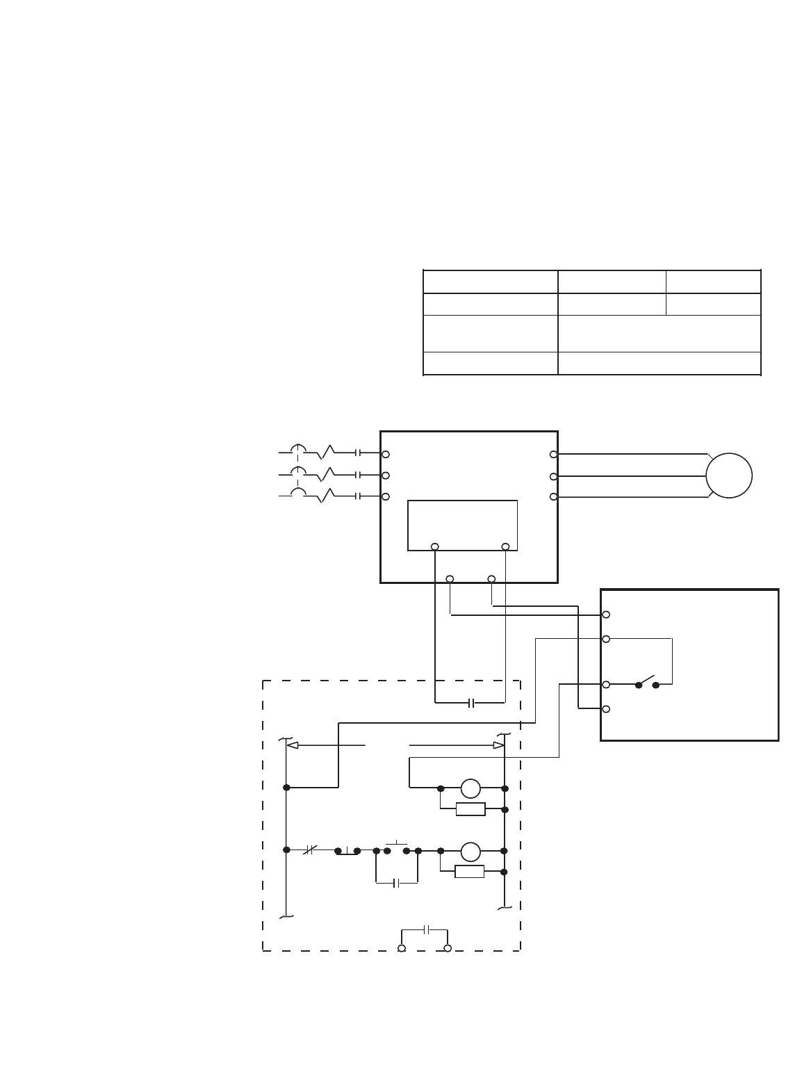
A6-4
Remote Mount Resistor Unit Installation (for GPD515C-A003 thru -A033
[CIMR-G5M20P41F thru 27P51F], -B001 thru -B034 [40P41F thru 40151F],
C003 thru C032 [51P51F thru 50221F])
IMPORTANT
Since the Remote Mount Resistor Unit generates heat during dynamic braking
operation, install it in a location away from other equipment.
1. Attach the Remote Mount Resistor Unit, maintaining a minimum 1.97 inch (50 mm)
clearance on each side and a minimum 7.87 inch (200 mm) clearance on top.
2. Remove the Remote Mount
Resistor Unit cover to access
its terminal block. Connect
the Remote Mount Resistor
Unit to the drive and to
external control circuitry
according to the chart at right
and Figure A6-3.
3. Reinstall and
secure
Remote
Mount Resistor
Unit cover and
drive front
cover.
4. Proceed to
"ADJUSTMENTS"
on page A6-8.
Figure A6-3. Wiring Remote Mount Resistor Unit to Drive
(GPD515C-A003 thru -A033 [CIMR-G5M20P41F thru 27P51F],
-B001 thru -B034 [40P41F thru 40151F], and -C003 thru -C032 [51P51F thru 50221F])
T1
T2
T3
L1 (R)
L2 (S)
L3 (T)
T1 (U)
T2 (V)
T3 (W)
CONTROL
PCB
311
PART OF USER SUPPLIED
EXTERNAL CIRCUIT B
P
2
1THG
THRX
1M
1M
1M
CB
L1
L2
L3
FAUL
T
CONTAC
T
THRX
1M
1M
THRX
POWER
ON
POWER
OFF
B1 B2
GPD 515/G5
REMOTE
MOUNT
RESISTOR
UNIT
Terminals B, P 1, 2 *
Lead Size (AWG) 12-10 18-14 *
Lead Type 600V ethylene propylene
rubber insulated, or equivalent
Terminal Screw M4
* Power leads for the Remote Mount Resistor Unit generate high levels of
electrical noise; these signal leads must be grouped separately.

A6-5
Braking Transistor Unit(s) and Remote Mount Resistor Unit(s) Installation
(for GPD515C-A049 [CIMR-G5M20111F] and above, -B041 [40181F] and
above, C041 [50301F] and above)
IMPORTANT
Since the Remote Mount Resistor Unit generates heat during dynamic braking
operation, install it in a location away from other equipment.
Select mounting locations for the Braking Transistor Unit(s) and Remote Mount Resistor
Unit(s) so that wiring between the drive and the (Master) Braking Transistor Unit, and
between each Braking Transistor Unit and its associated Remote Mount Resistor Unit, is
less than 33 feet (10 m).
1. Mount the Braking Transistor Unit(s) on a vertical surface. A Braking Transistor Unit
requires a minimum 1.18 inches (30 mm) clearance on each side and a minimum 3.94
inches (100 mm) clearance top and bottom. Attach the Remote Mount Resistor Unit
maintaining a minimum 1.97 inches (50 mm) clearance on each side and a minimum
7.87 inches (200 mm) clearance on top.
2. In each Braking Transistor Unit, set the nominal line voltage jumper plug to the
correct setting for the installation; this is factory set at the 230V/460V/575V
position. To access jumper plugs, remove plexiglass cover.
3. If multiple Braking Transistor Units are being installed, the unit closest to the drive
should have the SLAVE/MASTER jumper plug on its PCB set to the "MASTER" position
(factory setting); all others must have this jumper plug moved to the "SLAVE"
position.
4. If a single Braking Transistor Unit and Remote Mount Resistor Unit are being installed,
connect them to the drive and external control circuitry according to the chart below
and Figure A6-4.
If two or more Braking Transistor Units and Remote Mount Resistor Units are being
installed, connect them to the drive and to external circuitry according to the chart
below and Figure A6-5.
LEAD SIZE LEAD TERMINAL
UNIT TERMINALS (AWG) TYPE SCREWS
Remote Resistor Unit B, P 12-10 600V ethylene propylene M5
1, 2 * 18-14 * rubber insulated or equivalent M4
Braking Transistor Unit
P, Po, N, B 12-10 600V ethylene propylene M4
1, 2 * 18-14 * rubber insulated, or equivalent
* Power leads for the Remote Mount Resistor Unit generate high levels of electrical noise; these signal leads must be
grouped separately.
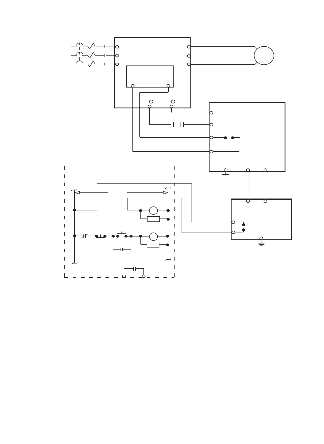
A6-6
5. The Braking Transistor Unit and Remote Mount Resistor Unit MUST BE GROUNDED.
Observe the following precautions:
•Use grounding leads conforming to National Electrical Code.
•If the installation requires the Remote Mount Resistor Unit to be used without its
enclosure (with grounding terminal), ground it by attaching a ground lead
at one of the mounting screws.
•Grounding resistance of the Braking Transistor Unit should be 100 ohms or less.
(1) For 600V Units, use terminal ⊕1.
(2) Fuse required only if UL/CUL certification is needed. See separate instruction sheet
02Y00025-0393 for details.
Figure A6-4. Wiring Single Braking Transistor Unit and Remote Mount Resistor Unit to Drive
(GPD515C-A049 thru -A080 [CIMR-G5M20111F thru 20181F], -B041 thru -B080 [40181F thru 40371F],
and -C041(1) and -C052(1) [50301F(1) and 50371F(1)])
T1
T2
T3
L1 (R)
L2 (S)
L3 (T)
T1 (U)
T2 (V)
T3 (W)
CONTROL
PCB
311
PART OF USER SUPPLIED
EXTERNAL CIRCUIT
B
P
N
31OL
1M
1M
1M
CB
L1
L2
L3
120VAC
FAUL
T
CONTAC
T
THRX
RC
IFU(2)
See Note(1)
1M
RC
1M
THRX
POWER
ON
POWER
OFF
1
1THG
B
P
P
o
GND
(E)
4
—
+ 3
GPD 515/G5
BRAKING
TRANSISTOR
UNIT
REMOTE
MOUNT
RESISTOR
UNIT
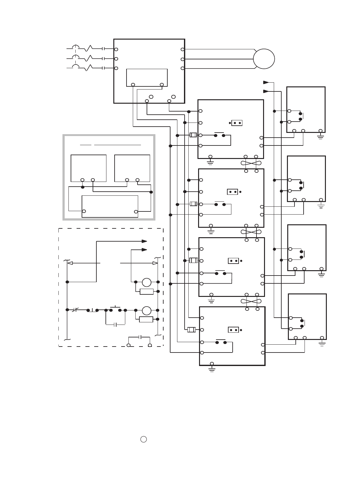
A6-7
Figure A6-5. Wiring Multiple Braking Transistor Units and Remote Mount Resistor Units to Drive
(GPD515C-A130 thru -A300 [CIMR-G5M20300F thru 20750F], -B096 thru -B605 [40451F thru 43000F],
and -C062 (1) thru -C200 (1) [50451F(1) thru 51600F(1)])
T1
T2
T3
L1 (R)
L2 (S)
L3 (T)
T1 (U)
T2 (V)
T3 (W)
GPD 515/G5
CONTROL
PCB
311
PART OF USER SUPPLIED
EXTERNAL
CIRCUIT
BRAKING
B
P
N
31OL
1M
1M
1M
CB
L1
L2
L3
120VAC
FAUL
T
CONTAC
T
THRX
RC
1M
RC
1M
THRX
POWER
ON
POWER
OFF
1
21THG
B
P
P
o
(E)
4
1
2
GND
MASTER
56
BRAKING
B
P
N
31OL
1
21THG
B
P
P
o
(E)
4
GND
SLAVE
56
BRAKING
B
P
N
31OL
1
21THG
B
P
P
o
(E)
4
GND
SLAVE
56
BRAKING
B
P
N
31OL
1
1THG
B
P
P
o
(E)
4
GND
SLAVE
12
12
12
NOT RECOMMENDED
WIRING CONFIGURATION
PoPo
P
BB
B
1
2
+ 3–
BRAKING
TRANSISTOR
UNIT
BRAKING
TRANSISTOR
UNIT
REMOTE MOUNT
RESISTOR UNIT
NOTE: Connect only the number of braking
transistor units and remote mount resistor
units required for the application.
REMOTE
MOUNT
RESISTOR
UNIT
REMOTE
MOUNT
RESISTOR
UNIT
REMOTE
MOUNT
RESISTOR
UNIT
REMOTE
MOUNT
RESISTOR
UNIT
IFU(2)
IFU(2)
IFU(2)
IFU(2)
See Note (1)
2
TRANSISTOR UNIT #1
TRANSISTOR UNIT #2
TRANSISTOR UNIT #3
TRANSISTOR UNIT #4
(1) For 600V Units, use terminal + 1.
(2) Fuse required only if UL/CUL certification is needed. See separate instruction sheet
02Y00025-0393 for details.

A6-8
6. IMPORTANT: After wiring, test insulation resistance of each Braking Transistor
Unit/Remote Mount Resistor Unit with a 900V megger as follows:
a. Disconnect leads between the Braking Transistor Unit and the drive. If
equipment with semiconductors is connected across terminals 1 & 2 of the
Braking Transistor Unit,
remove the wiring.
b. Connect common leads
(jumpers) across Braking
Transistor Unit terminals
N, P, Po, and B, and across
3 & 4, as shown in
Figure A6-6.
c. Measure the insulation
resistance at points a, b,
and c in Figure A6-6 with
the megger.
ADJUSTMENTS
7. ALL drives: Program L3-04 to " 0 ", to disable stall prevention during deceleration.
8. Only with Heat Sink Mount Resistor: Program L8-01 to " 1 ", to enable overheat
protection for the braking resistor.
OPERATION CHECK
9. During dynamic braking operation, verify that the "BRAKE" lamp inside the Braking
Unit is lit.
10. During dynamic braking operations, ensure that the required deceleration
characteristic is obtained. If not, contact MagneTek for assistance.
11. Reinstall and secure covers on the Braking Transistor Units, Remote Mount Resistor
Units, and the drive.
CAUTION
During normal operation, the Braking Transistor Unit and the Remote Mount
Resistor Unit enclosures must be kept closed, since high voltage is applied to
the dynamic braking circuit.
P
B
N
3
4
P
B
P0
GND (E)
c
b
a
REMOTE MOUNT
RESISTOR
UNIT
BRAKING
TRANSISTOR
UNIT
Figure A6-6. Megger Testing Set-up

I-1
INDEX
- A -
Accel/Decel Time ............................................ 5-3
Setting Unit .................................................. 5-5
Acceleration
Stall Prevention Level During ..................... 5-86
Stall Prevention. Limit During ..................... 5-86
Stall Prevention. Selection During ............. 5-86
Time 1 .......................................................... 5-3
Time 2 .......................................................... 5-3
Time 3 .......................................................... 5-3
Time 4 .......................................................... 5-3
Access Level ................................................... 5-7
Analog Inputs, Multi-function
(Term. 14 & 16) ......................................5-53
Analog Monitor Output, Multi-function
(Term. 21-23) ........................................ 5-57
Bias ............................................................ 5-57
Gain ........................................................... 5-57
Signal Level Selection ................................ 5-57
Output Selection ........................................ 5-57
At Set Frequency (Output Signal) ................. 5-73
Automatic Speed Regulator (ASR) ................. 5-9
ASR Integral Reset .................................... 5-59
Integral Time 1 ............................................. 5-9
Integral Time 2 ........................................... 5-11
Proportional Gain 1 ...................................... 5-9
Proportional Gain 2 .................................... 5-11
Output Lag Time ........................................ 5-11
Auto Restart .................................................... 5-7
Fault Contact Status During ......................... 5-8
No. of Attempts ............................................ 5-7
Auto-Tuning, Running
in Open Loop Vector Control ....................... 2-4
in Flux Vector Control ................................... 2-9
Auto-Tuning Faults & Corrective Actions ......... 6-6
Auxiliary Input and Output
Power Option Devices ...........................1-11
- B -
Base Block, External ..................................... 5-63
Base Block Time, Min. ................................... 5-63
Basic Programming ......................................... 4-8
Baud Rate, Ser. Comm.
(MODBUS Control) ........................... 5-49
Bias, Frequency Reference ........................... 5-29
Braking, DC Injection .................................... 5-14
Current ........................................................ 5-15
Start Frequency .............................. 5-15, 5-103
Time at Start ..................................... 5-14, 5-15
Time at Stop ............................................... 5-15
Braking, Dynamic .......................................... A6-1
- C -
Calculating Motor Parameters
[for Initial Start-up] ................................ 2-20
Capacity Related Parameters ....................... A3-1
Carrier Frequency ......................................... 5-12
Lower Limit ................................................. 5-12
Proportional Gain ....................................... 5-12
Upper limit .................................................. 5-12
Changing the Language on
the Digital Operator .............................. 2-19
Checking Encoder Pulses
[Troubleshooting] .................................. 6-29
Communication Error, Stop Method at
(MODBUS Control) ............................ A1-17
Conformance to European EMC
Directive ................................................. 1-13
Connections, Vector Control Motor ............... 1-24
Blower Motor .............................................. 1-26
Encoder Feedback (PG) ............................ 1-27
Motor Windings .......................................... 1-24
Control Circuit
Terminals .................................................... 1-17
Terminal (13, 14) Input Voltage
[Monitor Items] ................................... A1-28
Wiring ......................................................... 1-15
Control Method [Monitor Item] .................... A1-27
Control Method Related Parameters ............ A3-3
Control Method Selection ................................ 2-2
CPU ID No. [Monitor Item] .......................... A1-29
Critical Frequency Rejection ......................... 5-13
Current, DC Injection Braking ....................... 5-15
Current Meter (Analog Monitor) .................... 5-57
Current, Motor Rated (FLA) ................. 2-20, 5-90
- D -
DATA/ENTER Key .................................... 4-1, 4-3
DC Bus Voltage [Monitor Item] ................... A1-27
Deactivation Time, Power Loss Ride-thru ..... 5-50
Deceleration
Stall Prevention Selection During .............. 5-86
Time 1 .......................................................... 5-3
Time 2 .......................................................... 5-3
Time 3 .......................................................... 5-3
Time 4 .......................................................... 5-3
Deadband, Prohibited Frequency ................. 5-13
Delay Time, Excessive Speed Deviation
Detection (PG) .................................. 5-23
Derivative Time (PID) .................................... 5-80
Detection, Frequency (Output Signal) ........... 5-73
Detection, Speed (Output Signal) ................. 5-73
Diagnostics — see Troubleshooting
Digital "Motor Operated Pot" ......................... 5-45
Digital Operator ............................................... 4-1
Changing the Language on ....................... 2-19
Display Selection ....................................... 5-17
Menu Trees .................................................. 4-4
Mode Selection ............................................ 4-9
Monitor Selection (At Power-up) ................ 5-19
Test Run Using ........................................... 2-24
Dimensions ................................................... A5-1
Diode and IGBT (Transistor) Module
Resistance Test .................................... 6-27
Displaying Faults ............................................. 6-7
“Down Arrow” Key .................................... 4-1, 4-3
DRIVE Indicator Lamp ............................. 4-1, 4-2
Droop ............................................................. 5-19
Dwell .............................................................. 5-20
Dynamic Braking ........................................... A6-1
Dynamic Braking Resistor
Protection, Internal ............................... 5-46
- E -
Elapsed Operation Time [Monitor Item] ...... A1-28
Elapsed Timer
Selection .................................................... 5-46
Setting ........................................................ 5-45
Encoder (PG) Constant ................ 2-7, 2-15, 5-21
Encoder (PG) Parameters ............................. 5-21
Energy Saving Operation .............................. 5-27
Gain ........................................................... 5-27
Enclosure ...................................................... A5-1
Environment .......................................... 1-1, A2-3
ESC Key ................................................... 4-1, 4-4
European EMC Directive,
Conformance to ......................................1-13
Excessive Speed Deviation
Detection Delay Time ................................. 5-23
Detection Level .......................................... 5-23
External Fault Inputs ..................................... 5-28
- F -
Fast-Stop Decel Time .............................. 5-3, 5-4
Fault Contact Status
During Auto Restart .................................... 5-8
Fault Indication & Troubleshooting .................. 6-1
Faults & Corrective Action, Auto-Tuning .......... 6-6
FLA, Motor ........................................... 2-20, 5-90
Flash ID No. [Monitor Item] ......................... A1-28
Frequency
Base ......................................................... 5-108
Carrier ........................................................ 5-12
Detection Output Signal.............................. 5-73
Max. Output .............................................. 5-108
Meter (Analog Monitor) .............................. 5-57
Mid. Output ............................................... 5-108
Min. Output ............................................... 5-108
Prohibited ................................................... 5-13

I-2
INDEX – Continued
Frequency Detection Multi-
function Output ..................................... 5-73
Frequency Reference 1 ................................. 5-39
Frequency Reference 2 ................................. 5-39
Frequency Reference 3 ................................. 5-39
Frequency Reference 4 ................................. 5-39
Frequency Reference
Bias ............................................................ 5-29
Gain ........................................................... 5-29
Input Signals (Auto/Manual) ....................... 5-32
Jog .................................................... 5-36, 5-38
Limit, Lower ................................................ 5-34
Limit, Upper ................................................ 5-34
Loss Detection ........................................... 5-33
Retention .................................................... 5-33
FWD Indicator Lamp ................................ 4-1, 4-2
FWD/REV Key ......................................... 4-1, 4-2
- G -
Gain
Analog Monitor ........................................... 5-57
Energy Saving ............................................ 5-26
Frequency Reference ................................. 5-29
Proportional (PID) ...................................... 5-80
Torque Compensation ................................ 5-93
Zero-Servo ............................................... 5-110
Grounding ...................................................... 1-11
- H -
Hunting Prevention ........................................ 5-35
- I -
Indicator Lamps ....................................... 4-1, 4-2
Initial Start-up ("Local" Control) ....................... 2-1
Initialize Parameters (Reset Codes) ............. 5-83
Input and Output Power Option
Devices, Auxiliary ................................. 1-11
Input Phase Loss Detection .......................... 5-77
Input Selection
Analog, Multi-function ................................ 5-53
Multi-function Terminals ............................. 5-58
Input Terminal Status [Monitor Item] ........... A1-27
Input Voltage ................................................. A2-1
Inputs
Analog ........................................................ 5-53
Frequency Reference ................................. 5-31
Inspection (Receiving) ..................................... 1-1
Installation
Physical ........................................................ 1-1
Electrical ...................................................... 1-2
Integral Time (PID) ........................................ 5-80
Integral Value Limit (PID) .............................. 5-80
Integral Reset, ASR (PID) ............................. 5-82
Integral Value During Accel/
Decel Selection (PG) ............................ 5-24
Interconnection
2-wire Control ............................................. 1-20
3-wire Control ............................................. 1-22
Internal Dynamic Braking
Resistor Protection ............................... 5-46
- J -
Jog Frequency Reference .................... 5-35, 5-36
JOG Key .................................................. 4-1, 4-2
- K -
Keypad — see Digital Operator
- L -
Lag Filter Time, Output (PID) ........................ 5-81
Lamps, Indicator .............................. 4-1, 4-2
LCD Display ............................................ 4-1
Limit, Integral Value (PID) ..................... 5-80
Line-to-Line Resistance, Motor ................... A1-13
Listing of Parameters .................................... A1-1
LOCAL/REMOTE Key ..................................... 4-1
Selection .................................................... 5-44
Local/Remote Reference
Selection .................................................... 5-39
Lower Limit, Frequency Reference ............... 5-34
- M -
Main Circuit
Block Diagrams ............................1-8, 1-9, 1-10
Terminals .............................................. 1-3, 1-5
Input/Output Wiring ...................................... 1-2
Max. Output Frequency ...................... 2-20, 5-108
Max. Voltage ....................................... 2-21, 5-108
Mechanical resonance — see
Critical Frequency Rejection
MENU Key ............................................... 4-1, 4-3
Menu Trees, Digital Operator .......................... 4-5
Mid. Output Frequency ................................ 5-108
Mid. Output Voltage ..................................... 5-108
Min. Base Block Time .................................... 5-65
Min. Output Frequency ................................ 5-108
Min. Output Voltage ..................................... 5-108
Miscellaneous Parameters ............................ 5-44
Miscellaneous Protective Features ............... 5-46
MODBUS Control .......................................... 5-48
Operation Mode Selection ......................... 5-48
Reference Selection ................................... 5-48
Ser. Comm. Baud Rate ..................... 5-48, 5-49
Ser. Comm. Parity Selection ............. 5-48, 5-49
Ser. Comm. Station Address ............ 5-48, 5-49
Stopping Method at Ser.
Comm. Error ................................... A1-17
Mode Selection ............................................... 4-8
Model Numbers, Drive .................. xvii, A2-1,
A3-1, A5-1
Momentary Power Loss Ride-thru ................. 5-50
Deactivation Time ...................................... 5-50
Protection ................................................... 5-50
Monitor Selection (At Power-Up) ................... 5-19
Motor
Exciting Current [Monitor Item] ................ A1-28
Line-to-Line Resistance ........................... A1-13
Mechanical Loss ...................................... A1-13
Overload Protection Selection ................... 5-90
No-Load Current (NLA) .................. 2-20, A1-13
Parameters, Calculating
[Initial Start-up] ..................................... 2-20
Rated Current (FLA) ............. 5-90, 2-20, A1-13
Rated Voltage ................................ 2-20, A1-13
Secondary Current (Iq)
[Monitor Item] ..................................... A1-28
Selection (for OL Protection) ..................... 5-90
Speed [Monitor Item] ............................... A1-27
Stopping Method Selection ............... 5-14, 5-88
Switching — see Speed Search
Wiring .................................................. 1-2, 1-25
Mounting
Clearances ................................................... 1-1
Dimensions ................................................ A5-1
Location .............................................. 1-1, A2-4
Multi-function Analog Inputs
(Term. 14 & 16) ..................................... 5-53
Multi-function Input Terminals
(Term. 3-8) ............................................ 5-58
Multi-function Output Terminals
(Term. 9 & 10; 25-27) ........................... 5-71
Multi-step Speed Operation .......................... 5-40
- N -
Number of PG Gear Teeth 1 ......................... 5-25
Number of PG Gear Teeth 2 ......................... 5-25
- O -
Off-delay Timer .............................................. 5-66
Offset (PID) ................................................... 5-80
OH (Overheat) Protection Alarm Level ......... 5-46
OH Stopping Method Selection .................... 5-46
On-delay Timer .............................................. 5-66
Operation Method for Frequency
Reference Loss Detection .................... 5-33
Operation Mode Selection ............................. 5-39
Operation Selection
at Overspeed (PG) ..................................... 5-22
at PG Open Circuit ..................................... 5-22
at Speed Deviation (PG) ............................ 5-23
Operation Status [Monitor Item] .................. A1-28
Operator Detection Selection ........................ 5-45

I-3
INDEX – Continued
Operator Display (LCD) ................................... 4-1
Options — see Peripheral Devices
Output, Analog Monitor ................................. 5-57
Output Current [Monitor Item] ..................... A1-27
Output Frequency
Max. .............................................. 5-108, A1-12
Mid. ............................................... 5-108, A1-12
Min. ............................................... 5-108, A1-12
[Monitor Item] ........................................... A1-27
Output Lag Filter Time (PID) ......................... 5-81
Output Phase Loss Detection ....................... 5-77
Output Power [Monitor Item] ....................... A1-27
Output Selection, Analog Monitor ................. 5-57
Output Terminal Status [Monitor Item] ........ A1-27
Output Voltage [Monitor Item] ..................... A1-27
Output Voltage Ref. (Vd) [Monitor Item] ...... A1-29
Output Voltage Ref. (Vq) [Monitor Item] ...... A1-29
Outputs
Analog Monitor ........................................... 5-57
Contact/Open Collector .............................. 5-70
Overload Prot. Selection, Motor .................... 5-90
Overspeed Detection Level (PG) .................. 5-22
Overtorque Detection
Function Selection ..................................... 5-98
Level ........................................................... 5-98
Time ........................................................... 5-98
- P -
Parameter Selection/Initialization
(Reset Codes) ....................................... 5-83
Parameters
Factory Reset (Initialize) ............................ 5-83
Listing of .................................................... A1-1
Quick Reference For ..................................... xiv
Programming ............................................. 4-10
Related to Capacity ................................... A3-1
Related to Control Method ........................ A3-3
Parity Selection, Ser. Comm.
(MODBUS Control) ........................... 5-49
Peripheral devices
AC reactor .................................................. 1-12
Molded-case circuit breaker (MCCB) ........ A2-1
Noise filter .................................................. 1-12
PG Open Circuit Detection Delay Time ........ 5-21
PG Open Circuit, Operation Selection at ...... 5-21
PG Rotation ................................................... 5-24
PG Setup ....................................................... 5-21
Phase Loss Detection
Input ........................................................... 5-77
Output ........................................................ 5-77
Physical Installation ......................................... 1-1
PID Control .................................................... 5-78
Disable ....................................................... 5-60
Feedback Amount [Monitor Item] ............ A1-29
Feedback Signal Selection ........................ 5-79
Integral Value Limit .................................... 5-80
Offset ......................................................... 5-80
Output Filter Lag Time ............................... 5-81
PID Limit .................................................... 5-80
PID Selection ............................................. 5-78
PID Settings
Derivative Time ....................................... 5-80
Integral Time ........................................... 5-80
Proportional Gain ................................... 5-80
Potentiometer (External Speed) ........................ vii
Power Loss Ride-thru Time ........................... 5-51
Power On and Preliminary Checks
(Initial Start-up) ....................................... 2-2
Power Supply ......................................... 1-5, A2-1
Power Voltage Selection in
460V GPD 515 ....................................... 2-1
Pre-Operation Considerations ....................... 2-27
Preset Speeds — see Multi-step Speeds
Programmable Features .................................. 5-1
Prohibited Frequency 1 ................................. 5-13
Prohibited Frequency 2 ................................. 5-13
Prohibited Frequency 3 ................................. 5-13
Prohibited Frequency 4 ................................. 5-13
Prohibited Frequency Deadband .................. 5-13
Proportional Gain (PID) ................................. 5-80
Protection
Overcurrent, Instantaneous ....................... A2-3
Overheat, Heatsink .................................... A2-3
Overtorque ................................................. 5-98
Overvoltage ............................................... A2-3
Thermal Overload ...................................... 5-90
Undervoltage ............................................. A2-3
PWM Frequency — see
Carrier Frequency
- R -
Rated Current, Motor ........................... 2-20, 5-90
Ratings .................................................. xvii, A2-1
Receiving ......................................................... 1-1
Reference Selection (Local/Remote) ............ 5-39
REMOTE Indicator Lamps ....................... 4-1, 4-2
Reset Codes ................................................. 5-83
RESET Key .............................................. 4-1, 4-3
Resistance, Motor Line-to-Line ................... A1-13
REV Indicator Lamp ................................. 4-1, 4-2
Reverse Run Prohibit .................................... A1-2
Ride-thru, Momentary Power Loss ................ 5-51
Deactivation Time ...................................... 5-51
"Right Arrow" Key ..................................... 4-1, 4-3
Rotation, PG .................................................. 5-24
RUN Indicator Lamp ................................ 4-1, 4-2
RUN Key .................................................. 4-1, 4-2
Running
Forward ...................................................... 2-24
Reverse ...................................................... 2-24
Stall Prevention Level During ..................... 5-87
Stall Prevention Selection During .............. 5-87
- S -
Sample/Hold Function ....................................5-67
Scaling Display (Digital Operator) ................. 5-17
S-Curve Characteristics .................................. 5-6
Shock Resistance –– see S-Curve
Skip Frequency –– see Prohibited Frequency
Slip Compensation ........................................ 5-84
Gain ........................................................... 5-84
Limit ........................................................... 5-84
Primary Delay Time ................................... 5-84
Selection During Regeneration .................. 5-84
Soft Start — see S-Curve
Spare Parts ................................................... A4-1
Specifications ................................................ A2-1
Speed
Detection Output Signal ............................. 5-74
Range ........................................................ A2-1
Search ........................................................ 5-64
Speed Reference, Multiple (Multi-step
Speed Operation) ................................. 5-39
Speed Search Level ...................................... 5-64
Stall Prevention
Level During Accel ..................................... 5-86
Level During Running ................................ 5-87
Limit During Accel ...................................... 5-86
Selection During Accel ............................... 5-86
Selection During Decel .............................. 5-86
Selection During Running .......................... 5-87
Start-up, Initial ................................................. 2-1
Start-up Procedure, Simplified ............................ i
Station Address, Ser. Comm.
(MODBUS Control) ........................... 5-49
STOP Indicator Lamp .............................. 4-1, 4-2
STOP Key ................................................ 4-1, 4-2
Function During Remote Run .................... 5-45
Stop Method Sel. (OH) ............................... A1-46
Stopping Method .................................. 5-14, 5-88
Stopping Method at Comm. Error
(MODBUS Control) ............................... 5-50
Storage Function ........................................... 2-27
Switching Frequency, Accel/Decel .................. 5-5
- T -
Temperature
Ambient .............................................. 1-1, A2-4
Storage ...................................................... A2-4
Terminals
Description .......................................... 1-6, 1-17
Functions ............................................ 1-6, 1-17
Screw Sizes ................................................. 1-3
Test Run Using Digital Operator
("Local" Control) ................................... 2-24

I-4
INDEX – Continued
Thermal Overload Protection ........................ 5-90
Motor OL Protection Selection ................... 5-90
Motor OL Protection Time Constant .......... 5-90
Motor Rated Current .................................. 5-90
Motor Selection .......................................... 5-91
Torque Compensation ................................... 5-93
Gain [K
T
] .................................................... 5-93
Time Constant ............................................ 5-93
Torque Control (Command) ........................... 5-95
Selection .................................................... 5-95
Simplified Block Diagram ........................... 5-97
Speed/Torque Control Selection Timer ...... 5-95
Speed Limit ................................................ 5-96
Speed Limit Selection ................................ 5-96
Torque Reference Delay Time .................... 5-96
Torque Detection ........................................... 5-98
Overtorque Detection Level ....................... 5-98
Overtorque Detection Time ........................ 5-98
Selection .................................................... 5-98
Torque Limit ................................................. 5-101
Forward Torque Limit ............................... 5-101
Forward Regenerative Torque Limit ......... 5-101
Reverse Torque Limit ............................... 5-101
Reverse Regenerative Torque Limit ......... 5-101
Torque Reference (Internal) [Monitor Item] . A1-27
Trim Control ................................................... 5-69
± Speed Limits ........................................... 5-69
Troubleshooting ............................................... 6-1
Flowcharts .................................................. 6-10
- U -
Up/Down Function ......................................... 5-68
Upper Limit, Freq. Ref. .................................. 5-34
"Up Arrow" Key ........................................ 4-1, 4-3
User Parameters ......................................... 5-106
- V -
V/f Pattern
Custom ..................................................... 5-108
Standard .................................................. 5-106
Voltage
Input ............................................... 5-108, A2-1
Max. ......................................................... 5-108
Mid. Frequency ........................................ 5-108
Motor Rated ........................................ 2-5, 2-10
- W -
Weight ........................................................... A5-1
Wiring
2-wire Control ................................. 1-10b, 1-20
3-Wire Control ................................. 1-10b, 1-22
Control Circuit ............................................ 1-15
Diagrams .......................................... 1-15, 1-23
Distances ............................................ 1-2, 1-15
Main Circuit Input/Output ............................. 1-2
Encoder/PG-X2 Connections ..................... 1-24
- Z -
Zero-Servo Control ...................................... 5-110
Zero-Servo Gain ...................................... 5-111
Zero-Servo Completion Width .................. 5-111
Zero Speed Control ..................................... 5-112
Zero Speed Operation ............................. 5-112
Min. Output Frequency ............................. 5-112

GPD 515/G5 Technical Manual 04/01/02 SWV: 01114
GPD 515/G5 Drive
Technical Manual
Models: GPD515C- and CIMR-G5M Document Number: TM 4515
GPD 515/G5 Drive
YASKAWA ELECTRIC AMERICA, INC.
Drives Division 16555 W. Ryerson Rd., New Berlin, WI 53151, U.S.A.
Phone: (800) YASKAWA (800-927-5292) Fax: (262) 782-3418
Internet: http://www.drives.com
YASKAWA ELECTRIC AMERICA, INC.
Chicago-Corporate Headquarters
2121 Norman Drive South, Waukegan, IL 60085, U.S.A.
Phone: (800) YASKAWA (800-927-5292) Fax: (847) 887-7310
Internet: http://www.yaskawa.com
MOTOMAN INC.
805 Liberty Lane, West Carrollton, OH 45449, U.S.A.
Phone: (937) 847-6200 Fax: (937) 847-6277
Internet: http://www.motoman.com
YASKAWA ELECTRIC CORPORATION
New Pier Takeshiba South Tower, 1-16-1, Kaigan, Minatoku, Tokyo, 105-0022, Japan
Phone: 81-3-5402-4511 Fax: 81-3-5402-4580
Internet: http://www.yaskawa.co.jp
YASKAWA ELETRICO DO BRASIL COMERCIO LTDA.
Avenida Fagundes Filho, 620 Bairro Saude Sao Paolo-SP, Brasil CEP: 04304-000
Phone: 55-11-5071-2552 Fax: 55-11-5581-8795
Internet: http://www.yaskawa.com.br
YASKAWA ELECTRIC EUROPE GmbH
Am Kronberger Hang 2, 65824 Schwalbach, Germany
Phone: 49-6196-569-300 Fax: 49-6196-888-301
MOTOMAN ROBOTICS AB
Box 504 S38525, Torsas, Sweden
Phone: 46-486-48800 Fax: 46-486-41410
MOTOMAN ROBOTEC GmbH
Kammerfeldstrabe 1, 85391 Allershausen, Germany
Phone: 49-8166-900 Fax: 49-8166-9039
YASKAWA ELECTRIC UK LTD.
1 Hunt Hill Orchardton Woods Cumbernauld, G68 9LF, Scotland, United Kingdom
Phone: 44-12-3673-5000 Fax: 44-12-3645-8182
YASKAWA ELECTRIC KOREA CORPORATION
Paik Nam Bldg. 901 188-3, 1-Ga Euljiro, Joong-Gu, Seoul, Korea
Phone: 82-2-776-7844 Fax: 82-2-753-2639
YASKAWA ELECTRIC (SINGAPORE) PTE. LTD.
Head Office: 151 Lorong Chuan, #04-01, New Tech Park Singapore 556741, Singapore
Phone: 65-282-3003 Fax: 65-289-3003
TAIPEI OFFICE (AND YATEC ENGINEERING CORPORATION)
10F 146 Sung Chiang Road, Taipei, Taiwan
Phone: 886-2-2563-0010 Fax: 886-2-2567-4677
YASKAWA JASON (HK) COMPANY LIMITED
Rm. 2909-10, Hong Kong Plaza, 186-191 Connaught Road West, Hong Kong
Phone: 852-2803-2385 Fax: 852-2547-5773
BEIJING OFFICE
Room No. 301 Office Building of Beijing International Club,
21 Jianguomanwai Avenue, Beijing 100020, China
Phone: 86-10-6532-1850 Fax: 86-10-6532-1851
SHANGHAI OFFICE
27 Hui He Road Shanghai 200437 China
Phone: 86-21-6553-6600 Fax: 86-21-6531-4242
SHANGHAI YASKAWA-TONJI M & E CO., LTD.
27 Hui He Road Shanghai 200437 China
Phone: 86-21-6533-2828 Fax: 86-21-6553-6677
BEIJING YASKAWA BEIKE AUTOMATION ENGINEERING CO., LTD.
30 Xue Yuan Road, Haidian, Beijing 100083 China
Phone: 86-10-6232-9943 Fax: 86-10-6234-5002
SHOUGANG MOTOMAN ROBOT CO., LTD.
7, Yongchang-North Street, Beijing Economic & Technological Development Area,
Beijing 100076 China
Phone: 86-10-6788-0551 Fax: 86-10-6788-2878
YEA, TAICHUNG OFFICE IN TAIWAIN
B1, 6F, No.51, Section 2, Kung-Yi Road, Taichung City, Taiwan, R.O.C.
Phone: 886-4-2320-2227 Fax:886-4-2320-2239
Document Number: TM4515 (Supercedes: YEA-TOA-S616-10.11 and 10.12) 04/01/2002 Software Version: 01114
Data subject to change without notice.
