(Yorkshire) XPress Press Fit Solutions
XPress Press-Fit Solutions XPress Press-Fit Solutions
User Manual: (Yorkshire) XPress Press-Fit Solutions
Open the PDF directly: View PDF ![]() .
.
Page Count: 92
Press-fit solutions
NEW
67mm-108mm
Chromium Plated

2
Pegler Yorkshire
Unrivalled quality, innovation,
customer service and long-term
value for money
As part of the global Aalberts Industries NV Group,
Pegler Yorkshire is one of Britain’s largest and most
respected manufacturers of innovative products for the
demanding and diverse plumbing and heating industries.
Pegler Yorkshire – a unique story
It was in the late 19th century when two
separate and altruistic companies set out
on the long road to satisfying the needs
of prospective customers and, of course,
to profit in the process. Coincidentally
located just 30 miles apart, each was
driven by the same vision and ideals of a
no-compromise culture. Cutting corners was
never an option and only the best could
ever be good enough.
These two companies were Pegler and
Yorkshire Fittings. In meeting all the
challenges of the 20th and 21st centuries
both companies have changed a great deal,
the business ethos common to both never
has. And now these two like minds have
come together as Pegler Yorkshire – a single
source of proven, flow control solutions for
installers, specifiers and engineers in the
domestic, public and commercial markets.
Reputable and established brands
Just as Pegler and Yorkshire have endured
over such a long period, many of the brand
names they have created over time are
similarly very well established, in many
cases as market leaders in their respective
categories. The very extensive Pegler
Yorkshire product range now comprises more
than 15,000 lines – without rival for the
choice and coverage it offers and for the
number and scope of applications it
satisfies.
A mind for innovation
Brands which endure and are not easily
displaced must by definition be the product
of innovative thinking and technology that
continually stand the test of time. Pegler
Yorkshire’s no-compromise philosophy will
always put new product development high
on the agenda, based on not only meeting
the needs of today’s markets, but also
anticipating and meeting customers’
future needs.
The true value of knowledge
As well as the benefit of unparalleled
experience of the flow control market and
its growth over many decades, Pegler
Yorkshire has strong associations with
major industry bodies such as those
responsible for determining product and
performance standards.
The result is a comprehensive store of
knowledge and reference which is invaluable
in the key areas of research, development
and dealing efficiently and accurately with
customer enquiries – particularly with regard
to product application and suitability.
A charter for the best
in customer service
With such a diverse product range and
customer base, Pegler Yorkshire’s no-compromise
standards of quality, reliability and value
for money naturally go hand in hand with
the principle of delivering the best in
customer service.
Green awareness
and responsibilities
Developing products which reduce the carbon
footprint by saving water and energy is only
one side of the green issues coin. Pegler
Yorkshire is also increasingly committed to
recycling key production materials (such as
brass), eliminating the need for excessive
packaging wherever possible, and looking for
new ways in which the company’s day-to-day
operations can be improved to reduce waste
and minimise the impact on the environment.
Likewise, social responsibilities such as
supporting employee and local community
welfare are aspects of the very fabric and
philosophy upon which both Pegler and
Yorkshire were founded.
Standards
Pegler Yorkshire is dedicated to designing,
developing and manufacturing products of
the highest quality. We are members of
numerous standards committees and take an
active part in their development. Our
products, where applicable, comply with the
relevant British, European and International
standards. Whatever the latest developments,
we guarantee that our products will always
meet the latest and highest standards.
Trade bodies
Pegler Yorkshire is pleased to be associated
with several influential industry organisations:
Construction
Products
Association
Heating and
Ventilating
Contractors
Association
Association of
Plumbing and
Heating Contractors The Bathroom
Manufacturers
Association
Builders Merchants
Federation
British Plumbing
Employers Council
The Brass Page
for specifiers,
designers, engineers
and manufacturers
The Copper
Development
Association
Institute of
Plumbing
Scottish and
Northern Ireland
Plumbing Employers
Federation
Thermostatic
Mixing Valve
Manufacturers
Association
The UK
Copper Board
pec
CERTIFICATION LTD
Brass
Press-fit solutions
This data book has been produced in clearly defined
sections to help the user to find relevant information
quickly and easily. At the foot of each page there is a reminder
of the brochure sections with the relevant page numbers.
Section 1
Product range overview
Introduction to XPress
Key features and benefits 4-8
XPress Copper 5
XPress Stainless 5
XPress Carbon 6
XPress Copper Gas 6
XPress Stainless Gas 7
XPress Solar 7
Standards, approvals and guarantees 8
Section 2
Product range details
Sizes, dimensional details 9-71
and product codes
Section 3
Technical Data
Tube compatibility and
fitting applications 72
Materials specifications and
manufacturing standards 73
Working temperatures 74-75
Tubes, pipe and
their compatibilies 76-77
System design considerations
and tube expansion 78-81
Section 4
Installation instructions
15mm to 35mm sizes
Socket depths 82
Spacing 82
Preparation 83
Jointing 84
42mm to 108mm sizes
Socket depths 85
Spacing 85
Preparation 85
Jointing 87
Section 5
Flow charts 88-89
3
41Range overview 2Product details 3Technical data 4Installation instructions 5Flow charts
Press-fit solutions
The complete range
XPress press-fit:
cost-effective
jointing solutions
for so many
applications
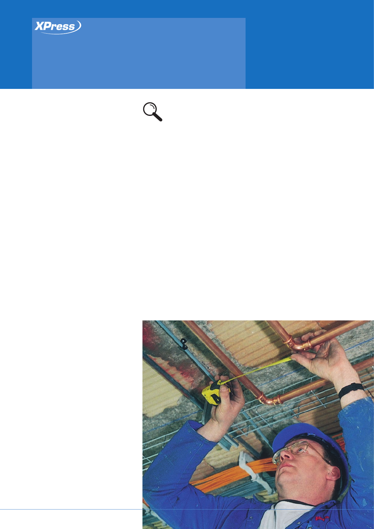
Pegler Yorkshire’s innovative and
comprehensive XPress range delivers all the
benefits of a heat-free, press-fit jointing
system to a wide variety of domestic,
commercial and industrial applications.
XPress also lives up to the promise of its
name in every respect: a method which is
easy, fast and highly cost-effective, simply
pressing together in seconds to create a
perfect joint every time, with the guarantee
of an uncontaminated installation.
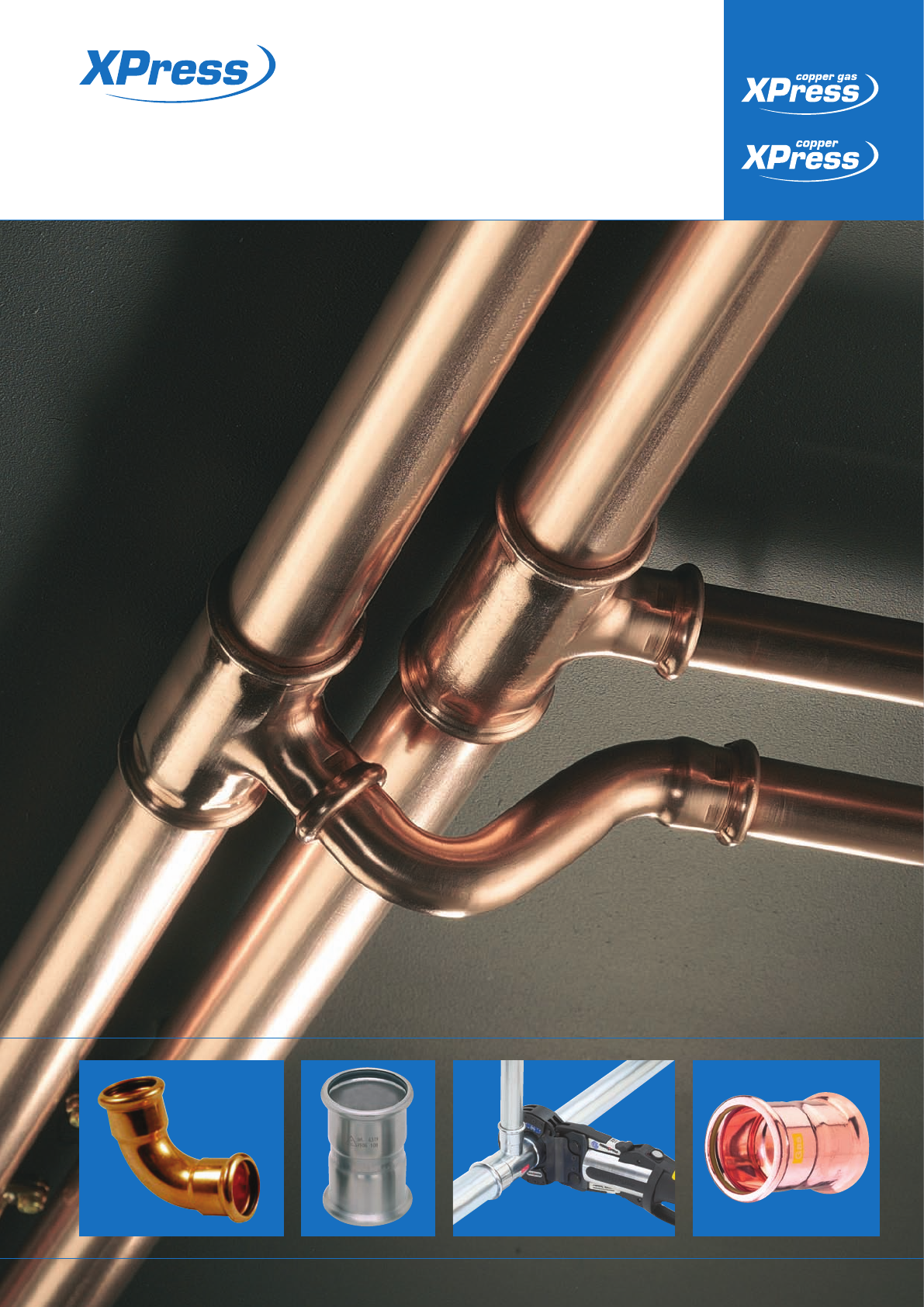
XPress fittings from Pegler Yorkshire make jointing easier, faster and more cost
effective than other jointing methods – a fittings system which simply presses
together in seconds to create a perfect joint, every time.
So many XPress
benefits, and
so much choice
Major savings in installation time and cost
compared with traditional jointing methods
A completely heat-free jointing system
that requires no additional solders,
adhesives, compounds, gas, hotworks
permits or extra and costly insurance
Clean, rapid, heat-free jointing: no
complicated clamping techniques or long
preparation procedures or waiting for
adhesive to dry
Safety: no naked flames
Perfectly clean internal bore – less
finishing or cleaning required
No localised annealing from high-
temperature working
No carbon deposits, internal solder runs
or flux residue – less risk of corrosion
System does not need to be ‘dry’ for
effective jointing
XPress fittings have a wide range of
approvals including WRAS and DVGW
Electrical continuity assured when the
XPress jointing process is complete
Ideal for diverse applications such
as domestic maintenance and
refurbishment, new build and large-scale
public sector projects.
XPress range
at a glance
XPress Copper: for hot and cold water
services, closed circuit heating, chilled
water and oil-free compressed air
applications, and incorporating a unique
and time-saving Leak Before Press (LBP)
design to instantly identify unpressed
joints, in 12mm-108mm sizes
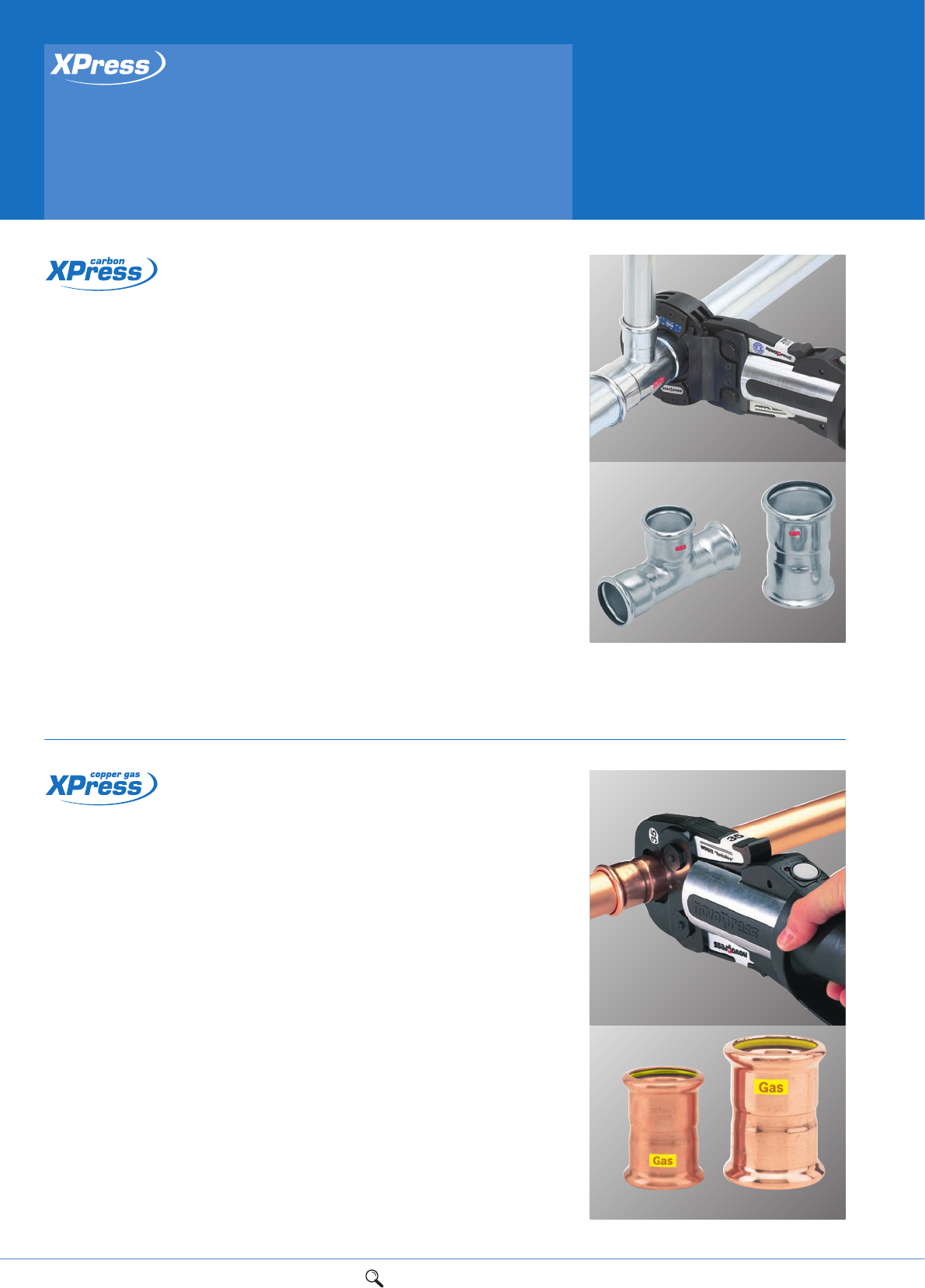
XPress Carbon: for closed circuit heating
and chilled water applications, with LBP
feature in 15mm-108mm sizes
XPress Stainless: the perfect solution
where water quality and hygiene are
crucial in food, pharmaceutical and
healthcare environments. Also offers LBP
in 15mm-108mm sizes
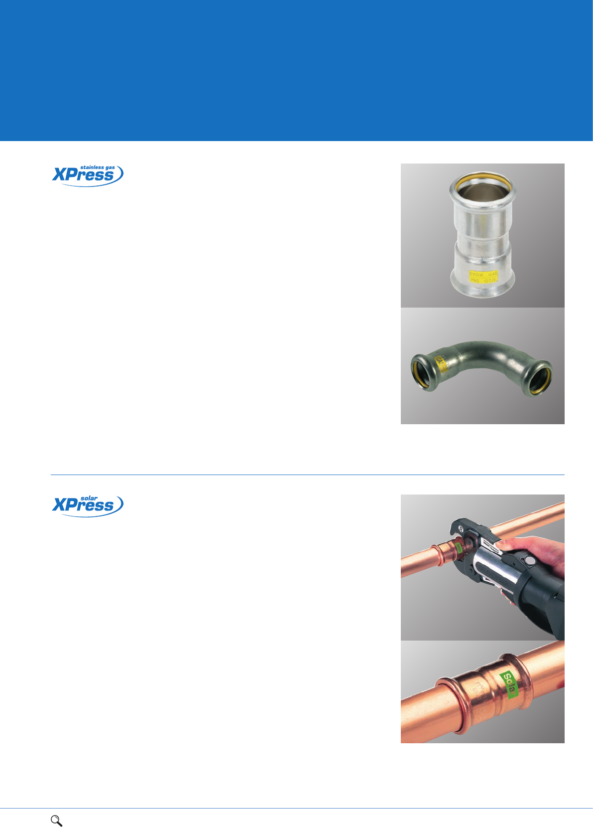
XPress Copper Gas: for internal and
external above-ground 2nd- and 3rd-family
gas services, includes the new supersize
range 15mm-108mm
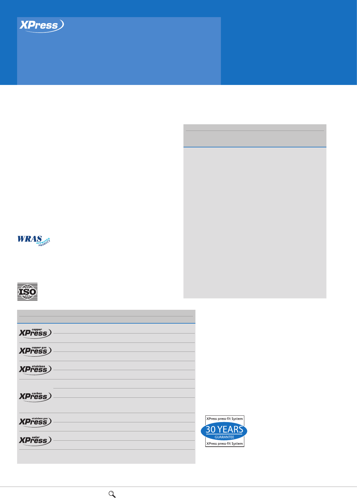
XPress Stainless Gas: for use with XPress
Stainless and other stainless steel System
tubes on above-ground 2nd- and 3rd-
family gas pipelines, including applications
where high levels of hydrogen sulphide
make copper unsuitable. Available in sizes
15mm-54mm
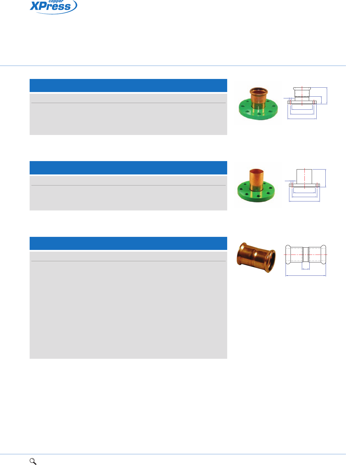
XPress Solar: delivers all the benefits of
a heat-free, press-fit jointing system for
solar applications. Available in sizes
15mm-54mm
For 67mm-108mm sizes of the above
designs, fitting allows for leak detection
prior to pressing.
1Range overview 2Product details 3Technical data 4Installation instructions 5Flow charts 5
1
Press-fit solutions
Product overview
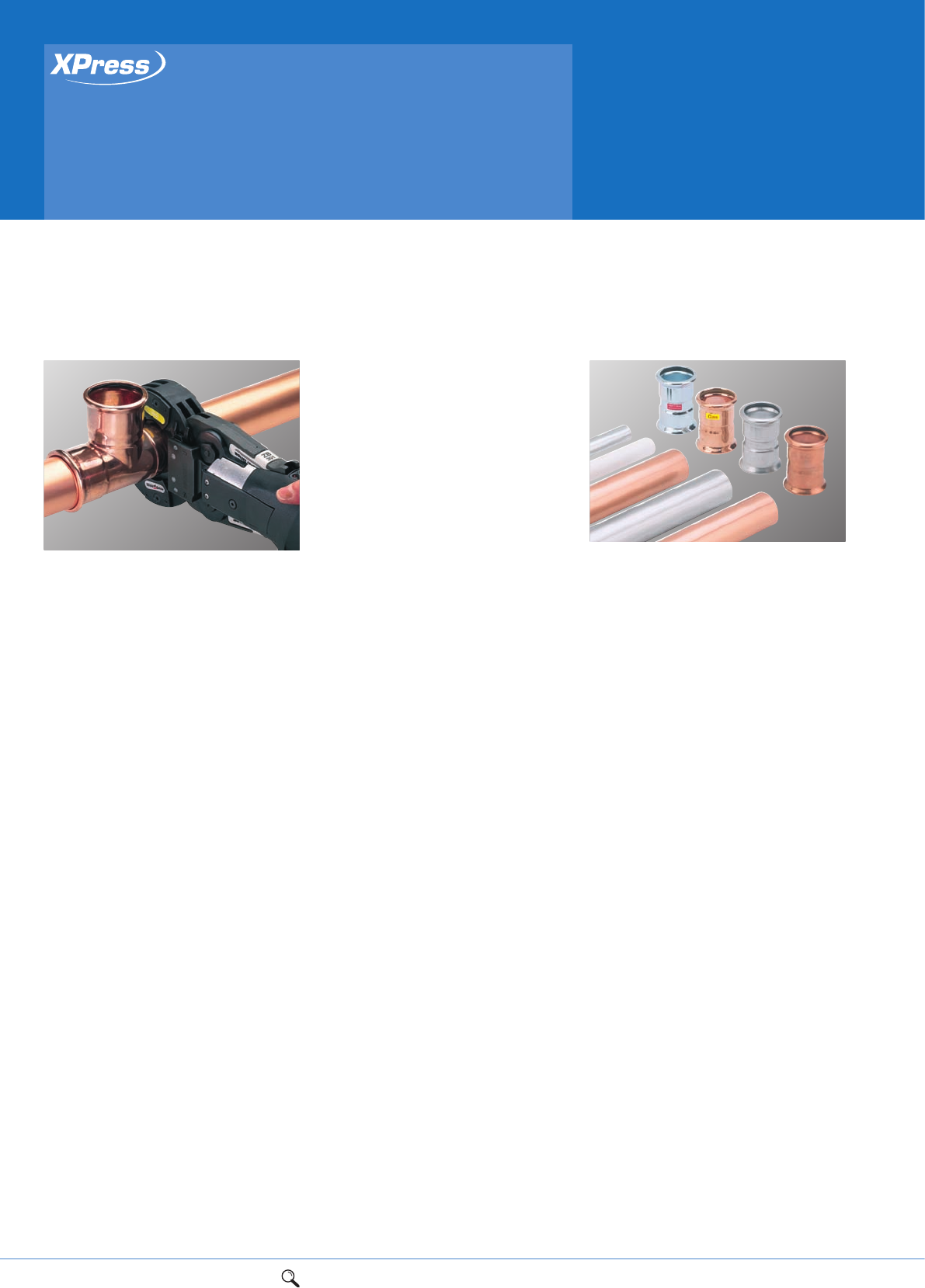
Features
Manufactured from copper alloy
Available in sizes 12mm to 108mm
Leak Before Press
Electrical continuity assured when
XPress joint complete
Clean, heat free jointing
Safety, no naked flames, no hotwork
permits or costly insurance
Wide range of approvals
GL approved (previously British Gas)
see XPress Gas section
Chromium plated range
Temperature rating from -24°C to 110°C
Pressure rating 16bar throughout
the temperature range.
XPress Copper fittings are manufactured
from copper and copper alloy and
incorporate a black EPDM Ethylene
Propylene Diene Monomer ‘O’ ring and a
unique “Leak Before Press” (LBP) design.
LBP has been developed to provide instant
identification of joints that have been
assembled correctly but mistakenly left
unpressed. This feature saves time, money
and potentially expensive call-backs.
Ideal for fast, efficient jointing of copper
tube to BS EN 1057 R250 and R290 in sizes
12mm-108mm. XPress fittings are designed
for use on hot and cold water services,
vented and unvented closed circuit heating,
chilled water and oil-free compressed air
applications within permissible pressure and
temperature limits.
an extremely low dissolved solid content.
XPress Stainless provides resistance to
RO purified water.
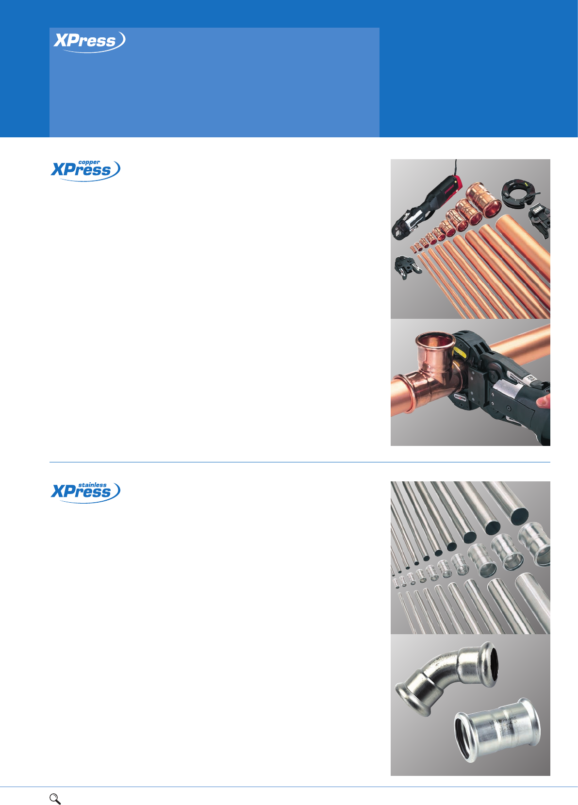
Features
Fittings are manufactured from
316L stainless steel
Tube is manufactured from
316 stainless steel
Available in sizes 15mm to 108mm
Leak Before Press
Clean, heat free jointing
Safety - no naked flames no hotwork
permits or costly insurance
Wide range of approvals
Temperature range -20°C to 110°C
Pressure rating 16bar throughout the
temperature range
Light weight, easy to handle.
XPress Stainless Steel is optimised for use
as a system and fittings are manufactured
from 316L (1.4404) stainless steel.
316 System tube is available in straight 6m
lengths. 15mm-54mm tube is manufactured
from BS 316 831/DIN 1.4401 stainless steel
strips conforming to BS 10088 Part 2.
Above 54mm the tube conforms to DVGW
W541. The fittings incorporate a black EPDM
(Ethylene Propylene Diene Monomer) ’O’ ring
and a unique “Leak Before Press” (LBP)
design. LBP has been developed as a final
check to the system to provide instant
identification of joints that have been
assembled correctly but mistakenly left
unpressed. This feature saves time, money
and potentially expensive call backs.
Designed for potable water applications
where water quality and hygiene are crucial,
particularly in the food, pharmaceutical and
healthcare environments and chilled water
applications. Water purified by Reverse
Osmosis (RO) is likely to have a low pH and
61Range overview 2Product details 3Technical data 4Installation instructions
Press-fit solutions
Product overview
XPress Carbon Steel is optimised for use as
a system. XPress Carbon Steel fittings are
now manufactured from EN 100-27-
1S205G2T (formerly known as Rst 34-2)
carbon steel.
The fittings incorporate a black EPDM
(Ethylene Propylene Diene Monomer) ’O’ ring
and a unique “Leak Before Press” (LBP)
design. LBP has been developed as a final
check to the system to provide instant
identification of joints that have been
assembled correctly but mistakenly left
unpresssed. This feature saves time, money
and potentially expensive call backs.
Each fitting is individually marked
indicating material.
XPress Carbon is designed for vented and
unvented closed circuit heating and chilled
water applications.
Features
Manufactured from carbon steel
Galvanised carbon system tube available
in 15mm to 108mm
Plastic coated carbon system tube
available in 15mm to 54mm
Leak Before Press
Temperature rating from -20°C to 110°C
Pressure rating 16bar throughout the
temperature range
Clean, heat free jointing
Safety - no naked flames, no hotwork
permits or costly insurance
XPress Copper Gas fittings are manufactured
from copper or copper alloy (typically
gunmetal) and incorporate a yellow
(HNBR) Hydrogenated Acrylonitrite
Butadiene Rubber ‘O’ ring. XPress Copper
Gas fittings do not have the LBP feature
for safety reasons.
Designed specifically for use with copper
tube to BS EN 1057 on internal and
external above ground 2nd and 3rd family
gas services and available in sizes
12mm-108mm.
XPress Copper Gas performance, when
correctly assembled with copper tube to
BS EN 1057 R250 and R290 (for above
ground use only), has a minimum operating
temperature range of between -20°C and
70°C. The maximum working pressure inside
buildings is 1bar and maximum working
pressure outside buildings is 5bar (maximum
test pressure 7.5bar).
XPress Copper Gas fittings are permanently
marked with a highly visible yellow marking
stating Gas/PN5 GT/1 on each fitting.
As part of the DVGW/GL (formerly British
Gas) approvals process, XPress Copper Gas
fittings have passed the High Temperature
Leakage Rate test at 650°C for 30 minutes.
Features
Manufactured from copper alloy
Available in sizes 15mm to 108mm (new)
For use in internal and external above
ground 2nd and 3rd family gas services
(see page 81) – where we locate the
gas families
Clean, heat free jointing
Safety - no naked flames, no hotwork
permits or costly insurance
GL Verified (formerly British Gas).
67mm to 108mm15mm to 54mm
1Range overview 2Product details 3Technical data 4Installation instructions 7
1
XPress Stainless Steel Gas is optimised for
use as a system. Fittings are manufactured
from 316 (BS 316S31/DIN 1.4401) or
316 Ti (BS 320531/DIN 1.4571).
The fittings incorporate a yellow HNBR
(Hydrogenated Acrylonitrite Butadiene
Rubber) ‘O’ ring. XPress Stainless Steel Gas
fittings do not have the LBP feature for
safety reasons.
Designed for use with 316 System tube or
stainless steel tube for BS 4127:1994 and
DVGW W541 on internal and external above
ground 2nd and 3rd family gas services and
available in sizes from 15mm-54mm.
XPress Stainless Gas fittings are approved
for use at temperatures from -20°C to 70°C.
The maximum working pressure inside
buildings is 1bar and maximum working
pressure outside buildings is 5bar (maximum
test pressure 7.5bar).
XPress Stainless Steel Gas fittings are
marked with a highly visible yellow label
stating Gas on each fitting.
As part of the DVGW/GL (formerly British
Gas) approvals process, XPress Stainless Gas
fittings have passed the High Temperature
Leakage Rate test at 650°C for
30 minutes at PN5/GT5.
Features
Manufactured from 316 stainless steel
Available in sizes 15mm to 54mm
Designed for use with XPress stainless
steel system tube
For use in internal and external above
ground 2nd and 3rd family gas services
(see page 81) – where we locate the
gas families
Clean, heat free jointing
Safety - no naked flames, no hotwork
permits or costly insurance
GL Verified (formerly British Gas).
Features
Manufactured from copper alloy
Available in sizes 15mm to 54mm
Leak Before Press
Suitable for high temperature solar
applications
Electrical continuity assured when XPress
joint complete
Clean, heat free jointing
Safety - no naked flames, no hotwork
permits or costly insurance
Temperature rating -35°C to 200°C
Pressure rating 10bar maximum
working pressure.
XPress Copper Solar fittings are
manufactured from copper and copper alloy
and incorporate a green FPM (Flurocarbon
rubber/Viton™) ‘O’ ring and incorporate the
unique “Leak Before Press” (LBP) design.
This feature means that any assembled
joints inadvertently left unpressed will
exhibit a leak during system testing. This
enables contractors to easily identify
unpressed fittings before commissioning.
XPress Copper Solar fittings are available in
sizes 15mm-54mm and are marked with a
highly visible label stating Solar on each
fitting, to confirm that solar fittings have
been installed once crimped.
Designed for use in solar applications and
for use with most proprietary ethylene
glycol and propylene glycol heat transfer
fluids in concentrations of up to 40%.
81Range overview 2Product details 3Technical data 4Installation instructions 5Flow charts
Press-fit solutions
Standards, approvals
and guarantees
It is Pegler Yorkshire’s policy to provide a range of products and services which meet,
or exceed, the requirements of our customers in respect of quality, cost and delivery.
Standards and approvals
Current and future standards
We at Pegler Yorkshire are dedicated to designing, developing and
manufacturing products of the highest quality. It is on this basis that you
can trust the XPress range to achieve all relevant British, European and
International standards.
Over recent years, tube and fittings for plumbing and heating systems have
been subject to a gradual harmonisation of standards. Today, a further
harmonisation is taking place that is set to incorporate copper and copper
alloy press-fit fittings within pr EN 1254 under Part 7.
It is a sign of our standing in the industry that we at Pegler Yorkshire are
helping to draft this and other new European standards, assisted by our
fellow members on the various European standards committees.
So, you can rest assured that whatever developments arise, our products
will always meet the latest standards.
XPress Copper and XPress Stainless Steel fittings are
tested and comply with the requirements of the United
Kingdom Water Regulations/ Byelaws (Scotland). The XPress stainless
steel System has been designed to provide optimum performance and cost
saving benefits for commercial and industrial potable water applications.
XPress Copper Gas fittings have been tested by the GWI and verified by
GL (formerly Advantica/British Gas).
ISO is achieved through the continuous improvement of our
Quality Management System in line with the requirements of
BS EN ISO 9001: 2008.
XPress fittings and tube Guarantee period (years)
5 102530
Fittings – – –
Fittings with Yorkex* copper tube – – –
Fittings – – –
Fittings with Yorkex* copper tube – – –
Fittings – – –
Fittings with XPress Stainless steel System tube – – –
Fittings –––
Fittings with XPress carbon steel System tube – ––
Fittings with XPress plastic coated
carbon steel System tube –––
Fittings – – –
Fittings with XPress Stainless steel System tube – – –
Fittings – – –
Fittings with Kuterlon* copper tube – – –
To qualify for guarantees, all products must be installed in accordance with our instructions on specified applications.
*Yorkex and Kuterlon are brand names of Yorkshire Copper Tube/KME Group.
Guarantees
10 YEAR GUARANTEE
XPress Carbon is guaranteed against all manufacturing
defects for 10 years when installed as a system using the
respective XPress Carbon tube. If installed along with
other manufacturing pipeline components that conform to
the specified standards they will carry a 5 year guarantee
against all manufacturing defects.
25 YEAR GUARANTEE
The XPress Copper, XPress Gas, XPress Stainless Gas and
XPress Solar ranges are guaranteed against all
manufacturing defects for 25 years when installed along
with other manufacturers pipeline components conforming
to the specified standard.
30 YEAR GUARANTEE
Where pipelines are constructed
exclusively from compatible XPress
Copper, Gas, Stainless and XPress
Solar fittings and XPress system
tubes (including the relevant
Yorkshire copper system tube,
namely Yorkex and Kuterlon, the resulting installations
will be deemed XPress Systems and as such qualify for
a 30 year guarantee against all manufacturing defects.
To qualify for guarantees, all products must be installed in
accordance with our instructions on specified applications.
PRODUCT APPROVALS
Approval
XPress XPress XPress XPress
Copper Copper Stainless Stainless
Country (water) (gas) (gas)
Advantica UK
–––
ATG Belgium
–––
CORBTI Poland
–––
CSTB France
–––
DG Denmark
–––
DNV Denmark
–––
DVGW Germany
–
Emi Hungary
–––
ETA Denmark
–––
GASTEC Netherlands
–––
GL (formly Advantica) UK
–––
G-LLOYDS Germany
–––
GOST-R Russia
–––
Kiwa Netherlands –––
Kiwa Gastec Netherlands –––
KVGB Belgium –––
OVGW Austria –––
Sintef Norway –––
SITAC Sweden –––
STF Finland –––
WRAS UK ––
1Range overview 2Product details 3Technical data 4Installation instructions 5Flow charts 9
2
LBP press-fit fittings
for jointing copper tube
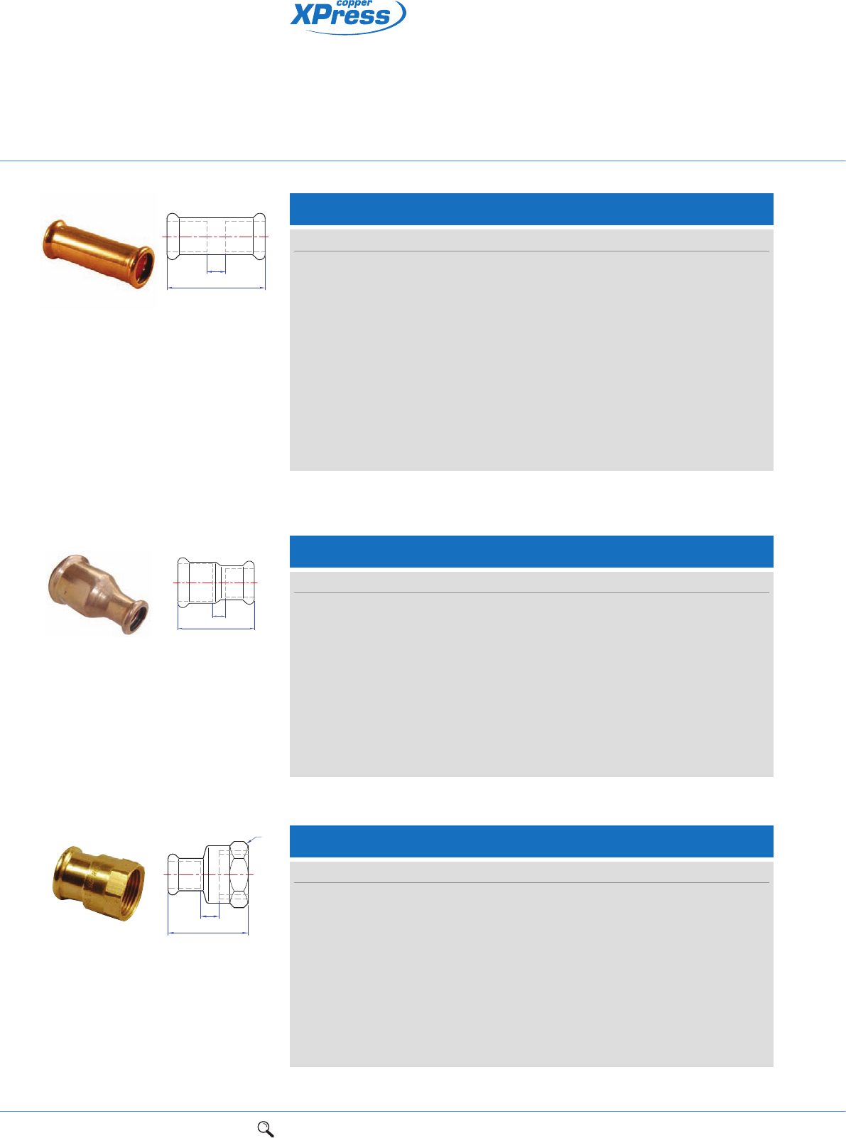
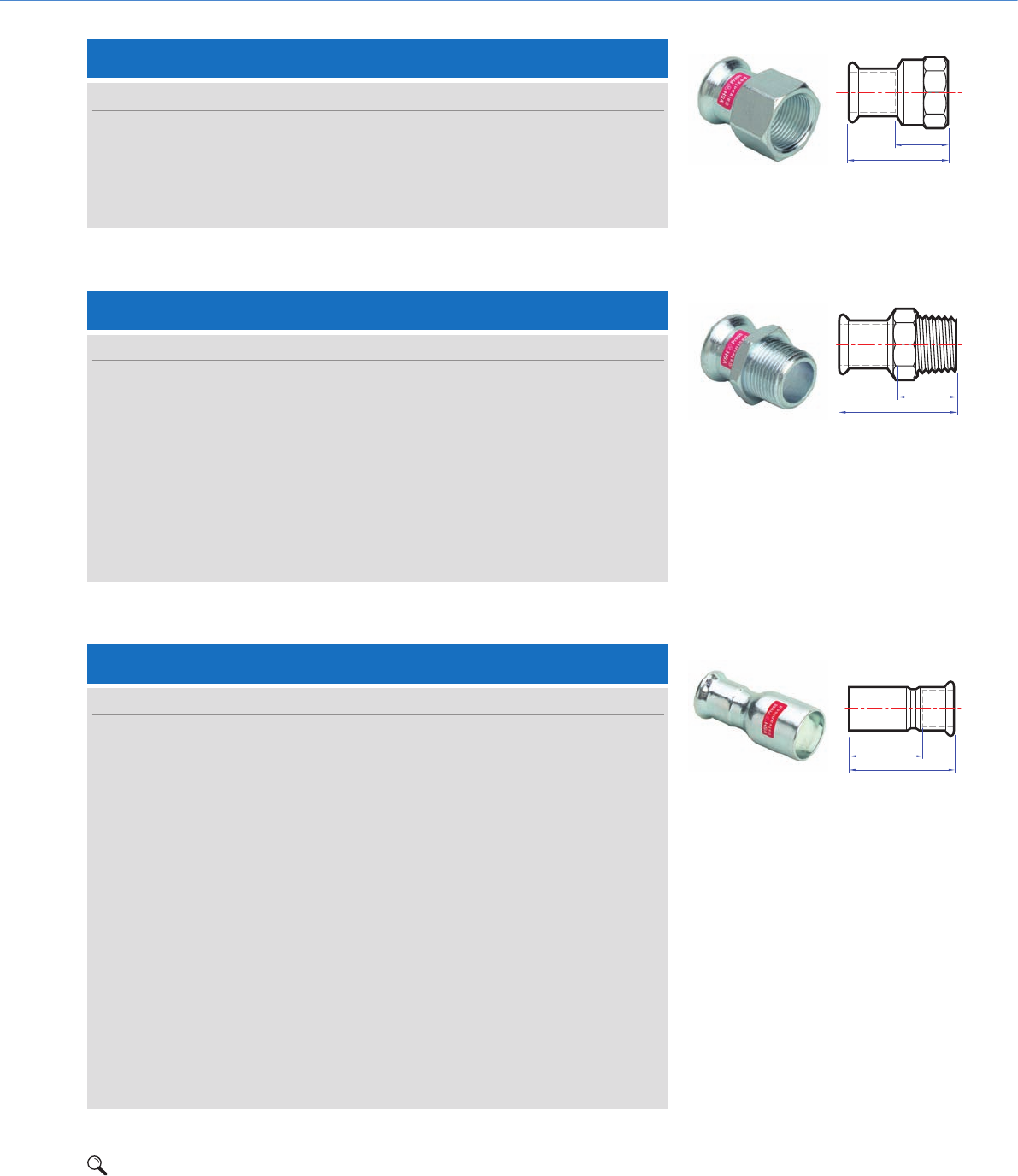
S1/7270 Straight coupling
Connection: Press-fit x press-fit.
Za
a
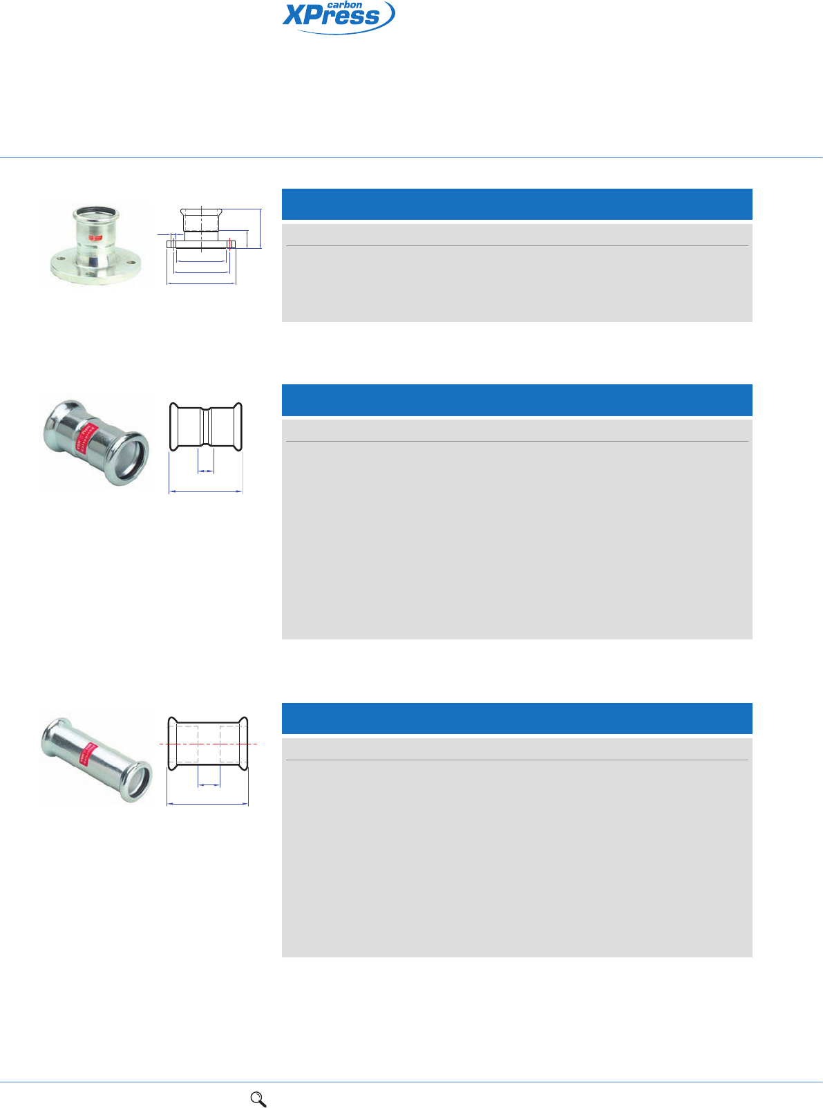
S1FMF/7510 Composite flange
Connection: Female copper press-fit socket with powder coated steel outer flange
to BS 4504 type 133, PN16 rated.
Za
a
g
d
e
f
S1FMM/7520 Composite flange
Connection: Press-fit x male end for insertion into fitting. Male copper spigot connection for
insertion into press-fit socket. Powder coated steel outer flange to BS 4504 type 133, PN16 rated.
ga
d
e
f
Size a Za Order code
12mm 42 8 38009
15mm 43 3 38010
18mm 44 4 38011
22mm 46 4 38020
28mm 50 4 38030
35mm 62 6 38032
42mm 71 7 38034
54mm 83 9 38035
64mm 148 48 38970
67mm 110 10 38036
76mm 110 10 38037
89mm 220 96 38039
108mm 205 71 38038
Size a d e f g Za Bolt holes Order code
67 x DN65 (21/2") PN16 103 100 145 185 18 53 4 38364
76 x DN80 (3") PN16 103 115 160 200 18 53 8 38365
89 x DN80 (3") PN16 113 135 160 200 18 51 8 38366
108 x DN100 (4") PN16 126 158 180 220 18 59 8 38367
Size a d e f g Bolt holes Order code
67 x DN65 (21/2") PN16 112 100 145 185 18 4 38359
76 x DN80 (3") PN16 113 115 160 200 18 8 38360
108 x DN100 (4") PN16 141 158 180 220 18 8 38362
10 1Range overview 2Product details 3Technical data 4Installation instructions 5Flow charts
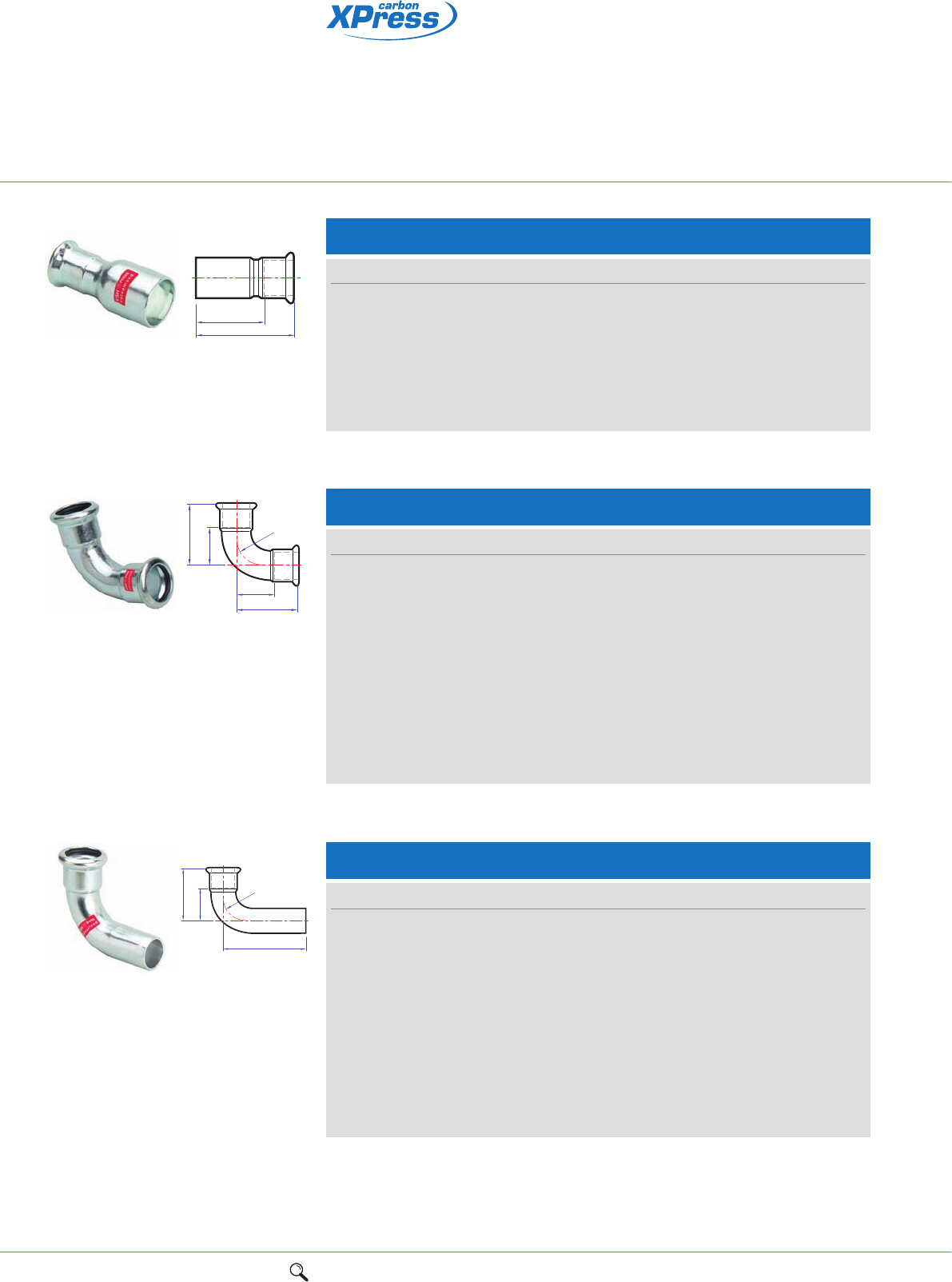
Connection: Press-fit x press-fit.
S1/7270S Slip – Straight coupling slip pattern
Connection: Press-fit x press-fit (without tube stop).
Za
a
Size a Za Order code
15mm 80 40 38044
18mm 80 40 38054
22mm 84 42 38045
28mm 91 45 38046
35mm 99 50 38047
42mm 119 60 38048
54mm 141 70 38049
64mm 102 2 38971
67mm 110 10 38040
76mm 110 10 38041
89mm 127 3 38042
108mm 131 9 38043
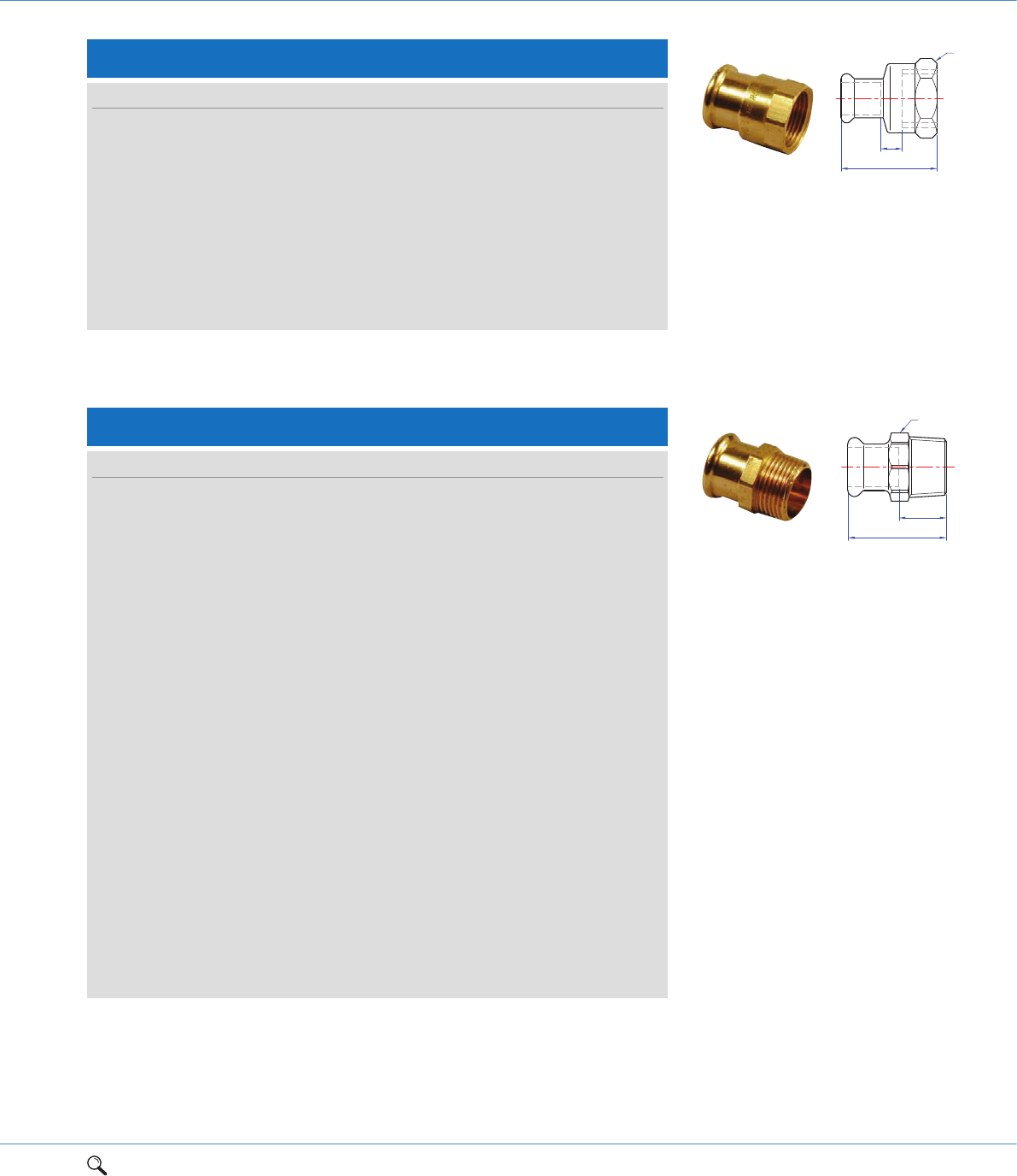
S1R/7240 Straight reducing coupling
Za
a
Size a Za Order code
15 x 12mm 44 7 38063
15 x 14mm 42 2 38060
16 x 15mm 42 2 38061
18 x 16mm 42 2 38062
22 x 15mm 52 11 38064
28 x 15mm 59 16 38065
28 x 22mm 54 10 38066
35 x 28mm 60 11 38067
42 x 35mm 67 11 38068
54 x 42mm 80 15 38069
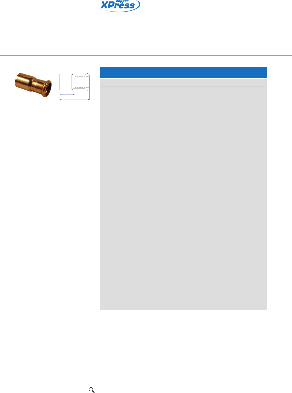
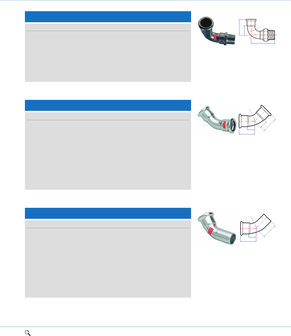
S2/6270G Straight female connector
Size a S Za Order code
12mm x 3/8" 31 20 2 38082
12mm x 1/2" 35 25 3 38081
15mm x 3/8" 33 20 2 38083
15mm x 1/2" 38 25 3 38090
15mm x 3/4" 39 30 3 38091
18mm x 1/2" 37 25 2 38084
18mm x 3/4" 39 30 3 38085
22mm x 1/2" 37 30 1 38086
22mm x 3/4" 39 30 2 38092
22mm x 1" 43 37 3 38087
Connection: Press-fit x BSP parallel female thread.
Za
a
S
LBP press-fit fittings
for jointing copper tube
1Range overview 2Product details 3Technical data 4Installation instructions 5Flow charts 11
2
Leak Before Press (LBP) technology identifies joints that have not been
pressed correctly in sizes 15mm-54mm
Designed for use in hot and cold water services, closed circuit heating,
chilled water and oil free compressed air applications
Heat free jointing provides time and cost saving benefits to
contractors/installers.
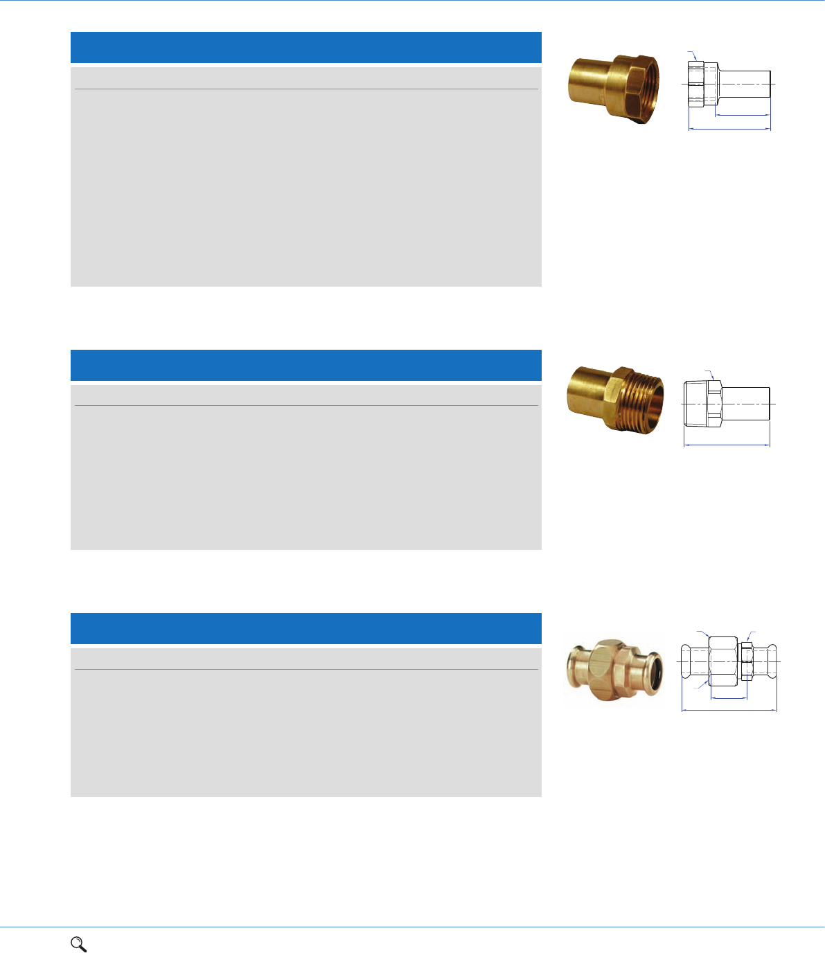
S3/6243G Straight male connector
Za
a
S
Size a S Za Order code
12mm x 3/8" 32 19 15 38105
12mm x 1/2" 36 19 19 38106
15mm x 3/8" 33 21 13 38107
15mm x 1/2" 37 21 17 38114
15mm x 3/4" 39 25 19 38115
18mm x 1/2" 37 25 17 38108
18mm x 3/4" 39 25 19 38109
22mm x 1/2" 38 30 17 38110
22mm x 3/4" 40 30 21 38116
22mm x 1" 42 32 21 38117
28mm x 3/4" 43 36 20 38111
28mm x 1" 44 36 21 38118
28mm x 11/4" 48 40 25 38127
35mm x 1" 48 41 22 38112
35mm x 11/4" 50 41 24 38119
42mm x 11/4" 58 51 28 38113
42mm x 11/2" 58 51 28 38120
54mm x 2" 63 63 28 38121
64mm x 21/2" 129 75 79 38956
67mm x 21/2" 93 80 50 38122
76mm x 21/2" 99 84 44 38126
76mm x 3" 110 94 59 38123
89mm x 3" 144 93 82 38125
108mm x 4" 132 117 50 38124
Connection: Press-fit x BSP male taper thread.
S2/6270G Straight female connector cont.
Size a S Za Order code
28mm x 3/4" 40 37 1 38088
28mm x 1" 45 37 2 38093
28mm x 11/4" 48 46 4 38103
35mm x 3/4" 42 30 4 38080
35mm x 1" 46 41 1 38089
35mm x 11/4" 50 46 1 38094
42mm x 11/4" 52 46 1 38101
42mm x 11/2" 54 53 2 38095
54mm x 2" 63 65 2 38096
64mm x 21/2" 123 83 12 38954
Connection: Press-fit x BSP parallel female thread.
Za
a
S
12 1Range overview 2Product details 3Technical data 4Installation instructions 5Flow charts
LBP press-fit fittings
for jointing copper tube
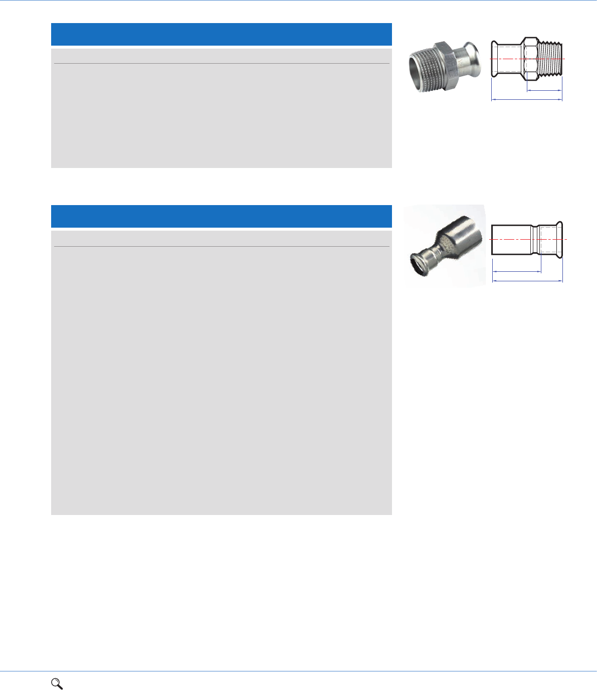
Connection: Larger end male for insertion into fitting x press-fit.
S6/7243 Reducer
Size a Za Order code
15 x 12mm 45 28 38193
15 x 14mm 52 32 38194
15 x 16mm 52 32 38195
18 x 12mm 47 30 38196
18 x 15mm 47 25 38197
18 x 16mm 52 32 38205
22 x 15mm 54 34 38200
22 x 18mm 48 26 38201
28 x 15mm 62 42 38202
28 x 18mm 59 37 38203
28 x 22mm 56 34 38204
35 x 22mm 68 47 38207
35 x 28mm 66 44 38208
42 x 22mm 76 55 38210
42 x 28mm 73 48 38211
42 x 35mm 75 48 38212
54 x 28mm 89 67 38215
54 x 35mm 90 63 38216
54 x 42mm 89 58 38217
67 x 28mm 109 86 38218
67 x 35mm 109 83 38219
67 x 42mm 110 80 38220
67 x 54mm 112 77 38221
76 x 35mm 113 87 38222
76 x 42mm 113 86 38223
76 x 54mm 116 81 38224
76 x 67mm 126 78 38225
89 x 42mm 135 105 38233
89 x 54mm 132 97 38226
89 x 76mm 140 90 38227
108 x 42mm 153 124 38228
108 x 54mm 156 120 38229
108 x 64mm 162 112 38236
108 x 67mm 166 116 38230
108 x 76mm 162 112 38231
108 x 89mm 166 106 38232
Za
a
1Range overview 2Product details 3Technical data 4Installation instructions 5Flow charts 13
2
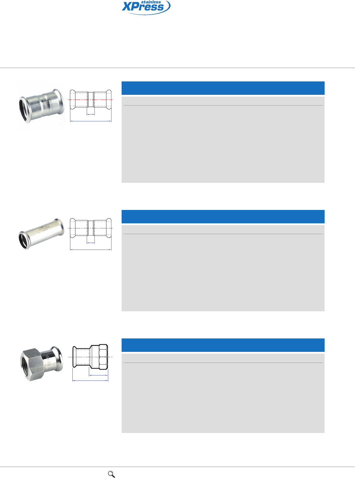
S8/6280G Male adaptor
Connection: Male copper for insertion into a fitting x BSP male taper thread.
S
a
S11/6330 Union coupling
Connection: Press-fit x press-fit.
Za
a
SS1
G
Size a S Order code
15mm x 1/2" 50 19 38170
18mm x 1/2" 50 19 38173
18mm x 3/4" 53 25 38174
22mm x 1/2" 51 25 38175
22mm x 3/4" 52 25 38171
28mm x 1" 57 32 38172
35mm x 11/4" 63 40 38176
42mm x 11/2" 80 46 38177
Size a G S S1 Za Order code
15mm 60 3/4" 30 25 20 38180
18mm 62 3/4" 30 25 22 38179
22mm 68 1" 36 32 26 38181
28mm 73 11/4" 46 40 27 38182
35mm 71 11/2" 52 46 19 38183
42mm 91 13/4" 58 51 31 38184
54mm 98 23/8" 75 65 28 38185
S7/6246G Female adaptor
Connection: Male copper for insertion into a fitting x BSP parallel female thread.
Za
S
a
Size a S Za Order code
15mm x 1/2" 47 25 32 38160
18mm x 1/2" 47 25 32 38157
18mm x 3/4" 49 30 33 38158
22mm x 1/2" 46 25 31 38159
22mm x 3/4" 49 30 32 38161
28mm x 3/4" 50 30 34 38166
28mm x 1" 54 37 35 38162
35mm x 1" 56 37 37 38167
35mm x 11/4" 60 46 38 38163
42mm x 11/2" 76 53 55 38164
54mm x 2" 86 65 60 38165
14 1Range overview 2Product details 3Technical data 4Installation instructions 5Flow charts
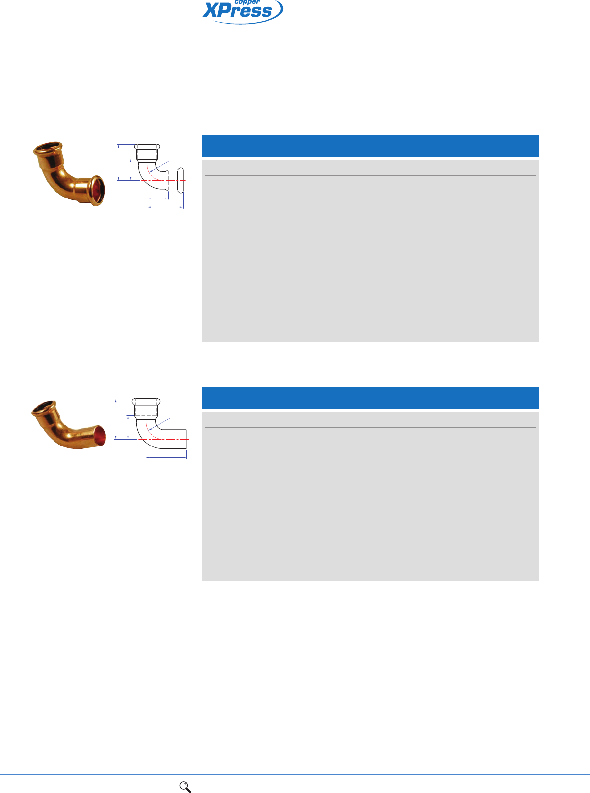
S12/7002A Elbow
Connection: Press-fit x press-fit.
Za
Za
a
ar
Za
a
c
r
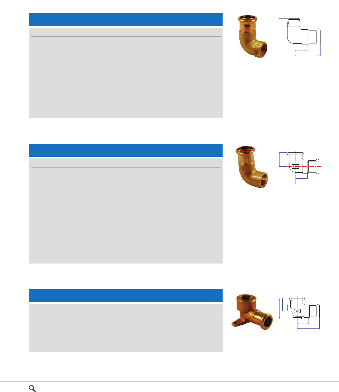
S12S/7001A Street elbow
Connection: Press-fit x male end for insertion into an XPress fitting.
LBP press-fit fittings
for jointing copper tube
Size a r Za Order code
12mm 31 14 14 38279
15mm 38 17 17 38280
18mm 42 22 22 38282
22mm 47 26 26 38290
28mm 56 34 34 38300
35mm 68 42 42 38302
42mm 80 50 50 38304
54mm 100 65 65 38306
64mm 172 90 122 38958
67mm 132 80 87 38307
76mm 142 90 92 38308
89mm 170 127 112 38309
108mm 201 161 135 38310
Size a c r Za Order code
12mm 31 45 14 14 38317
15mm 36 50 18 16 38318
18mm 42 53 22 22 38319
22mm 47 58 26 27 38320
28mm 58 64 34 34 38322
35mm 69 82 42 44 38324
42mm 81 101 50 52 38325
54mm 100 120 65 66 38326
67mm 130 175 80 78 38327
76mm 147 190 90 98 38328
89mm 215 250 127 153 38329
108mm 206 259 161 141 38330
1Range overview 2Product details 3Technical data 4Installation instructions 5Flow charts 15
2
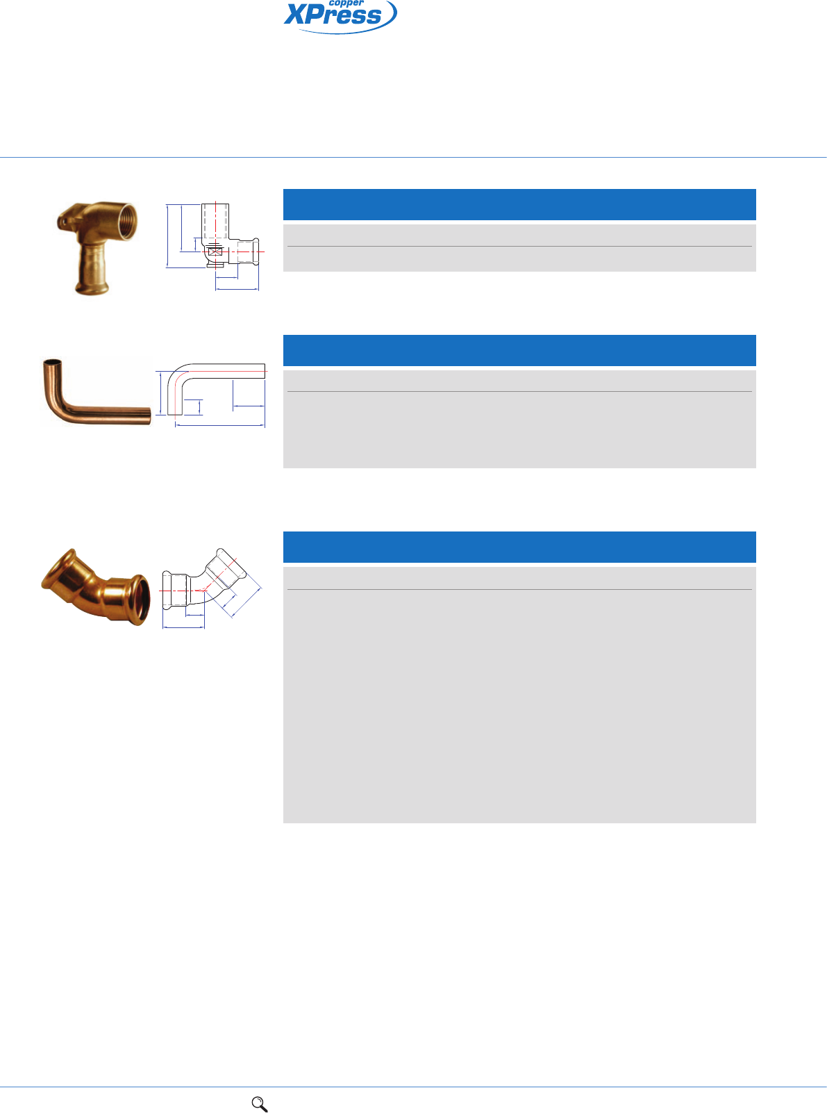
S13/6092G Male elbow
Connection: Press-fit x BSP male taper thread.
Za
c
a
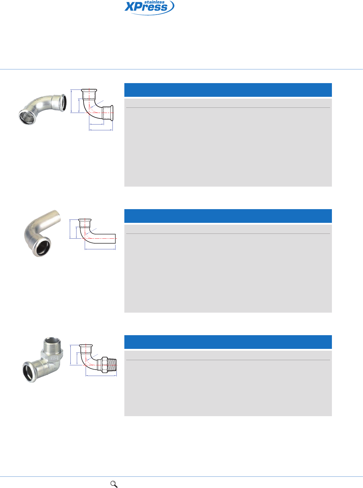
S14/6090G Female elbow
Connection: Press-fit x BSP parallel female thread.
Za
Zc
c
a
Size a c Za Order code
12mm x 3/8" 30 25 13 38371
12mm x 1/2" 32 31 15 38370
15mm x 3/8" 32 27 12 38339
15mm x 1/2" 38 34 19 38333
18mm x 1/2" 35 34 15 38340
18mm x 3/4" 38 33 18 38372
22mm x 3/4" 49 45 28 38334
28mm x 1" 58 53 36 38335
35mm x 11/4" 55 47 30 38336
42mm x 11/2" 62 51 32 38337
54mm x 2" 70 63 35 38338
Size a c Za Zc Order code
12mm x 3/8" 32 23 15 10 38346
12mm x 1/2" 34 23 17 7 38345
15mm x 3/8" 33 24 13 11 38347
15mm x 1/2" 41 24 20 15 38351
15mm x 3/4" 36 70 16 16 38344
18mm x 1/2" 36 30 16 14 38348
18mm x 3/4" 38 30 18 12 38349
22mm x 1/2" 53 24 32 13 38350
22mm x 3/4" 45 27 24 11 38353
28mm x 1" 51 33 28 14 38354
35mm x 11/4" 55 45 29 21 38355
42mm x 11/2" 85 45 57 26 38356
54mm x 2" 104 54 72 33 38357
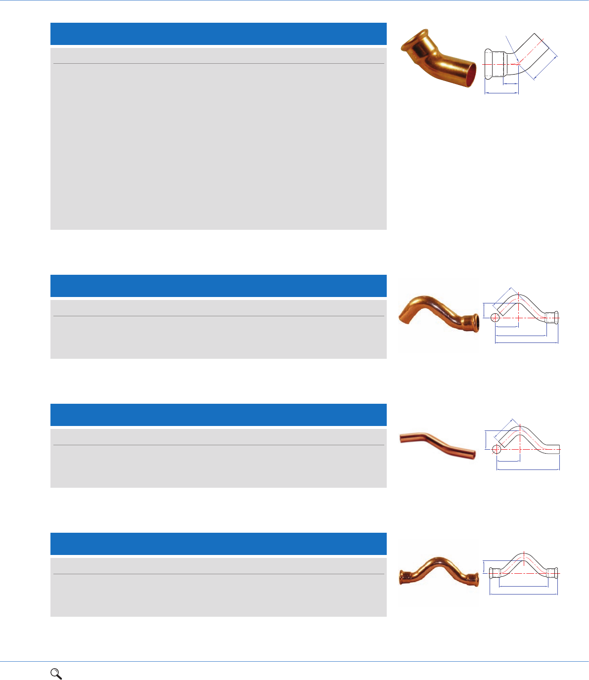
S15/6472G Backplate elbow
Connection: Press-fit x BSP parallel female thread.
Za
Zc
a
c
d
Size a c d Za Zc Order code
12mm x 1/2" 61 22 35 44 7 38397
15mm x 3/8" 41 36 49 21 14 38396
15mm x 1/2" 41 23 36 21 8 38400
18mm x 1/2" 41 24 39 21 9 38398
22mm x 3/4" 45 27 45 24 11 38401
16 1Range overview 2Product details 3Technical data 4Installation instructions 5Flow charts
LBP press-fit fittings
for jointing copper tube
Connection: Press-fit x parallel female thread.
S15L/6472L Backplate elbow
Size a c d Za Zc Order code
15mm x 1/2" 41 45 58 21 8 38399
Za
Zc
a
c
d
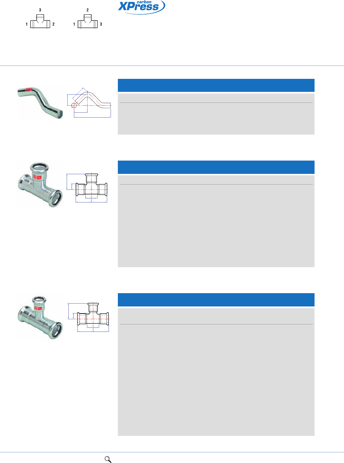
S19/7005 90º bend
Connection: Both ends male for insertion in to an XPress fitting.
a
b
Za Zb
Size a b Za Zb Order code
15mm 70 120 22 72 38390
18mm 70 120 17 67 38391
22mm 70 120 9 59 38392
28mm 80 120 7 47 38393
S21/7041 Obtuse elbow
Connection: Press-fit x press-fit.
Za a
Za
a
Size a Za Order code
12mm 23 6 38411
15mm 28 8 38410
18mm 29 9 38413
22mm 31 12 38412
28mm 37 16 38414
35mm 44 18 38416
42mm 51 21 38417
54mm 62 27 38418
64mm 114 64 38960
67mm 85 35 38419
76mm 91 45 38420
89mm 109 47 38422
108mm 125 59 38421
1Range overview 2Product details 3Technical data 4Installation instructions 5Flow charts 17
2
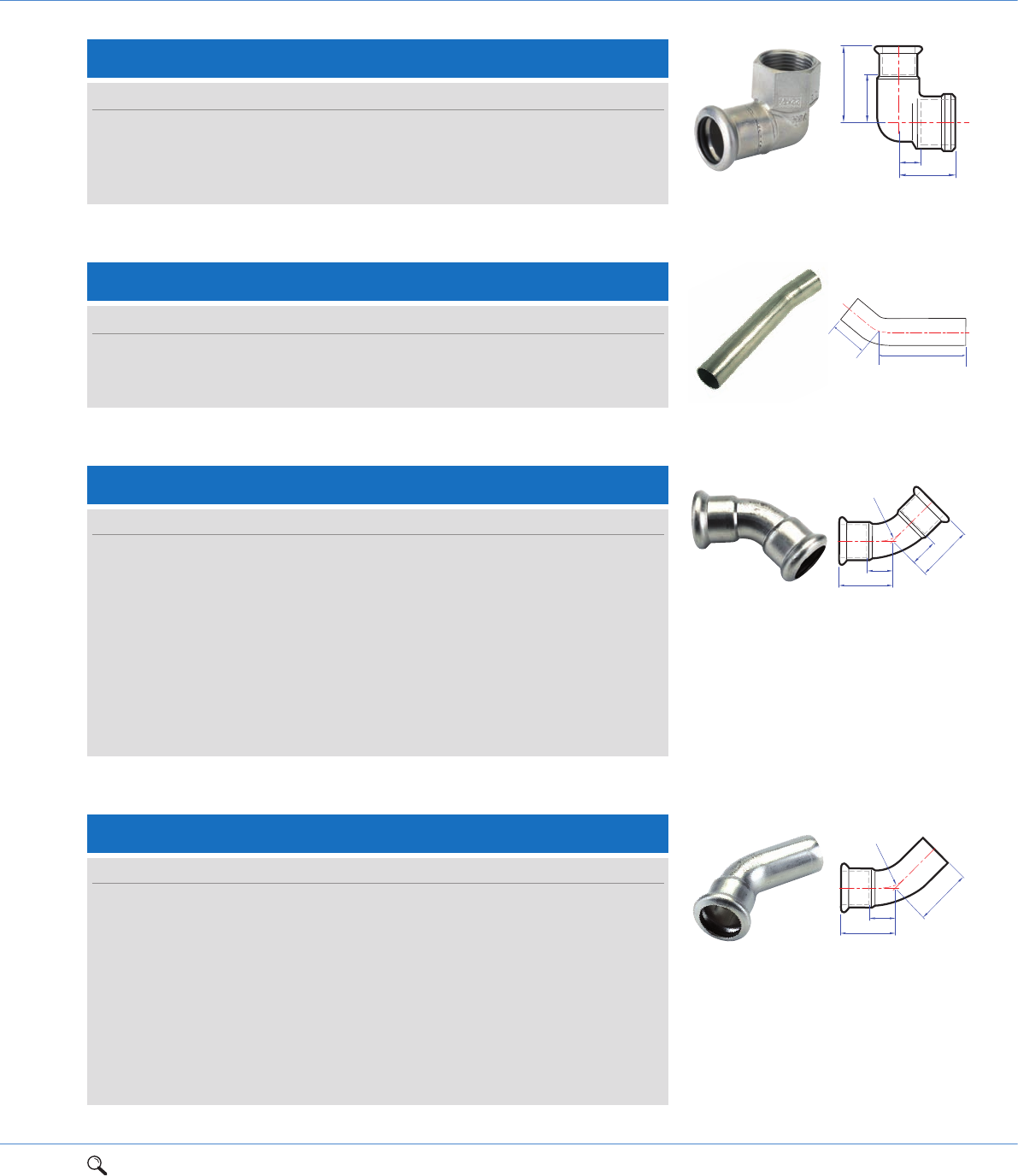
S21S/7040 Obtuse street elbow
Size a c Za Item code
12mm 23 32 6 38402
15mm 28 37 8 38404
18mm 29 39 9 38403
22mm 32 44 11 38405
28mm 37 47 14 38406
35mm 43 58 17 38407
42mm 51 71 21 38408
54mm 62 82 27 38409
64mm 114 145 64 38959
67mm 85 88 35 38430
76mm 95 146 35 38431
89mm 132 196 70 38433
108mm 127 184 60 38432
Connection: Press-fit x male end for insertion into an XPress fitting.
Za
a
c
r
Za
a
c
d
e
Connection: Press-fit x male end for insertion into an XPress fitting.
Connection: Both ends male for insertion into an XPress fitting.
Connection: Press-fit x press-fit.
Za
a
c
S22/7086 Partial crossover
Size a c d e Za Order code
15mm 110 40 44 25 90 38435
18mm 120 45 49 27 100 38437
22mm 134 50 55 30 113 38436
S22S/7087 Street crossover
Size a c d e Order code
15mm 157 56 46 30 38438
18mm 166 60 49 31 38434
22mm 178 65 55 33 38439
S23/7085 Full crossover
Size a c Za Order code
15mm 140 26 100 38440
18mm 151 27 111 38442
22mm 170 28 128 38441
a
e
d
c
18 1Range overview 2Product details 3Technical data 4Installation instructions 5Flow charts
Za
Za
Zc
aa
c
LBP press-fit fittings
for jointing copper tube
Tee specification
See page 73
UK specification European specification
Connection: Press-fit on all ends.
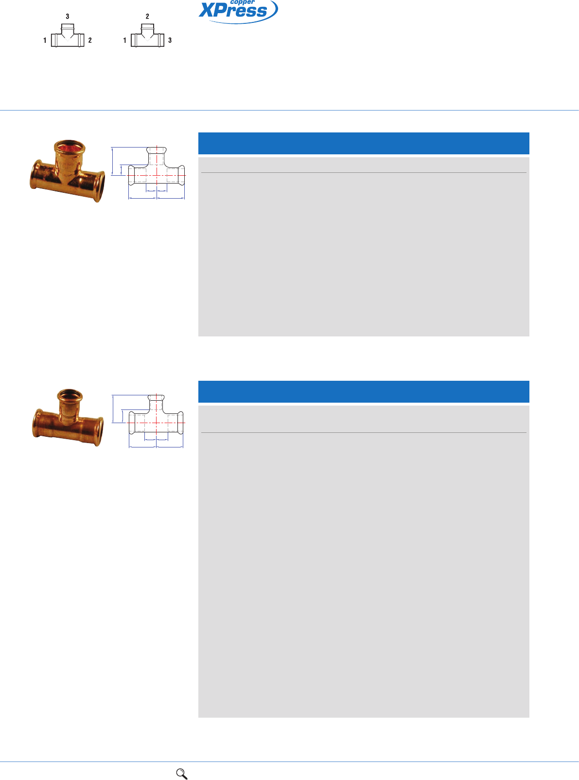
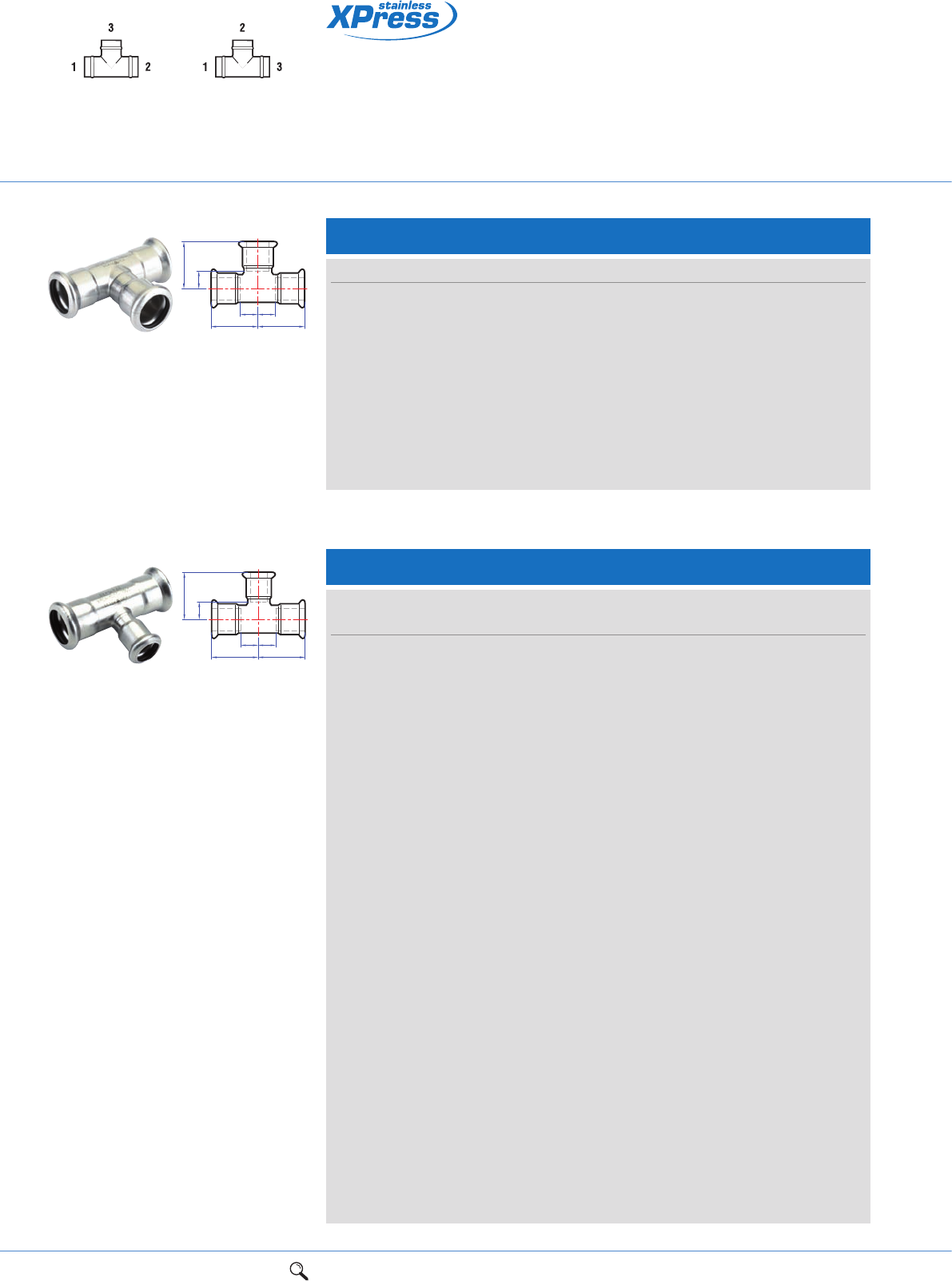
S24/7130 Equal tee
ZaZa
Zc
c
aa
Size a c Za Zc Order code
12mm 28 28 11 11 38472
15mm 32 32 12 12 38450
18mm 34 34 14 14 38451
22mm 37 37 16 16 38460
28mm 42 42 19 19 38462
35mm 50 50 24 24 38464
42mm 58 58 28 28 38466
54mm 69 69 34 34 38467
64mm 133 134 83 84 38961
67mm 95 107 45 58 38468
76mm 101 114 50 64 38469
89mm 162 162 100 100 38470
108mm 159 159 92 92 38471
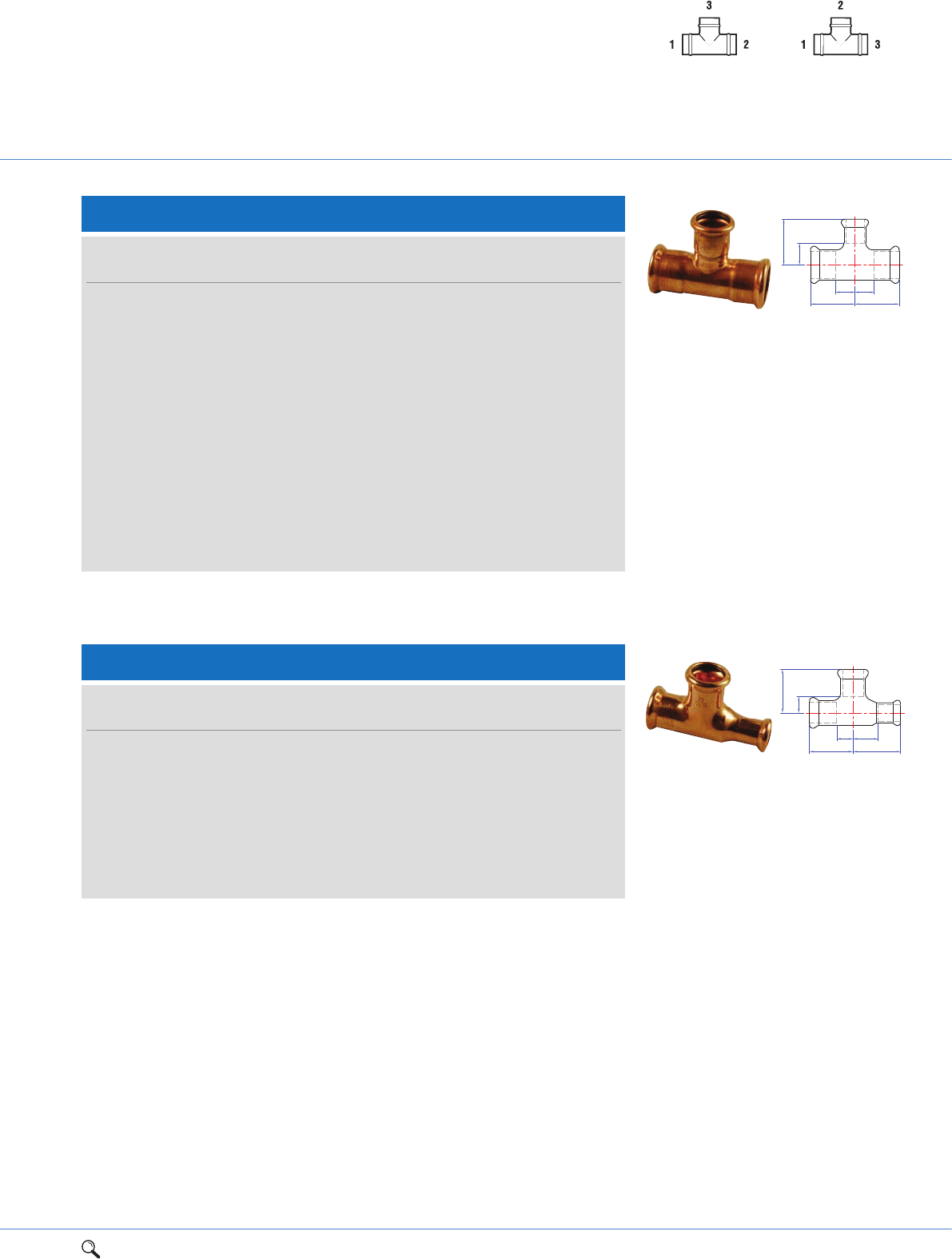
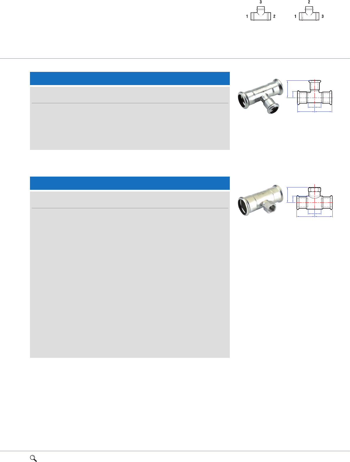
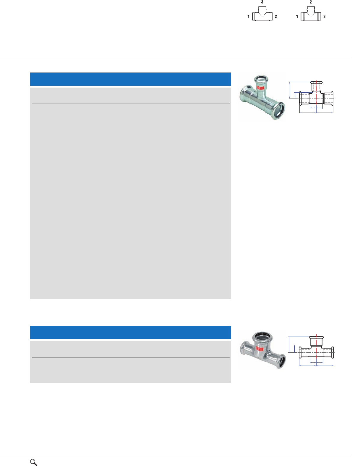
S25/7130 Tee, reduced branch
Connection: Press-fit on all ends.
Size
UK European a c Za c Order code
15 x 15 x 12mm 15 x 12 x 15mm 32 32 12 15 38488
18 x 18 x 12mm 18 x 12 x 18mm 34 35 14 18 38452
18 x 18 x 15mm 18 x 15 x 18mm 34 35 14 15 38454
22 x 22 x 12mm 22 x 12 x 22mm 37 34 16 17 38491
22 x 22 x 15mm 22 x 15 x 22mm 37 38 16 18 38490
22 x 22 x 18mm 22 x 18 x 22mm 37 38 16 18 38535
28 x 28 x 12mm 28 x 12 x 28mm 42 41 19 21 38493
28 x 28 x 15mm 28 x 15 x 28mm 42 41 19 21 38492
28 x 28 x 18mm 28 x 18 x 28mm 42 41 19 21 38538
28 x 28 x 22mm 28 x 22 x 28mm 42 41 19 20 38494
35 x 35 x 15mm 35 x 15 x 35mm 45 44 19 24 38496
35 x 35 x 22mm 35 x 22 x 35mm 45 45 19 24 38497
35 x 35 x 28mm 35 x 28 x 35mm 50 44 24 21 38498
42 x 42 x 15mm 42 x 15 x 42mm 50 48 20 28 38499
42 x 42 x 22mm 42 x 22 x 42mm 50 48 20 27 38500
42 x 42 x 28mm 42 x 28 x 42mm 56 49 26 26 38501
42 x 42 x 35mm 42 x 35 x 42mm 56 50 26 24 38502
54 x 54 x 22mm 54 x 22 x 54mm 60 54 25 33 38504
54 x 54 x 28mm 54 x 28 x 54mm 60 55 25 32 38505
54 x 54 x 35mm 54 x 35 x 54mm 61 55 24 29 38506
54 x 54 x 42mm 54 x 42 x 54mm 69 64 34 34 38507
64 x 64 x 35mm 64 x 35 x 64mm 115 102 65 76 38962
64 x 64 x 42mm 64 x 42 x 64mm 126 109 76 79 38963
1Range overview 2Product details 3Technical data 4Installation instructions 5Flow charts 19
2
S25/7130 Tee, reduced branch cont.
Connection: Press-fit on all ends.
Za
Za
Zc
aa
c
Tee specification
See page 73
UK specification European specification
Size
UK European a c Za c Order code
67 x 67 x 28mm 67 x 28 x 67mm 76 67 26 43 38550
67 x 67 x 35mm 67 x 35 x 67mm 80 70 29 43 38560
67 x 67 x 42mm 67 x 42 x 67mm 82 76 32 41 38561
67 x 67 x 54mm 67 x 54 x 67mm 88 78 47 43 38562
76 x 76 x 22mm 76 x 22 x 76mm 73 73 22 50 38563
76 x 76 x 28mm 76 x 28 x 76mm 77 73 26 50 38564
76 x 76 x 35mm 76 x 35 x 76mm 80 78 30 53 38553
76 x 76 x 42mm 76 x 42 x 76mm 103 106 55 70 38551
76 x 76 x 54mm 76 x 54 x 76mm 108 104 60 72 38552
89 x 89 x 54mm 89 x 54 x 89mm 136 119 77 86 38554
89 x 89 x 76mm 89 x 76 x 89mm 151 146 91 96 38556
108 x 108 x 54mm 108 x 54 x 108mm 131 129 66 93 38555
108 x 108 x 67mm 108 x 67 x 108mm 117 136 46 91 38565
108 x 108 x 76mm 108 x 76 x 108mm 140 141 73 93 38557
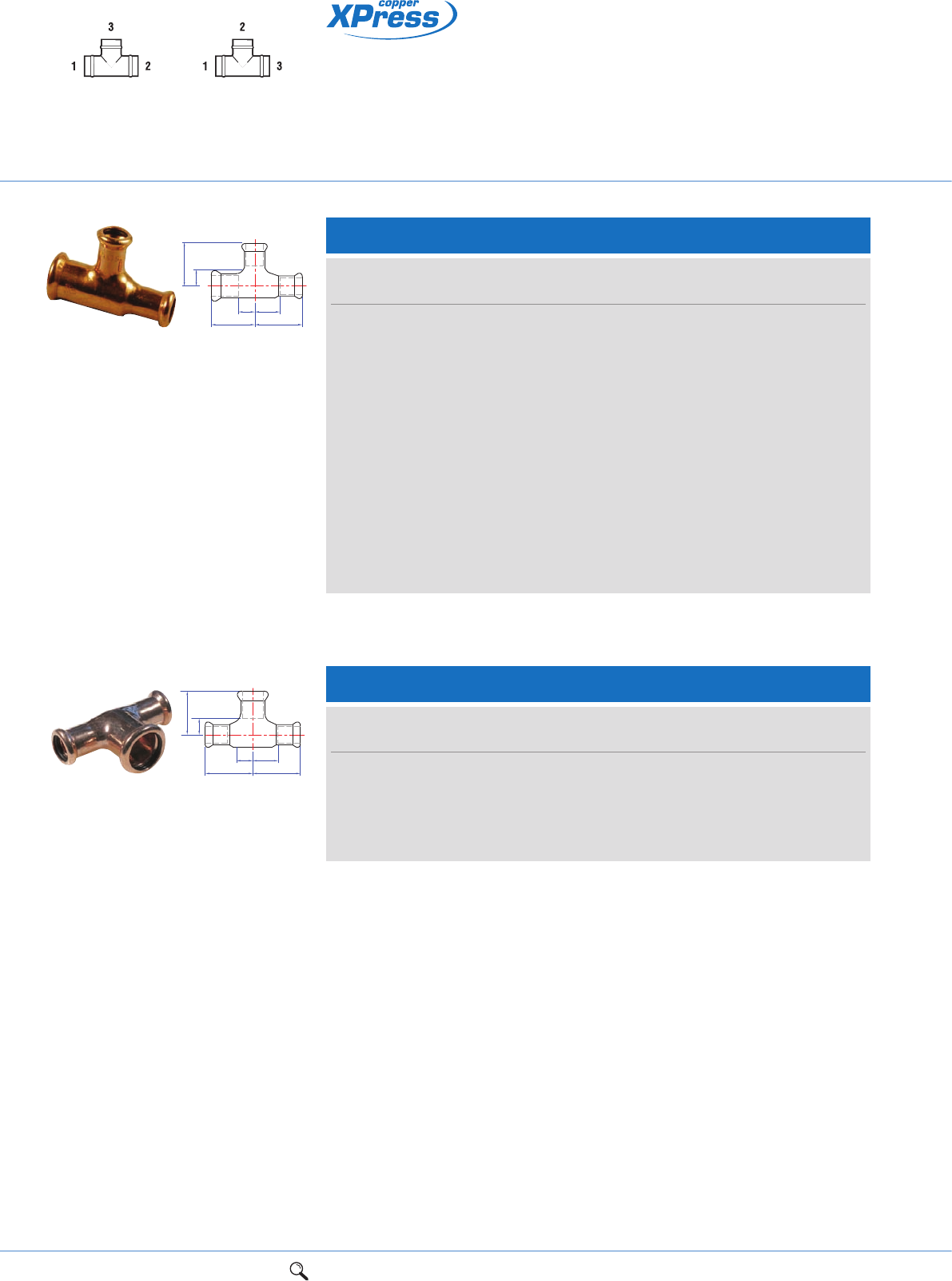
S26/7130 Tee, one end reduced
Connection: Press-fit on all ends.
Zc
c
Za Zd
ad
Size
UK European a c d Za Zc Zd Order code
15 x 12 x 15mm 15 x 15 x 12mm 32 32 36 12 12 19 38508
18 x 15 x 18mm 18 x 18 x 15mm 34 34 42 14 14 22 38455
22 x 15 x 22mm 22 x 22 x 15mm 37 37 46 16 16 26 38510
22 x 18 x 22mm 22 x 22 x 18mm 37 37 43 16 16 23 38511
28 x 15 x 28mm 28 x 28 x 15mm 42 42 55 19 19 35 38512
28 x 22 x 28mm 28 x 28 x 22mm 42 42 52 19 19 31 38514
35 x 22 x 35mm 35 x 35 x 22mm 51 50 72 25 24 51 38517
35 x 28 x 35mm 35 x 35 x 28mm 51 50 67 25 24 41 38518
20 1Range overview 2Product details 3Technical data 4Installation instructions 5Flow charts
LBP press-fit fittings
for jointing copper tube
Tee specification
See page 73
UK specification European specification
Connection: Press-fit on all ends.
S27/7130 Tee, one end and branch reduced
Connection: Press-fit on all ends.
c
Zc
Za
ad
Zd
Size
UK European a c d Za Zc Zd Order code
15 x 12 x 12mm 15 x 12 x 12mm 32 32 35 12 15 18 38527
18 x 15 x 15mm 18 x 15 x 15mm 34 35 40 14 15 20 38453
22 x 18 x 15mm 22 x 15 x 18mm 37 38 44 16 18 24 38531
22 x 15 x 15mm 22 x 15 x 15mm 37 44 43 16 18 23 38530
22 x 15 x 18mm 22 x 18 x 15mm 37 38 44 16 18 24 38533
22 x 18 x 18mm 22 x 18 x 18mm 37 38 41 16 18 21 38534
28 x 22 x 15mm 28 x 15 x 22mm 42 41 46 19 21 25 38536
28 x 22 x 18mm 28 x 18 x 22mm 42 41 47 19 21 26 38529
28 x 22 x 22mm 28 x 22 x 22mm 42 41 49 19 20 28 38532
35 x 22 x 22mm 35 x 22 x 22mm 51 44 67 25 23 45 38539
35 x 28 x 22mm 35 x 22 x 28mm 51 44 63 25 23 40 38541
35 x 28 x 28mm 35 x 28 x 28mm 51 44 67 25 21 44 38542
42 x 35 x 35mm 42 x 35 x 35mm 56 50 74 26 24 48 38546
54 x 42 x 42mm 54 x 42 x 42mm 69 64 83 34 34 53 38566
S28/7130 Tee, both ends reduced
c
Zc
Za
ad
Zd
Size
UK European a c Za Zc Order code
12 x 12 x 15mm 12 x 15 x 12mm 36 32 19 15 38447
15 x 15 x 18mm 15 x 18 x 15mm 35 32 15 12 38547
15 x 15 x 22mm 15 x 22 x 15mm 38 34 18 13 38545
22 x 22 x 28mm 22 x 28 x 22mm 52 42 31 19 38548
28 x 28 x 35mm 28 x 35 x 28mm 68 50 45 24 38549
1Range overview 2Product details 3Technical data 4Installation instructions 5Flow charts 21
2
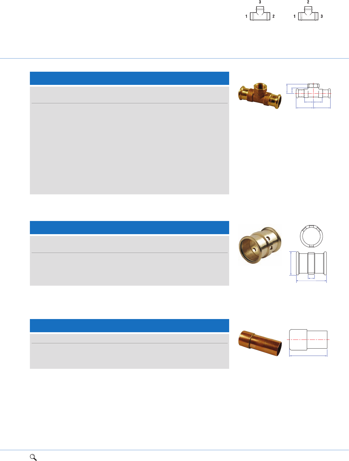
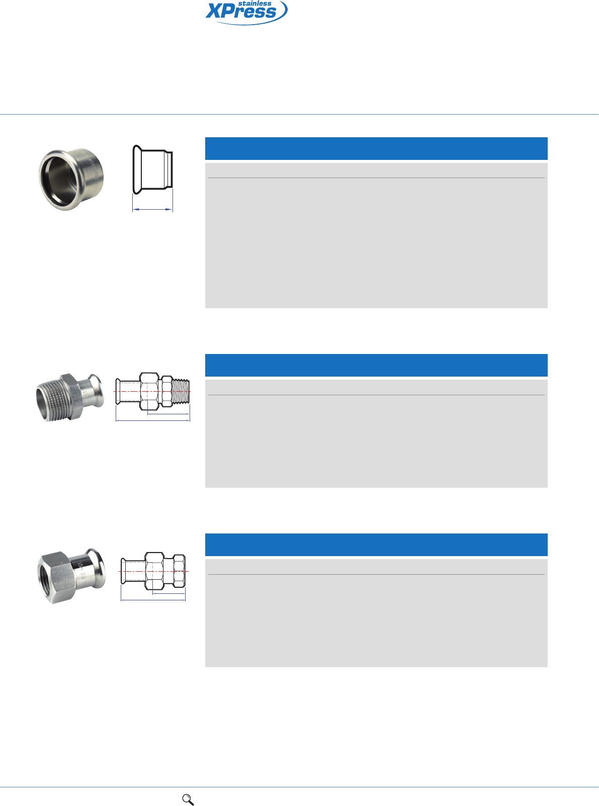
S30/6130G Female branch tee
Connection: Press-fit x BSP parallel female branch.
Za
a
Zc
c
Za
a
S60/S302 Stop end
Size a Item code
35mm 96 38686
42mm 108 38688
54mm 125 38690
Connection: Male end for insertion into an XPress fitting.
a
S32/6130G Female branch tee with multi ports
Tappings
Size a b Za A B C D Item code
67mm x 1/2" 130 84 29 1/2"1/2" - - 38189
76mm x 1/2" 130 96 28 1/2"1/2" - - 38188
89mm x 3/4" 160 108 36 3/4"3/4"3/4" - 38192
108mm x 3/4" 170 132 35 3/4"3/4"3/4"3/4" 38206
Connection: Press-fit x BSP parallel female branch.
Size
UK European a c Za Zc Order code
12 x 12mm x 1/2" 12 x 1/2" x 12mm 29 23 12 7 38584
15 x 15mm x 1/2" 15 x 1/2" x 15mm 34 26 14 11 38585
18 x 18mm x 1/2" 18 x 1/2" x 18mm 42 24 22 8 38586
22 x 22mm x 1/2" 22 x 1/2" x 22mm 42 26 21 11 38591
22 x 22mm x 3/4" 22 x 3/4" x 22mm 45 27 24 11 38587
28 x 28mm x 1/2" 28 x 1/2" x 28mm 44 29 21 14 38592
28 x 28mm x 3/4" 28 x 3/4" x 28mm 41 34 18 14 38593
35 x 35mm x 1/2" 35 x 1/2" x 35mm 50 34 24 19 38594
42 x 42mm x 1/2" 42 x 1/2" x 42mm 57 38 27 23 38596
54 x 54mm x 1/2" 54 x 1/2" x 54mm 69 44 34 29 38597
76 x 76mm x 1/2" 76 x 1/2" x 76mm 65 48 15 30 38190
108 x 108mm x 1/2" 108 x 1/2" x 108mm 82 65 15 53 38191
Tee specification
See page 73
UK specification European specification
Za
a
b
B
A
CD
22 1Range overview 2Product details 3Technical data 4Installation instructions 5Flow charts
LBP press-fit fittings
for jointing copper tube
Connection: Press-fit x female union end.
S68FF/6359 Union
Za
S
a
Size a Za S Order code
15mm x 3/4" 25 5 30 38235
18mm x 3/4" 28 8 30 38237
22mm x 1" 29 8 36 38238
28mm x 11/4" 31 8 46 38239
35mm x 11/2" 32 6 52 38242
42mm x 13/4" 39 9 58 38243
Connection: Press-fit x parallel female end.
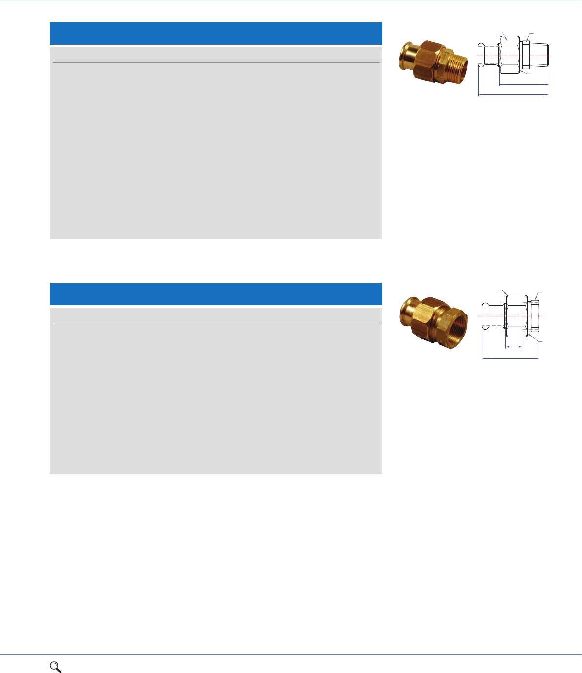
S65F/6096G Straight female union elbow connector
Za
Zc
a
c
S
G
S1
Size a c G S S1 Za Zc Order code
12mm x 1/2"4932
3/4" 30 27 32 17 38790
15mm x 1/2"5332
3/4" 30 27 33 17 38791
18mm x 1/2"5532
3/4" 30 27 35 17 38792
18mm x 3/4" 61 36 1 36 33 41 20 38793
22mm x 3/4" 62 36 1 36 33 41 20 38794
22mm x 1" 66 40 1 36 40 45 21 38795
28mm x 1" 68 44 11/4" 46 40 45 25 38796
35mm x 11/4"75501
1/2" 52 50 49 28 38797
42mm x 11/2"85531
3/4" 58 56 55 32 38798
54mm x 2" 99 64 23/8" 75 68 64 38 38799
Za
a
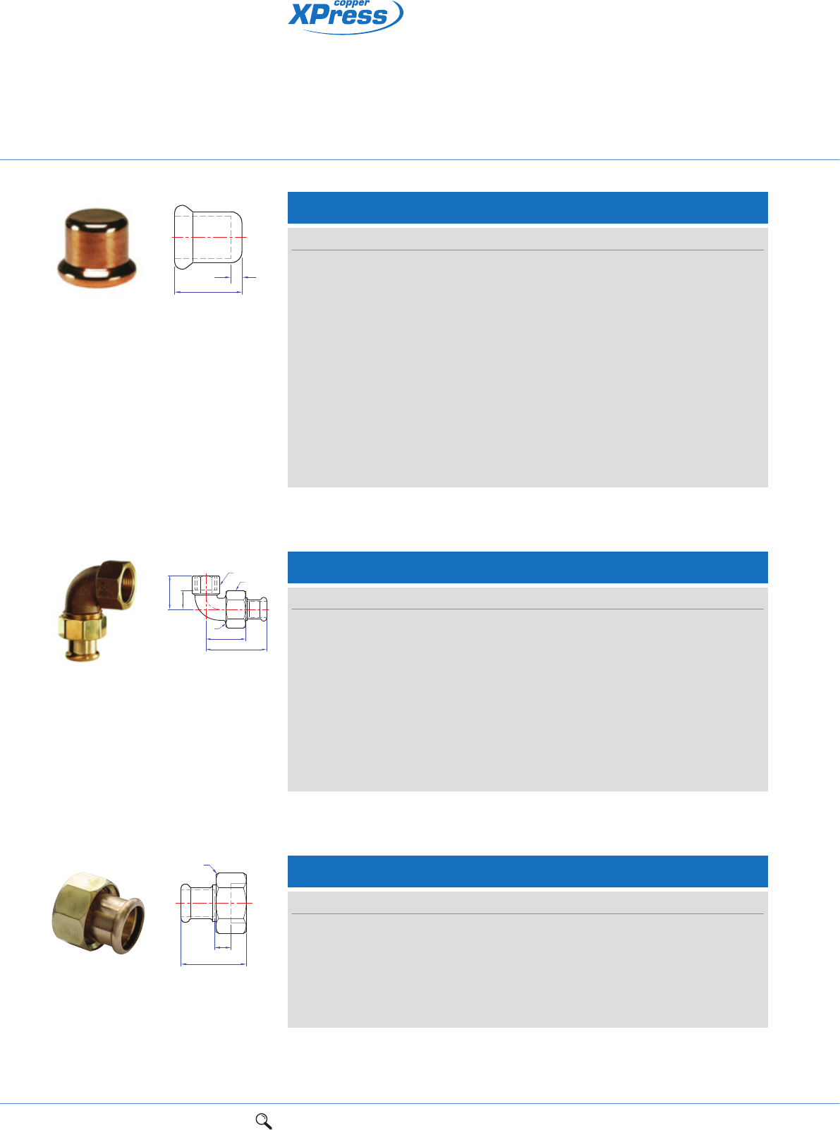
S61/7301 Stop end
Size a Za Order code
12mm 17 2 38702
15mm 20 2 38695
18mm 20 2 38696
22mm 21 2 38697
28mm 23 2 38698
35mm 26 2 38699
42mm 30 2 38700
54mm 35 2 38701
64mm 50 2 38689
67mm 50 2 38691
76mm 50 2 38692
89mm 62 2 38693
108mm 67 2 38694
Connection: Press-fit, for use with copper tube.
1Range overview 2Product details 3Technical data 4Installation instructions 5Flow charts 23
2
Connection: Press-fit x BSP taper male thread.
Za
a
G
S1
S
Connection: Press-fit x BSP parallel female thread.
Za G
S1
S
a
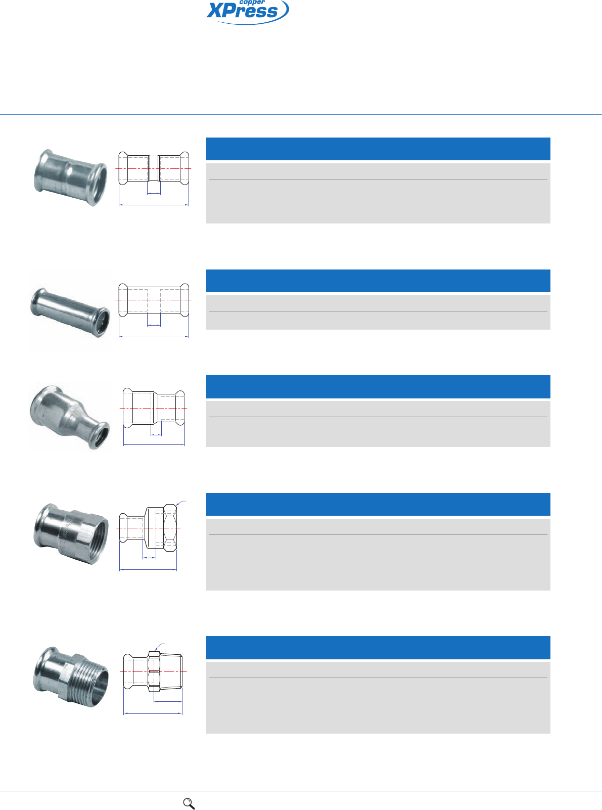
S69/6331G Straight male union connector
Size a G S S1 Za Order code
12mm x 3/8"48
1/2" 24 19 31 38807
12mm x 1/2"54
3/4" 30 25 37 38808
15mm x 1/2"62
3/4" 30 25 42 38813
15mm x 3/4"58
3/4" 30 25 38 38809
18mm x 1/2"59
3/4" 30 25 39 38810
18mm x 3/4"61
3/4" 30 25 41 38811
22mm x 1/2" 66 1" 36 32 45 38812
22mm x 3/4" 74 1" 36 32 53 38814
22mm x 1" 68 1" 36 32 47 38815
28mm x 3/4"75
3/4" 46 - 52 38820
28mm x 1" 76 11/4" 46 40 53 38816
35mm x 11/4"791
1/2" 52 46 53 38817
42mm x 11/2"881
3/4" 58 51 58 38818
54mm x 2" 101 23/8" 75 65 66 38819
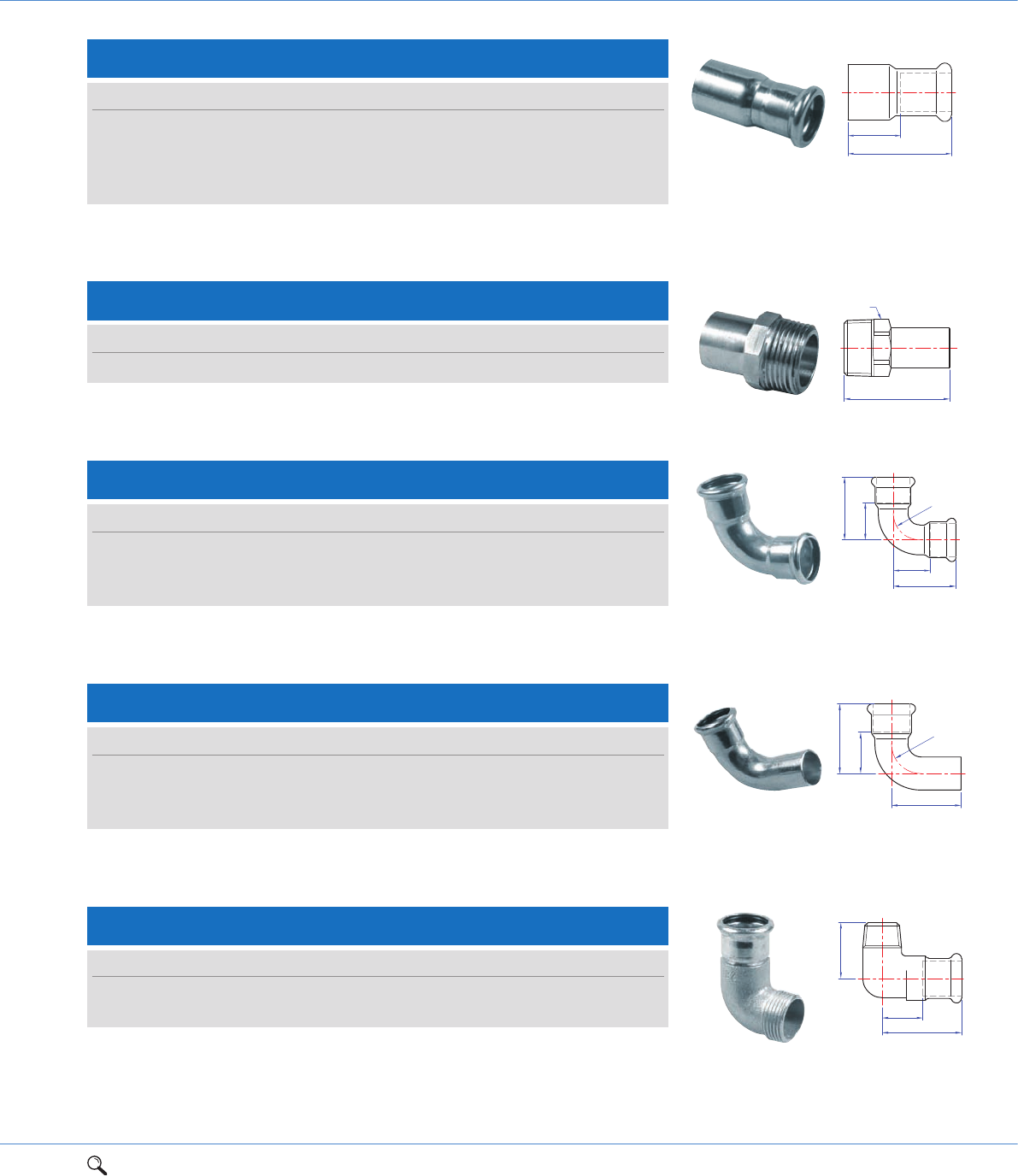
S69F/6330G Straight female union connector
Size a G S S1 Za Order code
12mm x 1/2"42
3/4" 30 26 10 38828
15mm x 1/2"52
3/4" 30 26 30 38833
15mm x 3/4"55
3/4" 30 31 18 38829
18mm x 1/2"48
3/4" 30 26 13 38830
18mm x 3/4"57
3/4" 30 31 21 38831
22mm x 3/4" 68 1" 36 32 43 38834
22mm x 1" 65 1" 36 39 25 38832
28mm x 3/4"65
3/4" 46 31 28 38827
28mm x 1" 65 11/4" 46 43 43 38835
35mm x 11/4"741
1/2" 52 48 52 38836
42mm x 11/2"831
3/4" 58 53 48 38837
54mm x 2" 90 23/8" 75 65 50 38838
24 1Range overview 2Product details 3Technical data 4Installation instructions 5Flow charts
S2CP/6270GCP Straight female connector
Size a S Za Order code
12mm x 3/8" 31 20 2 38619
12mm x 1/2" 35 25 3 38620
15mm x 3/8" 33 20 2 38621
15mm x 1/2" 38 25 3 38622
Connection: Press-fit x BSP parallel female thread.
Za
a
S
Chromium plated press-fit
fittings for jointing
chromium plated copper tube
S3CP/6243GCP Straight male connector
Za
a
S
Size a S Za Order code
12mm x 3/8" 32 19 15 38627
12mm x 1/2" 36 19 19 38628
15mm x 3/8" 33 21 13 38629
15mm x 1/2" 37 21 17 38630
Connection: Press-fit x BSP taper male thread.
S1CP/7270CP Straight coupling
Connection: Press-fit x press-fit.
Za
a
Size a Za Order code
12mm 42 8 38610
15mm 43 3 38611
22mm 46 4 38612
S1RCP/7240SCP Straight reducing coupling
Connection: Press-fit x press-fit.
Za
a
Size a Za Order code
15 x 12mm 44 7 38616
22 x 15mm 52 11 38617
S1SCP/7270SCP Slip Straight coupling slip pattern
Connection: Press-fit x press-fit (without tube stop).
Za
a
Size a Za Order code
15mm 80 40 38614
1Range overview 2Product details 3Technical data 4Installation instructions 5Flow charts 25
2
Leak Before Press (LBP) technology identifies joints that have not been
pressed correctly
Suitable for connecting to copper tube to BS EN 1057 (R250/R290)
Designed with a chromium plate finish to complement any room design
where exposed pipework is a feature.
Connection: Larger end male for insertion into fitting x press-fit.
S6CP/7243CP Reducer
Size a Za Order code
15 x 12mm 45 28 38636
18 x 12mm 47 30 38637
18 x 15mm 47 25 38638
22 x 15mm 54 34 38639
Za
a
S8CP/6280GCP Male adaptor
Connection: Male copper for insertion into an XPress fitting with BSP male taper thread.
S
a
Size a S Order code
15mm x 1/2" 50 19 38642
S12CP/7002ACP Elbow
Connection: Press-fit x press-fit.
Za
Za
a
ar
Size a r Za Order code
12mm 31 14 14 38645
15mm 38 17 17 38646
22mm 47 26 26 38647
Za
a
c
r
S12SCP/7001ACP Street elbow
Connection: Press-fit x male end for insertion into an XPress fitting.
Size a c r Za Order code
12mm 31 45 14 14 38649
15mm 36 50 18 16 38650
22mm 47 58 27 26 38651
Za
c
a
S13CP/6092GCP Male elbow
Connection: Press-fit x BSP taper male thread.
Size a c Za Order code
12mm x 1/2" 32 31 15 38654
15mm x 1/2" 38 34 19 38655
26 1Range overview 2Product details 3Technical data 4Installation instructions 5Flow charts
Chromium plated press-fit
fittings for jointing
chromium plated copper tube
S21SCP/7040CP Obtuse street elbow
Size a c Za Item code
12mm 23 32 6 38671
15mm 28 37 8 38672
Connection: Press-fit x male end for insertion into an XPress fitting.
Za
a
c
r
S15CP/6472GCP Backplate elbow
Size a c d Za Zc Item code
12mm x 1/2" 61 22 35 44 6 38665
15mm x 1/2" 41 23 36 21 8 38666
Connection: Press-fit x BSP parallel female thread.
Za
Zc
a
c
d
Za
a
c
d
e
Connection: Press-fit x male end for insertion into an XPress fitting.
S22CP/7086CP Partial crossover
Size a c d e Za Order code
15mm 110 40 44 25 90 38675
Connection: Press-fit x press-fit.
Za
a
c
S23CP/7085CP Full crossover
Size a c Za Order code
15mm 140 26 100 38677
S21CP/7041CP Obtuse elbow
Connection: Press-fit x press-fit.
Za a
Za
a
Size a Za Order code
12mm 23 6 38667
15mm 28 8 38668
Connection: Press-fit x BSP parallel female thread.
Za
Zc
c
a
S14CP/6090GCP Female elbow
Size a c Za Zc Order code
12mm x 3/8" 32 23 15 10 38659
15mm x 1/2" 41 24 20 15 38660
1Range overview 2Product details 3Technical data 4Installation instructions 5Flow charts 27
2
Connection: Press-fit on all ends.
S24CP/7130CP Equal tee
ZaZa
Zc
c
aa
Size a c Za Zc Order code
12mm 28 28 11 11 38710
15mm 32 32 12 12 38711
22mm 37 37 16 16 38712
S25CP/7130CP Tee, reduced branch
Connection: Press-fit on all ends.
Za
Za
Zc
aa
c
Size
UK European a c Za Zc Order code
15 x 15 x 12mm 15 x 12 x 15mm 32 32 12 15 38714
22 x 22 x 15mm 22 x 15 x 22mm 37 37 16 16 38715
S26CP/7130CP Tee, one end reduced
Connection: Press-fit on all ends.
Zc
c
Za Zd
ad
Size
UK European a c d Za Zc Zd Order code
15 x 12 x 15mm 15 x 15 x 12mm 32 32 36 12 12 19 38719
S27CP/7130CP Tee, one end and branch reduced
Connection: Press-fit on all ends.
c
Zc
Za
ad
Zd
Size
UK European a c d Za Zc Zd Order code
15 x 12 x 12mm 15 x 12 x 12mm 32 32 35 12 15 18 38723
Tee specification
See page 73
UK specification European specification
S30CP/6130GCP Female branch tee
Connection: Press-fit x BSP parallel female thread.
Za
a
Zc
c
Za
a
Size
UK European a c Za Zc Order code
15 x 15mm x 1/2" 15 x 1/2" x 15mm 34 26 14 11 38733
28 1Range overview 2Product details 3Technical data 4Installation instructions 5Flow charts
Chromium plated press-fit
fittings for jointing
chromium plated copper tube
Za
a
Connection: Press-fit for use with copper tube.
S61CP/7301CP Stop end
Size a Za Order code
15mm 20 2 38739
S68FFCP/6359CP Union
Size a Za S Item code
15mm x 3/4" 25 5 30 38742
Connection: Press-fit x female union end.
Za
S
a
1Range overview 2Product details 3Technical data 4Installation instructions 5Flow charts 29
2
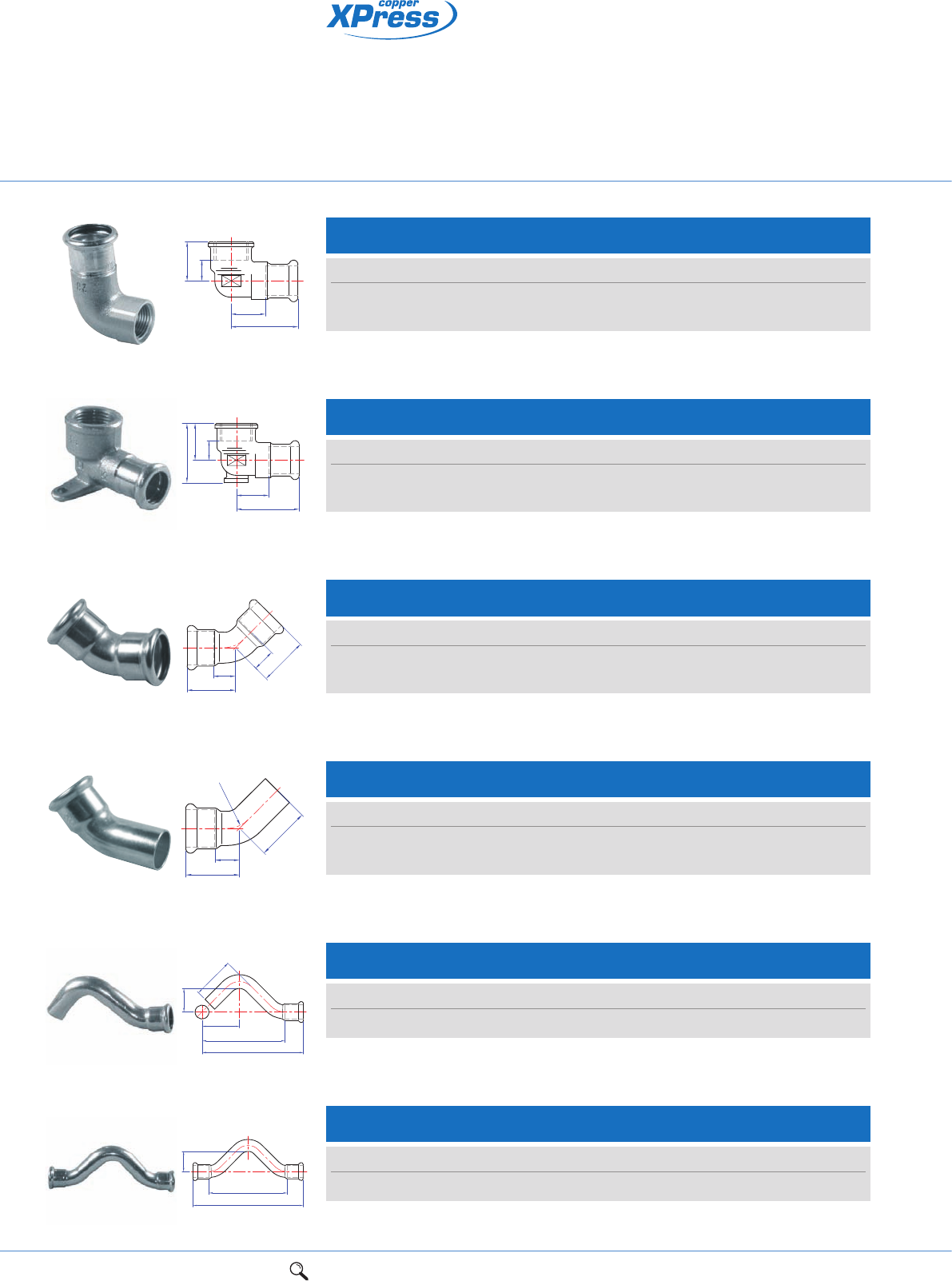
Stainless steel 316 system tube
Stainless steel fittings
SS610 Stainless steel 316 system tube
Size Finish Item code
15mm x 0.6mm x 6m Stainless steel 25010
18mm x 0.6mm x 6m Stainless steel 25012
22mm x 0.6mm x 6m Stainless steel 25014
28mm x 0.8mm x 6m Stainless steel 25016
35mm x 1.0mm x 6m Stainless steel 25018
42mm x 1.0mm x 6m Stainless steel 25020
54mm x 1.0mm x 6m Stainless steel 25022
Suitable for: XPress Stainless steel fittings and XPress Stainless Gas fittings.
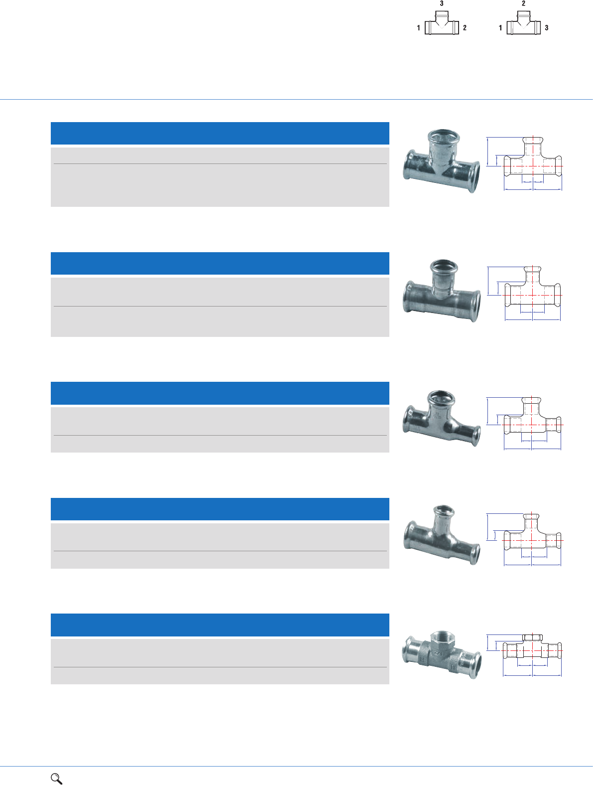
SS620 Stainless steel 316 system tube
Size Finish Item code
76mm x 2.0mm x 6m Stainless steel 25026
89mm x 2.0mm x 6m Stainless steel 25028
108mm x 2.0mm x 6m Stainless steel 25030
Suitable for: XPress Stainless steel fittings.
LBP 316 stainless steel
press-fit jointing system
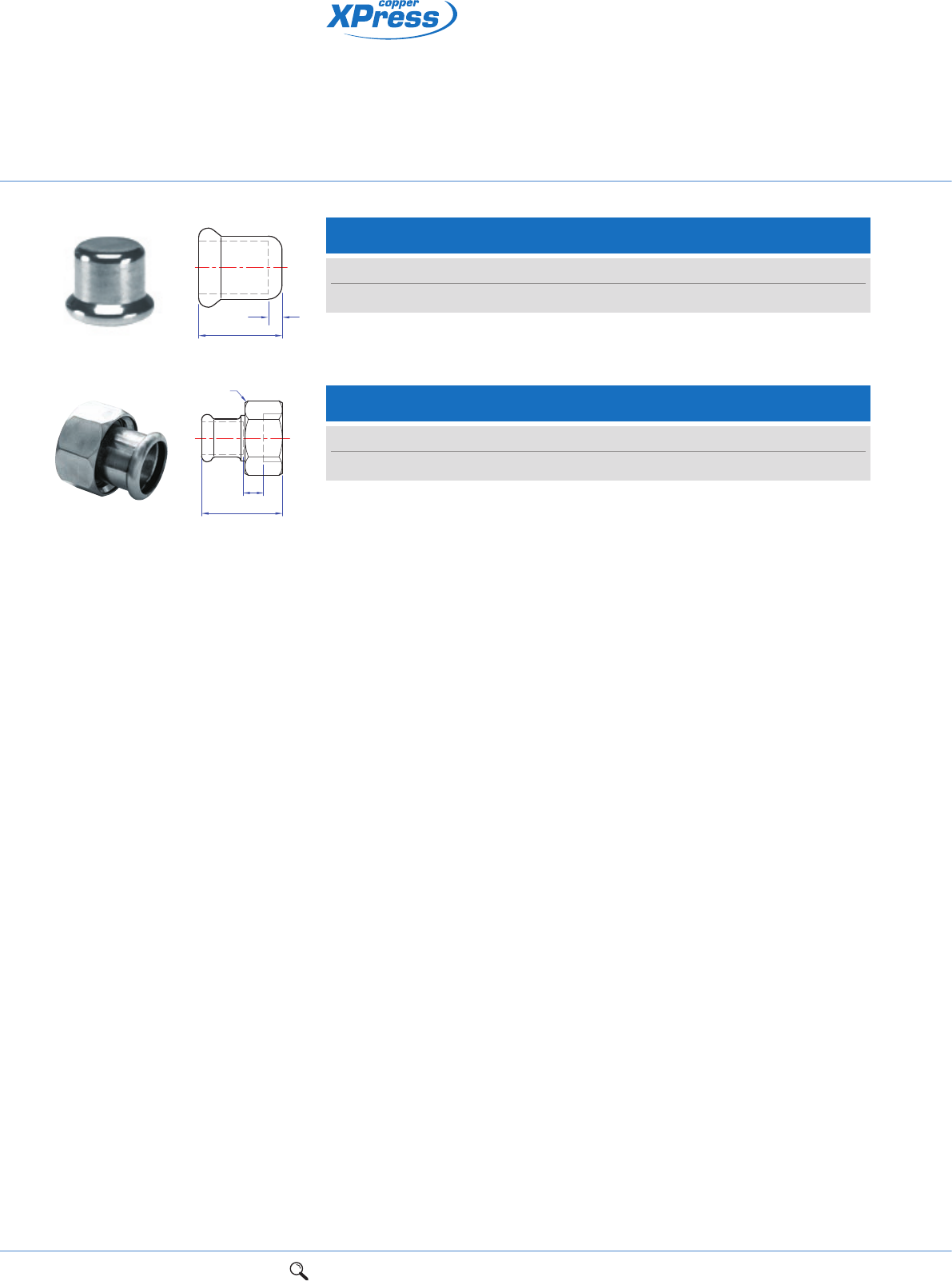
SS1FMF Composite flange
Size a Za e f g Holes Item code
42 91 61 110 150 18 4 11680
54 112 77 125 165 18 4 11681
76 111 56 145 185 18 4 20412
89 117 59 160 200 18 8 20413
108 136 60 180 220 18 8 20414
Connection: Press-fit x metric flange. Female press-fit socket with steel flange. Outer flange to
BS 4504 type 133, PN16 rated.
Za
a
g
d
e
f
30 1Range overview 2Product details 3Technical data 4Installation instructions 5Flow charts
LBP 316 stainless steel
press-fit jointing system
Za
a
SS1S Slip
Connection: Press-fit x press-fit (without tube stop).
SS2 Straight female connector
Size a Za Item code
15mm x 1/2" 38 8 11641
18mm x 1/2" 51 16 11643
18mm x 3/4" 38 6 11644
22mm x 1/2" 37 5 11646
22mm x 3/4" 40 16 11647
28mm x 1" 45 8 11648
35mm x 11/4" 50 24 11653
42mm x 11/2" 54 10 11654
54mm x 2" 63 11 11657
Connection: Press-fit x BSP parallel female thread.
Za
a
Size a Za Item code
15mm 80 34 11728
18mm 80 34 11730
22mm 84 25 11729
28mm 89 30 11731
35mm 99 30 11732
42mm 121 47 11733
54mm 138 40 11734
76mm 220 60 20428
89mm 201 20 20429
108mm 320 80 20430
Za
a
SS1 Straight coupling
Size a Za Item code
15mm 52 12 11694
18mm 53 13 11695
22mm 52 10 11696
28mm 57 12 11697
35mm 62 9 11698
42mm 74 15 11699
54mm 83 16 11700
76mm 126 15 20415
89mm 145 19 20416
108mm 171 17 20417
Connection: Press-fit x press-fit.
1Range overview 2Product details 3Technical data 4Installation instructions 5Flow charts 31
2
Leak Before Press (LBP) technology identifies joints that have not been
pressed correctly in sizes 15mm-54mm
Designed for potable water applications where water quality and hygiene are
crucial, particularly in the food, pharmaceutical and health care industries
Heat-free jointing provides time and cost saving benefits to
contractors/installers.
SS3 Straight male connector
Connection: Press-fit x BSP taper male thread.
Za
a
SS6 Reducer
Connection: Large end male for insertion into a fitting x press-fit.
Za
a
Size a Za Item code
18 x 15mm 59 39 11712
22 x 15mm 60 40 11713
22 x 18mm 61 42 11714
28 x 15mm 66 47 11715
28 x 18mm 63 43 11716
28 x 22mm 62 41 11717
35 x 18mm 77 57 11718
35 x 22mm 69 48 11719
35 x 28mm 68 44 11720
42 x 28mm 78 55 11722
42 x 35mm 80 54 11723
54 x 22mm 98 78 11724
54 x 28mm 96 73 11725
54 x 35mm 96 65 11726
54 x 42mm 96 64 11727
76 x 54mm 155 117 20422
89 x 54mm 167 129 20423
89 x 76mm 178 122 20424
108 x 54mm 184 145 20425
108 x 76mm 217 161 20426
108 x 89mm 206 144 20427
Size a Za Item code
15mm x 1/2" 38 18 11658
18mm x 1/2" 52 32 11660
18mm x 3/4" 55 32 11661
22mm x 3/4" 44 22 11664
28mm x 1" 48 25 11665
35mm x 11/4" 55 29 11670
42mm x 11/2" 60 30 11671
54mm x 2" 69 34 11674
32 1Range overview 2Product details 3Technical data 4Installation instructions 5Flow charts
SS12 Elbow
Size a Za Item code
15mm 41 21 11620
18mm 54 34 11621
22mm 61 40 11622
28mm 60 37 11623
35mm 71 45 11624
42mm 86 56 11625
54mm 106 70 11626
76mm 151 95 20406
89mm 175 112 20407
108mm 226 152 20408
Connection: Press-fit x press-fit.
SS12S Street elbow
Size a Za c Item code
15mm 42 21 54 11634
18mm 45 25 67 11635
22mm 52 30 62 11636
28mm 60 37 70 11637
35mm 73 45 81 11638
42mm 87 56 96 11639
54mm 106 71 113 11640
76mm 150 96 164 20409
89mm 280 216 318 20410
108mm 217 142 236 20411
Connection: Press-fit x male end for insertion into a fitting.
Za
Za
a
ar
Za
c
ar
SS13 Male elbow
Size a Za c Item code
15mm x 1/2" 40 20 28 11687
18mm x 1/2" 56 36 37 11688
22mm x 3/4" 45 25 38 11689
28mm x 1" 65 42 44 11690
35mm x 11/4" 52 26 51 11691
42mm x 11/2" 65 35 58 11692
54mm x 2" 90 55 60 11693
Connection: Press-fit x BSP taper male thread.
Za
c
ar
LBP 316 stainless steel
press-fit jointing system
1Range overview 2Product details 3Technical data 4Installation instructions 5Flow charts 33
2
SS14 Female elbow
Size a Za c Zc Item code
15mm x 1/2" 39 30 27 9 11682
22mm x 3/4" 45 24 33 27 11684
28mm x 1" 52 28 35 16 11685
35mm x 11/4" 59 33 42 20 11686
Connection: Press-fit x BSP parallel female thread.
Za
Zc
c
a
SS19S 30° bend
Size a b Item code
35mm 214 80 11795
42mm 272 99 11796
54mm 326 134 11797
Connection: Press-fit x BSP parallel female thread.
a
b
SS21 Obtuse elbow
Size a Za Item code
15mm 32 12 11604
18mm 37 17 11605
22mm 36 15 11606
28mm 41 18 11607
35mm 48 22 11608
42mm 56 26 11609
54mm 85 50 11610
76mm 100 43 20400
89mm 112 49 20401
108mm 138 60 20402
Connection: Press-fit x press-fit.
Za a
r
Za
a
SS21S Obtuse street elbow
Size a Za c Item code
15mm 32 16 40 11611
18mm 37 17 48 11612
22mm 36 15 43 11613
28mm 41 27 52 11614
35mm 48 28 53 11615
42mm 56 43 66 11616
54mm 67 32 73 11617
76mm 100 121 115 20403
89mm 107 42 130 20404
108mm 142 64 156 20405
Connection: Press-fit x male end for insertion into a fitting.
c
r
Za
a
34 1Range overview 2Product details 3Technical data 4Installation instructions 5Flow charts
SS24 Equal tee
Size a Za c Zc Item code
15mm 37 17 34 14 11735
18mm 39 19 35 19 11737
22mm 42 21 40 19 11740
28mm 46 23 47 24 11744
35mm 51 25 54 28 11749
42mm 59 29 60 30 11753
54mm 71 36 71 36 11758
76mm 127 72 119 64 20431
89mm 128 64 132 70 20432
108mm 155 77 163 85 20433
Connection: Press-fit on all ends.
ZaZa
Zc
c
aa
ZaZa
Zc
c
aa
SS25 Tee, reduced branch
Connection: Press-fit on all ends.
Size
UK European a Za c Zc Item code
18 x 18 x 15mm 18 x 15 x 18mm 39 19 35 15 11736
22 x 22 x 15mm 22 x 15 x 22mm 41 20 36 16 11738
22 x 22 x 18mm 22 x 18 x 22mm 42 21 38 18 11739
28 x 28 x 15mm 28 x 15 x 28mm 46 23 42 22 11741
28 x 28 x 18mm 28 x 18 x 28mm 46 23 42 22 11742
28 x 28 x 22mm 28 x 22 x 28mm 46 23 45 24 11743
35 x 35 x 15mm 35 x 15 x 35mm 50 24 45 25 11745
35 x 35 x 18mm 35 x 18 x 35mm 51 24 44 24 11746
35 x 35 x 22mm 35 x 22 x 35mm 50 24 47 26 11747
35 x 35 x 28mm 35 x 28 x 35mm 51 25 49 26 11748
42 x 42 x 22mm 42 x 22 x 42mm 59 29 50 29 11750
42 x 42 x 28mm 42 x 28 x 42mm 59 29 53 30 11751
42 x 42 x 35mm 42 x 35 x 42mm 59 29 57 31 11752
54 x 54 x 22mm 54 x 22 x 54mm 71 36 56 35 11754
54 x 54 x 28mm 54 x 28 x 54mm 71 36 59 36 11755
54 x 54 x 35mm 54 x 35 x 54mm 71 36 64 38 11756
54 x 54 x 42mm 54 x 42 x 54mm 71 36 68 38 11757
76 x 76 x 22mm 76 x 22 x 76mm 126 75 71 50 20434
76 x 76 x 28mm 76 x 28 x 76mm 126 75 74 51 20435
76 x 76 x 35mm 76 x 35 x 76mm 126 75 78 52 20436
76 x 76 x 42mm 76 x 42 x 76mm 126 75 84 54 20437
76 x 76 x 54mm 76 x 54 x 76mm 126 75 91 56 20438
89 x 89 x 22mm 89 x 22 x 89mm 128 64 78 57 20439
89 x 89 x 28mm 89 x 28 x 89mm 128 64 81 58 20440
89 x 89 x 35mm 89 x 35 x 89mm 128 64 85 59 20441
89 x 89 x 42mm 89 x 42 x 89mm 128 64 91 61 20442
89 x 89 x 54mm 89 x 54 x 89mm 128 64 97 62 20443
89 x 89 x 76mm 89 x 76 x 89mm 128 64 129 72 20444
108 x 108 x 22mm 108 x 22 x 108mm 155 77 87 66 20445
LBP 316 stainless steel
press-fit jointing system
Tee specification
See page 73
UK specification European specification
1Range overview 2Product details 3Technical data 4Installation instructions 5Flow charts 35
2
SS25 Tee, reduced branch cont.
Connection: Press-fit on all ends.
Size
UK European a Za c Zc Item code
108 x 108 x 28mm 108 x 28 x 108mm 155 77 90 67 20446
108 x 108 x 35mm 108 x 35 x 108mm 155 77 94 68 20447
108 x 108 x 42mm 108 x 42 x 108mm 155 77 100 70 20448
108 x 108 x 54mm 108 x 54 x 108mm 155 77 106 71 20449
108 x 108 x 76mm 108 x 76 x 108mm 155 77 140 85 20450
108 x 108 x 89mm 108 x 89 x 108mm 155 77 138 74 20451
ZaZa
Zc
c
aa
SS30 Female branch tee
Connection: Press-fit x BSP parallel female branch.
Size
UK European a Za c Zc Item code
15 x 15 x 1/2" 15 x 1/2" x 15 37 17 37 22 11759
18 x 18 x 1/2" 18 x 1/2" x 18 39 19 38 23 11760
18 x 18 x 3/4" 18 x 3/4" x 18 39 19 43 26 11761
22 x 22 x 1/2" 22 x 1/2" x 22 41 20 41 26 11762
22 x 22 x 3/4" 22 x 3/4" x 22 42 21 41 25 11763
28 x 28 x 1/2" 28 x 1/2" x 28 46 23 38 23 11765
28 x 28 x 3/4" 28 x 3/4" x 28 46 23 45 29 11766
35 x 35 x 1/2" 35 x 1/2" x 35 50 24 47 32 11767
35 x 35 x 3/4" 35 x 3/4" x 35 50 24 48 32 11768
42 x 42 x 1/2" 42 x 1/2" x 42 59 29 46 31 11769
42 x 42 x 3/4" 42 x 3/4" x 42 59 29 51 35 11770
54 x 54 x 1/2" 54 x 1/2" x 54 69 34 54 39 11771
54 x 54 x 3/4" 54 x 3/4" x 54 71 36 52 42 11773
54 x 54 x 2" 54 x 2" x 54 72 37 64 45 11772
76 x 76 x 3/4" 76 x 3/4" x 76 127 74 69 53 20452
76 x 76 x 2" 76 x 2" x 76 127 74 89 63 20453
89 x 89 x 3/4" 89 x 3/4" x 89 128 64 76 60 20454
89 x 89 x 2" 89 x 2" x 89 128 64 97 71 20455
108 x 108 x 3/4" 108 x 3/4" x 108 155 77 85 69 20456
108 x 108 x 2" 108 x 2" x 108 155 77 106 80 20457
ZaZa
Zc
c
aa
Tee specification
See page 73
UK specification European specification
36 1Range overview 2Product details 3Technical data 4Installation instructions 5Flow charts
a
SS61 Stop end
Size a Item code
15mm 37 11701
18mm 23 11702
22mm 41 11703
28mm 26 11704
35mm 30 11705
42mm 37 11706
54mm 41 11707
76mm 98 20418
89mm 100 20419
108mm 126 20420
Connection: Press-fit, for use on stainless steel tube.
SS69 Straight male union connector
Connection: Press-fit x BSP taper male thread.
Za
a
Size a Za Item code
15mm x 1/2" 62 42 11774
18mm x 1/2" 62 42 11776
22mm x 3/4" 69 48 11779
28mm x 1" 73 50 11781
35mm x 11/4" 78 52 11782
42mm x 11/2" 85 55 11783
54mm x 2" 100 65 11784
SS69F Straight female union connector
Connection: Press-fit x BSP parallel female thread.
Za
a
Size a Za Item code
15mm x 1/2" 57 22 11785
18mm x 1/2" 78 42 11787
22mm x 3/4" 63 26 11789
28mm x 1" 65 23 11791
35mm x 11/4" 73 25 11792
42mm x 11/2" 82 30 11793
54mm x 2" 91 30 11794
LBP 316 stainless steel
press-fit jointing system
1Range overview 2Product details 3Technical data 4Installation instructions 5Flow charts 37
2
LBP carbon steel
press-fit jointing system
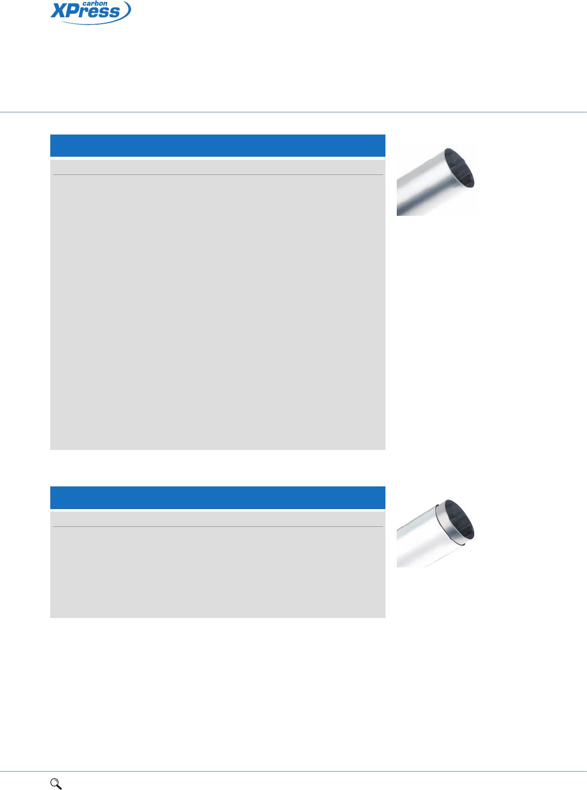
SC640 Galvanised carbon steel system tube
Suitable for: XPress Carbon press fittings
Size Finish Item code
15mm x 1.2mm x 3m Galvanised carbon steel 45080
18mm x 1.2mm x 3m Galvanised carbon steel 45081
22mm x 1.5mm x 3m Galvanised carbon steel 45082
28mm x 1.5mm x 3m Galvanised carbon steel 45083
35mm x 1.5mm x 3m Galvanised carbon steel 45084
42mm x 1.5mm x 3m Galvanised carbon steel 45085
54mm x 1.5mm x 3m Galvanised carbon steel 45086
67mm x 1.5mm x 3m Galvanised carbon steel 45090
76mm x 2.0mm x 3m Galvanised carbon steel 45087
89mm x 2.0mm x 3m Galvanised carbon steel 45088
108mm x 2mm x 3m Galvanised carbon steel 45089
15mm x 1.2mm x 6m Galvanised carbon steel 25080
18mm x 1.2mm x 6m Galvanised carbon steel 25081
22mm x 1.5mm x 6m Galvanised carbon steel 25082
28mm x 1.5mm x 6m Galvanised carbon steel 25083
35mm x 1.5mm x 6m Galvanised carbon steel 25084
42mm x 1.5mm x 6m Galvanised carbon steel 25085
54mm x 1.5mm x 6m Galvanised carbon steel 25086
67mm x 1.5mm x 6m Galvanised carbon steel 25090
76mm x 2.0mm x 6m Galvanised carbon steel 25087
89mm x 2.0mm x 6m Galvanised carbon steel 25088
108mm x 2.0mm x 6m Galvanised carbon steel 25089
SC660 Plastic coated galvanised carbon steel system tube
Suitable for: XPress Carbon press fittings
Size Finish Item code
15mm x 2.2mm x 6m Plastic coated carbon steel 25060
18mm x 2.2mm x 6m Plastic coated carbon steel 25061
22mm x 2.5mm x 6m Plastic coated carbon steel 25062
28mm x 2.5mm x 6m Plastic coated carbon steel 25063
35mm x 2.5mm x 6m Plastic coated carbon steel 25064
42mm x 2.5mm x 6m Plastic coated carbon steel 25065
54mm x 2.5mm x 6m Plastic coated carbon steel 25066
38 1Range overview 2Product details 3Technical data 4Installation instructions 5Flow charts
LBP carbon steel
press-fit jointing system
Za
a
SC1 Straight coupling
Connection: Press-fit x press-fit.
Size a Za Item code
15mm 53 13 20136
18mm 53 13 20137
22mm 55 13 20138
28mm 59 13 20139
35mm 65 13 20140
42mm 76 16 20141
54mm 86 16 20142
67mm 120 16 20662
76mm 141 31 20620
89mm 160 35 20621
108mm 193 46 20622
Za
a
g
d
e
f
SC1FMF Composite flange
Connection: Press-fit x metric flange. Female press-fit socket with carbon steel flange.
Outer flange to BS 4504, type 133, PN16 rated.
Size a Za d e f g Holes Item code
67 x DN65 (21/2") PN16 79 29 55 145 185 18 4 20685
76 x DN65 (21/2") PN16 126 74 - 145 185 18 4 20659
89 x DN80 (3") PN16 143 83 70 160 200 18 8 20660
108 x DN65 (4") PN16 168 79 - 180 220 18 8 20661
Za
a
SC1S Slip – Straight coupling slip pattern
Connection: Press-fit x press-fit (without tube stop).
Size a Za Item code
15mm 80 25 20144
18mm 80 25 20145
22mm 84 25 20146
28mm 91 30 20147
35mm 102 30 20148
42mm 120 40 20149
54mm 140 40 20150
67mm 120 20 20663
76mm 230 60 20623
89mm 255 70 20624
108mm 310 80 20625
1Range overview 2Product details 3Technical data 4Installation instructions 5Flow charts 39
2
Leak Before Press (LBP) technology identifies joints that have not been
pressed correctly in sizes 15mm-54mm
Designed for vented and unvented closed circuit heating
and chilled water applications
Heat-free jointing provides time and cost saving benefits to
contractors/installers.
Za
a
SC2 Straight female connector
Connection: Press-fit x BSP parallel female thread.
Size a Za Item code
15mm x 1/2" 41 6 20237
18mm x 1/2" 40 5 20238
18mm x 3/4" 43 6 20239
22mm x 3/4" 43 6 20240
28mm x 1" 49 3 20241
Za
a
SC3 Straight male connector
Connection: Press-fit x BSP taper male thread.
Size a Z Item code
15mm x 3/8" 35 15 20227
15mm x 1/2" 39 19 20228
18mm x 1/2" 39 19 20229
18mm x 3/4" 40 20 20230
22mm x 3/4" 44 23 20231
28mm x 1" 48 25 20232
35mm x 11/4" 55 29 20233
42mm x 11/2" 59 29 20234
54mm x 2" 69 34 20235
67mm x 21/2" 83 33 20664
Za
a
SC6 Reducer
Connection: Large male end for insertion into a fitting x press-fit.
Size a Za Item code
18 x 15mm 55 35 20213
22 x 15mm 58 38 20215
22 x 18mm 59 39 20216
28 x 15mm 65 45 20217
28 x 18mm 63 43 20218
28 x 22mm 63 42 20219
35 x 22mm 69 48 20220
35 x 28mm 70 47 20221
42 x 35mm 78 52 20222
54 x 22mm 98 77 20223
54 x 28mm 90 67 20224
54 x 35mm 90 64 20226
54 x 42mm 96 66 20225
67 x 28mm 142 119 20665
67 x 35mm 142 116 20666
67 x 42mm 142 112 20667
67 x 54mm 138 103 20668
76 x 54mm 143 106 20639
40 1Range overview 2Product details 3Technical data 4Installation instructions 5Flow charts
Za
Za
a
ar
SC12 Elbow
Connection: Press-fit x press-fit.
Size a Za r Item code
15mm 41 21 21 20155
18mm 45 25 25 20156
22mm 51 30 30 20157
28mm 60 37 37 20158
35mm 71 45 45 20159
42mm 86 56 56 20160
54mm 105 70 70 20161
67mm 165 115 80 20672
76mm 151 96 – 20626
89mm 174 114 – 20627
108mm 214 137 – 20628
SC6 Reducer cont.
Connection: Large male end for insertion into a fitting x press-fit.
Size a Za Item code
76 x 67mm 158 108 20669
89 x 54mm 161 125 20640
89 x 67mm 170 118 20670
89 x 76mm 157 102 20641
108 x 67mm 208 158 20671
108 x 76mm 199 144 20642
108 x 89mm 194 133 20643
Za
c
ar
SC12S Street elbow
Connection: Press-fit x male end for insertion into a fitting.
Size a Za c r Item code
15mm 41 21 48 21 20163
18mm 45 25 51 25 20164
22mm 51 30 58 30 20165
28mm 60 37 66 37 20166
35mm 71 45 77 45 20167
42mm 86 56 93 56 20168
54mm 105 70 111 70 20169
67mm 165 115 172 80 20673
76mm 151 96 167 - 20629
89mm 173 110 188 - 20630
108mm 214 137 235 - 20631
LBP carbon steel
press-fit jointing system
Za
a
1Range overview 2Product details 3Technical data 4Installation instructions 5Flow charts 41
2
Za
c
ar
SC13 Male elbow
Connection: Press-fit x male BSP taper thread.
Size a Za c Item code
15mm x 3/8" 41 21 45 20198
15mm x 1/2" 41 21 50 20199
18mm x 1/2" 45 25 58 20200
22mm x 3/4" 51 30 62 20201
28mm x 1" 60 37 75 20202
35mm x 11/4" 71 45 86 20206
42mm x 11/2" 86 56 96 20204
54mm x 2" 105 70 117 20205
Za a
r
Za
a
SC21 Obtuse elbow
Connection: Press-fit x press-fit.
Size a Za Item code
15mm 31 11 20170
18mm 32 12 20171
22mm 35 14 20172
28mm 40 17 20173
35mm 46 20 20174
42mm 56 26 20175
54mm 67 32 20176
67mm 119 69 20674
76mm 99 47 20632
89mm 113 53 20633
108mm 140 63 20634
SC21S Obtuse street elbow
Connection: Press-fit x male end for insertion into a fitting.
Size a Za c Item code
15mm 31 11 38 20177
18mm 32 12 38 20178
22mm 35 14 42 20179
28mm 40 17 46 20180
35mm 46 20 51 20181
42mm 56 26 63 20182
54mm 67 32 73 20183
67mm 119 69 126 20675
76mm 99 47 115 20635
89mm 109 46 128 20636
108mm 139 65 160 20637
c
r
Za
a
42 1Range overview 2Product details 3Technical data 4Installation instructions 5Flow charts
SC22S Partial crossover
Connection: Both ends male for insertion into a fitting.
Size a c d e Item code
15mm 155 54 45 31 20193
18mm 167 60 48 34 20194
22mm 177 65 54 37 20195
28mm 215 75 64 43 20196
a
e
d
c
SC24 Equal tee
Connection: Press-fit on all ends.
Size a Za c Zc Item code
15mm 35 15 44 24 20249
18mm 37 17 46 26 20250
22mm 40 19 49 28 20251
28mm 45 22 54 31 20252
35mm 51 25 60 34 20253
42mm 60 30 67 37 20254
54mm 71 36 78 43 20255
67mm 99 49 101 51 20676
76mm 115 60 111 56 20644
89mm 125 65 134 72 20645
108mm 155 79 153 77 20646
ZaZa
Zc
c
aa
ZaZa
Zc
c
aa
SC25 Tee, reduced branch
Connection: Press-fit on all ends.
Size
UK European a Za c Zc Item code
18 x 18 x 15mm 18 x 15 x 18mm 37 17 46 26 20258
22 x 22 x 15mm 22 x 15 x 22mm 40 19 48 28 20260
22 x 22 x 18mm 22 x 18 x 22mm 40 19 48 28 20261
28 x 28 x 15mm 28 x 15 x 28mm 45 22 51 31 20262
28 x 28 x 18mm 28 x 18 x 28mm 45 22 51 31 20263
28 x 28 x 22mm 28 x 22 x 28mm 45 22 52 31 20264
35 x 35 x 15mm 35 x 15 x 35mm 51 25 54 34 20265
35 x 35 x 18mm 35 x 18 x 35mm 51 25 54 34 20266
35 x 35 x 22mm 35 x 22 x 35mm 51 25 55 34 20267
35 x 35 x 28mm 35 x 28 x 35mm 51 25 57 34 20268
42 x 42 x 22mm 42 x 22 x 42mm 60 30 58 37 20269
42 x 42 x 28mm 42 x 28 x 42mm 60 30 60 37 20270
42 x 42 x 35mm 42 x 35 x 42mm 60 30 63 37 20271
54 x 54 x 22mm 54 x 22 x 54mm 71 36 64 43 20272
54 x 54 x 28mm 54 x 28 x 54mm 71 36 66 43 20273
LBP Carbon steel
press-fit jointing system
Tee specification
See page 73
UK specification European specification
1Range overview 2Product details 3Technical data 4Installation instructions 5Flow charts 43
2
ZaZa
Zc
c
aa
Tee specification
See page 73
UK specification European specification
SC28 Tee, both ends reduced
Connection: Press-fit on all ends.
Size
UK European a Za c Zc Item code
15 x 15 x 18mm 15 x 18 x 15mm 35 15 44 24 20709
15 x 15 x 22mm 15 x 22 x 15mm 33 15 39 18 20710
22 x 22 x 28mm 22 x 28 x 22mm 40 18 46 21 20712
ZaZa
Zc
c
aa
SC25 Tee, reduced branch cont.
Connection: Press-fit on all ends.
Size
UK European a Za c Zc Item code
54 x 54 x 35mm 54 x 35 x 54mm 71 36 69 43 20274
54 x 54 x 42mm 54 x 42 x 54mm 71 36 73 43 20275
67 x 67 x 28mm 67 x 28 x 67mm 99 49 70 46 20677
67 x 67 x 35mm 67 x 35 x 67mm 99 49 74 47 20678
67 x 67 x 42mm 67 x 42 x 67mm 99 49 80 48 20679
67 x 67 x 54mm 67 x 54 x 67mm 99 49 83 48 20680
76 x 76 x 22mm 76 x 22 x 76mm 126 70 71 48 20686
76 x 76 x 28mm 76 x 28 x 76mm 126 70 74 45 20687
76 x 76 x 35mm 76 x 35 x 76mm 126 70 80 53 20688
76 x 76 x 42mm 76 x 42 x 76mm 126 70 84 52 20689
76 x 76 x 54mm 76 x 54 x 76mm 115 60 84 46 20647
76 x 76 x 67mm 76 x 67 x 76mm 126 70 105 55 20681
89 x 89 x 22mm 89 x 22 x 89mm 126 63 79 50 20690
89 x 89 x 28mm 89 x 28 x 89mm 125 60 82 51 20691
89 x 89 x 35mm 89 x 35 x 89mm 126 63 86 58 20692
89 x 89 x 42mm 89 x 42 x 89mm 125 60 91 59 20693
89 x 89 x 54mm 89 x 54 x 89mm 126 63 99 61 20694
89 x 89 x 67mm 89 x 67 x 89mm 128 63 112 62 20682
89 x 89 x 76mm 89 x 76 x 89mm 129 68 117 62 20648
108 x 108 x 22mm 108 x 22 x 108mm 155 77 87 64 20695
108 x 108 x 28mm 108 x 28 x 108mm 155 77 90 66 20696
108 x 108 x 35mm 108 x 35 x 108mm 155 77 94 67 20697
108 x 108 x 42mm 108 x 42 x 108mm 155 77 100 68 20698
108 x 108 x 54mm 108 x 54 x 108mm 155 77 106 68 20699
108 x 108 x 76mm 108 x 76 x 108mm 155 77 133 78 20700
108 x 108 x 89mm 108 x 89 x 108mm 155 80 140 79 20649
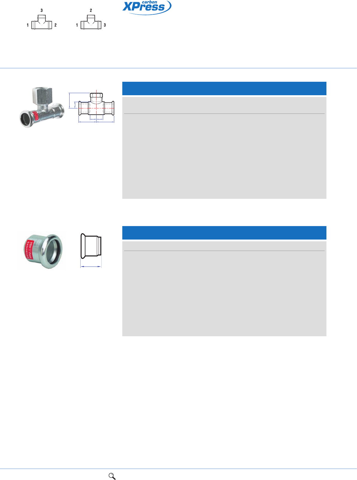
44 1Range overview 2Product details 3Technical data 4Installation instructions 5Flow charts
SC61 Stop end
Connection: Press-fit, for use on carbon steel tube.
Size a Za Item code
15mm 26 6 20295
18mm 26 6 20296
22mm 29 8 20297
28mm 32 9 20298
35mm 34 8 20299
42mm 43 13 20300
54mm 52 17 20301
67mm 84 34 20684
76mm 71 16 20656
89mm 80 19 20657
108mm 98 21 20658
a
LBP Carbon steel
press-fit jointing system
SC30 Female branch tee
Connection: Press-fit x BSP parallel female branch.
Size
UK European a Za c Zc Item code
15 x 15mm x 1/2" 15 x 1/2" x 15mm 35 15 36 16 20281
18 x 18mm x 1/2" 18 x 1/2" x 18mm 37 17 37 17 20282
22 x 22mm x 1/2" 22 x 1/2" x 22mm 40 19 39 20 20283
28 x 28mm x 1/2" 28 x 1/2" x 28mm 45 22 42 23 20284
35 x 35mm x 1/2" 35 x 1/2" x 35mm 51 25 45 27 20285
42 x 42mm x 1/2" 42 x 1/2" x 42mm 60 30 48 30 20286
54 x 54mm x 1/2" 54 x 1/2" x 54mm 71 36 54 35 20287
67 x 67mm x 3/4" 67 x 3/4" x 67mm 99 49 65 47 20683
76 x 76mm x 3/4" 76 x 3/4" x 76mm 115 60 71 39 20650
89 x 89mm x 3/4" 89 x 3/4" x 89mm 129 67 75 55 20651
108 x 108mm x 3/4" 108 x 3/4" x 108mm 155 79 86 68 20652
ZaZa
Zc
c
aa
Tee specification
See page 73
UK specification European specification
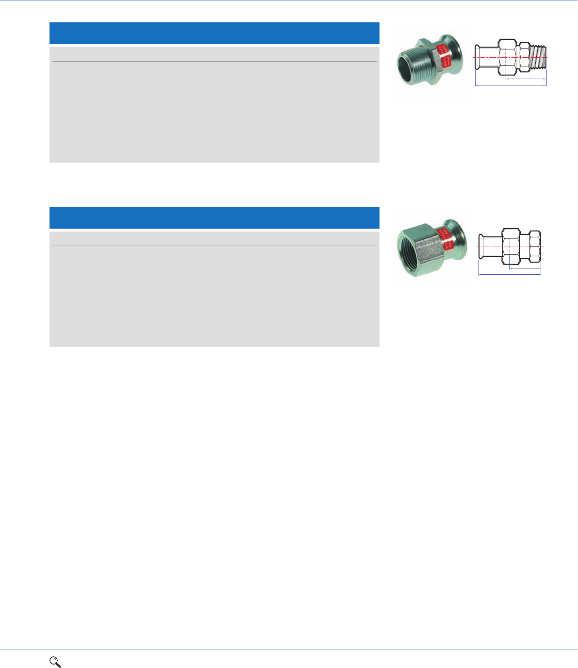
1Range overview 2Product details 3Technical data 4Installation instructions 5Flow charts 45
2
SC69 Straight male union connector
Connection: Press-fit x BSP taper male thread.
Size a Za Item code
15mm x 1/2" 64 44 20302
15mm x 3/4" 86 65 20303
18mm x 1/2" 64 44 20304
22mm x 3/4" 70 49 20307
28mm x 1" 75 52 20309
35mm x 11/4" 82 56 20310
42mm x 11/2" 88 58 20311
54mm x 2" 100 65 20312
Za
a
Za
a
SC69F Straight female union connector
Connection: Press-fit x BSP parallel female thread.
Size a Za Item code
15mm x 1/2" 59 20 20313
15mm x 3/4" 80 44 20314
18mm x 1/2" 59 20 20315
22mm x 3/4" 63 22 20317
28mm x 1" 65 19 20319
35mm x 11/4" 76 25 20320
42mm x 11/2" 83 28 20321
54mm x 2" 93 27 20322
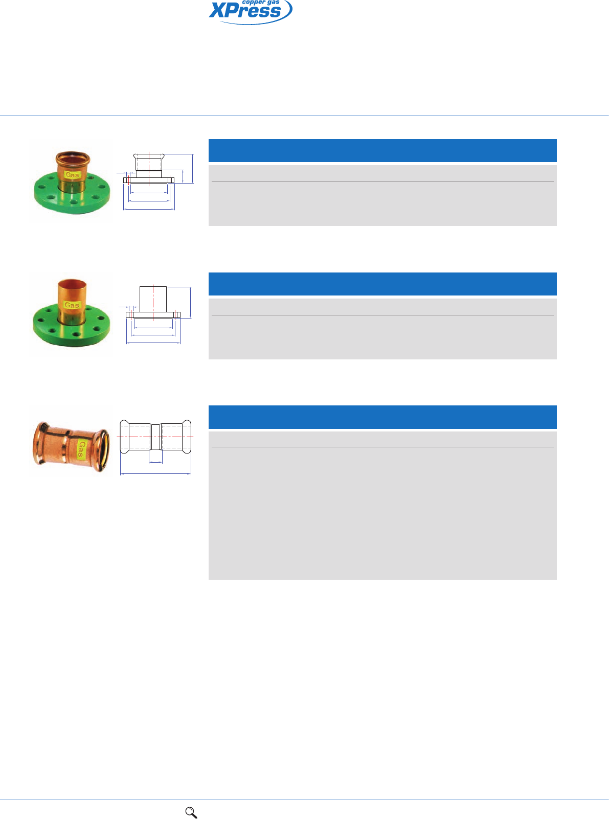
46 1Range overview 2Product details 3Technical data 4Installation instructions 5Flow charts
Copper press-fit fittings
for gas services
Za
a
g
d
e
f
SG1FMF/7510 Composite flange
Connection: Press-fit x metric flange. Female press-fit socket with carbon steel flange.
Outer flange to BS 4504, type 133, PN16 rated.
Size a Za d e f g Holes Item code
67 x DN65 (21/2") PN16 103 53 100 145 185 18 4 39281
76 x DN80 (3") PN16 103 53 115 160 200 18 8 39282
108 x DN100 (4") PN16 126 59 158 180 220 18 8 39284
ga
d
e
f
SG1FMM/7520 Composite flange
Connection: Press-fit x metric flange. Female press-fit socket with carbon steel flange.
Outer flange to BS 4504, type 133, PN16 rated.
Size a d e f g Holes Item code
67 x DN65 (21/2") PN16 112 100 145 185 18 4 39395
76 x DN80 (3") PN16 113 115 160 200 18 8 39396
108 x DN100 (4") PN16 141 158 180 220 18 8 39398
SG1/G7270 Straight coupling
Connection: Press-fit x press-fit.
Size a Z Item code
15mm 43 3 39700
18mm 44 4 39699
22mm 46 4 39701
28mm 50 4 39702
35mm 62 6 39703
42mm 71 7 39704
54mm 83 9 39705
67mm 110 10 39302
76mm 110 10 39303
108mm 205 71 39305
Z
a
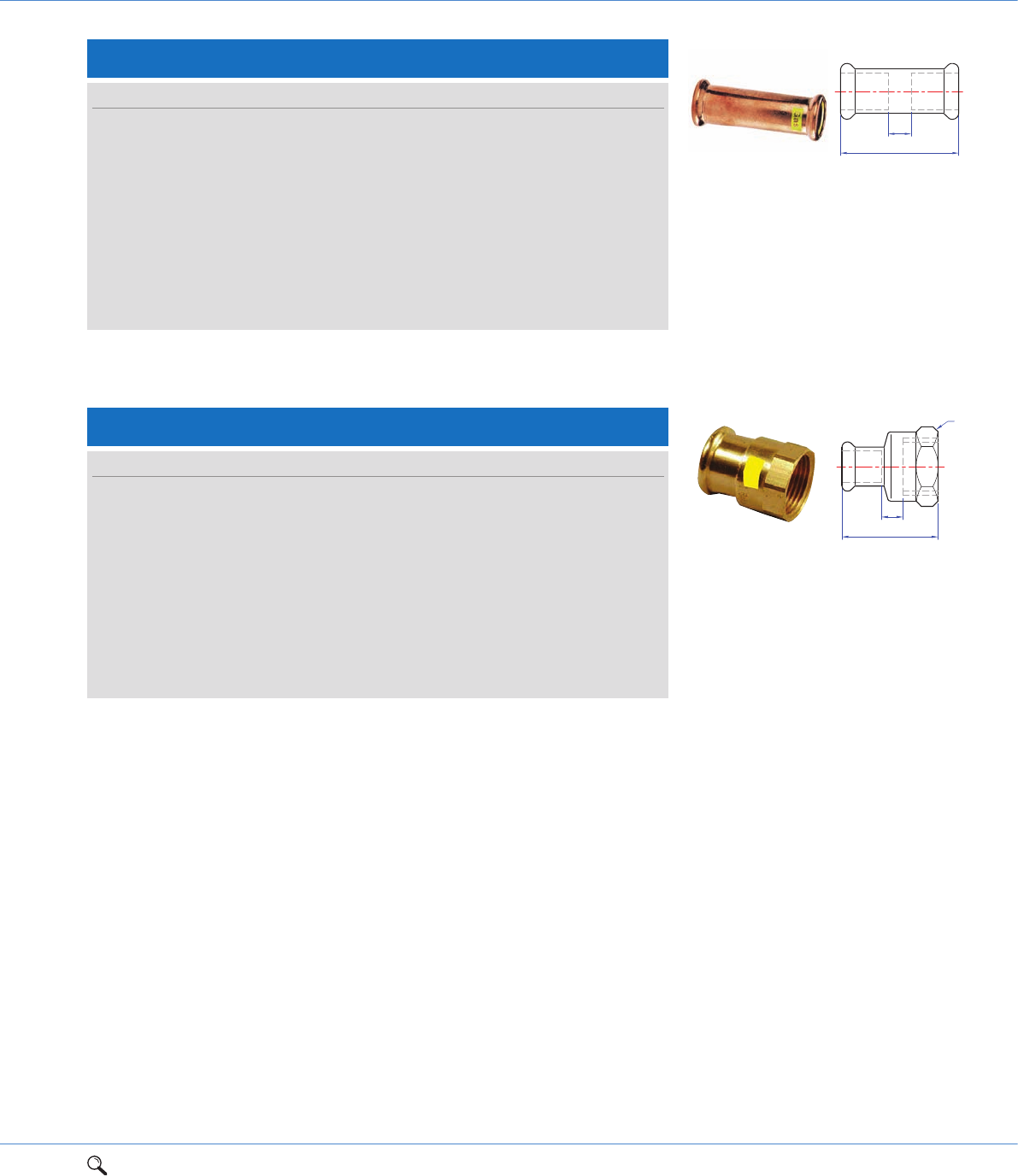
1Range overview 2Product details 3Technical data 4Installation instructions 5Flow charts 47
2
SG1S/G7270SG Slip – Straight coupling slip pattern
Connection: Press-fit x press-fit (without tube stop).
Size a Z max. Item code
15mm 80 40 39710
18mm 80 40 39709
22mm 84 42 39711
28mm 91 45 39712
35mm 99 50 39713
42mm 119 60 39714
54mm 141 70 39715
67mm 110 10 39307
76mm 110 10 39308
108mm 131 9 39310
Z
a
SG2/G6270G Straight female connector
Connection: Press-fit x BSP parallel female thread.
Size a S Za Item code
15mm x 1/2" 38 25 3 39720
15mm x 3/4" 39 30 3 39721
18mm x 1/2" 37 25 2 39716
18mm x 3/4" 39 30 3 39717
22mm x 1/2" 37 30 1 39722
22mm x 3/4" 39 30 2 39723
28mm x 1" 45 37 2 39724
35mm x 11/4" 50 46 2 39725
42mm x 11/2" 54 53 2 39726
54mm x 2" 63 65 2 39727
Za
a
S
Designed for internal and external above ground 2nd and
3rd family gas services - sizes 15mm-108mm
Designed specifically for use with copper tube to BS EN 1057
Heat-free jointing provides time and cost saving benefits to
contractors/installers.
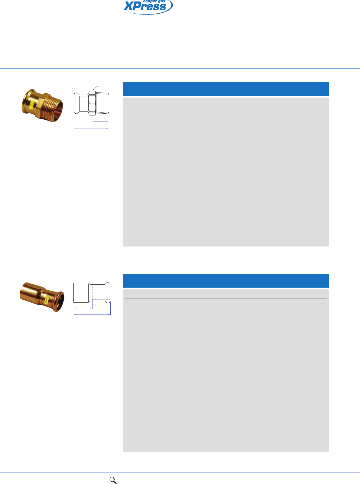
48 1Range overview 2Product details 3Technical data 4Installation instructions 5Flow charts
Copper press-fit fittings
for gas services
Za
a
S
SG3/G6243G Straight male connector
Connection: Press-fit x BSP taper male thread.
Size a S Za Item code
15mm x 1/2" 37 21 17 39730
15mm x 3/4" 39 25 19 39731
18mm x 1/2" 37 25 17 39728
18mm x 3/4" 39 25 19 39729
22mm x 1/2" 38 30 17 39732
22mm x 3/4" 40 30 21 39733
22mm x 1" 42 32 21 39734
28mm x 3/4" 43 36 20 39737
28mm x 1" 44 36 21 39735
28mm x 11/4" 48 40 25 39736
35mm x 1" 48 41 22 39738
35mm x 11/4" 50 41 24 39739
42mm x 11/4" 58 51 28 39741
42mm x 11/2" 58 51 28 39740
54mm x 2" 63 63 28 39742
67mm x 21/2" 93 80 50 39311
76mm x 3" 110 94 59 39313
108mm x 4" 132 117 50 39315
SG6/G7243 Reducer
Connection: Larger male end for insertion into a fitting x press-fit.
Size a Za Item code
18 x 15mm 47 25 39761
22 x 15mm 54 34 39750
22 x 18mm 48 26 39762
28 x 15mm 62 42 39751
28 x 18mm 59 37 39763
28 x 22mm 55 34 39752
35 x 22mm 68 47 39753
35 x 28mm 66 44 39754
42 x 22mm 76 55 39755
42 x 28mm 73 48 39756
42 x 35mm 75 48 39757
54 x 28mm 89 67 39760
54 x 35mm 90 63 39758
54 x 42mm 90 57 39759
67 x 28mm 109 86 39319
67 x 35mm 109 83 39320
67 x 42mm 110 80 39321
67 x 54mm 112 77 39322
76 x 35mm 113 87 39323
76 x 42mm 113 86 39324
Za
a
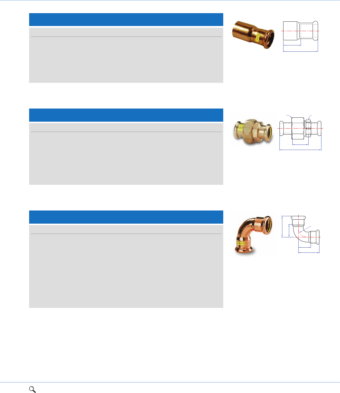
1Range overview 2Product details 3Technical data 4Installation instructions 5Flow charts 49
2
SG6/G7243 Reducer cont.
Connection: Larger male end for insertion into a fitting x press-fit.
Size a Za Item code
76 x 54mm 116 81 39325
76 x 67mm 126 78 39327
108 x 42mm 153 124 39334
108 x 54mm 156 120 39335
108 x 67mm 166 116 39337
108 x 76mm 162 112 39338
Za
a
SG12/G7002A Elbow
Connection: Press-fit x press-fit.
Size a Za r Item code
15mm 38 18 18 39780
18mm 42 22 22 39779
22mm 47 26 26 39781
28mm 57 34 34 39782
35mm 68 42 42 39783
42mm 80 50 50 39784
54mm 100 65 65 39785
67mm 132 87 80 39341
76mm 142 92 90 39342
108mm 201 135 161 39344
Za
Za
a
ar
Za
a
SS1
SG11/G6330 Union coupling
Size a Za S S1 Item code
15mm 61 21 34 28 39770
18mm 67 27 41 36 39906
22mm 66 24 41 36 39771
28mm 75 29 48 41 39772
35mm 82 30 58 50 39773
42mm 97 37 65 55 39774
54mm 103 33 80 70 39775
Connection: Press-fit x press-fit.
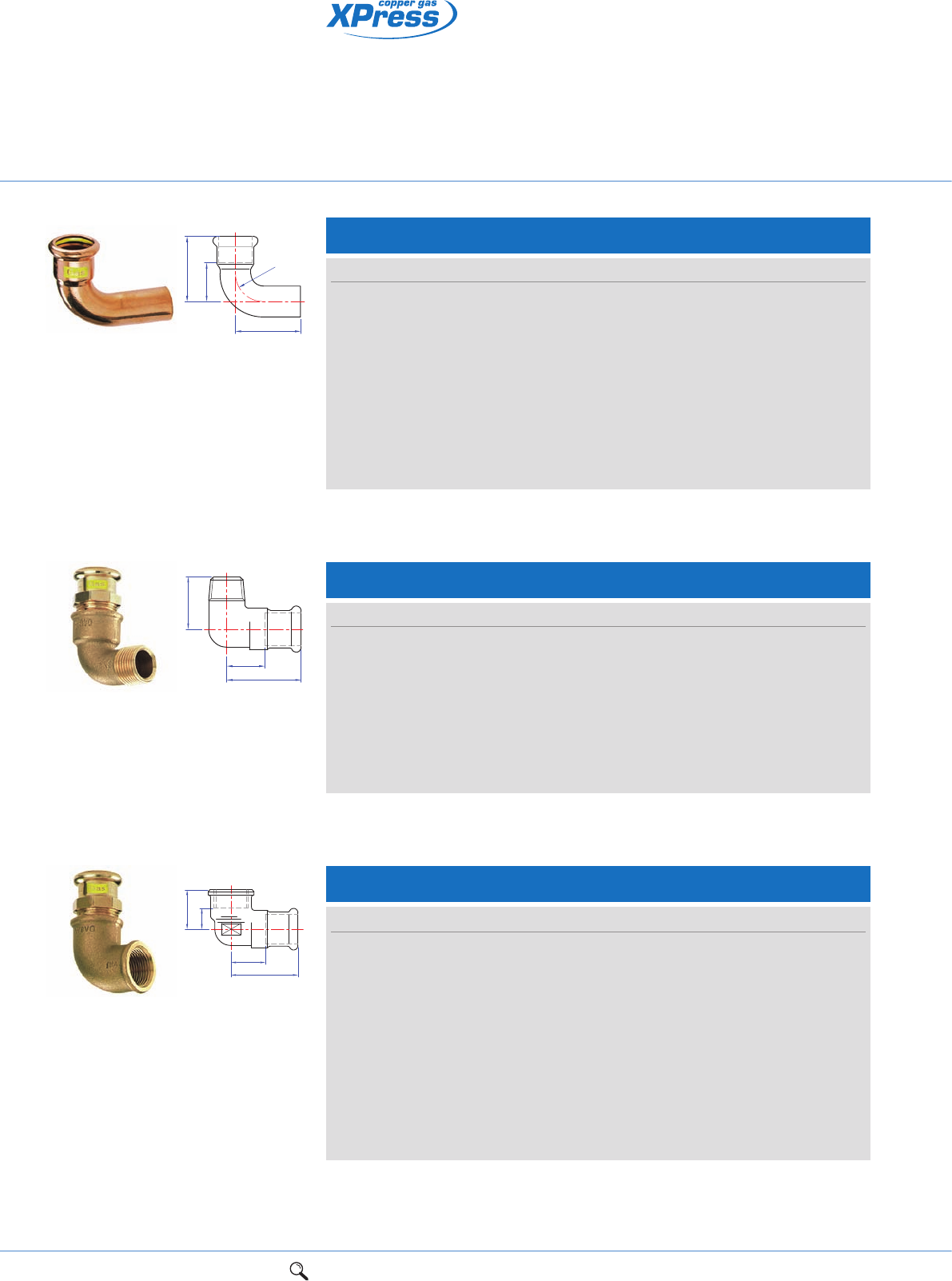
50 1Range overview 2Product details 3Technical data 4Installation instructions 5Flow charts
Copper press-fit fittings
for gas services
SG13/G6092G Male elbow
Connection: Press-fit x BSP taper male thread.
Size a c Za Item code
15mm x 1/2" 37 67 18 39800
18mm x 1/2" 64 34 35 39806
18mm x 3/4" 60 37 40 39807
22mm x 3/4" 48 79 27 39801
28mm x 1" 57 88 34 39802
35mm x 11/4" 80 59 54 39803
42mm x 11/2" 104 57 74 39804
54mm x 2" 118 80 83 39805
Za
c
a
SG14/G6090G Female elbow
Connection: Press-fit x parallel female thread.
Size a c Za Zc Item code
15mm x 1/2" 55 26 35 12 39810
15mm x 3/4" 63 29 43 22 39811
18mm x 1/2" 55 25 34 14 39808
18mm x 3/4" 61 29 41 22 39809
22mm x 1/2" 56 25 35 13 39813
22mm x 3/4" 62 29 25 14 39814
22mm x 1" 66 38 45 21 39812
28mm x 1" 73 37 50 20 39815
35mm x 11/4" 83 43 57 23 39816
42mm x 11/2" 88 46 59 27 39817
54mm x 2" 104 55 69 33 39818
Za
Zc
c
a
SG12S/G7001A Street elbow
Connection: Press-fit x male end for insertion into a fitting.
Size a c Za r Item code
15mm 36 50 16 18 39790
18mm 42 53 22 22 39789
22mm 47 58 27 26 39791
28mm 58 64 34 34 39792
35mm 69 82 44 42 39793
42mm 81 101 52 50 39794
54mm 100 120 66 65 39795
67mm 130 175 78 80 39346
76mm 147 190 98 90 39347
108mm 206 259 141 161 39349
Za
a
c
r
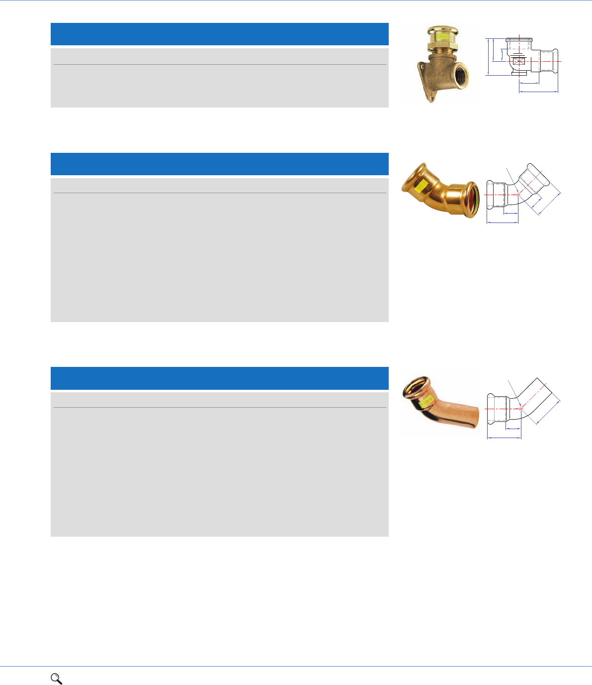
1Range overview 2Product details 3Technical data 4Installation instructions 5Flow charts 51
2
Za
Zc
a
c
d
SG15/G6471G Backplate elbow
Connection: Press-fit x BSP parallel female thread.
Size a d c Za Zc Item code
15mm x 1/2" 51 38 22 31 10 39820
18mm x 1/2" 51 38 22 31 10 39819
22mm x 3/4" 61 48 31 40 17 39821
Za
a
c
r
SG21S/G7040 Obtuse street elbow
Connection: Press-fit x male end for insertion into a fitting.
Size a c Za r Item code
15mm 28 37 8 18 39835
18mm 29 39 9 22 39833
22mm 32 44 11 26 39836
28mm 37 47 14 34 39837
35mm 43 58 17 42 39838
42mm 51 71 21 50 39839
54mm 62 82 27 65 39840
67mm 85 88 35 - 39356
76mm 95 146 35 - 39357
108mm 127 184 60 - 39359
Za a
r
Za
a
SG21/G7041 Obtuse elbow
Connection: Press-fit x press-fit.
Size a Za r Item code
15mm 28 8 18 39825
18mm 29 9 22 39823
22mm 33 14 26 39826
28mm 41 19 34 39827
35mm 47 22 42 39828
42mm 57 28 50 39829
54mm 68 32 65 39830
67mm 85 35 - 39351
76mm 91 45 - 39352
108mm 125 59 - 39354
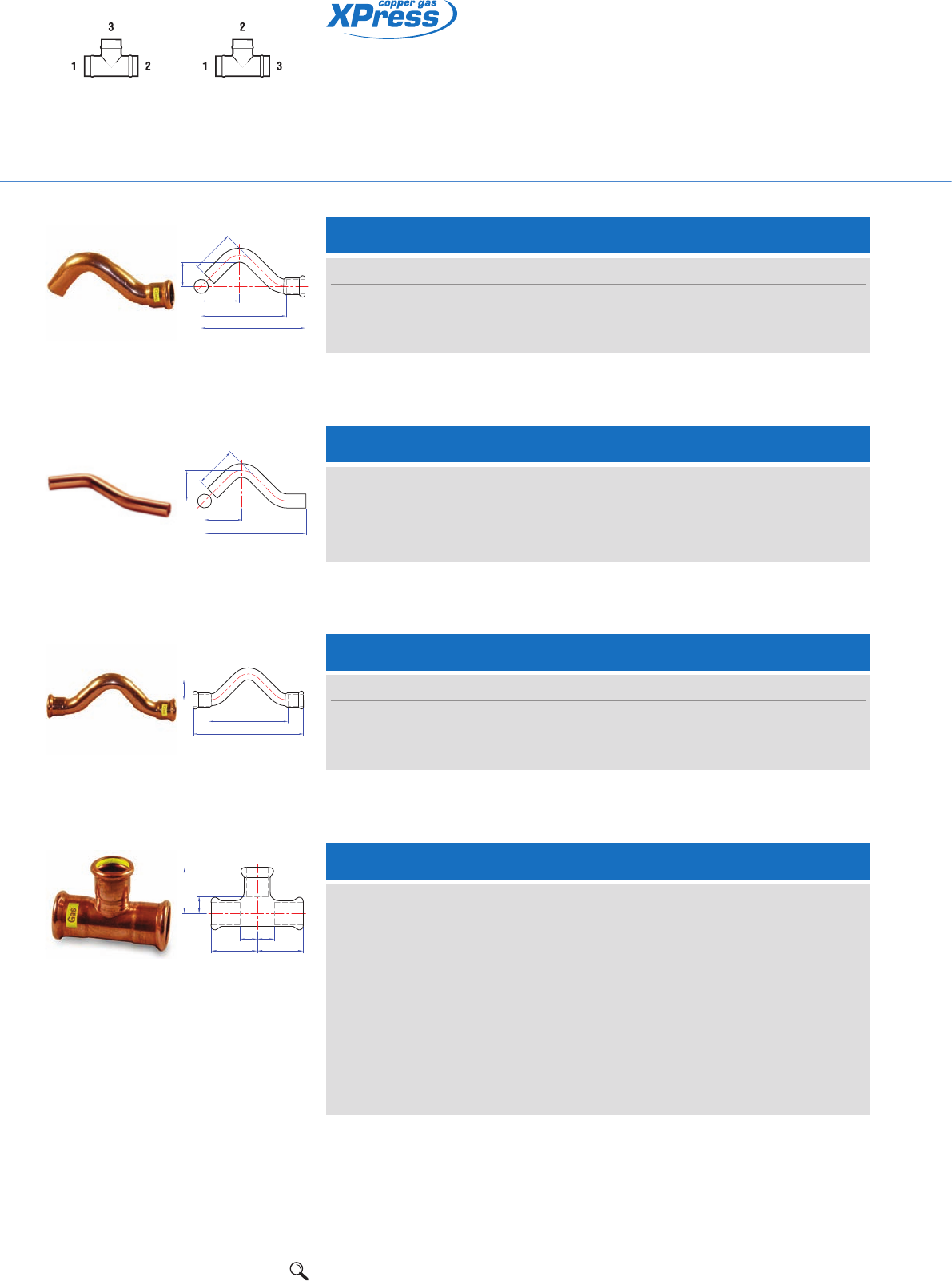
52 1Range overview 2Product details 3Technical data 4Installation instructions 5Flow charts
Copper press-fit fittings
for gas services
SG24/G7130 Equal tee
Connection: Press-fit on all ends.
Size a c Za Zc Item code
15mm 32 32 12 12 39850
18mm 34 34 14 14 39847
22mm 37 37 16 16 39851
28mm 42 42 19 19 39852
35mm 50 50 24 24 39853
42mm 57 57 27 27 39854
54mm 69 78 34 43 39855
67mm 95 107 45 58 39361
76mm 101 114 50 64 39362
108mm 159 159 92 92 39364
ZaZa
Zc
c
aa
Connection: Press-fit x press-fit.
Tee specification
See page 73
UK specification European specification
Za
a
c
SG23/G7085 Crossover
Size a Za c Order code
15mm 140 100 26 39844
18mm 151 111 27 39845
22mm 169 127 28 39846
Connection: Press-fit x male end for insertion into a fitting.
Za
a
c
d
e
SG22/G7086 Street crossover
Size a c d e Za Order code
15mm 110 41 46 26 90 39841
18mm 120 45 49 27 100 39842
22mm 135 50 55 28 114 39843
Connection: Both ends male for insertion into fitting.
SG22S/7087 Full crossover
Size a c d e Order code
15mm 157 56 46 30 38438
18mm 166 60 49 31 38434
22mm 178 65 55 33 38439
a
e
d
c
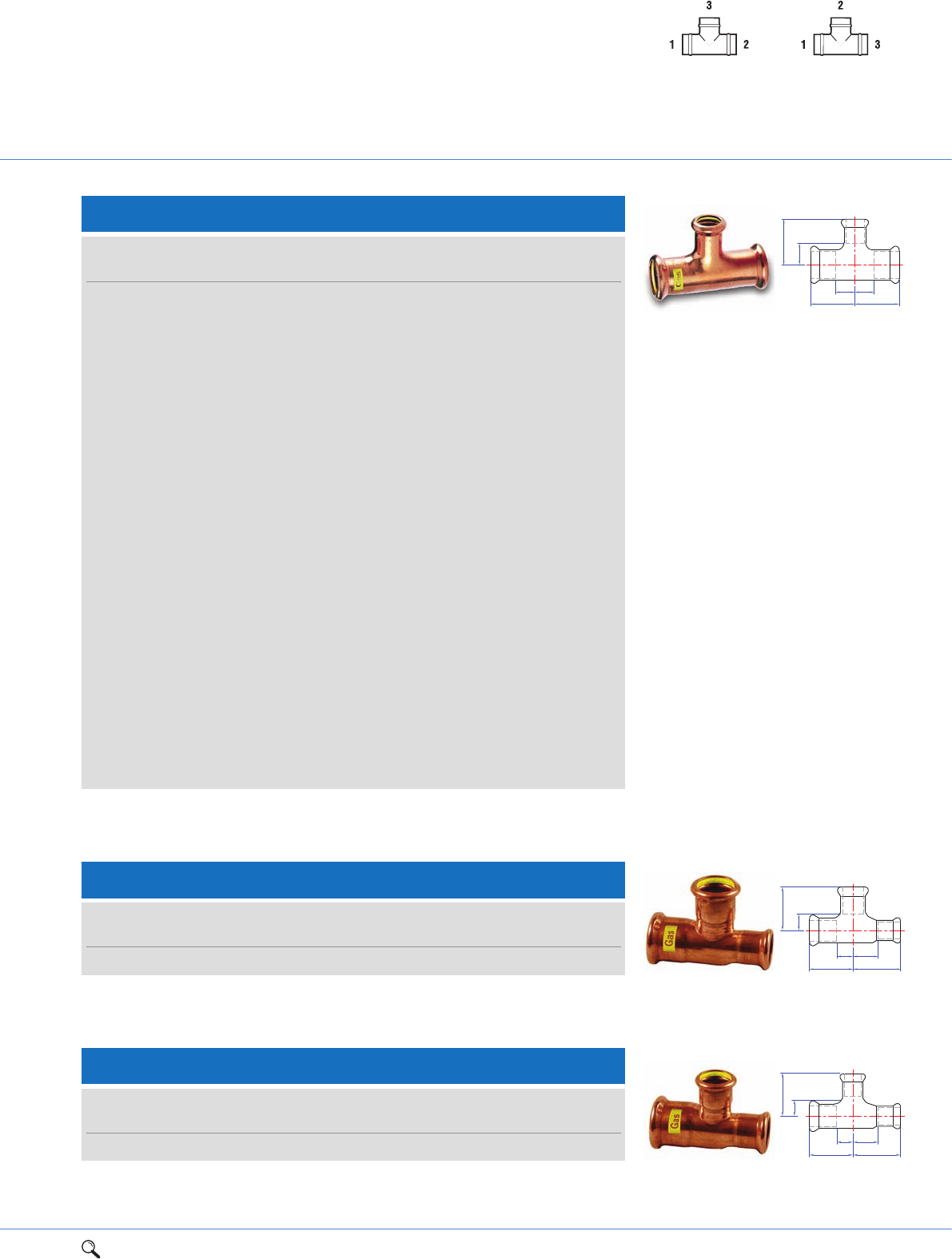
1Range overview 2Product details 3Technical data 4Installation instructions 5Flow charts 53
2
SG25 Tee, reduced branch
Connection: Press-fit on all ends.
Size
UK European a c Za Zc Item code
18 x 18 x 15mm 18 x 15 x 18mm 34 35 14 15 39856
22 x 22 x 15mm 22 x 15 x 22mm 37 38 16 18 39860
22 x 22 x 18mm 22 x 18 x 22mm 37 38 16 18 39868
28 x 28 x 15mm 28 x 15 x 28mm 42 41 19 21 39861
28 x 28 x 18mm 28 x 18 x 28mm 42 41 19 21 39857
28 x 28 x 22mm 28 x 22 x 28mm 42 41 19 20 39862
35 x 35 x 22mm 35 x 22 x 35mm 45 44 19 23 39863
35 x 35 x 28mm 35 x 28 x 35mm 50 44 24 21 39864
42 x 42 x 22mm 42 x 22 x 42mm 50 48 20 27 39869
42 x 42 x 28mm 42 x 28 x 42mm 56 49 26 26 39865
42 x 42 x 35mm 42 x 35 x 42mm 56 50 27 35 39866
54 x 54 x 22mm 54 x 22 x 54mm 60 54 25 33 39871
54 x 54 x 42mm 54 x 42 x 54mm 69 64 34 34 39867
67 x 67 x 28mm 67 x 28 x 67mm 76 67 26 43 39368
67 x 67 x 35mm 67 x 35 x 67mm 80 70 29 43 39369
67 x 67 x 42mm 67 x 42 x 67mm 82 76 32 41 39370
67 x 67 x 54mm 67 x 54 x 67mm 88 78 47 43 39371
76 x 76 x 22mm 76 x 22 x 76mm 73 73 22 50 39372
76 x 76 x 28mm 76 x 28 x 76mm 77 73 26 50 39373
76 x 76 x 35mm 76 x 35 x 76mm 80 78 30 53 39374
76 x 76 x 42mm 76 x 42 x 76mm 103 106 55 70 39375
76 x 76 x 54mm 76 x 54 x 76mm 108 104 60 72 39376
108 x 108 x 54mm 108 x 54 x 108mm 136 119 77 86 39382
108 x 108 x 67mm 108 x 67 x 108mm 117 136 46 91 39383
108 x 108 x 76mm 108 x 76 x 108mm 140 141 73 93 39384
Za
Za
Zc
aa
c
Tee specification
See page 73
UK specification European specification
SG26/G7130 Tee, one end reduced
Connection: Press-fit on all ends.
Size
UK European a c d Za Zc Zd Item code
22 x 15 x 22mm 22 x 22 x 15mm 37 37 46 16 16 26 39870
Zc
c
Za Zd
ad
SG27/G7130 Tee, one end and branch reduced
Connection: Press-fit on all ends.
Size
UK European a c d Za Zc Zd Item code
22 x 15 x 15mm 22 x 15 x 15mm 37 38 43 16 18 23 39875
c
Zc
Za
ad
Zd
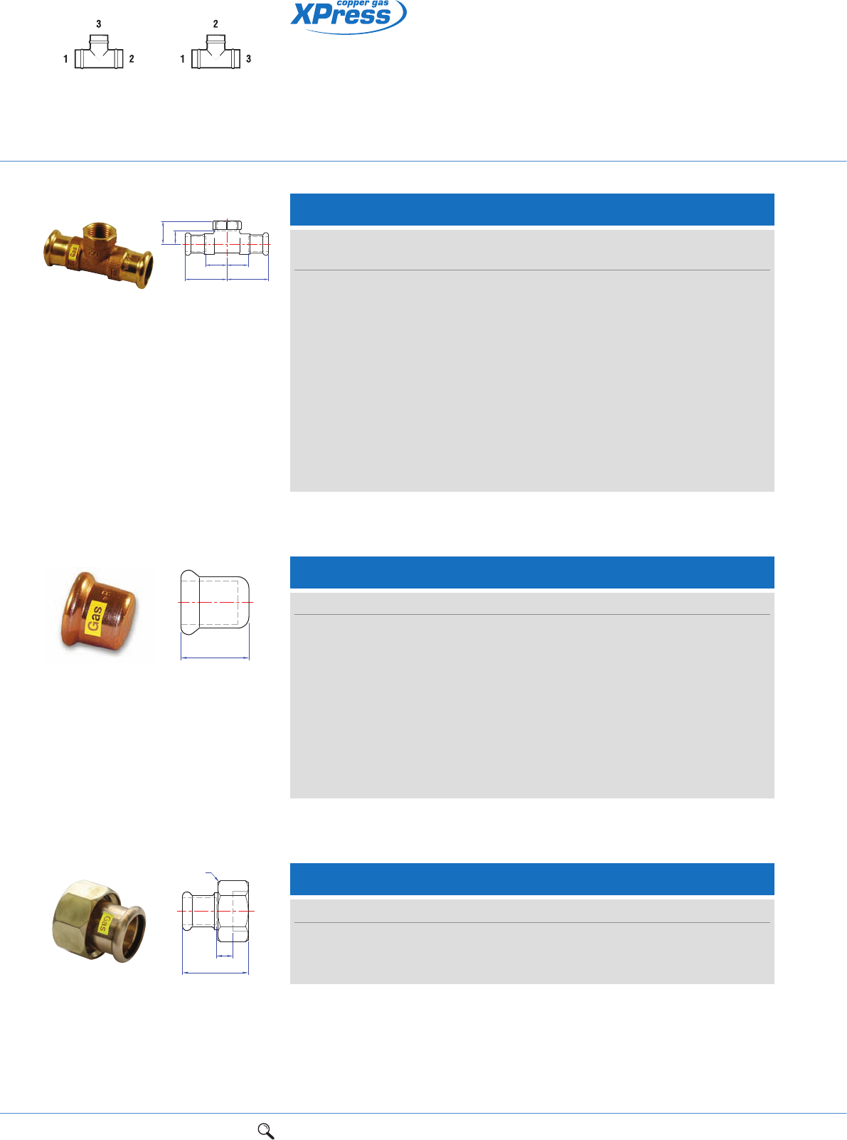
54 1Range overview 2Product details 3Technical data 4Installation instructions 5Flow charts
SG61/G7301 Stop end
Connection: Press-fit, for use on copper tube.
Connection: Press-fit x BSP parallel female branch.
Size a Item code
15mm 20 39880
18mm 20 39878
22mm 21 39881
28mm 23 39882
35mm 26 39883
42mm 30 39884
54mm 35 39885
67mm 50 39390
76mm 50 39391
108mm 67 39393
a
SG30/G6130G Female branch tee
Size
UK European a c Za Zc Order code
15 x 15mm x 1/2" 15 x 1/2" x 15mm 32 59 12 44 39890
18 x 18mm x 1/2" 18 x 1/2" x 18mm 34 62 14 47 39891
22 x 22mm x 1/2" 22 x 1/2" x 22mm 37 65 16 50 39892
22 x 22mm x 3/4" 22 x 3/4" x 22mm 37 67 16 51 39893
28 x 28mm x 1/2" 28 x 1/2" x 28mm 42 68 19 53 39894
28 x 28mm x 3/4" 28 x 3/4" x 28mm 42 69 19 52 39895
35 x 35mm x 1/2" 35 x 1/2" x 35mm 45 72 16 63 39896
35 x 35mm x 1" 35 x 1" x 35mm 50 34 24 19 39897
42 x 42mm x 1/2" 42 x 1/2" x 42mm 50 72 19 61 39898
54 x 54mm x 1/2" 54 x 1/2" x 54mm 60 79 26 70 39899
76 x 76mm x 1/2" 76 x 1/2" x 76mm 65 48 15 30 39386
108 x 108mm x 1/2" 108 x 1/2" x 108mm 82 65 15 53 39388
Za
a
Zc
c
Za
a
Connection: Press-fit x female union end.
SG68FF/G6360 Union
Za
S
a
Size a Za S Order code
15mm x 7/8" 29 9 34 39910
22mm x 11/8" 34 13 41 39911
28mm x 13/8" 41 18 48 39912
Copper press-fit fittings
for gas services
Tee specification
See page 73
UK specification European specification
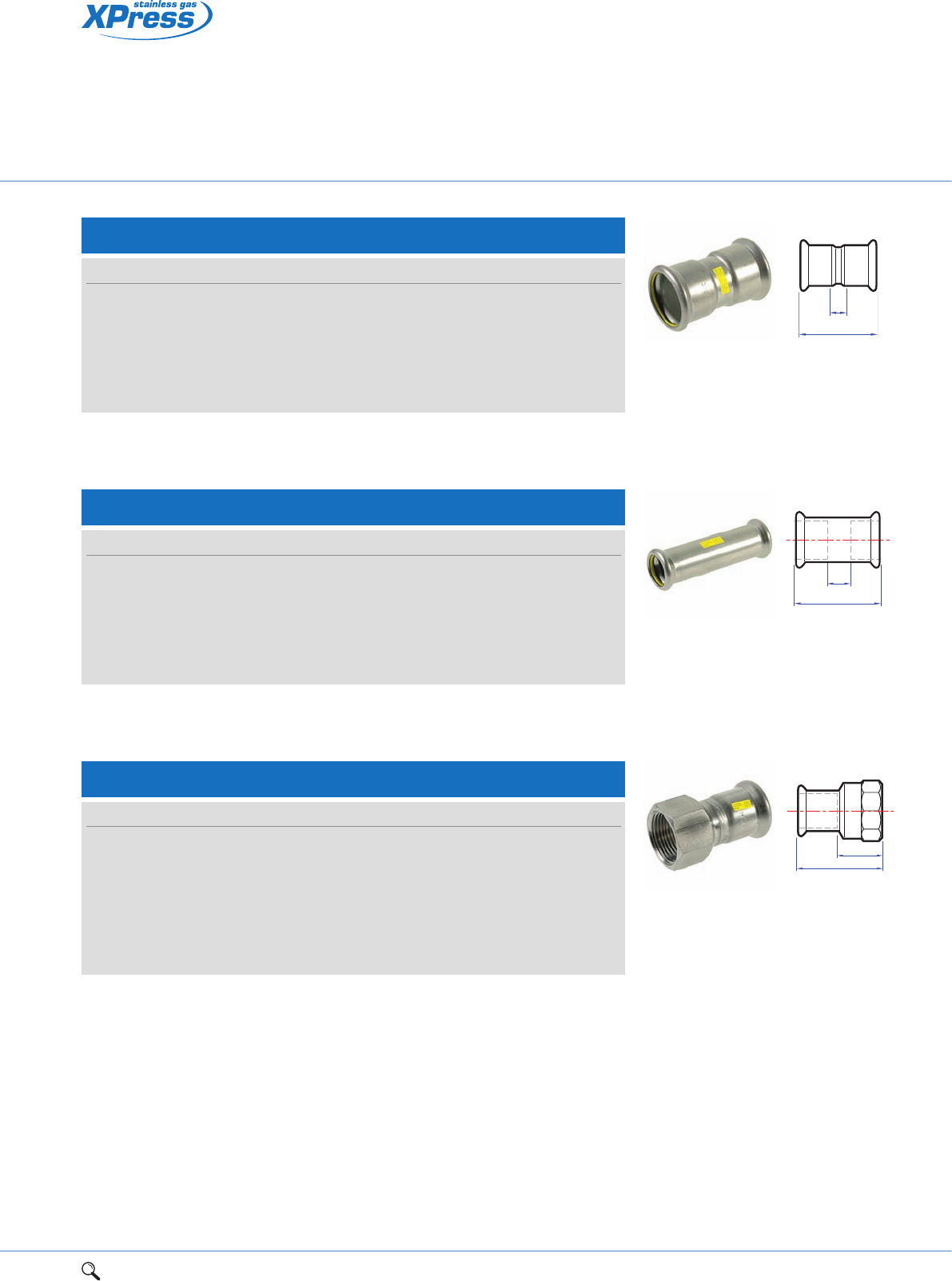
1Range overview 2Product details 3Technical data 4Installation instructions 5Flow charts 55
2
SSG1 Straight coupling
Connection: Press-fit x press-fit.
Size a Za Item code
15mm 52 12 11800
22mm 52 10 11802
28mm 57 12 11803
35mm 62 9 11804
42mm 74 15 11805
54mm 83 16 11806
Za
a
SSG1S Straight coupling slip pattern
Connection: Press-fit x press-fit (without tube stop).
Size a Za Item code
15mm 80 34 11808
22mm 84 25 11810
28mm 89 30 11811
35mm 99 30 11812
42mm 121 47 11813
54mm 138 40 11814
Za
a
SSG2 Straight female connector
Connection: Press-fit x BSP parallel female thread.
Size a Za Item code
15mm x 1/2" 38 8 11928
22mm x 1/2" 37 5 11930
22mm x 3/4" 40 16 11931
28mm x 1" 45 8 11933
35mm x 11/4" 50 24 11934
42mm x 11/2" 54 10 11936
54mm x 2" 63 11 11937
Za
a
Stainless steel press-fit
fittings for gas services
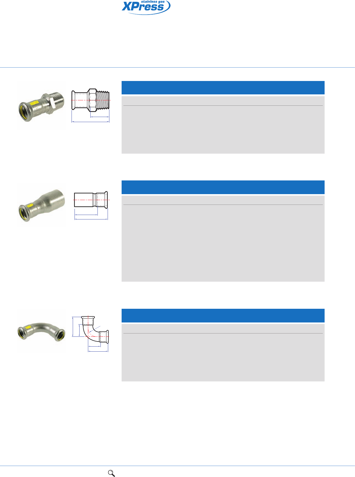
56 1Range overview 2Product details 3Technical data 4Installation instructions 5Flow charts
Stainless steel press-fit
fittings for gas services
SSG12 Elbow
Connection: Press-fit x press-fit.
Size a Za Item code
15mm 41 21 11816
22mm 61 40 11818
28mm 60 37 11819
35mm 71 45 11820
42mm 86 56 11821
54mm 106 70 11822
Za
Za
a
ar
SSG6 Reducer
Connection: Larger male end for insertion into a fitting x press-fit.
Size a Za Item code
22 x 15mm 60 40 11849
28 x 15mm 66 47 11851
28 x 22mm 62 41 11853
35 x 22mm 69 48 11854
35 x 28mm 68 44 11855
42 x 28mm 78 55 11856
42 x 35mm 80 54 11857
54 x 28mm 96 73 11858
54 x 35mm 96 65 11859
54 x 42mm 96 64 11860
Za
a
SSG3 Straight male connector
Connection: Press-fit x BSP taper male thread.
Size a Za Item code
15mm x 1/2" 38 18 11914
22mm x 3/4" 44 22 11917
28mm x 1" 48 25 11919
35mm x 11/4" 55 29 11920
42mm x 11/2" 60 30 11923
54mm x 2" 69 34 11924
Za
a
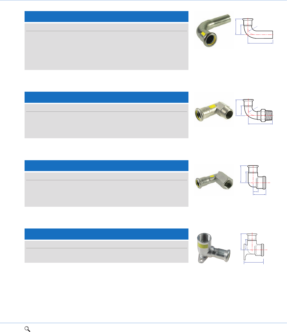
1Range overview 2Product details 3Technical data 4Installation instructions 5Flow charts 57
2
SSG12S Street elbow
Connection: Press-fit x male end for insertion into a fitting.
Size a Za c Item code
15mm 42 21 54 11824
22mm 52 30 62 11826
28mm 60 37 70 11827
35mm 73 45 81 11828
42mm 87 56 96 11829
54mm 106 71 113 11830
Za
c
ar
SSG13 Male elbow
Connection: Press-fit x BSP taper male thread.
Size a Za c Item code
15mm x 1/2" 40 20 28 11940
22mm x 3/4" 45 25 38 11942
28mm x 1" 65 42 44 11943
35mm x 11/4" 52 26 51 11944
Za
c
ar
Designed for use on above ground 2nd and 3rd family gas services
Designed to suit applications where high levels of hydrogen sulphide lead to
dust problems in copper pipelines
Designed for use with XPress stainless steel system tube.
SSG14 Female elbow
Connection: Press-fit x BSP parallel female thread.
Size a Za c Zc Item code
15mm x 1/2" 39 30 27 9 11950
22mm x 3/4" 45 24 33 27 11952
28mm x 1" 52 28 35 16 11953
35mm x 11/4" 59 33 42 20 11954
Za
Zc
c
a
SSG15 Backplate elbow
Connection: Press-fit x BSP parallel female thread.
Size a d Za Item code
15mm x 1/2" 49 43 29 11957
22mm x 3/4" 53 51 32 11959
Za
d
a
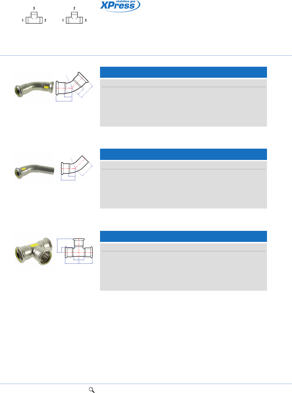
58 1Range overview 2Product details 3Technical data 4Installation instructions 5Flow charts
Stainless steel press-fit
fittings for gas services
SSG24 Equal tee
Connection: Press-fit on all ends.
Size a Za c Zc Item code
15mm 37 17 34 14 11865
22mm 42 21 40 19 11867
28mm 46 23 47 24 11868
35mm 51 25 54 28 11869
42mm 59 29 60 30 11870
54mm 71 36 71 36 11871
ZaZa
Zc
c
aa
Tee specification
See page 73
UK specification European specification
SSG21 Obtuse elbow
Connection: Press-fit x press-fit.
Size a Za Item code
15mm 32 12 11832
22mm 36 15 11834
28mm 41 18 11835
35mm 48 22 11836
42mm 56 26 11837
54mm 85 50 11838
Za a
r
Za
a
SSG21S Obtuse street elbow
Connection: Press-fit x male end for insertion into a fitting.
Size a Za c Item code
15mm 32 16 40 11840
22mm 36 15 43 11842
28mm 41 27 52 11843
35mm 48 28 53 11844
42mm 56 43 66 11845
54mm 67 32 73 11846
c
r
Za
a
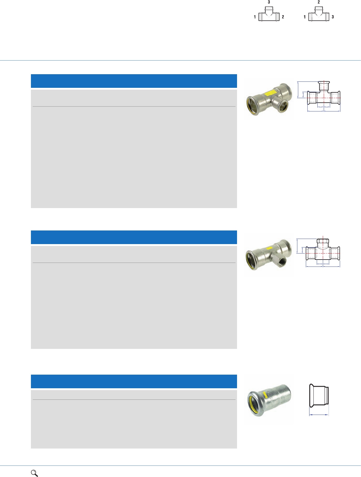
1Range overview 2Product details 3Technical data 4Installation instructions 5Flow charts 59
2
SSG25 Tee, reduced branch
Connection: Press-fit on all ends.
Size
UK European a Za c Zc Item code
22 x 22 x 15mm 22 x 15 x 22mm 41 20 36 16 11873
28 x 28 x 15mm 28 x 15 x 28mm 46 23 42 22 11875
28 x 28 x 22mm 28 x 22 x 28mm 46 23 45 24 11877
35 x 35 x 15mm 35 x 15 x 35mm 50 24 45 25 11878
35 x 35 x 22mm 35 x 22 x 35mm 50 24 47 26 11880
35 x 35 x 28mm 35 x 28 x 35mm 51 25 49 26 11881
42 x 42 x 22mm 42 x 22 x 42mm 59 29 50 29 11882
42 x 42 x 28mm 42 x 28 x 42mm 59 29 53 30 11883
42 x 42 x 35mm 42 x 35 x 42mm 59 29 57 31 11884
54 x 54 x 22mm 54 x 22 x 54mm 71 36 56 35 11885
54 x 54 x 28mm 54 x 28 x 54mm 71 36 59 36 11886
54 x 54 x 35mm 54 x 35 x 54mm 71 36 64 38 11887
54 x 54 x 42mm 54 x 42 x 54mm 71 36 68 38 11888
ZaZa
Zc
c
aa
SSG30 Female branch tee
Connection: Press-fit x BSP parallel female branch.
Size
UK European a Za c Zc Item code
15 x 15mm x 1/2" 15 x 1/2" x 15mm 37 17 37 22 11900
22 x 22mm x 1/2" 22 x 1/2" x 22mm 41 20 41 26 11903
22 x 22mm x 3/4" 22 x 3/4" x 22mm 42 21 41 25 11904
28 x 28mm x 1/2" 28 x 1/2" x 28mm 46 23 38 23 11905
28 x 28mm x 3/4" 28 x 3/4" x 28mm 46 23 45 29 11906
35 x 35mm x 1/2" 35 x 1/2" x 35mm 50 24 47 32 11907
35 x 35mm x 3/4" 35 x 3/4" x 35mm 50 24 48 32 11908
42 x 42mm x 1/2" 42 x 1/2" x 42mm 59 29 46 31 11909
54 x 54mm x 1/2" 54 x 1/2" x 54mm 69 34 54 39 11910
54 x 54mm x 3/4" 54 x 3/4" x 54mm 71 36 52 42 11911
54 x 54mm x 2" 54 x 2" x 54mm 72 37 64 45 11912
ZaZa
Zc
c
aa
SSG25 Reduced branch tee
Tee specification
See page 73
UK specification European specification
SSG61 Stop end
Connection: Press-fit.
Size a Item code
15mm 37 11980
22mm 41 11982
28mm 26 11983
35mm 30 11984
42mm 37 11985
54mm 41 11986
a
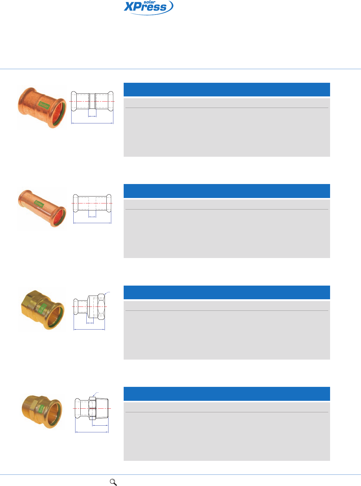
60 1Range overview 2Product details 3Technical data 4Installation instructions 5Flow charts
Connection: Press-fit x press-fit.
Connection: Press-fit x press-fit (without tube stop).
Connection: Press-fit x BSP parallel female thread.
Connection: Press-fit x BSP taper male thread.
SR1/7270 Straight coupling
Size L Z Item code
15mm 43 3 38010R
22mm 46 4 38020R
28mm 50 4 38030R
35mm 62 6 38032R
42mm 71 7 38034R
54mm 83 9 38035R
Z
L
SR1S/7270S Slip – Straight coupling slip pattern
Size L Z Item code
15mm 80 40 38044R
22mm 84 42 38045R
28mm 91 45 38046R
35mm 99 50 38047R
42mm 119 60 38048R
54mm 141 70 38049R
Z
L
SR2/6270G Straight female connector
Size L S Z Item code
15mm x 1/2" 38 25 3 38090R
22mm x 3/4" 39 30 2 38092R
28mm x 1" 45 37 2 38093R
35mm x 11/4" 50 46 1 38094R
42mm x 11/2" 54 53 2 38095R
54mm x 2" 63 65 2 38096R
Z
L
S
SR3/6243G Straight male connector
Size L S Z Item code
15mm x 1/2" 37 21 17 38114R
22mm x 3/4" 40 30 21 38116R
28mm x 1" 44 36 21 38118R
35mm x 11/4" 50 41 24 38119R
42mm x 11/2" 58 51 28 38120R
54mm x 2" 63 63 28 38121R
Z
S
L
LBP copper press-fit jointing
system for solar
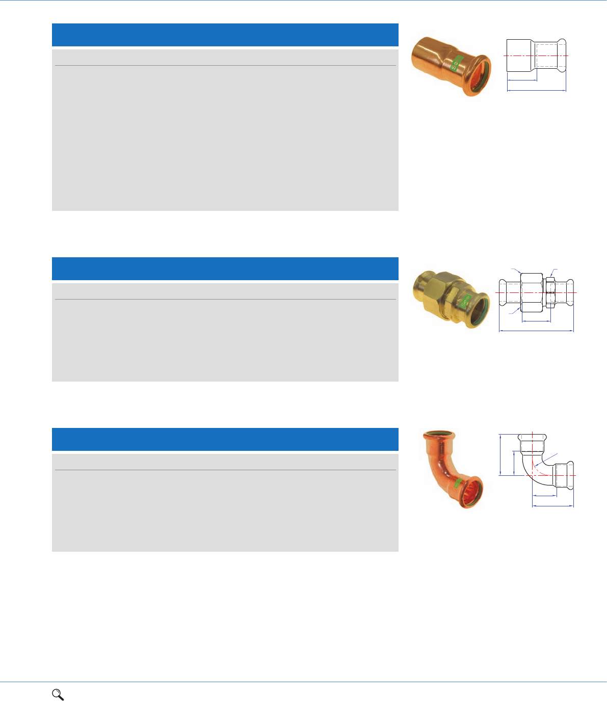
1Range overview 2Product details 3Technical data 4Installation instructions 5Flow charts 61
2
Connection: Larger male end for insertion into a fitting x press-fit.
Connection: Press-fit x press-fit.
Connection: Press-fit x press-fit.
SR11/6330 Union coupling
Size a G s S1 Za Item code
15mm 60 3/4" 30 25 20 38180R
22mm 68 1" 36 32 26 38181R
28mm 73 11/4" 46 40 27 38182R
35mm 71 11/2" 52 46 19 38183R
42mm 91 13/4" 58 51 31 38184R
54mm 98 23/8" 75 65 28 38185R
Za
G
SS1
a
Z
L
SR6/7243 Reducer
Size L Z Item code
22 x 15mm 54 34 38200R
28 x 15mm 62 42 38202R
28 x 22mm 56 34 38204R
35 x 22mm 68 47 38207R
35 x 28mm 66 44 38208R
42 x 22mm 76 55 38210R
42 x 28mm 73 48 38211R
42 x 35mm 75 48 38212R
54 x 28mm 89 67 38215R
54 x 35mm 90 63 38216R
54 x 42mm 89 58 38217R
SR12/7002A Elbow
Size a Z r Item code
15mm 38 17 17 38280R
22mm 47 26 26 38290R
28mm 56 34 34 38300R
35mm 68 42 42 38302R
42mm 80 50 50 38304R
54mm 100 65 65 38306R
r
Z
Z
a
a
Leak Before Press (LBP) technology identifies joints that have not been
pressed correctly (15mm-54mm)
Designed for solar installations where extreme temperatures operate
as low as -35ºC to a maximum 200ºC
Heat-free jointing provides time and cost saving benefits to
contractors/installers.
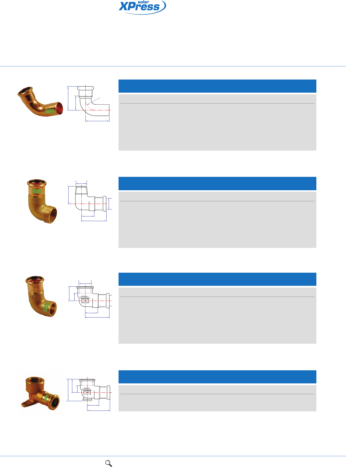
62 1Range overview 2Product details 3Technical data 4Installation instructions 5Flow charts
LBP copper press-fit jointing
system for solar
a
c
r
Za
SR12S/7001A Street elbow
Size a c r Za Item code
15mm 36 50 18 16 38318R
22mm 47 58 26 27 38320R
28mm 58 64 34 34 38322R
35mm 69 82 42 44 38324R
42mm 81 101 50 52 38325R
54mm 100 120 65 66 38326R
Connection: Press-fit x male end for insertion into a fitting.
SR13/6092G Male elbow
Size a c Za Item code
15mm x 1/2" 38 34 19 38333R
22mm x 3/4" 49 45 28 38334R
28mm x 1" 58 53 36 38335R
35mm x 11/4" 55 47 30 38336R
42mm x 11/2" 62 51 32 38337R
54mm x 2" 70 63 35 38338R
Connection: Press-fit x BSP taper male thread.
D
R
Z
L
L1
SR14/6090G Female elbow
Size a c Za Zc Item code
15mm x 1/2" 41 24 20 15 38351R
22mm x 3/4" 45 27 24 11 38353R
28mm x 1" 51 33 28 14 38354R
35mm x 11/4" 55 45 29 21 38355R
42mm x 11/2" 85 45 57 26 38356R
54mm x 2" 104 54 72 33 38357R
Connection: Press-fit x BSP parallel female thread.
L1
Z1
Z
L
Rp
SR15/6472G Backplate elbow
Size a c d Za Zc Item code
15mm x 1/2" 41 23 36 21 8 38400R
22mm x 3/4" 45 27 45 24 11 38401R
Connection: Press-fit x BSP parallel female thread.
d
c
Zc
Za
a
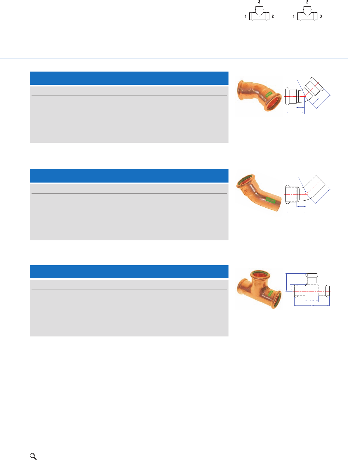
1Range overview 2Product details 3Technical data 4Installation instructions 5Flow charts 63
2
SR21S/7040 Obtuse street elbow
Size a c Za Item code
15mm 28 37 8 38404R
22mm 32 44 11 38405R
28mm 7 47 14 38406R
35mm 43 58 17 38407R
42mm 51 71 21 38408R
54mm 62 82 27 38409R
r
c
a
Za
SR21/7041 Obtuse elbow
Size a Z r Item code
15mm 28 8 18 38410R
22mm 31 12 26 38412R
28mm 41 19 34 38414R
35mm 47 22 42 38416R
42mm 57 28 50 38417R
54mm 68 32 65 38418R
Z
Z
a
a
r
S24 Equal tee
Size a c Za Zc Item code
15mm 32 32 12 12 38450R
22mm 37 37 16 16 38460R
28mm 42 42 19 19 38462R
35mm 50 50 24 24 38464R
42mm 58 58 28 28 38466R
54mm 69 69 34 34 38467R
SR24/7130 Equal tee
c
Zc
Za
aa
Za
Connection: Press-fit x press-fit.
Connection: Press-fit x male end for insertion into a fitting.
Connection: Press-fit on all ends.
Tee specification
See page 73
UK specification European specification
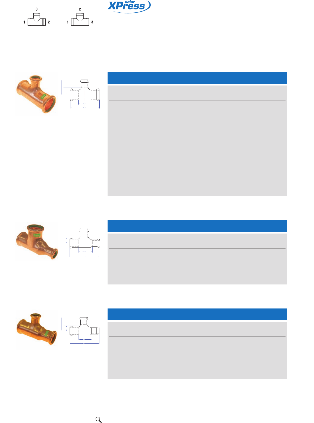
64 1Range overview 2Product details 3Technical data 4Installation instructions 5Flow charts
LBP copper press-fit jointing
system for solar
Tee specification
See page 73
UK specification European specification
SR25/7130 Tee, reduced branch
c
Zc
Za Za
aa
Size
UK European a c Za Zc Item code
22 x 22 x 15mm 22 x 15 x 22mm 37 38 16 18 38490R
28 x 28 x 15mm 28 x 15 x 28mm 42 41 19 21 38492R
28 x 28 x 22mm 28 x 22 x 28mm 42 41 19 20 38494R
35 x 35 x 15mm 35 x 15 x 35mm 45 44 19 24 38496R
35 x 35 x 22mm 35 x 22 x 35mm 45 45 19 24 38497R
35 x 35 x 28mm 35 x 28 x 35mm 50 44 24 21 38498R
42 x 42 x 15mm 42 x 15 x 42mm 50 48 20 28 38499R
42 x 42 x 22mm 42 x 22 x 42mm 50 48 20 27 38500R
42 x 42 x 28mm 42 x 28 x 42mm 56 49 26 26 38501R
42 x 42 x 35mm 42 x 35 x 42mm 56 50 26 24 38502R
54 x 54 x 22mm 54 x 22 x 54mm 60 54 25 33 38504R
54 x 54 x 28mm 54 x 28 x 54mm 60 55 25 32 38505R
54 x 54 x 35mm 54 x 35 x 54mm 61 55 24 29 38506R
54 x 54 x 42mm 54 x 42 x 54mm 69 64 34 34 38507R
SR26/7130 Tee, one end reduced
c
Zc
Za
ad
Zd
Size
UK European a c d Za Zc Zd Item code
22 x 15 x 22mm 22 x 22 x 15mm 37 37 46 16 16 26 38510R
28 x 15 x 28mm 28 x 28 x 15mm 42 42 55 19 19 35 38512R
28 x 22 x 28mm 28 x 28 x 22mm 42 42 52 19 19 31 38514R
35 x 22 x 35mm 35 x 35 x 22mm 51 50 72 25 24 51 38517R
35 x 28 x 35mm 35 x 35 x 28mm 51 50 67 25 24 41 38518R
SR27/7130 Tee, one end and branch reduced
c
Zc
Za
ad
Zd
Size
UK European a c d Za Zc Zd Item code
22 x 15 x 15mm 22 x 15 x 15mm 37 44 43 16 18 23 38530R
28 x 22 x 22mm 28 x 22 x 22mm 42 41 49 19 20 28 38532R
28 x 22 x 15mm 28 x 15 x 22mm 42 41 53 19 20 33 38536R
35 x 22 x 22mm 35 x 22 x 22mm 51 44 67 25 23 45 38539R
35 x 28 x 22mm 35 x 22 x 28mm 51 44 63 25 23 40 38541R
35 x 28 x 28mm 35 x 28 x 28mm 51 44 67 25 21 44 38542R
Connection: Press-fit on all ends.
Connection: Press-fit on all ends.
Connection: Press-fit on all ends.
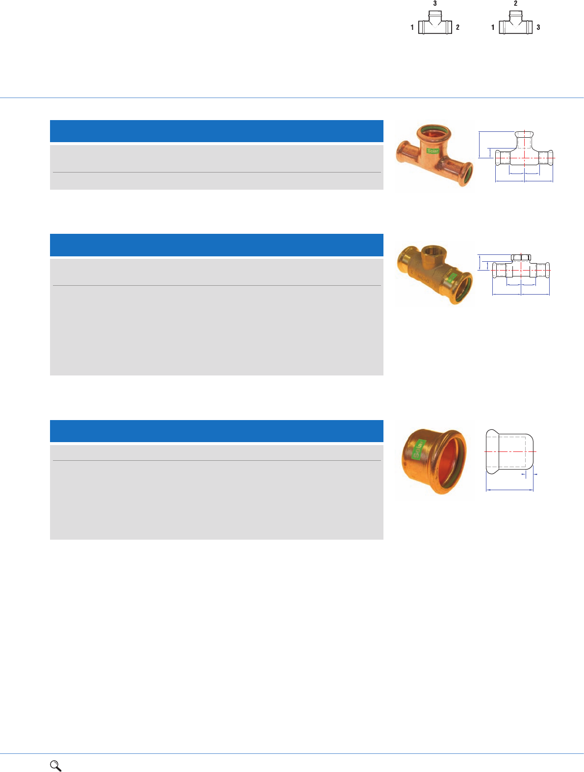
1Range overview 2Product details 3Technical data 4Installation instructions 5Flow charts 65
2
Tee specification
See page 73
UK specification European specification
SR28/7130 Tee, both ends reduced
c
Zc
Za
aa
Za
Size
UK European a c Za Zc Item code
15 x 15 x 22mm 15 x 22 x 15mm 38 34 18 13 38545R
Connection: Press-fit on all ends.
SR30/6130G Female branch tee
cZc
Za
aa
Za
Size
UK European a c Za Zc Item code
15 x 15mm x 1/2" 15 x 1/2" x 15mm 34 26 14 11 38585R
22 x 22mm x 1/2" 22 x 1/2" x 22mm 42 26 21 11 38591R
22 x 22mm x 3/4" 22 x 3/4" x 22mm 45 27 24 11 38587R
28 x 28mm x 1/2" 28 x 1/2" x 28mm 44 29 21 14 38592R
28 x 28mm x 3/4" 28 x 3/4" x 28mm 41 34 18 14 38593R
35 x 35mm x 1/2" 35 x 1/2" x 35mm 50 34 24 19 38594R
42 x 42mm x 1/2" 42 x 1/2" x 42mm 57 38 27 23 38596R
Connection: Press-fit x BSP parallel female branch.
Za
a
SR61/7301 Stop end
Size a Za Item code
15mm 20 2 38695R
22mm 21 2 38697R
28mm 23 2 38698R
35mm 26 2 38699R
42mm 30 2 38700R
54mm 35 2 38701R
Connection: Press-fit, for copper tube.
66 1Range overview 2Product details 3Technical data 4Installation instructions 5Flow charts
LBP copper press-fit jointing
system for solar
SR69/6331G Straight male union connector
SS1
G
Za
a
Size G S S1 a Za Item code
15mm x 1/2"3/4" 30 25 62 42 38813R
22mm x 3/4" 1" 36 32 74 53 38814R
28mm x 1" 11/4" 46 40 76 53 38816R
35mm x 11/4"1
1/2" 52 46 79 53 38817R
42mm x 11/2"1
3/4" 58 51 88 58 38818R
54mm x 2" 23/8" 75 65 101 66 38819R
SR69F/6330G Straight female union connector
SS1
G
Za
a
Size G S S1 a Za Item code
15mm x 1/2"3/4" 30 26 52 30 38833R
22mm x 3/4" 1" 36 32 68 43 38834R
28mm x 1" 11/4" 46 43 65 43 38835R
35mm x 11/4"1
1/2" 52 48 74 52 38836R
42mm x 11/2"1
3/4" 58 53 83 48 38837R
54mm x 2" 23/8" 75 65 90 50 38838R
Connection: Press-fit x BSP taper male thread.
Connection: Press-fit x BSP parallel female thread.
1Range overview 2Product details 3Technical data 4Installation instructions 5Flow charts 67
2
XPress accessories
S100 Replacement ‘O’ Rings
For use on XPress copper fittings only
Size Item code
15mm 39115
22mm 39122
28mm 39128
35mm 39135
42mm 39142
54mm 39154
67mm 39230
76mm 39231
108mm 39232
SS100 Replacement ‘O’ Rings
For use on XPress stainless and carbon fittings only
Size Item code
15mm 27000
18mm 27001
22mm 27002
28mm 27003
35mm 27004
42mm 27005
54mm 27006
76mm 27007
89mm 27008
108mm 27009
S104 Flat face union fibre washer (Mk1)
For use with XPress unions (not suitable for stainless steel)
Size Item code
1/2" 38989
3/4" 38990
1" 38991
11/4" 38992
11/2" 38993
2" 38994
21/2" 38995
Gas ‘O’ rings are not offered as spares. We do not recommend substituting gas ‘O’ rings to XPress fittings.
68 1Range overview 2Product details 3Technical data 4Installation instructions 5Flow charts
XPress accessories
Size Item code
15mm 39100
22mm 39101
28mm 39102
35mm 39103
42mm 39104
54mm 39105
67mm* 39106
S110 Depth gauge
Suitable for copper, carbon and stainless steel
Size Item code
15mm - 54mm 39160
SV100 Viton ‘O’ Rings
For use on XPress copper and XPress solar fittings
*Suitable for XPress copper and carbon 67mm.
SS106 Flat face union rubber washer (Mk2)
For use with XPress unions stainless and carbon steel only
Size Item code
15mm - 18mm 27030
22mm 27031
28mm 27032
35mm 27033
42mm 27034
54mm 27035
Size Item code
15mm 39080
18mm 39081
22mm 39082
28mm 39083
35mm 39084
42mm 39085
54mm 39086
76mm 39088
89mm 39089
108mm 39090
SV105 Viton ‘O’ Rings
For use on XPress stainless and XPress carbon fittings only
1Range overview 2Product details 3Technical data 4Installation instructions 5Flow charts 69
2
S120 Deburring tool
Size Item code
15mm - 54mm 39168
S122 Copper tube preparation kit
Size Item code
35mm - 54mm 39233
TA150 Noga deburring kit
Size Item code
15mm - 22mm 76207
S130 Silicon ‘O’ ring lubricant
For use with ‘O’ rings only
Size Item code
100g tub 39219
S135 Dri-slide lubricant
For use with jaws and slings only
Size Item code
115ml 39169
S115 Tube stripper
For use with SC660 tube
Size Item code
15mm 39260
18mm 39261
22mm 39262
28mm 39263
35mm - 54mm 39264
70 1Range overview 2Product details 3Technical data 4Installation instructions 5Flow charts
Press-fit tools and jaws
Press tools approved for pressing XPress
Dimension Manufacturer Press Tool Jaws Sling Jaw adaptor Sling Profile
(mm) (up to 35mm) (42mm and above) (Copper, Stainless/Carbon)
15 - 28 REMS REM-578012 Mini-Press ACC Mini M15 - M28 - - M
Battery powered (14.4V)
15 - 35 REMS REM-571013 Akku-Press M15 - M35 - - M
Battery powered (14.4V)
REM-571014 Akku-Press ACC M15 - M35 - - M
Battery powered (14.4V)
REM-577011 Power-Press M15 - M35 - - M
REM-572110 Power-Press E M15 - M35 - - M
REM-577010 Power-Press ACC M15 - M35 - - M
42 - 54 REMS REM-571013 Akku-Press - Z3 M42 (PR) M54 (PR) M
Battery powered (14.4V)
REM-571014 Akku-Press ACC - Z3 M42 (PR) M54 (PR) M
Battery powered (14.4V)
REM-577011 Power-Press - Z3 M42 (PR) M54 (PR) M
REM-572110 Power-Press E - Z3 M42 (PR) M54 (PR) M
REM-577010 Power-Press ACC - Z3 M42 (PR) M54 (PR) M
12 - 28 Novopress AFP 101 PB1 - - M
Battery powered (12V)
12 - 35 Novopress EFP2 PB2 - - M
EFP202 PB2 - - M
AFP202 PB2 - - M
ECO202 PB2 - - M
ACO202 PB2 - - M
42 - 54 Novopress EFP2 - ZB201/ZB203 (42/54mm) M
EFP202 - ZB201/ZB203 (42/54mm) M
AFP202 - ZB201/ZB203 (42/54mm) M
ECO202 - ZB201/ZB203 (42/54mm) M
ACO202 - ZB201/ZB203 (42/54mm) M
12 - 35 Novopress ECO301 PB3 - - M
42 - 67* ZB302 (For 42/54/67mm) 42/54 (also suitable for EFP2, M
EFP202, AFP202, ECO202, ACO202)
and 67mm
67* - 108** ZB321 (For 76/89/108 First press)** 76/89/108 and 108 copper only** M
108** ZB322 (For 108 second press only)** 108 and 108 copper only** M
*See page 71 for 67mm sling.
**For 108mm jaws, specify use for copper or stainless/carbon.
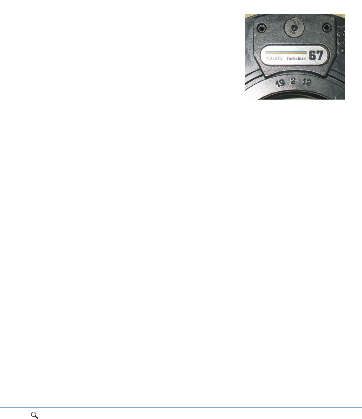
1Range overview 2Product details 3Technical data 4Installation instructions 5Flow charts 71
*67mm Sling (S322-67mm)
Novopress offers alternative slings for use on different press systems. As such we have to
reinforce the following instruction.
Where 67mm slings are required for crimping XPress Copper and XPress Carbon fittings,
installers must only use the Novopress sling reference 36516-01, marked
“WOESTE Yorkshire 67” as this is the correct profile for our XPress Press-fit 67mm
fittings. See photo on right.
Under no circumstances should any other brand of sling be used with our 67mm fittings as
these will lead to an incorrect crimp resulting in an immediate joint failure and invalidate
the Pegler Yorkshire Warranty.
XPress 67mm fittings that have inadvertently been crimped with the wrong brand of sling
cannot be successfully re-crimped with the “WOESTE Yorkshire 67” sling and unfortunately
will have to be cut out and replaced with a new fitting using the correct sling.
Power supply
It is essential when preparing to undertake an installation using XPress fittings and tools
that a suitable constant power source is available. If the supply of power is not constant it
may affect the performance of the joint.
Checking the power source is particularly important prior to joining with the S301/EC03
Pressmax tool as it includes safety software, which detects the amount of power available
to the machine. If there is not enough for the tool to initiate the pressing cycle and
complete a sound joint the tool will not commence the pressing operation. This feature is
particularly useful when installing large size press fittings, as the pressure required to press
these fittings is significantly grater than for smaller fittings, hence the power supply to the
tool must be guaranteed.
It is therefore recommended that when using a portable transformer to provide power to
the press tool, the transformer should be a minimum of 3KVA rated in order that a
continuous uninterrupted power supply is always available.
When a semi-permanent source of power such as a generator is being used it is essential
the plant is well maintained. The maximum cable size from generator to outlet and the
minimum length of cable between the power outlet and the tool should be used.
2

72 1Range overview 2Product details 3Technical data 4Installation instructions 5Flow charts
Press-fit solutions
Tube compatibility
and applications
*Heating applications only.
**For XPress solar, copper tube with a maximum temperature of 200ºC.
Typical applications
XPress XPress XPress XPress XPress XPress XPress
Tube/pipe type Copper Chromium Plated Stainless Carbon Copper Gas Stainless Gas Solar
Copper tube** ––––
Chromium plated copper tube – –––––
Stainless steel tube – – *– –
Carbon steel tube – – *–––
Plastic coated carbon steel tube – – *–––
It is advisable to make copper to steel connections via gunmetal/copper alloy fittings.
Hot and cold water services
Vented and unvented closed circuit heating
Chilled water and oil free compressed
air applications
With chromium plated finish for surface
mounted installations
Potable water applications where water
quality and hygiene are crucial
Pharmaceutical, food and health-care
environments
Chilled water applications
Vented and unvented closed circuit heating
Chilled water applications
Internal and external applications
Above ground 2nd and 3rd family gas
service pipelines
Above ground 2nd and 3rd family gas
service pipelines, including instances
where high levels of hydrogen sulphide
make copper unsuitable
Solar water heating systems
Fitting and tube compatibility
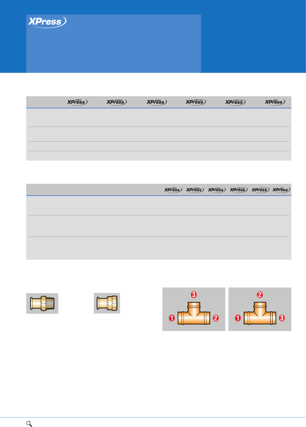
1Range overview 2Product details 3Technical data 4Installation instructions 5Flow charts 73
3
Press-fit solutions
Materials specification and
manufacturing standards
Component Standard Summary
Male ISO 7/EN10226-1 Pipe-threads, where pressure-
end thread (formerly BS 21/ISO 7) tight joints are made on the
threads (metric dimensions)
Female BS EN ISO 228:2003 Pipe-threads, where pressure-
end thread (formerly BS 2779/ tight joints are not made on the –––
ISO R228/1) threads (metric dimensions)
Female ISO 7/1 Pipe-threads, where pressure-
end thread tight joints are not made on the – ––
threads (metric dimensions)
Manufacturing standards
Connectors
Male connectors
XPress male
connectors
have threads
to BS 21/
ISO 7/EN 10226-1. Inert
jointing compounds or PTFE
tape should be applied to taper
threads and good quality
jointing washers should be used
with parallel threaded fittings.
PTFE tape should not be used in
conjuction with stainless steel
threads due to the water soluble
chloride ions it contains.
All XPress fittings with flat face
unions are supplied with fibre
washer seals.
Female connectors
XPress female
threaded
connectors have
internal parallel
threads to ISO 7/EN 10226-1.
Component
Body Copper or Stainless Carbon Steel Copper or Stainless Copper or
Gunmetal steel ST34-2 Gunmetal steel Gunmetal
Alloy (316L) (Nickel plated) Alloy (316) alloy
‘O’ ring EPDM* EPDM* EPDM* Yellow Yellow Green (FPM)
HNBR†HNBR†(Viton™)
‘O’ ring bead Copper Copper
Materials specification
NB. ‘O’ rings are supplied lubricated for easy tube insertion. *Ethylene Propylene Diene Monomer. †Hydrogenated Aerylonitrile Butadiene Rubber.
Tee specification
UK specification
First quote the ends on the
run (larger end first) and
then the branches.
European specification
Quote the larger end first,
then the branch, followed by
the remaining end.

74 1Range overview 2Product details 3Technical data 4Installation instructions 5Flow charts
Press-fit solutions
Working temperatures
Working temperatures and pressure tables
XPress Copper fittings have all been tested
and are suitable for use with approved tubes
at temperatures from -24ºC to 110ºC at a
maximum working pressure of 16bar
throughout the temperature range.
XPress Solar is approved with tube meeting
the temperature rates shown in the table
below and operates from -35ºC to 200ºC
at a maximum working pressure of 16bar
throughout the temperature range.
XPress Stainless and XPress Carbon fittings
have been tested and are suitable for use
with approved tubes at temperatures from
-20ºC to 110ºC at a maximum working
pressure of 16bar throughout the
temperature range. For high working pressure
applications contact the Pegler Yorkshire
technical help desk.
In wet systems based installations we
recommend all systems be thoroughly tested
upon completion. The installation may be
tested to 1.5 times the working pressure of
the system, up to a maximum of 16bar.
If higher test pressures are required advice
should be sought from Pegler Yorkshire.
Pressure testing of carbon
steel systems
The following recommendations apply
concerning the testing of XPress
Carbon Steel.
Due to the potential for corrosion and
perforation of carbon steel tube and fitting
systems left partially drained for extended
periods following hydraulic testing. It is
recommended that XPress Carbon Steel
systems be dry air/nitrogen tested, up to a
maximum of 3bar.
If hydraulic testing must be undertaken the
following should be considered.
A. The test water should contain anti-
corrosion chemicals with the intention that
post testing the system shall be left
completely full of water (suitable protection
against freezing will also have to be
considered).
B. If leaving the system full of water is not
practical then every effort shall be made to
fully drain and dry the pipe work by purging
with dry air.
Regarding the air/nitrogen testing of pipe
work with XPress Carbon Steel crimped
fittings the following points will need to be
considered.
1. The air should be clean, dry and free from
oil. Excessive oil carry over in compressed air
may be detrimental to the EPDM seals. This is
not a problem with nitrogen.
2. Air is many times more searching than
water. Hence, if the purpose of the air test is
only leak detection, then 0.5bar pressure will
be more than sufficient. Higher pressures can
in fact mask sealing issues that would be
revealed by low-pressure tests.
3. The need for higher test pressures to prove
the mechanical integrity of the joints brings
with it serious safety issues. Testing for such
a failure mode with high-pressure
air/nitrogen is potentially very dangerous as
the energy stored in 5bar air/nitrogen, when
released suddenly, could lead to damage to
equipment or more seriously, injury to
personnel. HSE issue guidelines for such
testing should be strictly adhered too.
4. It is therefore; recommended that an
initial low pressure test at 0.5bar is carried
out, having put the necessary safety
measures in place, to enable any leaks to be
found. Significantly leaking, un-pressed or
damaged joints shall be replaced, but those
with low leakage rates should be identified
for close inspection during the high-pressure
test. The full loading of the ‘O’ rings often
resolve small leaks identified during the
0.5bar test. When satisfied that the system
is sound and having the necessary safety
measures in place a 1.5 times working
pressure test can be carried out as per the
Copper Development Association (CDA)
Guidelines document ‘Pressure Testing Piping
Systems’. Leaking joints at this stage should
be identified and marked for replacement.
The system pressure should then be reduced
to 0.5bar again to confirm that no persistent
low-pressure leaks are present.
XPress Copper Gas fittings are approved for
use with copper tubes to BS EN 1057 at
temperatures from -20ºC to 70ºC and a
maximum working pressure of 5bar for
outside above ground pipework and 1bar
within buildings.
As part of the DVGW/GL (formally British
Gas) approvals process, XPress Gas fittings
have passed the High temperature test at
650°C for 30 minutes at PN1 (copper)/PN5
(stainless).
N.B. The maximum temperature and
pressure range in any system is dictated
by the component with the lowest
performance rating.
Achieving low temperatures
For products used in water systems, working
temperatures of less then 4°C can only be
achieved if antifreeze is added to the system.
Localised annealing of copper tube
XPress Copper installation should not be
carried out within 300mm of a brazed or
soldered joint, as the high temperature
required for capillary jointing anneals the
copper tube rendering it too soft for
press-fit jointing. In an existing XPress
Copper installation, brazing or soldering
should not be carried out within 300mm
of an existing press-fit joint as this may
damage the ‘O’ ring.
Do not braze or weld XPress carbon or XPress
stainless steel tubes.
Temperature Durability
200ºC Cumulative exposure 20hrs/year
180ºC Cumulative exposure 60hrs/year
150ºC Cumulative exposure 480hrs/year
90 - 130ºC Normal working temperature
-35ºC Winter temperature
Pressure Working condition
3bar Normal operating pressure
10bar Maximum working pressure
16bar Maximum test pressure
16bar Maximum surge pressure
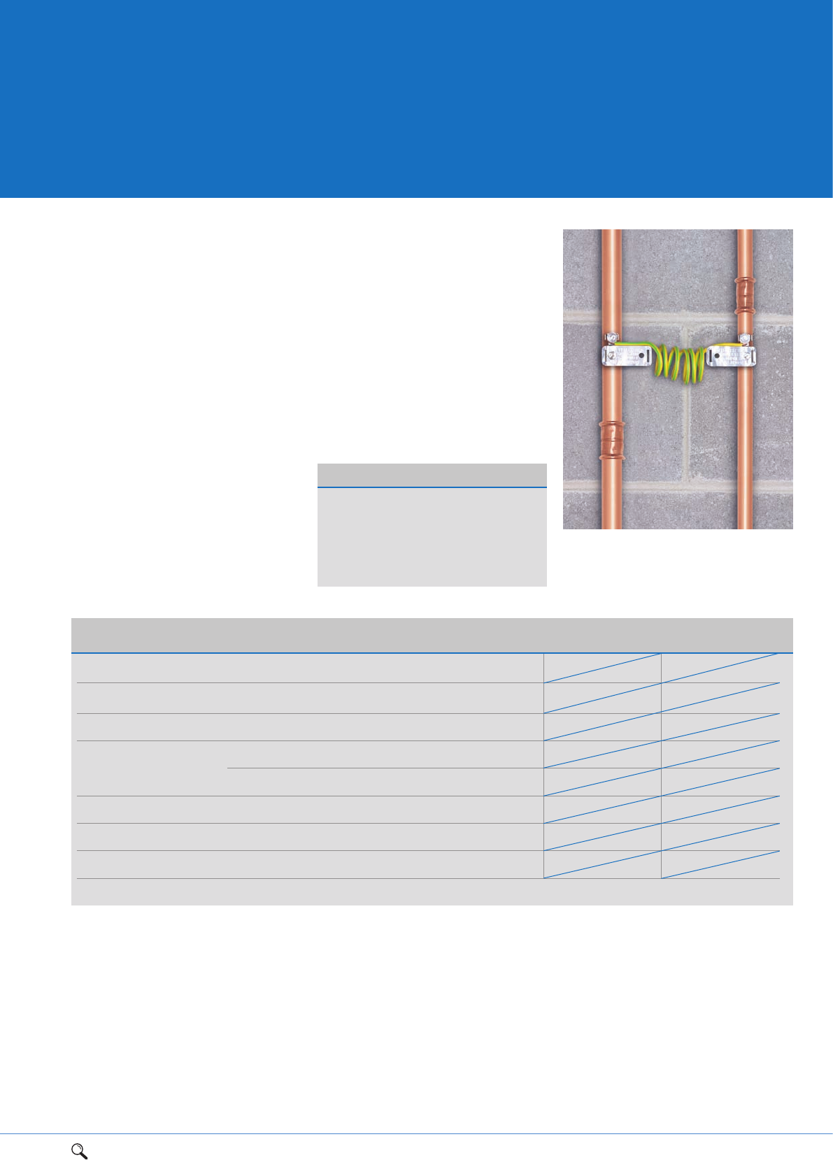
1Range overview 2Product details 3Technical data 4Installation instructions 5Flow charts 75
Electrical continuity
XPress Copper
XPress Stainless
XPress Carbon
XPress Copper Gas
XPress Stainless Gas
XPress Solar
XPress Copper Copper -24ºC 110ºC
16bar 16bar
XPress Copper chromium plated Copper chromium plated copper -24ºC 110ºC
16bar 16bar
XPress Stainless Stainless steel -20ºC 110ºC
16bar 16bar
XPress Carbon Carbon steel -20ºC 110ºC
16bar 16bar
Plastic coated carbon steel -20ºC 110ºC
16bar 16bar
XPress Copper Gas Copper -20ºC 70ºC
1bar* 5bar**
XPress Stainless Gas Stainless steel -20ºC 70ºC
1bar* 5bar**
XPress Solar Copper -35ºC 200ºC
3bar 10bar
All performance figures based on correct assembly of fittings and tube/pipe as detailed in installation instructions. *1bar inside. **5bar outside above ground.
XPress fitting Tube/pipe used with Min. temperature Max. temperature
and pressure and pressure
3
Pressure Equipment Directive
From 30th May 2002 most pressure
equipment and assemblies on the market in
the United Kingdom must comply with the
Pressure Equipment Directive (PED) 1999.
Fittings are exempt from the PED unless they
are incorporated into pressure equipment
falling within its scope. XPress valves are
also exempt. For a detailed explanation
please visit:
www.pegleryorkshire.co.uk/technical.cfm
Equipotential bonding
It is the installers duty to ensure that all
metallic pipework systems should comply
with the equipotential bonding requirements
of the current edition of the IEE electrical
wiring regulations (BS 7671: 1992).
All XPress products (below) provide
guaranteed electrical continuity once the
joints are pressed.
After all plumbing work has been completed,
always ensure continuity checks are
conducted by a qualified electrician in
accordance with regulations.
76 1Range overview 2Product details 3Technical data 4Installation instructions 5Flow charts
Press-fit solutions
Tubes, pipe and
their compatibilities
COPPER TUBE BS EN 1057 COMPATIBILITY: XPress Copper, XPress
Copper Gas fittings and XPress Solar. All tube tempers (R250 and
R290) are available in all the designated wall thicknesses
Outside Wall thickness
diameter 0.6mm 0.7mm 0.8mm 0.9mm 1.0mm 1.2mm 1.5mm 2.0mm 2.5mm
12mm †––––––––
15mm – †––
†––––
22mm – – – †††–––
28mm – – – †
†––
35mm –––––
†––
42mm –––––
†––
54mm –––––
†––
64mm –––––––
–
67mm –––––
––
76mm ––––––
–
88.9mm –––––––
–
108mm ––––––
–
Copper tube
Compatible copper
tube must meet
the requirements
of BS EN 1057 R250 and R290
for copper and copper alloy –
seamless round copper tubes for
water (and gas) in sanitary and
heating applications.
The higher the number, the
harder the material. As a result,
tube diameter, wall thickness,
length and the material temper
must all be specified for full
product designation.
All XPress Copper, Copper Gas
and XPress Solar fittings can be
used with copper tube, although
in humid conditions some
staining of the tube may be
witnessed (see page 79 Phenolic
foam section for details on
moisture-proof insulation).
Yorkex* copper System tube is
manufactured to the same
standards as above and offers
the same features and benefits
with a maximum rating of 100ºC.
Kuterlon* copper tube is
manufactured to the same
standards as above and offers
the same features and benefits
with the maximum temperature
rating of 200ºC.
When Yorkex*and Kuterlon* copper tube is used
with XPress fittings as part of a complete system
an enhanced guarantee of 30 years will apply.
XPress fittings can also be used with copper tube to the above standards, in which case
a 25 year guarantee will apply.
Yorkex* and Kuterlon* are brand names of
Yorkshire Copper Tube/KME Group.
STAINLESS STEEL 316 SYSTEM TUBE: Specification
Pegler Yorkshire Wall thickness
Outside 316 System EN 10312 Table 1 EN 10312 Table 2
diameter tube (formerly BS 4127) GW541 Table 3
(Comparison) (Comparison)
15mm 0.6mm 0.6mm –
18mm 0.6mm 0.7mm –
22mm 0.6mm 0.7mm –
28mm 0.8mm 0.8mm –
35mm 1.0mm 1.0mm –
42mm 1.0mm 1.1mm –
54mm 1.0mm 1.2mm –
76mm 2.0mm – 2.0mm
89mm 2.0mm – 2.0mm
108mm 2.0mm – 2.0mm
Stainless
steel 316
System tube
Specially designed
to be used with
XPress stainless
steel fittings, 316 System tube
is available in 6m straight
lengths in sizes from 15mm to
54mm. The tube is
manufactured from BS 316
S31/DIN 1.4401 stainless steel
strip conforming to BS10088
Part 2 and thanks to its
thin-walled geometry, is stiff,
lightweight and easy to handle.
However, when bending 316
System tube we recommend the
use of the Rothenberger Robend
3000 with rollers up to 28mm.
XPress stainless gas fittings are
also compatible with stainless
steel tubes to BS EN 10312
(encompassing the former
BS 4127) and DVGW GW541.
When XPress stainless steel System tube is used
with XPress fittings as part of a complete system
an enhanced guarantee of 30 years will apply.
XPress fittings can also be used with stainless steel tube to the above standards,
in which case a 25 year guarantee will apply.
The comparison data is for reference purposes only. Pegler Yorkshire offers the
‘Pegler Yorkshire 316 System tube’.
To qualify for our guarantees, all products must be installed in
accordance with our instructions on specified applications.
† R250 temper R290 temper
1Range overview 2Product details 3Technical data 4Installation instructions 771Range overview 2Product details 3Technical data 4Installation instructions 5Flow charts 77
XPRESS GALVANISED CARBON STEEL TUBE: Specification
Outside Wall thickness EN 10312 Table 1
diameter GW541 Table 2 (formerly BS 4127)
including
Outside plastic Galvanised Including
diameter coating tube plastic coating
15mm 17mm 1.2mm 2.2mm
18mm 19mm 1.2mm 2.2mm
22mm 24mm 1.5mm 2.5mm
28mm 30mm 1.5mm 2.5mm
35mm 37mm 1.5mm 2.5mm
42mm 44mm 1.5mm 2.5mm
54mm 56mm 1.5mm 2.5mm
67mm – 1.5mm –
76mm – 2.0mm –
89mm – 2.0mm –
108mm – 2.0mm –
Carbon steel System
tube is available in
6m straight lengths
in sizes from 15mm to 108mm.
Plastic coated galvanised carbon
steel tube is available in straight
6 metre lengths in sizes 15 to
54mm. Galvanised carbon steel
System tube is manufactured in
accordance with DIN 2394/
NEN1982 from material with a
very low carbon content and has
a thin walled profile resulting
in a lightweight easier to
handle product.
The galvanised coating (external
only) has a minimum thickness
of 7 microns and is thermally
applied which provides a
superior bond to the tube and
further resistance to corrosion.
XPress Carbon fittings can be
used with our SC640 galvanised
carbon steel System tube or our
SC660 plastic coated carbon
steel System tube.
Carbon tube should be stored
under cover and not exposed to
the elements.
XPress galvanised carbon steel
System tube and plastic coated
carbon steel System tube
When XPress galvanised carbon steel System tube
or plastic carbon steel System tube is used with
XPress fittings as part of a complete system an
enhanced 10 year guarantee will apply.
XPress fittings can also be used with carbon steel tube and plastic coated carbon steel
tube to the above standards, in which case a 5 year guarantee will apply.
3
To qualify for our guarantees, all products must be installed in
accordance with our instructions on specified applications.

78 1Range overview 2Product details 3Technical data 4Installation instructions 5Flow charts
Press-fit solutions
System design considerations
and tube expansion
XPRESS COPPER, XPRESS COPPER GAS AND XPRESS SOLAR: Copper tube expansion
Temperature Tube length
change 3m 4m 5m 6m 7m 8m 9m 10m 12m 25m
XPRESS STAINLESS AND XPRESS STAINLESS GAS: Stainless steel System tube expansion
Temperature Tube length
change 3m 4m 5m 6m 7m 8m 9m 10m 12m 25m
10ºC 0.5mm 0.7mm 0.9mm 1.0mm 1.2mm 1.4mm 1.5mm 1.7mm 2.0mm 4.3mm
20ºC 1.0mm 1.4mm 1.7mm 2.0mm 2.4mm 2.7mm 3.0mm 3.4mm 4.0mm 8.5mm
30ºC 1.5mm 2.0mm 2.6mm 3.1mm 3.6mm 4.1mm 4.6mm 5.1mm 6.1mm 13.0mm
40ºC 2.0mm 2.7mm 3.4mm 4.1mm 4.8mm 5.4mm 6.1mm 6.8mm 8.2mm 17.0mm
50ºC 2.6mm 3.4mm 4.3mm 5.1mm 6.0mm 6.8mm 7.7mm 8.5mm 10.2mm 21.0mm
60ºC 3.1mm 4.1mm 5.1mm 6.1mm 7.1mm 8.2mm 9.2mm 10.2mm 12.2mm 26.0mm
70ºC 3.6mm 4.8mm 6.0mm 7.1mm 8.3mm 9.5mm 10.7mm 11.9mm 14.3mm 30.0mm
80ºC 4.1mm 5.4mm 6.8mm 8.2mm 9.5mm 10.9mm 12.2mm 13.6mm 16.3mm 34.0mm
90ºC 4.6mm 6.1mm 7.7mm 9.2mm 10.7mm 12.2mm 13.8mm 15.3mm 18.4mm 38.0mm
100ºC 5.1mm 6.8mm 8.5mm 10.2mm 11.9mm 13.6mm 15.3mm 17.0mm 20.4mm 43.0mm
150ºC* 7.7mm 10.2mm 12.8mm 15.3mm 17.9mm 20.4mm 23.0mm 25.5mm 30.6mm 63.8mm
200ºC* 10.2mm 13.6mm 17.0mm 20.4mm 23.8mm 27.2mm 30.6mm 34.0mm 40.8mm 85.0mm
*Kuterlon copper tube.
10ºC 0.5mm 0.6mm 0.8mm 1.0mm 1.1mm 1.3mm 1.4mm 1.6mm 1.9mm 4.0mm
20ºC 1.0mm 1.3mm 1.6mm 1.9mm 2.2mm 2.6mm 2.9mm 3.2mm 3.8mm 8.0mm
30ºC 1.4mm 1.9mm 2.4mm 2.9mm 3.4mm 3.8mm 4.3mm 4.8mm 5.8mm 12.0mm
40ºC 1.9mm 2.6mm 3.2mm 3.8mm 4.5mm 5.1mm 5.8mm 6.4mm 7.7mm 16.0mm
50ºC 2.4mm 3.2mm 4.0mm 4.8mm 5.6mm 6.4mm 7.2mm 8.0mm 9.6mm 20.0mm
60ºC 2.9mm 3.8mm 4.8mm 5.8mm 6.7mm 7.7mm 8.6mm 9.6mm 11.5mm 24.0mm
70ºC 3.4mm 4.5mm 5.6mm 6.7mm 7.8mm 9.0mm 10.1mm 11.2mm 13.4mm 28.0mm
80ºC 3.8mm 5.1mm 6.4mm 7.7mm 9.0mm 10.2mm 11.5mm 12.8mm 15.4mm 32.0mm
90ºC 4.3mm 5.8mm 7.2mm 8.6mm 10.1mm 11.5mm 13.0mm 14.4mm 17.3mm 36.0mm
100ºC 4.8mm 6.4mm 8.0mm 9.6mm 11.2mm 12.8mm 14.4mm 16.0mm 19.2mm 40.0mm
The following are some of the specific design considerations which are important
to take account of when designing and installing pipework systems containing
XPress fittings.
Thermal movement
Thermal movement is a major
consideration when designing
plumbing and heating systems.
Pipework systems expand and
contract with changes in
temperature. If they are fixed
too rigidly and their movement
restricted, the systems will be
subject to stress which must be
avoided. So it’s important to
take the effect of thermal
movement into account when
designing or installing a system.
It’s especially important to
avoid stress concentrations
between fixed points typically
found at radiators, valves and
other fittings.
The following tables show
thermal expansion details for a
range of tube/pipe lengths and
temperature changes. For further
calculations please refer to the
Pegler Yorkshire System Design
Document or visit the website.
XPRESS CARBON**: Galvanised carbon steel System tube and plastic coated carbon steel System tube expansion
Temperature Tube length
change 3m 4m 5m 6m 7m 8m 9m 10m 12m 25m
10ºC 0.3mm 0.4mm 0.5mm 0.7mm 0.8mm 0.9mm 1.0mm 1.1mm 1.3mm 2.7mm
20ºC 0.7mm 0.9mm 1.1mm 1.3mm 1.5mm 1.7mm 1.9mm 2.2mm 2.6mm 5.4mm
30ºC 1.0mm 1.3mm 1.6mm 1.9mm 2.3mm 2.6mm 2.9mm 3.2mm 3.9mm 8.1mm
40ºC 1.3mm 1.7mm 2.2mm 2.6mm 3.0mm 3.5mm 3.9mm 4.3mm 5.2mm 10.8mm
50ºC 1.6mm 2.2mm 2.7mm 3.2mm 3.8mm 4.3mm 4.9mm 5.4mm 6.5mm 13.5mm
60ºC 1.9mm 2.6mm 3.2mm 3.9mm 4.5mm 5.2mm 5.8mm 6.5mm 7.8mm 16.2mm
70ºC 2.3mm 3.0mm 3.8mm 4.5mm 5.3mm 6.1mm 6.8mm 7.6mm 9.1mm 18.9mm
80ºC 2.6mm 3.5mm 4.3mm 5.2mm 6.1mm 6.9mm 7.8mm 8.6mm 10.4mm 21.6mm
90ºC 2.9mm 3.9mm 4.9mm 5.8mm 6.8mm 7.8mm 8.8mm 9.7mm 11.7mm 24.3mm
100ºC 3.2mm 4.3mm 5.4mm 6.5mm 7.6mm 8.6mm 9.7mm 10.8mm 13.0mm 27.0mm
**Closed circuit systems only.
1Range overview 2Product details 3Technical data 4Installation instructions 5Flow charts 79
Maximum spacing of support brackets for 316 System tube,
BS 4127 and W541 stainless steel tube and plastic coated
and galvanised carbon steel tube
Size Horizontal pitch Vertical pitch
15mm 1.80m 2.00m
18mm 2.10m 2.30m
22mm 2.40m 3.00m
28mm 2.40m 3.00m
35mm 2.70m 3.00m
42mm 3.00m 3.60m
54mm 3.00m 3.60m
76mm 3.00m 3.60m
89mm 3.60m 4.50m
108mm 3.60m 4.50m
Correct anchoring
Always ensure the spur used to anchor the
branch of a tee or connecting a radiator
is long enough to allow normal thermal
movement. Failure to observe this simple
rule can lead to a failure. Incorporating
expansion loops or bellows devices into the
system can help guard against such
problems, whilst a horseshoe link or offset
(see diagrams) is an ideal way to counteract
continual thermal cycling.
Techniques for expansion
stress relief
Design considerations
Some contracts may still require that
proprietary chemicals are used to cleanse and
flush pipework before full commissioning.
XPress is compatible with a wide selection of
products, to find out more contact us.
Pipe restraint
In any installation, the system should be
supported to ensure the minimum stress is
imposed on the tube/pipe and joints. For the
maximum spacing of supporting brackets for
internal installations, please see the tables
(above).
Insulation
For all XPress Systems, we recommend you
adhere to the insulation requirements as
specified by the Water Supply (Water
Fittings) Regulations and Building
Regulations 1999. These requirements are
equally applicable to plastic pipe and
stainless steel tube.
Phenolic foam
When using rigid phenolic foam (or other
thermal insulation) to lag pipework,
always remember to refer to the lagging
manufacturer’s fixing instructions. To avoid
the risk of external corrosion of copper
pipework lagged with this foam, the
European Phenolic Foam Association
recommend that such insulation products
be installed with a moisture barrier. Materials
like Densopaste or a plastics covering applied
by the tube manufacturer both provide an
appropriate barrier between the outer surface
of the tube or fitting and the foam.
Some manufacturers of this type of lagging
supply their products with an internal,
factory-applied sodium silicate barrier to
prevent external corrosion problems.
However, if you do need to add a barrier
product, we recommend that all
XPress fittings be fully installed before
these are applied and that they are
completely coated.
Local Water Authority
We recommend consulting the local water
authority when it comes to pipework
accessibility.
Building in dimensions
All Building in dimensions are correct at the
time of going to press. Pegler Yorkshire
reserves the right to change these
dimensions without prior notice, however
to ensure you are using the most up to date
information please refer to our web site
www.pegleryorkshire.co.uk
Covered pipework
Making provision for thermal movement is
vital where pipework of any material is
installed under screed or plaster or passes
through brick or blockwork. The preferred
practice is to use tubing with factory applied
protective plastic covering incorporating air
gaps to accommodate thermal movement or
to pass tubes and pipes through sleeves or
conduits or to lay them in ducts surrounded
by loose, inert non-rigid material such as
vermiculite or glass wool. For further
information, consult the publication
BS 6700:2006 Design, installation, testing
and maintenance of services supplying
water for domestic use within buildings
their curtilages.
Maximum spacing of support brackets for copper tube to BS EN 1057
Size Wall Temper Horizontal Vertical
thickness pitch pitch
12mm 0.6mm R250 1.00m 1.50m
15mm 0.7mm R250/R290 1.20m 1.80m
22mm 0.9mm R250/R290 1.80m 2.40m
28mm 0.9mm R250/R290 1.80m 2.40m
35mm 1.2mm R250/R290 2.40m 3.00m
42mm 1.2mm R250/R290 2.40m 3.00m
54mm 1.2mm R250/R290 2.70m 3.00m
64mm 2.0mm R250/R290 3.00m 3.00m
67mm 1.2mm R250/R290 3.00m 3.60m
76mm 1.5mm R250/R290 3.00m 3.60m
89mm 2.0mm R250/R290 3.00m 3.00m
108mm 1.5mm R250/R290 3.00m 3.60m
Horseshoe expansion link Offset
Crossover tee arrangement
expansion loop
3
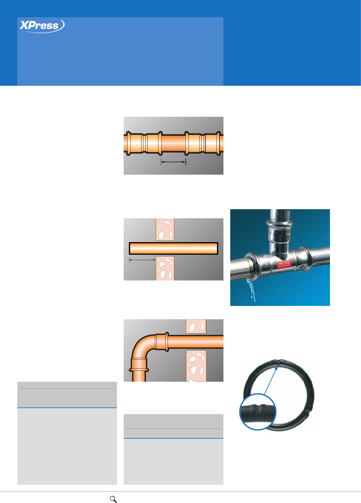
80 1Range overview 2Product details 3Technical data 4Installation instructions 5Flow charts
Press-fit solutions
System design considerations
and tube expansion
Spacing
Fitting spacing
Sufficient space must be left between
fittings to allow jaws or slings to be
attached to operate. See table for
fitting spacing.
Minimum projection
Similar consideration should be given to the
distance pipe stubs project through walls
or bulkheads. Refer to adjacent table.
Good practice
Projection distances shown in the adjacent
table also ensure that the subsequent
installation will be a convenient distance
from the wall.
Additives
For the most up to date information on
additives compatible with Pegler Yorkshire
systems please refer to the web site
www.pegleryorkshire.co.uk/en/brochures/
bulletins. We strongly recommend consulting
a commissioning engineer in conjunction
with the manufacturer prior to their use.
Tube bending
Portable bending machines are ideal for
copper tubes up to 28mm. Most machines
bend the tube between matched formers
and back guides that support the outside
diameter (OD) of the tube. This eliminates
the risk of the tube wall collapsing.
The point at which the bending pressure is
exerted must be maintained at the correct
distance in front of the former’s point of
support. It’s also important to keep formers
and guides well lubricated. Bending tubes
correctly will avoid any wrinkling and
flattening that can affect flow conditions.
Using adjustable bending machines (which
allow the pressure on the back guide to be
adjusted) will ensure perfect bends every
time so long as the root (inside) bending
radius is at least 3 times the outside
diameter of the tube.
With the bending of carbon tube it is
important to ensure the weld seam is kept
to the inside radius of the bend.
Pipework clearance
When designing an XPress System, please
take care to ensure all joints can be
accessed easily. Observe minimum gaps and
insertion distances to ensure sufficient
access for the pressing tool, where
applicable.
Fitting spacing for XPress
Min. gap Min.
between tube
Sizes fittings projection
15mm 10mm 40mm
18mm 10mm 40mm
22mm 10mm 40mm
28mm 10mm 60mm
35mm 10mm 70mm
42mm 20mm 70mm
54mm 20mm 70mm
67mm 30mm 70mm
76mm 40mm 80mm
89mm 50mm 90mm
108mm 50mm 100mm
Thermal expansion
When including expansion joints in a system
take care not to introduce tensional stress
when assembling and tightening threaded
connections. The XPress range includes male
and female connectors for the correct
jointing of expansion joints.
XPress ‘Leak Before Press’
XPress Copper, XPress Carbon, XPress Stainless
and XPress Solar offer a unique ‘Leak Before
Press’ feature (LBP) which enables any
connections which haven’t been pressed to
be easily identified during pressure testing at
pressures as low as 0.5bar.
XPress Carbon
and XPress Stainless
The LBP feature on both XPress Carbon and
XPress Stainless (sizes 15mm-54mm) is
created by the use of a specially profiled
EPDM ‘O’ ring.
The LBP ‘O’ rings have been
specially
designed to incorporate
a series of three
grooves in its
surface through which water
will leak from any un-pressed fitting.
When
pressed, the ‘O’ ring distorts, closing the
grooves to create a fully water- and
air-tight connection.
CARBON STEEL SYSTEM
TUBE: Bends
Size Minimum Radii
15mm 53mm
18mm 63mm
22mm 77mm
28mm 98mm
In sizes up to 28mm Carbon steel
System tube, is suitable for bending using proprietary
bend formers.
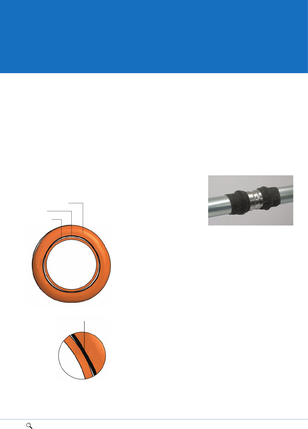
1Range overview 2Product details 3Technical data 4Installation instructions 5Flow charts 81
Note: Contact between ‘O’ ring and tube,
to maintain tube grip
Contact between
tube, ‘O’-ring
and fitting
which fixates
the tube.
The ‘O’-ring is black for XPress Copper
and green for XPress Solar.
XPress Copper fitting
Leak path
Copper tube
XPress Copper/XPress Solar
Whilst the mechanical properties of XPress
Copper with LBP are different, the benefits
are the same. The softer nature of copper
enables the LBP feature to be incorporated
into the ‘O’ ring bead in the fitting. The
bead is slightly triangular in shape and this
creates three spaces between the fitting
and the tube through which water will leak
if the fitting is not pressed. One additional
advantage of this system is that there is
still sufficient contact between the ‘O’ ring
and the tube to prevent it moving when
inserted. When pressed the shape of the
‘O’ ring bead is transformed from its
triangular shape to a round shape which,
once again, is perfectly water- and
air-tight.
Gas ‘O’ rings (and ‘O’ rings)
Pegler Yorkshire does not recommend ‘O’
rings are removed from the standard product
and replaced with a gas ‘O’ ring. To prevent
this gas ‘O’ rings are not offered as spares
within the XPress accessories range. We only
recommend gas fittings are purchased as
fully assembled products. We also do not
recommend that gas ‘O’ rings are removed
and replaced with standard ‘O’ rings.
Connecting tubes made
from dissimilar metal
The UK Water Regulations recommend that
tubes and fittings made from different types
of metals shall not be connected directly
together except where galvanic action is
unlikely or where effective measures are
taken to prevent it. Galvanic corrosion is a
process whereby the materials that come in
to contact with each other oxidises or
corrodes. If you are in doubt, we
recommend you refer to the full and
detailed information provided in Water
Regulations Guide (G2.11 and R3.2), or by
contacting the Water Regulations Advisory
Scheme info@wras.co.uk.
Mixed metal installations
The substitution of stainless steel XPress or
Tectite 316 fittings on a galvanised carbon
steel installation is acceptable in heating
and chilled water applications, if required.
When joining copper to carbon steel we
recommend the use of a yellow metal
i.e. brass or gunmetal to prevent
galvanic corrosion.
When doing this, care must be taken to
protect the SC640 galvanised tube surface
from the increased risk of external corrosion
at the stainless/galvanised steel interface.
Galvanised carbon steel is anodic to
stainless steel in air and, if the pipeline is
allowed to become wet, there is a risk of
localised corrosion of the carbon steel tube
surface adjacent to the stainless steel
fitting. This potential problem is less likely
in heating pipe work which usually remains
hot and dry.
In chilled water installations, an
accumulation of environmental condensate
on the pipe work could, under some
circumstances, leach out aggressive
chemicals from the insulation, resulting in
corrosion, particularly at the stainless
steel/carbon steel interface. Consequently,
we recommend that where stainless steel
fittings are installed on carbon steel pipe,
the joint area should be provided with
additional protection to prevent localised
corrosion. This can be as simple as wrapping
the interface area with an impervious
material such as Denso or PVC tape.
Provided these precautions are taken, there
is no reason why the combination of
stainless steel fittings and carbon steel
tube should not be entirely satisfactory.
Gas families
There are three gas families:
1st Family - manufactured gas
2nd Family - natural gas
3rd Family - LPG, compressed propane
and butane gas
XPress Copper Gas and Stainless Gas do not
have the LBP feature for safety reasons
and are designed for use in internal and
external above ground 2nd and 3rd family
gas services.
3
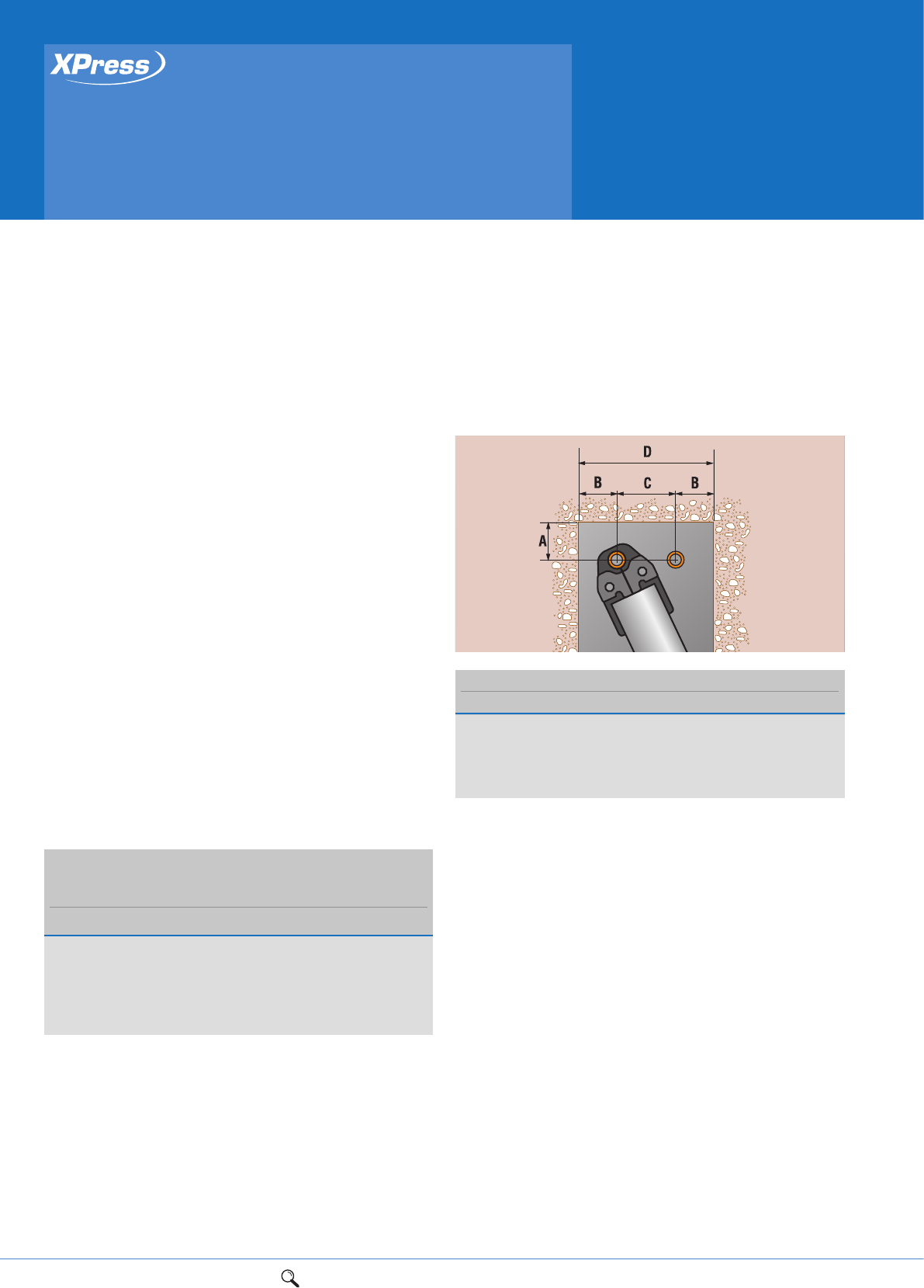
82 1Range overview 2Product details 3Technical data 4Installation instructions 5Flow charts
Press-fit solutions
Installation instructions
15mm to 35mm sizes
Guide to installation
Jointing procedures are almost identical for every type of XPress
fitting and compatible tube material. This includes XPress fittings
with ‘Leak before Press’ (LBP). Where there are variations these are
shown on the following pages and in the fitting instructions.
To ensure the fittings stay clean and the ‘O’ ring remains protected
from damage, only remove the fitting from its packaging
immediately prior to installation.
XPress gas fittings are not leak before press.
The tube can be fully inserted by hand. A damaged tube end will
require excessive force to be used. If this is the case you should
check the tube is round and deburred before continuing. Check the
‘O’ ring is not damaged. XPress fittings with plain male ends must
not be used directly with capillary fittings, since heating will
damage the non-metallic parts.
Heat should not be applied to XPress fittings, directly or indirectly.
They should be disconnected (where applicable) to avoid any
possible damage to non-metallic parts if they are to be used on a
system in conjunction with capillary fittings.
Similarly, reconnection must not be considered until the heated
tubes have been allowed to cool. Use pipe clips to secure finished
installations and prevent vibration or movement.
Socket depths
Spacing
Allow sufficient clearance around each fitting to allow press-fit
jaws to be attached without hindrance.
Health and safety
1. We recommend that eye protection is worn when operating all
pressing tools.
2. Do not activate a pressing tool without a fitting in the jaws.
Note: When using power tools, great care must be taken at all
times. Always refer to the manufacturers’ instructions for all
machines and tools you use. Please refer to
www.pegleryorkshire.co.uk/SHE for further COSHH information.
The XPress jointing system has been designed with easy, efficient installation
in mind. XPress Copper, XPress Stainless, XPress Carbon, XPress Copper Gas,
XPress Stainless Gas and XPress Solar have common installation instructions.
SOCKET DEPTHS:
XPRESS COPPER, SOLAR, STAINLESS, CARBON,
COPPER GAS AND STAINLESS GAS
Size Socket depth
15mm 20mm
18mm* 20mm
22mm 21mm
28mm 23mm
35mm 26mm
*Not XPress Copper/Gas
PIPEWORK CLEARANCE (mm)
Size ABCD
15mm 25 28 75 131
18mm 25 28 75 131
22mm 31 35 80 150
28mm 31 35 80 150
35mm 31 44 80 170
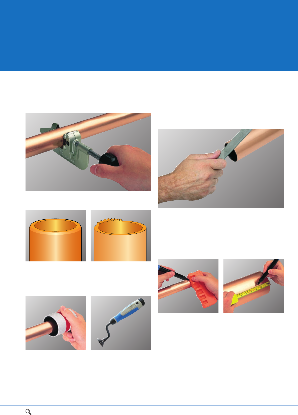
1Range overview 2Product details 3Technical data 4Installation instructions 5Flow charts 83
Preparation
Select the correct size of tube and fitting for the job. Ensure that both
are clean, in good condition and free from damage and imperfections.
1. Cut the tube square using a cutting tool such as the Rems
Cento, or a rotary tube cutter.
2. Care must be taken to ensure that tube is cut square, properly
deburred and free from scores.
3. Deburr both internal and external tube ends then wipe clean of
all swarf and debris to avoid damage to the 'O' ring upon tube
insertion. A S120 deburring tool can be used for this purpose, or
the Noga deburring kit (TA150) from the Tectite Advance range
of accessories.
1
33a
Tube cutters Remove burrs
2
4
3a. Noga hand tools. In order to remove any internal and external
burrs caused by the tube cutting operation, we recommend the use
of the Noga deburring kit. For internal deburring of all sizes, we
recommend the use of the TA143 and TA144 swivel blades used in
conjunction with TA147 handle. For external deburring of 15, 18
and 22mm tubes, we recommend the use of the TA145 used in
conjunction with the TA146 Rotadrive holder and the TA147 handle.
4. If a deburrer is not available use a fine file to prepare the
tube end.
5. If using plastic coated carbon steel system tube the plastic
coating must be removed from the socket depth of the fitting using
the S115 stripping tool from the XPress accessories range. Select
the correct size tool, fully insert the tube and twist the tool until
the excess of plastic is completely detached
6. The tube must be fully inserted to the fitting until it meets the
tube stop. Use a S110 XPress depth gauge or ruler to mark the
insertion (socket) depth of the fitting onto the tube – see table.
4
6
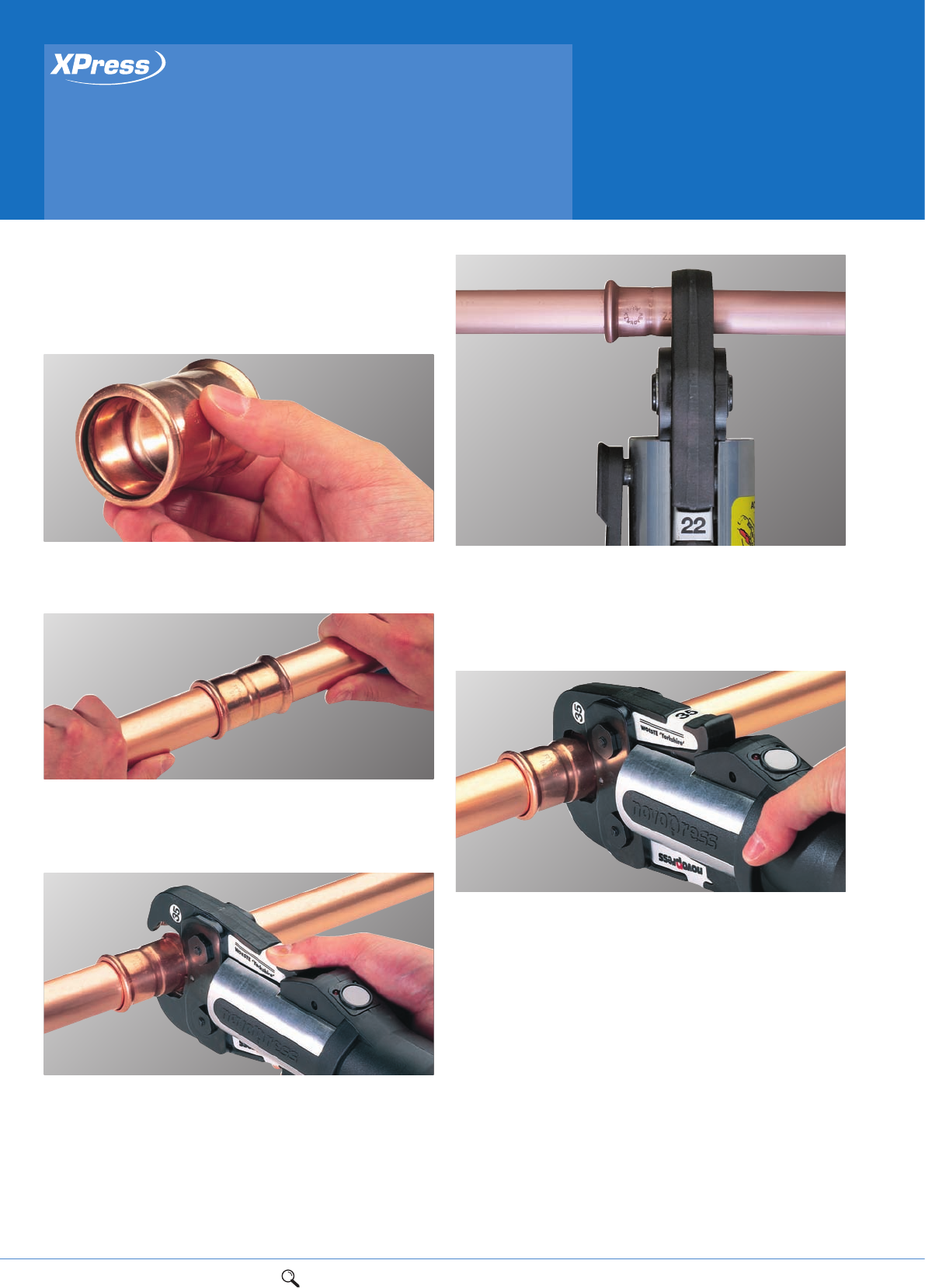
84 1Range overview 2Product details 3Technical data 4Installation instructions 5Flow charts
Jointing 15mm to 35mm
Please refer to the press-fit tool manufacturers instructions for
detailed operating and safety information before pressing joints.
Pegler Yorkshire recommends both Novopress and Rems tools.
1. Keep all fittings in their bag prior to installation to ensure the
lubrication does not dry out. Ensure the 'O' ring is seated correctly
within the fitting socket.
2. Assemble the joint, ensuring the tube is inserted into the fitting
until it meets the tube stop, using the insertion depth mark as a
visual aid. Only when the tube reaches the tube stop should the
pressing operation be undertaken.
3. Make the tool safe by isolating it from the power supply.
Select the correct jaws for the joint being made, checking that they
are free from damage. Attach the jaws, following the instructions
for your particular press-tool, and reconnect the power supply
when ready.
Insert the correctly sized jaws into the pressing tool and place
them over the bead at the mouth of the fitting. Ensure the jaw is
correctly lubricated with Dri-slide lubricant (S135 see page 86).
4. A 90° angle between the tube and jaws must be maintained
when pressing all joints. This will ensure the integrity of the joint
as well as protecting you from ‘kickback’. The pressing operation
should only be carried out when the tube is adequately supported
by brackets, not when the tube is suspended in the fitting
socket alone.
5. Keep your hands safely away from the joint and press the trigger
or button to start the jointing cycle. When the jaws fully enclose
the mouth of the fitting, the joint is complete. The jaw should
then be released from around the fitting. If all is in order, mark the
joint as complete.
1
2
5
3
Press-fit solutions
Installation instructions
15mm to 35mm sizes
4
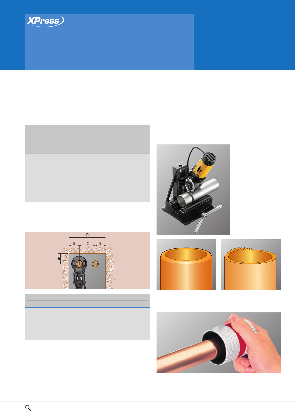
1Range overview 2Product details 3Technical data 4Installation instructions 5Flow charts 85
Press-fit solutions
Installation instructions
42mm to 108mm sizes
Socket depths
SOCKET DEPTHS:
XPRESS COPPER AND SOLAR, STAINLESS, CARBON,
COPPER GAS AND STAINLESS GAS
Size Socket depth
42mm 30mm
54mm 35mm
67mm** 50mm
76mm Copper 50mm
76mm Stainless/carbon 55mm
89mm* 64mm
108mm Copper 64mm
108mm Stainless/carbon 78mm
*Not XPress Copper/Gas
**Not XPress Stainless/Carbon
4
Press-fit solutions
Installation instructions
42mm to 108mm sizes
Spacing
Allow sufficient clearance around each fitting to allow pressing
jaws to be attached without hindrance.
Health and safety
1. We recommend that eye protection is worn when operating all
pressing tools.
2. Do not activate a pressing tool without a fitting in the jaws.
Note: When using power tools, great care must be taken at all
times. Always refer to the manufacturers’ instructions for all
machines and tools you use. Please refer to
www.pegleryorkshire.co.uk/SHE for further COSHH information.
The XPress jointing system has been designed with easy, efficient installation
in mind. XPress Copper, XPress Stainless, XPress Carbon, XPress Copper Gas,
XPress Stainless Gas and XPress Solar have common installation instructions.
PIPEWORK CLEARANCE (mm)
Size A B C D
42mm 75 75 115 265
54mm 85 85 120 290
67mm 100 100 145 345
76mm 115 115 165 395
89mm 125 125 185 435
108mm 135 135 200 470
Preparation
Select the correct size of tube and fitting for the job. Ensure that
both are clean, in good condition and free from damage and
imperfections.
1. Cut the tube square
using a cutting tool such
as the REMS Cento, or a
rotary tube cutter.
The Pegler
Yorkshire/REMS cutting
wheel is also available
for cutting carbon steel
tube. This significantly
reduces subsequent tube
preparation time. It is
available from REMS -
quote Ref. No. 845055.
2. Care must be taken to ensure that tube is cut square, properly
deburred and free from scores.
3. Deburr both internal and external tube ends then wipe clean of
all swarf and debris to avoid damage to the 'O' ring upon tube
insertion. An S120 deburring tool can be used for this purpose
on copper, stainless steel or carbon.
1
3
Tube cutters Remove burrs
2
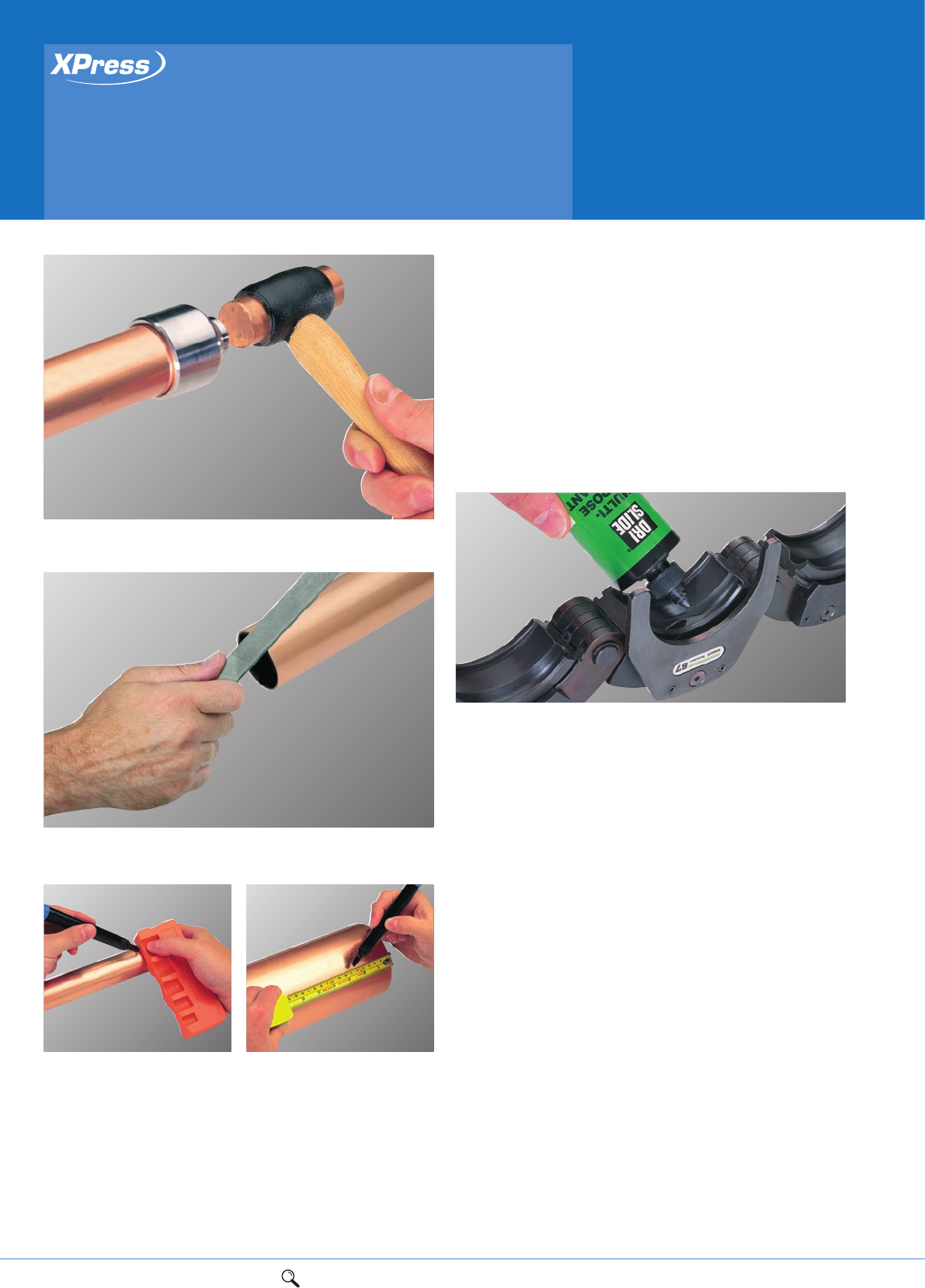
86 1Range overview 2Product details 3Technical data 4Installation instructions 5Flow charts
Press-fit solutions
Installation instructions
42mm to 108mm sizes
Dri-slide lubricant
(jaws and slings only)
Use of S135 Dri-Slide lubricant is essential when jointing large
sized fittings. The pressing profile groove of the sling jaws should
be cleaned and lubricated after every 50 joints for 42mm to 76mm
sizes, and every 5 joints for 108mm.
Dri-slide should also be applied between the main sling arms and
the moving segments; and along the pivot pins between the arms.
Note: Wipe clean any excess lubricant so that it does not come
into contact with the fitting 'O' ring.
4. Alternatively, for copper, use the appropriate sized XPress S122
percussion deburrer.
5. If a deburrer is not available use a fine file to prepare the
tube end.
6. The tube must be fully inserted to the fitting until it meets the
tube stop. Use a S110 XPress depth gauge or ruler to mark the
insertion (socket) depth of the fitting onto the tube – see table.
4
5
6
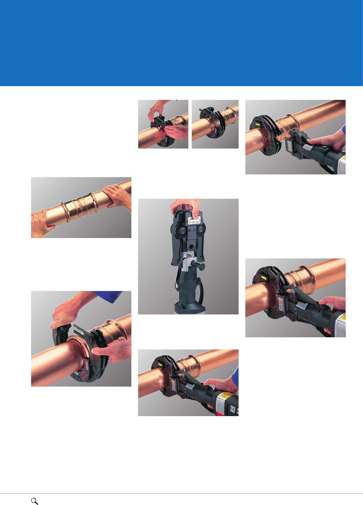
1Range overview 2Product details 3Technical data 4Installation instructions 5Flow charts 87
4
Jointing 42mm
to 108mm
Please refer to the pressing tool
manufacturer’s instructions for detailed
operating and safety information before
pressing joints. Pegler Yorkshire recommends
Novopress tools. 108mm XPress Copper
fittings must only be pressed with sling
jaws marked for copper only.
1. Assemble the joint, ensuring the tube is
inserted into the fitting until it meets the
tube stop, using the insertion depth mark
as a visual aid. Only when the tube reaches
the tube stop should the pressing operation
be undertaken.
2. Select the appropriate sized sling jaw,
open the sling by depressing the spring
loaded pin, pull the sling apart and place
over the fitting. Make sure the groove in
the sling corresponds to the bead on the
fitting and the support plate on the sling
fits over the tube side of the joint, taking
care not to trap your fingers in the sling.
Ensure the sling is correctly lubricated with
Dri-slide lubricant (S135 see page 86).
6. When pressing has been completed the
adaptor should be disengaged by depressing
the jaw levers, and the slings removed from
the fitting.
With the tool fully supported and not
hanging from the pipework, and with your
hands safely away from the jaws, start the
pressing cycle.
108mm second press
7. For 108mm fittings the press sling should
be left in place after the first clamp and the
secondary adaptor (S324) attached.
Re-check to ensure the tube is still fully
inserted into the fitting and repeat the
pressing operation to complete the
procedure.
The 108mm joint is not fully made until
the fitting has been through two pressing
operations. Allow sufficient clearance
around each fitting to allow press-fit jaws
to be attached without hindrance.
6
7
3. Turn the catch mechanism toward the
locking pin, depress the spring loaded pin
and push the catch into the pin until the
mechanism engages. Revolve the sling
around the fitting to the desired pressing
position.
4. Attach the appropriate adaptor to the
press tool and close the breach bolt.
Make the tool safe by isolating it from the
power supply.
5. Attach the sling by depressing the
adaptor jaw levers and inserting the claws
as far as possible into the grooves of the
sling. A 90° angle between the tube and
sling must be maintained when pressing all
joints. This will ensure the integrity of the
joint as well as protecting you from
‘kickback’. Commence the pressing operation
by pressing the trigger or button.
1
4
2
3
5
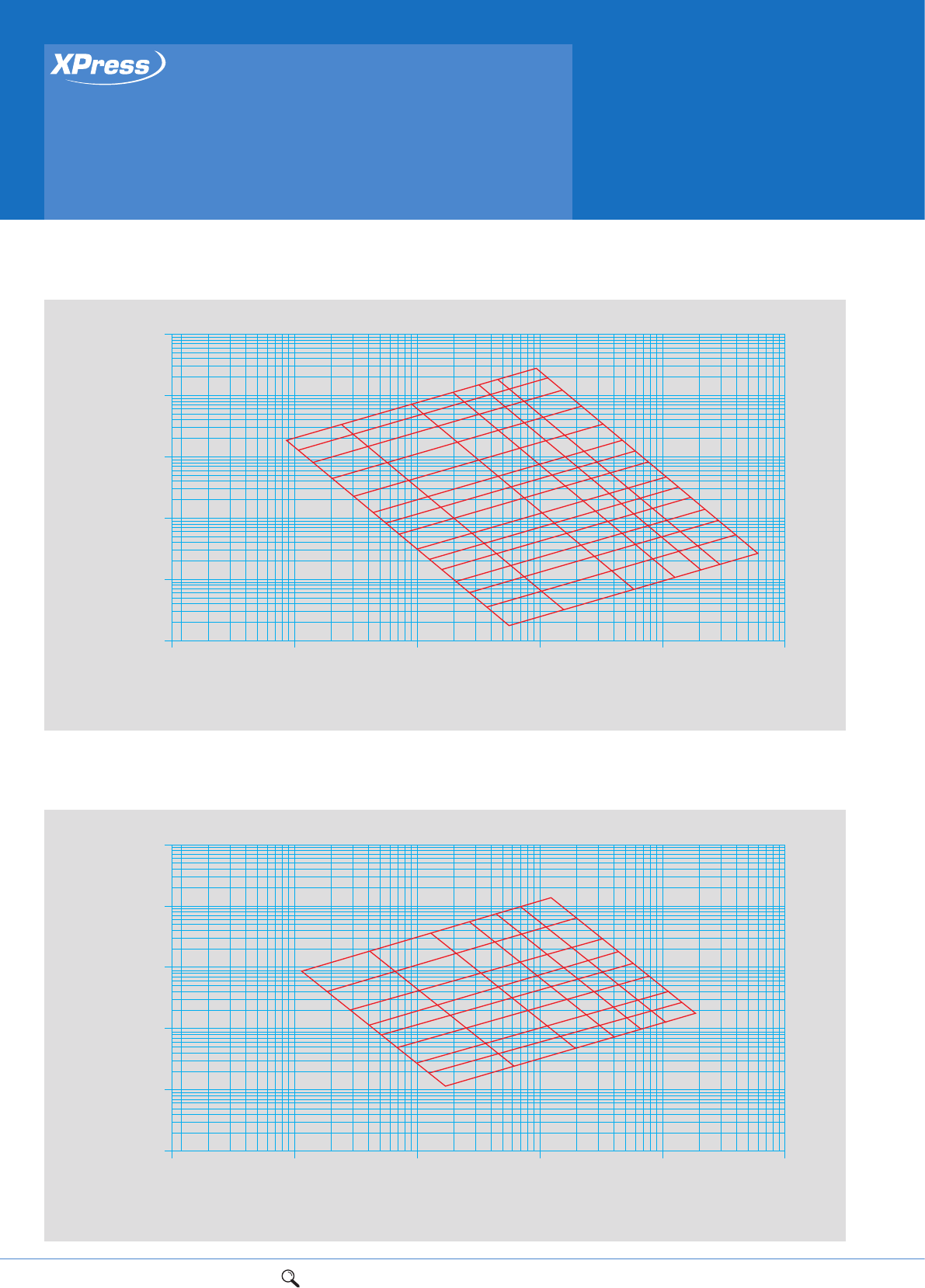
Press-fit solutions
Flow charts
Flow (l/s)
Pressure loss (mbar/minute) at 65ºC
Speed of circulation (m/s)
Outside tube diameter (mm)
0.001 0.01 0.1
0.1 0.2
0.4 0.6 0.81.0 1.5 159
133
103
28
35
42
54
76
22
18
15
12
108
6
1 10 100
0.001
0.01
0.01
0.1
1
10
100
Head loss/Pressure loss diagram: Copper
Flow (l/s)
Pressure loss (mbar/minute) at 65ºC
Speed of circulation (m/s)
Outside tube diameter (mm)
0.001 0.01 0.1
0.1
0.2
0.4 0.6 0.81.0 1.5 108
78
5442
35 28
22
18
15
1 10 100
0.001
0.01
0.01
0.1
1
10
100
Head loss/Pressure loss diagram: Carbon steel
88 1Range overview 2Product details 3Technical data 4Installation instructions 5Flow charts
1Range overview 2Product details 3Technical data 4Installation instructions 5Flow charts 89
5
Flow (l/s)
Pressure loss (mbar/minute) at 65ºC
Speed of circulation (m/s)
Outside tube diameter (mm)
0.001 0.01 0.1
0.1 0.2
0.4 0.6 0.81.0 1.5 108
78
5442
3528
22
18
15
1 10 100
0.001
0.01
0.01
0.1
1
10
100
Head loss/Pressure loss diagram: Stainless steel

90
Notes

91

UK sales
Free Phone: 0800 156 0010
Free Fax: 0808 156 1011
Email: uk.sales@pegleryorkshire.co.uk
Export
Tel: +44 (0) 1302 855 656
Fax: +44 (0) 1302 730 513
Email: export@pegleryorkshire.co.uk
Technical Help
Free Phone: 0800 156 0050
Free Fax: 0808 156 1012
Email: tech.help@pegleryorkshire.co.uk
Brochure Hotline
Free Phone: 0800 156 0020
Free Fax: 0808 156 1011
Email: info@pegleryorkshire.co.uk
www.pegleryorkshire.co.uk
Pegler Yorkshire Group Limited
St. Catherine’s Avenue, Doncaster,
South Yorkshire, DN4 8DF, England.
Tel: 0844 243 4400 Fax: 0844 243 9870
Registered in England Company No. 00401507
Registered Office: Haigh Park Road, Stourton, Leeds,
West Yorkshire, LS10 1RT, England.
All brand names and logo styles are registered trademarks.
Maintaining a policy of continual product development,
Pegler Yorkshire reserves the right to change specifications, design
and materials of products listed in this publication without prior notice.
LIT.REF: 880119.08.10
Pegler Yorkshire
Our brands:
RENEWABLE SOLUTIONS
LUXURY TAP SOLUTIONS
