Z Stack User's Guide CC2530 ZNP For Zig Bee PRO Network Processor Sample Applications
User Manual:
Open the PDF directly: View PDF ![]() .
.
Page Count: 74
- Abbreviations
- 1. Introduction
- 2. Assumptions
- 3. CC2530 ZNP Software and Hardware Description
- 2.1. Development System Requirements
- 2.2. CC2530 ZNP Software
- 2.3. CC2530 ZNP Hardware
- 2.3.1. MSP430 based hardware setup used for the sample applications
- 2.3.2. Hardware setup for a USB connected ZNP
- 2.3.3. Hardware for programming the CC2530EM
- 2.3.4. Hardware for programming the CC2531USBDongle
- 2.3.5. Easiest and quickest hardware choice
- 3. Building the ZNP needed for the sample application
- 4. Configuring and Using Z-Stack ZAP sample applications
- 4.1. ZAP Sample Applications Setup (general)
- 4.1.1. Hardware
- 4.1.2. Software
- 4.2. Temperature Voltage Sensor Application (TVSA)
- 4.2.1. Hardware and Software setup
- 4.2.2. Available Settings
- 4.2.3. UART Connection
- 4.2.4. Running the example
- 4.2.5. In Depth on the Example
- 4.3. Home Automation (HA) Sample Application
- 4.3.1. Hardware and Software setup
- 4.3.2. Running the example
- 4.3.3. In Depth on the Example
- 4.4. Smart Energy Sample Application
- 4.4.1. Required Tools
- 4.4.2. Configuring Certicom Keys for Production Devices
- 4.4.3. Getting Started
- 4.4.4. Theory of Operation
- 4.4.5. ESP
- 4.4.6. Simple Metering Device
- 4.4.7. Load Control Device
- 4.4.8. PCT
- 4.4.9. In Premise Display
- 4.4.10. Range Extender
- 4.4.11. Limitations of the SE Sample Application
- 4.5. ZAP Proxy to ZNP SBL
- 4.5.1. Hardware and Software setup
- 4.5.2. Required Settings
- 4.5.3. UART Connection
- 4.5.4. Incorporating the example
- 4.5.5. In Depth on the Example
- FAQ
- 5. References

Z-Stack
User’s Guide For
CC2530 ZigBee-PRO Network Processor
Sample Applications
ZigBee-2007 Release
Version 2.3.1-1.4.0
Document Number: SWRU242
Texas Instruments, Inc.
San Diego, California USA
Copyright 2010 Texas Instruments, Inc. All rights reserved.

Z-Stack User's Guide - CC2530 ZNP SWRU242 Version 1.2
Revision Description Date
1.0 Initial release 01/18/2010
1.1 Small corrections (Link Status messages, etc.) 01/21/2010
1.2 Updated for Z-stack 2.3.1 release. Document modifications include
support for installing Certicom keys in the CC2530 lock bits flash.
Enhanced Chapter 3 for ZNP SBL and Chapter 4 for ZAP Proxy to SBL
08/02/2010
i Copyright 2010 Texas Instruments, Inc. All rights reserved.

Z-Stack User's Guide - CC2530 ZNP SWRU242 Version 1.2
Table of Contents
ABBREVIATIONS...................................................................................................................... V
1. INTRODUCTION................................................................................................................. 1
2. ASSUMPTIONS.................................................................................................................... 2
3. CC2530 ZNP SOFTWARE AND HARDWARE DESCRIPTION .................................. 2
2.1. DEVELOPMENT SYSTEM REQUIREMENTS......................................................................... 2
2.2. CC2530 ZNP SOFTWARE ................................................................................................ 3
2.3. CC2530 ZNP HARDWARE ............................................................................................... 4
2.3.1. MSP430 BASED HARDWARE SETUP USED FOR THE SAMPLE APPLICATIONS .................. 4
2.3.2. HARDWARE SETUP FOR A USB CONNECTED ZNP ........................................................ 6
2.3.3. HARDWARE FOR PROGRAMMING THE CC2530EM....................................................... 7
2.3.4. HARDWARE FOR PROGRAMMING THE CC2531USBDONGLE ....................................... 8
2.3.5. EASIEST AND QUICKEST HARDWARE CHOICE................................................................ 9
3. BUILDING THE ZNP NEEDED FOR THE SAMPLE APPLICATION..................... 10
3.1. ZNP SOFTWARE PROJECT FILES ..................................................................................... 10
3.2. COMPILING A ZNP IMAGE (HEX-FILE)............................................................................ 11
3.3. ABOUT THE IMAGE WITH SERIAL BOOT LOADER SUPPORT .............................................. 14
3.4. PROGRAMMING THE ZNP IMAGE ONTO THE TARGET...................................................... 15
3.5. CHANGING SETTINGS IN THE ZNP PROJECT.................................................................... 18
4. CONFIGURING AND USING Z-STACK ZAP SAMPLE APPLICATIONS............. 18
4.1. ZAP SAMPLE APPLICATIONS SETUP (GENERAL)............................................................ 19
4.1.1. HARDWARE................................................................................................................ 19
4.1.2. SOFTWARE................................................................................................................. 20
4.2. TEMPERATURE VOLTAGE SENSOR APPLICATION (TVSA) ............................................. 23
4.2.1. HARDWARE AND SOFTWARE SETUP ........................................................................... 23
4.2.2. AVAILABLE SETTINGS................................................................................................ 23
4.2.3. UART CONNECTION.................................................................................................. 23
4.2.4. RUNNING THE EXAMPLE............................................................................................. 25
4.2.5. IN DEPTH ON THE EXAMPLE....................................................................................... 27
4.3. HOME AUTOMATION (HA) SAMPLE APPLICATION......................................................... 29
4.3.1. HARDWARE AND SOFTWARE SETUP ........................................................................... 29
4.3.2. RUNNING THE EXAMPLE............................................................................................. 30
4.3.3. IN DEPTH ON THE EXAMPLE....................................................................................... 30
4.4. SMART ENERGY SAMPLE APPLICATION ......................................................................... 34
4.4.1. REQUIRED TOOLS ...................................................................................................... 36
4.4.2. CONFIGURING CERTICOM KEYS FOR PRODUCTION DEVICES ..................................... 38
4.4.3. GETTING STARTED..................................................................................................... 41
4.4.4. THEORY OF OPERATION ............................................................................................. 49
4.4.5. ESP............................................................................................................................ 49
4.4.6. SIMPLE METERING DEVICE........................................................................................ 52
4.4.7. LOAD CONTROL DEVICE............................................................................................ 53
4.4.8. PCT ........................................................................................................................... 56
4.4.9. IN PREMISE DISPLAY ................................................................................................. 58
ii Copyright 2010 Texas Instruments, Inc. All rights reserved.

Z-Stack User's Guide - CC2530 ZNP SWRU242 Version 1.2
4.4.10. RANGE EXTENDER ..................................................................................................... 59
4.4.11. LIMITATIONS OF THE SE SAMPLE APPLICATION ........................................................ 60
4.5. ZAP PROXY TO ZNP SBL ............................................................................................. 62
4.5.1. HARDWARE AND SOFTWARE SETUP ........................................................................... 62
4.5.2. REQUIRED SETTINGS.................................................................................................. 62
4.5.3. UART CONNECTION.................................................................................................. 63
4.5.4. INCORPORATING THE EXAMPLE.................................................................................. 63
4.5.5. IN DEPTH ON THE EXAMPLE....................................................................................... 65
FAQ.............................................................................................................................................. 66
5. REFERENCES.................................................................................................................... 68
Table of Figures
FIGURE 1: INTERACTION BETWEEN THE ZAP AND THE ZNP ........................................................... 1
FIGURE 2: HW COMBINATIONS USED FOR SAMPLE APPLICATIONS.................................................. 4
FIGURE 3: CC2530 EVALUATION MODULE (CC2530EM).............................................................. 5
FIGURE 4: CCMSP-EM430F2618 & SMARTRF05EB WITH AN EM PLUGGED IN ........................... 5
FIGURE 5: MSP-EXP430F5438 WITH EM AND MSP-FET430UIF................................................. 6
FIGURE 6: PRINCIPLE FOR USING THE CC2531USB DONGLE AS ZNP............................................. 6
FIGURE 7: CC2531USBDONGLE .................................................................................................... 7
FIGURE 8: CC2530EM PLUGGED INTO A SMARTRF05EB FOR PROGRAMMING............................... 7
FIGURE 9: CC-DEBUGGER............................................................................................................... 8
FIGURE 10: PROGRAMMING THE CC2531USBDONGLE USING THE SMARTRF05EB....................... 8
FIGURE 11: CC2530EMK............................................................................................................... 9
FIGURE 12: LOCATION OF THE ZNP PROJECT. ............................................................................... 10
FIGURE 13: LOCATION OF THE ZNP WORKSPACE FILE................................................................... 10
FIGURE 14: VIEW AFTER OPENING ZNP.EWW IN THE IAR EW 8051............................................... 11
FIGURE 15: WORKSPACE SETUP .................................................................................................... 12
FIGURE 16: STARTING THE COMPILATION AND BUILD OF THE ZNP IMAGE .................................... 13
FIGURE 17: SUCCESSFUL BUILD WITHOUT ANY WARNINGS OR ERRORS ......................................... 14
FIGURE 18: MAP FILE WITH USEFUL INFORMATION (E.G. IMAGE SIZE)........................................... 14
FIGURE 19: SCREEN SHOT FROM SMARTRF FLASH PROGRAMMER (BEFORE PROGRAMMING)....... 16
FIGURE 20: SCREEN SHOT FROM SMARTRF FLASH PROGRAMMER (AFTER PROGRAMMING)......... 17
FIGURE 21: LOCATION OF THE ZAP SAMPLE APPLICATION CODE .................................................. 19
FIGURE 22: ZIGBEE DEVICE TYPE SELECTION (FOR TVSA AND HA SAMPLE APPLICATION) ........ 20
FIGURE 23: ZAP CONFIGURATION FILE EXAMPLE CONFIGURING CHANNEL 24 – 0X18 .................. 21
FIGURE 24: UART SETTINGS USED BY Z-SENSOR MONITOR ........................................................ 24
FIGURE 25: SCREEN SHOT FROM ZIGBEE SENSOR MONITOR (NO DONGLE CONNECTED)............... 26
FIGURE 26: SCREEN SHOT FROM ZIGBEE SENSOR MONITOR (DONGLE SUCCESSFULLY CONNECTED)
............................................................................................................................................... 26
FIGURE 27: SCREEN SHOT FROM ZIGBEE SENSOR MONITOR (1 DONGLE + 1 SENSOR)................... 27
FIGURE 28: SCREEN SHOT FROM UBIQUA SHOWING SNIFFER LOG ................................................. 31
FIGURE 29: SYSTEM CONTEXT DIAGRAM...................................................................................... 35
FIGURE 30: Z-CONVERTER GRAPHICAL INTERFACE...................................................................... 38
FIGURE 31: MEMORY MAP OF LOCK BITS PAGE.............................................................................. 39
iii Copyright 2010 Texas Instruments, Inc. All rights reserved.

Z-Stack User's Guide - CC2530 ZNP SWRU242 Version 1.2
FIGURE 32: SE SAMPLE APPLICATION WORKSPACE OPTIONS ......................................................... 41
FIGURE 33: SE SAMPLE APPLICATION WORKSPACE SETUP FOR ESP .............................................. 42
FIGURE 34: PROJECT OPTIONS (FET DEBUGGER) FOR SE SAMPLE APPLICATIONS........................ 44
FIGURE 35: SCREEN SHOT FROM Z-TOOL SHOWING THE SETTINGS WINDOW TO SET COM1
SETTINGS................................................................................................................................ 45
FIGURE 36: SETTINGS FOR SENDING THE ZDO_GET_LINK_KEY MESSAGE ............................... 46
FIGURE 37: SCREEN SHOT FROM UBIQUA PROTOCOL ANALYZER (SECURITY SETTINGS)............... 46
FIGURE 38: SCREEN SHOT FROM UBIQUA (START UP – PART 1)..................................................... 48
FIGURE 39: SCREEN SHOT FROM UBIQUA (START UP – PART 2)..................................................... 48
FIGURE 40: FLOWCHART OF DEVICE STARTUP LOGIC................................................................... 50
FIGURE 41: SEQUENCE DIAGRAM FOR A SIMPLE METER DEVICE.................................................. 53
FIGURE 42: SEQUENCE DIAGRAM FOR A LOAD CONTROL DEVICE ................................................ 54
FIGURE 43: SEQUENCE DIAGRAM FOR A PCT ............................................................................... 57
FIGURE 44: SEQUENCE DIAGRAM FOR AN IN PREMISE DISPLAY ................................................... 58
FIGURE 45: SEQUENCE DIAGRAM FOR A RANGE EXTENDER ......................................................... 59
FIGURE 46: FLOW DIAGRAM FOR ZAP PROXY TO ZNP SBL......................................................... 62
FIGURE 47: SBDEMO PC TOOL...................................................................................................... 63
FIGURE 48: ADDING THE FILES FOR ZAP PROXY TO ZNP SBL..................................................... 64
FIGURE 49: ADDING THE TASK FOR ZAP PROXY TO ZNP SBL ..................................................... 65
iv Copyright 2010 Texas Instruments, Inc. All rights reserved.

Z-Stack User's Guide - CC2530 ZNP SWRU242 Version 1.2
v Copyright 2010 Texas Instruments, Inc. All rights reserved.
Abbreviations
AF Application Framework
API Application Programming Interface
BB Battery Board
CBKE Certificate-based Key Establishment
DUT Device Under Test
EB Evaluation Board
ECC Elliptic Curve Cryptography
EM Evaluation Module
ESP Electronic Service Portal
HA Home Automation
HAL Hardware Abstraction Layer
HAN Home Area Network
HW Hardware
IPD In-Premise Display
OSAL Operating System Abstraction Layer
OTA Over-the-Air – refers to the process of and/or the ZCL for transmitting and
installing a new image in a device remotely via over-the-air messages.
PCT Programmable Communicating Thermostat
SBL Serial Boot Load – the capability to install a new image via a serial connection
such that the new image is installed directly and the receiving device does not
need extra non-volatile storage space to first store the new image before actually
installing it (e.g. a necessary intermediate step in OTA.)
SBL Serial Boot Loader – refers to the embedded code that implements SBL
capability.
SE Smart Energy
SNA Sensor Network Analyzer
SoC System on a Chip
SW Software
TVSA Temperature Voltage Sample Application
ZAP ZigBee-PRO Application Processor
ZCL ZigBee Cluster Library
ZDO ZigBee Device Object
ZNP ZigBee-PRO Network Processor
Z-Stack User's Guide - CC2530 ZNP SWRU242 Version 1.2
1. Introduction
This document accompanies the Texas Instruments Z-Stack™ solution for use with the CC2530
ZigBee® Development Kit. The Z-Stack software (www.ti.com/z-stack) is a complete protocol
stack and application development solution that conforms to ZigBee Alliance standards
(www.zigbee.org).
The purpose of this document is to explain the setup and usage of the sample applications that
are provided to create an MSP430-based ZigBee Application Processor (ZAP) that utilizes a
CC2530/CC2531 SoC-based ZigBee-PRO Network Processor (ZNP) to communicate over a
ZigBee network. Before addressing the different sample applications (Chapter 4) it is shown
which hardware setup to use (Chapter 3) and how to build the ZNP image (hex-file) that needs to
be programmed onto a CC2530/CC2531 (in the following simply referred to as SoC) to turn it
into a ZNP (Chapter 3). In the FAQ section towards the end of document, FAQs are addressed
while the References to other documentation can be found in Chapter 5.
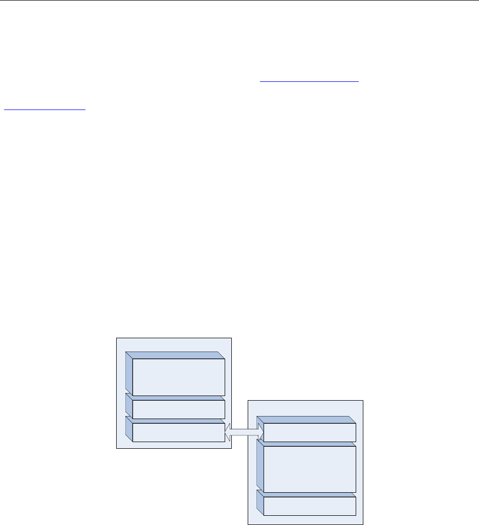
Figure 1 illustrates how easy an application processor can be connected to the SoC based ZNP to
obtain ZigBee connectivity. The ZAP describes the Processor/MCU that is running the
application code, which is using the CC2530-ZNP API over the UART/SPI/USB interface to
communicate with the ZNP, which is running the full Z-Stack and hence provides the ZigBee
connectivity with its IEEE 802.15.4 radio.
Application Processor
SPI/UART/USB interface
CC2530-ZNP API CC2530
Application
IEEE 802.15.4 Radio
ZigBee stack and
802.15.4 MAC
SPI/UART/USB interface
Figure 1: Interaction between the ZAP and the ZNP
For more technical details regarding the usage of the Z-Stack in general (partially also applicable
for the ZNP) the reader is referred to the Z-Stack documentation, where one should start with the
Z-Stack Developer's Guide [1]. The details of the ZNP interface are described in the CC2530-
ZNP Interface Specification [2].
Although the sample application examples utilize an MSP430 CPU, the ZAP could be any MCU
that supports the SPI/UART/USB connectivity to the ZNP (e.g. a Stellaris Cortex-M3 or a
1 Copyright 2010 Texas Instruments, Inc. All rights reserved.

Z-Stack User's Guide - CC2530 ZNP SWRU242 Version 1.2
Windows PC application). Only the HAL and OSAL specific components would need to be
ported to the other platform.
For general documentation regarding the Z-Stack the reader is first referred to the Z-Stack
Developer’s Guide and the Z-Stack User’s Guide of the respective platform, which can be found
in the platform specific folder in the Z-Stack documentation folder (C:\Texas
Instruments\ZStack-CC2530-x.x.x-x.x.x\Documents); for example for the CC2530 it is placed in:
C:\Texas Instruments\ZStack-CC2530-x.x.x-x.x.x\Documents\CC2530 (if you use the default
installation directory). After reading those Z-Stack guides the reader can find more detailed
information in the other Z-Stack documents.
2. Assumptions
1. All paths shown in text and figures assume that the Z-Stack was installed in the default
directory of the “C:” drive.
3. CC2530 ZNP Software and Hardware Description
After a short description of the development system requirements (Section 2.1), this Chapter
describes the software (Section 2.2) and hardware (Section 2.3) required for running and
working with the sample applications for the CC2530-ZNP.
2.1. Development System Requirements
The ZAP sample applications and the ZNP Z-Stack projects are based on the IAR Embedded
Workbench (EW8051 [3] and MSP430 [4]) suite of software development tools. These tools
support project management, compiling, assembling, linking, downloading, and debugging.
The Texas Instruments SmartRF Flash Programmer [5] is a tool that provides various
programming capabilities when using SmartRF based development kits.
Chapter 3 explains how to use the IAR Embedded Workbench and the SmartRF Flash
Programmer to build a ZNP image (hex-file) and then program it onto the SoC. The usage of the
sample application projects for the ZAP is addressed in Chapter 4.
In order to modify, build, and use the ZNP image and the ZAP sample applications (and to
program the resulting images onto the hardware the following software and development tools
are required:
For the ZNP: IAR Systems Embedded Workbench for 8051 [3]
For the ZAP (MSP430 based): IAR Systems Embedded Workbench for MSP430 [4]
For programming the hardware: Texas Instruments SmartRF Flash Programmer [5]
ZNP-Software: Texas Instruments Z-Stack – version ZStack-CC2530-2.3.1-1.4.0 or
newer [6]
ZAP-Software: ZAP sample application installer ZAP-MSP430-1.0.0 or newer [7]
2 Copyright 2010 Texas Instruments, Inc. All rights reserved.

Z-Stack User's Guide - CC2530 ZNP SWRU242 Version 1.2
For details regarding their installation the reader is referred to the corresponding documentation
for each of the installers and tools.
2.2. CC2530 ZNP Software
All you need to build your own CC2530/CC2531 based ZNP is a ZNP image (hex-file), which
you can program onto the SoC using the SmartRF Flash Programmer [5].
The software required to build a ZNP image (hex-file) is part of the “full” Z-Stack installation
package [6] (version ZStack-CC2530-2.3.1-1.4.0 or newer) that contains all of the documentation
and software required to install, configure, and develop applications using Z-Stack.
Documentation regarding the Z-Stack can be found in the Z-Stack documentation folder:
C:\Texas Instruments\ZStack-<platform>-<stack-version>-<applications version>\Documents\
e.g. C:\Texas Instruments\ZStack-CC2530-2.3.1-1.4.0\Documents\
(if you use the default installation directory).
The software required to build a ZNP image (hex-file) is provided in form of a Z-Stack project,
named ZNP. Details on how to use this project to build the ZNP image is given in Chapter 3.
The software required to build a ZAP image (hex-file) for a MSP430 based application processor
is provided in form of an additional installer [7]. The different projects and their usage are
addressed in Chapter 4.
Note: The ZNP software is part of the “full” Z-Stack installer [6] targeting the CC2530 platform
and it requires the IAR EW8051 [3] in case you want to build your own ZNP images (hex-files).
The ZAP software provided for the MSP430 (see Chapter 4) comes in a separate sample
application installer [7], which requires the IAR EW430 [4]. In case you have ready-built ZNP
images you do not need to install the ZNP software and the IAR EW8051; instead the only
additional tool you need to build a ZNP is the SmartRF Flash Programmer [5] to program the
ZNP image onto the SoC.
3 Copyright 2010 Texas Instruments, Inc. All rights reserved.

Z-Stack User's Guide - CC2530 ZNP SWRU242 Version 1.2
2.3. CC2530 ZNP Hardware
The ZNP can be built using Texas Instruments ZigBee-PRO capable system on chip (SoC)
devices; i.e. either CC2530 [8] or CC2531 [9]. The details on how to connect the SoC to the ZAP
via SPI/UART/USB are described in detail in the CC2530-ZNP Interface Specification [1]. The
following subsections address different hardware setups for a ZNP based development. The first
sections (2.3.1-2.3.4) describe several possible setups, as one already might own different
development boards; however, if you do not have any development boards yet, you should jump
straight to Section 2.3.5
For more detailed information regarding the different development boards the reader is referred
to the corresponding user guides.
2.3.1. MSP430 based hardware setup used for the sample applications
The sample applications in Chapter 4 are based on the CC2530 as ZNP and a MSP430
(MSP430F2618 / MSP430F5438) as ZAP (see Figure 2).
ZAP
ZAP ZNP
ZNP
Option-2: CCMSP-EM430F2618 & SmartRF05EB
ZigBee Network ProcessorZigBee Application Processor
Option-1/Option-2: CC2530EMOption-1: MSP-EXP430F5438
SPI
Figure 2: HW combinations used for Sample Applications
The CC2530 development board used for the sample applications is the CC2530EM (CC2530
Evaluation Module) shown in Figure 3. The CC2530EM is the reference design for the usage of
CC2530 and it is used in all CC2530 development kits (CC2530DK and CC2530ZDK). For
more details about the different CC2530 development boards/tools/kits the reader is referred to
the Tools & Software section of the CC2530 product folder [8].
4 Copyright 2010 Texas Instruments, Inc. All rights reserved.
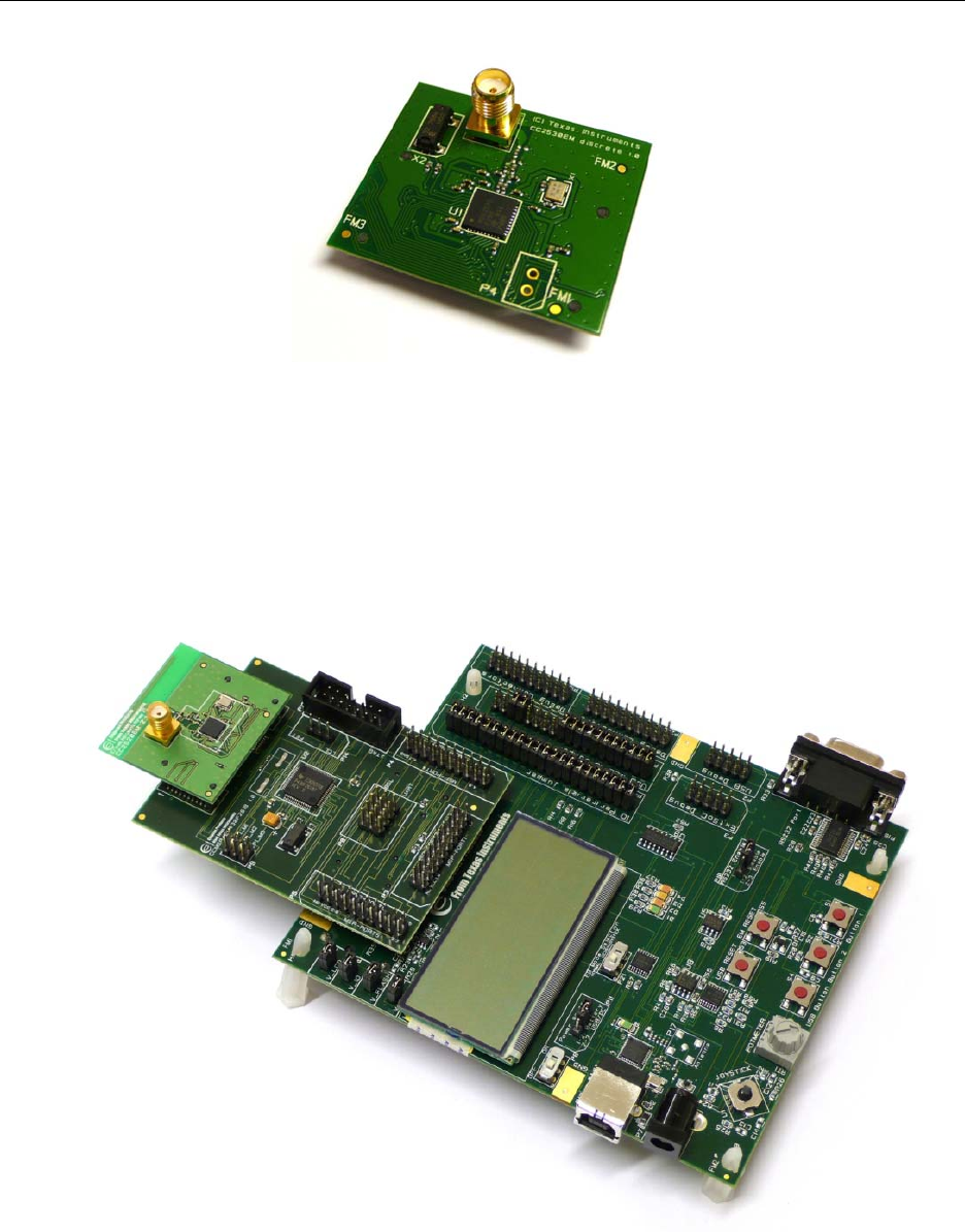
Z-Stack User's Guide - CC2530 ZNP SWRU242 Version 1.2
Figure 3: CC2530 Evaluation Module (CC2530EM)
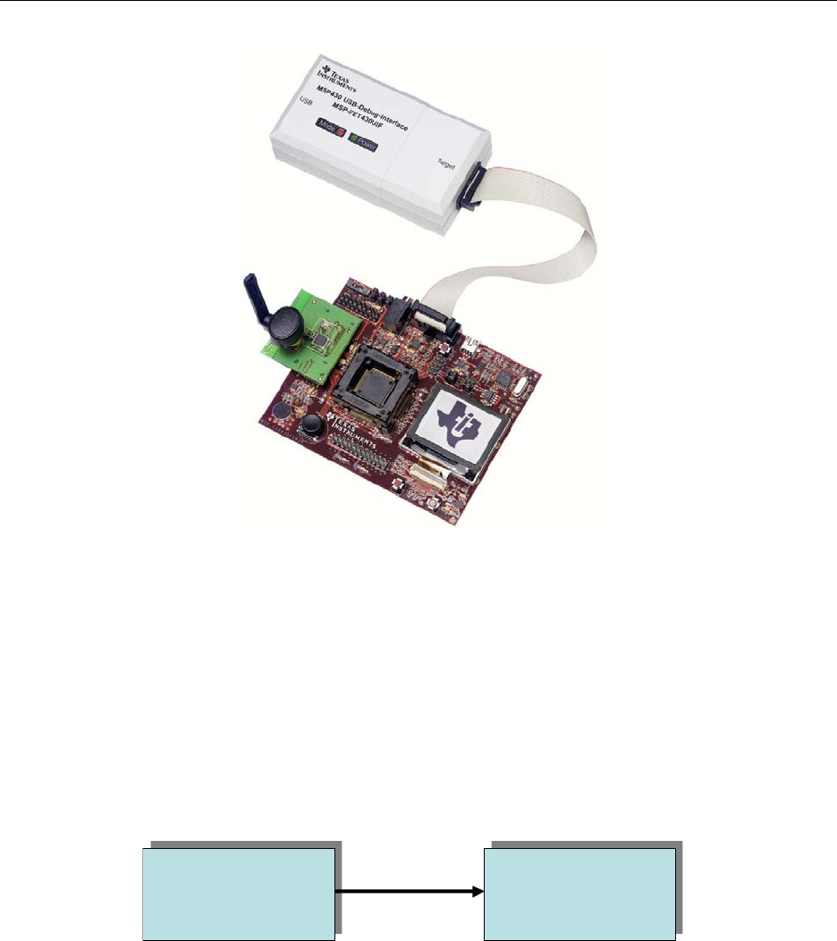
The development boards used for the ZAP are the CCMSP-EM430F2618 & SmartRF05EB for
the MSP430F2618 (see Figure 4) and the MSP-EXP430F5438 for the MSP430F5438 (see Figure
5). Both board setups have the connectors required to plug in a CC2530EM.
Figure 4: CCMSP-EM430F2618 & SmartRF05EB with an EM plugged in
5 Copyright 2010 Texas Instruments, Inc. All rights reserved.
Z-Stack User's Guide - CC2530 ZNP SWRU242 Version 1.2
Figure 5: MSP-EXP430F5438 with EM and MSP-FET430UIF
2.3.2. Hardware setup for a USB connected ZNP
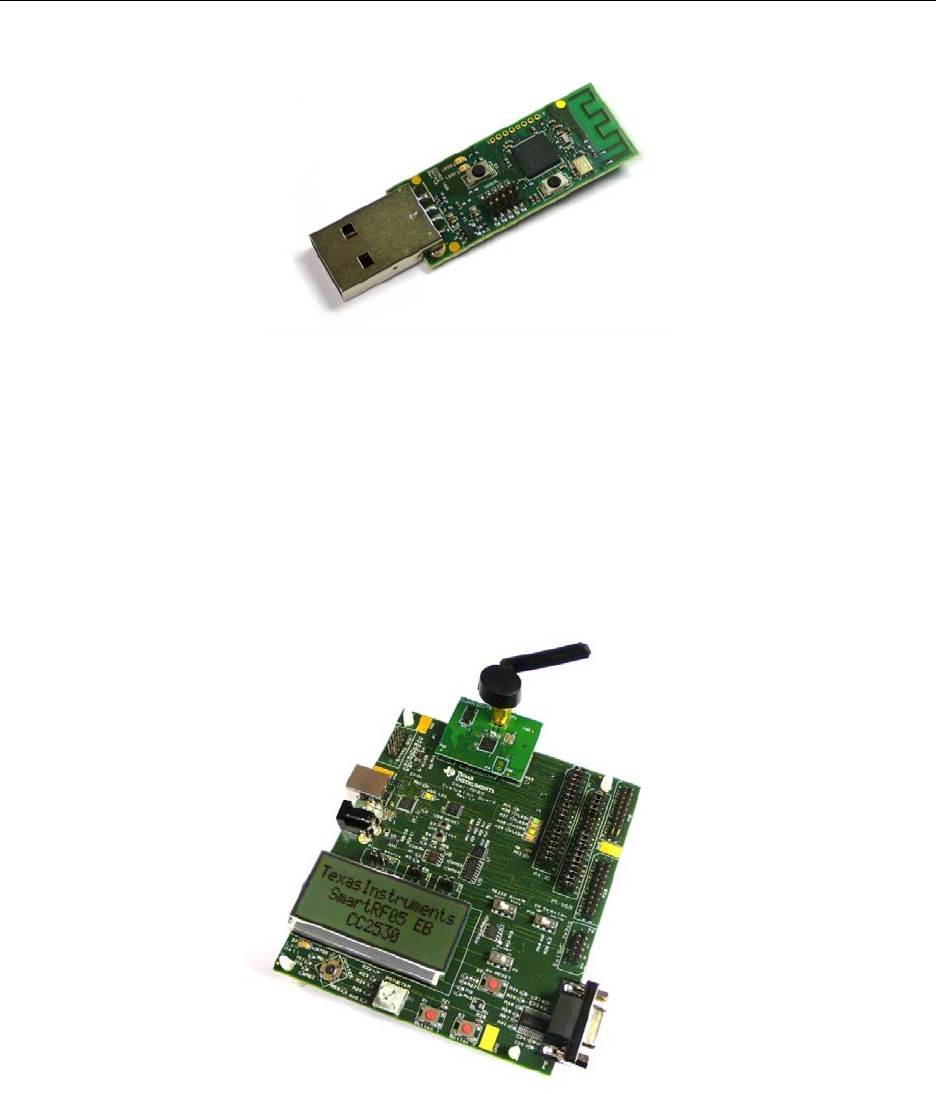
The CC2531USBDongle (see Figure 7) is a third HW option to work with a ZNP; however it
does not provide an MCU that could act as ZAP. The dongle is based on a CC2531 [9]; i.e.
providing an on-chip USB interface to the ZNP that one could use via a PC application (that acts
as ZAP); see Figure 6. However, as it is not used in the sample applications (described in
Chapter 4) it is not further addressed in this document.
ZAP
ZAP ZNP
ZNP
ZigBee Network ProcessorZigBee Application Processor
Option-3: CC2531USBDongleOption-3: PC
USB
Figure 6: Principle for using the CC2531USB Dongle as ZNP
6 Copyright 2010 Texas Instruments, Inc. All rights reserved.
Z-Stack User's Guide - CC2530 ZNP SWRU242 Version 1.2
Figure 7: CC2531USBDongle
2.3.3. Hardware for programming the CC2530EM
To program the ZNP image (hex-file) with the SmartRF Flash Programmer onto a CC2530EM,
the EM needs to be plugged directly into one of the following boards: SmartRF04EB,
SmartRF05EB (see Figure 8), SmartRF05BB, or SoC_BB board. The latter two boards, also
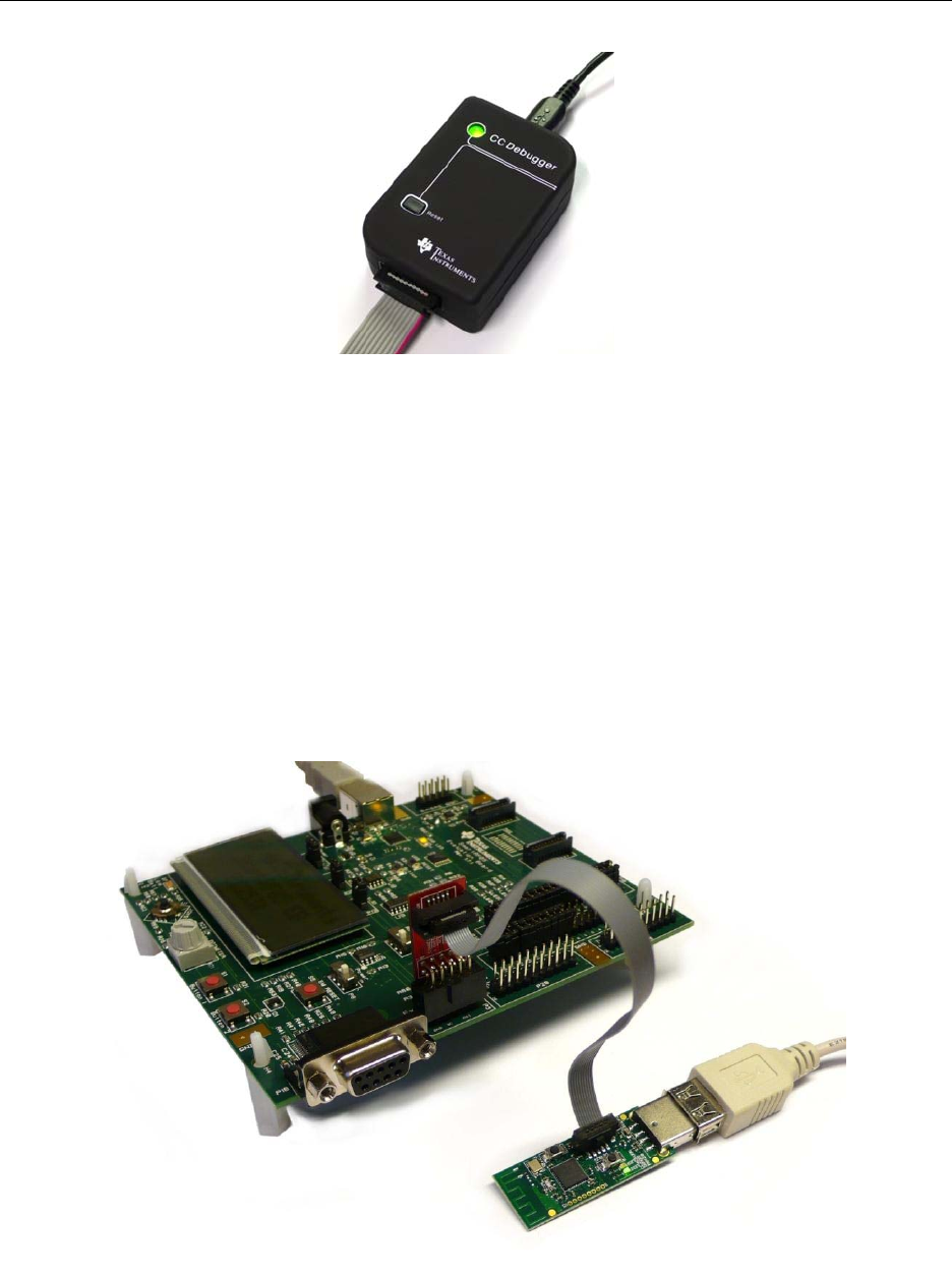
known as battery boards, also require the CC-Debugger [10] (see Figure 9) for programming.
Figure 8: CC2530EM plugged into a SmartRF05EB for programming
7 Copyright 2010 Texas Instruments, Inc. All rights reserved.
Z-Stack User's Guide - CC2530 ZNP SWRU242 Version 1.2
Figure 9: CC-Debugger
2.3.4. Hardware for programming the CC2531USBDongle
The CC2531USBDongle can be programmed by using the little 10 pin connector marked Debug.
Simply use the adapter cable (shipped with the CC2530DK, CC2530ZDK or the CC-Debugger)
to connect the Debug connector with the ExtSoC Debug connector on a SmartRF05EB (see
Figure 10) or the CC-Debugger. Then use the SmartRF Flash Programmer that should be able to
recognize the CC2531 SoC to program the CC2531. More info can be found on the
CC2531EMK product folder [11].
Figure 10: Programming the CC2531USBDongle using the SmartRF05EB
8 Copyright 2010 Texas Instruments, Inc. All rights reserved.

Z-Stack User's Guide - CC2530 ZNP SWRU242 Version 1.2
2.3.5. Easiest and quickest hardware choice
The reader, unfamiliar with the CC development HW and tools, easily gets confused about which
HW combination to choose, when reading the above sections (2.3.1-2.3.4). While the sections
above are useful to those that already have HW from other development activities it is
recommended for the new-comer to simply order a CC2520DK and a CC2530EMK (Figure 11).
The CC2520DK will provide you with twice the HW shown in Figure 4 (2 x CCMSP-
EM430F2618, 2 x SmartRF05EB, and 2 x CC2520EMs) and the CC2530EMK will provide you
the correct EMs to be used as ZNPs (as shown in Option-2 in Figure 2).
Figure 11: CC2530EMK
9 Copyright 2010 Texas Instruments, Inc. All rights reserved.

Z-Stack User's Guide - CC2530 ZNP SWRU242 Version 1.2
3. Building the ZNP needed for the sample application
This chapter explains how to build a ZNP image (hex-file) and how to program it onto the SoC
that is targeted to act as a ZNP. It also gives additional information at the end on how to change
some of the ZNP settings.
3.1. ZNP Software project files
As stated in Section 2.2, the Z-Stack project that builds a ZNP image is named ZNP, as shown in
Figure 12, and the corresponding project workspace file, znp.eww, can be found in the folder
shown in Figure 13.
Figure 12: Location of the ZNP project.
Figure 13: Location of the ZNP workspace file.
10 Copyright 2010 Texas Instruments, Inc. All rights reserved.
Z-Stack User's Guide - CC2530 ZNP SWRU242 Version 1.2
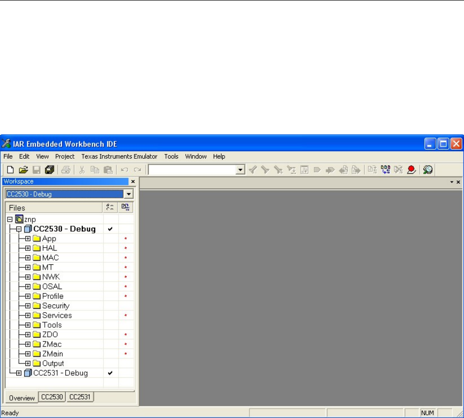
In order to get started simply open the workspace file znp.eww in the IAR Embedded Workbench
for the SoC (EW 8051 [3]); see Figure 14. Sections 3.2, 3.3, and 3.4 illustrate how to compile
and program the various ZNP images. Section 3.5 shows how to change the settings if required.
Note: Please check the ZStack-CC2530 Release Notes in the README CC2530 Full.txt file to
see which version of the IAR EW 8051 is required. The file can e.g. be found in the platform
specific directory: C:\Texas Instruments\ZStack-CC2530-x.x.x-x.x.x\Documents\CC2530.
Figure 14: View after opening znp.eww in the IAR EW 8051
3.2. Compiling a ZNP image (hex-file)
In this section it is shown how to compile a ZNP image based on the current settings in the
opened workspace For details on how to change the settings (e.g. channel, PAN ID) please see
Section 3.5. For more detailed information regarding the usage of the IAR Embedded
Workbench the reader is referred to the IAR documentation; e.g. starting with the EW8051 User
Guide [13].
As a first step, one has to choose the correct workspace setup from the 8 available
configurations. These configurations are provided so that users can automate the build of the
ZNP image to suit their desired need.
11 Copyright 2010 Texas Instruments, Inc. All rights reserved.

Z-Stack User's Guide - CC2530 ZNP SWRU242 Version 1.2
Figure 15: Workspace setup
CC2530 - Debug – this configuration produces a debuggable ZNP image that is downloaded and
run from the IAR IDE with the out-of-box settings from f8wConfig.cfg and znp.cfg. The linker
file associated with this configuration does not reserve a CODE segment for the serial boot
loader.
CC2530 - TestHex – this configuration produces an intel-extended-hex image that would be
loaded using a flash programming tool such as the TI SmartRF flash programmer. The linker file
associated with this configuration does not reserve a CODE segment for the serial boot loader.
This project has the following compile options (which override the out-of-box settings in
f8wConfig.cfg and znp.cfg). These extra options facilitate ZigBee Smart Energy testing.
ASSERT_RESET
MT_SYS_OSAL_NV_READ_CERTIFICATE_DATA=TRUE
MT_SYS_KEY_MANAGEMENT
ZCL_KEY_ESTABLISH
TC_LINKKEY_JOIN
SECURE=1
The MT_SYS_OSAL_NV_READ_CERTIFICATE_DATA=TRUE and MT_SYS_KEY_MANAGEMENT
compile option settings are used to allow the user to be able to initialize and retrieve the security
keys and certificate data by using MT (e.g. via Z-Tool or ZAP applications). While this is ok for
test and debug purposes, users should strongly consider turning off these compile option settings
for production devices to prevent any access to established link keys or Certicom certificate data.
CC2530 - ProdSBL – This configuration produces an image to be loaded via the serial boot
loader using a PC tool, such as SBDemo.exe, which is discussed in Section 4.5.3. The out of box
configuration settings from f8wConfig.cfg and znp.cfg are used.
CC2530 - ProdHex – This configuration produces an image that would be loaded using the
SmartRF flash programmer. The linker file associated with this configuration does reserve a
CODE segment for the serial boot loader and thus the resulting output of this build includes the
ZNP firmware plus serial boot loader. The out of box configuration settings from f8wConfig.cfg
12 Copyright 2010 Texas Instruments, Inc. All rights reserved.
Z-Stack User's Guide - CC2530 ZNP SWRU242 Version 1.2
and znp.cfg are used. Because this image includes the serial boot loader, the .bin file from the
build output of CC2530 - ProdSBL can be downloaded using the SBDemo.exe as well.
CC2531 configurations are analogous versions of the above.
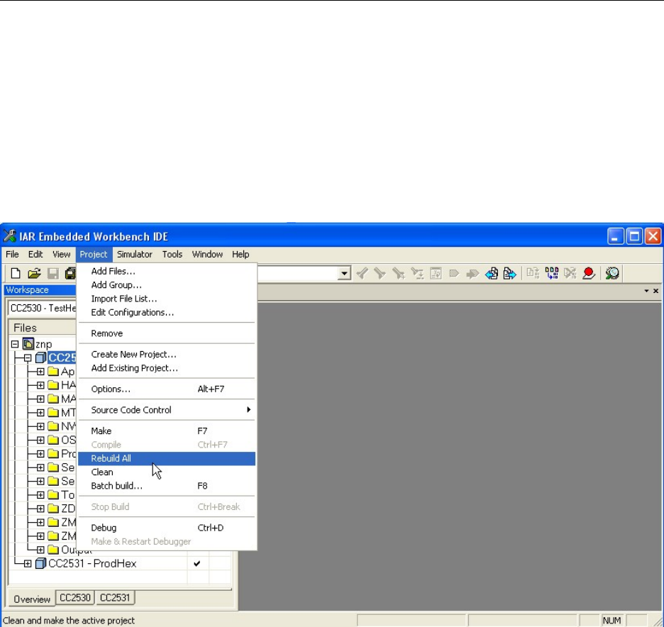
In the remainder of this section the setup “CC2530 - TestHex” is chosen as that is the one used
primarily for testing the ZNP.
Figure 16: Starting the compilation and build of the ZNP image
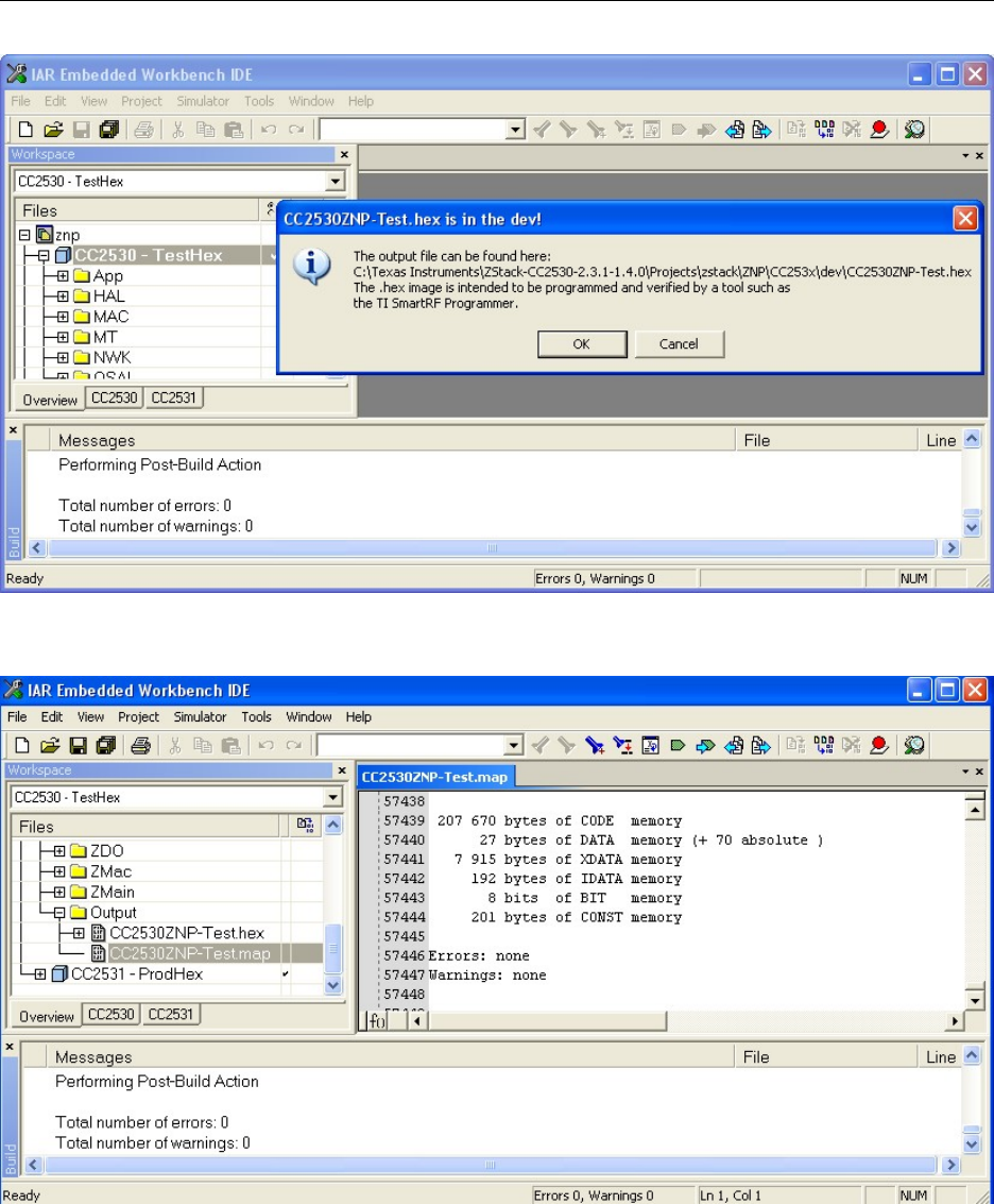
After the build has been finished successfully (i.e. there are neither warnings nor errors) as
shown in Figure 17, the resulting hex file can be found in the following directory:
C:\TexasInstruments\ZStack-CC2530-x.x.x-x.x.x\Projects\zstack\ZNP\CC253x\dev.
The next section shows how this resulting hex-file now can be programmed onto the SoC.
Note: When looking at the file size do not get confused by the info displayed/offered by
Windows as that number is often far too high and if it would be the real file size the image would
never fit into the flash of the SoC. In order to get the correct image size one can check the output
files generated by the IAR EW8051, by simply clicking the Output tap (at the end of the project
setup tree) and opening the CC2530ZNP-Test.map file. Useful information such as the image
size is provided at the end (see also Figure 18).
13 Copyright 2010 Texas Instruments, Inc. All rights reserved.
Z-Stack User's Guide - CC2530 ZNP SWRU242 Version 1.2
Figure 17: Successful build without any warnings or errors
Figure 18: Map file with useful information (e.g. image size)
3.3. About the image with serial boot loader support
As previously mentioned, the CC2530 – ProdHex configuration builds a ZNP image with serial
boot loader support.
14 Copyright 2010 Texas Instruments, Inc. All rights reserved.

Z-Stack User's Guide - CC2530 ZNP SWRU242 Version 1.2
The serial boot loader receives control from the reset vector and verifies whether valid ZNP code
is present. If so, then the serial boot loader gives the host processor a window of time in which to
force boot mode or an immediate jump to the ZNP code. The following rules apply to the serial
boot loader:
1. If the CRC is not 0x0000 or 0xFFFF and the CRC-shadow is identical, then the ZNP code is
valid.
2. If the CRC is not 0x0000 or 0xFFFF and the CRC-shadow is 0xFFFF, then the CRC is
calculated over the ZNP code image area (this will take over a minute.)
a. If the calculated CRC matches the read CRC, the CRC-shadow is programmed to this
identical value to speed-up future power-ups.
3. If the ZNP code is valid, wait for the host processor to send a 0xF8 to force boot-mode or an
0x07 to force an immediate jump to the ZNP code.
a. The default wait for UART and USB transport is 1 minute.
b. The default wait for SPI is 50 milliseconds.
4. If the ZNP code is valid and the wait expires, jump to the ZNP code.
5. If the ZNP code is not valid, immediately jump to the boot-code without waiting as described
above.
3.4. Programming the ZNP image onto the target
In this section it is shown how to load a ZNP image (hex-file) onto a SoC using the Texas
Instruments SmartRF Flash Programmer [5].
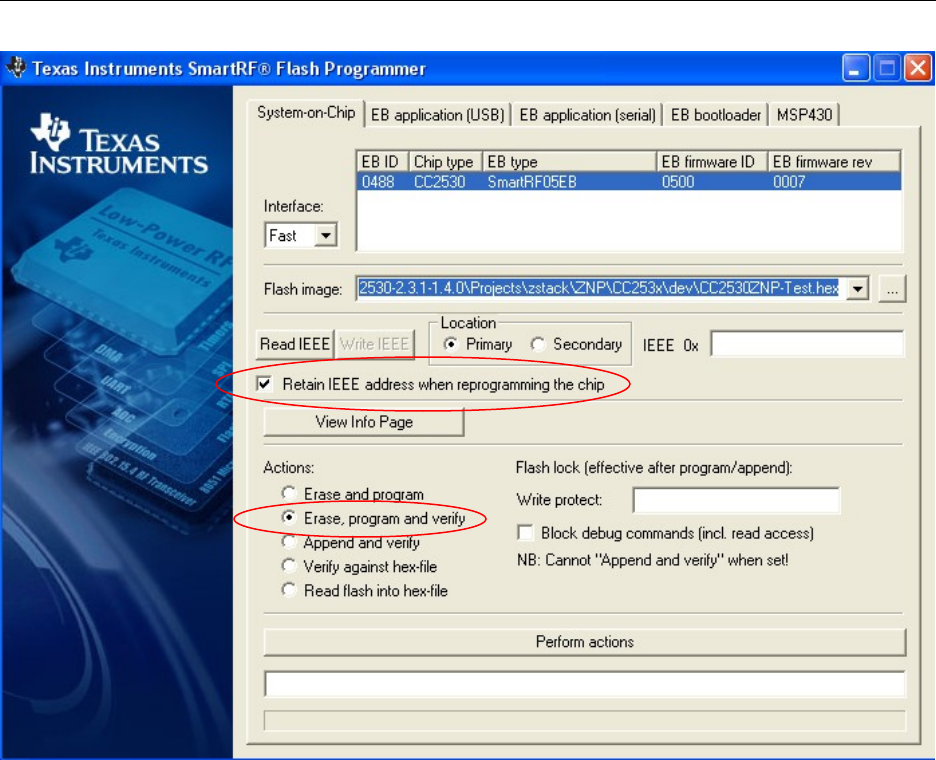
To get started, simply open the SmartRF Flash Programmer and connect the device to be
programmed to the PC (for the hardware-setup the reader is referred to Section 2.3) and turn the
device on. If everything is setup correctly the device should show up as shown in Figure 19,
indicating the EB ID, Chip type, EB type, EB firmware ID, and EB firmware ID rev.
As soon as the device to be programmed has been identified, the next step is to identify the
image (hex-file) that is to be programmed onto the device. By pressing the browse button to the
right of the Flash image field one can easily navigate to the location of the image. For the
example given in Section 3.2 the location would be C:\TexasInstruments\ZStack-CC2530-x.x.x-
x.x.x\Projects\zstack\ZNP\CC253x\dev\CC2530ZNP-Test.hex as shown in Figure 19.
15 Copyright 2010 Texas Instruments, Inc. All rights reserved.
Z-Stack User's Guide - CC2530 ZNP SWRU242 Version 1.2
Figure 19: Screen shot from SmartRF Flash Programmer (before programming)
After checking that the Retain IEEE address when reprogramming the chip and the Erase,
program and verify option are set (as shown in Figure 19) one only needs to press the Perform
actions button in the bottom of the window.
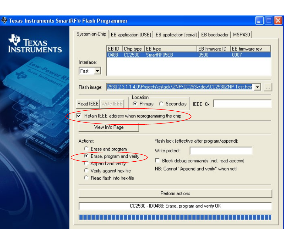
As soon as the button has been pressed the status line in the bottom will display the
progress/status. As soon as the programming has finished successfully the status line will display
“CC2530 – ID<EB ID>: Erase, program and verify OK” as shown in Figure 20.
In case the above described procedure runs into issues please check the SmartRF Flash
Programmer documentation [5] for resolution.
16 Copyright 2010 Texas Instruments, Inc. All rights reserved.
Z-Stack User's Guide - CC2530 ZNP SWRU242 Version 1.2
Figure 20: Screen shot from SmartRF Flash Programmer (after programming)
17 Copyright 2010 Texas Instruments, Inc. All rights reserved.

Z-Stack User's Guide - CC2530 ZNP SWRU242 Version 1.2
3.5. Changing settings in the ZNP project
While the previous sections in this chapter explained how to build a ZNP image and how to
program it onto a SoC (to make it act as ZNP), this section briefly points to the configuration
possibilities one has in order to build customized ZNP images. This is however only advised for
experienced users of the Z-Stack that want to use a different image than the default out-of-the-
box settings.
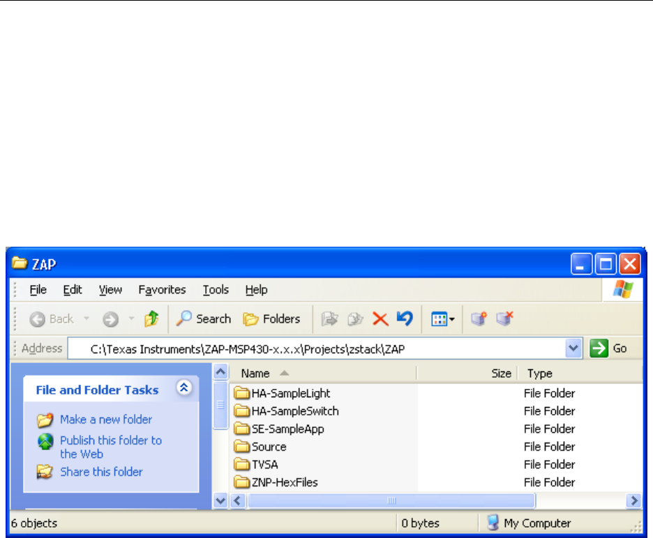
The recommended use of the ZNP is to use one of the pre-built hex-files that can be found in the
ZNP-HexFiles folder as shown in Figure 21. For more details about those hex files please consult
the readme file in that folder. When using the pre-built ZNP image (hex-file) one should only
customize the configuration on the ZAP side (see Section 4.1.2).
To configure your customized ZNP image you would need to look at the znp.cfg and the
f8wConfig.cfg for the ZNP project. Modifying the parameters in these two files is done in the
same way as for a normal non-ZNP Z-Stack project; hence, one can find more information about
the compile options and parameters in the standard Z-Stack documentation (after installing the
Z-Stack [6] it can be found in C:\Texas Instruments\ZStack-CC2530-x.x.x-x.x.x\Documents). A simple
example is the enabling of the security feature. The ZNP image is built to support security by
changing the -DSECURE=0 setting in f8wConfig.cfg to -DSECURE=1 (described in the Z-Stack
Developer’s Guide [1], where it is also shown in the Security chapter how to adjust the NWK
key and how to use a trust center link key).
4. Configuring and Using Z-Stack ZAP sample applications
After a general section describing the parts that are common for the different ZAP sample
applications, additional sections describe the different ZAP sample applications in more detail.
ZAP sample applications [7]:
Temperature Voltage Sensor Application (Section 4.2)
This application establishes a sensor network where the sensor nodes report data to a
central node, which is connected to a PC in order to display the data on the PC using a PC
tool.
Home Automation Sample Application (Section 4.3)
This application provides the code to setup a switch device and a light device, where
Home Automation Application Profile messages (using the ZigBee Cluster Library –
ZCL), triggered by using the joystick, are used to toggle the LED on the light device
Smart Energy Sample Application (Section 4.4)
This application provides the code to setup different smart energy (SE) devices based on
the Smart Energy Application Profile (using the ZigBee Cluster Library – ZCL) to
18 Copyright 2010 Texas Instruments, Inc. All rights reserved.
Z-Stack User's Guide - CC2530 ZNP SWRU242 Version 1.2
communicate with each other. Additionally it also illustrates how to setup the SE specific
security (using special key establishment).
The sample applications are all using the Operation System Abstraction Layer (OSAL) and
Hardware Abstraction Layer (HAL) concept known from the normal Z-Stack sample
applications. For more details the reader is referred to the Z-Stack documentation (C:\Texas
Instruments\ZStack-CC2530-x.x.x-x.x.x\Documents) and especially the HAL Porting Guide.pdf.
The location of where to find the code for the different ZAP sample applications (after installing
the corresponding software package ZAP-MSP430-x.x.x.exe [7]) is shown in Figure 21.
Figure 21: Location of the ZAP sample application code
4.1. ZAP Sample Applications Setup (general)
While the next sections provide specific information regarding the different sample applications
for the ZAP, this sections addresses the general aspects that are the same for all of them.
4.1.1. Hardware
As described in Section 2.3 (Figure 2) there are two MSP hardware configurations that are
supported by the ZAP sample applications: the CCMSP-EM430F2618 & SmartRF05EB for the
MSP430F2618 (see Figure 4) and the MSP-EXP430F5438 for the MSP430F5438 (see Figure 5).
Both board setups have the connectors required to plug in the CC2530EM (programmed to be a
ZNP as explained in Chapter 3).
In order to program the MSP430 in each of the two setups one needs to use the MSP430 USB-
Debug-Interface (MSP-FET430UIF) [15] that is provided together with the MSP430
19 Copyright 2010 Texas Instruments, Inc. All rights reserved.
Z-Stack User's Guide - CC2530 ZNP SWRU242 Version 1.2
development boards. The reader is referred to the CC2520DK User's Guide [16] for the details
on its usage.
User interface
Each ZAP sample application requires a certain user interaction, which is enabled by an LCD
display, LEDs, buttons and a joystick on the development boards. On the SmartRF05EB board
the joystick is marked with U1 – Joystick on the PCB, while on the MSP-EXP430F5438 it is
marked as SW2 and a circle around it. Both are in the lower left corner of the boards. Please refer
to the user guide’s of the different hardware for further details [17] & [18].
4.1.2. Software
While the sample applications all have their own specific parameters they have certain things in
common like ZigBee Device Selection, channel, PAN ID, etc.
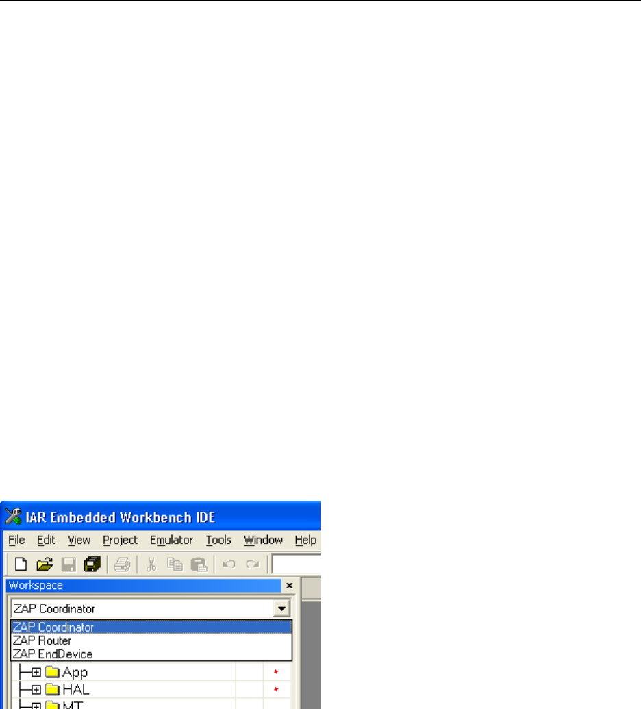
ZigBee Device Type Selection
After opening the workspace file for the ZAP sample application the user can define the device
type of the targeted node using one of the three options in the drop-down menu at the top left of
the screen (see Figure 22).
ZAP Coordinator – This will set the project to
program the device as ZigBee Coordinator.
ZAP Router – This will set the project to program
the device as ZigBee router.
ZAP End Device – This will set the project to
program the device as ZigBee End Device
Figure 22: ZigBee Device Type Selection (for TVSA and HA sample application)
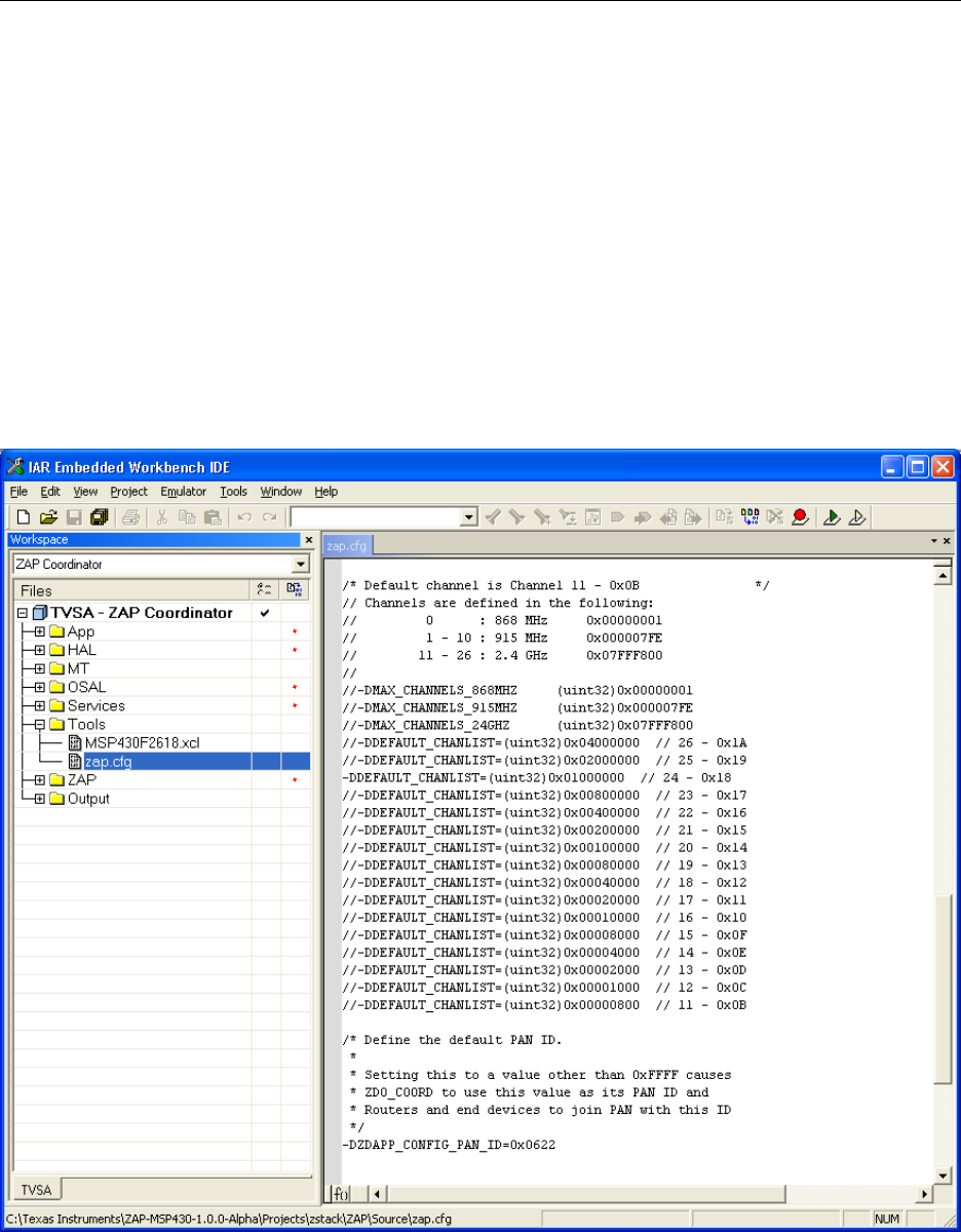
ZAP configuration file
Each ZAP sample application workspace contains the ZAP configuration file ZAP.cfg (see
Figure 23). This file contains a lot of the options required to setup the behavior of the resulting
ZigBee node; e.g. which PAN ID to use or look for (using -DZDAPP_CONFIG_PAN_ID) or the
channels to use (using -DDEFAULT_CHANLIST). For the details of how to set these parameters
20 Copyright 2010 Texas Instruments, Inc. All rights reserved.
Z-Stack User's Guide - CC2530 ZNP SWRU242 Version 1.2
the reader is referred to the Z-Stack Developer’s Guide [1] (Note: the naming of the parameters
might be different; e.g. for the normal Z-Stack projects the PAN ID parameter is denoted by
ZDO_CONFIG_PAN_ID).
The ZigBee 2007 specification defines the use of a 16-bit Personal Area Network Identifier
(PAN ID) to uniquely identify a network. The ZAP sample application provides the user with
two methods of selecting a PAN ID when starting or joining a network by setting the value of
DZDAPP_CONFIG_PAN_ID in the zap.cfg. For a Coordinator device, setting this value to
0xFFFF, forces it to start a network with a PAN ID equal to the least significant 16-bits of its
IEEE address. For a Router device, setting this parameter to 0xFFFF causes the device to join the
“best” network it can discover within the specified channel list, any other value causes it to use
the exact value specified. The “best” network is defined as the beacon response to scan
commands that has the highest received signal strength (RSSI).
Figure 23: ZAP configuration file example configuring channel 24 – 0x18
The IEEE 802.15.4 specification defines 16 channels in the 2.4 GHz frequency range. These
channels are assigned numbers 11 through 26. The Z-Stack initially defaults to channel 11, but
21 Copyright 2010 Texas Instruments, Inc. All rights reserved.

Z-Stack User's Guide - CC2530 ZNP SWRU242 Version 1.2
the user can select a different channel by changing the -DDEFAULT_CHANLIST option in
zap.cfg. This parameter is a bit map field, with each bit representing a single channel. The initial
default channel 11 (0xB) is represented by 0x00000800 (11th bit in the field, starting from bit 0).
In order to save information that needs to be reserved during power off or reset of the device the
Z-Stack uses NV (non-volatile) pages in the flash. The following parameters can be used to
configure the NV usage:
The ZAP_NV_RESTORE compile option in zap.cfg determines whether or not the network state
of the ZNP is restored after reset/power up. If ZAP_NV_RESTORE is set to FALSE the network
state of the ZNP will be cleared and default configuration used for start up.
At startup, the ZAP makes a series of calls using znp_nv_write for the items
ZCD_NV_LOGICAL_TYPE, ZDAPP_CONFIG_PAN_ID, DEFAULT_CHANLIST to configure
the logical device type (coordinator, router, or end-device), PAN ID, and scan channel mask,
respectively. The default values from the zap.cfg configuration file are taken as values. Note that
this configuration of ZNP has been automated if the ZAP_AUTO_CFG compile option is set to
TRUE in zap.cfg. This overrides the configuration values in znp.cfg.
The ZAP_AUTO_START compile option controls whether the device automatically starts up as a
ZigBee device. If ZAP_AUTO_START is set to FALSE, the user application will have to
manually call the ZDOInitDevice function to start the ZigBee functionality.
22 Copyright 2010 Texas Instruments, Inc. All rights reserved.

Z-Stack User's Guide - CC2530 ZNP SWRU242 Version 1.2
4.2. Temperature Voltage Sensor Application (TVSA)
The TVSA sample application is intended to show some basics of using the ZNP. In the TVSA
network, several ZigBee nodes (ZigBee Routers or ZigBee End Devices) send temperature and
voltage measurements at regular intervals to a central device (ZigBee Coordinator), which is
called the “Dongle”. The Dongle collects this information and sends it to the PC, over a UART
connection, for display. The Dongle acts as the ZigBee coordinator and the data collector point;
hence, it does not report its own temperature and voltage. It interfaces over the UART
connection to a PC tool called Z-Sensor Monitor Program (ZigBee Sensor Monitor) [14], which
is available from the Texas Instruments Website (e.g. at www.ti.com/cc2530zdk). If desired the
UART code on the dongle can easily be adjusted to fit the UART formatting used by other PC
tools. The following sections provide more details regarding the usage and modification of the
TVSA sample application.
4.2.1. Hardware and Software setup
To run this sample application you will need to build one ZAP Coordinator using the TVSA
workspace file TVSA.eww (see Figure 21 for its location). Using the ZAP Coordinator workspace
(see also Figure 22) will help you to set up the project for programming the device as a
coordinator (i.e. starting the ZigBee network) and at the same time as the “Dongle” collecting the
data and reporting it to the PC tool. Next to the ZAP Coordinator you will have to build the
sensor nodes that will report their data to the “Dongle”; they can be a ZAP Router or a ZAP End
Device. See Section 4.1 for details on how to set the device type.
4.2.2. Available Settings
Next to the general settings in the ZAP configuration file (zap.cfg; see Section 4.1.2 for details)
one has access to the following setting.
The time between the temperature/voltage reports can be set / changed by the following variable
in the tvsa.h file
#define TVSA_DLY_ANN 60000
Note: The code is written such that it randomizes this value a little (to avoid collisions with other
transmissions) and therefore does not give the exact same interval between reports.
4.2.3. UART Connection
If you wish to watch the information being sent to the PC in a program like the Windows
communication accessory HyperTerminal or a COM Port Sniffer this section describes the
UART Settings being used and also how these may be changed.
23 Copyright 2010 Texas Instruments, Inc. All rights reserved.
Z-Stack User's Guide - CC2530 ZNP SWRU242 Version 1.2
In case you have your own PC Tool this section will help you to identify the code you need to
change to establish the link between the PC Tool and the Dongle.
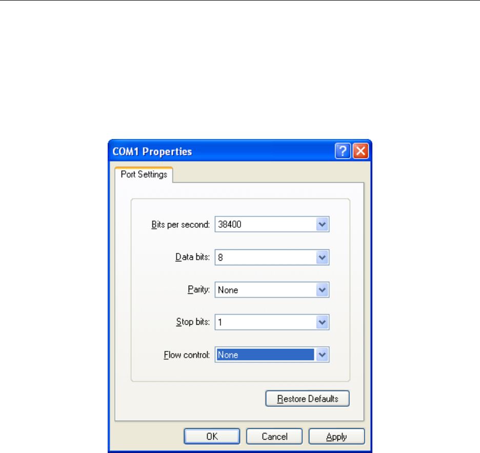
Connection to Z-Sensor Monitor:
The UART setup for connecting the Dongle to the Z-Sensor Monitor [14] is shown in Figure 24
below.
Figure 24: UART Settings used by Z-Sensor Monitor
Changing this UART Configuration to match your own PC tool is possible; however it will mean
incompatibility with the Z-Sensor Monitor; hence changes should be made with caution.
The UART settings are set in the tvsa.c file using the following code:
halUARTCfg_t uartConfig;
uartConfig.configured = TRUE;
#ifdef TVSA_DEMO
uartConfig.baudRate = HAL_UART_BR_115200;
#else
uartConfig.baudRate = HAL_UART_BR_38400;
#endif
24 Copyright 2010 Texas Instruments, Inc. All rights reserved.

Z-Stack User's Guide - CC2530 ZNP SWRU242 Version 1.2
uartConfig.flowControl = FALSE;
uartConfig.flowControlThreshold = 16;
uartConfig.rx.maxBufSize = 32;
uartConfig.tx.maxBufSize = 254;
uartConfig.idleTimeout = 6;
uartConfig.intEnable = TRUE;
uartConfig.callBackFunc = tvsaUartRx;
HalUARTOpen(TVSA_PORT, &uartConfig);
The HalUARTOpen function does the following:
1) Reads in the configuration provided (see lines above regarding UART settings)
2) Configures the UART settings on the microcontroller. For example I/O port
configuration, UART register configuration, UART clock source setting, etc
3) Sets baud rate
4) Sets flow control settings
5) Allocates and sets the RX and TX Buffers
6) Enables the UART interrupts
7) Clears status and other flags/buffers
To avoid invalid settings various checks are included relevant to the microcontroller; in this case
an MSP430.
4.2.4. Running the example
A simple demonstration of the TVSA sample application would be to program one Dongle and at
least one Router or End Device (following instructions given in the previous sections). Make
sure that all devices are powered and that the Dongle is properly connected to the computer using
a UART connection; details are given in the following.
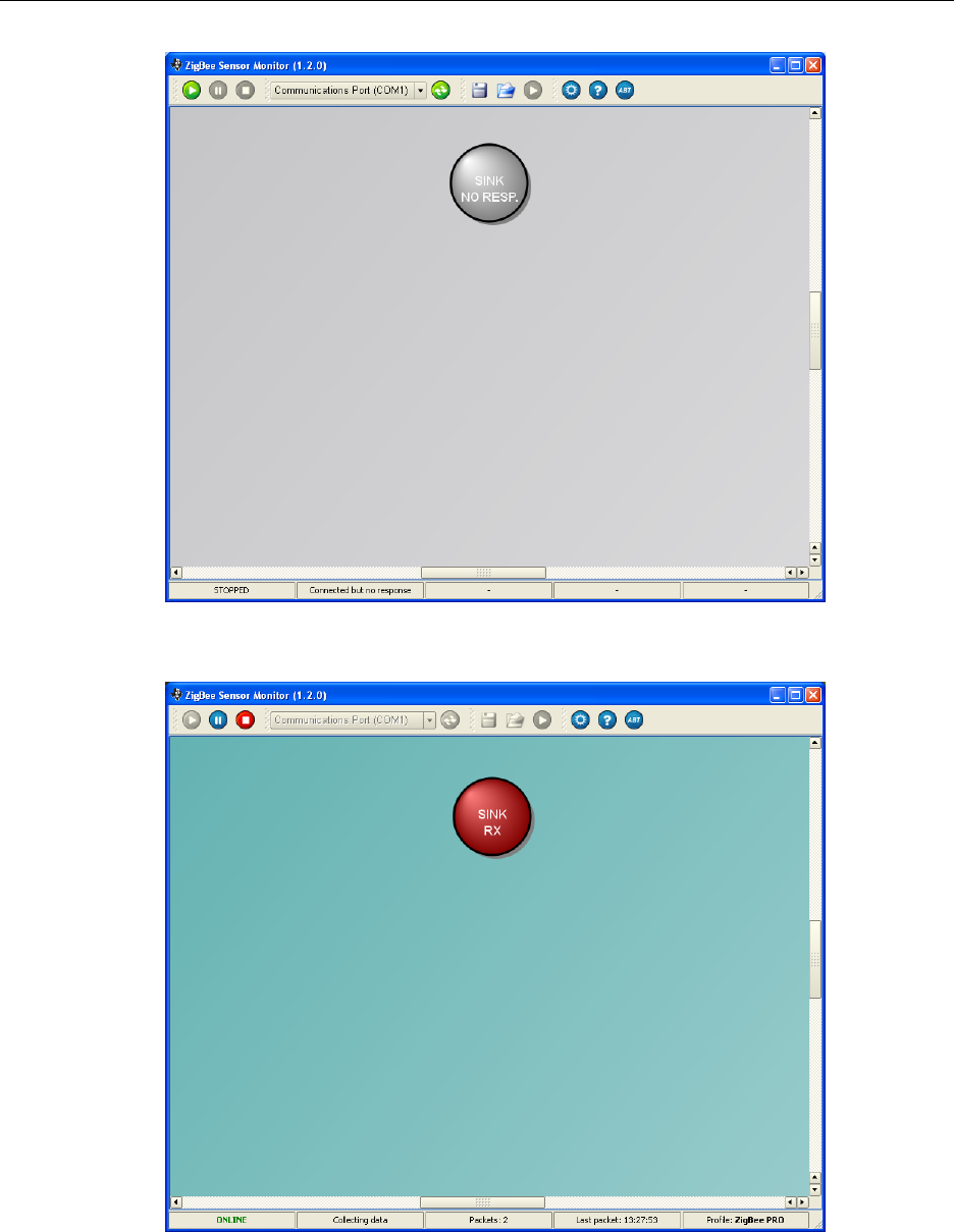
Set up the Dongle first. This can be done with the following steps
1) Connect the Dongle to the PC (ensure the UART connection is there)
2) Open Z-Sensor Monitor (see Figure 25)
3) Turn Dongle On
4) Press the Play Button in the Z-Sensor Monitor (first button to the left in the top).
In case you have followed the first steps successful the Circle representing the Dongle
(marked with Sink) should turn from grey to red color as shown in Figure 26. Then continue
with the next step:
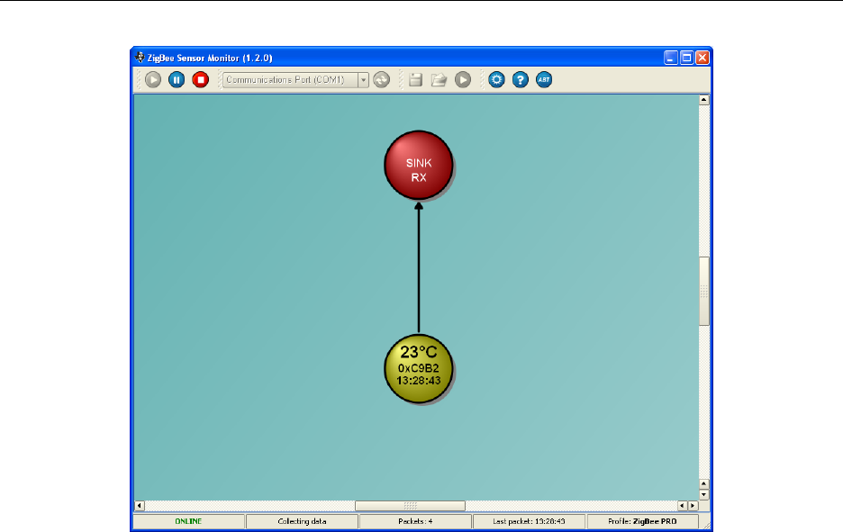
5) Turn on sensors (routers and/or end devices). Figure 27 illustrates the updated screen
shot after one sensor (in this case a router) has been inserted successfully into the
network.
25 Copyright 2010 Texas Instruments, Inc. All rights reserved.
Z-Stack User's Guide - CC2530 ZNP SWRU242 Version 1.2
Figure 25: Screen shot from ZigBee Sensor Monitor (no dongle connected)
Figure 26: Screen shot from ZigBee Sensor Monitor (dongle successfully connected)
26 Copyright 2010 Texas Instruments, Inc. All rights reserved.
Z-Stack User's Guide - CC2530 ZNP SWRU242 Version 1.2
Figure 27: Screen shot from ZigBee Sensor Monitor (1 dongle + 1 sensor)
4.2.5. In Depth on the Example
In the following more details about the TVSA sample application are given.
Temperature and Voltage Measurement
If the device is not a Dongle/Coordinator, then the file tvsa_cc2530znp.c gets included in the
build. In this file you will find the functions that calculate the temperature and voltage. These
come from the ADC on the CC2530 and its usage is demonstrated in the zapSysReq function,
retrieving ADC data using the ZNP/ZAP setup.
Note: Although there is some kind of calibration, please note that the code simply uses average
values and assumes a room temperature of 22 °C.
The temperature and voltage data is entered into a data array, which is sent directly over the air
in the reports to the dongle.
Over the air Packet Format
The data sent over the air is stored in a variable called tvsaDat[]. It is an array of 16 bytes
(uint8) with the following format (for all details see the definitions in tvsa.h):
27 Copyright 2010 Texas Instruments, Inc. All rights reserved.

Z-Stack User's Guide - CC2530 ZNP SWRU242 Version 1.2
tvsaDat[0] = <Command Sent>
// TVSA Command set.
#define TVSA_CMD_DAT 0 // TVSA data message.
#define TVSA_CMD_BEG 1 // Start reporting TVSA data.
#define TVSA_CMD_END 2 // Stop reporting TVSA data.
tvsaDat[1-8] = <extended IEEE address>
tvsaDat[9] = <parent address LSB>
tvsaDat[10] = <parent address MSB>
tvsaDat[11] = <temperature data>
tvsaDat[12] = <voltage data>
tvsaDat[13] = <0x80 if router or non-dongle coordinator, otherwise for an end
device it is defined as follows> tvsaDat[13] &= (0xFF ^ 0x80);
tvsaDat[14] = 0x01 if using source routing (i.e. if TVSA_SRC_RTG), otherwise
is not explicitly defined
tvsaDat[15] = CNF error count
Packet Format sent to Z-Sensor Monitor
The ping response is described in the CC2530ZDK Sensor Demo User’s Guide [14] on page 14.
Here we will simply describe the packet format sent to visualize the temperature and network
data after communication with the dongle has been established.
Z-Sensor Monitor requires UART packets of the following format.
Fifteen bytes in total should be sent.
Packet[0]=0xFE This is a start of frame delimiter
Packet[1]=10
Packet[2]=LO_UINT16(0x8746); //This takes the lower 8 bits
Packet[3]=HI_UINT16(0x8746); // This takes the higher 8 bits
Packet[4]=LO_UINT16(msg->srcAddr.addr.shortAddr); //Lower 8 bits of the
source address
Packet[5]=HI_UINT16(msg->srcAddr.addr.shortAddr); // Upper 8 bits of the
source address
Packet[6]=LO_UINT16(2);
Packet[7]=HI_UINT16(2);
Packet[8]=LO_UINT16(4);
Packet[9]=HI_UINT16(4);
Packet[10]= temperature data
Packet[11]=voltage data
Packet[12]=LSB of the parent devices address
Packet[13]=MSP of the parent devices address
Packet[14]=FCS Calculation on the previous 13 bytes (i.e. Packet[1] to
Packet[13])
28 Copyright 2010 Texas Instruments, Inc. All rights reserved.

Z-Stack User's Guide - CC2530 ZNP SWRU242 Version 1.2
4.3. Home Automation (HA) Sample Application
The ZigBee Home Automation Profile is the first public ZigBee Application Profile. The Home
Automation Sample Application provides sample code to build and setup a simple ZigBee
network consisting of a ZigBee HA Light and a ZigBee HA Switch. By using the joystick on the
switch device the user can trigger Home Automation messages to toggle the LED (light) on the
light device. It uses the ZigBee Cluster Library (ZCL) functionality of the Z-Stack, which is
implemented on the ZAP side as an individual OSAL task (ZCL Task: handles incoming and
outgoing ZCL messages).
The HA sample application, addressed in this section for the ZAP, is identical to the HA sample
application, which is provided with the full Z-Stack installer (ZStack-CC2530-x.x.x-x.x.x) [6].
That installer includes several sample applications that are described in the Z-Stack Sample
Applications.pdf document [20]. It can be found in the Z-Stack documentation folder C:\Texas
Instruments\ZStack-CC2530-x.x.x-x.x.x\Documents.
For more information about OSAL, the reader is referred to the Z-Stack Developer's Guide.pdf
[1] and the OSAL API.pdf (can also be found in the Z-Stack documentation folder). Information
about ZCL and its APIs can be found in Z-Stack ZCL API.pdf.
4.3.1. Hardware and Software setup
To setup this simple HA network, you will need a coordinator (to start the network) and another
device (router or end device). The coordinator is the light and the other device (router) is the
switch.
Next to the one switch additional switches can be added to the sample application; however,
when adding several lights only one can be controlled by a switch, due to the simplified
implemented binding process (explained in more detail in Section 4.3.3). Remark: The sample
application can easily be modified to support a setup with several switches and lamps in different
combinations; however, that is not part of this sample application as the goal is to demonstrate
the ZCL communication for HA only.
First, the user has to prepare two ZNP devices (e.g. based on CC2530EM). To program the ZNP
device (CC2530EM), you can use either one of the pre-built ZNP images (hex-files) or you can
build your own image with a ZNP project (as described in Chapter 3).
Now that you have 2 ZNP image without security has been used that can be found in the ZNP-
HexFiles folder (see Figure 21).
In the next step, build a ZAP Coordinator and a ZAP router (or ZAP end device) using the Home
Automation sample applications for the ZAP. See Figure 21 for the file location and Figure 22
on how to choose the ZigBee device type. For more details on how to program the MSP430
hardware with the resulting image see Section 4.1.
29 Copyright 2010 Texas Instruments, Inc. All rights reserved.

Z-Stack User's Guide - CC2530 ZNP SWRU242 Version 1.2
Build a ZAP coordinator using the SampleLight.eww workspace from the HA-SampleLight folder
for the MSP430 you have chosen (e.g. for the MSP430F2618 use C:\Texas Instruments\ZAP-
MSP430-1.0.0\Projects\zstack\ZAP\HA-SampleLight\MSP2618\SampleLight.eww) and a ZAP
router using the SampleSwitch.eww workspace from the HA-SampleSwitch folder.
After programming the corresponding MSP430 boards attach the ZNP devices (CC2530EM
modules) and you are ready to run the example.
4.3.2. Running the example
To start the sample application, turn on the devices (Light/Coordinator and Switch/Router). The
coordinator will start a ZigBee network and then the router will join that network.
Now, the only step remaining is to connect the switch functionality with the lamp functionality;
i.e. you have to “bind” the switch to the lamp. There are many different ways in the ZigBee
standard to establish this binding and how to setup a network; the whole process is referred to as
commissioning. For more info the reader is referred to a good whitepaper by Daintree [21].
In Home Automation sample application can use the ZDO Match Descriptor Request to establish
a binding between the switch and the light. To initiate the process, move the joystick on the
switch device to the left and release. An LED on the switch should be lid to indicate that a
connection, on the application level, between the switch and the lamp has been established
successfully. Now, you can toggle the light (LED on the SampleLight application) by moving the
joystick on the switch device up. The following section explains the details regarding the binding
messaging and the ZigBee messages used to toggle the light.
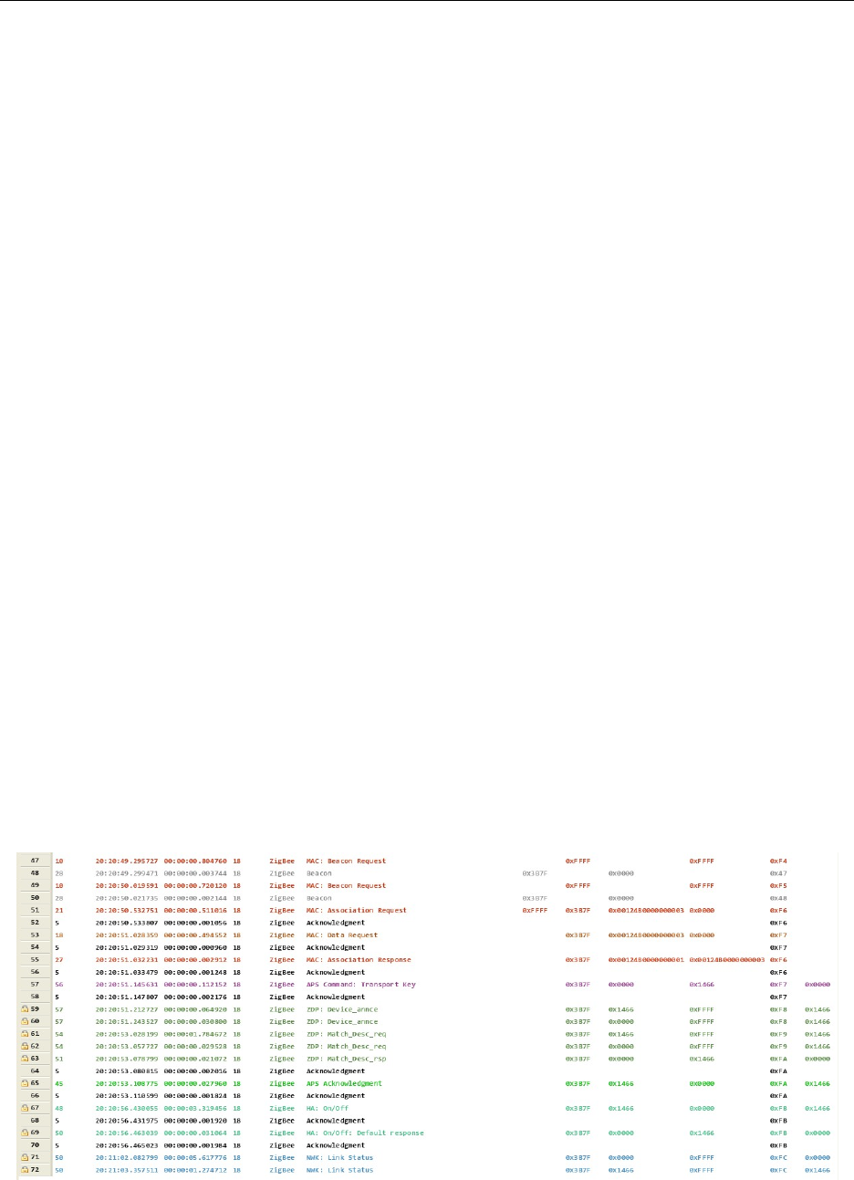
4.3.3. In Depth on the Example
This section describes the details of the HA sample application by going through the trace shown
in Figure 28 and explaining it. The trace was recorded for a coordinator based SampleLight and a
router based SampleSwitch using the Ubiqua Protocol Analyzer [22].
The Seq No (first column) shows the sequence number of the packets received. As can be seen
from the second column the application operates on channel 24, which was set using the
following parameter in zap.cfg (see Section 4.1.2 for more details):
-DDEFAULT_CHANLIST=(uint32)0x01000000 // 24 - 0x18
The first packet (packet #1; sent at 20:58:01.519), from the coordinator device, is a beacon
request to check whether there are any active networks on the channel with the intended PANID.
As no replies are sent, the coordinator starts its own network. A few seconds later (at
20:58:05.367) the router sends a beacon request (packet #2), after being powered up, to check
whether there is a network on this channel it can join. The coordinator replies to the beacon
request with its network specific information (packet #3); coming from MAC Src short address
30 Copyright 2010 Texas Instruments, Inc. All rights reserved.
Z-Stack User's Guide - CC2530 ZNP SWRU242 Version 1.2
0x0000, which is always the coordinator in a ZigBee network). Users that are familiar with the
standard Z-Stack sample application will notice that in this example only one single beacon
request is sent out by the router before doing the association and not three (this is just an
application choice and could be changed by the ZAP application designer if desired).
After sending the beacon request, the router evaluates the incoming responses according to the
parameters set in zap.cfg (e.g. PAN ID, see Section 4.1.2) and chooses the network and parent to
join. In the trace below, it chose the coordinator and sends an Association Request (packet #4) to
the coordinator’s MAC address 0x0000 (see MAC Dest field), using its own IEEE address to
identify itself as can be seen from the MAC Src field. It uses its IEEE address (also called long
address) as it has not been assigned a short address by the network yet. The coordinator
acknowledges that it received it on MAC level by sending a MAC Acknowledgment (packet #5).
After sending the Association request the router sends a Data Request to query whether there is
data for it at the coordinator (packet #6) expecting a response. The acknowledgment for this
request, sent by the coordinator (packet #7), includes a bit indicating that there is data pending
and that the data will be sent; hence, the router should wait for a packet to come. This
acknowledgment is then followed by the coordinator’s Association Response (packet #8), which
is acknowledged again on MAC level by the router (packet #9). The Association Response
contains the short address that the router got assigned by the coordinator (0x31eb); that will use
from now on when communicating in the network. Furthermore, it should be mentioned that the
coordinator, at the same time, identifies itself by using its own long address in the MAC Src field
of the Association Response.
After successfully joining the network, a DeviceAnnounce message is broadcasted (using short
address 0xffff on MAC level to reach all devices) by the router (MAC Src address set to 0x31eb)
to the entire network. However, as this is information relevant for the coordinator and other
routers in the network (i.e. not for end devices) it is send to 0xfffd on the NWK level (see NWK
Dest field of packet #10). As a result, it will be re-broadcasted through the network by the other
routers and the coordinator in the network (in this case, there is only the coordinator, packet
#11).
Figure 28: Screen shot from Ubiqua showing sniffer log
31 Copyright 2010 Texas Instruments, Inc. All rights reserved.

Z-Stack User's Guide - CC2530 ZNP SWRU242 Version 1.2
At this point, the router has successfully joined the network and has informed the whole network
of its presence.
Remark: The alert reader will at this point notice that some packets (e.g. packet #12) are
missing in the sniffer log. This is due to the fact that the NWK Link Status messages were
filtered out to not confuse the reader. These are periodic messages that are sent by routers and the
coordinator to monitor the link quality between them. In the sniffer logs shown in Figure 38 and
Figure 39 they can be seen (marked blue).
The next packets of the trace (packet #13 - #23) are all related to the application and are
triggered by user interaction.
Service discovery is performed by the switch device to match its “switch” functionality with a
corresponding light device. Packet #13 is the switch device looking for a match to it’s HA
Toggle clusters (ZDP Match Descriptor Request). The message was a broadcast message sent to
all powered devices (0xfffd) and is rebroadcasted by 0x0000 in packet #14. The light device
responds that it is a match (ZDP Match Descriptor Response) in packet #15.
In the code, the message is sent by calling the function ZDP_MatchDescReq() in zcl_samplesw.c.
Every device that receives the ZDP MatchDescReq will determine if it has any end point
registered with a matching application (i.e. matching input and output clusters, etc.). If there is a
match, a MatchDescriptorResponse is send back (as a unicast) to the source of the request. The
coordinator is a matching light device so it replies to the switch that they are compatible and
could cooperate.
Note: As can be seen from the trace only unicast messages (messages send to one particular
device) get acknowledged on MAC level (e.g. packet #16), while it makes no sense to
acknowledge broadcast messages.
In the SampleSwitch, the information from the response is stored in the zclSampleSw_DstAddr
variable (done in the case Match_Desc_rsp of the switch in the zclSampleSw_ProcessZDOMsgs
function in zcl_samplesw.c) and an according APS acknowledgment message is sent to the
SampleLight device (packet #17).
Note: As the goal of the sample application is only to demonstrate the HA cluster
communication, the application is kept simple. As a result, only the latest destination address is
saved; each SampleSwitch can only control one SampleLight, while a SampleLight can be
controlled by several SampleSwitch devices.
After successfully mapping a switch to a light, the user can now toggle the light on the switch by
turning/pressing the joystick on the switch up. To toggle the light, an HA compliant toggle
message is sent to the light (packet #20; acknowledged by packet #21 on MAC level), the light
acknowledges the receipt of the toggle command by sending the Default Response (packet #22;
acknowledged by packet#23 on MAC level).
32 Copyright 2010 Texas Instruments, Inc. All rights reserved.

Z-Stack User's Guide - CC2530 ZNP SWRU242 Version 1.2
The sending of the toggle command is triggered by calling the
zclGeneral_SendOnOff_CmdToggle() function (see function zclSampleSw_HandleKeys() and
case HAL_KEY_SW_1) in zcl_samplesw.c.
The receipt of the toggle command on the light device is fully handled by the ZCL task, which
uses the call back function (zclSampleLight_OnOffCB() defined in zcl_samplelight.c) to execute
the behavior defined by the application. The light application registered for callback functions
by calling zclGeneral_RegisterCmdCallbacks() in its initialization function
zclSampleLight_Init() such that the ZCL task can call it each time it receives the corresponding
toggle command.
For further information regarding the Home Automation sample application and the ZCL
handling the reader is referred to [20].
33 Copyright 2010 Texas Instruments, Inc. All rights reserved.

Z-Stack User's Guide - CC2530 ZNP SWRU242 Version 1.2
4.4. Smart Energy Sample Application
ZigBee Smart Energy (SE) is one of the public application profiles released for the ZigBee
2007 specification. It enables utility companies and their customers to directly communicate with
thermostats and other smart appliances; see www.zigbee.org for more information.
The Smart Energy Sample application, included in the MSP430 ZAP sample applications (ZAP-
MSP430-x.x.x.exe [7]), is the optimal starting point to build your own SE application on top of
Texas Instruments’ CC2530 ZNP.
This section describes how to use the Smart Energy Sample Application and discusses its theory
of operation. For a more general description of Smart Energy, the reader is referred to the ZigBee
Smart Energy specification available from www.zigbee.org. The reader should also review the Z-
Stack Smart Energy Developer’s Guide [19] prior to using this sample application.
There are seven defined application instances within the Smart Energy Sample Application IAR
project (for the location of the IAR project see Figure 21):
a. Energy Service Portal (ESP) as a Coordinator
b. Metering Device as a Router and also as an End Device
c. In Premise Display as an End Device
d. Programmable Communicating Thermostat (PCT) as an End Device
e. Load Control Device as a Router
f. Range Extender as a Router
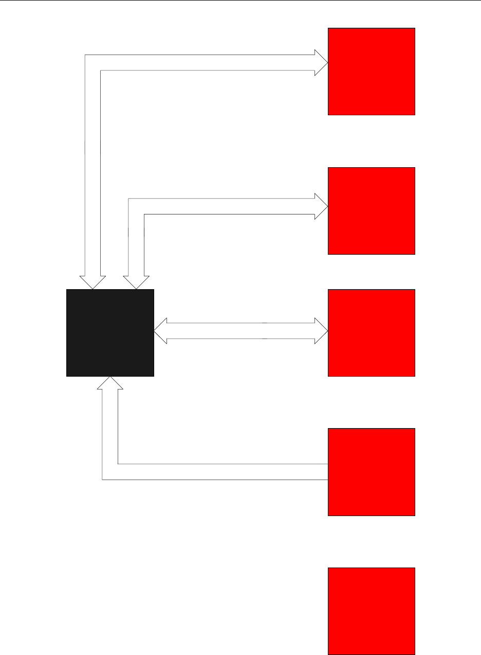
Figure 29 shows the usage model of how these sample application instances interact with the
ESP.
In the following sections detailed information is given regarding the SE sample application; the
required tools (4.4.1), how to get started (4.4.3), the theory behind its operation (4.4.4), and its
limitations (4.4.11).
34 Copyright 2010 Texas Instruments, Inc. All rights reserved.
Z-Stack User's Guide - CC2530 ZNP SWRU242 Version 1.2
In Premise
Display
Programmable
Communicating
Thermostat
(PCT)
Load
Control
Device
Simple
Metering
Device
Range
Extender
ESP
In Premise Display Queries For Latest Pricing Info,
and displays MESSAGE command from ESP
ESP Sends PCT Load Control Event
ESP Sends Load Control Event
Simple Metering Device Reports
Current Summation Delivered
Attribute Periodically
Range Extender will join the network,
perform key establishment, and route
packets but won't exchange app data
with the ESP
Figure 29: System Context Diagram
35 Copyright 2010 Texas Instruments, Inc. All rights reserved.

Z-Stack User's Guide - CC2530 ZNP SWRU242 Version 1.2
4.4.1. Required Tools
The tools that will be needed to evaluate this sample app and build your own application based
on it are the following (see also Section 2.1):
a. IAR Embedded Workbench EW8051 [3] to build a customized ZNP image (hex-file).
This is the case when targeting an image with the Certicom Library; however, if
Certicom ECC security is not used, one can use the pre-built ZNP image (hex-file)
customized with the correct compile options for use with the Smart Energy profile.
b. IAR Embedded Workbench EW430 [4] to build the SE sample applications that run
on the MSP430.
c. SmartRF Flash Programmer Tool [5] (includes USB drivers for the SmartRF05EB
board)
d. Ubiqua Protocol Analyzer from Ubilogix (www.ubilogix.com) or other type of
network analyzer that can support Smart Energy profile decodes
e. Z-Tool 2.0 (the tool is provided as part of the Z-Stack install)
f. Z-Converter – A tool used to transform Certicom certificates data into arrays that can
easily be imported into the sample applications (the tool is provided as part of the Z-
Stack install)
g. Certicom ECC library if using security. Fill out their SDK license registration form at
this URL:
http://www.certicom.com/index.php/component/chronocontact/?chronoformna
me=certicom_zigbee_sdk_registration_form. Alternatively, you may contact TI
directly to obtain a special installer that has the Certicom ECC library included.
Using Z-Converter to Transform Certicom Certificates
Z-Converter takes Certicom certificate data as input in the following format (the actual input
requires no carriage returns in order for Z-Converter to process the data correctly):
IEEE Address: 00124b0000000001
CA Pub Key: 0200fde8a7f3d1084224962a4e7c54e69ac3f04da6b8
Device Implicit Cert:
0204ac2c2656f1eea4ff5dac4edda176bfe4fa70d95600124b0000000001544553545345434101090001000001091003
Device Private Key: 00f035a9f731f265530ad5c1202562d56d1b822543
Device Public Key: 0202f71c27abfd28eb39e0b4a718ace4cf374559a6f6
This data must be entered line by line as shown above with no carriage returns into a text file.
Then the user imports this data into the Z-Converter using the “Load” button. Z-Converter then
transforms this data into an array output as follows:
IEEE Address: 0x01,0x00,0x00,0x00,0x00,0x4b,0x12,0x00
36 Copyright 2010 Texas Instruments, Inc. All rights reserved.

Z-Stack User's Guide - CC2530 ZNP SWRU242 Version 1.2
CA Pub Key: 0x02,0x00,0xfd,0xe8,0xa7,0xf3,0xd1,0x08,0x42,0x24,0x96,0x2a,0x4e,0x7c,0x54,0xe6,0x9a,
0xc3,0xf0,0x4d,0xa6,0xb8
Device Implicit Cert: 0x02,0x04,0xac,0x2c,0x26,0x56,0xf1,0xee,0xa4,0xff,0x5d,0xac,0x4e,0xdd,0xa1,0x76,0xbf,
0xe4,0xfa,0x70,0xd9,0x56,0x00,0x12,0x4b,0x00,0x00,0x00,0x00,0x01,0x54,0x45,0x53,0x54,
0x53,0x45,0x43,0x41,0x01,0x09,0x00,0x01,0x00,0x00,0x01,0x09,0x10,0x03
Device Private Key: 0x00,0xf0,0x35,0xa9,0xf7,0x31,0xf2,0x65,0x53,0x0a,0xd5,0xc1,0x20,0x25,0x62,0xd5,0x6d,
0x1b,0x82,0x25,0x43
Device Public Key:
0x02,0x02,0xf7,0x1c,0x27,0xab,0xfd,0x28,0xeb,0x39,0xe0,0xb4,0xa7,0x18,0xac,0xe4,0xcf,0x37,0x45,0x59,0xa6,0xf
6
Note that the Device Public Key is not used as part of the input into the Certicom library but is
provided for completeness.
The user then copies these values into the zap_certs.c application file as such:
const uint8 seIEEE[] = {
0x01, 0x00, 0x00, 0x00, 0x00, 0x4b, 0x12, 0x00
};
const uint8 seData0x69[] = {
0x03, 0x07, 0x8c, 0x45, 0xde, 0xa5, 0x06, 0xd0,
0x7f, 0x1b, 0x82, 0x21, 0x22, 0xb5, 0xa3, 0x1e,
0xb0, 0xa0, 0xd6, 0x29, 0x55, 0xdb, 0x00, 0x12,
0x4b, 0x00, 0x00, 0x00, 0x00, 0x01, 0x54, 0x45,
0x53, 0x54, 0x53, 0x45, 0x43, 0x41, 0x01, 0x09,
0x00, 0x08, 0x00, 0x00, 0x00, 0x00, 0x00, 0x00
};
const uint8 seData0x6A[] = {
0x02, 0x28, 0x4a, 0x56, 0x3f, 0x02, 0xf2, 0xc8,
0xbd, 0xa7, 0x57, 0xf9, 0x61, 0xbb, 0x8c, 0xb4,
0xfb, 0x6e, 0x90, 0xed, 0x42
};
const uint8 seData0x6B[] = {
0x02, 0x00, 0xfd, 0xe8, 0xa7, 0xf3, 0xd1, 0x08,
0x42, 0x24, 0x96, 0x2a, 0x4e, 0x7c, 0x54, 0xe6,
0x9a, 0xc3, 0xf0, 0x4d, 0xa6, 0xb8
};
The mapping of the labels from the Certicom certificate to the variables in the sample application
is as follows:
IEEE seIEEE[]
Device Implicit Cert seData0x69[]
Device Private Key seData0x6A[]
CA Pub Key seData0x6B[]
Figure 30 provides a screenshot of the Z-Converter graphical interface. The user can also save
the output into a text file for later use using the “Save As” button.
37 Copyright 2010 Texas Instruments, Inc. All rights reserved.
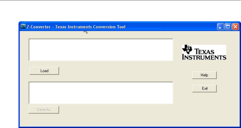
Z-Stack User's Guide - CC2530 ZNP SWRU242 Version 1.2
Figure 30: Z-Converter Graphical Interface
Upon initialization, the sample application will then initialize these certificates into the non-
volatile memory section of the CC2530 based ZNP as shown below:
// Program the necessary certificate data (done in Z-Stack apps by Z-Tool).
(void)znp_nv_write(ZCD_NV_lOCAL_CERTIFICATE, 0, sizeof(seData0x69), (uint8 *)seData0x69);
(void)znp_nv_write(ZCD_NV_STATIC_PRIVATE_KEY, 0, sizeof(seData0x6A), (uint8 *)seData0x6A);
(void)znp_nv_write(ZCD_NV_CA_PUBLIC_KEY, 0, sizeof(seData0x6B), (uint8 *)seData0x6B);
4.4.2. Configuring Certicom Keys for Production Devices
The previous section discussed a method for configuring Certicom keys from the host processor.
This works well for the development phase, but for production, a different solution is often
desired to help streamline the manufacturing process. For this reason, and also for enhanced
security, Z-stack provides an option to store the Certicom keys in the lock bits page of the
CC2530. This is also the recommended option as the CC2530 has a lock bit to lock the debug
interface port.
On the CC2530, the last available page of flash is used. Figure 31 shows the memory map of the
lock bits page.
38 Copyright 2010 Texas Instruments, Inc. All rights reserved.
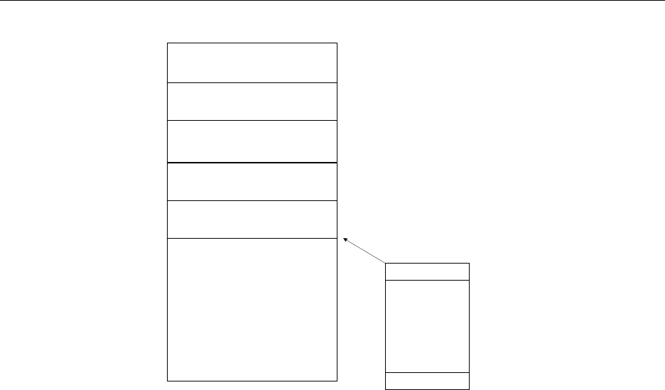
Z-Stack User's Guide - CC2530 ZNP SWRU242 Version 1.2
Application
OSAL
LockBitBytes(16bytes)
SecondaryIEEE(8bytes)
DevicePrivateKey(21bytes+1
bytepaddingtoNVwordsize)
ImplicitCert(48bytes)
CAPublicKey(22bytes)
Page127
Page0
Byte2048
ReservedforfutureZ‐stackuse
(1932bytes)
Byte0
Pages1‐126
CC2530flash
memorymap
Lockbitspage
Figure 31: Memory map of lock bits page
For the CC2530, the console version of the SmartRF Flash Programmer has been updated (since
ver 1.8) to provide a command line interface that is able to program the lock bits page with the
certificate data. The console program accepts a .hex file along with the certificate data in .txt
format.
The procedure to generate the .hex file is discussed in section 3.2.
At the command line prompt, the following syntax should be used:
SmartRFProgConsole S EPV “F= <path to hex file>” EKF=”<path to certificate file.txt>”
The format of the certificate should be as follows:
IEEE Address: 00124b0000000003
CA Pub Key: 0200fde8a7f3d1084224962a4e7c54e69ac3f04da6b8
Device Implicit Cert:
0204ac2c2656f1eea4ff5dac4edda176bfe4fa70d95600124b0000000003544553545345434101090
001000001091003
Device Private Key: 034bc37a7210b7407a51dc11e5aebaf2e1503f6955
Device Public Key: 020718021c2ce9c58d2ad8352ab9ff452ff1c3bdadb3
Note: The data for the device implicit cert should be on one line (i.e. no carriage return
separations should be included).
39 Copyright 2010 Texas Instruments, Inc. All rights reserved.
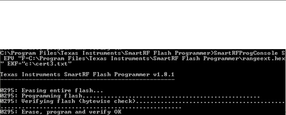
Z-Stack User's Guide - CC2530 ZNP SWRU242 Version 1.2
The .hex image would then be programmed into the CC2530 using the SmartRF Flash
Programmer tool at the same time the lock bits page is programmed with the certificate data in
the .txt file. The screenshot below shows an example.
There are also several functions in the console version that can be used to create a very flexible
script. First, note the 'x' option, that will list all available EBs. Example:
C:\Program Files\Texas Instruments\SmartRF Flash Programmer>SmartRFProgConsole.exe x
Texas Instruments SmartRF Flash Programmer
------------------------------------------
Device:SmartRF05EB ID:2769 (fwId:0500, fwRev:0013) Chip:CC2530
Device:SmartRF05EB ID:7335 (fwId:0500, fwRev:0013) Chip:CC2530
One can then write a batch script (or similar) with the following lines:
SmartRFProgConsole.exe S(2769) EPV F="hex_image.hex" EKF="certificate_data_1.txt"
SmartRFProgConsole.exe S(7335) EPV F="hex_image.hex" EKF="certificate_data_2.txt"
This example assumes that the path of the .hex image and the certificate data .txt file are in the
same directory as the SmartRFProgConsole.exe.
40 Copyright 2010 Texas Instruments, Inc. All rights reserved.
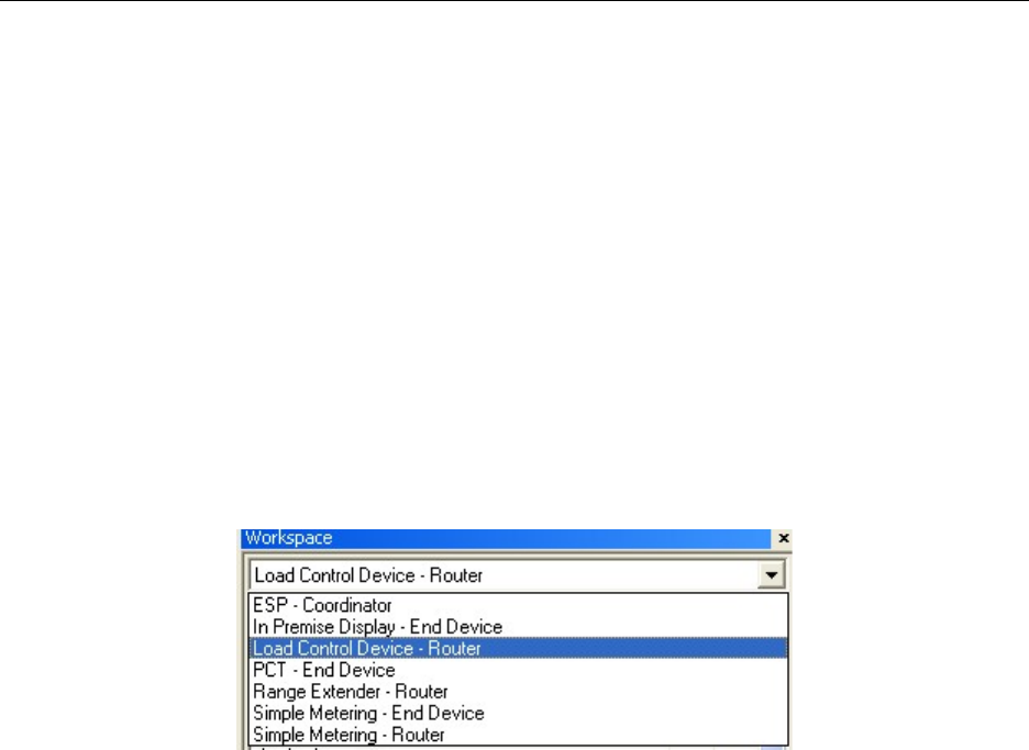
Z-Stack User's Guide - CC2530 ZNP SWRU242 Version 1.2
4.4.3. Getting Started
This section explains how to get started with the SE sample application.
Building the ESP and Simple Meter Application Instances
The SE sample application project is located in C:\Texas Instruments\ZAP-MSP430-
1.0.0\Projects\zstack\ZAP\SE-SampleApp\<Target> (e.g. <Target> = EXP5438); see also
Figure 21. The following steps explain how to build ESP and Simple Meter Application
Instances.
Start by opening the SampleApp.eww project file. The figures below (Figure 32 and Figure 33)
show how each configuration is organized. For each device configuration, only the relevant
application files are brought in for each device configuration.
Figure 32: SE sample application workspace options
41 Copyright 2010 Texas Instruments, Inc. All rights reserved.
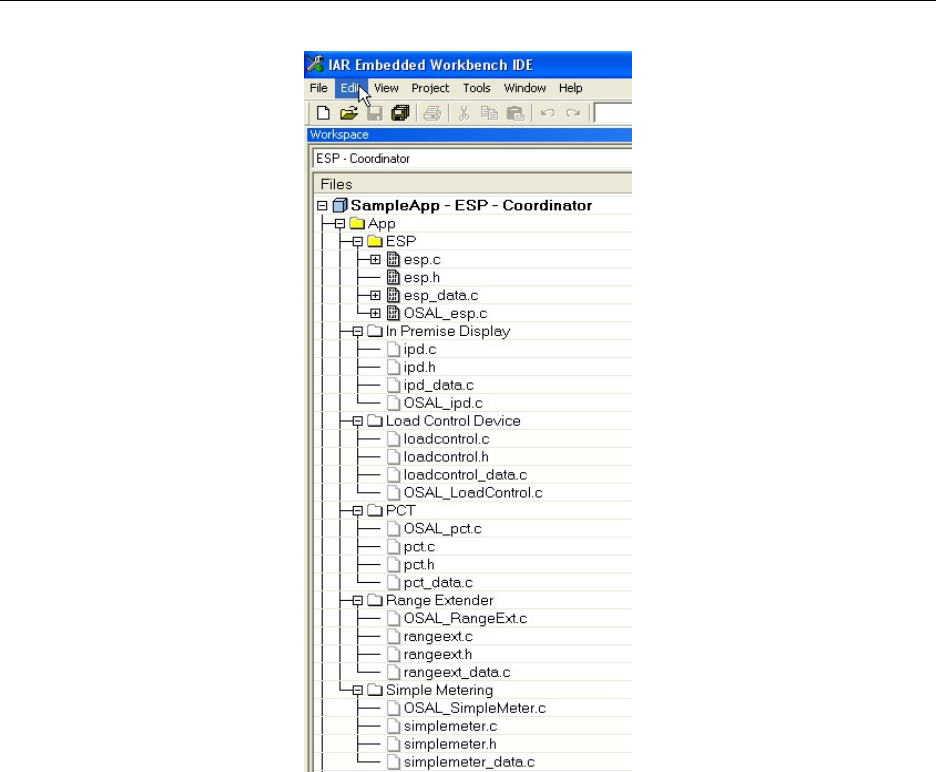
Z-Stack User's Guide - CC2530 ZNP SWRU242 Version 1.2
Figure 33: SE sample application workspace setup for ESP
Then build the “ESP – Coordinator” and “Simple Meter – Router” configurations:
1. Using Certicom ECC security requires that the CC2530 ZNP image (hex-file) is built
with the SECURE=1 compile option. Before rebuilding the ZNP image, take the
Certicom library and rename it to ecc.r51 and drop it into C:\Texas Instruments\ZStack-
2.3.1-1.4.0\Projects\zstack\Libraries\TI2530DB\bin
2. Typically, the NWK_INDIRECT_MSG_TIMEOUT parameter of the ZNP image (in the
f8wConfig.cfg file) must be increased to a suggested value of 10 in order to buffer the
message long enough to accommodate the 8 second poll period by the end device. The
MAX_POLL_FAILURE_RETRIES parameter should also be set to 4 as during the
CBKE procedure the ESP will be somewhat unresponsive to data requests during this
time.
3. When building the ZNP image (in addition to point 2 above), ensure the following
compile options are set as follows in the znp.cfg file (located in C:\Texas
Instruments\ZStack-2.3.1-1.4.0\Projects\zstack\Tools\CC2530DB):
42 Copyright 2010 Texas Instruments, Inc. All rights reserved.

Z-Stack User's Guide - CC2530 ZNP SWRU242 Version 1.2
-INTER_PAN
-DHOLD_AUTO_START
-DNV_RESTORE
-DNV_INIT
-SE_PROFILE
-ZNP_ZCL
-DMT_APP_FUNC
-DSECURE=1 (ONLY if using Certicom ECC security – otherwise set to 0)
4. When building the ZAP sample application project, ensure the following compile options
are set as follows in the zap.cfg file (located in C:\Texas Instruments\ZAP-MSP430-
1.0.0\Projects\zstack\ZAP\Source):
-DZAP_AUTO_CFG=TRUE
-DZAP_AUTO_START=TRUE
-DZAP_NV_RESTORE=FALSE
-DSECURE=1 (ONLY if using Certicom ECC security – otherwise set to 0)
-DZAP_ZNP_MT=TRUE (ONLY set to TRUE if using Certicom ECC security)
-DZDAPP_CONFIG_PAN_ID and -DDEFAULT_CHANLIST should be set to the
appropriate values.
5. Highlight the configuration desired (Figure 32) and go to Project
Options and select
the “Erase main and information memory” as shown in Figure 34. Then build the
program via Project
Rebuild All.
6. Download the program by clicking on the debug icon or by going to Project -> Debug.
Hit the Run button, and watch the coordinator start up, or if it’s a device, it will try to join
the network automatically. The IEEE address of the device and the PAN ID of the
network will be displayed on the LCD.
43 Copyright 2010 Texas Instruments, Inc. All rights reserved.
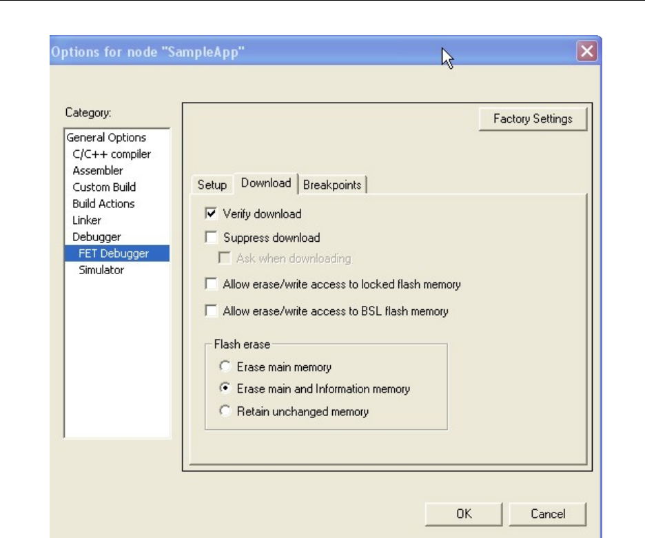
Z-Stack User's Guide - CC2530 ZNP SWRU242 Version 1.2
Figure 34: Project options (FET Debugger) for SE Sample Applications
Extracting Established Application Link Keys Using Z-Tool
One must use the Z-Tool program supplied with the Z-Stack installer to retrieve the established
link key pairs for each device connected to the ESP. Open Z-Tool from the Texas Instruments
start menu links and select Tools
Settings to configure the baud rate, Port Alias, and
Handshake protocol as shown below in Figure 35.
44 Copyright 2010 Texas Instruments, Inc. All rights reserved.
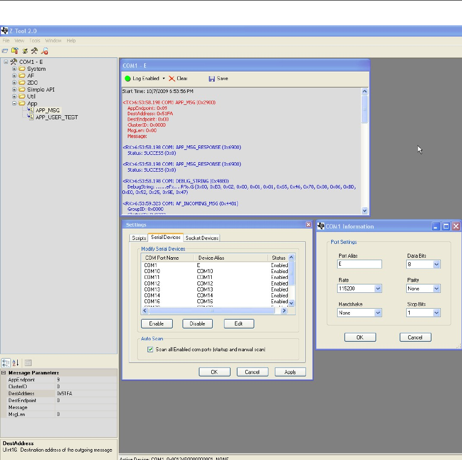
Z-Stack User's Guide - CC2530 ZNP SWRU242 Version 1.2
Figure 35: Screen shot from Z-Tool showing the settings window to set COM1 settings
Once key establishment is successful, use the ZDO_GET_LINK_KEY command to extract
the link key established for the device. This can be run on any of the pair of devices in order
to get the key (needed for the packet sniffer as described below). Configure the
ZDO_GET_LINK_KEY command as shown below in Figure 36. The only value that
changes is the IEEE Address of the partner device.
45 Copyright 2010 Texas Instruments, Inc. All rights reserved.
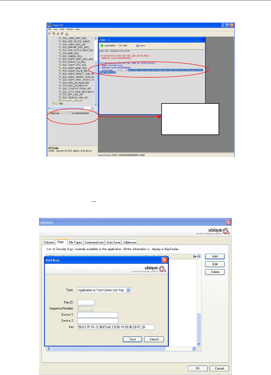
Z-Stack User's Guide - CC2530 ZNP SWRU242 Version 1.2
Enter the correct
partner IEEE
address here
Figure 36: Settings for sending the ZDO_GET_LINK_KEY message
Copy and paste the key into Ubiqua. To get to the menu for entering the Security Key as shown
in Figure 37 go to the Tools
Options… then select the Keys tab and double-click on the key
you want to modify or add a new key by pressing the add button.
Figure 37: Screen shot from Ubiqua Protocol Analyzer (security settings)
46 Copyright 2010 Texas Instruments, Inc. All rights reserved.

Z-Stack User's Guide - CC2530 ZNP SWRU242 Version 1.2
Running the ESP and Simple Meter Applications
After compiling the sample app instances (as described above) and programming the devices one
can start the applications as follows:
1. Power the coordinator, wait for "ZigBee Coord" to show up on the LCD display. The
next line of the LCD will display the PAN ID of the established network.
2. Then power the Simple Meter device. If using Certicom ECC security, verify with the
sniffer that key establishment is complete. If the Simple Meter device is configured as an
end device, its polling rate is set to 8secs. Therefore the key establishment procedure
takes a lot longer. Wait about 20 seconds for this to complete. Verify with the sniffer that
the end device received the confirm key response. Once the key establishment procedure
is completed, the Simple Meter device will start sending attribute reports to the ESP, and
the ESP will display the current summation delivered value on its LCD.
Note: The compile option NV_RESTORE is not turned on by default on the ZAP, so if you
power cycle any of the devices, it needs to go through the key establishment procedure again,
and a different link key would be used. NV_RESTORE is turned off by default to allow rapid
development. Also, any device joining the ESP wouldn't be able to join more than once since the
new link key is used for authenticating the device instead of the default TC link key. Power cycle
the ESP and then the joining device so that it is able to join using the default TC link key.
Figure 38 and Figure 39 show what happens in the Ubiqua Protocol Analyzer for these two
application instances (with Certicom ECC security in use).
47 Copyright 2010 Texas Instruments, Inc. All rights reserved.
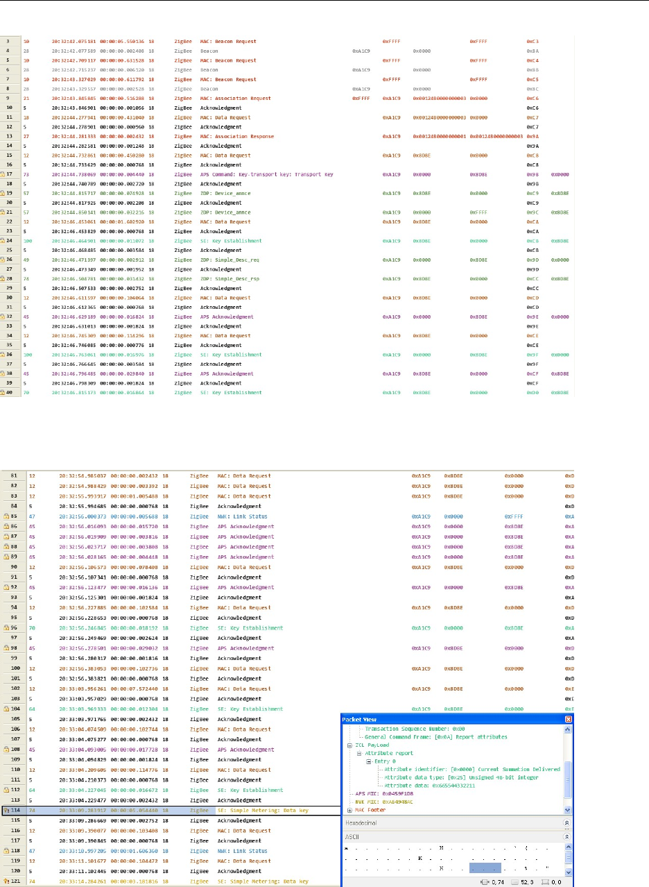
Z-Stack User's Guide - CC2530 ZNP SWRU242 Version 1.2
Figure 38: Screen shot from Ubiqua (start up – part 1)
Figure 39: Screen shot from Ubiqua (start up – part 2)
48 Copyright 2010 Texas Instruments, Inc. All rights reserved.

Z-Stack User's Guide - CC2530 ZNP SWRU242 Version 1.2
4.4.4. Theory of Operation
This section explains how each application instance behaves with respect to the ESP device and
also discusses the design of each application instance.
SE Secure Joining
The default trust center link key (TC link key) is used to commission each device. Each device
uses the SE secure joining process. See the Z-stack Smart Energy Developer’s Guide [19] for
more details.
Key Establishment
Upon successfully joining the network using security, each device will initiate key establishment
with the ESP. Certificate information required to perform the key establishment is entered in
ahead of time as part of the sample app initialization. Figure 40 shows a flowchart of the device
startup logic. The ZDO_STATE_CHANGE event is an OSAL system message that is provided
to the application to indicate that the device has successfully started or joined the network.
Device and Service Discovery
Each device communicates with the ESP. Since the ESP is the coordinator and will always have
a short address of 0x0000, devices that join the network can assume this and communicate with
the ESP directly. Therefore, no device discovery or service discovery is required for joining
devices. The ESP however, demonstrates the ability to discover Load Control devices and PCTs.
Once the device joins the network and performs a successful key establishment, it starts its
communications with the ESP based on the application behavior.
The following sections (4.4.5-4.4.10) define the application behavior for each device after it has
successfully joined the network using SE secure join, and has an application link key established
with the ESP.
4.4.5. ESP
The ESP is assumed to be the coordinator, trust center, and network manager of the network.
Every other device communicates with the ESP.
The ESP application instance consists of the following modules:
OSAL_esp.c – functions and tables for task initialization
esp.c – main application function that has init and event loop function
esp.h – header file for application module
esp_data.c – container for declaration of attributes, clusters, simple descriptor
49 Copyright 2010 Texas Instruments, Inc. All rights reserved.
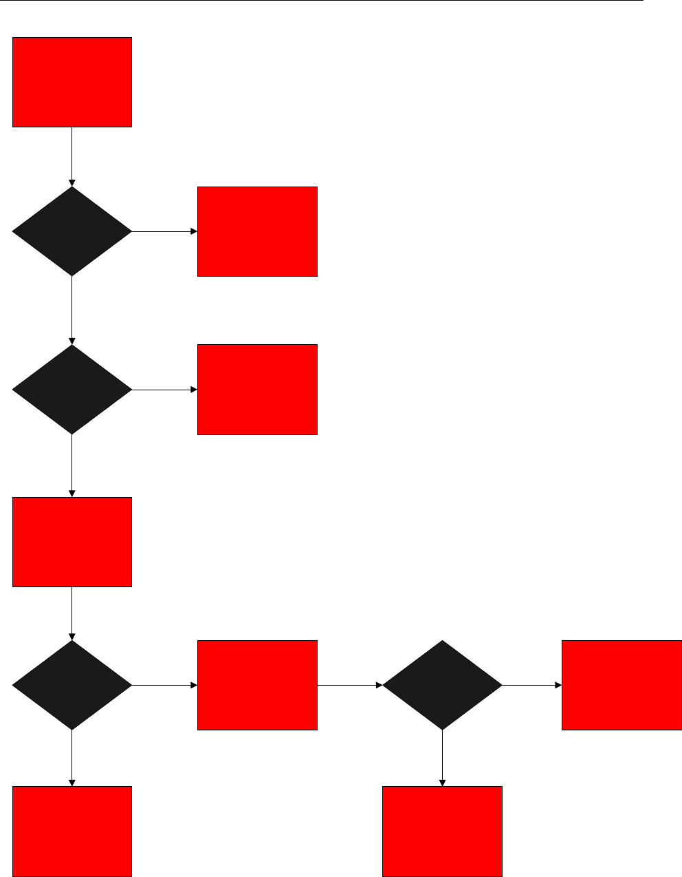
Z-Stack User's Guide - CC2530 ZNP SWRU242 Version 1.2
SECURE = 1?
ZDO_STATE_CHANGE
Event
Is Router/End
Device?
Set POLL_RATE to 8
seconds, Start
Application Function
NO
YES
NO Do Nothing
Check Link Key Status
Link Key Exists? Initiate Key
Establishment
NO
YES
YES
Set POLL_RATE to 8
seconds, Start
Application Function
Key Established? NO
YES
Do Nothing
Start
Application Function
Figure 40: Flowchart of Device Startup Logic
50 Copyright 2010 Texas Instruments, Inc. All rights reserved.

Z-Stack User's Guide - CC2530 ZNP SWRU242 Version 1.2
The ESP application makes function calls to the following ZCL SE functions and ZDO API
functions:
esp_GetCurrentPriceCB – callback executed when get current price message is received
either via unicast or INTER-PAN.
zclSE_Pricing_Send_PublishPrice – send publish price command to IPD either via
unicast or INTER-PAN.
esp_ProcessInReportCmd – print out value of current summation delivered when
attribute report is received
zclSE_LoadControl_Send_LoadControlEvent – send a load control event message to a
load control device
zclSE_Message_Send_DisplayMessage – send a message command to an IPD
esp_ProcessAppMsg – MT_SYS_APP_MSG can be used to tunnel any application
specific messages into the device via UART (e.g. by using Z-Tool). It is left as a hook so
the application developer can fill in the necessary functionality.
esp_ProcessZDOMsg – responses for end device announce and simple descriptor
requests are processed here. When an end device announce message is received, the
SIMPLE_DESC_QUERY_EVT event is set, and this causes the simple descriptor request
to be triggered for this source address.
esp_HandleKeys – user switch events are processed here. SW1 sends out a load control
event to the PCT, SW2 sends out a load control event to the load control device, SW3
sends out a display message command to the IPD.
The ESP interacts with other application instances in different ways. Endpoints, command
structures, ZDO callbacks, and SE callbacks are initialized by calling esp_Init. System and user
events are handled in esp_event_loop.
When a Simple Metering device joins the network, once the key establishment procedure is
successful, it will receive attribute reports from the Simple Metering device every 5 seconds.
Therefore, every 5 seconds the function esp_ProcessInReportCmd is called to display the
received CurrentSummationDelivered attribute on the ESP’s LCD screen.
When an IPD device joins the network, once the key establishment procedure is successful, it
will send a get pricing info message. On the ESP, the esp_GetCurrentPriceCB is called when the
get pricing info message is received. This then calls zclSE_Pricing_Send_PublishPrice to send
out the publish price command to the IPD. If SW3 is pressed, the function
zclSE_Message_Send_DisplayMessage is called to send a display MESSAGE to the IPD device.
51 Copyright 2010 Texas Instruments, Inc. All rights reserved.

Z-Stack User's Guide - CC2530 ZNP SWRU242 Version 1.2
When a PCT or Load Control device joins the network and establishes a link key with the ESP,
the ESP will discover these devices by using the end device announce to trigger a simple
descriptor ZDO request. Each simple descriptor response is parsed in the ZDO callback handler
esp_ProcessZDOMsg, and the device ID field is checked to determine whether this response
came from the PCT or Load Control Device. Depending on the device ID, the destination
address for the PCT or Load Control Device is then populated. This is how the ESP then knows
which type of load control event to send to which device. SW1 is used to send a PCT event to the
PCT, and SW2 is used to send an event to the load control device.
4.4.6. Simple Metering Device
The Simple Metering Device will periodically send reports for the CurrentSummationDelivered
Simple Metering attribute to the ESP. The ESP will display the CurrentSummationDelivered
value on the LCD. See Figure 41 for a sequence diagram.
The Simple Meter application instance consists of the following modules:
OSAL_simplemeter.c - functions and tables for task initialization
simplemeter.c – main application function that has init and event loop function
simplemeter.h – header file for application module
simplemeter_data.c – container for declaration of attributes, clusters, simple descriptor
The Simple Meter application makes the following function calls:
zcl_SendReportCmd – this function sends the CurrentSummationDelivered report
attribute to the ESP.
simplemeter_HandleKeys – user switch events are processed here.
Once the simple meter device joins the network, it goes through the state machine explained in
Figure 41. simplemeter_KeyEstablish_ReturnLinkKey is called to check if a link key has already
been established with the ESP. If it hasn’t, it will set the osal event
SIMPLEMETER_KEY_ESTABLISHMENT_REQUEST_EVT. The event handler for this in the
process event loop will then call zclGeneral_KeyEstablish_InitiateKeyEstablishment to do the
CBKE procedure. Upon its success, the application will receive a ZCL_KEY_ESTABLISH_IND
system message. An osal timer event called SIMPLEMETER_REPORT_ATTRIBUTE_EVT is
then started to send attribute reports every 5 seconds of the CurrentSummationDelivered
attribute. The structure for the report command is created and initialization of the attribute is
done in the simplemeter_Init function.
52 Copyright 2010 Texas Instruments, Inc. All rights reserved.

Z-Stack User's Guide - CC2530 ZNP SWRU242 Version 1.2
Simple
Metering
Device
ESP
Association Request
Association Response ZDO_STATE_CHANGE event to application
Initiate Key Establishment
Key Establishment Response ZCL_KEY_ESTABLISH_IND event to application
Report Simple Metering Attribute
every 5 seconds
esp_ProcessInReportCmd
called to display attribute on
LCD
Figure 41: Sequence Diagram for a Simple Meter Device
4.4.7. Load Control Device
The ESP will send a load control event to the Load Control Device via a user switch button
press. In the Load Control Event payload, the Device Class Field Bitmap will indicate that Bit 7
is set (representing Residential ON/OFF Load). When the Load Control Device receives the load
control event, it sends a ReportEventStatus command that it received it, and sends another one
when it starts it. The Start Time field will indicate to “Start Now”. The event duration will last 1
minute. While the load control event is in process, the Load Control Device will flash its LED.
When the load control event is finished, another ReportEventStatus command will be sent to the
ESP to indicate the completion of the load control event. See Figure 42 for a sequence diagram.
53 Copyright 2010 Texas Instruments, Inc. All rights reserved.
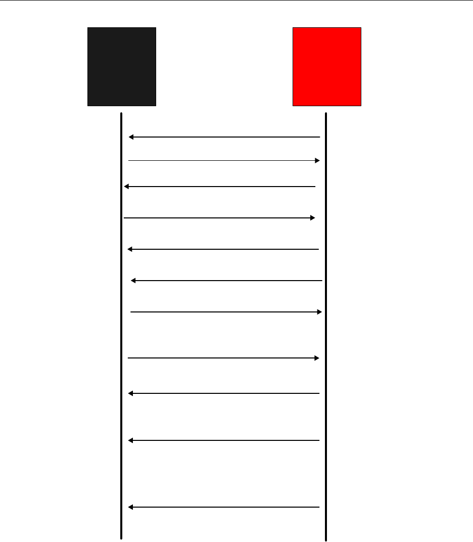
Z-Stack User's Guide - CC2530 ZNP SWRU242 Version 1.2
Load Control
Device
ESP
Association Request
Association Response ZDO_STATE_CHANGE event to application
Initiate Key Establishment
Key Establishment Response ZCL_KEY_ESTABLISH_IND event to application
End Device Annce
Process End Device Annce
Callback Simple Descriptor Request (to discover
PCT or Load Control Device)
Simple Descriptor ResponseProcess ZDO Simple
Descriptor Response Callback
User presses SW2
Send Load Control Event to Residential ON/
OFF Load units, Duration = 1 minute loadcontrol_LoadControlEventCB called
ReportEventStatus (Load
Control Event Started)
Load Control OSAL timer event occured, stop
blinking LED 4, display "Load Evt Complete"
on LCD
Set Load Control OSAL timer
event for 1 minute, blink LED 4,
Display "Load Evt Started" on
LCD
ReportEventStatus (Load Control
Event Received)
ReportEventStatus (Load
Control Event Complete)
Figure 42: Sequence Diagram for a Load Control Device
54 Copyright 2010 Texas Instruments, Inc. All rights reserved.

Z-Stack User's Guide - CC2530 ZNP SWRU242 Version 1.2
The Load Control Device application instance consists of the following modules:
OSAL_loadcontrol.c - functions and tables for task initialization
loadcontrol.c – main application function that has init and event loop function
loadcontrol.h – header file for application module
loadcontrol_data.c – container for declaration of attributes, clusters, simple descriptor
The Load Control application makes function calls to the following ZCL SE functions and ZDO
API functions:
loadcontrol_LoadControlEventCB – this function is called when the load control device
received a load control command.
zclSE_LoadControl_Send_ReportEventStatus – When a load control command is
received, the device sends a report event status command back to the ESP. Possible
values for the event type for this particular sample app could be event received, event
started, and event completed. The response structure (rsp) is made a global variable so
that the process event loop can manipulate the eventStatus field once the load control
event is complete.
loadcontrol_HandleKeys – user switch events are processed here.
Once the Load Control device joins the network, it goes through the state machine explained in
Figure 42. The function loadcontrol_KeyEstablish_ReturnLinkKey is called to check if a link key
has already been established with the ESP. If it hasn’t, it will set the osal event
LOADCONTROL_KEY_ESTABLISHMENT_REQUEST_EVT. The event handler for this in
the process event loop will then call zclGeneral_KeyEstablish_InitiateKeyEstablishment to do
the CBKE procedure. Upon its success, the application will receive a
ZCL_KEY_ESTABLISH_IND system message. Nothing is done at this point, and the load
control device is ready to accept load control messages from the ESP.
When a load control command is received, the callback loadcontrol_LoadControlEventCB is
executed. This callback function checks the issuer event id (0x12345678), the start time
(0x00000000 = NOW) in order to make sure that it is not just blindly responding to a random
load control event. Furthermore, it checks the deviceGroupClass to determine whether this load
control event was for the PCT or load control device. The values within this load control
command originate from the ESP. The correct string on the LCD is then displayed to indicate
whether this is a load control device event or PCT event. It is assumed that the load control
device belongs to the residential on/off load device class, and that the PCT belongs to the HVAC
compressor/furnace device class.
An osal timer event called LOADCONTROL_LOAD_CTRL_EVT is then started to commence
the load control event and flash the LED for the duration specified, which is 1 minute. When this
timer event expires, the status response of event completed is sent back to the ESP, and the LED
stops flashing. The user also sees a display on the LCD indicating that the load control event is
complete.
55 Copyright 2010 Texas Instruments, Inc. All rights reserved.

Z-Stack User's Guide - CC2530 ZNP SWRU242 Version 1.2
4.4.8. PCT
The PCT will have a very similar behavior to the Load Control Device. However, in the Load
Control Event payload, the Device Class Field BitMap will indicate that Bit 0 is set (HVAC
compressor or furnace). The Load Control Event for the PCT will be regarded as a “PCT Event”,
and the message “PCT Event Started” will be displayed if the device has LCD support. See
Figure 43 for a sequence diagram.
The PCT application instance consists of the following modules:
OSAL_pct.c - functions and tables for task initialization
pct.c – main application function that has init and event loop function
pct.h – header file for application module
pct_data.c – container for declaration of attributes, clusters, simple descriptor
The PCT application makes function calls to the following ZCL SE functions and ZDO API
functions:
pct_LoadControlEventCB – this function is called when the PCT device received a load
control command.
zclSE_LoadControl_Send_ReportEventStatus – When a load control command is
received, the device sends a report event status command back to the ESP. Possible
values for the event type for this particular sample app could be event received, event
started, and event completed. The response structure (rsp) is made a global variable so
that the process event loop can manipulate the eventStatus field once the PCT event is
complete.
pct_HandleKeys – user switch events are processed here.
Once the PCT device joins the network, it goes through the state machine explained in Figure 43.
pct_KeyEstablish_ReturnLinkKey is called to check if a link key has already been established
with the ESP. If it hasn’t, it will set the osal event
PCT_KEY_ESTABLISHMENT_REQUEST_EVT. The event handler for this in the process
event loop will then call zclGeneral_KeyEstablish_InitiateKeyEstablishment to do the CBKE
procedure. Upon its success, the application will receive a ZCL_KEY_ESTABLISH_IND
system message. Nothing is done at this point, and the PCT device is ready to accept load control
messages from the ESP.
When a load control command is received, the callback pct_LoadControlEventCB is executed.
This callback function checks the issuer event id (0x12345678), the start time (0x00000000 =
NOW) in order to make sure that it is not just blindly responding to a random load control event.
Furthermore, it checks the deviceGroupClass to determine whether this load control event was
for the PCT or load control device. The values within this load control command originate from
the ESP. The correct string on the LCD is then displayed to indicate whether this is a load
control device event or PCT event. It is assumed that the load control device belongs to the
56 Copyright 2010 Texas Instruments, Inc. All rights reserved.
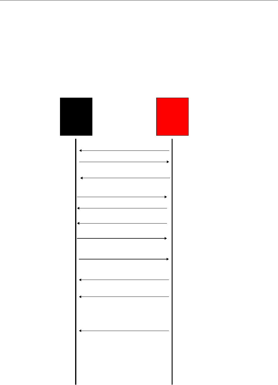
Z-Stack User's Guide - CC2530 ZNP SWRU242 Version 1.2
residential on/off load device class, and that the PCT belongs to the HVAC compressor/furnace
device class. An OSAL timer event called PCT_LOAD_CTRL_EVT is then started to
commence the load control event and flash the LED for the duration specified, which is 1
minute. When this timer event expires, the status response of event completed is sent back to the
ESP, and the LED stops flashing. The user also sees a display on the LCD indicating that the
PCT event is complete.
Note: The mechanics of the PCT and Load Control Device are the same. There are just slight
differences in variable names and the type of message displayed on the LCD.
Programmable
Communicating
Thermostat
(PCT)
ESP
Association Request
Association Response ZDO_STATE_CHANGE event to application
Initiate Key Establishment
Key Establishment Response ZCL_KEY_ESTABLISH_IND event to application
End Device Annce
Process End Device Annce
Callback Simple Descriptor Request (to discover
PCT or Load Control Device)
Simple Descriptor ResponseProcess ZDO Simple
Descriptor Response Callback
User presses SW1
Send Load Control Event to HVAC
units, Duration = 1 minute pct_LoadControlEventCB called
ReportEventStatus (Load
Control Event Received)
ReportEventStatus (Load
Control Event Started)
ReportEventStatus (Load
Control Event Completed) PCT OSAL timer event occured, stop blinking
LED 4, display "PCT Evt Complete" on LCD
Set PCT OSAL timer event for 1
minute, blink LED 4, Display
"PCT Evt Started" on LCD
Figure 43: Sequence Diagram for a PCT
57 Copyright 2010 Texas Instruments, Inc. All rights reserved.
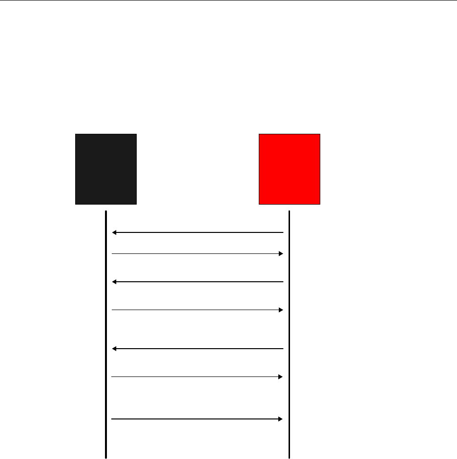
Z-Stack User's Guide - CC2530 ZNP SWRU242 Version 1.2
4.4.9. In Premise Display
The In Premise Display will use the GetCurrentPrice command to obtain the current pricing info
from the ESP. The user can press SW2 to send an INTER-PAN version of the Get Current Price
command to the ESP. The pricing information will be displayed on its LCD. The ESP will be
able to use the SW3 button press to send a display MESSAGE command to the In Premise
Display. This message will then be displayed on the LCD. See Figure 44 for a sequence diagram.
In Premise
Display
ESP
Association Request
Association Response ZDO_STATE_CHANGE event to application
Initiate Key Establishment
Key Establishment Response ZCL_KEY_ESTABLISH_IND event to application
Get Pricing Info every 5 seconds or
send via INTER-PAN using SW2
ipd_GetCurrentPriceCB
called
Send Publish Price ipd_PublishPriceCB called to
display Provider ID on LCD
User presses SW3 Send Display Message ipd_DisplayMessageCB
called to display "Rcvd
MESSAGE Cmd" on LCD
SW2 can be used to send an
INTER-PAN version of Get
Current Price
Figure 44: Sequence Diagram for an In Premise Display
The PCT application instance consists of the following modules:
OSAL_ipd.c – functions and tables for task initialization
ipd.c – main application function that has init and event loop function
ipd.h – header file for application module
ipd_data.c – container for declaration of attributes, clusters, simple descriptor
The IPD application makes function calls to the following ZCL SE functions and ZDO API
functions:
58 Copyright 2010 Texas Instruments, Inc. All rights reserved.
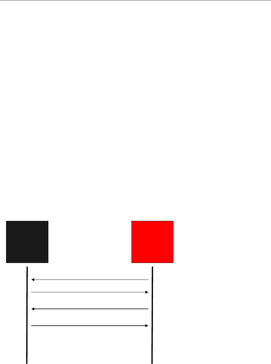
Z-Stack User's Guide - CC2530 ZNP SWRU242 Version 1.2
zclSE_Pricing_Send_GetCurrentPrice – this function sends the get current price request
to the ESP.
ipd_PublishPriceCB – this function is called when the IPD device receives the publish
price command from the ESP, and displays the provider ID on the LCD.
ipd_HandleKeys – user switch events are processed here.
Once the IPD device joins the network, it goes through the state machine explained in Figure 44.
pct_KeyEstablish_ReturnLinkKey is called to check if a link key has already been established
with the ESP. If it hasn’t, it will set the osal event
IPD_KEY_ESTABLISHMENT_REQUEST_EVT. The event handler for this in the process
event loop will then call zclGeneral_KeyEstablish_InitiateKeyEstablishment to do the CBKE
procedure. Upon its success, the application will receive a ZCL_KEY_ESTABLISH_IND
system message. An osal timer event called IPD_GET_PRICING_INFO_EVT is then started to
send the get pricing info request every 5 seconds. The result of the pricing request is received via
ipd_PublishPriceCB and is displayed on the LCD. Only the provider ID field of the published
price payload is displayed.
4.4.10. Range Extender
The Range Extender device will not exchange application data with the ESP. It will be able to
join the SE network, perform key establishment, and route packets. Figure 45 shows a sequence
diagram for the Range Extender.
Range
Extender
ESP
Association Request
Association Response ZDO_STATE_CHANGE event to application
Initiate Key Establishment
Key Establishment Response ZCL_KEY_ESTABLISH_IND event to application
Figure 45: Sequence Diagram for a Range Extender
59 Copyright 2010 Texas Instruments, Inc. All rights reserved.

Z-Stack User's Guide - CC2530 ZNP SWRU242 Version 1.2
The Range Extender application instance consists of the following modules:
OSAL_rangeext.c - functions and tables for task initialization
rangeext.c – main application function that has init and event loop function
rangeext.h – header file for application module
rangeext_data.c – container for declaration of attributes, clusters, simple descriptor
The Range Extender application makes function calls to the following functions:
rangeext_HandleKeys – user switch events are processed here.
The Range Extender application does not send any application level SE messages, but it does
join the network and perform key establishment. It functions as a standard ZigBee Pro router
device.
4.4.11. Limitations of the SE Sample Application
This section explains the limitations of the SE sample application.
Trust Center Operation
The trust center does not demonstrate how to refresh network keys.
The trust center does not demonstrate how to manage an access control list
The trust center assumes that joining devices have the same pre-configured trust center
link key already established at compile time in the ZNP image or using the application to
configure the corresponding NV item on the ZNP. It is assumed that the trust center link
key is already available. Out of band means of deriving the trust center link key is out of
the scope of this sample application.
Network Manager Operation
The ESP is the only device that has the Network Manager functionality.
The ZNP should be compiled with the NWK_MANAGER compile option in order to
enable Network Manager functionality hooks.
The ZNP default network manager application ZDNwkMgr.c is provided “as is” and there
is no application level functionality incorporated to demonstrate this Network Manager
application.
60 Copyright 2010 Texas Instruments, Inc. All rights reserved.

Z-Stack User's Guide - CC2530 ZNP SWRU242 Version 1.2
Secure Joining Operation
All devices must have the pre-configured Trust Center Link Key defined at compile time in the
ZNP image, or configured via the application processor.
Key Establishment Operation
SE Key Establishment is always initiated by the joining device and its partner will always be the
ESP.
Device Startup Behavior
The Smart Energy Profile spec mentions application best practices of controlling join/rejoin duty
cycles. This sample app does not make any attempt at changing the join/rejoin mechanism as
implemented in ZDApp.c in the ZNP image. The Smart Energy Profile spec says that end devices
should not be more than 7.5 seconds. This sample application therefore supports a nominal poll
rate of 8 seconds. The NWK_INDIRECT_MSG_TIMEOUT parameter in the f8wConfig.cfg file
must be increased to a suggested value of 10 in order to buffer the message long enough to
accommodate the 8 second poll period by the end device. The
MAX_POLL_FAILURE_RETRIES parameter should also be set to 4 as during the CBKE
procedure the ESP will be somewhat unresponsive to data requests during this time.
Load Control Device Behavior
There is no example of how to cancel a load control event from the ESP or how to supersede an
ongoing load control event.
ESP Behavior
The ESP service discovery implementation is limited to supporting up to two load control
devices at any given time, but could be easily modified to support more.
61 Copyright 2010 Texas Instruments, Inc. All rights reserved.
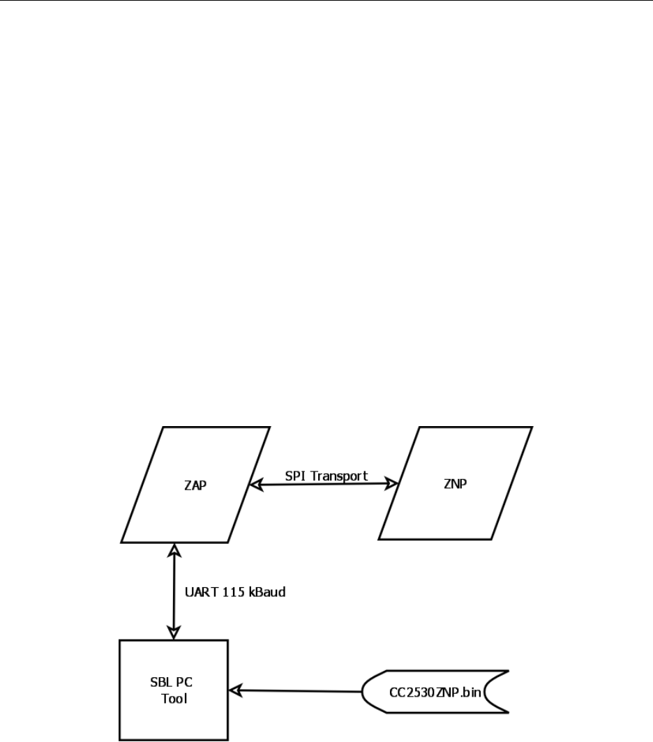
Z-Stack User's Guide - CC2530 ZNP SWRU242 Version 1.2
4.5. ZAP Proxy to ZNP SBL
As Chapter 3 described, the preferred method for updating the ZNP image is via the SBL
embedded in the released ZNP images. If your H/W allows direct access to the ZNP USB or
UART transport, existing PC Tools can be used to download a new ZNP image via SBL.
Otherwise, for SPI transport or other transports that are not externally available, the ZAP will
have to either control or proxy the SBL update. This section describes sample code that would be
incorporated as an addition to any ZAP sample application and which implements an SBL update
of the ZNP image by proxy to an existing PC Tool. Implementing the ZAP as the SBL master
and accessing the ZNP image to install from ZAP-side internal or external non-volatile memory
is a trivial (but completely H/W-dependent) enhancement to this ZAP-as-proxy sample
application.
4.5.1. Hardware and Software setup
The sample code requires SPI transport to the ZNP and a UART connection to an external PC
Tool. Such a setup is achieved with the MSP430F2618/5438 and CC2530EM described in 2.3.1
or 2.3.5.
Figure 46: Flow diagram for ZAP Proxy to ZNP SBL
4.5.2. Required Settings
In the general settings in the ZAP configuration file, zap.cfg (see Section 4.1.2 for details,) the
default setting of FALSE must be kept for both ZAP_ZNP_MT and ZAP_APP_MSG:
#define TVSA_DLY_ANN 60000
// Pass through MT from ZAP serial port Rx from Z-Tool to ZNP…
62 Copyright 2010 Texas Instruments, Inc. All rights reserved.
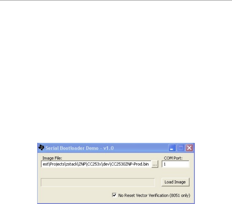
Z-Stack User's Guide - CC2530 ZNP SWRU242 Version 1.2
-DZAP_ZNP_MT=FALSE
// The following functionality depends on ZAP_ZNP_MT
-DZAP_APP_MSG=FALSE
This is because the SBL proxy code will use the serial port and has not been designed to co-exist
with the MT proxy (nor has the MT proxy code been designed to co-exist with something else.)
This SBL proxy code must be enabled by changing the default setting from FALSE to TRUE for
ZAP_SBL_PROXY:
// The following functionality is mutually-exclusive with the set of
// ZAP_ZNP_MT & ZAP_APP_MSG
// (i.e. do not have both set to TRUE simultaneously.)
-DZAP_SBL_PROXY=TRUE
4.5.3. UART Connection
Cable the SmartRF05 serial port or EXP5438 USB-to-serial port cable to the PC and access the
PC’s corresponding COM port with the SBDemo.exe tool. The SBDemo.exe tool can be found
in C:\Texas Instruments\ZAP-MSP430-x.x.x\Tools\SBL Tool.
Figure 47: SBDemo PC Tool
To download the new ZNP image, point it to the .bin file of interest, select the correct COM port
and check the box “No Reset Vector Verification (8051 only)”. Then press the “Load Image”
button to download the .bin file.
4.5.4. Incorporating the example
The TVSA Sample Application is used for demonstration purposes only – by merely changing
the corresponding paths/names this proxy SBL code would easily be incorporated into any
sample or proprietary ZAP application.
1. Find the sample code files here:
C:\Texas Instruments\ZAP-MSP430-x.x.x\Projects\zstack\ZAP\SBL\Source
And add these files to the target sample application as shown below:
63 Copyright 2010 Texas Instruments, Inc. All rights reserved.
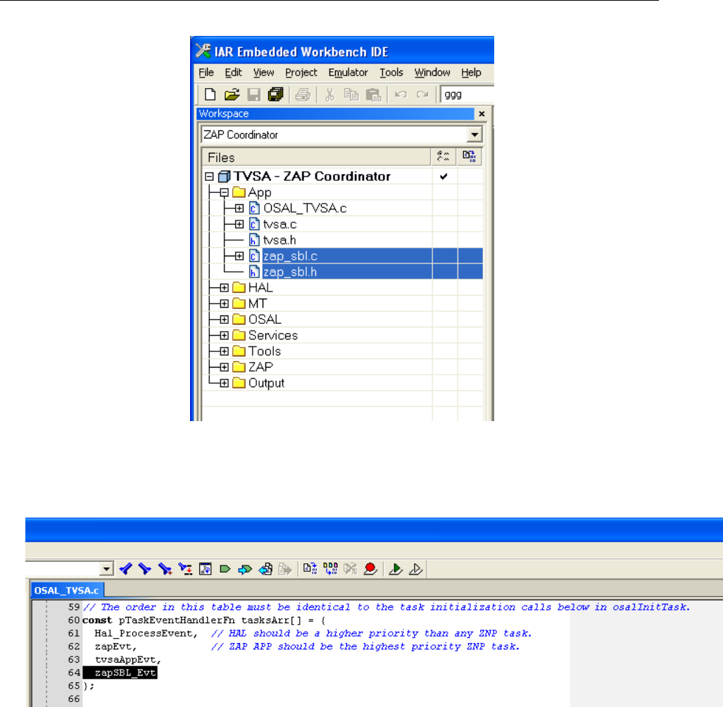
Z-Stack User's Guide - CC2530 ZNP SWRU242 Version 1.2
Figure 48: Adding the files for ZAP Proxy to ZNP SBL
2. Add the sample OSAL task to the target sample application as shown below:
64 Copyright 2010 Texas Instruments, Inc. All rights reserved.
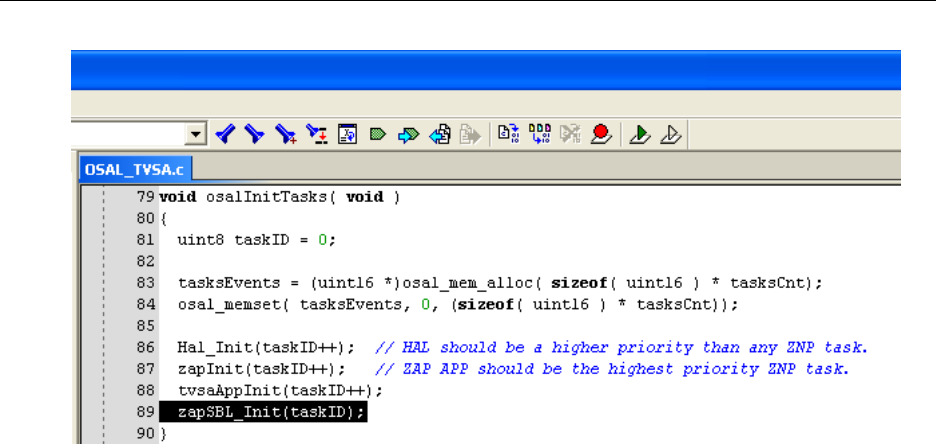
Z-Stack User's Guide - CC2530 ZNP SWRU242 Version 1.2
Figure 49: Adding the task for ZAP Proxy to ZNP SBL
Also add the following to the top of OSAL_TVSA.c:
extern void zapSBL_Init(uint8 id);
extern uint16 zapSBL_Evt(uint8 id, uint16 evts);
4.5.5. In Depth on the Example
In the following more details about the ZAP Proxy to ZNP SBL are given.
1. The zapSBL_Rx() function in zap_sbl.c, which is registered as the callback for the
UART connected to the PC, will enter the SBL proxy mode by any Rx byte. This is done
so early in parsing an incoming packet because the buffer for receiving it is not allocated
so that the normal running environment is not penalized.
2. An OSAL timer is used to detect a loss of UART activity:
osal_start_timerEx(zapSBL_TaskId, ZAP_SBL_EVT_EXIT, ZAP_SBL_DLY_EXIT)
3. The SBL proxy mode timeouts are defined in milliseconds at the top of the module:
#define ZAP_SBL_DLY_EXIT 15000
#define ZAP_SBL_DLY_WAIT 100
4. The SBL proxy mode is exited by a system reset:
mask = ZAP_SBL_EVT_EXIT;
HalReset();
65 Copyright 2010 Texas Instruments, Inc. All rights reserved.

Z-Stack User's Guide - CC2530 ZNP SWRU242 Version 1.2
FAQ
This Chapter addresses some frequently asked questions:
Q1: When do I need the IAR EW8051?
A1: You need the IAR EW8051 if you want to compile the Z-Stack code for the SoC; hence, you
will for example need it when you want to build your own ZNP images (hex-files). The latter
you would have to do if you cannot or do not want to use the available ready-built images.
Q2: Is it possible to use the Kick Start edition of the IAR EW430 to compile the ZAP Sample
applications?
A2: No, you need a version that is not code size limited (due to the code size of the sample
applications; i.e. you need either the evaluation edition or the full license version.
Q3: Where can I find more information about the OSAL and HAL?
A3: Both are described in the standard Z-Stack documentation (after installing the Z-Stack [6] it
can be found in C:\Texas Instruments\ZStack-CC2530-x.x.x-x.x.x\Documents) and one should start
reading with the Z-Stack Developer's Guide [1]. Then one could continue looking at the OSAL
API.pdf, Z-Stack HAL Porting Guide.pdf, and HAL Driver API.pdf
Q4: Can the application on the ZAP use APS fragmentation?
A4: Yes, fragmentation is supported.
Q5: Where is the trust center (TC), used for security, located?
A5: The trust center is implemented on the Coordinator ZNP image (if security is enabled).
Q6: Why are there several configuration files: zap.cfg, znp.cfg and f8wConfig.cfg?
A6: The sample application on the ZAP configures important parameters such as channel list,
PAN id and thus, these should be changed in the zap.cfg file (see Section 4.1.2 for details). The
settings in the znp.cfg and f8wConfig.cfg, like the default channel list and PAN id settings are not
relevant as they will be reconfigured by the ZAP based on zap.cfg. The configuration files
znp.cfg and f8wConfig.cfg are relevant for the user that does not want to use pre-built ZNP
66 Copyright 2010 Texas Instruments, Inc. All rights reserved.

Z-Stack User's Guide - CC2530 ZNP SWRU242 Version 1.2
images, but instead wants to configure and built customized ZNP images (e.g. changing the
security settings see described in Section 3.5 and Section 4.4.3 for details).
Q7: Isn’t there a potential race condition where you have MRDY asserted the same time SRDY
asserts (for example as AF data comes in asynchronously while you try to send a command to
the ZNP)? Does the low level driver check for SRDY high before asserting MRDY?
A7: The ZNP is the slave and the ZAP is the master. The slave does whatever the master wants,
regardless of which one pulled the “ready line” first – thus, by definition of the RPC protocol,
there is no race or potential race.
There are two possible scenarios to consider:
1. Slave is ready with an AREQ, it asserts its SRDY.
2. Master is ready with an SREQ, it asserts its MRDY.
Whether the 2 lines asserted at the exact same moment in time or nanoseconds apart, the slave is
bound by protocol to sit there holding its SRDY ready – it cannot de-assert its SRDY without
being led through the protocol by the master. After the master asserts its MRDY, it is bound by
protocol to sit there holding its MRDY ready until the slave asserts its SRDY. When finally the
master is sure that it is asserting its MRDY and the slave is asserting its SRDY, the master
proceeds with whatever it wants to do on the SPI according to protocol, which at this step are 2
options:
A. Make a “poll for data” which would allow the slave to regurgitate its AREQ. But we know the
master won’t be doing this, because it had an SREQ ready. So it will do B. in this scenario.
B. Make a SREQ according to protocol. And the slave, being a slave, is obliged to follow the
steps of an SREQ even though it has in its queue one or more AREQ’s ready to go.
67 Copyright 2010 Texas Instruments, Inc. All rights reserved.

Z-Stack User's Guide - CC2530 ZNP SWRU242 Version 1.2
68 Copyright 2010 Texas Instruments, Inc. All rights reserved.
5. References
[1] Z-Stack Developer's Guide -
C:\Texas Instruments\ZStack-CC2530-x.x.x-x.x.x\Documents\Z-Stack Developer's Guide.pdf
[2] CC2530-ZNP Interface Specification -
C:\Texas Instruments\ZStack-CC2530-x.x.x-x.x.x\Documents\CC2530ZNP_Interface_Specification.pdf
[3] IAR Embedded Workbench for 8051 (www.iar.com/ew8051; www.iar.com/ti_zigbee)
[4] IAR Embedded Workbench for MSP430 (www.iar.com/ew430; www.iar.com/ti_zigbee)
[5] Texas Instruments SmartRF Flash Programmer
(http://focus.ti.com/docs/toolsw/folders/print/flash-programmer.html )
[6] Texas Instruments Z-Stack – www.ti.com/z-stack
[7] MSP430 based ZAP sample code - ZAP-MSP430-x.x.x.exe – www.ti.com/z-stack
[8] CC2530 Product folder – http://focus.ti.com/docs/prod/folders/print/cc2530.html
[9] CC2531 Product folder – http://focus.ti.com/docs/prod/folders/print/cc2531.html
[10] CC-Debugger – http://focus.ti.com/docs/toolsw/folders/print/cc-debugger.html
[11] CC2531USBDongle – http://focus.ti.com/docs/toolsw/folders/print/cc2531emk.html
[12] CC2520DK – http://focus.ti.com/docs/toolsw/folders/print/cc2520dk.html
[13] IAR EW8051 User Guide (EW8051_UserGuide.pdf)
C:\Program Files\IAR Systems\EW8051_MCS-51_v7.51A\8051\doc\EW8051_UserGuide.pdf
[14] ZigBee Sensor Monitor (http://www.ti.com/litv/zip/swrc096d) &
Z-Stack Sensor Monitor User’s Guide (http://www.ti.com/litv/pdf/swru157d)
[15] MSP430 USB Debugging Interface –
(http://focus.ti.com/docs/toolsw/folders/print/msp-fet430uif.html)
[16] CC2520DK User's Guide – (http://www.ti.com/litv/pdf/swru138)
[17] SmartRF05EB User's Guide - (http://www.ti.com/litv/pdf/swru210)
[18] MSP-EXP430F5438 Experimenter Board User’s Guide –
(http://www.ti.com/lit/pdf/slau263)
[19] Z-Stack Smart Energy Developer’s Guide - C:\Texas Instruments\ZStack-CC2530-x.x.x-
x.x.x\Documents\ Z-Stack Smart Energy Developer's Guide.pdf
[20] Z-Stack Sample Applications Document - C:\Texas Instruments\ZStack-CC2530-x.x.x-
x.x.x\Documents\ Z-Stack Sample Applications.pdf
[21] Daintree Whitepaper “Understanding ZigBee Commissioning”;
http://www.daintree.net/resources/whitepapers
[22] Ubiqua Protocol Analyzer from Ubilogix; www.ubilogix.com
[23] Z-Stack ZCL API Document - C:\Texas Instruments\ZStack-CC2530-x.x.x-x.x.x\Documents\ Z-Stack
ZCL API.pdf
