Apple I Operation Manual Apple1manual Alt
User Manual:
Open the PDF directly: View PDF ![]() .
.
Page Count: 17
E
MANUAL
APPLE COMPUTER COMPANY
770 Welch Road _
Palo Alto, Calif. 94304
The Apple Computer is a complete micro-
processor system, consisting of a
Mos
Technology
6502 microprocessor and support
hardwart,
in-
tegral video display electronics, dynamic memory
and refresh hardware, and fully regulated power
supplies,
It
contains resident system monitor
software, enabling the user, via
the
keyboard
and display, to write, examine, debug, and run
programs efficiently;
thus
being
an educational
tool for
the
learning
of microprocessor
program-
ming, and an
aid
in
the development of
software.
The integral video display section and the
keyboard
interface renders unnecessary
the need
for an external
teletype,
The display section con-
tains its ownmemory, leaving all of RAM for uwr
programs, and the output format is 40 characters/
line, 24 lines/page, with auto sc&lling. Almost
any
ASCII
encoded keyboard will interface directly
with the Apple system,
The
board has sockets for upto 8K
bytes
of the 16 pin, 4K type, RAM, and the system is
fully expandable to 65K via the edge connector,
The
system uses
dynamic memory (4K bytes sup-
plied), although static memory may also be used.
All refreshing of dynamic memory, including all
I’ off - board ” expansion memory, is done auto-
matically. The entire system timing, including
the
microprocessor clock and aI1
video signals,
originates in a single crystal oscillator,
Further,
the
printed circuit board contains
a “breadboard area”, in which
the user can add
additional
I+ on -board I’
hardware ( for example,
extra PLUS, ACWs, EROM’s, and so on).
Thie manual
is divided into three Sections:
Section I GETTING THE
SYSTEM RUNNING,
Section IX USING’ THE SYSTEM
MONITOR.
(listing included)
SectionIII EXPANDING
THE
SYSTEM,
Please readsection I thoroughly, before at-
tempting to “power-up” your system, and study
Section III carefully before attempting to expand
your system. 1n addition to this manual, Apple
j’Tech Notes” are available which contain exam-
ples
of
expansion hardware and techniques.
I
SECTJ,UN X
GETTUG
THE
SYSTEM
RUNNING I
The Apple Computer is fully assembled,
tested, and burned in, The only external devices
necessary
for
operation of the system are: An
ASCII encoded keyboard, a video display monitor,
and AG power sources of 8 to IO Volts (RMS) @3
amps
and 28Volts (RMS) @l
amp.
The following three
articles describe the attachment
of
these devices
in
detail,
Keyboard:
Any ASCII encoded keyboard, with positive
DATA
outputs , interfaces directly with the Apple
system via a f’DIP’t connector, xf
your
keyboard
has negative logic DATA outputs (rare), you can
install inverters (7404) in the breadboard area.
The strobe can be either positive or negative, of
long or short duration, The rrDIPt’ keyboard can-
nectar (B4) has inputs far seven DATA lines, one
STROBE line,
and two normally-open pushbutton
switches, used for RESET (enter monitor),
and
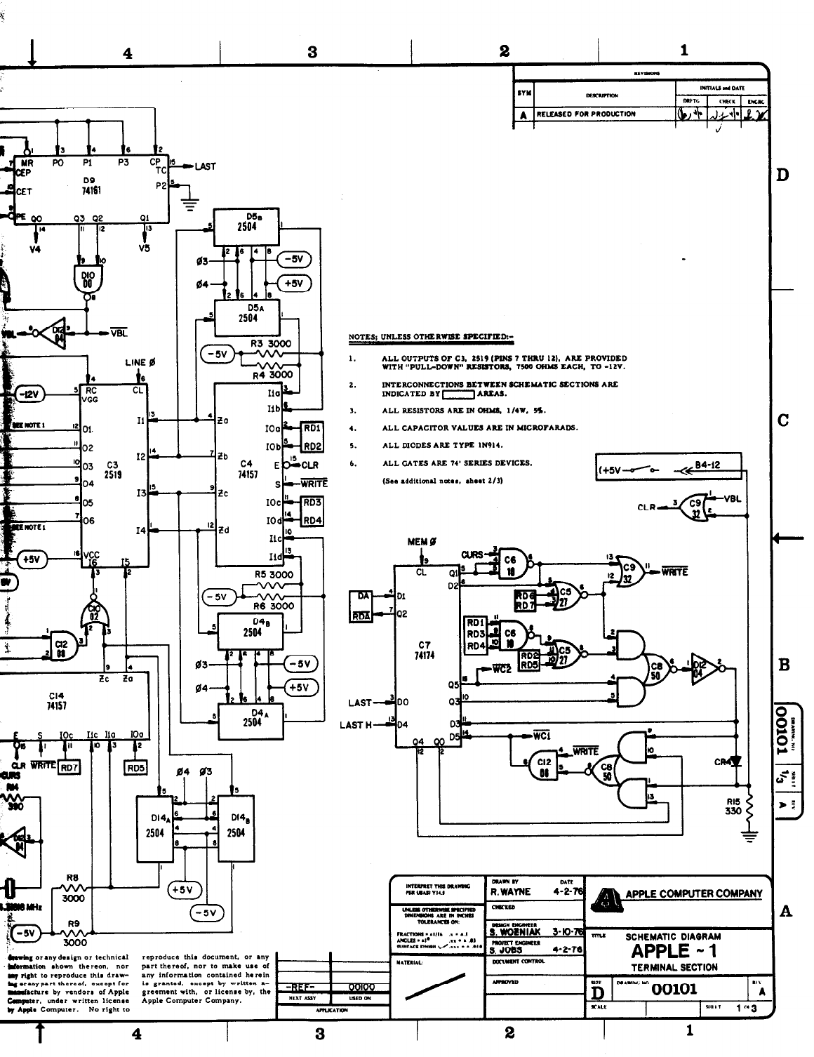
CLEAR SCREEN (see schematic diagram, sheet
3 of 3, for exact circuitry). This keyboard con-
nectar aIs0 supplies three
voltages,
(-HI, +12V,
and-12V) of which one or more may be necessary
to
operate the keyboard. Pin 15 of the keyboard
connector (B4) must be tied to t5V (pin
16)
for
normal operation,
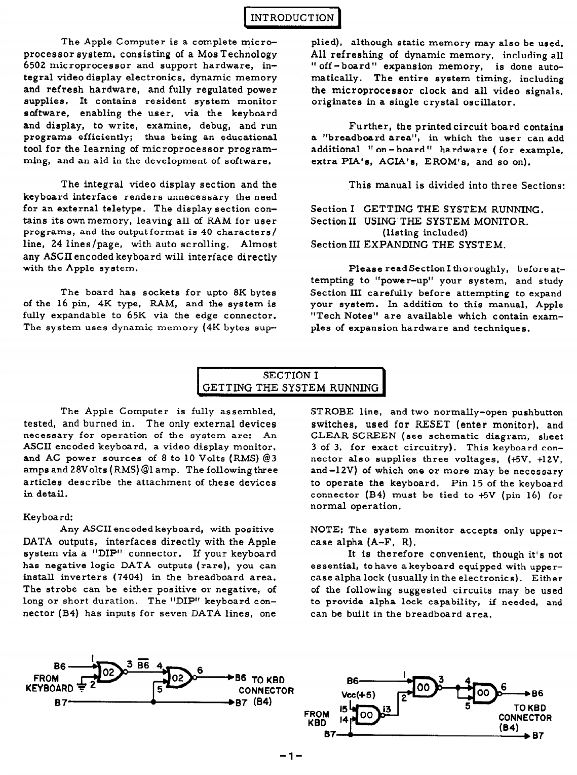
NOTE:
The
system
monitor accepts only upper-
case
alpha
(A-F, R).
It
is therefore convenient, though it’s not
essential,
to have a keyboard equipped with upper-
case
alpha lock
(usually in the electronics). Either
of the
following suggested circuits may
be
used
to provide alpha
lack capability, if needed, and
can be built in the breadboard
area,
oob”---*ss
5- TO KBD
CONNECTOR
104)
IL I
1
The Apple Computer outputs a composite
signal (composite of sync and video infor-
n) which can be applied to any standard
ter-scan type video display monitor. The out-
level is adjustable with the potentiometer
ted near the video output Molex connector, 52.
he additional two outside pins on the Molex con-
y t5 and+12 volts, to be used in future
sories. The composite video signal
modulated at the proper RF frequency,
uithan inexpensive commercially available device,
pplied to the antenna terminals of a home
sion receiver. Since the character format
characters /line, all television receivers
ilI have the necessary bandwidth to display the
40 characters. Two large manufacturers
o display monitors, which connect directly
e Apple Computer, are Motorola and Ball.
mating four-pin Molex connector is provided.
C\C Power Sources:
!y Two incoming AC power sources are re-
luired for operation: 8 to 10 VAC (RMS) at 3 amps,
!knd 28VAC (RMS) Center-Tapped at 1 amp. These
;‘\C supplies enter the system at the Molex con-
,Iector, Jl. The 8 to10 volts AC provides the raw
kc for the +5 volt supply, while the 28 VCT sup-
@es the raw AC for the t12 and -12 volt supplies,
.nd the -5V supply is derived from the -12V reg-
dated output.
The board, as supplied, requires no more
han 1.5 amps DC from the +5V supply, while the
egulator is capable of supplying 3 amps. The
eemaining 1.5 amps DC from the t5V supply is
.vailable for user hardware expansion (provided
uitable transformer ratings are employed).
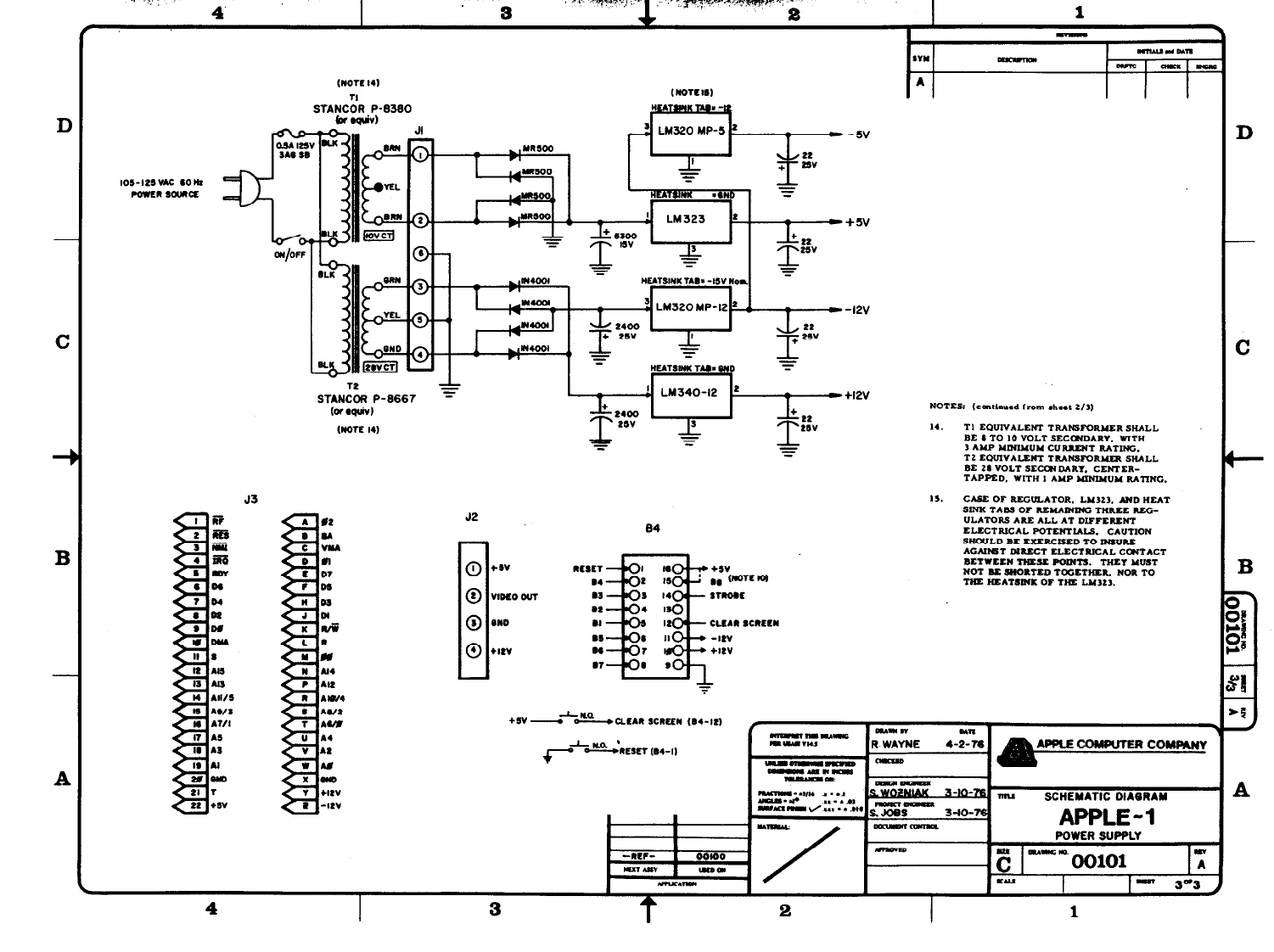
A suitable source of the raw AC voltages
.equired, are two commercially available trans-
ormers; Stancor P/N P-8380 or equivalent (8 to
0 volts at 3 amps), and Stancor P/N P-8667 or
equivalent ( 28VCT at 1 amp). Simply wire the
secondaries tothe mating six-pinMolex connector
supplied, and wire the primaries in parallel, as
shown in the schematic diagram (power supply
section, Dwg.No. 00101, sheet 3 of 3,
TEST PROGRAM
After attaching the keyboard, display, and
AC power sources, you can try a simple program
to test if your system and the attachments are
functioning together properly. While it does not
test many possible areas of the microprocessor
system, the test program will test for the correct
attachment of the keyboard, display, and power
supplies.
FIRST:
Hit the RESET button to enter the system
monitor. A backslash should be displayed,
and the cursor should drop to the next line.
SECOND:
Type- gzA9bQbAAb2gbEFbFFb
E8 b 8A b 4C b 2 b Q (RET)
(@ is a zero, NOT an alpha “011; b means
blank or space; and (RET) hit the “return”
key on the keyboard)
THIRD:
Type- Q . A (RET)
(This should print out, on the display, the
program you have just entered.)
FOURTH:
Type- R (=T)
(R means run the program.)
THE PROGRAM SHOULD THEN PRINT
OUT ON THE DISPLAY A CONTINUOUS STREAM
OF ASCII CHARACTERS. TO STOP THE PRO-
GRAM AND RETURNTO THE SYSTEM MONITOR,
HIT THE “RESET” BUTTON. TO RUN AGAIN,
TYPE : R (RET).
-2-
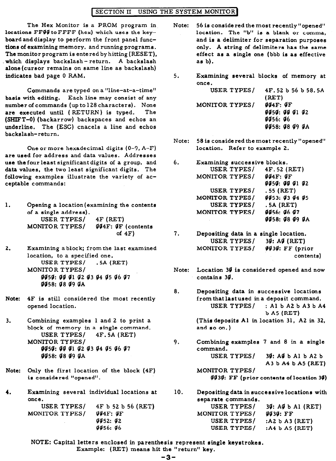
SECTION II USING THE SYSTEM MONITOR
The Hex Monitor is a PROM program in
locations FFVO t0FFF.F (hex) which uses the key-
bosrdanddisplay to perform the front panel func-
tions of examining memory, and running programs.
Themonitorprogramis entered byhitting(RESET),
which displays backslash - return. A backslash
alone(cursor remains on same line as backslash)
indicates bad page 0 RAM.
Commands are typed on a “line-at-a-time”
basis with editing. Each line may consist of any
number of commands (up to 128 characters). None
are executed until ( RETURN) is typed. The
(SHIFT-O) (backarrow) backspaces and ethos an
underline. The (ESC) cnacels a line and echo8
backslash-return.
One or more hexadecimal digits (O-9, A-F)
are used for address and data values. Addresses
use the four least significant digits of a group, and
data values, the two least significant digits. The
following examples illustrate the variety of ac-
ceptable commands:
1. Opening a location (examining the contents
of a single address).
USER TYPES/ 4F (RET)
MONITOR TYPES/ q04F: VF (contents
of 4F)
2. Examining a block; from the last examined
location, to a specified one.
USER TYPES/ .5A (RET)
MONITOR TYPES/
6459: VU 01 42
43 94 d5 46 47
0458: V8 d9 VA
Note: 4F is still considered the most recently
opened location.
3.
Combining examples 1 and 2 to print a
block of memory in a single command.
USER TYPES/ 4F. 5A (RET)
MONITOR TYPES /
9050: VV
Ql
02 V3 44 05 06 47
0458: 08 99 @A
Note: Only the first location of the block (4F)
is considered “opened”.
4. Examining several individual locations at
once.
USER TYPES/ 4F b 52 b
56
(RET)
MONITOR TYPES/ d04F: OF
0452: d2
VV56: 06
Note:
5.
Note:
6.
7.
Note:
8.
9.
10.
56 is conside red the most recently “opened”
location. The “b” is a blank or comma,
and is a delimiter for separation purposes
only. A string of delimiters has the same
effect as a single one (bbb is as effective
as b).
Examining several blocks of memory at
once.
USER TYPES/ 4F. 52 b
56
b 58.5A
WET)
MONITOR TYPES/ 4@4F: OF
vv5v: vv Vl
42
VQ56: 66
@d58: d8 d9 OA
58 is considered themost recently”opened”
location. Refer to example 2.
Examining successive blocks.
USER TYPES/ 4F. 52 (RET)
MONITOR TYPES/ g@BF: VF
vv50: da Vl v2
USER TYPES /
MONITOR TYPES/ i;&(:;T;4 Q5
USER TYPES/ .5A (RET)
MONITOR TYPES/
9456: 96
a7
VV58: 08 09 @A
Depositing data in a single location.
USER TYPES / 38: AO (RET)
MONITOR TYPES/ $Q3d: FF (prior
contents)
Location 34 is considered opened and now
contains 3Q.
Depositing data in successive locations
from that lastused in a deposit command.
USER TYPES / : Al b A2 b A3 b A4
b A5 (RET)
(This deposits Al in location 31, A2 in 32,
and so on.)
Combining examples 7 and 8 in a single
command.
USER TYPES/ 3@: Aa b Al b A2 b
A3 b A4 b A5 (RET)
MONITOR TYPES/
QQ3Q: FF (prior contents of location 34)
Depositing data in successive locations with
separate commands.
USER TYPES/ 30: AQ b Al (RET)
MONITOR TYPES / VQ3Q: FF
USER TYPES/ :A2 b A3 (RET)
USER TYPES/ :A4 b A5 (RET)
NOTE: Capital letters enclosed in parenthesis represent single keystrokes.
Example: (RET) means hit the “return” key.
-3-
Note:
11.
Note:
12.
Note:
13.
14.
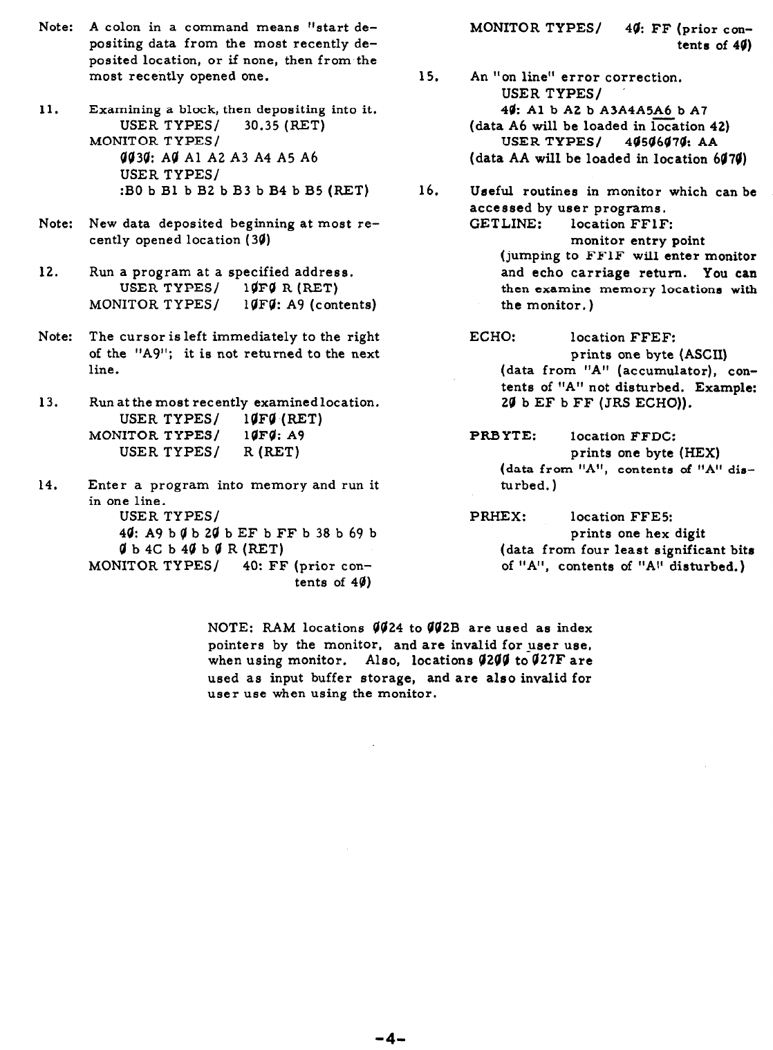
A colon in a command means “start de-
positing data from the most recently de-
posited location, or if none, then from-the
most recently opened one.
Examining a block, then depositing into it.
USER TYPES/ 30.35 (RET)
MONITOR TYPES/
QQ3Q: A@ Al A2 A3 A4 A5 A6
USER TYPES/
:BO b Bl b B2 b B3 b B4 b B5 (RET)
New data deposited beginning at most re-
cently opened location (34)
Run a program at a specified address.
USER TYPES/ l@FO R (RET)
MONITOR TYPES/ l@Fg: A9 (contents)
The cursor is left immediately to the right
of the “A9”; it is not returned to the next
line.
Run at the most recently examinedlocation.
USER TYPES/ l@F@ (RET)
MONITOR TYPES / 1QFQ: A9
USER TYPES/ R (RET)
Enter a program into memory and run it
in one line.
USER TYPES/
44: A9 b Q b 24 b EF b FF b 38 b 69 b
qb4Cb4@b@R(RET)
MONITOR TYPES/ 40: FF (prior con-
tents of 40)
MONITOR TYPES/ 44: FF (prior con-
tents of 49)
15. An “on line” error correction.
USER TYPES/ ’
4& Al b A2 b A3A4A5A6 b A7
(data A6 will be loaded in location 42)
USER TYPES/ 405(/6474: AA
(data AA will be loaded in location
6079)
16.
Useful routines in monitor which can be
accessed by user programs.
GETLINE: location FFl F:
monitor entry point
(jumping to FFlF will enter monitor
and echo carriage return. You can
then examine memory locations with
the monitor, )
ECHO: location FFEF:
prints one byte (ASCII)
(data from “A” (accumulator), con-
tents of rlA” not disturbed. Example:
2d
b EF b FF (JRS ECHO)).
PRBYTE: location FFDC:
prints one byte (HEX)
(data from “A”, contents of “A” dis-
turbed. )
PRI-IEX: location FFES:
prints one hex digit
(data from four least significant bits
of “A”, contents of “Al’ disturbed.)
NOTE: RAM locations @@24 to @02B are used as index
pointers by the monitor, and are invalid for user use,
when using monitor. Also, locations 02QO tdO27F are
used as input buffer storage, and are also invalid for
user use when using the monitor.
-4.
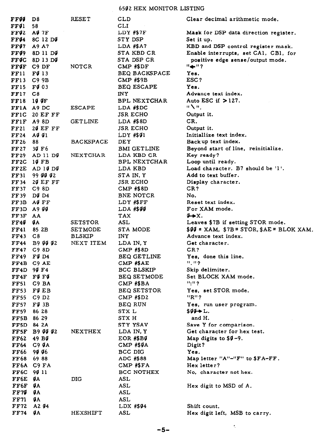
6582 HEX MONITOR LISTING
FFQQ
D8
FF01 58
FF02 A0 ?F
FF@4 8C 12 D0
FF@? A9 A?
FF09 8D 11 Dd
FF@C 8D 13 D0
FF0F C9 DF
FFll F0 13
FF13 C9 9B
FF15 F0 03
FFI? C8
FF18 1Q 0F
FFlA A9 DC
FFlC 20 EF FF
FFlF A9 8D
FF21 20 EF FF
FF24 A0 @l
FF26 88
FF27 34 F6
FF29 AD 11 D0
FFBC 10 FB
FFZE AD 10 D0
FF31 99
@0
@2
FF 34 20 EF FF
FF37 c9 8D
FF 39 D0 D4
FF3B A0 FF
FF3D A9
d0
FF3F AA
FF4@ @A
FF41 85 2B
FF43 C8
FF44 B9 00 02
FF47 c9 8D
FF49 F@ D4
FF4B C9 AE
FF4D 90 F4
FF4F F0 F0
FF51 C9 BA
FF53 F0 EB
FF55 C9 D2
FF57 F0 3B
FF59 86 28
FF5B 86 29
FFSD 84 2A
FFSF B9 00 02
FF62 49 B0
FF64 C9 0A
FF66 90 06
FF68 69 88
FF6A C9 FA
FF6C 90 11
FF6E @A
FF6F @A
FF70 @A
FF71 @A
FF72 A2 04
FF74 @A
RESET
NOTCR
ESCAPE
GETLINE
BACKSPACE
NEXTCHAR
SETSTOR
SETMODE
BLSKIP
NEXT ITEM
NEXTHEX
DIG
HEXSHIFT
CLD
CL1
LDY #$7F
STY DSP
LDA #$A?
STA KBD CR
STA DSP CR
CMP #$DF
BEQ BACKSPACE
CMP #$9B
BEQ ESCAPE
INY
BPL NEXTCHAR
LDA #$DC
JSR ECHO
LDA #$8D
JSR ECHO
LDY #$01
DEY
BMI GETLINE
LDA KBD CR
BPL NEXTCHAR
LDA KBD
STA IN, Y
JSR ECHO
CMP #$SD
BNE NOTCR
LDY #$FF
LDA #$00
TAX
ASL
STA MODE
INY
LDA IN, Y
CMP #$8~
BEQ GETLINE
GMP #$AE
BCC BLSKIP
BEQ SETMODE
CMP #$BA
BEQ SETSTOR
CMP #$D2
BEQ RUN
STX L
STX H
STY YSAV
LDA IN, Y
EOR #$BO
CMP #$0A
BCC DIG
ADC #$88
CMP #$FA
BCC NOTHEX
ASL
ASL
ASL
ASL
LDX #$04
ASL
-50
Clear decimal arithmetic mode.
Mask for DSP data direction register.
Set it up.
KBD and DSP control register mask.
Enable interrupts, set CAI, GBl, for
positive edge sense/output mode.
,,*,I( 7
Yes.
ESC ?
Yes.
Advance text index.
Auto ESC if >12?.
I, \ 11
,
Output it.
CR.
Output it.
Initiallize text index.
Backup text index.
Beyond start of line, reinitialize.
Key ready?
Loop until ready.
Load character. B? should be ‘1 I.
Add to text buffer.
Display character.
CR?
No.
Reset text index.
For XAM mode.
a-ex.
Leaves $?B if setting STOR mode.
$00 = XAM, $?B = STOR, $AE = BLOK XAM.
Advance text index.
Get character.
CR?
Yes, done this line.
,I* If 7
Skip delimiter.
Set BLOCK XAM mode.
If.,, 7
Yes, set STOR mode.
!lR!l,
Yes, run user program.
$Qa+L.
and H.
Save Y for comparison.
Get character for hex test.
Map digits to $0 -9.
Digit?
Yes.
Map letter “A” -uF”
t0
SFA-FF.
Hex letter?
No, character not hex.
Hex digit to MSD of A.
Shift count.
Hex digit left, MSB to carry.
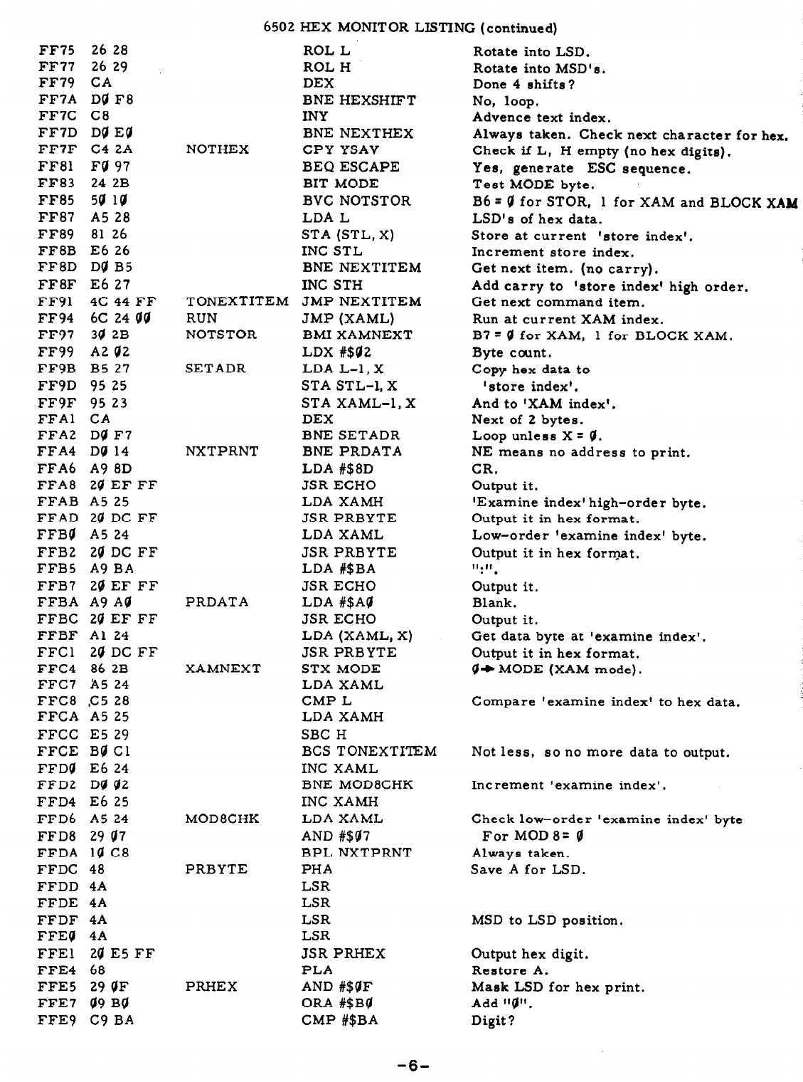
6502 HEX MONITOR LISTING (continued)
TONEXTITEM
RUN
NOTSTOR
ROL L
ROL H
DEX
BNE HEXSHIFT
INY
BNE NEXTHEX
CPY YSAV
BEQ ESCAPE
BIT MODE
BVC NOTSTOR
LDA L
STA (STL, X)
INC STL
BNE NEXTITEM
INC STH
JMP NEXTITEM
JMP (XAML)
BMI XAMNEXT
LDX
#$@2
LDA L-l, X
STA STL-1, X
STA XAML-1, X
DEX
BNE SETADR
BNE PRDATA
LDA #$8D
JSR ECHO
LDA XAMH
JSR PRBYTE
LDA XAML
JSR PRBYTE
LDA #$BA
JSR ECHO
LDA #$AQ
JSR ECHO
LDA (XAML, x)
JSR PRBYTE
STX MODE
LDA XAML
CMP L
LDA XAMH
SBC H
BCS TONEXTITEM
INC XAML
BNE MOD8CHK
INC XAMH
LDA XAML
AND #$47
BPL NXTPRNT
PHA
LSR
LSR
LSR
LSR
JSR PRHEX
PLA
AND #$QF
ORA #$BU
CMP #$BA
Rotate into LSD.
Rotate into MSD’ s .
Done 4 shifts?
No, loop.
Advence text index.
Always taken. Check next character for hex.
Check if L, H empty (no hex digits),
Yes, generate ESC sequence.
Test MODE byte.
B6 = 0 for STOR, 1 for XAM and BLOCK XAM
LSD’s of hex data.
Store at current ‘store index’.
Increment store index.
Get next item. (no carry).
Add carry to ‘store index’ high order.
Get next command item.
Run at current XAM index.
B7 = @ for XAM, 1 for BLOCK XAM.
Byte taunt.
Copy hex data to
‘store index’.
And to ‘XAM index’.
Next of 2 bytes.
Loop unless X = 0.
NE means no address to print.
CR.
Output it.
‘Examine index’ high-order byte.
Output it in hex format.
Low-order ‘examine index’ byte.
Output it in hex format.
11.11
. .
Output it.
Blank.
Output it.
Get data byte at ‘examine index’.
Output it in hex format.
@+ MODE (XAM mode).
Compare ‘examine index’ to hex data.
Not less, so no more data to output.
Increment ‘examine index’.
Check low-order ‘examine index’ byte
For MOD 8~ 0
Always taken.
Save A for LSD.
MSD to LSD position.
Output hex digit.
Restore A.
Mask LSD for hex print.
Add “g” .
Digit?
FF75 26 28
FF77 26 29
FF79 CA
FF7A Da F8
FF7C C8
FF7D Dg Ed
FF7F C4 2A
FF81 F@ 97
FF83 24 2B
FF85 5@ l@
FF87 A5 28
FF89 81 26
FF8B E6 26
FF8D Dg B5
FF8F E6 27
FF91 4C 44 FF
FF94 6C 24 gg
FF97 34 2B
FF99 A2 Q2
FF9B B5 27
FFSD 95 25
FF9F 95 23
FFAl CA
FFA2 Dg F7
FFA4 D@ 14
FFA6 A9 8D
FFA8 2@ EF FF
FFAB A5 25
FFAD 2g DC FF
FFBq A5 24
FFB2 2Q DC FF
FFB5 A9 BA
FFB7 20 EF FF
FFBA A9 A@
FFBC 2g EF FF
FFBF Al 24
FFCl 24 DC FF
FFC4 86 2B
FFC7 A5 24
FFC8 ,C5 28
FFCA A5 25
FFCC E5 29
FFCE BQ Cl
FFD@ E6 24
FFD2 D@ 42
FFD4 E6 25
FFD6 A5 24
FFD8 29 47
FFDA 10 C8
FFDC 48
FFDD 4A
FFDE 4A
FFDF 4A
FFEQ 4A
FFEl 20 E5 FF
FFE4 68
FFE5 29 gF
FFE7 a9 BQ
FFE9 C9 BA
NOTHEX
SETADR
NXTPRNT
PRDATA
XAMNEXT
MOD8CHK
PRBYTE
PRHEX
-6-
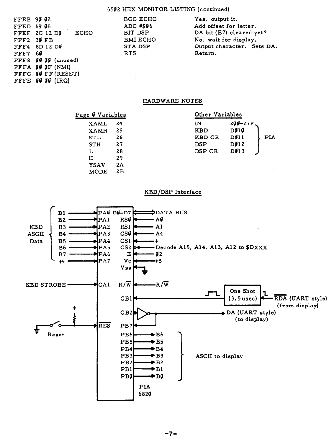
650.2 HEX MONITOR LISTING (continued)
9Q Q2
69 Q6
2C 12Dd ECHO
3@ FB
8D 12 Dq
is a9 1 unused)
‘iW gF (NW
00 FF (RESET)
QQ 00 (IRQ)
BCC ECHO Yes, output it.
ADC #$a6 Add offset for letter.
BIT DSP DA bit (B7) cleared yet?
BMI ECHO No, wait for display.
STA DSP Output character. Sets DA.
RTS Return.
FFEB
FFED
FFEF
FFF2
FFF4
FFF7
FFF8
FFFA
FFFC
FFFE
Page Q Variables
XAML 24
XAMH 25
STL 26
STH 27
L 28
H 29
YSAV 2A
MODE 2B
HARDWARE NOTES
Other Variables
IN 2@@-27F
KBD DQlQ
KBD CR Dal1 PIA
DSP DO12
DSP CR Dal 3
KBD/DSP Interface
CPA~ D@-D~ <-/DATA BUS
*PA1 RSqa AQ
bPA2 RSI 4 Al .
A4
+
+PA5 cs2 M Decode A15, A14, A13, Al2 to $DXXX
42
PA7 Vc +5
KBD STROBE . CA1 R/F 6 R/iii One Shot
CBl* J-L (3.5usec) Lm (UART style)
t
t (from display)
CB2
I
eDA (UART style)
l RES
(to display)
PB74
Reset
ASCII to display
-7-
SECTION III
HOW TO EXPAND THE APPLE SYSTEM
.
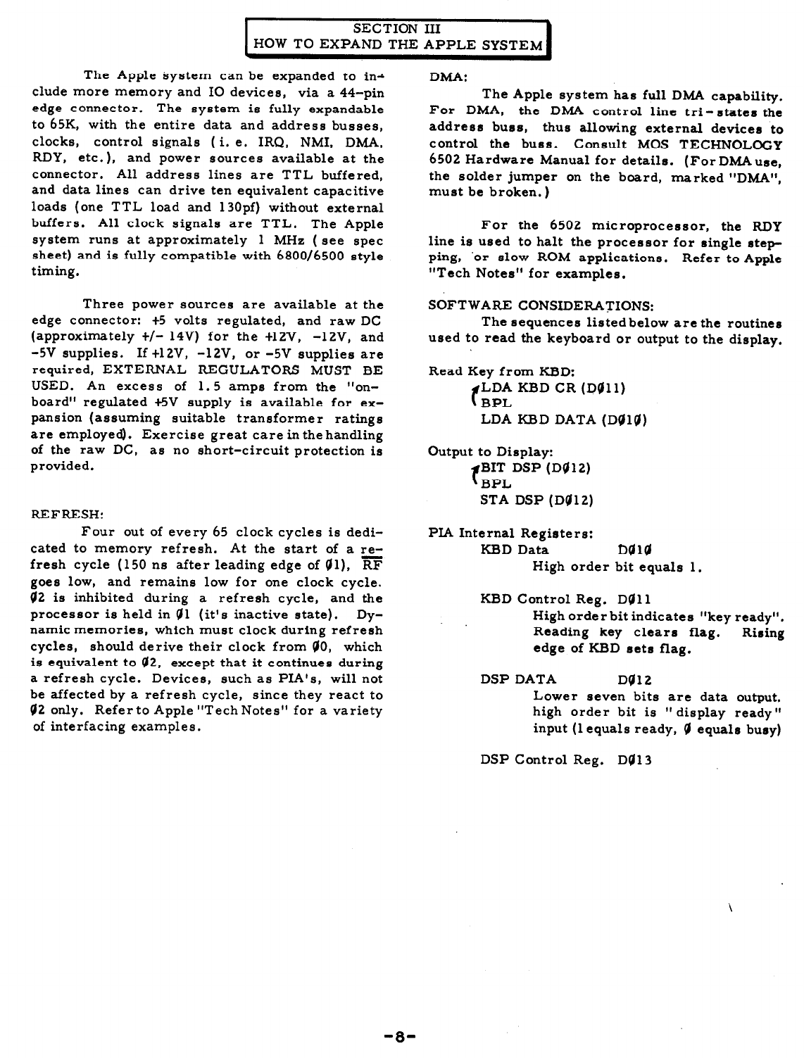
The Apple system can be expanded to ina
elude more memory and IO devices, via a 44-pin
edge connector. The system is fully expandable
to 65K, with the entire data and address busses,
clocks, control signals (i. e. IRQ, NMI, DMA,
RDY, etc.), and power sources available at the
connector. All address lines are TTL buffered,
and data lines can drive ten equivalent capacitive
loads (one TTL load and 130pf) without external
buffers. All clock signals are TTL. The Apple
system runs at approximately 1 MHz ( see spec
sheet) and is fully compatible with 6800/6500 style
timing.
Three power sources are available at the
edge connector: +5 volts regulated, and raw DC
(approximately t/- 14V) for the t12V, -12V, and
-5V supplies. If +12V, -12V, or -5V supplies are
required, EXTERNAL REGULATORS MUST BE
USED. An excess of 1.5 amps from the “on-
board” regulated +5V supply is available for ex-
pansion (assuming suitable transformer ratings
are employed). Exercise great care in the handling
of the raw DC, as no short-circuit protection is
provided.
REFRESH:
Four out of every 65 clock cycles is dedi-
cated to memory refresh. At the start of a re-
fresh cycle (150 ns after leading edge of Ql), RF
goes low, and remains low for one clock cycle.
Q2 is inhibited during a refresh cycle, and the
processor is held in Ql (it’s inactive state). Dy-
namic memories, which must clock during refresh
cycles, should derive their clock from 00, which
is equivalent to Q2, except that it continues during
a refresh cycle. Devices, such as PIA’s, will not
be affected by a refresh cycle, since they react to
42 only. Refer to Apple “Tech Notes” for a variety
of interfacing examples.
DMA:
The Apple system has full DMA capability.
For DMA, the DMA control line tri-states the
address buss, thus allowing external devices to
control the buss. Consult MOS TECHNOLOGY
6502 Hardware Manual for details. (ForDMAuse,
the solder jumper on the board, marked “DMA”,
must be broken.)
For the 6502 microprocessor, the RDY
line is used to halt the processor for single step-
ping,
‘or slow ROM applications. Refer to Apple
“Tech Notes” for examples.
SOFTWARE CONSIDERATIONS:
The sequences listed below are the routines
used to read the keyboard or output to the display,
Read Key from KBD:
f LDA KBD CR (D@ll)
BPL
LDA KBD DATA (Del@)
Output to Display:
f BIT DSP (Dq12)
BPL
STA DSP (Da12)
PIA Internal Registers:
KBD Data Ddl@
High order bit equals 1.
KBD Control Reg. DQll
High order bit indicates “key ready”.
Reading key clears flag. Rising
edge of KBD sets flag.
DSP DATA Dg12
Lower seven bits are data output,
high order bit is ‘I display ready”
input (1 equals ready, q equals busy)
DSP Control Reg. Da13
-8-
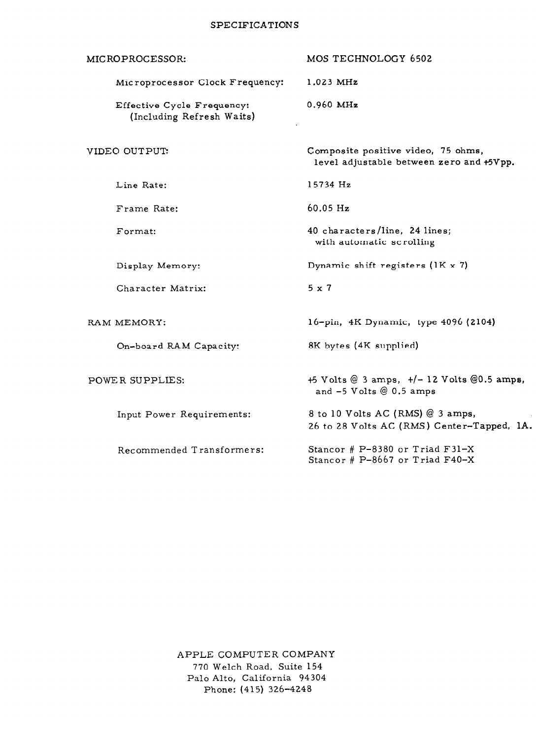
SPECIFICATIONS
MICROPROCESSOR: MOS TECHNOLOGY 6502
Microprocessor Clock Frequency: 1.023 MHz
Effective Cycle Frequency:
(Including Refresh Waits)
0.960 MHz
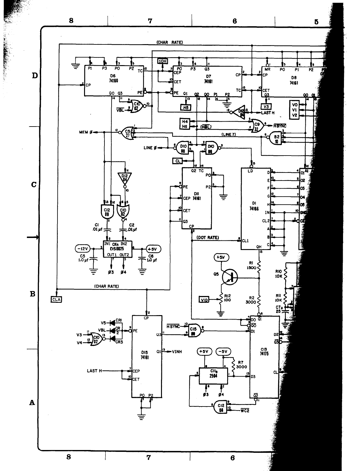
VIDEO OUTPUT: Composite positive video, 75 ohms,
level adjustable between zero and t5Vpp.
Line Rate: 15734 Hz
Frame Rate: 60.05 Hz
Format: 40 characters/line, 24 lines;
with automatic SC rolling
Display Memory: Dynamic shift registers (1K x 7)
Character Matrix: 5x7
RAM MEMORY: 16-pin, 4K Dynamic, type 4096 (2104)
On-board RAM Capacity: 8K bytes (4K supplied)
POWER SUPPLIES: t-5 Volts @ 3 amps, t/- 12 Volts GO.5 amps,
and -5 Volts @ 0.5 amps
Input Power Requirements: 8 to 10 Volts AC (RMS) @ 3 amps,
26 to 28 Volts AC (RMS) Center-Tapped, 1A.
Recommended Transformers: Stancor # P-8380 or Triad F31-X
Stancor # P-8667 or Triad F40-X
APPLE COMPUTER COMPANY
770 Welch Road, Suite 154
Palo Alto, California 94304
Phone: (415) 326-4248
--
The Apple Computer Company hereby warrants each of
its products, and all components therein contained, to be free
from defects in materials and/or workmanship for a period of
thirty(30) days from date of purchase. In the event of the occur-
rence of malfunction, or other indication of failure attributable
directly to faulty workmanship and/or material, then, upon re-
turn of the product to the Apple Computer Company, at 770 Welch
Road, Palo Alto, California, 94304 (postage prepaid), the Apple
Computer Company will, at its option, repair or replace said
products or components thereof, to what ever extent Apple Com-
puter Company shall deem necessary, to restore said product
to proper operating condition. All such repairs or replacements
shall be rendered by the Apple Computer Company, without
charge to the customer.
The responsibility for the failure of any Apple Computer
product, or component thereof, which, at the discretion of the
Apple Computer Company, shall have resulted either directly or
indirectly from accident, abuse, or misapplication of the product,
shall be assumed bythe customer, and the Apple Computer Com-
pany shall assume no liability as a consequence of such events
under the terms of this warranty.
While every effort, on the part of Apple Computer Com-
pany, is made to provide clear and accurate technical instruction
on the use, implementation, and application of its products, the
Apple Computer Company shall assume noliability in events which
may arise from the application of such technical instruction, nor
shall the Apple Computer Company be held liable for the quality,
interconnection, or application of periferal products, which may
have been recommended by Apple Computer Company, but which
have not been supplied as part of the product.
This warranty contains and embodies the limits of re-
sponsibility of the Apple Computer Company, with regard to its
products, and no other liability is expressed, implied, or should
be assumed by the purchaser, and in no event shall the Apple
Computer Company be held liable for the loss of time, effort,
or transportation costs, nor for loss of potential profits or other
consequential losses which might arise from the purchase, assem-
bly, use, application, or subsequent sale of the products of Apple
Computer Company, nor from any instructions and/or technical
information thereto related.
D
C
B
-
A
J3
s
iiE3
fiiz
ia
mv
OD
s4
01
00
w
5
At5
Au
AS/5
AU5
AT/If
A5
AS
Al
mm
7
l sv
72
STANCOR P-8667 -
(or rpuiv)
NOTE I41
02
SA
VWA
n
07
05
s2
ol
uii?
II
00
AM
AU
NW4
AU2
AW
A.
A2
A0
5m
*II”
42”
J2
15.
RESET
”
55
52
DI CLLA” 5CRELY
l 5
Ds
D7
3 AUP MMlM”Y CURacNT RATUG
17. cWIVALcNT TMN.woRYrX SHALL
BE 25 VOLT SCccnMRI. CCNTCR-
TAPPED. WIT” I AMP -“Y RATlNC.
CASE OF RcGul.ATcaR. l.M,*,. AND HEAT
SINE TAB5 or RcuAlwmti TNRCC SEC-
ULATORS ARC ALL dT *IPrcncM
ELLCTRICAL POTEt4TUL.S. CAUTION
SNOULD cc cxcnaDcD TO INmIRE
AGAIWST DIucc7 cLccINc*L CCWTACT
DCTWCCW llD5c PorNIs. Txc, YWT
NOT DC DHORTCD TCGCTHED. Non TO
TNC NEATSINE OF TNE IA,*,.
+5v -+-ma -CLEAR 5CI22N (54-12)
-I&.0 ’
r -“E5CT ‘D4-”
UImv -
WAYNE 4-L APPLE COMPUTER COMPANY
uu-- -
-ml- -o* --
--.IIU . . ..a
izxLfu \/:::m-:.% s-m- SCHEYATIC DIASRAM
f,, 3-10-q
-. .- .-_
APPLE-1
POWER SUPPLY
1
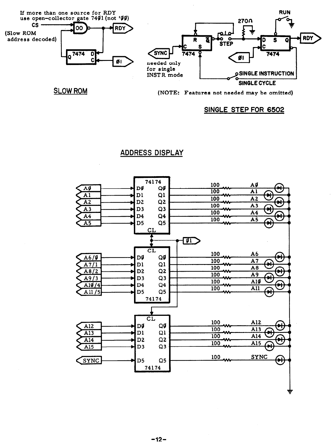
If more than one source for RDY
use open-collector gate 7441 (not ‘QQ)
cs
(Slow ROM
address decoded)
for single ’
INSTR mode
/SINGLE INSTRUCTION
0
SINGLE CYCLE
SLOW ROM
(NOTE: Features not needed may be omitted)
SINGLE STEP FOR 6502
ADDRESS DISPLAY
74174
D@ QQ
Dl Ql
D2 Q2
D3 43
D4 Q4
D5 Q5
1
nrr
1WU
100
~
100
100
100
-12-
I
-
C
I
-
1
2: vss
ss
iii
VI*
so
-
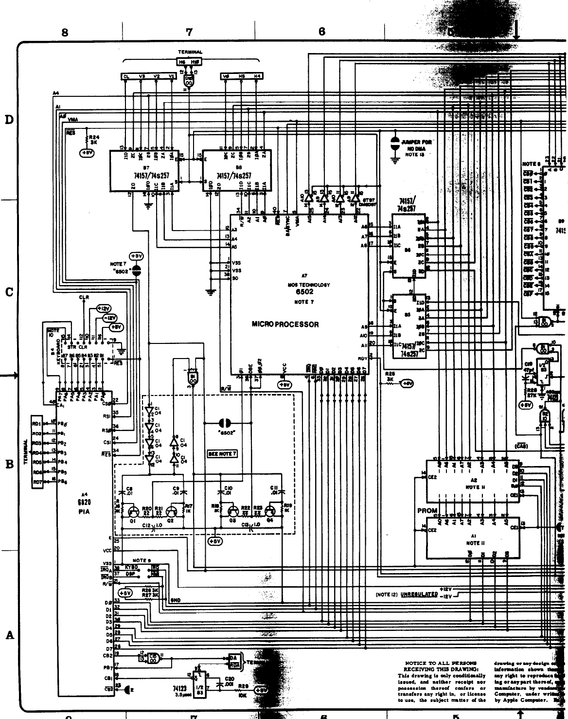
A7
Nos TCcnNolDQY
6502
NOTE 7
MICROPROCESSOR
; o I
: n
I&
9
l sv
--..-----,
I
m
n
---- -----
‘Cl
104
6,
04
7
i
I
i
6
1
2
S
4
ti
‘r
E&l
PIA
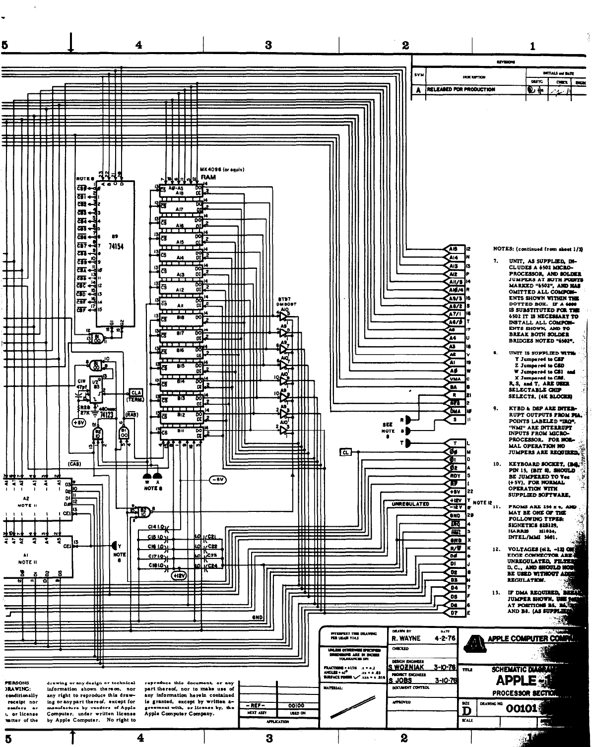
7. UNIT. As SuPPma Dl-
CLUDES A (5002 MICW
PROCWS. Am soI.wn
JUYPRS AT Bonl NUYB
)UBXZD “b502”. W “A‘
OMITTED ALL coMnw-
ENTS SNOW4 wInuN1s
DOTTED BOX. IF A b,”
IS SUBSTITIITED KI TlS
bWL Xl’ lS NWXSMRY YO
~~TALL ALL coams i
ENTssNom. ANDTO
BIUXX Bon4 SOLWE -- I
BRIDXS NOYED “b%P. ..;
‘.
9. XYBDLDSPABB- .
RIJPT OUTPUTS ?Y)M Pm. -’
POINTS LABELED “ISO%
“NMI” ARE RrrlILUIPI
INPUTS TROY l‘lCBO-
PRoccssolL
IO~IIDG
UAL OPCMTYIW I(0 ;+
J”MPEns Asx wnrag
m ICLb-4 I h.-
II
-._
-12v
Pr
IF&
1
=
+sv
P
I
l!fJ#f
=
KHAR RATE)
1
e
CP
v3
v4
DIS
74161
LAST Ii
” a3 CP
T
(DOT RATE) t
E
F
G
CL2
A
VINH
1 1
-
=
00
a3 a2 Of
I. II I2 13
i
“-s
v4 If!5
:.
I
Pm
I
ALL OUTPUTS OF C3, 2519 (PINS 7 THRV 12). ARE PROVIDED
WITH “PULL-DOWN” MSISTO”S, 7306 OHMS EACH. TO -12V.
205
2 06 14I-
2 vcc 5 R5 3000
LAST H
r
Dl4* 6 - ? Dl4,
2504 ? c4 2504
S_ 5
APPLE COMPUTER COMPANY
APPLE - 1
I -CmnX TERMINAL SECTION
