Arctic_cat_2012_dvx_300_300_utility_service_manual Arctic Cat 2012 Dvx 300 Utility Service Manual
User Manual: arctic_cat_2012_dvx_300_300_utility_service_manual
Open the PDF directly: View PDF ![]() .
.
Page Count: 115 [warning: Documents this large are best viewed by clicking the View PDF Link!]
- FOREWORD
- TABLE OF CONTENTS
- General Information
- Periodic Maintenance/ Tune-Up
- SPECIAL TOOLS
- Periodic Maintenance Chart
- Lubrication Points
- Air Filter
- Valve/Tappet Clearance
- Testing Engine Compression
- Spark Plug
- Muffler/Spark Arrester
- Engine Oil - Filter
- Rear Drive Lubricant (Utility)
- Transmission Lubricant
- Drive Chain (DVX)
- Driveshaft/Coupling (Utility)
- Nuts/Bolts/Cap Screws
- Headlight/Taillight- Brakelight
- Shift Lever
- Hydraulic Brake Systems
- Auxiliary/Rear Hydraulic Brake
- Burnishing Brake Pads
- Checking/Replacing V-Belt
- Engine/Transmission
- SPECIAL TOOLS
- Removing Engine/ Transmission
- Top-Side Components
- Removing Top-Side Components
- Servicing Top-Side Components
- Installing Top-Side Components
- Left-Side Components
- Removing Left-Side Components
- Servicing Left-Side Components
- Installing Left-Side Components
- Right-Side Components
- Removing Right-Side Components
- Servicing Right-Side Components
- Installing Right-Side Components
- Center Crankcase Components
- Separating Crankcase Halves
- Disassembling Crankcase Half
- Servicing Center Crankcase Components
- Assembling Crankcase Half
- Joining Crankcase Halves
- Installing Engine/ Transmission
- Troubleshooting
- Fuel/Lubrication/Cooling
- Electrical System
- SPECIAL TOOLS
- RPM Limiter
- Testing Electrical Components
- Electrical Connections
- Switches
- Battery
- Brakelight Switch (Auxiliary)
- Brakelight Switch (Handlebar Control)
- Coolant Temperature and Cooling Fan Switches
- Fan Motor
- Fuse Block
- Fuses
- Ignition Coil
- Indicator Lights (DVX)
- LCD Gauge Assembly
- Ignition Switch
- Handlebar Control Switches
- Magneto Coils
- Starter Motor
- Starter Relay
- CDI Unit
- Regulator/Rectifier
- Start-in-Gear Relay
- Headlights
- Taillight - Brakelight
- Ignition Timing
- Troubleshooting
- Drive System
- Suspension
- Steering/Frame/Controls

FOREWORD
This Arctic Cat Service Manual contains service, maintenance, and troubleshooting information for the 2012 Arctic
Cat ATV 300 Utility/DVX 300. This manual is designed to aid service personnel in service-oriented applications.
This manual is divided into sections. Each section covers a specific ATV component or system and, in addition to the
standard service procedures, includes disassembling, inspecting, and assembling instructions. When using this manual
as a guide, the technician should use discretion as to how much disassembly is needed to correct any given condition.
The service technician should become familiar with the operation and construction of each component or system by
carefully studying this manual. This manual will assist the service technician in becoming more aware of and efficient
with servicing procedures. Such efficiency not only helps build consumer confidence but also saves time and labor.
All Arctic Cat ATV publications and decals display the words Warning, Caution, Note, and At This Point to emphasize
important information. The symbol ! WARNING identifies personal safety-related information. Be sure to fol-
low the directive because it deals with the possibility of severe personal injury or even death. A CAUTION identi-
fies unsafe practices which may result in ATV-related damage. Follow the directive because it deals with the possibility
of damaging part or parts of the ATV. The symbol NOTE: identifies supplementary information worthy of particular
attention. The symbol AT THIS POINT directs the technician to certain and specific procedures to promote
efficiency and to improve clarity.
At the time of publication, all information, photographs, and illustrations were technically correct. Some photographs
used in this manual are used for clarity purposes only and are not designed to depict actual conditions. Because Arctic
Cat Inc. constantly refines and improves its products, no retroactive obligation is incurred.
All materials and specifications are subject to change without notice.
Keep this manual accessible in the shop area for reference.
Product Service and
Warranty Department
Arctic Cat Inc.
© 2011 Arctic Cat Inc. July 2011
®™ Trademarks of Arctic Cat Inc., Thief River Falls, MN 56701
FOR ARCTIC CAT ATV DISCOUNT PARTS CALL 606-678-9623 OR 606-561-4983
www.mymowerparts.com
M
SHAR
E OUR PASSION.
TT
A
A
A
A
A
A
V
V
Manual
n
Service M
S
S
n
v
u
c
a
a
r
M
u
l
a
a
i
e
e
M
S
S
M
n
a
a
r
v
c
ervice
S
S
M
0
0
0
0
0
0
00
3
0
0
30
X
3
X
3
X 3
X
X
V
X
VX
VX
D
V
V
DV
X
VX 300
DVX 3
0
0
0
0
0
0
D
D
D
V
V
V
X
X
DVX 300
y
300 Utility300 Utility
Utility
i
l
00 Uti
3
3
3
0
0
0
0
U
U
3
3
TABLE OF CONTENTS
General Information........................................................... 2
General Specifications.................................................. 2
Torque Specifications.................................................... 3
Torque Conversions (ft-lb/N-m)..................................... 4
Break-In Procedure ...................................................... 4
Gasoline - Oil - Lubricant.............................................. 4
Genuine Parts............................................................... 5
Preparation For Storage ............................................... 5
Preparation After Storage ............................................. 6
Periodic Maintenance/Tune-Up......................................... 7
Periodic Maintenance Chart ......................................... 7
Lubrication Points ......................................................... 8
Air Filter ........................................................................ 8
Valve/Tappet Clearance................................................ 8
Testing Engine Compression ........................................ 9
Spark Plug .................................................................... 9
Muffler/Spark Arrester ................................................ 10
Engine Oil - Filter........................................................ 10
Rear Drive Lubricant (Utility) ...................................... 11
Transmission Lubricant ............................................... 11
Drive Chain (DVX) ...................................................... 12
Driveshaft/Coupling (Utility) ........................................ 13
Nuts/Bolts/Cap Screws ............................................... 13
Headlight/Taillight- Brakelight ..................................... 13
Shift Lever................................................................... 13
Hydraulic Brake Systems............................................ 14
Auxiliary/Rear Hydraulic Brake ................................... 16
Burnishing Brake Pads ............................................... 18
Checking/Replacing V-Belt ......................................... 18
Engine/Transmission....................................................... 20
Removing Engine/ Transmission ................................ 21
Top-Side Components ................................................ 26
Removing Top-Side Components ............................... 26
Servicing Top-Side Components ................................ 28
Installing Top-Side Components ................................. 32
Left-Side Components................................................ 34
Removing Left-Side Components............................... 34
Servicing Left-Side Components ................................ 34
Installing Left-Side Components................................. 40
Right-Side Components ............................................. 41
Removing Right-Side Components ............................ 42
Servicing Right-Side Components.............................. 47
Installing Right-Side Components .............................. 54
Center Crankcase Components ................................. 55
Separating Crankcase Halves .................................... 55
Disassembling Crankcase Half................................... 55
Servicing Center Crankcase Components ................. 55
Assembling Crankcase Half........................................ 57
Joining Crankcase Halves .......................................... 57
Installing Engine/Transmission ................................... 57
Troubleshooting .......................................................... 61
Fuel/Lubrication/Cooling................................................. 64
Carburetor................................................................... 64
Throttle Cable Free-Play............................................. 68
Engine RPM (Idle) ...................................................... 68
Gas Tank..................................................................... 68
Gas Tank Valve........................................................... 69
Gas/Vent Hoses.......................................................... 69
Oil Flow Chart............................................................. 69
Oil Pump..................................................................... 70
Liquid Cooling System................................................ 70
Radiator.......................................................................70
Hoses/Thermostat.......................................................71
Fan ..............................................................................71
Water Pump ................................................................71
Troubleshooting ...........................................................72
Electrical System..............................................................73
RPM Limiter ................................................................73
Testing Electrical Components ....................................73
Electrical Connections.................................................73
Switches......................................................................73
Battery.........................................................................73
Brakelight Switch (Auxiliary)........................................74
Brakelight Switch (Handlebar Control) ........................74
Coolant Temperature and Cooling Fan Switches ........75
Fan Motor ....................................................................75
Fuse Block...................................................................75
Fuses ..........................................................................76
Ignition Coil .................................................................76
Indicator Lights (DVX) .................................................77
LCD Gauge Assembly.................................................77
Ignition Switch .............................................................78
Handlebar Control Switches........................................78
Magneto Coils .............................................................79
Starter Motor ...............................................................79
Starter Relay ...............................................................79
CDI Unit.......................................................................80
Regulator/Rectifier ......................................................80
Start-in-Gear Relay .....................................................80
Headlights ...................................................................81
Taillight - Brakelight .....................................................81
Ignition Timing.............................................................81
Troubleshooting ...........................................................82
Drive System.....................................................................84
Rear Drive Assembly Schematics ...............................84
Rear Drive Axle (DVX).................................................84
Rear Drive Axle (Utility)...............................................87
Troubleshooting Drive System.....................................96
Troubleshooting Brake System....................................96
Suspension .......................................................................97
Front and Rear Suspension Assembly Schematics ....97
Front Shock Absorbers................................................97
Rear Shock Absorber ..................................................98
Swing Arm...................................................................99
Front A-Arms .............................................................102
Wheels and Tires ......................................................104
Troubleshooting .........................................................105
Steering/Frame/Controls................................................106
Steering Post/Tie Rods .............................................106
Measuring/Adjusting Toe-In/Toe-Out.........................108
Body ..........................................................................108
Steering Post Cover/Instrument Pod .........................111
Front Brake Lever/Master Cylinder Assembly ...........111
Auxiliary Brake Pedal/Master Cylinder Assembly......112
Throttle Control .........................................................113
Troubleshooting .........................................................114
FOR ARCTIC CAT ATV DISCOUNT PARTS CALL 606-678-9623 OR 606-561-4983
www.mymowerparts.com
Note: To navigate through this manual, use the PAGE UP/PAGE DOWN buttons on the keyboard, click on the
Table of Contents bookmarks on the left side of the screen, or click the blue text below. To return to this page,
click the Manual Table of Contents button at the bottom of each page.
Click on the blue text to go.

2
General Information
NOTE: Some photographs and illustrations used in
this manual are used for clarity purposes only and
are not designed to depict actual conditions.
General Specifications
Specifications subject to change without notice.
CHASSIS DVX Utility
Dry Weight (approx) 192.8 kg (425 lb) 216 kg (477 lb)
Length (overall) 171.9 cm (67.7 in.) 187 cm (73.6 in.)
Height (overall) 113.5 cm (44.7 in.) 111.8 cm (44.0 in.)
Width (overall) 113.5 cm (44.7 in.) 105.1 cm (41.40 in.)
Suspension Travel (Front)
(Rear)
15.5 cm (6.1 in.)
16.5 cm (6.5 in.)
12.7 cm (5.0 in.)
12.7 cm (5.0 in.)
Brake Type Hydraulic w/Brake Lever Lock and
Auxiliary Brake
Tire Size (Front)
(Rear)
AT21 x 7-10
AT2 0 x 11 - 9
AT22 x 7-10
AT2 2 x 10 - 1 0
Tire Inflation Pressure2(Front)
2(Rear)
0.28 kg/cm2 (4 psi)
0.25 kg/cm2 (3.5 psi)
MISCELLANY
Spark Plug Type NGK DPR7EA-9
Spark Plug Gap 0.8-0.9 mm (0.032-0.036 in.)
Gas Tank Capacity 12.8 L (3.4 U.S. gal.)
Reserve Capacity 4.54 L (1.2 U.S. gal.)
Engine Oil Capacity 1.6 L (1.7 U.S. qt) 1.4 L (1.5 U.S. gt)
Transmission (Overhaul)
Lubricant Capacity (Change)
400 ml (13.5 fl/oz)
300 ml (10.1 fl/oz)
600 ml (20.3 fl/oz)
500 ml (16.9 fl/oz)
Gasoline (recommended) 87 Octane Regular Unleaded
Engine Oil (recommended) Arctic Cat ACX All Weather (Synthetic)
Cooling System Capacity 1.4 L (1.5 U.S. qt)
Rear Drive Capacity N/A 150 ml (5 fl oz)
Rear Drive Lubricant N/A SAE Approved
80W-90 Hypoid
Brake Fluid DOT 4
Taillight/Brakelight 12V/5W/21W
Headlight 12V/35W (2)
Starting System Electric Electric w/Manual
Recoil (Emergency)
FUEL SYSTEM
Carburetor Type Keihin CVK32
Main Jet 112
Starter Jet 60
Slow Jet 38
Pilot Screw Setting (turns) 1 3/4
Needle Jet 4.0/3.6
Jet Needle NLRA
Idle RPM 1250-1350
Float Arm Height 17.0 mm (0.67 in.)
Throttle Cable Free-Play (at lever) 1-4 mm (1/16-3/16 in.)
IGNITION
Ignition Timing 5° BTDC (“F” mark) @1000
RPM
Spark Plug Cap 4500-6150 ohms
Ignition Coil Resistance (primary)
(secondary)
2.4-3.0 ohms (terminal to
terminal)
12,300-16,600 ohms (high
tension - plug cap removed -
to ground)
Ignition Coil Peak Voltage (primary/CDI) 9.6-16.4 DC volts
(black/white to green/gray)
MAGNETO
Magneto Coil Resistance (trigger)
(charging)
105-110 ohms
(blue/yellow to green/white)
Less than 1 ohm
(yellow to yellow)
Stator Coil Peak Voltage (trigger) 1.1-1.4 DC volts
(blue/yellow to green/white)
Magneto Output (approx) 220W @ 5000 RPM
Stator Coil Output (no load) 40-60 AC volts@3500 RPM
(yellow to yellow)
CAMSHAFT AND CYLINDER HEAD
Cam Lobe Height (min) (intake)
(exhaust)
34.15 mm
34.05 mm
Rocker Arm/Shaft Clearance (max) 0.1 mm
Cylinder Head/Cover Distortion (max) 0.05 mm
CYLINDER, PISTON, AND RINGS
Piston Skirt/Cylinder Clearance (max) 0.12 mm
Cylinder Bore 72.705-72.715 mm
Piston Diameter 18 mm from Skirt End
(max)
72.625 mm
Bore x Stroke 72.7 x 65.2 mm
Cylinder Trueness (max) 0.05 mm
Piston Ring to Groove Clearance (max)
(1st/2nd)
0.09 mm
Piston Ring End Gap - Installed (top)
(middle)
(oil)
0.15-0.30 mm
0.30-0.45 mm
0.20-0.70 mm
Piston Pin Bore (max) 17.06 mm
Piston Pin Outside Diameter (min) 16.96 mm
CRANKSHAFT
Connecting Rod (small end inside
diameter) (max)
17.06 mm
Connecting Rod (big end side-to-side) 0.05-0.40 mm
Connecting Rod (small end deflection)
(max)
1 mm
Crankshaft (web-to-web) 55.15-55.20 mm
Crankshaft Runout (max) 0.1 mm
Oil Pressure at 60°C (140°F) (above)
@ 3000 RPM (below)
0.3 kg/cm² (4.3 psi)
0.7 kg/cm² (10 psi)
TRANSMISSION
Clutch Release Screw 1/8 turn back
Drive Plate (fiber) Thickness (min) 2.4 mm
Drive Plate (fiber) Tab (min) 11 mm
Driven Plate (warpage) (max) 0.1 mm
Clutch Spring Length (min) 27.5 mm
Clutch Wheel Inside Diameter (max) Scuffing of contact surface
Clutch Shoe Lining Thickness 0.5 mm
Clutch Engagement RPM 2000 ± 200
Clutch Lock-Up RPM 3400 ± 300
VALVES AND GUIDES
Valve/Tappet Clearance (intake/exhaust)
(cold engine)
0.1 mm
Valve Guide/Stem Clearance (max)
(intake)
(exhaust)
0.06 mm
0.08 mm
Valve Spring Free Length (min) (inner)
(outer)
29.4 mm
39.0 mm
Valve Spring Tension @ 18.0 mm (intake) 10.2-11.8 kg (22.5-26.0 lb)
Valve Spring Tension @ 21.5 mm
(exhaust)
19.05-22.0 kg (42.0-48.5 lb)
FOR ARCTIC CAT ATV DISCOUNT PARTS CALL 606-678-9623 OR 606-561-4983
www.mymowerparts.com

3
Torque Specifications
*w/Red Loctite #271
STEERING COMPONENTS
Part Part Bolted To Torque
ft-lb N-m
Handlebar Clamp Cap Screw Steering Head 18 24
Steering Post Support Block Frame 17 23
Steering Post Nut Steering Post 50 68
Upper And Lower Ball Joint Nut Steering Knuckle 22 30
Tie Rod End Nut Steering Knuckle 15 20
Tie Rod Lock Nut Tie Rod 15 20
ELECTRICAL COMPONENTS
Starter Motor Lead Cable Nut Starter 36
in.-lb
5
Starter Motor Mounting Bolt Crankcase 9 12
EXHAUST COMPONENTS
Exhaust Pipe Engine 25 34
Muffler Mounting Bolt Frame 25 34
BRAKE COMPONENTS
Brake Hose Union Bolt Master Cylinder/
Caliper
25 34
Brake Bleed Screw Caliper 56
in.-lb
5
Brake Caliper Mounting Cap Screw Steering Knuckle/
Swing Arm
25 34
Master Cylinder (Front) Handlebar 13 18
Brake Pad Mounting Pin (Front/Rear) Brake Caliper 13 18
Brake Caliper Slide Pin (Front/Rear) Brake Caliper 25 34
Front Brake Line Nut Brake Line/Junction
Block
25 34
Brake Caliper (Rear) Swing Arm Housing 25 34
SUSPENSION COMPONENTS (Front)
A-Arm Pivot Nut Frame 32 44
Front Shock Absorber Mounting Nut*
(Upper/Lower)
Frame 29 39
SUSPENSION COMPONENTS (Rear)
Left Pivot Bolt (Utility) Swing Arm 36
in.-lb
5
Right Pivot Bolt (Utility) Swing Arm 82 112
Left Pivot Lock Nut (Utility) Left Pivot Bolt 82 112
Swing Arm Pivot Nut (DVX) Frame 50 68
Rear Shock Absorber Mounting Nut
(Upper/Lower)
Frame/Swing Arm 29 39
Axle Housing Cap Screw (Utility) Final Drive Gear
Case
40 54
Axle Housing Cap Screw (DVX) Swing Arm 29 39
DRIVE TRAIN COMPONENTS
Engine Mounting Through-Bolt Frame 29 39
Engine Mounting Bracket Cap Screw Frame 16 22
Rear Axle Housing (Utility) Swing Arm 40 54
Rear Axle Housing (DVX) Tube 29 39
Gear Case Swing Arm 50 68
Pinion Nut Shaft 72 98
Gear Case Cover (8 mm)
(10 mm)
Gear Case 19
36
26
49
Hub Nut (Front) Front/Spindle 50 68
Wheel Lug Nut Hub 32 44
Hub Nut (Rear) Axle 72 98
Rear Axle Nut* (Utility) Axle 72 98
Rear Axle Nut* (DVX) Axle 86 117
ENGINE/TRANSMISSION
Part Part Bolted To Torque
ft-lb N-m
Cylinder Head Cylinder 7 10
Cylinder Nut Crankcase 7 10
Camshaft Holder Cylinder Head 18 24
Bevel Drive Gear (Utility) Driveshaft 72 98
Magneto Rotor/Flywheel Crankshaft 47 64
Bevel Driven Gear (Utility) Driven Shaft 72 98
Output Drive Sprocket Lock Plate
(DVX)
Driveshaft 43 59
Crankcase Cap Screw Crankcase 8 11
Engine Oil Screen/Filter Cap Crankcase 11 15
Shift Cam Stopper Plug* (Utility) Left Case 20 27
Shift Cam Stopper Plug* (DVX) Transmission Case 35 48
Camshaft Chain Tensioner Adjuster Cam Chain
Tensioner
912
Cam Chain Tensioner Cover Bolt Tensioner 24
in.-lb
3
Starter Ratchet Crankshaft 68 92
Camshaft Chain Tensioner Mount Cylinder Head 9 12
Camshaft Chain Tension Spring Holder
Plug
Cam Chain
Tensioner
36
in.-lb
4
Centrifugal Clutch Housing Driveshaft 40 54
Timing Plug Right Case 16 22
Driven Pulley Retaining Nut Driven Shaft
(Transmission)
43 59
Drive Plate Nut* Fixed Driven Face 43 59
Drive Pulley Nut Crankshaft 72 98
Engine Oil Drain Plug Crankcase 21 29
Transmission Drain Plug Transmission 21 29
Transmission Case Cover Transmission 20 27
FOR ARCTIC CAT ATV DISCOUNT PARTS CALL 606-678-9623 OR 606-561-4983
www.mymowerparts.com

4
Torque Conversions
(ft-lb/N-m)
Break-In Procedure
A new ATV and an overhauled ATV engine require a
“break-in” period. The first 10 hours (or 200 miles) are
most critical to the life of this ATV. Proper operation dur-
ing this break-in period will help assure maximum life
and performance from the ATV.
During the first 10 hours (or 200 miles) of operation,
always use less than 1/2 throttle. Varying the engine
RPM during the break-in period allows the components
to “load” (aiding the mating process) and then “unload”
(allowing components to cool). Although it is essential to
place some stress on the engine components during
break-in, care should be taken not to overload the engine
too often. Do not pull a trailer or carry heavy loads dur-
ing the 10-hour break-in period.
When the engine starts, allow it to warm up properly. Idle
the engine several minutes until the engine has reached
normal operating temperature. Do not idle the engine for
excessively long periods of time.
During the break-in period, a maximum of 1/2 throttle is
recommended; however, brief full-throttle accelerations
and variations in driving speeds contribute to good
engine break-in.
After the completion of the break-in period, the engine
oil and oil filter should be changed. Other maintenance
after break-in should include checking of all prescribed
adjustments and tightening of all fasteners.
Gasoline - Oil - Lubricant
RECOMMENDED GASOLINE
The recommended gasoline to use is 87 minimum octane
regular unleaded. In many areas, oxygenates (either etha-
nol or MTBE) are added to the gasoline. Oxygenated
gasolines containing up to 10% ethanol, 5% methane, or
5% MTBE are acceptable gasolines.
When using ethanol blended gasoline, it is not necessary
to add a gasoline antifreeze since ethanol will prevent the
accumulation of moisture in the fuel system.
RECOMMENDED ENGINE OIL
The recommended oil to use is Arctic Cat ACX All
Weather synthetic engine oil, which has been specifically
formulated for use in this Arctic Cat engine. Although
Arctic Cat ACX All Weather synthetic engine oil is the
only oil recommended for use in this engine, use of any
API certified SM 0W-40 oil is acceptable.
OILCHARTJ
ft-lb N-m ft-lb N-m ft-lb N-m ft-lb N-m
11.4 26 35.4 51 69.4 76 103.4
22.7 27 36.7 52 70.7 77 104.7
34.1 28 38.1 53 72.1 78 106.1
45.4 29 39.4 54 73.4 79 107.4
56.8 30 40.8 55 74.8 80 108.8
68.2 31 42.2 56 76.2 81 110.2
79.5 32 43.5 57 77.5 82 111.5
810.9 33 44.9 58 78.9 83 112.9
912.2 34 46.2 59 80.2 84 114.2
10 13.6 35 47.6 60 81.6 85 115.6
11 15 36 49 61 83 86 117
12 16.3 37 50.3 62 84.3 87 118.3
13 17.7 38 51.7 63 85.7 88 119.7
14 19 39 53 64 87 89 121
15 20.4 40 54.4 65 88.4 90 122.4
16 21.8 41 55.8 66 89.8 91 123.8
17 23.1 42 57.1 67 91.1 92 125.1
18 24.5 43 58.5 68 92.5 93 126.5
19 25.8 44 59.8 69 93.8 94 127.8
20 27.2 45 61.2 70 95.2 95 129.2
21 28.6 46 62.6 71 96.6 96 130.6
22 29.9 47 63.9 72 97.9 97 131.9
23 31.3 48 65.3 73 99.3 98 133.3
24 32.6 49 66.6 74 100.6 99 134.6
25 34 50 68 75 102 100 136
CAUTION
Do not use white gas. Only Arctic Cat approved gaso-
line additives should be used.
CAUTION
Any oil used in place of the recommended oil could
cause serious engine damage. Do not use oils which
contain graphite or molybdenum additives. These oils
can adversely affect clutch operation. Also, not recom-
mended are racing, vegetable, non-detergent, and cas-
tor-based oils.
FOR ARCTIC CAT ATV DISCOUNT PARTS CALL 606-678-9623 OR 606-561-4983
www.mymowerparts.com
5
RECOMMENDED REAR DRIVE
LUBRICANT (Utility)
The recommended lubricant is Arctic Cat Gear Lube or
an equivalent gear lube which is SAE approved 80W-90
hypoid. This lubricant meets all of the lubrication
requirements of the Arctic Cat ATV rear drive.
RECOMMENDED TRANSMISSION
LUBRICANT
The recommended lubricant is Arctic Cat Gear Lube or an
equivalent gear lube which is SAE approved 80W-90
hypoid. This lubricant meets all the lubrication requirements
of the Arctic Cat ATV front differential and rear drive.
FILLING GAS TANK
Since gasoline expands as its temperature rises, the gas
tank must be filled to its rated capacity only. Expansion
room must be maintained in the tank particularly if the
tank is filled with cold gasoline and then moved to a
warm area.
ATV0049B
Tighten the gas tank cap securely after filling the tank.
Genuine Parts
When replacement of parts is necessary, use only genuine
Arctic Cat ATV parts. They are precision-made to ensure
high quality and correct fit. Refer to the appropriate Illus-
trated Parts Manual for the correct part number, quantity,
and description.
Preparation For Storage
Arctic Cat recommends the following procedure to pre-
pare the ATV for storage.
1. Clean the seat cushion (cover and base) with a damp
cloth and allow it to dry.
2. Clean the ATV thoroughly by washing dirt, oil,
grass, and other foreign matter from the entire ATV.
Allow the ATV to dry thoroughly. DO NOT get
water into any part of the engine or air intake.
3. Either drain the gas tank or add Fuel Stabilizer to the
gas in the gas tank. Remove the air filter housing
cover and air filter. Start the engine and allow it to
idle; then using Arctic Cat Engine Storage Preserver,
slowly inject the preserver into the air filter opening
for a period of 10 to 20 seconds; then stop the
engine. Install the air filter and housing cover.
4. Drain the carburetor float chamber.
5. Plug the exhaust hole in the exhaust system with a
clean cloth.
6. Apply light oil to the upper steering post bushing and
plungers of the shock absorbers.
7. Tighten all nuts, bolts, cap screws, and screws. Make
sure rivets holding components together are tight.
Replace all loose rivets. Care must be taken that all
calibrated nuts, cap screws, and bolts are tightened to
specifications.
8. Fill the cooling system to the FULL line in the cool-
ing system reservoir with properly mixed coolant.
CAUTION
Any lubricant used in place of the recommended lubri-
cant could cause serious rear drive damage.
CAUTION
Any lubricant used in place of the recommended lubri-
cant could cause serious front differential/rear drive
damage.
! WARNING
Always fill the gas tank in a well-ventilated area. Never
add fuel to the ATV gas tank near any open flames or
with the engine running. DO NOT SMOKE while filling
the gas tank.
! WARNING
Do not overflow gasoline when filling the gas tank. A
fire hazard could materialize. Always allow the engine to
cool before filling the gas tank.
! WARNING
Do not over-fill the gas tank.
CAUTION
Prior to storing the ATV, it must be properly serviced to
prevent rusting and component deterioration.
CAUTION
Rapid induction of oil or any liquid into a four-cycle
engine can cause “hydraulic-lock” resulting in severe
engine damage.
CAUTION
If the interior of the air filter housing is dirty, clean the
area before starting the engine.
FOR ARCTIC CAT ATV DISCOUNT PARTS CALL 606-678-9623 OR 606-561-4983
www.mymowerparts.com

6
9. Disconnect the battery cables; then remove the bat-
tery, clean the battery posts and cables, and store in a
clean, dry area.
10. Store the ATV indoors in a level position.
Preparation After
Storage
Taking the ATV out of storage and correctly preparing it
will assure many miles and hours of trouble-free riding.
Arctic Cat recommends the following procedure to pre-
pare the ATV.
1. Clean the ATV thoroughly.
2. Clean the engine. Remove the cloth from the exhaust
system.
3. Check all control wires and cables for signs of wear
or fraying. Replace if necessary.
4. Change the engine oil and filter.
5. Check the coolant level and add properly mixed
coolant as necessary.
6. Charge the battery; then install. Connect the battery
cables.
7. Check the entire brake systems (fluid level, pads,
etc.), all controls, headlights, taillight, brakelight,
and headlight aim; adjust or replace as necessary.
8. Tighten all nuts, bolts, cap screws, and screws mak-
ing sure all calibrated nuts, cap screws, and bolts are
tightened to specifications.
9. Check tire pressure. Inflate to recommended pressure
as necessary.
10. Make sure the steering moves freely and does not
bind.
11. Check the spark plug. Clean or replace as necessary.
CAUTION
This maintenance-free battery should be charged at the
recommended rate every 30 days or permanent damage
may occur if the battery completely discharges.
CAUTION
Avoid storing outside in direct sunlight and avoid using
a plastic cover as moisture will collect on the ATV caus-
ing rusting.
CAUTION
The ignition switch must be in the OFF position prior to
installing the battery or damage may occur to the igni-
tion system.
CAUTION
Connect the positive battery cable first; then the nega-
tive.
FOR ARCTIC CAT ATV DISCOUNT PARTS CALL 606-678-9623 OR 606-561-4983
www.mymowerparts.com

7
Periodic Maintenance/
Tune-Up
SPECIAL TOOLS
A number of special tools must be available to the techni-
cian when performing service procedures in this section.
Refer to the current Special Tools Catalog for the appro-
priate tool description.
NOTE: Special tools are available from the Arctic
Cat Service Parts Department.
Periodic Maintenance
Chart
A = Adjust I = Inspect C = Clean L = Lubricate D = Drain R = Replace T = Tighten
* Service/Inspect more frequently when operating in adverse conditions.
** When using Arctic Cat ACX All Weather synthetic oil, oil change interval can be increased to every 1,000 miles or every year.
Description p/n
Compression Tester Kit 0444-213
Tappet Adjuster 0444-189
Item
Initial Service After
Break-In (First
Month or 100 Miles)
Every
Day
Every Month or
Every 100 Miles
Every 3 Months
or Every 300
Miles
Every 6 Months
or Every 500
Miles
Every Year
or Every
1500 Miles
As
Needed
Battery I I C
Air Filter/Drain Tube I I C* R
Valve/Tappet Clearance I I A
Spark Plug I I R (4000 Mi
or 18 Mo)
Muffler/Spark Arrester CR
Gas/Vent Hoses I I R (2 Yrs)
Gas Tank Valve IC
Throttle Cable I I C-L A-R
Carb Float Chamber D*
Engine RPM (Idle) I I A
Engine Oil Level I A
Engine Oil - Screen* C C** C
Drive Chain (DVX) I I C-L
Rear Drive Lubricant (Utility) I I R A
Transmission Lubricant I I R A
Tires/Air Pressure I I A-R
Steering Components I I I R
V-Belt I IR
Suspension (Ball joint boots, tie
rods, differential and rear drive
bellows)
II l* R
Nuts/Cap Screws/Screws I I T
Ignition Timing I
Headlight/Taillight-Brakelight I I R
Switches I I R
Shift Lever IA-L
Choke Cable I C-L R
Recoil Starter (Utility) I C-R
Handlebar Grips I R
Handlebars I I R
Gauges/Indicators I I R
Frame/Welds/Racks I I l
Electrical Connections lC
Complete Brake System (Hydraulic
and Auxiliary)
II C L-R
Brake Pads I I* R
Brake Fluid I I R (2 Yrs)
Brake Hoses I I R (4 Yrs)
Coolant/Cooling System I I R (2 Yrs)
FOR ARCTIC CAT ATV DISCOUNT PARTS CALL 606-678-9623 OR 606-561-4983
www.mymowerparts.com
8
Lubrication Points
It is advisable to lubricate certain components periodi-
cally to ensure free movement. Apply light oil to the
components using the following list as reference.
A. Throttle Lever Pivot/Cable Ends
B. Brake Lever Pivot
C. Auxiliary Brake Pivot/Clevis
D. Choke Cable Upper End
E. Shift Lever/Ball Joints
F. Idle RPM Screw
Air Filter
Use the following procedure to remove the filter and
inspect and/or clean it.
CLEANING AND INSPECTING
FILTER
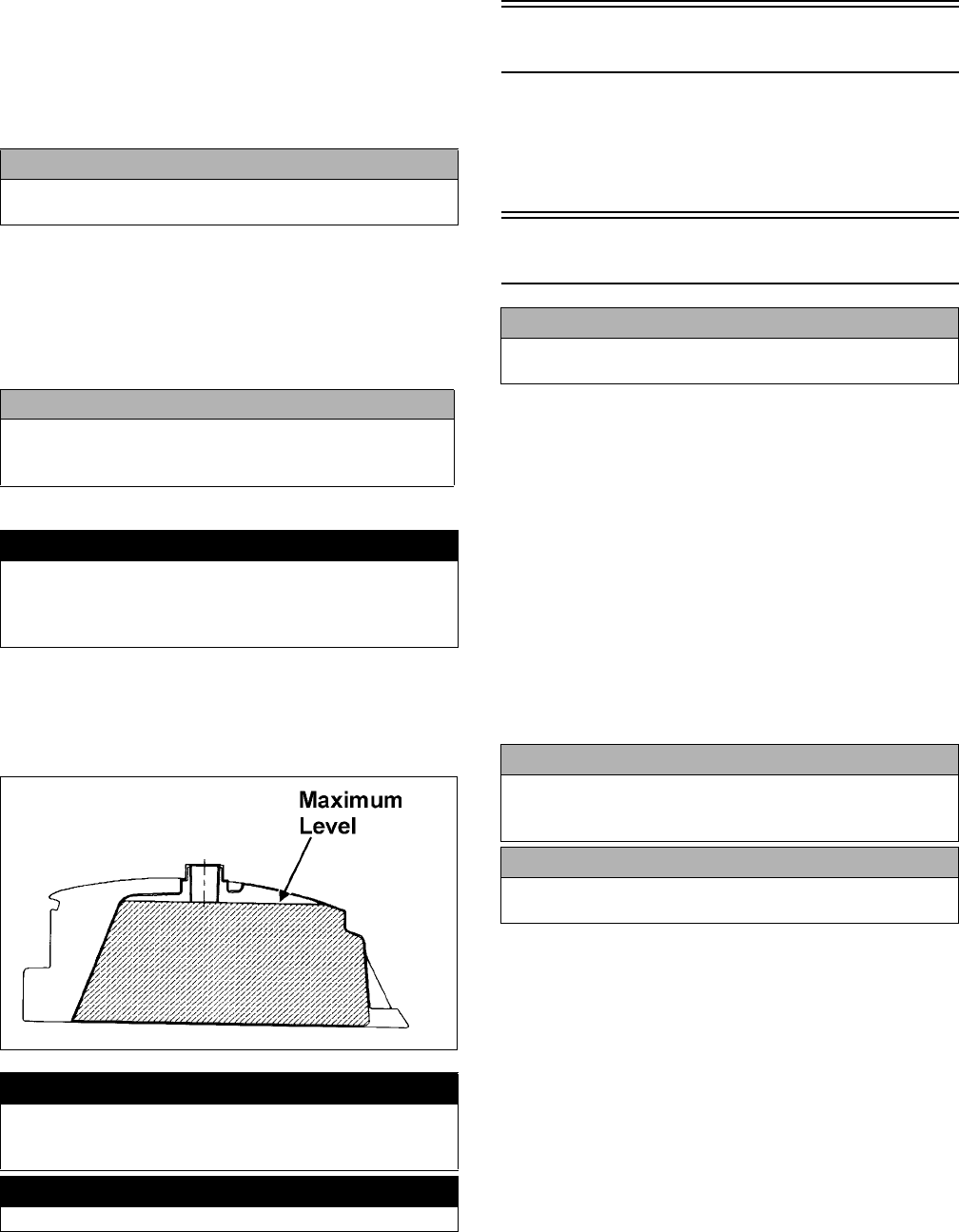
1. Remove the seat.
2. Remove the air filter housing cover from the retain-
ing clips.
KM095A
3. Loosen the clamp; then remove the filter.
KM097B
4. Fill a wash pan larger than the filter with a non-flam-
mable cleaning solvent; then dip the filter in the sol-
vent and wash it.
NOTE: Foam Filter Cleaner and Foam Filter Oil are
available from Arctic Cat.
5. Dry the filter.
6. Put the filter in a plastic bag; then pour in air filter oil
and work the filter.
7. Clean any dirt or debris from inside the air cleaner.
Make sure no dirt enters the carburetor.
8. Place the filter in the air filter housing making sure it
is properly seated and secure with the clamp.
9. Install the air filter housing cover and secure with the
retaining clips; then install the seat making sure it
locks securely.
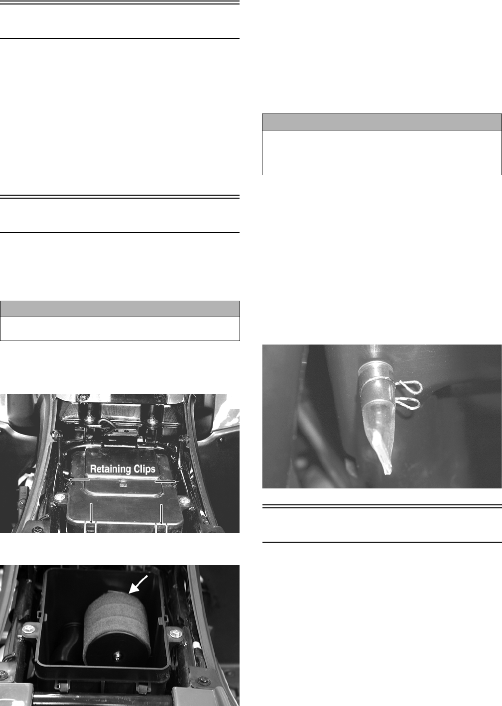
CHECKING/DRAINING DRAIN TUBE
Periodically check the drain tube for gasoline or oil accu-
mulation. If noticed, remove the drain tube cap from
beneath the housing and drain the gasoline or oil into a
suitable container; then install and secure the tube cap.
KM114
Valve/Tappet Clearance
To check and adjust valve/tappet clearance, use the fol-
lowing procedure.
NOTE: The seat assembly, side panels, and gas
tank must be removed for this procedure.
1. Remove the timing inspection plug; then remove the
cylinder head cover (see Engine/Transmission -
Removing Top-Side Components).
2. Rotate the crankshaft so the “T” mark on the fly-
wheel aligns with the index mark on the right-side
crankcase cover.
NOTE: At this point, the round hole in the camshaft
gear should be up.
CAUTION
Failure to inspect the air filter frequently if the vehicle is used
in dusty, wet, or muddy conditions can damage the engine.
CAUTION
A torn air filter can cause damage to the ATV engine. Dirt
and dust may get inside the engine if the element is torn.
Carefully examine the element for tears before and after
cleaning it. Replace the element with a new one if it is torn.
FOR ARCTIC CAT ATV DISCOUNT PARTS CALL 606-678-9623 OR 606-561-4983
www.mymowerparts.com

9
3. Place Tappet Adjuster onto the jam nut securing the
tappet adjuster screw; then rotate the adjuster dial
clockwise until the end is seated in the tappet
adjuster screw.
4. While holding the adjuster dial in place, use the
adjuster handle and loosen the jam nut; then rotate the
tappet adjuster screw clockwise until friction is felt.
5. Align the adjuster handle with one of the marks on
the adjuster dial.
6. While holding the adjuster handle in place, rotate the
adjuster dial counterclockwise until proper valve/
tappet clearance is attained.
NOTE: Refer to the appropriate specifications in Engine/
Transmission for the proper valve/tappet clearance.
NOTE: Rotating the adjuster dial counterclockwise
will open the valve/tappet clearance by 0.05 mm
(0.002 in.) per mark.
7. While holding the adjuster dial at the proper clear-
ance setting, tighten the jam nut securely with the
valve adjuster handle.
8. Place the cylinder head cover with a new O-ring into
position; then tighten the cover securely.
KM703
9. Install the timing inspection plug.
Testing Engine
Compression
To test engine compression, use the following procedure.
1. Remove the high tension lead from the spark plug.
2. Using compressed air, blow any debris from around
the spark plug.
3. Remove the spark plug; then attach the high tension
lead to the plug and ground the plug on the cylinder
head well away from the spark plug hole.
4. Attach the gauge from Compression Tester Kit.
NOTE: The engine must be warm and the battery
must be fully charged for this test.
5. While holding the throttle lever in the full-open posi-
tion, crank the engine over with the electric starter
until the gauge shows a peak reading (five to 10
compression strokes).
NOTE: The compression should be within a range
of 210-230 psi in the full-open throttle position.
6. If compression is abnormally low, verify the follow-
ing items.
A. Starter cranks engine over.
B. Gauge functions properly.
C. Throttle lever in the full-open position.
D. Valve/tappet clearance correct.
E. Valve not bent or discolored.
F. Valve seat not discolored.
NOTE: To service valves, see Engine/Transmission.
7. Pour 29.5 ml (1 fl oz) of oil into the spark plug hole,
attach the gauge, and test compression.
8. If compression is now evident, service the piston
rings (see Engine/Transmission).
Spark Plug
A light brown insulator indicates that the plug is correct.
A white or dark insulator indicates that the engine may
need to be serviced or the carburetor may need to be
adjusted. To maintain a hot, strong spark, keep the plug
free of carbon.
ATV-0051
Adjust the gap to 0.8-0.9 mm (0.032-0.036 in.) for proper
ignition. Use a wire feeler gauge to check the gap.
! WARNING
Always wear safety glasses when using compressed air.
CAUTION
Before removing the spark plug, make sure to clean the
area around the spark plug. Dirt could enter engine
when removing or installing the spark plug.
FOR ARCTIC CAT ATV DISCOUNT PARTS CALL 606-678-9623 OR 606-561-4983
www.mymowerparts.com
10
ATV0052B
When installing the spark plug, make sure to tighten it
securely. A new spark plug should be tightened 1/2 turn
once the washer contacts the cylinder head. A used spark
plug should be tightened 1/8-1/4 turn once the washer
contacts the cylinder head.
Muffler/Spark Arrester
The muffler has a spark arrester which must be periodi-
cally cleaned. At the intervals shown in the Periodic
Maintenance Chart, clean the spark arrester using the fol-
lowing procedure.
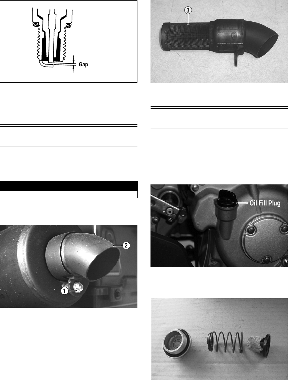
1. Remove the cap screw (1) securing the spark arrester
(2) to the muffler assembly; then carefully remove
the spark arrester.
KM139A
2. Using a soft wire brush, clean the carbon from the
screen (3) taking care not to tear or damage the screen.
.
KM140B
3. Install the spark arrester and secure with the cap
screw. Tighten securely.
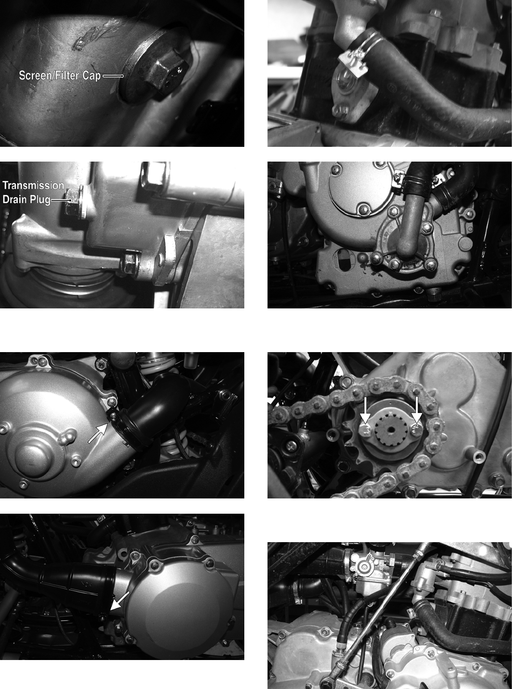
Engine Oil - Filter
Replace the engine oil and clean the screen/filter at the
scheduled intervals. The engine should always be warm
when the oil is changed so the oil will drain easily and
completely.
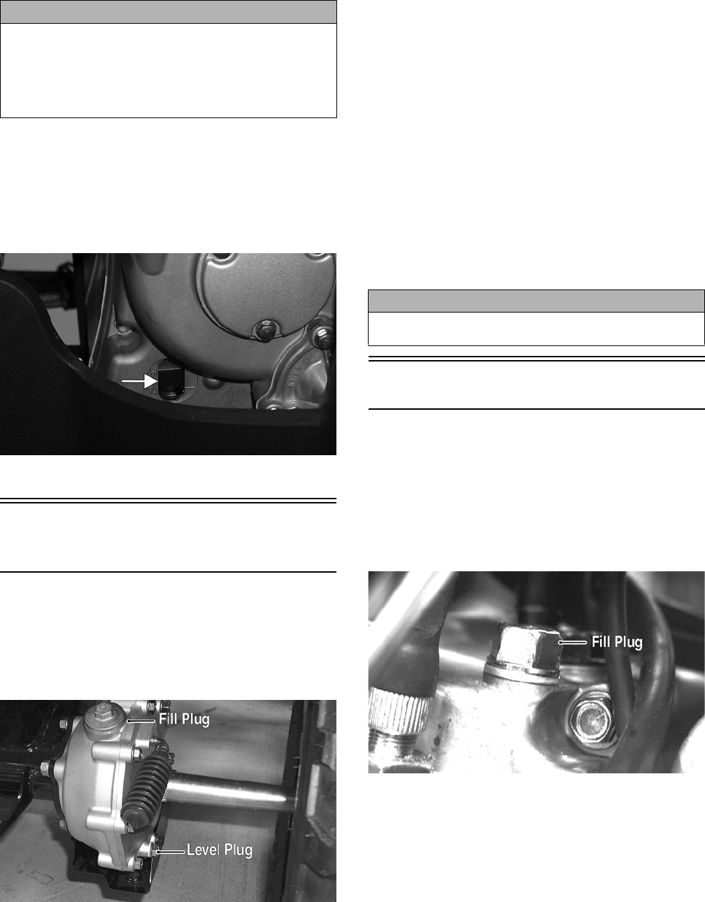
1. Park the ATV on level ground.
2. Loosen the oil fill plug.
KM126A
3. Remove the screen/filter cap from the bottom of the
engine and drain the oil into a drain pan. Account for
a spring, O-ring, and screen/filter.
DSC02248
4. Clean the screen/filter in parts-cleaning solvent; then
inspect the O-ring and replace if damaged.
! WARNING
Wait until the muffler cools to avoid burns.
FOR ARCTIC CAT ATV DISCOUNT PARTS CALL 606-678-9623 OR 606-561-4983
www.mymowerparts.com
11
5. Install the screen/filter, spring, and screen/filter cap
into the bottom of the engine and tighten to 11 ft-lb.
6. Remove the oil fill plug and pour in 1.6 L (1.7 U.S.
qt) of the recommended oil into the fill hole; then
install the oil fill plug.
7. Start the engine (while the ATV is outside on level
ground) and allow it to idle for a few minutes.
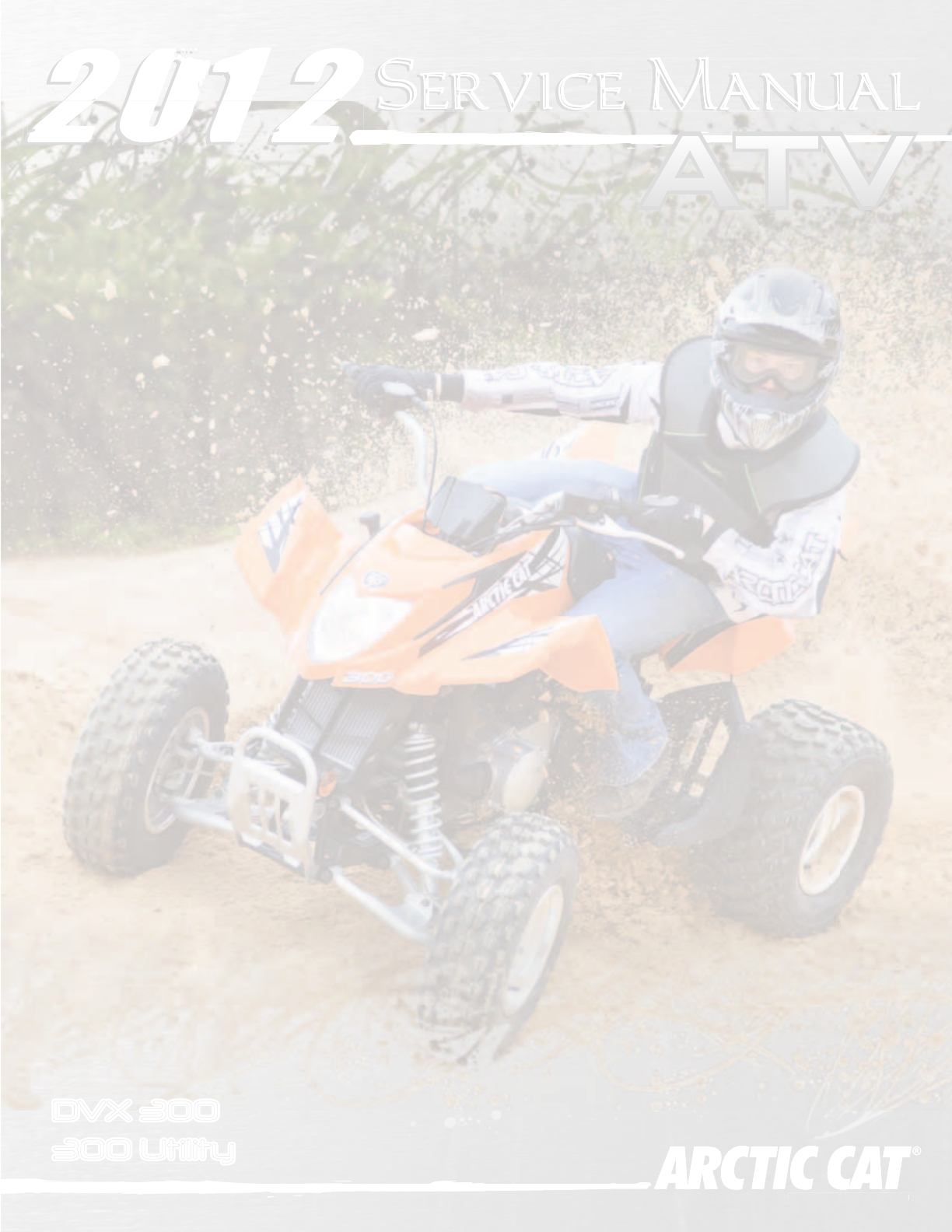
8. Turn the engine off and wait approximately one minute.
Check the oil level in the engine oil inspection window.
The oil level should be visible through the window. If
oil is not visible, add recommended oil until the oil
level is visible between the lines of the window.
KM127A
9. Inspect the area around the screen/filter cap for leaks.
Rear Drive Lubricant
(Utility)
Check and change the lubricant according to the Periodic
Maintenance Chart. When changing the lubricant, use
approved SAE 80W-90 hypoid gear lube. To check lubri-
cant, use the following procedure.
1. Remove the rear drive level plug; the lubricant level
should be at the threads of the plug.
KM131A
2. If low, add SAE approved 80W-90 hypoid gear lube
as necessary.
To change the lubricant, use the following procedure.
1. Place the ATV on level ground.
2. Loosen the fill plug.
3. Remove the cap screws securing the rear drive gear
guard; then remove the guard.
4. Drain the lubricant into a drain pan by removing the
drain plug from the bottom of the rear drive.
NOTE: If the rear drive lubricant is contaminated
with water, inspect the drain plug, fill plug, and/or
bladder.
5. After all the lubricant has been drained, install the
drain plug and tighten securely. Install the rear drive
gear guard and tighten the cap screws securely.
6. Pour the appropriate amount of recommended lubri-
cant into the fill hole. Remove the level plug and
check for appropriate level.
7. Install the fill plug.
Transmission Lubricant
Change the lubricant according to the Periodic Mainte-
nance Chart. When changing the lubricant, use approved
SAE 80W-90 hypoid gear lube.
To change the lubricant, use the following procedure.
1. Place the ATV on level ground.
2. Loosen the fill plug; then remove the transmission
drain plug and drain the transmission lubricant.
KM104A
CAUTION
Any oil used in place of the recommended oil could
cause serious engine damage. Do not use oils which
contain graphite or molybdenum additives. These oils
can adversely affect clutch operation. Also, not recom-
mended are racing, vegetable, non-detergent, and cas-
tor-based oils.
CAUTION
Water entering the outer end of the axle will not be able
to enter the rear drive unless the seals are damaged.
FOR ARCTIC CAT ATV DISCOUNT PARTS CALL 606-678-9623 OR 606-561-4983
www.mymowerparts.com

12
KM106A
3. Install the drain plug and tighten securely.
4. Remove the fill plug and pour the appropriate
amount of recommended lubricant into the fill hole.
5. Install the fill plug and tighten securely.
6. Check the area around the drain plug for leakage.
Drive Chain (DVX)
Drive chain condition and adjustment should be
inspected each day before the ATV is operated. Always
follow the following guidelines for inspecting and servic-
ing the drive chain.
INSPECTING
Inspect the drive chain for any of the following conditions.
A. Loose pins.
B. Loose or cracked rollers.
C. Dry or rusted links.
D. Kinked or binding links.
E. Excessive wear.
The presence of any of the conditions requires drive
chain replacement.
NOTE: If the drive chain is worn or damaged, the
sprockets may also be worn or damaged. Inspect the
sprockets for worn, broken, or damaged teeth.
Always inspect the sprockets when a new drive chain
is being installed.
CLEANING AND LUBRICATING
The drive chain should be cleaned and lubricated fre-
quently to prolong chain and sprocket life. Use the fol-
lowing procedure to clean and lubricate the chain.
NOTE: This ATV is equipped with an O-ring type
roller chain. Each link incorporates small O-rings to
seal out water and dirt. Care should be taken to
choose cleaning solutions and lubricants that are
suitable for O-ring type chains.
1. Using a suitable, nonflammable cleaning solution,
thoroughly wash the chain and sprockets.
2. Allow the chain to dry; then apply a dry, graphite-
based lubricant to the chain.
NOTE: The drive chain should be lubricated with a
dry, graphite-based chain lubricant. By using a dry,
graphite-based chain lubricant, dirt build-up on the
drive chain will be minimized.
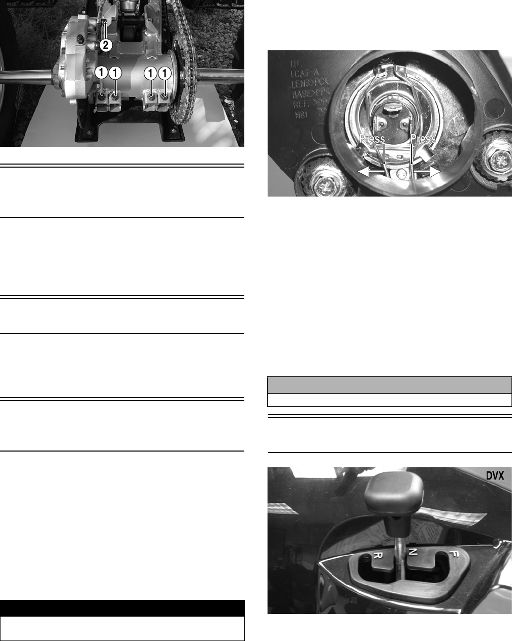
ADJUSTING TENSION
1. Loosen the four cap screws (1) at the rear of the axle
housing; then loosen the cap screw (2) on the front of
the brake caliper.
KM902A
2. Install an appropriate pin through the axle hub and
rear sprocket.
KM158A
3. With a person seated on the ATV, check chain ten-
sion at the mid-point of the chain.
NOTE: Chain “slack” should be within a range of
30-40 mm (1.2-1.6 in.).
4. Push the ATV forward to tighten chain tension; push
the ATV backward to loosen chain tension.
5. Tighten the four cap screws (1) to 29 ft-lb; then
tighten the cap screw (2) to 29 ft-lb.
! WARNING
Failure to inspect and maintain the drive chain can be
hazardous. Operating the ATV with the drive chain in
poor condition or improperly adjusted can cause an
accident resulting in possible injury.
FOR ARCTIC CAT ATV DISCOUNT PARTS CALL 606-678-9623 OR 606-561-4983
www.mymowerparts.com
13
KM902A
Driveshaft/Coupling
(Utility)
The following drive system components should be
inspected periodically to ensure proper operation.
A. Spline lateral movement (slop).
B. Coupling not cracked, damaged, or worn.
Nuts/Bolts/Cap Screws
Tighten all nuts, bolts, and cap screws. Make sure rivets
holding components together are tight. Replace all loose
rivets. Care must be taken that all calibrated nuts, bolts,
and cap screws are tightened to specifications.
Headlight/Taillight-
Brakelight
Each time the ATV is used, lights should be checked for
proper function. Turn the ignition switch to the LIGHTS
position; the headlights and taillight should illuminate.
Test the brakelight by compressing the brake lever. The
brakelight should illuminate.
NOTE: The bulb portion of the headlight is fragile.
HANDLE WITH CARE. When replacing the headlight
bulb, do not touch the glass portion of the bulb. If the
glass is touched, it must be cleaned with a dry cloth
before installing. Skin oil residue on the bulb will
shorten the life of the bulb.
To replace the headlight bulb, use the following procedure.
1. Remove the boot from the back of the headlight
housing; then remove the three-wire connector from
the bulb.
2. Using care not to bend or deform the spring clip,
release the two ends of the spring clip from the light
housing; then remove the bulb from the headlight
housing.
KM192A
3. Install the new bulb into the headlight housing; then
secure with the spring clip.
4. Connect the three-wire connector to the bulb; then
install the boot.
To replace the taillight-brakelight bulb, use the following
procedure.
1. Remove the two screws and remove the lens cover.
2. Push the bulb in and turn it counterclockwise.
3. Install the new bulb by turning it clockwise while
pushing in.
4. Install the lens cover.
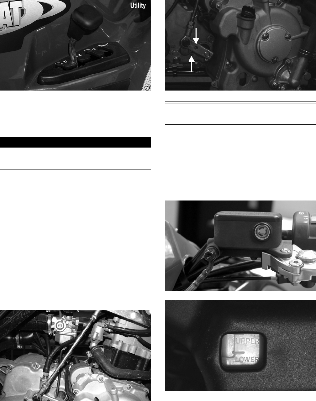
Shift Lever
KM363A
! WARNING
Do not attempt to remove the bulb when it is hot. Severe
burns may result.
CAUTION
Tighten the lens cover screws only until they are snug.
FOR ARCTIC CAT ATV DISCOUNT PARTS CALL 606-678-9623 OR 606-561-4983
www.mymowerparts.com
14
KM124B
CHECKING ADJUSTMENT
Stop the ATV completely and shift the transmission into
the R position. The reverse gear indicator light should be
illuminated.
If the reverse gear indicator light does not illuminate
when shifted to the reverse position, the switch may be
faulty, the fuse may be blown, the bulb may be faulty, a
connection may be loose or corroded, or the lever may
need adjusting. To adjust, proceed to Adjusting Shift
Lever.
ADJUSTING SHIFT LEVER
1. Place the shift lever in the N (neutral) position; then
set the engine stop switch to the STOP position and
turn the ignition switch to the RUN position. The
neutral indicator light should illuminate.
NOTE: If the neutral indicator light does not illumi-
nate, adjustment of the shift linkage will be required.
To adjust, proceed to step 2.
2. Loosen the jam nuts on both ends of the shift rod and
turn the shift rod until the neutral light illuminates.
Tighten the jam nuts securely.
KM313
NOTE: On the DVX, the neutral position in the trans-
mission is indexed by passing a Phillips screwdriver
through the transmission shift arm and into the index
hole in the transmission cover.
KM179A
Hydraulic Brake Systems
CHECKING/BLEEDING
The hydraulic brake systems have been filled and bled at
the factory. To check and/or bleed a hydraulic brake sys-
tem, use the following procedure.
1. With the master cylinder in a level position, check
the fluid level in the reservoir. If the level in the res-
ervoir is not visible in the sight glass, add DOT 4
brake fluid.
KM113
KM137
2. Compress the brake lever/pedal several times to
check for a firm brake. If the brake is not firm, the
system must be bled.
3. To bleed the brake system, use the following proce-
dure.
! WARNING
Never shift the ATV into reverse gear when the ATV is
moving as it could cause the ATV to stop suddenly
throwing the operator from the ATV.
FOR ARCTIC CAT ATV DISCOUNT PARTS CALL 606-678-9623 OR 606-561-4983
www.mymowerparts.com

15
A. Remove the cover and fill the reservoir with DOT
4 Brake Fluid.
B. Install and secure the cover; then slowly compress
the brake lever several times.
C. Remove the protective cap, install one end of a
clear hose onto one FRONT bleed screw, and
direct the other end into a container; then while
holding slight pressure on the brake lever, open
the bleed screw and watch for air bubbles. Close
the bleed screw before releasing the brake lever.
Repeat this procedure until no air bubbles are
present.
KM116A
NOTE: During the bleeding procedure, watch the
reservoir sight glass very closely to make sure there
is always a sufficient amount of brake fluid. Failure to
maintain a sufficient amount of fluid in the reservoir
will result in air in the system.
D. At this point, perform steps B and C on the other
FRONT bleed screw; then move to the REAR
bleed screw and follow the same procedure.
4. Carefully check the entire hydraulic brake system
that all hose connections are tight, the bleed screws
are tight, the protective caps are installed, and no
leakage is present.
INSPECTING HOSES
Carefully inspect the hydraulic brake hoses for cracks or
other damage. If found, the brake hoses must be replaced.
CHECKING/REPLACING FRONT
PADS
The clearance between the brake pads and brake discs is
adjusted automatically as the brake pads wear. The only
maintenance that is required is replacement of the brake
pads when they show excessive wear. Check the thick-
ness of each of the brake pads as follows.
1. Remove a front wheel.
2. Measure the thickness of each brake pad.
3. If thickness of either brake pad is less than 1.0 mm
(0.039 in.), the brake pad must be replaced.
NOTE: The brake pads should be replaced as a set.
4. To replace the brake pads, use the following proce-
dure.
A. With the wheel removed, remove the brake pad
alignment pins from the caliper; then remove the
mounting cap screws.
KM265A
KM266A
B. Remove the caliper from the disc; then compress
the caliper holder and remove the brake pads.
KM267
C. Install new brake pads; then install the two brake
pad alignment pins.
CAUTION
This hydraulic brake system is designed to use DOT 4
brake fluid only. If brake fluid must be added, care must
be taken as brake fluid is very corrosive to painted sur-
faces.
FOR ARCTIC CAT ATV DISCOUNT PARTS CALL 606-678-9623 OR 606-561-4983
www.mymowerparts.com

16
KM268
D. Spread the brake pads and place the brake caliper
over the disc. Secure with the mounting cap
screws. Tighten the cap screws to 25 ft-lb; then
tighten the alignment pins to 13 ft-lb.
KM266A
5. Install the wheel. Tighten to 32 ft-lb.
6. Burnish the brake pads (see Burnishing Brake Pads
in this section).
Auxiliary/Rear Hydraulic
Brake
CHECKING
1. With the engine off, the transmission in neutral, and
the reverse lever in the forward position, press the
brake pedal and attempt to move the ATV.
2. If the rear wheels are locked, it is functioning prop-
erly.
3. If the rear wheels are not locked, it must be repaired
or bled.
BLEEDING
To bleed the auxiliary brake, see Hydraulic Brake Sys-
tems - CHECKING/BLEEDING in this section.
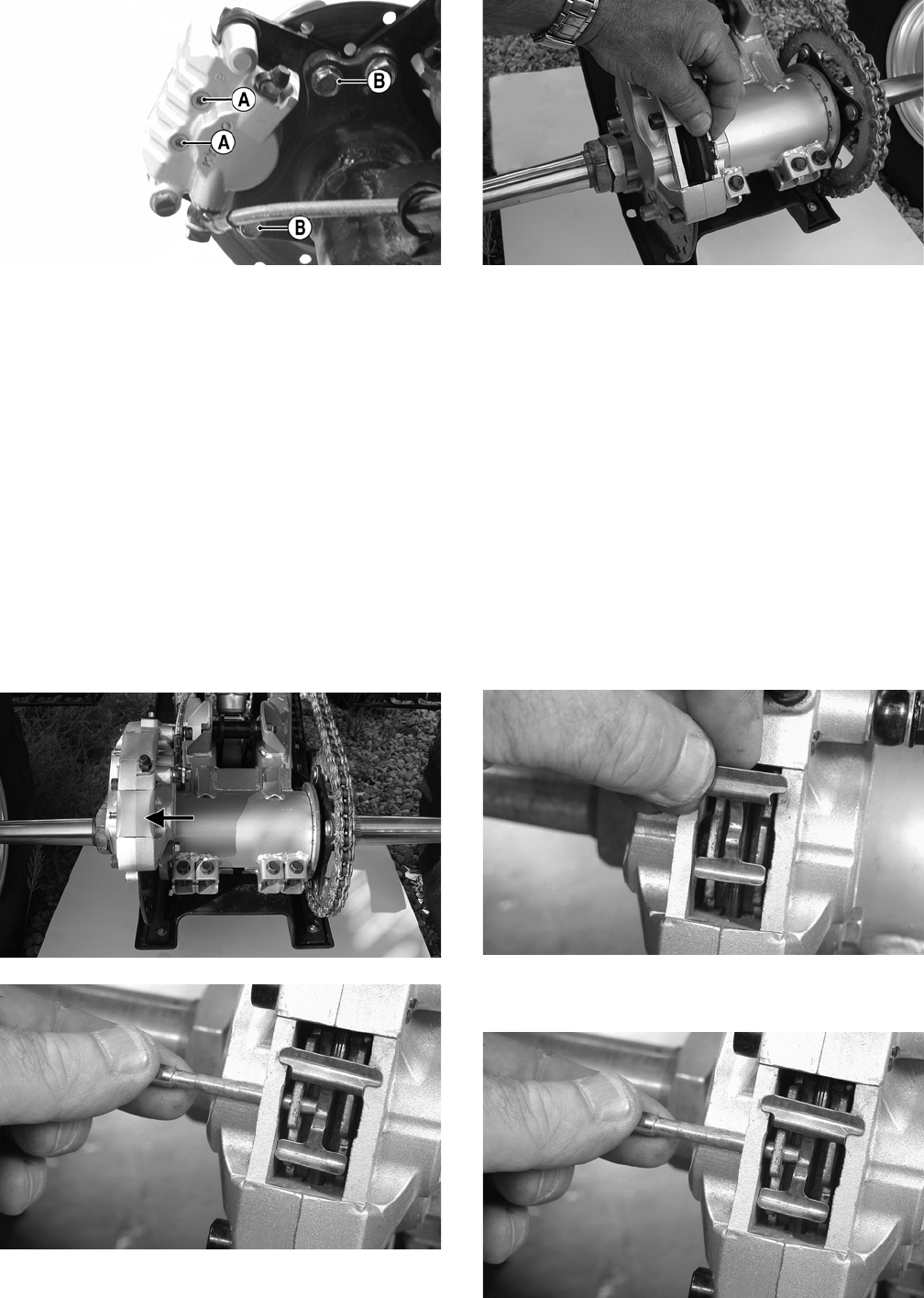
MEASURING/REPLACING REAR
BRAKE PADS (Utility)
Removing
1. Support the ATV on a suitable support stand.
2. Remove the left rear wheel.
3. Remove the two brake pad alignment pins (A); then
remove the mounting cap screws (B).
KM273A
4. Remove the caliper from the disc; then compress the
caliper holder and remove the brake pads.
KM267
Inspecting and Measuring
1. Inspect the pads for gouges, chips, or wear.
2. Inspect the disc for gouges, grooves, cracks, and
warpage.
3. Using a calipers, measure the thickness of each brake
pad.
4. If the thickness of either brake pad is less than 1.0
mm (0.039 in.), the brake pad must be replaced.
NOTE: The brake pads should be replaced as a set.
Installing
1. Install new brake pads; then install the two brake pad
alignment pins.
2. Spread the brake pads and place the brake caliper
over the disc; then secure with the mounting cap
screws (B). Tighten the cap screws to 25 ft-lb; then
tighten the alignment pins (A) to 13 ft-lb.
FOR ARCTIC CAT ATV DISCOUNT PARTS CALL 606-678-9623 OR 606-561-4983
www.mymowerparts.com
17
KM273A
3. Install the wheel and secure. Tighten to 32 ft-lb.
4. Remove the ATV from the support stand.
NOTE: Whenever installing new pads, the new pads
must be burnished (see Burnishing Brake Pads in
this section).
MEASURING/REPLACING REAR/
AUXILIARY BRAKE PADS (DVX)
Removing
NOTE: The brake caliper on the DVX contains two
sets of brake pads. The front pads are controlled by
the main brake lever and the rear pads are controlled
by the auxiliary brake pedal.
1. Remove the brake pad dust cover; then remove the
clip pin and pull the brake pad retaining pin out of
the caliper.
KM902B
KM244
2. Remove the brake spring plate; then remove the
brake pads.
KM905
Inspecting and Measuring
1. Inspect the pads for gouges, chips, or wear.
2. Inspect the disc for gouges, grooves, cracks, and
warpage.
3. Using a calipers, measure the thickness of each brake pad.
4. If the thickness of any brake pad is less than 1.0 mm
(0.039 in.), the brake pad must be replaced.
NOTE: The brake pads should be replaced as a set.
5. Using a calipers, measure the thickness of the disc. If
any portion of the disc is less than 3.00 mm (0.12
in.), the disc must be replaced (see Drive System).
Installing
1. Install the brake pads in the caliper; then insert the
brake spring plate.
KM245
2. Install the brake pad retaining pin and secure with
the clip pin; then install the dust cover.
KM244
FOR ARCTIC CAT ATV DISCOUNT PARTS CALL 606-678-9623 OR 606-561-4983
www.mymowerparts.com
18
3. Burnish the brake pads (see Burnishing Brake Pads
in this section).
Burnishing Brake Pads
Brake pads (both hydraulic and auxiliary) must be bur-
nished to achieve full braking effectiveness. Braking dis-
tance will be extended until brake pads are properly
burnished. To properly burnish the brake pads, use the
following procedure.
1. Choose an area large enough to safely accelerate the
ATV to 30 mph and to brake to a stop.
2. Accelerate to 30 mph; then compress brake lever or
apply the auxiliary brake to decelerate to 0-5 mph.
3. Repeat procedure on each brake system five times
until brake pads are burnished.
4. Adjust the auxiliary brake (if necessary).
5. Verify that the brakelight illuminates when the hand
lever is compressed or the brake pedal is depressed.
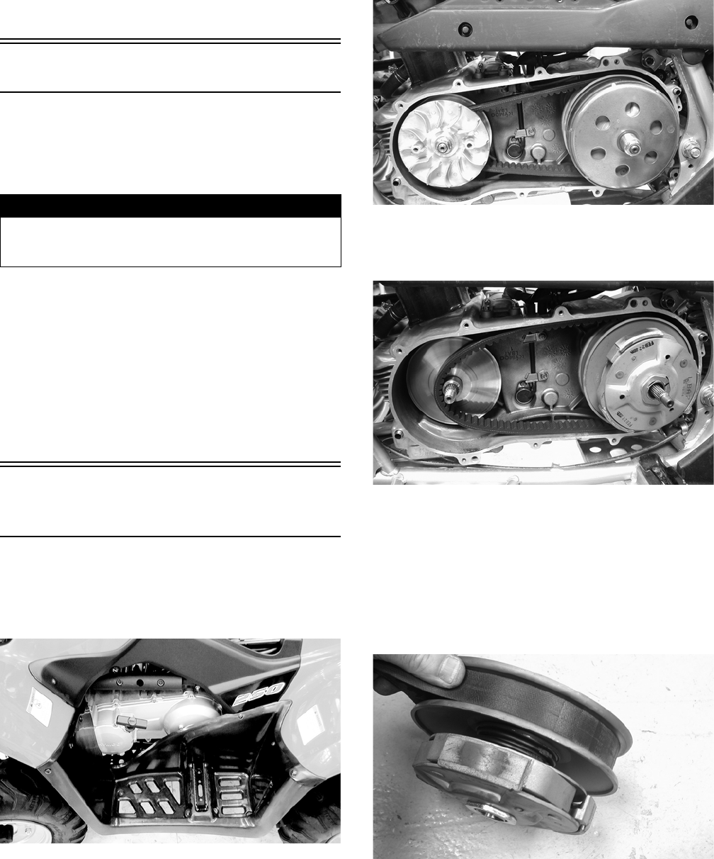
Checking/Replacing
V-Belt
REMOVING
1. On the Utility, remove the left footwell; then remove
the recoil starter assembly. On the DVX, proceed to
step 2.
KM279
2. Remove the front and rear V-belt housing cooling
ducts.
3. Remove the cap screws securing the V-belt cover
noting the location of the different-lengthed cap
screws for installing purposes; then using a rubber
mallet, gently tap on the cover tabs to loosen the
cover. Remove the cover. Account for two alignment
pins and one gasket.
KM253
4. Remove the nut securing the movable drive face;
then remove the face. Account for the stepped
washer and spacer.
KM276
5. Remove the nut securing the driven pulley; then
remove the splined bushing, centrifugal clutch, pul-
ley, and V-belt.
INSTALLING
1. Using a rubber mallet, spread the driven pulley
sheaves by driving the V-belt down between the
sheaves; then slide the driven pulley and V-belt into
position.
KM262
2. Install the centrifugal clutch housing onto the driven
shaft; then install the splined bushing and secure
with the driven pulley retaining nut. Tighten to 40 ft-
lb.
! WARNING
Failure to properly burnish the brake pads could lead to
premature brake pad wear or brake loss. Brake loss can
result in severe injury.
FOR ARCTIC CAT ATV DISCOUNT PARTS CALL 606-678-9623 OR 606-561-4983
www.mymowerparts.com

19
KM276
3. Install the movable drive face onto the crankshaft
making sure to “bottom” the sheave out against the
center bushing. The crankshaft splines should be vis-
ible and the stepped washer should sit over the
splines.
KM263A
4. Secure the movable drive face to the crankshaft with
the drive pulley nut and tighten to 72 ft-lb.
5. Install the V-belt cover and tighten the cap screws
securely; then connect the cooling boots and tighten
the clamps securely.
KM252A
6. Install the recoil starter and footwell assembly (Util-
ity). Tighten all hardware securely.
CAUTION
If the splines are not protruding as shown, the V-belt
may be too deep in the drive sheaves. This would cause
the drive pulley to be under-tightened and severe drive
sheave or crankshaft damage could occur.
CAUTION
On the DVX, the rear boot clamp must be oriented as
shown or interference with heat shielding could occur.
FOR ARCTIC CAT ATV DISCOUNT PARTS CALL 606-678-9623 OR 606-561-4983
www.mymowerparts.com

20
Engine/Transmission
This section has been organized into sub-sections which
show a progression for the complete servicing of the Arc-
tic Cat ATV engine/transmission.
To service the center crankcase halves, the engine/trans-
mission must be removed from the frame.
To service top-side, left-side, and right-side components,
the engine/transmission does not have to be removed
from the frame.
NOTE: Arctic Cat recommends the use of new gas-
kets, lock nuts, and seals and lubricating all internal
components when servicing the engine/transmission.
SPECIAL TOOLS
A number of special tools must be available to the techni-
cian when performing service procedures in this section.
Refer to the current Special Tools Catalog for the appro-
priate tool description.
NOTE: Special tools are available from the Arctic
Cat Service Parts Department.
Description p/n
Crankcase Separator/Crankshaft Remover 0444-152
Piston Pin Puller 0644-328
Spanner Wrench 0444-192
Flywheel Holder 0444-193
Magneto Rotor Remover 0444-187
Tappet Adjuster 0444-189
Surface Plate 0644-016
Driven Pulley Compressor 0444-195
V Blocks 0644-535
FOR ARCTIC CAT ATV DISCOUNT PARTS CALL 606-678-9623 OR 606-561-4983
www.mymowerparts.com
21
Removing Engine/
Transmission
Many service procedures can be performed without
removing the engine/transmission from the frame.
Closely observe the note introducing each sub-section for
this important information.
Secure the ATV on a support stand to elevate the wheels.
DVX
1. Remove the seat.
2. Remove the negative cable from the battery; then
remove the positive cable. Remove the battery hold-
down strap; then remove the battery.
3. Remove the reinstallable rivet from the bottom of the
electrical tray; then remove and lay the tray forward.
Leave the starter relay, fuse block, and CDI attached.
KM357
4. Remove the gas tank cover panel; then install the gas
tank cap and remove the gas tank vent hose.
5. Remove the body (see Steering/Frame).
6. Remove the air filter housing (see Fuel/Lubrication/
Cooling).
7. Remove the gas tank (see Fuel/Lubrication/Cooling).
8. Remove the muffler assembly (see Steering/Frame).
9. Remove the carburetor (see Fuel/Lubrication/Cooling).
10. Remove the coil (see Electrical System).
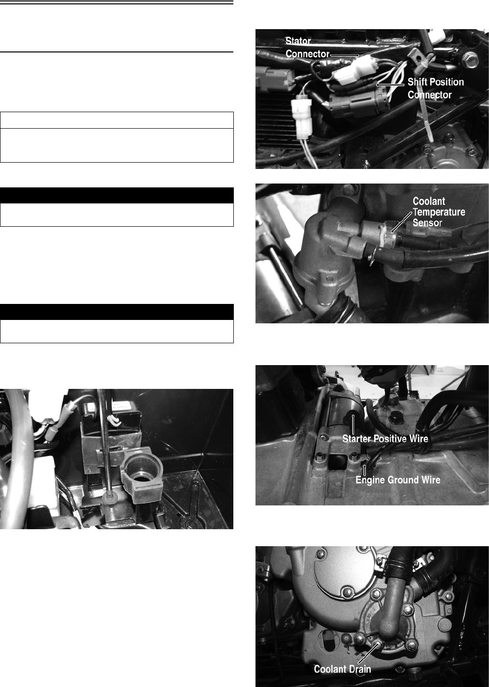
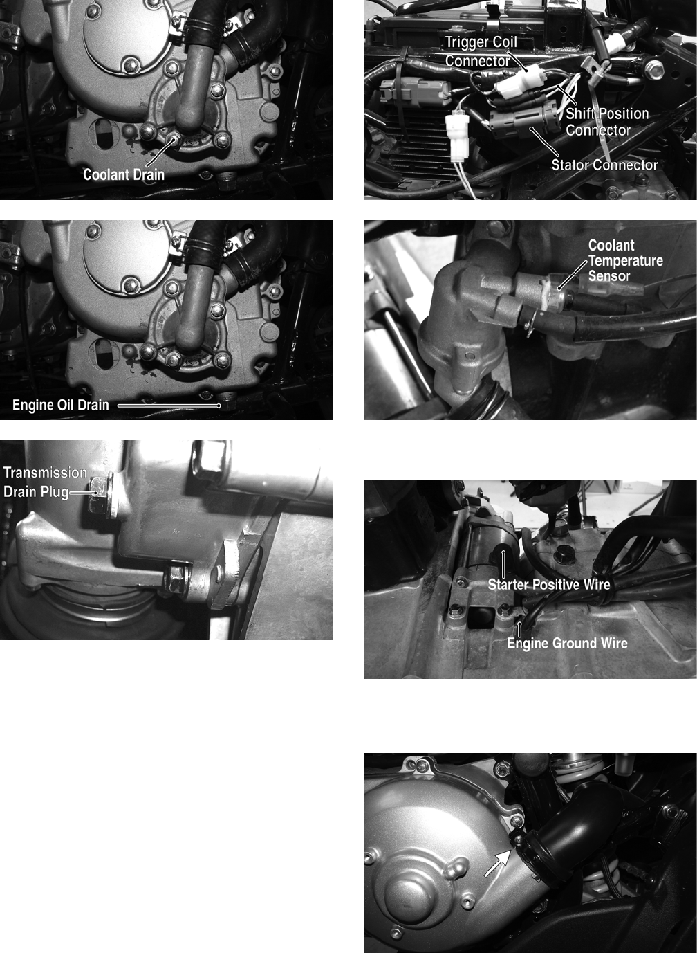
11. Disconnect the stator connector, shift position con-
nector, and coolant temperature sensor.
KM348A
KM324A
12. Remove the starter positive wire; then remove the
engine ground wire.
KM319A
13. Drain the coolant, engine oil, and transmission gear lubri-
cant; then install the drain plugs and tighten to 21 ft-lb.
KM314A
AT THIS POINT
If the technician’s objective is to service/replace left-
side cover oil seals, the engine/transmission does not
have to be removed from the frame.
! WARNING
Make sure the ATV is solidly supported on the support
stand to avoid injury.
! WARNING
Battery acid is harmful if it contacts eyes, skin, or cloth-
ing. Care must be taken whenever handling a battery.
FOR ARCTIC CAT ATV DISCOUNT PARTS CALL 606-678-9623 OR 606-561-4983
www.mymowerparts.com
22
KM147A
KM106A
14. Loosen the clamps; then remove the front and rear V-
belt cooling boots from the V-belt housing.
KM359A
KM360A
15. Loosen the clamps; then disconnect the coolant
hoses from the engine.
KM323
KM314
16. Remove the output drive sprocket cover; then
remove the output drive sprocket.
KM344A
17. Disconnect the shift linkage from the transmission
shift arm.
KM313
FOR ARCTIC CAT ATV DISCOUNT PARTS CALL 606-678-9623 OR 606-561-4983
www.mymowerparts.com
23
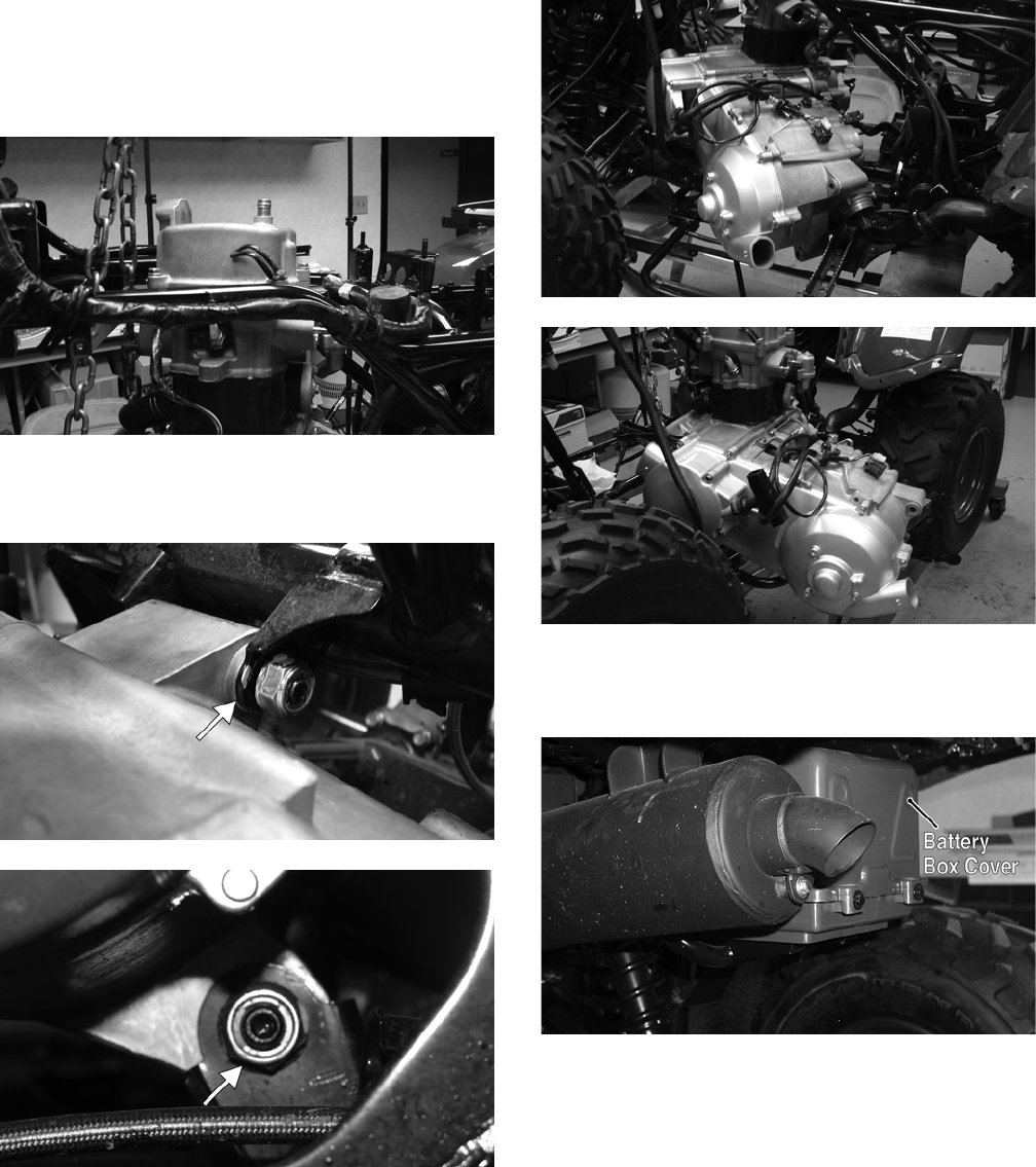
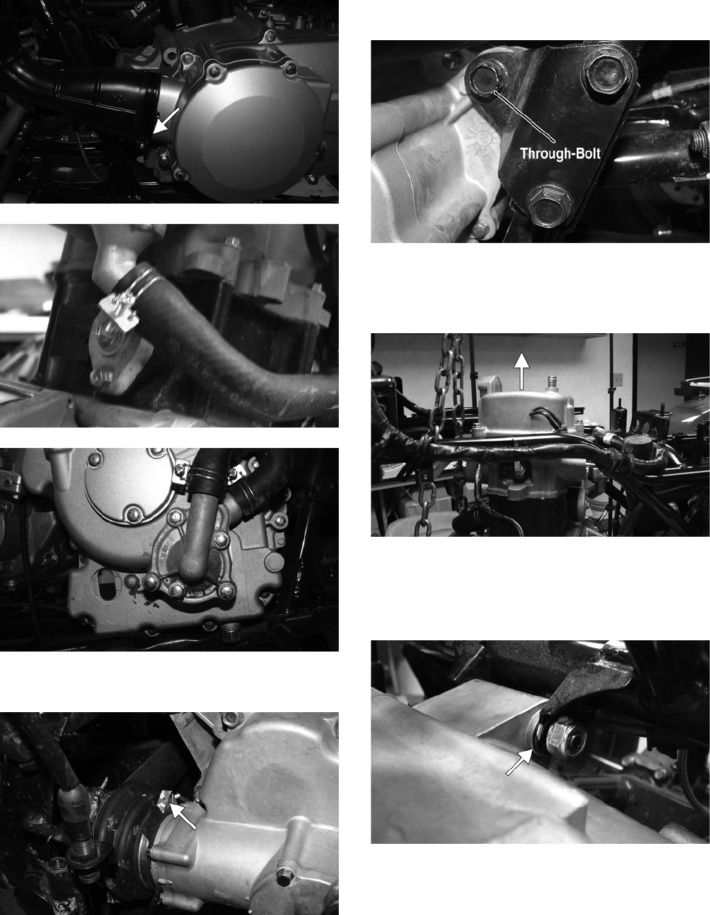
18. Remove the front engine mounting through-bolt;
then remove the left and right engine mounting
brackets from the frame.
19. Attach a suitable lifting sling and engine lift to the
front engine mounting boss.
KM332
20. Raise the engine lift to take the slack out of the sling;
then remove the upper rear and lower rear engine
through-bolts.
KM333A
KM325A
21. Raise the front of the engine sufficiently to allow the
engine assembly to be moved forward enough to clear
the rear mounting brackets (approximately 6 in.).
22. Lower the front of the engine slowly, swing the rear
of the engine to the left, and slide the engine out of
the left-side of the frame.
KM330
KM331
Utility
1. Remove the seat; then remove the battery box cover.
KM133A
2. Remove the negative cable from the battery; then
remove the positive cable.
3. Drain the coolant, engine oil, and transmission gear
lubricant; then install the drain plugs and tighten to
21 ft-lb.
FOR ARCTIC CAT ATV DISCOUNT PARTS CALL 606-678-9623 OR 606-561-4983
www.mymowerparts.com
24
KM314A
KM314B
KM106A
4. Remove the gas tank cover panel and gas tank vent
hose.
5. Remove the side panels; then remove the front rack
and front fenders (see Steering/Frame).
6. Remove the air filter housing (see Fuel/Lubrication/
Cooling.
7. Remove the gas tank (see Fuel/Lubrication/Cooling).
8. Remove the muffler assembly (see Steering/Frame).
9. Remove the carburetor (see Fuel/Lubrication/Cool-
ing).
10. Remove the coil (see Electrical System).
11. Disconnect the stator connector, shift position con-
nector, trigger coil connector, and coolant tempera-
ture sensor.
KM347A
KM324A
12. Remove the starter positive wire; then remove the
engine ground wire from the crankcase.
KM319A
13. Remove the front and rear V-belt cooling boots from
the V-belt housing; then remove the coolant hoses
from the engine.
KM359A
FOR ARCTIC CAT ATV DISCOUNT PARTS CALL 606-678-9623 OR 606-561-4983
www.mymowerparts.com
25
KM360A
KM323
KM314
14. Loosen the output drive boot clamp; then slide the
boot off the output housing.
KM315A
15. Disconnect the shift linkage from the transmission
shift arm; then swing the shift linkage forward and
out of the way.
16. Remove the front engine through-bolt; then remove
the two engine mounting brackets from the frame.
KM414A
17. Attach a suitable lifting sling and engine lift to the
front engine mounting boss; then using an engine
lift, apply slight upward pressure on the engine/
transmission.
KM332A
18. Remove the upper rear and lower rear engine
through-bolts to free the engine/transmission; then
raise the front of the engine/transmission sufficiently
to allow the engine assembly to be moved forward
enough to disengage the driveshaft.
KM333A
FOR ARCTIC CAT ATV DISCOUNT PARTS CALL 606-678-9623 OR 606-561-4983
www.mymowerparts.com

26
KM325A
19. Swing the rear of the engine/transmission to the left;
then slide the engine out of the left-side of the frame.
KM329
KM331
Top-Side Components
NOTE: For efficiency, it is preferable to remove and
disassemble only those components which need to
be addressed and to service only those components.
The technician should use discretion and sound
judgment.
NOTE: The engine/transmission does not have to
removed from the frame for this procedure.
Removing Top-Side
Components
A. Valve Cover
B. Cylinder Head
NOTE: Remove the spark plug and timing inspec-
tion plug; then rotate the crankshaft to top-dead-cen-
ter of the compression stroke.
1. Remove the cap screws securing the cylinder head
cover. Account for the O-ring.
KM703
NOTE: Keep the mounting hardware with the cover
for assembly purposes.
2. Remove the plug from the cam chain tensioner; then
turn the cam chain tensioner screw clockwise to
release the chain tension.
KM704A
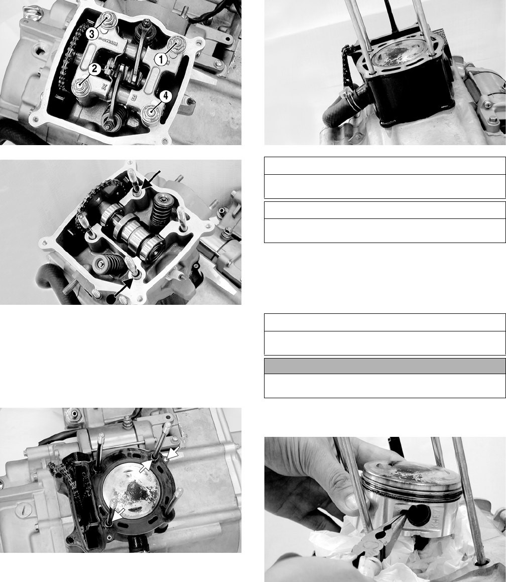
3. Using a crisscross pattern, loosen the four nuts secur-
ing the camshaft holder to the cylinder head. Use 2-3
steps until the nuts are all free; then remove the cam-
shaft holder. Account for four washers and two
alignment pins.
AT THIS POINT
To service any one specific component, only limited dis-
assembly of components may be necessary. Note the
AT THIS POINT information in each sub-section.
FOR ARCTIC CAT ATV DISCOUNT PARTS CALL 606-678-9623 OR 606-561-4983
www.mymowerparts.com
27
KM706A
KM707A
4. Remove the camshaft gear from the cam chain; then
secure the timing chain so it will not fall into the
engine. Remove the camshaft.
5. Remove the two external cap screws securing the
cylinder head to the cylinder; then remove the cylin-
der head. Account for two alignment pins and a cyl-
inder head gasket.
KM718A
6. Remove the cam chain guide; then disconnect the
coolant hose and remove the cylinder. Support the
piston with rubber bands or other suitable supports.
Account for two dowel pins and the cylinder gasket.
KM450
C. Cylinder
D. Piston
NOTE: Steps 1-6 in the preceding sub-section must
precede this procedure.
7. Using a needle nose pliers, remove one piston pin
circlip. Take care not to drop it into the crankcase.
KM451
8. Using Piston Pin Puller, remove the piston pin.
Account for the opposite-side circlip. Remove the
piston.
NOTE: It is advisable to remove the opposite-side
circlip prior to using the puller.
AT THIS POINT
To service valves and cylinder head, see Servicing Top-
Side Components sub-section.
AT THIS POINT
To inspect cam chain guide, see Servicing Top-Side
Components sub-section.
AT THIS POINT
To service cylinder, see Servicing Top-Side Compo-
nents sub-section.
CAUTION
When removing the cylinder, be sure to support the pis-
ton to prevent damage to the crankcase and piston.
FOR ARCTIC CAT ATV DISCOUNT PARTS CALL 606-678-9623 OR 606-561-4983
www.mymowerparts.com

28
NOTE: Support the connecting rod with rubber
bands to avoid damaging the rod or install a connect-
ing rod holder.
NOTE: If the existing rings will not be replaced with
new rings, note the location of each ring for proper
installation. When replacing with new rings, replace
as a complete set only. If the piston rings must be
removed, remove them in this sequence.
A. Starting with the top ring, slide one end of the ring
out of the ring-groove.
B. Remove each ring by working it toward the dome
of the piston while rotating it out of the groove.
Servicing Top-Side
Components
NOTE: Whenever a part is worn excessively, cracked,
or damaged in any way, replacement is necessary.
VALVE ASSEMBLY
When servicing valve assembly, inspect valve seats,
valve stems, valve faces, and valve stem ends for pits,
discoloration, or other signs of abnormal wear.
NOTE: Whenever a valve is out of tolerance, it must
be replaced.
Cleaning/Inspecting Camshaft
Holder
1. Remove the rocker arm shafts, rocker arms, and stop
plate from the camshaft holder.
KM708A
2. Inspect the camshaft holder for cracks, distortion, or
galling.
3. Inspect the rocker arm shafts for blue discoloration
or scoring.
4. Inspect the rocker arms for excessive wear, loose
adjusters, or scored camshaft followers.
KM710A
Removing Valves
NOTE: Keep all valves and valve components as a
set. Note the original location of each valve set for
use during installation. Return each valve set to its
original location during installation.
1. Using a valve spring compressor, compress the valve
springs and remove the valve cotters. Account for an
upper spring retainer.
KM717A
2. Remove the valve seal, valve springs, and the lower
remaining spring seat. Discard the valve seal.
NOTE: The valve seals must be replaced.
3. Invert the cylinder head and remove the valves.
Measuring Valve Stem/Valve Guide
Clearance
1. Using a micrometer, measure the valve stem outside
diameter; then using a suitable snap gauge and
micrometer, measure the valve guide inside diameter.
2. Acceptable clearance must be within specifications.
Inspecting Valve Face
Inspect the valve face for pitting, grooving, or discolor-
ation. Replace any valve that is damaged.
CAUTION
Do not allow the connecting rod to go down inside the
crankcase. If the rod is down inside the crankcase and
the crankshaft is rotated, severe damage will result.
AT THIS POINT
To service piston, see Servicing Top-Side Components
sub-section.
AT THIS POINT
To service center crankcase components only, proceed
to Removing Left-Side Components.
FOR ARCTIC CAT ATV DISCOUNT PARTS CALL 606-678-9623 OR 606-561-4983
www.mymowerparts.com

29
CYLINDER HEAD ASSEMBLY
NOTE: If the cylinder head cannot be trued, it must
be replaced.
Cleaning/Inspecting Cylinder Head
1. Using a non-metallic carbon removal tool, remove
any carbon build-up from the combustion chamber
making sure not to nick, scrape, or damage the com-
bustion chamber or the sealing surface.
2. Inspect the spark plug hole for any damaged threads.
Repair damaged threads using a “heli-coil” insert.
3. Place the cylinder head on the surface plate covered
with #400 grit wet-or-dry sandpaper. Using light
pressure, move the cylinder head in a figure eight
motion. Inspect the sealing surface for any indication
of high spots. A high spot can be noted by a bright
metallic finish. Correct any high spots before assem-
bly by continuing to move the cylinder head in a fig-
ure eight motion until a uniform bright metallic
finish is attained.
Measuring Cylinder Head
Distortion
1. Remove any carbon buildup in the combustion
chamber.
2. Lay a straightedge across the cylinder head; then
using a feeler gauge, check the distortion factor
between the head and the straightedge.
3. Maximum distortion must not exceed specifications.
CC141D
Measuring Camshaft Lobe Height
1. Using a calipers, measure each cam lobe height.
ATV1013A
2. The lobe heights must not be less than minimum
specifications.
Inspecting Camshaft Bearing
Journal
1. Inspect the bearing journal for scoring, seizure
marks, or pitting.
2. If excessive scoring, seizure marks, or pitting is
found, the cylinder head assembly must be replaced.
Measuring Rocker Arm/
Shaft Clearance
1. Using a dial calipers, measure the inside diameter of
the rocker arm; then measure the outside diameter of
the rocker arm shaft.
2. Acceptable clearance must not exceed specifications.
Installing Valves
1. Apply grease to the inside surface of the valve seals;
then place a lower spring seat and valve guide seal
over each valve guide.
2. Insert each valve into its original valve location.
3. Install the valve springs with the closest coils toward
the cylinder head.
ATV-1011A
4. Place a spring retainer over the valve springs; then
using the valve spring compressor, compress the
valve springs and install the valve cotters.
CAUTION
Water or parts-cleaning solvent must be used in con-
junction with the wet-or-dry sandpaper or damage to
the sealing surface may result.
FOR ARCTIC CAT ATV DISCOUNT PARTS CALL 606-678-9623 OR 606-561-4983
www.mymowerparts.com
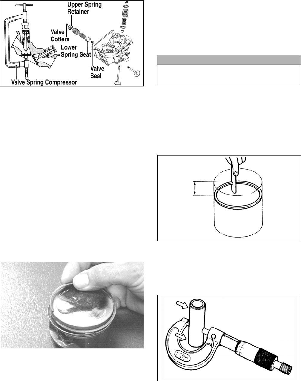
30
KM717A
PISTON ASSEMBLY
NOTE: Whenever a piston, rings, or pin are out of
tolerance, they must be replaced.
Cleaning/Inspecting Piston
1. Using a non-metallic carbon removal tool, remove
any carbon buildup from the dome of the piston.
2. Inspect the piston for cracks in the piston pin, dome,
and skirt areas.
3. Inspect the piston for seizure marks or scuffing.
Repair with #400 grit wet-or-dry sandpaper and
water or honing oil.
NOTE: If scuffing or seizure marks are too deep to
correct with the sandpaper, replace the piston.
4. Inspect the perimeter of each piston for signs of
excessive “blowby.” Excessive “blowby” indicates
worn piston rings or an out-of-round cylinder.
Removing Piston Rings
1. Starting with the top ring, slide one end of the ring
out of the ring-groove.
CC400D
2. Remove each ring by working it toward the dome of
the piston while rotating it out of the groove.
NOTE: If the existing rings will not be replaced with
new ones, note the location of each ring for proper
installation. When installing new rings, install as a
complete set only.
Cleaning/Inspecting Piston Rings
1. Take an old piston ring and snap it into two pieces;
then grind the end of the old ring to a 45° angle and
to a sharp edge.
2. Using the sharpened ring as a tool, clean carbon from
the ring-grooves. Be sure to position the ring with its
tapered side up.
Measuring Piston-Ring End Gap
(Installed)
1. Place each piston ring in the wear portion of the cyl-
inder. Use the piston to position each ring squarely in
the cylinder.
2. Using a feeler gauge, measure each piston-ring end
gap. Acceptable ring end gap must not exceed speci-
fications.
KM452
Measuring Piston Pin (Outside
Diameter) and Piston-Pin Bore
1. Measure the piston pin outside diameter at each end
and in the center. If measurement is not within speci-
fications, the piston pin must be replaced.
ATV-1070
2. Insert an inside dial indicator into the piston-pin
bore. The diameter must not exceed specifications.
Take two measurements to ensure accuracy.
CAUTION
Improper cleaning of the ring-grooves by the use of the
wrong type of ring-groove cleaner will result in severe
damage to the piston.
FOR ARCTIC CAT ATV DISCOUNT PARTS CALL 606-678-9623 OR 606-561-4983
www.mymowerparts.com

31
ATV-1069
Measuring Piston Skirt/
Cylinder Clearance
1. Measure the cylinder front to back in six places.
CC397D
2. Measure the corresponding piston diameter at a point
18 mm above the piston skirt at a right angle to the
piston-pin bore. Subtract this measurement from the
measurement in step 1. The difference (clearance)
must be within specifications.
Installing Piston Rings
1. Install ring expander (4) in the bottom groove of the
piston; then install the thin oil rings (3) over the
expander making sure the expander ends do not
overlap. Stagger the end gaps of the upper and lower
thin oil rings according to the illustration.
NOTE: Note the direction of the exhaust side of the
piston (5) for correct ring end gap orientation.
ATV-1085B
2. Install the compression rings (1 and 2) so the letter
on the top surface of each ring faces the dome of the
piston. Rotate the rings until the ring end gaps are on
directly opposite sides of the piston according to the
illustration.
726-306A
CYLINDER ASSEMBLY
NOTE: If the cylinder cannot be trued, it must be
replaced.
Cleaning/Inspecting Cylinder
1. Wash the cylinder in parts-cleaning solvent.
2. Inspect the cylinder for pitting, scoring, scuffing,
warpage, and corrosion. If marks are found, repair
the surface using a cylinder hone (see Honing Cylin-
der in this sub-section).
3. Place the cylinder on the surface plate covered with
#400 grit wet-or-dry sandpaper. Using light pressure,
move the cylinder in a figure eight motion. Inspect
the sealing surface for any indication of high spots.
A high spot can be noted by a bright metallic finish.
Correct any high spots before assembly by continu-
ing to move the cylinder in a figure eight motion
until a uniform bright metallic finish is attained.
Inspecting Cam Chain Guide
1. Inspect cam chain guide for cuts, tears, breaks, or
chips.
2. If the chain guide is damaged, it must be replaced.
Honing Cylinder
1. Using a slide gauge and a dial indicator or a snap
gauge, measure the cylinder bore diameter in three
locations from top to bottom and again from top to
bottom at 90° from the first measurements for a total
of six measurements. The trueness (out-of-round-
ness) is the difference between the highest and low-
est reading. Maximum trueness (out-of-roundness)
must not exceed specifications.
CAUTION
Incorrect installation of the piston rings will result in
engine damage.
CAUTION
Water or parts-cleaning solvent must be used in con-
junction with the wet-or-dry sandpaper or damage to
the sealing surface may result.
FOR ARCTIC CAT ATV DISCOUNT PARTS CALL 606-678-9623 OR 606-561-4983
www.mymowerparts.com
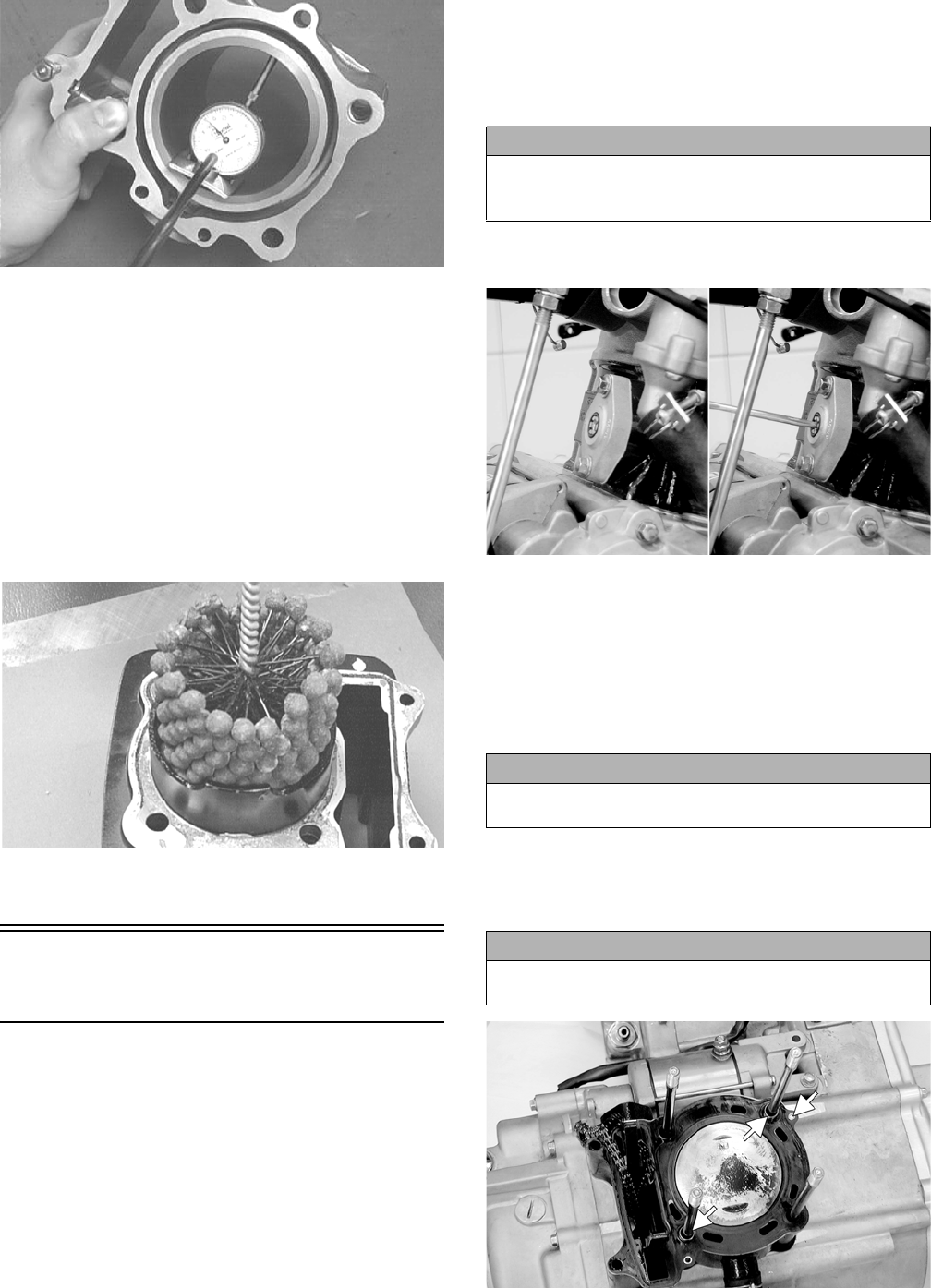
32
CC127D
2. Wash the cylinder in parts-cleaning solvent.
3. Inspect the cylinder for pitting, scoring, scuffing, and
corrosion. If marks are found, repair the surface
using a #320 grit ball hone.
NOTE: To produce the proper 60° cross-hatch pat-
tern, use a low RPM drill (600 RPM) at the rate of 30
strokes per minute. If honing oil is not available, use
a lightweight petroleum-based oil. Thoroughly clean
cylinder after honing using soap and hot water. Dry
with compressed air; then immediately apply oil to
the cylinder bore. If the bore is severely damaged or
gouged, replace the cylinder.
CC390D
4. If any measurement exceeds the limit, replace the
cylinder.
Installing Top-Side
Components
A. Piston
B. Cylinder
1. Install the piston on the connecting rod making sure
there is a circlip on each side and the open end of the
circlip is directed upwards or downwards.
NOTE: The piston should be installed so the IN
mark is toward the intake (rear) side of the cylinder.
2. Place the two alignment pins into position. Place the
cylinder gasket into position; then place a piston
holder (or suitable substitute) beneath the piston skirt
and square the piston in respect to the crankcase.
3. Lubricate the inside wall of the cylinder; then using a
ring compressor or the fingers, compress the rings
and slide the cylinder over the piston. Route the cam
chain up through the cylinder cam chain housing;
then remove the piston holder and seat the cylinder
firmly on the crankcase.
4. Turn the cam chain tensioner screw clockwise to
retract the tensioner spring.
KM705
C. Cylinder Head
D. Valve Cover
NOTE: Steps 1-4 in the preceding sub-section must
precede this procedure.
5. While keeping tension on the cam chain, place the
front cam chain guide into the cylinder.
6. Place the head gasket into position on the cylinder.
Place the alignment pins into position; then place the
head assembly into position on the cylinder making
sure the cam chain is routed through the chain cavity.
KM718A
CAUTION
The cylinder should slide on easily. Do not force the cyl-
inder or damage to the piston, rings, cylinder, or crank-
shaft assembly may occur.
CAUTION
Care should be taken that the bottom of the chain guide
is secured in the crankcase boss.
CAUTION
Keep tension on the cam chain to avoid damaging the
crankcase boss.
FOR ARCTIC CAT ATV DISCOUNT PARTS CALL 606-678-9623 OR 606-561-4983
www.mymowerparts.com
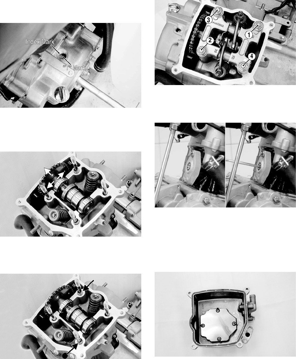
33
7. Turn the crankshaft as required to align the “T” mark
on the rotor/flywheel with the index mark on the
right-side crankcase cover.
KM779A
8. With the index hole in the camshaft gear directed
away from the cylinder head and the two punch
marks aligned with the cylinder head surface, install
the timing gear into the cam chain and seat the cam-
shaft into the camshaft journals.
KM715A
9. Install the two alignment pins; then install the cam-
shaft holder and secure with the four cylinder head
nuts and washer. Using a crisscross pattern, tighten
to 18 ft-lb.
KM707A
KM706A
10. Install the cam chain tensioner assembly and tighten
the mounting cap screws to 9 ft-lb; then turn the ten-
sioner screw counterclockwise to tension the cam
chain.
KM705
11. Install the cam chain tensioner cover bolt and tighten
to 24 in.-lb.
12. Check that the cam gear alignment marks are cor-
rectly oriented; then install and tighten the external
cylinder head to cylinder cap screws to 7 ft-lb.
13. Install the cylinder head cover with a new O-ring and
tighten securely.
KM703
FOR ARCTIC CAT ATV DISCOUNT PARTS CALL 606-678-9623 OR 606-561-4983
www.mymowerparts.com
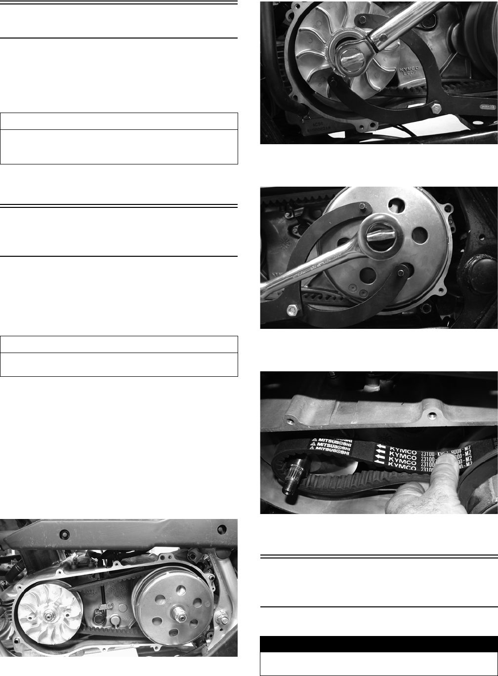
34
Left-Side Components
NOTE: For efficiency, it is preferable to remove and
disassemble only those components which need to
be addressed and to service only those components.
The technician should use discretion and sound
judgment.
NOTE: The engine/transmission does not have to
be removed from the frame for this procedure.
Removing Left-Side
Components
A. Recoil Starter (Utility)
1. Remove the five recoil starter cover cap screws.
Remove the recoil starter assembly noting the loca-
tion of the dowel pins. Note the condition of the
recoil cover gasket. Replace if damaged.
B. V-Belt Cover
C. Drive Pulley
D. Driven Pulley/Centrifugal Clutch
Assembly
NOTE: On the Utility, step 1 in the preceding sub-
section must precede this procedure.
2. Remove the ten cap screws securing the V-belt
cover; then remove the cover noting the location of
the two dowel pins. Note the condition of the V-belt
cover gasket. Replace if damaged.
KM253
3. On the Utility using a suitable holder to prevent the
drive pulley from turning, remove the drive face nut
and starter ratchet; then remove the drive pulley face.
KM365
4. Hold the centrifugal clutch with a suitable holder;
then remove the clutch retaining nut and clutch collar.
KM364
5. Remove the outer clutch housing; then remove the
centrifugal clutch, driven pulley, and V-belt.
KM369
6. Remove the drive pulley collar and the movable
drive face taking care not to loose the rollers.
Servicing Left-Side
Components
RECOIL STARTER (Utility)
AT THIS POINT
To service any one specific component, only limited dis-
assembly of components may be necessary. Note the
AT THIS POINT information in each sub-section.
AT THIS POINT
To service the recoil starter, see Servicing Left-Side
Components sub-section.
! WARNING
Always wear safety glasses when servicing the recoil
starter.
FOR ARCTIC CAT ATV DISCOUNT PARTS CALL 606-678-9623 OR 606-561-4983
www.mymowerparts.com

35
Removing/Disassembling
1. Remove the cap screws securing the recoil starter
assembly to the V-belt cover; then remove the starter.
Account for two alignment pins.
KM413A
2. Rotate the reel clockwise until the notch of the reel is
near the rope guide in the case. Guide the rope into
the notch and slowly allow the reel to unwind until
all spiral spring tension is released.
3. Remove the cap screw. Account for the ratchet
guide, spacer, and spring.
KM411
4. Carefully lift the reel free of the case making sure the
spiral spring does not accidentally disengage from
the case.
KM402A
5. Remove the protective cover from the starter handle
and pull the rope out of the handle; then untie the
knot in the rope and remove the handle. Account for
a flat washer.
KM408
NOTE: Do not remove the spiral spring unless
replacement is necessary. It should be visually
inspected in place to save time. If replacement is nec-
essary, follow steps 6-7.
6. Remove the spiral spring from the case by lifting the
spring end up and out. Hold the remainder of the
spring with thumbs and alternately release each
thumb to allow the spring to gradually release from
the case.
7. Unwind the rope from the reel and remove the rope.
Cleaning and Inspecting
NOTE: Whenever a part is worn excessively,
cracked, or damaged in any way, replacement is nec-
essary.
1. Clean all components.
2. Inspect the springs and ratchet for wear or damage.
3. Inspect the reel and case for cracks or damage.
4. Inspect the shaft for wear, cracks, or damage.
5. Inspect the rope for breaks or fraying.
6. Inspect the spiral spring for cracks, crystallization, or
abnormal bends.
! WARNING
During the disassembling procedure, continuous back-
ward pressure must be exerted on the reel so it does
not accidentally unwind and cause injury.
CAUTION
During the disassembling procedure, make sure all
spring tension is released before continuing.
! WARNING
Care must be taken when lifting the reel free of the case.
Wear safety glasses to avoid injury.
FOR ARCTIC CAT ATV DISCOUNT PARTS CALL 606-678-9623 OR 606-561-4983
www.mymowerparts.com
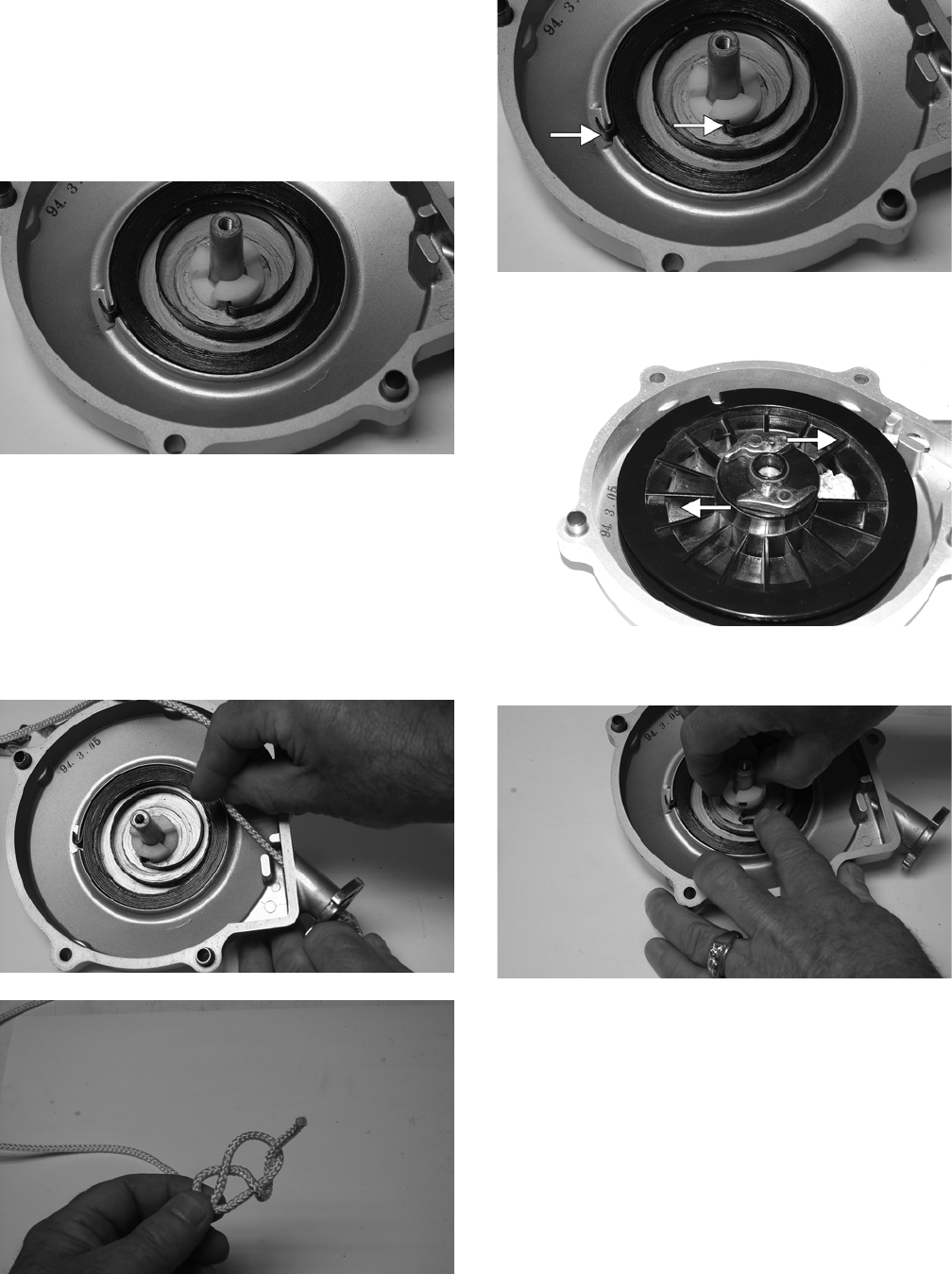
36
7. Inspect the handle for damage, cracks, or deteriora-
tion.
Assembling/Installing
1. If removed, insert the spiral spring into the case with
the outer end of the spring around the mounting lug
in the case; then wind it in a counterclockwise direc-
tion until the complete spring is installed.
NOTE: The spiral spring must seat evenly in the
recoil case.
KM402
2. Insert the rope through the hole in the reel and tie a
knot in the end; then wrap the rope clockwise around
the reel leaving approximately 50 cm (20 in.) of rope
free of the reel.
3. Apply low-temperature grease to the spring and hub.
4. Thread the end of the rope through the guide hole of
the case; then thread the rope through the handle and
washer and secure it with a double knot. Install the
protective cover into the handle.
KM400
KM405
5. Align the inner hook of the spiral spring with the
notch in the reel spacer.
KM402A
6. Install the ratchets making sure the ends are properly
oriented on the reel.
KM397A
7. Install the spacer, spring, and the ratchet guide mak-
ing sure the ratchet pins engage the guide.
KM401
8. Hold the ratchet guide down in place on the ratchet
pins and secure with the cap screw coated with blue
Loctite #243. Tighten securely.
FOR ARCTIC CAT ATV DISCOUNT PARTS CALL 606-678-9623 OR 606-561-4983
www.mymowerparts.com
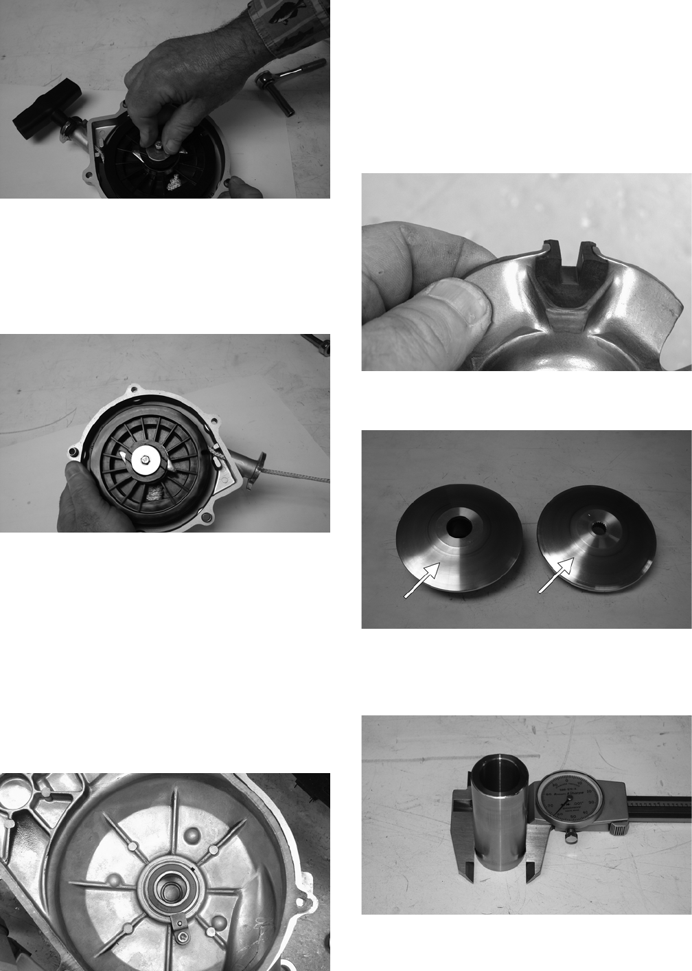
37
KM410
9. With the 50 cm (20 in.) of rope exposed, hook the
rope in the notch of the reel.
10. Rotate the reel four turns clockwise; then release the
rope from the notch and allow the rope to retract.
11. Pull the rope out two or three times to check for cor-
rect tension and ratchet extender.
KM412
NOTE: Increasing the rotations in step 10 will
increase spring tension.
12. Place the recoil starter assembly into position on the
left-side cover; then tighten the cap screws to securely.
V-BELT COVER
1. Inspect the bearing for excessive wear, rough or
binding when turning, seal condition, and secure
mounting in the V-belt cover.
NOTE: If the bearing is worn excessively, turns
roughly, or bearing seals are loose, the bearings
must be replaced.
KM254
2. Inspect the V-belt cover for cracks, distortion, and
loose alignment pins.
NOTE: If the V-belt cover is cracked or distorted or if
the bearing is loose in the cover, the cover must be
replaced.
DRIVE PULLEY
1. Remove the ramp plate from the movable drive face;
then inspect the ramp plate guides and weight roller
for damage or excessive wear.
KM256
2. Inspect the face surfaces of the fixed and movable
drive faces for grooving, nicks, or discoloration.
KM394A
3. Inspect the drive pulley collar for wear or damage.
Measure the outside diameter of the drive pulley col-
lar sliding surface. The minimum service limit is
26.94 mm.
KM389
FOR ARCTIC CAT ATV DISCOUNT PARTS CALL 606-678-9623 OR 606-561-4983
www.mymowerparts.com
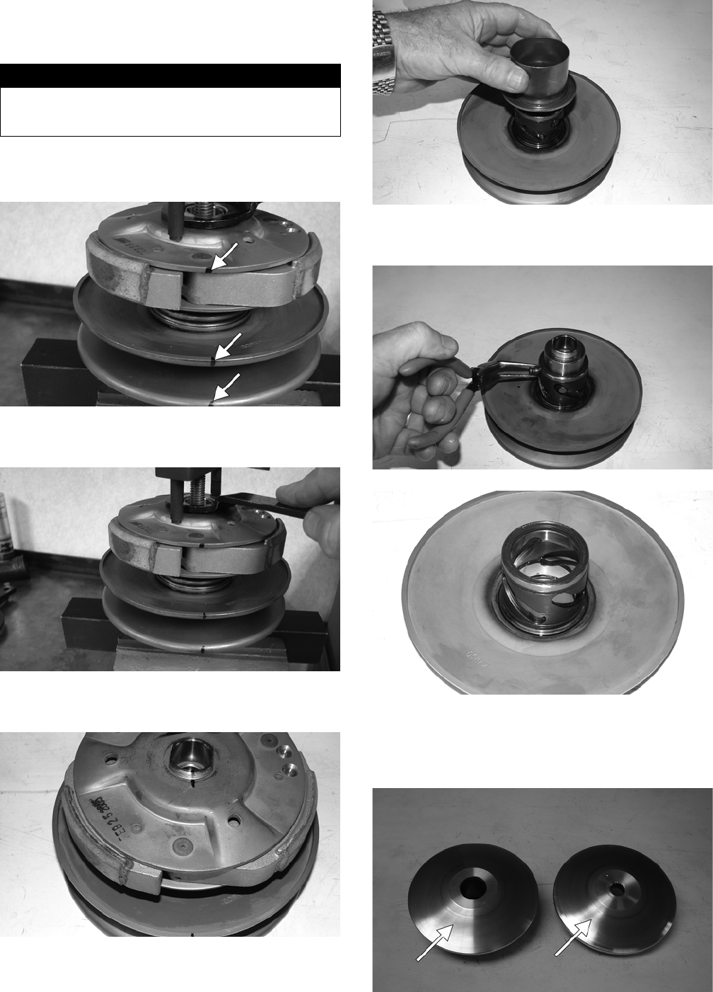
38
DRIVEN PULLEY/CENTRIFUGAL
CLUTCH ASSEMBLY
Disassembling
1. Place the driven pulley on a suitable spring compres-
sor; then mark the pulley faces and centrifugal clutch
for alignment during assembling.
KM374A
2. Secure the centrifugal clutch with the spring com-
pressor; then remove the drive plate nut.
KM373
3. Release the spring pressure and remove the centrifu-
gal clutch assembly from the driven pulley.
KM375
4. Remove the spring and spring seat; then remove the
hub collar.
KM385
5. Remove four pins and bushings from the fixed face
hub; then remove the movable face.
KM384
KM380
Inspecting
1. Inspect the pulley faces for wear, galling, or groov-
ing.
KM394A
! WARNING
This procedure involves relaxing a compressed spring
assembly. DO NOT attempt disassembling without the
proper tools.
FOR ARCTIC CAT ATV DISCOUNT PARTS CALL 606-678-9623 OR 606-561-4983
www.mymowerparts.com
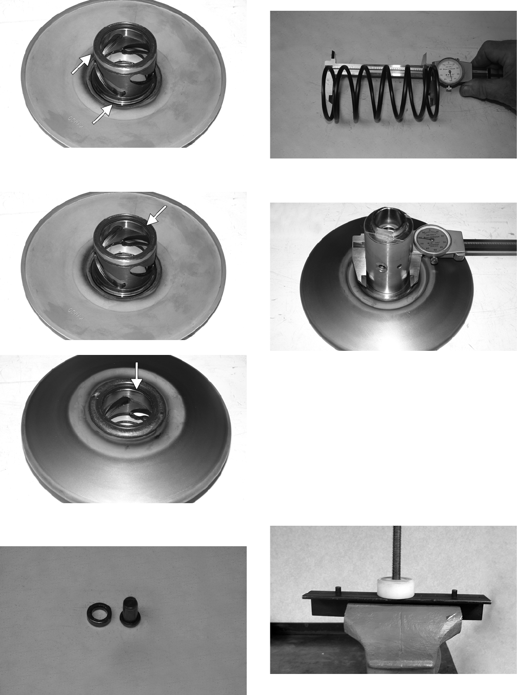
39
2. Inspect the O-rings on the movable face for nicks,
tears, or swelling.
KM380A
3. Inspect two grease seals in the movable face for
nicks, cuts, or damage.
KM380B
KM382A
4. Inspect the pins and bushings for wear, flat spots,
looseness, or cracking.
KM379
5. Measure the driven face spring free length. If the free
length is less than 131 mm, the spring must be
replaced.
KM376
6. Measure the driven fixed face hub using a calipers.
The minimum service limit is 39.93 mm.
KM378
7. Measure the thickness of the centrifugal clutch shoe
lining. The minimum service limit for the lining is
0.5 mm.
NOTE: If any shoe lining is below the service limit,
the complete set must be replaced.
Assembling
1. Place the fixed face of the driven pulley on the pulley
compressor base.
NOTE: Make sure the spacer is on the base or dam-
age to the fixed face will occur when the spring is
compressed.
KX571
FOR ARCTIC CAT ATV DISCOUNT PARTS CALL 606-678-9623 OR 606-561-4983
www.mymowerparts.com
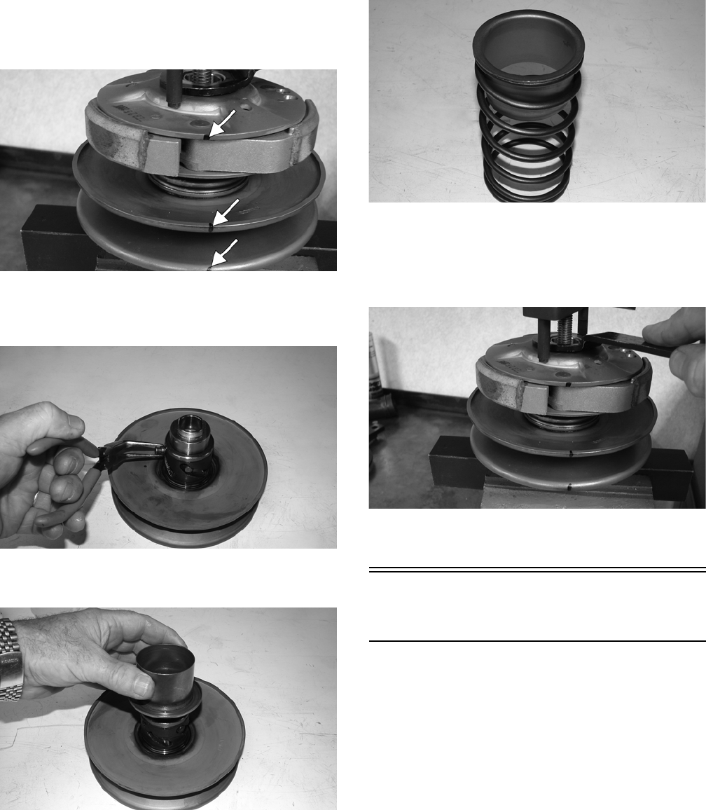
40
2. Apply multi-purpose grease to the O-rings and
grease seals on the movable face; then install on the
fixed face making sure the alignment marks are
properly aligned.
KM374A
3. Install the pins and spacers into the fixed face hub;
then pack the cam slots in the movable face with
multi-purpose grease.
KM384
4. Install the spring seat over the hub and movable face
hub.
KM385
5. Place the spring holder on the spring; then install the
spring on the pulley assembly.
KM386
6. Place the centrifugal clutch assembly, drive plate nut,
and clutch compressor adapter in position; then using
the clutch compressor wing nut, compress the clutch
spring and install the nut (lightly coated with red
Loctite #271).
KM373
7. Using a suitable holding fixture, tighten the drive
plate nut (coated with red Loctite #271) to 43 ft-lb.
Installing Left-Side
Components
A. Drive Pulley
B. Driven Pulley/Centrifugal Clutch
Assembly
C. V-Belt Cover
1. Install the movable drive face and drive pulley collar
on the crankshaft.
2. Open the faces of the driven pulley; then insert a
suitable wedge between the faces to hold them apart.
3. Place the V-belt around the pulley and push the belt
down between the pulley faces; then install the
driven pulley/centrifugal clutch assembly onto the
driveshaft. Loop the V-belt over the drive pulley col-
lar.
FOR ARCTIC CAT ATV DISCOUNT PARTS CALL 606-678-9623 OR 606-561-4983
www.mymowerparts.com

41
KM262
KM369
4. Place the fixed drive face into position on the crank-
shaft and engage the splines making sure the splines
extend beyond the pulley face hub.
KM263A
5. On the Utility, install the starter ratchet on the crank-
shaft making sure to engage the splines; then secure
with the flange nut and tighten to 68 ft-lb.
KM366
KM365
6. Install the centrifugal clutch housing and clutch collar;
then secure with the flange nut and tighten to 40 ft-lb.
KM253
KM368
7. Install the alignment pins and a new gasket on the
crankcase; then install the V-belt cover and secure
with the cap screws. Tighten securely.
8. On the Utility, install the recoil starter and secure
with the cap screws. Tighten securely.
Right-Side Components
NOTE: For efficiency, it is preferable to remove and
disassemble only those components which need to be
addressed and to service only those components. The
technician should use discretion and sound judgment.
AT THIS POINT
To service center crankcase components only, proceed
to Removing Right-Side Components.
FOR ARCTIC CAT ATV DISCOUNT PARTS CALL 606-678-9623 OR 606-561-4983
www.mymowerparts.com
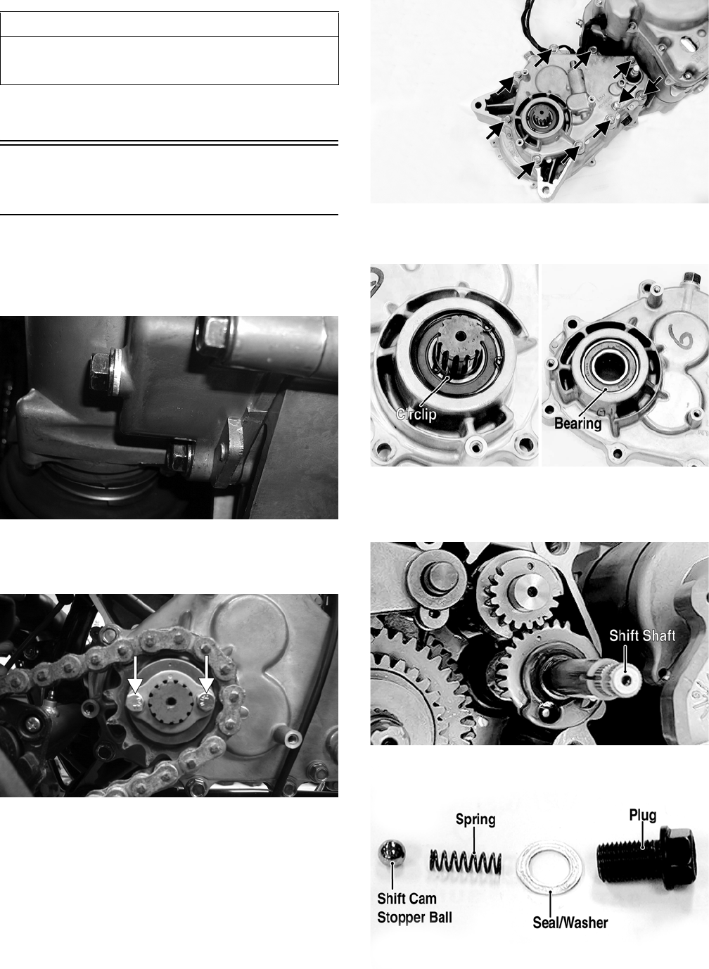
42
NOTE: The engine/transmission does not have to
be removed from the frame for this procedure.
Removing Right-Side
Components
A. Transmission (DVX)
1. Drain the transmission lubricant into a suitable con-
tainer; then install the drain plug and tighten to 21 ft-
lb.
KM106
2. Remove the drive sprocket cover; then remove the
cap screws and lock plate securing the sprocket to
the driveshaft and remove the sprocket.
KM344A
3. Remove the cap screws securing the transmission
case cover to the transmission; then remove the
cover. Account for the dowel pins and gasket.
KM609A
4. Remove the output driveshaft circlip; then remove
the driveshaft from the transmission case cover.
KM611A
5. Remove the shift shaft; then remove the plug.
Account for one shift cam stopper ball, spring, and
seal/washer.
KM677A
KM619A
AT THIS POINT
To service any one specific component, only limited dis-
assembly of components may be necessary. Note the
AT THIS POINT information in each sub-section.
FOR ARCTIC CAT ATV DISCOUNT PARTS CALL 606-678-9623 OR 606-561-4983
www.mymowerparts.com
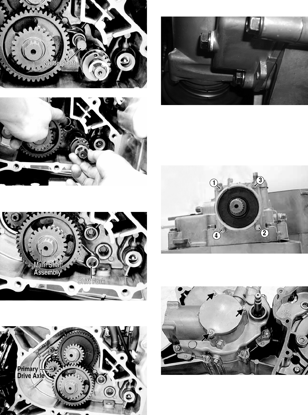
43
6. Remove the shift fork guide shaft; then hold the shift
fork away from the shift cam and remove the shift cam.
KM620A
KM621
7. Remove the shift fork; then remove the main shaft
assembly.
KM622A
8. Remove the countershaft; then remove the primary
drive axle.
KM627B
A. Transmission (Utility)
1. Drain the transmission lubricant into a suitable con-
tainer; then install the drain plug and tighten to 21 ft-
lb.
KM106
NOTE: If the engine has not been removed, remove
the swing arm assembly (see Suspension).
2. Using a crisscross pattern, remove four cap screws
securing the secondary driven bevel gear assembly to
the transmission case cover; then remove the assem-
bly. Account for an O-ring.
KM646A
3. Remove the three cap screws securing the secondary
drive bevel gear cover; then remove the cover.
Account for a gasket.
KM648A
4. Remove the speedometer gear retainer nut, washer,
and speedometer gear.
FOR ARCTIC CAT ATV DISCOUNT PARTS CALL 606-678-9623 OR 606-561-4983
www.mymowerparts.com
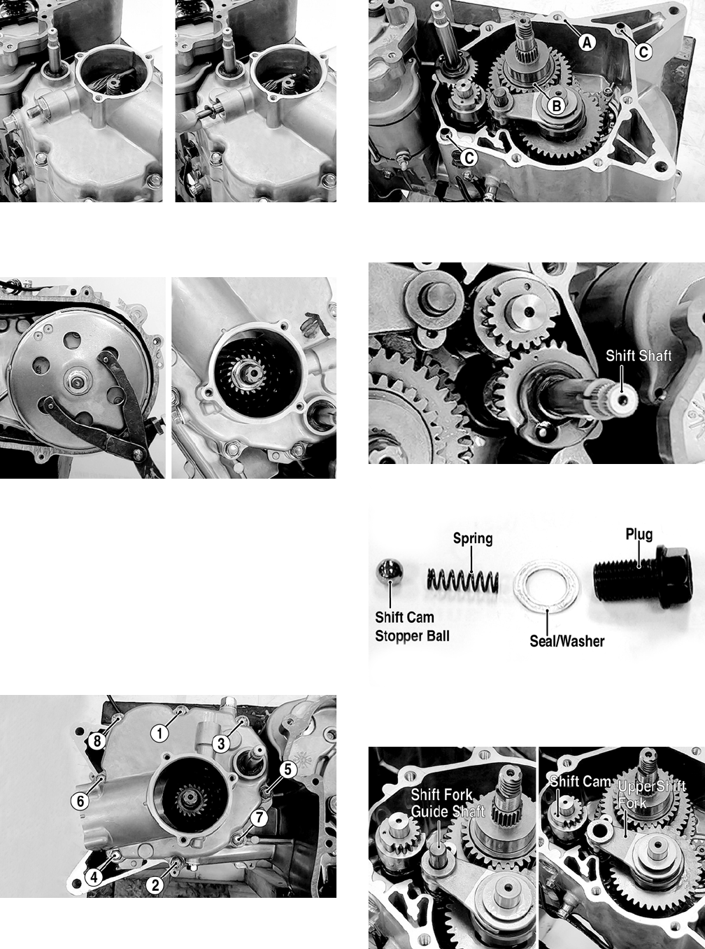
44
KM649
5. Using a Spanner Wrench to hold the centrifugal
clutch housing, remove the nut securing the second-
ary drive bevel gear to the driveshaft.
KM650
NOTE: If the engine has been removed and the left-
side components are removed, install the centrifugal
clutch housing on the driveshaft. If the left-side com-
ponents have not been removed, see Removing Left-
Side Components in this section. Remove only the V-
belt cover.
6. Remove the eight cap screws securing the transmis-
sion case cover to the transmission case; then remove
the cover. Account for a gasket (A), the secondary
drive bevel gear, washer (B), and two alignment pins
(C).
KM651A
KM652A
7. Remove the shift shaft; then remove plug, seal/
washer, spring, and shift cam stopper ball.
KM677A
KM619A
8. Remove the shift fork guide shaft; then remove the
upper shift fork and shift cam.
KM679A
9. Remove the lower shift fork.
FOR ARCTIC CAT ATV DISCOUNT PARTS CALL 606-678-9623 OR 606-561-4983
www.mymowerparts.com
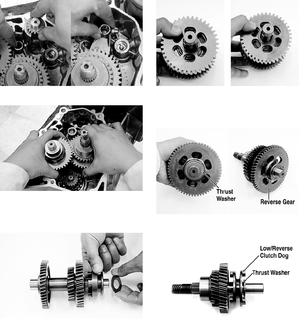
45
KM680
10. Remove the countershaft and driveshaft as an assembly.
KM681
11. To disassemble the countershaft, use the following
procedure.
A. Remove the thrust washer and high gear clutch
dog.
KM684
B. Remove the high drive gear circlip and washer;
then remove the high drive gear and thrust
washer.
KM685
12. To disassemble the driveshaft, use the following pro-
cedure.
A. Remove the thrust washer; then remove the
reverse gear.
KM689A
B. Remove a thrust washer and the low/reverse
clutch dog.
KM690A
C. Remove the low driven gear snap ring and
washer; then remove the low driven gear and
thrust washer.
FOR ARCTIC CAT ATV DISCOUNT PARTS CALL 606-678-9623 OR 606-561-4983
www.mymowerparts.com
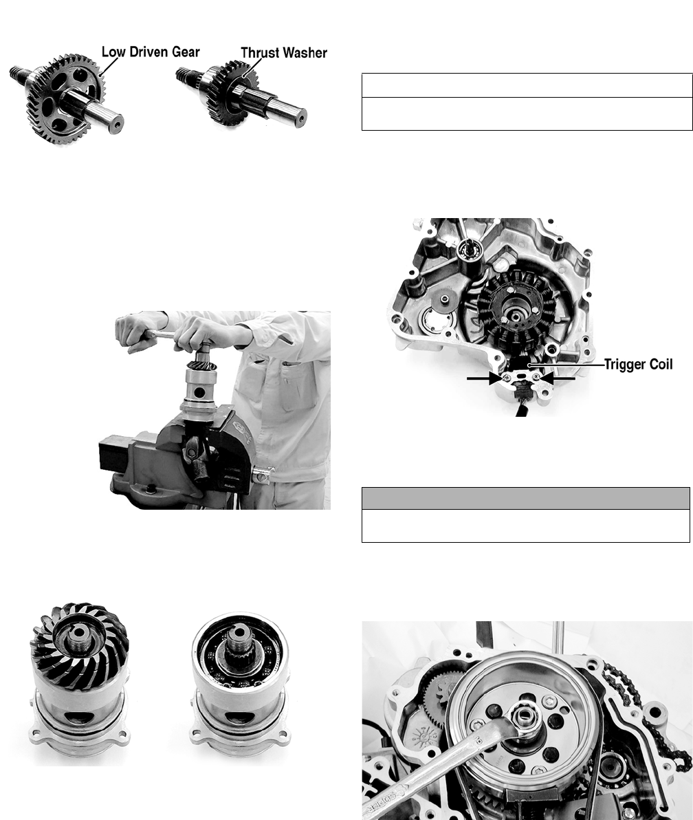
46
KM692A
13. To disassemble the secondary driven bevel gear
assembly, use the following procedure.
A. Secure the universal joint using a suitable vise;
then engage the output end of the shaft with the
universal joint.
KM653
B. Remove the nut securing the driven bevel gear;
then remove the gear. Account for a washer.
KM654
C. Remove the shaft and housing from the universal
joint and remove the shaft from the housing.
NOTE: If left-side components are still attached,
remove the centrifugal clutch/driven pulley (see
Removing Left-Side Components in this section).
B. Water Pump
C. Trigger Coil
D. Stator Coil
E. Rotor/Flywheel
14. Remove the right crankcase cover (see Fuel/Lubrica-
tion/Cooling - Water Pump).
15. Remove the trigger coil mounting screws; then
remove the wire set plate.
KM772A
16. Remove the three cap screws securing the stator coil
to the crankcase cover; then remove the stator coil
and trigger coil.
17. Remove the oil-through and spring from the end of
the crankshaft; then hold the rotor/flywheel with an
appropriate holding tool and remove the flywheel nut
and washer.
KM774
18. Install the flywheel puller and crankshaft protector;
then remove the rotor/flywheel. Account for a key
and the starter one-way clutch bearing.
AT THIS POINT
To remove/service the water pump, see Fuel/Lubrica-
tion/Cooling.
CAUTION
Use extreme care to avoid damaging or shorting the
wiring.
FOR ARCTIC CAT ATV DISCOUNT PARTS CALL 606-678-9623 OR 606-561-4983
www.mymowerparts.com
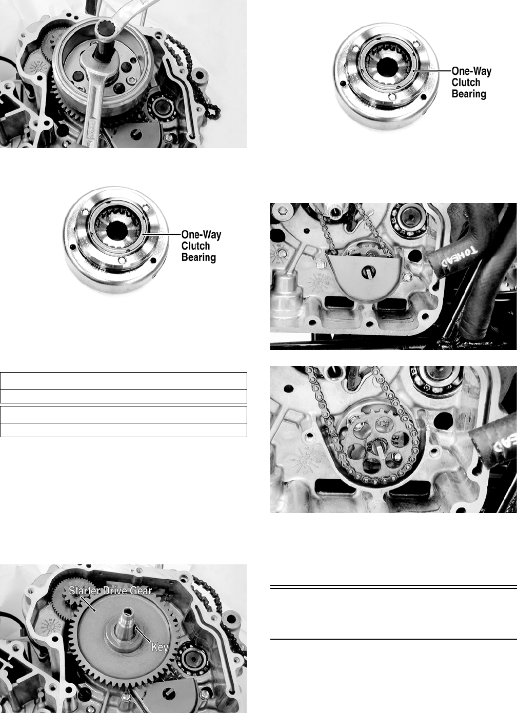
47
KM775
KM766A
NOTE: The starter one-way clutch bearing is direc-
tion oriented and will only function if installed prop-
erly. Note the markings or arrows when removed.
F. Oil Pump
NOTE: Steps 14-18 in the preceding sub-section
must precede this procedure.
19. Remove the rotor/flywheel (see Rotor/Flywheel in
this sub-section).
20. Remove the starter drive gear and place together
with the rotor/flywheel to keep the one-way clutch
bearing intact.
KM767A
KM766A
21. Remove the two cap screws securing the oil baffle to
the crankcase and remove the baffle; then remove the
snap ring securing the oil pump driven sprocket.
KM428
KM429
22. Remove the oil pump drive chain and oil pump
driven sprocket.
23. Remove the two cap screws securing the oil pump to
the crankcase and remove the oil pump.
Servicing Right-Side
Components
NOTE: Whenever a part is worn excessively,
cracked, damaged in any way, or out of tolerance,
replacement is necessary.
AT THIS POINT
To service the stator coil, see Electrical System.
AT THIS POINT
To service the trigger coil, see Electrical System.
FOR ARCTIC CAT ATV DISCOUNT PARTS CALL 606-678-9623 OR 606-561-4983
www.mymowerparts.com

48
TRANSMISSION (DVX)
Inspecting
1. Measure the shift fork guide shaft runout. If runout
exceeds 0.03 mm, the shaft must be replaced.
KM623
2. Inspect the shift forks for distortion, discoloration,
scoring, or excessive wear.
3. Inspect the shift cam groove and shift cam gear for
excessive wear.
KM625
4. Inspect shift shaft and shift shaft gear for excessive
wear.
KM626
5. Inspect all gear teeth for chipping, discoloration, pit-
ting, or excessive wear. Replace as required.
6. Inspect clutch dogs and mating surfaces for chip-
ping, rounding, or excessive wear. Replace as
required.
KM628
7. Inspect all bearings, bushings, seals, and shafts for
proper fit, surface mating, or discoloration. Replace
as required.
8. Inspect transmission housing and cover for cracks,
scoring or galling of bearing bores, or discoloration
of cases.
Assembling
1. Place the thrust washer, needle bearing, reverse gear,
and splined retainer onto the main shaft; then secure
with the circlip.
KM631A
2. Install the clutch dog, splined washer, bushing, and
primary driven gear onto the main shaft; then install
the second splined washer, spacer collar, and thrust
washer. The main shaft is now assembled and can be
installed.
KM629A
FOR ARCTIC CAT ATV DISCOUNT PARTS CALL 606-678-9623 OR 606-561-4983
www.mymowerparts.com
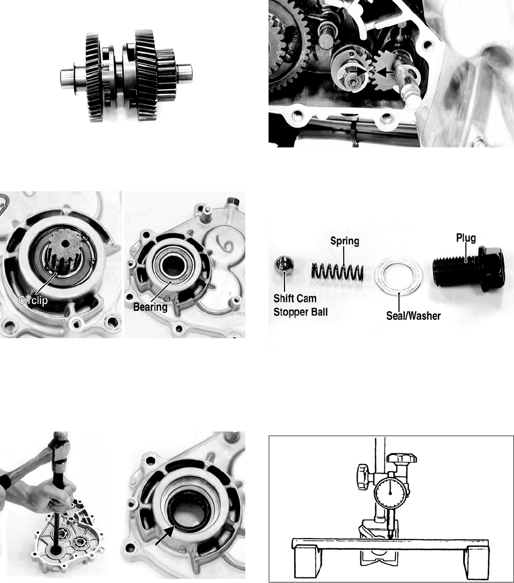
49
KM628
3. Install the drive axle into the transmission housing;
then secure with the circlip.
KM611A
4. Apply multi-purpose grease to the lip of the main
drive seal; then using a suitable driver, install the seal
into the gear case.
5. Install the countershaft; then making sure the main
shaft thrust washer is in place, install the main shaft
assembly into the gear case.
KM613A
6. Install the shift shaft making sure the pin in the gear
position switch engages the slot in the shift shaft and
the shift shaft gear is correctly timed to the shift cam.
KM617A
7. Install the shift cam stopper ball, spring, seal/washer,
and plug (threads coated with red Loctite #271).
Tighten to 35 ft-lb.
KM619A
TRANSMISSION (Utility)
Inspecting
1. Measure the shift fork guide shaft runout. If runout
exceeds 0.03 mm, the shaft must be replaced.
KM623
2. Inspect the shift forks for distortion, discoloration, or
excessive wear.
3. Inspect the shift cam groove and shift cam gear for
excessive wear.
FOR ARCTIC CAT ATV DISCOUNT PARTS CALL 606-678-9623 OR 606-561-4983
www.mymowerparts.com
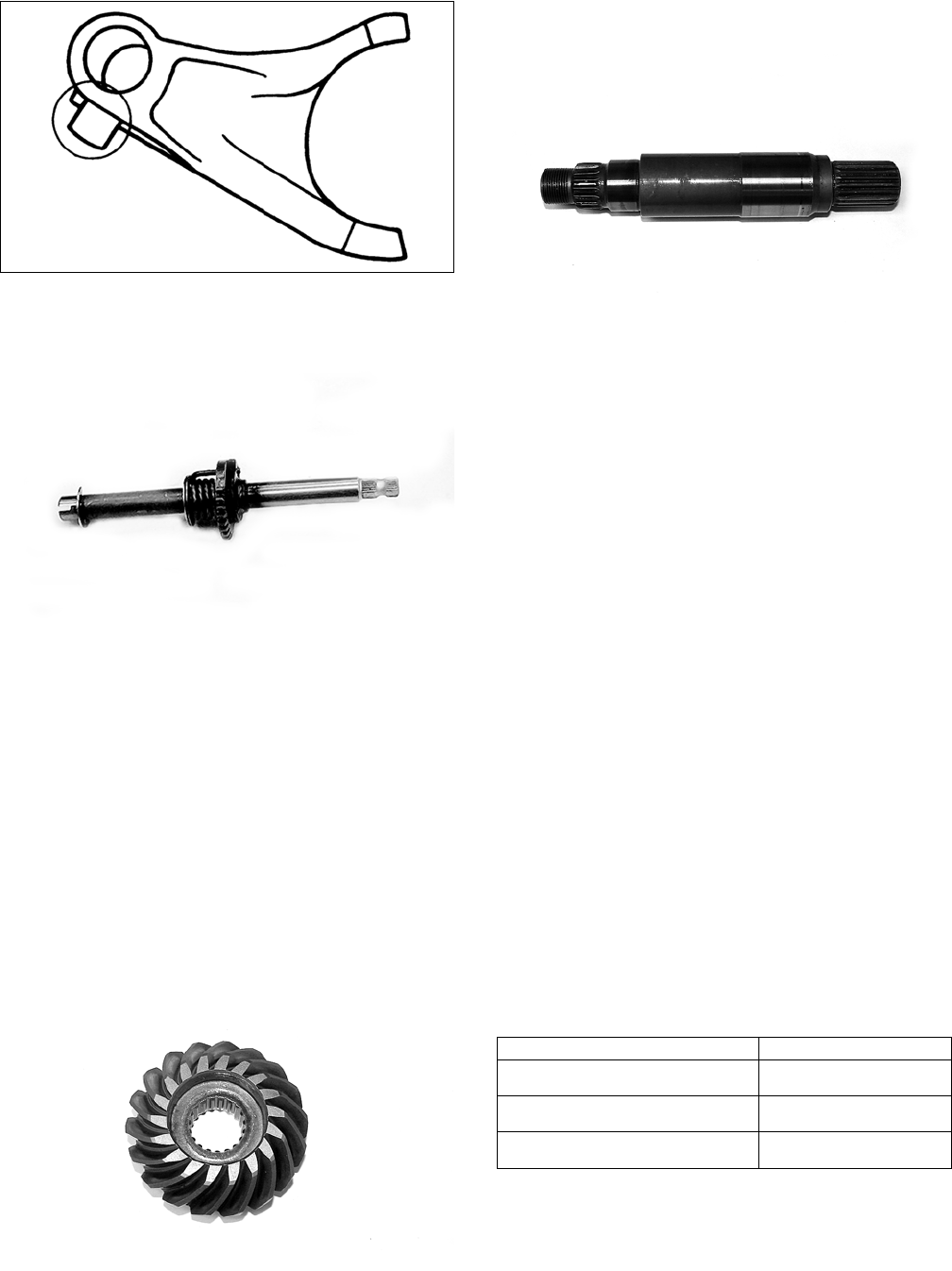
50
KM624
4. Inspect the shift shaft and gear for excessive wear.
Check that the spring is not broken.
KM683
5. Inspect all gear teeth for chipping, discoloration, pit-
ting, or excessive wear. Replace as required.
6. Inspect clutch dogs and mating surfaces for chip-
ping, rounding, or excessive wear. Replace as
required.
7. Inspect all bearings, bushings, seals, and shafts for
proper fit, surface mating, or discoloration. Replace
as required.
8. Inspect transmission housing and cover for cracks,
scoring or galling of bearing bores, or case discolor-
ation.
9. Inspect the drive and driven bevel gears for chipping,
flaking, or excessive wear in the splines. Replace as
required.
KM422
10. Inspect the secondary driven bevel gear housing for
cracks, loose bearings, or signs of discoloration from
heat. Replace as required.
11. Inspect the driven shaft for scoring, discoloration, or
worn splines.
KM421
SECONDARY GEARS
Checking Backlash
1. Remove the secondary drive bevel gear cover.
2. Mount a dial indicator so as to allow the tip to con-
tact the secondary driven bevel gear.
3. Mount the indicator tip of the dial indicator on the
secondary driven bevel gear (centered on the gear
tooth).
4. While rocking the driven bevel gear back and forth,
note the maximum backlash reading on the gauge.
5. Acceptable backlash range is 0.03-0.15 mm (0.001-
0.006 in.).
Correcting Backlash
NOTE: If backlash measurement is within the
acceptable range, no correction is necessary.
1. If backlash measurement is less than specified,
remove an existing driven bevel gear shim, measure
it, and install a new thinner shim.
2. If backlash measurement is more than specified,
remove an existing driven bevel gear shim, measure
it, and install a thicker shim.
NOTE: Continue to remove, measure, and install
until backlash measurement is within tolerance. Note
the following chart.
Checking Tooth Contact
NOTE: After correcting backlash of the secondary
driven bevel gear, it is necessary to check tooth con-
tact.
1. Remove the secondary driven output shaft assembly
from the left-side crankcase half.
Backlash Measurement Shim Correction
Under 0.03 mm (0.001 in.) Decrease Shim
Thickness
At 0.03-0.15 mm
(0.001-0.006 in.)
No Correction Required
Over 0.15 mm (0.006 in.) Increase Shim
Thickness
FOR ARCTIC CAT ATV DISCOUNT PARTS CALL 606-678-9623 OR 606-561-4983
www.mymowerparts.com

51
2. Clean the secondary driven bevel gear teeth of old oil
and grease residue.
3. Apply a thin, even coat of a machinist-layout dye to
several teeth of the gear.
4. Rotate the secondary driven bevel gear several revo-
lutions in both directions.
5. Examine the tooth contact pattern in the dye and
compare the pattern to the illustrations.
ATV-0103
ATV-0105
ATV-0104
Correcting Tooth Contact
NOTE: If tooth contact pattern is comparable to the
correct pattern illustration, no correction is necessary.
If tooth contact pattern is comparable to an incorrect pat-
tern, correct tooth contact according to the following chart.
NOTE: To correct tooth contact, increase or decrease
shims as necessary on both secondary drive and
driven gears equally. Use the “Tooth Contact/Shim
Correction” chart above for shim selections.
Assembling
1. Using the appropriate bearing and seal drivers,
install any required bearings and seals in the trans-
mission case and case cover.
KM696
2. Replace any required bearings and seals in the sec-
ondary driven bevel gear shaft case. Apply oil to all
seal lips.
KM695
3. Apply oil to the secondary driven bevel gear shaft;
then install the bearing into the case.
KM420
Tooth Contact Shim Correction
Contacts at Top Increase Shim Thickness
Contacts at Root Decrease Shim Thickness
CAUTION
After correcting tooth contact, backlash must again be
checked and corrected (if necessary). Continue the cor-
recting backlash/correcting tooth contact procedures
until they are both within tolerance values.
FOR ARCTIC CAT ATV DISCOUNT PARTS CALL 606-678-9623 OR 606-561-4983
www.mymowerparts.com
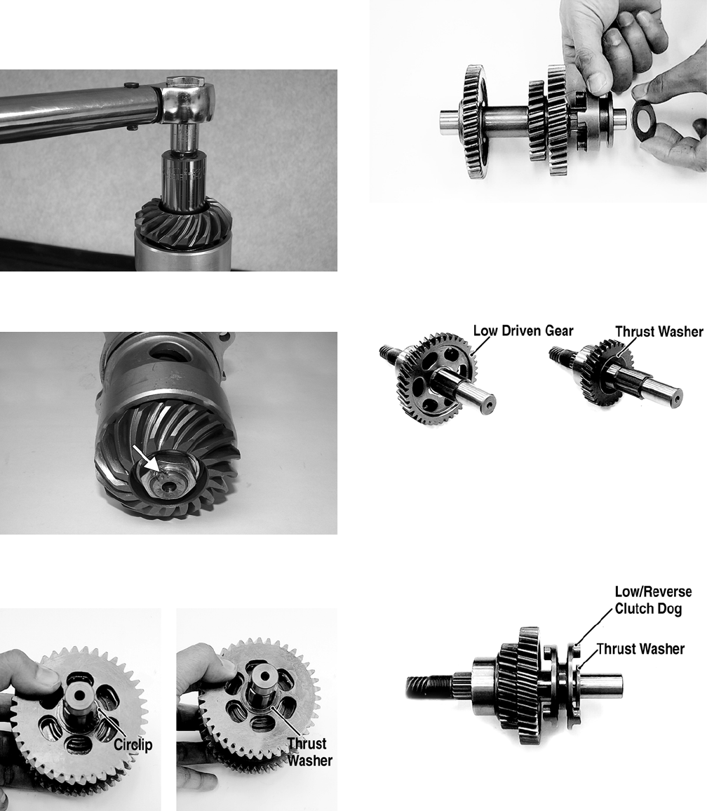
52
4. Install the flat thrust washer and driven bevel gear on
the driven shaft; then using the universal joint and
vise to hold the shaft, install a new nut and tighten to
72 ft-lb.
KM425
5. Use a center punch to stake the nut to the driven
shaft.
KM426A
6. Install the high drive gear thrust washer on the coun-
tershaft; then install the high drive gear and secure
with a circlip.
KM685A
7. Install the high gear clutch dog and flat washer. At
this point, the countershaft is ready for installation.
KM684
8. Install the low driven gear washer on the driveshaft;
then install the low driven gear and thrust washer.
Secure with a snap ring.
KM692A
9. Install the low/reverse clutch dog and spacer washer;
then install the reverse gear and reverse gear thrust
washer. At this point, the driveshaft is ready for
installation.
KM690A
10. Apply clean engine oil to the assembled shafts and
gears; then install the countershaft and driveshaft
simultaneously into the transmission case.
FOR ARCTIC CAT ATV DISCOUNT PARTS CALL 606-678-9623 OR 606-561-4983
www.mymowerparts.com
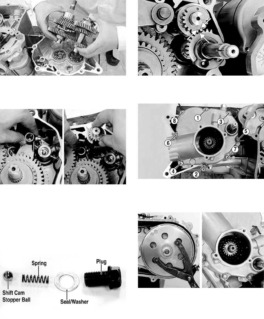
53
KM699
11. Install the low/reverse shift fork into the low/reverse
clutch dog; then install the shift cam into the trans-
mission case and engage the shift fork pawl in the
appropriate shift cam groove.
KM700
12. Install the high shift fork into the high clutch dog;
then engage the shift fork pawl into the appropriate
shift cam groove.
13. Install the shift fork shaft making sure that the shift
fork pawls remain engaged in the shift cam; then
install the shift cam stopper ball, spring, seal/washer,
and plug (threads coated with red Loctite #271).
Tighten to 20 ft-lb.
KM619A
14. Install the shift shaft making sure to align the timing
mark between the two marks on the shift cam.
KM702A
15. Install the two alignment pins, gasket, and transmis-
sion case cover and secure with eight cap screws.
Tighten in a crisscross pattern to 20 ft-lb.
KM651A
16. Install a spacer washer and the drive bevel gear on
the driveshaft; then while holding the centrifugal
clutch housing with an appropriate holder, secure the
bevel gear with a new nut and tighten to 72 ft-lb.
KM650
17. Use a center punch to stake the nut to the driveshaft.
18. Apply clean engine oil to a new O-ring and install in
the groove of the secondary driven bevel gear hous-
ing; then with the index marks aligned, install the
secondary driven bevel gear assembly in the trans-
mission case.
FOR ARCTIC CAT ATV DISCOUNT PARTS CALL 606-678-9623 OR 606-561-4983
www.mymowerparts.com

54
KM673
19. Loosely secure the secondary driven bevel gear
assembly using the four cap screws; then using a
crisscross pattern, tighten the cap screws until fully
seated in the transmission housing.
KM646A
Installing Right-Side
Components
A. Oil Pump
1. Install the oil pump with the arrow on the pump body
directed upward; then secure with the two cap screws
and tighten securely. Make sure the shaft turns freely
after installing.
KM434A
2. Install the oil pump driven sprocket and drive chain;
then secure the driven sprocket with a snap ring.
3. Install the oil pump baffle and tighten the cap screws
securely.
B. Rotor/Flywheel
C. Trigger Coil
D. Stator Coil
4. Install the starter idler shaft and gear in the crank-
case; then install the starter driven gear on the crank-
shaft.
KM767
NOTE: Make sure the crankshaft and rotor/flywheel
contact surfaces are clean and dry before installing
the flywheel.
5. Install the key in the crankshaft; then with the starter
one-way bearing correctly installed, place the rotor/
flywheel onto the crankshaft and position the align-
ing keyway with the key.
6. Secure the rotor/flywheel on the crankshaft with the
nut and tighten to 47 ft-lb; then install the spring and
oil-through in the crankshaft.
KM773A
7. Install the trigger coil and stator coil in the right-side
crankcase cover; then secure with the existing hard-
ware and tighten securely.
E. Water Pump
F. Transmission
See Servicing Right-Side Components in this sub-section.
AT THIS POINT
To install the water pump, see Fuel/Lubrication/Cooling.
FOR ARCTIC CAT ATV DISCOUNT PARTS CALL 606-678-9623 OR 606-561-4983
www.mymowerparts.com
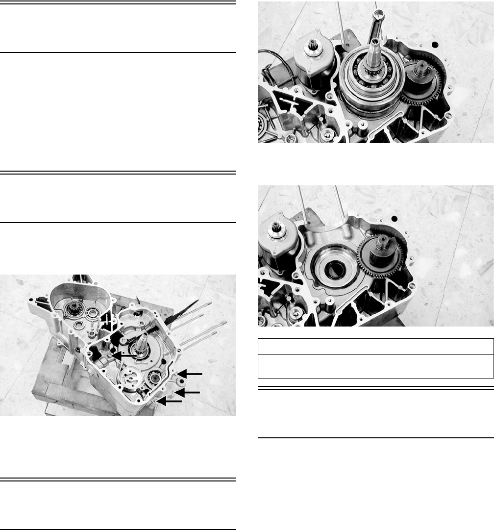
55
Center Crankcase
Components
NOTE: This procedure cannot be done with the
engine/transmission in the frame. Complete Remov-
ing procedures for Top-Side, Left-Side, and Right-
Side must precede this procedure.
NOTE: For efficiency, it is preferable to remove and
disassemble only those components which need to be
addressed and to service only those components. The
technician should use discretion and sound judgment.
Separating Crankcase
Halves
1. Remove the left-side and right-side cap screws
securing the crankcase halves noting the position of
the different-sized cap screws for joining purposes.
KM720A
2. Using Crankcase Separator/Crankshaft Remover and
tapping lightly with a rubber mallet, separate the
crankcase halves. Account for two alignment pins
and a gasket.
Disassembling Crankcase
Half
1. Remove the crankshaft from the left crankcase half.
KM721
2. Remove the balancer shaft from the left crankcase
half.
KM722
Servicing Center
Crankcase Components
NOTE: Whenever a part is worn excessively,
cracked, damaged in any way, or out of tolerance,
replacement is necessary.
CRANKSHAFT ASSEMBLY
Measuring Connecting Rod
(Small End Inside Diameter)
1. Insert a snap gauge into the upper connecting rod
small end bore; then remove the gauge and measure
it with micrometer.
AT THIS POINT
To service crankshaft assembly, see Servicing Center
Crankcase Components sub-section.
FOR ARCTIC CAT ATV DISCOUNT PARTS CALL 606-678-9623 OR 606-561-4983
www.mymowerparts.com

56
CC290D
2. Maximum diameter must not exceed specifications.
Measuring Connecting Rod
(Small End Deflection)
1. Place the crankshaft on a set of V-blocks and mount a
dial indicator and base on the surface plate. Position
the indicator contact point against the center of the
connecting rod small end journal.
2. Zero the indicator and push the small end of the con-
necting rod away from the dial indicator.
3. Maximum deflection must not exceed specifications.
Measuring Connecting Rod
(Big End Side-to-Side)
1. Push the lower end of the connecting rod to one side
of the crankshaft journal.
2. Using a feeler gauge, measure the gap between the
connecting rod and crankshaft journal.
CC289D
3. Acceptable gap range must be within specifications.
Measuring Crankshaft (Runout)
1. Place the crankshaft on a set of V blocks.
2. Mount a dial indicator and base on the surface plate.
Position the indicator contact at point 1 of the crank-
shaft.
ATV-1074
3. Zero the indicator and rotate the crankshaft slowly.
4. Maximum runout must not exceed specifications.
NOTE: Proceed to check runout on the other end of
the crankshaft by positioning the indicator contact at
point 2 and following steps 3-4.
Measuring Crankshaft (Web-to-
Web)
1. Using a calipers, measure the distance from the out-
side edge of one web to the outside edge of the other
web.
ATV-1017
2. Acceptable width range must be within specifica-
tions.
CRANK BALANCER SHAFT
Inspecting
Inspect the gear teeth and bearing surfaces for chips, dis-
coloration, or excessive wear.
CAUTION
Care should be taken to support the connecting rod
when rotating the crankshaft.
FOR ARCTIC CAT ATV DISCOUNT PARTS CALL 606-678-9623 OR 606-561-4983
www.mymowerparts.com

57
KM724
Assembling Crankcase
Half
NOTE: For ease of assembling, install components
on the left-side crankcase half.
To assemble center crankcase components, install the
balancer shaft into the left-side crankcase half; then align
the timing mark on the balancer shaft with the timing
mark on the crankshaft. Install the crankshaft.
KM728A
Joining Crankcase Halves
1. Verify that the alignment pins and a new gasket are
in place and that both case halves are clean and
grease free. Place the right-side half onto the left-
side half.
2. Using a plastic mallet, lightly tap the case halves
together until cap screws can be installed.
3. From the right side, install the crankcase cap screws
noting the location of the different-sized cap screws;
then tighten only until snug.
NOTE: Rotate the crankshaft back and forth to
ensure no binding or sticking occurs while tightening
the cap screws.
MD1008
4. From the left side, install the remaining crankcase
cap screws; then tighten only until snug.
NOTE: Rotate the crankshaft back and forth to
ensure no binding or sticking occurs while tightening
the cap screws.
CC871
5. In a crisscross/case-to-case pattern, tighten the cap
screws until the halves are correctly joined; then
tighten to 8 ft-lb.
NOTE: Rotate the crankshaft back and forth to
ensure no binding or sticking occurs.
Installing Engine/
Transmission
DVX
1. Attach a suitable engine lift to the front engine
mounting boss; then lift the engine/transmission into
the frame from the left side. The front of the engine/
transmission should go in first.
2. Lifting the front of the engine/transmission, move
the assembly forward sufficiently to clear the rear
engine mounts; then slide the engine/transmission
into the rear mounts.
AT THIS POINT
After completing center crankcase components, pro-
ceed to Installing Right-Side Components, to Installing
Left-Side Components, and to Installing Top-Side Com-
ponents.
FOR ARCTIC CAT ATV DISCOUNT PARTS CALL 606-678-9623 OR 606-561-4983
www.mymowerparts.com
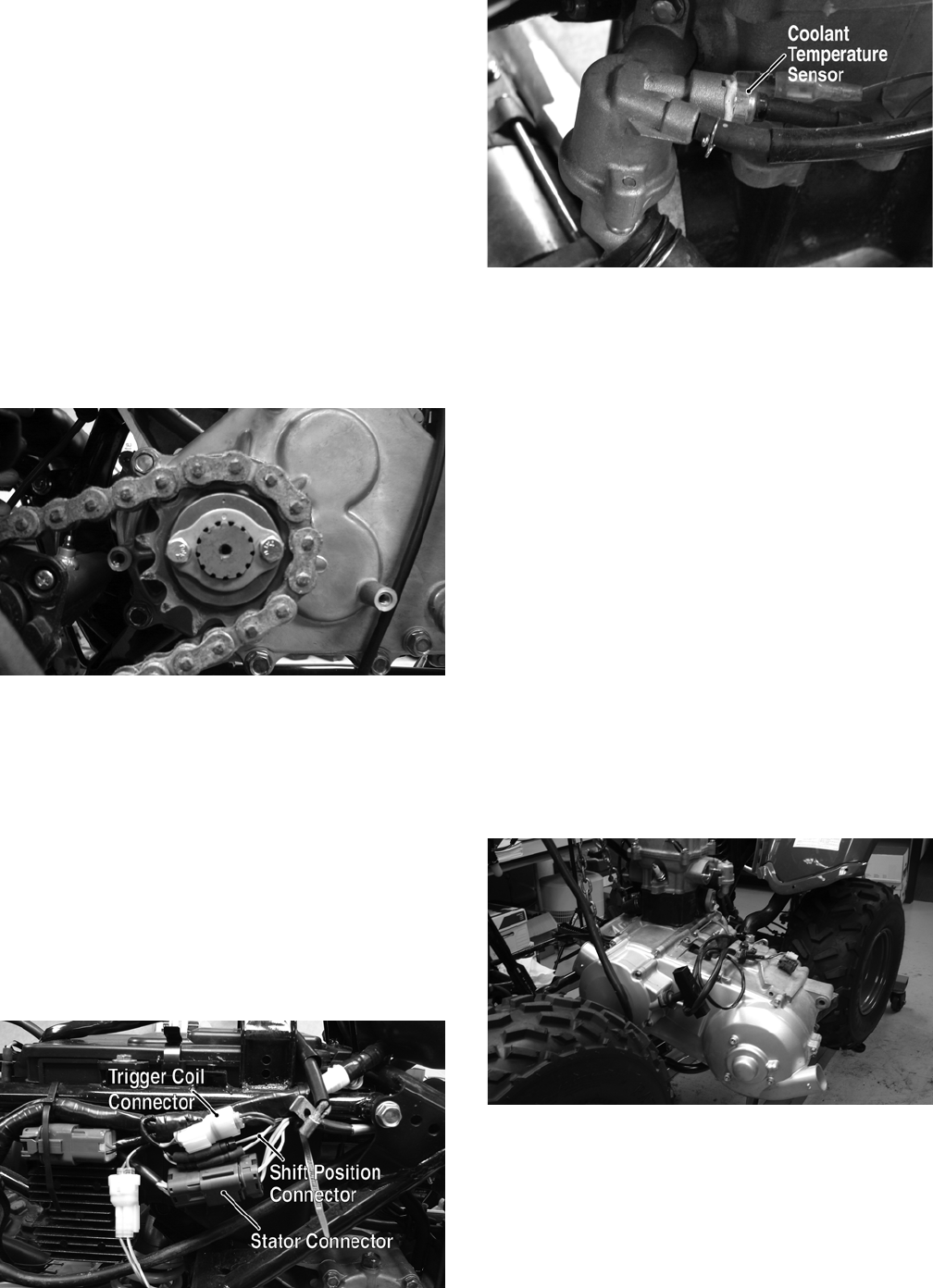
58
3. Lower the engine/transmission and install the lower
rear and upper rear through-bolts and nuts. Finger
tighten only.
4. Remove the engine lift from the front mounting boss;
then install the left and right engine mounting brack-
ets and attach with the existing hardware. Finger
tighten only.
5. Install the front engine through-bolt and nut; then
tighten the engine mounting bracket cap screws to 16
ft-lb.
6. Tighten the engine through-bolt nuts to 29 ft-lb.
7. Connect the shift linkage to the shift arm and tighten
the nut securely.
8. Install the output drive sprocket and drive chain; then
secure with the lock plate and two cap screws.
Tighten to 43 ft-lb and bend the tabs up on the lock
plate.
KM344
9. Install the output drive sprocket cover with the exist-
ing hardware and tighten securely.
10. Connect the upper and lower coolant hoses to the
engine and secure with the clamps. Tighten securely.
11. Connect the front and rear cooling boots to the V-belt
housing and secure with the clamps. Tighten
securely.
12. Connect the starter wire to the starter stud and secure
with a washer and nut. Tighten securely.
13. Connect the stator connector, shift position connec-
tor, and the coolant temperature sensor; then secure
the engine ground cable to the engine and tighten the
cap screw securely.
KM347A
KM324A
14. Install the coil (see Electrical System).
15. Install the carburetor (see Fuel/Lubrication/Cooling).
16. Install the exhaust pipe/muffler assembly (see Steer-
ing/Frame).
17. Install the gas tank (see Fuel/Lubrication/Cooling).
18. Install the air filter housing (see Steering/Frame).
19. Install the body (see Steering/Frame).
20. Install the gas tank cover panel.
21. Install the electrical tray. Install the battery and con-
nect the positive cable; then connect the negative
cable.
22. Pour in the recommended amount and grade of
engine coolant, engine oil, and transmission lubri-
cant.
23. Install the seat.
Utility
1. Attach a suitable engine lift to the front engine
mounting boss; then lift the engine/transmission
assembly into the frame from the left side. The front
of the engine/transmission should go in first.
KM331
2. Lifting the front of the engine/transmission, move
the assembly forward sufficiently to clear the rear
engine mounts; then engage the secondary bevel
driveshaft into the universal joint splines.
FOR ARCTIC CAT ATV DISCOUNT PARTS CALL 606-678-9623 OR 606-561-4983
www.mymowerparts.com
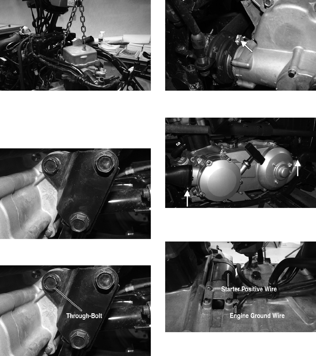
59
KM328
3. Slide the engine/transmission rearward into the rear
engine mounts; then install the rear through-bolts
and nuts. Do not tighten at this time.
4. Remove the engine lift from the front engine mount-
ing boss; then install the engine mounting brackets to
the frame. Finger tighten only.
KM414
5. Install the front engine through-bolt; then tighten the
engine mounting brackets to 16 ft-lb.
KM414A
6. Tighten the nuts on the two rear and one front
through-bolt to 29 ft-lb.
7. Connect the shift linkage using the existing hard-
ware.
8. Install the output drive boot onto the bevel driven
gear housing and secure with the existing clamp.
KM315A
9. Connect the V-belt cooling boots to the V-belt hous-
ing and secure with the existing hose clamps.
KM307A
10. Connect the engine ground wire to the engine; then
connect the starter positive wire to the starter using
the existing hardware. Tighten securely.
KM319A
11. Connect the coolant temperature sensor; then con-
nect the trigger coil connector, shift position connec-
tor, and stator connector.
FOR ARCTIC CAT ATV DISCOUNT PARTS CALL 606-678-9623 OR 606-561-4983
www.mymowerparts.com
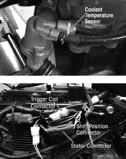
60
KM324A
KM347A
12. Install the coil (see Electrical System).
13. Install the carburetor (see Fuel/Lubrication/Cooling).
14. Install the muffler assembly (see Steering/Frame).
15. Install the gas tank and air filter (see Fuel/Lubrica-
tion/Cooling).
16. Install the fenders and front rack; then install the side
panels (see Steering/Frame).
17. Install the battery; then connect the positive and neg-
ative battery cables.
18. Pour in the recommended amount and grade of
engine coolant, engine oil, and transmission lubri-
cant.
19. Start the engine and allow it to warm up; then check
all fluid levels and add as required.
FOR ARCTIC CAT ATV DISCOUNT PARTS CALL 606-678-9623 OR 606-561-4983
www.mymowerparts.com

61
Troubleshooting
Problem: Engine will not start or is hard to start (Compression too low)
Condition Remedy
1. Valve clearance out of adjustment
2. Valve guides worn - seated poorly
3. Valves mistimed
4. Piston rings worn excessively
5. Cylinder bore worn
6. Spark plug seating poorly
7. Starter motor cranks too slowly - does not turn
1. Adjust clearance
2. Repair - replace guides
3. Adjust valve timing
4. Replace rings
5. Replace cylinder
6. Tighten plug
7. See Electrical System
Problem: Engine will not start or is hard to start (No spark)
Condition Remedy
1. Spark plug fouled
2. Spark plug wet
3. Magneto defective
4. CDI unit defective
5. Ignition coil defective
6. High-tension lead open - shorted
1. Clean - replace plug
2. Clean - dry plug
3. Replace magneto
4. Replace CDI unit
5. Replace ignition coil
6. Replace high tension lead
Problem: Engine will not start or is hard to start (No fuel reaching the carburetor)
Condition Remedy
1. Gas tank vent hose obstructed
2. Carburetor inlet needle defective
3. Fuel hose obstructed
4. Fuel screens obstructed
1. Clean vent hose
2. Replace needle
3. Clean - replace hose
4. Clean - replace inlet screen - valve screen
Problem: Engine stalls easily
Condition Remedy
1. Spark plug fouled
2. Magneto defective
3. CDI unit defective
4. Carburetor jets obstructed
5. Valve clearance out of adjustment
1. Clean plug
2. Replace magneto
3. Replace CDI unit
4. Clean jets
5. Adjust clearance
Problem: Engine noisy (Excessive valve chatter)
Condition Remedy
1. Valve clearance too large
2. Valve spring(s) weak - broken
3. Rocker arm - rocker arm shaft worn
4. Camshaft worn
1. Adjust clearance
2. Replace spring(s)
3. Replace arm - shaft
4. Replace camshaft
Problem: Engine noisy (Noise seems to come from piston)
Condition Remedy
1. Piston - cylinder worn
2. Combustion chamber carbon buildup
3. Piston pin - piston pin bore worn
4. Piston rings - ring groove(s) worn
1. Replace - service piston - cylinder
2. Clean chamber
3. Replace - service pin - bore
4. Replace rings - piston
Problem: Engine noisy (Noise seems to come from timing chain)
Condition Remedy
1. Chain stretched
2. Sprockets worn
3. Tension adjuster malfunctioning
1. Replace chain
2. Replace sprockets
3. Repair - replace adjuster
Problem: Engine noisy (Noise seems to come from crankshaft)
Condition Remedy
1. Bearing worn - burned
2. Lower rod-end bearing worn - burned
3. Connecting rod side clearance too large
1. Replace bearing
2. Replace bearing
3. Replace thrust washer(s)
Problem: Engine noisy (Noise seems to come from transmission)
Condition Remedy
1. Gears worn - rubbing
2. Splines worn
3. Primary gears worn - rubbing
4. Bearings worn
5. Bushing worn
1. Replace gears
2. Replace shaft(s)
3. Replace gears
4. Replace bearings
5. Replace bushing
Problem: Engine noisy (Noise seems to come from secondary-transmission/right-side cover)
Condition Remedy
1. Gears - shaft(s) worn
2. Bearing(s)/bushing(s) damaged
1. Replace gears - shafts
2. Replace bearing(s)/bushing(s)
FOR ARCTIC CAT ATV DISCOUNT PARTS CALL 606-678-9623 OR 606-561-4983
www.mymowerparts.com

62
Problem: Engine noisy (Noise seems to come from secondary bevel gear and final driven shaft)
Condition Remedy
1. Drive - driven bevel gears damaged - worn
2. Backlash excessive
3. Tooth contact improper
4. Bearing damaged
5. Gears worn - rubbing
6. Splines worn
7. Final driven shaft thrust clearance too large
1. Replace gears
2. Adjust backlash
3. Adjust contact
4. Replace bearing
5. Replace gears
6. Replace shaft(s)
7. Replace thrust washer(s)
Problem: Centrifugal clutch slipping
Condition Remedy
1. Clutch shoes worn
2. Clutch housing excessively worn
3. Drive belt slipping - worn
1. Replace shoes
2. Replace clutch housing
3. Replace drive belt
Problem: Secondary-transmission will not shift or shift back
Condition Remedy
1. Sliding dog broken - worn
2. Gearshift fork broken - worn
3. Hi/Low shift lever out of adjustment
4. Gearshift cam worn
5. Cam stopper spring weak
6. Gearshift fork shaft worn
7. Engine idle too high
8. Shift linkage out of adjustment
1. Replace dog
2. Replace fork
3. Adjust lever
4. Replace cam
5. Replace spring
6. Replace shaft
7. Adjust engine idle
8. Adjust shift linkage
Problem: Engine idles poorly
Condition Remedy
1. Valve clearance out of adjustment
2. Valve seating poor
3. Valve guides defective
4. Rocker arms - arm shaft worn
5. Magneto defective
6. CDI unit defective
7. Spark plug fouled - gap too wide
8. Ignition coil defective
9. Float out of adjustment
10. Jets obstructed
11. Pilot screw setting improper
1. Adjust clearance
2. Replace - service seats - valves
3. Replace guides
4. Replace arms - shafts
5. Replace magneto
6. Replace CDI unit
7. Adjust gap - replace plug
8. Replace ignition coil
9. Adjust float height
10. Clean jets
11. Adjust pilot screw
Problem: Engine runs poorly at high speed
Condition Remedy
1. High RPM “cut out” against RPM limiter
2. Valve springs weak
3. Valve timing out of adjustment
4. Cams - rocker arms worn
5. Spark plug gap too narrow
6. Ignition coil defective
7. Float level too low
8. Air cleaner element obstructed
9. Fuel hose obstructed
1. Shift into higher gear - decrease speed
2. Replace springs
3. Adjust timing
4. Replace cams - arms
5. Adjust gap
6. Replace ignition oil
7. Adjust float height
8. Clean element
9. Clean - prime hose
Problem: Exhaust smoke dirty or heavy
Condition Remedy
1. Oil (in the engine) overfilled - contaminated
2. Piston rings - cylinder worn
3. Valve guides worn
4. Cylinder wall scored - scuffed
5. Valve stems worn
6. Stem seals defective
7. Air cleaner element obstructed
8. Float level too high
1. Drain excess oil - replace oil
2. Replace - service rings - cylinder
3. Replace guides
4. Replace - service cylinder
5. Replace valves
6. Replace seals
7. Clean element
8. Adjust float level
Problem: Engine lacks power
Condition Remedy
1. Valve clearance incorrect
2. Valve springs weak
3. Valve timing out of adjustment
4. Piston ring(s) - cylinder worn
5. Valve seating poor
6. Spark plug fouled
7. Rocker arms - shafts worn
8. Spark plug gap incorrect
9. Carburetor jets obstructed
10. Float level out of adjustment
11. Air cleaner element obstructed
12. Oil (in the engine) overfilled - contaminated
13. Intake manifold leaking air
14. Cam chain worn
1. Adjust clearance
2. Replace springs
3. Adjust timing
4. Replace - service rings - cylinder
5. Repair seats
6. Clean - replace plug
7. Replace arms - shafts
8. Adjust gap - replace plug
9. Clean jets
10. Adjust float height
11. Clean element
12. Drain excess oil - change oil
13. Tighten - replace manifold
14. Replace cam chain
FOR ARCTIC CAT ATV DISCOUNT PARTS CALL 606-678-9623 OR 606-561-4983
www.mymowerparts.com

63
Problem: Engine overheats
Condition Remedy
1. Carbon deposit (piston crown) excessive
2. Oil low
3. Octane low - gasoline poor
4. Oil pump defective
5. Oil circuit obstructed
6. Gasoline level (in float chamber) too low
7. Intake manifold leaking air
8. Coolant level low
9. Fan malfunctioning
10. Fan switch malfunctioning
11. Thermostat stuck - closed
12. Radiator hoses - cap damaged - obstructed
1. Clean piston
2. Add oil
3. Drain - replace gasoline
4. Replace pump
5. Clean circuit
6. Adjust float height
7. Tighten - replace manifold
8. Fill - examine system for leaks
9. Check fan fuse - replace fan
10. Replace fan switch
11. Replace thermostat
12. Clear obstruction - replace hoses
FOR ARCTIC CAT ATV DISCOUNT PARTS CALL 606-678-9623 OR 606-561-4983
www.mymowerparts.com
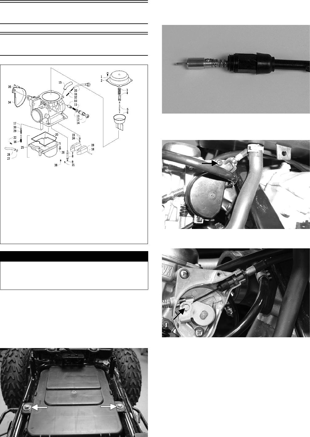
64
Fuel/Lubrication/Cooling
Carburetor
0742-556
REMOVING
1. Remove the seat; then remove the gas tank (see Gas
Tank in this section).
2. Remove the cap screws securing the air filter hous-
ing to the frame; then loosen the clamp securing air
inlet boot to the carburetor and remove the air filter.
KM320A
3. Remove the choke assembly from the carburetor
leaving the choke cable attached to the choke
plunger.
.
KC0018
4. Remove the screw securing the throttle actuator
cover to the carburetor; then remove the cover.
PR154B
5. Remove the throttle cable from the actuator arm.
PR162C
6. Loosen the outer jam nut securing the throttle cable
to the carburetor body; then route the cable out of the
way.
! WARNING
Whenever any maintenance or inspection is performed
on the fuel system during which there may be fuel leak-
age, there should be no welding, smoking, open flames,
etc., in the area.
KEY
1. Screw
2. Top
3. Spring
4. Seat, Spring
5. Jet Needle
6. Vacuum Piston
7. Needle Jet
8. Needle Jet Holder
9. Main Jet
10. Starter Valve
11. Coil Spring
12. Cap
13. O-Ring
14. Cable
15. Tube
16. Pilot Screw
17. O-Ring
18. Float Arm Pin
19. Float
20. O-Ring
21. Slow Jet
22. Drain Screw
23. Float Valve
24. Float Valve Clip
25. Float Chamber
26. Screw
27. Clip
28. Drain Tube
29. Spring
30. Washer
31. Washer
32. Spring
33. Idle Adjust Screw
34. Top Cover
35. Screw
36. Starter Jet
FOR ARCTIC CAT ATV DISCOUNT PARTS CALL 606-678-9623 OR 606-561-4983
www.mymowerparts.com

65
PR162B
7. Disconnect the vent hose; then remove the carbure-
tor.
DISASSEMBLING
1. Remove the four Phillips-head screws securing the
top cover; then remove the cover.
KC0019A
2. Remove the vacuum piston assembly from the carbu-
retor body. Account for a spring, spring seat, and the
jet needle.
KC0021A
3. Remove the Phillips-head screws securing the float
chamber; then remove the chamber. Account for the
O-ring.
KC0022A
KC0063A
4. Remove the float pin.
KC0024A
5. Lift the float assembly from the carburetor. Account
for the float valve.
CC753
NOTE: Note the locations of the jets, pilot screw,
and holder for disassembling procedures.
FOR ARCTIC CAT ATV DISCOUNT PARTS CALL 606-678-9623 OR 606-561-4983
www.mymowerparts.com
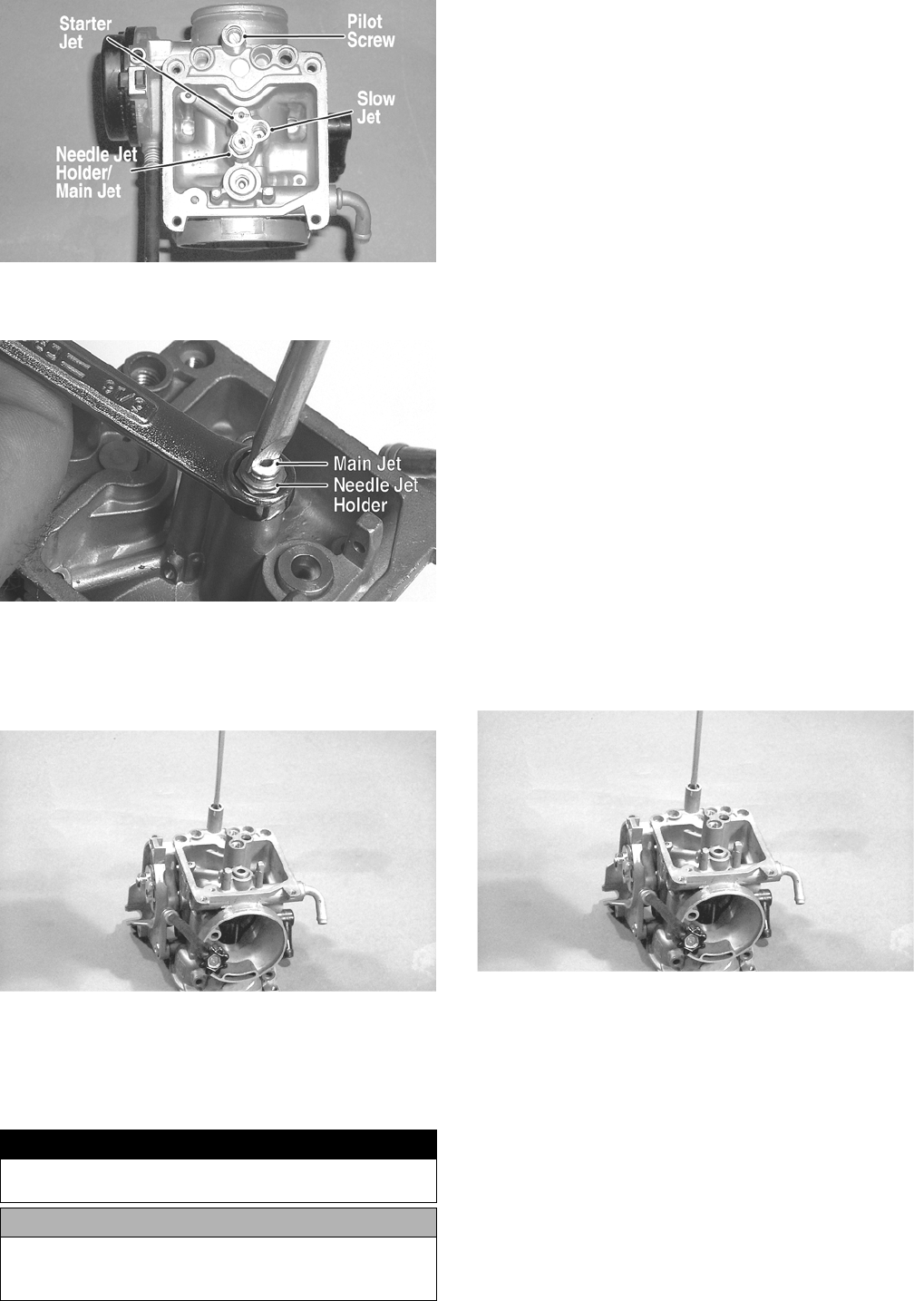
66
CC761A
6. Secure the needle jet holder with a wrench; then
remove the main jet.
KC0030A
7. Remove the needle jet holder; then remove the nee-
dle jet, slow jet, and the starter jet.
8. Remove the pilot screw. Account for a spring,
washer, and an O-ring.
CC758
CLEANING AND INSPECTING
NOTE: Whenever a part is worn excessively,
cracked, or damaged in any way, replacement is nec-
essary.
1. Place all metallic components in a wire basket and
submerge in carburetor cleaner.
2. Soak for 30 minutes; then rinse with clean, hot water.
3. Wash all non-metallic components with soap and
water. Rinse thoroughly.
4. Dry all components with compressed air only mak-
ing sure all holes, orifices, and channels are unob-
structed.
5. Inspect the carburetor body for cracks, nicks,
stripped threads, and any imperfections in the cast-
ing.
6. Inspect the vacuum piston for cracks, imperfections
in the casting, or cracks and tears in the rubber.
7. Inspect float for damage.
8. Inspect gasket and O-rings for distortion, tears, or
noticeable damage.
9. Inspect tips of the jet needle, pilot screw, and the
needle jet for wear, damage, or distortion.
10. Inspect the slow jet and main jet for obstructions or
damage.
NOTE: If the slow jet is obstructed, the mixture will
be extremely lean at idle and part-throttle operation.
11. Inspect the float valve for wear or damage.
12. Inspect the carburetor mounting flange for damage
and tightness.
ASSEMBLING
1. Install the pilot screw, spring, washer, and O-ring.
CC758
NOTE: Turn the pilot screw clockwise until it is
lightly seated; then turn it counterclockwise the rec-
ommended number of turns as an initial setting.
NOTE: Note the locations of the jets and holder dur-
ing assembling procedures.
! WARNING
When drying components with compressed air, always
wear safety glasses.
CAUTION
DO NOT place any non-metallic components in parts-
cleaning solvent because damage or deterioration will
result.
FOR ARCTIC CAT ATV DISCOUNT PARTS CALL 606-678-9623 OR 606-561-4983
www.mymowerparts.com
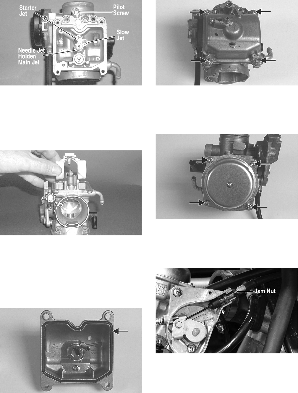
67
CC761A
2. Install the slow jet. Tighten securely.
3. Install the main jet into the needle jet holder and
tighten securely; then install the needle jet, starter jet,
and needle jet holder assembly into the carburetor
and tighten securely.
4. Place the float assembly (with float valve) into posi-
tion and secure to the carburetor with the float pin.
CC753
NOTE: Check float arm height by placing the carbu-
retor on its side w/float contacting the needle; then
measure with a caliper the height when the float arm
is in contact with the needle valve. Float arm height
should be 17 mm.
5. Place the float chamber into position making sure the
O-ring is properly positioned; then secure with the
Phillips-head screws.
KC0063A
KC0022A
6. Place the jet needle, spring seat, and spring into the
vacuum piston; then place the assembly down into
the carburetor.
7. Place the top cover into position; then secure with
the Phillips-head screws. Tighten securely.
KC0019A
INSTALLING
1. Connect the vent hose onto the carburetor.
2. Place the throttle cable into position and secure by
tightening the outer jam nut.
PR162B
3. Connect the throttle cable to the actuator arm.
FOR ARCTIC CAT ATV DISCOUNT PARTS CALL 606-678-9623 OR 606-561-4983
www.mymowerparts.com
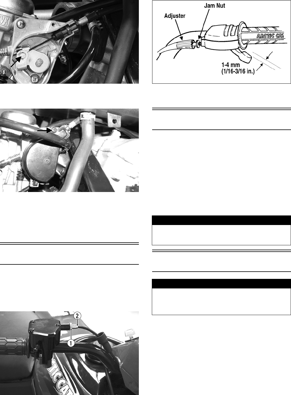
68
PR162C
4. Place the throttle actuator cover into position on the
carburetor; then secure with the screw.
PR154B
5. Connect the choke assembly to the carburetor.
6. Install the air filter; then tighten the clamp securing
the air inlet boot to the carburetor. Secure the air fil-
ter housing to the frame with the cap screws.
7. Install the gas tank; then install the seat.
Throttle Cable Free-Play
To adjust throttle cable free-play, use the following pro-
cedure.
1. Slide the rubber boot away from the adjuster; then
loosen the jam nut (1) from the throttle cable adjuster
(2).
KM111A
2. Turn the adjuster until the throttle cable has proper
free-play of 1-4 mm (1/16-3/16 in.) at the lever.
ATV-0047B
3. Tighten the jam nut against the throttle cable adjuster
securely; then slide the rubber boot over the adjuster.
Engine RPM (Idle)
To properly adjust the idle RPM, a tachometer is neces-
sary. To adjust idle RPM, use the following procedure.
NOTE: The idle adjustment screw is located on the
right side of the carburetor.
1. With the transmission in neutral, start the engine and
warm it up to normal operating temperature.
2. Turn the idle adjustment screw clockwise one turn
past the recommended RPM setting; then turn it
counterclockwise to the correct setting of 1250-1350
RPM.
Gas Tank
REMOVING
1. Turn the gas tank valve to the OFF position.
2. Remove the seat.
3. Disconnect the hose from the carburetor to the gas
tank at the tank connection.
4. Cut the tie-down securing the gas hose to the cables
and hoses.
5. Remove the cap screws securing the gas tank to the
frame.
! WARNING
Adjust the idle to the correct RPM. Make sure the engine
is at normal operating temperature before adjusting the
idle RPM.
! WARNING
Whenever any maintenance or inspection is made on
the fuel system during which there may be fuel leakage,
there should be no welding, smoking, open flames, etc.,
in the area.
FOR ARCTIC CAT ATV DISCOUNT PARTS CALL 606-678-9623 OR 606-561-4983
www.mymowerparts.com
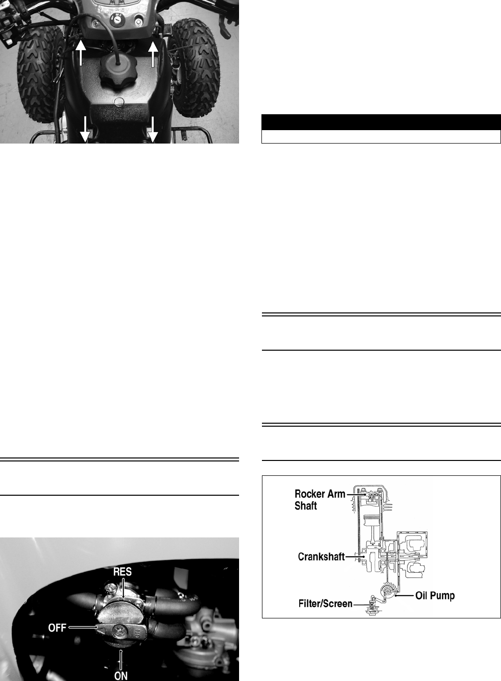
69
KM327A
6. Remove the vent hose; then remove the gas tank.
CLEANING AND INSPECTING
NOTE: Whenever a part is worn excessively, cracked,
or damaged in any way, replacement is necessary.
1. Clean all gas tank components with parts-cleaning
solvent.
2. Inspect all hoses for cracks or leaks.
3. Inspect gas tank valve, tank cap, and tank for leaks,
holes, and damaged threads.
4. Inspect the gas gauge for proper operation.
INSTALLING
1. Place the gas tank into position on the frame; then
install the cap screws. Tighten securely.
2. Connect the gas hose from the carburetor; then
secure hose to cables and hoses with a cable tie.
3. Install the vent hose; then fill the gas tank with gaso-
line.
4. Turn the gas tank valve to the ON position and
inspect for leakage.
5. Install the seat.
Gas Tank Valve
The ATV has a valve attached to the gas tank. There are
three positions: ON, RES, and OFF.
KM043A
In the OFF position, the valve will not allow gasoline to
flow to the carburetor. In the ON position (the normal
operating position), gasoline will flow from the tank to
the carburetor. In this position, 4.54 L (1.2 U.S. gal.) will
remain in the tank as a reserve quantity. Moving the
valve to the RES position will allow the operator to use
the remaining gasoline in the tank. When turning the
valve to any of the three positions, make sure the indica-
tor is pointed directly at the position desired.
REMOVING/INSPECTING
1. Remove the gas hose from the valve by releasing the
clamp.
2. Remove the two machine screws securing the valve;
then remove the valve. Account for the gasket.
3. Inspect the gasket and valve/tank mating surfaces for
damage or deterioration.
4. Inspect for and remove any obstructions in the valve.
INSTALLING
1. Place the valve and gasket into position on the tank
and secure with the machine screws. Tighten securely.
2. Install the gas hose onto the valve with the clamp.
Gas/Vent Hoses
Replace the gas hose every two years. Damage from
aging may not always be visible. Do not bend or obstruct
the routing of the carburetor vent hose. Make sure the
vent hose is securely connected to the carburetor and the
opposite end is always open.
Oil Flow Chart
KM427A
! WARNING
Drain the gas tank prior to this procedure.
FOR ARCTIC CAT ATV DISCOUNT PARTS CALL 606-678-9623 OR 606-561-4983
www.mymowerparts.com
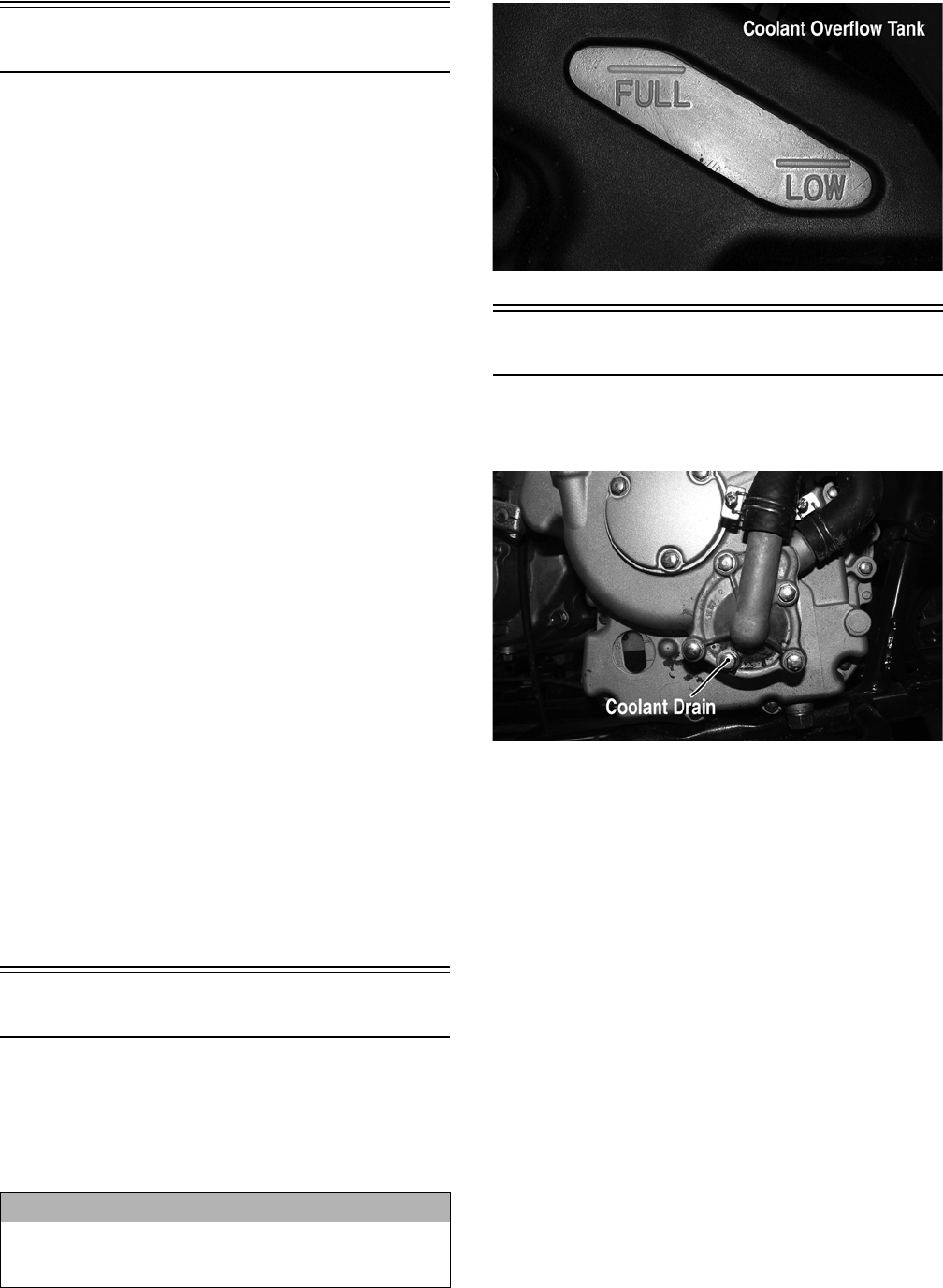
70
Oil Pump
NOTE: Whenever internal engine components wear
excessively or break and whenever oil is contami-
nated, the oil pump should be disassembled,
cleaned, and inspected.
NOTE: The oil pump is not a serviceable compo-
nent. If the pump is defective, the oil pump must be
replaced.
REMOVING/DISASSEMBLING
1. Remove the oil pump from the engine (see Right-
Side Components in Engine/Transmission).
2. Remove the Phillips-head screw on the back side of
the pump and separate the pump housing and cover.
Note the position of the inner and outer rotors and
alignment pin for assembly.
3. Remove oil pump components.
CLEANING AND INSPECTING
NOTE: If any part is worn excessively, cracked, or
damaged in any way, the oil pump must be replaced.
1. Clean all oil pump components.
2. Inspect the rotors for scoring and gouges.
3. Inspect the alignment pin, driveshaft, and driven
sprocket for damage.
4. Inspect the pump housing and cover for cracks or
damage.
ASSEMBLING/INSTALLING
1. Place the rotors into the pump housing making sure
the alignment pin is in the groove of the rotor.
2. Place the cover onto the pump housing.
3. Secure the pump with the Phillips-head screw coated
with red Loctite #271.
4. Install the oil pump into the engine (see Right-Side
Components in Engine/Transmission).
Liquid Cooling System
When filling the cooling system, use pre-mixed Arctic
Cat Antifreeze. While the cooling system is being filled,
air pockets may develop; therefore, run the engine for
five minutes after the initial fill, shut the engine off, and
fill the coolant overflow tank under the seat to the FULL
line.
KM136A
Radiator
REMOVING
1. Drain the coolant at the engine.
KM314A
2. On the Utility, remove the front rack; then remove
the front cover and fender assembly (see Steering/
Frame).
3. Remove the upper and lower coolant hoses.
4. Remove the cap screws and nuts securing the radia-
tor to the frame.
5. Disconnect the fan wiring from the main wiring har-
ness; then remove the radiator/fan assembly and
account for the grommets and collars.
6. Remove the fan/fan shroud assembly from the radiator.
CLEANING AND INSPECTING
NOTE: Whenever a part is worn excessively, cracked,
or damaged in any way, replacement is necessary.
1. Flush the radiator with water to remove any contami-
nants.
2. Inspect the radiator for leaks and damage.
3. Inspect all hoses for cracks and deterioration.
4. Inspect all fasteners and grommets for damage or
wear.
CAUTION
After operating the ATV for the initial 5-10 minutes, stop
the engine, allow the engine to cool down, and check
the coolant level. Add coolant as necessary.
FOR ARCTIC CAT ATV DISCOUNT PARTS CALL 606-678-9623 OR 606-561-4983
www.mymowerparts.com

71
INSTALLING
1. Position the fan/fan shroud assembly on the radiator;
then secure with existing hardware.
2. Place the radiator with grommets and collars into
position on the frame; then install the cap screws and
nuts. Tighten securely.
3. Install the upper and lower coolant hoses; then
secure with hose clamps.
4. On the Utility, install the front cover and fender
assembly; then install the front rack (see Steering/
Frame).
5. Fill the cooling system with the recommended
amount of antifreeze. Check for leakage.
6. Connect the fan wiring to the main wiring harness.
7. Start the engine and run for 3-5 minutes; then check
coolant level in the radiator and in the coolant overflow
tank and add as required to the appropriate levels.
KM339A
KM136A
8. On the Utility, install the cover and rack (see Steering/
Frame).
Hoses/Thermostat
REMOVING
1. Drain approximately one U.S. qt of coolant from the
cooling system.
2. Remove the two machine screws securing the ther-
mostat housing cover to the thermostat housing.
Account for an O-ring and a thermostat.
INSPECTING
NOTE: Whenever a part is worn excessively,
cracked, or damaged in any way, replacement is nec-
essary.
1. Inspect the thermostat for corrosion, wear, or spring
damage.
2. Using the following procedure, inspect the thermo-
stat for proper operation.
A. Suspend the thermostat in a container filled with
water.
B. Heat the water and monitor the temperature with a
thermometer.
C. The thermostat should start to open at 78-82° C
(172-179° F) and should be full-open at 90° C
(194° F).
D. If the thermostat does not open, it must be
replaced.
3. Inspect all coolant hoses, connections, and clamps
for deterioration, cracks, and wear.
NOTE: All coolant hoses and clamps should be
replaced every four years or 4000 miles.
INSTALLING
1. Place the thermostat and O-ring into the thermostat
housing; then secure the thermostat housing cover to
the thermostat housing with the two cap screws.
Tighten securely.
2. Fill the cooling system with the recommended
amount of antifreeze. Check for leakage.
Fan
REMOVING
1. Remove the radiator (see Radiator in this section).
2. Remove the fan assembly from the radiator.
INSTALLING
1. Position the fan assembly on the radiator; then secure
with existing hardware.
2. Install the radiator (see Radiator in this section).
Water Pump
REMOVING/DISASSEMBLING
1. Drain the coolant.
2. Remove the four cap screws securing the water
pump case. Account for the gasket and two align-
ment pins.
3. Remove the impeller, washer, and seal washer.
FOR ARCTIC CAT ATV DISCOUNT PARTS CALL 606-678-9623 OR 606-561-4983
www.mymowerparts.com

72
4. Remove the mechanical seal using the following pro-
cedure.
A. Tap the tip of a small sheet metal screw into the
inner-metal edge of the seal.
B. Grip the screw with a pair of vise-grip pliers and
pull the seal out. Account for the pump drive seal.
CLEANING AND INSPECTING
NOTE: Whenever a part is worn excessively,
cracked, or damaged in any way, replacement is nec-
essary.
1. Clean all pump components in parts-cleaning sol-
vent.
2. Inspect the mechanical seal and pump drive seal for
damage.
NOTE: If the mechanical seal and/or pump drive
seal are damaged, they must be replaced as a set.
3. Inspect the impeller for corrosion or damage.
ASSEMBLING/INSTALLING
NOTE: Treat seals and O-rings with clean antifreeze
for initial lubrication.
1. Press the seal washer into the impeller by hand.
2. Install the water pump drive seal; then drive the
mechanical seal into the crankcase cover using an
appropriate seal driver.
3. Install the impeller with seal washer onto the water
pump shaft and tighten securely.
4. Place the water pump case into position and secure
with the four cap screws.
5. Fill the cooling system with the recommended
amount of antifreeze.
NOTE: While the cooling system is being filled, air
pockets may develop; therefore, run the engine for
five minutes after the initial fill, shut the engine off,
and then fill the cooling system.
6. Check the entire cooling system for leakage.
Troubleshooting
Problem: Starting impaired
Condition Remedy
1. Starter jet obstructed
2. Starter jet passage obstructed
3. Starter body - carburetor leaking air
4. Starter valve not operating properly
1. Clean jet
2. Clean passage
3. Tighten - adjust - replace gasket
4. Check - adjust valve
Problem: Idling or low speed impaired
Condition Remedy
1. Slow jet obstructed - loose
2. Slow jet outlet obstructed
3. Low speed fuel screw setting incorrect
4. Starter valve not fully closed
5. Float height incorrect
1. Clean - tighten jet
2. Clean outlet
3. Adjust screw
4. Adjust valve
5. Adjust float height
Problem: Medium or high speed impaired
Condition Remedy
1. High RPM “cut out” against RPM limiter
2. Main jet obstructed
3. Needle jet obstructed
4. Throttle vacuum piston not operating properly
5. Filter obstructed
6. Float height incorrect
7. Starter valve not fully closed
1. Shift into higher gear - decrease RPM speed
2. Clean main jet
3. Clean needle jet
4. Check piston operation
5. Clean filter
6. Adjust float height
7. Adjust valve
Problem: Overflow and fuel level fluctuations
Condition Remedy
1. Float valve worn - damaged
2. Float valve spring broken
3. Float not working properly
4. Float valve dirty
5. Float height too high - too low
1. Replace valve
2. Replace spring
3. Adjust float height - replace float
4. Clean valve
5. Adjust float height
FOR ARCTIC CAT ATV DISCOUNT PARTS CALL 606-678-9623 OR 606-561-4983
www.mymowerparts.com

73
Electrical System
This section has been organized into sub-sections which
show procedures for the complete servicing of the Arctic
Cat ATV electrical system.
SPECIAL TOOLS
A number of special tools must be available to the techni-
cian when performing service procedures in this section.
Refer to the current Special Tools Catalog for the appro-
priate tool description.
NOTE: Special tools are available from the Arctic
Cat Service Parts Department.
RPM Limiter
NOTE: The ATV is equipped with a CDI unit that
retards ignition timing when maximum RPM is
approached. When the RPM limiter is activated, it
could be misinterpreted as a high-speed misfire.
Testing Electrical
Components
All of the electrical tests should be made using the Fluke
Model 77 Multimeter and when testing peak voltage, the
Peak Voltage Reading Adapter must be used. If any other
type of meter is used, readings may vary due to internal
circuitry. When troubleshooting a specific component,
always verify first that the fuse(s) are good, that the
bulb(s) are good, that the connections are clean and tight,
that the battery is fully charged, and that all appropriate
switches are activated.
NOTE: For absolute accuracy, all tests should be
made at room temperature of approximately 68° F.
Electrical Connections
The electrical connections should be checked periodi-
cally for proper function. In case of an electrical failure,
check fuses, connections (for tightness, corrosion, dam-
age), and/or bulbs.
Switches
Each time the ATV is used, switches should be checked
for proper operation. Use the following list for reference.
A. Ignition switch — engine will start.
B. Emergency stop switch — engine will stop.
C. Reverse switch — reverse indicator light will illu-
minate.
D. Hi/Lo switch — headlight high beam or low beam
will illuminate.
E. Brake switches — rear brakelight will illuminate.
Battery
The battery is located under the seat (DVX) or behind the
seat (Utility).
After being in service, batteries require regular cleaning
and recharging in order to deliver peak performance and
maximum service life. The following procedure is rec-
ommended for cleaning and maintaining a sealed battery.
Always read and follow instructions provided with bat-
tery chargers and battery products.
1. Remove the battery hold-down; then disconnect the
battery cables (negative cable first).
2. Remove the battery from the battery compartment;
then thoroughly wash the battery and battery com-
partment with soap and water.
NOTE: If battery posts, cable ends, or the battery
case has a build-up of white/green powder residue,
apply water and baking soda to neutralize acid; then
flush off with warm soapy water.
3. Using a wire brush, clean the battery posts and cable
ends removing all corrosive buildup. Replace dam-
aged cables or cable ends.
4. Using a multimeter, test the battery voltage. The
meter must read at least 12.5 DC Volts for a fully
charged battery.
NOTE: At this point if the meter reads as specified,
the battery may be returned to service (see step 8).
Description p/n
Fluke Model 77 Multimeter 0644-559
MaxiClips 0744-041
Peak Voltage Reading Adapter 0644-307
Tachometer 0644-275
Timing Light 0644-296
! WARNING
Any time service is performed on a battery, the following
must be observed: keep sparks, open flame, cigarettes, or
any other flame away. Always wear safety glasses. Protect
skin and clothing when handling a battery. When servicing
battery in enclosed space, keep the area well-ventilated.
CAUTION
Do not remove seal strip.
! WARNING
Battery acid is harmful if it contacts eyes, skin, or cloth-
ing. Care must be taken whenever handling a battery.
FOR ARCTIC CAT ATV DISCOUNT PARTS CALL 606-678-9623 OR 606-561-4983
www.mymowerparts.com
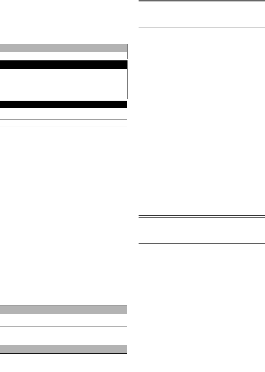
74
5. If the meter reads less than specified voltage, charge
the battery using the following guidelines.
A. When using an automatic battery charger, always
follow the charger manufacturer’s instructions.
B. When using a constant-current battery charger,
use the following Battery Charging Chart.
NOTE: If the battery voltage is 11.5 DC Volts or less,
some chargers may “cut off” and fail to charge. If this
occurs, connect a fully charged booster battery in
parallel (positive to positive and negative to negative)
for a short period of time with the charger connected.
After 10-15 minutes, disconnect the booster battery
leaving the charger connected and the charger
should continue to charge. If the charger “cuts off,”
replace the battery.
6. After charging the battery for the specified time,
remove the battery charger and allow the battery to
sit for 1-2 hours.
7. Connect the multimeter and test the battery voltage.
The meter should read at least 12.5 DC Volts. If the
voltage is as specified, the battery is ready for ser-
vice.
NOTE: If voltage in step 7 is below specifications,
charge the battery an additional 1-5 hours; then
retest.
8. Place the battery in the battery compartment; then
coat the battery posts and cable ends with a light coat
of multi-purpose grease.
9. Connect the battery cables (positive cable first); then
install the battery hold-down.
Brakelight Switch
(Auxiliary)
The switch connector is the two-prong white connector
on the right side of the engine directly above the switch.
NOTE: The ignition switch must be in the ON position.
VOLTAGE (Wiring Harness Side)
1. Set the meter selector to the DC Voltage position.
2. Connect the red tester to the brown/blue wire; then
connect the black tester lead to ground.
3. The meter must show battery voltage.
NOTE: If the meter shows no battery voltage, trou-
bleshoot the battery, fuse, switch, or the main wiring
harness.
NOTE: If the meter shows battery voltage, the main
wiring harness is good; proceed to test the switch/
component, the connector, and the switch wiring har-
ness for resistance.
RESISTANCE (Switch Connector)
1. Set the meter selector to the OHMS position.
2. Connect the red tester lead to the brown/blue wire; then
connect the black tester lead to the green/yellow wire.
3. When the brake pedal is depressed, the meter must
show less than 1 ohm.
NOTE: If the meter shows more than 1 ohm of resis-
tance, replace the switch.
Brakelight Switch
(Handlebar Control)
The switch has spade-type connectors which engage the
harness connectors at the switch.
NOTE: The ignition switch must be in the ON position.
VOLTAGE (Wiring Harness
Connector)
1. Set the meter selector to the DC Voltage position.
2. Connect the red tester lead to the brown/blue wire;
then connect the black tester lead to ground.
3. The meter must show battery voltage.
NOTE: If the meter shows no battery voltage, trou-
bleshoot the battery, fuse, switch, or the main wiring
harness.
NOTE: If the meter shows battery voltage, the main
wiring harness is good; proceed to test the switch/
component, the connector, and the switch wiring har-
ness for resistance.
CAUTION
Never exceed the standard charging rate.
! WARNING
An overheated battery could explode causing severe
injury or death. Always monitor charging times and
charge rates carefully. Stop charging if the battery
becomes very warm to the touch. Allow it to cool before
resuming charging.
Battery Charging Chart (Constant-Current Charger)
Battery Voltage
(DC)
Charge
State
Charge Time Required
(at 1.5-2.0 Amps)
12.5 or more 100% None
12.2-12.4 75%-99% 3-6 hours
12.0-12.2 50%-74% 5-11 hours
11.0-11.9 25%-49% 13 hours (minimum)
11.5 or less 0-24% 20 hours (minimum)
CAUTION
Before installing the battery, make sure the ignition
switch is in the OFF position.
CAUTION
Connecting cables in reverse (positive to negative and
negative to positive) can cause serious damage to the
electrical system.
FOR ARCTIC CAT ATV DISCOUNT PARTS CALL 606-678-9623 OR 606-561-4983
www.mymowerparts.com

75
RESISTANCE (Switch)
NOTE: The brake lever must be compressed for this
test. Also, the ignition switch must be in the OFF
position.
1. Set the meter selector to the OHMS position.
2. Connect the red tester lead to one spade terminal;
then connect the black tester lead to the other spade
terminal.
3. When the lever is compressed, the meter must show
less than 1 ohm.
NOTE: If the meter shows more than 1 ohm of resis-
tance, replace the switch.
Coolant Temperature and
Cooling Fan Switches
1. Connect the meter leads (selector in the OHMS posi-
tion) to the switch contacts.
2. Suspend the switch and a thermometer in a container
of cooking oil; then heat the oil.
NOTE: Neither the switch nor the thermometer
should be allowed to touch the bottom of the con-
tainer or inaccurate readings will occur. Use wire
holders to suspend switch and thermometer.
733-554E
3. On the cooling fan switch when the temperature
reaches 86-90° C (187-194° F), the meter should
read a closed circuit. On the coolant temperature sen-
sor when the temperature reaches 120° C (218° F),
the meter should read 16.0 ohms.
4. Allow the oil to cool. On the cooling fan switch
when the temperature is within a range of 80-85° C
(176-185° F), the meter should read an open circuit.
On the coolant temperature sensor, monitor the tem-
perature and resistance as the oil cools. At 100° C
(212° F) the meter should read 27 ohms, at 80° C
(176° F) 52 ohms, and at 50° C (122° F) 154 ohms.
5. If the readings are not as indicated, the switch must
be replaced.
6. Install the switch and tighten securely.
7. Connect the switch leads.
Fan Motor
The fan motor connector is located directly above the
fan. To access the connector on the Utility, the front rack
and front center cover must be removed (see Steering/
Frame).
NOTE: The ignition switch must be in the ON position.
VOLTAGE (Main Harness
Connector to Fan Motor)
1. Set the meter selector to the DC Voltage position.
2. Connect the red tester lead to the brown/blue wire;
then connect the black tester lead to ground.
3. The meter must show battery voltage.
NOTE: If the meter shows no battery voltage, trouble-
shoot the battery, fuse, or the main wiring harness.
NOTE: If the meter shows battery voltage, the main
wiring harness is good. The connector should be
checked for resistance.
RESISTANCE (Fan Motor
Connector)
1. Set the meter selector to the OHMS position.
2. Connect the red tester lead to the blue wire; then con-
nect the black tester lead to the black wire.
3. The meter must show 50-60 ohms.
NOTE: If the meter does not show as specified, trou-
bleshoot or replace the connector or the fan.
NOTE: To determine if the fan motor is good, con-
nect the blue wire from the fan connector to a 12 volt
DC power supply; then connect the black wire from
the fan connector to ground. The fan should operate.
Fuse Block
The fuses are located in a fuse block under the seat.
If there is any type of electrical system failure, always
check the fuses first.
NOTE: To remove a fuse, compress the locking tabs
on either side of the fuse case and lift out.
! WARNING
Care should be taken to keep clear of the fan blades.
FOR ARCTIC CAT ATV DISCOUNT PARTS CALL 606-678-9623 OR 606-561-4983
www.mymowerparts.com
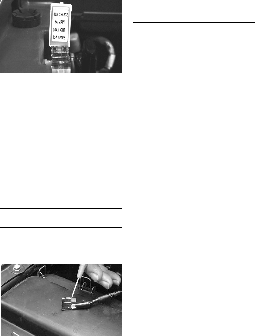
76
KM102
NOTE: The ignition switch must be in the LIGHTS
position.
1. Remove all fuses from the fuse block.
2. Set the meter selector to the DC Voltage position.
3. Connect the black tester lead to ground.
4. Using the red tester lead, contact each end of the 30
amp fuse holder connector terminals individually.
5. The meter must show battery voltage from one side
of the connector terminal ends.
6. Install the 30 amp fuse; then using the red tester lead,
check the remaining two fuse holder connectors as in
step 4.
NOTE: Battery voltage will be indicated from only
one side of the fuse holder connector terminal; the
other side will show no voltage.
NOTE: If the meter shows no battery voltage, trouble-
shoot the battery, fuse block, or the main wiring harness.
Fuses
1. Set the meter selector to the OHMS position.
2. Connect the red tester lead to one spade end of the
fuse; then connect the black tester lead to the other
spade end.
AR610D
3. The meter must show less than 1 ohm resistance. If
the meter reads open, replace the fuse.
NOTE: Make sure the fuses are returned to their
proper position according to amperage. Refer to the
fuse block cover for fuse placement.
Ignition Coil
The ignition coil is on the left side of the frame above the
engine. To access the coil on the Utility, the left side
panel must be removed (see Steering/Frame).
PEAK VOLTAGE (Primary/CDI Side)
NOTE: All of the peak voltage tests should be made
using the Fluke Model 77 Multimeter with Peak Volt-
age Reading Adapter. If any other type of tester is
used, readings may vary due to internal circuitry.
NOTE: The battery must be at full charge for these tests.
NOTE: The ignition switch must be in the ON posi-
tion; the emergency stop switch must be in the RUN
position. Also, the white/blue wire must be discon-
nected from the coil.
1. Set the meter selector to the DC Voltage position.
2. Connect the red tester lead to the black/white wire; then
connect the black tester lead to the green/gray wire.
3. The meter reading must be within specifications.
NOTE: If the voltage is not as specified in the above
test, inspect the main wiring harness, main fuse, igni-
tion fuse, ignition switch, or engine stop switch.
RESISTANCE
NOTE: For these tests, the meter selector must be
set to the OHMS position.
Primary Winding
1. Remove the two spade connectors from the coil; then
connect the red tester lead to either terminal and the
black tester lead to the other terminal.
2. The meter reading must be within specification.
Secondary Winding
1. Connect the red tester lead to the high tension lead
(plug cap removed); then connect the black tester
lead to ground.
2. The meter reading must be within specification.
NOTE: If the meter does not show as specified,
replace ignition coil.
Spark Plug Cap
1. Connect the red tester lead to one end of the cap; then
connect the black tester lead to the other end of the cap.
FOR ARCTIC CAT ATV DISCOUNT PARTS CALL 606-678-9623 OR 606-561-4983
www.mymowerparts.com
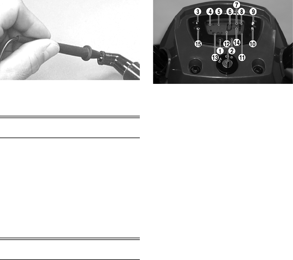
77
AR603D
2. The meter reading must be within specification.
NOTE: If the meter does not read as specified,
replace the spark plug cap.
Indicator Lights (DVX)
To access the indicator lights, use the following proce-
dure.
1. Remove the two cap screws and one reinstallable
rivet securing the instrument pod; then turn the
instrument pod over to access the indicator lights.
2. Remove the light to be tested by pulling the bulb
socket from the light pod; then remove the bulb from
the socket.
NOTE: Bulbs must be checked by switching to a
position where the bulb is illuminated. Power to the
indicator light may be verified by installing a working
light bulb in that position.
LCD Gauge Assembly
REMOVING
To remove the LCD gauge assembly, see Steering/Frame.
TESTING
NOTE: If any functions (segments or displays) are
not normal or do not display as indicated, the LCD
gauge must be replaced.
1. Remove the instrument pod; then disconnect the
speedometer cable. Leave the gauge connected to the
wiring harness.
NOTE: To perform the following tests, two MaxiClips
and one jumper wire will be required.
2. Connect the black MaxiClip to the green/black wire.
3. Connect the red MaxiClip to the light green/red wire;
then connect the jumper between the MaxiClips and
turn the ignition switch to the ON position. The neu-
tral indicator light (9) must illuminate.
KM123D
4. Connect the red MaxiClip to the blue/red wire. The
reverse indicator light (10) must illuminate.
5. Connect the red MaxiClip to the white/red wire. The
low range light (3) must illuminate.
6. Connect the red MaxiClip to the green/blue wire.
The temperature indicator (4) must indicate hot (all
indicator segments visible) and begin flashing. The
thermometer icon will also flash.
7. Connect the red MaxiClip to the yellow/white wire.
The fuel quantity indicator (8) must sequence (one
segment every 8-10 seconds) until the bottom seg-
ment begins flashing. After flashing for 8-10 sec-
onds, the bottom segment will extinguish and the gas
pump icon (7) will begin flashing.
NOTE: There must be sufficient gas in the gas tank to
illuminate at least one fuel quantity indicator segment.
8. Connect the red MaxiClip to the blue wire; then con-
nect a voltmeter to the MaxiClips (red meter lead to
red and black meter lead to black).
9. Set the meter selector to the DC Voltage position;
then turn the ignition switch to the LIGHTS position
and the light control switch to the HI beam position.
The tester must indicate battery voltage and the high
beam indicator light (15) must illuminate. If the tes-
ter does not read battery voltage, troubleshoot the
ignition switch, light control switch, or wiring har-
ness and connectors.
10. Connect the red MaxiClip to the brown/black wire.
The tester must read battery voltage and the speed-
ometer backlight (5) must illuminate. If the tester
does not read battery voltage, troubleshoot the igni-
tion switch or wiring harness connectors.
11. Depress and hold the Mode/Set button (1). The
speedometer should switch between mph and km/h
as indicated by icon (12).
12. Depress and hold the Mode/Set button (2). The dis-
tance mode should shift between ODO and TRIP as
indicated by icon (12).
13. Depress and hold the Mode/Set buttons (1) and (2)
simultaneously. The hour segment of the clock
should flash indicating the clock (13) is in the set
mode. Release the Mode/Set button (2) and release
when the desired hour (1-24) appears.
FOR ARCTIC CAT ATV DISCOUNT PARTS CALL 606-678-9623 OR 606-561-4983
www.mymowerparts.com

78
14. Depress and release the Mode/Set button (1) to shift
the clock set to the minute segment; then depress
Mode/Set button (2) to set the desired minute.
NOTE: In the clock set mode, the gauge will default
to normal operation 10 seconds after the Mode/Set
buttons are released.
15. With the ignition switch in the ON position, use a
small screwdriver or suitable tool to spin the input
quill of the speedometer. The speed indicator (6)
must indicate a value greater than zero.
INSTALLING
To install the LCD gauge assembly, see Steering/Frame.
Ignition Switch
The connector is the white one beneath the front cover.
To access the connector on the Utility, the front rack and
front cover must be removed (see Steering/Frame).
VOLTAGE
NOTE: Perform this test on the lower side of the
connector.
1. Set the meter selector to the DC Voltage position.
2. Connect the red meter lead to the red/white wire;
then connect the black meter lead to ground.
3. The meter must show battery voltage.
NOTE: If the meter shows no battery voltage, trou-
bleshoot the battery, 30 amp fuse, or the main wiring
harness.
RESISTANCE
NOTE: Perform this test on the upper side of the
connector.
1. Turn the ignition switch to the ON position.
2. Set the meter selector to the OHMS position.
3. Connect the red tester lead to the red wire; then con-
nect the black tester lead to the black wire.
4. The meter must show less than 1 ohm.
5. Turn the ignition switch to the LIGHTS position.
6. Connect the red tester lead to the red wire; then con-
nect the black tester lead to the brown wire.
7. The meter must show less than 1 ohm.
NOTE: If the meter shows more than 1 ohm of resis-
tance, replace the switch.
Handlebar Control
Switches
Two white connectors join the handlebar control switch
pigtails to the main harness. To access the connectors on
the Utility, the front rack and front cover must be
removed (see Steering/Frame).
NOTE: These tests should be made on the switch
side of the connectors with the connectors uncoupled.
RESISTANCE (HI Beam)
1. Set the meter selector to the OHMS position.
2. Connect the red tester lead to the blue wire; then con-
nect the black tester lead to the brown/black wire.
3. With the dimmer switch in the HI position, the meter
must show less than 1 ohm.
NOTE: If the meter shows more than 1 ohm of resis-
tance, troubleshoot or replace the switch/component
or the connector.
RESISTANCE (LO Beam)
1. Connect the red tester lead to the white wire; then
connect the black tester lead to the brown/black wire.
2. With the dimmer switch in the LO position, the
meter must show less than 1 ohm.
NOTE: If the meter reads more than 1 ohm of resis-
tance, troubleshoot or replace the switch/component
or the connector.
RESISTANCE (Starter Button)
1. Set the meter selector to the OHMS position.
2. Connect the red tester lead to the black/white wire;
then connect the black tester lead to the yellow/red
wire.
3. With the starter button depressed, the meter must
show less than 1 ohm.
4. With the starter button released, the meter must show
an open circuit.
NOTE: If the meter does not show as specified,
replace the switch/component or connector.
RESISTANCE (Emergency Stop)
1. Set the meter selector to the OHMS position.
2. Connect the red tester lead to the brown/blue wire;
then connect the black tester lead to the black/white
wire.
3. With the switch in the OFF position, the meter must
show an open circuit.
4. With the switch in the RUN position, the meter must
show less than 1 ohm.
NOTE: If the meter shows more than 1 ohm of resis-
tance, troubleshoot or replace the switch/component
or the connector.
FOR ARCTIC CAT ATV DISCOUNT PARTS CALL 606-678-9623 OR 606-561-4983
www.mymowerparts.com

79
RESISTANCE (Reverse Override)
1. Set the meter selector to the OHMS position.
2. Connect the red tester lead to the green/red wire;
then connect the black tester lead to the blue/red
wire. The meter must show an open circuit.
3. Depress and hold the reverse override button. The
meter must show less than 1 ohm of resistance.
NOTE: If the meter does not show as specified,
replace the switch/component or connector.
Magneto Coils
VOLTAGE (Charging Coil - Output)
1. Set the meter selector to the DC Voltage position.
2. Connect the red tester lead to the positive battery
post; then connect the black tester lead to the nega-
tive battery post.
3. With the engine running at a constant 5000 RPM
(with the headlights on), the meter must show 14-
15.5 DC volts.
NOTE: If voltage is lower than specified, test stator
coil - no load.
VOLTAGE (Stator Coil - No Load)
The connector is the black and white one on the right side
of the engine just above the brake cable adjuster.
NOTE: Test the connector that comes from the
engine.
1. Set the meter selector to the AC Voltage position.
2. Test between the three yellow wires for a total of
three tests.
3. With the engine running at the specified RPM, all
wire tests must show as specified.
NOTE: If both voltage tests failed, check all connec-
tions, etc., and test again. If no voltage is present,
replace the stator assembly.
RESISTANCE (Charging Coil)
1. Set the meter selector to OHMS position.
2. Test between the three yellow wires for a total of
three tests.
3. The meter reading must be within specification.
RESISTANCE (Trigger Coil)
1. Set the meter selector to the OHMS position.
2. Connect the red tester lead to the blue/yellow wire;
then connect the black tester lead to the green/white
wire. The meter reading must be within specification.
PEAK VOLTAGE
NOTE: All of the peak voltage tests should be made
using the Fluke Model 77 Multimeter with Peak Volt-
age Reading Adapter. If any other type of tester is
used, readings may vary due to internal circuitry.
NOTE: The battery must be at full charge for these tests.
Stator Coil (Trigger)
1. Set the meter selector to the DC Voltage position.
2. Connect the red tester lead to the blue/yellow wire;
then connect the black tester lead to the green/white
wire.
3. Crank the engine over using the electric starter.
4. The meter reading must be within specification.
Starter Motor
NOTE: The starter motor is not a serviceable com-
ponent. If the starter motor does not operate, see
Starter Relay in this section. If the relay tests normal,
replace the starter motor.
REMOVING/INSTALLING
1. Disconnect the battery.
2. Remove the nut securing the positive cable to the
starter; then remove the cable from the starter.
3. Remove the two cap screws securing the starter to
the crankcase; then remove the starter. Account for
the wiring forms and an O-ring.
4. Install the new starter motor.
Starter Relay
VOLTAGE
1. Set the meter selector to the DC Voltage position.
2. Connect the red tester lead to the battery supply ter-
minal (1); then connect the black lead to the starter
terminal (2).
CAUTION
Do not run the engine at high RPM for more than 10 sec-
onds.
CAUTION
Do not run the engine at high RPM for more than 10 sec-
onds.
CAUTION
Always disconnect the negative battery cable from the
battery first; then disconnect the positive cable.
FOR ARCTIC CAT ATV DISCOUNT PARTS CALL 606-678-9623 OR 606-561-4983
www.mymowerparts.com

80
KM458A
3. Turn the ignition switch to the ON position. The
meter must read battery voltage.
NOTE: If battery voltage is not shown on the meter,
troubleshoot the battery connections, ground con-
nections, and starter cable connections.
4. With the transmission in neutral, depress the starter
button. There should be an audible “click” from the
starter relay and the meter should show 0 DC volts.
If the meter indicates as specified, replace the starter.
If there is no audible click and meter reads battery
voltage, proceed to step 5.
5. Disconnect the two-wire connector on the starter
relay pigtail from the main harness; then on the har-
ness side, connect the red tester lead to the yellow/
red wire and the black tester lead to the yellow/green
wire.
6. With the transmission in neutral, depress the starter
button. The meter must read battery voltage. If bat-
tery voltage is indicated, replace the starter solenoid.
If no voltage is indicated, troubleshoot the gear posi-
tion switch, starter button, ignition switch, or harness
connectors.
CDI Unit
The CDI is located beneath the seat near the battery.
NOTE: The CDI unit is not a serviceable component.
If the unit is defective, it must be replaced.
The CDI is rarely the cause for electrical problems; how-
ever, if the CDI is suspected, substitute another CDI unit
to verify the suspected one is defective.
NOTE: Prior to replacing the CDI unit to assure the
CDI unit is defective, it is advisable to perform a CDI
peak voltage test (see Ignition Coil in this section)
and/or perform a continuity test of the wiring harness
from the CDI connector to the CDI unit.
Regulator/Rectifier
The regulator/rectifier is located on the right side of the
frame. Verify all other charging system components
before the regulator/rectifier is replaced.
TESTING
1. Start the engine and warm up to normal operating
temperature; then connect a multimeter to the battery
as follows.
2. Select the DC Voltage position; then connect the red
tester lead to the positive battery post and the black
tester lead to the negative battery post.
3. Start the engine and slowly increase RPM. The volt-
age should increase with the engine RPM to a maxi-
mum of 15.5 DC volts.
NOTE: If voltage rises above 15.5 DC volts, the reg-
ulator is faulty or a battery connection is loose or cor-
roded. Clean and tighten battery connections or
replace the regulator/rectifier. If voltage does not rise,
check Voltage (Stator Coil - No Load) sub-section. If
charging coil voltage is normal, replace the regulator/
rectifier.
Start-in-Gear Relay
NOTE: The relay schematic is embossed on the
relay housing for testing continuity.
NOTE: The module and wiring harness are not a
serviceable component and must be replaced as an
assembly.
TESTING
The start-in-gear relay is located under the seat below the
fuse block. To test the relay, use the following procedure.
1. Turn the ignition switch to the ON position; then
compress the brake lever or depress the auxiliary
brake pedal. There should be an audible “click” from
the start-in-gear relay.
NOTE: The brakelight should illuminate whenever
either brake is applied. If the brakelight does not illumi-
nate, troubleshoot the respective brakelight switch.
2. Apply the opposite brake from step 1. There should
be an audible “click” from the start-in-gear relay.
3. Disconnect the four-wire connector from the start-in-
gear relay; then using a voltmeter, connect the red
tester lead to the green/yellow wire (1) and the black
tester lead to the green wire (3).
KM460A
FOR ARCTIC CAT ATV DISCOUNT PARTS CALL 606-678-9623 OR 606-561-4983
www.mymowerparts.com

81
4. With the ignition switch in the ON position, select
the DC volts position on the tester; then apply either
brake. The meter must read battery voltage. If battery
voltage is observed and no audible “click” was heard
in step 1 or 2, remove the tester leads and replace the
start-in-gear relay.
5. Shift the gear selector out of neutral and connect a
jumper wire between the yellow/green wire (2) and
the green wire (4).
KM460A
6. Momentarily depress the starter button. The starter
should engage. If the starter engages, replace the
start-in-gear relay. If the starter does not engage,
troubleshoot the battery connections, starter relay, or
starter connections.
Headlights
On the Utility, the connectors are the two 3-prong ones
secured to the front bumper supports (one on each side)
with cable ties.
On the DVX, the connectors are the two 3-prong ones
under the front fender.
BULB VERIFICATION (LO and HI
Beam)
Visually inspect the bulb for broken filaments, blacken-
ing, or loose bulb base.
VOLTAGE
NOTE: Perform this test in turn on the main harness
side of the connectors. Also, the ignition switch must be
in the LIGHTS position and the engine must be running.
1. Set the meter selector to the DC Voltage position.
2. Connect the red tester lead to the green wire; then
connect the black tester lead to the white wire.
3. With the dimmer switch in the LO position (LO
beam), the meter must show battery voltage.
4. Connect the red tester lead to the blue wire. With the
dimmer switch in the HI position (HI beam), the
meter must show battery voltage.
NOTE: If battery voltage is not shown in any test,
inspect the fuses, battery, main wiring harness, con-
nectors, or the left handlebar switch.
Taillight - Brakelight
The connector is the 3-prong one located under the rear
fender assembly.
BULB VERIFICATION
Visually inspect the bulb for broken filaments, blacken-
ing, or loose bulb base.
VOLTAGE (Taillight)
NOTE: Perform this test on the main harness side of
the connector. Also, the ignition switch should be in
the LIGHTS position.
1. Set the meter selector to the DC Voltage position.
2. Connect the red tester lead to the brown/black wire;
then connect the black tester lead to the green wire.
3. With the ignition key in the LIGHTS position, the
meter must show battery voltage.
NOTE: If the meter shows no voltage, inspect fuses,
wiring harness, connectors, and switches.
VOLTAGE (Brakelight)
NOTE: Perform this test on the main harness side of
the connector. Also, the ignition switch should be in
the ON position and the brake (either foot pedal or
hand lever) must be applied.
1. Set the meter selector to the DC Voltage position.
2. Connect the red tester lead to the green/yellow wire;
then connect the black tester lead to the green wire.
3. With either brake applied, the meter must show bat-
tery voltage.
NOTE: If the meter shows no voltage, inspect fuses,
wiring harness, connectors, and switches.
Ignition Timing
The ignition timing cannot be adjusted; however, verify-
ing ignition timing can aid in troubleshooting other com-
ponents. To verify ignition timing, use the following
procedure.
1. Attach the Timing Light to the spark plug high ten-
sion lead; then remove the timing inspection plug
from the left-side crankcase cover.
2. Using the Tachometer, start the engine and run at
1000 RPM; ignition timing should be 5° BTDC (“F”
mark).
3. Install the timing inspection plug.
If ignition timing cannot be verified, the rotor may be
damaged, the key may be sheared, the trigger coil bracket
may be bent or damaged, or the CDI unit may be faulty.
FOR ARCTIC CAT ATV DISCOUNT PARTS CALL 606-678-9623 OR 606-561-4983
www.mymowerparts.com

82
Troubleshooting
Problem: Spark absent or weak
Condition Remedy
1. Ignition coil defective
2. Spark plug defective
3. Magneto defective
4. CDI unit defective
5. Pick-up coil defective
1. Replace ignition coil
2. Replace plug
3. Replace magneto
4. Replace CDI unit
5. Replace pick-up coil
Problem: Spark plug fouled with carbon
Condition Remedy
1. Mixture too rich
2. Idling RPM too high
3. Gasoline incorrect
4. Air cleaner element dirty
5. Spark plug incorrect (too cold)
6. Valve seals cracked - missing
7. Oil rings worn - broken
1. Adjust carburetor
2. Adjust carburetor
3. Change to correct gasoline
4. Clean element
5. Replace plug
6. Replace seals
7. Replace rings
Problem: Spark plug electrodes overheat or burn
Condition Remedy
1. Spark plug incorrect (too hot)
2. Engine overheats
3. Spark plug loose
4. Mixture too lean
1. Replace plug
2. Service cooling system
3. Tighten plug
4. Adjust carburetor
Problem: Magneto does not charge
Condition Remedy
1. Lead wires/connections shorted - loose - open
2. Magneto coils shorted - grounded - open
3. Regulator/rectifier defective
1. Repair - replace - tighten lead wires
2. Replace magneto coils
3. Replace regulator/rectifier
Problem: Magneto charges, but charging rate is below the specification
Condition Remedy
1. Lead wires shorted - open - loose (at terminals)
2. Stator coils (charging) grounded - open
3. Regulator/rectifier defective
4. Cell plates (battery) defective
1. Repair - tighten lead wires
2. Replace stator coils
3. Replace regulator/rectifier
4. Replace battery
Problem: Magneto overcharges
Condition Remedy
1. Internal battery short circuited
2. Regulator/rectifier defective
3. Regulator/rectifier poorly grounded
1. Replace battery
2. Replace regulator/rectifier
3. Clean - tighten ground connection
Problem: Charging unstable
Condition Remedy
1. Lead wire intermittently shorting
2. Magneto internally shorted
3. Regulator/rectifier defective
1. Replace lead wire
2. Replace magneto
3. Replace regulator/rectifier
Problem: Starter button not effective
Condition Remedy
1. Battery charge low
2. Switch contacts defective
3. Starter motor brushes not seating
4. Starter relay defective
5. Emergency stop - ignition switch off
6. Wiring connections loose - disconnected
7. Starter bushings worn
8. Starter armature shorted - open
9. Brake switch defective
1. Recharge - replace battery
2. Replace switch
3. Repair - replace brushes
4. Replace relay
5. Turn on switches
6. Connect - tighten - repair connections
7. Replace starter
8. Replace starter
9. Replace switch
Problem: Battery “sulfation” (Acidic white powdery substance or spots on surfaces of cell plates)
Condition Remedy
1. Charging rate too low - too high
2. Specific gravity too low
3. Battery run-down - damaged
4. Electrolyte contaminated
1. Replace battery
2. Charge battery
3. Replace battery
4. Replace battery
FOR ARCTIC CAT ATV DISCOUNT PARTS CALL 606-678-9623 OR 606-561-4983
www.mymowerparts.com

83
Problem: Battery discharges too rapidly
Condition Remedy
1. Electrolyte contaminated
2. Specific gravity too high
3. Battery short-circuited
4. Specific gravity too low
1. Replace battery
2. Check charging
3. Replace battery
4. Recharge battery
Problem: Battery polarity reversed
Condition Remedy
1. Battery incorrectly connected
2. Electrical system damaged
1. Reverse connections - replace battery
2. Replace damaged components
FOR ARCTIC CAT ATV DISCOUNT PARTS CALL 606-678-9623 OR 606-561-4983
www.mymowerparts.com
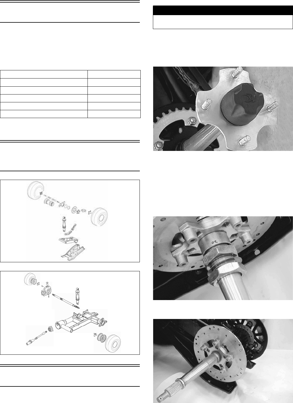
84
Drive System
SPECIAL TOOLS
A number of special tools must be available to the techni-
cian when performing service procedures in this section.
Refer to the current Special Tools Catalog for the appro-
priate tool description.
NOTE: Special tools are available from the Arctic
Cat Service Parts Department.
Rear Drive Assembly
Schematics
KM462
KM463
Rear Drive Axle (DVX)
REMOVING
1. Secure the ATV on a support stand to elevate the rear
wheels.
2. Engage the brake lever lock; then remove the
wheels.
3. Remove the hub caps; then remove and discard the
cotter pins.
KM464
4. Remove the rear wheel hubs; then remove the brake
caliper and lay aside.
NOTE: Do not apply pressure to the brake pedal
with the caliper removed. The brake piston will be
pushed out and brake fluid will be spilled.
5. Remove the two axle nuts (left-hand threads).
Account for one flat washer and a spacer.
KM471
6. Remove the brake disc assembly from the axle.
KM472
Description p/n
Pivot Lock Nut Wrench 0444-201
Rear Axle Nut Wrench 0444-198
Pinion Gear Bearing Nut Wrench 0444-203
Pinion Puller 0444-202
V Blocks 0644-535
DVX
Utility
! WARNING
Make sure the ATV is solidly supported on the support
stand to avoid injury.
FOR ARCTIC CAT ATV DISCOUNT PARTS CALL 606-678-9623 OR 606-561-4983
www.mymowerparts.com
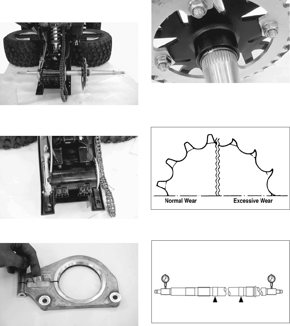
85
7. Loosen the drive chain (see Periodic Maintenance);
then slip the chain off the sprocket and remove the
axle assembly from the right side.
KM476A
8. Remove the cap screw from the rear brake caliper
holder; then remove the snap ring securing the cali-
per holder to the axle housing.
KM481A
9. Remove the brake caliper holder and aligning collar.
Account for the O-ring.
KM483
10. Remove the four cap screws from the rear of the
swing arm assembly; then remove the rear axle hous-
ing from the right side of the swing arm.
11. Remove the snap ring securing the driven sprocket to
the axle; then remove the sprocket.
KM477
CLEANING AND INSPECTING
1. Inspect the sprocket teeth for wear. If they are worn
as shown, replace the engine sprocket, rear sprocket,
and drive chain as a set.
ATV2185
2. Measure the rear axle runout as shown using V
blocks and a dial indicator. If the axle runout exceeds
1.5 mm (0.06 in.), the axle must be replaced.
KM480
3. Inspect the dust seals for wear or damage. If any
defect is found, replace the dust seal.
4. Inspect the axle bearings by rotating them by hand. If
any roughness, binding, or excessive looseness is
found, replace the axle bearings.
NOTE: If the axle bearings are replaced, replace the
dust seals with new ones. Always pack the bearings
with a good quality wheel bearing grease.
FOR ARCTIC CAT ATV DISCOUNT PARTS CALL 606-678-9623 OR 606-561-4983
www.mymowerparts.com
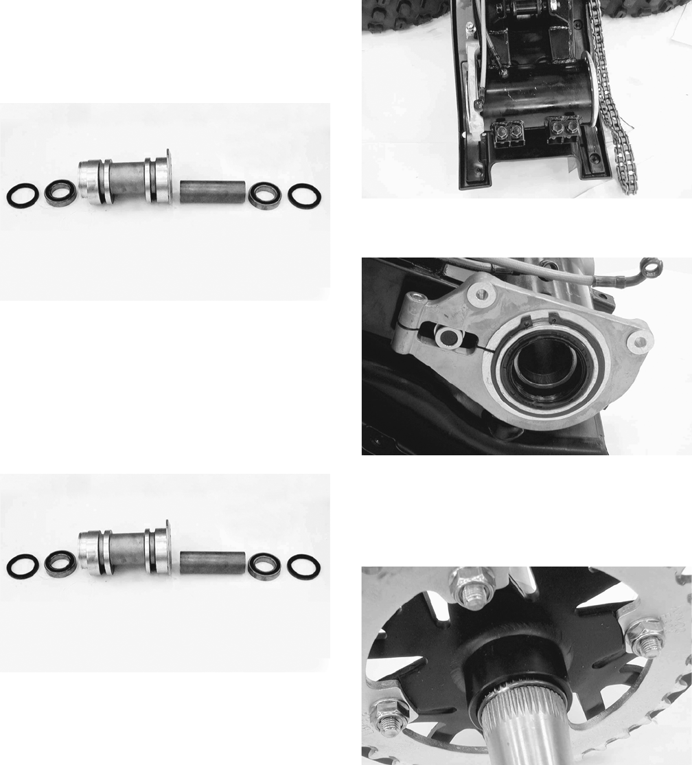
86
Removing Bearings
1. Remove the dust seals using an appropriate seal removal
tool; then using an appropriate driver, drive the bearings
out of the axle housing. Account for one spacer.
NOTE: Do not reuse bearings after removal.
KM486
2. Clean the axle housing and inspect for cracks, elon-
gated holes, and wear in bearing bores.
Installing Bearings
1. Pack the new bearings with a good quality wheel
bearing grease; then install the right bearing first
using an appropriate bearing installer. The sealed
side of the bearing must be directed inward.
2. Install the spacer; then install the left bearing.
KM486
3. Install new dust seals and lightly coat the lips with
grease.
INSTALLING
1. Install the axle housing in the swing arm; then install
and finger-tighten the two cap screws.
KM481A
2. Install the brake caliper holder; then install the cir-
clip and cap screw and finger-tighten only.
.
KM482
3. Slide the axle into the axle housing from the right
side; then apply multipurpose grease to all splined
areas of the axle.
4. Install the sprocket and sprocket hub on the axle and
secure with the snap ring; then install the drive chain.
KM477
5. On the left side, install the brake disc assembly and
spacer; then install the brake caliper and secure with
the two cap screws.
NOTE: To aid in tightening the axle nuts, engage the
brake lever lock.
NOTE: It is necessary to calculate the torque value
using the following formula due to the offset of the
special tool used to tighten the axle nuts.
FOR ARCTIC CAT ATV DISCOUNT PARTS CALL 606-678-9623 OR 606-561-4983
www.mymowerparts.com
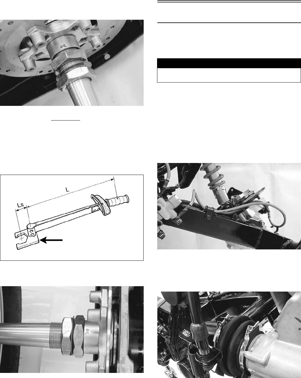
87
6. Coat the axle threads with red Loctite #271 and
install one axle nut (left-hand threads); then using the
Rear Axle Nut Wrench, tighten the inner axle nut to
calculated specification.
KM471
T: Torque wrench reading to be calculated
Ts: Specified torque value (86 ft-lb)
Ls: Tool offset length (center to center)
L: Length of torque wrench (handle pivot to headcenter)
ATV2189
7. Install the washer; then install the outer axle nut and
tighten to calculated specification.
KM470
8. Adjust the drive chain (see Periodic Maintenance/
Tune-Up); then tighten the two cap screws.
9. Install the wheel hubs and tighten the rear wheel hub
nuts to 72 ft-lb; then install the cotter pins and hub caps.
10. Install the rear wheels and tighten to 32 ft-lb.
Rear Drive Axle (Utility)
REMOVING
1. Secure the ATV on a support stand to elevate the rear
wheels.
2. Compress the brake lever and engage the brake lever
lock; then remove the rear wheels and hub caps.
3. Remove the cotter pins and rear hub nuts; then
remove the hubs.
4. Disengage the brake lever lock; then remove the rear
brake calipers and brake disc.
NOTE: Do not apply the brakes with the calipers
removed. The brake pistons will be pushed out and
brake fluid will be spilled.
KM505
5. Remove the rear drive gear case; then drain the gear
case.
6. Loosen the clamp securing the joint boot to the
swing arm; then slip the boot off the swing arm.
KM504
7. Remove the clamp securing the brakeline hose to the
swing arm; then remove the lower rear shock
absorber mounting nut and bolt.
L x Ts = T
L + Ls
! WARNING
Make sure the ATV is solidly supported on the support
stand to avoid injury.
FOR ARCTIC CAT ATV DISCOUNT PARTS CALL 606-678-9623 OR 606-561-4983
www.mymowerparts.com
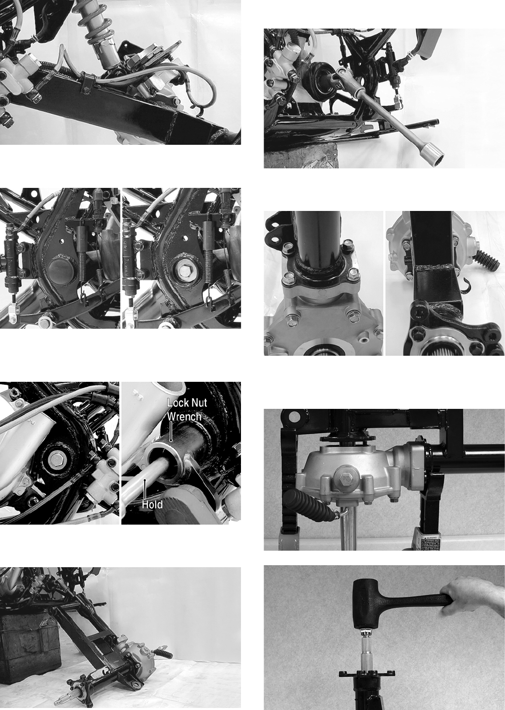
88
KM505
8. Remove the left and right pivot caps; then remove
the right-side pivot bolt.
KM506
9. From the left side, remove the pivot lock nut using
Pivot Lock Nut Wrench; then remove the left pivot
adjusting bolt.
KM533B
10. Remove the swing arm assembly. Account for the
driveshaft spring.
KM508
11. Disengage the universal joint from the transmission
output shaft splines and set the driveshaft aside.
KM509
12. Remove the eight cap screws securing the swing arm
to the final drive gear case.
KM513
13. Support the swing arm from the right side; then using
a rubber mallet, drive the axle shaft from the swing
arm tube. Account for two O-rings.
KM536
KM537
FOR ARCTIC CAT ATV DISCOUNT PARTS CALL 606-678-9623 OR 606-561-4983
www.mymowerparts.com
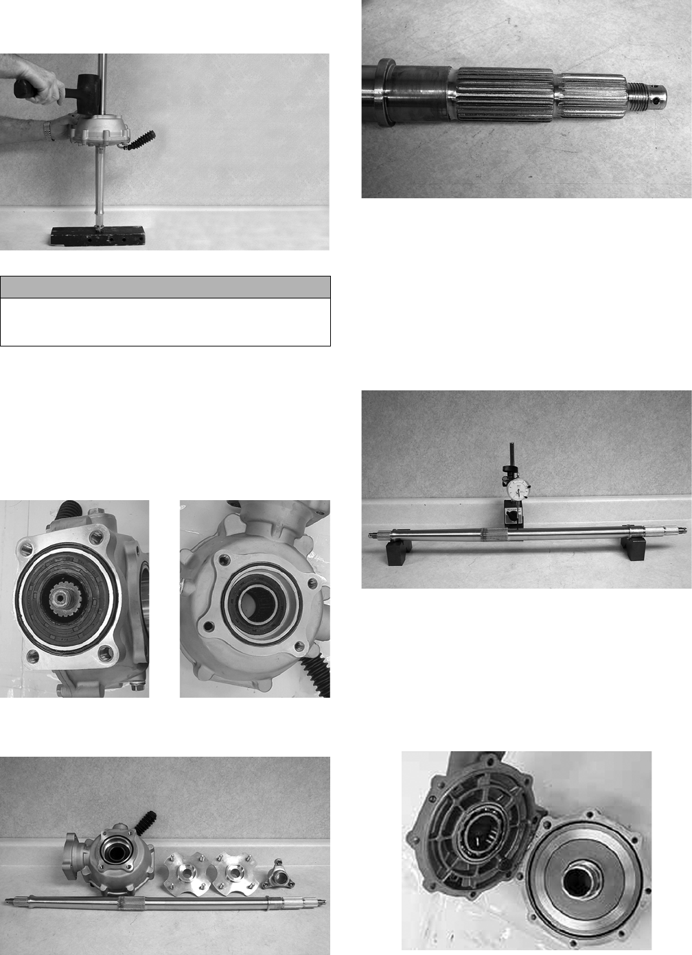
89
14. Place the right end (shorter length) of the axle on a
wood block; then using a rubber mallet, drive the
gear case from the axle.
KM538
CLEANING AND INSPECTING
NOTE: Whenever a part is worn excessively,
cracked, or damaged in any way, replacement is nec-
essary.
1. Clean all parts with parts-cleaning solvent and dry
with compressed air.
2. Inspect all seals for nicks, tears, or deterioration.
KM519
3. Inspect all splines and hubs for excessive wear,
chips, cracks, or distortion.
KM539
KM540
4. Check that all bearings turn freely and smoothly and
are not worn, discolored, or missing dust seals.
5. Inspect brake components for leaks, excessive wear,
or discoloration.
6. Check the axle shaft for runout using a dial indicator
and suitable supports. Maximum runout is 3 mm
(0.12 in.).
NOTE: Axle runout is equal to 1/2 the total dial indi-
cator reading.
KM543
7. Check the final drive gear case assembly for smooth
gear operation. If gears are noisy or if there is any
catching or binding, the gear case assembly must be
repaired.
DISASSEMBLING
1. Remove the cap screws securing the gear case cover
to the gear case; then remove the gear case cover and
right ring gear shim.
KM918
CAUTION
Support the gear case by hand or damage to the gear
case could occur as it will fall free once it clears the
splined portion of the axle.
FOR ARCTIC CAT ATV DISCOUNT PARTS CALL 606-678-9623 OR 606-561-4983
www.mymowerparts.com

90
KM919A
2. Remove the oil seal from the front of the gear case;
then using the Pinion Gear Bearing Nut Wrench,
remove the pinion nut.
KM920A
KM921
3. Remove the pinion shaft using the pinion puller; then
using a three-jaw puller, remove the pinion bearing.
Account for the pinion shim.
KM922
KM923
KM924A
4. Remove the oil seals from the case and cover; then
drive the bearings out of the case.
KM925
KM926
FOR ARCTIC CAT ATV DISCOUNT PARTS CALL 606-678-9623 OR 606-561-4983
www.mymowerparts.com
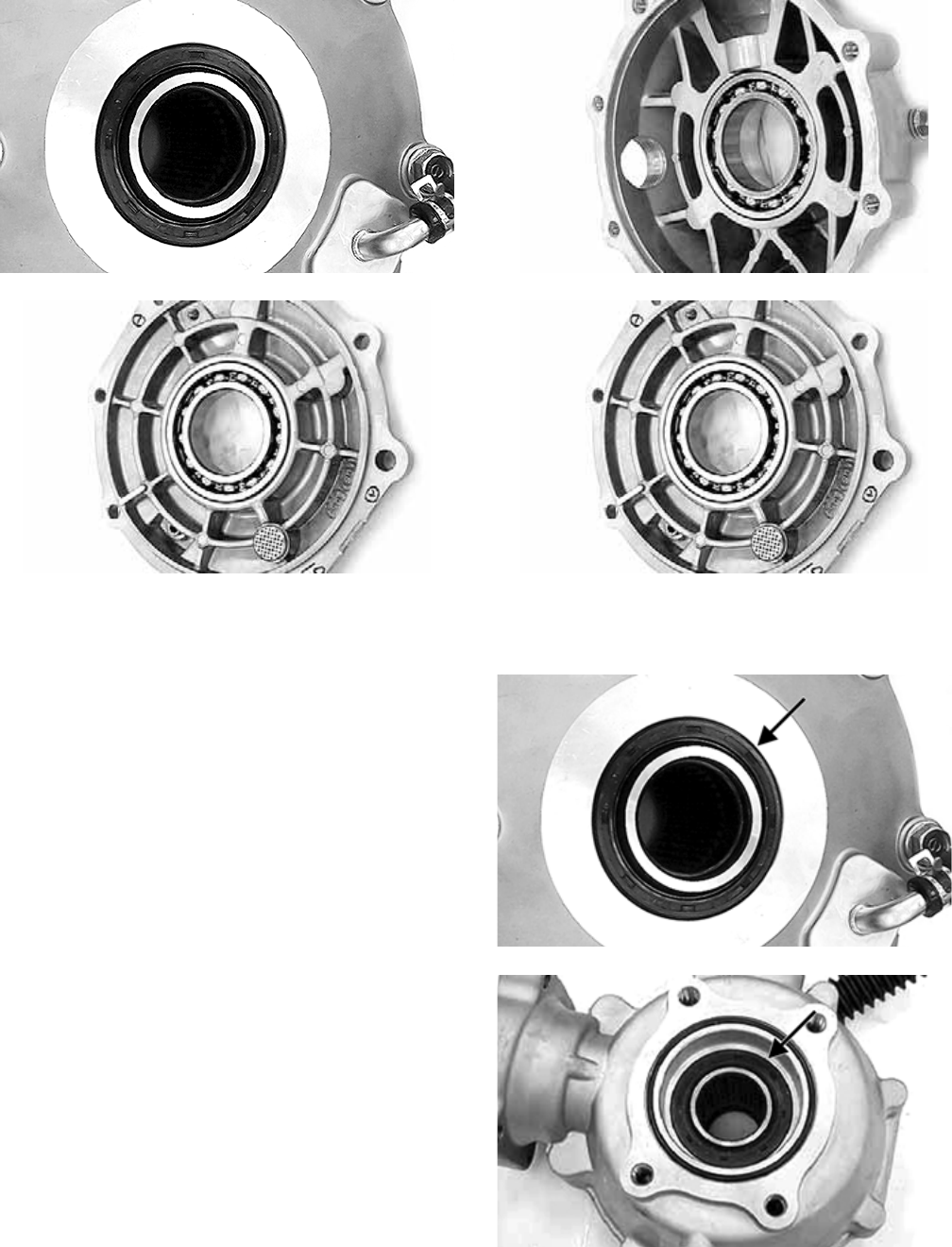
91
KM927
KM928
5. Heat the gear case to approximately 180° F and using
a blind-bushing puller, remove the pinion needle
bearing.
CLEANING AND INSPECTING
1. Clean all components in parts cleaning solvent and
dry with compressed air.
2. Inspect all bearings for excessive wear, discolor-
ation, roughness in turning, or flaking.
3. Inspect gears for excessive wear, chipped teeth, flak-
ing, or discoloration.
4. Inspect the gear case and cover for cracks, warpage,
or scoring of bearing bores.
5. If seals have not been removed and will be reused,
inspect for nicks, tears, missing tension springs, or
excessive wear on lips.
ASSEMBLING
1. Drive the bearings into the gear case and gear case
cover using an appropriate bearing driver. Make sure
the bearing is firmly seated.
KM926
KM928
2. Apply grease to the seal lips; then using a seal driver,
drive the seals into the gear case and cover (flat side
out) until flush with the seal bore.
KM927A
KM925A
3. Drive a new pinion needle bearing into the gear case;
then apply molybdenum disulfide grease to the nee-
dle bearing. Secure with the snap ring.
FOR ARCTIC CAT ATV DISCOUNT PARTS CALL 606-678-9623 OR 606-561-4983
www.mymowerparts.com
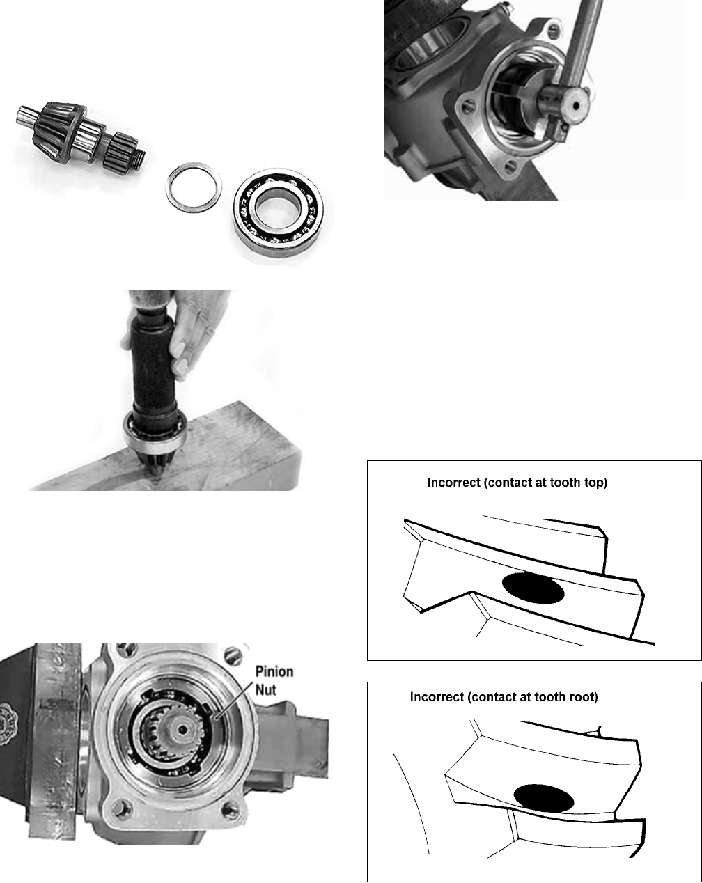
92
4. If the pinion bearing was removed from the pinion,
install the shim and bearing on the pinion shaft with
the marked-side of the bearing directed toward the
front of the pinion shaft.
KM924
KM935
NOTE: When the gear set, ring gear, ring gear bear-
ing, and/or gear case is being replaced, use a 2 mm
(0.08 in.) thick shim for initial set-up.
5. Drive the pinion assembly into the gear case seating
the bearing firmly; then secure with a new lock nut
and using the pinion lock nut wrench, tighten to 72
ft-lb.
KM920A
KM921
6. Apply grease to the pinion seal lips and install into
the gear case until fully seated; then apply a light
coating of machinist’s layout dye or paste to several
ring gear teeth.
7. Install the proper shims on the ring gear and install
into the gear case; then install the case cover and
secure with the case cap screws. Tighten in a criss-
cross pattern while rotating the pinion gear.
Checking Tooth Contact
1. Rotate the ring gear several turns in either direction;
then check gear contact through the oil filler hole.
2. Examine the tooth contact pattern in the dye and
compare the pattern to the illustrations.
ATV-0103
ATV-0105
FOR ARCTIC CAT ATV DISCOUNT PARTS CALL 606-678-9623 OR 606-561-4983
www.mymowerparts.com
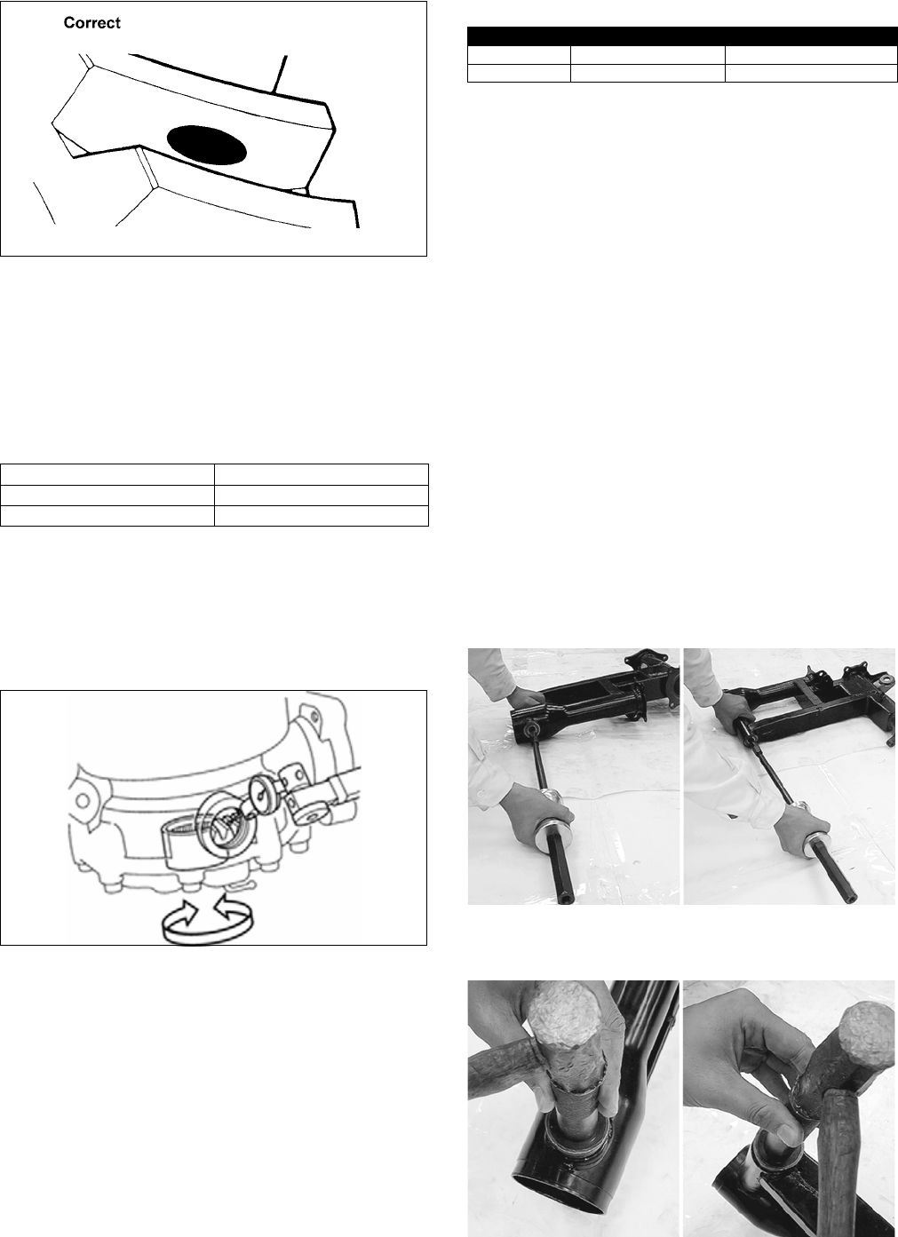
93
ATV-0104
Correcting Tooth Contact
NOTE: If tooth contact pattern is comparable to the
correct pattern illustration, no correction is neces-
sary.
If tooth contact pattern is comparable to an incorrect pat-
tern, correct tooth contact according to the following
chart.
After tooth contact is corrected, gear backlash must be
checked.
Checking Backlash
1. Mount a dial indicator through the oil fill plug to
contact a tooth on the ring gear; then “zero” the dial
indicator.
KM936
2. While locking the pinion shaft to prevent it from
turning, rock the ring gear back and forth and record
the measurement. Standard backlash should be 0.05-
0.25 mm (0.002-0.010 in.). Maximum service limit
is 0.4 mm (0.016 in.).
3. Remove the dial indicator and rotate the ring gear
120°; then repeat steps 1-2.
4. Repeat step 3 for a total of three measurements; then
compare the difference between the three. Maximum
allowable difference is 0.2 mm (0.08 in.).
NOTE: If the difference in measurements exceeds
specifications, the bearings are not installed squarely
or the gear case is warped. If backlash is not within
specifications, correct using the following chart.
NOTE: Always change both shims by the same
amount on opposite sides. If left shim is increased,
right shim must be decreased by the same amount.
5. After backlash is corrected, recheck gear tooth con-
tact. Repeat Correcting Tooth Contact and Checking
Backlash until both are within specifications.
6. When tooth contact and backlash are within specifi-
cation, remove the cap screws securing the cover to
the gear case.
7. Clean any oil from the mating surfaces; then apply
an even coat of silicone sealant to the mating sur-
faces and install the gear case covers.
8. Install six 8 mm and two 10 mm cap screws and
while rotating the pinion gear, tighten in a crisscross
pattern to the specified torque (8 mm cap screws to
19 ft-lb, 10 mm cap screws to 36 ft-lb).
REPLACING SWING ARM SEALS
AND BEARINGS
To replace damaged or worn seals and bearings in the
swing arm assembly, use the following procedure.
1. Remove the dust seals from the swing arm pivot;
then using a slide hammer and bearing puller,
remove the pivot bearings.
KM521
2. Drive in new pivot bearings until fully seated; then
install new dust seals.
KM522
Tooth Contact Shim Correction
Contacts at Top Decrease Shim Thickness
Contacts at Root Increase Shim Thickness
Backlash Ring Gear Left Side Ring Gear Right Side
Insufficient Decrease Shim Increase Shim
Excessive Increase Shim Decrease Shim
FOR ARCTIC CAT ATV DISCOUNT PARTS CALL 606-678-9623 OR 606-561-4983
www.mymowerparts.com
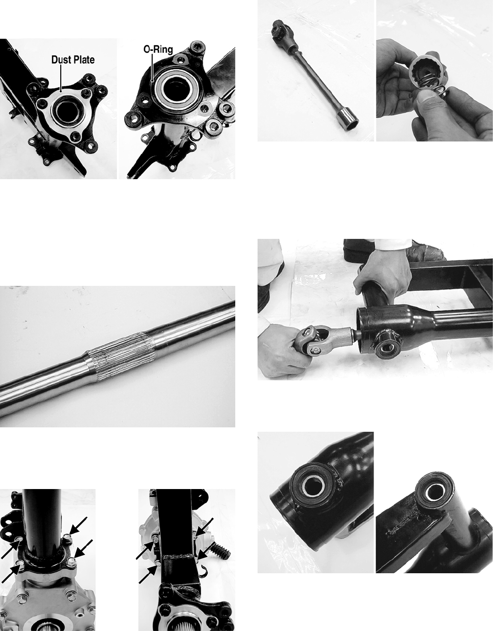
94
3. Remove the three cap screws, the dust plate, and one
O-ring from the left axle housing on the swing arm;
then from the right side, drive out the axle bearing.
KM523A
4. Using a suitable bearing driver, install the new axle
bearing into the axle housing; then install the O-ring
and dust plate. Tighten the three cap screws securely.
INSTALLING
1. Install new O-rings in the grooves of the gear case;
then grease the center splines of the axle and install
in the gear case from the left side.
KM527
2. Install the rear axle and gear case into the right side
of the swing arm; then secure the gear case to the
swing arm assembly with the eight cap screws.
Tighten to 50 ft-lb.
KM528A
3. Apply grease to the universal joint splines and drive-
shaft splines; then install the driveshaft spring into
the driveshaft.
KM529
NOTE: Apply a liberal amount of grease to the drive-
shaft splines and the driveshaft spring. This will aid
in keeping the spring in position while assembling.
4. Insert the driveshaft assembly into the swing arm
tube; then engage the driveshaft splines with the pin-
ion shaft splines in the rear drive gear case.
KM530
5. Pack approximately 3 g (0.1 oz) of grease into each
swing arm pivot bearing cavity; then apply grease to
the lips of the dust seals.
KM531
6. Align the swing arm assembly in the frame and
engage the universal joint onto the splines of the sec-
ondary driven bevel gear shaft.
FOR ARCTIC CAT ATV DISCOUNT PARTS CALL 606-678-9623 OR 606-561-4983
www.mymowerparts.com
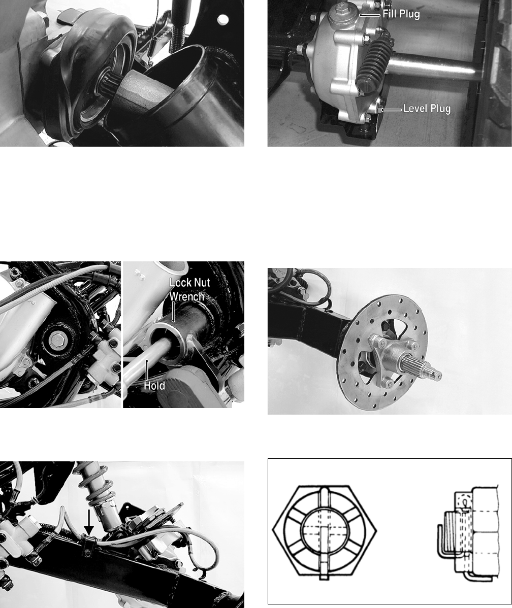
95
KM532
7. Install the right pivot bolt and left pivot adjusting
bolt and tighten securely; then move the swing arm
up and down to seat the bearings. Tighten the left
pivot bolt to 36 in.-lb and the right pivot bolt to 82 ft-
lb.
8. Install the left pivot lock nut; then while holding the
left pivot adjusting bolt, use Pivot Lock Nut Wrench
to tighten the lock nut to 82 ft-lb.
KM533B
9. Install the shock absorber using the existing hard-
ware and tighten to 29 ft-lb; then install the brakeline
hose clamp on the swing arm and tighten securely.
KM505A
10. Tighten the final drive gear case drain plug securely;
then remove the fill plug and level plug.
KM131A
11. Pour the recommended gear lubricant into the fill
hole until lubricant is visible on the threads of the
level hole; then install the level plug and the fill plug
and tighten securely.
12. Install the rear drive gear case guard and tighten the
cap screws securely.
13. Apply grease to the brake disc hub and wheel hubs;
then install the disc and rear hubs.
KM502
14. Install the hub nuts and tighten to 72 ft-lb; then
install new cotter pins and bend as shown.
KM469
15. Install the rear brake calipers and tighten to 25 ft-lb.
16. Install the rear hub caps; then install the rear wheels
and tighten to 32 ft-lb.
17. Remove the ATV from the support stand.
FOR ARCTIC CAT ATV DISCOUNT PARTS CALL 606-678-9623 OR 606-561-4983
www.mymowerparts.com

96
Troubleshooting
Drive System
Troubleshooting
Brake System
Problem: Power not transmitted from engine to wheels
Condition Remedy
1. Rear axle shaft serration worn - broken 1. Replace shaft
Problem: Braking poor
Condition Remedy
1. Pad worn
2. Pedal free-play excessive
3. Brake fluid leaking
4. Hydraulic system entrapped air
5. Master cylinder/brake cylinder seal worn
1. Replace pads
2. Adjust free-play
3. Repair - replace hydraulic system
4. Bleed hydraulic system
5. Replace appropriate cylinder
Problem: Brake lever travel excessive
Condition Remedy
1. Hydraulic system entrapped air
2. Brake fluid low
3. Brake fluid incorrect
4. Piston seal - cup worn
1. Bleed hydraulic system
2. Add fluid to proper level/bleed system
3. Replace with correct fluid
4. Replace master cylinder
Problem: Brake fluid leaking
Condition Remedy
1. Connection joints loose
2. Hose cracked
3. Piston seal worn
1. Tighten joint
2. Replace hose
3. Replace master/brake cylinder
FOR ARCTIC CAT ATV DISCOUNT PARTS CALL 606-678-9623 OR 606-561-4983
www.mymowerparts.com
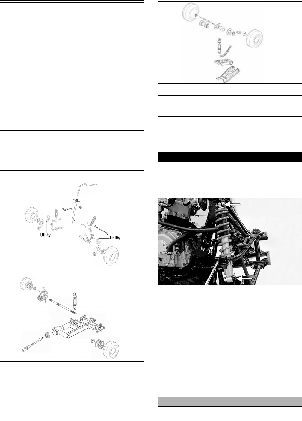
97
Suspension
The following suspension system components should be
inspected periodically to ensure proper operation.
A. Shock absorber rods not bent, pitted, or damaged.
B. Rubber damper not cracked, broken, or missing.
C. Shock absorber body not damaged, punctured, or
leaking.
D. Shock absorber eyelets not broken, bent, or
cracked.
E. Shock absorber eyelet bushings not worn, deterio-
rated, cracked, or missing.
F. Shock absorber spring not broken or sagging.
Front and Rear
Suspension Assembly
Schematics
KM598E
KM463
KM462
Front Shock Absorbers
REMOVING
1. Secure the ATV on a support stand to elevate the
wheels and to release load on the suspension.
2. Remove the cap screws and nuts securing each shock
absorber to the A-arm and frame.
KM573A
CLEANING AND INSPECTING
NOTE: Whenever a part is worn excessively, cracked,
or damaged in any way, replacement is necessary.
1. Clean the shock absorbers in parts-cleaning solvent.
2. Inspect each shock rod for nicks, pits, bends, and
oily residue.
3. Inspect the springs, spring retainers, shock rods, shock
bodies, and eyelets for cracks, leaks, and bends.
INSTALLING
1. Install each shock absorber to the frame and A-arm
with cap screws and nuts. Tighten all nuts to 29 ft-lb.
2. Remove the ATV from the support stand.
Utility
! WARNING
Make sure the ATV is solidly supported on the support
stand to avoid injury.
CAUTION
Do not tighten the nut beyond the recommended speci-
fication or the shock eyelet or mount WILL be damaged.
DVX
FOR ARCTIC CAT ATV DISCOUNT PARTS CALL 606-678-9623 OR 606-561-4983
www.mymowerparts.com
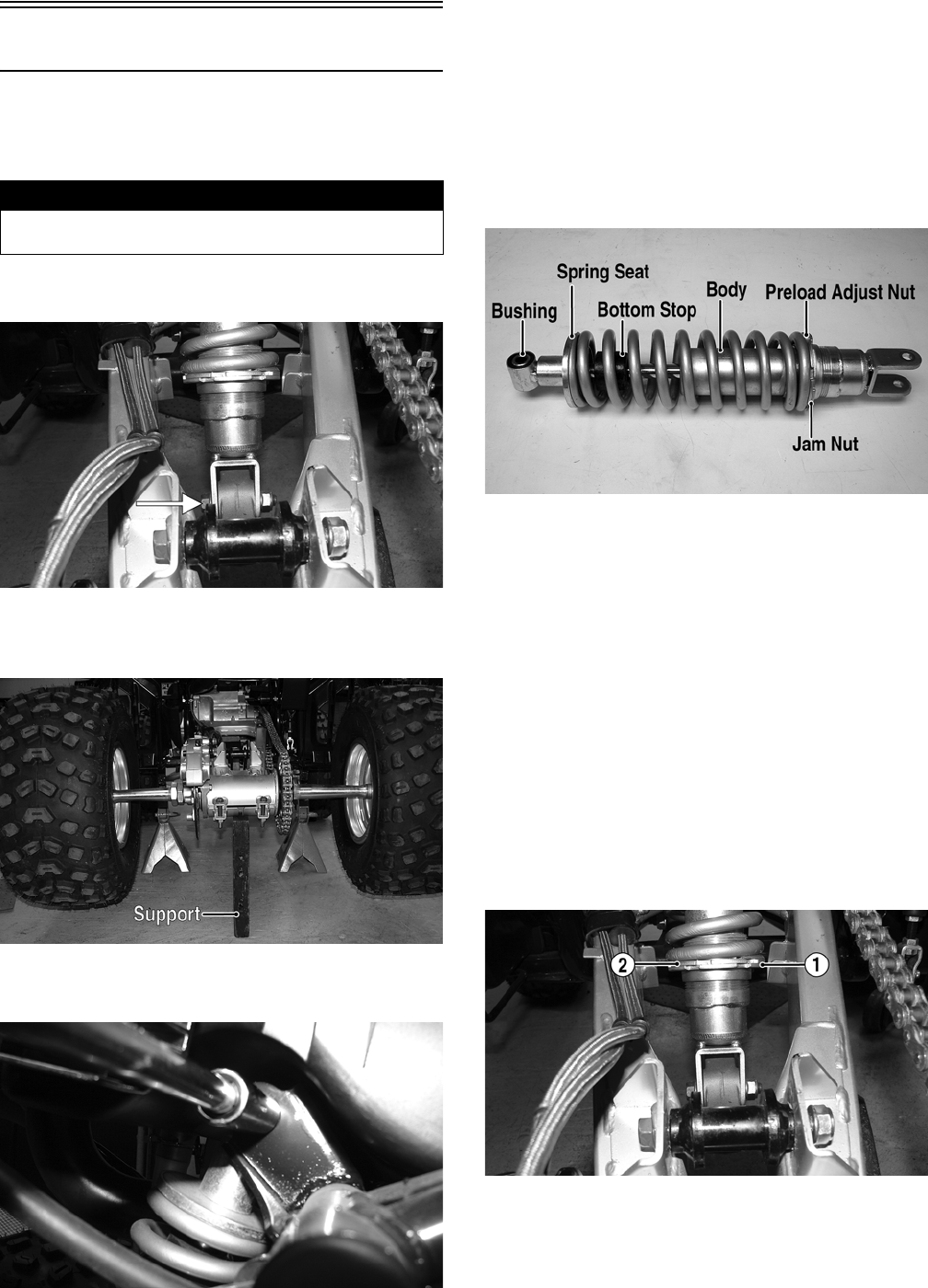
98
Rear Shock Absorber
REMOVING
1. Secure the ATV on a support stand to elevate the
wheels and to release load on the suspension.
2. Remove the rear shield plate from the swing arm; then
remove the lower shock mounting nut and cap screw.
KM551A
NOTE: Support the swing arm with a block of wood
or other support to allow removal of the cap screw.
KM555A
3. Remove the upper shock mounting nut and cap screw;
then remove the shock absorber from the frame.
KM554
CLEANING AND INSPECTING
1. Clean the shock absorber in parts-cleaning solvent.
2. Inspect the shock absorber body, bottom stop, and
rubber bushing for damage and leaking oil. If any
defects are found, replace the shock absorber.
3. Inspect the spring, spring seat, and preload adjust-
ment nuts and threads for damage or corrosion. If
corrosion is present on the threads, clean with a fine
wire brush and oil lightly.
KM561A
INSTALLING
1. Raise the swing-arm and place the shock absorber in
position; then install the upper and lower cap screws
and nuts.
2. Tighten the upper nut and the lower nut to 29 ft-lb.
3. Install the rear swing arm skid plate and four cap
screws. Tighten securely.
ADJUSTING SPRING PRELOAD
The rear spring preload is adjustable by changing the
spring set length. Using the following procedure, adjust
the spring.
1. Loosen the lock nut (1). Adjust the spring preload by
turning the adjuster (2) clockwise to increase spring
preload or counterclockwise to decrease spring pre-
load.
KM551B
2. Tighten the lock nut securely.
! WARNING
Make sure the ATV is solidly supported on the support
stand to avoid injury.
FOR ARCTIC CAT ATV DISCOUNT PARTS CALL 606-678-9623 OR 606-561-4983
www.mymowerparts.com
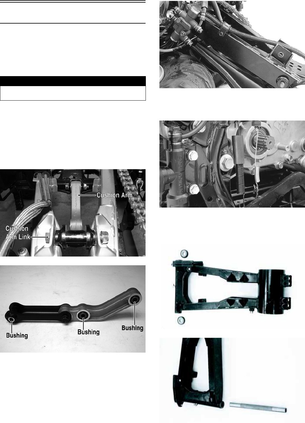
99
Swing Arm
REMOVING AND DISASSEMBLING
For the Utility, see Rear Drive Axle in Drive System. For
the DVX, use the following procedure.
1. Secure the ATV on a support stand to elevate the
wheels and to release load on the suspension.
2. Remove the rear wheels; then remove the rear hub
caps and hub nuts. Discard the cotter pins.
3. Remove the rear axle assembly (see Drive System);
then remove the rear shock absorber.
4. Remove the cushion arm lock nut and cap screw;
then remove the lock nut and cap screw securing the
cushion arm link to the swing arm. Remove the cush-
ion arm/link assembly. Account for three bushings.
KM557A
KM568A
5. Remove the axle housing (see Drive System).
6. Remove the brake hose guide clamp.
KM495
7. Remove the swing-arm pivot nut; then remove the
swing-arm pivot flange bolt and remove the swing
arm.
KM496
8. Remove the chain guide.
9. Remove the dust seals from the swing arm; then
remove two bushings and the swing arm axle.
KM499B
KM500
! WARNING
Make sure the ATV is solidly supported on the support
stand to avoid injury.
FOR ARCTIC CAT ATV DISCOUNT PARTS CALL 606-678-9623 OR 606-561-4983
www.mymowerparts.com
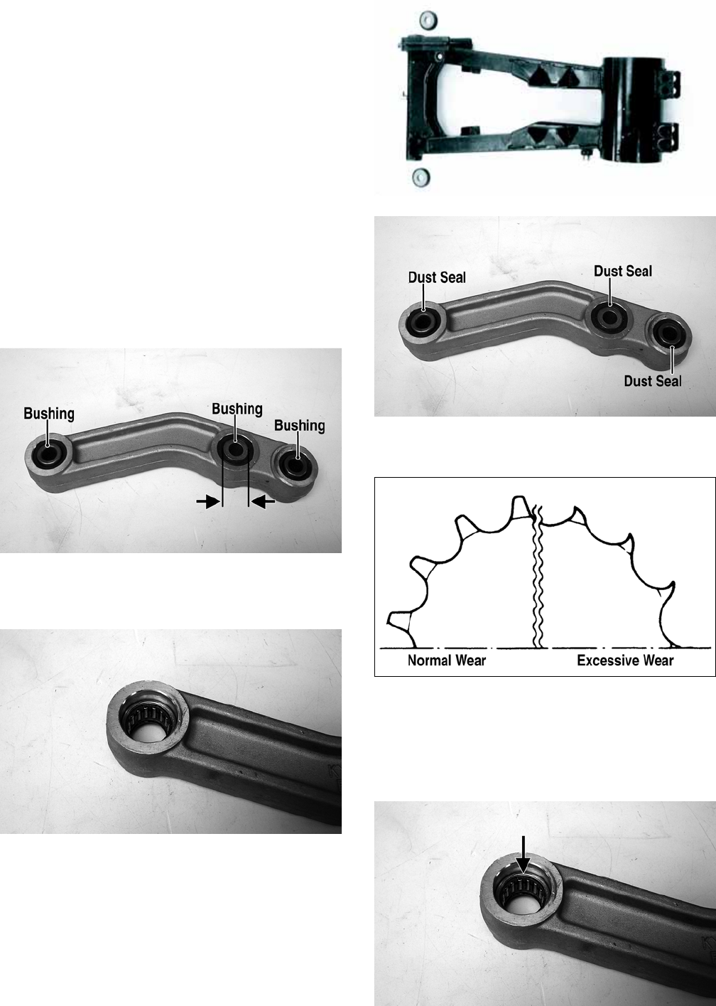
100
10. Remove the lock nut and cap screw securing the
cushion link to the cushion arm. Account for a bush-
ing.
CLEANING AND INSPECTING
NOTE: Whenever a part is worn excessively,
cracked, or damaged in any way, replacement is nec-
essary.
1. Inspect the dust seals, bushings, and pivot axle for
wear or damage. If any defect is found, they must be
replaced.
2. To inspect the swing arm and swing arm axle, place
the swing arm axle and bushings in the swing arm;
then using the flange bolt, rock the bushings and axle
from side to side and up and down. If excessive play
is noted, the bushings, axle, or swing arm must be
replaced. Check for cracks or broken welds.
3. To inspect the cushion arm bushings, install the
bushings in the cushion arm; then check for exces-
sive play by rocking the bushing.
KM564A
4. Inspect the needle bearings for missing rollers, rust
or corrosion, or flat rollers. Check for a tight fit in
boss. Replace the arm if bearings are loose.
KM565
5. Inspect all dust seals and replace if they are cracked,
torn, dried out, or loose.
KM499B
KM564B
6. Inspect the drive chain and sprockets for excessive
wear, chain stiffness, or rust/corrosion.
ATV2185
ASSEMBLING AND INSTALLING
1. Remove any nicks or burrs from the bearing bosses
in the cushion arm with fine emory cloth; then using
a suitable bearing installer, press new needle bear-
ings into the end bosses of the cushion arm.
KM565A
FOR ARCTIC CAT ATV DISCOUNT PARTS CALL 606-678-9623 OR 606-561-4983
www.mymowerparts.com
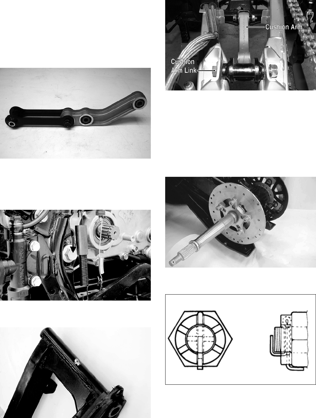
101
2. If the bushing was removed from the middle boss of
the cushion arm, press in a new bushing.
NOTE: The bearings and bushing must be centered
in the bearing boss so the dust seals can be properly
installed.
3. Using an appropriate seal driver, install the new dust
seals in the cushion arm; then apply multi-purpose
grease to the bearings, bushing, and dust seal lips.
4. Install the bushings in the cushion arm and cushion link;
then connect the cushion link to the cushion arm with
the flange cap screw and lock nut. Tighten securely.
KM568
5. Install the swing arm axle and bushings; then install
the dust seals and lubricate the lips with grease.
6. Place the swing arm into position in the frame; then
install the swing arm pivot cap screw and lock nut.
Tighten to 50 ft-lb.
KM496A
7. Apply grease to the swing arm pivot through the
grease fitting.
KM501
8. Place the cushion arm and cushion arm/link assem-
bly into position and secure with the flange cap
screws and new lock nuts. Tighten securely.
KM557A
9. Install the shock absorber and secure with the exist-
ing hardware. Tighten to 29 ft-lb.
10. Install the axle housing, axle, and brake assembly
(see Drive System).
11. Install the drive chain and sprockets (see Drive Sys-
tem); then adjust the chain to specifications (see
Periodic Maintenance/Tune-Up).
12. Apply grease to the axle splines; then install the hubs
and hub nuts. Tighten to 72 ft-lb.
KM468
13. Install new cotter pins; then install the hub caps and
rear wheels. Tighten the lug nuts to 32 ft-lb.
KM469
FOR ARCTIC CAT ATV DISCOUNT PARTS CALL 606-678-9623 OR 606-561-4983
www.mymowerparts.com
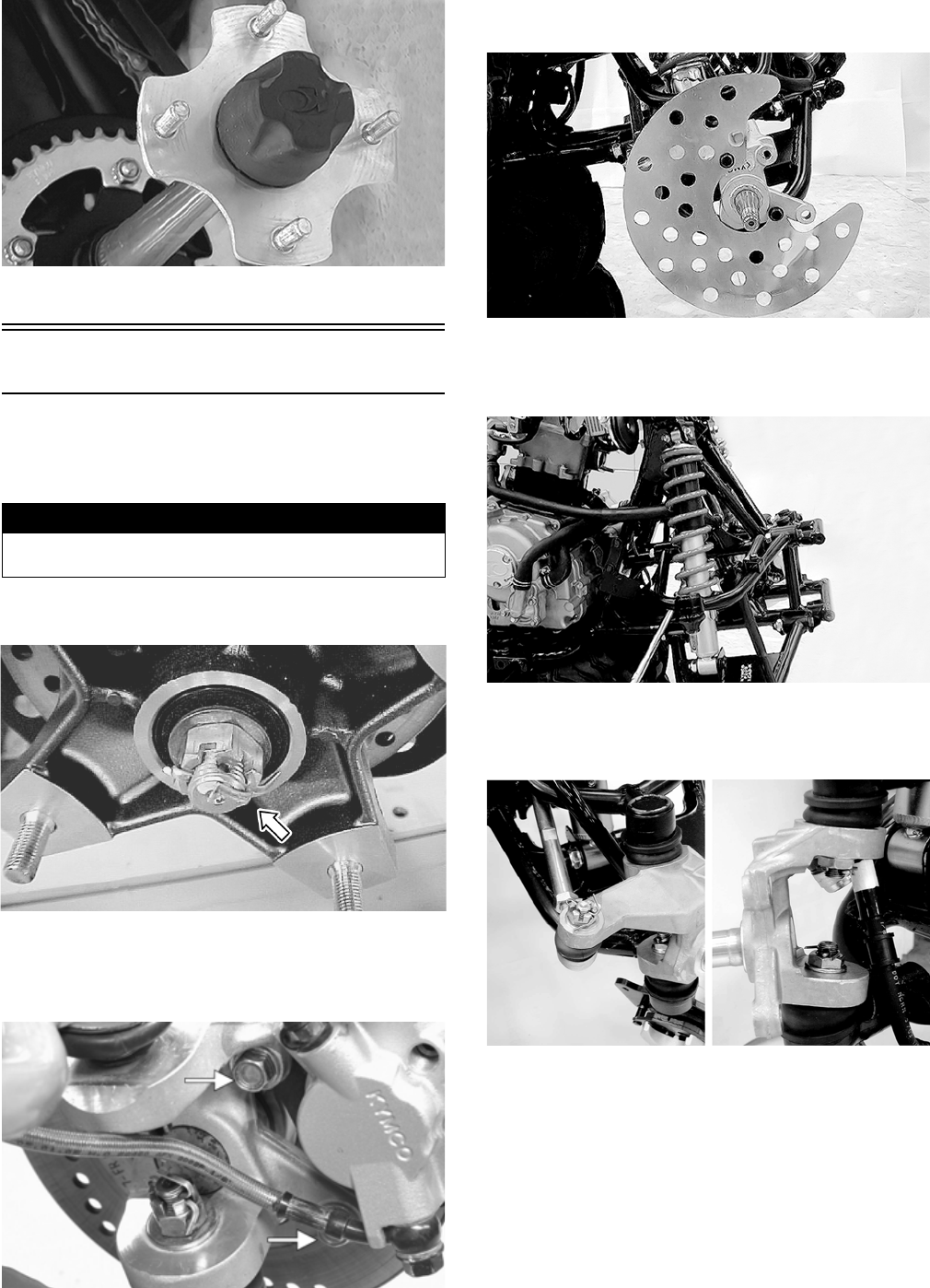
102
KM464
14. Remove the ATV from the support stand.
Front A-Arms
REMOVING
1. Secure the ATV on a support stand to elevate the
front wheels; then remove a front wheel.
2. Remove the hub cap; then remove the cotter pin from
the nut.
SP366
3. Remove the nut securing the hub.
4. Remove the cap screws securing the brake caliper;
then remove the caliper and lay aside.
KM266A
5. Remove the hub assembly; then on the Utility,
remove the disc cover.
KM569
6. Remove the cotter pin and slotted nut securing the tie
rod end to the knuckle; then remove the tie rod end
from the knuckle.
KM573
7. Remove the brake hose clamp from the A-arm; then
remove the cotter pins and slotted nuts securing the
upper and lower ball joints.
KM570
8. Remove the shock absorber mounting cap screws;
then remove the shock absorber assembly.
9. Using a ball joint remover, remove the ball joints
from the knuckle; then remove the front bumper.
CLEANING AND INSPECTING
NOTE: Whenever a part is worn excessively,
cracked, or damaged in any way, replacement is nec-
essary.
! WARNING
Make sure the ATV is solidly supported on the support
stand to avoid injury.
FOR ARCTIC CAT ATV DISCOUNT PARTS CALL 606-678-9623 OR 606-561-4983
www.mymowerparts.com

103
1. Clean the knuckle in parts-cleaning solvent; then dry
with compressed air. If any damage or excessive
wear is detected, the knuckle must be replaced.
2. Inspect the ball joint for boot damage or wear.
Replace the A-arm if the ball joint is damaged or
worn.
3. Inspect the arm for broken welds, cracks, or bends.
Replace if damaged.
4. Remove the bushings and dust seals and inspect for
damage to seal lips and spacers.
NOTE: The pivots are equipped with roller bearings.
The bearing rollers may fall out when the spacers are
removed.
5. Check the bearings for excessive wear and replace
them if worn.
6. Using a suitable bearing remover, remove the pivot
bearings; then clean all parts in parts-cleaning sol-
vent.
SP382
NOTE: All bearings, bushings, and seals that are
removed must be replaced with new ones.
INSTALLING
1. Install the bearings in the upper arm pivot to a depth
of 13.6 mm (0.535 in.) with a bearing installer and
suitable spacer.
ATV2196A
2. Coat the spacers and the lips of the dust seals with
multi-purpose grease; then install them in the upper
pivot.
3. Repeat steps 1 and 2 for the lower A-arm.
4. Clean all grease from the ball joint tapers and the
knuckle bores; then install the arms to the steering
knuckle and tighten the ball joint nuts to 22 ft-lb.
Install new cotter pins.
SP388A
NOTE: During assembly, new cotter pins should be
installed.
SP390
5. Install the arms to the frame with the pivot cap
screws; then tighten the nuts to 32 ft-lb.
KM579
6. Install the front bumper assembly; then install the
front shock absorbers. Apply red Loctite #271 on the
cap screw threads and tighten to 29 ft-lb.
7. On the Utility, apply red Loctite #271 to the mount-
ing cap screws; then install the disc cover and tighten
securely.
FOR ARCTIC CAT ATV DISCOUNT PARTS CALL 606-678-9623 OR 606-561-4983
www.mymowerparts.com

104
KM569
8. Connect the tie rod ends to the steering knuckle; then
tighten the nut to 15 ft-lb and install a new cotter pin.
NOTE: During assembly, new cotter pins should be
installed.
KM581
Wheels and Tires
TIRE SIZE
The ATV is equipped with low-pressure tubeless tires of
the size and type listed. Do not under any circumstances
substitute tires of a different type or size.
TIRE INFLATION PRESSURE
Tire inflation pressure should be as specified.
REMOVING
1. Secure the ATV on a support stand to elevate the
wheels.
2. Remove the wheels.
NOTE: Keep left-side and right-side wheels sepa-
rated for installing them on their proper sides.
CLEANING AND INSPECTING
NOTE: Whenever a part is worn excessively,
cracked, or damaged in any way, replacement is nec-
essary.
1. Clean the wheels and hubs with parts-cleaning sol-
vent.
2. Clean the tires with soap and water.
3. Inspect each wheel for cracks, dents, or bends.
4. Inspect each tire for cuts, wear, missing lugs, and
leaks.
INSTALLING
1. Install each wheel on its hub.
NOTE: Make sure each wheel is installed on its
proper hub as noted in removing (the “rotation
arrow” must indicate forward direction of rotation).
AF612D
2. Tighten to 32 ft-lb.
CHECKING/INFLATING
1. Using an air pressure gauge, measure the air pressure
in each tire. Adjust the air pressure as necessary to
meet the recommended inflation pressure.
2. Inspect the tires for damage, wear, or punctures.
NOTE: If repair is needed, follow the instructions
found on the tire repair kit or remove the wheel and
have it repaired professionally.
! WARNING
Use only Arctic Cat approved tires when replacing tires.
Failure to do so could result in unstable ATV operation.
! WARNING
Always use the size and type of tires specified. Always
maintain proper tire inflation pressure.
! WARNING
Do not mix tire tread patterns. Use the same pattern
type on front and rear. Failure to heed warning could
cause poor handling qualities of the ATV and could
cause excessive drive train damage not covered by war-
ranty.
! WARNING
Make sure the ATV is solidly supported on the support
stand to avoid injury.
! WARNING
Do not operate the ATV if tire damage exists.
FOR ARCTIC CAT ATV DISCOUNT PARTS CALL 606-678-9623 OR 606-561-4983
www.mymowerparts.com

105
NOTE: Make sure all tires are the specified size and
have identical tread pattern.
3. Check the front wheel toe-in and toe-out and adjust
as necessary (see Steering/Frame).
4. Test drive the ATV on a dry, level surface and note
any pulling to the left or right during acceleration,
deceleration, and braking.
NOTE: If pulling is noted, measure the circumference
of the front and rear tires on the pulling side. Compare
the measurements with the tires on the opposite side.
If pulling is noted during braking only, check and
adjust the brakes as necessary and recheck operation
(see Periodic Maintenance/Tune-Up).
5. Increase the air pressure in the tires with the smallest
circumference measurement until all tires are equal
in circumference.
6. Repeat steps 4-5 as necessary to ensure proper handling.
Troubleshooting
Problem: Suspension too soft
Condition Remedy
1. Spring(s) weak
2. Shock absorber damaged
1. Replace spring(s)
2. Replace shock absorber
Problem: Suspension too stiff
Condition Remedy
1. A-arm-related bushings worn or binding 1. Replace bushing
Problem: Suspension noisy
Condition Remedy
1. Cap screws (suspension system) loose
2. A-arm-related bushings worn
1. Tighten cap screws
2. Replace bushings
Problem: Rear wheel oscillation
Condition Remedy
1. Rear wheel hub bearings worn - loose
2. Tires defective - incorrect
3. Wheel rim distorted
4. Wheel hub cap screws loose
5. Axle shaft nut loose
6. Auxiliary brake adjusted incorrectly
7. Rear suspension arm-related bushing worn
8. Rear shock absorber damaged
9. Rear suspension arm nut loose
1. Replace bearings
2. Replace tires
3. Replace rim
4. Tighten cap screws
5. Tighten nut
6. Adjust brake
7. Replace bushing
8. Replace shock absorber
9. Tighten nut
FOR ARCTIC CAT ATV DISCOUNT PARTS CALL 606-678-9623 OR 606-561-4983
www.mymowerparts.com
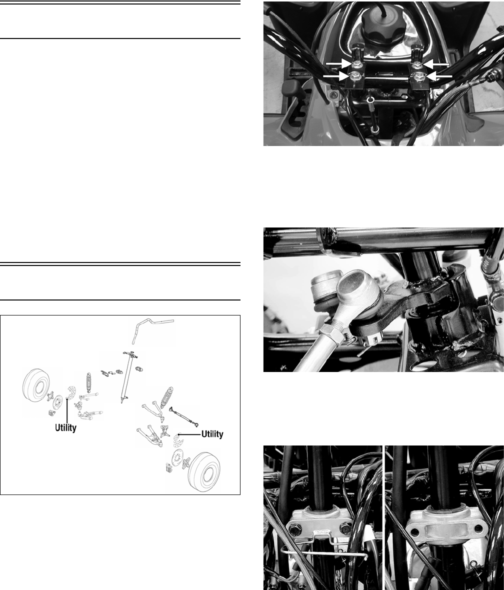
106
Steering/Frame/Controls
The following steering components should be inspected
periodically to ensure safe and proper operation.
A. Handlebar grips not worn, broken, or loose.
B. Handlebar not bent or cracked and has equal and
complete full-left and full-right capability.
C. Steering post bearing assembly/bearing housing
not broken, worn, or binding.
D. Ball joints not worn, cracked, or damaged.
E. Tie rods not bent or cracked.
F. Knuckles not worn, cracked, or damaged.
G. Cotter pins not damaged or missing.
The frame, welds, and racks should be checked periodi-
cally for damage, bends, cracks, deterioration, broken
components, and missing components.
Steering Post/Tie Rods
KM598E
REMOVING
1. On the Utility, remove the front rack and front center
panel (see Body in this section). On the DVX, pro-
ceed to step 2.
2. Remove the steering post cover (DVX) or the instru-
ment pod (Utility) (see Steering Post Cover/Instru-
ment Pod in this section); then remove the cap
screws securing the handlebar to the steering post.
Account for two handlebar holders.
KM189A
3. Lift the handlebar out of the lower handlebar holders
and lay the handlebar forward.
4. Remove the cotter pins and slotted nuts securing the
tie rod ends to the steering post arm; then disconnect
the tie rods from the arm.
KM590
5. Remove the cotter pin and slotted nut from the lower
end of the steering post; then remove the upper steer-
ing shaft support block. Account for a cable guide,
two steering support blocks, and the upper steering
post bushing.
.
KM588
FOR ARCTIC CAT ATV DISCOUNT PARTS CALL 606-678-9623 OR 606-561-4983
www.mymowerparts.com
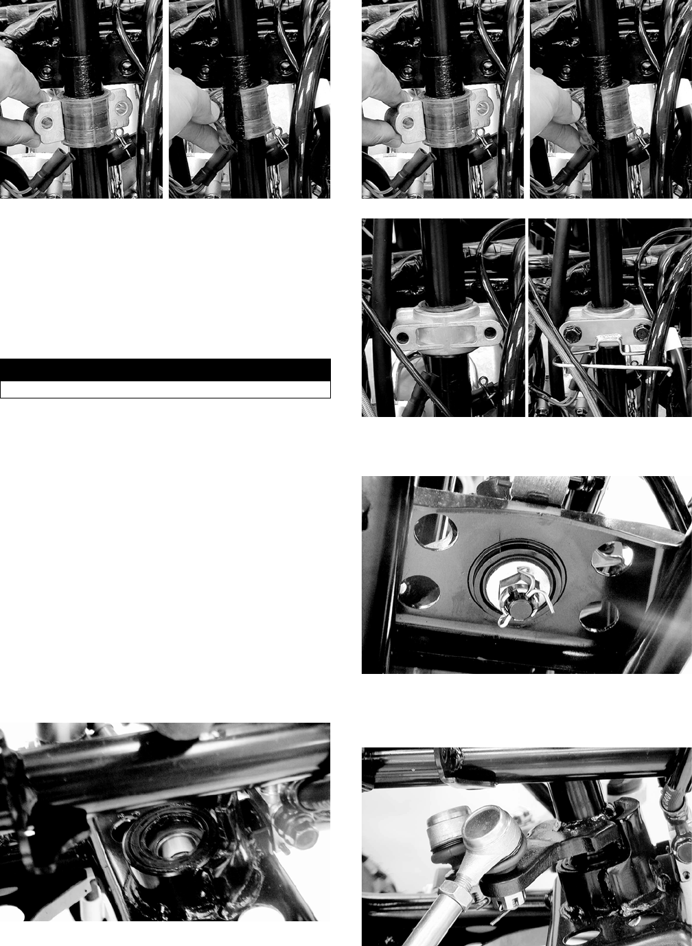
107
KM589
6. Remove the steering post from the ATV.
CLEANING AND INSPECTING
NOTE: Whenever a part is worn excessively, cracked,
or damaged in any way, replacement is necessary.
1. Wash the tie rod ends in parts-cleaning solvent. Dry
with compressed air. Inspect the pivot area for wear.
Apply a low-temperature grease to the ends.
2. Inspect the tie rods for damaged threads or wear.
3. Inspect the tie rods for cracks or unusual bends.
4. Inspect all welded areas for cracks or deterioration.
5. Inspect the steering post and steering-post holders
for cracks, bends, or wear.
6. Inspect the handlebar clamps for cracks or wear.
7. Inspect the handlebar for cracks, wear, or unusual
bends.
8. Inspect the handlebar grips for damage or wear.
9. Inspect the lower steering post support bearing and
seal for wear or cracks.
INSTALLING
1. Apply a thin coat of grease to the lips of the lower
steering post seals; then lower the steering post into
position in the lower steering post bearings.
KM593
2. Apply a thin coat of grease to the upper steering post
bushing; then secure the steering post with the support
blocks and existing hardware. Tighten to 17 ft-lb.
KM589
KM595
3. Install the slotted nut on the lower steering post and
tighten to 50 ft-lb; then install a new cotter pin.
KM591
4. Place the inner tie rod ends into the steering post arm
and tighten the slotted nuts to 15 ft-lb; then install
new cotter pins.
KM590
! WARNING
Always wear safety glasses when using compressed air.
FOR ARCTIC CAT ATV DISCOUNT PARTS CALL 606-678-9623 OR 606-561-4983
www.mymowerparts.com
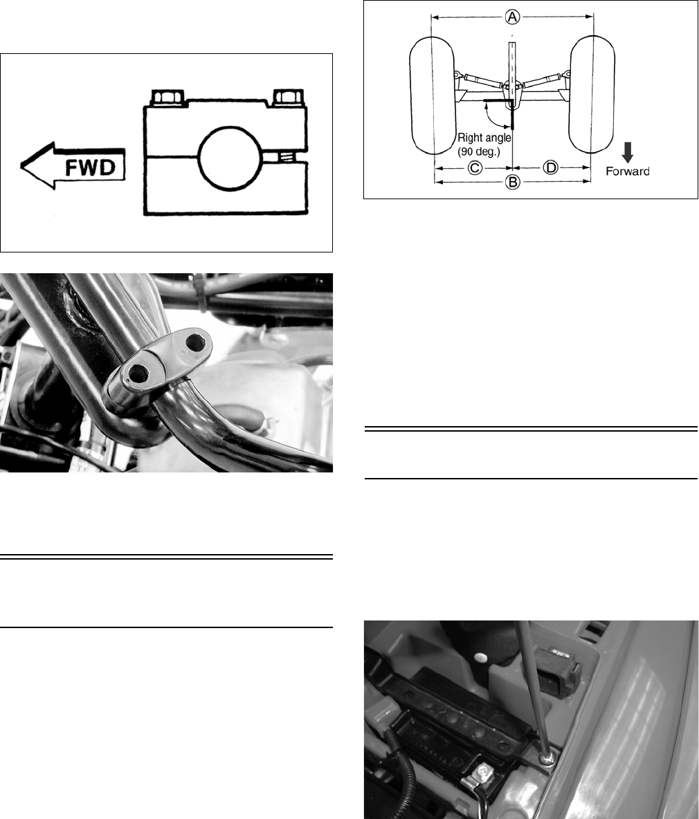
108
5. Install the handlebar and tighten the clamp cap
screws to 18 ft-lb making sure to tighten the front
cap screws first.
KM587
KM597
6. Install the instrument pod (Utility) or steering post
cover (DVX).
7. Install the center panel and front rack (Utility).
Measuring/Adjusting
Toe-In/Toe-Out
1. With the ATV on a level surface, center the handle-
bar for straight ahead using a suitable means of mea-
suring centering; then adjust tire pressure to
specifications (see General Information).
2. Support the front of the ATV with the wheels free to
rotate; then center and secure the handlebar.
3. Measure the distance (A) and (B) between the front
wheels; then subtract distance (B) from (A). Distance
A - Distance B = Toe-In.
ATV2205
4. Adjust toe-in to 15 mm (0.60 in.); then measure dis-
tances (C) and (D). Distances (C) and (D) should be
equal.
5. After all the adjustments are to specifications,
tighten the tie-rod lock nuts to 15 ft-lb.
NOTE: Prior to locking the jam nuts, make sure the
ball joints are at the center of their normal range of
motion and at the correct angle.
NOTE: The front wheels do not have to be removed
to adjust the tie rod. Also, care should be taken not to
disturb the handlebar position.
Body
REMOVING (DVX)
1. Remove the seat; then remove the battery hold-down
strap, battery, and starter relay. Lay the relay aside
without disconnecting the wiring.
NOTE: Always remove the negative battery cable
first; then the positive cable.
SP107
2. Remove the CDI, start-in-gear relay, and fuse block
and lay aside without disconnecting the wires; then
remove the shift knob.
3. Remove the six cap screws securing the body to the
top of the frame; then remove the cap screws from
the bottom of the battery box.
FOR ARCTIC CAT ATV DISCOUNT PARTS CALL 606-678-9623 OR 606-561-4983
www.mymowerparts.com

109
KM782A
KM790A
4. Remove four flange nuts and cap screws securing the
rear fender support; then remove the push nuts from
the mounting studs at the front of the rear fenders.
KM785A
KM784A
5. Remove the hardware securing the front fenders to
the fender supports; then disconnect the headlight.
KM352A
6. Turn the handlebar to the left; then raise the body
turning it to the right and lift clear of the handlebar.
REMOVING (Utility)
1. Remove the seat; then remove the battery box cover.
KM793A
2. Disconnect the negative battery cable first; then the
positive cable.
3. Remove the battery hold-down strap; then remove
the battery.
4. Remove the front and rear racks; then remove the
cap screws securing the front center panel and
remove the panel.
KM308A
5. Remove the cap screws and flange nuts securing the
mud guards to the front and rear fenders; then
remove the cap screws securing the mud guards to
the front rests and remove the mud guards.
FOR ARCTIC CAT ATV DISCOUNT PARTS CALL 606-678-9623 OR 606-561-4983
www.mymowerparts.com
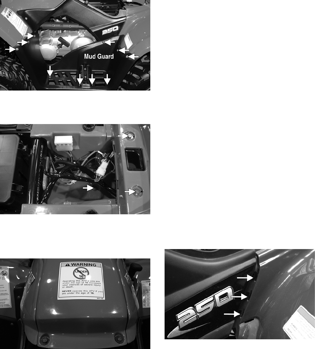
110
KM789A
6. Remove the side panels; then remove the cap screws
and flange nuts securing the front and rear fenders to
the frame and fender supports.
KM799B
7. Disconnect the left and right headlight connectors;
then disconnect the taillight.
8. Remove the gas tank cover; then remove the shift
knob and front and rear fenders.
KM797
CLEANING AND INSPECTING
NOTE: Whenever a part is worn excessively,
cracked, or damaged in any way, replacement is nec-
essary.
1. Clean all body components with soap and water.
2. Inspect the body and fenders for cracks.
3. Inspect threaded areas of all mounting studs for strip-
ping.
4. Inspect for missing decals.
INSTALLING (DVX)
1. Fit the body over the handlebar and rotate into nor-
mal mounting position.
2. Using the existing hardware, secure the front fenders
to the fender supports; then connect the headlight.
3. Using the existing hardware, secure the rear fenders
to the forward fender supports; then secure the rear
fender to the frame with four cap screws and flange
nuts. Tighten securely.
4. Install the six cap screws securing the body to the top
of the frame. Tighten securely.
5. Install the fuse block, start-in-gear relay, and the
CDI; then install the body mounting cap screw into
the bottom of the battery box.
6. Install the battery and battery hold-down strap; then
connect the positive battery cable and the negative
battery cable.
NOTE: Always install the positive cable first; then
install the negative cable.
7. Install the seat making sure it is latched securely.
INSTALLING (Utility)
1. Place the front and rear fenders into position on the
frame and secure with the existing hardware; then
install the gas tank cover. Tighten all fasteners
securely.
2. Connect the headlight and taillight connectors; then
install the shift knob.
3. Making sure the locating tabs engage the appropriate
slots in the fenders, install the side panels.
KM340A
4. Install the mud guards and secure to the fenders and
foot rest supports with the existing hardware. Make
sure all locating tabs are appropriately engaged with
the fenders and side panels.
FOR ARCTIC CAT ATV DISCOUNT PARTS CALL 606-678-9623 OR 606-561-4983
www.mymowerparts.com
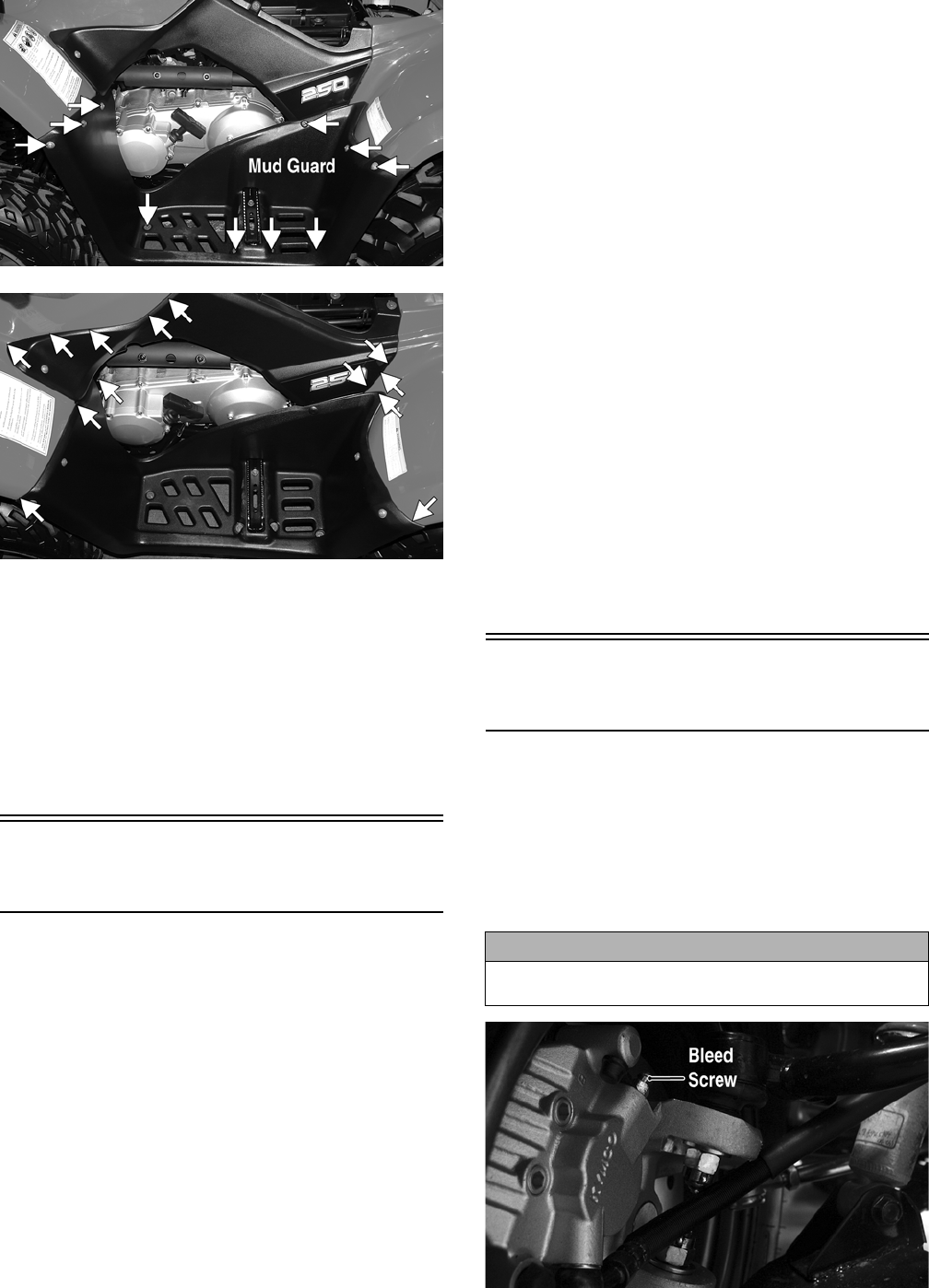
111
KM789A
KM788A
5. Install the front center cover; then install the front
and rear racks. Tighten all fasteners securely.
6. Install the battery; then connect the positive battery
cable, negative battery cable, and battery hold-down
strap.
NOTE: Always install the positive cable first; then
install the negative cable.
7. Install the battery cover; then install the seat making
sure it locks securely in place.
Steering Post Cover/
Instrument Pod
REMOVING (DVX)
1. Remove the two reinstallable rivets on the rear of the
steering post cover; then lift up and push the assem-
bly forward to remove.
2. Disconnect the wire connectors from the indicator
lights and from the ignition switch.
REMOVING (Utility)
1. Remove the reinstallable rivet on the front of the
instrument pod and the two cap screws on the rear;
then lift the assembly off and disconnect the speed-
ometer cable.
2. Remove the self-tapping screw securing the LCD
gauge assembly to the instrument pod; then remove
the LCD gauge.
NOTE: The LCD gauge is not a serviceable compo-
nent. If any functions are incorrect or indicator lights
do not illuminate, the LCD gauge must be replaced.
INSPECTING/SERVICING (DVX)
1. Remove the two self-tapping screws securing the
indicator lamp assembly in the steering post cover.
2. Inspect the bulbs for blackening or burn out. Replace
as required.
3. Inspect the indicator lamp holder for loose sockets, bro-
ken wires, or loose connections. Replace as required.
INSPECTING (Utility)
The LCD gauge is not a serviceable component. To
inspect the LCD gauge, see Electrical System.
INSTALLING (DVX)
1. Connect the indicator lamp connectors; then connect
the main harness connector to the ignition switch.
2. Place the steering post cover onto the mounting
bracket; then secure with the reinstallable rivets.
INSTALLING (Utility)
1. Connect the main harness connector to the LCD
gauge; then connect the ignition harness to the igni-
tion connectors.
2. Place the instrument pod onto the mounting bracket; then
secure with the reinstallable rivet and two cap screws.
Front Brake Lever/Master
Cylinder Assembly
NOTE: The master cylinder is a non-serviceable
component; it must be replaced as an assembly.
REMOVING
1. Connect a clear hose to the bleed screw on either
front brake caliper; then open the bleed screw and
pump the brake fluid into a suitable container. Close
the bleed screw.
KM116A
CAUTION
Brake fluid is highly corrosive. Do not spill brake fluid
on any surface of the ATV.
FOR ARCTIC CAT ATV DISCOUNT PARTS CALL 606-678-9623 OR 606-561-4983
www.mymowerparts.com

112
NOTE: Do not reuse brake fluid. When exposed to
air, brake fluid rapidly absorbs moisture.
2. Remove the brakeline hose union bolt; then remove
the cap screws securing the master cylinder assembly
to the handlebar. Discard the crush washers from the
union bolt.
KM800A
3. Remove the brake lever, brakelight switch, and brake
lever lock.
INSPECTING
NOTE: Whenever a part is worn excessively,
cracked, or damaged in any way, replacement is nec-
essary.
1. Inspect the pivot bolt securing the brake lever for
wear.
2. Inspect the brake lever for elongation of the pivot
hole.
3. Inspect the reservoir for cracks and leakage.
4. Inspect the brake hose for cracks and deterioration
and the condition of the fittings (threaded and com-
pression).
5. Inspect the brakelight switch for corrosion, cracks,
missing or broken mounting tabs, or broken and
frayed wiring.
NOTE: If the brakelight switch is determined to be
not serviceable, see Electrical System.
INSTALLING
1. Install the brakelight switch on the master cylinder;
then install the brake lever and brake lever lock.
2. Install the master cylinder assembly on the handlebar
engaging the alignment stud in the hole in the han-
dlebar; then secure with the master cylinder clamp
and two cap screws. Make sure the UP arrow on the
clamp is directed upward.
KM800B
3. Tighten the cap screw (1) to 13 ft-lb; then tighten the
cap screw (2) to 13 ft-lb.
KM800B
4. Using new crush washers, secure the brake hose to
the master cylinder with the brake hose union bolt.
Tighten to 25 ft-lb.
KM800A
5. Fill the master cylinder with DOT 4 brake fluid; then
bleed the system (see Periodic Maintenance).
Auxiliary Brake Pedal/
Master Cylinder
Assembly
NOTE: The auxiliary brake master cylinder is a non-
serviceable component; it must be replaced as an
assembly.
FOR ARCTIC CAT ATV DISCOUNT PARTS CALL 606-678-9623 OR 606-561-4983
www.mymowerparts.com
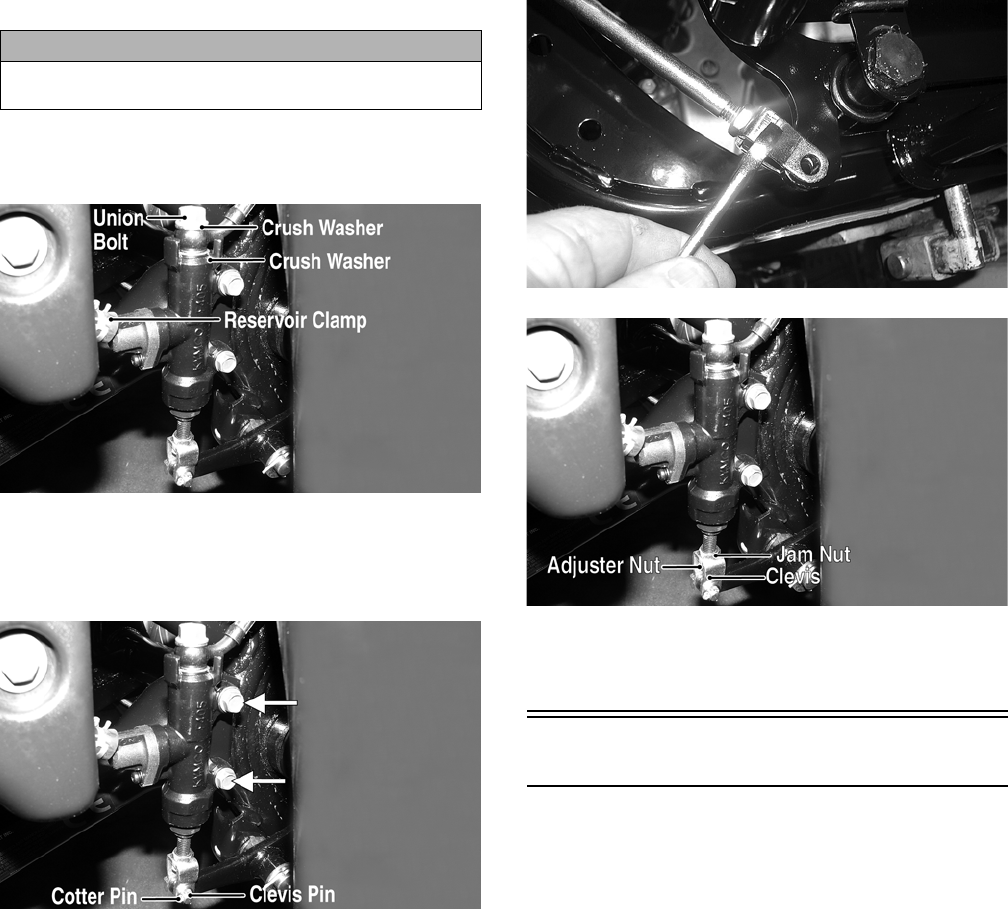
113
REMOVING
1. Connect a clear plastic hose to the appropriate bleed
screw on the rear brake caliper; then loosen the bleed
screw and pump the foot brake until the fluid is
pumped into a suitable container.
2. Compress the reservoir clamp and remove the reser-
voir hose; then remove the union bolt. Account for
and discard two crush washers.
KM801A
3. Remove the cotter pin from the clevis pin and
remove the clevis pin; then remove the two cap
screws securing the master cylinder to the frame and
remove the master cylinder.
KM801B
4. Loosen the jam nut; then remove the clevis and
adjuster nut.
INSTALLING
1. Install the jam nut; then install the clevis and adjuster
nut. Finger-tighten only at this time.
2. Secure the master cylinder to the frame with the two
cap screws and tighten securely.
3. Using two new crush washers, connect the brake
hose to the master cylinder with the union bolt; then
making sure the spring clamp is seated securely, con-
nect the reservoir hose to the master cylinder.
Tighten the union bolt to 25 ft-lb.
4. Making sure the brake pedal is fully released and
against the stop, turn the clevis and adjuster nut until
the hole in the clevis is aligned with the hole in the
brake pedal lever; then tighten the jam nut securely.
CD476
KM801C
5. Fill the master cylinder reservoir with DOT 4 brake
fluid and bleed the system (see Periodic Mainte-
nance/Tune-Up).
Throttle Control
REMOVING
1. Remove the boot from the throttle cable adjuster;
then loosen the jam nut and turn the adjuster com-
pletely in to loosen the cable.
2. Remove the three machine screws securing the cover
to the throttle control; then remove the cover and dis-
engage the throttle cable from the throttle arm.
3. Turn the cable adjuster out of the throttle control
housing; then remove the two machine screws secur-
ing the throttle control to the handlebar and remove
the throttle control.
INSTALLING
1. Making sure the throttle housing upper flat aligns
with the alignment mark on the handlebar, place the
throttle control into position on the handlebar and
secure with the two machine screws; then tighten the
machine screws securely.
CAUTION
Brake fluid is highly corrosive. Do not spill brake fluid
on any surface of the ATV.
FOR ARCTIC CAT ATV DISCOUNT PARTS CALL 606-678-9623 OR 606-561-4983
www.mymowerparts.com

114
KM122B
2. Thread the throttle cable into the throttle housing and
turn the adjuster completely in; then connect the
throttle cable to the throttle arm.
3. Install the throttle housing cover; then adjust the
throttle cable (see Fuel/Lubrication/Cooling).
Troubleshooting
Problem: Handling too heavy or stiff
Condition Remedy
1. Front wheel alignment incorrect
2. Lubrication inadequate
3. Tire inflation pressure incorrect
4. Tie rod ends seizing
5. Linkage connections seizing
1. Adjust alignment
2. Lubricate appropriate components
3. Adjust pressure
4. Replace tie rod ends
5. Repair - replace connections
Problem: Steering oscillation
Condition Remedy
1. Tires inflated unequally
2. Wheel(s) wobbly
3. Wheel hub cap screw(s) loose - missing
4. Wheel hub bearing worn - damaged
5. Tie rod ends worn - loose
6. Tires defective - incorrect
7. A-arm bushings damaged
8. Bolts - nuts (frame) loose
1. Adjust pressure
2. Replace wheel(s)
3. Tighten - replace cap screws
4. Replace bearing
5. Replace - tighten tie rod ends
6. Replace tires
7. Replace bushings
8. Tighten bolts - nuts
Problem: Steering pulling to one side
Condition Remedy
1. Tires inflated unequally
2. Front wheel alignment incorrect
3. Wheel hub bearings worn - broken
4. Frame distorted
5. Shock absorber defective
1. Adjust pressure
2. Adjust alignment
3. Replace bearings
4. Repair - replace frame
5. Replace shock absorber
Problem: Steering impaired
Condition Remedy
1. Tire pressure too high
2. Steering linkage connections worn
3. Cap screws (suspension system) loose
1. Adjust pressure
2. Replace connections
3. Tighten cap screws
Problem: Tire wear rapid or uneven
Condition Remedy
1. Wheel hub bearings worn - loose
2. Front wheel alignment incorrect
1. Replace bearings
2. Adjust alignment
Problem: Steering noise
Condition Remedy
1. Cap screws - nuts loose
2. Wheel hub bearings broken - damaged
3. Lubrication inadequate
1. Tighten cap screws - nuts
2. Replace bearings
3. Lubricate appropriate components
FOR ARCTIC CAT ATV DISCOUNT PARTS CALL 606-678-9623 OR 606-561-4983
www.mymowerparts.com
