Product Detail Manual AT
User Manual: at
Open the PDF directly: View PDF ![]() .
.
Page Count: 686 [warning: Documents this large are best viewed by clicking the View PDF Link!]
- QUICK REFERENCE INDEX
- Table of Contents
- RE4F04B
- TROUBLE DIAGNOSIS - INDEX
- PRECAUTIONS
- PREPARATION
- OVERALL SYSTEM
- ON BOARD DIAGNOSTIC SYSTEM DESCRIPTION
- TROUBLE DIAGNOSIS - INTRODUCTION
- TROUBLE DIAGNOSIS - BASIC INSPECTION
- TROUBLE DIAGNOSIS - GENERAL DESCRIPTION
- TROUBLE DIAGNOSIS FOR POWER SUPPLY
- DTC U1000 CAN COMMUNICATION LINE
- DTC P0705 PARK/NEUTRAL POSITION SWITCH
- DTC P0710 A/T FLUID TEMPERATURE SENSOR CIRCUIT
- DTC P0720 VEHICLE SPEED SENSOR·A/T (REVOLUTION SENSOR)
- DTC P0725 ENGINE SPEED SIGNAL
- DTC P0731 A/T 1ST GEAR FUNCTION
- DTC P0732 A/T 2ND GEAR FUNCTION
- DTC P0733 A/T 3RD GEAR FUNCTION
- DTC P0734 A/T 4TH GEAR FUNCTION
- DTC P0740 TORQUE CONVERTER CLUTCH SOLENOID VALVE
- DTC P0744 A/T TCC S/V FUNCTION (LOCK-UP)
- DTC P0745 LINE PRESSURE SOLENOID VALVE
- DTC P0750 SHIFT SOLENOID VALVE A
- DTC P0755 SHIFT SOLENOID VALVE B
- DTC P1705 THROTTLE POSITION SENSOR [ACCELERATOR PEDAL POSITION (APP) SENSOR]
- DTC P1760 OVERRUN CLUTCH SOLENOID VALVE
- DTC BATT/FLUID TEMP SEN (A/T FLUID TEMP SENSOR CIRCUIT AND TCM POWER SOURCE)
- DTC VEHICLE SPEED SENSOR MTR
- DTC TURBINE REVOLUTION SENSOR
- DTC CONTROL UNIT (RAM), CONTROL UNIT (ROM)
- DTC CONTROL UNIT (EEP ROM)
- TROUBLE DIAGNOSIS FOR SYMPTOMS
- Wiring Diagram — AT — NONDTC
- O/D OFF Indicator Lamp Does Not Come On
- Engine Cannot Be Started in P and N Position
- In P Position, Vehicle Moves Forward or Backward When Pushed
- In N Position, Vehicle Moves
- Large Shock. N -> R Position
- Vehicle Does Not Creep Backward in R Position
- Vehicle Does Not Creep Forward in D or L Position
- Vehicle Cannot Be Started From D1
- A/T Does Not Shift: D1 -> D2 or Does Not Kickdown: D4 -> D2
- A/T Does Not Shift: D2 -> D3
- A/T Does Not Shift: D3 -> D4
- A/T Does Not Perform Lock-up
- A/T Does Not Hold Lock-up Condition
- Lock-up Is Not Released
- Engine Speed Does Not Return To Idle (Light Braking D4 -> D3)
- Vehicle Does Not Start From D1
- A/T Does Not Shift: D4 -> D3, When Overdrive Control Switch ON -> OFF
- A/T Does Not Shift: D3 -> L2, When Selector Lever D -> L Position
- Vehicle Does Not Decelerate By Engine Brake
- TCM Self-diagnosis Does Not Activate
- SHIFT CONTROL SYSTEM
- A/T SHIFT LOCK SYSTEM
- KEY INTERLOCK CABLE
- ON-VEHICLE SERVICE
- REMOVAL AND INSTALLATION
- OVERHAUL
- DISASSEMBLY
- REPAIR FOR COMPONENT PARTS
- Manual Shaft
- Oil Pump
- Control Valve Assembly
- Control Valve Upper Body
- Control Valve Lower Body
- Reverse Clutch
- High Clutch
- Forward and Overrun Clutches
- Low & Reverse Brake
- Rear Internal Gear, Forward Clutch Hub and Overrun Clutch Hub
- Output Shaft, Idler Gear, Reduction Pinion Gear and Bearing Retainer
- Band Servo Piston Assembly
- Final Drive
- ASSEMBLY
- SERVICE DATA AND SPECIFICATIONS (SDS)
- General Specifications
- Shift Schedule
- Stall Revolution
- Line Pressure
- Control Valves
- Accumulator
- Clutch and Brakes
- Final Drive
- Planetary Carrier and Oil Pump
- Input Shaft
- Reduction Pinion Gear
- Band Servo
- Output Shaft
- Bearing Retainer
- Total End Play
- Reverse Clutch End Play
- Removal and Installation
- Shift Solenoid Valves
- Solenoid Valves
- A/T Fluid Temperature Sensor
- Revolution Sensor
- Dropping Resistor
- Turbine Revolution Sensor (Power Train Revolution Sensor)
- RE5F22A
- INDEX FOR DTC
- PRECAUTIONS
- PREPARATION
- A/T FLUID
- A/T CONTROL SYSTEM
- ON BOARD DIAGNOSTIC (OBD) SYSTEM
- TROUBLE DIAGNOSIS
- DTC Inspection Priority Chart
- Fail-Safe
- How To Perform Trouble Diagnosis For Quick and Accurate Repair
- A/T Electrical Parts Location
- Circuit Diagram
- Inspections Before Trouble Diagnosis
- Check Before Engine is Started
- Check at Idle
- Cruise Test - Part 1
- Cruise Test - Part 2
- Cruise Test - Part 3
- Shift Schedule
- Symptom Chart
- TCM Input/Output Signal Reference Values
- CONSULT-II Function (A/T)
- Diagnostic Procedure
- DTC U1000 CAN COMMUNICATION LINE
- DTC P0500 VEHICLE SPEED SENSOR MTR
- DTC P0613 TCM PROCESSOR
- DTC P0705 PARK/NEUTRAL POSITION SWITCH
- DTC P0710 A/T FLUID TEMPERATURE SENSOR CIRCUIT
- DTC P0711 FLUID TEMPERATURE SENSOR PERFORMANCE
- DTC P0717 TURBINE REVOLUTION SENSOR CIRCUIT
- DTC P0722 VEHICLE SPEED SENSOR A/T (REVOLUTION SENSOR) CIRCUIT
- DTC P0726 ENGINE SPEED INPUT CIRCUIT PERFORMANCE
- DTC P0731 A/T 1ST GEAR FUNCTION
- DTC P0732 A/T 2ND GEAR FUNCTION
- DTC P0733 A/T 3RD GEAR FUNCTION
- DTC P0734 A/T 4TH GEAR FUNCTION
- DTC P0735 A/T 5TH GEAR FUNCTION
- DTC P0744 A/T TCC S/V FUNCTION (LOCK-UP)
- DTC P0745 PRESSURE CONTROL SOLENOID VALVE A (LINE PRESSURE)
- DTC P0750 SHIFT SOLENOID VALVE A
- DTC P0755 SHIFT SOLENOID VALVE B
- DTC P0760 SHIFT SOLENOID VALVE C
- DTC P0762 SHIFT SOLENOID VALVE C STUCK ON
- DTC P0765 SHIFT SOLENOID VALVE D
- DTC P0770 SHIFT SOLENOID VALVE E
- DTC P0775 PRESSURE CONTROL SOLENOID VALVE B (SHIFT PRESSURE)
- DTC P0780 SHIFT
- DTC P0795 PRESSURE CONTROL SOLENOID VALVE C (TCC AND SHIFT PRESSURE)
- DTC P0797 PRESSURE CONTROL SOLENOID VALVE C STUCK ON
- DTC P0825 LEVER SWITCH CIRCUIT
- DTC P0882 TCM POWER INPUT SIGNAL
- DTC P1726 ELECTRIC THROTTLE CONTROL SYSTEM
- TROUBLE DIAGNOSIS FOR SYMPTOMS
- O/D OFF Indicator Lamp Does Not Come On
- Engine Cannot Be Started In “P” or “N” Position
- In “P” Position, Vehicle Moves When Pushed
- In “N” Position, Vehicle Moves
- Large Shock (“N” to “D” Position)
- Vehicle Does Not Creep Backward In “R” Position
- Vehicle Does Not Creep Forward In “D” or “L” Position
- Vehicle Cannot Be Started From D1
- A/T Does Not Shift: D1 -> D2
- A/T Does Not Shift: D2 -> D3
- A/T Does Not Shift: D3 -> D4
- A/T Does Not Shift: D4 -> D5
- A/T Does Not Perform Lock-up
- A/T Does Not Hold Lock-up Condition
- Lock-up Is Not Released
- A/T Does Not Shift: 5th gear -> 4th gear, When Lever Switch “OFF” -> “ON”
- A/T Does Not Shift: 4th gear ->3rd gear, When Selector Lever “D” -> “L” Position
- A/T Does Not Shift: 3rd gear -> 2nd gear, When Lever Switch “OFF” -> “ON”
- A/T Does Not Shift: 2nd gear -> 1st gear, When Release Accelerator Pedal
- Vehicle Does Not Decelerate By Engine Brake
- TCM Self-diagnosis Does Not Activate
- SHIFT CONTROL SYSTEM
- A/T SHIFT LOCK SYSTEM
- KEY INTERLOCK CABLE
- ON-VEHICLE SERVICE
- REMOVAL AND INSTALLATION
- OVERHAUL
- DISASSEMBLY
- REPAIR FOR COMPONENT PARTS
- ASSEMBLY
- SERVICE DATA AND SPECIFICATIONS (SDS)
- RE4F04B
- POWER SUPPLY ROUTING CIRCUIT
- ELECTRICAL UNITS
- SUPER MULTIPLE JUNCTION (SMJ)
- FUSE BLOCK-JUNCTION BOX (J/B)
- FUSE AND FUSIBLE LINK BOX

AT-1
AUTOMATIC TRANSAXLE
C TRANSMISSION/TRANSAXLE
CONTENTS
D
E
F
G
H
I
J
K
L
M
SECTION
A
B
AT
Revision: September 2005 2005 Quest
RE4F04B
TROUBLE DIAGNOSIS - INDEX ................................ 8
Alphabetical & P No. Index for DTC ......................... 8
PRECAUTIONS ........................................................ 10
Precautions for Supplemental Restraint System
(SRS) “AIR BAG” and “SEAT BELT PRE-TEN-
SIONER” ................................................................ 10
Precautions for On Board Diagnostic (OBD) System
of A/T and Engine .................................................. 10
Precautions ............................................................ 10
Service Notice or Precautions ................................ 12
Wiring Diagrams and Trouble Diagnosis ................ 13
PREPARATION ......................................................... 14
Special Service Tools ............................................. 14
Commercial Service Tools ...................................... 17
OVERALL SYSTEM ................................................. 18
A/T Electrical Parts Location .................................. 18
Circuit Diagram ...................................................... 19
Cross-sectional View .............................................. 20
Hydraulic Control Circuit ........................................ 21
Shift Mechanism ..................................................... 22
Control System ....................................................... 30
CAN Communication .............................................. 31
Control Mechanism ................................................ 32
Control Valve .......................................................... 37
ON BOARD DIAGNOSTIC SYSTEM DESCRIP-
TION .......................................................................... 38
Introduction ............................................................ 38
OBD-II Function for A/T System ............................. 38
One or Two Trip Detection Logic of OBD-II ............ 38
OBD-II Diagnostic Trouble Code (DTC) ................. 38
Malfunction Indicator Lamp (MIL) ........................... 42
CONSULT-II Function (TCM) ................................. 42
Diagnostic Procedure Without CONSULT-II ........... 54
TROUBLE DIAGNOSIS - INTRODUCTION ............. 59
Introduction ............................................................ 59
Work Flow .............................................................. 63
TROUBLE DIAGNOSIS - BASIC INSPECTION ...... 65
A/T Fluid Check ...................................................... 65
A/T Fluid Cooler Cleaning ...................................... 65
Stall Test ................................................................. 68
Line Pressure Test .................................................. 71
Road Test ............................................................... 72
TROUBLE DIAGNOSIS - GENERAL DESCRIP-
TION .......................................................................... 87
Symptom Chart ....................................................... 87
TCM Terminals and Reference Value ..................... 96
TROUBLE DIAGNOSIS FOR POWER SUPPLY ....100
Wiring Diagram — AT — MAIN ............................100
Diagnostic Procedure ...........................................101
DTC U1000 CAN COMMUNICATION LINE ............103
Description ............................................................103
On Board Diagnosis Logic ....................................103
Possible Cause .....................................................103
DTC Confirmation Procedure ...............................103
Wiring Diagram — AT — CAN ..............................104
Diagnostic Procedure ...........................................105
DTC P0705 PARK/NEUTRAL POSITION SWITCH .106
Description ............................................................106
On Board Diagnosis Logic ....................................106
Possible Cause .....................................................106
Diagnostic Trouble Code (DTC) Confirmation Pro-
cedure ...................................................................106
Wiring Diagram — AT — PNP/SW .......................108
Diagnostic Procedure ...........................................109
DTC P0710 A/T FLUID TEMPERATURE SENSOR
CIRCUIT ..................................................................112
Description ............................................................112
On Board Diagnosis Logic ....................................112
Possible Cause .....................................................112
Diagnostic Trouble Code (DTC) Confirmation Pro-
cedure ...................................................................112
Wiring Diagram — AT — FTS ..............................114
Diagnostic Procedure ...........................................115
DTC P0720 VEHICLE SPEED SENSOR·A/T (REV-
OLUTION SENSOR) ...............................................118
Description ............................................................118
On Board Diagnosis Logic ....................................118
Possible Cause .....................................................118
Diagnostic Trouble Code (DTC) Confirmation Pro-

AT-2
Revision: September 2005 2005 Quest
cedure ...................................................................118
Wiring Diagram — AT — VSSA/T .........................120
Diagnostic Procedure ...........................................121
DTC P0725 ENGINE SPEED SIGNAL ...................123
Description ............................................................123
On Board Diagnosis Logic ....................................123
Possible Cause .....................................................123
Diagnostic Trouble Code (DTC) Confirmation Pro-
cedure ...................................................................123
Wiring Diagram — AT — ENGSS .........................124
Diagnostic Procedure ...........................................125
DTC P0731 A/T 1ST GEAR FUNCTION .................127
Description ............................................................127
On Board Diagnosis Logic ....................................127
Possible Cause .....................................................127
Diagnostic Trouble Code (DTC) Confirmation Pro-
cedure ...................................................................127
Wiring Diagram — AT — 1ST ...............................129
Diagnostic Procedure ...........................................130
DTC P0732 A/T 2ND GEAR FUNCTION ................132
Description ............................................................132
On Board Diagnosis Logic ....................................132
Possible Cause .....................................................132
Diagnostic Trouble Code (DTC) Confirmation Pro-
cedure ...................................................................132
Wiring Diagram — AT — 2ND ..............................134
Diagnostic Procedure ...........................................135
DTC P0733 A/T 3RD GEAR FUNCTION ................137
Description ............................................................137
On Board Diagnosis Logic ....................................137
Possible Cause .....................................................137
Diagnostic Trouble Code (DTC) Confirmation Pro-
cedure ...................................................................137
Wiring Diagram — AT — 3RD ..............................139
Diagnostic Procedure ...........................................140
DTC P0734 A/T 4TH GEAR FUNCTION ................142
Description ............................................................142
On Board Diagnosis Logic ....................................142
Possible Cause .....................................................142
Diagnostic Trouble Code (DTC) Confirmation Pro-
cedure ...................................................................142
Wiring Diagram — AT — 4TH ...............................144
Diagnostic Procedure ...........................................145
DTC P0740 TORQUE CONVERTER CLUTCH
SOLENOID VALVE .................................................149
Description ............................................................149
On Board Diagnosis Logic ....................................149
Possible Cause .....................................................149
Diagnostic Trouble Code (DTC) Confirmation Pro-
cedure ...................................................................149
Wiring Diagram — AT — TCV ..............................151
Diagnostic Procedure ...........................................152
DTC P0744 A/T TCC S/V FUNCTION (LOCK-UP) .154
Description ............................................................154
On Board Diagnosis Logic ....................................154
Possible Cause .....................................................154
Diagnostic Trouble Code (DTC) Confirmation Pro-
cedure ...................................................................154
Wiring Diagram — AT — TCCSIG ........................156
Diagnostic Procedure ............................................157
DTC P0745 LINE PRESSURE SOLENOID VALVE .162
Description ............................................................162
On Board Diagnosis Logic ....................................162
Possible Cause .....................................................162
Diagnostic Trouble Code (DTC) Confirmation Pro-
cedure ...................................................................162
Wiring Diagram — AT — LPSV ............................164
Diagnostic Procedure ............................................165
DTC P0750 SHIFT SOLENOID VALVE A ...............168
Description ............................................................168
On Board Diagnosis Logic ....................................168
Possible Cause .....................................................168
Diagnostic Trouble Code (DTC) Confirmation Pro-
cedure ...................................................................168
Wiring Diagram — AT — SSV/A ...........................170
Diagnostic Procedure ............................................171
DTC P0755 SHIFT SOLENOID VALVE B ...............173
Description ............................................................173
On Board Diagnosis Logic ....................................173
Possible Cause .....................................................173
Diagnostic Trouble Code (DTC) Confirmation Pro-
cedure ...................................................................173
Wiring Diagram — AT — SSV/B ...........................175
Diagnostic Procedure ............................................176
DTC P1705 THROTTLE POSITION SENSOR
[ACCELERATOR PEDAL POSITION (APP) SEN-
SOR] ........................................................................178
Description ............................................................178
On Board Diagnosis Logic ....................................179
Possible Cause .....................................................179
Diagnostic Trouble Code (DTC) Confirmation Pro-
cedure ...................................................................179
Wiring Diagram — AT — TPS ...............................181
Diagnostic Procedure ............................................182
DTC P1760 OVERRUN CLUTCH SOLENOID
VALVE ......................................................................184
Description ............................................................184
On Board Diagnosis Logic ....................................184
Possible Cause .....................................................184
Diagnostic Trouble Code (DTC) Confirmation Pro-
cedure ...................................................................184
Wiring Diagram — AT — OVRCSV ......................186
Diagnostic Procedure ............................................187
DTC BATT/FLUID TEMP SEN (A/T FLUID TEMP
SENSOR CIRCUIT AND TCM POWER SOURCE) .189
Description ............................................................189
On Board Diagnosis Logic ....................................189
Possible Cause .....................................................189
Diagnostic Trouble Code (DTC) Confirmation Pro-
cedure ...................................................................189
Wiring Diagram — AT — BA/FTS .........................191
Diagnostic Procedure ............................................192
DTC VEHICLE SPEED SENSOR MTR ...................195
Description ............................................................195
On Board Diagnosis Logic ....................................195
Possible Cause .....................................................195
Diagnostic Trouble Code (DTC) Confirmation Pro-

AT-3
D
E
F
G
H
I
J
K
L
M
A
B
AT
Revision: September 2005 2005 Quest
cedure .................................................................. 195
Wiring Diagram — AT — VSSMTR ...................... 197
Diagnostic Procedure ........................................... 198
DTC TURBINE REVOLUTION SENSOR ............... 200
Description ........................................................... 200
On Board Diagnosis Logic ................................... 200
Possible Cause .................................................... 200
Diagnostic Trouble Code (DTC) Confirmation Pro-
cedure .................................................................. 200
Wiring Diagram — AT — TRSA/T ........................ 202
Diagnostic Procedure ........................................... 203
DTC CONTROL UNIT (RAM), CONTROL UNIT
(ROM) ..................................................................... 205
Description ........................................................... 205
On Board Diagnosis Logic ................................... 205
Possible Cause .................................................... 205
Diagnostic Trouble Code (DTC) Confirmation Pro-
cedure .................................................................. 205
Diagnostic Procedure ........................................... 206
DTC CONTROL UNIT (EEP ROM) ......................... 207
Description ........................................................... 207
On Board Diagnosis Logic ................................... 207
Possible Cause .................................................... 207
Diagnostic Trouble Code (DTC) Confirmation Pro-
cedure .................................................................. 207
Diagnostic Procedure ........................................... 208
TROUBLE DIAGNOSIS FOR SYMPTOMS ............ 209
Wiring Diagram — AT — NONDTC ...................... 209
O/D OFF Indicator Lamp Does Not Come On ..... 212
Engine Cannot Be Started in P and N Position .... 214
In P Position, Vehicle Moves Forward or Backward
When Pushed ....................................................... 215
In N Position, Vehicle Moves ................................ 215
Large Shock. N → R Position .............................. 217
Vehicle Does Not Creep Backward in R Position . 218
Vehicle Does Not Creep Forward in D or L Position . 220
Vehicle Cannot Be Started From D1 ..................... 222
A/T Does Not Shift: D1 → D 2 or Does Not Kickdown:
D4 → D2 ............................................................... 224
A/T Does Not Shift: D2 → D 3 ............................... 226
A/T Does Not Shift: D3 → D4 ............................... 228
A/T Does Not Perform Lock-up ............................ 230
A/T Does Not Hold Lock-up Condition ................. 232
Lock-up Is Not Released ...................................... 233
Engine Speed Does Not Return To Idle (Light Brak-
ing D4 → D3 ) ....................................................... 234
Vehicle Does Not Start From D1 ........................... 236
A/T Does Not Shift: D4 → D 3 , When Overdrive Con-
trol Switch ON → OFF ......................................... 236
A/T Does Not Shift: D3 → L2 , When Selector Lever
D → L Position ..................................................... 237
Vehicle Does Not Decelerate By Engine Brake ... 237
TCM Self-diagnosis Does Not Activate ................ 239
SHIFT CONTROL SYSTEM ................................... 245
Removal and Installation ...................................... 245
Control Cable ....................................................... 246
A/T SHIFT LOCK SYSTEM .................................... 247
Description ........................................................... 247
Shift Lock System Electrical Parts Location ......... 247
Wiring Diagram — AT — SHIFT ...........................248
Diagnostic Procedure ...........................................249
KEY INTERLOCK CABLE ......................................251
Components .........................................................251
Removal ...............................................................251
Installation ............................................................252
ON-VEHICLE SERVICE ..........................................253
Control Valve Assembly and Accumulators ..........253
Revolution Sensor Replacement ..........................255
Turbine Revolution Sensor (Power Train Revolution
Sensor) Replacement ...........................................255
Park/Neutral Position (PNP) Switch Adjustment ..255
ATF Cooler ...........................................................255
ATF Cooler Valve ..................................................256
Control Cable Adjustment .....................................258
Differential Side Oil Seal Replacement ................258
REMOVAL AND INSTALLATION ...........................260
Removal ...............................................................260
Inspection After Removal .....................................260
Installation ............................................................260
OVERHAUL ............................................................261
Components .........................................................261
Oil Channel ...........................................................266
Locations of Adjusting Shims, Needle Bearings,
Thrust Washers and Snap Rings ..........................267
DISASSEMBLY .......................................................268
Disassembly .........................................................268
REPAIR FOR COMPONENT PARTS .....................283
Manual Shaft ........................................................283
Oil Pump ...............................................................286
Control Valve Assembly ........................................290
Control Valve Upper Body ....................................299
Control Valve Lower Body ....................................303
Reverse Clutch .....................................................305
High Clutch ...........................................................308
Forward and Overrun Clutches ............................313
Low & Reverse Brake ...........................................319
Rear Internal Gear, Forward Clutch Hub and Over-
run Clutch Hub ......................................................322
Output Shaft, Idler Gear, Reduction Pinion Gear and
Bearing Retainer ...................................................326
Band Servo Piston Assembly ...............................331
Final Drive ............................................................336
ASSEMBLY .............................................................341
Assembly (1) .........................................................341
Adjustment (1) ......................................................342
Assembly (2) .........................................................347
Adjustment (2) ......................................................354
Assembly (3) .........................................................357
SERVICE DATA AND SPECIFICATIONS (SDS) ....364
General Specifications ..........................................364
Shift Schedule ......................................................364
Stall Revolution .....................................................364
Line Pressure .......................................................365
Control Valves ......................................................365
Accumulator ..........................................................365
Clutch and Brakes ................................................366
Final Drive ............................................................368
Planetary Carrier and Oil Pump ............................368

AT-4
Revision: September 2005 2005 Quest
Input Shaft ............................................................369
Reduction Pinion Gear .........................................369
Band Servo ...........................................................370
Output Shaft .........................................................370
Bearing Retainer ...................................................371
Total End Play .......................................................371
Reverse Clutch End Play ......................................371
Removal and Installation ......................................371
Shift Solenoid Valves ............................................372
Solenoid Valves ....................................................372
A/T Fluid Temperature Sensor ..............................372
Revolution Sensor ................................................372
Dropping Resistor .................................................372
Turbine Revolution Sensor (Power Train Revolution
Sensor) .................................................................372
RE5F22A
INDEX FOR DTC .....................................................373
Alphabetical Index ................................................373
DTC No. Index ......................................................374
PRECAUTIONS .......................................................375
Precautions for Supplemental Restraint System
(SRS) “AIR BAG” and “SEAT BELT PRE-TEN-
SIONER” ...............................................................375
Precautions for On Board Diagnostic (OBD) System
of A/T and Engine .................................................375
Precautions for A/T Assembly or TCM Replacement .376
Precautions ...........................................................377
Service Notice or Precautions ..............................378
Wiring Diagrams and Trouble Diagnosis ..............378
PREPARATION .......................................................379
Special Service Tools ...........................................379
Commercial Service Tools ....................................381
A/T FLUID ...............................................................382
Changing A/T Fluid ...............................................382
Checking A/T Fluid ...............................................382
A/T Fluid Cooler Cleaning ....................................382
A/T CONTROL SYSTEM ........................................385
Cross-Sectional View ............................................385
Shift Mechanism ...................................................386
TCM Function .......................................................401
Input/Output Signal of TCM ..................................402
CAN Communication ............................................402
Line Pressure Control ...........................................403
Shift Control ..........................................................403
Lock-Up Control ....................................................405
ON BOARD DIAGNOSTIC (OBD) SYSTEM ..........407
Introduction ...........................................................407
OBD-II Function for A/T System ...........................407
One or Two Trip Detection Logic of OBD-II ..........407
OBD-II Diagnostic Trouble Code (DTC) ...............407
Malfunction Indicator Lamp (MIL) .........................410
TROUBLE DIAGNOSIS ..........................................411
DTC Inspection Priority Chart ...............................411
Fail-Safe ...............................................................411
How To Perform Trouble Diagnosis For Quick and
Accurate Repair ....................................................413
A/T Electrical Parts Location .................................419
Circuit Diagram .....................................................420
Inspections Before Trouble Diagnosis ..................421
Check Before Engine is Started ............................425
Check at Idle .........................................................425
Cruise Test - Part 1 ...............................................427
Cruise Test - Part 2 ...............................................428
Cruise Test - Part 3 ...............................................429
Shift Schedule .......................................................431
Symptom Chart .....................................................431
TCM Input/Output Signal Reference Values .........438
CONSULT-II Function (A/T) ..................................441
Diagnostic Procedure ............................................447
DTC U1000 CAN COMMUNICATION LINE ............450
Description ............................................................450
On Board Diagnosis Logic ....................................450
Possible Cause .....................................................450
DTC Confirmation Procedure ................................450
Wiring Diagram — AT — CAN ..............................451
Diagnostic Procedure ............................................452
DTC P0500 VEHICLE SPEED SENSOR MTR .......453
Description ............................................................453
On Board Diagnosis Logic ....................................453
Possible Cause .....................................................453
DTC Confirmation Procedure ................................453
Diagnostic Procedure ............................................454
DTC P0613 TCM PROCESSOR .............................455
Description ............................................................455
On Board Diagnosis Logic ....................................455
Possible Cause .....................................................455
DTC Confirmation Procedure ................................455
Diagnostic Procedure ............................................456
DTC P0705 PARK/NEUTRAL POSITION SWITCH .457
Description ............................................................457
On Board Diagnosis Logic ....................................457
Possible Cause .....................................................457
DTC Confirmation Procedure ................................457
Wiring Diagram — AT — PNP/SW .......................458
Diagnostic Procedure ............................................460
Component Inspection ..........................................462
DTC P0710 A/T FLUID TEMPERATURE SENSOR
CIRCUIT ..................................................................463
Description ............................................................463
On Board Diagnosis Logic ....................................463
Possible Cause .....................................................463
DTC Confirmation Procedure ................................463
Wiring Diagram — AT — FTS ...............................464
Diagnostic Procedure ............................................465
Component Inspection ..........................................467
DTC P0711 FLUID TEMPERATURE SENSOR PER-
FORMANCE ............................................................468
Description ............................................................468
On Board Diagnosis Logic ....................................468
Possible Cause .....................................................468
DTC Confirmation Procedure ................................468
Wiring Diagram — AT — FTSP ............................469
Diagnostic Procedure ............................................470
Component Inspection ..........................................472
DTC P0717 TURBINE REVOLUTION SENSOR CIR-

AT-5
D
E
F
G
H
I
J
K
L
M
A
B
AT
Revision: September 2005 2005 Quest
CUIT ........................................................................ 473
Description ........................................................... 473
On Board Diagnosis Logic ................................... 473
Possible Cause .................................................... 473
DTC Confirmation Procedure ............................... 473
Wiring Diagram — AT — TRSC ........................... 474
Diagnostic Procedure ........................................... 475
Component Inspection ......................................... 476
DTC P0722 VEHICLE SPEED SENSOR A/T (REV-
OLUTION SENSOR) CIRCUIT ............................... 477
Description ........................................................... 477
On Board Diagnosis Logic ................................... 477
Possible Cause .................................................... 477
DTC Confirmation Procedure ............................... 477
Wiring Diagram — AT — VSSATC ....................... 478
Diagnostic Procedure ........................................... 479
Component Inspection ......................................... 480
DTC P0726 ENGINE SPEED INPUT CIRCUIT PER-
FORMANCE ........................................................... 481
Description ........................................................... 481
On Board Diagnosis Logic ................................... 481
Possible Cause .................................................... 481
DTC Confirmation Procedure ............................... 481
Diagnostic Procedure ........................................... 481
DTC P0731 A/T 1ST GEAR FUNCTION ................ 483
Description ........................................................... 483
On Board Diagnosis Logic ................................... 483
Possible Cause .................................................... 483
DTC Confirmation Procedure ............................... 483
Wiring Diagram — AT — 1STSIG ........................ 484
Diagnostic Procedure ........................................... 485
DTC P0732 A/T 2ND GEAR FUNCTION ................ 486
Description ........................................................... 486
On Board Diagnosis Logic ................................... 486
Possible Cause .................................................... 486
DTC Confirmation Procedure ............................... 486
Wiring Diagram — AT — 2NDSIG ........................ 488
Diagnostic Procedure ........................................... 490
DTC P0733 A/T 3RD GEAR FUNCTION ................ 492
Description ........................................................... 492
On Board Diagnosis Logic ................................... 492
Possible Cause .................................................... 492
DTC Confirmation Procedure ............................... 492
Wiring Diagram — AT — 3RDSIG ........................ 494
Diagnostic Procedure ........................................... 496
DTC P0734 A/T 4TH GEAR FUNCTION ................ 498
Description ........................................................... 498
On Board Diagnosis Logic ................................... 498
Possible Cause .................................................... 498
DTC Confirmation Procedure ............................... 498
Wiring Diagram — AT — 4THSIG ........................ 500
Diagnostic Procedure ........................................... 501
DTC P0735 A/T 5TH GEAR FUNCTION ................ 503
Description ........................................................... 503
On Board Diagnosis Logic ................................... 503
Possible Cause .................................................... 503
DTC Confirmation Procedure ............................... 503
Wiring Diagram — AT — 5THSIG ........................ 505
Diagnostic Procedure ........................................... 507
DTC P0744 A/T TCC S/V FUNCTION (LOCK-UP) .509
Description ............................................................509
On Board Diagnosis Logic ....................................509
Possible Cause .....................................................509
DTC Confirmation Procedure ...............................509
Wiring Diagram — AT — TCCSIG ........................510
Diagnostic Procedure ...........................................511
DTC P0745 PRESSURE CONTROL SOLENOID
VALVE A (LINE PRESSURE) .................................512
Description ............................................................512
On Board Diagnosis Logic ....................................512
Possible Cause .....................................................512
DTC Confirmation Procedure ...............................512
Wiring Diagram — AT — PC/A .............................513
Diagnostic Procedure ...........................................514
Component Inspection ..........................................516
DTC P0750 SHIFT SOLENOID VALVE A ...............517
Description ............................................................517
On Board Diagnosis Logic ....................................517
Possible Cause .....................................................517
DTC Confirmation Procedure ...............................517
Wiring Diagram — AT — SSV/A ...........................518
Diagnostic Procedure ...........................................519
Component Inspection ..........................................521
DTC P0755 SHIFT SOLENOID VALVE B ...............522
Description ............................................................522
On Board Diagnosis Logic ....................................522
Possible Cause .....................................................522
DTC Confirmation Procedure ...............................522
Wiring Diagram — AT — SSV/B ...........................523
Diagnostic Procedure ...........................................524
Component Inspection ..........................................526
DTC P0760 SHIFT SOLENOID VALVE C ...............527
Description ............................................................527
On Board Diagnosis Logic ....................................527
Possible Cause .....................................................527
DTC Confirmation Procedure ...............................527
Wiring Diagram — AT — SSV/C ..........................528
Diagnostic Procedure ...........................................529
Component Inspection ..........................................531
DTC P0762 SHIFT SOLENOID VALVE C STUCK ON .532
Description ............................................................532
On Board Diagnosis Logic ....................................532
Possible Cause .....................................................532
DTC Confirmation Procedure ...............................532
Wiring Diagram — AT — SSV/CS ........................533
Diagnostic Procedure ...........................................534
Component Inspection ..........................................536
DTC P0765 SHIFT SOLENOID VALVE D ...............537
Description ............................................................537
On Board Diagnosis Logic ....................................537
Possible Cause .....................................................537
DTC Confirmation Procedure ...............................537
Wiring Diagram — AT — SSV/D ..........................538
Diagnostic Procedure ...........................................539
Component Inspection ..........................................541
DTC P0770 SHIFT SOLENOID VALVE E ...............542
Description ............................................................542
On Board Diagnosis Logic ....................................542

AT-6
Revision: September 2005 2005 Quest
Possible Cause .....................................................542
DTC Confirmation Procedure ...............................542
Wiring Diagram — AT — SSV/E ...........................543
Diagnostic Procedure ...........................................544
Component Inspection ..........................................546
DTC P0775 PRESSURE CONTROL SOLENOID
VALVE B (SHIFT PRESSURE) ...............................547
Description ............................................................547
On Board Diagnosis Logic ....................................547
Possible Cause .....................................................547
DTC Confirmation Procedure ...............................547
Wiring Diagram — AT — PC/B .............................548
Diagnostic Procedure ...........................................549
Component Inspection ..........................................551
DTC P0780 SHIFT ...................................................552
Description ............................................................552
On Board Diagnosis Logic ....................................552
Possible Cause .....................................................552
DTC Confirmation Procedure ...............................552
Wiring Diagram — AT — SFTFNC .......................553
Diagnostic Procedure ...........................................555
DTC P0795 PRESSURE CONTROL SOLENOID
VALVE C (TCC AND SHIFT PRESSURE) ..............556
Description ............................................................556
On Board Diagnosis Logic ....................................556
Possible Cause .....................................................556
DTC Confirmation Procedure ...............................556
Wiring Diagram — AT — PC/C .............................557
Diagnostic Procedure ...........................................558
Component Inspection ..........................................560
DTC P0797 PRESSURE CONTROL SOLENOID
VALVE C STUCK ON ..............................................561
Description ............................................................561
On Board Diagnosis Logic ....................................561
Possible Cause .....................................................561
DTC Confirmation Procedure ...............................561
Wiring Diagram — AT — PC/CS ..........................562
Diagnostic Procedure ...........................................563
Component Inspection ..........................................565
DTC P0825 LEVER SWITCH CIRCUIT ..................566
Description ............................................................566
On Board Diagnosis Logic ....................................566
Possible Cause .....................................................566
DTC Confirmation Procedure ...............................566
Wiring Diagram — AT — LVRSW .........................567
Diagnostic Procedure ...........................................568
Component Inspection ..........................................569
DTC P0882 TCM POWER INPUT SIGNAL ............570
Description ............................................................570
On Board Diagnosis Logic ....................................570
Possible Cause .....................................................570
DTC Confirmation Procedure ...............................570
Wiring Diagram — AT — PWR/IN ........................571
Diagnostic Procedure ...........................................573
Component Inspection ..........................................574
DTC P1726 ELECTRIC THROTTLE CONTROL
SYSTEM ..................................................................575
Description ............................................................575
TROUBLE DIAGNOSIS FOR SYMPTOMS ............576
O/D OFF Indicator Lamp Does Not Come On ......576
Engine Cannot Be Started In “P” or “N” Position ...578
In “P” Position, Vehicle Moves When Pushed .......578
In “N” Position, Vehicle Moves ..............................579
Large Shock (“N” to “D” Position) ..........................580
Vehicle Does Not Creep Backward In “R” Position .581
Vehicle Does Not Creep Forward In “D” or “L” Posi-
tion ........................................................................582
Vehicle Cannot Be Started From D1 .....................583
A/T Does Not Shift: D1 → D2 ................................583
A/T Does Not Shift: D2 → D3 ................................584
A/T Does Not Shift: D3 → D4 ................................585
A/T Does Not Shift: D4 → D5 ................................586
A/T Does Not Perform Lock-up .............................587
A/T Does Not Hold Lock-up Condition ..................588
Lock-up Is Not Released .......................................589
A/T Does Not Shift: 5th gear → 4th gear, When Lever
Switch “OFF” → “ON” ...........................................590
A/T Does Not Shift: 4th gear → 3rd gear, When
Selector Lever “D” → “L” Position .........................591
A/T Does Not Shift: 3rd gear → 2nd gear, When
Lever Switch “OFF” → “ON” .................................593
A/T Does Not Shift: 2nd gear → 1st gear, When
Release Accelerator Pedal ...................................594
Vehicle Does Not Decelerate By Engine Brake ....595
TCM Self-diagnosis Does Not Activate .................596
SHIFT CONTROL SYSTEM ....................................598
Removal and Installation .......................................598
Control Cable ........................................................599
A/T SHIFT LOCK SYSTEM .....................................600
Description ............................................................600
Shift Lock System Electrical Parts Location ..........600
Wiring Diagram — AT — SHIFT ...........................601
Diagnostic Procedure ............................................602
KEY INTERLOCK CABLE ......................................604
Components ..........................................................604
Removal ................................................................604
Installation .............................................................605
ON-VEHICLE SERVICE ..........................................606
Revolution Sensor Replacement ..........................606
Turbine Revolution Sensor Replacement .............606
Park/Neutral Position (PNP) Switch Adjustment ...606
ATF Cooler ............................................................607
ATF Cooler Valve ..................................................607
Control Cable Adjustment .....................................608
Side cover .............................................................609
Control Valve Assembly ........................................609
Transmission wire .................................................609
REMOVAL AND INSTALLATION ............................611
Removal ................................................................611
Inspection After Removal ......................................611
Installation .............................................................611
OVERHAUL .............................................................612
Components ..........................................................612
Locations of Needle Bearings, Bearing Races and
Thrust Washers .....................................................618
DISASSEMBLY .......................................................619
Disassembly ..........................................................619

AT-7
D
E
F
G
H
I
J
K
L
M
A
B
AT
Revision: September 2005 2005 Quest
REPAIR FOR COMPONENT PARTS ..................... 638
Oil Pump, 2nd Coast Brake & 2nd Brake ............. 638
One-Way Clutch Outer Race Sub Assembly & 2nd
Coast Brake Hub & One-Way Clutch No.1 ........... 644
Transaxle Case Cover & B5 Brake ...................... 646
Differential Gear Assembly .................................. 652
ASSEMBLY ............................................................. 655
Assembly (1) ........................................................ 655
Adjustment ........................................................... 663
Assembly (2) ........................................................ 665
SERVICE DATA AND SPECIFICATIONS (SDS) .... 680
General Specifications ......................................... 680
Shift Schedule ......................................................680
Stall Speed ...........................................................681
Line Pressure .......................................................681
Time Lag ...............................................................681
Shift Solenoid Valves ............................................681
Solenoid Valves ....................................................682
Clutch, Gear and Brakes ......................................682
Final Drive ............................................................684
A/T Fluid Temperature Sensor ..............................685
Turbine Revolution Sensor ...................................685
Revolution Sensor ................................................685

AT-8
[RE4F04B]
TROUBLE DIAGNOSIS - INDEX
Revision: September 2005 2005 Quest
TROUBLE DIAGNOSIS - INDEX PFP:00000
Alphabetical & P No. Index for DTC UCS000M8
ALPHABETICAL INDEX FOR DTC
NOTE:
If DTC U1000 is displayed with other DTCs, first perform the trouble diagnosis for DTC U1000. Refer to
AT-103, "DTC U1000 CAN COMMUNICATION LINE" .
*1: These numbers are prescribed by SAE J2012.
*2: When the fail-safe operation occurs, the MIL illuminates.
*3: The MIL illuminates when both the “Revolution sensor signal” and the “Vehicle speed sensor signal” meet the fail-safe condition at
the same time.
Items
(CONSULT-II screen terms)
DTC
Reference page
CONSULT-II
GST*1
A/T 1ST GR FNCTN P0731 AT-127
A/T 2ND GR FNCTN P0732 AT-132
A/T 3RD GR FNCTN P0733 AT-137
A/T 4TH GR FNCTN P0734 AT-142
A/T TCC S/V FNCTN P0744 AT-154
ATF TEMP SEN/CIRC P0710 AT-112
CAN COMM CIRCUIT U1000 AT-103
ENGINE SPEED SIG P0725 AT-123
L/PRESS SOL/CIRC P0745 AT-162
O/R CLTCH SOL/CIRC P1760 AT-184
PNP SW/CIRC P0705 AT-106
SFT SOL A/CIRC*2 P0750 AT-168
SFT SOL B/CIRC*2 P0755 AT-173
TCC SOLENOID/CIRC P0740 AT-149
TP SEN/CIRC A/T*2 P1705 AT-178
VEH SPD SEN/CIR AT*3 P0720 AT-118

TROUBLE DIAGNOSIS - INDEX
AT-9
[RE4F04B]
D
E
F
G
H
I
J
K
L
M
A
B
AT
Revision: September 2005 2005 Quest
P NO. INDEX FOR DTC
NOTE:
If DTC U1000 is displayed with other DTCs, first perform the trouble diagnosis for DTC U1000. Refer to
AT-103, "DTC U1000 CAN COMMUNICATION LINE" .
*1: These numbers are prescribed by SAE J2012.
*2: When the fail-safe operation occurs, the MIL illuminates.
*3: The MIL illuminates when both the “Revolution sensor signal” and the “Vehicle speed sensor signal” meet the fail-safe condition at
the same time.
DTC Items
(CONSULT-II screen terms) Reference page
CONSULT-II
GST*1
P0705 PNP SW/CIRC AT-106
P0710 ATF TEMP SEN/CIRC AT-112
P0720 VEH SPD SEN/CIR AT*3 AT-118
P0725 ENGINE SPEED SIG AT-123
P0731 A/T 1ST GR FNCTN AT-127
P0732 A/T 2ND GR FNCTN AT-132
P0733 A/T 3RD GR FNCTN AT-137
P0734 A/T 4TH GR FNCTN AT-142
P0740 TCC SOLENOID/CIRC AT-149
P0744 A/T TCC S/V FNCTN AT-154
P0745 L/PRESS SOL/CIRC AT-162
P0750 SFT SOL A/CIRC*2 AT-168
P0755 SFT SOL B/CIRC*2 AT-173
P1705 TP SEN/CIRC A/T*2 AT-178
P1760 O/R CLTCH SOL/CIRC AT-184
U1000 CAN COMM CIRCUIT AT-103
AT-10
[RE4F04B]
PRECAUTIONS
Revision: September 2005 2005 Quest
PRECAUTIONS PFP:00001
Precautions for Supplemental Restraint System (SRS) “AIR BAG” and “SEAT
BELT PRE-TENSIONER” UCS000M9
The Supplemental Restraint System such as “AIR BAG” and “SEAT BELT PRE-TENSIONER”, used along
with a front seat belt, helps to reduce the risk or severity of injury to the driver and front passenger for certain
types of collision. This system includes seat belt switch inputs and dual stage front air bag modules. The SRS
system uses the seat belt switches to determine the front air bag deployment, and may only deploy one front
air bag, depending on the severity of a collision and whether the front occupants are belted or unbelted.
Information necessary to service the system safely is included in the SRS and SB section of this Service Man-
ual.
WARNING:
●To avoid rendering the SRS inoperative, which could increase the risk of personal injury or death
in the event of a collision which would result in air bag inflation, all maintenance must be per-
formed by an authorized NISSAN/INFINITI dealer.
●Improper maintenance, including incorrect removal and installation of the SRS, can lead to per-
sonal injury caused by unintentional activation of the system. For removal of Spiral Cable and Air
Bag Module, see the SRS section.
●Do not use electrical test equipment on any circuit related to the SRS unless instructed to in this
Service Manual. SRS wiring harnesses can be identified by yellow and/or orange harnesses or
harness connectors.
Precautions for On Board Diagnostic (OBD) System of A/T and Engine UCS000MA
The ECM has an on board diagnostic system. It will light up the malfunction indicator lamp (MIL) to warn the
driver of a malfunction causing emission deterioration.
CAUTION:
●Be sure to turn the ignition switch OFF and disconnect the negative battery cable before any
repair or inspection work. The open/short circuit of related switches, sensors, solenoid valves,
etc. will cause the MIL to light up.
●Be sure to connect and lock the connectors securely after work. A loose (unlocked) connector will
cause the MIL to light up due to an open circuit. (Be sure the connector is free from water, grease,
dirt, bent terminals, etc.)
●Be sure to route and secure the harnesses properly after work. Interference of the harness with a
bracket, etc. may cause the MIL to light up due to a short circuit.
●Be sure to connect rubber tubes properly after work. A misconnected or disconnected rubber tube
may cause the MIL to light up due to a malfunction of the EGR system or fuel injection system, etc.
●Be sure to erase the unnecessary malfunction information (repairs completed) from the TCM or
ECM before returning the vehicle to the customer.
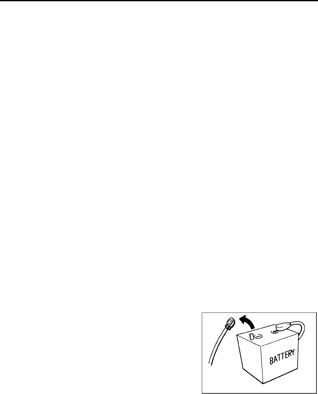
Precautions UCS000MB
●Before connecting or disconnecting the TCM harness con-
nector, turn ignition switch OFF and disconnect negative
battery cable. Failure to do so may damage the TCM.
Because battery voltage is applied to TCM even if ignition
switch is turned off.
SEF289H
PRECAUTIONS
AT-11
[RE4F04B]
D
E
F
G
H
I
J
K
L
M
A
B
AT
Revision: September 2005 2005 Quest
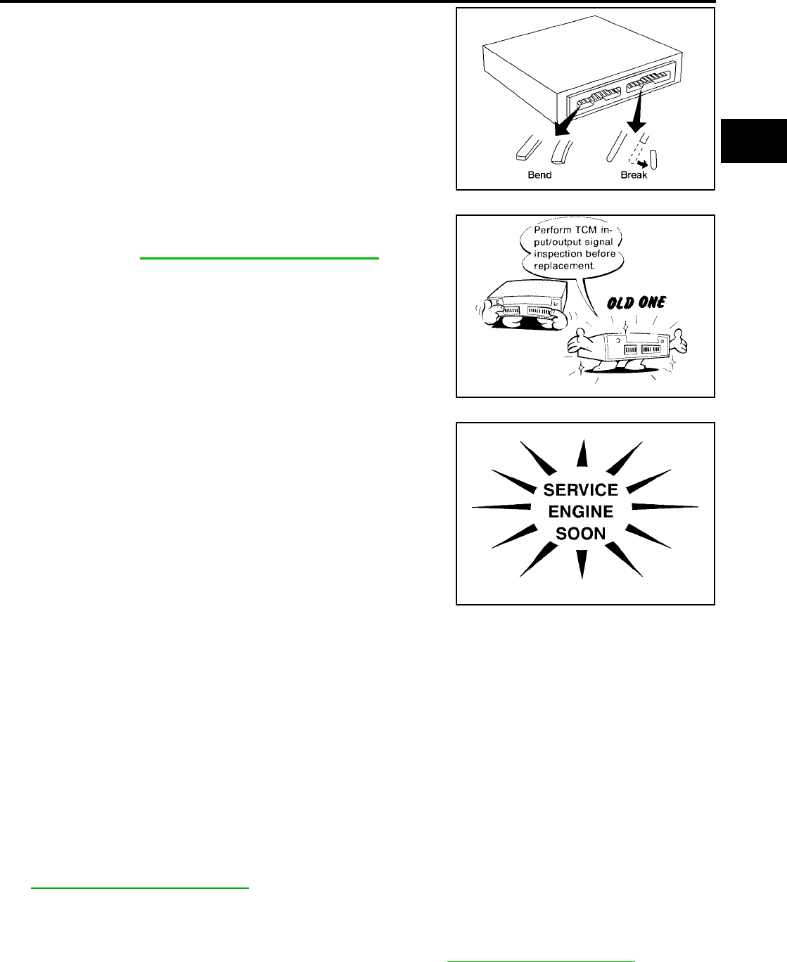
●When connecting or disconnecting pin connectors into or
from TCM, take care not to damage pin terminals (bend or
break).
Make sure that there are not any bends or breaks on TCM
pin terminal, when connecting pin connectors.
●Before replacing TCM, perform TCM input/output signal
inspection and make sure whether TCM functions properly
or not. Refer to AT-97, "TCM INSPECTION TABLE" .
●After performing each TROUBLE DIAGNOSIS, perform
“DTC (Diagnostic Trouble Code) CONFIRMATION PROCE-
DURE”.
The DTC should not be displayed in the “DTC CONFIRMA-
TION PROCEDURE” if the repair is completed.
●Before proceeding with disassembly, thoroughly clean the out-
side of the transaxle. It is important to prevent the internal parts
from becoming contaminated by dirt or other foreign matter.
●Disassembly should be done in a clean work area.
●Use lint-free cloth or towels for wiping parts clean. Common
shop rags can leave fibers that could interfere with the operation
of the transaxle.
●Place disassembled parts in order for easier and proper assembly.
●All parts should be carefully cleaned with a general purpose, non-flammable solvent before inspection or
reassembly.
●Gaskets, seals and O-rings should be replaced any time the transaxle is disassembled.
●It is very important to perform functional tests whenever they are indicated.
●The valve body contains precision parts and requires extreme care when parts are removed and serviced.
Place disassembled valve body parts in order for easier and proper assembly. Care will also prevent
springs and small parts from becoming scattered or lost.
●Properly installed valves, sleeves, plugs, etc. will slide along bores in valve body under their own weight.
●Before assembly, apply a coat of recommended ATF to all parts. Apply petroleum jelly to protect O-rings
and seals, or hold bearings and washers in place during assembly. Do not use grease.
●Extreme care should be taken to avoid damage to O-rings, seals and gaskets when assembling.
●Clean or replace ATF cooler if excessive foreign material is found in oil pan or clogging strainer. Refer to
AT-12, "ATF COOLER SERVICE" .
●After overhaul, refill the transaxle with new ATF.
●When the A/T drain plug is removed, only some of the fluid is drained. Old A/T fluid will remain in torque
converter and ATF cooling system.
Always follow the procedures when changing A/T fluid. Refer to MA-23, "Changing A/T Fluid" .
AAT470A
MEF040DA
SAT964I

AT-12
[RE4F04B]
PRECAUTIONS
Revision: September 2005 2005 Quest
Service Notice or Precautions UCS000MC
FAIL-SAFE
The TCM has an electronic Fail-Safe (limp home mode). This allows the vehicle to be driven even if a major
electrical input/output device circuit is damaged.
Under Fail-Safe, the vehicle always runs in third gear, even with a shift lever position of L or D. The customer
may complain of sluggish or poor acceleration.
When the ignition key is turned ON following Fail-Safe operation, O/D OFF indicator lamp blinks for about 8
seconds. [For “TCM Self-diagnostic Procedure (No Tools)”, refer to AT-54, "TCM SELF-DIAGNOSTIC PRO-
CEDURE (NO TOOLS)" .]
The blinking of the O/D OFF indicator lamp for about 8 seconds will appear only once and be cleared. The
customer may resume normal driving conditions.
Always follow the “Work Flow” (Refer to AT-63, "Work Flow" ).
The SELF-DIAGNOSIS results will be as follows:
●The first SELF-DIAGNOSIS will indicate damage to the vehicle speed sensor or the revolution sensor.
●During the next SELF-DIAGNOSIS, performed after checking the sensor, no damages will be indicated.
TORQUE CONVERTER SERVICE
The torque converter should be replaced under any of the following conditions:
●External leaks in the hub weld area.
●Converter hub is scored or damaged.
●Converter pilot is broken, damaged or fits poorly into crankshaft.
●Steel particles are found after flushing the cooler and cooler lines.
●Pump is damaged or steel particles are found in the converter.
●Vehicle has TCC shudder and/or no TCC apply. Replace only after all hydraulic and electrical diagnoses
have been made. (Converter clutch material may be glazed.)
●Converter is contaminated with engine coolant containing antifreeze.
●Internal failure of stator roller clutch.
●Heavy clutch debris due to overheating (blue converter).
●Steel particles or clutch lining material found in fluid filter or on magnet when no internal parts in unit are
worn or damaged — indicates that lining material came from converter.
The torque converter should not be replaced if:
●The fluid has an odor, is discolored, and there is no evidence of metal or clutch facing particles.
●The threads in one or more of the converter bolt holes are damaged.
●Transaxle failure did not display evidence of damaged or worn internal parts, steel particles or clutch plate
lining material in unit and inside the fluid filter.
●Vehicle has been exposed to high mileage (only). The exception may be where the torque converter
clutch dampener plate lining has seen excess wear by vehicles operated in heavy and/or constant traffic,
such as taxi, delivery or police use.
ATF COOLER SERVICE
If A/T fluid contains frictional material (clutches, bands, etc.), or if an A/T is repaired, overhauled, or replaced,
inspect and clean the A/T fluid cooler mounted in the radiator or replace the radiator. Flush cooler lines using
cleaning solvent and compressed air after repair. For A/T fluid cooler cleaning procedure, refer to AT-65, "A/T
Fluid Cooler Cleaning" . For radiator replacement, refer to CO-10, "RADIATOR" .
OBD-II SELF-DIAGNOSIS
●A/T self-diagnosis is performed by the TCM in combination with the ECM. The results can be read through
the blinking pattern of the O/D OFF indicator or the malfunction indicator lamp (MIL). Refer to the table on
AT-43 for the indicator used to display each self-diagnostic result.
●The self-diagnostic results indicated by the MIL are automatically stored in both the ECM and TCM mem-
ories.
Always perform the procedure “HOW TO ERASE DTC” on AT-40 to complete the repair and avoid
unnecessary blinking of the MIL.
●The following self-diagnostic items can be detected using ECM self-diagnostic results mode* only when
the O/D OFF indicator lamp does not indicate any malfunctions.
–park/neutral position (PNP) switch

PRECAUTIONS
AT-13
[RE4F04B]
D
E
F
G
H
I
J
K
L
M
A
B
AT
Revision: September 2005 2005 Quest
*: For details of OBD-II, refer to EC-51, "ON BOARD DIAGNOSTIC (OBD) SYSTEM" .
●Certain systems and components, especially those related to OBD, may use a new style slide-
locking type harness connector.
For description and how to disconnect, refer to PG-67, "HARNESS CONNECTOR" .
Wiring Diagrams and Trouble Diagnosis UCS000MD
When you read wiring diagrams, refer to the following:
●GI-13, "How to Read Wiring Diagrams"
●PG-4, "POWER SUPPLY ROUTING CIRCUIT"
When you perform trouble diagnosis, refer to the following:
●GI-9, "How to Follow Trouble Diagnoses"
●GI-25, "How to Perform Efficient Diagnosis for an Electrical Incident"
AT-14
[RE4F04B]
PREPARATION
Revision: September 2005 2005 Quest
PREPARATION PFP:00002
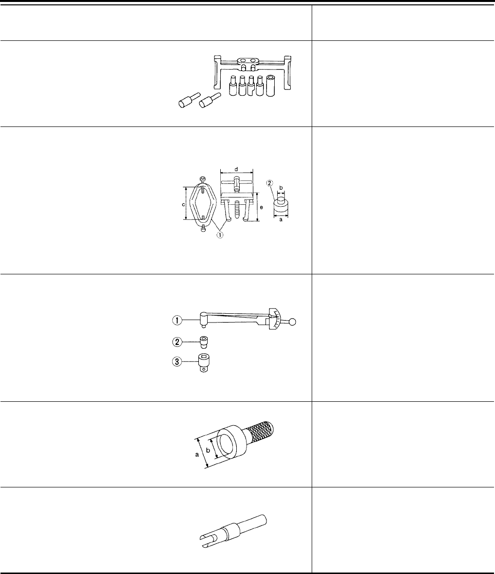
Special Service Tools UCS000ME
The actual shapes of Kent-Moore tools may differ from those of special service tools illustrated here.
Tool number
(Kent-Moore No.)
Tool name
Description
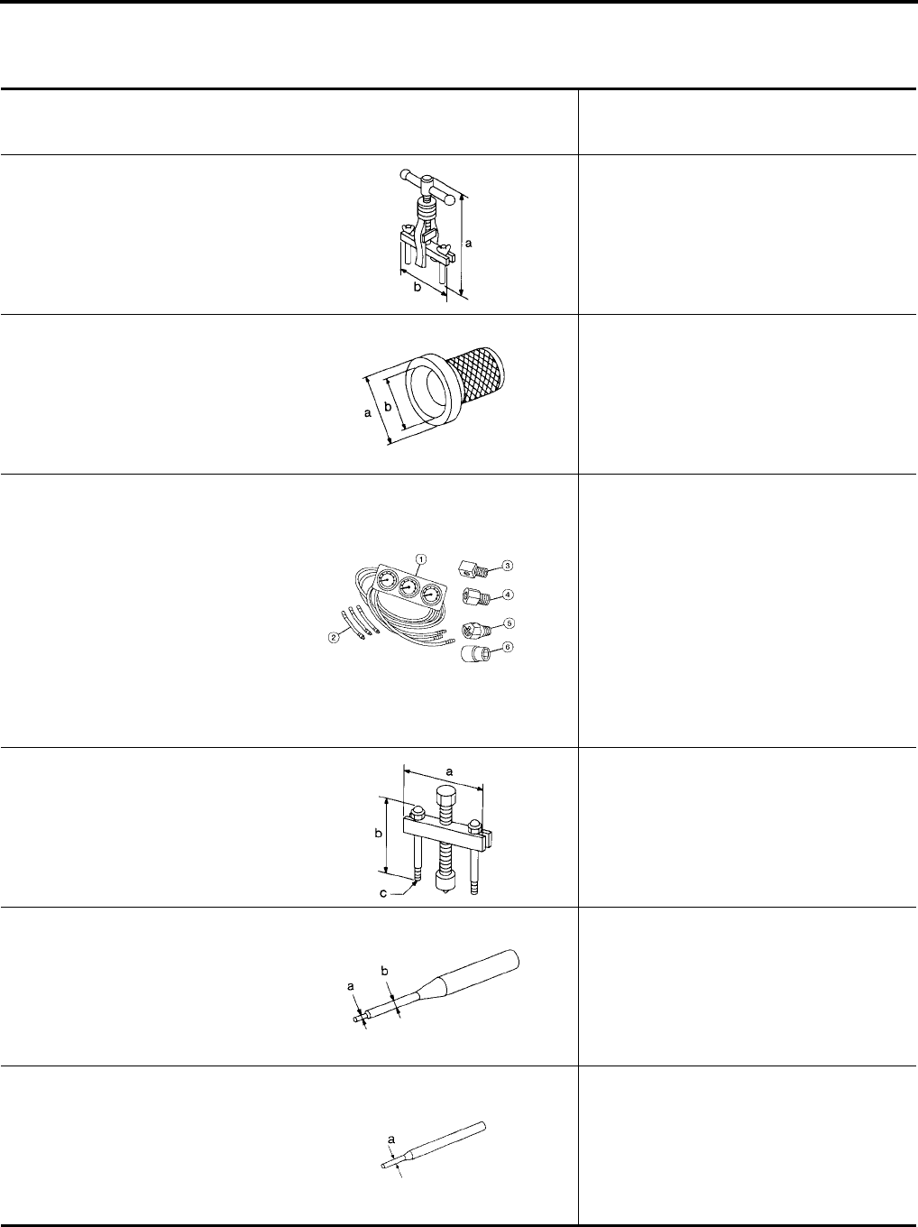
KV381054S0
(J-34286)
Puller
a: 250 mm (9.84 in)
b: 160 mm (6.30 in)
●Removing differential side oil seals
●Removing differential side bearing outer
race
●Removing idler gear bearing outer race
ST33400001
(J-26082)
Drift
a: 60 mm (2.36 in) dia.
b: 47 mm (1.85 in) dia.
●Installing differential side oil seal
(RH side)
●Installing oil seal on oil pump housing
(J-34301-C)
Oil pressure gauge set
1 (J-34301-1)
Oil pressure gauge
2 (J-34301-2)
Hoses
3 (J-34298)
Adapter
4 (J-34282-2)
Adapter
5 (790-301-1230-A)
60° Adapter
6 (J-34301-15)
Square socket
Measuring line pressure
ST27180001
(J-25726-A)
Puller
a: 100 mm (3.94 in)
b: 110 mm (4.33 in)
c: M8 x 1.25P
Removing idler gear
ST23540000
(J-25689-A)
Pin punch
a: 2.3 mm (0.091 in) dia.
b: 4 mm (0.16 in) dia.
Removing and installing parking rod plate and
manual plate pins
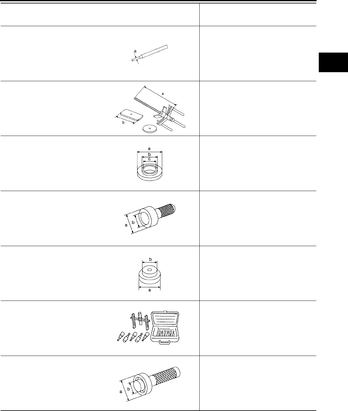
ST25710000
(J-25689-A)
Pin punch
a: 2 mm (0.08 in) dia.
Aligning groove of manual shaft and hole of
transmission case
NT414
NT086
AAT896
NT424
NT442
NT410
PREPARATION
AT-15
[RE4F04B]
D
E
F
G
H
I
J
K
L
M
A
B
AT
Revision: September 2005 2005 Quest
KV32101000
(J-25689-A)
Pin punch
a: 4 mm (0.16 in) dia.
●Removing and installing manual shaft re-
taining pin
●Removing and installing pinion mate shaft
lock pin
KV31102400
(J-34285 and J-34285-87)
Clutch spring compressor
a: 320 mm (12.60 in)
b: 174 mm (6.85 in)
●Removing and installing clutch return
springs
●Installing low & reverse brake piston
KV40100630
(J-26092)
Drift
a: 67.5 mm (2.657 in) dia.
b: 44 mm (1.73 in) dia.
c: 38.5 mm (1.516 in) dia.
●Installing reduction gear bearing inner race
●Installing idler gear bearing inner race
ST30720000
(J-25405 and J-34331)
Bearing installer
a: 77 mm (3.03 in) dia.
b: 55.5 mm (2.185 in) dia.
Installing idler gear bearing outer race
ST35321000
(—)
Drift
a: 49 mm (1.93 in) dia.
b: 41 mm (1.61 in) dia.
Installing output shaft bearing
(J-34291-A)
Shim setting gauge set
●Selecting oil pump cover bearing race and
oil pump thrust washer
●Selecting side gear thrust washer
ST33230000
(J-25805-01)
Drift
a: 51 mm (2.01 in) dia.
b: 28.5 mm (1.122 in) dia.
Installing differential side bearing inner race
(RH side)
Tool number
(Kent-Moore No.)
Tool name
Description
NT410
NT423
NT107
NT115
NT073
NT101
NT084
AT-16
[RE4F04B]
PREPARATION
Revision: September 2005 2005 Quest
(J-34290)
Shim selecting tool set
Selecting differential side bearing adjusting
shim
ST3306S001
(J-22888-D)
Differential side bearing puller set
1 ST33051001
(J-22888-D)
Puller
2 ST33061000
(J-8107-2)
Adapter
a: 38 mm (1.50 in) dia.
b: 28.5 mm (1.122 in) dia.
c: 130 mm (5.12 in)
d: 135 mm (5.31 in)
e: 100 mm (3.94 in)
Removing differential side bearing inner race
ST3127S000
(J-25765-A)
Preload gauge
1 GG91030000
(J-25765-A)
Torque wrench
2 HT62940000
(—)
Socket adapter
3 HT62900000
(—)
Socket adapter
Checking differential side bearing preload
ST35271000
(J-26091)
Drift
a: 72 mm (2.83 in) dia.
b: 63 mm (2.48 in) dia.
Installing idler gear
(J-39713)
Preload adapter
●Selecting differential side bearing adjusting
shim
●Checking differential side bearing preload
Tool number
(Kent-Moore No.)
Tool name
Description
NT080
AMT153
NT124
NT115
NT087
PREPARATION
AT-17
[RE4F04B]
D
E
F
G
H
I
J
K
L
M
A
B
AT
Revision: September 2005 2005 Quest
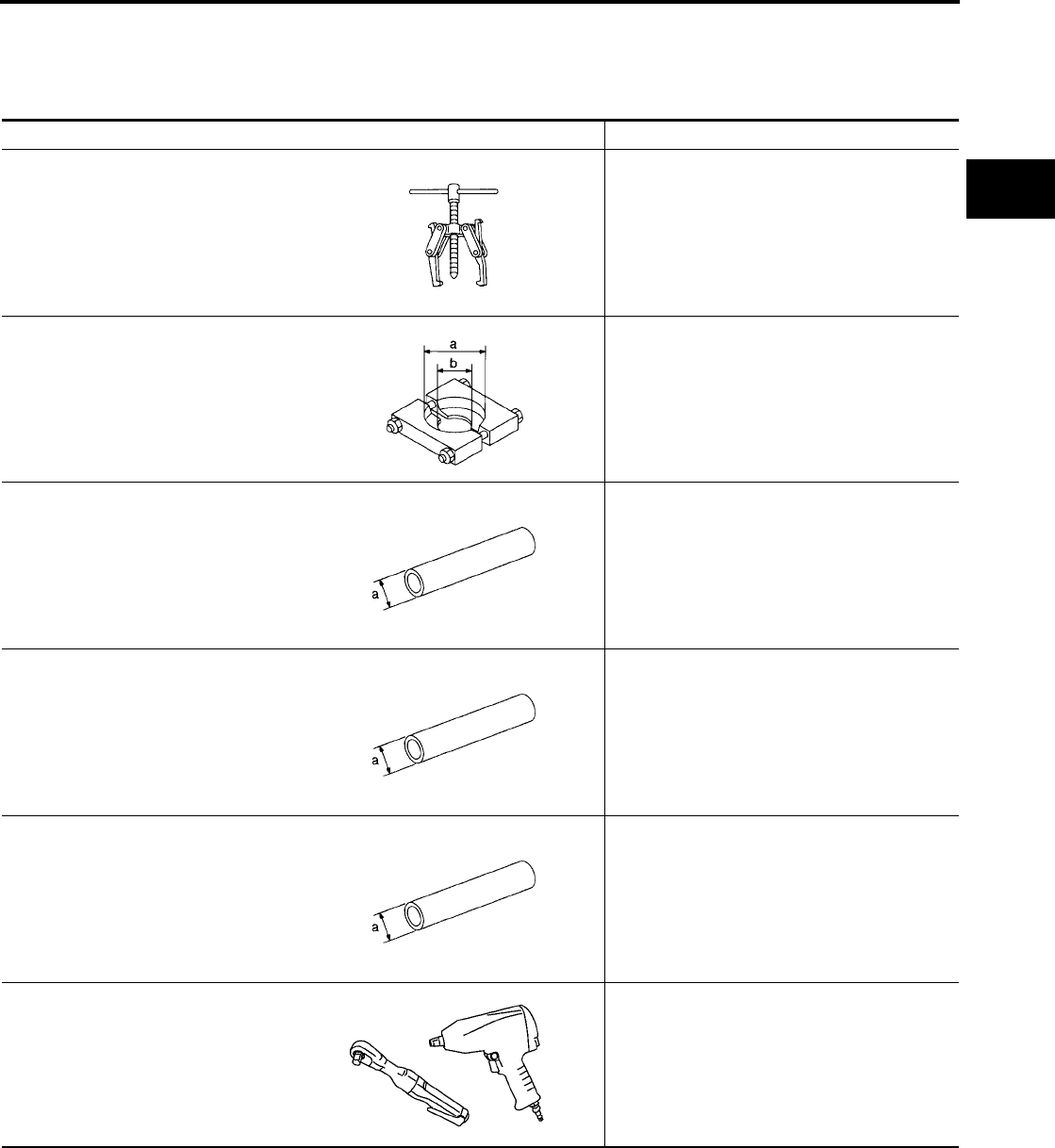
Commercial Service Tools UCS000MF
Tool name Description
Puller ● Removing idler gear bearing inner race
●Removing and installing band servo piston
snap ring
Puller
a: 60 mm (2.36 in) dia.
b: 35 mm (1.38 in) dia.
Removing reduction gear bearing inner race
Drift
a: 36 mm (1.42 in) dia.
Installing needle bearing on bearing retainer
Drift
a: 33.5 mm (1.319 in) dia.
Removing needle bearing from bearing retain-
er
Drift
a: 75 mm (2.95 in) dia.
Installing differential side bearing outer race
(RH side)
Power tool
●Removing transaxle assembly
●Removing transaxle oil pan
●Removing transaxle case and cover
NT077
NT411
NT083
NT083
NT083
PBIC0190E
AT-18
[RE4F04B]
OVERALL SYSTEM
Revision: September 2005 2005 Quest
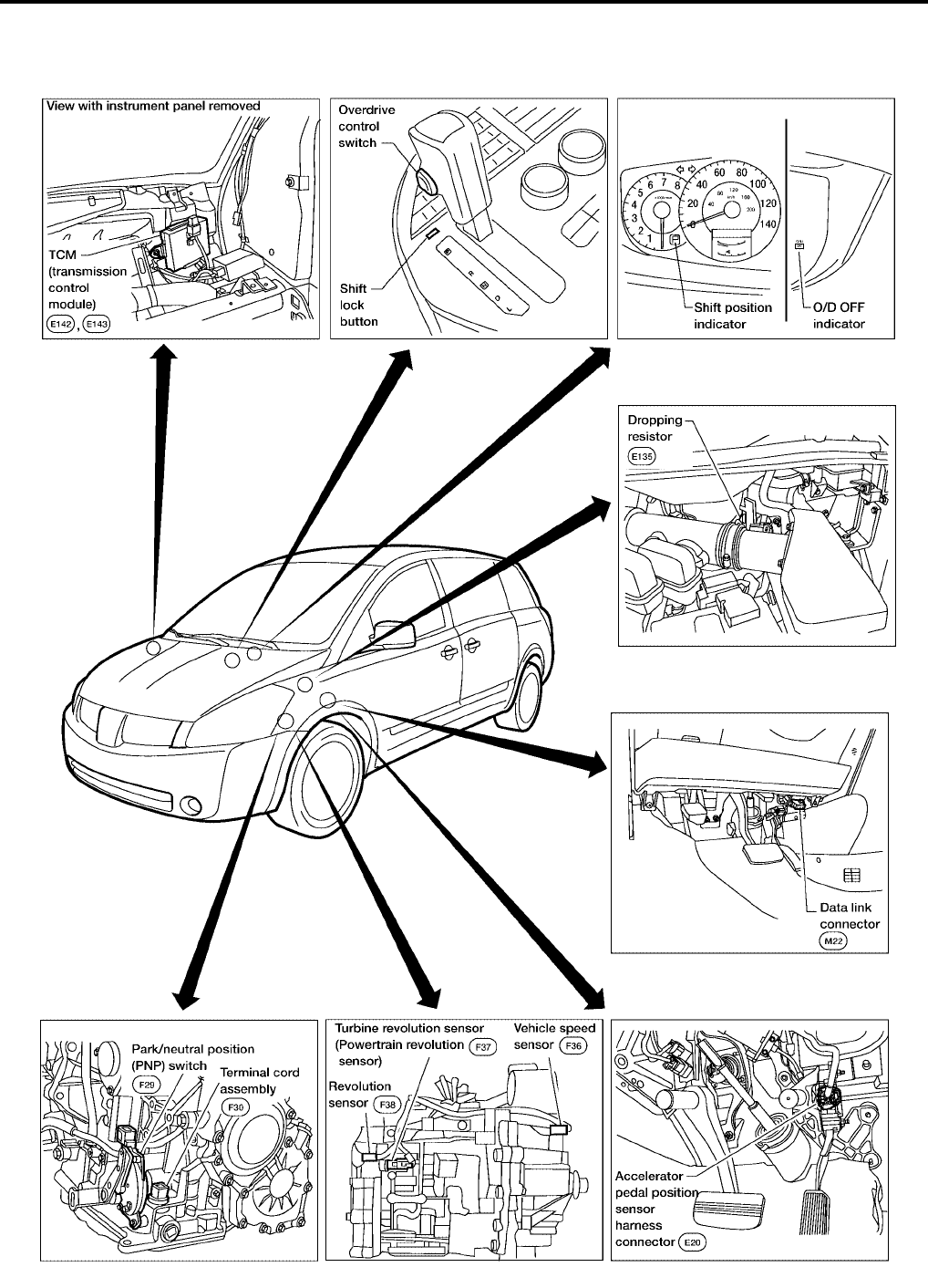
OVERALL SYSTEM PFP:00000
A/T Electrical Parts Location UCS000MG
BCIA0001E
OVERALL SYSTEM
AT-19
[RE4F04B]
D
E
F
G
H
I
J
K
L
M
A
B
AT
Revision: September 2005 2005 Quest
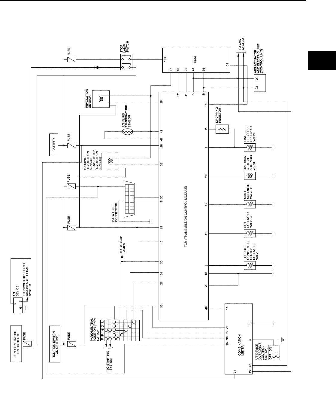
Circuit Diagram UCS000MH
BCWA0521E
AT-20
[RE4F04B]
OVERALL SYSTEM
Revision: September 2005 2005 Quest
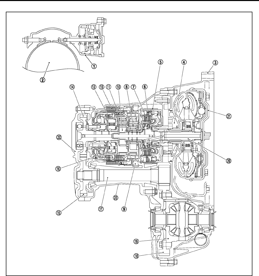
Cross-sectional View UCS000MI
1. Band servo piston 2. Reverse clutch drum 3. Converter housing
4. Oil pump 5. Brake band 6. Reverse clutch
7. High clutch 8. Front planetary gear 9. Low one-way clutch
10. Rear planetary gear 11. Forward clutch 12. Overrun clutch
13. Low & reverse brake 14. Output gear 15. Idler gear
16. Forward one-way clutch 17. Pinion reduction gear 18. Final gear
19. Differential case 20. Input shaft 21. Torque converter
22. Side cover 23. Transaxle case
SCIA3174E
OVERALL SYSTEM
AT-21
[RE4F04B]
D
E
F
G
H
I
J
K
L
M
A
B
AT
Revision: September 2005 2005 Quest
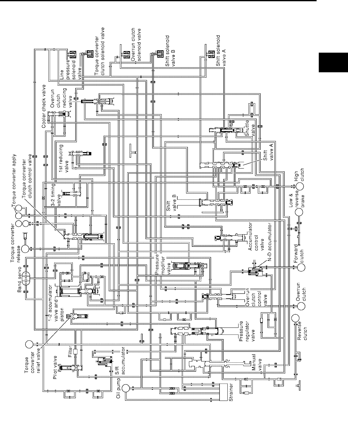
Hydraulic Control Circuit UCS000MJ
SAT489K
AT-22
[RE4F04B]
OVERALL SYSTEM
Revision: September 2005 2005 Quest
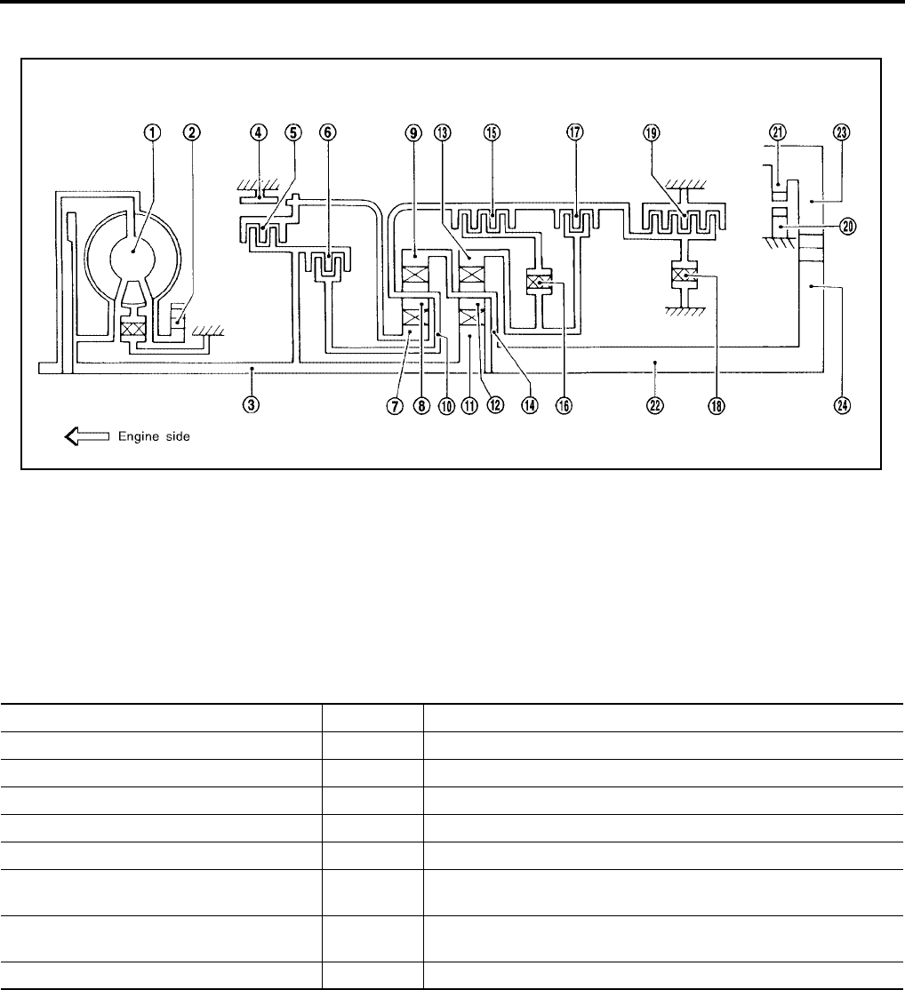
Shift Mechanism UCS000MK
CONSTRUCTION
FUNCTION OF CLUTCH AND BRAKE
1. Torque converter 2. Oil pump 3. Input shaft
4. Brake band 5. Reverse clutch 6. High clutch
7. Front sun gear 8. Front pinion gear 9. Front internal gear
10. Front planetary carrier 11. Rear sun gear 12. Rear pinion gear
13. Rear internal gear 14. Rear planetary carrier 15. Forward clutch
16. Forward one-way clutch 17. Overrun clutch 18. Low one-way clutch
19. Low & reverse brake 20. Parking pawl 21. Parking gear
22. Output shaft 23. Idle gear 24. Output gear
SAT998I
Clutch and brake components Abbr. Function
Reverse clutch 5R/C To transmit input power to front sun gear 7 .
High clutch 6H/C To transmit input power to front planetary carrier 10 .
Forward clutch 15 F/C To connect front planetary carrier 10 with forward one-way clutch 16 .
Overrun clutch 17 O/C To connect front planetary carrier 10 with rear internal gear 13 .
Brake band 4 B/B To lock front sun gear 7 .
Forward one-way clutch 16 F/O.C When forward clutch 15 is engaged, to stop rear internal gear 13
from rotating in opposite direction against engine revolution.
Low one-way clutch 18 L/O.C To stop front planetary carrier 10 from rotating in opposite direction
against engine revolution.
Low & reverse brake 19 L & R/B To lock front planetary carrier 10 .

OVERALL SYSTEM
AT-23
[RE4F04B]
D
E
F
G
H
I
J
K
L
M
A
B
AT
Revision: September 2005 2005 Quest
CLUTCH AND BAND CHART
*1: Operates when overdrive control switch is set in “OFF” position.
*2: Oil pressure is applied to both 2nd “apply” side and 3rd “release” side of band servo piston. However, brake band does not contract
because oil pressure area on the “release” side is greater than that on the “apply” side.
*3: Oil pressure is applied to 4th “apply” side in condition *2 above, and brake band contracts.
*4: A/T will not shift to 4th when selector lever is set in 3 position.
O: Operates
A: Operates when throttle opening is less than 3/16, activating engine brake.
B: Operates during “progressive” acceleration.
C: Operates but does not affect power transmission.
D: Operates when throttle opening is less than 3/16, but does not affect engine brake.
Shift position
Re-
verse
clutch
5
High
clutch
6
For-
ward
clutch
15
Over-
run
clutch
17
Band servo For-
ward
one-
way
clutch
16
Low
one-
way
clutch
18
Low &
re-
verse
brake
19
Lock-
up Remarks
2nd
apply
3rd re-
lease
4th
apply
PPARK POSI-
TION
RO OREVERSE
POSITION
NNEUTRAL
POSITION
D*4
1st O *1D B B Automatic
shift
1 ⇔ 2 ⇔ 3
⇔ 4
2nd O *1 A O B
3rd O O *1 A *2C C B *1O
4th O C *3C C O O
L
1st O O B B Automatic
shift
1 ⇔ 2 ⇐ 3
2nd O O O B
3rd OOO*2CC B
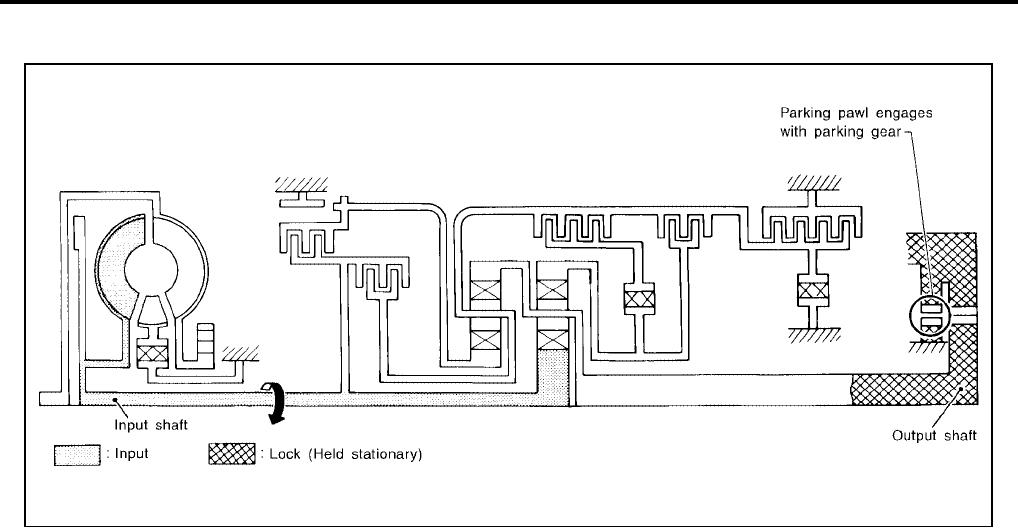
AT-24
[RE4F04B]
OVERALL SYSTEM
Revision: September 2005 2005 Quest
POWER TRANSMISSION
P and N Positions
●P position
Similar to the N position, the clutches do not operate. The parking pawl engages with the parking gear to
mechanically hold the output shaft so that the power train is locked.
●N position
Power from the input shaft is not transmitted to the output shaft because the clutches do not operate.
SAT991I
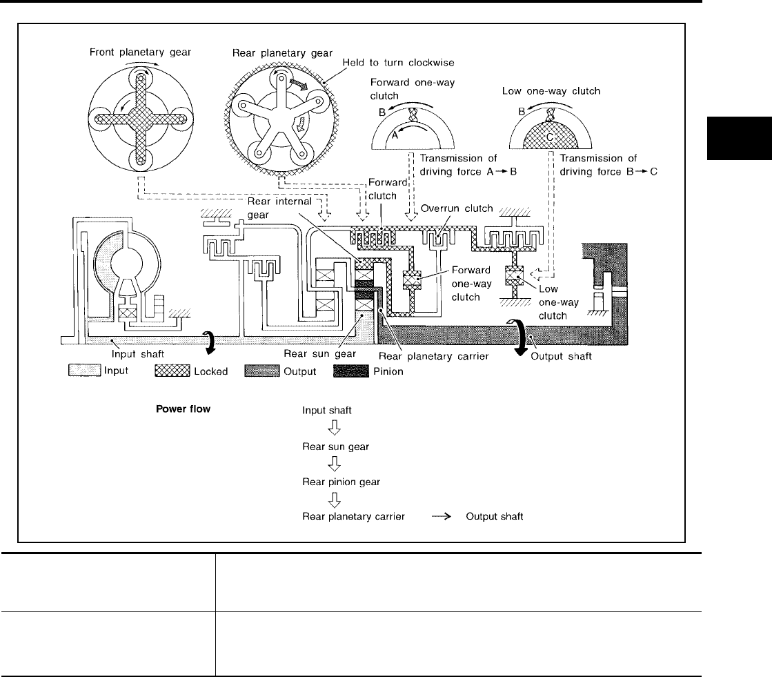
OVERALL SYSTEM
AT-25
[RE4F04B]
D
E
F
G
H
I
J
K
L
M
A
B
AT
Revision: September 2005 2005 Quest
D1 and L1 Positions
SCIA3325E
●Forward one-way clutch
●Forward clutch
●Low one-way clutch
Rear internal gear is locked to rotate counterclockwise because of the functioning of these
three clutches.
Overrun clutch
engagement conditions
(Engine brake)
D1 : Overdrive control switch “OFF” and throttle opening is less than 3/16
L1 : Always engaged
At D1 and L1 positions, engine brake is not activated due to free turning of low one-way
clutch.
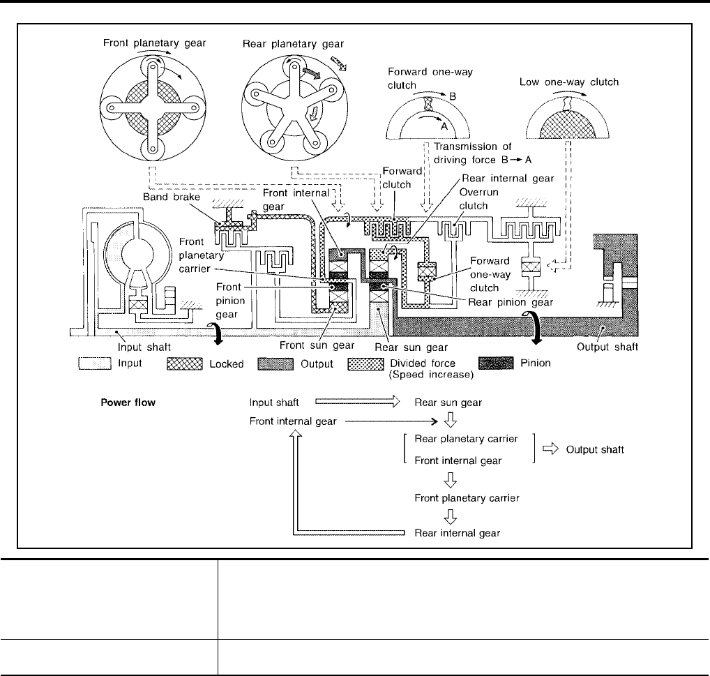
AT-26
[RE4F04B]
OVERALL SYSTEM
Revision: September 2005 2005 Quest
D2 and L2 Positions
SCIA3326E
●Forward clutch
●Forward one-way clutch
●Brake band
Rear sun gear drives rear planetary carrier and combined front internal gear. Front internal
gear now rotates around front sun gear accompanying front planetary carrier.
As front planetary carrier transfers the power to rear internal gear through forward clutch and
forward one-way clutch, this rotation of rear internal gear increases the speed of rear plane-
tary carrier compared with that of the 1st speed.
Overrun clutch
engagement conditions
D2 : Overdrive control switch “OFF” and throttle opening is less than 3/16
L2 : Always engaged
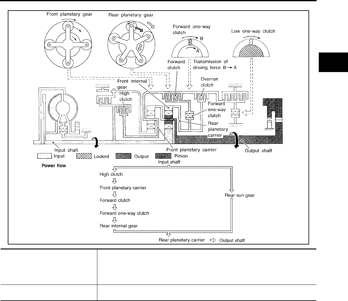
OVERALL SYSTEM
AT-27
[RE4F04B]
D
E
F
G
H
I
J
K
L
M
A
B
AT
Revision: September 2005 2005 Quest
D3 and L3 Positions
SCIA3327E
●High clutch
●Forward clutch
●Forward one-way clutch
Input power is transmitted to front planetary carrier through high clutch. And front planetary
carrier is connected to rear internal gear by operation of forward clutch and forward one-way
clutch.
This rear internal gear rotation and another input (the rear sun gear) accompany rear plane-
tary carrier to turn at the same speed.
Overrun clutch
engagement conditions
D3 : Overdrive control switch “OFF” and throttle opening is less than 3/16
L3 : Always engaged
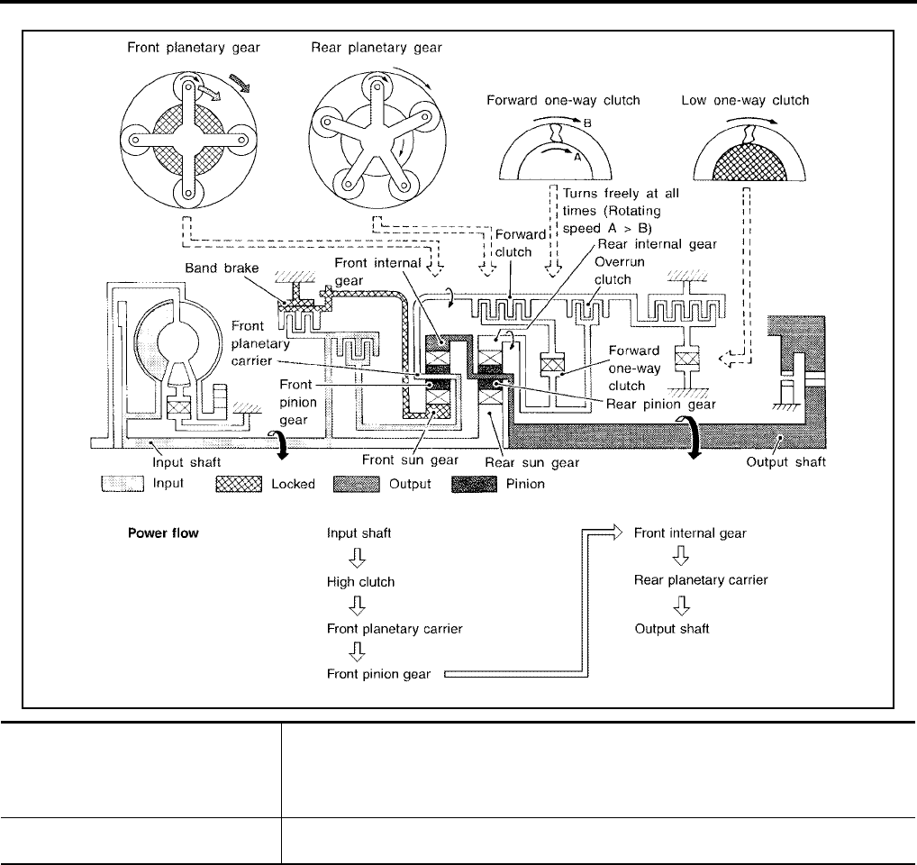
AT-28
[RE4F04B]
OVERALL SYSTEM
Revision: September 2005 2005 Quest
D4 Position
SCIA3328E
●High clutch
●Brake band
●Forward clutch (Does not affect
power transmission)
Input power is transmitted to front carrier through high clutch.
This front carrier turns around the sun gear which is fixed by brake band and makes front
internal gear (output) turn faster.
Engine brake At D4 position, there is no one-way clutch in the power transmission line and engine brake
can be obtained when decelerating.
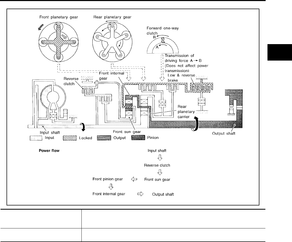
OVERALL SYSTEM
AT-29
[RE4F04B]
D
E
F
G
H
I
J
K
L
M
A
B
AT
Revision: September 2005 2005 Quest
R Position
SCIA3329E
●Reverse clutch
●Low & reverse brake
Front planetary carrier is stationary because of the operation of low & reverse brake.
Input power is transmitted to front sun gear through reverse clutch, which drives front inter-
nal gear in the opposite direction.
Engine brake As there is no one-way clutch in the power transmission line, engine brake can be obtained
when decelerating.
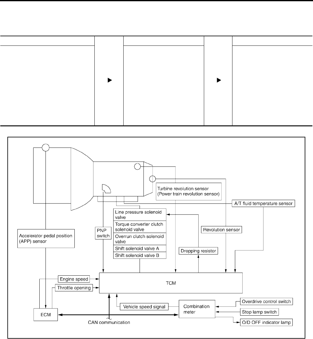
AT-30
[RE4F04B]
OVERALL SYSTEM
Revision: September 2005 2005 Quest
Control System UCS000ML
OUTLINE
The automatic transaxle senses vehicle operating conditions through various sensors. It always controls the
optimum shift position and reduces shifting and lock-up shocks.
CONTROL SYSTEM
SENSORS (or SIGNALS) TCM ACTUATORS
Park/neutral position (PNP) switch
Accelerator pedal position (APP) sen-
sor
Engine speed signal
A/T fluid temperature sensor
Revolution sensor
Vehicle speed signal
Overdrive control switch
ASCD control signal
Stop lamp switch
Turbine revolution sensor (power train
revolution sensor)
Shift control
Line pressure control
Lock-up control
Overrun clutch control
Timing control
Fail-safe control
Self-diagnosis
CAN communication line control
Shift solenoid valve A
Shift solenoid valve B
Overrun clutch solenoid valve
Torque converter clutch solenoid
valve
Line pressure solenoid valve
O/D OFF indicator lamp
SCIA3357E

OVERALL SYSTEM
AT-31
[RE4F04B]
D
E
F
G
H
I
J
K
L
M
A
B
AT
Revision: September 2005 2005 Quest
TCM FUNCTION
The function of the TCM is to:
●Receive input signals sent from various switches and sensors.
●Determine required line pressure, shifting point, lock-up operation, and engine brake operation.
●Send required output signals to the respective solenoids.
INPUT/OUTPUT SIGNAL OF TCM
CAN Communication UCS0015M
SYSTEM DESCRIPTION
CAN (Controller Area Network) is a serial communication line for real time application. It is an on-vehicle mul-
tiplex communication line with high data communication speed and excellent error detection ability. Many elec-
tronic control units are equipped onto a vehicle, and each control unit shares information and links with other
control units during operation (not independent). In CAN communication, control units are connected with 2
communication lines (CAN H line, CAN L line) allowing a high rate of information transmission with less wiring.
Each control unit transmits/receives data but selectively reads required data only.
For details, refer to LAN-5, "CAN COMMUNICATION" .
Sensors and solenoid valves Function
Input
Park/neutral position (PNP) switch Detects select lever position and sends a signal to TCM.
Accelerator pedal position (APP) sensor Detects throttle valve position and sends a signal to TCM.
Closed throttle position signal Detects throttle valves fully-closed position and sends a signal from ECM to
TCM.
Wide open throttle position signal Detects throttle valve position of greater than 1/2 or full throttle and sends a
signal from ECM to TCM.
Engine speed signal Receives signal from ECM.
A/T fluid temperature sensor Detects transmission fluid temperature and sends a signal to TCM.
Revolution sensor Detects output shaft rpm and sends a signal to TCM.
Vehicle speed sensor Used as an auxiliary vehicle speed sensor. Sends a signal when revolution
sensor (installed on transmission) malfunctions.
Overdrive control switch Sends a signal, which prohibits a shift to D4 (overdrive) position, to the TCM.
ASCD control signal Sends the cruise signal and D4 (overdrive) cancellation signal from ECM to
TCM.
Turbine revolution sensor (power train
revolution sensor) Detects forward clutch drum rpm and sends a signal to TCM.
Stop lamp switch Send the lock-up release signal to the TCM at time of D4 (lock-up).
Output
Shift solenoid valve A/B Selects shifting point suited to driving conditions in relation to a signal sent
from TCM.
Line pressure solenoid valve Regulates (or decreases) line pressure suited to driving conditions in relation
to a signal sent from TCM.
Torque converter clutch solenoid valve Regulates (or decreases) lock-up pressure suited to driving conditions in rela-
tion to a signal sent from TCM.
Overrun clutch solenoid valve Controls an “engine brake” effect suited to driving conditions in relation to a
signal sent from TCM.
O/D OFF indicator lamp Shows TCM faults, when A/T control components malfunction.
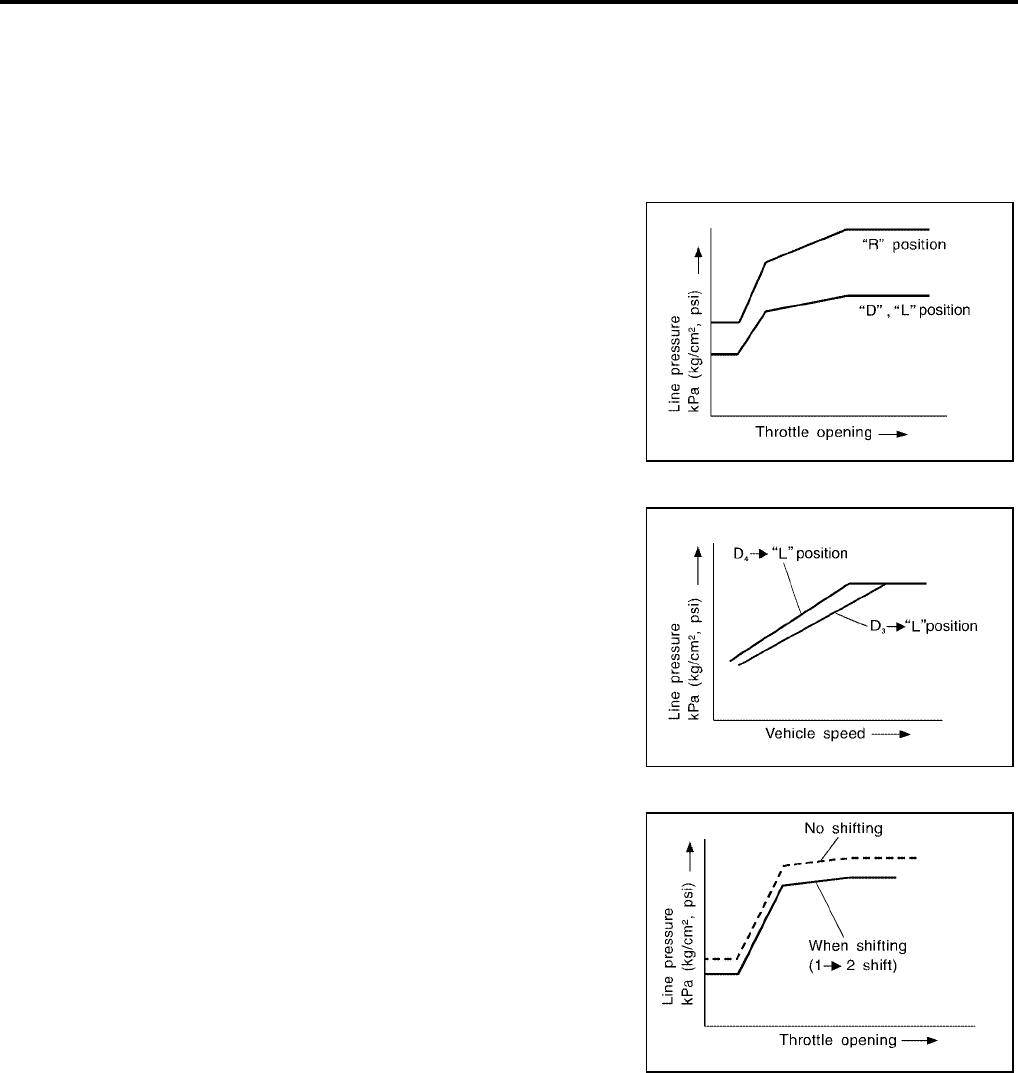
AT-32
[RE4F04B]
OVERALL SYSTEM
Revision: September 2005 2005 Quest
Control Mechanism UCS000MM
LINE PRESSURE CONTROL
TCM has various line pressure control characteristics to meet the driving conditions.
An ON-OFF duty signal is sent to the line pressure solenoid valve based on TCM characteristics.
Hydraulic pressure on the clutch and brake is electronically controlled through the line pressure solenoid valve
to accommodate engine torque. This results in smooth shift operation.
Normal Control
The line pressure to throttle opening characteristics is set for suitable
clutch operation.
Back-up Control (Engine brake)
If the selector lever is shifted to L position while driving in D4 (O/D)
or D3 , great driving force is applied to the clutch inside the transmis-
sion. Clutch operating pressure (line pressure) must be increased to
deal with this driving force.
During Shift Change
The line pressure is temporarily reduced corresponding to a change
in engine torque when shifting gears (that is, when the shift solenoid
valve is switched for clutch operation) to reduce shifting shock.
At Low Fluid Temperature
●Fluid viscosity and frictional characteristics of the clutch facing change with fluid temperature. Clutch
engaging or band-contacting pressure is compensated for, according to fluid temperature, to stabilize
shifting quality.
SCIA3359E
SCIA3360E
SAT005J
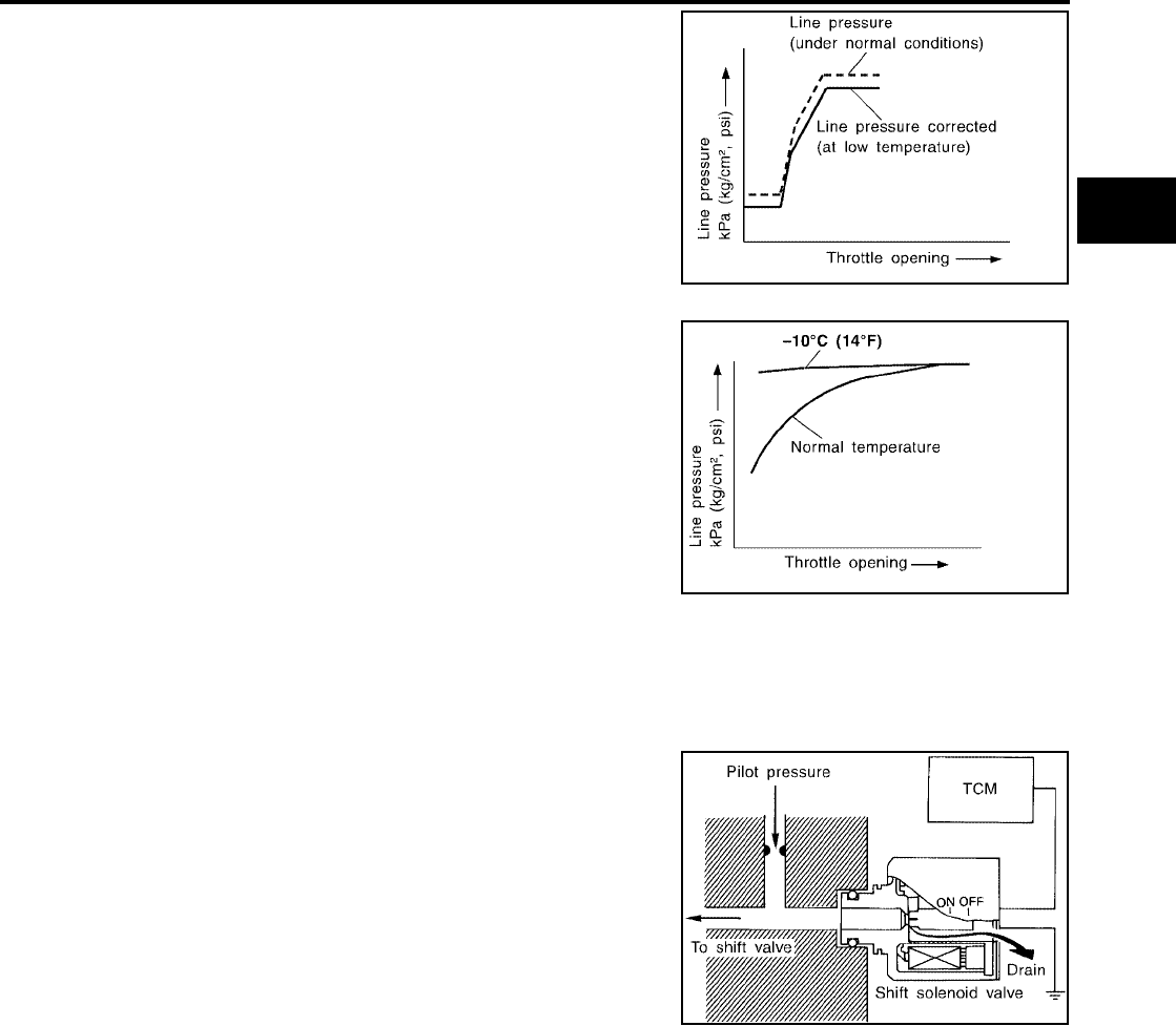
OVERALL SYSTEM
AT-33
[RE4F04B]
D
E
F
G
H
I
J
K
L
M
A
B
AT
Revision: September 2005 2005 Quest
●The line pressure is reduced below 60°C (140°F) to prevent
shifting shock due to low viscosity of automatic transmission
fluid when temperature is low.
●Line pressure is increased to a maximum irrespective of the
throttle opening when fluid temperature drops to −10°C (14°F).
This pressure rise is adopted to prevent a delay in clutch and
brake operation due to extreme drop of fluid viscosity at low
temperature.
SHIFT CONTROL
The shift is regulated entirely by electronic control to accommodate vehicle speed and varying engine opera-
tions. This is accomplished by electrical signals transmitted by the revolution sensor and the ECM (throttle
opening). This results in improved acceleration performance and fuel economy.
Control of Shift Solenoid Valves A and B
The shift solenoid valve performs simple ON-OFF operation. When
set to ON, the drain circuit closes and pilot pressure is applied to the
shift valve.
The TCM activates shift solenoid valves A and B according to sig-
nals from the ECM (throttle opening) and revolution sensor to select
the optimum gear position on the basis of the shift schedule memo-
rized in the TCM.
SAT006J
SAT007J
SAT008J
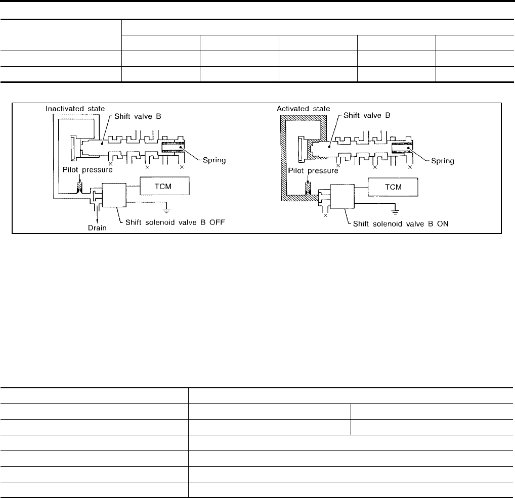
AT-34
[RE4F04B]
OVERALL SYSTEM
Revision: September 2005 2005 Quest
Relation between shift solenoid valves A and B and gear positions
Control of Shift Valves A and B
Pilot pressure generated by the operation of shift solenoid valves A and B is applied to the end face of shift
valves A and B.
The drawing above shows the operation of shift valve B. When the shift solenoid valve is ON, pilot pressure
applied to the end face of the shift valve overcomes spring force, moving the valve upward.
LOCK-UP CONTROL
The torque converter clutch piston in the torque converter is locked to eliminate torque converter slip to
increase power transmission efficiency. The solenoid valve is controlled by an ON-OFF duty signal sent from
the TCM. The signal is converted to an oil pressure signal which controls the lock-up piston.
Conditions for Lock-up Operation
When vehicle is driven in 3rd or 4th gear positions, vehicle speed and throttle opening are detected. If the
detected values fall within the lock-up zone memorized in the TCM, lock-up is performed.
Shift solenoid valve Gear position
D1 , L1D2 , L2D3D4 (O/D) N-P
A ON (Closed) OFF (Open) OFF (Open) ON (Closed) ON (Closed)
B ON (Closed) ON (Closed) OFF (Open) OFF (Open) ON (Closed)
SAT009J
Selector lever D position
Overdrive control switch ON OFF
Gear position D4D3
Vehicle speed sensor More than set value
ECM (throttle opening) Less than set opening
Closed throttle position signal OFF
A/T fluid temperature sensor More than 20°C (68°F)
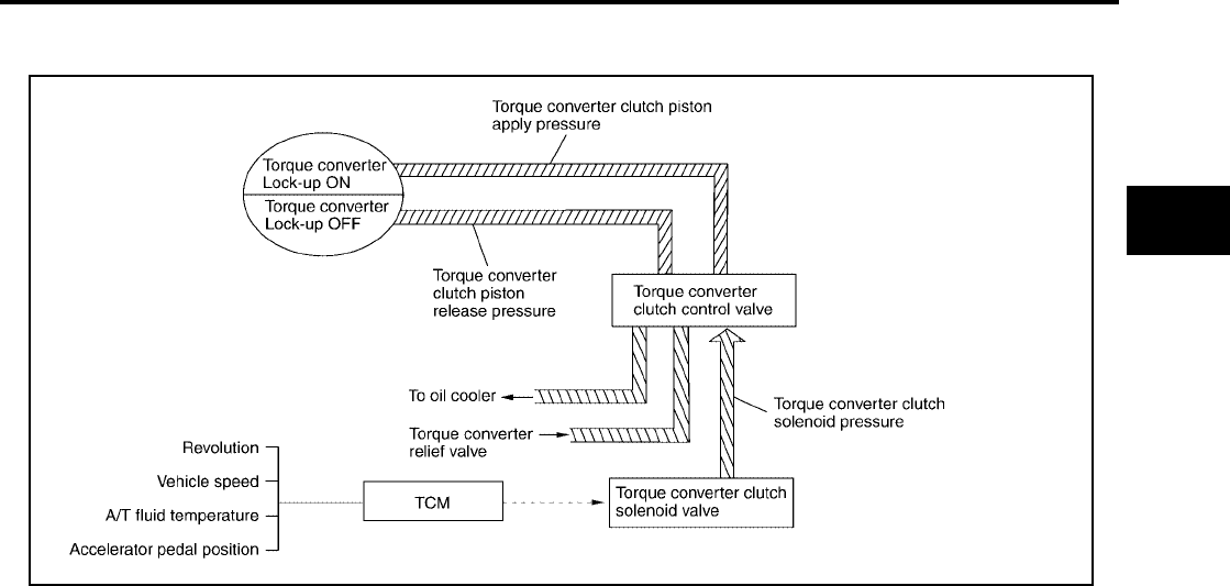
OVERALL SYSTEM
AT-35
[RE4F04B]
D
E
F
G
H
I
J
K
L
M
A
B
AT
Revision: September 2005 2005 Quest
Torque Converter Clutch Control Valve Control
LOCK-UP CONTROL SYSTEM DIAGRAM
LOCK-UP RELEASED
In the lock-up released state, the torque converter clutch control valve is set into the unlocked state by the
torque converter clutch solenoid and the lock-up apply pressure is drained and the torque converter clutch pis-
ton release pressure is generated.
In this way, the torque converter clutch piston is not coupled.
LOCK-UP APPLIED
In the lock-up applied state, the torque converter clutch control valve is set into the locked state by the torque
converter clutch solenoid and lock-up apply pressure is generated and the torque converter clutch piston
release pressure is drained.
In this way, the torque converter clutch piston is pressed and coupled.
Smooth Lock-up Control
When shifting from the lock-up released state to the lock-up applied state, the current output to the torque con-
verter clutch solenoid is controlled with the TCM. In this way, when shifting to the lock-up applied state, the
torque converter clutch is temporarily set to the half-clutched state to reduce the shock.
HALF-CLUTCHED STATE
The current output from the TCM to the torque converter clutch solenoid is varied to steadily increase the
torque converter clutch solenoid pressure.
In this way, the lock-up apply pressure gradually rises and while the torque converter clutch piston is put into
half-clutched status, the torque converter clutch piston operating pressure is increased and the coupling is
completed smoothly.
SCIA3330E

AT-36
[RE4F04B]
OVERALL SYSTEM
Revision: September 2005 2005 Quest
OVERRUN CLUTCH CONTROL (ENGINE BRAKE CONTROL)
Forward one-way clutch is used to reduce shifting shocks in downshifting operations. This clutch transmits
engine torque to the wheels. However, drive force from the wheels is not transmitted to the engine because
the one-way clutch rotates idle. This means the engine brake is not effective.
The overrun clutch operates when the engine brake is needed.
Overrun Clutch Operating Conditions
Overrun Clutch Solenoid Valve Control
The overrun clutch solenoid valve is operated by an ON-OFF signal
transmitted by the TCM to provide overrun clutch control (engine
brake control).
When this solenoid valve is ON, the pilot pressure drain port closes.
When it is OFF, the drain port opens.
During the solenoid valve ON pilot pressure is applied to the end
face of the overrun clutch control valve.
Overrun Clutch Control Valve Operation
When the solenoid valve is ON, pilot pressure is applied to the over-
run clutch control valve. This pushes up the overrun clutch control
valve. The line pressure is then shut off so that the clutch does not
engage.
When the solenoid valve is OFF, pilot pressure is not generated. At
this point, the overrun clutch control valve moves downward by
spring force. As a result, overrun clutch operation pressure is pro-
vided by the overrun clutch reducing valve. This causes the overrun
clutch to engage.
In the L position, the overrun clutch control valve remains pushed
down so that the overrun clutch is engaged at all times.
SCIA3361E
Selector lever position Gear position Throttle opening
D position D1 , D2 , D3 gear position Less than 3/16
L position L1 , L2 gear position At any position
SAT015J
SCIA3362E

OVERALL SYSTEM
AT-37
[RE4F04B]
D
E
F
G
H
I
J
K
L
M
A
B
AT
Revision: September 2005 2005 Quest
Control Valve UCS000MN
FUNCTION OF CONTROL VALVES
Valve name Function
Pressure regulator valve, plug and sleeve
plug
Regulates oil discharged from the oil pump to provide optimum line pressure for all driv-
ing conditions.
Pressure modifier valve and sleeve Used as a signal supplementary valve to the pressure regulator valve. Regulates pres-
sure-modifier pressure (signal pressure) which controls optimum line pressure for all
driving conditions.
Pilot valve Regulates line pressure to maintain a constant pilot pressure level which controls lock-up
mechanism, overrun clutch, shift timing.
Accumulator control valve Regulates accumulator back-pressure to pressure suited to driving conditions.
Manual valve Directs line pressure to oil circuits corresponding to select positions.
Hydraulic pressure drains when the shift lever is in Neutral.
Shift valve A Simultaneously switches three oil circuits using output pressure of shift solenoid valve A
to meet driving conditions (vehicle speed, throttle opening, etc.).
Provides automatic downshifting and up-shifting (1st → 2nd → 3rd → 4th gears/4th →
3rd → 2nd → 1st gears) in combination with shift valve B.
Shift valve B Simultaneously switches two oil circuits using output pressure of shift solenoid valve B in
relation to driving conditions (vehicle speed, throttle opening, etc.).
Provides automatic downshifting and up-shifting (1st → 2nd → 3rd → 4th gears/4th →
3rd → 2nd → 1st gears) in combination with shift valve A.
Overrun clutch control valve Switches hydraulic circuits to prevent engagement of the overrun clutch simultaneously
with application of the brake band in D4 . (Interlocking occurs if the overrun clutch
engages during D4 .)
“1” reducing valve Reduces low & reverse brake pressure to dampen engine-brake shock when down-shift-
ing from the L position L2 to L1 .
Overrun clutch reducing valve Reduces oil pressure directed to the overrun clutch and prevents engine-brake shock.
In 1st and 2nd positions, line pressure acts on the overrun clutch reducing valve to
increase the pressure-regulating point, with resultant engine brake capability.
Torque converter relief valve Prevents an excessive rise in torque converter pressure.
Torque converter clutch control valve, plug
and sleeve
Activates or inactivates the lock-up function.
Also provides smooth lock-up through transient application and release of the lock-up
system.
1-2 accumulator valve and piston Dampens the shock encountered when 2nd gear band servo contracts, and provides
smooth shifting.
3-2 timing valve Switches the pace that oil pressure is released depending on vehicle speed; maximizes
the high clutch release timing, and allows for soft down shifting.
Shuttle valve Determines if the overrun clutch solenoid valve should control the 3-2 timing valve or the
overrun clutch control valve and switches between the two.
Cooler check valve At low speeds and with a small load when little heat is generated, saves the volume of
cooler flow, and stores the oil pressure for lock up.

AT-38
[RE4F04B]
ON BOARD DIAGNOSTIC SYSTEM DESCRIPTION
Revision: September 2005 2005 Quest
ON BOARD DIAGNOSTIC SYSTEM DESCRIPTION PFP:00000
Introduction UCS000MO
The A/T system has two self-diagnostic systems.
The first is the emission-related on board diagnostic system (OBD-II) performed by the TCM (transmission
control module) in combination with the ECM. The malfunction is indicated by the MIL (malfunction indicator
lamp) and is stored as a DTC in the ECM memory but not the TCM memory.
The second is the TCM original self-diagnosis indicated by the O/D OFF indicator lamp. The malfunction is
stored in the TCM memory. The detected items are overlapped with OBD-II self-diagnostic items. For details,
refer to AT-43, "SELF-DIAGNOSTIC RESULT TEST MODE" .
OBD-II Function for A/T System UCS000MP
The ECM provides emission-related on board diagnostic (OBD-II) functions for the A/T system. One function
is to receive a signal from the TCM used with OBD-related parts of the A/T system. The signal is sent to the
ECM when a malfunction occurs in the corresponding OBD-related part. The other function is to indicate a
diagnostic result by means of the MIL (malfunction indicator lamp) on the instrument panel. Sensors, switches
and solenoid valves are used as sensing elements.
The MIL automatically illuminates in One or Two Trip Detection Logic when a malfunction is sensed in relation
to A/T system parts.
One or Two Trip Detection Logic of OBD-II UCS000MQ
ONE TRIP DETECTION LOGIC
If a malfunction is sensed during the first test drive, the MIL will illuminate and the malfunction will be stored in
the ECM memory as a DTC. The TCM is not provided with such a memory function.
TWO TRIP DETECTION LOGIC
When a malfunction is sensed during the first test drive, it is stored in the ECM memory as a 1st trip DTC
(diagnostic trouble code) or 1st trip freeze frame data. At this point, the MIL will not illuminate. — First Trip
If the same malfunction as that experienced during the first test drive is sensed during the second test drive,
the MIL will illuminate. — Second Trip
A/T-related parts for which the MIL illuminates during the first or second test drive are listed below.
The “trip” in the “One or Two Trip Detection Logic” means a driving mode in which self-diagnosis is performed
during vehicle operation.
OBD-II Diagnostic Trouble Code (DTC) UCS000MR
HOW TO READ DTC AND 1ST TRIP DTC
DTC and 1st trip DTC can be read by the following methods.
( With CONSULT-II or GST) CONSULT-II or GST (Generic Scan Tool) Examples: P0705, P0710,
P0720, P0725, etc.
These DTCs are prescribed by SAE J2012.
(CONSULT-II also displays the malfunctioning component or system.)
●1st trip DTC No. is the same as DTC No.
●Output of the diagnostic trouble code indicates that the indicated circuit has a malfunction. How-
ever, in case of the Mode II and GST they do not indicate whether the malfunction is still occurring
or occurred in the past and returned to normal.
CONSULT-II can identify them as shown below. Therefore, using CONSULT-II (if available) is rec-
ommended.
Items MIL
One trip detection Two trip detection
Shift solenoid valve A — DTC: P0750 X
Shift solenoid valve B — DTC: P0755 X
Accelerator pedal position (APP) sensor — DTC: P1705 X
Except above X
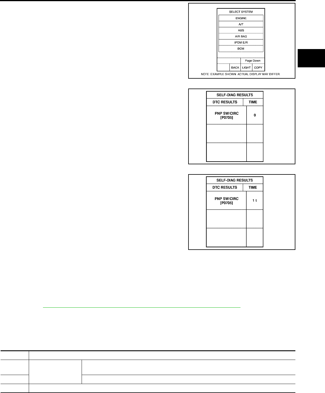
ON BOARD DIAGNOSTIC SYSTEM DESCRIPTION
AT-39
[RE4F04B]
D
E
F
G
H
I
J
K
L
M
A
B
AT
Revision: September 2005 2005 Quest
A sample of CONSULT-II display for DTC and 1st trip DTC is shown
in the following page. DTC or 1st trip DTC of a malfunction is dis-
played in “SELF DIAGNOSIS” mode for “ENGINE” with CONSULT-
II. Time data indicates how many times the vehicle was driven after
the last detection of a DTC.
If the DTC is being detected currently, the time data will be “0”.
If a 1st trip DTC is stored in the ECM, the time data will be “1t”.
Freeze Frame Data and 1st Trip Freeze Frame Data
The ECM has a memory function, which stores the driving condition such as fuel system status, calculated
load value, engine coolant temperature, short term fuel trim, long term fuel trim, engine speed and vehicle
speed at the moment the ECM detects a malfunction.
Data which are stored in the ECM memory, along with the 1st trip DTC, are called 1st trip freeze frame data,
and the data, stored together with the DTC data, are called freeze frame data and displayed on CONSULT-II
or GST. The 1st trip freeze frame data can only be displayed on the CONSULT-II screen, not on the GST. For
details, refer to EC-57, "FREEZE FRAME DATA AND 1ST TRIP FREEZE FRAME DATA" .
Only one set of freeze frame data (either 1st trip freeze frame data of freeze frame data) can be stored in the
ECM. 1st trip freeze frame data is stored in the ECM memory along with the 1st trip DTC. There is no priority
for 1st trip freeze frame data and it is updated each time a different 1st trip DTC is detected. However, once
freeze frame data (2nd trip detection/MIL on) is stored in the ECM memory, 1st trip freeze frame data is no
longer stored. Remember, only one set of freeze frame data can be stored in the ECM. The ECM has the fol-
lowing priorities to update the data.
Both 1st trip freeze frame data and freeze frame data (along with the DTCs) are cleared when the ECM mem-
ory is erased.
BCIA0030E
SAT015K
SAT016K
Priority Items
1
Freeze frame data
Misfire — DTC: P0300 - P0306
Fuel Injection System Function — DTC: P0171, P0172, P0174, P0175
2 Except the above items (Includes A/T related items)
3 1st trip freeze frame data

AT-40
[RE4F04B]
ON BOARD DIAGNOSTIC SYSTEM DESCRIPTION
Revision: September 2005 2005 Quest
HOW TO ERASE DTC
The diagnostic trouble code can be erased by CONSULT-II, GST or ECM DIAGNOSTIC TEST MODE as
described following.
●If the battery terminal is disconnected, the diagnostic trouble code will be lost within 24 hours.
●When you erase the DTC, using CONSULT-II or GST is easier and quicker than switching the mode
selector on the ECM.
The following emission-related diagnostic information is cleared from the ECM memory when erasing DTC
related to OBD-II. For details, refer to EC-52, "Emission-related Diagnostic Information" .
●Diagnostic trouble codes (DTC)
●1st trip diagnostic trouble codes (1st trip DTC)
●Freeze frame data
●1st trip freeze frame data
●System readiness test (SRT) codes
●Test values
HOW TO ERASE DTC (WITH CONSULT-II)
●If a DTC is displayed for both ECM and TCM, it needs to be erased for both ECM and TCM.
1. If the ignition switch stays ON after repair work, be sure to turn ignition switch OFF once. Wait at least 10
seconds and then turn it ON (engine stopped) again.
2. Turn CONSULT-II “ON” and touch “A/T”.
3. Touch “SELF-DIAG RESULTS”.
4. Touch “ERASE”. (The DTC in the TCM will be erased.) Then touch “BACK” twice.
5. Touch “ENGINE”.
6. Touch “SELF DIAGNOSIS”.
7. Touch “ERASE”. (The DTC in the ECM will be erased.)

ON BOARD DIAGNOSTIC SYSTEM DESCRIPTION
AT-41
[RE4F04B]
D
E
F
G
H
I
J
K
L
M
A
B
AT
Revision: September 2005 2005 Quest
HOW TO ERASE DTC (WITH GST)
1. If the ignition switch stays ON after repair work, be sure to turn ignition switch OFF once. Wait at least 10
seconds and then turn it ON (engine stopped) again.
2. Perform “TCM SELF-DIAGNOSTIC PROCEDURE (NO TOOLS)”. Refer to AT-54, "TCM SELF-DIAG-
NOSTIC PROCEDURE (NO TOOLS)" . (The engine warm-up step can be skipped when performing the
diagnosis only to erase the DTC.)
3. Select Mode 4 with Generic Scan Tool (GST). For details, refer to EC-146, "Generic Scan Tool (GST)
Function" .
HOW TO ERASE DTC (NO TOOLS)
1. If the ignition switch stays ON after repair work, be sure to turn ignition switch OFF once. Wait at least 10
seconds and then turn it ON (engine stopped) again.
2. Perform “TCM SELF-DIAGNOSTIC PROCEDURE (NO TOOLS)”. Refer to AT-54, "TCM SELF-DIAG-
NOSTIC PROCEDURE (NO TOOLS)" . (The engine warm-up step can be skipped when performing the
diagnosis only to erase the DTC.)
3. Perform “OBD-II SELF-DIAGNOSTIC PROCEDURE (NO TOOLS)”. Refer to EC-65, "How to Erase DTC"
.
SCIA5575E
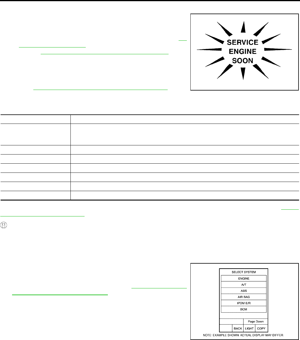
AT-42
[RE4F04B]
ON BOARD DIAGNOSTIC SYSTEM DESCRIPTION
Revision: September 2005 2005 Quest
Malfunction Indicator Lamp (MIL) UCS000MS
1. The malfunction indicator lamp will light up when the ignition
switch is turned ON without the engine running. This is for
checking the lamp.
●If the malfunction indicator lamp does not light up, refer to DI-
22, "WARNING LAMPS" .
[Or see EC-743, "MIL AND DATA LINK CONNECTOR" .]
2. When the engine is started, the malfunction indicator lamp
should go off.
If the lamp remains on, the on board diagnostic system has
detected an emission-related (OBD-II) malfunction. For details,
refer to EC-52, "Emission-related Diagnostic Information" .
CONSULT-II Function (TCM) UCS000MT
CONSULT-II can display each diagnostic item using the diagnostic test modes shown following.
After performing “SELF-DIAGNOSTIC place check marks for results on the “Diagnostic Worksheet”, AT-60,
"DIAGNOSTIC WORKSHEET" . Reference pages are provide following the items.
SELF-DIAGNOSTIC PROCEDURE (WITH CONSULT-II)
CAUTION:
If CONSULT-II is used with no connection of CONSULT-II CONVERTER, malfunctions might be
detected in self-diagnosis depending on control unit which carry out CAN communication.
●For details, refer to the separate “CONSULT-II Operations Manual”.
1. Touch on CONSULT-II, touch “START (NISSAN BASED
VHCL)”, and touch “ENGINE” for OBD-II detected items or touch
“A/T” for TCM self-diagnosis.
If “ENGINE” or “A/T” is not displayed, go to GI-37, "CONSULT-II
Data Link Connector (DLC) Circuit" .
SAT964I
TCM diagnostic mode Description
WORK SUPPORT
Supports inspections and adjustments. Commands are transmitted to the TCM for setting the status
suitable for required operation, input/output signals are received from the TCM and received data is
displayed.
SELF-DIAG RESULTS Displays TCM self-diagnosis results.
DATA MONITOR Displays TCM input/output data in real time.
CAN DIAG SUPPORT MNTR The result of transmit/receive diagnosis of CAN communication can be read.
ACTIVE TEST Operation of electrical loads can be checked by sending drive signal to them.
FUNCTION TEST Conducted by CONSULT-II instead of a technician to determine whether each system is "OK" or "NG".
ECU PART NUMBER TCM part number can be read.
BCIA0030E
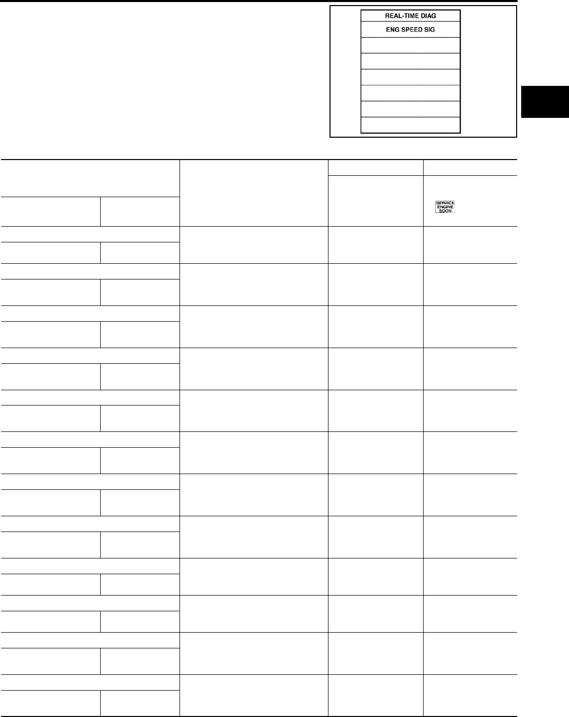
ON BOARD DIAGNOSTIC SYSTEM DESCRIPTION
AT-43
[RE4F04B]
D
E
F
G
H
I
J
K
L
M
A
B
AT
Revision: September 2005 2005 Quest
2. Touch “SELF DIAG RESULTS”.
Display shows malfunction experienced since the last erasing
operation.
CONSULT-II performs “Real Time Diagnosis”.
Also, any malfunction detected while in this mode will be dis-
played at real time.
SELF-DIAGNOSTIC RESULT TEST MODE
SAT987J
Detected items
(Screen terms for CONSULT-II, “SELF
DIAGNOSIS” test mode) Malfunction is detected when...
TCM self-diagnosis OBD-II (DTC)
Available by O/D OFF
indicator lamp
Available by malfunc-
tion indicator lamp*2,
“ENGINE” on
CONSULT-II or GST
“A/T” “ENGINE”
Park/neutral position (PNP) switch circuit ●TCM does not receive the correct
voltage signal (based on the gear
position) from the switch.
—P0705
— PNP SW/CIRC
Revolution sensor
●TCM does not receive the proper
voltage signal from the sensor. XP0720
VHCL SPEED SEN·A/T VEH SPD SEN/
CIR AT
Vehicle speed signal from meter ●TCM does not receive the proper
voltage signal from the combina-
tion meter.
X—
VHCL SPEED
SEN·MTR —
A/T 1st gear function ●A/T cannot be shifted to the 1st
gear position even if electrical cir-
cuit is good.
— P0731*1
A/T 1ST GR FNCTN A/T 1ST GR
FNCTN
A/T 2rd gear function ●A/T cannot be shifted to the 2nd
gear position even if electrical cir-
cuit is good.
— P0732*1
A/T 2ND GR FNCTN A/T 2ND GR
FNCTN
A/T 3rd gear function ●A/T cannot be shifted to the 3rd
gear position even if electrical cir-
cuit is good.
— P0733*1
A/T 3RD GR FNCTN A/T 3RD GR
FNCTN
A/T 4th gear function ●A/T cannot be shifted to the 4th
gear position even if electrical cir-
cuit is good.
— P0734*1
A/T 4TH GR FNCTN A/T 4TH GR
FNCTN
A/T TCC S/V function (lock-up)
●A/T cannot perform lock-up even if
electrical circuit is good. — P0744*1
A/T TCC S/V FNCTN A/T TCC S/V
FNCTN
Shift solenoid valve A ●TCM detects an improper voltage
drop when it tries to operate the
solenoid valve.
XP0750
SHIFT SOLENOID/V A SFT SOL A/CIRC
Shift solenoid valve B ●TCM detects an improper voltage
drop when it tries to operate the
solenoid valve.
X P0755
SHIFT SOLENOID/V B SFT SOL B/CIRC
Overrun clutch solenoid valve ●TCM detects an improper voltage
drop when it tries to operate the
solenoid valve.
XP1760
OVERRUN CLUTCH S/
V
O/R CLUCH SOL/
CIRC
T/C clutch solenoid valve ●TCM detects an improper voltage
drop when it tries to operate the
solenoid valve.
XP0740
T/C CLUTCH SOL/V TCC SOLENOID/
CIRC

AT-44
[RE4F04B]
ON BOARD DIAGNOSTIC SYSTEM DESCRIPTION
Revision: September 2005 2005 Quest
X: Applicable
−: Not applicable
*1: These malfunctions cannot be displayed by MIL if another malfunction is assigned to MIL.
*2: Refer to EC-67, "Malfunction Indicator Lamp (MIL)" .
*3: If malfunction is detected in multiple systems including CAN communication line, CAN communication line trouble diagnosis shall be
performed first.
DATA MONITOR MODE (A/T)
NOTICE:
1. The CONSULT-II electrically displays shift timing and lock-up timing (that is, operation timing of each sole-
noid).
Check for time difference between actual shift timing and the CONSULT-II display. If the difference is
noticeable, mechanical parts (except solenoids, sensors, etc.) may be malfunctioning. Check mechanical
parts using applicable diagnostic procedures.
Line pressure solenoid valve ●TCM detects an improper voltage
drop when it tries to operate the
solenoid valve.
X P0745
LINE PRESSURE S/V L/PRESS SOL/
CIRC
Accelerator pedal position (APP) sensor ●TCM receives an excessively low
or high voltage from this sensor X P1705
THROTTLE POSI SEN TP/SEN/CIRC A/T
Engine speed signal
●TCM does not receive the proper
voltage signal from the ECM. X P0725
ENGINE SPEED SIG ENGINE SPEED
SIG
A/T fluid temperature sensor
●TCM receives an excessively low
or high voltage from the sensor. X P0710
BATT/FLUID TEMP
SEN
ATF TEMP SEN/
CIRC
CAN communication*3
●When malfunction is detected in
CAN communication line. X U1000
CAN COMM CIRCUIT CAN COMM CIR-
CUIT
Turbine revolution sensor
(power train revolution sensor ●TCM does not receive proper volt-
age signal from sensor X—
TURBINE REV —
TCM (RAM)
●TCM memory (RAM) is malfunc-
tioning ——
CONTROL UNIT
(RAM) —
TCM (ROM)
●TCM memory (ROM) is malfunc-
tioning ——
CONTROL UNIT
(ROM) —
TCM (EEP ROM)
●TCM memory (EEP ROM) is mal-
functioning. ——
CONT UNIT(EEP
ROM) —
Initial start ●This is not a malfunction message
(Whenever shutting off a power
supply to the TCM, this message
appears on the screen.)
X—
INITIAL START —
No failure
(NO SELF DIAGNOSTIC FAILURE INDI-
CATED FURTHER TESTING MAY BE
REQUIRED**)
●No failure has been detected. X X
Detected items
(Screen terms for CONSULT-II, “SELF
DIAGNOSIS” test mode) Malfunction is detected when...
TCM self-diagnosis OBD-II (DTC)
Available by O/D OFF
indicator lamp
Available by malfunc-
tion indicator lamp*2,
“ENGINE” on
CONSULT-II or GST
“A/T” “ENGINE”

ON BOARD DIAGNOSTIC SYSTEM DESCRIPTION
AT-45
[RE4F04B]
D
E
F
G
H
I
J
K
L
M
A
B
AT
Revision: September 2005 2005 Quest
2. Shift schedule (which implies gear position) displayed on CONSULT-II and that indicated in Service Man-
ual may differ slightly. This occurs because of the following reasons:
–Actual shift schedule has more or less tolerance or allowance,
–Shift schedule indicated in Service Manual refers to the point where shifts start, and
–Gear position displayed on CONSULT-II indicates the point where shifts are completed.
3. Shift solenoid valve “A” or “B” is displayed on CONSULT-II at the start of shifting. Gear position is dis-
played upon completion of shifting (which is computed by TCM).
Item Display
Selection monitor item
Description Remarks
TCM
INPUT
SIG-
NALS
MAIN
SIG-
NALS
SELEC-
TION
FROM
MENU
Vehicle speed sensor 1
(A/T)
(Revolution sensor)
VHCL/S SE-A/
T
[km/h] or [mph] X —
● Vehicle speed com-
puted from signal of
revolution sensor is
displayed.
●When racing engine in
N or P with vehicle sta-
tionary, CONSULT-II
data may not indicate
0 km/h (0 mph).
Vehicle speed sensor 2
(Meter)
VHCL/S SE-
MTR
[km/h] or [mph]
X—
●Vehicle speed com-
puted from signal of
vehicle speed sensor is
displayed.
●Vehicle speed display
may not be accurate
under approx. 10 km/h
(6 mph). It may not
indicate 0 km/h (0
mph) when vehicle is
stationary.
Accelerator pedal posi-
tion (APP) sensor
THRTL POS
SEN
[V]
X —
●Accelerator pedal posi-
tion (APP) sensor sig-
nal voltage is displayed
A/T fluid temperature
sensor
FLUID TEMP
SE
[V] X—
●A/T fluid temperature
sensor signal voltage is
displayed.
●Signal voltage lowers
as fluid temperature
rises.
Battery voltage BATTERY
VOLT
[V]
X—
●Source voltage of TCM
is displayed.
Engine speed ENGINE
SPEED
[rpm] XX
●Engine speed, com-
puted from engine
speed signal, is dis-
played.
●Engine speed display
may not be accurate
under approx. 800
rpm. It may not indi-
cate 0 rpm even when
engine is not running.
Turbine revolution sen-
sor (power train revolu-
tion sensor)
TURBINE REV
[rpm]
X—
●Checks changing
speed then performs
oil pressure control and
torque down control
●Error may occur under
approx. 800 rpm and
will not indicate 0 rpm
even if engine is not
running.
Overdrive control switch OVERDRIVE
SW
[ON/OFF] X—
●ON/OFF state com-
puted from signal of
overdrive control
switch, is displayed.
PN position (PNP) switch PN POSI SW
[ON/OFF] X—
●ON/OFF state com-
puted from signal of
PN position switch, is
displayed.
R position switch R POSITION
SW
[ON/OFF] X—
●ON/OFF state com-
puted from signal of R
position switch, is dis-
played.

AT-46
[RE4F04B]
ON BOARD DIAGNOSTIC SYSTEM DESCRIPTION
Revision: September 2005 2005 Quest
D position switch D POSITION
SW
[ON/OFF] X—
●ON/OFF state com-
puted from signal of D
position switch, is dis-
played.
L position switch 2 POSITION
SW
[ON/OFF] X—
●ON/OFF status, com-
puted from signal of L
(2nd) position switch, is
displayed.
1 position switch 1 POSITION
SW
[ON/OFF] X—
●ON/OFF status, com-
puted from signal of 1st
position switch, is dis-
played.
●This is displayed even
when no 1st position
switch is equipped.
ASCD cruise signal ASCD-
CRUISE
[ON/OFF] X —
●Status of ASCD cruise
signal is displayed.
ON ... Cruising state
OFF ... Normal run-
ning state
ASCD OD cut signal ASCD-OD
CUT
[ON/OFF] X—
●Status of ASCD OD
release signal is dis-
played.
ON ... OD released
OFF ... OD not
released
Kickdown switch KICKDOWN
SW
[ON/OFF] X—
●ON/OFF status, com-
puted from signal of
kickdown switch, is dis-
played.
●This is displayed even
when no kickdown
switch is equipped.
A/T mode switch POWER
SHIFT SW
[ON/OFF]
X—
●Not mounted but dis-
played
Closed throttle position
signal
CLOSED THL/
SW
[ON/OFF] X—
●ON/OFF status, com-
puted from signal of
closed throttle position
signal, is displayed.
●This means closed
throttle position signal
input via CAN commu-
nication line.
Wide open throttle posi-
tion signal
W/O THRL/P-
SW
[ON/OFF] X —
●ON/OFF status, com-
puted from signal of
wide open throttle posi-
tion signal, is dis-
played.
●This means wide open
throttle position signal
input via CAN commu-
nication line.
Shift solenoid valve A *SHIFT S/V A
[ON/OFF] —— ●Displays status of
check signal (reinput
signal) for TCM control
signal output. Remains
unchanged when sole-
noid valves are open or
shorted.
Shift solenoid valve B *SHIFT S/V B
[ON/OFF] ——
Overrun clutch solenoid
valve
*OVRRUN/C
S/V
[ON/OFF]
——
A/T mode switch HOLD SW
[ON/OFF] X— ●Not mounted but dis-
played
Stop lamp switch BRAKE SW
[ON/OFF]
X—
●ON/OFF status is dis-
played.
ON ... Brake pedal is
depressed.
OFF ... Brake pedal is
released.
Item Display
Selection monitor item
Description Remarks
TCM
INPUT
SIG-
NALS
MAIN
SIG-
NALS
SELEC-
TION
FROM
MENU

ON BOARD DIAGNOSTIC SYSTEM DESCRIPTION
AT-47
[RE4F04B]
D
E
F
G
H
I
J
K
L
M
A
B
AT
Revision: September 2005 2005 Quest
Gear position GEAR
—X
●Gear position data,
used for computation
by TCM, is displayed.
Selector lever position SLCT LVR
POSI —X
●Selector lever position
data, used for compu-
tation by TCM, is dis-
played.
●A specific value used
for control is displayed
if fail-safe is activated
due to error.
Vehicle speed VEHICLE
SPEED
[km/h] or [mph]
—X
●Vehicle speed data,
used for computation
by TCM, is displayed.
Throttle position THROTTLE
POSI
[/8] —X
●Throttle position data,
used for computation
by TCM, is displayed.
●A specific value used
for control is displayed
if fail-safe is activated
due to error.
Line pressure duty LINE PRES
DTY
[%] — X
●Control value of line
pressure solenoid
valve, computed by
TCM from each input
signal, is displayed.
Torque converter clutch
solenoid valve duty
TCC S/V
DUTY
[%] —X
●Control value of torque
converter clutch sole-
noid valve, computed
by TCM from each
input signal, is dis-
played.
Shift solenoid valve A SHIFT S/V A
[ON/OFF]
—X
●Control value of shift
solenoid valve A, com-
puted by TCM from
each input signal, is
displayed.
●Control value of sole-
noid is displayed even
if solenoid circuit is dis-
connected.
The OFF signal is dis-
played if solenoid cir-
cuit is shorted.
Shift solenoid valve B SHIFT S/V B
[ON/OFF]
—X
●Control value of shift
solenoid valve B, com-
puted by TCM from
each input signal, is
displayed.
Overrun clutch solenoid
valve
OVERRUN/C
S/V
[ON/OFF] — X
●Control value of over-
run clutch solenoid
valve computed by
TCM from each input
signal is displayed.
Self-diagnosis display
lamp (O/D OFF indicator
lamp)
SELF-D DP
LMP
[ON/OFF]
—X
●Control status of O/D
OFF indicator lamp is
displayed.
Torque converter slip
ratio
TC SLIP
RATIO [0.000] ——
●Ratio of engine revolu-
tion to input shaft revo-
lution of torque
converter.
Torque converter slip
speed
TC SLIP
SPEED
[rpm] — —
●Difference in revolu-
tion between input
shaft revolution and
torque converter input
shaft revolution.
●Display does not indi-
cate engine is stopped
even if 0 rpm — this is
not a malfunction.
Voltage Voltage
[V] — —
●Value measured by
voltage probe is dis-
played.
Item Display
Selection monitor item
Description Remarks
TCM
INPUT
SIG-
NALS
MAIN
SIG-
NALS
SELEC-
TION
FROM
MENU
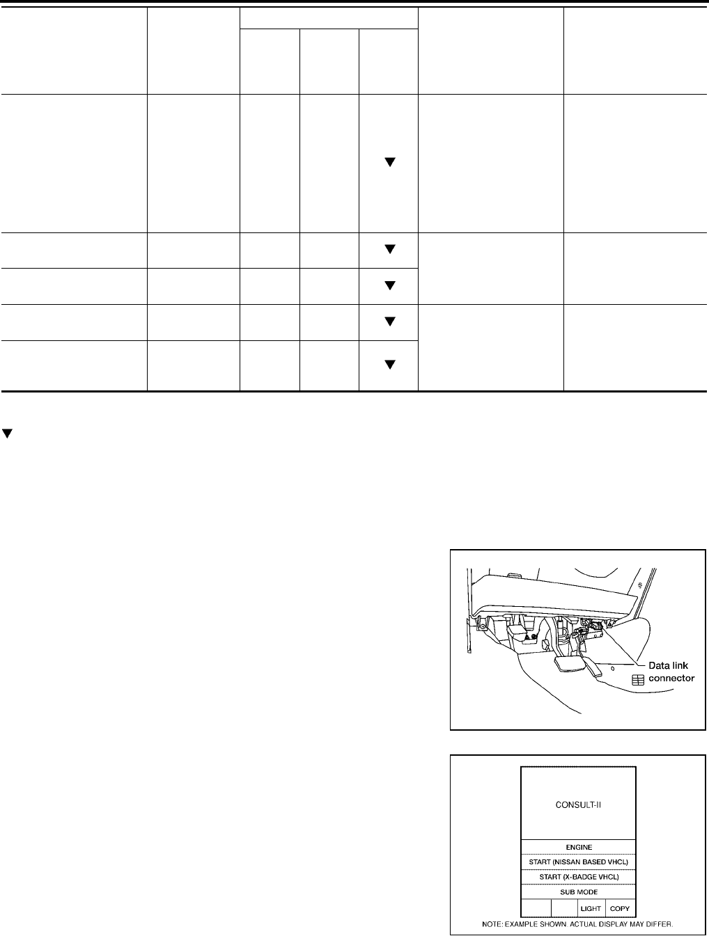
AT-48
[RE4F04B]
ON BOARD DIAGNOSTIC SYSTEM DESCRIPTION
Revision: September 2005 2005 Quest
X: Applicable
—: Not applicable
: Option
DTC WORK SUPPORT MODE WITH CONSULT-II
CONSULT-II Setting Procedure
CAUTION:
If CONSULT-II is used with no connection of CONSULT-II CONVERTER, malfunctions might be
detected in self-diagnosis depending on control unit which carry out CAN communication.
●For details, refer to the separate “CONSULT-II Operations Man-
ual”.
1. Turn ignition switch OFF.
2. Connect CONSULT-II and CONSULT-II CONVERTER to data
link connector, which is located in instrument lower panel on
driver side.
3. Turn ignition switch to ON position. (Do not start engine.)
4. Touch “START (NISSAN BASED VHCL)”.
Frequency Frequency [Hz]
——
●Value measured by
pulse probe is dis-
played. If measure-
ment is impossible, "#"
sign is displayed. "#"
sign is also displayed
at the final data value
until the measurement
result is obtained.
Duty cycle (high) DUTY-HI
[%] —— ●Duty cycle value for
measurement probe is
displayed.
Duty cycle (low) DUTY-LOW
[%] ——
Plus width (high) PLS WIDTH-HI
[msec] —— ●Measured pulse width
of measurement probe
is displayed.
Plus width (low) PLS WIDTH-
LOW
[msec]
——
Item Display
Selection monitor item
Description Remarks
TCM
INPUT
SIG-
NALS
MAIN
SIG-
NALS
SELEC-
TION
FROM
MENU
BBIA0336E
BCIA0029E
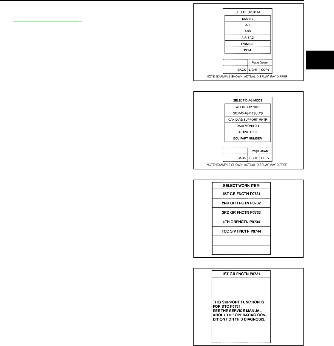
ON BOARD DIAGNOSTIC SYSTEM DESCRIPTION
AT-49
[RE4F04B]
D
E
F
G
H
I
J
K
L
M
A
B
AT
Revision: September 2005 2005 Quest
5. Touch “A/T”.
If “A/T” is not indicated, go to GI-37, "CONSULT-II Data Link
Connector (DLC) Circuit" .
6. Touch “DTC WORK SUPPORT”.
7. Touch select item menu (1ST, 2ND, etc.).
8. Touch “START”.
BCIA0030E
BCIA0031E
SAT018K
SAT589J

AT-50
[RE4F04B]
ON BOARD DIAGNOSTIC SYSTEM DESCRIPTION
Revision: September 2005 2005 Quest
9. Perform driving test according to “DTC CONFIRMATION PRO-
CEDURE” in “TROUBLE DIAGNOSIS FOR DTC”.
●When testing conditions are satisfied, CONSULT-II screen
changes from “OUT OF CONDITION” to “TESTING”.
10. Stop vehicle. If “NG” appears on the screen, malfunction may
exist. Go to “DIAGNOSTIC PROCEDURE”.
SAT019K
SAT591J
SAT592J
SAT593J
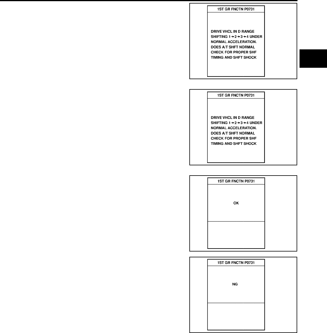
ON BOARD DIAGNOSTIC SYSTEM DESCRIPTION
AT-51
[RE4F04B]
D
E
F
G
H
I
J
K
L
M
A
B
AT
Revision: September 2005 2005 Quest
11. Perform test drive to check gear shift feeling in accordance with
instructions displayed.
12. Touch “YES” or “NO”.
13. CONSULT-II procedure ended.
If “NG” appears on the scene, a malfunction may exist. Go to
“DIAGNOSTIC PROCEDURE”.
SAT594J
SAT595J
SAT596J
SAT593J
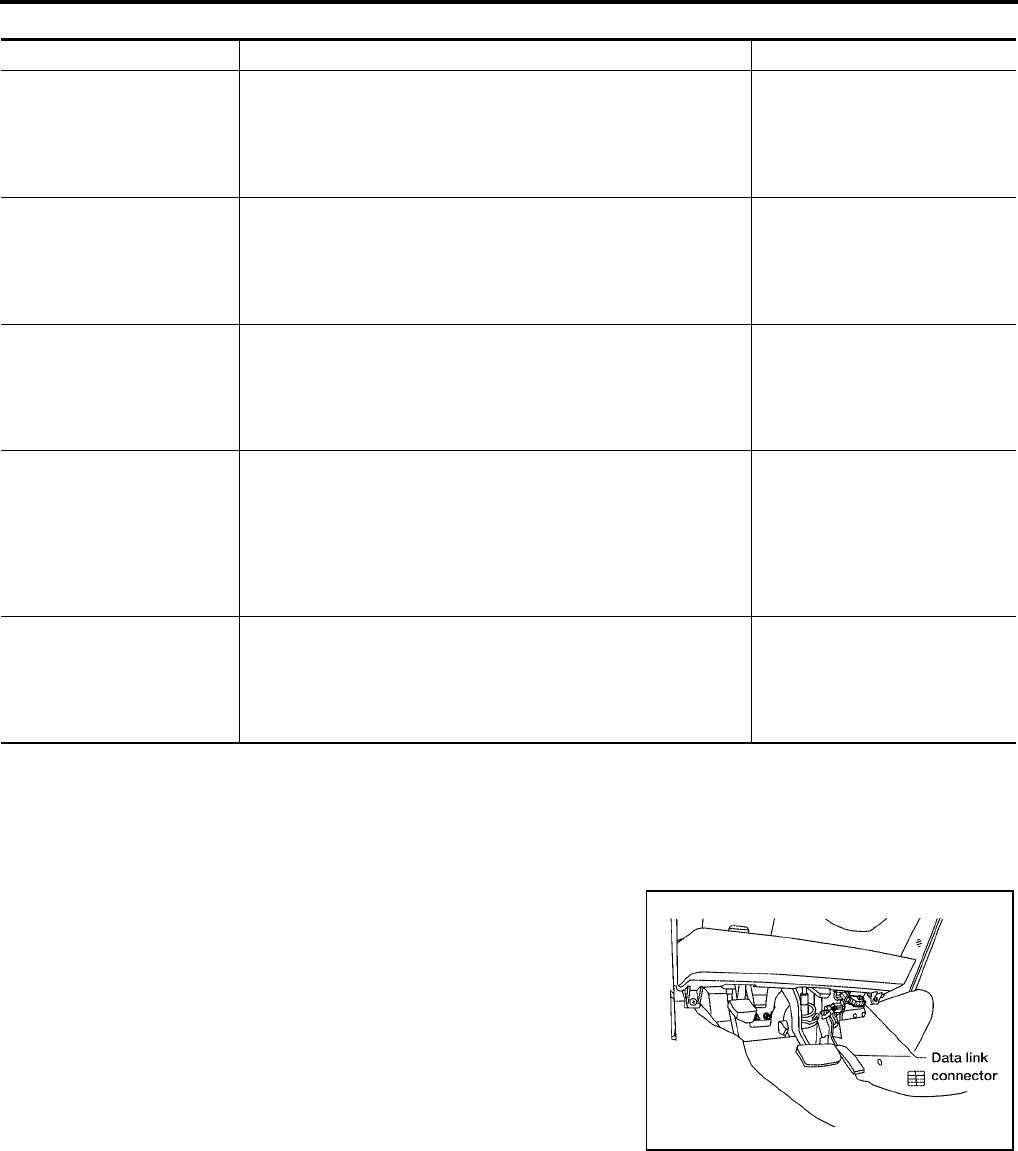
AT-52
[RE4F04B]
ON BOARD DIAGNOSTIC SYSTEM DESCRIPTION
Revision: September 2005 2005 Quest
DTC WORK SUPPORT MODE
CAN DIAGNOSTIC SUPPORT MONITOR
CONSULT-II Setting Procedure
CAUTION:
If CONSULT-II is used with no connection of CONSULT-II CONVERTER, malfunctions might be
detected in self-diagnosis depending on control unit which carry out CAN communication.
●For details, refer to the separate “CONSULT-II Operations Man-
ual”.
1. Turn ignition switch OFF.
2. Connect CONSULT-II and CONSULT-II CONVERTER to data
link connector, which is located in instrument lower panel on
driver side.
DTC work support item Description Check item
1ST GR FNCTN P0731
Following items for “A/T 1st gear function (P0731)” can be con-
firmed.
●Self-diagnosis status (whether the diagnosis is being conducted
or not)
●Self-diagnosis result (OK or NG)
●Shift solenoid valve A
●Shift solenoid valve B
●Each clutch
●Hydraulic control circuit
2ND GR FNCTN P0732
Following items for “A/T 2nd gear function (P0732)” can be con-
firmed.
●Self-diagnosis status (whether the diagnosis is being conducted
or not)
●Self-diagnosis result (OK or NG)
●Shift solenoid valve B
●Each clutch
●Hydraulic control circuit
3RD GR FNCTN P0733
Following items for “A/T 3rd gear function (P0733)” can be con-
firmed.
●Self-diagnosis status (whether the diagnosis is being conducted
or not)
●Self-diagnosis result (OK or NG)
●Shift solenoid valve A
●Each clutch
●Hydraulic control circuit
4TH GR FNCTN P0734
Following items for “A/T 4th gear function (P0734)” can be con-
firmed.
●Self-diagnosis status (whether the diagnosis is being conducted
or not)
●Self-diagnosis result (OK or NG)
●Shift solenoid valve A
●Shift solenoid valve B
●Overrun clutch solenoid valve
●Line pressure solenoid valve
●Each clutch
●Hydraulic control circuit
TCC S/V FNCTN P0744
Following items for “A/T TCC S/V function (lock-up) (P0744)” can
be confirmed.
●Self-diagnosis status (whether the diagnosis is being conducted
or not)
●Self-diagnosis result (OK or NG)
●Torque converter clutch sole-
noid valve
● Each clutch
●Hydraulic control circuit
BBIA0336E
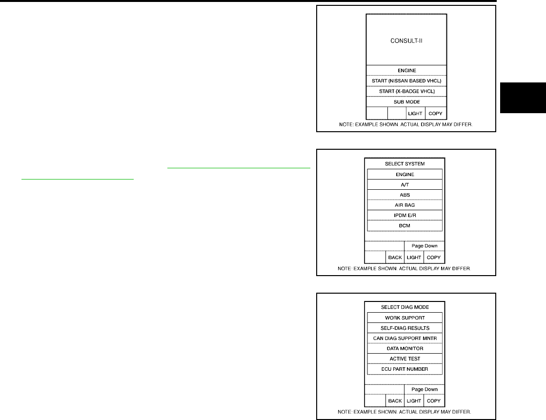
ON BOARD DIAGNOSTIC SYSTEM DESCRIPTION
AT-53
[RE4F04B]
D
E
F
G
H
I
J
K
L
M
A
B
AT
Revision: September 2005 2005 Quest
3. Turn ignition switch to ON position. (Do not start engine.)
4. Touch “START (NISSAN BASED VHCL)”.
5. Touch “A/T”.
If “A/T” is not indicated, go to GI-37, "CONSULT-II Data Link
Connector (DLC) Circuit" .
6. Touch “CAN DIAGNOSTIC SUPPORT MONITOR”.
BCIA0029E
BCIA0030E
BCIA0031E

AT-54
[RE4F04B]
ON BOARD DIAGNOSTIC SYSTEM DESCRIPTION
Revision: September 2005 2005 Quest
Diagnostic Procedure Without CONSULT-II UCS000MU
OBD-II SELF-DIAGNOSTIC PROCEDURE (WITH GST)
Refer to EC-146, "Generic Scan Tool (GST) Function" .
OBD-II SELF-DIAGNOSTIC PROCEDURE (NO TOOLS)
Refer to EC-67, "Malfunction Indicator Lamp (MIL)" .
TCM SELF-DIAGNOSTIC PROCEDURE (NO TOOLS)
1. CHECK O/D OFF INDICATOR LAMP
1. Move selector lever to P position.
Start engine and warm it up to normal engine operating temper-
ature.
2. Turn ignition switch to OFF position.
3. Wait 5 seconds.
4. Turn ignition switch to ON position. (Do not start engine.)
5. Does O/D OFF indicator lamp come on for about 2 seconds?
Yes or No
Yes >> GO TO 2.
No >> Stop procedure. Perform AT-212, "O/D OFF Indicator
Lamp Does Not Come On" before proceeding.
2. JUDGEMENT PROCEDURE STEP 1
1. Turn ignition switch to OFF position.
2. Push and hold shift lock release button.
3. Move selector lever to D position.
4. Push and hold overdrive control switch to ON position.
5. Turn ignition switch to ON position. (Do not start engine.)
Wait more than 2seconds after turning ignition switch to ON.
>> GO TO 3.
BCIA0002E
BCIA0003E
SCIA3532E
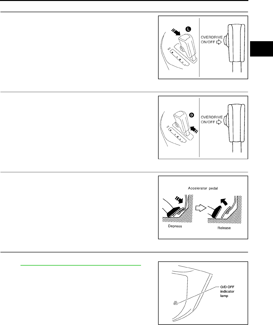
ON BOARD DIAGNOSTIC SYSTEM DESCRIPTION
AT-55
[RE4F04B]
D
E
F
G
H
I
J
K
L
M
A
B
AT
Revision: September 2005 2005 Quest
3. JUDGEMENT PROCEDURE STEP 2
1. Move selector lever to L position.
2. Release overdrive control switch to OFF position.
(O/D OFF indicator lamp: ON)
>> GO TO 4.
4. JUDGEMENT PROCEDURE STEP 3
1. Move selector lever to D position.
2. Push and hold overdrive control switch to ON position.
(O/D OFF indicator lamp: OFF)
>> GO TO 5.
5. JUDGEMENT PROCEDURE STEP 4
1. Depress accelerator pedal fully and release it.
>> GO TO 6.
6. CHECK SELF-DIAGNOSTIC CODE
Check O/D OFF indicator lamp.
Refer to AT-56, "JUDGEMENT OF SELF-DIAGNOSIS CODE" .
>> DIAGNOSIS END
SCIA3534E
SCIA3537E
SAT981F
BCIA0003E
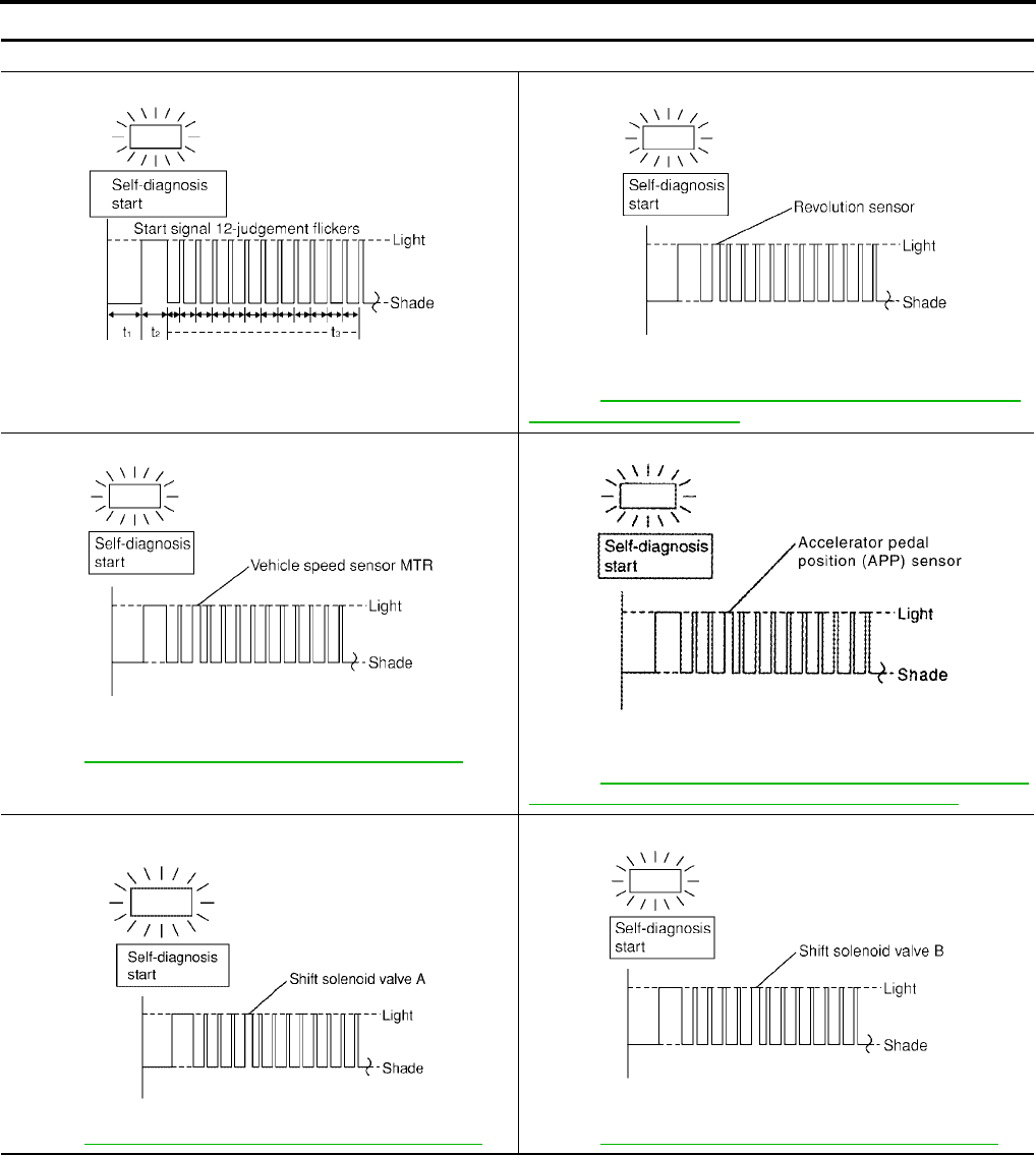
AT-56
[RE4F04B]
ON BOARD DIAGNOSTIC SYSTEM DESCRIPTION
Revision: September 2005 2005 Quest
JUDGEMENT OF SELF-DIAGNOSIS CODE
O/D OFF indicator lamp:
All judgement flickers are the same.
All circuits that can be confirmed by self-diagnosis are OK.
1st judgement flicker is longer than others.
Revolution sensor circuit is short-circuited or disconnected.
Þ Go to AT-118, "DTC P0720 VEHICLE SPEED SENSOR·A/T
(REVOLUTION SENSOR)" .
2nd judgement flicker is longer than others.
Vehicle speed signal circuit is short-circuited or disconnected.
Þ Go to AT-195, "DTC VEHICLE SPEED SENSOR MTR" .
3rd judgement flicker is longer than others.
Accelerator pedal position (APP) sensor circuit is short-circuited
or disconnected.
Þ Go to AT-178, "DTC P1705 THROTTLE POSITION SENSOR
[ACCELERATOR PEDAL POSITION (APP) SENSOR]" .
4th judgement flicker is longer than others.
Shift solenoid valve A circuit is short-circuited or disconnected.
Þ Go to AT-168, "DTC P0750 SHIFT SOLENOID VALVE A" .
5th judgement flicker is longer than others.
Shift solenoid valve B circuit is short-circuited or disconnected.
Þ Go to AT-173, "DTC P0755 SHIFT SOLENOID VALVE B" .
SCIA3387E SCIA3388E
SCIA3389E SCIA3390E
SCIA3391E SCIA3392E

ON BOARD DIAGNOSTIC SYSTEM DESCRIPTION
AT-57
[RE4F04B]
D
E
F
G
H
I
J
K
L
M
A
B
AT
Revision: September 2005 2005 Quest
6th judgement flicker is longer than others.
Overrun clutch solenoid valve circuit is short-circuited or discon-
nected.
Þ Go to AT-184, "DTC P1760 OVERRUN CLUTCH SOLENOID
VALVE" .
7th judgement flicker is longer than others.
Torque converter clutch solenoid valve circuit is short-circuited or
disconnected.
Þ Go to AT-149, "DTC P0740 TORQUE CONVERTER CLUTCH
SOLENOID VALVE" .
8th judgement flicker is longer than others.
A/T fluid temperature sensor is disconnected or TCM power
source circuit is damaged.
Þ Go to AT-189, "DTC BATT/FLUID TEMP SEN (A/T FLUID
TEMP SENSOR CIRCUIT AND TCM POWER SOURCE)" .
9th judgement flicker is longer than others.
Engine speed signal circuit is short-circuited or disconnected.
Þ Go to AT-123, "DTC P0725 ENGINE SPEED SIGNAL" .
10th judgement flicker is longer than others.
Turbine revolution sensor (power train revolution sensor) circuit is
short-circuited or disconnected.
Þ Go to AT-200, "DTC TURBINE REVOLUTION SENSOR" .
11th judgement flicker is longer than others.
Line pressure solenoid valve circuit is short-circuited or discon-
nected.
Þ Go to AT-162, "DTC P0745 LINE PRESSURE SOLENOID
VALVE" .
O/D OFF indicator lamp:
SCIA3393E SCIA3394E
SCIA3395E SCIA3396E
SCIA3397E SCIA3398E

AT-58
[RE4F04B]
ON BOARD DIAGNOSTIC SYSTEM DESCRIPTION
Revision: September 2005 2005 Quest
t1 = 2.5 seconds t2 = 2.0 seconds t3 = 1.0 second t4 = 1.0 second
12th judgement flicker is longer than others.
CAN communication line is damaged.
Þ Go to AT-103, "DTC U1000 CAN COMMUNICATION LINE" .
Lamp does not blink.
Park/neutral position (PNP) switch, overdrive control switch,
closed throttle position signal or wide-open throttle position signal
circuit is disconnected or TCM is damaged.
Þ Go to AT-239, "TCM Self-diagnosis Does Not Activate" .
Flickers as shown below.
Battery power is low.
Battery has been disconnected for a long time.
Battery is connected conversely.
(When reconnecting TCM connectors.—This is not a problem.)
O/D OFF indicator lamp:
SCIA3399E SCIA3400E
SCIA3401E
TROUBLE DIAGNOSIS - INTRODUCTION
AT-59
[RE4F04B]
D
E
F
G
H
I
J
K
L
M
A
B
AT
Revision: September 2005 2005 Quest
TROUBLE DIAGNOSIS - INTRODUCTION PFP:00000
Introduction UCS000MV
The TCM receives a signal from the vehicle speed sensor, ECM
(throttle opening) or park/neutral position (PNP) switch and provides
shift control or lock-up control via A/T solenoid valves.
The TCM also communicates with the ECM by means of a signal
sent from sensing elements used with the OBD-related parts of the
A/T system for malfunction-diagnostic purposes. The TCM is capa-
ble of diagnosing malfunctioning parts while the ECM can store mal-
functions in its memory.
Input and output signals must always be correct and stable in the
operation of the A/T system. The A/T system must be in good oper-
ating condition and be free of valve seizure, solenoid valve malfunc-
tion, etc.
It is much more difficult to diagnose a problem that occurs intermit-
tently rather than continuously. Most intermittent problems are
caused by poor electric connections or improper wiring. In this case,
careful checking of suspected circuits may help prevent the replace-
ment of good parts.
A visual check only, may not find the cause of the problems. A road
test with CONSULT-II (or GST) or a circuit tester connected should
be performed. Follow the “Work Flow”. Refer to AT-63, "Work Flow" .
Before undertaking actual checks, take a few minutes to talk with a
customer who approaches with a drive ability complaint. The cus-
tomer can supply good information about such problems, especially
intermittent ones. Find out what symptoms are present and under
what conditions they occur. A “DIAGNOSTIC WORKSHEET” like the
example on page AT-61 should be used.
Start your diagnosis by looking for “conventional” problems first. This
will help troubleshoot driveability problems on an electronically con-
trolled engine vehicle.
Also check related Service bulletins for information.
SAT631IA
SAT632I
SEF234G
AT-60
[RE4F04B]
TROUBLE DIAGNOSIS - INTRODUCTION
Revision: September 2005 2005 Quest
DIAGNOSTIC WORKSHEET
Information from Customer
KEY POINTS
WHAT ........ Vehicle & A/T model
WHEN ........ Date, Frequencies
WHERE ..... Road conditions
HOW .......... Operating conditions, Symptoms
Customer name MR/MS Model & Year VIN
Trans. model Engine Mileage
Incident Date Manuf. Date In Service Date
Frequency ❏ Continuous ❏ Intermittent ( times a day)
Symptoms ❏ Vehicle does not move. (❏ Any position ❏ Particular position)
❏ No up-shift (❏ 1st → 2nd ❏ 2nd → 3rd ❏ 3rd → 4th)
❏ No down-shift (❏ 4th → 3rd ❏ 3rd → 2nd ❏ 2nd → 1st)
❏ Lockup malfunction
❏ Shift point too high or too low.
❏ Shift shock or slip (❏ N → D ❏ Lockup ❏ Any drive position)
❏ Noise or vibration
❏ No kickdown
❏ No pattern select
❏ Others
()
O/D OFF indicator lamp Blinks for about 8 seconds.
❏ Continuously lit ❏ Not lit
Malfunction indicator lamp (MIL) ❏ Continuously lit ❏ Not lit
TROUBLE DIAGNOSIS - INTRODUCTION
AT-61
[RE4F04B]
D
E
F
G
H
I
J
K
L
M
A
B
AT
Revision: September 2005 2005 Quest
Diagnostic Worksheet
1. ❏ Read the Fail-safe and listen to customer complaints. AT-12
2. ❏ CHECK A/T FLUID AT-65
❏ Leakage (Follow specified procedure)
❏ Fluid condition
❏ Fluid level
3. ❏ Perform STALL TEST and PRESSURE TEST. AT-68,
AT-71
❏ Stall test — Mark possible damaged components/others.
❏ Torque converter one-way clutch
❏ Reverse clutch
❏ Forward clutch
❏ Overrun clutch
❏ Forward one-way clutch
❏ Low & reverse brake
❏ Low one-way clutch
❏ Engine
❏ Line pressure is low
❏ Clutches and brakes except high clutch and
brake band are OK
❏ Line pressure test — Suspected parts:
4. ❏ Perform all ROAD TEST and mark required procedures. AT-72
4-1. Check before engine is started. AT-74
❏ O/D OFF Indicator Lamp Does Not Come On, AT-212
❏ SELF-DIAGNOSTIC PROCEDURE - Mark detected items.
❏ Park/neutral position (PNP) switch, AT-106 .
❏ A/T fluid temperature sensor, AT-112 .
❏ Vehicle speed sensor·A/T (Revolution sensor), AT-118 .
❏ Engine speed signal, AT-123 .
❏ Turbine revolution sensor (power train revolution sensor), AT-200 .
❏ Torque converter clutch solenoid valve, AT-149 .
❏ Line pressure solenoid valve, AT-162 .
❏ Shift solenoid valve A, AT-168 .
❏ Shift solenoid valve B, AT-173 .
❏ Accelerator pedal position (APP) sensor, AT-178 .
❏ Overrun clutch solenoid valve, AT-184 .
❏ A/T fluid temperature sensor, AT-112 .
❏ Vehicle speed sensor·MTR, AT-195 .
❏ CAN communication line, AT-103 .
❏ Control unit (RAM), Control unit (ROM), AT-205 .
❏ Control unit (EEP ROM), AT-207 .
❏ Park/neutral position (PNP) & overdrive control switches, closed throttle position signal and wide-
open throttle position signals check AT-239 .
❏ Battery
❏ Others
AT-62
[RE4F04B]
TROUBLE DIAGNOSIS - INTRODUCTION
Revision: September 2005 2005 Quest
4.
4-2. Check at idle AT-74
❏ Engine Cannot Be Started In P and N Position, AT-214 .
❏ In P Position, Vehicle Moves Forward or Backward When Pushed, AT-215 .
❏ In N Position, Vehicle Moves, AT-215 .
❏ Large Shock. N → R Position, AT-217 .
❏ Vehicle Does Not Creep Backward In R Position, AT-218 .
❏ Vehicle Does Not Creep Forward In D or L Position, AT-220 .
4-3. Cruise test AT-76
AT-81
Part-1
❏ Vehicle Cannot Be Started From D1 , AT-222 .
❏ A/T Does Not Shift: D1 → D2 or Does Not Kickdown: D4 → D2 , AT-224 .
❏ A/T Does Not Shift: D2 → D3 , AT-226 .
❏ A/T Does Not Shift: D3 → D4 , AT-228 .
❏ A/T Does Not Perform Lock-up, AT-230 .
❏ A/T Does Not Hold Lock-up Condition, AT-232 .
❏ Lock-up Is Not Released, AT-233 .
❏ Engine Speed Does Not Return To Idle (Light Braking D4 → D3 ), AT-234 .
Part-2 AT-84
❏ Vehicle Does Not Start From D1 , AT-236 .
❏ A/T Does Not Shift: D1 → D2 or Does Not Kickdown: D4 → D2 , AT-224 .
❏ A/T Does Not Shift: D2 → D3 , AT-226 .
❏ A/T Does Not Shift: D3 → D4 , AT-228 .
Part-3 AT-85
❏ A/T Does Not Shift: D4 → D3 , When Overdrive Control Switch ON → OFF, AT-236 .
❏ Engine Speed Does Not Return To Idle (Engine Brake In D3 ), AT-234 .
❏ A/T Does Not Shift: D3 → L2 , When Selector Lever D → L Position, AT-237 .
❏ Vehicle Does Not Decelerate By Engine Brake, AT-237 .
❏ SELF-DIAGNOSTIC PROCEDURE — Mark detected items.
❏ Park/neutral position (PNP) switch, AT-106 .
❏ A/T fluid temperature sensor, AT-112 .
❏ Vehicle speed sensor·A/T (Revolution sensor), AT-118 .
❏ Engine speed signal, AT-123 .
❏ Turbine revolution sensor (power train revolution sensor), AT-200 .
❏ Torque converter clutch solenoid valve, AT-149 .
❏ Line pressure solenoid valve, AT-162 .
❏ Shift solenoid valve A, AT-168 .
❏ Shift solenoid valve B, AT-173 .
❏ Accelerator pedal position (APP) sensor, AT-178 .
❏ Overrun clutch solenoid valve, AT-184 .
❏ A/T fluid temperature sensor, AT-112 .
❏ Vehicle speed sensor·MTR, AT-195 .
❏ CAN communication line, AT-103 .
❏ Control unit (RAM), Control unit (ROM), AT-205 .
❏ Control unit (EEP ROM), AT-207 .
❏ Park/neutral position (PNP) & overdrive control switches, closed throttle position signal and wide-
open throttle position signals check AT-239 .
❏ Battery
❏ Others
5. ❏ For self-diagnosis NG items, inspect each component. Repair or replace the damaged parts. AT-253
6. ❏ Perform all ROAD TEST and re-mark required procedures. AT-72
7. ❏ Perform DTC CONFIRMATION PROCEDURE for following MIL indicating items and check out NG items.
Refer toEC-52, "Emission-related Diagnostic Information" .
EC-52
❏ DTC (P0731) A/T 1st gear function, AT-127 .
❏ DTC (P0732) A/T 2nd gear function, AT-132 .
❏ DTC (P0733) A/T 3rd gear function, AT-137 .
❏ DTC (P0734) A/T 4th gear function, AT-142 .
❏ DTC (P0744) A/T TCC S/V function (lock-up), AT-154 .

TROUBLE DIAGNOSIS - INTRODUCTION
AT-63
[RE4F04B]
D
E
F
G
H
I
J
K
L
M
A
B
AT
Revision: September 2005 2005 Quest
Work Flow UCS000MW
HOW TO PERFORM TROUBLE DIAGNOSES FOR QUICK AND ACCURATE REPAIR
A good understanding of the malfunction conditions can make troubleshooting faster and more accurate.
In general, each customer feels differently about a problem. It is important to fully understand the symptoms or
conditions for a customer complaint.
Make good use of the two sheets provided, AT-60, "Information from Customer" and AT-61, "Diagnostic Work-
sheet" , to perform the best troubleshooting possible.
8. ❏ Perform the Diagnostic Procedures for all remaining items marked NG. Repair or replace the damaged parts.
Refer to the Symptom Chart when you perform the procedures. (The chart also shows some other possible
symptoms and the component inspection orders.)
AT-42
AT-54
9. ❏ Erase DTC from TCM and ECM memories. AT-40

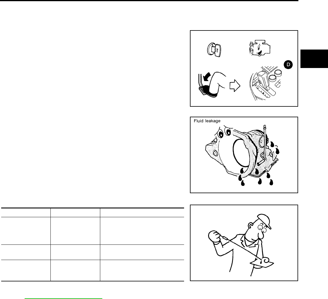
TROUBLE DIAGNOSIS - BASIC INSPECTION
AT-65
[RE4F04B]
D
E
F
G
H
I
J
K
L
M
A
B
AT
Revision: September 2005 2005 Quest
TROUBLE DIAGNOSIS - BASIC INSPECTION PFP:00000
A/T Fluid Check UCS000MX
FLUID LEAKAGE CHECK
1. Clean area suspected of leaking. — for example, mating surface
of converter housing and transmission case.
2. Start engine, apply foot brake, place selector lever in D position
and wait a few minutes.
3. Stop engine.
4. Check for fresh leakage.
FLUID CONDITION CHECK
FLUID LEVEL CHECK
Refer to MA-21, "Checking A/T Fluid" .
A/T Fluid Cooler Cleaning UCS0015J
Whenever an automatic transaxle is repaired, overhauled, or replaced, the A/T fluid cooler mounted in the
radiator must be inspected and cleaned.
Metal debris and friction material, if present, can become trapped in the A/T fluid cooler. This debris can con-
taminate the newly serviced A/T or, in severe cases, can block or restrict the flow of A/T fluid. In either case,
malfunction of the newly serviced A/T may result.
Debris, if present, may build up as A/T fluid enters the cooler inlet. It will be necessary to back flush the cooler
through the cooler outlet in order to flush out any built up debris.
A/T FLUID COOLER CLEANING PROCEDURE
1. Position an oil pan under the automatic transaxle's inlet and outlet cooler hoses.
2. Identify the inlet and outlet fluid cooler hoses.
BCIA0007E
SAT288G
Fluid status Conceivable Cause Required Operation
Varnished (viscous
varnish state)
Clutch, brake
scorched
Replace the A/T fluid and check the
A/T main unit and the vehicle for
malfunctions (wire harnesses,
cooler pipes, etc.)
Milky white or
cloudy Water in the fluid Replace the A/T fluid and check for
places where water is getting in.
Large amount of
metal powder mixed
in
Unusual wear of
sliding parts within
A/T
Replace the A/T fluid and check for
improper operation of the A/T.
SAT638A
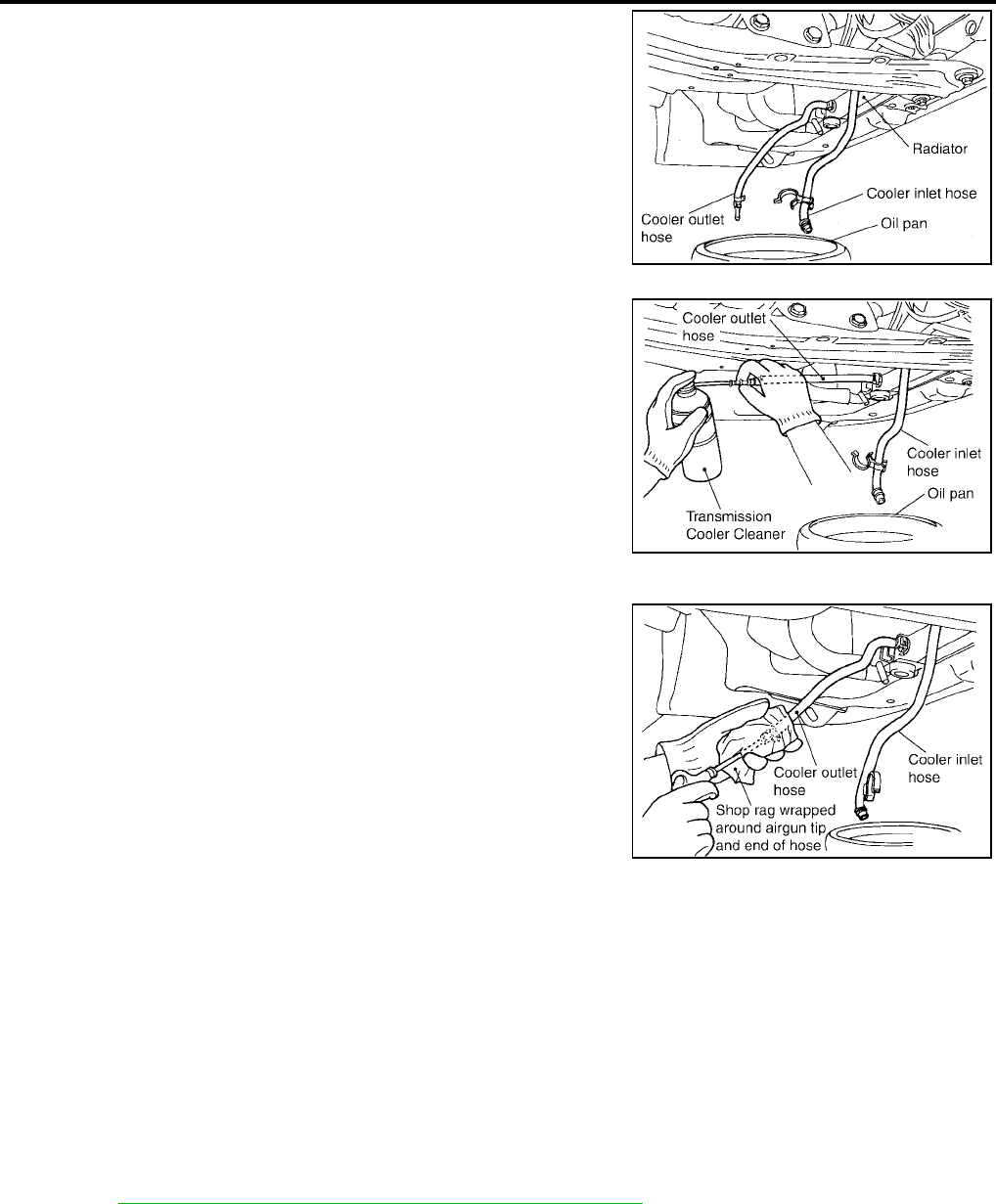
AT-66
[RE4F04B]
TROUBLE DIAGNOSIS - BASIC INSPECTION
Revision: September 2005 2005 Quest
3. Disconnect the fluid cooler inlet and outlet rubber hoses from the
steel cooler tubes or bypass valve.
NOTE:
Replace the cooler hoses if rubber material from the hose
remains on the tube fitting.
4. Allow any A/T fluid that remains in the cooler hoses to drain into
the oil pan.
5. Insert the extension adapter hose of a can of Transmission
Cooler Cleaner (Nissan P/N 999MP-AM006) into the cooler out-
let hose.
CAUTION:
●Wear safety glasses and rubber gloves when spraying
the Transmission Cooler Cleaner.
●Spray cooler cleaner only with adequate ventilation.
●Avoid contact with eyes and skin.
●Do not breath vapors or spray mist.
6. Hold the hose and can as high as possible and spray Transmis-
sion Cooler Cleaner in a continuous stream into the cooler outlet
hose until fluid flows out of the cooler inlet hose for 5 seconds.
7. Insert the tip of an air gun into the end of the cooler outlet hose.
8. Wrap a shop rag around the air gun tip and of the cooler outlet
hose.
9. Blow compressed air regulated to 5 - 9 kg/cm2 (70 - 130 psi) through the cooler outlet hose for 10 sec-
onds to force out any remaining fluid.
10. Repeat steps 5 through 9 three additional times.
11. Position an oil pan under the banjo bolts that connect the fluid cooler steel lines to the transaxle.
12. Remove the banjo bolts.
13. Flush each steel line from the cooler side back toward the transaxle by spraying Transmission Cooler
Cleaner in a continuous stream for 5 seconds.
14. Blow compressed air regulated to 5 - 9 kg/cm2 (70 - 130 psi) through each steel line from the cooler side
back toward the transaxle for 10 seconds to force out any remaining fluid.
15. Ensure all debris is removed from the steel cooler lines.
16. Ensure all debris is removed from the banjo bolts and fittings.
17. Perform AT-66, "A/T FLUID COOLER DIAGNOSIS PROCEDURE" .
A/T FLUID COOLER DIAGNOSIS PROCEDURE
NOTE:
Insufficient cleaning of the cooler inlet hose exterior may lead to inaccurate debris identification.
1. Position an oil pan under the automatic transaxle's inlet and outlet cooler hoses.
2. Clean the exterior and tip of the cooler inlet hose.
SCIA2945E
SCIA2955E
SCIA2962E
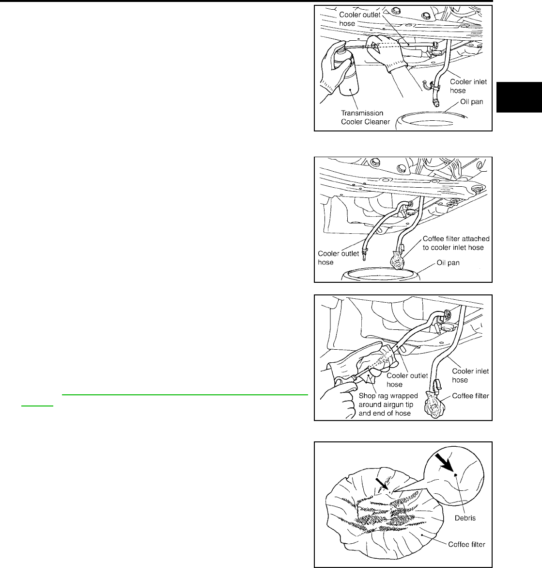
TROUBLE DIAGNOSIS - BASIC INSPECTION
AT-67
[RE4F04B]
D
E
F
G
H
I
J
K
L
M
A
B
AT
Revision: September 2005 2005 Quest
3. Insert the extension adapter hose of a can of Transmission
Cooler Cleaner (Nissan P/N 999MP-AM006) into the cooler out-
let hose.
CAUTION:
●Wear safety glasses and rubber gloves when spraying
the Transmission Cooler Cleaner.
●Spray cooler cleaner only with adequate ventilation.
●Avoid contact with eyes and skin.
●Do not breath vapors or spray mist.
4. Hold the hose and can as high as possible and spray Transmis-
sion Cooler Cleaner in a continuous stream into the cooler outlet
hose until fluid flows out of the cooler inlet hose for 5 seconds.
5. Tie a common white, basket-type coffee filter to the end of the
cooler inlet hose.
6. Insert the tip of an air gun into the end of the cooler outlet hose.
7. Wrap a shop rag around the air gun tip and end of cooler outlet
hose.
8. Blow compressed air regulated to 5 - 9 kg/cm2 (70 - 130 psi)
through the cooler outlet hose to force any remaining A/T fluid
into the coffee filter.
9. Remove the coffee filter from the end of the cooler inlet hose.
10. Perform AT-67, "A/T FLUID COOLER INSPECTION PROCE-
DURE" .
A/T FLUID COOLER INSPECTION PROCEDURE
1. Inspect the coffee filter for debris.
a. If small metal debris less than 1mm (0.040 in) in size or metal
powder is found in the coffee filter, this is normal. If normal
debris is found, the A/T fluid cooler/radiator can be re-used and
the procedure is ended.
SCIA2955E
SCIA2965E
SCIA2966E
SCIA2967E
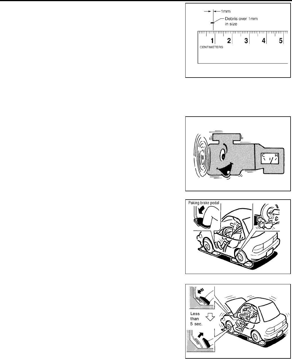
AT-68
[RE4F04B]
TROUBLE DIAGNOSIS - BASIC INSPECTION
Revision: September 2005 2005 Quest
b. If one or more pieces of debris are found that are over 1mm in
size and/or peeled clutch facing material is found in the coffee
filter, the fluid cooler is not serviceable. The radiator/fluid cooler
must be replaced and the inspection procedure is ended.
A/T FLUID COOLER FINAL INSPECTION
After performing all procedures, ensure that all remaining oil is cleaned from all components.
Stall Test UCS000MY
STALL TEST PROCEDURE
1. Check A/T fluid and engine oil levels. If necessary, add fluid and
oil.
2. Drive vehicle for approximately 10 minutes or until fluid and oil
reach operating temperature.
3. Set parking brake and block wheels.
4. Install a tachometer where it can be seen by driver during test.
●It is good practice to mark the point of specified engine
rpm on indicator.
5. Start engine, apply foot brake, and place selector lever in D
position.
6. Accelerate to wide open throttle gradually while applying foot
brake.
7. Quickly note the engine stall revolution and immediately release
throttle.
●During test, never hold throttle wide open for more than 5
seconds.
SCIA2971E
ATF operating temperature :50 - 80°C (122 - 176°F)
SAT647B
SCIA1224E
Stall revolution : 2,500 - 3,050 rpm
SAT514G

TROUBLE DIAGNOSIS - BASIC INSPECTION
AT-69
[RE4F04B]
D
E
F
G
H
I
J
K
L
M
A
B
AT
Revision: September 2005 2005 Quest
8. Move selector lever to N position.
9. Cool off ATF.
●Run engine at idle for at least one minute.
10. Repeat steps 5 through 9 with selector lever in L and R posi-
tions.
JUDGEMENT OF STALL TEST
The test result and possible damaged components relating to each result are shown in the illustrations on next
page.
In order to pinpoint the possible damaged components, refer to AT-64, "WORK FLOW CHART" .
NOTE:
Stall revolution is too high in D or L position:
●Slippage occurs in 1st gear but not in 2nd and 3rd gears. ..... Low one-way clutch slippage
●Slippage occurs in the following gears:
1st through 3rd gears in D position and engine brake functions.
1st and 2nd gears in L position and engine brake functions with accelerator pedal released (fully closed
throttle). ..... Forward clutch or forward one-way clutch slippage
Stall revolution is too high in R position:
●Engine brake does not function in R position. ..... Low & reverse brake slippage
●Engine brake functions in R position. ..... Reverse clutch slippage
Stall revolution within specifications:
●Vehicle does not achieve speed of more than 80 km/h (50 MPH). ..... One-way clutch seizure in torque
converter housing
CAUTION:
Be careful since automatic fluid temperature increases abnormally.
●Slippage occurs in 3rd and 4th gears in D position. ..... High clutch slippage
●Slippage occurs in 2nd and 4th gear in D position. ..... Brake band slippage
●Engine brake does not function in 2nd and 3rd gears in D position with overdrive control switch set to ON
and 2nd gear in L position. ..... Overrun clutch slippage
Stall revolution less than specifications:
●Poor acceleration during starts. ..... One-way clutch seizure in torque converter
BCIA0008E
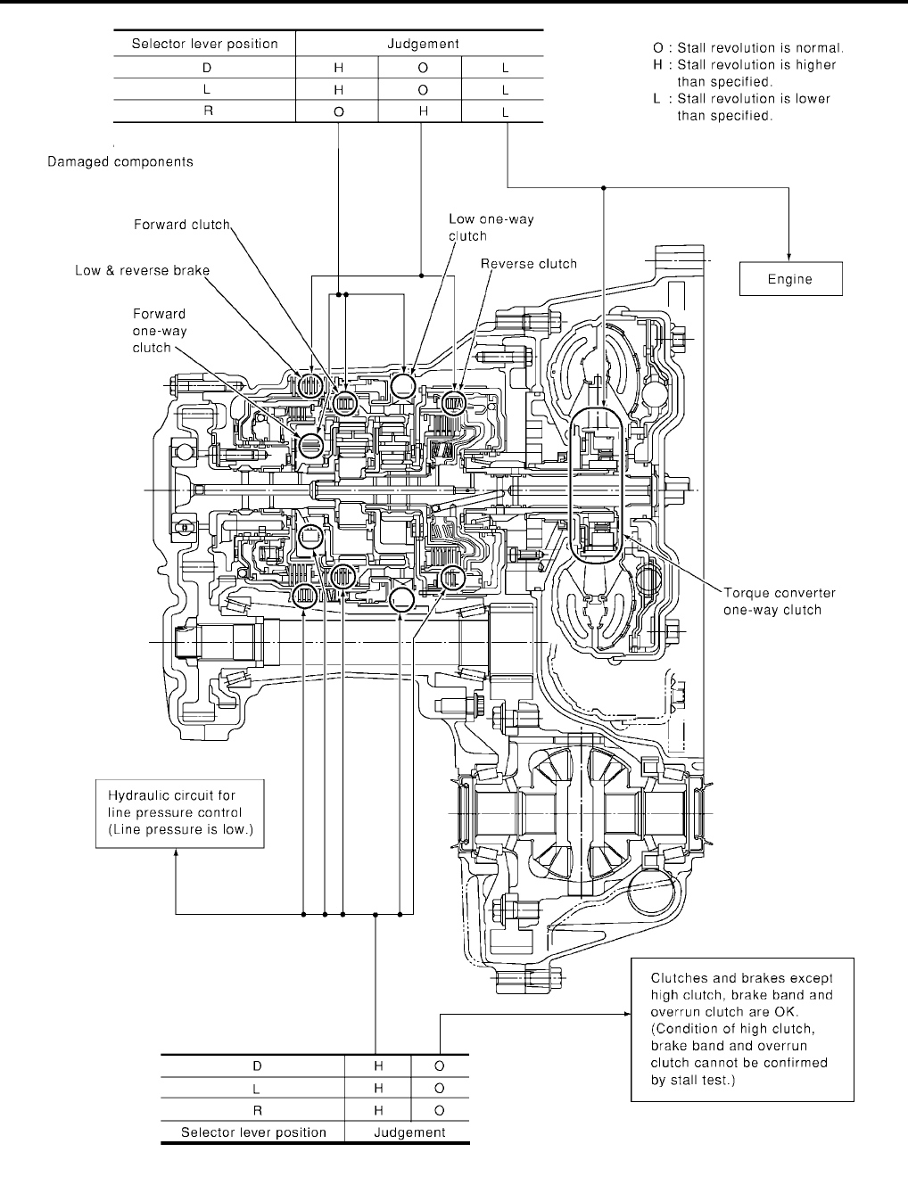
AT-70
[RE4F04B]
TROUBLE DIAGNOSIS - BASIC INSPECTION
Revision: September 2005 2005 Quest
SCIA3439E
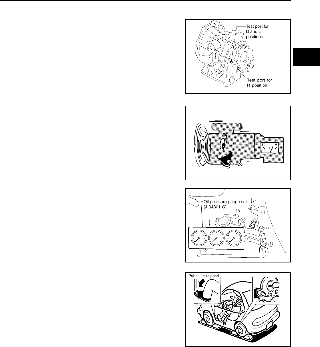
TROUBLE DIAGNOSIS - BASIC INSPECTION
AT-71
[RE4F04B]
D
E
F
G
H
I
J
K
L
M
A
B
AT
Revision: September 2005 2005 Quest
Line Pressure Test UCS000MZ
LINE PRESSURE TEST PORTS
Location of line pressure test ports are shown in the illustration.
●Always replace pressure plugs as they are self-sealing
bolts.
LINE PRESSURE TEST PROCEDURE
1. Check A/T fluid and engine oil levels. If necessary, add fluid and
oil.
2. Drive vehicle for approximately 10 minutes or until fluid and oil
reach operating temperature.
3. Install pressure gauge to corresponding line pressure port.
4. Set parking brake and block wheels.
●Continue to depress brake pedal fully while line pressure
test is being performed at stall speed.
SCIA3682E
ATF operating temperature :50 - 80°C (122 - 176°F)
SAT647B
SCIA5376E
SCIA1224E
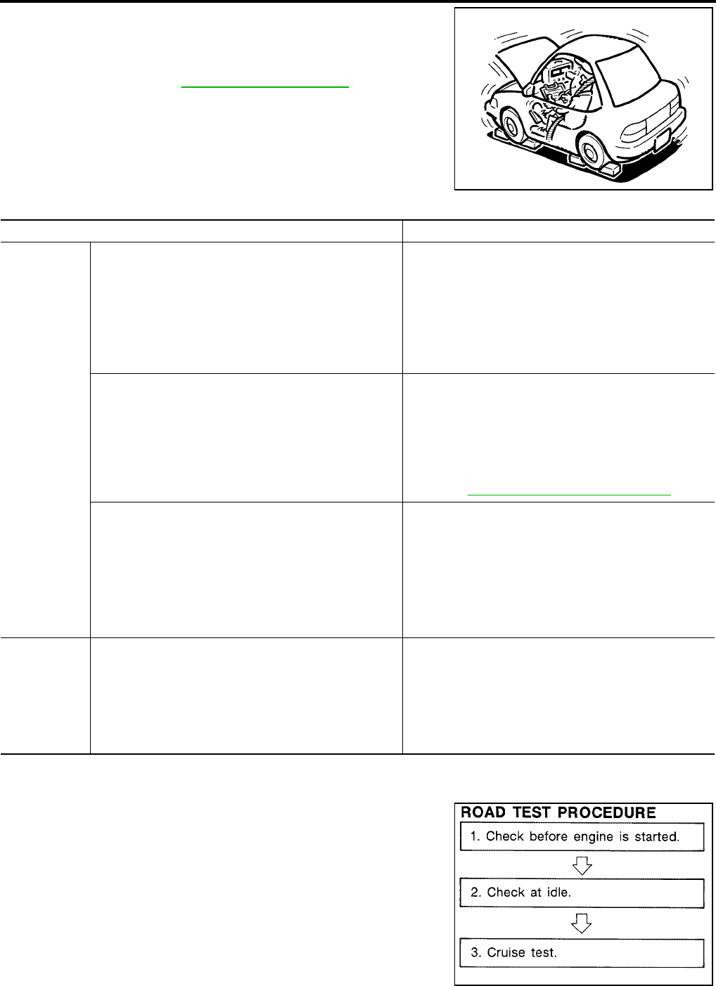
AT-72
[RE4F04B]
TROUBLE DIAGNOSIS - BASIC INSPECTION
Revision: September 2005 2005 Quest
5. Start engine and measure line pressure at idle and stall speed.
●When measuring line pressure at stall speed, follow the
stall test procedure.
JUDGEMENT OF LINE PRESSURE TEST
Road Test UCS000N0
DESCRIPTION
●The purpose of the test is to determine overall performance of A/
T and analyze causes of problems.
●The road test consists of the following three parts:
1. Check before engine is started
2. Check at idle
3. Cruise test
Line pressure : AT-365, "Line Pressure"
SAT493G
Judgement Suspected parts
At idle
Line pressure is low in all positions. ●Oil pump wear
●Control piston damage
●Pressure regulator valve or plug sticking
●Spring for pressure regulator valve damaged
●Fluid pressure leakage between oil strainer and pres-
sure regulator valve
●Clogged strainer
Line pressure is low in particular position. ●Fluid pressure leakage between manual valve and par-
ticular clutch
●For example, line pressure is:
− Low in R positions, but
− Normal in D and L positions.
Therefore, fluid leakage exists at or around low &
reverse brake circuit.
Refer to AT-23, "CLUTCH AND BAND CHART" .
Line pressure is high. ●Maladjustment of accelerator pedal position sensor
●A/T fluid temperature sensor damaged
●Line pressure solenoid valve sticking
●Short circuit of line pressure solenoid valve circuit
●Pressure modifier valve sticking
●Pressure regulator valve or plug sticking
●Open in dropping resistor circuit
At stall speed
Line pressure is low. ●Maladjustment of accelerator pedal position sensor
●Line pressure solenoid valve sticking
●Short circuit of line pressure solenoid valve circuit
●Pressure regulator valve or plug sticking
●Pressure modifier valve sticking
●Pilot valve sticking
SAT786A
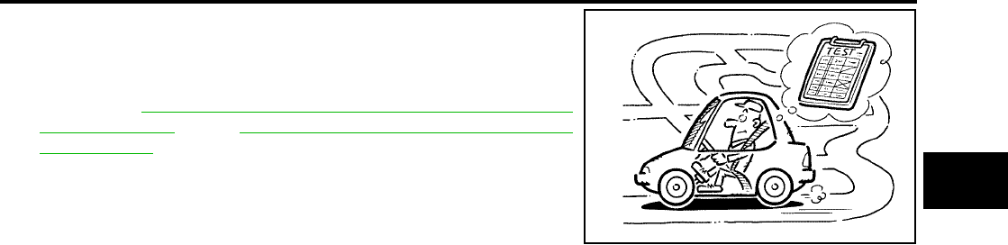
TROUBLE DIAGNOSIS - BASIC INSPECTION
AT-73
[RE4F04B]
D
E
F
G
H
I
J
K
L
M
A
B
AT
Revision: September 2005 2005 Quest
●Before road test, familiarize yourself with all test procedures and
items to check.
●Conduct tests on all items until specified symptom is found.
Troubleshoot items which check out No Good after road test.
Refer to AT-38, "ON BOARD DIAGNOSTIC SYSTEM
DESCRIPTION" , and AT-209, "TROUBLE DIAGNOSIS FOR
SYMPTOMS" .
SAT496G

AT-74
[RE4F04B]
TROUBLE DIAGNOSIS - BASIC INSPECTION
Revision: September 2005 2005 Quest
1. CHECK BEFORE ENGINE IS STARTED
1. CHECK O/D OFF INDICATOR LAMP
1. Park vehicle on flat surface.
2. Move selector lever to P position.
3. Turn ignition switch to OFF position. Wait at least 5 seconds.
4. Set overdrive control switch to ON position.
5. Turn ignition switch to ON position. (Do not start engine.)
6. Does O/D OFF indicator lamp come on for about 2 seconds?
Yes or No
Yes >> GO TO 2.
No >> Stop ROAD TEST. Go to AT-212, "O/D OFF Indicator
Lamp Does Not Come On" .
2. CHECK O/D OFF INDICATOR LAMP
Does O/D OFF indicator lamp flicker for about 8 seconds?
Yes or No
Yes >> TCM is under fail-safe mode. Perform self-diagnosis
and check NG items on the DIAGNOSTIC WORK-
SHEET, AT-61 . Refer to AT-42, "SELF-DIAGNOSTIC
PROCEDURE (WITH CONSULT-II)" or AT-54, "TCM
SELF-DIAGNOSTIC PROCEDURE (NO TOOLS)" .
No >> 1. Turn ignition switch to OFF position.
2. Perform self-diagnosis and note NG items.
Refer to AT-42, "SELF-DIAGNOSTIC PROCEDURE
(WITH CONSULT-II)" or AT-54, "TCM SELF-DIAG-
NOSTIC PROCEDURE (NO TOOLS)" .
3. GO TO AT-74, "2. CHECK AT IDLE" .
2. CHECK AT IDLE
1. CHECK ENGINE START
1. Park vehicle on flat surface.
2. Move selector lever to P or N position.
3. Turn ignition switch to OFF position.
4. Turn ignition switch to START position.
5. Is engine started?
Yes or No
Yes >> GO TO 2.
No >> Stop ROAD TEST. Mark the box on the DIAGNOSTIC
WORKSHEET. Go to AT-214, "Engine Cannot Be
Started in P and N Position" .
SCIA3528E
BCIA0003E
SCIA3547E
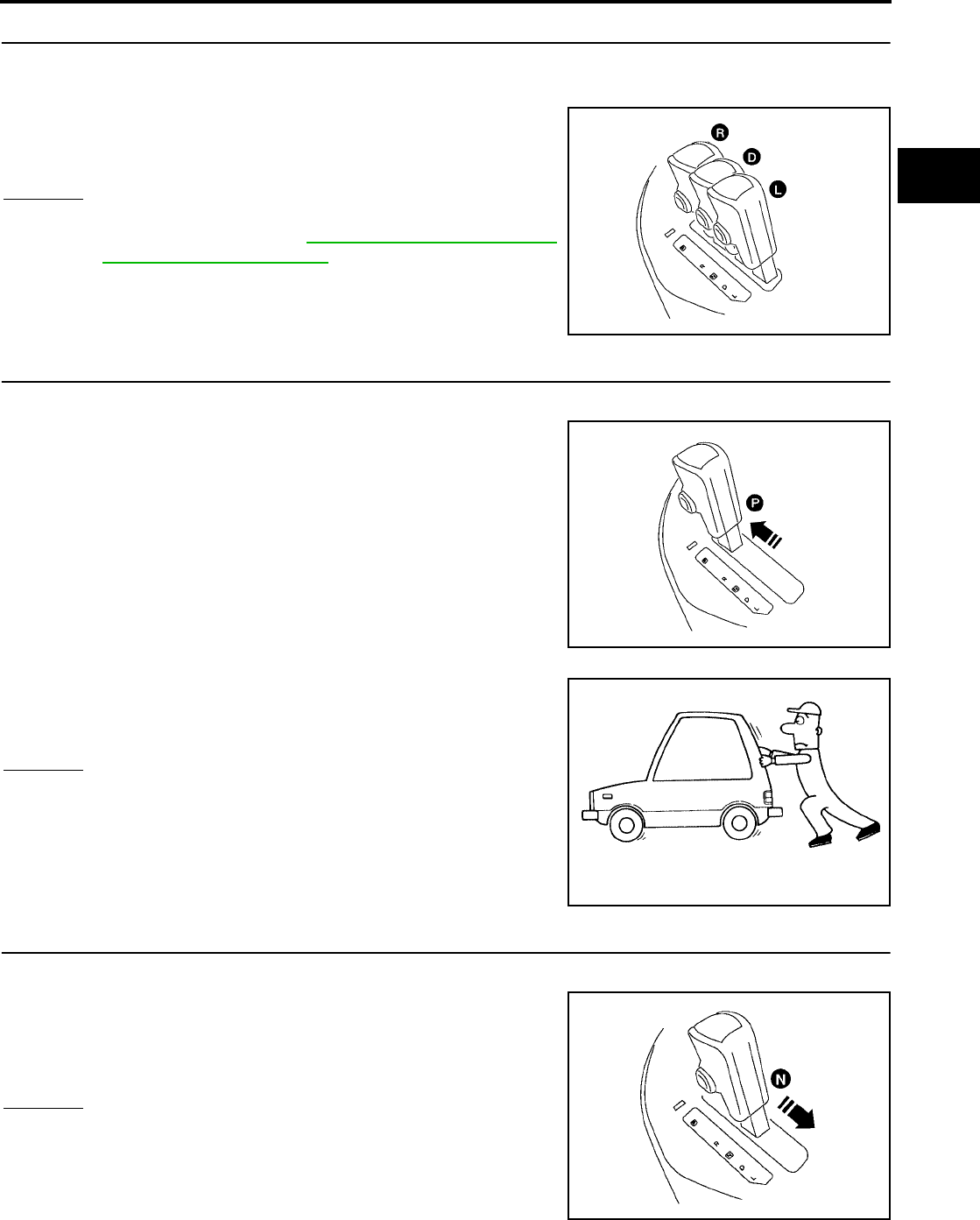
TROUBLE DIAGNOSIS - BASIC INSPECTION
AT-75
[RE4F04B]
D
E
F
G
H
I
J
K
L
M
A
B
AT
Revision: September 2005 2005 Quest
2. CHECK ENGINE START
1. Turn ignition switch to OFF position.
2. Push and hold shift lock release button.
3. Move selector lever to D, L or R position.
4. Turn ignition switch to START position.
5. Is engine started?
Yes or No
Yes >> Stop ROAD TEST. Mark the box on the DIAGNOSTIC
WORKSHEET. Go to AT-214, "Engine Cannot Be
Started in P and N Position" .
No >> GO TO 3.
3. CHECK VEHICLE MOVE
1. Turn ignition switch to OFF position.
2. Move selector lever to P position.
3. Release parking brake.
4. Push vehicle forward or backward.
5. Does vehicle move when it is pushed forward or backward?
6. Apply parking brake.
Yes or No
Yes >> Mark the box “In P Position, Vehicle Moves Forward Or
Backward When Pushed” on the DIAGNOSTIC WORK-
SHEET. Continue ROAD TEST.
No >> GO TO 4.
4. CHECK VEHICLE MOVE
1. Apply parking brake.
2. Move selector lever to N position.
3. Start engine.
4. Release parking brake.
5. Does vehicle move forward or backward?
Yes or No
Yes >> Mark the box “In N Position, Vehicle Moves” on the
DIAGNOSTIC WORKSHEET. Continue ROAD TEST.
No >> GO TO 5.
BCIA0009E
BCIA0002E
SAT796A
SCIA3548E
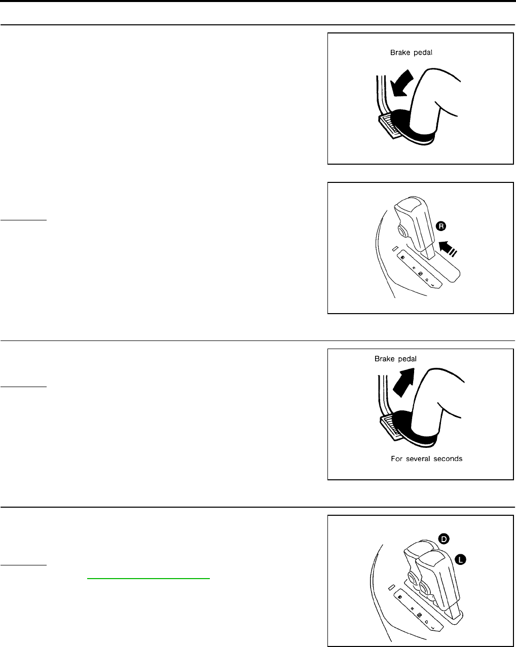
AT-76
[RE4F04B]
TROUBLE DIAGNOSIS - BASIC INSPECTION
Revision: September 2005 2005 Quest
5. CHECK SHIFT LOCK
1. Apply foot brake.
2. Move selector lever to R position.
3. Is there large shock when changing from N to R position?
Yes or No
Yes >> Mark the box “Large shock N →R Position” on the
DIAGNOSTIC WORKSHEET. Continue ROAD TEST.
No >> GO TO 6.
6. CHECK VEHICLE MOVE
1. Release foot brake for several seconds.
2. Does vehicle creep backward when foot brake is released?
Yes or No
Yes >> GO TO 7.
No >> Mark the box “Vehicle Does Not Creep Backward In R
Position” on the DIAGNOSTIC WORKSHEET. Continue
ROAD TEST.
7. CHECK VEHICLE MOVE
1. Move selector lever to D and L positions and check if vehicle
creeps forward.
2. Does vehicle creep forward in all two positions?
Yes or No
Yes >> Go to AT-76, "3. CRUISE TEST" .
No >> Mark the box “Vehicle Does Not Creep Forward In D Or
L Position” on the DIAGNOSTIC WORKSHEET. Con-
tinue ROAD TEST.
3. CRUISE TEST
●Check all items listed in Parts 1 through 3.
SAT797A
BCIA0010E
SAT799A
SCIA3549E
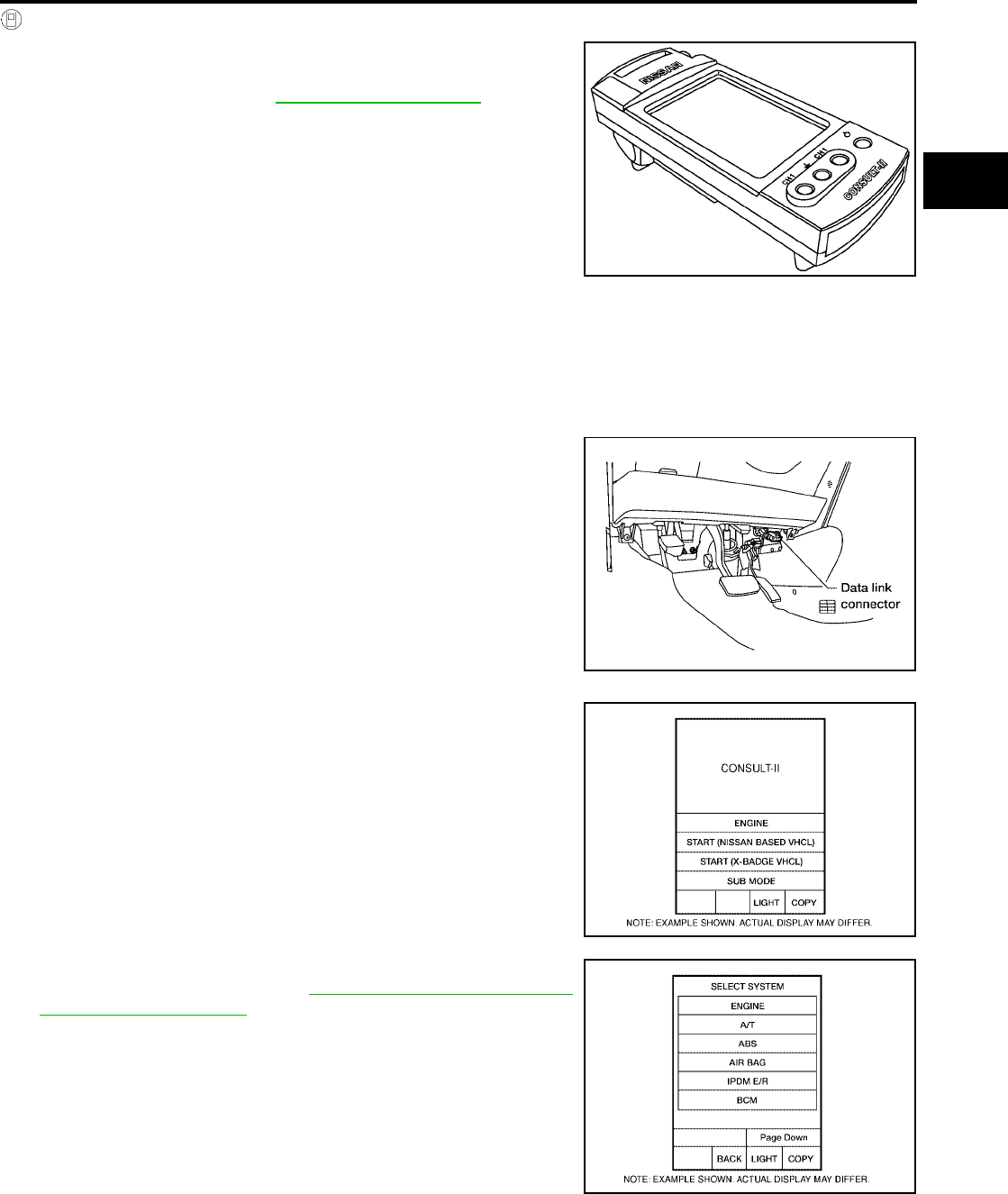
TROUBLE DIAGNOSIS - BASIC INSPECTION
AT-77
[RE4F04B]
D
E
F
G
H
I
J
K
L
M
A
B
AT
Revision: September 2005 2005 Quest
With CONSULT-II
●Using CONSULT-II, conduct a cruise test and record the result.
●Print the result and ensure that shifts and lock-ups take place as
per Shift Schedule. Refer to AT-364, "Shift Schedule"
CONSULT-II Setting Procedure
CAUTION:
If CONSULT-II is used with no connection of CONSULT-II CONVERTER, malfunctions might be
detected in self-diagnosis depending on control unit which carry out CAN communication.
●For details, refer to the separate “CONSULT-II Operations Manual”.
1. Turn ignition switch OFF.
2. Connect CONSULT-II and CONSULT-II CONVERTER to data
link connector, which is located in left side dash panel.
3. Turn ignition switch ON.
4. Touch “START (NISSAN BASED VHCL)”.
5. Touch “A/T”.
If “A/T” is not indicated, go to GI-37, "CONSULT-II Data Link
Connector (DLC) Circuit" .
SAT601J
BBIA0336E
BCIA0029E
BCIA0030E
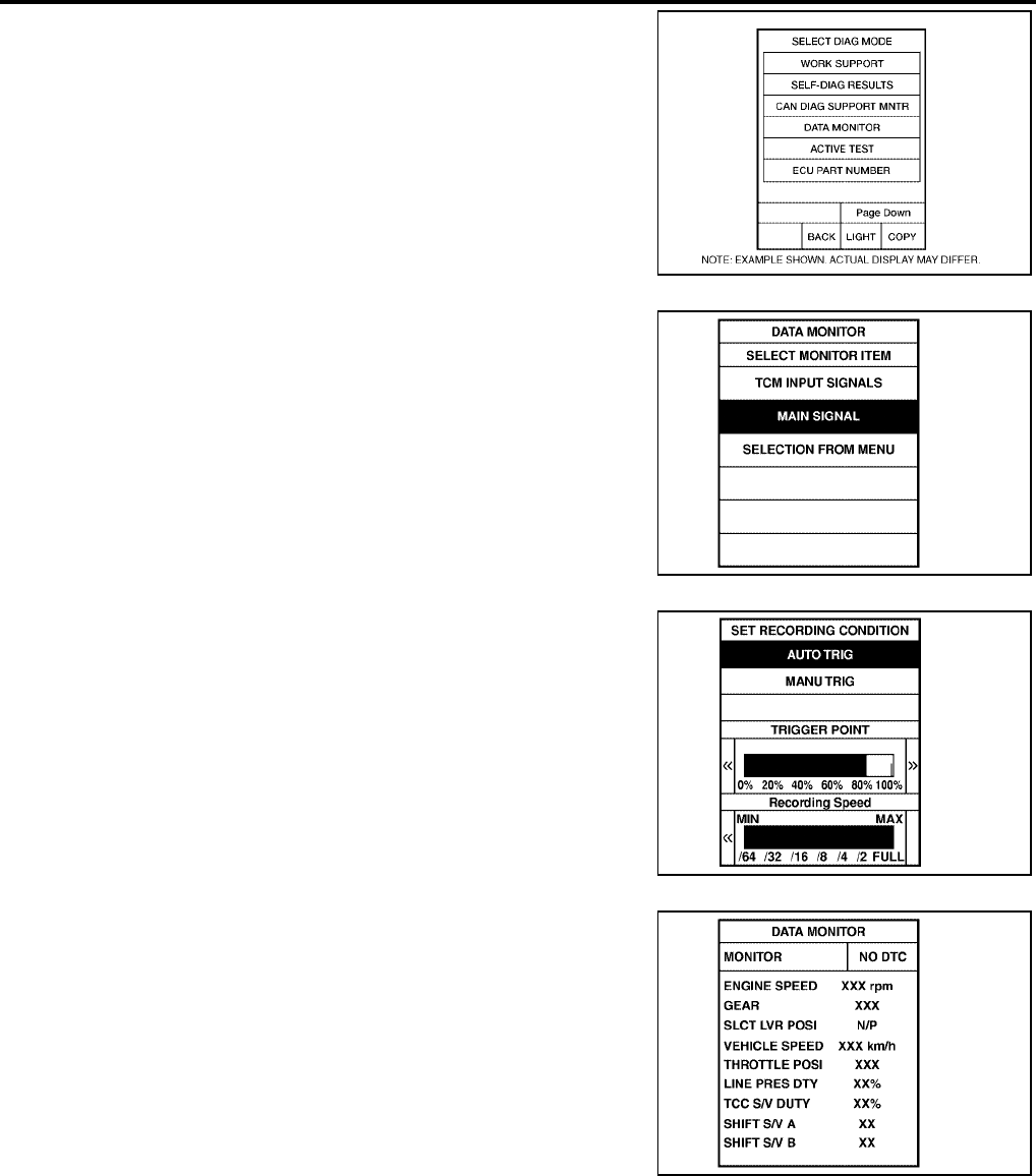
AT-78
[RE4F04B]
TROUBLE DIAGNOSIS - BASIC INSPECTION
Revision: September 2005 2005 Quest
6. Touch “DATA MONITOR”.
7. Touch “MAIN SIGNALS” or “TCM INPUT SIGNALS”.
8. See “Numerical Display”, “Barchart Display” or “Line Graph Dis-
play”.
9. Touch “SETTING” to set recording condition (“AUTO TRIG” or
“MANU TRIG”) and touch “BACK”.
10. Touch “Start”.
11. When performing cruise test, touch “RECORD”.
BCIA0031E
SAT175K
SAT973J
SAT134K

TROUBLE DIAGNOSIS - BASIC INSPECTION
AT-79
[RE4F04B]
D
E
F
G
H
I
J
K
L
M
A
B
AT
Revision: September 2005 2005 Quest
12. After finishing cruise test part 1, touch “STOP”.
13. Touch “STORE” and touch “BACK”.
14. Touch “DISPLAY”.
15. Touch “PRINT”.
16. Check the monitor data printed out.
17. Continue cruise test part 2 and 3.
SAT135K
SAT987J
SAT974J
SAT975J
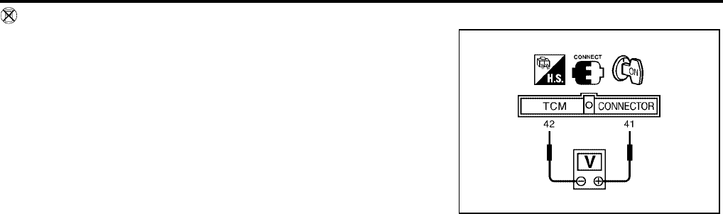
AT-80
[RE4F04B]
TROUBLE DIAGNOSIS - BASIC INSPECTION
Revision: September 2005 2005 Quest
Without CONSULT-II
●Throttle position sensor can be checked by voltage across termi-
nals 41 (W) and 42 (B) of TCM.
LCIA0097E

TROUBLE DIAGNOSIS - BASIC INSPECTION
AT-81
[RE4F04B]
D
E
F
G
H
I
J
K
L
M
A
B
AT
Revision: September 2005 2005 Quest
Cruise Test — Part 1
1. CHECK STARTING GEAR (D1 ) POSITION
1. Drive vehicle for approximately 10 minutes to warm engine oil and ATF up to operating temperature.
2. Park vehicle on flat surface.
3. Set overdrive control switch to ON position.
4. Move selector lever to P position.
5. Start engine.
6. Move selector lever to D position.
7. Accelerate vehicle by constantly depressing accelerator pedal
half-way.
8. Does vehicle start from D1 ?
Read gear position.
Yes or No
Yes >> GO TO 2.
No >> Mark the box of “Vehicle Cannot Be Started From D1 ”
on the DIAGNOSTIC WORKSHEET. Continue ROAD
TEST.
2. CHECK SHIFT UP (D1 TO D2 )
Does A/T shift from D1 to D2 at the specified speed?
Read gear position, throttle opening and vehicle speed.
Yes or No
Yes >> GO TO 3.
No >> Mark the box of “A/T Does Not Shift: D1 → D2 or Does
Not Kickdown: D4 →D2 ” on the DIAGNOSTIC WORK-
SHEET. Continue ROAD TEST. Continue ROAD TEST.
ATF operating temperature : 50 - 80°C (122 - 176°F)
SCIA3528E
SCIA3550E
SAT495G
Specified speed when shifting from D1 to D2
: Refer to AT-364, "Shift Schedule" .
SAT954I

AT-82
[RE4F04B]
TROUBLE DIAGNOSIS - BASIC INSPECTION
Revision: September 2005 2005 Quest
3. CHECK SHIFT UP (D2 TO D3 )
Does A/T shift from D2 to D3 at the specified speed?
Read gear position, throttle opening and vehicle speed.
Yes or No
Yes >> GO TO 4.
No >> Mark the box of “A/T Does Not Shift: D2 → D3 ” on the
DIAGNOSTIC WORKSHEET. Continue ROAD TEST.
Continue ROAD TEST.
4. CHECK SHIFT UP (D3 TO D4 )
Does A/T shift from D3 to D4 at the specified speed?
Read gear position, throttle opening and vehicle speed.
Yes or No
Yes >> GO TO 5.
No >> Mark the box of “A/T Does Not Shift: D3 → D4 ” on the
DIAGNOSTIC WORKSHEET. Continue ROAD TEST.
Continue ROAD TEST.
5. CHECK LOCK-UP (D4 TO D4 L/U)
Does A/T perform lock-up at the specified speed?
Read vehicle speed, throttle opening when lock-up duty
becomes 94%.
Yes or No
Yes >> GO TO 6.
No >> Mark the box of “A/T Does Not Perform Lock-up” on the
DIAGNOSTIC WORKSHEET. Continue ROAD TEST.
6. CHECK HOLD LOCK-UP
Does A/T hold lock-up condition for more than 30 seconds?
Yes or No
Yes >> GO TO 7.
No >> Mark the box of “A/T Does Not Hold Lock-up Condition” on the DIAGNOSTIC WORKSHEET.
Continue ROAD TEST.
Specified speed when shifting from D2 to D3
: Refer to AT-364, "Shift Schedule" .
SAT955I
Specified speed when shifting from D3 to D4
: Refer to AT-364, "Shift Schedule" .
SAT956I
Specified speed when lock-up occurs
: Refer to AT-364, "Shift Schedule" .
SAT957I

TROUBLE DIAGNOSIS - BASIC INSPECTION
AT-83
[RE4F04B]
D
E
F
G
H
I
J
K
L
M
A
B
AT
Revision: September 2005 2005 Quest
7. CHECK SHIFT DOWN (D4 L/U TO D4 )
1. Release accelerator pedal.
2. Is lock-up released when accelerator pedal is released?
Yes or No
Yes >> GO TO 8.
No >> Mark the box of “Lock-up Is Not Released” on the DIAG-
NOSTIC WORKSHEET. Continue ROAD TEST.
8. CHECK SHIFT DOWN (D4 TO D3 )
1. Decelerate vehicle by applying foot brake lightly.
2. Does engine speed return to idle smoothly when A/T is shifted
from D4 to D3 ?
Read gear position and engine speed.
Yes or No
Yes >> 1. Stop vehicle.
2. Go to AT-84, "Cruise Test — Part 2" .
No >> Mark the box of “Engine Speed Does Not Return To Idle
(Light Braking D4 → D3 )” on the DIAGNOSTIC WORK-
SHEET. Continue ROAD TEST.
SAT958I
SAT959I
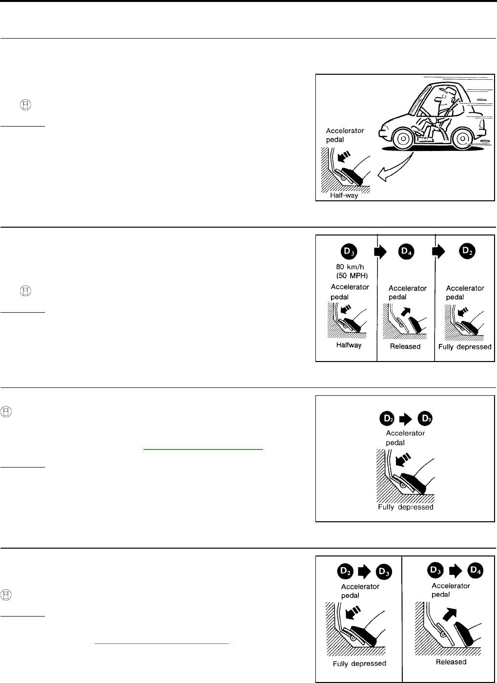
AT-84
[RE4F04B]
TROUBLE DIAGNOSIS - BASIC INSPECTION
Revision: September 2005 2005 Quest
Cruise Test — Part 2
1. CHECK STARTING GEAR (D1 ) POSITION
1. Confirm overdrive control switch is in ON position.
2. Confirm gear selector lever is in D position.
3. Accelerate vehicle by half throttle again.
4. Does vehicle start from D1 ?
Read gear position.
Yes or No
Yes >> GO TO 2.
No >> Mark the box of “Vehicle Does Not Start From D1 ” on
the DIAGNOSTIC WORKSHEET. Continue ROAD
TEST.
2. CHECK SHIFT UP AND SHIFT DOWN (D3 TO D4 TO D2 )
1. Accelerate vehicle to 80 km/h (50 MPH) as shown in illustration.
2. Release accelerator pedal and then quickly depress it fully.
3. Does A/T shift from D4 to D2 as soon as accelerator pedal is
depressed fully?
Read gear position and throttle opening.
Yes or No
Yes >> GO TO 3.
No >> Mark the box of “A/T Does Not Shift: D1 → D2 or Does
Not Kickdown: D4 → D2 ” on the DIAGNOSTIC WORK-
SHEET. Continue ROAD TEST.
3. CHECK SHIFT UP (D2 TO D3 )
Does A/T shift from D2 to D3 at the specified speed?
Read gear position, throttle opening and vehicle speed.
Yes or No
Yes >> GO TO 4.
No >> Mark the box of “A/T Does Not Shift: D2 → D3 ” on the
DIAGNOSTIC WORKSHEET. Continue ROAD TEST.
4. CHECK SHIFT UP (D3 TO D4 ) AND ENGINE BRAKE
Release accelerator pedal after shifting from D2 to D3 .
Does A/T shift from D3 to D4 and does vehicle decelerate by engine
brake?
Read gear position, throttle opening and vehicle speed.
Yes or No
Yes >> 1. Stop vehicle.
2. Go to AT-85, "Cruise Test — Part 3" .
No >> Mark the box of “A/T Does Not Shift: D3 → D4 ” on the
DIAGNOSTIC WORKSHEET. Continue ROAD TEST.
SAT495G
SAT404H
Specified speed when shifting from D2 to D3
: Refer to AT-364, "Shift Schedule" .
SAT960I
SAT405H
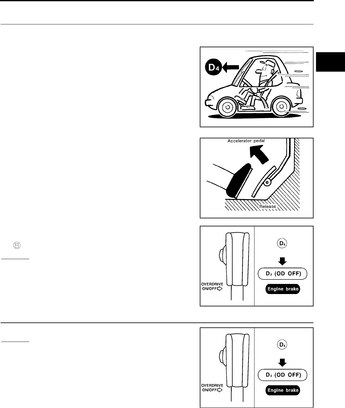
TROUBLE DIAGNOSIS - BASIC INSPECTION
AT-85
[RE4F04B]
D
E
F
G
H
I
J
K
L
M
A
B
AT
Revision: September 2005 2005 Quest
Cruise Test — Part 3
1. VEHICLE SPEED (D4 ) POSITION
1. Confirm overdrive control switch is in ON position.
2. Confirm gear selector lever is in D position.
3. Accelerate vehicle using half-throttle to D4 .
4. Release accelerator pedal.
5. Set overdrive control switch to OFF position while driving in D4 .
6. Does A/T shift from D4 to D3 (O/D OFF)?
Read gear position and vehicle speed.
Yes or No
Yes >> GO TO 2.
No >> Mark the box of “A/T Does Not Shift: D4 → D3 , When
Overdrive Control Switch ON → OFF” on the DIAGNOS-
TIC WORKSHEET. Continue ROAD TEST.
2. CHECK ENGINE BRAKE
Does vehicle decelerate by engine brake?
Yes or No
Yes >> GO TO 3.
No >> Mark the box of “Engine Speed Does Not Return To Idle
(Engine Brake in D3 )” on the DIAGNOSTIC WORK-
SHEET. Continue ROAD TEST.
SAT812A
SAT813A
BCIA0011E
BCIA0011E
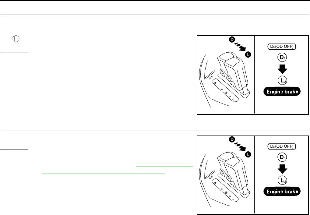
AT-86
[RE4F04B]
TROUBLE DIAGNOSIS - BASIC INSPECTION
Revision: September 2005 2005 Quest
3. CHECK SHIFT DOWN (D3 TO L2 )
1. Move selector lever from D to L position while driving in D3 (O/D OFF).
2. Does A/T shift from D3 (O/D OFF) to L2 ?
Read gear position.
Yes or No
Yes >> GO TO 4.
No >> Mark the box of “A/T Does Not Shift: D3 → L2 , When
Selector Lever D → L Position” on the DIAGNOSTIC
WORKSHEET. Continue ROAD TEST.
4. CHECK ENGINE BRAKE
Does vehicle decelerate by engine brake?
Yes or No
Yes >> 1. Stop vehicle.
2. Perform self-diagnosis. Refer to AT-54, "TCM SELF-
DIAGNOSTIC PROCEDURE (NO TOOLS)" .
No >> Mark the box of “Vehicle Does Not Decelerate By
Engine Brake” on the DIAGNOSTIC WORKSHEET.
Stop ROAD TEST.
BCIA0012E
BCIA0012E

TROUBLE DIAGNOSIS - GENERAL DESCRIPTION
AT-87
[RE4F04B]
D
E
F
G
H
I
J
K
L
M
A
B
AT
Revision: September 2005 2005 Quest
TROUBLE DIAGNOSIS - GENERAL DESCRIPTION PFP:00000
Symptom Chart UCS000N1
Numbers are arranged in order of inspection.
Perform inspections starting with number one and work up.
Items Symptom Condition Diagnostic Item Reference Page
No Lock-up
Engagement/
TCC Inoperative
Torque converter
is not locked up.
ON vehicle
1. Accelerator pedal position (APP) sensor AT-178
2. Vehicle speed sensor·A/T (Revolution
sensor) and vehicle speed sensor·MTR AT-118, AT-195
3. Engine speed signal AT-123
4. A/T fluid temperature sensor AT-112
5. Line pressure test AT-71
6. Torque converter clutch solenoid valve AT-149
7. Control valve assembly AT-253
OFF vehicle 8. Torque converter AT-268
Torque converter
clutch piston slip.
ON vehicle
1. Fluid level AT-65
2. Accelerator pedal position (APP) sensor AT-178
3. Line pressure test AT-71
4. Torque converter clutch solenoid valve AT-149
5. Line pressure solenoid valve AT-162
6. Control valve assembly AT-253
OFF vehicle 7. Torque converter AT-268
Lock-up point is
extremely high or
low.
ON vehicle
1. Accelerator pedal position (APP) sensor AT-178
2. Vehicle speed sensor·A/T (Revolution
sensor) and vehicle speed sensor·MTR AT-118, AT-195
3. Torque converter clutch solenoid valve AT-149
4. Control valve assembly AT-253
Shift Shock
Sharp shock in
shifting from N to
D position.
ON vehicle
1. Engine idling rpm EC-83
2. Accelerator pedal position (APP) sensor AT-178
3. Line pressure test AT-71
4. A/T fluid temperature sensor AT-112
5. Engine speed signal AT-123
6. Line pressure solenoid valve AT-162
7. Control valve assembly AT-253
8. Accumulator N-D AT-268
OFF vehicle 9. Forward clutch AT-313
Too sharp a
shock in change
from D1 to D2 .
ON vehicle
1. Accelerator pedal position (APP) sensor AT-178
2. Line pressure test AT-71
3. Accumulator servo release AT-268
4. Control valve assembly AT-253
5. A/T fluid temperature sensor AT-112
OFF vehicle 6. Brake band AT-268

AT-88
[RE4F04B]
TROUBLE DIAGNOSIS - GENERAL DESCRIPTION
Revision: September 2005 2005 Quest
Shift Shock
Too sharp a
shock in change
from D2 to D3 .
ON vehicle
1. Accelerator pedal position (APP) sensor AT-178
2. Line pressure test AT-71
3. Control valve assembly AT-253
OFF vehicle 4. High clutch AT-308
5. Brake band AT-268
Too sharp a
shock in change
from D3 to D4 .
ON vehicle
1. Accelerator pedal position (APP) sensor AT-178
2. Line pressure test AT-71
3. Control valve assembly AT-253
4. A/T fluid temperature sensor AT-112
OFF vehicle
5. Brake band AT-268
6. Overrun clutch AT-313
7. Forward one-way clutch AT-322
Gear change
shock felt during
deceleration by
releasing acceler-
ator pedal.
ON vehicle
1. Accelerator pedal position (APP) sensor AT-178
2. Line pressure test AT-71
3. Overrun clutch solenoid valve AT-184
4. Control valve assembly AT-253
Improper Shift
Timing
Too high a gear
change point from
D1 to D2 , from
D2 to D3 , from
D3 to D4 .
ON vehicle
1. Accelerator pedal position (APP) sensor AT-178
2. Vehicle speed sensor·A/T (Revolution
sensor) and vehicle speed sensor·MTR AT-118, AT-195
3. Shift solenoid valve A AT-168
4. Shift solenoid valve B AT-173
Gear change
directly from D 1
to D3 occurs.
ON vehicle 1. Fluid level AT-65
2. Accumulator servo release AT-261
OFF vehicle 3. Brake band AT-268
Too high a
change point from
D4 to D3 , from
D3 to D2 , from
D2 to D1 .
ON vehicle
1. Accelerator pedal position (APP) sensor AT-178
2. Vehicle speed sensor·A/T (Revolution
sensor) and vehicle speed sensor·MTR AT-118, AT-195
Kickdown does
not operate when
depressing pedal
in D4 within kick-
down vehicle
speed.
ON vehicle
1. Accelerator pedal position (APP) sensor AT-178
2. Vehicle speed sensor·A/T (Revolution
sensor) and vehicle speed sensor·MTR AT-118, AT-195
3. Shift solenoid valve A AT-168
4. Shift solenoid valve B AT-173
Kickdown oper-
ates or engine
overruns when
depressing pedal
in D4 beyond
kickdown vehicle
speed limit.
ON vehicle
1. Vehicle speed sensor·A/T (Revolution
sensor) and vehicle speed sensor·MTR AT-118, AT-195
2. Accelerator pedal position (APP) sensor AT-178
3. Shift solenoid valve A AT-168
4. Shift solenoid valve B AT-173
Gear change
from L2 to L3 in L
position.
ON vehicle
1. Park/neutral position (PNP) switch AT-106
2. Control cable adjustment AT-258
Items Symptom Condition Diagnostic Item Reference Page

TROUBLE DIAGNOSIS - GENERAL DESCRIPTION
AT-89
[RE4F04B]
D
E
F
G
H
I
J
K
L
M
A
B
AT
Revision: September 2005 2005 Quest
No Down Shift
Failure to change
gear from D4 to
D3 .
ON vehicle
1. Fluid level AT-65
2. Accelerator pedal position (APP) sensor AT-178
3. Overrun clutch solenoid valve AT-184
4. Shift solenoid valve A AT-168
5. Line pressure solenoid valve AT-162
6. Control valve assembly AT-253
OFF vehicle 7. Brake band AT-268
8. Overrun clutch AT-313
Failure to change
gear from D3 to
D2 or from D4 to
D2 .
ON vehicle
1. Fluid level AT-65
2. Accelerator pedal position (APP) sensor AT-178
3. Shift solenoid valve A AT-168
4. Shift solenoid valve B AT-173
5. Control valve assembly AT-253
OFF vehicle 6. High clutch AT-308
7. Brake band AT-268
Failure to change
gear from D2 to
D1 or from D3 to
D1 .
ON vehicle
1. Fluid level AT-65
2. Accelerator pedal position (APP) sensor AT-178
3. Shift solenoid valve A AT-168
4. Shift solenoid valve B AT-173
5. Control valve assembly AT-253
OFF vehicle
6. Low one-way clutch AT-268
7. High clutch AT-308
8. Brake band AT-268
Failure to change
from D3 to L2
when changing
lever into L posi-
tion.
AT-237
ON vehicle
1. Accelerator pedal position (APP) sensor AT-178
2. Shift solenoid valve B AT-173
3. Control valve assembly AT-253
4. Control cable adjustment AT-258
OFF vehicle 5. Brake band AT-268
Items Symptom Condition Diagnostic Item Reference Page

AT-90
[RE4F04B]
TROUBLE DIAGNOSIS - GENERAL DESCRIPTION
Revision: September 2005 2005 Quest
No Up Shift
Failure to change
gear from D1 to
D2 .
ON vehicle
1. Control cable adjustment AT-258
2. Shift solenoid valve A AT-168
3. Control valve assembly AT-253
4. Vehicle speed sensor·A/T (Revolution
sensor) and vehicle speed sensor·MTR AT-118, AT-195
5. Accelerator pedal position (APP) sensor AT-178
OFF vehicle 6. Brake band AT-268
Failure to change
gear from D2 to
D3 .
ON vehicle
1. Control cable adjustment AT-258
2. Shift solenoid valve B AT-173
3. Control valve assembly AT-253
4. Vehicle speed sensor·A/T (Revolution
sensor) and vehicle speed sensor·MTR AT-118, AT-195
5. Accelerator pedal position (APP) sensor AT-178
OFF vehicle 6. High clutch AT-308
7. Brake band AT-268
Failure to change
gear from D3 to
D4 .
ON vehicle
1. Park/neutral position (PNP) switch AT-106
2. Overdrive control switch AT-239
3. Control cable adjustment AT-258
4. Shift solenoid valve A AT-168
5. Vehicle speed sensor·A/T (Revolution
sensor) and vehicle speed sensor·MTR AT-118, AT-195
6. A/T fluid temperature sensor AT-112
7. Accelerator pedal position (APP) sensor AT-178
OFF vehicle 8. Brake band AT-268
A/T does not shift
to D4 when driv-
ing with over-
drive control
switch ON.
ON vehicle
1. Accelerator pedal position (APP) sensor AT-178
2. Park/neutral position (PNP) switch AT-106
3. Overdrive control switch AT-239
4. Vehicle speed sensor·A/T (Revolution
sensor) and vehicle speed sensor·MTR AT-118, AT-195
5. Shift solenoid valve A AT-168
6. Overrun clutch solenoid valve AT-184
7. Control valve assembly AT-253
8. A/T fluid temperature sensor AT-112
9. Line pressure solenoid valve AT-162
OFF vehicle 10. Brake band AT-268
11. Overrun clutch AT-313
Items Symptom Condition Diagnostic Item Reference Page

TROUBLE DIAGNOSIS - GENERAL DESCRIPTION
AT-91
[RE4F04B]
D
E
F
G
H
I
J
K
L
M
A
B
AT
Revision: September 2005 2005 Quest
Slips/Will Not
Engage
Vehicle will not
run in R position
(but runs in D and
L positions).
Clutch slips.
Very poor accel-
eration.
ON vehicle
1. Control cable adjustment AT-258
2. Stall test AT-68
3. Line pressure test AT-71
4. Line pressure solenoid valve AT-162
5. Control valve assembly AT-253
OFF vehicle 6. Reverse clutch AT-305
7. Low & reverse brake AT-319
Vehicle will not
run in D and L
positions (but
runs in R posi-
tion).
ON vehicle 1. Control cable adjustment AT-258
OFF vehicle 2. Low one-way clutch AT-268
Vehicle will not
run in D and L
positions (but
runs in R posi-
tion). Clutch slips.
Very poor accel-
eration.
ON vehicle
1. Fluid level AT-65
2. Stall test AT-68
3. Line pressure test AT-71
4. Line pressure solenoid valve AT-162
5. Control valve assembly AT-253
6. Accumulator N-D AT-268
OFF vehicle
7. Reverse clutch AT-305
8. High clutch AT-308
9. Forward clutch AT-313
10. Forward one-way clutch AT-268
11. Low one-way clutch AT-268
Clutches or
brakes slip some-
what in starting.
ON vehicle
1. Fluid level AT-65
2. Control cable adjustment AT-258
3. Accelerator pedal position (APP) sensor AT-178
4. Line pressure test AT-71
5. Line pressure solenoid valve AT-162
6. Control valve assembly AT-253
7. Accumulator N-D AT-268
8. Shift solenoid valve A AT-168
9. Shift solenoid valve B AT-173
10. Overrun clutch solenoid valve AT-184
11. Torque converter clutch solenoid valve AT-149
OFF vehicle
12. Forward clutch AT-313
13. Reverse clutch AT-305
14. Low & reverse brake AT-319
15. Oil pump AT-286
16. Torque converter AT-268
Items Symptom Condition Diagnostic Item Reference Page

AT-92
[RE4F04B]
TROUBLE DIAGNOSIS - GENERAL DESCRIPTION
Revision: September 2005 2005 Quest
Slips/Will Not
Engage
No creep at all.
AT-218, AT-220
ON vehicle
1. Fluid level AT-65
2. Line pressure test AT-71
3. Control valve assembly AT-253
OFF vehicle
4. Forward clutch AT-313
5. Oil pump AT-286
6. Torque converter AT-268
Almost no shock
or clutches slip-
ping in change
from D1 to D2 .
ON vehicle
1. Fluid level AT-65
2. Accelerator pedal position (APP) sensor AT-178
3. Line pressure test AT-71
4. Accumulator servo release AT-261
5. Control valve assembly AT-253
OFF vehicle 6. Brake band AT-268
Almost no shock
or slipping in
change from D2
to D3 .
ON vehicle
1. Fluid level AT-65
2. Accelerator pedal position (APP) sensor AT-178
3. Line pressure test AT-71
4. Control valve assembly AT-253
OFF vehicle 5. High clutch AT-308
6. Forward clutch AT-313
Almost no shock
or slipping in
change from D3
to D4 .
ON vehicle
1. Fluid level AT-65
2. Accelerator pedal position (APP) sensor AT-178
3. Line pressure test AT-71
4. Control valve assembly AT-253
OFF vehicle 5. Brake band AT-268
Races extremely
fast or slips in
changing from D4
to D3 when
depressing pedal.
ON vehicle
1. Fluid level AT-65
2. Accelerator pedal position (APP) sensor AT-178
3. Line pressure test AT-71
4. Line pressure solenoid valve AT-162
5. Shift solenoid valve A AT-168
6. Control valve assembly AT-253
OFF vehicle 7. Brake band AT-268
8. Forward clutch AT-313
Races extremely
fast or slips in
changing from D4
to D2 when
depressing pedal.
ON vehicle
1. Fluid level AT-65
2. Accelerator pedal position (APP) sensor AT-178
3. Line pressure test AT-71
4. Line pressure solenoid valve AT-162
5. Shift solenoid valve A AT-168
6. Shift solenoid valve B AT-173
7. Control valve assembly AT-253
OFF vehicle 8. Brake band AT-268
9. Forward clutch AT-313
Items Symptom Condition Diagnostic Item Reference Page

TROUBLE DIAGNOSIS - GENERAL DESCRIPTION
AT-93
[RE4F04B]
D
E
F
G
H
I
J
K
L
M
A
B
AT
Revision: September 2005 2005 Quest
Slips/Will Not
Engage
Races extremely
fast or slips in
changing from D3
to D2 when
depressing pedal.
ON vehicle
1. Fluid level AT-65
2. Accelerator pedal position (APP) sensor AT-178
3. Line pressure test AT-71
4. Line pressure solenoid valve AT-162
5. Shift solenoid valve B AT-173
6. Control valve assembly AT-253
OFF vehicle 7. Brake band AT-268
8. High clutch AT-308
Races extremely
fast or slips in
changing from D4
or D3 to D1 when
depressing pedal.
ON vehicle
1. Fluid level AT-65
2. Accelerator pedal position (APP) sensor AT-178
3. Line pressure test AT-71
4. Line pressure solenoid valve AT-162
5. Shift solenoid valve A AT-168
6. Shift solenoid valve B AT-173
7. Control valve assembly AT-253
OFF vehicle
8. Forward clutch AT-313
9. Forward one-way clutch AT-268
10. Low one-way clutch AT-268
Vehicle will not
run in any posi-
tion.
ON vehicle
1. Fluid level AT-65
2. Control cable adjustment AT-258
3. Line pressure test AT-71
4. Line pressure solenoid valve AT-162
OFF vehicle
5. Oil pump AT-286
6. High clutch AT-308
7. Brake band AT-268
8. Low & reverse brake AT-319
9. Torque converter AT-268
10. Parking components AT-283
Items Symptom Condition Diagnostic Item Reference Page

AT-94
[RE4F04B]
TROUBLE DIAGNOSIS - GENERAL DESCRIPTION
Revision: September 2005 2005 Quest
Others
Engine cannot be
started in P and N
positions.
AT-214
ON vehicle
1. Ignition switch and starter SC-13
2. Control cable adjustment AT-258
3. Park/neutral position (PNP) switch adjust-
ment AT-255
Engine starts in
positions other
than P and N.
ON vehicle
1. Control cable adjustment AT-258
2. Park/neutral position (PNP) switch adjust-
ment AT-255
Transaxle noise
in P and N posi-
tions.
ON vehicle
1. Fluid level AT-65
2. Line pressure test AT-71
3. Accelerator pedal position (APP) sensor AT-178
4. Vehicle speed sensor·A/T (Revolution
sensor) and vehicle speed sensor·MTR AT-118, AT-195
OFF vehicle 5. Oil pump AT-286
6. Torque converter AT-268
Vehicle moves
when changing
into P position or
parking gear does
not disengage
when shifted out
of P position.
ON vehicle 1. Control cable adjustment AT-258
OFF vehicle 2. Parking components AT-283
Vehicle runs in N
position.
AT-215
ON vehicle 1. Control cable adjustment AT-258
OFF vehicle
2. Forward clutch AT-313
3. Reverse clutch AT-305
4. Overrun clutch AT-313
Vehicle braked
when shifting into
R position.
ON vehicle
1. Fluid level AT-65
2. Line pressure test AT-71
3. Line pressure solenoid valve AT-162
4. Control valve assembly AT-253
OFF vehicle
5. High clutch AT-308
6. Brake band AT-268
7. Forward clutch AT-313
8. Overrun clutch AT-313
Excessive creep. ON vehicle 1. Engine idling rpm EC-83
Items Symptom Condition Diagnostic Item Reference Page

TROUBLE DIAGNOSIS - GENERAL DESCRIPTION
AT-95
[RE4F04B]
D
E
F
G
H
I
J
K
L
M
A
B
AT
Revision: September 2005 2005 Quest
Others
Engine stops
when shifting
lever into R, D
and L.
ON vehicle
1. Engine idling rpm EC-83
2. Fluid level AT-65
3. Torque converter clutch solenoid valve AT-149
4. Control valve assembly AT-253
OFF vehicle 5. Torque converter AT-268
Vehicle braked by
gear change from
D1 to D 2 .
ON vehicle 1. Fluid level AT-65
OFF vehicle
2. Reverse clutch AT-305
3. Low & reverse brake AT-319
4. High clutch AT-308
5. Low one-way clutch AT-268
Vehicle braked by
gear change from
D2 to D3 .
ON vehicle 1. Fluid level AT-65
OFF vehicle 2. Brake band AT-268
Vehicle braked by
gear change from
D3 to D4 .
ON vehicle 1. Fluid level AT-65
OFF vehicle
2. Overrun clutch AT-313
3. Forward one-way clutch AT-268
4. Reverse clutch AT-305
Maximum speed
not attained.
Acceleration
poor.
ON vehicle
1. Fluid level AT-65
2. Park/neutral position (PNP) switch AT-106
3. Overdrive control switch AT-239
4. Accelerator pedal position (APP) sensor AT-178
5. Vehicle speed sensor·A/T (Revolution
sensor) and vehicle speed sensor·MTR AT-118, AT-195
6. Shift solenoid valve A AT-168
7. Shift solenoid valve B AT-173
8. Control valve assembly AT-253
OFF vehicle
9. Reverse clutch AT-305
10. High clutch AT-308
11. Brake band AT-268
12. Low & reverse brake AT-319
13. Oil pump AT-286
14. Torque converter AT-268
Transaxle noise
in D, L and R
positions.
ON vehicle 1. Fluid level AT-65
OFF vehicle 2. Torque converter AT-268
Items Symptom Condition Diagnostic Item Reference Page

AT-96
[RE4F04B]
TROUBLE DIAGNOSIS - GENERAL DESCRIPTION
Revision: September 2005 2005 Quest
TCM Terminals and Reference Value UCS000N2
PREPARATION
●Measure voltage between each terminal and terminal 25 or 48
by following “TCM INSPECTION TABLE”.
Others
Transaxle over-
heats.
ON vehicle
1. Fluid level AT-65
2. Engine idling rpm EC-83
3. Accelerator pedal position (APP) sensor AT-178
4. Line pressure test AT-71
5. Line pressure solenoid valve AT-162
6. Control valve assembly AT-253
OFF vehicle
7. Oil pump AT-286
8. Reverse clutch AT-305
9. High clutch AT-308
10. Brake band AT-268
11. Forward clutch AT-313
12. Overrun clutch AT-313
13. Low & reverse brake AT-319
14. Torque converter AT-268
ATF shoots out
during operation.
White smoke
emitted from
exhaust pipe dur-
ing operation.
ON vehicle 1. Fluid level AT-65
OFF vehicle
2. Reverse clutch AT-305
3. High clutch AT-308
4. Brake band AT-268
5. Forward clutch AT-313
6. Overrun clutch AT-313
7. Low & reverse brake AT-319
Offensive smell at
fluid charging
pipe.
ON vehicle 1. Fluid level AT-65
OFF vehicle
2. Torque converter AT-268
3. Oil pump AT-286
4. Reverse clutch AT-305
5. High clutch AT-308
6. Brake band AT-268
7. Forward clutch AT-313
8. Overrun clutch AT-313
9. Low & reverse brake AT-319
Items Symptom Condition Diagnostic Item Reference Page
AAT475A
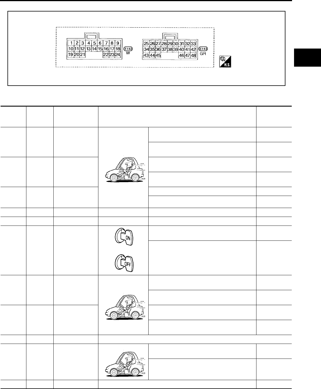
TROUBLE DIAGNOSIS - GENERAL DESCRIPTION
AT-97
[RE4F04B]
D
E
F
G
H
I
J
K
L
M
A
B
AT
Revision: September 2005 2005 Quest
TCM HARNESS CONNECTOR TERMINAL LAYOUT
TCM INSPECTION TABLE
Data are reference value and are measured between each terminal and ground.
SCIA3369E
Terminal Wire color Item Condition
Judgement
standard
(Approx.)
1G/R
Line pressure
solenoid valve
When releasing accelerator pedal after warming
up engine. 1.5 - 3.0V
When depressing accelerator pedal fully after
warming up engine. 0V
2W/B
Line pressure
solenoid valve
(with dropping
resistor)
When releasing accelerator pedal after warming
up engine. 4 - 14V
When depressing accelerator pedal fully after
warming up engine. 0V
3 G/B
Torque converter
clutch solenoid
valve
When A/T performs lock-up. 8 - 15V
When A/T does not perform lock-up. 0V
5 L CAN-H — — —
6 P CAN-L — — —
10 R/Y Power source or
With ignition switch ON. Battery volt-
age
With ignition switch OFF. 0V
11 R/Y Shift solenoid
valve A
When shift solenoid valve A operates.
(When driving in D1 or D4 .)
Battery volt-
age
When shift solenoid valve A does not operate.
(When driving in D2 or D3 .) 0V
12 LG/B Shift solenoid
valve B
When shift solenoid valve B operates.
(When driving in D1 or D2 .)
Battery volt-
age
When shift solenoid valve B does not operate.
(When driving in D3 or D4 .) 0V
19 R/Y Power source Same as No. 10
20 BR/Y Overrun clutch
solenoid valve
When overrun clutch solenoid valve operates. Battery volt-
age
When overrun clutch solenoid valve does not
operate. 0V
25 B Ground Always 0V
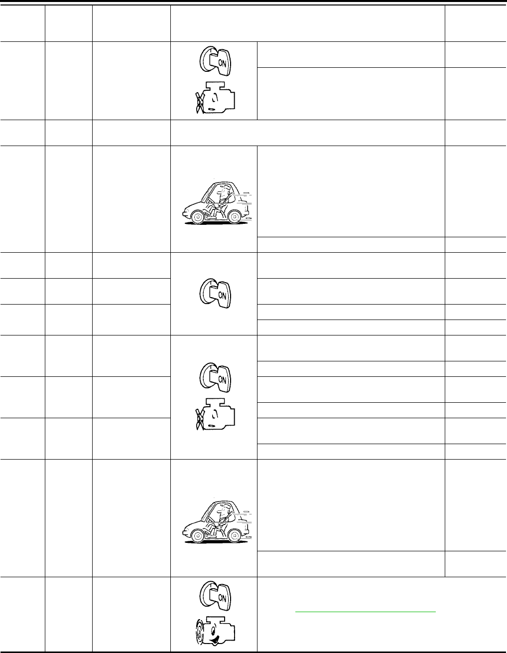
AT-98
[RE4F04B]
TROUBLE DIAGNOSIS - GENERAL DESCRIPTION
Revision: September 2005 2005 Quest
27 P/B PNP switch L
position
When setting selector lever to L position. Battery volt-
age
When setting selector lever to other positions. 0V
28 Y/R Power source
(Memory back-up) Always Battery volt-
age
29 W Revolution sensor
When moving at 20 km/h (12 MPH), use the
CONSULT-II pulse frequency measuring func-
tion.*1
CAUTION:
Connect the diagnosis data link cable to the
vehicle diagnosis connector.
*1: A circuit tester cannot be used to test this
item.
450 Hz
When vehicle is parked. 0V
30* BR/Y Data link connec-
tor (RX) ——
31* P Data link connec-
tor (TX) ——
32 G/O Sensor power Ignition switch ON. 4.5 - 5.5V
Ignition switch OFF. 0V
34 G PNP switch D
position
When setting selector lever to D position. Battery volt-
age
When setting selector lever to other positions. 0V
35 G/W PNP switch R
position
When setting selector lever to R position. Battery volt-
age
When setting selector lever to other positions. 0V
36 R/G PNP switch P or N
position
When setting selector lever to P or N position. Battery volt-
age
When setting selector lever to other positions. 0V
38 G
Turbine revolution
sensor (power
train revolution
sensor)
When moving at 20 km/h (12 MPH), use the
CONSULT-II pulse frequency measuring func-
tion.*1
CAUTION:
Connect the diagnosis data link cable to the
vehicle diagnosis connector.
*1: A circuit tester cannot be used to test this
item.
240 Hz
When vehicle is parked. Under 1.3V or
over 4.5V
39 W/G Engine speed sig-
nal
Refer to EC-124, "ECM INSPECTION TABLE" (ECM terminal
103).
Terminal Wire color Item Condition
Judgement
standard
(Approx.)
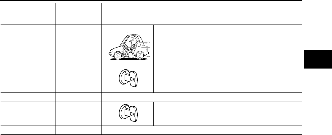
TROUBLE DIAGNOSIS - GENERAL DESCRIPTION
AT-99
[RE4F04B]
D
E
F
G
H
I
J
K
L
M
A
B
AT
Revision: September 2005 2005 Quest
*: These terminals are connected to the Data link connector.
40 V/R Vehicle speed sig-
nal
When moving vehicle at 2 to 3 km/h (1 to 2
MPH) for 1 m (3 ft) or more.
Intermittently
changes
between
approx. 0V
and approx.
4.5V
41 W
Accelerator pedal
position (APP)
sensor
When depressing accelerator pedal slowly after
warming up engine.
(Voltage rises gradually in response to throttle
position.)
Fully-closed
throttle: 0.5V
Fully-open
throttle: 4V
42 B Sensor ground Always 0V
47 G A/T fluid tempera-
ture sensor
When ATF temperature is 20°C (68°F). 1.5V
When ATF temperature is 80°C (176°F). 0.5V
48 B Ground Always 0V
Terminal Wire color Item Condition
Judgement
standard
(Approx.)
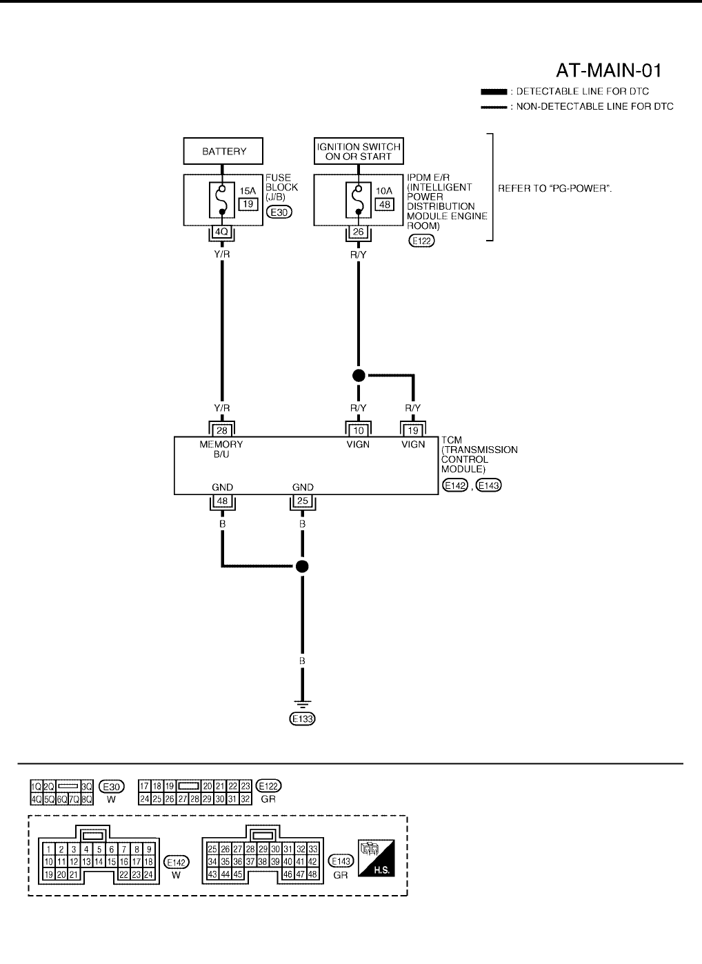
AT-100
[RE4F04B]
TROUBLE DIAGNOSIS FOR POWER SUPPLY
Revision: September 2005 2005 Quest
TROUBLE DIAGNOSIS FOR POWER SUPPLY PFP:00000
Wiring Diagram — AT — MAIN UCS000N4
BCWA0298E
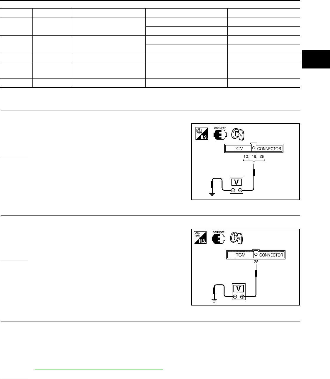
TROUBLE DIAGNOSIS FOR POWER SUPPLY
AT-101
[RE4F04B]
D
E
F
G
H
I
J
K
L
M
A
B
AT
Revision: September 2005 2005 Quest
TCM TERMINALS AND REFERENCE VALUE (MEASURED BETWEEN EACH TERMINAL AND GROUND)
Diagnostic Procedure UCS000N5
1. CHECK TCM POWER SOURCE STEP 1
1. Turn ignition switch to ON position. (Do not start engine.)
2. Check voltage between TCM harness connectors E142, E143
terminals 10 (R/Y), 19 (R/Y), 28 (Y/R) and ground.
OK or NG
OK >> GO TO 2.
NG >> GO TO 3.
2. CHECK TCM POWER SOURCE STEP 2
1. Turn ignition switch to OFF position.
2. Check voltage between TCM harness connector E143 terminal
28 (Y/R) and ground.
OK or NG
OK >> GO TO 4.
NG >> GO TO 3.
3. DETECT MALFUNCTIONING ITEM
Check the following items:
●Fuse
●Harness for short or open between battery, ignition switch and TCM harness connectors E142, E143 ter-
minals 10 (R/Y), 19 (R/Y) and 28 (Y/R)
●Ignition switch
Refer toPG-4, "POWER SUPPLY ROUTING CIRCUIT" .
OK or NG
OK >> GO TO 4.
NG >> Repair or replace damaged parts.
TERMINAL WIRE COLOR ITEM CONDITION DATA (APPROX.)
10 R/Y POWER SOURCE IGNITION ON BATTERY VOLTAGE
IGNITION OFF 0V
19 R/Y POWER SOURCE IGNITION ON BATTERY VOLTAGE
IGNITION OFF 0V
25 B GROUND Always 0V
28 Y/R POWER SOURCE
(MEMORY BACKUP) Always BATTERY VOLTAGE
48 B GROUND Always 0V
Voltage : Battery voltage
LCIA0094E
Voltage : Battery voltage
WCIA0095E
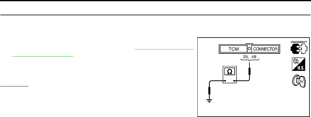
AT-102
[RE4F04B]
TROUBLE DIAGNOSIS FOR POWER SUPPLY
Revision: September 2005 2005 Quest
4. CHECK TCM GROUND CIRCUIT
1. Turn ignition switch to OFF position.
2. Disconnect TCM harness connector.
3. Check continuity between TCM harness connector E143 termi-
nals 25 (B), 48 (B) and ground. Refer to AT-100, "Wiring Dia-
gram — AT — MAIN" .
If OK, check harness for short to ground and short to power.
OK or NG
OK >> INSPECTION END
NG >> Repair open circuit or short to ground or short to power
in harness or connectors.
Continuity should exist.
SAT515J
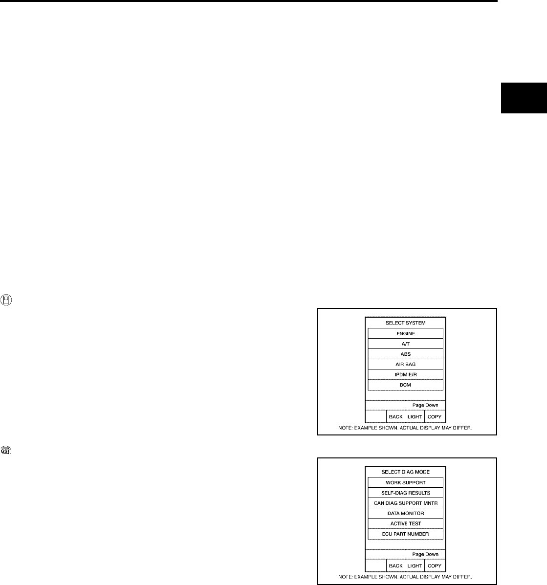
DTC U1000 CAN COMMUNICATION LINE
AT-103
[RE4F04B]
D
E
F
G
H
I
J
K
L
M
A
B
AT
Revision: September 2005 2005 Quest
DTC U1000 CAN COMMUNICATION LINE PFP:23710
Description UCS000PO
CAN (Controller Area Network) is a serial communication line for real time application. It is an on-vehicle mul-
tiplex communication line with high data communication speed and excellent malfunction detection ability.
Many electronic control units are equipped onto a vehicle, and each control unit shares information and links
with other control units during operation (not independent). In CAN communication, control units are con-
nected with 2 communication lines (CAN H line, CAN L line) allowing a high rate of information transmission
with less wiring. Each control unit transmits/receives data but selectively reads required data only.
On Board Diagnosis Logic UCS000PP
●This is an OBD-II self-diagnostic item.
●Diagnostic trouble code “CAN COMM CIRCUIT” with CONSULT-II or U1000 without CONSULT-II is
detected when TCM cannot communicate to other control units.
Possible Cause UCS000PQ
Harness or connectors
(CAN communication line is open or shorted.)
DTC Confirmation Procedure UCS000PR
NOTE:
If “DTC Confirmation Procedure” has been previously conducted, always turn ignition switch “OFF”
and wait at least 10 seconds before conducting the next test.
After the repair, perform the following procedure to confirm the malfunction is eliminated.
WITH CONSULT-II
1. Turn ignition switch to “ON” position. (Do not start engine.)
2. Select “DATA MONITOR” mode for “A/T” with CONSULT-II.
3. Wait at least 6 seconds or start engine and wait for at least 6
seconds.
WITH GST
Follow the procedure “WITH CONSULT-II”.
BCIA0030E
BCIA0031E
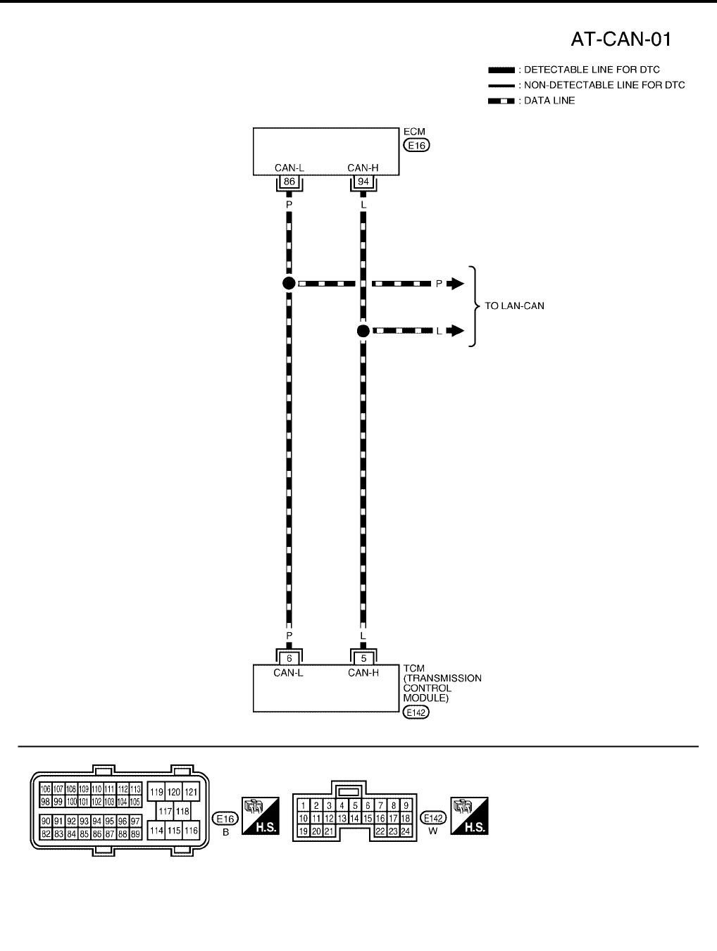
AT-104
[RE4F04B]
DTC U1000 CAN COMMUNICATION LINE
Revision: September 2005 2005 Quest
Wiring Diagram — AT — CAN UCS000PS
BCWA0299E
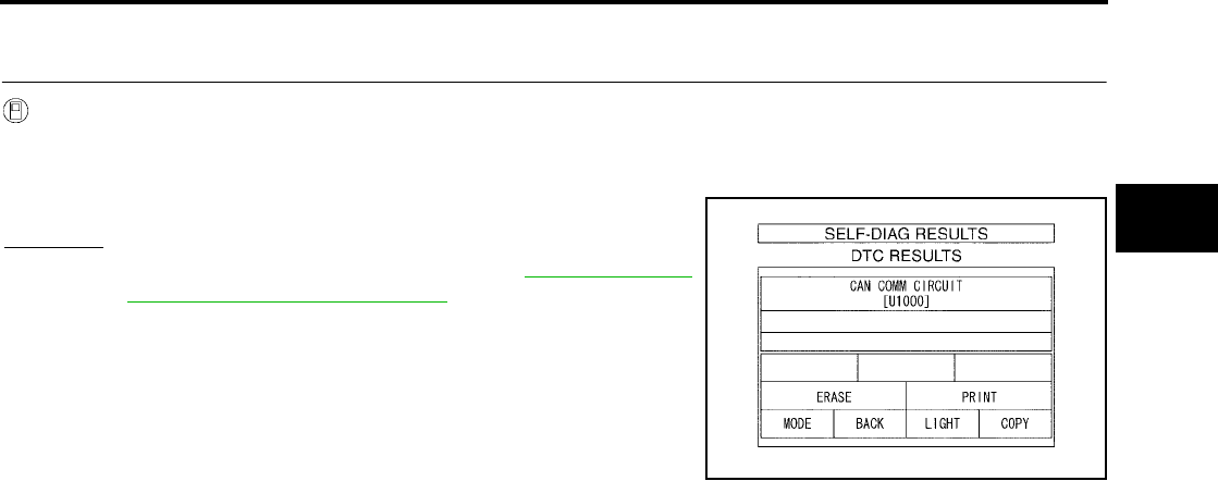
DTC U1000 CAN COMMUNICATION LINE
AT-105
[RE4F04B]
D
E
F
G
H
I
J
K
L
M
A
B
AT
Revision: September 2005 2005 Quest
Diagnostic Procedure UCS000PT
1. CHECK CAN COMMUNICATION CIRCUIT
With CONSULT-II
1. Turn ignition switch to “ON” position. (Do not start engine.)
2. Select “SELF-DIAG RESULTS” mode for “A/T” with CONSULT-II.
3. The “CAN COMM CIRCUIT” is detected.
Yes or No
Yes >> Print out CONSULT-II screen, GO TO LAN-3, "Precau-
tions When Using CONSULT-II" .
No >> INSPECTION END
PCIA0061E
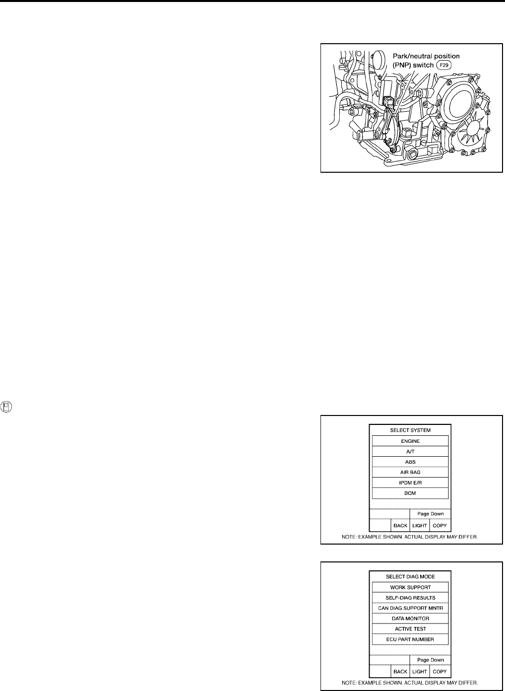
AT-106
[RE4F04B]
DTC P0705 PARK/NEUTRAL POSITION SWITCH
Revision: September 2005 2005 Quest
DTC P0705 PARK/NEUTRAL POSITION SWITCH PFP:32006
Description UCS000N6
●The park/neutral position (PNP) switch includes a transmission
range switch.
●The transmission range switch detects the selector lever posi-
tion and sends a signal to the TCM.
On Board Diagnosis Logic UCS000N7
Diagnostic trouble code “PNP SW/CIRC” with CONSULT-II or P0705 without CONSULT-II is detected when
TCM does not receive the correct voltage signal from the switch based on the gear position.
Possible Cause UCS000N8
Check the following items.
●Harness or connectors
(The park/neutral position (PNP) switch circuit is open or shorted.)
●Park/neutral position (PNP) switch
Diagnostic Trouble Code (DTC) Confirmation Procedure UCS000N9
CAUTION:
Always drive vehicle at a safe speed.
NOTE:
If “DTC Confirmation Procedure” has been previously conducted, always turn ignition switch OFF and
wait at least 10 seconds before conducting the next test.
After the repair, perform the following procedure to confirm the malfunction is eliminated.
WITH CONSULT-II
1. Turn ignition switch to ON position. (Do not start engine.)
2. Select “DATA MONITOR” mode for “ENGINE” with CONSULT-II.
3. Start engine and maintain the following conditions for at least 5
consecutive seconds.
VHCL SPEED SE: 10 km/h (6 MPH) or more
THRTL POS SEN: More than 1.3V
Selector lever: D position (OD “ON” or “OFF”)
WCIA0066E
BCIA0030E
BCIA0031E

DTC P0705 PARK/NEUTRAL POSITION SWITCH
AT-107
[RE4F04B]
D
E
F
G
H
I
J
K
L
M
A
B
AT
Revision: September 2005 2005 Quest
WITH GST
Follow the procedure “With CONSULT-II”.
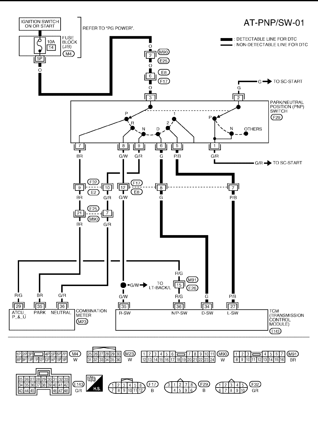
AT-108
[RE4F04B]
DTC P0705 PARK/NEUTRAL POSITION SWITCH
Revision: September 2005 2005 Quest
Wiring Diagram — AT — PNP/SW UCS000NA
BCWA0300E
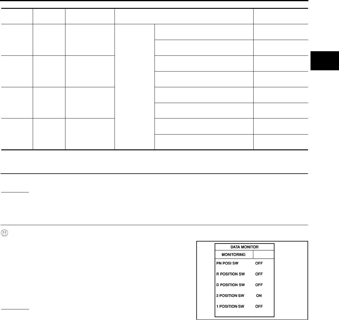
DTC P0705 PARK/NEUTRAL POSITION SWITCH
AT-109
[RE4F04B]
D
E
F
G
H
I
J
K
L
M
A
B
AT
Revision: September 2005 2005 Quest
TCM TERMINALS AND REFERENCE VALUE (MEASURED BETWEEN EACH TERMINAL AND GROUND)
Diagnostic Procedure UCS000NB
1. INSPECTION START
Do you have CONSULT-II?
Yes or No
Yes >> GO TO 2.
No >> GO TO 5.
2. CHECK PARK/NEUTRAL POSITION (PNP) SWITCH CIRCUIT (WITH CONSULT-II)
With CONSULT-II
1. Turn ignition switch to ON position. (Do not start engine.)
2. Select “DATA MONITOR” mode for “A/T” with CONSULT-II.
3. Read out P/N, R, D, 2nd position switches moving selector lever
to each position.
Check that the signal of the selector lever position is indicated
properly.
NOTE:
“2 POSITION SW” indicates L position status.
OK or NG
OK >> GO TO 8.
NG >> GO TO 3.
TERMINAL WIRE
COLOR ITEM CONDITION DATA (APPROX.)
27 P/B PNP SWITCH
L POSITION
IGNITION ON
WHEN SETTING SELECTOR LEVER IN
L POSITION BATTERY VOLTAGE
WHEN SETTING SELECTOR LEVER IN
OTHER POSITIONS 0V
34 G PNP SWITCH
D POSITION
WHEN SETTING SELECTOR LEVER IN
D POSITION BATTERY VOLTAGE
WHEN SETTING SELECTOR LEVER IN
OTHER POSITIONS 0V
35 G/W PNP SWITCH
R POSITION
WHEN SETTING SELECTOR LEVER IN
R POSITION BATTERY VOLTAGE
WHEN SETTING SELECTOR LEVER IN
OTHER POSITIONS 0V
36 R/G PNP SWITCH
P OR N POSITION
WHEN SETTING SELECTOR LEVER IN
P OR N POSITION BATTERY VOLTAGE
WHEN SETTING SELECTOR LEVER IN
OTHER POSITIONS 0V
SAT701J

AT-110
[RE4F04B]
DTC P0705 PARK/NEUTRAL POSITION SWITCH
Revision: September 2005 2005 Quest
3. CHECK PARK/NEUTRAL POSITION (PNP) SWITCH
Check the following item:
●Park/neutral position (PNP) switch
Check continuity between PNP switch harness connector F29
terminals 1 and 2 and between terminals 3 and 5, 6, 7, 8 and 9
while moving manual shaft through each position.
OK or NG
OK >> GO TO 6.
NG >> GO TO 4.
4. CHECK MANUAL CONTROL CABLE ADJUSTMENT
Check PNP switch again with manual control cable disconnected from manual shaft of A/T assembly. Refer to
test group 2 (With CONSULT-II) or 7 (With out CONSULT-II).
OK or NG
OK >> Adjust manual control cable. Refer to AT-258, "Control Cable Adjustment" .
NG >> GO TO 5.
5. CHECK PNP SWITCH ADJUSTMENT
Remove PNP switch from A/T assembly and check continuity of PNP switch terminals. Refer to test group 3.
OK or NG
OK >> Adjust PNP switch. Refer to AT-255, "Park/Neutral Position (PNP) Switch Adjustment" .
NG >> Repair or replace PNP switch.
6. DETECT MALFUNCTIONING ITEM
Check the following items:
●Fuse
●Harness for short or open between ignition switch and park/neutral position (PNP) switch
●Harness for short or open between park/neutral position (PNP) switch and TCM
●Harness for short or open between park/neutral position (PNP) switch and combination meter
●Harness for short or open between combination meter and TCM
●Ignition switch
Refer to PG-4, "POWER SUPPLY ROUTING CIRCUIT" .
OK or NG
OK >> GO TO 8.
NG >> Repair or replace damaged parts.
Lever position Terminal
P 3 - 7 1 - 2
R3 - 8
N 3 - 9 1 - 2
D3 - 6
L3 - 5 SCIA3372E
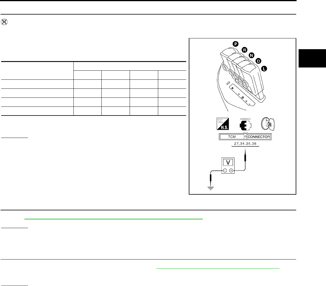
DTC P0705 PARK/NEUTRAL POSITION SWITCH
AT-111
[RE4F04B]
D
E
F
G
H
I
J
K
L
M
A
B
AT
Revision: September 2005 2005 Quest
7. CHECK PARK/NEUTRAL POSITION (PNP) SWITCH CIRCUIT (WITHOUT CONSULT-II)
Without CONSULT-II
1. Turn ignition switch to ON position. (Do not start engine.)
2. Check voltage between TCM harness connector E143 terminals
27 (P/B), 34 (G), 35 (G/W), 36 (R/G) and ground while moving
selector lever through each position.
B: Battery voltage
0: 0V
OK or NG
OK >> GO TO 8.
NG >> GO TO 3.
8. CHECK DTC
Perform AT-106, "Diagnostic Trouble Code (DTC) Confirmation Procedure" .
OK or NG
OK >> INSPECTION END
NG >> GO TO 9.
9. CHECK TCM INSPECTION
1. Perform TCM input/output signal inspection. Refer to AT-96, "TCM Terminals and Reference Value" .
2. If NG, recheck TCM pin terminals for damage or loose connection with harness connector.
OK or NG
OK >> INSPECTION END
NG >> Repair or replace damaged parts.
Lever Position Terminal
36 35 34 27
P, N B000
R0B00
D00B0
L000B
SCIA3373E
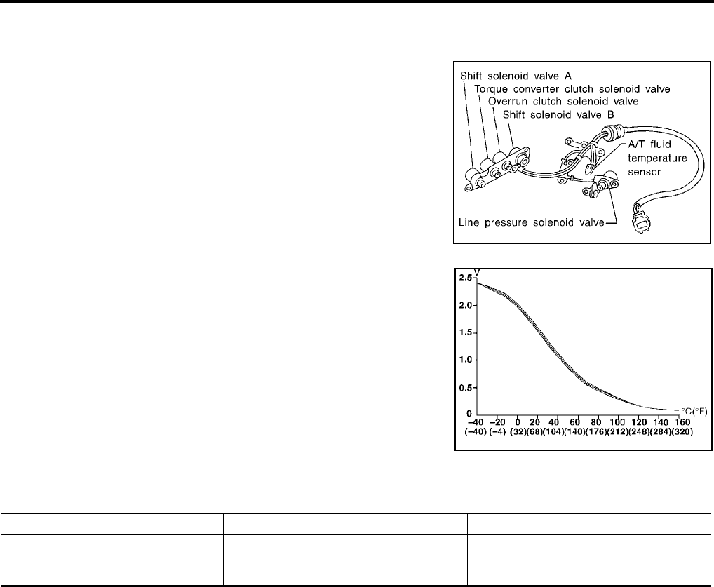
AT-112
[RE4F04B]
DTC P0710 A/T FLUID TEMPERATURE SENSOR CIRCUIT
Revision: September 2005 2005 Quest
DTC P0710 A/T FLUID TEMPERATURE SENSOR CIRCUIT PFP:31940
Description UCS000NC
The A/T fluid temperature sensor detects the A/T fluid temperature
and sends a signal to the TCM.
CONSULT-II REFERENCE VALUE IN DATA MONITOR MODE
Remarks: Specification data are reference values.
On Board Diagnosis Logic UCS000ND
Diagnostic trouble code “ATF TEMP SEN/CIRC” with CONSULT-II or P0710 without CONSULT-II is detected
when TCM receives an excessively low or high voltage from the sensor.
Possible Cause UCS000NE
Check the following items.
●Harness or connectors
(The sensor circuit is open or shorted.)
●A/T fluid temperature sensor
Diagnostic Trouble Code (DTC) Confirmation Procedure UCS000NF
CAUTION:
Always drive vehicle at a safe speed.
NOTE:
If “DTC Confirmation Procedure” has been previously conducted, always turn ignition switch OFF and
wait at least 10 seconds before conducting the next test.
After the repair, perform the following procedure to confirm the malfunction is eliminated.
SAT283HB
SAT021J
Monitor item Condition Specification (Approximately)
FLUID TEMP SE [V]
Cold [20°C (68°F)]
↓
Hot [80°C (176°F)]
1.5V
↓
0.5V

DTC P0710 A/T FLUID TEMPERATURE SENSOR CIRCUIT
AT-113
[RE4F04B]
D
E
F
G
H
I
J
K
L
M
A
B
AT
Revision: September 2005 2005 Quest
WITH CONSULT-II
1. Turn ignition switch ON and select “DATA MONITOR” mode for
“ENGINE” with CONSULT-II.
2. Select "ECM INPUT SIGNALS" touch "START".
3. Start engine and maintain the following conditions for at least 10 minutes (Total). (It is not necessary to
maintain continuously.)
ENG SPEED: 450 rpm or more
VEHICLE SPEED: 10 km/h (6 MPH) or more
THRTL POSI: More than 1.2V
Selector lever: D position
WITH GST
Follow the procedure “With CONSULT-II”.
BCIA0030E
BCIA0031E
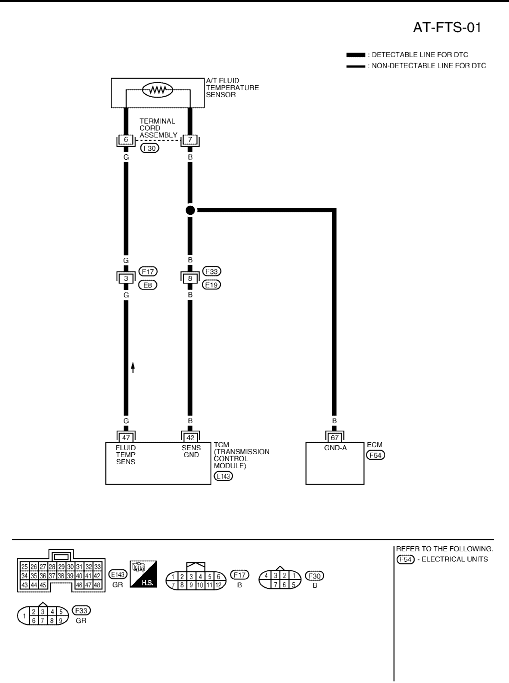
AT-114
[RE4F04B]
DTC P0710 A/T FLUID TEMPERATURE SENSOR CIRCUIT
Revision: September 2005 2005 Quest
Wiring Diagram — AT — FTS UCS000NG
BCWA0172E
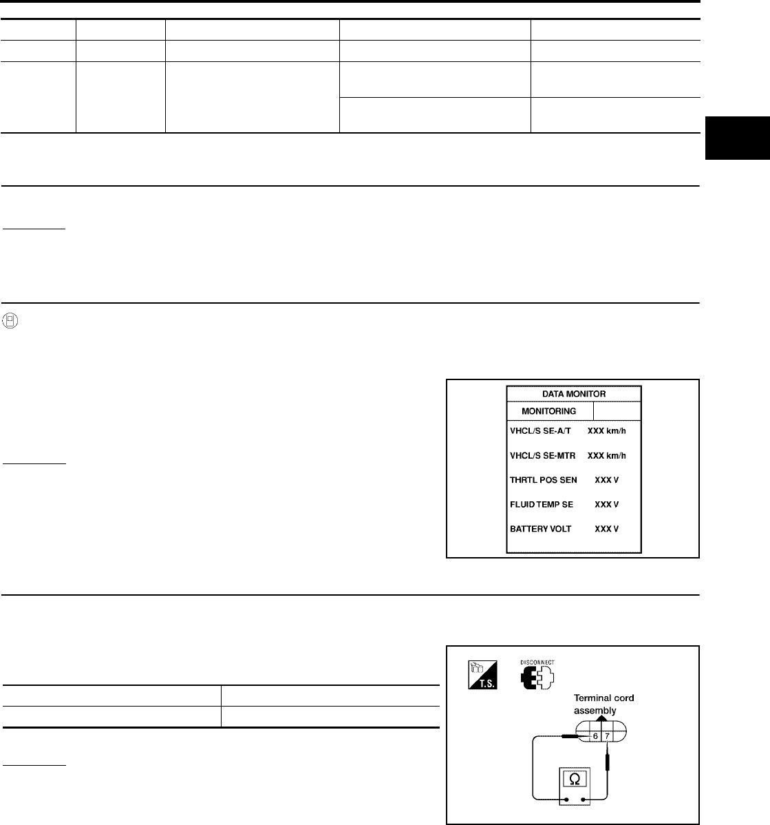
DTC P0710 A/T FLUID TEMPERATURE SENSOR CIRCUIT
AT-115
[RE4F04B]
D
E
F
G
H
I
J
K
L
M
A
B
AT
Revision: September 2005 2005 Quest
TCM TERMINALS AND REFERENCE VALUE (MEASURED BETWEEN EACH TERMINAL AND GROUND)
Diagnostic Procedure UCS000NH
1. INSPECTION START
Do you have CONSULT-II?
Yes or No
Yes >> GO TO 2.
No >> GO TO 6.
2. CHECK INPUT SIGNAL OF A/T FLUID TEMPERATURE SENSOR (WITH CONSULT-II)
With CONSULT-II
1. Start engine.
2. Select “DATA MONITOR” mode for “A/T” with CONSULT-II.
3. Read out the value of “FLUID TEMP SE”.
OK or NG
OK >> GO TO 7.
NG >> GO TO 3.
3. CHECK A/T FLUID TEMPERATURE SENSOR WITH TERMINAL CORD ASSEMBLY
1. Turn ignition switch to OFF position.
2. Disconnect terminal cord assembly connector in engine compartment.
3. Check resistance between terminal cord F30 terminals 6 and 7
when A/T is cold.
4. Reinstall any part removed.
OK or NG
OK >> GO TO 4.
NG >> GO TO 5.
TERMINAL WIRE COLOR ITEM CONDITION DATA (APPROX.)
42 B SENSOR GROUND Always 0V
47 G A/T FLUID TEMPERATURE
SENSOR
IGNITION ON AND ATF TEMPER-
ATURE IS 20°C (68°F) 1.5V
IGNITION ON AND ATF TEMPER-
ATURE IS 80°C (176°F) 0.5V
Voltage :Cold [20°C (68°F)] → Hot [80°C (176°F)]
:Approximately 1.5V → 0.5V
LCIA0090E
Temperature Resistance (Approx.)
Cold [20°C (68°F)] 2.5kΩ
WCIA0097E
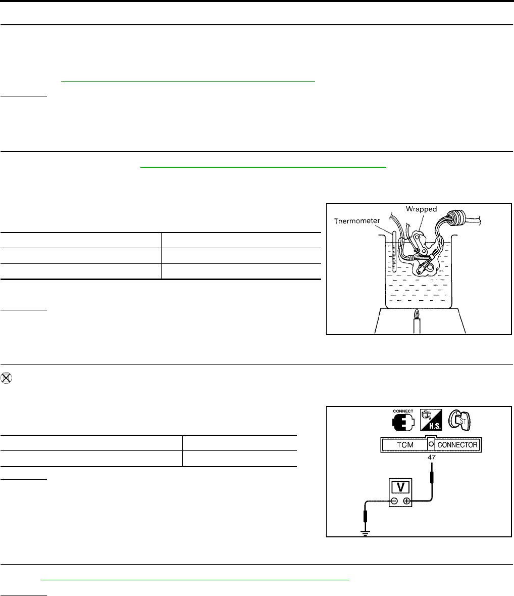
AT-116
[RE4F04B]
DTC P0710 A/T FLUID TEMPERATURE SENSOR CIRCUIT
Revision: September 2005 2005 Quest
4. DETECT MALFUNCTIONING ITEM
Check the following items:
●Harness for short to ground or short to power or open between TCM, ECM and terminal cord assembly
●Ground circuit for ECM
Refer to EC-166, "POWER SUPPLY AND GROUND CIRCUIT" .
OK or NG
OK >> GO TO 7.
NG >> Repair or replace damaged parts.
5. DETECT MALFUNCTIONING ITEM
1. Remove oil pan. Refer to AT-253, "Control Valve Assembly and Accumulators" .
2. Check the following items:
–A/T fluid temperature sensor
• Check resistance between two terminals while changing temper-
ature as shown at below.
–Harness of terminal cord assembly for short or open
OK or NG
OK >> GO TO 7.
NG >> Repair or replace damaged parts.
6. CHECK INPUT SIGNAL OF A/T FLUID TEMPERATURE SENSOR (WITHOUT CONSULT-II)
Without CONSULT-II
1. Start engine.
2. Check voltage between TCM harness connector E143 terminal
47 (G) and ground while warming up A/T.
OK or NG
OK >> GO TO 7.
NG >> GO TO 3.
7. CHECK DTC
Perform AT-112, "Diagnostic Trouble Code (DTC) Confirmation Procedure" .
OK or NG
OK >> INSPECTION END
NG >> GO TO 8.
Temperature °C (°F) Resistance (Approx.)
20 (68) 2.5kΩ
80 (176) 0.3kΩ
SAT298F
Temperature Voltage (Approx.)
Cold [20°C (68°F)] → Hot [80°C (176°F)] 1.5V → 0.5V
WCIA0049E

DTC P0710 A/T FLUID TEMPERATURE SENSOR CIRCUIT
AT-117
[RE4F04B]
D
E
F
G
H
I
J
K
L
M
A
B
AT
Revision: September 2005 2005 Quest
8. CHECK TCM INSPECTION
1. Perform TCM input/output signal inspection. Refer to AT-96, "TCM Terminals and Reference Value" .
2. If NG, recheck TCM pin terminals for damage or loose connection with harness connector.
OK or NG
OK >> INSPECTION END
NG >> Repair or replace damaged parts.

AT-118
[RE4F04B]
DTC P0720 VEHICLE SPEED SENSOR·A/T (REVOLUTION SENSOR)
Revision: September 2005 2005 Quest
DTC P0720 VEHICLE SPEED SENSOR·A/T (REVOLUTION SENSOR) PFP:32702
Description UCS000NI
The revolution sensor detects the revolution of the idler gear parking
pawl lock gear and emits a pulse signal. The pulse signal is sent to
the TCM which converts it into vehicle speed.
On Board Diagnosis Logic UCS000NJ
Diagnostic trouble code “VEH SPD SEN/CIR AT” with CONSULT-II or P0720 without CONSULT-II is detected
when TCM does not receive the proper voltage signal from the sensor.
Possible Cause UCS000NK
Check the following items.
●Harness or connectors
(The sensor circuit is open or shorted.)
●Revolution sensor
Diagnostic Trouble Code (DTC) Confirmation Procedure UCS000NL
CAUTION:
●Always drive vehicle at a safe speed.
●Be careful not to rev engine into the red zone on the tachometer.
NOTE:
If “DTC Confirmation Procedure” has been previously conducted, always turn ignition switch OFF and
wait at least 10 seconds before conducting the next test.
After the repair, perform the following procedure to confirm the malfunction is eliminated.
WITH CONSULT-II
1. Turn ignition switch ON and select “DATA MONITOR” mode for
“A/T” with CONSULT-II.
LCIA0070E
BCIA0030E
BCIA0031E

DTC P0720 VEHICLE SPEED SENSOR·A/T (REVOLUTION SENSOR)
AT-119
[RE4F04B]
D
E
F
G
H
I
J
K
L
M
A
B
AT
Revision: September 2005 2005 Quest
2. Drive vehicle and check for an increase of “VHCL/S SE-MTR” value.
If the check result is NG, go to AT-121, "Diagnostic Procedure" .
If the check result is OK, go to following step.
3. Select “DATA MONITOR” mode for “ENGINE” with CONSULT-II.
4. Start engine and maintain the following conditions for at least 5 consecutive seconds.
VHCL SPEED SE: 30 km/h (19 MPH) or more
THRTL POS SEN: More than 1.2V
Selector lever: D position
Driving location: Driving the vehicle uphill (increased engine load) will help maintain the driving
conditions required for this test.
If the check result is NG, go to AT-121, "Diagnostic Procedure" .
If the check result is OK, go to following step.
5. Maintain the following conditions for at least 5 consecutive seconds.
CMPS·RPM (REF): 3,500 rpm or more
THRTL POS SEN: More than 1.2V
Selector lever: D position
Driving location: Driving the vehicle uphill (increased engine load) will help maintain the driving
conditions required for this test.
WITH GST
Follow the procedure “With CONSULT-II”.
BCIA0030E
BCIA0031E
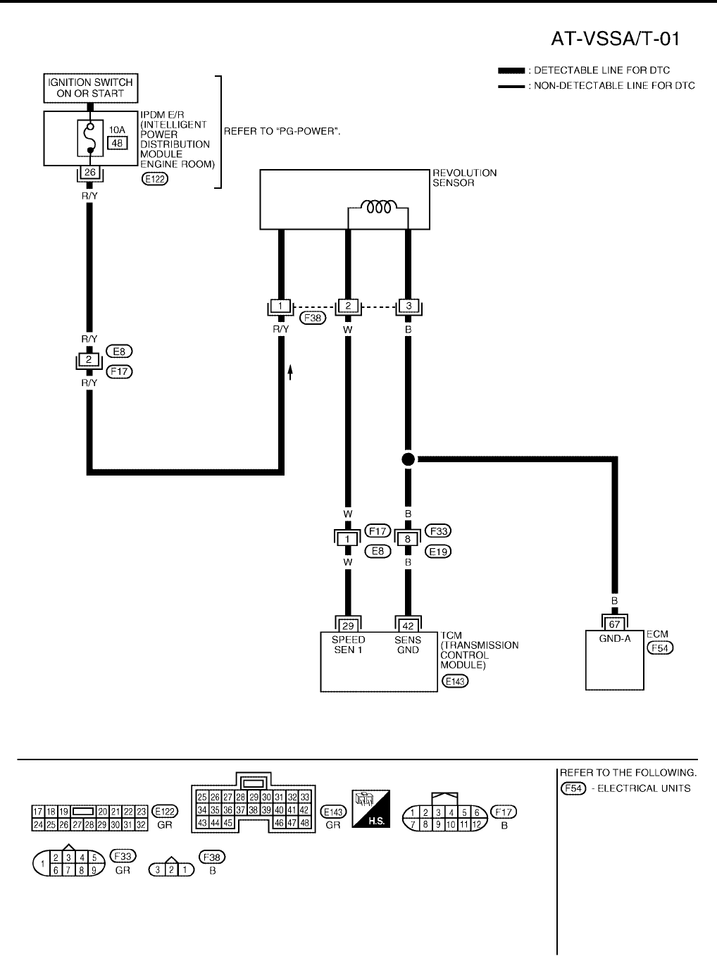
AT-120
[RE4F04B]
DTC P0720 VEHICLE SPEED SENSOR·A/T (REVOLUTION SENSOR)
Revision: September 2005 2005 Quest
Wiring Diagram — AT — VSSA/T UCS000NM
BCWA0173E
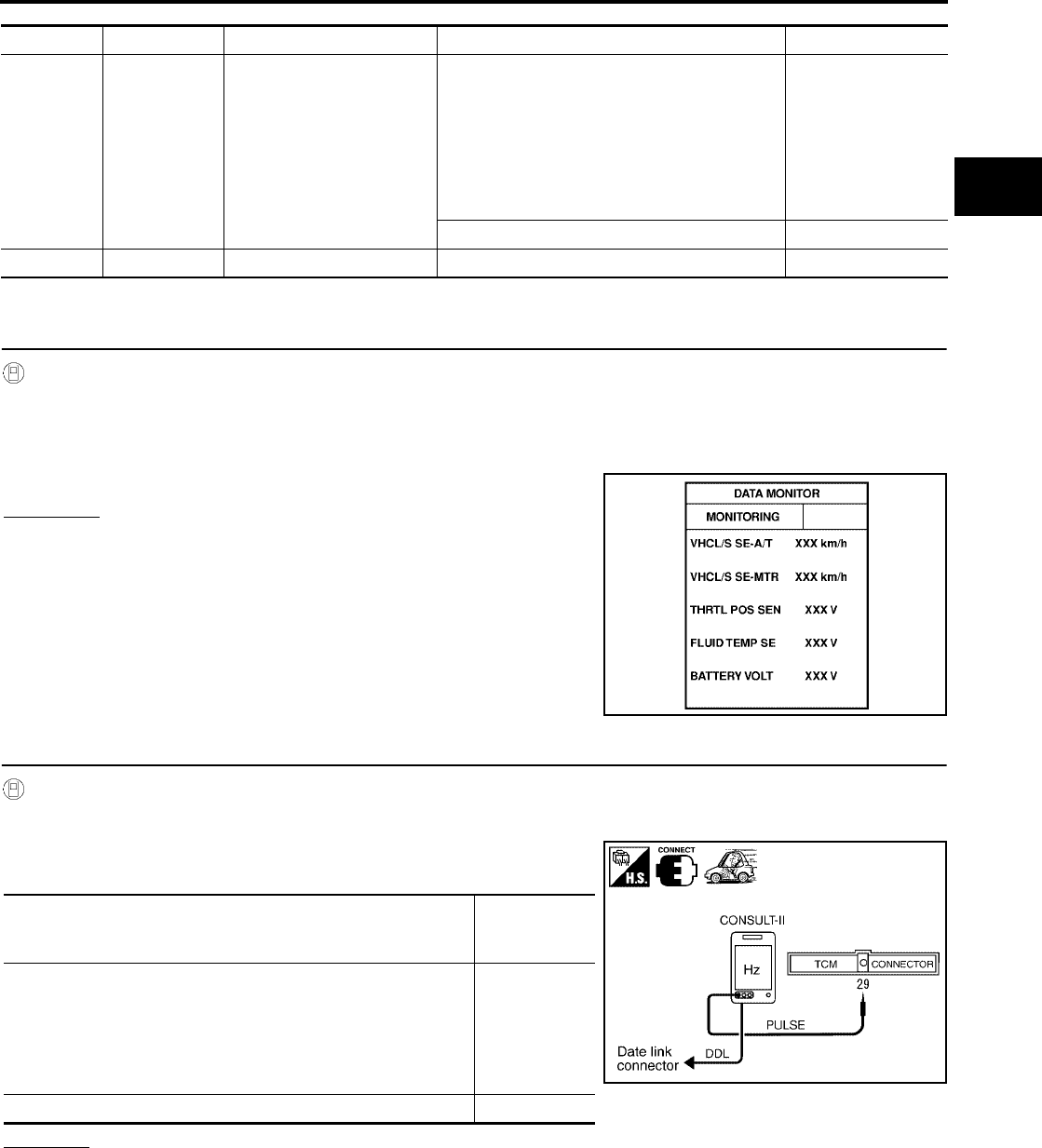
DTC P0720 VEHICLE SPEED SENSOR·A/T (REVOLUTION SENSOR)
AT-121
[RE4F04B]
D
E
F
G
H
I
J
K
L
M
A
B
AT
Revision: September 2005 2005 Quest
TCM TERMINALS AND REFERENCE VALUE (MEASURED BETWEEN EACH TERMINAL AND GROUND)
Diagnostic Procedure UCS000NN
1. CHECK INPUT SIGNAL (WITH CONSULT-II)
With CONSULT-II
1. Start engine.
2. Select “DATA MONITOR” mode for “A/T” with CONSULT-II.
3. Read out the value of “VHCL/S SE-A/T” while driving.
Check the value changes according to driving speed.
OK or NG
OK >> GO TO 5.
NG >> GO TO 2.
2. CHECK REVOLUTION SENSOR (WITH CONSULT-II)
With CONSULT-II
1. Start engine.
2. Check pulse between TCM harness connector E143 terminal 29
(W) and ground.
OK or NG
OK >> GO TO 5.
NG >> GO TO 3.
TERMINAL WIRE COLOR ITEM CONDITION DATA (APPROX.)
29 W REVOLUTION SENSOR
VEHICLE MOVING AT 20 KM/H (12 MPH).
USE THE CONSULT-II PULSE FREQUENCY
MEASURING FUNCTION. A CIRCUIT
TESTER CANNOT BE USED TO TEST THIS
ITEM.
CAUTION: CONNECT THE DIAGNOSIS DATA
LINK CABLE TO THE VEHICLE DIAGNOSIS
CONNECTOR.
450 HZ
VEHICLE NOT MOVING. 0V
42 B SENSOR GROUND Always 0V
LCIA0090E
Condition
Judgement
standard
(Approx.)
When moving at 20 km/h (12 MPH), use the CONSULT-II pulse
frequency measuring function.*1
CAUTION:
Connect the diagnosis data link cable to the vehicle diagno-
sis connector.
*1: A circuit tester cannot be used to test this item.
450 Hz
When vehicle is parked. 0V
SCIA3374E
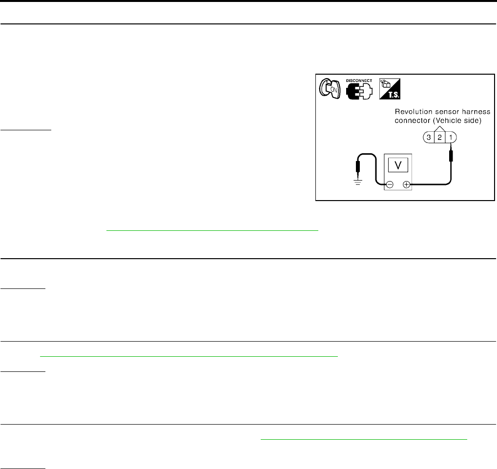
AT-122
[RE4F04B]
DTC P0720 VEHICLE SPEED SENSOR·A/T (REVOLUTION SENSOR)
Revision: September 2005 2005 Quest
3. CHECK POWER FOR REVOLUTION SENSOR
1. Turn ignition switch to OFF position.
2. Disconnect the revolution sensor harness connector.
3. Turn ignition switch to ON position. (Do not start engine.)
4. Check voltage between revolution sensor harness connector
F38 terminal 1 (R/Y) and ground.
OK or NG
OK >> GO TO 4.
NG >> Check the following items. If any items is damaged,
repair or replace damaged parts.
●Fuse
●Harness for short or open between ignition switch and
revolution sensor
●Ignition switch
Refer to PG-4, "POWER SUPPLY ROUTING CIRCUIT" .
4. DETECT MALFUNCTIONING ITEM
Check harness for short or open between TCM, ECM and revolution sensor.
OK or NG
OK >> Repair or replace revolution sensor.
NG >> Repair or replace damaged parts.
5. CHECK DTC
Perform AT-118, "Diagnostic Trouble Code (DTC) Confirmation Procedure" .
OK or NG
OK >> INSPECTION END
NG >> GO TO 6.
6. CHECK TCM INSPECTION
1. Perform TCM input/output signal inspection. Refer to AT-96, "TCM Terminals and Reference Value" .
2. If NG, recheck TCM pin terminals for damage or loose connection with harness connector.
OK or NG
OK >> INSPECTION END
NG >> Repair or replace damaged parts.
Voltage : Battery voltage
SCIA2615E

DTC P0725 ENGINE SPEED SIGNAL
AT-123
[RE4F04B]
D
E
F
G
H
I
J
K
L
M
A
B
AT
Revision: September 2005 2005 Quest
DTC P0725 ENGINE SPEED SIGNAL PFP:24825
Description UCS000NO
The engine speed signal is sent from the ECM to the TCM.
On Board Diagnosis Logic UCS000NP
Diagnostic trouble code “ENGINE SPEED SIG” with CONSULT-II or P0725 without CONSULT-II is detected
when TCM does not receive the proper voltage signal from ECM.
Possible Cause UCS000NQ
Check harness or connectors. (The sensor circuit is open or shorted.)
Diagnostic Trouble Code (DTC) Confirmation Procedure UCS000NR
CAUTION:
Always drive vehicle at a safe speed.
NOTE:
If “DTC Confirmation Procedure” has been previously conducted, always turn ignition switch OFF and
wait at least 10 seconds before conducting the next test.
After the repair, perform the following procedure to confirm the malfunction is eliminated.
WITH CONSULT-II
1. Turn ignition switch ON and select “DATA MONITOR” mode for
“ENGINE” with CONSULT-II.
2. Start engine and maintain the following conditions for at least 10 consecutive seconds.
VHCL SPEED SE: 10 km/h (6 MPH) or more
THRTL POS SEN: More than 1.2V
Selector lever: D position
WITH GST
Follow the procedure “With CONSULT-II”.
BCIA0030E
BCIA0031E
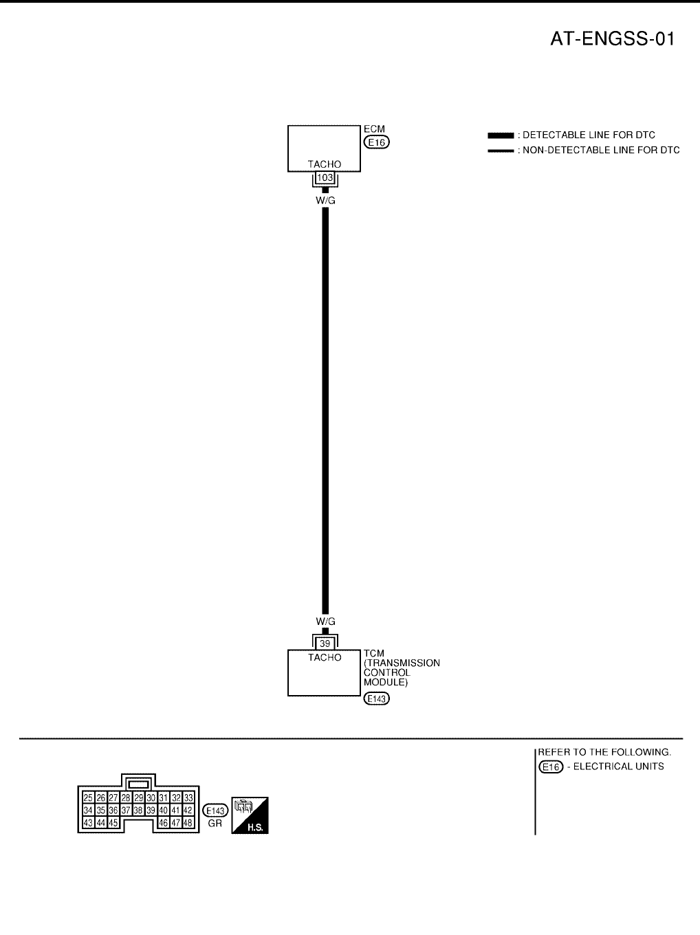
AT-124
[RE4F04B]
DTC P0725 ENGINE SPEED SIGNAL
Revision: September 2005 2005 Quest
Wiring Diagram — AT — ENGSS UCS000NS
BCWA0006E
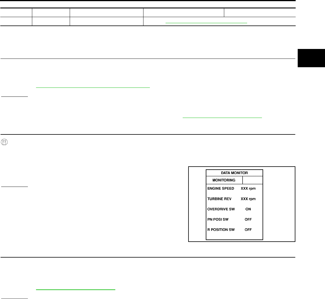
DTC P0725 ENGINE SPEED SIGNAL
AT-125
[RE4F04B]
D
E
F
G
H
I
J
K
L
M
A
B
AT
Revision: September 2005 2005 Quest
TCM TERMINALS AND REFERENCE VALUE (MEASURED BETWEEN EACH TERMINAL AND GROUND)
Diagnostic Procedure UCS000NT
1. CHECK DTC WITH ECM
●Check P code with CONSULT-II “ENGINE”.
Turn ignition switch ON and select “SELF-DIAGNOSTIC RESULTS” mode for “ENGINE” with CONSULT-
II.
Refer to EC-67, "Malfunction Indicator Lamp (MIL)" .
OK or NG
OK (with CONSULT-II)>> GO TO 2.
OK (without CONSULT-II)>> GO TO 4.
NG >> Check ignition signal circuit for engine control. Refer to EC-686, "IGNITION SIGNAL" .
2. CHECK INPUT SIGNAL (WITH CONSULT-II)
With CONSULT-II
1. Start engine.
2. Select “DATA MONITOR” mode for “A/T” with CONSULT-II.
3. Read out the value of “ENGINE SPEED”.
Check engine speed changes according to throttle position.
OK or NG
OK >> GO TO 5.
NG >> GO TO 3.
3. DETECT MALFUNCTIONING ITEM
Check the following items:
●Harness for short or open between TCM and ECM
●Resistor and ignition coil
Refer to EC-686, "IGNITION SIGNAL" .
OK or NG
OK >> GO TO 5.
NG >> Repair or replace damaged parts.
TERMINAL WIRE COLOR ITEM CONDITION DATA
39 W/G ENGINE SPEED SIGNAL Refer to EC-124, "ECM INSPECTION TABLE" (ECM terminal 103).
SAT645J
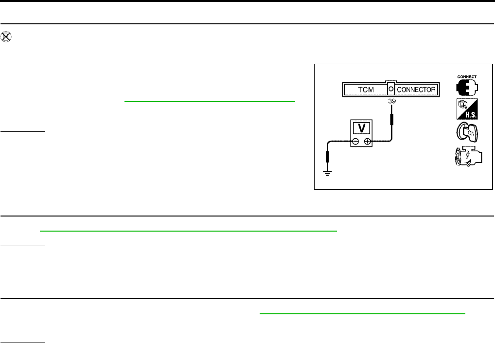
AT-126
[RE4F04B]
DTC P0725 ENGINE SPEED SIGNAL
Revision: September 2005 2005 Quest
4. CHECK INPUT SIGNAL (WITHOUT CONSULT-II)
Without CONSULT-II
1. Start engine.
2. Check voltage between TCM harness connector E143 terminal
39 (W/G) and ground.
OK or NG
OK >> GO TO 5.
NG >> GO TO 3.
5. CHECK DTC
Perform AT-123, "Diagnostic Trouble Code (DTC) Confirmation Procedure" .
OK or NG
OK >> INSPECTION END
NG >> GO TO 6.
6. CHECK TCM INSPECTION
1. Perform TCM input/output signal inspection. Refer to AT-96, "TCM Terminals and Reference Value" .
2. If NG, recheck TCM pin terminals for damage or loose connection with harness connector.
OK or NG
OK >> INSPECTION END
NG >> Repair or replace damaged parts.
Voltage Refer to EC-124, "ECM INSPECTION TABLE"
(ECM terminal 103).
LCIA0099E

DTC P0731 A/T 1ST GEAR FUNCTION
AT-127
[RE4F04B]
D
E
F
G
H
I
J
K
L
M
A
B
AT
Revision: September 2005 2005 Quest
DTC P0731 A/T 1ST GEAR FUNCTION PFP:31940
Description UCS000NU
●This malfunction will not be detected while the O/D OFF indicator lamp is indicating another self-diagnosis
malfunction.
●This malfunction is detected when the A/T does not shift into first gear position as instructed by the TCM.
This is not caused by electrical malfunction (circuits open or shorted) but by mechanical malfunction such
as control valve sticking, improper solenoid valve operation, etc.
On Board Diagnosis Logic UCS000NV
This diagnosis monitors actual gear position by checking the torque converter slip ratio calculated by TCM as
follows:
Torque converter slip ratio = A x C/B
A: Output shaft revolution signal from revolution sensor
B: Engine speed signal from ECM
C: Gear ratio determined as gear position which TCM supposes
If the actual gear position is higher than the position (1st) supposed by TCM, the slip ratio will be more than
normal. In case the ratio exceeds the specified value, TCM judges this diagnosis malfunction.
This malfunction will be caused when either shift solenoid valve A is stuck open or shift solenoid valve B is
stuck open.
Gear positions supposed by TCM are as follows.
In case of gear position with no malfunctions: 1 , 2, 3 and 4 positions
In case of gear position with shift solenoid valve A stuck open: 2* , 2, 3 and 3 positions
In case of gear position with shift solenoid valve B stuck open: 4* , 3, 3 and 4 positions to each gear position
above
*: P0731 is detected.
Diagnostic trouble code “A/T 1ST GR FNCTN” with CONSULT-II or P0731 without CONSULT-II is detected
when A/T cannot be shifted to the 1st gear position even if electrical circuit is good.
Possible Cause UCS000NW
Check the following items.
●Shift solenoid valve A
●Shift solenoid valve B
●Each clutch
●Hydraulic control circuit
Diagnostic Trouble Code (DTC) Confirmation Procedure UCS000NX
CAUTION:
●Always drive vehicle at a safe speed.
●Be careful not to rev engine into the red zone on the tachometer.
NOTE:
If “DTC Confirmation Procedure” has been previously conducted, always turn ignition switch OFF and
wait at least 10 seconds before conducting the next test.
TESTING CONDITION:
Always drive vehicle on a level road to improve the accuracy of test.
After the repair, perform the following procedure to confirm the malfunction is eliminated.
Gear position 1 2 3 4
Shift solenoid valve A ON (Closed) OFF (Open) OFF (Open) ON (Closed)
Shift solenoid valve B ON (Closed) ON (Closed) OFF (Open) OFF (Open)

AT-128
[RE4F04B]
DTC P0731 A/T 1ST GEAR FUNCTION
Revision: September 2005 2005 Quest
WITH CONSULT-II
1. Start engine and select “DATA MONITOR” mode for “A/T” with
CONSULT-II.
2. Make sure that output voltage of A/T fluid temperature sensor is
within the range below.
FLUID TEMP SEN: 0.5 - 1.5V
If out of range, drive the vehicle to decrease the voltage (warm
up the fluid) or stop engine to increase the voltage (cool down
the fluid).
3. Select “1ST GR FNCTN P0731” of “DTC WORK SUPPORT”
mode for “A/T” with CONSULT-II and touch “START”.
4. Accelerate vehicle to 20 to 25 km/h (12 to 16 MPH) under the
following condition and release the accelerator pedal com-
pletely.
THROTTLE POSI: Less than 1.0/8 (at all times during step 4)
Selector lever: D position
–Check that “GEAR” shows “2” after releasing pedal.
5. Depress accelerator pedal to WOT (more than 7.0/8 of “THROT-
TLE POSI”) quickly from a speed of 20 to 25 km/h (12 to 16
MPH) until “TESTING” changes to “STOP VEHICLE” or “COM-
PLETED”. (It will take approximately 3 seconds.)
If the check result NG appears on CONSULT-II screen, go to AT-
130, "Diagnostic Procedure" .
If “STOP VEHICLE” appears on CONSULT-II screen, go to the following step.
–Check that “GEAR” shows “1” when depressing accelerator pedal to WOT.
–If “TESTING” does not appear on CONSULT-II for a long time, select “SELF-DIAG RESULTS” for
“ENGINE”. In case a 1st trip DTC other than P0731 is shown, refer to applicable “TROUBLE DIAG-
NOSIS FOR DTC”.
6. Stop vehicle.
7. Follow the instruction displayed. (Check for normal shifting refer-
ring to the table below.)
8. Make sure that “OK” is displayed. (If “NG” is displayed, refer to
“DIAGNOSTIC PROCEDURE”.)
Refer to AT-130, "Diagnostic Procedure" .
Refer to AT-364, "Shift Schedule" .
WITH GST
Follow the procedure “With CONSULT-II”.
BCIA0030E
Vehicle condition Gear on actual transmission shift pattern when
screen is changed to 1 → 2 → 3 → 4
No malfunction exists. 1 → 2 → 3 → 4
Malfunction for P0731 exists. 2 → 2 → 3 → 3
4 → 3 → 3 → 4
BCIA0031E
SAT021J
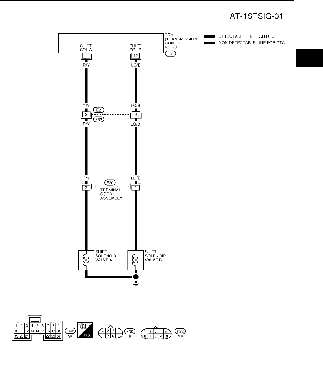
DTC P0731 A/T 1ST GEAR FUNCTION
AT-129
[RE4F04B]
D
E
F
G
H
I
J
K
L
M
A
B
AT
Revision: September 2005 2005 Quest
Wiring Diagram — AT — 1ST UCS000NY
BCWA0174E
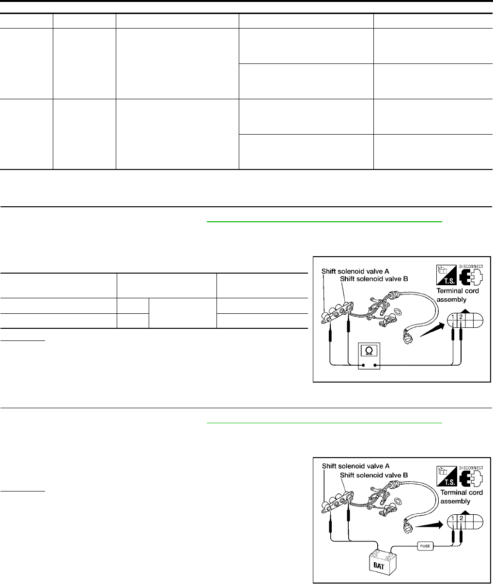
AT-130
[RE4F04B]
DTC P0731 A/T 1ST GEAR FUNCTION
Revision: September 2005 2005 Quest
TCM TERMINALS AND REFERENCE VALUE (MEASURED BETWEEN EACH TERMINAL AND GROUND)
Diagnostic Procedure UCS000NZ
1. CHECK VALVE RESISTANCE
1. Remove control valve assembly. Refer to AT-253, "Control Valve Assembly and Accumulators" .
–Shift solenoid valve A
–Shift solenoid valve B
2. Check resistance between two terminals.
OK or NG
OK >> GO TO 2.
NG >> Repair or replace damaged parts.
2. CHECK VALVE OPERATION
1. Remove control valve assembly. Refer to AT-253, "Control Valve Assembly and Accumulators" .
–Shift solenoid valve A
–Shift solenoid valve B
2. Check solenoid valve by listening for its operating sound while
applying battery voltage to the terminal and ground.
OK or NG
OK >> GO TO 3.
NG >> Repair or replace shift solenoid valve assembly.
TERMINAL WIRE COLOR ITEM CONDITION DATA (APPROX.)
11 R/Y SHIFT SOLENOID VALVE A
WHEN SHIFT SOLENOID VALVE
A IS OPERATING (DRIVING IN D1
OR D4 )
BATTERY VOLTAGE
WHEN SHIFT SOLENOID VALVE
A IS NOT OPERATING (DRIVING
IN D2 OR D3 )
0V
12 LG/B SHIFT SOLENOID VALVE B
WHEN SHIFT SOLENOID VALVE
B IS OPERATING (DRIVING IN D1
OR D2 )
BATTERY VOLTAGE
WHEN SHIFT SOLENOID VALVE
B IS NOT OPERATING (DRIVING
IN D3 OR D4 )
0V
Solenoid valve Terminal Resistance
(Approx.)
Shift solenoid valve A 2 Ground 20 - 30Ω
Shift solenoid valve B 1 5 - 20Ω
WCIA0089E
WCIA0090E

DTC P0731 A/T 1ST GEAR FUNCTION
AT-131
[RE4F04B]
D
E
F
G
H
I
J
K
L
M
A
B
AT
Revision: September 2005 2005 Quest
3. CHECK CONTROL VALVE
1. Disassemble control valve assembly. Refer to AT-290, "Control
Valve Assembly" .
2. Check to ensure that:
–Valve, sleeve and plug slide along valve bore under their own
weight.
–Valve, sleeve and plug are free from burrs, dents and scratches.
–Control valve springs are free from damage, deformation and
fatigue.
–Hydraulic line is free from obstacles.
OK or NG
OK >> GO TO 4.
NG >> Repair control valve assembly.
4. CHECK DTC
Perform AT-127, "Diagnostic Trouble Code (DTC) Confirmation Procedure" .
OK or NG
OK >> INSPECTION END
NG >> Check transaxle inner parts. (Clutch, brake, etc.)
SAT367H

AT-132
[RE4F04B]
DTC P0732 A/T 2ND GEAR FUNCTION
Revision: September 2005 2005 Quest
DTC P0732 A/T 2ND GEAR FUNCTION PFP:31940
Description UCS000O0
●This malfunction will not be detected while the O/D OFF indicator lamp is indicating another self-diagnosis
malfunction.
●This malfunction is detected when the A/T does not shift into second gear position as instructed by the
TCM. This is not caused by electrical malfunction (circuits open or shorted) but by mechanical malfunction
such as control valve sticking, improper solenoid valve operation, etc.
On Board Diagnosis Logic UCS000O1
This diagnosis monitors actual gear position by checking the torque converter slip ratio calculated by TCM as
follows:
Torque converter slip ratio = A x C/B
A: Output shaft revolution signal from revolution sensor
B: Engine speed signal from ECM
C: Gear ratio determined as gear position which TCM supposes
If the actual gear position is higher than the position (2nd) supposed by TCM, the slip ratio will be more than
normal. In case the ratio exceeds the specified value, TCM judges this diagnosis malfunction.
This malfunction will be caused when shift solenoid valve B is stuck open.
Gear positions supposed by TCM are as follows.
In case of gear position with no malfunctions: 1, 2 , 3 and 4 positions
In case of gear position with shift solenoid valve B stuck open: 4, 3* , 3 and 4 positions to each gear position
above
*: P0732 is detected.
Diagnostic trouble code “A/T 2ND GR FNCTN” with CONSULT-II or P0732 without CONSULT-II is detected
when A/T cannot be shifted to the 2nd gear position even if electrical circuit is good.
Possible Cause UCS000O2
Check the following items.
●Shift solenoid valve B
●Each clutch
●Hydraulic control circuit
Diagnostic Trouble Code (DTC) Confirmation Procedure UCS000O3
CAUTION:
●Always drive vehicle at a safe speed.
●Be careful not to rev engine into the red zone on the tachometer.
NOTE:
If “DTC Confirmation Procedure” has been previously conducted, always turn ignition switch OFF and
wait at least 10 seconds before conducting the next test.
TESTING CONDITION:
Always drive vehicle on a level road to improve the accuracy of test.
After the repair, perform the following procedure to confirm the malfunction is eliminated.
Gear position 1 2 3 4
Shift solenoid valve A ON (Closed) OFF (Open) OFF (Open) ON (Closed)
Shift solenoid valve B ON (Closed) ON (Closed) OFF (Open) OFF (Open)
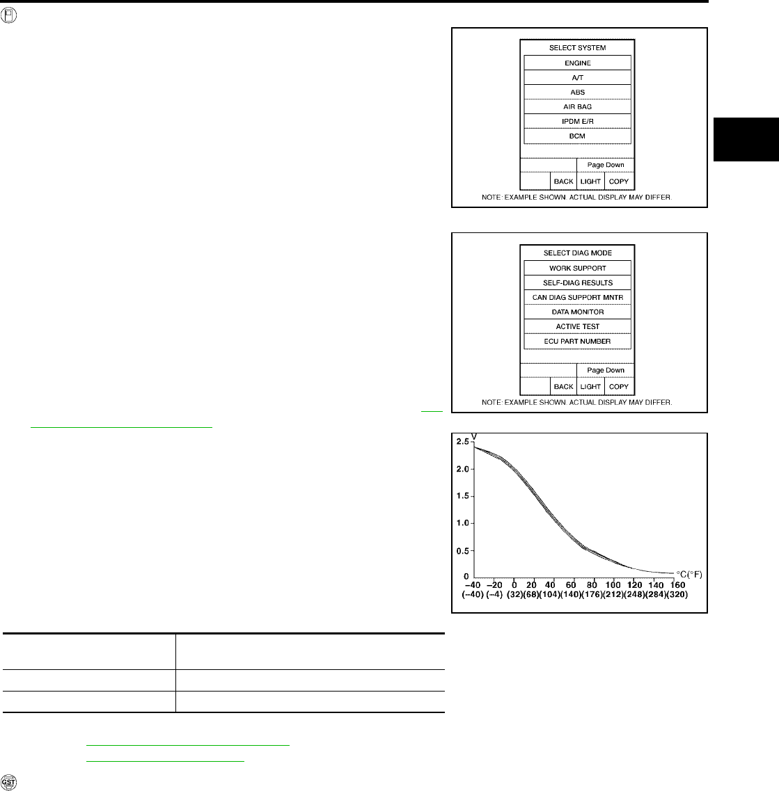
DTC P0732 A/T 2ND GEAR FUNCTION
AT-133
[RE4F04B]
D
E
F
G
H
I
J
K
L
M
A
B
AT
Revision: September 2005 2005 Quest
WITH CONSULT-II
1. Start engine and select “DATA MONITOR” mode for “A/T” with
CONSULT-II.
2. Make sure that output voltage of A/T fluid temperature sensor is
within the range below.
FLUID TEMP SEN: 0.5 - 1.5V
If out of range, drive the vehicle to decrease the voltage (warm
up the fluid) or stop engine to increase the voltage (cool down
the fluid).
3. Select “2ND GR FNCTN P0732” of “DTC WORK SUPPORT”
mode for “A/T” with CONSULT-II and touch “START”.
4. Accelerate vehicle to 45 to 50 km/h (28 to 31 MPH) under the
following condition and release the accelerator pedal com-
pletely.
THROTTLE POSI: Less than 1.0/8
Selector lever: D position (O/D ON)
–Check that “GEAR” shows “3” or “4” after releasing pedal.
5. Depress accelerator pedal to WOT (more than 7.0/8 of “THROT-
TLE POSI”) quickly from a speed of 45 to 50 km/h (28 to 31
MPH) until “TESTING” changes to “STOP VEHICLE” or “COM-
PLETE”. (It will take approximately 3 seconds.)
If the check result NG appears on CONSULT-II screen, go to AT-
135, "Diagnostic Procedure" .
If “STOP VEHICLE” appears on CONSULT-II screen, go to fol-
lowing step.
–Check that “GEAR” shows “2” when depressing accelera-
tor pedal to WOT.
–If “TESTING” does not appear on CONSULT-II for a long
time, select “SELF-DIAG RESULTS” for “ENGINE”. In case a
1st trip DTC other than P0732 is shown, refer to applicable
“TROUBLE DIAGNOSIS FOR DTC”.
6. Stop vehicle.
7. Follow the instruction displayed. (Check for normal shifting refer-
ring to the table below.)
8. Make sure that “OK” is displayed. (If “NG” is displayed, refer to “DIAGNOSTIC PROCEDURE”.)
Refer to AT-135, "Diagnostic Procedure" .
Refer to AT-364, "Shift Schedule" .
WITH GST
Follow the procedure “With CONSULT-II”.
BCIA0030E
Vehicle condition Gear on actual transmission shift pattern when
screen is changed to 1 → 2 → 3 → 4
No malfunction exists 1 → 2 → 3 → 4
Malfunction for P0732 exists. 4 → 3 → 3 → 4
BCIA0031E
SAT021J
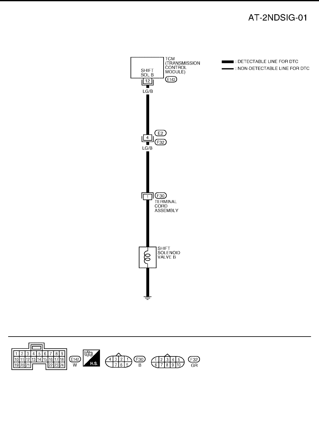
AT-134
[RE4F04B]
DTC P0732 A/T 2ND GEAR FUNCTION
Revision: September 2005 2005 Quest
Wiring Diagram — AT — 2ND UCS000O4
BCWA0175E

DTC P0732 A/T 2ND GEAR FUNCTION
AT-135
[RE4F04B]
D
E
F
G
H
I
J
K
L
M
A
B
AT
Revision: September 2005 2005 Quest
TCM TERMINALS AND REFERENCE VALUE (MEASURED BETWEEN EACH TERMINAL AND GROUND)
Diagnostic Procedure UCS000O5
1. CHECK VALVE RESISTANCE
1. Remove control valve assembly. Refer to AT-253, "Control Valve Assembly and Accumulators" .
–Shift solenoid valve B
2. Check resistance to the terminal and ground.
OK or NG
OK >> GO TO 2.
NG >> Repair or replace shift solenoid valve assembly.
2. CHECK VALVE OPERATION
1. Remove control valve assembly. Refer to AT-253, "Control Valve Assembly and Accumulators" .
–Shift solenoid valve B
2. Check solenoid valve by listening for its operating sound while
applying battery voltage to the terminal and ground.
OK or NG
OK >> GO TO 3.
NG >> Repair or replace shift solenoid valve assembly.
3. CHECK CONTROL VALVE
1. Disassemble control valve assembly. Refer to AT-290, "Control
Valve Assembly" .
2. Check to ensure that:
–Valve, sleeve and plug slide along valve bore under their own
weight.
–Valve, sleeve and plug are free from burrs, dents and scratches.
–Control valve springs are free from damage, deformation and
fatigue.
–Hydraulic line is free from obstacles.
OK or NG
OK >> GO TO 4.
NG >> Repair control valve assembly.
TERMINAL WIRE COLOR ITEM CONDITION DATA (APPROX.)
12 LG/B SHIFT SOLENOID VALVE B
WHEN SHIFT SOLENOID VALVE
B IS OPERATING (DRIVING IN D1
OR D2 )
BATTERY VOLTAGE
WHEN SHIFT SOLENOID VALVE
B IS NOT OPERATING (DRIVING
IN D3 OR D4 )
0V
Solenoid valve Terminal Resistance
(Approx.)
Shift solenoid valve B 1 Ground 5 - 20Ω
WCIA0091E
WCIA0092E
SAT367H

DTC P0733 A/T 3RD GEAR FUNCTION
AT-137
[RE4F04B]
D
E
F
G
H
I
J
K
L
M
A
B
AT
Revision: September 2005 2005 Quest
DTC P0733 A/T 3RD GEAR FUNCTION PFP:31940
Description UCS000O6
●This malfunction will not be detected while the O/D OFF indicator lamp is indicating another self-diagnosis
malfunction.
●This malfunction is detected when the A/T does not shift into third gear position as instructed by the TCM.
This is not caused by electrical malfunction (circuits open or shorted) but by mechanical malfunction such
as control valve sticking, improper solenoid valve operation, malfunctioning servo piston or brake band,
etc.
On Board Diagnosis Logic UCS000O7
This diagnosis monitors actual gear position by checking the torque converter slip ratio calculated by TCM as
follows:
Torque converter slip ratio = A x C/B
A: Output shaft revolution signal from revolution sensor
B: Engine speed signal from ECM
C: Gear ratio determined as gear position which TCM supposes
If the actual gear position is higher than the position (3rd) supposed by TCM, the slip ratio will be more than
normal. In case the ratio exceeds the specified value, TCM judges this diagnosis malfunction.
This malfunction will be caused when shift solenoid valve A is stuck closed.
Gear positions supposed by TCM are as follows.
In case of gear position with no malfunctions: 1, 2, 3 and 4 positions
In case of gear position with shift solenoid valve A stuck closed: 1, 1, 4* and 4 positions to each gear position
above
*: P0733 is detected.
Diagnostic trouble code “A/T 3RD GR FNCTN” with CONSULT-II or P0733 without CONSULT-II is detected
when A/T cannot be shifted to the 3rd gear position even if electrical circuit is good.
Possible Cause UCS000O8
Check the following items.
●Shift solenoid valve A
●Each clutch
●Hydraulic control circuit
Diagnostic Trouble Code (DTC) Confirmation Procedure UCS000O9
CAUTION:
●Always drive vehicle at a safe speed.
●Be careful not to rev engine into the red zone on the tachometer.
NOTE:
If “DTC Confirmation Procedure” has been previously conducted, always turn ignition switch “OFF”
and wait at least 10 seconds before conducting the next test.
TESTING CONDITION:
Always drive vehicle on a level road to improve the accuracy of test.
After the repair, perform the following procedure to confirm the malfunction is eliminated.
Gear position 1 2 3 4
Shift solenoid valve A ON (Closed) OFF (Open) OFF (Open) ON (Closed)
Shift solenoid valve B ON (Closed) ON (Closed) OFF (Open) OFF (Open)
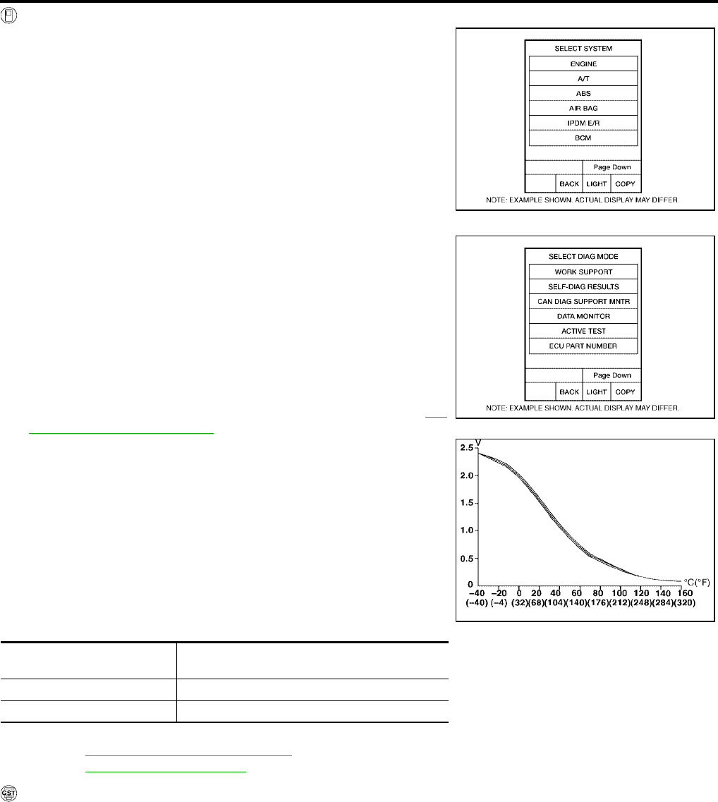
AT-138
[RE4F04B]
DTC P0733 A/T 3RD GEAR FUNCTION
Revision: September 2005 2005 Quest
WITH CONSULT-II
1. Start engine and select “DATA MONITOR” mode for “A/T” with
CONSULT-II.
2. Make sure that output voltage of A/T fluid temperature sensor is
within the range below.
FLUID TEMP SEN: 0.5 - 1.5V
If out of range, drive the vehicle to decrease the voltage (warm
up the fluid) or stop engine to increase the voltage (cool down
the fluid).
3. Select “3RD GR FNCTN P0733” of “DTC WORK SUPPORT”
mode for “A/T” with CONSULT-II and touch “START”.
4. Accelerate vehicle to 60 to 75 km/h (37 to 47 MPH) under the
following condition and release the accelerator pedal com-
pletely.
THROTTLE POSI: Less than 1.0/8 (at all times during step 4)
Selector lever: D position
–Check that “GEAR” shows “4” after releasing pedal.
5. Depress accelerator pedal steadily with 3.5/8 - 4.5/8 of “THROT-
TLE POSI” from a speed of 60 to 75 km/h (37 to 47 MPH) until
“TESTING” changes to “STOP VEHICLE” or “COMPLETED”. (It
will take approximately 3 seconds.)
If the check result NG appears on CONSULT-II screen, go to AT-
140, "Diagnostic Procedure" .
If “STOP VEHICLE” appears on CONSULT-II screen, go to fol-
lowing step.
–Check that “GEAR” shows “3” when depressing accelera-
tor pedal with 3.5/8 - 4.5/8 of “THROTTLE POSI”.
–If “TESTING” does not appear on CONSULT-II for a long
time, select “SELF-DIAG RESULTS” for “ENGINE”. In case a
1st trip DTC other than P0733 is shown, refer to applicable
“TROUBLE DIAGNOSIS FOR DTC”.
6. Stop vehicle.
7. Follow the instruction displayed. (Check for normal shifting refer-
ring to the table below.)
8. Make sure that “OK” is displayed. (If “NG” is displayed, refer to “DIAGNOSTIC PROCEDURE”.)
Refer to AT-140, "Diagnostic Procedure" .
Refer to AT-364, "Shift Schedule" .
WITH GST
Follow the procedure “With CONSULT-II”.
BCIA0030E
Vehicle condition Gear on actual transmission shift pattern when
screen is changed to 1 → 2 → 3 → 4
No malfunction exists. 1 → 2 → 3 → 4
Malfunction for P0733 exists. 1 → 1 → 4 → 4
BCIA0031E
SAT021J

DTC P0733 A/T 3RD GEAR FUNCTION
AT-139
[RE4F04B]
D
E
F
G
H
I
J
K
L
M
A
B
AT
Revision: September 2005 2005 Quest
Wiring Diagram — AT — 3RD UCS000OA
BCWA0176E
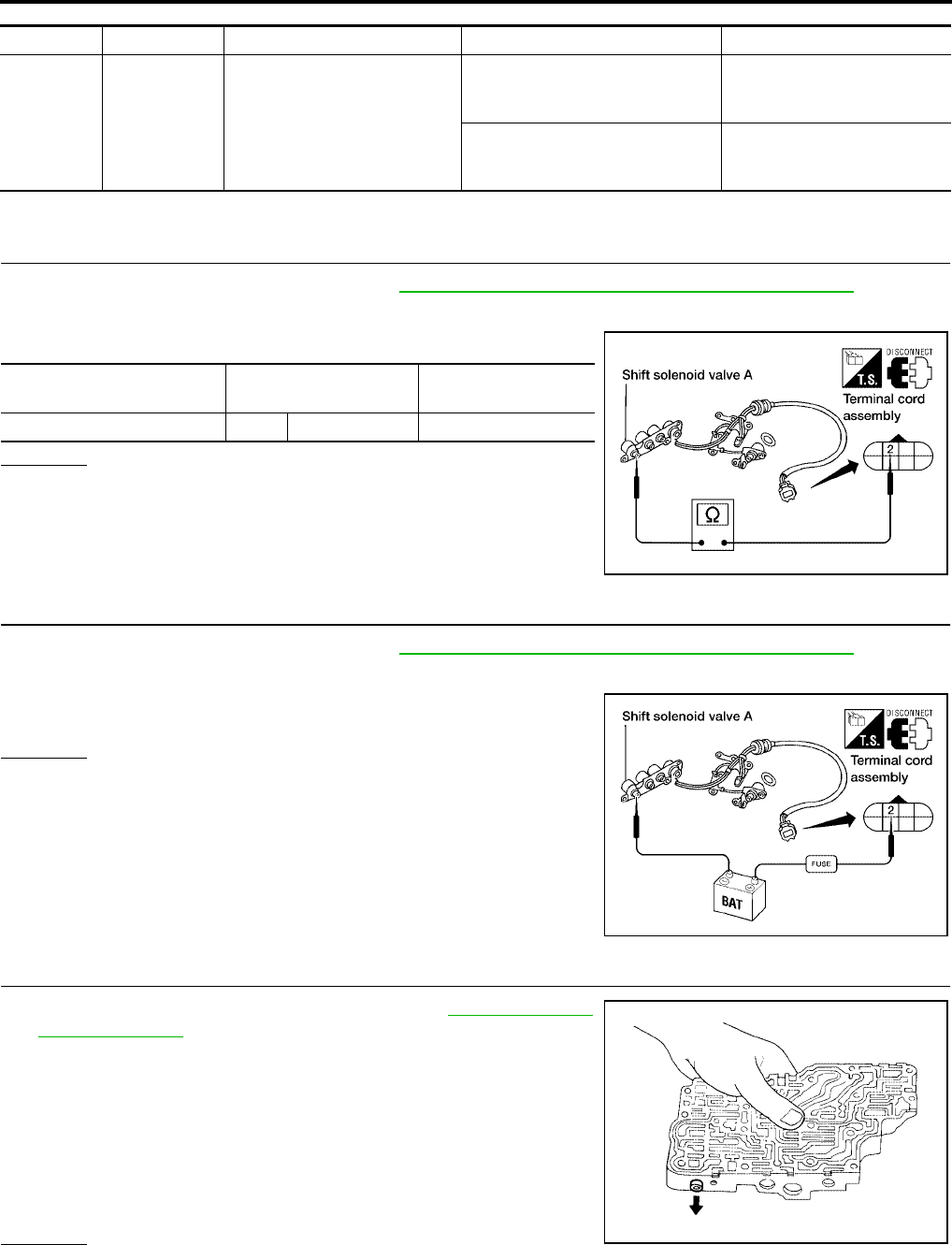
AT-140
[RE4F04B]
DTC P0733 A/T 3RD GEAR FUNCTION
Revision: September 2005 2005 Quest
TCM TERMINALS AND REFERENCE VALUE (MEASURED BETWEEN EACH TERMINAL AND GROUND)
Diagnostic Procedure UCS000OB
1. CHECK VALVE RESISTANCE
1. Remove control valve assembly. Refer to AT-253, "Control Valve Assembly and Accumulators" .
–Shift solenoid valve A
2. Check resistance to the terminal and ground.
OK or NG
OK >> GO TO 2.
NG >> Repair or replace shift solenoid valve assembly.
2. CHECK VALVE OPERATION
1. Remove control valve assembly. Refer to AT-253, "Control Valve Assembly and Accumulators" .
–Shift solenoid valve A
2. Check solenoid valve by listening for its operating sound while
applying battery voltage to the terminal and ground.
OK or NG
OK >> GO TO 3.
NG >> Repair or replace shift solenoid valve assembly.
3. CHECK CONTROL VALVE
1. Disassemble control valve assembly. Refer to AT-290, "Control
Valve Assembly" .
2. Check to ensure that:
–Valve, sleeve and plug slide along valve bore under their own
weight.
–Valve, sleeve and plug are free from burrs, dents and scratches.
–Control valve springs are free from damage, deformation and
fatigue.
–Hydraulic line is free from obstacles.
OK or NG
OK >> GO TO 4.
NG >> Repair control valve assembly.
TERMINAL WIRE COLOR ITEM CONDITION DATA (APPROX.)
11 R/Y SHIFT SOLENOID VALVE A
WHEN SHIFT SOLENOID VALVE
A IS OPERATING (DRIVING IN D1
OR D4 )
BATTERY VOLTAGE
WHEN SHIFT SOLENOID VALVE
A IS NOT OPERATING (DRIVING
IN D2 OR D3 )
0V
Solenoid valve Terminal Resistance
(Approx.)
Shift solenoid valve A 2 Ground 20 - 30Ω
WCIA0093E
WCIA0094E
SAT367H

AT-142
[RE4F04B]
DTC P0734 A/T 4TH GEAR FUNCTION
Revision: September 2005 2005 Quest
DTC P0734 A/T 4TH GEAR FUNCTION PFP:31940
Description UCS000OC
●This malfunction will not be detected while the O/D OFF indicator lamp is indicating another self-diagnosis
malfunction.
●This malfunction is detected when the A/T does not shift into fourth gear position or line pressure is low as
instructed by the TCM. This is not caused by electrical malfunction (circuits open or shorted) but by
mechanical malfunction such as control valve sticking, improper solenoid valve operation, malfunctioning
oil pump or torque converter clutch, etc.
CONSULT-II REFERENCE VALUE IN DATA MONITOR MODE
Remarks: Specification data are reference values.
On Board Diagnosis Logic UCS000OD
This diagnosis monitors actual gear position by checking the torque converter slip ratio calculated by TCM as
follows:
Torque converter slip ratio = A x C/B
A: Output shaft revolution signal from revolution sensor
B: Engine speed signal from ECM
C: Gear ratio determined as gear position which TCM supposes
If the actual gear position is much lower than the position (4th) supposed by TCM, the slip ratio will be much
less than normal. In case the ratio does not reach the specified value, TCM judges this diagnosis malfunction.
This malfunction will be caused when shift solenoid valve A is stuck open or shift solenoid valve B is stuck
closed.
Gear positions supposed by TCM are as follows.
In case of gear position with no malfunctions: 1, 2, 3 and 4 positions
In case of gear position with shift solenoid valve A stuck open: 2, 2, 3 and 3* position
In case of gear position with shift solenoid valve B stuck closed: 1, 2, 2 and 1* positions to each gear position
above
*: P0734 is detected.
And also, this malfunction will be caused when line pressure is lower than normal such as when line pressure
solenoid valve is stuck open.
Diagnostic trouble code “A/T 4TH GR FNCTN” with CONSULT-II or P0734 without CONSULT-II is detected
when A/T cannot be shifted to the 4th gear position even if electrical circuit is good.
Possible Cause UCS000OE
Check the following items.
●Shift solenoid valve A
●Shift solenoid valve B
● Line pressure solenoid valve
●Each clutch
●Hydraulic control circuit
Diagnostic Trouble Code (DTC) Confirmation Procedure UCS000OF
CAUTION:
●Always drive vehicle at a safe speed.
Gear position 1 2 3 4
Shift solenoid valve A ON (Closed) OFF (Open) OFF (Open) ON (Closed)
Shift solenoid valve B ON (Closed) ON (Closed) OFF (Open) OFF (Open)
Monitor item Condition Specification
Torque converter clutch
solenoid valve duty
Lock-up OFF
↓
Lock-up ON
Approximately 4%
↓
Approximately 94%
Line pressure solenoid
valve duty
Small throttle opening (Low line pressure)
↓
Large throttle opening (High line pressure)
Approximately 24%
↓
Approximately 95%
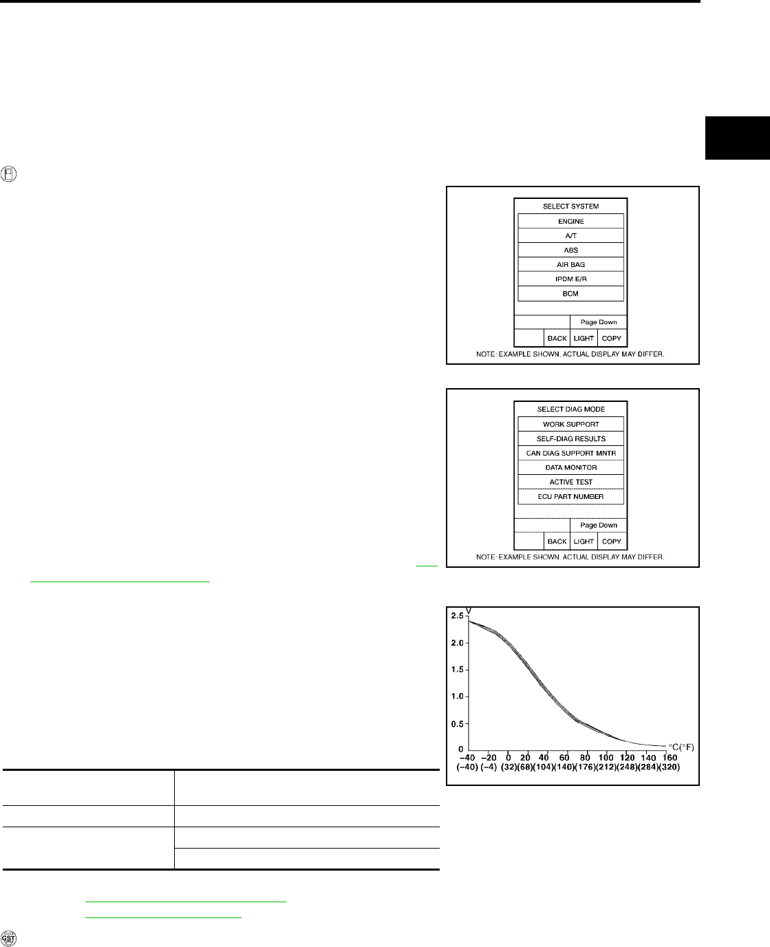
DTC P0734 A/T 4TH GEAR FUNCTION
AT-143
[RE4F04B]
D
E
F
G
H
I
J
K
L
M
A
B
AT
Revision: September 2005 2005 Quest
●If conducting this “DTC CONFIRMATION PROCEDURE” again, always turn ignition switch OFF
and wait at least 10 seconds before continuing.
●Be careful not to rev engine into the red zone on the tachometer.
NOTE:
If “DTC Confirmation Procedure” has been previously conducted, always turn ignition switch OFF and
wait at least 10 seconds before conducting the next test.
TESTING CONDITION:
Always drive vehicle on a level road to improve the accuracy of test.
After the repair, perform the following procedure to confirm the malfunction is eliminated.
WITH CONSULT-II
1. Start engine and select “DATA MONITOR” mode for “A/T” with
CONSULT-II.
2. Make sure that output voltage of A/T fluid temperature sensor is
within the range below.
FLUID TEMP SEN: 0.5 - 1.5V
If out of range, drive the vehicle to decrease the voltage (warm
up the fluid) or stop engine to increase the voltage (cool down
the fluid).
3. Select “4TH GR FNCTN P0734” of “DTC WORK SUPPORT”
mode for “A/T” with CONSULT-II and touch “START”.
4. Accelerate vehicle to 55 to 65 km/h (34 to 40 MPH) under the
following condition and release the accelerator pedal com-
pletely.
THROTTLE POSI: Less than 5.5/8 (at all times during step 4)
Selector lever: D position
–Check that “GEAR” shows “3” after releasing pedal.
5. Depress accelerator pedal steadily with 1.0/8 - 2.0/8 of “THROT-
TLE POSI” from a speed of 55 to 65 km/h (34 to 40 MPH) until
“TESTING” has turned to “STOP VEHICLE” or “COMPLETED”.
(It will take approximately 3 seconds.)
If the check result NG appears on CONSULT-II screen, go to AT-
145, "Diagnostic Procedure" .
If “STOP VEHICLE” appears on CONSULT-II screen, go to following step.
–Check that “GEAR” shows “4” when depressing accelera-
tor pedal with 1.0/8 - 2.0/8 of “THROTTLE POSI”.
–If “TESTING” does not appear on CONSULT-II for a long
time, select “SELF-DIAG RESULTS” for “ENGINE”. In case a
1st trip DTC other than P0734 is shown, refer to applicable
“TROUBLE DIAGNOSIS FOR DTC”.
6. Stop vehicle.
7. Follow the instruction displayed. (Check for normal shifting refer-
ring to the table below.)
8. Make sure that “OK” is displayed. (If “NG” is displayed, refer to “DIAGNOSTIC PROCEDURE”.)
Refer to AT-145, "Diagnostic Procedure" .
Refer to AT-364, "Shift Schedule" .
WITH GST
Follow the procedure “With CONSULT-II”.
BCIA0030E
Vehicle condition Gear on actual transmission shift pattern when
screen is changed to 1 → 2 → 3 → 4
No malfunction exists 1 → 2 → 3 → 4
Malfunction for P0734 exists. 2 → 2 → 3 → 3
1 → 2 → 2 → 1
BCIA0031E
SAT021J
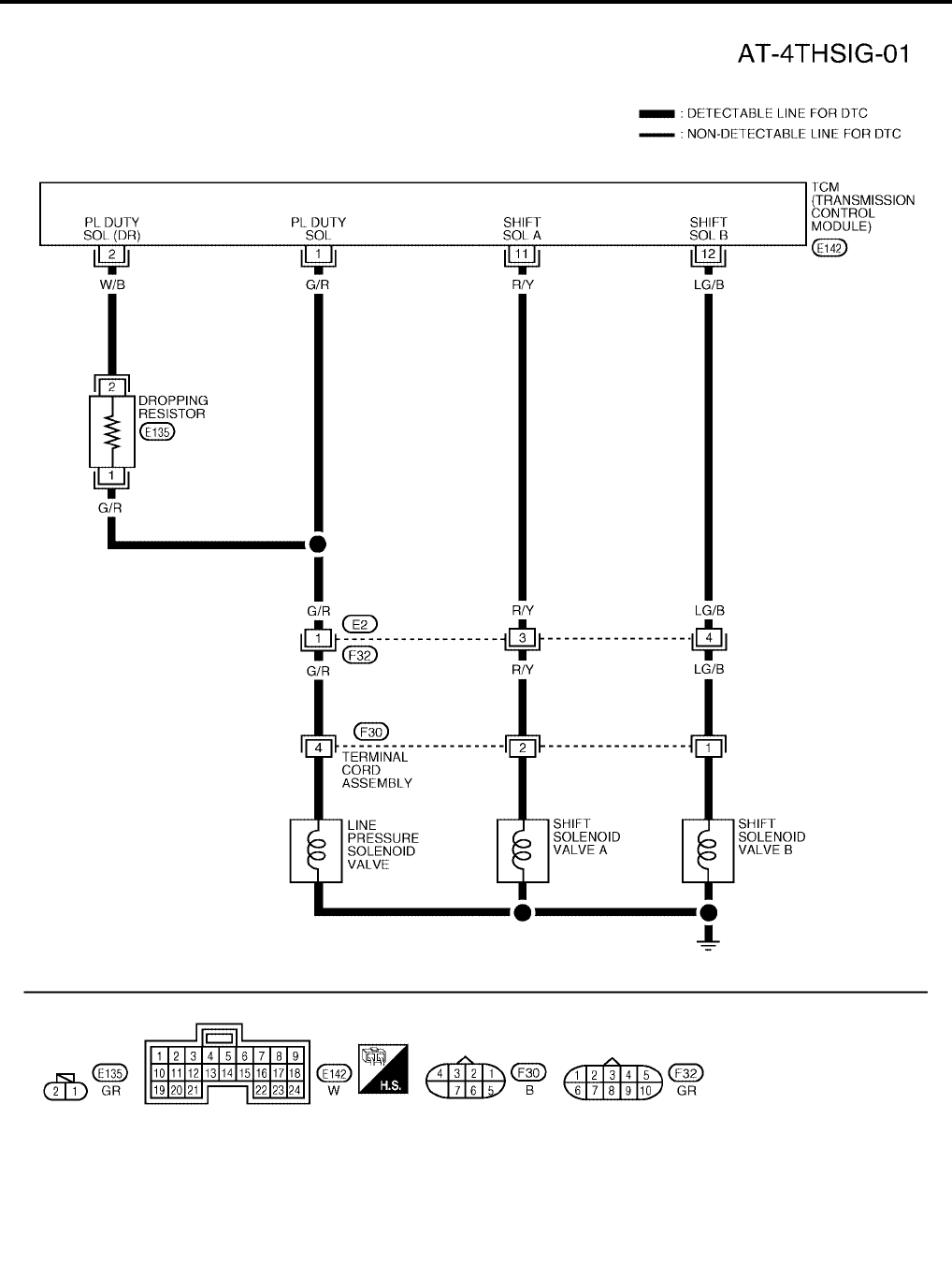
AT-144
[RE4F04B]
DTC P0734 A/T 4TH GEAR FUNCTION
Revision: September 2005 2005 Quest
Wiring Diagram — AT — 4TH UCS000OG
BCWA0301E
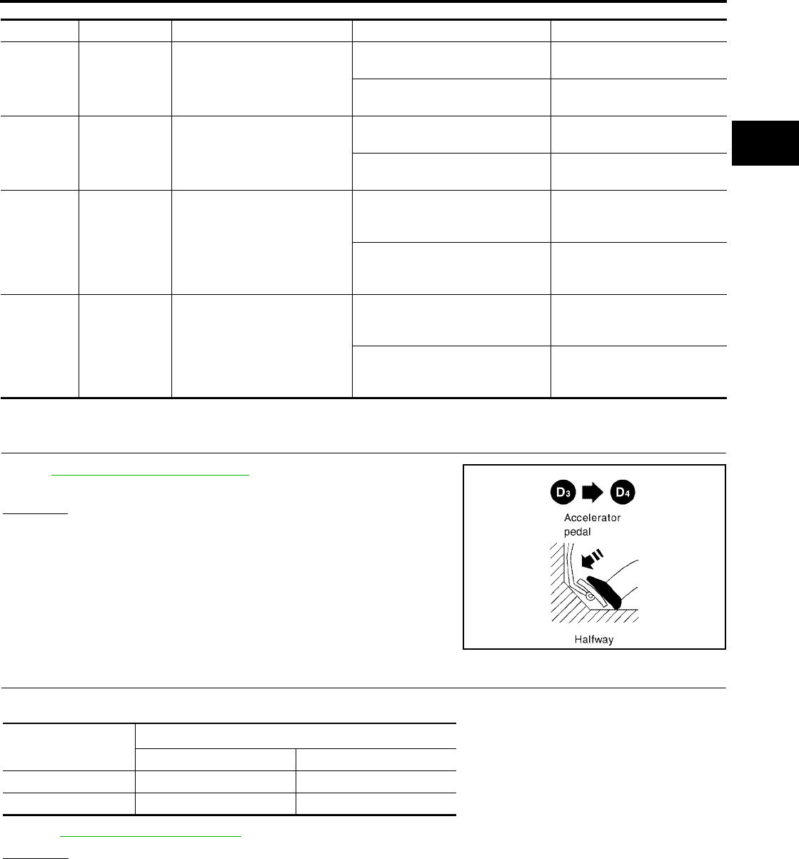
DTC P0734 A/T 4TH GEAR FUNCTION
AT-145
[RE4F04B]
D
E
F
G
H
I
J
K
L
M
A
B
AT
Revision: September 2005 2005 Quest
TCM TERMINALS AND REFERENCE VALUE (MEASURED BETWEEN EACH TERMINAL AND GROUND)
Diagnostic Procedure UCS000OH
1. CHECK SHIFT UP (D3 TO D4 )
During AT-81, "Cruise Test — Part 1" , does A/T shift from D3 to D4
at the specified speed?
Yes or No
Yes >> GO TO 11.
No >> GO TO 2.
2. CHECK LINE PRESSURE
Perform line pressure test.
Refer to AT-71, "Line Pressure Test" .
OK or NG
OK >> GO TO 3.
NG >> GO TO 7.
TERMINAL WIRE COLOR ITEM CONDITION DATA (APPROX.)
1G/R
LINE PRESSURE SOLENOID
VALVE
WHEN ACCELERATOR PEDAL
IS RELEASED WHILE DRIVING 1.5 - 3.0V
WHEN ACCELERATOR PEDAL
IS DEPRESSED WHILE DRIVING 0V
2W/B
LINE PRESSURE SOLENOID
VALVE (DROPPING RESIS-
TOR)
WHEN ACCELERATOR PEDAL
IS RELEASED WHILE DRIVING 4 - 14V
WHEN ACCELERATOR PEDAL
IS DEPRESSED WHILE DRIVING 0V
11 R/Y SHIFT SOLENOID VALVE A
WHEN SHIFT SOLENOID VALVE
A IS OPERATING (DRIVING IN D1
OR D4 )
BATTERY VOLTAGE
WHEN SHIFT SOLENOID VALVE
A IS NOT OPERATING (DRIVING
IN D2 OR D3 )
0V
12 LG/B SHIFT SOLENOID VALVE B
WHEN SHIFT SOLENOID VALVE
B IS OPERATING (DRIVING IN D1
OR D2 )
BATTERY VOLTAGE
WHEN SHIFT SOLENOID VALVE
BE IS NOT OPERATING (DRIV-
ING IN D3 OR D4 )
0V
SAT988H
Engine speed
rpm
Line pressure kPa (kg/cm2 , psi)
D and L position R position
Idle 500 (5.1, 73) 778 (7.9, 113)
Stall 1,223 (12.6, 179) 1,918 (19.6, 278)
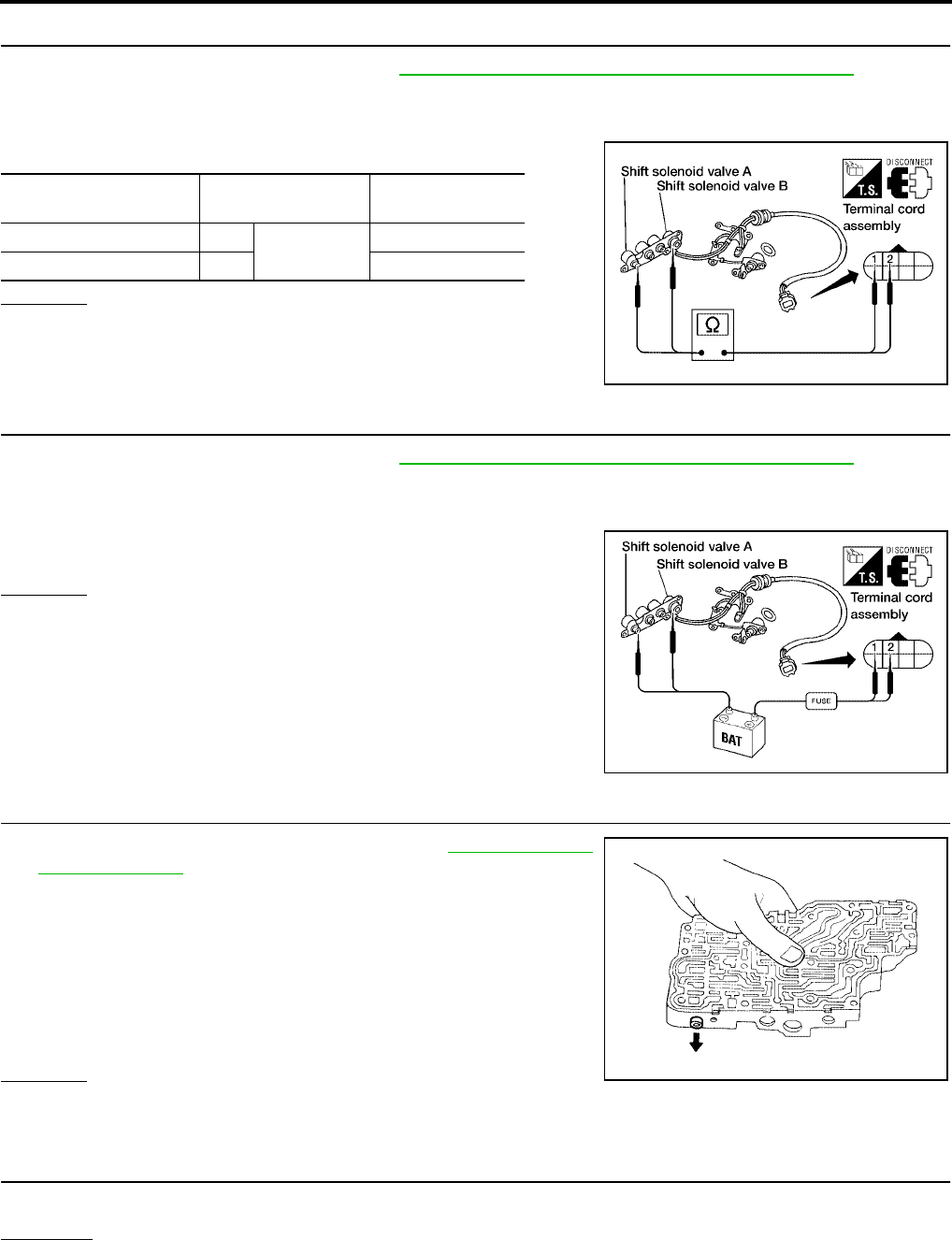
AT-146
[RE4F04B]
DTC P0734 A/T 4TH GEAR FUNCTION
Revision: September 2005 2005 Quest
3. CHECK VALVE RESISTANCE
1. Remove control valve assembly. Refer to AT-253, "Control Valve Assembly and Accumulators" .
–Shift solenoid valve A
–Shift solenoid valve B
2. Check resistance between two terminals.
OK or NG
OK >> GO TO 5.
NG >> Replace solenoid valve assembly.
4. CHECK VALVE OPERATION
1. Remove control valve assembly. Refer to AT-253, "Control Valve Assembly and Accumulators" .
–Shift solenoid valve A
–Shift solenoid valve B
2. Check solenoid valve by listening for its operating sound while
applying battery voltage to the terminal and ground.
OK or NG
OK >> GO TO 5.
NG >> Replace solenoid valve assembly.
5. CHECK CONTROL VALVE
1. Disassemble control valve assembly. Refer to AT-290, "Control
Valve Assembly" .
2. Check to ensure that:
–Valve, sleeve and plug slide along valve bore under their own
weight.
–Valve, sleeve and plug are free from burrs, dents and scratches.
–Control valve springs are free from damage, deformation and
fatigue.
–Hydraulic line is free from obstacles.
OK or NG
OK >> GO TO 6.
NG >> Repair control valve.
6. CHECK SHIFT UP (D3 TO D4 )
Does A/T shift from D3 to D 4 at the specified speed?
OK or NG
OK >> GO TO 11.
NG >> Check transaxle inner parts. (Clutch, brake, etc.)
Solenoid valve Terminal. Resistance
(Approx.)
Shift solenoid valve A 2 Ground 20 - 30Ω
Shift solenoid valve B 1 5 - 20Ω
WCIA0089E
WCIA0090E
SAT367H

DTC P0734 A/T 4TH GEAR FUNCTION
AT-147
[RE4F04B]
D
E
F
G
H
I
J
K
L
M
A
B
AT
Revision: September 2005 2005 Quest
7. CHECK VALVE RESISTANCE
1. Remove control valve assembly. Refer to AT-253, "Control Valve Assembly and Accumulators" .
–Line pressure solenoid valves
2. Check resistance to the terminal and ground.
OK or NG
OK >> GO TO 9.
NG >> Replace solenoid valve assembly.
8. CHECK VALVE OPERATION
1. Remove control valve assembly. Refer to AT-253, "Control Valve Assembly and Accumulators" .
–Line pressure solenoid valves
2. Check solenoid valve by listening for its operating sound while
applying battery voltage to the terminal and ground.
OK or NG
OK >> GO TO 9.
NG >> Replace solenoid valve assembly.
9. CHECK CONTROL VALVE
1. Disassemble control valve assembly. Refer to AT-290, "Control
Valve Assembly" .
2. Check line pressure circuit valves for sticking.
–Pressure regulator valve
–Pilot valve
–Pressure modifier valve
OK or NG
OK >> GO TO 10.
NG >> Repair control valve.
10. CHECK SHIFT UP (D3 TO D4 )
Does A/T shift from D 3 to D4 at the specified speed?
OK or NG
OK >> GO TO 11.
NG >> Check transaxle inner parts. (Clutch, brake, etc.)
Solenoid valve Terminal Resistance
(Approx.)
Line pressure solenoid valve 4 Ground 2.5 - 5Ω
WCIA0098E
WCIA0099E
SAT367H


DTC P0740 TORQUE CONVERTER CLUTCH SOLENOID VALVE
AT-149
[RE4F04B]
D
E
F
G
H
I
J
K
L
M
A
B
AT
Revision: September 2005 2005 Quest
DTC P0740 TORQUE CONVERTER CLUTCH SOLENOID VALVE PFP:31940
Description UCS000OI
The torque converter clutch solenoid valve is activated, with the gear
in D4 , by the TCM in response to signals sent from the vehicle
speed and the ECM (throttle opening). Lock-up piston operation will
then be controlled.
Lock-up operation, however, is prohibited when A/T fluid tempera-
ture is too low.
When the accelerator pedal is depressed (less than 2/8) in lock-up
condition, the engine speed should not change abruptly. If there is a
big jump in engine speed, there is no lock-up.
CONSULT-II REFERENCE VALUE IN DATA MONITOR MODE
Remarks: Specification data are reference values.
On Board Diagnosis Logic UCS000OJ
Diagnostic trouble code “TCC SOLENOID/CIRC” with CONSULT-II or P0740 without CONSULT-II is detected
when TCM detects an improper voltage drop when it tries to operate the solenoid valve.
Possible Cause UCS000OK
Check the following items.
●Torque converter clutch solenoid valve
●Harness or connectors
(The solenoid circuit is open or shorted.)
Diagnostic Trouble Code (DTC) Confirmation Procedure UCS000OL
NOTE:
If “DTC Confirmation Procedure” has been previously conducted, always turn ignition switch OFF and
wait at least 10 seconds before conducting the next test.
After the repair, perform the following procedure to confirm the malfunction is eliminated.
WITH CONSULT-II
1. Turn ignition switch to ON position. (Do not start engine.)
SAT283HB
Monitor item Condition Specification
TCC S/V DUTY
Lock-up OFF
↓
Lock-up ON
Approximately 4%
↓
Approximately 94%
BCIA0030E
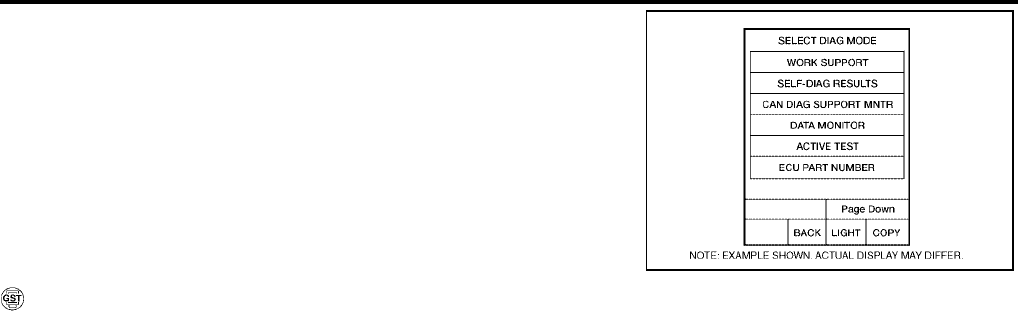
AT-150
[RE4F04B]
DTC P0740 TORQUE CONVERTER CLUTCH SOLENOID VALVE
Revision: September 2005 2005 Quest
2. Select “DATA MONITOR” mode for “ENGINE” with CONSULT-II
and wait at least 1 second.
3. Start engine and maintain the following condition for at least 5
consecutive seconds.
VHCL SPEED SE: 80km/h (50 MPH) or more
THROTTLE POSI: 0.5/8 - 1.0/8
Selector lever: D position (O/D ON)
Driving location: Driving the vehicle uphill (increased
engine load) will help maintain the driving conditions
required for this test.
WITH GST
Follow the procedure “With CONSULT-II”.
BCIA0031E

DTC P0740 TORQUE CONVERTER CLUTCH SOLENOID VALVE
AT-151
[RE4F04B]
D
E
F
G
H
I
J
K
L
M
A
B
AT
Revision: September 2005 2005 Quest
Wiring Diagram — AT — TCV UCS000OM
BCWA0178E
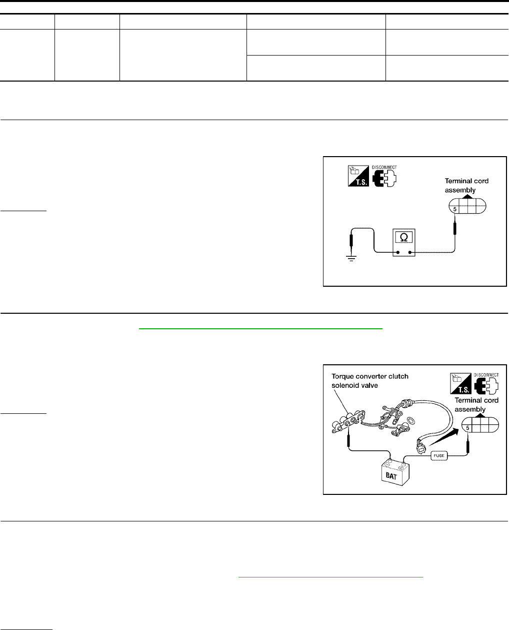
AT-152
[RE4F04B]
DTC P0740 TORQUE CONVERTER CLUTCH SOLENOID VALVE
Revision: September 2005 2005 Quest
TCM TERMINALS AND REFERENCE VALUE (MEASURED BETWEEN EACH TERMINAL AND GROUND)
Diagnostic Procedure UCS000ON
1. CHECK VALVE RESISTANCE
1. Turn ignition switch to OFF position.
2. Disconnect terminal cord assembly connector in engine compartment.
3. Check resistance between terminal cord assembly harness con-
nector F30 terminal 5 and ground.
OK or NG
OK >> GO TO 3.
NG >> GO TO 2.
2. CHECK VALVE OPERATION
1. Remove oil pan. Refer to AT-253, "Control Valve Assembly and Accumulators" .
2. Check the following items:
–Torque converter clutch solenoid valve
• Check solenoid valve by listening for its operating sound while
applying battery voltage to the terminal and ground.
–Harness of terminal cord assembly for short or open
OK or NG
OK >> GO TO 3.
NG >> Repair or replace damaged parts.
3. CHECK POWER SOURCE CIRCUIT
1. Turn ignition switch to OFF position.
2. Disconnect TCM harness connector.
3. Check continuity between terminal cord assembly harness connector F30 terminal 5(G/B) and TCM har-
ness connector E142 terminal 3(G/B). Refer to AT-151, "Wiring Diagram — AT — TCV" .
4. Reinstall any part removed.
OK or NG
OK >> GO TO 4.
NG >> Repair open circuit or short to ground or short to power in harness or connectors.
TERMINAL WIRE COLOR ITEM CONDITION DATA (APPROX.)
3 G/B TORQUE CONVERTER
CLUTCH SOLENOID VALVE
WITH TORQUE CONVERTER
LOCK-UP 8 - 15V
WITHOUT TORQUE CON-
VERTER LOCK-UP 0V
Resistance : 5 - 20Ω
WCIA0100E
WCIA0101E
Continuity should exist.

DTC P0740 TORQUE CONVERTER CLUTCH SOLENOID VALVE
AT-153
[RE4F04B]
D
E
F
G
H
I
J
K
L
M
A
B
AT
Revision: September 2005 2005 Quest
4. CHECK DTC
Perform AT-149, "Diagnostic Trouble Code (DTC) Confirmation Procedure" .
OK or NG
OK >> INSPECTION END
NG >> GO TO 5.
5. CHECK TCM INSPECTION
1. Perform TCM input/output signal inspection. Refer to AT-96, "TCM Terminals and Reference Value" .
2. If NG, recheck TCM pin terminals for damage or loose connection with harness connector.
OK or NG
OK >> INSPECTION END
NG >> Repair or replace damaged parts.

AT-154
[RE4F04B]
DTC P0744 A/T TCC S/V FUNCTION (LOCK-UP)
Revision: September 2005 2005 Quest
DTC P0744 A/T TCC S/V FUNCTION (LOCK-UP) PFP:31940
Description UCS000OO
●This malfunction will not be detected while the O/D OFF indicator lamp is indicating another self-diagnosis
malfunction.
●This malfunction is detected when the A/T does not shift into fourth gear position or the torque converter
clutch does not lock up as instructed by the TCM. This is not caused by electrical malfunction (circuits
open or shorted) but by mechanical malfunction such as control valve sticking, improper solenoid valve
operation, malfunctioning oil pump or torque converter clutch, etc.
CONSULT-II REFERENCE VALUE IN DATA MONITOR MODE
Remarks: Specification data are reference values.
On Board Diagnosis Logic UCS000OP
This diagnosis monitors actual gear position by checking the torque converter slip ratio calculated by TCM as
follows:
Torque converter slip ratio = A x C/B
A: Output shaft revolution signal from revolution sensor
B: Engine speed signal from ECM
C: Gear ratio determined as gear position which TCM supposes
If the actual gear position is much lower than the position (4th) supposed by TCM, the slip ratio will be much
less than normal. In case the ratio does not reach the specified value, TCM judges this diagnosis malfunction.
This malfunction will be caused when shift solenoid valve B is stuck closed.
Gear positions supposed by TCM are as follows.
In case of gear position with no malfunctions: 1, 2, 3 and 4 positions
In case of gear position with shift solenoid valve B stuck closed: 1, 2, 2 and 1 * positions to each gear position
above
*: P0744 is detected.
Diagnostic trouble code “A/T TCC S/V FNCTN” with CONSULT-II or P0744 without CONSULT-II is detected
when A/T cannot perform lock-up even if electrical circuit is good.
Possible Cause UCS000OQ
Check the following items.
●Line pressure solenoid valve
●Torque converter clutch solenoid valve
● Each clutch
●Hydraulic control circuit
Diagnostic Trouble Code (DTC) Confirmation Procedure UCS000OR
CAUTION:
Always drive vehicle at a safe speed.
NOTE:
If “DTC Confirmation Procedure” has been previously conducted, always turn ignition switch OFF and
wait at least 10 seconds before conducting the next test.
After the repair, perform the following procedure to confirm the malfunction is eliminated.
Monitor item Condition Specification
TCC S/V DUTY
Lock-up OFF
↓
Lock-up ON
Approximately 4%
↓
Approximately 94%
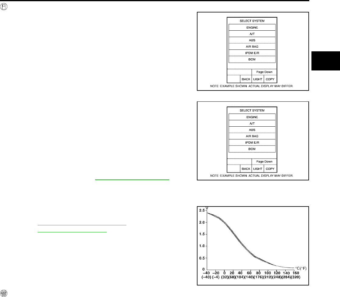
DTC P0744 A/T TCC S/V FUNCTION (LOCK-UP)
AT-155
[RE4F04B]
D
E
F
G
H
I
J
K
L
M
A
B
AT
Revision: September 2005 2005 Quest
WITH CONSULT-II
1. Start engine and select “DATA MONITOR” mode for “A/T” with
CONSULT-II.
2. Make sure that output voltage of A/T fluid temperature sensor is
within the range below.
FLUID TEMP SEN: 0.5 - 1.5V
If out of range, drive vehicle to decrease voltage (warm up the
fluid) or stop engine to increase voltage (cool down the fluid).
3. Select “TCC S/V FNCTN P0744” of “DTC WORK SUPPORT”
mode for “A/T” with CONSULT-II and touch “START”.
4. Accelerate vehicle to more than 80 km/h (50 MPH) and maintain
the following condition continuously until “TESTING” has turned
to “COMPLETE”. (It will take approximately 30 seconds after
“TESTING” shows.)
THROTTLE POSI: 1.0/8 - 2.0/8 (at all times during step 4)
Selector lever: D position
TCC S/V DUTY: More than 94%
VHCL/S SE-A/T: Constant speed of more than 80 km/h (50
MPH)
–Check that “GEAR” shows “4”.
–For shift schedule, refer to AT-364, "Shift Schedule" .
–If “TESTING” does not appear on CONSULT-II for a long
time, select “SELF-DIAG RESULTS”. In case a 1st trip DTC other than P0744 is shown, refer to
applicable “TROUBLE DIAGNOSIS FOR DTC”.
5. Make sure that “OK” is displayed. (If “NG” is displayed, refer to
“DIAGNOSTIC PROCEDURE”.)
Refer to AT-157, "Diagnostic Procedure" .
Refer to AT-364, "Shift Schedule" .
WITH GST
Follow the procedure “With CONSULT-II”.
BCIA0030E
BCIA0030E
SAT021J
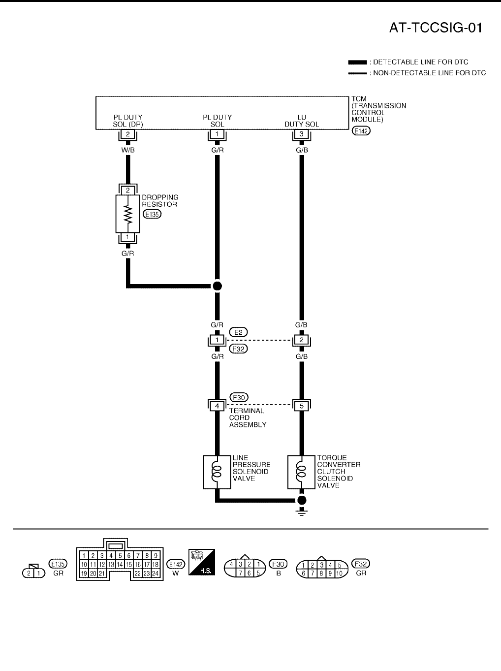
AT-156
[RE4F04B]
DTC P0744 A/T TCC S/V FUNCTION (LOCK-UP)
Revision: September 2005 2005 Quest
Wiring Diagram — AT — TCCSIG UCS000OS
BCWA0179E
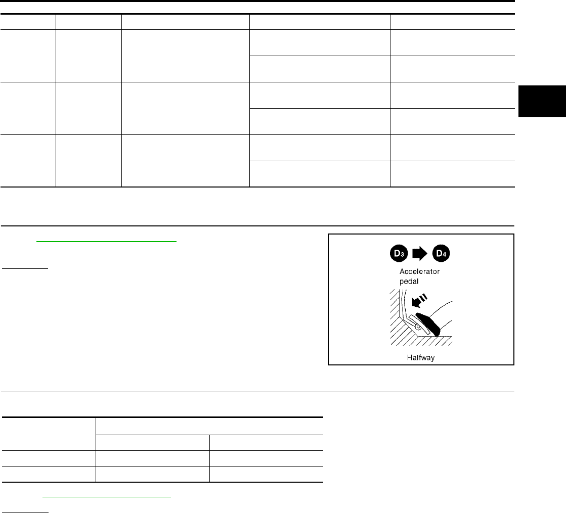
DTC P0744 A/T TCC S/V FUNCTION (LOCK-UP)
AT-157
[RE4F04B]
D
E
F
G
H
I
J
K
L
M
A
B
AT
Revision: September 2005 2005 Quest
TCM TERMINALS AND REFERENCE VALUE (MEASURED BETWEEN EACH TERMINAL AND GROUND)
Diagnostic Procedure UCS000OT
1. CHECK SHIFT UP (D3 TO D4 )
During AT-81, "Cruise Test — Part 1" , does A/T shift from D3 to D4
at the specified speed?
Yes or No
Yes >> GO TO 11.
No >> GO TO 2.
2. CHECK LINE PRESSURE
Perform line pressure test.
Refer to AT-71, "Line Pressure Test" .
OK or NG
OK >> GO TO 3.
NG >> GO TO 6.
TERMINAL WIRE COLOR ITEM CONDITION DATA (APPROX.)
1G/R
LINE PRESSURE SOLENOID
VALVE
WHEN ACCELERATOR PEDAL
IS RELEASED WHILE DRIVING 1.5 - 3.0V
WHEN ACCELERATOR PEDAL
IS DEPRESSED WHILE DRIVING 0V
2W/B
LINE PRESSURE SOLENOID
VALVE (DROPPING RESIS-
TOR)
WHEN ACCELERATOR PEDAL
IS RELEASED WHILE DRIVING 4 - 14V
WHEN ACCELERATOR PEDAL
IS DEPRESSED WHILE DRIVING 0V
3G/B
TORQUE CONVERTER
CLUTCH SOLENOID VALVE
WITH TORQUE CONVERTER
LOCK-UP 8 - 15V
WITHOUT TORQUE CON-
VERTER LOCK-UP 0V
SAT988H
Engine speed
rpm
Line pressure kPa (kg/cm2 , psi)
D and L position R position
Idle 500 (5.1, 73) 778 (7.9, 113)
Stall 1,223 (12.6, 179) 1,918 (19.6, 278)
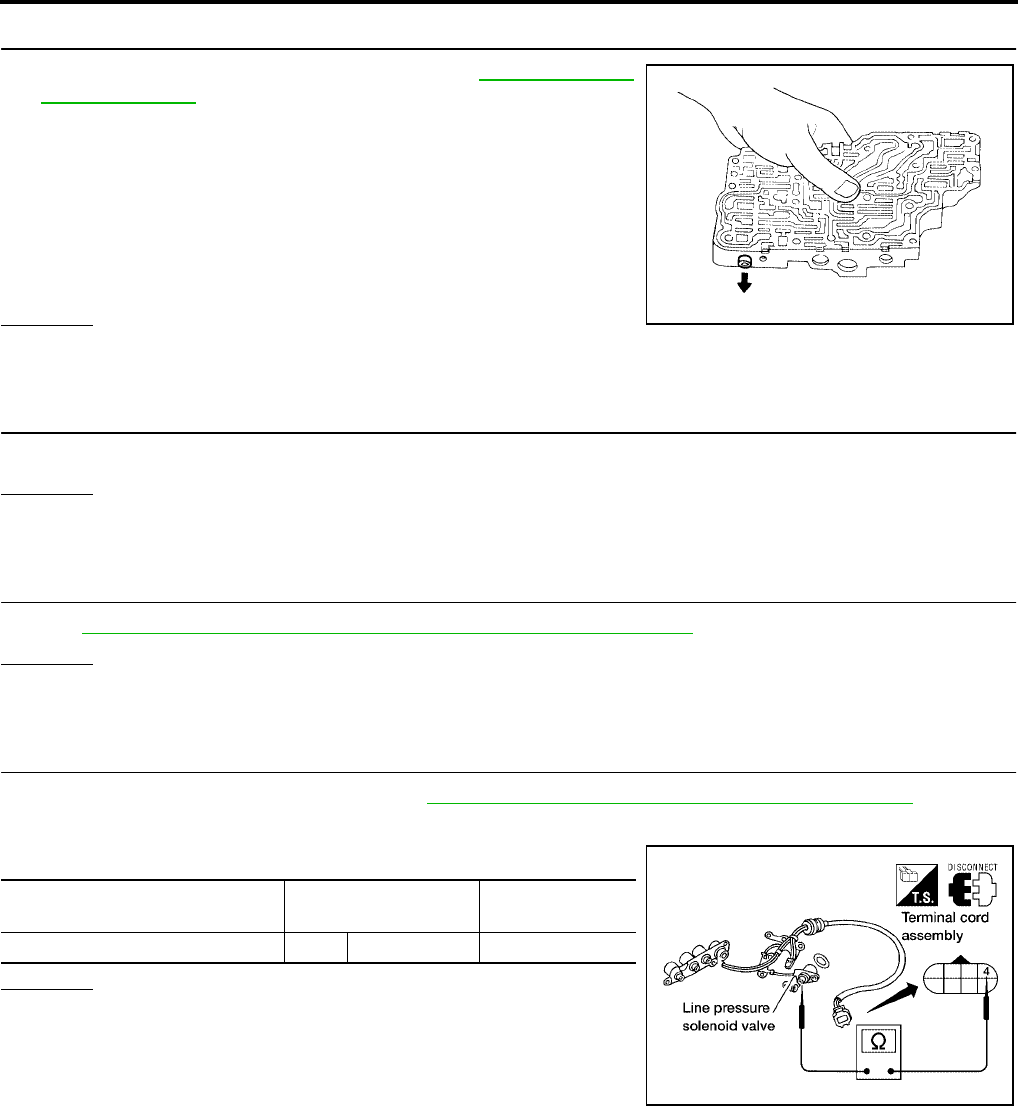
AT-158
[RE4F04B]
DTC P0744 A/T TCC S/V FUNCTION (LOCK-UP)
Revision: September 2005 2005 Quest
3. CHECK CONTROL VALVE
1. Disassemble control valve assembly. Refer to AT-290, "Control
Valve Assembly" .
2. Check to ensure that:
–Valve, sleeve and plug slide along valve bore under their own
weight.
–Valve, sleeve and plug are free from burrs, dents and scratches.
–Control valve springs are free from damage, deformation and
fatigue.
–Hydraulic line is free from obstacles.
OK or NG
OK >> GO TO 4.
NG >> Repair control valve.
4. CHECK SHIFT UP (D3 TO D4 )
Does A/T shift from D3 to D4 at the specified speed?
OK or NG
OK >> GO TO 5.
NG >> Check control valve again. Repair or replace control valve assembly.
5. CHECK DTC
Perform AT-154, "Diagnostic Trouble Code (DTC) Confirmation Procedure" .
OK or NG
OK >> INSPECTION END
NG >> GO TO 11.
6. CHECK VALVE RESISTANCE
1. Remove control valve assembly. Refer to AT-253, "Control Valve Assembly and Accumulators" .
–Line pressure solenoid valve
2. Check resistance to the terminal and ground.
OK or NG
OK >> GO TO 8.
NG >> Replace solenoid valve assembly.
SAT367H
Solenoid valve Terminal Resistance
(Approx.)
Line pressure solenoid valve 4 Ground 2.5 - 5Ω
WCIA0098E
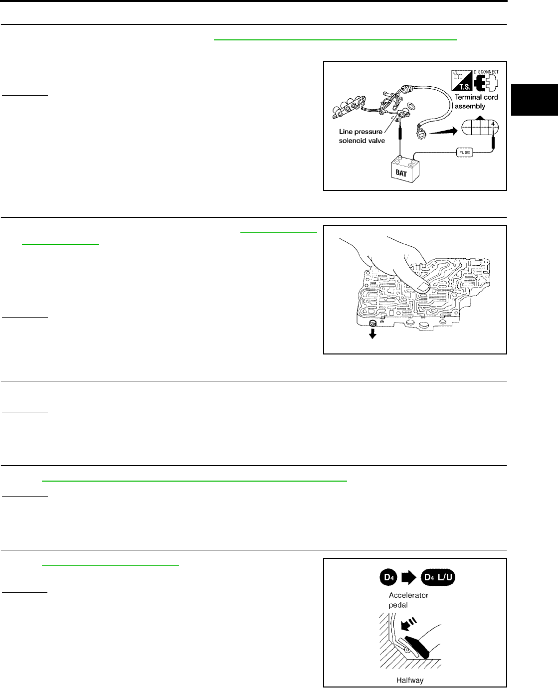
DTC P0744 A/T TCC S/V FUNCTION (LOCK-UP)
AT-159
[RE4F04B]
D
E
F
G
H
I
J
K
L
M
A
B
AT
Revision: September 2005 2005 Quest
7. CHECK VALVE OPERATION
1. Remove control valve assembly. Refer to AT-253, "Control Valve Assembly and Accumulators" .
–Line pressure solenoid valve
2. Check solenoid valve by listening for its operating sound while
applying battery voltage to the terminal and ground.
OK or NG
OK >> GO TO 8.
NG >> Replace solenoid valve assembly.
8. CHECK CONTROL VALVE
1. Disassemble control valve assembly. Refer to AT-290, "Control
Valve Assembly" .
2. Check line pressure circuit valves for sticking.
–Pressure regulator valve
–Pilot valve
–Pressure modifier valve
OK or NG
OK >> GO TO 9.
NG >> Repair control valve.
9. CHECK SHIFT UP (D3 TO D4 )
Does A/T shift from D3 to D4 at the specified speed?
OK or NG
OK >> GO TO 10.
NG >> Check control valve again. Repair or replace control valve assembly.
10. CHECK DTC
Perform AT-154, "Diagnostic Trouble Code (DTC) Confirmation Procedure" .
OK or NG
OK >> INSPECTION END
NG >> GO TO 11.
11. CHECK LOCK-UP
During AT-81, "Cruise Test — Part 1" , does A/T perform lock-up at
the specified speed?
Yes or No
Yes >> Perform “Cruise test — Part 1” again and return to the
start point of this test group.
No >> GO TO 12.
WCIA0099E
SAT367H
SAT989H
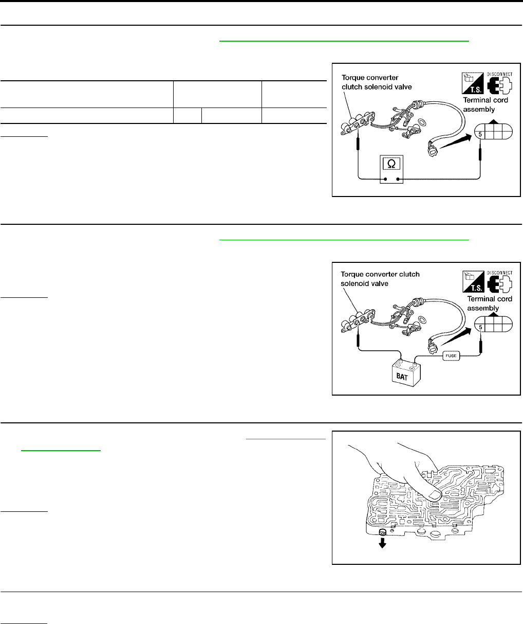
AT-160
[RE4F04B]
DTC P0744 A/T TCC S/V FUNCTION (LOCK-UP)
Revision: September 2005 2005 Quest
12. CHECK VALVE RESISTANCE
1. Remove control valve assembly. Refer to AT-253, "Control Valve Assembly and Accumulators" .
–Torque converter clutch solenoid valve
2. Check resistance to the terminal and ground.
OK or NG
OK >> GO TO 14.
NG >> Replace solenoid valve assembly.
13. CHECK VALVE OPERATION
1. Remove control valve assembly. Refer to AT-253, "Control Valve Assembly and Accumulators" .
–Torque converter clutch solenoid valve
2. Check solenoid valve by listening for its operating sound while
applying battery voltage to the terminal and ground.
OK or NG
OK >> GO TO 14.
NG >> Replace solenoid valve assembly.
14. CHECK CONTROL VALVE
1. Disassemble control valve assembly. Refer to AT-290, "Control
Valve Assembly" .
2. Check control valves for sticking.
–Torque converter clutch control valve
–Torque converter clutch relief valve
OK or NG
OK >> GO TO 15.
NG >> Repair control valve.
15. CHECK LOCK-UP
Does A/T perform lock-up at the specified speed?
Yes or No
Yes >> GO TO 16.
No >> Check control valve again. Repair or replace control valve assembly.
Solenoid valve Terminal Resistance
(Approx.)
Torque converter clutch solenoid valve 5 Ground 5 - 20Ω
WCIA0102E
WCIA0101E
SAT367H

DTC P0744 A/T TCC S/V FUNCTION (LOCK-UP)
AT-161
[RE4F04B]
D
E
F
G
H
I
J
K
L
M
A
B
AT
Revision: September 2005 2005 Quest
16. CHECK DTC
Perform AT-154, "Diagnostic Trouble Code (DTC) Confirmation Procedure" .
OK or NG
OK >> INSPECTION END
NG >> Perform “Cruise test — Part 1” again and return to the start point of this test group.
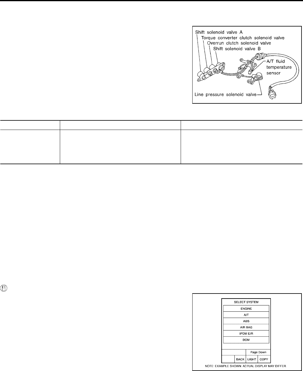
AT-162
[RE4F04B]
DTC P0745 LINE PRESSURE SOLENOID VALVE
Revision: September 2005 2005 Quest
DTC P0745 LINE PRESSURE SOLENOID VALVE PFP:31940
Description UCS000OU
The line pressure solenoid valve regulates the oil pump discharge
pressure to suit the driving condition in response to a signal sent
from the TCM.
The line pressure duty cycle value is not consistent when the
closed throttle position signal is “ON”. To confirm the line pres-
sure duty cycle at low pressure, the accelerator (throttle)
should be open until the closed throttle position switch is
“OFF”.
CONSULT-II REFERENCE VALUE IN DATA MONITOR MODE
Remarks: Specification data are reference values.
On Board Diagnosis Logic UCS000OV
Diagnostic trouble code “L/PRESS SOL/CIRC” with CONSULT-II or P0745 without CONSULT-II is detected
when TCM detects an improper voltage drop when it tries to operate the solenoid valve.
Possible Cause UCS000OW
Check the following items.
●Harness or connectors
(The solenoid circuit is open or shorted.)
●Line pressure solenoid valve
Diagnostic Trouble Code (DTC) Confirmation Procedure UCS000OX
NOTE:
If “DTC Confirmation Procedure” has been previously conducted, always turn ignition switch OFF and
wait at least 10 seconds before conducting the next test.
After the repair, perform the following procedure to confirm the malfunction is eliminated.
WITH CONSULT-II
1. Turn ignition switch ON and select “DATA MONITOR” mode for
“ENGINE” with CONSULT-II.
SAT283HB
Monitor item Condition Specification
LINE PRES DTY
Small throttle opening
(Low line pressure)
↓
Large throttle opening
(High line pressure)
Approximately 24%
↓
Approximately 95%
BCIA0030E

DTC P0745 LINE PRESSURE SOLENOID VALVE
AT-163
[RE4F04B]
D
E
F
G
H
I
J
K
L
M
A
B
AT
Revision: September 2005 2005 Quest
2. Depress accelerator pedal completely and wait at least 5 sec-
onds.
WITH GST
Follow the procedure “With CONSULT-II”.
BCIA0031E
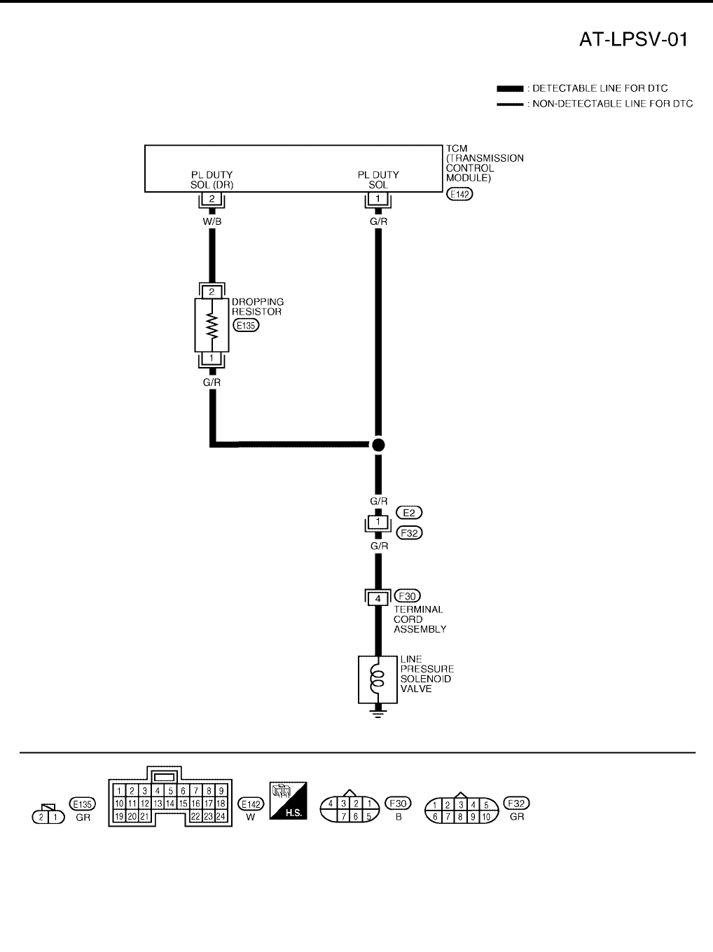
AT-164
[RE4F04B]
DTC P0745 LINE PRESSURE SOLENOID VALVE
Revision: September 2005 2005 Quest
Wiring Diagram — AT — LPSV UCS000OY
BCWA0180E
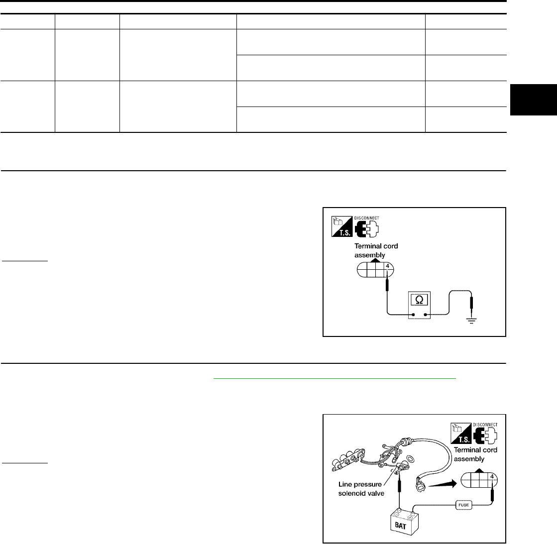
DTC P0745 LINE PRESSURE SOLENOID VALVE
AT-165
[RE4F04B]
D
E
F
G
H
I
J
K
L
M
A
B
AT
Revision: September 2005 2005 Quest
TCM TERMINALS AND REFERENCE VALUE (MEASURED BETWEEN EACH TERMINAL AND GROUND)
Diagnostic Procedure UCS000OZ
1. CHECK VALVE RESISTANCE
1. Turn ignition switch to OFF position.
2. Disconnect terminal cord assembly connector in engine compartment.
3. Check resistance between terminal cord assembly harness con-
nector F30 terminal 4 and ground.
OK or NG
OK >> GO TO 3.
NG >> GO TO 2.
2. CHECK VALVE OPERATION
1. Remove control valve assembly. Refer to AT-253, "Control Valve Assembly and Accumulators" .
2. Check the following items:
–Line pressure solenoid valve
• Check solenoid valve by listening for its operating sound while
applying battery voltage to the terminal and ground.
–Harness of terminal cord assembly for short or open
OK or NG
OK >> GO TO 3.
NG >> Repair or replace damaged parts.
TERMINAL WIRE COLOR ITEM CONDITION DATA (APPROX.)
1G/R
LINE PRESSURE SOLE-
NOID VALVE
WHEN ACCELERATOR PEDAL IS RELEASED
WHILE DRIVING 1.5 - 3.0V
WHEN ACCELERATOR PEDAL IS
DEPRESSED WHILE DRIVING 0V
2W/B
LINE PRESSURE SOLE-
NOID VALVE (DROPPING
RESISTOR)
WHEN ACCELERATOR PEDAL IS RELEASED
WHILE DRIVING 4 - 14V
WHEN ACCELERATOR PEDAL IS
DEPRESSED WHILE DRIVING 0V
Resistance : 2.5 - 5Ω
WCIA0103E
WCIA0099E

AT-166
[RE4F04B]
DTC P0745 LINE PRESSURE SOLENOID VALVE
Revision: September 2005 2005 Quest
3. CHECK POWER SOURCE AND DROPPING RESISTOR CIRCUIT
1. Turn ignition switch to OFF position.
2. Disconnect TCM harness connector.
3. Check resistance between terminal cord assembly harness con-
nector F30 terminal 4 (G/R) and TCM harness connector E142
terminal 2 (W/B).
OK or NG
OK >> GO TO 5.
NG >> GO TO 4.
4. DETECT MALFUNCTIONING ITEM
Check the following items:
●Dropping resistor
●Check resistance between two terminals.
●Harness for short or open between TCM harness connector
E142 terminal 2 (W/B) and terminal cord assembly F30 terminal
4 (G/R)
OK or NG
OK >> GO TO 5.
NG >> Repair or replace damaged parts.
5. CHECK POWER SOURCE CIRCUIT
1. Turn ignition switch to OFF position.
2. Check continuity between terminal cord assembly harness connector F30 terminal 4(G/R) and TCM har-
ness connector E142 terminal 1(G/R). Refer to AT-164, "Wiring Diagram — AT — LPSV" .
3. Reinstall any part removed.
OK or NG
OK >> GO TO 6.
NG >> Repair open circuit or short to ground or short to power in harness or connectors.
6. CHECK DTC
Perform AT-162, "Diagnostic Trouble Code (DTC) Confirmation Procedure" .
OK or NG
OK >> INSPECTION END
NG >> GO TO 7.
Resistance :12Ω (Approx.)
WCIA0105E
Resistance :12Ω (Approx.)
WCIA0040E
Continuity should exist.

DTC P0745 LINE PRESSURE SOLENOID VALVE
AT-167
[RE4F04B]
D
E
F
G
H
I
J
K
L
M
A
B
AT
Revision: September 2005 2005 Quest
7. CHECK TCM INSPECTION
1. Perform TCM input/output signal inspection. Refer to AT-96, "TCM Terminals and Reference Value" .
2. If NG, recheck TCM pin terminals for damage or loose connection with harness connector.
OK or NG
OK >> INSPECTION END
NG >> Repair or replace damaged parts.

AT-168
[RE4F04B]
DTC P0750 SHIFT SOLENOID VALVE A
Revision: September 2005 2005 Quest
DTC P0750 SHIFT SOLENOID VALVE A PFP:31940
Description UCS000P0
Shift solenoid valves A and B are turned ON or OFF by the TCM in
response to signals sent from the park/neutral position (PNP) switch,
vehicle speed and ECM (throttle opening). Gears will then be shifted
to the optimum position.
On Board Diagnosis Logic UCS000P1
Diagnostic trouble code “SFT SOL A/CIRC” with CONSULT-II or P0750 without CONSULT-II is detected when
TCM detects an improper voltage drop when it tries to operate the solenoid valve.
Possible Cause UCS000P2
Check the following items.
●Harness or connectors
(The solenoid circuit is open or shorted.)
●Shift solenoid valve A
Diagnostic Trouble Code (DTC) Confirmation Procedure UCS000P3
CAUTION:
Always drive vehicle at a safe speed.
NOTE:
If “DTC Confirmation Procedure” has been previously conducted, always turn ignition switch OFF and
wait at least 10 seconds before conducting the next test.
After the repair, perform the following procedure to confirm the malfunction is eliminated.
WITH CONSULT-II
1. Turn ignition switch ON and select “DATA MONITOR” mode for
“ENGINE” with CONSULT-II.
SAT283HB
Gear position 1 2 3 4
Shift solenoid valve A ON (Closed) OFF (Open) OFF (Open) ON (Closed)
Shift solenoid valve B ON (Closed) ON (Closed) OFF (Open) OFF (Open)
BCIA0030E
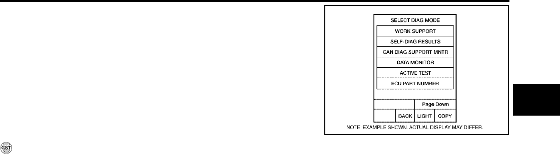
DTC P0750 SHIFT SOLENOID VALVE A
AT-169
[RE4F04B]
D
E
F
G
H
I
J
K
L
M
A
B
AT
Revision: September 2005 2005 Quest
2. Start engine.
3. Drive vehicle in D position and allow the transmission to shift 1
→ 2 (“GEAR”).
WITH GST
Follow the procedure “With CONSULT-II”.
BCIA0031E
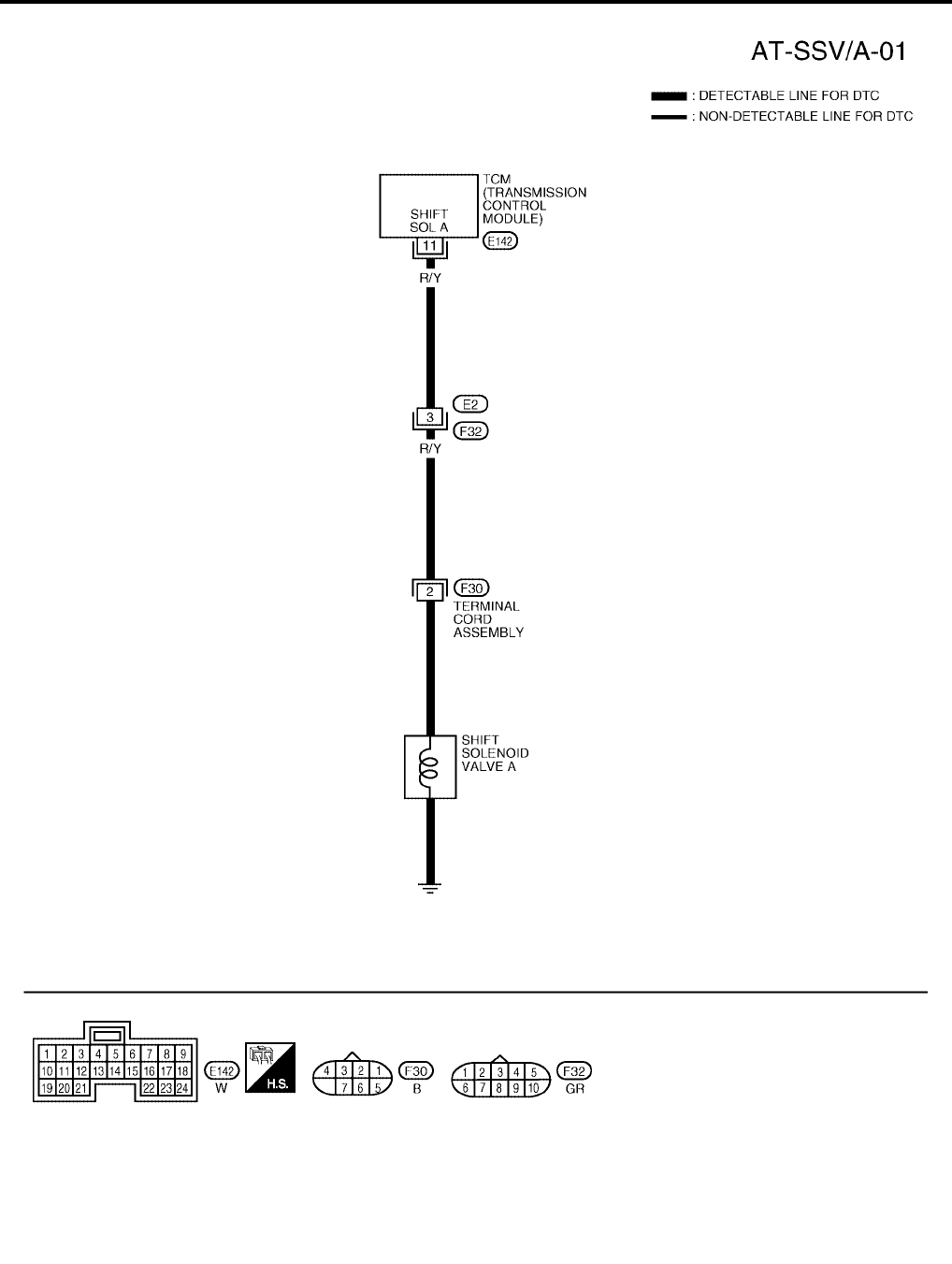
AT-170
[RE4F04B]
DTC P0750 SHIFT SOLENOID VALVE A
Revision: September 2005 2005 Quest
Wiring Diagram — AT — SSV/A UCS000P4
BCWA0302E

DTC P0750 SHIFT SOLENOID VALVE A
AT-171
[RE4F04B]
D
E
F
G
H
I
J
K
L
M
A
B
AT
Revision: September 2005 2005 Quest
TCM TERMINALS AND REFERENCE VALUE (MEASURED BETWEEN EACH TERMINAL AND GROUND)
Diagnostic Procedure UCS000P5
1. CHECK VALVE RESISTANCE
1. Turn ignition switch to OFF position.
2. Disconnect terminal cord assembly connector in engine compartment.
3. Check resistance between terminal cord assembly harness con-
nector F30 terminal 2 and ground.
OK or NG
OK >> GO TO 3.
NG >> GO TO 2.
2. CHECK VALVE OPERATION
1. Remove control valve assembly. Refer to AT-253, "Control Valve Assembly and Accumulators" .
2. Check the following items:
–Shift solenoid valve A
–Operation check
• Check solenoid valve by listening for its operating sound while
applying battery voltage to the terminal and ground.
–Harness of terminal cord assembly for short or open
OK or NG
OK >> GO TO 3.
NG >> Repair or replace damaged parts.
3. CHECK POWER SOURCE CIRCUIT
1. Turn ignition switch to OFF position.
2. Disconnect TCM harness connector.
3. Check continuity between terminal cord assembly harness connector F30 terminal 2 (R/Y) and TCM har-
ness connector E142 terminal 11 (R/Y). Refer to AT-170, "Wiring Diagram — AT — SSV/A" .
4. Reinstall any part removed.
OK or NG
OK >> GO TO 4.
NG >> Repair open circuit or short to ground or short to power in harness or connectors.
TERMINAL WIRE COLOR ITEM CONDITION DATA (APPROX.)
11 R/Y SHIFT SOLENOID VALVE A
WHEN SHIFT SOLENOID VALVE A IS
OPERATING (DRIVING IN D1 OR D4 ) BATTERY VOLTAGE
WHEN SHIFT SOLENOID VALVE A IS
NOT OPERATING (DRIVING IN D2 OR D3
)
0V
Resistance : 20 - 30Ω
WCIA0106E
WCIA0094E
Continuity should exist.

AT-172
[RE4F04B]
DTC P0750 SHIFT SOLENOID VALVE A
Revision: September 2005 2005 Quest
4. CHECK DTC
Perform AT-168, "Diagnostic Trouble Code (DTC) Confirmation Procedure" .
OK or NG
OK >> INSPECTION END
NG >> GO TO 5.
5. CHECK TCM INSPECTION
1. Perform TCM input/output signal inspection. Refer to AT-96, "TCM Terminals and Reference Value" .
2. If NG, recheck TCM pin terminals for damage or loose connection with harness connector.
OK or NG
OK >> INSPECTION END
NG >> Repair or replace damaged parts.
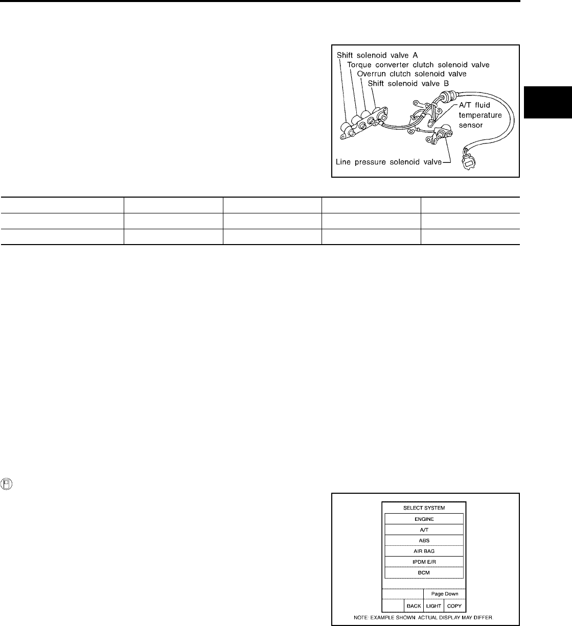
DTC P0755 SHIFT SOLENOID VALVE B
AT-173
[RE4F04B]
D
E
F
G
H
I
J
K
L
M
A
B
AT
Revision: September 2005 2005 Quest
DTC P0755 SHIFT SOLENOID VALVE B PFP:31940
Description UCS000P6
Shift solenoid valves A and B are turned ON or OFF by the TCM in
response to signals sent from the park/neutral position (PNP) switch,
vehicle speed and ECM (throttle opening). Gears will then be shifted
to the optimum position.
On Board Diagnosis Logic UCS000P7
Diagnostic trouble code “SFT SOL B/CIRC” with CONSULT-II or P0755 without CONSULT-II is detected when
TCM detects an improper voltage drop when it tries to operate the solenoid valve.
Possible Cause UCS000P8
Check the following items.
●Harness or connectors
(The solenoid circuit is open or shorted.)
●Shift solenoid valve B
Diagnostic Trouble Code (DTC) Confirmation Procedure UCS000P9
CAUTION:
Always drive vehicle at a safe speed.
NOTE:
If “DTC Confirmation Procedure” has been previously conducted, always turn ignition switch OFF and
wait at least 10 seconds before conducting the next test.
After the repair, perform the following procedure to confirm the malfunction is eliminated.
WITH CONSULT-II
1. Turn ignition switch ON and select “DATA MONITOR” mode for
“ENGINE” with CONSULT-II.
SAT283HB
Gear position 1 2 3 4
Shift solenoid valve A ON (Closed) OFF (Open) OFF (Open) ON (Closed)
Shift solenoid valve B ON (Closed) ON (Closed) OFF (Open) OFF (Open)
BCIA0030E
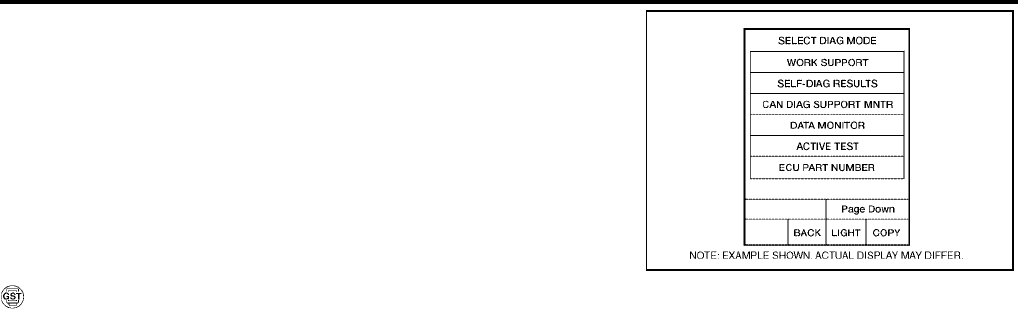
AT-174
[RE4F04B]
DTC P0755 SHIFT SOLENOID VALVE B
Revision: September 2005 2005 Quest
2. Start engine.
3. Drive vehicle in D position and allow the transmission to shift 1
→ 2 → 3 (“GEAR”).
WITH GST
Follow the procedure “With CONSULT-II”.
BCIA0031E
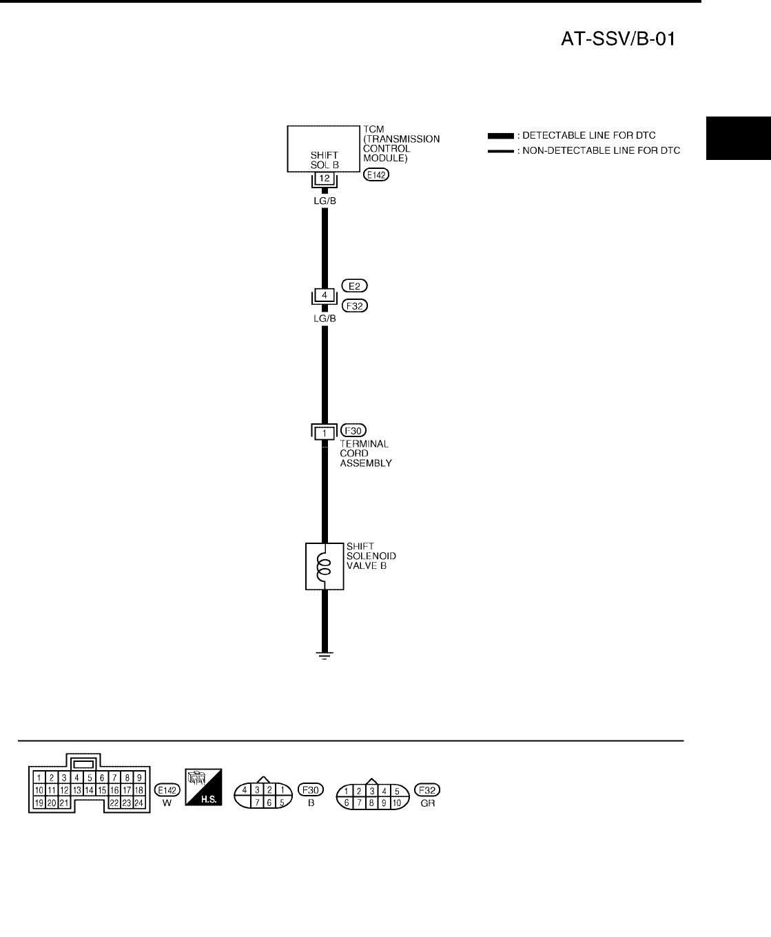
DTC P0755 SHIFT SOLENOID VALVE B
AT-175
[RE4F04B]
D
E
F
G
H
I
J
K
L
M
A
B
AT
Revision: September 2005 2005 Quest
Wiring Diagram — AT — SSV/B UCS000PA
BCWA0182E
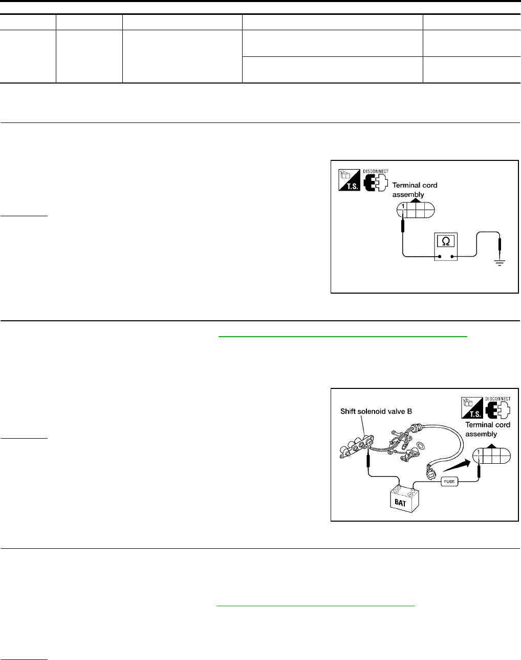
AT-176
[RE4F04B]
DTC P0755 SHIFT SOLENOID VALVE B
Revision: September 2005 2005 Quest
TCM TERMINALS AND REFERENCE VALUE (MEASURED BETWEEN EACH TERMINAL AND GROUND)
Diagnostic Procedure UCS000PB
1. CHECK VALVE RESISTANCE
1. Turn ignition switch to OFF position.
2. Disconnect terminal cord assembly connector in engine compartment.
3. Check resistance between terminal cord assembly harness con-
nector F30 terminal 1 and ground.
OK or NG
OK >> GO TO 3.
NG >> GO TO 2.
2. CHECK VALVE OPERATION
1. Remove control valve assembly. Refer to AT-253, "Control Valve Assembly and Accumulators" .
2. Check the following items:
–Shift solenoid valve B
–Operation check
• Check solenoid valve by listening for its operating sound while
applying battery voltage to the terminal and ground.
–Harness of terminal cord assembly for short or open
OK or NG
OK >> GO TO 3.
NG >> Repair or replace damaged parts.
3. CHECK POWER SOURCE CIRCUIT
1. Turn ignition switch to OFF position.
2. Disconnect TCM harness connector.
3. Check continuity between terminal cord harness connector F30 terminal 1(LG/B) and TCM harness con-
nector E142 terminal 12 (LG/B). Refer to AT-175, "Wiring Diagram — AT — SSV/B" .
4. Reinstall any part removed.
OK or NG
OK >> GO TO 4.
NG >> Repair open circuit or short to ground or short to power in harness or connectors.
TERMINAL WIRE COLOR ITEM CONDITION DATA (APPROX.)
12 LG/B SHIFT SOLENOID VALVE B
WHEN SHIFT SOLENOID VALVE B IS
OPERATING (DRIVING IN D1 OR D2 ) BATTERY VOLTAGE
WHEN SHIFT SOLENOID VALVE BE IS
NOT OPERATING (DRIVING IN D3 OR D4 ) 0V
Resistance : 5 - 20Ω
WCIA0107E
WCIA0092E
Continuity should exist.

DTC P0755 SHIFT SOLENOID VALVE B
AT-177
[RE4F04B]
D
E
F
G
H
I
J
K
L
M
A
B
AT
Revision: September 2005 2005 Quest
4. CHECK DTC
Perform AT-173, "Diagnostic Trouble Code (DTC) Confirmation Procedure" .
OK or NG
OK >> INSPECTION END
NG >> GO TO 5.
5. CHECK TCM INSPECTION
1. Perform TCM input/output signal inspection. Refer to AT-96, "TCM Terminals and Reference Value" .
2. If NG, recheck TCM pin terminals for damage or loose connection with harness connector.
OK or NG
OK >> INSPECTION END
NG >> Repair or replace damaged parts.
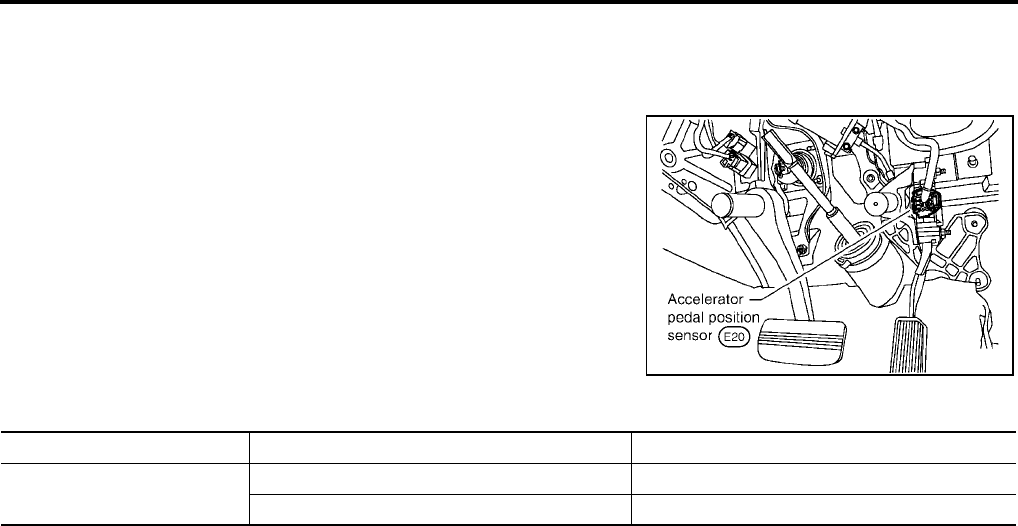
AT-178
[RE4F04B]
DTC P1705 THROTTLE POSITION SENSOR [ACCELERATOR PEDAL POSI-
TION (APP) SENSOR]
Revision: September 2005 2005 Quest
DTC P1705 THROTTLE POSITION SENSOR [ACCELERATOR PEDAL POSITION
(APP) SENSOR] PFP:22560
Description UCS000PC
The accelerator pedal position (APP) sensor is part of the system
that controls throttle position. This system also uses an electric throt-
tle control actuator, which consists of a throttle control motor and
throttle position sensors. Accelerator pedal position signal is sent to
the ECM.
CONSULT-II REFERENCE VALUE IN DATA MONITOR MODE
Remarks: Specification data are reference values.
SCIA3551E
Monitor item Condition Specification
THRTL POS SEN Fully-closed throttle Approximately 0.5V
Fully-open throttle Approximately 4V
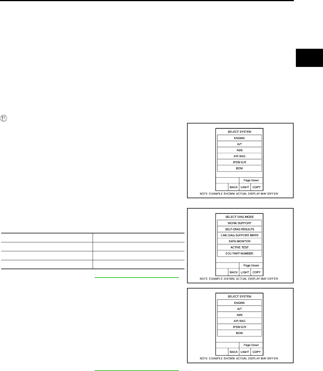
DTC P1705 THROTTLE POSITION SENSOR [ACCELERATOR PEDAL POSI-
TION (APP) SENSOR]
AT-179
[RE4F04B]
D
E
F
G
H
I
J
K
L
M
A
B
AT
Revision: September 2005 2005 Quest
On Board Diagnosis Logic UCS000PD
Diagnostic trouble code TP SEN/CIRC A/T with CONSULT-II or P1705 without CONSULT-II is detected when
TCM receives an excessively low or high voltage from the ECM.
Possible Cause UCS000PE
Harness or connectors
(The sensor circuit is open or shorted.)
Diagnostic Trouble Code (DTC) Confirmation Procedure UCS000PF
CAUTION:
Always drive vehicle at a safe speed.
NOTE:
If “DTC Confirmation Procedure” has been previously conducted, always turn ignition switch OFF and
wait at least 10 seconds before conducting the next test.
After the repair, perform the following procedure to confirm the malfunction is eliminated.
WITH CONSULT-II
1. Turn ignition switch ON and select “DATA MONITOR” mode for
“A/T” with CONSULT-II.
2. Touch "SELECTION FROM MENU".
3. Touch "THRTL POS SEN".
Touch "START"
If the check result is NG, go to AT-182, "Diagnostic Procedure" .
If the check result is OK, go to following step.
4. Turn ignition switch ON and select “DATA MONITOR” mode for
“ENGINE” with CONSULT-II.
5. Touch "SELECTION FROM MENU"
6. Touch "VHCL SPEED SE" and "THRTL SEN 1".
Touch "START".
7. Start engine and maintain the following conditions for at least 3
consecutive seconds. Then release accelerator pedal com-
pletely.
VHCL SPEED SE: 10 km/h (6 MPH) or more
THRTL POS 1: Approximately 3V or less
Selector lever: D position
If the check result is NG, go to AT-182, "Diagnostic Procedure" .
If the check result is OK, go to following step.
BCIA0030E
Accelerator pedal condition THRTL POS SEN
Fully released Approx. 0.5V
Partially depressed 0.5 - 4V
Fully depressed Approx. 4V
BCIA0031E
BCIA0030E

AT-180
[RE4F04B]
DTC P1705 THROTTLE POSITION SENSOR [ACCELERATOR PEDAL POSI-
TION (APP) SENSOR]
Revision: September 2005 2005 Quest
8. Maintain the following conditions for at least 3 consecutive sec-
onds. Then release accelerator pedal completely.
VHCL SPEED SE: 10 km/h (6 MPH) or more
Accelerator pedal: Wide open throttle
Selector lever: D position
WITH GST
Follow the procedure “With CONSULT-II”.
BCIA0031E

DTC P1705 THROTTLE POSITION SENSOR [ACCELERATOR PEDAL POSI-
TION (APP) SENSOR]
AT-181
[RE4F04B]
D
E
F
G
H
I
J
K
L
M
A
B
AT
Revision: September 2005 2005 Quest
Wiring Diagram — AT — TPS UCS000PG
BCWA0183E
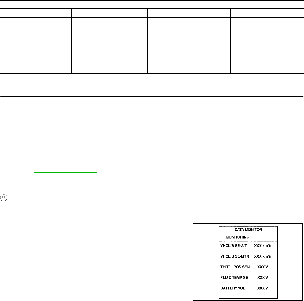
AT-182
[RE4F04B]
DTC P1705 THROTTLE POSITION SENSOR [ACCELERATOR PEDAL POSI-
TION (APP) SENSOR]
Revision: September 2005 2005 Quest
TCM TERMINALS AND REFERENCE VALUE (MEASURED BETWEEN EACH TERMINAL AND GROUND)
Diagnostic Procedure UCS000PH
1. CHECK DTC WITH ECM
●Check P code with CONSULT-II “ENGINE”.
Turn ignition switch ON and select “SELF DIAGNOSTIC RESULTS” mode for “ENGINE” with CONSULT-
II.
Refer to EC-67, "Malfunction Indicator Lamp (MIL)" .
OK or NG
OK (with CONSULT-II)>> GO TO 2.
OK (without CONSULT-II)>> GO TO 3.
NG >> Check accelerator pedal position (APP) sensor circuit for engine control. Refer to EC-655, "DTC
P2122, P2123 APP SENSOR" , EC-662, "DTC P2127, P2128 APP SENSOR" , EC-678, "DTC
P2138 APP SENSOR" .
2. CHECK INPUT SIGNAL (WITH CONSULT-II)
With CONSULT-II
1. Turn ignition switch to ON position. (Do not start engine.)
2. Select “DATA MONITOR” mode for “A/T” with CONSULT-II.
3. Read out the value of “THRTL POS SEN”.
OK or NG
OK >> GO TO 4.
NG >> Check harness for short or open between ECM and
TCM regarding accelerator pedal position signal circuit.
TERMINAL WIRE COLOR ITEM CONDITION DATA (APPROX.)
32 G/O SENSOR POWER IGNITION SWITCH ON 4.5 -5.5V
IGNITION SWITCH OFF 0V
41 W ACCELERATOR PEDAL POSI-
TION (APP) SENSOR
IGNITION ON AND ACCELERA-
TOR PEDAL IS DEPRESSED
SLOWLY AFTER WARMING UP
ENGINE
FULLY CLOSED THROTTLE:
0.5V
FULLY OPEN THROTTLE:
4V
42 B SENSOR GROUND Always 0V
Voltage:
Fully-closed throttle :Approximately 0.5V
Fully-open throttle :Approximately 4V
LCIA0090E
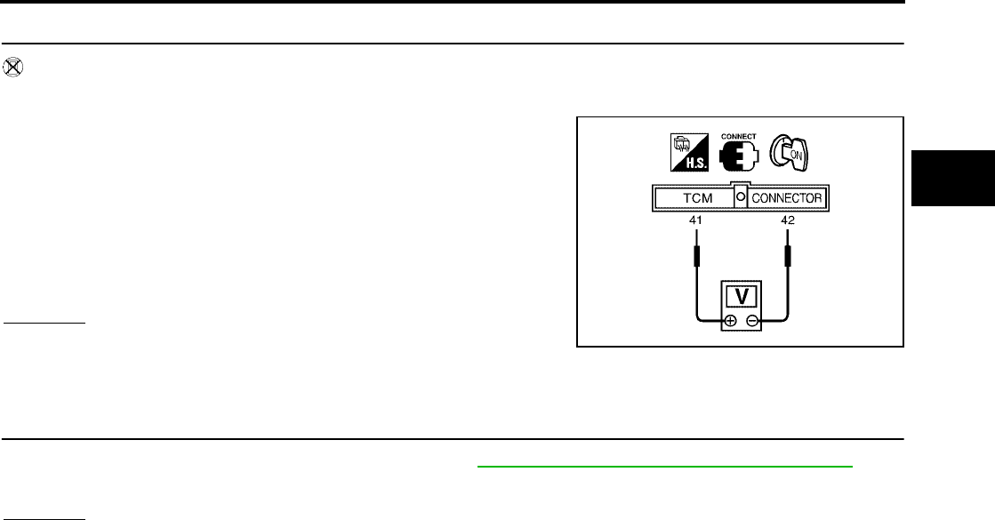
DTC P1705 THROTTLE POSITION SENSOR [ACCELERATOR PEDAL POSI-
TION (APP) SENSOR]
AT-183
[RE4F04B]
D
E
F
G
H
I
J
K
L
M
A
B
AT
Revision: September 2005 2005 Quest
3. CHECK INPUT SIGNAL (WITHOUT CONSULT-II)
Without CONSULT-II
1. Turn ignition switch to ON position. (Do not start engine.)
2. Check voltage between TCM harness connector E143 terminals
41 (W) and 42 (B) while accelerator pedal is depressed slowly.
OK or NG
OK >> GO TO 4.
NG >> Check harness for short or open between ECM and
TCM regarding accelerator pedal position signal circuit.
4. CHECK TCM INSPECTION
1. Perform TCM input/output signal inspection. Refer to AT-96, "TCM Terminals and Reference Value" .
2. If NG, recheck TCM pin terminals for damage or loose connection with harness connector.
OK or NG
OK >> INSPECTION END
NG >> Repair or replace damaged parts.
Voltage:
Fully-closed throttle valve : Approximately 0.5V
Fully-open throttle valve : Approximately 4V
(Voltage rises gradually in response to throttle posi-
tion.)
LCIA0100E

AT-184
[RE4F04B]
DTC P1760 OVERRUN CLUTCH SOLENOID VALVE
Revision: September 2005 2005 Quest
DTC P1760 OVERRUN CLUTCH SOLENOID VALVE PFP:31940
Description UCS000PI
The overrun clutch solenoid valve is activated by the TCM in
response to signals sent from the park/neutral position (PNP) switch,
overdrive control switch, vehicle speed and ECM (throttle opening).
The overrun clutch operation will then be controlled.
On Board Diagnosis Logic UCS000PJ
Diagnostic trouble code “O/R CLTCH SOL/CIRC” with CONSULT-II or P1760 without CONSULT-II is detected
when TCM detects an improper voltage drop when it tries to operate the solenoid valve.
Possible Cause UCS000PK
Check the following items.
●Harness or connectors
(The solenoid circuit is open or shorted.)
●Overrun clutch solenoid valve
Diagnostic Trouble Code (DTC) Confirmation Procedure UCS000PL
CAUTION:
Always drive vehicle at a safe speed.
NOTE:
If “DTC Confirmation Procedure” has been previously conducted, always turn ignition switch OFF and
wait at least 10 seconds before conducting the next test.
TESTING CONDITION:
Always drive vehicle on a level road to improve accuracy of test.
After the repair, perform the following procedure to confirm the malfunction is eliminated.
WITH CONSULT-II
1. Turn ignition switch ON and select “DATA MONITOR” mode for
“A/T” with CONSULT-II.
2. Start engine.
3. Accelerate vehicle to a speed of more than 10 km/h (6 MPH)
with selector lever in D position.
SAT283HB
BCIA0030E

DTC P1760 OVERRUN CLUTCH SOLENOID VALVE
AT-185
[RE4F04B]
D
E
F
G
H
I
J
K
L
M
A
B
AT
Revision: September 2005 2005 Quest
4. Release accelerator pedal completely with selector lever in 3
position.
WITH GST
Follow the procedure “With CONSULT-II”.
BCIA0031E
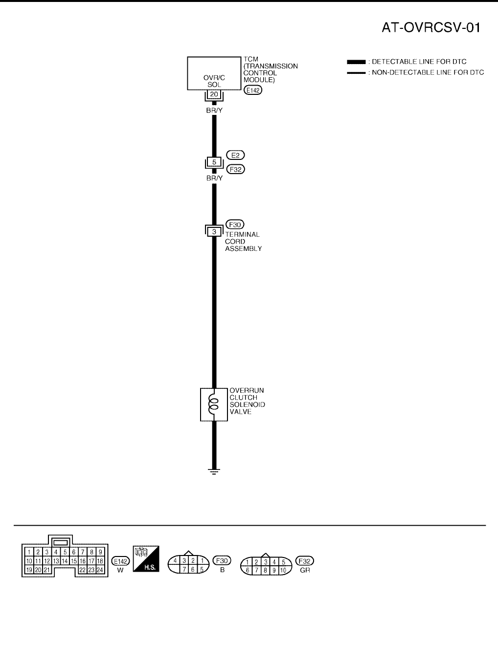
AT-186
[RE4F04B]
DTC P1760 OVERRUN CLUTCH SOLENOID VALVE
Revision: September 2005 2005 Quest
Wiring Diagram — AT — OVRCSV UCS000PM
BCWA0184E
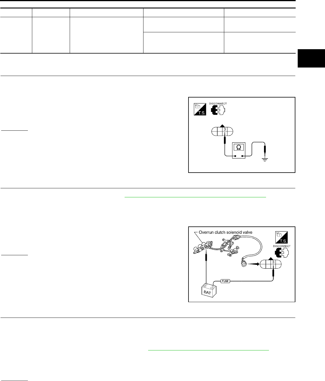
DTC P1760 OVERRUN CLUTCH SOLENOID VALVE
AT-187
[RE4F04B]
D
E
F
G
H
I
J
K
L
M
A
B
AT
Revision: September 2005 2005 Quest
TCM TERMINALS AND REFERENCE VALUE (MEASURED BETWEEN EACH TERMINAL AND GROUND)
Diagnostic Procedure UCS000PN
1. CHECK VALVE RESISTANCE
1. Turn ignition switch to OFF position.
2. Disconnect terminal cord assembly connector in engine compartment.
3. Check resistance between terminal cord assembly F30 terminal
3 and ground.
OK or NG
OK >> GO TO 3.
NG >> GO TO 2.
2. CHECK VALVE OPERATION
1. Remove control valve assembly. Refer to AT-253, "Control Valve Assembly and Accumulators" .
2. Check the following items:
–Overrun clutch solenoid valve
–Operation check
• Check solenoid valve by listening for its operating sound while
applying battery voltage to the terminal and ground.
–Harness of terminal cord assembly for short or open
OK or NG
OK >> GO TO 3.
NG >> Repair or replace damaged parts.
3. CHECK POWER SOURCE CIRCUIT
1. Turn ignition switch to OFF position.
2. Disconnect TCM harness connector.
3. Check continuity between terminal cord assembly harness connector F30 terminal 3 (BR/Y) and TCM har-
ness connector E142 terminal 20 (BR/Y). Refer to AT-186, "Wiring Diagram — AT — OVRCSV" .
4. Reinstall any part removed.
OK or NG
OK >> GO TO 4.
NG >> Repair open circuit or short to ground or short to power in harness or connectors.
TERMINAL WIRE COLOR ITEM CONDITION DATA (APPROX.)
20 BR/Y OVERRUN CLUTCH SOLE-
NOID VALVE
WHEN OVERRUN CLUTCH
SOLENOID VALVE OPERATES BATTERY VOLTAGE
WHEN OVERRUN CLUTCH
SOLENOID VALVE DOES NOT
OPERATE
0V
Resistance : 20 - 30Ω
LCIA0092E
LCIA0093E
Continuity should exist.

AT-188
[RE4F04B]
DTC P1760 OVERRUN CLUTCH SOLENOID VALVE
Revision: September 2005 2005 Quest
4. CHECK DTC
Perform AT-184, "Diagnostic Trouble Code (DTC) Confirmation Procedure" .
OK or NG
OK >> INSPECTION END
NG >> GO TO 5.
5. CHECK TCM INSPECTION
1. Perform TCM input/output signal inspection. Refer to AT-96, "TCM Terminals and Reference Value" .
2. If NG, recheck TCM pin terminals for damage or loose connection with harness connector.
OK or NG
OK >> INSPECTION END
NG >> Repair or replace damaged parts.

DTC BATT/FLUID TEMP SEN (A/T FLUID TEMP SENSOR CIRCUIT AND TCM
POWER SOURCE)
AT-189
[RE4F04B]
D
E
F
G
H
I
J
K
L
M
A
B
AT
Revision: September 2005 2005 Quest
DTC BATT/FLUID TEMP SEN (A/T FLUID TEMP SENSOR CIRCUIT AND TCM
POWER SOURCE) PFP:31940
Description UCS000PU
The A/T fluid temperature sensor detects the A/T fluid temperature
and sends a signal to the TCM.
CONSULT-II REFERENCE VALUE IN DATA MONITOR MODE
Remarks: Specification data are reference values.
On Board Diagnosis Logic UCS000PV
Diagnostic trouble code “BATT/FLUID TEMP SEN” with CONSULT-II or 8th judgement flicker without CON-
SULT-II is detected when TCM receives an excessively low or high voltage from the sensor.
Possible Cause UCS000PW
Check the following items.
●Harness or connectors
(The sensor circuit is open or shorted.)
●A/T fluid temperature sensor
Diagnostic Trouble Code (DTC) Confirmation Procedure UCS000PX
After the repair, perform the following procedure to confirm the malfunction is eliminated.
WITH CONSULT-II
1. Start engine.
SAT283HB
SAT021J
Monitor item Condition Specification (Approximately)
FLUID TEMP SE [V]
Cold [20°C (68°F)]
↓
Hot [80°C (176°F)]
1.5V
↓
0.5V
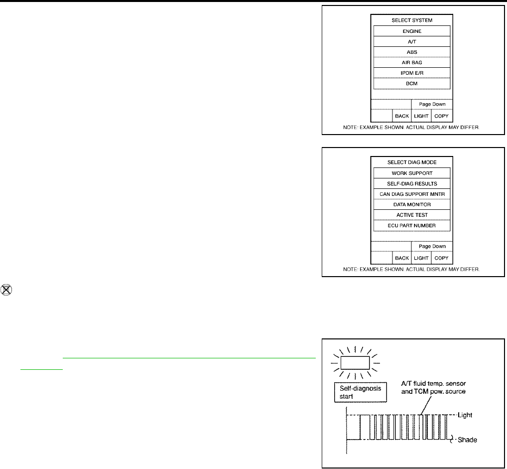
AT-190
[RE4F04B]
DTC BATT/FLUID TEMP SEN (A/T FLUID TEMP SENSOR CIRCUIT AND TCM
POWER SOURCE)
Revision: September 2005 2005 Quest
2. Select “DATA MONITOR” mode for “A/T” with CONSULT-II.
3. Drive vehicle under the following conditions:
Selector lever in D, vehicle speed higher than 20 km/h (12
MPH).
WITHOUT CONSULT-II
1. Start engine.
2. Drive vehicle under the following conditions:
Selector lever in D, vehicle speed higher than 20 km/h (12 MPH).
3. Perform self-diagnosis.
Refer to AT-54, "TCM SELF-DIAGNOSTIC PROCEDURE (NO
TOOLS)" .
BCIA0030E
BCIA0031E
SCIA3395E
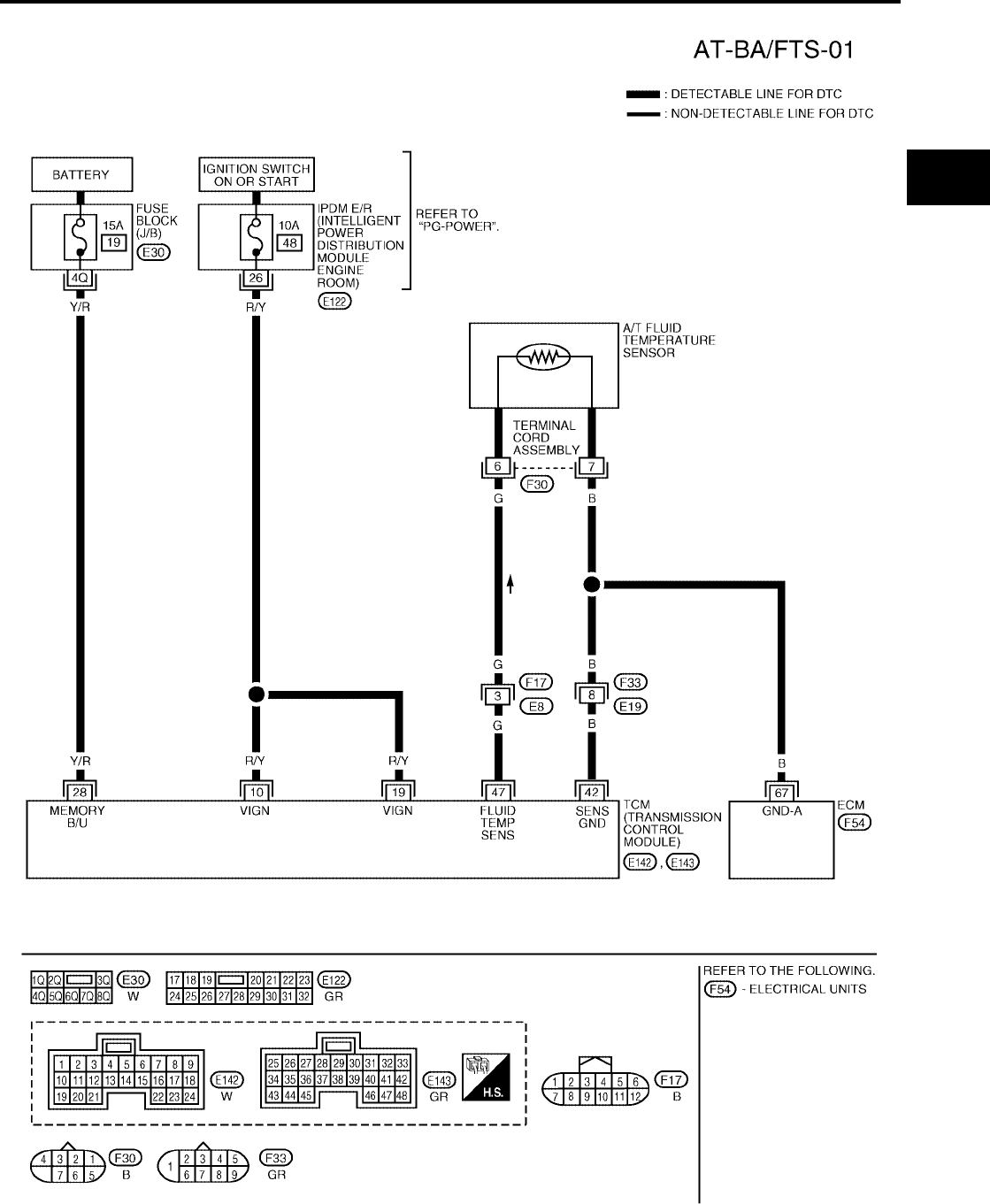
DTC BATT/FLUID TEMP SEN (A/T FLUID TEMP SENSOR CIRCUIT AND TCM
POWER SOURCE)
AT-191
[RE4F04B]
D
E
F
G
H
I
J
K
L
M
A
B
AT
Revision: September 2005 2005 Quest
Wiring Diagram — AT — BA/FTS UCS000PY
BCWA0303E
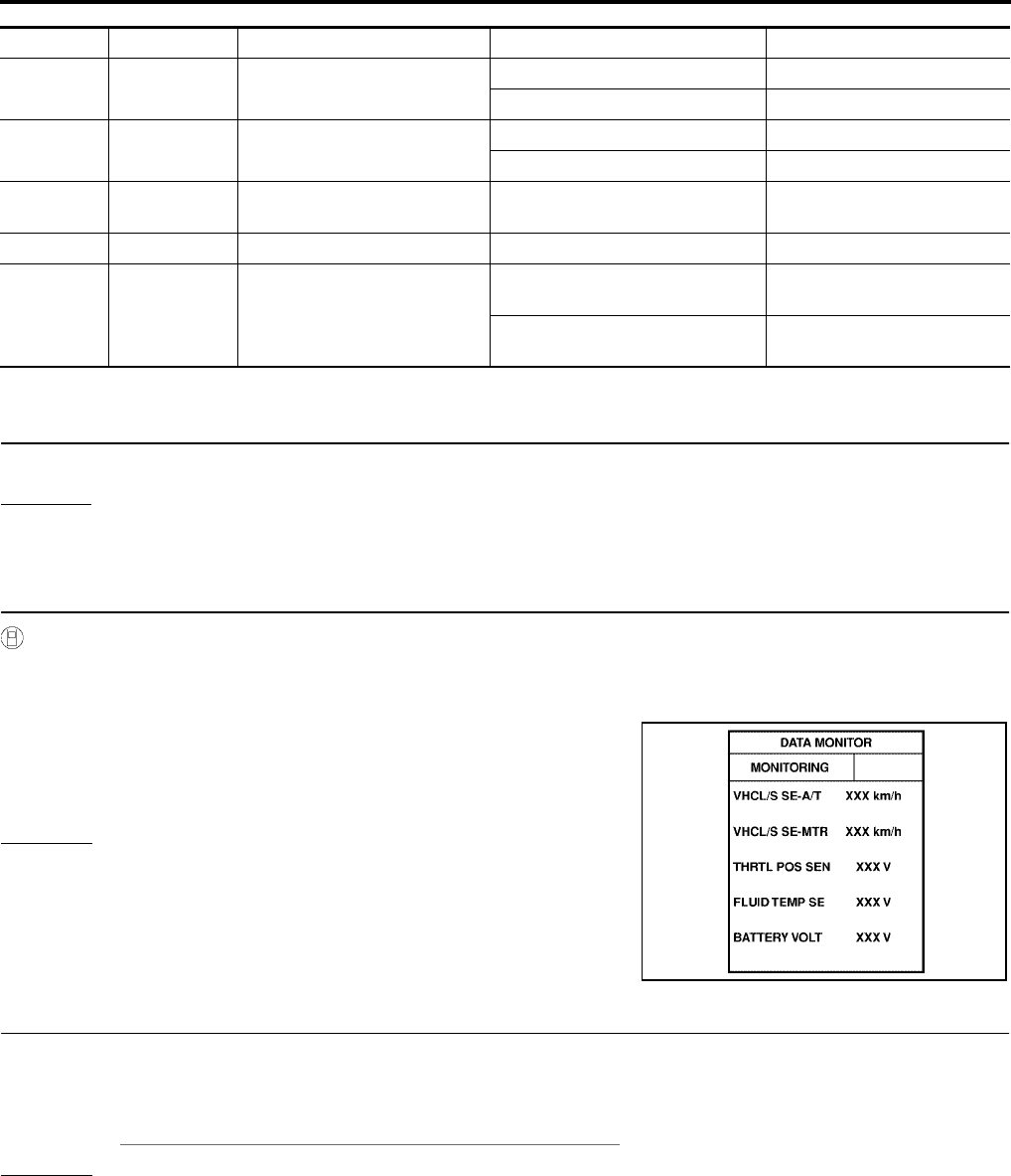
AT-192
[RE4F04B]
DTC BATT/FLUID TEMP SEN (A/T FLUID TEMP SENSOR CIRCUIT AND TCM
POWER SOURCE)
Revision: September 2005 2005 Quest
TCM TERMINALS AND REFERENCE VALUE (MEASURED BETWEEN EACH TERMINAL AND GROUND)
Diagnostic Procedure UCS000PZ
1. INSPECTION START
Do you have CONSULT-II?
Yes or No
Yes >> GO TO 2.
No >> GO TO 9.
2. CHECK INPUT SIGNAL OF A/T FLUID TEMPERATURE SENSOR (WITH CONSULT-II)
With CONSULT-II
1. Start engine.
2. Select “DATA MONITOR” mode for “A/T” with CONSULT-II.
3. Read out the value of “FLUID TEMP SE”.
OK or NG
OK >> GO TO 10.
NG >> GO TO 3.
3. DETECT MALFUNCTIONING ITEM
Check the following items:
●Harness for short or open between TCM, ECM and terminal cord assembly
●Ground circuit for ECM
Refer to EC-166, "POWER SUPPLY AND GROUND CIRCUIT" .
OK or NG
OK >> GO TO 4.
NG >> Repair or replace damaged parts.
TERMINAL WIRE COLOR ITEM CONDITION DATA (APPROX.)
10 R/Y POWER SOURCE IGNITION ON BATTERY VOLTAGE
IGNITION OFF 0V
19 R/Y POWER SOURCE IGNITION ON BATTERY VOLTAGE
IGNITION OFF 0V
28 Y/R POWER SOURCE
(MEMORY BACKUP) Always BATTERY VOLTAGE
42 B SENSOR GROUND Always 0V
47 G A/T FLUID TEMPERATURE
SENSOR
IGNITION ON WITH ATF TEM-
PERATURE AT 20°C (68°F) 1.5V
IGNITION ON WITH ATF TEM-
PERATURE AT 80°C (176°F) 0.5V
Voltage :Cold [20°C (68°F)] → Hot [80°C (176°F)]
:Approximately 1.5V → 0.5V
LCIA0090E
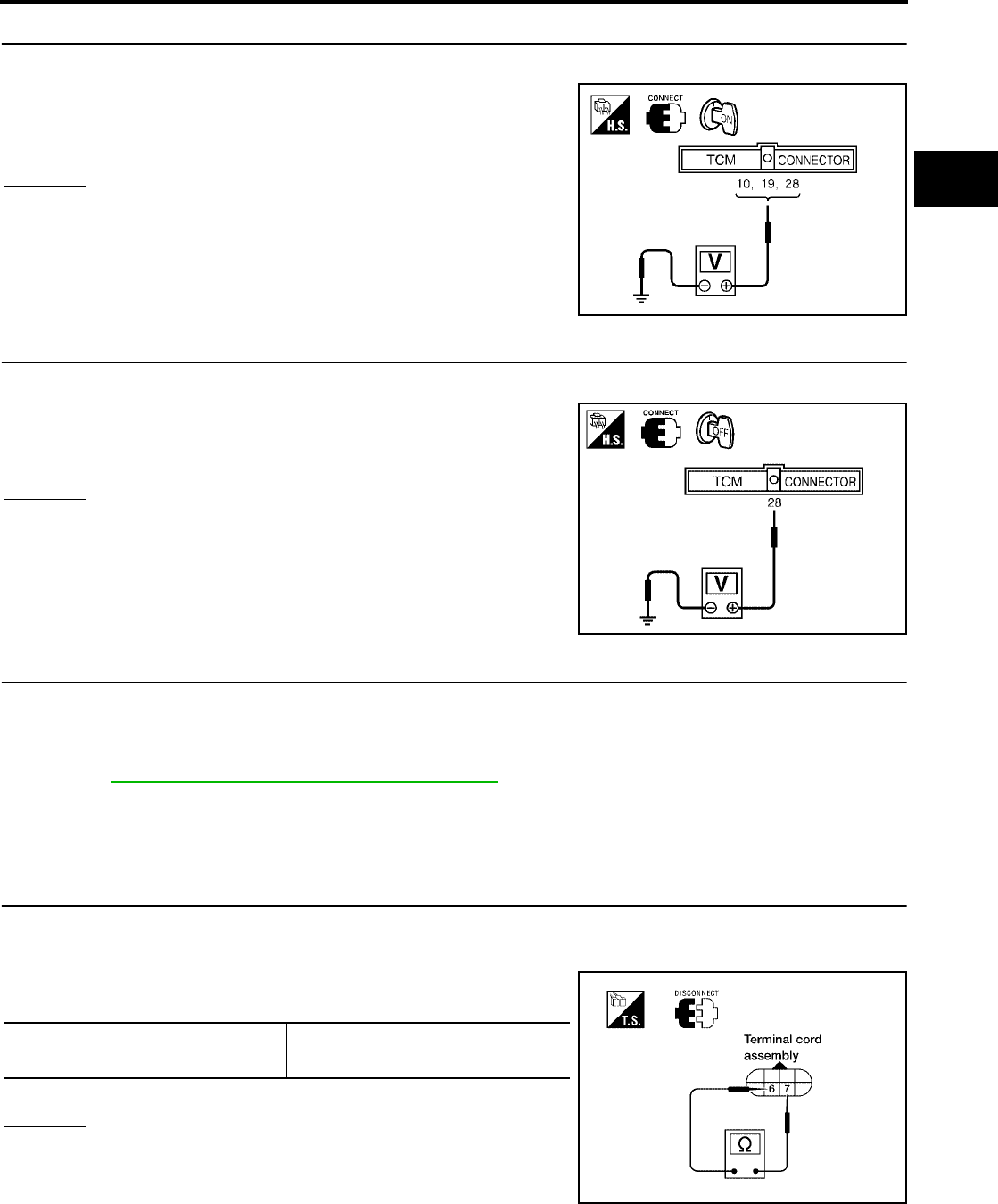
DTC BATT/FLUID TEMP SEN (A/T FLUID TEMP SENSOR CIRCUIT AND TCM
POWER SOURCE)
AT-193
[RE4F04B]
D
E
F
G
H
I
J
K
L
M
A
B
AT
Revision: September 2005 2005 Quest
4. CHECK TCM POWER SOURCE STEP 1
1. Turn ignition switch to ON position. (Do not start engine.)
2. Check voltage between TCM harness connectors E142, E143
terminals 10 (R/Y), 19 (R/Y), 28 (Y/R) and ground.
OK or NG
OK >> GO TO 5.
NG >> GO TO 6.
5. CHECK TCM POWER SOURCE STEP 2
1. Turn ignition switch to OFF position.
2. Check voltage between TCM harness connector E143 terminal
28 (Y/R) and ground.
OK or NG
OK >> GO TO 7.
NG >> GO TO 6.
6. DETECT MALFUNCTIONING ITEM
Check the following items:
●Harness for short or open between battery, ignition switch and TCM
●Ignition switch and fuse
Refer to PG-4, "POWER SUPPLY ROUTING CIRCUIT" .
OK or NG
OK >> GO TO 7.
NG >> Repair or replace damaged parts.
7. CHECK A/T FLUID TEMPERATURE SENSOR WITH TERMINAL CORD ASSEMBLY
1. Turn ignition switch to OFF position.
2. Disconnect terminal cord assembly connector in engine compartment.
3. Check resistance between terminal cord assembly F30 termi-
nals 6 and 7 when A/T is cold.
4. Reinstall any part removed.
OK or NG
OK >> GO TO 10.
NG >> GO TO 8.
Voltage : Battery voltage
LCIA0094E
Voltage : Battery voltage
WCIA0095E
Temperature Resistance (Approx.)
Cold [20°C (68°F)] 2.5kΩ
WCIA0097E
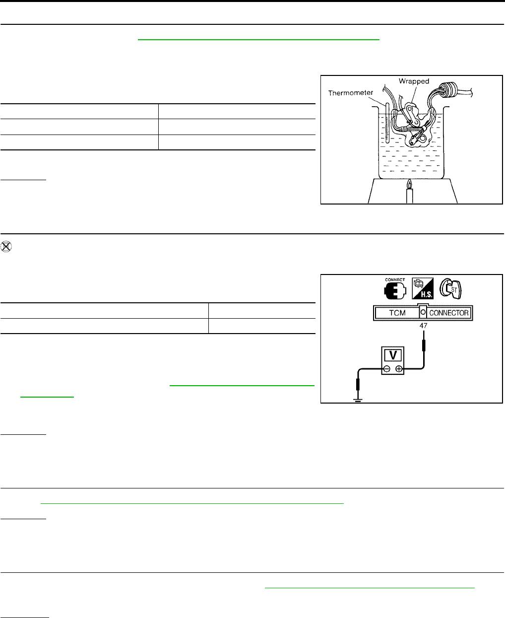
AT-194
[RE4F04B]
DTC BATT/FLUID TEMP SEN (A/T FLUID TEMP SENSOR CIRCUIT AND TCM
POWER SOURCE)
Revision: September 2005 2005 Quest
8. DETECT MALFUNCTIONING ITEM
1. Remove oil pan. Refer to AT-253, "Control Valve Assembly and Accumulators" .
2. Check the following items:
–A/T fluid temperature sensor
• Check resistance between two terminals while changing temper-
ature as shown at below.
–Harness of terminal cord assembly for short or open
OK or NG
OK >> GO TO 10.
NG >> Repair or replace damaged parts.
9. CHECK INPUT SIGNAL OF A/T FLUID TEMPERATURE SENSOR (WITHOUT CONSULT-II)
Without CONSULT-II
1. Start engine.
2. Check voltage between TCM harness connector E143 terminal
47(G) and ground while warming up A/T.
3. Turn ignition switch to OFF position.
4. Disconnect TCM harness connector.
5. Check resistance between TCM harness connector E143 termi-
nal 42 (B) and ground. Refer to AT-191, "Wiring Diagram — AT
— BA/FTS" .
OK or NG
OK >> GO TO 10.
NG >> GO TO 3.
10. CHECK DTC
Perform AT-189, "Diagnostic Trouble Code (DTC) Confirmation Procedure" .
OK or NG
OK >> INSPECTION END
NG >> GO TO 11.
11. CHECK TCM INSPECTION
1. Perform TCM input/output signal inspection. Refer to AT-96, "TCM Terminals and Reference Value" .
2. If NG, recheck TCM pin terminals for damage or loose connection with harness connector.
OK or NG
OK >> INSPECTION END
NG >> Repair or replace damaged parts.
Temperature °C (°F) Resistance (Approx.)
20 (68) 2.5kΩ
80 (176) 0.3kΩ
SAT298F
Temperature Voltage (Approx.)
Cold [20°C (68°F)] → Hot [80°C (176°F)] 1.5V → 0.5V
Continuity should exist.
WCIA0044E

DTC VEHICLE SPEED SENSOR MTR
AT-195
[RE4F04B]
D
E
F
G
H
I
J
K
L
M
A
B
AT
Revision: September 2005 2005 Quest
DTC VEHICLE SPEED SENSOR MTR PFP:24814
Description UCS000Q0
The vehicle speed sensor·MTR is built into the speedometer assembly. The sensor functions as an auxiliary
device to the revolution sensor when it is malfunctioning. The TCM will then use a signal sent from the vehicle
speed sensor·MTR.
On Board Diagnosis Logic UCS000Q1
Diagnostic trouble code “VHCL SPEED SEN·MTR” with CONSULT-II or 2nd judgement flicker without CON-
SULT-II is detected when TCM does not receive the proper voltage signal from the sensor.
Possible Cause UCS000Q2
Check the following items.
●Harness or connectors
(The sensor circuit is open or shorted.)
●Combination meter
●ABS actuator and electric unit (control unit)
Diagnostic Trouble Code (DTC) Confirmation Procedure UCS000Q3
CAUTION:
●Always drive vehicle at a safe speed.
●If conducting this “DTC Confirmation Procedure” again, always turn ignition switch OFF and wait
at least 10 seconds before continuing.
After the repair, perform the following procedure to confirm the malfunction is eliminated.
WITH CONSULT-II
1. Turn ignition switch ON and select “DATA MONITOR” mode for
“A/T” with CONSULT-II.
2. Start engine and accelerate vehicle from 0 to 25 km/h (0 to 16
MPH).
WITHOUT CONSULT-II
1. Start engine.
2. Drive vehicle under the following conditions:
Selector lever in D and vehicle speed higher than 25 km/h (16 MPH).
BCIA0030E
BCIA0031E
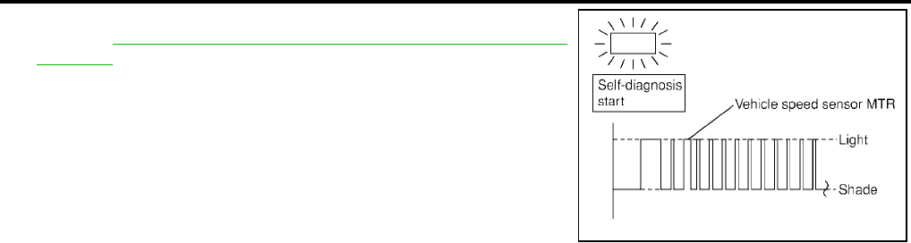
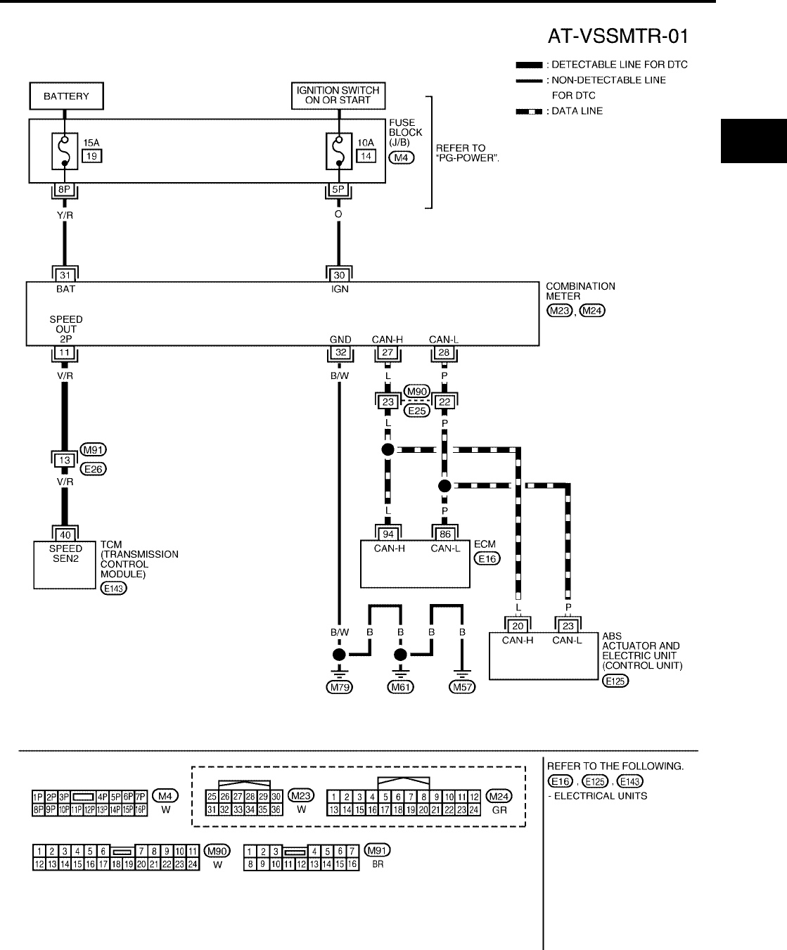
DTC VEHICLE SPEED SENSOR MTR
AT-197
[RE4F04B]
D
E
F
G
H
I
J
K
L
M
A
B
AT
Revision: September 2005 2005 Quest
Wiring Diagram — AT — VSSMTR UCS000Q4
BCWA0522E
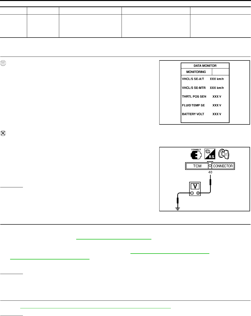
AT-198
[RE4F04B]
DTC VEHICLE SPEED SENSOR MTR
Revision: September 2005 2005 Quest
TCM TERMINALS AND REFERENCE VALUE (MEASURED BETWEEN EACH TERMINAL AND GROUND)
Diagnostic Procedure UCS000Q5
1. CHECK INPUT SIGNAL
With CONSULT-II
1. Start engine.
2. Select “DATA MONITOR” mode for “A/T” with CONSULT-II.
3. Read out the value of “VHCL/S SE-MTR” while driving.
Check the value changes according to driving speed.
Without CONSULT-II
1. Start engine.
2. Check voltage between TCM harness connector E143 terminal
40 (V/R) and ground while driving at 2 to 3 km/h (1 to 2 MPH) for
1 m (3 ft) or more.
OK or NG
OK >> GO TO 3.
NG >> GO TO 2.
2. DETECT MALFUNCTIONING ITEM
Check the following items:
●Combination meter. Refer to DI-5, "COMBINATION METERS" .
●Harness for short or open between TCM and combination meter.
●ABS actuator and electric unit (control unit). Refer to BRC-11, "TROUBLE DIAGNOSIS" (without VDC) or
BRC-55, "TROUBLE DIAGNOSIS" (with VDC).
●Harness for short or open between combination meter and ABS actuator and electric unit (control unit).
OK or NG
OK >> GO TO 3.
NG >> Repair or replace damaged parts.
3. CHECK DTC
Perform AT-195, "Diagnostic Trouble Code (DTC) Confirmation Procedure" .
OK or NG
OK >> INSPECTION END
NG >> GO TO 4.
TERMINAL WIRE COLOR ITEM CONDITION DATA (APPROX.)
40 V/R VEHICLE SPEED SIGNAL
WHEN MOVING VEHICLE AT 2
TO 3 KM/H (1 TO 2 MPH) FOR 1
M (3 FT) OR MORE.
INTERMITTENTLY
CHANGES BETWEEN
APPROX. 0V AND APPROX.
4.5V
LCIA0090E
Voltage : Intermittently changes between approx. 0V
and approx. 4.5V
SCIA3120E

DTC VEHICLE SPEED SENSOR MTR
AT-199
[RE4F04B]
D
E
F
G
H
I
J
K
L
M
A
B
AT
Revision: September 2005 2005 Quest
4. CHECK TCM INSPECTION
1. Perform TCM input/output signal inspection. Refer to AT-96, "TCM Terminals and Reference Value" .
2. If NG, recheck TCM pin terminals for damage or loose connection with harness connector.
OK or NG
OK >> INSPECTION END
NG >> Repair or replace damaged parts.

AT-200
[RE4F04B]
DTC TURBINE REVOLUTION SENSOR
Revision: September 2005 2005 Quest
DTC TURBINE REVOLUTION SENSOR PFP:31935
Description UCS000Q6
The turbine revolution sensor (power train revolution sensor) detects
forward clutch drum rpm (revolutions per minute). It is located on the
input side of the automatic transaxle. The vehicle speed sensor A/T
(Revolution sensor) is located on the output side of the automatic
transaxle. With the two sensors, input and output rpms are accu-
rately detected. The result is optimal shift timing during deceleration
and improved shifting.
On Board Diagnosis Logic UCS0015R
Diagnostic trouble code “TURBINE REV” with CONSULT-II or 10th judgement flicker without CONSULT-II is
detected when TCM does not receive the proper voltage signal from the sensor.
Possible Cause UCS0015S
Check the following items.
●Harness or connectors
(The sensor circuit is open or shorted.)
●Turbine revolution sensor (power train revolution sensor)
Diagnostic Trouble Code (DTC) Confirmation Procedure UCS0015T
CAUTION:
●Always drive vehicle at a safe speed.
●If conducting this “DTC CONFIRMATION PROCEDURE” again, always turn ignition switch “OFF”
and wait at least 5 seconds before continuing.
After the repair, perform the following procedure to confirm the malfunction is eliminated.
WITH CONSULT-II
1. Start engine.
2. Select “DATA MONITOR” mode for “A/T” with CONSULT-II.
3. Drive vehicle under the following conditions:
Selector lever in D, vehicle speed higher than 40 km/h (25
MPH), engine speed higher than 1,500 rpm, throttle opening
greater than 1.0/8 of the full throttle position and driving for more
than 5 seconds.
SCIA3402E
BCIA0030E
BCIA0031E
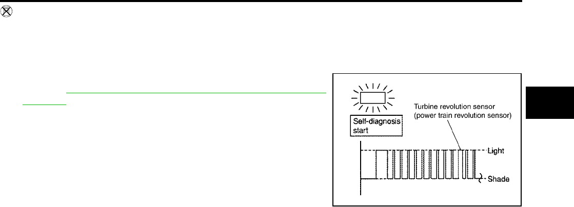
DTC TURBINE REVOLUTION SENSOR
AT-201
[RE4F04B]
D
E
F
G
H
I
J
K
L
M
A
B
AT
Revision: September 2005 2005 Quest
WITHOUT CONSULT-II
1. Start engine.
2. Drive vehicle under the following conditions:
Selector lever in “D” and vehicle speed higher than 40 km/h (25 MPH), engine speed higher than 1,500
rpm, throttle opening greater than 1.0/8 of the full throttle position and driving for more than 5 seconds.
3. Perform self-diagnosis.
Refer to AT-54, "TCM SELF-DIAGNOSTIC PROCEDURE (NO
TOOLS)" .
SCIA3397E
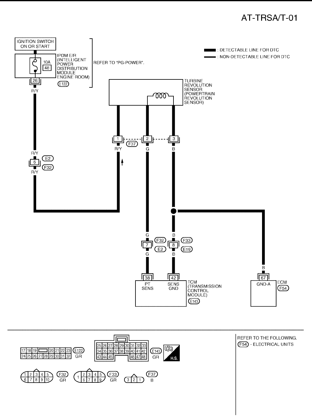
AT-202
[RE4F04B]
DTC TURBINE REVOLUTION SENSOR
Revision: September 2005 2005 Quest
Wiring Diagram — AT — TRSA/T UCS000Q7
BCWA0187E
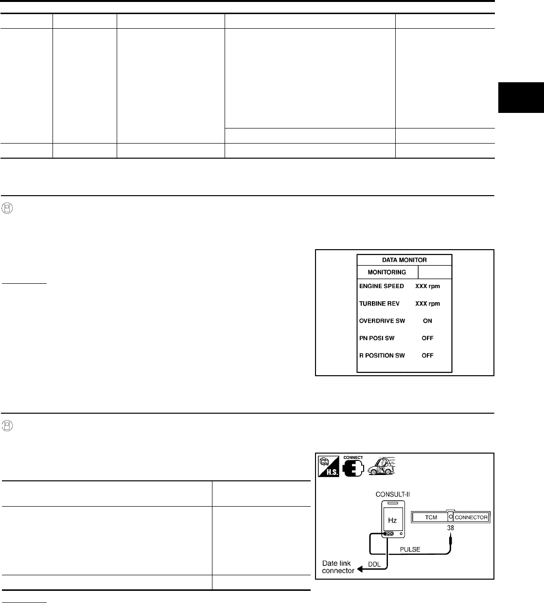
DTC TURBINE REVOLUTION SENSOR
AT-203
[RE4F04B]
D
E
F
G
H
I
J
K
L
M
A
B
AT
Revision: September 2005 2005 Quest
TCM TERMINALS AND REFERENCE VALUE (MEASURED BETWEEN EACH TERMINAL AND GROUND)
Diagnostic Procedure UCS000Q8
1. CHECK INPUT SIGNAL
With CONSULT-II
1. Start engine.
2. Select “DATA MONITOR” mode for “A/T” with CONSULT-II.
3. Read out the value of “TURBINE REV” while driving.
Check the value changes according to driving speed.
OK or NG
OK >> GO TO 5.
NG >> GO TO 2.
2. CHECK TURBINE REVOLUTION SENSOR (POWER TRAIN REVOLUTION SENSOR) (WITH CON-
SULT-II)
With CONSULT-II
1. Start engine.
2. Check pulse between TCM harness connector E143 terminal 38
(G) and ground.
OK or NG
OK >> GO TO 5.
NG >> GO TO 3.
TERMINAL WIRE COLOR ITEM CONDITION DATA (APPROX.)
38 G
TURBINE REVOLUTION
SENSOR (POWER TRAIN
REVOLUTION SENSOR)
WHEN MOVING AT 20 KM/H (12 MPH),
USE THE CONSULT-II PULSE FRE-
QUENCY MEASURING FUNCTION.*1
CAUTION:
CONNECT THE DIAGNOSIS DATA LINK
CABLE TO THE VEHICLE DIAGNOSIS
CONNECTOR.
*1: A CIRCUIT TESTER CANNOT BE USED
TO TEST THIS ITEM.
240 Hz
WHEN VEHICLE IS PARKED. Under 1.3V or over 4.5V
42 B SENSOR GROUND Always 0V
SAT740J
Condition Judgement standard
(Approx.)
When moving at 20 Km/h (12 MPH), use the CON-
SULT-II pulse frequency measuring function.*1
CAUTION:
Connect the diagnosis data link cable to the vehicle
diagnosis connector.
*1: A circuit tester cannot be used to test this item.
240 Hz
When vehicle parks. Under 1.3V or over 4.5V SCIA3403E
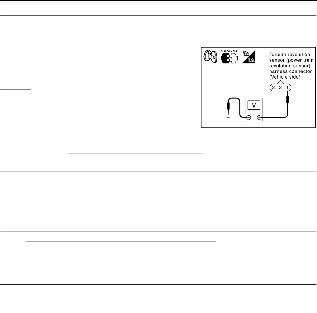
AT-204
[RE4F04B]
DTC TURBINE REVOLUTION SENSOR
Revision: September 2005 2005 Quest
3. CHECK POWER FOR TURBINE REVOLUTION SENSOR (POWER TRAIN REVOLUTION SENSOR)
1. Turn ignition switch to OFF position.
2. Disconnect the turbine revolution sensor (power train revolution sensor) harness connector.
3. Turn ignition switch to ON position. (Do not start engine.)
4. Check voltage between turbine revolution sensor (power train
revolution sensor) harness connector F37 terminal 1 (R/Y) and
ground.
OK or NG
OK >> GO TO 4.
NG >> Check the following items. If any items is damaged,
repair or replace damaged parts.
●Fuse
●Harness for short or open between ignition switch and
turbine revolution sensor (power train revolution sensor)
● Ignition switch
Refer to PG-4, "POWER SUPPLY ROUTING CIRCUIT" .
4. DETECT MALFUNCTIONING ITEM
Check harness for short or open between TCM, ECM and turbine revolution sensor (power train revolution
sensor).
OK or NG
OK >> Repair or replace turbine revolution sensor (power train revolution sensor).
NG >> Repair or replace damaged parts.
5. CHECK DTC
Perform AT-200, "Diagnostic Trouble Code (DTC) Confirmation Procedure" .
OK or NG
OK >> INSPECTION END.
NG >> GO TO 6.
6. CHECK TCM INSPECTION
1. Perform TCM input/output signal inspection. Refer to AT-96, "TCM Terminals and Reference Value" .
2. If NG, recheck TCM pin terminal for damage or loose connection with harness connector.
OK or NG
OK >> INSPECTION END.
NG >> Repair or replace damaged parts.
Voltage : Battery voltage
SCIA2771E

DTC CONTROL UNIT (RAM), CONTROL UNIT (ROM)
AT-205
[RE4F04B]
D
E
F
G
H
I
J
K
L
M
A
B
AT
Revision: September 2005 2005 Quest
DTC CONTROL UNIT (RAM), CONTROL UNIT (ROM) PFP:31036
Description UCS000QA
The TCM consists of a microcomputer and connectors for signal
input and output and for power supply. The unit controls the A/T.
On Board Diagnosis Logic UCS000QB
Diagnostic trouble code “CONTROL UNIT (RAM)”, “CONTROL UNIT (ROM)” with CONSULT-II is detected
when TCM memory (RAM) or (ROM).
Possible Cause UCS000QC
TCM.
Diagnostic Trouble Code (DTC) Confirmation Procedure UCS000QD
NOTE:
If “DTC Confirmation Procedure” has been previously conducted, always turn ignition switch OFF and
wait at least 10 seconds before conducting the next test.
WITH CONSULT-II
1. Turn ignition switch ON and select “DATA MONITOR” mode for
A/T with CONSULT-II.
2. Start engine.
3. Run engine for at least 2 seconds at idle speed.
SAT574J
BCIA0030E
BCIA0031E

AT-206
[RE4F04B]
DTC CONTROL UNIT (RAM), CONTROL UNIT (ROM)
Revision: September 2005 2005 Quest
Diagnostic Procedure UCS000QE
1. INSPECTION START
With CONSULT-II
1. Turn ignition switch ON and select “SELF DIAGNOSIS” mode for A/T with CONSULT-II.
2. Touch “ERASE”.
3. Perform AT-205, "Diagnostic Trouble Code (DTC) Confirmation Procedure" .
4. Is the “CONTROL UNIT (RAM)” or “CONTROL UNIT (ROM)” displayed again?
Yes or No
Yes >> Replace TCM.
No >> INSPECTION END
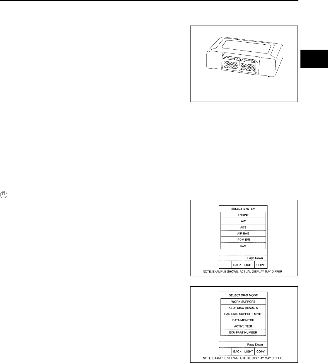
DTC CONTROL UNIT (EEP ROM)
AT-207
[RE4F04B]
D
E
F
G
H
I
J
K
L
M
A
B
AT
Revision: September 2005 2005 Quest
DTC CONTROL UNIT (EEP ROM) PFP:31036
Description UCS000QF
The TCM consists of a microcomputer and connectors for signal
input and output and for power supply. The unit controls the A/T.
On Board Diagnosis Logic UCS0015U
Diagnostic trouble code “CONTROL UNIT (EEP ROM)” with CONSULT-II is detected when TCM memory
(EEP ROM) is malfunctioning.
Possible Cause UCS0015V
TCM.
Diagnostic Trouble Code (DTC) Confirmation Procedure UCS0015W
NOTE:
If “DTC Confirmation Procedure” has been previously conducted, always turn ignition switch OFF and
wait at least 10 seconds before conducting the next test.
WITH CONSULT-II
1. Turn ignition switch “ON” and select “DATA MONITOR” mode for
A/T with CONSULT-II.
2. Start engine.
3. Run engine for at least 2 seconds at idle speed.
SAT574J
BCIA0030E
BCIA0031E

AT-208
[RE4F04B]
DTC CONTROL UNIT (EEP ROM)
Revision: September 2005 2005 Quest
Diagnostic Procedure UCS000QG
1. CHECK DTC
With CONSULT-II
1. Turn ignition switch “ON” and select “SELF DIAGNOSIS” mode for A/T with CONSULT-II.
2. Move selector lever to “R” position.
3. Depress accelerator pedal (Full throttle position).
4. Touch “ERASE”.
5. Turn ignition switch “OFF” position for 10 seconds.
6. Perform AT-207, "Diagnostic Trouble Code (DTC) Confirmation Procedure" .
Is the “CONT UNIT (EEP ROM)” displayed again?
Yes >> Replace TCM.
No >> INSPECTION END

TROUBLE DIAGNOSIS FOR SYMPTOMS
AT-209
[RE4F04B]
D
E
F
G
H
I
J
K
L
M
A
B
AT
Revision: September 2005 2005 Quest
TROUBLE DIAGNOSIS FOR SYMPTOMS PFP:00007
Wiring Diagram — AT — NONDTC UCS000QH
BCWA0305E

AT-210
[RE4F04B]
TROUBLE DIAGNOSIS FOR SYMPTOMS
Revision: September 2005 2005 Quest
TCM TERMINALS AND REFERENCE VALUE (MEASURED BETWEEN EACH TERMINAL AND GROUND)
TERMINAL WIRE COLOR ITEM CONDITION DATA (APPROX.)
27 P/B PNP SWITCH
L POSITION
IGNITION ON AND SELECTOR LEVER IN
L POSITION BATTERY VOLTAGE
IGNITION ON AND SELECTOR LEVER IN
OTHER POSITIONS 0V
34 G PNP SWITCH
D POSITION
IGNITION ON AND SELECTOR LEVER IN
D POSITION BATTERY VOLTAGE
IGNITION ON AND SELECTOR LEVER IN
OTHER POSITIONS 0V
35 G/W PNP SWITCH
R POSITION
IGNITION ON AND SELECTOR LEVER IN
R POSITION BATTERY VOLTAGE
IGNITION ON AND SELECTOR LEVER
IN OTHER POSITIONS 0V
36 R/G PNP SWITCH
P OR N POSITION
IGNITION ON AND SELECTOR LEVER IN
P OR N POSITION BATTERY VOLTAGE
IGNITION ON AND SELECTOR LEVER IN
OTHER POSITIONS 0V
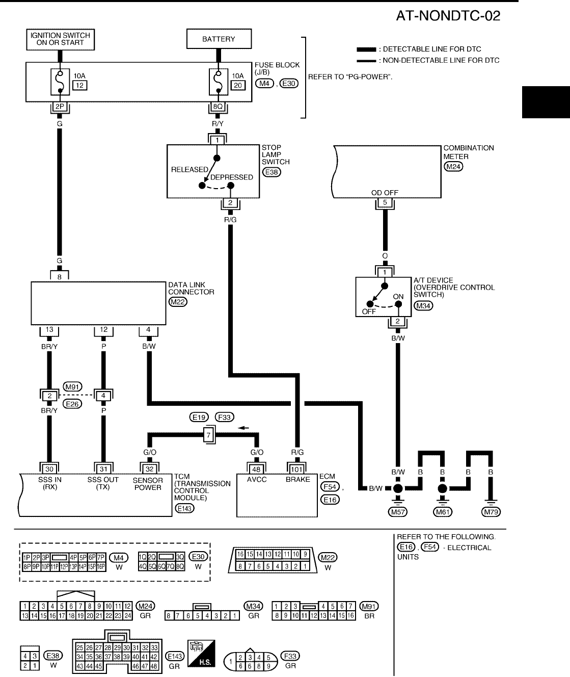
TROUBLE DIAGNOSIS FOR SYMPTOMS
AT-211
[RE4F04B]
D
E
F
G
H
I
J
K
L
M
A
B
AT
Revision: September 2005 2005 Quest
BCWA0318E

AT-212
[RE4F04B]
TROUBLE DIAGNOSIS FOR SYMPTOMS
Revision: September 2005 2005 Quest
TCM TERMINALS AND REFERENCE VALUE MEASURED BETWEEN EACH TERMINAL AND 25 OR 48 (TCM GROUND)
O/D OFF Indicator Lamp Does Not Come On UCS000QI
SYMPTOM:
O/D OFF indicator lamp does not come on for about 2 seconds when turning ignition switch to ON.
1. CHECK TCM POWER SOURCE STEP 1
1. Turn ignition switch to ON position. (Do not start engine.)
2. Check voltage between TCM harness connectors E142, E143
terminals 10 (R/Y), 19 (R/Y), 28 (Y/R) and ground.
OK or NG
OK >> GO TO 2.
NG >> GO TO 3.
2. CHECK TCM POWER SOURCE STEP 2
1. Turn ignition switch to OFF position.
2. Check voltage between TCM harness connector E143 terminal
28 (Y/R) and ground.
OK or NG
OK >> GO TO 4.
NG >> GO TO 3.
3. DETECT MALFUNCTIONING ITEM
Check the following items:
●Fuse
●Harness for short or open between battery, ignition switch and TCM harness connectors E142, E143 ter-
minals 10 (R/Y), 19 (R/Y) and 28 (Y/R)
Refer to AT-100, "Wiring Diagram — AT — MAIN" .
●Ignition switch
Refer to PG-4, "POWER SUPPLY ROUTING CIRCUIT" .
OK or NG
OK >> GO TO 4.
NG >> Repair or replace damaged parts.
TERMINAL WIRE COLOR ITEM CONDITION DATA (APPROX.)
30 BR/Y DATA LINK CONNECTOR (RX) — —
31 P DATA LINK CONNECTOR (TX) — —
32 G/O SENSOR POWER IGNITION SWITCH ON 4.5 - 5.5V
IGNITION SWITCH OFF 0V
Voltage : Battery voltage
LCIA0094E
Voltage : Battery voltage
WCIA0095E
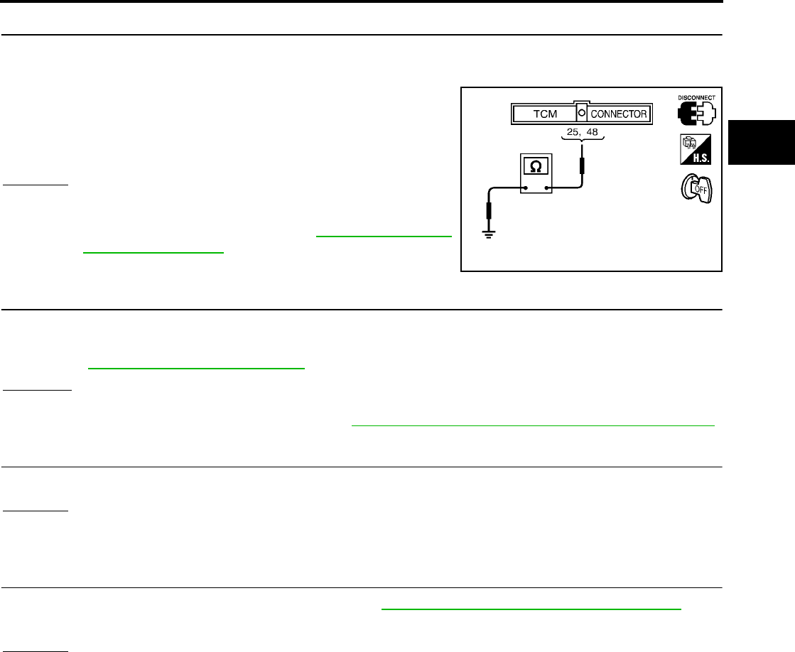
TROUBLE DIAGNOSIS FOR SYMPTOMS
AT-213
[RE4F04B]
D
E
F
G
H
I
J
K
L
M
A
B
AT
Revision: September 2005 2005 Quest
4. CHECK TCM GROUND CIRCUIT
1. Turn ignition switch to OFF position.
2. Disconnect TCM harness connector.
3. Check continuity between TCM harness connector E143 termi-
nals 25 (B), 48 (B) and ground.
If OK, check harness for short to ground and short to power.
OK or NG
OK >> GO TO 5.
NG >> Repair open circuit or short to ground or short to power
in harness or connectors. Refer to AT-100, "Wiring Dia-
gram — AT — MAIN" .
5. CHECK O/D OFF INDICATOR LAMP CIRCUIT
1. Turn ignition switch “OFF”.
2. Check the combination meter.
Refer to DI-5, "COMBINATION METERS" .
OK or NG
OK >> GO TO 6.
NG >> Replace the combination meter. Refer to DI-21, "Removal and Installation of Combination Meter" .
6. CHECK SYMPTOM
Check again.
OK or NG
OK >> INSPECTION END
NG >> GO TO 7.
7. CHECK TCM INSPECTION
1. Perform TCM input/output signal inspection. Refer to AT-96, "TCM Terminals and Reference Value" .
2. If NG, recheck TCM pin terminals for damage or loose connection with harness connector.
OK or NG
OK >> INSPECTION END
NG >> Repair or replace damaged parts.
Continuity should exist.
SAT515J
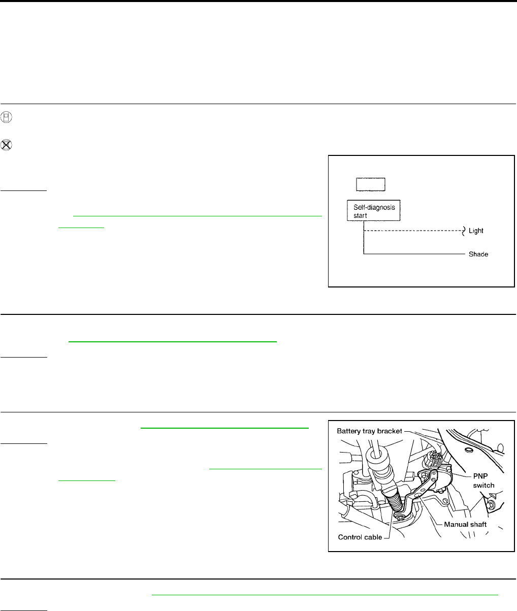
AT-214
[RE4F04B]
TROUBLE DIAGNOSIS FOR SYMPTOMS
Revision: September 2005 2005 Quest
Engine Cannot Be Started in P and N Position UCS000QJ
SYMPTOM:
●Engine cannot be started with selector lever in P or N position.
●Engine can be started with selector lever in D, L or R position.
1. CHECK PARK/NEUTRAL POSITION (PNP) SWITCH CIRCUIT
With CONSULT-II
Does “DATA MONITOR” show damage to park/neutral position (PNP) switch circuit?
Without CONSULT-II
Does self-diagnosis show damage to park/neutral position (PNP)
switch circuit?
Yes or No
Yes >> Check park/neutral position (PNP) switch circuit. Refer
to AT-106, "DTC P0705 PARK/NEUTRAL POSITION
SWITCH" .
No >> GO TO 2.
2. CHECK PARK/NEUTRAL POSITION (PNP) SWITCH
Check for short or open of park/neutral position (PNP) switch harness connector F29 terminals 1(G/R) and
2(G). Refer to AT-108, "Wiring Diagram — AT — PNP/SW" .
OK or NG
OK >> GO TO 3.
NG >> Repair or replace park/neutral position (PNP) switch.
3. ADJUST CONTROL CABLE
Check control cable. Refer to AT-258, "Control Cable Adjustment"
OK or NG
OK >> GO TO 4.
NG >> Adjust control cable. Refer to AT-258, "Control Cable
Adjustment" .
4. CHECK STARTING SYSTEM
Check starting system. Refer to SC-13, "Trouble Diagnoses with Battery/Starting/Charging System Tester" .
OK or NG
OK >> INSPECTION END
NG >> Repair or replace damaged parts.
SCIA3400E
BCIA0014E
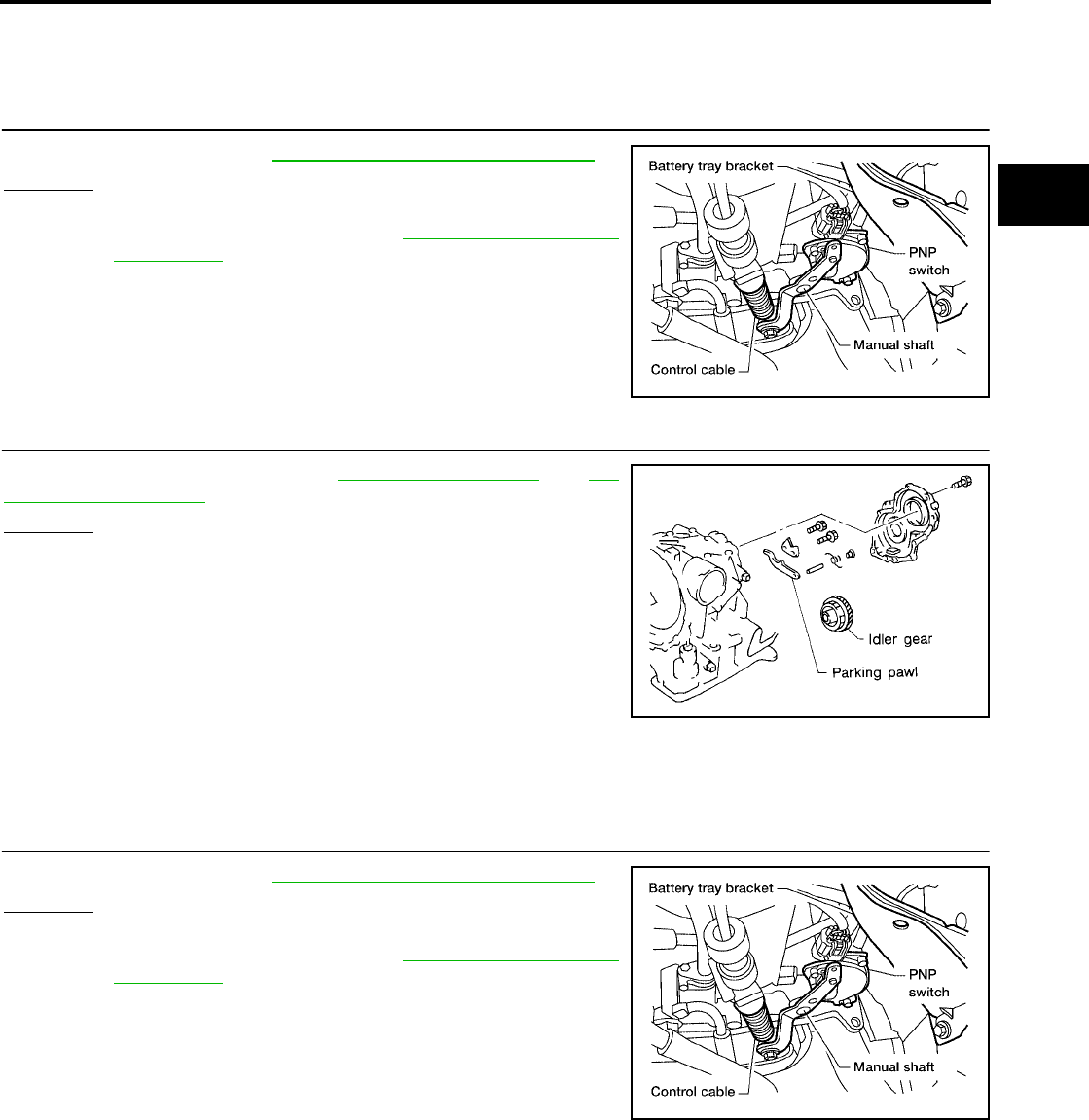
TROUBLE DIAGNOSIS FOR SYMPTOMS
AT-215
[RE4F04B]
D
E
F
G
H
I
J
K
L
M
A
B
AT
Revision: September 2005 2005 Quest
In P Position, Vehicle Moves Forward or Backward When Pushed UCS000QK
SYMPTOM:
Vehicle moves when it is pushed forward or backward with selector lever in P position.
1. ADJUST CONTROL CABLE
Check control cable. Refer to AT-258, "Control Cable Adjustment"
OK or NG
OK >> GO TO 2.
NG >> Adjust control cable. Refer to AT-258, "Control Cable
Adjustment" .
2. CHECK PARKING COMPONENTS
Check parking components. Refer to AT-261, "OVERHAUL" and AT-
268, "DISASSEMBLY" .
OK or NG
OK >> INSPECTION END
NG >> Repair or replace damaged parts.
In N Position, Vehicle Moves UCS000QL
SYMPTOM:
Vehicle moves forward or backward when selecting N position.
1. ADJUST CONTROL CABLE
Check control cable. Refer to AT-258, "Control Cable Adjustment"
OK or NG
OK >> GO TO 2.
NG >> Adjust control cable. Refer to AT-258, "Control Cable
Adjustment" .
BCIA0014E
SAT282F
BCIA0014E
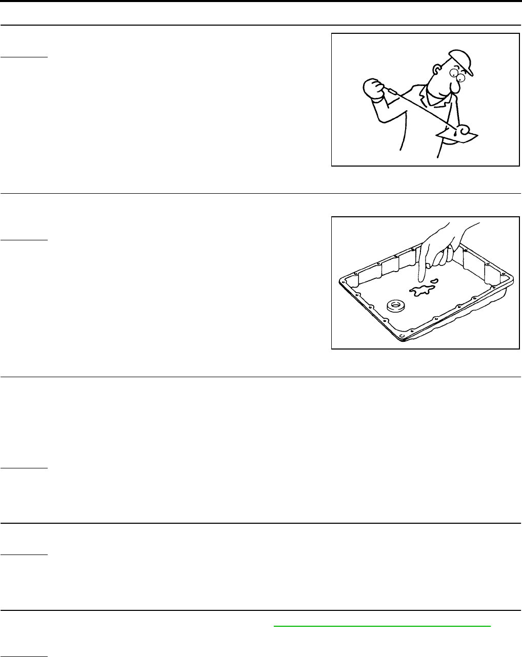
AT-216
[RE4F04B]
TROUBLE DIAGNOSIS FOR SYMPTOMS
Revision: September 2005 2005 Quest
2. CHECK A/T FLUID LEVEL
Check A/T fluid level again.
OK or NG
OK >> GO TO 3.
NG >> Refill ATF.
3. CHECK A/T FLUID CONDITION
1. Remove oil pan.
2. Check A/T fluid condition.
OK or NG
OK >> GO TO 5.
NG >> GO TO 4.
4. DETECT MALFUNCTIONING ITEM
1. Disassemble A/T.
2. Check the following items:
–Forward clutch assembly
–Overrun clutch assembly
–Reverse clutch assembly
OK or NG
OK >> GO TO 5.
NG >> Repair or replace damaged parts.
5. CHECK SYMPTOM
Check again.
OK or NG
OK >> INSPECTION END
NG >> GO TO 6.
6. CHECK TCM INSPECTION
1. Perform TCM input/output signal inspection. Refer to AT-96, "TCM Terminals and Reference Value" .
2. If NG, recheck TCM pin terminals for damage or loose connection with harness connector.
OK or NG
OK >> INSPECTION END
NG >> Repair or replace damaged parts.
SAT638A
SAT171B
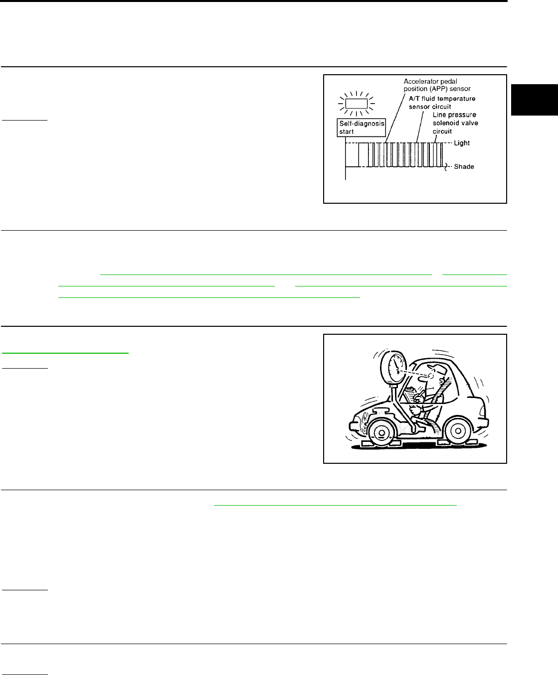
TROUBLE DIAGNOSIS FOR SYMPTOMS
AT-217
[RE4F04B]
D
E
F
G
H
I
J
K
L
M
A
B
AT
Revision: September 2005 2005 Quest
Large Shock. N → R Position UCS000QM
SYMPTOM:
There is large shock when changing from N to R position.
1. CHECK SELF-DIAGNOSTIC RESULTS
Does self-diagnosis show damage to A/T fluid temperature sensor,
line pressure solenoid valve or accelerator pedal position (APP) sen-
sor circuit?
Yes or No
Yes >> GO TO 2.
No >> GO TO 3.
2. CHECK DAMAGED CIRCUIT
Check damaged circuit.
>> Refer to AT-112, "DTC P0710 A/T FLUID TEMPERATURE SENSOR CIRCUIT" , AT-162, "DTC
P0745 LINE PRESSURE SOLENOID VALVE" or AT-178, "DTC P1705 THROTTLE POSITION
SENSOR [ACCELERATOR PEDAL POSITION (APP) SENSOR]" .
3. CHECK LINE PRESSURE
Check line pressure at idle with selector lever in D position. Refer to
AT-71, "Line Pressure Test" .
OK or NG
OK >> GO TO 5.
NG >> GO TO 4.
4. DETECT MALFUNCTIONING ITEM
1. Remove control valve assembly. Refer to AT-253, "Control Valve Assembly and Accumulators" .
2. Check the following items:
–Valves to control line pressure (Pressure regulator valve, pressure modifier valve, pilot valve and pilot fil-
ter)
–Line pressure solenoid valve
–Oil pump assembly
OK or NG
OK >> GO TO 5.
NG >> Repair or replace damaged parts.
5. CHECK SYMPTOM
Check again.
OK or NG
OK >> INSPECTION END
NG >> GO TO 6.
SCIA3406E
SAT494G

AT-218
[RE4F04B]
TROUBLE DIAGNOSIS FOR SYMPTOMS
Revision: September 2005 2005 Quest
6. CHECK TCM INSPECTION
1. Perform TCM input/output signal inspection. Refer to AT-96, "TCM Terminals and Reference Value" .
2. If NG, recheck TCM pin terminals for damage or loose connection with harness connector.
OK or NG
OK >> INSPECTION END
NG >> Repair or replace damaged parts.
Vehicle Does Not Creep Backward in R Position UCS000QN
SYMPTOM:
Vehicle does not creep backward when selecting R position.
1. CHECK A/T FLUID LEVEL
Check A/T fluid level again.
OK or NG
OK >> GO TO 2.
NG >> Refill ATF.
2. CHECK LINE PRESSURE
Check line pressure at idle with selector lever in R position. Refer to
AT-71, "Line Pressure Test" .
OK or NG
OK >> GO TO 4.
NG >> GO TO 3.
3. DETECT MALFUNCTIONING ITEM
1. Remove control valve assembly. Refer to AT-253, "Control Valve Assembly and Accumulators" .
2. Check the following items:
–Valves to control line pressure (Pressure regulator valve, pressure modifier valve, pilot valve and pilot fil-
ter)
–Line pressure solenoid valve
3. Disassemble A/T.
4. Check the following item:
–Oil pump assembly
OK or NG
OK >> GO TO 4.
NG >> Repair or replace damaged parts.
SAT638A
SAT494G
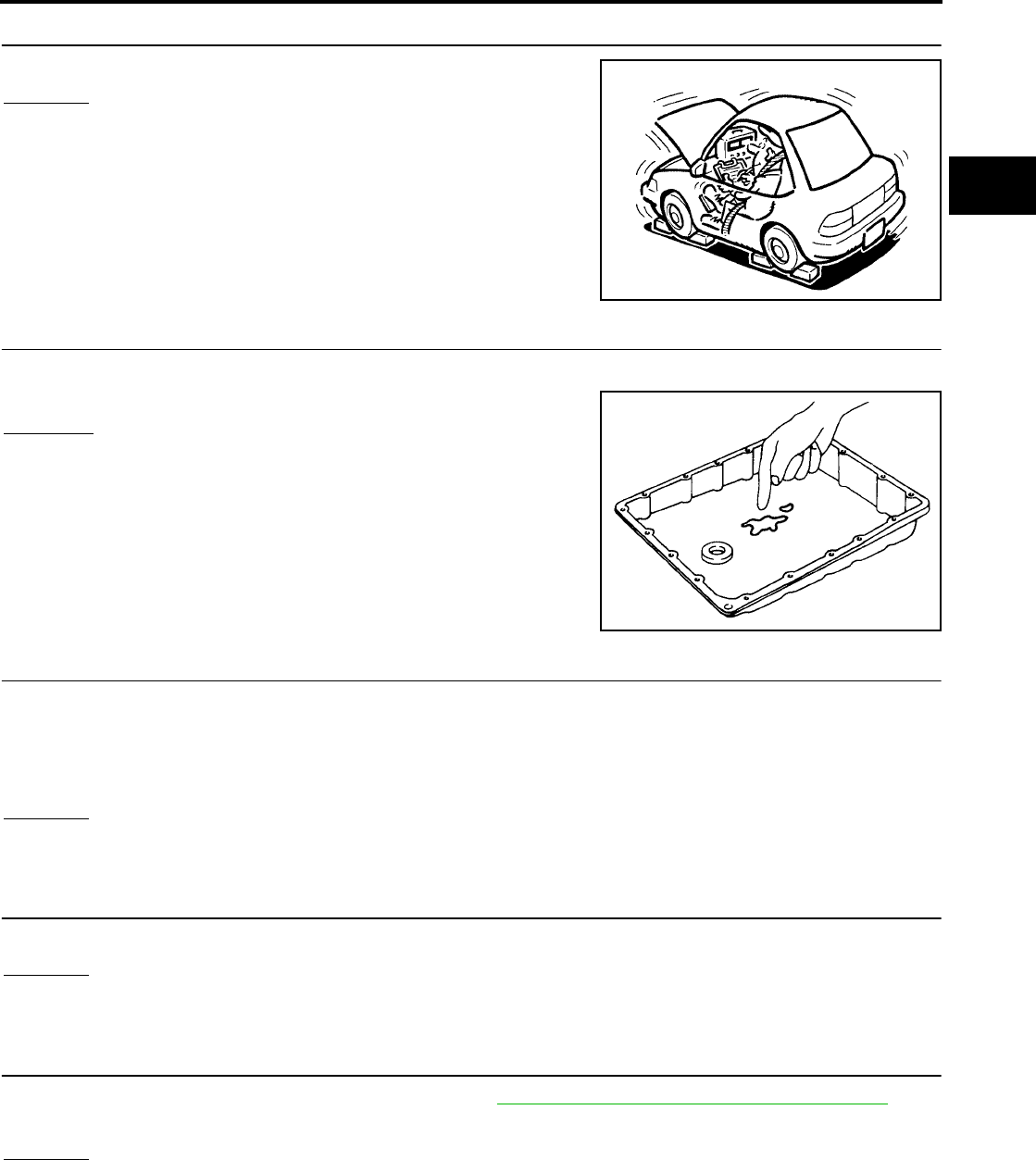
TROUBLE DIAGNOSIS FOR SYMPTOMS
AT-219
[RE4F04B]
D
E
F
G
H
I
J
K
L
M
A
B
AT
Revision: September 2005 2005 Quest
4. CHECK STALL REVOLUTION
Check stall revolution with selector lever in R positions.
OK or NG
OK >> GO TO 7.
NG >> GO TO 5.
5. CHECK A/T FLUID CONDITION
1. Remove oil pan.
2. Check A/T fluid condition.
OK or NG
OK >> GO TO 7.
NG >> GO TO 6.
6. DETECT MALFUNCTIONING ITEM
1. Disassemble A/T.
2. Check the following items:
–Low & reverse brake assembly
–Reverse clutch assembly
OK or NG
OK >> GO TO 6.
NG >> Repair or replace damaged parts.
7. CHECK SYMPTOM
Check again.
OK or NG
OK >> INSPECTION END
NG >> GO TO 10.
8. CHECK TCM INSPECTION
1. Perform TCM input/output signal inspection. Refer to AT-96, "TCM Terminals and Reference Value" .
2. If NG, recheck TCM pin terminals for damage or loose connection with harness connector.
OK or NG
OK >> INSPECTION END
NG >> Repair or replace damaged parts.
SAT493G
SAT171B

AT-220
[RE4F04B]
TROUBLE DIAGNOSIS FOR SYMPTOMS
Revision: September 2005 2005 Quest
Vehicle Does Not Creep Forward in D or L Position UCS000QO
SYMPTOM:
Vehicle does not creep forward when selecting D or L position.
1. CHECK A/T FLUID LEVEL
Check A/T fluid level again.
OK or NG
OK >> GO TO 2.
NG >> Refill ATF.
2. CHECK LINE PRESSURE
Check line pressure at idle with selector lever in D position. Refer to
AT-71, "Line Pressure Test" .
OK or NG
OK >> GO TO 4.
NG >> GO TO 3.
3. DETECT MALFUNCTIONING ITEM
1. Remove control valve assembly. Refer to AT-253, "Control Valve Assembly and Accumulators" .
2. Check the following items:
–Valves to control line pressure (Pressure regulator valve, pressure modifier valve, pilot valve and pilot fil-
ter)
–Line pressure solenoid valve
3. Disassemble A/T.
4. Check the following item:
–Oil pump assembly
OK or NG
OK >> GO TO 4.
NG >> Repair or replace damaged parts.
SAT638A
SAT494G
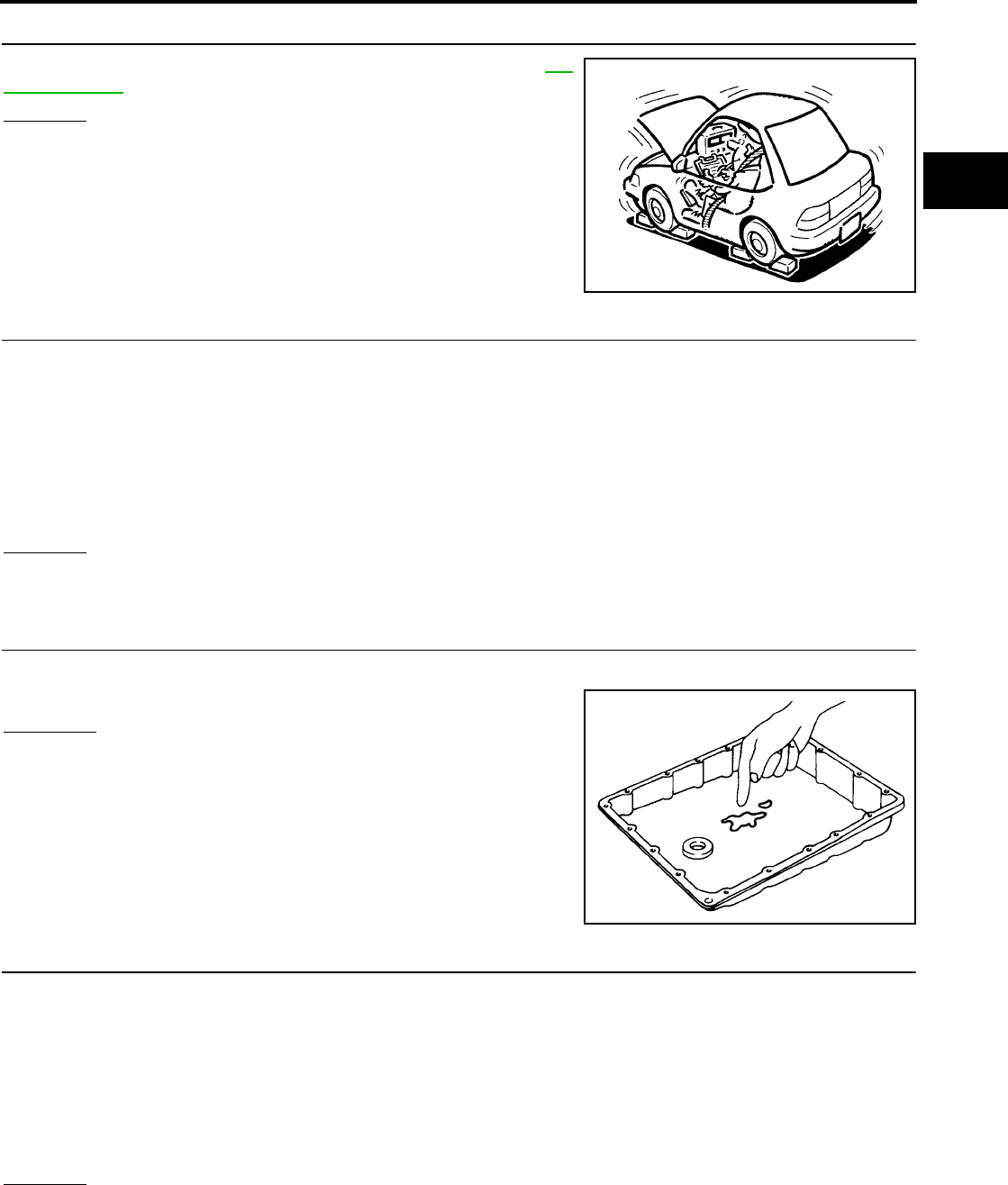
TROUBLE DIAGNOSIS FOR SYMPTOMS
AT-221
[RE4F04B]
D
E
F
G
H
I
J
K
L
M
A
B
AT
Revision: September 2005 2005 Quest
4. CHECK STALL REVOLUTION
Check stall revolution with selector lever in D position. Refer to AT-
68, "Stall Test" .
OK or NG
OK >> GO TO 6.
NG >> GO TO 5.
5. DETECT MALFUNCTIONING ITEM
1. Disassemble A/T.
2. Check the following items:
–Reverse clutch assembly
–Forward clutch assembly
–Forward one-way clutch
–Low one-way clutch
–High clutch assembly
OK or NG
OK >> GO TO 6.
NG >> Repair or replace damaged parts.
6. CHECK A/T FLUID CONDITION
1. Remove oil pan.
2. Check A/T fluid condition.
OK or NG
OK >> GO TO 8.
NG >> GO TO 7.
7. DETECT MALFUNCTIONING ITEM
1. Disassemble A/T.
2. Check the following items:
–Reverse clutch assembly
–Forward clutch assembly
–Forward one-way clutch
–Low one-way clutch
–High clutch assembly
OK or NG
OK >> GO TO 8.
NG >> Repair or replace damaged parts.
SAT493G
SAT171B

AT-222
[RE4F04B]
TROUBLE DIAGNOSIS FOR SYMPTOMS
Revision: September 2005 2005 Quest
8. CHECK SYMPTOM
Check again.
OK or NG
OK >> INSPECTION END
NG >> GO TO 9.
9. CHECK TCM INSPECTION
1. Perform TCM input/output signal inspection. Refer to AT-96, "TCM Terminals and Reference Value" .
2. If NG, recheck TCM pin terminals for damage or loose connection with harness connector.
OK or NG
OK >> INSPECTION END
NG >> Repair or replace damaged parts.
Vehicle Cannot Be Started From D1UCS000QP
SYMPTOM:
Vehicle cannot be started from D1 on Cruise test — Part 1.
1. CHECK SYMPTOM
Is “Vehicle Does Not Creep Backward in R Position” OK?
Yes or No
Yes >> GO TO 2.
No >> Go to AT-218, "Vehicle Does Not Creep Backward in R Position" .
2. CHECK SELF-DIAGNOSTIC RESULTS
Does self-diagnosis show damage to vehicle speed sensor·A/T (rev-
olution sensor), overrun clutch solenoid valve, torque converter
clutch solenoid valve, shift solenoid valve A, B or vehicle speed sen-
sor·MTR after cruise test?
Yes or No
Yes >> Check damaged circuit. Refer to AT-118, "DTC P0720
VEHICLE SPEED SENSOR·A/T (REVOLUTION SEN-
SOR)" , AT-184, "DTC P1760 OVERRUN CLUTCH
SOLENOID VALVE" , AT-149, "DTC P0740 TORQUE
CONVERTER CLUTCH SOLENOID VALVE" , AT-168,
"DTC P0750 SHIFT SOLENOID VALVE A" , AT-173,
"DTC P0755 SHIFT SOLENOID VALVE B" or AT-195,
"DTC VEHICLE SPEED SENSOR MTR" .
No >> GO TO 3.
3. CHECK ACCELERATOR PEDAL POSITION (APP) SENSOR
Check accelerator pedal position (APP) sensor. Refer to AT-178,
"DTC P1705 THROTTLE POSITION SENSOR [ACCELERATOR
PEDAL POSITION (APP) SENSOR]" .
OK or NG
OK >> GO TO 4.
NG >> Repair or replace accelerator pedal position (APP) sen-
sor circuit.
SCIA3408E
SCIA3551E
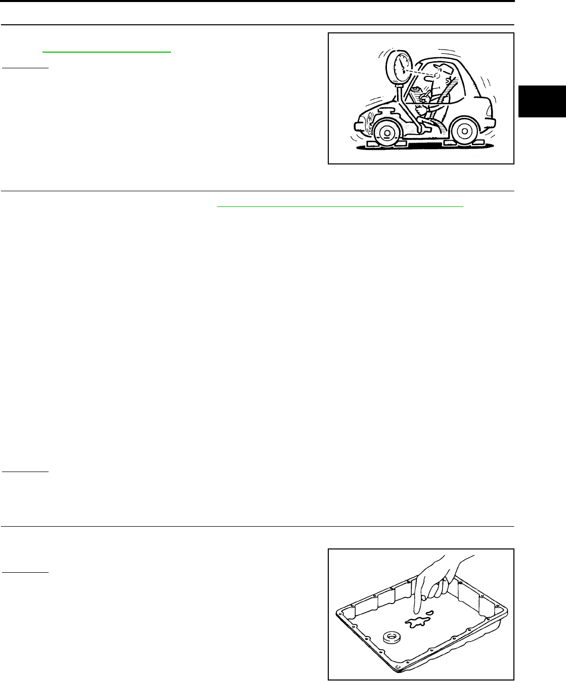
TROUBLE DIAGNOSIS FOR SYMPTOMS
AT-223
[RE4F04B]
D
E
F
G
H
I
J
K
L
M
A
B
AT
Revision: September 2005 2005 Quest
4. CHECK LINE PRESSURE
Check line pressure at stall point with selector lever in D position.
Refer to AT-71, "Line Pressure Test" .
OK or NG
OK >> GO TO 6.
NG >> GO TO 5.
5. DETECT MALFUNCTIONING ITEM
1. Remove control valve assembly. Refer to AT-253, "Control Valve Assembly and Accumulators" .
2. Check the following items:
–Shift valve A
–Shift valve B
–Shift solenoid valve A
–Shift solenoid valve B
–Pilot valve
–Pilot filter
3. Disassemble A/T.
4. Check the following items:
–Reverse clutch assembly
–Low & reverse brake assembly
–High clutch assembly
–Forward clutch assembly
–Forward one-way clutch
–Low one-way clutch
–Torque converter
–Oil pump assembly
OK or NG
OK >> GO TO 8.
NG >> Repair or replace damaged parts.
6. CHECK A/T FLUID CONDITION
1. Remove oil pan.
2. Check A/T fluid condition.
OK or NG
OK >> GO TO 7.
NG >> GO TO 5.
SAT494G
SAT171B
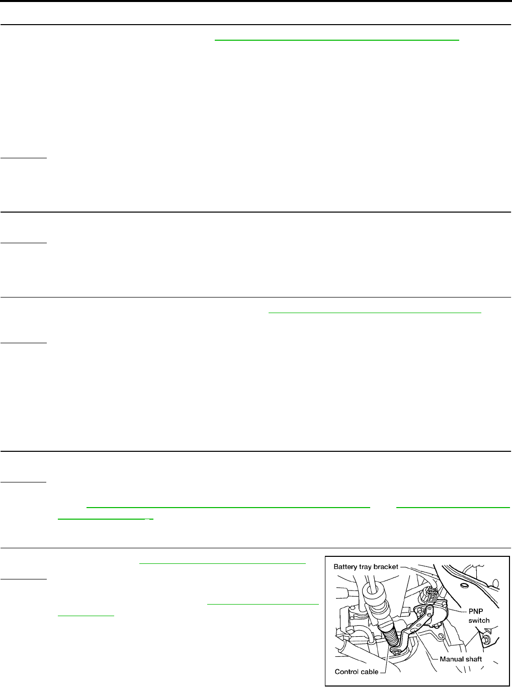
AT-224
[RE4F04B]
TROUBLE DIAGNOSIS FOR SYMPTOMS
Revision: September 2005 2005 Quest
7. DETECT MALFUNCTIONING ITEM
1. Remove control valve assembly. Refer to AT-253, "Control Valve Assembly and Accumulators" .
2. Check the following items:
–Shift valve A
–Shift valve B
–Shift solenoid valve A
–Shift solenoid valve B
–Pilot valve
–Pilot filter
OK or NG
OK >> GO TO 8.
NG >> Repair or replace damage parts.
8. CHECK SYMPTOM
Check again.
OK or NG
OK >> INSPECTION END
NG >> GO TO 9.
9. CHECK TCM INSPECTION
1. Perform TCM input/output signal inspection. Refer to AT-96, "TCM Terminals and Reference Value" .
2. If NG, recheck TCM pin terminals for damage or loose connection with harness connector.
OK or NG
OK >> INSPECTION END
NG >> Repair or replace damaged parts.
A/T Does Not Shift: D1 → D2 or Does Not Kickdown: D4 → D2UCS000QQ
SYMPTOM:
A/T does not shift from D1 to D2 at the specified speed.
A/T does not shift from D4 to D2 when depressing accelerator pedal fully at the specified speed.
1. CHECK SYMPTOM
Are “Vehicle Does Not Creep Forward In D or L Position” and “Vehicle Cannot Be Started From D1 ” OK?
Yes or No
Yes >> GO TO 2.
No >> Go to AT-220, "Vehicle Does Not Creep Forward in D or L Position" and AT-222, "Vehicle Cannot
Be Started From D1" .
2. ADJUST CONTROL CABLE
Check control cable. Refer to AT-258, "Control Cable Adjustment"
OK or NG
OK >> GO TO 3.
NG >> Adjust control cable. Refer to AT-258, "Control Cable
Adjustment" .
BCIA0014E

TROUBLE DIAGNOSIS FOR SYMPTOMS
AT-225
[RE4F04B]
D
E
F
G
H
I
J
K
L
M
A
B
AT
Revision: September 2005 2005 Quest
3. CHECK VEHICLE SPEED SENSOR·A/T AND VEHICLE SPEED SENSOR·MTR CIRCUIT
Check vehicle speed sensor·A/T (revolution sensor) and vehicle speed sensor·MTR circuit. Refer to AT-118,
"DTC P0720 VEHICLE SPEED SENSOR·A/T (REVOLUTION SENSOR)" and AT-195, "DTC VEHICLE
SPEED SENSOR MTR" .
OK or NG
OK >> GO TO 4.
NG >> Repair or replace vehicle speed sensor·A/T (revolution sensor) and vehicle speed sensor·MTR
circuits.
4. CHECK ACCELERATOR PEDAL POSITION (APP) SENSOR
Check accelerator pedal position (APP) sensor. Refer to AT-178,
"DTC P1705 THROTTLE POSITION SENSOR [ACCELERATOR
PEDAL POSITION (APP) SENSOR]" .
OK or NG
OK >> GO TO 5.
NG >> Repair or replace accelerator pedal position (APP) sen-
sor circuit.
5. CHECK A/T FLUID CONDITION
1. Remove oil pan.
2. Check A/T fluid condition.
OK or NG
OK >> GO TO 7.
NG >> GO TO 6.
6. DETECT MALFUNCTIONING ITEM
1. Remove control valve. Refer to AT-253, "Control Valve Assembly and Accumulators" .
2. Check the following items:
–Shift valve A
–Shift valve B
–Shift solenoid valve A
–Shift solenoid valve B
–Pilot valve
–Pilot filter
3. Disassemble A/T.
4. Check the following items:
–Servo piston assembly
–Brake band
OK or NG
OK >> GO TO 8.
NG >> Repair or replace damaged parts.
SCIA3551E
SAT171B
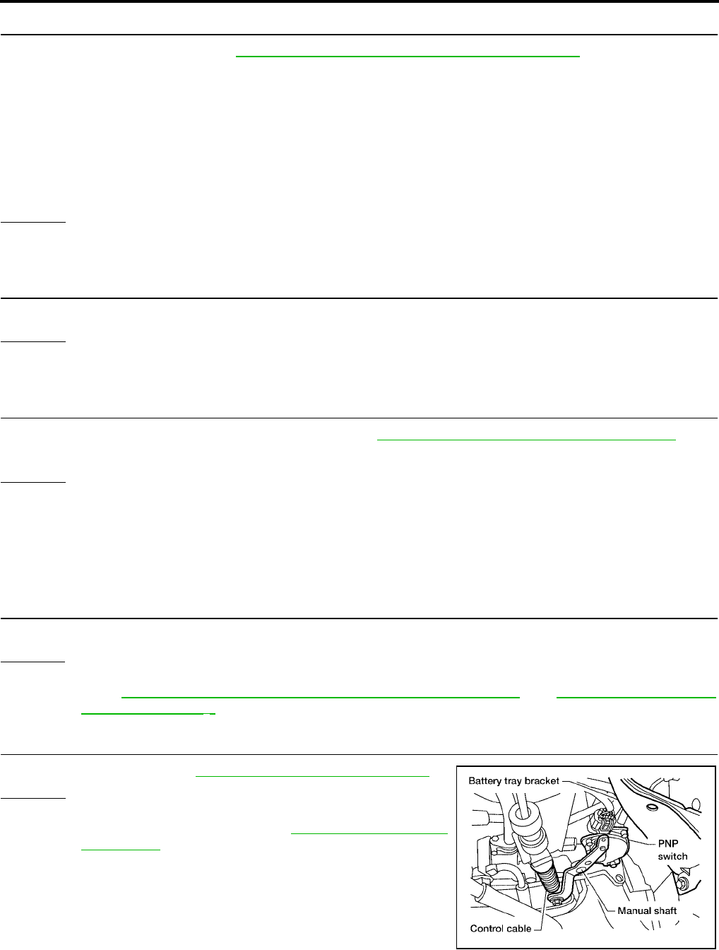
AT-226
[RE4F04B]
TROUBLE DIAGNOSIS FOR SYMPTOMS
Revision: September 2005 2005 Quest
7. DETECT MALFUNCTIONING ITEM
1. Remove control valve. Refer to AT-253, "Control Valve Assembly and Accumulators" .
2. Check the following items:
–Shift valve A
–Shift valve B
–Shift solenoid valve A
–Shift solenoid valve B
–Pilot valve
–Pilot filter
OK or NG
OK >> GO TO 8.
NG >> Repair or replace damaged parts.
8. CHECK SYMPTOM
Check again.
OK or NG
OK >> INSPECTION END
NG >> GO TO 9.
9. CHECK TCM INSPECTION
1. Perform TCM input/output signal inspection. Refer to AT-96, "TCM Terminals and Reference Value" .
2. If NG, recheck TCM pin terminals for damage or loose connection with harness connector.
OK or NG
OK >> INSPECTION END
NG >> Repair or replace damaged parts.
A/T Does Not Shift: D2 → D 3 UCS000QR
SYMPTOM:
A/T does not shift from D2 to D3 at the specified speed.
1. CHECK SYMPTOM
Are “Vehicle Does Not Creep Forward in D or L Position” and “Vehicle Cannot Be Started From D1” OK?
Yes or No
Yes >> GO TO 2.
No >> Go to AT-220, "Vehicle Does Not Creep Forward in D or L Position" and AT-222, "Vehicle Cannot
Be Started From D1" .
2. ADJUST CONTROL CABLE
Check control cable. Refer to AT-258, "Control Cable Adjustment"
OK or NG
OK >> GO TO 3.
NG >> Adjust control cable. Refer to AT-258, "Control Cable
Adjustment" .
BCIA0014E

TROUBLE DIAGNOSIS FOR SYMPTOMS
AT-227
[RE4F04B]
D
E
F
G
H
I
J
K
L
M
A
B
AT
Revision: September 2005 2005 Quest
3. CHECK VEHICLE SPEED SENSOR·A/T AND VEHICLE SPEED SENSOR·MTR CIRCUIT
Check vehicle speed sensor·A/T (revolution sensor) and vehicle speed sensor·MTR circuit. Refer to AT-118,
"DTC P0720 VEHICLE SPEED SENSOR·A/T (REVOLUTION SENSOR)" and AT-195, "DTC VEHICLE
SPEED SENSOR MTR" .
OK or NG
OK >> GO TO 4.
NG >> Repair or replace vehicle speed sensor·A/T (revolution sensor) and vehicle speed sensor·MTR
circuits.
4. CHECK ACCELERATOR PEDAL POSITION (APP) SENSOR
Check accelerator pedal position (APP) sensor. Refer to AT-178,
"DTC P1705 THROTTLE POSITION SENSOR [ACCELERATOR
PEDAL POSITION (APP) SENSOR]" .
OK or NG
OK >> GO TO 5.
NG >> Repair or replace accelerator pedal position (APP) sen-
sor circuit.
5. CHECK A/T FLUID CONDITION
1. Remove oil pan.
2. Check A/T fluid condition.
OK or NG
OK >> GO TO 7.
NG >> GO TO 6.
6. DETECT MALFUNCTIONING ITEM
1. Remove control valve assembly. Refer to AT-253, "Control Valve Assembly and Accumulators" .
2. Check the following items:
–Shift valve B
–Shift solenoid valve B
–Pilot valve
–Pilot filter
3. Disassemble A/T.
4. Check the following items:
–Servo piston assembly
–High clutch assembly
–Brake band
OK or NG
OK >> GO TO 8.
NG >> Repair or replace damaged parts.
SCIA3551E
SAT171B
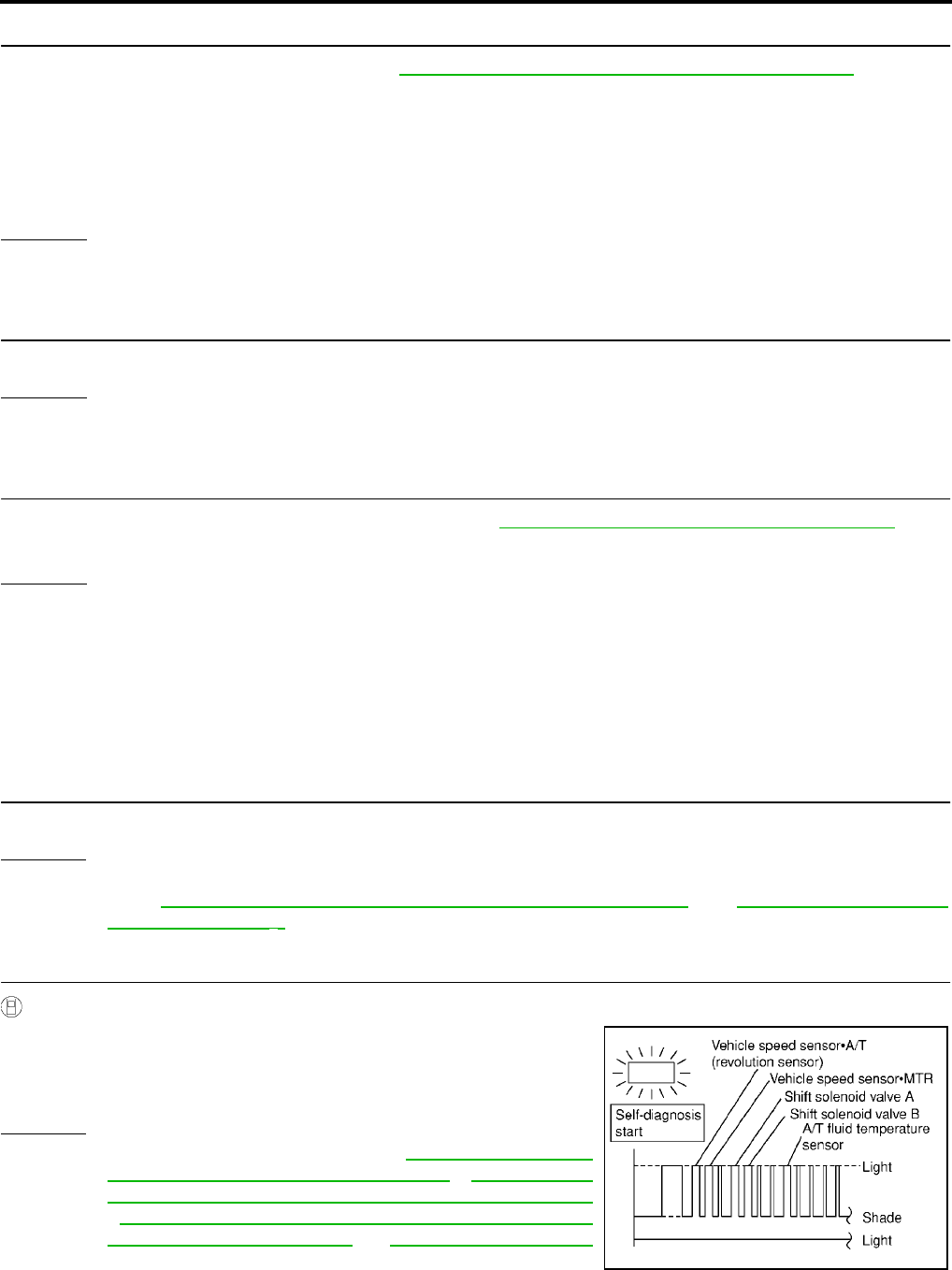
AT-228
[RE4F04B]
TROUBLE DIAGNOSIS FOR SYMPTOMS
Revision: September 2005 2005 Quest
7. DETECT MALFUNCTIONING ITEM
1. Remove control valve assembly. Refer to AT-253, "Control Valve Assembly and Accumulators" .
2. Check the following items:
–Shift valve B
–Shift solenoid valve B
–Pilot valve
–Pilot filter
OK or NG
OK >> GO TO 8.
NG >> Repair or replace damaged parts.
8. CHECK SYMPTOM
Check again.
OK or NG
OK >> INSPECTION END
NG >> GO TO 9.
9. CHECK TCM INSPECTION
1. Perform TCM input/output signal inspection. Refer to AT-96, "TCM Terminals and Reference Value" .
2. If NG, recheck TCM pin terminals for damage or loose connection with harness connector.
OK or NG
OK >> INSPECTION END
NG >> Repair or replace damaged parts.
A/T Does Not Shift: D3 → D4UCS000QS
SYMPTOM:
●A/T does not shift from D3 to D4 at the specified speed.
●A/T must be warm before D3 to D4 shift will occur.
1. CHECK SYMPTOM
Are “Vehicle Does Not Creep Forward in D or L Position” and “Vehicle Cannot Be Started From D 1 ” OK?
Yes or No
Yes >> GO TO 2.
No >> Go to AT-220, "Vehicle Does Not Creep Forward in D or L Position" and AT-222, "Vehicle Cannot
Be Started From D1" .
2. CHECK SELF-DIAGNOSTIC RESULTS
With CONSULT-II
Does self-diagnosis show damage to park/neutral position (PNP)
switch, overdrive control switch, A/T fluid temperature sensor, vehi-
cle speed sensor·A/T (revolution sensor), shift solenoid valve A or B,
vehicle speed sensor·MTR circuits?
Yes or No
Yes >> Check damaged circuit. Refer to AT-106, "DTC P0705
PARK/NEUTRAL POSITION SWITCH" , AT-112, "DTC
P0710 A/T FLUID TEMPERATURE SENSOR CIRCUIT"
, AT-118, "DTC P0720 VEHICLE SPEED SENSOR·A/T
(REVOLUTION SENSOR)" , AT-168, "DTC P0750
SCIA3409E

TROUBLE DIAGNOSIS FOR SYMPTOMS
AT-229
[RE4F04B]
D
E
F
G
H
I
J
K
L
M
A
B
AT
Revision: September 2005 2005 Quest
SHIFT SOLENOID VALVE A" , AT-173, "DTC P0755 SHIFT SOLENOID VALVE B" or AT-195,
"DTC VEHICLE SPEED SENSOR MTR" .
No >> GO TO 3.
3. CHECK ACCELERATOR PEDAL POSITION (APP) SENSOR
Check accelerator pedal position (APP) sensor. Refer to AT-178,
"DTC P1705 THROTTLE POSITION SENSOR [ACCELERATOR
PEDAL POSITION (APP) SENSOR]" .
OK or NG
OK >> GO TO 4.
NG >> Repair or replace accelerator pedal position (APP) sen-
sor circuit.
4. CHECK A/T FLUID CONDITION
1. Remove oil pan.
2. Check A/T fluid condition.
OK or NG
OK >> GO TO 6.
NG >> GO TO 5.
5. DETECT MALFUNCTIONING ITEM
1. Remove control valve assembly. Refer to AT-253, "Control Valve Assembly and Accumulators" .
2. Check the following items:
–Shift valve A
–Shift solenoid valve A
–Overrun clutch control valve
–Overrun clutch solenoid valve
–Pilot valve
–Pilot filter
3. Disassemble A/T.
4. Check the following items:
–Servo piston assembly
–Brake band
OK or NG
OK >> GO TO 7.
NG >> Repair or replace damaged parts.
SCIA3551E
SAT171B
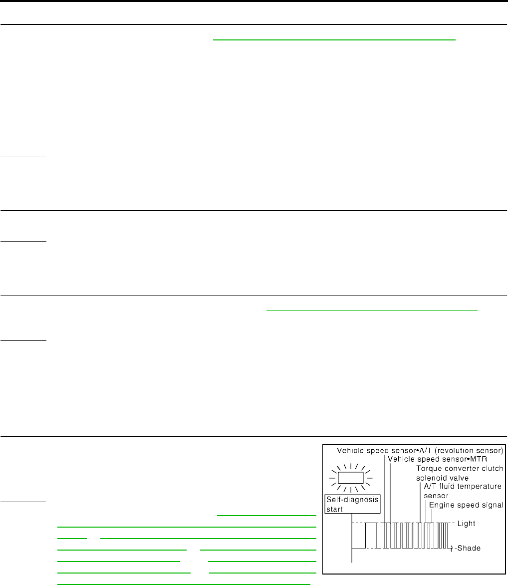
AT-230
[RE4F04B]
TROUBLE DIAGNOSIS FOR SYMPTOMS
Revision: September 2005 2005 Quest
6. DETECT MALFUNCTIONING ITEM
1. Remove control valve assembly. Refer to AT-253, "Control Valve Assembly and Accumulators" .
2. Check the following items:
–Shift valve A
–Shift solenoid valve A
–Overrun clutch control valve
–Overrun clutch solenoid valve
–Pilot valve
–Pilot filter
OK or NG
OK >> GO TO 7.
NG >> Repair or replace damaged parts.
7. CHECK SYMPTOM
Check again.
OK or NG
OK >> INSPECTION END
NG >> GO TO 8.
8. CHECK TCM INSPECTION
1. Perform TCM input/output signal inspection. Refer to AT-96, "TCM Terminals and Reference Value" .
2. If NG, recheck TCM pin terminals for damage or loose connection with harness connector.
OK or NG
OK >> INSPECTION END
NG >> Repair or replace damaged parts.
A/T Does Not Perform Lock-up UCS000QT
SYMPTOM:
A/T does not perform lock-up at the specified speed.
1. CHECK SELF-DIAGNOSTIC RESULTS
Does self-diagnosis show damage to Vehicle speed sensor·A/T (rev-
olution sensor), A/T fluid temperature sensor, Vehicle speed sen-
sor·MTR, engine speed signal, torque converter clutch solenoid
valve circuit after cruise test?
Yes or No
Yes >> Check damaged circuit. Refer to AT-118, "DTC P0720
VEHICLE SPEED SENSOR·A/T (REVOLUTION SEN-
SOR)" , AT-112, "DTC P0710 A/T FLUID TEMPERA-
TURE SENSOR CIRCUIT" , AT-195, "DTC VEHICLE
SPEED SENSOR MTR" , AT-123, "DTC P0725
ENGINE SPEED SIGNAL" , AT-149, "DTC P0740
TORQUE CONVERTER CLUTCH SOLENOID VALVE" .
No >> GO TO 2.
SCIA3410E

TROUBLE DIAGNOSIS FOR SYMPTOMS
AT-231
[RE4F04B]
D
E
F
G
H
I
J
K
L
M
A
B
AT
Revision: September 2005 2005 Quest
2. CHECK ACCELERATOR PEDAL POSITION (APP) SENSOR
Check accelerator pedal position (APP) sensor. Refer to AT-178,
"DTC P1705 THROTTLE POSITION SENSOR [ACCELERATOR
PEDAL POSITION (APP) SENSOR]" .
OK or NG
OK >> GO TO 3.
NG >> Repair or replace accelerator pedal position (APP) sen-
sor circuit.
3. DETECT MALFUNCTIONING ITEM
1. Remove control valve. Refer to AT-253, "Control Valve Assembly and Accumulators" .
2. Check the following items:
–Torque converter clutch control valve
–Torque converter relief valve
–Pilot valve
–Pilot filter
3. Disassemble A/T.
4. Check the following items:
–Torque converter
OK or NG
OK >> GO TO 4.
NG >> Repair or replace damaged parts.
4. CHECK SYMPTOM
Check again.
OK or NG
OK >> INSPECTION END
NG >> GO TO 5.
5. CHECK TCM INSPECTION
1. Perform TCM input/output signal inspection. Refer to AT-96, "TCM Terminals and Reference Value" .
2. If NG, recheck TCM pin terminals for damage or loose connection with harness connector.
OK or NG
OK >> INSPECTION END
NG >> Repair or replace damaged parts.
SCIA3551E
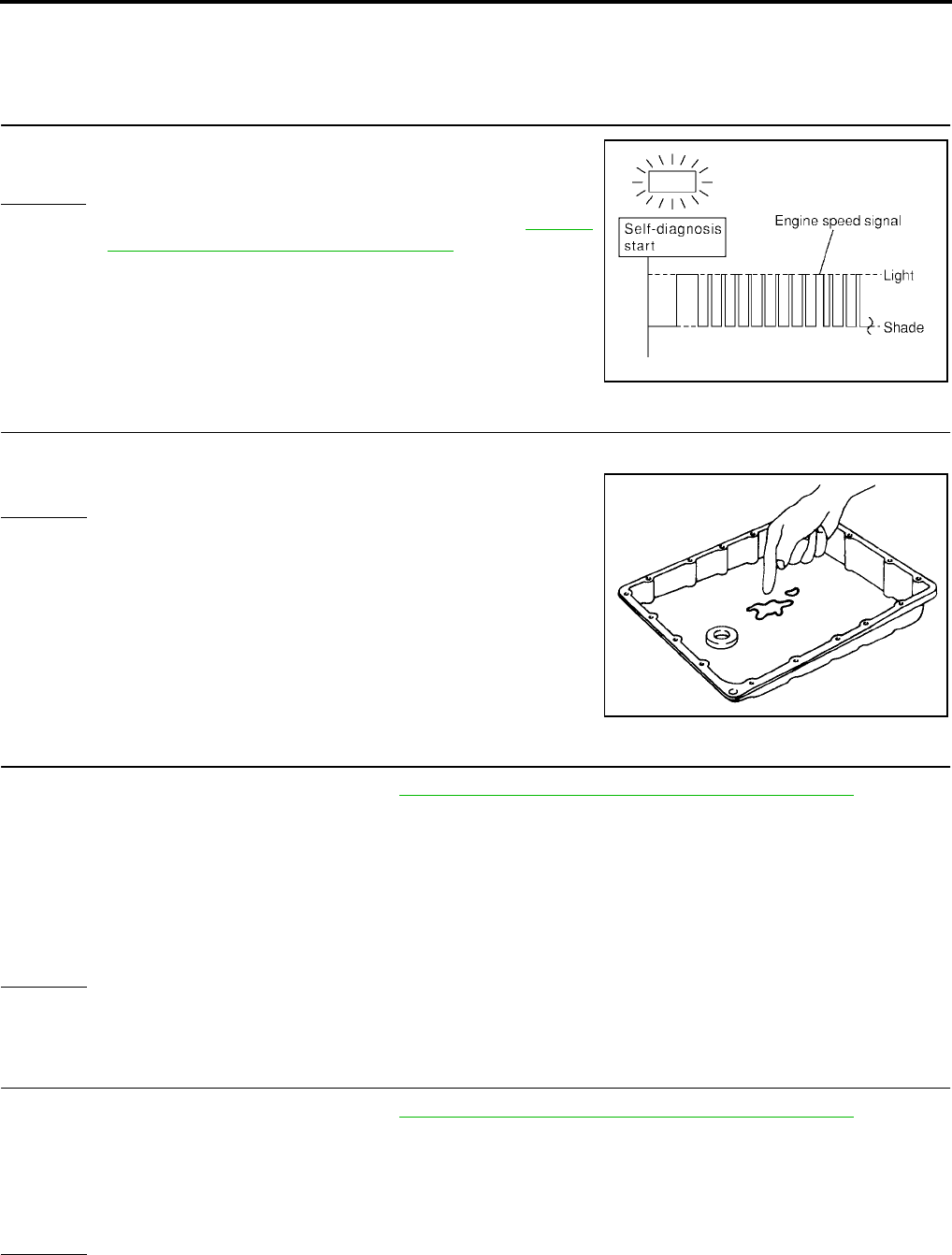
AT-232
[RE4F04B]
TROUBLE DIAGNOSIS FOR SYMPTOMS
Revision: September 2005 2005 Quest
A/T Does Not Hold Lock-up Condition UCS000QU
SYMPTOM:
A/T does not hold lock-up condition for more than 30 seconds.
1. CHECK SELF-DIAGNOSTIC RESULTS
Does self-diagnosis show damage to engine speed signal circuit
after cruise test?
Yes or No
Yes >> Check engine speed signal circuit. Refer to AT-123,
"DTC P0725 ENGINE SPEED SIGNAL" .
No >> GO TO 2.
2. CHECK A/T FLUID CONDITION
1. Remove oil pan.
2. Check A/T fluid condition.
OK or NG
OK >> GO TO 4.
NG >> GO TO 3.
3. DETECT MALFUNCTIONING ITEM
1. Remove control valve assembly. Refer to AT-253, "Control Valve Assembly and Accumulators" .
2. Check the following items:
–Torque converter clutch control valve
–Pilot valve
–Pilot filter
3. Disassemble A/T.
4. Check torque converter and oil pump assembly.
OK or NG
OK >> GO TO 5.
NG >> Repair or replace damaged parts.
4. DETECT MALFUNCTIONING ITEM
1. Remove control valve assembly. Refer to AT-253, "Control Valve Assembly and Accumulators" .
2. Check the following items:
–Torque converter clutch control valve
–Pilot valve
–Pilot filter
OK or NG
OK >> GO TO 5.
NG >> Repair or replace damaged parts.
SCIA3396E
SAT171B
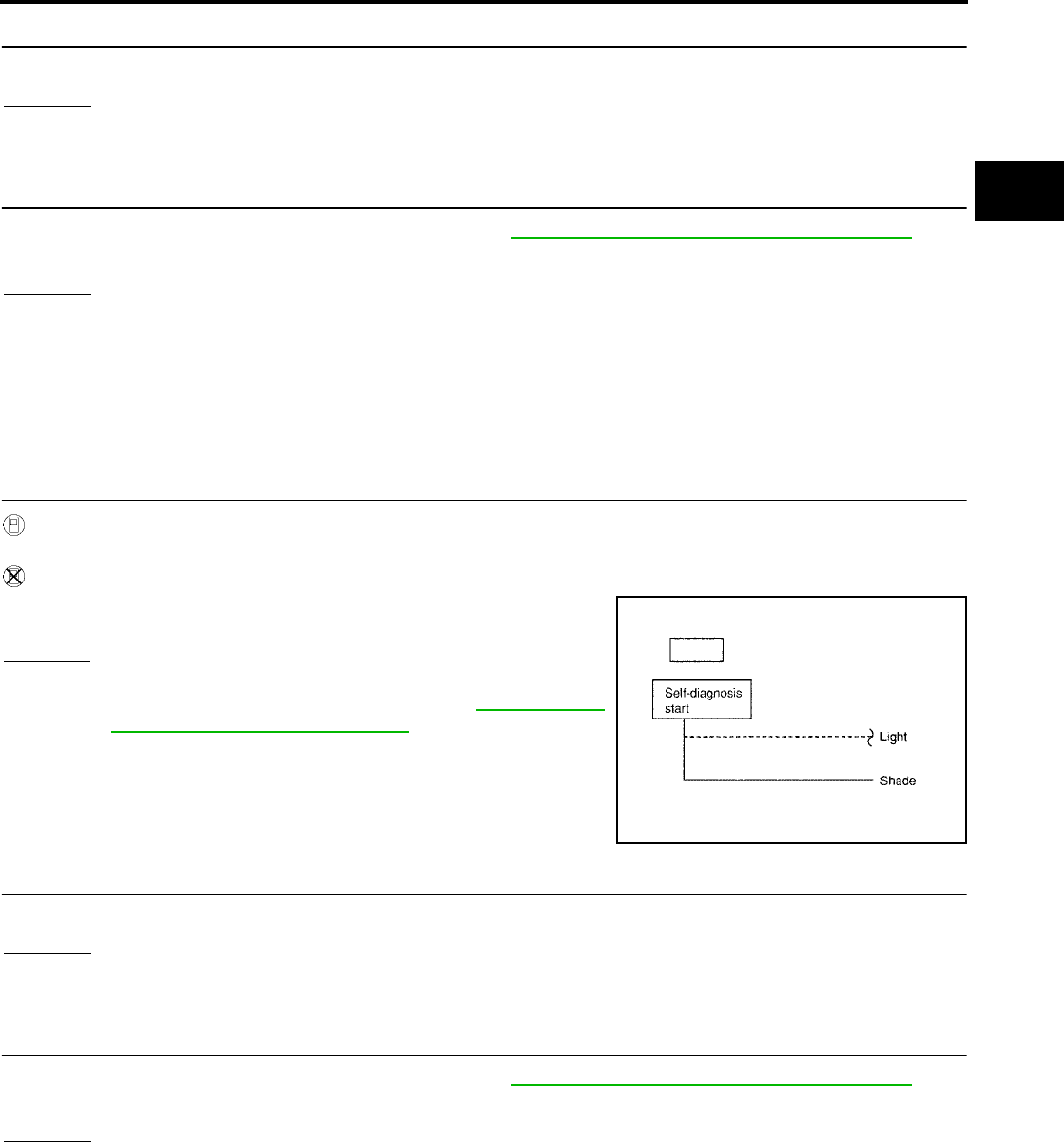
TROUBLE DIAGNOSIS FOR SYMPTOMS
AT-233
[RE4F04B]
D
E
F
G
H
I
J
K
L
M
A
B
AT
Revision: September 2005 2005 Quest
5. CHECK SYMPTOM
Check again.
OK or NG
OK >> INSPECTION END
NG >> GO TO 6.
6. CHECK TCM INSPECTION
1. Perform TCM input/output signal inspection. Refer to AT-96, "TCM Terminals and Reference Value" .
2. If NG, recheck TCM pin terminals for damage or loose connection with harness connector.
OK or NG
OK >> INSPECTION END
NG >> Repair or replace damaged parts.
Lock-up Is Not Released UCS000QV
SYMPTOM:
Lock-up is not released when accelerator pedal is released.
1. CHECK CLOSED THROTTLE POSITION SIGNAL AND WIDE OPEN THROTTLE POSITION SIGNAL
CIRCUIT
With CONSULT-II
Does “DATA MONITOR” show damage to “CLOSED THL/SW” and “W/O THRL/P-SW” circuit?
Without CONSULT-II
Does self-diagnosis show damage to closed throttle position signal
and wide open throttle position signal circuit?
Yes or No
Yes >> Check closed throttle position signal and wide open
throttle position signal circuit. Refer to AT-239, "TCM
Self-diagnosis Does Not Activate" .
No >> GO TO 2.
2. CHECK SYMPTOM
Check again.
OK or NG
OK >> INSPECTION END
NG >> GO TO 3.
3. CHECK TCM INSPECTION
1. Perform TCM input/output signal inspection. Refer to AT-96, "TCM Terminals and Reference Value" .
2. If NG, recheck TCM pin terminals for damage or loose connection with harness connector.
OK or NG
OK >> INSPECTION END
NG >> Repair or replace damaged parts.
SCIA3400E
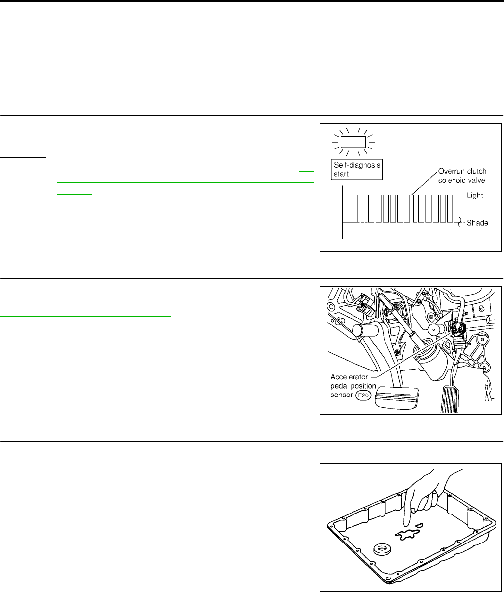
AT-234
[RE4F04B]
TROUBLE DIAGNOSIS FOR SYMPTOMS
Revision: September 2005 2005 Quest
Engine Speed Does Not Return To Idle (Light Braking D4 → D3 ) UCS000QW
SYMPTOM:
●Engine speed does not smoothly return to idle when A/T shifts from D4 to D3 .
●Vehicle does not decelerate by engine brake when turning overdrive control switch OFF.
●Vehicle does not decelerate by engine brake when shifting A/T from D to L position.
1. CHECK SELF-DIAGNOSTIC RESULTS
Does self-diagnosis show damage to overrun clutch solenoid valve
circuit after cruise test?
Yes or No
Yes >> Check overrun clutch solenoid valve circuit. Refer to AT-
184, "DTC P1760 OVERRUN CLUTCH SOLENOID
VALVE" .
No >> GO TO 2.
2. CHECK ACCELERATOR PEDAL POSITION (APP) SENSOR
Check accelerator pedal position (APP) sensor. Refer to AT-178,
"DTC P1705 THROTTLE POSITION SENSOR [ACCELERATOR
PEDAL POSITION (APP) SENSOR]" .
OK or NG
OK >> GO TO 3.
NG >> Repair or replace accelerator pedal position (APP) sen-
sor circuit.
3. CHECK A/T FLUID CONDITION
1. Remove oil pan.
2. Check A/T fluid condition.
OK or NG
OK >> GO TO 5.
NG >> GO TO 4.
SCIA3393E
SCIA3551E
SAT171B

TROUBLE DIAGNOSIS FOR SYMPTOMS
AT-235
[RE4F04B]
D
E
F
G
H
I
J
K
L
M
A
B
AT
Revision: September 2005 2005 Quest
4. DETECT MALFUNCTIONING ITEM
1. Remove control valve assembly. Refer to AT-253, "Control Valve Assembly and Accumulators" .
2. Check the following items:
–Overrun clutch control valve
–Overrun clutch reducing valve
–Overrun clutch solenoid valve
3. Disassemble A/T.
4. Check the following items:
–Overrun clutch assembly
OK or NG
OK >> GO TO 6.
NG >> Repair or replace damaged parts.
5. DETECT MALFUNCTIONING ITEM
1. Remove control valve assembly. Refer to AT-253, "Control Valve Assembly and Accumulators" .
2. Check the following items:
–Overrun clutch control valve
–Overrun clutch reducing valve
–Overrun clutch solenoid valve
OK or NG
OK >> GO TO 6.
NG >> Repair or replace damaged parts.
6. CHECK SYMPTOM
Check again.
OK or NG
OK >> INSPECTION END
NG >> GO TO 7.
7. CHECK TCM INSPECTION
1. Perform TCM input/output signal inspection. Refer to AT-96, "TCM Terminals and Reference Value" .
2. If NG, recheck TCM pin terminals for damage or loose connection with harness connector.
OK or NG
OK >> INSPECTION END
NG >> Repair or replace damaged parts.
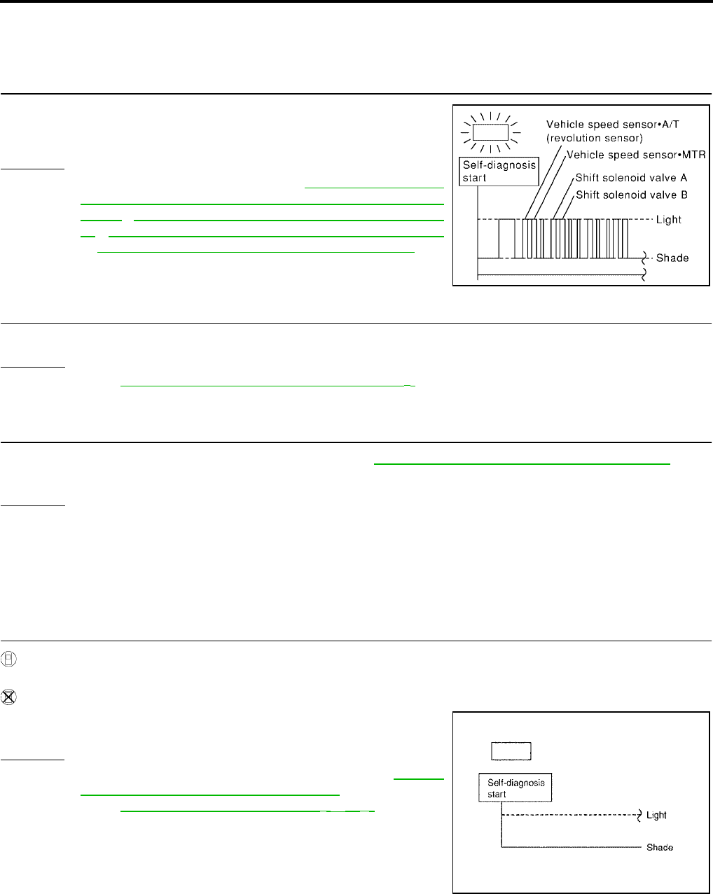
AT-236
[RE4F04B]
TROUBLE DIAGNOSIS FOR SYMPTOMS
Revision: September 2005 2005 Quest
Vehicle Does Not Start From D1UCS000QX
SYMPTOM:
Vehicle does not start from D1 on Cruise test — Part 2.
1. CHECK SELF-DIAGNOSTIC RESULTS
Does self-diagnosis show damage to vehicle speed sensor·A/T (rev-
olution sensor), shift solenoid valve A, B or vehicle speed sen-
sor·MTR after cruise test?
Yes or No
Yes >> Check damaged circuit. Refer to AT-118, "DTC P0720
VEHICLE SPEED SENSOR·A/T (REVOLUTION SEN-
SOR)" , AT-168, "DTC P0750 SHIFT SOLENOID VALVE
A" , AT-173, "DTC P0755 SHIFT SOLENOID VALVE B"
or AT-195, "DTC VEHICLE SPEED SENSOR MTR" .
No >> GO TO 2.
2. CHECK SYMPTOM
Check again.
OK or NG
OK >> Go to AT-222, "Vehicle Cannot Be Started From D1" .
NG >> GO TO 3.
3. CHECK TCM INSPECTION
1. Perform TCM input/output signal inspection. Refer to AT-96, "TCM Terminals and Reference Value" .
2. If NG, recheck TCM pin terminals for damage or loose connection with harness connector.
OK or NG
OK >> INSPECTION END
NG >> Repair or replace damaged parts.
A/T Does Not Shift: D4 → D3 , When Overdrive Control Switch ON → OFF UCS000QY
SYMPTOM:
A/T does not shift from D4 to D3 when changing overdrive control switch to “OFF” position.
1. CHECK OVERDRIVE CONTROL SWITCH CIRCUIT
With CONSULT-II
Does “DATA MONITOR” show damage to overdrive control switch circuit?
Without CONSULT-II
Does self-diagnosis show damage to overdrive control switch cir-
cuit?
Yes or No
Yes >> Check overdrive control switch circuit. Refer to AT-239,
"TCM Self-diagnosis Does Not Activate" .
No >> Go to AT-226, "A/T Does Not Shift: D2 → D 3" .
SCIA3411E
SCIA3400E
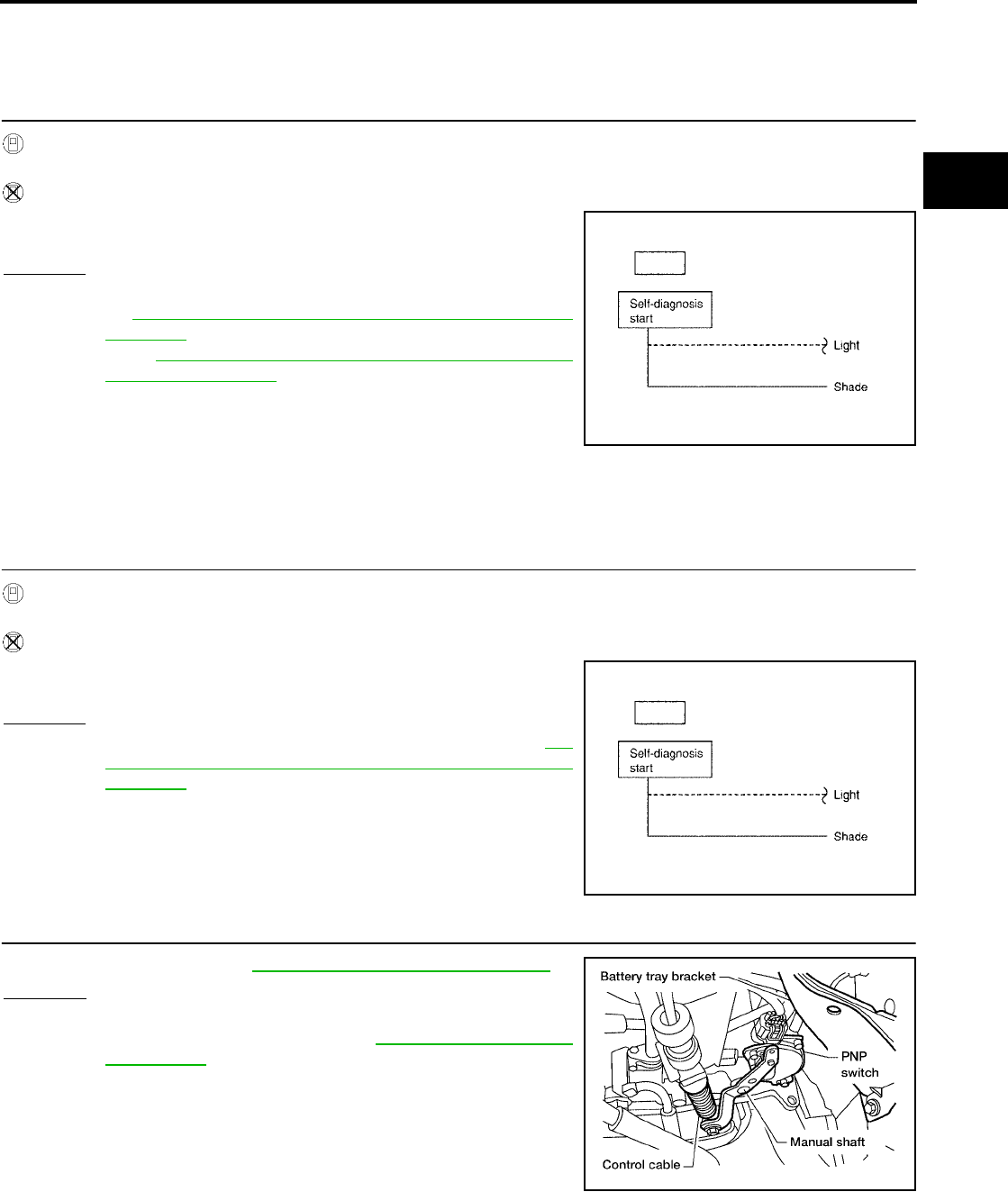
TROUBLE DIAGNOSIS FOR SYMPTOMS
AT-237
[RE4F04B]
D
E
F
G
H
I
J
K
L
M
A
B
AT
Revision: September 2005 2005 Quest
A/T Does Not Shift: D3 → L2 , When Selector Lever D → L Position UCS000QZ
SYMPTOM:
A/T does not shift from D3 to L2 when changing selector lever from D to L position.
1. CHECK PARK/NEUTRAL POSITION (PNP) SWITCH CIRCUIT
With CONSULT-II
Does “DATA MONITOR” show damage to park/neutral position (PNP) switch circuit?
Without CONSULT-II
Does self-diagnosis show damage to park/neutral position (PNP)
switch circuit?
Yes or No
Yes >> Check park/neutral position (PNP) switch circuit. Refer
to AT-106, "DTC P0705 PARK/NEUTRAL POSITION
SWITCH" .
No >> Go to AT-224, "A/T Does Not Shift: D1 → D2 or Does Not
Kickdown: D4 → D2" .
Vehicle Does Not Decelerate By Engine Brake UCS000R1
SYMPTOM:
Vehicle does not decelerate by engine brake when shifting from D3 to L2 .
1. CHECK PARK/NEUTRAL POSITION (PNP) SWITCH CIRCUIT
With CONSULT-II
Does “DATA MONITOR” show damage to park/neutral position (PNP) switch circuit?
Without CONSULT-II
Does self-diagnosis show damage to park/neutral position (PNP)
switch circuit?
Yes or No
Yes >> Check park/neutral position (PNP) switch. Refer to AT-
106, "DTC P0705 PARK/NEUTRAL POSITION
SWITCH" .
No >> GO TO 2.
2. ADJUST CONTROL CABLE
Check control cable. Refer to AT-258, "Control Cable Adjustment"
OK or NG
OK >> GO TO 3.
NG >> Adjust control cable. Refer to AT-258, "Control Cable
Adjustment" .
SCIA3400E
SCIA3400E
BCIA0014E
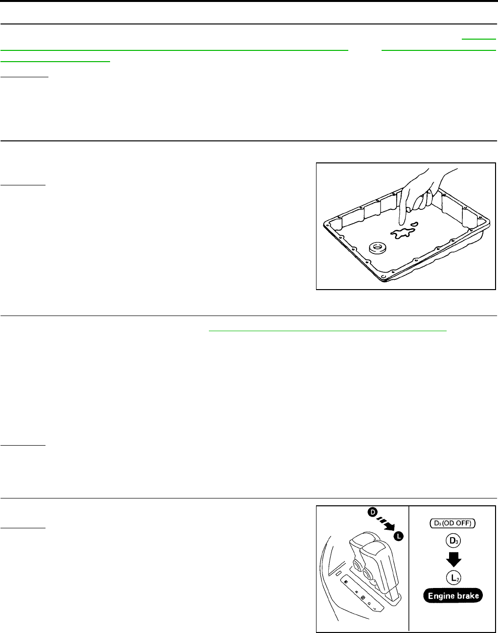
AT-238
[RE4F04B]
TROUBLE DIAGNOSIS FOR SYMPTOMS
Revision: September 2005 2005 Quest
3. CHECK VEHICLE SPEED SENSOR·A/T AND VEHICLE SPEED SENSOR·MTR CIRCUIT
Check vehicle speed sensor·A/T (revolution sensor) and vehicle speed sensor·MTR circuit. Refer to AT-118,
"DTC P0720 VEHICLE SPEED SENSOR·A/T (REVOLUTION SENSOR)" and AT-195, "DTC VEHICLE
SPEED SENSOR MTR" .
OK or NG
OK >> GO TO 4.
NG >> Repair or replace vehicle speed sensor·A/T (revolution sensor) and vehicle speed sensor·MTR
circuits.
4. CHECK A/T FLUID CONDITION
1. Remove oil pan.
2. Check A/T fluid condition.
OK or NG
OK >> GO TO 6.
NG >> GO TO 5.
5. DETECT MALFUNCTIONING ITEM
1. Remove control valve assembly. Refer to AT-253, "Control Valve Assembly and Accumulators" .
2. Check the following items:
–Shift valve A
–Overrun clutch solenoid valve
3. Disassemble A/T.
4. Check the following items:
–Overrun clutch assembly
–Low & reverse brake assembly
OK or NG
OK >> GO TO 6.
NG >> Repair or replace damaged parts.
6. CHECK SYMPTOM
Check again.
OK or NG
OK >> INSPECTION END
NG >> GO TO 7.
SAT171B
BCIA0012E
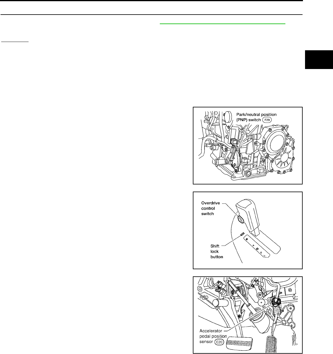
TROUBLE DIAGNOSIS FOR SYMPTOMS
AT-239
[RE4F04B]
D
E
F
G
H
I
J
K
L
M
A
B
AT
Revision: September 2005 2005 Quest
7. CHECK TCM INSPECTION
1. Perform TCM input/output signal inspection. Refer to AT-96, "TCM Terminals and Reference Value" .
2. If NG, recheck TCM pin terminals for damage or loose connection with harness connector.
OK or NG
OK >> INSPECTION END
NG >> Repair or replace damaged parts.
TCM Self-diagnosis Does Not Activate UCS000R2
SYMPTOM:
O/D OFF indicator lamp does not come on in TCM self-diagnostic procedure even if the lamp circuit is
good.
DESCRIPTION
●Park/neutral position (PNP) switch
The park/neutral (PNP) switch assembly includes a transmission
range switch. The transmission range switch detects the selec-
tor lever position and sends a signal to the TCM.
●Overdrive control switch
Detects the overdrive control switch position (ON or OFF) and
sends the signal via CAN communication to the TCM from com-
bination meter.
●Closed throttle position signal and wide-open throttle posi-
tion signal
ECM judges throttle opening based on a signal from accelerator
pedal position (APP) sensor, and sends the signal via CAN com-
munication to TCM
WCIA0066E
BCIA0015E
SCIA3551E
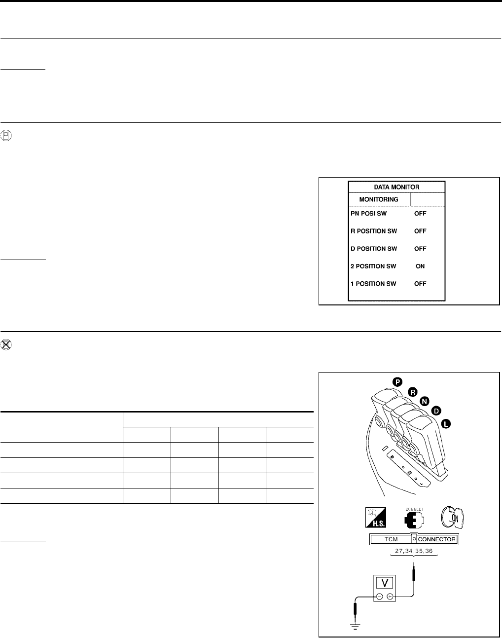
AT-240
[RE4F04B]
TROUBLE DIAGNOSIS FOR SYMPTOMS
Revision: September 2005 2005 Quest
DIAGNOSTIC PROCEDURE
1. INSPECTION START
Do you have CONSULT-II?
Yes or No
Yes >> GO TO 2.
No >> GO TO 3.
2. CHECK PARK/NEUTRAL POSITION (PNP) SWITCH CIRCUIT (WITH CONSULT-II)
With CONSULT-II
1. Turn ignition switch to “ON” position. (Do not start engine.)
2. Select “DATA MONITOR” mode for “A/T” with CONSULT-II.
3. Read out P/N, R, D, 2nd position switches moving selector lever
to each position.
Check that the signal of the selector lever position is indicated
properly.
NOTE:
“2 POSITION SW” indicates L position status.
OK or NG
OK >> GO TO 8.
NG >> GO TO 4.
3. CHECK PARK/NEUTRAL POSITION (PNP) SWITCH CIRCUIT (WITHOUT CONSULT-II)
Without CONSULT-II
1. Turn ignition switch to ON position. (Do not start engine.)
2. Check voltage between TCM harness connector E143 terminals
27 (P/B), 34 (G), 35 (G/W), 36 (R/G) and ground while moving
selector lever through each position.
B: Battery voltage
0: 0V
OK or NG
OK >> GO TO 9.
NG >> GO TO 4.
SAT701J
Lever Position Terminal
36 35 34 27
P, N B000
R0B00
D00B0
L 000B
SCIA3373E
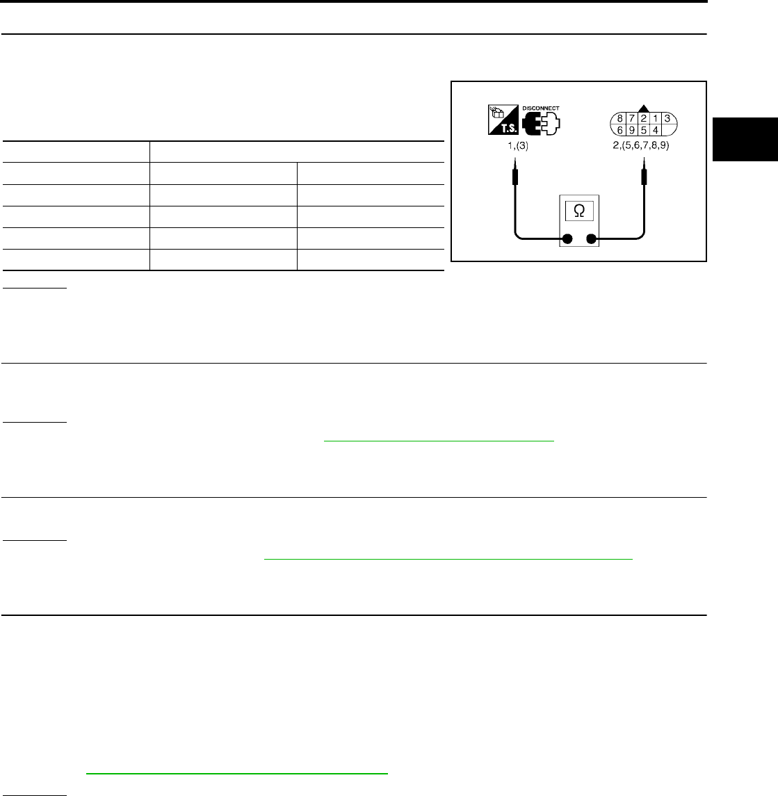
TROUBLE DIAGNOSIS FOR SYMPTOMS
AT-241
[RE4F04B]
D
E
F
G
H
I
J
K
L
M
A
B
AT
Revision: September 2005 2005 Quest
4. CHECK PARK/NEUTRAL POSITION (PNP) SWITCH
Check the following item:
●Park/neutral position (PNP) switch
Check continuity between PNP switch harness connector F29
terminals 1 and 2 and between terminals 3 and 5, 6, 7, 8 and 9
while moving manual shaft through each position.
OK or NG
OK >> GO TO 7.
NG >> GO TO 5.
5. CHECK MANUAL CONTROL CABLE ADJUSTMENT
Check PNP switch again with manual control cable disconnected from manual shaft of A/T assembly. Refer to
test group 2 (With CONSULT-II) or 7 (With out CONSULT-II).
OK or NG
OK >> Adjust manual control cable. Refer to AT-258, "Control Cable Adjustment" .
NG >> GO TO 6.
6. CHECK PNP SWITCH ADJUSTMENT
Remove PNP switch from A/T assembly and check continuity of PNP switch terminals. Refer to test group 3.
OK or NG
OK >> Adjust PNP switch. Refer to AT-255, "Park/Neutral Position (PNP) Switch Adjustment" .
NG >> Repair or replace PNP switch.
7. DETECT MALFUNCTIONING ITEM
Check the following items:
●Fuse
●Harness for short or open between ignition switch and park/neutral position (PNP) switch
●Harness for short or open between park/neutral position (PNP) switch and TCM
●Harness for short or open between park/neutral position (PNP) switch and combination meter
●Harness for short or open between combination meter and TCM
●Ignition switch
Refer to PG-4, "POWER SUPPLY ROUTING CIRCUIT" .
OK or NG
OK (With CONSULT-II)>>GO TO 8.
OK (Without CONSULT-II)>>GO TO 9.
NG >> Repair or replace damaged parts.
Lever position Terminal
P 3 - 7 1 - 2
R3 - 8
N 3 - 9 1 - 2
D3 - 6
L3 - 5 SCIA3372E

AT-242
[RE4F04B]
TROUBLE DIAGNOSIS FOR SYMPTOMS
Revision: September 2005 2005 Quest
8. CHECK OVERDRIVE CONTROL SWITCH CIRCUIT (WITH CONSULT-II)
With CONSULT-II
1. Turn ignition switch to “ON” position. (Do not start engine.)
2. Select “DATA MONITOR” mode for “A/T” with CONSULT-II.
3. Read out “OVERDRIVE SW”.
Check the signal of the overdrive control switch is indicated
properly.
(Overdrive switch “ON” displayed on CONSULT-II means over-
drive “OFF”.)
OK or NG
OK >> GO TO 10.
NG >> GO TO 9.
9. CHECK OVERDRIVE CONTROL SWITCH
Check the following item:
●Overdrive control switch
–Check continuity between A/T device (overdrive control switch)
harness connector M34 terminals 1 and 2.
OK or NG
OK >> GO TO 10.
NG >> Repair or replace damaged parts.
10. DETECT MALFUNCTIONING ITEM
Check the following items:
●Harness for short or open between combination meter and A/T device (overdrive control switch)
●Harness of ground circuit for A/T device (overdrive control switch) for short or open
●Combination meter
Refer to DI-5, "COMBINATION METERS" .
OK or NG
OK (With CONSULT-II)>>GO TO 11.
OK (Without CONSULT-II)>>GO TO 12.
NG >> Repair or replace damaged parts.
SAT645J
Switch position Continuity
ON No
OFF Yes
SCIA3425E

TROUBLE DIAGNOSIS FOR SYMPTOMS
AT-243
[RE4F04B]
D
E
F
G
H
I
J
K
L
M
A
B
AT
Revision: September 2005 2005 Quest
11. CHECK CLOSED THROTTLE POSITION AND WIDE OPEN THROTTLE POSITION SIGNAL CIR-
CUIT (WITH CONSULT-II)
With CONSULT-II
1. Turn ignition switch to “ON” position. (Do not start engine.)
2. Select “DATA MONITOR” mode for A/T with CONSULT-II.
3. Read out “CLOSED THL/SW” and “W/O THRL-SW” depressing and releasing accelerator pedal.
Check the signal of throttle position signal is indicated properly.
OK or NG
OK >> GO TO 13.
NG >> Check the following items. If any items are damaged, repair or replace damaged parts.
●Accelerator pedal position (APP) sensor — Refer to AT-178, "DTC P1705 THROTTLE POSI-
TION SENSOR [ACCELERATOR PEDAL POSITION (APP) SENSOR]" .
●Harness for short or open between accelerator pedal position sensor and ECM
12. CHECK CLOSED THROTTLE POSITION AND WIDE OPEN THROTTLE POSITION SIGNAL CIR-
CUIT (WITHOUT CONSULT-II)
Without CONSULT-II
Check the following items:
●Accelerator pedal position sensor — Refer to AT-178, "DTC P1705 THROTTLE POSITION SENSOR
[ACCELERATOR PEDAL POSITION (APP) SENSOR]" .
●Harness for short or open between accelerator pedal position sensor and ECM
OK or NG
OK >> GO TO 13.
NG >> Repair or replace damaged parts.
13. CHECK SYMPTOM
Check again.
OK or NG
OK >> INSPECTION END
NG >> GO TO 14.
Accelerator pedal
condition
Data monitor
CLOSED THL/SW W/O THRL-SW
Released ON OFF
Fully depressed OFF ON
SAT646J

AT-244
[RE4F04B]
TROUBLE DIAGNOSIS FOR SYMPTOMS
Revision: September 2005 2005 Quest
14. CHECK TCM INSPECTION
1. Perform TCM input/output signal inspection. Refer to AT-96, "TCM Terminals and Reference Value" .
2. If NG, recheck TCM pin terminals for damage or loose connection with harness connector.
OK or NG
OK >> INSPECTION END
NG >> Repair or replace damaged parts.
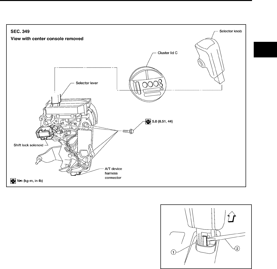
SHIFT CONTROL SYSTEM
AT-245
[RE4F04B]
D
E
F
G
H
I
J
K
L
M
A
B
AT
Revision: September 2005 2005 Quest
SHIFT CONTROL SYSTEM PFP:34901
Removal and Installation UCS0024G
CONTROL DEVICE
SELECTOR KNOB
REMOVAL
1. Slide the selector knob cover downwards with fingers to reveal
the selector knob latch.
2. Gently pry the selector knob latch outward to release then lift the
selector knob up to remove.
INSTALLATION
Set the selector knob in place on the selector lever and push downward until the selector knob latch engages.
BCIA0021E
WCIA0235E
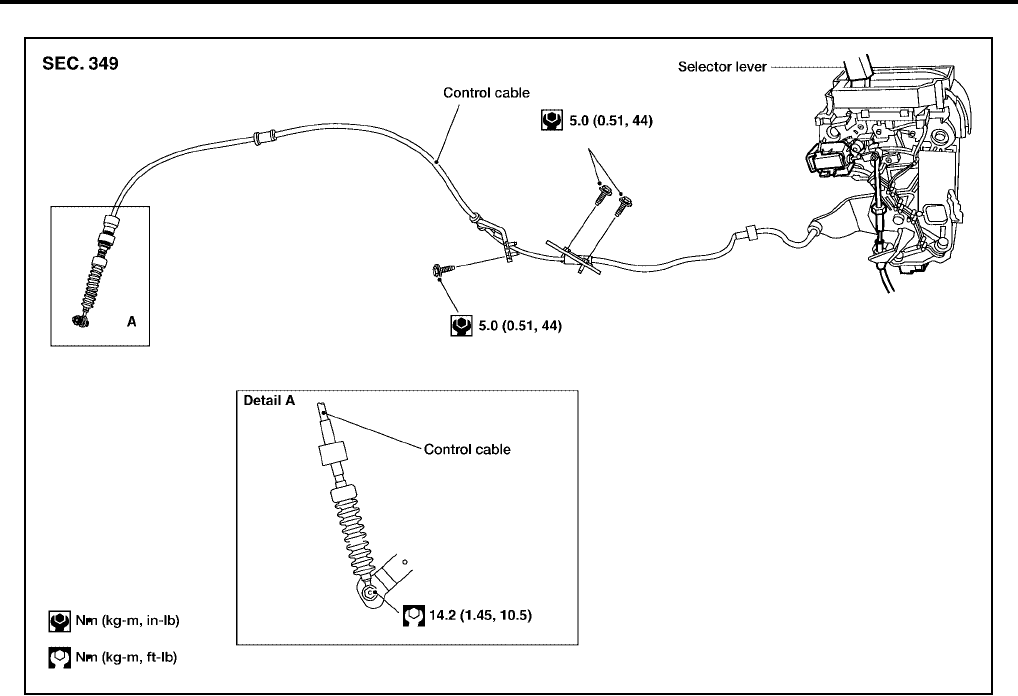
AT-246
[RE4F04B]
SHIFT CONTROL SYSTEM
Revision: September 2005 2005 Quest
Control Cable UCS000R9
BCIA0023E

A/T SHIFT LOCK SYSTEM
AT-247
[RE4F04B]
D
E
F
G
H
I
J
K
L
M
A
B
AT
Revision: September 2005 2005 Quest
A/T SHIFT LOCK SYSTEM PFP:34950
Description UCS00161
●The mechanical key interlock mechanism also operates as a shift lock:
With the ignition switch turned to ON, the selector lever cannot be shifted from “P” (parking) to any other
position unless the brake pedal is depressed.
With the key removed, the selector lever cannot be shifted from “P” to any other position.
The key cannot be removed unless the selector lever is placed in “P”.
●The shift lock and key interlock mechanisms are controlled by the ON-OFF operation of the shift lock sole-
noid and by the operation of the rotator and slider located inside the key cylinder.
Shift Lock System Electrical Parts Location UCS00162
BCIA0017E

AT-248
[RE4F04B]
A/T SHIFT LOCK SYSTEM
Revision: September 2005 2005 Quest
Wiring Diagram — AT — SHIFT UCS00163
BCWA0523E
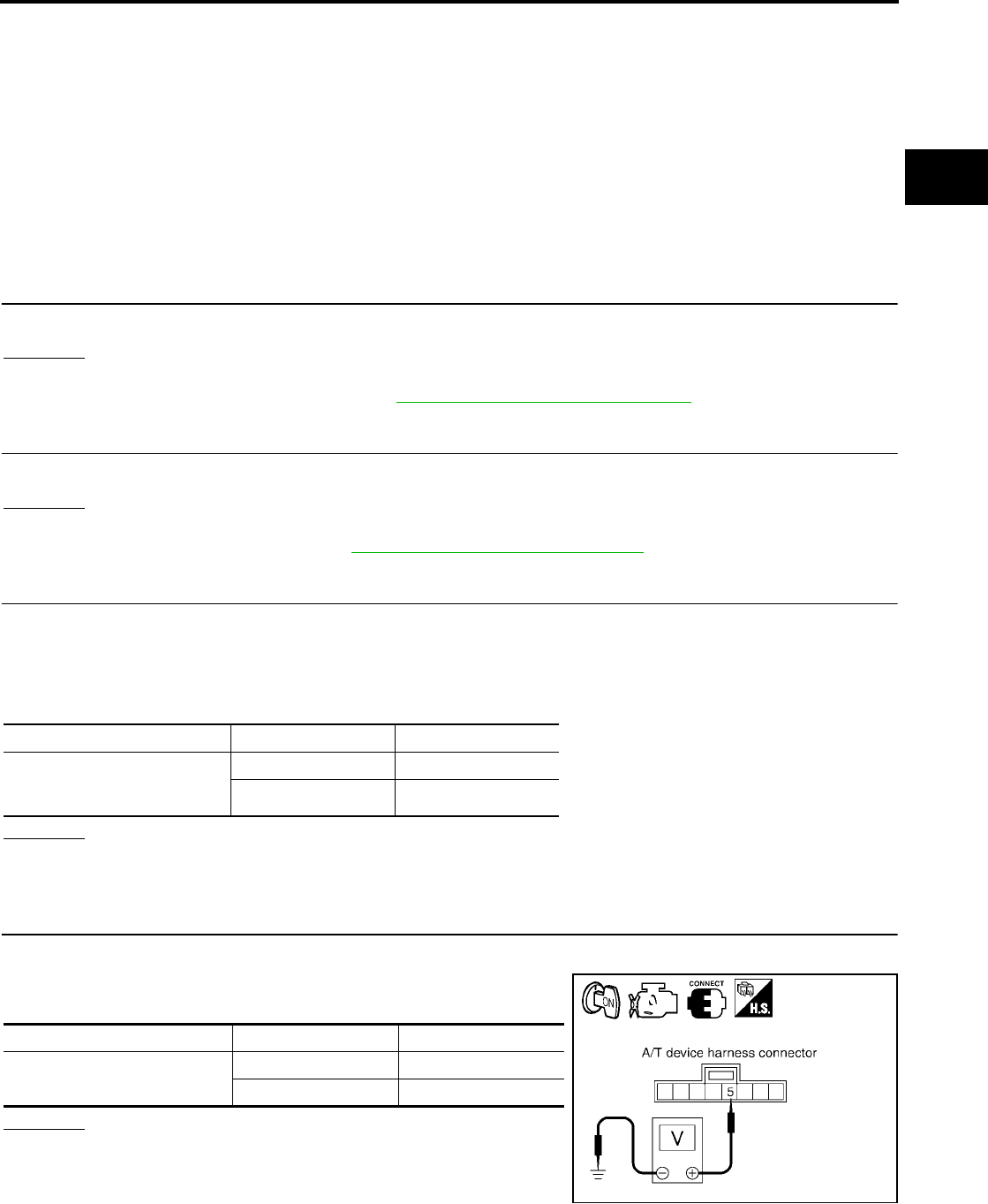
A/T SHIFT LOCK SYSTEM
AT-249
[RE4F04B]
D
E
F
G
H
I
J
K
L
M
A
B
AT
Revision: September 2005 2005 Quest
Diagnostic Procedure UCS00164
SYMPTOM 1:
●Selector lever cannot be moved from “P” position with key in ON position and brake pedal
applied.
●Selector lever can be moved from “P” position with key in ON position and brake pedal released.
●Selector lever can be moved from “P” position when key is removed from key cylinder.
SYMPTOM 2:
●Ignition key cannot be removed when selector lever is set to “P” position.
●Ignition key can be removed when selector lever is set to any position except “P”.
1. CHECK KEY INTERLOCK CABLE
Check the key interlock cable for damage.
OK or NG
OK >> GO TO 2.
NG >> Repair key interlock cable. Refer to AT-251, "KEY INTERLOCK CABLE" .
2. CHECK SELECTOR LEVER POSITION
Check the selector lever position for damage.
OK or NG
OK >> GO TO 3.
NG >> Check selector lever. Refer to AT-258, "Control Cable Adjustment" .
3. CHECK SHIFT LOCK SOLENOID AND PARK POSITION SWITCH
1. Connect A/T device harness connector.
2. Turn ignition switch “ON”.
3. Selector lever is set in “P” position.
4. Check operation sound.
OK or NG
OK >> INSPECTION END
NG >> GO TO 4.
4. CHECK POWER SOURCE
1. Turn ignition switch “ON”. (Do not start engine.)
2. Check the voltage between A/T device harness connector M34
terminal 5 (R) and ground.
OK or NG
OK >> GO TO 7.
NG >> GO TO 5.
Condition Brake pedal Operation sound
When ignition switch is turned
to “ON” position and selector
lever is set in “P” position.
Depressed Yes
Released No
Condition Brake pedal Data (Approx.)
When ignition switch is turned to
“ON” position.
Depressed Battery voltage
Released 0V
SCIA3437E

AT-250
[RE4F04B]
A/T SHIFT LOCK SYSTEM
Revision: September 2005 2005 Quest
5. CHECK STOP LAMP SWITCH
1. Turn ignition switch “OFF”.
2. Disconnect stop lamp switch harness connector.
3. Check continuity between stop lamp switch harness connector
E38 terminals 3 and 4.
Check stop lamp switch after adjusting brake pedal — refer to
BR-6, "BRAKE PEDAL" .
OK or NG
OK >> GO TO 6.
NG >> Repair or replace damaged parts.
6. DETECT MALFUNCTIONING ITEM
Check the following items. If any items are damaged, repair or replace damaged parts.
●10A fuse [No.1, located in the fuse block (J/B)]
●Harness for short or open between ignition switch and stop lamp switch harness connector E38 terminal 3
(R/W)
●Harness for short or open between stop lamp switch harness connector E38 terminal 4 (L) and diode-4
harness connector E149 terminal 2 (L).
●Harness for short or open between diode-4 harness connector E149 terminal 1 (R) and A/T device har-
ness connector M34 terminal 5 (R).
●Diode-4
●Ignition switch (Refer to PG-4, "POWER SUPPLY ROUTING CIRCUIT" .)
OK or NG
OK >> GO TO 7.
NG >> Repair or replace damaged parts.
7. CHECK GROUND CIRCUIT
1. Turn ignition switch “OFF”.
2. Disconnect A/T device harness connector.
3. Check continuity between A/T device harness connector M34
terminal 6 (B) and ground.
4. Connect A/T device harness connector.
OK or NG
OK >> Replace shift lock solenoid or park position switch.
NG >> Repair open circuit or short to ground or short to power
in harness or connectors.
Condition Continuity
When brake pedal is depressed Yes
When brake pedal is released No
SCIA2126E
Continuity should exist.
SCIA3438E

KEY INTERLOCK CABLE
AT-251
[RE4F04B]
D
E
F
G
H
I
J
K
L
M
A
B
AT
Revision: September 2005 2005 Quest
KEY INTERLOCK CABLE PFP:34908
Components UCS001EH
CAUTION:
●Install key interlock cable in such a way that it will not be damaged by sharp bends, twists or inter-
ference with adjacent parts.
●After installing key interlock cable to control device, make sure that casing cap and bracket are
firmly secured in their positions. If casing cap can be removed with an external load of less than
39.2 N (4.0 kg, 8.8 lb), replace key interlock cable with new one.
Removal UCS001EI
1. Unlock slider by squeezing lock tabs on slider from adjuster
holder.
2. Remove casing cap from bracket of control device and remove
interlock rod from cable.
WCIA0231E
WCIA0232E
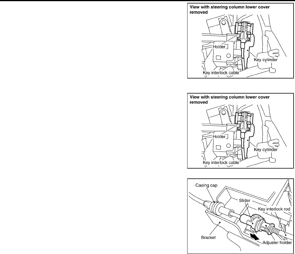
AT-252
[RE4F04B]
KEY INTERLOCK CABLE
Revision: September 2005 2005 Quest
3. Remove holder from key cylinder and remove key interlock
cable.
Installation UCS001EJ
1. Set key interlock cable to key cylinder and install holder.
2. Turn ignition key to lock position.
3. Set selector lever to P position.
4. Insert interlock rod into adjuster holder.
5. Install casing cap to bracket.
6. Move slider in order to fix adjuster holder to interlock rod.
WCIA0233E
WCIA0233E
WCIA0234E
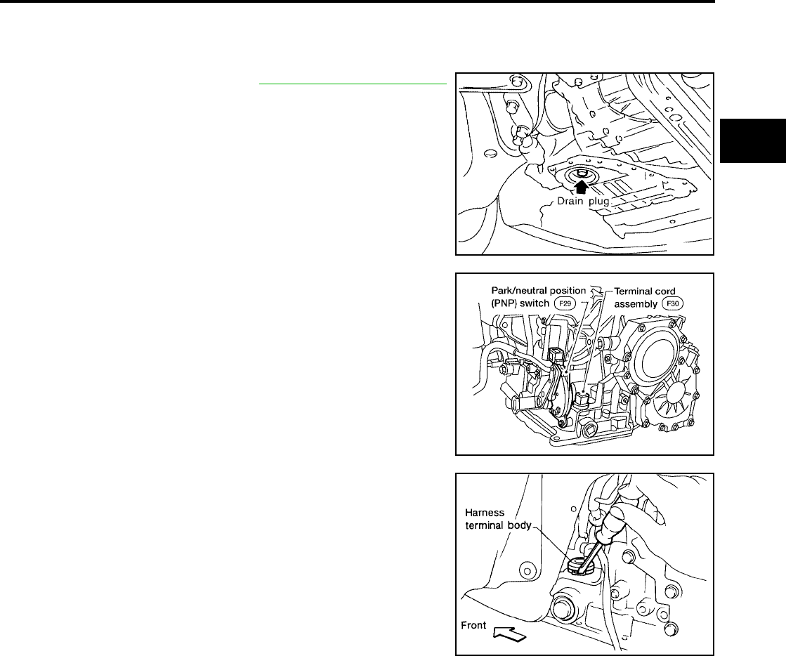
ON-VEHICLE SERVICE
AT-253
[RE4F04B]
D
E
F
G
H
I
J
K
L
M
A
B
AT
Revision: September 2005 2005 Quest
ON-VEHICLE SERVICE PFP:00000
Control Valve Assembly and Accumulators UCS000RA
REMOVAL
1. Drain ATF from transaxle. Refer to MA-23, "Changing A/T Fluid"
.
2. Remove oil pan using power tools, and gasket.
●Do not reuse oil pan bolts.
3. Disconnect terminal cord assembly harness connector.
4. Remove stopper ring from terminal cord assembly harness ter-
minal body.
5. Remove terminal cord assembly harness from transmission
case by pushing on terminal body.
SAT031J
WCIA0071E
SAT995C
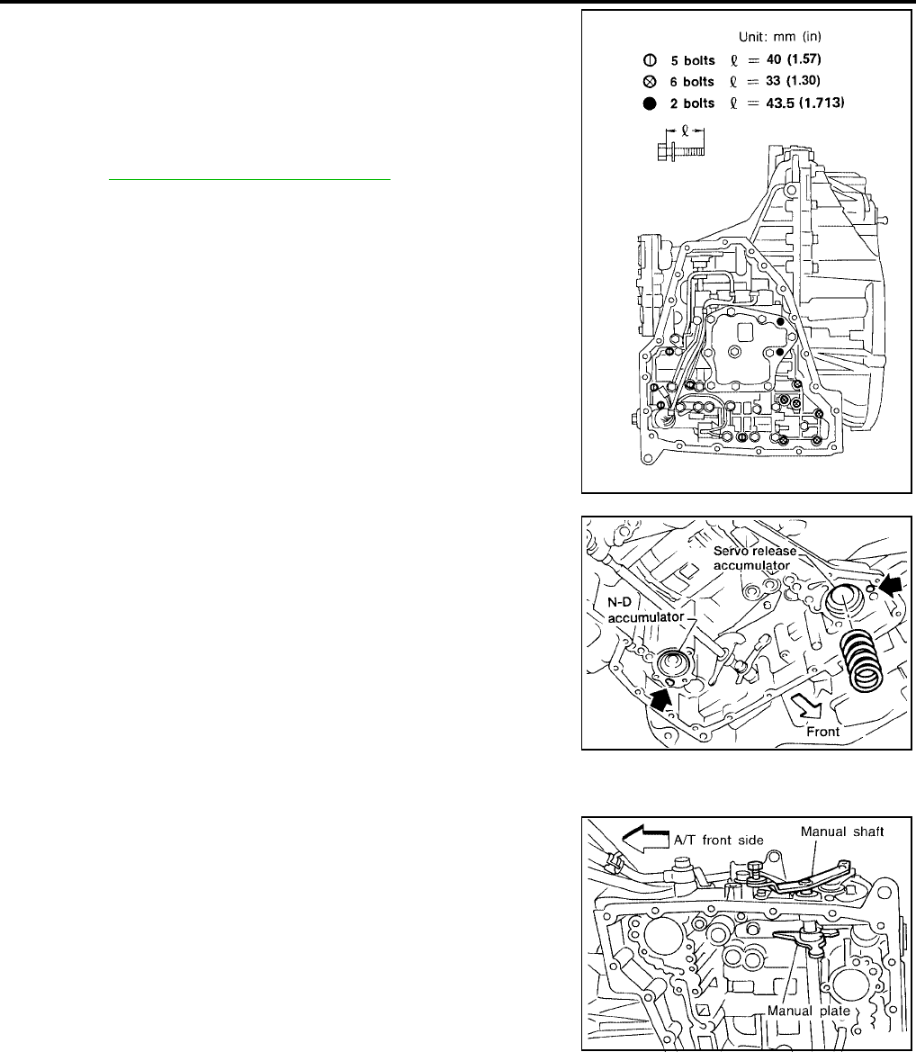
AT-254
[RE4F04B]
ON-VEHICLE SERVICE
Revision: September 2005 2005 Quest
6. Remove control valve assembly by removing fixing bolts I , X
and ●.
Bolt length, number and location are shown in the illustration.
CAUTION:
Be careful not to drop manual valve and servo release accu-
mulator return spring.
7. Disassemble and inspect control valve assembly if necessary.
Refer to AT-290, "Control Valve Assembly" .
8. Remove servo release and N-D accumulators by applying com-
pressed air if necessary.
●Hold each piston with a rag.
INSTALLATION
Note the following, and installation is in the reverse order of removal.
●Set manual shaft in Neutral, then align manual plate with
groove in manual valve.
●After installing control valve assembly, make sure that
selector lever can be moved to all positions.
SAT004F
AAT279
SAT091J
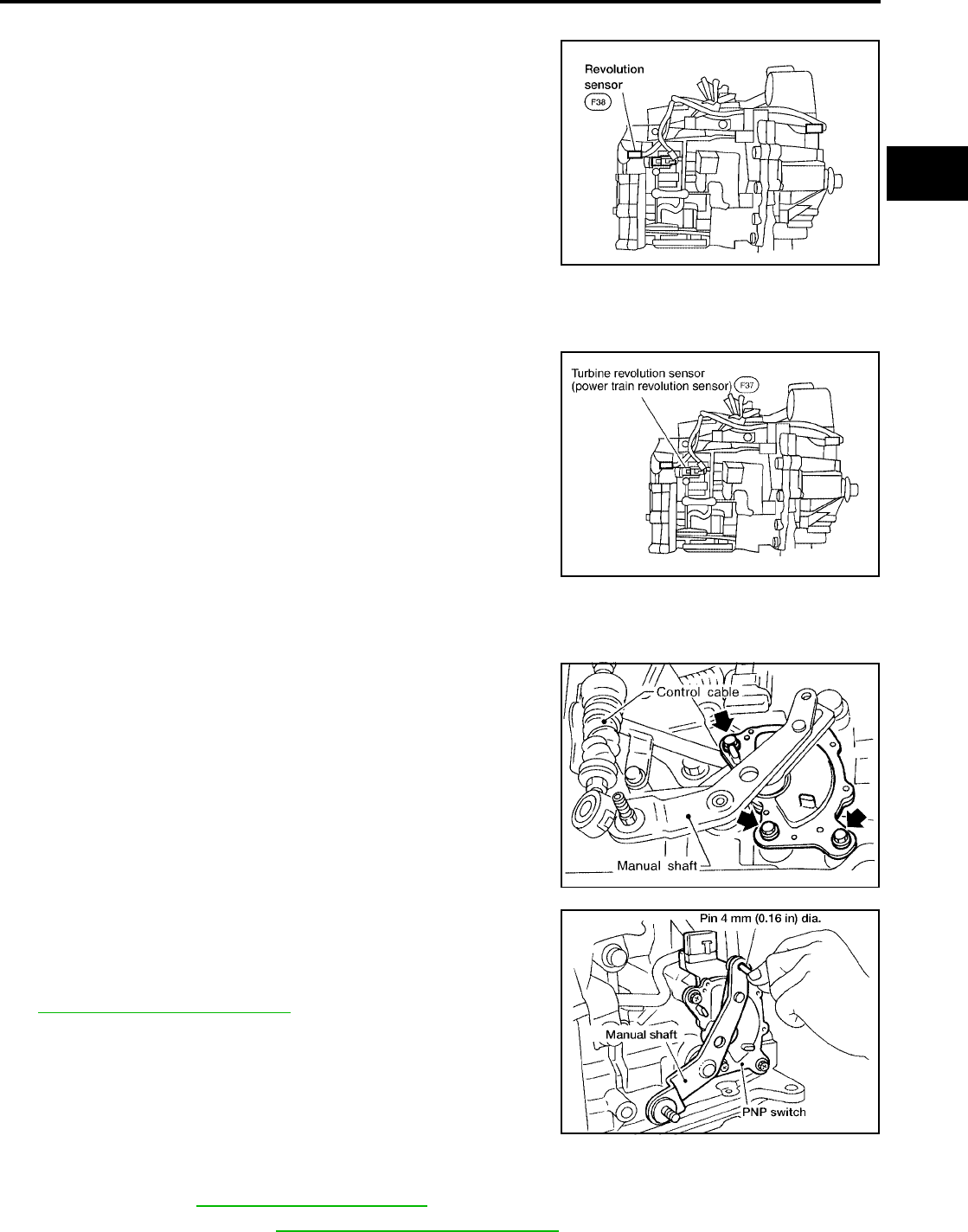
ON-VEHICLE SERVICE
AT-255
[RE4F04B]
D
E
F
G
H
I
J
K
L
M
A
B
AT
Revision: September 2005 2005 Quest
Revolution Sensor Replacement UCS000RB
1. Disconnect electrical connector.
2. Remove revolution sensor from A/T.
3. Installation is in the reverse order of removal.
CAUTION:
●Do not reuse O-ring.
●Apply petroleum jelly to O-ring.
●Be careful not to mis-connect because shape of connec-
tors are same as turbine revolution sensor (power train
revolution sensor).
NOTE:
To prevent mis-connect, revolution sensor harness connector is
color taped for identification.
Turbine Revolution Sensor (Power Train Revolution Sensor) Replacement UCS000RC
1. Disconnect electrical connector.
2. Remove bolt, and turbine revolution sensor (power train revolu-
tion sensor) from A/T.
3. Installation is in the reverse order of removal.
CAUTION:
●Do not reuse O-ring.
●Apply petroleum jelly to O-ring.
●Be careful not to mis-connect because shape of connec-
tors are same as revolution sensor.
NOTE:
To prevent mis-connection, revolution sensor harness connector
is color taped for identification.
Park/Neutral Position (PNP) Switch Adjustment UCS000RD
1. Remove control cable from manual shaft.
2. Set manual shaft in N position.
3. Loosen park/neutral position (PNP) switch fixing bolts.
4. Insert pin into adjustment holes in both park/neutral position
(PNP) switch and manual shaft as near vertical as possible.
5. Installation is in the reverse order of removal.
6. Check continuity of park/neutral position (PNP) switch. Refer to
AT-109, "Diagnostic Procedure" .
ATF Cooler UCS0010W
REMOVAL
1. Drain ATF. Refer to MA-23, "Changing A/T Fluid" .
2. Drain engine coolant, refer to MA-14, "Changing Engine Coolant" .
LCIA0070E
SCIA3402E
SAT033J
AAT469A
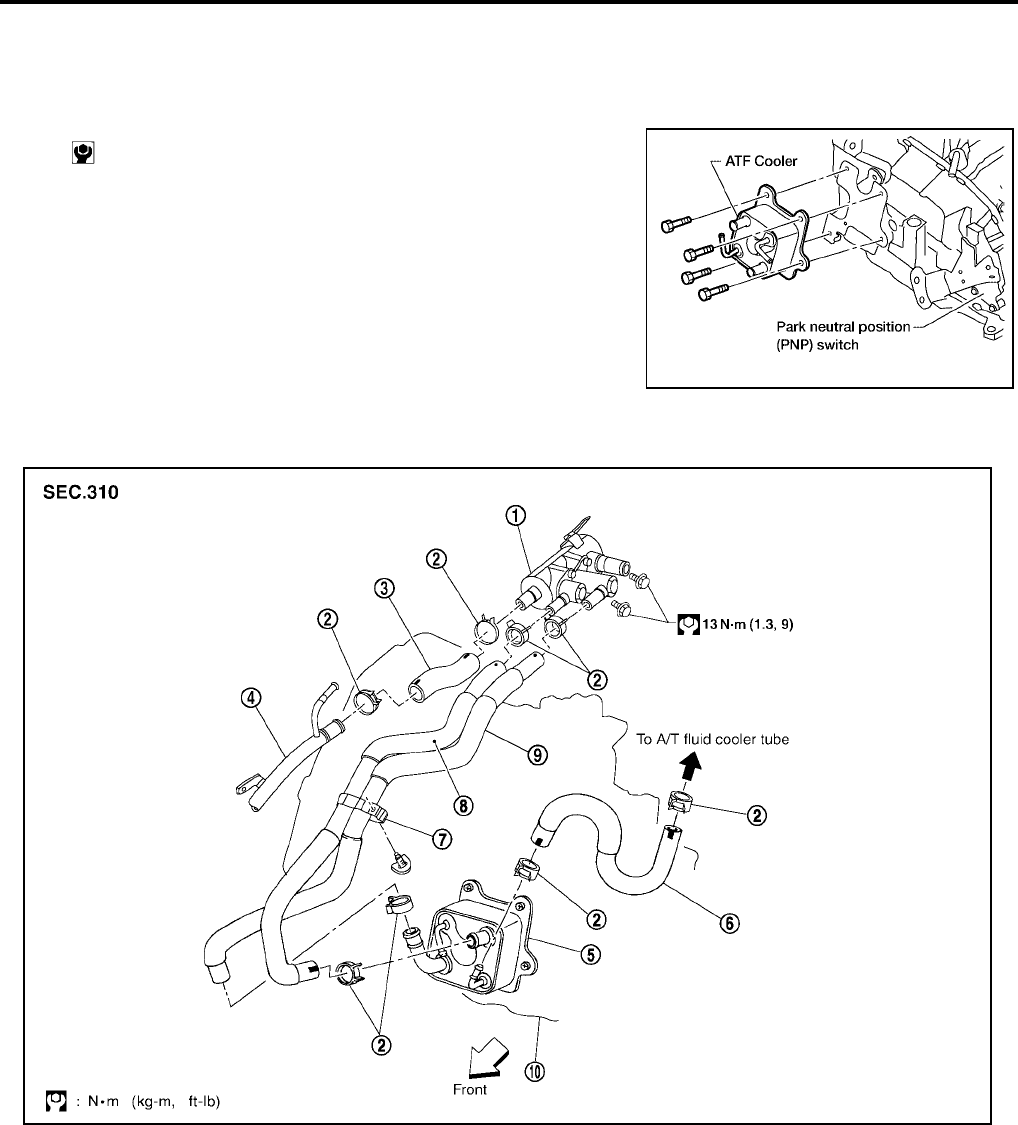
AT-256
[RE4F04B]
ON-VEHICLE SERVICE
Revision: September 2005 2005 Quest
3. Remove hose clamps and hoses from ATF cooler.
4. Remove four bolts from ATF cooler and remove ATF cooler.
INSTALLATION
Installation is the reverse order of removal.
ATF Cooler Valve UCS0015L
Refer to the figure for ATF cooler valve and hoses removal and installation information.
: 4.2 N·m (0.43 kg-m, 37 in-lb)
BBIA0278E
1. ATF cooler valve assembly 2. Hose clamp 3. Heater hose
4. Heater pipe 5. ATF cooler 6. ATF cooler hose
7. Hose clip 8. Outlet water hose 9. Inlet water hose
10. Transaxle assembly
SCIA3849E

ON-VEHICLE SERVICE
AT-257
[RE4F04B]
D
E
F
G
H
I
J
K
L
M
A
B
AT
Revision: September 2005 2005 Quest
COMPONENT INSPECTION
1. Make sure that ATF cooler valve is fully opened at room temper-
ature.
2. Submerge ATF cooler valve in a water-filled container, and then
heat it up with temperature of over 82°C (180°F) for 10 minutes
more.
3. Make sure that ATF cooler valve is fully closed.
Dimension “A”: More than 72.0 mm (2.835 in)
A: Distance between ATF cooler valve port end face
and valve shaft end face.
SCIA2711J
SCIA2993E
Dimension “A”: Less than 66.5 mm (2.618 in)
A: Distance between ATF cooler valve port end face
and valve shaft end face.
SCIA2711J
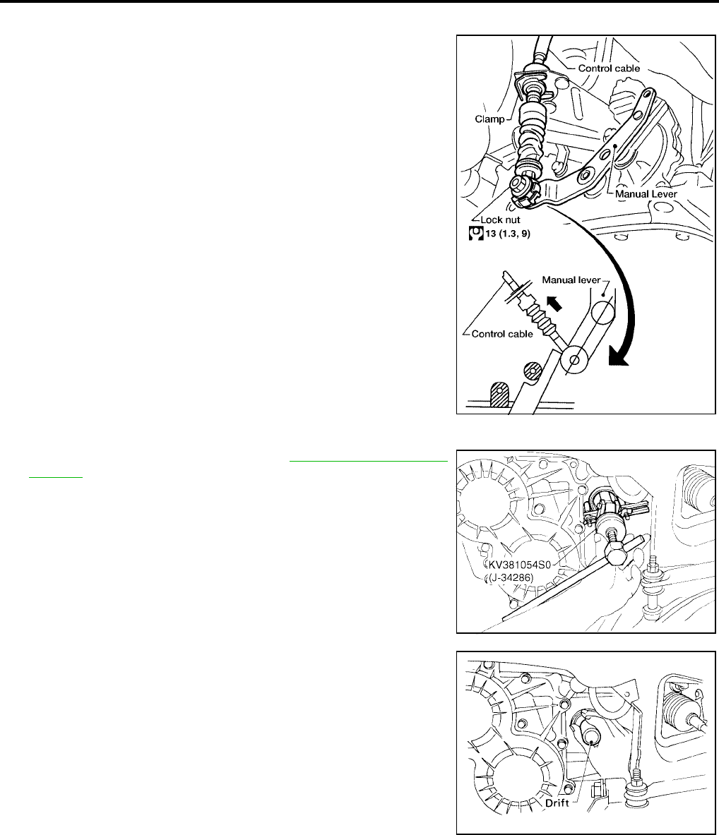
AT-258
[RE4F04B]
ON-VEHICLE SERVICE
Revision: September 2005 2005 Quest
Control Cable Adjustment UCS000RE
Move selector lever from the P position to the L position. You should
be able to feel the detent in each position. If the detent cannot be felt
or the pointer indicating the position is improperly aligned, the control
cable needs adjustment.
1. Place selector lever in the P position.
CAUTION:
Turn wheels more than 1/4 turn and apply the parking brake.
2. Loosen control cable lock nut.
3. Secure the manual lever.
4. Using the specified force, push control cable in the direction of
the arrow shown in the illustration.
5. Tighten control cable lock nut.
6. Move selector lever from P to L position. Make sure that selector
lever moves smoothly.
●Make sure that the starter operates when the selector
lever is placed in the N or P position.
●Make sure that the transmission is locked properly when
the selector lever is placed in the P position.
Differential Side Oil Seal Replacement UCS000RF
1. Remove drive shaft assembly. Refer toFAX-8, "FRONT DRIVE
SHAFT" .
2. Remove oil seal.
3. Install oil seal.
●Apply ATF before installing.
Specified force : 9.8 N (1.0 kg, 2.2 lb)
WCIA0211E
SCIA5377E
SAT782
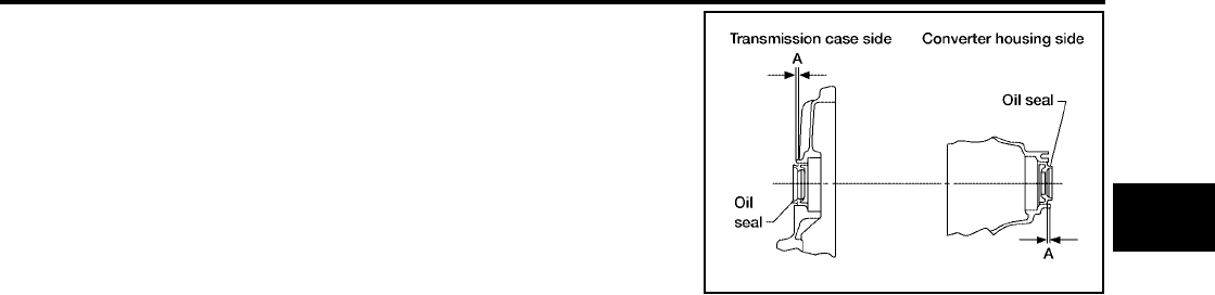
ON-VEHICLE SERVICE
AT-259
[RE4F04B]
D
E
F
G
H
I
J
K
L
M
A
B
AT
Revision: September 2005 2005 Quest
●Install oil seals so dimension A is within specification
4. Installation is in the reverse order of removal.
A: −0.5 mm (−0.02 in) to 0.5 mm (0.02 in)
AAT531A
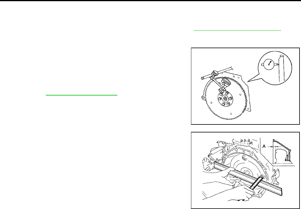
AT-260
[RE4F04B]
REMOVAL AND INSTALLATION
Revision: September 2005 2005 Quest
REMOVAL AND INSTALLATION PFP:00000
Removal UCS001E2
Remove the engine and transaxle assembly from the vehicle. Refer to EM-134, "ENGINE ASSEMBLY" .
Inspection After Removal UCS001E3
●Drive plate runout
CAUTION:
Do not allow any magnetic materials to contact the ring
gear teeth.
●If this runout is out of allowance, replace drive plate and ring
gear.
●When connecting torque converter to transaxle, measure dis-
tance “A” to be certain that they are correctly assembled.
Installation UCS001E4
Install in the reverse order of removal.
Maximum allowable runout:
Refer to EM-167, "DRIVE PLATE" .
SAT977H
Distance “A” : 14 mm (0.55 in) or more
SAT044A

OVERHAUL
AT-261
[RE4F04B]
D
E
F
G
H
I
J
K
L
M
A
B
AT
Revision: September 2005 2005 Quest
OVERHAUL PFP:00000
Components UCS000RI
1. Differential side bearing adjusting
shim
2. Differential side bearing 3. Final gear
4. Differential case 5. Pinion mate gear thrust washer 6. Pinion mate gear
7. Pinion mate shaft 8. Lock pin 9. Side gear
10. Side gear thrust washer 11. Differential side bearing 12. Plug
13. O-ring 14. Differential side oil seal 15. Torque converter
16. Cooler bracket 17. Converter housing 18. Differential lubricant tube
19. Clip 20. Input shaft O-ring 21. Oil seal
22. Oil pump housing 23. O-ring 24. Outer gear
25. Inner gear 26. Oil pump cover 27. Oil pump assembly
28. Seal ring 29. Gasket
SCIA3601E
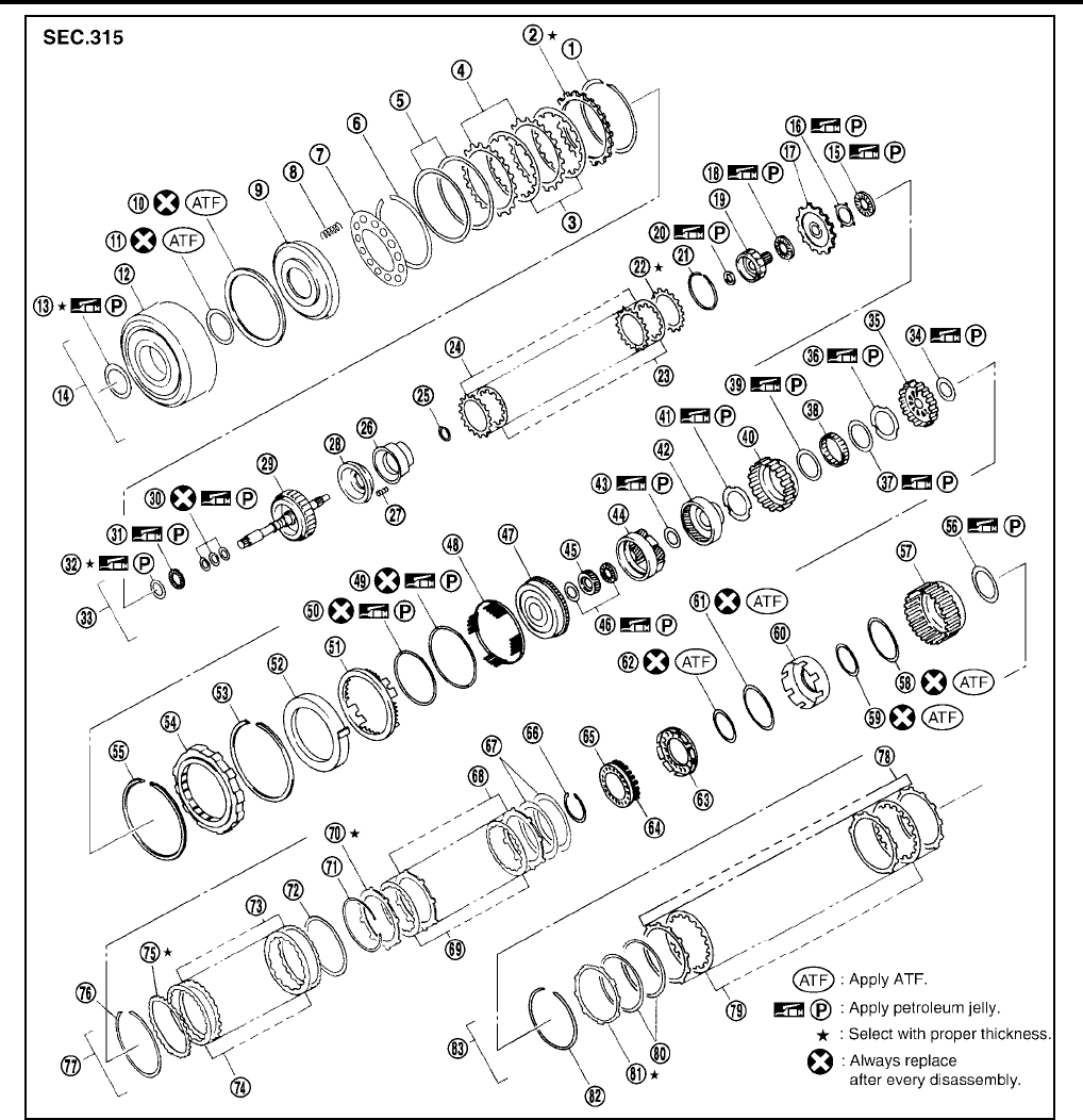
AT-262
[RE4F04B]
OVERHAUL
Revision: September 2005 2005 Quest
1. Snap ring 2. Retaining plate 3. Drive plate
4. Driven plate 5. Dish plate 6. Snap ring
7. Spring retainer 8. Return spring 9. Reverse clutch piston
10. Seal ring 11. D-ring 12. Reverse clutch drum
13. Thrust washer 14. Reverse clutch assembly 15. Needle bearing
16. Bearing race 17. Front sun gear 18. Needle bearing
19. High clutch hub 20. Needle bearing 21. Snap ring
22. Retaining plate 23. Drive plate 24. Driven plate
25. Snap ring 26. Cancel force cover 27. Return spring
28. Input clutch piston 29. High clutch drum 30. Seal ring
31. Needle bearing 32. Bearing race 33. High clutch
34. Needle bearing 35. Overrun clutch hub 36. Thrust washer
37. Bearing 38. Forward one-way clutch 39. Bearing
SCIA3602E

OVERHAUL
AT-263
[RE4F04B]
D
E
F
G
H
I
J
K
L
M
A
B
AT
Revision: September 2005 2005 Quest
40. Forward clutch hub 41. Thrust washer 42. Rear internal gear
43. Needle bearing 44. Rear planetary carrier 45. Rear sun gear
46. Needle bearing 47. Front planetary carrier 48. Spring retainer
49. D-ring 50. D-ring 51. Low & reverse brake piston
52. Retainer 53. Snap ring 54. Low one-way clutch
55. Snap ring 56. Needle bearing 57. Forward clutch drum
58. Seal ring
59.
D-ring 60. Forward clutch piston
61. Seal ring 62. D-ring 63. Overrun clutch piston
64. Return spring 65. Spring retainer 66. Snap ring
67. Dish plate 68. Driven plate 69. Drive plate
70. Retaining plate 71. Snap ring 72. Dish plate
73. Driven plate 74. Drive plate 75. Retaining plate
76. Snap ring 77. Forward clutch and overrun clutch 78. Driven plate
79. Drive plate 80. Dish plate 81. Retaining plate
82. Snap ring 83. Low & reverse brake

AT-264
[RE4F04B]
OVERHAUL
Revision: September 2005 2005 Quest
1. Side cover fitting bolt 2. Side cover 3. Adjusting shim
4. Output shaft bearing 5. Output shaft 6. Seal ring
7. Needle bearing 8. A/T fluid level gauge 9. A/T fluid charging pipe
10. O-ring 11. Oil seal 12. Revolution sensor
13. Turbine revolution sensor (power
train revolution sensor)
14. Bracket 15. Breather hose
16. Lock nut 17. Anchor end pin 18. Transaxle case
SCIA3603E

OVERHAUL
AT-265
[RE4F04B]
D
E
F
G
H
I
J
K
L
M
A
B
AT
Revision: September 2005 2005 Quest
19. Bearing retainer 20. Seal ring 21. Radial needle bearing
22. Snap ring 23. Reduction pinion gear 24. Reduction pinion gear bearing inner
race
25. Reduction pinion gear bearing outer
race
26. Brake band 27. Strut
28. O-ring 29. O-ring 30. Servo release accumulator piston
31. Return spring 32. Control valve assembly 33. Gasket
34. Drain plug gasket 35. Drain plug 36. Magnet
37. Oil pan 38. Oil pan fitting bolt 39. Low & reverse brake tube
40. Oil sleeve 41. Stopper ring 42. O-ring
43. N-D accumulator piston 44. Return spring 45. A/T fluid cooler tube
46. Copper washer 47. Parking rod 48. Retaining pin
49. Oil seal 50. Detente spring 51. Manual shaft
52. Retaining pin 53. Manual plate 54. Parking rod plate
55. O/D servo piston 56. O/D servo piston retainer 57. O-ring
58. D-ring 59. Servo piston retainer 60. O-ring
61. E-ring 62. Spring retainer 63. O/D servo return spring
64. D-ring 65. Band servo piston 66. Band servo thrust washer
67. Band servo piston stem 68. 2nd servo return spring 69. PNP switch
70. Parking pawl 71. Parking shaft 72. Return spring
73. Paring pawl spacer 74. Parking actuator sport 75. Idler gear bearing outer race
76. Adjusting shim 77. Idler gear bearing inner race 78. Idler gear
79. Lock nut
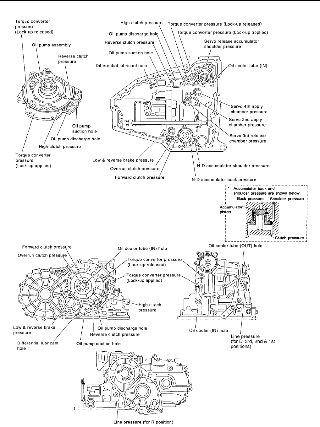
AT-266
[RE4F04B]
OVERHAUL
Revision: September 2005 2005 Quest
Oil Channel UCS000RJ
SCIA3278E
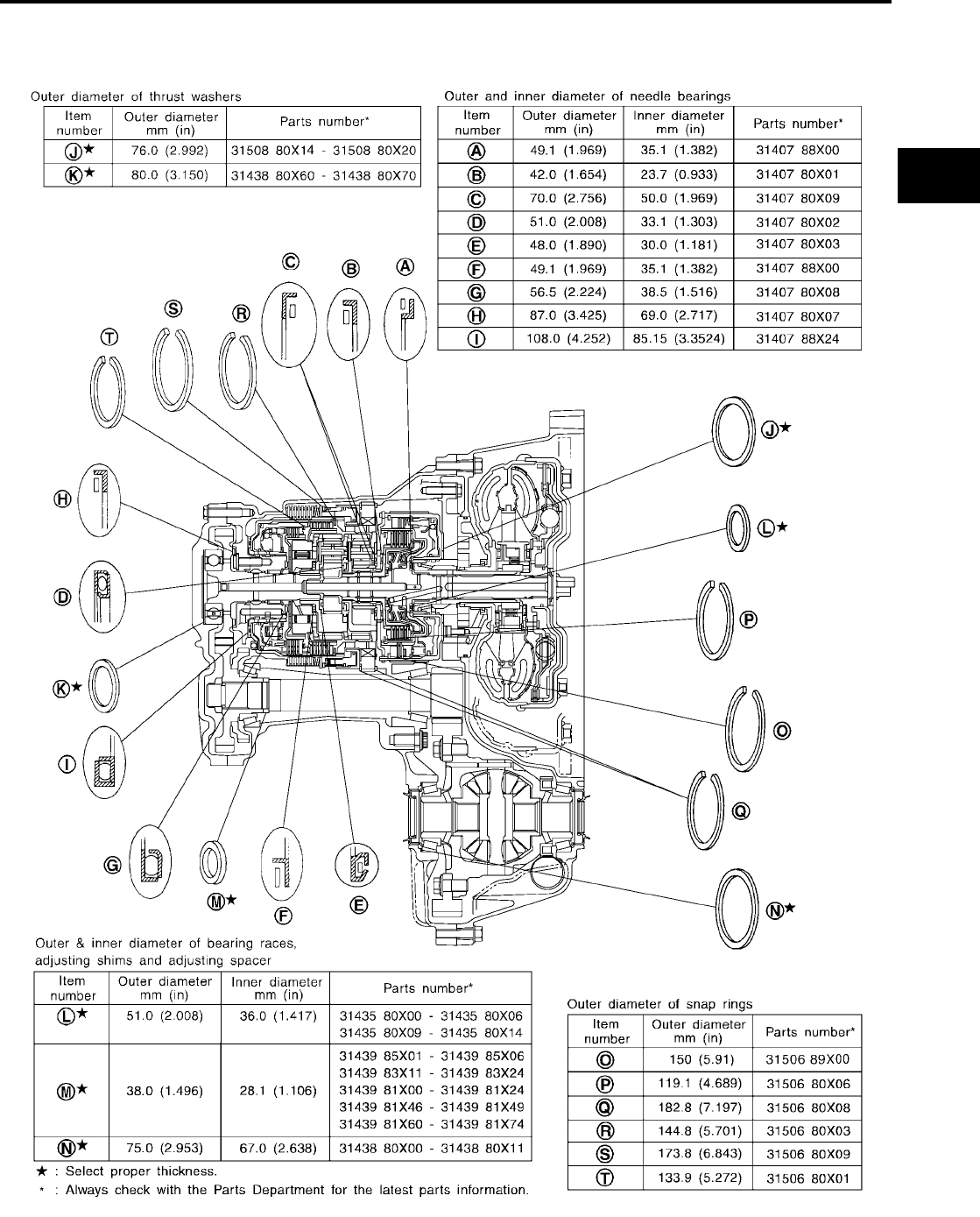
OVERHAUL
AT-267
[RE4F04B]
D
E
F
G
H
I
J
K
L
M
A
B
AT
Revision: September 2005 2005 Quest
Locations of Adjusting Shims, Needle Bearings, Thrust Washers and Snap
Rings UCS000RK
SCIA3277E
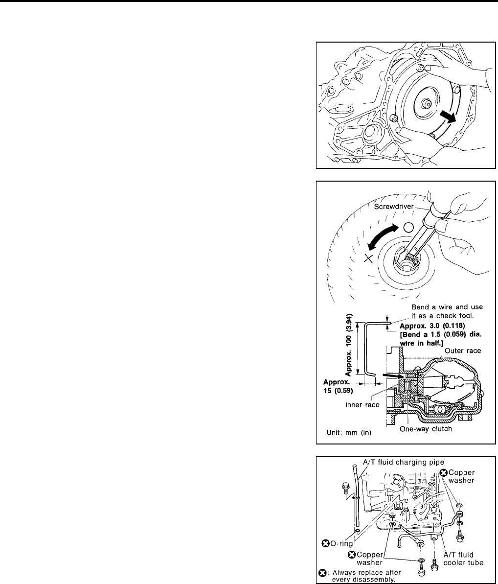
AT-268
[RE4F04B]
DISASSEMBLY
Revision: September 2005 2005 Quest
DISASSEMBLY PFP:31020
Disassembly UCS000RL
1. Drain ATF through drain plug.
2. Remove torque converter.
3. Check torque converter one-way clutch using check tool as
shown at left.
a. Insert check tool into the groove of bearing support built into
one-way clutch outer race.
b. When fixing bearing support with check tool, rotate one- way
clutch spline using screwdriver.
c. Check that inner race rotates clockwise only. If not, replace
torque converter assembly.
4. Remove A/T fluid level gauge.
5. Remove A/T fluid charging pipe and fluid cooler tube.
SAT008D
SAT009D
SCIA3606E
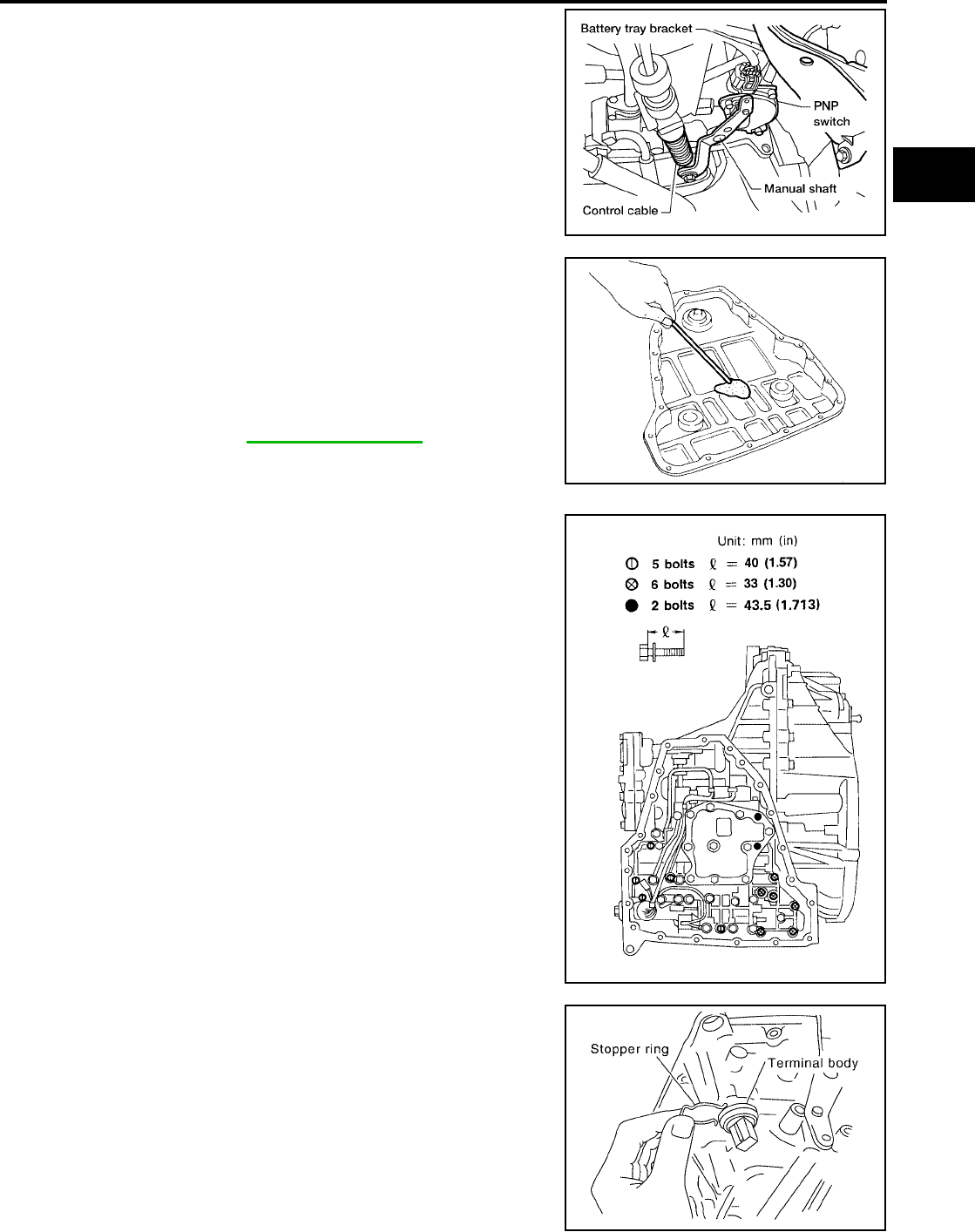
DISASSEMBLY
AT-269
[RE4F04B]
D
E
F
G
H
I
J
K
L
M
A
B
AT
Revision: September 2005 2005 Quest
6. Set manual shaft to position P.
7. Remove park/neutral position (PNP) switch.
8. Remove oil pan using power tools, and oil pan gasket.
9. Check foreign materials in oil pan to help determine causes of
malfunction. If the fluid is very dark, smells burned, or contains
foreign particles, the frictional material (clutches, band) may
need replacement. A tacky film that will not wipe clean indicates
varnish build up. Varnish can cause valves, servo, and clutches
to stick and can inhibit pump pressure.
●If frictional material is detected, replace radiator after
repair of A/T. Refer to CO-10, "RADIATOR" .
10. Remove control valve assembly according to the following pro-
cedures.
a. Remove control valve assembly mounting bolts I , X and ●.
b. Remove stopper ring from terminal body.
●Do not expand stopper ring excessively.
BCIA0014E
SCIA3476E
SAT004F
SCIA3607E
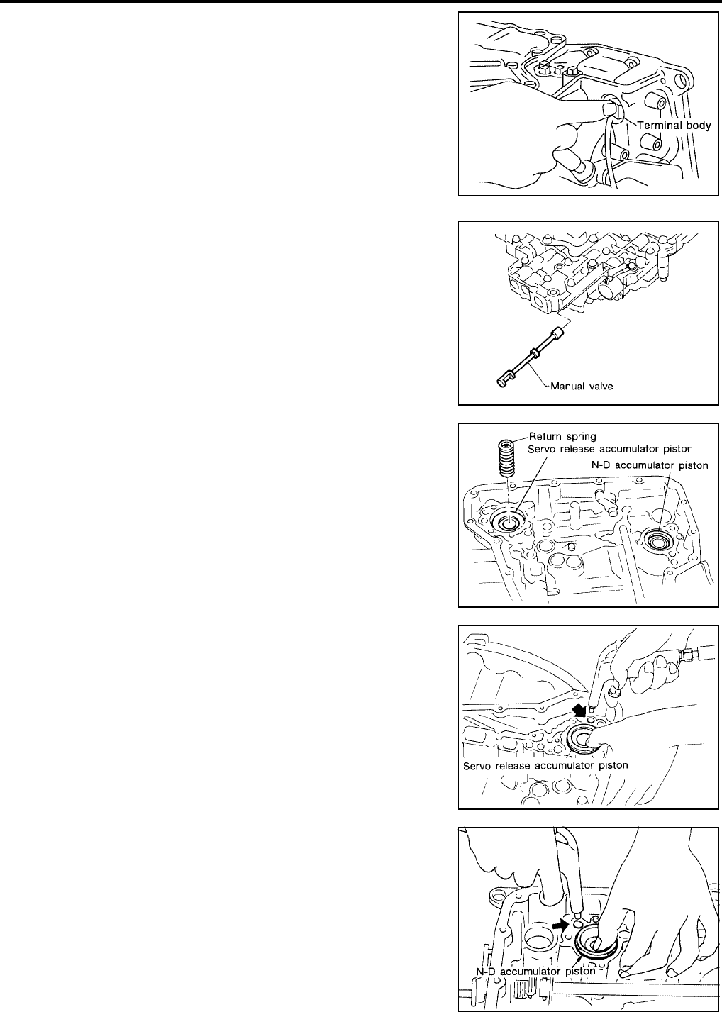
AT-270
[RE4F04B]
DISASSEMBLY
Revision: September 2005 2005 Quest
c. Push terminal body into transaxle case and draw out terminal
cord assembly.
11. Remove manual valve from control valve assembly.
12. Remove return spring from servo release accumulator piston.
13. Remove servo release accumulator piston with compressed air.
CAUTION:
●Strong flow of air will push the accumulator piston out
along with a splash of oil. Cover the area with paper tow-
els and blow air little by little to avoid this.
●Wrap the removed accumulator piston in a paper towel.
14. Remove O-rings from servo release accumulator piston.
15. Remove N-D accumulator piston and return spring with com-
pressed air.
CAUTION:
●Strong flow of air will push the accumulator piston out
along with a splash of oil. Cover the area with paper tow-
els and blow air little by little to avoid this.
●Wrap the removed accumulator piston in a paper towel.
16. Remove O-rings from N-D accumulator piston.
SCIA0801E
SAT005F
SCIA3477E
SAT019DA
SAT020D
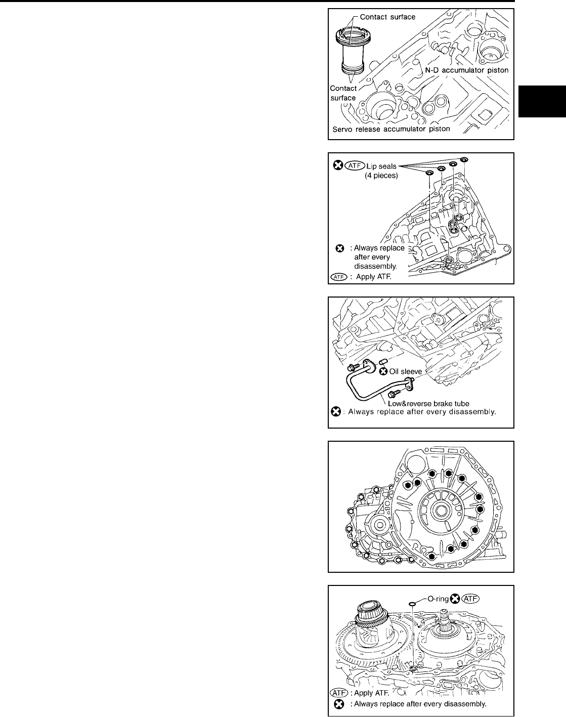
DISASSEMBLY
AT-271
[RE4F04B]
D
E
F
G
H
I
J
K
L
M
A
B
AT
Revision: September 2005 2005 Quest
17. Check accumulator pistons and contact surface of transaxle
case for damage.
18. Check accumulator return springs for damage and free length.
19. Remove lip seals.
20. Remove low & reverse brake tube and oil sleeve.
21. Remove converter housing according to the following proce-
dures.
a. Remove converter housing mounting bolts using power tools.
b. Remove converter housing by tapping it lightly.
c. Remove O-ring from differential oil port.
SAT023DA
SCIA3850E
SCIA3851E
SAT008F
SCIA3852E
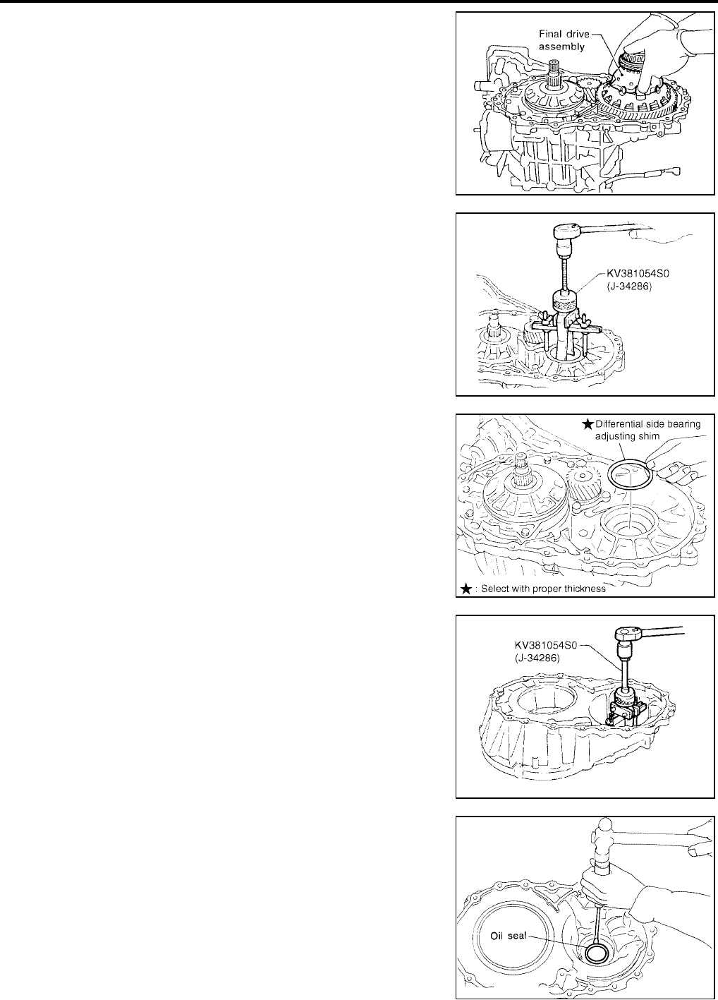
AT-272
[RE4F04B]
DISASSEMBLY
Revision: September 2005 2005 Quest
22. Remove final drive assembly from transaxle case.
23. Remove differential side bearing outer race and side bearing
adjusting shim from transaxle case.
24. Remove differential side bearing adjusting shim from transaxle
case.
25. Remove differential side bearing outer race from converter
housing.
26. Remove oil seal with screwdriver from converter housing.
●Be careful not to damage case.
SAT228F
SCIA5378E
SCIA3628E
SCIA5379E
SAT032D
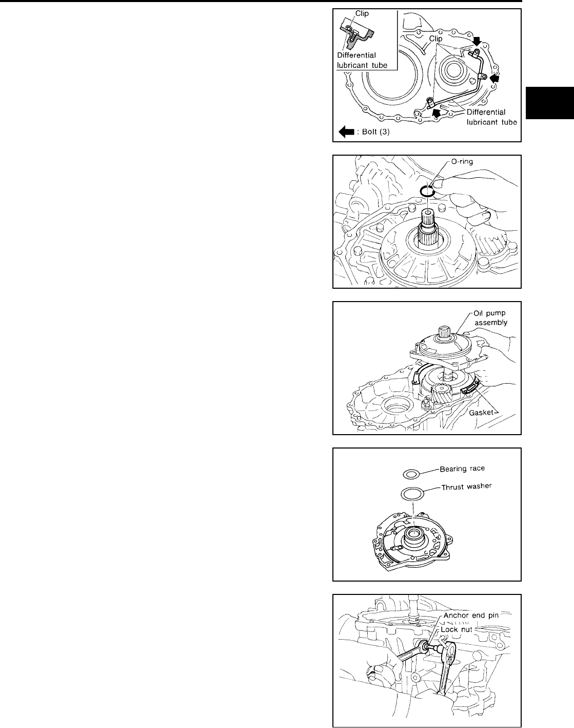
DISASSEMBLY
AT-273
[RE4F04B]
D
E
F
G
H
I
J
K
L
M
A
B
AT
Revision: September 2005 2005 Quest
27. Remove differential lubricant tube from converter housing.
28. Remove oil pump according to the following procedures.
a. Remove O-ring from input shaft.
b. Remove oil pump assembly and gasket from transaxle case.
c. Remove thrust washer and bearing race from oil pump assem-
bly.
29. Remove brake band according to the following procedures.
a. Loosen lock nut, then back off anchor end pin.
SCIA3284E
SAT225F
SCIA3282E
SAT013F
SAT014FA
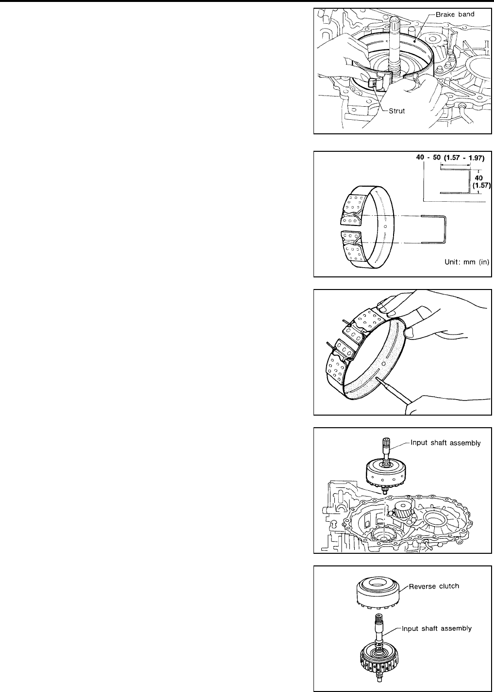
AT-274
[RE4F04B]
DISASSEMBLY
Revision: September 2005 2005 Quest
b. Remove brake band and strut from transaxle case.
●To prevent brake linings from cracking or peeling, do not
stretch the flexible band unnecessarily. When removing
the brake band, always secure it with a clip as shown in
the figure at left.
Leave the clip in position after removing the brake band.
c. Check brake band facing for damage, cracks, wear or burns.
30. Remove input shaft assembly (high clutch assembly) and
reverse clutch according to the following procedures.
a. Remove input shaft assembly (high clutch assembly) with
reverse clutch.
b. Remove input shaft assembly (high clutch assembly) from
reverse clutch.
SAT196F
SAT039D
SAT040D
SAT549F
SAT566F
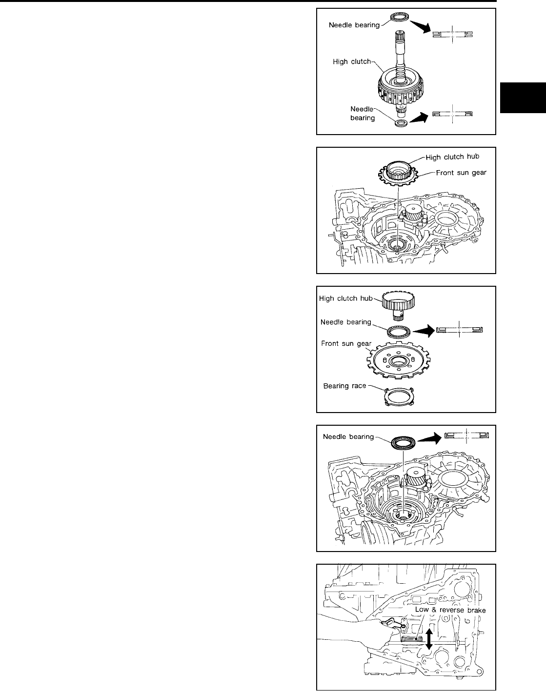
DISASSEMBLY
AT-275
[RE4F04B]
D
E
F
G
H
I
J
K
L
M
A
B
AT
Revision: September 2005 2005 Quest
c. Remove needle bearings from high clutch drum and check for
damage or wear.
d. Remove high clutch hub and front sun gear from transaxle case.
e. Remove front sun gear and needle bearing from high clutch hub
and check for damage or wear.
f. Remove bearing race from front sun gear and check for damage
or wear.
31. Remove needle bearing from transaxle case and check for dam-
age or wear.
32. Apply compressed air and check to see that low & reverse brake
operates.
SAT567F
SAT568F
SAT019F
SAT020F
SCIA3632E

AT-276
[RE4F04B]
DISASSEMBLY
Revision: September 2005 2005 Quest
33. Remove low one-way clutch and front planetary carrier assem-
bly according to the following procedures.
a. Remove snap ring with flat-bladed screwdriver.
● Do not expand snap ring excessively.
b. Remove low one-way clutch with a hook made of wire.
c. Remove snap ring with flat-bladed screwdriver.
●Do not expand snap ring excessively.
d. Remove front planetary carrier with low & reverse brake piston
and retainer.
SCIA3633E
AAT889
SCIA3634E
SCIA3635E
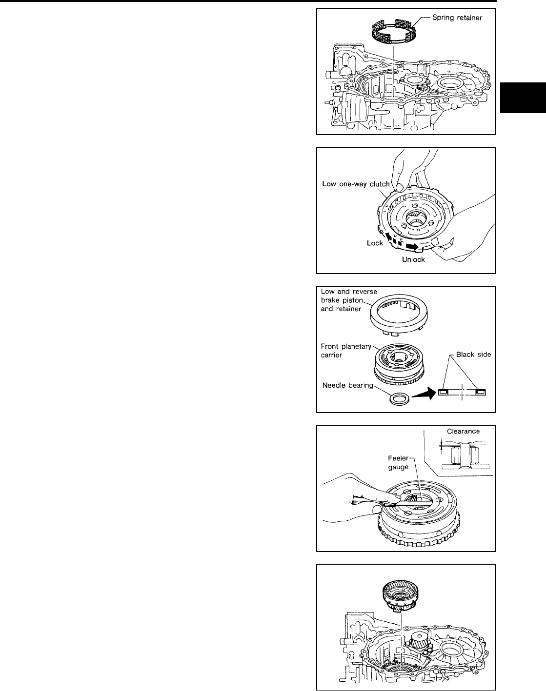
DISASSEMBLY
AT-277
[RE4F04B]
D
E
F
G
H
I
J
K
L
M
A
B
AT
Revision: September 2005 2005 Quest
e. Remove low & reverse brake spring retainer.
●Do not remove return springs from spring retainer.
f. Check that low one-way clutch rotates in the direction of the
clockwise arrow and locks in the opposite direction.
g. Remove needle bearing, low & reverse brake piston and retainer
from front planetary carrier.
h. Check front planetary carrier, low one-way clutch and needle
bearing for damage or wear.
i. Check clearance between planetary gears and planetary carrier
with feeler gauge.
Replace front planetary carrier if the clearance exceeds allow-
able limit.
34. Remove rear planetary carrier assembly and rear sun gear
according to the following procedures.
a. Remove rear planetary carrier assembly from transaxle case.
SAT148F
SAT048D
SAT024F
Standard clearance : 0.20 - 0.70 mm
(0.0079 - 0.0276 in)
Allowable limit : 0.80 mm (0.0315 in)
SAT025F
SAT026F
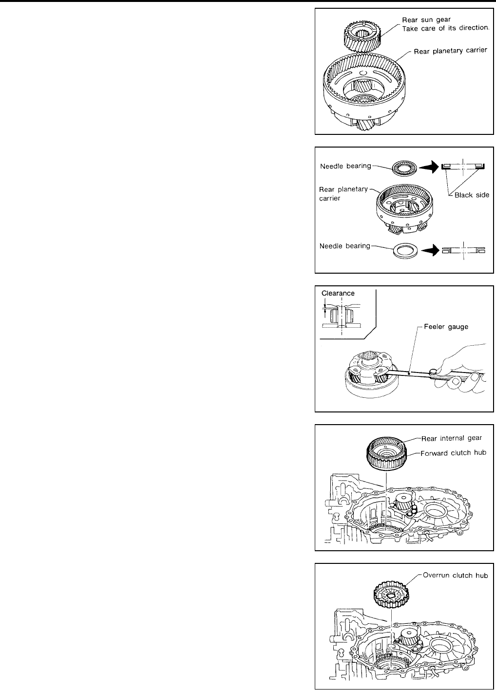
AT-278
[RE4F04B]
DISASSEMBLY
Revision: September 2005 2005 Quest
b. Remove rear sun gear from rear planetary carrier.
c. Remove needle bearings from rear planetary carrier assembly.
d. Check rear planetary carrier, rear sun gear and needle bearings
for damage or wear.
e. Check clearance between pinion washer and rear planetary car-
rier with feeler gauge.
Replace rear planetary carrier if the clearance exceeds allow-
able limit.
35. Remove rear internal gear and forward clutch hub from tran-
saxle case.
36. Remove overrun clutch hub from transaxle case.
SAT027F
SAT028F
Standard clearance : 0.20 - 0.70 mm
(0.0079 - 0.0276 in)
Allowable limit : 0.80 mm (0.0315 in)
SAT054D
SAT029F
SAT030F
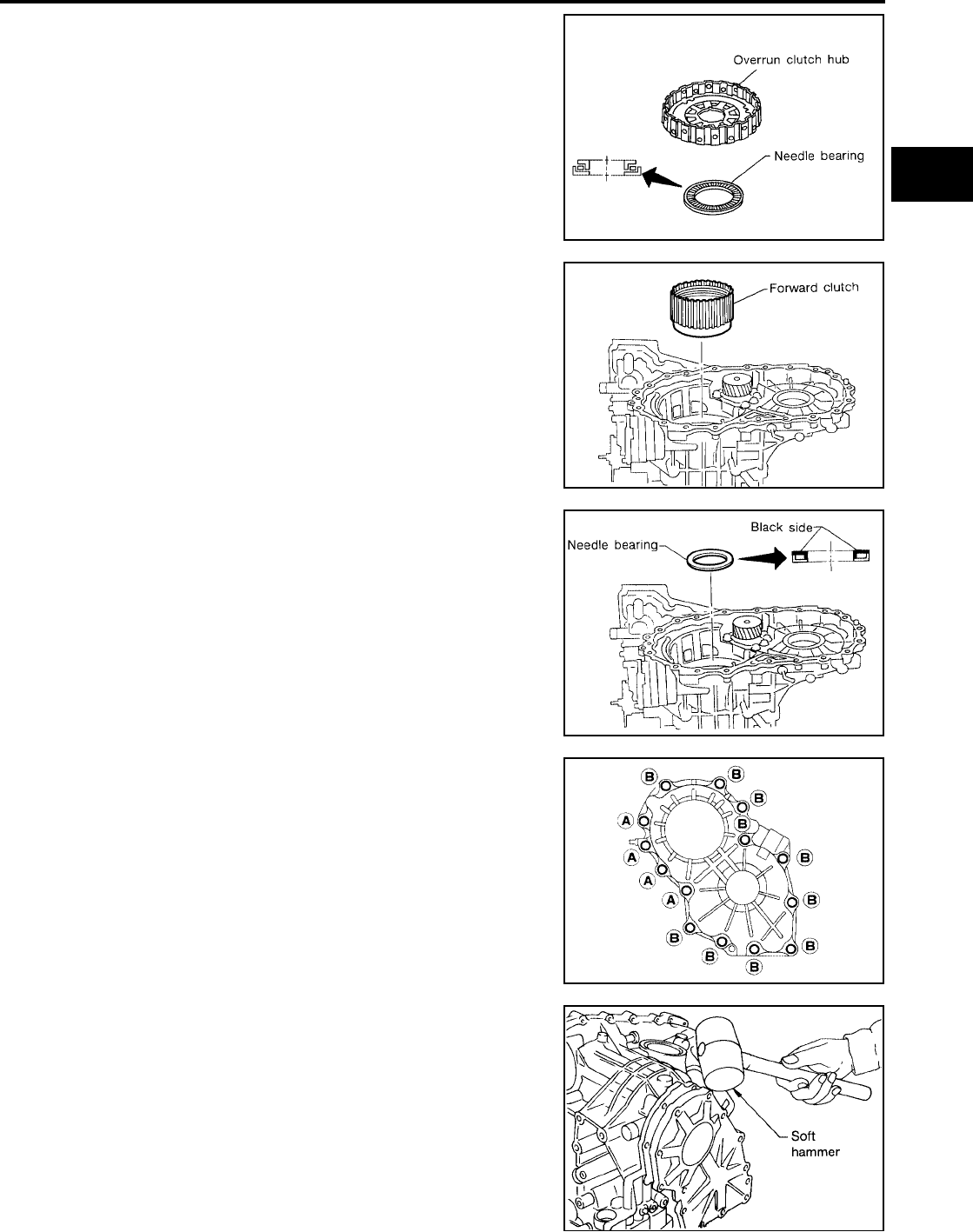
DISASSEMBLY
AT-279
[RE4F04B]
D
E
F
G
H
I
J
K
L
M
A
B
AT
Revision: September 2005 2005 Quest
37. Remove needle bearing from overrun clutch hub and check for
damage or wear.
38. Remove forward clutch assembly from transaxle case.
39. Remove needle bearing from transaxle case.
40. Remove output shaft assembly according to the following proce-
dures.
a. Remove side cover bolts.
●Do not mix bolts A and B.
●Always replace bolts A as they are self-sealing bolts.
b. Remove side cover by lightly tapping it with a soft hammer.
●Be careful not to drop output shaft assembly. It might
come out when removing side cover.
SCIA3285E
SAT032F
SAT033F
AAT850
SAT434D
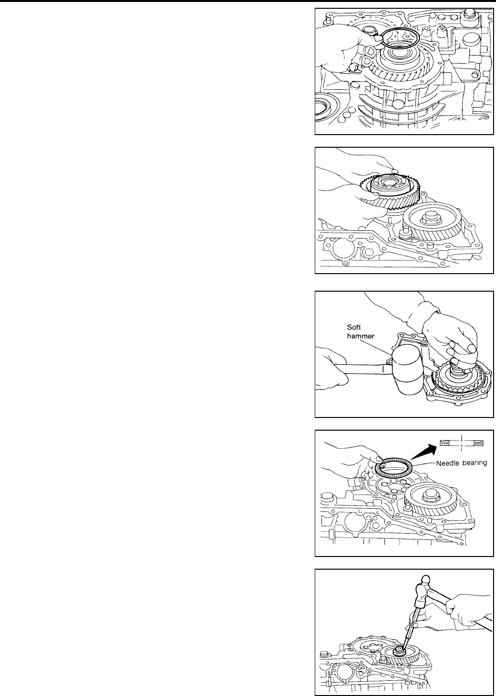
AT-280
[RE4F04B]
DISASSEMBLY
Revision: September 2005 2005 Quest
c. Remove adjusting shim.
d. Remove output shaft assembly.
●If output shaft assembly came off with side cover, tap cover
with a soft hammer to separate.
e. Remove needle bearing.
41. Disassemble reduction pinion gear according to the following
procedures.
a. Set manual shaft to position P to fix idler gear.
b. Unlock idler gear lock nut using a pin punch.
SAT440D
SAT035F
SAT435D
SAT036F
SAT037F
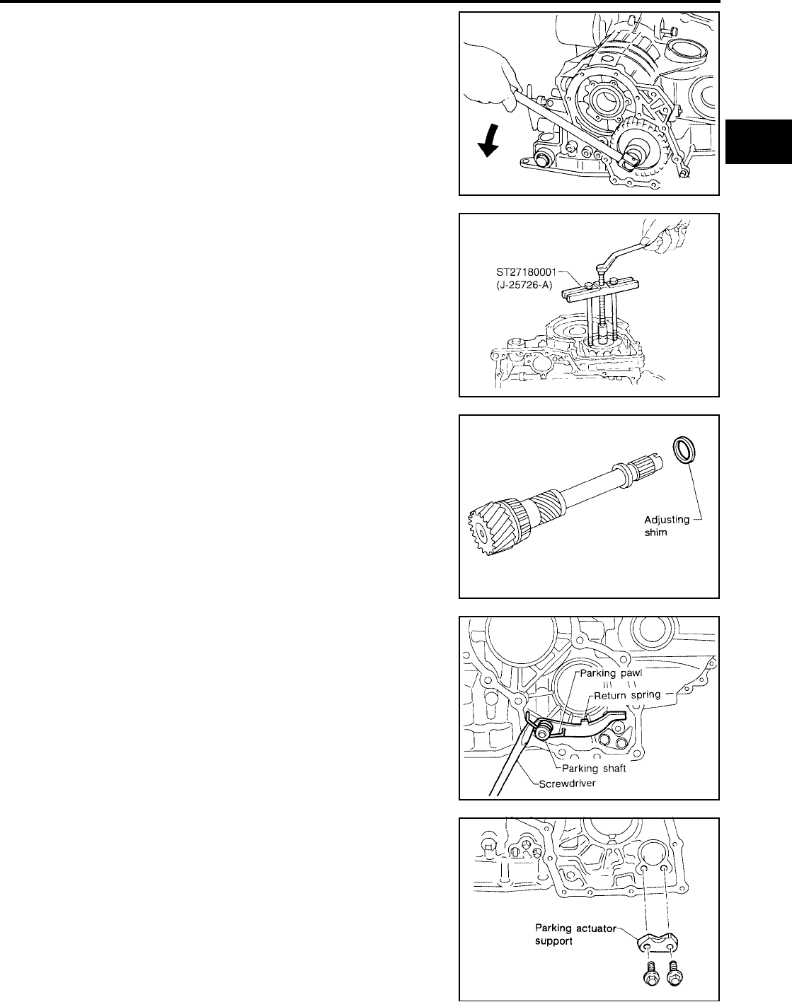
DISASSEMBLY
AT-281
[RE4F04B]
D
E
F
G
H
I
J
K
L
M
A
B
AT
Revision: September 2005 2005 Quest
c. Remove idler gear lock nut.
●Do not reuse idler gear lock nut.
d. Remove idler gear with puller.
e. Remove reduction pinion gear.
f. Remove adjusting shim from reduction pinion gear.
42. Remove return spring from parking shaft with screwdriver.
43. Draw out parking shaft and remove parking pawl from transaxle
case.
44. Check parking pawl and shaft for damage or wear.
45. Remove parking actuator support from transaxle case.
46. Check parking actuator support for damage or wear.
SAT061D
SCIA5380E
SAT916D
SAT039F
SAT066D

AT-282
[RE4F04B]
DISASSEMBLY
Revision: September 2005 2005 Quest
47. Remove side oil seal with screwdriver from transaxle case.
CAUTION:
Be careful not to scratch transaxle case.
SAT040F

REPAIR FOR COMPONENT PARTS
AT-283
[RE4F04B]
D
E
F
G
H
I
J
K
L
M
A
B
AT
Revision: September 2005 2005 Quest
REPAIR FOR COMPONENT PARTS PFP:00000
Manual Shaft UCS000RM
COMPONENTS
REMOVAL
1. Remove detent spring from transaxle case.
2. Drive out manual plate retaining pin.
1. Oil seal 2. Parking rod 3. Retaining pin
4. Parking rod plate 5. Retaining pin 6. Manual plate
7. Manual shaft 8. Retaining pin 9. Detente spring
SCIA3286E
SAT042F
SCIA5381E

AT-284
[RE4F04B]
REPAIR FOR COMPONENT PARTS
Revision: September 2005 2005 Quest
3. Drive and pull out parking rod plate retaining pin.
4. Remove parking rod plate from manual shaft.
5. Draw out parking rod from transaxle case.
6. Pull out manual shaft retaining pin.
7. Remove manual shaft and manual plate from transaxle case.
8. Remove manual shaft oil seal.
CAUTION:
Be careful not to scratch transaxle case.
INSPECTION
●Check component parts for wear or damage. Replace if necessary.
INSTALLATION
1. Install manual shaft oil seal.
CAUTION:
●Do not reuse oil seal.
●Apply ATF to outer surface of oil seal.
SCIA5382E
SAT049F
SAT080D
SAT081D
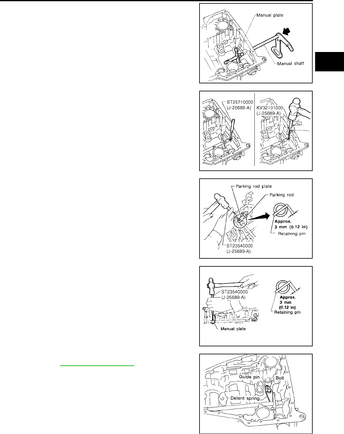
REPAIR FOR COMPONENT PARTS
AT-285
[RE4F04B]
D
E
F
G
H
I
J
K
L
M
A
B
AT
Revision: September 2005 2005 Quest
2. Install manual shaft and manual plate.
3. Align groove of manual shaft and hole of transaxle case.
4. Install manual shaft retaining pin up to bottom of hole.
5. Install parking rod to parking rod plate.
6. Set parking rod assembly onto manual shaft and drive retaining
pin.
CAUTION:
●Do not reuse retaining pin.
●Both ends of pin should protrude.
7. Drive manual plate retaining pin.
CAUTION:
●Do not reuse retaining pin.
●Both ends of pin should protrude.
8. Install detent spring. Tighten detent spring bolts to the specified
torque. Refer to AT-283, "COMPONENTS" .
SCIA3627E
SCIA5383E
SCIA5384E
SCIA5385E
SAT042F
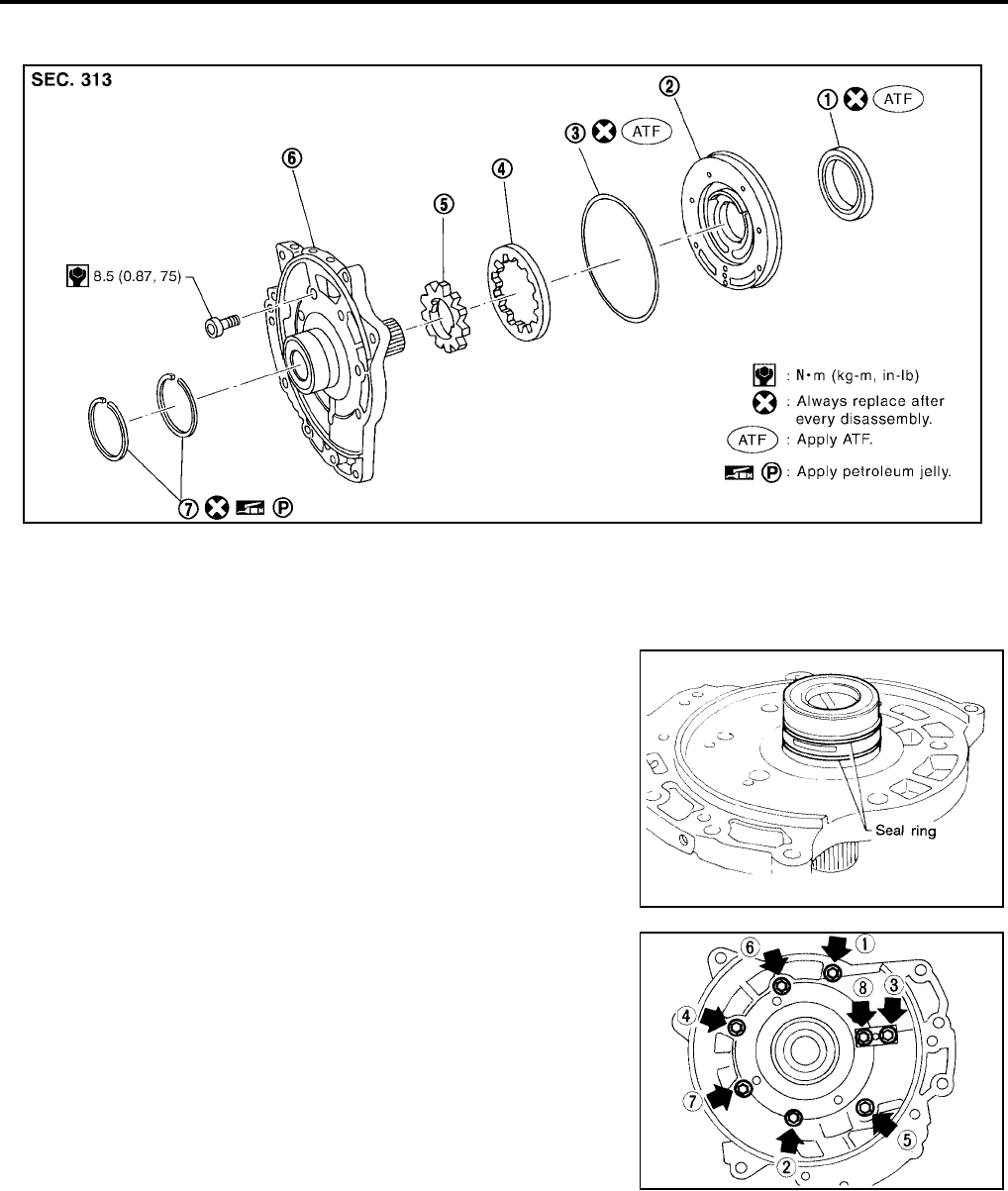
AT-286
[RE4F04B]
REPAIR FOR COMPONENT PARTS
Revision: September 2005 2005 Quest
Oil Pump UCS000RN
COMPONENTS
DISASSEMBLY
1. Remove seal rings.
2. Loosen bolts in a crisscross pattern and remove oil pump cover.
1. Oil seal 2. Oil pump housing 3. O-ring
4. Outer gear 5. Inner gear 6. Oil pump cover
7. Seal ring
SCIA3341E
SAT699H
SAT051F

REPAIR FOR COMPONENT PARTS
AT-287
[RE4F04B]
D
E
F
G
H
I
J
K
L
M
A
B
AT
Revision: September 2005 2005 Quest
3. Remove inner and outer gear from oil pump housing.
4. Remove O-ring from oil pump housing.
5. Remove oil pump housing oil seal.
INSPECTION
Oil Pump Housing, Oil Pump Cover, Inner Gear and Outer Gear
●Check for wear or damage.
SAT092D
SAT093D
SAT094D

AT-288
[RE4F04B]
REPAIR FOR COMPONENT PARTS
Revision: September 2005 2005 Quest
Side Clearances
●Measure side clearance of inner and outer gears in at least four
places around each outside edge. Maximum measured values
should be within specified positions.
●If clearance is less than standard, select inner and outer gear as
a set so that clearance is within specifications.
●If clearance is more than standard, replace whole oil pump
assembly except oil pump cover.
●Measure clearance between outer gear and oil pump housing.
●If not within allowable limit, replace whole oil pump assembly
except oil pump cover.
Seal Ring Clearance
●Measure clearance between seal ring and ring groove.
●If not within allowable limit, replace oil pump cover assembly.
Standard clearance : 0.030 - 0.050 mm
(0.0012 - 0.0020 in)
Inner and outer gear:
Refer to AT-364, "SERVICE DATA AND SPECIFICA-
TIONS (SDS)" .
SAT095D
Standard clearance : 0.111 - 0.181 mm
(0.0044 - 0.0071 in)
Allowable limit : 0.181 mm (0.0071 in)
SAT096D
Standard clearance : 0.1 - 0.25 mm (0.0039 - 0.0098
in)
Allowable limit : 0.25 mm (0.0098 in)
SAT097D

REPAIR FOR COMPONENT PARTS
AT-289
[RE4F04B]
D
E
F
G
H
I
J
K
L
M
A
B
AT
Revision: September 2005 2005 Quest
ASSEMBLY
1. Install oil seal on oil pump housing.
2. Install O-ring on oil pump housing.
CAUTION:
●Do not reuse O-ring.
●Apply ATF to O-ring.
3. Install inner and outer gears on oil pump housing.
CAUTION:
Be careful of direction of inner gear.
4. Install oil pump cover on oil pump housing.
a. Wrap masking tape around splines of oil pump cover assembly
to protect seal. Position oil pump cover assembly on oil pump
housing assembly, then remove masking tape.
b. Tighten bolts in a crisscross pattern. Tighten oil pump cover
bolts to the specified torque. Refer to AT-286, "COMPONENTS"
.
SCIA5386E
SCIA2841E
SAT092D
SAT051F

AT-290
[RE4F04B]
REPAIR FOR COMPONENT PARTS
Revision: September 2005 2005 Quest
5. Install new seal rings carefully after packing ring groove with
petroleum jelly.
CAUTION:
●Do not spread gap of seal ring excessively while install-
ing. The ring may be deformed.
●Do not reuse seal rings.
●Apply petroleum jelly to seal rings.
Control Valve Assembly UCS000RO
COMPONENTS
DISASSEMBLY
Disassemble upper, inter and lower bodies.
SCIA3638E
1. Oil strainer 2. Control valve lower body 3. Oil cooler relief valve spring
4. Check ball 5. Solenoid valve assembly 6. Terminal body
7. Stopper ring 8. O-rings 9. Separating plate
10. Support plate 11. Steel ball 12. Control valve inter body
13. Pilot filter 14. Separating plate 15. Control valve upper body
SCIA3610E
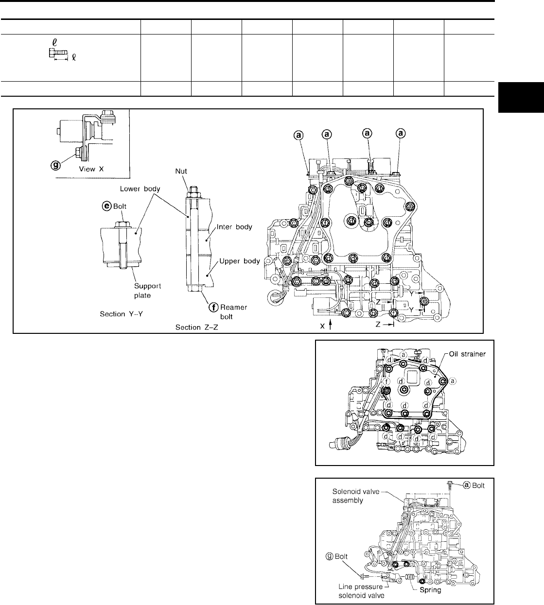
REPAIR FOR COMPONENT PARTS
AT-291
[RE4F04B]
D
E
F
G
H
I
J
K
L
M
A
B
AT
Revision: September 2005 2005 Quest
Bolt length, number and location:
f: Reamer bolt and nut.
1. Remove bolts a , d , reamer bolt f and nut and remove oil
strainer from control valve assembly.
2. Remove solenoid valve assembly and line pressure solenoid
valve from control valve assembly.
Bolt symbol abcdefg
Bolt length “ ” mm (in) 13.5
(0.531)
58.0
(2.283)
40.0
(1.575)
66.0
(2.598)
33.0
(1.299)
78.0
(3.071)
18.0
(0.709)
Number of bolts 6 3 6 11 2 2 1
SAT704J
SCIA3484E
SCIA3639E
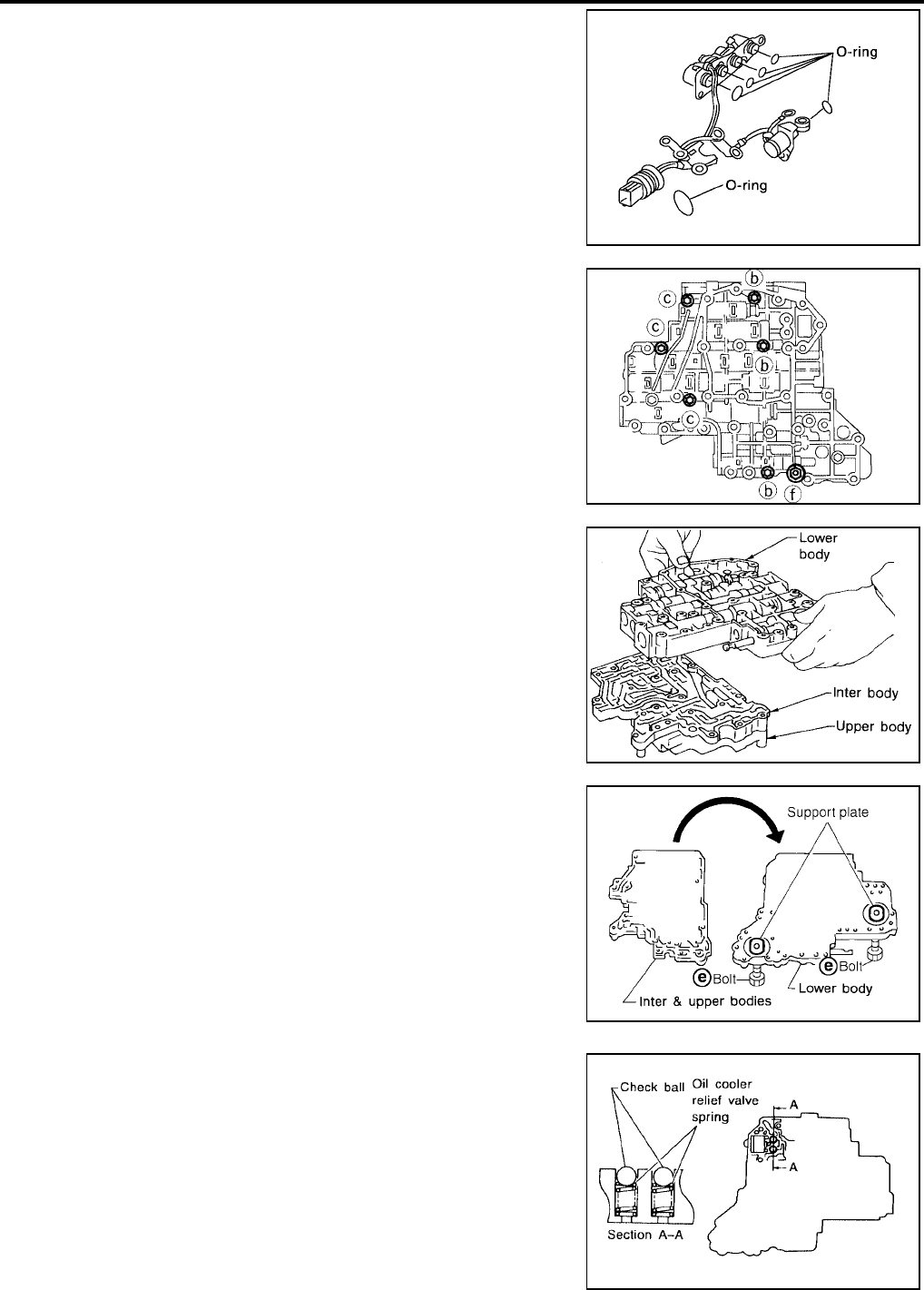
AT-292
[RE4F04B]
REPAIR FOR COMPONENT PARTS
Revision: September 2005 2005 Quest
3. Remove O-rings from solenoid valves and terminal body.
4. Place upper body facedown, and remove bolts b , c , f and nut .
CAUTION:
Remove bolts with upper body facing down, because upper
body and inter body may come off and steel ball may fall
and be lost.
5. Remove inter body from lower body.
6. Turn over lower body.
7. Remove bolts e , separating plate and support plate from lower
body.
8. Remove check balls and oil cooler relief valve springs from
lower body.
CAUTION:
Be careful not to lose check balls and oil cooler relief valve
springs.
SCIA0804E
SAT064FA
SAT432D
SCIA3289E
SAT110DA
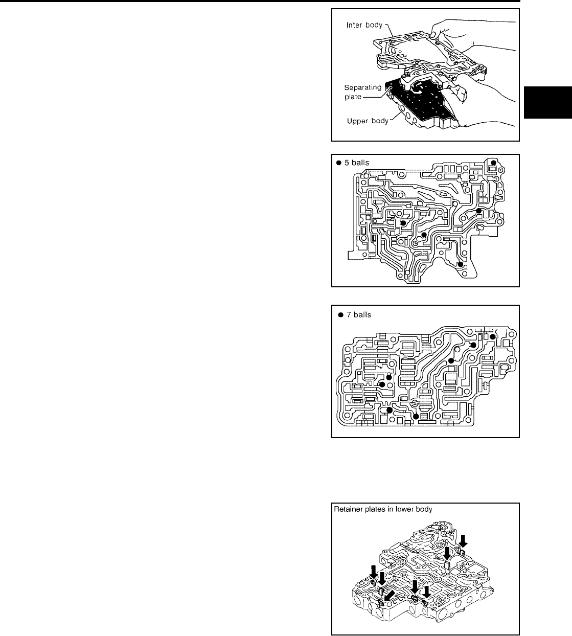
REPAIR FOR COMPONENT PARTS
AT-293
[RE4F04B]
D
E
F
G
H
I
J
K
L
M
A
B
AT
Revision: September 2005 2005 Quest
9. Remove inter body from upper body.
10. Check to see that steel balls are properly positioned in inter
body and then remove them.
CAUTION:
Be careful not to lose steel balls.
11. Remove pilot filter from upper body.
12. Check to see that steel balls are properly positioned in upper
body and then remove them.
CAUTION:
Be careful not to lose steel balls.
INSPECTION
Lower and Upper Bodies
CAUTION:
Be careful not to lose these parts.
●Check to see that retainer plates are properly positioned in lower
body.
SAT065FA
SAT705J
SAT771J
SCIA3290E
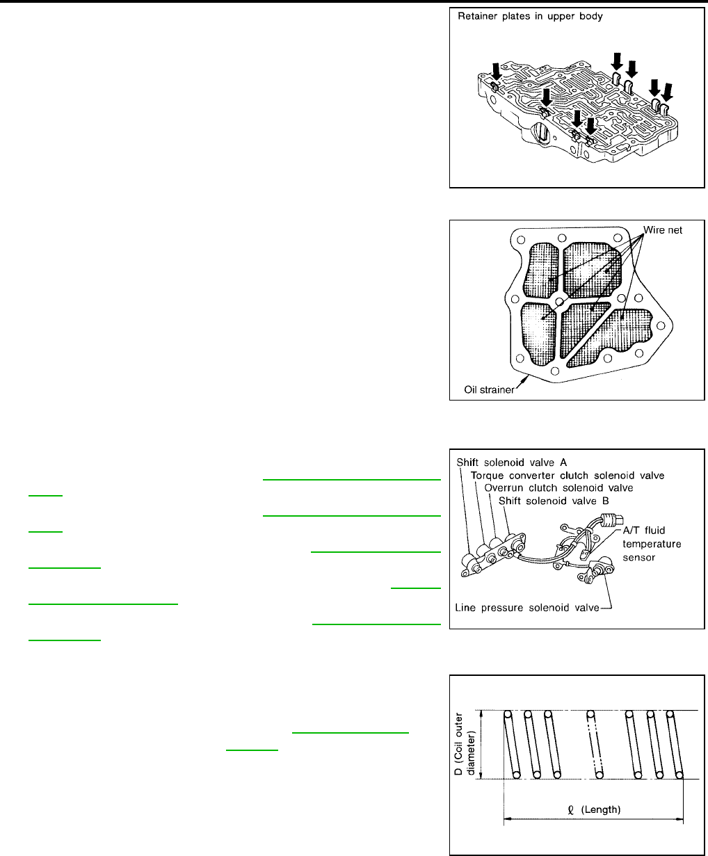
AT-294
[RE4F04B]
REPAIR FOR COMPONENT PARTS
Revision: September 2005 2005 Quest
●Check to see that retainer plates are properly positioned in
upper body.
Oil Strainer
●Check wire netting of oil strainer for damage.
Shift Solenoid Valves “A” and “B”, Line Pressure Solenoid Valve, Torque Converter Clutch
Solenoid Valve and Overrun Clutch Solenoid Valve
●Measure resistance.
●For shift solenoid valve A, refer to AT-171, "Diagnostic Proce-
dure" .
●For shift solenoid valve B, refer to AT-176, "Diagnostic Proce-
dure" .
●For line pressure solenoid valve, refer to AT-165, "Diagnostic
Procedure" .
●For torque converter clutch solenoid valve, refer to AT-152,
"Diagnostic Procedure" .
●For overrun clutch solenoid valve, refer to AT-187, "Diagnostic
Procedure" .
Oil Cooler Relief Valve Spring
●Check springs for damage or deformation.
●Measure free length and outer diameter.
SAT551G
SCIA3291E
SCIA3485E
Inspection standard : Refer to AT-365, "Control
Valves" .
SAT138D
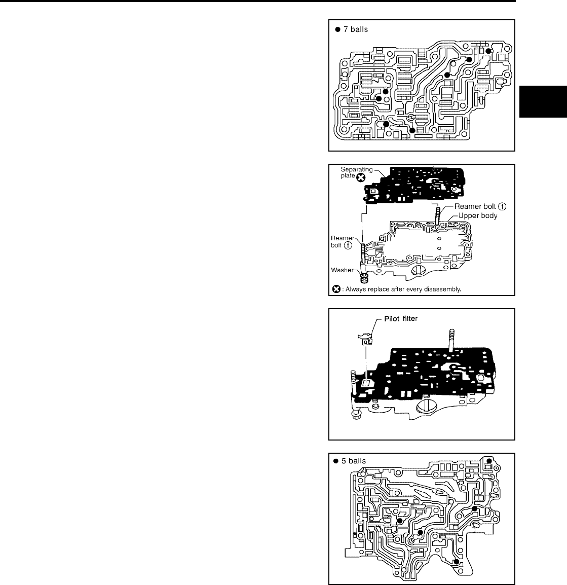
REPAIR FOR COMPONENT PARTS
AT-295
[RE4F04B]
D
E
F
G
H
I
J
K
L
M
A
B
AT
Revision: September 2005 2005 Quest
ASSEMBLY
1. Install upper, inter and lower body.
a. Place oil circuit of upper body face up. Install steel balls in their
proper positions.
b. Install reamer bolts f from bottom of upper body. Using reamer
bolts as guides, install separating plate as a set.
CAUTION:
Do not reuse separating plate.
c. Install pilot filter.
d. Place lower body as shown in figure (side of inter body face up).
Install steel balls in their proper positions.
SAT771J
SCIA3856E
SAT074F
SAT705J
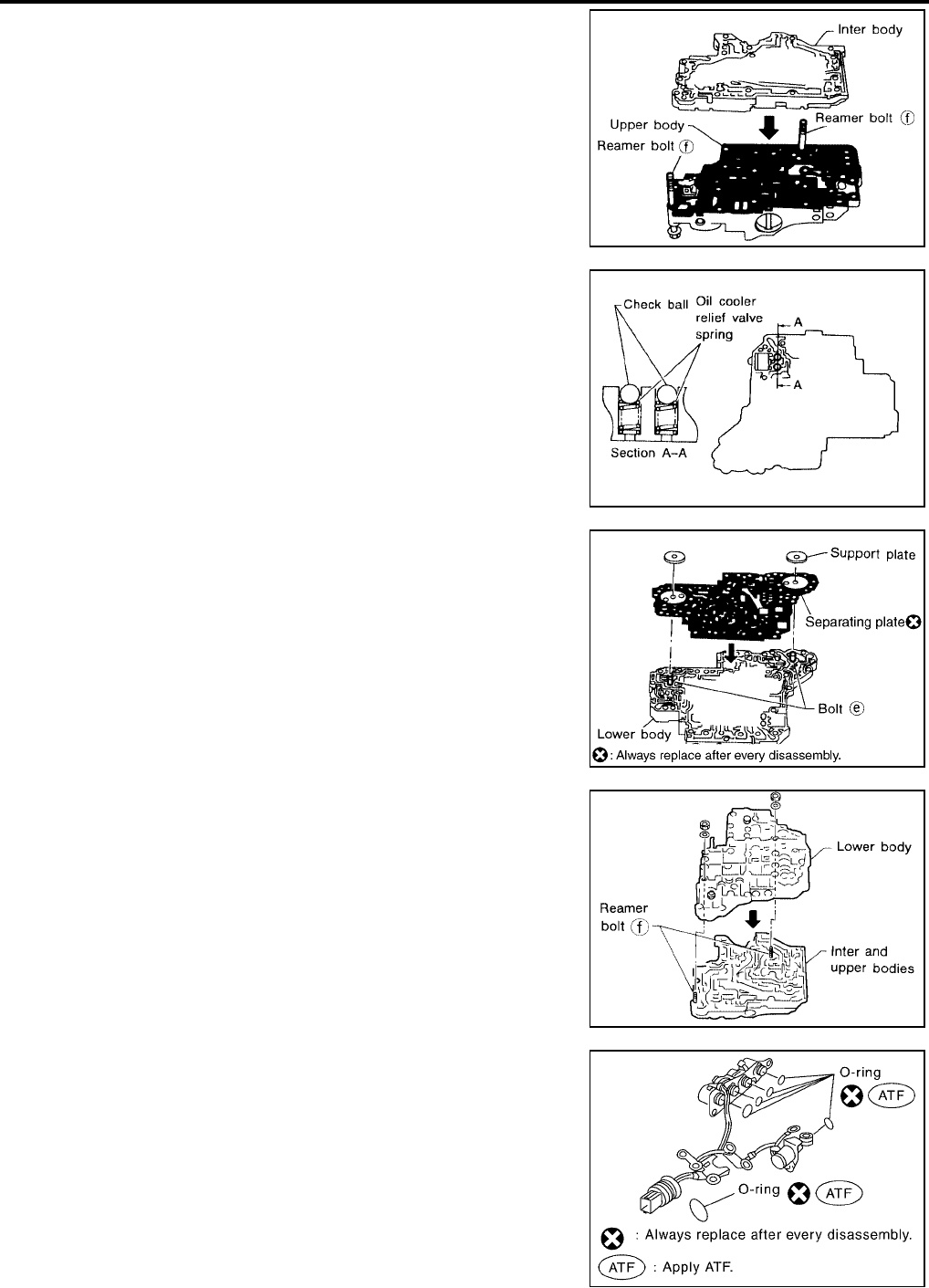
AT-296
[RE4F04B]
REPAIR FOR COMPONENT PARTS
Revision: September 2005 2005 Quest
e. Install inter body on upper body using reamer bolts f as guides.
CAUTION:
Be careful not to dislocate or drop steel balls.
f. Install check balls and oil cooler relief valve springs in their
proper positions in lower body.
g. Install bolts e from bottom of lower body. Using bolts e as
guides, install separating plate as a set.
CAUTION:
Do not reuse separating plate.
h. Temporarily install support plates on lower body.
i. Install lower body on inter body using reamer bolts f as guides
and tighten reamer bolts f slightly.
2. Install O-rings to solenoid valves and terminal body.
CAUTION:
●Do not reuse O-rings.
●Apply ATF to O-rings.
SAT076FA
SAT110DA
SCIA3857E
SAT126DA
SCIA3693E
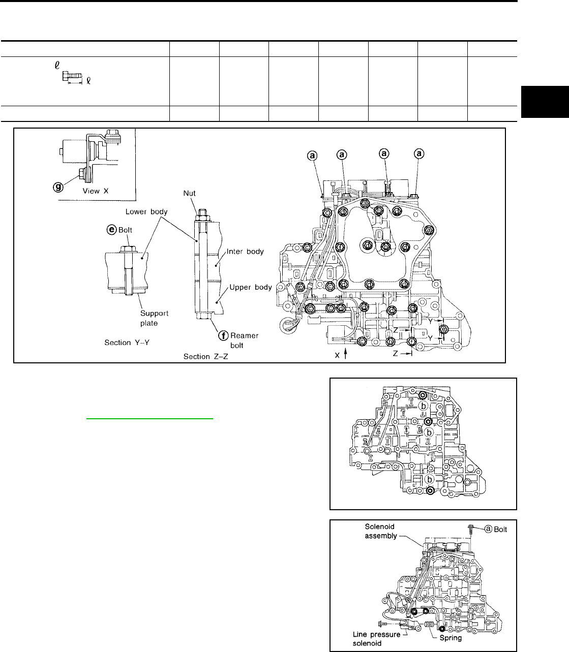
REPAIR FOR COMPONENT PARTS
AT-297
[RE4F04B]
D
E
F
G
H
I
J
K
L
M
A
B
AT
Revision: September 2005 2005 Quest
3. Install and tighten bolts.
Bolt length, number and location:
a. Install and tighten bolts b to specified torque.
b. Install solenoid valve assembly and line pressure solenoid valve
to lower body.
Bolt symbol abcdefg
Bolt length “ ” mm (in) 13.5
(0.531)
58.0
(2.283)
40.0
(1.575)
66.0
(2.598)
33.0
(1.299)
78.0
(3.071)
18.0
(0.709)
Number of bolts 6 3 6 11 2 2 1
SAT704J
Specified torque
: Refer to AT-290, "COMPONENTS" .
SAT081FA
SCIA3486E
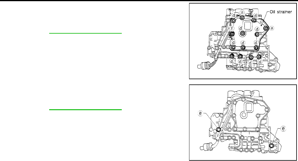
AT-298
[RE4F04B]
REPAIR FOR COMPONENT PARTS
Revision: September 2005 2005 Quest
c. Set oil strainer, then tighten bolts a , d , f and nuts to specified
torque.
d. Tighten bolts e to specified torque.
Specified torque
: Refer to AT-290, "COMPONENTS" .
SCIA3484E
Specified torque
: Refer to AT-290, "COMPONENTS" .
SCIA3487E
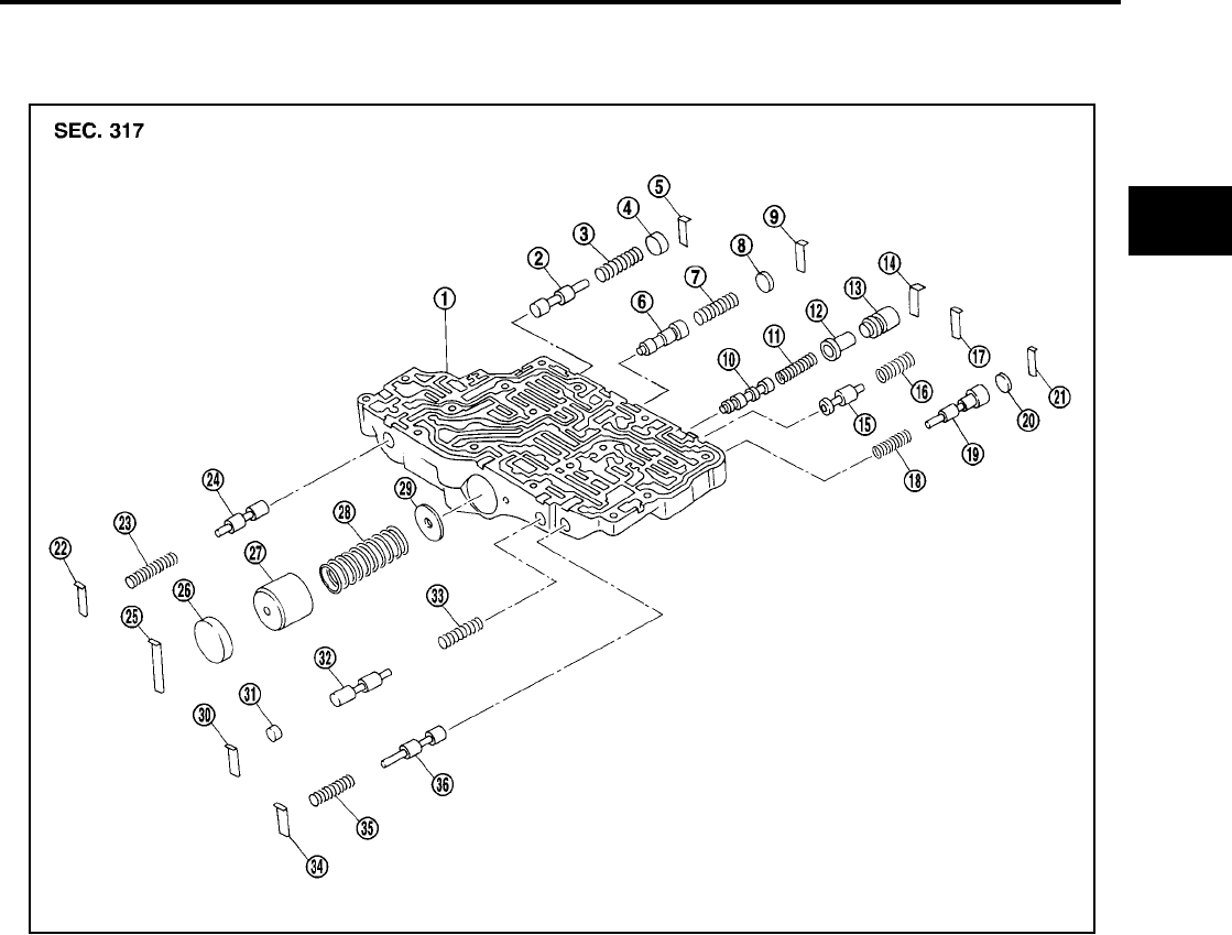
REPAIR FOR COMPONENT PARTS
AT-299
[RE4F04B]
D
E
F
G
H
I
J
K
L
M
A
B
AT
Revision: September 2005 2005 Quest
Control Valve Upper Body UCS000RP
COMPONENTS
Apply ATF to all components before installation.
1. Control valve upper body 2. Cooler check valve 3. Return spring
4. Plug 5. Retainer plate 6. 1-2 accumulator valve
7. Return spring 8. Plug 9. Retainer plate
10. Torque converter clutch control
valve
11. Return spring 12. Torque converter clutch control plug
13. Torque converter clutch control
sleeve
14. Retainer plate 15. Torque converter relief valve
16. Return spring 17. Retainer plate 18. Return spring
19. Overrun clutch reducing valve 20. Plug 21. Retainer plate
22. Retainer plate 23. Return spring 24. Pilot valve
25. Retainer plate 26. Plug 27. 1-2 accumulator piston
28. Return spring 29. 1-2 accumulator retainer plate 30. Retainer plate
31. Plug 32. 1st reducing valve 33. Return spring
34. Retainer plate 35. Return spring 36. 3-2 timing valve
SAT772J
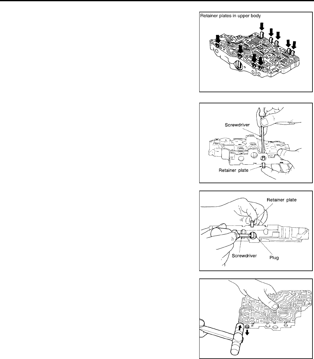
AT-300
[RE4F04B]
REPAIR FOR COMPONENT PARTS
Revision: September 2005 2005 Quest
DISASSEMBLY
1. Remove valves at retainer plates.
CAUTION:
Do not use a magnetic pick-up tool.
a. Use a screwdriver to remove retainer plates.
b. Remove retainer plates while holding spring, plugs or sleeves.
●Remove plugs slowly to prevent internal parts from jump-
ing out.
c. Place mating surface of valve body face down, and remove
internal parts.
●If a valve is hard to remove, place valve body face down
and lightly tap it with a soft hammer.
●Be careful not to drop or damage valves and sleeves.
SCIA3294E
SAT553G
SAT554G
SAT137D
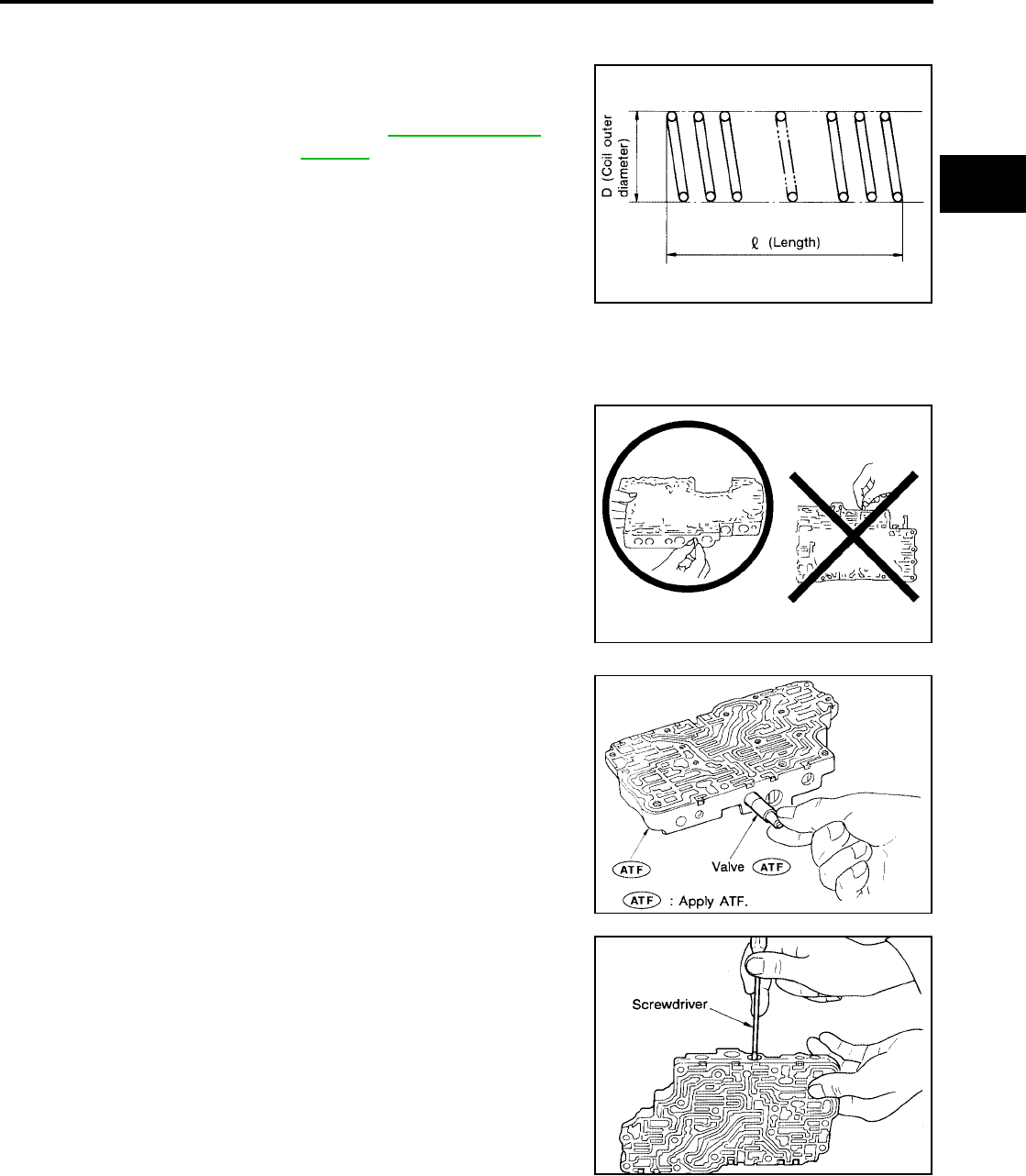
REPAIR FOR COMPONENT PARTS
AT-301
[RE4F04B]
D
E
F
G
H
I
J
K
L
M
A
B
AT
Revision: September 2005 2005 Quest
INSPECTION
Valve Spring
●Measure free length and outer diameter of each valve spring.
Also check for damage or deformation.
●Replace valve springs if deformed or fatigued.
Control Valves
●Check sliding surfaces of valves, sleeves and plugs.
ASSEMBLY
●Lay control valve body down when installing valves. Do not
stand the control valve body upright.
1. Lubricate the control valve body and all valves with ATF. Install
control valves by sliding them carefully into their bores.
CAUTION:
●Install each control valve one by one.
●Install control valves after checking, because some of
them are similar.
●Be careful not to scratch or damage valve body.
●Wrap a small screwdriver with vinyl tape and use it to insert
the valves into their proper positions.
Inspection standard : Refer to AT-365, "Control
Valves" .
SAT138D
SAT139D
SAT140DA
SAT141D
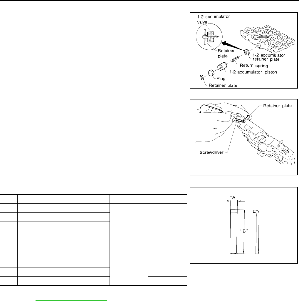
AT-302
[RE4F04B]
REPAIR FOR COMPONENT PARTS
Revision: September 2005 2005 Quest
1-2 Accumulator Valve
●Install 1-2 accumulator valve. Align 1-2 accumulator retainer
plate from opposite side of control valve body.
●Install return spring, 1-2 accumulator piston and plug.
1. Install retainer plates.
●While pushing plug or return spring, install retainer plate.
Retainer Plate (Upper Body) Unit: mm (in)
●Install proper retainer plates.
Refer to AT-299, "COMPONENTS" .
SAT142D
SAT143D
No. Name of control valve Width A Length B
22 Pilot valve
6.0 (0.236)
21.5 (0.846)
30 1st reducing valve
34 3-2 timing valve
17 Torque converter relief valve
9 1-2 accumulator valve 40.5 (1.594)
25 1-2 accumulator piston
21 Overrun clutch reducing valve 24.0 (0.945)
5 Cooler check valve
14 Torque converter clutch control valve 28.0 (1.102)
SAT086F
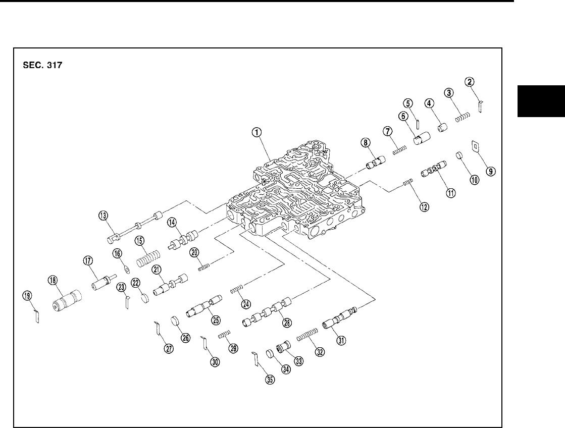
REPAIR FOR COMPONENT PARTS
AT-303
[RE4F04B]
D
E
F
G
H
I
J
K
L
M
A
B
AT
Revision: September 2005 2005 Quest
Control Valve Lower Body UCS000RQ
COMPONENTS
Apply ATF to all components before installation.
1. Control valve lower body 2. Retainer plate 3. Return spring
4. Piston 5. Parallel pin 6. Sleeve
7. Return spring 8. Pressure modifier valve 9. Retainer plate
10. Plug 11. Shift valve B 12. Return spring
13. Manual valve 14. Pressure regulator valve 15. Return spring
16. Spring seat 17. Plug 18. Sleeve
19. Retainer plate 20. Return spring 21. Overrun clutch control valve
22. Plug 23. Retainer plate 24. Return spring
25. Accumulator control valve 26. Plug 27. Retainer plate
28. Shift valve A 29. Return spring 30. Retainer plate
31. Shuttle valve 32. Return spring 33. Plug
34. Plug 35. Retainer plate
SAT773J

AT-304
[RE4F04B]
REPAIR FOR COMPONENT PARTS
Revision: September 2005 2005 Quest
DISASSEMBLY
●Remove valves at retainer plate.
For removal procedures, refer to AT-303, "COMPONENTS" .
INSPECTION
Valve Springs
●Check each valve spring for damage or deformation. Also mea-
sure free length and outer diameter.
●Replace valve springs if deformed or fatigued.
Control Valves
●Check sliding surfaces of control valves, sleeves and plugs for damage.
ASSEMBLY
●Install control valves.
For installation procedures, refer to AT-303, "COMPONENTS" .
Retainer Plate (Lower Body) Unit: mm (in)
●Install proper retainer plates.
Refer to AT-303, "COMPONENTS" .
SCIA3290E
Inspection standard : Refer to AT-365, "Control
Valves" .
SAT138D
SCIA3290E
No. Name of control valve and plug Width A Length B Type
19 Pressure regulator valve
6.0
(0.236)
28.0
(1.102) I
27 Accumulator control valve
30 Shift valve A
23 Overrun clutch control valve
2 Pressure modifier valve
35 Shuttle valve
9 Shift valve B — — II SAT089F
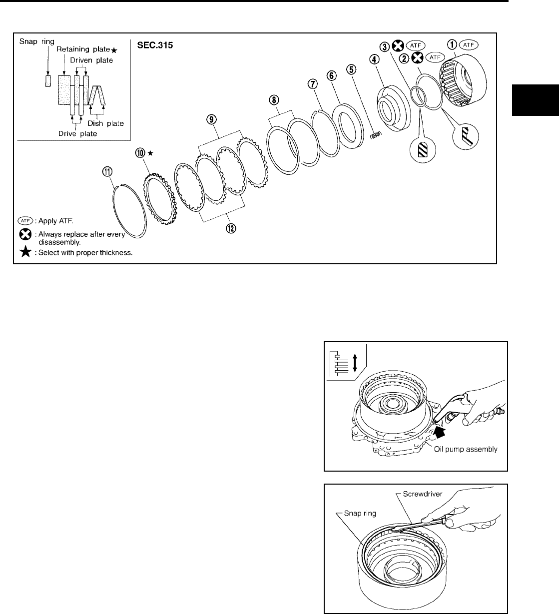
REPAIR FOR COMPONENT PARTS
AT-305
[RE4F04B]
D
E
F
G
H
I
J
K
L
M
A
B
AT
Revision: September 2005 2005 Quest
Reverse Clutch UCS000RR
COMPONENTS
DISASSEMBLY
1. Check operation of reverse clutch
a. Install seal ring onto drum support of oil pump cover and install
reverse clutch assembly. Apply compressed air to oil hole.
b. Check to see that retaining plate moves to snap ring.
c. If retaining plate does not contact snap ring:
●D-ring might be damaged.
●Oil seal might be damaged.
●Fluid might be leaking past piston check ball.
2. Remove snap ring.
CAUTION:
Do not expand snap ring excessively.
3. Remove drive plates, driven plates, retaining plate, and dish
plates.
1. Reverse clutch drum 2. Seal ring 3. D-ring
4. Reverse clutch piston 5. Return spring 6. Spring retainer
7. Snap ring 8. Dish plate 9. Driven plate
10. Retaining plate 11. Snap ring 12. Drive plate
SCIA3315E
SCIA3316E
SCIA3317E

AT-306
[RE4F04B]
REPAIR FOR COMPONENT PARTS
Revision: September 2005 2005 Quest
4. Set Tool on spring retainer and remove snap ring from reverse
clutch drum while compressing return springs.
CAUTION:
●Set Tool directly over springs.
●Do not expand snap ring excessively.
5. Remove spring retainer and return springs.
6. Remove piston from reverse clutch drum by turning it.
7. Remove D-ring and oil seal from piston.
INSPECTION
Reverse Clutch Snap Ring, Spring Retainer and Return Springs
●Check for deformation, fatigue or damage.
If necessary, replace.
Reverse Clutch Drive Plates
●Check facing for burns, cracks or damage.
●Measure thickness of facing.
●If not within wear limit, replace.
Reverse Clutch Dish Plates
●Check for deformation or damage.
●Measure thickness of dish plate.
●If deformed or fatigued, replace.
Reverse Clutch Piston
●Make sure that check balls are not fixed.
●Apply compressed air to check ball oil hole opposite the return spring. Make sure there is no air leakage.
●Apply compressed air to oil hole on return spring side to make sure that air leaks past ball.
SCIA5387E
SCIA3319E
Thickness of drive plate:
Standard : 1.6 mm (0.063 in)
Wear limit : 1.4 mm (0.055 in)
SAT162D
Thickness of dish plate : 3.18 mm (0.1252 in)
SAT163D
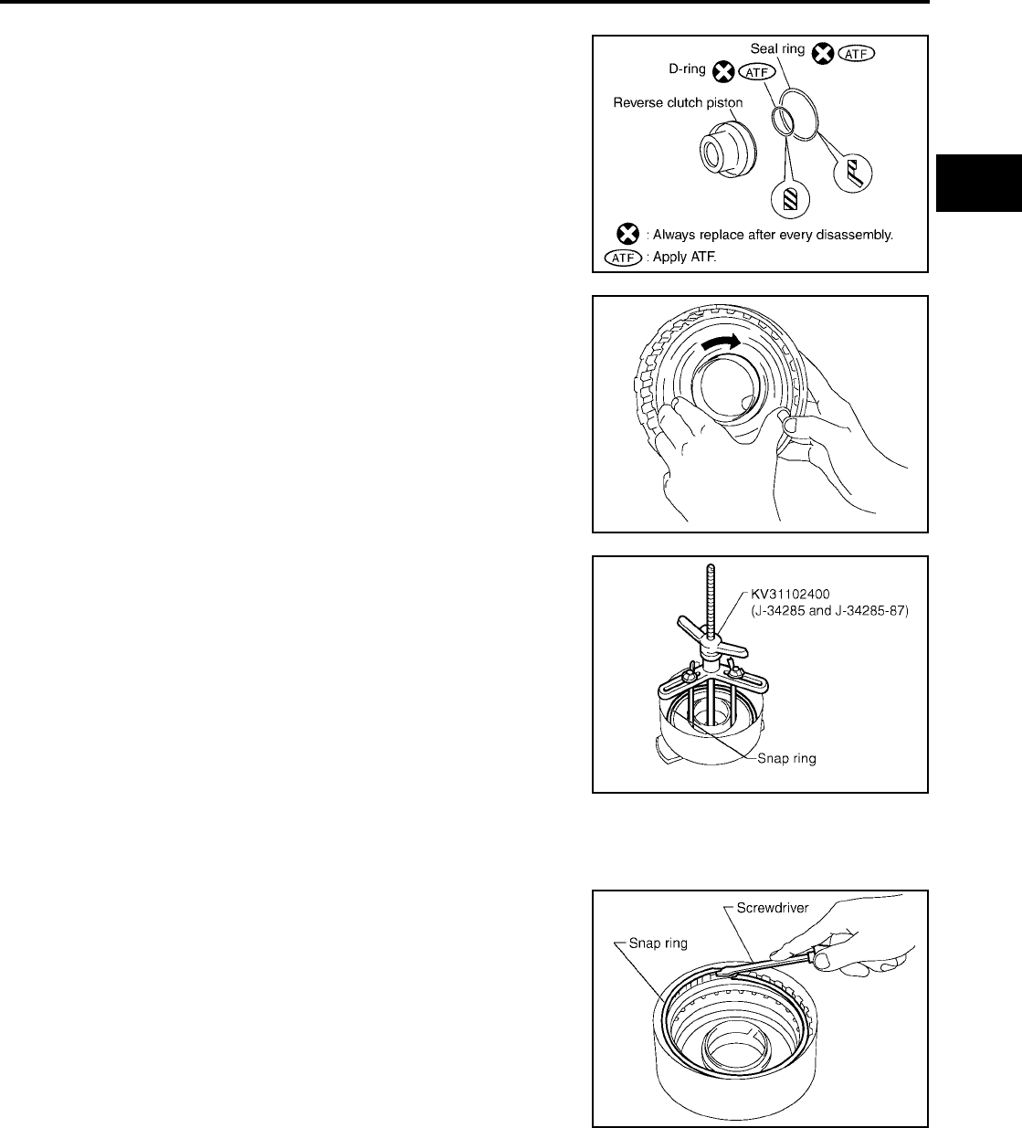
REPAIR FOR COMPONENT PARTS
AT-307
[RE4F04B]
D
E
F
G
H
I
J
K
L
M
A
B
AT
Revision: September 2005 2005 Quest
ASSEMBLY
1. Install D-ring and oil seal on piston.
CAUTION:
●Take care with the direction of oil seal.
●Apply ATF to both parts.
2. Install piston assembly by turning it slowly.
CAUTION:
Apply ATF to inner surface of drum.
3. Install return springs and spring retainer on piston.
CAUTION:
Do not expand snap ring excessively.
4. Set Tool on spring retainer and install snap ring while compressing return springs.
CAUTION:
Set Tool directly over return springs.
5. Install drive plates, driven plates, retaining plate and dish plates.
CAUTION:
Take care with order of plates.
6. Install snap ring.
CAUTION:
Do not expand snap ring excessively.
SCIA3320E
SCIA3319E
SCIA5387E
SCIA3317E
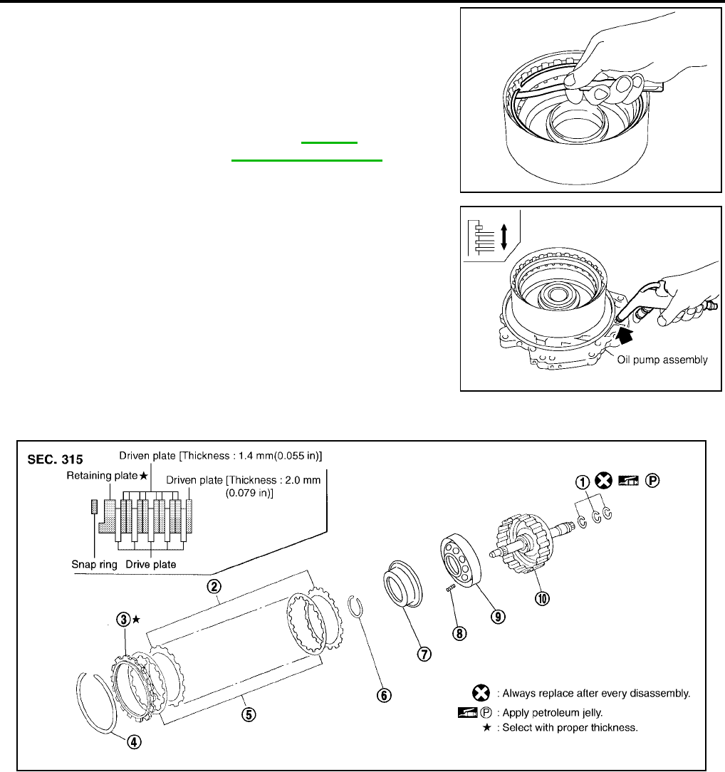
AT-308
[RE4F04B]
REPAIR FOR COMPONENT PARTS
Revision: September 2005 2005 Quest
7. Measure clearance between retaining plate and snap ring. If not
within allowable limit, select proper retaining plate.
8. Check operation of reverse clutch.
High Clutch UCS000RS
COMPONENTS
Specified clearance
Standard : 0.5 - 0.8 mm
(0.020 - 0.031 in)
Allowable limit : 1.2 mm (0.047 in)
Retaining plate : Refer to AT-366,
"REVERSE CLUTCH" .
SCIA3321E
SCIA3316E
1. Seal ring 2. Driven plate 3. Retaining plate
4. Snap ring 5. Drive plate 6. Snap ring
7. Cancel force cover 8. Return spring 9. Input clutch piston
10. Input shaft assembly (High clutch
drum)
SCIA3880E

REPAIR FOR COMPONENT PARTS
AT-309
[RE4F04B]
D
E
F
G
H
I
J
K
L
M
A
B
AT
Revision: September 2005 2005 Quest
DISASSEMBLY
1. Check operation of high clutch.
a. Apply compressed air to oil hole of input shaft with nylon cloth.
CAUTION:
Stop up hole on opposite side of input shaft with nylon
cloth.
b. Check to see that retaining plate moves to snap ring.
c. If retaining plate does not contact snap ring:
●D-ring might be damaged.
●Oil seal might be damaged.
●Fluid might be leaking past piston check ball.
2. Remove seal rings from input shaft.
CAUTION:
Always replace when removed.
3. Remove snap ring.
CAUTION:
Do not expand snap ring excessively.
4. Remove drive plates, driven plates and retaining plate.
5. Set Tool on cancel force cover and remove snap ring from high
clutch drum while compressing return springs.
CAUTION:
●Set Tool directly over springs.
●Do not expand snap ring excessively.
6. Remove spring retainer and return springs.
SAT176D
SAT177D
SAT095F
SCIA5388E
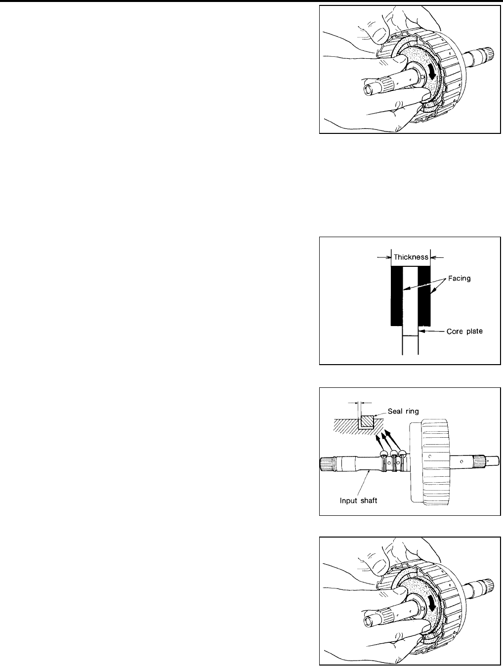
AT-310
[RE4F04B]
REPAIR FOR COMPONENT PARTS
Revision: September 2005 2005 Quest
7. Remove input clutch piston from high clutch drum by turning it.
INSPECTION
High Clutch Snap Ring, Spring Retainer and Return Springs
●Check for deformation, fatigue or damage.
If necessary, replace.
●When replacing spring retainer and return springs, replace them as a set.
High Clutch Drive Plates
●Check facing for burns, cracks or damage.
●Measure thickness of facing.
●If not within wear limit, replace.
Seal Ring Clearance
●Install new seal rings onto input shaft.
●Measure clearance between seal ring and ring groove.
●If not within allowable limit, replace input shaft assembly.
ASSEMBLY
1. Install input clutch piston assembly by turning it slowly.
CAUTION:
Apply ATF to inner surface of drum.
2. Install return springs and cancel force cover on input clutch piston.
SAT111F
Thickness of drive plate:
Standard : 1.5 mm (0.059 in)
Wear limit : 1.3 mm (0.051 in)
SAT162D
Standard clearance : 0.08 - 0.23 mm
(0.0031 - 0.0091 in)
Allowable limit : 0.23 mm (0.0091 in)
SAT187D
SAT111F
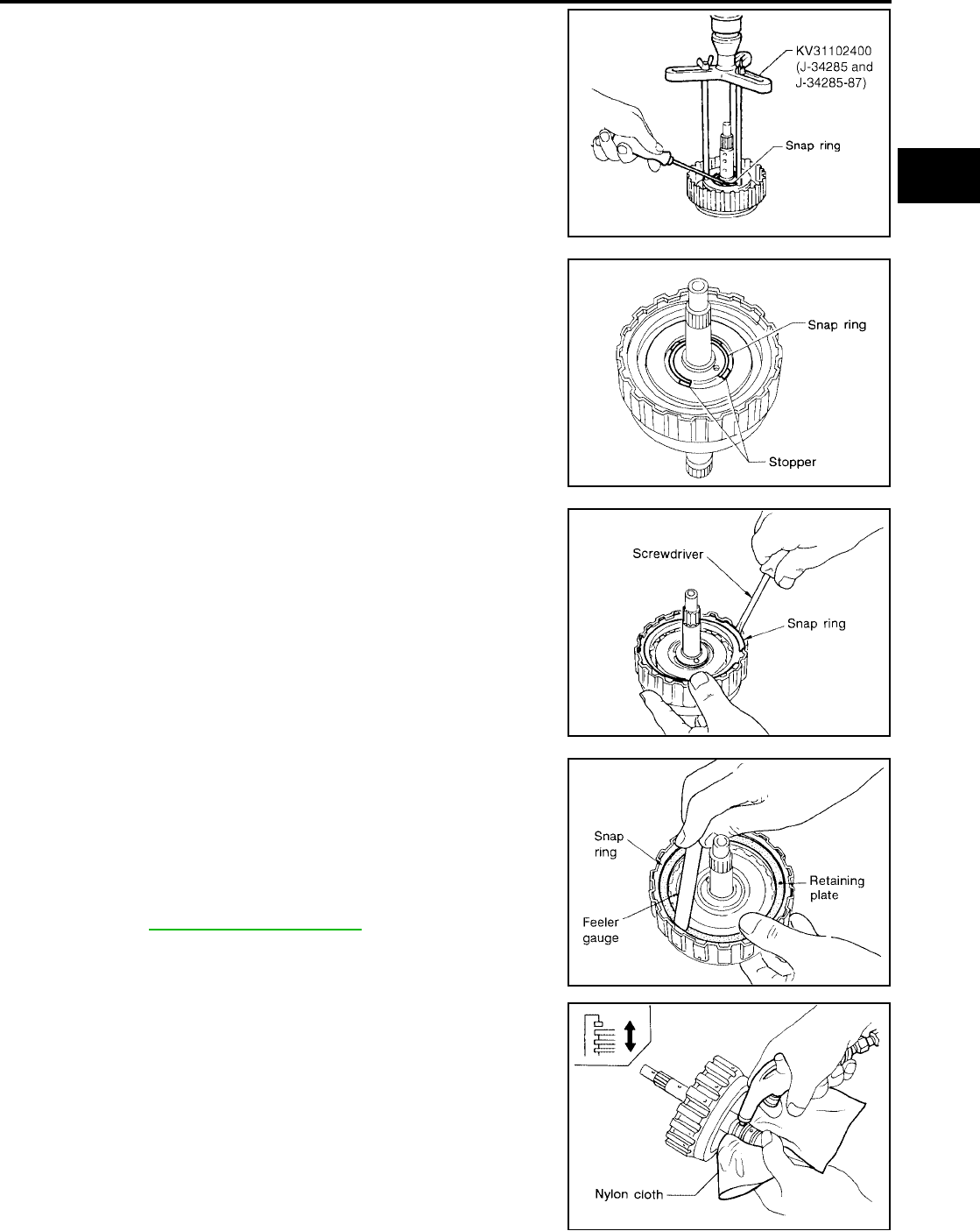
REPAIR FOR COMPONENT PARTS
AT-311
[RE4F04B]
D
E
F
G
H
I
J
K
L
M
A
B
AT
Revision: September 2005 2005 Quest
3. Set Tool on cancel force cover and install snap ring while slowly
compressing return springs.
CAUTION:
●Set Tool directly over return springs.
●Do not expand snap ring excessively.
●Do not align snap ring gap with spring retainer stopper.
4. Install drive plates, driven plates and retaining plate.
CAUTION:
Take care with the order and direction of plates.
5. Install snap ring.
CAUTION:
Do not expand snap ring excessively.
6. Measure clearance between retaining plate and snap ring. If not
within allowable limit, select proper retaining plate.
7. Check operation of high clutch.
SCIA5388E
SAT113F
SAT095F
Specified clearance
Standard : 1.8 - 2.2 mm (0.071 - 0.087 in)
Allowable limit : 2.8 mm (0.110 in)
Retaining plate
: Refer to AT-366, "HIGH CLUTCH" .
SAT116F
SAT196D
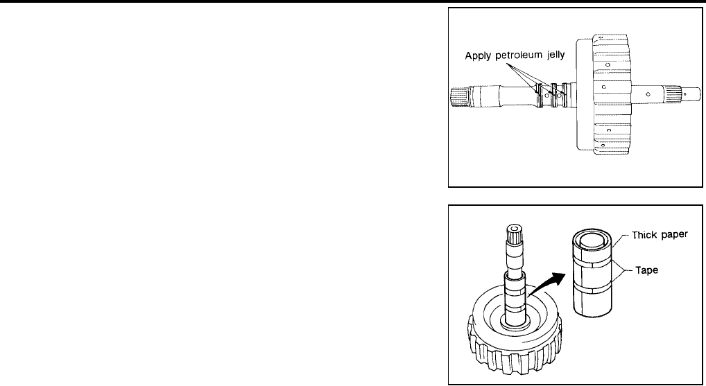
AT-312
[RE4F04B]
REPAIR FOR COMPONENT PARTS
Revision: September 2005 2005 Quest
8. Install seal rings to input shaft.
CAUTION:
●Apply petroleum jelly to seal rings.
●Always replace when removed.
●Roll paper around seal rings to prevent seal rings from
spreading.
SAT197D
SAT198D
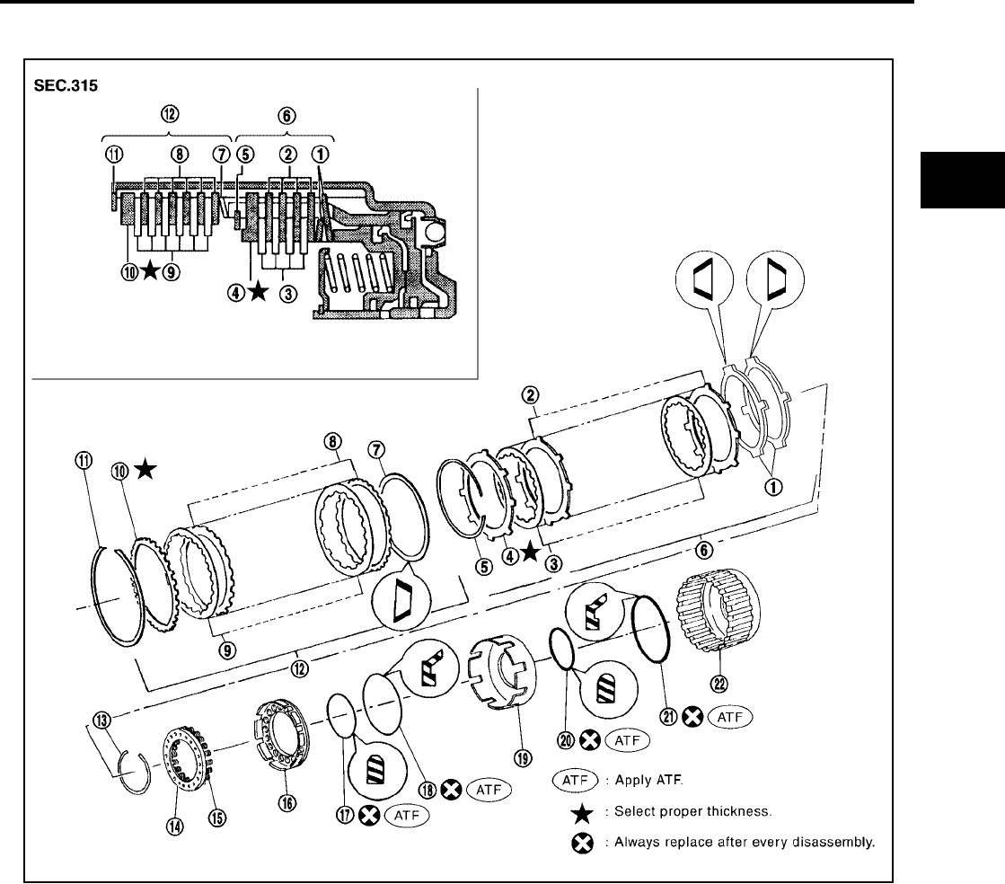
REPAIR FOR COMPONENT PARTS
AT-313
[RE4F04B]
D
E
F
G
H
I
J
K
L
M
A
B
AT
Revision: September 2005 2005 Quest
Forward and Overrun Clutches UCS000RT
COMPONENTS
1. Dish plate 2. Driven plate 3. Drive plate
4. Retaining plate 5. Snap ring 6. Overrun clutch
7. Dish plate 8. Driven plate 9. Drive plate
10. Retaining plate 11. Snap ring 12. Forward clutch
13. Snap ring 14. Spring retainer 15. Return spring
16. Overrun clutch piston 17. D-ring 18. Seal ring
19. Forward clutch piston 20. D-ring 21. Seal ring
22. Forward clutch drum
SCIA3611E

AT-314
[RE4F04B]
REPAIR FOR COMPONENT PARTS
Revision: September 2005 2005 Quest
DISASSEMBLY
1. Check operation of forward clutch and overrun clutch.
a. Install bearing retainer on forward clutch drum.
b. Apply compressed air to oil hole of forward clutch drum.
c. Check to see that retaining plate moves to snap ring.
d. If retaining plate does not contact snap ring:
●D-ring might be damaged.
●Oil seal might be damaged.
●Fluid might be leaking past piston check ball.
2. Remove snap ring for forward clutch.
CAUTION:
Do not expand snap ring excessively.
3. Remove drive plates, driven plates, retaining plate and dish
plate for forward clutch.
4. Remove snap ring for overrun clutch.
CAUTION:
Do not expand snap ring excessively.
5. Remove drive plates, driven plates, retaining plate and dish
plate for overrun clutch.
6. Set Tool on spring retainer and remove snap ring from forward
clutch drum while compressing return springs.
CAUTION:
●Set Tool directly over return springs.
●Do not expand snap ring excessively.
7. Remove spring retainer and return springs.
CAUTION:
Do not remove return springs from spring retainer.
SAT123F
SAT203D
SAT204D
SCIA5389E
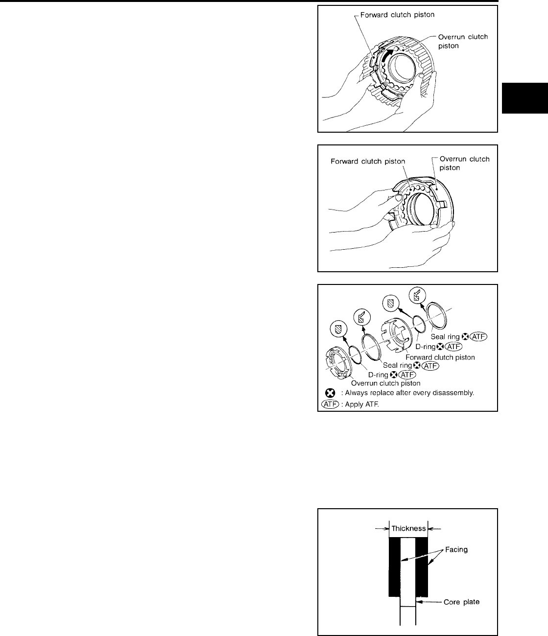
REPAIR FOR COMPONENT PARTS
AT-315
[RE4F04B]
D
E
F
G
H
I
J
K
L
M
A
B
AT
Revision: September 2005 2005 Quest
8. Remove forward clutch piston with overrun clutch piston from
forward clutch drum by turning it.
9. Remove overrun clutch piston from forward clutch piston by
turning it.
10. Remove D-rings and seal rings from forward clutch piston and
overrun clutch piston.
INSPECTION
Snap Rings, Spring Retainer and Return Springs
●Check for deformation, fatigue or damage.
●Replace if necessary.
●When replacing spring retainer and return springs, replace them as a set.
Forward Clutch and Overrun Clutch Drive Plates
●Check facing for burns, cracks or damage.
●Measure thickness of facing.
●If not within wear limit, replace.
SAT125F
SAT126F
SCIA3859E
Thickness of drive plate:
Forward clutch
Standard : 1.6 mm (0.063 in)
Wear limit : 1.4 mm (0.055 in)
Overrun clutch
Standard : 1.6 mm (0.063 in)
Wear limit : 1.4 mm (0.055 in) SAT162D
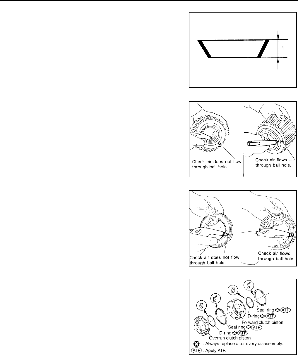
AT-316
[RE4F04B]
REPAIR FOR COMPONENT PARTS
Revision: September 2005 2005 Quest
Forward Clutch and Overrun Clutch Dish Plates
●Check for deformation or damage.
●Measure thickness of dish plate.
●If deformed or fatigued, replace.
Forward Clutch Drum
●Make sure that check balls are not fixed.
●Apply compressed air to check ball oil hole from outside of for-
ward clutch drum. Make sure air leaks past ball.
●Apply compressed air to oil hole from inside of forward clutch
drum. Make sure there is no air leakage.
Overrun Clutch Piston
●Make sure that check balls are not fixed.
●Apply compressed air to check ball oil hole opposite the return
spring. Make sure there is no air leakage.
●Apply compressed air to oil hole on return spring side. Make
sure that air leaks past ball.
ASSEMBLY
1. Install D-rings and seal rings on forward clutch piston and over-
run clutch piston.
CAUTION:
●Do not reuse D-ring and seal ring.
●Take care with direction of seal ring.
●Apply ATF to both parts.
Thickness of dish plate
Forward clutch : 2.7 mm (0.106 in)
Overrun clutch : 2.7 mm (0.106 in)
SAT163D
SAT213D
SAT212D
SCIA3859E
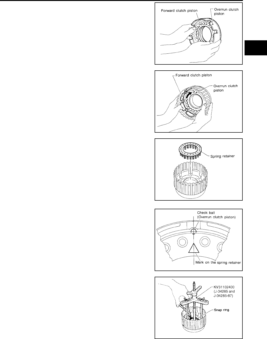
REPAIR FOR COMPONENT PARTS
AT-317
[RE4F04B]
D
E
F
G
H
I
J
K
L
M
A
B
AT
Revision: September 2005 2005 Quest
2. Install overrun clutch piston assembly on forward clutch piston
by turning it slowly.
CAUTION:
Apply ATF to inner surface of forward clutch piston.
3. Install forward clutch piston assembly on forward clutch drum by
turning it slowly.
CAUTION:
Apply ATF to inner surface of drum.
4. Install return spring on overrun clutch piston.
●Align the mark on spring retainer with check ball in overrun
clutch piston.
5. Set Tool on spring retainer and install snap ring while compress-
ing return springs.
CAUTION:
●Set Tool directly over return springs.
●Do not expand snap ring excessively.
SAT126F
SAT125F
SAT131F
SAT133F
SCIA5389E
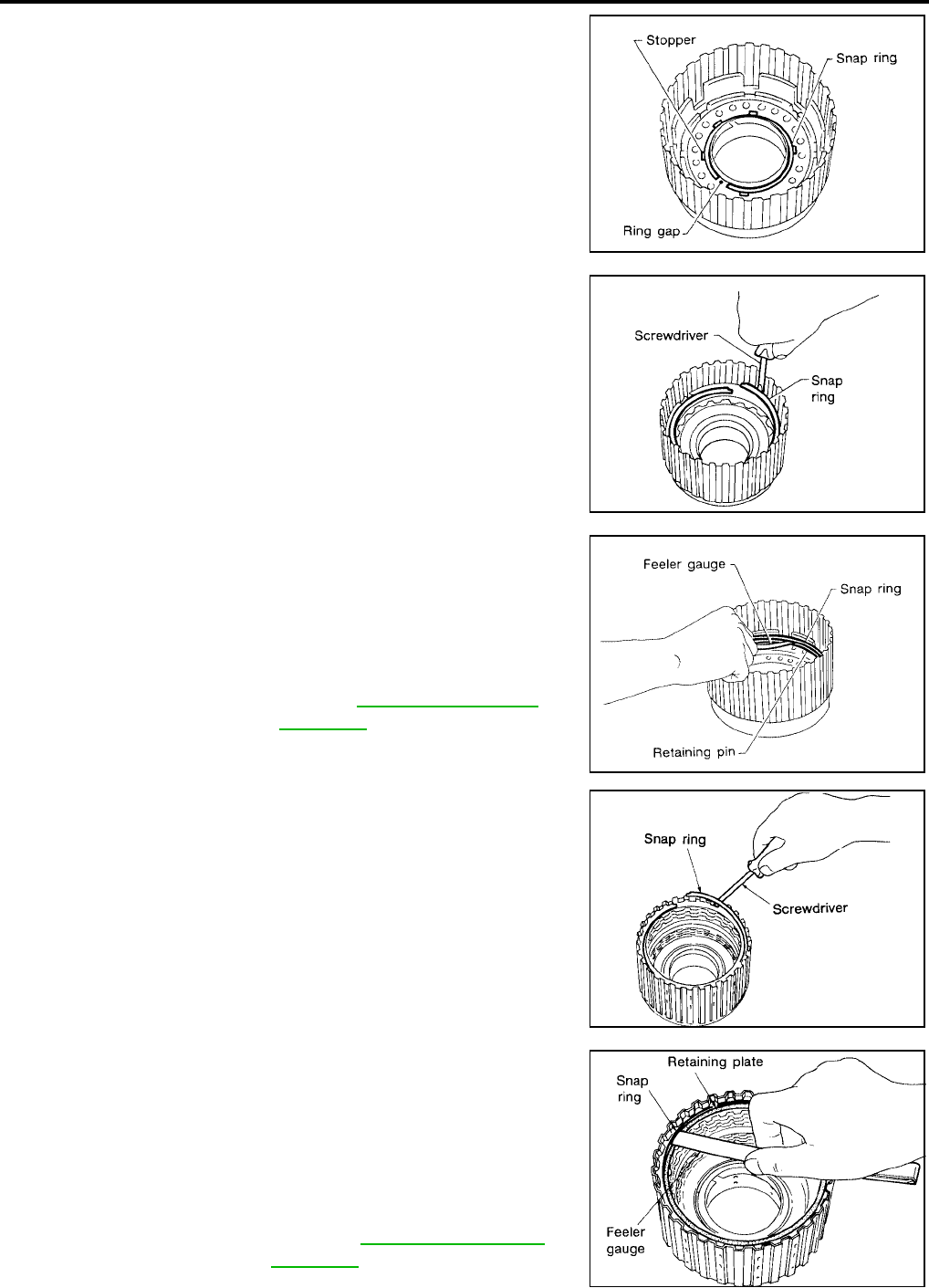
AT-318
[RE4F04B]
REPAIR FOR COMPONENT PARTS
Revision: September 2005 2005 Quest
●Do not align snap ring gap with spring retainer stopper.
6. Install drive plates, driven plates, retaining plate and dish plate
for overrun clutch.
CAUTION:
Take care with order of plates.
7. Install snap ring for overrun clutch.
CAUTION:
Do not expand snap ring excessively.
8. Measure clearance between overrun clutch retaining plate and
snap ring.
If not within allowable limit, select proper retaining plate.
9. Install drive plates, driven plates, retaining plate and dish plate
for forward clutch.
CAUTION:
Take care with order of plates.
10. Install snap ring for forward clutch.
CAUTION:
Do not expand snap ring excessively.
11. Measure clearance between forward clutch retaining plate and
snap ring.
If not within allowable limit, select proper retaining plate.
SAT134F
SAT204D
Specified clearance
Standard : 0.7 - 1.1 mm (0.028 - 0.043 in)
Allowable limit : 1.7 mm (0.067 in)
Overrun clutch
retaining plate Refer to AT-367, "OVERRUN
CLUTCH" .
SAT135F
SAT203D
Specified clearance
Standard : 0.45 - 0.85 mm
(0.0177 - 0.0335 in)
Allowable limit : 1.85 mm (0.0728 in)
Forward clutch
retaining plate : Refer to AT-367, "FORWARD
CLUTCH" .
SAT228D
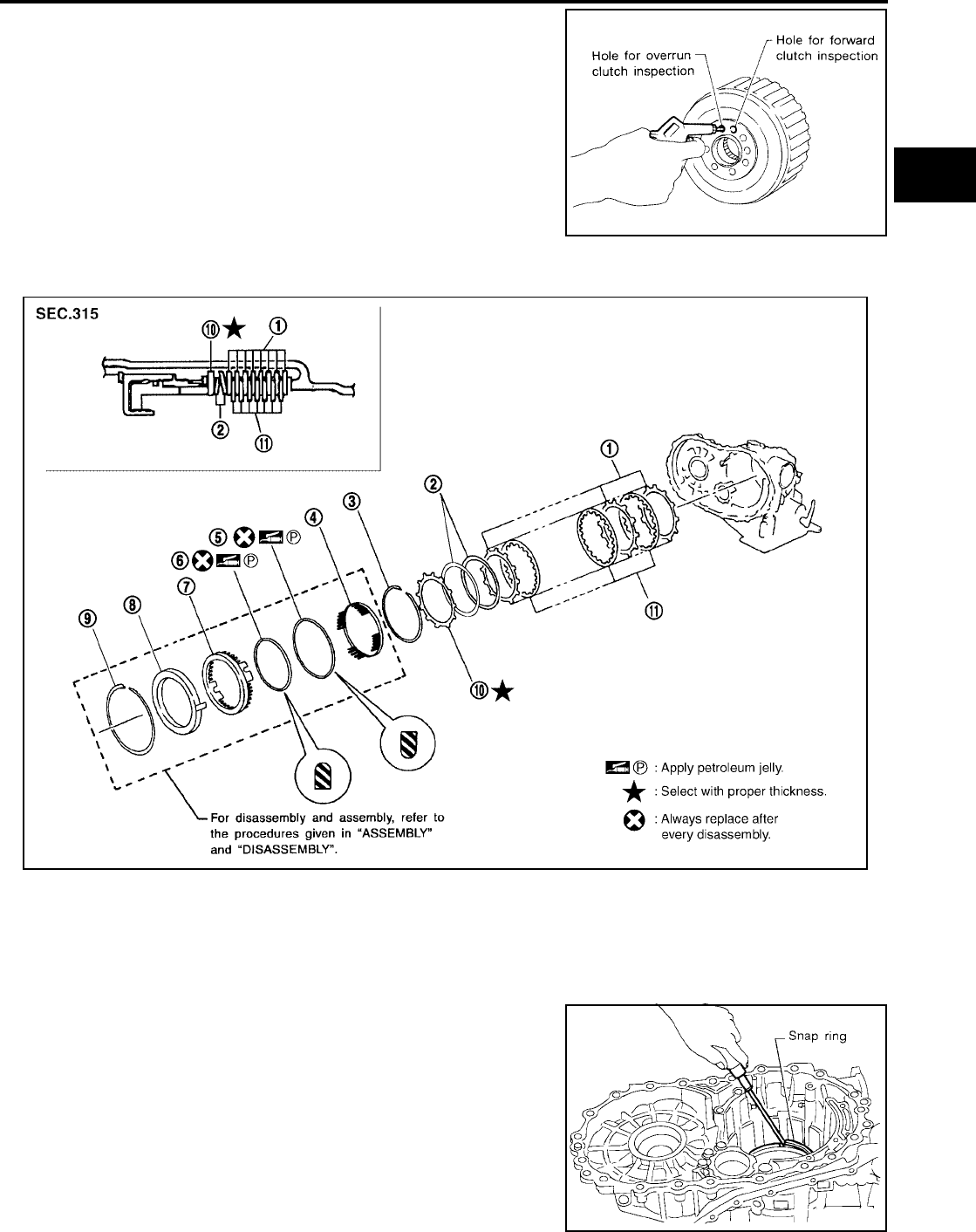
REPAIR FOR COMPONENT PARTS
AT-319
[RE4F04B]
D
E
F
G
H
I
J
K
L
M
A
B
AT
Revision: September 2005 2005 Quest
12. Check operation of forward clutch.
13. Check operation of overrun clutch.
Low & Reverse Brake UCS000RU
COMPONENTS
DISASSEMBLY
1. Check operation of low & reverse brake.
a. Apply compressed air to oil hole of transaxle case.
b. Check to see that retaining plate moves to snap ring.
c. If retaining plate does not contact snap ring:
CAUTION:
●D-ring might be damaged.
●Fluid might be leaking past piston check ball.
●Do not expand snap ring excessively.
SAT123F
1. Driven plate 2. Dish plate 3. Snap ring
4. Spring retainer 5. D-ring 6. D-ring
7. Low & reverse brake piston 8. Retainer 9. Snap ring
10. Retaining plate 11. Drive plate
SCIA3343E
SAT147F
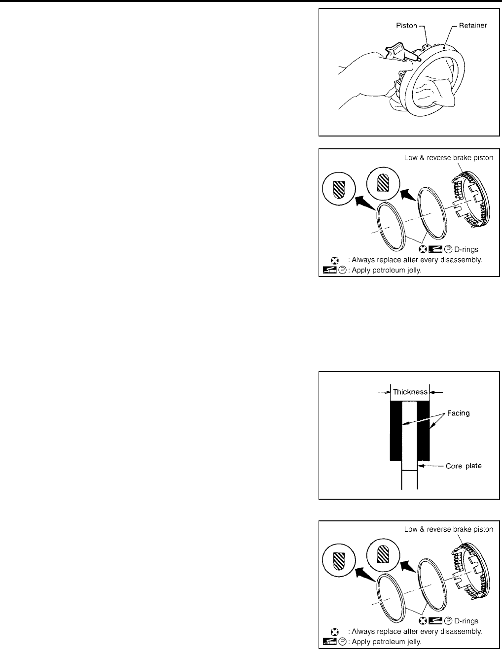
AT-320
[RE4F04B]
REPAIR FOR COMPONENT PARTS
Revision: September 2005 2005 Quest
2. In order to remove piston, apply compressed air to oil hole of
retainer while holding piston.
CAUTION:
Apply air gradually and allow piston to come out evenly.
3. Remove D-rings from piston.
INSPECTION
Low & Reverse Brake Snap Ring, Spring Retainer and Return Springs
●Check for deformation, fatigue or damage.
If necessary, replace.
●When replacing spring retainer and return springs, replace them as a set.
Low & Reverse Brake Drive Plate
●Check facing for burns, cracks or damage.
●Measure thickness of facing.
●If not within wear limit, replace.
ASSEMBLY
1. Install D-rings on piston.
CAUTION:
●Do not reuse D-ring.
●Apply ATF to both parts.
SAT149F
SCIA2998E
Thickness of drive plate
Standard : 1.8 mm (0.071 in)
Wear limit : 1.6 mm (0.063 in)
SAT162D
SCIA2998E
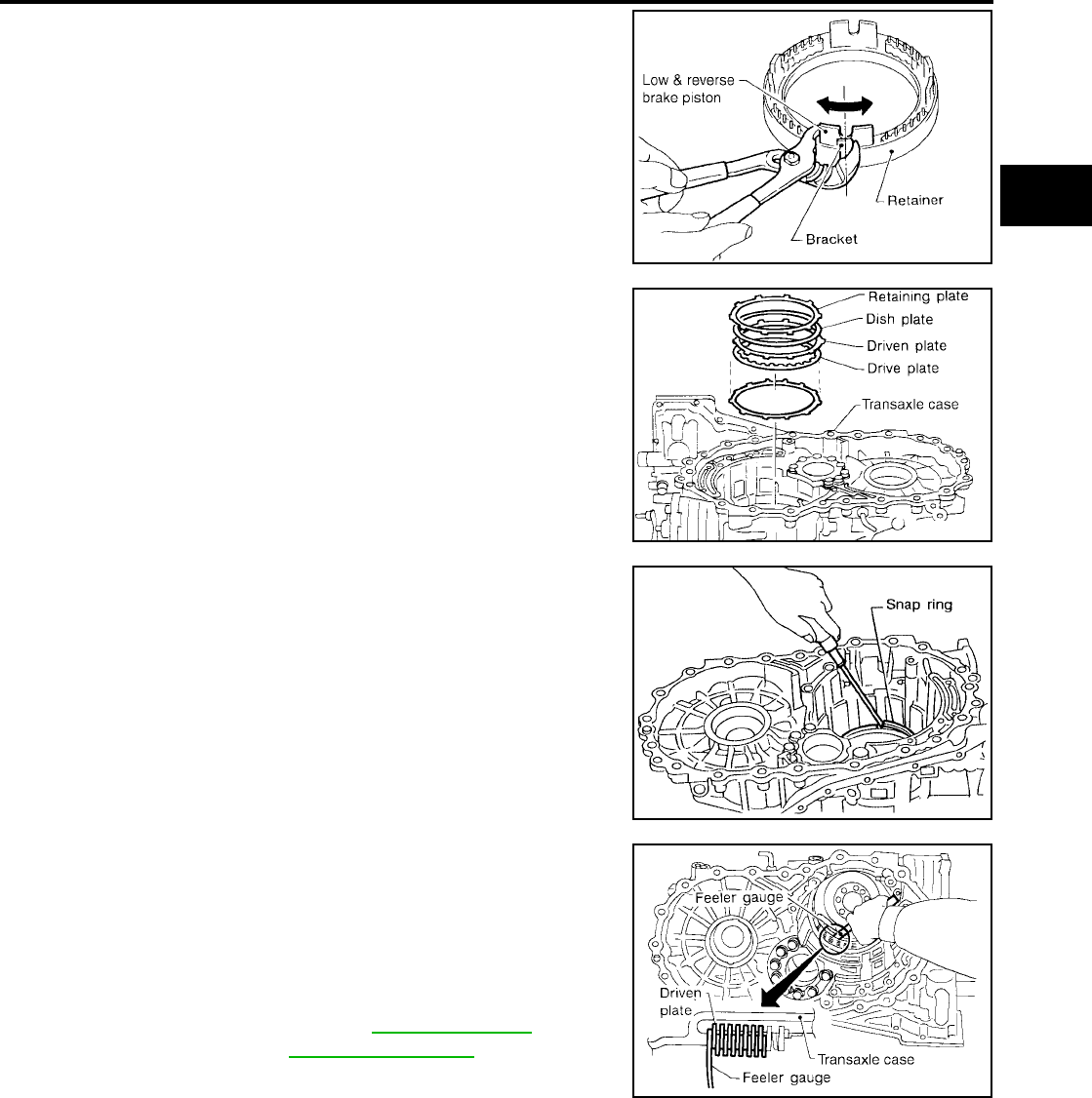
REPAIR FOR COMPONENT PARTS
AT-321
[RE4F04B]
D
E
F
G
H
I
J
K
L
M
A
B
AT
Revision: September 2005 2005 Quest
2. Set and align piston with retainer.
CAUTION:
This operation is required in order to engage the protru-
sions of piston to return springs correctly.
Further procedures are given in “ASSEMBLY”.
3. Install driven plates, drive plates, retaining plate and dish plate
on transaxle case.
CAUTION:
Take care with order of plates and direction of dish plate.
4. Install snap ring.
CAUTION:
Do not expand snap ring excessively
5. Measure clearance between driven plate and transaxle case. If
not within allowable limit, select proper retaining plate. (front
side)
SCIA3652E
SCIA3653E
SAT546G
Specified clearance
Standard : 1.7 - 2.1 mm (0.067 - 0.083 in)
Allowable limit : 3.3 mm (0.130 in)
Retaining plate Refer to AT-367, "LOW &
REVERSE BRAKE" .
SCIA3654E
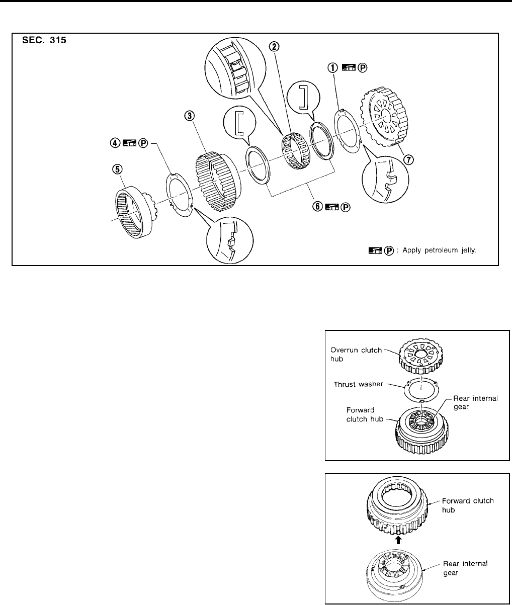
AT-322
[RE4F04B]
REPAIR FOR COMPONENT PARTS
Revision: September 2005 2005 Quest
Rear Internal Gear, Forward Clutch Hub and Overrun Clutch Hub UCS000RV
COMPONENTS
DISASSEMBLY
1. Remove overrun clutch hub and thrust washer from forward
clutch hub.
2. Remove forward clutch hub from rear internal gear.
1. Thrust washer 2. Forward one-way clutch 3. Forward clutch hub
4. Thrust washer 5. Rear internal gear 6. Bearing
7. Overrun clutch hub
SCIA3344E
SAT157F
SAT251D

REPAIR FOR COMPONENT PARTS
AT-323
[RE4F04B]
D
E
F
G
H
I
J
K
L
M
A
B
AT
Revision: September 2005 2005 Quest
3. Remove bearing from rear internal gear.
4. Remove thrust washer from rear internal gear.
5. Remove bearing from forward one-way clutch.
6. Remove forward one-way clutch from forward clutch hub.
SAT252DA
SAT253D
SAT254DA
SAT255D
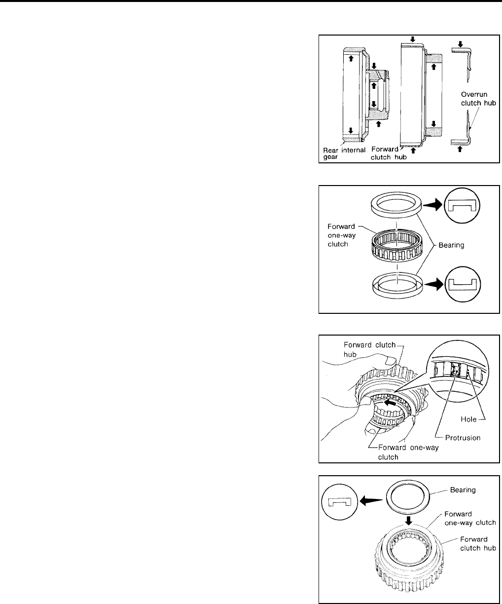
AT-324
[RE4F04B]
REPAIR FOR COMPONENT PARTS
Revision: September 2005 2005 Quest
INSPECTION
Rear Internal Gear, Forward Clutch Hub and Overrun Clutch Hub
●Check rubbing surfaces for wear or damage.
Bearings and Forward One-Way Clutch
●Check bearings for deformation and damage.
●Check forward one-way clutch for wear and damage.
ASSEMBLY
1. Install forward one-way clutch on forward clutch.
CAUTION:
Take care with the direction of forward one-way clutch.
2. Install bearing on forward one-way clutch.
CAUTION:
Apply petroleum jelly to bearing.
SAT256D
SAT158FA
SAT976H
SAT159FA
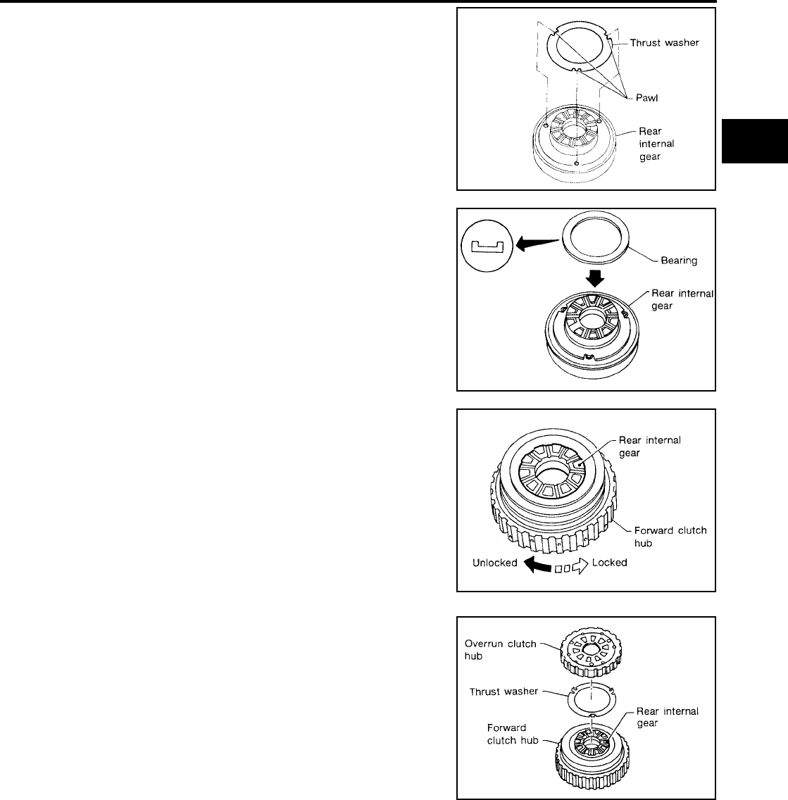
REPAIR FOR COMPONENT PARTS
AT-325
[RE4F04B]
D
E
F
G
H
I
J
K
L
M
A
B
AT
Revision: September 2005 2005 Quest
3. Install thrust washer on rear internal gear.
CAUTION:
●Apply petroleum jelly to thrust washer.
●Align hooks of thrust washer with holes of rear internal
gear.
4. Install bearing on rear internal gear.
CAUTION:
Apply petroleum jelly to bearing.
5. Install forward clutch hub on rear internal gear.
CAUTION:
●Check operation of forward one-way clutch.
Hold rear internal gear and turn forward clutch hub.
Check forward clutch hub for correct locking and unlock-
ing directions.
●If not as shown in figure, check installation direction of
forward one-way clutch.
6. Install thrust washer and overrun clutch hub.
CAUTION:
●Apply petroleum jelly to thrust washer.
●Align hooks of thrust washer with holes of overrun clutch
hub.
●Align projections of rear internal gear with holes of over-
run clutch hub.
SAT160F
SAT161FA
AAT426
SAT157F

AT-326
[RE4F04B]
REPAIR FOR COMPONENT PARTS
Revision: September 2005 2005 Quest
Output Shaft, Idler Gear, Reduction Pinion Gear and Bearing Retainer UCS000RW
COMPONENTS
DISASSEMBLY
1. Remove seal rings from output shaft and bearing retainer.
1. Lock nut 2. Idler gear 3. Adjusting shim
4. Idler gear bearing 5. Reduction pinion gear bearing outer
race
6. Reduction pinion gear bearing inner
race
7. Reduction pinion gear 8. Snap ring 9. Radial needle bearing
10. Seal ring 11. Bearing retainer 12. Needle bearing
13. Seal ring 14. Out put shaft 15. Out put shaft bearing
SCIA3612E
SAT164F
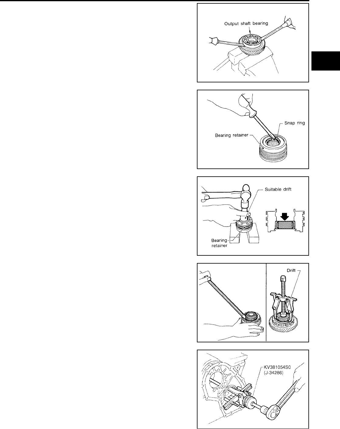
REPAIR FOR COMPONENT PARTS
AT-327
[RE4F04B]
D
E
F
G
H
I
J
K
L
M
A
B
AT
Revision: September 2005 2005 Quest
2. Remove output shaft bearing with screwdrivers.
CAUTION:
●Always replace bearing with a new one when removed.
●Do not damage output shaft.
3. Remove snap ring from bearing retainer.
CAUTION:
Do not expand snap ring excessively.
4. Remove needle bearing from bearing retainer.
5. Remove idler gear bearing inner race from idler gear.
6. Remove idler gear bearing outer race from transaxle case.
SAT165F
SAT166F
SAT167F
SAT168F
SCIA5390E

AT-328
[RE4F04B]
REPAIR FOR COMPONENT PARTS
Revision: September 2005 2005 Quest
7. Press out reduction pinion gear bearing inner race from reduc-
tion pinion gear.
8. Remove reduction pinion gear bearing outer race from transaxle
case.
INSPECTION
Output Shaft, Idler Gear and Reduction Pinion Gear
●Check shafts for cracks, wear or bending.
●Check gears for wear, chips and cracks.
Bearing
●Make sure bearings roll freely and are free from noise, cracks,
pitting or wear.
●When replacing taper roller bearing, replace outer and inner
race as a set.
Seal Ring Clearance
●Install new seal rings to output shaft.
●Measure clearance between seal ring and ring groove of output
shaft.
●If not within allowable limit, replace output shaft.
●Install new seal rings to bearing retainer.
●Measure clearance between seal ring and ring groove of bear-
ing retainer.
●If not within allowable limit, replace bearing retainer.
SAT169F
SAT319K
SPD715
Standard clearance : 0.10 - 0.25 mm
(0.0039 - 0.0098 in)
Allowable limit : 0.25 mm (0.0098 in)
Standard clearance : 0.10 - 0.30 mm (0.0039 - 0.0118 in)
Allowable limit : 0.30 mm (0.0118 in)
SAT171F

REPAIR FOR COMPONENT PARTS
AT-329
[RE4F04B]
D
E
F
G
H
I
J
K
L
M
A
B
AT
Revision: September 2005 2005 Quest
ASSEMBLY
1. Press reduction pinion gear bearing inner race on reduction pin-
ion gear.
2. Install reduction pinion gear bearing outer race on transaxle
case.
3. Press idler gear bearing inner race on idler gear.
4. Install idler gear bearing outer race on transaxle case.
SCIA5391E
SAT319K
SCIA5392E
SCIA5393E

AT-330
[RE4F04B]
REPAIR FOR COMPONENT PARTS
Revision: September 2005 2005 Quest
5. Press output shaft bearing on output shaft.
6. Press needle bearing on bearing retainer.
7. Install snap ring to bearing retainer.
CAUTION:
Do not expand snap ring excessively.
8. After packing ring grooves with petroleum jelly, carefully install
new seal rings on output shaft and bearing retainer.
CAUTION:
●Apply petroleum jelly.
●Roll paper around seal rings to prevent seal rings from
spreading.
SAT863D
SAT176F
SAT166F
SCIA3660E
SAT179F

REPAIR FOR COMPONENT PARTS
AT-331
[RE4F04B]
D
E
F
G
H
I
J
K
L
M
A
B
AT
Revision: September 2005 2005 Quest
Band Servo Piston Assembly UCS000RX
COMPONENTS
DISASSEMBLY
1. Remove O/D servo piston retainer fixing bolts.
2. Apply compressed air to oil hole in transaxle case to remove O/
D servo piston retainer and band servo piston assembly.
CAUTION:
Hold band servo piston assembly with a rag or nylon waste.
3. Remove 2nd servo return spring from transaxle case.
1. Lock nut 2. Anchor end pin 3. Brake band
4. Strut 5. O-ring 6. Servo piston retainer
7. D-ring 8. O/D servo piston 9. O-rings
10. O/D servo piston retainer 11. E-ring 12. Spring retainer
13. O/D servo return spring 14. D-ring 15. Band servo piston
16. Band servo thrust washer 17. Band servo piston stem 18. 2nd servo return spring
SCIA3297E
AAT879
SAT093J
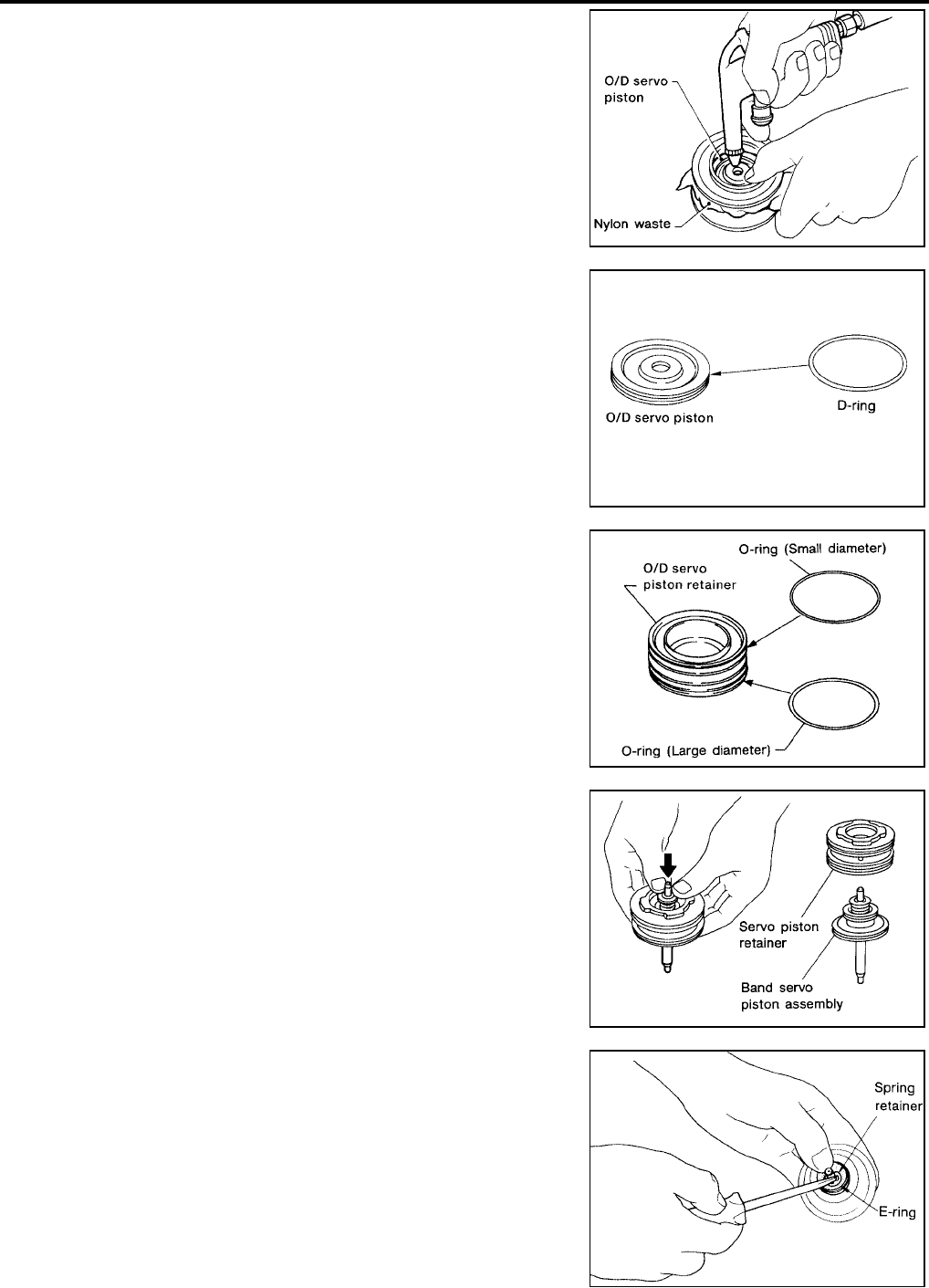
AT-332
[RE4F04B]
REPAIR FOR COMPONENT PARTS
Revision: September 2005 2005 Quest
4. Apply compressed air to oil hole in O/D servo piston retainer to
remove O/D servo piston from retainer.
CAUTION:
Hold O/D band servo piston while applying compressed air.
5. Remove D-ring from O/D servo piston.
6. Remove O-rings from O/D servo piston retainer.
7. Remove band servo piston assembly from servo piston retainer
by pushing it forward.
8. Place band servo piston stem end on a wooden block. While
pushing spring retainer down, remove E-ring.
AAT880
AAT881
AAT882
SAT293D
SAT294D
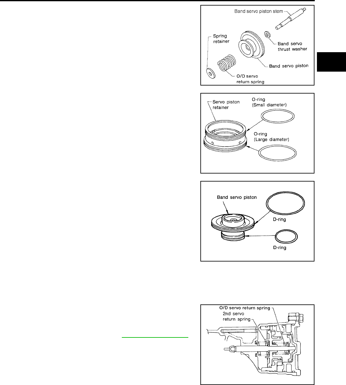
REPAIR FOR COMPONENT PARTS
AT-333
[RE4F04B]
D
E
F
G
H
I
J
K
L
M
A
B
AT
Revision: September 2005 2005 Quest
9. Remove spring retainer, O/D servo return spring, band servo
thrust washer and band servo piston stem from band servo pis-
ton.
10. Remove O-rings from servo piston retainer.
11. Remove D-rings from band servo piston.
INSPECTION
Pistons, Retainers and Piston Stem
●Check frictional surfaces for abnormal wear or damage.
Return Springs
●
Check for deformation or damage.
●Measure free length and outer diameter.
SCIA3670E
SCIA3872E
SAT297D
Inspection standard : Refer to AT-370, "Band Servo"
.
AAT884
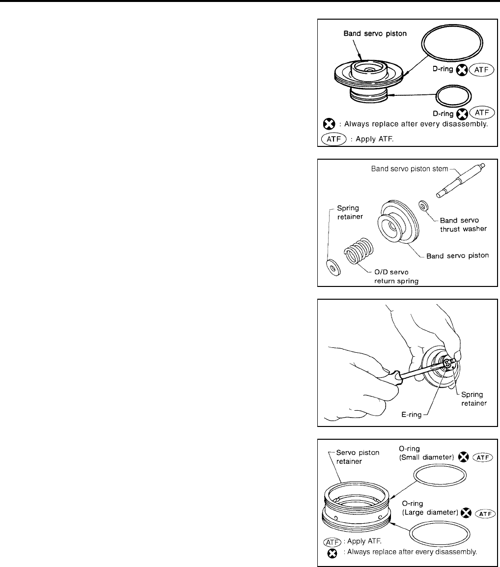
AT-334
[RE4F04B]
REPAIR FOR COMPONENT PARTS
Revision: September 2005 2005 Quest
ASSEMBLY
1. Install D-rings to servo piston retainer.
CAUTION:
●Do not reuse D-rings.
●Apply ATF to D-rings.
●Pay attention to position of each D-ring.
2. Install band servo piston stem, band servo thrust washer, O/D
servo return spring and spring retainer to band servo piston.
3. Place band servo piston stem end on a wooden block. While
pushing spring retainer down, install E-ring.
4. Install O-rings to O/D servo piston retainer.
CAUTION:
●Do not reuse O-rings.
●Apply ATF to O-rings.
●Pay attention to position of each O-ring.
SCIA3688E
SCIA3670E
SAT301D
SCIA3671E

REPAIR FOR COMPONENT PARTS
AT-335
[RE4F04B]
D
E
F
G
H
I
J
K
L
M
A
B
AT
Revision: September 2005 2005 Quest
5. Install band servo piston assembly to servo piston retainer by
pushing it inward.
6. Install D-ring to O/D servo piston.
CAUTION:
●Do not reuse D-ring.
●Apply ATF to D-ring.
7. Install O-rings to O/D servo piston retainer.
CAUTION:
●Do not reuse O-rings.
●Apply ATF to O-rings.
●Pay attention to position of each O-ring.
8. Install O/D servo piston to O/D servo piston retainer.
9. Install band servo piston assembly and 2nd servo return spring
to transaxle case.
CAUTION:
Apply ATF to O-ring of band servo piston assembly and
transaxle case.
SAT303D
SCIA3689E
SCIA3871E
AAT886
SCIA3878E

AT-336
[RE4F04B]
REPAIR FOR COMPONENT PARTS
Revision: September 2005 2005 Quest
10. Install O/D servo piston assembly to transaxle case.
CAUTION:
Apply ATF to O-ring of O/D servo piston assembly and tran-
saxle case.
11. Install O-ring to O/D servo piston retainer.
CAUTION:
●Do not reuse O-ring.
●Apply ATF to O-ring.
12. Install O/D servo piston retainer to transaxle case.
Refer to AT-331, "COMPONENTS" .
Final Drive UCS000RY
COMPONENTS
SCIA3879E
AAT879
1. Pinion mate gear 2. Pinion mate thrust washer 3. Pinion mate shaft
4. Lock pin 5. Side gear 6. Side gear thrust washer
7. Differential side bearing 8. Differential case 9. Final gear
10. Differential side bearing 11. Differential side bearing adjusting
shim
SCIA3346E

REPAIR FOR COMPONENT PARTS
AT-337
[RE4F04B]
D
E
F
G
H
I
J
K
L
M
A
B
AT
Revision: September 2005 2005 Quest
DISASSEMBLY
1. Remove final gear.
2. Press out differential side bearings.
●Be careful not to mix up the right and left bearings.
3. Remove differential side bearing outer race and side bearing
adjusting shim from transaxle case.
4. Drive out pinion mate shaft lock pin.
SMT505B
SCIA5394E
SCIA5378E
SCIA5395E

AT-338
[RE4F04B]
REPAIR FOR COMPONENT PARTS
Revision: September 2005 2005 Quest
5. Draw out pinion mate shaft.
6. Remove pinion mate gears and side gears.
INSPECTION
Gear, Washer, Shaft and Case
●Check mating surfaces of differential case, side gears and pin-
ion mate gears.
●Check washers for wear.
Bearings
●Make sure bearings roll freely and are free from noise, cracks,
pitting or wear.
●When replacing taper roller bearing, replace outer and inner
race as a set.
ASSEMBLY
1. Attach side gear thrust washers to side gears, then install pinion
mate thrust washers and pinion mate gears in place.
●Apply ATF to any parts.
SAT316D
SAT544F
SPD715
SMT839
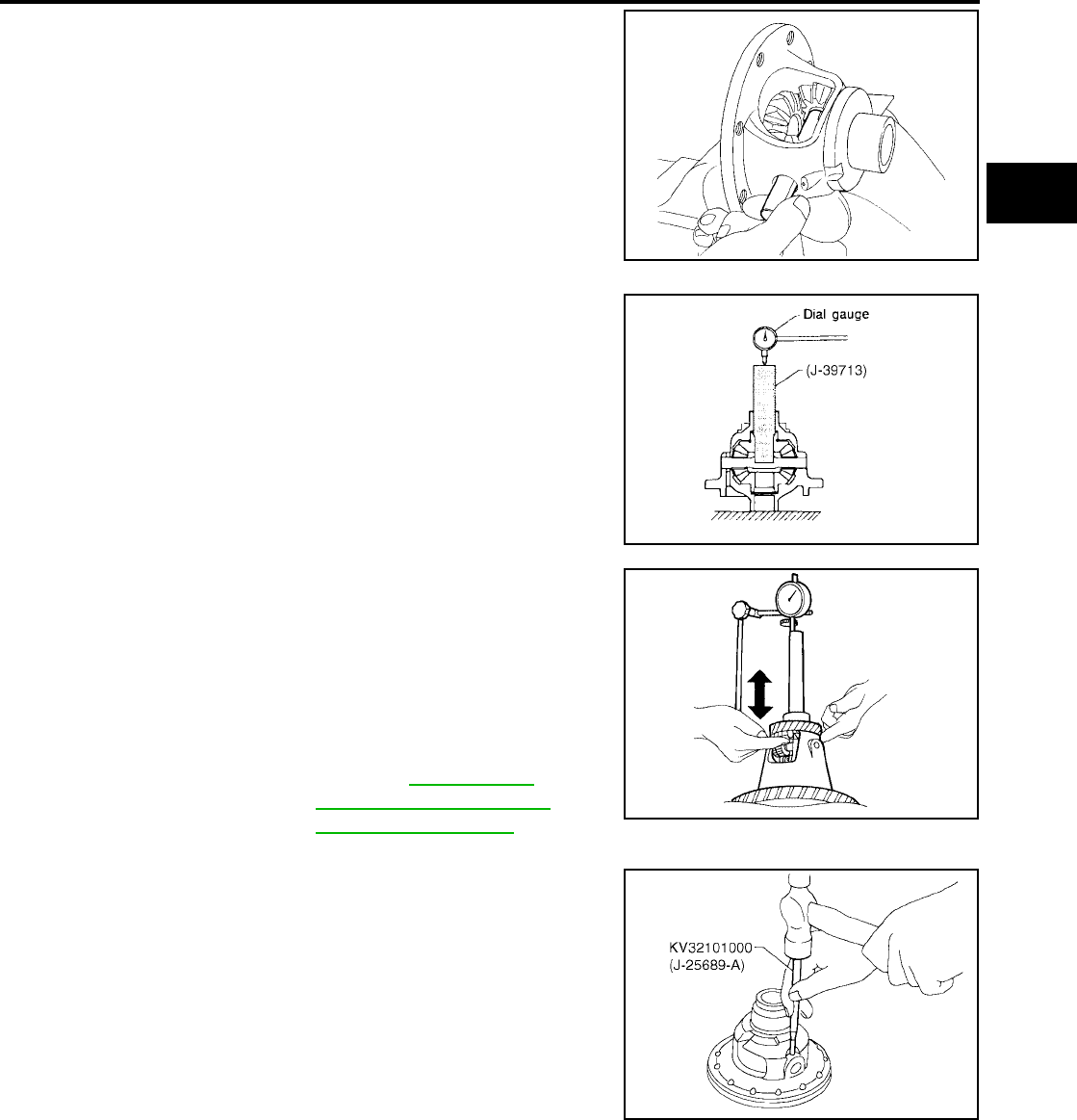
REPAIR FOR COMPONENT PARTS
AT-339
[RE4F04B]
D
E
F
G
H
I
J
K
L
M
A
B
AT
Revision: September 2005 2005 Quest
2. Insert pinion mate shaft.
●When inserting, be careful not to damage pinion mate
thrust washers.
3. Measure clearance between side gear and differential case with
washers following the procedure below:
a. Set Tool and dial indicator on side gear.
b. Move side gear up and down to measure dial indicator deflec-
tion. Always measure indicator deflection on both side gears.
c. If not within specification, adjust clearance by changing thick-
ness of differential side gear thrust washers.
4. Install lock pin.
●Make sure that lock pin is flush with case.
SMT087A
SCIA5396E
Clearance between side
gear and differential
case with washer
: 0.1 - 0.2 mm
(0.004 - 0.008 in)
Differential side gear
thrust washers : Refer to AT-368, "DIF-
FERENTIAL SIDE GEAR
THRUST WASHERS" . SMT611A
SCIA5395E
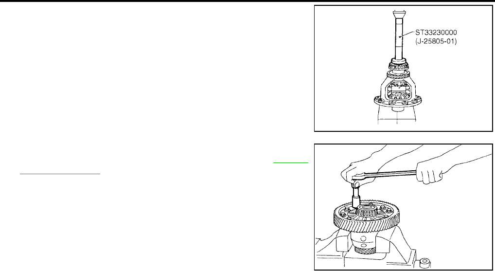
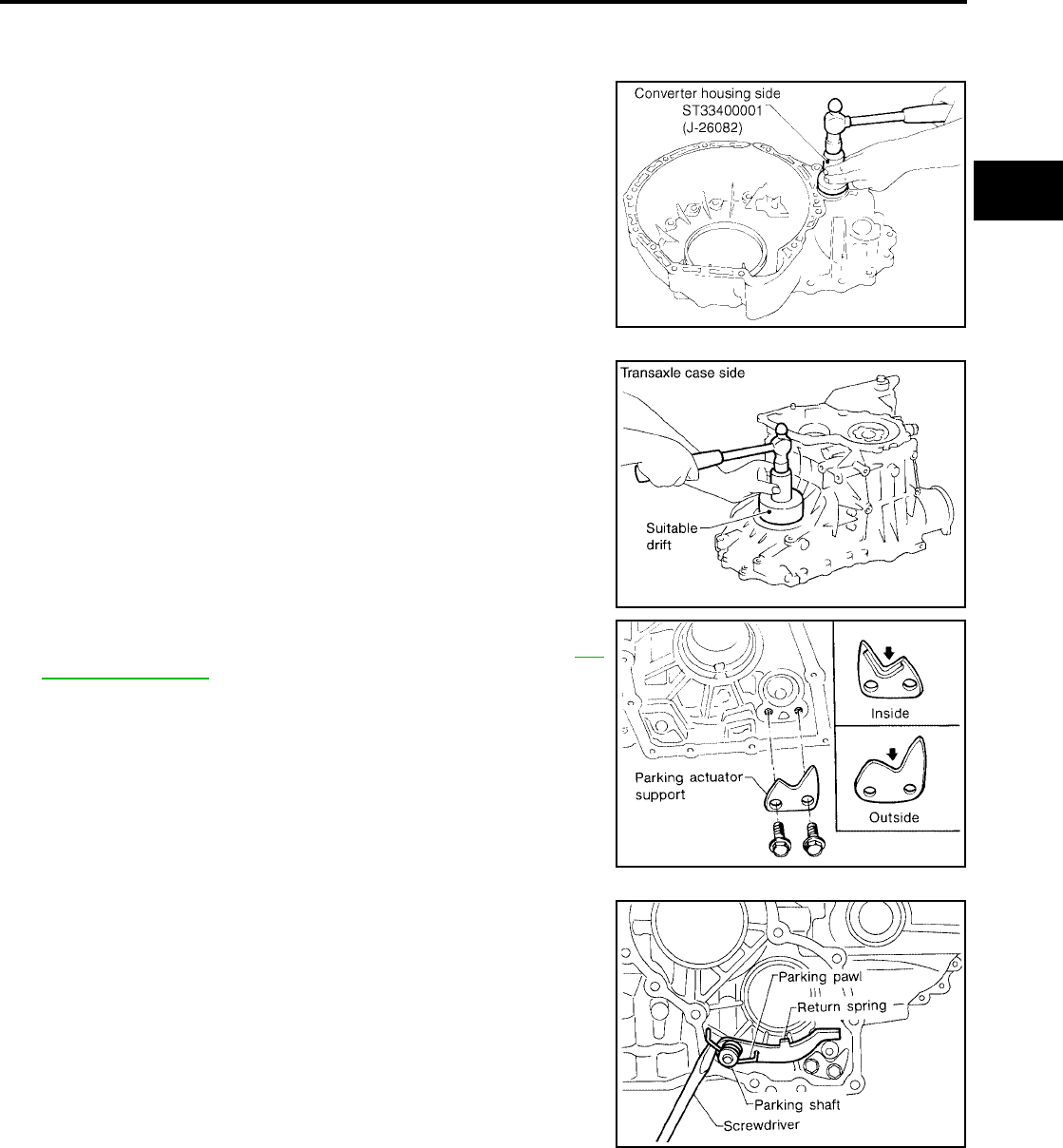
ASSEMBLY
AT-341
[RE4F04B]
D
E
F
G
H
I
J
K
L
M
A
B
AT
Revision: September 2005 2005 Quest
ASSEMBLY PFP:00000
Assembly (1) UCS000RZ
1. Install differential side oil seals on transaxle case and converter
housing.
2. Install parking actuator support to transaxle case. Tighten park-
ing actuator support bolts to the specified torque. Refer to AT-
261, "OVERHAUL" .
CAUTION:
Pay attention to direction of parking actuator support.
3. Install parking pawl on transaxle case and fix it with parking
shaft.
4. Install return spring.
SCIA5399E
SCIA3616E
SAT183F
SAT039F

AT-342
[RE4F04B]
ASSEMBLY
Revision: September 2005 2005 Quest
Adjustment (1) UCS000S0
DIFFERENTIAL SIDE BEARING PRELOAD
1. Install differential side bearing outer race without adjusting shim
on transaxle case.
2. Install differential side bearing outer race on converter housing.
3. Place final drive assembly on transaxle case.
4. Install transaxle case on converter housing. Tighten transaxle
case fixing bolts to the specified torque. Refer to AT-261,
"OVERHAUL" .
5. Attach dial indicator on differential case at converter housing
side.
6. Insert Tool into differential side gear from transaxle case side.
7. Move Tool up and down and measure dial indicator deflection.
8. Select proper thickness of differential side bearing adjusting
shim(s).
Suitable shim thickness = Dial indicator deflection + Speci-
fied bearing preload
SAT870D
SAT008F
Differential side bearing
preload adjusting shim : Refer to AT-368, "DIF-
FERENTIAL SIDE BEAR-
ING PRELOAD
ADJUSTING SHIMS" .
Bearing preload : 0.05 - 0.09 mm
(0.0020 - 0.0035 in)
SCIA5400E
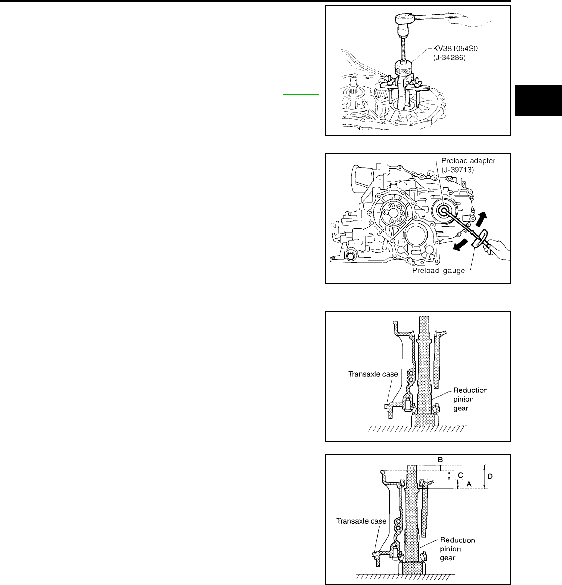
ASSEMBLY
AT-343
[RE4F04B]
D
E
F
G
H
I
J
K
L
M
A
B
AT
Revision: September 2005 2005 Quest
9. Remove converter housing from transaxle case.
10. Remove final drive assembly from transaxle case.
11. Remove differential side bearing outer race from transaxle case.
12. Reinstall differential side bearing outer race and shim(s)
selected from SDS table on transaxle case.
13. Reinstall converter housing on transaxle case and tighten tran-
saxle case fixing bolts to the specified torque. Refer to AT-261,
"OVERHAUL" .
14. Insert Tool and measure turning torque of final drive assembly.
●Turn final drive assembly in both directions several times
to seat bearing rollers correctly.
●When old bearing is used again, turning torque will be
slightly less than the above.
●Make sure torque is close to the specified range.
REDUCTION PINION GEAR BEARING PRELOAD
1. Remove transaxle case and final drive assembly from converter
housing.
2. Select proper thickness of reduction pinion gear bearing adjust-
ing shim using the following procedures.
a. Place reduction pinion gear on transaxle case as shown.
b. Place idler gear bearing on transaxle case.
c. Measure dimensions “B” “C” and “D” and calculate dimension
“A”.
SCIA5378E
Turning torque of final drive assembly (New bearing)
: 0.8 - 1.5 N-m (8.0 - 15.7 kg-cm, 7 - 13 in-lb)
Preload adapter : — (J−39713) SCIA5401E
SCIA3623E
A = D − (B + C)
“A” : Distance between the surface of idler gear bear-
ing inner race and the adjusting shim mating sur-
face of reduction pinion gear.
SCIA3624E

AT-344
[RE4F04B]
ASSEMBLY
Revision: September 2005 2005 Quest
● Measure dimension “B” between the end of reduction pinion
gear and the surface of transaxle case.
●Measure dimension “B” in at least two places.
●Measure dimension “C” between the surface of idler gear
bearing inner race and the surface of transaxle case.
●Measure dimension “C” in at least two places.
●Measure dimension “D” between the end of reduction pinion
gear and the adjusting shim mating surface of reduction pin-
ion gear.
●Measure dimension “D” in at least two places.
●Calculate dimension “A”.
d. Measure dimension “E” between the end of idler gear and the
idler gear bearing inner race mating surface of idler gear.
●Measure dimension “E” in at least two places.
e. Select proper thickness of reduction pinion gear bearing adjust-
ing shim.
SCIA3625E
SCIA3626E
A = D − (B + C)
SAT336DA
Proper shim thickness = A − E − 0.05 mm (0.0020 in)*
(*: Bearing preload)
Reduction pinion gear
bearing adjusting shim : Refer to AT-369,
"REDUCTION PINION
GEAR BEARING ADJUST-
ING SHIMS" .
SAT337D

ASSEMBLY
AT-345
[RE4F04B]
D
E
F
G
H
I
J
K
L
M
A
B
AT
Revision: September 2005 2005 Quest
3. Install reduction gear and reduction gear bearing adjusting shim
selected in step 2-e on transaxle case.
4. Press idler gear bearing inner race on idler gear.
5. Press idler gear on reduction gear.
CAUTION:
Press idler gear until idler gear fully contacts adjusting
shim.
6. Tighten idler gear lock nut to the specified torque. Refer to AT-
261, "OVERHAUL" .
CAUTION:
Lock idler gear with parking pawl when tightening lock nut.
7. Measure turning torque of reduction pinion gear.
●When measuring turning torque, turn reduction pinion
gear in both directions several times to seat bearing roll-
ers correctly.
●If turning torque is out of specification, decrease or
increase thickness of reduction pinion gear bearing
adjusting shim.
8. After properly adjusting turning torque, clinch idler gear lock nut
as shown.
SCIA5402E
SAT189F
Turning torque of reduction pinion gear
: 0.05 - 0.39 N-m (0.5 - 4.0 kg-cm, 0.43 - 3.47 in-lb)
SCIA5403E
SAT699D
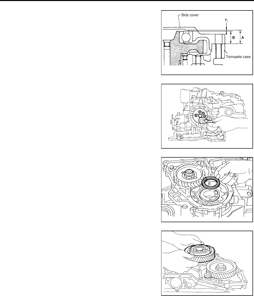
AT-346
[RE4F04B]
ASSEMBLY
Revision: September 2005 2005 Quest
OUTPUT SHAFT END PLAY
●Measure clearance between side cover and the end of the out-
put shaft bearing.
●Select proper thickness of adjusting shim so that clearance is
within specifications.
1. Install bearing retainer for output shaft.
2. Install needle bearing on bearing retainer.
3. Install output shaft on transaxle case.
SCIA3853E
SAT191F
SAT438D
SAT035F
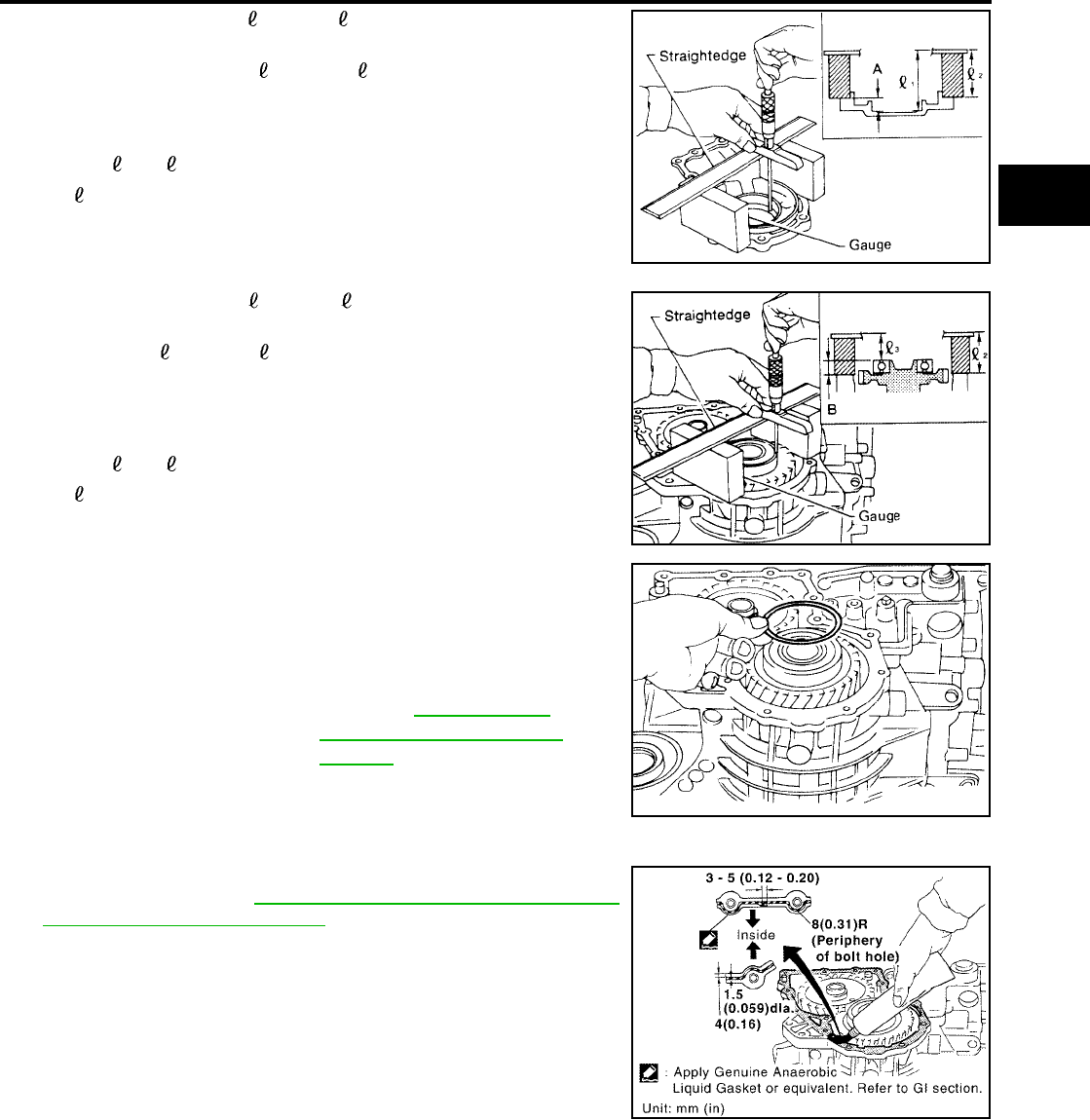
ASSEMBLY
AT-347
[RE4F04B]
D
E
F
G
H
I
J
K
L
M
A
B
AT
Revision: September 2005 2005 Quest
4. Measure dimensions “ 1 ” and “ 2 ” at side cover and then cal-
culate dimension “A”.
●Measure dimension “ 1 ” and “ 2 ” in at least two places.
5. Measure dimensions “ 2 ” and “ 3 ” and then calculate dimen-
sion “B”.
●Measure “ 2 ” and “ 3 ” in at least two places.
6. Select proper thickness of adjusting shim so that output shaft
end play (clearance between side cover and output shaft bear-
ing) is within specifications.
7. Install adjusting shim on output shaft bearing.
Assembly (2) UCS000S1
1. Apply anaerobic liquid gasket to transaxle case as shown in
illustration. Refer to GI-43, "RECOMMENDED CHEMICAL
PRODUCTS AND SEALANTS" .
“A” : Distance between transaxle case fitting sur-
face and adjusting shim mating surface.
A = 1 − 2
2: Height of gauge
SAT374F
“B” : Distance between the end of output shaft bear-
ing outer race and the side cover fitting surface
of transaxle case.
B = 2 − 3
2: Height of gauge
SAT375F
Output shaft end play
(A − B) : 0 - 0.15 mm (0 - 0.0059 in)
Output shaft end play
adjusting shims : Refer to AT-371, "OUT-
PUT SHAFT ADJUSTING
SHIMS" .
SAT440D
SCIA3854E
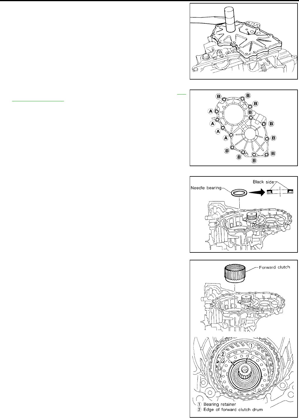
AT-348
[RE4F04B]
ASSEMBLY
Revision: September 2005 2005 Quest
2. Set side cover on transaxle case.
CAUTION:
Apply locking sealant to the mating surface of transaxle
case.
3. Tighten side cover fixing bolts to specified torque. Refer to AT-
261, "OVERHAUL" .
CAUTION:
●Do not mix bolts A and B.
●Always replace bolts A as they are self-sealing bolts.
4. Remove paper rolled around bearing retainer.
5. Install thrust washer on bearing retainer.
CAUTION:
Apply petroleum jelly to thrust washer.
6. Install forward clutch assembly.
CAUTION:
●Align teeth of low & reverse brake drive plates before
installing.
●Make sure that bearing retainer seal rings are not spread.
●If forward clutch assembly is correctly seated, points 1
and 2 are at almost same level.
SAT442D
AAT850
SAT033F
SAT194F
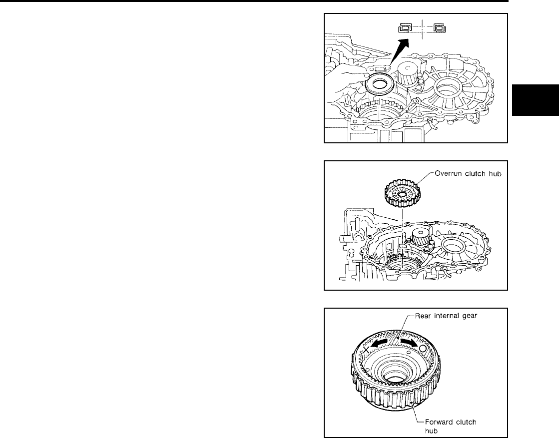
ASSEMBLY
AT-349
[RE4F04B]
D
E
F
G
H
I
J
K
L
M
A
B
AT
Revision: September 2005 2005 Quest
7. Install thrust needle bearing on bearing retainer.
CAUTION:
●Apply petroleum jelly to thrust needle bearing.
●Pay attention to direction of thrust needle bearing.
8. Install overrun clutch hub.
CAUTION:
●Apply petroleum jelly to thrust washers.
●Align teeth of overrun clutch drive plates before install-
ing.
9. Hold forward clutch hub and turn rear internal gear.
Check overrun clutch hub for correct directions of lock and
unlock.
●If not shown as illustrated, check installed direction of
forward one-way clutch.
SAT195F
SAT030F
SAT198F

AT-350
[RE4F04B]
ASSEMBLY
Revision: September 2005 2005 Quest
10. Install forward clutch hub and rear internal gear assembly.
CAUTION:
●Align teeth of forward clutch drive plates before install-
ing.
●Check that three hooks of thrust washer are correctly
aligned after installing.
11. Install rear planetary carrier assembly and rear sun gear accord-
ing to the following procedures.
a. Install needle bearings on rear planetary carrier.
CAUTION:
●Apply petroleum jelly to needle bearings.
●Pay attention to direction of needle bearings.
b. Install rear sun gear on rear planetary carrier.
CAUTION:
Pay attention to direction of rear sun gear.
c. Install rear planetary carrier on transaxle case.
SAT199F
SAT028F
SAT027F
SAT026F
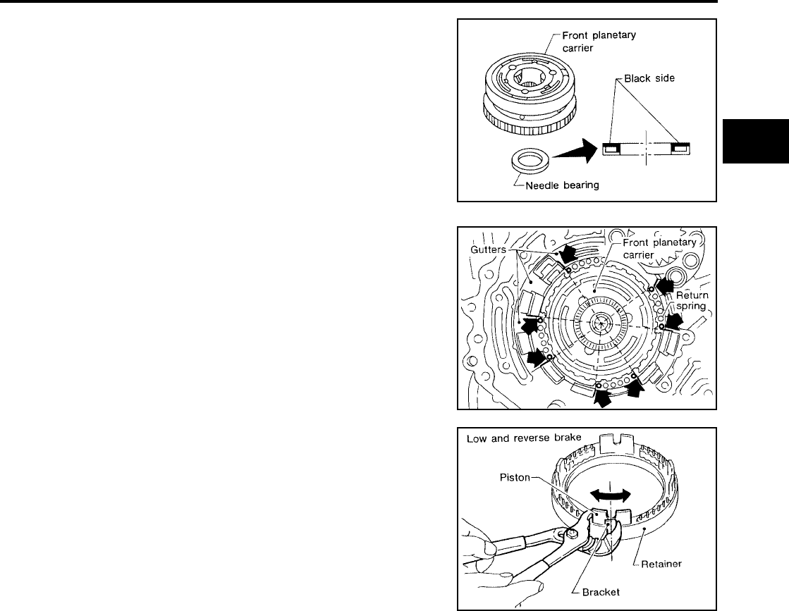
ASSEMBLY
AT-351
[RE4F04B]
D
E
F
G
H
I
J
K
L
M
A
B
AT
Revision: September 2005 2005 Quest
12. Install thrust needle bearing on front planetary carrier, then
install them together on transaxle case.
CAUTION:
●Apply petroleum jelly to thrust needle bearing.
●Pay attention to direction of thrust needle bearing.
13. Install low & reverse brake piston according to the following pro-
cedures.
a. Set and align return springs to transaxle case gutters as shown
in illustration.
b. Set and align piston with retainer.
SAT380F
SAT322F
SAT323F
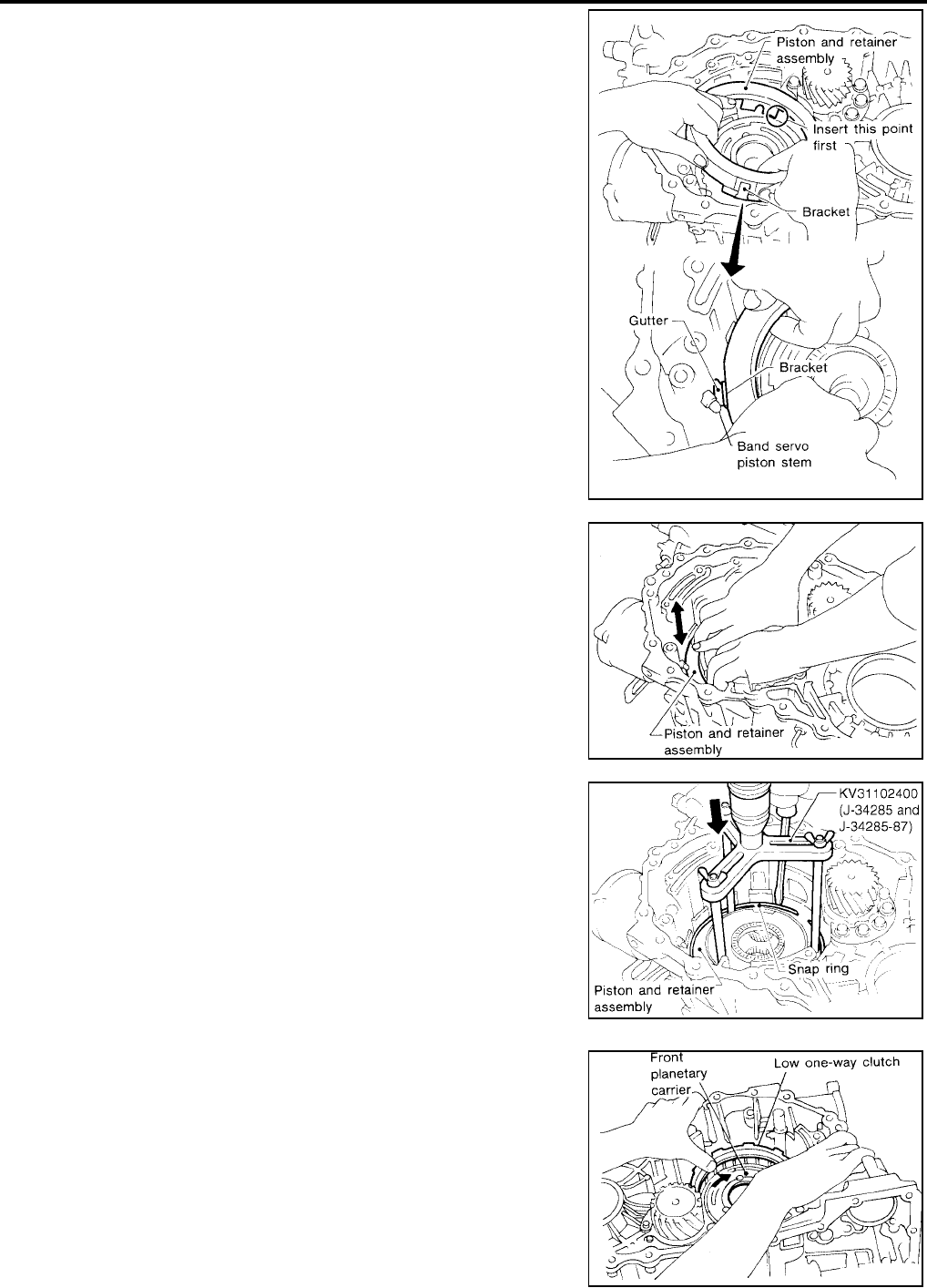
AT-352
[RE4F04B]
ASSEMBLY
Revision: September 2005 2005 Quest
c. Install piston and retainer assembly on the transaxle case.
CAUTION:
Align bracket to specified gutter as indicated in illustration.
d. Check that each protrusion of piston is correctly set to corre-
sponding return spring as follows.
●Push piston and retainer assembly evenly and confirm
they move smoothly.
●If they can not move smoothly, remove piston and
retainer assembly and align return spring correctly as
instructed in step “a”.
e. Push down piston and retainer assembly and install snap ring.
14. Install low one-way clutch to front planetary carrier by turning
carrier in the direction of the arrow shown.
SAT324F
SAT325F
SCIA5404E
SAT206F
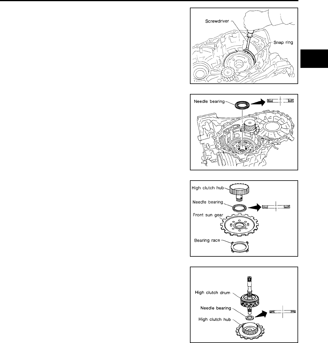
ASSEMBLY
AT-353
[RE4F04B]
D
E
F
G
H
I
J
K
L
M
A
B
AT
Revision: September 2005 2005 Quest
15. Install snap ring with screwdriver.
CAUTION:
●Forward clutch and bearing must be correctly installed
for snap ring to fit into groove of transaxle case.
●Do not expand snap ring excessively.
16. Install needle bearing on transaxle case.
CAUTION:
●Apply petroleum jelly to needle bearing.
●Pay attention to direction of needle bearing.
17. Install bearing race, needle bearing and high clutch hub on front
sun gear.
CAUTION:
●Apply petroleum jelly to needle bearing.
●Pay attention to direction of needle bearing.
18. Install needle bearing and high clutch drum on high clutch hub.
SAT046D
SAT020F
SAT019F
SAT018F
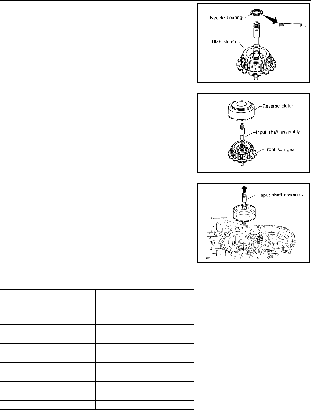
AT-354
[RE4F04B]
ASSEMBLY
Revision: September 2005 2005 Quest
19. Install needle bearing on high clutch drum.
CAUTION:
●Apply petroleum jelly to needle bearing.
●Pay attention to direction of needle bearing.
20. Remove paper rolled around input shaft.
21. Install input shaft assembly in reverse clutch.
CAUTION:
Align teeth of reverse clutch drive plates before installing.
22. Install reverse clutch assembly on transaxle case.
CAUTION:
Align teeth of high clutch drive plates before installing.
Adjustment (2) UCS000S2
When any parts listed below are replaced, adjust total end play and reverse clutch end play.
SAT017F
SAT016F
SAT015F
Part name Total end play Reverse clutch end
play
Transaxle case ●●
Overrun clutch hub ●●
Rear internal gear ●●
Rear planetary carrier ●●
Rear sun gear ●●
Front planetary carrier ●●
Front sun gear ●●
High clutch hub ●●
High clutch drum ●●
Oil pump cover ●●
Reverse clutch drum — ●

ASSEMBLY
AT-355
[RE4F04B]
D
E
F
G
H
I
J
K
L
M
A
B
AT
Revision: September 2005 2005 Quest
TOTAL END PLAY
1. Adjust total end play “T1 ”.
a. With original bearing race installed, place Tool onto oil pump.
The long ends of legs should be placed firmly on machined sur-
face of oil pump assembly. The gauging cylinder should rest on
top of bearing race. Lock gauging cylinder in place with set
screw.
b. Install gauging plunger into cylinder.
c. With needle bearing installed on high clutch drum, place Tool
legs on machined surface of transaxle case (with gasket). Then
allow plunger to rest on needle bearing.
d. Measure gap between cylinder and plunger. This measurement
should give exact total end play.
●If end play is out of specification, decrease or increase thick-
ness of bearing race as necessary.
SAT213F
SCIA5405E
SCIA5406E
Total end play “T1 ”
: 0.25 - 0.55 mm (0.0098 - 0.0217 in)
Available bearing race for adjusting total end play
: Refer to AT-371, "BEARING RACE FOR ADJUST-
ING TOTAL END PLAY" .
SAT216F
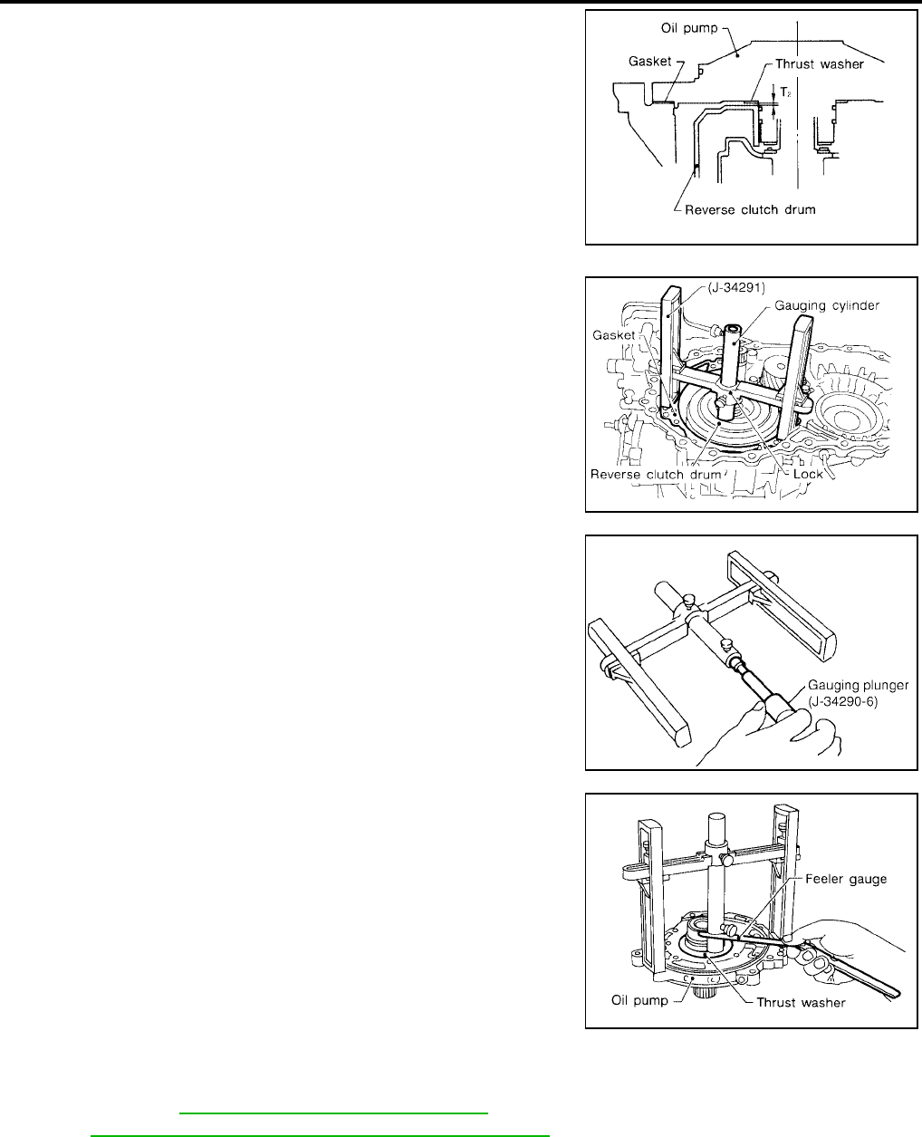
AT-356
[RE4F04B]
ASSEMBLY
Revision: September 2005 2005 Quest
2. Adjust reverse clutch drum end play “T2 ”.
a. Place Tool on machined surface of transaxle case (with gasket).
Then allow gauging cylinder to rest on reverse clutch drum. Lock
cylinder in place with set screw.
b. Install gauging plunger into cylinder.
c. With original thrust washer installed on oil pump, place Tool legs
onto machined surface of oil pump assembly. Then allow
plunger to rest on thrust washer.
d. Measure gap between cylinder and plunger with feeler gauge.
This measurement should give exact reverse clutch drum end
play.
●If end play is out of specification, decrease or increase thick-
ness of thrust washer as necessary.
SAT218F
SCIA5407E
SCIA5408E
Reverse clutch drum end play “T2 ”
: 0.61 - 1.00 mm (0.0240 - 0.0394 in)
Available thrust washer for adjusting reverse clutch
drum end play
: Refer to AT-371, "THRUST WASHERS FOR
ADJUSTING REVERSE CLUTCH DRUM END PLAY" .
SAT221F

ASSEMBLY
AT-357
[RE4F04B]
D
E
F
G
H
I
J
K
L
M
A
B
AT
Revision: September 2005 2005 Quest
Assembly (3) UCS000S3
1. Install anchor end pin and lock nut on transaxle case.
2. Place brake band on outside of reverse clutch drum. Tighten
anchor end pin just enough so that brake band is evenly fitted on
reverse clutch drum.
3. Place bearing race selected in total end play adjustment step on
oil pump cover.
CAUTION:
Apply petroleum jelly to bearing race.
4. Place thrust washer selected in reverse clutch end play step on
reverse clutch drum.
CAUTION:
Apply petroleum jelly to thrust washer.
5. Install oil pump assembly and gasket on transaxle case.
CAUTION:
Do not reuse gasket.
6. Tighten oil pump fixing bolts to the specified torque.
7. Install O-ring to input shaft.
CAUTION:
●Apply petroleum jelly to O-ring.
●Do not reuse O-ring.
SAT196F
SAT013F
SCIA3618E
SCIA3855E
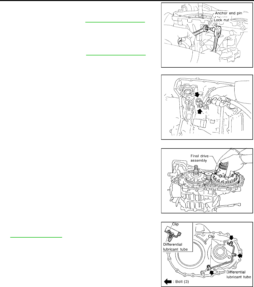
AT-358
[RE4F04B]
ASSEMBLY
Revision: September 2005 2005 Quest
8. Adjust brake band.
a. Tighten anchor end pin to the specified torque.
●Do not reuse anchor end pin.
b. Back off anchor end pin two and a half turns.
c. While holding anchor end pin, tighten lock nut.
9. Apply compressed air to oil holes of transaxle case and check
operation of brake band.
10. Install final drive assembly on transaxle case.
11. Install differential lubricant tube on converter housing. Tighten
differential lubricant tube bolts to the specified torque. Refer to
AT-261, "OVERHAUL" .
Anchor end pin : Refer to AT-368, "BRAKE BAND" .
Lock nut : Refer to AT-368, "BRAKE BAND" .
SAT014FA
SAT397D
SAT228F
SCIA3284E
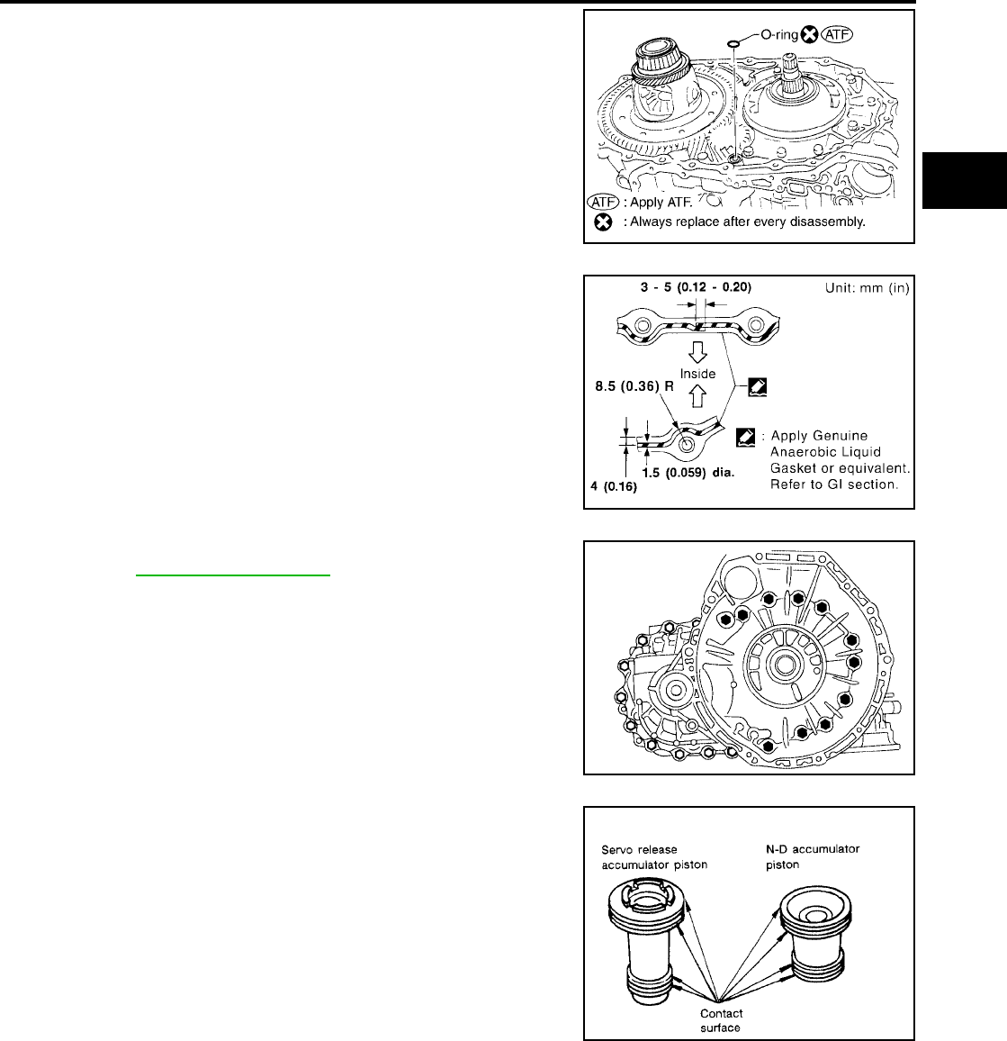
ASSEMBLY
AT-359
[RE4F04B]
D
E
F
G
H
I
J
K
L
M
A
B
AT
Revision: September 2005 2005 Quest
12. Install O-ring on differential oil port of transaxle case.
CAUTION:
●Apply ATF to O-ring.
●Do not reuse O-ring.
13. Install converter housing on transaxle case.
●Apply locking sealant to mating surface of converter
housing.
●Tighten converter housing bolts to the specified torque.
Refer to AT-261, "OVERHAUL" .
14. Install accumulator piston.
a. Check contact surface of accumulator piston for damage.
SCIA3852E
SCIA3620E
SAT008F
SCIA3302E
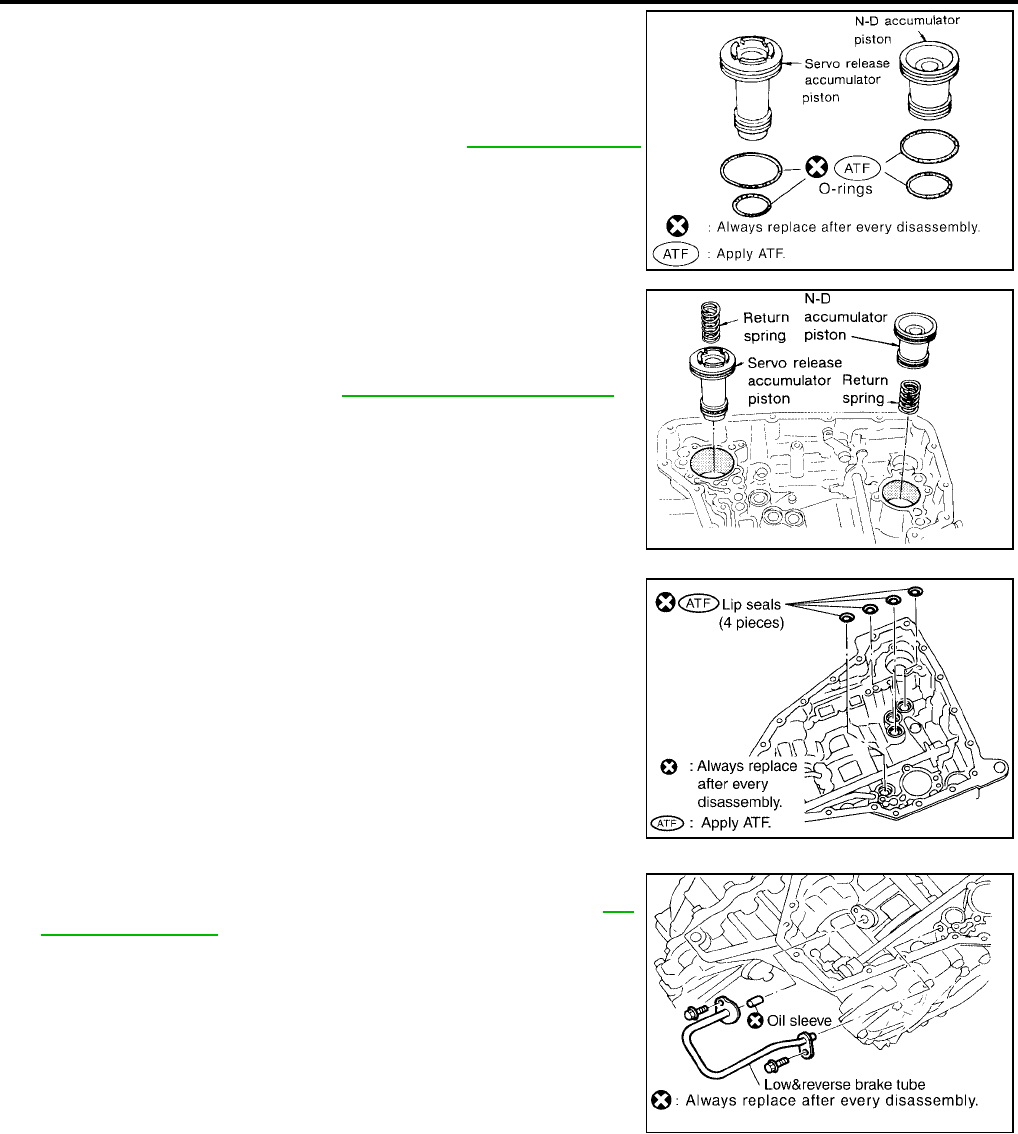
AT-360
[RE4F04B]
ASSEMBLY
Revision: September 2005 2005 Quest
b. Install O-rings on accumulator piston.
CAUTION:
●Do not reuse O-rings.
●Apply ATF to O-rings.
c. Install accumulator pistons and return springs on transaxle case.
CAUTION:
Apply ATF to inner surface of transaxle case.
15. Install lip seals for band servo oil holes on transaxle case.
CAUTION:
●Do not reuse lip seals.
●Apply petroleum jelly to lip seals.
16. Install low & reverse brake tube and oil sleeve. Tighten low &
reverse brake tube bolts to the specified torque. Refer to AT-
261, "OVERHAUL" .
CAUTION:
Do not reuse oil sleeve.
Accumulator piston O-rings : Refer to AT-365, "O-RING" .
SCIA3303E
Return springs : Refer to AT-366, "RETURN SPRING" .
SAT237FA
SCIA3850E
SCIA3851E
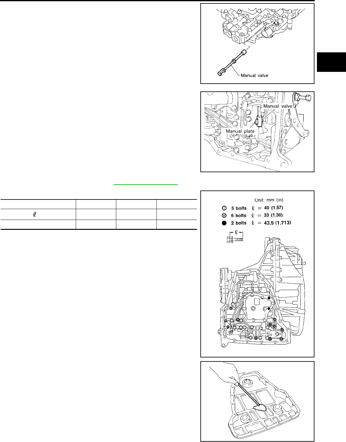
ASSEMBLY
AT-361
[RE4F04B]
D
E
F
G
H
I
J
K
L
M
A
B
AT
Revision: September 2005 2005 Quest
17. Install control valve assembly.
a. Insert manual valve into control valve assembly.
CAUTION:
Apply ATF to manual valve.
b. Set manual shaft in Neutral position.
c. Install control valve assembly on transaxle case while aligning
manual valve with manual plate.
d. Pass solenoid harness through transaxle case and install termi-
nal body on transaxle case by pushing it.
e. Install stopper ring to terminal body.
f. Tighten bolts I , X and ●. Refer to AT-261, "OVERHAUL" .
Bolt length, number and location:
18. Install oil pan.
a. Attach a magnet to oil pan.
b. Install new oil pan gasket on transaxle case.
c. Install oil pan on transaxle case.
CAUTION:
●Always replace oil pan bolts as they are self-sealing
bolts.
●Tighten four bolts in a crisscross pattern to prevent dislo-
cation of gasket.
SAT005F
SAT094J
Bolt symbol IX●
Bolt length “ ” mm (in) 40 (1.57) 33 (1.30) 43.5 (1.713)
Number of bolts 5 6 2
SAT004F
SCIA3476E
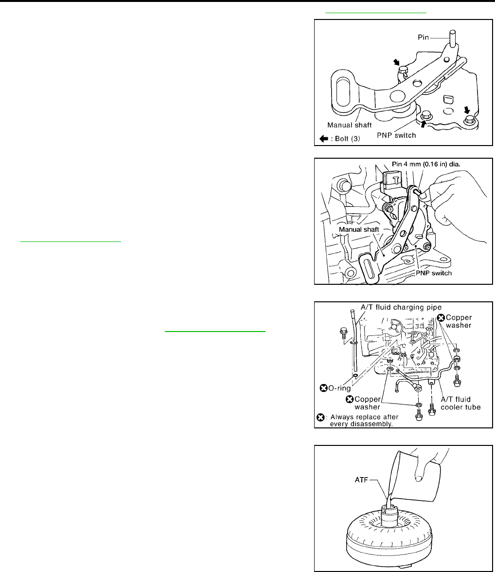
AT-362
[RE4F04B]
ASSEMBLY
Revision: September 2005 2005 Quest
d. Tighten oil pan bolts and drain plug to the specified torque. Refer to AT-261, "OVERHAUL" .
19. Install park/neutral position (PNP) switch.
a. Set manual shaft in P position.
b. Temporarily install park/neutral position (PNP) switch on manual
shaft.
c. Move selector lever to N position.
d. Use a 4 mm (0.16 in) pin for this adjustment.
i. Insert the pin straight into the manual shaft adjustment hole.
ii. Rotate park/neutral position (PNP) switch until the pin can also
be inserted straight into hole in park/neutral position (PNP)
switch.
e. Tighten park/neutral position (PNP) switch fixing bolts. Refer to
AT-261, "OVERHAUL" .
f. Remove pin from adjustment hole after adjusting park/neutral
position (PNP) switch.
20. Install A/T fluid charging pipe and fluid cooler tube to transaxle
case. Tighten A/T fluid charging pipe and fluid cooler tube bolts
to the specified torque. Refer to AT-261, "OVERHAUL" .
CAUTION:
Do not reuse O-ring and copper washer.
21. Install A/T fluid level gauge.
22. Install torque converter.
a. Pour ATF into torque converter.
CAUTION:
●Approximately 1 liter (1-1/8 US qt, 7/8 Imp qt) of fluid is
required for a new torque converter.
●When reusing old torque converter, add the same amount
of fluid as was drained.
SCIA3621E
SCIA3622E
SCIA3606E
SAT428DA

ASSEMBLY
AT-363
[RE4F04B]
D
E
F
G
H
I
J
K
L
M
A
B
AT
Revision: September 2005 2005 Quest
b. Install torque converter while aligning notches of torque con-
verter with notches of oil pump.
c. Measure distance “A” to check that torque converter is in proper
position.
SAT429D
Distance A : 14 mm (0.55 in) or more
SAT430D
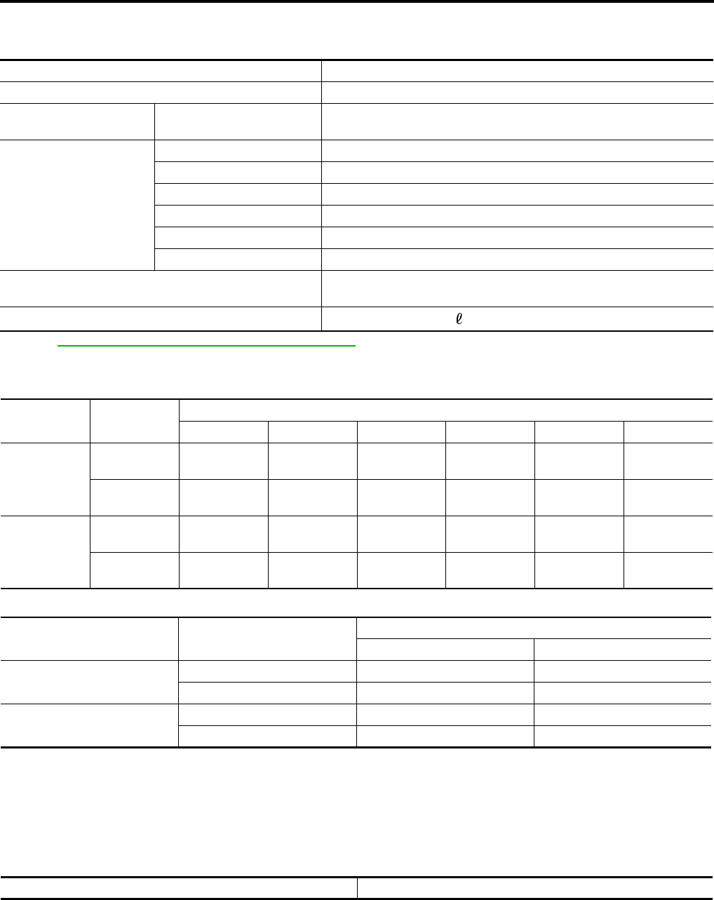
AT-364
[RE4F04B]
SERVICE DATA AND SPECIFICATIONS (SDS)
Revision: September 2005 2005 Quest
SERVICE DATA AND SPECIFICATIONS (SDS) PFP:00030
General Specifications UCS000S4
*: Refer to MA-10, "RECOMMENDED FLUIDS AND LUBRICANTS" .
Shift Schedule UCS000S5
VEHICLE SPEED WHEN SHIFTING GEARS THROTTLE POSITION
VEHICLE SPEED WHEN PERFORMING AND RELEASING LOCK-UP
NOTE:
●Closed throttle: Throttle opening is 1/8 or below, and closed throttle position signal is trend OFF.
●Half throttle: Throttle opening is 4/8.
●Perform lock-up inspection after warming up engine.
●Lock-up vehicle speed may vary depending on the driving conditions and circumstances.
Stall Revolution UCS000S6
Engine VQ35DE
Automatic transaxle model RE4F04B
Automatic transaxle
assembly Model code number 89X01
Transaxle gear ratio
1st 2.785
2nd 1.545
3rd 1.000
4th 0.694
Reverse 2.272
Final drive 3.525
Recommended fluid Genuine NISSAN Matic D ATF (Continental) US or Alaska) or Canada
NISSAN Automatic Transmission Fluid *
Fluid capacity 8.9 (9-3/8 US qt, 7-7/8 Imp qt)
Throttle posi-
tion Shift pattern Vehicle speed km/h (MPH)
D 1 → D2D2 → D3D3 → D4D4 → D3D3 → D2D2 → D1
Full throttle
Comfort 71 - 79
(44 - 49)
132 - 140
(82 - 87)
202 - 210
(126 - 130)
198 - 206
(123 - 128)
122 - 130
(76 - 81)
51 - 59
(32 - 37)
Auto power 71 - 79
(44 - 49)
132 - 140
(82 - 87)
202 - 210
(126 - 130)
198 - 206
(123 - 128)
122 - 130
(76 - 81)
51 - 59
(32 - 37)
Half throttle
Comfort 41 - 49
(25 - 30)
74 - 82
(46 - 51)
144 - 152
(89 - 94)
81 - 89
(50 - 55)
43 - 51
(27 - 32)
9 - 17
(6 - 11)
Auto power 48 - 56
(30 - 35)
91 - 99
(57 - 62)
144 - 152
(89 - 94)
81 - 89
(50 - 55)
49 - 57
(30 - 35)
9 - 17
(6 - 11)
Throttle position Overdrive control switch
[Shift position]
Vehicle speed km/h (MPH)
Lock-up “ON” Lock-up “OFF”
Closed throttle ON [D4 ] 66 - 74 (41 - 46) 63 - 71 (39 - 44)
OFF [D3 ] 86 - 94 (53 - 58) 83 - 91 (52 - 57)
Half throttle ON [D4 ] 168 - 176 (104 - 109) 116 - 124 (72 - 77)
OFF [D3 ] 86 - 94 (53 - 58) 83 - 91 (52 - 57)
Stall revolution rpm 2,500 - 3,050
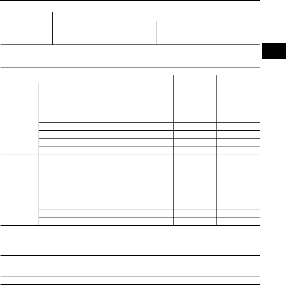
SERVICE DATA AND SPECIFICATIONS (SDS)
AT-365
[RE4F04B]
D
E
F
G
H
I
J
K
L
M
A
B
AT
Revision: September 2005 2005 Quest
Line Pressure UCS000S7
Control Valves UCS000S8
CONTROL VALVE AND PLUG RETURN SPRINGS Unit: mm (in)
*: Always check with the Parts Department for the latest parts information.
Accumulator UCS000S9
O-RING Unit: mm (in)
*: Always check with the Parts Department for the latest parts information.
Engine speed
rpm
Line pressure kPa (kg/cm2 , psi)
D and L positions R position
Idle 500 (5.1, 73) 778 (7.9, 113)
Stall 1,223 (12.6, 179) 1,918 (19.6, 278)
Parts Item
Part No.* Free length Outer diameter
Upper body
23 Pilot valve spring 31742-3AX03 38.98 (1.535) 8.9 (0.350)
7 1-2 accumulator valve spring 31742-3AX00 20.5 (0.807) 6.95 (0.274)
28 1-2 accumulator piston spring 31742-3AX09 55.66 (2.191) 19.5 (0.768)
33 1st reducing valve spring 31742-85X05 27.0 (1.063) 7.0 (0.276)
35 3-2 timing valve spring 31736-01X00 23.0 (0.906) 6.65 (0.262)
18 Overrun clutch reducing valve spring 31742-80X15 37.5 (1.476) 6.9 (0.272)
16 Torque converter relief valve spring 31742-80X07 31.0 (1.220) 9.0 (0.354)
11 Torque converter clutch control valve 31742-85X00 56.98 (2.243) 6.5 (0.256)
3 Cooler check valve spring 31742-85X01 29.4 (1.157) 6.0 (0.236)
Lower body
15 Pressure regulator valve spring 31742-80X13 45.0 (1.772) 15.0 (0.591)
20 Overrun clutch control valve spring 31762-80X00 21.7 (0.854) 7.0 (0.276)
24 Accumulator control valve spring 31742-80X02 22.0 (0.866) 6.5 (0.256)
29 Shift valve A spring 31762-80X00 21.7 (0.854) 7.0 (0.276)
32 Shuttle valve spring 31762-41X04 51.0 (2.008) 5.65 (0.222)
12 Shift valve B spring 31762-80X00 21.7 (0.854) 7.0 (0.276)
7 Pressure modifier valve spring 31742-80X16 32.0 (1.260) 6.9 (0.272)
3 Pressure modifier piston spring 31742-41X15 30.5 (1.201) 9.8 (0.386)
— Oil cooler relief valve spring 31872-31X00 17.02 (0.670) 8.0 (0.315)
Accumulator Part No.* Inner diameter
(Small) Part No.* Inner diameter
(Large)
Servo release accumulator 31526-41X03 26.9 (1.059) 31526-41X02 44.2 (1.740)
N-D accumulator 31526-31X08 34.6 (1.362) 31672-21X00 39.4 (1.551)

AT-366
[RE4F04B]
SERVICE DATA AND SPECIFICATIONS (SDS)
Revision: September 2005 2005 Quest
RETURN SPRING Unit: mm (in)
*: Always check with the Parts Department for the latest parts information.
Clutch and Brakes UCS000SA
REVERSE CLUTCH
*: Always check with the Parts Department for the latest parts information.
HIGH CLUTCH
*: Always check with the Parts Department for the latest parts information.
Accumulator Part number* Free length Outer diameter
Servo release accumulator 31605-85X00 52.5 (2.067) 20.1 (0.791)
N-D accumulator 31605-31X02 43.5 (1.713) 27.0 (1.063)
Number of drive plates 2
Number of driven plates 2
Drive plate thickness mm (in) Standard 1.6 (0.063)
Allowable limit 1.4 (0.055)
Driven plate thickness mm (in) Standard 1.8 (0.070)
Clearance mm (in) Standard 0.5 - 0.8 (0.020 - 0.031)
Allowable limit 1.2 (0.047)
Thickness of retaining plates
Thickness mm (in) Part number*
6.6 (0.260)
6.8 (0.268)
7.0 (0.276)
7.2 (0.283)
7.4 (0.291)
7.6 (0.299)
7.8 (0.307)
31537-89X00
31537-89X01
31537-89X02
31537-89X03
31537-89X04
31537-89X05
31537-89X06
Number of drive plates 5
Number of driven plates 8*1 + 1*2
Drive plate thickness mm (in) Standard 1.5 (0.059)
Allowable limit 1.3 (0.051)
Driven plate thickness mm (in) Standard *1 *2
1.4 (0.055) 2.0 (0.079)
Clearance mm (in) Standard 1.8 - 2.2 (0.071 - 0.087)
Allowable limit 2.8 (0.110)
Thickness of retaining plates
Thickness mm (in) Part number*
2.8 (0.110)
3.0 (0.118)
3.2 (0.126)
3.4 (0.134)
3.6 (0.142)
31537-89X07
31537-81X10
31537-81X11
31537-81X12
31537-81X13

SERVICE DATA AND SPECIFICATIONS (SDS)
AT-367
[RE4F04B]
D
E
F
G
H
I
J
K
L
M
A
B
AT
Revision: September 2005 2005 Quest
FORWARD CLUTCH
*: Always check with the Parts Department for the latest parts information.
OVERRUN CLUTCH
*: Always check with the Parts Department for the latest parts information.
LOW & REVERSE BRAKE
*: Always check with the Parts Department for the latest parts information.
Number of drive plates 6
Number of driven plates 6
Drive plate thickness mm (in) Standard 1.6 (0.063)
Allowable limit 1.4 (0.055)
Driven plate thickness mm (in) Standard 1.8 (0.071)
Clearance mm (in) Standard 0.45 - 0.85 (0.0177 - 0.0335)
Allowable limit 1.85 (0.0728)
Thickness of retaining plates
Thickness mm (in) Part number*
3.2 (0.126)
3.4 (0.134)
3.6 (0.142)
3.8 (0.150)
4.0 (0.157)
4.2 (0.165)
4.4 (0.173)
31537-80X76
31537-80X75
31537-80X70
31537-80X71
31537-80X72
31537-80X73
31537-80X74
Number of drive plates 4
Number of driven plates 4
Drive plate thickness mm (in) Standard 1.6 (0.063)
Allowable limit 1.4 (0.055)
Driven plate thickness mm (in) Standard 1.8 (0.071)
Clearance mm (in) Standard 0.7 - 1.1 (0.028 - 0.043)
Allowable limit 1.7 (0.067)
Thickness of retaining plates
Thickness mm (in) Part number*
3.0 (0.118)
3.2 (0.126)
3.4 (0.134)
3.6 (0.142)
3.8 (0.150)
31537-80X65
31537-80X66
31537-80X67
31537-80X68
31537-80X69
Number of drive plates 7
Number of driven plates 7 + 1
Drive plate thickness mm (in) Standard 1.8 (0.071)
Allowable limit 1.6 (0.063)
Driven plate thickness mm (in) Standard 1.8 (0.071)
Clearance mm (in) Standard 1.7 - 2.1 (0.067 - 0.083)
Allowable limit 3.3 (0.130)
Thickness of retaining plates
Thickness mm (in) Part number*
2.0 (0.079)
2.2 (0.087)
2.4 (0.094)
2.6 (0.102)
2.8 (0.110)
3.0 (0.118)
3.2 (0.126)
3.4 (0.134)
31667-80X00
31667-80X01
31667-80X02
31667-80X03
31667-80X04
31667-80X05
31667-80X06
31667-80X07

AT-368
[RE4F04B]
SERVICE DATA AND SPECIFICATIONS (SDS)
Revision: September 2005 2005 Quest
CLUTCH AND BRAKE RETURN SPRINGS Unit: mm (in)
*: Always check with the Parts Department for the latest parts information.
BRAKE BAND
Final Drive UCS000SB
DIFFERENTIAL SIDE GEAR CLEARANCE
DIFFERENTIAL SIDE GEAR THRUST WASHERS
*: Always check with the Parts Department for the latest parts information.
DIFFERENTIAL SIDE BEARING PRELOAD ADJUSTING SHIMS
*: Always check with the Parts Department for the latest parts information.
BEARING PRELOAD
TURNING TORQUE
Planetary Carrier and Oil Pump UCS000SC
PLANETARY CARRIER
Parts Part number* Free length Outer diameter
Reverse clutch (27 pcs) 31505-89X03 28.3 (1.114) 8.0 (0.315)
High clutch (18 pcs) 31505-89X04 20.0 (0.787) 8.3 (0.327)
Forward clutch (Overrun clutch)
(22 pcs) 31505-80X02 21.4 (0.843) 10.3 (0.406)
Low & reverse brake (24 pcs) 31505-89X02 21.6 (0.850) 6.6 (0.260)
Anchor end pin tightening torque N-m (kg-m, in-lb) 4.9 (0.50, 43)
Number of returning revolutions for anchor end pin 2.5
Lock nut tightening torque N-m (kg-m, ft-lb) 34 (3.5, 25)
Clearance between side gear and differential case with
washer mm (in) 0.1 - 0.2 (0.004 - 0.008)
Thickness mm (in) Part number*
0.75 (0.0295)
0.80 (0.0315)
0.85 (0.0335)
0.90 (0.0354)
0.95 (0.0374)
38424-81X00
38424-81X01
38424-81X02
38424-81X03
38424-81X04
Thickness mm (in) Part number*
0.48 (0.0189)
0.52 (0.0205)
0.56 (0.0220)
0.60 (0.0236)
0.64 (0.0252)
0.68 (0.0268)
0.72 (0.0283)
0.76 (0.0299)
0.80 (0.0315)
0.84 (0.0331)
0.88 (0.0346)
0.92 (0.0362)
31438-80X00
31438-80X01
31438-80X02
31438-80X03
31438-80X04
31438-80X05
31438-80X06
31438-80X07
31438-80X08
31438-80X09
31438-80X10
31438-80X11
Differential side bearing preload mm (in) 0.05 - 0.09 (0.0020 - 0.0035)
Turning torque of final drive assembly N-m (kg-cm, in-lb) 0.8 - 1.5 (8.0 - 15.7, 7 - 13)
Clearance between planetary carrier
and pinion washer mm (in)
Standard 0.20 - 0.70 (0.0079 - 0.0276)
Allowable limit 0.80 (0.0315)
SERVICE DATA AND SPECIFICATIONS (SDS)
AT-369
[RE4F04B]
D
E
F
G
H
I
J
K
L
M
A
B
AT
Revision: September 2005 2005 Quest
OIL PUMP
*: Always check with the Parts Department for the latest parts information.
Input Shaft UCS000SD
SEAL RING CLEARANCE
SEAL RING
*: Always check with the Parts Department for the latest parts information.
Reduction Pinion Gear UCS000SE
TURNING TORQUE
REDUCTION PINION GEAR BEARING ADJUSTING SHIMS
Oil pump side clearance mm (in) 0.030 - 0.050 (0.0012 - 0.0020)
Thickness of inner gears and outer gears
Inner gear
Thickness mm (in) Part number*
11.99 - 12.0 (0.4720 - 0.4724)
11.98 - 11.99 (0.4717 - 0.4720)
11.97 - 11.98 (0.4713 - 0.4717)
31346-80X00
31346-80X01
31346-80X02
Outer gear
Thickness mm (in) Part number*
11.99 - 12.0 (0.4720 - 0.4724)
11.98 - 11.99 (0.4717 - 0.4720)
11.97 - 11.98 (0.4713 - 0.4717)
31347-80X00
31347-80X01
31347-80X02
Clearance between oil pump
housing and outer gear mm
(in)
Standard 0.111 - 0.181 (0.0044 - 0.0071)
Allowable limit 0.181 (0.0071)
Oil pump cover seal ring
clearance mm (in)
Standard 0.1 - 0.25 (0.0039 - 0.0098)
Allowable limit 0.25 (0.0098)
Input shaft seal ring clearance mm (in) Standard 0.08 - 0.23 (0.0031 - 0.0091)
Allowable limit 0.23 (0.0091)
Outer diameter mm (in) Inner diameter mm (in) Width mm (in) Part number*
26 (1.024) 22.4 (0.882) 1.971 (0.078) 31525-80X02
Turning torque of reduction pinion gear N-m (kg-cm, in-lb) 0.05 - 0.39 (0.5 - 4.0, 0.43 - 3.47)
Thickness mm (in) Part number Thickness mm (in) Part number*
4.60 (0.1811) 31439-85X01 5.24 (0.2063) 31439-81X12
4.62 (0.1819) 31439-85X02 5.26 (0.2071) 31439-81X13
4.64 (0.1827) 31439-85X03 5.28 (0.2079) 31439-81X14
4.66 (0.1835) 31439-85X04 5.30 (0.2087) 31439-81X15
4.68 (0.1843) 31439-85X05 5.32 (0.2094) 31439-81X16
4.70 (0.1850) 31439-83X06 5.34 (0.2102) 31439-81X17
4.72 (0.1858) 31439-83X11 5.36 (0.2110) 31439-81X18
4.74 (0.1866) 31439-83X12 5.38 (0.2118) 31439-81X19
4.76 (0.1874) 31439-83X13 5.40 (0.2126) 31439-81X20
4.78 (0.1882) 31439-83X14 5.42 (0.2134) 31439-81X21
4.80 (0.1890) 31439-83X15 5.44 (0.2142) 31439-81X22
4.82 (0.1898) 31439-83X16 5.46 (0.2150) 31439-81X23
4.84 (0.1906) 31439-83X17 5.48 (0.2157) 31439-81X24
4.86 (0.1913) 31439-83X18 5.50 (0.2165) 31439-81X46
4.88 (0.1921) 31439-83X19 5.52 (0.2173) 31439-81X47

AT-370
[RE4F04B]
SERVICE DATA AND SPECIFICATIONS (SDS)
Revision: September 2005 2005 Quest
*: Always check with the Parts Department for the latest parts information.
Band Servo UCS000SF
RETURN SPRING Unit: mm (in)
*: Always check with the Parts Department for the latest parts information.
Output Shaft UCS000SG
SEAL RING CLEARANCE
SEAL RING
*: Always check with the Parts Department for the latest parts information.
END PLAY
4.90 (0.1929) 31439-83X20 5.54 (0.2181) 31439-81X48
4.92 (0.1937) 31439-83X21 5.56 (0.2189) 31439-81X49
4.94 (0.1945) 31439-83X22 5.58 (0.2197) 31439-81X60
4.96 (0.1953) 31439-83X23 5.60 (0.2205) 31439-81X61
4.98 (0.1961) 31439-83X24 5.62 (0.2213) 31439-81X62
5.00 (0.1969) 31439-81X00 5.64 (0.2220) 31439-81X63
5.02 (0.1976) 31439-81X01 5.66 (0.2228) 31439-81X64
5.04 (0.1984) 31439-81X02 5.68 (0.2236) 31439-81X65
5.06 (0.1992) 31439-81X03 5.70 (0.2244) 31439-81X66
5.08 (0.2000) 31439-81X04 5.72 (0.2252) 31439-81X67
5.10 (0.2008) 31439-81X05 5.74 (0.2260) 31439-81X68
5.12 (0.2016) 31439-81X06 5.76 (0.2268) 31439-81X69
5.14 (0.2024) 31439-81X07 5.78 (0.2276) 31439-81X70
5.16 (0.2031) 31439-81X08 5.80 (0.2283) 31439-81X71
5.18 (0.2039) 31439-81X09 5.82 (0.2291) 31439-81X72
5.20 (0.2047) 31439-81X10 5.84 (0.2299) 31439-81X73
5.22 (0.2055) 31439-81X11 5.86 (0.2307) 31439-81X74
Thickness mm (in) Part number Thickness mm (in) Part number*
Return spring Part number* Free length Outer diameter
2nd servo return spring 31605-31X20 32.5 (1.280) 25.9 (1.020)
OD servo return spring 31605-80X07 62.6 (2.465) 21.7 (0.854)
Output shaft seal ring clearance mm
(in)
Standard 0.10 - 0.25 (0.0039 - 0.0098)
Allowable limit 0.25 (0.0098)
Outer diameter mm (in) Inner diameter mm (in) Width mm (in) Part number*
33.71 (1.327) 30.25 (1.191) 1.95 (0.077) 31525-80X09
Output shaft end play mm (in) 0 - 0.15 (0 - 0.0059)

SERVICE DATA AND SPECIFICATIONS (SDS)
AT-371
[RE4F04B]
D
E
F
G
H
I
J
K
L
M
A
B
AT
Revision: September 2005 2005 Quest
OUTPUT SHAFT ADJUSTING SHIMS
*: Always check with the Parts Department for the latest parts information.
Bearing Retainer UCS000SH
SEAL RING CLEARANCE
Total End Play UCS000SI
BEARING RACE FOR ADJUSTING TOTAL END PLAY
*: Always check with the Parts Department for the latest parts information.
Reverse Clutch End Play UCS000SJ
THRUST WASHERS FOR ADJUSTING REVERSE CLUTCH DRUM END PLAY
*: Always check with the Parts Department for the latest parts information.
Removal and Installation UCS000SK
Unit: mm (in)
Thickness mm (in) Part number*
0.80 (0.0315)
0.84 (0.0331)
0.88 (0.0346)
0.92 (0.0362)
0.96 (0.0378)
1.00 (0.0394)
1.04 (0.0409)
1.08 (0.0425)
1.12 (0.0441)
1.16 (0.0457)
1.20 (0.0472)
31438-80X60
31438-80X61
31438-80X62
31438-80X63
31438-80X64
31438-80X65
31438-80X66
31438-80X67
31438-80X68
31438-80X69
31438-80X70
Bearing retainer seal ring
clearance mm (in)
Standard 0.10 - 0.30 (0.0039 - 0.0118)
Allowable limit 0.30 (0.0118)
Total end play mm (in) 0.25 - 0.55 (0.0098 - 0.0217)
Thickness mm (in) Part number*
0.8 (0.031)
1.0 (0.039)
1.2 (0.047)
1.4 (0.055)
1.6 (0.063)
1.8 (0.071)
2.0 (0.079)
0.9 (0.035)
1.1 (0.043)
1.3 (0.051)
1.5 (0.059)
1.7 (0.067)
1.9 (0.075)
31435-80X00
31435-80X01
31435-80X02
31435-80X03
31435-80X04
31435-80X05
31435-80X06
31435-80X09
31435-80X10
31435-80X11
31435-80X12
31435-80X13
31435-80X14
Reverse clutch end play mm (in) 0.61 - 1.00 (0.0240 - 0.0394)
Thickness mm (in) Part number*
0.80 (0.0315)
0.95 (0.0374)
1.10 (0.0433)
1.25 (0.0492)
1.40 (0.0551)
1.55 (0.0610)
1.70 (0.0669)
1.85 (0.0728)
31508-80X13
31508-80X14
31508-80X15
31508-80X16
31508-80X17
31508-80X18
31508-80X19
31508-80X20
Distance between end of converter housing and torque converter 14 (0.55)

AT-372
[RE4F04B]
SERVICE DATA AND SPECIFICATIONS (SDS)
Revision: September 2005 2005 Quest
Shift Solenoid Valves UCS000SL
Solenoid Valves UCS000SM
A/T Fluid Temperature Sensor UCS000SN
Remarks: Specification data are reference values.
Revolution Sensor UCS000SO
Dropping Resistor UCS000SP
Turbine Revolution Sensor (Power Train Revolution Sensor) UCS000SQ
Gear position 1 2 3 4
Shift solenoid valve A ON (Closed) OFF (Open) OFF (Open) ON (Closed)
Shift solenoid valve B ON (Closed) ON (Closed) OFF (Open) OFF (Open)
Solenoid valves Resistance (Approx.) ΩTerminal No.
Shift solenoid valve A 20 - 30 2
Shift solenoid valve B 5 - 20 1
Overrun clutch solenoid valve 20 - 30 3
Line pressure solenoid valve 2.5 - 5 4
Torque converter clutch solenoid valve 5 - 20 5
Monitor item Condition Specification (Approximately)
A/T fluid temperature sensor
Cold [20°C (68°F)]
↓
Hot [80°C (176°F)]
1.5V
↓
0.5V
2.5 kΩ
↓
0.3 kΩ
Condition Judgement standard
When moving at 20 km/h (12 MPH), use the CONSULT-II pulse frequency measuring func-
tion.*1
CAUTION:
Connect the diagnosis data link cable to the vehicle diagnosis connector.
*1: A circuit tester cannot be used to test this item.
450 Hz (Approx.)
When vehicle parks. 0V
Resistance (Approx.) 12Ω
Condition Judgement standard
When moving at 20 km/h (12 MPH), use the CONSULT-II pulse frequency measuring func-
tion.*1
CAUTION:
Connect the diagnosis data link cable to the vehicle diagnosis connector.
*1: A circuit tester cannot be used to test this item.
240 Hz (Approx.)
When vehicle parks. Under 1.3V or over 4.5V

INDEX FOR DTC
AT-373
[RE5F22A]
D
E
F
G
H
I
J
K
L
M
A
B
AT
Revision: September 2005 2005 Quest
INDEX FOR DTC PFP:00024
Alphabetical Index UCS000SR
NOTE:
If DTC U1000 is displayed with other DTCs, first perform the trouble diagnosis for DTC U1000. Refer to
AT-450 .
*1: These numbers are prescribed by SAE J2012.
Items
(CONSULT-II screen terms)
DTC
Reference page
OBD-II Except OBD-II
CONSULT-II
GST*1
CONSULT-II
only “TRANSMIS-
SION”
A/T 1ST GR FNCTN P0731 P0731 AT-483
A/T 2ND GR FNCTN P0732 P0732 AT-486
A/T 3RD GR FNCTN P0733 P0733 AT-492
A/T 4TH GR FNCTN P0734 P0734 AT-498
A/T 5TH GR FNCTN P0735 P0735 AT-503
A/T TCC S/V FNCTN P0744 P0744 AT-509
ATF TEMP SEN/CIRC P0710 P0710 AT-463
CAN COMM CIRCUIT U1000 U1000 AT-450
ELEC TH CONTROL — P1726 AT-575
ENG SPD INP PERFOR — P0726 AT-481
FLUID TEMP SEN P0711 P0711 AT-468
GEAR LEVER SWITCH — P0825 AT-566
PC SOL A(L/PRESS) P0745 P0745 AT-512
PC SOL B(SFT/PRS) P0775 P0775 AT-547
PC SOL C(TCC&SFT) P0795 P0795 AT-556
PC SOL C STC ON P0797 P0797 AT-561
PNP SW/CIRC P0705 P0705 AT-457
SHIFT P0780 P0780 AT-552
SHIFT SOL A P0750 P0750 AT-517
SHIFT SOL B P0755 P0755 AT-522
SHIFT SOL C P0760 P0760 AT-527
SHIFT SOL D P0765 P0765 AT-537
SHIFT SOL E P0770 P0770 AT-542
SFT SOL C STUCK ON P0762 P0762 AT-532
TCM POWER INPT SIG P0882 P0882 AT-570
TCM PROCESSOR — P0613 AT-455
TURBINE SENSOR P0717 P0717 AT-473
VEH SPD SE/CIR-MTR — P0500 AT-453
VHCL SPEED SEN-A/T P0722 P0722 AT-477

AT-374
[RE5F22A]
INDEX FOR DTC
Revision: September 2005 2005 Quest
DTC No. Index UCS000SS
NOTE:
If DTC U1000 is displayed with other DTCs, first perform the trouble diagnosis for DTC U1000. Refer to
AT-450 .
*1: These numbers are prescribed by SAE J2012.
DTC
Items
(CONSULT-II screen terms) Reference page
OBD-II Except OBD-II
CONSULT-II
GST*1
CONSULT-II
only “TRANSMIS-
SION”
— P0500 VEH SPD SE/CIR-MTR AT-453
— P0613 TCM PROCESSOR AT-455
P0705 P0705 PNP SW/CIRC AT-457
P0710 P0710 ATF TEMP SEN/CIRC AT-463
P0711 P0711 FLUID TEMP SEN AT-468
P0717 P0717 TURBINE SENSOR AT-473
P0722 P0722 VHCL SPEED SEN-A/T AT-477
— P0726 ENG SPD INP PERFOR AT-481
P0731 P0731 A/T 1ST GR FNCTN AT-483
P0732 P0732 A/T 2ND GR FNCTN AT-486
P0733 P0733 A/T 3RD GR FNCTN AT-492
P0734 P0734 A/T 4TH GR FNCTN AT-498
P0735 P0735 A/T 5TH GR FNCTN AT-503
P0744 P0744 A/T TCC S/V FNCTN AT-509
P0745 P0745 PC SOL A(L/PRESS) AT-512
P0750 P0750 SHIFT SOL A AT-517
P0755 P0755 SHIFT SOL B AT-522
P0760 P0760 SHIFT SOL C AT-527
P0762 P0762 SFT SOL C STUCK ON AT-532
P0765 P0765 SHIFT SOL D AT-537
P0770 P0770 SHIFT SOL E AT-542
P0775 P0775 PC SOL B(SFT/PRS) AT-547
P0780 P0780 SHIFT AT-552
P0795 P0795 PC SOL C(TCC&SFT) AT-556
P0797 P0797 PC SOL C STC ON AT-561
— P0825 GEAR LEVER SWITCH AT-566
P0882 P0882 TCM POWER INPT SIG AT-570
— P1726 ELEC TH CONTROL AT-575
U1000 U1000 CAN COMM CIRCUIT AT-450

PRECAUTIONS
AT-375
[RE5F22A]
D
E
F
G
H
I
J
K
L
M
A
B
AT
Revision: September 2005 2005 Quest
PRECAUTIONS PFP:00001
Precautions for Supplemental Restraint System (SRS) “AIR BAG” and “SEAT
BELT PRE-TENSIONER” UCS000ST
The Supplemental Restraint System such as “AIR BAG” and “SEAT BELT PRE-TENSIONER”, used along
with a front seat belt, helps to reduce the risk or severity of injury to the driver and front passenger for certain
types of collision. This system includes seat belt switch inputs and dual stage front air bag modules. The SRS
system uses the seat belt switches to determine the front air bag deployment, and may only deploy one front
air bag, depending on the severity of a collision and whether the front occupants are belted or unbelted.
Information necessary to service the system safely is included in the SRS and SB section of this Service Man-
ual.
WARNING:
●To avoid rendering the SRS inoperative, which could increase the risk of personal injury or death
in the event of a collision which would result in air bag inflation, all maintenance must be per-
formed by an authorized NISSAN/INFINITI dealer.
●Improper maintenance, including incorrect removal and installation of the SRS, can lead to per-
sonal injury caused by unintentional activation of the system. For removal of Spiral Cable and Air
Bag Module, see the SRS section.
●Do not use electrical test equipment on any circuit related to the SRS unless instructed to in this
Service Manual. SRS wiring harnesses can be identified by yellow and/or orange harnesses or
harness connectors.
Precautions for On Board Diagnostic (OBD) System of A/T and Engine UCS000SU
The ECM has an on board diagnostic system. It will light up the malfunction indicator lamp (MIL) to warn the
driver of a malfunction causing emission deterioration.
CAUTION:
●Be sure to turn the ignition switch “OFF” and disconnect the negative battery cable before any
repair or inspection work. The open/short circuit of related switches, sensors, solenoid valves,
etc. will cause the MIL to light up.
●Be sure to connect and lock the connectors securely after work. A loose (unlocked) connector will
cause the MIL to light up due to an open circuit. (Be sure the connector is free from water, grease,
dirt, bent terminals, etc.)
●Be sure to route and secure the harnesses properly after work. Interference of the harness with a
bracket, etc. may cause the MIL to light up due to a short circuit.
●Be sure to connect rubber tubes properly after work. A misconnected or disconnected rubber tube
may cause the MIL to light up due to a malfunction of the EGR system or fuel injection system, etc.
●Be sure to erase the unnecessary malfunction information (repairs completed) from the TCM and
ECM before returning the vehicle to the customer.

AT-376
[RE5F22A]
PRECAUTIONS
Revision: September 2005 2005 Quest
Precautions for A/T Assembly or TCM Replacement UCS000SV
●When replacing A/T assembly or TCM, refer to the pattern table below and initialize TCM if necessary.
TCM INITIALIZATION PATTERNS
NOTE:
“Old one” is the TCM or A/T assembly that has been used on other vehicles.
METHOD FOR TCM INITIALIZATION
1. Perform “CONSULT-II SETTING PROCEDURE”. Refer to AT-441, "CONSULT-II SETTING PROCE-
DURE" .
2. Set the vehicle following the items listed below.
●Ignition switch “ON”.
●Selector lever “P” or “N” position.
●Engine not running.
●Vehicle speed is 0km/h (0 MPH).
●Ignition voltage is more than 10.5V.
●Malfunction was not detected.
3. Touch “WORK SUPPORT”.
4. Touch “INITIALIZATION”.
5. Initialize TCM following the direction in display.
TCM A/T assembly Erasing EEPROM in TCM Remarks
Replaced with
new one
Not replaced
Not required Not required because the EEPROM in TCM is in the default
state.
Replaced with
new or old one
Not replaced Replaced with
new or old one
Required Required because data connot be conformed to previous
data written in the EEPROM in TCM.
Replaced with
old one
Not replaced
Replaced with
new or old one
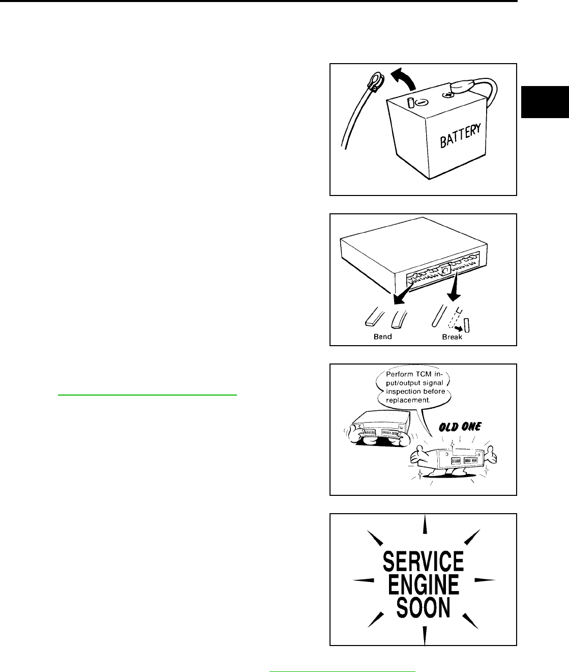
PRECAUTIONS
AT-377
[RE5F22A]
D
E
F
G
H
I
J
K
L
M
A
B
AT
Revision: September 2005 2005 Quest
Precautions UCS000SW
NOTE:
Do not remove or disassemble any RE5F22A model transaxle parts unless specified to do so in AT
section.
●Before connecting or disconnecting the TCM harness con-
nector, turn ignition switch “OFF” and disconnect negative
battery cable. Because battery voltage is applied to TCM
even if ignition switch is turned “OFF”.
●When connecting or disconnecting pin connectors into or
from TCM, take care not to damage pin terminals (bend or
break).
Make sure that there are not any bends or breaks on TCM
pin terminal, when connecting pin connectors.
●Before replacing TCM, perform TCM input/output signal
inspection and make sure whether TCM functions properly
or not. AT-439, "TCM INSPECTION TABLE".
●After performing each TROUBLE DIAGNOSIS, perform
“DTC (Diagnostic Trouble Code) CONFIRMATION PROCE-
DURE”.
The DTC should not be displayed in the “DTC CONFIRMA-
TION PROCEDURE” if the repair is completed.
●Always use the specified brand of A/T fluid. Refer to MA-10, "Fluids and Lubricants" .
●Use paper rags not cloth rags during work.
●After replacing the A/T fluid, dispose of the waste oil using the methods prescribed by law, ordinance, etc.
SEF289H
SEF291H
MEF040DA
SEF217U

AT-378
[RE5F22A]
PRECAUTIONS
Revision: September 2005 2005 Quest
●Before proceeding with disassembly, thoroughly clean the outside of the transaxle. It is important to pre-
vent the internal parts from becoming contaminated by dirt or other foreign matter.
●Disassembly should be done in a clean work area.
●Use lint-free cloth or towels for wiping parts clean. Common shop rags can leave fibers that could interfere
with the operation of the transaxle.
●Place disassembled parts in order for easier and proper assembly.
●All parts should be carefully cleaned with a general purpose, non-flammable solvent before inspection or
reassembly.
●Gaskets, seals and O-rings should be replaced any time the transaxle is disassembled.
●It is very important to perform functional tests whenever they are indicated.
●The valve body contains precision parts and requires extreme care when parts are removed and serviced.
Place disassembled valve body parts in order for easier and proper assembly. Care will also prevent
springs and small parts from becoming scattered or lost.
●Properly installed valves, sleeves, plugs, etc. will slide along bores in valve body under their own weight.
●Before assembly, apply a coat of recommended ATF to all parts. Apply petroleum jelly to protect O-rings
and seals, or hold bearings and washers in place during assembly. Do not use grease.
●Extreme care should be taken to avoid damage to O-rings, seals and gaskets when assembling.
●After overhaul, refill the transaxle with new ATF.
●When the A/T drain plug is removed, only some of the fluid is drained. Old A/T fluid will remain in torque
converter and ATF cooling system.
Always follow the procedures under “Changing A/T Fluid” in the AT section when changing A/T fluid. Refer
to AT-382, "Changing A/T Fluid" , AT-382, "Checking A/T Fluid" .
Service Notice or Precautions UCS000SX
ATF COOLER SERVICE
If A/T fluid contains frictional material (clutches, bands, etc.), or if an A/T is repaired, overhauled, or replaced,
inspect and clean the A/T fluid cooler mounted in the radiator or replace the radiator. Flush cooler lines using
cleaning solvent and compressed air after repair. For A/T fluid cooler cleaning procedure, refer to AT-382, "A/T
Fluid Cooler Cleaning" . For radiator replacement, refer to CO-10, "RADIATOR" .
OBD-II SELF-DIAGNOSIS
●A/T self-diagnosis is performed by the TCM in combination with the ECM. The results can be read through
the blinking pattern of the O/D OFF indicator or the malfunction indicator lamp (MIL). Refer to the table on
AT-442, "SELF-DIAG RESULT MODE" for the indicator used to display each self-diagnostic result.
●The self-diagnostic results indicated by the MIL are automatically stored in both the ECM and TCM mem-
ories.
Always perform the procedure on AT-408, "HOW TO ERASE DTC" to complete the repair and
avoid unnecessary blinking of the MIL.
● For details of OBD-II, refer to EC-51, "ON BOARD DIAGNOSTIC (OBD) SYSTEM" .
●Certain systems and components, especially those related to OBD, may use the new style slide-
locking type harness connector. For description and how to disconnect, refer to PG-67, "HAR-
NESS CONNECTOR" .
Wiring Diagrams and Trouble Diagnosis UCS000SY
When you read wiring diagrams, refer to the following:
●GI-13, "How to Read Wiring Diagrams".
●PG-4, "POWER SUPPLY ROUTING CIRCUIT" for power distribution circuit.
When you perform trouble diagnosis, refer to the following:
●GI-9, "How to Follow Trouble Diagnoses".
●GI-25, "How to Perform Efficient Diagnosis for an Electrical Incident".
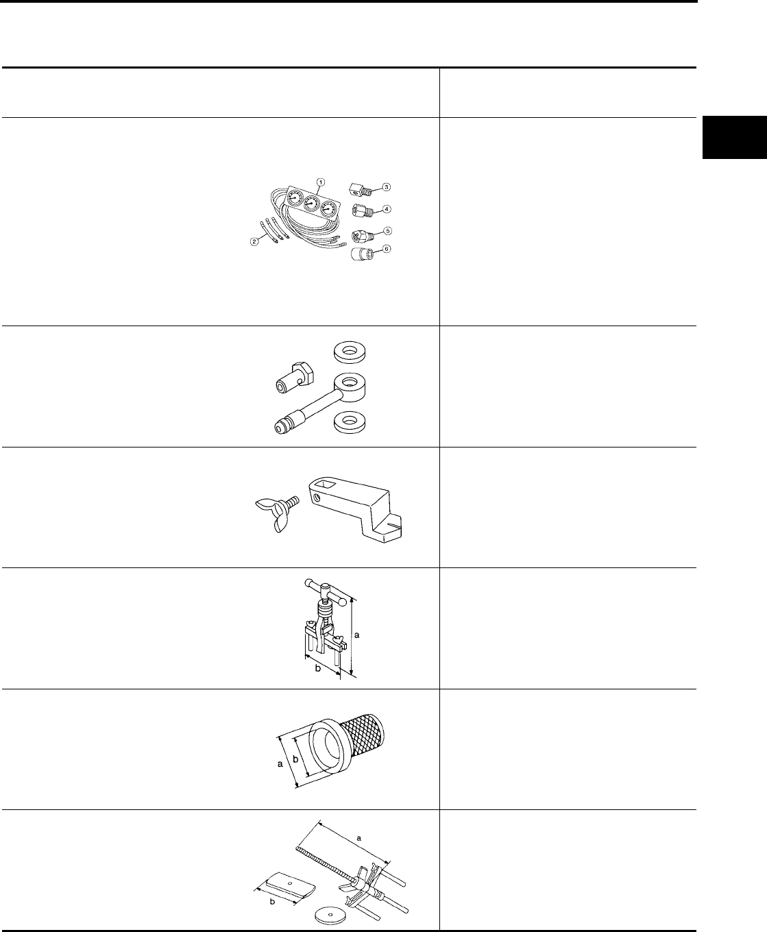
PREPARATION
AT-379
[RE5F22A]
D
E
F
G
H
I
J
K
L
M
A
B
AT
Revision: September 2005 2005 Quest
PREPARATION PFP:00002
Special Service Tools UCS002LA
The actual shapes of Kent-Moore tools may differ from those of special service tools illustrated here.
Tool number
(Kent-Moore No.)
Tool name
Description
(J-34301-C)
Oil pressure gauge set
1 (J-34301-1)
Oil pressure gauge
2 (J-34301-2)
Hoses
3 (J-34298)
Adapter
4 (J-34282-2)
Adapter
5 (790-301-1230-A)
60° Adapter
6 (J-34301-15)
Square socket
Measuring line pressure
(J-45542)
Adapter
Measuring line pressure
(J-45404)
Alignment tool
Adjusting park/neutral position (PNP) switch
ST33290001
(J-34286)
Puller
a:250 mm(9.84 in)
b:160 mm(6.30 in)
●Removing oil pump assembly
●Removing thrust roller bearing
ST33400001
(J-26082)
Drift
a:60 mm(2.36 in) dia.
b:74 mm(1.85 in) dia.
Installing differential side oil seals
KV31102400
(J-34285 and J-34285-87)
Clutch spring compressor
a:320 mm(12.60 in)
b:174 mm(6.85 in)
Removing and installing return springs
AAT896
SCIA3019E
SCIA3018E
NT414
NT086
NT423
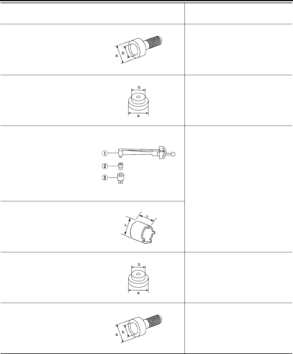
AT-380
[RE5F22A]
PREPARATION
Revision: September 2005 2005 Quest
ST30720000
(J-25405)
Drift
a:77 mm(3.03 in) dia.
b:55.5 mm(2.185 in) dia.
●Installing oil seal
●Installing thrust roller bearing
ST30612000
(J-25742-2)
Drift
a:62 mm(2.44 in) dia.
b:40 mm(1.57 in) dia.
Removing outer race and adjust shim
ST3127S000
(J-25765-A)
Preload gauge
1 GG91030000
(J-25765-A)
Torque wrench
2 HT62940000
(—)
Socket adapter
3 HT62900000
(—)
Socket adapter
Checking differential side bearing preload
KV40102500
(J-28815)
Drift
a:60 mm(2.362 in) dia.
b:45 mm(1.772 in)
ST33061000
(J-8107-2)
Drift
a:38 mm(1.496 in) dia.
b:28.5 mm(1.122 in) dia.
●Removing tapered roller bearing
●Installing manual valve oil seal
KV38100500
(—)
Drift
a:80 mm(3.15 in) dia.
b:60 mm(2.362 in) dia.
Installing tapered roller bearing
Tool number
(Kent-Moore No.)
Tool name
Description
NT115
NT073
NT124
SCIA5517E
NT073
NT115
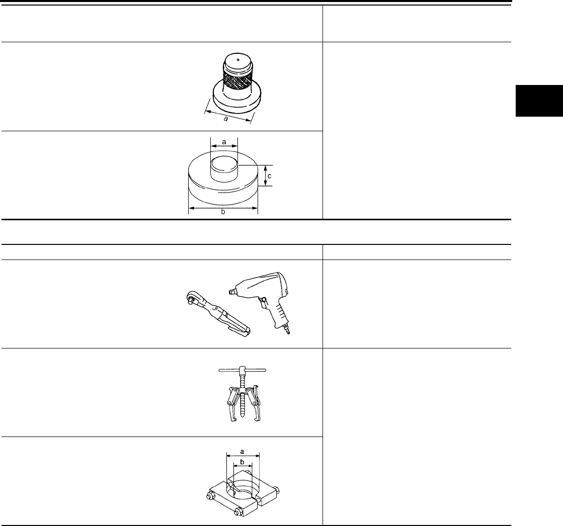
PREPARATION
AT-381
[RE5F22A]
D
E
F
G
H
I
J
K
L
M
A
B
AT
Revision: September 2005 2005 Quest
Commercial Service Tools UCS002LB
KV40100621
(J-25273)
Drift
a:76 mm(2.992 in) dia.
Installing outer race and adjust shim
ST30022000
(—)
Drift
a:56 mm(2.205 in) dia.
b:110 mm(4.331 in) dia.
c:15 mm(0.591 in)
Tool number
(Kent-Moore No.)
Tool name
Description
SCIA5518E
SCIA5519E
Tool name Description
Power tool Loosening bolts and nuts
Puller Removing tapered roller bearing
Puller
a:60 mm(2.36 in) dia.
b:35 mm(1.38 in) dia.
PBIC0190E
NT077
NT411
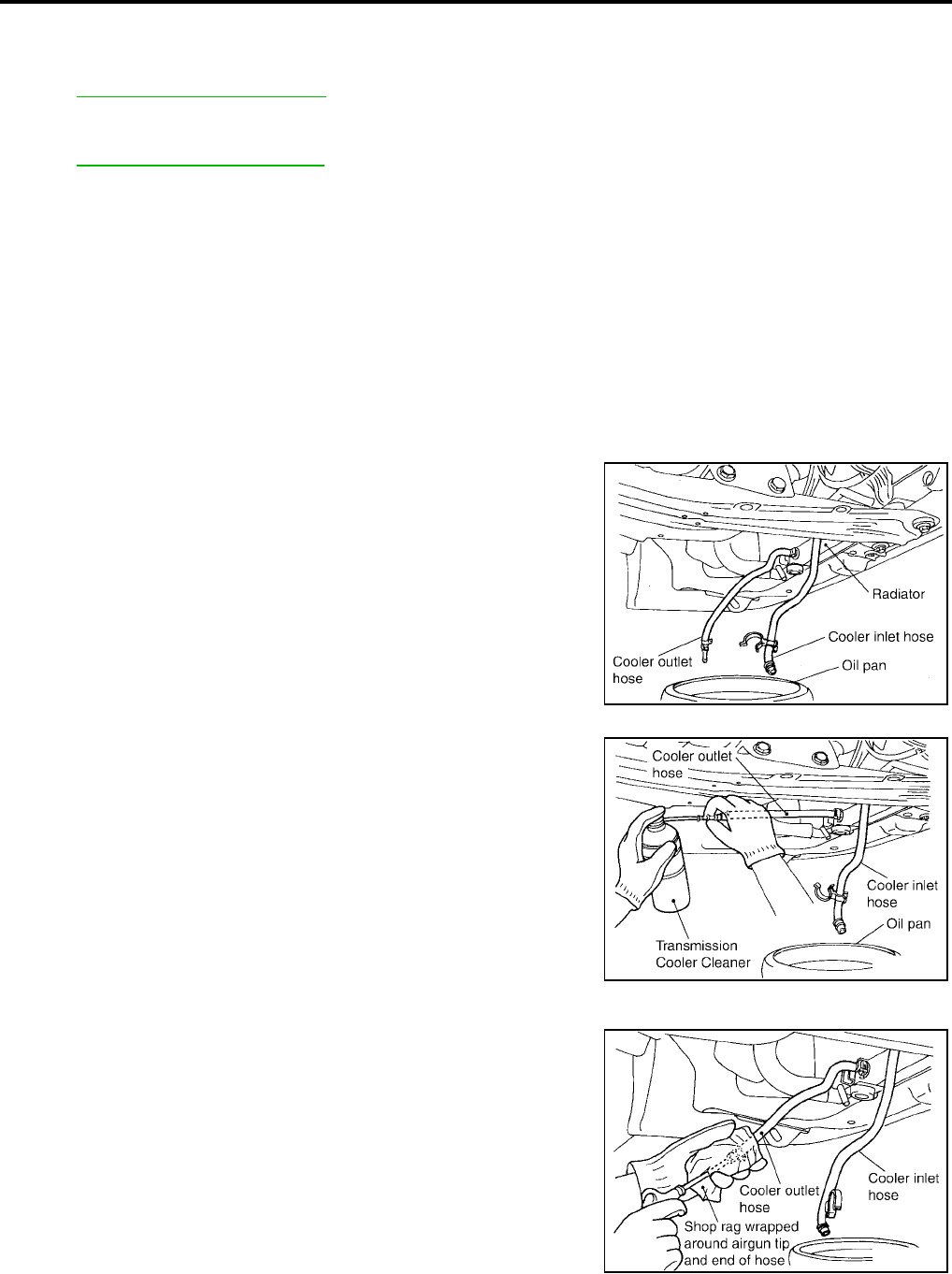
AT-382
[RE5F22A]
A/T FLUID
Revision: September 2005 2005 Quest
A/T FLUID PFP:KLE40
Changing A/T Fluid UCS000T1
Refer to MA-23, "Changing A/T Fluid" .
Checking A/T Fluid UCS000T2
Refer to MA-21, "Checking A/T Fluid" .
A/T Fluid Cooler Cleaning UCS001EQ
Whenever an automatic transaxle is repaired, overhauled, or replaced, the A/T fluid cooler mounted in the
radiator must be inspected and cleaned.
Metal debris and friction material, if present, can become trapped in the A/T fluid cooler. This debris can con-
taminate the newly serviced A/T or, in severe cases, can block or restrict the flow of A/T fluid. In either case,
malfunction of the newly serviced A/T may result.
Debris, if present, may build up as A/T fluid enters the cooler inlet. It will be necessary to back flush the cooler
through the cooler outlet in order to flush out any built up debris.
A/T FLUID COOLER CLEANING PROCEDURE
1. Position an oil pan under the automatic transaxle's inlet and outlet cooler hoses.
2. Identify the inlet and outlet fluid cooler hoses.
3. Disconnect the fluid cooler inlet and outlet rubber hoses from the
steel cooler tubes or bypass valve.
NOTE:
Replace the cooler hoses if rubber material from the hose
remains on the tube fitting.
4. Allow any A/T fluid that remains in the cooler hoses to drain into
the oil pan.
5. Insert the extension adapter hose of a can of Transmission
Cooler Cleaner (Nissan P/N 999MP-AM006) into the cooler out-
let hose.
CAUTION:
●Wear safety glasses and rubber gloves when spraying
the Transmission Cooler Cleaner.
●Spray cooler cleaner only with adequate ventilation.
●Avoid contact with eyes and skin.
●Do not breath vapors or spray mist.
6. Hold the hose and can as high as possible and spray Transmis-
sion Cooler Cleaner in a continuous stream into the cooler outlet
hose until fluid flows out of the cooler inlet hose for 5 seconds.
7. Insert the tip of an air gun into the end of the cooler outlet hose.
8. Wrap a shop rag around the air gun tip and of the cooler outlet
hose.
SCIA2945E
SCIA2955E
SCIA2962E
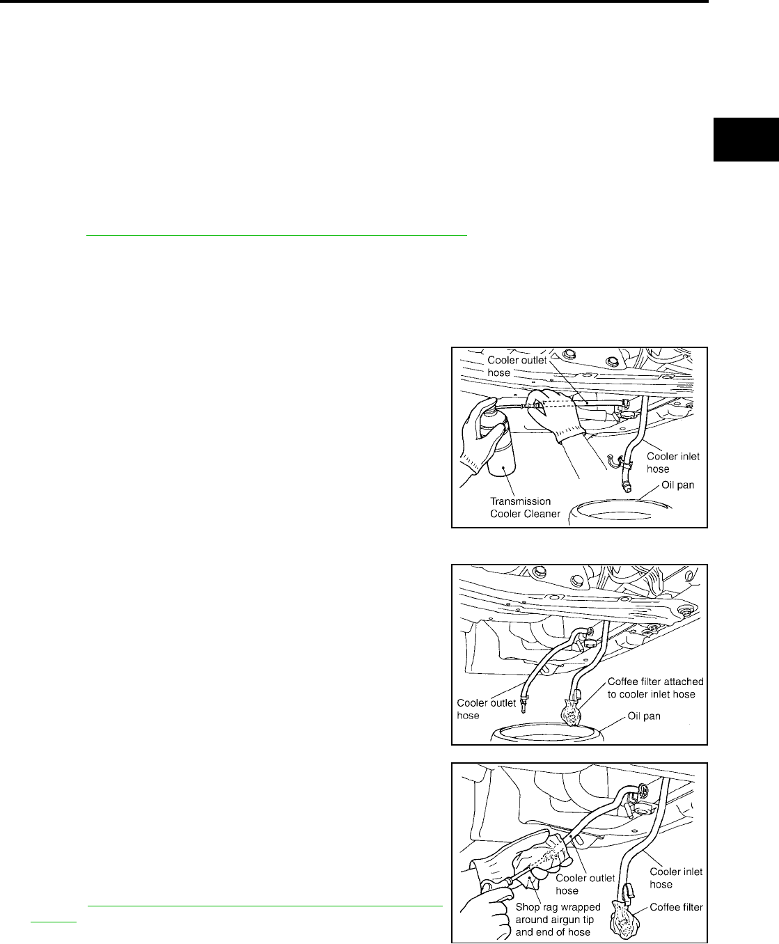
A/T FLUID
AT-383
[RE5F22A]
D
E
F
G
H
I
J
K
L
M
A
B
AT
Revision: September 2005 2005 Quest
9. Blow compressed air regulated to 5 - 9 kg/cm2 (70 - 130 psi) through the cooler outlet hose for 10 sec-
onds to force out any remaining fluid.
10. Repeat steps 5 through 9 three additional times.
11. Position an oil pan under the banjo bolts that connect the fluid cooler steel lines to the transaxle.
12. Remove the banjo bolts.
13. Flush each steel line from the cooler side back toward the transaxle by spraying Transmission Cooler
Cleaner in a continuous stream for 5 seconds.
14. Blow compressed air regulated to 5 - 9 kg/cm2 (70 - 130 psi) through each steel line from the cooler side
back toward the transaxle for 10 seconds to force out any remaining fluid.
15. Ensure all debris is removed from the steel cooler lines.
16. Ensure all debris is removed from the banjo bolts and fittings.
17. Perform AT-383, "A/T FLUID COOLER DIAGNOSIS PROCEDURE" .
A/T FLUID COOLER DIAGNOSIS PROCEDURE
NOTE:
Insufficient cleaning of the cooler inlet hose exterior may lead to inaccurate debris identification.
1. Position an oil pan under the automatic transaxle's inlet and outlet cooler hoses.
2. Clean the exterior and tip of the cooler inlet hose.
3. Insert the extension adapter hose of a can of Transmission
Cooler Cleaner (Nissan P/N 999MP-AM006) into the cooler out-
let hose.
CAUTION:
●Wear safety glasses and rubber gloves when spraying
the Transmission Cooler Cleaner.
● Spray cooler cleaner only with adequate ventilation.
●Avoid contact with eyes and skin.
●Do not breath vapors or spray mist.
4. Hold the hose and can as high as possible and spray Transmis-
sion Cooler Cleaner in a continuous stream into the cooler outlet
hose until fluid flows out of the cooler inlet hose for 5 seconds.
5. Tie a common white, basket-type coffee filter to the end of the
cooler inlet hose.
6. Insert the tip of an air gun into the end of the cooler outlet hose.
7. Wrap a shop rag around the air gun tip and end of cooler outlet
hose.
8. Blow compressed air regulated to 5 - 9 kg/cm2 (70 - 130 psi)
through the cooler outlet hose to force any remaining A/T fluid
into the coffee filter.
9. Remove the coffee filter from the end of the cooler inlet hose.
10. Perform AT-384, "A/T FLUID COOLER INSPECTION PROCE-
DURE" .
SCIA2955E
SCIA2965E
SCIA2966E
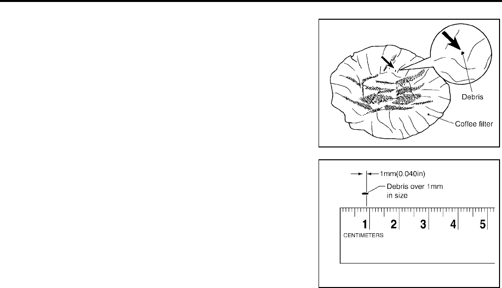
AT-384
[RE5F22A]
A/T FLUID
Revision: September 2005 2005 Quest
A/T FLUID COOLER INSPECTION PROCEDURE
1. Inspect the coffee filter for debris.
a. If small metal debris less than 1mm (0.040 in) in size or metal
powder is found in the coffee filter, this is normal. If normal
debris is found, the A/T fluid cooler/radiator can be re-used and
the procedure is ended.
b. If one or more pieces of debris are found that are over 1mm
(0.040in) in size and/or peeled clutch facing material is found in
the coffee filter, the fluid cooler is not serviceable. The radiator/
fluid cooler must be replaced and the inspection procedure is
ended.
A/T FLUID COOLER FINAL INSPECTION
After performing all procedures, ensure that all remaining oil is cleaned from all components.
SCIA2967E
SCIA5257E

A/T CONTROL SYSTEM
AT-385
[RE5F22A]
D
E
F
G
H
I
J
K
L
M
A
B
AT
Revision: September 2005 2005 Quest
A/T CONTROL SYSTEM PFP:31036
Cross-Sectional View UCS001E5
1. Converter housing 2. 2nd brake 3. One-way clutch No. 2
4. Control valve assembly 5. Side cover 6. 1st and reverse brake
7. Forward clutch 8. Direct clutch 9. Transaxle case cover
10. B5 brake 11. Transaxle case 12. U/D clutch
13. U/D brake 14. Final gear 15. Differential case
16. Output shaft 17. Counter driven gear 18. Counter drive gear
19. Input shaft 20. Oil pump 21. One-way clutch No. 1
22. 2nd coast brake 23. Torque converter 24. Main rear planetary gear
25. Main front planetary gear 26. U/D rear planetary gear 27. U/D front planetary gear
SCIA2575E
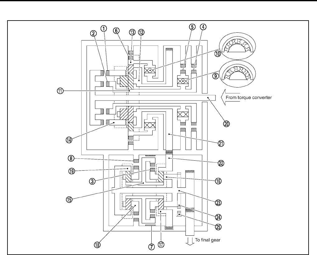
AT-386
[RE5F22A]
A/T CONTROL SYSTEM
Revision: September 2005 2005 Quest
Shift Mechanism UCS001E6
CONSTRUCTION
1. Forward clutch 2. Direct clutch 3. U/D clutch
4. 2nd coast brake 5. 2nd brake 6. 1st and reverse brake
7. U/D brake 8. B5 brake 9. One-way clutch No. 1
10. One-way clutch No. 2 11. Main sun gear 12. Main planetary carrier
13. Main front internal gear 14. Main rear internal gear 15. U/D sun gear
16. U/D front planetary carrier 17. U/D front internal gear 18. U/D rear planetary carrier
19. U/D rear internal gear 20. Input shaft 21. Counter drive gear
22. Counter driven gear 23. Output shaft 24. Parking gear
25. Parking pawl
SCIA2576E

A/T CONTROL SYSTEM
AT-387
[RE5F22A]
D
E
F
G
H
I
J
K
L
M
A
B
AT
Revision: September 2005 2005 Quest
FUNCTION OF CLUTCH AND BRAKE
CLUTCH AND BAND CHART
: Operates
: In transition between applied and released.
*1: A/T will not shift to 5th when lever switch is pushed (indicated A/T indicator “4”).
*2: A/T will not shift to 3th when lever switch is pushed (indicated A/T indicator “2”).
NOTE:
When shifting D to L position or lever switch pushes (indicated A/T indicator “4” at D position or “2” at L position), down shift permission
control is activated. Refer to AT-404, "Down Shift Permission Control" .
Clutch and brake components Abbr. Function
Forward clutch 1F/C Connect input shaft 20 to main rear internal gear 10 .
Direct clutch 2 D/C Connect input shaft 20 to main sun gear 11 .
U/D clutch 3U/D.C Connect U/D sun gear 15 to U/D front planetary carrier 16 .
2nd coast brake 42nd C/B Lock main sun gear 11 .
2nd brake 52nd/B Lock counterclockwise rotation of main sun gear 11 .
1st and reverse brake 61st & R/B Lock main front internal gear 13 .
U/D brake 7U/D.B Lock U/D sun gear 15 .
B5 brake 8B5/B Lock U/D rear planetary carrier 18 .
One-way clutch No. 1 9O.C1 Lock counterclockwise rotation of main sun gear 11 , when 2nd brake 5 oper-
ations.
One-way clutch No. 2 10 O.C2 Lock counterclockwise rotation of main front internal gear 13 .
Shift position
Clutch Brake One-way clutch
Remarks
F/C
1D/C
2 U/D.C
3
2nd C/
B
4
2nd/B
5
1st &
R/B
6
U/D.B
7B5/B
8O.C1
9O.C2
10
PPARK
POSITION
RREVERSE
POSITION
NNEUTRAL
POSITION
D*1
1st
Automatic shift
1 ⇔ 2 ⇔ 3 ⇔
4 ⇔ 5
1 ⇔ 2
2nd
2 ⇔ 3
3rd
3 ⇔ 4
4th
4 ⇔ 5
5th
L*2
1st
Automatic shift
1 ⇔ 2 ⇔ 3
1 ⇔ 2
2nd
2 ⇔ 3
3rd

AT-388
[RE5F22A]
A/T CONTROL SYSTEM
Revision: September 2005 2005 Quest
POWER TRANSMISSION
“N” position
Since both the forward clutch and the direct clutch are released, torque from the input shaft drive is not trans-
mitted to the output shaft.
“P” position
●The same as for the “N” position, both the forward clutch and the direct clutch are released, so torque
from the input shaft drive is not transmitted to the output shaft.
●The parking pole linked with the selector lever meshes with the parking gear and fastens the output shaft
mechanically.
1. Forward clutch 2. Direct clutch 3. U/D clutch
4. 2nd coast brake 5. 2nd brake 6. 1st and reverse brake
7. U/D brake 8. B5 brake 9. One-way clutch No. 1
10. One-way clutch No. 2 11. Main sun gear 12. Main planetary carrier
13. Main front internal gear 14. Main rear internal gear 15. U/D sun gear
16. U/D front planetary carrier 17. U/D front internal gear 18. U/D rear planetary carrier
19. U/D rear internal gear 20. Input shaft 21. Counter drive gear
22.
Counter driven gear 23. Output shaft 24. Parking gear
25. Parking pawl
SCIA2577E

A/T CONTROL SYSTEM
AT-389
[RE5F22A]
D
E
F
G
H
I
J
K
L
M
A
B
AT
Revision: September 2005 2005 Quest
“D”, “L” positions 1st gear
1. Input shaft rotates clockwise.
2. Forward clutch operates. (Connect input shaft to main rear internal gear.)
3. Main rear internal gear rotates clockwise.
4. Main rear planetary pinion gear rotates itself clockwise.
5. Main front large planetary pinion gear rotates itself clockwise for rear planetary pinion and one.
6. Main front small planetary pinion gear rotates itself counterclockwise.
7. Main front internal gear is going to rotates counterclockwise.
8. One-way clutch No. 2 operates. (Lock counterclockwise rotation of main front internal gear.)
9. Main planetary carrier revolves clockwise due to reaction force of front small planetary pinion gear.
10. Counter drive gear rotates clockwise for main planetary carrier and one.
11. Counter driven gear rotates counterclockwise.
12. U/D front internal gear rotates counterclockwise for counter driven gear and one.
13. U/D front planetary pinion gear rotates itself counterclockwise.
14. U/D sun gear rotates clockwise.
15. U/D rear planetary pinion gear rotates itself counterclockwise.
16. B5 brake operate. (Lock rotation of U/D rear planetary carrier.)
17. U/D rear internal gear rotates counterclockwise.
18. U/D front planetary carrier and output shaft rotates counterclockwise for U/D rear internal gear and one.
19. Final gear clockwise.
●During deceleration, main front internal gear clockwise due to rotation itself clockwise of main front small
planetary pinion gear, but driving force loses due to free of one-way clutch No. 2. Therefore, engine brake
does not operate.

AT-390
[RE5F22A]
A/T CONTROL SYSTEM
Revision: September 2005 2005 Quest
1. Forward clutch 2. Direct clutch 3. U/D clutch
4. 2nd coast brake 5. 2nd brake 6. 1st and reverse brake
7. U/D brake 8. B5 brake 9. One-way clutch No. 1
10. One-way clutch No. 2 11. Main sun gear 12. Main planetary carrier
13. Main front internal gear 14. Main rear internal gear 15. U/D sun gear
16. U/D front planetary carrier 17. U/D front internal gear 18. U/D rear planetary carrier
19. U/D rear internal gear 20. Input shaft 21. Counter drive gear
22. Counter driven gear 23. Output shaft 24. Parking gear
25. Parking pawl
SCIA2585E

A/T CONTROL SYSTEM
AT-391
[RE5F22A]
D
E
F
G
H
I
J
K
L
M
A
B
AT
Revision: September 2005 2005 Quest
“D”, “L” positions 2nd gear
1. Input shaft rotates clockwise.
2. Forward clutch operates. (Connect input shaft to main rear internal gear.)
3. Main rear internal gear rotates clockwise.
4. Main rear planetary pinion gear rotates itself clockwise.
5. Main front large planetary pinion gear rotates itself clockwise for rear planetary pinion and one.
6. 2nd brake and 2nd coast brake operates.
7. One-way clutch No. 1 operates. (Lock rotation of main sun gear.)
8. Main planetary carrier revolves clockwise due to reaction force of front large planetary pinion gear.
9. Counter drive gear rotates clockwise for main planetary carrier and one.
10. Counter driven gear rotates counterclockwise.
11. U/D front internal gear rotates counterclockwise for counter driven gear and one.
12. U/D front planetary pinion gear rotates itself counterclockwise.
13. U/D sun gear rotates clockwise.
14. U/D rear planetary pinion gear rotates itself counterclockwise.
15. B5 brake operate. (Lock rotation of U/D rear planetary carrier.)
16. U/D rear internal gear rotates counterclockwise.
17. U/D front planetary carrier and output shaft rotates counterclockwise for U/D rear internal gear and one.
18. Final gear clockwise.
●During deceleration, driving force is connected to input shaft directly without one-way clutch. Therefore,
engine brake operates.

AT-392
[RE5F22A]
A/T CONTROL SYSTEM
Revision: September 2005 2005 Quest
1. Forward clutch 2. Direct clutch 3. U/D clutch
4. 2nd coast brake 5. 2nd brake 6. 1st and reverse brake
7. U/D brake 8. B5 brake 9. One-way clutch No. 1
10. One-way clutch No. 2 11. Main sun gear 12. Main planetary carrier
13. Main front internal gear 14. Main rear internal gear 15. U/D sun gear
16. U/D front planetary carrier 17. U/D front internal gear 18. U/D rear planetary carrier
19. U/D rear internal gear 20. Input shaft 21. Counter drive gear
22. Counter driven gear 23. Output shaft 24. Parking gear
25. Parking pawl
SCIA2587E

A/T CONTROL SYSTEM
AT-393
[RE5F22A]
D
E
F
G
H
I
J
K
L
M
A
B
AT
Revision: September 2005 2005 Quest
“D”, “L” positions 3rd gear
1. Input shaft rotates clockwise.
2. Forward clutch operates. (Connect input shaft to main rear internal gear.)
3. Main rear internal gear rotates clockwise.
4. Main rear planetary pinion gear rotates itself clockwise.
5. Main front large planetary pinion gear rotates itself clockwise for rear planetary pinion and one.
6. 2nd brake and 2nd coast brake operates.
7. One-way clutch No. 1 operates. (Lock rotation of main sun gear.)
8. Main planetary carrier revolves clockwise due to reaction force of front large planetary pinion gear.
9. Counter drive gear rotates clockwise for main planetary carrier and one.
10. Counter driven gear rotates counterclockwise.
11. U/D front internal gear rotates counterclockwise for counter driven gear and one.
12. U/D front planetary pinion gear rotates itself counterclockwise.
13. U/D brake operate. (Lock rotation of U/D sun gear.)
14. U/D front planetary carrier revolves counterclockwise due to reaction force of U/D front planetary pinion
gear.
15. U/D rear internal gear and output shaft rotates counterclockwise for U/D front planetary carrier and one.
16. Final gear clockwise.
●During deceleration, driving force is connected to input shaft directly without one-way clutch. Therefore,
engine brake operates.
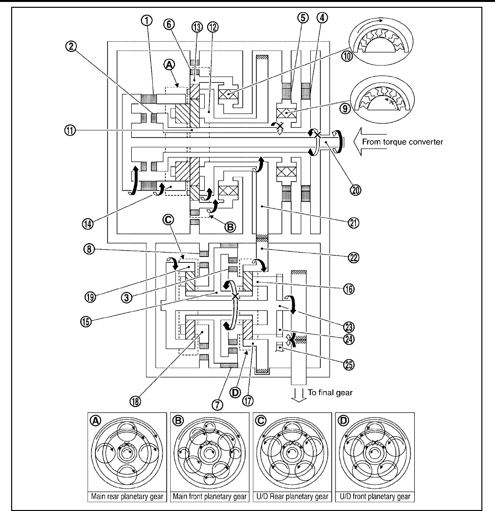
AT-394
[RE5F22A]
A/T CONTROL SYSTEM
Revision: September 2005 2005 Quest
1. Forward clutch 2. Direct clutch 3. U/D clutch
4. 2nd coast brake 5. 2nd brake 6. 1st and reverse brake
7. U/D brake 8. B5 brake 9. One-way clutch No. 1
10. One-way clutch No. 2 11. Main sun gear 12. Main planetary carrier
13. Main front internal gear 14. Main rear internal gear 15. U/D sun gear
16. U/D front planetary carrier 17. U/D front internal gear 18. U/D rear planetary carrier
19. U/D rear internal gear 20. Input shaft 21. Counter drive gear
22. Counter driven gear 23. Output shaft 24. Parking gear
25. Parking pawl
SCIA2588E

A/T CONTROL SYSTEM
AT-395
[RE5F22A]
D
E
F
G
H
I
J
K
L
M
A
B
AT
Revision: September 2005 2005 Quest
“D” positions 4th gear
1. Input shaft rotates clockwise.
2. Forward clutch operates. (Connect input shaft to main rear internal gear.)
3. Main rear internal gear rotates clockwise.
4. Main rear planetary pinion gear rotates itself clockwise.
5. Main front large planetary pinion gear rotates itself clockwise for rear planetary pinion and one.
6. 2nd brake and 2nd coast brake operates.
7. One-way clutch No. 1 operates. (Lock rotation of main sun gear.)
8. Main planetary carrier revolves clockwise due to reaction force of front large planetary pinion gear.
9. Counter drive gear rotates clockwise for main planetary carrier and one.
10. Counter driven gear rotates counterclockwise.
11. U/D front internal gear rotates counterclockwise for counter driven gear and one.
12. U/D clutch operate. (Connect U/D sun gear to U/D front planetary carrier.)
13. U/D front planetary pinion gear cannot rotate itself, and U/D unit rotates counterclockwise as one.
14. Output shaft rotates counterclockwise for U/D unit and one.
15. Final gear clockwise.
●During deceleration, driving force is connected to input shaft directly without one-way clutch. Therefore,
engine brake operates.
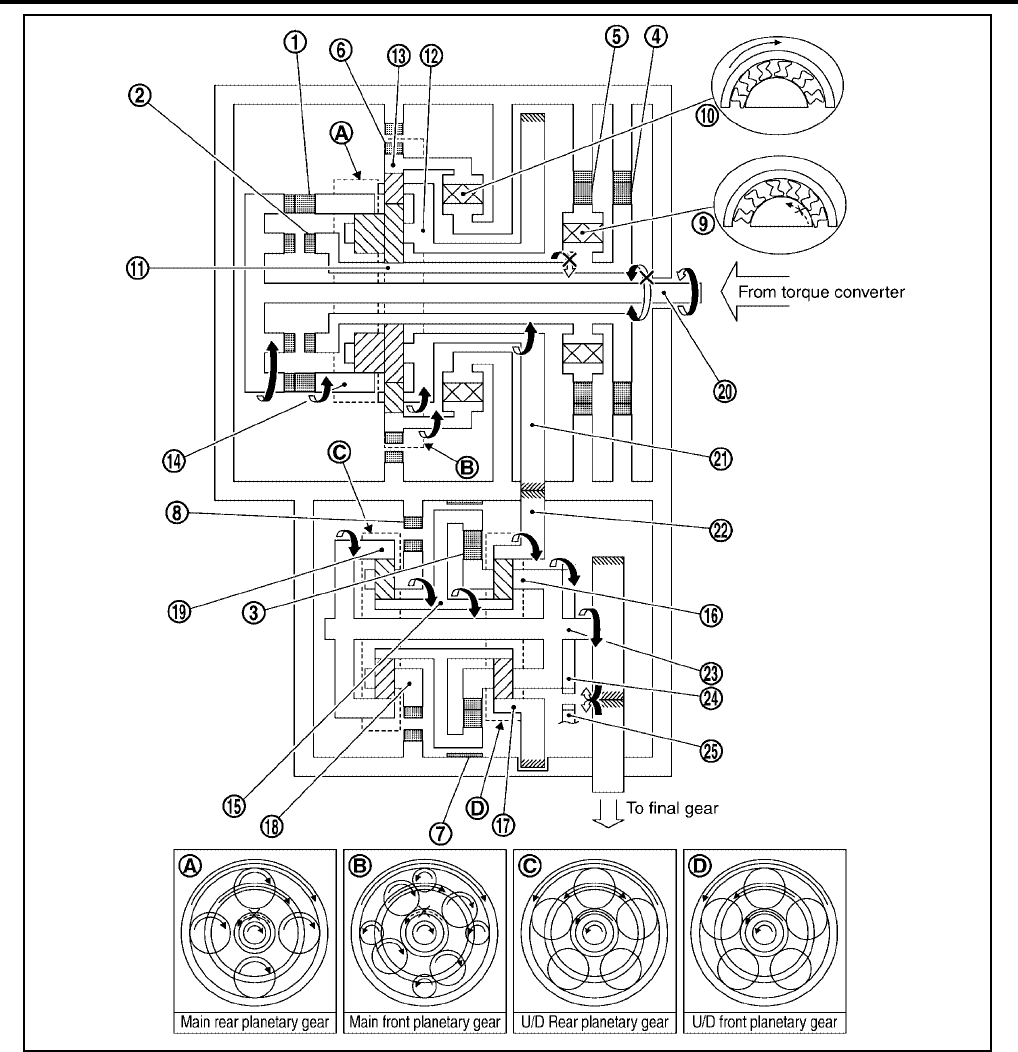
AT-396
[RE5F22A]
A/T CONTROL SYSTEM
Revision: September 2005 2005 Quest
1. Forward clutch 2. Direct clutch 3. U/D clutch
4. 2nd coast brake 5. 2nd brake 6. 1st and reverse brake
7. U/D brake 8. B5 brake 9. One-way clutch No. 1
10. One-way clutch No. 2 11. Main sun gear 12. Main planetary carrier
13. Main front internal gear 14. Main rear internal gear 15. U/D sun gear
16. U/D front planetary carrier 17. U/D front internal gear 18. U/D rear planetary carrier
19. U/D rear internal gear 20. Input shaft 21. Counter drive gear
22. Counter driven gear 23. Output shaft 24. Parking gear
25. Parking pawl
SCIA2592E

A/T CONTROL SYSTEM
AT-397
[RE5F22A]
D
E
F
G
H
I
J
K
L
M
A
B
AT
Revision: September 2005 2005 Quest
“D” positions 5th gear
1. Input shaft rotates clockwise.
2. Forward clutch operates. (Connect input shaft to main rear internal gear.)
3. Direct clutch operates. (Connect input shaft to main sun gear.)
4. Main rear planetary pinion gear cannot rotate itself, and main rear planetary unit rotates clockwise as one.
5. Main front large planetary pinion gear cannot rotate itself for main rear planetary pinion gear and one, and
main front planetary unit rotates clockwise as one.
6. Counter drive gear rotates clockwise for main front planetary unit and one.
7. Counter driven gear rotates counterclockwise.
8. U/D front internal gear rotates counterclockwise for counter driven gear and one.
9. U/D clutch operate. (Connect U/D sun gear to U/D front planetary carrier.)
10. U/D front planetary pinion gear cannot rotate itself, and U/D unit rotates counterclockwise as one.
11. Output shaft rotates counterclockwise for U/D unit and one.
12. Final gear clockwise.
●During deceleration, driving force is connected to input shaft directly without one-way clutch. Therefore,
engine brake operates.
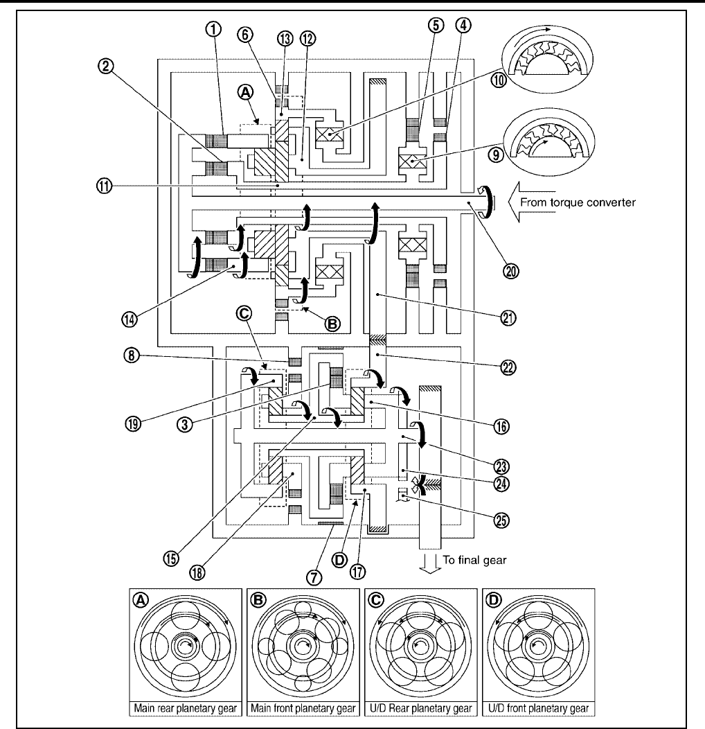
AT-398
[RE5F22A]
A/T CONTROL SYSTEM
Revision: September 2005 2005 Quest
1. Forward clutch 2. Direct clutch 3. U/D clutch
4. 2nd coast brake 5. 2nd brake 6. 1st and reverse brake
7. U/D brake 8. B5 brake 9. One-way clutch No. 1
10. One-way clutch No. 2 11. Main sun gear 12. Main planetary carrier
13. Main front internal gear 14. Main rear internal gear 15. U/D sun gear
16. U/D front planetary carrier 17. U/D front internal gear 18. U/D rear planetary carrier
19. U/D rear internal gear 20. Input shaft 21. Counter drive gear
22. Counter driven gear 23. Output shaft 24. Parking gear
25. Parking pawl
SCIA2593E

A/T CONTROL SYSTEM
AT-399
[RE5F22A]
D
E
F
G
H
I
J
K
L
M
A
B
AT
Revision: September 2005 2005 Quest
“R” position
1. Input shaft rotates clockwise.
2. Direct clutch operates. (Connect input shaft to main sun gear.)
3. Main sun gear rotates clockwise.
4. Main rear planetary pinion gear rotates itself clockwise.
5. Main front large planetary pinion gear rotates itself counterclockwise for rear planetary pinion gear and
one.
6. Main front small planetary pinion gear rotates itself clockwise.
7. 1st and reverse brake operates. (Lock rotation of main front internal gear.)
8. Main planetary carrier revolves counterclockwise due to reaction force of front small planetary pinion gear.
9. Counter drive gear rotates counterclockwise for main planetary carrier and one.
10. Counter driven gear rotates clockwise.
11. U/D front internal gear rotates clockwise for counter driven gear and one.
12. U/D front planetary pinion gear rotates itself clockwise.
13. U/D sun gear rotates counterclockwise.
14. U/D rear planetary pinion gear rotates itself clockwise.
15. B5 brake operate. (Lock rotation of U/D rear planetary carrier.)
16. U/D rear internal gear rotates clockwise.
17. U/D front planetary carrier and output shaft rotates clockwise for U/D rear internal gear and one.
18. Final gear counterclockwise.
● During deceleration, driving force is connected to input shaft directly without one-way clutch. Therefore,
engine brake operates.

AT-400
[RE5F22A]
A/T CONTROL SYSTEM
Revision: September 2005 2005 Quest
1. Forward clutch 2. Direct clutch 3. U/D clutch
4. 2nd coast brake 5. 2nd brake 6. 1st and reverse brake
7. U/D brake 8. B5 brake 9. One-way clutch No. 1
10. One-way clutch No. 2 11. Main sun gear 12. Main planetary carrier
13. Main front internal gear 14. Main rear internal gear 15. U/D sun gear
16. U/D front planetary carrier 17. U/D front internal gear 18. U/D rear planetary carrier
19. U/D rear internal gear 20. Input shaft 21. Counter drive gear
22. Counter driven gear 23. Output shaft 24. Parking gear
25. Parking pawl
SCIA2594E
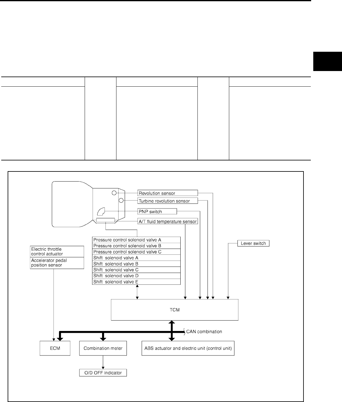
A/T CONTROL SYSTEM
AT-401
[RE5F22A]
D
E
F
G
H
I
J
K
L
M
A
B
AT
Revision: September 2005 2005 Quest
TCM Function UCS001E7
The function of the TCM is to:
●Receive input signals sent from various switches and sensors.
●Determine required line pressure, shifting point, lock-up operation, and engine brake operation.
●Send required output signals to the respective solenoids.
CONTROL SYSTEM OUTLINE
The automatic transaxle senses vehicle operating conditions through various sensors or signals. It always
controls the optimum shift position and reduces shifting and lock-up shocks.
CONTROL SYSTEM DIAGRAM
SENSORS (or SIGNAL)
Þ
TCM
Þ
ACTUATORS
PNP switch
Throttle angle signal
Throttle position signal
Engine speed signal
Engine torque signal
A/T fluid temperature sensor
Revolution sensor
Turbine revolution sensor
Vehicle speed signal
Lever switch signal
Stop lamp switch signal
Shift control
Line pressure control
Lock-up control
Engine brake control
Timing control
Fail-safe control
Self-diagnosis
CONSULT-II communication line
CAN communication line
On board diagnosis
Shift solenoid valve A
Shift solenoid valve B
Shift solenoid valve C
Shift solenoid valve D
Shift solenoid valve E
Pressure control solenoid valve A
Pressure control solenoid valve B
Pressure control solenoid valve C
O/D OFF indicator lamp
WCIA0492E

AT-402
[RE5F22A]
A/T CONTROL SYSTEM
Revision: September 2005 2005 Quest
Input/Output Signal of TCM UCS001E8
*1: Spare for revolution sensor
*2: Spare for throttle angle signal
*3: If these input and output signals are different, the TCM triggers the fail-safe function.
*4: Used as a condition for starting self-diagnostics; if self-diagnostics are not started, it is judged that there is some kind of error.
*5: CAN communications.
CAN Communication UCS001E9
SYSTEM DESCRIPTION
CAN (Controller Area Network) is a serial communication line for real time application. It is an on-vehicle mul-
tiplex communication line with high data communication speed and excellent error detection ability. Many elec-
tronic control units are equipped onto a vehicle, and each control unit shares information and links with other
control units during operation (not independent). In CAN communication, control units are connected with 2
communication lines (CAN H line, CAN L line) allowing a high rate of information transmission with less wiring.
Each control unit transmits/receives data but selectively reads required data only.
For details, refer to LAN-5, "CAN COMMUNICATION" .
Control item
Line
pressure
control
Vehicle
speed
control
Shift
control
Lock-up
control
Engine
brake
control
Fail-safe
function
(*3)
Self-diag-
nostics
function
Input
Throttle angle signal(*5) XX XXXX X
Throttle position signal(*5) X(*2) X(*2) XX(*2) X(*4)
Revolution sensor XXXXXXX
Turbine revolution sensor X X X X X X
Vehicle speed signal MTR(*1) (*5) XXXX XX
Engine speed signals(*5) XXX XX
Engine torque signals(*5) XXXXX X
PNP switch XXXXXX
X(*4)
Lever switch XX XXX
Stop lamp switch signal(*5) XXX
X(*4)
A/T fluid temperature sensor X X X X X X
ASCD Operation signal(*5) XXX
Overdrive cancel signal(*5) XXX
TCM power supply voltage signalXXXXXXX
Out-
put
Shift solenoid valve A/B/C/D/E X X X X
Pressure control solenoid valve AXXXXXXX
Pressure control solenoid valve B X X X X X
Pressure control solenoid valve C X X X X
Self-diagnostics table(*5) X
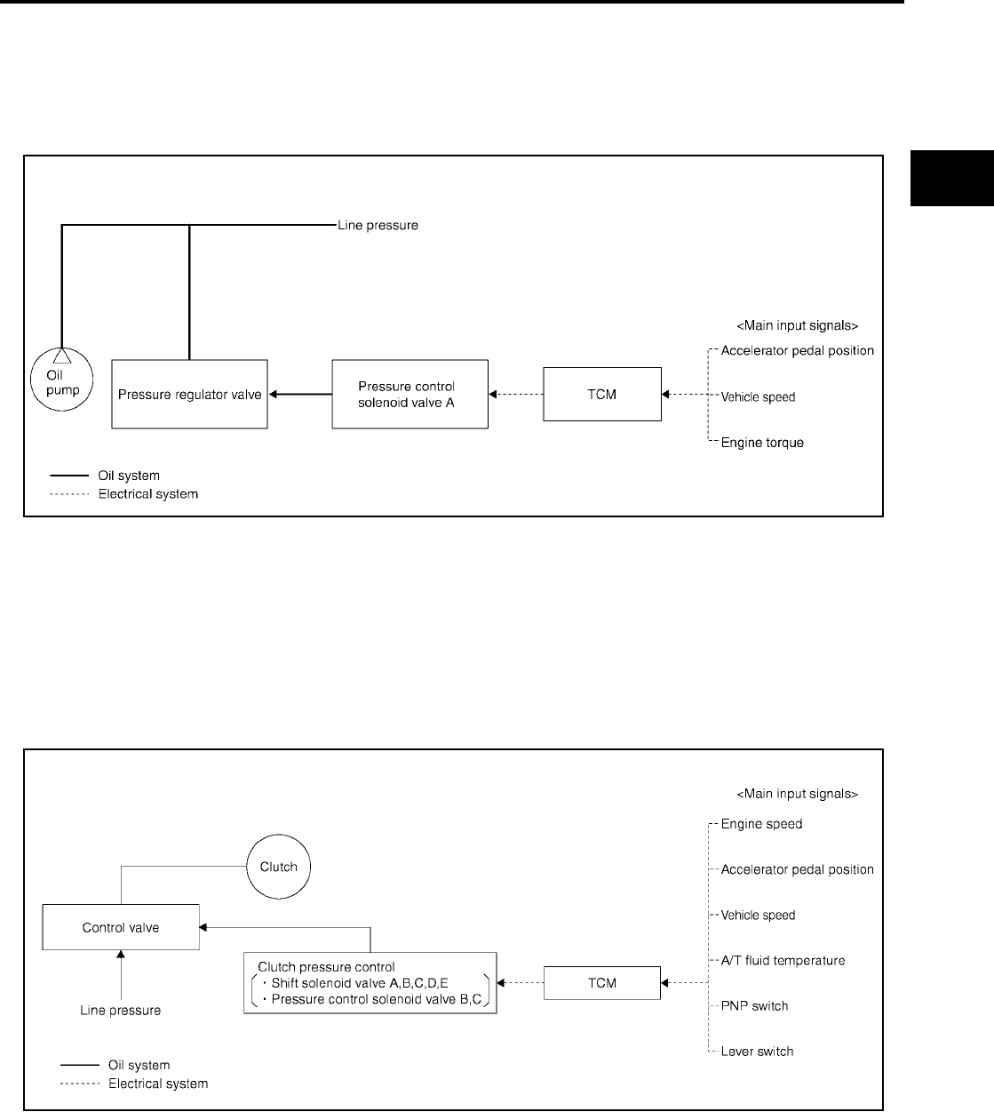
A/T CONTROL SYSTEM
AT-403
[RE5F22A]
D
E
F
G
H
I
J
K
L
M
A
B
AT
Revision: September 2005 2005 Quest
Line Pressure Control UCS001EA
●The pressure control solenoid A controls linear line pressure by control signal from TCM and line pressure
for clutches and brakes to reduce shift shock.
●This pressure control solenoid A controls the pressure regulator valve as the signal pressure and adjusts
the pressure of the operating oil discharged from the oil pump to the line pressure most appropriate to the
driving state.
LINE PRESSURE CONTROL IS BASED ON THE TCM LINE PRESSURE CHARACTERISTIC
PATTERN
In order to obtain the most appropriate line pressure characteristic to meet the current driving state, the TCM
controls the pressure control solenoid A current valve and thus controls the line pressure.
Shift Control UCS001EB
The clutch pressure control solenoid is controlled by the signals from the switches and sensors. Thus, the
clutch pressure is adjusted to be appropriate to the engine load state and vehicle driving state. It becomes
possible to finely control the clutch hydraulic pressure with high precision and a smoother shift change charac-
teristic is attained.
Basically TCM programmed for economy mode, but TCM changes to several shift schedule automatically
according to specified condition.
SCIA2605E
SCIA3569E

AT-404
[RE5F22A]
A/T CONTROL SYSTEM
Revision: September 2005 2005 Quest
SPECIAL SHIFT MODE
Upslope Mode
When TCM detects upslope from load of engine torque and decrease of acceleration, this mode changes shift
points in high-speed side according to the upslope degree and avoids busy shift of A/T.
Downslope Mode
When TCM detects downslope from increase of acceleration with accelerator full close, this mode operates
moderate engine brake by changing shift points in high-speed side.
Hot Mode Control
This control lowers ATF temperature by changing shift points when the temperature is extremely high.
Down Shift Permission Control
In order to avoid the over speed of the engine, down shift is done only at under a constant vehicle speed.
UP/DOWN SHIFT LEARNING CONTROL
This control learns the pressure to each clutch or brake in order to reduce shifting shock at each shifting (Up,
Down, Coast down).
N-D SHIFT CONTROL
This control improves the N-D shift quality due to controlling line pressure solenoid valve according to forward
clutch piston stroke learned in N-D shift learning control and applying best hydraulic pressure to forward clutch
at N-D shift (include L).
N-D SHIFT LEARNING CONTROL
This control learns the forward clutch hydraulic pressure due to monitoring a forward clutch engaging time and
a rotation change rate.
N-R SHIFT CONTROL
This control improves the N-R shift quality due to controlling shift pressure solenoid valve according to direct
clutch piston stroke learned in N-R shift learning control and applying best hydraulic pressure to direct clutch
at N-R shift.
N-R SHIFT LEARNING CONTROL
This control learns the direct clutch hydraulic pressure due to monitoring a direct clutch engaging time and a
rotation change rate.
TORQUE REDUCTION CONTROL
This control improves the shift quality due to sending torque reduction request signal from TCM to ECM and
cutting engine torque increase of shift at N-D shift, N-R shift and 1 ⇔ 2 ⇔ 3 ⇔ 4 ⇔ 5.
If accelerator pedal is depressed rapidly, this control establishes the upper limit value of engine torque and
avoids engine flare at 2 ⇔ 3, 3 ⇔ 4 and 4 Þ 2 of clutch to clutch shift.
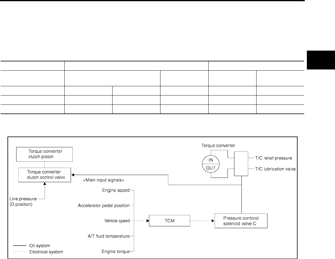
A/T CONTROL SYSTEM
AT-405
[RE5F22A]
D
E
F
G
H
I
J
K
L
M
A
B
AT
Revision: September 2005 2005 Quest
Lock-Up Control UCS001EC
The torque converter clutch piston in the torque converter is engaged to eliminate torque converter slip to
increase power transmission efficiency.
The torque converter clutch control valve operation is controlled by the pressure control solenoid valve C,
which is controlled by a signal from TCM, and the torque converter clutch control valve engages or releases
the torque converter clutch piston.
Lock-up Operation Condition Table
TORQUE CONVERTER CLUTCH CONTROL VALVE CONTROL
Lock-up Control System Diagram
Lock-up Released
●In the lock-up released state, the torque converter clutch control valve is set into the unlocked state by the
pressure control solenoid valve C and the lock-up apply pressure is drained.
In this way, the torque converter clutch piston is not coupled.
Lock-up Applied
●In the lock-up applied state, the torque converter clutch control valve is set into the locked state by the
pressure control solenoid valve C and lock-up apply pressure is generated.
In this way, the torque converter clutch piston is pressed and coupled.
Selector lever D position L position
Lever switch
(A/T indicator)
OFF
(D)
ON
(4)
OFF
(3)
ON
(2)
Gear position 54432
Lock-up ×–××–
Slip lock-up ×××––
SCIA2612E

AT-406
[RE5F22A]
A/T CONTROL SYSTEM
Revision: September 2005 2005 Quest
SMOOTH LOCK-UP CONTROL
When shifting from the lock-up released state to the lock-up applied state, the current output to the pressure
control solenoid valve C is controlled with the TCM. In this way, when shifting to the lock-up applied state, the
torque converter clutch is temporarily set to the half-clutched state to reduce the shock.
Half-Clutched State
●The current output from the TCM to the pressure control solenoid valve C is varied to steadily increase the
pressure control solenoid valve C pressure.
In this way, the lock-up apply pressure gradually rises and while the torque converter clutch piston is put
into half-clutched status, the torque converter clutch piston operating pressure is increased and the cou-
pling is completed smoothly.
Slip Lock-up Control
●In the slip region, the pressure control solenoid valve C current is controlled with the TCM to put it into the
half-clutched state. This absorbs the engine torque fluctuation and lock-up operates from low speed.
This raises the fuel efficiency for 4th and 5th gears at both low speed and when the accelerator has a low
degree of opening.
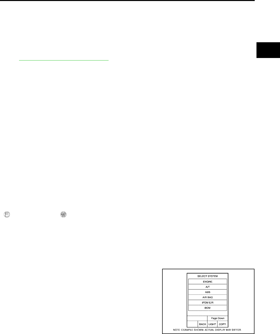
ON BOARD DIAGNOSTIC (OBD) SYSTEM
AT-407
[RE5F22A]
D
E
F
G
H
I
J
K
L
M
A
B
AT
Revision: September 2005 2005 Quest
ON BOARD DIAGNOSTIC (OBD) SYSTEM PFP:00028
Introduction UCS000TD
The A/T system has two self-diagnostic systems.
The first is the emission-related on board diagnostic system (OBD-II) performed by the TCM in combination
with the ECM. The malfunction is indicated by the MIL (malfunction indicator lamp) and is stored as a DTC in
the ECM memory but not the TCM memory.
The second is the TCM original self-diagnosis indicated by the O/D OFF indicator lamp. The malfunction is
stored in the TCM memory. The detected items are overlapped with OBD-II self-diagnostic items. For detail,
refer to AT-442, "SELF-DIAG RESULT MODE" .
OBD-II Function for A/T System UCS000TE
The ECM provides emission-related on board diagnostic (OBD-II) functions for the A/T system. One function
is to receive a signal from the TCM used with OBD-related parts of the A/T system. The signal is sent to the
ECM when a malfunction occurs in the corresponding OBD-related part. The other function is to indicate a
diagnostic result by means of the MIL (malfunction indicator lamp) on the instrument panel. Sensors, switches
and solenoid valves are used as sensing elements.
The MIL automatically illuminates in One or Two Trip Detection Logic when a malfunction is sensed in relation
to A/T system parts.
One or Two Trip Detection Logic of OBD-II UCS000TF
ONE TRIP DETECTION LOGIC
If a malfunction is sensed during the first test drive, the MIL will illuminate and the malfunction will be stored in
the ECM memory as a DTC. The TCM is not provided with such a memory function.
TWO TRIP DETECTION LOGIC
When a malfunction is sensed during the first test drive, it is stored in the ECM memory as a 1st trip DTC
(diagnostic trouble code) or 1st trip freeze frame data. At this point, the MIL will not illuminate. — 1st Trip
If the same malfunction as that experienced during the first test drive is sensed during the second test drive,
the MIL will illuminate. — 2nd Trip
The “trip” in the “One or Two Trip Detection Logic” means a driving mode in which self-diagnosis is performed
during vehicle operation.
OBD-II Diagnostic Trouble Code (DTC) UCS000TG
HOW TO READ DTC AND 1ST TRIP DTC
DTC and 1st trip DTC can be read by the following methods.
( with CONSULT-II or GST) CONSULT-II or GST (Generic Scan Tool) Examples: P0705, P0710 etc.
These DTC are prescribed by SAE J2012.
(CONSULT-II also displays the malfunctioning component or system.)
●1st trip DTC No. is the same as DTC No.
●Output of the diagnostic trouble code indicates that the indicated circuit has a malfunction. How-
ever, in case of the Mode II and GST, they do not indicate whether the malfunction is still occurring
or occurred in the past and returned to normal.
CONSULT-II can identify them as shown below, therefore, CONSULT-II (if available) is recom-
mended.
A sample of CONSULT-II display for DTC and 1st trip DTC is shown
on the next page. DTC or 1st trip DTC of a malfunction is displayed
in SELF-DIAGNOSTIC RESULTS mode for “ENGINE” with CON-
SULT-II. Time data indicates how many times the vehicle was driven
after the last detection of a DTC.
BCIA0030E
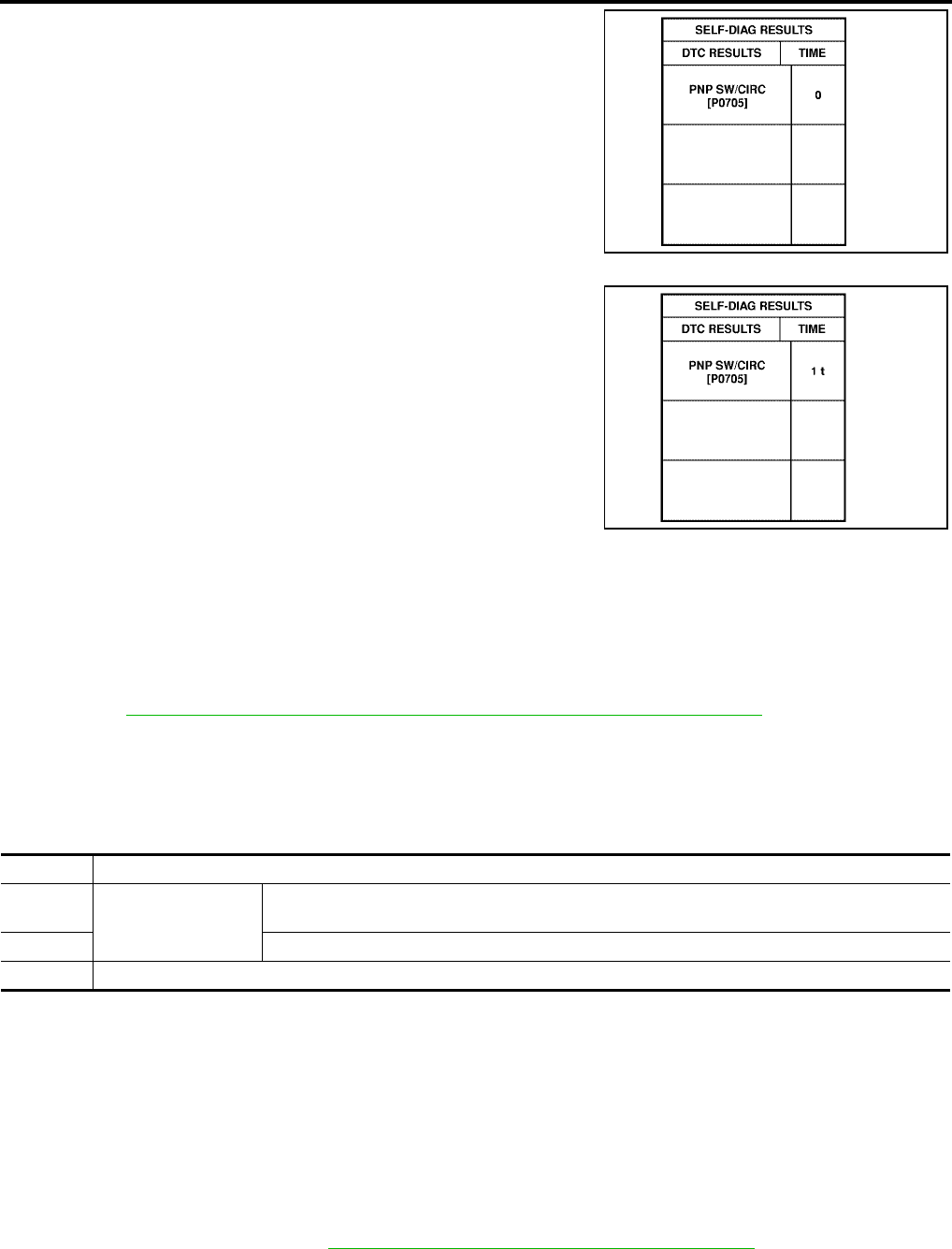
AT-408
[RE5F22A]
ON BOARD DIAGNOSTIC (OBD) SYSTEM
Revision: September 2005 2005 Quest
If the DTC is being detected currently, the time data will be “0”.
If a 1st trip DTC is stored in the ECM, the time data will be “1t”.
Freeze Frame Data and 1st Trip Freeze Frame Data
The ECM has a memory function, which stores the driving condition such as fuel system status, calculated
load value, engine coolant temperature, short term fuel trim, long term fuel trim, engine speed and vehicle
speed at the moment the ECM detects a malfunction.
Data which are stored in the ECM memory, along with the 1st trip DTC, are called 1st trip freeze frame data,
and the data, stored together with the DTC data, are called freeze frame data and displayed on CONSULT-II
or GST. The 1st trip freeze frame data can only be displayed on the CONSULT-II screen, not on the GST. For
detail, refer to EC-57, "FREEZE FRAME DATA AND 1ST TRIP FREEZE FRAME DATA" .
Only one set of freeze frame data (either 1st trip freeze frame data of freeze frame data) can be stored in the
ECM. 1st trip freeze frame data is stored in the ECM memory along with the 1st trip DTC. There is no priority
for 1st trip freeze frame data and it is updated each time a different 1st trip DTC is detected. However, once
freeze frame data (2nd trip detection/MIL on) is stored in the ECM memory, 1st trip freeze frame data is no
longer stored. Remember, only one set of freeze frame data can be stored in the ECM. The ECM has the fol-
lowing priorities to update the data.
Both 1st trip freeze frame data and freeze frame data (along with the DTC) are cleared when the ECM mem-
ory is erased.
HOW TO ERASE DTC
The diagnostic trouble code can be erased by CONSULT-II, GST or ECM DIAGNOSTIC TEST MODE as
described following.
●If the battery cable is disconnected, the diagnostic trouble code will be lost within 24 hours.
●When you erase the DTC, using CONSULT-II or GST is easier and quicker than switching the mode
selector on the ECM.
The following emission-related diagnostic information is cleared from the ECM memory when erasing DTC
related to OBD-II. For details, refer to EC-52, "Emission-related Diagnostic Information" .
●Diagnostic trouble codes (DTC)
●1st trip diagnostic trouble codes (1st trip DTC)
●Freeze frame data
SAT015K
SAT016K
Priority Items
1 Freeze frame data Misfire — DTC: P0300 - P0306
Fuel Injection System Function — DTC: P0171, P0172, P0174, P0175
2 Except the above items (Includes A/T related items)
3 1st trip freeze frame data

ON BOARD DIAGNOSTIC (OBD) SYSTEM
AT-409
[RE5F22A]
D
E
F
G
H
I
J
K
L
M
A
B
AT
Revision: September 2005 2005 Quest
●1st trip freeze frame data
●System readiness test (SRT) codes
●Test values
How to erase DTC (with CONSULT-II)
●If a DTC is displayed for both ECM and TCM, it is necessary to be erased for both ECM and TCM.
1. If the ignition switch stays “ON” after repair work, be sure to turn ignition switch “OFF” once. Wait at least
10 seconds and then turn it “ON” (engine stopped) again.
2. Turn CONSULT-II “ON” and touch “A/T”.
3. Touch “SELF-DIAG RESULTS”.
4. Touch “ERASE”. (The DTC in the TCM will be erased.) Then touch “BACK” twice.
5. Touch “ENGINE”.
6. Touch “SELF-DIAG RESULTS”.
7. Touch “ERASE”. (The DTC in the ECM will be erased.)
How to erase DTC (with GST)
1. If the ignition switch stays “ON” after repair work, be sure to turn ignition switch “OFF” once. Wait at least
10 seconds and then turn it “ON” (engine stopped) again.
2. Erase DTC with TCM. Refer to AT-449, "ERASE SELF-DIAGNOSIS" . (The engine warm-up step can be
skipped when performing the diagnosis only to erase the DTC.)
3. Select Mode 4 with Generic Scan Tool (GST). For details, refer to EC-146, "Generic Scan Tool (GST)
Function" .
How to erase DTC (no tools)
The O/D OFF indicator lamp is located on the instrument panel.
SCIA5576E
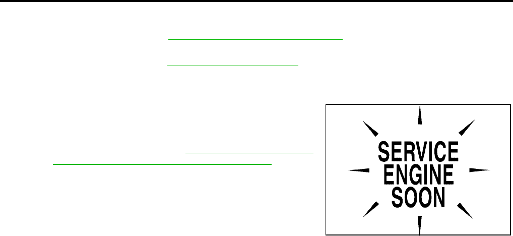
AT-410
[RE5F22A]
ON BOARD DIAGNOSTIC (OBD) SYSTEM
Revision: September 2005 2005 Quest
1. If the ignition switch stays “ON” after repair work, be sure to turn ignition switch “OFF” once. Wait at least
10 seconds and then turn it “ON” (engine stopped) again.
2. Erase DTC with TCM. Refer to AT-449, "ERASE SELF-DIAGNOSIS" . (The engine warm-up step can be
skipped when performing the diagnosis only to erase the DTC.)
3. Erase DTC with ECM. Refer to EC-65, "How to Erase DTC" .
Malfunction Indicator Lamp (MIL) UCS000TH
DESCRIPTION
The MIL is located on the instrument panel.
1. The MIL will light up when the ignition switch is turned “ON” with-
out the engine running. This is a bulb check.
●If the MIL does not light up, refer to DI-22, "WARNING LAMPS" ,
or see EC-743, "MIL AND DATA LINK CONNECTOR" .
2. When the engine is started, the MIL should go off.
If the MIL remains on, the on board diagnostic system has
detected an engine system malfunction.
SEF217U

TROUBLE DIAGNOSIS
AT-411
[RE5F22A]
D
E
F
G
H
I
J
K
L
M
A
B
AT
Revision: September 2005 2005 Quest
TROUBLE DIAGNOSIS PFP:00004
DTC Inspection Priority Chart UCS000TI
If some DTCs are displayed at the same time, perform inspections one by one based on the following priority
chart.
NOTE:
If DTC U1000 is displayed with other DTCs, first perform the trouble diagnosis for DTC U1000. Refer to
AT-450 .
Fail-Safe UCS000TJ
The TCM has an electrical fail-safe mode. This mode makes it possible to operate even if there is a malfunc-
tion in a main electronic control input/output signal circuit.
In fail-safe mode, a driving condition is selected according to the malfunctioning location, and line pressure is
set at the maximum. For this reason, the customer will be subjected to uncomfortable “slipping” or “poor accel-
eration” of the vehicle.
In that case, handle according to the “diagnostics flow” (Refer to AT-415 ).
FAIL-SAFE FUNCTION
If any malfunction occurs in a sensor or solenoid, this function controls the A/T to make driving possible.
NOTE:
Line pressure is set at the maximum in fail-safe mode. Although gear position differs depending on
the type of fail-safe modes, CONSULT-II indicates “5th”.
Priority Detected items (DTC)
1 U1000 CAN communication line
2 Except above
DTC Malfunction items Fail-safe*
P0500 Vehicle speed signal No learning control.
P0613 TCM processor Fail-safe mode 4
P0705 PNP switch Fail-safe mode 4
P0710 ATF temperature sensor circuit Sets ATF temperature data at 111°C (232°F) after 15 minutes. Inhibits
lock-up control.
P0711 ATF temperature sensor function Sets ATF temperature data at 111°C (232°F) after 15 minutes. Inhibits
lock-up control.
P0717 Turbine revolution sensor Fail-safe mode 1
P0722 Revolution sensor Uses vehicle speed signal from combination meter as a substitute. Inhib-
its learning control.
P0726 Engine speed signal input circuit perfor-
mance Fail-safe mode 1
P0731 1st gear function No 1st gear, no control for N-D shift.
P0732 2nd gear function Fail-safe mode 1. Also, ECM restricts engine torque to prevent clutch
slipping.
P0733 3rd gear function Fail-safe mode 1. Also, ECM restricts engine torque to prevent clutch
slipping.
P0734 4th gear function Fail-safe mode 1. Also, ECM restricts engine torque to prevent clutch
slipping.
P0735 5th gear function Fail-safe mode 1. Also, ECM restricts engine torque to prevent clutch
slipping.
P0744 Lock-up function Fail-safe mode 1
P0745 Pressure control solenoid valve A Fail-safe mode 1. Also, ECM restricts engine torque to prevent clutch
slipping.

AT-412
[RE5F22A]
TROUBLE DIAGNOSIS
Revision: September 2005 2005 Quest
*: For fail-safe modes 1 to 10, refer to AT-412, "Fail-safe mode list" .
Fail-safe mode list
P0750 Shift solenoid valve A
Any one of fail-safe modes
●Fail-safe mode 1
●Fail-safe mode 7. Also, ECM restricts input torque to prevent clutch
slipping.
P0755 Shift solenoid valve B
Any one of fail-safe modes
●Fail-safe mode 1
●Fail-safe mode 8
P0760 Shift solenoid valve C
Any one of fail-safe modes
●Fail-safe mode 2
●Fail-safe mode 5
●Fail-safe mode 9
P0762 Shift solenoid valve C stuck ON Fail-safe mode 2. Also, ECM restricts engine torque to prevent clutch
slipping.
P0765 Shift solenoid valve D
Any one of fail-safe modes
●Fail-safe mode 1
●Fail-safe mode 10. Also, ECM restricts input torque to prevent clutch
slipping.
P0770 Shift solenoid valve E
Any one of fail-safe modes
●Fail-safe mode 1. Also, ECM restricts engine torque to prevent clutch
slipping.
●Fail-safe mode 6. Also, ECM restricts engine torque to prevent clutch
slipping.
P0775 Pressure control solenoid valve B Fail-safe mode 3
P0780 Shift function Fail-safe mode 1. Also, ECM restricts input torque to prevent clutch slip-
ping.
P0795 Pressure control solenoid valve C Fail-safe mode 1
P0797 Pressure control solenoid valve C stuck ON Fail-safe mode 1
P0825 Lever switch No lever switch control.
P0882 TCM power input signal Fail-safe mode 1
P1726 Electric throttle control
●The accelerator opening angle is controlled by ECM according to a
pre-determined accelerator angle to make driving possible.
●No lock-up, no learning control.
U1000 CAN communication circuit
Any one of fail-safe modes
●Fail-safe mode 1
●Fail-safe mode 1. Also, ECM restricts engine torque to prevent clutch
slipping.
●No learning control.
●No lock-up, no learning control, no special shift mode control.
DTC Malfunction items Fail-safe*
Fail-safe mode Selector lever Gear
position*1
Shift solenoid valve Pressure control sole-
noid valve
ABCDEABC
Fail-safe mode 1
D position 4th OFF OFF OFF OFF OFF OFF OFF OFF
L position 2nd OFF OFF ON OFF OFF OFF OFF OFF
R position Reverse OFF OFF OFF OFF ON OFF OFF OFF
Fail-safe mode 2
(CONSULT-II dis-
plays “8”)
D position 3rd OFF OFF ON ON OFF OFF OFF OFF
L position 2nd OFF OFF ON OFF OFF OFF OFF OFF
R position Reverse OFF OFF ON OFF ON OFF OFF OFF
TROUBLE DIAGNOSIS
AT-413
[RE5F22A]
D
E
F
G
H
I
J
K
L
M
A
B
AT
Revision: September 2005 2005 Quest
*1: CONSULT-II indicates “5th”.
*2: Reverse gear ratio difference (Gear ratio: 3.342)
*3: 3rd gear ratio difference (Gear ratio: 2.301)
How To Perform Trouble Diagnosis For Quick and Accurate Repair UCS000TK
INTRODUCTION
The TCM receives a signal from the vehicle speed signal, ECM (throttle opening) or PNP switch and provides
shift control or lock-up control via A/T solenoid valves.
The TCM also communicates with the ECM by means of a signal
sent from sensing elements used with the OBD-related parts of the
A/T system for malfunction-diagnostic purposes. The TCM is capa-
ble of diagnosing malfunctioning parts while the ECM can store mal-
functions in its memory.
Input and output signals must always be correct and stable in the
operation of the A/T system. The A/T system must be in good oper-
ating condition and be free of valve seizure, solenoid valve malfunc-
tion, etc.
Fail-safe mode 3
D position 4th OFF OFF OFF OFF OFF OFF OFF OFF
L position 2nd OFF OFF ON OFF ON OFF OFF OFF
R position Reverse OFF OFF OFF OFF ON OFF OFF OFF
Fail-safe mode 4
D position 4th OFF OFF OFF OFF OFF OFF OFF OFF
L position 4th OFF OFF OFF OFF OFF OFF OFF OFF
R position Reverse OFF OFF OFF OFF OFF OFF OFF OFF
Fail-safe mode 5
D position 4th OFF OFF OFF OFF OFF OFF OFF OFF
L position 4th OFF OFF OFF OFF OFF OFF OFF OFF
R position Reverse OFF OFF OFF OFF ON OFF OFF OFF
Fail-safe mode 6
D position 4th OFF OFF OFF OFF OFF OFF OFF OFF
L position 2nd OFF OFF ON OFF OFF OFF OFF OFF
R position Reverse OFF OFF ON OFF OFF OFF OFF OFF
Fail-safe mode 7
D position 4th ON OFF OFF OFF OFF OFF OFF OFF
L position 2nd ON OFF ON OFF OFF OFF OFF OFF
R position Reverse*2 ON OFF ON ON OFF OFF OFF OFF
Fail-safe mode 8
(CONSULT-II dis-
plays “1”)
D position 5th OFF ON OFF OFF OFF OFF OFF OFF
L position (2nd)*3 OFF ON ON OFF OFF OFF OFF OFF
R position Reverse OFF ON OFF OFF ON OFF OFF OFF
Fail-safe mode 9
(CONSULT-II dis-
plays “8”)
D position 4th OFF OFF OFF ON OFF OFF OFF OFF
L position 4th OFF OFF OFF OFF OFF OFF OFF OFF
R position Reverse OFF OFF OFF OFF ON OFF OFF OFF
Fail-safe mode 10
(CONSULT-II dis-
plays “6”)
D position 4th OFF OFF OFF ON OFF OFF OFF OFF
L position 3rd OFF OFF ON ON OFF OFF OFF OFF
R position Reverse*2 OFF OFF ON ON OFF OFF OFF OFF
Fail-safe mode Selector lever Gear
position*1
Shift solenoid valve Pressure control sole-
noid valve
ABCDEABC
SAT631IB
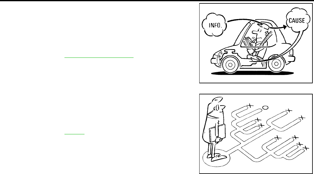
AT-414
[RE5F22A]
TROUBLE DIAGNOSIS
Revision: September 2005 2005 Quest
It is much more difficult to diagnose an error that occurs intermit-
tently rather than continuously. Most intermittent errors are caused
by poor electric connections or improper wiring. In this case, careful
checking of suspected circuits may help prevent the replacement of
good parts.
A visual check only may not find the cause of the errors. A road test
with CONSULT-II (or GST) or a circuit tester connected should be
performed. Follow the AT-415, "WORK FLOW" .
Before undertaking actual checks, take a few minutes to talk with a
customer who approaches with a driveability complaint. The cus-
tomer can supply good information about such errors, especially
intermittent ones. Find out what symptoms are present and under
what conditions they occur. A “Diagnostic Worksheet” as shown on
the example (Refer to AT-416 ) should be used.
Start your diagnosis by looking for “conventional” errors first. This will
help troubleshoot driveability errors on an electronically controlled
engine vehicle.
Also check related Service bulletins.
SAT632I
SEF234G

TROUBLE DIAGNOSIS
AT-415
[RE5F22A]
D
E
F
G
H
I
J
K
L
M
A
B
AT
Revision: September 2005 2005 Quest
WORK FLOW
A good understanding of the malfunction conditions can make troubleshooting faster and more accurate.
In general, each customer feels differently about a malfunction. It is important to fully understand the symp-
toms or conditions for a customer complaint.
Make good use of the two sheets provided, “Information From Customer” (Refer to AT-416 ) and “Diagnostic
Worksheet” (Refer to AT-416 ), to perform the best troubleshooting possible.
Work Flow Chart
*1. AT-416 *2. AT-416 *3. AT-411
*4. AT-421 *5. AT-421, AT-423 *6. AT-424
*7. AT-441 *8. AT-407 *9. AT-410
*10. AT-450 *11. AT-575 *12. AT-576
*13. AT-596 *14. AT-431 *15. AT-408
*16. AT-450 *17. AT-575 *18. EC-52
SCIA0501E
AT-416
[RE5F22A]
TROUBLE DIAGNOSIS
Revision: September 2005 2005 Quest
DIAGNOSTIC WORKSHEET
Information From Customer
KEY POINTS
●WHAT..... Vehicle & A/T model
●WHEN..... Date, Frequencies
●WHERE..... Road conditions
●HOW..... Operating conditions, Symptoms
Diagnostic Worksheet Chart
Customer name MR/MS Model & Year VIN
Trans. Model Engine Mileage
Incident Date Manuf. Date In Service Date
Frequency ❏ Continuous ❏ Intermittent ( times a day)
Symptoms ❏ Vehicle does not move. (❏ Any position ❏ Particular position)
❏ No up-shift (❏ 1st → 2nd ❏ 2nd → 3rd ❏ 3rd → 4th ❏ 4th → 5th)
❏ No down-shift (❏ 5th → 4th ❏ 4th → 3rd ❏ 3rd → 2nd ❏ 2nd → 1st)
❏ Lock-up malfunction
❏ Shift point too high or too low.
❏ Shift shock or slip (❏ N → D ❏ Lock-up ❏ Any drive position)
❏ Noise or vibration
❏ No kick down
❏ No pattern select
❏ Others
()
Malfunction indicator lamp (MIL) ❏ Continuously lit ❏ Not lit
1❏ Read the item on cautions concerning fail-safe and understand the customer's complaint. AT-411
2
❏ A/T fluid inspection
AT-421
❏ Leak (Repair leak location.)
❏ State
❏ Amount
3
❏ Stall test, time lag test and line pressure test
AT-421, AT-
423
❏ Stall test
❏ Engine
❏ Torque converter one-way clutch
❏ Line pressure is low
❏ Forward clutch
❏ Direct clutch
❏ 1st and reverse brake
❏ B5 brake
❏ One-way clutch No. 2
❏ Oil pump
❏ Oil strainer
❏ Oil leak for each range circuit
❏ Time lag test
❏ Line pressure is low
❏ Forward clutch
❏ Direct clutch
❏ 1st and reverse brake
❏ One-way clutch No. 2
❏ Oil pump
❏ Oil strainer
❏ Oil leak for “D” position circuit
❏ Oil leak for “R” position circuit
❏ Line pressure inspection - Suspected part:
TROUBLE DIAGNOSIS
AT-417
[RE5F22A]
D
E
F
G
H
I
J
K
L
M
A
B
AT
Revision: September 2005 2005 Quest
4
❏ Perform all road tests and enter checks in required inspection items. AT-424
4-1.
Check before engine is started
AT-425
❏ The O/D OFF indicator lamp does not come on. AT-576 .
❏ Perform self-diagnostics. Enter checks for detected items.
❏ Vehicle speed sensor·MTR. AT-453 .
❏ TCM processor. AT-455 .
❏ PNP switch. AT-457 .
❏ A/T fluid temperature sensor circuit. AT-463 .
❏ A/T fluid temperature sensor performance. AT-468 .
❏ Turbine revolution sensor circuit. AT-473 .
❏ Vehicle speed sensor·A/T (revolution sensor) circuit. AT-477 .
❏ Engine speed input circuit performance. AT-481 .
❏ 1st gear function. AT-483 .
❏ 2nd gear function. AT-486 .
❏ 3rd gear function. AT-492 .
❏ 4th gear function. AT-498 .
❏ 5th gear function. AT-503 .
❏ Lock-up function. AT-509 .
❏ Shift function. AT-552 .
❏ Pressure control solenoid valve A. AT-512 .
❏ Pressure control solenoid valve B. AT-547 .
❏ Pressure control solenoid valve C. AT-556 .
❏ Shift solenoid valve A. AT-517 .
❏ Shift solenoid valve B. AT-522 .
❏ Shift solenoid valve C. AT-527 .
❏ Shift solenoid valve D. AT-537 .
❏ Shift solenoid valve E. AT-542 .
❏ Pressure control solenoid valve C stuck ON. AT-561 .
❏ Shift solenoid valve C stuck ON. AT-532 .
❏ Lever switch circuit. AT-566 .
❏ TCM power input signal. AT-570 .
❏ Electric throttle control system. AT-575 .
❏ CAN communication. AT-450 .
❏ Battery
❏ Other
4-2.
Idle inspection
AT-425
❏ Engine cannot be started in “P” and “N” position. AT-578 .
❏ In “ P” position, vehicle moves when pushed. AT-578 .
❏ In “N” position, vehicle moves. AT-579 .
❏ Large shock when shifted from “N” to “D” position. AT-580 .
❏ Vehicle does not creep backward in “R” position. AT-581 .
❏ Vehicle does not creep forward in “D” or “L” position. AT-582 .
4-3.
Driving tests
AT-427
Part 1
❏ Vehicle cannot be started from D1. AT-583 .
❏ A/T does not shift: D1 → D2. AT-583 .
❏ A/T does not shift: D2 → D3. AT-584 .
❏ A/T does not shift: D3 → D4. AT-585 .
❏ A/T does not shift: D4 → D5. AT-586 .
❏ A/T does not perform lock-up. AT-587
❏ A/T does not hold lock-up condition. AT-588 .
❏ Lock-up is not released. AT-589 .

AT-418
[RE5F22A]
TROUBLE DIAGNOSIS
Revision: September 2005 2005 Quest
44-3
Part 2
AT-428
❏ Vehicle cannot be started from D1. AT-583 .
❏ A/T does not shift: D1 → D2. AT-583 .
❏ A/T does not shift: D2 → D3. AT-584 .
❏ A/T does not shift: D3 → D4. AT-585 .
Part 3
AT-429
❏ A/T does not shift: 5th gear → 4th gear, when lever switch “OFF” → “ON”. AT-590 .
❏ A/T does not shift: 4th gear → 3rd gear, when selector lever “D” → “L”. AT-591 .
❏ A/T does not shift: 3rd gear → 2nd gear, when lever switch “OFF” → “ON”. AT-593 .
❏ A/T does not shift: 2nd gear → 1st gear, when release accelerator pedal. AT-594 .
❏ Vehicle does not decelerate by engine brake. AT-595 .
❏ Perform self-diagnostics. Enter checks for detected items.
❏ Vehicle speed sensor·MTR. AT-453 .
❏ TCM processor. AT-455 .
❏ PNP switch. AT-457 .
❏ A/T fluid temperature sensor circuit. AT-463 .
❏ A/T fluid temperature sensor performance. AT-468 .
❏ Turbine revolution sensor circuit. AT-473 .
❏ Vehicle speed sensor·A/T (revolution sensor) circuit. AT-477 .
❏ Engine speed input circuit performance. AT-481 .
❏ 1st gear function. AT-483 .
❏ 2nd gear function. AT-486 .
❏ 3rd gear function. AT-492 .
❏ 4th gear function. AT-498 .
❏ 5th gear function. AT-503 .
❏ Lock-up function. AT-509 .
❏ Shift function. AT-552 .
❏ Pressure control solenoid valve A. AT-512 .
❏ Pressure control solenoid valve B. AT-547 .
❏ Pressure control solenoid valve C. AT-556 .
❏ Shift solenoid valve A. AT-517 .
❏ Shift solenoid valve B. AT-522 .
❏ Shift solenoid valve C. AT-527 .
❏ Shift solenoid valve D. AT-537 .
❏ Shift solenoid valve E. AT-542 .
❏ Pressure control solenoid valve C stuck ON. AT-561 .
❏ Shift solenoid valve C stuck ON. AT-532 .
❏ Lever switch circuit. AT-566 .
❏ TCM power input signal. AT-570 .
❏ Electric throttle control system. AT-575 .
❏ CAN communication. AT-450 .
❏ Battery
❏ Other
5❏ Inspect each system for items found to be NG in the self-diagnostics and repair or replace the malfunction
parts.
6❏ Perform all road tests and enter the checks again for the required items. AT-424
7
❏ For any remaining NG items, perform the “diagnostics procedure” and repair or replace the malfunction parts.
See the chart for diagnostics by symptoms. (This chart also contains other symptoms and inspection proce-
dures.)
AT-431
8❏ Erase the results of the self-diagnostics from the TCM. AT-449
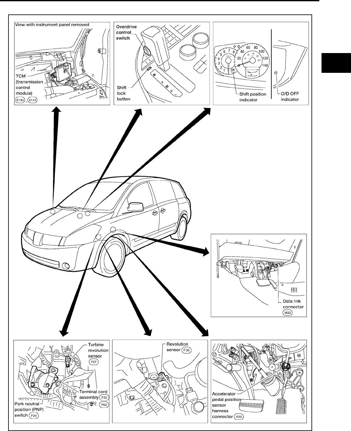
TROUBLE DIAGNOSIS
AT-419
[RE5F22A]
D
E
F
G
H
I
J
K
L
M
A
B
AT
Revision: September 2005 2005 Quest
A/T Electrical Parts Location UCS000TL
WCIA0421E
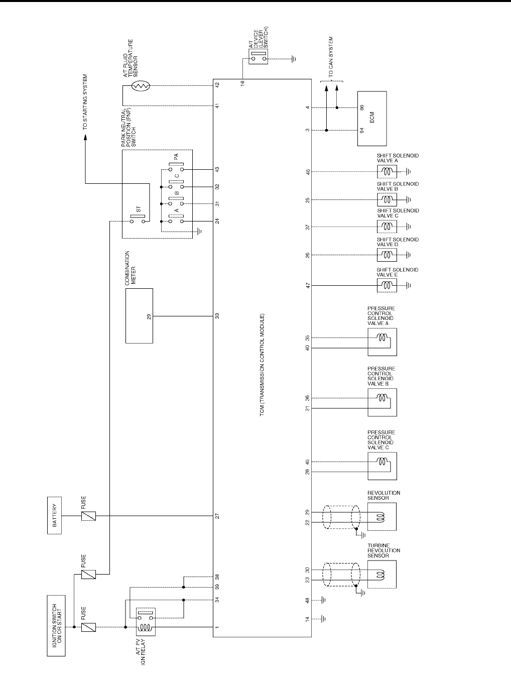
AT-420
[RE5F22A]
TROUBLE DIAGNOSIS
Revision: September 2005 2005 Quest
Circuit Diagram UCS000TM
BCWA0307E

TROUBLE DIAGNOSIS
AT-421
[RE5F22A]
D
E
F
G
H
I
J
K
L
M
A
B
AT
Revision: September 2005 2005 Quest
Inspections Before Trouble Diagnosis UCS000TN
A/T FLUID CHECK
Fluid leakage and fluid level check
●Inspect for fluid leakage and check the fluid level. Refer to MA-21, "Checking A/T Fluid" .
Fluid condition check
Inspect the fluid condition.
STALL TEST
Stall test procedure
1. Inspect the amount of engine oil. Replenish the engine oil if necessary.
2. Drive for about 10 minutes to warm up the vehicle so that the A/
T fluid temperature is 50 to 80°C (122 to 176°F). Inspect the
amount of A/T fluid. Replenish if necessary.
3. Switch of A/C and light etc. are off.
4. Securely engage the parking brake so that the tires do not turn.
5. Engine start, apply foot brake, and place selector lever in “D”
position.
6. While holding down the foot brake, gradually press down the
accelerator pedal.
7. Quickly read off the stall speed, then quickly remove your foot
from the accelerator pedal.
CAUTION:
Do not hold down the accelerator pedal for more than 5 sec-
onds during this test.
8. Move the selector lever to the “N” position.
9. Cool down the A/T fluid.
Fluid status Conceivable Cause Required Operation
Varnished (viscous
varnish state)
Clutch, brake
scorched
Replace the A/T fluid and check the
A/T main unit and the vehicle for
malfunctions (wire harnesses,
cooler pipes, etc.)
Milky white or
cloudy Water in the fluid Replace the A/T fluid and check for
places where water is getting in.
Large amount of
metal powder mixed
in
Unusual wear of
sliding parts within
A/T
Replace the A/T fluid and check for
improper operation of the A/T.
SAT638A
SAT647B
SCIA1224E
SAT514G
AT-422
[RE5F22A]
TROUBLE DIAGNOSIS
Revision: September 2005 2005 Quest
CAUTION:
Run the engine at idle for at least one minute.
10. Repeat step 5 through 9 with selector lever in “L” and “R” positions.
Judgement stall test
O: Stall speed within standard value position
H: Stall speed higher than standard value
L: Stall speed lower than standard value
TIME LAG TEST
Time lag test procedure
1. Inspect the amount of engine oil. Replenish the engine oil if necessary.
2. Drive for about 10 minutes to warm up the vehicle so that the A/
T fluid temperature is 50 to 80°C (122 to 176°F). Check the
amount of A/T fluid. Replenish if necessary.
3. Switch of A/C and light etc. are off.
4. Securely engage the parking brake so that the tires do not turn.
5. Engine start, apply foot brake.
6. Measure time lag by using stopwatch from moment when shift
lever is shifted in “N” to “D” position and “N” to “R” position until
moment slightly shock can be felt.
CAUTION:
●Make sure to take 3 measurement and take the average
value.
●Make sure to keep interval for more than one minute
between time lag tests.
(That purpose is to remove clutch/brake pressure was
left unfinished.)
Stall speed: 2,430 - 2,730 rpm
Selector lever position Possible cause
D, L R
Stall rotation
HO
●Line pressure is low (pressure control solenoid valve A malfunction, primary regulator
valve malfunction)
●Forward clutch (slipping)
●One-way clutch No. 2
OH
●Line pressure is low (pressure control solenoid valve A malfunction, primary regulator
valve malfunction)
●Direct clutch (slipping)
●1st and reverse brake (slipping)
LL
●Engine or torque converter one-way clutch
HH
●Line pressure is low (pressure control solenoid valve A malfunction, primary regulator
valve malfunction)
●B5 brake (slipping)
●Oil pump
●Oil strainer (clogging)
●Oil leak for each range circuit
SAT647B
SCIA1224E

TROUBLE DIAGNOSIS
AT-423
[RE5F22A]
D
E
F
G
H
I
J
K
L
M
A
B
AT
Revision: September 2005 2005 Quest
Judgement time lag test
LINE PRESSURE TEST
Line pressure test port
Location of line pressure test port is show in the figure.
Line pressure test procedure
1. Inspect the amount of engine oil and replenish if necessary.
2. Drive the car for about 10 minutes to warm it up so that the A/T fluid reaches in range of 50 to 80°C (122
to 176°F), then inspect the amount of A/T fluid and replenish if necessary.
NOTE:
The automatic fluid temperature rises in range of 50 to 80°C (122 to 176°F) during 10 minutes of
driving.
3. Switch of A/C and light etc. are off.
4. After warming up A/T, remove the oil pressure detection plug and install the oil pressure gauge [SST: (J-
34301-C)] and adapter [SST: (J-45542)].
CAUTION:
Make sure to check no oil leak after installing oil pressure gage.
5. Securely engage the parking brake so that the tires do not turn.
Time lag:
“N” to “D” position: Less than 0.7 sec.
“N” to “R” position: Less than 1.2 sec.
Result of time lag test Possible cause
Longer than standards “N” to “D” position
●Line pressure is low (pressure control solenoid valve A malfunction, primary regulator
valve malfunction)
●Forward clutch (slipping)
●One-way clutch No. 2
● Oil leak for “D” range circuit
Longer than standards “N” to “R” position
●Line pressure is low
●Direct clutch (slipping)
●1st and reverse brake (slipping)
●Oil leak for “R” range circuit
●Oil pump
●Oil strainer (clogging)
SCIA2669E
SCIA1224E

AT-424
[RE5F22A]
TROUBLE DIAGNOSIS
Revision: September 2005 2005 Quest
6. Start the engine, then measure the line pressure at both idle and
the stall speed.
CAUTION:
●Keep the brake pedal pressed all the way down during
measurement.
●When measuring the line pressure at the stall speed,
refer to AT-421, "STALL TEST" .
7. After the measurements are complete, install the oil pressure
detection plug and tighten to the specified torque.
CAUTION:
Do not reuse O-ring.
Line pressure
Judgement of line pressure test
ROAD TEST
Description
●The road test inspects overall performance of the A/T and analyzes possible malfunction causes.
●The road test is perform in the following three stages.
1. Check before engine is started. Refer to AT-425 .
2. Check at idle. Refer to AT-425 .
3. Cruise test
●Inspect all the items from Part 1 to Part 3. Refer to AT-427 ,
AT-428 , AT-429 .
:7.4 N·m (0.75 kg-m, 65 in-lb) SAT493G
Engine speed Line pressure kPa (kg/cm2 , psi)
D, L positions R position
At idle speed 333 - 392 (3.4 - 4.0, 48 - 57) 500 - 608 (5.1 - 6.2, 73 - 88)
At stall speed 1,285 - 1,393 (13.1 - 14.2, 186 - 202) 1,706 - 1,981 (17.4 - 20.2, 247 - 287)
Judgement Possible cause
Higher than standards both “D”, “L” and “R” positions ●Pressure control solenoid valve A malfunction
●Primary regulator valve malfunction
Lower than standards both “D”, “L” and “R” positions
●Pressure control solenoid valve A malfunction
●Primary regulator valve malfunction
●Oil pump malfunction
●B5 bake malfunction
●Oil leak for each range circuit malfunction
Lower than standards only “D” position ●Oil leak for “D” range circuit malfunction
●Forward clutch malfunction
Lower than standards only “R” position
●Oil leak for “R” range circuit malfunction
●Direct clutch malfunction
●1st and reverse brake malfunction
SAT786A
TROUBLE DIAGNOSIS
AT-425
[RE5F22A]
D
E
F
G
H
I
J
K
L
M
A
B
AT
Revision: September 2005 2005 Quest
●Before beginning the road test, check the test procedure and
inspection items.
●Test all inspection items until the symptom is uncovered. Diag-
nose NG items when all road tests are complete.
Check Before Engine is Started UCS000TO
1. CHECK O/D OFF INDICATOR LAMP
1. Park vehicle on level surface.
2. Move selector lever to “P” position.
3. Turn ignition switch “OFF” and wait at least 10 seconds.
4. Turn ignition switch “ON”. (Do not start engine.)
Does O/D OFF indicator lamp light up for about 2 seconds?
YES >> 1. Turn ignition switch “OFF”.
2. Perform the self-diagnostics and record all NG items on the diagnostics worksheet. Refer to AT-
447, "Diagnostic Procedure" .
3. Go to AT-425, "Check at Idle" .
No >> Stop the road test and go to AT-576, "O/D OFF Indicator Lamp Does Not Come On" .
Check at Idle UCS000TP
1. CHECK STARTING THE ENGINE
1. Park vehicle on level surface.
2. Move selector lever to “P” position.
3. Turn ignition switch “OFF”.
4. Turn ignition switch “START”.
Does the engine start?
YES >> GO TO 2.
No >> Stop the road test and go to AT-578, "Engine Cannot Be Started In “P” or “N” Position" .
2. CHECK STARTING THE ENGINE
1. Push and hold shift lock release button.
2. Move selector lever in “D”, “L” or “R” position.
3. Turn ignition switch “START”.
Does the engine start in either position?
YES >> Stop the road test and go to AT-578, "Engine Cannot Be Started In “P” or “N” Position" .
No >> GO TO 3.
SAT496G

AT-426
[RE5F22A]
TROUBLE DIAGNOSIS
Revision: September 2005 2005 Quest
3. CHECK “P” POSITION FUNCTIONS
1. Move selector lever to “P” position.
2. Turn ignition switch “OFF”.
3. Release the parking brake.
4. Push the vehicle forward or backward.
5. Engage the parking brake.
When you push the vehicle with disengaging the parking brake, does it move?
YES >> Enter a check mark at “In P position, vehicle moves when pushed” on the diagnostics worksheet,
then continue the road test.
No >> GO TO 4.
4. CHECK “N” POSITION FUNCTIONS
1. Start the engine.
2. Move selector lever to “N” position.
3. Release the parking brake.
Does vehicle move forward or backward?
YES >> Enter a check mark at “In N position, vehicle moves” on the diagnostics worksheet, then continue
the road test.
No >> GO TO 5.
5. CHECK SHIFT SHOCK
1. Engage the brake.
2. Move selector lever to “D” position.
When the transaxle is shifted from “N” to “D”, is there an excessive shock?
YES >> Enter a check mark at “Large shock when shifted from N to D position” on the diagnostics work-
sheet, then continue the road test.
No >> GO TO 6.
6. CHECK “R” POSITION FUNCTIONS
1. Engage the brake.
2. Move selector lever to “R” position.
3. Disengage the brake for 4 to 5 seconds.
Does the vehicle creep backward?
YES >> GO TO 7.
No >> Enter a check mark at “Vehicle does not creep backward in R position” on the diagnostics work-
sheet, then continue the road test.
7. CHECK “D” AND “L” POSITIONS FUNCTIONS
Inspect whether the vehicle moves forward when the transaxle is put into the “D” and “L” positions.
Does the vehicle move forward in the “D” and “L” positions?
YES >> Go to AT-427, "Cruise Test - Part 1" , AT-428, "Cruise Test - Part 2" , and AT-429, "Cruise Test -
Part 3" .
No >> Enter a check mark at “Vehicle does not creep forward in D or L position” on the diagnostics work-
sheet, then continue the road test.

TROUBLE DIAGNOSIS
AT-427
[RE5F22A]
D
E
F
G
H
I
J
K
L
M
A
B
AT
Revision: September 2005 2005 Quest
Cruise Test - Part 1 UCS000TQ
1. CHECK STARTING OUT FROM D1
1. Drive the vehicle for about 10 minutes to warm up the engine oil and A/T fluid.
Appropriate temperature for the A/T fluid: 50 - 80°C (122 - 176°F)
2. Park the vehicle on a level surface.
3. Move selector lever to “P” position.
4. Start the engine.
5. Move selector lever to “D” position.
6. Press the accelerator pedal about half way down to accelerate the vehicle.
With CONSULT-II
Read off the gear positions.
Starts from D1?
YES >> GO TO 2.
No >> Enter a check mark at “Vehicle cannot be started from D1” on the diagnostics worksheet, then
continue the road test.
2. CHECK SHIFT-UP D1 → D2
Press down the accelerator pedal about half way and inspect if the vehicle shifts up (D1 → D2) at the appropri-
ate speed.
●Refer to AT-431 .
With CONSULT-II
Read the gear position, throttle degree of opening, and vehicle speed.
Does the A/T shift-up D1 → D2 at the correct speed?
YES >> GO TO 3.
No >> Enter a check mark at “A/T does not shift D1 → D2” on the diagnostics worksheet, then continue
the road test.
3. CHECK SHIFT-UP D2 → D3
Press down the accelerator pedal about half way and inspect if the vehicle shifts up (D2 → D3) at the appropri-
ate speed.
●Refer to AT-431 .
With CONSULT-II
Read the gear position, throttle degree of opening, and vehicle speed.
Does the A/T shift-up D2 → D3 at the correct speed?
YES >> GO TO 4.
No >> Enter a check mark at “A/T does not shift D2 → D3” on the diagnostics worksheet, then continue
the road test.
4. CHECK SHIFT-UP D3 → D4
Press down the accelerator pedal about half way and inspect if the vehicle shifts up (D3 → D4) at the appropri-
ate speed.
●Refer to AT-431 .
With CONSULT-II
Read the gear position, throttle degree of opening, and vehicle speed.
Does the A/T shift-up D3 → D4 at the correct speed?
YES >> GO TO 5.
NO >> Enter a check mark at “A/T does not shift D3 → D4” on the diagnostics worksheet, then continue
the road test.

AT-428
[RE5F22A]
TROUBLE DIAGNOSIS
Revision: September 2005 2005 Quest
5. CHECK SHIFT-UP D4 → D5
Press down the accelerator pedal about half way and inspect if the vehicle shifts up (D4 → D5) at the appropri-
ate speed.
●Refer to AT-431 .
With CONSULT-II
Read the gear position, throttle degree of opening, and vehicle speed.
Does the A/T shift-up D4 → D5 at the correct speed?
YES >> GO TO 6.
NO >> Enter a check mark at “A/T does not shift D4 → D5” on the diagnostics worksheet, then continue
the road test.
6. CHECK LOCK-UP
When releasing accelerator pedal from D5, check lock-up from D5 to L/U.
●Refer to AT-431 .
With CONSULT-II
Read the lock-up status.
Does it lock-up?
YES >> GO TO 7.
NO >> Enter a check mark at “A/T does not perform lock-up” on the diagnostics worksheet, then continue
the road test.
7. CHECK LOCK-UP HOLD
Check lock−up hold.
Does it maintain lock-up status?
YES >> GO TO 8.
NO >> Enter a check mark at “A/T does not hold lock-up condition” on the diagnostics worksheet, then
continue the road test.
8. CHECK LOCK-UP RELEASE
Check lock-up cancellation by depressing brake pedal lightly to decelerate.
With CONSULT-II
Read the lock-up status.
Does lock-up cancel?
YES >> 1. Stop the vehicle.
2. Go to Cruise test - Part 2 (Refer to AT-428 ).
NO >> Enter a check mark at “Lock-up is not released” on the diagnostics worksheet, then continue the
road test. Go to Cruise test - Part 2 (Refer to AT-428 ).
Cruise Test - Part 2 UCS000TR
1. CHECK STARTING FROM D1
1. Move selector lever the “D” position.
2. Accelerate at half throttle.
With CONSULT-II
Read the gear position.
Does it start from D1?
YES >> GO TO 2.
NO >> Enter a check mark at “Vehicle cannot be started from D1” on the diagnostics worksheet, then
continue the road test.

TROUBLE DIAGNOSIS
AT-429
[RE5F22A]
D
E
F
G
H
I
J
K
L
M
A
B
AT
Revision: September 2005 2005 Quest
2. CHECK SHIFT-UP D1 → D2
Press the accelerator pedal down all the way and inspect whether or not the transaxle shifts up (D1 → D2) at
the correct speed.
●Refer to AT-431 .
With CONSULT-II
Read the gear position, accelerator angle and vehicle speed.
Does the A/T shift-up D1 → D2 at the correct speed?
YES >> GO TO 3.
NO >> Enter a check mark at “A/T does not shift D1 → D2” on the diagnostics worksheet, then continue
the road test.
3. CHECK SHIFT-UP D2 → D3
Press the accelerator pedal down all the way and inspect whether or not the transaxle shifts up (D2 → D3) at
the correct speed.
●Refer to AT-431 .
With CONSULT-II
Read the gear position, accelerator angle and vehicle speed.
Does the A/T shift-up D2 → D3 at the correct speed?
YES >> GO TO 4.
NO >> Enter a check mark at “A/T does not shift D2 → D3” on the diagnostics worksheet, then continue
the road test.
4. CHECK SHIFT-UP D3 → D4 AND ENGINE BRAKE
When the transaxle changes speed D2 → D3, return the accelerator pedal.
Does the A/T shift-up D3 → D4 and apply the engine brake?
YES >> 1. Stop the vehicle.
2. Go to Cruise test - Part 3 (Refer to AT-429 ).
NO >> Enter a check mark at “A/T does not shift D3 → D4” on the diagnostics worksheet, then continue
the road test.
Cruise Test - Part 3 UCS000TS
1. CHECK SHIFT DOWN (D5 TO D4)
1. Confirm lever switch is in OFF position. (O/D OFF indicator lamp “OFF”.)
2. Confirm gear selector lever is in D position.
3. Accelerate vehicle using half-throttle to D5.
4. Release accelerator pedal.
5. Push lever switch while driving in D5. (O/D OFF indicator lamp “ON” and A/T indicator “4”.)
With CONSULT-II
Read the gear position, throttle degree of opening, and vehicle speed.
Does A/T shift from D5 to D4?
YES >> GO TO 2.
NO >> Enter a check mark at “Vehicle does not shift: 5th gear → 4th gear, when lever switch OFF → ON”
on diagnostics worksheet, then continue the road test.

AT-430
[RE5F22A]
TROUBLE DIAGNOSIS
Revision: September 2005 2005 Quest
2. CHECK SHIFT DOWN (D4 TO L3)
1. Driving in D4.
2. Move selector lever from D to L position while D4.
3. Release accelerator pedal.
With CONSULT-II
Read the gear position, throttle degree of opening, and vehicle speed.
Does A/T shift from D4 to L3?
YES >> GO TO 3.
NO >> Enter a check mark at “Vehicle does not shift: 4th gear → 3rd gear, when selector lever D → L
position” on diagnostics worksheet, then continue the road test.
3. CHECK SHIFT DOWN (L3 TO L2)
1. Confirm lever switch is in OFF position. (A/T indicator “3”.)
2. Confirm gear selector lever is in L position.
3. Accelerate vehicle using half-throttle to L3.
4. Release accelerator pedal.
5. Push lever switch while driving in L3. (A/T indicator “2”.)
With CONSULT-II
Read the gear position, throttle degree of opening, and vehicle speed.
Does A/T shift from L3 to L2?
YES >> GO TO 4.
NO >> Enter a check mark at “Vehicle does not shift: 3rd gear → 2nd gear, when lever switch OFF →
ON” on diagnostics worksheet, then continue the road test.
4. CHECK SHIFT DOWN (L2 TO L1)
Release accelerator pedal.
With CONSULT-II
Read the gear position, throttle degree of opening, and vehicle speed.
Does A/T shift from L2 to L1?
YES >> GO TO 5.
NO >> Enter a check mark at “Vehicle does not shift: 2nd gear → 1st gear, when release accelerator
pedal” on diagnostics worksheet, then continue the road test.
5. CHECK ENGINE BRAKE
Depress and release accelerator pedal while driving in L1.
With CONSULT-II
Read the gear position.
Does engine braking effectively reduce speed in L1 position?
YES >> 1. Stop the vehicle.
2. Perform the self-diagnostics. Refer to AT-447, "Diagnostic Procedure" .
NO >> Enter a check mark at “Vehicle does not decelerate by engine brake” on the diagnostics work-
sheet, then continue trouble diagnosis.
TROUBLE DIAGNOSIS
AT-431
[RE5F22A]
D
E
F
G
H
I
J
K
L
M
A
B
AT
Revision: September 2005 2005 Quest
Shift Schedule UCS000TT
VEHICLE SPEED WHEN SHIFTING GEARS
VEHICLE SPEED WHEN PERFORMING AND RELEASING COMPLETE LOCK-UP
●Lock-up vehicle speed indicates the speed in D position.
●Perform lock-up inspection after warming up engine.
●Lock-up vehicle speed may vary depending on the driving conditions and circumstances.
VEHICLE SPEED WHEN PERFORMING AND RELEASING SLIP LOCK-UP
●Slip lock-up vehicle speed indicates the speed in D position.
●Perform slip lock-up inspection after warming up engine.
●Slip lock-up vehicle speed may vary depending on the driving conditions and circumstances.
Symptom Chart UCS002K4
Numbers are arranged in order of inspection.
Perform inspections starting with number one and work up.
CAUTION:
Do not remove or disassemble any RE5F22A model transaxle parts unless specified to do so in AT
section.
Accelerator angle Vehicle speed km/h (MPH) (Approx.)
D1 →D2D2 →D3D3 →D4D4 →D5D5 →D4D4 →D3D3 →D2D2 →D1
100 % 67
(42)
105
(65)
170
(106)
241
(150)
230
(143)
160
(99)
92
(57)
45
(28)
90 % 67
(42)
105
(65)
170
(106)
241
(150)
230
(143)
160
(99)
92
(57)
45
(28)
80 % 65
(40)
100
(62)
152
(94)
227
(141)
178
(111)
142
(88)
86
(53)
45
(28)
70 % 53
(33)
80
(50)
125
(78)
185
(115)
147
(91)
137
(85)
68
(42)
38
(24)
60 % 46
(29)
71
(44)
106
(66)
156
(97)
108
(67)
78
(48)
46
(29)
22
(14)
50 % 43
(27)
67
(42)
97
(60)
145
(90)
98
(61)
68
(42)
40
(25)
18
(11)
40 % 38
(24)
60
(37)
89
(55)
130
(81)
89
(55)
56
(35)
30
(19)
13
(8)
30 % 33
(21)
50
(31)
70
(43)
108
(67)
68
(42)
45
(28)
25
(16)
12
(7)
20 % 23
(14)
35
(22)
49
(30)
77
(48)
49
(30)
32
(20)
22
(14)
8
(5)
10 % 17
(11)
29
(18)
39
(24)
58
(36)
44
(27)
32
(20)
22
(14)
8
(5)
Accelerator angle Vehicle speed km/h (MPH) (Approx.)
Lock-up “ON” Lock-up “OFF”
50 % 190 (118) 137 (85)
15% 101 (63) 72 (45)
0 - 8 % 73 (45) 70 (43)
Accelerator angle Gear position Vehicle speed km/h (MPH) (Approx.)
Slip lock-up “ON” Slip lock-up “OFF”
0 - 10 % 4th 45 (28) 42 (26)
5th 58 (36) 55 (34)

AT-432
[RE5F22A]
TROUBLE DIAGNOSIS
Revision: September 2005 2005 Quest
Symptom Condition Diagnostic Item Reference
page
With selector lever in D position, driving is
not possible.
ON vehicle
1. Fluid level and state AT-421
2. Control cable and PNP switch adjustment AT-608, AT-
606
3. TCM AT-438
4. Pressure control solenoid valve A AT-512
5. Control valve assembly AT-609
OFF vehicle
6. Torque converter AT-611
7. Forward and direct clutch assembly AT-619
8. B5 brake AT-646
9. One-way clutch No.2 AT-619
With selector lever in R position, driving is
not possible.
ON vehicle
1. Fluid level and state AT-421
2. Control cable and PNP switch adjustment AT-608, AT-
606
3. TCM AT-438
4. Shift solenoid valve A AT-517
5. Shift solenoid valve B AT-522
6. Pressure control solenoid valve A AT-512
7. Control valve assembly AT-609
OFF vehicle
8. Torque converter AT-619
9. Forward and direct clutch assembly AT-619
10. 1st and reverse brake AT-619
11. B5 brake AT-646
No shock at all or the clutch slips when
vehicle changes speed.
ON vehicle
1. Fluid level and state AT-421
2. Control cable and PNP switch adjustment AT-608, AT-
606
3. TCM AT-438
4. Shift solenoid valve A AT-517
5. Shift solenoid valve B AT-522
6. Shift solenoid valve E AT-542
7. Pressure control solenoid valve A AT-512
8. Pressure control solenoid valve C AT-556
9. Control valve assembly AT-609
OFF vehicle 10. Accumulator AT-619
Time lag is large. (“N” →“ D” position)
ON vehicle
1. Fluid level and state AT-421
2. Actual engine torque signal AT-481
3. Turbine revolution sensor AT-473
4. TCM AT-438
5. Control valve assembly AT-609
OFF vehicle 6. Accumulator AT-619
7. Forward and direct clutch assembly AT-619

TROUBLE DIAGNOSIS
AT-433
[RE5F22A]
D
E
F
G
H
I
J
K
L
M
A
B
AT
Revision: September 2005 2005 Quest
Time lag is large. (“N” →“ R” position)
ON vehicle
1. Fluid level and state AT-421
2. Actual engine torque signal AT-481
3. Turbine revolution sensor AT-473
4. TCM AT-438
5. Shift solenoid valve E AT-542
6. Control valve assembly AT-609
OFF vehicle 7. Forward and direct clutch assembly AT-619
8. 1st and reverse brake AT-619
Engine does not start in “N”, “P” position. ON vehicle
1. Ignition switch and starter PG-4, SC-10
2. Control cable adjustment AT-608
3. PNP switch AT-457
Engine starts in positions other than “N” or
“P”. ON vehicle
1. Ignition switch and starter PG-4, SC-10
2. Control cable adjustment AT-608
3. PNP switch AT-457
Engine stalls when selector lever shifted “N”
→ “D”, “R”. ON vehicle
1. Fluid level and state AT-421
2. TCM AT-438
3. Shift solenoid valve D AT-537
4. Pressure control solenoid valve C AT-556
5. Control valve assembly AT-609
Engine stall when vehicle slow down. ON vehicle
1. Fluid level and state AT-421
2. TCM AT-438
3. Shift solenoid valve D AT-537
4. Shift solenoid valve E AT-542
5. Pressure control solenoid valve C AT-556
6. Control valve assembly AT-609
Acceleration is extremely poor. ON vehicle
1. Fluid level and state AT-421
2. Control cable and PNP switch adjustment AT-608, AT-
606
3. Engine speed signal AT-481
4. Electric throttle control signal AT-575
Gear does not change from D1 → D2 .
ON vehicle
1. Fluid level and state AT-421
2. TCM AT-438
3. Electric throttle control signal AT-575
4. Shift solenoid valve A AT-517
5. Shift solenoid valve B AT-522
6. Shift solenoid valve C AT-527
7. Shift solenoid valve D AT-537
8. Control valve assembly AT-609
OFF vehicle
9. 2nd coast brake AT-638, AT-
644
10. 2nd brake AT-638
11. One-way clutch No.1 AT-644
12. One-way clutch No.2 AT-619
Symptom Condition Diagnostic Item Reference
page

AT-434
[RE5F22A]
TROUBLE DIAGNOSIS
Revision: September 2005 2005 Quest
Gear does not change from D2 → D3 .
ON vehicle
1. Fluid level and state AT-421
2. TCM AT-438
3. Electric throttle control signal AT-575
4. Shift solenoid valve B AT-522
5. Shift solenoid valve C AT-527
6. Shift solenoid valve D AT-537
7. Pressure control solenoid valve A AT-512
8. Control valve assembly AT-609
OFF vehicle 9. U/D brake AT-619
10. B5 brake AT-646
Gear does not change from D3 → D4 .
ON vehicle
1. Fluid level and state AT-421
2. TCM AT-438
3. Electric throttle control signal AT-575
4. Shift solenoid valve B AT-522
5. Shift solenoid valve C AT-527
6. Shift solenoid valve D AT-537
7. Control valve assembly AT-609
OFF vehicle 8. U/D clutch AT-619
9. U/D brake AT-619
Gear does not change from D4 → D5 .
ON vehicle
1. Fluid level and state AT-421
2. TCM AT-438
3. Electric throttle control signal AT-575
4. Shift solenoid valve B AT-522
5. Shift solenoid valve C AT-527
6. Control valve assembly AT-609
OFF vehicle
7. Forward and direct clutch assembly AT-619
8. 2nd coast brake AT-638, AT-
644
9. One-way clutch No.1 AT-644
In D range, does not downshift to 1st gear.
ON vehicle
1. Fluid level and state AT-421
2. TCM AT-438
3. Electric throttle control signal AT-575
4. Shift solenoid valve A AT-517
5. Shift solenoid valve B AT-522
6. Shift solenoid valve C AT-527
7. Shift solenoid valve D AT-537
8. Control valve assembly AT-609
OFF vehicle
9. 2nd coast brake AT-638, AT-
644
10. 2nd brake AT-638
11. One-way clutch No.1 AT-644
12. One-way clutch No.2 AT-619
Symptom Condition Diagnostic Item Reference
page

TROUBLE DIAGNOSIS
AT-435
[RE5F22A]
D
E
F
G
H
I
J
K
L
M
A
B
AT
Revision: September 2005 2005 Quest
In D range, does not downshift to 2nd gear.
ON vehicle
1. Fluid level and state AT-421
2. TCM AT-438
3. Electric throttle control signal AT-575
4. Shift solenoid valve B AT-522
5. Shift solenoid valve C AT-527
6. Shift solenoid valve D AT-537
7. Pressure control solenoid valve A AT-512
8. Control valve assembly AT-609
OFF vehicle 9. U/D brake AT-619
10. B5 brake AT-646
In D range, does not downshift to 3rd gear.
ON vehicle
1. Fluid level and state AT-421
2. TCM AT-438
3. Electric throttle control signal AT-575
4. Shift solenoid valve B AT-522
5. Shift solenoid valve C AT-527
6. Shift solenoid valve D AT-537
7. Control valve assembly AT-609
OFF vehicle 8. U/D clutch AT-619
9. U/D brake AT-619
In D range, does not downshift to 4th gear.
ON vehicle
1. Fluid level and state AT-421
2. TCM AT-438
3. Electric throttle control signal AT-575
4. Shift solenoid valve B AT-522
5. Shift solenoid valve C AT-527
6. Control valve assembly AT-609
OFF vehicle
7. Forward and direct clutch assembly AT-619
8. 2nd coast brake AT-638, AT-
644
9. One-way clutch No.1 AT-644
Does not lock-up or lock-up is not released. ON vehicle
1. Fluid level and state AT-421
2. Stop lamp switch signal AT-596
3. ATF temperature sensor AT-463
4. TCM AT-438
5. Shift solenoid valve C AT-527
6. Shift solenoid valve D AT-537
7. Pressure control solenoid valve C AT-556
8. Control valve assembly AT-609
OFF vehicle 9. Torque converter AT-611
Symptom Condition Diagnostic Item Reference
page

AT-436
[RE5F22A]
TROUBLE DIAGNOSIS
Revision: September 2005 2005 Quest
Engine brake does not work.
ON vehicle
1. Fluid level and state AT-421
2. TCM AT-438
3. Shift solenoid valve E AT-542
4. Electric throttle control signal AT-575
5. Control valve assembly AT-609
OFF vehicle
6. 2nd coast brake AT-638, AT-
644
7. U/D brake AT-619
8. B5 brake AT-646
Shift point is high or low. ON vehicle
1. Pressure control solenoid valve A AT-512
2. Engine speed signal AT-481
3. Electric throttle control signal AT-575
4. Revolution sensor AT-477
5. TCM AT-438
6. Control valve assembly AT-609
Large shock. (“N” →“ D” position)
ON vehicle
1. Fluid level and state AT-421
2. Actual engine torque signal AT-481
3. Turbine revolution sensor AT-473
4. ATF temperature sensor AT-463
5. Shift solenoid valve A AT-517
6. Shift solenoid valve B AT-522
7. Pressure control solenoid valve A AT-512
8. TCM AT-438
9. Control valve assembly AT-609
OFF vehicle 10. Accumulator AT-619
11. Forward and direct clutch assembly AT-619
Large shock. (“N” →“ R” position)
ON vehicle
1. Fluid level and state AT-421
2. Actual engine torque signal AT-481
3. Turbine revolution sensor AT-473
4. ATF temperature sensor AT-463
5. Shift solenoid valve E AT-542
6. Pressure control solenoid valve B AT-547
7. TCM AT-438
8. Control valve assembly AT-609
OFF vehicle 9. Forward and direct clutch assembly AT-619
10. 1st and reverse brake AT-619
Symptom Condition Diagnostic Item Reference
page

TROUBLE DIAGNOSIS
AT-437
[RE5F22A]
D
E
F
G
H
I
J
K
L
M
A
B
AT
Revision: September 2005 2005 Quest
Shock is too large when shift up. ON vehicle
1. Fluid level and state AT-421
2. Actual engine torque signal AT-481
3. Turbine revolution sensor AT-473
4. ATF temperature sensor AT-463
5. TCM power input signal AT-570
6. Shift solenoid valve A AT-517
7. Shift solenoid valve B AT-522
8. Shift solenoid valve C AT-527
9. Shift solenoid valve D AT-537
10. Shift solenoid valve E AT-542
11. Pressure control solenoid valve A AT-512
12. Pressure control solenoid valve B AT-547
13. Pressure control solenoid valve C AT-556
14. TCM AT-438
15. Control valve assembly AT-609
Shock is too large for coast down. ON vehicle
1. Fluid level and state AT-421
2. Actual engine torque signal AT-481
3. Turbine revolution sensor AT-473
4. ATF temperature sensor AT-463
5. TCM power input signal AT-570
6. Shift solenoid valve A AT-517
7. Shift solenoid valve B AT-522
8. Shift solenoid valve C AT-527
9. Shift solenoid valve D AT-537
10. Shift solenoid valve E AT-542
11. Pressure control solenoid valve A AT-512
12. Pressure control solenoid valve B AT-547
13. Pressure control solenoid valve C AT-556
14. TCM AT-438
15. Control valve assembly AT-609
Symptom Condition Diagnostic Item Reference
page

AT-438
[RE5F22A]
TROUBLE DIAGNOSIS
Revision: September 2005 2005 Quest
TCM Input/Output Signal Reference Values UCS000TX
TCM TERMINAL CONNECTOR LAYOUT
Shock is too large for kick down. ON vehicle
1. Fluid level and state AT-421
2. Actual engine torque signal AT-481
3. Turbine revolution sensor AT-473
4. ATF temperature sensor AT-463
5. TCM power input signal AT-570
6. Shift solenoid valve A AT-517
7. Shift solenoid valve B AT-522
8. Shift solenoid valve C AT-527
9. Shift solenoid valve D AT-537
10. Shift solenoid valve E AT-542
11. Pressure control solenoid valve A AT-512
12. Pressure control solenoid valve B AT-547
13. Pressure control solenoid valve C AT-556
14. TCM AT-438
15. Control valve assembly AT-609
Strange noise in “R”,“N” or“ D” position.
ON vehicle 1. Fluid level and state AT-421
2. Control valve assembly AT-609
OFF vehicle
3. Torque convertor AT-619
4. Parking component AT-612
5. Gear system AT-619
With selector lever in P position, vehicle
does not enter parking condition or, with
selector lever in another position, parking
condition is not cancelled.
ON vehicle
1. PNP switch AT-457
2. Control cable adjustment AT-608
3. Control valve assembly AT-609
OFF vehicle 4. Parking component AT-612
Vehicle runs with transaxle in “ P” position. ON vehicle
1. Fluid level and state AT-421
2. PNP switch AT-457
3. Control cable and PNP switch adjustment AT-608, AT-
606
4. Line pressure test AT-423
Vehicle runs with transaxle in “N” position. ON vehicle
1. Fluid level and state AT-421
2. PNP switch AT-457
3. Control cable and PNP switch adjustment AT-608, AT-
606
4. Line pressure test AT-423
Symptom Condition Diagnostic Item Reference
page
WCIA0406E
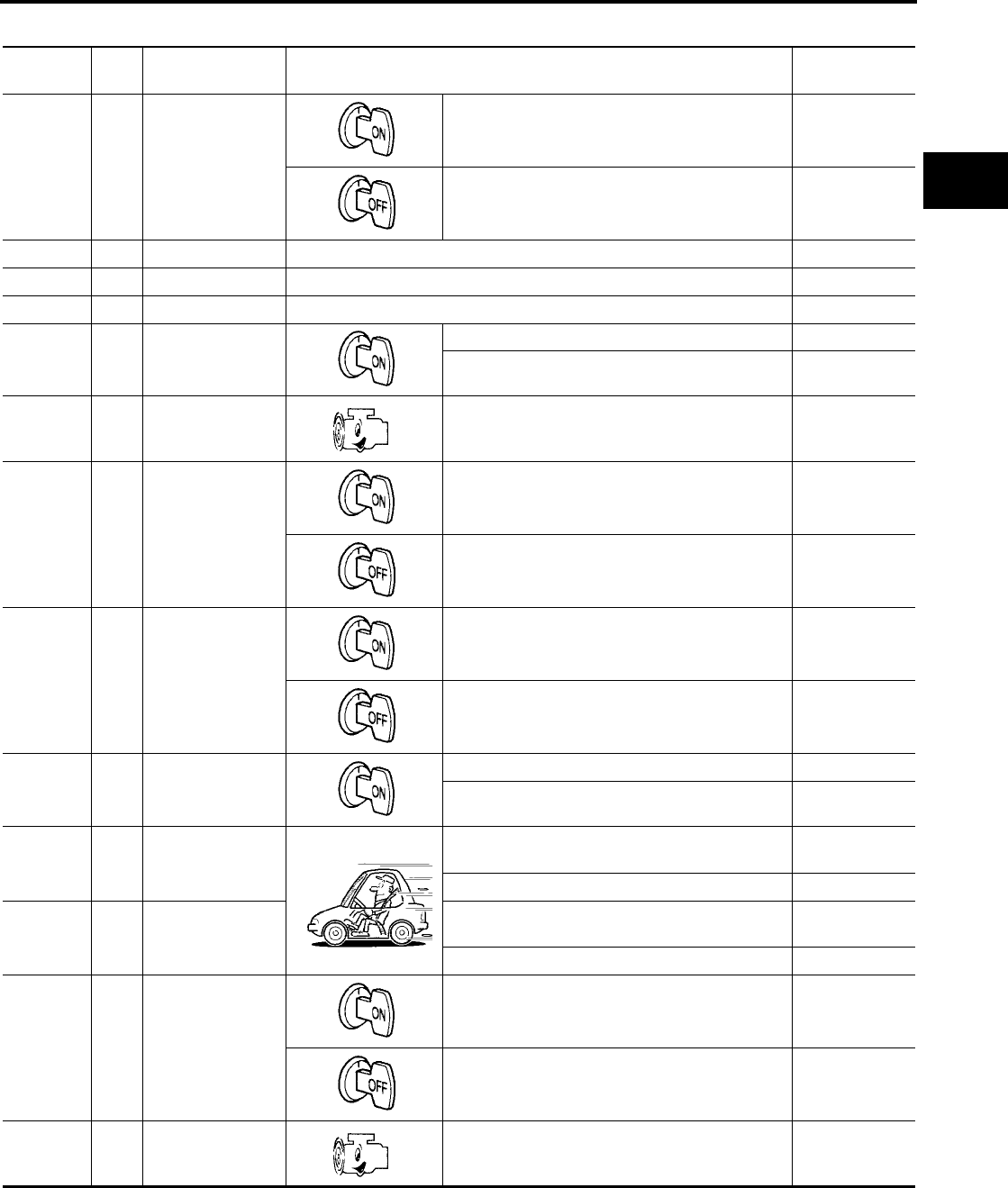
TROUBLE DIAGNOSIS
AT-439
[RE5F22A]
D
E
F
G
H
I
J
K
L
M
A
B
AT
Revision: September 2005 2005 Quest
TCM INSPECTION TABLE
Data are reference value and are measured between each terminal and ground.
Terminal Wire
color Item Condition Data (Approx.)
1 Y/W A/T PV IGN relay
When turning ignition switch ON. 0 - 1.5V
When turning ignition switch OFF. 0V
3 L CAN H – –
4 P CAN L – –
14 B Ground – 0V
16 O Lever switch
Lever switch: “ON” position 0V
Lever switch: “OFF” position Battery voltage
21 G/B
Pressure control
solenoid valve B
ground
When engine is running with idle speed and set-
ting selector lever to “P” position. 0V
22 L Revolution sensor
power supply
When turning ignition switch ON. Battery voltage
When turning ignition switch OFF. 0V
23 G
Turbine revolution
sensor power sup-
ply
When turning ignition switch ON. Battery voltage
When turning ignition switch OFF. 0V
24 BR PNP switch A
Selector lever: “P”, “R” and “L” position 0V
Other than the above Battery voltage
25 G/R Shift solenoid
valve B
When shift solenoid valve B operates.
(When driving in 1st or 5th gear.) Battery voltage
When shift solenoid valve B does not operate. 0V
26 G Shift solenoid
valve D
When shift solenoid valve D operates.
(When driving in 3rd, 4th or 5th gear.) Battery voltage
When shift solenoid valve D does not operate. 0V
27 Y/R Power supply
(Memory back-up)
When turning ignition switch ON. Battery voltage
When turning ignition switch OFF. Battery voltage
28 W
Pressure control
solenoid valve C
ground
When engine is running with idle speed and set-
ting selector lever to “P” position. 0V

AT-440
[RE5F22A]
TROUBLE DIAGNOSIS
Revision: September 2005 2005 Quest
29 R Revolution sensor When moving at 20 km/h (12 MPH) in 1st gear. 119Hz
30 R Turbine revolution
sensor When moving at 20 km/h (12 MPH) in 1st gear. 371Hz
31 G/Y PNP switch B Selector lever: “R”, “N”, “D” and “L” position 0V
Other than the above Battery voltage
32 P/B PNP switch C Selector lever: “D” and “L” position 0V
Other than the above Battery voltage
33 R/V PNP switch PN Selector lever: “P” and “N” position Battery voltage
Other than the above 0V
34 P Power supply
When turning ignition switch ON. Battery voltage
When turning ignition switch OFF. 0V
35 L/Y Pressure control
solenoid valve A
When engine is running with idle speed and set-
ting selector lever to “P” position. 300Hz
36 W/L Pressure control
solenoid valve B
When engine is running with idle speed and set-
ting selector lever to “P” position. 300Hz
37 R/B Shift solenoid
valve C
When shift solenoid valve C operates.
(When driving in 1st, 2nd, 3rd or reverse gear.) Battery voltage
When shift solenoid valve C does not operate. 0V
38 Y/B Power supply
(A/T PV IGN relay)
When turning ignition switch ON. Battery voltage
Measure 3 seconds after switching “OFF” the
ignition switch. 0V
39 Y/B Power supply
(A/T PV IGN relay)
When turning ignition switch ON. Battery voltage
Measure 3 seconds after switching “OFF” the
ignition switch. 0V
40 L/G
Pressure control
solenoid valve A
ground
When engine is running with idle speed and set-
ting selector lever to “P” position. 0V
41 R/Y Fluid temperature
sensor
When ATF temperature 0°C (32°F) 4.0V
When ATF temperature 20°C (68°F) 3.0V
When ATF temperature 80°C (176°F) 0.8V
When ATF temperature 100°C (212°F) 0.5V
42 LG/B Fluid temperature
sensor ground –0V
43 V/W PNP switch PA
Selector lever: “P”, “N” and “L” position 0V
Other than the above Battery voltage
Terminal Wire
color Item Condition Data (Approx.)
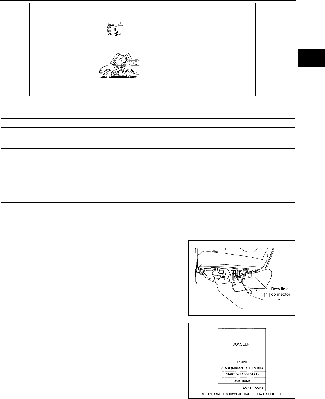
TROUBLE DIAGNOSIS
AT-441
[RE5F22A]
D
E
F
G
H
I
J
K
L
M
A
B
AT
Revision: September 2005 2005 Quest
CONSULT-II Function (A/T) UCS000TY
CONSULT-II can display each diagnostic item using the diagnostic test modes shown following.
CONSULT-II SETTING PROCEDURE
CAUTION:
If CONSULT-II is used with no connection of CONSULT-II CONVERTER, malfunctions might be
detected in self-diagnosis depending on control unit which carry out CAN communication.
●For details, refer to the separate “CONSULT-II Operations Man-
ual”.
1. Turn ignition switch “OFF”.
2. Connect CONSULT-II and CONSULT-II CONVERTER to data
link connector, which is located in driver instrument panel
(lower).
3. Turn ignition switch “ON”.
4. Touch “START (NISSAN BASED VHCL)”.
45 O/B Pressure control
solenoid valve C
When engine is running with idle speed and set-
ting selector lever to “P” position. 300Hz
46 W/G Shift solenoid
valve A
When shift solenoid valve A operates.
(When driving in 1st gear.) Battery voltage
When shift solenoid valve A does not operate. 0V
47 BR/Y Shift solenoid
valve E
When shift solenoid valve E operates.
(When driving in reverse gear.) Battery voltage
When shift solenoid valve E does not operate. 0V
48 B Ground – 0V
Terminal Wire
color Item Condition Data (Approx.)
TCM diagnostic mode Description
WORK SUPPORT
Supports inspections and adjustments. Commands are transmitted to the TCM for setting the status
suitable for required operation, input/output signals are received from the TCM and received data is
displayed.
SELF-DIAG RESULTS Displays TCM self-diagnosis results.
DATA MONITOR Displays TCM input/output data in real time.
CAN DIAG SUPPORT MNTR The result of transmit/receive diagnosis of CAN communication can be read.
ACTIVE TEST Operation of electrical loads can be checked by sending drive signal to them.
FUNCTION TEST Conducted by CONSULT-II instead of a technician to determine whether each system is "OK" or "NG".
ECU PART NUMBER TCM part number can be read.
BBIA0336E
BCIA0029E
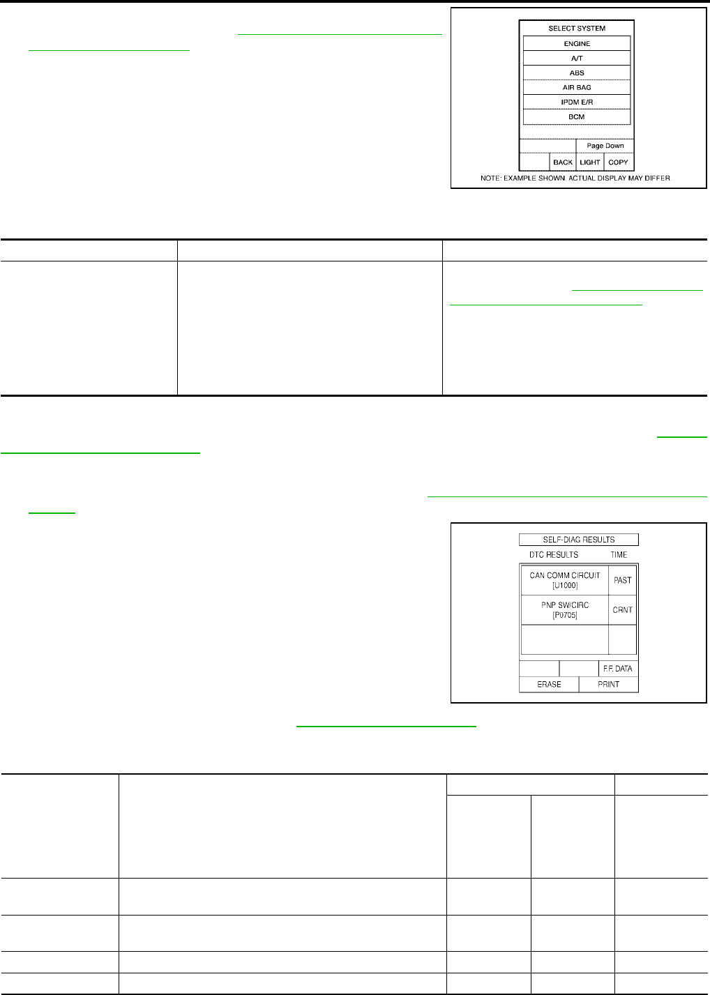
AT-442
[RE5F22A]
TROUBLE DIAGNOSIS
Revision: September 2005 2005 Quest
5. Touch “A/T”.
If “A/T” is not indicated, go to GI-37, "CONSULT-II Data Link
Connector (DLC) Circuit" .
6. Perform each diagnostic test mode according to each service
procedure.
WORK SUPPORT MODE
Work item
SELF-DIAG RESULT MODE
After performing “SELF-DIAGNOSTIC place check marks for results on the “Diagnostic Worksheet”, AT-416,
"DIAGNOSTIC WORKSHEET" . Reference pages are provide following the items.
Operation procedure
1. Perform “CONSULT-II SETTING PROCEDURE”. Refer to AT-441, "CONSULT-II SETTING PROCE-
DURE" .
2. Touch “SELF-DIAG RESULTS”.
Display shows malfunction experienced since the last erasing
operation.
NOTE:
●The details for “TIME” are as follow:
–“CRNT”: Error currently detected with TCM.
–“PAST”: Error detected in the past and memorized with
TCM.
●Touch “F.F.DATA” on “SELF-DIAG RESULTS” screen to
display freeze frame data. Freeze frame data shows driv-
ing condition when malfunction is detected.
For freeze frame data items, refer to AT-445, "Display item list" .
Display item list X: Applicable —: Not applicable
BCIA0030E
Work item Condition Usage
INITIALIZATION Under the following conditions.
●Ignition switch “ON”.
●Selector lever “P” or “N” position.
●Engine not running.
●Vehicle speed is 0 km/h (0 MPH).
●Ignition voltage is more than 10.5V.
●Malfunction was not detected.
Use to initialize TCM in a case of replacing tran-
saxle or TCM. Refer to AT-376, "Precautions for
A/T Assembly or TCM Replacement" .
SCIA2741E
Items (CONSULT-II
screen terms) Malfunction is detected when...
TCM self-diagnosis OBD-II (DTC)
O/D OFF
indicator
lamp*3
“A/T” with
CONSULT-II
MIL indicator
lamp*1 ,
“ENGINE” with
CONSULT-II or
GST
CAN COMM CIR-
CUIT ●When a malfunction is detected in CAN communications X U1000*4 U1000*4
VEH SPD SE/CIR-
MTR
●ECM detects a malfunction in vehicle speed sensor signal,
after that TCM inputs the result by CAN communication. X P0500 P0500
TCM PROCESSOR ●TCM processor is malfunctioning. — P0613 —
PNP SW/CIRC ●PNP switch signals input with impossible pattern X P0705 P0705

TROUBLE DIAGNOSIS
AT-443
[RE5F22A]
D
E
F
G
H
I
J
K
L
M
A
B
AT
Revision: September 2005 2005 Quest
ATF TEMP SEN/
CIRC
●Normal voltage is not applied to ATF temperature sensor
due to open, short, and so on.
●During running, the ATF temperature sensor signal voltage
is excessively high or low.
X P0710 P0710
FLUID TEMP SEN ●ATF temperature signal does not change. — P0711 P0711*2
TURBINE SENSOR
●Signal from turbine revolution sensor does not input due to
open, short, and so on.
●Unexpected signal input during running.
X P0717 P0717
VHCL SPEED
SEN-A/T
●Signal from revolution sensor does not input due to open,
short, and so on.
●Unexpected signal input during running.
X P0722 P0722
ENG SPD INP
PERFOR
●Malfunction is detected in engine speed signal, actual
engine torque signal or torque reduction signal that is out-
put from ECM through CAN communication.
X P0726 P0726
A/T 1ST GR
FNCTN
●A/T cannot be shifted to the 1st gear position even if elec-
trical circuit is good. X P0731 P0731*2
A/T 2ND GR
FNCTN
●A/T cannot be shifted to the 2nd gear position even if elec-
trical circuit is good. X P0732 P0732*2
A/T 3RD GR
FNCTN
●A/T cannot be shifted to the 3rd gear position even if elec-
trical circuit is good. X P0733 P0733*2
A/T 4TH GR
FNCTN
●A/T cannot be shifted to the 4th gear position even if elec-
trical circuit is good. X P0734 P0734*2
A/T 5TH GR
FNCTN
●A/T cannot be shifted to the 5th gear position even if elec-
trical circuit is good. X P0735 P0735*2
A/T TCC S/V
FNCTN
●A/T cannot perform lock-up even if electrical circuit is
good. X P0744 P0744*2
PC SOL A(L/
PRESS) ●Normal voltage is not applied to solenoid due to open,
short, and so on.
●TCM detects as irregular by comparing target value with
monitor value.
X P0745 P0745
SHIFT SOL A X P0750 P0750
SHIFT SOL B X P0755 P0755
SHIFT SOL C X P0760 P0760
SFT SOL C STUCK
ON
●Condition of shift solenoid valve C is different from monitor
value, and relation between gear position and actual gear
ratio is irregular.
X P0762 P0762*2
SHIFT SOL D ●Normal voltage is not applied to solenoid due to open,
short, and so on.
●TCM detects as irregular by comparing target value with
monitor value.
X P0765 P0765
SHIFT SOL E X P0770 P0770
PC SOL B(SFT/
PRS) X P0775 P0775
SHIFT
●No rotation change occurs between input (turbine revolu-
tion sensor) and output (revolution sensor) and shifting
time is long.
●Shifting ends immediately.
● Condition in malfunction engine revs up usually shifting.
X P0780 P0780*2
PC SOL
C(TCC&SFT)
●Normal voltage is not applied to solenoid due to open,
short, and so on.
●TCM detects as irregular by comparing target value with
monitor value.
X P0795 P0795
Items (CONSULT-II
screen terms) Malfunction is detected when...
TCM self-diagnosis OBD-II (DTC)
O/D OFF
indicator
lamp*3
“A/T” with
CONSULT-II
MIL indicator
lamp*1 ,
“ENGINE” with
CONSULT-II or
GST

AT-444
[RE5F22A]
TROUBLE DIAGNOSIS
Revision: September 2005 2005 Quest
*1: Refer to AT-410, "Malfunction Indicator Lamp (MIL)" .
*2: These malfunctions cannot be displayed MIL if another malfunction is assigned to MIL.
*3: Indicate it when performing TCM SELF-DIAGNOSTIC PROCEDURE (NO TOOLS). Refer to AT-448, "TCM SELF-DIAGNOSTIC
PROCEDURE (NO TOOLS)" .
*4: If DTC U1000 is displayed with other DTCs, first perform the trouble diagnosis for DTC U1000. Refer to AT-450 .
CAN DIAGNOSTIC SUPPORT MONITOR
Operation procedure
1. Perform “CONSULT-II SETTING PROCEDURE”. Refer to AT-441, "CONSULT-II SETTING PROCE-
DURE" .
2. Touch “CAN DIAGNOSTIC SUPPORT MONITOR”.
DATA MONITOR MODE
NOTICE:
1. The CONSULT-II electrically displays shift timing and lock-up timing (that is, operation timing of each sole-
noid).
Check for time difference between actual shift timing and the CONSULT-II display. If the difference is
noticeable, mechanical parts (except solenoids, sensors, etc.) may be malfunctioning. Check mechanical
parts using applicable diagnostic procedures.
2. Shift schedule (which implies gear position) displayed on CONSULT-II and that indicated in Service Man-
ual may differ slightly. This occurs because of the following reasons:
–Actual shift schedule has more or less tolerance or allowance,
–Shift schedule indicated in Service Manual refers to the point where shifts start, and
–Gear position displayed on CONSULT-II indicates the point where shifts are completed.
3. Display of solenoid valves on CONSULT-II changes at the start of shifting, while gear position is displayed
upon completion of shifting (which is computed by TCM).
PC SOL C STC ON
●Condition of pressure control solenoid valve C is different
from monitor value, and relation between gear position
and actual gear ratio or lock-up status is irregular.
X P0797 P0797*2
GEAR LEVER
SWITCH
●Lever switch signal is incorrectly input due to open, short,
and so on. — P0825 —
TCM POWER INPT
SIG ●Voltage supplied to TCM is too low. — P0882 P0882
ELEC TH CON-
TROL
●The electric throttle control system for ECM is in a mal-
function, after that TCM inputs the result by CAN commni-
cation.
X P1726 P1726
NO DTC IS
DETECTED.
FURTHER TEST-
ING MAY BE
REQUIRED.
●No NG item has been detected. — X X
Items (CONSULT-II
screen terms) Malfunction is detected when...
TCM self-diagnosis OBD-II (DTC)
O/D OFF
indicator
lamp*3
“A/T” with
CONSULT-II
MIL indicator
lamp*1 ,
“ENGINE” with
CONSULT-II or
GST
BCIA0031E

TROUBLE DIAGNOSIS
AT-445
[RE5F22A]
D
E
F
G
H
I
J
K
L
M
A
B
AT
Revision: September 2005 2005 Quest
Operation procedure
1. Perform “CONSULT-II SETTING PROCEDURE”. Refer to AT-441, "CONSULT-II SETTING PROCE-
DURE" .
2. Touch “DATA MONITOR”.
NOTE:
When malfunction is detected, CONSULT-II performs REAL-TIME DIAGNOSIS.
Also, any malfunction detected while in this mode will be displayed at real time.
Display item list X: Standard —: Not applicable
Monitored item (Unit)
Monitor item selection
Remarks
ECU INPUT
SIGNALS
MAIN SIG-
NALS
SELEC-
TION FROM
MENU
VHCL/S SE-A/T (km/h) X X X Vehicle speed recognized by the TCM.
VHCL/S SE-MTR* (km/h) X — X
FLUID TEMP SE* (V) X — X
FLUID TEMP* (°C) — — X
COOLAN TEMP* (°C) — — X
Displays status of engine coolant tem-
perature.
Signal input with CAN communication
line.
BATTERY VOLT* (V) X — X
ENGINE SPEED* (rpm) X X X Signal input with CAN communication
line.
TURBINE REV* (rpm) X — X Turbine revolution computed from signal
of turbine revolution sensor is displayed.
OUTPUT REV* (rpm) — — X Output revolution computed from signal
of revolution sensor is displayed.
PNP SW A* (ON/OFF) X — X
PNP SW B* (ON/OFF) X — X
PNP SW C* (ON/OFF) X — X
PNP SW PA* (ON/OFF) X — X
PNP SW PN (ON/OFF) X — X
MANU MODE SW* (ON/OFF) X — X
Not mounted but displayed.
NON M-MODE SW* (ON/OFF) X — X
UP SW* (ON/OFF) X — X
DOWN SW* (ON/OFF) X — X
RANGE SLCT SW (ON/OFF) X — X This means lever switch.
BRAKE SW* (ON/OFF) X — X This means stop lamp switch signal via
CAN communication line.
CLSO THL POS (ON/OFF) X — X
Signal input with CAN communication
line.
ASCD SIGNAL (ON/OFF) X — X
ASCD OD OFF (ON/OFF) X — X
ABS SIGNAL (ON/OFF) X — X
TCS SIGNAL (ON/OFF) X — X
TCS GEAR HOLD (ON/OFF) X — X
TCS SFT CNG (ON/OFF) — — X Requests TCM for shift schedule
change.
LOCK-UP* (ON/OFF) — — X Always “ON” during lock-up, regardless
of types.

AT-446
[RE5F22A]
TROUBLE DIAGNOSIS
Revision: September 2005 2005 Quest
SLCT LVR POSI* — — X Displays “##” when TCM can not judge
selector lever position.
MANU GR POSI — — X Always displays “##”.
GEAR* — — X
Indicates current gear position.
When setting in P or N position, indicate
by shift solenoid valves.
When setting in R position, displays “1”.
Displays “##” when TCM can not judge
gear position.
NEXT GR POSI — — X Displays “##” when TCM can not judge
gear position.
REDCT DEM SIG (ON/OFF) — — X Displays status of engine torque reduc-
tion demand signal.
TC SLIP RATIO — — X
SLIP REV (rpm) — — X Difference between engine speed and
torque converter input shaft speed.
ACCELE ANGLE* (%) X X X
Degree of opening for accelerator recog-
nized by the TCM.
For fail-safe operation, the specific value
used for control is displayed.
PC SOL A OUT* (A) — — X
PC SOL A MON* (A) — X X
PC SOL B OUT* (A) — — X
PC SOL B MON* (A) — X X
PC SOL C OUT* (A) — — X
PC SOL C MON* (A) — X X
SFT SOL A OUT* (ON/OFF) — — X
SFT SOL B OUT* (ON/OFF) — — X
SFT SOL C OUT* (ON/OFF) — — X
SFT SOL D OUT* (ON/OFF) — — X
SFT SOL E OUT* (ON/OFF) — — X
SFT SOL A MON* (ON/OFF) — X X
SFT SOL B MON* (ON/OFF) — X X
SFT SOL C MON* (ON/OFF) — X X
SFT SOL D MON* (ON/OFF) — X X
SFT SOL E MON* (ON/OFF) — X X
G-RATE (G) — — X
F-SAFE MODE (OK/1 to 10) — X X
Numbers indicate types of fail-safe
modes. Refer to AT-412, "Fail-safe
mode list" .
VDC SIGNAL (ON/OFF) X — X Signal input with CAN communication
line.
Monitored item (Unit)
Monitor item selection
Remarks
ECU INPUT
SIGNALS
MAIN SIG-
NALS
SELEC-
TION FROM
MENU
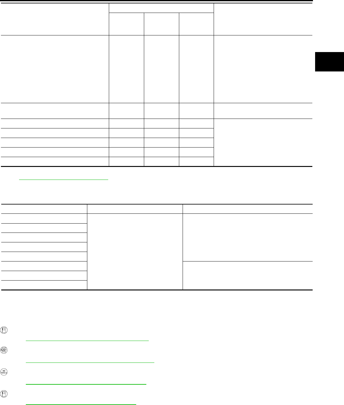
TROUBLE DIAGNOSIS
AT-447
[RE5F22A]
D
E
F
G
H
I
J
K
L
M
A
B
AT
Revision: September 2005 2005 Quest
*: Also, the items appear on CONSULT-II screen in freeze frame data mode of self-diagnostic results only if DTC is detected. For details,
refer to AT-442, "SELF-DIAG RESULT MODE" .
ACTIVE TEST MODE
Test item
*: Except when P0711, P0731, P0732, P0733, P0734, P0735, P0744, P0762, P0780 or P0797 is detected.
NOTE:
Approximately 10 seconds after the operation is begun, “TEST IS STOPPED” will be displayed.
Diagnostic Procedure UCS000TZ
OBD-II SELF-DIAGNOSTIC PROCEDURE (WITH CONSULT-II)
Refer to EC-133, "CONSULT-II Function (ENGINE)" .
OBD-II SELF-DIAGNOSTIC PROCEDURE (WITH GST)
Refer to EC-146, "Generic Scan Tool (GST) Function" .
OBD-II SELF-DIAGNOSTIC PROCEDURE (NO TOOLS)
Refer to EC-67, "Malfunction Indicator Lamp (MIL)" .
TCM SELF-DIAGNOSTIC PROCEDURE (WITH CONSULT-II)
Refer to AT-442, "SELF-DIAG RESULT MODE" .
SHIFT SCHDULE — — X
The details for data of shift schedule are
as follow:
NOR: Normal mode
UP1: Upslope 1 mode
UP2: Upslope 2 mode (steeper then
“UP1”)
DOWN: Downslope mode
HOT1: Hot 1 mode
HOT2: Hot 2 mode (higher temperature
than “HOT1”)
Voltage (V) — — X Displays the value measured by the volt-
age probe.
Frequency (Hz) — — X
The value measured by the pulse probe
is displayed.
DUTY-HI (high) (%) — — X
DUTY-LOW (low) (%) — — X
PLS WIDTH-HI (ms) — — X
PLS WIDTH-LOW (ms) — — X
Monitored item (Unit)
Monitor item selection
Remarks
ECU INPUT
SIGNALS
MAIN SIG-
NALS
SELEC-
TION FROM
MENU
Test item Condition Description
SHIFT SOLENOID A
Under the following conditions.
●Ignition switch “ON”
●Selector lever “P” or “N” position
●Engine not running
●Vehicle speed is 0 km/h (0 MPH).
●Ignition voltage is more than 10.5V.
●Malfunction was not detected.*
Each shift solenoid operate ON/OFF by receiving the
drive signal.
SHIFT SOLENOID B
SHIFT SOLENOID C
SHIFT SOLENOID D
SHIFT SOLENOID E
PRESSURE CONTROL SOL A Each pressure control solenoid is activated by receiv-
ing the drive signal.
PRESSURE CONTROL SOL B
PRESSURE CONTROL SOL C

AT-448
[RE5F22A]
TROUBLE DIAGNOSIS
Revision: September 2005 2005 Quest
TCM SELF-DIAGNOSTIC PROCEDURE (NO TOOLS)
Description
As a method for locating the suspect system, when the self-diagnostics start signal is input, the memory for
the malfunction location is output and the O/D OFF indicator lamp flashes to display the corresponding DTC.
Diagnostic procedure
1. CHECK O/D OFF INDICATOR LAMP
1. Start the engine with selector lever in “P” position. Warm engine to normal operating temperature.
2. Turn ignition switch “ON” and “OFF” at least twice, then leave it in the “OFF” position.
3. Wait 10 seconds.
4. Turn ignition switch “ON”. (Do not start engine.)
Does O/D OFF indicator lamp come on for about 2 seconds?
YES >> GO TO 2.
NO >> GO TO AT-576, "O/D OFF Indicator Lamp Does Not Come On" .
2. JUDGEMENT PROCEDURE
NOTE:
After turning ignition switch “ON” (at step 6), perform within 2 seconds (while O/D OFF indicator lamp come
on.).
1. Turn ignition switch “OFF”.
2. Push shift lock release button.
3. Move selector lever from “P” to “D” position.
4. Release accelerator pedal. (Set the closed throttle position signal “ON”.)
5. Depress brake pedal. (Stop lamp switch signal “ON”.)
6. Turn ignition switch “ON”.
7. Move the selector lever to the “N” position and release brake pedal. (Stop lamp switch signal “OFF”.)
8. Move the selector lever to “D” position and depress brake pedal. (Stop lamp switch signal “ON”.)
9. Release brake pedal. (Stop lamp switch signal “OFF”.)
10. Depress accelerator pedal fully and release it.
>> GO TO 3.
3. CHECK SELF-DIAGNOSIS CODE
Check O/D OFF indicator lamp.
Refer to AT-449, "Judgement self-diagnosis code" .
If the system does not go into self-diagnostics, refer to AT-596, "TCM Self-diagnosis Does Not Activate" .
>> DIAGNOSIS END
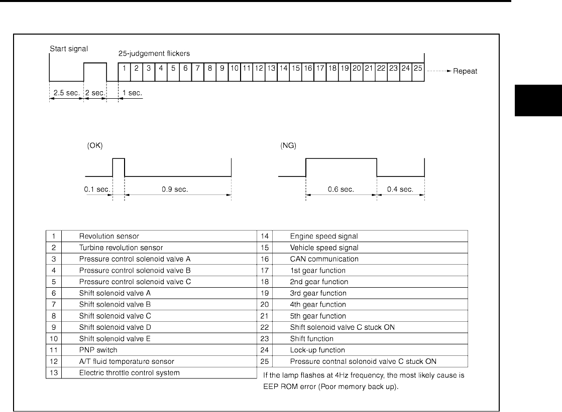
TROUBLE DIAGNOSIS
AT-449
[RE5F22A]
D
E
F
G
H
I
J
K
L
M
A
B
AT
Revision: September 2005 2005 Quest
Judgement self-diagnosis code
When a malfunction is detected, the malfunction route is indicated by longer illumination of the indicator lamp.
ERASE SELF-DIAGNOSIS
●In order to make it easier to find the cause of hard-to-duplicate malfunctions, malfunction information is
stored into the control unit as necessary during use by the user. This memory is not erased no matter how
many times the ignition switch is turned ON and OFF.
●However, this information is erased by turning ignition switch “OFF” after executing self-diagnostics or by
erasing the memory using the CONSULT-II.
SCIA2758E

AT-450
[RE5F22A]
DTC U1000 CAN COMMUNICATION LINE
Revision: September 2005 2005 Quest
DTC U1000 CAN COMMUNICATION LINE PFP:23710
Description UCS000U0
CAN (Controller Area Network) is a serial communication line for real time application. It is an on-vehicle mul-
tiplex communication line with high data communication speed and excellent malfunction detection ability.
Many electronic control units are equipped onto a vehicle, and each control unit shares information and links
with other control units during operation (not independent). In CAN communication, control units are con-
nected with 2 communication lines (CAN H line, CAN L line) allowing a high rate of information transmission
with less wiring. Each control unit transmits/receives data but selectively reads required data only.
On Board Diagnosis Logic UCS000U1
●This is an OBD-II self-diagnostic item.
●Diagnostic trouble code “CAN COMM CIRCUIT” with CONSULT-II or U1000 without CONSULT-II is
detected when TCM cannot communicate to other control units.
Possible Cause UCS000U2
Harness or connectors
(CAN communication line is open or shorted.)
DTC Confirmation Procedure UCS000U3
NOTE:
If “DTC Confirmation Procedure” has been previously performed, always turn ignition switch “OFF”
and wait at least 10 seconds before performing the next test.
After the repair, perform the following procedure to confirm the malfunction is eliminated.
WITH CONSULT-II
1. Turn ignition switch “ON”. (Do not start engine.)
2. Select “DATA MONITOR” mode for “A/T” with CONSULT-II.
3. Start engine.
4. Drive vehicle and maintain the following condition for at least 6
seconds.
SLCT LVR POSI: “D” position
5. If DTC is detected, go to AT-452, "Diagnostic Procedure" .
WITH GST
Follow the procedure “WITH CONSULT-II”.
BCIA0030E

DTC U1000 CAN COMMUNICATION LINE
AT-451
[RE5F22A]
D
E
F
G
H
I
J
K
L
M
A
B
AT
Revision: September 2005 2005 Quest
Wiring Diagram — AT — CAN UCS000U4
BCWA0308E
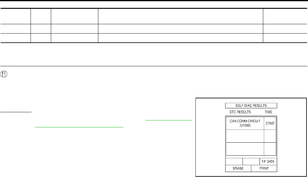
AT-452
[RE5F22A]
DTC U1000 CAN COMMUNICATION LINE
Revision: September 2005 2005 Quest
TCM terminals and data are reference value.
Diagnostic Procedure UCS000U5
1. CHECK CAN COMMUNICATION CIRCUIT
With CONSULT-II
1. Turn ignition switch “ON” and start engine.
2. Select “SELF-DIAG RESULTS” mode for “TRANSMISSION” with in CONSULT-II.
3. The “CAN COMM CIRCUIT” is detected.
Yes or No?
Yes >> Print out CONSULT-II screen, GO TO LAN-3, "Precau-
tions When Using CONSULT-II" .
No >> INSPECTION END
Terminal Wire
color Item Condition Data (Approx.)
3 L CAN H – –
4 P CAN L – –
SCIA2818E

DTC P0500 VEHICLE SPEED SENSOR MTR
AT-453
[RE5F22A]
D
E
F
G
H
I
J
K
L
M
A
B
AT
Revision: September 2005 2005 Quest
DTC P0500 VEHICLE SPEED SENSOR MTR PFP:24814
Description UCS0015A
The vehicle speed sensor·MTR signal is transmitted from combination meter to TCM by CAN communication
line. The signal functions as an auxiliary device to the revolution sensor when it is malfunctioning. The TCM
will then use the vehicle speed sensor·MTR signal.
On Board Diagnosis Logic UCS0015B
●This is not an OBD-II self-diagnostic item.
●Diagnostic trouble code “VEH SPD SE/CIR-MTR” with CONSULT-II or 15th judgement flicker without
CONSULT-II is detected when TCM does not receive the proper vehicle speed sensor MTR signal (input
by CAN communication) from combination meter.
Possible Cause UCS0015C
●Harness or connectors
(The signal circuit is open or shorted.)
●Combination meter
●ABS actuator and electric unit (control unit)
●Wheel sensor
DTC Confirmation Procedure UCS0015D
CAUTION:
Always drive vehicle at a safe speed.
NOTE:
If “DTC Confirmation Procedure” has been previously performed, always turn ignition switch “OFF”
and wait at least 10 seconds before performing the next test.
After the repair, perform the following procedure to confirm the malfunction is eliminated.
WITH CONSULT-II
1. Turn ignition switch “ON” and select “DATA MONITOR” mode for
“A/T” with CONSULT-II.
2. Start engine.
3. Drive vehicle and maintain the following conditions for at least 5
consecutive seconds.
VHCL/S SE-A/T: 30 km/h (17 MPH) or more
ACCELE ANGLE: 10 % or less
4. If DTC is detected, go to AT-454, "Diagnostic Procedure" .
BCIA0030E

AT-454
[RE5F22A]
DTC P0500 VEHICLE SPEED SENSOR MTR
Revision: September 2005 2005 Quest
Diagnostic Procedure UCS0015E
1. CHECK INPUT SIGNALS
With CONSULT-II
1. Start engine.
2. Select “DATA MONITOR” mode for “A/T” with CONSULT-II.
3. Drive vehicle, and then make sure that the values of “VHCL/S
SE-A/T” and “VHCL/S SE-MTR” are same.
OK or NG
OK >> GO TO 4.
NG >> GO TO 2.
2. CHECK DTC WITH ABS ACTUATOR AND ELECTRIC UNIT (CONTROL UNIT)
Refer to BRC-11, "TROUBLE DIAGNOSIS" (with TCS/ABS) or BRC-55, "TROUBLE DIAGNOSIS" (with
VDC/TCS/ABS).
OK or NG
OK >> GO TO 3.
NG >> If NG, recheck pin terminals for damage or loose connection with harness connector.
3. CHECK DTC WITH COMBINATION METER
Refer to DI-5, "COMBINATION METERS" .
OK or NG
OK >> GO TO 4.
NG >> If NG, recheck pin terminals for damage or loose connection with harness connector.
4. CHECK DTC
Perform “DTC Confirmation Procedure”. Refer to AT-453, "DTC Confirmation Procedure" .
OK or NG
OK >> INSPECTION END
NG >> GO TO 5.
5. CHECK TCM
1. Check TCM input/output signal.
2. If NG, recheck TCM pin terminals for damage or loose connection with harness connector.
OK or NG
OK >> INSPECTION END
NG >> Repair or replace damaged parts.
SCIA2922E

DTC P0613 TCM PROCESSOR
AT-455
[RE5F22A]
D
E
F
G
H
I
J
K
L
M
A
B
AT
Revision: September 2005 2005 Quest
DTC P0613 TCM PROCESSOR PFP:31036
Description UCS0011Q
The TCM consists of a microcomputer and connectors for signal
input and output and for power supply. The TCM controls the A/T.
On Board Diagnosis Logic UCS0011R
●This is not an OBD-II self-diagnostic item.
●Diagnostic trouble code “TCM PROCESSOR” with CONSULT-II is detected when TCM processor is mal-
functioning.
Possible Cause UCS0011S
TCM
DTC Confirmation Procedure UCS0011T
NOTE:
If “DTC Confirmation Procedure” has been previously performed, always turn ignition switch “OFF”
and wait at least 10 seconds before performing the next test.
After the repair, perform the following procedure to confirm the malfunction is eliminated.
WITH CONSULT-II
1. Turn ignition switch “ON”. (Do not start engine.)
2. Select “DATA MONITOR” mode for “A/T” with CONSULT-II.
3. Start engine.
4. Run engine for at least 2 consecutive seconds at idle speed.
5. If DTC is detected, go to AT-456, "Diagnostic Procedure" .
SCIA2820E
BCIA0030E
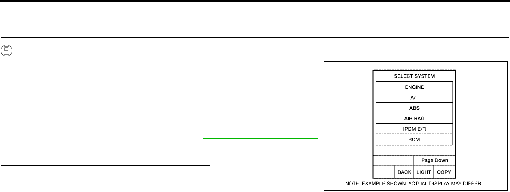
AT-456
[RE5F22A]
DTC P0613 TCM PROCESSOR
Revision: September 2005 2005 Quest
Diagnostic Procedure UCS0011U
1. CHECK DTC
With CONSULT-II
1. Turn ignition switch “ON”. (Do not start engine.)
2. Select “SELF-DIAG RESULTS” mode for “A/T” with CONSULT-
II.
3. Touch “ERASE”.
4. Turn ignition switch “OFF” and wait at least 10 seconds.
5. Perform DTC confirmation procedure, AT-455, "DTC Confirma-
tion Procedure" .
Is the “TCM PROCESSOR” displayed again?
YES >> Replace TCM.
NO >> INSPECTION END BCIA0030E
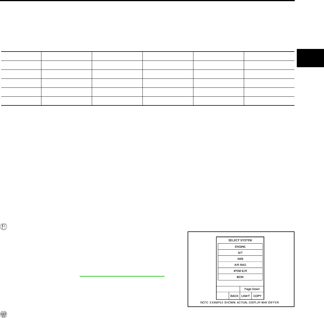
DTC P0705 PARK/NEUTRAL POSITION SWITCH
AT-457
[RE5F22A]
D
E
F
G
H
I
J
K
L
M
A
B
AT
Revision: September 2005 2005 Quest
DTC P0705 PARK/NEUTRAL POSITION SWITCH PFP:32006
Description UCS000UC
●The park/neutral position (PNP) switch includes a transmission range switch.
●The transmission range switch detects the selector lever position and sends a signal to the TCM.
●TCM judges the selector lever position by the park/neutral position (PNP) switch signal.
On Board Diagnosis Logic UCS000UD
●This is an OBD-II self-diagnostic item.
●Diagnostic trouble code “PNP SW/CIRC” with CONSULT-II or P0705 without CONSULT-II is detected
when PNP switch signals input with impossible pattern.
Possible Cause UCS000UE
●Harness or connectors
[The park/neutral position (PNP) switch and TCM circuit is open or shorted.]
●Park/neutral position (PNP) switch
DTC Confirmation Procedure UCS000UF
NOTE:
If “DTC Confirmation Procedure” has been previously performed, always turn ignition switch “OFF”
and wait at least 10 seconds before performing the next test.
After the repair, perform the following procedure to confirm the malfunction is eliminated.
WITH CONSULT-II
1. Turn ignition switch “ON”. (Do not start engine.)
2. Select “DATA MONITOR” mode for “A/T” with CONSULT-II.
3. Move selector lever to each position.
SLCT LVR POSI: “P”, “R”, “N”, “D” or “L” position
4. Wait for at least 5 consecutive seconds at each position.
5. If DTC is detected, go to AT-460, "Diagnostic Procedure" .
WITH GST
Follow the procedure “With CONSULT-II”.
Selector lever PNP switch A PNP switch B PNP switch C PNP switch PA PNP switch PN
P ON OFF OFF ON ON
R ON ON OFF OFF OFF
N OFF ON OFF ON ON
D OFF ON ON OFF OFF
LONONONONOFF
BCIA0030E
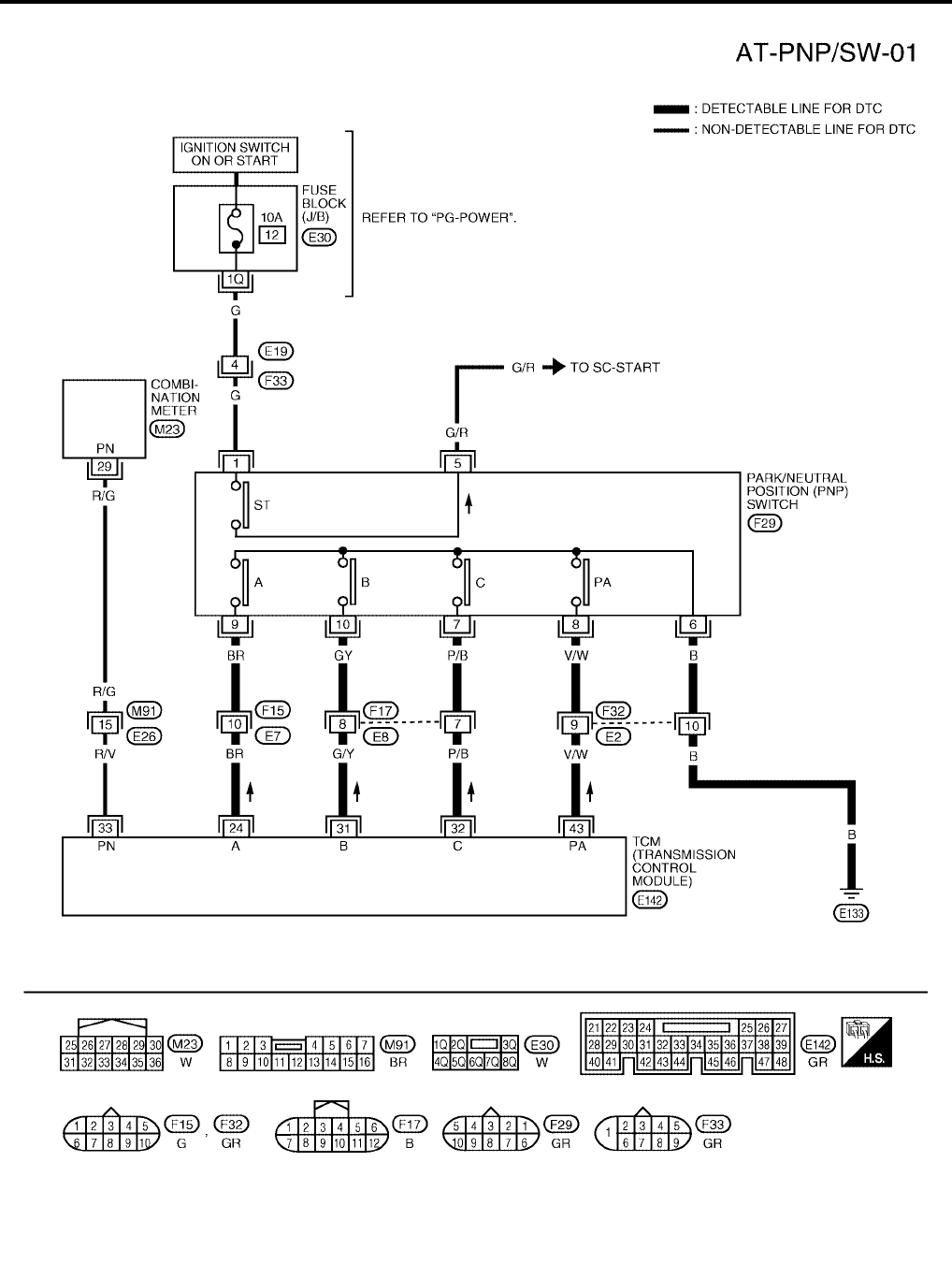
AT-458
[RE5F22A]
DTC P0705 PARK/NEUTRAL POSITION SWITCH
Revision: September 2005 2005 Quest
Wiring Diagram — AT — PNP/SW UCS000UG
BCWA0309E

DTC P0705 PARK/NEUTRAL POSITION SWITCH
AT-459
[RE5F22A]
D
E
F
G
H
I
J
K
L
M
A
B
AT
Revision: September 2005 2005 Quest
TCM terminals and data are reference value. Measured between each terminal and ground.
Terminal Wire
color Item Condition Data (Approx.)
24 BR PNP switch A Selector lever: “P”, “R” and “L” position 0V
Other than the above Battery voltage
31 G/Y PNP switch B Selector lever: “R”, “N”, “D” and “L” position 0V
Other than the above Battery voltage
32 P/B PNP switch C Selector lever: “D” and “L” position 0V
Other than the above Battery voltage
33 R/V PNP switch PN Selector lever: “P” and “N” position Battery voltage
Other than the above 0V
43 V/W PNP switch PA Selector lever: “P”, “N” and “L” position 0V
Other than the above Battery voltage

AT-460
[RE5F22A]
DTC P0705 PARK/NEUTRAL POSITION SWITCH
Revision: September 2005 2005 Quest
Diagnostic Procedure UCS000UH
1. CHECK PNP SWITCH CIRCUIT
With CONSULT-II
1. Turn ignition switch “ON”. (Do not start engine.)
2. Select “DATA MONITOR” mode for “A/T” with CONSULT-II.
3. Move selector lever to “P”, “R”, “N”, “D” and “L” position and
check the value of “PNP SW A”, “PNP SW B”, “PNP SW C”,
“PNP SW PA” and “PNP SW PN”.
Without CONSULT-II
1. Turn ignition switch “ON”. (Do not start engine.)
2. Move selector lever to “P”, “R”, “N”, “D” and “L” position and
check voltage between the TCM connector terminals and
ground.
OK or NG
OK >> GO TO 5.
NG >> GO TO 2.
Selector
lever
“PNP SW
A”
“PNP SW
B”
“PNP SW
C”
“PNP SW
PA”
“PNP SW
PN”
P ON OFF OFF ON ON
R ON ON OFF OFF OFF
N OFF ON OFF ON ON
D OFF ON ON OFF OFF
LONONONONOFF
Selector
lever
Connector No. E142
Terminal (Wire color)
24 (BR) -
Ground
31 (G/Y) -
Ground
32 (P/B) -
Ground
33 (P/V) -
Ground
43 (V/W) -
Ground
P 0V Battery
voltage
Battery
voltage
Battery
voltage 0V
R0V 0V
Battery
voltage 0V Battery
voltage
NBattery
voltage 0V Battery
voltage
Battery
voltage 0V
D Battery
voltage 0V 0V 0V
Battery
voltage
L 0V 0V 0V 0V 0V
SCIA2823E
SCIA2826E
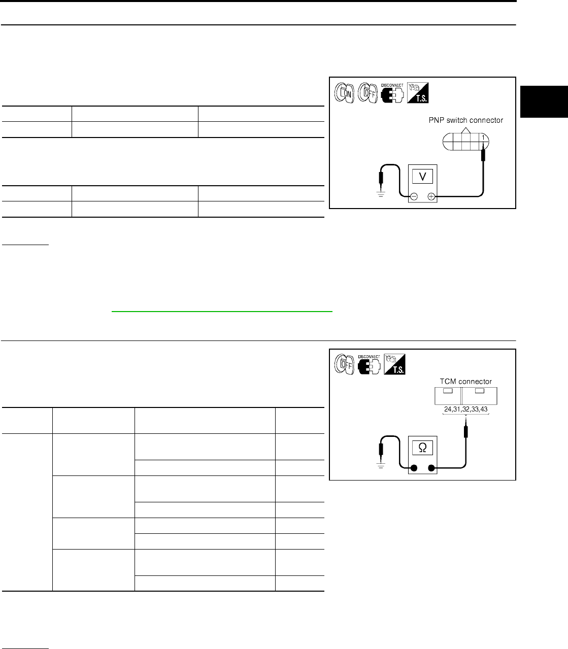
DTC P0705 PARK/NEUTRAL POSITION SWITCH
AT-461
[RE5F22A]
D
E
F
G
H
I
J
K
L
M
A
B
AT
Revision: September 2005 2005 Quest
2. CHECK PNP SWITCH POWER SOURCE CIRCUIT
1. Turn ignition switch “OFF”.
2. Disconnect the PNP switch connector.
3. Turn ignition switch “ON”. (Do not start engine.)
4. Check the voltage between PNP switch connector terminal 1
and ground.
5. Turn ignition switch “OFF”.
6. Check voltage between PNP switch connector terminal 1 and
ground.
7. If OK, check harness for short-circuit to ground or power source.
OK or NG
OK >> GO TO 3.
NG >> Check the following. If any items are damaged, repair or replace damaged parts.
●Harness for short or open between ignition switch and PNP switch
●Ignition switch and fuse
Refer to PG-4, "POWER SUPPLY ROUTING CIRCUIT" .
3. CHECK HARNESS BETWEEN TCM AND PNP SWITCH
1. Turn ignition switch “OFF”.
2. Disconnect the TCM connector and PNP switch connector.
3. Check continuity between TCM connector terminals 24, 31, 32,
43 and ground.
4. If OK, check the following.
–Harness for short-circuit to ground or power source.
–Open or short-circuit in the harness between combination meter and TCM.
OK or NG
OK >> GO TO 5.
NG >> GO TO 4.
Connector Terminal (Wire color) Voltage
F29 1 (G) - Ground Battery voltage
Connector Terminal (Wire color) Voltage
F29 1 (G) - Ground 0V SCIA3576E
Connector Terminal (Wire
color) Condition Continuity
E142
24 (BR) - Ground
Selector lever: “P”, “R” and “L”
position Yes
Other than the above No
31 (G/Y) - Ground
Selector lever: “R”, “N”, “D” and “L”
position Yes
Other than the above No
32 (P/B) - Ground Selector lever: “D” and “L” position Yes
Other than the above No
43 (V/W) - Ground
Selector lever: “P”, “N” and “L”
position Yes
Other than the above No
SCIA2827E
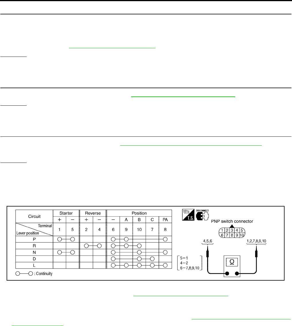
AT-462
[RE5F22A]
DTC P0705 PARK/NEUTRAL POSITION SWITCH
Revision: September 2005 2005 Quest
4. DETECT MALFUNCTIONING ITEM
Check the following.
●Open or short-circuit in the harness between TCM and PNP switch A, B, C, PA.
●Open or short-circuit in the harness for ground of PNP switch.
●PNP switch. Refer to AT-462, "Component Inspection" .
OK or NG
OK >> GO TO 6.
NG >> Repair or replace damaged parts.
5. CHECK DTC
Perform “DTC Confirmation Procedure”. Refer to AT-457, "DTC Confirmation Procedure" .
OK or NG
OK >> INSPECTION END
NG >> GO TO 6.
6. CHECK TCM
1. Check TCM input/output signal. Refer to AT-438, "TCM Input/Output Signal Reference Values" .
2. If NG, recheck TCM pin terminals for damage or loose connection with harness connector.
OK or NG
OK >> INSPECTION END
NG >> Repair or replace damaged parts.
Component Inspection UCS000UI
PNP SWITCH
1. Check continuity between PNP switch terminals while moving selector lever. Refer to the following table.
2. If NG, check again with control cable disconnected. (Refer to step 1 above.)
3. If OK on step 2, adjust control cable. Refer to AT-608, "Control Cable Adjustment" .
4. If NG on step 2, remove park/neutral position (PNP) switch from A/T and check continuity of park/neutral
position (PNP) switch terminals. (Refer to step 1 above.)
5. If OK on step 4, adjust park/neutral position (PNP) switch. Refer to AT-606, "Park/Neutral Position (PNP)
Switch Adjustment" .
6. If NG on step 4, replace park/neutral position (PNP) switch.
SCIA3577E
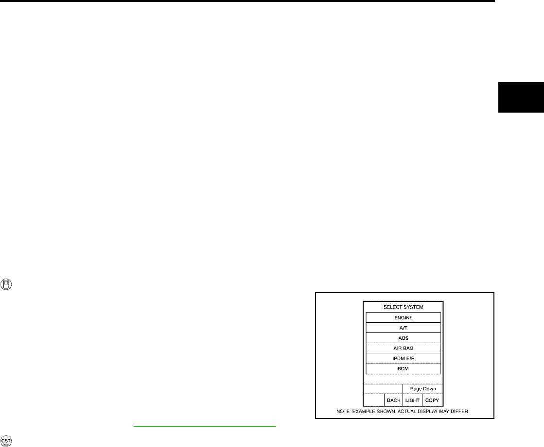
DTC P0710 A/T FLUID TEMPERATURE SENSOR CIRCUIT
AT-463
[RE5F22A]
D
E
F
G
H
I
J
K
L
M
A
B
AT
Revision: September 2005 2005 Quest
DTC P0710 A/T FLUID TEMPERATURE SENSOR CIRCUIT PFP:31940
Description UCS000W4
The A/T fluid temperature sensor detects the A/T fluid temperature and sends a signal to the TCM.
On Board Diagnosis Logic UCS000W6
●This is an OBD-II self-diagnostic item.
●Diagnostic trouble code “ATF TEMP SEN/CIRC” with CONSULT-II or P0710 without CONSULT-II is
detected under the following conditions.
–When normal voltage not applied to ATF temperature sensor due to open, short, and so on.
–When during running, the ATF temperature sensor signal voltage is excessively high or low.
Possible Cause UCS000W7
●Harness or connectors
(The sensor circuit is open or shorted.)
●A/T fluid temperature sensor
DTC Confirmation Procedure UCS000W8
NOTE:
If “DTC Confirmation Procedure” has been previously performed, always turn ignition switch “OFF”
and wait at least 10 seconds before performing the next test.
After the repair, perform the following procedure to confirm the malfunction is eliminated.
WITH CONSULT-II
1. Turn ignition switch “ON”. (Do not start engine.)
2. Select “DATA MONITOR” mode for “A/T” with CONSULT-II.
3. Start engine.
4. Warm up engine so that engine coolant temperature is more
than 50°C (122°F).
COOLAN TEMP: More than 50°C (122°F)
5. Maintain the following conditions for at least 16 minutes (Total).
(It is not necessary to drive vehicle.)
COOLAN TEMP: More than 50°C (122°F)
SLCT LVR POSI: “D” position
6. If DTC is detected, go to AT-465, "Diagnostic Procedure" .
WITH GST
Follow the procedure “With CONSULT-II”.
BCIA0030E

AT-464
[RE5F22A]
DTC P0710 A/T FLUID TEMPERATURE SENSOR CIRCUIT
Revision: September 2005 2005 Quest
Wiring Diagram — AT — FTS UCS000W9
BCWA0340E

DTC P0710 A/T FLUID TEMPERATURE SENSOR CIRCUIT
AT-465
[RE5F22A]
D
E
F
G
H
I
J
K
L
M
A
B
AT
Revision: September 2005 2005 Quest
TCM terminals and data are reference value. Measured between each terminal and ground.
Diagnostic Procedure UCS002LE
1. CHECK FLUID TEMPERATURE SENSOR SIGNAL
With CONSULT-II
1. Start engine.
2. Select “A/T” with “DATA MONITOR” mode in CONSULT-II.
3. Read out the value of “FLUID TEMP SE”.
Without CONSULT-II
1. Start engine.
2. Check voltage between TCM connector terminals 41 and 42
while warming up A/T. Refer to AT-464, "Wiring Diagram — AT
— FTS" .
3. Turn ignition switch “OFF”.
4. Disconnect the TCM connector.
5. Check if there is continuity between the connector terminal and ground.
OK or NG
OK >> GO TO 6.
NG >> GO TO 2.
Terminal Wire
color Item Condition Data (Approx.)
41 R/Y Fluid temperature
sensor
When ATF temperature 0°C (32°F) 4.0V
When ATF temperature 20°C (68°F) 3.0V
When ATF temperature 80°C (176°F) 0.8V
When ATF temperature 100°C (212°F) 0.5V
42 LG/B Fluid temperature
sensor ground –0V
Item name Condition Display value (Approx.)
Fluid temperature sensor
0°C (32°F) 4.0V
20°C (68°F) 3.0V
80°C (176°F) 0.8V
100°C (212°F) 0.5V
SCIA2870E
Connector Terminal (Wire color) Temperature Voltage (Approx.)
E142 41 (R/Y) - 42 (LG/B) (ground)
0°C (32°F) 4.0V
20°C (68°F) 3.0V
80°C (176°F) 0.8V
100°C (212°F) 0.5V
SCIA2871E
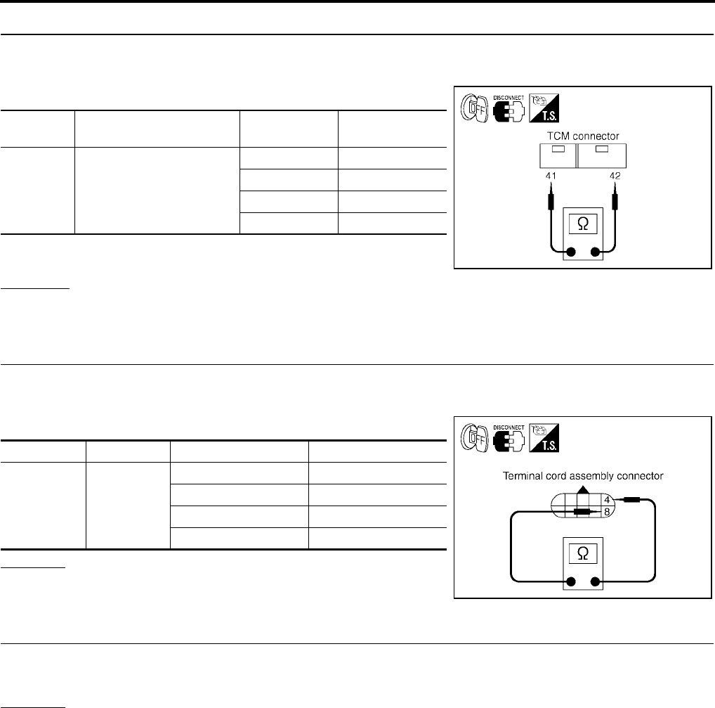
AT-466
[RE5F22A]
DTC P0710 A/T FLUID TEMPERATURE SENSOR CIRCUIT
Revision: September 2005 2005 Quest
2. CHECK FLUID TEMPERATURE SENSOR CIRCUIT
1. Turn ignition switch “OFF”.
2. Disconnect the TCM connector.
3. Check resistance between terminals 41 and 42.
4. Check if there is continuity between the connector terminal and
ground.
OK or NG
OK >> GO TO 6.
NG >> GO TO 3.
3. CHECK TERMINAL CORD ASSEMBLY WITH A/T FLUID TEMPERATURE SENSOR
1. Turn ignition switch “OFF”.
2. Disconnect terminal cord assembly harness connector.
3. Check resistance between terminals 4 and 8.
OK or NG
OK >> GO TO 4.
NG >> GO TO 5.
4. CHECK HARNESS BETWEEN TCM AND TERMINAL CORD ASSEMBLY
Check the following.
●Open or short-circuit in the harness between TCM and terminal cord assembly.
OK or NG
OK >> GO TO 6.
NG >> Repair or replace damaged parts.
Connector Terminal (Wire color) Temperature Resistance
(Approx.)
E142 41 (R/Y) - 42 (LG/B) (ground)
0°C (32°F) 9.8 kΩ
20°C (68°F) 4.2 kΩ
80°C (176°F) 0.54 kΩ
100°C (212°F) 0.31 kΩ
SCIA2872E
Connector Terminal Temperature Resistance (Approx.)
F30 4 - 8
0°C (32°F) 9.8 kΩ
20°C (68°F) 4.2 kΩ
80°C (176°F) 0.54 kΩ
100°C (212°F) 0.31 kΩ
SCIA2873E
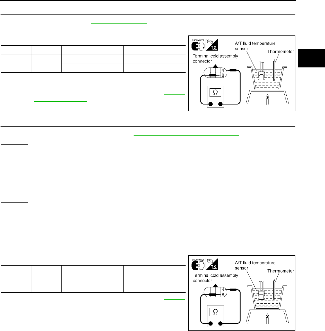
DTC P0710 A/T FLUID TEMPERATURE SENSOR CIRCUIT
AT-467
[RE5F22A]
D
E
F
G
H
I
J
K
L
M
A
B
AT
Revision: September 2005 2005 Quest
5. CHECK A/T FLUID TEMPERATURE SENSOR
1. Remove side cover. Refer to AT-609, "Side cover" .
2. Disconnect A/T fluid temperature sensor.
3. Check resistance between terminals 4 and 8.
OK or NG
OK >> GO TO 6.
NG >> Repair or replace transmission wire. Refer to AT-609,
"Transmission wire" .
6. CHECK DTC
Perform “DTC Confirmation Procedure”. Refer to AT-463, "DTC Confirmation Procedure" .
OK or NG
OK >> INSPECTION END
NG >> GO TO 7.
7. CHECK TCM
1. Check TCM input/output signal. Refer to AT-438, "TCM Input/Output Signal Reference Values" .
2. If NG, recheck TCM pin terminals for damage or loose connection with harness connector.
OK or NG
OK >> INSPECTION END
NG >> Repair or replace damaged parts.
Component Inspection UCS002LF
A/T FLUID TEMPERATURE SENSOR
1. Remove side cover. Refer to AT-609, "Side cover" .
2. Disconnect A/T fluid temperature sensor.
3. Check resistance between terminals 4 and 8.
4. If NG, repair and replace transmission wire. Refer to AT-609,
"Transmission wire" .
Connector Terminal Temperature Resistance
F30 4 - 8 10°C (°F) 5.80 - 7.09kΩ
110°C (°F) 0.23 - 0.26kΩ
SCIA4323E
Connector Terminal Temperature Resistance
F30 4 - 8 10°C (°F) 5.80 - 7.09kΩ
110°C (°F) 0.23 - 0.26kΩ
SCIA4323E
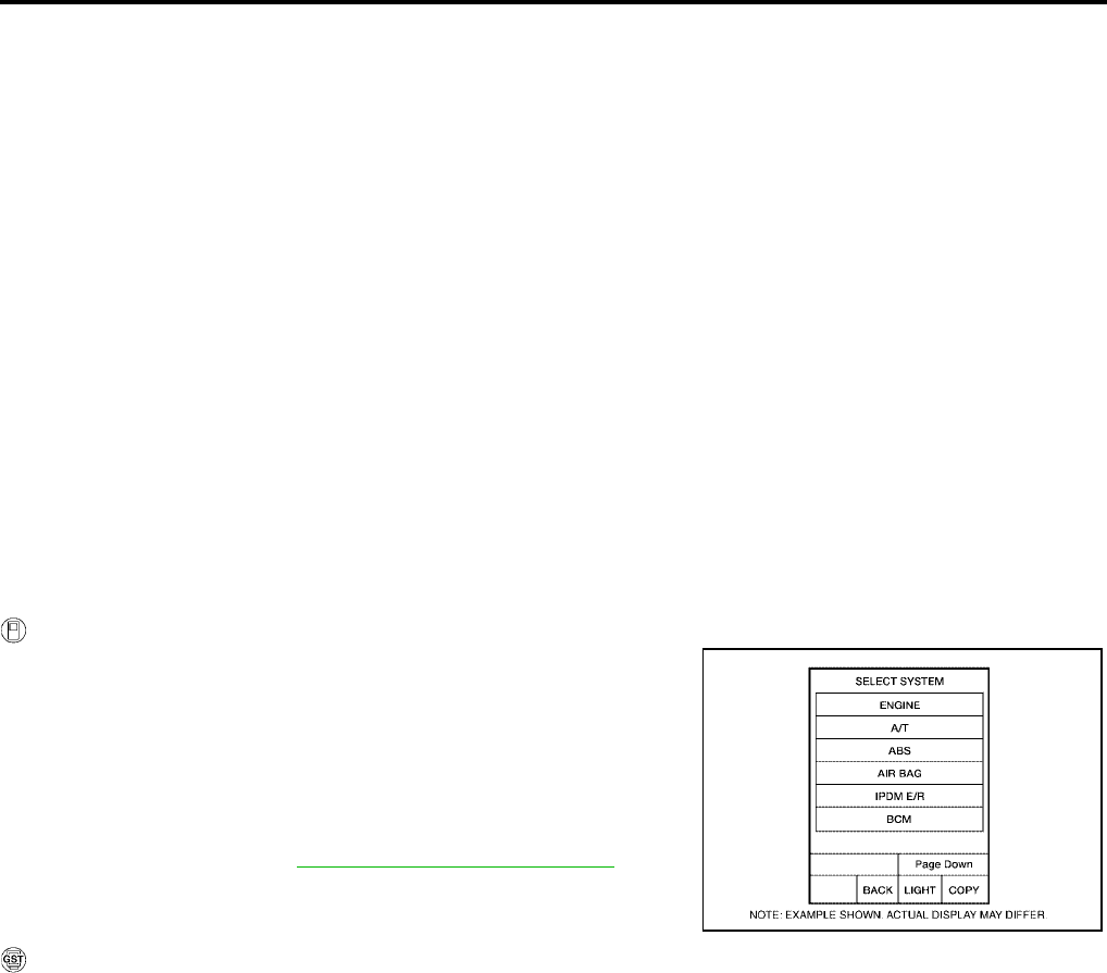
AT-468
[RE5F22A]
DTC P0711 FLUID TEMPERATURE SENSOR PERFORMANCE
Revision: September 2005 2005 Quest
DTC P0711 FLUID TEMPERATURE SENSOR PERFORMANCE PFP:31940
Description UCS0011V
The A/T fluid temperature sensor detects the A/T fluid temperature and sends a signal to the TCM.
On Board Diagnosis Logic UCS0011W
●This is an OBD-II self-diagnostic item.
●Diagnostic trouble code “FLUID TEMP SEN” with CONSULT-II or P0711 without CONSULT-II is detected
when ATF temperature signal does not change.
Possible Cause UCS0011X
●Harness or connectors
(The sensor circuit is open or shorted.)
●A/T fluid temperature sensor
DTC Confirmation Procedure UCS0011Y
CAUTION:
Always drive vehicle at a safe speed.
NOTE:
If “DTC Confirmation Procedure” has been previously performed, always turn ignition switch “OFF”
and wait at least 10 seconds before performing the next test.
After the repair, perform the following procedure to confirm the malfunction is eliminated.
WITH CONSULT-II
1. Turn ignition switch “ON”. (Do not start engine.)
2. Select “DATA MONITOR” mode for “A/T” with CONSULT-II.
3. Start engine.
4. Drive vehicle and maintain the following conditions for at least
15 minutes (Total). (It is not necessary to maintain continuously.)
VHCL SPEED SE-A/T: 40 km/h (25 MPH) or more
SLCT LVR POSI: “D” position
5. If DTC is detected, go to AT-470, "Diagnostic Procedure" .
WITH GST
Follow the procedure “With CONSULT-II”.
BCIA0030E

DTC P0711 FLUID TEMPERATURE SENSOR PERFORMANCE
AT-469
[RE5F22A]
D
E
F
G
H
I
J
K
L
M
A
B
AT
Revision: September 2005 2005 Quest
Wiring Diagram — AT — FTSP UCS0011Z
BCWA0341E
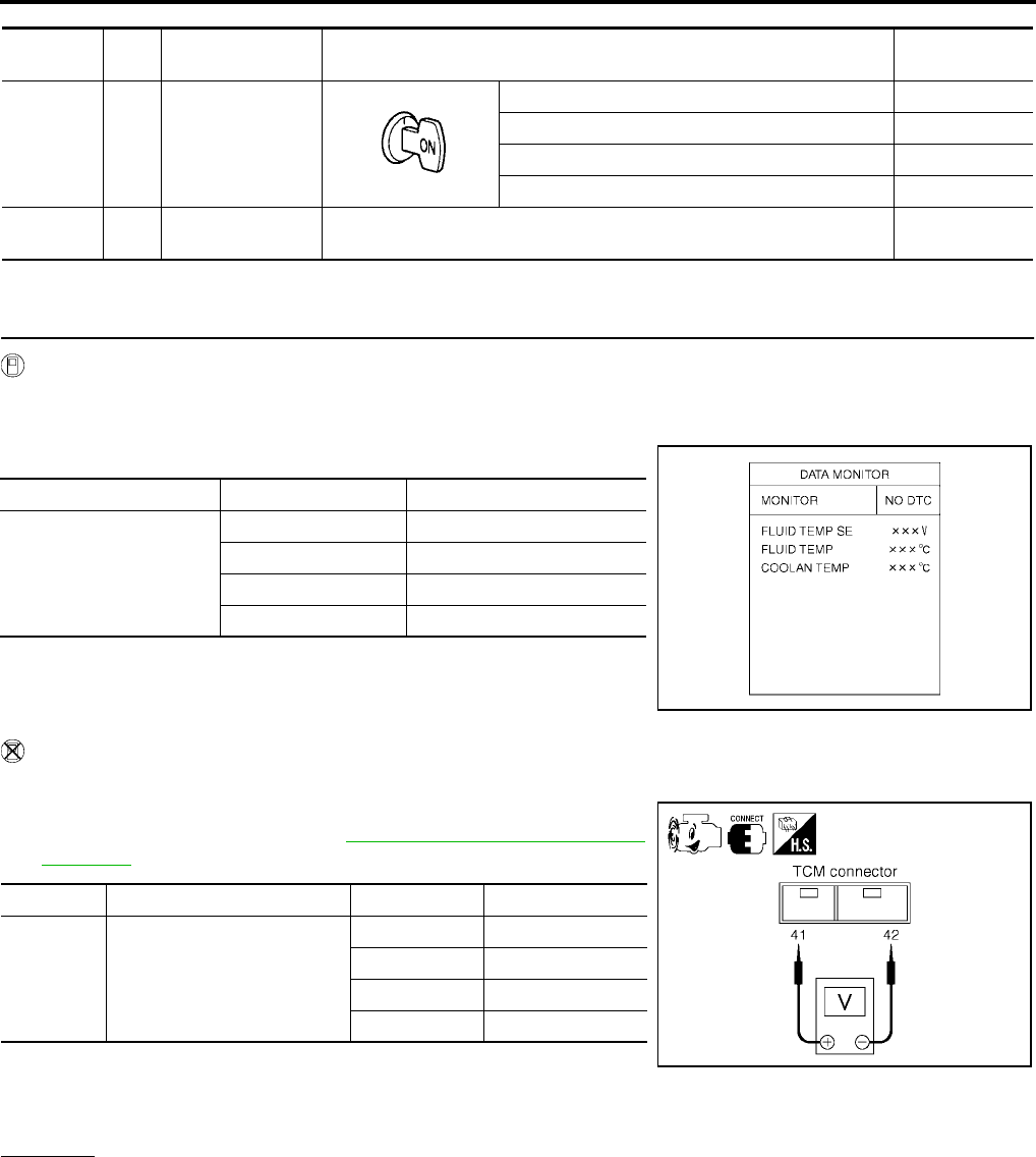
AT-470
[RE5F22A]
DTC P0711 FLUID TEMPERATURE SENSOR PERFORMANCE
Revision: September 2005 2005 Quest
TCM terminals and data are reference value. Measured between each terminal and ground.
Diagnostic Procedure UCS002LG
1. CHECK FLUID TEMPERATURE SENSOR SIGNAL
With CONSULT-II
1. Start engine.
2. Select “A/T” with “DATA MONITOR” mode in CONSULT-II.
3. Read out the value of “FLUID TEMP SE”.
Without CONSULT-II
1. Start engine.
2. Check voltage between TCM connector terminals 41 and 42
while warming up A/T. Refer to AT-469, "Wiring Diagram — AT
— FTSP" .
3. Turn ignition switch “OFF”.
4. Disconnect the TCM connector.
5. Check if there is continuity between the connector terminal and ground.
OK or NG
OK >> GO TO 6.
NG >> GO TO 2.
Terminal Wire
color Item Condition Data (Approx.)
41 R/Y Fluid temperature
sensor
When ATF temperature 0°C (32°F) 4.0V
When ATF temperature 20°C (68°F) 3.0V
When ATF temperature 80°C (176°F) 0.8V
When ATF temperature 100°C (212°F) 0.5V
42 LG/B Fluid temperature
sensor ground –0V
Item name Condition Display value (Approx.)
Fluid temperature sensor
0°C (32°F) 4.0V
20°C (68°F) 3.0V
80°C (176°F) 0.8V
100°C (212°F) 0.5V
SCIA2870E
Connector Terminal (Wire color) Temperature Voltage (Approx.)
E142 41 (R/Y) - 42 (LG/B) (ground)
0°C (32°F) 4.0V
20°C (68°F) 3.0V
80°C (176°F) 0.8V
100°C (212°F) 0.5V
SCIA2871E
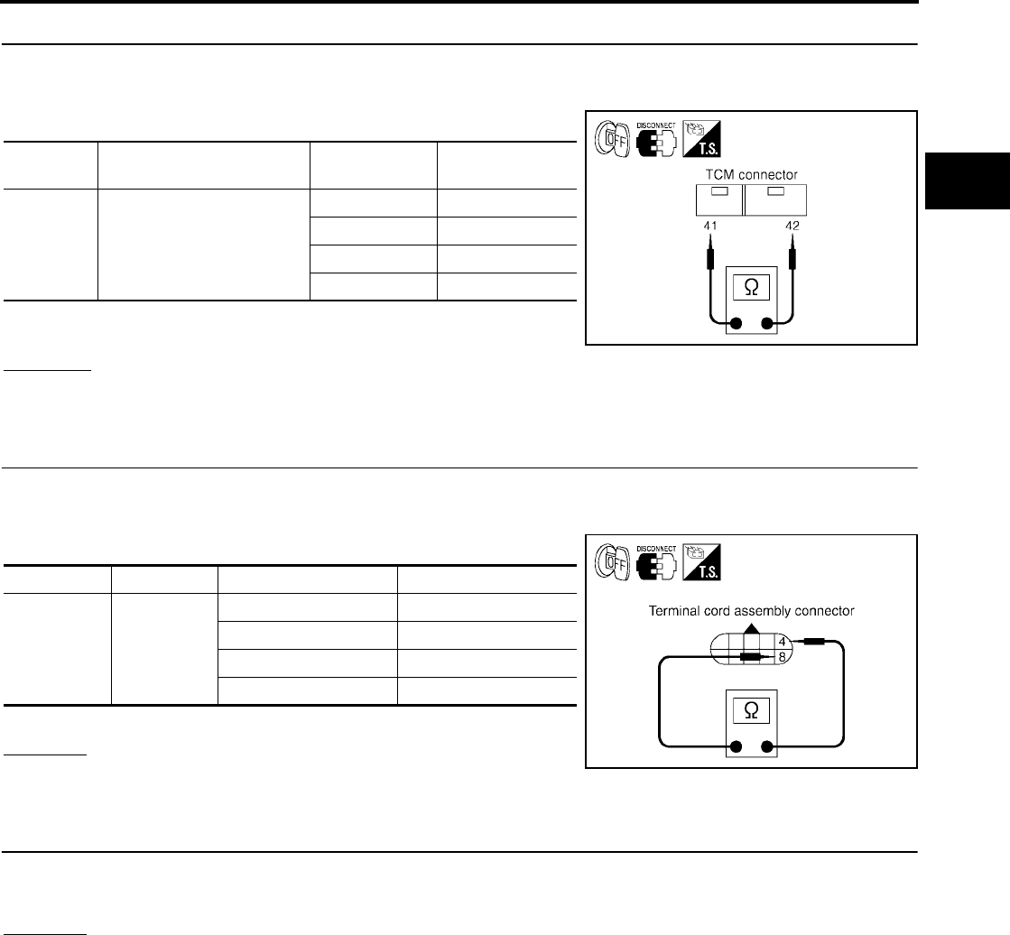
DTC P0711 FLUID TEMPERATURE SENSOR PERFORMANCE
AT-471
[RE5F22A]
D
E
F
G
H
I
J
K
L
M
A
B
AT
Revision: September 2005 2005 Quest
2. CHECK FLUID TEMPERATURE SENSOR CIRCUIT
1. Turn ignition switch “OFF”.
2. Disconnect the TCM connector.
3. Check resistance between terminals 41 and 42.
4. Check if there is continuity between the connector terminal and
ground.
OK or NG
OK >> GO TO 6.
NG >> GO TO 3.
3. CHECK TERMINAL CORD ASSEMBLY WITH A/T FLUID TEMPERATURE SENSOR
1. Turn ignition switch “OFF”.
2. Disconnect terminal cord assembly harness connector.
3. Check resistance between terminals 4 and 8.
4. Reinstall any part removed.
OK or NG
OK >> GO TO 4.
NG >> GO TO 5.
4. CHECK HARNESS BETWEEN TCM AND TERMINAL CORD ASSEMBLY
Check the following.
●Open or short-circuit in the harness between TCM and terminal cord assembly.
OK or NG
OK >> GO TO 6.
NG >> Repair or replace damaged parts.
Connector Terminal (Wire color) Temperature Resistance
(Approx.)
E142 41 (R/Y) - 42 (LG/B) (ground)
0°C (32°F) 9.8 kΩ
20°C (68°F) 4.2 kΩ
80°C (176°F) 0.54 kΩ
100°C (212°F) 0.31 kΩ
SCIA2872E
Connector Terminal Temperature Resistance (Approx.)
F30 4 - 8
0°C (32°F) 9.8 kΩ
20°C (68°F) 4.2 kΩ
80°C (176°F) 0.54 kΩ
100°C (212°F) 0.31 kΩ
SCIA2873E

AT-472
[RE5F22A]
DTC P0711 FLUID TEMPERATURE SENSOR PERFORMANCE
Revision: September 2005 2005 Quest
5. CHECK A/T FLUID TEMPERATURE SENSOR
1. Remove side cover. Refer to AT-609, "Side cover" .
2. Disconnect A/T fluid temperature sensor.
3. Check resistance between terminals 4 and 8.
OK or NG
OK >> GO TO 6.
NG >> Repair or replace transmission wire. Refer to AT-609,
"Transmission wire" .
6. CHECK DTC
Perform “DTC Confirmation Procedure”. Refer to AT-468, "DTC Confirmation Procedure" .
OK or NG
OK >> INSPECTION END
NG >> GO TO 7.
7. CHECK TCM
1. Check TCM input/output signal. Refer to AT-438, "TCM Input/Output Signal Reference Values" .
2. If NG, recheck TCM pin terminals for damage or loose connection with harness connector.
OK or NG
OK >> INSPECTION END
NG >> Repair or replace damaged parts.
Component Inspection UCS002LH
A/T FLUID TEMPERATURE SENSOR
1. Remove side cover. Refer to AT-609, "Side cover" .
2. Disconnect A/T fluid temperature sensor.
3. Check resistance between terminals 4 and 8.
4. If NG, repair or replace transmission wire. Refer to AT-609,
"Transmission wire" .
Connector Terminal) Temperature Resistance
F30 4 - 8 10°C (°F) 5.80 - 7.09kΩ
110°C (°F) 0.23 - 0.26kΩ
SCIA4323E
Connector Terminal) Temperature Resistance
F30 4 - 8 10°C (°F) 5.80 - 7.09kΩ
110°C (°F) 0.23 - 0.26kΩ
SCIA4323E
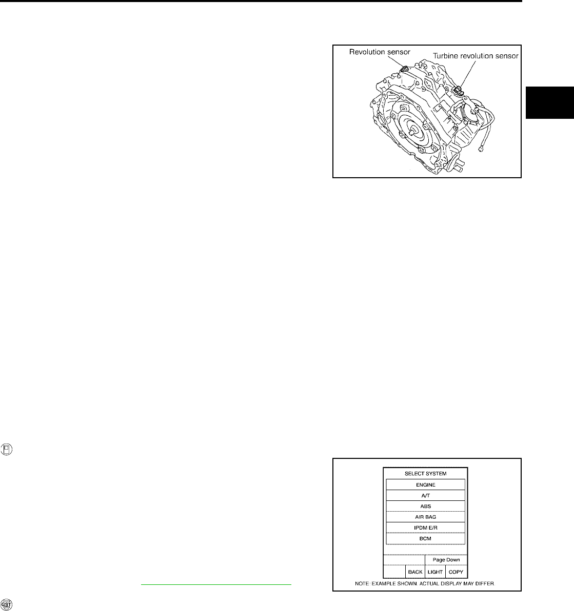
DTC P0717 TURBINE REVOLUTION SENSOR CIRCUIT
AT-473
[RE5F22A]
D
E
F
G
H
I
J
K
L
M
A
B
AT
Revision: September 2005 2005 Quest
DTC P0717 TURBINE REVOLUTION SENSOR CIRCUIT PFP:31935
Description UCS000WB
●The turbine revolution sensor detects forward clutch drum rpm
(revolutions per minute). It is located on the input side of the
automatic transaxle. The revolution sensor is located on the out-
put side of the automatic transaxle. With the two sensors, input
and output rpms are accurately detected. The result is optimal
shift timing during deceleration and improved shifting.
●Hall IC is installed in turbine revolution sensor, it itself handles in
pulse of rectangular wave signal and transmits it to TCM due to
hall effect. TCM recognizes the pulse with input rpm speed. Size
of output doesn't depend on a rotation number and is fixed.
On Board Diagnosis Logic UCS000WC
●This is an OBD-II self-diagnostic item.
●Diagnostic trouble code “TURBINE SENSOR” with CONSULT-II or P0717 without CONSULT-II is
detected under the following conditions.
–When signal from turbine revolution sensor does not input due to open, short, and so on.
–When unexpected signal input during running.
Possible Cause UCS000WD
●Harness or connectors
(The sensor circuit is open or shorted.)
●Turbine revolution sensor
DTC Confirmation Procedure UCS000WE
CAUTION:
Always drive vehicle at a safe speed.
NOTE:
If “DTC Confirmation Procedure” has been previously performed, always turn ignition switch “OFF”
and wait at least 10 seconds before performing the next test.
After the repair, perform the following procedure to confirm the malfunction is eliminated.
WITH CONSULT-II
1. Turn ignition switch “ON”. (Do not start engine.)
2. Select “DATA MONITOR” mode for “A/T” with CONSULT-II.
3. Start engine.
4. Drive vehicle and maintain the following conditions for at least 1
consecutive minute.
FLUID TEMP: More than 20°C (68°F)
VHCL/S SE-A/T: 70 km/h (43 MPH) or more
SLCT LVR POSI: “D” position
GEAR: Except 1st position
5. If DTC is detected, go to AT-475, "Diagnostic Procedure" .
WITH GST
Follow the procedure “With CONSULT-II”.
SCIA2830E
BCIA0030E
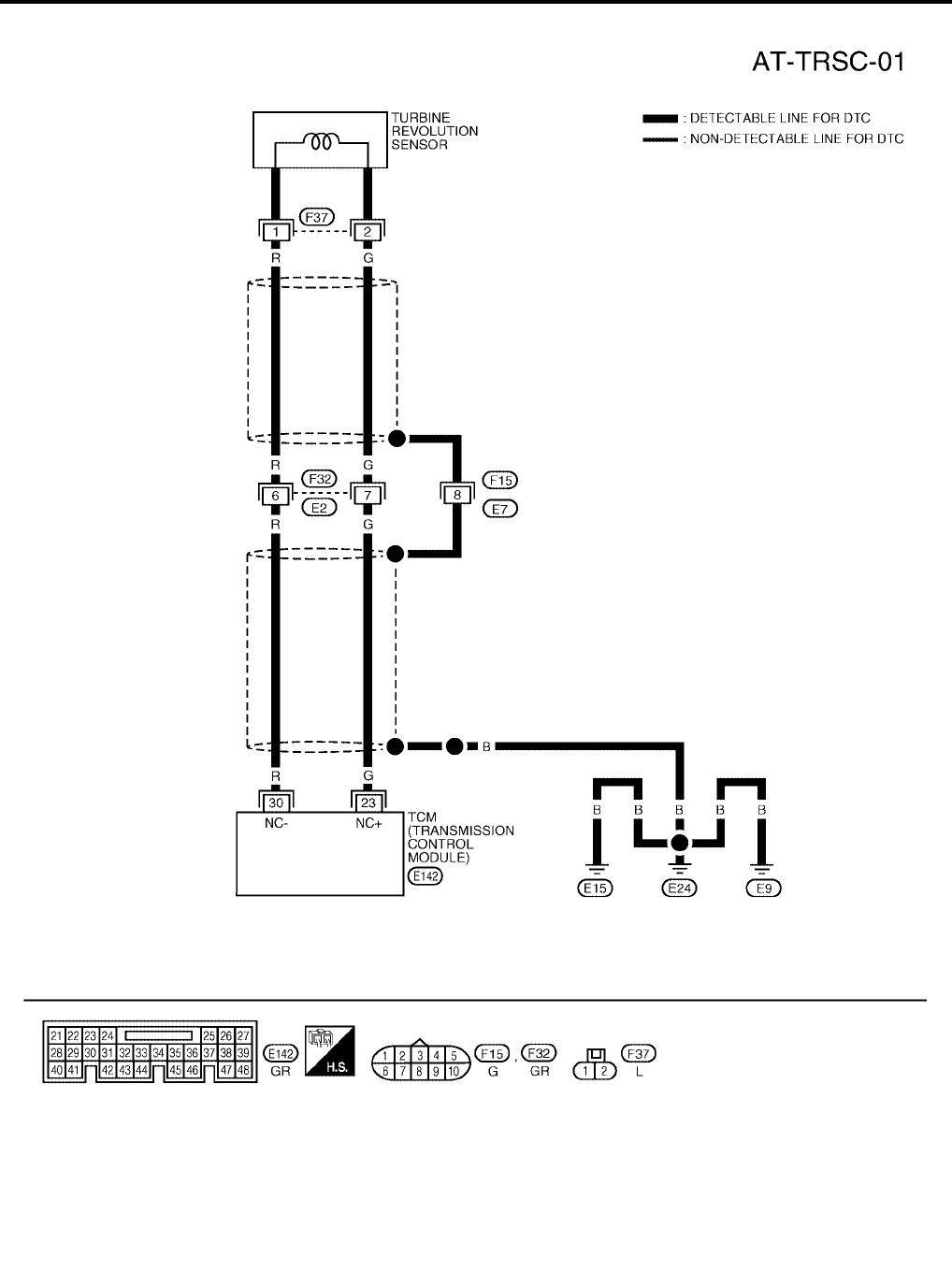
AT-474
[RE5F22A]
DTC P0717 TURBINE REVOLUTION SENSOR CIRCUIT
Revision: September 2005 2005 Quest
Wiring Diagram — AT — TRSC UCS000WF
BCWA0342E

DTC P0717 TURBINE REVOLUTION SENSOR CIRCUIT
AT-475
[RE5F22A]
D
E
F
G
H
I
J
K
L
M
A
B
AT
Revision: September 2005 2005 Quest
TCM terminals and data are reference value. Measured between each terminal and ground.
Diagnostic Procedure UCS000WG
1. CHECK TURBINE REVOLUTION SENSOR CIRCUIT
With CONSULT-II
1. Start engine.
2. Select “DATA MONITOR” mode for “A/T” with CONSULT-II.
3. Drive vehicle and read out the value of “TURBINE REV”.
Without CONSULT-II
1. Start the engine.
2. Check pulse between TCM connector terminals 23 and 30.
OK or NG
OK >> GO TO 3.
NG >> GO TO 2.
2. DETECT MALFUNCTIONING ITEM
Check the following.
●Open or short-circuit in the harness between TCM and turbine revolution sensor.
●Turbine revolution sensor. Refer to AT-476, "Component Inspection" .
OK or NG
OK >> GO TO 3.
NG >> Repair or replace damaged parts.
Terminal Wire
color Item Condition Data (Approx.)
23 G
Turbine revolution
sensor power sup-
ply
When turning ignition switch ON. Battery voltage
When turning ignition switch OFF. 0V
30 R Turbine revolution
sensor When moving at 20 km/h (12 MPH) in 1st gear. 371Hz
Monitor item Condition Specification
TURBINE REV During driving (lock-up ON) Approximately matches the
engine speed.
SCIA2924E
Connector Terminal (Wire color) Condition Data
(Approx.)
E142 23 (G) - 30 (R) (ground) When moving at 20 km/h (12
MPH) in 1st gear. 371 Hz
SCIA2925E
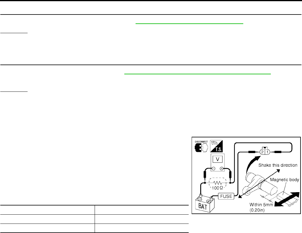
AT-476
[RE5F22A]
DTC P0717 TURBINE REVOLUTION SENSOR CIRCUIT
Revision: September 2005 2005 Quest
3. CHECK DTC
Perform “DTC Confirmation Procedure”. Refer to AT-473, "DTC Confirmation Procedure" .
OK or NG
OK >> INSPECTION END
NG >> GO TO 4.
4. CHECK TCM
1. Check TCM input/output signal. Refer to AT-438, "TCM Input/Output Signal Reference Values" .
2. If NG, recheck TCM pin terminals for damage or loose connection with harness connector.
OK or NG
OK >> INSPECTION END
NG >> Repair or replace damaged parts.
Component Inspection UCS0015F
TURBINE REVOLUTION SENSOR
1. Remove turbine revolution sensor.
2. Connect 12V power supply and 100 Ω resistance to the termi-
nal. (Do not mistake polarity)
3. Inspect the voltage of HIGH and LOW signal by shaking mag-
netic body from side to side at turbine revolution sensor tip [gap
is within 5 mm (0.20 in)].
CAUTION:
Make sure to shake direction from bolt hole to sensor-self
when shaking magnetic body. If not, voltage value cannot
change.
4. If NG, replace turbine revolution sensor.
Signal Voltage (Approx.)
HIGH 1.2 - 1.6V
LOW 0.4 - 0.8V
SCIA3578E
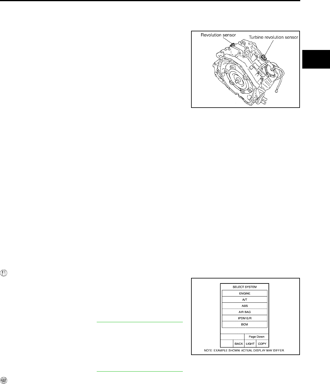
DTC P0722 VEHICLE SPEED SENSOR A/T (REVOLUTION SENSOR) CIRCUIT
AT-477
[RE5F22A]
D
E
F
G
H
I
J
K
L
M
A
B
AT
Revision: September 2005 2005 Quest
DTC P0722 VEHICLE SPEED SENSOR A/T (REVOLUTION SENSOR) CIRCUIT
PFP:31935
Description UCS000UJ
●The revolution sensor detects the revolution of the idler gear
parking pawl lock gear and emits a pulse signal. The pulse sig-
nal is sent to the TCM which converts it into vehicle speed.
●Hall IC is installed in revolution sensor, it itself handles in pulse
of rectangular wave signal and transmits it to TCM due to hall
effect. TCM recognizes the pulse with vehicle speed. Size of
output doesn't depend on a rotation number and is fixed.
On Board Diagnosis Logic UCS000UK
●This is an OBD-II self-diagnostic item.
●Diagnostic trouble code “VHCL SPEED SEN-A/T” with CONSULT-II or P0722 without CONSULT-II is
detected under the following conditions.
–When signal from revolution sensor does not input due to open, short, and so on.
–When unexpected signal input during running.
Possible Cause UCS000UL
●Harness or connectors
(The sensor circuit is open or shorted.)
●Revolution sensor
DTC Confirmation Procedure UCS000UM
CAUTION:
●Always drive vehicle at a safe speed.
●Be careful not to rev engine into the red zone on the tachometer.
NOTE:
If “DTC Confirmation Procedure” has been previously performed, always turn ignition switch “OFF”
and wait at least 10 seconds before performing the next test.
After the repair, perform the following procedure to confirm the malfunction is eliminated.
WITH CONSULT-II
1. Turn ignition switch “ON”. (Do not start engine.)
2. Select “DATA MONITOR” mode for “A/T” with CONSULT-II.
3. Start engine.
4. Drive vehicle and check for an increase of “VHCL/S SE-A/T”
value in response to “VHCL/S SE-MTR” value.
If the check result is NG, go to AT-479, "Diagnostic Procedure" .
If the check result is OK, go to following step.
5. Maintain the following conditions for at least 2 consecutive min-
utes.
FLUID TEMP: More than 20°C (68°F)
VHCL/S SE-A/T: 70 km/h (43 MPH) or more
SLCT LVR POSI: “D” position
If the check result is NG, go to AT-479, "Diagnostic Procedure" .
WITH GST
Follow the procedure “With CONSULT-II”.
SCIA2830E
BCIA0030E

AT-478
[RE5F22A]
DTC P0722 VEHICLE SPEED SENSOR A/T (REVOLUTION SENSOR) CIRCUIT
Revision: September 2005 2005 Quest
Wiring Diagram — AT — VSSATC UCS000UN
BCWA0399E
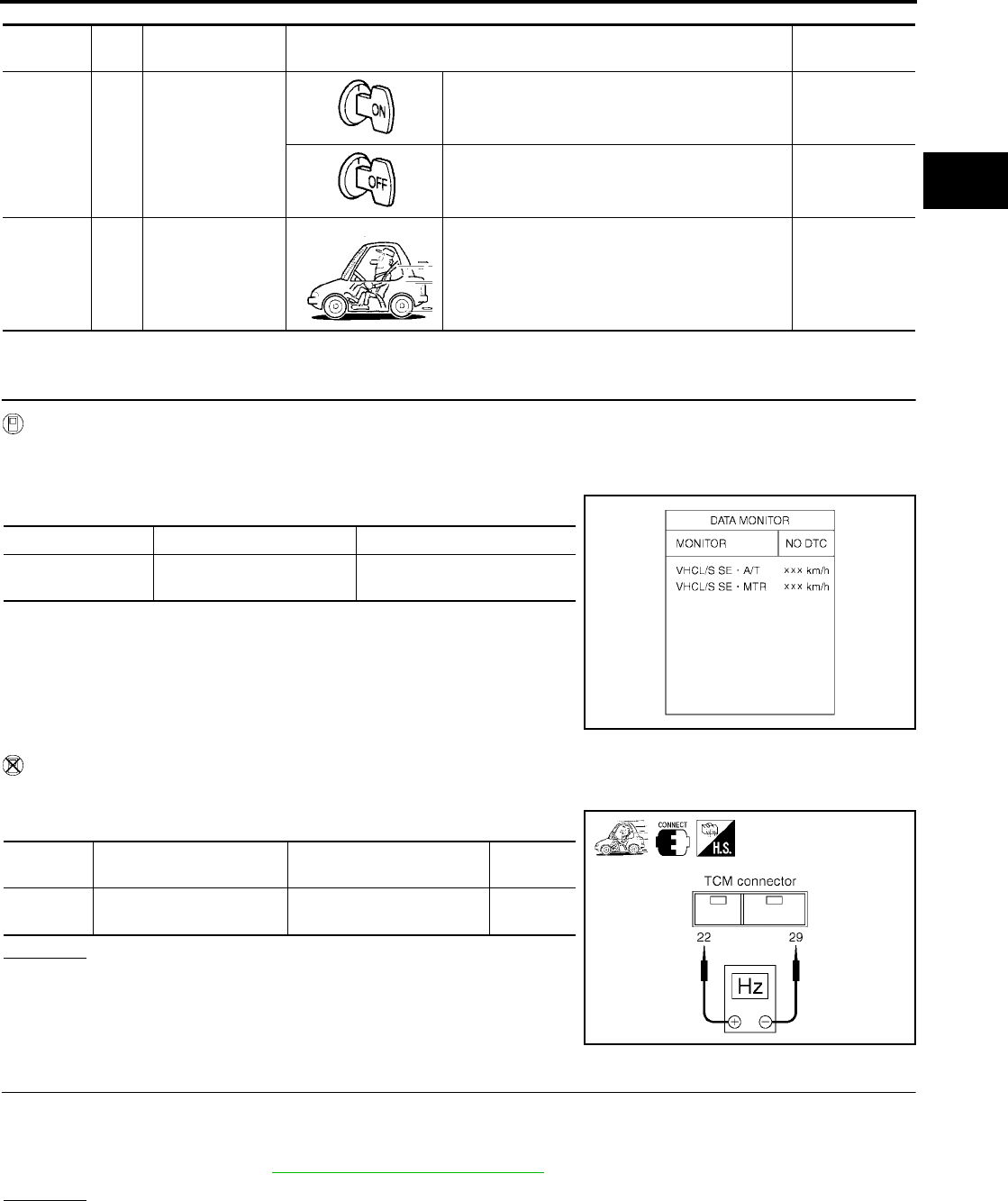
DTC P0722 VEHICLE SPEED SENSOR A/T (REVOLUTION SENSOR) CIRCUIT
AT-479
[RE5F22A]
D
E
F
G
H
I
J
K
L
M
A
B
AT
Revision: September 2005 2005 Quest
TCM terminals and data are reference value. Measured between each terminal and ground.
Diagnostic Procedure UCS000UO
1. CHECK REVOLUTION SENSOR CIRCUIT
With CONSULT-II
1. Start engine.
2. Select “DATA MONITOR” mode for “A/T” with CONSULT-II.
3. Drive vehicle and read out the value of “VHCL/S SE-AT”.
Without CONSULT-II
1. Start the engine.
2. Check pulse between TCM connector terminals 22 and 29.
OK or NG
OK >> GO TO 3.
NG >> GO TO 2.
2. DETECT MALFUNCTIONING ITEM
Check the following.
●Open or short-circuit in the harness between TCM and revolution sensor.
●Revolution sensor. Refer to AT-480, "Component Inspection" .
OK or NG
OK >> GO TO 3.
NG >> Repair or replace damaged parts.
Terminal Wire
color Item Condition Data (Approx.)
22 L Revolution sensor
power supply
When turning ignition switch ON. Battery voltage
When turning ignition switch OFF. 0V
29 R Revolution sensor When moving at 20 km/h (12 MPH) in 1st gear. 119Hz
Monitor item Condition Specification
VHCL/S SE-AT During driving Approximately matches the
speedometer reading.
SCIA2922E
Connector Terminal (Wire color) Condition Data
(Approx.)
E142 22 (L) - 29 (R) (ground) When moving at 20 km/h
(12 MPH) in 1st gear. 119 Hz
SCIA2928E

AT-480
[RE5F22A]
DTC P0722 VEHICLE SPEED SENSOR A/T (REVOLUTION SENSOR) CIRCUIT
Revision: September 2005 2005 Quest
3. CHECK DTC
Perform “DTC Confirmation Procedure”. Refer to AT-477, "DTC Confirmation Procedure" .
OK or NG
OK >> INSPECTION END
NG >> GO TO 4.
4. CHECK TCM
1. Check TCM input/output signal. Refer to AT-438, "TCM Input/Output Signal Reference Values" .
2. If NG, recheck TCM pin terminals for damage or loose connection with harness connector.
OK or NG
OK >> INSPECTION END
NG >> Repair or replace damaged parts.
Component Inspection UCS0015G
REVOLUTION SENSOR
1. Remove revolution sensor.
2. Connect 12V power supply and 100 Ω resistance to the termi-
nal. (Do not mistake polarity)
3. Inspect the voltage of HIGH and LOW signal by shaking mag-
netic body from side to side at revolution sensor tip [gap is within
5mm (0.20 in)].
CAUTION:
Make sure to shake direction from bolt hole to sensor-self
when shaking magnetic body. If not, voltage value cannot
change.
4. If NG, replace revolution sensor.
Signal Voltage (Approx.)
HIGH 1.2 - 1.6V
LOW 0.4 - 0.8V
SCIA3578E

DTC P0726 ENGINE SPEED INPUT CIRCUIT PERFORMANCE
AT-481
[RE5F22A]
D
E
F
G
H
I
J
K
L
M
A
B
AT
Revision: September 2005 2005 Quest
DTC P0726 ENGINE SPEED INPUT CIRCUIT PERFORMANCE PFP:31036
Description UCS000UP
The engine speed signal is sent from the ECM to the TCM.
On Board Diagnosis Logic UCS000UQ
●This is not an OBD-II self-diagnostic item.
●Diagnostic trouble code “ENG SPD INP PERFOR” with CONSULT-II or 14th judgement flicker without
CONSULT-II is detected when malfunction is detected in engine speed signal, actual engine torque signal
or torque reduction signal that is output from ECM through CAN communication.
Possible Cause UCS000UR
●Harness or connectors
(The signal circuit is open or shorted.)
●ECM
DTC Confirmation Procedure UCS000US
CAUTION:
Always drive vehicle at a safe speed.
NOTE:
If “DTC Confirmation Procedure” has been previously performed, always turn ignition switch “OFF”
and wait at least 10 seconds before performing the next test.
After the repair, perform the following procedure to confirm the malfunction is eliminated.
WITH CONSULT-II
1. Turn ignition switch “ON” and select “DATA MONITOR” mode for
“A/T” with CONSULT-II.
2. Start engine.
3. Drive vehicle and maintain the following conditions for at least
10 consecutive seconds.
VHCL/S SE-A/T: 10 km/h (6 MPH) or more
ACCELE ANGLE: More than 10 %
SLCT LVR POSI: “D” position
4. If DTC is detected, go to AT-481, "Diagnostic Procedure" .
Diagnostic Procedure UCS000UT
1. CHECK DTC WITH ECM
With CONSULT-II
1. Turn ignition switch “ON”. (Do not start engine.)
2. Select “SELF-DIAG RESULTS” mode for “ENGINE” with CON-
SULT-II. Refer to EC-133, "CONSULT-II Function (ENGINE)" .
OK or NG
OK >> GO TO 2.
NG >> Check the DTC detected item, go to EC-9, "INDEX FOR
DTC" .
●If CAN communication line is detected, go to AT-450,
"DTC U1000 CAN COMMUNICATION LINE" .
BCIA0030E
BCIA0030E

AT-482
[RE5F22A]
DTC P0726 ENGINE SPEED INPUT CIRCUIT PERFORMANCE
Revision: September 2005 2005 Quest
2. CHECK DTC WITH TCM
With CONSULT-II
1. Start engine.
2. Select “DATA MONITOR” mode for “A/T” with CONSULT-II.
3. While monitoring “ENGINE SPEED”, check for engine speed
change corresponding to “ACCELE ANGLE”.
OK or NG
OK >> GO TO 3.
NG >> Check the ignition signal circuit.
●Refer to EC-686, "IGNITION SIGNAL" .
3. CHECK DTC
Perform “DTC Confirmation Procedure”. Refer to AT-481, "DTC Confirmation Procedure" .
OK or NG
OK >> INSPECTION END
NG >> GO TO 4.
4. CHECK TCM
1. Check TCM input/output signal. Refer to AT-438, "TCM Input/Output Signal Reference Values" .
2. If NG, recheck TCM pin terminals for damage or loose connection with harness connector.
OK or NG
OK >> INSPECTION END
NG >> Repair or replace damaged parts.
SCIA2929E
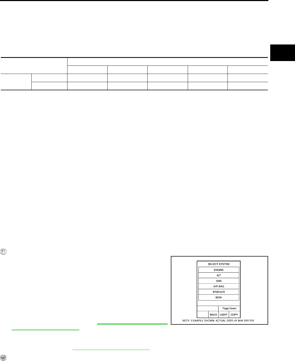
DTC P0731 A/T 1ST GEAR FUNCTION
AT-483
[RE5F22A]
D
E
F
G
H
I
J
K
L
M
A
B
AT
Revision: September 2005 2005 Quest
DTC P0731 A/T 1ST GEAR FUNCTION PFP:31940
Description UCS00121
●This malfunction will not be detected while the O/D OFF indicator lamp is indicating another self-diagnosis
malfunction.
●This malfunction is detected when the A/T does not shift into first gear position as instructed by the TCM.
This is not caused by electrical malfunction (circuits open or shorted) but by mechanical malfunction such
as control valve sticking, improper solenoid valve operation, etc.
On Board Diagnosis Logic UCS00122
●This is an OBD-II self-diagnostic item.
●Diagnostic trouble code “A/T 1ST GR FNCTN” with CONSULT-II or P0731 without CONSULT-II is
detected when A/T cannot be shifted to the 1st gear position even if electrical circuit is good.
Possible Cause UCS002LP
●Shift solenoid valve A
(Off stick.)
●2nd brake
●2nd coast brake
●One-way clutch No.1
●One-way clutch No.2
●Hydraulic control circuit
DTC Confirmation Procedure UCS00124
CAUTION:
●Always drive vehicle at a safe speed.
●Be careful not to rev engine into the red zone on the tachometer.
NOTE:
If “DTC Confirmation Procedure” has been previously performed, always turn ignition switch “OFF”
and wait at least 10 seconds before performing the next test.
After the repair, perform the following procedure to confirm the malfunction is eliminated.
WITH CONSULT-II
1. Start engine and select “DATA MONITOR” mode for “A/T” with
CONSULT-II.
2. Make sure that ATF temperature is within the range below.
FLUID TEMP: More than 20°C (68°F)
If out of range, drive the vehicle to warm up the fluid.
3. Accelerate vehicle to maintain the following conditions for at
least 12 consecutive seconds.
SLCT LVR POSI: “D” position
GEAR: 1st position
[Vehicle speed and accelerator angle: 1st gear position
retainable condition. (Refer to AT-680, "VEHICLE SPEED
WHEN SHIFTING GEARS" .)]
Driving location: Driving the vehicle uphill (increased engine load) will help maintain the driving
conditions required for this test.
4. If DTC is detected, go to AT-485, "Diagnostic Procedure" .
WITH GST
Follow the procedure “With CONSULT-II”.
Gear position Shift solenoid valve
ABCDE
1st D ON (Closed) ON (Open) ON (Open) OFF (Open) OFF (Closed)
L ON (Closed) ON (Open) ON (Open) OFF (Open) OFF (Closed)
BCIA0030E
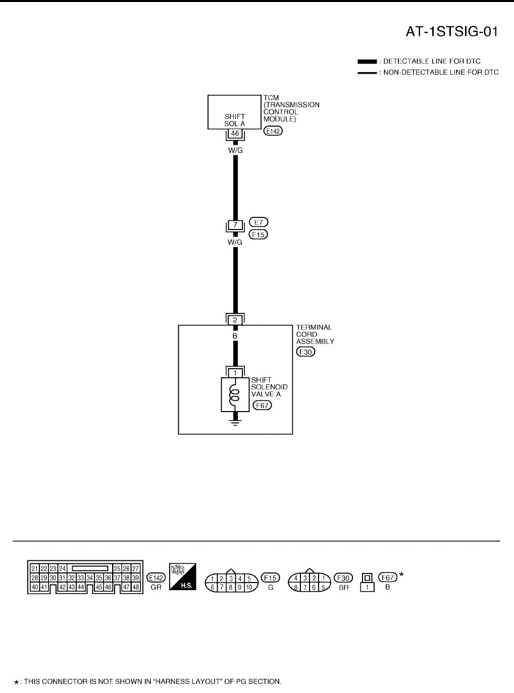
AT-484
[RE5F22A]
DTC P0731 A/T 1ST GEAR FUNCTION
Revision: September 2005 2005 Quest
Wiring Diagram — AT — 1STSIG UCS00125
BCWA0344E

DTC P0731 A/T 1ST GEAR FUNCTION
AT-485
[RE5F22A]
D
E
F
G
H
I
J
K
L
M
A
B
AT
Revision: September 2005 2005 Quest
TCM terminal and data are reference value. Measured between each terminal and ground.
Diagnostic Procedure UCS002LI
1. CHECK SHIFT SOLENOID VALVE A CIRCUIT
Perform “Diagnostic Procedure” for DTC P0750. Refer to AT-519, "Diagnostic Procedure" .
OK or NG
OK >> GO TO 2.
NG >> Repair or replace damaged parts.
2. CHECK MALFUNCTIONING ITEM
1. Control valve assembly. Refer to AT-609, "Control Valve Assembly" .
2. Disassembly A/T. Refer to AT-619, "DISASSEMBLY" .
3. Check the following item:
–2nd brake. Refer to AT-638, "Oil Pump, 2nd Coast Brake & 2nd Brake" .
–2nd coast brake. Refer to AT-638, "Oil Pump, 2nd Coast Brake & 2nd Brake" , AT-644, "One-Way Clutch
Outer Race Sub Assembly & 2nd Coast Brake Hub & One-Way Clutch No.1" .
–One-way clutch No.1. Refer to AT-644, "One-Way Clutch Outer Race Sub Assembly & 2nd Coast Brake
Hub & One-Way Clutch No.1" .
–One-way clutch No.2. Refer to AT-619, "DISASSEMBLY" .
OK or NG
OK >> GO TO 3.
NG >> Repair or replace damaged parts.
3. CHECK DTC
Perform “DTC Confirmation Procedure”. Refer to AT-483, "DTC Confirmation Procedure" .
OK or NG
OK >> INSPECTION END
NG >> Replace control valve assembly. Refer to AT-609, "Control Valve Assembly" .
Terminal Wire
color Item Condition Data (Approx.)
46 W/G Shift solenoid
valve A
When shift solenoid valve A operates.
(When driving in 1st gear.) Battery voltage
When shift solenoid valve A does not operate. 0V
AT-486
[RE5F22A]
DTC P0732 A/T 2ND GEAR FUNCTION
Revision: September 2005 2005 Quest
DTC P0732 A/T 2ND GEAR FUNCTION PFP:31940
Description UCS0024A
●This malfunction will not be detected while the O/D OFF indicator lamp is indicating another self-diagnosis
malfunction.
●This malfunction is detected when the A/T does not shift into second gear position as instructed by the
TCM. This is not caused by electrical malfunction (circuits open or shorted) but by mechanical malfunction
such as control valve sticking, improper solenoid valve operation, etc.
On Board Diagnosis Logic UCS0024B
●This is an OBD-II self-diagnostic item.
●Diagnostic trouble code “A/T 2ND GR FNCTN” with CONSULT-II or P0732 without CONSULT-II is
detected when A/T cannot be shifted to the 2nd gear position even if electrical circuit is good.
Possible Cause UCS002LQ
●Shift solenoid valve A
(On stick.)
●Shift solenoid valve B
(On stick.)
●Shift solenoid valve C
(Off stick.)
●Shift solenoid valve D
(On stick.)
●Pressure control solenoid valve A
(On stick.)
●Pressure control solenoid valve C
(On stick.)
●U/D brake
●2nd coast brake
●2nd brake
●One-way clutch No.1
●One-way clutch No.2
●B5 brake
●Hydraulic control circuit
DTC Confirmation Procedure UCS0024D
CAUTION:
●Always drive vehicle at a safe speed.
●Be careful not to rev engine into the red zone on the tachometer.
NOTE:
If “DTC Confirmation Procedure” has been previously performed, always turn ignition switch “OFF”
and wait at least 10 seconds before performing the next test.
After the repair, perform the following procedure to confirm the malfunction is eliminated.
Gear position Shift solenoid valve
AB CDE
2nd D OFF (Open) OFF (Closed) ON (Open) OFF (Open) OFF (Closed)
L OFF (Open) OFF (Closed) ON (Open) OFF (Open) OFF (Closed)
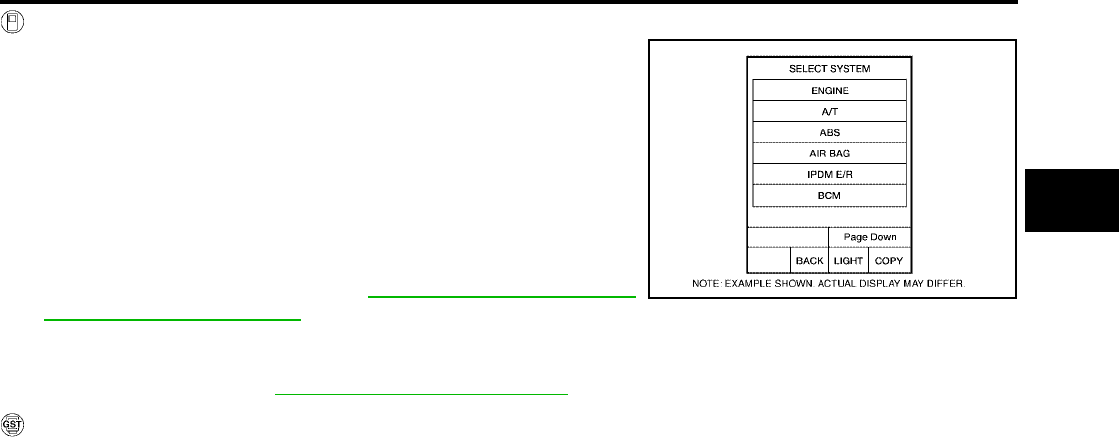
DTC P0732 A/T 2ND GEAR FUNCTION
AT-487
[RE5F22A]
D
E
F
G
H
I
J
K
L
M
A
B
AT
Revision: September 2005 2005 Quest
WITH CONSULT-II
1. Start engine and select “DATA MONITOR” mode for “A/T” with
CONSULT-II.
2. Make sure that ATF temperature is within the range below.
FLUID TEMP: More than 20°C (68°F)
If out of range, drive the vehicle to warm up the fluid.
3. Accelerate vehicle to maintain the following conditions for at
least 12 consecutive seconds.
SLCT LVR POSI: “D” position
GEAR: 2nd position
[Vehicle speed and accelerator angle: 2nd gear position
retainable condition. (Refer to AT-680, "VEHICLE SPEED
WHEN SHIFTING GEARS" .)]
Driving location: Driving the vehicle uphill (increased engine load) will help maintain the driving
conditions required for this test.
4. If DTC is detected, go to AT-490, "Diagnostic Procedure" .
WITH GST
Follow the procedure “With CONSULT-II”.
BCIA0030E
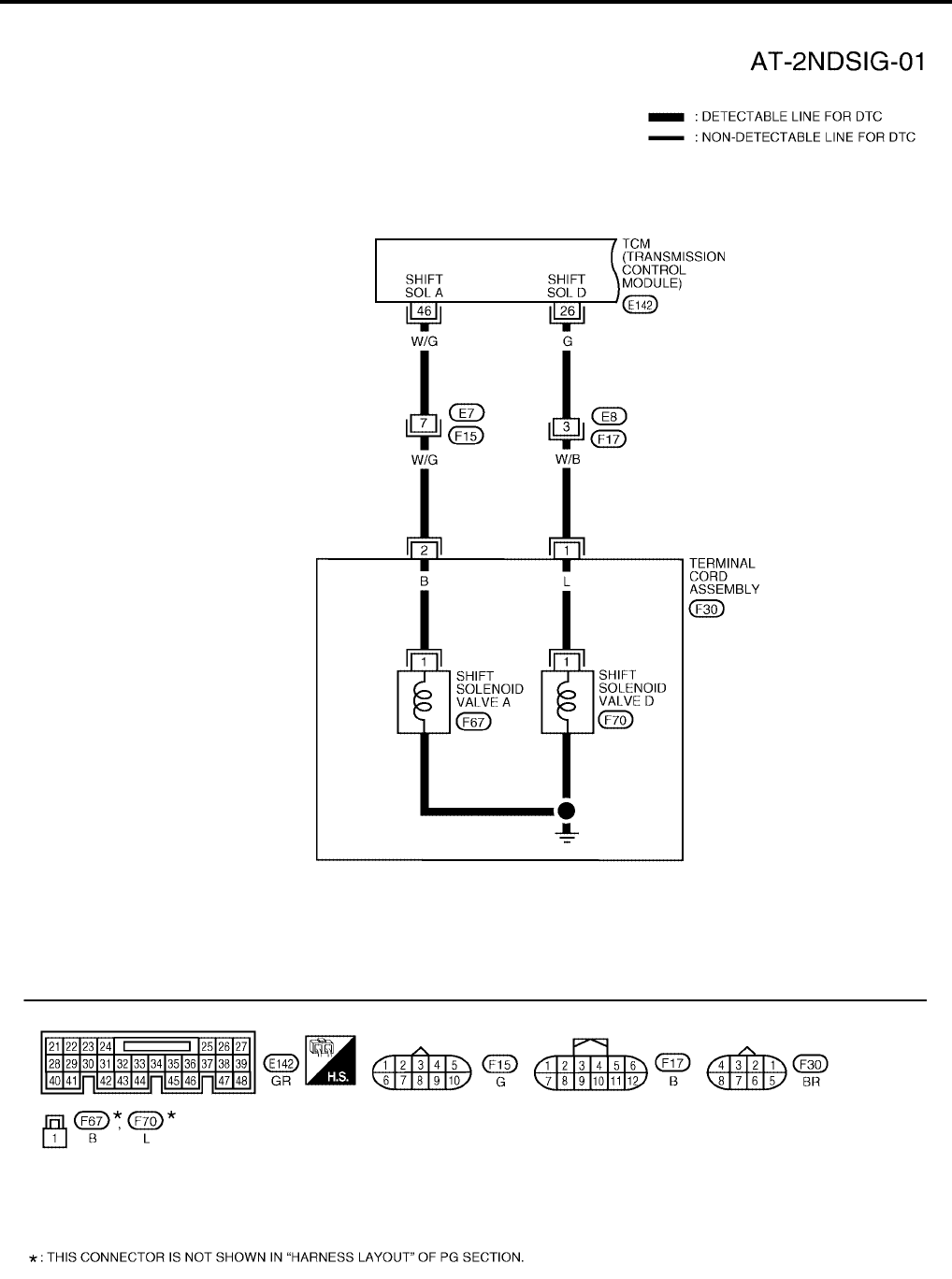
AT-488
[RE5F22A]
DTC P0732 A/T 2ND GEAR FUNCTION
Revision: September 2005 2005 Quest
Wiring Diagram — AT — 2NDSIG UCS0024E
BCWA0310E
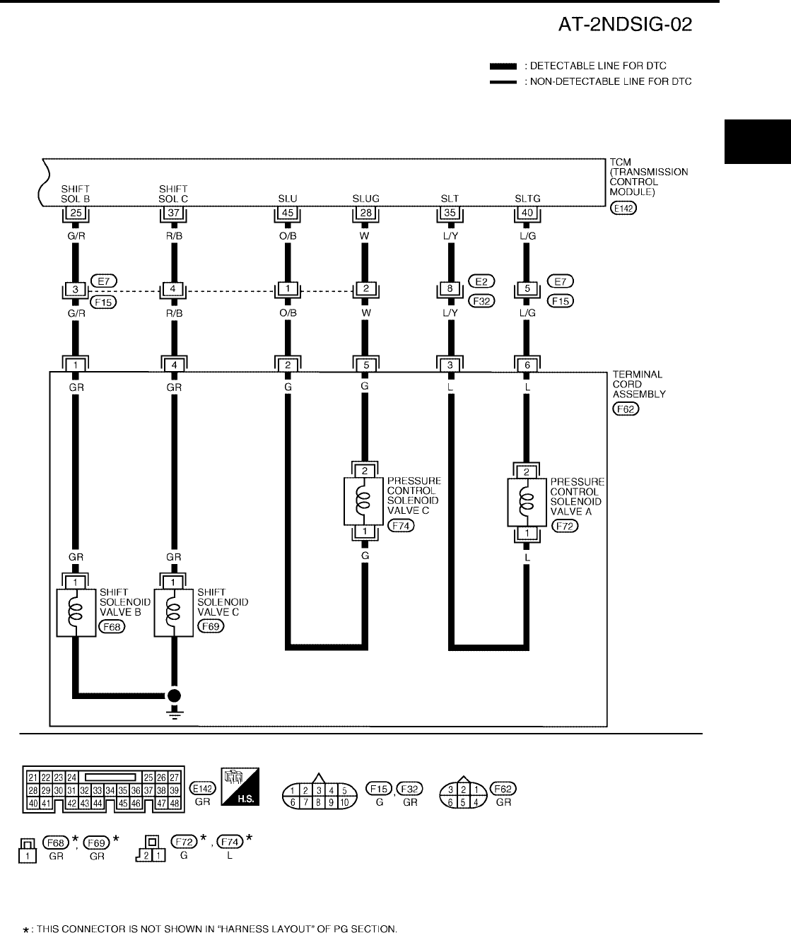
DTC P0732 A/T 2ND GEAR FUNCTION
AT-489
[RE5F22A]
D
E
F
G
H
I
J
K
L
M
A
B
AT
Revision: September 2005 2005 Quest
BCWA0311E
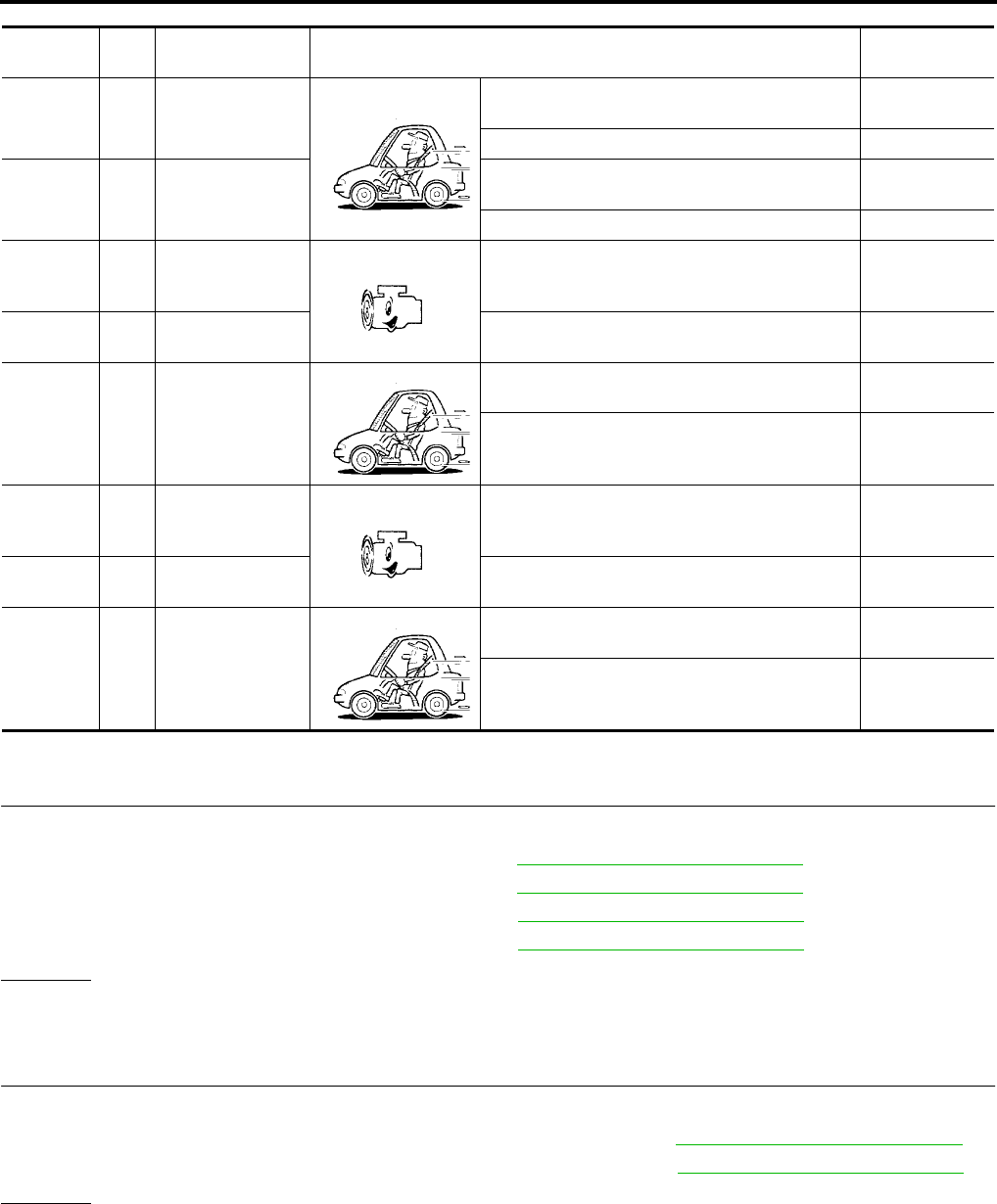
AT-490
[RE5F22A]
DTC P0732 A/T 2ND GEAR FUNCTION
Revision: September 2005 2005 Quest
TCM terminals and data are reference value. Measured between each terminal and ground.
Diagnostic Procedure UCS002LJ
1. CHECK EACH SHIFT SOLENOID VALVE CIRCUIT
Perform “Diagnostic Procedure” for the following DTCs.
●“DTC P0750 SHIFT SOLENOID VALVE A” (Refer to AT-519, "Diagnostic Procedure" .)
●“DTC P0755 SHIFT SOLENOID VALVE B” (Refer to AT-524, "Diagnostic Procedure" .)
●“DTC P0760 SHIFT SOLENOID VALVE C” (Refer to AT-529, "Diagnostic Procedure" .)
●“DTC P0765 SHIFT SOLENOID VALVE D” (Refer to AT-539, "Diagnostic Procedure" .)
OK or NG
OK >> GO TO 2.
NG >> Repair or replace damaged parts.
2. CHECK EACH PRESSURE CONTROL SOLENOID VALVE CIRCUIT
Perform “Diagnostic Procedure” for the following DTCs.
●“DTC P0745 PRESSURE CONTROL SOLENOID VALVE A” (Refer to AT-514, "Diagnostic Procedure" .)
●“DTC P0795 PRESSURE CONTROL SOLENOID VALVE C” (Refer to AT-558, "Diagnostic Procedure" .)
OK or NG
OK >> GO TO 3.
NG >> Repair or replace damaged parts.
Terminal Wire
color Item Condition Data (Approx.)
25 G/R Shift solenoid
valve B
When shift solenoid valve B operates.
(When driving in 1st or 5th gear.) Battery voltage
When shift solenoid valve B does not operate. 0V
26 G Shift solenoid
valve D
When shift solenoid valve D operates.
(When driving in 3rd, 4th or 5th gear.) Battery voltage
When shift solenoid valve D does not operate. 0V
28 W
Pressure control
solenoid valve C
ground
When engine is running with idle speed and set-
ting selector lever to “P” position. 0V
35 L/Y Pressure control
solenoid valve A
When engine is running with idle speed and set-
ting selector lever to “P” position. 300Hz
37 R/B Shift solenoid
valve C
When shift solenoid valve C operates.
(When driving in 1st, 2nd, 3rd or reverse gear.) Battery voltage
When shift solenoid valve C does not operate. 0V
40 L/G
Pressure control
solenoid valve A
ground
When engine is running with idle speed and set-
ting selector lever to “P” position. 0V
45 O/B Pressure control
solenoid valve C
When engine is running with idle speed and set-
ting selector lever to “P” position. 300Hz
46 W/G Shift solenoid
valve A
When shift solenoid valve A operates.
(When driving in 1st gear.) Battery voltage
When shift solenoid valve A does not operate. 0V

DTC P0732 A/T 2ND GEAR FUNCTION
AT-491
[RE5F22A]
D
E
F
G
H
I
J
K
L
M
A
B
AT
Revision: September 2005 2005 Quest
3. CHECK MALFUNCTIONING ITEM
1. Control valve assembly. Refer to AT-609, "Control Valve Assembly" .
2. Disassembly A/T. Refer to AT-619, "DISASSEMBLY" .
3. Check the following item:
–U/D brake. Refer to AT-619, "DISASSEMBLY" .
–2nd coast brake. Refer to AT-638, "Oil Pump, 2nd Coast Brake & 2nd Brake" , AT-644, "One-Way Clutch
Outer Race Sub Assembly & 2nd Coast Brake Hub & One-Way Clutch No.1" .
–2nd brake. Refer to AT-638, "Oil Pump, 2nd Coast Brake & 2nd Brake" .
–One-way clutch No.1. Refer to AT-644, "One-Way Clutch Outer Race Sub Assembly & 2nd Coast Brake
Hub & One-Way Clutch No.1" .
–One-way clutch No.2. Refer to AT-619, "DISASSEMBLY" .
–B5 brake. Refer to AT-646, "Transaxle Case Cover & B5 Brake" .
OK or NG
OK >> GO TO 4.
NG >> Repair or replace damaged parts.
4. CHECK DTC
Perform “DTC Confirmation Procedure”. Refer to AT-486, "DTC Confirmation Procedure" .
OK or NG
OK >> INSPECTION END
NG >> Replace control valve assembly. Refer to AT-609, "Control Valve Assembly" .

AT-492
[RE5F22A]
DTC P0733 A/T 3RD GEAR FUNCTION
Revision: September 2005 2005 Quest
DTC P0733 A/T 3RD GEAR FUNCTION PFP:31940
Description UCS0012D
●This malfunction will not be detected while the O/D OFF indicator lamp is indicating another self-diagnosis
malfunction.
●This malfunction is detected when the A/T does not shift into third gear position as instructed by the TCM.
This is not caused by electrical malfunction (circuits open or shorted) but by mechanical malfunction such
as control valve sticking, improper solenoid valve operation, etc.
On Board Diagnosis Logic UCS0012E
●This is an OBD-II self-diagnostic item.
●Diagnostic trouble code “A/T 3RD GR FNCTN” with CONSULT-II or P0733 without CONSULT-II is
detected when A/T cannot be shifted to the 3rd gear position even if electrical circuit is good.
Possible Cause UCS002LR
●Shift solenoid valve A
(On stick.)
●Shift solenoid valve B
(On stick.)
●Shift solenoid valve C
(Off stick.)
●Shift solenoid valve D
(Off stick.)
●Pressure control solenoid valve A
(On stick.)
●B5 brake
●U/D clutch
●U/D brake
●Hydraulic control circuit
DTC Confirmation Procedure UCS0014O
CAUTION:
●Always drive vehicle at a safe speed.
●Be careful not to rev engine into the red zone on the tachometer.
NOTE:
If “DTC Confirmation Procedure” has been previously performed, always turn ignition switch “OFF”
and wait at least 10 seconds before performing the next test.
After the repair, perform the following procedure to confirm the malfunction is eliminated.
WITH CONSULT-II
1. Start engine and select “DATA MONITOR” mode for “A/T” with
CONSULT-II.
2. Make sure that ATF temperature is within the range below.
FLUID TEMP: More than 20°C (68°F)
If out of range, drive the vehicle to warm up the fluid.
3. Accelerate vehicle to maintain the following conditions for at
least 12 consecutive seconds.
SLCT LVR POSI: “D” position
GEAR: 3rd position
Gear position Shift solenoid valve
ABCDE
3rd D OFF (Open) OFF (Closed) ON (Open) ON (Closed) OFF (Closed)
L OFF (Open) OFF (Closed) ON (Open) ON (Closed) OFF (Closed)
BCIA0030E

DTC P0733 A/T 3RD GEAR FUNCTION
AT-493
[RE5F22A]
D
E
F
G
H
I
J
K
L
M
A
B
AT
Revision: September 2005 2005 Quest
[Vehicle speed and accelerator angle: 3rd gear position retainable condition. (Refer to AT-680,
"VEHICLE SPEED WHEN SHIFTING GEARS" .)]
Driving location: Driving the vehicle uphill (increased engine load) will help maintain the driving
conditions required for this test.
4. If DTC is detected, go to AT-496, "Diagnostic Procedure" .
WITH GST
Follow the procedure “With CONSULT-II”.
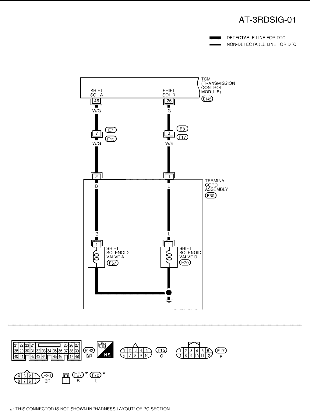
AT-494
[RE5F22A]
DTC P0733 A/T 3RD GEAR FUNCTION
Revision: September 2005 2005 Quest
Wiring Diagram — AT — 3RDSIG UCS0012H
BCWA0312E
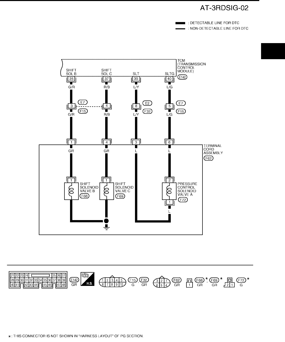
DTC P0733 A/T 3RD GEAR FUNCTION
AT-495
[RE5F22A]
D
E
F
G
H
I
J
K
L
M
A
B
AT
Revision: September 2005 2005 Quest
BCWA0313E

AT-496
[RE5F22A]
DTC P0733 A/T 3RD GEAR FUNCTION
Revision: September 2005 2005 Quest
TCM terminals and data are reference value. Measured between each terminal and ground.
Diagnostic Procedure UCS002LK
1. CHECK EACH SHIFT SOLENOID VALVE CIRCUIT
Perform “Diagnostic Procedure” for the following DTCs.
●“DTC P0750 SHIFT SOLENOID VALVE A” (Refer to AT-519, "Diagnostic Procedure" .)
●“DTC P0755 SHIFT SOLENOID VALVE B” (Refer to AT-524, "Diagnostic Procedure" .)
●“DTC P0760 SHIFT SOLENOID VALVE C” (Refer to AT-529, "Diagnostic Procedure" .)
●“DTC P0765 SHIFT SOLENOID VALVE D” (Refer to AT-539, "Diagnostic Procedure" .)
OK or NG
OK >> GO TO 2.
NG >> Repair or replace damaged parts.
2. CHECK PRESSURE CONTROL SOLENOID VALVE A CIRCUIT
Perform “Diagnostic Procedure” for DTC P0745. Refer to AT-514, "Diagnostic Procedure" .
OK or NG
OK >> GO TO 3.
NG >> Repair or replace damaged parts.
Terminal Wire
color Item Condition Data (Approx.)
25 G/R Shift solenoid
valve B
When shift solenoid valve B operates.
(When driving in 1st or 5th gear.) Battery voltage
When shift solenoid valve B does not operate. 0V
26 G Shift solenoid
valve D
When shift solenoid valve D operates.
(When driving in 3rd, 4th or 5th gear.) Battery voltage
When shift solenoid valve D does not operate. 0V
35 L/Y Pressure control
solenoid valve A
When engine is running with idle speed and set-
ting selector lever to “P” position. 300Hz
37 R/B Shift solenoid
valve C
When shift solenoid valve C operates.
(When driving in 1st, 2nd, 3rd or reverse gear.) Battery voltage
When shift solenoid valve C does not operate. 0V
40 L/G
Pressure control
solenoid valve A
ground
When engine is running with idle speed and set-
ting selector lever to “P” position. 0V
46 W/G Shift solenoid
valve A
When shift solenoid valve A operates.
(When driving in 1st gear.) Battery voltage
When shift solenoid valve A does not operate. 0V

DTC P0733 A/T 3RD GEAR FUNCTION
AT-497
[RE5F22A]
D
E
F
G
H
I
J
K
L
M
A
B
AT
Revision: September 2005 2005 Quest
3. CHECK MALFUNCTIONING ITEM
1. Control valve assembly. Refer to AT-609, "Control Valve Assembly" .
2. Disassembly A/T. Refer to AT-619, "DISASSEMBLY" .
3. Check the following item:
–B5 brake. Refer to AT-646, "Transaxle Case Cover & B5 Brake" .
–U/D clutch. Refer to AT-619, "DISASSEMBLY" .
–U/D brake. Refer to AT-619, "DISASSEMBLY" .
OK or NG
OK >> GO TO 4.
NG >> Repair or replace damaged parts.
4. CHECK DTC
Perform “DTC Confirmation Procedure”. Refer to AT-492, "DTC Confirmation Procedure" .
OK or NG
OK >> INSPECTION END
NG >> Replace the control valve assembly. Refer to AT-609, "Control Valve Assembly" .

AT-498
[RE5F22A]
DTC P0734 A/T 4TH GEAR FUNCTION
Revision: September 2005 2005 Quest
DTC P0734 A/T 4TH GEAR FUNCTION PFP:31940
Description UCS0012J
●This malfunction will not be detected while the O/D OFF indicator lamp is indicating another self-diagnosis
malfunction.
●This malfunction is detected when the A/T does not shift into fourth gear position as instructed by the
TCM. This is not caused by electrical malfunction (circuits open or shorted) but by mechanical malfunction
such as control valve sticking, improper solenoid valve operation, etc.
On Board Diagnosis Logic UCS0012K
●This is an OBD-II self-diagnostic item.
●Diagnostic trouble code “A/T 4TH GR FNCTN” with CONSULT-II or P0734 without CONSULT-II is
detected when A/T cannot be shifted to the 4th gear position even if electrical circuit is good.
Possible Cause UCS002LS
●Shift solenoid valve A
(On stick.)
●Shift solenoid valve B
(On stick.)
●Shift solenoid valve C
(On stick.)
● Pressure control solenoid valve A
(On stick.)
●Forward and direct clutch assembly
●U/D clutch
●U/D brake
●2nd coast brake
●One-way clutch No.1
●Hydraulic control circuit
DTC Confirmation Procedure UCS0014P
CAUTION:
●Always drive vehicle at a safe speed.
●Be careful not to rev engine into the red zone on the tachometer.
NOTE:
If “DTC Confirmation Procedure” has been previously performed, always turn ignition switch “OFF”
and wait at least 10 seconds before performing the next test.
After the repair, perform the following procedure to confirm the malfunction is eliminated.
WITH CONSULT-II
1. Start engine and select “DATA MONITOR” mode for “A/T” with
CONSULT-II.
2. Make sure that ATF temperature is within the range below.
FLUID TEMP: More than 20°C (68°F)
If out of range, drive the vehicle to warm up the fluid.
3. Accelerate vehicle to maintain the following conditions for at
least 12 consecutive seconds.
SLCT LVR POSI: “D” position
GEAR: 4th position
[Vehicle speed and accelerator angle: 4th gear position
retainable condition. (Refer to AT-680, "VEHICLE SPEED
WHEN SHIFTING GEARS" .)]
Gear position Shift solenoid valve
ABCDE
4th D OFF (Open) OFF (Closed) OFF (Closed) ON (Closed) OFF (Closed)
BCIA0030E

DTC P0734 A/T 4TH GEAR FUNCTION
AT-499
[RE5F22A]
D
E
F
G
H
I
J
K
L
M
A
B
AT
Revision: September 2005 2005 Quest
Driving location: Driving the vehicle uphill (increased engine load) will help maintain the driving
conditions required for this test.
4. If DTC is detected, go to AT-501, "Diagnostic Procedure" .
WITH GST
Follow the procedure “With CONSULT-II”.

AT-500
[RE5F22A]
DTC P0734 A/T 4TH GEAR FUNCTION
Revision: September 2005 2005 Quest
Wiring Diagram — AT — 4THSIG UCS0012N
BCWA0345E
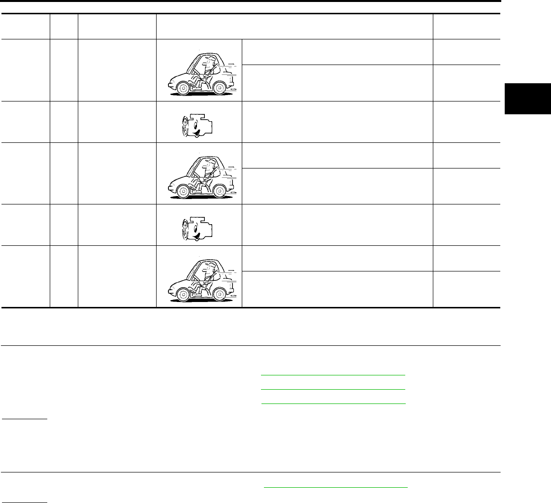
DTC P0734 A/T 4TH GEAR FUNCTION
AT-501
[RE5F22A]
D
E
F
G
H
I
J
K
L
M
A
B
AT
Revision: September 2005 2005 Quest
TCM terminals and data are reference value. Measured between each terminal and ground.
Diagnostic Procedure UCS002LL
1. CHECK EACH SHIFT SOLENOID VALVE CIRCUIT
Perform “Diagnostic Procedure” for the following DTCs.
●“DTC P0750 SHIFT SOLENOID VALVE A” (Refer to AT-519, "Diagnostic Procedure" .)
●“DTC P0755 SHIFT SOLENOID VALVE B” (Refer to AT-524, "Diagnostic Procedure" .)
●“DTC P0760 SHIFT SOLENOID VALVE C” (Refer to AT-529, "Diagnostic Procedure" .)
OK or NG
OK >> GO TO 2.
NG >> Repair or replace damaged parts.
2. CHECK PRESSURE CONTROL SOLENOID VALVE A CIRCUIT
Perform “Diagnostic Procedure” for DTC P0745. Refer to AT-514, "Diagnostic Procedure" .
OK or NG
OK >> GO TO 3.
NG >> Repair or replace damaged parts.
Terminal Wire
color Item Condition Data (Approx.)
25 G/R Shift solenoid
valve B
When shift solenoid valve B operates.
(When driving in 1st or 5th gear.) Battery voltage
When shift solenoid valve B does not operate. 0V
35 L/Y Pressure control
solenoid valve A
When engine is running with idle speed and set-
ting selector lever to “P” position. 300Hz
37 R/B Shift solenoid
valve C
When shift solenoid valve C operates.
(When driving in 1st, 2nd, 3rd or reverse gear.) Battery voltage
When shift solenoid valve C does not operate. 0V
40 L/G
Pressure control
solenoid valve A
ground
When engine is running with idle speed and set-
ting selector lever to “P” position. 0V
46 W/G Shift solenoid
valve A
When shift solenoid valve A operates.
(When driving in 1st gear.) Battery voltage
When shift solenoid valve A does not operate. 0V

AT-502
[RE5F22A]
DTC P0734 A/T 4TH GEAR FUNCTION
Revision: September 2005 2005 Quest
3. CHECK MALFUNCTIONING ITEM
1. Control valve assembly. Refer to AT-609, "Control Valve Assembly" .
2. Disassembly A/T. Refer to AT-619, "DISASSEMBLY" .
3. Check the following item:
–Forward and direct clutch assembly. Refer to AT-619, "DISASSEMBLY" .
–2nd coast brake. Refer to AT-638, "Oil Pump, 2nd Coast Brake & 2nd Brake" , AT-644, "One-Way Clutch
Outer Race Sub Assembly & 2nd Coast Brake Hub & One-Way Clutch No.1" .
–U/D brake. Refer to AT-619, "DISASSEMBLY" .
–U/D clutch. Refer to AT-619, "DISASSEMBLY" .
–One-way clutch No.1. Refer to AT-644, "One-Way Clutch Outer Race Sub Assembly & 2nd Coast Brake
Hub & One-Way Clutch No.1" .
OK or NG
OK >> GO TO 4.
NG >> Repair or replace damaged parts.
4. CHECK DTC
Perform “DTC Confirmation Procedure”. Refer to AT-498, "DTC Confirmation Procedure" .
OK or NG
OK >> INSPECTION END
NG >> Replace the control valve assembly. Refer to AT-609, "Control Valve Assembly" .
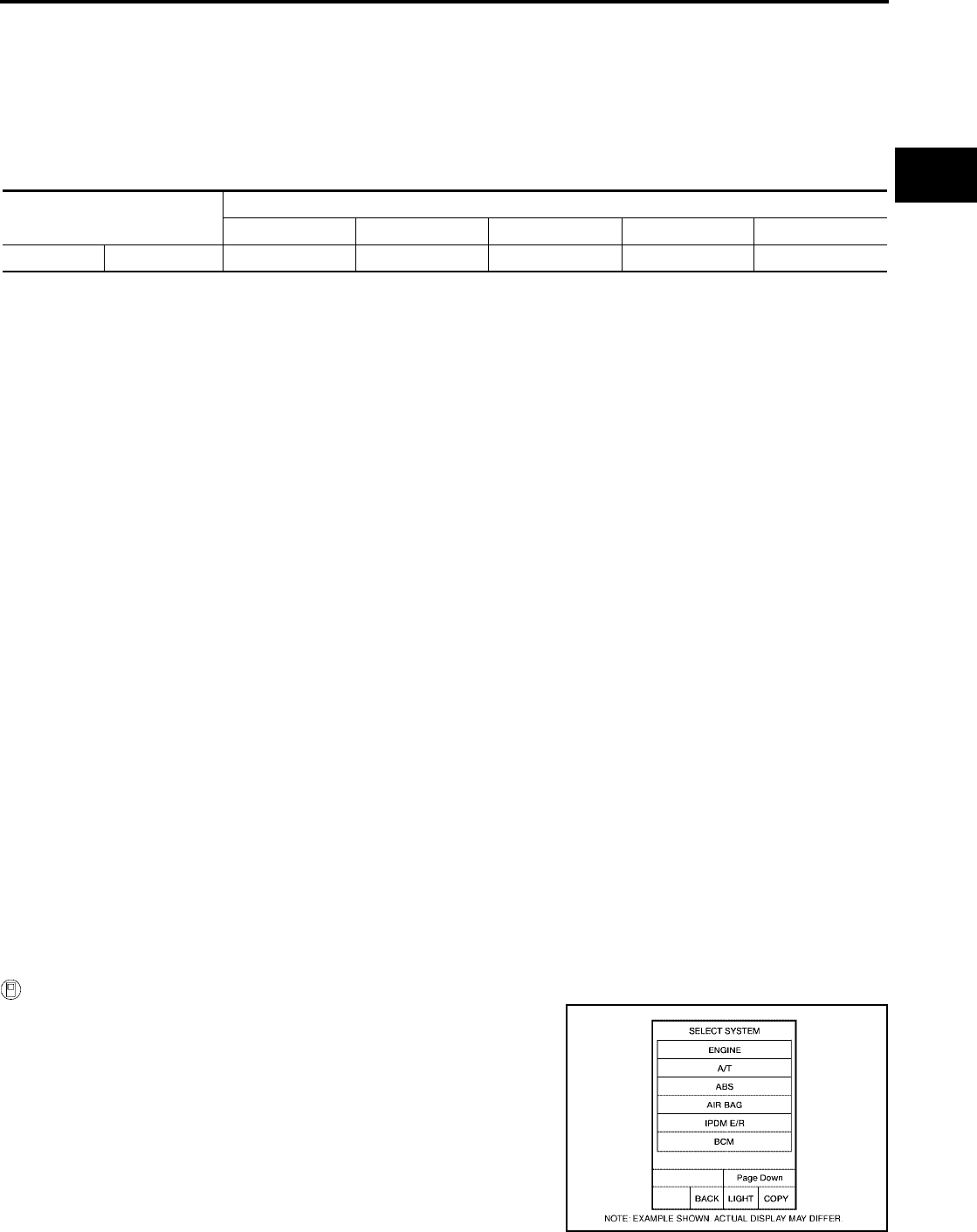
DTC P0735 A/T 5TH GEAR FUNCTION
AT-503
[RE5F22A]
D
E
F
G
H
I
J
K
L
M
A
B
AT
Revision: September 2005 2005 Quest
DTC P0735 A/T 5TH GEAR FUNCTION PFP:31940
Description UCS0012P
●This malfunction will not be detected while the O/D OFF indicator lamp is indicating another self-diagnosis
malfunction.
●This malfunction is detected when the A/T does not shift into fifth gear position as instructed by the TCM.
This is not caused by electrical malfunction (circuits open or shorted) but by mechanical malfunction such
as control valve sticking, improper solenoid valve operation, etc.
On Board Diagnosis Logic UCS0012Q
●This is an OBD-II self-diagnostic item.
●Diagnostic trouble code “A/T 5TH GR FNCTN” with CONSULT-II or P0735 without CONSULT-II is
detected when A/T cannot be shifted to the 5th gear position even if electrical circuit is good.
Possible Cause UCS002LT
●Shift solenoid valve B
(Off stick.)
●Shift solenoid valve C
(On stick.)
●Shift solenoid valve E
(On stick.)
●Pressure control solenoid valve A
(On stick.)
●Pressure control solenoid valve B
(On stick.)
●Forward and direct clutch assembly
●Direct clutch
●2no coast brake
●One-way clutch No.1
●Hydraulic control circuit
DTC Confirmation Procedure UCS0014Q
CAUTION:
●Always drive vehicle at a safe speed.
●Be careful not to rev engine into the red zone on the tachometer.
NOTE:
If “DTC Confirmation Procedure” has been previously performed, always turn ignition switch “OFF”
and wait at least 10 seconds before performing the next test.
After the repair, perform the following procedure to confirm the malfunction is eliminated.
WITH CONSULT-II
1. Start engine and select “DATA MONITOR” mode for “A/T” with
CONSULT-II.
2. Make sure that ATF temperature is within the range below.
FLUID TEMP: More than 20°C (68°F)
If out of range, drive the vehicle to warm up the fluid.
3. Accelerate vehicle to maintain the following conditions for at
least 12 consecutive seconds.
SLCT LVR POSI: “D” position
GEAR: 5th position
Gear position Shift solenoid valve
ABCD E
5th D OFF (Open) ON (Open) OFF (Closed) ON (Closed) OFF (Closed)
BCIA0030E

AT-504
[RE5F22A]
DTC P0735 A/T 5TH GEAR FUNCTION
Revision: September 2005 2005 Quest
[Vehicle speed and accelerator angle: 5th gear position retainable condition. (Refer to AT-680,
"VEHICLE SPEED WHEN SHIFTING GEARS" .)]
Driving location: Driving the vehicle uphill (increased engine load) will help maintain the driving
conditions required for this test.
4. If DTC is detected, go to AT-507, "Diagnostic Procedure" .
WITH GST
Follow the procedure “With CONSULT-II”.
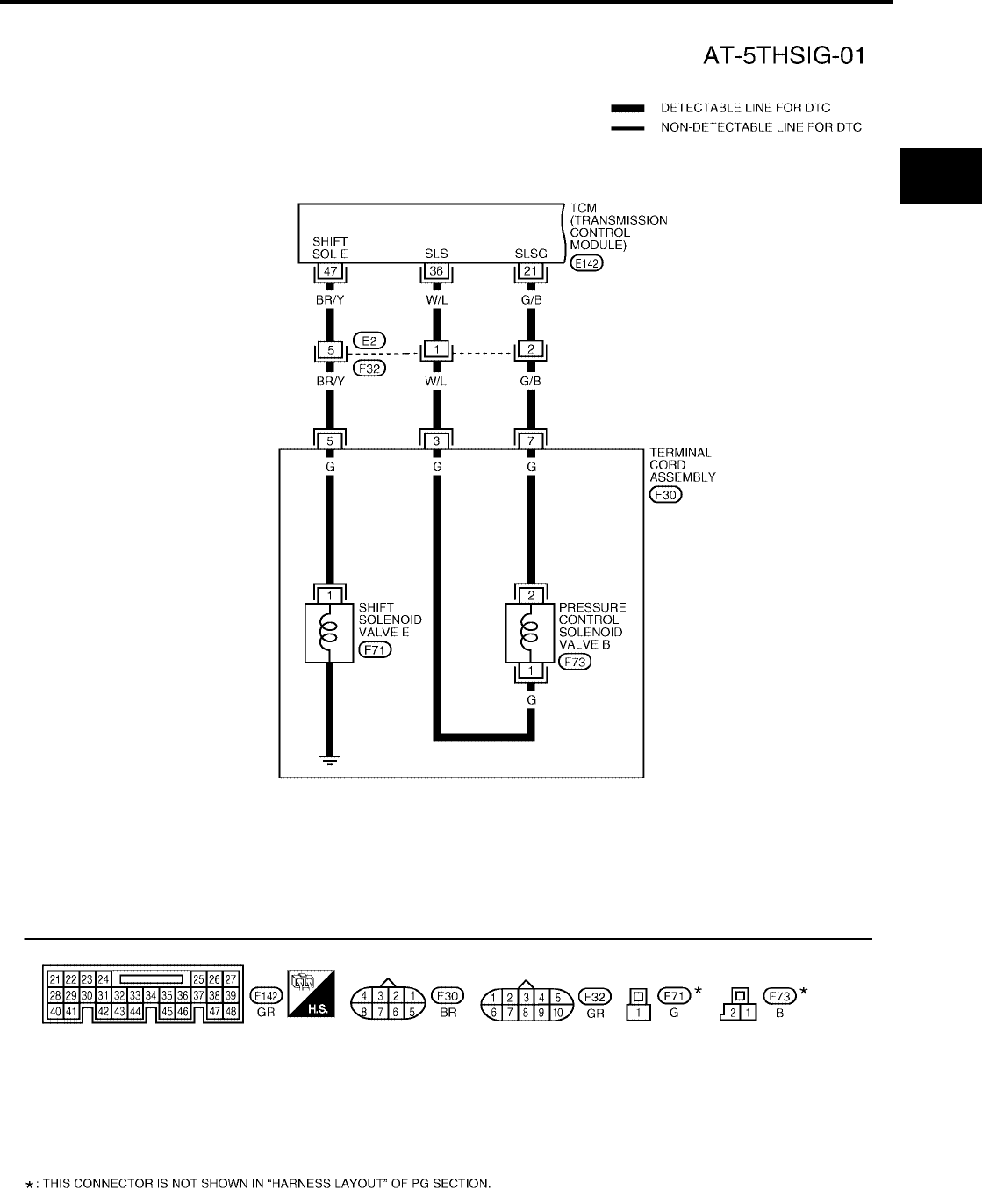
DTC P0735 A/T 5TH GEAR FUNCTION
AT-505
[RE5F22A]
D
E
F
G
H
I
J
K
L
M
A
B
AT
Revision: September 2005 2005 Quest
Wiring Diagram — AT — 5THSIG UCS0012T
BCWA0346E
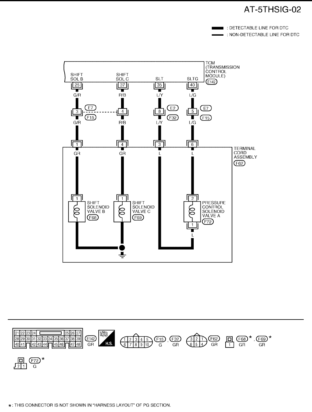
AT-506
[RE5F22A]
DTC P0735 A/T 5TH GEAR FUNCTION
Revision: September 2005 2005 Quest
BCWA0347E
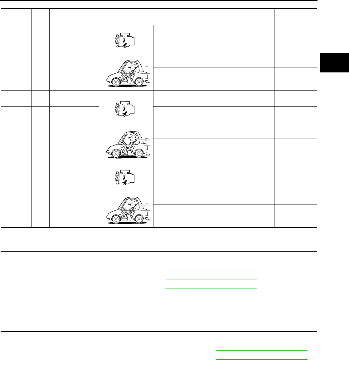
DTC P0735 A/T 5TH GEAR FUNCTION
AT-507
[RE5F22A]
D
E
F
G
H
I
J
K
L
M
A
B
AT
Revision: September 2005 2005 Quest
TCM terminals and data are reference value. Measured between each terminal and ground.
Diagnostic Procedure UCS002LM
1. CHECK EACH SHIFT SOLENOID VALVE CIRCUIT
Perform “Diagnostic Procedure” for the following DTCs.
●“DTC P0755 SHIFT SOLENOID VALVE B” (Refer to AT-524, "Diagnostic Procedure" .)
●“DTC P0760 SHIFT SOLENOID VALVE C” (Refer to AT-529, "Diagnostic Procedure" .)
●“DTC P0770 SHIFT SOLENOID VALVE E” (Refer to AT-544, "Diagnostic Procedure" .)
OK or NG
OK >> GO TO 2.
NG >> Repair or replace damaged parts.
2. CHECK EACH PRESSURE CONTROL SOLENOID VALVE CIRCUIT
Perform “Diagnostic Procedure” for the following DTCs.
●“DTC P0745 PRESSURE CONTROL SOLENOID VALVE A” (Refer to AT-514, "Diagnostic Procedure" .)
●“DTC P0775 PRESSURE CONTROL SOLENOID VALVE B” (Refer to AT-549, "Diagnostic Procedure" .)
OK or NG
OK >> GO TO 3.
NG >> Repair or replace damaged parts.
Terminal Wire
color Item Condition Data (Approx.)
21 G/B
Pressure control
solenoid valve B
ground
When engine is running with idle speed and set-
ting selector lever to “P” position. 0V
25 G/R Shift solenoid
valve B
When shift solenoid valve B operates.
(When driving in 1st or 5th gear.) Battery voltage
When shift solenoid valve B does not operate. 0V
35 L/Y Pressure control
solenoid valve A
When engine is running with idle speed and set-
ting selector lever to “P” position. 300Hz
36 W/L Pressure control
solenoid valve B
When engine is running with idle speed and set-
ting selector lever to “P” position. 300Hz
37 R/B Shift solenoid
valve C
When shift solenoid valve C operates.
(When driving in 1st, 2nd, 3rd or reverse gear.) Battery voltage
When shift solenoid valve C does not operate. 0V
40 L/G
Pressure control
solenoid valve A
ground
When engine is running with idle speed and set-
ting selector lever to “P” position. 0V
47 BR/Y Shift solenoid
valve E
When shift solenoid valve E operates.
(When driving in reverse gear.) Battery voltage
When shift solenoid valve E does not operate. 0V

AT-508
[RE5F22A]
DTC P0735 A/T 5TH GEAR FUNCTION
Revision: September 2005 2005 Quest
3. CHECK MALFUNCTIONING ITEM
1. Control valve assembly. Refer to AT-609, "Control Valve Assembly" .
2. Disassembly A/T. Refer to AT-619, "DISASSEMBLY" .
3. Check the following item:
–Forward and direct clutch assembly. Refer to AT-619, "DISASSEMBLY" .
–2nd brake. Refer to AT-638, "Oil Pump, 2nd Coast Brake & 2nd Brake" .
–One-way clutch No.1. Refer to AT-644, "One-Way Clutch Outer Race Sub Assembly & 2nd Coast Brake
Hub & One-Way Clutch No.1" .
OK or NG
OK >> GO TO 4.
NG >> Repair or replace damaged parts.
4. CHECK DTC
Perform “DTC Confirmation Procedure”. Refer to AT-503, "DTC Confirmation Procedure" .
OK or NG
OK >> INSPECTION END
NG >> Replace the control valve assembly. Refer to AT-609, "Control Valve Assembly" .
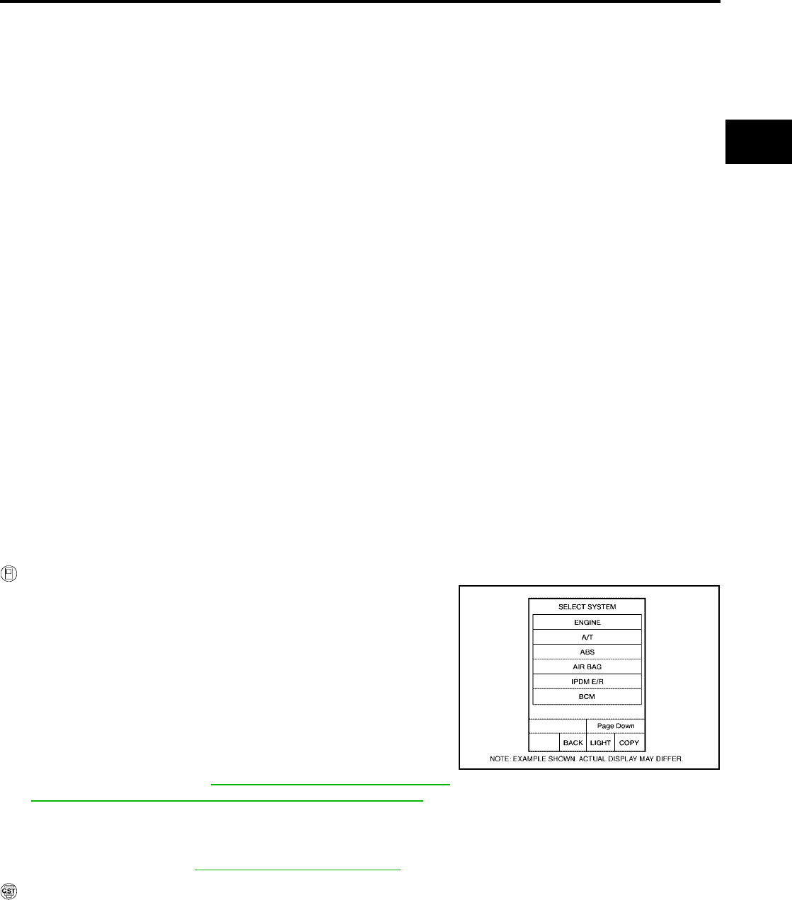
DTC P0744 A/T TCC S/V FUNCTION (LOCK-UP)
AT-509
[RE5F22A]
D
E
F
G
H
I
J
K
L
M
A
B
AT
Revision: September 2005 2005 Quest
DTC P0744 A/T TCC S/V FUNCTION (LOCK-UP) PFP:31940
Description UCS000V1
●This malfunction will not be detected while the O/D OFF indicator lamp is indicating another self-diagnosis
malfunction.
●This malfunction is detected when the torque converter clutch does not lock up as instructed by the TCM.
This is not caused by electrical malfunction (circuits open or shorted) but by mechanical malfunction such
as control valve sticking, improper solenoid valve operation, malfunctioning oil pump or torque converter
clutch, etc.
On Board Diagnosis Logic UCS000V2
●This is an OBD-II self-diagnostic item.
●Diagnostic trouble code “A/T TCC S/V FNCTN” with CONSULT-II or P0744 without CONSULT-II is
detected when A/T cannot perform lock-up even if electrical circuit is good.
Possible Cause UCS000V3
●Shift solenoid valve D
(Off stick.)
●Pressure control solenoid valve C
(Off stick.)
●Torque converter clutch
●Hydraulic control circuit
DTC Confirmation Procedure UCS000V4
CAUTION:
●Always drive vehicle at a safe speed.
●Be careful not to rev engine into the red zone on the tachometer.
NOTE:
If “DTC Confirmation Procedure” has been previously performed, always turn ignition switch “OFF”
and wait at least 10 seconds before performing the next test.
After the repair, perform the following procedure to confirm the malfunction is eliminated.
WITH CONSULT-II
1. Start engine and select “DATA MONITOR” mode for “A/T” with
CONSULT-II.
2. Make sure that ATF temperature is within the range below.
FLUID TEMP: More than 20°C (68°F)
If out of range, drive the vehicle to warm up the fluid.
3. Accelerate vehicle to more than 100 km/h (62 MPH) and main-
tain the following conditions for at least 12 consecutive seconds.
SLCT LVR POSI: “D” position
GEAR: 5th position
SLIP REV: Less than 100 rpm
ACCELE ANGLE: More than 5 %
LOCK-UP: ON (Refer to AT-681, "VEHICLE SPEED WHEN
PERFORMING AND RELEASING COMPLETE LOCK-UP" .)
[Vehicle speed: Constant speed of more than 100 km/h (62 MPH).]
Driving location: Driving the vehicle uphill (increased engine load) will help maintain the driving
conditions required for this test.
4. If DTC is detected, go to AT-511, "Diagnostic Procedure" .
WITH GST
Follow the procedure “With CONSULT-II”.
BCIA0030E
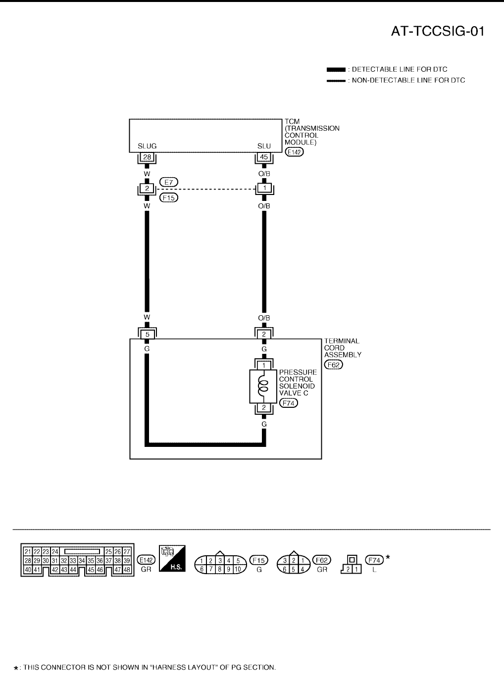
AT-510
[RE5F22A]
DTC P0744 A/T TCC S/V FUNCTION (LOCK-UP)
Revision: September 2005 2005 Quest
Wiring Diagram — AT — TCCSIG UCS000V5
BCWA0348E
DTC P0744 A/T TCC S/V FUNCTION (LOCK-UP)
AT-511
[RE5F22A]
D
E
F
G
H
I
J
K
L
M
A
B
AT
Revision: September 2005 2005 Quest
TCM terminals and data are reference value. Measured between each terminal and ground.
Diagnostic Procedure UCS002LN
1. CHECK SHIFT SOLENOID VALVE D CIRCUIT
Perform “Diagnostic Procedure” for DTC P0765. Refer to AT-539, "Diagnostic Procedure" .
OK or NG
OK >> GO TO 2.
NG >> Repair or replace damaged parts.
2. CHECK PRESSURE CONTROL SOLENOID VALVE C CIRCUIT
Perform “Diagnostic Procedure” for DTC P0795. Refer to AT-558, "Diagnostic Procedure" .
OK or NG
OK >> GO TO 3.
NG >> Repair or replace damaged parts.
3. CHECK MALFUNCTIONING ITEM
1. Control valve assembly. Refer to AT-609, "Control Valve Assembly" .
2. Disassembly A/T. Refer to AT-619, "DISASSEMBLY" .
3. Check the following item:
–Torque converter clutch. Refer to AT-619, "DISASSEMBLY" .
OK or NG
OK >> GO TO 4.
NG >> Repair or replace damaged parts.
4. CHECK DTC
Perform “DTC Confirmation Procedure”. Refer to AT-509, "DTC Confirmation Procedure" .
OK or NG
OK >> INSPECTION END
NG >> Replace the control valve assembly. Refer to AT-609, "Control Valve Assembly" .
Terminal Wire
color Item Condition Data (Approx.)
28 W
Pressure control
solenoid valve C
ground
When engine is running with idle speed and set-
ting selector lever to “P” position. 0V
45 O/B Pressure control
solenoid valve C
When engine is running with idle speed and set-
ting selector lever to “P” position. 300Hz
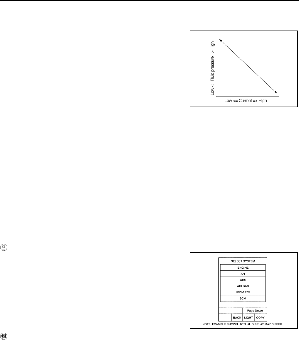
AT-512
[RE5F22A]
DTC P0745 PRESSURE CONTROL SOLENOID VALVE A (LINE PRESSURE)
Revision: September 2005 2005 Quest
DTC P0745 PRESSURE CONTROL SOLENOID VALVE A (LINE PRESSURE)
PFP:31940
Description UCS000V7
●The pressure control solenoid valve A is normally high, 3-port
linear pressure control solenoid.
●The pressure control solenoid valve A regulates the oil pump
discharge pressure to suit the driving condition in response to a
signal sent from the TCM.
On Board Diagnosis Logic UCS000V8
●This is an OBD-II self-diagnostic item.
●Diagnostic trouble code “PC SOL A(L/PRESS)” with CONSULT-II or P0745 without CONSULT-II is
detected under the following conditions.
–When normal voltage is not applied to solenoid due to open, short, and so on.
–When TCM detects as irregular by comparing target value with monitor value.
Possible Cause UCS000V9
●Harness or connectors
(The solenoid circuit is open or shorted.)
●Pressure control solenoid valve A
DTC Confirmation Procedure UCS000VA
NOTE:
If “DTC Confirmation Procedure” has been previously performed, always turn ignition switch “OFF”
and wait at least 10 seconds before performing the next test.
After the repair, perform the following procedure to confirm the malfunction is eliminated.
WITH CONSULT-II
1. Turn ignition switch “ON”. (Do not start engine.)
2. Select “DATA MONITOR” mode for “A/T” with CONSULT-II.
3. Start engine.
4. Run engine for at least 13 consecutive seconds at idle speed.
5. If DTC is detected, go to AT-514, "Diagnostic Procedure" .
WITH GST
Follow the procedure “With CONSULT-II”.
SCIA2831E
BCIA0030E
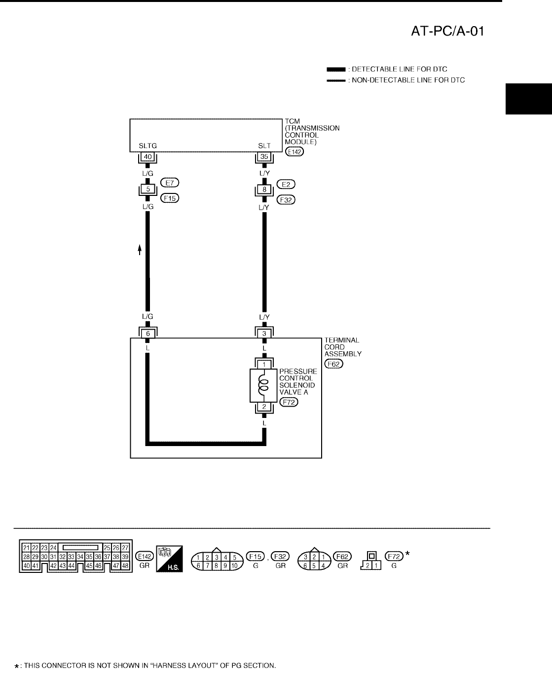
DTC P0745 PRESSURE CONTROL SOLENOID VALVE A (LINE PRESSURE)
AT-513
[RE5F22A]
D
E
F
G
H
I
J
K
L
M
A
B
AT
Revision: September 2005 2005 Quest
Wiring Diagram — AT — PC/A UCS000VB
BCWA0349E

AT-514
[RE5F22A]
DTC P0745 PRESSURE CONTROL SOLENOID VALVE A (LINE PRESSURE)
Revision: September 2005 2005 Quest
TCM terminals and data are reference value. Measured between each terminal and ground.
Diagnostic Procedure UCS002LU
1. CHECK PRESSURE CONTROL SOLENOID VALVE A SIGNAL
With CONSULT-II
1. After warming up the engine and transaxle, turn ignition switch “OFF”.
2. Turn ignition switch “ON”. (Do not start engine.)
3. Select “DATA MONITOR” mode for “A/T” with CONSULT-II.
4. Read out the value of “PC SOL A OUT” and “PC SOL A MON”.
Without CONSULT-II
1. Start the engine.
2. Check pulse between TCM connector terminals 35 and 40.
OK or NG
OK >> GO TO 7.
NG >> GO TO 2.
2. CHECK PRESSURE CONTROL SOLENOID VALVE A CIRCUIT
1. Turn ignition switch “OFF”.
2. Disconnect the TCM connector.
3. Check resistance between TCM connector terminals 35 and 40.
OK or NG
OK >> GO TO 7.
NG >> GO TO 3.
Terminal Wire
color Item Condition Data (Approx.)
35 L/Y Pressure control
solenoid valve A
When engine is running with idle speed and set-
ting selector lever to “P” position. 300Hz
40 L/G
Pressure control
solenoid valve A
ground
When engine is running with idle speed and set-
ting selector lever to “P” position. 0V
Monitor item Condition Display value
(Approx.)
●PC SOL A OUT
●PC SOL A MON
When releasing accelerator pedal with set-
ting selector lever to “P” position. 1.00 A
When depressing accelerator pedal fully set-
ting selector lever to “P” position. 0.32 A
SCIA2907E
Connector Terminal (Wire
color) Condition Data
(Approx.)
E142 35 (L/Y) - 40 (L/G)
When engine is running with idle
speed and setting selector lever to
“P” position.
300 Hz
SCIA2908E
Connector Terminal (Wire
color) Condition Resistance
(Approx.)
E142 35 (L/Y) - 40 (L/G) Temperature: 20°C (68°F) 5.0 - 5.6 Ω
SCIA2909E
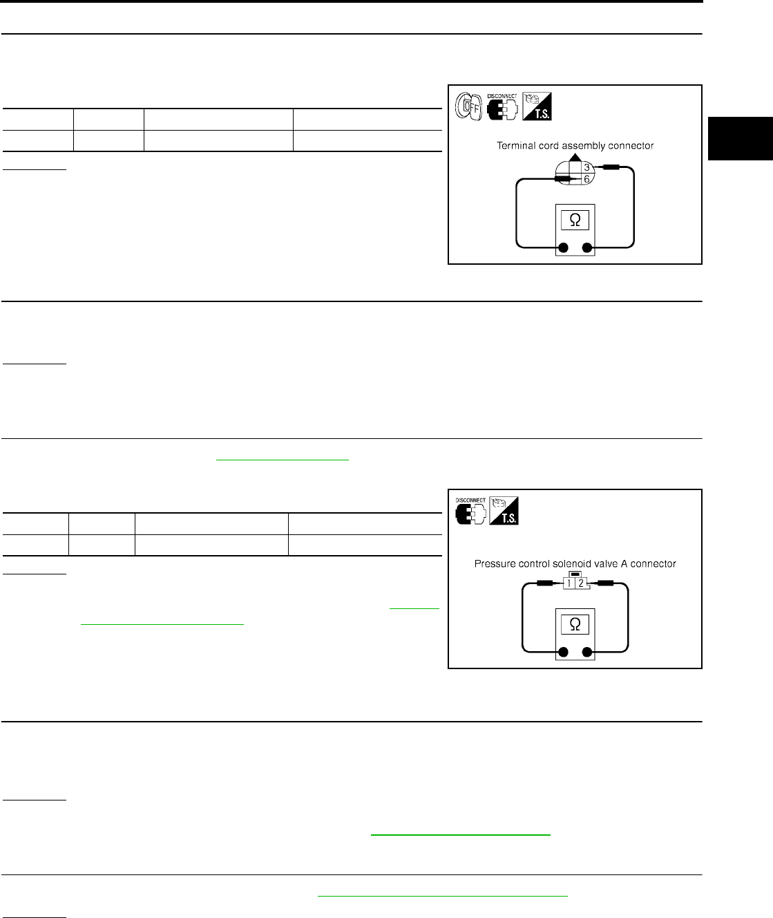
DTC P0745 PRESSURE CONTROL SOLENOID VALVE A (LINE PRESSURE)
AT-515
[RE5F22A]
D
E
F
G
H
I
J
K
L
M
A
B
AT
Revision: September 2005 2005 Quest
3. CHECK TERMINAL CORD ASSEMBLY WITH PRESSURE CONTROL SOLENOID VALVE A
1. Turn ignition switch “OFF”.
2. Disconnect terminal cord assembly harness connector.
3. Check resistance between terminals 3 and 6.
OK or NG
OK >> GO TO 4.
NG >> GO TO 5.
4. CHECK HARNESS BETWEEN TCM AND TERMINAL CORD ASSEMBLY
Check the following.
●Open or short-circuit in the harness between TCM and terminal cord assembly.
OK or NG
OK >> GO TO 7.
NG >> Repair or replace damaged parts.
5. CHECK PRESSURE CONTROL SOLENOID VALVE A
1. Remove side cover. Refer to AT-609, "Side cover" .
2. Disconnect pressure control solenoid valve A harness connector.
3. Check resistance between terminals 1 and 2.
OK or NG
OK >> GO TO 6.
NG >> Replace the control valve assembly. Refer to AT-609,
"Control Valve Assembly" .
6. CHECK HARNESS BETWEEN TERMINAL CORD ASSEMBLY AND PRESSURE CONTROL SOLE-
NOID VALVE A
Check the following.
●Open or short-circuit in the harness between terminal cord assembly and pressure control solenoid valve
A.
OK or NG
OK >> GO TO 7.
NG >> Repair or replace transmission wire. Refer to AT-609, "Transmission wire" .
7. CHECK DTC
Perform “DTC Confirmation Procedure”. Refer to AT-512, "DTC Confirmation Procedure" .
OK or NG
OK >> INSPECTION END
NG >> GO TO 8.
Connector Terminal Condition Resistance (Approx.)
F62 3 - 6 Temperature: 20°C (68°F) 5.0 - 5.6 Ω
SCIA2910E
Connector Terminal Condition Resistance (Approx.)
F72 1 - 2 Temperature: 20°C (68°F) 5.0 - 5.6 Ω
SCIA4326E
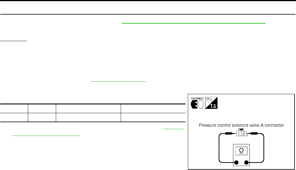
AT-516
[RE5F22A]
DTC P0745 PRESSURE CONTROL SOLENOID VALVE A (LINE PRESSURE)
Revision: September 2005 2005 Quest
8. CHECK TCM
1. Check TCM input/output signal. Refer to AT-438, "TCM Input/Output Signal Reference Values" .
2. If NG, recheck TCM pin terminals for damage or loose connection with harness connector.
OK or NG
OK >> INSPECTION END
NG >> Repair or replace damaged parts.
Component Inspection UCS002LV
PRESSURE CONTROL SOLENOID VALVE A
1. Remove side cover. Refer to AT-609, "Side cover" .
2. Disconnect pressure control solenoid valve A harness connector.
3. Check resistance between terminals 1 and 2.
4. If NG, replace the control valve assembly. Refer to AT-609,
"Control Valve Assembly" .
Connector Terminal Condition Resistance (Approx.)
F72 1 - 2 Temperature: 20°C (68°F) 5.0 - 5.6 Ω
SCIA4326E
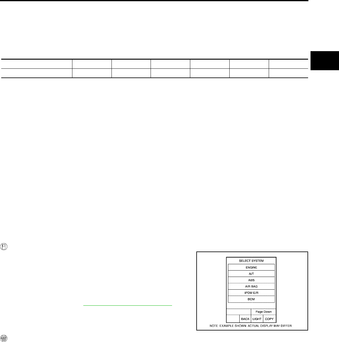
DTC P0750 SHIFT SOLENOID VALVE A
AT-517
[RE5F22A]
D
E
F
G
H
I
J
K
L
M
A
B
AT
Revision: September 2005 2005 Quest
DTC P0750 SHIFT SOLENOID VALVE A PFP:31940
Description UCS00131
●Shift solenoid valves are installed directly in control valve body. The shift solenoid valves operates of ON
and OFF by the control signal from TCM. Combinations of 5 shift solenoid valves, A, B, C, D and E, shifts
gear positions.
●The shift solenoid valve A is a normally open, ON-OFF type solenoid.
On Board Diagnosis Logic UCS00132
●This is an OBD-II self-diagnostic item.
●Diagnostic trouble code “SHIFT SOL A” with CONSULT-II or P0750 without CONSULT-II is detected
under the following conditions.
–When normal voltage is not applied to solenoid due to open, short, and so on.
–When TCM detects as irregular by comparing target value with monitor value.
Possible Cause UCS00133
●Harness or connectors
(The solenoid circuit is open or shorted.)
●Shift solenoid valve A
DTC Confirmation Procedure UCS00134
CAUTION:
●Always drive vehicle at a safe speed.
● Be careful not to rev engine into the red zone on the tachometer.
NOTE:
If “DTC Confirmation Procedure” has been previously performed, always turn ignition switch “OFF”
and wait at least 10 seconds before performing the next test.
After the repair, perform the following procedure to confirm the malfunction is eliminated.
WITH CONSULT-II
1. Turn ignition switch “ON”. (Do not start engine.)
2. Select “DATA MONITOR” mode for “A/T” with CONSULT-II.
3. Start engine.
4. Drive vehicle and allow the following conditions.
SLCT LVR POSI: “D” position
GEAR: 1st Þ 2nd position
5. If DTC is detected, go to AT-519, "Diagnostic Procedure" .
WITH GST
Follow the procedure “With CONSULT-II”.
Gear position D1 , L1D2 , L2D3 , L3D4D5Reverse
Shift solenoid valve A ON (Closed) OFF (Open) OFF (Open) OFF (Open) OFF (Open) OFF (Open)
BCIA0030E
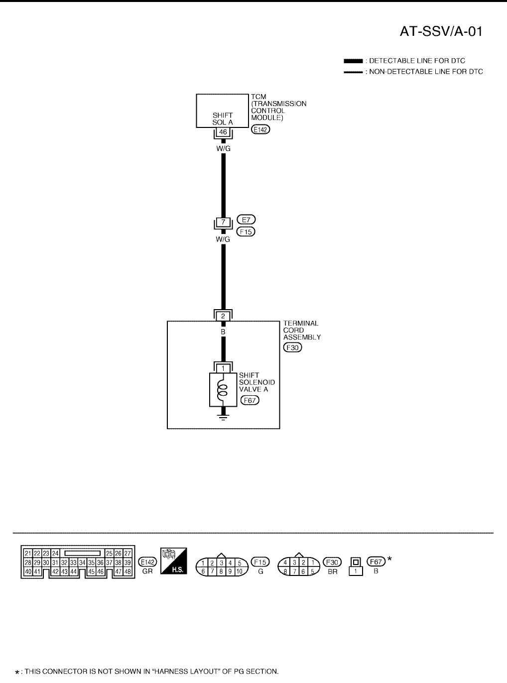
AT-518
[RE5F22A]
DTC P0750 SHIFT SOLENOID VALVE A
Revision: September 2005 2005 Quest
Wiring Diagram — AT — SSV/A UCS00135
BCWA0350E
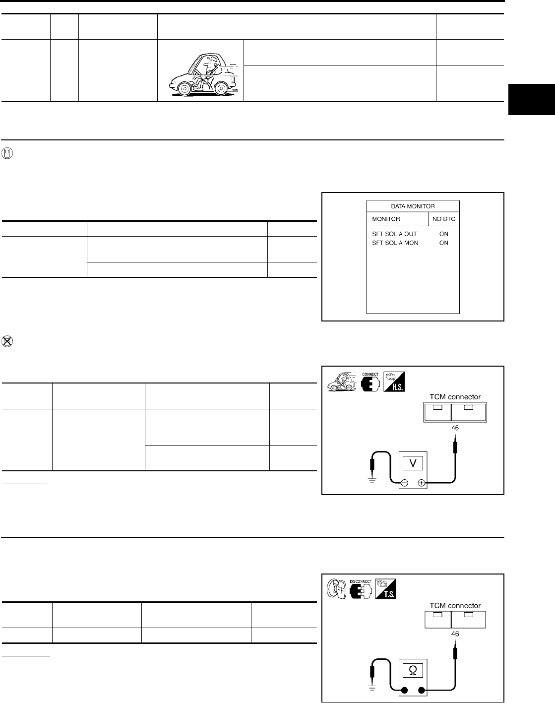
DTC P0750 SHIFT SOLENOID VALVE A
AT-519
[RE5F22A]
D
E
F
G
H
I
J
K
L
M
A
B
AT
Revision: September 2005 2005 Quest
TCM terminal and data are reference value. Measured between each terminal and ground.
Diagnostic Procedure UCS002LW
1. CHECK SHIFT SOLENOID VALVE A SIGNAL
With CONSULT-II
1. Start engine.
2. Select “A/T” with “DATA MONITOR” mode in CONSULT-II.
3. Drive vehicle and read out the value of “SFT SOL A OUT” and
“SFT SOL A MON”.
Without CONSULT-II
1. Drive vehicle.
2. Check voltage between TCM connector terminal and ground.
OK or NG
OK >> GO TO 7.
NG >> GO TO 2.
2. CHECK SHIFT SOLENOID VALVE A CIRCUIT
1. Turn ignition switch “OFF”.
2. Disconnect the TCM connector.
3. Check resistance between TCM connector terminal 46 and
ground.
OK or NG
OK >> GO TO 7.
NG >> GO TO 3.
Terminal Wire
color Item Condition Data (Approx.)
46 W/G Shift solenoid
valve A
When shift solenoid valve A operates.
(When driving in 1st gear.) Battery voltage
When shift solenoid valve A does not operate. 0V
Monitor item Condition Indication
●SFT SOL A OUT
●SFT SOL A MON
When shift solenoid valve A operates.
(When driving in 1st gear.) ON
When shift solenoid valve A does not operate. OFF
SCIA2874E
Connector Terminal (Wire color) Condition Voltage
(Approx.)
E142 46 (W/G) - Ground
When shift solenoid valve A
operates.
(When driving in 1st gear.)
Battery
voltage
When shift solenoid valve A
does not operate. 0V
SCIA2875E
Connector Terminal (Wire color) Condition Resistance
(Approx.)
E142 46 (W/G) - Ground Temperature: 20°C (68°F) 11 - 16 Ω
SCIA2877E
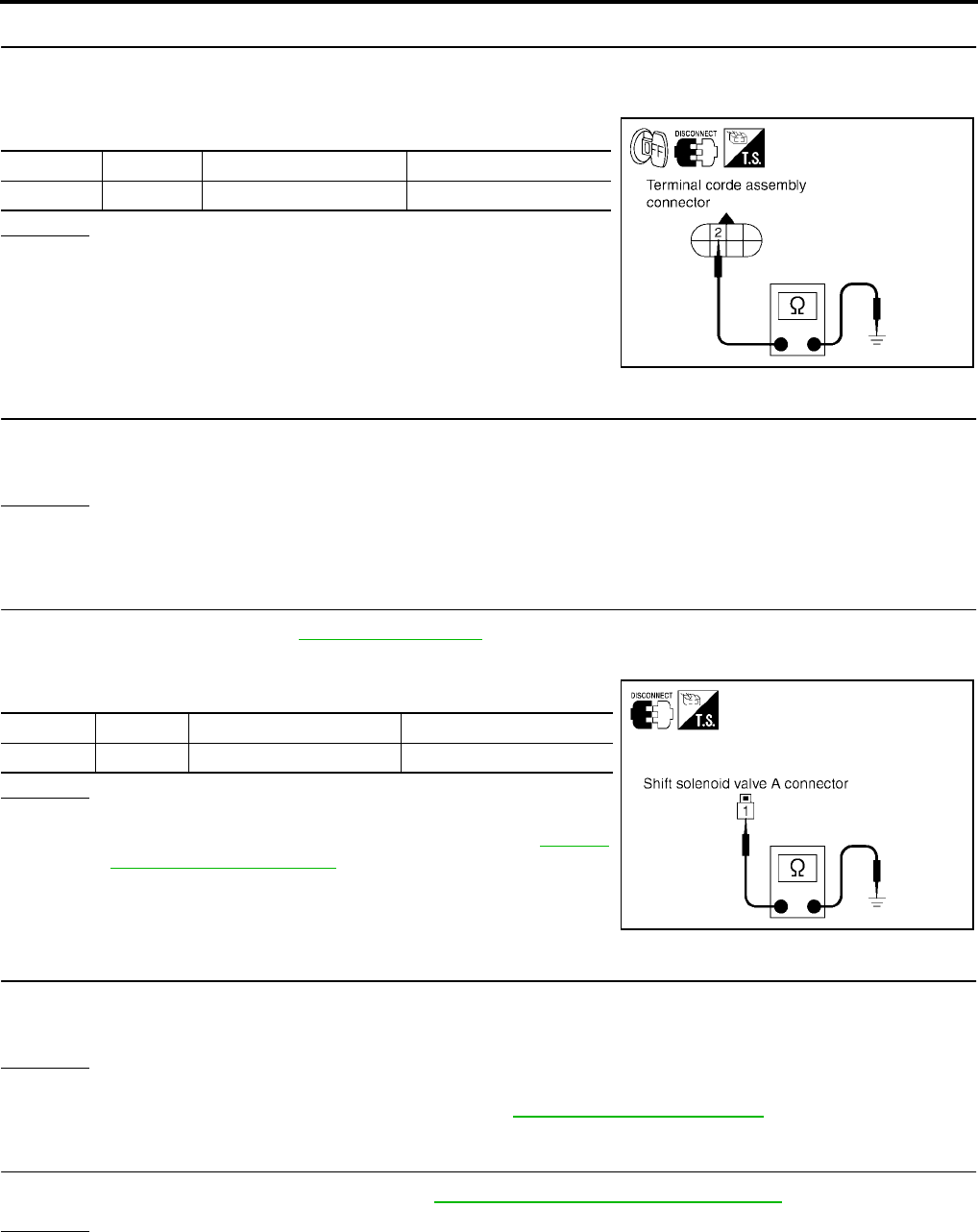
AT-520
[RE5F22A]
DTC P0750 SHIFT SOLENOID VALVE A
Revision: September 2005 2005 Quest
3. CHECK TERMINAL CORD ASSEMBLY WITH SHIFT SOLENOID VALVE A
1. Turn ignition switch “OFF”.
2. Disconnect terminal cord assembly harness connector.
3. Check resistance between terminal 2 and ground.
OK or NG
OK >> GO TO 4.
NG >> GO TO 5.
4. CHECK HARNESS BETWEEN TCM AND TERMINAL CORD ASSEMBLY
Check the following.
●Open or short-circuit in the harness between TCM and terminal cord assembly.
OK or NG
OK >> GO TO 7.
NG >> Repair or replace damaged parts.
5. CHECK SHIFT SOLENOID VALVE A
1. Remove side cover. Refer to AT-609, "Side cover" .
2. Disconnect shift solenoid valve A harness connector.
3. Check resistance between terminal 1 and ground.
OK or NG
OK >> GO TO 6.
NG >> Replace the control valve assembly. Refer to AT-609,
"Control Valve Assembly" .
6. CHECK HARNESS BETWEEN TERMINAL CORD ASSEMBLY AND SHIFT SOLENOID VALVE A
Check the following.
●Open or short-circuit in the harness between terminal cord assembly and shift solenoid valve A.
OK or NG
OK >> GO TO 7.
NG >> Repair or replace transmission wire. Refer to AT-609, "Transmission wire" .
7. CHECK DTC
Perform “DTC Confirmation Procedure”. Refer toAT-517, "DTC Confirmation Procedure" .
OK or NG
OK >> INSPECTION END
NG >> GO TO 8.
Connector Terminal Condition Resistance (Approx.)
F30 2 - Ground Temperature: 20°C (68°F) 11 - 16 Ω
SCIA2878E
Connector Terminal Condition Resistance (Approx.)
F67 1 - Ground Temperature: 20°C (68°F) 11 - 16 Ω
SCIA4334E
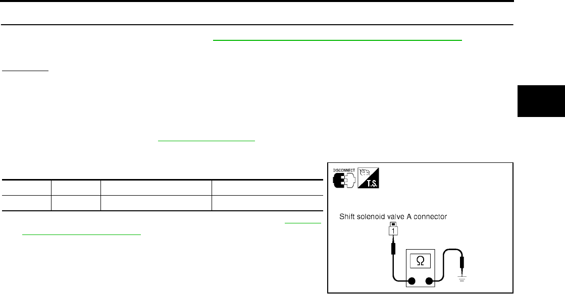
DTC P0750 SHIFT SOLENOID VALVE A
AT-521
[RE5F22A]
D
E
F
G
H
I
J
K
L
M
A
B
AT
Revision: September 2005 2005 Quest
8. CHECK TCM
1. Check TCM input/output signal. Refer to AT-438, "TCM Input/Output Signal Reference Values" .
2. If NG, recheck TCM pin terminals for damage or loose connection with harness connector.
OK or NG
OK >> INSPECTION END
NG >> Repair or replace damaged parts.
Component Inspection UCS002LX
SHIFT SOLENOID VALVE A
1. Remove side cover. Refer to AT-609, "Side cover" .
2. Disconnect shift solenoid valve A harness connector.
3. Check resistance between terminal 1 and ground.
4. If NG, replace the control valve assembly. Refer to AT-609,
"Control Valve Assembly" .
Connector Terminal Condition Resistance (Approx.)
F67 1 - Ground Temperature: 20°C (68°F) 11 - 16 Ω
SCIA4334E
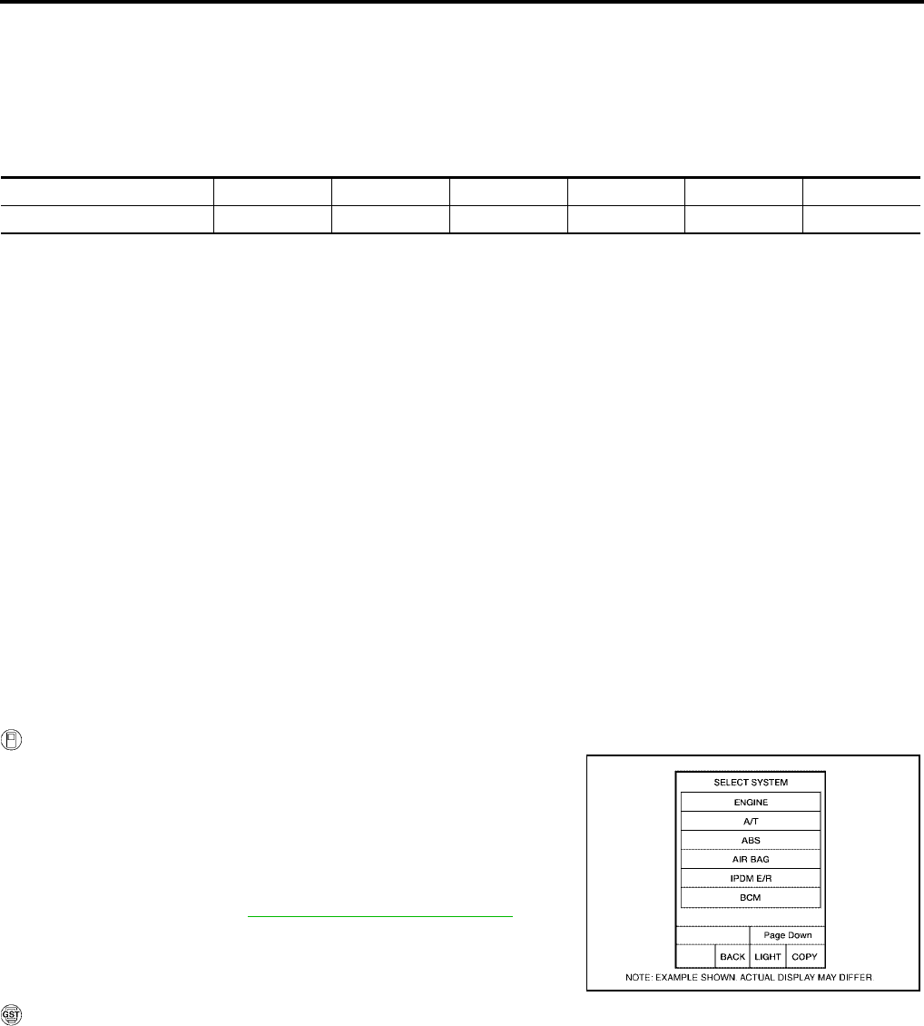
AT-522
[RE5F22A]
DTC P0755 SHIFT SOLENOID VALVE B
Revision: September 2005 2005 Quest
DTC P0755 SHIFT SOLENOID VALVE B PFP:31940
Description UCS0013D
●Shift solenoid valves are installed directly in control valve body. The shift solenoid valves operates of ON
and OFF by the control signal from TCM. Combinations of 5 shift solenoid valves, A, B, C, D and E, shifts
gear positions.
●The shift solenoid valve B is a normally closed, ON-OFF type solenoid.
On Board Diagnosis Logic UCS0013E
●This is an OBD-II self-diagnostic item.
●Diagnostic trouble code “SHIFT SOL B” with CONSULT-II or P0755 without CONSULT-II is detected
under the following conditions.
–When normal voltage is not applied to solenoid due to open, short, and so on.
–When TCM detects as irregular by comparing target value with monitor value.
Possible Cause UCS0013F
●Harness or connectors
(The solenoid circuit is open or shorted.)
●Shift solenoid valve B
DTC Confirmation Procedure UCS0014R
CAUTION:
●Always drive vehicle at a safe speed.
●Be careful not to rev engine into the red zone on the tachometer.
NOTE:
If “DTC Confirmation Procedure” has been previously performed, always turn ignition switch “OFF”
and wait at least 10 seconds before performing the next test.
After the repair, perform the following procedure to confirm the malfunction is eliminated.
WITH CONSULT-II
1. Turn ignition switch “ON”. (Do not start engine.)
2. Select “DATA MONITOR” mode for “A/T” with CONSULT-II.
3. Start engine.
4. Drive vehicle and allow the following conditions.
SLCT LVR POSI: “D” position
GEAR: 1st Þ 2nd and 4th Þ 5th position
5. If DTC is detected, go to AT-524, "Diagnostic Procedure" .
WITH GST
Follow the procedure “With CONSULT-II”.
Gear position D1 , L1D2 , L2D3 , L3D4D5Reverse
Shift solenoid valve B ON (Open) OFF (Closed) OFF (Closed) OFF (Closed) ON (Open) OFF (Closed)
BCIA0030E

DTC P0755 SHIFT SOLENOID VALVE B
AT-523
[RE5F22A]
D
E
F
G
H
I
J
K
L
M
A
B
AT
Revision: September 2005 2005 Quest
Wiring Diagram — AT — SSV/B UCS0013H
BCWA0351E
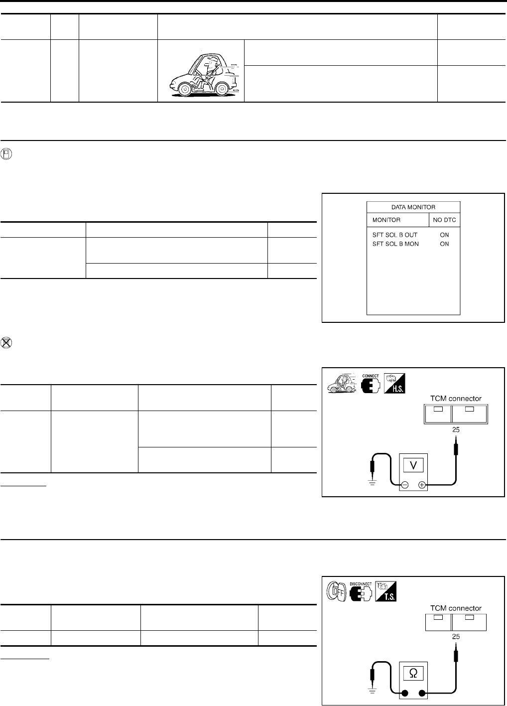
AT-524
[RE5F22A]
DTC P0755 SHIFT SOLENOID VALVE B
Revision: September 2005 2005 Quest
TCM terminal and data are reference value. Measured between each terminal and ground.
Diagnostic Procedure UCS002LY
1. CHECK SHIFT SOLENOID VALVE B SIGNAL
With CONSULT-II
1. Start engine.
2. Select “A/T” with “DATA MONITOR” mode in CONSULT-II.
3. Drive vehicle and read out the value of “SFT SOL B OUT” and
“SFT SOL B MON”.
Without CONSULT-II
1. Drive vehicle.
2. Check voltage between TCM connector terminal and ground.
OK or NG
OK >> GO TO 7.
NG >> GO TO 2.
2. CHECK SHIFT SOLENOID VALVE B CIRCUIT
1. Turn ignition switch “OFF”.
2. Disconnect the TCM connector.
3. Check resistance between TCM connector terminal 25 and
ground.
OK or NG
OK >> GO TO 7.
NG >> GO TO 3.
Terminal Wire
color Item Condition Data (Approx.)
25 G/R Shift solenoid
valve B
When shift solenoid valve B operates.
(When driving in 1st or 5th gear.) Battery voltage
When shift solenoid valve B does not operate. 0V
Monitor item Condition Indication
●SFT SOL B OUT
●SFT SOL B MON
When shift solenoid valve B operates.
(When driving in 1st or 5th gear.) ON
When shift solenoid valve B does not operate. OFF
SCIA2879E
Connector Terminal (Wire color) Condition Voltage
(Approx.)
E142 25 (G/R) - Ground
When shift solenoid valve B
operates.
(When driving in 1st or 5th gear.)
Battery
voltage
When shift solenoid valve B does
not operate. 0V
SCIA2880E
Connector Terminal (Wire color) Condition Resistance
(Approx.)
E142 25 (G/R) - Ground Temperature: 20°C (68°F) 11 - 16 Ω
SCIA2881E

DTC P0755 SHIFT SOLENOID VALVE B
AT-525
[RE5F22A]
D
E
F
G
H
I
J
K
L
M
A
B
AT
Revision: September 2005 2005 Quest
3. CHECK TERMINAL CORD ASSEMBLY WITH SHIFT SOLENOID VALVE B
1. Turn ignition switch “OFF”.
2. Disconnect terminal cord assembly harness connector.
3. Check resistance between terminal 1 and ground.
OK or NG
OK >> GO TO 4.
NG >> GO TO 5.
4. CHECK HARNESS BETWEEN TCM AND TERMINAL CORD ASSEMBLY
Check the following.
●Open or short-circuit in the harness between TCM and terminal cord assembly.
OK or NG
OK >> GO TO 7.
NG >> Repair or replace damaged parts.
5. CHECK SHIFT SOLENOID VALVE B
1. Remove side cover. Refer to AT-609, "Side cover" .
2. Disconnect shift solenoid valve B harness connector.
3. Check resistance between terminal 1 and ground.
OK or NG
OK >> GO TO 6.
NG >> Replace the control valve assembly. Refer to AT-609,
"Control Valve Assembly" .
6. CHECK HARNESS BETWEEN TERMINAL CORD ASSEMBLY AND SHIFT SOLENOID VALVE B
Check the following.
●Open or short-circuit in the harness between terminal cord assembly and shift solenoid valve B.
OK or NG
OK >> GO TO 7.
NG >> Repair or replace transmission wire. Refer to AT-609, "Transmission wire" .
7. CHECK DTC
Perform “DTC Confirmation Procedure”. Refer to AT-522, "DTC Confirmation Procedure" .
OK or NG
OK >> INSPECTION END
NG >> GO TO 8.
Connector Terminal Condition Resistance (Approx.)
F62 1 - Ground Temperature: 20°C (68°F) 11 - 16 Ω
SCIA2882E
Connector Terminal Condition Resistance (Approx.)
F68 1 - Ground Temperature: 20°C (68°F) 11 - 16 Ω
SCIA4335E
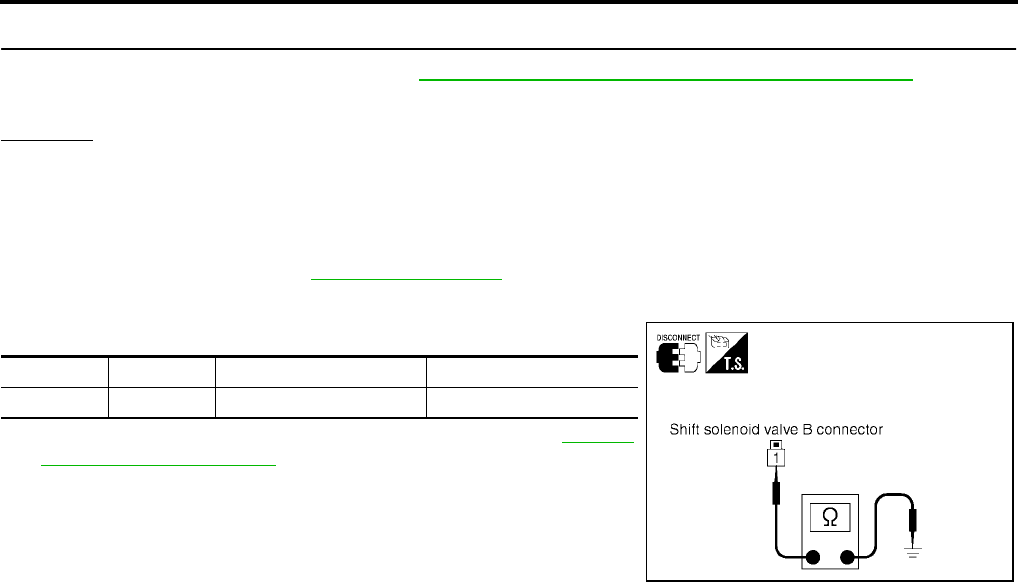
AT-526
[RE5F22A]
DTC P0755 SHIFT SOLENOID VALVE B
Revision: September 2005 2005 Quest
8. CHECK TCM
1. Check TCM input/output signal. Refer to AT-438, "TCM Input/Output Signal Reference Values" .
2. If NG, recheck TCM pin terminals for damage or loose connection with harness connector.
OK or NG
OK >> INSPECTION END
NG >> Repair or replace damaged parts.
Component Inspection UCS002LZ
SHIFT SOLENOID VALVE B
1. Remove side cover. Refer to AT-609, "Side cover" .
2. Disconnect shift solenoid valve B harness connector.
3. Check resistance between terminal 1 and ground.
4. If NG, replace the control valve assembly. Refer to AT-609,
"Control Valve Assembly" .
Connector Terminal Condition Resistance (Approx.)
F68 1 - Ground Temperature: 20°C (68°F) 11 - 16 Ω
SCIA4335E

DTC P0760 SHIFT SOLENOID VALVE C
AT-527
[RE5F22A]
D
E
F
G
H
I
J
K
L
M
A
B
AT
Revision: September 2005 2005 Quest
DTC P0760 SHIFT SOLENOID VALVE C PFP:31940
Description UCS0013J
●Shift solenoid valves are installed directly in control valve body. The shift solenoid valves operates of ON
and OFF by the control signal from TCM. Combinations of 5 shift solenoid valves, A, B, C, D and E, shifts
gear positions.
●The shift solenoid valve C is a normally closed, ON-OFF type solenoid.
On Board Diagnosis Logic UCS0013K
●This is an OBD-II self-diagnostic item.
●Diagnostic trouble code “SHIFT SOL C” with CONSULT-II or P0760 without CONSULT-II is detected
under the following conditions.
–When normal voltage is not applied to solenoid due to open, short, and so on.
–When TCM detects as irregular by comparing target value with monitor value.
Possible Cause UCS0013L
●Harness or connectors
(The solenoid circuit is open or shorted.)
●Shift solenoid valve C
DTC Confirmation Procedure UCS0014S
CAUTION:
●Always drive vehicle at a safe speed.
●Be careful not to rev engine into the red zone on the tachometer.
NOTE:
If “DTC Confirmation Procedure” has been previously performed, always turn ignition switch “OFF”
and wait at least 10 seconds before performing the next test.
After the repair, perform the following procedure to confirm the malfunction is eliminated.
WITH CONSULT-II
1. Turn ignition switch “ON”. (Do not start engine.)
2. Select “DATA MONITOR” mode for “A/T” with CONSULT-II.
3. Start engine.
4. Drive vehicle and allow the following conditions.
SLCT LVR POSI: “D” position
GEAR: 3rd Þ 4th position
5. If DTC is detected, go to AT-529, "Diagnostic Procedure" .
WITH GST
Follow the procedure “With CONSULT-II”.
Gear position D1 , L1D2 , L2D3 , L3D4D5Reverse
Shift solenoid valve C ON (Open) ON (Open) ON (Open) OFF (Closed) OFF (Closed) ON (Open)
BCIA0030E
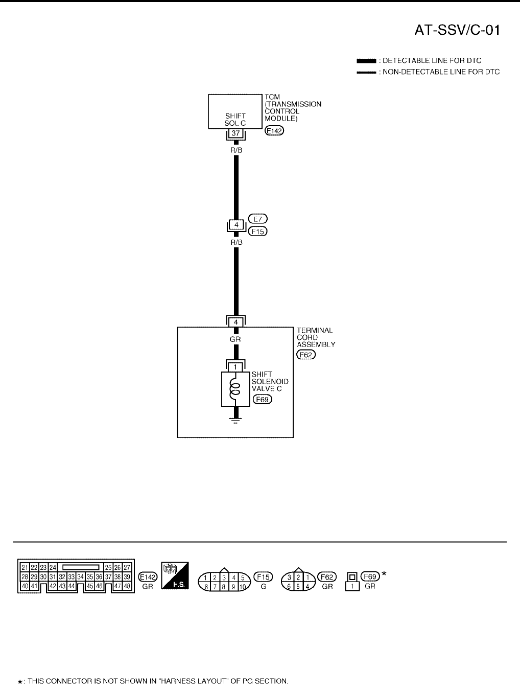
AT-528
[RE5F22A]
DTC P0760 SHIFT SOLENOID VALVE C
Revision: September 2005 2005 Quest
Wiring Diagram — AT — SSV/C UCS0013N
BCWA0352E

DTC P0760 SHIFT SOLENOID VALVE C
AT-529
[RE5F22A]
D
E
F
G
H
I
J
K
L
M
A
B
AT
Revision: September 2005 2005 Quest
TCM terminal and data are reference value. Measured between each terminal and ground.
Diagnostic Procedure UCS002M0
1. CHECK SHIFT SOLENOID VALVE C SIGNAL
With CONSULT-II
1. Start engine.
2. Select “A/T” with “DATA MONITOR” mode in CONSULT-II.
3. Drive vehicle and read out the value of “SFT SOL C OUT” and
“SFT SOL C MON”.
Without CONSULT-II
1. Drive vehicle.
2. Check voltage between TCM connector terminal and ground.
OK or NG
OK >> GO TO 7.
NG >> GO TO 2.
Terminal Wire
color Item Condition Data (Approx.)
37 R/B Shift solenoid
valve C
When shift solenoid valve C operates.
(When driving in 1st, 2nd, 3rd or reverse gear.) Battery voltage
When shift solenoid valve C does not operate. 0V
Monitor item Condition Indication
●SFT SOL C OUT
●SFT SOL C MON
When shift solenoid valve C operates.
(When driving in 1st, 2nd, 3rd or reverse gear.) ON
When shift solenoid valve C does not operate. OFF
SCIA2883E
Connector Terminal (Wire color) Condition Voltage
(Approx.)
E142 37 (R/B) - Ground
When shift solenoid valve C
operates.
(When driving in 1st, 2nd, 3rd
or reverse gear.)
Battery
voltage
When shift solenoid valve C
does not operate. 0V
SCIA2884E

AT-530
[RE5F22A]
DTC P0760 SHIFT SOLENOID VALVE C
Revision: September 2005 2005 Quest
2. CHECK SHIFT SOLENOID VALVE C CIRCUIT
1. Turn ignition switch “OFF”.
2. Disconnect the TCM connector.
3. Check resistance between TCM connector terminal 37 and
ground.
OK or NG
OK >> GO TO 7.
NG >> GO TO 3.
3. CHECK TERMINAL CORD ASSEMBLY WITH SHIFT SOLENOID VALVE C
1. Turn ignition switch “OFF”.
2. Disconnect terminal cord assembly harness connector.
3. Check resistance between terminal 4 and ground.
OK or NG
OK >> GO TO 4.
NG >> GO TO 5.
4. CHECK HARNESS BETWEEN TCM AND TERMINAL CORD ASSEMBLY
Check the following.
●Open or short-circuit in the harness between TCM and terminal cord assembly.
OK or NG
OK >> GO TO 7.
NG >> Repair or replace damaged parts.
5. CHECK SHIFT SOLENOID VALVE C
1. Remove side cover. Refer to AT-609, "Side cover" .
2. Disconnect shift solenoid valve C harness connector.
3. Check resistance between terminal 1 and ground.
OK or NG
OK >> GO TO 6.
NG >> Replace the control valve assembly. Refer to AT-609,
"Control Valve Assembly" .
Connector Terminal (Wire color) Condition Resistance
(Approx.)
E142 37 (R/B) - Ground Temperature: 20°C (68°F) 11 - 16 Ω
SCIA2885E
Connector Terminal Condition Resistance (Approx.)
F62 4 - Ground Temperature: 20°C (68°F) 11 - 16 Ω
SCIA2886E
Connector Terminal Condition Resistance (Approx.)
F69 1 - Ground Temperature: 20°C (68°F) 11 - 16 Ω
SCIA4338E

DTC P0760 SHIFT SOLENOID VALVE C
AT-531
[RE5F22A]
D
E
F
G
H
I
J
K
L
M
A
B
AT
Revision: September 2005 2005 Quest
6. CHECK HARNESS BETWEEN TERMINAL CORD ASSEMBLY AND SHIFT SOLENOID VALVE C
Check the following.
●Open or short-circuit in the harness between terminal cord assembly and shift solenoid valve C.
OK or NG
OK >> GO TO 7.
NG >> Repair or replace transmission wire.
7. CHECK DTC
Perform “DTC Confirmation Procedure”. Refer to AT-527, "DTC Confirmation Procedure" .
OK or NG
OK >> INSPECTION END
NG >> GO TO 8.
8. CHECK TCM
1. Check TCM input/output signal. Refer to AT-438, "TCM Input/Output Signal Reference Values" .
2. If NG, recheck TCM pin terminals for damage or loose connection with harness connector.
OK or NG
OK >> INSPECTION END
NG >> Repair or replace damaged parts.
Component Inspection UCS002M1
SHIFT SOLENOID VALVE C
1. Remove side cover. Refer to AT-609, "Side cover" .
2. Disconnect shift solenoid valve C harness connector.
3. Check resistance between terminal 1 and ground.
4. If NG, replace the control valve assembly. Refer to AT-609,
"Control Valve Assembly" .
Connector Terminal Condition Resistance (Approx.)
F69 1 - Ground Temperature: 20°C (68°F) 11 - 16 Ω
SCIA4338E
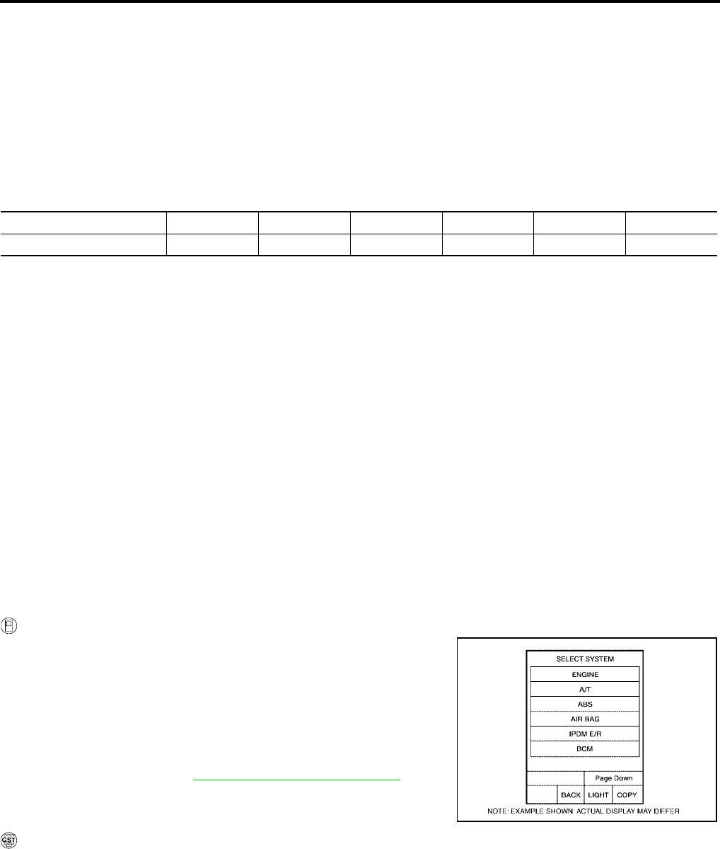
AT-532
[RE5F22A]
DTC P0762 SHIFT SOLENOID VALVE C STUCK ON
Revision: September 2005 2005 Quest
DTC P0762 SHIFT SOLENOID VALVE C STUCK ON PFP:31940
Description UCS00141
●This malfunction will not be detected while the O/D OFF indicator lamp is indicating another self-diagnosis
malfunction.
●This is not caused by electrical malfunction (circuits open or shorted) but by mechanical malfunction such
as control valve sticking, improper solenoid valve operation, etc.
●Shift solenoid valves are installed directly in control valve body. The shift solenoid valves operates of ON
and OFF by the control signal from TCM. Combinations of 5 shift solenoid valves, A, B, C, D and E, shifts
gear positions.
●The shift solenoid valve C is a normally closed, ON-OFF type solenoid.
On Board Diagnosis Logic UCS00142
●This is an OBD-II self-diagnostic item.
●Diagnostic trouble code “SFT SOL C STUCK ON” with CONSULT-II or P0762 without CONSULT-II is
detected when condition of shift solenoid valve C is different from monitor value, and relation between
gear position and actual gear ratio is irregular.
Possible Cause UCS00143
●Shift solenoid valve C
(On stick.)
●Hydraulic control circuit
DTC Confirmation Procedure UCS0014V
CAUTION:
●Always drive vehicle at a safe speed.
●Be careful not to rev engine into the red zone on the tachometer.
NOTE:
If “DTC Confirmation Procedure” has been previously performed, always turn ignition switch “OFF”
and wait at least 10 seconds before performing the next test.
After the repair, perform the following procedure to confirm the malfunction is eliminated.
WITH CONSULT-II
1. Turn ignition switch “ON”. (Do not start engine.)
2. Select “DATA MONITOR” mode for “A/T” with CONSULT-II.
3. Start engine.
4. Drive vehicle and allow the following conditions.
SLCT LVR POSI: “D” position
GEAR: 3rd Þ 4th position
ACCELE ANGLE: More than 10 %
5. If DTC is detected, go to AT-534, "Diagnostic Procedure" .
WITH GST
Follow the procedure “With CONSULT-II”.
Gear position D1 , L1D2 , L2D 3 , L3D4D5Reverse
Shift solenoid valve C ON (Open) ON (Open) ON (Open) OFF (Closed) OFF (Closed) ON (Open)
BCIA0030E
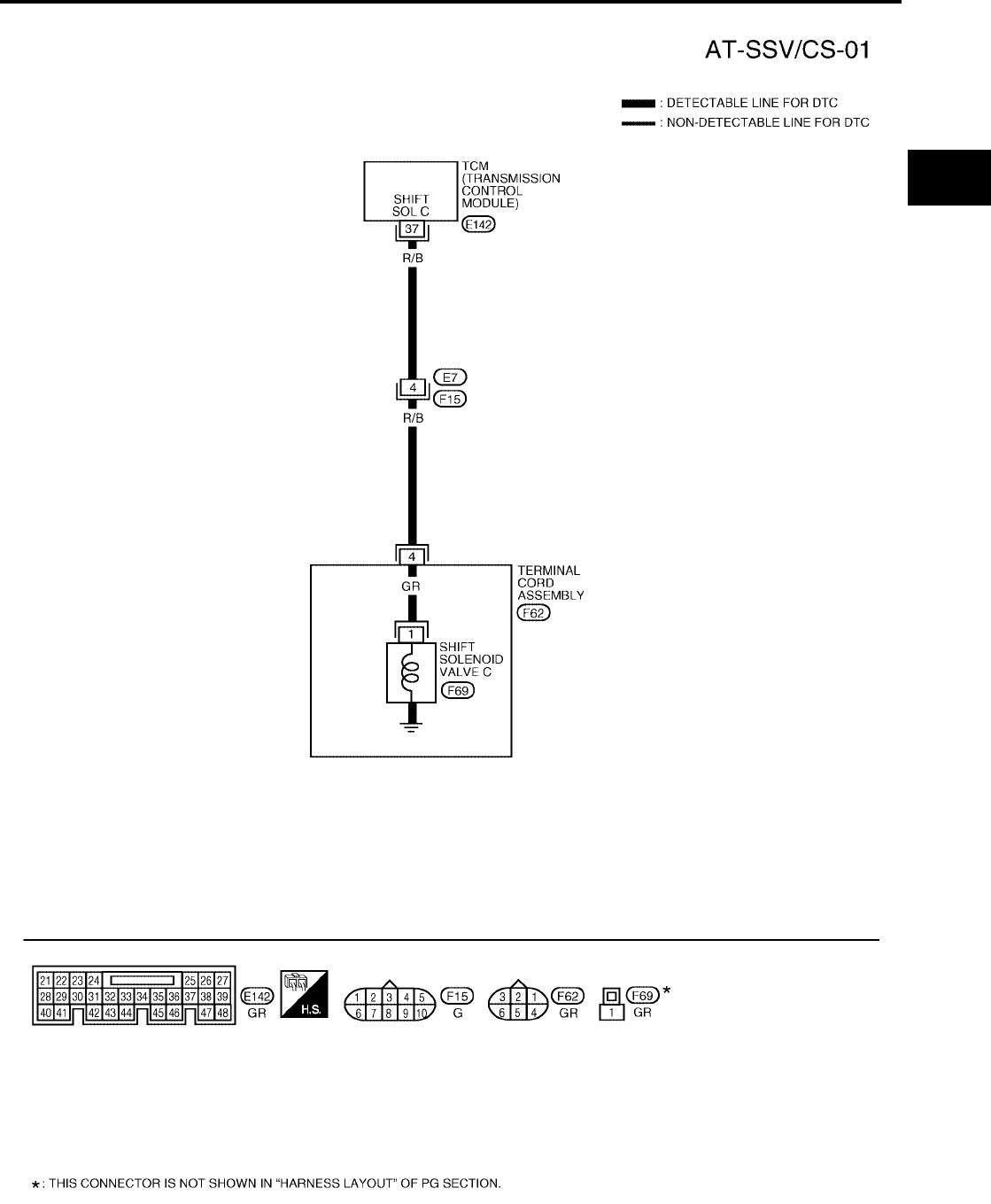
DTC P0762 SHIFT SOLENOID VALVE C STUCK ON
AT-533
[RE5F22A]
D
E
F
G
H
I
J
K
L
M
A
B
AT
Revision: September 2005 2005 Quest
Wiring Diagram — AT — SSV/CS UCS00145
BCWA0353E

AT-534
[RE5F22A]
DTC P0762 SHIFT SOLENOID VALVE C STUCK ON
Revision: September 2005 2005 Quest
TCM terminal and data are reference value. Measured between each terminal and ground.
Diagnostic Procedure UCS002M2
1. CHECK SHIFT SOLENOID VALVE C SIGNAL
With CONSULT-II
1. Start engine.
2. Select “A/T” with “DATA MONITOR” mode in CONSULT-II.
3. Drive vehicle and read out the value of “SFT SOL C OUT” and
“SFT SOL C MON”.
Without CONSULT-II
1. Drive vehicle.
2. Check voltage between TCM connector terminal and ground.
OK or NG
OK >> GO TO 7.
NG >> GO TO 2.
Terminal Wire
color Item Condition Data (Approx.)
37 R/B Shift solenoid
valve C
When shift solenoid valve C operates.
(When driving in 1st, 2nd, 3rd or reverse gear.) Battery voltage
When shift solenoid valve C does not operate. 0V
Monitor item Condition Indication
●SFT SOL C OUT
●SFT SOL C MON
When shift solenoid valve C operates.
(When driving in 1st, 2nd, 3rd or reverse gear.) ON
When shift solenoid valve C does not operate. OFF
SCIA2883E
Connector Terminal (Wire color) Condition Voltage
(Approx.)
E142 37 (R/B) - Ground
When shift solenoid valve C
operates.
(When driving in 1st, 2nd, 3rd
or reverse gear.)
Battery
voltage
When shift solenoid valve C
does not operate. 0V
SCIA2884E
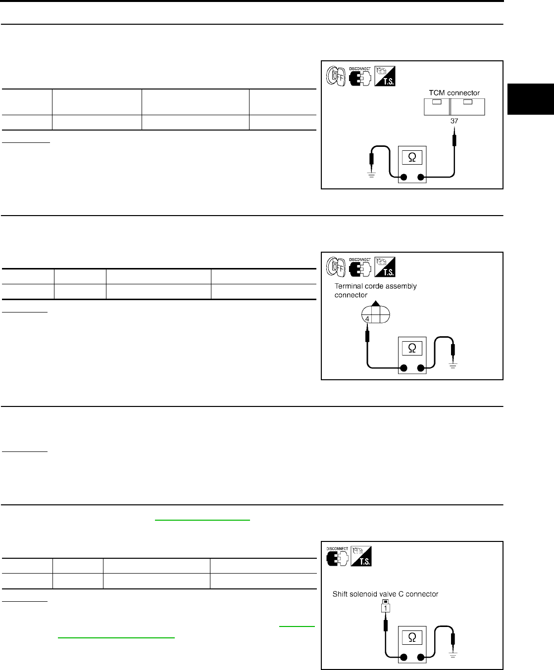
DTC P0762 SHIFT SOLENOID VALVE C STUCK ON
AT-535
[RE5F22A]
D
E
F
G
H
I
J
K
L
M
A
B
AT
Revision: September 2005 2005 Quest
2. CHECK SHIFT SOLENOID VALVE C CIRCUIT
1. Turn ignition switch “OFF”.
2. Disconnect the TCM connector.
3. Check resistance between TCM connector terminal 37 and
ground.
OK or NG
OK >> GO TO 7.
NG >> GO TO 3.
3. CHECK TERMINAL CORD ASSEMBLY WITH SHIFT SOLENOID VALVE C
1. Turn ignition switch “OFF”.
2. Disconnect terminal cord assembly harness connector.
3. Check resistance between terminal 4 and ground.
OK or NG
OK >> GO TO 4.
NG >> GO TO 5.
4. CHECK HARNESS BETWEEN TCM AND TERMINAL CORD ASSEMBLY
Check the following.
●Open or short-circuit in the harness between TCM and terminal cord assembly.
OK or NG
OK >> GO TO 7.
NG >> Repair or replace damaged parts.
5. CHECK SHIFT SOLENOID VALVE C
1. Remove side cover. Refer to AT-609, "Side cover" .
2. Disconnect shift solenoid valve C harness connector.
3. Check resistance between terminal 1 and ground.
OK or NG
OK >> GO TO 6.
NG >> Replace the control valve assembly. Refer to AT-609,
"Control Valve Assembly" .
Connector Terminal (Wire color) Condition Resistance
(Approx.)
E142 37 (R/B) - Ground Temperature: 20°C (68°F) 11 - 16 Ω
SCIA2885E
Connector Terminal Condition Resistance (Approx.)
F62 4 - Ground Temperature: 20°C (68°F) 11 - 16 Ω
SCIA2886E
Connector Terminal Condition Resistance (Approx.)
F69 1 - Ground Temperature: 20°C (68°F) 11 - 16 Ω
SCIA4338E
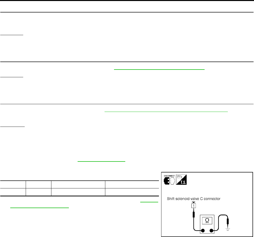
AT-536
[RE5F22A]
DTC P0762 SHIFT SOLENOID VALVE C STUCK ON
Revision: September 2005 2005 Quest
6. CHECK HARNESS BETWEEN TERMINAL CORD ASSEMBLY AND SHIFT SOLENOID VALVE C
Check the following.
●Open or short-circuit in the harness between terminal cord assembly and shift solenoid valve C.
OK or NG
OK >> GO TO 7.
NG >> Repair or replace transmission wire.
7. CHECK DTC
Perform “DTC Confirmation Procedure”. Refer to AT-532, "DTC Confirmation Procedure" .
OK or NG
OK >> INSPECTION END
NG >> GO TO 8.
8. CHECK TCM
1. Check TCM input/output signal. Refer to AT-438, "TCM Input/Output Signal Reference Values" .
2. If NG, recheck TCM pin terminals for damage or loose connection with harness connector.
OK or NG
OK >> INSPECTION END
NG >> Repair or replace damaged parts.
Component Inspection UCS002M3
SHIFT SOLENOID VALVE C
1. Remove side cover. Refer to AT-609, "Side cover" .
2. Disconnect shift solenoid valve C harness connector.
3. Check resistance between terminal 1 and ground.
4. If NG, replace the control valve assembly. Refer to AT-609,
"Control Valve Assembly" .
Connector Terminal Condition Resistance (Approx.)
F69 1 - Ground Temperature: 20°C (68°F) 11 - 16 Ω
SCIA4338E

DTC P0765 SHIFT SOLENOID VALVE D
AT-537
[RE5F22A]
D
E
F
G
H
I
J
K
L
M
A
B
AT
Revision: September 2005 2005 Quest
DTC P0765 SHIFT SOLENOID VALVE D PFP:31940
Description UCS0013P
●Shift solenoid valves are installed directly in control valve body. The shift solenoid valves operates of ON
and OFF by the control signal from TCM. Combinations of 5 shift solenoid valves, A, B, C, D and E, shifts
gear positions.
●The shift solenoid valve D is a normally open, ON-OFF type solenoid.
On Board Diagnosis Logic UCS0013Q
●This is an OBD-II self-diagnostic item.
●Diagnostic trouble code “SHIFT SOL D” with CONSULT-II or P0765 without CONSULT-II is detected
under the following conditions.
–When normal voltage is not applied to solenoid due to open, short, and so on.
–When TCM detects as irregular by comparing target value with monitor value.
Possible Cause UCS0013R
●Harness or connectors
(The solenoid circuit is open or shorted.)
●Shift solenoid valve D
DTC Confirmation Procedure UCS0014T
CAUTION:
●Always drive vehicle at a safe speed.
●Be careful not to rev engine into the red zone on the tachometer.
NOTE:
If “DTC Confirmation Procedure” has been previously performed, always turn ignition switch “OFF”
and wait at least 10 seconds before performing the next test.
After the repair, perform the following procedure to confirm the malfunction is eliminated.
WITH CONSULT-II
1. Turn ignition switch “ON”. (Do not start engine.)
2. Select “DATA MONITOR” mode for “A/T” with CONSULT-II.
3. Start engine.
4. Drive vehicle and allow the following conditions.
SLCT LVR POSI: “D” position
GEAR: 2nd Þ 3rd position
5. If DTC is detected, go to AT-539, "Diagnostic Procedure" .
WITH GST
Follow the procedure “With CONSULT-II”.
Gear position D1 , L1D2 , L2D3 , L3D4D5Reverse
Shift solenoid valve D OFF (Open) OFF (Open) ON (Closed) ON (Closed) ON (Closed) OFF (Open)
BCIA0030E
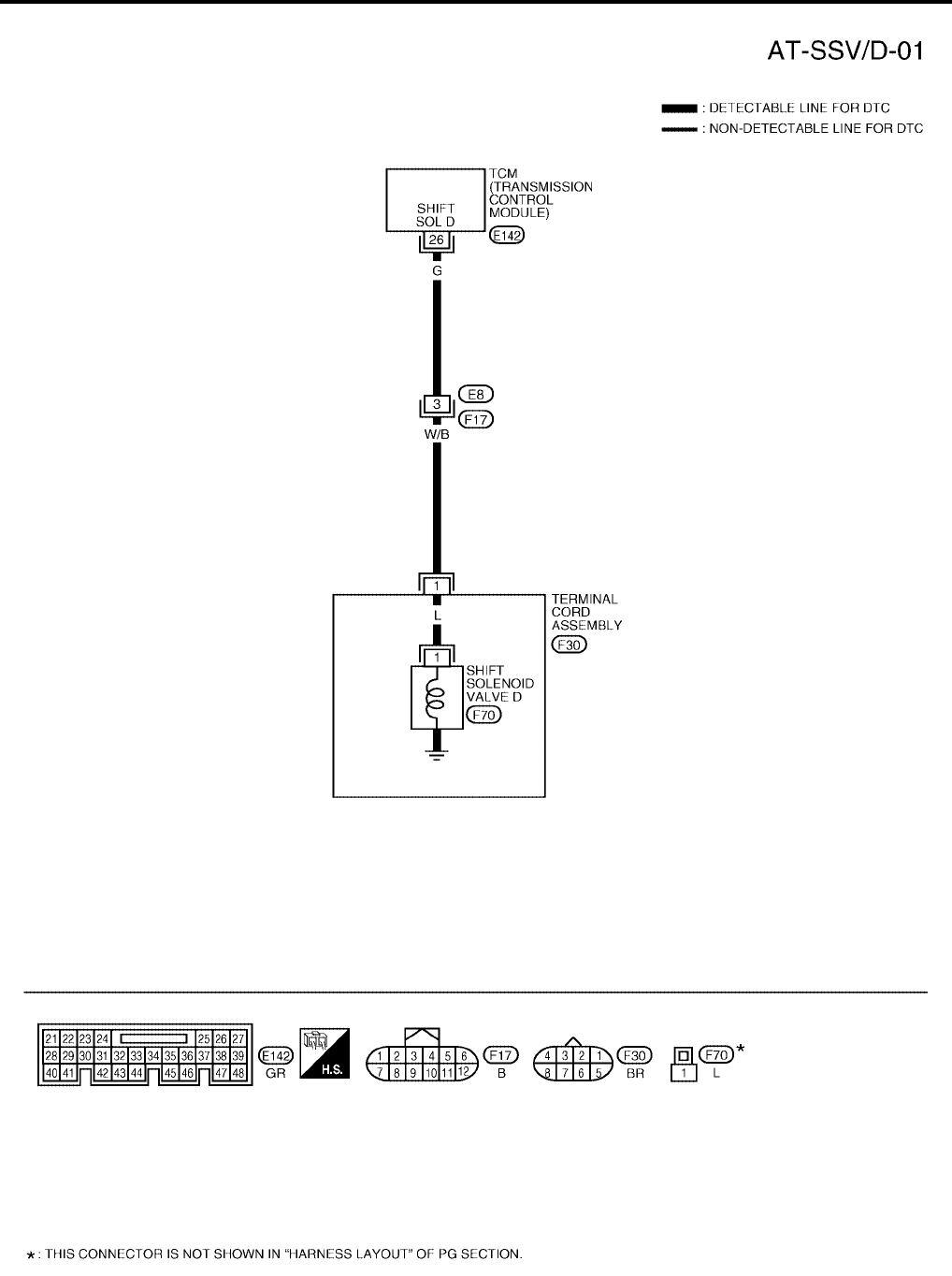
AT-538
[RE5F22A]
DTC P0765 SHIFT SOLENOID VALVE D
Revision: September 2005 2005 Quest
Wiring Diagram — AT — SSV/D UCS0013T
BCWA0354E
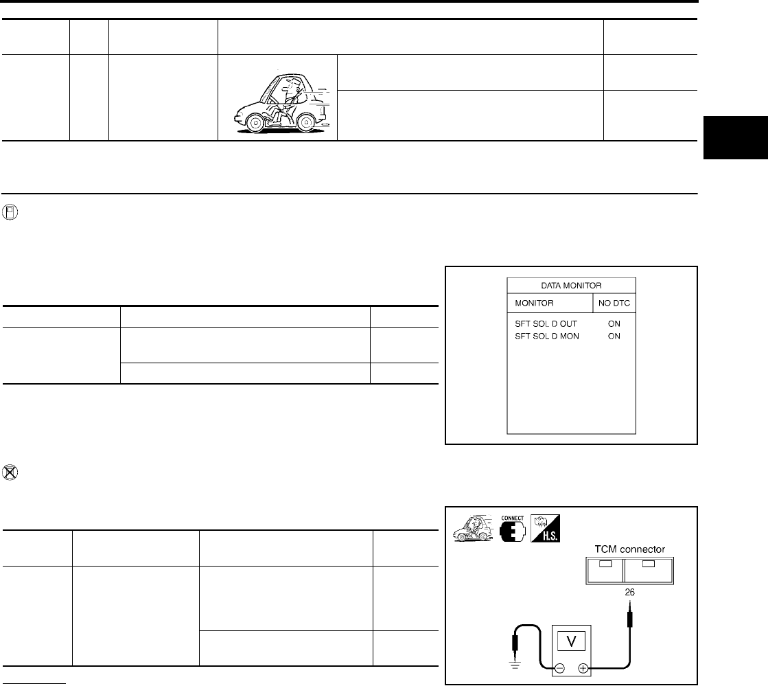
DTC P0765 SHIFT SOLENOID VALVE D
AT-539
[RE5F22A]
D
E
F
G
H
I
J
K
L
M
A
B
AT
Revision: September 2005 2005 Quest
TCM terminal and data are reference value. Measured between each terminal and ground.
Diagnostic Procedure UCS002M4
1. CHECK SHIFT SOLENOID VALVE D SIGNAL
With CONSULT-II
1. Start engine.
2. Select “A/T” with “DATA MONITOR” mode in CONSULT-II.
3. Drive vehicle and read out the value of “SFT SOL D OUT” and
“SFT SOL D MON”.
Without CONSULT-II
1. Drive vehicle.
2. Check voltage between TCM connector terminal and ground.
OK or NG
OK >> GO TO 7.
NG >> GO TO 2.
Terminal Wire
color Item Condition Data (Approx.)
26 G Shift solenoid
valve D
When shift solenoid valve D operates.
(When driving in 3rd, 4th or 5th gear.) Battery voltage
When shift solenoid valve D does not operate. 0V
Monitor item Condition Indication
●SFT SOL D OUT
●SFT SOL D MON
When shift solenoid valve D operates.
(When driving in 3rd, 4th or 5th gear.) ON
When shift solenoid valve D does not operate. OFF
SCIA2888E
Connector Terminal (Wire color) Condition Voltage
(Approx.)
E142 26 (G) - Ground
When shift solenoid valve D
operates.
(When driving in 3rd, 4th or 5th
gear.)
Battery
voltage
When shift solenoid valve D
does not operate. 0V
SCIA2889E
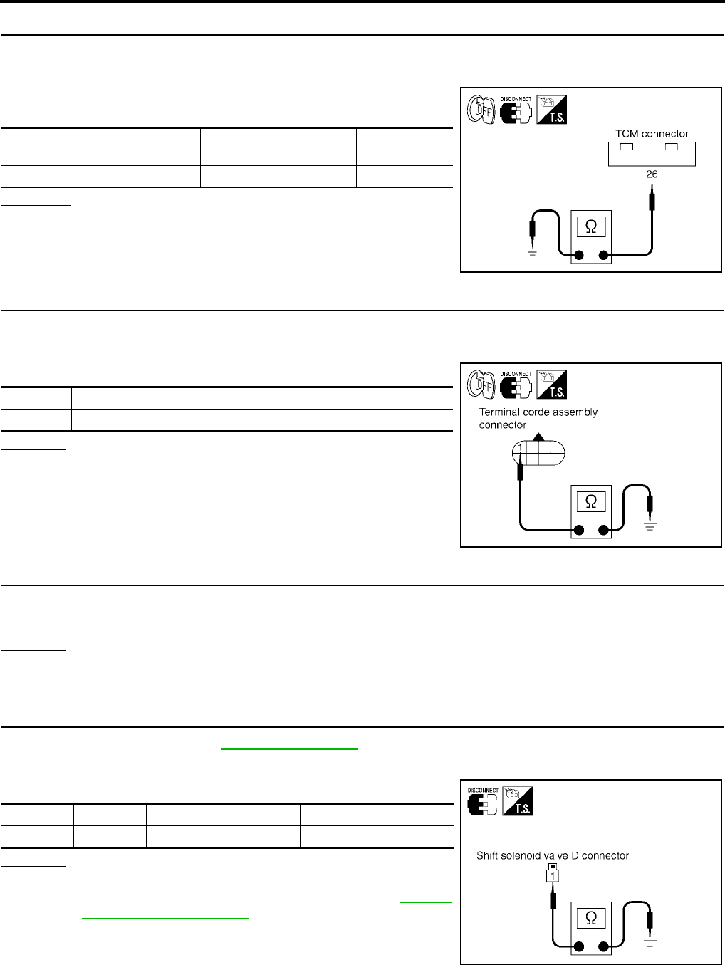
AT-540
[RE5F22A]
DTC P0765 SHIFT SOLENOID VALVE D
Revision: September 2005 2005 Quest
2. CHECK SHIFT SOLENOID VALVE D CIRCUIT
1. Turn ignition switch “OFF”.
2. Disconnect the TCM connector.
3. Check resistance between TCM connector terminal 26 and
ground.
OK or NG
OK >> GO TO 7.
NG >> GO TO 3.
3. CHECK TERMINAL CORD ASSEMBLY WITH SHIFT SOLENOID VALVE D
1. Turn ignition switch “OFF”.
2. Disconnect terminal cord assembly harness connector.
3. Check resistance between terminal 1 and ground.
OK or NG
OK >> GO TO 4.
NG >> GO TO 5.
4. CHECK HARNESS BETWEEN TCM AND TERMINAL CORD ASSEMBLY
Check the following.
●Open or short-circuit in the harness between TCM and terminal cord assembly.
OK or NG
OK >> GO TO 7.
NG >> Repair or replace damaged parts.
5. CHECK SHIFT SOLENOID VALVE D
1. Remove side cover. Refer to AT-609, "Side cover" .
2. Disconnect shift solenoid valve D harness connector.
3. Check resistance between terminal 1 and ground.
OK or NG
OK >> GO TO 6.
NG >> Replace the control valve assembly. Refer to AT-609,
"Control Valve Assembly" .
Connector Terminal (Wire color) Condition Resistance
(Approx.)
E142 26 (G) - Ground Temperature: 20°C (68°F) 11 - 16 Ω
SCIA2890E
Connector Terminal Condition Resistance (Approx.)
F30 1 - Ground Temperature: 20°C (68°F) 11 - 16 Ω
SCIA2891E
Connector Terminal Condition Resistance (Approx.)
F70 1 - Ground Temperature: 20°C (68°F) 11 - 16 Ω
SCIA4339E
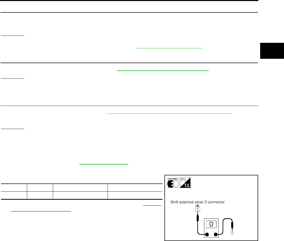
DTC P0765 SHIFT SOLENOID VALVE D
AT-541
[RE5F22A]
D
E
F
G
H
I
J
K
L
M
A
B
AT
Revision: September 2005 2005 Quest
6. CHECK HARNESS BETWEEN TERMINAL CORD ASSEMBLY AND SHIFT SOLENOID VALVE D
Check the following.
●Open or short-circuit in the harness between terminal cord assembly and shift solenoid valve D.
OK or NG
OK >> GO TO 7.
NG >> Repair or replace transmission wire. Refer to AT-609, "Transmission wire" .
7. CHECK DTC
Perform “DTC Confirmation Procedure”. Refer to AT-537, "DTC Confirmation Procedure" .
OK or NG
OK >> INSPECTION END
NG >> GO TO 8.
8. CHECK TCM
1. Check TCM input/output signal. Refer to AT-438, "TCM Input/Output Signal Reference Values" .
2. If NG, recheck TCM pin terminals for damage or loose connection with harness connector.
OK or NG
OK >> INSPECTION END
NG >> Repair or replace damaged parts.
Component Inspection UCS002M5
SHIFT SOLENOID VALVE D
1. Remove side cover. Refer to AT-609, "Side cover" .
2. Disconnect shift solenoid valve D harness connector.
3. Check resistance between terminal 1 and ground.
4. If NG, replace the control valve assembly. Refer to AT-609,
"Control Valve Assembly" .
Connector Terminal Condition Resistance (Approx.)
F70 1 - Ground Temperature: 20°C (68°F) 11 - 16 Ω
SCIA4339E
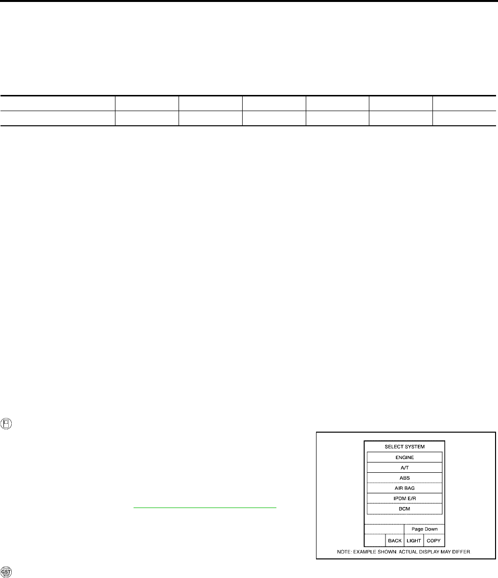
AT-542
[RE5F22A]
DTC P0770 SHIFT SOLENOID VALVE E
Revision: September 2005 2005 Quest
DTC P0770 SHIFT SOLENOID VALVE E PFP:31940
Description UCS00137
●Shift solenoid valves are installed directly in control valve body. The shift solenoid valves operates of ON
and OFF by the control signal from TCM. Combinations of 5 shift solenoid valves, A, B, C, D and E, shifts
gear positions.
●The shift solenoid valve E is a normally closed, ON-OFF type solenoid.
NOTE:
The condition of shift solenoid valve E is ON (Open) with shifting D2 ⇔ D3 (L2 ⇔ L3 ) and D3 ⇔ D4 .
On Board Diagnosis Logic UCS00138
●This is an OBD-II self-diagnostic item.
●Diagnostic trouble code “SHIFT SOL E” with CONSULT-II or P0770 without CONSULT-II is detected
under the following conditions.
–When normal voltage is not applied to solenoid due to open, short, and so on.
–When TCM detects as irregular by comparing target value with monitor value.
Possible Cause UCS00139
●Harness or connectors
(The solenoid circuit is open or shorted.)
●Shift solenoid valve E
DTC Confirmation Procedure UCS0014U
CAUTION:
●Always drive vehicle at a safe speed.
●Be careful not to rev engine into the red zone on the tachometer.
NOTE:
If “DTC Confirmation Procedure” has been previously performed, always turn ignition switch “OFF”
and wait at least 10 seconds before performing the next test.
After the repair, perform the following procedure to confirm the malfunction is eliminated.
WITH CONSULT-II
1. Turn ignition switch “ON”. (Do not start engine.)
2. Select “DATA MONITOR” mode for “A/T” with CONSULT-II.
3. Start engine.
4. Move selector lever between “N” and “R”.
SLCT LVR POSI: “N” ⇔ “R” position
5. If DTC is detected, go to AT-544, "Diagnostic Procedure" .
WITH GST
Follow the procedure “With CONSULT-II”.
Gear position D 1 , L1D2 , L2D3 , L3D4D5Reverse
Shift solenoid valve E OFF (Closed) OFF (Closed) OFF (Closed) OFF (Closed) OFF (Closed) ON (Open)
BCIA0030E
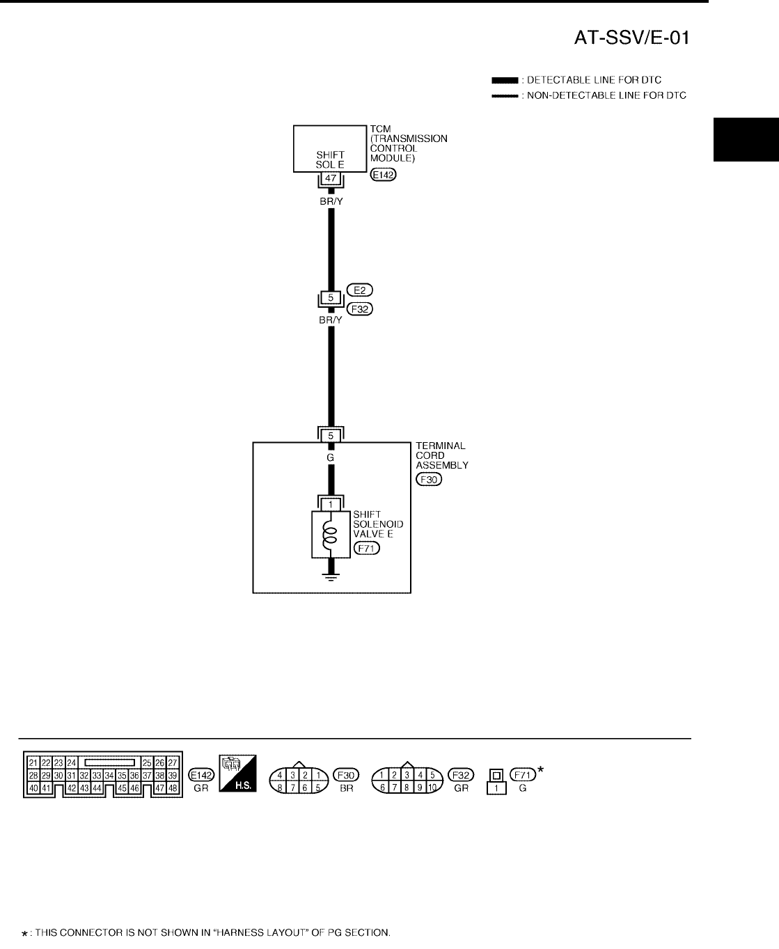
DTC P0770 SHIFT SOLENOID VALVE E
AT-543
[RE5F22A]
D
E
F
G
H
I
J
K
L
M
A
B
AT
Revision: September 2005 2005 Quest
Wiring Diagram — AT — SSV/E UCS0013B
BCWA0355E

AT-544
[RE5F22A]
DTC P0770 SHIFT SOLENOID VALVE E
Revision: September 2005 2005 Quest
TCM terminal and data are reference value. Measured between each terminal and ground.
Diagnostic Procedure UCS002M6
1. CHECK SHIFT SOLENOID VALVE E SIGNAL
With CONSULT-II
1. Start engine.
2. Select “A/T” with “DATA MONITOR” mode in CONSULT-II.
3. Drive vehicle and read out the value of “SFT SOL E OUT” and
“SFT SOL E MON”.
Without CONSULT-II
1. Drive vehicle.
2. Check voltage between TCM connector terminal and ground.
OK or NG
OK >> GO TO 7.
NG >> GO TO 2.
2. CHECK SHIFT SOLENOID VALVE E CIRCUIT
1. Turn ignition switch “OFF”.
2. Disconnect the TCM connector.
3. Check resistance between TCM connector terminal 47 and
ground.
OK or NG
OK >> GO TO 7.
NG >> GO TO 3.
Terminal Wire
color Item Condition Data (Approx.)
47 BR/Y Shift solenoid
valve E
When shift solenoid valve E operates.
(When driving in reverse gear.) Battery voltage
When shift solenoid valve E does not operate. 0V
Monitor item Condition Indication
●SFT SOL E OUT
●SFT SOL E MON
When shift solenoid valve E operates.
(When driving in reverse gear.) ON
When shift solenoid valve E does not operate. OFF
SCIA2895E
Connector Terminal (Wire color) Condition Voltage
(Approx.)
E142 47 (BR/Y) - Ground
When shift solenoid valve E
operates.
(When driving in reverse gear.)
Battery
voltage
When shift solenoid valve E
does not operate. 0V
SCIA2896E
Connector Terminal (Wire color) Condition Resistance
(Approx.)
E142 47 (BR/Y) - Ground Temperature: 20°C (68°F) 11 - 16 Ω
SCIA2897E

DTC P0770 SHIFT SOLENOID VALVE E
AT-545
[RE5F22A]
D
E
F
G
H
I
J
K
L
M
A
B
AT
Revision: September 2005 2005 Quest
3. CHECK TERMINAL CORD ASSEMBLY WITH SHIFT SOLENOID VALVE E
1. Turn ignition switch “OFF”.
2. Disconnect terminal cord assembly harness connector.
3. Check resistance between terminal 5 and ground.
OK or NG
OK >> GO TO 4.
NG >> GO TO 5.
4. CHECK HARNESS BETWEEN TCM AND TERMINAL CORD ASSEMBLY
Check the following.
●Open or short-circuit in the harness between TCM and terminal cord assembly.
OK or NG
OK >> GO TO 7.
NG >> Repair or replace damaged parts.
5. CHECK SHIFT SOLENOID VALVE E
1. Remove side cover. Refer to AT-609, "Side cover"
2. Disconnect shift solenoid valve E harness connector.
3. Check resistance between terminal 1 and ground.
OK or NG
OK >> GO TO 6.
NG >> Replace the control valve assembly. Refer to AT-609,
"Control Valve Assembly" .
6. CHECK HARNESS BETWEEN TERMINAL CORD ASSEMBLY AND SHIFT SOLENOID VALVE E
Check the following.
●Open or short-circuit in the harness between terminal cord assembly and shift solenoid valve E.
OK or NG
OK >> GO TO 7.
NG >> Repair or replace transmission wire. Refer to AT-609, "Transmission wire" .
7. CHECK DTC
Perform “DTC Confirmation Procedure”. Refer to AT-542, "DTC Confirmation Procedure" .
OK or NG
OK >> INSPECTION END
NG >> GO TO 8.
Connector Terminal Condition Resistance (Approx.)
F30 5 - Ground Temperature: 20°C (68°F) 11 - 16 Ω
SCIA2898E
Connector Terminal Condition Resistance (Approx.)
F71 1 - Ground Temperature: 20°C (68°F) 11 - 16 Ω
SCIA4340E
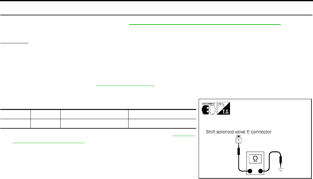
AT-546
[RE5F22A]
DTC P0770 SHIFT SOLENOID VALVE E
Revision: September 2005 2005 Quest
8. CHECK TCM
1. Check TCM input/output signal. Refer to AT-438, "TCM Input/Output Signal Reference Values" .
2. If NG, recheck TCM pin terminals for damage or loose connection with harness connector.
OK or NG
OK >> INSPECTION END
NG >> Repair or replace damaged parts.
Component Inspection UCS002M7
SHIFT SOLENOID VALVE E
1. Remove side cover. Refer to AT-609, "Side cover" .
2. Disconnect shift solenoid valve E harness connector.
3. Check resistance between terminal 1 and ground.
4. If NG, replace the control valve assembly. Refer to AT-609,
"Control Valve Assembly" .
Connector Terminal Condition Resistance (Approx.)
F71 1 - Ground Temperature: 20°C (68°F) 11 - 16 Ω
SCIA4340E
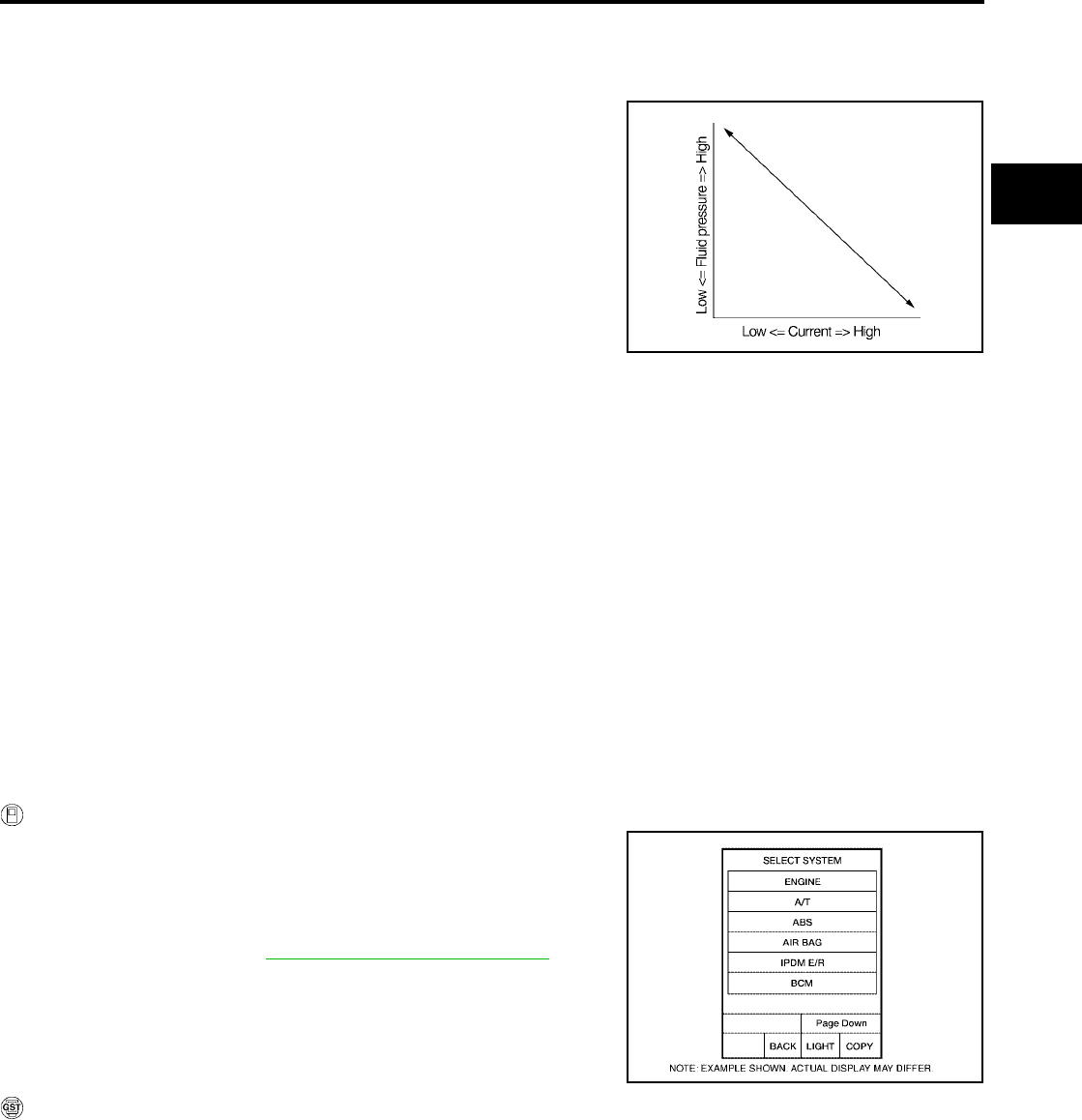
DTC P0775 PRESSURE CONTROL SOLENOID VALVE B (SHIFT PRESSURE)
AT-547
[RE5F22A]
D
E
F
G
H
I
J
K
L
M
A
B
AT
Revision: September 2005 2005 Quest
DTC P0775 PRESSURE CONTROL SOLENOID VALVE B (SHIFT PRESSURE)
PFP:31940
Description UCS0012V
●The pressure control solenoid valve B is normally high, 3-port
linear pressure control solenoid.
●The pressure control solenoid valve B controls linear shift pres-
sure by control signal from TCM and controls 2nd coast brake
directly under 2nd, 3rd, 4th and direct clutch directly under 5th
and reverse.
On Board Diagnosis Logic UCS0012W
●This is an OBD-II self-diagnostic item.
●Diagnostic trouble code “PC SOL B(SFT/PRS)” with CONSULT-II or P0775 without CONSULT-II is
detected under the following conditions.
–When normal voltage is not applied to solenoid due to open, short, and so on.
–When TCM detects as irregular by comparing target value with monitor value.
Possible Cause UCS0012X
●Harness or connectors
(The solenoid circuit is open or shorted.)
●Pressure control solenoid valve B
DTC Confirmation Procedure UCS0012Y
NOTE:
If “DTC Confirmation Procedure” has been previously performed, always turn ignition switch “OFF”
and wait at least 10 seconds before performing the next test.
After the repair, perform the following procedure to confirm the malfunction is eliminated.
WITH CONSULT-II
1. Turn ignition switch “ON”. (Do not start engine.)
2. Select “DATA MONITOR” mode for “A/T” with CONSULT-II.
3. Start engine.
4. Run engine for at least 13 consecutive seconds at idle speed.
5. If DTC is detected, go to AT-549, "Diagnostic Procedure" .
WITH GST
Follow the procedure “With CONSULT-II”.
SCIA2831E
BCIA0030E

AT-548
[RE5F22A]
DTC P0775 PRESSURE CONTROL SOLENOID VALVE B (SHIFT PRESSURE)
Revision: September 2005 2005 Quest
Wiring Diagram — AT — PC/B UCS0012Z
BCWA0356E

DTC P0775 PRESSURE CONTROL SOLENOID VALVE B (SHIFT PRESSURE)
AT-549
[RE5F22A]
D
E
F
G
H
I
J
K
L
M
A
B
AT
Revision: September 2005 2005 Quest
TCM terminals and data are reference value. Measured between each terminal and ground.
Diagnostic Procedure UCS002M8
1. CHECK PRESSURE CONTROL SOLENOID VALVE B SIGNAL
With CONSULT-II
1. After warming up the engine and transaxle, turn ignition switch “OFF”.
2. Turn ignition switch “ON”. (Do not start engine.)
3. Select “DATA MONITOR” mode for “A/T” with CONSULT-II.
4. Read out the value of “PC SOL B OUT” and “PC SOL B MON”.
Without CONSULT-II
1. Start the engine.
2. Check pulse between TCM connector terminals 21 and 36.
OK or NG
OK >> GO TO 7.
NG >> GO TO 2.
2. CHECK PRESSURE CONTROL SOLENOID VALVE B CIRCUIT
1. Turn ignition switch “OFF”.
2. Disconnect the TCM connector.
3. Check resistance between TCM connector terminals 21 and 36.
OK or NG
OK >> GO TO 7.
NG >> GO TO 3.
Terminal Wire
color Item Condition Data (Approx.)
21 G/B
Pressure control
solenoid valve B
ground
When engine is running with idle speed and set-
ting selector lever to “P” position. 0V
36 W/L Pressure control
solenoid valve B
When engine is running with idle speed and set-
ting selector lever to “P” position. 300Hz
Monitor item Condition Display value
(Approx.)
●PC SOL B OUT
●PC SOL B MON
Selector lever: Manual shift gate position 1.00 A
Other than the above. 0.30 A
SCIA2907E
Connector Terminal (Wire color) Condition Data
(Approx.)
E142 36 (W/L) - 21 (G/B)
(Ground)
When engine is running with idle
speed and setting selector lever
to “P” position.
300 Hz
SCIA2911E
Connector Terminal (Wire color) Condition Resistance
(Approx.)
E142 36 (W/L) - 21 (G/B)
(Ground) Temperature: 20°C (68°F) 5.0 - 5.6 Ω
SCIA2912E
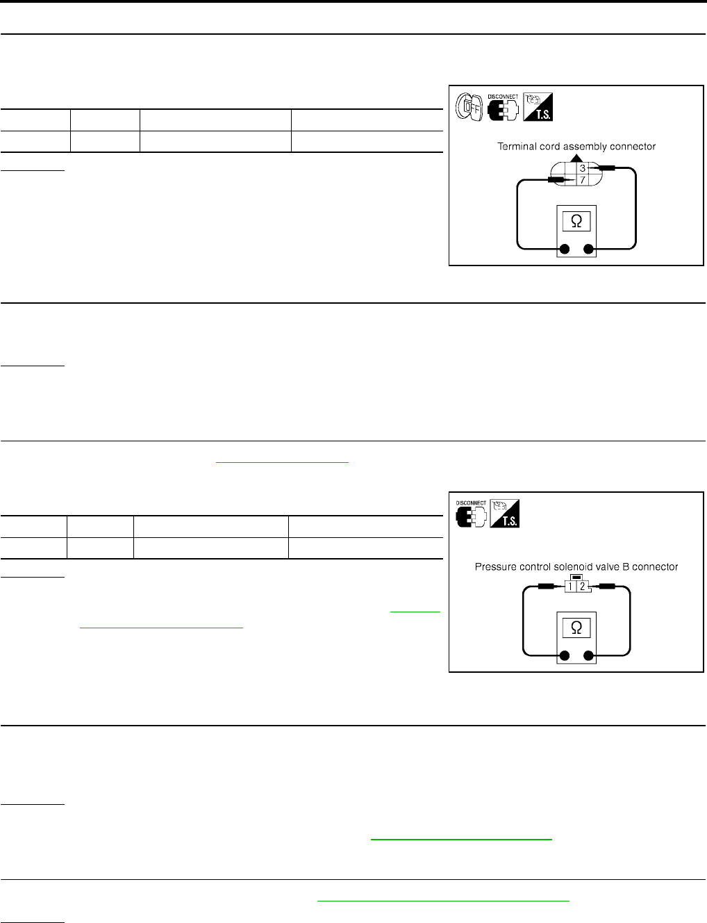
AT-550
[RE5F22A]
DTC P0775 PRESSURE CONTROL SOLENOID VALVE B (SHIFT PRESSURE)
Revision: September 2005 2005 Quest
3. CHECK TERMINAL CORD ASSEMBLY WITH PRESSURE CONTROL SOLENOID VALVE B
1. Turn ignition switch “OFF”.
2. Disconnect terminal cord assembly harness connector.
3. Check resistance between terminals 3 and 7.
OK or NG
OK >> GO TO 4.
NG >> GO TO 5.
4. CHECK HARNESS BETWEEN TCM AND TERMINAL CORD ASSEMBLY
Check the following.
●Open or short-circuit in the harness between TCM and terminal cord assembly.
OK or NG
OK >> GO TO 7.
NG >> Repair or replace damaged parts.
5. CHECK PRESSURE CONTROL SOLENOID VALVE B
1. Remove side cover. Refer to AT-609, "Side cover" .
2. Disconnect pressure control solenoid valve B harness connector.
3. Check resistance between terminals 1 and 2.
OK or NG
OK >> GO TO 6.
NG >> Replace the control valve assembly. Refer to AT-609,
"Control Valve Assembly" .
6. CHECK HARNESS BETWEEN TERMINAL CORD ASSEMBLY AND PRESSURE CONTROL SOLE-
NOID VALVE B
Check the following.
●Open or short-circuit in the harness between terminal cord assembly and pressure control solenoid valve
B.
OK or NG
OK >> GO TO 7.
NG >> Repair or replace transmission wire. Refer to AT-609, "Transmission wire" .
7. CHECK DTC
Perform “DTC Confirmation Procedure”. Refer to AT-547, "DTC Confirmation Procedure" .
OK or NG
OK >> INSPECTION END
NG >> GO TO 8.
Connector Terminal Condition Resistance (Approx.)
F30 3 - 7 Temperature: 20°C (68°F) 5.0 - 5.6 Ω
SCIA2913E
Connector Terminal Condition Resistance (Approx.)
F73 1 - 2 Temperature: 20°C (68°F) 5.0 - 5.6 Ω
SCIA4341E
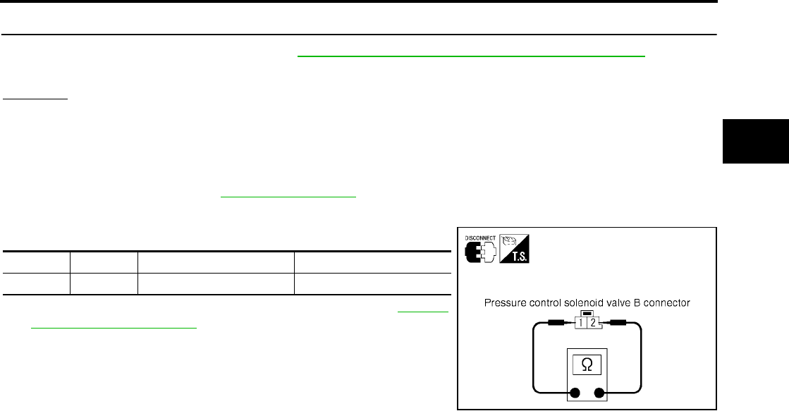
DTC P0775 PRESSURE CONTROL SOLENOID VALVE B (SHIFT PRESSURE)
AT-551
[RE5F22A]
D
E
F
G
H
I
J
K
L
M
A
B
AT
Revision: September 2005 2005 Quest
8. CHECK TCM
1. Check TCM input/output signal. Refer to AT-438, "TCM Input/Output Signal Reference Values" .
2. If NG, recheck TCM pin terminals for damage or loose connection with harness connector.
OK or NG
OK >> INSPECTION END
NG >> Repair or replace damaged parts.
Component Inspection UCS002M9
PRESSURE CONTROL SOLENOID VALVE B
1. Remove side cover. Refer to AT-609, "Side cover" .
2. Disconnect pressure control solenoid valve B harness connector.
3. Check resistance between terminals 1 and 2.
4. If NG, replace the control valve assembly. Refer to AT-609,
"Control Valve Assembly" .
Connector Terminal Condition Resistance (Approx.)
F73 1 - 2 Temperature: 20°C (68°F) 5.0 - 5.6 Ω
SCIA4341E

AT-552
[RE5F22A]
DTC P0780 SHIFT
Revision: September 2005 2005 Quest
DTC P0780 SHIFT PFP:31940
Description UCS0014D
●This malfunction will not be detected while the O/D OFF indicator lamp is indicating another self-diagnosis
malfunction.
●This malfunction is detected when the A/T does not shift as instructed by the TCM. This is not caused by
electrical malfunction (circuits open or shorted) but by mechanical malfunction such as control valve stick-
ing, improper solenoid valve operation, etc.
On Board Diagnosis Logic UCS0014E
●This is an OBD-II self-diagnostic item.
●Diagnostic trouble code “SHIFT” with CONSULT-II or P0780 without CONSULT-II is detected under the
following conditions.
–When no rotation change occurs between input (turbine revolution sensor) and output (revolution sensor)
and shifting time is long.
–When shifting ends immediately.
–When engine revs up unusually during shifting.
Possible Cause UCS0014F
●Shift solenoid valve D
(Off error.)
●Shift solenoid valve E
(Off error.)
●Pressure control solenoid valve A
(On/Off error.)
●Pressure control solenoid valve B
(On/Off error.)
●Pressure control solenoid valve C
(On/Off error.)
●Hydraulic control circuit
DTC Confirmation Procedure UCS0014W
CAUTION:
●Always drive vehicle at a safe speed.
●Be careful not to rev engine into the red zone on the tachometer.
NOTE:
If “DTC Confirmation Procedure” has been previously performed, always turn ignition switch “OFF”
and wait at least 10 seconds before performing the next test.
After the repair, perform the following procedure to confirm the malfunction is eliminated.
WITH CONSULT-II
1. Start engine and select “DATA MONITOR” mode for “A/T” with
CONSULT-II.
2. Make sure that ATF temperature is within the range below.
FLUID TEMP: More than 60°C (140°F)
If out of range, drive the vehicle to warm up the fluid.
3. Drive vehicle and allow the following conditions.
SLCT LVR POSI: “D” position
GEAR: 1st Þ 2nd Þ 3rd Þ 4th Þ 5th position
(Vehicle speed: Refer to AT-680, "VEHICLE SPEED WHEN
SHIFTING GEARS" .)
4. If DTC is detected, go to AT-555, "Diagnostic Procedure" .
WITH GST
Follow the procedure “With CONSULT-II”.
BCIA0030E
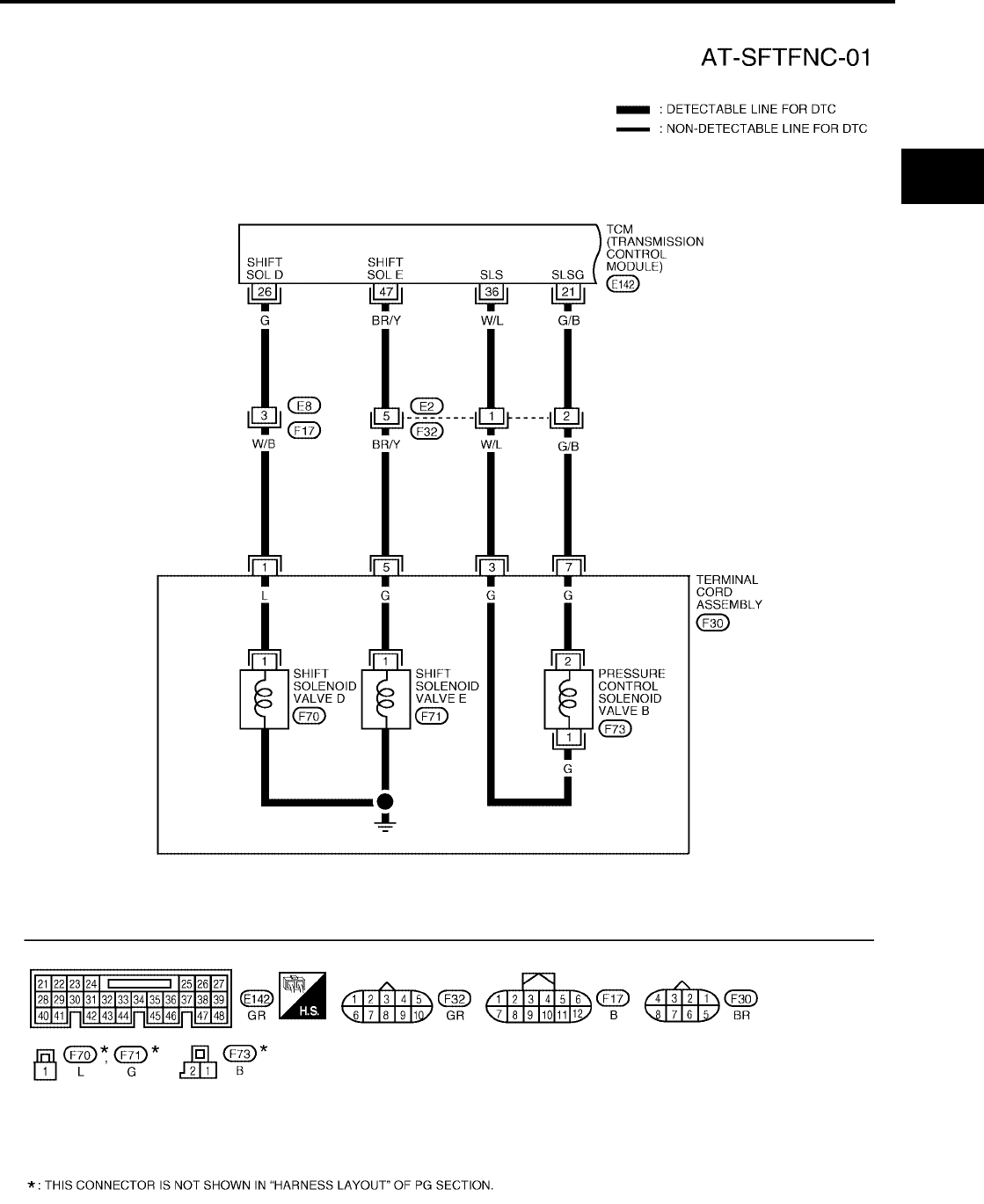
DTC P0780 SHIFT
AT-553
[RE5F22A]
D
E
F
G
H
I
J
K
L
M
A
B
AT
Revision: September 2005 2005 Quest
Wiring Diagram — AT — SFTFNC UCS0014H
BCWA0314E

AT-554
[RE5F22A]
DTC P0780 SHIFT
Revision: September 2005 2005 Quest
BCWA0315E

DTC P0780 SHIFT
AT-555
[RE5F22A]
D
E
F
G
H
I
J
K
L
M
A
B
AT
Revision: September 2005 2005 Quest
TCM terminals and data are reference value. Measured between each terminal and ground.
Diagnostic Procedure UCS0014I
1. CHECK EACH SHIFT SOLENOID VALVE CIRCUIT
Perform “Diagnostic Procedure” for the following DTCs.
●“DTC P0765 SHIFT SOLENOID VALVE D” (Refer to AT-539, "Diagnostic Procedure" .)
●“DTC P0770 SHIFT SOLENOID VALVE E” (Refer to AT-544, "Diagnostic Procedure" .)
OK or NG
OK >> GO TO 2.
NG >> Repair or replace damaged parts.
2. CHECK EACH PRESSURE CONTROL SOLENOID VALVE CIRCUIT
Perform “Diagnostic Procedure” for the following DTCs.
●“DTC P0745 PRESSURE CONTROL SOLENOID VALVE A” (Refer to AT-514, "Diagnostic Procedure" .)
●“DTC P0775 PRESSURE CONTROL SOLENOID VALVE B” (Refer to AT-549, "Diagnostic Procedure" .)
●“DTC P0795 PRESSURE CONTROL SOLENOID VALVE C” (Refer to AT-558, "Diagnostic Procedure" .)
OK or NG
OK >> GO TO 3.
NG >> Repair or replace damaged parts.
3. CHECK DTC
Perform “DTC Confirmation Procedure”. Refer to AT-552, "DTC Confirmation Procedure" .
OK or NG
OK >> INSPECTION END
NG >> Replace transmission wire or control valve assembly. Refer to AT-609, "Transmission wire" or AT-
609, "Control Valve Assembly" .
Terminal Wire
color Item Condition Data (Approx.)
21 G/B
Pressure control
solenoid valve B
ground
When engine is running with idle speed and set-
ting selector lever to “P” position. 0V
26 G Shift solenoid
valve D
When shift solenoid valve D operates.
(When driving in 3rd, 4th or 5th gear.) Battery voltage
When shift solenoid valve D does not operate. 0V
28 W
Pressure control
solenoid valve C
ground
When engine is running with idle speed and set-
ting selector lever to “P” position. 0V
35 L/Y Pressure control
solenoid valve A
When engine is running with idle speed and set-
ting selector lever to “P” position. 300Hz
36 W/L Pressure control
solenoid valve B
When engine is running with idle speed and set-
ting selector lever to “P” position. 300Hz
40 L/G
Pressure control
solenoid valve A
ground
When engine is running with idle speed and set-
ting selector lever to “P” position. 0V
45 O/B Pressure control
solenoid valve C
When engine is running with idle speed and set-
ting selector lever to “P” position. 300Hz
47 BR/Y Shift solenoid
valve E
When shift solenoid valve E operates.
(When driving in reverse gear.) Battery voltage
When shift solenoid valve E does not operate. 0V

AT-556
[RE5F22A]
DTC P0795 PRESSURE CONTROL SOLENOID VALVE C (TCC AND SHIFT
PRESSURE)
Revision: September 2005 2005 Quest
DTC P0795 PRESSURE CONTROL SOLENOID VALVE C (TCC AND SHIFT PRES-
SURE) PFP:31940
Description UCS000UU
●The pressure control solenoid valve C is normally low, 3-port lin-
ear pressure control solenoid.
●The pressure control solenoid valve C is activated to control the
apply and release of the 2nd brake and 1st and reverse brake,
and torque converter clutch.
●Lock-up operation, however, is prohibited when A/T fluid tem-
perature is too low.
●When the accelerator pedal is depressed (less than 1/8) in lock-
up condition, the engine speed should not change abruptly. If
there is a big jump in engine speed, there is no lock-up.
On Board Diagnosis Logic UCS000UW
●This is an OBD-II self-diagnostic item.
●Diagnostic trouble code “PC SOL C(TCC&SFT)” with CONSULT-II or P0795 without CONSULT-II is
detected under the following conditions.
–When normal voltage is not applied to solenoid due to open, short, and so on.
–When TCM detects as irregular by comparing target value with monitor value.
Possible Cause UCS000UX
●Harness or connectors
(The solenoid circuit is open or shorted.)
●Pressure control solenoid valve C
DTC Confirmation Procedure UCS000UY
NOTE:
If “DTC Confirmation Procedure” has been previously performed, always turn ignition switch “OFF”
and wait at least 10 seconds before performing the next test.
After the repair, perform the following procedure to confirm the malfunction is eliminated.
WITH CONSULT-II
1. Turn ignition switch “ON”. (Do not start engine.)
2. Select “DATA MONITOR” mode for “A/T” with CONSULT-II.
3. Start engine.
4. Run engine for at least 13 consecutive seconds at idle speed.
5. If DTC is detected, go to AT-558, "Diagnostic Procedure" .
WITH GST
Follow the procedure “With CONSULT-II”.
SCIA2833E
BCIA0030E

DTC P0795 PRESSURE CONTROL SOLENOID VALVE C (TCC AND SHIFT
PRESSURE)
AT-557
[RE5F22A]
D
E
F
G
H
I
J
K
L
M
A
B
AT
Revision: September 2005 2005 Quest
Wiring Diagram — AT — PC/C UCS000UZ
BCWA0357E
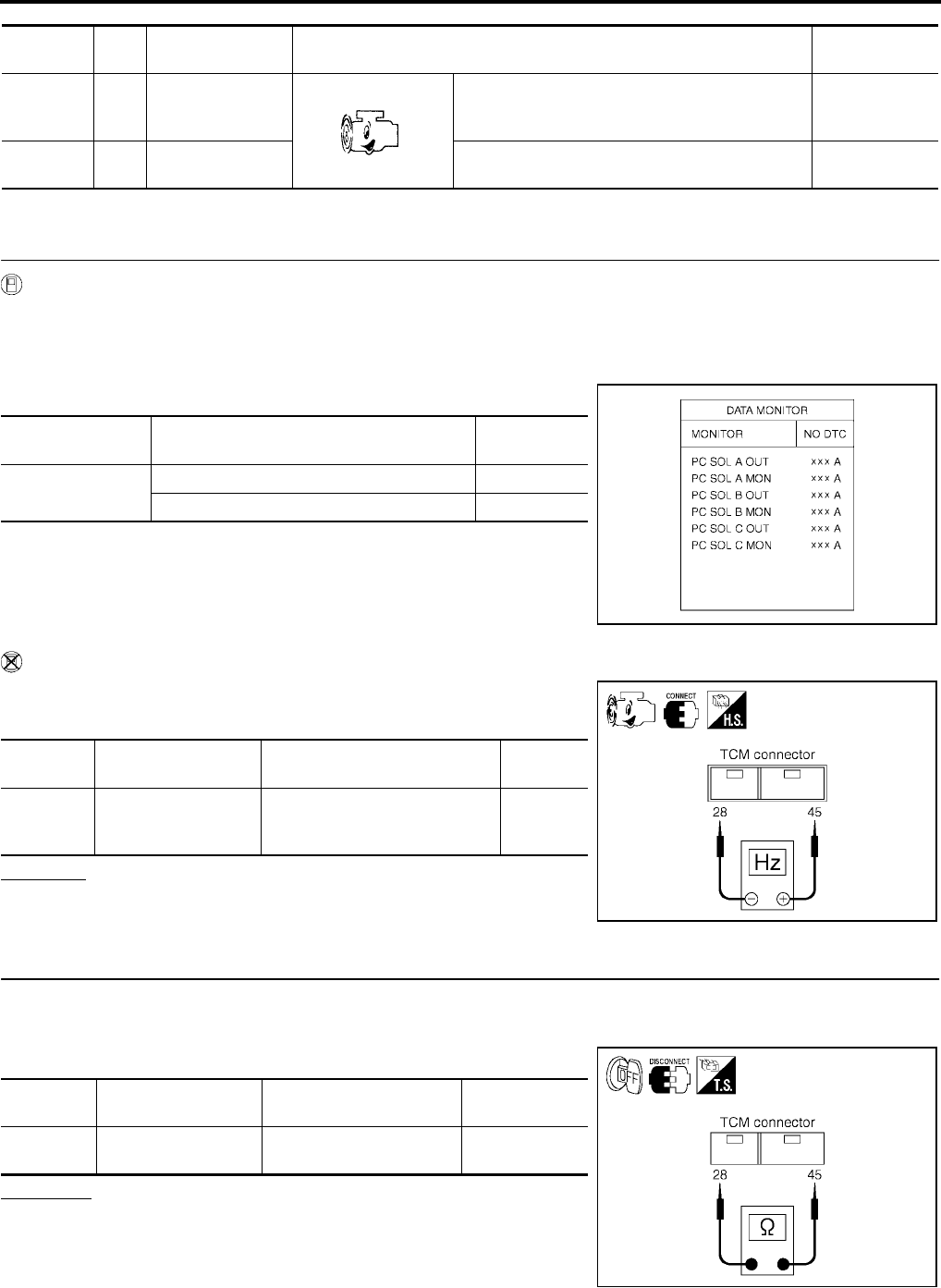
AT-558
[RE5F22A]
DTC P0795 PRESSURE CONTROL SOLENOID VALVE C (TCC AND SHIFT
PRESSURE)
Revision: September 2005 2005 Quest
TCM terminals and data are reference value. Measured between each terminal and ground.
Diagnostic Procedure UCS002MD
1. CHECK PRESSURE CONTROL SOLENOID VALVE C SIGNAL
With CONSULT-II
1. After warming up the engine and transaxle, turn ignition switch “OFF”.
2. Turn ignition switch “ON”. (Do not start engine.)
3. Select “A/T” with “DATA MONITOR” mode in CONSULT-II.
4. Read out the value of “PC SOL C OUT” and “PC SOL C MON”.
Without CONSULT-II
1. Start the engine.
2. Check pulse between TCM connector terminals 28 and 45.
OK or NG
OK >> GO TO 7.
NG >> GO TO 2.
2. CHECK PRESSURE CONTROL SOLENOID VALVE C CIRCUIT
1. Turn ignition switch “OFF”.
2. Disconnect the TCM connector.
3. Check resistance between TCM connector terminals 28 and 45.
OK or NG
OK >> GO TO 7.
NG >> GO TO 3.
Terminal Wire
color Item Condition Data (Approx.)
28 W
Pressure control
solenoid valve C
ground
When engine is running with idle speed and set-
ting selector lever to “P” position. 0V
45 O/B Pressure control
solenoid valve C
When engine is running with idle speed and set-
ting selector lever to “P” position. 300Hz
Monitor item Condition Display value
(Approx.)
●PC SOL C OUT
●PC SOL C MON
Selector lever: Manual shift gate position 1.00 A
Other than the above. 0.20 A
SCIA2907E
Connector Terminal (Wire color) Condition Data
(Approx.)
E142 45 (O/B) - 28 (W)
(Ground)
When engine is running with idle
speed and setting selector lever
to “P” position.
300 Hz
SCIA2914E
Connector Terminal (Wire color) Condition Resistance
(Approx.)
E142 45 (O/B) - 28 (W)
(Ground) Temperature: 20°C (68°F) 5.0 - 5.6 Ω
SCIA2915E

DTC P0795 PRESSURE CONTROL SOLENOID VALVE C (TCC AND SHIFT
PRESSURE)
AT-559
[RE5F22A]
D
E
F
G
H
I
J
K
L
M
A
B
AT
Revision: September 2005 2005 Quest
3. CHECK TERMINAL CORD ASSEMBLY WITH PRESSURE CONTROL SOLENOID VALVE C
1. Turn ignition switch “OFF”.
2. Disconnect terminal cord assembly harness connector.
3. Check resistance between terminals 2 and 5.
OK or NG
OK >> GO TO 4.
NG >> GO TO 5.
4. CHECK HARNESS BETWEEN TCM AND TERMINAL CORD ASSEMBLY
Check the following.
●Open or short-circuit in the harness between TCM and terminal cord assembly.
OK or NG
OK >> GO TO 7.
NG >> Repair or replace damaged parts.
5. CHECK PRESSURE CONTROL SOLENOID VALVE C
1. Remove side cover. Refer to AT-609, "Side cover" .
2. Disconnect pressure control solenoid valve C harness connector.
3. Check resistance between terminals 1 and 2.
OK or NG
OK >> GO TO 6.
NG >> Replace the control valve assembly. Refer to AT-609,
"Control Valve Assembly" .
6. CHECK HARNESS BETWEEN TERMINAL CORD ASSEMBLY AND PRESSURE CONTROL SOLE-
NOID VALVE C
Check the following.
●Open or short-circuit in the harness between terminal cord assembly and pressure control solenoid valve
C.
OK or NG
OK >> GO TO 7.
NG >> Repair or replace transmission wire. Refer to AT-609, "Transmission wire" .
7. CHECK DTC
Perform “DTC Confirmation Procedure”. Refer to AT-556, "DTC Confirmation Procedure" .
OK or NG
OK >> INSPECTION END
NG >> GO TO 8.
Connector Terminal Condition Resistance (Approx.)
F62 2 - 5 Temperature: 20°C (68°F) 5.0 - 5.6 Ω
SCIA2916E
Connector Terminal Condition Resistance (Approx.)
F74 1 - 2 Temperature: 20°C (68°F) 5.0 - 5.6 Ω
SCIA4342E

AT-560
[RE5F22A]
DTC P0795 PRESSURE CONTROL SOLENOID VALVE C (TCC AND SHIFT
PRESSURE)
Revision: September 2005 2005 Quest
8. CHECK TCM
1. Check TCM input/output signal. Refer to AT-438, "TCM Input/Output Signal Reference Values" .
2. If NG, recheck TCM pin terminals for damage or loose connection with harness connector.
OK or NG
OK >> INSPECTION END
NG >> Repair or replace damaged parts.
Component Inspection UCS002MA
PRESSURE CONTROL SOLENOID VALVE C
1. Remove side cover. Refer to AT-609, "Side cover" .
2. Disconnect pressure control solenoid valve C harness connector.
3. Check resistance between terminals 1 and 2.
4. If NG, replace the control valve assembly. Refer to AT-609,
"Control Valve Assembly" .
Connector Terminal Condition Resistance (Approx.)
F74 1 - 2 Temperature: 20°C (68°F) 5.0 - 5.6 Ω
SCIA4342E

DTC P0797 PRESSURE CONTROL SOLENOID VALVE C STUCK ON
AT-561
[RE5F22A]
D
E
F
G
H
I
J
K
L
M
A
B
AT
Revision: September 2005 2005 Quest
DTC P0797 PRESSURE CONTROL SOLENOID VALVE C STUCK ON PFP:31940
Description UCS00147
●This malfunction will not be detected while the O/D OFF indicator lamp is indicating another self-diagnosis
malfunction.
●This is not caused by electrical malfunction (circuits open or shorted) but by mechanical malfunction such
as control valve sticking, improper solenoid valve operation, etc.
●The pressure control solenoid valve C is normally low, 3-port lin-
ear pressure control solenoid.
●The pressure control solenoid valve C is activated to control the
apply and release of the 2nd brake and 1st and reverse brake,
and torque converter clutch.
●Lock-up operation, however, is prohibited when A/T fluid tem-
perature is too low.
●When the accelerator pedal is depressed (less than 1/8) in lock-
up condition, the engine speed should not change abruptly. If
there is a big jump in engine speed, there is no lock-up.
On Board Diagnosis Logic UCS00148
●This is an OBD-II self-diagnostic item.
●Diagnostic trouble code “PC SOL C STC ON” with CONSULT-II or P0797 without CONSULT-II is detected
when condition of pressure control solenoid valve C is different from monitor value, and relation between
gear position and actual gear ratio or lock-up status is irregular.
Possible Cause UCS00149
●Pressure control solenoid valve C
(On stick.)
●Hydraulic control circuit
DTC Confirmation Procedure UCS0014A
NOTE:
If “DTC Confirmation Procedure” has been previously performed, always turn ignition switch “OFF”
and wait at least 10 seconds before performing the next test.
After the repair, perform the following procedure to confirm the malfunction is eliminated.
WITH CONSULT-II
1. Turn ignition switch “ON”. (Do not start engine.)
2. Select “DATA MONITOR” mode for “A/T” with CONSULT-II.
3. Start engine.
4. Run engine for at least 4 consecutive minutes at idle speed.
5. If DTC is detected, go to AT-563, "Diagnostic Procedure" .
WITH GST
Follow the procedure “With CONSULT-II”.
SCIA2833E
BCIA0030E
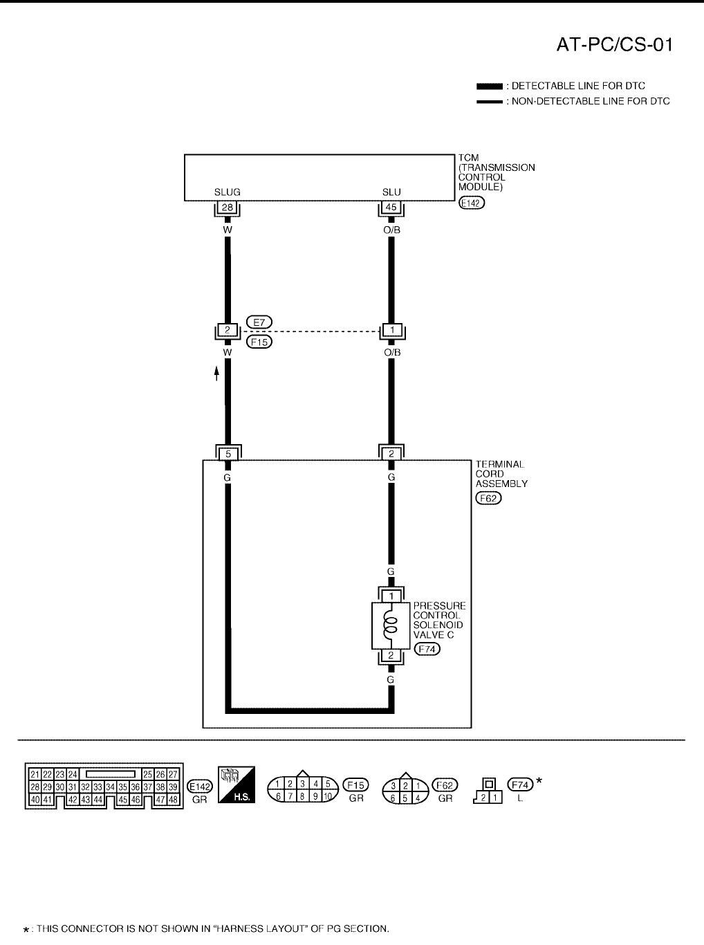
AT-562
[RE5F22A]
DTC P0797 PRESSURE CONTROL SOLENOID VALVE C STUCK ON
Revision: September 2005 2005 Quest
Wiring Diagram — AT — PC/CS UCS0014B
BCWA0358E
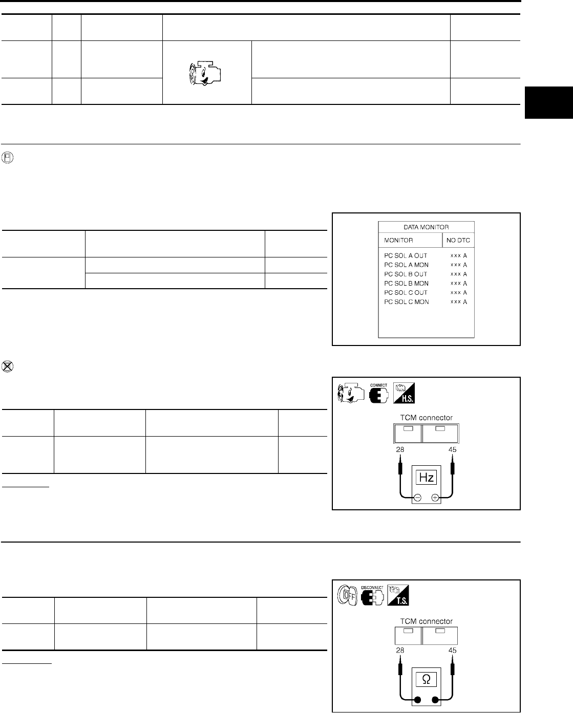
DTC P0797 PRESSURE CONTROL SOLENOID VALVE C STUCK ON
AT-563
[RE5F22A]
D
E
F
G
H
I
J
K
L
M
A
B
AT
Revision: September 2005 2005 Quest
TCM terminals and data are reference value. Measured between each terminal and ground.
Diagnostic Procedure UCS002MB
1. CHECK PRESSURE CONTROL SOLENOID VALVE C SIGNAL
With CONSULT-II
1. After warming up the engine and transaxle, turn ignition switch “OFF”.
2. Turn ignition switch “ON”. (Do not start engine.)
3. Select “A/T” with “DATA MONITOR” mode in CONSULT-II.
4. Read out the value of “PC SOL C OUT” and “PC SOL C MON”.
Without CONSULT-II
1. Start the engine.
2. Check pulse between TCM connector terminals 28 and 45.
OK or NG
OK >> GO TO 7.
NG >> GO TO 2.
2. CHECK PRESSURE CONTROL SOLENOID VALVE C CIRCUIT
1. Turn ignition switch “OFF”.
2. Disconnect the TCM connector.
3. Check resistance between TCM connector terminals 28 and 45.
OK or NG
OK >> GO TO 7.
NG >> GO TO 3.
Terminal Wire
color Item Condition Data (Approx.)
28 W
Pressure control
solenoid valve C
ground
When engine is running with idle speed and set-
ting selector lever to “P” position. 0V
45 O/B Pressure control
solenoid valve C
When engine is running with idle speed and set-
ting selector lever to “P” position. 300Hz
Monitor item Condition Display value
(Approx.)
●PC SOL C OUT
●PC SOL C MON
Selector lever: Manual shift gate position 1.00 A
Other than the above. 0.20 A
SCIA2907E
Connector Terminal (Wire color) Condition Data
(Approx.)
E142 45 (O/B) - 28 (W)
(Ground)
When engine is running with idle
speed and setting selector lever
to “P” position.
300 Hz
SCIA2914E
Connector Terminal (Wire color) Condition Resistance
(Approx.)
E142 45 (O/B) - 28 (W)
(Ground) Temperature: 20°C (68°F) 5.0 - 5.6 Ω
SCIA2915E
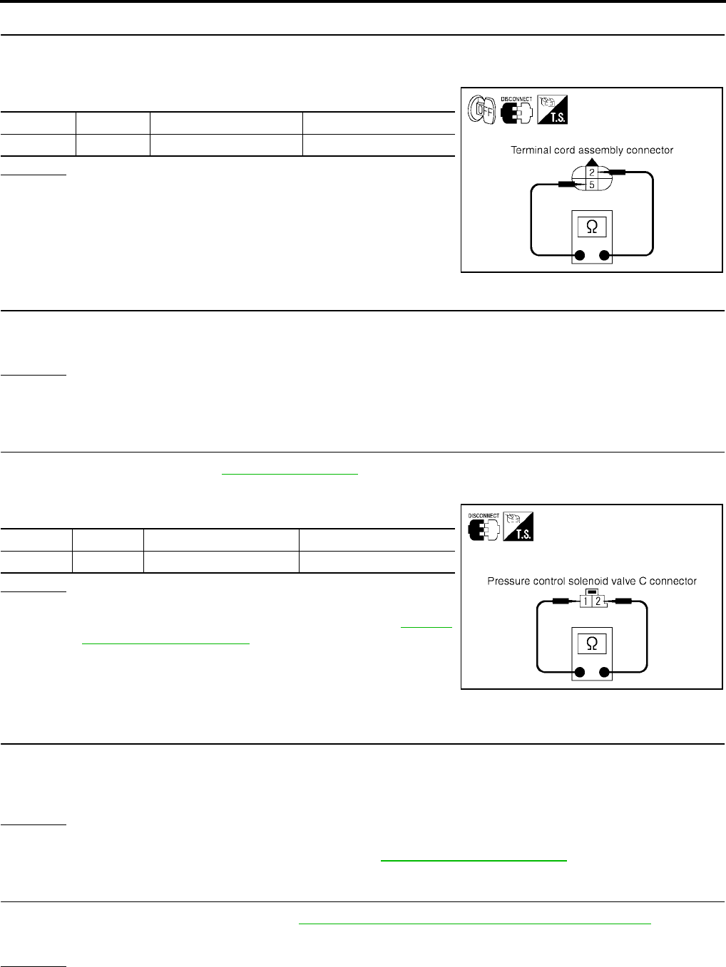
AT-564
[RE5F22A]
DTC P0797 PRESSURE CONTROL SOLENOID VALVE C STUCK ON
Revision: September 2005 2005 Quest
3. CHECK TERMINAL CORD ASSEMBLY WITH PRESSURE CONTROL SOLENOID VALVE C
1. Turn ignition switch “OFF”.
2. Disconnect terminal cord assembly harness connector.
3. Check resistance between terminals 2 and 5.
OK or NG
OK >> GO TO 4.
NG >> GO TO 5.
4. CHECK HARNESS BETWEEN TCM AND TERMINAL CORD ASSEMBLY
Check the following.
●Open or short-circuit in the harness between TCM and terminal cord assembly.
OK or NG
OK >> GO TO 7.
NG >> Repair or replace damaged parts.
5. CHECK PRESSURE CONTROL SOLENOID VALVE C
1. Remove side cover. Refer to AT-609, "Side cover" .
2. Disconnect pressure control solenoid valve C harness connector.
3. Check resistance between terminals 1 and 2.
OK or NG
OK >> GO TO 6.
NG >> Replace the control valve assembly. Refer to AT-609,
"Control Valve Assembly" .
6. CHECK HARNESS BETWEEN TERMINAL CORD ASSEMBLY AND PRESSURE CONTROL SOLE-
NOID VALVE C
Check the following.
●Open or short-circuit in the harness between terminal cord assembly and pressure control solenoid valve
C.
OK or NG
OK >> GO TO 7.
NG >> Repair or replace transmission wire. Refer to AT-609, "Transmission wire" .
7. CHECK TCM
1. Check TCM input/output signal. Refer to AT-438, "TCM Input/Output Signal Reference Values" .
2. If NG, recheck TCM pin terminals for damage or loose connection with harness connector.
OK or NG
OK >> GO TO 8.
NG >> Repair or replace damaged parts.
Connector Terminal Condition Resistance (Approx.)
F62 2 - 5 Temperature: 20°C (68°F) 5.0 - 5.6 Ω
SCIA2916E
Connector Terminal Condition Resistance (Approx.)
F74 1 - 2 Temperature: 20°C (68°F) 5.0 - 5.6 Ω
SCIA4342E
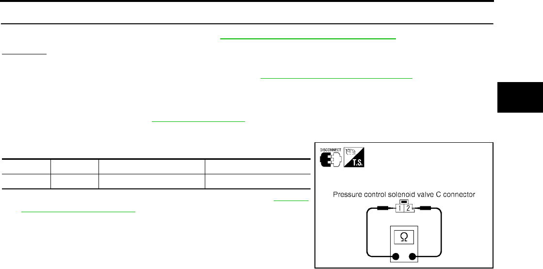
DTC P0797 PRESSURE CONTROL SOLENOID VALVE C STUCK ON
AT-565
[RE5F22A]
D
E
F
G
H
I
J
K
L
M
A
B
AT
Revision: September 2005 2005 Quest
8. CHECK DTC
Perform “DTC Confirmation Procedure”. Refer toAT-561, "DTC Confirmation Procedure" .
OK or NG
OK >> INSPECTION END
NG >> Replace the control valve assembly. Refer to AT-609, "Control Valve Assembly" .
Component Inspection UCS002MC
PRESSURE CONTROL SOLENOID VALVE C
1. Remove side cover. Refer to AT-609, "Side cover" .
2. Disconnect pressure control solenoid valve C harness connector.
3. Check resistance between terminals 1 and 2.
4. If NG, replace the control valve assembly. Refer to AT-609,
"Control Valve Assembly" .
Connector Terminal Condition Resistance (Approx.)
F74 1 - 2 Temperature: 20°C (68°F) 5.0 - 5.6 Ω
SCIA4342E

AT-566
[RE5F22A]
DTC P0825 LEVER SWITCH CIRCUIT
Revision: September 2005 2005 Quest
DTC P0825 LEVER SWITCH CIRCUIT PFP:25130
Description UCS0010X
Lever switch is installed in A/T device. It sends lever switch position (ON or OFF) signals to TCM.
On Board Diagnosis Logic UCS0010Z
●This is not an OBD-II self-diagnostic item.
●Diagnostic trouble code “GEAR LEVER SWITCH” with CONSULT-II is detected when TCM monitors lever
switch signal, and judges as irregular when impossible input pattern occurs.
Possible Cause UCS00110
●Harness or connectors
(Lever switch circuit is open or shorted.)
●Lever switch (built into A/T device)
DTC Confirmation Procedure UCS00111
NOTE:
If “DTC Confirmation Procedure” has been previously performed, always turn ignition switch “OFF”
and wait at least 10 seconds before performing the next test.
After the repair, perform the following procedure to confirm the malfunction is eliminated.
WITH CONSULT-II
1. Turn ignition switch “ON”. (Do not start engine.)
2. Select “DATA MONITOR” mode for “A/T” with CONSULT-II.
3. Set overdrive control switch to “OFF” position.
4. Wait for at least 30 consecutive seconds.
5. If DTC is detected, go to AT-568, "Diagnostic Procedure" .
BCIA0030E
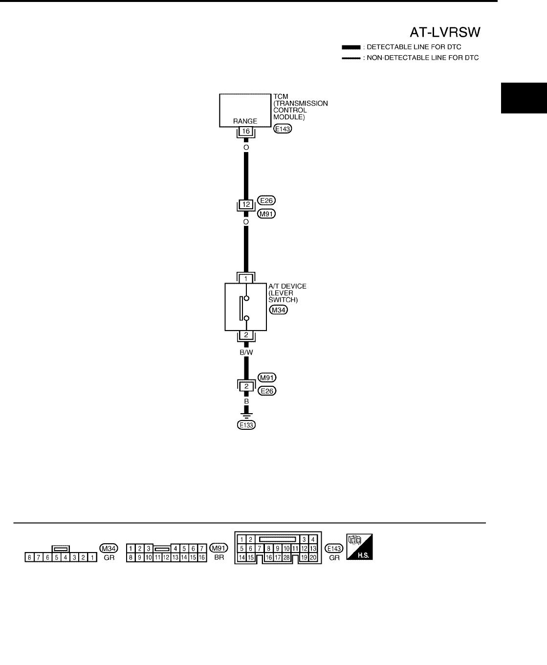
DTC P0825 LEVER SWITCH CIRCUIT
AT-567
[RE5F22A]
D
E
F
G
H
I
J
K
L
M
A
B
AT
Revision: September 2005 2005 Quest
Wiring Diagram — AT — LVRSW UCS00112
BCWA0524E

AT-568
[RE5F22A]
DTC P0825 LEVER SWITCH CIRCUIT
Revision: September 2005 2005 Quest
TCM terminal and data are reference value. Measured between each terminal and ground.
Diagnostic Procedure UCS00113
1. CHECK LEVER SWITCH CIRCUIT
With CONSULT-II
1. Turn ignition switch “ON”. (Do not start engine.)
2. Select “DATA MONITOR” mode for “A/T” with CONSULT-II.
3. Read out ON/OFF switching action of the “RANGE SLCT SW”.
Without CONSULT-II
1. Turn ignition switch “ON”. (Do not start engine.)
2. Check voltage between the TCM connector terminal and
ground.
OK or NG
OK >> GO TO 4.
NG >> GO TO 2.
2. CHECK HARNESS BETWEEN TCM AND A/T DEVICE (LEVER SWITCH)
1. Turn ignition switch “OFF”.
2. Disconnect the TCM connector.
3. Check the continuity between TCM connector terminal 16 and
ground.
4. If OK, check harness for short-circuit to ground or power source.
OK or NG
OK >> GO TO 4.
NG >> GO TO 3.
Terminal Wire
color Item Condition Data (Approx.)
16 O Lever switch
Lever switch: “ON” position 0V
Lever switch: “OFF” position Battery voltage
SCIA3579E
Connector
No.
Terminal (Wire
color) Condition Voltage
(Approx.)
E143 16 (O) -
Ground
Lever switch: “ON” position 0V
Lever switch: “OFF” position Battery
voltage
SCIA3580E
Connector
No.
Terminal (Wire
color) Condition Continuity
E143 16 (O) -
Ground
Lever switch: “ON” position Yes
Lever switch: “OFF” position No
SCIA3581E

DTC P0825 LEVER SWITCH CIRCUIT
AT-569
[RE5F22A]
D
E
F
G
H
I
J
K
L
M
A
B
AT
Revision: September 2005 2005 Quest
3. DETECT MALFUNCTIONING ITEM
Check the following.
●Open or short-circuit in the harness between TCM and A/T device (lever switch).
●Open or short-circuit in the harness for ground of lever switch.
●Lever switch. Refer to AT-569, "Component Inspection" .
OK or NG
OK >> GO TO 4.
NG >> Repair or replace damaged parts.
4. CHECK DTC
Perform “DTC Confirmation Procedure”. Refer to AT-566, "DTC Confirmation Procedure" .
OK or NG
OK >> INSPECTION END
NG >> GO TO 5.
5. CHECK TCM
1. Check TCM input/output signal.
2. If NG, recheck TCM pin terminals for damage or loose connection with harness connector.
OK or NG
OK >> INSPECTION END
NG >> Repair or replace damaged parts.
Component Inspection UCS00114
LEVER SWITCH
Check continuity between A/T device (lever switch) harness connec-
tor M34 terminals 1 and 2.
Switch position Continuity
ON Yes
OFF No
SCIA3582E

AT-570
[RE5F22A]
DTC P0882 TCM POWER INPUT SIGNAL
Revision: September 2005 2005 Quest
DTC P0882 TCM POWER INPUT SIGNAL PFP:31036
Description UCS000VD
When the power supply to the TCM is cut “OFF”, for example because the battery is removed, and the self-
diagnostics memory function stops, malfunction is detected.
On Board Diagnosis Logic UCS000VE
●This is an OBD-II self-diagnostic item.
●Diagnostic trouble code “TCM POWER INPT SIG” with CONSULT-II or P0882 without CONSULT-II is
detected when voltage supplied to TCM is too low.
Possible Cause UCS000VF
●Harness or connectors
(Battery or ignition switch and TCM circuit is open or shorted.)
●A/T PV IGN relay
DTC Confirmation Procedure UCS0014X
CAUTION:
●Always drive vehicle at a safe speed.
●Be careful not to rev engine into the red zone on the tachometer.
NOTE:
If “DTC Confirmation Procedure” has been previously performed, always turn ignition switch “OFF”
and wait at least 10 seconds before performing the next test.
After the repair, perform the following procedure to confirm the malfunction is eliminated.
WITH CONSULT-II
1. Turn ignition switch “ON”. (Do not start engine.)
2. Select “DATA MONITOR” mode for “A/T” with CONSULT-II.
3. Start engine.
4. Depress accelerator pedal or drive vehicle and maintain the fol-
lowing condition for at least 20 consecutive seconds.
TURBINE REV: More than 800 rpm
5. If DTC is detected, go to AT-573, "Diagnostic Procedure" .
BCIA0030E
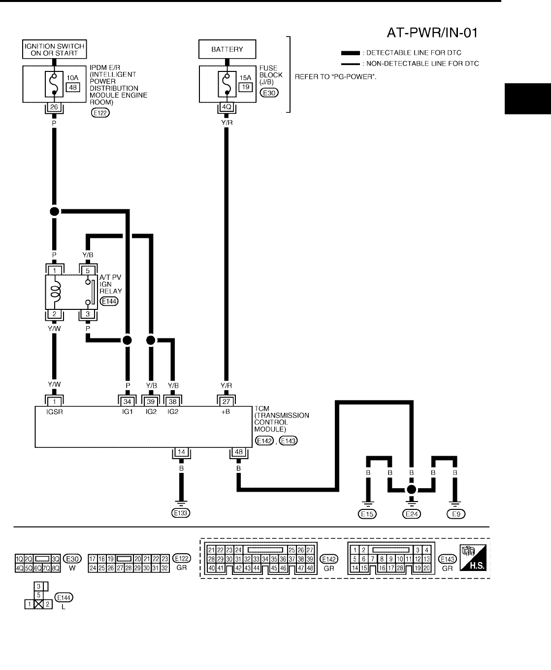
DTC P0882 TCM POWER INPUT SIGNAL
AT-571
[RE5F22A]
D
E
F
G
H
I
J
K
L
M
A
B
AT
Revision: September 2005 2005 Quest
Wiring Diagram — AT — PWR/IN UCS000VH
BCWA0317E
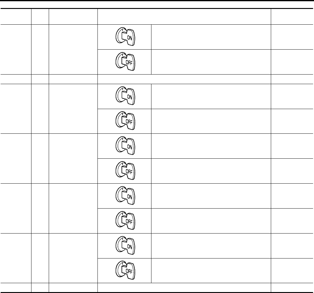
AT-572
[RE5F22A]
DTC P0882 TCM POWER INPUT SIGNAL
Revision: September 2005 2005 Quest
TCM terminals and data are reference value. Measured between each terminal and ground.
Terminal Wire
color Item Condition Data (Approx.)
1 Y/W A/T PV IGN relay
When turning ignition switch ON. 0 - 1.5V
When turning ignition switch OFF. 0V
14 B Ground – 0V
27 Y/R Power supply
(Memory back-up)
When turning ignition switch ON. Battery voltage
When turning ignition switch OFF. Battery voltage
34 P Power supply
When turning ignition switch ON. Battery voltage
When turning ignition switch OFF. 0V
38 Y/B Power supply
(A/T PV IGN relay)
When turning ignition switch ON. Battery voltage
Measure 3 seconds after switching “OFF” the
ignition switch. 0V
39 Y/B Power supply
(A/T PV IGN relay)
When turning ignition switch ON. Battery voltage
Measure 3 seconds after switching “OFF” the
ignition switch. 0V
48 B Ground – 0V

DTC P0882 TCM POWER INPUT SIGNAL
AT-573
[RE5F22A]
D
E
F
G
H
I
J
K
L
M
A
B
AT
Revision: September 2005 2005 Quest
Diagnostic Procedure UCS000VI
1. CHECK TCM POWER SOURCE CIRCUIT
1. Turn ignition switch “ON”. (Do not start engine.)
2. Check voltage between TCM terminals and ground.
3. Turn ignition switch “OFF”.
4. Check voltage between TCM terminals and ground.
OK or NG
OK >> GO TO 3.
NG >> GO TO 2.
2. DETECT MALFUNCTIONING ITEM
Check the following:
●Harness for short or open between battery and TCM terminal 27
●Harness for short or open between ignition switch and TCM terminals 1, 34, 38 and 39
●10A fuse [No. 19, located in the fuse block (J/B) or No. 48, located in the IPDM E/R]
●Ignition switch. Refer to PG-4, "POWER SUPPLY ROUTING CIRCUIT" .
●A/T PV IGN relay. Refer to AT-574, "Component Inspection" .
OK or NG
OK >> GO TO 3.
NG >> Repair or replace damaged parts.
3. CHECK TCM GROUND CIRCUIT
1. Turn ignition switch “OFF”.
2. Disconnect TCM harness connector.
3. Check continuity between TCM terminals 14 (B), 48 (B) and
ground.
If OK, check harness for short to ground and short to power.
OK or NG
OK >> GO TO 4.
NG >> Repair open circuit or short to ground or short to power
in harness or connectors.
Connector Terminal (Wire color) Voltage (Approx.)
E143 1 (Y/W) - Ground 0 - 1.5V
E142
27 (Y/R) - Ground
Battery voltage
34 (P) - Ground
38 (Y/B) - Ground
39 (Y/B) - Ground
Connector Terminal (Wire color) Voltage (Approx.)
E143 1 (Y/W) - Ground 0V
E142
27 (Y/R) - Ground Battery voltage
34 (P) - Ground 0V
38 (Y/B) - Ground 0V
39 (Y/B) - Ground 0V
SCIA2930E
Continuity should exist.
SCIA2933E
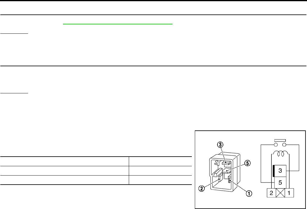
AT-574
[RE5F22A]
DTC P0882 TCM POWER INPUT SIGNAL
Revision: September 2005 2005 Quest
4. CHECK DTC
Check again. Refer to AT-570, "DTC Confirmation Procedure" .
OK or NG
OK >> INSPECTION END
NG >> GO TO 5.
5. CHECK TCM
1. Check TCM input/output signal.
2. If NG, recheck TCM pin terminals for damage or loose connection with harness connector.
OK or NG
OK >> INSPECTION END
NG >> Repair or replace damaged parts.
Component Inspection UCS000VJ
A/T PV IGN RELAY
1. Apply 12V direct current between A/T PV IGN relay terminals 1
and 2.
2. Check continuity between relay terminals 3 and 5.
3. If NG, replace A/T PV IGN relay.
Condition Continuity
12V direct current supply between terminals 1 and 2 Yes
OFF No
SCIA1245E

DTC P1726 ELECTRIC THROTTLE CONTROL SYSTEM
AT-575
[RE5F22A]
D
E
F
G
H
I
J
K
L
M
A
B
AT
Revision: September 2005 2005 Quest
DTC P1726 ELECTRIC THROTTLE CONTROL SYSTEM PFP:23710
Description UCS000VZ
This DTC is displayed with other DTCs regarding ECM. Perform the trouble diagnosis for other DTCs dis-
played. Refer to EC-100, "TROUBLE DIAGNOSIS" .
When this DTC is detected, lock-up operation and learning control are canceled.
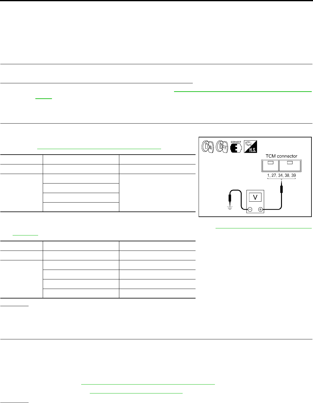
AT-576
[RE5F22A]
TROUBLE DIAGNOSIS FOR SYMPTOMS
Revision: September 2005 2005 Quest
TROUBLE DIAGNOSIS FOR SYMPTOMS PFP:00007
O/D OFF Indicator Lamp Does Not Come On UCS002LO
SYMPTOM:
O/D OFF indicator lamp does not come on for about 2 seconds when turning ignition switch to “ON”.
DIAGNOSTIC PROCEDURE
1. CHECK CAN COMMUNICATION LINE
Perform the self-diagnosis.
Is a malfunction in the CAN communication indicated in the results?
YES >> Check the CAN communication line. Refer to AT-450, "DTC U1000 CAN COMMUNICATION
LINE" .
NO >> GO TO 2.
2. CHECK TCM POWER SOURCE CIRCUIT
1. Turn ignition switch “ON”. (Do not start engine.)
2. Check voltage between TCM connector terminals and ground.
Refer to AT-571, "Wiring Diagram — AT — PWR/IN" .
3. Turn ignition switch “OFF”.
4. Check voltage between TCM connector terminals and ground. Refer to AT-571, "Wiring Diagram — AT —
PWR/IN" .
OK or NG
OK >> GO TO 4.
NG >> GO TO 3.
3. DETECT MALFUNCTIONING ITEM
Check the following:
●Harness for short or open between battery and TCM terminal 27
●Harness for short or open between ignition switch and TCM terminals 1, 34, 38 and 39
●10A fuse [No. 19, located in the fuse block (J/B) or No. 48, located in the IPDM E/R]
●Ignition switch. Refer to PG-4, "POWER SUPPLY ROUTING CIRCUIT" .
●A/T PV IGN relay. Refer to AT-574, "Component Inspection" .
OK or NG
OK >> GO TO 4.
NG >> Repair or replace damaged parts.
Connector Terminal (Wire color) Voltage (Approx.)
E143 1 (Y/W) - Ground 0 - 1.5V
E142
27 (Y/R) - Ground
Battery voltage
34 (P) - Ground
38 (Y/B) - Ground
39 (Y/B) - Ground
Connector Terminal (Wire color) Voltage (Approx.)
E143 1 (Y/W) - Ground 0V
E142
27 (Y/R) - Ground Battery voltage
34 (P) - Ground 0V
38 (Y/B) - Ground 0V
39 (Y/B) - Ground 0V
SCIA2930E
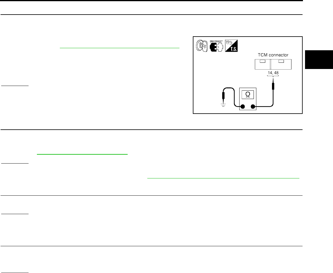
TROUBLE DIAGNOSIS FOR SYMPTOMS
AT-577
[RE5F22A]
D
E
F
G
H
I
J
K
L
M
A
B
AT
Revision: September 2005 2005 Quest
4. CHECK TCM GROUND CIRCUIT
1. Turn ignition switch “OFF”.
2. Disconnect the TCM harness connector.
3. Check continuity between TCM terminals 14 (B), 48 (B) and
ground. Refer to AT-571, "Wiring Diagram — AT — PWR/IN" .
4. If OK, check harness for short-circuit to ground or the power
source.
OK or NG
OK >> GO TO 5.
NG >> Repair open circuit or short to ground or short to power
in harness or connectors.
5. CHECK O/D OFF INDICATOR LAMP CIRCUIT
1. Turn ignition switch “OFF”.
2. Check the combination meter.
Refer to DI-5, "COMBINATION METERS" .
OK or NG
OK >> GO TO 6.
NG >> Replace the combination meter. Refer to DI-21, "Removal and Installation of Combination Meter" .
6. SYMPTOM CHECK
Check again.
OK or NG
OK >> INSPECTION END
NG >> GO TO 7.
7. CHECK TCM
1. Check TCM input/output signal.
2. If NG, recheck TCM pin terminals for damage or loose connection with harness connector.
OK or NG
OK >> INSPECTION END
NG >> Repair or replace damaged parts.
Continuity should exist.
SCIA2933E

AT-578
[RE5F22A]
TROUBLE DIAGNOSIS FOR SYMPTOMS
Revision: September 2005 2005 Quest
Engine Cannot Be Started In “P” or “N” Position UCS002K6
SYMPTOM:
●Engine cannot be started with selector lever in “P” or “N” position.
●Engine can be started with selector lever in “D”, “L” or “R” position.
DIAGNOSTIC PROCEDURE
1. CHECK STARTING SYSTEM
Check starting system. Refer to SC-10, "STARTING SYSTEM" .
OK or NG
OK >> GO TO 2.
NG >> Repair or replace damaged parts.
2. CHECK CONTROL CABLE
Check the control cable.
●Refer to AT-608, "Control Cable Adjustment" .
OK or NG
OK >> GO TO 3.
NG >> Adjust control cable. Refer to AT-608, "Control Cable Adjustment" .
3. CHECK PNP SWITCH CIRCUIT
Perform self-diagnosis.
Do the self-diagnostic results indicate PNP switch?
YES >> Check the malfunctioning system. Refer to AT-457, "DTC P0705 PARK/NEUTRAL POSITION
SWITCH" .
NO >> INSPECTION END
In “P” Position, Vehicle Moves When Pushed UCS002K7
SYMPTOM:
Even though the selector lever is set in the “P” position, the parking mechanism is not actuated,
allowing the vehicle to be moved when it is pushed.
DIAGNOSTIC PROCEDURE
1. CHECK PNP SWITCH CIRCUIT
Perform self-diagnosis.
Do the self-diagnostic results indicate PNP switch?
YES >> Check the malfunctioning system. Refer to AT-457, "DTC P0705 PARK/NEUTRAL POSITION
SWITCH" .
NO >> GO TO 2.
2. CHECK CONTROL CABLE
Check the control cable.
●Refer to AT-608, "Control Cable Adjustment" .
OK or NG
OK >> GO TO 3.
NG >> Adjust control cable. Refer to AT-608, "Control Cable Adjustment" .
3. SYMPTOM CHECK
Check again.
OK or NG
OK >> INSPECTION END
NG >> Repair or replace damaged parts.

TROUBLE DIAGNOSIS FOR SYMPTOMS
AT-579
[RE5F22A]
D
E
F
G
H
I
J
K
L
M
A
B
AT
Revision: September 2005 2005 Quest
In “N” Position, Vehicle Moves UCS002K8
SYMPTOM:
Vehicle moves forward or backward when selecting “N” position.
DIAGNOSTIC PROCEDURE
1. CHECK A/T FLUID LEVEL
Check the A/T fluid level. Refer to AT-421, "A/T FLUID CHECK" .
OK or NG
OK >> GO TO 2.
NG >> Refill ATF.
2. CHECK PNP SWITCH CIRCUIT
Perform self-diagnosis.
Do the self-diagnostic results indicate PNP switch?
YES >> Check the malfunctioning system. Refer to AT-457, "DTC P0705 PARK/NEUTRAL POSITION
SWITCH" .
NO >> GO TO 3.
3. CHECK CONTROL CABLE
Check the control cable.
●Refer to AT-608, "Control Cable Adjustment" .
OK or NG
OK >> GO TO 3.
NG >> Adjust control cable. Refer to AT-608, "Control Cable Adjustment" .
4. CHECK SYMPTOM
Check again.
OK or NG
OK >> INSPECTION END
NG >> GO TO 4.
5. CHECK TCM
1. Check TCM input/output signal. Refer to AT-438, "TCM Input/Output Signal Reference Values" .
2. If NG, recheck TCM pin terminals for damage or loose connection with harness connector.
OK or NG
OK >> INSPECTION END
NG >> Repair or replace damaged parts.

AT-580
[RE5F22A]
TROUBLE DIAGNOSIS FOR SYMPTOMS
Revision: September 2005 2005 Quest
Large Shock (“N” to “D” Position) UCS002K9
SYMPTOM:
A noticeable shock occurs when the selector lever is shifted from the “N” to “D” position.
DIAGNOSTIC PROCEDURE
1. CHECK A/T FLUID LEVEL
Check the A/T fluid level. Refer to AT-421, "A/T FLUID CHECK" .
OK or NG
OK >> GO TO 2.
NG >> Refill ATF.
2. CHECK SELF-DIAGNOSTIC RESULTS
Perform self-diagnosis.
Is any malfunction detected by self-diagnostic?
YES >> Check the malfunctioning system.
NO >> GO TO 3.
3. DETECT MALFUNCTIONING ITEM
1. Control valve assembly. Refer to AT-609, "Control Valve Assembly" .
2. Disassemble A/T. Refer to AT-619, "DISASSEMBLY" .
3. Check the following items:
–Accumulator. Refer to AT-619, "DISASSEMBLY" .
–Forward and direct clutch assembly. Refer to AT-619, "DISASSEMBLY" .
OK or NG
OK >> GO TO 4.
NG >> Repair or replace damaged parts.
4. CHECK TCM
1. Check TCM input/output signal. Refer to AT-438, "TCM Input/Output Signal Reference Values" .
2. If NG, recheck TCM pin terminals for damage or loose connection with harness connector.
OK or NG
OK >> GO TO 5.
NG >> Repair or replace damaged parts.
5. CHECK SYMPTOM
Check again.
OK or NG
OK >> INSPECTION END
NG >> Repair or replace damaged parts.

TROUBLE DIAGNOSIS FOR SYMPTOMS
AT-581
[RE5F22A]
D
E
F
G
H
I
J
K
L
M
A
B
AT
Revision: September 2005 2005 Quest
Vehicle Does Not Creep Backward In “R” Position UCS002KA
SYMPTOM:
The vehicle does not creep in the “R” position. Or an extreme lack of acceleration is observed.
DIAGNOSTIC PROCEDURE
1. CHECK A/T FLUID LEVEL
Check the A/T fluid level. Refer to AT-421, "A/T FLUID CHECK" .
OK or NG
OK >> GO TO 2.
NG >> Refill ATF.
2. CHECK CONTROL CABLE AND PNP SWITCH POSITION
Check the control cable and PNP switch position.
●Refer to AT-608, "Control Cable Adjustment" .
OK or NG
OK >> GO TO 3.
NG >> Adjust control cable and PNP switch position. Refer to AT-608, "Control Cable Adjustment" or AT-
606, "Park/Neutral Position (PNP) Switch Adjustment" .
3. CHECK SELF-DIAGNOSTIC RESULTS
Perform self-diagnosis.
Is any malfunction detected by self-diagnostic?
YES >> Check the malfunctioning system.
NO >> GO TO 4.
4. DETECT MALFUNCTIONING ITEM
1. Control valve assembly. Refer to AT-609, "Control Valve Assembly" .
2. Disassemble A/T. Refer to AT-619, "DISASSEMBLY" .
3. Check the following items:
–Forward and direct clutch assembly. Refer to AT-619, "DISASSEMBLY" .
–1st and reverse brake. Refer to AT-619, "DISASSEMBLY" .
–B5 brake. Refer to AT-646, "Transaxle Case Cover & B5 Brake" .
–Torque convertor. Refer to AT-619, "DISASSEMBLY" .
OK or NG
OK >> GO TO 5.
NG >> Repair or replace damaged parts.
5. CHECK TCM
1. Check TCM input/output signal. Refer to AT-438, "TCM Input/Output Signal Reference Values" .
2. If NG, recheck TCM pin terminals for damage or loose connection with harness connector.
OK or NG
OK >> GO TO 6.
NG >> Repair or replace damaged parts.
6. CHECK SYMPTOM
Check again.
OK or NG
OK >> INSPECTION END
NG >> Repair or replace damaged parts.

AT-582
[RE5F22A]
TROUBLE DIAGNOSIS FOR SYMPTOMS
Revision: September 2005 2005 Quest
Vehicle Does Not Creep Forward In “D” or “L” Position UCS002KB
SYMPTOM:
Vehicle does not creep forward when selecting “D” or “L” position.
DIAGNOSTIC PROCEDURE
1. CHECK A/T FLUID LEVEL
Check the A/T fluid level. Refer to AT-421, "A/T FLUID CHECK" .
OK or NG
OK >> GO TO 2.
NG >> Refill ATF.
2. CHECK CONTROL CABLE AND PNP SWITCH POSITION
Check the control cable and PNP switch position.
●Refer to AT-608, "Control Cable Adjustment" .
OK or NG
OK >> GO TO 3.
NG >> Adjust control cable and PNP switch position. Refer to AT-608, "Control Cable Adjustment" or AT-
606, "Park/Neutral Position (PNP) Switch Adjustment" .
3. CHECK PRESSURE CONTROL SOLENOID VALVE A CIRCUIT
Perform self-diagnosis.
Do the self-diagnostic results indicate pressure control solenoid valve A?
YES >> Check the malfunctioning system. Refer to AT-512, "DTC P0745 PRESSURE CONTROL SOLE-
NOID VALVE A (LINE PRESSURE)" .
NO >> GO TO 4.
4. DETECT MALFUNCTIONING ITEM
1. Control valve assembly. Refer to AT-609, "Control Valve Assembly" .
2. Disassemble A/T. Refer to AT-619, "DISASSEMBLY" .
3. Check the following items:
–Forward and direct clutch assembly. Refer to AT-619, "DISASSEMBLY" .
–One-way clutch No.2. Refer to AT-619, "DISASSEMBLY" .
–B5 brake. Refer to AT-646, "Transaxle Case Cover & B5 Brake" .
–Torque convertor. Refer to AT-619, "DISASSEMBLY" .
OK or NG
OK >> GO TO 5.
NG >> Repair or replace damaged parts.
5. CHECK TCM
1. Check TCM input/output signal. Refer to AT-438, "TCM Input/Output Signal Reference Values" .
2. If NG, recheck TCM pin terminals for damage or loose connection with harness connector.
OK or NG
OK >> GO TO 6.
NG >> Repair or replace damaged parts.
6. CHECK SYMPTOM
Check again.
OK or NG
OK >> INSPECTION END
NG >> Repair or replace damaged parts.

TROUBLE DIAGNOSIS FOR SYMPTOMS
AT-583
[RE5F22A]
D
E
F
G
H
I
J
K
L
M
A
B
AT
Revision: September 2005 2005 Quest
Vehicle Cannot Be Started From D1UCS002KC
SYMPTOM:
Vehicle cannot be started from D1 on cruise test - Part 1.
DIAGNOSTIC PROCEDURE
1. CONFIRM THE SYMPTOM
Check if vehicle creeps in “R” position.
OK or NG
OK >> GO TO 2.
NG >> Refer to AT-581, "Vehicle Does Not Creep Backward In “R” Position" .
2. CHECK SELF-DIAGNOSTIC RESULTS
Perform self-diagnosis.
Is any malfunction detected by self-diagnostic?
YES >> Check the malfunctioning system.
NO >> GO TO 3.
3. CHECK LINE PRESSURE
Check the line pressure at the engine stall point. Refer to AT-423, "LINE PRESSURE TEST" .
OK or NG
OK >> GO TO 4.
NG >> Check the malfunctioning item. Refer to AT-424, "Judgement of line pressure test" .
4. DETECT MALFUNCTIONING ITEM
1. Control valve assembly. Refer to AT-609, "Control Valve Assembly" .
2. Disassemble A/T. Refer to AT-619, "DISASSEMBLY" .
3. Check the following items:
–Forward and direct clutch assembly. Refer to AT-619, "DISASSEMBLY" .
–One-way clutch No.2. Refer to AT-619, "DISASSEMBLY" .
–B5 brake. Refer to AT-646, "Transaxle Case Cover & B5 Brake" .
OK or NG
OK >> GO TO 5.
NG >> Repair or replace damaged parts.
5. CHECK TCM
1. Check TCM input/output signal. Refer to AT-438, "TCM Input/Output Signal Reference Values" .
2. If NG, recheck TCM pin terminals for damage or loose connection with harness connector.
OK or NG
OK >> GO TO 6.
NG >> Repair or replace damaged parts.
6. CHECK SYMPTOM
Check again.
OK or NG
OK >> INSPECTION END
NG >> Repair or replace damaged parts.
A/T Does Not Shift: D1 → D2UCS002KD
SYMPTOM:
The vehicle does not shift-up from the D1 to D2 gear at the specified speed.

AT-584
[RE5F22A]
TROUBLE DIAGNOSIS FOR SYMPTOMS
Revision: September 2005 2005 Quest
DIAGNOSTIC PROCEDURE
1. CONFIRM THE SYMPTOM
Check if vehicle creeps forward in “D” or “L” position and vehicle can be started from D1.
OK or NG
OK >> GO TO 2.
NG >> Refer to AT-582, "Vehicle Does Not Creep Forward In “D” or “L” Position" , AT-583, "Vehicle Can-
not Be Started From D1" .
2. CHECK A/T FLUID LEVEL
Check the A/T fluid level. Refer to AT-421, "A/T FLUID CHECK" .
OK or NG
OK >> GO TO 3.
NG >> Refill ATF.
3. CHECK SELF-DIAGNOSTIC RESULTS
Perform self-diagnosis.
Is any malfunction detected by self-diagnostic?
YES >> Check the malfunctioning system.
NO >> GO TO 4.
4. DETECT MALFUNCTIONING ITEM
1. Control valve assembly. Refer to AT-609, "Control Valve Assembly" .
2. Disassemble A/T. Refer to AT-619, "DISASSEMBLY" .
3. Check the following items:
–One-way clutch No.1. Refer to AT-644, "One-Way Clutch Outer Race Sub Assembly & 2nd Coast Brake
Hub & One-Way Clutch No.1" .
–One-way clutch No.2. Refer to AT-619, "DISASSEMBLY" .
–2nd coast brake. Refer to AT-638, "Oil Pump, 2nd Coast Brake & 2nd Brake" , AT-644, "One-Way Clutch
Outer Race Sub Assembly & 2nd Coast Brake Hub & One-Way Clutch No.1" .
–2nd brake. Refer to AT-638, "Oil Pump, 2nd Coast Brake & 2nd Brake" .
OK or NG
OK >> GO TO 5.
NG >> Repair or replace damaged parts.
5. CHECK TCM
1. Check TCM input/output signal. Refer to AT-438, "TCM Input/Output Signal Reference Values" .
2. If NG, recheck TCM pin terminals for damage or loose connection with harness connector.
OK or NG
OK >> GO TO 6.
NG >> Repair or replace damaged parts.
6. CHECK SYMPTOM
Check again.
OK or NG
OK >> INSPECTION END
NG >> Repair or replace damaged parts.
A/T Does Not Shift: D2 → D3UCS002KE
SYMPTOM:
The vehicle does not shift-up from D2 to D3 gear at the specified speed.

TROUBLE DIAGNOSIS FOR SYMPTOMS
AT-585
[RE5F22A]
D
E
F
G
H
I
J
K
L
M
A
B
AT
Revision: September 2005 2005 Quest
DIAGNOSTIC PROCEDURE
1. CONFIRM THE SYMPTOM
Check if vehicle creeps forward in “D” or “L” position and vehicle can be started from D1.
OK or NG
OK >> GO TO 2.
NG >> Refer to AT-582, "Vehicle Does Not Creep Forward In “D” or “L” Position" ,AT-583, "Vehicle Can-
not Be Started From D1" .
2. CHECK A/T FLUID LEVEL
Check the A/T fluid level. Refer to AT-421, "A/T FLUID CHECK" .
OK or NG
OK >> GO TO 3.
NG >> Refill ATF.
3. CHECK SELF-DIAGNOSTIC RESULTS
Perform self-diagnosis.
Is any malfunction detected by self-diagnostic?
YES >> Check the malfunctioning system.
NO >> GO TO 4.
4. DETECT MALFUNCTIONING ITEM
1. Control valve assembly. Refer to AT-609, "Control Valve Assembly" .
2. Disassemble A/T. Refer to AT-619, "DISASSEMBLY" .
3. Check the following items:
–U/D brake. Refer to AT-619, "DISASSEMBLY" .
–B5 brake. Refer to AT-646, "Transaxle Case Cover & B5 Brake" .
OK or NG
OK >> GO TO 5.
NG >> Repair or replace damaged parts.
5. CHECK TCM
1. Check TCM input/output signal. Refer to AT-438, "TCM Input/Output Signal Reference Values" .
2. If NG, recheck TCM pin terminals for damage or loose connection with harness connector.
OK or NG
OK >> GO TO 6.
NG >> Repair or replace damaged parts.
6. CHECK SYMPTOM
Check again.
OK or NG
OK >> INSPECTION END
NG >> Repair or replace damaged parts.
A/T Does Not Shift: D3 → D4UCS002KF
SYMPTOM:
●The vehicle does not shift-up from the D3 to D4 gear at the specified speed.
●The vehicle does not shift-up from the D3 to D4 gear unless A/T is warmed up.

AT-586
[RE5F22A]
TROUBLE DIAGNOSIS FOR SYMPTOMS
Revision: September 2005 2005 Quest
DIAGNOSTIC PROCEDURE
1. CONFIRM THE SYMPTOM
Check if vehicle creeps forward in “D” or “L” position and vehicle can be started from D1.
OK or NG
OK >> GO TO 2.
NG >> Refer to AT-582, "Vehicle Does Not Creep Forward In “D” or “L” Position" , AT-583, "Vehicle Can-
not Be Started From D1" .
2. CHECK A/T FLUID LEVEL
Check the A/T fluid level. Refer to AT-421, "A/T FLUID CHECK" .
OK or NG
OK >> GO TO 3.
NG >> Refill ATF.
3. CHECK SELF-DIAGNOSTIC RESULTS
Perform self-diagnosis.
Is any malfunction detected by self-diagnostic?
YES >> Check the malfunctioning system.
NO >> GO TO 4.
4. DETECT MALFUNCTIONING ITEM
1. Control valve assembly. Refer to AT-609, "Control Valve Assembly" .
2. Disassemble A/T. Refer to AT-619, "DISASSEMBLY" .
3. Check the following items:
–U/D brake. Refer to AT-619, "DISASSEMBLY" .
–U/D clutch. Refer to AT-619, "DISASSEMBLY" .
OK or NG
OK >> GO TO 6.
NG >> Repair or replace damaged parts.
5. CHECK TCM
1. Check TCM input/output signal. Refer to AT-438, "TCM Input/Output Signal Reference Values" .
2. If NG, recheck TCM pin terminals for damage or loose connection with harness connector.
OK or NG
OK >> GO TO 5.
NG >> Repair or replace damaged parts.
6. CHECK SYMPTOM
Check again.
OK or NG
OK >> INSPECTION END
NG >> Repair or replace damaged parts.
A/T Does Not Shift: D4 → D5UCS002KG
SYMPTOM:
●The vehicle does not shift-up from the D4 to D5 gear at the specified speed.
●The vehicle does not shift-up from the D4 to D5 gear unless A/T is warmed up.

TROUBLE DIAGNOSIS FOR SYMPTOMS
AT-587
[RE5F22A]
D
E
F
G
H
I
J
K
L
M
A
B
AT
Revision: September 2005 2005 Quest
DIAGNOSTIC PROCEDURE
1. CONFIRM THE SYMPTOM
Check if vehicle creeps forward in “D” or “L” position and vehicle can be started from D1.
OK or NG
OK >> GO TO 2.
NG >> Refer to AT-582, "Vehicle Does Not Creep Forward In “D” or “L” Position" ,AT-583, "Vehicle Can-
not Be Started From D1" .
2. CHECK A/T FLUID LEVEL
Check the A/T fluid level. Refer to AT-421, "A/T FLUID CHECK" .
OK or NG
OK >> GO TO 3.
NG >> Refill ATF.
3. CHECK SELF-DIAGNOSTIC RESULTS
Perform self-diagnosis.
Is any malfunction detected by self-diagnostic?
YES >> Check the malfunctioning system.
NO >> GO TO 4.
4. DETECT MALFUNCTIONING ITEM
1. Control valve assembly. Refer to AT-609, "Control Valve Assembly" .
2. Disassemble A/T. Refer to AT-619, "DISASSEMBLY" .
3. Check the following items:
–Forward and direct clutch assembly. Refer to AT-619, "DISASSEMBLY" .
–2nd coast brake. Refer to AT-638, "Oil Pump, 2nd Coast Brake & 2nd Brake" , AT-644, "One-Way Clutch
Outer Race Sub Assembly & 2nd Coast Brake Hub & One-Way Clutch No.1" .
–One-way clutch No.1. Refer to AT-644, "One-Way Clutch Outer Race Sub Assembly & 2nd Coast Brake
Hub & One-Way Clutch No.1" .
OK or NG
OK >> GO TO 5.
NG >> Repair or replace damaged parts.
5. CHECK TCM
1. Check TCM input/output signal. Refer to AT-438, "TCM Input/Output Signal Reference Values" .
2. If NG, recheck TCM pin terminals for damage or loose connection with harness connector.
OK or NG
OK >> GO TO 6.
NG >> Repair or replace damaged parts.
6. CHECK SYMPTOM
Check again.
OK or NG
OK >> INSPECTION END
NG >> Repair or replace damaged parts.
A/T Does Not Perform Lock-up UCS002KH
SYMPTOM:
A/T does not perform lock-up at the specified speed.

AT-588
[RE5F22A]
TROUBLE DIAGNOSIS FOR SYMPTOMS
Revision: September 2005 2005 Quest
DIAGNOSTIC PROCEDURE
1. CHECK A/T FLUID LEVEL
Check the A/T fluid level. Refer to AT-421, "A/T FLUID CHECK" .
OK or NG
OK >> GO TO 2.
NG >> Refill ATF.
2. CHECK STOP LAMP SWITCH CIRCUIT
Check the stop lamp switch circuit. Refer to BRC-11, "TROUBLE DIAGNOSIS" (with TCS/ABS) or BRC-55,
"TROUBLE DIAGNOSIS" (with VDC/TCS/ABS).
OK or NG
OK >> GO TO 3.
NG >> Repair or replace damaged parts.
3. CHECK SELF-DIAGNOSTIC RESULTS
Perform self-diagnosis.
Is any malfunction detected by self-diagnostic?
YES >> Check the malfunctioning system.
NO >> GO TO 4.
4. DETECT MALFUNCTIONING ITEM
1. Control valve assembly. Refer to AT-609, "Control Valve Assembly" .
2. Disassemble A/T. Refer to AT-619, "DISASSEMBLY" .
3. Check the following items:
–Torque converter. Refer to AT-619, "DISASSEMBLY" .
OK or NG
OK >> GO TO 5.
NG >> Repair or replace damaged parts.
5. CHECK TCM
1. Check TCM input/output signal. Refer to AT-438, "TCM Input/Output Signal Reference Values" .
2. If NG, recheck TCM pin terminals for damage or loose connection with harness connector.
OK or NG
OK >> GO TO 6.
NG >> Repair or replace damaged parts.
6. CHECK SYMPTOM
Check again.
OK or NG
OK >> INSPECTION END
NG >> Repair or replace damaged parts.
A/T Does Not Hold Lock-up Condition UCS002KI
SYMPTOM:
The lock-up condition cannot be maintained for more than 30 seconds.

TROUBLE DIAGNOSIS FOR SYMPTOMS
AT-589
[RE5F22A]
D
E
F
G
H
I
J
K
L
M
A
B
AT
Revision: September 2005 2005 Quest
DIAGNOSTIC PROCEDURE
1. CHECK A/T FLUID LEVEL
Check the A/T fluid level. Refer to AT-421, "A/T FLUID CHECK" .
OK or NG
OK >> GO TO 2.
NG >> Refill ATF.
2. CHECK STOP LAMP SWITCH CIRCUIT
Check the stop lamp switch circuit. Refer to BRC-11, "TROUBLE DIAGNOSIS" (with TCS/ABS) or BRC-55,
"TROUBLE DIAGNOSIS" (with VDC/TCS/ABS).
OK or NG
OK >> GO TO 3.
NG >> Repair or replace damaged parts.
3. CHECK SELF-DIAGNOSTIC RESULTS
Perform self-diagnosis.
Is any malfunction detected by self-diagnostic?
YES >> Check the malfunctioning system.
NO >> GO TO 4.
4. DETECT MALFUNCTIONING ITEM
1. Control valve assembly. Refer to AT-609, "Control Valve Assembly" .
2. Disassemble A/T. Refer to AT-619, "DISASSEMBLY" .
3. Check the following items:
–Torque converter. Refer to AT-619, "DISASSEMBLY" .
OK or NG
OK >> GO TO 5.
NG >> Repair or replace damaged parts.
5. CHECK TCM
1. Check TCM input/output signal. Refer to AT-438, "TCM Input/Output Signal Reference Values" .
2. If NG, recheck TCM pin terminals for damage or loose connection with harness connector.
OK or NG
OK >> GO TO 6.
NG >> Repair or replace damaged parts.
6. CHECK SYMPTOM
Check again.
OK or NG
OK >> INSPECTION END
NG >> Repair or replace damaged parts.
Lock-up Is Not Released UCS002KJ
SYMPTOM:
The lock-up condition cannot be cancelled even after releasing the accelerator pedal.

AT-590
[RE5F22A]
TROUBLE DIAGNOSIS FOR SYMPTOMS
Revision: September 2005 2005 Quest
DIAGNOSTIC PROCEDURE
1. CHECK A/T FLUID LEVEL
Check the A/T fluid level. Refer to AT-421, "A/T FLUID CHECK" .
OK or NG
OK >> GO TO 2.
NG >> Refill ATF.
2. CHECK STOP LAMP SWITCH CIRCUIT
Check the stop lamp switch circuit. Refer to BRC-11, "TROUBLE DIAGNOSIS" (with TCS/ABS) or BRC-55,
"TROUBLE DIAGNOSIS" (with VDC/TCS/ABS).
OK or NG
OK >> GO TO 3.
NG >> Repair or replace damaged parts.
3. CHECK SELF-DIAGNOSTIC RESULTS
Perform self-diagnosis.
Is any malfunction detected by self-diagnostic?
YES >> Check the malfunctioning system.
NO >> GO TO 4.
4. DETECT MALFUNCTIONING ITEM
1. Control valve assembly. Refer to AT-609, "Control Valve Assembly" .
2. Disassemble A/T. Refer to AT-619, "DISASSEMBLY" .
3. Check the following items:
–Torque converter. Refer to AT-619, "DISASSEMBLY" .
OK or NG
OK >> GO TO 5.
NG >> Repair or replace damaged parts.
5. CHECK TCM
1. Check TCM input/output signal. Refer to AT-438, "TCM Input/Output Signal Reference Values" .
2. If NG, recheck TCM pin terminals for damage or loose connection with harness connector.
OK or NG
OK >> GO TO 6.
NG >> Repair or replace damaged parts.
6. CHECK SYMPTOM
Check again.
OK or NG
OK >> INSPECTION END
NG >> Repair or replace damaged parts.
A/T Does Not Shift: 5th gear → 4th gear, When Lever Switch “OFF” → “ON”UCS002KL
SYMPTOM:
A/T does not shift from D5 to D4 , when pushed lever switch to “ON” position. (O/D OFF indicator lamp
“ON” and A/T indicator “4”.)

TROUBLE DIAGNOSIS FOR SYMPTOMS
AT-591
[RE5F22A]
D
E
F
G
H
I
J
K
L
M
A
B
AT
Revision: September 2005 2005 Quest
DIAGNOSTIC PROCEDURE
1. CHECK A/T FLUID LEVEL
Check the A/T fluid level. Refer to AT-421, "A/T FLUID CHECK" .
OK or NG
OK >> GO TO 2.
NG >> Refill ATF.
2. CHECK SELF-DIAGNOSTIC RESULTS
Perform self-diagnosis.
Is any malfunction detected by self-diagnostic?
YES >> Check the malfunctioning system.
NO >> GO TO 3.
3. DETECT MALFUNCTIONING ITEM
1. Control valve assembly. Refer to AT-609, "Control Valve Assembly" .
2. Disassemble A/T. Refer to AT-619, "DISASSEMBLY" .
3. Check the following items:
–Forward and direct clutch assembly. Refer to AT-619, "DISASSEMBLY" .
–2nd coast brake. Refer to AT-638, "Oil Pump, 2nd Coast Brake & 2nd Brake" , AT-644, "One-Way Clutch
Outer Race Sub Assembly & 2nd Coast Brake Hub & One-Way Clutch No.1" .
–One-way clutch No.1. Refer to AT-644, "One-Way Clutch Outer Race Sub Assembly & 2nd Coast Brake
Hub & One-Way Clutch No.1" .
OK or NG
OK >> GO TO 4.
NG >> Repair or replace damaged parts.
4. CHECK TCM
1. Check TCM input/output signal. Refer to AT-438, "TCM Input/Output Signal Reference Values" .
2. If NG, recheck TCM pin terminals for damage or loose connection with harness connector.
OK or NG
OK >> GO TO 5.
NG >> Repair or replace damaged parts.
5. CHECK SYMPTOM
Check again.
OK or NG
OK >> INSPECTION END
NG >> Repair or replace damaged parts.
A/T Does Not Shift: 4th gear → 3rd gear, When Selector Lever “D” → “L” Posi-
tion UCS002KM
SYMPTOM:
A/T does not shift from D4 to L3 , when changed selector lever from “D” to “L” position. (A/T indicator
“3”.)

AT-592
[RE5F22A]
TROUBLE DIAGNOSIS FOR SYMPTOMS
Revision: September 2005 2005 Quest
DIAGNOSTIC PROCEDURE
1. CHECK A/T FLUID LEVEL
Check the A/T fluid level. Refer to AT-421, "A/T FLUID CHECK" .
OK or NG
OK >> GO TO 2.
NG >> Refill ATF.
2. CHECK SELF-DIAGNOSTIC RESULTS
Perform self-diagnosis.
Is any malfunction detected by self-diagnostic?
YES >> Check the malfunctioning system.
NO >> GO TO 3.
3. DETECT MALFUNCTIONING ITEM
1. Control valve assembly. Refer to AT-609, "Control Valve Assembly" .
2. Disassemble A/T. Refer to AT-619, "DISASSEMBLY" .
3. Check the following items:
–U/D clutch. Refer to AT-619, "DISASSEMBLY" .
–U/D brake. Refer to AT-619, "DISASSEMBLY" .
OK or NG
OK >> GO TO 4.
NG >> Repair or replace damaged parts.
4. CHECK TCM
1. Check TCM input/output signal. Refer to AT-438, "TCM Input/Output Signal Reference Values" .
2. If NG, recheck TCM pin terminals for damage or loose connection with harness connector.
OK or NG
OK >> GO TO 5.
NG >> Repair or replace damaged parts.
5. CHECK SYMPTOM
Check again.
OK or NG
OK >> INSPECTION END
NG >> Repair or replace damaged parts.

TROUBLE DIAGNOSIS FOR SYMPTOMS
AT-593
[RE5F22A]
D
E
F
G
H
I
J
K
L
M
A
B
AT
Revision: September 2005 2005 Quest
A/T Does Not Shift: 3rd gear → 2nd gear, When Lever Switch “OFF” → “ON”
UCS002KN
SYMPTOM:
A/T does not shift from L3 to L2 , when pushed lever switch to “ON” position. (A/T indicator “2”.)
DIAGNOSTIC PROCEDURE
1. CHECK A/T FLUID LEVEL
Check the A/T fluid level. Refer to AT-421, "A/T FLUID CHECK" .
OK or NG
OK >> GO TO 2.
NG >> Refill ATF.
2. CHECK SELF-DIAGNOSTIC RESULTS
Perform self-diagnosis.
Is any malfunction detected by self-diagnostic?
YES >> Check the malfunctioning system.
NO >> GO TO 3.
3. DETECT MALFUNCTIONING ITEM
1. Control valve assembly. Refer to AT-609, "Control Valve Assembly" .
2. Disassemble A/T. Refer to AT-619, "DISASSEMBLY" .
3. Check the following items:
–U/D brake. Refer to AT-619, "DISASSEMBLY" .
–B5 brake. Refer to AT-646, "Transaxle Case Cover & B5 Brake" .
OK or NG
OK >> GO TO 4.
NG >> Repair or replace damaged parts.
4. CHECK TCM
1. Check TCM input/output signal. Refer to AT-438, "TCM Input/Output Signal Reference Values" .
2. If NG, recheck TCM pin terminals for damage or loose connection with harness connector.
OK or NG
OK >> GO TO 5.
NG >> Repair or replace damaged parts.
5. CHECK SYMPTOM
Check again.
OK or NG
OK >> INSPECTION END
NG >> Repair or replace damaged parts.

AT-594
[RE5F22A]
TROUBLE DIAGNOSIS FOR SYMPTOMS
Revision: September 2005 2005 Quest
A/T Does Not Shift: 2nd gear → 1st gear, When Release Accelerator Pedal UCS002KO
SYMPTOM:
A/T does not shift from L2 to L1 , when releasing accelerator pedal.
DIAGNOSTIC PROCEDURE
1. CHECK A/T FLUID LEVEL
Check the A/T fluid level. Refer to AT-421, "A/T FLUID CHECK" .
OK or NG
OK >> GO TO 2.
NG >> Refill ATF.
2. CHECK SELF-DIAGNOSTIC RESULTS
Perform self-diagnosis.
Is any malfunction detected by self-diagnostic?
YES >> Check the malfunctioning system.
NO >> GO TO 3.
3. DETECT MALFUNCTIONING ITEM
1. Control valve assembly. Refer to AT-609, "Control Valve Assembly" .
2. Disassemble A/T. Refer to AT-619, "DISASSEMBLY" .
3. Check the following items:
–2nd coast brake. Refer to AT-638, "Oil Pump, 2nd Coast Brake & 2nd Brake" , AT-644, "One-Way Clutch
Outer Race Sub Assembly & 2nd Coast Brake Hub & One-Way Clutch No.1" .
–2nd brake. Refer to AT-638, "Oil Pump, 2nd Coast Brake & 2nd Brake" .
–One-way clutch No.1. Refer to AT-644, "One-Way Clutch Outer Race Sub Assembly & 2nd Coast Brake
Hub & One-Way Clutch No.1" .
–One-way clutch No.2. Refer to AT-619, "DISASSEMBLY" .
OK or NG
OK >> GO TO 4.
NG >> Repair or replace damaged parts.
4. CHECK TCM
1. Check TCM input/output signal. Refer to AT-438, "TCM Input/Output Signal Reference Values" .
2. If NG, recheck TCM pin terminals for damage or loose connection with harness connector.
OK or NG
OK >> GO TO 5.
NG >> Repair or replace damaged parts.
5. CHECK SYMPTOM
Check again.
OK or NG
OK >> INSPECTION END
NG >> Repair or replace damaged parts.

TROUBLE DIAGNOSIS FOR SYMPTOMS
AT-595
[RE5F22A]
D
E
F
G
H
I
J
K
L
M
A
B
AT
Revision: September 2005 2005 Quest
Vehicle Does Not Decelerate By Engine Brake UCS002KP
SYMPTOM:
No engine brake is applied when the gear is shifted from the 2nd to 1st gear in “L” position.
DIAGNOSTIC PROCEDURE
1. CHECK A/T FLUID LEVEL
Check the A/T fluid level. Refer to AT-421, "A/T FLUID CHECK" .
OK or NG
OK >> GO TO 2.
NG >> Refill ATF.
2. CHECK SELF-DIAGNOSTIC RESULTS
Perform self-diagnosis.
Do the self-diagnostic results indicate shift solenoid valve E, electric throttle control system?
YES >> Check the malfunctioning system. Refer to AT-542, "DTC P0770 SHIFT SOLENOID VALVE E" ,
AT-575, "DTC P1726 ELECTRIC THROTTLE CONTROL SYSTEM" .
NO >> GO TO 3.
3. DETECT MALFUNCTIONING ITEM
1. Control valve assembly. Refer to AT-609, "Control Valve Assembly" .
2. Disassemble A/T. Refer to AT-619, "DISASSEMBLY" .
3. Check the following items:
–2nd coast brake. Refer to AT-638, "Oil Pump, 2nd Coast Brake & 2nd Brake" , AT-644, "One-Way Clutch
Outer Race Sub Assembly & 2nd Coast Brake Hub & One-Way Clutch No.1" .
–U/D brake. Refer to AT-619, "DISASSEMBLY" .
–B5 brake. Refer to AT-646, "Transaxle Case Cover & B5 Brake" .
OK or NG
OK >> GO TO 4.
NG >> Repair or replace damaged parts.
4. CHECK TCM
1. Check TCM input/output signal. Refer to AT-438, "TCM Input/Output Signal Reference Values" .
2. If NG, recheck TCM pin terminals for damage or loose connection with harness connector.
OK or NG
OK >> GO TO 5.
NG >> Repair or replace damaged parts.
5. CHECK SYMPTOM
Check again.
OK or NG
OK >> INSPECTION END
NG >> Repair or replace damaged parts.

AT-596
[RE5F22A]
TROUBLE DIAGNOSIS FOR SYMPTOMS
Revision: September 2005 2005 Quest
TCM Self-diagnosis Does Not Activate UCS002KQ
SYMPTOM:
O/D OFF indicator lamp does not come on in TCM self-diagnostic procedure even if the lamp circuit is
good.
DESCRIPTION
●Park/neutral position (PNP) switch
The park/neutral (PNP) switch assembly includes a transmission range switch. The transmission range
switch detects the selector lever position and sends a signal to the TCM.
●Stop lamp switch signal
Detects the brake pedal state (stop lamp switch is ON or OFF) and sends a signal via CAN communica-
tion line to the TCM.
●Closed throttle position signal
ECM judges throttle opening based on a signal from accelerator pedal position sensor, and sends the sig-
nal via CAN communication line to TCM.
DIAGNOSTIC PROCEDURE
1. CHECK PARK/ NEUTRAL POSITION (PNP) SWITCH CIRCUIT
Check the park/neutral position (PNP) switch circuit. Refer to AT-457, "DTC P0705 PARK/NEUTRAL POSI-
TION SWITCH" .
OK or NG
OK >> GO TO 2.
NG >> Repair or replace damaged parts.
2. CHECK STOP LAMP SWITCH CIRCUIT
Check the stop lamp switch circuit. Refer to BRC-11, "TROUBLE DIAGNOSIS" (with TCS/ABS) or BRC-55,
"TROUBLE DIAGNOSIS" (with VDC/TCS/ABS).
OK or NG
OK >> GO TO 3.
NG >> Repair or replace damaged parts.
3. CHECK CLOSED THROTTLE POSITION SIGNAL CIRCUIT
Perform self-diagnosis for ECM. Refer to EC-52, "Emission-related Diagnostic Information" .
OK or NG
OK >> GO TO 4.
NG >> Repair or replace damaged parts.
4. CHECK DATA MONITOR (WITH CONSULT-II)
With CONSULT-II
1. Turn ignition switch “ON”. (Do not start engine.)
2. Select “A/T” with “DATA MONITOR” mode in CONSULT-II.
3. Depress or release accelerator pedal and read out ON/OFF sig-
naling action of the “CLSD THL POS”.
4. Depress or release brake pedal and read out ON/OFF signaling
action of the “BRAKE SW”.
OK or NG
OK >> GO TO 7.
NG >> GO TO 5.
SCIA2946E

TROUBLE DIAGNOSIS FOR SYMPTOMS
AT-597
[RE5F22A]
D
E
F
G
H
I
J
K
L
M
A
B
AT
Revision: September 2005 2005 Quest
5. CHECK TCM
1. Check TCM input/output signal. Refer to AT-438, "TCM Input/Output Signal Reference Values" .
2. If NG, recheck TCM pin terminals for damage or loose connection with harness connector.
OK or NG
OK >> GO TO 6.
NG >> Repair or replace damaged parts.
6. CHECK CAN COMMUNICATION LINE
Check the CAN communication line. Refer to AT-450, "DTC U1000 CAN COMMUNICATION LINE" .
OK or NG
OK >> GO TO 7.
NG >> Repair or replace damaged parts.
7. CHECK SYMPTOM
Check again.
OK or NG
OK >> INSPECTION END
NG >> Replace the TCM.
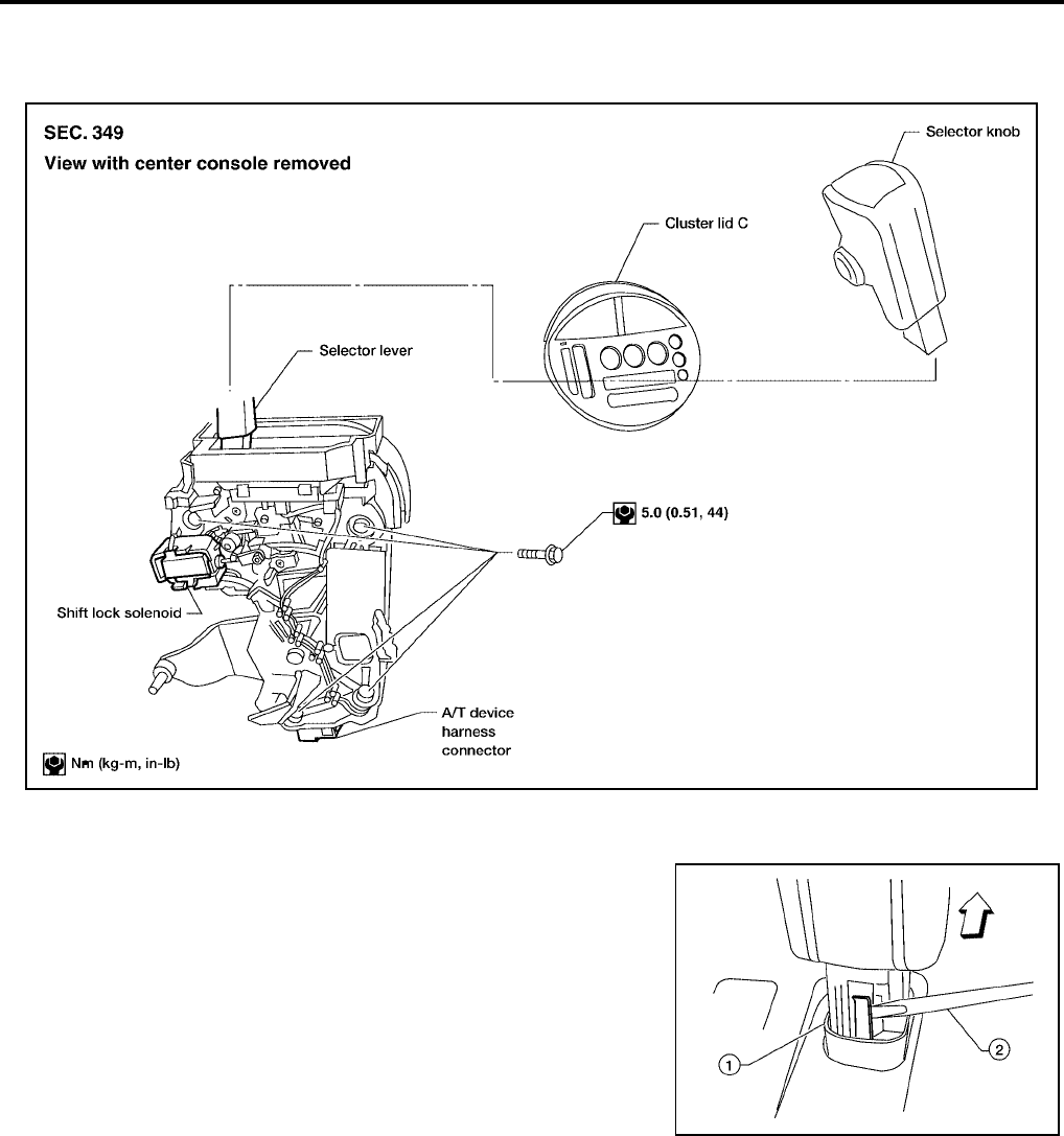
AT-598
[RE5F22A]
SHIFT CONTROL SYSTEM
Revision: September 2005 2005 Quest
SHIFT CONTROL SYSTEM PFP:34901
Removal and Installation UCS0024H
CONTROL DEVICE
SELECTOR KNOB
REMOVAL
1. Slide the selector knob cover downwards with fingers to reveal
the selector knob latch.
2. Gently pry the selector knob latch outward to release then lift the
selector knob up to remove.
INSTALLATION
Set the selector knob in place on the selector lever and push downward until the selector knob latch engages.
BCIA0021E
WCIA0235E
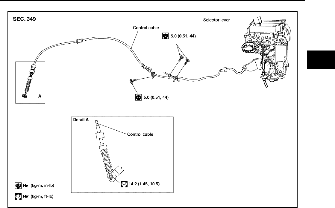
SHIFT CONTROL SYSTEM
AT-599
[RE5F22A]
D
E
F
G
H
I
J
K
L
M
A
B
AT
Revision: September 2005 2005 Quest
Control Cable UCS0024I
BCIA0023E

AT-600
[RE5F22A]
A/T SHIFT LOCK SYSTEM
Revision: September 2005 2005 Quest
A/T SHIFT LOCK SYSTEM PFP:34950
Description UCS001ED
●The mechanical key interlock mechanism also operates as a shift lock:
With the ignition switch turned to ON, the selector lever cannot be shifted from “P” (parking) to any other
position unless the brake pedal is depressed.
With the key removed, the selector lever cannot be shifted from “P” to any other position.
The key cannot be removed unless the selector lever is placed in “P”.
●The shift lock and key interlock mechanisms are controlled by the ON-OFF operation of the shift lock sole-
noid and by the operation of the rotator and slider located inside the key cylinder.
Shift Lock System Electrical Parts Location UCS001EE
BCIA0017E
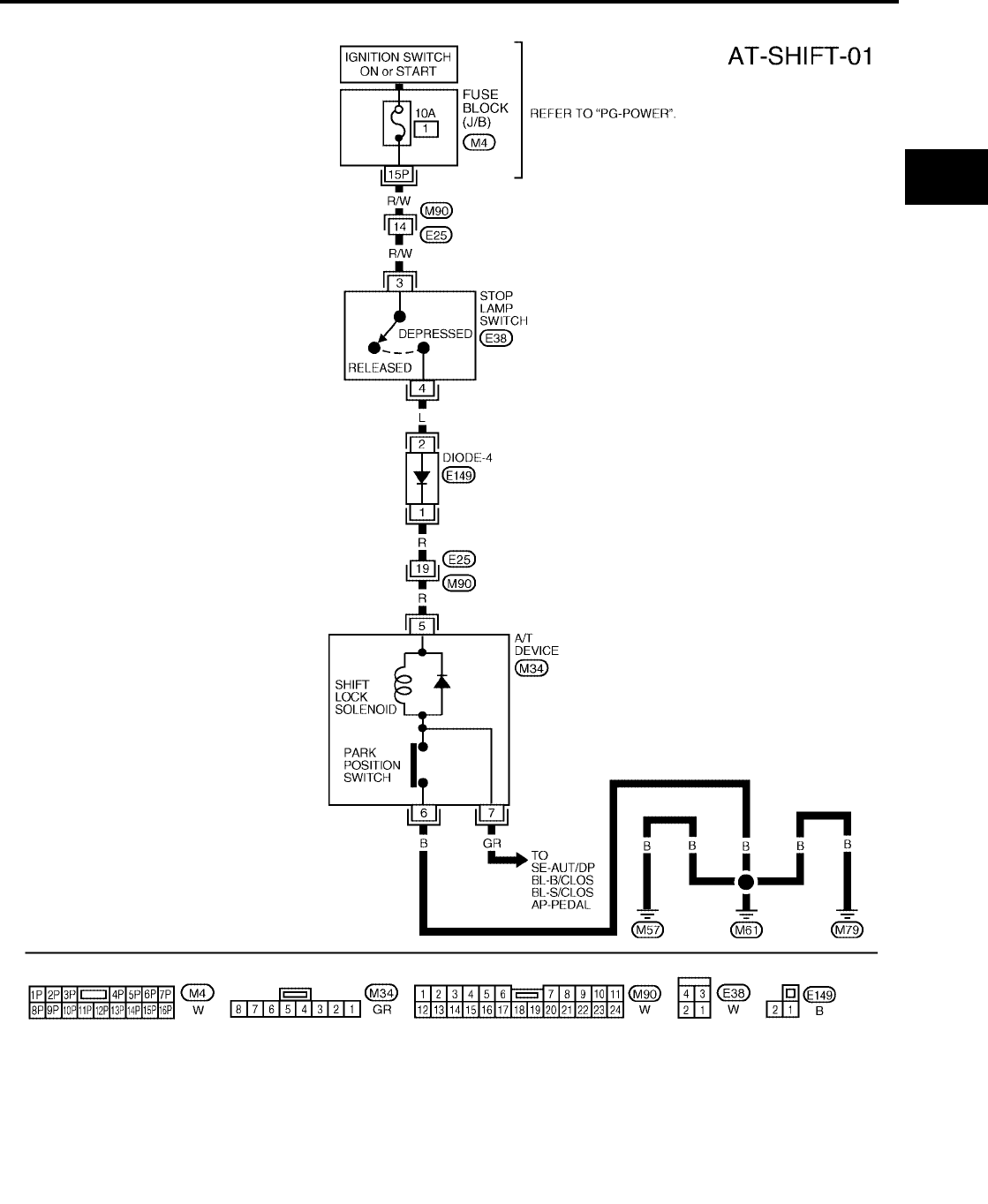
A/T SHIFT LOCK SYSTEM
AT-601
[RE5F22A]
D
E
F
G
H
I
J
K
L
M
A
B
AT
Revision: September 2005 2005 Quest
Wiring Diagram — AT — SHIFT UCS001EF
BCWA0221E
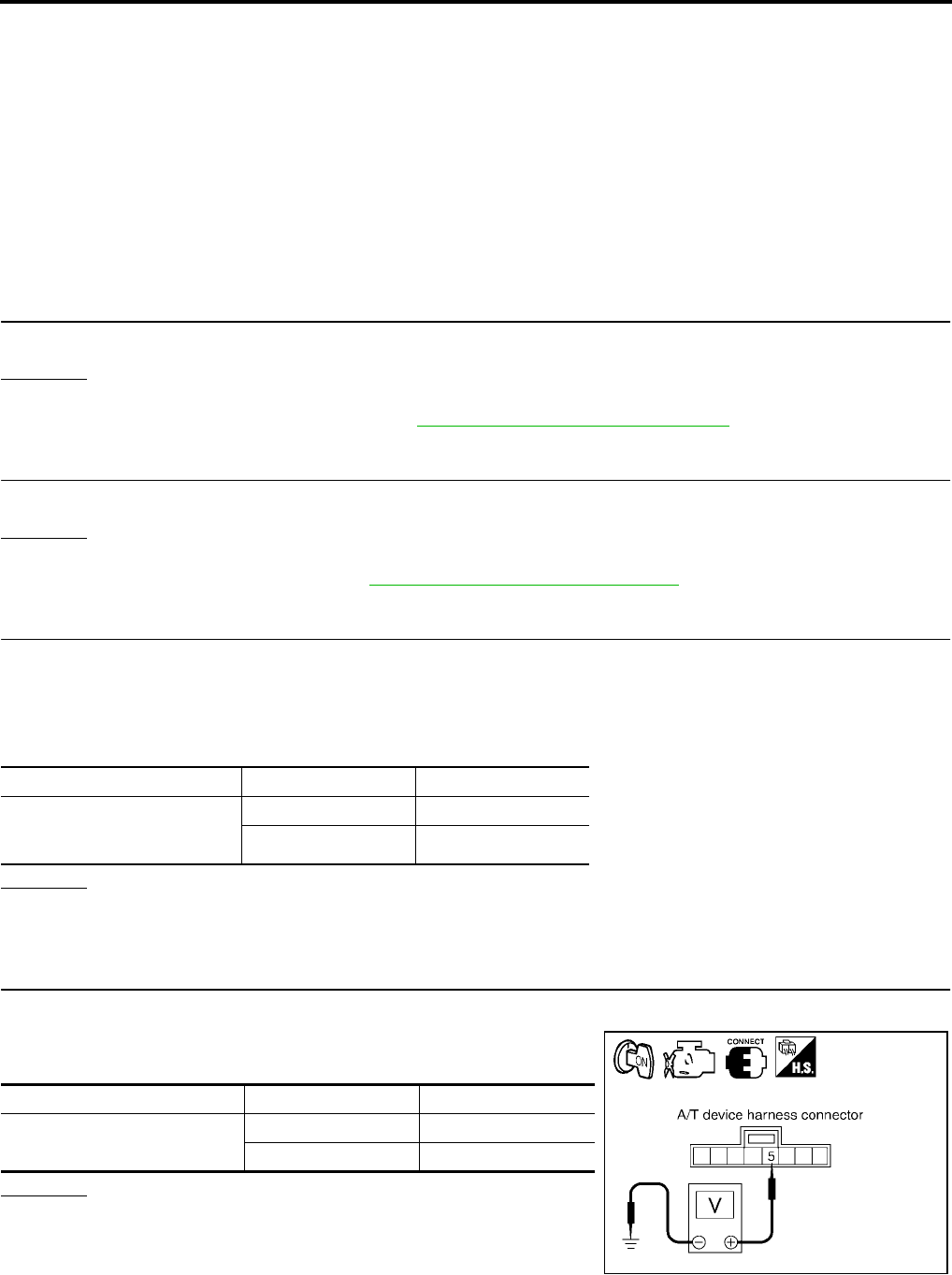
AT-602
[RE5F22A]
A/T SHIFT LOCK SYSTEM
Revision: September 2005 2005 Quest
Diagnostic Procedure UCS001EG
SYMPTOM 1:
●Selector lever cannot be moved from “P” position with key in ON position and brake pedal
applied.
●Selector lever can be moved from “P” position with key in ON position and brake pedal released.
●Selector lever can be moved from “P” position when key is removed from key cylinder.
SYMPTOM 2:
●Ignition key cannot be removed when selector lever is set to “P” position.
●Ignition key can be removed when selector lever is set to any position except “P”.
1. CHECK KEY INTERLOCK CABLE
Check the key interlock cable for damage.
OK or NG
OK >> GO TO 2.
NG >> Repair key interlock cable. Refer to AT-604, "KEY INTERLOCK CABLE" .
2. CHECK SELECTOR LEVER POSITION
Check the selector lever position for damage.
OK or NG
OK >> GO TO 3.
NG >> Check selector lever. Refer to AT-608, "Control Cable Adjustment" .
3. CHECK SHIFT LOCK SOLENOID AND PARK POSITION SWITCH
1. Connect A/T device harness connector.
2. Turn ignition switch “ON”.
3. Selector lever is set in “P” position.
4. Check operation sound.
OK or NG
OK >> INSPECTION END
NG >> GO TO 4.
4. CHECK POWER SOURCE
1. Turn ignition switch “ON”. (Do not start engine.)
2. Check the voltage between A/T device harness connector M34
terminal 5 (R) and ground.
OK or NG
OK >> GO TO 7.
NG >> GO TO 5.
Condition Brake pedal Operation sound
When ignition switch is turned
to “ON” position and selector
lever is set in “P” position.
Depressed Yes
Released No
Condition Brake pedal Data (Approx.)
When ignition switch is turned to
“ON” position.
Depressed Battery voltage
Released 0V
SCIA3437E
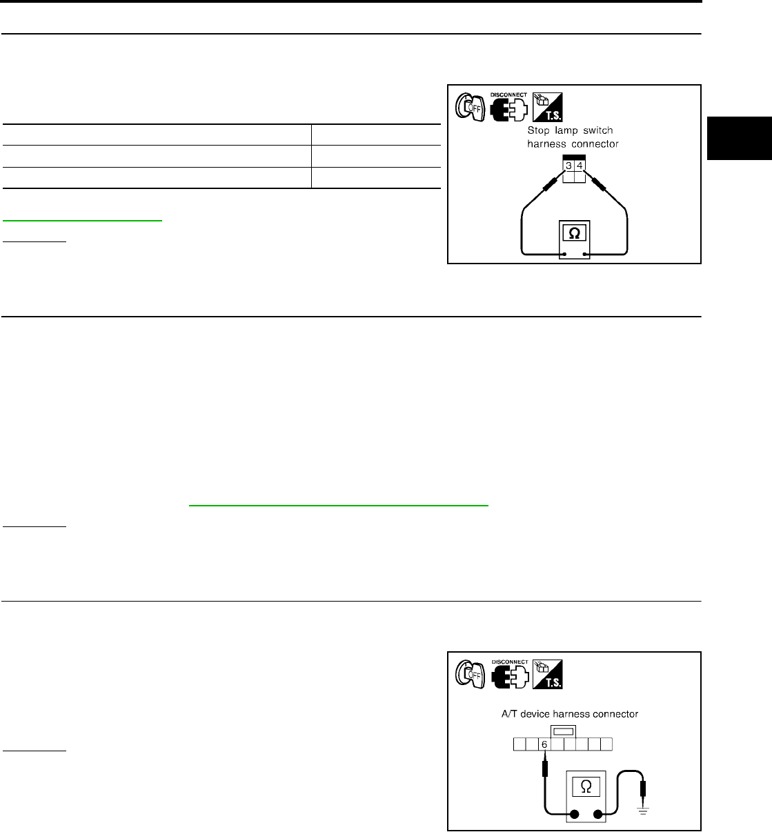
A/T SHIFT LOCK SYSTEM
AT-603
[RE5F22A]
D
E
F
G
H
I
J
K
L
M
A
B
AT
Revision: September 2005 2005 Quest
5. CHECK STOP LAMP SWITCH
1. Turn ignition switch “OFF”.
2. Disconnect stop lamp switch harness connector.
3. Check continuity between stop lamp switch harness connector
E38 terminals 3 and 4.
Check stop lamp switch after adjusting brake pedal — refer to
BR-6, "BRAKE PEDAL" .
OK or NG
OK >> GO TO 6.
NG >> Repair or replace damaged parts.
6. DETECT MALFUNCTIONING ITEM
Check the following items. If any items are damaged, repair or replace damaged parts.
●10A fuse [No.1, located in the fuse block (J/B)]
●Harness for short or open between ignition switch and stop lamp switch harness connector E38 terminal 3
(R/W)
●Harness for short or open between stop lamp switch harness connector E38 terminal 4 (L) and diode-4
harness connector E149 terminal 2 (L).
●Harness for short or open between diode-4 harness connector E149 terminal 1 (R) and A/T device har-
ness connector M34 terminal 5 (R).
●Diode-4
● Ignition switch (Refer to PG-4, "POWER SUPPLY ROUTING CIRCUIT" .)
OK or NG
OK >> GO TO 7.
NG >> Repair or replace damaged parts.
7. CHECK GROUND CIRCUIT
1. Turn ignition switch “OFF”.
2. Disconnect A/T device harness connector.
3. Check continuity between A/T device harness connector M34
terminal 6 (B) and ground.
4. Connect A/T device harness connector.
OK or NG
OK >> Replace shift lock solenoid or park position switch.
NG >> Repair open circuit or short to ground or short to power
in harness or connectors.
Condition Continuity
When brake pedal is depressed Yes
When brake pedal is released No
SCIA2126E
Continuity should exist.
SCIA3438E
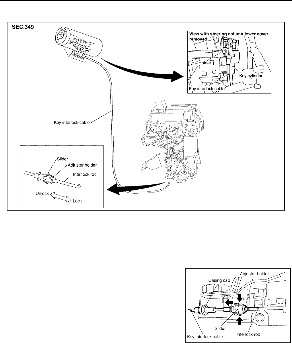
AT-604
[RE5F22A]
KEY INTERLOCK CABLE
Revision: September 2005 2005 Quest
KEY INTERLOCK CABLE PFP:34908
Components UCS001EN
CAUTION:
●Install key interlock cable in such a way that it will not be damaged by sharp bends, twists or inter-
ference with adjacent parts.
●After installing key interlock cable to control device, make sure that casing cap and bracket are
firmly secured in their positions. If casing cap can be removed with an external load of less than
39.2 N (4.0 kg, 8.8 lb), replace key interlock cable with new one.
Removal UCS001EO
1. Unlock slider by squeezing lock tabs on slider from adjuster
holder.
2. Remove casing cap from bracket of control device and remove
interlock rod from cable.
WCIA0231E
WCIA0232E

KEY INTERLOCK CABLE
AT-605
[RE5F22A]
D
E
F
G
H
I
J
K
L
M
A
B
AT
Revision: September 2005 2005 Quest
3. Remove holder from key cylinder and remove key interlock
cable.
Installation UCS001EP
1. Set key interlock cable to key cylinder and install holder.
2. Turn ignition key to lock position.
3. Set selector lever to P position.
4. Insert interlock rod into adjuster holder.
5. Install casing cap to bracket.
6. Move slider in order to fix adjuster holder to interlock rod.
WCIA0233E
WCIA0233E
WCIA0234E
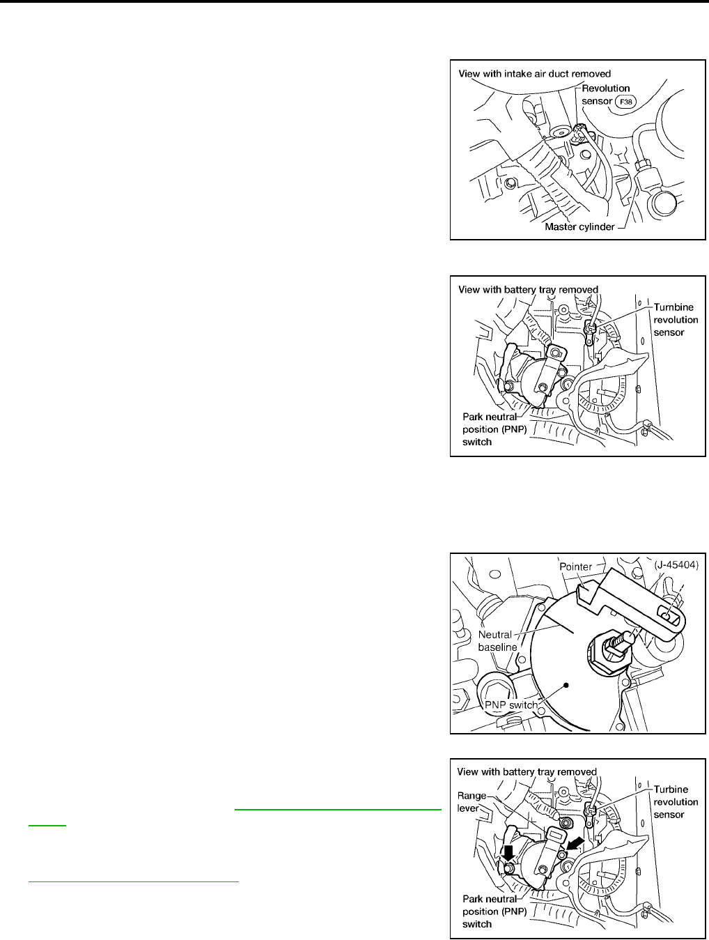
AT-606
[RE5F22A]
ON-VEHICLE SERVICE
Revision: September 2005 2005 Quest
ON-VEHICLE SERVICE PFP:00000
Revolution Sensor Replacement UCS002KR
1. Remove intake air duct.
2. Disconnect electrical connector.
3. Remove revolution sensor from A/T.
4. Reinstall any part removed.
●Do not reuse seal bolt.
Turbine Revolution Sensor Replacement UCS002KS
1. Remove battery and bracket.
2. Disconnect electrical connector.
3. Remove bolt, and turbine revolution sensor from A/T.
4. Reinstall any part removed.
●Do not reuse seal bolt.
Park/Neutral Position (PNP) Switch Adjustment UCS002KT
1. Remove battery and bracket.
2. Remove cable from range lever.
3. Set range lever in neutral position.
4. Remove range lever and install alignment tool (J-45404).
5. Loosen park/neutral position (PNP) switch fixing bolts.
6. Adjust park/neutral position (PNP) switch so that alignment tool
(J-45404) pointer aligns with neutral base line on park/neutral
position (PNP) switch body.
7. Tighten park/neutral position (PNP) switch fixing bolts.
8. Reinstall range lever and cable.
9. Adjust control cable. Refer to AT-608, "Control Cable Adjust-
ment" .
10. Reinstall battery and bracket.
11. Check continuity of park/neutral position (PNP) switch. Refer to
AT-462, "Component Inspection" .
BBIA0272E
BBIA0273E
SCIA5374E
BBIA0274E
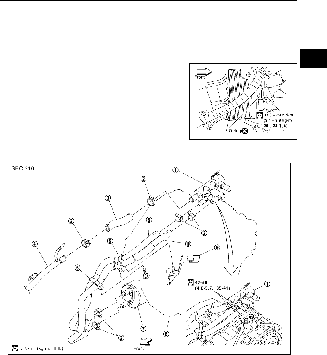
ON-VEHICLE SERVICE
AT-607
[RE5F22A]
D
E
F
G
H
I
J
K
L
M
A
B
AT
Revision: September 2005 2005 Quest
ATF Cooler UCS002KU
REMOVAL
1. Drain ATF.
2. Drain engine coolant, refer to MA-14, "Changing Engine Coolant" .
3. Remove hose clamps and hoses from ATF cooler.
4. Remove bolt from ATF cooler and remove ATF cooler.
INSTALLATION
Installation is the reverse order of removal.
●Do not reuse sealing parts.
ATF Cooler Valve UCS002KV
Refer to the figure for ATF cooler valve and hoses removal and installation information.
BBIA0275E
1. ATF cooler valve assembly 2. Hose clamp 3. Heater hose
4. Heater pipe 5. Outlet water hose 6. Hose clip
7. ATF cooler assembly 8. Transaxle assembly 9. Control cable bracket
10. Inlet water hose
SCIA2975E
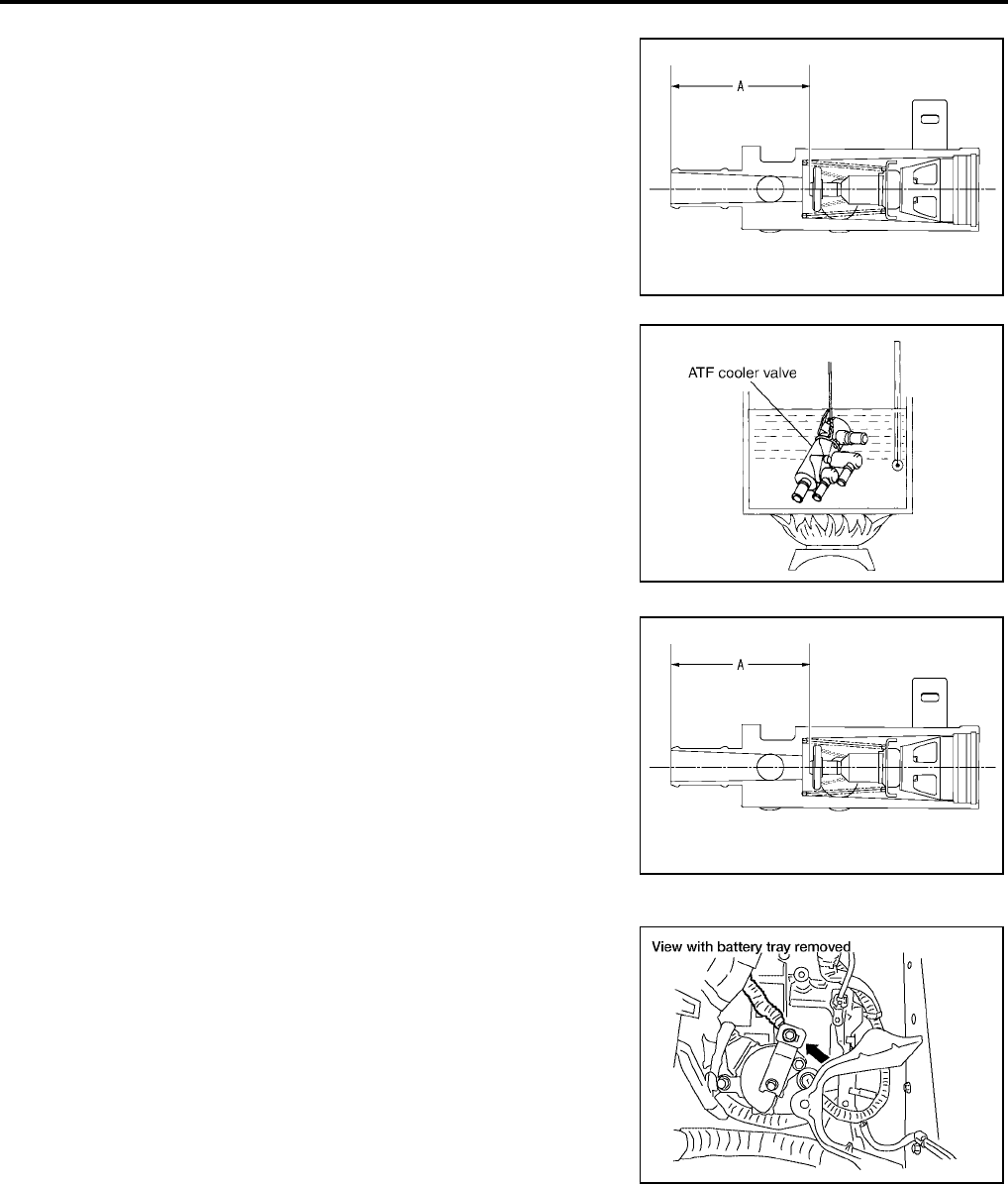
AT-608
[RE5F22A]
ON-VEHICLE SERVICE
Revision: September 2005 2005 Quest
COMPONENT INSPECTION
1. Make sure that ATF cooler valve is fully opened at room temper-
ature.
2. Submerge ATF cooler valve in a water-filled container, and then
heat it up with temperature of over 82°C (180°F) for 10 minutes
more.
3. Make sure that ATF cooler valve is fully closed.
Control Cable Adjustment UCS002KW
Move selector lever from the P position to the D position. You should
be able to feel the detent in each position. If the detent cannot be felt
or the pointer indicating the position is improperly aligned, the control
cable needs adjustment.
1. Place selector lever in the P position.
CAUTION:
Turn wheels more than 1/4 turn and apply the parking brake.
2. Loosen control cable lock nut.
3. Using the specified force, push control cable in the direction of
the arrow shown in the illustration.
4. Tighten control cable lock nut.
5. Move selector lever from P to D position. Make sure that selector lever moves smoothly.
●Make sure that the starter operates when the selector lever is placed in the N or P position.
●Make sure that the transmission is locked properly when the selector lever is placed in the P
position.
Dimension “A”: More than 72.0 mm (2.835 in)
A: Distance between ATF cooler valve port end face
and valve shaft end face.
SCIA2711J
SCIA2993E
Dimension “A”: Less than 66.5 mm (2.618 in)
A: Distance between ATF cooler valve port end face
and valve shaft end face.
SCIA2711J
Specified force : 9.8 N (1.0 kg, 2.2 lb)
BBIA0279E
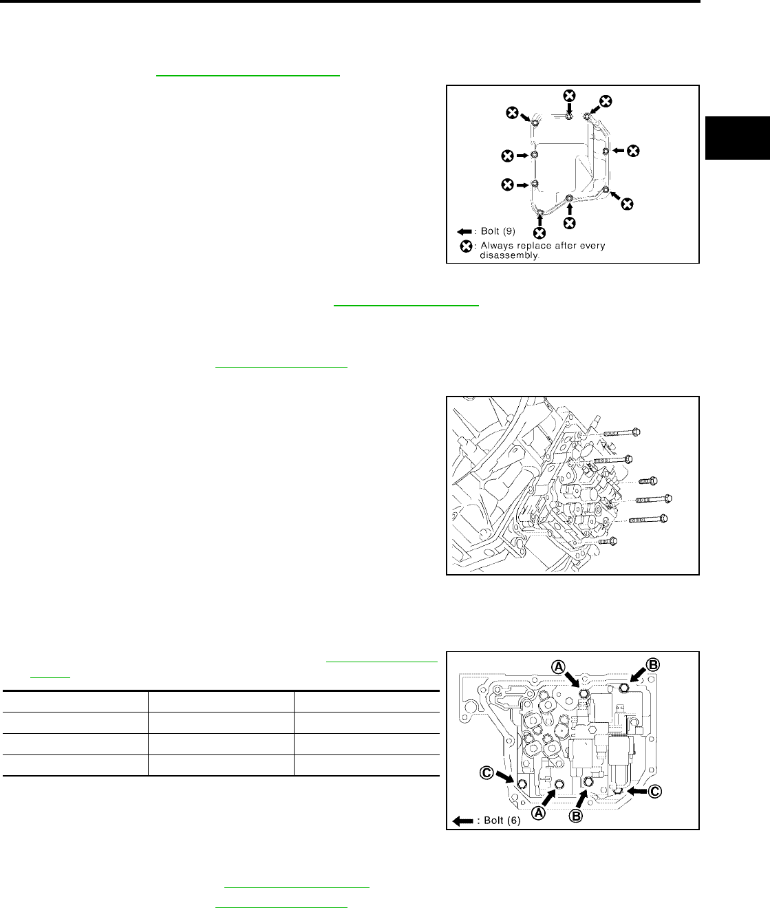
ON-VEHICLE SERVICE
AT-609
[RE5F22A]
D
E
F
G
H
I
J
K
L
M
A
B
AT
Revision: September 2005 2005 Quest
Side cover UCS002KX
REMOVAL
1. Remove engine under cover.
2. Drain ATF. Refer to MA-23, "Changing A/T Fluid" .
3. Remove side cover bolts and side cover.
INSTALLATION
Installation is the reverse order of removal. Refer to AT-612, "Components" .
Control Valve Assembly UCS002KY
REMOVAL
1. Remove side cover. Refer to AT-609, "Side cover" .
2. Disconnect solenoid valve connectors.
3. Disconnect control valve assembly bolts and remove control
valve assembly.
INSTALLATION
Installation is the reverse order of removal.
●Install bolts in sequence as shown. Refer to AT-612, "Compo-
nents" for specified torque.
Transmission wire UCS002KZ
REMOVAL
1. Remove PNP switch. Refer to AT-612, "Components" .
2. Remove side cover. Refer to AT-609, "Side cover" .
SCIA4144E
SCIA4151E
Bolt symbol Length mm (in) Number of bolts
A 55 (2.17) 2
B 50 (1.97) 2
C 16 (0.63) 2
SCIA4152E
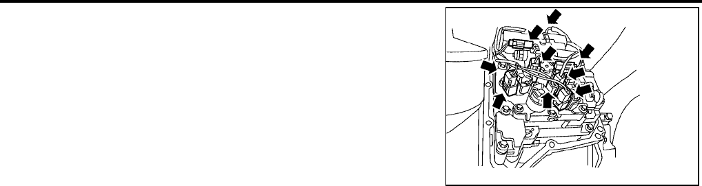
AT-610
[RE5F22A]
ON-VEHICLE SERVICE
Revision: September 2005 2005 Quest
3. Disconnect solenoid valve connectors.
4. Remove transmission wire.
INSTALLATION
Installation is the reverse order of removal.
WCIA0238E

REMOVAL AND INSTALLATION
AT-611
[RE5F22A]
D
E
F
G
H
I
J
K
L
M
A
B
AT
Revision: September 2005 2005 Quest
REMOVAL AND INSTALLATION PFP:00000
Removal UCS0015P
Remove the engine and transaxle assembly from the vehicle. Refer to EM-134, "ENGINE ASSEMBLY" .
Inspection After Removal UCS001E1
●Drive plate runout
CAUTION:
Do not allow any magnetic materials to contact the ring
gear teeth.
●If this runout is out of allowance, replace drive plate and ring
gear.
●When connecting torque converter to transaxle, measure dis-
tance “A” to be certain that they are correctly assembled.
Installation UCS0015Q
●Install in the reverse order of removal.
●When replacing the A/T assembly, initialize TCM. Refer to AT-376, "Precautions for A/T Assembly or TCM
Replacement" .
●Perform road test. Refer to AT-424, "ROAD TEST" .
Maximum allowable runout:
Refer to EM-167, "DRIVE PLATE" .
SAT977H
Distance “A” : 14 mm (0.55 in) or more
SAT044A
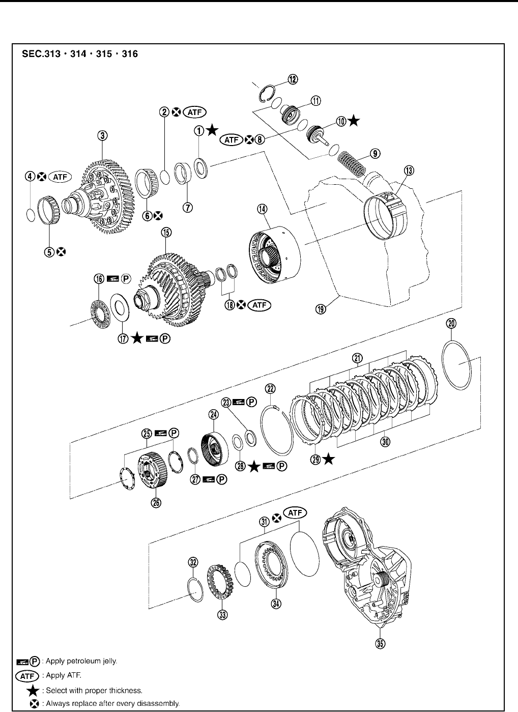
AT-612
[RE5F22A]
OVERHAUL
Revision: September 2005 2005 Quest
OVERHAUL PFP:00000
Components UCS002L0
SCIA5433E

OVERHAUL
AT-613
[RE5F22A]
D
E
F
G
H
I
J
K
L
M
A
B
AT
Revision: September 2005 2005 Quest
1. Adjust shim 2. O-ring 3. Differential gear assembly
4. O-ring 5. Tapered roller bearing 6. Tapered roller bearing
7. Outer race 8. O-ring 9. Compression spring
10. U/D brake piston assembly 11. U/D brake damper assembly 12. Snap ring
13. U/D brake band assembly 14. U/D clutch assembly 15. U/D gear assembly
16. Thrust needle roller bearing 17. Thrust bearing race 18. Seal ring
19. Transaxle case 20. B5 brake cushion plate 21. B5 brake disc
22. Snap ring 23. Thrust bearing race 24. U/D RR planetary ring gear
sub assembly
25. Thrust bearing race 26. U/D RR planetary carrier assembly 27. Thrust needle roller bearing
28. Adjust shim 29. B5 brake flange 30. B5 brake plate
31. O-ring 32. Snap ring 33. Return spring
34. B5 brake piston 35. Transaxle case cover
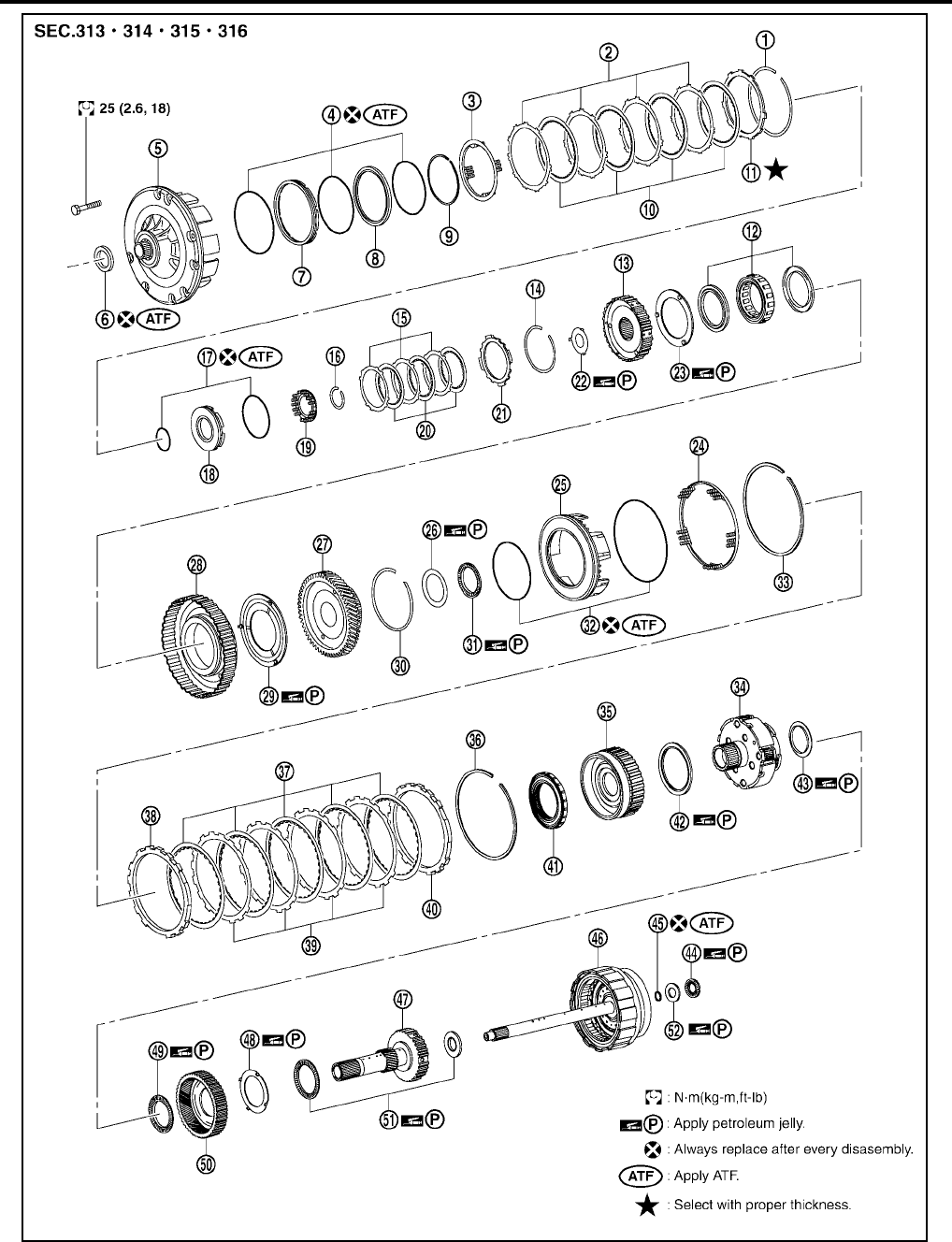
AT-614
[RE5F22A]
OVERHAUL
Revision: September 2005 2005 Quest
1. Snap ring 2. 2nd brake plate 3. Return spring
4. O-ring 5. Oil pump assembly 6. Oil seal
7. 2nd brake piston 8. 2nd brake sleeve 9. Snap ring
SCIA5434E

OVERHAUL
AT-615
[RE5F22A]
D
E
F
G
H
I
J
K
L
M
A
B
AT
Revision: September 2005 2005 Quest
10. 2nd brake disc 11. 2nd brake flange 12. One-way clutch No.1
13. 2nd coast brake hub 14. Snap ring 15. 2nd coast brake plate
16. Snap ring 17. O-ring 18. 2nd coast brake piston
19. Return spring 20. 2nd coast brake disc 21. 2nd coast brake flange
22. Thrust washer 23. Thrust washer 24. Return spring
25. 1st and reverse brake piston 26. Thrust bearing race 27. Counter drive gear sub assembly
28. One-way clutch outer race sub assem-
bly
29. Thrust washer 30. Snap ring
31. Thrust bearing 32. O-ring 33. Snap ring
34. Planetary gear assembly 35. FR planetary ring gear assembly 36. Snap ring
37. 1st and reverse brake disc 38. 1st and reverse brake flange 39. 1st and reverse brake plate
40. 1st and reverse brake flange 41. One-way clutch No.2 42. Thrust bearing
43. Thrust bearing race 44. Thrust needle roller bearing 45. Seal ring
46. Forward and direct clutch assembly 47. Planetary sun gear sub assembly 48. Thrust bearing race
49. Thrust needle roller bearing 50. RR planetary ring gear assembly 51. Thrust needle roller bearing
52. Thrust bearing race
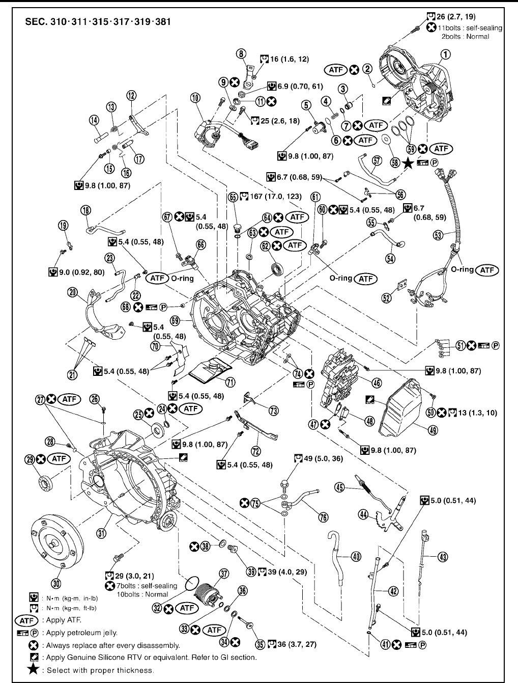
AT-616
[RE5F22A]
OVERHAUL
Revision: September 2005 2005 Quest
1. Transaxle case cover 2. Seal ring 3. Forward clutch accumulator piston
4. Compression spring 5. Accumulator cover 6. O-ring
7. Seal ring 8. Range lever 9. Washer plate
SCIA5435E

OVERHAUL
AT-617
[RE5F22A]
D
E
F
G
H
I
J
K
L
M
A
B
AT
Revision: September 2005 2005 Quest
10. PNP switch 11. Lock washer 12. Parking lock pawl
13. Torsion spring No.1 14. Parking lock pawl shaft 15. Spring guide sleeve
16. Torsion spring No.2 17. Parking lockpin sub assembly 18. U/D brake apply tube sub assembly
19. Tube clamp 20. Oil reservoir plate 21. Oil cleaner magnet
22. Tube clamp 23. Differential gear lube apply tube 24. Seal ring
25. Thrust roller bearing 26. Straight screw plug 27. O-ring
28. Straight screw plug 29. Differential side oil seal 30. Torque converter
31. Transaxle housing 32. O-ring 33. O-ring
34. Spring washer 35. Hexagon bolt 36. Washer
37. ATF cooler assembly 38. gasket 39. Drain plug
40. Air breather hose 41. O-ring 42. A/T fluid charging pipe
43. A/T fluid level gauge 44. Manual valve lever sub assembly 45. Parking lock rod sub assembly
46. Control valve assembly 47. Suction cover gasket 48. Suction cover
49. Side cover 50. Seal bolt 51. Governor apply gasket
52. Sensor clamp 53. Transmission wire 54. Transaxle lube apply tube
55. Tube clamp 56. Tube clamp 57. U/D clutch apply tube sub assembly
58. Bearing race 59. Seal ring 60. Seal bolt
61. Turbine revolution sensor 62. Differential side oil seal 63. Manual valve oil seal
64. O-ring 65. Anchor bolt 66. Revolution sensor
67. Seal bolt 68. Governor apply gasket 69. Transaxle case
70. Oil reservoir plate 71. Oil strainer sub assembly 72. Manual detent spring sub assembly
73. Parking lock pawl bracket 74. Governor apply gasket 75. Copper washer
76. Fluid cooler tube
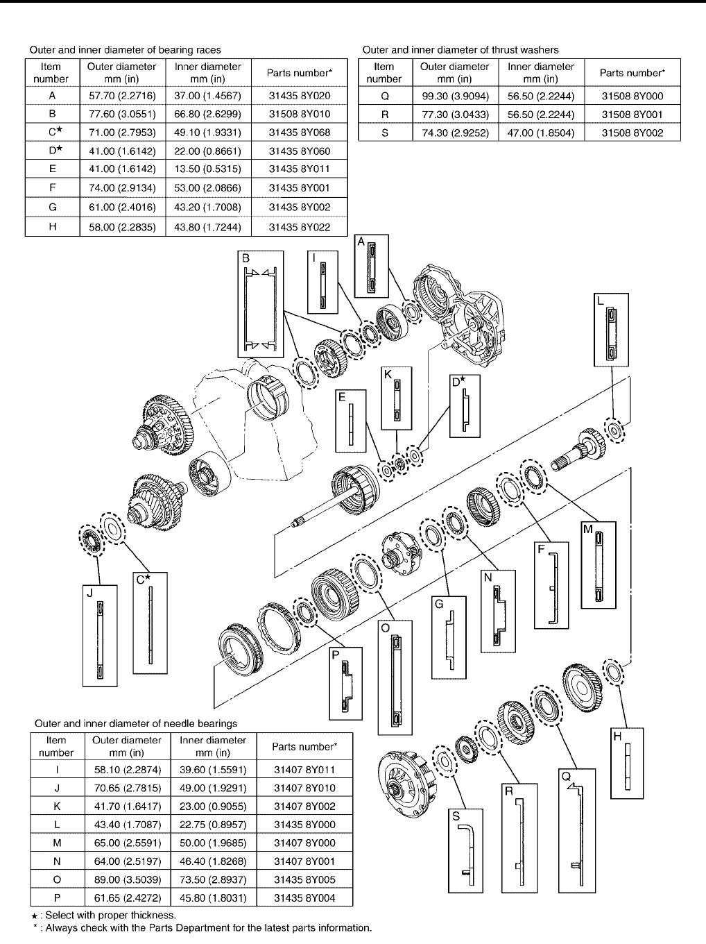
AT-618
[RE5F22A]
OVERHAUL
Revision: September 2005 2005 Quest
Locations of Needle Bearings, Bearing Races and Thrust Washers UCS002L1
SCIA5436E
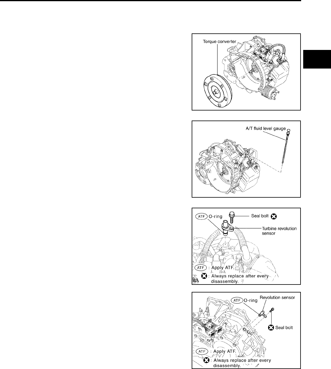
DISASSEMBLY
AT-619
[RE5F22A]
D
E
F
G
H
I
J
K
L
M
A
B
AT
Revision: September 2005 2005 Quest
DISASSEMBLY PFP:31020
Disassembly UCS002L2
1. Drain ATF through drain plug.
2. Remove torque converter by transaxle case it firmly and turning
while pulling straight out.
3. Remove A/T fluid level gauge.
4. Remove A/T fluid charging pipe.
5. Remove O-ring from A/T fluid charging pipe.
6. Remove air breather hose.
7. Remove fluid cooler tube.
8. Remove turbine revolution sensor.
CAUTION:
Be careful not to damage the turbine revolution sensor and
transaxle case.
9. Remove revolution sensor.
CAUTION:
Be careful not to damage the revolution sensor and tran-
saxle case.
SCIA4134E
SCIA4135E
SCIA4137E
SCIA4136E
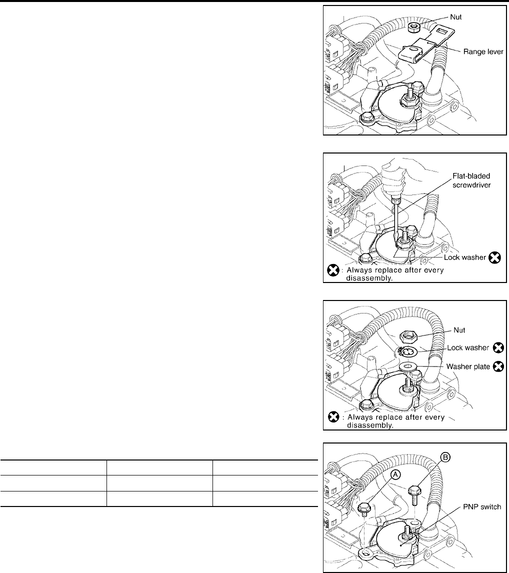
AT-620
[RE5F22A]
DISASSEMBLY
Revision: September 2005 2005 Quest
10. Remove nut and range lever.
11. Using a flat-bladed screwdriver, pry off the lock washer.
12. Loosen nut and remove lock washer.
13. Remove washer plate.
14. Remove PNP switch from transaxle case.
SCIA4138E
SCIA4139E
SCIA4140E
Bolt symbol Length mm (in) Number of bolts
A 20 (0.79) 1
B 33 (1.30) 1
SCIA4141E
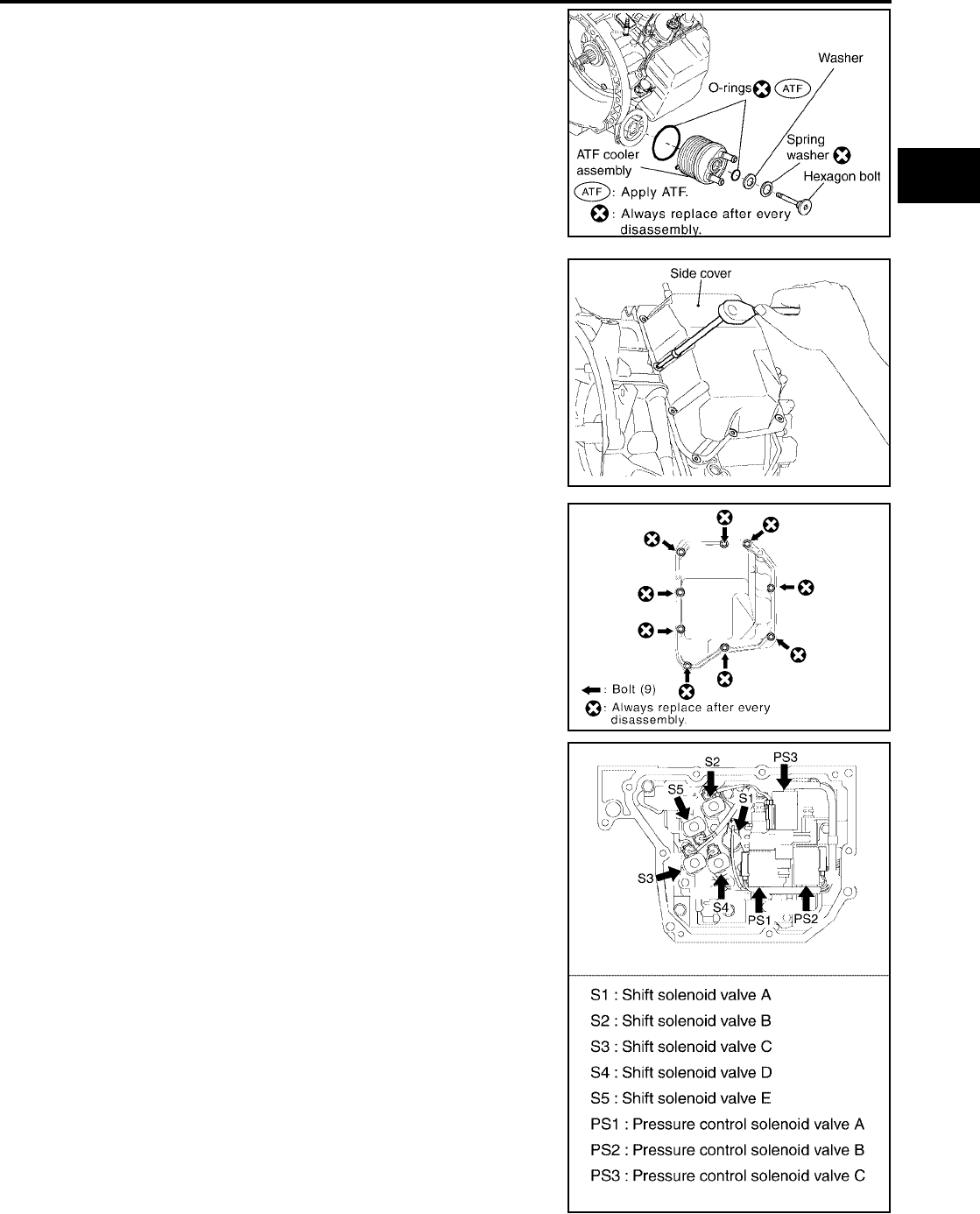
DISASSEMBLY
AT-621
[RE5F22A]
D
E
F
G
H
I
J
K
L
M
A
B
AT
Revision: September 2005 2005 Quest
15. Remove hexagon bolt.
16. Remove ATF cooler assembly, washer and spring washer.
17. Remove O-rings from the ATF cooler assembly.
18. Remove side cover.
CAUTION:
Be careful not to damage side cover and transaxle case.
19. Disconnect solenoid connectors.
CAUTION:
Be careful not to damage connector.
SCIA4142E
SCIA4143E
SCIA4144E
SCIA4146E
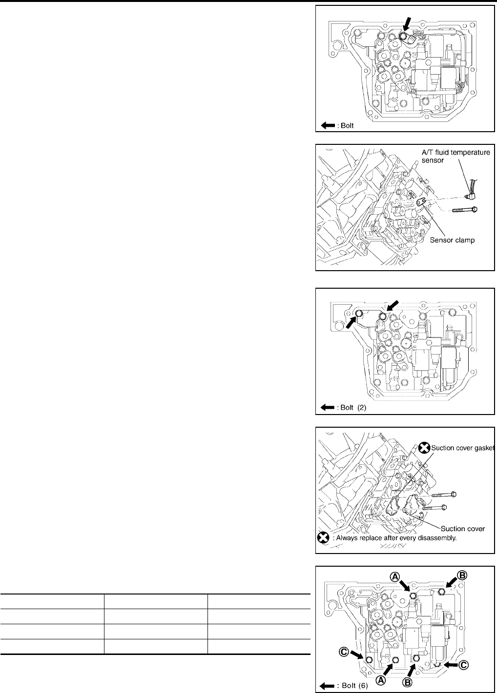
AT-622
[RE5F22A]
DISASSEMBLY
Revision: September 2005 2005 Quest
20. Remove sensor clamp tightening bolt.
21. Remove sensor clamp and A/T fluid temperature sensor.
CAUTION:
Be careful not to damage A/T fluid temperature sensor.
22. Remove suction cover tightening bolts.
23. Remove suction cover and suction cover gasket.
24. Remove control valve assembly tightening bolts from transaxle
case.
SCIA4148E
SCIA4147E
SCIA4150E
SCIA4149E
Bolt symbol Length mm (in) Number of bolts
A 55 (2.17) 2
B 50 (1.97) 2
C 16 (0.63) 2
SCIA4152E

DISASSEMBLY
AT-623
[RE5F22A]
D
E
F
G
H
I
J
K
L
M
A
B
AT
Revision: September 2005 2005 Quest
25. While holding control valve assembly, disconnect parking lock
rod sub assembly from manual valve lever sub assembly and
remove control valve assembly.
NOTE:
Shift position is “N”.
26. Remove governor apply gaskets.
27. Remove transmission wire.
CAUTION:
Be careful not to damage solenoid connectors and A/T fluid
temperature sensor.
28. Remove oil pump assembly tightening bolts from transaxle
case.
SCIA4153E
SCIA4154E
SCIA4155E
SCIA4156E
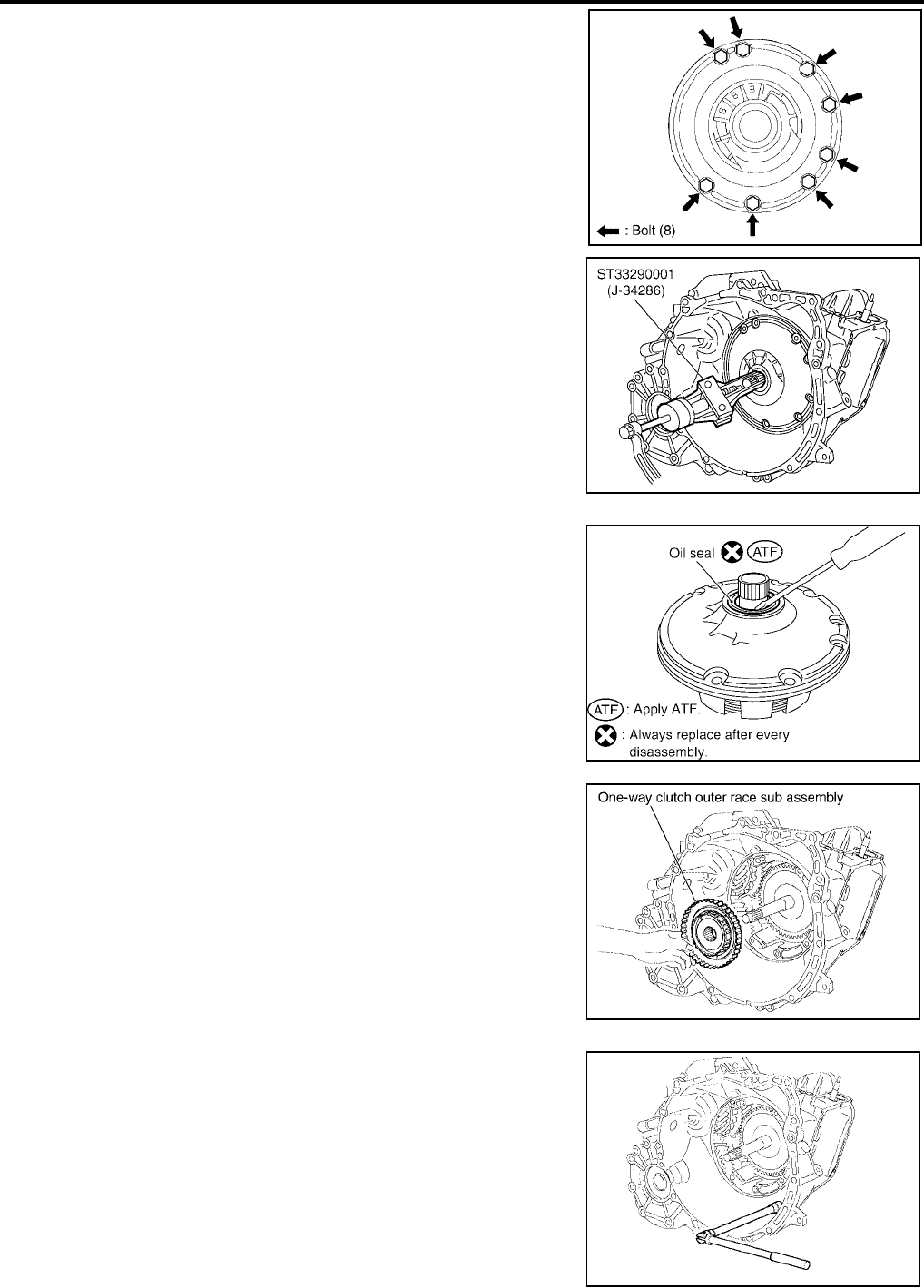
AT-624
[RE5F22A]
DISASSEMBLY
Revision: September 2005 2005 Quest
29. Remove oil pump assembly.
30. Remove oil seal from oil pump assembly.
CAUTION:
Be careful not to scratch oil pump assembly.
31. Remove one-way clutch outer race sub assembly.
32. Remove thrust washer.
33. Remove transaxle housing bolts from transaxle case.
SCIA4157E
SCIA5359E
SCIA4396E
SCIA4159E
SCIA4160E
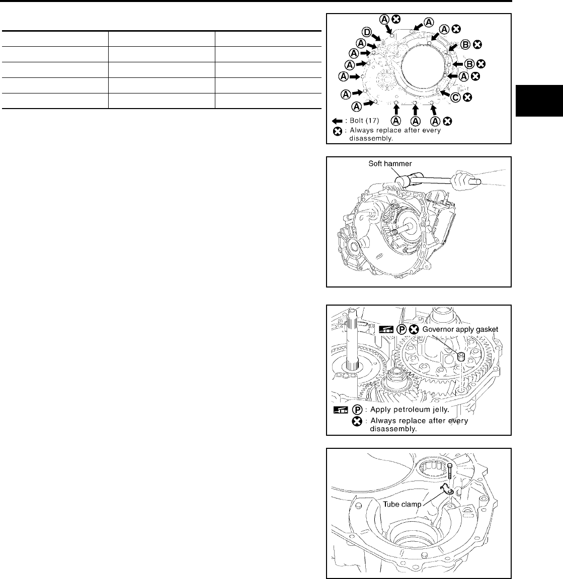
DISASSEMBLY
AT-625
[RE5F22A]
D
E
F
G
H
I
J
K
L
M
A
B
AT
Revision: September 2005 2005 Quest
*:Torx bolt
34. Remove transaxle housing using a soft hammer.
35. Remove governor apply gasket.
36. Remove seal ring.
37. Remove tube clamp.
Bolt symbol Length mm (in) Number of bolts
A 30 (1.18) 13
B 35 (1.38) 2
C 45 (1.77) 1
D* — 1
SCIA5495E
SCIA4162E
SCIA4163E
SCIA4164E
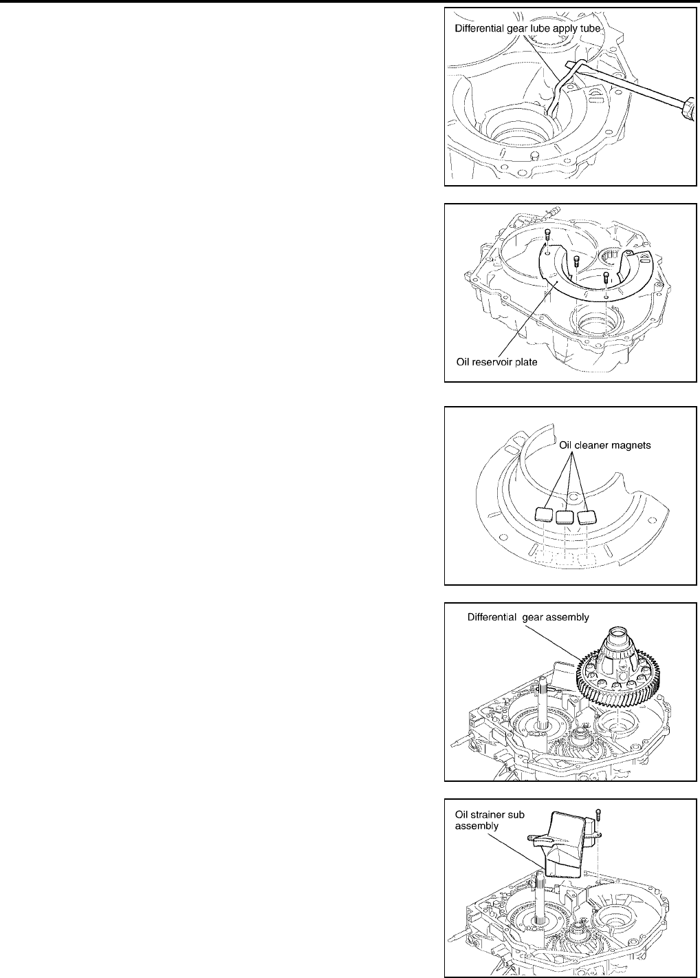
AT-626
[RE5F22A]
DISASSEMBLY
Revision: September 2005 2005 Quest
38. Using a flat-bladed screwdriver and remove differential gear
lube apply tube.
CAUTION:
●Be careful not to bend or damage differential gear lube
apply tube.
●Be careful not to damage transaxle housing.
39. Remove oil reservoir plate.
40. Remove oil cleaner magnets from oil reservoir plate.
41. Remove differential gear assembly.
42. Remove oil strainer sub assembly.
SCIA4165E
SCIA4166E
SCIA4167E
SCIA4168E
SCIA4169E
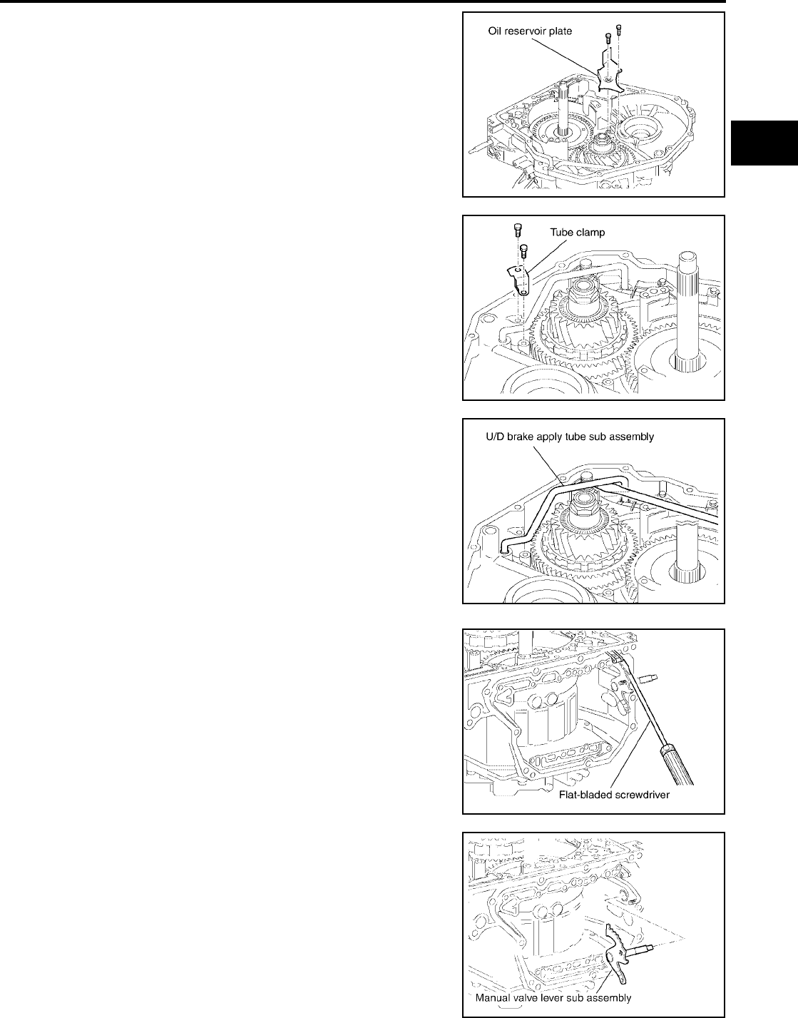
DISASSEMBLY
AT-627
[RE5F22A]
D
E
F
G
H
I
J
K
L
M
A
B
AT
Revision: September 2005 2005 Quest
43. Remove oil reservoir plate.
44. Remove tube clamp.
45. Using a flat-bladed screwdriver and remove U/D brake apply
tube sub assembly.
CAUTION:
●Be careful not to bend or damage U/D brake apply tube
sub assembly.
●Be careful not to damage transaxle case.
46. Disconnect manual detent spring sub assembly from manual
valve lever sub assembly.
47. Remove manual valve lever sub assembly from parking lock rod
sub assembly.
SCIA4170E
SCIA4171E
SCIA4172E
SCIA4174E
SCIA4175E
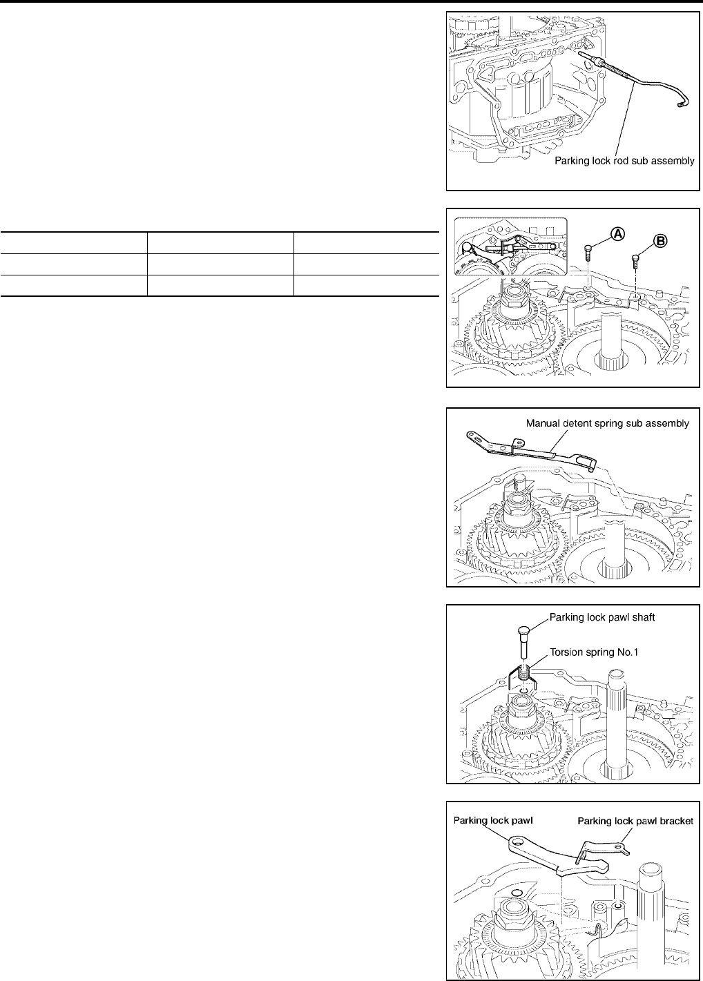
AT-628
[RE5F22A]
DISASSEMBLY
Revision: September 2005 2005 Quest
48. Remove parking lock rod sub assembly.
49. Remove tightening bolts for manual detent spring sub assembly.
50. Remove manual detent spring sub assembly.
51. Remove parking lock pawl shaft and torsion spring No.1.
52. Remove parking lock pawl bracket and parking lock pawl.
SCIA4176E
Bolt symbol Length mm (in) Number of bolts
A 16.7 (0.657) 1
B 14.0 (0.551) 1
SCIA4177E
SCIA4178E
SCIA4179E
WCIA0420E
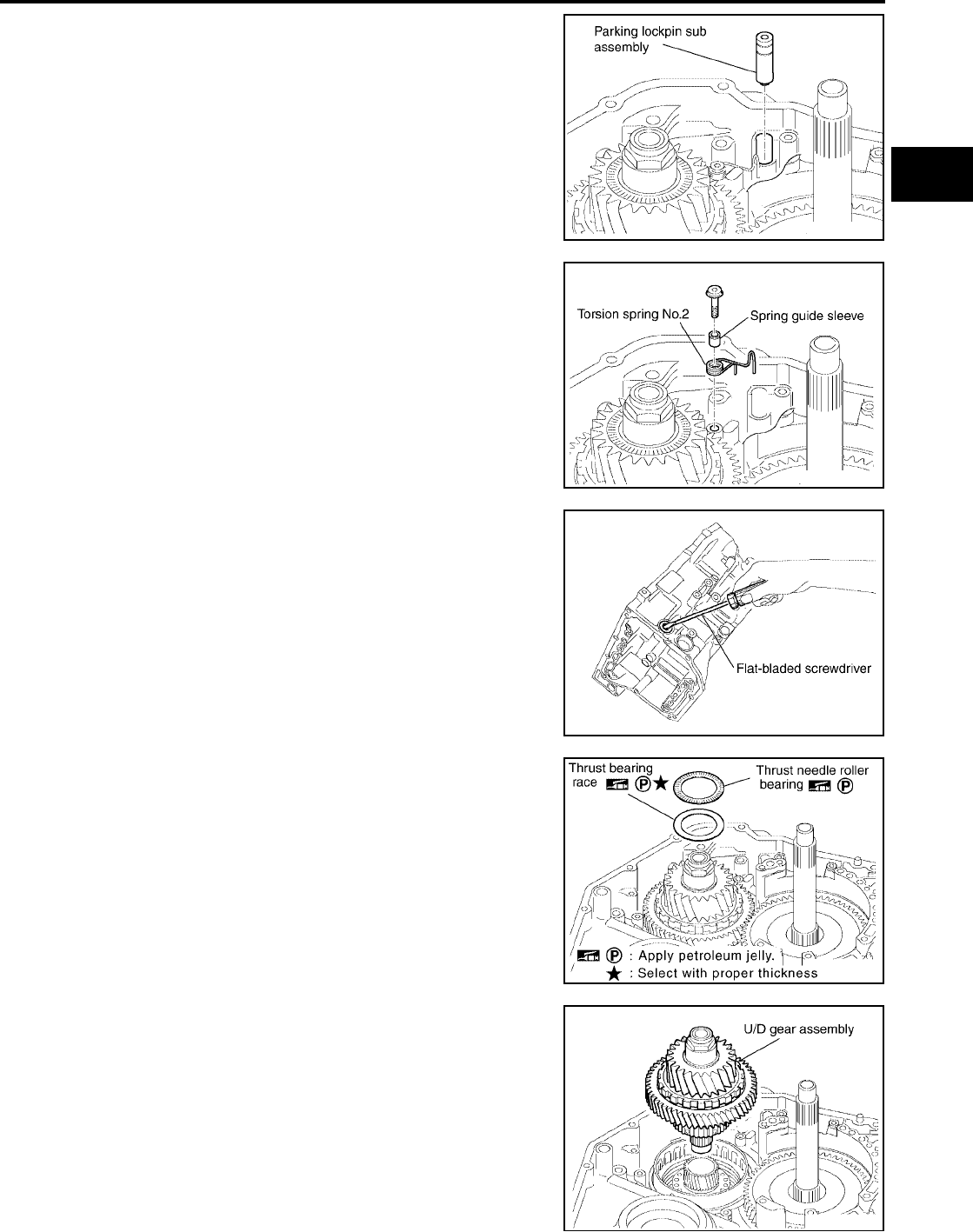
DISASSEMBLY
AT-629
[RE5F22A]
D
E
F
G
H
I
J
K
L
M
A
B
AT
Revision: September 2005 2005 Quest
53. Remove parking lockpin sub assembly.
54. Remove spring guide sleeve and torsion spring No.2.
55. Using a flat-bladed screwdriver and remove manual valve oil
seal.
CAUTION:
Be careful not to damage transaxle case.
56. Remove thrust needle roller bearing and thrust bearing race
from U/D gear assembly.
57. Remove U/D gear assembly.
58. Remove seal rings from U/D gear assembly.
SCIA4181E
SCIA4182E
SCIA4183E
WCIA0338E
SCIA4185E
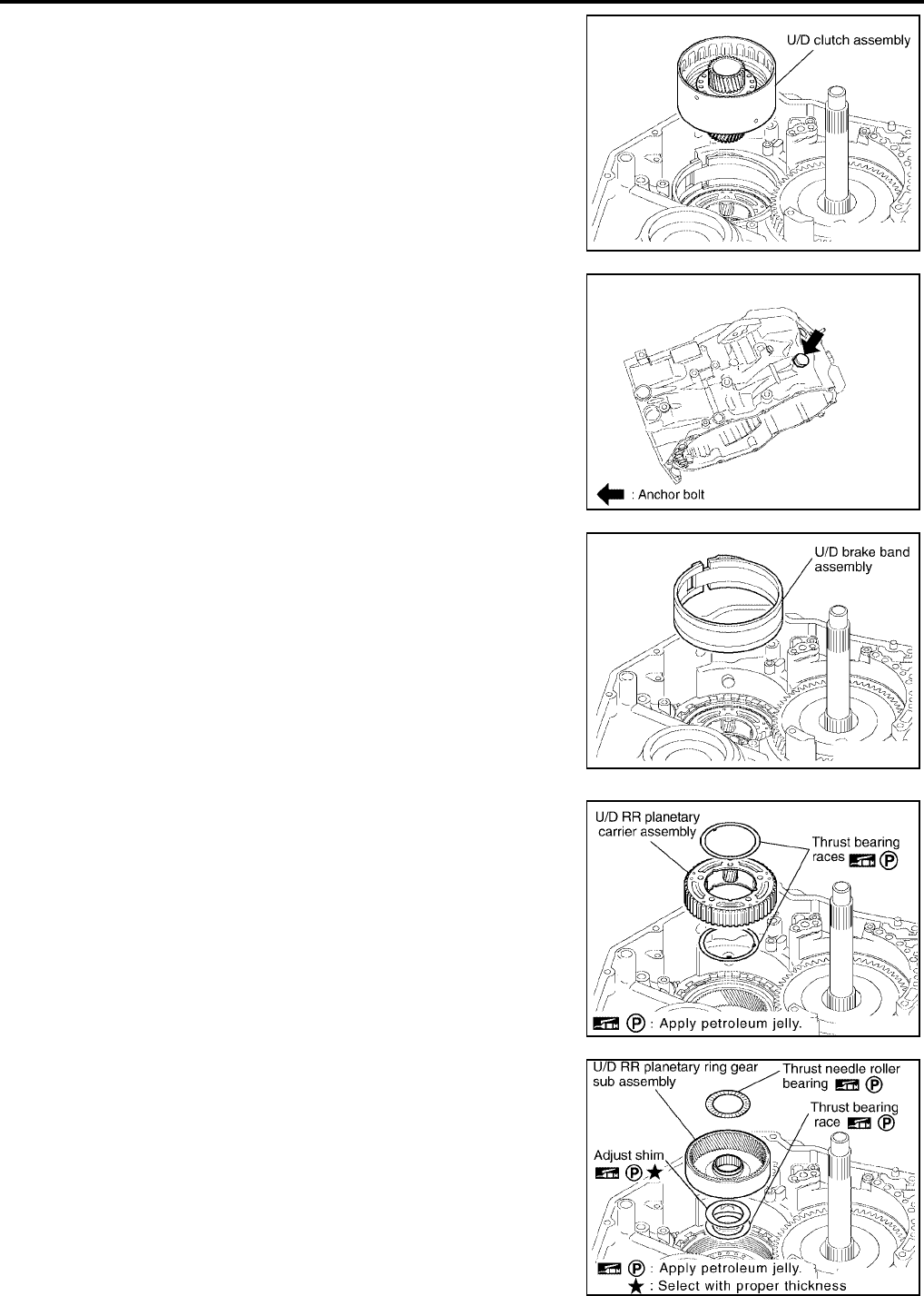
AT-630
[RE5F22A]
DISASSEMBLY
Revision: September 2005 2005 Quest
59. Remove U/D clutch assembly.
60. Remove anchor bolt.
61. Remove U/D brake band assembly.
CAUTION:
Be careful not to damage transaxle case.
62. Remove U/D RR planetary carrier assembly and thrust bearing
races.
63. Remove U/D RR planetary ring gear sub assembly.
64. Remove thrust needle roller bearing, adjust shim and thrust
bearing race from U/D RR planetary ring gear sub assembly.
SCIA4186E
SCIA4193E
SCIA4187E
SCIA5505E
WCIA0339E

DISASSEMBLY
AT-631
[RE5F22A]
D
E
F
G
H
I
J
K
L
M
A
B
AT
Revision: September 2005 2005 Quest
65. Using a snap ring pliers and remove snap ring.
66. Remove U/D brake damper assembly.
67. Remove O-rings from U/D brake damper assembly.
68. Remove U/D brake piston assembly and compression spring.
69. Remove O-ring from U/D brake piston assembly.
70. Remove transaxle case cover bolts from transaxle case.
*:Stud bolt
SCIA4190E
SCIA4191E
SCIA4192E
SCIA4194E
Bolt symbol Length mm (in) Number of bolts
A 30 (1.18) 8
B 45 (1.77) 2
C 48 (1.89) 2
D* — 1
SCIA5413E

AT-632
[RE5F22A]
DISASSEMBLY
Revision: September 2005 2005 Quest
71. Tap transaxle case cover using a soft hammer.
CAUTION:
Be careful not to damage transaxle case cover.
72. Remove transaxle case cover.
73. Remove governor apply gaskets from transaxle case.
74. Remove tube clamp.
75. Using a flat-bladed screwdriver, remove transaxle lube apply
tube.
CAUTION:
●Be careful not to bend or damage transaxle lube apply
tube.
●Be careful not to damage transaxle case.
SCIA4196E
SCIA4197E
SCIA4198E
SCIA4199E
SCIA4200E
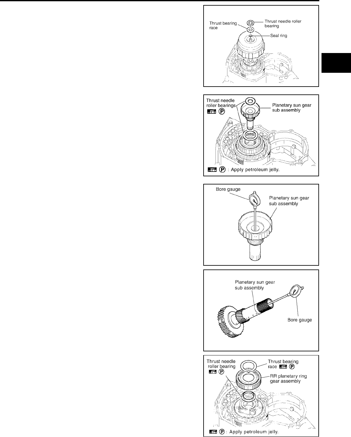
DISASSEMBLY
AT-633
[RE5F22A]
D
E
F
G
H
I
J
K
L
M
A
B
AT
Revision: September 2005 2005 Quest
76. Remove forward and direct clutch assembly.
77. Remove thrust bearing race, thrust needle roller bearing and
seal ring from forward and direct clutch assembly.
78. Remove planetary sun gear sub assembly and thrust needle
roller bearings.
79. Using a bore gauge, measure the inner diameter of planetary
sun gear sub assembly bushing.
CAUTION:
Measure at different places and take an average. If it is
greater than the maximum, replace it with a new planetary
sun gear sub assembly.
80. Remove RR planetary ring gear assembly.
81. Remove thrust needle roller bearing and thrust bearing race
from RR planetary ring gear assembly.
SCIA5421E
SCIA5499E
Standard :22.200 - 22.226mm (0.8740 - 0.8750in)
Allowable limit :22.276 (0.8770in)
SCIA4255E
SCIA4256E
SCIA4203E
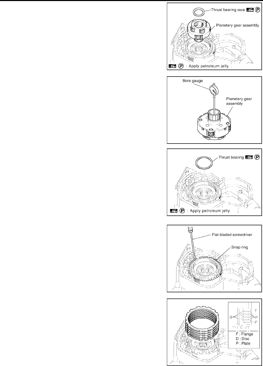
AT-634
[RE5F22A]
DISASSEMBLY
Revision: September 2005 2005 Quest
82. Remove planetary gear assembly.
83. Remove thrust bearing race from planetary gear assembly.
84. Using a bore gauge, measure the inner diameter of planetary
gear assembly bushing.
CAUTION:
Measure at different places and take an average. If it is
greater than the maximum, replace it with a new planetary
gear assembly.
85. Remove thrust bearing.
86. Using a flat-bladed screwdriver and remove snap ring.
87. Remove 1st and reverse brake flanges, 1st and reverse brake
discs and 1st and reverse brake plates.
●INSPECTION
–Check that the sliding surface of discs are not worn and burnt.
If necessary, replace them.
CAUTION:
Replace new discs by soaking them at least 2 hours in A/T
fluid.
SCIA4204E
Standard :30.056 - 30.082mm (1.1833 - 1.1843in)
Allowable limit :30.132 (1.1863in)
SCIA4254E
SCIA4205E
SCIA4206E
SCIA4207E
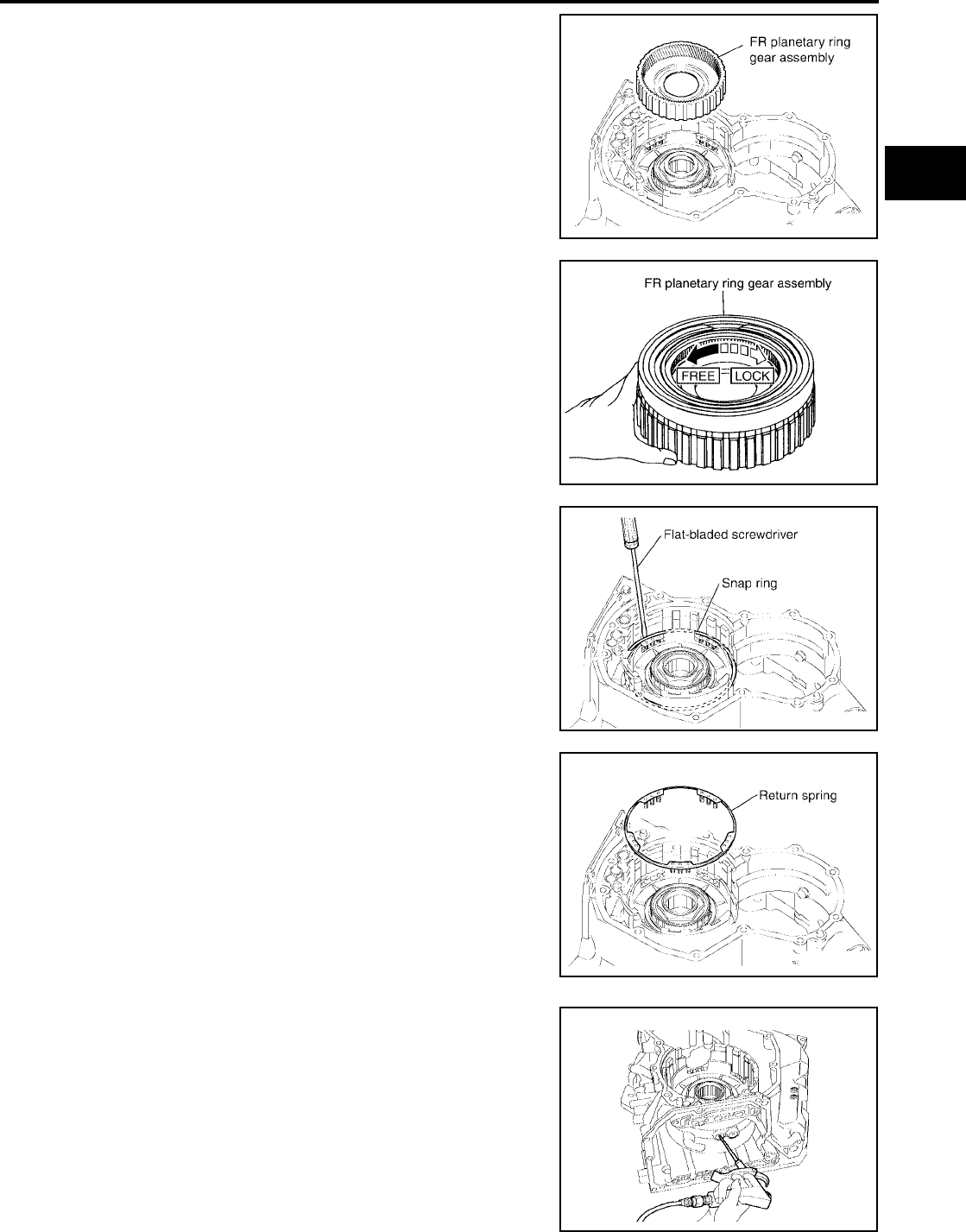
DISASSEMBLY
AT-635
[RE5F22A]
D
E
F
G
H
I
J
K
L
M
A
B
AT
Revision: September 2005 2005 Quest
88. Remove FR planetary ring gear assembly with one-way clutch
No.2.
89. Make sure that the FR planetary ring gear assembly turns freely
counterclockwise and locks clockwise.
90. Using a flat-bladed screwdriver and remove snap ring.
91. Remove return spring.
92. While pushing the piston by hand, apply compressed air (4Kg/
cm2 ) into the oil passage of transaxle case as shown in the fig-
ure and remove 1st and reverse brake piston.
SCIA4208E
SCIA4414E
SCIA4209E
SCIA4210E
SCIA4211E
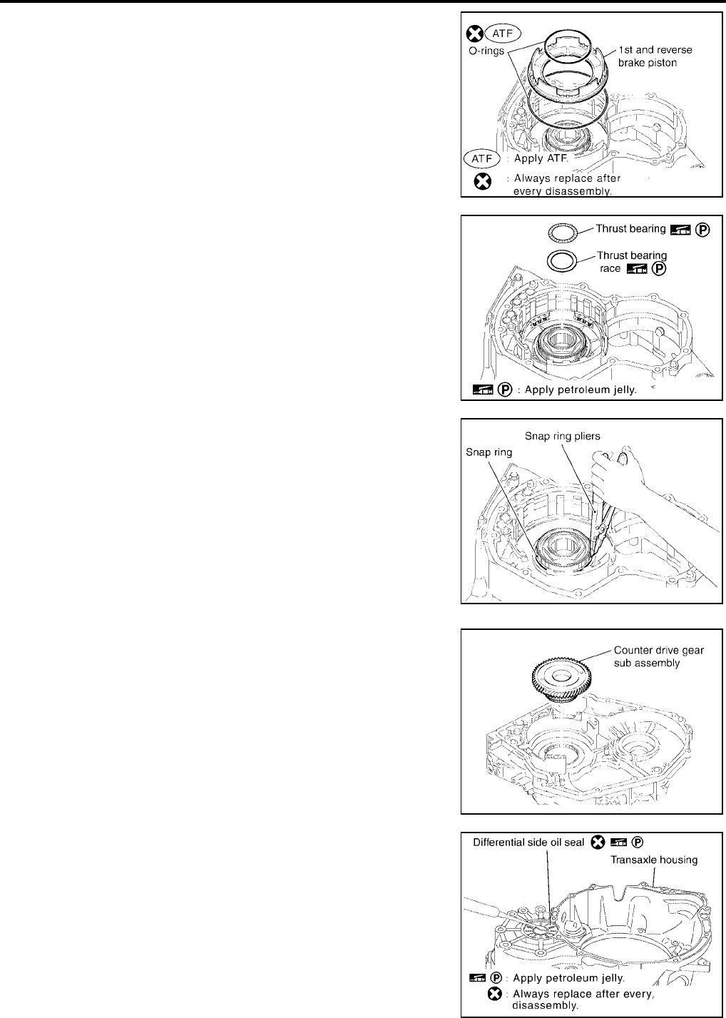
AT-636
[RE5F22A]
DISASSEMBLY
Revision: September 2005 2005 Quest
93. Remove O-rings from 1st and reverse brake piston.
94. Remove thrust bearing and thrust bearing race from counter
drive gear sub assembly.
95. Using a snap ring pliers and remove snap ring.
96. Remove counter drive gear sub assembly.
97. Using a flat-bladed screwdriver remove differential side oil seal
from transaxle case and transaxle housing.
CAUTION:
Be careful not to scratch transaxle case and transaxle
housing.
SCIA4212E
SCIA4213E
SCIA4214E
SCIA4215E
SCIA4216E
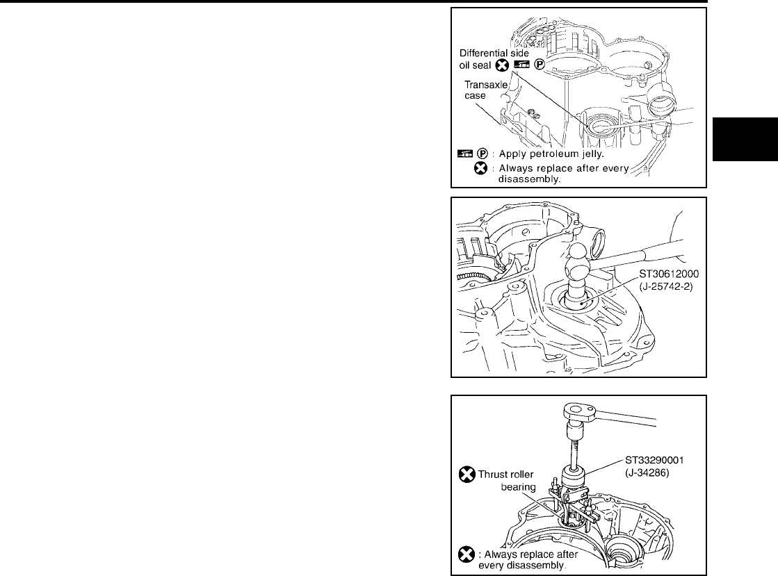
DISASSEMBLY
AT-637
[RE5F22A]
D
E
F
G
H
I
J
K
L
M
A
B
AT
Revision: September 2005 2005 Quest
98. Remove outer race and adjust shim from transaxle case.
99. Remove thrust roller bearing from transaxle housing.
SCIA4217E
SCIA5360E
SCIA5361E
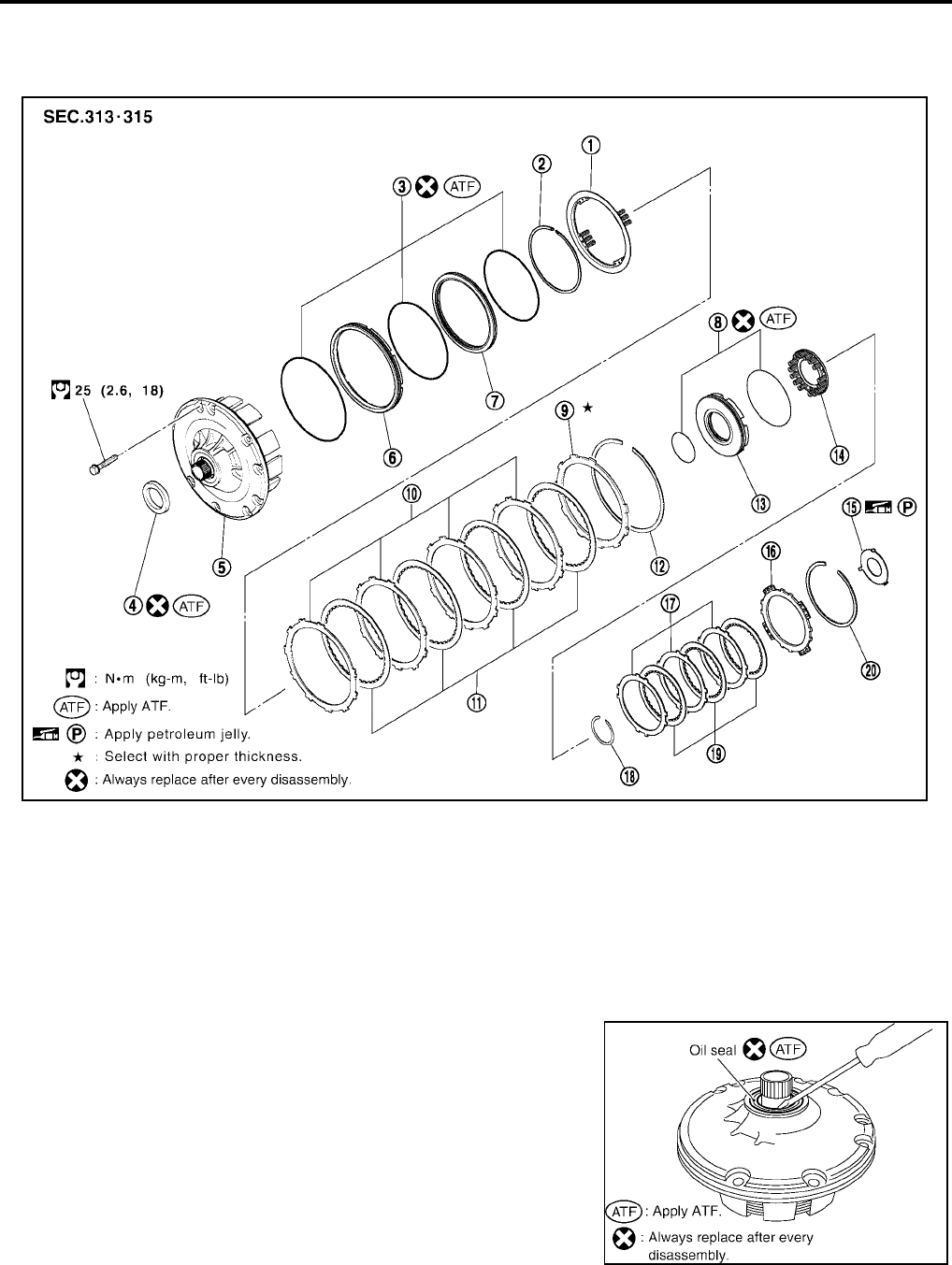
AT-638
[RE5F22A]
REPAIR FOR COMPONENT PARTS
Revision: September 2005 2005 Quest
REPAIR FOR COMPONENT PARTS PFP:00000
Oil Pump, 2nd Coast Brake & 2nd Brake UCS002L3
COMPONENTS
DISASSEMBLY
1. Remove oil seal from oil pump assembly.
CAUTION:
Be careful not to scratch oil pump assembly.
1. Return spring 2. Snap ring 3. O-ring
4. Oil seal 5. Oil pump assembly 6. 2nd brake piston
7. 2nd brake sleeve 8. O-ring 9. 2nd brake flange
10. 2nd brake plate 11. 2nd brake disc 12. Snap ring
13. 2nd coast brake piston 14. Return spring 15. Thrust washer
16. 2nd coast brake flange 17. 2nd coast brake plate 18. Snap ring
19. 2nd coast brake disc 20. Snap ring
SCIA4384E
SCIA4396E
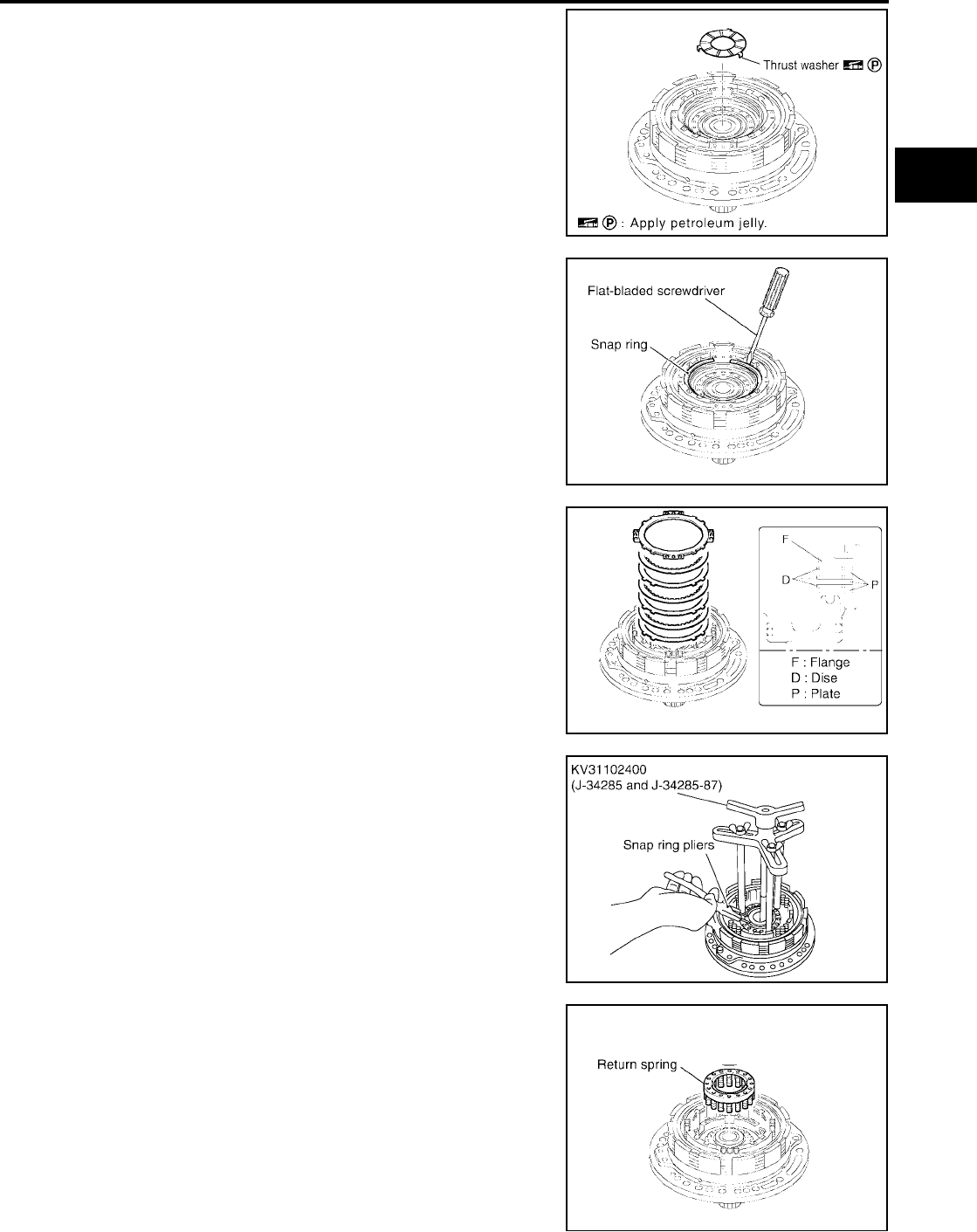
REPAIR FOR COMPONENT PARTS
AT-639
[RE5F22A]
D
E
F
G
H
I
J
K
L
M
A
B
AT
Revision: September 2005 2005 Quest
2. Remove thrust washer from oil pump assembly.
3. Using a flat-bladed screwdriver and remove snap ring.
4. Remove 2nd coast brake flange, 2nd coast brake discs and 2nd
coast brake plates.
5. Place clutch spring compressor on return spring, and compress
return spring with a press.
6. Using a snap ring pliers and remove snap ring.
7. Remove return spring.
SCIA4218E
SCIA4219E
SCIA4220E
SCIA5362E
SCIA4222E
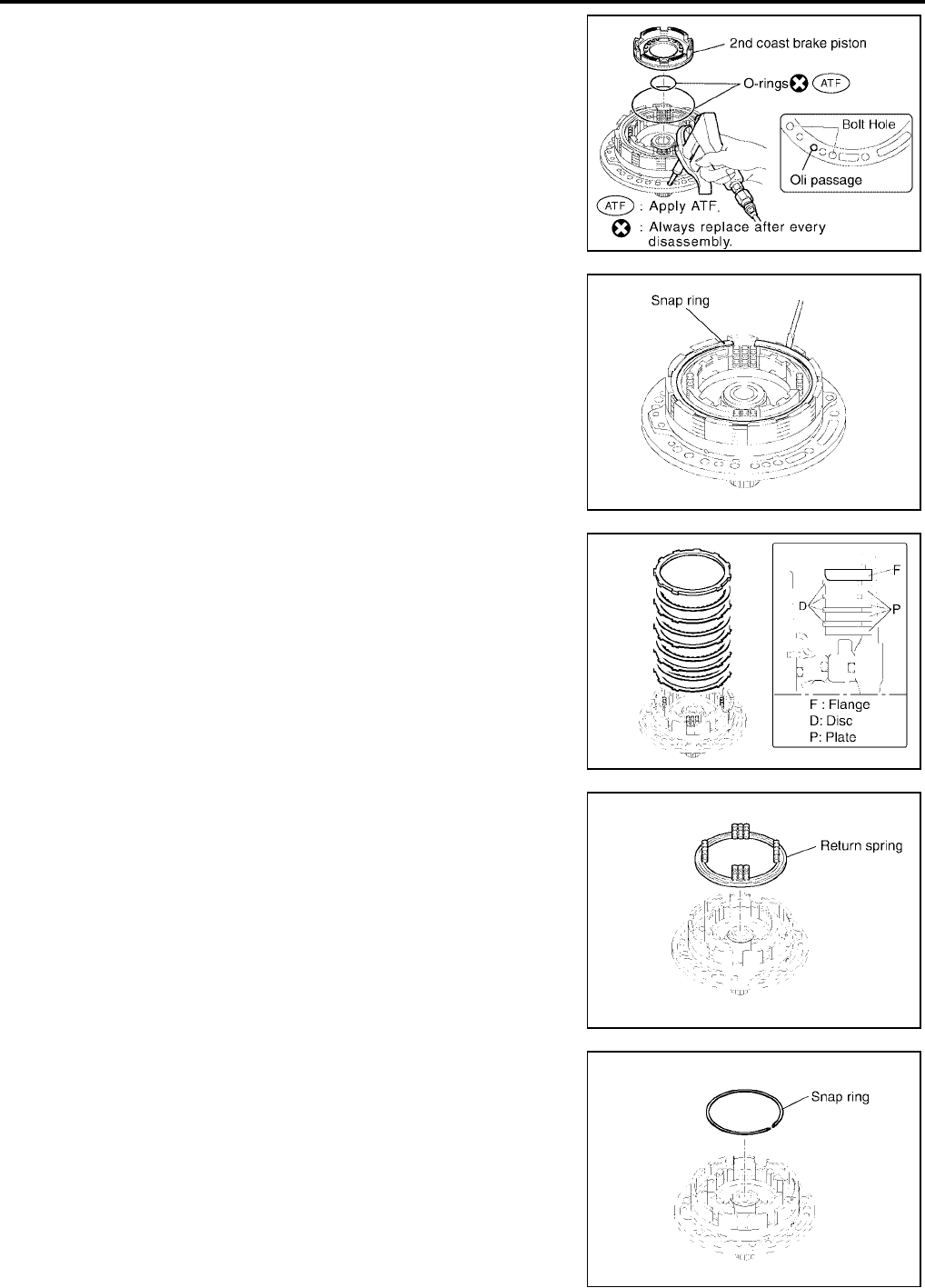
AT-640
[RE5F22A]
REPAIR FOR COMPONENT PARTS
Revision: September 2005 2005 Quest
8. While pushing the 2nd coast brake piston by hand, apply com-
pressed air (4kg/cm2 ) into the oil passage as shown in the fig-
ure and remove 2nd coast brake piston.
CAUTION:
Be careful not to damage the O-ring and 2nd coast brake
piston.
9. Remove O-rings from 2nd coast brake piston.
10. Using a flat-bladed screwdriver and remove snap ring.
11. Remove 2nd brake flange, 2nd brake discs and 2nd brake
plates.
12. Remove return spring.
13. Using a flat-bladed screwdriver and remove snap ring.
CAUTION:
Be careful not to damage oil pump assembly and 2nd brake
piston.
SCIA4223E
SCIA4224E
SCIA4225E
SCIA4226E
SCIA4227E
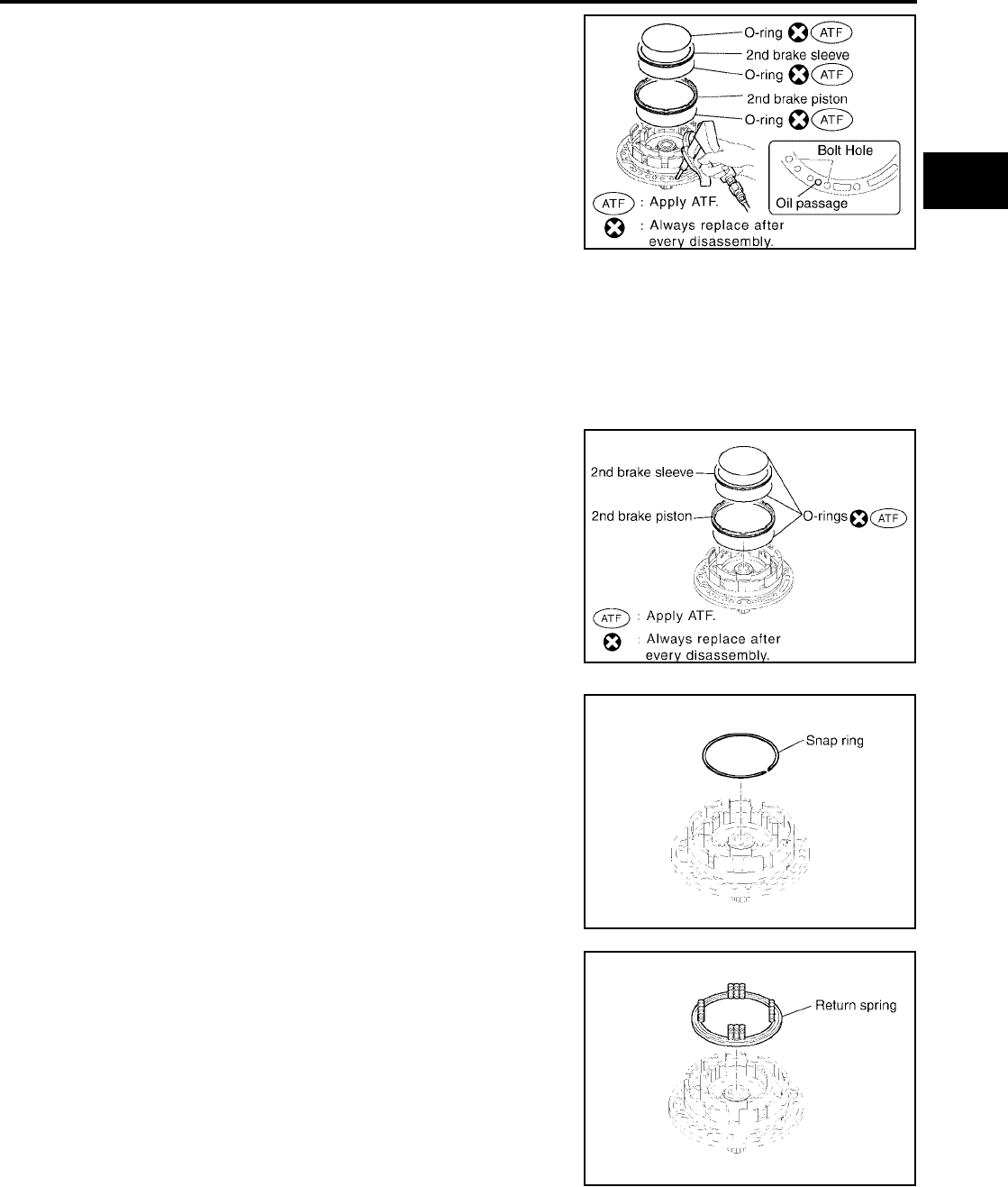
REPAIR FOR COMPONENT PARTS
AT-641
[RE5F22A]
D
E
F
G
H
I
J
K
L
M
A
B
AT
Revision: September 2005 2005 Quest
14. While pushing the 2nd brake piston by hand, apply compressed
air (4kg/cm2 ) into the oil passage as shown in the figure and
remove 2nd brake piston (With 2nd brake sleeve).
CAUTION:
Be careful not to damage 2nd brake piston and 2nd brake
sleeve.
15. Remove O-rings from 2nd brake piston and 2nd brake sleeve.
INSPECTION
●Check that the sliding surface of discs and plates is not worn or burnt. If the discs or plates is worn or
burnt, replace it
CAUTION:
Replace new clutch discs by soaking them at least 2 hours in ATF.
ASSEMBLY
1. Install O-rings in 2nd brake sleeve and 2nd brake piston.
CAUTION:
●Do not reuse O-ring.
●Apply ATF to O-ring.
2. Coat the inner surfaces of oil pump assembly with ATF.
3. Press 2nd brake piston and 2nd brake sleeve into oil pump
assembly.
4. Using a flat-bladed screwdriver and install snap ring.
CAUTION:
Be careful not to damage oil pump assembly.
5. Place return spring on 2nd brake piston with the spring side up.
SCIA4228E
SCIA4229E
SCIA4227E
SCIA4226E
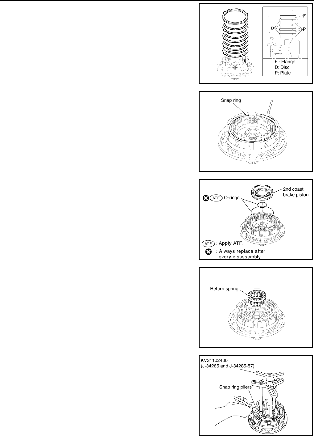
AT-642
[RE5F22A]
REPAIR FOR COMPONENT PARTS
Revision: September 2005 2005 Quest
6. Install 2nd brake flange, 2nd brake discs and 2nd brake plates.
7. Using a flat-bladed screwdriver and install snap ring.
8. Install O-rings in 2nd coast brake piston.
CAUTION:
●Do not reuse O-rings.
●Apply ATF to O-rings.
9. Coat the inner surfaces of oil pump assembly with ATF.
10. Press 2nd coast brake piston into oil pump assembly.
11. Install return spring.
12. Place clutch spring compressor on return spring, and compress
return spring with a press.
13. Using a snap ring pliers and install snap ring.
SCIA4225E
SCIA4224E
SCIA4230E
SCIA4222E
SCIA5362E

REPAIR FOR COMPONENT PARTS
AT-643
[RE5F22A]
D
E
F
G
H
I
J
K
L
M
A
B
AT
Revision: September 2005 2005 Quest
14. Install 2nd coast brake flange, 2nd coast brake discs and 2nd
coast brake plates.
15. Place clutch spring compressor on 2nd coast brake flange, and
compress return spring with a press.
16. Using a flat-bladed screwdriver and install snap ring.
17. Set a dial indicator as shown in the figure.
18. When applying compressed air (4Kg/cm2 ) into the oil passage
as shown, measure 2nd brake piston stroke and check 2nd
brake piston moves smoothly.
If 2nd brake piston stroke is out standards, select another
flange. Refer to AT-682, "2ND BRAKE" .
19. Set a dial indicator as shown in the figure.
20. When applying compressed air (4Kg/cm2 ) into the oil passage
as shown, measure 2nd coast brake piston stroke and check
2nd coast brake piston moves smoothly.
21. Install thrust washer facing the flat surface up.
CAUTION:
Apply petroleum jelly to thrust washer.
SCIA4220E
SCIA5363E
Piston stroke :1.10 - 1.50mm (0.0433 - 0.0591in)
SCIA5500E
Piston stroke :0.76 - 1.44mm (0.0299 - 0.0567in)
SCIA5501E
SCIA4218E
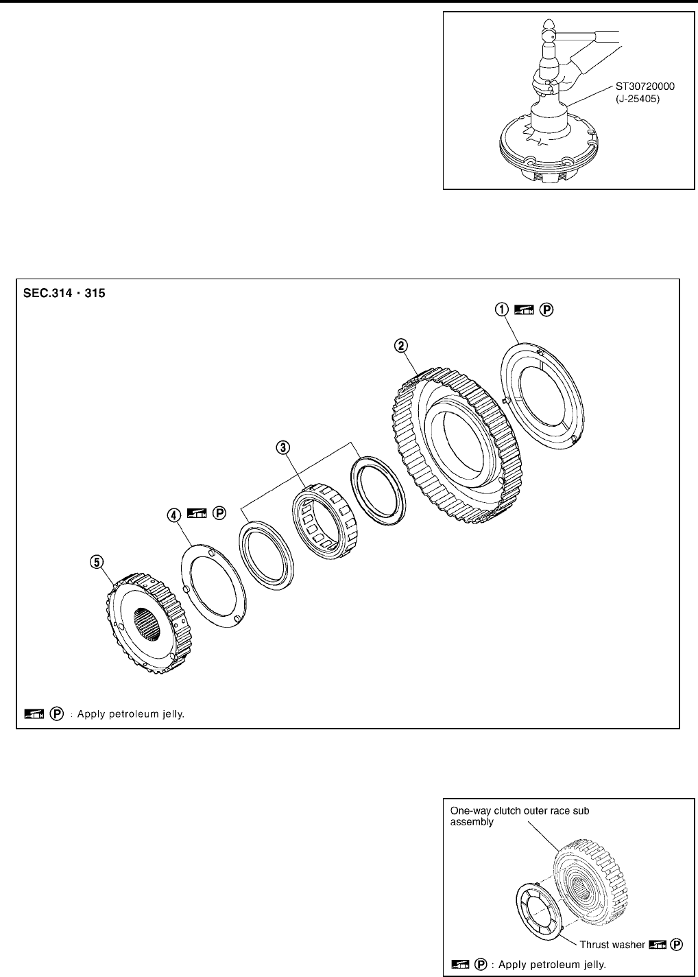
AT-644
[RE5F22A]
REPAIR FOR COMPONENT PARTS
Revision: September 2005 2005 Quest
22. Install oil seal into oil pump assembly until it is flush.
CAUTION:
●Do not reuse oil seal.
●Apply ATF to oil seal.
One-Way Clutch Outer Race Sub Assembly & 2nd Coast Brake Hub & One-Way
Clutch No.1 UCS002L4
COMPONENTS
DISASSEMBLY
1. Remove thrust washer from one-way clutch outer race sub
assembly.
SCIA5364E
1. Thrust washer 2. One-way clutch outer race sub assembly 3. One-way clutch No.1
4. Thrust washer 5. 2nd coast brake hub
SCIA4234E
SCIA4235E
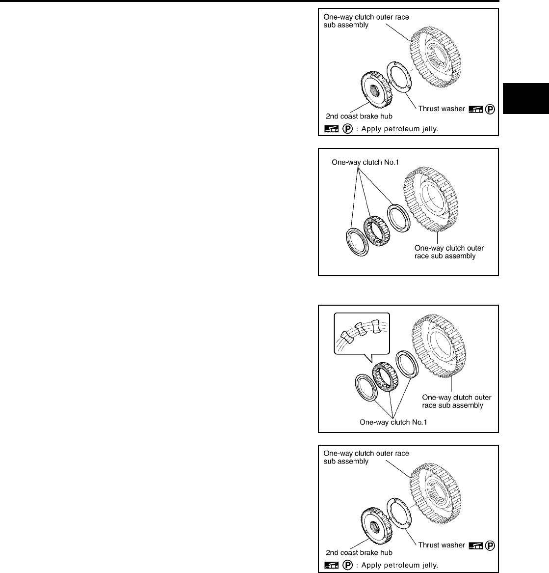
REPAIR FOR COMPONENT PARTS
AT-645
[RE5F22A]
D
E
F
G
H
I
J
K
L
M
A
B
AT
Revision: September 2005 2005 Quest
2. Remove 2nd coast brake hub from one-way clutch outer race
sub assembly.
3. Remove thrust washer from 2nd coast brake hub.
4. Remove one-way clutch No.1 from one-way clutch outer race
sub assembly.
ASSEMBLY
1. Install one-way clutch No.1 into the one-way clutch outer race
sub assembly.
CAUTION:
Do not mistake the direction of one-way clutch No.1.
2. Install thrust washer into 2nd coast brake hub.
CAUTION:
Coat the thrust washer with petroleum jelly. Align the tab of
the washer with the hollow of the 2nd coast brake hub.
3. Install 2nd coast brake hub into one-way clutch outer race sub
assembly.
CAUTION:
While turning the 2nd coast brake hub, slide it into one-way
clutch outer race sub assembly.
SCIA4236E
SCIA4237E
SCIA4238E
SCIA4236E

AT-646
[RE5F22A]
REPAIR FOR COMPONENT PARTS
Revision: September 2005 2005 Quest
4. Coat the thrust washer with petroleum jelly. Align the tab of the
washer with the hollow of the one-way clutch outer race sub
assembly.
CAUTION:
Apply petroleum jelly to thrust washer.
INSPECTION
●Hold one-way clutch outer race sub assembly, and check that
2nd coast brake hub turns freely clockwise and locks counter-
clockwise.
Transaxle Case Cover & B5 Brake UCS002L5
COMPONENTS
SCIA4235E
SCIA4239E
SCIA5441E

REPAIR FOR COMPONENT PARTS
AT-647
[RE5F22A]
D
E
F
G
H
I
J
K
L
M
A
B
AT
Revision: September 2005 2005 Quest
DISASSEMBLY
1. Remove tube clamps.
2. Remove the U/D clutch apply tube sub assembly, using suitable
tool.
CAUTION:
Be careful not to damage the U/D clutch apply tube sub
assembly and transaxle case cover.
3. Remove bearing race and seal rings from transaxle case cover.
4. Remove accumulator cover, compression spring and forward
clutch accumulator piston.
5. Remove O-ring from the accumulator cover.
6. Remove seal ring from the forward clutch accumulator piston.
1. Transaxle case cover 2. Seal ring 3. O-ring
4. Return spring 5. Snap ring 6. B5 brake piston
7. Seal ring 8. Bearing race 9. U/D clutch apply tube sub assembly
10. Tube clamp 11. Forward clutch accumulator piston 12. Compression spring
13. Accumulator cover 14. O-ring 15. Seal ring
16. B5 brake cushion plate 17. B5 brake plate 18. B5 brake flange
19. Snap ring 20. B5 brake disc
SCIA5502E
SCIA4241E
WCIA0386E
SCIA4243E
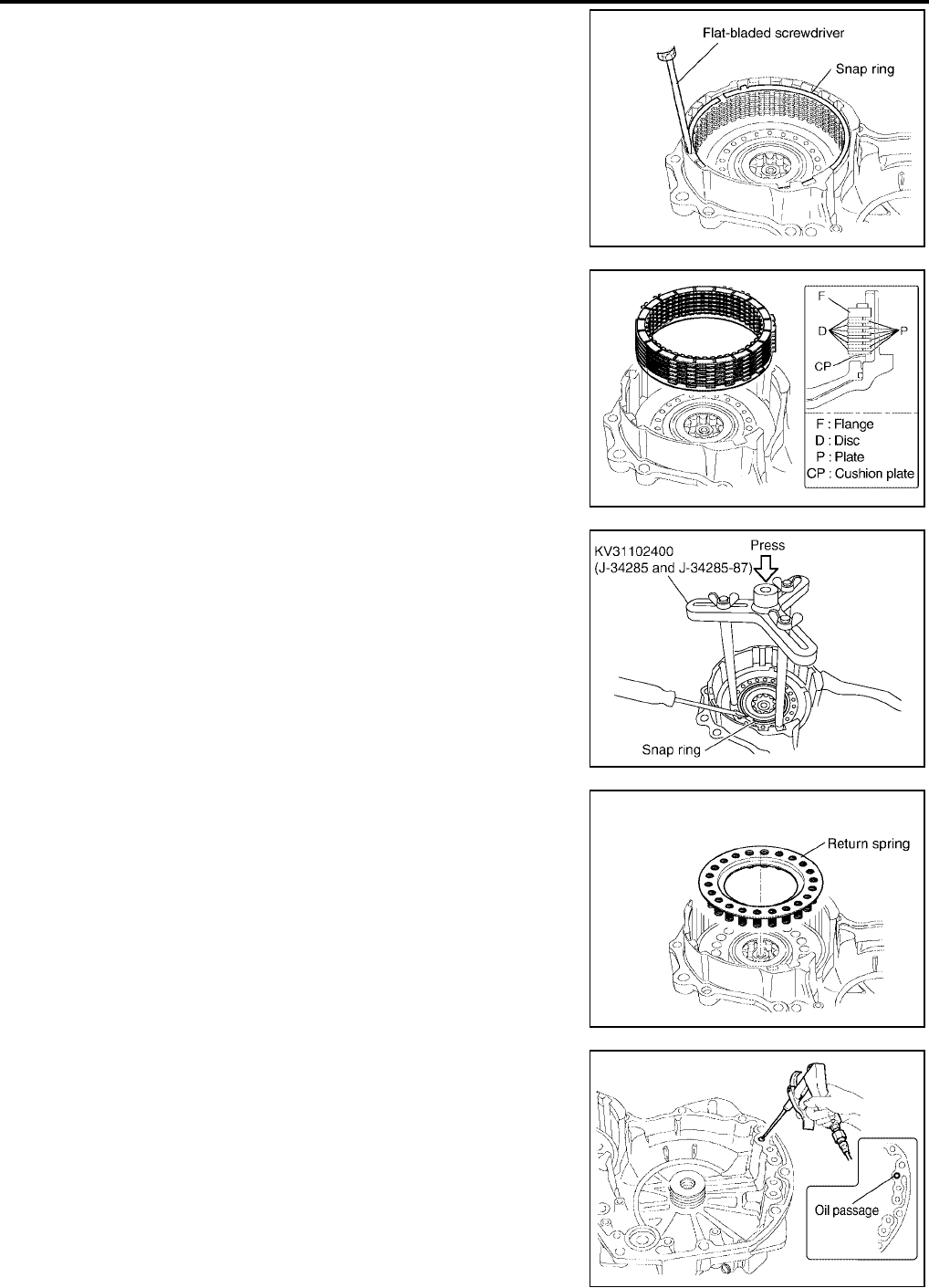
AT-648
[RE5F22A]
REPAIR FOR COMPONENT PARTS
Revision: September 2005 2005 Quest
7. Remove snap ring, using a flat-bladed screwdriver.
8. Remove B5 brake flange, B5 brake discs, B5 brake plates and
B5 brake cushion plate.
9. Place clutch spring compressor on return spring, and compress
return spring with a press.
CAUTION:
Do not press return spring too much to avoid deformation.
10. Remove snap ring, using suitable tool.
11. Remove return spring.
12. While pushing B5 brake piston by hand, apply compressed air
(4Kg/cm2 ) into the oil passage as shown in the figure and
remove B5 brake piston.
SCIA4244E
SCIA4245E
SCIA5365E
SCIA4247E
SCIA4248E
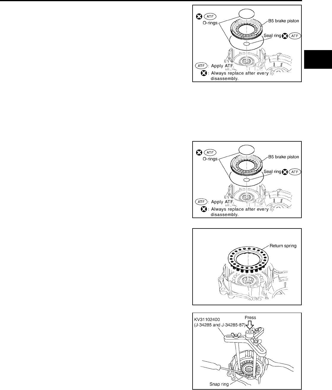
REPAIR FOR COMPONENT PARTS
AT-649
[RE5F22A]
D
E
F
G
H
I
J
K
L
M
A
B
AT
Revision: September 2005 2005 Quest
13. Remove O-rings from B5 brake piston.
14. Remove seal ring from transaxle case cover.
INSPECTION
●Check that the sliding surface of discs and plates are not worn or burnt. If the discs or plates are worn or
burnt, replace them.
CAUTION:
Soak new clutch discs at least 2 hours in ATF.
ASSEMBLY
1. Install seal ring in transaxle case cover.
CAUTION:
●Do not reuse seal ring.
●Apply ATF to seal ring.
2. Install O-rings in B5 brake piston.
CAUTION:
●Do not reuse O-rings.
●Apply ATF to O-rings.
3. Coat the inner surface of transaxle case cover with ATF.
4. Press B5 brake piston into the transaxle case cover.
5. Place return spring on B5 brake piston.
6. Place clutch spring compressor on return spring, and compress
return spring with a press.
CAUTION:
Do not press return spring too much to avoid deformation.
7. Install snap ring, using suitable tool.
SCIA4249E
SCIA4249E
SCIA4247E
SCIA5365E
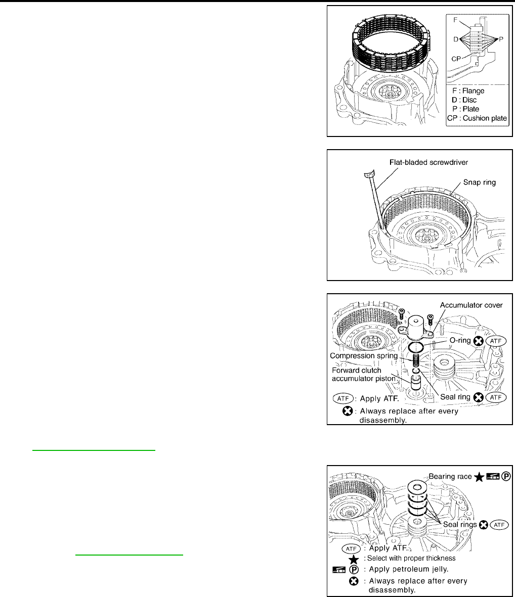
AT-650
[RE5F22A]
REPAIR FOR COMPONENT PARTS
Revision: September 2005 2005 Quest
8. Install B5 brake cushion plate.
CAUTION:
Be sure direction of B5 brake cushion plate.
9. Install B5 brake flange, B5 brake plates and B5 brake discs as
shown in the figure.
10. Install snap ring, using a flat-bladed screwdriver.
11. Install O-ring in accumulator cover.
CAUTION:
●Do not reuse O-ring.
●Apply ATF to O-ring.
12. Install seal ring in forward clutch accumulator piston.
CAUTION:
●Do not reuse seal ring.
●Apply ATF to seal ring.
13. Install forward clutch accumulator piston, compression spring
and accumulator cover in transaxle case cover.
14. Tighten accumulator cover torx bolts to specified torque. Refer
to AT-646, "COMPONENTS" .
15. Install seal rings and bearing race in transaxle case cover.
CAUTION:
●Do not reuse seal rings.
●Apply ATF to seal rings.
●Apply petroleum jelly to bearing race.
●Assemble the selected bearing race in the correct order.
Refer to AT-655, "ASSEMBLY" .
SCIA4245E
SCIA4244E
SCIA4243E
WCIA0386E
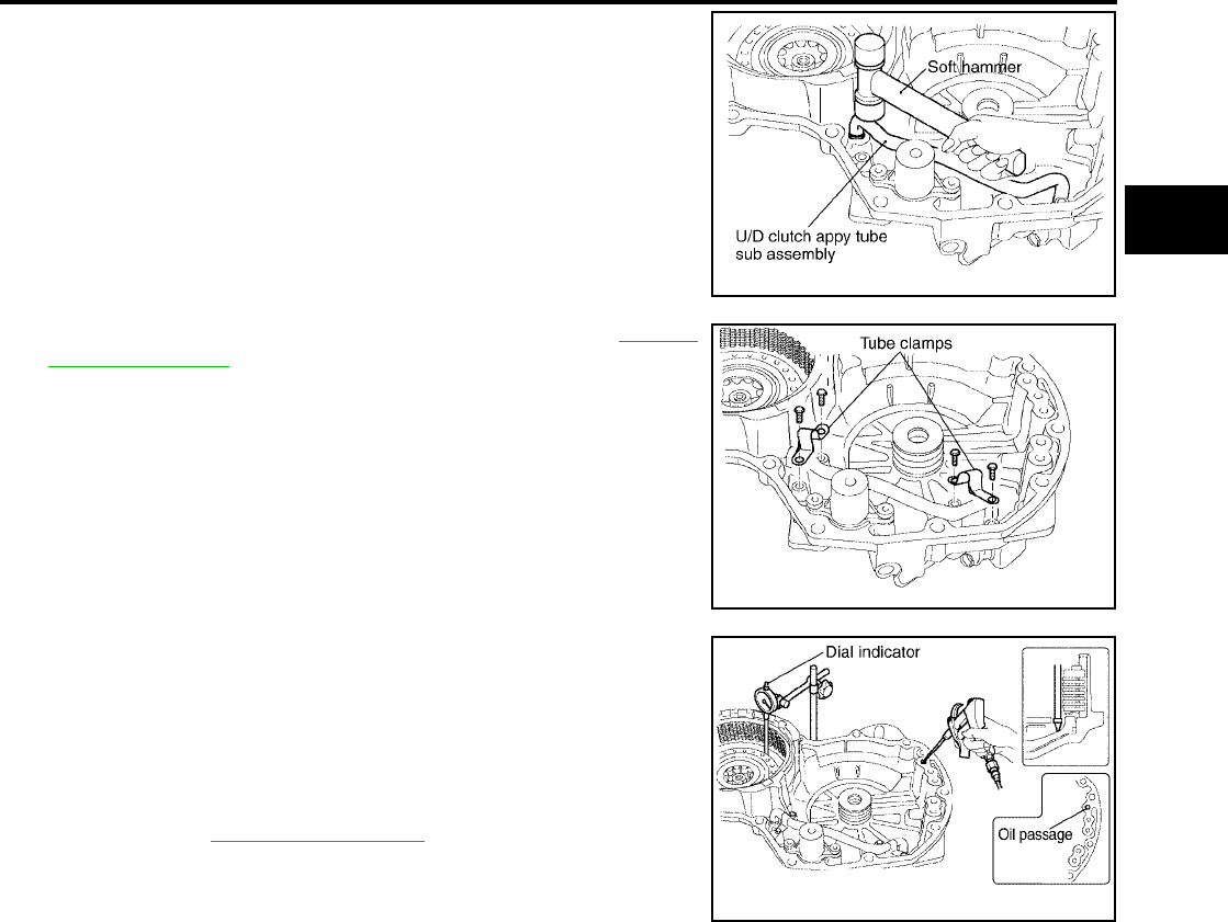
REPAIR FOR COMPONENT PARTS
AT-651
[RE5F22A]
D
E
F
G
H
I
J
K
L
M
A
B
AT
Revision: September 2005 2005 Quest
16. Install the U/D clutch apply tube sub assembly, using a soft
hammer.
17. Tighten tube clamp bolts to specified torque. Refer to AT-646,
"COMPONENTS" .
18. Set a dial indicator as shown in the figure.
19. When applying compressed air (4Kg/cm2 ) into the oil passage
as shown, measure the B5 brake piston stroke and check the B5
brake piston moves smoothly.
If the B5 brake piston stroke is out standards, select another
flange. Refer to AT-683, "B5 BRAKE" .
SCIA4252E
SCIA5502E
Piston stroke :2.34 - 2.70mm (0.0921 - 0.1063in)
SCIA5503E
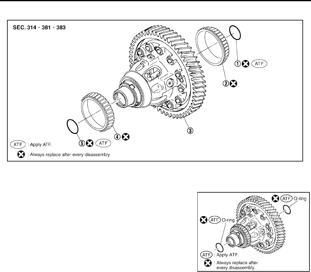
AT-652
[RE5F22A]
REPAIR FOR COMPONENT PARTS
Revision: September 2005 2005 Quest
Differential Gear Assembly UCS002L6
COMPONENTS
DISASSEMBLY
1. Remove O-rings from differential gear assembly.
1. O-ring 2. Tapered roller bearing 3. Differential gear assembly
4. Tapered roller bearing 5. O-ring
SCIA4407E
SCIA4408E

REPAIR FOR COMPONENT PARTS
AT-653
[RE5F22A]
D
E
F
G
H
I
J
K
L
M
A
B
AT
Revision: September 2005 2005 Quest
2. Remove tapered roller bearings, using a puller.
ASSEMBLY
1. Install tapered roller bearings in differential gear assembly.
CAUTION:
Do not reuse tapered roller bearings.
SCIA5366E
SCIA5368E
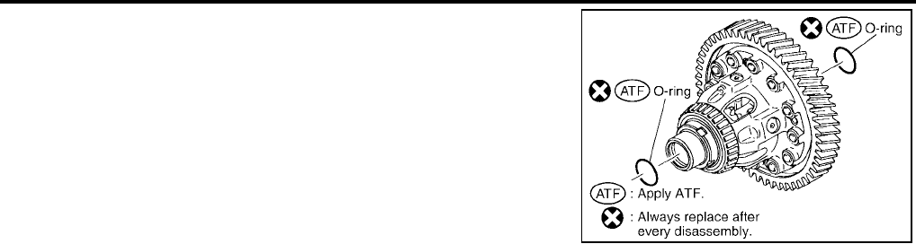
AT-654
[RE5F22A]
REPAIR FOR COMPONENT PARTS
Revision: September 2005 2005 Quest
2. Install O-rings in differential gear assembly.
CAUTION:
●Do not reuse O-rings.
●Apply ATF to O-rings.
SCIA4408E
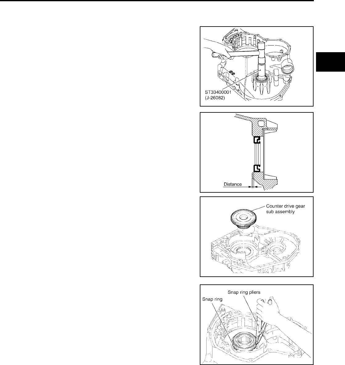
ASSEMBLY
AT-655
[RE5F22A]
D
E
F
G
H
I
J
K
L
M
A
B
AT
Revision: September 2005 2005 Quest
ASSEMBLY PFP:00000
Assembly (1) UCS002L7
1. Install the differential side oil seal into transaxle case, using a
drift.
CAUTION:
●Do not reuse differential side oil seal.
●Apply ATF to differential side oil seal.
2. Install counter drive gear sub assembly.
3. Using a snap ring pliers and install snap ring.
Distance : 3.0 - 4.0 mm (0.118 - 0.157 in)
SCIA5369E
SCIA4473E
SCIA4215E
SCIA4214E
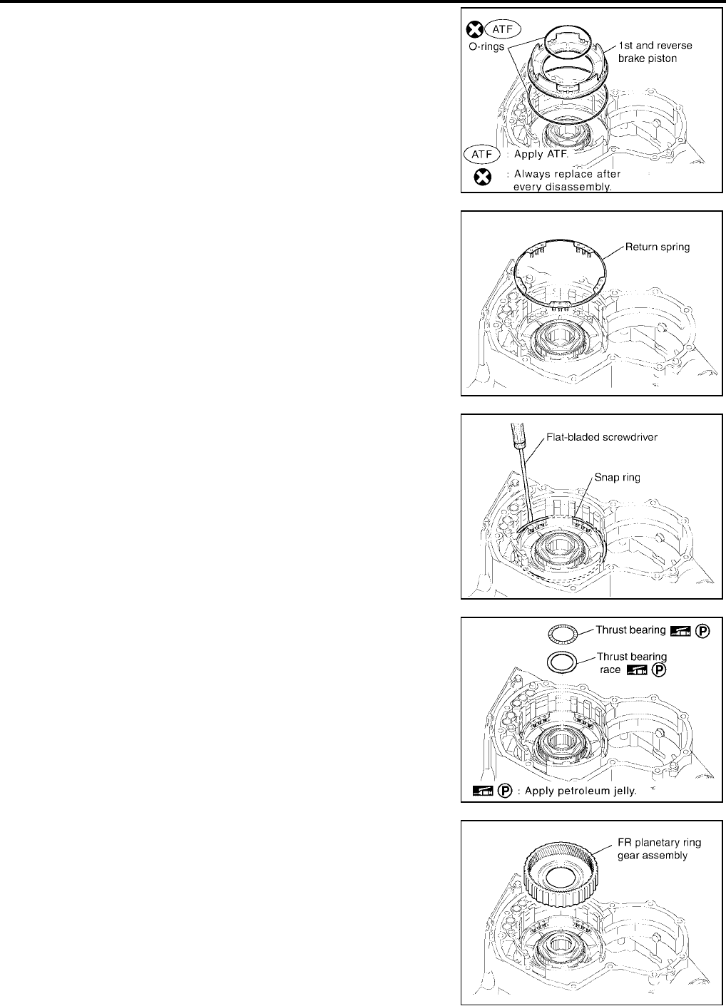
AT-656
[RE5F22A]
ASSEMBLY
Revision: September 2005 2005 Quest
4. Install O-rings in 1st and reverse brake piston.
CAUTION:
●Do not reuse O-rings.
●Apply ATF to O-rings.
5. Coat the inner surface of transaxle case with ATF.
6. Install 1st and reverse brake piston in transaxle case.
7. Put return spring on 1st and reverse brake piston.
8. While compressing the return spring by hand, install the snap
ring into groove with a flat-bladed screwdriver.
9. Put thrust bearing race and thrust bearing on counter drive gear
sub assembly.
CAUTION:
Apply petroleum jelly to thrust bearing and thrust bearing
race.
10. Install FR planetary ring gear assembly with one-way clutch
No.2.
SCIA4212E
SCIA4210E
SCIA4209E
SCIA4213E
SCIA4208E
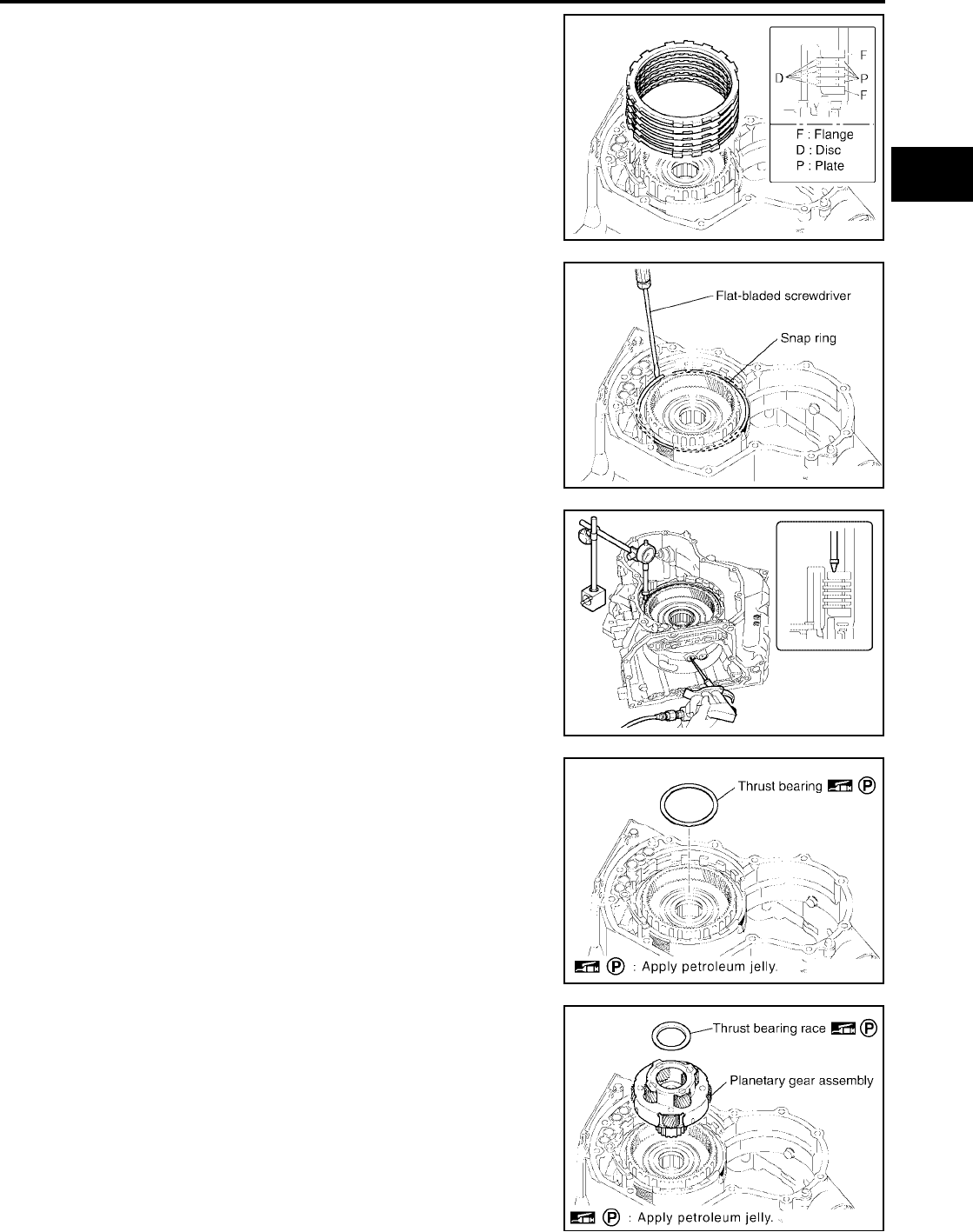
ASSEMBLY
AT-657
[RE5F22A]
D
E
F
G
H
I
J
K
L
M
A
B
AT
Revision: September 2005 2005 Quest
11. Install 1st and reverse brake flanges, 1st and reverse brake
discs and 1st and reverse brake plates.
12. Using a flat-bladed screwdriver and install snap ring.
13. Set a dial indicator as shown in the figure.
14. Applying compressed air (4Kg/cm2 ) and measure the 1st and
reverse brake piston stroke.
In a case that is out of reference, check the following items:
●Oil pressure leak
●Damage of O-ring
●Wear damage of discs
15. Install thrust bearing.
CAUTION:
Apply petroleum jelly to thrust bearing.
16. Install planetary gear assembly.
17. Install thrust bearing race in planetary gear assembly.
CAUTION:
Apply petroleum jelly to thrust bearing race.
SCIA4207E
SCIA4206E
Piston stroke : 1.39 - 2.21 mm (0.0547 - 0.0870 in)
SCIA4258E
SCIA4205E
SCIA4204E
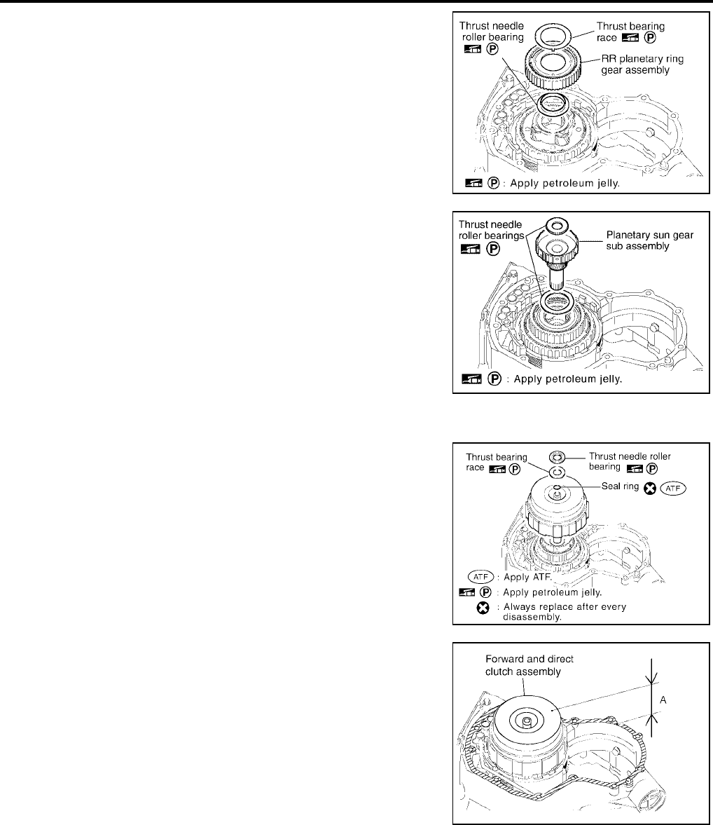
AT-658
[RE5F22A]
ASSEMBLY
Revision: September 2005 2005 Quest
18. Install thrust needle roller bearing and thrust bearing race in RR
planetary ring gear assembly.
CAUTION:
Apply petroleum jelly to thrust needle roller bearing and
thrust bearing race.
19. Install RR planetary ring gear assembly.
20. Install planetary sun gear sub assembly and thrust needle roller
bearings.
CAUTION:
Apply petroleum jelly to thrust needle roller bearings.
21. Install forward and direct clutch assembly.
22. Install thrust bearing race, thrust needle roller bearing and seal
ring in forward and direct clutch assembly.
CAUTION:
●Apply petroleum jelly to thrust needle roller bearing and
thrust bearing race.
●Apply ATF to seal ring.
●Do not reuse seal ring.
23. Check the distance of “A”.
CAUTION:
If the distance is out of standards, adjust with in standards
again.
SCIA4203E
SCIA5499E
SCIA5412E
“A” : 50.850 - 51.825 mm (2.0020 - 2.0404 in)
SCIA4259E
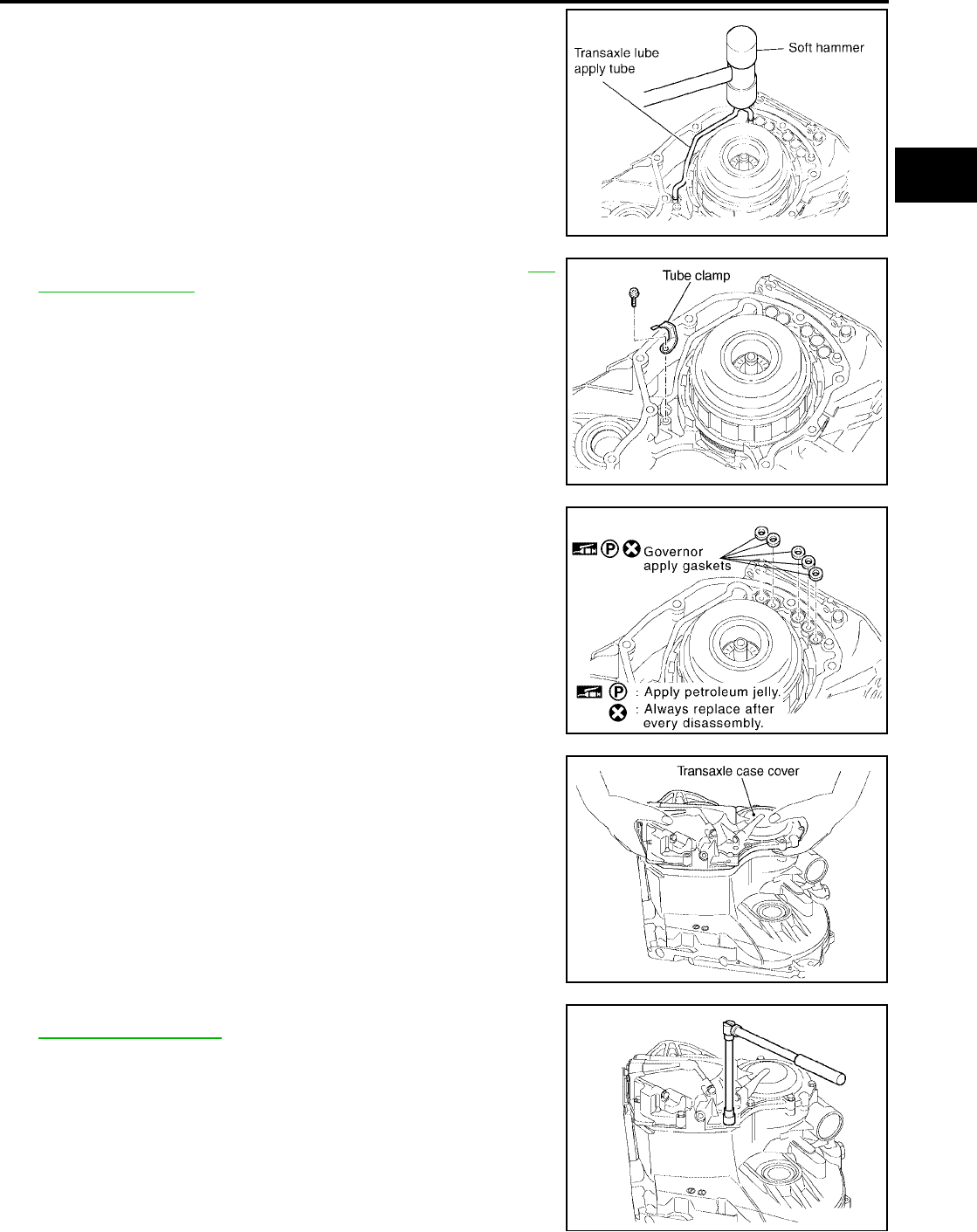
ASSEMBLY
AT-659
[RE5F22A]
D
E
F
G
H
I
J
K
L
M
A
B
AT
Revision: September 2005 2005 Quest
24. Using a soft hammer and install transaxle lube apply tube.
CAUTION:
Be careful not to bend and damage transaxle lube apply
tube.
25. Tighten tube clamp fixing bolt to specified torque. Refer to AT-
612, "Components" .
26. Install governor apply gaskets in transaxle case.
CAUTION:
●Do not reuse governor apply gaskets.
●Apply petroleum jelly to governor apply gaskets.
27. Install transaxle case cover in transaxle case.
28. Tighten transaxle case cover bolts to specified torque. Refer to
AT-612, "Components" .
CAUTION:
Use old seal bolts when checking and adjusting the end
play because of re-installing transaxle case cover.
SCIA4260E
SCIA4199E
SCIA4198E
SCIA4197E
SCIA4194E

AT-660
[RE5F22A]
ASSEMBLY
Revision: September 2005 2005 Quest
*:Stud bolt
29. Tighten anchor bolt to specified torque. Refer to AT-612, "Com-
ponents" .
CAUTION:
●Do not reuse O-ring.
●Apply ATF to O-ring.
30. Install O-ring in U/D brake piston assembly.
CAUTION:
●Do not reuse O-ring.
●Apply ATF to O-ring.
31. Coat the inner surface of transaxle case with ATF.
32. Install compression spring and U/D brake piston assembly.
33. Install O-rings in U/D brake damper assembly.
CAUTION:
●Do not reuse O-rings.
●Apply ATF to O-rings.
34. Install U/D brake damper assembly.
35. Using a snap ring pliers and install snap ring.
CAUTION:
If the snap ring is deformed, replace it.
Bolt symbol Length mm (in) Number of bolts
A 30 (1.18) 8
B 45 (1.77) 2
C 48 (1.89) 2
D* — 1
SCIA5413E
SCIA4193E
SCIA4192E
SCIA4191E
SCIA4190E
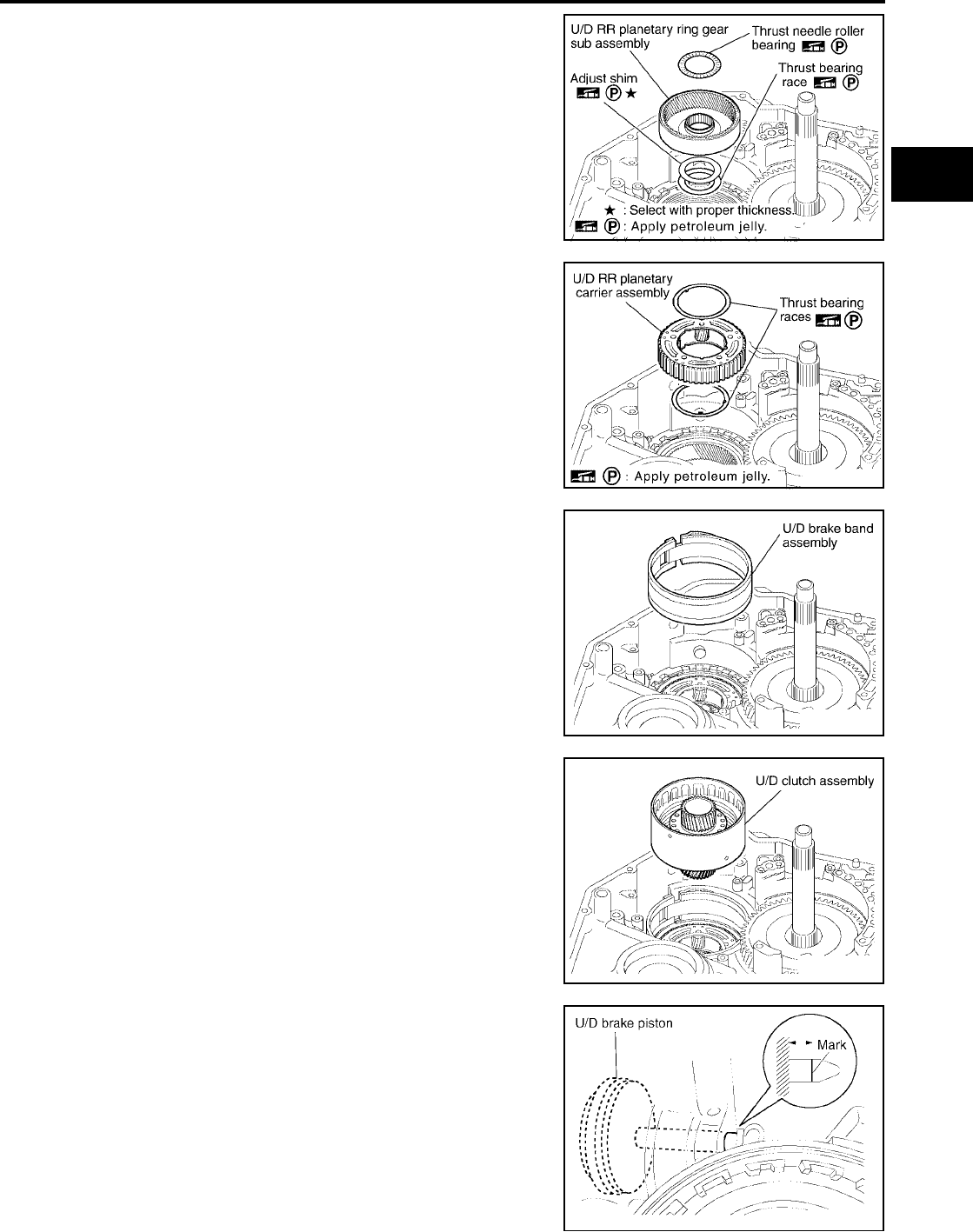
ASSEMBLY
AT-661
[RE5F22A]
D
E
F
G
H
I
J
K
L
M
A
B
AT
Revision: September 2005 2005 Quest
36. Install thrust needle roller bearing, adjust shim and thrust bear-
ing race in U/D RR planetary ring gear sub assembly.
CAUTION:
Apply petroleum jelly to adjust shim, thrust needle roller
bearing and thrust bearing race.
37. Install U/D RR planetary ring gear sub assembly.
38. Install U/D RR planetary carrier assembly and thrust bearing
races.
CAUTION:
Apply petroleum jelly to thrust bearing races.
39. Install U/D brake band assembly.
40. Install U/D clutch assembly.
41. Measure the U/D brake piston stroke applying and releasing the
compressed air (4Kg/cm2 ) as shown in the figure.
CAUTION:
Measure U/D brake piston stroke after assembling U/D
clutch assembly.
SCIA5414E
SCIA5505E
SCIA4187E
SCIA4186E
Piston Stroke : 5.76 - 6.76 mm (0.2268 - 0.2661 in)
SCIA4263E
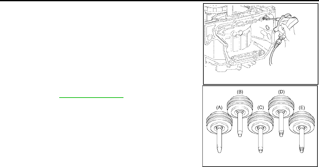

ASSEMBLY
AT-663
[RE5F22A]
D
E
F
G
H
I
J
K
L
M
A
B
AT
Revision: September 2005 2005 Quest
Adjustment UCS002L8
ADJUST PRELOAD OF TAPERED ROLLER BEARING
1. Install adjust shim and outer race in transaxle case.
2. Install differential gear assembly in transaxle case.
3. Install transaxle housing into transaxle case.
4. Tighten transaxle housing and transaxle case bolts to specified
torque. Refer to AT-612, "Components" .
CAUTION:
Use old seal bolts when checking and adjusting and pre-
load because of re-installing transaxle housing.
*:Torx bolt
SCIA5370E
SCIA4265E
Bolt symbol Length mm (in) Number of bolts
A 30 (1.18) 13
B 35 (1.38) 2
C 45 (1.77) 1
D* — 1
SCIA4267E
SCIA5495E

AT-664
[RE5F22A]
ASSEMBLY
Revision: September 2005 2005 Quest
5. Insert Tool and measure turning torque of differential gear
assembly.
6. Turn differential gear assembly in both directions several times
to seat bearing rollers correctly.
If the preload is not within specification, remove differential gear
assembly from transaxle case. Re-select adjust shim. Refer to
AT-684, "DIFFERENTIAL SIDE BEARING ADJUSTING SHIMS"
.
Turning torque
(New bearing) : 0.7 - 1.2 N·m
(0.08 - 0.12kg-m, 7 - 10 in-lb)
SCIA5371E
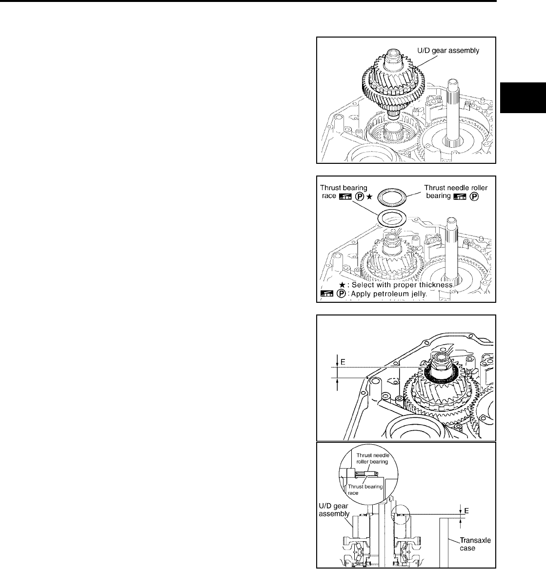
ASSEMBLY
AT-665
[RE5F22A]
D
E
F
G
H
I
J
K
L
M
A
B
AT
Revision: September 2005 2005 Quest
Assembly (2) UCS002L9
1. Remove transaxle housing and differential gear assembly from transaxle case.
2. Install seal rings in U/D gear assembly.
CAUTION:
●Do not reuse seal rings.
●Apply ATF to seal rings.
3. Install U/D gear assembly.
4. Install thrust needle roller bearing and thrust bearing race in U/D
gear assembly.
a. Perform the following procedure for adjustment.
CAUTION:
Apply petroleum jelly to thrust needle roller bearing and
thrust bearing race.
b. Make sure that measurement “E” is within the specifications.
NOTE:
“E” is the height between the edge of transaxle case and the
roller part of thrust needle roller bearing.
SCIA4185E
SCIA5415E
Specification E : 1.269 - 1.645 mm (0.0500 - 0.0648 in)
SCIA5452E
SCIA5459E
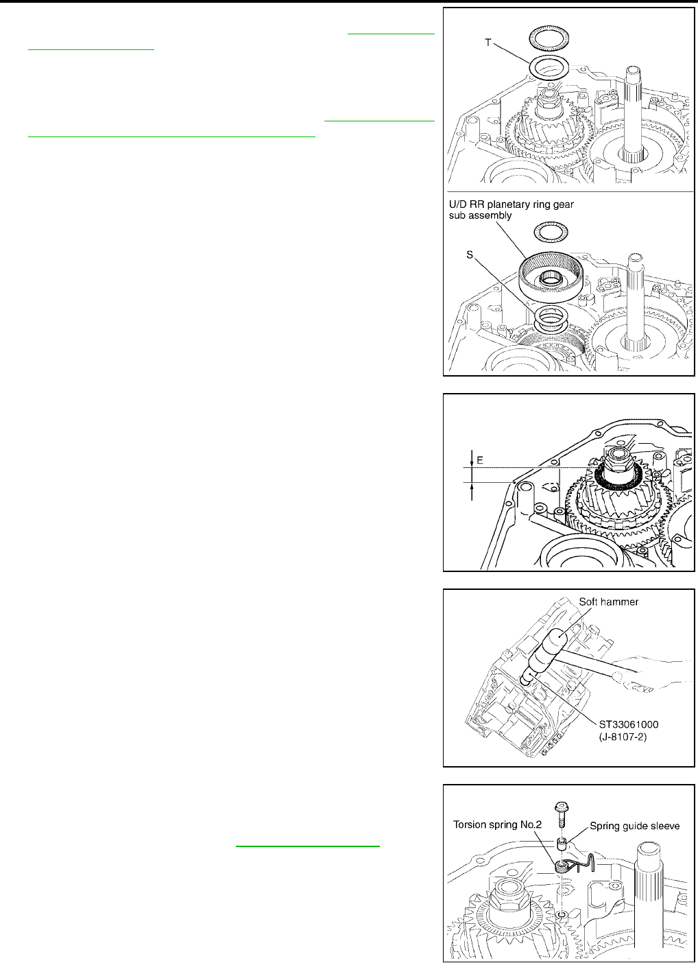
AT-666
[RE5F22A]
ASSEMBLY
Revision: September 2005 2005 Quest
c. If measurement “E” is outside the specifications, replace “T” with
a one that has applicable thickness. Refer to AT-684, "U/D
GEAR ASSEMBLY" .
CAUTION:
When adjusting “T”, use “S” of thickness 0.81mm (0.032in).
d. If all of “T” do not fit “E” within the specifications, replace “S” with
a one that has applicable thickness. Refer to AT-684, "U/D RR
PLANETARY RING GEAR SUB ASSEMBLY" .
CAUTION:
When adjusting “S”, use “T” of thickness 0.80mm (0.031in).
e. Make sure that measurement “E” is within the specifications.
5. Install manual valve oil seal into transaxle case until it is flush.
CAUTION:
●Do not reuse manual valve oil seal.
●Apply ATF to manual valve oil seal.
6. Install spring guide sleeve and torsion spring No.2 in transaxle
case.
7. Tighten spring guide sleeve and torsion spring No.2 fixing torx
bolt to specified torque. Refer to AT-612, "Components" .
SCIA5488E
SCIA5452E
SCIA5486E
SCIA4182E
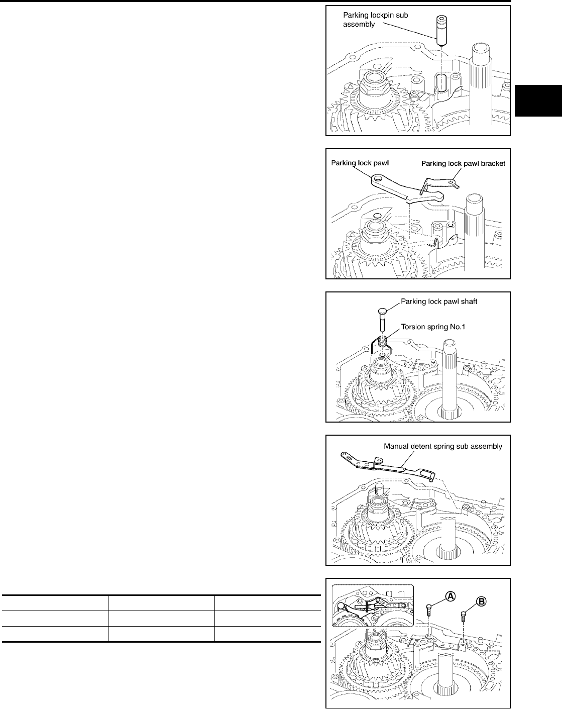
ASSEMBLY
AT-667
[RE5F22A]
D
E
F
G
H
I
J
K
L
M
A
B
AT
Revision: September 2005 2005 Quest
8. Install parking lockpin sub assembly.
9. Install parking lock pawl bracket and parking lock pawl.
10. Install parking lock pawl shaft and torsion spring No.1.
11. Install manual detent spring sub assembly.
12. Temporary tightening the bolts.
SCIA4181E
WCIA0420E
SCIA4179E
SCIA4178E
Bolt symbol Length mm (in) Number of bolts
A 16.7 (0.657) 1
B 14.0 (0.551) 1
SCIA4177E
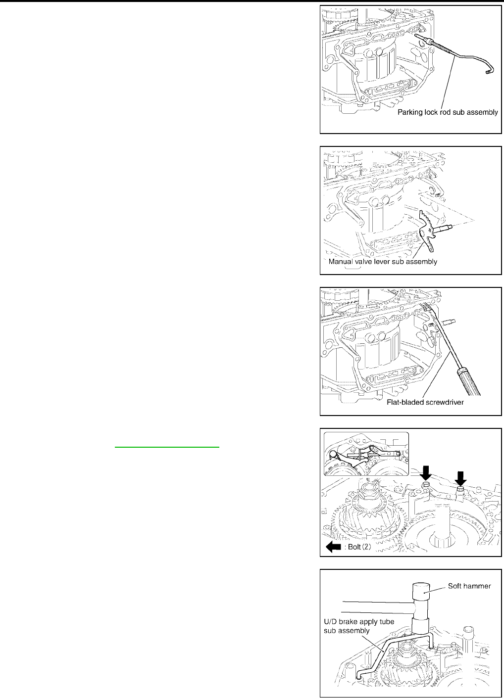
AT-668
[RE5F22A]
ASSEMBLY
Revision: September 2005 2005 Quest
13. Install parking lock rod sub assembly.
14. Install manual valve lever sub assembly connect parking lock
rod sub assembly to it.
15. Using a flat-bladed screwdriver and connect manual detent
spring sub assembly to manual valve lever sub assembly.
16. Tighten manual detent spring sub assembly fixing bolts to speci-
fied torque. Refer to AT-612, "Components" .
17. Using a soft hammer and install U/D brake apply tube sub
assembly.
CAUTION:
Be careful not to damage U/D brake apply tube sub assem-
bly.
SCIA4176E
SCIA4175E
SCIA4174E
SCIA4550E
SCIA4270E
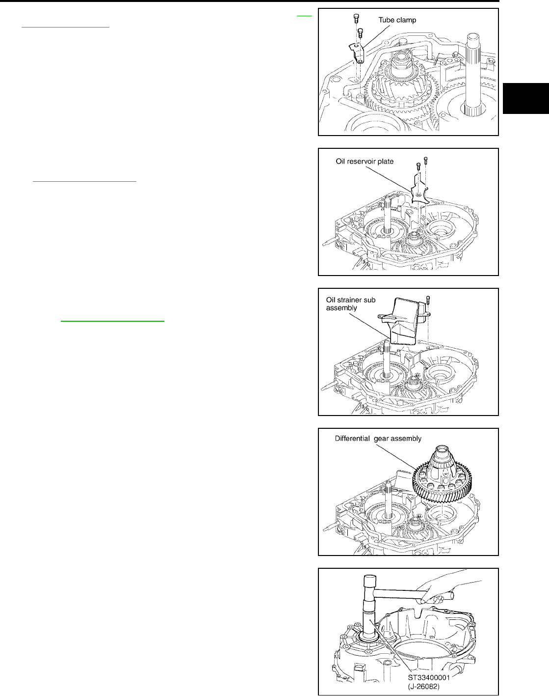
ASSEMBLY
AT-669
[RE5F22A]
D
E
F
G
H
I
J
K
L
M
A
B
AT
Revision: September 2005 2005 Quest
18. Tighten tube clamp fixing bolts to specified torque. Refer to AT-
612, "Components" .
19. Install oil reservoir plate in transaxle case.
20. Tighten oil reservoir plate fixing bolts to specified torque. Refer
to AT-612, "Components" .
21. Install oil strainer sub assembly in transaxle case.
22. Tighten oil strainer sub assembly fixing bolt to specified torque.
Refer to AT-612, "Components" .
23. Install differential gear assembly.
24. Use a drift to drive differential side oil seal into transaxle hous-
ing.
CAUTION:
●Do not reuse differential side oil seal.
●Apply ATF to differential side oil seal.
SCIA4171E
SCIA4170E
SCIA4169E
SCIA4168E
Distance : 14.8 - 15.8 mm (0.583 - 0.622 in)
SCIA5372E
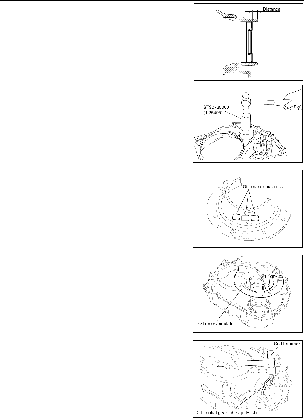
AT-670
[RE5F22A]
ASSEMBLY
Revision: September 2005 2005 Quest
25. Install thrust roller bearing in transaxle housing.
CAUTION:
Do not reuse thrust roller bearing.
26. Install oil cleaner magnets on oil reservoir plate.
27. Install oil reservoir plate in transaxle housing.
28. Tighten oil reservoir plate fixing bolts to specified torque. Refer
to AT-612, "Components" .
29. Using a soft hammer and install differential gear lube apply tube.
CAUTION:
Be careful not to bend or damage differential gear lube
apply tube.
SCIA4474E
SCIA5373E
SCIA4167E
SCIA4166E
SCIA4272E
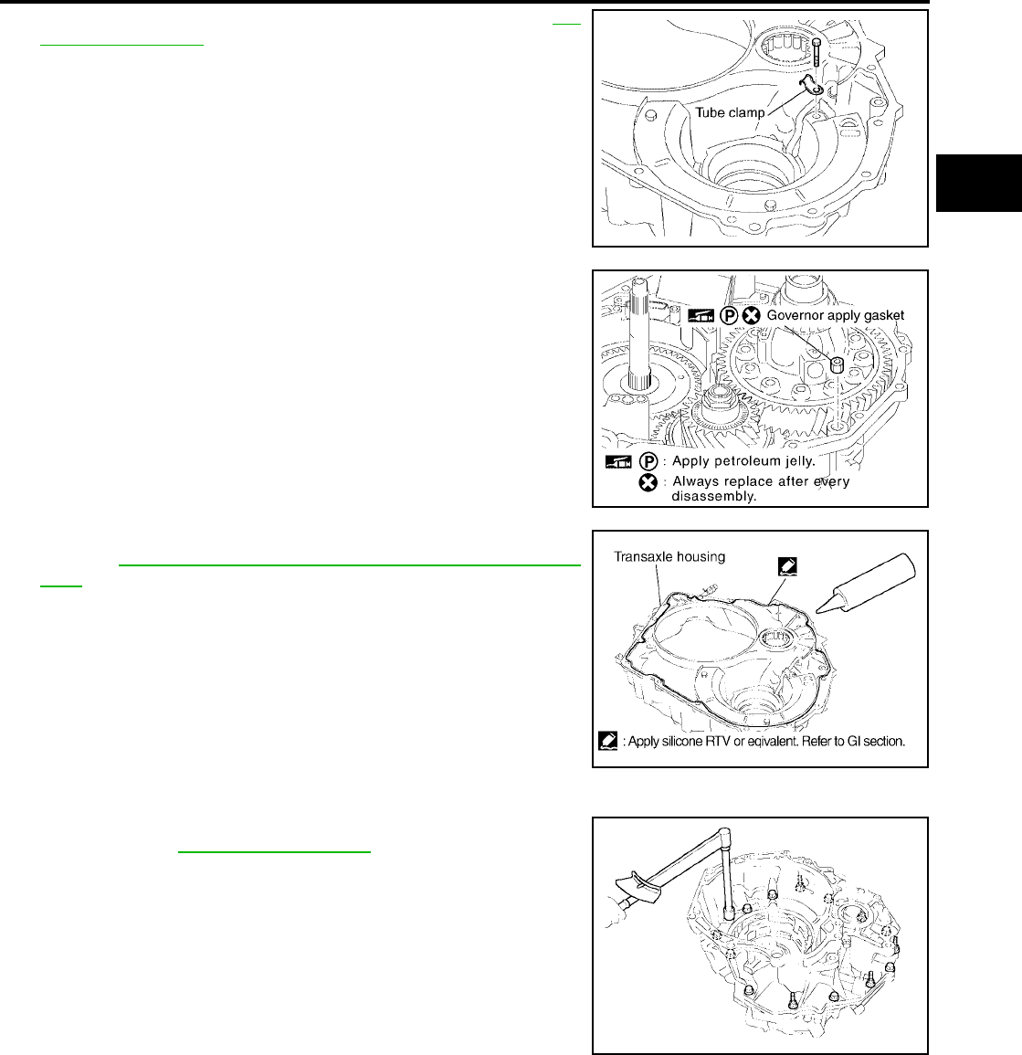
ASSEMBLY
AT-671
[RE5F22A]
D
E
F
G
H
I
J
K
L
M
A
B
AT
Revision: September 2005 2005 Quest
30. Tighten tube clamp fixing bolt to specified torque. Refer to AT-
612, "Components" .
31. Install governor apply gasket.
CAUTION:
●Do not reuse governor apply gasket.
●Apply petroleum jelly to governor apply gasket.
32. Install seal ring.
CAUTION:
●Do not reuse seal ring.
●Apply ATF to seal ring.
33. Apply silicone RTV to transaxle housing as shown in illustration.
Refer to GI-43, "Recommended Chemical Products and Seal-
ants" .
CAUTION:
Complete remove all moisture, oil and sealant, etc. From
transaxle housing and transaxle case.
34. Install transaxle housing in transaxle case.
35. Tighten transaxle housing and transaxle case bolts to specified
torque. Refer to AT-612, "Components" .
CAUTION:
Do not reuse seal bolts.
SCIA4164E
SCIA4163E
SCIA5506E
SCIA4267E
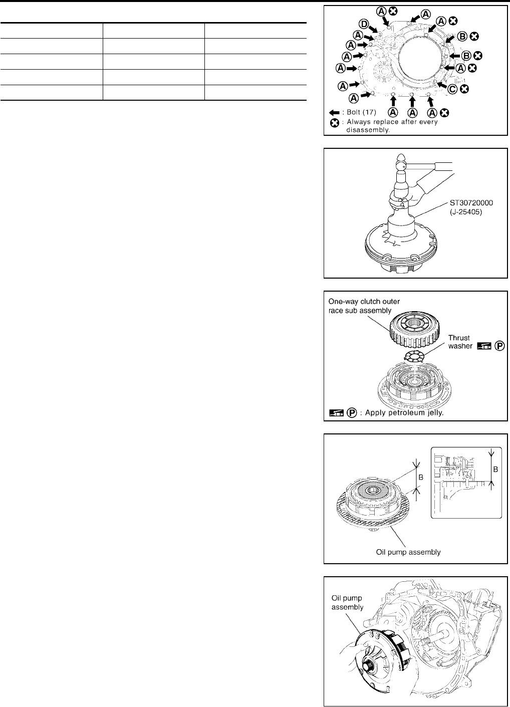
AT-672
[RE5F22A]
ASSEMBLY
Revision: September 2005 2005 Quest
*:Torx bolt
36. Install oil seal into oil pump assembly until it is flush.
CAUTION:
●Do not reuse oil seal.
●Apply ATF to oil seal.
37. Install thrust washer and one- way clutch outer race sub assem-
bly in oil pump assembly.
CAUTION:
Apply petroleum jelly to thrust washer.
38. Check the distance of “B”.
CAUTION:
If the distance is out of standards, adjust within standards
again.
39. Place oil pump assembly through the input shaft in horizontal
position, and align the bolt holes of the oil pump assembly with
transaxle case. Lightly press oil pump assembly.
CAUTION:
Be careful not to drop one-way clutch outer race sub
assembly.
Bolt symbol Length mm (in) Number of bolts
A 30 (1.18) 13
B 35 (1.38) 2
C 45 (1.77) 1
D* — 1
SCIA5495E
SCIA5364E
SCIA4274E
“B” : 51.09 - 51.71 mm (2.0114 - 2.0358 in)
SCIA4275E
SCIA4276E

ASSEMBLY
AT-673
[RE5F22A]
D
E
F
G
H
I
J
K
L
M
A
B
AT
Revision: September 2005 2005 Quest
40. Tighten oil pump assembly bolts to specified torque. Refer to AT-
612, "Components" .
41. Set a dial indicator as shown in the figure, move the input shaft
and measure the end play.
If the end play is out of standards, select another thrust bearing
race. Refer to AT-683, "FORWARD AND DIRECT CLUTCH
ASSEMBLY" .
SCIA4156E
SCIA4157E
End play : 0.188 - 0.570 mm (0.0074 - 0.0224 in)
SCIA4277E
SCIA5417E
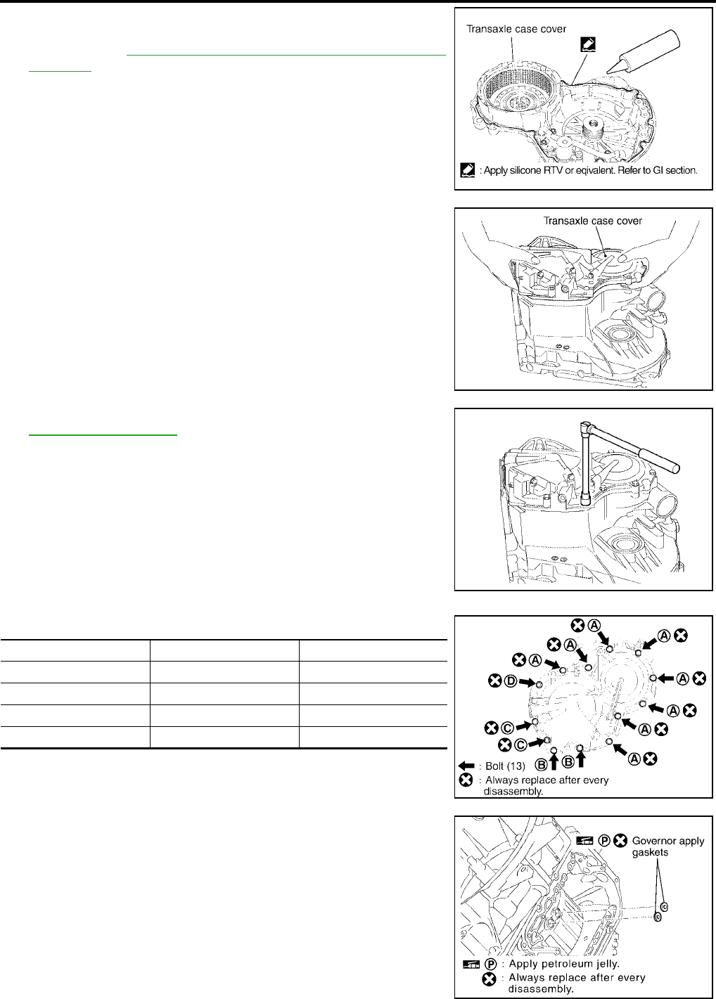
AT-674
[RE5F22A]
ASSEMBLY
Revision: September 2005 2005 Quest
42. Remove transaxle case cover.
43. Apply silicone RTV to transaxle case cover as shown in illustra-
tion. Refer to GI-43, "Recommended Chemical Products and
Sealants" .
CAUTION:
Complete remove all moisture, oil and sealant, etc. From
transaxle case cover and transaxle.
44. Install transaxle case cover in transaxle case.
45. Tighten transaxle case cover bolts to specified torque. Refer to
AT-612, "Components" .
CAUTION:
Do not reuse seal bolts.
*:Stud bolt
46. Install governor apply gaskets.
CAUTION:
●Apply petroleum jelly to governor apply gaskets.
●Do not reuse governor apply gaskets.
SCIA5507E
SCIA4197E
SCIA4194E
Bolt symbol Length mm (in) Number of bolts
A 30 (1.18) 8
B 45 (1.77) 2
C 48 (1.89) 2
D* — 1
SCIA5413E
SCIA4154E
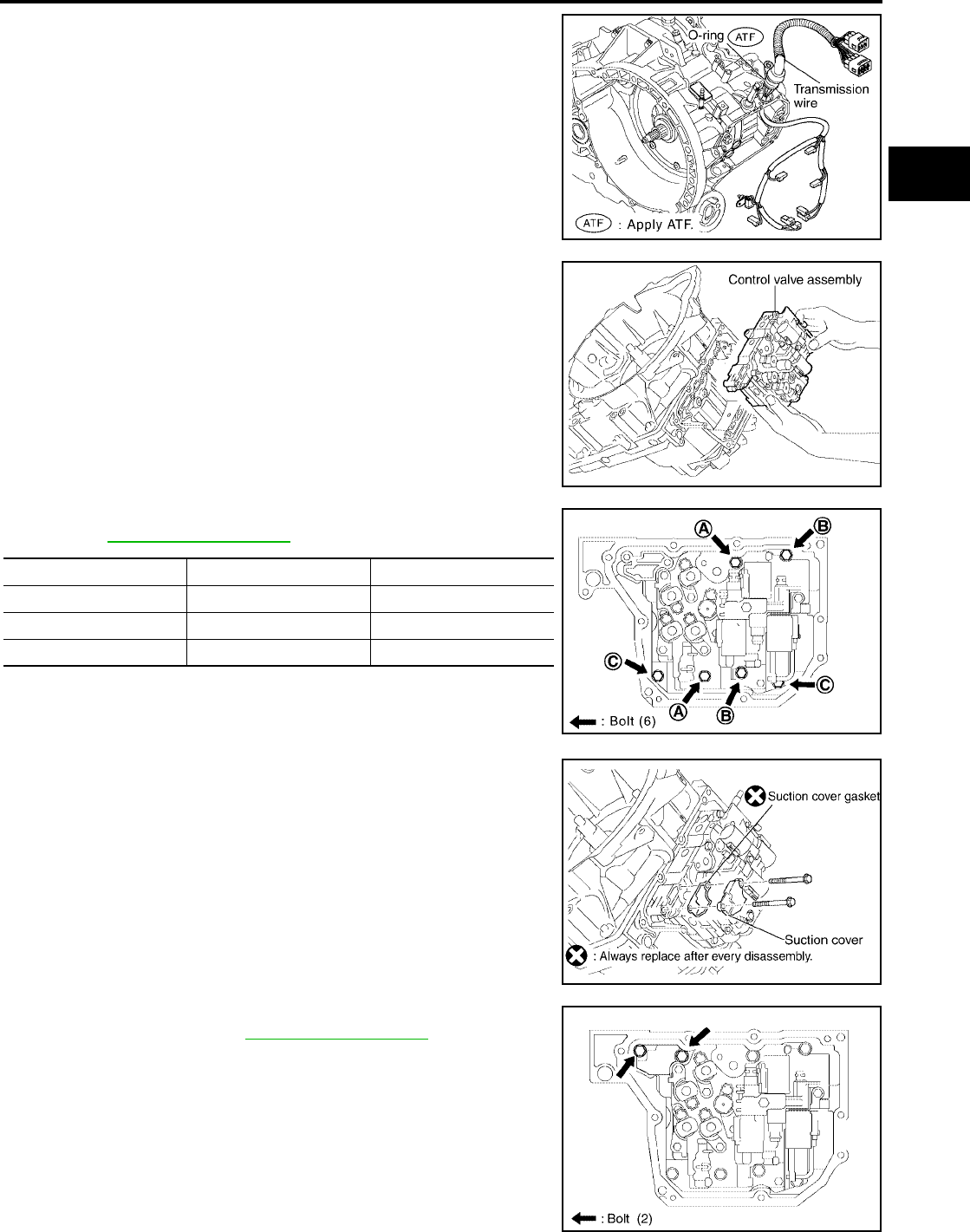
ASSEMBLY
AT-675
[RE5F22A]
D
E
F
G
H
I
J
K
L
M
A
B
AT
Revision: September 2005 2005 Quest
47. Install transmission wire.
CAUTION:
●Be careful not to break the solenoid connector and A/T
fluid temperature sensor.
●Apply ATF to O-ring.
48. While holding control valve assembly, connect the parking lock
rod sub assembly to manual valve lever sub assembly.
NOTE:
Shift position is “N”.
49. Tighten control valve assembly fixing bolts to specified torque.
Refer to AT-612, "Components" .
50. Install suction cover and suction cover gasket in control valve
assembly.
CAUTION:
Do not reuse suction cover gasket.
51. Tighten suction cover gasket and suction cover fixing bolts to
specified torque. Refer to AT-612, "Components" .
SCIA4155E
SCIA4153E
Bolt symbol Length mm (in) Number of bolts
A 55 (2.17) 2
B 50 (1.97) 2
C 16 (0.63) 2
SCIA4152E
SCIA4149E
SCIA4150E
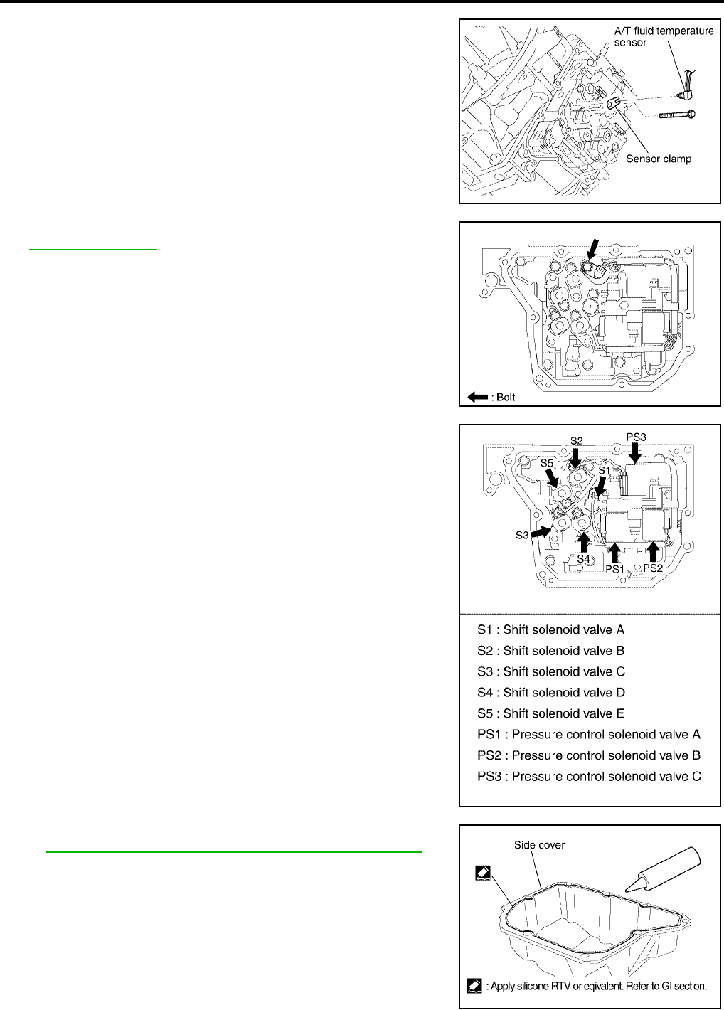
AT-676
[RE5F22A]
ASSEMBLY
Revision: September 2005 2005 Quest
52. Install sensor clamp and A/T fluid temperature sensor in control
valve assembly.
53. Tighten sensor clamp fixing bolt to specified torque. Refer to AT-
612, "Components" .
54. Connect the solenoid connectors.
55. Apply silicone RTV to side cover as shown in illustration. Refer
to GI-43, "Recommended Chemical Products and Sealants" .
CAUTION:
Completely remove all moisture, oil and sealant, etc. From
side cover and transaxle case.
SCIA4147E
SCIA4148E
SCIA4146E
SCIA5508E
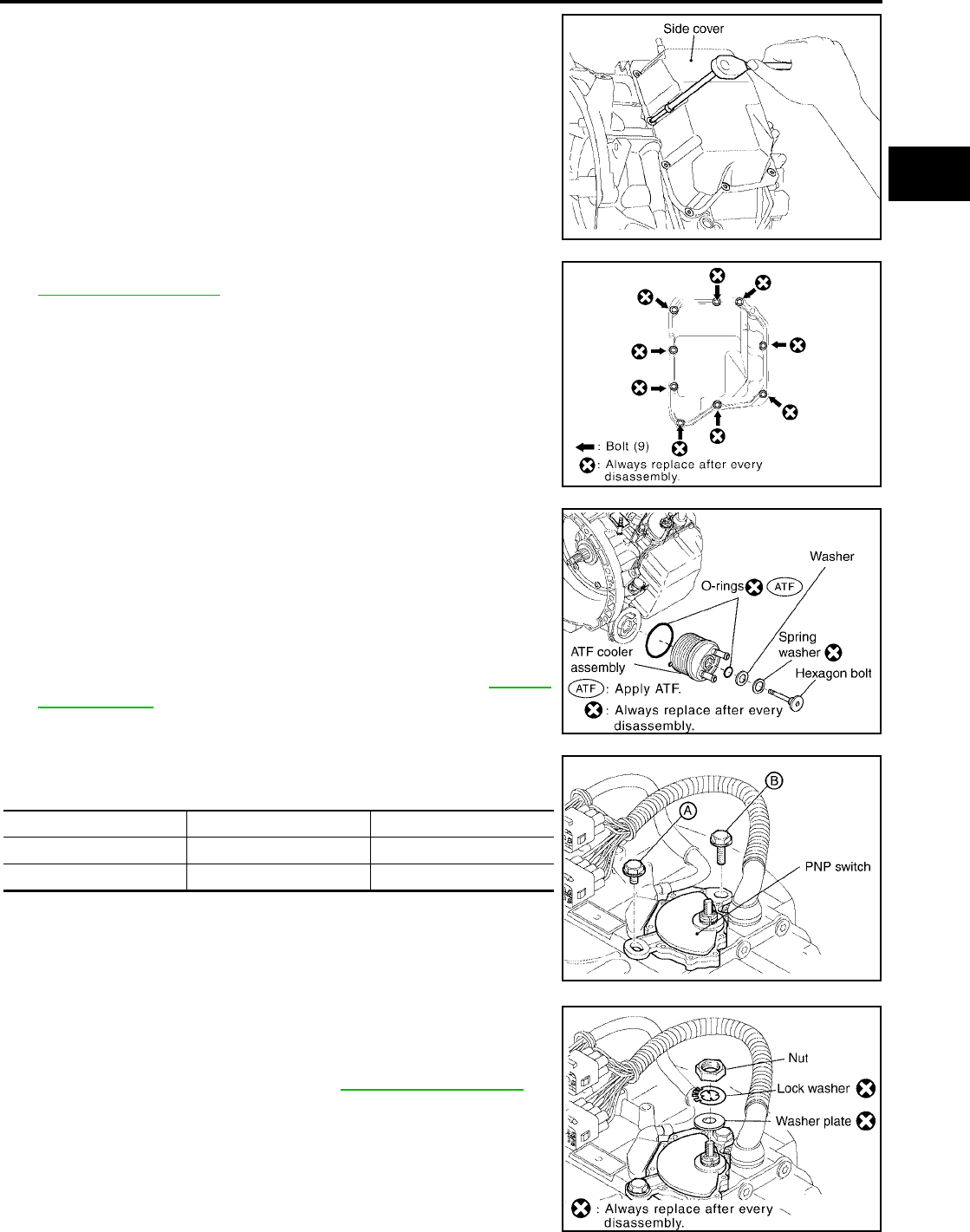
ASSEMBLY
AT-677
[RE5F22A]
D
E
F
G
H
I
J
K
L
M
A
B
AT
Revision: September 2005 2005 Quest
56. Install side cover in transaxle case.
57. Tighten side cover fixing torx bolts to specified torque. Refer to
AT-612, "Components" .
CAUTION:
Do not reuse seal bolts.
58. Install O-rings in ATF cooler assembly.
CAUTION:
●Do not reuse O-rings.
●Apply ATF to O-rings.
59. Install ATF cooler assembly, washer and spring washer.
CAUTION:
Do not reuse spring washer.
60. Tighten hexagon bolt to specified torque. Refer to AT-612,
"Components" .
61. Install PNP switch to manual valve lever sub assembly.
62. Temporary tightening the bolts.
63. Install washer plate and lock washer.
CAUTION:
Do not reuse washer plate and lock washer.
64. Tighten nut specified torque. Refer to AT-612, "Components" .
SCIA4143E
SCIA4144E
SCIA4142E
Bolt symbol Length mm (in) Number of bolts
A 20 (0.79) 1
B 33 (1.30) 1
SCIA4141E
SCIA4140E

AT-678
[RE5F22A]
ASSEMBLY
Revision: September 2005 2005 Quest
65. Install alignment tool.
66. Adjust PNP switch so that alignment tool pointer aligns with neu-
tral base line on PNP switch body.
67. Tighten PNP switch fixing torx bolts to specified torque. Refer to
AT-612, "Components" .
68. Using a flat-bladed screwdriver and bend the lock washer.
69. Install range lever in manual valve lever sub assembly.
70. Tighten range lever fixing nut to specified torque. Refer to AT-
612, "Components" .
71. Install turbine revolution sensor in transaxle case.
72. Tighten turbine revolution sensor fixing bolt to specified torque.
Refer to AT-612, "Components" .
CAUTION:
●Do not reuse seal bolt.
●Apply ATF to O-ring.
SCIA5374E
SCIA4434E
SCIA4139E
SCIA4138E
SCIA4137E
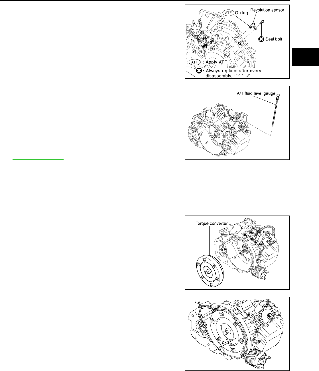
ASSEMBLY
AT-679
[RE5F22A]
D
E
F
G
H
I
J
K
L
M
A
B
AT
Revision: September 2005 2005 Quest
73. Install revolution sensor in transaxle case.
74. Tighten revolution sensor fixing bolt to specified torque. Refer to
AT-612, "Components" .
CAUTION:
●Do not reuse seal bolt.
●Apply ATF to O-ring.
75. Install O-ring in A/T fluid charging pipe.
CAUTION:
●Do not reuse O-ring.
●Apply petroleum jelly to O-ring.
76. Install A/T fluid charging pipe in transaxle housing.
77. Install fluid cooler tube.
CAUTION:
Do not reuse copper washer.
78. Tighten fluid cooler tube union to specified torque. Refer to AT-
612, "Components" .
79. Install air breather hose.
80. Install A/T fluid level gauge.
81. Install drain plug in transaxle housing.
CAUTION:
Do not reuse gasket.
82. Tighten drain plug to specified torque. Refer to AT-612, "Components" .
83. Install torque converter.
84. Check the distance of “C”.
CAUTION:
If the distance is out of standards, adjust within standards
again.
SCIA4136E
SCIA4135E
SCIA4134E
“C” : 14.0 mm (0.551 in)
SCIA4279E
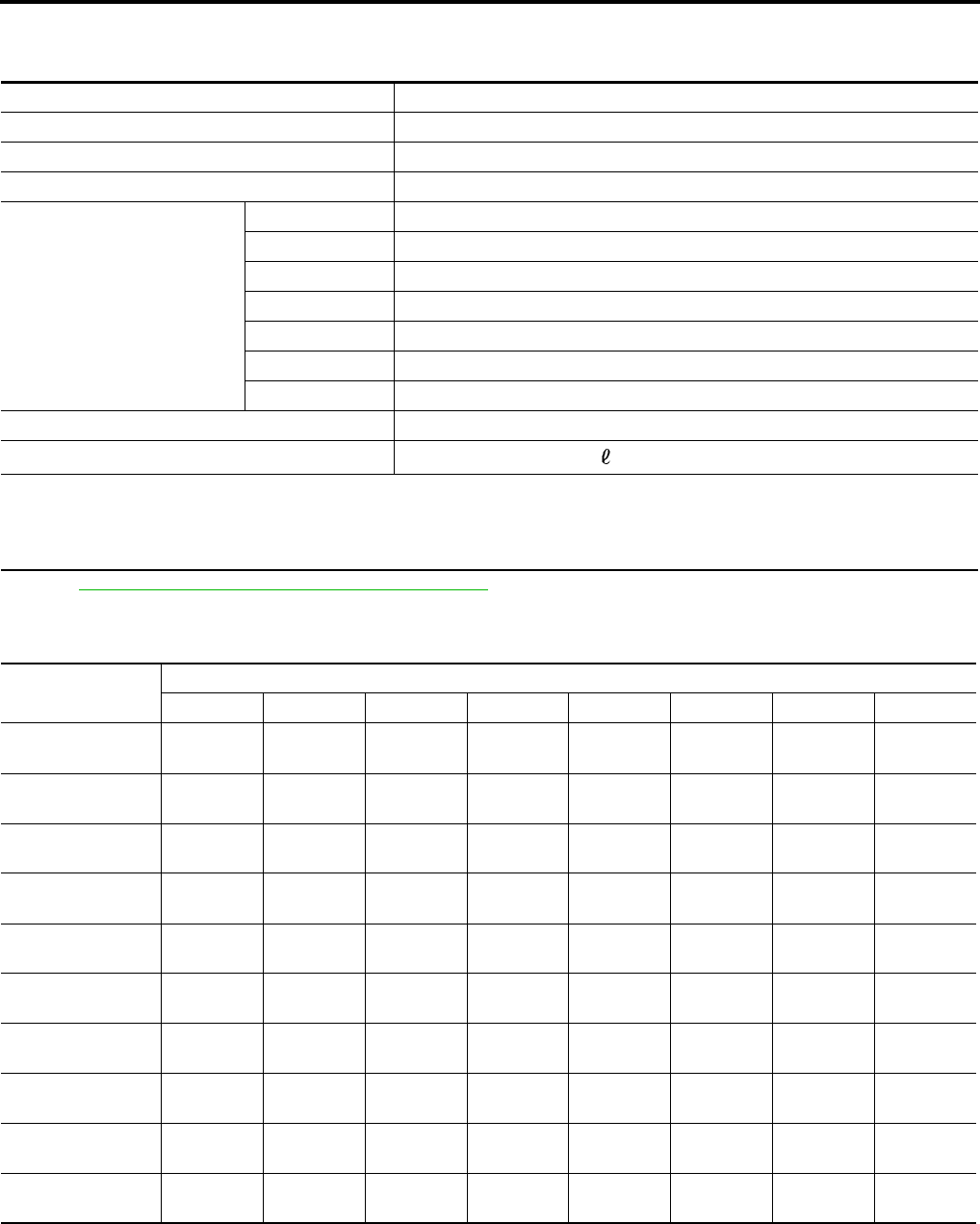
AT-680
[RE5F22A]
SERVICE DATA AND SPECIFICATIONS (SDS)
Revision: September 2005 2005 Quest
SERVICE DATA AND SPECIFICATIONS (SDS) PFP:00030
General Specifications UCS0010I
*: Refer to MA-10, "RECOMMENDED FLUIDS AND LUBRICANTS" .
Shift Schedule UCS0010T
VEHICLE SPEED WHEN SHIFTING GEARS
Engine VQ35DE
Automatic transaxle model RE5F22A
Automatic transaxle model code number CK710
Stall torque ratio 1.8: 1
Transaxle gear ratio
1st 4.657
2nd 3.032
3rd 1.982
4th 1.341
5th 1.018
Reverse 5.114
Final drive 2.269
Recommended fluid Genuine NISSAN Matic K ATF *
Fluid capacity 7.4 (7-7/8 US qt, 6-1/2 Imp qt)
CAUTION:
●Use only Genuine Nissan Matic K ATF. Do not mix with other fluid.
●Using automatic transaxle fluid other than Genuine Nissan Matic K ATF will deteriorate in driveability and automatic tran-
saxle durability, and may damage the automatic transaxle, which is not covered by the warranty.
Accelerator angle Vehicle speed km/h (MPH) (Approx.)
D1 →D2D2 →D3D3 →D4D4 →D5D5 →D4D4 →D3D3 →D2D2 →D1
100 % 67
(42)
105
(65)
170
(106)
241
(150)
230
(143)
160
(99)
92
(57)
45
(28)
90 % 67
(42)
105
(65)
170
(106)
241
(150)
230
(143)
160
(99)
92
(57)
45
(28)
80 % 65
(40)
100
(62)
152
(94)
227
(141)
178
(111)
142
(88)
86
(53)
45
(28)
70 % 53
(33)
80
(50)
125
(78)
185
(115)
147
(91)
137
(85)
68
(42)
38
(24)
60 % 46
(29)
71
(44)
106
(66)
156
(97)
108
(67)
78
(48)
46
(29)
22
(14)
50 % 43
(27)
67
(42)
97
(60)
145
(90)
98
(61)
68
(42)
40
(25)
18
(11)
40 % 38
(24)
60
(37)
89
(55)
130
(81)
89
(55)
56
(35)
30
(19)
13
(8)
30 % 33
(21)
50
(31)
70
(43)
108
(67)
68
(42)
45
(28)
25
(16)
12
(7)
20 % 23
(14)
35
(22)
49
(30)
77
(48)
49
(30)
32
(20)
22
(14)
8
(5)
10 % 17
(11)
29
(18)
39
(24)
58
(36)
44
(27)
32
(20)
22
(14)
8
(5)

SERVICE DATA AND SPECIFICATIONS (SDS)
AT-681
[RE5F22A]
D
E
F
G
H
I
J
K
L
M
A
B
AT
Revision: September 2005 2005 Quest
VEHICLE SPEED WHEN PERFORMING AND RELEASING COMPLETE LOCK-UP
●Lock-up vehicle speed indicates the speed in D position.
●Perform lock-up inspection after warming up engine.
●Lock-up vehicle speed may vary depending on the driving conditions and circumstances.
VEHICLE SPEED WHEN PERFORMING AND RELEASING SLIP LOCK-UP
●Slip lock-up vehicle speed indicates the speed in D position.
●Perform slip lock-up inspection after warming up engine.
●Slip lock-up vehicle speed may vary depending on the driving conditions and circumstances.
Stall Speed UCS0010M
Line Pressure UCS0010N
Time Lag UCS0010U
Shift Solenoid Valves UCS0010V
Accelerator angle Vehicle speed km/h (MPH) (Approx.)
Lock-up “ON” Lock-up “OFF”
50 % 190 (118) 137 (85)
15% 101 (63) 72 (45)
0 - 8 % 73 (45) 70 (43)
Accelerator angle Gear position Vehicle speed km/h (MPH) (Approx.)
Slip lock-up “ON” Slip lock-up “OFF”
0 - 10 % 4th 45 (28) 42 (26)
5th 58 (36) 55 (34)
Stall speed 2,430 - 2,730 rpm
Engine speed Line pressure kPa (kg/cm2 , psi)
D, L positions R position
At idle speed 333 - 392 (3.4 - 4.0, 48 - 57) 500 - 608 (5.1 - 6.2, 73 - 88)
At stall speed 1,285 - 1,393 (13.1 - 14.2, 186 - 202) 1,706 - 1,981 (17.4 - 20.2, 247 - 287)
Selector lever Time
N to D position Less than 0.7 sec.
N to R position Less than 1.2 sec.
Shift position Shift solenoid valve Remarks
ABCDE
P OFF (Open) OFF (Closed) OFF (Closed) OFF (Open) OFF (Closed) PARK POSITION
R OFF (Open) OFF (Closed) ON (Open) OFF (Open) ON (Open) REVERSE POSITION
N OFF (Open) OFF (Closed) OFF (Closed) OFF (Open) OFF (Closed) NEUTRAL POSITION
D
1st ON (Closed) ON (Open) ON (Open) OFF (Open) OFF (Closed)
Automatic shift
1 ⇔ 2 ⇔ 3 ⇔ 4 ⇔ 5
1 ⇔ 2 OFF (Open) OFF (Closed) ON (Open) OFF (Open) OFF (Closed)
2nd OFF (Open) OFF (Closed) ON (Open) OFF (Open) OFF (Closed)
2 ⇔ 3 OFF (Open) OFF (Closed) ON (Open) ON (Closed) ON (Open)
3rd OFF (Open) OFF (Closed) ON (Open) ON (Closed) OFF (Closed)
3 ⇔ 4 OFF (Open) OFF (Closed) OFF (Closed) ON (Closed) ON (Open)
4th OFF (Open) OFF (Closed) OFF (Closed) ON (Closed) OFF (Closed)
4 ⇔ 5 OFF (Open) ON (Open) OFF (Closed) ON (Closed) OFF (Closed)
5th OFF (Open) ON (Open) OFF (Closed) ON (Closed) OFF (Closed)
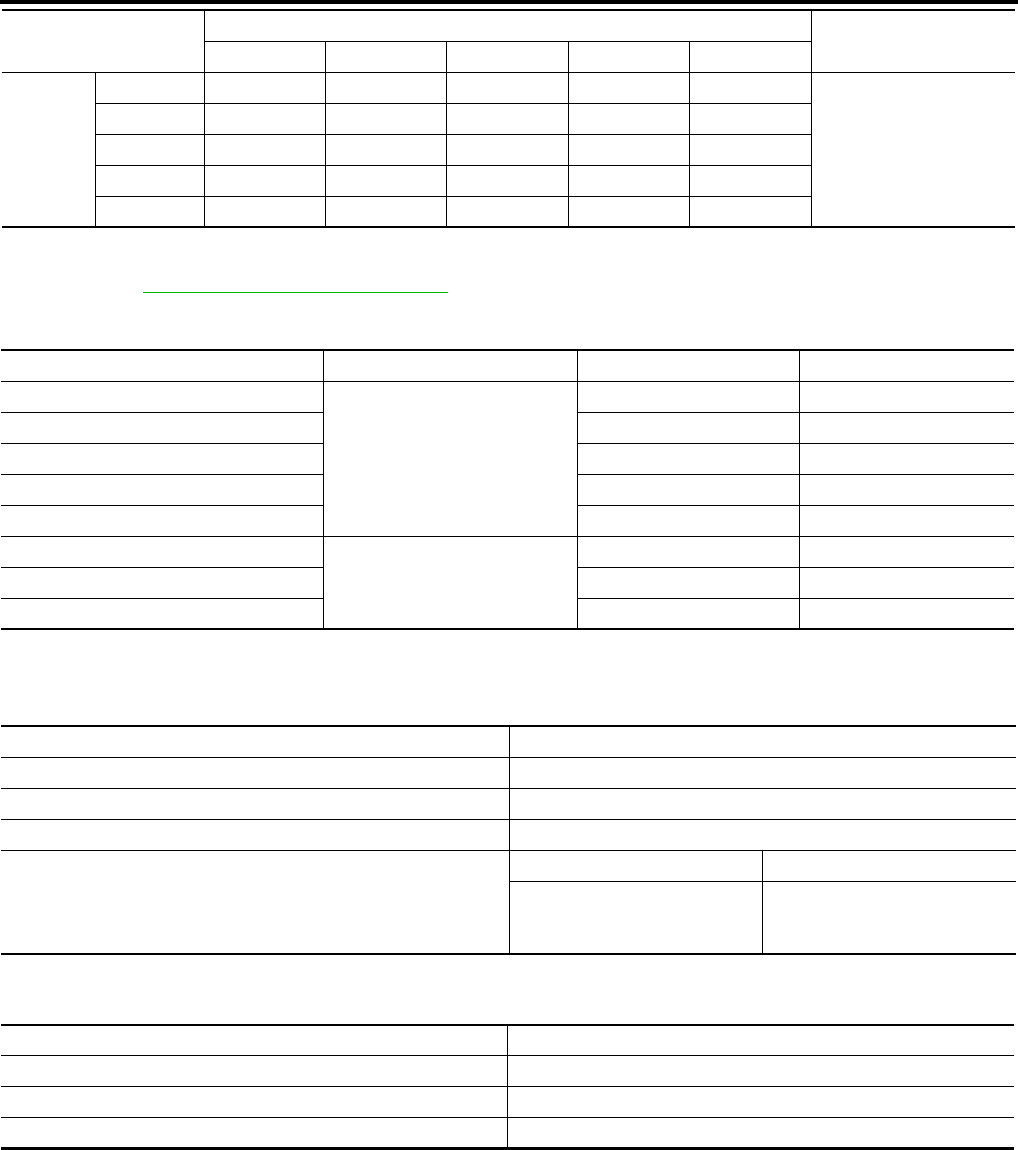
AT-682
[RE5F22A]
SERVICE DATA AND SPECIFICATIONS (SDS)
Revision: September 2005 2005 Quest
NOTE:
When shifting D to L position or lever switch sets in “ON” position (indicated O/D OFF indicator lamp), down shift permission control is
activated. Refer to AT-404, "Down Shift Permission Control" .
Solenoid Valves UCS0010O
Specified resistance at 20°C (68°F).
Clutch, Gear and Brakes UCS002LC
2ND BRAKE
*: Always check with the Parts Department for the latest parts information.
2ND COAST BRAKE
L
1st ON (Closed) ON (Open) ON (Open) OFF (Open) OFF (Closed)
Automatic shift
1 ⇔ 2 ⇔ 3
1 ⇔ 2 OFF (Open) OFF (Closed) ON (Open) OFF (Open) OFF (Closed)
2nd OFF (Open) OFF (Closed) ON (Open) OFF (Open) OFF (Closed)
2 ⇔ 3 OFF (Open) OFF (Closed) ON (Open) ON (Closed) ON (Open)
3rd OFF (Open) OFF (Closed) ON (Open) ON (Closed) OFF (Closed)
Shift position Shift solenoid valve Remarks
ABCDE
Solenoid valves Resistance (Approx.) Connector (Color) Terminal
Shift solenoid valve A
11 - 16 Ω
F30 (BR) 2
Shift solenoid valve B F62(GR) 1
Shift solenoid valve C F62(GR) 4
Shift solenoid valve D F30 (BR) 1
Shift solenoid valve E F30 (BR) 5
Pressure control solenoid valve A
5.0 - 5.6 Ω
F62(GR) 3 - 6
Pressure control solenoid valve B F30 (BR) 3 - 7
Pressure control solenoid valve C F62(GR) 2 - 5
Number of 2nd brake plates 4
Number of 2nd brake discs 4
Number of 2nd brake flange 1
Piston stroke mm (in) 1.10 - 1.50 (0.0433 - 0.0591)
Thickness of 2nd brake flanges
Thickness mm (in) Part number*
3.6 (0.142)
3.8 (0.150)
4.0 (0.157)
31537 8Y011
31537 8Y012
31537 8Y013
Number of 2nd coast brake plates 3
Number of 2nd coast brake discs 3
Number of 2nd coast brake flange 1
Piston stroke mm (in) 0.76 - 1.44 (0.0299 - 0.0567)
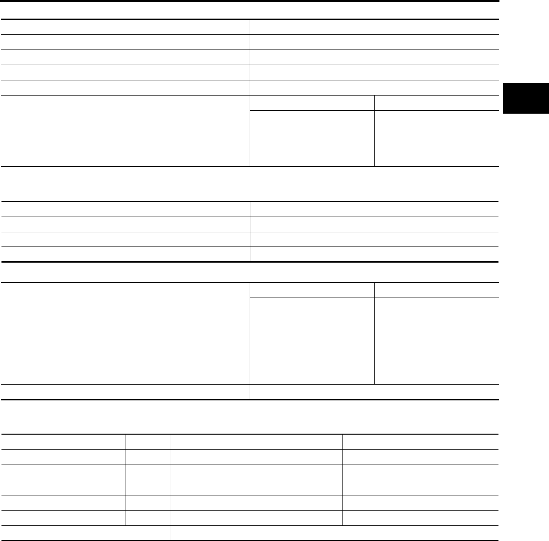
SERVICE DATA AND SPECIFICATIONS (SDS)
AT-683
[RE5F22A]
D
E
F
G
H
I
J
K
L
M
A
B
AT
Revision: September 2005 2005 Quest
B5 BRAKE
* : Always check with the Parts Department for the latest parts information.
1ST AND REVERSE BRAKE
FORWARD AND DIRECT CLUTCH ASSEMBLY
* : Always check with the Parts Department for the latest parts information.
U/D BRAKE
*: Always check with the Parts Department for the latest parts information.
Number of B5 brake plates 6
Number of B5 brake discs 6
Number of B5 brake flange 1
Number of B5 brake cushion plate 1
Piston stroke mm (in) 2.34 - 2.70 (0.0921 - 0.1063)
Thickness of B5 brake flanges
Thickness mm (in) Part number*
5.0 (0.197)
5.1 (0.202)
5.2 (0.205)
5.3 (0.209)
5.5 (0.217)
31667 8Y016
31667 8Y017
31667 8Y018
31667 8Y019
31667 8Y020
Number of 1st and reverse brake plates 4
Number of 1st and reverse brake discs 5
Number of 1st and reverse brake flanges 2
Piston stroke mm (in) 1.39 - 2.21 (0.0547 - 0.0870)
Thickness of thrust washer races
Thickness mm (in) Part number*
0.81 (0.0319)
0.90 (0.0350)
1.00 (0.0400)
1.10 (0.0430)
1.20 (0.0470)
1.30 (0.0510)
1.40 (0.0550)
1.50 (0.0590)
31435 8Y060
31435 8Y061
31435 8Y062
31435 8Y063
31435 8Y064
31435 8Y065
31435 8Y066
31435 8Y067
End play mm (in) 0.188 - 0.570 mm (0.0074 - 0.0224)
Piston type Mark Piston length mm (in) Part number*
A — 63.7 (2.508) 31615 8Y005
B 1 64.2 (2.528) 31615 8Y004
C 2 64.7 (2.547) 31615 8Y003
D 3 65.2 (2.567) 31615 8Y002
E 4 65.7 (2.587) 31615 8Y001
Piston stroke mm (in) 5.76 - 6.76 mm (0.2268 - 0.2661)

AT-684
[RE5F22A]
SERVICE DATA AND SPECIFICATIONS (SDS)
Revision: September 2005 2005 Quest
U/D RR PLANETARY RING GEAR SUB ASSEMBLY
* : Always check with the Parts Department for the latest parts information.
U/D GEAR ASSEMBLY
* : Always check with the Parts Department for the latest parts information.
PLANETARY SUN GEAR SUB ASSEMBLY
PLANETARY GEAR ASSEMBLY
Final Drive UCS002LD
DIFFERENTIAL SIDE BEARING ADJUSTING SHIMS
*: Always check with the Parts Department for the latest parts information.
TURNING TORQUE
Thickness of adjust shims
Thickness mm (in) Part number*
0.81 (0.0319)
0.90 (0.0350)
1.00 (0.0400)
1.10 (0.0430)
1.20 (0.0470)
1.30 (0.0510)
1.40 (0.0550)
1.50 (0.0590)
1.60 (0.0630)
31435 8Y100
31435 8Y101
31435 8Y102
31435 8Y103
31435 8Y104
31435 8Y105
31435 8Y106
31435 8Y107
31435 8Y108
Thickness of thrust washer races
Thickness mm (in) Part number*
0.80 (0.0310)
0.90 (0.0350)
1.00 (0.0400)
1.10 (0.0430)
1.20 (0.0470)
1.30 (0.0510)
1.40 (0.0550)
1.50 (0.0590)
31435 8Y021
31435 8Y068
31435 8Y069
31435 8Y070
31435 8Y071
31435 8Y072
31435 8Y073
31435 8Y074
Inner diameter of planetary sun
gear sub assembly bushing
mm (in)
Standard 22.200 - 22.226 (0.8740 - 0.8750)
Allowable limit 22.276 (0.8770)
Inner diameter of planetary
gear assembly bushing mm (in)
Standard 30.056 - 30.082 (1.1833 - 1.1843)
Allowable limit 30.132 (1.1863)
Thickness mm (in) Part number* Thickness mm (in) Part number*
1.00 (0.0394)
1.05 (0.0413)
1.10 (0.0433)
1.15 (0.0453)
1.20 (0.0472)
1.25 (0.0492)
1.30 (0.0512)
1.33 (0.0524)
1.36 (0.0535)
1.39 (0.0547)
1.42 (0.0559)
1.45 (0.0571)
31438 8Y001
31438 8Y002
31438 8Y003
31438 8Y004
31438 8Y005
31438 8Y006
31438 8Y007
31438 8Y008
31438 8Y009
31438 8Y010
31438 8Y011
31438 8Y012
1.48 (0.0583)
1.51 (0.0594)
1.54 (0.0606)
1.57 (0.0618)
1.60 (0.0630)
1.65 (0.0650)
1.70 (0.0669)
1.75 (0.0689)
1.80 (0.0709)
1.85 (0.0728)
1.90 (0.0748)
31438 8Y013
31438 8Y014
31438 8Y015
31438 8Y016
31438 8Y017
31438 8Y018
31438 8Y019
31438 8Y020
31438 8Y021
31438 8Y022
31438 8Y023
Turning torque of final drive assembly 0.7 - 1.2 N·m (0.08 - 0.12kg-m, 7 - 10 in-lb)

SERVICE DATA AND SPECIFICATIONS (SDS)
AT-685
[RE5F22A]
D
E
F
G
H
I
J
K
L
M
A
B
AT
Revision: September 2005 2005 Quest
A/T Fluid Temperature Sensor UCS0010P
Turbine Revolution Sensor UCS0010Q
*: Voltage with both end of 100 Ω resistance.
Revolution Sensor UCS0010R
*: Voltage with both end of 100 Ω resistance.
Condition Voltage (Approx.) Resistance (Approx.)
ATF temperature
0°C (32°F) 4.0V 9.8 kΩ
20°C (68°F) 3.0V 4.2 kΩ
80°C (176°F) 0.8V 0.54 kΩ
100°C (212°F) 0.5V 0.31 kΩ
Condition Signal Voltage* (Approx.)
Connect 12V power supply and 100 Ω resistance, and then shake magnetic body. HIGH 1.2 - 1.6V
LOW 0.4 - 0.8V
Condition Signal Voltage* (Approx.)
Connect 12V power supply and 100 Ω resistance, and then shake magnetic body. HIGH 1.2 - 1.6V
LOW 0.4 - 0.8V

AT-686
[RE5F22A]
SERVICE DATA AND SPECIFICATIONS (SDS)
Revision: September 2005 2005 Quest
