227A/227C MANp 10120.01 BARTON S 227A And 227C DP Indicators IOM
User Manual: BARTON s 227A and 227C DP Indicators IOM Resource Library
Open the PDF directly: View PDF ![]() .
.
Page Count: 16
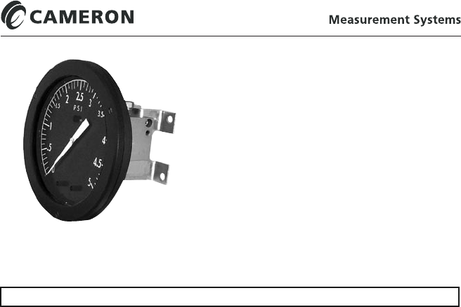
MODELS 227A/227C
DIFFERENTIAL PRESSURE INDICATOR
(Standard and Inverted Configurations)
227A uses 224 DPU
227C uses 224C DPU
Installation Manual
Part No. 10120, Rev. 01
July 2007
CONTENTS
Prepages ............................................................................... Page 2
Safety Statement ............................................................. Page 2
Product Warranty Statement ............................................. Page 2
Record of Changes .......................................................... Page 2
Section 1 - Introduction .......................................................... Page 3
1-1. General.................................................................... Page 3
1-2. Product Description .................................................. Page 3
1-3. Theory of Operation ................................................. Page 3
1-4. Specications ........................................................... Page 4
Section 2 - Installation ............................................................ Page 5
2-1. General.................................................................... Page 5
2-2. Mounting ................................................................. Page 5
2-3. DPU Installation ....................................................... Page 5
2-4. Zero Check/Adjustment ............................................ Page 6
Section 3 - Maintenance and Calibration .................................. Page 7
3-1. DPU Installation/Maintenance ................................... Page 7
3-2. Tools Required for Maintenance ................................. Page 7
3-3. Calibration Check ..................................................... Page 7
3-4. Pointer Installation and Removal ................................ Page 7/8
3-5. Complete Calibration ................................................ Page 8
3-6. Overrange Stop Adjustment ....................................... Page 10
3-7. Locking Drive Arm to Torque Tube ............................ Page 10
3-8. Drive Arm Tightness Test .......................................... Page 11
Section 4 - Parts Drawing/List................................................. Page 12
Figure 4-1. 227A/227C Parts Drawing ............................. Page 12
Table 4-1. 227A/227C Parts List ..................................... Page 13
Section 5 - Install/Dimensional Drawings.................................. Page 14
Figure 4-1. 227A/227C Parts Drawing ............................. Page 14/15
[This manual is for indicator only - see separate 224/224C DPU manual, per model
number listed above.]

2
PRODUCT WARRANTY STATEMENT
The product warranty applicable to this instrument is stated on the back cover of this
manual.
RECORD OF CHANGES
DATE DESCRIPTION
00E2 5/00 Reduced Booklet 227C INV. w/224C APX (99H4)
00K25c 11/00 Booklet Format 227C w/224 DPU information in body
03D77d 4/03 Combined 200/227A/227C Manual
03G76d 7/03 Combined 227A/227C (Standard and Inverted) Versions
(Replaces 227A (10121), 227C (10130) Inverted, and 227
portion of 200/227A/227C (10055) Manuals);
Rev. Co. Name/Logo to PRIME Measurement Products;
Added para. 2-4, Zero Check/Adjustment procedure;
Rev. Section 3 - Maintenance and Calibration;
Rev. Section 4 - Parts Drawing and Parts List
Rev. Section 5 - Install/Dimensional Drawings
04L55a 12/04 Rev. warranty - made specic to M227A/227C units
01 7/07 Revised corporate name/logo/contact information to reect
Cameron ownership.
SAFETY
Before installing this instrument, become familiar with the installation instructions
in Section 2 and in the separate 224/224C DPU manual.
DANGER notes indicate the presence of a hazard which will cause severe
personal injury, death, or substantial property damage if warning is ignored.
WARNING notes indicate the presence of a hazard which can cause severe
personal injury, death, or substantial property damage if warning is ignored.
CAUTION notes indicate the presence of a hazard which will or can cause
moderate personal injury or property damage if warning is ignored.
DANGER, WARNING, and/or CAUTION notes that appear on the following
pages of this manual should be reviewed before proceeding: None. (Important!
Before installing or operating this instrument, review all safety notices
contained in the separate 224/224C DPU manual, per models listed
DPU "C" VERSION DESIGN CHANGE
The 227C utilizes a 224C DPU, which is a redesigned version of the 224 DPU. The "C"
version is identical in function, performance, installation, and operation to the previous
version - redesign was for improved manufacturing only. This design change does not
affect the instrument being actuated. Selected congurations of 227A
(using a 224 [Non-C] DPU) are for Nuclear/Government only.

3
SECTION 1 - INTRODUCTION
1-1. General
The Model 227A/227C Differential Pressure Indicator is designed to measure
liquid ow or liquid level. In ow measurement applications, the instrument is
connected to the low and high pressure sides of a primary device (orice plate,
a venturi tube, or a ow tube) located in the process run. In liquid level measure-
ment applications, the instrument is connected to monitor changes in differential
pressure relative to variations of liquid height in a vessel.
1-2. Product Description
The indicator has a 6 inch dial. The indicating pointer traverses a 270° arc
(nominal) to measure differential pressure, ow, or liquid level. The indicator
movement has a micrometer screw for range adjustment. Zero is adjusted by
"slipping" pointer on hub, which can be done without removing the scaleplate
or pointer. The Range can also be adjusted without removing the scaleplate or
pointer. Linearity adjustments are accessible after removal of the scale plate.
The 227A is actuated by a Model 224 Differential Pressure Unit (DPU). The
227C is actuated by a Model 224C DPU. Refer to the separate DPU Manuals.
1-3. Theory of Operation
The 227A/227C consists of the actuating DPU and the indicator (case assem-
bly).
A. Differential Pressure Unit (DPU)
The 224/224C DPU consists of a dual bellows assembly (one high pressure and
one low pressure bellows), which is enclosed by a set of two pressure housings
(pressure heads).
The dual bellows assembly consists of two internally-connected bellows, a center
plate, overrange valves, a temperature compensator, a torque tube assembly,
and range springs. The bellows and center plate are completely lled with a non-
corrosive liquid and then sealed. The pressure housings, located on either side of
the center plate, are connected by pipe or tubing to the system primary device.
Variations in differential pressure within the pressure housing cause the bel-
lows to expand/contract laterally, in the direction of lower pressure. The lateral
movement of the bellows is converted to angular rotation as transmitted to the
torque tube shaft by the drive arm. The torque tube assembly provides mechani-
cal output in response to the bellows movement and actuates the mechanism of
the process monitoring instruments. For more information on the DPU, refer to
the separate 224/224C DPU manual.
B. Indicator
The indicator is attached directly to the actuating unit (DPU). The indicator
consists of a drive arm assembly, linkage, and a movement assembly to which
the indicating pointer is attached. Changes in differential pressure are sensed
by the DPU bellows and transmitted as rotary motion through the torque tube
to the drive arm assembly of the indicator. The linkage and movement assembly
respond to the action of the drive arm assembly to position the pointer in direct
relationship to the amount of bellows travel.

4
1-4. Specications
Accuracy (DP Range):
0-30" w.c. to 0-50" w.c.
(0-75 mbar to 0-124 mbar) ................ ±0.75% of full scale
0-51" w.c. to 0-60 psi
(0-127 mbar to 0-4.1 bar) .................. ±0.5% of full scale
0-61 psi to 0-150 psi
(0-4.2 bar to 0-10.3 bar).................... ±0.75% of full scale
0-151 psi to 0-400 psi
(0-10.4 bar to 0-27.6 bar).................. ±1.0% of full scale
0-401 psi to 0-600 psi
(0-27.7 bar to 0-41.3 bar).................. ±1.5% of full scale
0-601 psi to 0-1,000 psi
(0-41.4 bar to 0-69 bar)..................... ±4.0% of full scale
Dial Size .............................................. 6" Diameter
Temperature Limits .............................. -40 °F/°C to +180°F (+82°C)
(+40°F minimum for water lled
units)
Indicator Case ...................................... Aluminum Alloy, Enamel or Epoxy
Finish or 316 SST
Lens .................................................... Polycarbonate (shatterproof glass for
SST Version)
O-rings (Wetted) ................................... Buna-N, Viton, or EPT
Overall Dimensions............................... per conguration and 224/224C
DPU housing rating. See ODD
drawings in Section 5.
Weight ................................................ 6 to 9.5 lbs (approx.) Weight
depends on DPU conguration/
materials.
Differential Pressure Unit (DPU):
For DPU specications, refer to the separate 224/224C DPU manual.

5
SECTION 2 - INSTALLATION
2-1. General
The instrument should be inspected at time of unpacking to detect any damage
that may have occurred during shipment. Note: The DPU was checked for
accuracy at the factory — do not change any of the settings during exami-
nation or accuracy will be affected.
For applications requiring special cleaning/precautions, a polyethylene
bag is used to protect the instrument from contamination. This bag
should be removed only under conditions of extreme cleanliness.
2-2. Mounting
Per ODD drawings in Section 5.
2-3. DPU Installation
Refer to the separate 224/224C DPU manual, per models listed on front page,
for DPU installation and maintenance.
6
2-4. Zero Check/Adjustment
It may be necessary to reset the ZERO before placing the 227A/227C into
service. This procedure can be accomplished without removing the scaleplate.
NOTICE
Adjusting the instrument's ZERO in accordance with the following pro-
cedure does not invalidate the original factory calibration or warranty.
1. Fix the instrument in a stable position, with the top of the DPU level with
the horizontal plane.
2. Using a at-blade screwdriver, remove the three (3) or (9 on SST case) bezel
screws (see Figure 2-2).
3. Lift the screws, bezel, lens, and lens gasket away from the case.
4. Set the pointer to ZERO position, by "slipping" the pointer on the hub, per
the following (refer to Figure 2-3):
With a 1/4" open-end wrench (in-
cluded in calibration kit 0288-1032B),
hold the hexagon pointer hub xed
and rotate the pointer with ngers
until the pointer accurately indicates
ZERO on the scale.
5. Reassemble the unit, attaching the lens
gasket, lens, and bezel to the case.
Secure the bezel with the three (3) (or
9 on SST case) bezel screws. Tighten
the screws until they are snug.
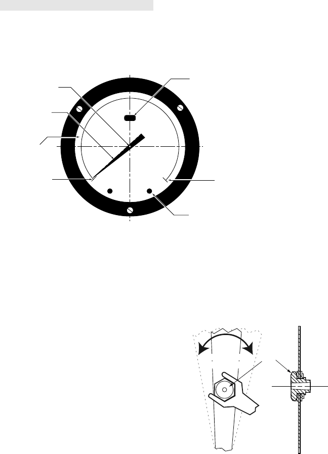
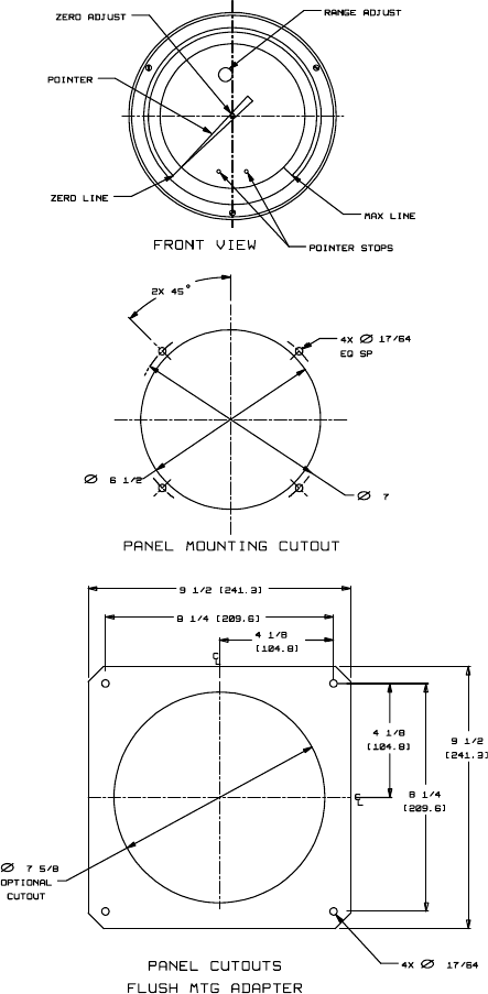
Figure 2-2. Instrument Face
HUB
Pointer "slipped"
rotated on hub
Hub held in place
with 1/4" wrench
Figure 2-3. "Slipping" Pointer
Pointer Stop
Max. Line
Zero Line
Pointer
Zero Adjust
Range Adjust
Scale Plate
FRONT VIEW

7
SECTION 3 - MAINTENANCE AND CALIBRATION
3-1. DPU Installation/Maintenance/Repair
DPU inspection, cleaning, service, repair, range change, and BUA replacement
procedures (along with applicable WARNINGS, CAUTIONS, and NOTICES,
are presented in the separate 224/224C DPU manual.
3-2. Tools Required For Maintenance
Table 3-1. Tools
Equipment Purpose
Pointer Puller Pointer Removal
Small Screwdriver Scaleplate Removal and Replacement
Medium Screwdriver Bezel Removal and Replacement
1/4" & 1/8" Open-end Wrenches Zero (1/4") /Range (1/8") Adjustment
For DPU specic tools, refer to separate DPU Manual.
3-3. Calibration Check
To ensure the unit calibration is within factory-set calibration tolerances, per-
form the following procedure. NOTICE: Review all procedures, WARN-
INGS/NOTICES in the separate 224/224C DPU manual BEFORE
performing this procedure.
1. Mount instrument and connect to a standard pressure source (see separate
224/224C manual).
2. If the zero indication is incorrect, remove bezel/lens assembly and re-adjust
zero, per Zero Check/Adjustment procedure, per paragraph 2-4.
3. Apply 0, 50, and 100% of full scale pressure. If indication is within speci-
ed limits, no adjustments are necessary. If indication is not within specied
limits, perform a complete calibration, per paragraph 3-5.
3-4. Pointer Installation and Removal
During adjustment and calibration of the unit, it may be necessary to remove
and reinstall the pointer, per the following procedures:
A. Pointer Installation
1. Position pointer on movement shaft with pointer set at zero scale.
It may be necessary to enlarge the hub hole, using a tapered broach
(included in the toolkit (p/n 0288-1032B).
2. Lightly tap pointer hub with a hand-set or other at-end tool. Use
perpendicular blows to avoid bending shaft.
3. Check indicating switch for calibration over its entire range (refer
to Switch Calibration in this section). If indicating switch is correctly
calibrated, secure pointer to movement shaft by tapping hub with a
hand-set or other at-end tool.
(Continued on next page...)
8
3-4. Pointer Installation and Removal (Continued)
B. Pointer Removal
Pointer is removed with Pointer Puller (p/n 0163-0005B), which is in-
cluded in the toolkit (p/n 0288-1032B), see Figure 3-1.
1. Slide pointer puller
along pointer until
pin protruding from
tip of screw in pointer
puller is directly over
movement shaft and
arms of pointer puller
are directly under
pointer.
2. Gently turn knurled
head of screw
clockwise, push-
ing pin against movement shaft and lifting pointer with arms. Finger
pressure should be sufcient to pull the pointer free. If more pressure
is required, an Allen wrench (inserted into head of the screw) can be
used. However, care should be exercised: too much pressure can cause
the pin to break.
3-5. Complete Calibration (DP=Differential Pressure)
A complete calibration of instrument is required whenever the DPU assembly is
replaced. NOTICE: Review all procedures, WARNINGS/NOTICES in
the separate 224/224C DPU manual BEFORE performing this procedure.
1. Securely mount instrument in an approximately level position and connect
DPU into the test setup, as described in the appropriate (separate) DPU
manual.
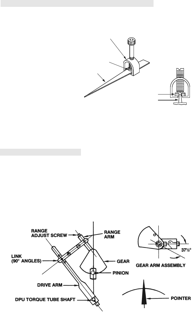
2. Attach linkage between drive arm and movement. See Figure 3-2 (standard
227A/C) or Figure 3-3 (Inverted 227A/C) for linkage alignment at 50%
DP. Inspect parts for straightness and pivot-t without binding.
Figure 3-2. (Standard) Range/Linearity Adj. (50% DP)
POINTER
HUB
POINTER PULLER
(0163.0005B)
HUB
MOVEMENT SHAFT
Figure 3-1. Pointer Puller
9
3-5. Complete Calibration (Continued) (DP=Differential
Pressure)
3. Set pointer at zero on scale by slipping pointer on hub. Hold tip of pointer
and turn hub with wrench (refer to paragraph 2-4).
4. Apply 100% DP. If pointer exceeds 100% on scale, lengthen range arm.
Remove pressure.
5. Set zero and span, using hub for zero adjustment and range adjust screw on
the movement for span adjustments.
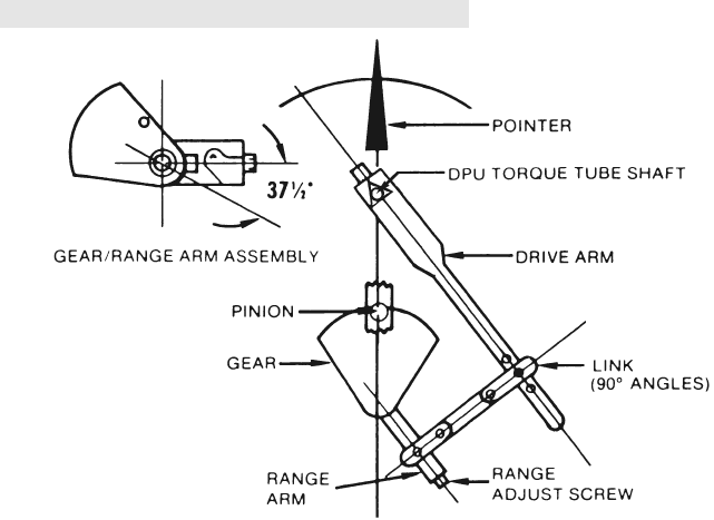
6. Apply 50% DP. If pointer does not indicate 50% scale, a linearity adjust-
ment is necessary. Loosen drive arm screw and move arm to shift pointer
in direction of error (approx. 10:1). Tighten drive arm screw.
7. Release pressure and reset pointer at zero. Check the span. If gear in move-
ment reaches limit of travel as a result of linearity adjustment (step 6), slip
range arm along gear approximately 5 degrees from normal 37.5 degree
angle to approximately 43 degrees. Range arm is slipped by applying pres-
sure to range arm with thumb, while holding gear rmly in place. Retest
pointer response at 50% and 100% DP, and adjust linkage until readings
are acceptable.
8. Apply 0%, 25%, 50%, 75%, 100%, 75%, 50%, 25%, and 0% of DP
consecutively to instrument without overshoot. Lightly tap indicator to over-
come friction. Pointer should accurately indicate each applied pressure.
10. Test instrument repeatability by applying 0%, 50%, 0%, 50% DP. Indicator
should accurately indicate each applied pressure.
(Continued on next page...)
Figure 3-3. (Inverted) Range/Linearity Adj. (50% DP)
10
3-5. Complete Calibration (Continued) (DP=Differential Pressure)
11. Set overrange stops to prevent pointer from striking snubbers on scale (see
paragraph 3-6). Tighten all screws. Test setting by manually moving pointer
from zero position to 50%, then let the pointer return freely. An off-set
in zero reading indicates pointer slippage. If necessary, tap pointer hub to
tighten it to shaft.
12. Reassemble unit, making sure bezel screws are snug.
3-6. Overrange Stop Adjustment
1. Apply sufcient pressure to the high pressure housing to deect the pointer
against the snubber on the scale plate. Slide the upper overrange stop
against the drive arm and tighten the overrange stop screw.
2. Apply sufcient pressure to the low pressure housing to deect the pointer
against the zero stop snubber on the scale plate. Slide the zero-stop against
the drive arm and tighten the zero-stop screw.
3. Remove the pointer and calibration scale. Replace the pointer at zero (ad-
just zero as necessary). Replace the lens and bezel assembly.
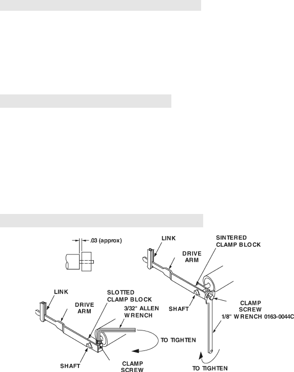
3-7. Locking Drive Arm to Torque Tube
1. Slip the drive arm over the torque tube shaft; clear the end of the torque-
tube housing by approximately 0.030-inches before securing to prevent
interference.
2. To tighten the drive arm assembly onto the torque-tube shaft:
a. While supporting the block and shaft, tighten the clamp screw until
snug to the shaft.
b. Still supporting block/shaft, tighten clamp screw an additional:
• Sintered: 1/3 to 1/2 turn (This screw can normally turn one full
revolution before breaking.)
• Slotted: 1/4 to 1/3 turn (The slot in the slotted clamp block should
still be open.)
NOTICE: For Seismic and High Shock Qualied Units, perform
Drive Arm Tightness Test, per paragraph 3-8.
Figure 3-4. Locking Drive Arm to Torque Tube

11
3-8. Drive Arm Tightness Test
This procedure tests the drive arm to torque tube attachment for tightness, by
applying torque developed by the DPU onto a xed drive arm. Care should be
taken to apply pressure slowly, as torque is being applied to the connection
through the torque tube drive shaft and not the torque tube itself.
With pointer at normal 0% torque tube rotation position (max. minimum scale
position or 0% on a normal 0 to 100% scale unit), adjust drive arm stop bracket
(or use alternate means) to prevent pointer from moving (stop bracket interferes
with drive arm movement). Note: On reverse acting/split range units, it will be
necessary to pressurize DPU to move pointer to max. minimum scale position,
and on suppressed units, it will be necessary to apply pressure to establish a
reference point to check for "zero" shift.
Pressurize DPU to full calibrated scale DP (100% of full scale range) to achieve
8-degrees of torque tube drive shaft equivalent torque onto the connection.
Observe shift in the unit "zero" following DPU depressurization (as required) and
drive arm stop bracket readjusting (to allow free movement of drive arm and
pointer). A downscale (counter-clockwise) shift in "zero" of greater than 1/2% is
indicative of drive arm slippage necessitating further clamp block tightening.
12
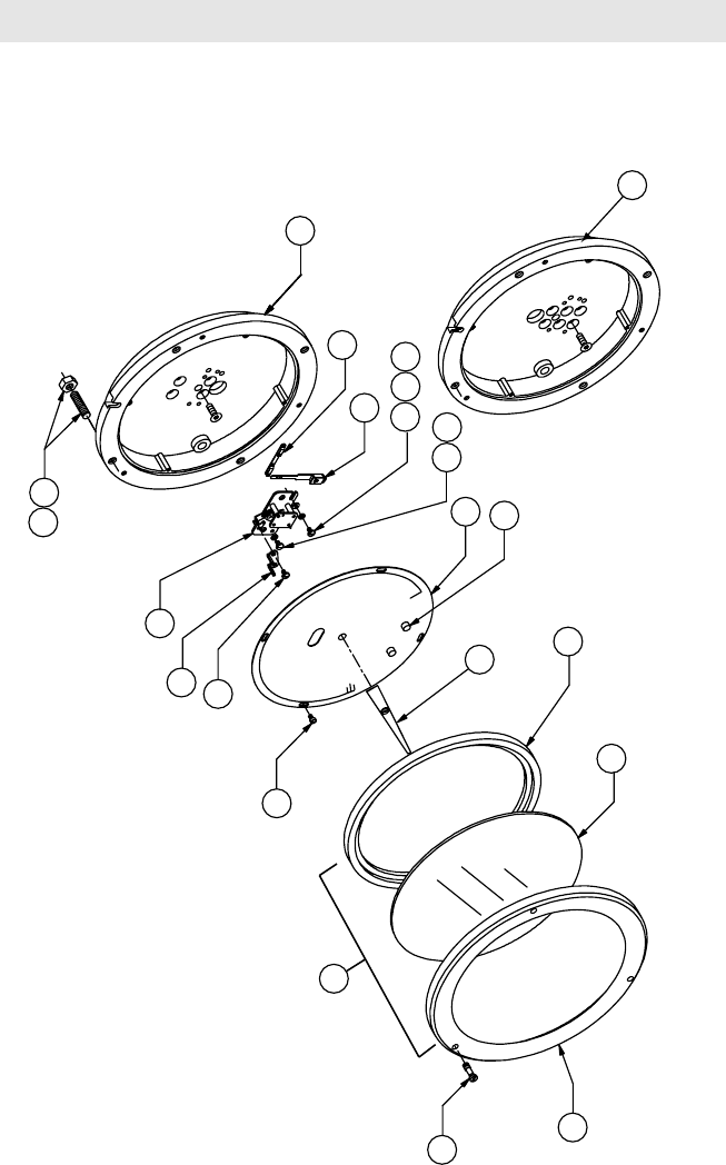
SECTION 4 - PARTS DRAWING/LIST
Figure 4-1. 227A/227C Parts Drawing
1
5
7
6
21
19
11
18
17
3
2
12
4
10
9
8
13
14
15
19 15 20
1/4
A
PED LABEL - on DPU Housing
(PED complient units only)
1
(Inverted
Configuration)
(Standard
Configuration)

13
Table 4-1. 227A/227C Parts List
Item Description Part No. Per
Unit
1Case: 1
Standard 0227-0014C
Inverted 0227-1028C
2Bezel (Part Of Item #21) 0277-0029C 1
3* Lens, Cover (Part Of Item #21) 0181-0038C 1
4* Gasket (Part Of Item #21) 0277-0026C 1
5** Scale Plate 1
White On Black Background 0227-0013C
Black On White Background 0227-1003C
6* Pointer Assembly: 1
White 0288-0030B
Black 0288-0031B
7Movement Assembly 0288-0035B 1
8Drive Arm Assembly 0226-0023B 1
9Link Assembly 0226-0020B 1
10 Stop Bracket 0288-0028C 1
11* Bezel Screws, SST 0181-0007C 3
12 Snubber 0226-0028C 2
13 Screw, Sl Fil. Hd. 4-40 X 3/16, SST 0114-0023J 4
14* Screw, Bd. Hd., 4-40 X 3/16, SST 0117-0012J 1
15* Washer, Split Lock, #4, SST 0003-0062K 2
16 Screw, Flat Hd., #10 X 1/2 0240-0019J 6
17 Screw, Slotted Set, 1/4-20 X 1 0340-0003J 4
18 Nut, 1/4-20, Hex, STL 0500-0010J 4
19 Screw, Rd. Hd., 4-40 X 1/4, SST 0111-0034J 2
20 Washer, Flat, #4, SST 0003-0096K 1
21 Bezel Assembly (Items 2, 3, & 4) 0277-0018B 1
22 Differential Pressure Unit (DPU)
(Not Shown)
227A Uses 224 DPU
227C Uses 224C DPU
Inverted Units Use Inverted 224/224C DPUs
SEE DPU
MANUAL
1
23 Calibration Kit (Not Shown) 0288-1032B 1
24 Plug, Restrictor Vent (Not Shown) 0080-1022T 1
Notes: * Indicates recommended spare part; ** SCALE PLATE INDENTIFICATION:
If the scale plate shows an SCR number, this will identify it. Otherwise, provide the
following information:
1. Square Root or Linear Graduations
2. Scale (e.g., 0-100, 25-0-100, etc.)
3. Number of Graduations (linear scales only)
4. Data (e.g., PSI (bar), inches of water column (meter), etc.)
5. Standard plates have black background
When ordering parts, specify serial number of instrument. Minimum parts order is
$100.00. For 224/224C parts, refer to separate 224/224C DPU manual.
14
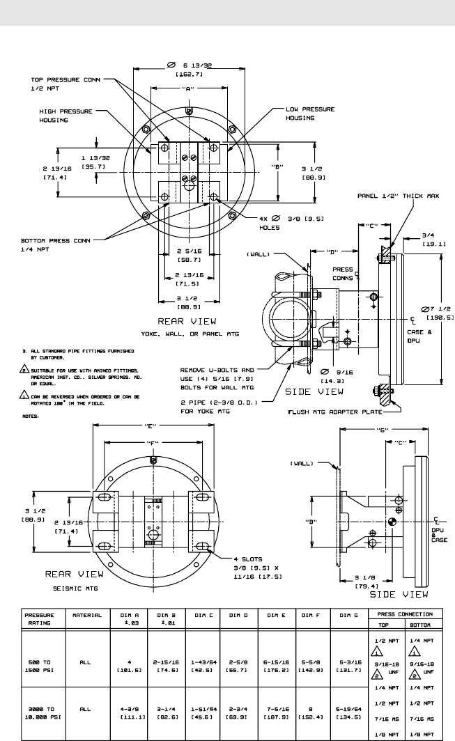
SECTION 5 - INSTALL/DIMENSIONAL DRAWINGS
Figure 5-1. 227A/227C Dimensions (Based on 0227C-10013, Rev.00)
Note: For other DPU dimensional information, refer to the separate DPU manual (as
listed on the front page).
15
Figure 5-1. 227A/227C Dimensions (Continued)

Formerly: NuFlo Measurement Systems • Barton Instrument Systems • Caldon, Inc.
MEASUREMENT SYSTEMS
USA • CANADA • UK • SCOTLAND • CHINA • UAE
ALGERIA • MALAYSIA • SINGAPORE • www.c-a-m.com/flo
44.1243.826741
ms-uk@c-a-m.com
EUROPE,
MIDDLE EAST
& AFRICA
603.2287.1039
ms-asiapacific@c-a-m.com
ASIA
PACIFIC
1.800.654.3760
ms-us@c-a-m.com
NORTH
AMERICA
281.582.9500
HOUSTON
HEAD OFFICE
Product Warranty
A. Warranty
Cameron International Corporation ("Cameron") warrants that at the time of shipment, the
products manufactured by Cameron and sold hereunder will be free from defects in material and
workmanship, and will conform to the specications furnished by or approved by Cameron.
B. Warranty Adjustment
(1) If any defect within this warranty appears, Buyer shall notify Cameron immediately.
(2) Cameron agrees to repair or furnish a replacement for, but not install, any product which
within one (1) year from the date of shipment by Cameron shall, upon test and examination
by Cameron, prove defective within the above warranty.
(3) No product will be accepted for return or replacement without the written authorization of
Cameron. Upon such authorization, and in accordance with instructions by Cameron, the
product will be returned shipping charges prepaid by Buyer. Replacements made under this
warranty will be shipped prepaid.
C. Exclusions from Warranty
(1) THE FOREGOING WARRANTY IS IN LIEU OF AND EXCLUDES ALL OTHER EXPRESSED
OR IMPLIED WARRANTIES OF MERCHANTABILITY, OR FITNESS FOR
A PARTICULAR PURPOSE, OR OTHERWISE.
(2) Components manufactured by any supplier other than Cameron shall bear only the warranty
made by the manufacturer of that product, and Cameron assumes no responsibility for the per-
formance or reliability of the unit as a whole.
(3) "In no event shall Cameron be liable for indirect, incidental, or consequential damages nor shall
the liability of Cameron arising in connection with any products sold hereunder (whether such
liability arises from a claim based on contract, warranty, tort, or otherwise) exceed the actual
amount paid by Buyer to Cameron for the products delivered hereunder."
(4) The warranty does not extend to any product manufactured by Cameron which has been
subjected to misuse, neglect, accident, improper installation or to use in violation of instructions
furnished by Cameron.
(5) The warranty does not extend to or apply to any unit which has been repaired or altered at any
place other than at Cameron's factory or service locations by persons not expressly approved by
Cameron.
Product Brand
Barton® is a registered trademark of Cameron International Corporation ("Cameron").
