CBA 300 SR80 Bettis Cba300 Ds
User Manual: SR80
Open the PDF directly: View PDF ![]() .
.
Page Count: 12
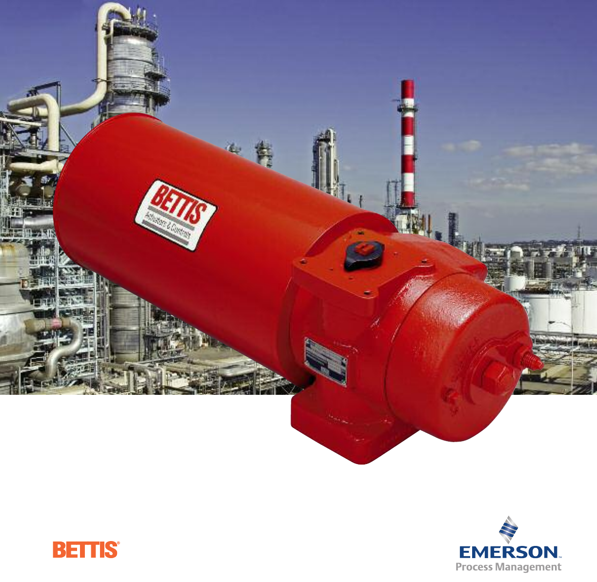
CBA-300 Series
Pneumatic
Actuators
Strong, Efficient and Cost Effective
CBA-300 SERIES PNEUMATIC
DESIGN AND CONSTRUCTION
Introduction
For more than 45 years, Bettis®valve actuators have
demonstrated the latest technology. The CBA 300-
Series pneumatic actuators combine the strengths of
our new generation G-Series scotch-yoke actuators,
while incorporating several new design economies for
efficient and cost effective operation.
The advanced 300-Series have enhanced water ingress
and corrosion protection. These compact actuators are
lightweight and ideally suited for automating virtually
any quarter-turn (90-degree) rotating mechanism
including ball, butterfly and plug valves. With a variety
of options, the 300-Series can meet your most demand-
ing valve automation needs.
Operating Ranges
Double-acting 300-Series actuators are available with
guaranteed minimum torque outputs ranging from
7,388 lb-in to 20,337 lb-in (835 to 2,333 Nm). 300-Series
spring-return models require pressure in only one
direction of travel and are available for fail clockwise or
counterclockwise applications. These models produce
spring ending torques ranging from 2,532 lb-in through
10,457 lb-in (286 to 1,182 Nm).
Standard construction 300-Series actuators are
designed for operation temperatures ranging from -20°F
to +200°F (-29°C to +93°C). Optional high temperature
trim allows operation from 0°F to 350°F (-18°C to +177°C)
and special non-PED low temperature trim permit
operation to -40°F (-40°C).
Pneumatic operating pressures for the 300-Series
range from 40 to 150 PSIG (3 to 10 BAR).
2
13
14
3
11 10
2
■PED 97/23/EC Compliant
■
Suitable for SIL 2 and SIL 3
■
Water Ingress Protected –
IP66 and IP67M
■Five-Year Warranty
■NAMUR Topworks
■ISO/DIN Bottom Mounting
■Jackscrew Option
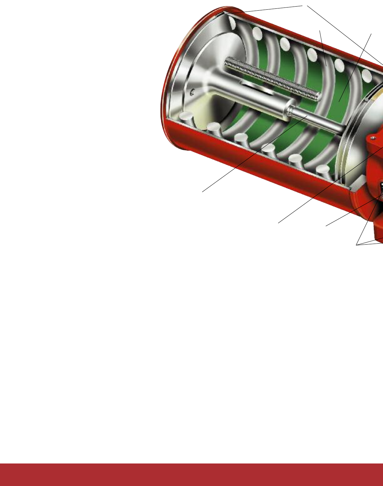
Features and Advantages
Water Ingress Protection – The 300-Series actuators meet both IP66 and
IP67M specifications for submergence and severe high pressure water del-
uge test, offering superior water ingress and corrosion protection. The actu-
ator has no gaskets and is totally o-ring sealed.
1) NAMUR Topworks
– The 300-Series utilizes the internationally accepted
NAMUR mounting configuration that allows standardization of accessory
hardware and the direct or close coupling of NAMUR designed hardware
and accessories.
2) New Quad Sealed Torque Shaft – The lower torque shaft has two
independent seals – the outer seal protects the large bearing area and
the primary, inner cup seal from the environment. The upper shaft
bearing area features a bi-directional, double lip seal providing twice
the level of protection from corrosion and contaminants.
3) New O-Ring Sealed Cylinders – The o-ring sealed cylinders essentially
eliminate the possibility of any cylinder leakage throughout the full
range of operating pressures and climatic conditions.
4) Name Plate – Long lasting stainless steel plate provides lifetime trace-
ability and critical operating information.
5) Standard Accessory Mounting Pad – The new accessory mounting
pad is standard and identical on all CBA and CBA 300-Series models,
allowing for the panel mounting of controls.
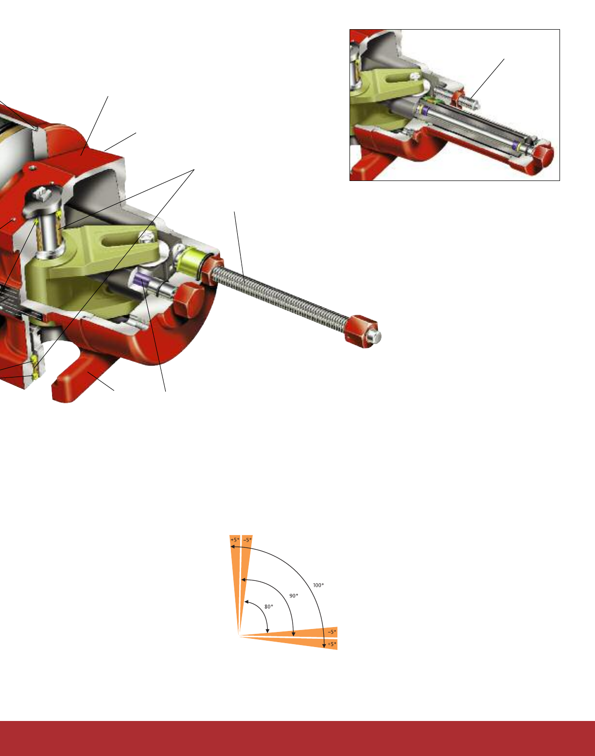
6) Jackscrew Option (Shown) – A blowout-proof, economical jackscrew
manual override is available with the 300-Series. When equipped with
a jackscrew, it also acts as a stop adjustment screw. The jackscrew
feature has several advantages:
■Produces full rated torque output in the event of air supply loss.
■Available with or without handwheel, locking devices and many
other options. Consult factory.
■The manual override absorbs impact loads at maximum
recommended actuator speeds.
■Double-acting models are available with one or two jackscrews.
Bi-directional Travel Stops – Dual stops
allowing 80° to 100° total travel adjustment.
This feature provides an unmatched travel
range to assist in prolonging valve seat
integrity.
Optional Bi-directional Extended Travel
Stop (ETS) – Allows 0° to 100° extended
travel adjustment capability, and can be
used as a lockout device. Consult factory.
7) ISO/DIN Actuator/Valve Interface – The 300-Series has an ISO/DIN
F14 mounting configuration. This female interface allows close
coupling or direct mounting of the actuator to the valve topworks.
M-11 hydraulic override configuration
Standard stop screw
8) Efficient All Bearing Design – The 300-Series pis-
ton has three field replaceable bearings. They
include a TFE piston head bearing, PTFE/bronze
bearings on either piston end and on the yoke pin.
These bearings help to assure smooth and consis-
tent torque output, while enhancing total cycle life
capabilities.
9) Torque Shaft Bearing – The torque shaft
features field replaceable upper and lower
PTFE-coated, copper-clad metallic bearings.
10) Xylan™ Cylinder Coating – This fluoropolymer
(TFE-based) coating is highly resistant to corrosion
and thermal shock. It also provides for excellent
lubricity, adding significantly to piston seal life and
actuator efficiency. Xylan has been laboratory
(ASTM B117) tested and field proven to be extremely
resistant to contaminants typically found in instru-
ment air supply systems.
11) Springs – High-strength, high-performance alloy
carbon steel springs are protected by Tactyl 50, a
pliable self-healing coating. Bettis takes and addi-
tional step and shot peens the springs, helping to
extend the actuator’s spring cycle life.
12) Ductile Iron Housing – CBA actuator housings are
made of pressure vessel quality ductile iron which
is approved for use by ASME and the Pressure
Equipment Directive (PED 97/23/EC). All housings
have been optimized by finite element analysis and
are designed for light weight while retaining
maxi-
mum strength, ductility and corrosion resistance.
13) Center Bar and Torque Shaft – Utilizes a
proprietary surface conversion process, producing
an extremely hard surface exhibiting excellent wear
and corrosion resistance. The center bar guides the
piston throughout its full stoke, preventing metal
to metal contact with the cylinder bore.
3
9
6Jackscrew option (See
insert for standard stop
screw configuration)
78
5
12

4
General Definitions
To clarify and standardize terminology, Bettis offers the
following definitions for terms commonly used. Please become
familiar with and use the following standard definitions when
referring to Bettis quarter-turn actuators.
Quarter-turn: A device which rotates a minimum of 90 degrees.
All Bettis quarter-turn actuators will rotate more than 90 degrees.
Position: That degree of rotation describing an actuator’s
current location. The mid position of a quarter-turn actuator is
generally at forty-five(45) degrees.
CW: Clockwise rotation.
CCW: Counterclockwise rotation.
Stroke: A continuous, ninety (90) degree rotation of a quarter-turn
actuator. Bettis spring-return actuators have two (2) different
strokes, a pressure stroke and a spring stroke. Bettis double-
acting actuators have two (2) pressure strokes. Note that rack
and pinon actuators have common torque valves for both pressure
strokes, while scotch yoke actuators have different torque values
depending on which side of the piston is doing the work.
Cycle: The collective reference to two (2) strokes, one (1) for
clockwise (CW) rotation and one (1) for counterclockwise (CCW)
rotation. Bettis actuators must rotate through two (2) stroke to
complete one (1) cycle.
Safety Factor: Represents a protective component (an adjustment
to torque requirement) sometimes added to a valve’s required
torque value. Often used when the user/specifier is not certain of
the valve’s torque requirements, or because of other application
concerns.
Sizing Bettis Actuators
The following information is generally the minimum required
for sizing Bettis quarter-turn pneumatic and hydraulic actuators
for specific valve requirements.
A) An accurate maximum torque requirement must be obtained
before actuator sizing begins. Normal maximum stem torque for
a properly applied and maintained valve is usually defined as: The
maximum starting torque required to rotate the valve element
(ball, disc,plug, etc.) from a fully closed position
(unsealing),
against the maximum normal valve rated different
pressures.
Most valve manufacturers make adjustments in the form of
torque amendments under various operating conditions.
Application operating conditions such as temperature extremes,
actual differential pressure, unusual loading, high flow rates,
operating speeds, etc. are some of the most common causes for
adjustments.
Bettis recommends that the valve manufacturer supply the
maximum required torque value(s) (including any adjustments
or
suggested safety factors). Additionally, the valve manufacturer
must identify at which position(s) and direction(s) of rotation
(CCW or CW) these maximum requirements occur.
B) Bettis actuators include stops which will resist the maximum
rated torque output of the actuator. The possibility exists, that
should the valve become immobilized during rotation, the actua-
tor could exceed the maximum allowable valve input torque rat-
ing. If this possibility is a concern, your application needs further
review.
Once the maximum torque requirements, its position, and
direction of rotation are identified, the appropriate Bettis actuator
can be selected from torque output charts on pages 4–7.
SIZING AND SELECTION
Actuator Selection Procedures
A) Determine the type of Bettis actuator required: double-acting
or spring-return.
B) Determine the power supply media: pneumatic or hydraulic,
and the minimum/maximum supply pressure(s) at the actuator.
C) Using this information, select the applicable torque rating
table and see the appropriate following examples.
Scotch-Yoke, Double-Acting Actuators (example
assumes CW to close)
Note: The valve’s torque requirements must be exceeded by
the actuator’s torque output at all corresponding positions and
directions of rotation.
Bettis has included Start, Minimum, and End pressure torque
outputs for your use.
A) Using your minimum operating pressure, select an operating
pressure column from the Pressure Torque Rating Section of less
than or equal pressure. Move down the column until both starting
and minimum output torques are found which exceed the valve’s
maximum and minimum torque requirements. Determine the
Bettis model number at the left, under the model number column.
B) Once a Bettis actuator model has been selected, use the per-
formance data tables to ensure your maximum supply pressure
does not exceed the maximum operating pressure (M.O.P.) for
your Bettis actuator. If the actuator selected is not rated for your
maximum supply pressure, either the maximum supply pressure
must be reduced or an actuator rated for a higher M.O.P. must
be selected.
Scotch-Yoke, Spring-Return, Fail CLOCKWISE Actuators
(example assumes CW to close)
Note: The valve’s maximum torque requirements must be
exceeded by the actuator’s torque output at all corresponding
positions and directions of rotation.
Bettis has included Start, Minimum, and End Spring Torque
outputs, as well as Start, Minimum and End Pressure Torque
Outputs for your use. The minimum torque outputs listed on the
Spring-Return torque charts are the lowest value of torque output
available at any position, during either stroke (pressure or spring).
A) Select from the Spring Torque column a Spring Ending torque
output which exceeds that of the valve’s maximum seating
requirement.
B) Proceed to the right using your minimum operating pressure
and select an operating pressure column from the Pressure
Torque Rating Section of less than or equal pressure. The Pressure
Start torque output must exceed the valve’s torque requirement
at this position (unseating). The Pressure End torque output must
exceed the valve’s torque requirement at this position (full flow)
and direction of rotation (CCW).
C) Once a Bettis actuator model has been selected, use the per-
formance data tables to ensure your maximum supply pressure
does not exceed the maximum operating pressure (M.O.P.) for
your Bettis actuator. If the actuator selected is not rated for your
maximum supply pressure, either the maximum supply pressure
must be reduced or an actuator rated for a higher M.O.P. must be
selected.
Contact your local Authorized Bettis distributor or a Bettis
manufacturing
facility if you require assistance.
5
Performance Data – CBA-300-Series (Pneumatic) - Imperial & metric
Notes:
◆CBA-SRXXM mechanical handwheel overrides are available on these models. The override adds approximately 2 lbs. (.8 kg) to the weight of the
standard CBA model.
▲Maximum volume including cavity required for calculating consumption per stroke.
*Maximum System Pressure (MSP) – The maximum allowable system supply pressure to which the actuator may be exposed.
** Maximum Operating Pressure (MOP) is the pressure required
to produce the maximum rated torque of the actuator.
*** Maximum Allowable Working Pressure (MAWP) is the
maximum static pressure that may be applied to a fully
stroked actuator against the travel stops.
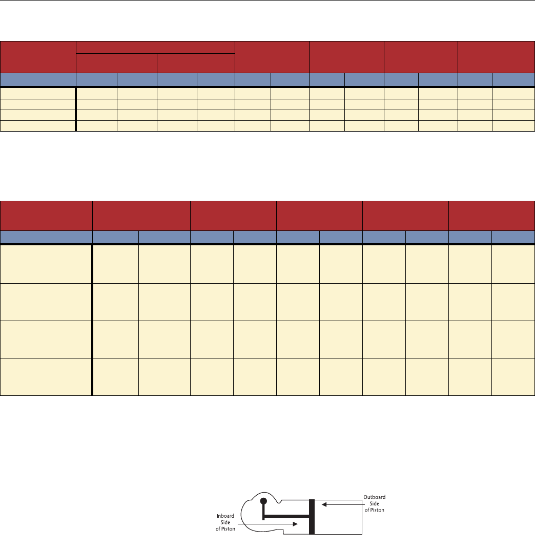
Standard installation produces clockwise rotation
when the outboard side of piston is pressurized.
Standard installation produces counterclockwise
rotation when the inboard side of piston is pressurized.
Note: Actuator may be installed opposite of that shown above.
Double-Acting Actuators
CBA-Series
Volumes Maximum System Maximum Operating Maximum Allowable Approximate Weight
Actuator Outboard Inboard Pressure Pressure Working Pressure of Actuator
Model (Housing) (MSP)* (MOP)** (MAWP)***
Cu. Inches Cubic CM Cu. Inches Cubic CM PSIG Bar PSIG Bar PSIG Bar Lbs. KG
CBA 730 260 4260.6 562 9209.5 120 8.3 105 7.2 200 13.8 130 59
CBA 830 341 5588.0 633 10373.0 90 6.2 80 5.5 200 13.8 140 63.5
CBA 930 433 7095.6 713 11683.9 70 4.8 65 4.5 170 11.7 155 70.3
CBA 1030 572 9373.4 834 13666.8 55 3.8 50 3.4 130 9.0 170 77.1
Spring-Return Actuators
CBA-Series
Maximum System Maximum Operating Maximum Allowable Approximate Weight
Actuator Volume Pressure Pressure Working Pressure of Actuator
Model (MSP)* (MOP)** (MAWP)***
Cu. Inches Cubic CM PSIG Bar PSIG Bar Lbs. KG
◆CBA 730- SR40 562 9209.5 150 10.3 135 9.3 200 13.8 158 71.7
SR60 562 9209.5 155 10.7 140 9.7 200 13.8 160.5 72.8
SR80 562 9209.5 160 11.0 145 10.0 200 13.8 163 73.9
SR100 562 9209.5 165 11.4 150 10.3 200 13.8 164 74.4
◆CBA 830- SR40 633 10373.0 125 8.6 105 7.2 200 13.8 180 81.6
SR60 633 10373.0 125 8.6 110 7.6 200 13.8 184.5 83.7
SR80 633 10373.0 130 9.0 115 8.0 200 13.8 188 85.3
SR100 633 10373.0 140 9.7 120 8.3 200 13.8 192.5 87.3
◆CBA 930- SR40 713 11683.9 120 8.3 85 5.9 170 11.7 195 88.5
SR60 713 11683.9 120 8.3 90 6.2 170 11.7 202 91.6
SR80 713 11683.9 120 8.3 95 6.6 170 11.7 206.5 93.7
SR100 713 11683.9 120 8.3 105 7.2 170 11.7 205 93.0
◆CBA 1030- SR40 834 13666.8 95 6.5 70 4.8 130 9.0 220 99.8
SR60 834 13666.8 100 6.9 75 5.2 130 9.0 225.5 102.5
SR80 834 13666.8 110 7.6 80 5.5 130 9.0 233.5 105.9
— — — ——————

Torque Ratings – CBA-300-Series (Pneumatic) - Imperial
All Published Torques are Typical Minimum Values.
Operating Pressure (PSIG)
Actuator Stroke 40 50 60 70 80 90 100 110
Model Position Pressure Torque Output Start/Min./End (lb-in)
CBA730
Start/End
7388 9235 11082 12929 14776 16623 18470
Minimum 4248 5310 6372 7434 8496 9558 10620
CBA830
Start/End
9697 12121 14545 16969 19393
Minimum 5575 6969 8363 9757 11151
CBA930
Start/End
12313 15391 18470
Minimum 7080 8850 10620
CBA1030
Start/End
16270 20337
Minimum 9355 11694
Double-Acting Actuators
Spring-Return Actuators
6
Spring Torque Operating Pressure (PSIG)
Actuator (in-lbs) 40 50 60 70 80 90 100 110 120 130 140 150
Model Start/Min./End Pressure Torque Output Start/Min./End (lb-in)
CBA730-SR40 Start 4383 4589 6436 8283 10130 11977 13824 15671 17518 19365 21212
Min. 1759 1808 2782 3747 4712 5677 6641 7599 8557 9515 10473
End 2532 2544 4391 6238 8085 9932 11779 13626 15473 17319 19166
CBA730-SR60 Start 6748 5225 7095 8965 10835 12705 14575 16445 18315 20185 22055
Min. 2625 1704 2709 3692 4657 5622 6587 7552 8517 9483 10446
End 3732 1892 3762 5632 7502 9372 11242 13112 14982 16852 18722
CBA730-SR80 Start 9340 8033 9903 11773 13643 15513 17383 19253 21123
Min. 3450 2565 3591 4578 5564 6529 7494 8459 9424
End 4576 2767 4637 6507 8377 10247 12117 13987 15857
CBA730-SR100 Start 11755 10637 12530 14423 16316 18210 20103 21996
Min. 4301 3499 4513 5500 6488 7458 8423 9388
End 5792 4046 5939 7832 9725 11619 13512 15405
CBA830-SR40 Start 5739 6029 8453 10877 13301 15725 18149 20573
Min. 2330 2406 3700 4982 6263 7545 8826 10099
End 3318 3354 5778 8202 10626 13050 15474 17899
CBA830-SR60 Start 9010 7299 9783 12268 14753 17237 19722 22207
Min. 3443 2216 3587 4898 6189 7471 8753 10035
End 4637 2226 4711 7196 9680 12165 14650 17135
CBA830-SR80 Start 12171 10786 13271 15756 18241 20725
Min. 4565 3400 4772 6083 7394 8679
End 5978 3605 6089 8574 11059 13544
CBA830-SR100 Start 15438 14385 16870 19354 21839
Min. 5677 4560 5935 7258 8569
End 7218 4873 7358 9842 12327
CBA930-SR40 Start 7471 7849 11004 14159 17315 20470
Min. 3063 3163 4866 6551 8237 9922
End 4317 4364 7519 10674 13829 16985
CBA930-SR60 Start 11942 9602 12757 15912 19067 22223
Min. 4470 2577 4691 6425 8145 9830
End 5586 2577 5732 8888 12043 15194
CBA930-SR80 Start 15872 13771 16927 20082
Min. 5977 4442 6258 7993
End 7523 4544 7699 10854
CBA930-SR100 Start 19822 17899 21054
Min. 7500 6009 7808
End 9498 6489 9644
CBA1030-SR40 Start 9929 10455 14624 18793 22962
Min. 4036 4178 6431 8658 10885
End 5629 5703 9872 14041 18210
CBA1030-SR60 Start 15924 12989 17159 21328
Min. 5839 3245 6204 8507
End 7108 3245 7415 11584
CBA1030-SR80 Start 20580 17626 21796
Min. 7978 5937 8299
End 10457 6438 10607

7
Spring-Return Actuators
Torque Ratings – CBA-Series (Pneumatic) - metric
All Published Torques are Typical Minimum Values.
Double-Acting Actuators
Spring Torque Operating Pressure (Bar)
Actuator (Nm) 3 3.5 455.5 678910 11
Model Start/Min/End Pressure Torque Output Start/Min./End (Nm)
CBA730-SR40 Start 495 592 743 894 1197 1348 1500 1802 2105 2408
Min. 198 204 314 423 532 641 750 859 967 1075
End 286 361 512 663 966 1117 1269 1571 1874 2177
CBA730-SR60 Start 763 606 760 1066 1219 1373 1679 1986 2292
Min. 297 193 306 417 526 635 744 853 962
End 422 230 383 690 843 996 1302 1609 1915
CBA730-SR80 Start 1055 961 1114 1267 1574 1880 2187 2493
Min. 390 290 406 517 629 738 847 956
End 517 366 519 672 979 1285 1592 1898
CBA730-SR100 Start 1328 1138 1448 1759 2069 2379
Min. 486 395 510 622 733 843
End 654 393 704 1014 1324 1634
CBA830-SR40 Start 648 777 976 1175 1572 1770 1969 2366
Min. 263 272 418 563 708 853 997 1141
End 375 475 674 872 1270 1468 1667 2064
CBA830-SR60 Start 1017 846 1050 1457 1660 1864 2271
Min. 389 250 405 553 699 844 989
End 524 273 476 884 1087 1291 1698
CBA830-SR80 Start 1375 1289 1493 1697 2104 2511
Min. 516 384 539 687 835 981
End 675 478 682 885 1292 1699
CBA830-SR100 Start 1744 1542 1949 2356
Min. 641 515 671 820
End 816 467 874 1281
CBA930-SR40 Start 844 1012 1271 1529 2046 2305
Min. 346 357 550 740 931 1121
End 488 618 877 1135 1652 1911
CBA930-SR60 Start 1349 1112 1371 1888 2146 2405
Min. 505 291 530 726 920 1111
End 631 318 577 1094 1352 1611
CBA930-SR80 Start 1793 1646 1904 2163
Min. 675 502 707 903
End 850 603 862 1120
CBA930-SR100 Start 2240 1916 2433
Min. 847 679 882
End 1073 627 1144
CBA1030-SR40 Start 1122 1347 1688 2030
Min. 456 472 727 978
End 636 810 1151 1493
CBA1030-SR60 Start 1799 1504 1845 2528
Min. 660 367 701 961
End 803 403 744 1427
CBA1030-SR80 Start 2325 2110 2452
Min. 901 671 938
End 1182 846 1187
Operating Pressure (PSIG)
Actuator Stroke 3 3.5 455.5 67 8
Model Position Pressure Torque Output Start/Min./End (lb-in)
CBA730 Start/End 908 1059 1211 1513 1665 1816 2119 2421
Minimum 522 609 696 870 957 1044 1218 1392
CBA830 Start/End 1192 1390 1589 1986 2185 2384
Minimum 685 799 914 1142 1256 1371
CBA930 Start/End 1513 1766 2018
Minimum 870 1015 1160
CBA1030 Start/End 2000 2333
Minimum 1150 1341
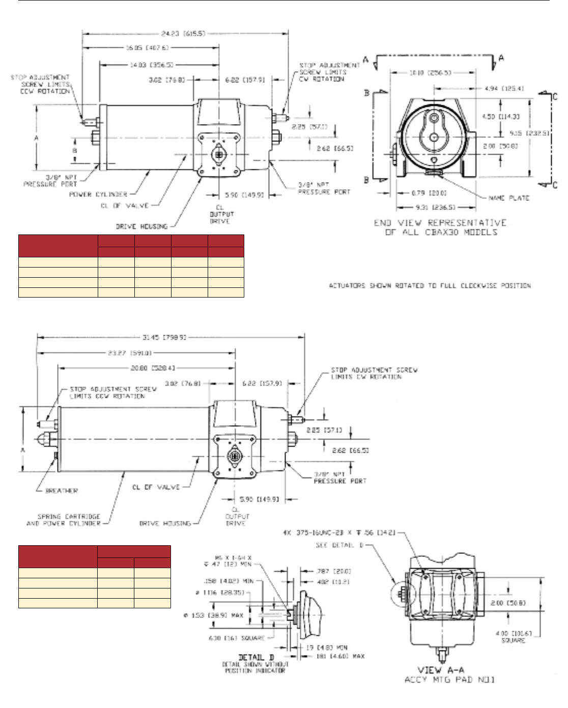
Dimensions – CBA-300-Series (Pneumatic) - in/mm
Metric dimensions in parentheses
Double-Acting Actuators
CBAX30
Spring Return Actuators
CBAX30-SRX
A
Actuator
Model In. MM
CBA 730-SRX 7.69 195.3
CBA 830-SRX 8.69 220.7
CBA 930-SRX 9.69 246.1
CBA 1030-SRX 11.00 279.4
ABAB
Actuator
Model In. In. MM MM
CBA 730-SRX 7.63 3.00 193.8 76.2
CBA 830-SRX 8.63 3.50 219.2 88.9
CBA 930-SRX 9.63 4.00 244.6 101.6
CBA 1030-SRX 10.88 4.50 276.4 114.3
8
9
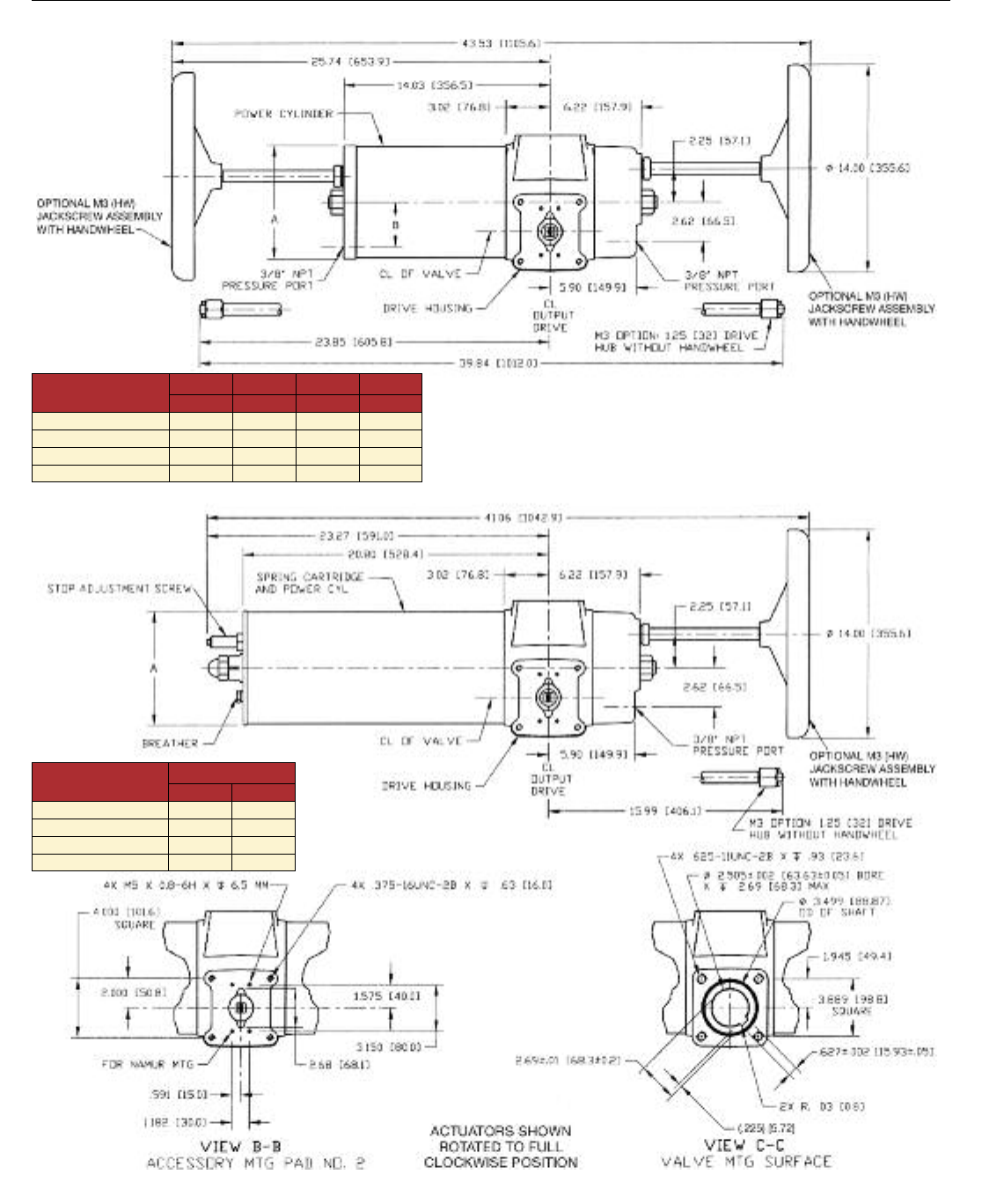
Dimensions – CBA-300-Series (Pneumatic) - in/mm M3(HW) Overrides
Metric dimensions in parentheses
Double Acting Actuators – CBAX30-M3(HW)
Spring Return Actuators – CBAX30-SRX-M3(HW)
A
Actuator
Model In. MM
CBA 730-SRX-M3HW 7.69 195.3
CBA 830-SRX-M3HW 8.69 220.7
CBA 930-SRX-M3HW 9.69 246.1
CBA 1030-SRX-M3HW 11.00 279.4
ABAB
Actuator
Model In. In. MM MM
CBA 730-M3HW 7.63 3.00 193.8 76.2
CBA 830-M3HW 8.63 3.50 219.2 88.9
CBA 930-M3HW 9.63 4.00 244.6 101.6
CBA 1030-M3HW 10.88 4.50 276.4 114.3
M3/M3HW – This Jackscrew manual override is a mechanical advantage
device threaded through a special adapter or the end cap of the CBA-300
Series cylinder to exert linear thrust on the actuator’s piston rod. The Jackscrew
override is available for all CBA-300 models with or without handwheel.
10
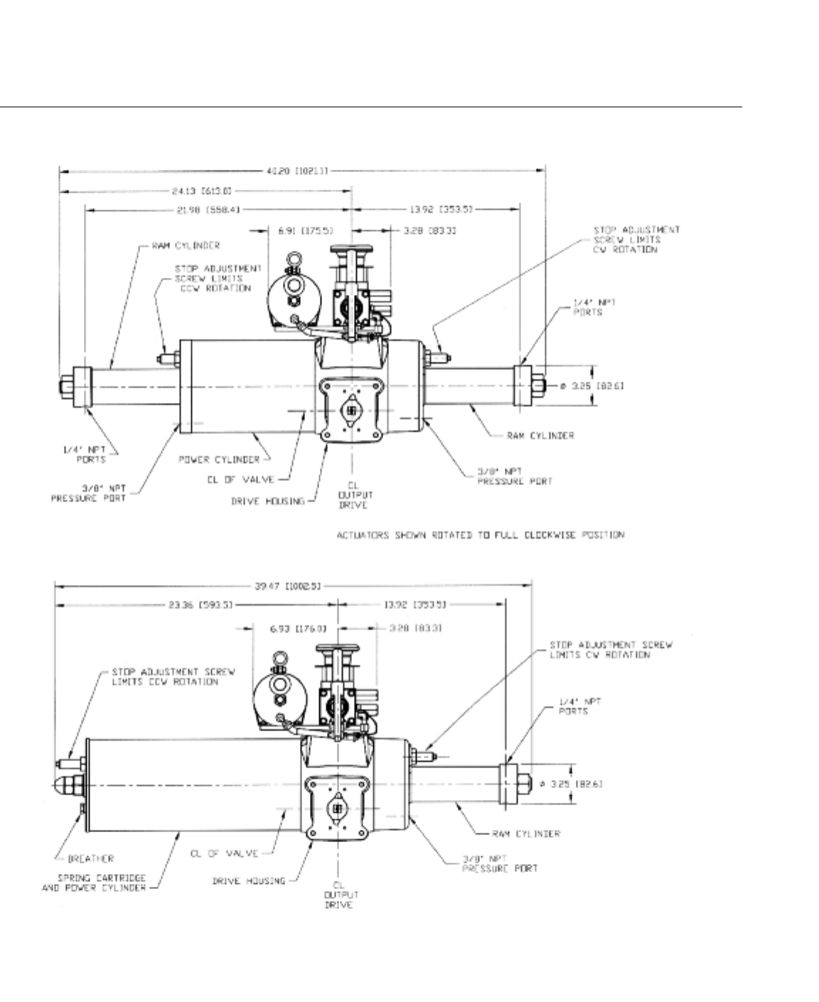
M11 – This hydraulic manual override is a compact modular system
designed for use with all CBA-300 pneumatic Series actuators. The override
can be used on either spring-return or double-acting models and can be
applied to pneumatic or hydraulic units. Remote mount units are available,
consult factory.
Dimensions – CBA-300-Series (Pneumatic) - in/mm M-11 Override
Metric dimensions in parentheses
Double-Acting Actuators
CBAX30-M11
Spring Return Actuators
CBAX30-SRX-M11
11
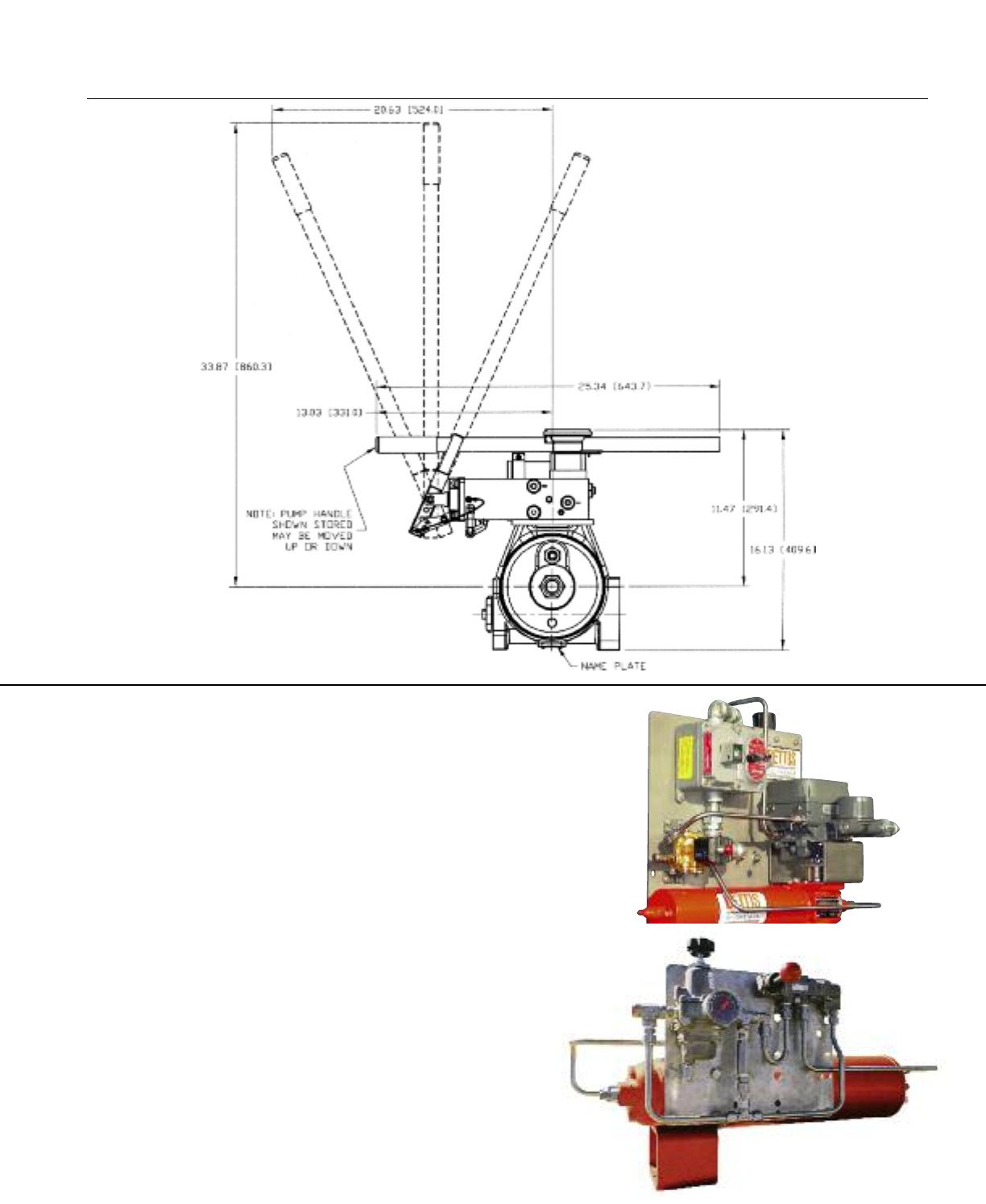
Dimensions – CBA-300-Series (Pneumatic) - in/mm M-11 Override
Metric dimensions in parentheses
SIL-PAC™– The unique SIL-PAC solution provides a complete hardware
and Bettis-supplied documentation package,embracing IEC, ISA and
OSHA standards, for use in a SIL application. The CBA-300 Series actuators
have a Failure Modes and Effects Diagnostics Analysis (FMEDA) report
performed by Exida.com™ for SIL suitability. They can be combined with
other components such as solenoid valves, switches and regulators. When
Fisher’s TÜV-certified FIELDVUE®DVC controller is added, SIL-PAC is capable
of partial stroke testing PLUS providing continuous monitoring of supply
pressure, valve position and pressure values to the actuator to verify its
proper working condition. The SIL-PAC package can then be mounted on
the appropriate quarter-turn valve for SIL1, 2 or 3 applications.
Bettis Automated Packages
Bettis offers complete packages as a solution for final valve control. Bettis
has the capability to combine the CBA-300 actuator, necessary controls and
selected valve into a single system – perfect for large international projects.
With this capability, Bettis can integrate its products with the complete
offering of control options, including world-class PlantWeb®digital plant
architecture and the entire range of Emerson automation solutions.
BettiSystemsTM – Bettis has pre-engineered and documented a series
of commonly required control systems. These approved systems utilize
standard components, reduce lead times, and simplify purchasing, installa-
tion and start-up. Please consult the factory for additional information.
Options
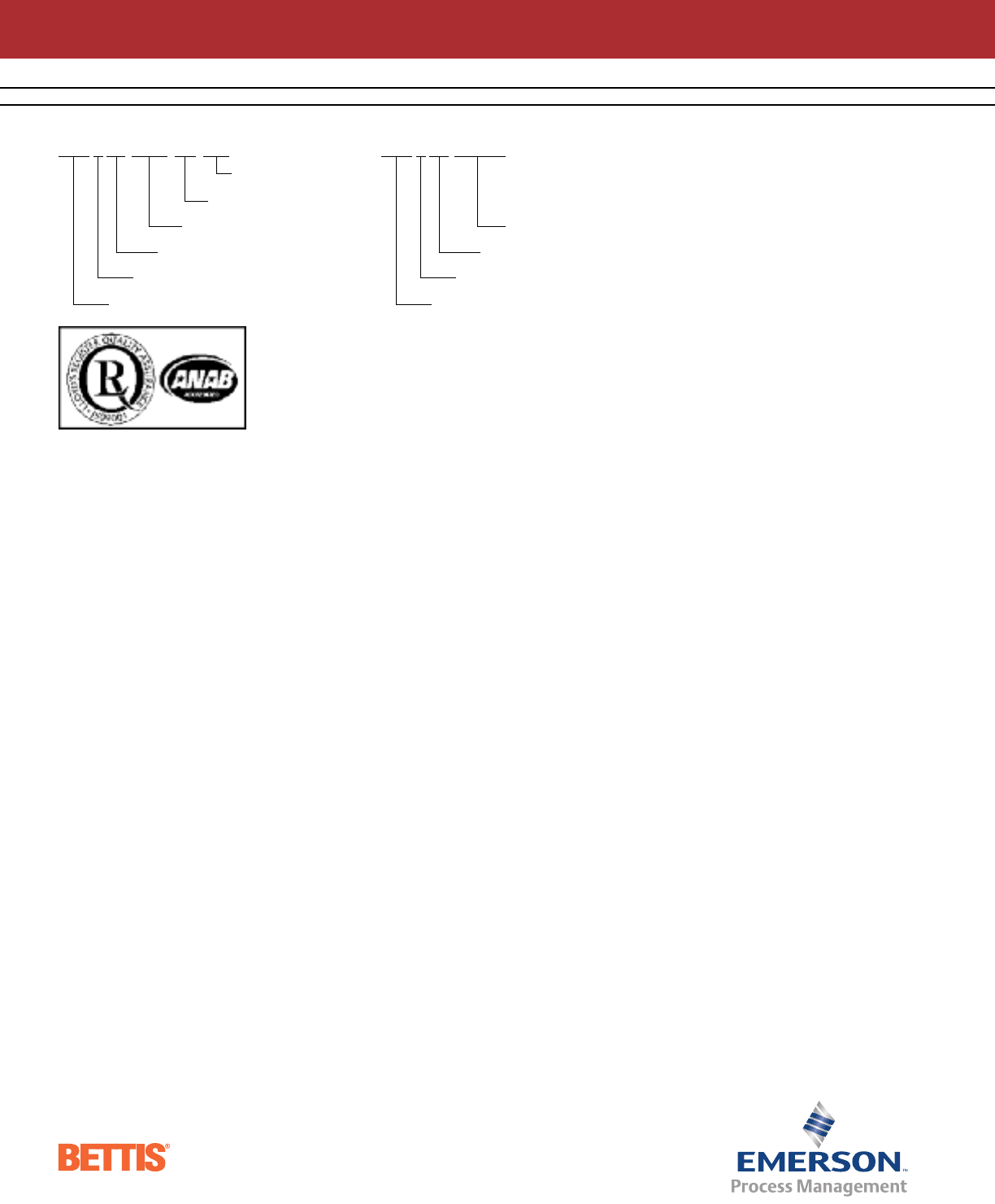
Spring-Return Example
CBA 7 30 SR80-M3-CW
ORDERING / MODEL DESIGNATION
Fail “CW”
Jackscrew without handwheel
Spring-Return, nominal 80 psig
Nominal Cylinder Size (In.)
Nominal Moment Arm (e.g. 3.0 In.)
Center Bar
Double-Acting Example
CBA 9 30 M3HW
Jackscrew without handwheel
Nominal Cylinder Size (In.)
Nominal Moment Arm (e.g. 3.0 In.)
Center Bar
OPTIONAL FEATURES
Fail-Safe Operation
Bettis 300-Series actuators are
capable of fail-safe operation
using either stored compressed
air (air fail safe) or a mechanical
spring.
Trims
Trim options for the 300-Series
actuators include high temperature,
low temperature, no copper
or no yellow
metal trims.
Consult factory with your trim
requirements.
Bettis Brochure # 22.00-5 REV: 6-08 2.5M/6-08
North & South America
18703 GH Circle
PO Box 508
Waller, Texas 77484
USA
T +1 281 727 5300
F +1 281 727 5353
2500 Park Avenue West
Mansfield, Ohio 44906
USA
T +1 419 529 4311
F +1 419 529 3688
9009 King Palm Drive
Tampa , Florida 33619
USA
T +1 813 630 2255
F +1 813 630 9449
4112-91A Street
Edmonton, Alberta T6E5V2
Canada
T +1 780 450 3600
F +1 780 450 1400
Av. Hollingsworth,325
Iporanga
Sorocaba, SP 18087-105
Brazil
T +55 15 3238 3788
F +55 15 3228 3300
Europe
Asveldweg 11
7556 BT Hengelo(O)
The Netherlands
T +31 74 256 1010
F +31 74 291 0938
Siemensring 112
D-47877 Willich
Germany
T +49 2154 499 660
F +49 2154 499 6613
30/36 Allee du Plateau
93250 Villemomble
France
T +331 48 122610
F +331 48 122619
6 Bracken Hill
South West Industrial Estate
Peterlee, Co Durham
SR82LS, United Kingdom
T +44 191 518 0020
F +44 191 518 0032
3 Furze Court
114 Wickham Road
Fareham, Hampshire
PO167SH ,United Kingdom
T +44 132 984 8900
F +44 132 984 8901
Middle East & Africa
2 Monteer Road, Isando
Kempton Park, 1600
South Africa
T +27 11 974 3336
F +27 11 974 7005
PO Box 17033
Jebel Ali Free Zone
Dubai,
United Arab Emirates
T +971 4883 5235
F +971 4883 5312
Asia Pacific
19, Kian Teck Crescent,
Singapore 628885
T +65 6262 4515
F +65 6268 0028
9/F Gateway Building
No.10 Ya Bao Road
Chaoyang District
Beijing, P.R. China
T +86 10 5821 1188
F +86 10 5821 1100
No 15 Xing Wang Road
Wuqing Development Area
Tianjin 301700
P.R. China
T +86 22 8212 3300
F +86 22 8212 3308
Lot 13111, Mukim Labu,
Kawasan Perindustrian Nilai
71807 Nilai, Negeri Sembilan
Malaysia
T +60 6 799 2323
F +60 6 799 9942
471 Mountain Highway
Bayswater, Victoria 3153
Australia
T +61 3 9721 0200
F +61 3 9720 0588
301, Solitaire Corporate Park
151, M.V. Road, Andheri(E)
Mumbai-400093,
Maharashtra, India
T +91 22 6694 2711
F +91 22 2825 3394
NOF Shinagawa Konan Building
1-2-5, Higashi-shinagawa
Shinagawa-Ku, Tokyo
140-0002 Japan
T +81 3 5769 6873
F +81 3 5769 6902
© 2008 Emerson Process Management. All rights reserved.
The Emerson logo is a trademark and service mark of Emerson Electric Co. “Brand mark listing” are marks of one of the Emerson Process Management family of companies.
All other marks are property of their respective owners.
The contents of this publication are presented for information purposes only, and while every effort has been made to ensure their accuracy, they are not to be construed
as warranties or guarantees, express or implied, regarding the products or services described herein or their use or applicability. All sales are governed by our terms and
conditions, which are available on request. We reserve the right to modify or improve the designs or specifications of our products at any time without notice.
The color orange, U.S. Reg. No. 2,739,393, is a registered trademark of the Bettis Corporation.
www.Bettis.com
Contact Us: Emerson Process Management, Valve Automation facilities at your nearest location:
