Product Detail Manual BL
User Manual: bl
Open the PDF directly: View PDF ![]() .
.
Page Count: 210 [warning: Documents this large are best viewed by clicking the View PDF Link!]
- QUICK REFERENCE INDEX
- Table of Contents
- PRECAUTIONS
- PREPARATION
- SQUEAK AND RATTLE TROUBLE DIAGNOSES
- HOOD
- POWER DOOR LOCK SYSTEM
- Component Parts and Harness Connector Location
- System Description
- Schematic
- Wiring Diagram – D/LOCK –
- Terminals and Reference Value for BCM
- Terminals and Reference Value for Driver Door Control Unit (LCU01)
- Terminals and Reference Value for Passenger and Rear LH, RH Door Control Units
- Work Flow
- Preliminary Check
- CONSULT–II Function
- On Board Diagnosis
- Symptom Chart
- Door Lock & Unlock Switch Check
- Communication Line Check
- Door Unlock Sensor Check
- Door Lock Actuator Check – Driver –
- Door Lock Actuator Check – Passenger, Rear LH,RH –
- Electronic Key Switch Check.
- REMOTE KEYLESS ENTRY SYSTEM
- System Description
- Schematic
- Wiring Diagram – KEYLES –
- Terminal and Reference Value for BCM
- Terminal and Reference Value for Driver Door Control Unit (LCU01)
- Passenger And Rear LH, RH Door Control Unit Terminal Reference Value
- Work Flow
- Preliminary Check
- CONSULT–II Function
- On Board Diagnosis
- Trouble Diagnosis Chart by Symptom
- Electronic Key Check
- Key Switch Check
- Trunk Lid Opener Cancel Switch Check
- Trunk Lid Opener Actuator Check
- Check Trunk Open Signal
- Horn Reminder Check
- Hazard Indicator Operation Check
- Multi-Remote Control Receiver Check
- Electronic Key Battery Replacement
- ID Code Entry Procedure
- DOOR
- FRONT DOOR LOCK
- REAR DOOR LOCK
- TRUNK LID
- TRUNK LID AND FUEL FILLER LID OPENER
- VEHICLE SECURITY (THEFT WARNING) SYSTEM
- Component Parts Harness Connector Location
- System Description
- Schematic
- Wiring Diagram — VEHSEC —
- CONSULT-II Function
- Trouble Diagnoses
- Preliminary Check
- Symptom Chart
- Diagnostic Procedure 1
- Diagnostic Procedure 2
- Diagnostic Procedure 3
- Diagnostic Procedure 4
- Diagnostic Procedure 5
- Diagnostic Procedure 6
- Diagnostic Procedure 7
- ELECTRONIC KEY SYSTEM
- IVIS (INFINITI VEHICLE IMMOBILIZER SYSTEM-NATS)
- HOMELINK UNIVERSAL TRANSCEIVER
- BODY REPAIR
- JOINT CONNECTOR (J/C)
- ELECTRICAL UNITS
- SUPER MULTIPLE JUNCTION (SMJ)
- FUSE BLOCK - JUNCTION BOX (J/B) NO.1
- FUSE BLOCK - JUNCTION BOX (J/B) NO.2
- FUSE, FUSIBLE LINK AND RELAY BLOCK (J/B)
- FUSE, FUSIBLE LINK AND RELAY BOX

BL-1
BODY, LOCK & SECURITY SYSTEM
I BODY
CONTENTS
C
D
E
F
G
H
J
K
L
M
SECTION BL A
B
BL
Revision: 2004 April 2002 Q45
BODY, LOCK & SECURITY SYSTEM
PRECAUTIONS .......................................................... 4
Precautions for Supplemental Restraint System
(SRS) “AIR BAG” and “SEAT BELT PRE-TEN-
SIONER” .................................................................. 4
Precautions for work ................................................ 4
Wiring Diagnosis and trouble Diagnosis .................. 4
PREPARATION ........................................................... 5
Special Service Tools ............................................... 5
Commercial Service Tools ........................................ 5
SQUEAK AND RATTLE TROUBLE DIAGNOSES ..... 6
Work Flow ................................................................ 6
CUSTOMER INTERVIEW ..................................... 6
DUPLICATE THE NOISE AND TEST DRIVE ....... 7
CHECK RELATED SERVICE BULLETINS ........... 7
LOCATE THE NOISE AND IDENTIFY THE
ROOT CAUSE ...................................................... 7
REPAIR THE CAUSE ........................................... 8
CONFIRM THE REPAIR ....................................... 8
Generic Squeak and Rattle Troubleshooting ........... 8
INSTRUMENT PANEL .......................................... 8
CENTER CONSOLE ............................................. 9
DOORS ................................................................. 9
TRUNK .................................................................. 9
SUNROOF/HEADLINER ....................................... 9
SEATS ................................................................... 9
UNDERHOOD ..................................................... 10
Diagnostic Worksheet .............................................11
HOOD ....................................................................... 13
Fitting Adjustment .................................................. 13
FRONT END HEIGHT ADJUSTMENT AND LAT-
ERAL/LONGITUDINAL CLEARANCE ADJUST-
MENT .................................................................. 13
SURFACE HEIGHT ADJUSTMENT ................... 13
Removal and Installation of Hood Assembly. ......... 14
Removal and Installation of Hood Lock Control. .... 15
REMOVAL ........................................................... 15
INSTALLATION ................................................... 16
Hood Lock Control Inspection. ............................... 16
POWER DOOR LOCK SYSTEM .............................. 17
Component Parts and Harness Connector Location ... 17
System Description ................................................. 18
POWER SUPPLY AND GROUND ...................... 18
OPERATION ........................................................ 18
Schematic ............................................................... 19
Wiring Diagram – D/LOCK – .................................. 20
Terminals and Reference Value for BCM ............... 26
Terminals and Reference Value for Driver Door Con-
trol Unit (LCU01) ..................................................... 27
Terminals and Reference Value for Passenger and
Rear LH, RH Door Control Units ............................ 27
Work Flow ............................................................... 28
Preliminary Check .................................................. 28
POWER SUPPLY AND GROUND CIRCUIT
INSPECTION ...................................................... 28
CONSULT–II Function ............................................ 29
DIAGNOSTIC ITEMS DESCRIPTION ................. 29
CONSULT-II BASIC OPERATION PROCEDURE
... 30
IVMS COMMUNICATION INSPECTION ............. 31
COMMUNICATION SYSTEM A .......................... 33
COMMUNICATION SYSTEM B .......................... 33
COMMUNICATION SYSTEM C .......................... 33
SELF-DIAGNOSIS RESULTS ............................. 33
DATA MONITOR ................................................. 34
ACTIVE TEST ..................................................... 34
On Board Diagnosis ............................................... 35
DIAGNOSIS ITEM ............................................... 35
COMMUNICATION DIAGNOSIS ......................... 35
COMMUNICATION SYSTEM A .......................... 37
COMMUNICATION SYSTEM B .......................... 37
COMMUNICATION SYSTEM C .......................... 37
SWITCH MONITOR ............................................ 38
POWER DOOR LOCK SYSTEM SELF SELF-
DIAGNOSIS ........................................................ 39
Symptom Chart ....................................................... 40
Door Lock & Unlock Switch Check ......................... 40
Communication Line Check .................................... 41
Door Unlock Sensor Check .................................... 42
Door Lock Actuator Check – Driver – ..................... 42
Door Lock Actuator Check – Passenger, Rear

BL-2
Revision: 2004 April 2002 Q45
LH,RH – .................................................................. 43
Electronic Key Switch Check. ................................. 44
REMOTE KEYLESS ENTRY SYSTEM ..................... 45
System Description ................................................. 45
POWER SUPPLY AND GROUND ....................... 45
OPERATING PROCEDURE ................................ 45
POWER DOOR LOCK OPERATION ...................45
HAZARD AND HORN REMINDER ..................... 45
OPERATING FUNCTION OF HAZARD AND
HORN REMINDER .............................................. 45
TRUNK LID OPENER OPERATION .................... 46
PANIC ALARM OPERATION ............................... 46
Schematic ............................................................... 47
Wiring Diagram – KEYLES – .................................. 48
Terminal and Reference Value for BCM ................. 57
Terminal and Reference Value for Driver Door Con-
trol Unit (LCU01) ..................................................... 58
Passenger And Rear LH, RH Door Control Unit Ter-
minal Reference Value ............................................ 58
Work Flow ............................................................... 59
Preliminary Check .................................................. 59
POWER SUPPLY AND GROUND CIRCUIT
INSPECTION ....................................................... 59
SYSTEM INSPECTION ....................................... 60
CONSULT–II Function ............................................ 60
DIAGNOSTIC ITEMS DESCRIPTION ................. 61
CONSULT-II BASIC OPERATION PROCEDURE
... 61
IVMS COMMUNICATION INSPECTION ............. 62
COMMUNICATION SYSTEM A ........................... 64
COMMUNICATION SYSTEM B ........................... 64
COMMUNICATION SYSTEM C .......................... 64
DATA MONITOR .................................................. 65
ACTIVE TEST ..................................................... 65
WORK SUPPORT ............................................... 66
On Board Diagnosis ............................................... 66
DIAGNOSIS ITEM ............................................... 66
COMMUNICATION DIAGNOSIS ......................... 66
COMMUNICATION SYSTEM A ........................... 68
COMMUNICATION SYSTEM B ........................... 69
COMMUNICATION SYSTEM C .......................... 69
SWITCH MONITOR ............................................ 70
Trouble Diagnosis Chart by Symptom .................... 71
Electronic Key Check ............................................. 71
Key Switch Check ................................................... 72
Trunk Lid Opener Cancel Switch Check ................. 73
Trunk Lid Opener Actuator Check .......................... 74
Check Trunk Open Signal ....................................... 75
Horn Reminder Check ............................................ 76
Hazard Indicator Operation Check .........................77
Multi-Remote Control Receiver Check ................... 78
Electronic Key Battery Replacement ...................... 80
REMOTE CONTROLLER BATTERY CHECK ..... 81
ID Code Entry Procedure ....................................... 82
PROCEDURE 1 (WITHOUT CONSULT-II) .......... 82
PROCEDURE 2 (WITH CONSULT-II) ................. 83
DOOR ........................................................................85
Fitting Adjustment ................................................... 85
FRONT DOOR .................................................... 85
REAR DOOR .......................................................85
STRIKER ADJUSTMENT ....................................86
Removal and Installation .........................................86
Door Weathers trip ..................................................87
FRONT DOOR LOCK ................................................88
Component Structure ..............................................88
Inspection and Adjustment. .....................................88
EXTERIOR HANDLE ROD ADJUSTMENT .........88
Removal and Installation .........................................88
REMOVAL ............................................................88
INSTALLATION ....................................................89
Disassembly and Assembly ....................................89
DISASSEMBLY ....................................................89
ASSEMBLY ..........................................................90
REAR DOOR LOCK ..................................................91
Components ............................................................91
Inspection and Adjustment ......................................91
EXTERIOR HANDLE ROD ADJUSTMENT .........91
Removal and Installation of Door Lock ...................92
REMOVAL ............................................................92
INSTALLATION ....................................................92
Disassembly and Assembly ....................................93
DISASSEMBLY ....................................................93
ASSEMBLY ..........................................................93
TRUNK LID ................................................................94
Fitting Adjustment ...................................................94
LONGITUDINAL AND LATERAL CLEARANCE
ADJUSTMENT .....................................................94
SURFACE HEIGHT ADJUSTMENT ....................94
Removal and Installation of Trunk Lid Assembly ....95
Removal and Installation of Trunk Lid Lock ............95
LOCK REMOVAL .................................................95
STRIKER REMOVAL ...........................................95
LOCK AND STRIKER INSTALLATION ................96
Removal and Installation of Trunk Lid Weather-strip ...96
TRUNK LID AND FUEL FILLER LID OPENER ........97
Component Part and Harness Connector Location ...97
Wiring Diagram — T&FLID — .................................98
Terminals and Reference Value for BCM ................99
VEHICLE SECURITY (THEFT WARNING) SYSTEM .100
Component Parts Harness Connector Location ...100
System Description ...............................................101
DESCRIPTION ..................................................101
POWER SUPPLY ..............................................101
INITIAL CONDITION TO ACTIVATE THE SYS-
TEM ...................................................................102
VEHICLE SECURITY SYSTEM ACTIVATION
(WITH KEY OR ELECTRONIC KEY USED TO
LOCK DOORS) ..................................................102
VEHICLE SECURITY SYSTEM ALARM OPER-
ATION ................................................................102
VEHICLE SECURITY SYSTEM DEACTIVATION .103
PANIC ALARM OPERATION .............................103
Schematic .............................................................104
Wiring Diagram — VEHSEC — ............................105
CONSULT-II Function ........................................... 111
CONSULT-II INSPECTION PROCEDURE ........ 111
Trouble Diagnoses ................................................113
WORK FLOW ....................................................113

BL-3
C
D
E
F
G
H
J
K
L
M
A
B
BL
Revision: 2004 April 2002 Q45
Preliminary Check .................................................114
Symptom Chart .....................................................115
Diagnostic Procedure 1 .........................................115
Diagnostic Procedure 2 .........................................118
Diagnostic Procedure 3 .........................................119
Diagnostic Procedure 4 ........................................ 120
Diagnostic Procedure 5 ........................................ 123
Diagnostic Procedure 6 ........................................ 124
Diagnostic Procedure 7 ........................................ 126
ELECTRONIC KEY SYSTEM ................................. 128
Component Parts and Harness Connector Location . 128
System Description .............................................. 128
SECURITY INDICATOR .................................... 129
OUTLINE OF ELECTRONIC KEY OPERATION . 129
Schematic ............................................................ 130
Wiring Diagram – NATS – .................................... 131
Work Flow ............................................................ 134
Diagnostic System Diagram ................................. 135
Symptom Chart .................................................... 135
SYMPTOM 1: ELECTRONIC KEY DOES NOT
TURN ................................................................ 135
SYMPTOM 2: SECURITY INDICATOR DOES
NOT FLASH ...................................................... 136
Symptom 1 ........................................................... 136
Symptom 2 ........................................................... 139
CONSULT-ll Function ........................................... 140
CONSULT-II CHECK PROCEDURE ................. 140
CONSULT-II DIAGNOSTIC TEST MODE FUNC-
TION .................................................................. 141
HOW TO READ SELF-DIAGNOSTIC RESULTS . 141
SYMPTOM: ELECTRONIC KEY DOES NOT
TURN ................................................................ 142
Self-Diagnosis Results 1 ...................................... 142
Self-Diagnosis Results 2 ...................................... 144
Self-Diagnosis Results 3 ...................................... 144
IVIS (INFINITI VEHICLE IMMOBILIZER SYSTEM-
NATS) ...................................................................... 146
Component Parts and Harness Connector Location . 146
System Description .............................................. 146
System Composition ............................................ 147
Schematic ............................................................ 148
Wiring Diagram – NATS – .................................... 149
CONSULT- ll ......................................................... 152
CONSULT-II INSPECTION PROCEDURE ....... 152
CONSULT-II DIAGNOSTIC TEST MODE FUNC-
TION .................................................................. 152
HOW TO READ SELF-DIAGNOSTIC RESULTS . 153
NATS SELF-DIAGNOSTIC RESULT ITEM
CHART .............................................................. 153
Work Flow ............................................................ 154
Symptom Chart 1 ................................................. 155
Symptom Chart 2 ................................................. 155
Diagnostic System Diagram ................................. 156
Diagnostic Procedure 1 ........................................156
Diagnostic Procedure 2 ........................................156
Diagnostic Procedure 3 ........................................159
Diagnostic Procedure 4 ........................................159
Diagnostic Procedure 5 ........................................160
HOMELINK UNIVERSAL TRANSCEIVER .............161
Wiring Diagram – TRNSCV – ...............................161
Trouble Diagnoses ...............................................162
DIAGNOSTIC PROCEDURE ............................162
BODY REPAIR ........................................................164
Body Exterior Paint Color .....................................164
Body Component Parts ........................................165
UNDERBODY COMPONENT PARTS ..............165
BODY COMPONENT PARTS ...........................167
Corrosion Protection .............................................169
DESCRIPTION ..................................................169
ANTI-CORROSIVE WAX ..................................170
UNDERCOATING ..............................................171
Body Sealing ........................................................172
DESCRIPTION ..................................................172
Body Construction ................................................175
BODY CONSTRUCTION ..................................175
Body Alignment ....................................................176
BODY CENTER MARKS ...................................176
PANEL PARTS MATCHING MARKS .................177
DESCRIPTION ..................................................178
ENGINE COMPARTMENT ................................179
UNDERBODY ...................................................181
PASSENGER COMPARTMENT .......................183
REAR BODY .....................................................185
Handling Precautions for Plastics .........................187
HANDLING PRECAUTIONS FOR PLASTICS ..187
LOCATION OF PLASTIC PARTS ......................188
Precautions in Repairing High Strength Steel .......190
HIGH STRENGTH STEEL (HSS) USED IN NIS-
SAN VEHICLES ................................................190
Replacement Operations ......................................193
DESCRIPTION ..................................................193
RADIATOR CORE SUPPORT ..........................196
RADIATOR CORE SUPPORT (PARTIAL
REPLACEMENT) ..............................................197
HOODLEDGE ...................................................198
HOODLEDGE (PARTIAL REPLACEMENT) .....199
FRONT SIDE MEMBER ....................................200
FRONT SIDE MEMBER (PARTIAL REPLACE-
MENT) ...............................................................201
FRONT PILLAR .................................................202
CENTER PILLAR ..............................................204
OUTER SILL .....................................................205
REAR FENDER .................................................206
REAR PANEL ....................................................207
REAR FLOOR REAR ........................................208
REAR SIDE MEMBER EXTENSION .................209

BL-4
PRECAUTIONS
Revision: 2004 April 2002 Q45
PRECAUTIONS PFP:00001
Precautions for Supplemental Restraint System (SRS) “AIR BAG” and “SEAT
BELT PRE-TENSIONER” EIS000OI
The Supplemental Restraint System such as “AIR BAG” and “SEAT BELT PRE-TENSIONER”, used along
with a front seat belt, helps to reduce the risk or severity of injury to the driver and front passenger for certain
types of collision. Information necessary to service the system safely is included in the SRS and SB section of
this Service Manual.
WARNING:
●To avoid rendering the SRS inoperative, which could increase the risk of personal injury or death
in the event of a collision which would result in air bag inflation, all maintenance must be per-
formed by an authorized NISSAN/INFINITI dealer.
●Improper maintenance, including incorrect removal and installation of the SRS, can lead to per-
sonal injury caused by unintentional activation of the system. For removal of Spiral Cable and Air
Bag Module, see the SRS section.
●Do not use electrical test equipment on any circuit related to the SRS unless instructed to in this
Service Manual. SRS wiring harnesses can be identified by yellow and/or orange harnesses or
harness connectors.
Precautions for work EIS000G9
●After removing and installing the opening/closing parts, be sure to carry out fitting adjustments to check
their operational.
●Check the lubrication level, damage, and wear of each part. If necessary, grease or replace it.
Wiring Diagnosis and trouble Diagnosis EIS000GA
When you read wiring diagrams, refer to the followings:
●"HOW TO READ WIRING DIAGRAMS" in GI section
●"POWER SUPPLY ROUTING" for power distribution circuit in PG section
When you perform trouble diagnosis, refer to the followings:
●"HOW TO FOLLOW TEST GROUP IN TROUBLE DIAGNOSIS" in GI section
●"HOW TO PERFORM EFFICIENT DIAGNOSIS FOR AN ELECTRICAL INCIDENT" in GI section
Check for any Service bulletins before servicing the vehicle.
PREPARATION
BL-5
C
D
E
F
G
H
J
K
L
M
A
B
BL
Revision: 2004 April 2002 Q45
PREPARATION PFP:00002
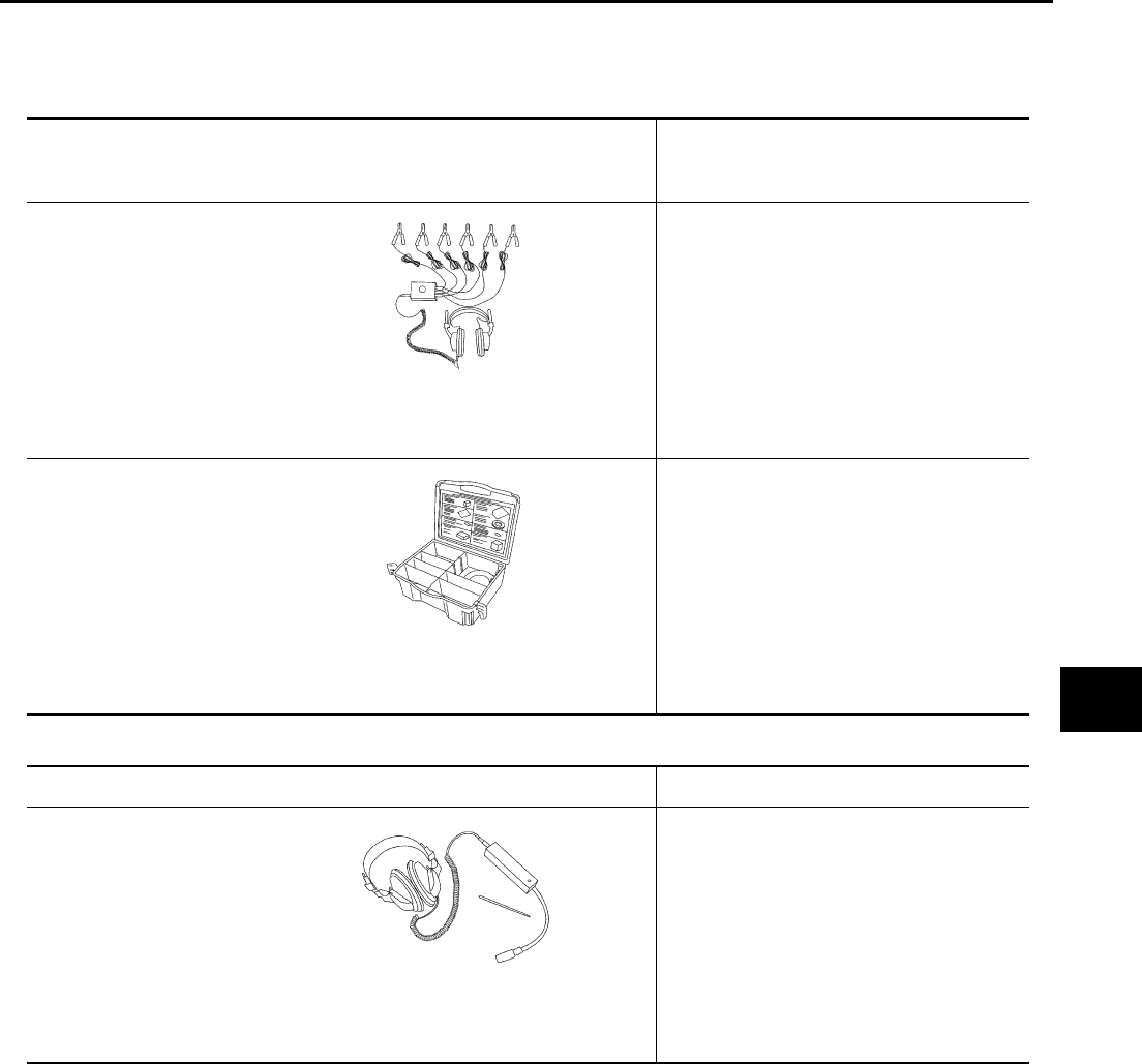
Special Service Tools EIS000YZ
The actual shapes of Kent-Moore tools may differ from those of special service tools illustrated here.
Commercial Service Tools EIS000Z0
Tool number
(Kent-Moore No.)
Tool name
Description
(J-39570)
Chassis ear Location the noise
(J-43980)
NISSAN Squeak and
Rattle Kit
Repairing the cause of noise
SIIA0993E
SIIA0994E
Tool name Description
Engine ear Location the noise
SIIA0995E
BL-6
SQUEAK AND RATTLE TROUBLE DIAGNOSES
Revision: 2004 April 2002 Q45
SQUEAK AND RATTLE TROUBLE DIAGNOSES PFP:00000
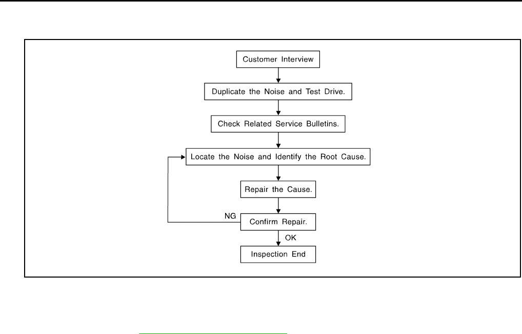
Work Flow EIS000Z1
CUSTOMER INTERVIEW
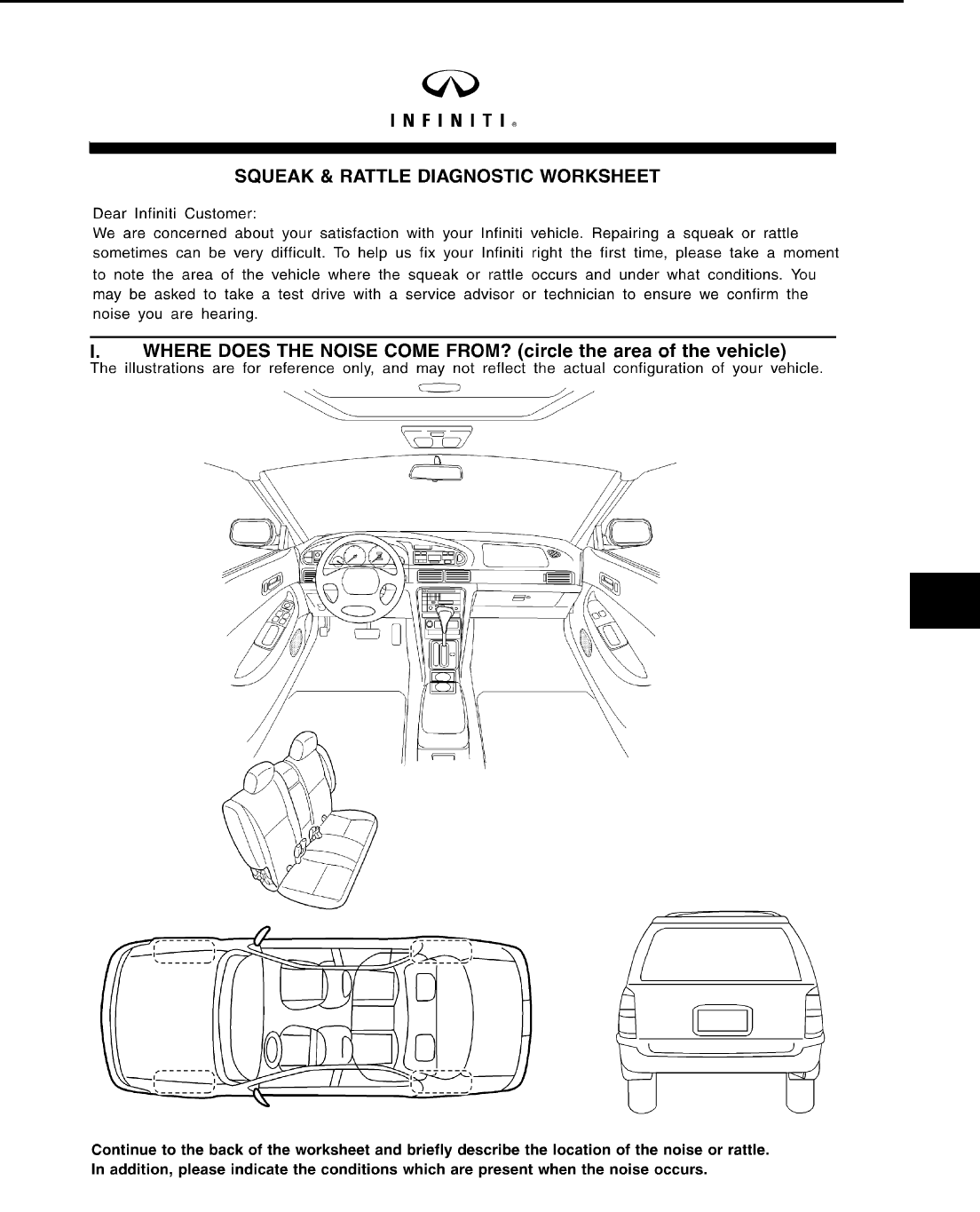
Interview the customer if possible, to determine the conditions that exist when the noise occurs.Use the Diag-
nostic Worksheet during the interview to document the facts and conditions when the noise occurs and any
customer's comments; refer BL-11, "Diagnostic Worksheet" . This information is necessary to duplicate the
conditions that exist when the noise occurs.
●The customer may not be able to provide a detailed description or the location of the noise. Attempt to
obtain all the facts and conditions that exist when the noise occurs (or does not occur).
●If there is more than one noise in the vehicle, be sure to diagnose and repair the noise that the customer
is concerned about. This can be accomplished by test driving the vehicle with the customer.
●After identifying the type of noise, isolate the noise in terms of its characteristics.The noise characteristics
are provided so the customer, service adviser and technician are all speaking the same language when
defining the noise.
●Squeak —(Like tennis shoes on a clean floor)
Squeak characteristics include the light contact/fast movement/brought on by road conditions/hard sur-
faces=higher pitch noise/softer surfaces=lower pitch noises/edge to surface=chirping
●Creak—(Like walking on an old wooden floor)
Creak characteristics include firm contact/slow movement/twisting with a rotational movement/pitch
dependent on materials/often brought on by activity.
●Rattle—(Like shaking a baby rattle)
Rattle characteristics include the fast repeated contact/vibration or similar movement/loose parts/missing
clip or fastener/incorrect clearance.
●Knock —(Like a knock on a door)
Knock characteristics include hollow sounding/sometimes repeating/often brought on by driver action.
●Tick—(Like a clock second hand)
Tick characteristics include gentle contacting of light materials/loose components/can be caused by driver
action or road conditions.
●Thump—(Heavy, muffled knock noise)
Thump characteristics include softer knock/dead sound often drought on by activity.
●Buzz—(Like a bumble bee)
Buzz characteristics include high frequency rattle/firm contact.
●Often the degree of acceptable noise level will vary depending upon the person. A noise that you may
judge as acceptable may be very irritating to the customer.
●Weather conditions, especially humidity and temperature, may have a great effect on noise level.
SBT842

SQUEAK AND RATTLE TROUBLE DIAGNOSES
BL-7
C
D
E
F
G
H
J
K
L
M
A
B
BL
Revision: 2004 April 2002 Q45
DUPLICATE THE NOISE AND TEST DRIVE
If possible, drive the vehicle with the customer until the noise is duplicated. Note any additional information on
the Diagnostic Worksheet regarding the conditions or location of the noise. This information can be used to
duplicate the same conditions when you confirm the repair.
If the noise can be duplicated easily during the test drive, to help identify the source of the noise, try to dupli-
cate the noise with the vehicle stopped by doing one or all of the following:
1) Close a door.
2) Tap or push/pull around the area where the noise appears to be coming from.
3) Rev the engine.
4) Use a floor jack to recreate vehicle "twist".
5) At idle, apply engine load (electrical load, half-clutch on M/T model, drive position on A/T model).
6) Raise the vehicle on a hoist and hit a tire with a rubber hammer.
●Drive the vehicle and attempt to duplicate the conditions the customer states exist when the noise occurs.
●If it is difficult to duplicate the noise, drive the vehicle slowly on an undulating or rough road to stress the
vehicle body.
CHECK RELATED SERVICE BULLETINS
After verifying the customer concern or symptom, check ASIST for Technical Service Bulletins (TSBs) related
to that concern or symptom.
If a TSB relates to the symptom, follow the procedure to repair the noise.
LOCATE THE NOISE AND IDENTIFY THE ROOT CAUSE
1. Narrow down the noise to a general area.To help pinpoint the source of the noise, use a listening tool
(Chassis Ear: J-39570,Engine Ear: J-39565 and mechanics stethoscope).
2. Narrow down the noise to a more specific area and identify the cause of the noise by:
●removing the components in the area that you suspect the noise is coming from.
Do not use too much force when removing clips and fasteners, otherwise clips and fastener can be broken
or lost during the repair, resulting in the creation of new noise.
●tapping or pushing/pulling the component that you suspect is causing the noise.
Do not tap or push/pull the component with excessive force, otherwise the noise will be eliminated only
temporarily.
●feeling for a vibration with your hand by touching the component(s) that you suspect is (are) causing the
noise.
●placing a piece of paper between components that you suspect are causing the noise.
●looking for loose components and contact marks.
Refer to BL-8, "Generic Squeak and Rattle Troubleshooting" .

BL-8
SQUEAK AND RATTLE TROUBLE DIAGNOSES
Revision: 2004 April 2002 Q45
REPAIR THE CAUSE
●If the cause is a loose component, tighten the component securely.
●If the cause is insufficient clearance between components:
–separate components by repositioning or loosening and retightening the component, if possible.
–insulate components with a suitable insulator such as urethane pads, foam blocks, felt cloth tape or ure-
thane tape. A Nissan Squeak and Rattle Kit (J-43980)is available through your authorized Nissan Parts
Department.
CAUTION:
Do not use excessive force as many components are constructed of plastic and may be damaged.
Always check with the Parts Department for the latest parts information.
The following materials are contained in the Nissan Squeak and Rattle Kit (J-43980).Each item can be
ordered separately as needed.
URETHANE PADS [1.5mm(0.059 in) thick]
Insulates connectors, harness, etc.
76268-9E005: 100×135mm(3.94×5.31 in)/76884-71L01: 60×85mm(2.36×3.35 in)/76884-71L02:
15×25mm(0.59×0.98 in)
INSULATOR (Foam blocks)
Insulates components from contact.Can be used to fill space behind a panel.
73982-9E000: 45mm(1.77 in) thick, 50×50mm(1.97×1.97 in)/73982-50Y00: 10mm(0.39 in) think,
50×50mm(1.97×1.97 in)
INSULATOR (Light foam block)
80845-71L00: 30mm(1.18 in) thick, 30×50mm(1.18×1.97 in)
FELT CLOTHTAPE
Used to insulate where movement does not occur.Ideal for instrument panel applications.
68370-4B000: 15×25mm(0.59×0.98 in) pad/68239-13E00: 5mm(0.20 in) wide tape roll The following
materials, not found in the kit, can also be used to repair squeaks and rattles.
UHMW(TEFLON) TAPE
Insulates where slight movement is present. Ideal for instrument panel applications.
SILICONE GREASE
Used in of UHMW tape that will be visible or not fit.
Note: Will only last a few months.
SILICONE SPRAY
Use when grease cannot be applied.
DUCT TAPE
Use to eliminate movement.
CONFIRM THE REPAIR
Confirm that the cause of a noise is repaired by test driving the vehicle. Operate the vehicle under the same
conditions as when the noise originally occurred. Refer to the notes on the Diagnostic Worksheet.
Generic Squeak and Rattle Troubleshooting EIS000Z2
Refer to Table of Contents for specific component removal and installation information.
INSTRUMENT PANEL
Most incidents are caused by contact and movement between:
1. The cluster lid A and instrument panel
2. Acrylic lens and combination meter housing
3. Instrument panel to front pillar garnish
4. Instrument panel to windshield
5. Instrument panel mounting pins
6. Wiring harnesses behind the combination meter
7. A/C defroster duct and duct joint
These incidents can usually be located by tapping or moving the components to duplicate the noise or by
pressing on the components while driving to stop the noise. Most of these incidents can be repaired by apply-
ing felt cloth tape or silicon spray (in hard to reach areas).Urethane pads can be used to insulate wiring har-
ness.

SQUEAK AND RATTLE TROUBLE DIAGNOSES
BL-9
C
D
E
F
G
H
J
K
L
M
A
B
BL
Revision: 2004 April 2002 Q45
CAUTION:
Do not use silicone spray to isolate a squeak or rattle. If you saturate the area with silicone, you will
not be able to recheck the repair.
CENTER CONSOLE
Components to pay attention to include:
1. Shifter assembly cover to finisher
2. A/C control unit and cluster lid C
3. Wiring harnesses behind audio and A/C control unit
The instrument panel repair and isolation procedures also apply to the center console.
DOORS
Pay attention to the:
1. Finisher and inner panel making a slapping noise
2. Inside handle escutcheon to door finisher
3. Wiring harnesses tapping
4. Door striker out of alignment causing a popping noise on starts and stops
Tapping or moving the components or pressing on them while driving to duplicate the conditions can isolate
many of these incidents. You can usually insulate the areas with felt cloth tape or insulator foam blocks from
the Nissan Squeak and Rattle Kit (J-43980) to repair the noise.
TRUNK
Trunk noises are often caused by a loose jack or loose items put into the trunk by the owner.
In addition look for:
1. Trunk lid dumpers out of adjustment
2. Trunk lid striker out of adjustment
3. The trunk lid torsion bars knocking together
4. A loose license plate or bracket
Most of these incidents can be repaired by adjusting, securing or insulating the item(s) or component(s) caus-
ing the noise.
SUNROOF/HEADLINER
Noises in the sunroof/headliner area can often be traced to one of the following:
1. Sunroof lid, rail, linkage or seals making a rattle or light knocking noise
2. Sunvisor shaft shaking in the holder
3. Front or rear windshield touching headliner and squeaking
Again, pressing on the components to stop the noise while duplicating the conditions can isolate most of these
incidents. Repairs usually consist of insulating with felt cloth tape.
SEATS
When isolating seat noise it's important to note the position the seat is in and the load placed on the seat when
the noise is present. These conditions should be duplicated when verifying and isolating the cause of the
noise.
Cause of seat noise include:
1. Headrest rods and holder
2. A squeak between the seat pad cushion and frame
3. The rear seat back lock and bracket
These noises can be isolated by moving or pressing on the suspected components while duplicating the con-
ditions under which the noise occurs. Most of these incidents can be repaired by repositioning the component
or applying urethane tape to the contact area.

BL-10
SQUEAK AND RATTLE TROUBLE DIAGNOSES
Revision: 2004 April 2002 Q45
UNDERHOOD
Some interior noise may be caused by components under the hood or on the engine wall. The noise is then
transmitted into the passenger compartment.
Causes of transmitted underhood noise include:
1. Any component mounted to the engine wall
2. Components that pass through the engine wall
3. Engine wall mounts and connectors
4. Loose radiator mounting pins
5. Hood bumpers out of adjustment
6. Hood striker out of adjustment
These noise can be difficult to isolate since they cannot be reached from the interior of the vehicle. The best
method is to secure, move or insulate one component at a time and test drive the vehicle. Also, engine RPM
or load can be changed to isolate the noise. Repairs can usually be made by moving, adjusting securing, or
insulating the component causing the noise.
SQUEAK AND RATTLE TROUBLE DIAGNOSES
BL-11
C
D
E
F
G
H
J
K
L
M
A
B
BL
Revision: 2004 April 2002 Q45
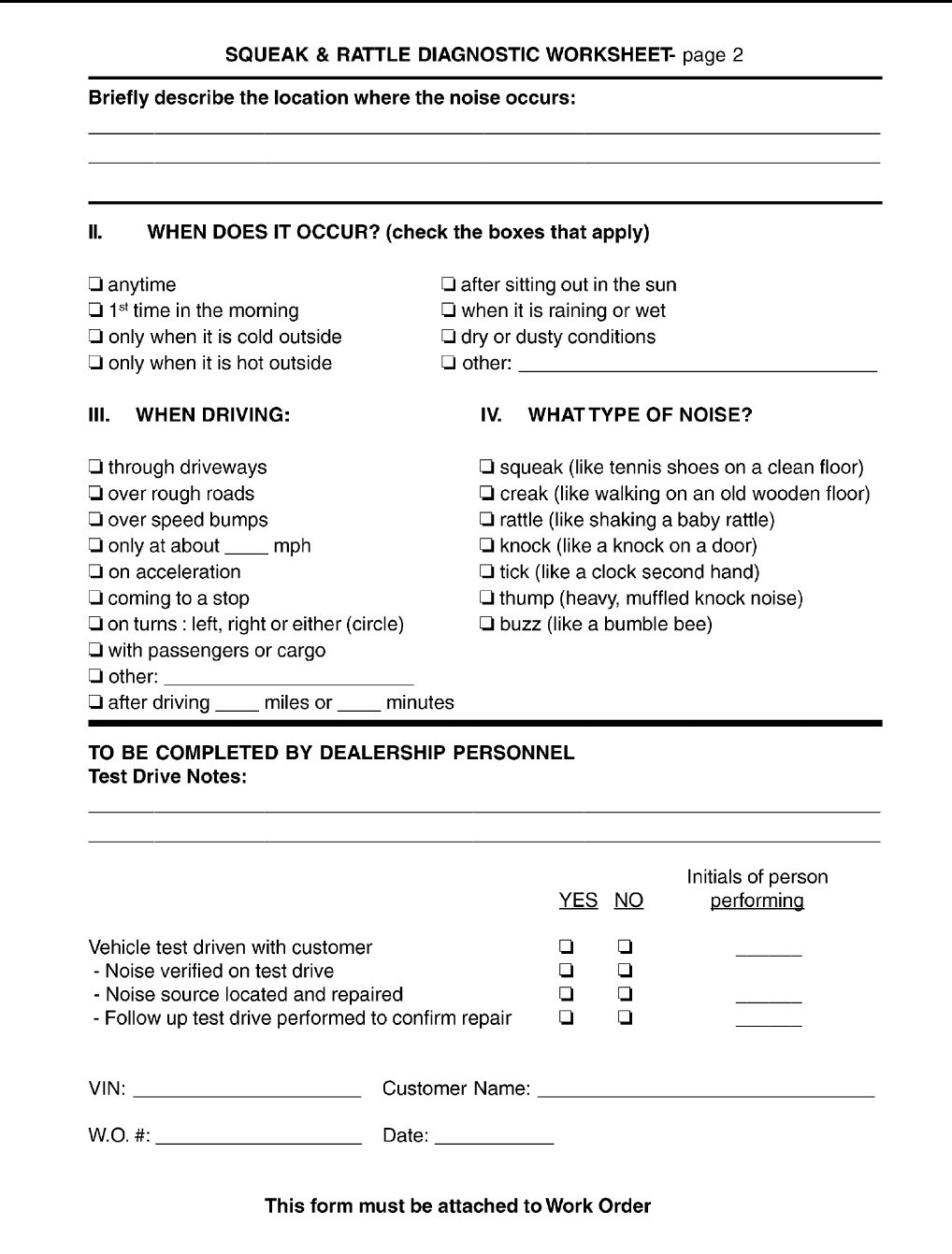
Diagnostic Worksheet EIS000Z3
SBT860
BL-12
SQUEAK AND RATTLE TROUBLE DIAGNOSES
Revision: 2004 April 2002 Q45
SBT844
HOOD
BL-13
C
D
E
F
G
H
J
K
L
M
A
B
BL
Revision: 2004 April 2002 Q45
HOOD PFP:F5100
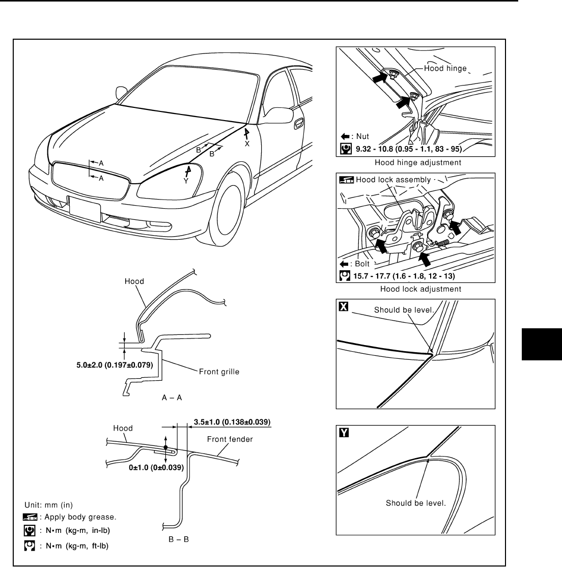
Fitting Adjustment EIS000GD
FRONT END HEIGHT ADJUSTMENT AND LATERAL/LONGITUDINAL CLEARANCE ADJUST-
MENT
1. Remove the hood lock and adjust the height by rotating the bumper rubber until the hood becomes 1 to
1.5 mm (0.04 to 0.059 in) higher than the fender.
2. Temporarily tighten the food lock, and position it by engaging it with the food striker. Check the lock and
striker for looseness, and tighten the lock mounting bolt to the specified torque.
SURFACE HEIGHT ADJUSTMENT
1. Remove the hood lock, and adjust the surface height difference of the hood and fender according to the
fitting standard dimension, by rotating RH and LH bumper rubbers.
2. Install the hood lock temporarily, and align the food striker and lock so that the centers of striker and lock
become vertical viewed from the front, by moving the hood lock laterally.
SIIA0323E
BL-14
HOOD
Revision: 2004 April 2002 Q45
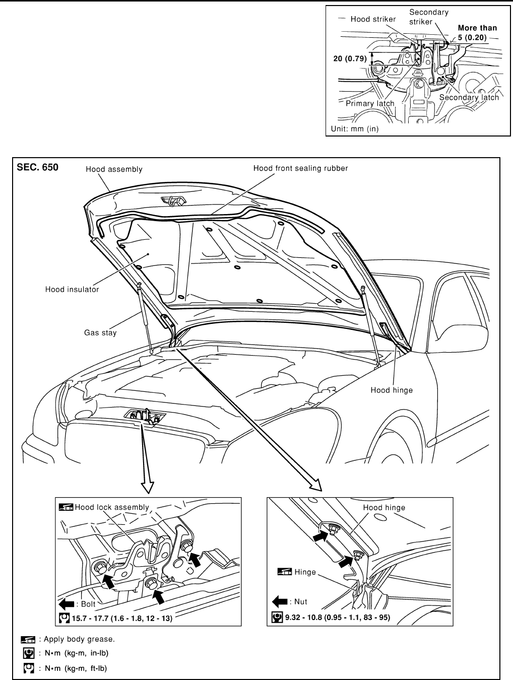
3. Check that the secondary latch is properly engaged with the
secondary striker with hood's own weight by dropping it from
approx. 200 mm (7.87 in) height or by pressing it lightly approx.
3 kg (29 N).
CAUTION:
Do not drop the hood from 300 mm (11.81 in) height or
higher.
4. Move the hood lock up and down so that the striker and lock are
engaged firmly with the hood closed.
5. Tighten the lock mounting bolts to the specified torque.
Removal and Installation of Hood Assembly. EIS000GE
1. Remove stud balls on the hood stays at the body side.
2. Remove the hinge mounting nuts on the hood to remove the hood assembly.
PIIA0181E
SIIA0324E
HOOD
BL-15
C
D
E
F
G
H
J
K
L
M
A
B
BL
Revision: 2004 April 2002 Q45
Install in the reverse order of removal.
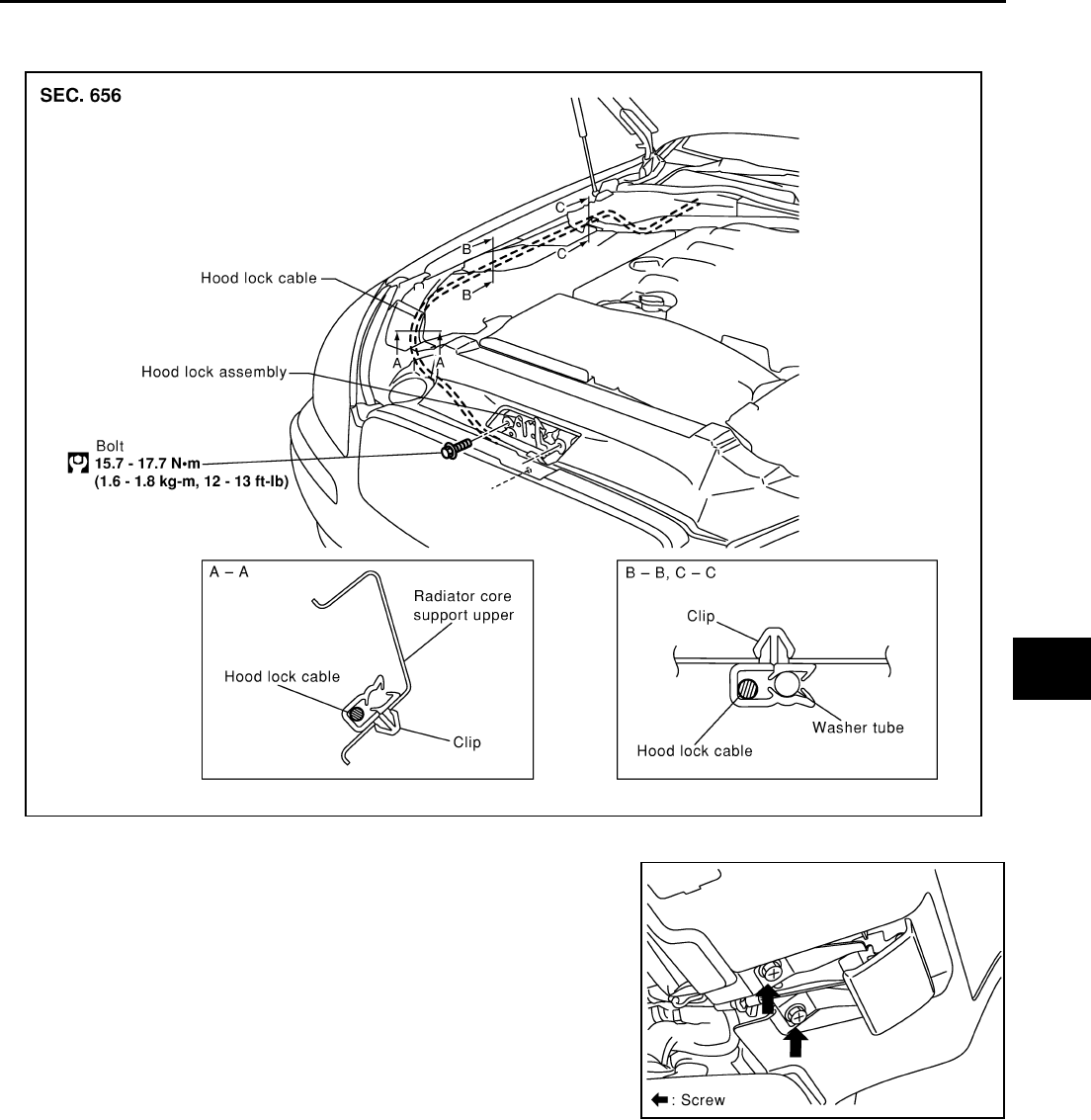
Removal and Installation of Hood Lock Control. EIS000GF
REMOVAL
1. Disconnect the hood lock cable from the hood lock, and clip it
from the radiator core upper support and hood ledge.
2. Remove the mounting screws, and remove the hood opener.
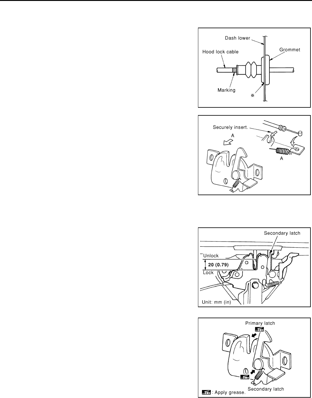
3. Remove the grommet on the dash board, and pull the hood lock
cable toward the passenger compartment.
CAUTION:
While pulling, be careful not to damage (peeling) the out-
side of the hood lock cable.
SIIA0325E
SIIA0326E
BL-16
HOOD
Revision: 2004 April 2002 Q45
INSTALLATION
1. Pull the hood lock cable through the panel hole to the engine compartment.
CAUTION:
Be careful not to bend the cable too much, keeping the
radius 100mm (3.94 in) or more.
2. Check that the cable is not offset from the positioning grommet,
and push the grommet into the panel hole securely.
3. Apply the sealant to the grommet (at * mark) properly.
4. Install the cable securely to the lock.
5. After installing, check the hood lock adjustment and hood
opener operation.
Hood Lock Control Inspection. EIS000GG
CAUTION:
If the hood lock cable is bent or deformed, replace it.
1. Check that the secondary latch is properly engaged with the
secondary striker with hood's own weight by dropping it from
approx. 200 mm (7.87 in) height.
2. While operating the hood opener, carefully check that the front
end of the hood is raised by approx. 20 mm (0.79 in). Also check
that the hood opener returns to the original position.
3. Check the hood lock lubrication condition. If necessary, apply
"body grease" to the points shown in the figure.
PIIA0173E
PIIA0174E
PIIA0175E
PIIA0176E
POWER DOOR LOCK SYSTEM
BL-17
C
D
E
F
G
H
J
K
L
M
A
B
BL
Revision: 2004 April 2002 Q45
POWER DOOR LOCK SYSTEM PFP:24814
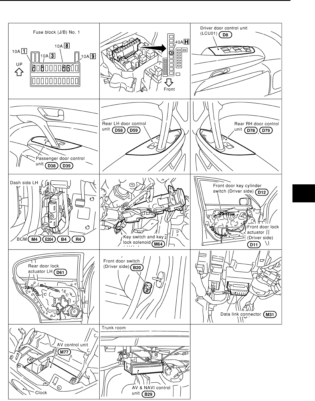
Component Parts and Harness Connector Location EIS000QL
CIIM0003E

BL-18
POWER DOOR LOCK SYSTEM
Revision: 2004 April 2002 Q45
System Description EIS0010I
POWER SUPPLY AND GROUND
Power is supplied at all times
●through 10A fuse [No. 8, located in the fuse block (J/B) No.1]
●to key switch terminal 3.
Power is supplied to BCM terminal 69 through key switch terminal 4 when key switch is inserted in the elec-
tronic key cylinder.
BCM is connected to LCU01 as DATA LINE A-3.
When door switch is in OPEN position, ground is supplied
●to BCM terminal 33, 37, 142 or 143
●through door switch terminal 1
When door is unlocked, ground is supplied
●to door LCU terminal 6 or each door control unit 13
●from terminal 2 of each door unlock sensor.
When the door is locked with the emergency key, ground is supplied
●to LCU01 terminal 10
●through terminal 3 of the key cylinder switch LH
●through body grounds M24 and M114.
When the door is unlocked with the emergency key, ground is supplied
●to LCU01 terminal 9
●through terminal 1 of the key cylinder switch LH
●through body grounds M24 and M114.
OPERATION
●The lock & unlock switch (SW) on driver’s door trim can lock and unlock all doors.
●With the lock knob on front LH door set to “LOCK”, all doors are locked. (Signals from front door unlock
sensor)
●With the door key inserted in the key cylinder on front LH door, turning it to “LOCK”, will lock all doors;
turning it to “UNLOCK” once unlocks the corresponding door; turning it to “UNLOCK” again within 3 sec-
onds after the first unlock operation unlocks all of the other doors. (Signals from front door key cylinder
switch)
Key Reminder Door System
However, if the electronic key is in the electronic key cylinder and one or more of the doors are open, setting
the lock & unlock switch, lock knob, or the door key to “LOCK” locks the doors once but then immediately
unlocks them. (Combination signals from key switch, door switch and door unlock sensor)
POWER DOOR LOCK SYSTEM
BL-19
C
D
E
F
G
H
J
K
L
M
A
B
BL
Revision: 2004 April 2002 Q45
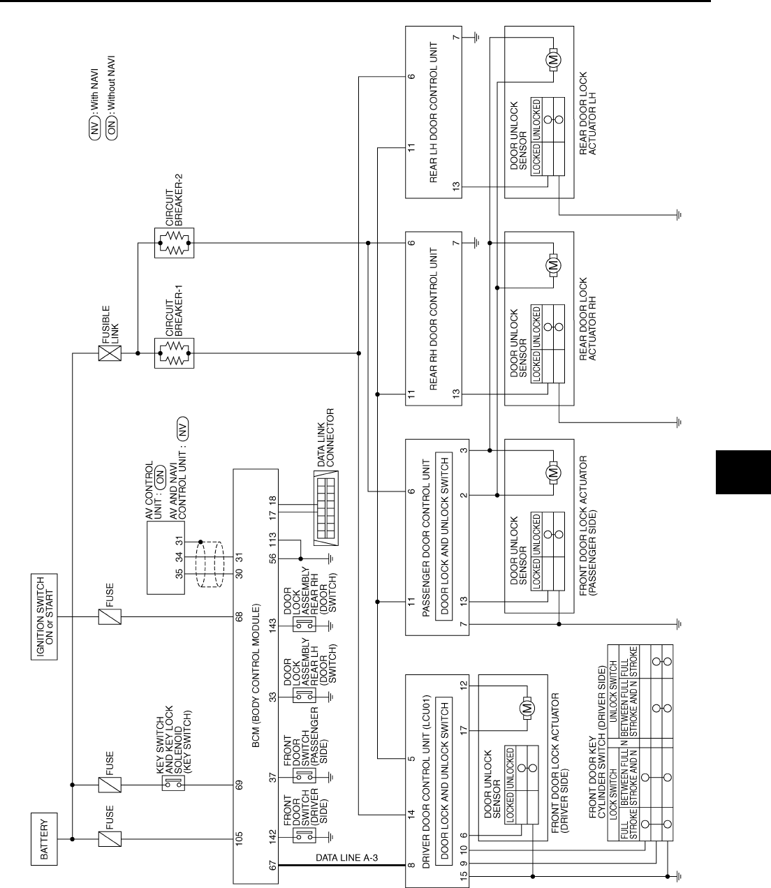
Schematic EIS0010J
TIWM0005E
BL-20
POWER DOOR LOCK SYSTEM
Revision: 2004 April 2002 Q45
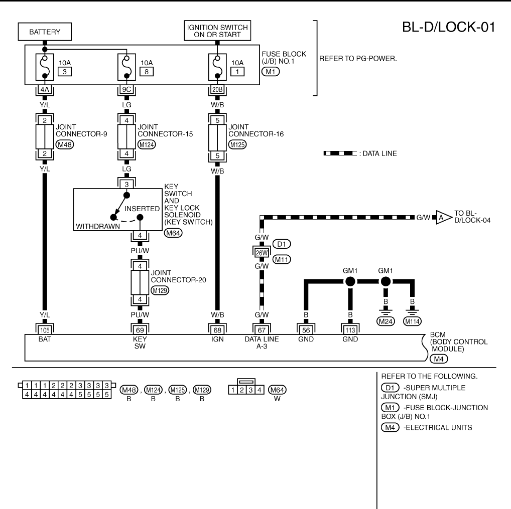
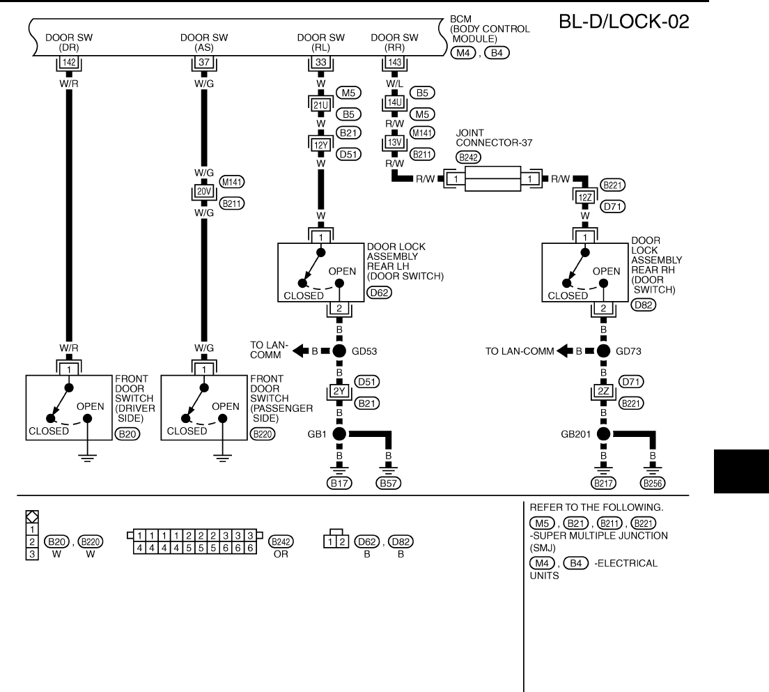
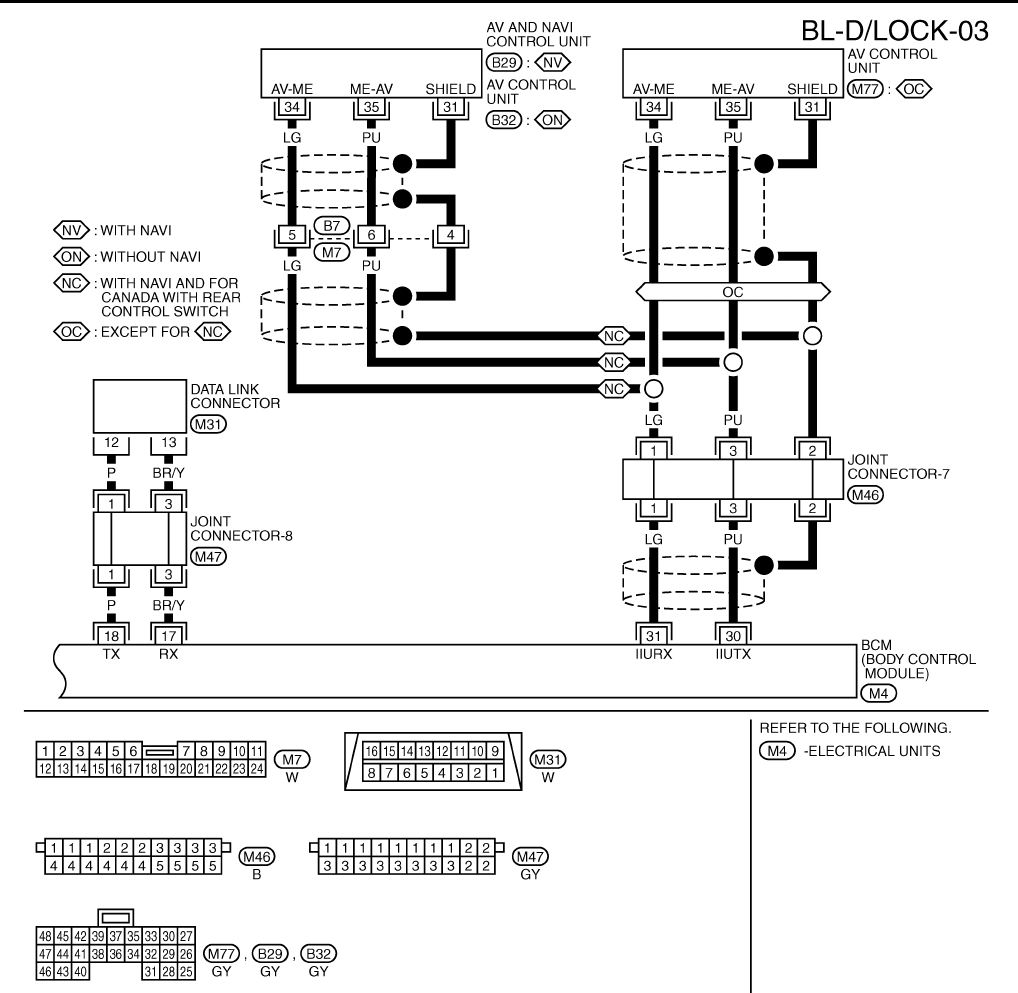
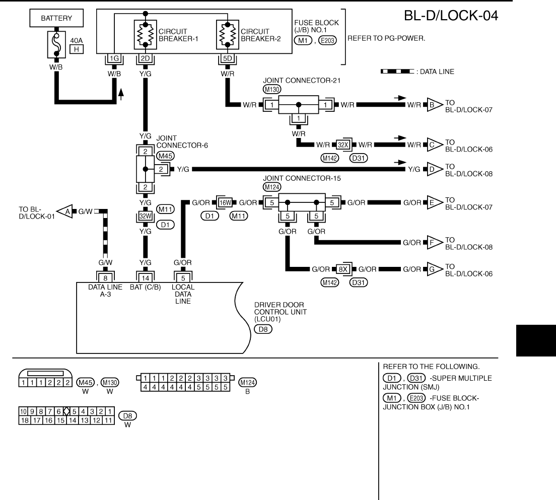
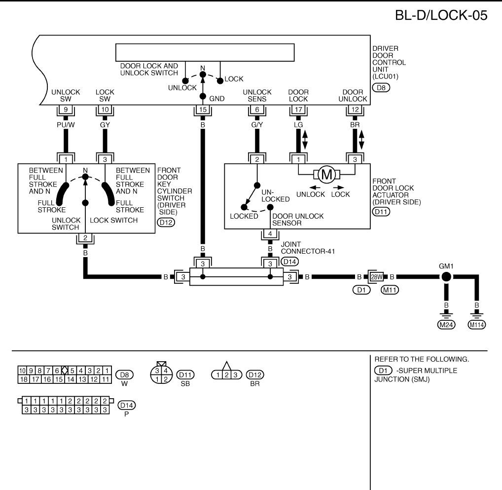
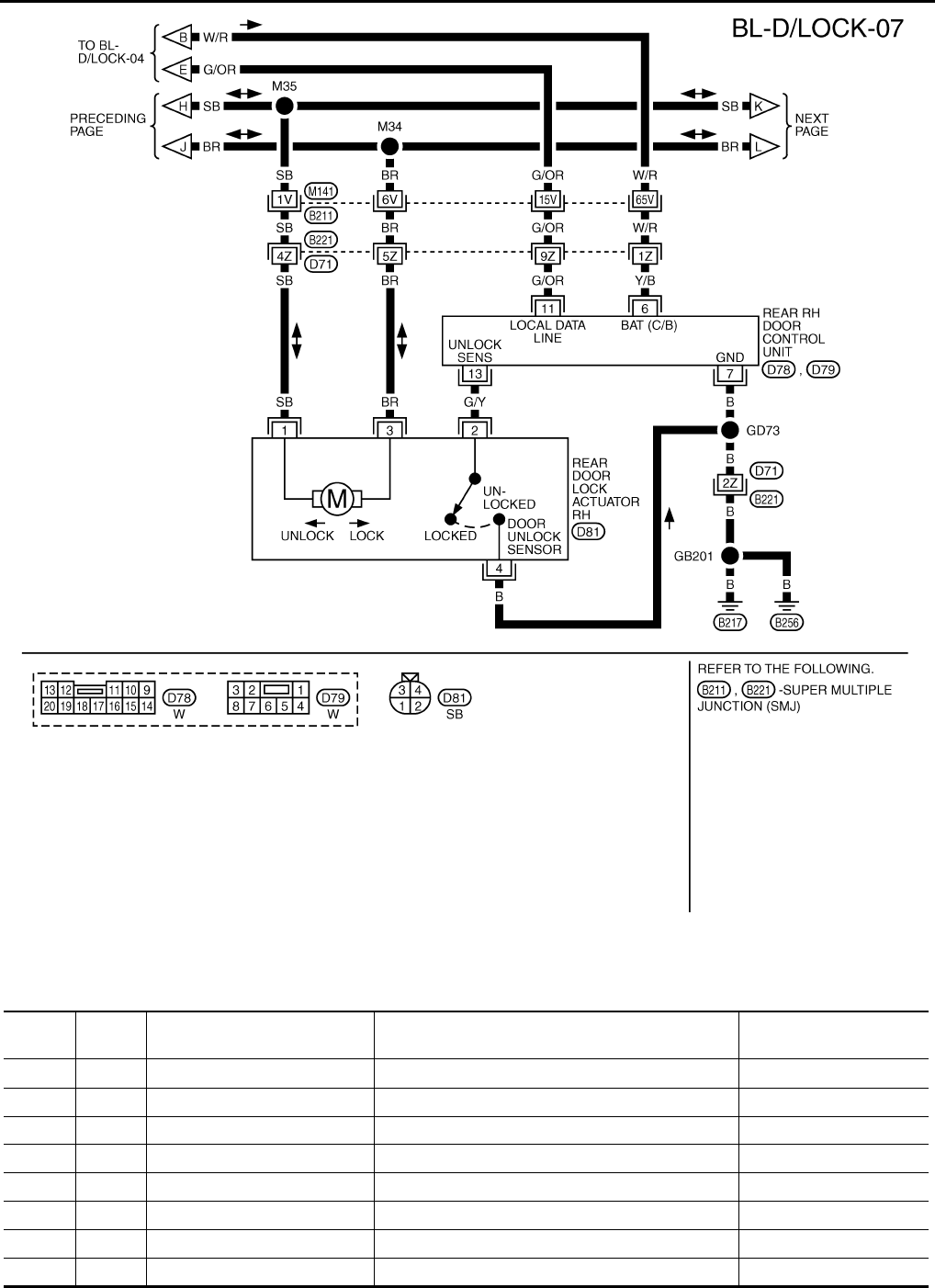
Wiring Diagram – D/LOCK – EIS000QN
TIWM0006E
POWER DOOR LOCK SYSTEM
BL-21
C
D
E
F
G
H
J
K
L
M
A
B
BL
Revision: 2004 April 2002 Q45
TIWM0007E
BL-22
POWER DOOR LOCK SYSTEM
Revision: 2004 April 2002 Q45
TIWM0009E
POWER DOOR LOCK SYSTEM
BL-23
C
D
E
F
G
H
J
K
L
M
A
B
BL
Revision: 2004 April 2002 Q45
TIWM0010E
BL-24
POWER DOOR LOCK SYSTEM
Revision: 2004 April 2002 Q45
TIWM0011E

POWER DOOR LOCK SYSTEM
BL-25
C
D
E
F
G
H
J
K
L
M
A
B
BL
Revision: 2004 April 2002 Q45
TIWM0012E
BL-26
POWER DOOR LOCK SYSTEM
Revision: 2004 April 2002 Q45
Terminals and Reference Value for BCM EIS000QO
TIWM0013E
TERMI-
NAL
WIRE
COLOR ITEM CONDITION VOLTAGE
17 BR/Y Data link RX — —
18 P Data link TX — —
30 PU IIU TX — —
31 LG IIU RX — —
33 W Rear LH door switch Door open (ON) →close (OFF) 0V → Battery voltage
37 W/G Passenger door switch Door open (ON) →close (OFF) 0V → Battery voltage
56 B Ground — 0V
67 G/W Data line A-3 — —
POWER DOOR LOCK SYSTEM
BL-27
C
D
E
F
G
H
J
K
L
M
A
B
BL
Revision: 2004 April 2002 Q45
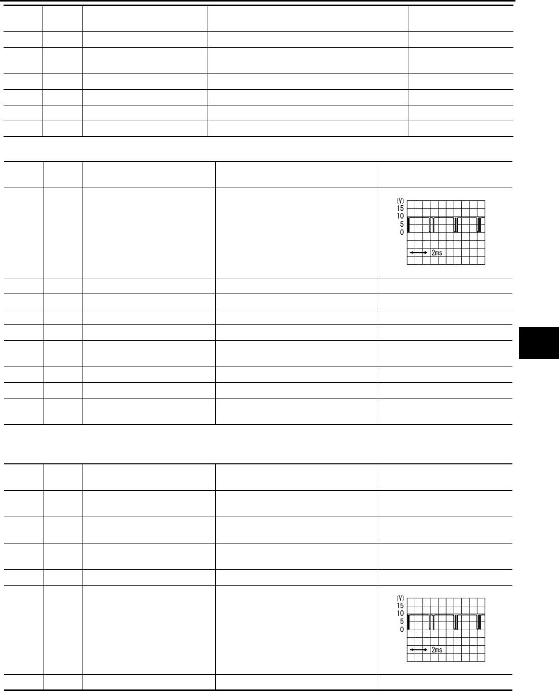
Terminals and Reference Value for Driver Door Control Unit (LCU01) EIS000QP
Terminals and Reference Value for Passenger and Rear LH, RH Door Control
Units EIS000SC
*Only for passenger door control unit.
( ): Wire color for rear RH/LH door control unit.
68 W/B IGN power supply — Battery voltage
69 PU/W Electronic key switch
(insert)
Key Inserted (ON) →
key removed from IGN key cylinder (OFF) Battery voltage→0V
105 Y/L BAT power supply — Battery voltage
113 B Ground — 0V
142 W/R Driver door switch Door open (ON) →close (OFF) 0V → Battery voltage
143 W/L Rear RH door switch Door open (ON) →close (OFF) 0V → Battery voltage
TERMI-
NAL
WIRE
COLOR ITEM CONDITION VOLTAGE
TERMI-
NAL
WIRE
COLOR ITEM CONDITION VOLTAGE
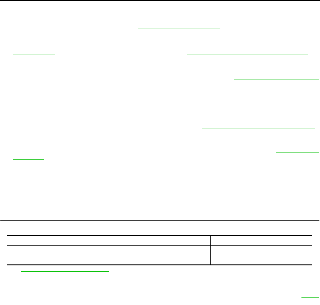
5 G/OR Local communication line —
6 G/Y Door unlock sensor OFF (Locked) → ON (unlocked) 5V → 0V
8 G/W Data line A-3 — —
9 PU/W Door key cylinder unlock switch OFF (Neutral) → ON (Unlocked) 5V → 0V
10 GY Door key cylinder lock switch OFF (Neutral) → ON (Locked) 5V → 0V
12 BR Driver door lock actuator
(Unlock)
Door lock & unlock switch
(Free → Unlocked) 0V → Battery voltage
14 Y/G Power source (PTC) — Battery voltage
15 B Ground — 0V
17 LG Driver door lock actuator
(Lock)
Door lock & unlock switch
(Free → Locked) 0V → Battery voltage
SIIA0591J
TERMI-
NAL
WIRE
COLOR ITEM CONDITION VOLTAGE
*2 SB Door lock actuator (Lock) Door lock & unlock switch
(Free → Locked) 0V → Battery voltage
*3 BR Door lock actuator (Unlock) Door lock & unlock switch
(Free → Unlocked) 0V → Battery voltage
6W/R
(Y/R) Power source (PTC) — Battery voltage
7 B Ground — 0V
11 G/OR Local communication line —
13 G/Y Door unlock sensor OFF (Locked) → ON (unlocked) 5V → 0V
SIIA0591J
BL-28
POWER DOOR LOCK SYSTEM
Revision: 2004 April 2002 Q45
Work Flow EIS00134
1. Check the trouble symptom and customer's requests.
2. Understand the outline of system. Refer to BL-18, "System Description" .
3. Perform the preliminary check. Refer to BL-28, "Preliminary Check" .
4. Perform the communication inspection. If CONSULT-II is used, refer to BL-31, "IVMS COMMUNICATION
INSPECTION" section. If CONSULT-II is not used, refer to BL-35, "COMMUNICATION DIAGNOSIS" . Is
the communication diagnosis result OK? If OK, GO TO step 7. If NG, GO TO step 5.
5. Repair or replace depending on the diagnosis result.
6. Perform the communication diagnosis again. If CONSULT-II is used, refer to BL-31, "IVMS COMMUNICA-
TION INSPECTION" . If CONSULT-II is not used, refer to BL-35, "COMMUNICATION DIAGNOSIS" . Is
communication diagnosis result OK? If OK, GO TO step 7. If NG, GO TO step 5.
7. Perform the self-diagnosis. If CONSULT-II is used, If CONSULT-II is not used, Is self-diagnosis result OK?
If OK, GO TO step 11. If NG, GO TO step 8.
8. Repair or replace depending on the diagnosis result.
9. Perform the self-diagnosis again. If CONSULT-II is used refer to BL-33, "SELF-DIAGNOSIS RESULTS" ,
If CONSULT-II is not used, refer to BL-39, "POWER DOOR LOCK SYSTEM SELF SELF-DIAGNOSIS" .
Is self-diagnosis result OK? If OK, GO TO step 11. If NG, GO TO step 8.
10. Referring to Trouble diagnosis chart, repair or replace the cause of the incident. Refer to BL-40, "Symp-
tom Chart"
11. Does power door lock system operate normally? If it operates normally, GO TO step 12. If NG, GO TO
step 10.
12. Inspection END.
Preliminary Check EIS00135
POWER SUPPLY AND GROUND CIRCUIT INSPECTION
1. FUSE INSPECTION
●Check if any of the following fuses in BCM are blown.
Refer to BL-20, "Wiring Diagram – D/LOCK –" .
Is inspection result OK?
YES >> GO TO 2.
NO >> If fuse is blown, be sure to eliminate cause of problem before installing new fuse, refer to PG-2,
"POWER SUPPLY ROUTING" .
Unit Power source Fuse No.
BCM Battery power supply 3
IGN power supply 1

POWER DOOR LOCK SYSTEM
BL-29
C
D
E
F
G
H
J
K
L
M
A
B
BL
Revision: 2004 April 2002 Q45
2. POWER SUPPLY CIRCUIT INSPECTION
Remove the connectors for BCM and driver door LCU or passenger, rear LH, RH door control units, measure
the voltage between terminal No. (refer to the "Chart" below) of connector and body ground.
OK or NG?
OK >> GO TO 3.
NG >> Check harness for opened short.
3. GROUND CIRCUIT INSPECTION
Check the continuity between the following terminals connector for BCM, driver door LCU, passenger or rear
RH, LH door control units and body ground.
OK or NG?
OK >> Power supply and ground circuit is.
NG >> Repair or replace harness.
CONSULT–II Function EIS00136
●CONSULT-II executes the following functions by combining data reception and command transmission via
the communication line from BCM. IVMS communication inspection, work support (only function setting of
seats and steering wheel), self-diagnosis, data monitor, and active test display.
DIAGNOSTIC ITEMS DESCRIPTION
Unit Terminals
(wire color) Power source condition Voltage
Connector (+) (–)
BCM (M4) 105 (Y/L)
Body ground
Battery power supply Ignition switch OFF Battery voltage
68 (W/B) IGN power supply Ignition switch ON Battery voltage
Driver door LCU (D8) 14 (Y/G) Battery power supply Ignition switch OFF Battery voltage
Passenger door con-
trol unit (D39) 6 (W/R)
Battery power supply Ignition switch OFF Battery voltage
Rear LH door control
unit (D59) 6 (Y/B)
Rear RH door control
unit (D79) 6 (Y/B)
Unit Terminal
(wire color) Signal Ignition switch Continuity
Connector (+) (–)
BCM (M4) 56 (B) and 113 (B)
Body ground
Ground Ignition switch OFF Continuity should exist
Driver door LCU (D8) 15 (B) Ground Ignition switch OFF Continuity should exist
Passenger door con-
trol unit (D39)
7 (B) Ground Ignition switch OFF Continuity should exist
Rear LH door control
unit (D59)
Rear RH door control
unit (D79)
IVMS diagnosis
position Diagnosis mode Description
IVMS–
COMM CHECK
IVMS–
COMM DIAGNOSIS
Diagnosis of continuity in the communication line(s), and of the function of the
IVMS-communication interface between the body control module and the
local control units, accoplished by transmitting a signal from the body control
module to the local control units.
WAKE–UP DIAGNOSIS
Diagnosis of the“ wake-up” function of local control units by having a techni-
cian input the switch data into the local control unit that is in the temporary
“sleep” condition.
BL-30
POWER DOOR LOCK SYSTEM
Revision: 2004 April 2002 Q45
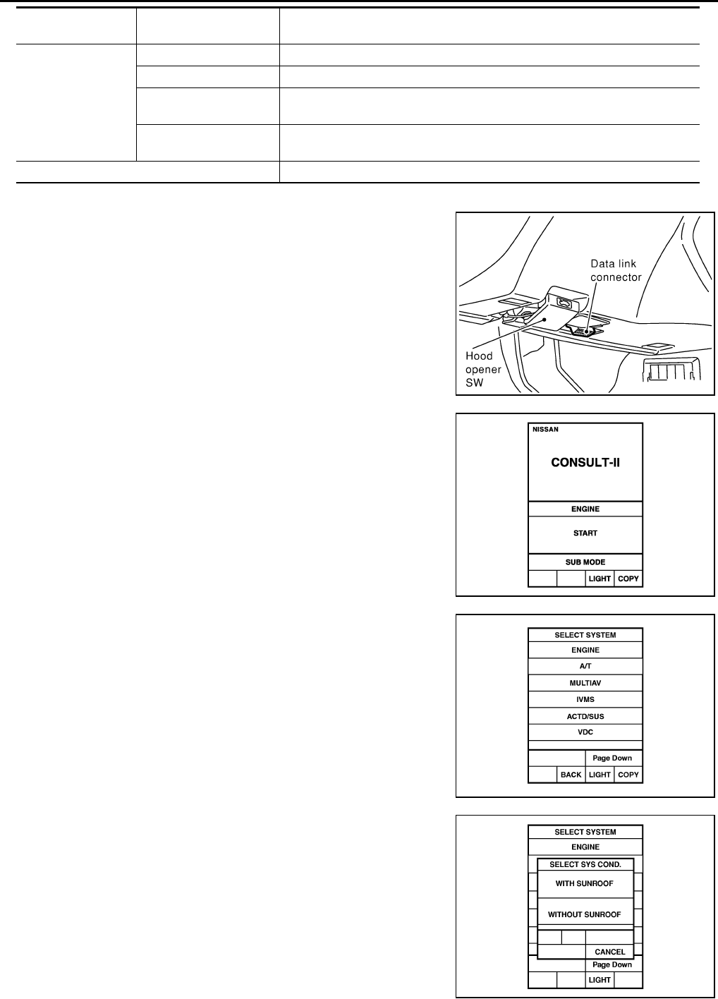
CONSULT-II BASIC OPERATION PROCEDURE
1. With the ignition switch OFF, connect CONSULT–II to the data
link connector, and turn the ignition switch ON.
2. Touch "START".
3. Touch "IVMS".
4. Check the model specification, touch either "WITH SUNROOF"
or "WITHOUT SUNROOF".
5. Touch "OK". If the selection is wrong, touch "CANCEL".
Each system
inspection .
Work support Changes the setting for each function.
Self-diagnosis results Carries out self-diagnosis.
Data monitor Displays data relative to the body control module (BCM) input signals and var-
ious control related data for each system.
Active test Turns on/off actuators, relay and according to the commands transmitted by
the CONSULT-II unit.
BCM PART NUMBER Displays BCM part No.
IVMS diagnosis
position Diagnosis mode Description
SHIA0179E
PIIA0182E
PIIA0183E
PIIA0184E

POWER DOOR LOCK SYSTEM
BL-31
C
D
E
F
G
H
J
K
L
M
A
B
BL
Revision: 2004 April 2002 Q45
6. Select the desired part to be diagnosed on the "SELECT TEST ITEM" screen.
IVMS COMMUNICATION INSPECTION
●IVMS contains the IVMS communication diagnosis and wake–up diagnosis.
IVMS Communication Diagnosis.
●IVMS communication diagnosis consists of the communication diagnosis, sleep diagnosis, and inactive
communication diagnosis between BCM and each local unit (LCU), and display the results on the CON-
SULT–ll screen.
NOTE:
Sleep is a power saving function when a vehicle is stationary (all BCM related electrical equipment: OFF,
and the timer: OFF).
●The function also stores the communication malfunction records and inactive communication records, and
displays the data on the CONSULT–II screen (Error record diagnosis)
*: malfunctioning item record
Operation Procedure
1. Touch "IVMS-COMM CHECK" on "SELECT TEST ITEM".
2. Touch "IVMS-COMM DIAGNOSIS" on "SELECT DIAG ITEM" screen.
3. Touch "START" on "IVMS-COMM DIAGNOSIS" screen to start the diagnosis.
4. After the diagnosis is completed, the malfunctioning system is displayed.
5. When the malfunctioning items are displayed, touch "PRINT" to record.
6. Touch "ERASE".
7. Perform the communication inspection again to check that any malfunctioning item is displayed.
8. Check the displayed items.
Wake-Up Diagnosis
●The wake-up diagnosis is carried out when BCM detects the wake-up signal from each local unit (LCU).
When the switch shown on the screen is operated as instructed, each local control unit (LCU) outputs the
wake-up signal. If BCM cannot detect a wake-up signal, it is judged malfunctioning. The malfunctioning
local control unit (LCU) is displayed on the screen.
NOTE:
If any unspecified switch is operated, "Switch data not match" is displayed as a malfunctioning system.
Operation Procedure
1. Touch "IVMS-COMM CHECK" on "SELECT TEST ITEM" screen.
2. Touch "WAKE-UP DIAGNOSIS" on "SELECT DIAG ITEM" screen.
3. Touch "START" on "WAKE-UP DIAGNOSIS" screen to start the diagnosis.
4. Touch "NEXT" to select the local control unit (LCU) to be diagnosed.
5. Check that any malfunction is displayed. If necessary, touch "PRINT" to record.
6. Perform the inspection to the malfunctioning item.
Malfunction
description
CONSULT–II dis-
play item Description
Communication
error COMM DATA
●Communicating with each LCU is judged sound when the communication is nor-
mally completed and the transmitted data and received data are identically the
same. In other cases, it is judged malfunctioning. If the communication is inactive,
no diagnosis result is displayed.
Inactive communi-
cation NO RESPONSE
●Communicating with each LCU is judged sound when at least one time communi-
cation is normally completed within three trials. In other cases, it is judged mal-
functioning.
Sleep malfunction SLEEP ●Check that each LCU enters sleep mode.
Communication
error *
PAST COMM
DATA
●The records when communication signal malfunctions were continuously detected
while the communication was normal are displayed. Or the records when a mal-
function is detected during the past sleep mode are displayed.
Inactive communi-
cation*
PAST NO
RESPONSE
●The records when inactive communications were continuously detected while the
communication was normal are displayed.

BL-32
POWER DOOR LOCK SYSTEM
Revision: 2004 April 2002 Q45
Malfunction Code Table
NOTE:
●For a specific local control unit (LCU), either "PAST COMM DATA" or "PAST NO RESPONSE" may be displayed instead of the
above results. This is caused by the data record, so erase the records.
(The display only shows the incident records, they are not malfunctions caused during the diagnosis. One possible cause is that an
irreproducible incident symptom occurred.)
●Follow the steps below to erase the memory
Perform either disconnect BCM battery power supply or erase memory with CONSULT-II.
●With the battery connected, if the local control unit (LCU) connector is disconnected and left for approximately 1 minute, the BCM
stores "NO RESPONSE" record.
Malfunctioning
item Display unit CONSULT–II IVMS communication
diagnosis content
Self-diagnosis
trouble code
No.
Malfunctioning system and
reference
COMM DATA
One LCU is dis-
played.
POWER WINDOW C/U–DR
"COMM DATA" 24
Replace the displayed
LCU.
DOOR MIRROR C/U–RH
"COMM DATA" 27
DOOR MIRROR C/U–LH
"COMM DATA" 37
POWER SEAT C/U–DR
"COMM DATA" 47
Multiple LCUs
are displayed
BCM
"COMM FAIL1" ,"COMM FAIL2"
Displays in
order of 24
→27→37→47
→and cycles
from 24.
Communication system A:
Refer to BL-33, "COMMU-
NICATION SYSTEM A" .
NO
RESPONSE
One LCU is dis-
played.
POWER WINDOW C/U–DR
"NO RESPONSE" 25
Communication system B:
Refer to BL-33, "COMMU-
NICATION SYSTEM B" .
DOOR MIRROR C/U–RH
"NO RESPONSE" 28
DOOR MIRROR C/U–LH
"NO RESPONSE" 38
POWER SEAT C/U–DR
"NO RESPONSE" 48
Multiple LCUs
are displayed BCM/HARNESS
Displays in
order of
25→28→38→4
8 and cycles
from 25.
Communication system C:
Refer to BL-33, "COMMU-
NICATION SYSTEM C" .
SLEEP malfunc-
tion
One LCU is dis-
played.
POWER WINDOW C/U–DR "SLEEP"
No self-diagno-
sis function
Replace the displayed
LCU.
DOOR MIRROR C/U–RH
"SLEEP"
DOOR MIRROR C/U–LH
"SLEEP"
POWER SEAT C/U–DR
"SLEEP"
Multiple LCUs
are displayed All the above control units are displayed. No self-diagno-
sis function
Communication system A:
Refer to BL-33, "COMMU-
NICATION SYSTEM A" .

POWER DOOR LOCK SYSTEM
BL-33
C
D
E
F
G
H
J
K
L
M
A
B
BL
Revision: 2004 April 2002 Q45
COMMUNICATION SYSTEM A
1. BCM INSPECTION
Replace the BCM with a known-good one, and carry out the communication diagnosis. Refer to BL-31, "IVMS
COMMUNICATION INSPECTION" .
OK or NG?
OK >> Replace the BCM.
NG >> GO TO 2.
2. LCU INSPECTION
1. Replace with the previously installed BCM.
2. Replace the LCU with a known-good one, and carry out the communication diagnosis. Refer to BL-31,
"IVMS COMMUNICATION INSPECTION" .
OK or NG?
OK >> Replace the LCU.
NG >> Repair or replace harness.
COMMUNICATION SYSTEM B
1. CONNECTOR INSPECTION
Check the terminals (at the control unit and harness) on the malfunctioning LCU for disconnection, bend, and
other malfunctions.
OK or NG?
OK >> GO TO 2.
NG >> Repair the terminals and connectors.
2. LCU INSPECTION
Replace the LCU with a known-good one, and carry out the communication diagnosis. Refer toBL-31, "IVMS
COMMUNICATION INSPECTION" .
OK or NG?
OK >> Replace the LCU.
NG >> Repair the communication harness between the indicated LCU and BCM.
COMMUNICATION SYSTEM C
1. CONNECTOR INSPECTION
Check the terminals (at the control unit and harness) on BCM and LCU for disconnection, bend, and other
malfunctions.
OK or NG?
OK >> GO TO 2.
NG >> Repair the terminals and connectors.
2. BCM INSPECTION
Replace the BCM with a known-good one, and carry out the communication diagnosis. Refer to BL-31, "IVMS
COMMUNICATION INSPECTION" .
OK or NG?
OK >> Replace the BCM.
NG >> Repair the communication harness between the LCU and BCM control.
SELF-DIAGNOSIS RESULTS
Operation Procedure
1. Touch "DOOR LOCK" on the "SELECT TEST ITEM" screen.
2. Touch "SELF-DIAG RESULTS" on the "SELECT DIAG MODE" screen.
3. Touch "START" on the "SELF DIAG RESULTS" screen.

BL-34
POWER DOOR LOCK SYSTEM
Revision: 2004 April 2002 Q45
4. Door lock actuator automatically locks/unlocks all the doors before the door lock actuator self-diagnosis
start.
5. After the diagnosis is completed, the malfunctioning system name is displayed.
6. When the malfunctioning items are displayed, touch "PRINT" to keep the records.
7. Touch "ERASE".
8. Perform the self-diagnosis again to check that any malfunctioning item is displayed.
9. Perform out the inspection to the displayed items. If "No failure" is displayed, the malfunctioning item
recorded at first shall be checked.
Self-Diagnostic Result List
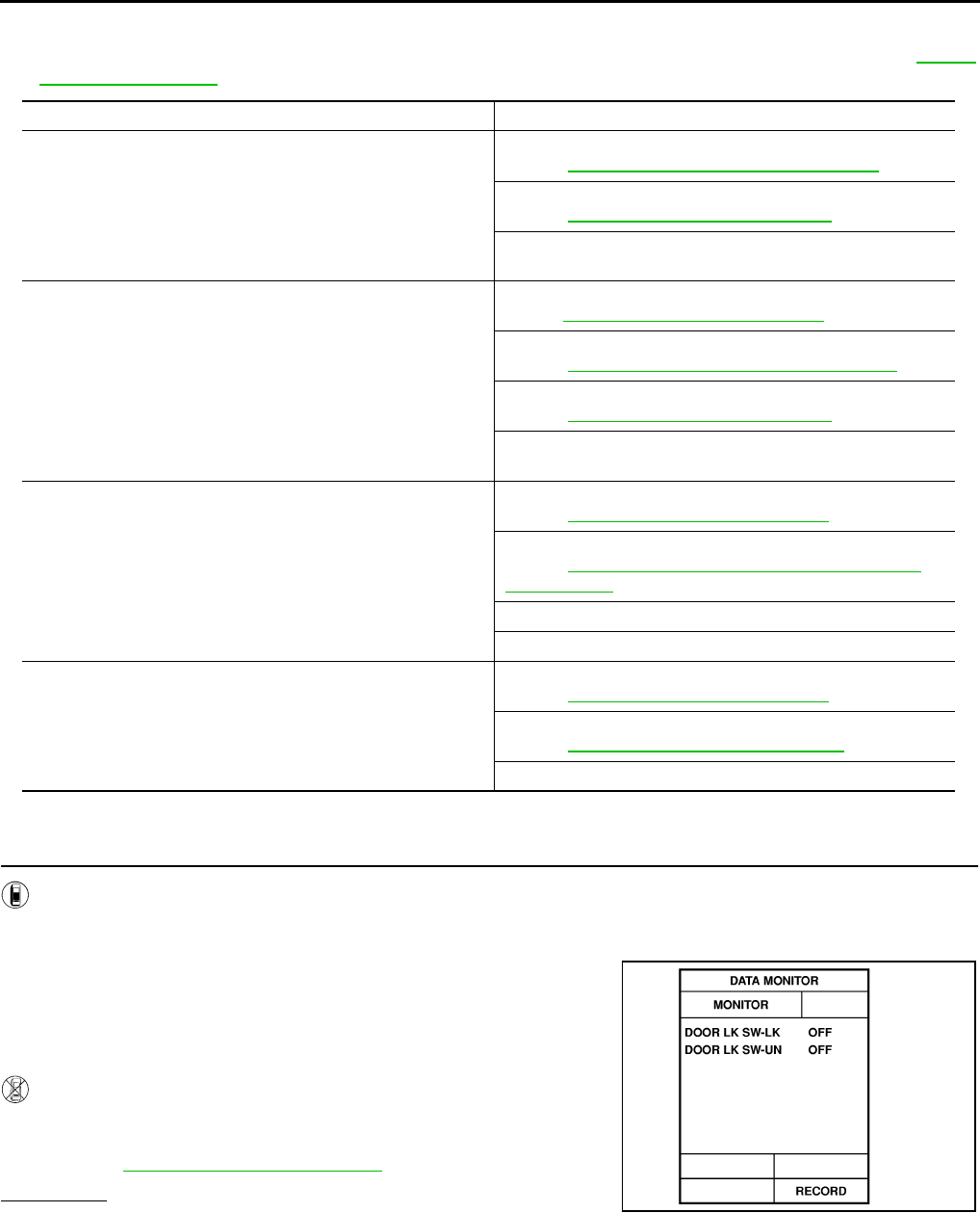
DATA MONITOR
Operation Procedure
1. Touch "DOOR LOCK" on "SELECT TEST ITEM" screen.
2. Touch "DATA MONITOR" on "SELECT DIAG MODE" screen.
3. Touch "MAINSIGNALS" or "SELECTION FROM MENU" on "DATA MONITOR" screen.
4. Touch "START".
5. If "SELECTION FROM MENU" is selected, touch the desired monitor item. If "MAIN SIGNALS" is
selected, the main item required to control is monitored.
6. During monitoring, touching "COPY" can start recording the monitor item status.
Data Monitor Item
ACTIVE TEST
Operation Procedure
1. Touch "DOOR LOCK" on "SELECT TEST ITEM" screen.
Malfunctioning system. Malfunction detecting condition
DOOR LOCK MOTOR-DR The circuit for the driver side door lock actuator/unlock sensor is malfunctioning.
DOOR LOCK MOTOR-AS The circuit for the passenger side door lock actuator/unlock sensor is malfunctioning.
DOOR LOCK MOTOR-RR/RH The circuit for the rear RH side door lock actuator/unlock sensor is malfunctioning.
DOOR LOCK MOTOR-RR/LH The circuit for the rear LH side door lock actuator/unlock sensor is malfunctioning.
NO DTC IS DETECTED/FUR-
THER TESTING MAY BE
REQUIRED
No malfunction in the above items.
MAIN SIGNALS Monitors the main items.
SELECTION FROM MENU Selects and monitors the items.
Monitored item Description
IGN KEY SW Indicates [ON/OFF] condition of electronic key switch.
IGN ON SW Indicates [ON/OFF] condition of ignition switch.
DOOR LK SW-LK Indicates [ON/OFF] condition of lock signal from lock/unlock switch front LH.
DOOR LK SW-UN Indicates [ON/OFF] condition of unlock signal from lock/unlock switch front LH.
LOCK SIG-DE Indicates [ON/OFF] condition of driver door unlock signal from door lock sensor.
LOCK SIG-AS Indicates [ON/OFF] condition of passenger door unlock signal from door lock sensor.
LOCK SIG-RR/LH Indicates [ON/OFF] condition of rear LH door unlock signal from door lock sensor.
LOCK SIG-RR/RH Indicates [ON/OFF] condition of rear RH door unlock signal from door lock sensor.
DOOR SW-DR Indicates [ON/OFF] condition of front door switch LH.
DOOR SW-AS Indicates [ON/OFF] condition of front door switch RH.
KEY CYL UN-DR Indicates [ON/OFF] condition of unlock signal from driver door key cylinder.
KEY CYL LK-DR Indicates [ON/OFF] condition of lock signal from driver door key cylinder.
MAIN/S UNLK AS Indicates [ON/OFF] condition of unlock signal from lock/unlock switch front RH
MAIN/S LOCK AS Indicates [ON/OFF] condition of lock signal from lock/unlock switch front RH
POWER DOOR LOCK SYSTEM
BL-35
C
D
E
F
G
H
J
K
L
M
A
B
BL
Revision: 2004 April 2002 Q45
2. Touch "ACTIVE TEST" on "SELECT DIAG MODE" screen.
3. Touch the item to be tested, and check the operation.
4. During the operation check, touching "OFF" deactivates the operation.
Active Test Item
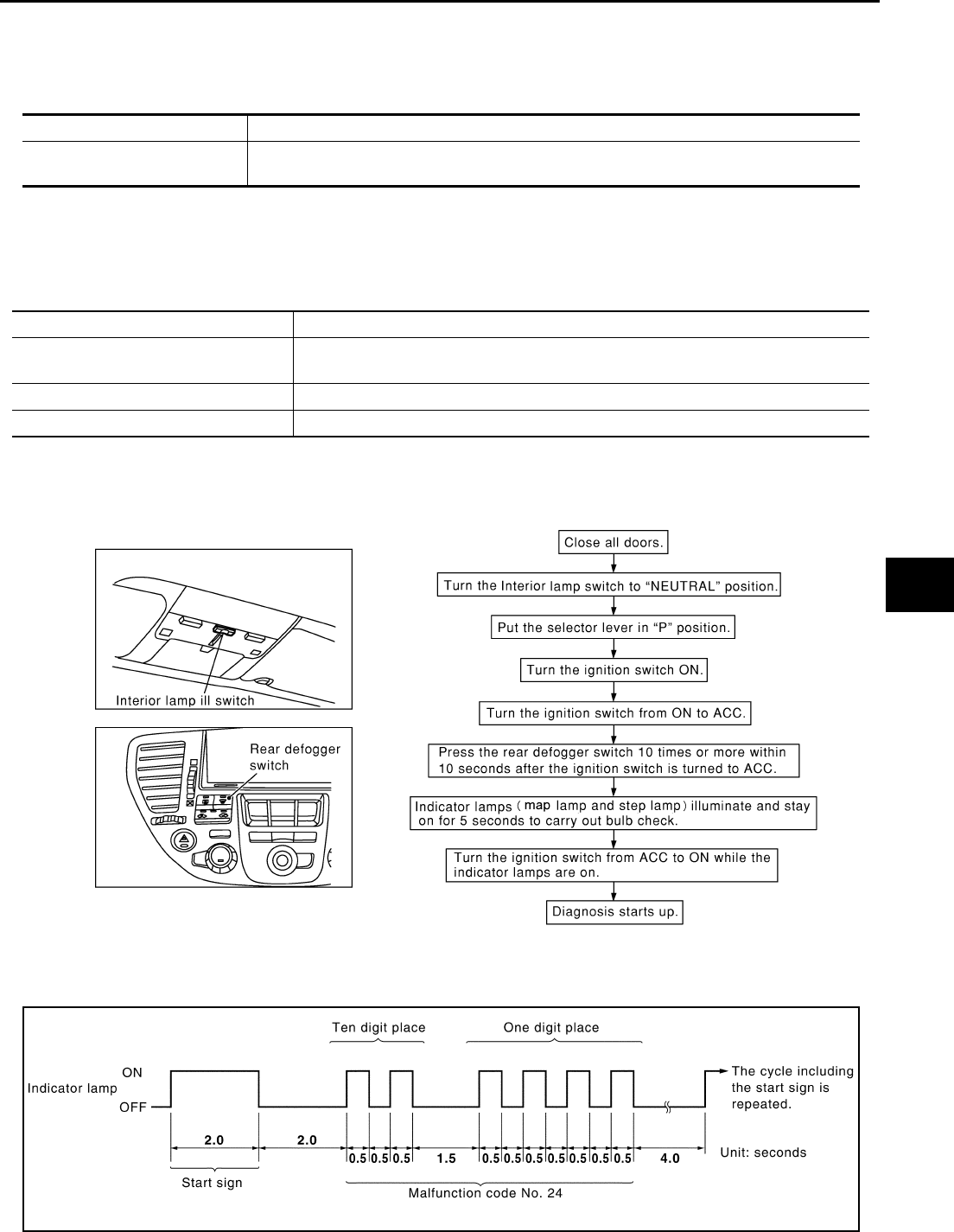
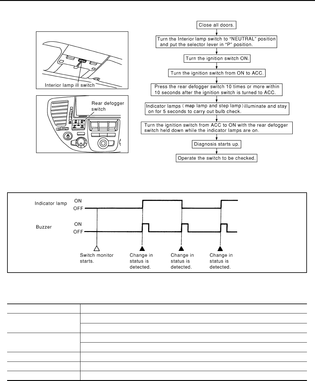
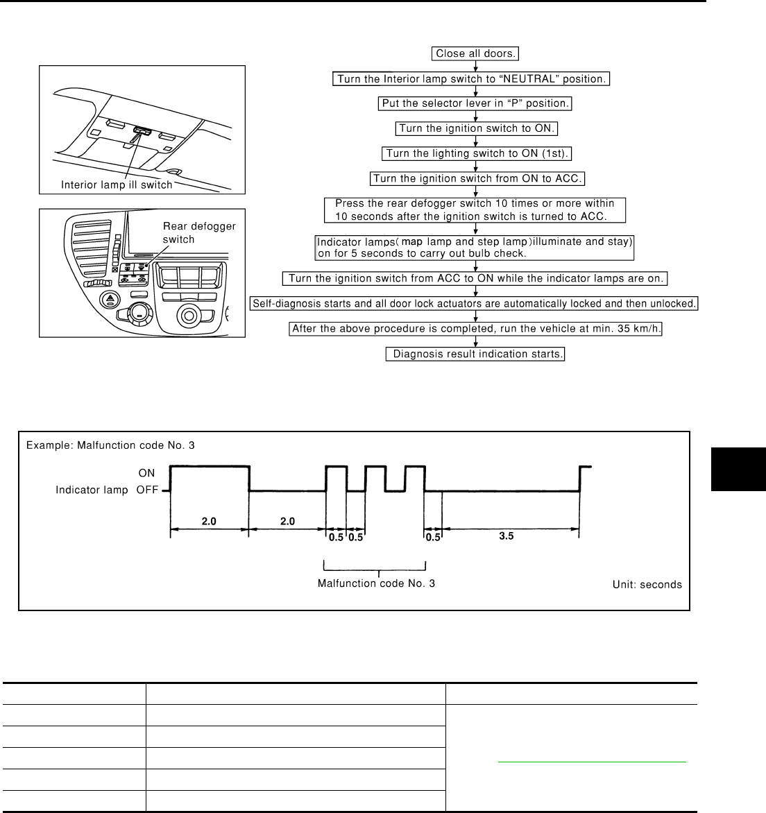
On Board Diagnosis EIS00137
ON BOARD DIAGNOSTIC RESULTS INDICATOR LAMP
●Front map lamps and step lamps (all seats) act as the indicators for the on board diagnosis.
DIAGNOSIS ITEM
COMMUNICATION DIAGNOSIS
●Check the communication between BCM and local control unit (LCU).
How To Perform Communication Diagnosis
Description
In this mode, a malfunction code is indicated by the number of flashes from the front map lamps and step
lamps as shown below:
Test item. Malfunction detecting condition
DR LOCK MTR-ALL This test is able to check all door lock actuators lock operation.
These actuators lock when “ON” on CONSULT-II screen is touched.
Diagnosis item Content
IVMS communication diagnosis Diagnosis any abnormality or inability of communication between BCM and LCU (DATA
LINE A-3).
Switch monitor Monitoring conditions of switches connected to BCM, LCU and Door control unit.
Power door lock system self-diagnosis Diagnose malfunctions in the each door lock actuator system.
SIIA0409E
SIIA0410E

BL-36
POWER DOOR LOCK SYSTEM
Revision: 2004 April 2002 Q45
After indicator lamp turns on for 2 seconds then off for 2 seconds, it flashes [cycling ON (0.5 sec.)/OFF (0.5
sec.)] to indicate a malfunction code of the first digit. Then, 1 second after indicator lamp turns off, it again
flashes [cycling ON (0.5 sec.)/OFF (0.5 sec.)] to indicate a malfunction code of the second digit.
For example, the indicator lamp goes on and off for 0.5 seconds twice and after 1.0 seconds, it goes on and off
for 0.5 seconds four times. This indicates malfunction code.
Malfunction Code Table
NOTE:
●For a specific local control unit (LCU), either "PAST COMM DATA" or "PAST NO RESPONSE" may be displayed instead of the
above results. This is caused by the data record, so erase the records.
(The display only shows the fault records, they are not malfunctions caused during the diagnosis. One possible cause is that an
irreproducible fault symptom occurred.)
●Follow the steps below to erase the memory
Carry out either disconnect BCM battery power supply or erase memory with CONSULT-II.
●With the battery connected, if the local control unit (LCU) connector is disconnected and left for approximately 1 minute, the BCM
stores "NO RESPONSE" record.
Cancel Of Communication Diagnosis
If the following conditions are satisfied, the communication diagnosis is cancelled.
Malfunctioning
item Display unit CONSULT–II IVMS communication
diagnosis content
Self-diagnosis
trouble code
No.
Malfunctioning system and
reference
COMM DATA
One LCU is dis-
played.
POWER WINDOW C/U–DR
"COMM DATA" 24
Replace the displayed
LCU.
DOOR MIRROR C/U–RH
"COMM DATA" 27
DOOR MIRROR C/U–LH
"COMM DATA" 37
POWER SEAT C/U–DR
"COMM DATA" 47
Multiple LCUs
are displayed
BCM
"COMM FAIL1" ,"COMM FAIL2"
Displays in
order of 24
→27→37→47
→and cycles
from 24.
Communication system A:
Refer to BL-37, "COMMU-
NICATION SYSTEM A" .
NO
RESPONSE
One LCU is dis-
played.
POWER WINDOW C/U–DR
"NO RESPONSE" 25
Communication system B:
Refer to BL-37, "COMMU-
NICATION SYSTEM B" .
DOOR MIRROR C/U–RH
"NO RESPONSE" 28
DOOR MIRROR C/U–LH
"NO RESPONSE" 38
POWER SEAT C/U–DR
"NO RESPONSE" 48
Multiple LCUs
are displayed BCM/HARNESS
Displays in
order of
25→28→38→4
8 and cycles
from 25.
Communication system C:
Refer to BL-37, "COMMU-
NICATION SYSTEM C" .
SLEEP malfunc-
tion
One LCU is dis-
played.
POWER WINDOW C/U–DR "SLEEP"
No self-diagno-
sis function
Replace the displayed
LCU.
DOOR MIRROR C/U–RH
"SLEEP"
DOOR MIRROR C/U–LH
"SLEEP"
POWER SEAT C/U–DR
"SLEEP"
Multiple LCUs
are displayed All the above control units are displayed. No self-diagno-
sis function
Communication system A:
Refer to BL-37, "COMMU-
NICATION SYSTEM A" .

POWER DOOR LOCK SYSTEM
BL-37
C
D
E
F
G
H
J
K
L
M
A
B
BL
Revision: 2004 April 2002 Q45
●Turn ignition switch OFF.
●Drive the vehicle more than 7 km/h (4 MPH).
●Ten minutes have passed since the diagnosis result indication start without any diagnosis cancel opera-
tion.
COMMUNICATION SYSTEM A
1. BCM INSPECTION
Replace the BCM with a known-good one, and carry out the communication diagnosis. Refer to BL-35, "COM-
MUNICATION DIAGNOSIS" .
OK or NG?
OK >> Replace BCM.
NG >> GO TO 2.
2. LCU INSPECTION
1. Replace with the BCM.
2. Replace the LCU with a known-good one, and carry out the communication diagnosis. Refer toBL-35,
"COMMUNICATION DIAGNOSIS" .
OK or NG?
OK >> Replace LCU.
NG >> Repair or replace harness.
COMMUNICATION SYSTEM B
1. CONNECTOR INSPECTION
Check the terminals (at the control unit and harness) on the malfunctioning LCU for disconnection, bend, and
other malfunctions.
OK or NG?
OK >> GO TO 2.
NG >> Repair the terminals and connectors.
2. LCU INSPECTION
Replace the LCU with a known-good one, and carry out the communication diagnosis. Refer to BL-41, "Com-
munication Line Check" .
OK or NG?
OK >> Replace LCU.
NG >> Repair communication harness between the indicated LCU and BCM.
COMMUNICATION SYSTEM C
1. CONNECTOR INSPECTION
Check the terminals (at the control unit and harness) on BCM and LCU for disconnection, bend, misalignment,
and other malfunctions.
OK or NG?
OK >> GO TO 2.
NG >> Repair terminals and connectors.
2. BCM INSPECTION
Replace the BCM with a known-good one, and carry out the communication diagnosis. Refer to BL-35, "COM-
MUNICATION DIAGNOSIS" .
OK or NG?
OK >> Replace BCM.
NG >> Repair the communication harness between LCU and BCM control.
BL-38
POWER DOOR LOCK SYSTEM
Revision: 2004 April 2002 Q45
SWITCH MONITOR
How To Perform Switch Monitor
Description
In this mode, when BCM detects the input signal from a switch in IVMS as shown below, the detection is indi-
cated by the front map lamp and front step lamps with buzzer.
Switch Monitor Item
●The status of the switch (except the ignition switch, interior lamp switch, and map lamp switch) as input to
each control unit can be monitored.
Cancel Of Switch Monitor.
●Turn ignition switch OFF.
●Drive the vehicle at more than 7 km/h (4MPH).
SIIA0411E
PIIA0177E
Control unit name. Item
BCM All door switch
Electronic key (lock / unlock switch and trunk switch)
Driver door control unit
(LCU01)
Door lock and unlock switch (LOCK / UNLOCK)
Driver door unlock sensor
Passenger door control unit Passenger door unlock sensor
Rear LH door control unit Rear LH door unlock sensor
Rear RH door control unit Rear RH door unlock sensor
POWER DOOR LOCK SYSTEM
BL-39
C
D
E
F
G
H
J
K
L
M
A
B
BL
Revision: 2004 April 2002 Q45
POWER DOOR LOCK SYSTEM SELF SELF-DIAGNOSIS
How To Perform Self-Diagnosis
Description
In this mode, a malfunction code is indicated by the number of flashes from the front map lamps and step
lamps as shown below:
After indicator lamp turns ON for 2 seconds and then turns OFF, it flashes to indicate a malfunction code. For
example, the indicator lamp goes on and off for 0.5 seconds three times. This indicates malfunction code.
Malfunction Code Table
Cancel Of Self-Diagnosis
●Turn ignition switch OFF.
SIIA0535E
PIIA0178E
Code No. Detected items Diagnostic procedure
1 Driver door lock actuator / unlock sensor
Refer to BL-42, "Door Unlock Sensor Check" .
2 Passenger door lock actuator / unlock sensor
3 Rear RH door lock actuator / unlock sensor
4 Rear LH door lock actuator / unlock sensor
9 No malfunction in the above items
BL-40
POWER DOOR LOCK SYSTEM
Revision: 2004 April 2002 Q45
Symptom Chart EIS0010K
●Before carrying out the inspection on the following table, carry out the preliminary check. Refer to BL-28,
"Preliminary Check" .
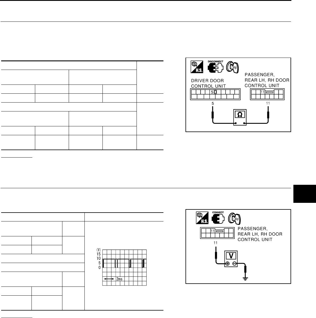
Door Lock & Unlock Switch Check EIS0010L
1. CHECK DOOR LOCK AND UNLOCK SWITCH
With CONSULT-II
See “DOOR LK SW-LK or UN” in DATA MONITOR mode.
●When door lock and unlock switch is turned to lock :
●When lock and unlock switch is turned to unlock :
Without CONSULT-II
●Check door lock and unlock switch operation in Switch monitor
mode.
(Refer to BL-38, "SWITCH MONITOR" .)
OK or NG ?
OK >> Replace driver door control unit (LCU).
NG >> Replace key switch.
Symptom malfunctioning system and reference
Power door lock does not operate with door lock and unlock
switch on power window main switch.
Door lock and unlock switch check.
Refer to BL-40, "Door Lock & Unlock Switch Check" .
Communication line check.
Refer to BL-41, "Communication Line Check" .
If above systems are “OK”, replace driver door control unit
(LCU).
Power door lock does not operate with driver door lock knob
switch.
Door unlock sensor check (driver side).
Refer toBL-42, "Door Unlock Sensor Check" .
Door lock actuator check – Driver –.
Refer to BL-42, "Door Lock Actuator Check – Driver –" .
Communication line check.
Refer to BL-41, "Communication Line Check" .
If above systems are “OK”, replace driver door control unit
(LCU).
Specific door lock actuator does not operate.
Door unlock sensor check.
Refer to BL-42, "Door Unlock Sensor Check" .
Door lock actuator chack ( Passenger, Rear LH, RH ).
Refer to BL-43, "Door Lock Actuator Check – Passenger,
Rear LH,RH –" .
Communication line check.
If above systems are “OK”, replace door control unit.
Key reminder door system does not operate properly.
Door unlock sensor check.
Refer to BL-42, "Door Unlock Sensor Check" .
Key switch check.
Refer to BL-44, "Electronic Key Switch Check." .
If above systems are “OK”, replace BCM.
DOOK LK SW–LK OFF → ON
DOOK LK SW–UN OFF → ON
SEL561W
POWER DOOR LOCK SYSTEM
BL-41
C
D
E
F
G
H
J
K
L
M
A
B
BL
Revision: 2004 April 2002 Q45
Communication Line Check EIS0010M
1. CHECK COMMUNICATION CIRCUIT
1. Turn ignition switch OFF.
2. Disconnect connectors for driver door control unit (LCU) and malfunctioning door control unit.
3. Check continuity between driver door control unit (LCU) harness connector terminal 5 and malfunctioning
door control unit harness connector terminal 11.
OK or NG ?
OK >> GO TO 2.
NG >> ●Repair or replace harness.
2. CHECK COMMUNICATION SIGNAL
●Connect driver door control unit (LCU) and malfunctioning door control unit connector.
●Check voltage between malfunctioning door control unit harness connector terminal 11 and body ground.
OK or NG ?
OK >> Communication signal is OK.
NG >> ●All door control unit (passenger, rear LH or RH ) connected are NG.→ Replace Driver door
LCU.
●Any of door control unit (passenger, rear LH or RH door control unit ) connected are NG.→
Replace malfunctioning door control unit.
Terminals
Continuity
Driver door control unit (LCU)
( + )
Passenger door control unit
( – )
Connector Terminal Connector Terminal
D8 5 (G/OR) D37 11 (G/OR) Yes
Terminals
Continuity
Driver door control unit (LCU)
( + )
Passenger door control unit
( – )
Connector Terminal Connector Terminal
D8 5 (G/OR) D58 (LH)
D78 (RH) 11 (G/OR) Yes
PIIA0219E
Terminals Voltage
Passenger door control
unit ( + ) ( – )
Connector Terminal Ground
D38 11 (G/OR)
Rear LH, RH door control unit
Terminals
Rear door control unit
( + ) ( – )
Connector Terminal
Ground
D58 (LH)
D78 (RH) 11 (G/OR)
PIIA0220E
SIIA0591J
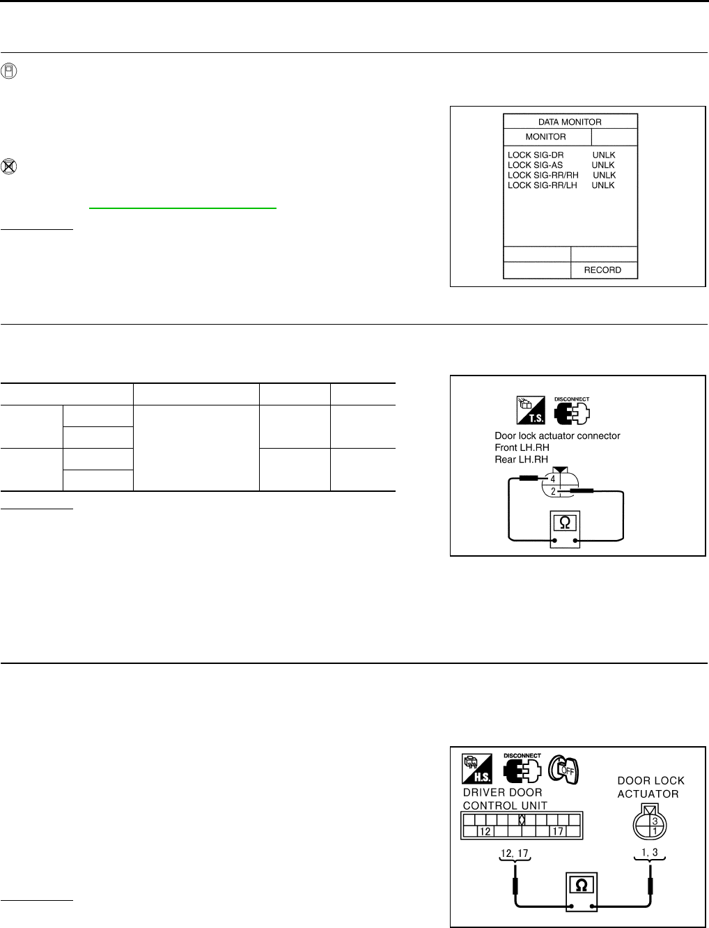
BL-42
POWER DOOR LOCK SYSTEM
Revision: 2004 April 2002 Q45
Door Unlock Sensor Check EIS0010N
1. CHECK DOOR UNLOCK SENSOR INPUT SIGNAL
With CONSULT−II
●Check door unlock sensor (“LOCK SIG”) in"DATA MONITOR" mode with CONSULT−II.
Without CONSULT−II
●Check door lock knob operation in Switch monitor mode.
(Refer to BL-38, "SWITCH MONITOR" .)
OK or NG?
OK >> Door unlock sensor is OK.
NG >> GO TO 2.
2. CHECK DOOR UNLOCK SENSOR
1. Disconnect door lock actuator connector.
2. Check continuity between door lock actuator (door unlock sensor) terminal 2(G/Y) and 4(B).
OK or NG?
OK >> Check the following.
●Ground circuit for door unlock sensor
●Harness for open or short between door LCU or door
control unit and door unlock sensor
NG >> Replace door lock actuator.
Door Lock Actuator Check – Driver – EIS0010O
1. CHECK DOOR LOCK ACTUATOR HARNESS
1. Turn the ignition switch OFF.
2. Disconnect driver door control unit (LCU) and door lock actuator connector.
3. Check continuity between driver door control unit (LCU) harness connector D8 terminals 12(BR), 17(LG)
and front door lock actuator harness connector D11 terminals 1(LG), 3(BR).
4. Check continuity between door control unit (LCU) harness con-
nector D8 terminals 12(BR), 17(LG) and body ground.
OK or NG?
OK >> GO TO 2.
NG >> Repair or replace harness.
When door is open : LOCK SIG LOCK
When door is closed : LOCK SIG UNLOCK
PIIA0348E
Actuator connector Terminals Condition Continuity
Front
door
LH : D11
2 (G/Y) − 4 (B)
Locked No
RH : D41
Rear
door
LH : D61 Unlocked Yes
RH : D81
PIIA0349E
12(BR) – 3(BR) : Continuity should exist.
17(LG) – 1(LG) : Continuity should exist.
12(BR) – ground : Continuity should not exist.
17(LG) – ground : Continuity should not exist.
SIIA1010E
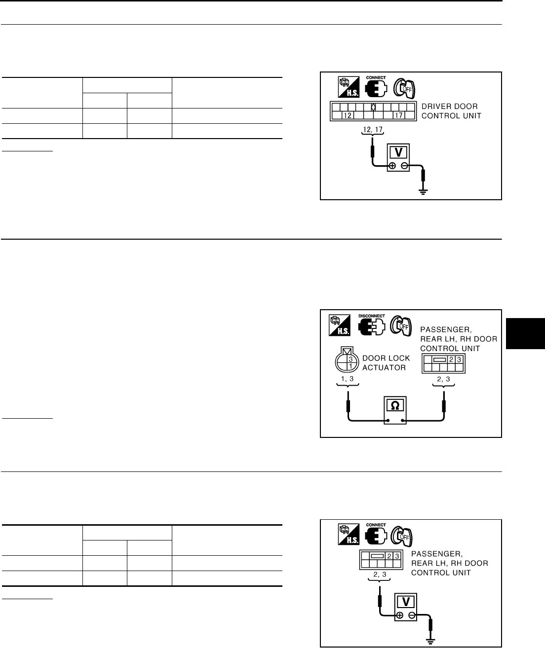
POWER DOOR LOCK SYSTEM
BL-43
C
D
E
F
G
H
J
K
L
M
A
B
BL
Revision: 2004 April 2002 Q45
2. CHECK OUTPUT SIGNAL
●Connect driver door LCU01 connector.
●Check voltage between driver door LCU01 harness connector D8 terminal 12(BR), 17(LG) and body
ground.
OK or NG?
OK >> Replace driver door lock actuator.
NG >> Replace driver door LCU01.
Door Lock Actuator Check – Passenger, Rear LH,RH – EIS0010P
1. CHECK DOOR LOCK ACTUATOR HARNESS
1. Turn the ignition switch OFF.
2. Disconnect passenger door control unit and door lock actuator connector.
3. Check continuity between passenger door control unit harness connector D39 terminals 2(SB), 3(BR) and
door lock actuator harness connector D41(Passenger), D81(Rear RH) or D61(Rear LH) terminals 1(SB),
3(BR).
4. Check continuity between door control unit harness connector
D39 terminals 2(SB), 3(BR) and body ground.
OK or NG?
OK >> GO TO 2.
NG >> Repair or replace harness.
2. CHECK OUTPUT SIGNAL
●Connect passenger door connector.
●Check voltage between passenger door control unit harness connector D41 terminals 1(SB), 3(BR) and
body ground.
OK or NG?
OK >> Replace door lock actuator.
NG >> Replace passenger door control unit.
Door lock operation Terminals Voltage (V)
+-
Unlock 12 (BR) Ground 0V → Battery voltage
Lock 17(LG) Ground 0V → Battery voltage
SIIA1011E
1(SB) – 2(SB) : Continuity should exist.
3(BR) – 3(BR) : Continuity should exist.
2(SB) – ground : Continuity should not exist.
3(BR) – ground : Continuity should not exist.
PIIA0238E
Door lock operation Terminals Voltage (V)
+-
Unlock 3 (BR) Ground 0V → Battery voltage
Lock 2(SB) Ground 0V → Battery voltage
PIIA0239E
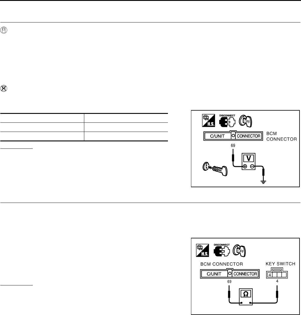
BL-44
POWER DOOR LOCK SYSTEM
Revision: 2004 April 2002 Q45
Electronic Key Switch Check. EIS0013Q
1. CHECK KEY SWITCH
With CONSULT-II
●Check electronic key cylinder switch “IGN KEY SW” in “DATA MONITOR” mode with CONSULT-II.
When key is inserted in electronic key cylinder :
When key is removed from electronic key cylinder :
Without CONSULT-II
1. Disconnect BCM connector.
2. Check voltage between harness connector M4 terminls 69 (PU/W) and body ground.
OK or NG ?
OK >> electronic key switch is OK .
NG >> GO TO 2.
2. CHECK KEY SWITCH CIRCUIT
1. Remove the key from the electronic key cylinder.
2. Disconnect key switch connector.
3. Check continuity between BCM harness conector M4 terminal 69(PU/W) and key switch harness connec-
tor M64 terminal 4(PU/W) for the key detection switch.
4. Check continuity between BCM harness connector M4 terminal
69(PU/W) and body ground.
OK or NG ?
OK >> Replace key switch.
NG >> Repair or replace harness.
IGN KEY SW ON
IGN KEY SW OFF
Condition Voltage (V)
Key is inserted Battery Voltage
Key is removed 0V
PIIA0240E
: Continuity should exist.
: Continuity should not exist.
PIIA0241E

REMOTE KEYLESS ENTRY SYSTEM
BL-45
C
D
E
F
G
H
J
K
L
M
A
B
BL
Revision: 2004 April 2002 Q45
REMOTE KEYLESS ENTRY SYSTEM PFP:28596
System Description EIS0028D
POWER SUPPLY AND GROUND
BCM is connected to LCU01 as DATA LINE A-3.
Power is supplied at all times
●through 10A fuse [No. 8, located in the fuse block (J/B)]
●to key switch terminal 3.
When the key switch is in ON position (key is inserted in ignition key cylinder), power is supplied
●through key switch terminal 4
●to BCM terminal 69
When any of the four door switches is in OPEN position, ground is supplied
●to BCM terminal 33, 37, 142, 143
●through door switches body grounds.
When a front LH door is unlocked, driver door LCU terminal 6 receives a ground signal from terminal 2 of front
LH door unlock sensor.
When a front RH, rear LH or RH door is unlocked, each door control unit terminal 13 receiver a ground signal
from terminal 2 of each door unlock sensor.
Electronic key signal input
●through multi remote control receiver
●to BCM terminal 27
The remote keyless entry system controls operation of the
●power door lock
●trunk lid opener
●panic alarm
●hazard and horn reminder
OPERATING PROCEDURE
BCM can receive signals from electronic key when key switch is in OFF position (key is not in cylinder). It then
sends the signals to LCU01 as DATA LINE A-3.
POWER DOOR LOCK OPERATION
When BCM receives a LOCK signal from electronic key, BCM will then send a LOCK signal
●from its terminals 67 (DATA LINE A-3)
●to front LH door control unit (LCU) terminal 8.
When an UNLOCK signal is sent from electronic key once, driver’s door will be unlocked.
Then, if an UNLOCK signal is sent from electronic key again within 3 seconds, all other doors will be unlocked.
For detailed description, refer to BL-18, "System Description" .
HAZARD AND HORN REMINDER
Power is supplied at all times
●through 15A fuse (No. 56, located in the fusible link and fuse box)
●to horn relay terminal 2.
When BCM receives a LOCK or UNLOCK signal from electronic key, ground is supplied
●to combination flasher unit relay terminal 6
●through BCM terminal 7 and
●to horn relay terminal 1
●through BCM terminal 127
combination flasher unit and horn relay are now engaged, and hazard warning lamps flash and horn sounds
as a reminder.)
OPERATING FUNCTION OF HAZARD AND HORN REMINDER
This vehicle is set in hazard indicator and horn mode when you first receive the vehicle.

BL-46
REMOTE KEYLESS ENTRY SYSTEM
Revision: 2004 April 2002 Q45
Hazard Indicator And Horn Mode
When the LOCK button is pushed, the hazard indicator flashes twice and horn chirps once.
When the UNLOCK button is pushed, the hazard indicator flashes once.
Hazard Indicator Only Mode
When the LOCK button is pushed, the hazard indicator flashes twice.
When the UNLOCK button is pushed, neither the hazard indicator nor the hone operates.
TRUNK LID OPENER OPERATION
Power is supplied at all times
●through 20A fuse [No. 15, located in the fuse block (J/B)]
●to trunk lid opener actuator terminal 1.
When a TRUNK OPEN signal is sent from electronic key without the electronic key inserted in the ignition key
cylinder, if the trunk lid opener cancel switch is in the ON position, ground is supplied
●through 10A fuse [No.3, located in the fuse block (J/B)]
●to trunk lid opener relay
●through trunk lid cancel switch terminals 1 and 2, and
●through BCM terminal 109
Then power and ground are supplied, trunk lid opener actuator opens trunk lid.
PANIC ALARM OPERATION
Remote keyless entry system activates horn and head lamps intermittently when an ALARM signal is sent
from electronic key to remote keyless entry system without the electronic key inserted in the ignition key cylin-
der. For detailed description, refer to BL-100, "VEHICLE SECURITY (THEFT WARNING) SYSTEM" .
MODE
(Push “LOCK” and “UNLOCK” buttons for more than 2 sec-
onds to switch)
Switching indicator LOCK UNLOCK
Hazard indicator and horn →HAZARD INDICATOR ONLY HAZARD – 3 times HAZARD – twice No operation
Hazard indicator only →HAZARD INDICATOR AND
HORN
HAZARD – once
HORN – once
HAZARD – twice
HORN – once HAZARD – once
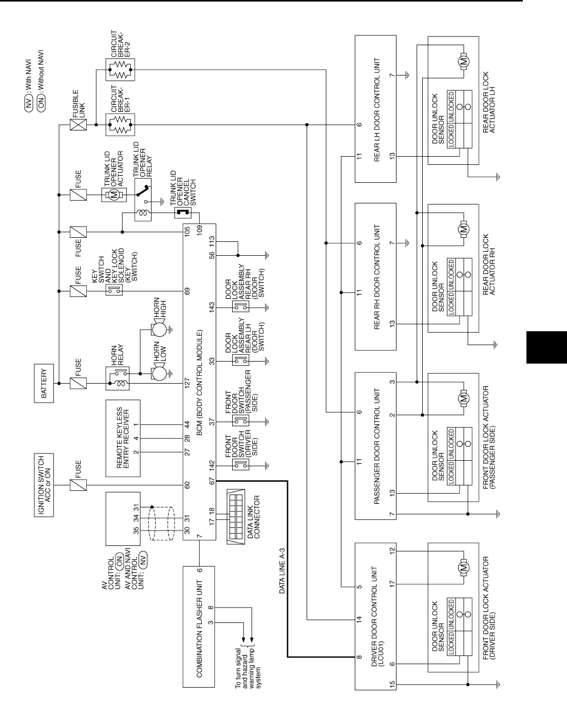
REMOTE KEYLESS ENTRY SYSTEM
BL-47
C
D
E
F
G
H
J
K
L
M
A
B
BL
Revision: 2004 April 2002 Q45
Schematic EIS0028E
TIWM0106E
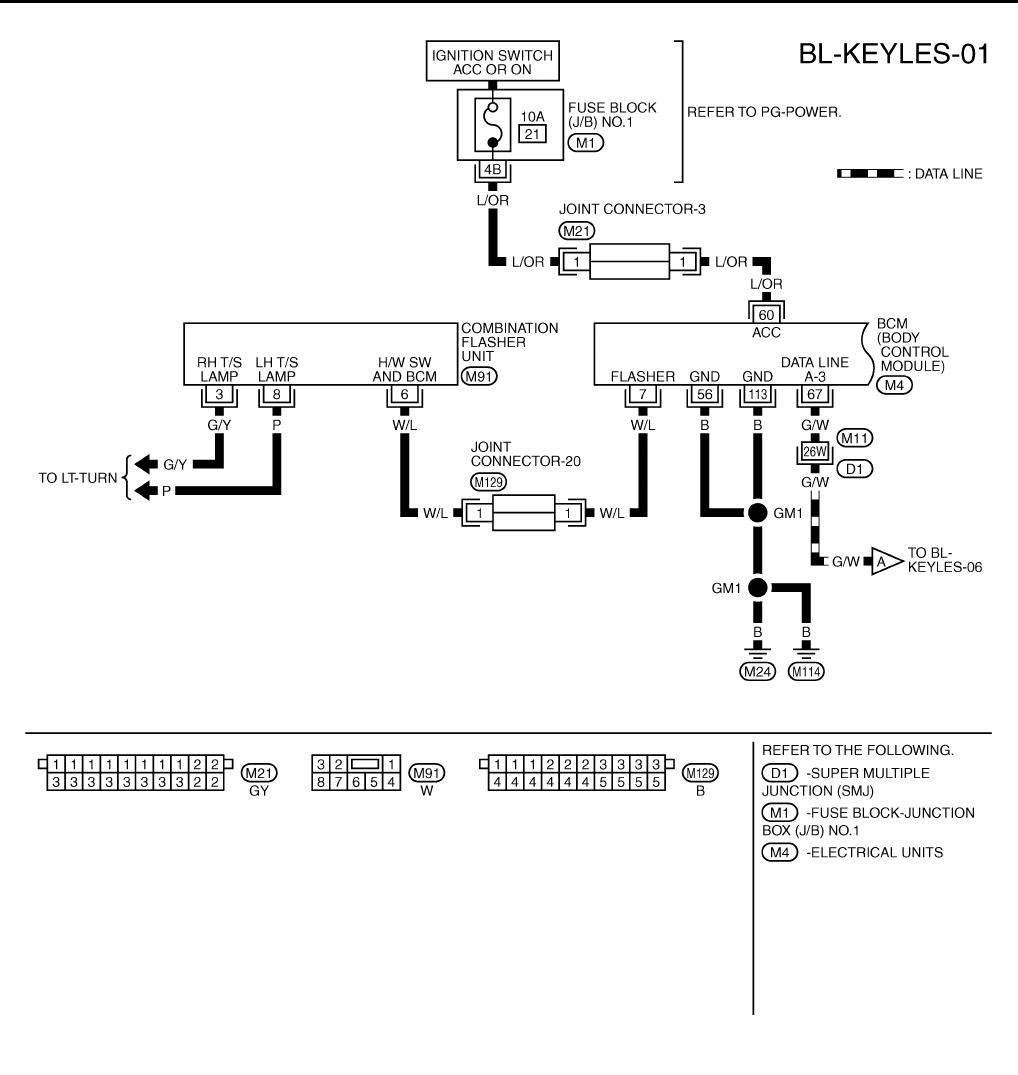
BL-48
REMOTE KEYLESS ENTRY SYSTEM
Revision: 2004 April 2002 Q45
Wiring Diagram – KEYLES – EIS0028F
TIWM0107E
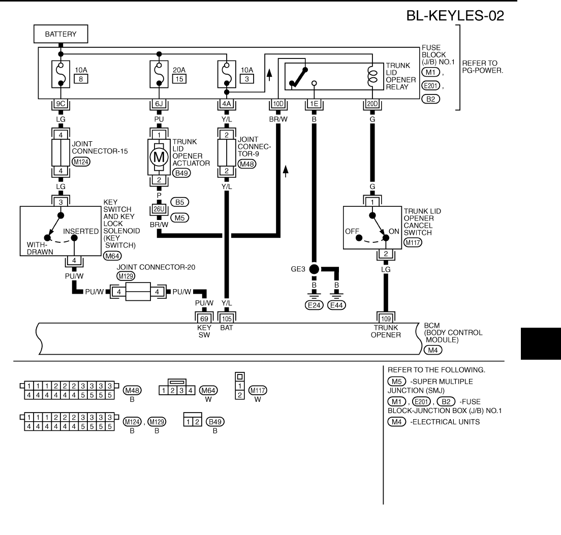
REMOTE KEYLESS ENTRY SYSTEM
BL-49
C
D
E
F
G
H
J
K
L
M
A
B
BL
Revision: 2004 April 2002 Q45
TIWM0108E
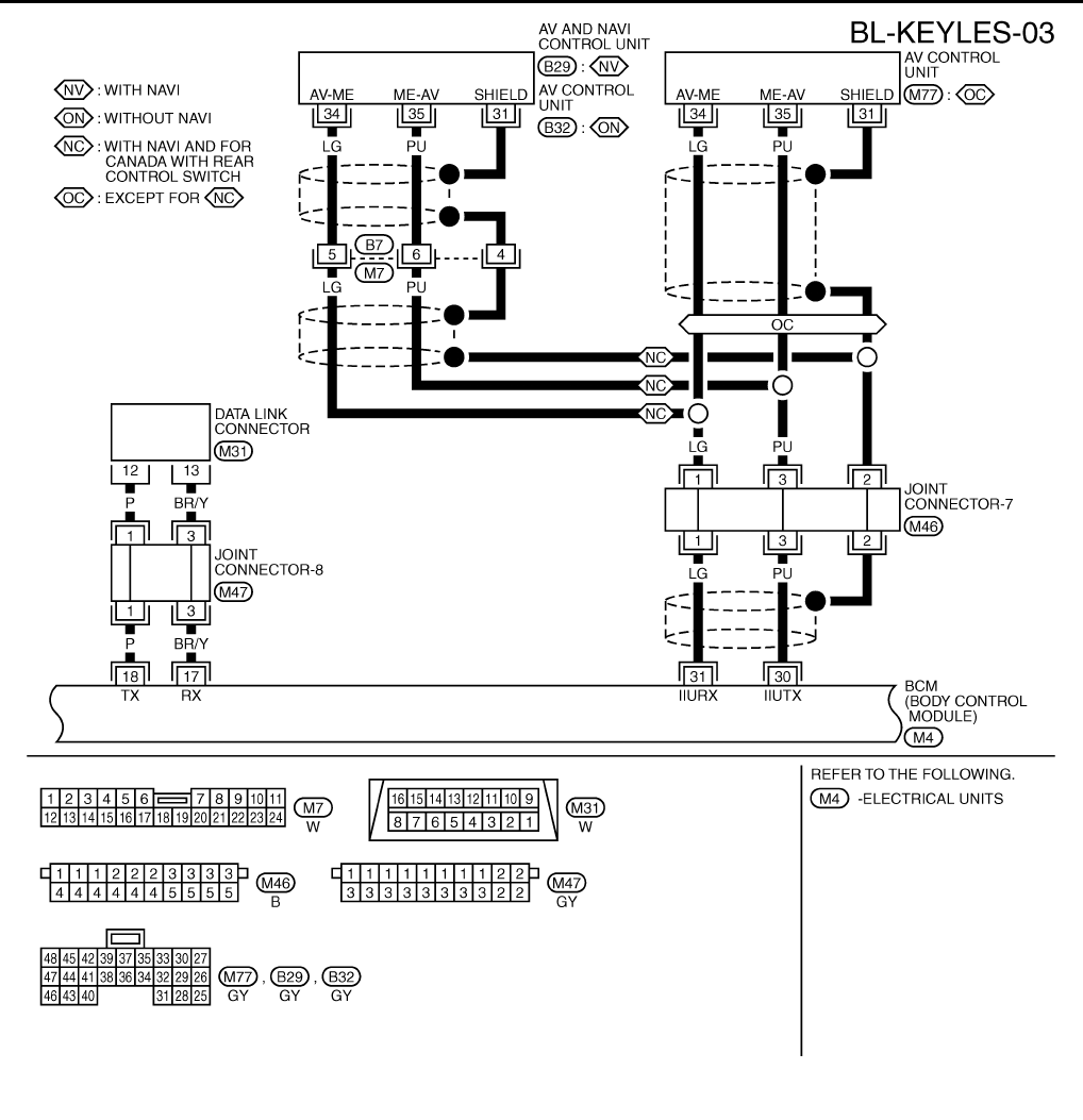
BL-50
REMOTE KEYLESS ENTRY SYSTEM
Revision: 2004 April 2002 Q45
TIWM0109E
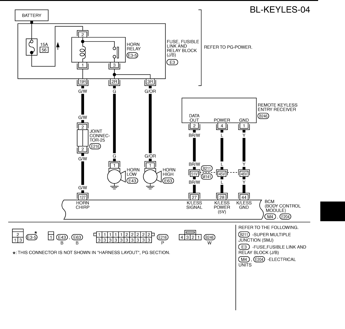
REMOTE KEYLESS ENTRY SYSTEM
BL-51
C
D
E
F
G
H
J
K
L
M
A
B
BL
Revision: 2004 April 2002 Q45
TIWM0110E
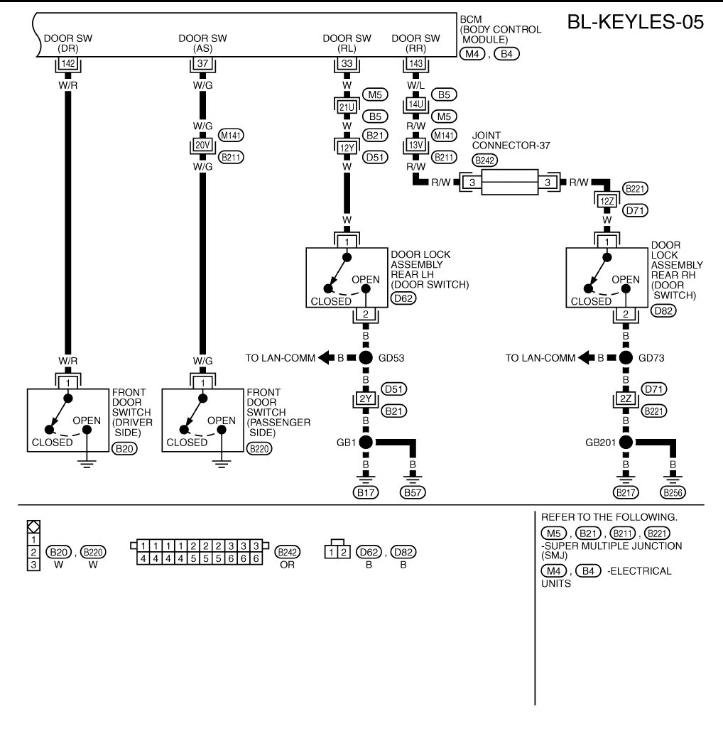
BL-52
REMOTE KEYLESS ENTRY SYSTEM
Revision: 2004 April 2002 Q45
TIWM0111E
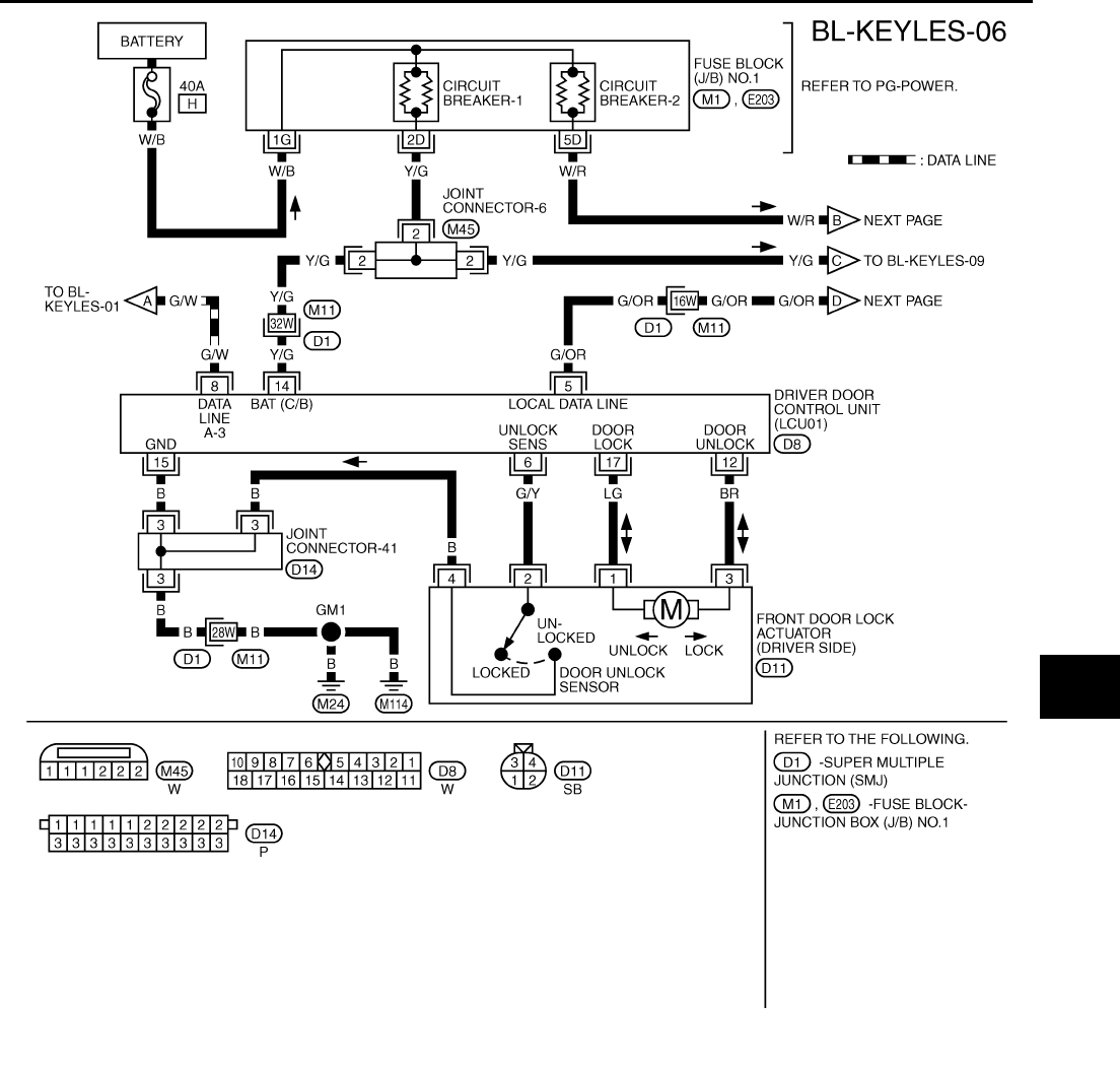
REMOTE KEYLESS ENTRY SYSTEM
BL-53
C
D
E
F
G
H
J
K
L
M
A
B
BL
Revision: 2004 April 2002 Q45
TIWM0112E
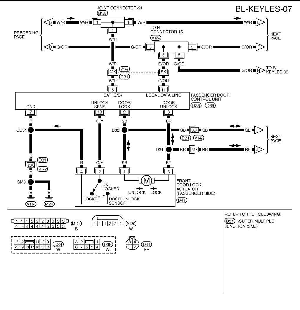
BL-54
REMOTE KEYLESS ENTRY SYSTEM
Revision: 2004 April 2002 Q45
TIWM0113E
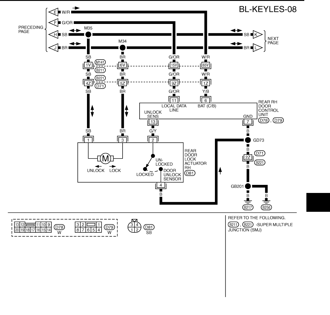
REMOTE KEYLESS ENTRY SYSTEM
BL-55
C
D
E
F
G
H
J
K
L
M
A
B
BL
Revision: 2004 April 2002 Q45
TIWM0114E
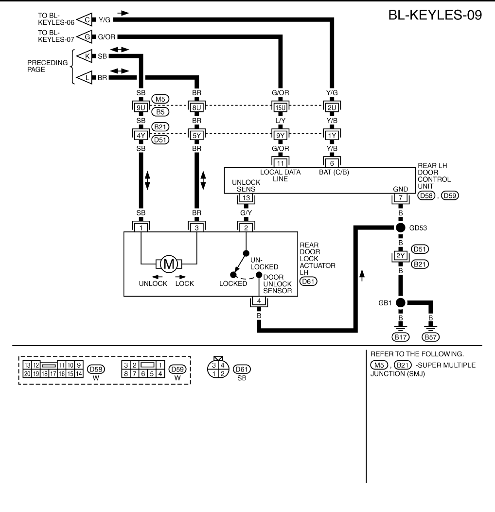
BL-56
REMOTE KEYLESS ENTRY SYSTEM
Revision: 2004 April 2002 Q45
TIWM0115E
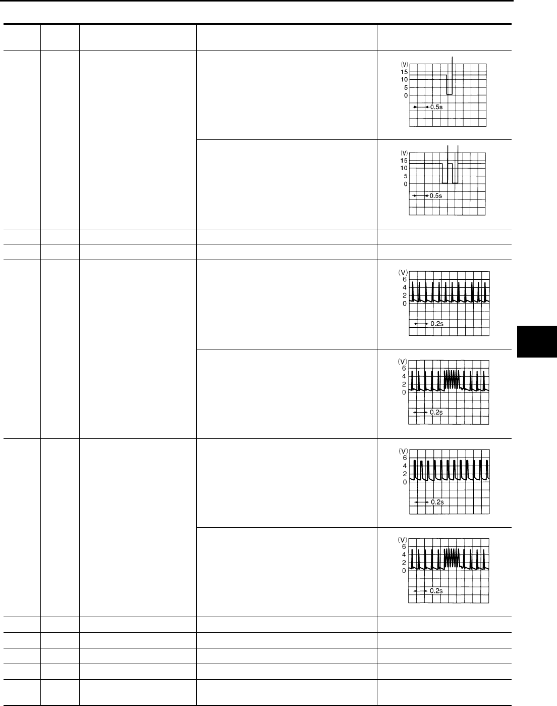
REMOTE KEYLESS ENTRY SYSTEM
BL-57
C
D
E
F
G
H
J
K
L
M
A
B
BL
Revision: 2004 April 2002 Q45
Terminal and Reference Value for BCM EIS0028G
TER-
MINAL
WIRE
COLOR ITEM CONDITION VOLTAGE
7 W/L Combination flasher unit
Door locking with electronic key (Twice)
Door unlocking with electronic key (Once)
17 BR/Y Data line RX — —
18 P Data line TX — —
27 BR/W Multi-remote control receiver
(Pulse)
stand-by
Press any of the electronic key switches
28 L Multi-remote control receiver
(Power supply)
stand-by
Press any of the electronic key switches
30 PU IIUTX — —
31 LG IIU RX — —
33 W Rear LH door switch Door open (ON) →close (OFF) 0V → Battery voltage
37 W/G Passenger door switch Door open (ON) →close (OFF) 0V → Battery voltage
44 Y Multi-remote control receiver
(Ground) —0V
ELN0504D
ELN0505D
OCC3879D
OCC3880D
OCC3881D
OCC3880D
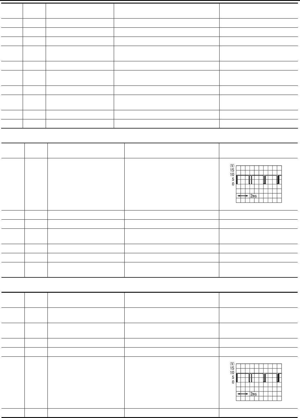
BL-58
REMOTE KEYLESS ENTRY SYSTEM
Revision: 2004 April 2002 Q45
Terminal and Reference Value for Driver Door Control Unit (LCU01) EIS0028H
Passenger And Rear LH, RH Door Control Unit Terminal Reference Value EIS0028I
56 B Ground — 0V
60 L/OR ACC power supply — Battery voltage
67 G/W Data line A-3 — —
69 PU/W Ignition key switch
(insert)
Key Inserted (ON) →
key removed from IGN key cylinder (OFF) Battery voltage → 0V
105 Y/L BAT power supply — Battery voltage
109 LG Trunk lid opener cancel
switch Trunk lid opener cancel switch ON → OFF Battery voltage → 0V
113 B Ground — 0V
127 G/W Horn relay When panic alarm is operated using elec-
tronic key (ON → OFF) Battery voltage → 0V
142 W/R Driver door switch Door open (ON) →close (OFF) 0V → Battery voltage
143 W/L Rear RH door switch Door open (ON) →close (OFF) 0V → Battery voltage
TER-
MINAL
WIRE
COLOR ITEM CONDITION VOLTAGE
TERMI-
NAL
WIRE
COLOR ITEM CONDITION VOLTAGE
5 G/OR Local communication line —
6 G/Y Door unlock sensor OFF (Locked) → ON (unlocked) 5V → 0V
8 G/W Data line A-3 — —
12 BR Driver door lock actuator
(Unlock)
Door lock & unlock switch
(Free → Unlock) 0V → Battery voltage
14 Y/G Power source (PTC) — Battery voltage
15 B Ground — 0V
17 LG Driver door lock actuator
(Lock)
Door lock & unlock switch
(Free → Lock) 0V → Battery voltage
SIIA0591J
TERMI-
NAL
WIRE
COLOR ITEM CONDITION Standard (V)
*2 SB Door lock actuator (Lock) Door lock & unlock switch
(Free → Lock) 0V → Battery voltage
*3 BR Door lock actuator (Unlock) Door lock & unlock switch
(Free → Unlock) 0V → Battery voltage
6 W/R Power source (PTC) — Battery voltage
7 B Ground — 0V
11 G/OR Local communication line —
13 G/Y Door unlock sensor OFF (Locked) → ON (unlocked) 5V → 0V
SIIA0591J

REMOTE KEYLESS ENTRY SYSTEM
BL-59
C
D
E
F
G
H
J
K
L
M
A
B
BL
Revision: 2004 April 2002 Q45
NOTE:
*Only for passenger door control unit.
Work Flow EIS0028J
1. Check the symptom and customer's requests.
2. Understand the outline of system. Refer to BL-45, "System Description" .
3. Perform the preliminary check. Refer to BL-59, "Preliminary Check" .
4. Perform the communication inspection. If CONSULT-II is used, refer to BL-62, "IVMS COMMUNICATION
INSPECTION" . If CONSULT-II is not used, refer toBL-66, "COMMUNICATION DIAGNOSIS" . Is the com-
munication diagnosis result OK? If OK, GO TO step 7. If NG, GO TO step 5.
5. Repair or replace depending on the diagnosis result.
6. Perform the communication diagnosis again. If CONSULT-II is used, refer to BL-62, "IVMS COMMUNICA-
TION INSPECTION" . If CONSULT-II is not used, refer to BL-66, "COMMUNICATION DIAGNOSIS" . Is
communication diagnosis result OK? If OK, GO TO step 7. If NG, GO TO step 5.
7. Referring to Trouble diagnosis chart, repair or replace the cause of the incident.Refer to BL-71, "Trouble
Diagnosis Chart by Symptom" .
8. Does the remote keyless entry system operate normally? If it operates normally, GO TO step 9. If NG, GO
TO step 7.
9. Inspection end.
Preliminary Check EIS0028K
POWER SUPPLY AND GROUND CIRCUIT INSPECTION
1. FUSE INSPECTION
●Check if any of the following fuses in the BCM are blown.
Refer to BL-48, "Wiring Diagram – KEYLES –" .
OK or NG?
OK >> GO TO 2.
NG >> If fuse is blown, be sure to eliminate cause of problem before installing new fuse, refer to PG-2,
"POWER SUPPLY ROUTING" .
2. POWER SUPPLY CIRCUIT INSPECTION
Remove the connectors for BCM and driver door control unit (LCU) or passenger, rear LH, RH door control
units, measure the voltage between the terminal No. (Refer to the "Chart" below) of the connector and body
ground.
OK or NG?
OK >> GO TO 3.
NG >> Check harness for open or short.
Unit Power source Fuse No.
BCM Battery power supply 3
ACC power supply 21
(+)
(–) Power source Condition Voltage
Unit Terminal
(wire color)
BCM 105 (Y/L)
Body ground
Battery power supply Ignition switch OFF Battery voltage
60 (L/OR) ACC power supply Ignition switch ACC Battery voltage
Driver door LCU 14 (Y/G) Battery power supply Ignition switch OFF Battery voltage
Passenger door con-
trol unit. 6 (W/R)
Battery power supply Ignition switch OFF Battery voltage
Rear LH door control
unit. 6 (Y/B)
Rear RH door control
unit. 6 (Y/B)
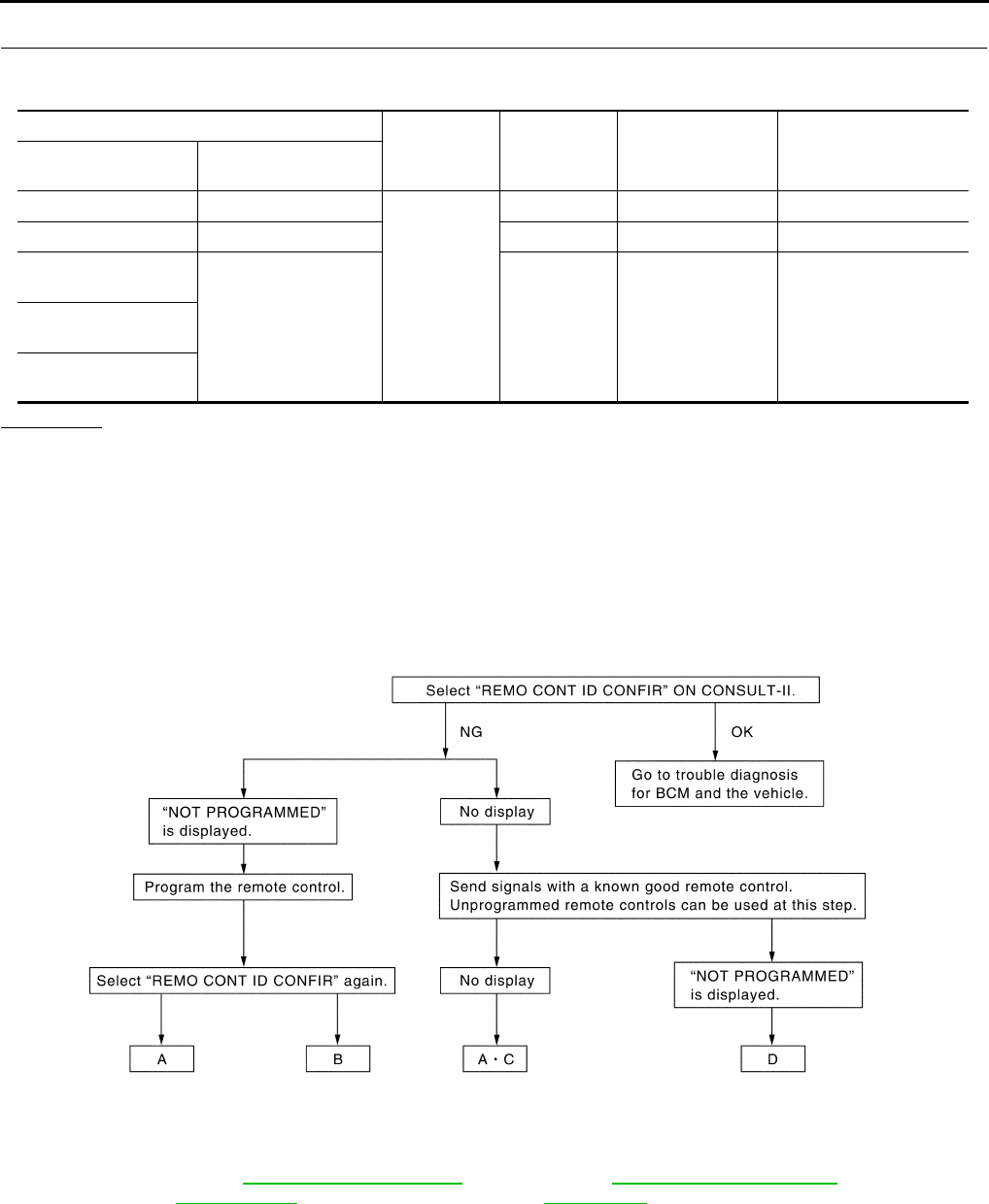
BL-60
REMOTE KEYLESS ENTRY SYSTEM
Revision: 2004 April 2002 Q45
3. GROUND CIRCUIT INSPECTION
Check the continuity between the following terminals on the vehicle-side connector for BCM, driver door LCU,
passenger or rear LH, RH door control units and body ground.
OK or NG?
OK >> Power supply and ground circuit is "OK".
NG >> Repair or replace harness.
SYSTEM INSPECTION
●When the Remote Keyless Entry System is malfunctioning, determine which part has caused the incident,
before carrying out the trouble diagnosis.
●Using the following diagnosis flowchart, determine whether the electronic key or the vehicle component
(multi remote control receiver or BCM) has a malfunction and confirm the part to be checked.
Inspection with CONSULT-II
CONSULT–II Function EIS0028L
●CONSULT-II executes the following functions by combining data received and command transmitted via
the communication line from BCM. IVMS communication inspection, work support (only function setting of
seats and steering wheel), self-diagnosis, data monitor, and active test display.
(+)
(–) Signal Condition Continuity
Unit Terminal
(wire color)
IVMS control unit 56 (B) and 113 (B)
Body ground
Ground Ignition switch OFF Continuity should exist
Driver door LCU 15 (B) Ground Ignition switch OFF Continuity should exist
Passenger door con-
trol unit.
7 (B) Ground Ignition switch OFF Continuity should exist
Rear LH door control
unit.
Rear RH door control
unit.
SIIA0563E
A : Replace BCM B : electronic key not registered
C :Multi remote control receiver inspection.
Refer to BL-78, "Multi-Remote Control
Receiver Check"
D :electronic key inspection
Refer to BL-80, "Electronic Key Battery
Replacement"
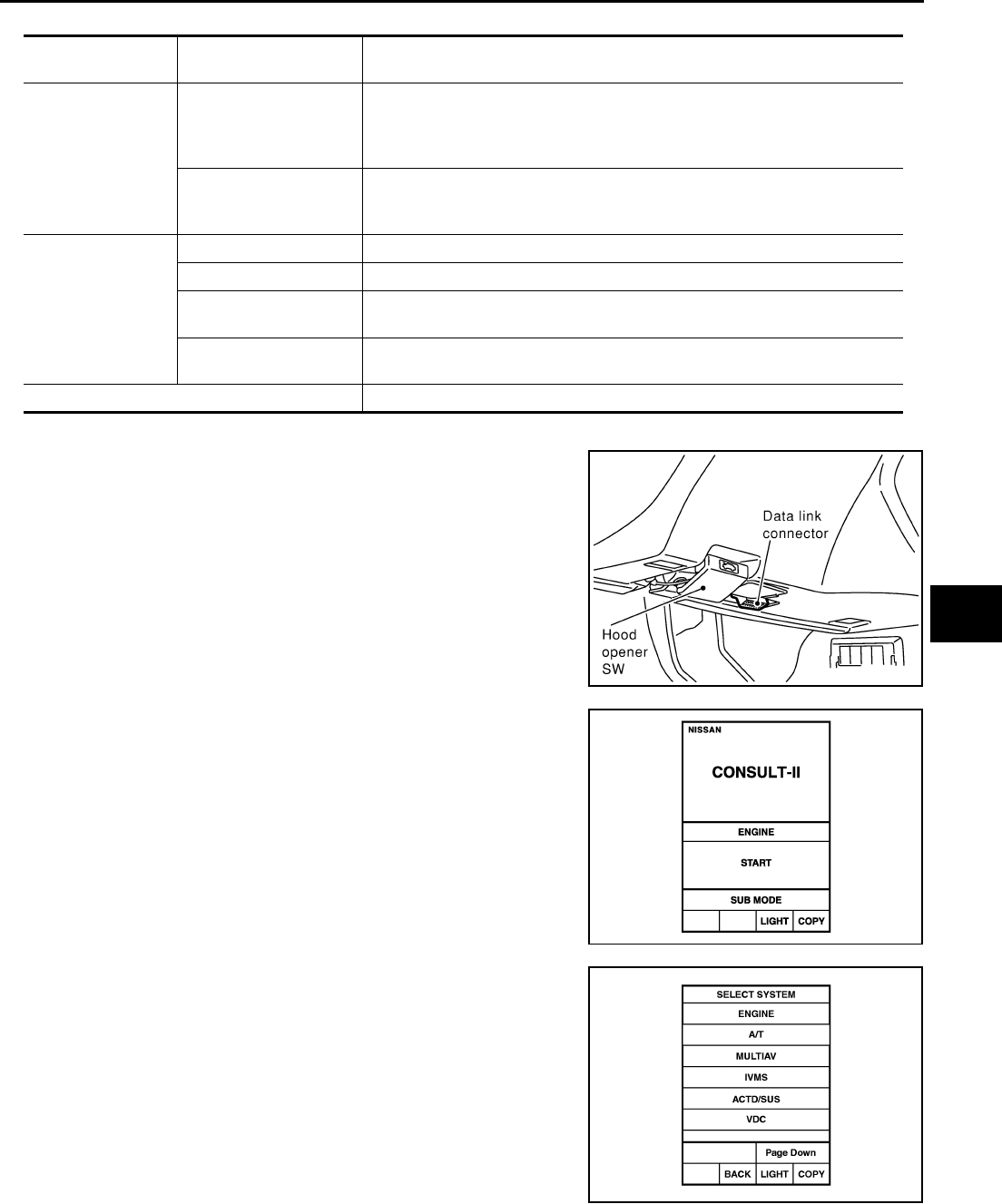
REMOTE KEYLESS ENTRY SYSTEM
BL-61
C
D
E
F
G
H
J
K
L
M
A
B
BL
Revision: 2004 April 2002 Q45
DIAGNOSTIC ITEMS DESCRIPTION
CONSULT-II BASIC OPERATION PROCEDURE
1. With the ignition switch OFF, connect CONSULT–II to the data
link connector on vehicle side, and turn the ignition switch ON.
2. Touch "START".
3. Touch "IVMS".
IVMS diagnosis
position Diagnosis mode Description
IVMS–
COMM CHECK
IVMS–
COMM DIAGNOSIS
Diagnosis of continuity in the communication line(s), and of the function of the
IVMS-communication interface between the body control module and the
local control units, accoplished by transmitting a signal from the body control
module to the local control units.
WAKE–UP DIAGNOSIS
Diagnosis of the“ wake-up” function of local control units by having a techni-
cian input the switch data into the local control unit that is in the temporary
“sleep” condition.
Each system
inspection .
Work support Changes the setting for each function.
Self-diagnosis results Carries out self-diagnosis.
Data monitor Displays data relative to the body control module (BCM) input signals and var-
ious control related data for each system.
Active test Turns on/off actuators, relay and according to the commands transmitted by
the CONSULT-II unit.
BCM PART NUMBER Displays BCM part No.
SHIA0179E
PIIA0182E
PIIA0183E
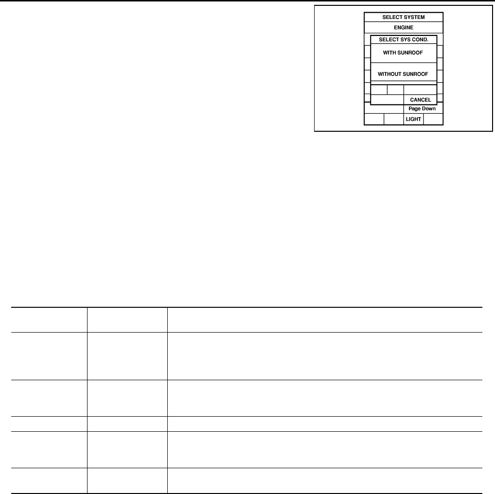
BL-62
REMOTE KEYLESS ENTRY SYSTEM
Revision: 2004 April 2002 Q45
4. Check the model specification, touch either "WITH SUNROOF"
or "WITHOUT SUNROOF".
5. Touch "OK". If the selection is wrong, touch "CANCEL".
6. Select the desired part to be diagnosed on the "SELECT TEST ITEM" screen.
IVMS COMMUNICATION INSPECTION
●IVMS contains the IVMS communication diagnosis and wake-up diagnosis.
IVMS Communication Diagnosis
●IVMS communication diagnosis consists of the communication diagnosis, sleep diagnosis, and inactive
communication diagnosis between BCM and each local unit (LCU), and display the results on the CON-
SULT–ll screen.
NOTE:
Sleep is a power saving function when a vehicle is stationary (all BCM related electrical equipment: OFF,
and the timer: OFF).
●The function also stores the communication malfunction records and inactive communication records, and
displays the data on the CONSULT–II screen (Error record diagnosis)
*: malfunctioning item record
Operation Procedure
1. Touch "IVMS–COMM CHECK" on "SELECT TEST ITEM".
2. Touch "IVMS–COMM DIAGNOSIS" on "SELECT DIAG ITEM" screen.
3. Touch "START" on "IVMS–COMM DIAGNOSIS" screen to start the diagnosis.
4. After the diagnosis is completed, the malfunctioning system is displayed.
5. When the malfunctioning items are displayed, touch "PRINT" to record.
6. Touch "ERASE".
7. Perform the communication inspection again to check that any malfunctioning item is displayed.
8. Check the displayed items.
Wake-Up Diagnosis
●The wake-up diagnosis is carried out when BCM detects the wake-up signal from each local unit (LCU).
When the switch shown on the screen is operated as instructed, each local control unit (LCU) outputs the
PIIA0184E
Malfunction
description
CONSULT–II dis-
play item Description
Communication
error COMM DATA
●Communicating with each LCU is judged sound when the communication is nor-
mally completed and the transmitted data and received data are identically the
same. In other cases, it is judged malfunctioning. If the communication is inactive,
no diagnosis result is displayed.
Inactive communi-
cation NO RESPONSE
●Communicating with each LCU is judged sound when at least one time communi-
cation is normally completed within three trials. In other cases, it is judged mal-
functioning.
Sleep malfunction SLEEP ●Check that each LCU enters sleep mode.
Communication
error *
PAST COMM
DATA
●The records when communication signal malfunctions were continuously detected
while the communication was normal are displayed. Or the records when a mal-
function is detected during the past sleep mode are displayed.
Inactive communi-
cation*
PAST NO
RESPONSE
●The records when inactive communications were continuously detected while the
communication was normal are displayed.

REMOTE KEYLESS ENTRY SYSTEM
BL-63
C
D
E
F
G
H
J
K
L
M
A
B
BL
Revision: 2004 April 2002 Q45
wake-up signal. If BCM cannot detect a wake-up signal, it is judged malfunctioning. The malfunctioning
local control unit (LCU) is displayed on the screen.
NOTE:
If any unspecified switch is operated, "Switch data not match" is displayed as a malfunctioning system.
Operation Procedure
1. Touch "IVMS–COMM CHECK" on "SELECT TEST ITEM" screen.
2. Touch "WAKE–UP DIAGNOSIS" on "SELECT DIAG ITEM" screen.
3. Touch "START" on "WAKE–UP DIAGNOSIS" screen to start the diagnosis.
4. Touch "NEXT" to select the local control unit (LCU) to be diagnosed.
5. Check that any malfunction is displayed. If necessary, touch "PRINT" to record.
6. Preform the inspection to the malfunctioning item.
Malfunction Code Table
NOTE:
●For a specific local control unit (LCU), either "PAST COMM DATA" or "PAST NO RESPONSE" may be displayed instead of the
above results. This is caused by the data record, so erase the records.
Malfunctioning
item Display unit CONSULT–II IVMS communication
diagnosis content
Self-diagnosis
trouble code
No.
Malfunctioning system and
reference
COMM DATA
One LCU is dis-
played.
POWER WINDOW C/U–DR
"COMM DATA" 24
Replace the displayed
LCU.
DOOR MIRROR C/U–RH
"COMM DATA" 27
DOOR MIRROR C/U–LH
"COMM DATA" 37
POWER SEAT C/U–DR
"COMM DATA" 47
Multiple LCUs
are displayed
BCM
"COMM FAIL1" ,"COMM FAIL2"
Displays in
order of 24
→27→37→47
→and cycles
from 24.
Communication system A:
Refer to BL-64, "COMMU-
NICATION SYSTEM A" .
NO
RESPONSE
One LCU is dis-
played.
POWER WINDOW C/U–DR
"NO RESPONSE" 25
Communication system B:
Refer to BL-64, "COMMU-
NICATION SYSTEM B" .
DOOR MIRROR C/U–RH
"NO RESPONSE" 28
DOOR MIRROR C/U–LH
"NO RESPONSE" 38
POWER SEAT C/U–DR
"NO RESPONSE" 48
Multiple LCUs
are displayed BCM/HARNESS
Displays in
order of
25→28→38→4
8 and cycles
from 25.
Communication system C:
Refer to BL-64, "COMMU-
NICATION SYSTEM C" .
SLEEP malfunc-
tion
One LCU is dis-
played.
POWER WINDOW C/U–DR "SLEEP"
No self-diagno-
sis function
Replace the displayed
LCU.
DOOR MIRROR C/U–RH
"SLEEP"
DOOR MIRROR C/U–LH
"SLEEP"
POWER SEAT C/U–DR
"SLEEP"
Multiple LCUs
are displayed All the above control units are displayed. No self-diagno-
sis function
Communication system A:
Refer to BL-64, "COMMU-
NICATION SYSTEM A" .

BL-64
REMOTE KEYLESS ENTRY SYSTEM
Revision: 2004 April 2002 Q45
(The display only shows the incident records, they are not malfunctions caused during the diagnosis. One possible cause is that an
reproducible incident occurred.)
●Follow the steps below to erase the memory
Perform either disconnect BCM battery power supply or erase memory with CONSULT-II.
●With the battery connected, if the local control unit (LCU) connector is disconnected and left for approximately 1 minute, the BCM
stores "NO RESPONSE" record.
COMMUNICATION SYSTEM A
1. BCM INSPECTION
Replace the BCM with a known-good one, and perform out the communication diagnosis. Refer to BL-62,
"IVMS COMMUNICATION INSPECTION" .
OK or NG?
YES >> Replace BCM.
NO >> GO TO 2.
2. LCU INSPECTION
1. Replace with the BCM.
2. Replace the LCU with a known-good one, and perform the communication diagnosis. Refer to BL-62,
"IVMS COMMUNICATION INSPECTION" .
OK or NG?
YES >> Replace LCU.
NO >> Repair or replace harness.
COMMUNICATION SYSTEM B
1. CONNECTOR INSPECTION
Check the terminals (at the control unit and harness) on the malfunctioning LCU for disconnection, bend, and
other malfunctions.
OK or NG?
OK >> GO TO 2.
NG >> Repair terminals and connectors.
2. LCU INSPECTION
Replace the malfunctioning LCU with a known-good one, and perform the communication diagnosis. Refer to
BL-62, "IVMS COMMUNICATION INSPECTION" .
OK or NG?
OK >> Replace LCU.
NG >> Repair communication harness between the indicated LCU and BCM.
COMMUNICATION SYSTEM C
1. CONNECTOR INSPECTION
Check the terminals (at the control unit and harness) on BCM and LCU for disconnection, bend, and other
malfunctions.
OK or NG?
OK >> GO TO 2.
NG >> Repair terminals and connectors.
2. BCM INSPECTION
Replace the BCM with a known-good one, and perform the communication diagnosis. Refer to BL-62, "IVMS
COMMUNICATION INSPECTION" .
OK or NG?
OK >> Replace BCM.
NG >> Repair communication harness between the LCU and BCM.

REMOTE KEYLESS ENTRY SYSTEM
BL-65
C
D
E
F
G
H
J
K
L
M
A
B
BL
Revision: 2004 April 2002 Q45
DATA MONITOR
Operation Procedure
1. Select the desired part to be diagnosed on the "SELECT TEST ITEM" screen.
2. Touch "DATA MONITOR" on "SELECT DIAG MODE" screen.
3. Touch "MAIN SIGNALS" or "SELECTION FROM MENU" on "DATA MONITOR" screen.
4. Touch "START".
5. If "SELECTION FROM MENU" is selected, touch the desired monitor item. If "ALL SIGNALS" is
selected, the all item required to control is monitored.
6. During monitoring, touching "COPY" can start recording the monitor item status.
Remote Keyless Entry Item.
Trunk Lid Opener Item
ACTIVE TEST
Operation Procedure
1. Select the desired part to be diagnosed on "SELECT TEST ITEM" screen.
2. Touch "ACTIVE TEST" on "SELECT DIAG MODE" screen.
3. Touch the item to be tested, and check the operation.
4. During the operation check, touching "OFF" deactivates the operation.
System CONSULT-II selected diagnosis
part.
Remote keyless entry MULTI-REMOTE CONT SYS
Trunk lid opener Trunk lid opening
ALL SIGNALS Monitor all items.
SELECTION FROM MENU Selects and monitors the items.
Monitored item Description
IGN KEY SW Indicates [ON/OFF] condition of ignition key switch.
IGN ACC SW Indicates [ON/OFF] condition of ignition switch in ACC position.
DOOR SW-DR Indicates [ON/OFF] condition of front door switch LH.
DOOR SW-AS Indicates [ON/OFF] condition of front door switch RH.
DOOR SW-RR Indicates [ON/OFF] condition of rear door switch RH.
DOOR SW-RL Indicates [ON/OFF] condition of rear door switch LH.
LOCK SIG-DR Indicates [ON/OFF] condition of driver door unlock signal from door lock sensor.
LOCK SIG-AS Indicates [ON/OFF] condition of passenger door unlock signal from door lock sensor.
LOCK SIG-RR/LH Indicates [ON/OFF] condition of rear LH door unlock signal from door lock sensor.
LOCK SIG-RR/RH Indicates [ON/OFF] condition of rear RH door unlock signal from door lock sensor.
LOCK BUTTON Indicates [ON/OFF] condition of lock signal from electronic key.
UNLOCK BUTTON Indicates [ON/OFF] condition of unlock signal from electronic key.
PANIC BTN Indicates [ON/OFF] condition of panic signal from electronic key.
TRUNK BTN-CON Indicates [ON/OFF] condition of trunk open signal from electronic key.
Monitored item Description
TRUNK OPNR SW Indicates [ON/OFF] condition of trunk open signal from trunk open switch.
System CONSULT-II selected diagnosis
part.
Remote key less entry MULTI-REMOTE CONT SYS
Trunk lid opener Trunk lid opening

BL-66
REMOTE KEYLESS ENTRY SYSTEM
Revision: 2004 April 2002 Q45
Remote Keyless Entry Test Item
Trunk Lid Opener Test Item
WORK SUPPORT
Operation Procedure
1. Touch "MULTI-REMOTE CONT SYS" on "SELECT TEST ITEM" screen.
2. Touch "WORK SUPPORT" on "SELECT DIAG MODE" screen.
3. Select the desired work item on "SELECT WORK ITEM" screen.
Work Support Item
On Board Diagnosis EIS0028M
ON BOARD DIAGNOSTIC RESULTS INDICATOR LAMP
●Front map lamps and step lamps (all seats) act as the indicators for the on board diagnosis.
DIAGNOSIS ITEM
COMMUNICATION DIAGNOSIS
●Check the communication between BCM and local control unit (LCU).
TEST ITEM DISCRIPTION
TRUNK OPEN S/V This test is able to check trunk lid opener actuator operation.
The trunk is unlocked when “ON” on CONSULT-II screen is touched.
HAZARD This test is able to check hazard reminder operation.
The hazard lamp turns on when “ON” on CONSULT-II screen is touched.
HORN This test is able to check panic alarm and horn reminder operations.
The alarm activate for 0.5 seconds after “ON” on CONSULT-II screen is touched.
TEST ITEM DISCRIPTION
TRUNK OPEN S/V This test is able to check trunk lid opener actuator operation.
The trunk is unlocked when “ON” on CONSULT-II screen is touched.
WORK ITEM
REMO CONT ID CONFIR
REMO CONT ID REGIST
REMO CONT ID ERASUR
WORK ITEM DISCRIPTION
REMO CONT ID CONFIR It can be checked whether electronic key ID code is registered or not in this mode.
REMO CONT ID REGIST electronic key ID code can be registered.
REMO CONT ID ERASUR electronic key ID code can be erased.
Diagnosis item. Content
IVMS communication diagnosis Diagnosing any abnormality or inability of communication between BCM and LCU
(DATA LINE A-3).
Switch monitor Monitoring conditions of switches connected to BCM, LCU and Door control unit.
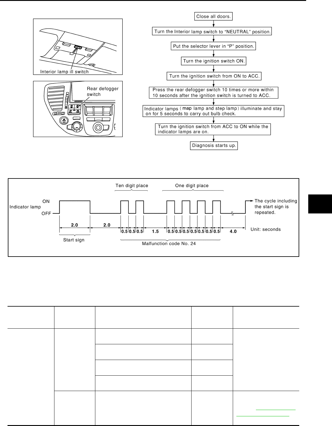
REMOTE KEYLESS ENTRY SYSTEM
BL-67
C
D
E
F
G
H
J
K
L
M
A
B
BL
Revision: 2004 April 2002 Q45
How To Perform Communication Diagnosis
Description
In this mode, a malfunction code is indicated by the number of flashes from the front map lamps and step
lamps as shown below:
After indicator lamp turns on for 2 seconds then off for 2 seconds, it flashes [cycling ON (0.5 sec.)/OFF (0.5
sec.)] to indicate a malfunction code of the first digit. Then, 1 second after indicator lamp turns off, it again
flashes [cycling ON (0.5 sec.)/OFF (0.5 sec.)] to indicate a malfunction code of the second digit.
For example, the indicator lamp goes on and off for 0.5 seconds twice and after 1.0 seconds, it goes on and off
for 0.5 seconds four times. This indicates malfunction code.
Malfunction Code Table
SIIA0409E
SIIA0410E
Malfunction item Display unit CONSULT–II IVMS communication
diagnosis content
Self-diagnosis
trouble code
No.
Malfunctioning system and
reference
COMM DATA
One LCU is dis-
played.
POWER WINDOW C/U–DR
"COMM DATA" 24
Replace the displayed
LCU.
DOOR MIRROR C/U–RH
"COMM DATA" 27
DOOR MIRROR C/U–LH
"COMM DATA" 37
POWER SEAT C/U–DR
"COMM DATA" 47
Multiple LCUs
are displayed
BCM
"COMM FAIL1" ,"COMM FAIL2"
Displays in
order of 24
→27→37→47
→and cycles
from 24.
Communication system A:
Refer to BL-68, "COMMU-
NICATION SYSTEM A" .

BL-68
REMOTE KEYLESS ENTRY SYSTEM
Revision: 2004 April 2002 Q45
NOTE:
●For a specific local control unit (LCU), either "PAST COMM DATA" or "PAST NO RESPONSE" may be displayed instead of the
above results. This is caused by the data record, so erase the records.
(The display only shows the incident records, they are not malfunctions caused during the diagnosis. One possible cause is that an
reproducible incident occurred.)
●Follow the steps below to erase the memory
Perform either disconnect BCM battery power supply or erase memory with CONSULT-II.
●With the battery connected, if the local control unit (LCU) connector is disconnected and left for approximately 1 minute, the BCM
stores "NO RESPONSE" record.
Cancel Of Communication Diagnosis
If the following conditions are satisfied, the communication diagnosis is cancelled.
●Turn ignition switch OFF.
●Drive the vehicle more than 7 km/h (4 MPH).
●Ten minutes have passed since the diagnosis result indication start without any diagnosis cancel opera-
tion.
COMMUNICATION SYSTEM A
1. BCM INSPECTION
Replace the malfunctioning BCM with a known-good one, and perform the communication diagnosis. Refer to
BL-66, "COMMUNICATION DIAGNOSIS" .
OK or NG?
OK >> Replace the BCM.
NG >> GO TO 2.
NO
RESPONSE
One LCU is dis-
played.
POWER WINDOW C/U–DR
"NO RESPONSE" 25
Communication system B:
Refer to BL-69, "COMMU-
NICATION SYSTEM B" .
DOOR MIRROR C/U–RH
"NO RESPONSE" 28
DOOR MIRROR C/U–LH
"NO RESPONSE" 38
POWER SEAT C/U–DR
"NO RESPONSE" 48
Multiple LCUs
are displayed BCM/HARNESS
Displays in
order of
25→28→38→4
8 and cycles
from 25.
Communication system C:
Refer to BL-69, "COMMU-
NICATION SYSTEM C" .
SLEEP malfunc-
tion
One LCU is dis-
played.
POWER WINDOW C/U–DR "SLEEP"
No self-diagno-
sis function
Replace the displayed
LCU.
DOOR MIRROR C/U–RH
"SLEEP"
DOOR MIRROR C/U–LH
"SLEEP"
POWER SEAT C/U–DR
"SLEEP"
Multiple LCUs
are displayed All the above control units are displayed. No self-diagno-
sis function
Communication system A:
Refer to BL-68, "COMMU-
NICATION SYSTEM A" .
Malfunction item Display unit CONSULT–II IVMS communication
diagnosis content
Self-diagnosis
trouble code
No.
Malfunctioning system and
reference

REMOTE KEYLESS ENTRY SYSTEM
BL-69
C
D
E
F
G
H
J
K
L
M
A
B
BL
Revision: 2004 April 2002 Q45
2. LCU INSPECTION
1. Replace with the previously installed BCM.
2. Replace the LCU with a known-good one, and perform the communication diagnosis. Refer toBL-66,
"COMMUNICATION DIAGNOSIS" .
OK or NG?
OK >> Replace the LCU.
NG >> Replace the BCM.
COMMUNICATION SYSTEM B
1. CONNECTOR INSPECTION
Check the terminals (at the control unit and harness) on the malfunctioning LCU for disconnection, bend, and
other malfunctions.
OK or NG?
OK >> GO TO 2.
NG >> Repair the terminals and connectors.
2. LCU INSPECTION
Replace the LCU with a known-good one, and perform the communication diagnosis. Refer to BL-66, "COM-
MUNICATION DIAGNOSIS" .
OK or NG?
OK >> Replace the LCU.
NG >> Repair the communication harness between the indicated LCU and BCM.
COMMUNICATION SYSTEM C
1. CONNECTOR INSPECTION
Check the terminals (at the control unit and harness) on BCM and LCU for disconnection, bend and other mal-
functions.
OK or NG?
OK >> GO TO 2.
NG >> Repair the terminals and connectors.
2. BCM INSPECTION
Replace the BCM with a known-good one, and perform the communication diagnosis. Refer to BL-66, "COM-
MUNICATION DIAGNOSIS" .
OK or NG?
OK >> Replace the BCM
NG >> Repair the communication harness between the LCU and BCM control.
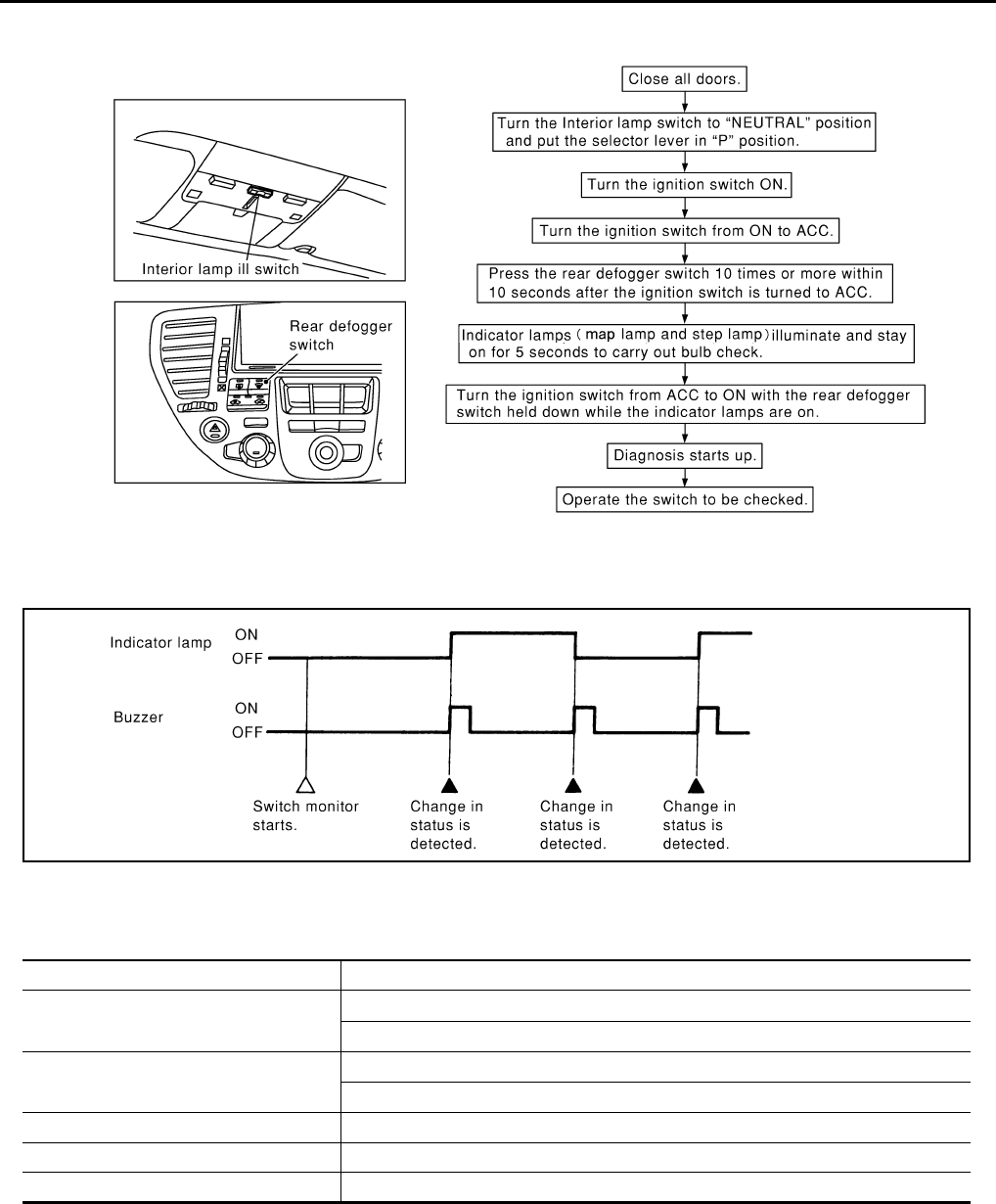
BL-70
REMOTE KEYLESS ENTRY SYSTEM
Revision: 2004 April 2002 Q45
SWITCH MONITOR
How To Perform Switch Monitor
Description
In this mode, when BCM detects the input signal from a switch in IVMS as shown below, the detection is indi-
cated by the front map lamp and front step lamps with buzzer.
Switch Monitor Item
●The status of the switch (except the ignition switch, interior lamp switch, and map lamp switch) as input to
each control unit can be monitored.
Cancel Of Switch Monitor.
●Turn ignition switch OFF.
●Drive the vehicle more than 7 km/h (4 MPH).
SIIA0411E
PIIA0177E
Control unit Item
BCM All door switch
Electronic key (lock / unlock switch and trunk switch)
Driver door contro unit (LCU)l Door lock & unlock switch (LOCK / UNLOCK)
Driver door unlock sensor
Passenger door control unit. Passenger door unlock sensor
RH rear door control unit. Rear RH door unlock sensor
LH rear door control unit. Rear LH door unlock sensor
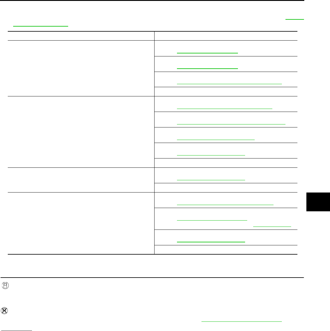
REMOTE KEYLESS ENTRY SYSTEM
BL-71
C
D
E
F
G
H
J
K
L
M
A
B
BL
Revision: 2004 April 2002 Q45
Trouble Diagnosis Chart by Symptom EIS0028N
●Before carrying out the inspection on the following table, perform the preliminary check. Refer to BL-59,
"Preliminary Check" .
Electronic Key Check EIS0028O
1. ELECTRONIC KEY CHECK
With CONSULT-II
●Check Electronic Key switch “LOCK / UNLOCK BUTTON”, “TRUNK BTN-COM” and “PANIC BTN” in
“DATA MONITOR” mode with CONSULT-ll.
Without CONSULT-II
●Check electronic key switch in “SWITCH MONITOR” mode.Refer to BL-70, "SWITCH MONITOR" .
OK or NG?
OK >> Electronic key is OK.
NG >> GO TO 2.
Symptom malfunctioning system and reference
All functions of multi-remote control system do not operate.
Electronic key check.
Refer to BL-72, "Key Switch Check" .
Key switch check.
Refer to BL-72, "Key Switch Check" .
Multi remote control receiver check.
Refer to BL-78, "Multi-Remote Control Receiver Check" .
If the above systems are “OK”, replace BCM.
Trunk lid does not open when trunk opener button is continu-
ously pressed.
Trunk lid opener actuator check.
Refer to BL-74, "Trunk Lid Opener Actuator Check" .
Trunk lid cancel switch check.
Refer to BL-73, "Trunk Lid Opener Cancel Switch Check" .
Trunk open signal check.
Refer to BL-75, "Check Trunk Open Signal" .
Electronic key check.
Refer to BL-71, "Electronic Key Check" .
If the above systems are “OK”, replace BCM.
Door lock or unlock does not function.
(Power door lock system is “OK”.)
Electronic key check.
Refer to BL-71, "Electronic Key Check" .
If the above system is “OK”, replace BCM.
Hazard and horn reminder does not activate properly when
pressing lock or unlock button of electronic key.
Hazard reminder check.
Refer to BL-77, "Hazard Indicator Operation Check" .
Horn reminder check.
Refer to BL-76, "Horn Reminder Check" .
(First check the horn chirp setting.Refer to WW-27, "HORN" .)
Electronic key check.
Refer to BL-71, "Electronic Key Check" .
If the above system is normal, replace the IVMS control unit.
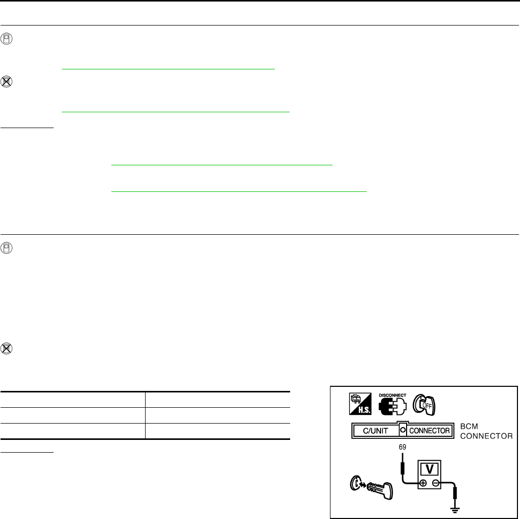
BL-72
REMOTE KEYLESS ENTRY SYSTEM
Revision: 2004 April 2002 Q45
2. ELECTRONIC KEY ID CHECK
With CONSULT-II
●Check electronic key “ID Code” in“WORK SUPPORT” mode with CONSULT-II.
Refer to BL-83, "PROCEDURE 2 (With CONSULT-II)" .
Without CONSULT-II
●Check electronic key “ID Code” in "REMOTE CONTROLLER ID SET UP" mode.
Refer to BL-82, "PROCEDURE 1 (Without CONSULT-II)" .
OK or NG?
OK >> Electronic key not registered.
NG >> ●Check multi remote control receiver.
Refer to BL-78, "Multi-Remote Control Receiver Check" .
●Check electronic key.
Refer to BL-81, "REMOTE CONTROLLER BATTERY CHECK" .
Key Switch Check EIS0028P
1. CHECK KEY SWITCH
With CONSULT-II
●Check ignition key cylinder switch “IGN KEY SW” in “DATA MONITOR” mode with CONSULT-II.
When key is inserted in ignition key cylinder:
When key is removed from ignition key cylinder:
Without CONSULT-II
1. Disconnect BCM connector.
2. Check voltage between harness connector M4 terminals 69 (PU/W) and body ground.
OK or NG?
OK >> Key switch is OK.
NG >> GO TO 2.
IGN KEY SW ON
IGN KEY SW OFF
Condition Voltage
Key is inserted Battery Voltage
Key is removed 0V
PIIA0240E
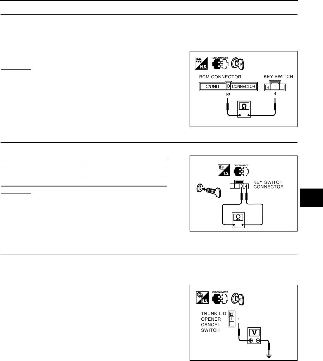
REMOTE KEYLESS ENTRY SYSTEM
BL-73
C
D
E
F
G
H
J
K
L
M
A
B
BL
Revision: 2004 April 2002 Q45
2. CHECK KEY SWITCH CIRCUIT
1. Remove the key from the ignition key cylinder.
2. Disconnect key switch connector.
3. Check continuity BCM harness connector M4 terminal 69(PU/W) and key switch harness connector M64
terminal 4(PU/W).
OK or NG?
OK >> GO TO 3.
NG >> Repair or replace harness.
3. CHECK KEY SWITCH
1. Check continuity between key switch terminals 3 and 4.
OK or NG?
OK >> Check harness for open or short between key switch
and fuse.
NG >> Replace key switch.
Trunk Lid Opener Cancel Switch Check EIS0028Q
1. CHECK POWER SUPPLY CIRCUIT
1. Turn ignition switch OFF.
2. Disconnect trunk lid opener cancel switch connector.
3. Check voltage between opener cancel switch harness connector M117 terminal 1(G) and body ground.
OK or NG?
OK >> GO TO 2.
NG >> Check the following
●Trunk lid opener relay.
●Harness for open or short between trunk lid opener
cancel switch and trunk lid opener relay.
: Continuity should exist.
PIIA0241E
Condition continuity
Key is inserted YES
Key is removed NO
PIIA0408E
: Battery voltage should exist.
PIIA0242E
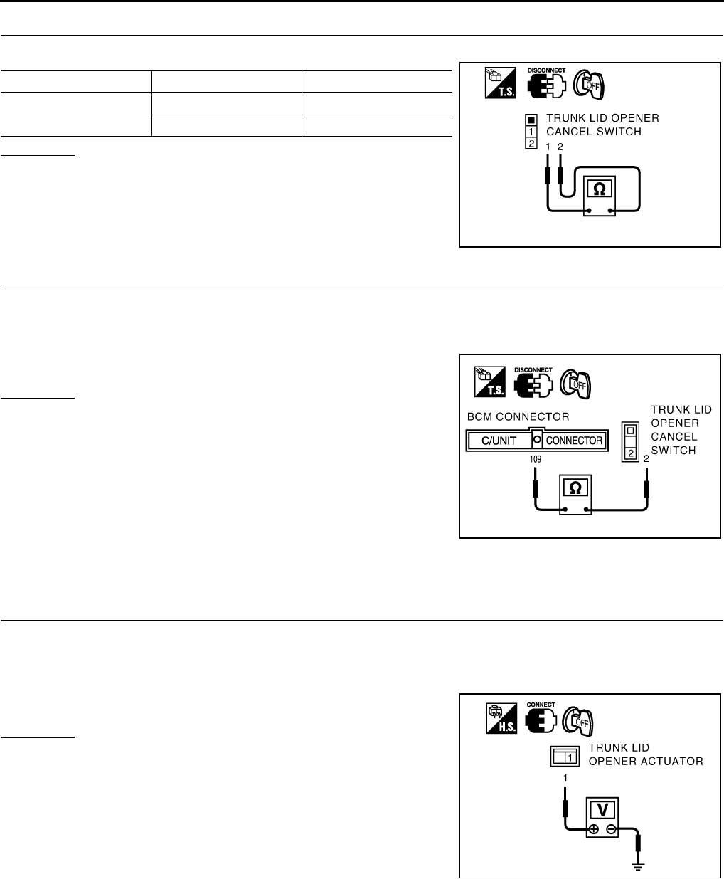
BL-74
REMOTE KEYLESS ENTRY SYSTEM
Revision: 2004 April 2002 Q45
2. CANCEL SWITCH INSPECTION
Check continuity between trunk lid opener cancel switch terminals 1 and 2.
OK or NG?
OK >> GO TO 3.
NG >> Replace trunk lid opener cancel switch.
3. CHECK HARNESS CONTINUITY
1. Disconnect BCM connector.
2. Check continuity between BCM harness connector M4 terminal 109(LG) and trunk lid opener cancel
switch harness connector M117 terminal 2(LG).
OK or NG?
OK >> Trunk lid opener cancel switch is OK.
NG >> Repair or replace harness.
Trunk Lid Opener Actuator Check EIS0028R
Before carrying out the following diagnosis, check that the trunk opener cancel switch is turned ON.
1. CHECK POWER SUPPLY CIRCUIT
1. Turn ignition switch OFF.
2. Disconnect trunk lid opener actuator connector.
3. Check voltage between trunk lid opener actuator harness connector B49 terminal 1(PU) and body ground.
OK or NG?
OK >> GO TO 2.
NG >> Check harness for open and short between trunk lid
opener actuator and fuse.
Terminal Condition Continuity
1 – 2 Switch : ON Yes
Switch : OFF No
PIIA0243E
: Continuity should exist.
PIIA0244E
: Battery voltage should exist.
PIIA0245E
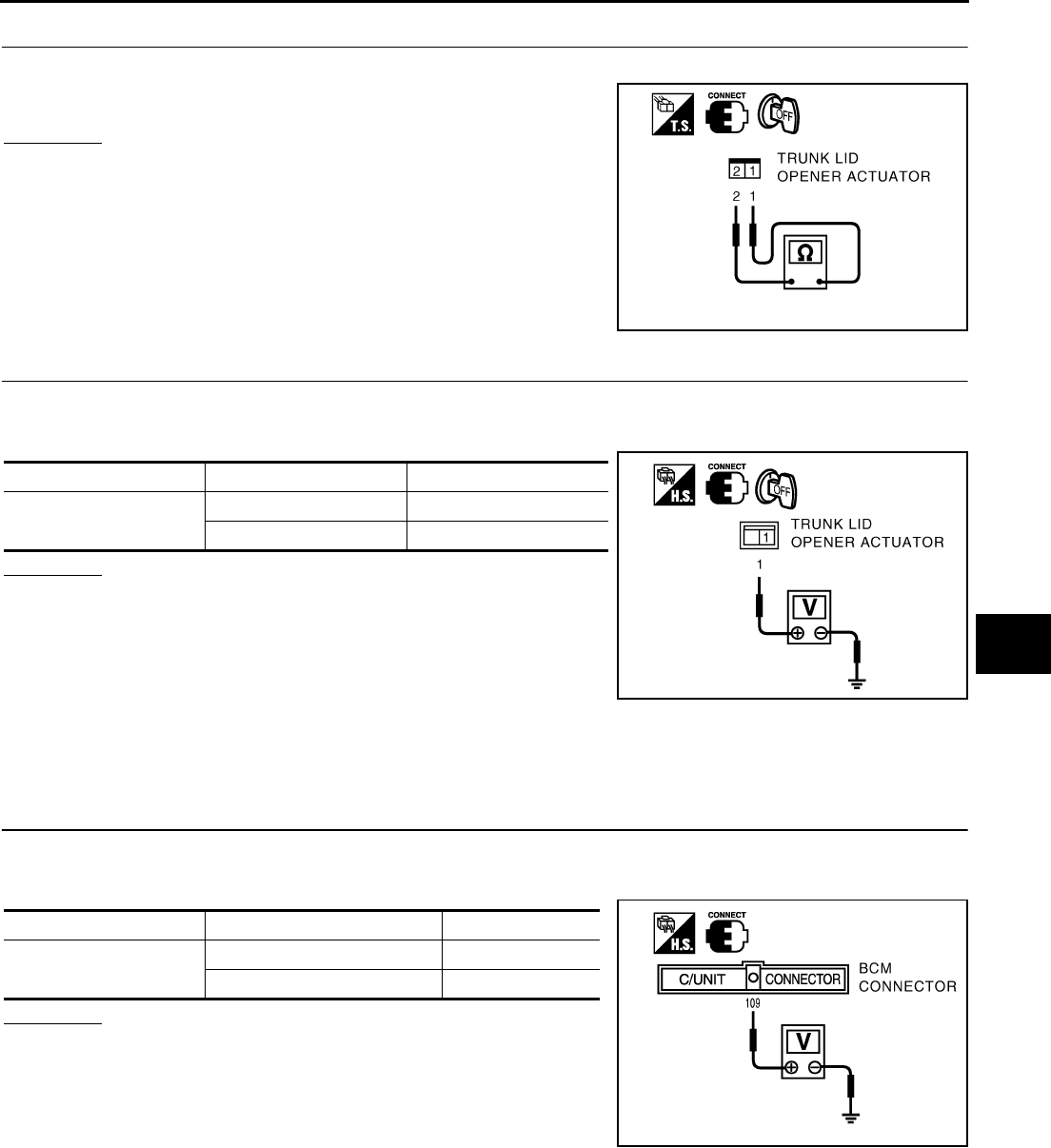
REMOTE KEYLESS ENTRY SYSTEM
BL-75
C
D
E
F
G
H
J
K
L
M
A
B
BL
Revision: 2004 April 2002 Q45
2. CHECK TRUNK LID OPENER ACTUATOR
Check continuity between trunk lid opener actuator terminals 1 and 2.
OK or NG?
OK >> GO TO 3.
NG >> Replace trunk lid opener actuator.
3. CHECK TRUNK LID OPENER RELAY CIRCUIT
1. Connect trunk lid opener actuator connector.
2. Check voltage between harness connector B49 terminal 1(PU) and body ground.
OK or NG?
OK >> Trunk lid opener actuator is OK.
NG >> Check the following.
●Harness for open and short between trunk lid opener
actuator and trunk lid opener relay.
●Harness between trunk lid opener relay and body
ground.
●Replace trunk lid opener relay
Check Trunk Open Signal EIS0028S
1. CHECK BCM OUTPUT SIGNAL
1. Remove electronic key from ignition key cylinder.
2. Check voltage between BCM harness connector M4 terminal 109(LG) and body ground.
OK or NG?
OK >> BCM output signal (Trunk open signal) is OK.
NG >> Replace BCM.
: Continuity should exist.
PIIA0246E
Terminal Condition Voltage
1 (PU) – body ground Opener switch : ON 0V (0.7 seconds)
Opener switch : OFF Battery voltage
PIIA0245E
Terminal Condition Voltage
109 (LG) – body ground Electronic key switch : ON 0V (0.7 seconds)
Electronic key switch : OFF Battery voltage
PIIA0247E
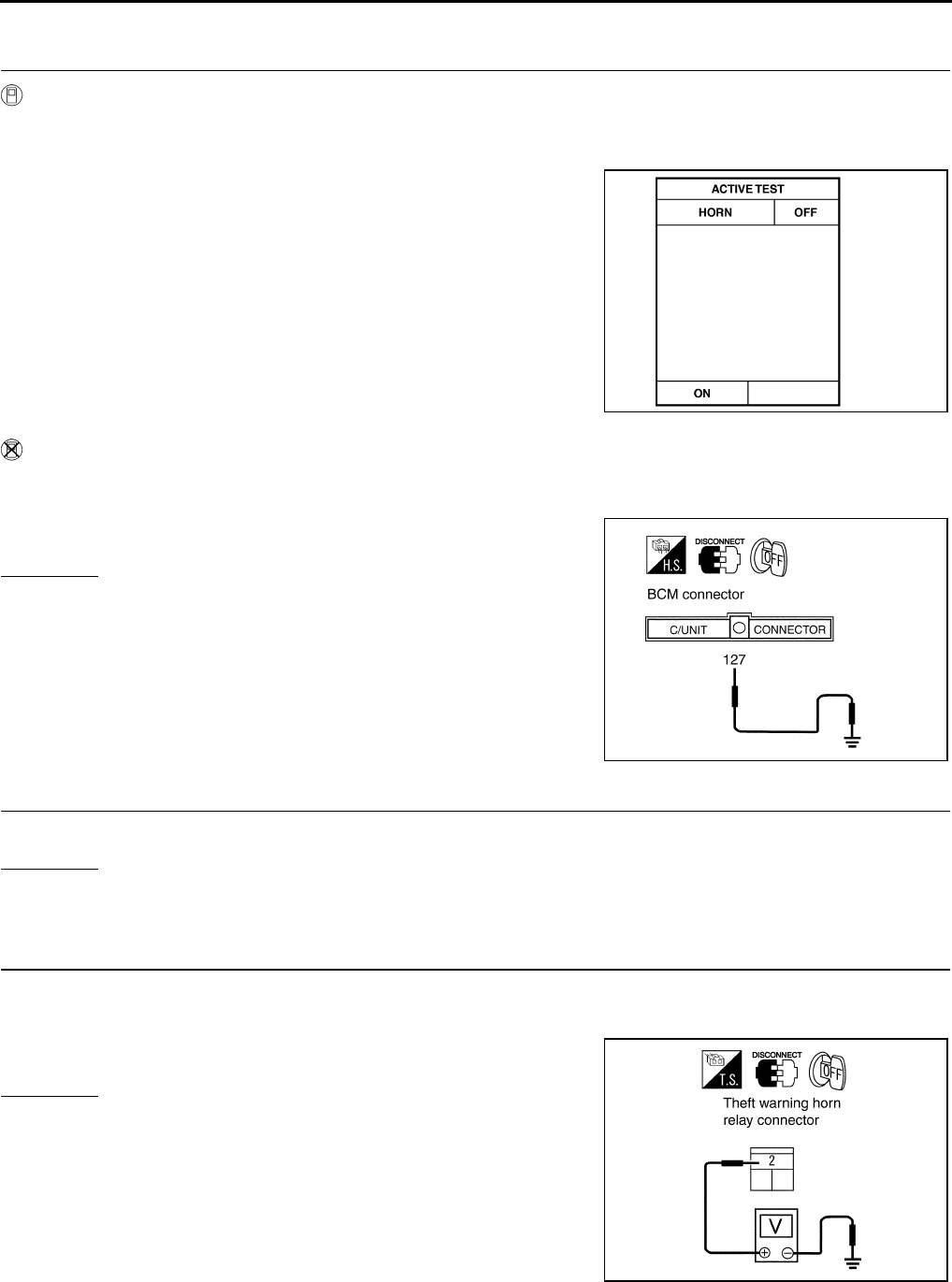
BL-76
REMOTE KEYLESS ENTRY SYSTEM
Revision: 2004 April 2002 Q45
Horn Reminder Check EIS0028T
1. CHECK HORN CHIRP OPERATION
With CONSULT−II
●Check horn chirp “HORN” in "ACTIVE TEST" mode with CONSULT−II.
●Perform operation shown on display.
Without CONSULT−II
1. Disconnect BCM connector.
2. Apply ground to BCM connector E204 terminal 127(G/W).
OK or NG?
OK >> Horn alarm is OK.
NG >> GO TO 2.
2. CHECK HORN RELAY
Check horn relay condition.
OK or NG?
OK >> GO TO 3.
NG >> Replace horn relay.
3. CHECK POWER SUPPLY FOR HORN RELAY
1. Disconnect horn relay connector.
2. Check voltage between horn relay connector E3-5 terminal 2(G/W) and ground.
OK or NG?
OK >> GO TO 4.
NG >> Check the following.
●15A fuse [No. 56, located in the fuse, fusible link and
relay block (J/B)]
●Harness for open or short between horn relay and
fuse
: Horn should sound.
SEL945W
: Horn should sound.
PIIA0359E
Battery voltage should exist.
PIIA0360E
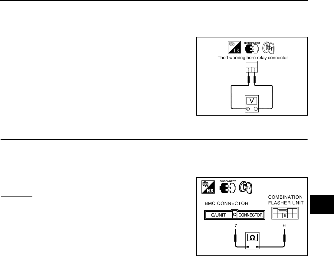
REMOTE KEYLESS ENTRY SYSTEM
BL-77
C
D
E
F
G
H
J
K
L
M
A
B
BL
Revision: 2004 April 2002 Q45
4. CHECK HORN RELAY CIRCUIT
1. Disconnect horn relay connector.
2. Check voltage between horn relay connector E3-5 terminals 1(G/W) and 3(G).
OK or NG?
OK >> Replace BCM.
NG >> Check harness for open or short between horn relay and
BCM.
Hazard Indicator Operation Check EIS0028U
1. CHECK COMBINATION FLASHER UNIT CIRCUIT
1. Remove electronic key from ignition key cylinder.
2. Disconnect BCM and combination flasher unit connector.
3. Check continuity between BCM harness connector M4 terminal 7(W/L) and combination flasher unit har-
ness connector M91 terminal 6(W/L).
OK or NG?
OK >> GO TO 2.
NG >> Repair or replace harness.
Battery voltage should exist.
PIIA0361E
: Continuity should exist.
PIIA0248E
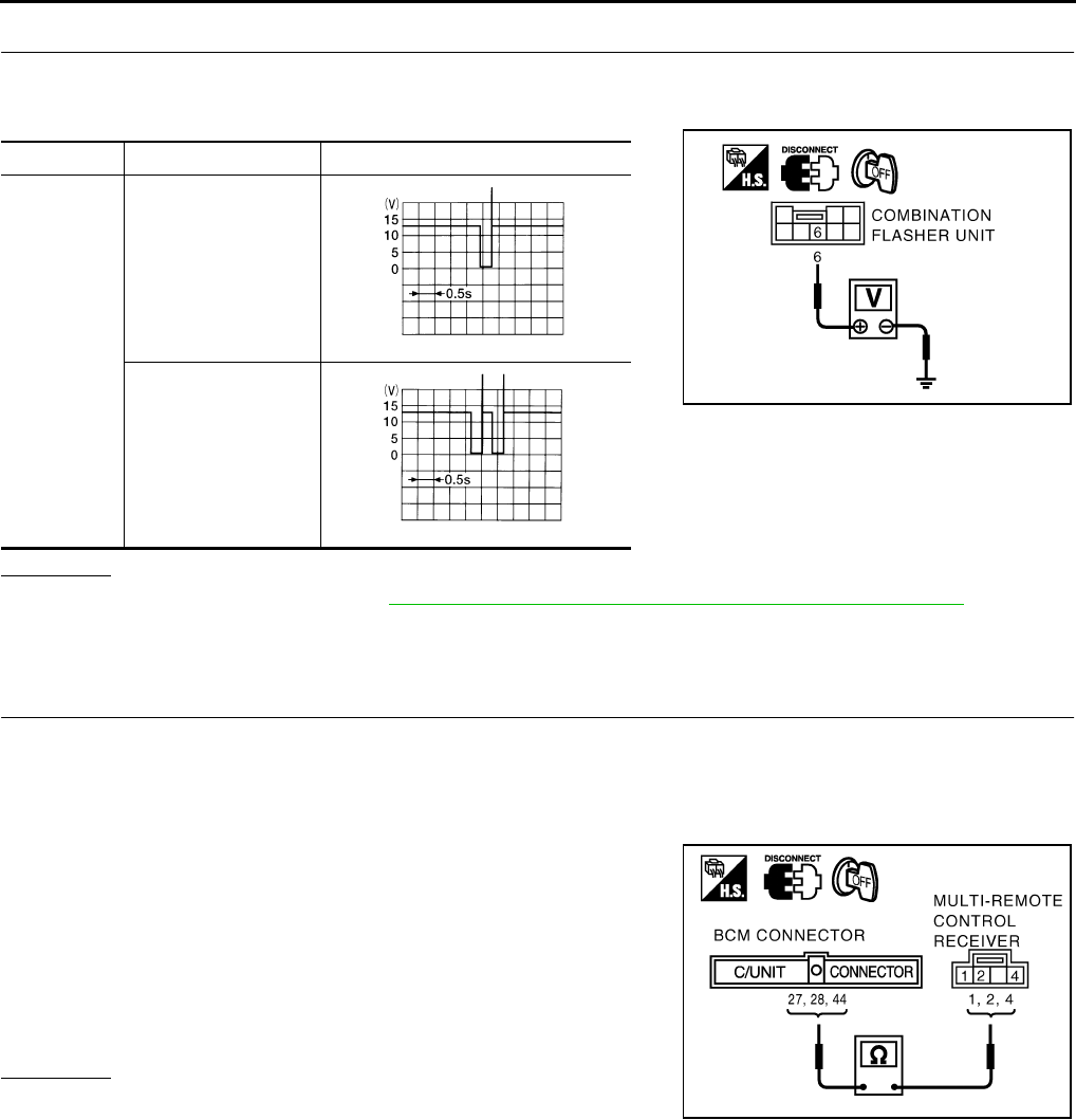
BL-78
REMOTE KEYLESS ENTRY SYSTEM
Revision: 2004 April 2002 Q45
2. CHECK BCM OUTPUT SIGNAL
1. Connect BCM connector.
2. Check voltage between flasher unit harness connector M91 terminal 6(W/L) and body ground.
OK or NG?
OK >> Check flasher unit. Refer toLT-57, "TURN SIGNAL AND HAZARD WARNING LAMPS" .
NG >> Replace BCM.
Multi-Remote Control Receiver Check EIS0028V
1. CHECK MULTI-REMOTE CONTROL RECEIVER HARNESS
1. Remove electronic key from ignition key cylinder.
2. Disconnect multi-remote control receiver and BCM connector.
3. Check continuity between multi-remote control receiver harness connector B246 terminals 1(Y), 2(BR/W),
4(L) and BCM harness connector M4 terminals 27(BR/W), 28(L), 44(Y).
4. Check continuity between multi-remote control receiver harness
connector B246 terminals 1(Y), 2(BR/W), 4(L) and body ground.
OK or NG?
OK >> GO TO 2.
NG >> Repair or replace harness.
Terminal Condition Voltage
6 (W/L) –
body ground
Electronic key
: LOCK switch ON
Electronic key
: UNLOCK switch ON
PIIA0249E
ELN0504D
ELN0505D
1(Y) – 44(Y) : Continuity should exist.
2(BR/W) – 27(BR/W) : Continuity should exist.
3(L) – 28(L) : Continuity should exist.
: Continuity should not exist.
PIIA0250E

REMOTE KEYLESS ENTRY SYSTEM
BL-79
C
D
E
F
G
H
J
K
L
M
A
B
BL
Revision: 2004 April 2002 Q45
2. CHECK MULTI-REMOTE CONTROL RECEIVER GROUND CIRCUIT
1. Connect BCM control unit connector.
2. Check continuity between multi-remote control receiver harness connector B246 terminal 1(Y) and body
ground.
OK or NG?
OK >> GO TO 3.
NG >> Repair or replace harness.
3. CHECK MUITI-REMOTE CONTROL RECEIVER POWER SUPPLY CIRCUIT
1. Connect multi-remote control receiver connector.
2. Check the voltage between multi-remote control receiver harness connector B246 terminal 4(L) and body
ground.
OK or NG?
OK >> GO TO 4.
NG >> Replace BCM.
: Continuity should exist.
PIIA0251E
Terminal Condition Voltage
4 (L) – body
ground
stand−by
Press any of the elec-
tronic key switches
PIIA0252E
OCC3881D
OCC3882D
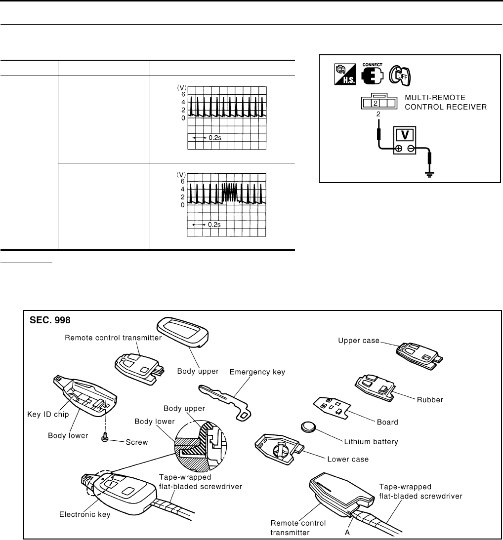
BL-80
REMOTE KEYLESS ENTRY SYSTEM
Revision: 2004 April 2002 Q45
4. CHECK MULTI-REMOTE CONTROL RECEIVER OUTPUT SIGNAL
Check the voltage between multi-remote control receiver harness connector B246 terminal 2(BR/W) and body
ground.
OK or NG?
OK >> Replace BCM.
NG >> Replace multi-remote control receiver.
Electronic Key Battery Replacement EIS0028W
1. Remove the mounting screw on the back side of the electronic key, and insert a slotted screwdriver
wrapped with tape into the emergency key slot. Twist the screwdriver to separate the upper body from the
lower body. Then take out the electronic key transmitter.
CAUTION:
During disassembly, do not impact the transponder on the lower body.
2. Insert a slotted screwdriver wrapped with tape into the electronic key transmitter (A) and twist the screw-
driver to disassemble the transmitter.
3. Replace the battery fixed on the lower body. Be sure to install new battery properly with the positive side
facing the lower case.
CAUTION:
●During disassembly, be careful not to touch the board surface. Visually check the board for
color change (bluish) and deposit.
Terminal Condition Voltage
2 (BR/W) –
body ground
stand−by
Press any of the elec-
tronic key switches
PIIA0253E
OCC3879D
OCC3880D
PIIA0179E
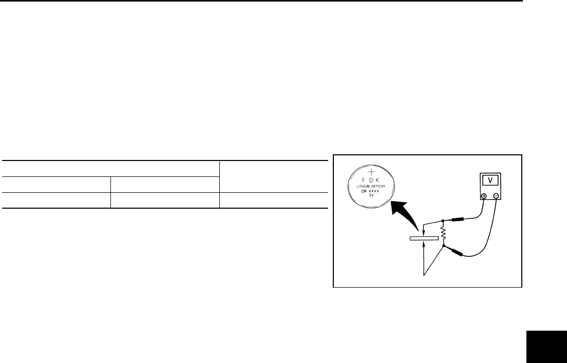
REMOTE KEYLESS ENTRY SYSTEM
BL-81
C
D
E
F
G
H
J
K
L
M
A
B
BL
Revision: 2004 April 2002 Q45
●When replacing the battery, keep the electrode contact clear of foreign materials such as dust
and grease.
4. After replacing the battery, engage the tab on the side of the body while being careful not to pinch the rub-
ber, and assemble the upper and lower bodies.
5. While being careful of engagement between the upper and lower bodies at the end, assemble the elec-
tronic key transmitter, and tighten it with screws.
CAUTION:
After replacing the battery, be sure to check that the door locking operates normally using the
electronic key.
REMOTE CONTROLLER BATTERY CHECK
Remove battery and measure voltage across battery positive and negative terminals, “+” and “–”.
Measuring terminal Voltage
( + ) ( – )
Battery positive terminal Battery negative terminal 2.5 – 3.0V
OCC0607D
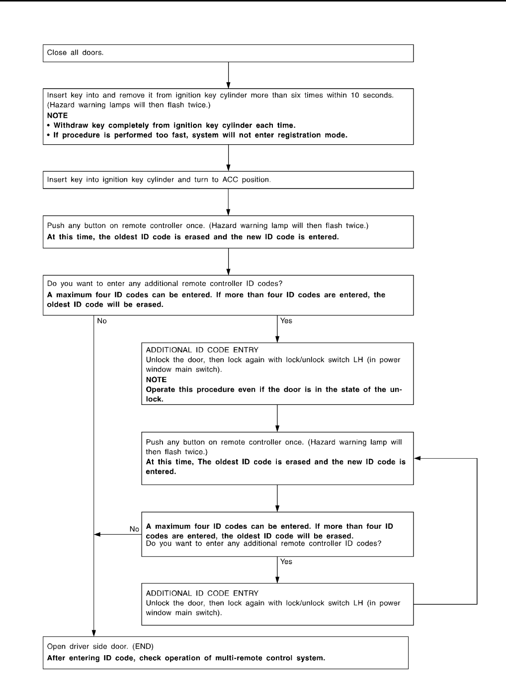
BL-82
REMOTE KEYLESS ENTRY SYSTEM
Revision: 2004 April 2002 Q45
ID Code Entry Procedure EIS0028X
PROCEDURE 1 (WITHOUT CONSULT-II)
SEL170Y
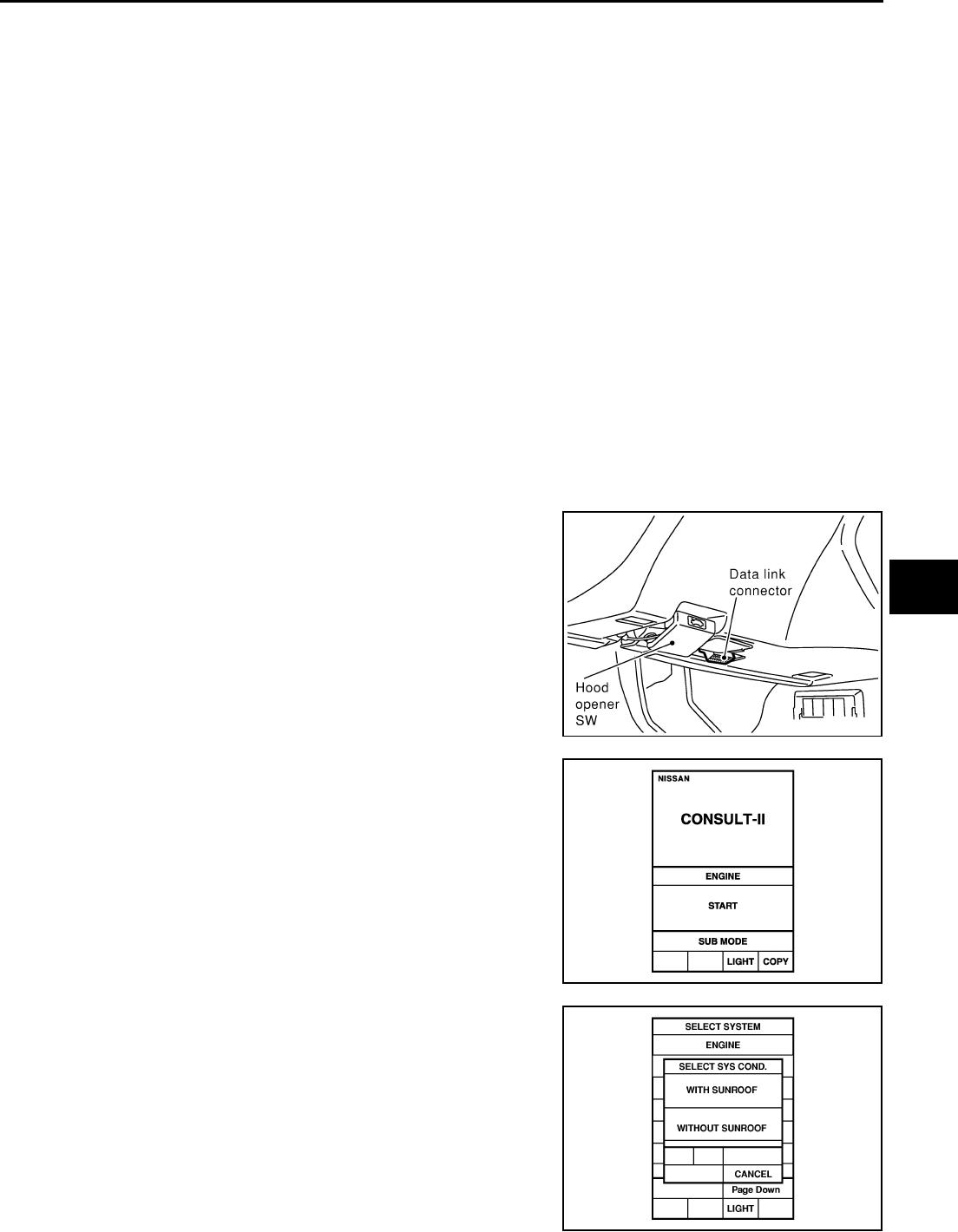
REMOTE KEYLESS ENTRY SYSTEM
BL-83
C
D
E
F
G
H
J
K
L
M
A
B
BL
Revision: 2004 April 2002 Q45
NOTE:
●If a electronic key is lost, the ID code of the lost electronic key must be erased to prevent unauthorized
use. A specific ID code can be erased with CONSULT-II. However, when the ID code of a lost electronic
key is not known, all controller ID codes should be erased. After all ID codes are erased, the ID codes of
all remaining and/or new remote controllers must be re-registered. To erase all ID codes in memory, regis-
ter one ID code (electronic key) four times. After all ID codes are erased, the ID codes of all remaining
and/or new electronic keys must be re-registered.
●When registering an additional electronic key, the existing ID codes in memory may or may not be erased.
If four ID codes are stored in memory, when an additional code is registered, only the oldest code is
erased. If less than four ID codes are stored in memory, when an additional ID code is registered, the new
ID code is added and no ID codes are erased.
●If you need to activate more than two additional new electronic keys, repeat the procedure “Additional ID
code entry” for each new electronic key.
●Entry of maximum four ID codes is allowed. When more than four ID codes are entered, the oldest ID
code will be erased.
●Even if same ID code that is already in the memory is input, the same ID code can be entered. The code
is counted as an additional code.
PROCEDURE 2 (WITH CONSULT-II)
NOTE:
If a electronic key is lost, the ID code of the lost electronic key must be erased to prevent unauthorized use.
When the ID code of a lost electronic key is not known, all controller ID codes should be erased. After all ID
codes are erased, the ID codes of all remaining and/or new remote controllers must be re-registered.
1. Turn ignition switch "OFF".
2. Connect "CONSULT-ll" to the data link connector.
3. Turn ignition switch "ON".
4. Touch "START"
5. Check the model specification, touch either "WITH SUNROOF"
or "WITHOUT SUNROOF".
6. Touch "OK". If the selection is wrong, touch "CANCEL".
SHIA0179E
PIIA0182E
PIIA0184E
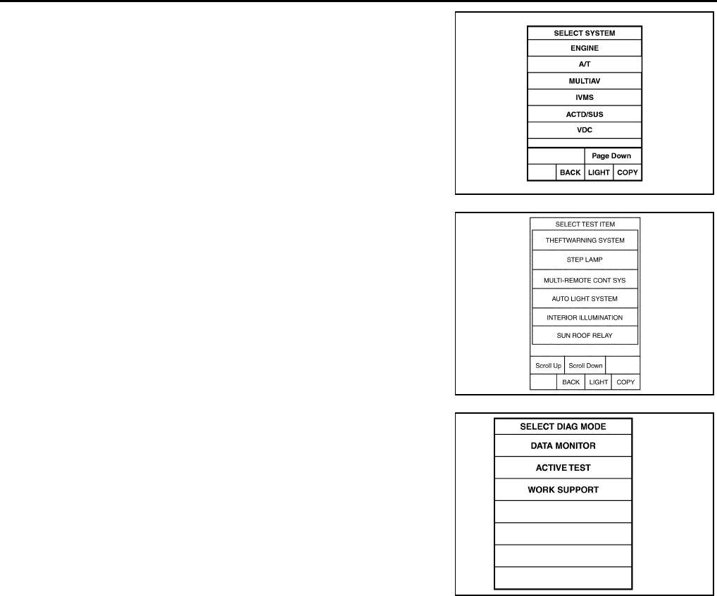
BL-84
REMOTE KEYLESS ENTRY SYSTEM
Revision: 2004 April 2002 Q45
7. Touch "IVMS"
8. Touch "MULTI-REMOTE CONT SYS".
9. Touch "WORK SUPPORT".
10. The item shown on the figure at right can be set up.
●"REMO CONT ID CONFIR"
Use this mode to confirm if a electronic key ID code is registered
or not.
●"REMO CONT ID REGIST" Use this mode to register a elec-
tronic key ID code.
NOTE:
Register the ID code when electronic key or BCM is replaced, or
when additional electronic key is required.
●"REMO CONT ID ERASUR" Use this mode to erase a electronic
key ID code.
PIIA0183E
PIIA0373E
SEL274W
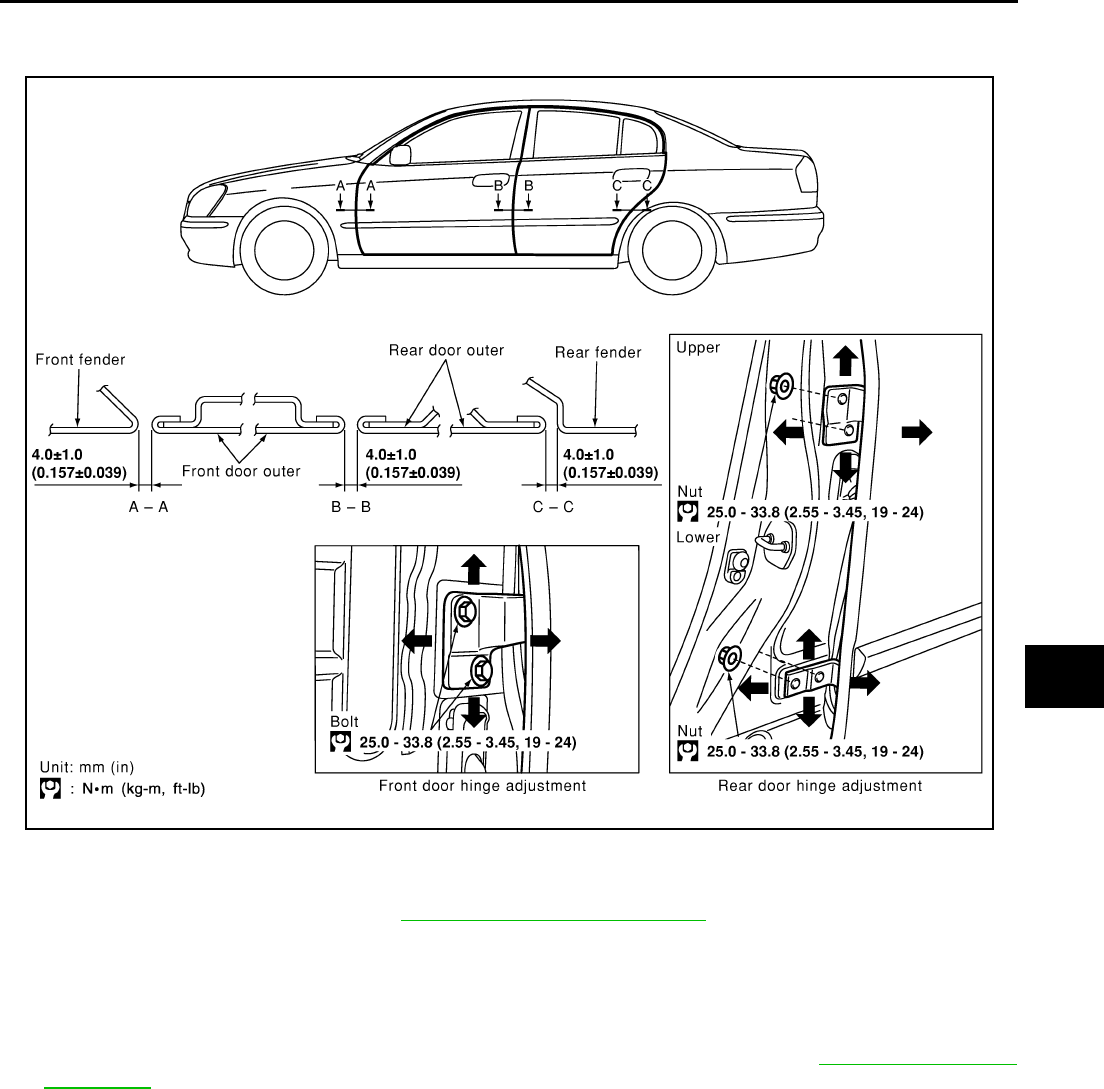
DOOR
BL-85
C
D
E
F
G
H
J
K
L
M
A
B
BL
Revision: 2004 April 2002 Q45
DOOR PFP:80100
Fitting Adjustment EIS000HA
FRONT DOOR
Longitudinal Clearance and Surface Height Adjustment at Front End
1. Remove the fender protector. Refer to EI-22, "Removal and Installation" .
2. Accessing from inside the fender, loosen the hinge mounting bolts. Raise the front door at rear end to
adjust.
REAR DOOR
Longitudinal Clearance and Surface Height Adjustment at Front End
1. Remove the center pillar upper garnish and center pillar lower garnish. Refer to EI-38, "Removal and
Installation" .
2. Accessing from inside the vehicle, loosen the mounting nuts. Open the rear door, and raise the rear door
at rear end to adjust.
SIIA0327E
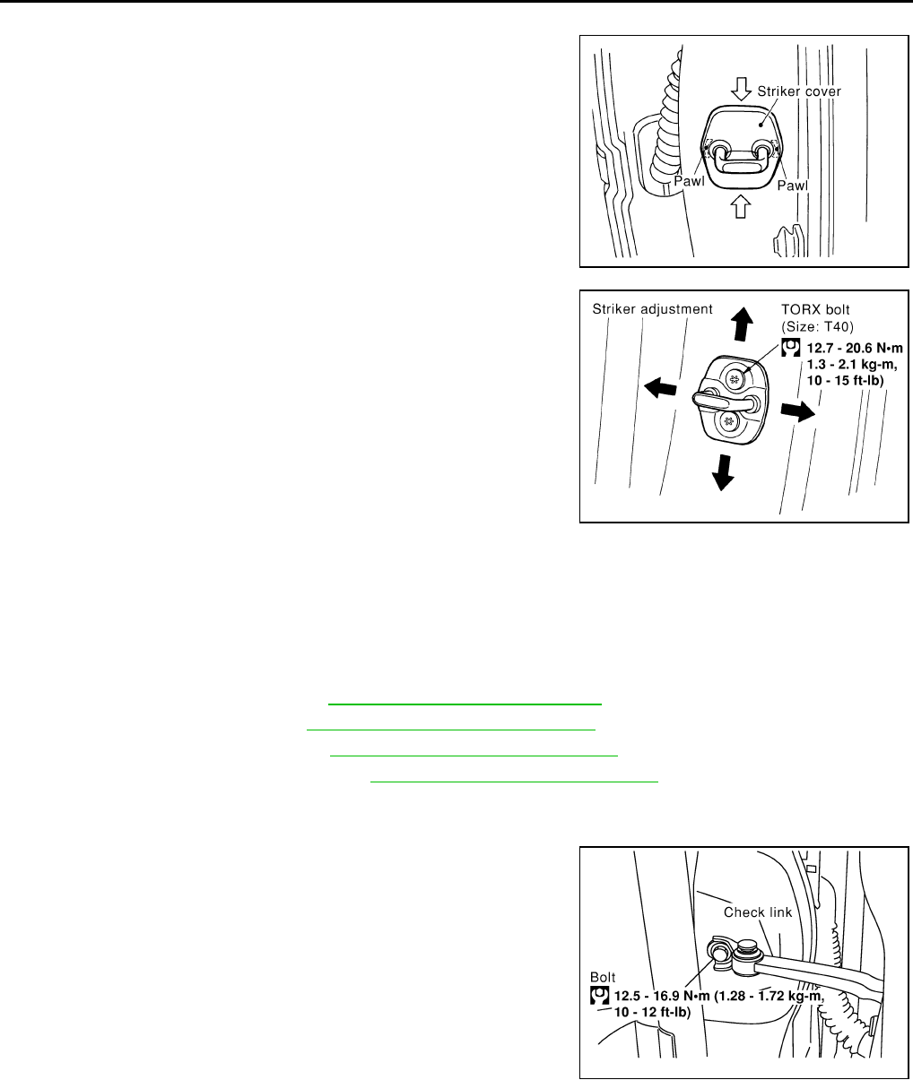
BL-86
DOOR
Revision: 2004 April 2002 Q45
STRIKER ADJUSTMENT
1. Remove the striker cover.
2. Adjust the striker so that it becomes parallel with the lock inser-
tion direction.
Removal and Installation EIS000HB
CAUTION:
●When removing and installing the door assembly, support the door with a jack and shop cloth to
protect the door and body.
●When removing and installing door assembly, be sure to carry out the fitting adjustment.
●Check the hinge rotating part for poor lubrication. If necessary, apply "body grease".
1. Remove the door finisher. Refer to EI-31, "Removal and Installation" .
2. Remove the inner seal. Refer to GW-45, "Removal and Installation" .
3. Remove the door window. Refer to GW-45, "Removal and Installation" .
4. Remove the module assembly. Refer to GW-45, "Removal and Installation" .
5. Remove the door harness.
6. Remove the check link cover.
7. Remove the mounting bolts of the check link on the vehicle.
SIIA0886E
SIIA0338E
SIIA0339E
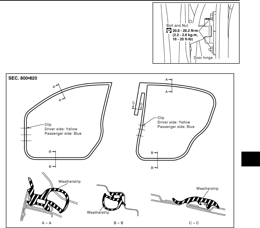
DOOR
BL-87
C
D
E
F
G
H
J
K
L
M
A
B
BL
Revision: 2004 April 2002 Q45
8. Remove the door-side hinge mounting nuts and bolts, and
remove the door assembly.
Install in the reverse order of removal.
Door Weathers trip EIS000HC
SIIA0340E
SIIA0328E
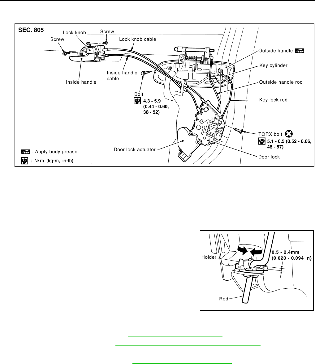
BL-88
FRONT DOOR LOCK
Revision: 2004 April 2002 Q45
FRONT DOOR LOCK PFP:80502
Component Structure EIS000HD
Inspection and Adjustment. EIS000HE
1. Remove the front door finisher. Refer to EI-31, "Removal and Installation" .
2. Remove the front speaker. Refer to AV-28, "Removal and Installation of Door Speaker"
3. Remove the front door window. Refer to GW-45, "Removal and Installation" .
4. Remove the front door module assembly. Refer to GW-45, "Removal and Installation" .
EXTERIOR HANDLE ROD ADJUSTMENT
●Rotate the bushing to adjust so that the clearance between the
bushing and rod becomes as shown in the figure.
CAUTION:
Be careful not to make the clearance 0 mm (0 in) or the rod
pressed continuously.
Removal and Installation EIS000HF
REMOVAL
1. Remove the front door finisher. Refer to EI-31, "Removal and Installation" .
2. Remove the front speaker. Refer to AV-28, "Removal and Installation of Door Speaker" .
3. Remove the front door window. GW-45, "Removal and Installation" .
4. Remove the front door module assembly. GW-45, "Removal and Installation" .
SIIA0299E
SBT978
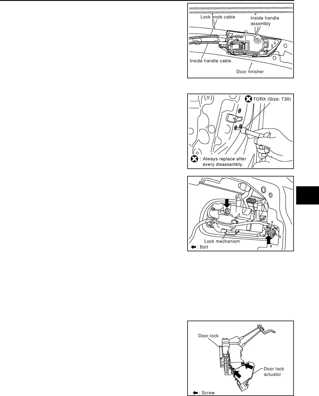
FRONT DOOR LOCK
BL-89
C
D
E
F
G
H
J
K
L
M
A
B
BL
Revision: 2004 April 2002 Q45
5. Disconnect the inside handle cable and locking knob cable from
the back side of the front door finisher.
6. Reach to separate the key cylinder rod and exterior handle rod connection (on the handle).
7. Remove the mounting screws (TORX T30), remove the door
lock assembly.
8. Disconnect the door lock actuator connector.
9. Remove the exterior handle mounting bolts, move the exterior
handle assembly backward, and then remove it from the panel
in front of the exterior handle escutcheon.
INSTALLATION
Install in the reverse order of removal.
CAUTION:
To install each rod, be sure to rotate the rod holder until a click is felt.
Disassembly and Assembly EIS000HG
DISASSEMBLY
CAUTION:
Be sure to remove or install the actuator with the door lock assembly removed.
1. Remove the mounting screws, and remove the actuator from the
door lock assembly.
2. Pull the actuator straight downward to separate it from the door
lock assembly.
SIIA0266E
SIIA0341E
SIIA0342E
SIIA0343E

BL-90
FRONT DOOR LOCK
Revision: 2004 April 2002 Q45
ASSEMBLY
1. Align the actuator pivot with the cutout on the knob lever of the door lock assembly, then assemble the
actuator.
2. Move the knob lever and the actuator pivot toward the lock-on direction, and check that it engages
securely.
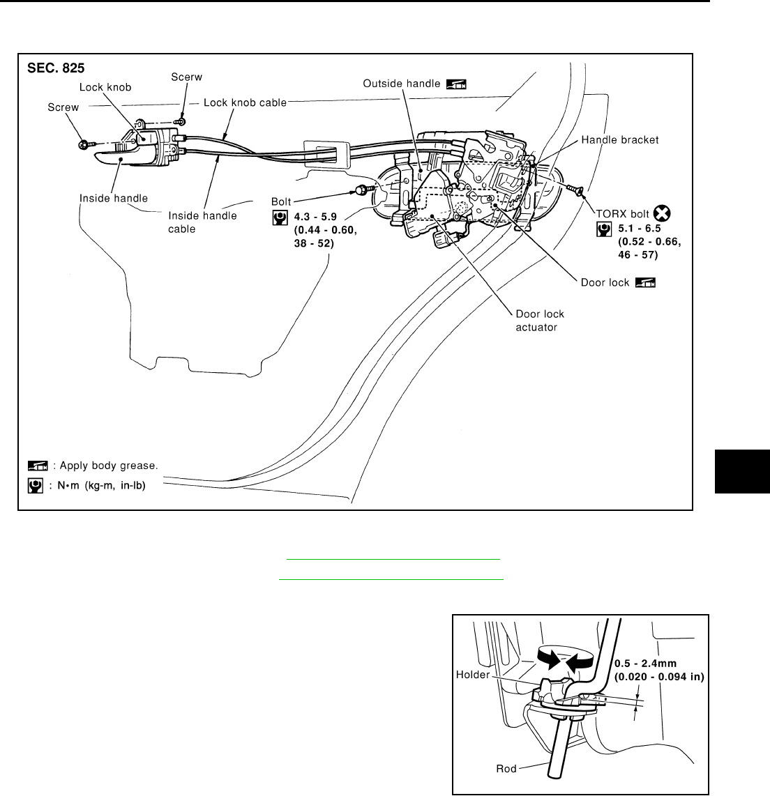
REAR DOOR LOCK
BL-91
C
D
E
F
G
H
J
K
L
M
A
B
BL
Revision: 2004 April 2002 Q45
REAR DOOR LOCK PFP:82502
Components EIS000HH
Inspection and Adjustment EIS000HI
1. Remove the rear door finisher. Refer to EI-31, "Removal and Installation" .
2. Remove the frame assembly. Refer to GW-48, "Removal and Installation" .
EXTERIOR HANDLE ROD ADJUSTMENT
Rotate the bushing to adjust so that the clearance between the bush-
ing and rod becomes as shown in the figure.
CAUTION:
Be careful not to make the clearance 0 mm (0 in) or the rod
pressed continuously.
SIIA0303E
SBT978
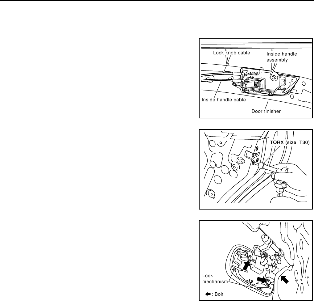
BL-92
REAR DOOR LOCK
Revision: 2004 April 2002 Q45
Removal and Installation of Door Lock EIS000HJ
REMOVAL
1. Remove the rear door finisher. Refer to EI-31, "Removal and Installation"
2. Remove the frame assembly. Refer to GW-48, "Removal and Installation" .
3. After gaining access to the inside handle on the back side of the
rear door finisher, disconnect the inside handle cable and lock-
ing knob cable.
4. Remove the mounting screws (TORX T30), remove the door
lock assembly.
5. Disconnect the door lock actuator connector.
6. Remove the exterior handle mounting bolts, and move the han-
dle backward to disengage it from the panel in front of the exte-
rior handle escutcheon, then remove the handle.
INSTALLATION
Install in the reverse order of removal.
CAUTION:
To install each rod, be sure to rotate the rod holder until a click is felt.
SIIA0266E
SIIA0344E
SIIA0345E
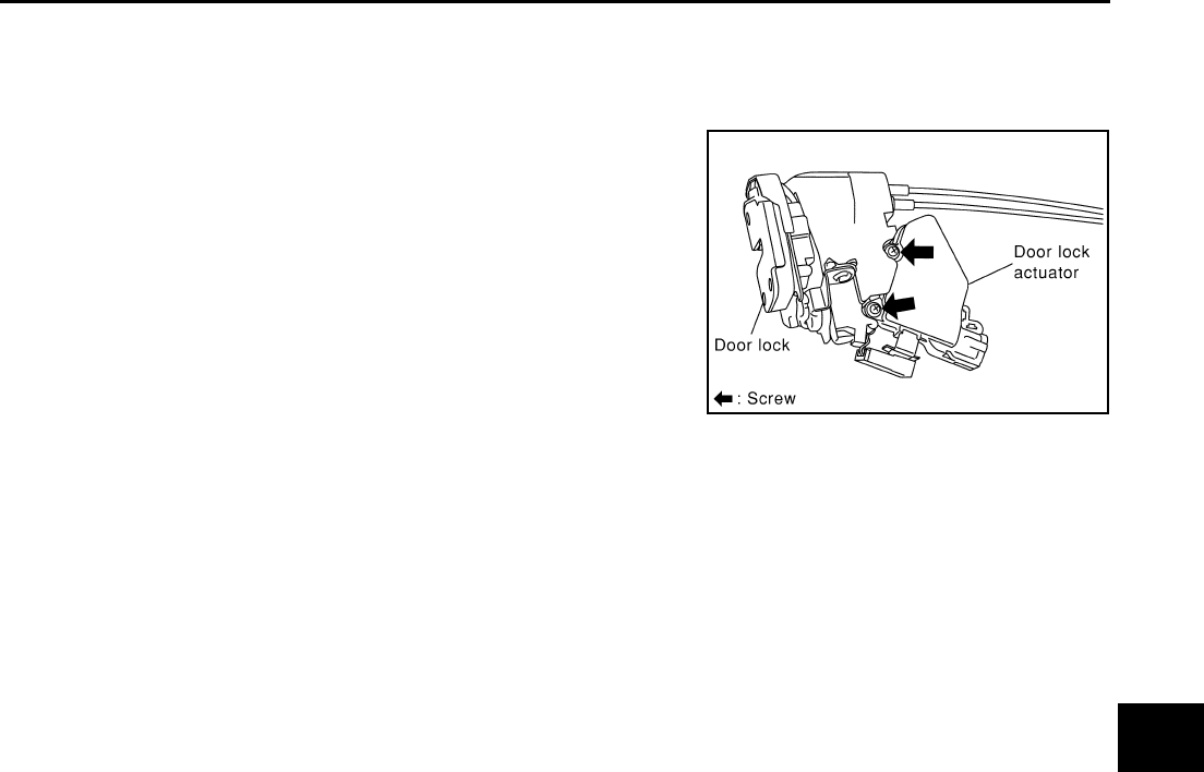
REAR DOOR LOCK
BL-93
C
D
E
F
G
H
J
K
L
M
A
B
BL
Revision: 2004 April 2002 Q45
Disassembly and Assembly EIS000HL
DISASSEMBLY
CAUTION:
Be sure to remove or install the actuator with the door lock assembly removed.
1. Remove the mounting screws, and remove the actuator from the
door lock assembly.
2. Pull the actuator straight downward to separate it from the door
lock assembly.
ASSEMBLY
1. Align the actuator pivot with the cutout on the knob lever of the door lock assembly, then assemble the
actuator.
2. Move the knob lever and the actuator pivot toward the lock-on direction, and check that it engages
securely.
SIIA0346E
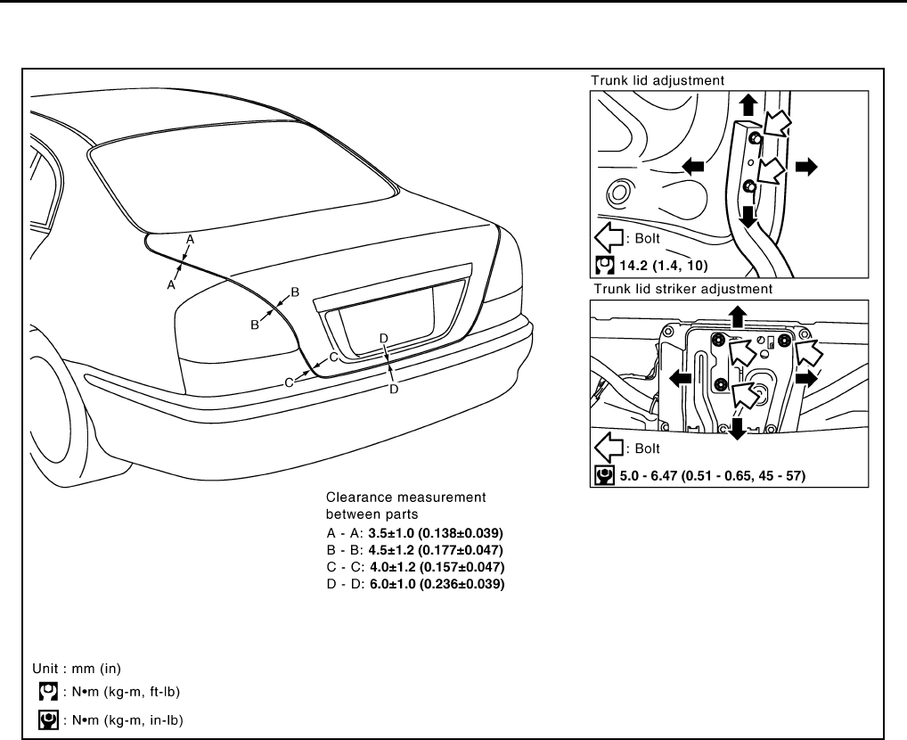
BL-94
TRUNK LID
Revision: 2004 April 2002 Q45
TRUNK LID PFP:H4300
Fitting Adjustment EIS000HW
LONGITUDINAL AND LATERAL CLEARANCE ADJUSTMENT
1. With the striker released, loosen the trunk lid hinge mounting bolts to close the trunk lid.
2. Make the lateral clearance and the clearance to the rear window glass equal, and open the trunk lid to
tighten the mounting bolts to the specified torque.
SURFACE HEIGHT ADJUSTMENT
1. Loosen the striker mounting bolts. Raise the striker to the top position, and temporarily tighten the upper
mounting bolt at the position.
2. Close the trunk lid lightly and adjust the surface height, then open the trunk lid to finally tighten the striker
mounting bolts to the specified torque.
PIIB1573E
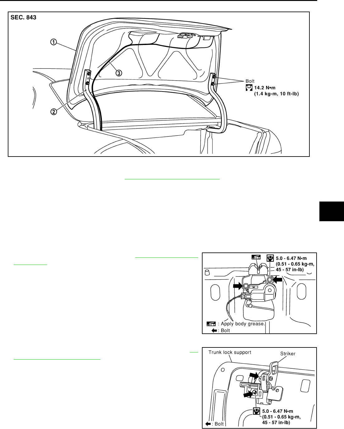
TRUNK LID
BL-95
C
D
E
F
G
H
J
K
L
M
A
B
BL
Revision: 2004 April 2002 Q45
Removal and Installation of Trunk Lid Assembly EIS000HX
1. Remove the trunk lid finisher. Refer to EI-51, "Removal and Installation" .
2. Disconnect the connectors in the trunk lid, and remove the harness clamps to pull the harness out of the
trunk lid.
3. Remove the mounting bolts, and remove the trunk lid assembly.
CAUTION:
After installing, apply touch-up paint (the body color) onto the head of the hinge mounting bolts.
Install in the reverse order of removal.
Removal and Installation of Trunk Lid Lock EIS000HY
LOCK REMOVAL
1. Remove the trunk lid finisher. Refer to EI-51, "Removal and
Installation" .
2. Separate the key cylinder rod.
3. After removing the harness connector, remove the mounting
bolts, and remove the trunk lid lock.
STRIKER REMOVAL
1. Remove the trunk rear plate and trunk rear finisher. Refer to EI-
51, "Removal and Installation" .
2. Remove the mounting bolts, and remove the trunk lock support
from the vehicle.
3. After removing the harness connector, remove the mounting
bolts, and remove the striker from the trunk lock support.
PIIB1574E
1. Trunk lid assembly 2. Trunk lid hinge 3. Trunk lid harness
SIIA0331E
SIIA0333E
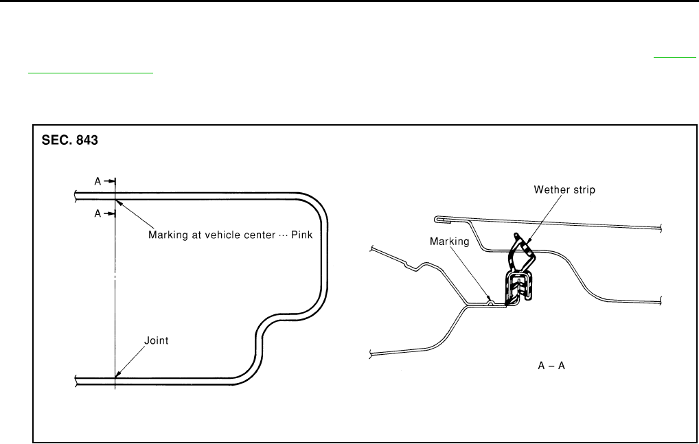
BL-96
TRUNK LID
Revision: 2004 April 2002 Q45
LOCK AND STRIKER INSTALLATION
1. Install in the reverse order of removal.
2. After installing, close the trunk lid lightly. Preform the lock and surface height adjustment. Refer to BL-94,
"Fitting Adjustment" .
3. After installing, check the operation.
Removal and Installation of Trunk Lid Weather-strip EIS000HZ
1. Install the weather-strip from the front with the vehicle center mark aligned to the weather-strip mark.
2. At rear side, align the weather-strip seam to the center of the striker.
3. After installing, pull the weather-strip lightly to check for looseness.
CAUTION:
The weather-strip shall be fit tightly onto the corners and trunk lid rear plate.
SIIA0180E
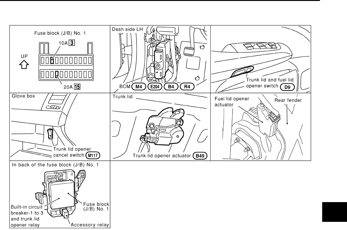
TRUNK LID AND FUEL FILLER LID OPENER
BL-97
C
D
E
F
G
H
J
K
L
M
A
B
BL
Revision: 2004 April 2002 Q45
TRUNK LID AND FUEL FILLER LID OPENER PFP:84640
Component Part and Harness Connector Location EIS000IV
CIIM0001E
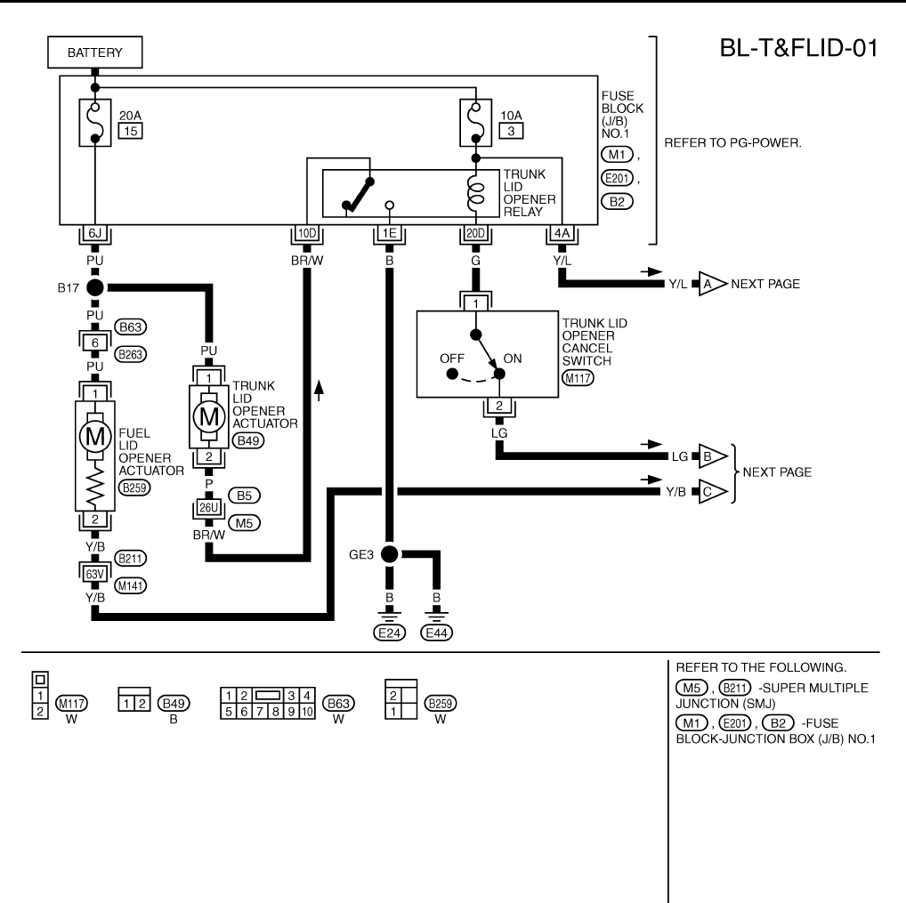
BL-98
TRUNK LID AND FUEL FILLER LID OPENER
Revision: 2004 April 2002 Q45
Wiring Diagram — T&FLID — EIS000IW
TIWM0001E
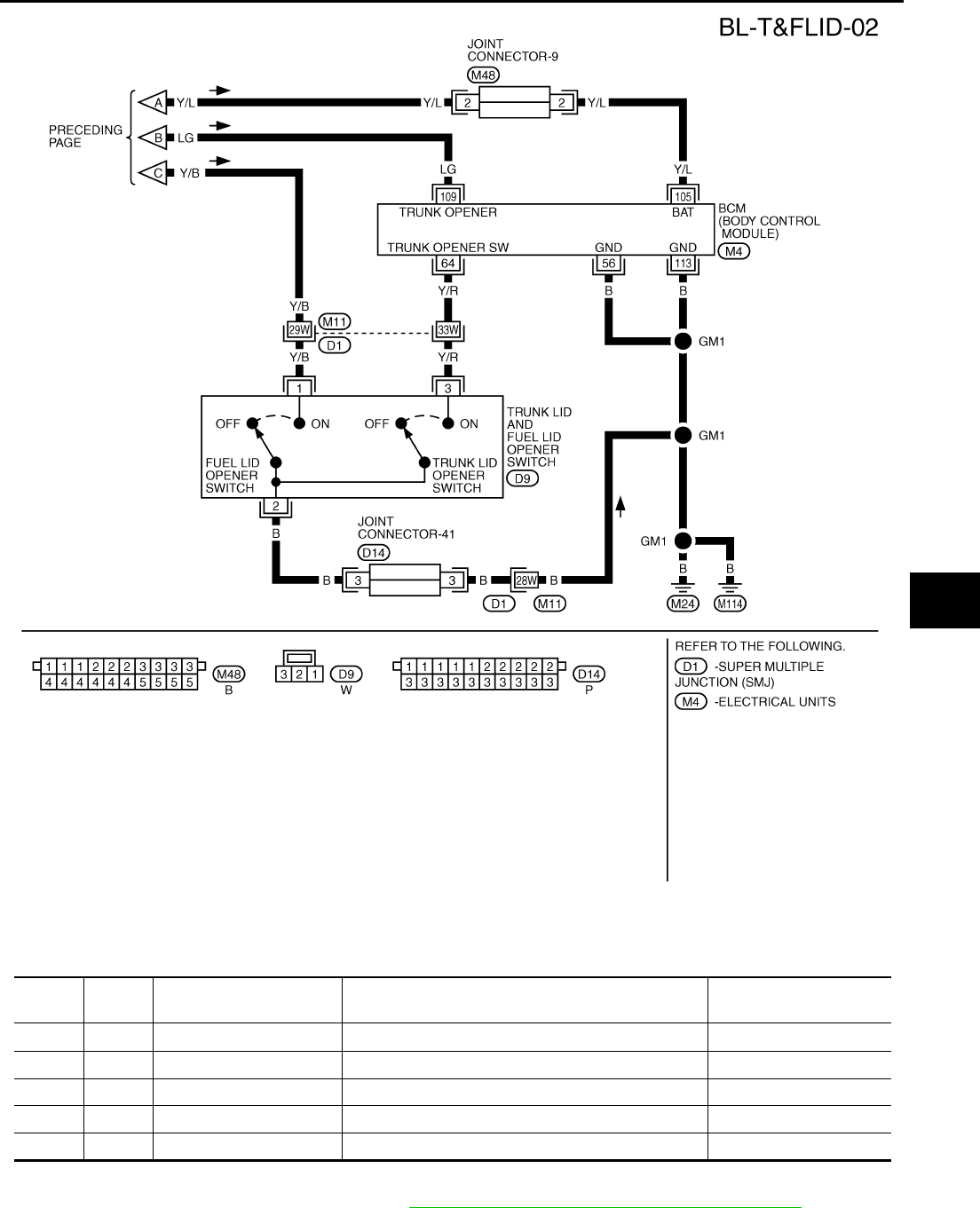
TRUNK LID AND FUEL FILLER LID OPENER
BL-99
C
D
E
F
G
H
J
K
L
M
A
B
BL
Revision: 2004 April 2002 Q45
Terminals and Reference Value for BCM EIS000IX
NOTE:
For Trouble diagnosis of trunk lid opener, refer to BL-45, "REMOTE KEYLESS ENTRY SYSTEM" .
TIWM0002E
TERMI-
NAL
WIRE
COLOR ITEM CONDITION VOLTAGE
56 B Ground — 0V
64 Y/R Trunk lid opener switch Trunk lid opener switch OFF→ON 5V→0V
105 Y/L BAT power supply — Battery voltage
109 LG Trunk lid opener relay Trunk lid opener switch OFF→ON Battery voltage → 0V
113 B Ground — 0V
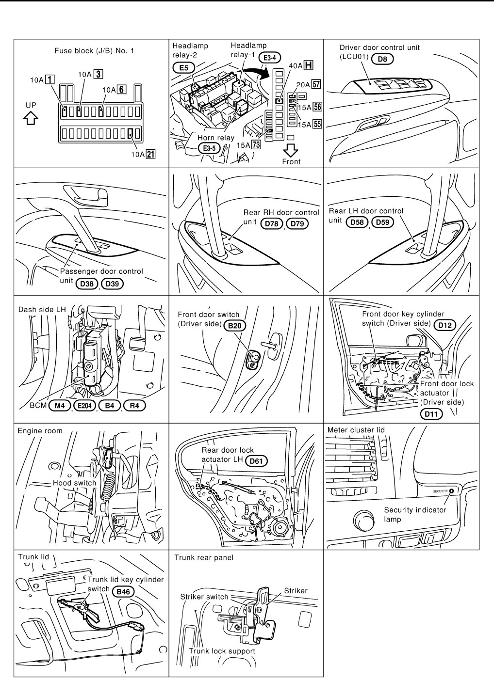
BL-100
VEHICLE SECURITY (THEFT WARNING) SYSTEM
Revision: 2004 April 2002 Q45
VEHICLE SECURITY (THEFT WARNING) SYSTEM PFP:28491
Component Parts Harness Connector Location EIS000TX
CIIM0005E

VEHICLE SECURITY (THEFT WARNING) SYSTEM
BL-101
C
D
E
F
G
H
J
K
L
M
A
B
BL
Revision: 2004 April 2002 Q45
System Description EIS000TY
DESCRIPTION
Setting the theft warning system
Disarmed phase
●When the vehicle is being driven or when doors or trunk lid is open, the vehicle security system is set in
the disarmed phase on the assumption that the owner is inside or near the vehicle.
Pre-armed phase and armed phase
●The vehicle security system turns into the "pre-armed" phase when hood, trunk lid and all doors are
closed and locked by electronic key. The security indicator lamp illuminates for 30 seconds. Then, the sys-
tem automatically shifts into the "armed" phase.
Canceling the set theft warning system
When the following 1 or 2 operation is performed, the armed phase is canceled.
1. Unlock the doors with the electronic key.
2. Open the trunk lid with the electronic key. When the trunk lid is closed after opening the trunk lid with the
electronic key, the system returns to the armed phase.
Activating the alarm operation of the vehicle security system
Make sure the system is in the armed phase.
When the following operation 1, 2 or 3 is performed, the system sounds the horns and flashes the head-lamps
for about 50 seconds.
1. Engine hood or any door is opened before unlocking door with electronic key.
2. Door is unlocked without using electronic key.
3. Trunk lid is opened without using electronic key.
POWER SUPPLY
Power is supplied at all times
●through 10A fuse [No.6, located in the fuse block (J/B) No.1]
●to security indicator lamp terminal 20.
Power is supplied at all times
●through 10A fuse [No.3, located in the fuse block (J/B) No.1]
●to BCM terminal No.105.
With the ignition switch in the ACC or ON position, power is supplied
●through 10A fuse [No.21, located in the fuse block (J/B) No.1]
●to BCM terminal No.60.
With the ignition switch in the ON position, power is supplied
●through 10A fuse [No.1, located in the fuse block (J/B)No.1]
●to BCM terminal No.68.
BCM is connected to LCU01 as DATA LINE A – 3.

BL-102
VEHICLE SECURITY (THEFT WARNING) SYSTEM
Revision: 2004 April 2002 Q45
INITIAL CONDITION TO ACTIVATE THE SYSTEM
The operation of the vehicle security system is controlled by the doors, hood and trunk lid.
To activate the vehicle security system, BCM must receive signals indicating the doors, hood and trunk lid are
closed and the doors are locked.
When a door is open, BCM terminal No.33, No.37, No.142 or No.143 receives a ground signal from each door
switch.
When a driver door is unlocked, driver door LCU terminal No.6 receives a ground signal from terminal No.2 of
driver door unlock sensor.
When a passenger, rear LH or RH door is unlocked, passenger, rear LH or RH door control unit terminal No.13
receives a ground signal from terminal No.2 of driver door unlock sensor.
When the hood is open, BCM terminal No.122 receives a ground signal
●from terminal No.1 of the hood switch
●through body grounds No.E42 and No.E62.
When the trunk lid is open, BCM terminal No.146 receives a ground signal
●from terminal No.1 of the trunk room lamp switch
●through body grounds No.B17, No.B57.
When the doors are locked with electronic key and none of the described conditions exist, the vehicle security
system will automatically shift to armed phase.
VEHICLE SECURITY SYSTEM ACTIVATION (WITH KEY OR ELECTRONIC KEY USED TO LOCK
DOORS)
If the emergency key is used to lock doors, LCU01 terminal No.10 receives a ground signal
●from terminal No.3 of the driver door key cylinder switch.
●through body grounds No.M24 and No.M114
If this signal or lock signal from electronic key is received by BCM, the vehicle security system will activate
automatically.
Once the vehicle security system has been activated, BCM terminal No.65 supplies ground to terminal No.19
of the security indicator lamp.
The security lamp will illuminate for approximately 30 seconds and then blink.
Now the vehicle security system is in armed phase.
VEHICLE SECURITY SYSTEM ALARM OPERATION
The vehicle security system is triggered by
●opening a door
●opening the trunk lid
●opening the hood
●unlocking door without using the electronic key.
The vehicle security system will be triggered once the system is in armed phase,
●when BCM receives a ground signal at terminal No.33, No.37, No.142, No.143 (door switch),
No.146(trunk room lamp switch) or No.122(hood switch)
●when driver door LCU receives a ground signal at terminal No.6(driver door unlock sensor)
●when passenger, rear LH, RH door control unit receives a ground signal at terminal No.13(passenger, rear
LH, RH door unlock sensor)
Power is supplied at all times
●to head lamp relay-1 terminal No.2 and
●through 15A fuse (No. 56, located in fuse block (J/B) No.1)
●to horn relay terminal No.2.
When the vehicle security system is triggered, ground is supplied intermittently
●from BCM terminal No.5(lamp relay) and No.127(horn relay)
●to head lamp relay terminal No.1 and
●to horn relay terminal No.1.
The head lamps flash and the horn sounds intermittently.
The alarm automatically turns off after 2 or 3 minutes but will reactivate if the vehicle is tampered with again.

VEHICLE SECURITY (THEFT WARNING) SYSTEM
BL-103
C
D
E
F
G
H
J
K
L
M
A
B
BL
Revision: 2004 April 2002 Q45
VEHICLE SECURITY SYSTEM DEACTIVATION
To deactivate the vehicle security system, a door or the trunk lid must be unlocked with the key or electronic
key.
When the key is used to unlock a door, LCU01 terminal No.9 receives a ground signal
●from terminal No.1 of the driver door key cylinder switch.
When the emergency key is used to unlock the trunk lid, BCM terminal No.145 receives a ground signal from
terminal No.1 of the trunk lid key cylinder switch.
When the BCM receives either one of these signals or unlock signal from electronic key, the vehicle security
system is deactivated. (Disarmed phase)
PANIC ALARM OPERATION
Remote keyless entry system may or may not operate vehicle security system (horn and head lamps) as
required.
When the Remote keyless entry system is triggered, ground is supplied intermittently.
●from BCM terminal No.5(lamp relay) and No.127(horn relay)
●to lamp relay terminal No.1 and
●to security horn relay terminal No.1.
The head lamp flashes and the horn sounds intermittently.
The alarm automatically turns off after 30 seconds or when BCM receives any signal from electronic key.
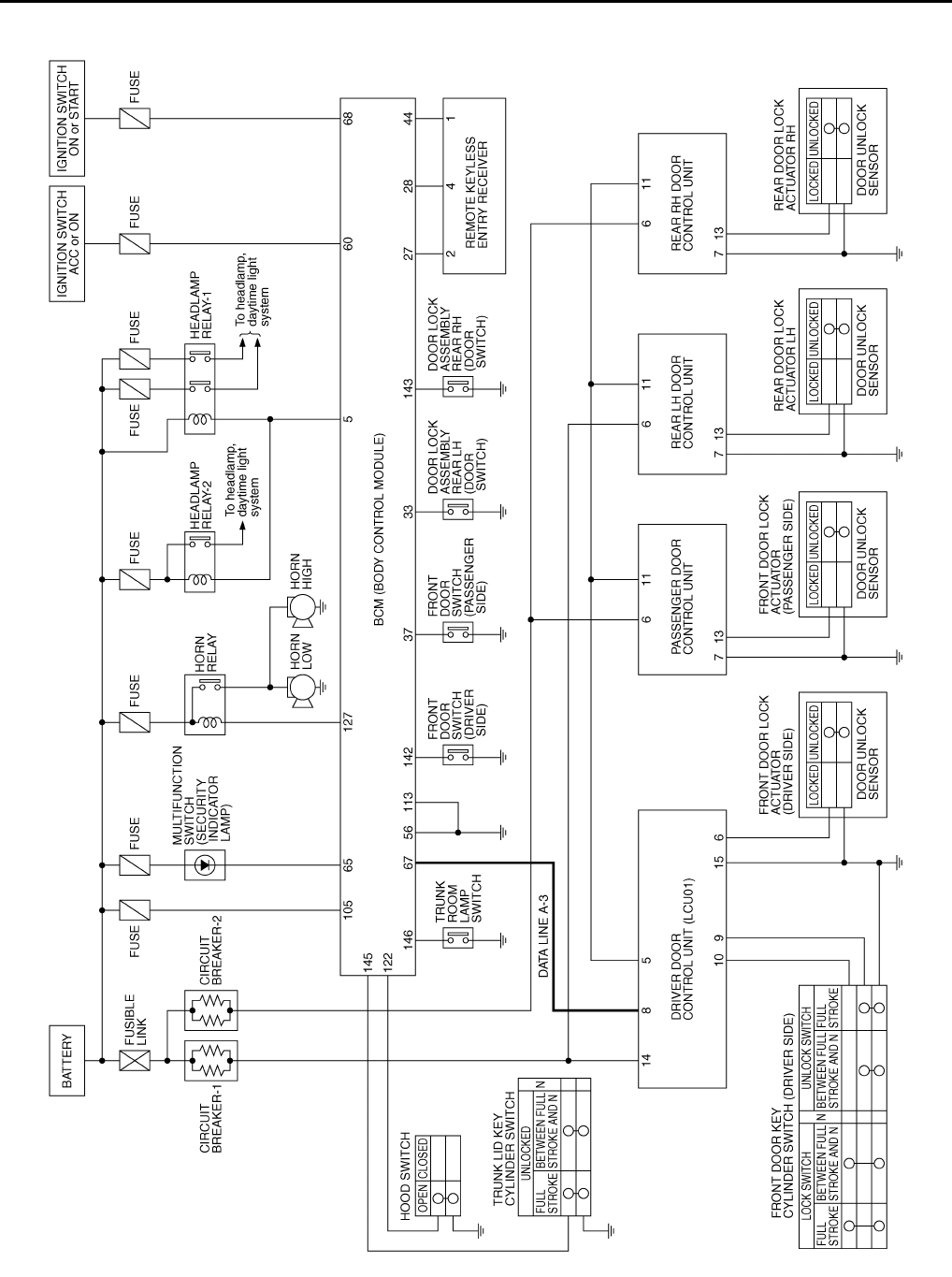
BL-104
VEHICLE SECURITY (THEFT WARNING) SYSTEM
Revision: 2004 April 2002 Q45
Schematic EIS000TZ
TIWM0116E
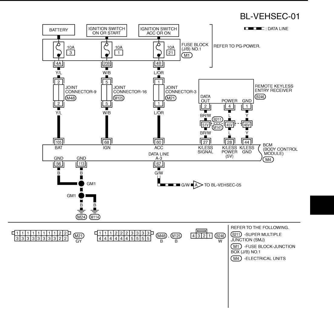
VEHICLE SECURITY (THEFT WARNING) SYSTEM
BL-105
C
D
E
F
G
H
J
K
L
M
A
B
BL
Revision: 2004 April 2002 Q45
Wiring Diagram — VEHSEC — EIS000U0
TIWM0117E
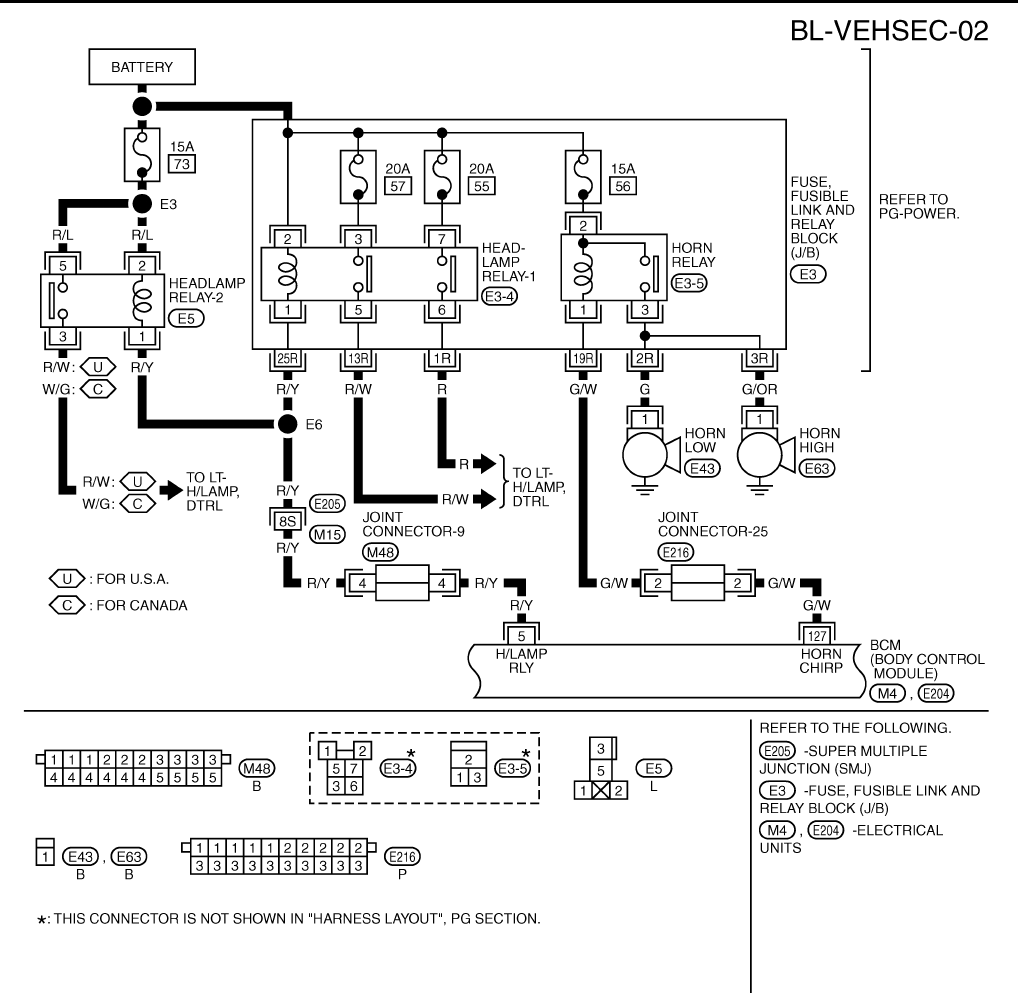
BL-106
VEHICLE SECURITY (THEFT WARNING) SYSTEM
Revision: 2004 April 2002 Q45
TIWM0025E
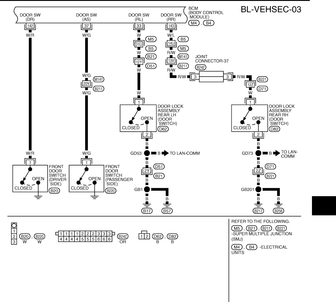
VEHICLE SECURITY (THEFT WARNING) SYSTEM
BL-107
C
D
E
F
G
H
J
K
L
M
A
B
BL
Revision: 2004 April 2002 Q45
TIWM0026E
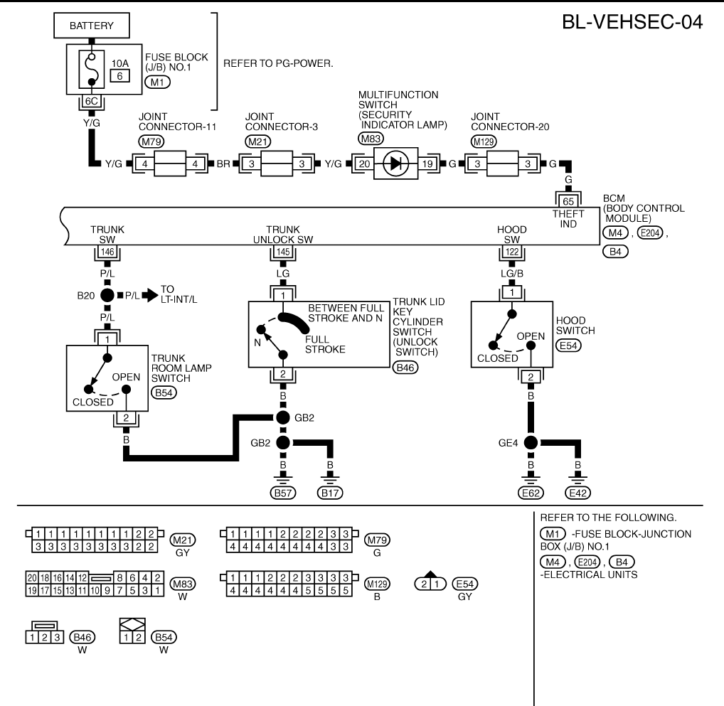
BL-108
VEHICLE SECURITY (THEFT WARNING) SYSTEM
Revision: 2004 April 2002 Q45
TIWM0027E
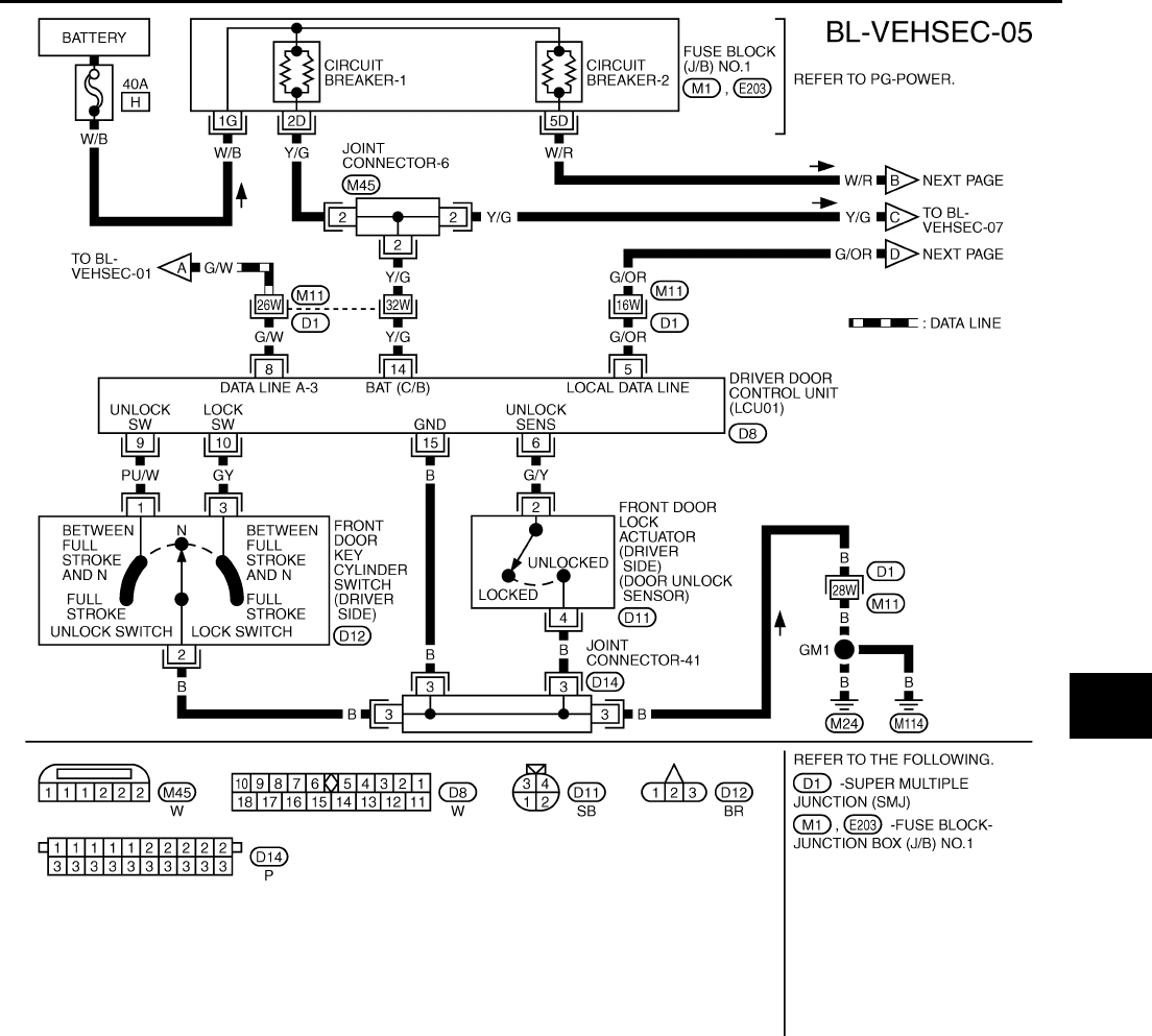
VEHICLE SECURITY (THEFT WARNING) SYSTEM
BL-109
C
D
E
F
G
H
J
K
L
M
A
B
BL
Revision: 2004 April 2002 Q45
TIWM0028E
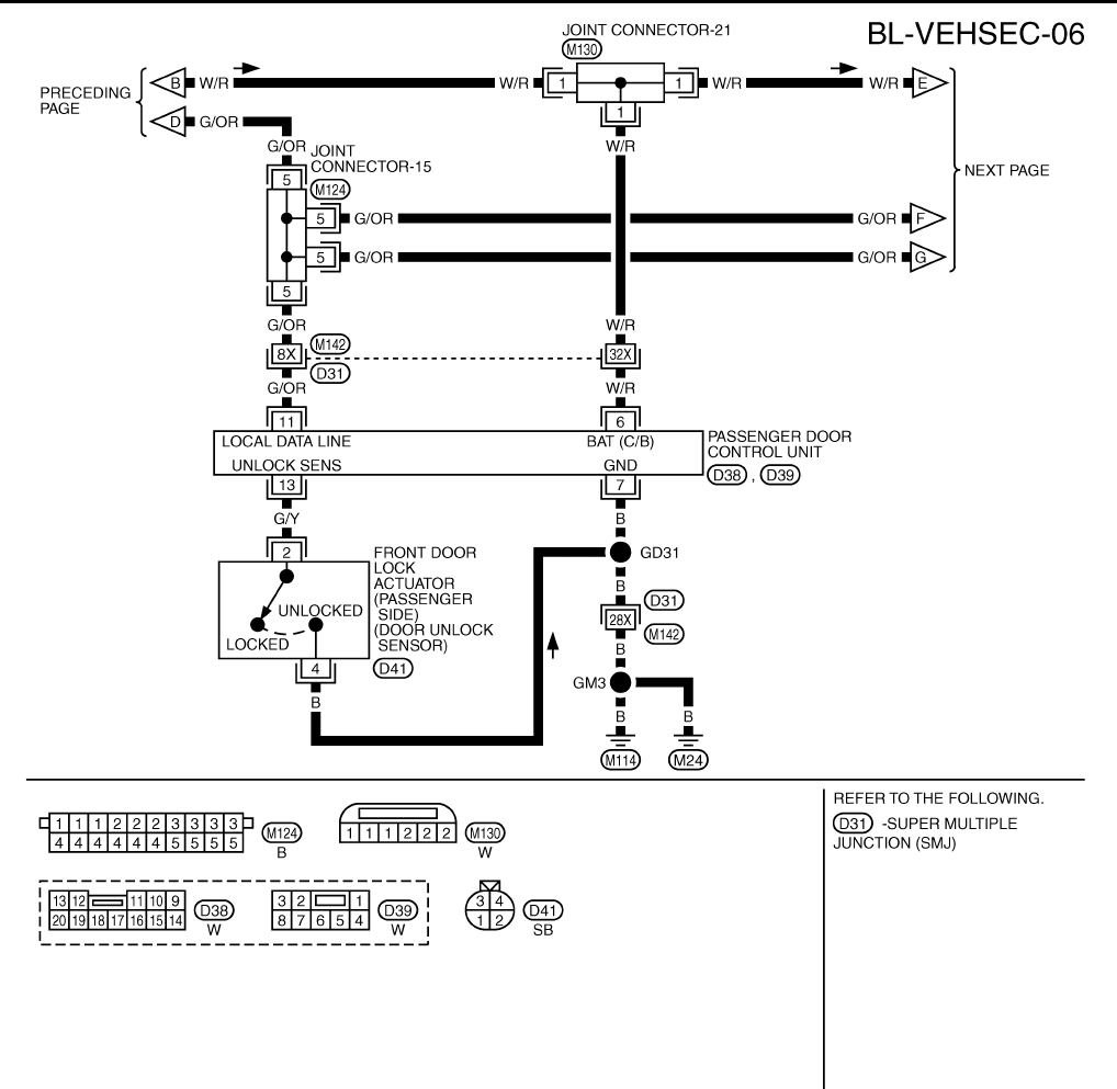
BL-110
VEHICLE SECURITY (THEFT WARNING) SYSTEM
Revision: 2004 April 2002 Q45
TIWM0029E
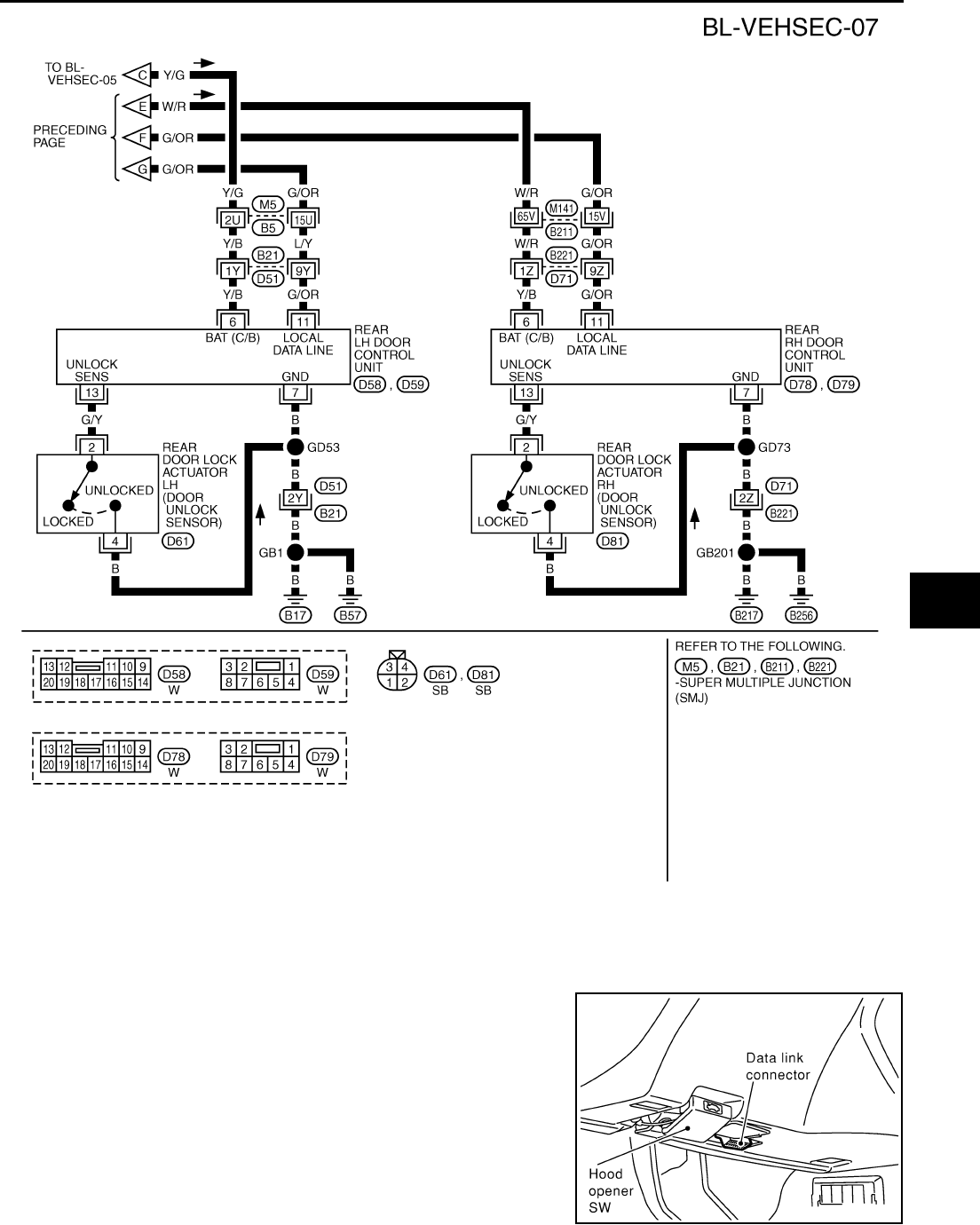
VEHICLE SECURITY (THEFT WARNING) SYSTEM
BL-111
C
D
E
F
G
H
J
K
L
M
A
B
BL
Revision: 2004 April 2002 Q45
CONSULT-II Function EIS000U1
CONSULT-II INSPECTION PROCEDURE
1. With the ignition switch OFF, connect CONSULT–II to the data
link connector, and turn the ignition switch ON.
TIWM0030E
SHIA0179E
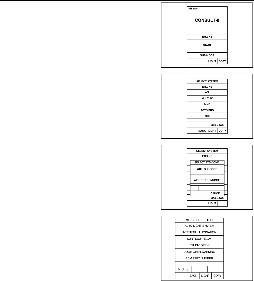
BL-112
VEHICLE SECURITY (THEFT WARNING) SYSTEM
Revision: 2004 April 2002 Q45
2. Touch "START".
3. Touch "IVMS" on the "SELECT SYSTEM" screen.
4. Check the model specification, touch either "WITH SUNROOF"
or "WITH OUT SUNROOF".
5. Touch "OK". If the selection is wrong, touch "CANCEL".
6. Touch "THEFT WARNING SYSTEM" on the "SELECT TEST
ITEM" screen.
●DATA MONITOR and ACTIVE TEST are available for the
vehicle security system.
PIIA0182E
PIIA0183E
PIIA0184E
SIIA0983E
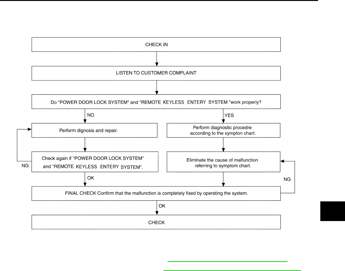
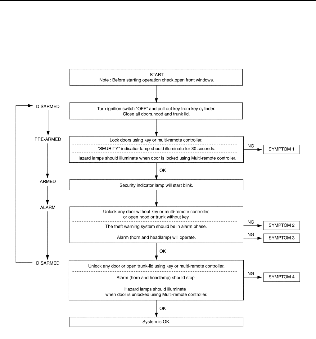
BL-114
VEHICLE SECURITY (THEFT WARNING) SYSTEM
Revision: 2004 April 2002 Q45
Preliminary Check EIS00156
The system operation is canceled by turning ignition switch to "ACC" at any step between START and ARMED
in the following flow chart.
NOTE:
Before performing PRELIMINARY CHECK, disconnect IVCS unit connectors not to operate INFINITI commu-
nicator.
After performing preliminary check, go to symptom chart.
SIIA0992E
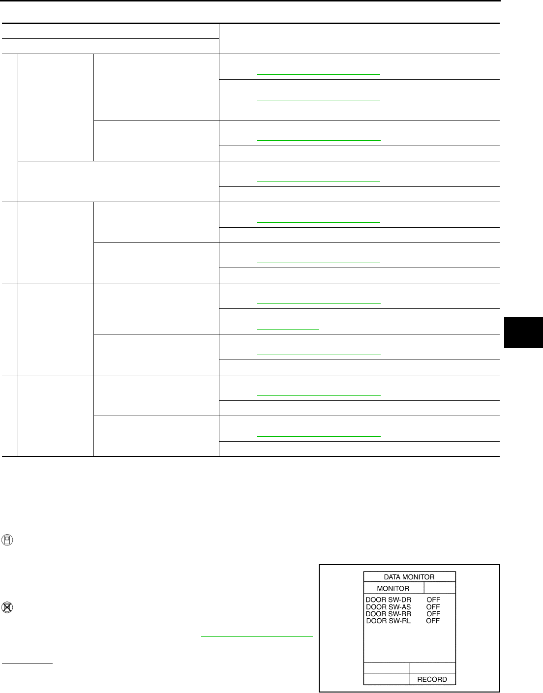
VEHICLE SECURITY (THEFT WARNING) SYSTEM
BL-115
C
D
E
F
G
H
J
K
L
M
A
B
BL
Revision: 2004 April 2002 Q45
Symptom Chart EIS000U5
*1: Make sure the system is in the armed phase.
Diagnostic Procedure 1 EIS000U6
1 – 1 DOOR SWITCH CHECK
1. CHECK DOOR SWITCH INPUT SIGNAL
With CONSULT−II
●Check door switch (“DOOR SW”) in "DATA MONITOR" mode with CONSULT−II.
Without CONSULT−II
●Check all door switches in Switch monitor mode.
Refer to Remote keyless entry system BL-70, "SWITCH MONI-
TOR" .
OK or NG?
OK >> Door switch is OK.
NG >> GO TO 2.
PROCEDURE Diagnostic procedure
SYMPTOM
1
Vehicle security
system cannot be
set by ····
All items
●Door out side key,
●Electronic key
Diagnostic Procedure 1 (Door, hood and trunk room lamp switch check)
Refer to BL-115, "Diagnostic Procedure 1" .
Diagnostic Procedure 3 (Door unlock sensor check)
Refer to BL-119, "Diagnostic Procedure 3" .
If the above systems are “OK”, replace BCM.
Door outside key
Diagnostic Procedure 4 (Door key cylinder switch check)
Refer to BL-120, "Diagnostic Procedure 4" .
If the above systems are “OK”, check driver door LCU01.
Security indicator does not turn “ON”.
Diagnostic Procedure 2 (Security indicator lamp check)
Refer to BL-118, "Diagnostic Procedure 2" .
If the above systems are “OK”, replace BCM.
2
*1
Vehicle security
system does not
alarm when ····
Any door is opened.
Diagnostic Procedure 1 (Door, hood and trunk room lamp switch check)
Refer to BL-115, "Diagnostic Procedure 1" .
If the above systems are “OK”, replace BCM.
Any door is unlocked without
using electronic key
Diagnostic Procedure 3 (Door unlock sensor check)
Refer to BL-119, "Diagnostic Procedure 3" .
If the above system is “OK”, check door LCU01 or door control unit.
3
Vehicle security
alarm does not
activate.
Horn alarm
Diagnostic Procedure 6 (Theft warning horn alarm check)
Refer to BL-124, "Diagnostic Procedure 6" .
If the above systems are “OK”, check horn system.
Refer to WW-27, "HORN" .
Head lamp alarm
Diagnostic Procedure 7 (Head lamp alarm check)
Refer to BL-126, "Diagnostic Procedure 7" .
If the above systems are “OK”, replace BCM.
4
Vehicle security
system cannot be
canceled by ····
Door outside key
Diagnostic Procedure 4 (Door key cylinder switch check)
Refer to BL-120, "Diagnostic Procedure 4" .
If the above systems are “OK”, check driver door LCU01.
Trunk lid key
Diagnostic Procedure 5 (Trunk lid key cylinder switch check)
Refer to BL-123, "Diagnostic Procedure 5" .
If the above systems are “OK”, replace BCM.
When door is open : DOOR SW ON
When door is closed : DOOR SW OFF
PIIA0340E
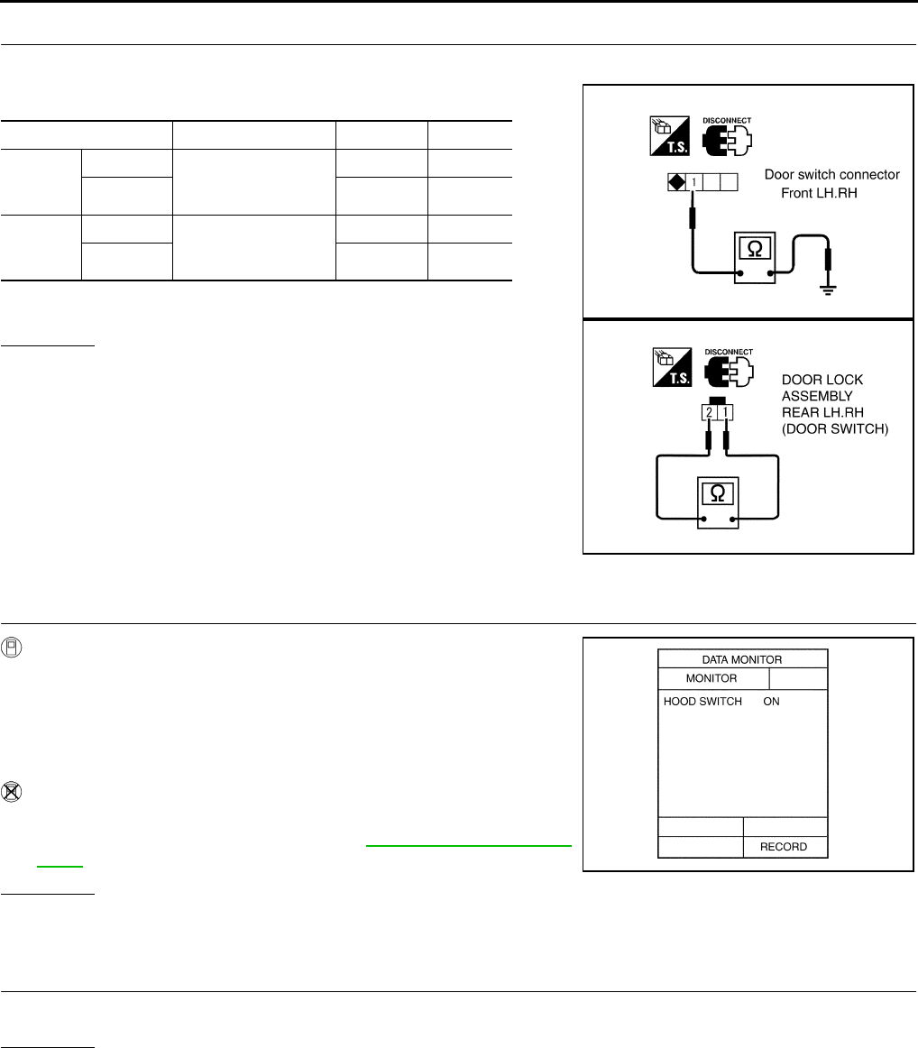
BL-116
VEHICLE SECURITY (THEFT WARNING) SYSTEM
Revision: 2004 April 2002 Q45
2. CHECK DOOR SWITCH
1. Disconnect door switch connector.
2. Check continuity between following terminals and body ground.
OK or NG?
OK >> Check the following.
●Door switch ground condition (Front door) or door
switch ground circuit (Rear door)
●Harness for open or short between door switch and
BCM
NG >> Replace door switch.
1 – 2 HOOD SWITCH CHECK
1. CHECK HOOD SWITCH INPUT SIGNAL
With CONSULT−II
●Check “HOOD SWITCH” in "DATA MONITOR" mode with CON-
SULT−II.
Without CONSULT−II
●Check hood switch in Switch monitor mode.
Refer to Remote keyless entry system BL-70, "SWITCH MONI-
TOR" .
OK or NG?
OK >> Hood switch is OK.
NG >> GO TO 2.
2. CHECK DOOR SWITCH
Check hood switch and hood fitting condition.
OK or NG?
OK >> GO TO 3.
NG >> Adjust installation of hood switch.
Door switch connector Terminals Condition Continuity
Front
door
switch
LH: B20 1(LH:W/R,RH:W/G)−
Ground
Pressed No
RH: B220 Repressed Yes
Rear
door
switch
LH: D62
1 (W)− 2 (B)
Pressed No
RH: D82 Repressed Yes
PIIA0341E
PIIA0342E
When hood is open : HOOD SW ON
When hood is closed : HOOD SW OFF
PIIA0343E
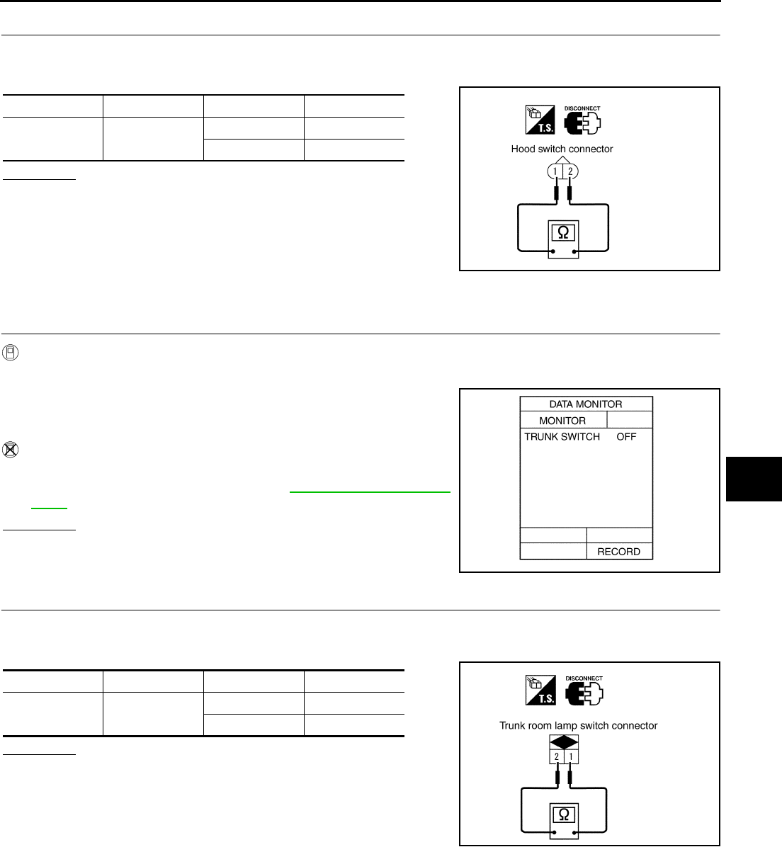
VEHICLE SECURITY (THEFT WARNING) SYSTEM
BL-117
C
D
E
F
G
H
J
K
L
M
A
B
BL
Revision: 2004 April 2002 Q45
3. CHECK HOOD SWITCH
1. Disconnect hood switch connector.
2. Check continuity between hood switch terminals.
OK or NG?
OK >> Check the following.
●Hood switch ground circuit
●Harness for open or short between hood switch and
BCM
NG >> Replace hood switch.
1 – 3 TRUNK ROOM LAMP SWITCH CHECK
1. CHECK TRUNK ROOM LAMP SWITCH INPUT SIGNAL
With CONSULT−II
●Check “TRUNK SWITCH” in "DATA MONITOR" mode with CONSULT−II.
Without CONSULT−II
●Check trunk room lamp switch in Switch monitor mode.
Refer to Remote keyless entry system BL-70, "SWITCH MONI-
TOR" .
OK or NG?
OK >> Trunk room lamp switch is OK.
NG >> GO TO 2.
2. CHECK TRUNK ROOM LAMP SWITCH
1. Disconnect trunk room lamp switch connector.
2. Check continuity between trunk room lamp switch terminals.
OK or NG?
OK >> Check the following.
●Trunk room lamp switch ground circuit
●Harness for open or short between trunk room lamp
switch and BCM
NG >> Replace trunk room lamp switch.
Connector Terminals Condition Continuity
E54 1(LG/B)− 2(B) Closed No
Open Yes
PIIA0344E
When trunk lid is open : TRUNK SW ON
When trunk lid is closed : TRUNK SW OFF
PIIA0345E
Connector Terminals Condition Continuity
B54 1(P/L)− 2(B) Closed No
Open Yes
PIIA0346E
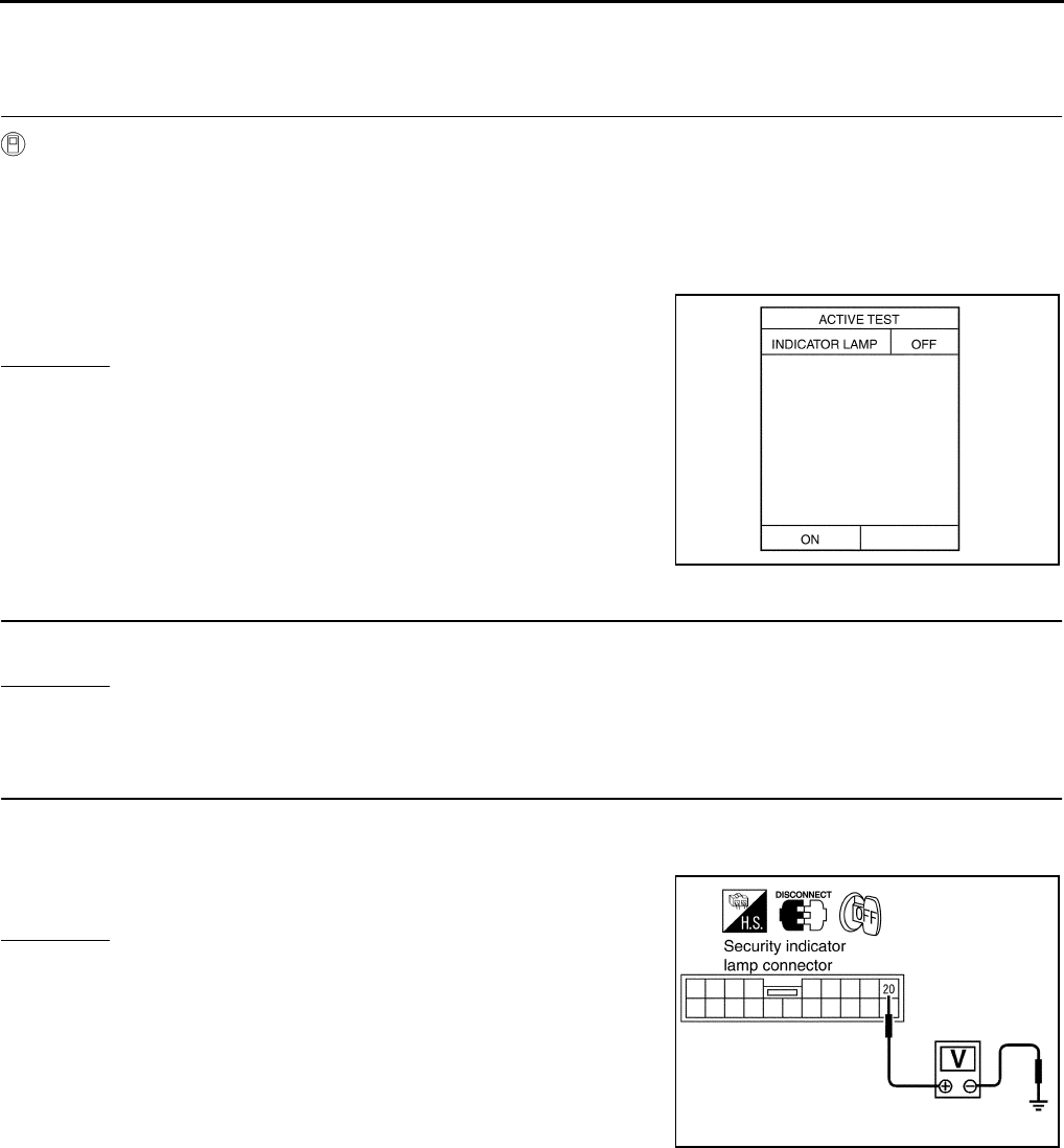
BL-118
VEHICLE SECURITY (THEFT WARNING) SYSTEM
Revision: 2004 April 2002 Q45
Diagnostic Procedure 2 EIS000UM
SECURITY INDICATOR LAMP CHECK
1. INDICATOR LAMP ACTIVE TEST
With CONSULT−II
●Check “INDICATOR LAMP” in "ACTIVE TEST" mode with CONSULT−II.
NOTE:
If CONSULT-II is not available, skip this procedure and go to the
next procedure.
OK or NG?
OK >> Security indicator lamp is OK.
NG >> GO TO 2.
2. INDICATOR LAMP CHECK
Check indicator lamp condition.
OK or NG?
OK >> GO TO 3.
NG >> Replace indicator lamp.
3. CHECK POWER SUPPLY CIRCUIT FOR INDICATOR LAMP
1. Disconnect security indicator lamp connector.
2. Check voltage between indicator lamp connector M83 terminal 20(Y/G) and ground.
OK or NG?
OK >> Check harness for open or short between security indi-
cator lamp and BCM.
NG >> Check the following.
●10A fuse [No. 6, located in fuse block (J/B) No.1]
●Harness for open or short between security indicator
lamp and BCM.
Perform operation shown on display.
Indicator lamp should illuminate.
PIIA0347E
: Battery voltage should exist.
PIIA0380E
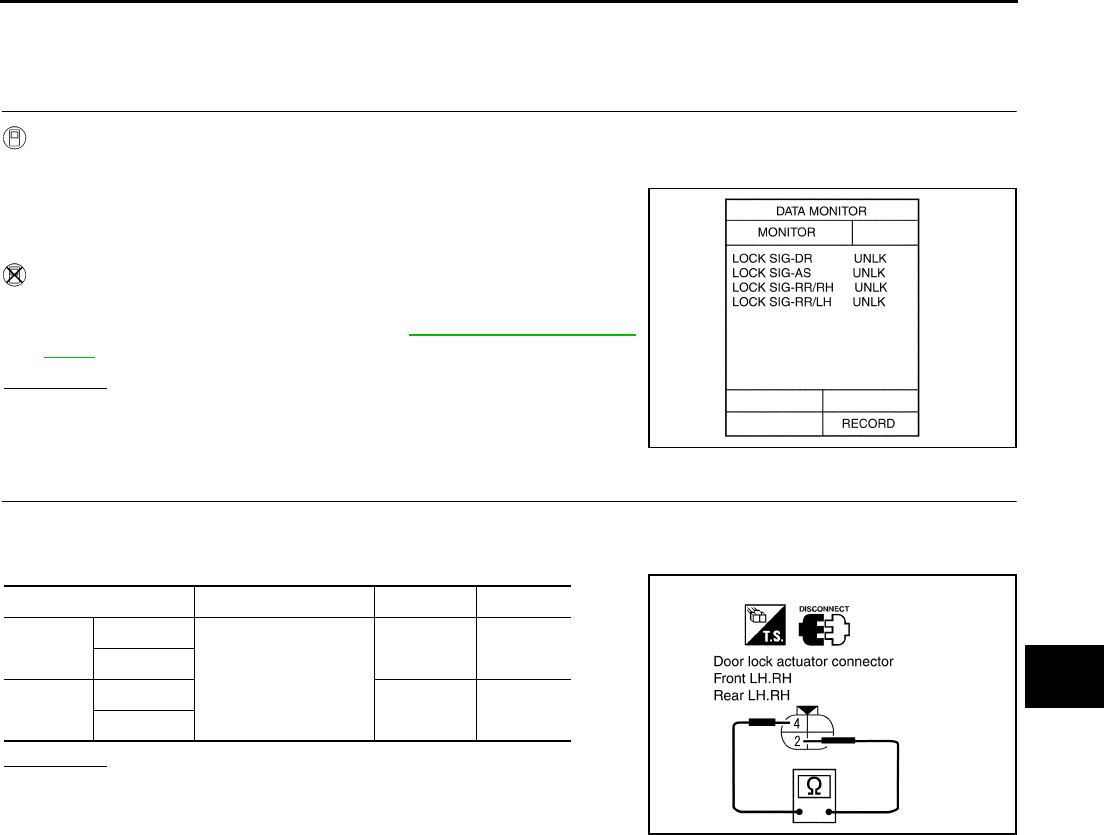
VEHICLE SECURITY (THEFT WARNING) SYSTEM
BL-119
C
D
E
F
G
H
J
K
L
M
A
B
BL
Revision: 2004 April 2002 Q45
Diagnostic Procedure 3 EIS000UN
DOOR UNLOCK SENSOR CHECK
1. CHECK DOOR UNLOCK SENSOR INPUT SIGNAL
With CONSULT−II
●Check door unlock sensor (“LOCK SIG”) in "DATA MONITOR" mode with CONSULT−II.
Without CONSULT−II
●Check door lock knob operation in Switch monitor mode.
Refer to Remote keyless entry system BL-70, "SWITCH MONI-
TOR" .
OK or NG?
OK >> Door unlock sensor is OK.
NG >> GO TO 2.
2. CHECK DOOR UNLOCK SENSOR
1. Disconnect door lock actuator connector.
2. Check continuity between door lock actuator (door unlock sensor) terminals 2(G/Y) and 4(B).
OK or NG?
OK >> Check the following.
●Ground circuit for door unlock sensor
●Harness for open or short between door LCU or door
control unit and door unlock sensor
NG >> Replace door lock actuator.
When door is open : LOCK SIG LOCK
When door is closed : LOCK SIG UNLK
PIIA0348E
Actuator connector Terminals Condition Continuity
Front
door
LH: D11
2 (G/Y) − 4 (B)
Locked No
RH: D41
Rear
door
LH: D61 Unlocked Yes
RH: D81
PIIA0349E
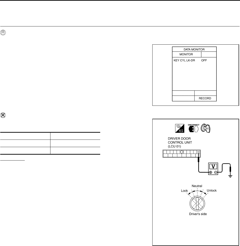
BL-120
VEHICLE SECURITY (THEFT WARNING) SYSTEM
Revision: 2004 April 2002 Q45
Diagnostic Procedure 4 EIS000UO
4–1 DOOR KEY CYLINDER LOCK SWITCH CHECK
1. CHECK DOOR KEY CYLINDER SWITCH INPUT SIGNAL (LOCK SIGNAL)
With CONSULT−II
●Check driver door key cylinder switch (“KEY CYL LK”) in "DATA MONITOR" mode with CONSULT−II.
Without CONSULT−II
Check voltage between driver door control unit (LCU) connector D8
terminal 10 (GY) and ground.
OK or NG?
OK >> Driver door key cylinder switch (lock) is OK.
NG >> GO TO 2.
“KEY CYL LK” should be “ON” when key inserted in
door key cylinder was turned to lock.
PIIA0350E
Key position Voltage
Neutral / Unlock Approx. 5V
Lock 0V
PIIA0351E
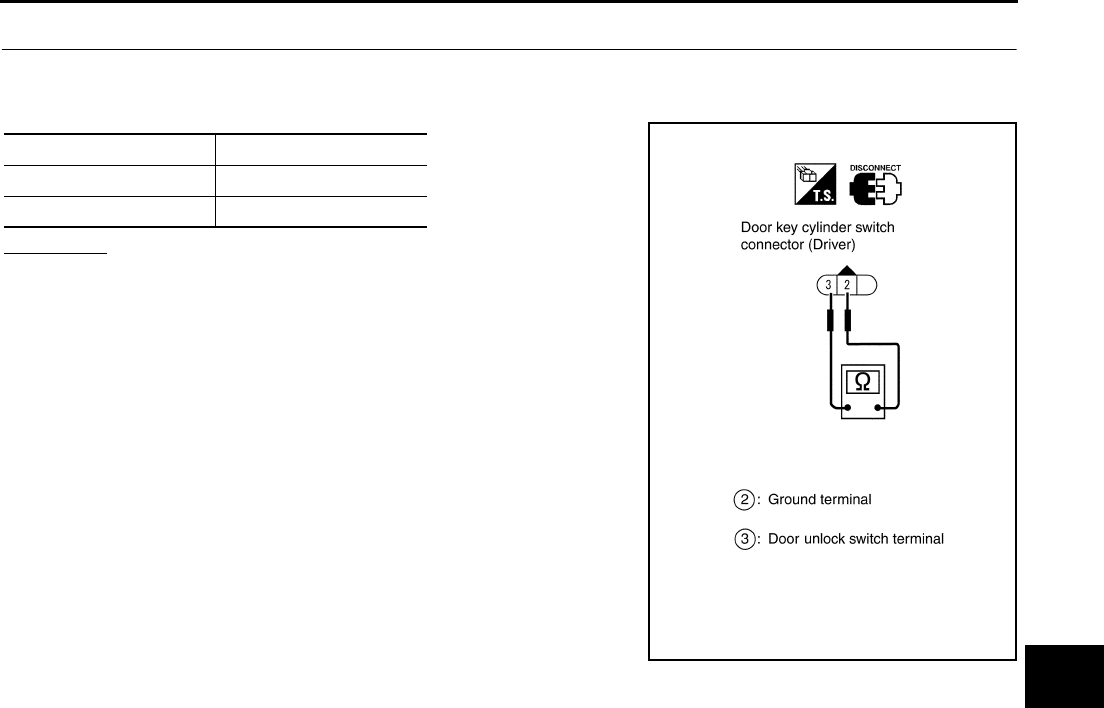
VEHICLE SECURITY (THEFT WARNING) SYSTEM
BL-121
C
D
E
F
G
H
J
K
L
M
A
B
BL
Revision: 2004 April 2002 Q45
2. CHECK DOOR KEY CYLINDER SWITCH
1. Disconnect driver door key cylinder switch connector.
2. Check continuity between driver door key cylinder switch connector D12 terminals 2(B) and 3(G/Y).
OK or NG?
OK >> Check the following.
●Driver door key cylinder switch ground circuit
●Harness for open or short between driver door control
unit (LCU) and driver door key cylinder switch
NG >> Replace driver door key cylinder switch.
Key position Continuity
Neutral / Unlock No
Lock Yes
PIIA0352E
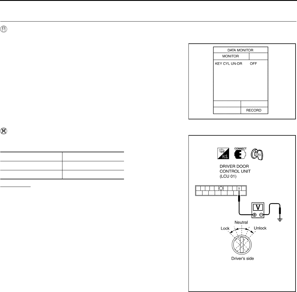
BL-122
VEHICLE SECURITY (THEFT WARNING) SYSTEM
Revision: 2004 April 2002 Q45
4–2 DOOR KEY CYLINDER UNLOCK SWITCH CHECK
1. CHECK DOOR KEY CYLINDER SWITCH INPUT SIGNAL (UNLOCK SIGNAL)
With CONSULT−II
●Check driver door key cylinder switch (“KEY CYL UN”) in "DATA MONITOR" mode with CONSULT−II.
Without CONSULT−II
Check voltage between LCU01 connector D8 terminal 9 (PU/W) and
ground.
OK or NG?
OK >> driver door key cylinder switch (unlock) is OK.
NG >> GO TO 2.
“KEY CYL UN−DR” should be “ON” when key inserted
in driver door key cylinder was turned to lock.
PIIA0353E
Key position Voltage
Neutral / Lock Approx. 5V
Unlock 0V
PIIA0354E
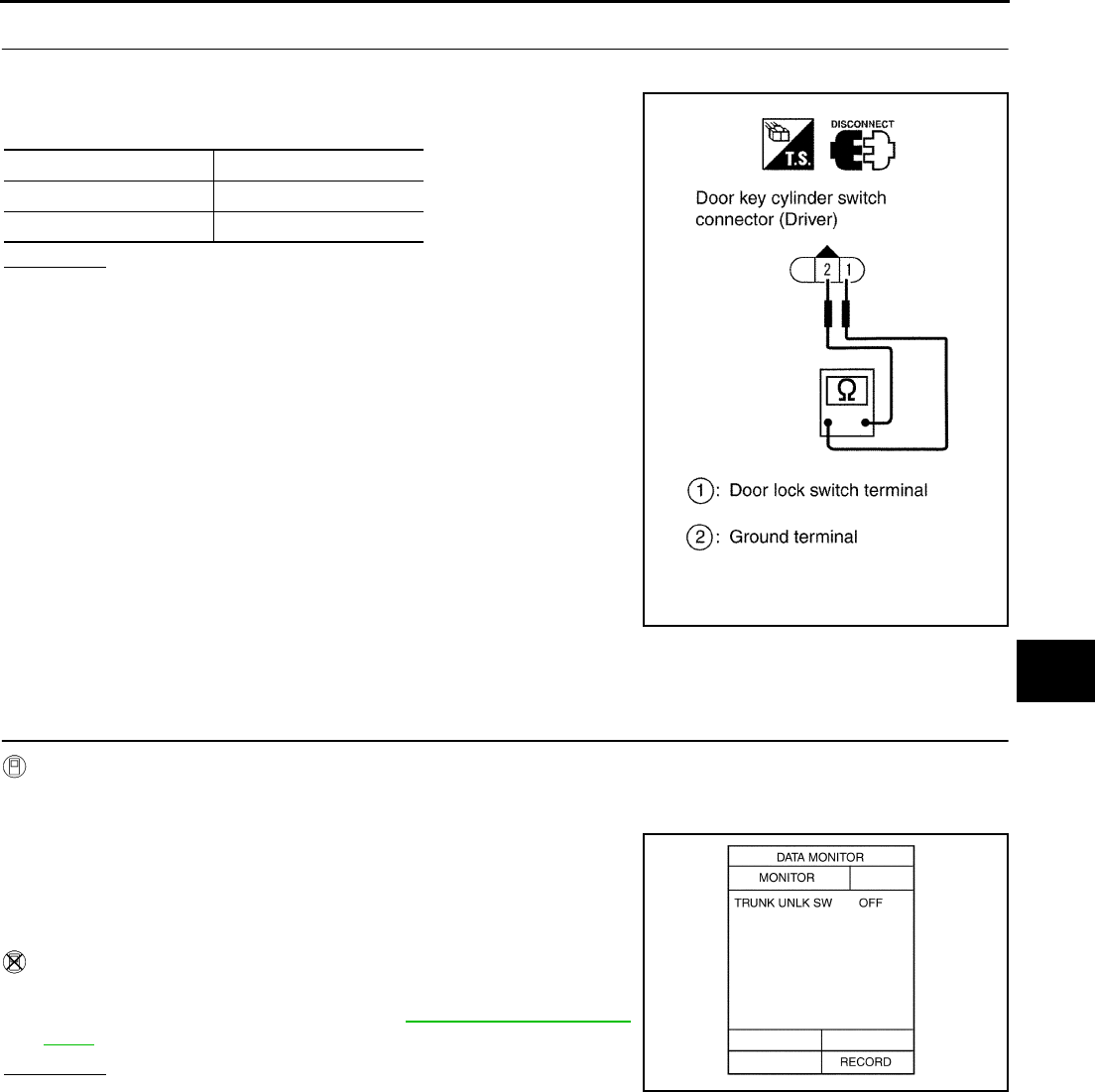
VEHICLE SECURITY (THEFT WARNING) SYSTEM
BL-123
C
D
E
F
G
H
J
K
L
M
A
B
BL
Revision: 2004 April 2002 Q45
2. CHECK DOOR KEY CYLINDER SWITCH
1. Disconnect driver door key cylinder switch connector.
2. Check continuity between driver door key cylinder switch con-
nector D12 terminals 1(PU/W) and 3(GY).
OK or NG?
OK >> Check the following.
●Driver door key cylinder switch ground circuit
●Harness for open or short between driver door control
unit (LCU) and driver door key cylinder switch
NG >> Replace driver door key cylinder switch.
Diagnostic Procedure 5 EIS000UQ
TRUNK LID KEY UNLOCK SIGNAL CHECK
1. CHECK TRUNK KEY CYLINDER SWITCH INPUT SIGNAL (UNLOCK SIGNAL)
With CONSULT−II
Check trunk key cylinder switch (“TRUNK UNLK SW”) in "DATA MONITOR" mode with CONSULT−II.
●When key in key cylinder is at “NEUTRAL” position,
●When key is “UNLOCK” position,
Without CONSULT−II
●Check trunk key cylinder switch in Switch monitor mode.
Refer to Remote keyless entry system BL-70, "SWITCH MONI-
TOR" .
OK or NG?
OK >> Trunk key cylinder switch is OK.
NG >> GO TO 2.
Key position Continuity
Neutral / Lock No
Unlock Yes
PIIA0355E
TRUNK UNLK SW: OFF
TRUNK UNLK SW: ON
PIIA0356E
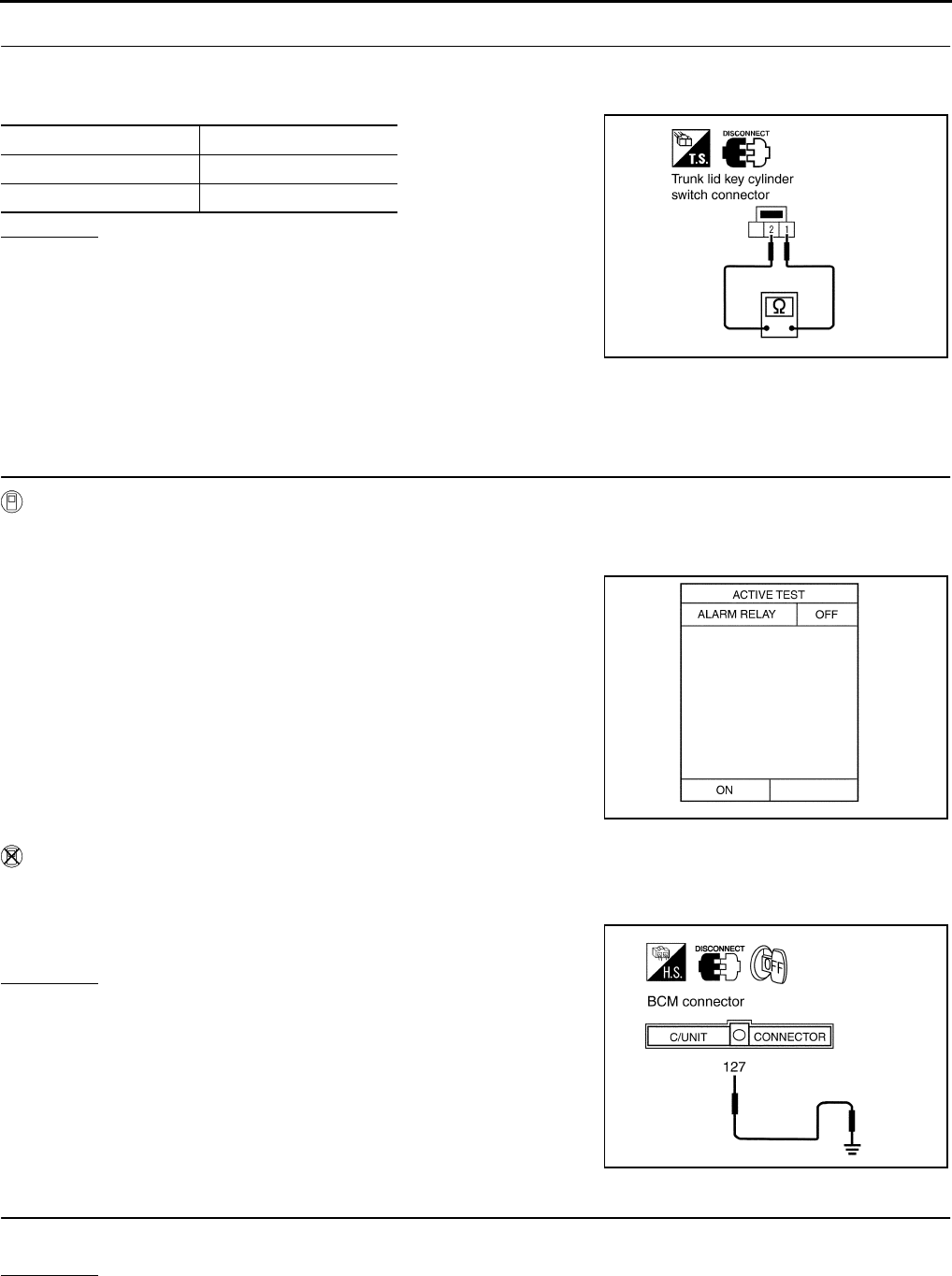
BL-124
VEHICLE SECURITY (THEFT WARNING) SYSTEM
Revision: 2004 April 2002 Q45
2. CHECK TRUNK KEY CYLINDER SWITCH (UNLOCK SWITCH)
1. Disconnect trunk key cylinder switch connector.
2. Check continuity between trunk key cylinder switch connector B46 terminals 1(LG) and 2(B).
OK or NG?
OK >> Check the following.
●Trunk key cylinder switch ground circuit
●Harness for open or short between trunk key cylinder
switch and BCM
NG >> Replace trunk key cylinder switch.
Diagnostic Procedure 6 EIS000UR
THEFT WARNING HORN ALARM CHECK
1. CHECK VEHICLE SECURITY HORN ALARM OPERATION
With CONSULT−II
●Check horn relay “ALARM RELAY” in "ACTIVE TEST" mode with CONSULT−II.
●Perform operation shown on display.
Without CONSULT−II
1. Disconnect BCM connector.
2. Apply ground to BCM connector E204 terminal 127(G/W).
OK or NG?
OK >> Horn alarm is OK.
NG >> GO TO 2.
2. CHECK HORN RELAY
Check horn relay condition.
OK or NG?
OK >> GO TO 3.
NG >> Replace horn relay.
Condition Continuity
Neutral No
Unlocked Yes
PIIA0357E
Theft warning horn alarm should operate.
PIIA0358E
Does horn alarm activate?
PIIA0359E
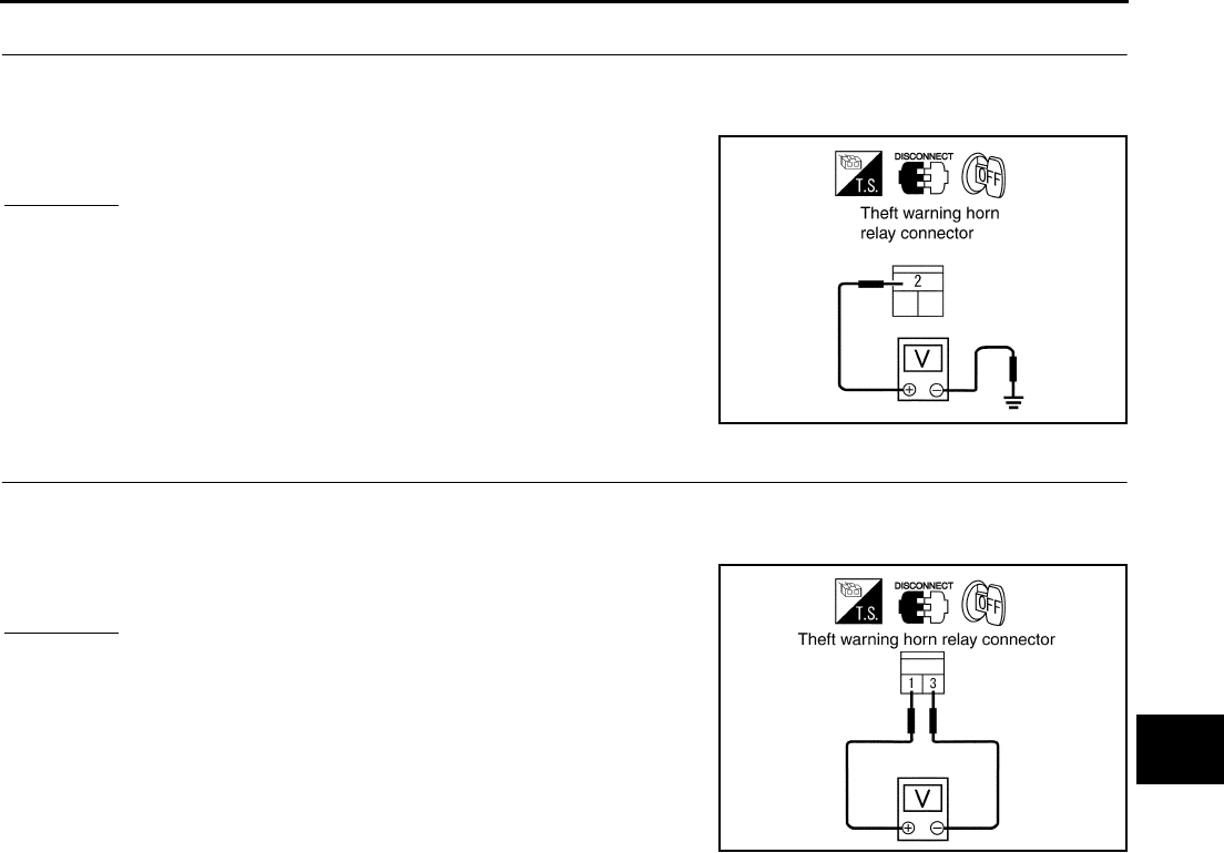
VEHICLE SECURITY (THEFT WARNING) SYSTEM
BL-125
C
D
E
F
G
H
J
K
L
M
A
B
BL
Revision: 2004 April 2002 Q45
3. CHECK POWER SUPPLY FOR HORN RELAY
1. Disconnect horn relay connector.
2. Check voltage between horn relay connector E3-5 terminal 2 and ground.
OK or NG?
OK >> GO TO 4.
NG >> Check the following.
●15A fuse [No. 56, located in the fuse, fusible link and
relay block (J/B)]
●Harness for open or short between horn relay and
fuse
4. CHECK HORN RELAY CIRCUIT
1. Disconnect horn relay connector.
2. Check voltage between horn relay connector E3-5 terminals 1 and 3.
OK or NG?
OK >> Check harness for open or short between horn relay and
BCM.
NG >> Check harness for open or short.
Battery voltage should exist.
PIIA0360E
Battery voltage should exist
PIIA0361E
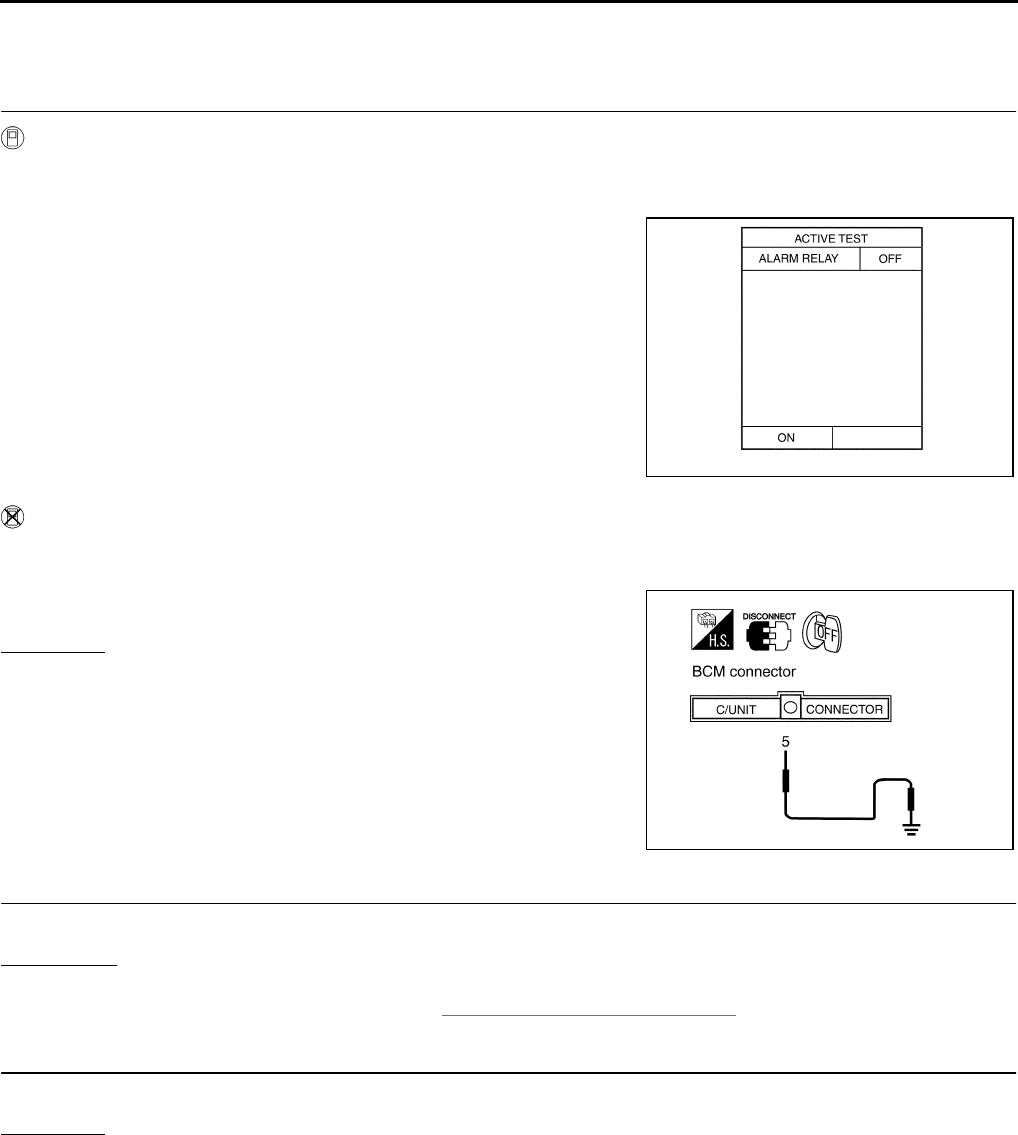
BL-126
VEHICLE SECURITY (THEFT WARNING) SYSTEM
Revision: 2004 April 2002 Q45
Diagnostic Procedure 7 EIS000US
THEFT WARNING HEAD LAMP ALARM CHECK
1. CHECK VEHICLE SECURITY HEAD LAMP ALARM OPERATION
With CONSULT−II
●Check head lamp relay “ALARM RELAY” in "ACTIVE TEST" mode with CONSULT−II.
●Perform operation shown on display.
Without CONSULT−II
1. Disconnect BCM connector.
2. Apply ground to BCM connector M4 terminal 5(R/Y).
OK or NG?
OK >> Head lamp alarm is OK.
NG >> GO TO 2.
2. CHECK HEAD LAMP RELAY 1
●Does head lamp come on when turning lighting switch “ON”?
YES or NO?
YES >> GO TO 3.
NO >> Check head lamp system. Refer to LT-5, "HEADLAMP (FOR USA)" .
3. CHECK HEAD LAMP RELAY 2
●Check head lamp relay condition.
OK or NG?
OK >> GO TO 4.
NG >> Replace horn relay.
Theft warning head lamp alarm should operate.
PIIA0362E
Does head lamp alarm activate?
PIIA0363E
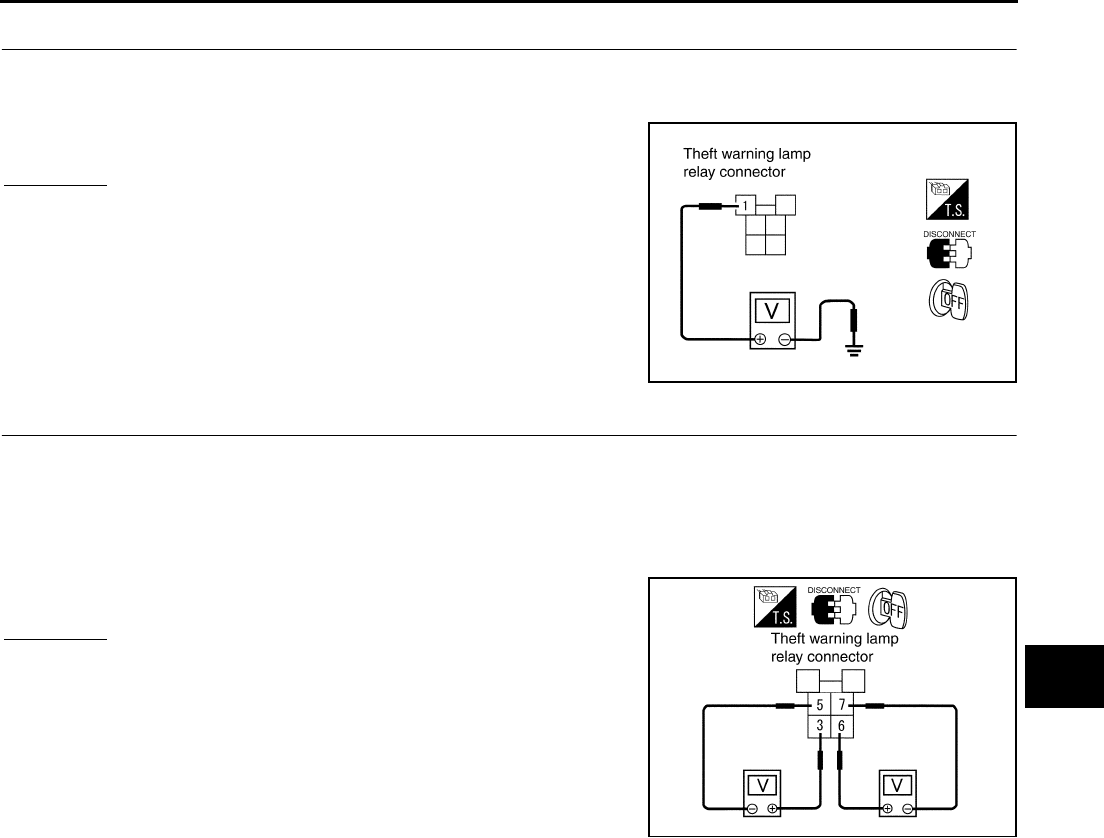
VEHICLE SECURITY (THEFT WARNING) SYSTEM
BL-127
C
D
E
F
G
H
J
K
L
M
A
B
BL
Revision: 2004 April 2002 Q45
4. CHECK POWER SUPPLY FOR HEAD LAMP RELAY
1. Disconnect head lamp relay-1 connector.
2. Check voltage between head lamp relay-1 connector E3-4 terminal 1 and ground.
OK or NG?
OK >> GO TO 5.
NG >> Harness for open or short between head lamp relay and
battery.
5. CHECK HORN RELAY CIRCUIT
1. Turn lighting switch to 2nd position.
2. Check voltage between head lamp relay-1 connector E3-4 terminals 3 and 5.
3. Check voltage between head lamp relay-1 connector E3-4 terminals 6 and 7.
OK or NG?
OK >> Check harness for open or short between head lamp
relay and BCM.
NG >> Check harness for open or short.
Battery voltage should exist.
PIIA0364E
Battery voltage should exist
Battery voltage should exist
PIIA0365E
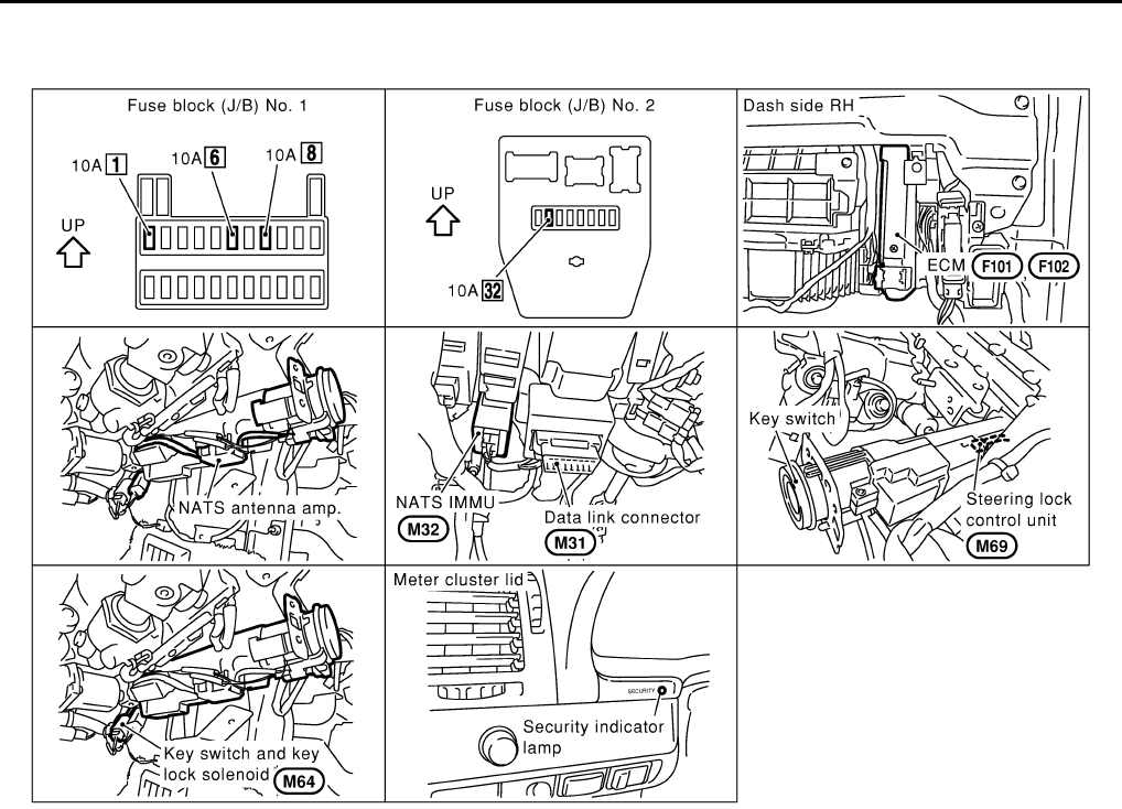
BL-128
ELECTRONIC KEY SYSTEM
Revision: 2004 April 2002 Q45
ELECTRONIC KEY SYSTEM PFP:80561
Component Parts and Harness Connector Location EIS000O4
System Description EIS000O3
●Every electronic key (including transponder) has its own key ID No. However, only an electronic key with
the key ID registered in the NATS IMMU and ECM can turn ON while inserted in the ignition key cylinder,
allowing the engine to start.
●An ignition key (electronic key) with straight contour is adopted to prevent the electronic key from vehicle
theft by abuse of duplicated key etc.
●If the batteries for the vehicle and handheld transmitter are discharged, using the emergency key inte-
grated into the electronic key, the driver/passenger doors and trunk lid can be operated for open/close,
and the steering wheel lock can be unlocked.
NOTE:
The engine cannot be started with an emergency key.
●If any of ECM, NATS IMMU, steering lock control unit (integrated in the key cylinder) or ignition key (elec-
tronic key) has been replaced, or if the trouble diagnosis requires additional registration, mandatory re-
registration procedure and registration of the electronic key ID code (if an ignition-key is added) are
required.
NOTE:
All the keys kept by the vehicle owner re-registration of the key ID (electronic key) shall be necessary.
●If the vehicle owner requires, electronic key ID codes can be registered for up to four keys (including the
electronic key). In this case, the key IDs shall also be registered.
NOTE:
●The key ID code and remote controller ID code for the key equipped on the vehicle have already been
registered at factory.
●When conducting registration of key ID at repair, part replacement, and electronic key addition, even the
registered ignition (standard) key shall be registered again. Therefore, collect all the keys from the vehicle
owner.
CIIM0006E
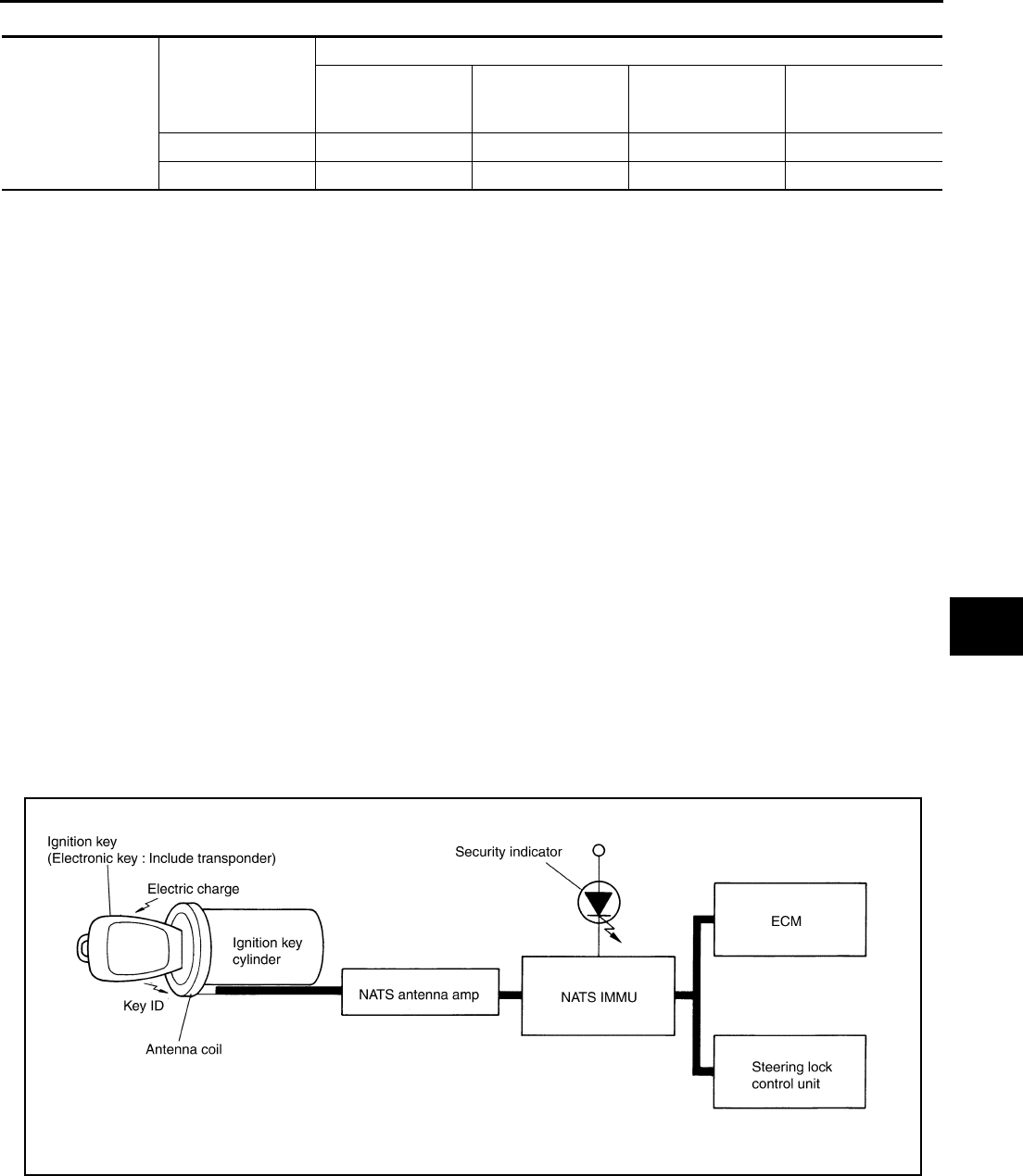
ELECTRONIC KEY SYSTEM
BL-129
C
D
E
F
G
H
J
K
L
M
A
B
BL
Revision: 2004 April 2002 Q45
SECURITY INDICATOR
OUTLINE OF ELECTRONIC KEY OPERATION
Operation 1 (Insert the key into the ignition key cylinder.)
1. By inserting the ignition key (electronic key: built-in transponder) into the key cylinder, the key detection
switch is turned to ON.
2. The power is supplied from the immobilizer control module → immobilizer antenna amp → antenna coil.
3. The current through the antenna coil induces a magnetic field.
4. The coil in the transponder induces electromotive force by mutual induction, which is charged in the
capacitor.
5. The transponder uses the charged energy to transmit the built-in key ID signal.
6. The sent key ID signal is received by the antenna coil and transmitted via the immobilizer antenna amp to
NATS IMMU.
7. NATS IMMU compares the stored key ID and received one, and only if the matching result is OK, it trans-
mits the key rotation permission signal to the steering lock control unit (integrated in the key cylinder).
8. When the key rotation permission signal is input, the steering lock control unit activates the electronic key
solenoid valve in the key cylinder to allow the electronic key to turn.
9. Turn ignition switch ON.
10. Only if the key ID matching result is OK, the ECM allows the engine to start.
Operation 2 (Withdraw the key from the ignition key cylinder.)
1. Return the electronic key to the LOCK position of the steering system lock.
2. When the key is removed, the electronic key solenoid valve in the key cylinder returns to inhibit the key
from turning. In this case, the steering lock control unit processes the key switch ON → OFF signal by
itself to inhibit the electronic key from turning.
NOTE:
If the A/T selector lever is not in "P" position, the electronic key does not return to LOCK position.
Condition of secu-
rity indicator
Key
Operation or condition
Ignition switch: ON
position
Ignition switch: ACC
position
Ignition switch: OFF
position (electronic
key is inserted.)
Ignition switch: OFF
position (electronic
key is not inserted.)
Electronic key Lamp OFF Lamp OFF Lamp OFF Blinking
Emergency key ON ON ON Blinking
PIIA0376E
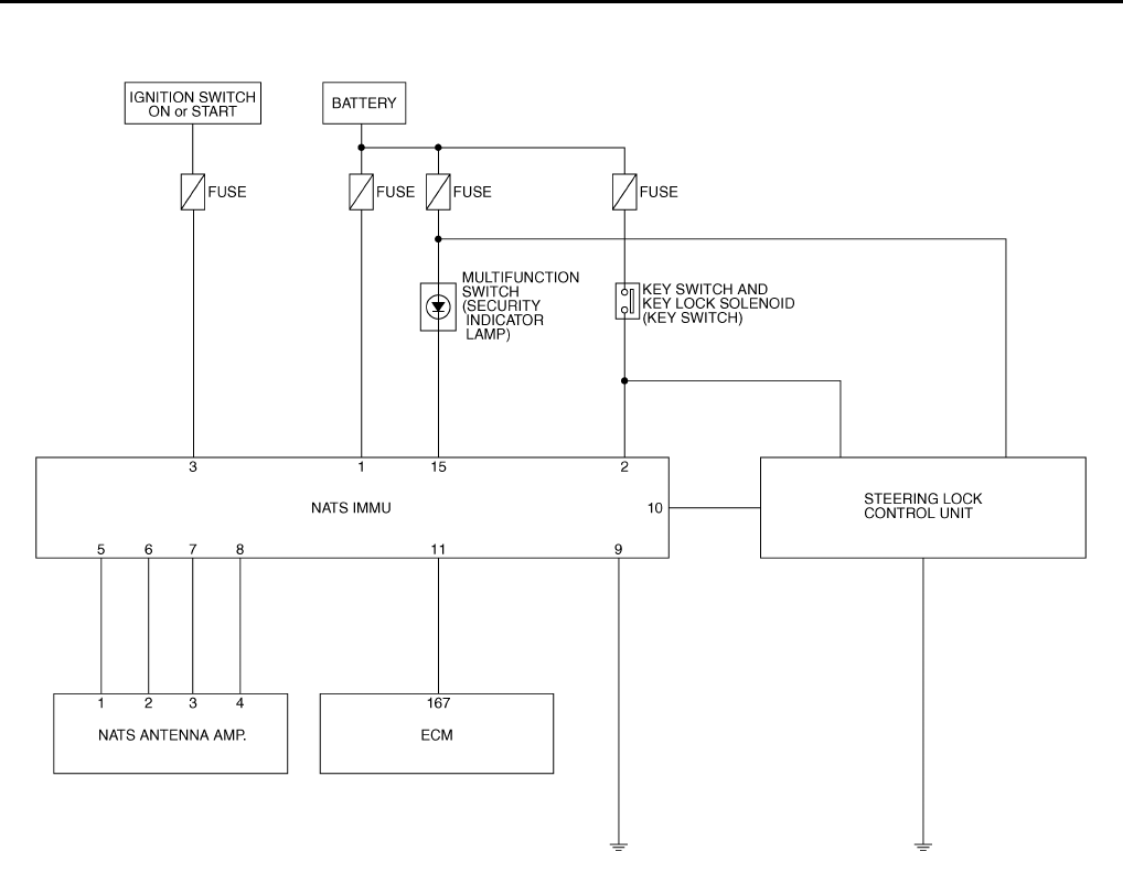
BL-130
ELECTRONIC KEY SYSTEM
Revision: 2004 April 2002 Q45
Schematic EIS0012R
TIWM0032E

ELECTRONIC KEY SYSTEM
BL-131
C
D
E
F
G
H
J
K
L
M
A
B
BL
Revision: 2004 April 2002 Q45
Wiring Diagram – NATS – EIS0012S
TIWM0033E

BL-132
ELECTRONIC KEY SYSTEM
Revision: 2004 April 2002 Q45
TIWM0034E
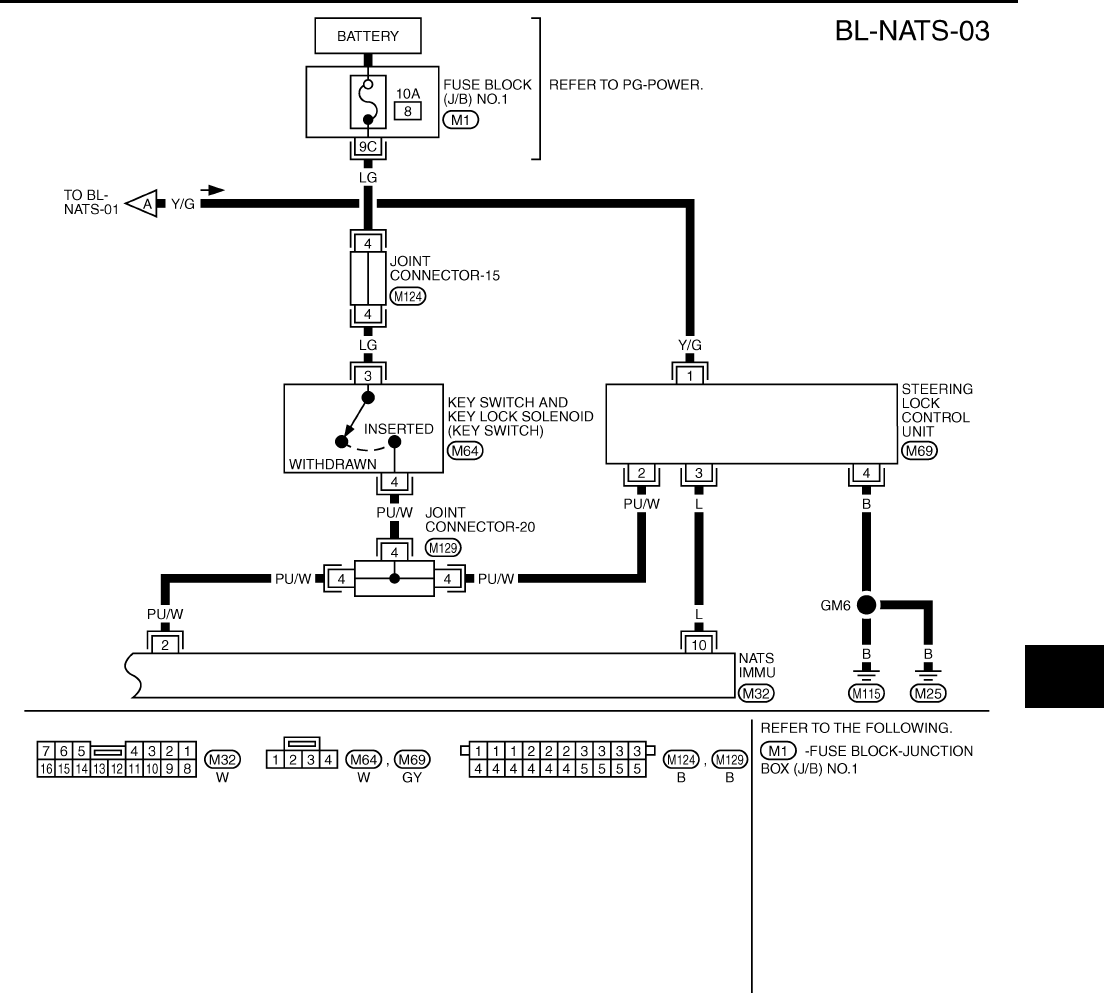
ELECTRONIC KEY SYSTEM
BL-133
C
D
E
F
G
H
J
K
L
M
A
B
BL
Revision: 2004 April 2002 Q45
TIWM0035E
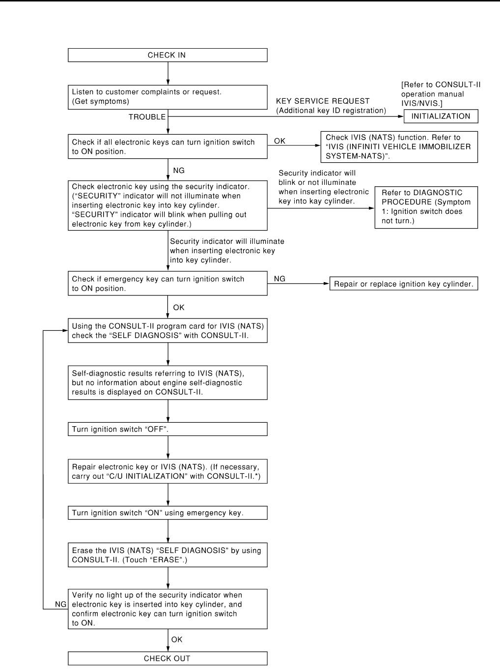
BL-134
ELECTRONIC KEY SYSTEM
Revision: 2004 April 2002 Q45
Work Flow EIS000O7
PIIA0377E
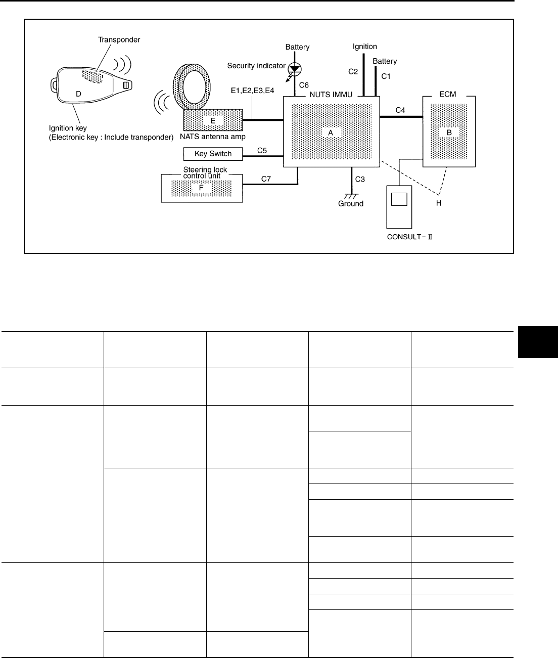
ELECTRONIC KEY SYSTEM
BL-135
C
D
E
F
G
H
J
K
L
M
A
B
BL
Revision: 2004 April 2002 Q45
Diagnostic System Diagram EIS000O8
Symptom Chart EIS0012T
SYMPTOM 1: ELECTRONIC KEY DOES NOT TURN
●Before performing the following diagnosis, be sure to check that the ignition key cylinder will be turned by
the emergency key. If the ignition key cylinder cannot be turned by the emergency key, the ignition key
cylinder is malfunctioning.
PIIA0378E
Symptom Check without CON-
SULT-II
CONSULT-II Self-diag-
nosis results
Possible malfunctioning
part or status
Reference part in the
trouble diagnostic sys-
tem diagram
Security indicator
remains flashing with
Electronic key inserted.
Security indicator ON
condition check — Key switch C5
Security indicator illumi-
nates with Electronic key
inserted.
Electronic key check
(diagnosis procedure 1) —
Electronic key not regis-
tered
D
Electronic key
(Transponder malfunc-
tion)
Check harness between
the antenna amplifier–
and NATS IMMU (Diag-
nosis procedures 2, 3, 4,
5, 6, 7, 8, 9, 10, 11).
CHAIN OFF IMMU-KEY
P1612
Antenna amp E
NATS IMMU A
Electronic key
(Transponder malfunc-
tion)
D
Harness system C1, 2, 3, 5
E1, 2, 3, 4
Security indicator
remains OFF with Elec-
tronic key inserted.
Check harness between
NATS IMMU-and the
steering lock control
module.
(Diagnosis procedures
12, 13, 14, 15)
—
NATS IMMU A
Steering lock control unit F
Harness system C7
Ignition key cylinder —
Checking with the emer-
gency key —

BL-136
ELECTRONIC KEY SYSTEM
Revision: 2004 April 2002 Q45
SYMPTOM 2: SECURITY INDICATOR DOES NOT FLASH
Symptom 1 EIS0012U
1. CHECK REGISTRATION OF ELECTRONIC KEY
Re-register the electronic key (all electronic keys), and check the symptom.
OK or NG?
OK >> Electronic key ID not registered
NG >> Check the following.
●All the electronic keys unsuccessful: GO TO 2.
●Only specific electronic key unsuccessful: malfunction in the applicable electronic key (includ-
ing transponder)
2. CHECK ANTENNA AMP INSTALLATION
Check the installation condition of the antenna amplifier.
OK or NG?
OK >> GO TO 3.
NG >> Install the antenna amplifier correctly: Reference part E.
3. CHECK POWER SUPPLY CIRCUIT FOR NATS IMMU
1. Disconnect the NATS IMMU connector.
2. Check voltage between NATS IMMU harness connector M32 terminal 1(W) and body ground.
OK or NG?
OK >> GO TO 4.
NG >> Check the following.
●Check fuse.
●Check harness for open or short between fuse block and NATS IMMU.
4. CHECK GROUND CIRCUIT FOR NATS IMMU
Check continuity between NATS IMMU harness connector M32 terminal 9(B/W) and body ground.
OK or NG?
OK >> GO TO 5.
NG >> Check harness and connector between body ground and NATS IMMU: Reference part C3.
Symptom Check without CON-
SULT-II
CONSULT-II Self-diag-
nosis results
Possible malfunctioning
part or status
Reference part in the
trouble diagnostic sys-
tem diagram
Security indicator does
not turn ON.
Check harness of secu-
rity indicator. —
Security indicator —
Open circuit in the bat-
tery power supply line to
the security indicator
—
NATS IMMU A
Harness system C
: Battery voltage should exist.
: Continuity should exist.
ELECTRONIC KEY SYSTEM
BL-137
C
D
E
F
G
H
J
K
L
M
A
B
BL
Revision: 2004 April 2002 Q45
5. CHECK ELECTRONIC KEY INSERT SIGNAL
Check voltage between NATS IMMU harness connector M32 terminal 2(PU/W) and body ground.
OK or NG?
OK >> GO TO 6.
NG >> Check the following.
●Key switch (insert) malfunction.
●Check harness for open or short between fuse block and the key switch (insert).
●Check harness for open or short between key switch (insert) and NATS IMMU.
6. CHECK NATS ANTENNA AMP. CIRCUIT 1
Insert electronic key into ignition key cylinder, and immediately check voltage between antenna amp harness
connector M65 terminal 1(R) and body ground.
OK or NG?
OK >> GO TO 7.
NG >> GO TO 10.
7. CHECK NATS ANTENNA AMP. CIRCUIT 2
●Disconnect antenna amp connector.
●Check continuity between antenna amp harness connector M65 terminal 4(B/R) and body ground.
OK or NG?
OK >> GO TO 8.
NG >> GO TO 10.
8. CHECK NATS ANTTENA AMP. CIRCUIT 3
●Connect antenna amp connector.
●Insert the electronic key into the ignition key cylinder, and immediately check voltage between antenna
amp harness connector M65 terminal 2(Y) and body ground.
OK or NG?
OK >> GO TO 9.
NG >> GO TO 10.
Terminals Condition Voltage
2 (PU/W) − body ground
Electronic key removed from
ignition key cylinder 0V
Electronic key inserted Battery voltage
Terminals Condition Voltage
1 (R) − body ground Insert electronic key into
ignition key cylinder.
Approx. 5V (for 3 seconds
after inserting the key)
: Continuity should exist.
Terminals Condition Voltage
2 (Y) − body ground Insert electronic key into
ignition key cylinder.
Pointer of tester should
move.

BL-138
ELECTRONIC KEY SYSTEM
Revision: 2004 April 2002 Q45
9. CHECK NATS ANTENNA AMP. CIRCUIT 4
Insert the electronic key into the ignition key cylinder, and immediately check voltage between antenna amp
harness connector M65 terminal 3(Y/G) and body ground.
OK or NG?
OK >> Replace NATS antenna amp: Reference part E.
NG >> GO TO 10.
10. CHECK NATS ANTENNA AMP. CIRCUIT 5
●Turn ignition switch OFF.
●Disconnect NATS IMMU and antenna amp connector.
●Check continuity between NATS IMMU harness connector M32 terminals 5(R), 6(Y), 7(Y/G), 8(B/R) and
antenna amp harness connector M65 terminals 1(R), 2(Y), 3(Y/G), 4(B/R).
●Check continuity between NATS IMMU harness connector M32 terminals 5(R), 6(Y), 7(Y/G), 8(B/R) and
body ground.
OK or NG?
OK >> Replace NATS IMMU: Reference part A.
NG >> Harness malfunction between NATS IMMU and the antenna amplifier: Reference parts E1, 2, 3, 4
11. PERFORM INITIALIZATION WITH CONSULT-II
Perform initialization with CONSULT-II.
For the operation of initialization, refer to “CONSULT-II operation manual IVIS / NVIS”.
OK or NG?
OK >> END.
NG >> GO TO 12.
12. CHECK POWER SUPPLY CIRCUIT FOR STEERING LOCK CONTROL UNIT
●Turn ignition switch OFF.
●Disconnect steering lock control unit connector.
●Check voltage between steering lock control unit connector 1(Y/G) body ground.
OK or NG?
OK >> GO TO 13.
NG >> Check the following.
●Check fuse.
●Check harness for open or short between fuse block and steering lock control unit.
Terminals Condition Voltage
3 (Y/G) − body ground Insert electronic key into
electronic key cylinder.
Pointer of tester
should move.
5(R) - 1(R) : Continuity should exist.
6(Y) - 2(Y) : Continuity should exist.
7(Y/G) - 3(Y/G) : Continuity should exist.
8(B/R) - 4(B/R) : Continuity should exist.
5(R) - ground : Continuity should not exist.
6(Y) - ground : Continuity should not exist.
7(Y/G) - ground : Continuity should not exist.
8(B/R) - ground : Continuity should not exist.
: Battery voltage should exist.

ELECTRONIC KEY SYSTEM
BL-139
C
D
E
F
G
H
J
K
L
M
A
B
BL
Revision: 2004 April 2002 Q45
13. CHECK GROUND CIRCUIT FOR STEERING LOCK
Check voltage continuity steering lock control unit harness connector M69 terminal 4(B) and body ground.
OK or NG?
OK >> GO TO 14.
NG >> Repair or replace harness.
14. CHECK ELECTRONIC KEY INSERT SIGNAL 2
Check voltage between steering lock control unit harness connector M69 terminal 2(PU/W) and body ground.
OK or NG?
OK >> GO TO 15.
NG >> Check the following.
●Check harness for open or short between fuse block and key switch.
●Check harness for open or short between key switch and steering lock control unit.
15. CHECK STEERING LOCK CONTROL UNIT
Insert the electronic key into the ignition key cylinder, and immediately check voltage between steering control
unit harness connector M69 terminal 3(L) and body ground.
OK or NG?
OK >> Replace steering lock control unit.
NG >> ●Replace NATS IMMU.
●Check harness for open or short between NATS IMMU and steering lock control unit.
Symptom 2 EIS0012V
1. CHECK SECURITY INDICATOR POWER CIRCUIT
●Turn ignition switch OFF.
●Disconnect the security indicator connector.
●Check voltage between security indicator harness connector M83 terminal 20(Y/G) and body ground.
OK or NG?
OK >> GO TO 2.
NG >> Check harness for open or short between fuse block and security indicator.
: Continuity should exist.
Terminals Condition Voltage
2 (L) − body ground
Electronic key removed from
ignition key cylinder 0V
Electronic key inserted Battery voltage
Terminals Condition Voltage
3 (L) − body ground Insert electronic key into
ignition key cylinder.
Pointer of tester
should move.
: Battery voltage should exist.
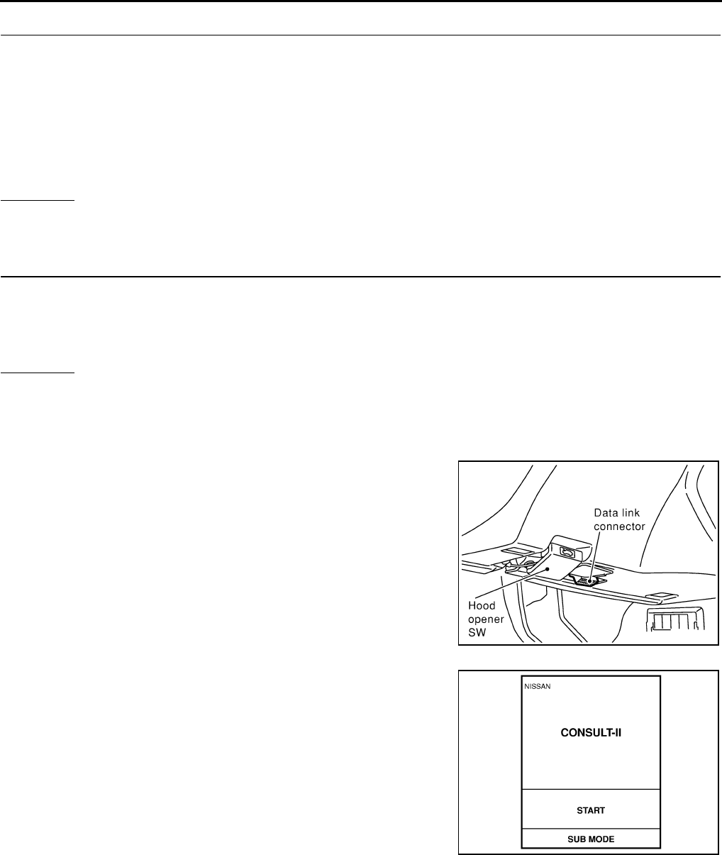
BL-140
ELECTRONIC KEY SYSTEM
Revision: 2004 April 2002 Q45
2. SECURITY INDICATOR GROUND CIRCUIT
●Disconnect the NATS IMMU connector.
●Check continuity between security indicator harness connector M83 terminal 19(G) and NATS IMMU har-
ness connector M32 terminal 15(G).
●Check continuity between NATS IMMU harness connector M32 terminal 15(G) and body ground.
OK or NG?
OK >> GO TO 3.
NG >> Repair or replace harness.
3. CHECK INDICATOR GROUND SIGNAL
1. Connect NATS IMMU connector.
2. Check continuity between NATS IMMU harness connector M32 terminal 15(G) and body ground.
OK or NG?
OK >> Replace security indicator.
NG >> Replace NATS IMMU
CONSULT-ll Function EIS0012W
CONSULT-II CHECK PROCEDURE
1. Turn ignition switch OFF.
2. Connect “CONSULT-II” to Data link connector for CONSULT-II.
3. Insert IVIS (NATS) program card into CONSULT-II.
Program card “IVIS (NATS)”
4. Turn ignition switch ON.
5. Touch “START”.
: Continuity should exist.
: Continuity should not exist.
: Continuity should exist intermittently.
SHIA0179E
PBR455D
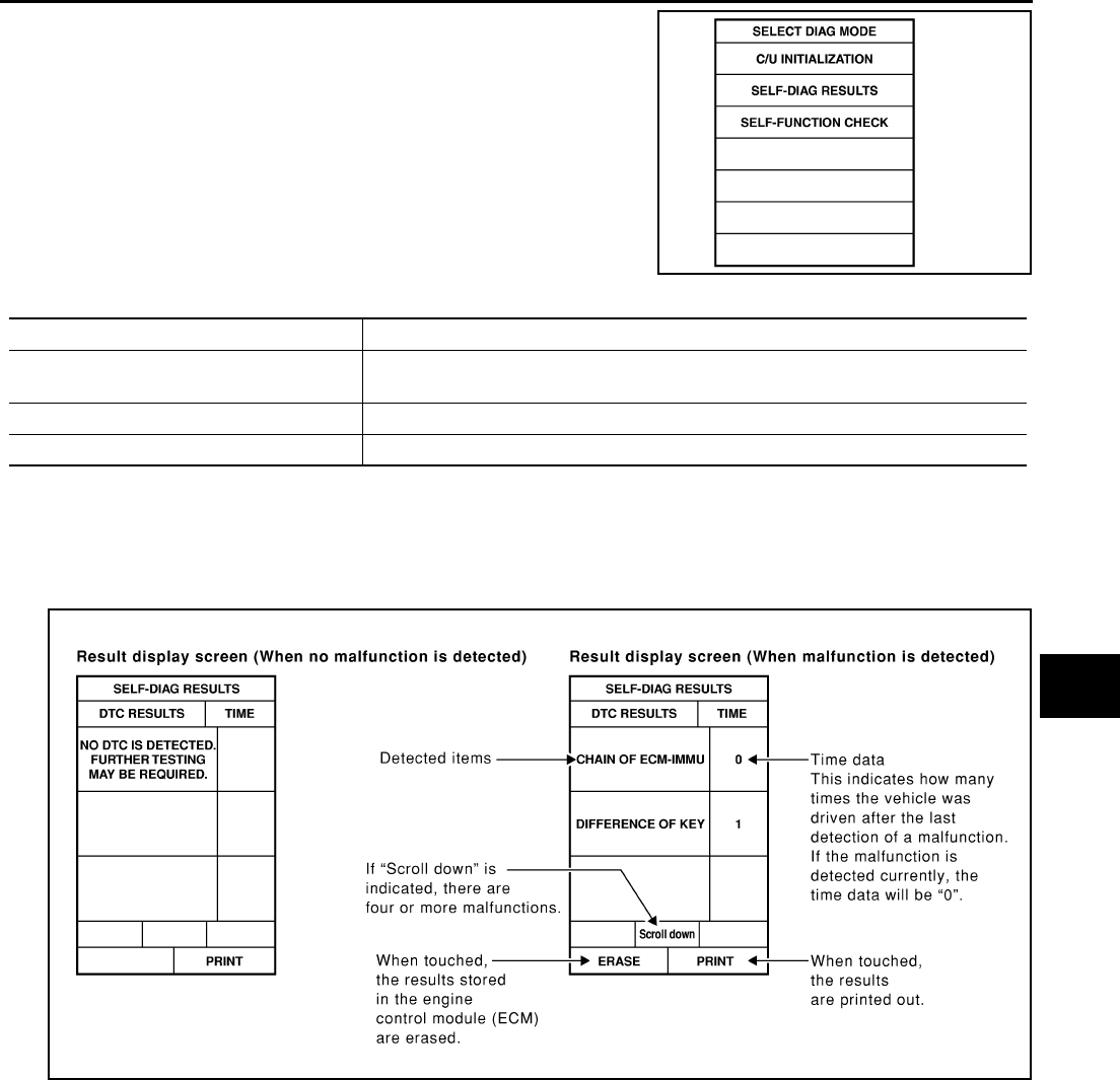
ELECTRONIC KEY SYSTEM
BL-141
C
D
E
F
G
H
J
K
L
M
A
B
BL
Revision: 2004 April 2002 Q45
6. Perform each diagnostic test mode according to each service
procedure.
For further information, see the CONSULT-II Operation Manual,
IVIS/NVIS.
CONSULT-II DIAGNOSTIC TEST MODE FUNCTION
NOTE:
When any initialization is performed, all ID numbers previously registered will be erased and all IVIS (NATS)
electronic keys must be registered again. The engine cannot be started with an unregistered key. The system
will show “DIFFERENCE OF KEY” or “LOCK MODE” as a self-diagnostic result on the CONSULT-II screen.
HOW TO READ SELF-DIAGNOSTIC RESULTS
SEL145Y
CONSULT- II DIAGNOSTIC TEST MODE Description
C/U INITIALIZATION When replacing any of the following three components, C/U initialization is necessary.
[IVIS (NATS) electronic key / NATS IMMU/ ECM]
SELF- FUNCTION CHECK ECM checks its own IVIS (NATS) communication interface by itself.
SELF- DIAGNOSTIC RESULTS Detected items (screen terms) are as shown in the chart below.
SEL953W

BL-142
ELECTRONIC KEY SYSTEM
Revision: 2004 April 2002 Q45
SYMPTOM: ELECTRONIC KEY DOES NOT TURN
Self-Diagnosis Results 1 EIS0012X
CHAIN OF ECM-IMMU
1. POWER SUPPLY CIRCUIT FOR NATS IMMU
●Turn ignition switch OFF.
●Disconnect NATS IMMU connector.
●Check voltage between NATS IMMU harness connector M32 terminal 1(W) and body ground.
OK or NG?
OK >> GO TO 2.
NG >> Check the following.
●10A fuse.[No.32 located in fuse block (J/B)]
●harness for open or short between fuse block and NATS IMMU: Reference part C1
2. CHECK IGNITION ON SIGNAL FOR NATS IMMU
●Turn ignition switch ON.
●Check voltage between NATS IMMU harness connector M32 terminal 3(W/B) and body ground.
OK or NG?
OK >> GO TO 3.
NG >> Check the following.
●10A fuse.[No.1 located in fuse block (J/B)]
●harness for open or short between fuse block and NATS IMMU: Reference part C2
3. CHECK CIRCUIT FOR NATS IMMU
Check continuity between NATS IMMU harness connector M32 terminal 9(B/W) and body ground.
OK or NG?
OK >> GO TO 4.
NG >> Repair or replace harness. : Reference part C3.
Symptom
Malfunction-
ing system is
displayed.
Self-diagno-
sis results Possible malfunctioning part or status
Reference part in the
trouble diagnostic
system diagram
●Security indicator
ON
●Electronic key does
not turn.
CHAIN OF
ECM-IMMU
P1612
1
Open circuit in battery power supply line to NATS
IMMU C1
NATS IMMU A
ECM 2 NATS IMMU A
Open circuit in ground line to NATS IMMU C3
CHAIN OF
IMMU-KEY
P1614
3
Open, short to the power supply, or short to ground in
the communication line between the antenna amplifier
and NATS IMMU.
E1 - E4
Open circuit in the power supply line to the antenna
amplifier E3
Open circuit in the ground line to the antenna amplifier E4
Electronic key (including transponder) malfunction D
NATS IMMU malfunction A
Antenna amp E
: Battery voltage should exist.
: Battery voltage should exist.
: Continuity should exist.

ELECTRONIC KEY SYSTEM
BL-143
C
D
E
F
G
H
J
K
L
M
A
B
BL
Revision: 2004 April 2002 Q45
4. CHECK NATS ANTENNA AMP. CIRCUIT 1
●Turn ignition switch OFF.
●Disconnect antenna amp connector.
●Insert electronic key into ignition key cylinder, and immediately check voltage between the antenna amp
harness connector M65 terminal 1(R) and body ground.
OK or NG?
OK >> GO TO 5.
NG >> GO TO 8.
5. CHECK NATS ANTENNA AMP. CIRCUIT 2
●Connect antenna amp connector.
●Insert the electronic key into the ignition key cylinder, and immediately check voltage between antenna
amp harness connector M65 terminal 2(Y) and body ground.
OK or NG?
OK >> GO TO 6.
NG >> GO TO 8.
6. CHECK NATS ANTENNA AMP. CIRCUIT 3
Insert the electronic key into the ignition key cylinder, and immediately check voltage between antenna amp
harness connector M65 terminal 3(Y/G) and body ground.
OK or NG?
OK >> GO TO 7.
NG >> GO TO 8.
7. CHECK NATS ANTENNA AMP. CIRCUIT 4
●Disconnect antenna amp connector.
●Check continuity between antenna amp harness connector M65 terminal 4(B/R) and body ground.
OK or NG?
OK >> Replace antenna amp : Reference part E
NG >> GO TO 8.
Terminals Condition Voltage
1 (R) − body ground Insert electronic key into
ignition key cylinder.
Approx. 5V (for 3 seconds
after inserting the key)
Terminals Condition Voltage
2 (Y) − body ground Insert electronic key into
ignition key cylinder.
Pointer of tester should
move.
Terminals Condition Voltage
3 (Y/G) − body ground Insert electronic key into
ignition key cylinder.
Pointer of tester
should move.
: Continuity should exist.

BL-144
ELECTRONIC KEY SYSTEM
Revision: 2004 April 2002 Q45
8. HARNESS CHECK
●Disconnect NATS IMMU connector.
●Check continuity between antenna amp harness connector M65 terminal 1(R), 2(Y), 3(Y/G), 4(B/R) and
NATS IMMU harness connector M32 terminal 5(R), 6(Y), 7(Y/G), 8(B/R).
Reference parts: E1, E2, E3, E4
OK or NG?
OK >> Replace harness between NATS IMMU and antenna amp. : Reference part E1, E2, E3, E4
NG >> 1. Replace NATS IMMU : Reference part A.
2. Perform initialization with CONSULT-II.
For the operation of initialization, refer to "CONSULT-II operation manual IVIS / NVIS".
Self-Diagnosis Results 2 EIS0012Y
1. CONTINUITY CHECK
Check continuity between NATS IMMU harness connector M32 terminal 9(B/W) and body ground.
OK or NG?
OK >> 1. Replace NATS IMMU : Reference part A
2. Perform initialization with CONSULT-II.
For the operation of initialization, refer to "CONSULT-II operation manual IVIS / NVIS".
NG >> Check harness for open or short between NATS IMMU and body ground. : Reference part C3
Self-Diagnosis Results 3 EIS0012Z
1. CHECK OF ELECTRONIC KEY (TRANSPONDER)
Using the other registered electronic key, check that the ignition switch can be turned ON.
OK or NG?
OK >> GO TO 2.
NG >> electronic key (transponder) malfunction.
2. CHECK NATS ANTENNA AMP INSTALLATION
Check the installation condition of the antenna amplifier.
OK or NG?
OK >> GO TO 3.
NG >> Install the antenna amp correctly.
3. CHECK NATS ANTENNA AMP. CIRCUIT 1
Insert the electronic key into the ignition key cylinder, and immediately check voltage between antenna amp
harness connector M65 terminal 3(Y/G) and body ground.
OK or NG?
OK >> GO TO 4.
NG >> GO TO 7.
1 – 5 : Continuity should exist.
2 – 6 : Continuity should exist.
3 – 7 : Continuity should exist.
4 – 8 : Continuity should exist.
: Continuity should exist.
Terminals Condition Voltage
3 (Y/G) − body ground Insert electronic key into
ignition key cylinder.
Pointer of tester
should move.

ELECTRONIC KEY SYSTEM
BL-145
C
D
E
F
G
H
J
K
L
M
A
B
BL
Revision: 2004 April 2002 Q45
4. CHECK NATS ANTENNA AMP. CIRCUIT 2
●Turn ignition switch OFF.
●Disconnect antenna amp connector.
●Insert electronic key into ignition key cylinder, and immediately check voltage between the antenna amp
harness connector M65 terminal 1(R) and body ground.
OK or NG?
OK >> GO TO 5.
NG >> GO TO 7.
5. CHECK NATS ANTENNA AMP. CIRCUIT 3
●Connect antenna amp connector.
●Insert the electronic key into the ignition key cylinder, and immediately check voltage between antenna
amp harness connector M65 terminal 2(Y) and body ground.
OK or NG?
OK >> GO TO 6.
NG >> GO TO 7.
6. CHECK NATS ANTENNA AMP. CIRCUIT 4
●Disconnect antenna amp connector.
●Check continuity between antenna amp harness connector M65 terminal 4(B/R) and body ground.
OK or NG?
OK >> Replace antenna amp : Reference part E
NG >> GO TO 7
7. CHECK NATS ANTENNA AMP. CIRCUIT 5
●Disconnect NATS IMMU connector.
●Check continuity between antenna amp harness connector M65 terminal 1(R), 2(Y), 3(Y/G), 4(B/R) and
NATS IMMU harness connector M32 terminal 5(R), 6(Y), 7(Y/G), 8(B/R).
Reference parts: E1, E2, E3, E4
OK or NG?
OK >> Replace harness between NATS IMMU and antenna amp. : Reference part E1, E2, E3, E4
NG >> 1. Replace NATS IMMU : Reference part A
2. Perform initialization with CONSULT-II.
For the operation of initialization, refer to "CONSULT-II operation manual IVIS / NVIS".
Terminals Condition Voltage
1 (R) − body ground Insert electronic key into
ignition key cylinder.
Approx. 5V (for 3 seconds
after inserting the key)
Terminals Condition Voltage
2 (Y) − body ground Insert electronic key into
ignition key cylinder.
Pointer of tester should
move.
: Continuity should exist.
1 – 5 : Continuity should exist.
2 – 6 : Continuity should exist.
3 – 7 : Continuity should exist.
4 – 8 : Continuity should exist.

BL-146
IVIS (INFINITI VEHICLE IMMOBILIZER SYSTEM-NATS)
Revision: 2004 April 2002 Q45
IVIS (INFINITI VEHICLE IMMOBILIZER SYSTEM-NATS) PFP:28591
Component Parts and Harness Connector Location EIS00128
NOTE:
If customer reports a “No start” condition, request ALL ELECTRONIC KEY to be brought to the Dealer is case
of a NATS malfunction.
System Description EIS00129
IVIS (Infinity Vehicle Immobilizer System – NATS) has the following immobilizer functions:
●Since only IVIS (NATS) electronic keys, whose ID nos. have been registered into the ECM and IMMU of
IVIS (NATS), allow the engine to run, operation of a stolen vehicle without a IVIS (NATS) registered elec-
tronic key is pre-vented by IVIS (NATS).
That is to say, IVIS (NATS) will immobilize the engine if someone tries to start it without the registered
electronic key of IVIS (NATS).
●All of the originally supplied electronic key IDs (except for card key and emergency key) have been IVIS
(NATS) registered. If requested by the vehicle owner, a maximum of four key IDs can be registered into
the IVIS (NATS) components.
●The security indicator blinks when the ignition switch is in “OFF” or “ACC” position. Therefore, IVIS
(NATS) warns outsiders that the vehicle is equipped with the anti-theft system.
●When IVIS (NATS) detects any malfunctions, the security indicator lamp lights up while electronic key is in
the “ON” position.
●IVIS (NATS) trouble diagnoses, system initialization and additional registration of other IVIS (NATS) elec-
tronic key IDs must be carried out using CONSULT- ll hardware and CONSULT- ll IVIS (NATS) software.
When IVIS (NATS) initialization has been completed, the ID of the inserted electronic key is automatically
IVIS (NATS) registered. Then, if necessary, additional registration of other IVIS (NATS) electronic key IDs
can be carried out.
Regarding the procedures of IVIS (NATS) initialization and IVIS (NATS) electronic key ID registration,
refer to CONSULT-II operation manual, IVIS/NVIS.
CIIM0006E
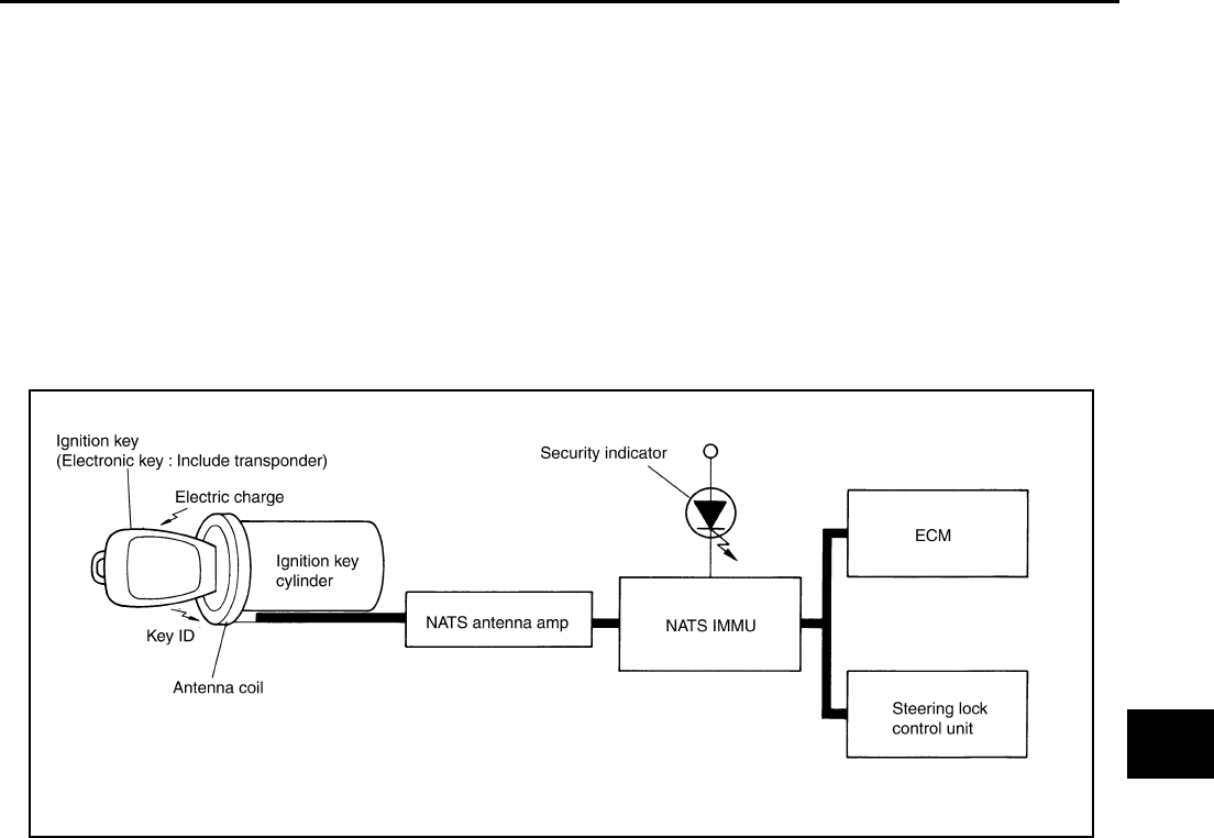
IVIS (INFINITI VEHICLE IMMOBILIZER SYSTEM-NATS)
BL-147
C
D
E
F
G
H
J
K
L
M
A
B
BL
Revision: 2004 April 2002 Q45
NOTE:
When servicing a malfunction of the IVIS (NATS) indicated by lighting up of Security Indicator Lamp or regis-
tering another IVIS (NATS) electronic key ID no., it is necessary to re-register original key identification. There-
fore, be sure to receive ALL ELECTRONIC KEYS from vehicle owner.
System Composition EIS0012A
The immobilizer function of the IVIS (NATS) consists of the following:
●IVIS (NATS) electronic key
●IVIS (NATS) antenna amp. Located in the ignition key cylinder
●Steering lock control unit.
●IVIS (NATS) immobilizer control unit (IMMU)
●Engine control module (ECM)
●Security indicator
PIIA0376E

BL-148
IVIS (INFINITI VEHICLE IMMOBILIZER SYSTEM-NATS)
Revision: 2004 April 2002 Q45
Schematic EIS0012B
TIWM0032E
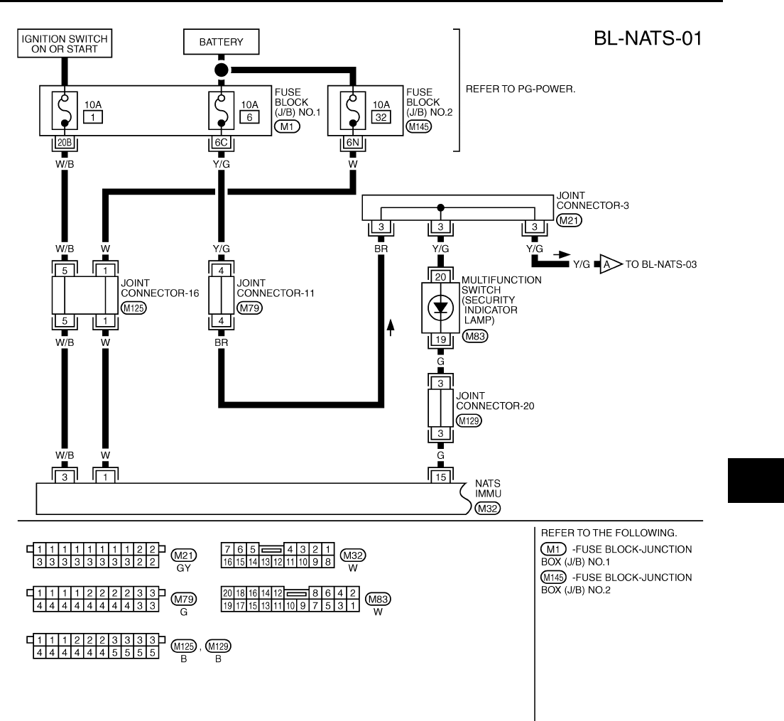
IVIS (INFINITI VEHICLE IMMOBILIZER SYSTEM-NATS)
BL-149
C
D
E
F
G
H
J
K
L
M
A
B
BL
Revision: 2004 April 2002 Q45
Wiring Diagram – NATS – EIS0012C
TIWM0033E
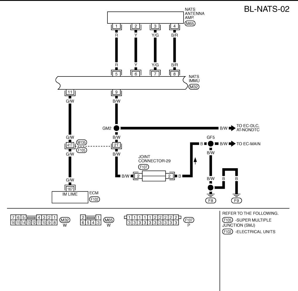
BL-150
IVIS (INFINITI VEHICLE IMMOBILIZER SYSTEM-NATS)
Revision: 2004 April 2002 Q45
TIWM0034E

IVIS (INFINITI VEHICLE IMMOBILIZER SYSTEM-NATS)
BL-151
C
D
E
F
G
H
J
K
L
M
A
B
BL
Revision: 2004 April 2002 Q45
TIWM0035E
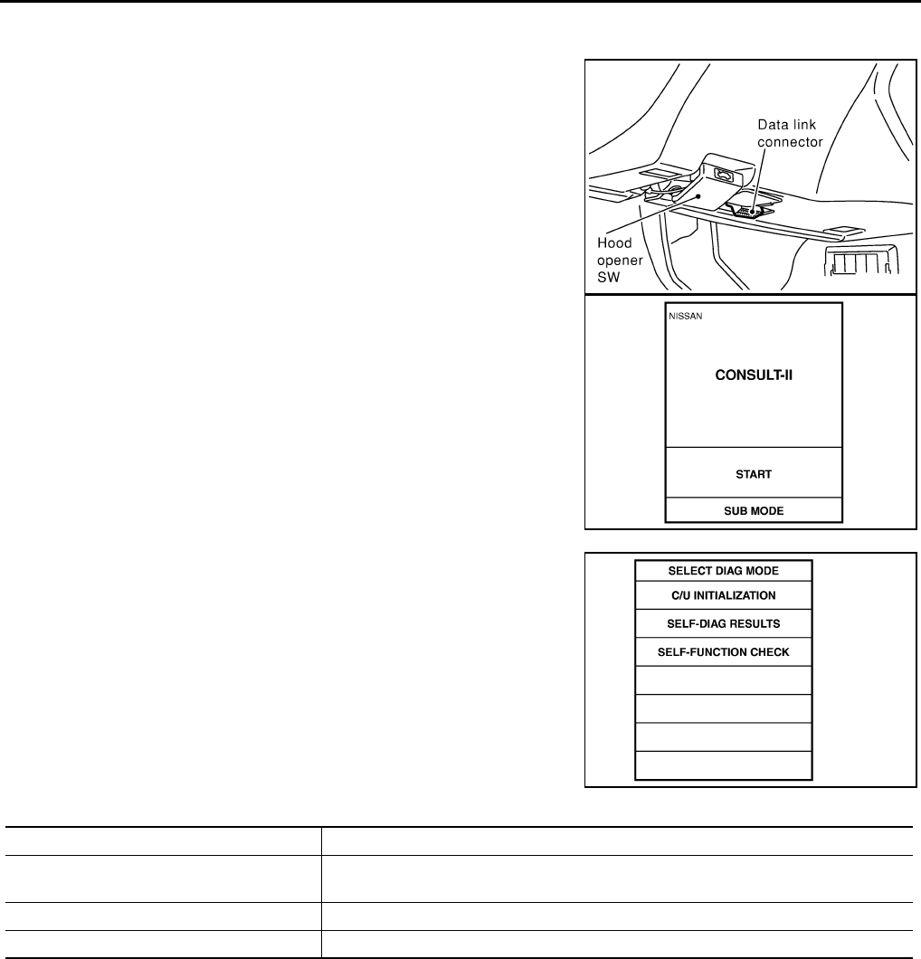
BL-152
IVIS (INFINITI VEHICLE IMMOBILIZER SYSTEM-NATS)
Revision: 2004 April 2002 Q45
CONSULT- ll EIS0012D
CONSULT-II INSPECTION PROCEDURE
1. Turn ignition switch OFF.
2. Connect CONSULT-II to data link connector.
3. Insert IVIS (NATS) program card into CONSULT-II.
Program card “IVIS (NATS)”
4. Turn ignition switch ON.
5. Touch “START”.
6. Perform each diagnostic test mode according to each service
procedure.
For further information, see the CONSULT-II Operation Manual,
IVIS/NVIS.
CONSULT-II DIAGNOSTIC TEST MODE FUNCTION
NOTE:
When any initialization is performed, all ID numbers previously registered will be erased and all IVIS (NATS)
electronic keys must be registered again. The engine cannot be started with an unregistered key. The system
will show “DIFFERENCE OF KEY” or “LOCK MODE” as a self-diagnostic result on the CONSULT-II screen.
SHIA0179E
PBR455D
SEL145Y
CONSULT- II DIAGNOSTIC TEST MODE Description
C/U INITIALIZATION When replacing any of the following three components, C/U initialization is necessary.
[IVIS (NATS) electronic key/ IMMU/ ECM]
SELF- FUNCTION CHECK ECM checks its own IVIS (NATS) communication interface by itself.
SELF- DIAGNOSTIC RESULTS Detected items are as shown in the chart below.
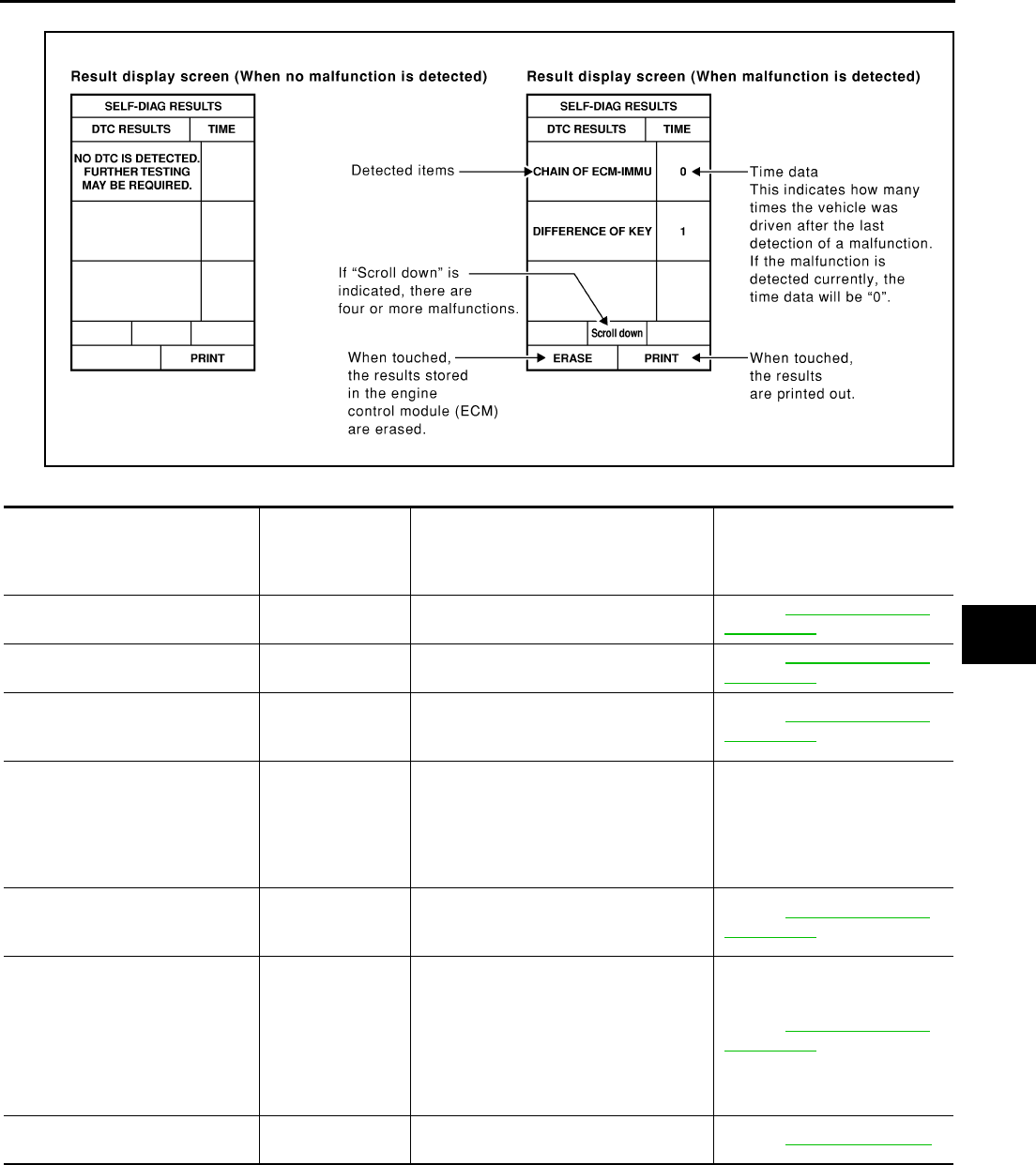
IVIS (INFINITI VEHICLE IMMOBILIZER SYSTEM-NATS)
BL-153
C
D
E
F
G
H
J
K
L
M
A
B
BL
Revision: 2004 April 2002 Q45
HOW TO READ SELF-DIAGNOSTIC RESULTS
NATS SELF-DIAGNOSTIC RESULT ITEM CHART
SEL953W
Detected items (Screen terms)
P No.Code
(Self-diagnostic
result of
"ENGINE")
Description Diagnostic procedure
ECM INT CIRC-IMMU P1613 The malfunction of ECM internal circuit
of IMMU communication line is detected.
Refer to BL-156, "Diagnostic
Procedure 1" .
CHAIN OF ECM-IMMU P1612 Communication impossible between
ECM and IMMU.
Refer to BL-156, "Diagnostic
Procedure 2" .
DIFFERENCE OF KEY P1615
IMMU can receive the key ID signal but
the result of ID verification between key
ID and IMMU is NG.
Refer to BL-159, "Diagnostic
Procedure 3" .
CHAIN OF IMMU-KEY P1614 IMMU cannot receive the key ID signal.
Perform initialization with CON-
SULT-II.
For the operation of initializa-
tion,.
refer to “CONSULT-II operation
manual, IVIS/NVIS"
ID DISCORD, IMM-ECM P1611
The result of ID verification between
IMMU and ECM is NG. System initializa-
tion is required.
Refer to BL-159, "Diagnostic
Procedure 4" .
LOCK MODE P1610
When the starting operation is carried
out 5 or more times consecutively under
the following conditions, IVIS(NATS) will
shift the mode to one which prevents the
engine from being started.
●unregistered electronic key is used
●IMMU or ECM malfunctioning
Refer to BL-160, "Diagnostic
Procedure 5" .
DON'T ERASE BEFORE
CHECKING ENG DIAG —Engine trouble data and IVIS (NATS)
trouble data have been detected in ECM. Refer to BL-154, "Work Flow" .
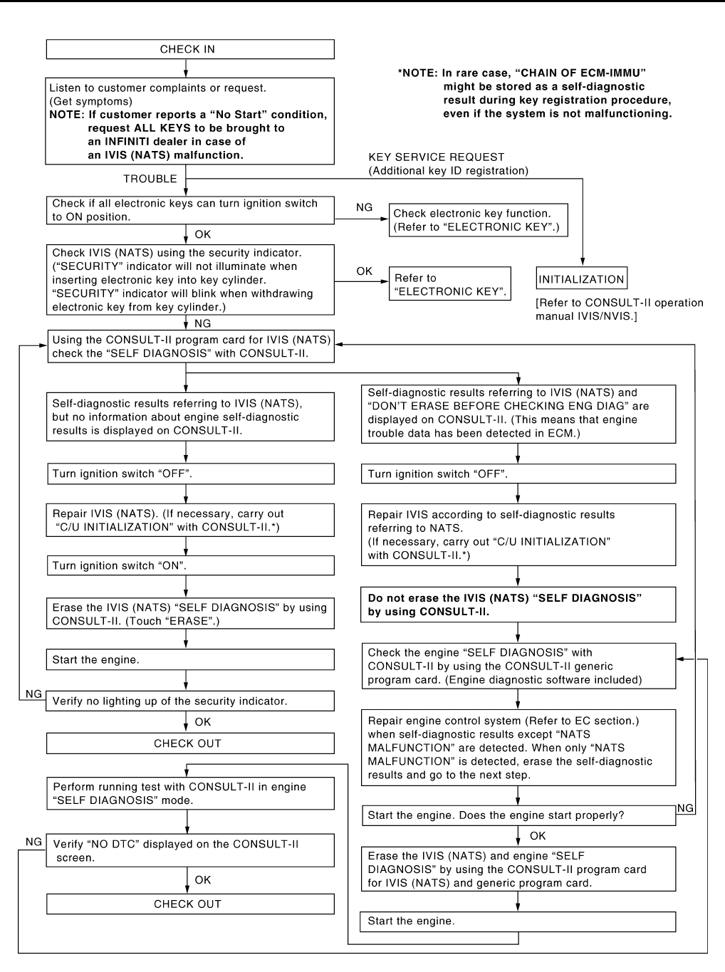
BL-154
IVIS (INFINITI VEHICLE IMMOBILIZER SYSTEM-NATS)
Revision: 2004 April 2002 Q45
Work Flow EIS0012E
PIIA0379E

IVIS (INFINITI VEHICLE IMMOBILIZER SYSTEM-NATS)
BL-155
C
D
E
F
G
H
J
K
L
M
A
B
BL
Revision: 2004 April 2002 Q45
Symptom Chart 1 EIS0028Z
*: When IVIS (NATS) detects trouble, the security indicator lights up while electronic key is in the “ON” position.
Symptom Chart 2 EIS00159
SYMPTOM
Displayed “SELF-DIAG
RESULTS” on CON-
SULT-II screen.
DIAGNOSTIC PROCE-
DURE
SYSTEM (Malfunction-
ing part or mode)
REFERENCE PART
NO. OF ILLUSTRATION
●Security indicator
lighting up*
●Engine will start.
ECM INT CIRC-IMMU Refer to BL-156, "Diag-
nostic Procedure 1" . ECM B
●Security indicator
lighting up*
●Engine hard to start
CHAIN OF ECM-IMMU Refer to BL-156, "Diag-
nostic Procedure 2" .
Open circuit in battery
voltage line of IMMU cir-
cuit
C1
Open circuit in ignition
line of IMMU circuit C2
Open circuit in ground
line of IMMU circuit C3
Open circuit in commu-
nication line between
IMMU and ECM
C4
Short circuit between
IMMU and ECM commu-
nication line and battery
voltage line
C4
Short circuit between
IMMU and ECM commu-
nication line and ground
line
C4
ECM B
IMMU A
DIFFERENCE OF KEY Refer to BL-159, "Diag-
nostic Procedure 3" .
Unregistered key D
IMMU A
CHAIN OF IMMU-KEY
Perform initialization
with CONSULT-II.
For the operation of ini-
tialization,.
refer to “CONSULT-II
operation manual IVIS/
NVIS”.
Malfunction of key ID
chip E5
IMMU A
Antenna amp E6
ID DISCORD, IMM-ECM Refer to BL-159, "Diag-
nostic Procedure 4"
System initialization has
not yet been completed. F
ECM F
LOCK MODE Refer to BL-160, "Diag-
nostic Procedure 5" . LOCK MODE D
●MIL staying ON
●Security indicator
lighting up*
DON'T ERASE
BEFORE CHECKING
ENG DIAG
WORK FLOW
Engine trouble data and
NATS trouble data have
been detected in ECM
—
SYMPTOM SYSTEM
(Malfunctioning part or mode)
Security ind. Does not light up
Security ind.
Open circuit between Fuse and IVIS (NATS) IMMU
Continuation of initialization mode
IVIS (NATS) IMMU
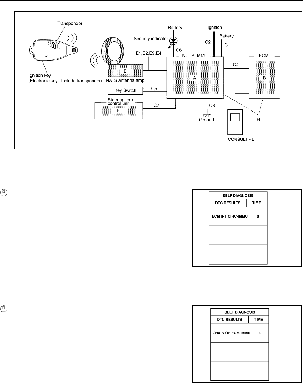
BL-156
IVIS (INFINITI VEHICLE IMMOBILIZER SYSTEM-NATS)
Revision: 2004 April 2002 Q45
Diagnostic System Diagram EIS0015A
Diagnostic Procedure 1 EIS00291
Self-diagnostic results: "ECM INT CIRC-IMMU" displayed on CONSULT-II screen
1. SELF-DIAGNOSTIC RESULTS
Confirm SELF-DIAGNOSTIC RESULTS “ECM INT CIRC-IMMU”
displayed on CONSULT-II screen.
YES >> 1. Replace ECM.
(Diagnostic system diagram part No. B)
2. Perform initialization with CONSULT-II.
For the operation of initialization, refer to “CONSULT-
II operation manual, IVIS/NVIS".
Diagnostic Procedure 2 EIS00292
Self-diagnostic results: “CHAIN OF ECM-IMMU” displayed on CONSULT-II screen
1. SELF-DIAGNOSTIC RESULTS
Perform self-diagnosis. Is “CHAIN OF ECM-IMMU” displayed on
the screen?
YES >> GO TO 2.
NO >> GO TO
PIIA0378E
SEL314W
SEL292W
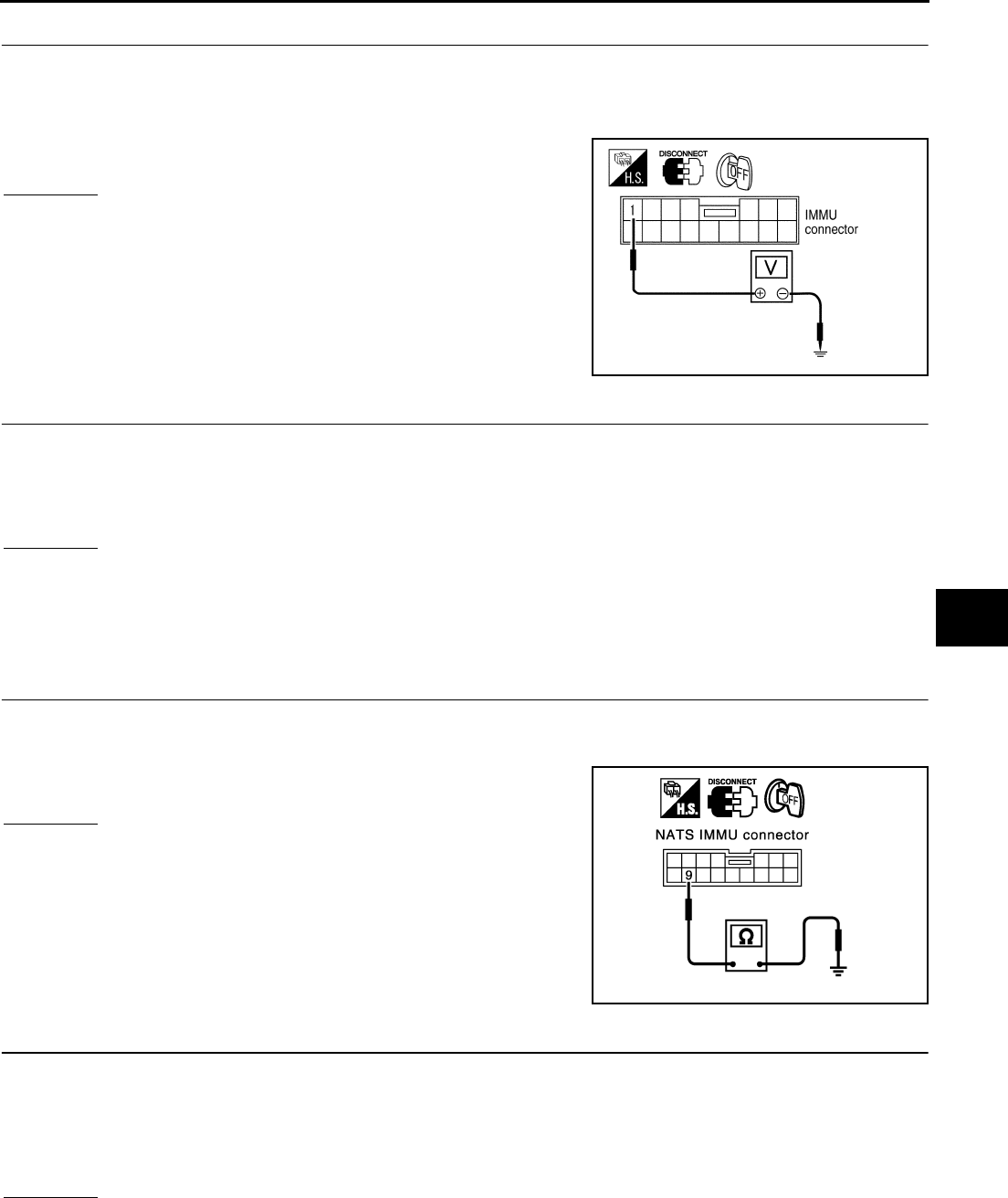
IVIS (INFINITI VEHICLE IMMOBILIZER SYSTEM-NATS)
BL-157
C
D
E
F
G
H
J
K
L
M
A
B
BL
Revision: 2004 April 2002 Q45
2. POWER SUPPLY CIRCUIT CHECK
1. Turn ignition switch OFF.
2. Disconnect NATS IMMU connector M32.
3. Check voltage between NATS IMMU harness connector M32 terminal 1 (W) and body ground.
OK or NG?
OK >> GO TO 3.
NG >> Check the following:
●10A fuse [No.32, located in fuse block (J/B)]
●Harness for open or short between fuse and NATS
IMMU connector.
3. POWER SUPPLY CIRCUIT CHECK
1. Turn ignition switch ON.
2. Check voltage between NATS IMMU harness connector M32 terminal 3 (W/B) and body ground.
OK or NG?
OK >> GO TO 4.
NG >> Check the following:
●10A fuse [No. 1, located in fuse block (J/B)]
●Harness for open or short between fuse and NATS IMMU connector.
4. BODY GROUND CIRCUIT CHECK
1. Turn ignition switch OFF.
2. Check continuity between NATS IMMU harness connector M32 terminal 9 (B/W) and body ground.
OK or NG?
OK >> GO TO 5.
NG >> Repair or replace harness between NATS IMMU and
body ground.
5. COMMUNICATION LINE CIRCUIT CHECK
1. Disconnect ECM and NATS IMMU connector.
2. Check continuity between NATS IMMU harness connector M32 terminal 11 (G/W) and ECM harness con-
nector F102 terminal 167 (G/W).
OK or NG?
OK >> GO TO 6.
NG >> Repair or replace harness between NATS IMMU and BCM.
Battery voltage should exist.
PIIA0366E
Battery voltage should exist.
Continuity should exist.
PIIA3123E
Continuity should exist.

BL-158
IVIS (INFINITI VEHICLE IMMOBILIZER SYSTEM-NATS)
Revision: 2004 April 2002 Q45
6. COMMUNICATION LINE CIRCUIT CHECK
1. Turn the ignition switch OFF.
2. Check continuity between NATS IMMU harness connector M32 terminal 11 (G/W) and body ground.
OK or NG?
OK >> GO TO 7.
NG >> Communication line is short-circuit with ground line.
●Repair or replace harness.
7. REPLACE NATS IMMU
1. Replace NATS IMMU Ref. part No. A
2. Perform initialization with CONSULT-II.
For initialization, refer to “CONSULT-II Operation Manual NATS-IVIS/NVIS”.
Does the engine start?
Yes >> NATS IMMU is malfunctioning.
No >> ●ECM is malfunctioning.
●Replace ECM. Ref. part No. B
Continuity should not exist.
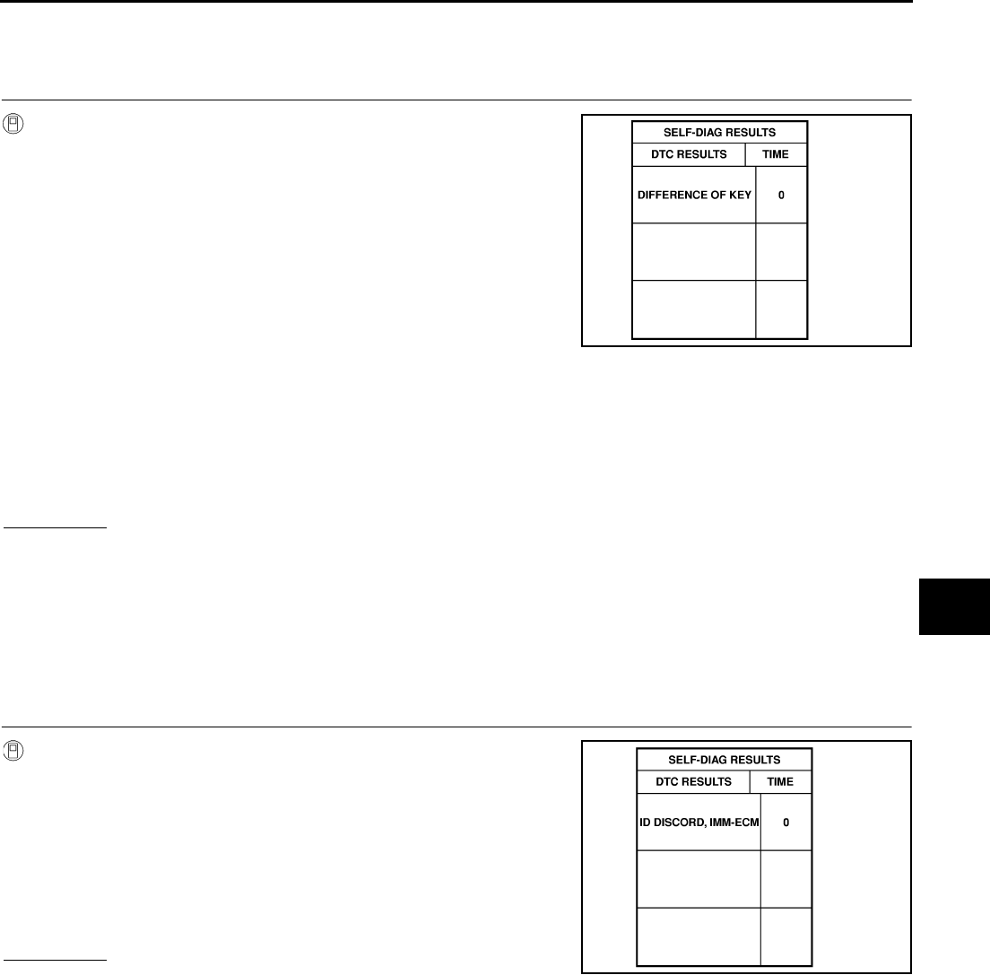
IVIS (INFINITI VEHICLE IMMOBILIZER SYSTEM-NATS)
BL-159
C
D
E
F
G
H
J
K
L
M
A
B
BL
Revision: 2004 April 2002 Q45
Diagnostic Procedure 3 EIS00293
Self-diagnostic results: “DIFFERENCE OF KEY” displayed on CONSULT-II screen
1. SELF-DIAGNOSTIC RESULTS
Confirm SELF-DIAGNOSTIC RESULTS “DIFFERENCE OF KEY”
displayed on CONSULT-II screen.
●Perform initialization with CONSULT-ll.
Re-register all IVIS(NATS) electronic key IDs.
For the operation of initialization, refer to “CONSULT-ll operation manual IVIS/NVIS”.
●Start the engine.
YES or NO?
YES >> END (electronic key ID was unregistered.)
NO >> Replace NATS IMMU.
●Perform initialization with CONSULT-II.
For the operation of initialization, refer to “CONSULT-II operation manual IVIS/NVIS”.
Diagnostic Procedure 4 EIS00294
Self-diagnostic results: “ID DISCORD, IMMU-ECM” displayed on CONSULT-II screen
1. SELF-DIAGNOSTIC RESULTS
Confirm SELF-DIAGNOSTIC RESULTS “ID DISCORD, IMMU-
ECM” displayed on CONSULT-II screen.
●Perform initialization with CONSULT-ll.
Re-register all IVIS (NATS) electronic key IDs.
For the operation of initialization, refer to “CONSULT-ll operation
manual IVIS/NVIS”.
●Start the engine.
YES or NO?
YES >> END (electronic key ID was unregistered.)
NO >> Replace ECM.
●Perform initialization with CONSULT-II.
For the operation of initialization, refer to “CONSULT-II operation manual IVIS/NVIS”.
SEL956W
: Does the engine start?
: Does the engine start?
SEL958W
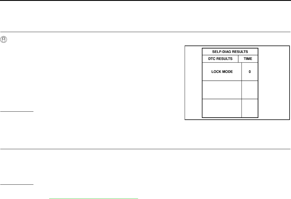
BL-160
IVIS (INFINITI VEHICLE IMMOBILIZER SYSTEM-NATS)
Revision: 2004 April 2002 Q45
Diagnostic Procedure 5 EIS00295
Self-diagnostic results: “LOCK MODE” displayed on CONSULT-II screen
1. SELF-DIAGNOSTIC RESULTS
Confirm SELF-DIAGNOSTIC RESULTS “LOCK MODE” displayed on CONSULT-II screen.
1. Turn the ignition switch to OFF position.
2. Turn the ignition switch to ON position with a registered elec-
tronic key. (Do not start engine.) Wait for 5 seconds.
3. Return the electronic key to the OFF position.
4. Repeat steps 2 and 3 twice (total of three cycles).
5. Start the engine.
YES or NO?
YES >> System is OK. (Now the system is escaped from “LOCK
MODE”)
NO >> GO TO 2.
2. PERFORM INITIALIZATION
Perform initialization with CONSULT-ll.
For the initialization procedure, refer to “CONSULT-ll operation manual IVIS/NVIS”.
YES or NO?
YES >> System is OK.
NO >> Go to BL-159, "Diagnostic Procedure 3" .
: Does the engine start?
SEL960W
: Can the system be initialized?
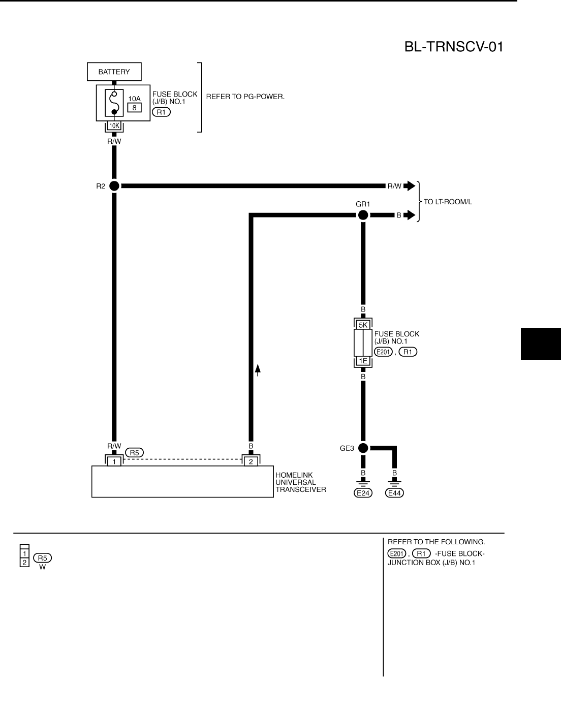
HOMELINK UNIVERSAL TRANSCEIVER
BL-161
C
D
E
F
G
H
J
K
L
M
A
B
BL
Revision: 2004 April 2002 Q45
HOMELINK UNIVERSAL TRANSCEIVER PFP:96401
Wiring Diagram – TRNSCV – EIS00296
TIWM0118E
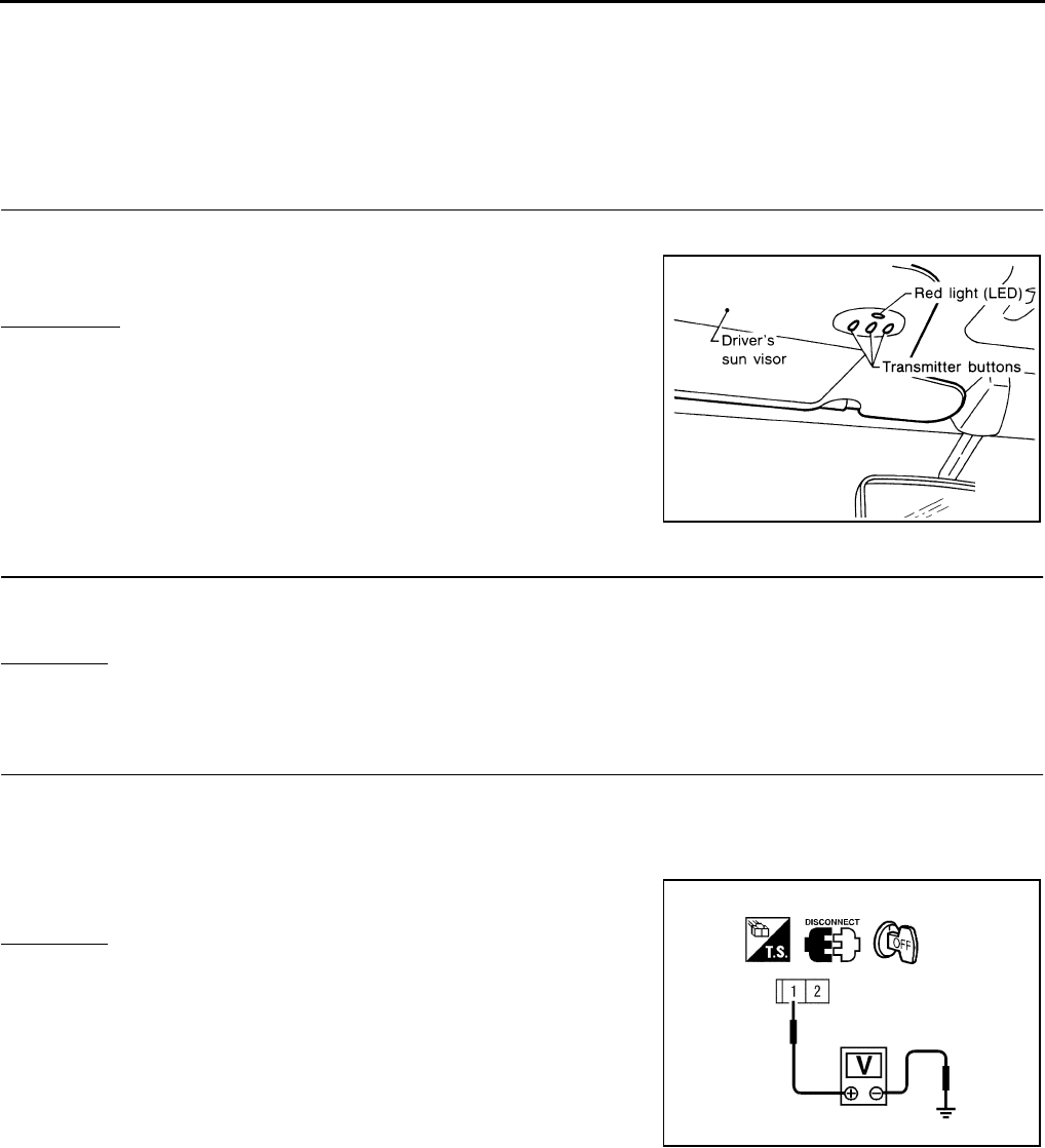
BL-162
HOMELINK UNIVERSAL TRANSCEIVER
Revision: 2004 April 2002 Q45
Trouble Diagnoses EIS00297
DIAGNOSTIC PROCEDURE
SYMPTOM: Transmitter does not activate receiver.
Before conducting the procedure given below, make sure that system receiver (garage door opener, etc.)
operates with original, hand-held transmitter. If NG, receiver or hand-held transmitter is at fault, not vehicle
related.
1. ILLUMINATE CHECK
●Turn ignition switch “OFF”.
●Does red light (LED) of transmitter illuminate when any button is
pressed?
YES or NO?
YES >> GO TO 2.
NO >> GO TO 3.
2. TRANSMITTER CHECK
Check transmitter with Tool*.
*:For details, refer to Technical Service Bulletin.
OK or NG?
OK >> Receiver or handheld transmitter malfunction, not vehicle related.
NG >> Replace transmitter with sun visor assembly.
3. POWER SUPPLY CHECK
1. Disconnect transmitter connector.
2. Turn ignition switch “OFF”.
3. Check voltage between transmitter harness connector R5 terminal 1(R/W) and body ground.
OK or NG?
OK >> GO TO 4.
NG >> ●Check 10A fuse [No. 8 located in the fuse block (J/B)
No.1]
●Harness for open or short between fuse and transmit-
ter
SEL442U
: Battery voltage should exist.
PIIA0338E
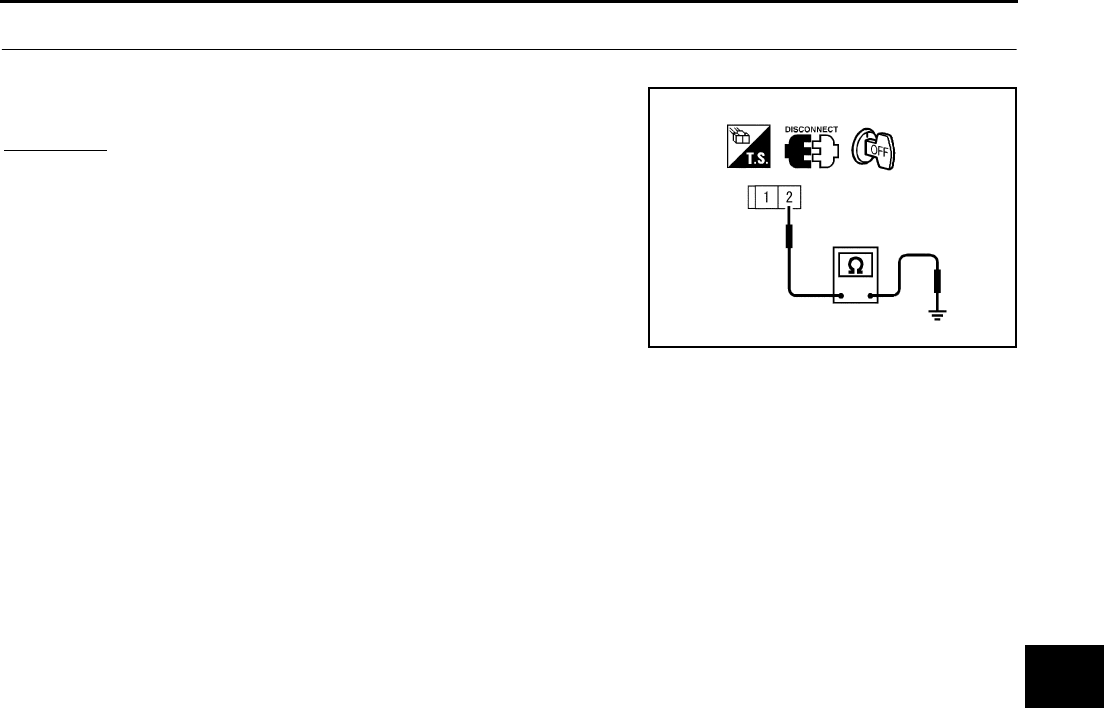
HOMELINK UNIVERSAL TRANSCEIVER
BL-163
C
D
E
F
G
H
J
K
L
M
A
B
BL
Revision: 2004 April 2002 Q45
4. GROUND CIRCUIT CHECK
Check continuity between transmitter harness connector R5 terminal 2(B) and body ground.
OK or NG?
OK >> Replace transmitter with sun visor assembly.
NG >> Repair harness.
: Continuity should exist.
PIIA0339E
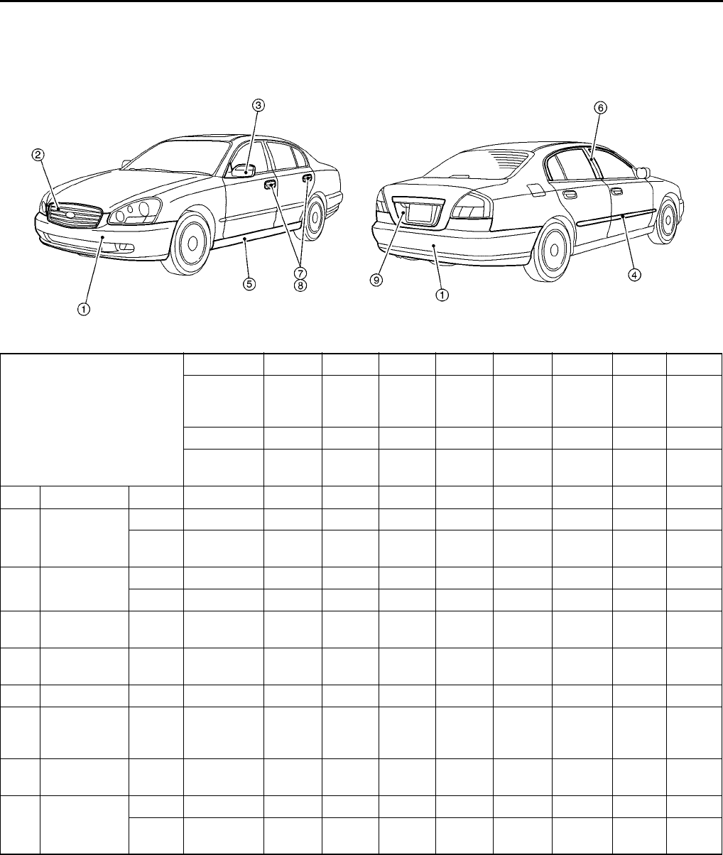
BL-164
BODY REPAIR
Revision; 2004 April 2002 Q45
BODY REPAIR PFP:60100
Body Exterior Paint Color
EIS000K2
2S:2-Coat solid, M:Metallic, P:Pearl, 3P:3-Coat pearl, TM:Micro titanium metallic
PIIA0090E
Component
Color code BAX8 BBW5 BDT2 BJW0 BKH3 BKR4 BKX6 BQX1
Description Red Dark
Blue Dark
Green
Yellow-
ish
Green
Black Green Silver White
Paint type P P P M 2S M TM 3P
Hard clear
coat XXXXX XXX
1 Bumper fascia Body Body color BAX8 BBW5 BDT2 BJW0 BKH3 BKR4 BKX6 BQX1
2 Front grille
Body Black AG01 AG01 AG01 AG01 AG01 AG01 AG01 AG01
Molding Chromium-
plate Cr Cr Cr Cr Cr Cr Cr Cr
3Door outside
mirror
Case Body color BAX8 BBW5 BDT2 BJW0 BKH3 BKR4 BKX6 BQX1
Base Body color BAX8 BBW5 BDT2 BJW0 BKH3 BKR4 BKX6 BQX1
4Side guard
molding Body color BAX8 BBW5 BDT2 BJW0 BKH3 BKR4 BKX6 BQX1
5Center
mudguard Body color BAX8 BBW5 BDT2 BJW0 BKH3 BKR4 BKX6 BQX1
6 Door sash Black 701G-1 701G-1 701G-1 701G-1 701G-1 701G-1 701G-1 701G-1
7
Door outside
handle
escutcheon
Body color BAX8 BBW5 BDT2 BJW0 BKH3 BKR4 BKX 6 BQX1
8Door outside
handle
Chromium-
plate Cr Cr Cr Cr Cr Cr Cr Cr
9Back door
finisher
Body Body color BAX8 BBW5 BDT2 BJW0 BKH3 BKR4 BKX6 BQX1
Molding Chromium-
plate Cr Cr Cr Cr Cr Cr Cr Cr

BODY REPAIR
BL-165
C
D
E
F
G
H
J
K
L
M
A
B
BL
Revision; 2004 April 2002 Q45
Body Component Parts
EIS00A5Y
UNDERBODY COMPONENT PARTS
SIIA2424E

BL-166
BODY REPAIR
Revision; 2004 April 2002 Q45
1. Radiator core support assembly
2. Upper radiator core support
3. Side radiator core support
4. Lower radiator core support
5. Hood lock stay
6. Hoodledge assembly (RH&LH)
7. Hoodledge reinforcement (RH&LH)
8. Upper hoodledge (RH&LH)
9. Lower front hoodledge (RH&LH)
10. Rear hoodledge reinforcement (RH&LH)
11. Upper dash crossmember assembly
12. Upper dash assembly
13. Side cowl top
14. Lower dash
15. Side dash (RH&LH)
16. Front floor center
17. Front floor
18. Inner sill (RH&LH)
19. Rear seat crossmember assembly
20. Rear floor front
21. Rear seat crossmember
22. Rear floor belt anchor reinforcement
23. Rear seat back support assembly
24. Center rear crossmember
25. Rear floor rear
26. Muffler mounting bracket
27. Rear floor side (RH&LH)
28. Spare tire clamp bracket
29. Front side member closing plate assembly (RH&LH)
30. Front side member front closing plate (RH&LH)
31. Front side member assembly (RH&LH)
32. Front side member (RH&LH)
33. Front side member outrigger assembly (RH&LH)
34. Front side member rear extension (RH&LH)
35. Rear side member assembly (RH&LH)
36. Rear side member extension (RH&LH)
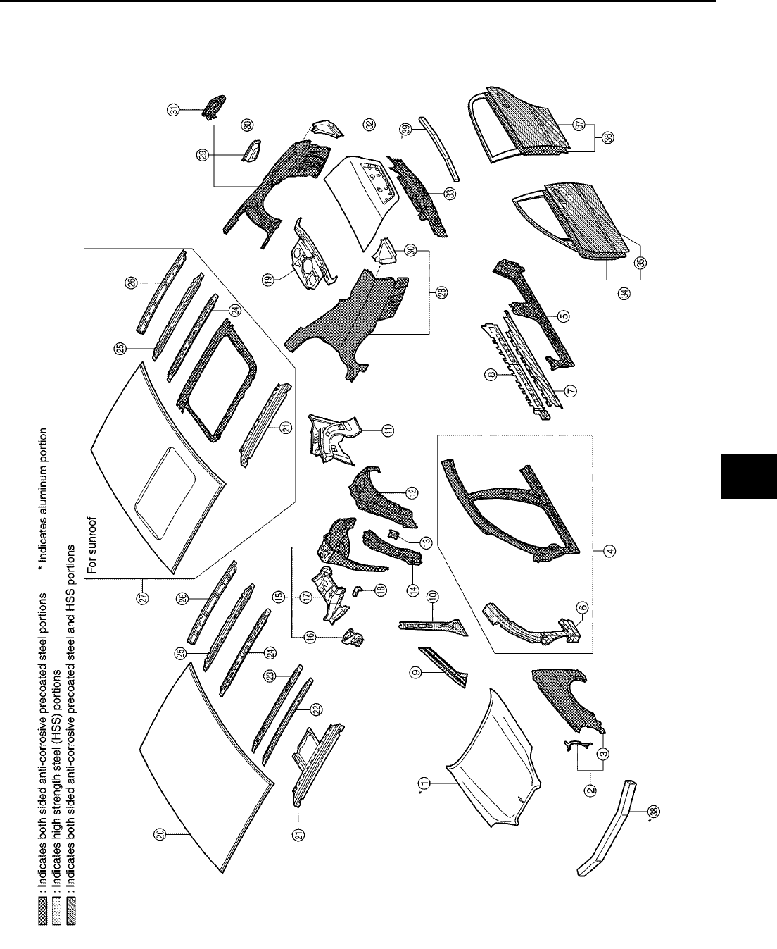
BODY REPAIR
BL-167
C
D
E
F
G
H
J
K
L
M
A
B
BL
Revision; 2004 April 2002 Q45
BODY COMPONENT PARTS
SIIA2425E

BL-168
BODY REPAIR
Revision; 2004 April 2002 Q45
1. Hood
2. Front fender (RH&LH)
3. Front fender bracket (RH&LH)
4. Side body assembly (RH&LH)
5. Outer sill (RH&LH)
6. Upper front pillar hinge brace assembly (RH&LH)
7. Outer sill reinforcement (RH&LH)
8. Center sill reinforcement (RH&LH)
9. Upper inner front pillar assembly (RH&LH)
10. Inner center pillar (RH&LH)
11. Inner rear pillar (RH&LH)
12. Outer rear wheelhouse (RH&LH)
13. Outer rear wheelhouse brace (RH&LH)
14. Outer rear wheelhouse reinforcement (RH&LH)
15. Inner rear wheelhouse assembly (RH&LH)
16. Seat back support (RH&LH)
17. Side parcel shelf (RH&LH)
18. Rear parcel shelf bracket (RH&LH)
19. Parcel shelf with rear waist
20. Roof
21. Front roof rail
22. Front roof bow
23. Center roof bow No.1
24. Rear roof bow
25. Center roof bow No.2
26. Rear roof rail
27. Roof assembly
28. Rear fender (LH)
29. Rear fender (RH)
30. Rear combination lamp base
31. Fuel filler lid
32. Trunk lid
33. Rear panel assembly
34. Front door assembly (RH&LH)
35. Outer front door panel (RH&LH)
36. Rear door assembly (RH&LH)
37. Outer rear door panel (RH&LH)
38. Front bumper reinforcement
39. Rear bumper reinforcement
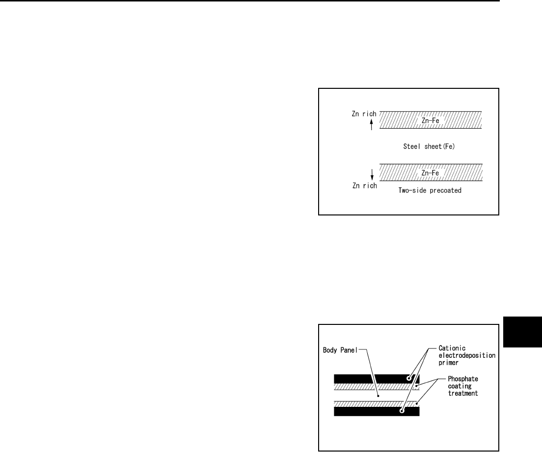
BODY REPAIR
BL-169
C
D
E
F
G
H
J
K
L
M
A
B
BL
Revision; 2004 April 2002 Q45
Corrosion Protection
EIS000K4
DESCRIPTION
To provide improved corrosion prevention, the following anti-corrosive measures have been implemented in
NISSAN production plants. When repairing or replacing body panels, it is necessary to use the same anti-cor-
rosive measures.
ANTI-CORROSIVE PRECOATED STEEL (GALVANNEALED STEEL)
To improve repairability and corrosion resistance, a new type of anti-
corrosive percolated steel sheet has been adopted replacing con-
ventional zinc-coated steel sheet.
Galvannealed steel is electroplated and heated to form Zinc-iron
alloy, which provides excellent and long term corrosion resistance
with cationic electrode position primer.
Nissan Genuine Service Parts are fabricated from galvannealed steel. Therefore, it is recommended that
GENUINE NISSAN PARTS or equivalent be used for panel replacement to maintain the anti-corrosive perfor-
mance built into the vehicle at the factory.
PHOSPHATE COATING TREATMENT AND CATIONIC ELECTRODEPOSITION PRIMER
A phosphate coating treatment and a cationic electrode position primer, which provide excellent corrosion pro-
tection, are employed on all body components.
CAUTION:
Confine paint removal during welding operations to an absolute
minimum.
Nissan Genuine Service Parts are also treated in the same manner. Therefore, it is recommended that GENU-
INE NISSAN PARTS or equivalent be used for panel replacement to maintain anti-corrosive performance built
into the vehicle at the factory.
PIIA0093E
PIIA0095E
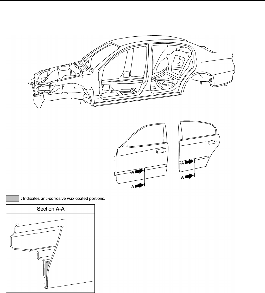
BL-170
BODY REPAIR
Revision; 2004 April 2002 Q45
ANTI-CORROSIVE WAX
To improve corrosion resistance, anti-corrosive wax is applied inside the body sill and inside other closed sec-
tions. Accordingly, when replacing these parts, be sure to apply anti-corrosive wax to the appropriate areas of
the new parts. Select an excellent anti-corrosive wax which will penetrate after application and has a long shelf
life.
PIIA0096E
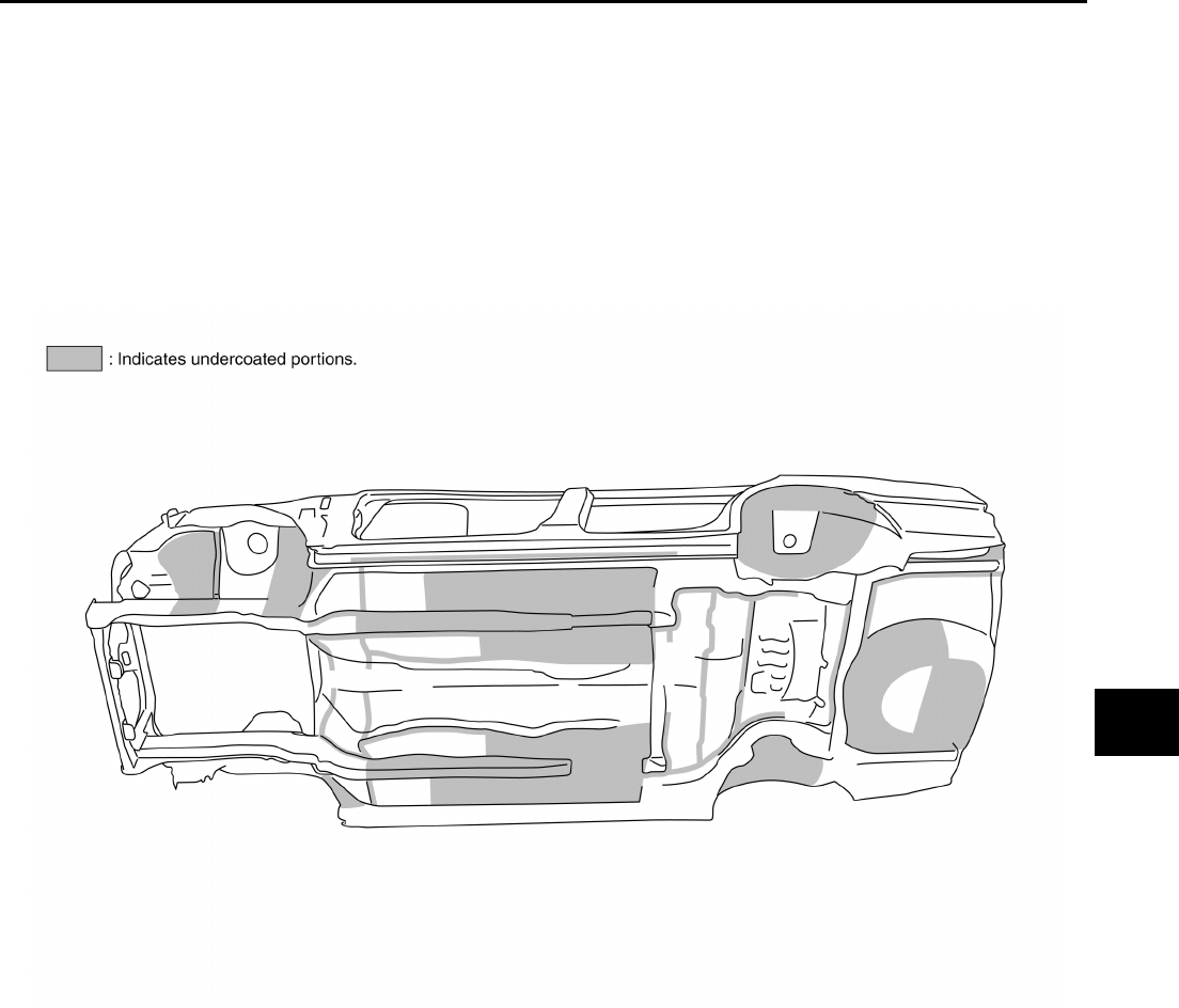
BODY REPAIR
BL-171
C
D
E
F
G
H
J
K
L
M
A
B
BL
Revision; 2004 April 2002 Q45
UNDERCOATING
The underside of the floor and wheelhouse are undercoated to prevent rust, vibration, noise and stone chip-
ping. Therefore, when such a panel is replaced or repaired, apply undercoating to that part. Use an undercoat-
ing which is rust preventive, soundproof, vibration-proof, shock-resistant, adhesive, and durable.
Precautions in undercoating
1. Do not apply undercoating to any place unless specified (such as the areas above the muffler and three
way catalyst which are subjected to heat).
2. Do not undercoat the exhaust pipe or other parts which become hot.
3. Do not undercoat rotating parts.
4. Apply bitumen wax after applying undercoating.
PIIA0097E
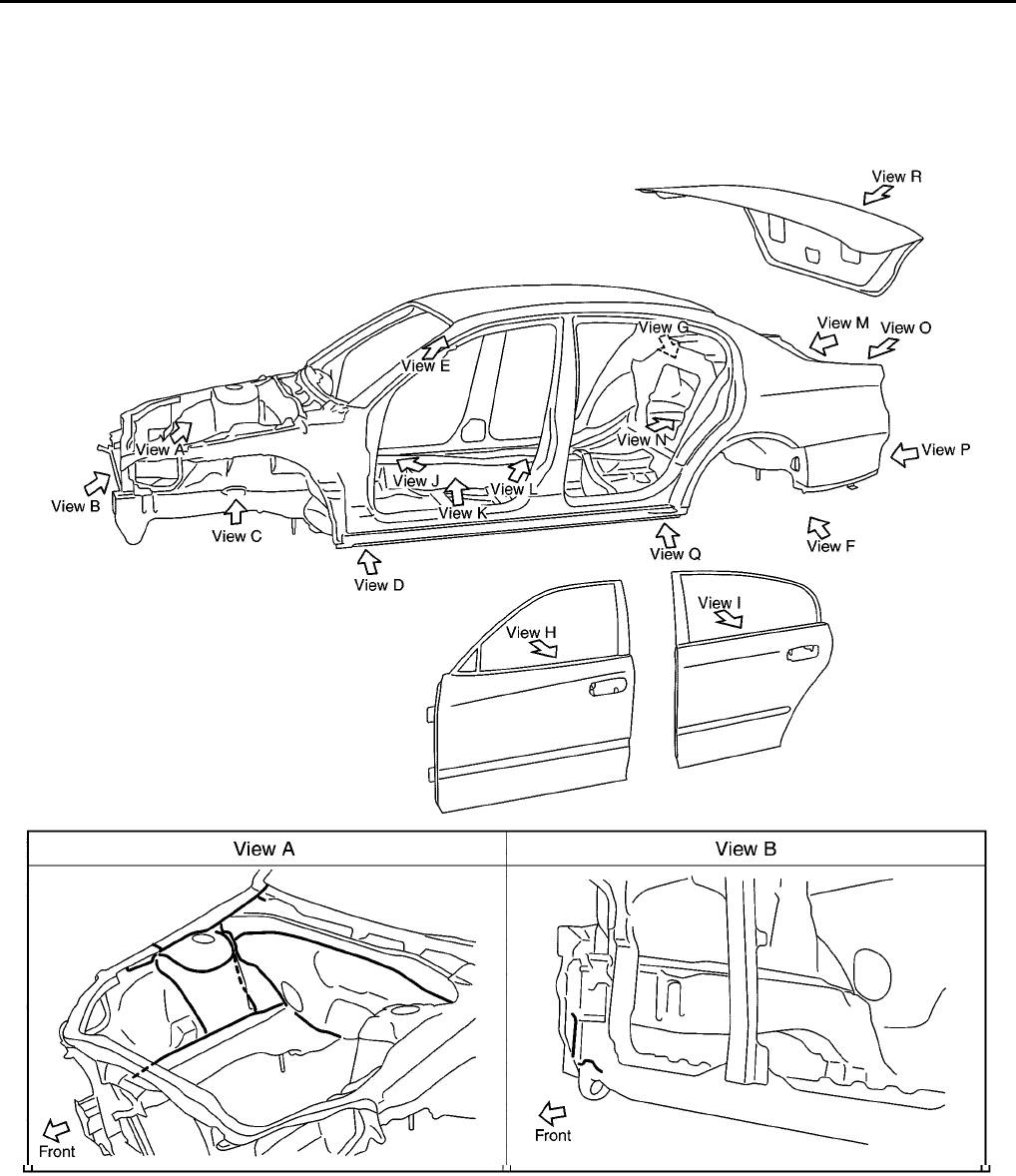
BL-172
BODY REPAIR
Revision; 2004 April 2002 Q45
Body Sealing
EIS000K5
DESCRIPTION
The following figure shows the areas which are sealed at the factory. Sealant which has been applied to these
areas should be smooth and free from cuts or gaps. Care should be taken not to apply an excess amount of
sealant and not to allow other unaffected parts to come into contact with the sealant.
PIIA0098E
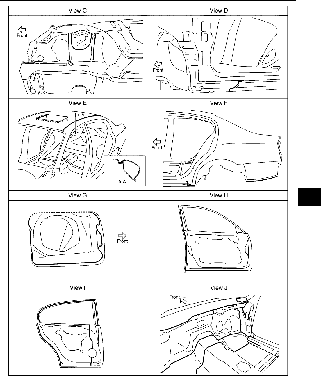
BODY REPAIR
BL-173
C
D
E
F
G
H
J
K
L
M
A
B
BL
Revision; 2004 April 2002 Q45
PIIA0099E
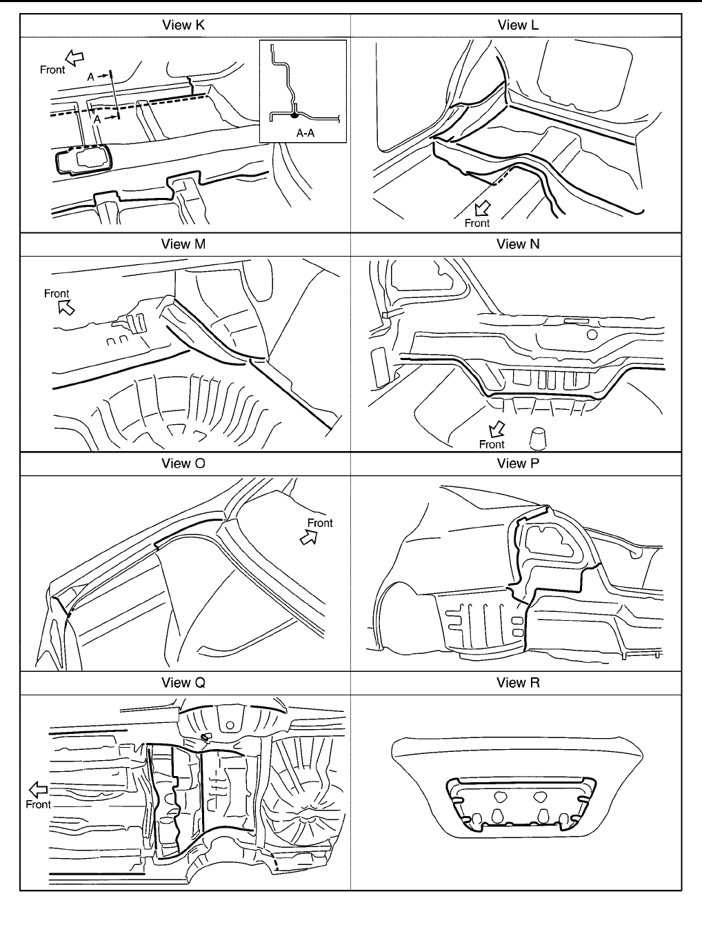
BL-174
BODY REPAIR
Revision; 2004 April 2002 Q45
PIIA0100E
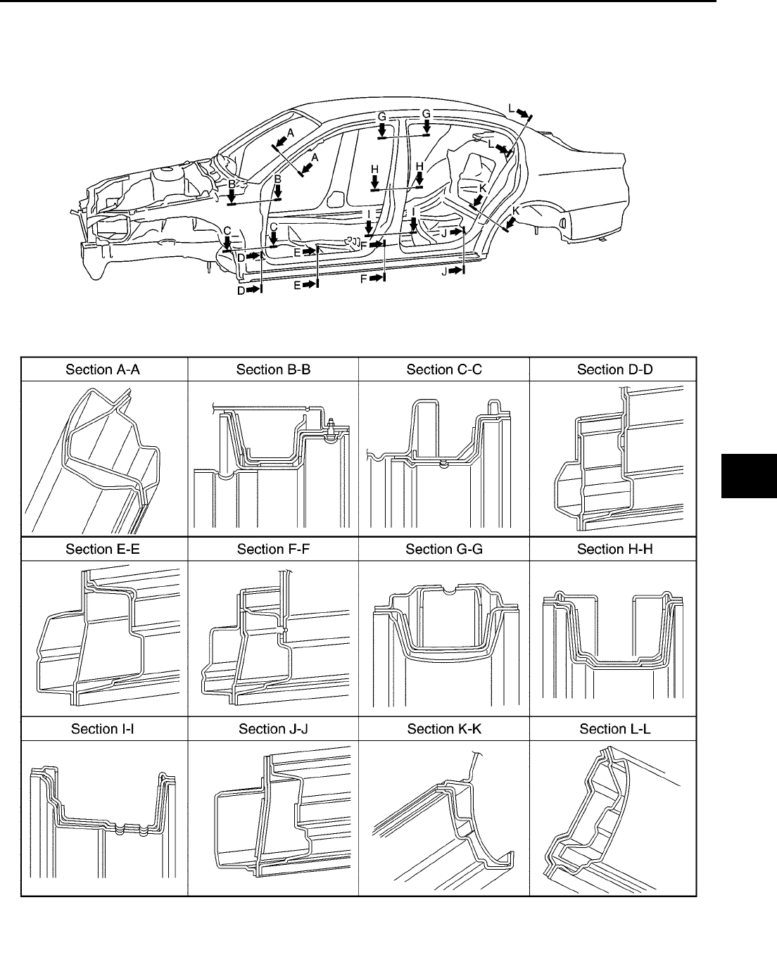
BODY REPAIR
BL-175
C
D
E
F
G
H
J
K
L
M
A
B
BL
Revision; 2004 April 2002 Q45
Body Construction
EIS000K6
BODY CONSTRUCTION
PIIA0101E
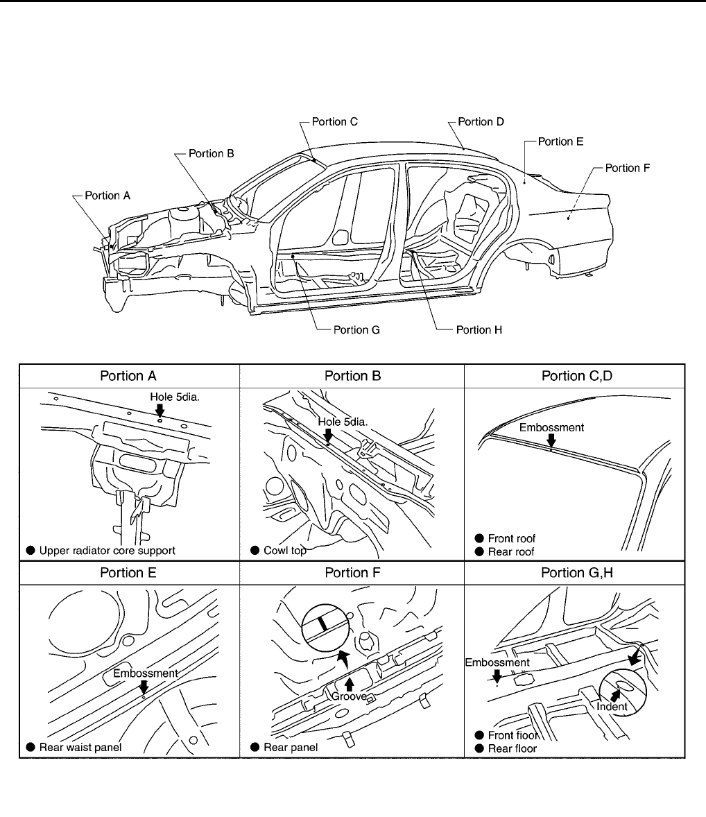
BL-176
BODY REPAIR
Revision; 2004 April 2002 Q45
Body Alignment
EIS000K7
BODY CENTER MARKS
A mark has been placed on each part of the body to indicate the vehicle center. When repairing parts dam-
aged by an accident which might affect the vehicle frame (members, pillars, etc.), more accurate and effective
repair will be possible by using these marks together with body alignment specifications.
PIIA0102E
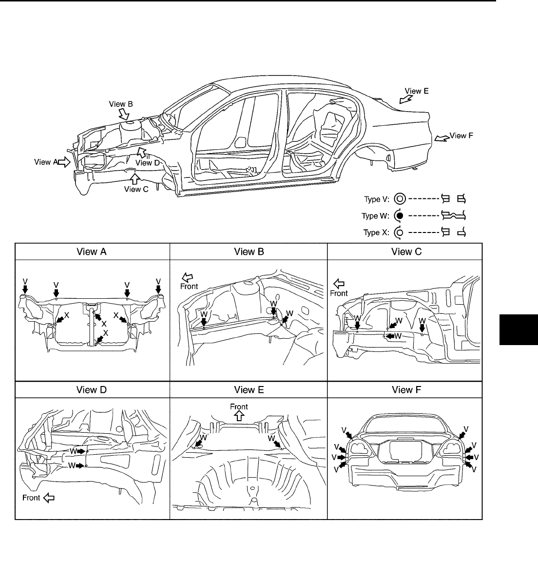
BODY REPAIR
BL-177
C
D
E
F
G
H
J
K
L
M
A
B
BL
Revision; 2004 April 2002 Q45
PANEL PARTS MATCHING MARKS
A mark has been placed on each body panel to indicate the parts matching positions. When repairing parts
damaged by an accident which might affect the vehicle structure (members, pillars, etc.), more accurate and
effective repair will be possible by using these marks together with body alignment specifications.
PIIA0103E
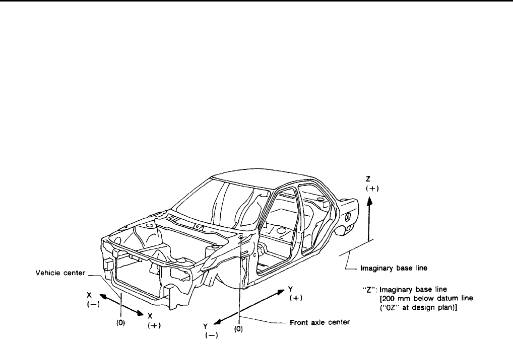
BL-178
BODY REPAIR
Revision; 2004 April 2002 Q45
DESCRIPTION
●All dimensions indicated in the figures are actual.
●When using a tracking gauge, adjust both pointers to equal length. Then check the pointers and gauge
itself to make sure there is no free play.
●When a measuring tape is used, check to be sure there is no elongation, twisting or bending.
●Measurements should be taken at the center of the mounting holes.
●An asterisk (*) following the value at the measuring point indicates that the measuring point on the other
side is symmetrically the same value.
●The coordinates of the measurement points are the distances measured from the standard line of "X", "Y"
and "Z".
PIIA0104E
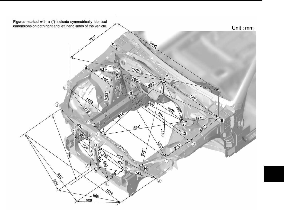
BODY REPAIR
BL-179
C
D
E
F
G
H
J
K
L
M
A
B
BL
Revision; 2004 April 2002 Q45
ENGINE COMPARTMENT
Measurement
PIIA0105E
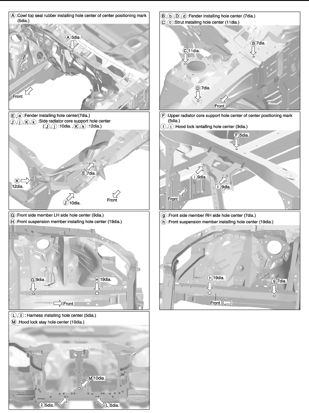
BL-180
BODY REPAIR
Revision; 2004 April 2002 Q45
Measurement Points
PIIA0106E
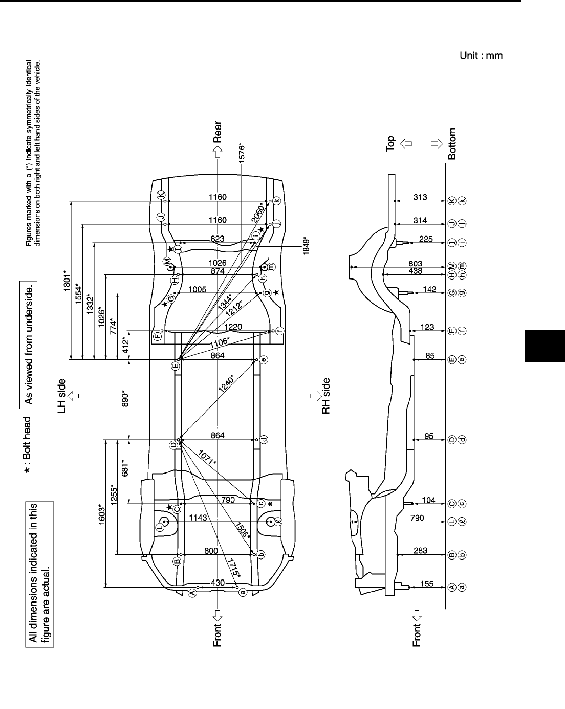
BODY REPAIR
BL-181
C
D
E
F
G
H
J
K
L
M
A
B
BL
Revision; 2004 April 2002 Q45
UNDERBODY
Measurement
PIIA0107E
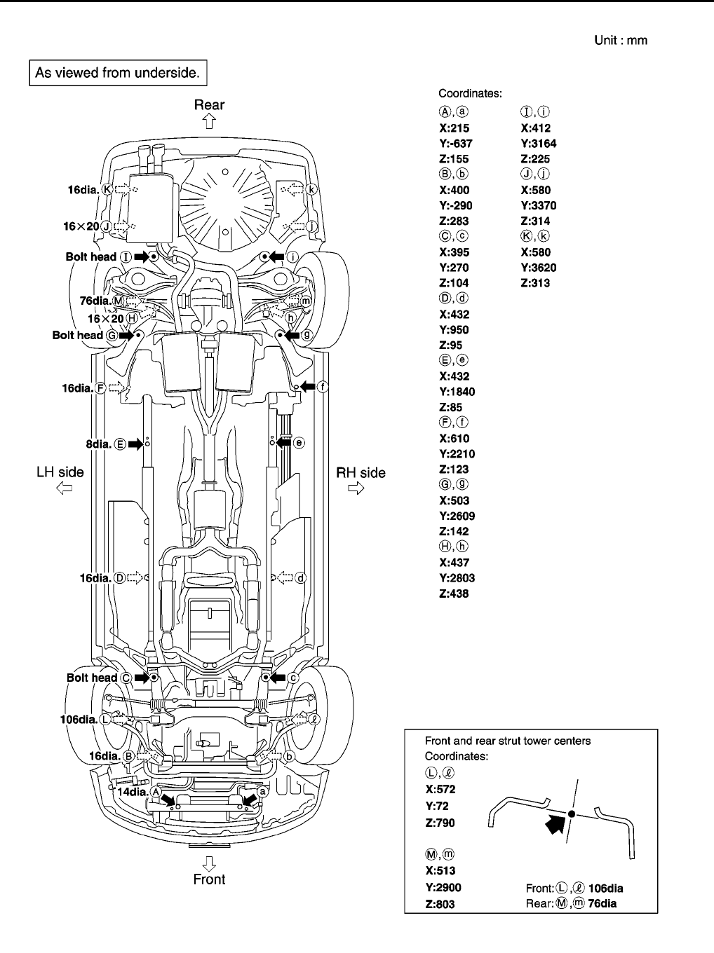
BL-182
BODY REPAIR
Revision; 2004 April 2002 Q45
Measurement Points
PIIA0108E
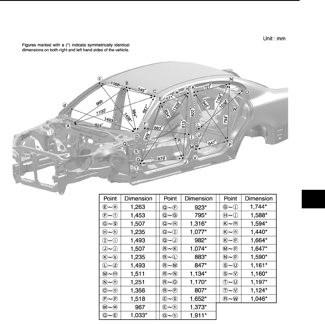
BODY REPAIR
BL-183
C
D
E
F
G
H
J
K
L
M
A
B
BL
Revision; 2004 April 2002 Q45
PASSENGER COMPARTMENT
Measurement
PIIA0109E
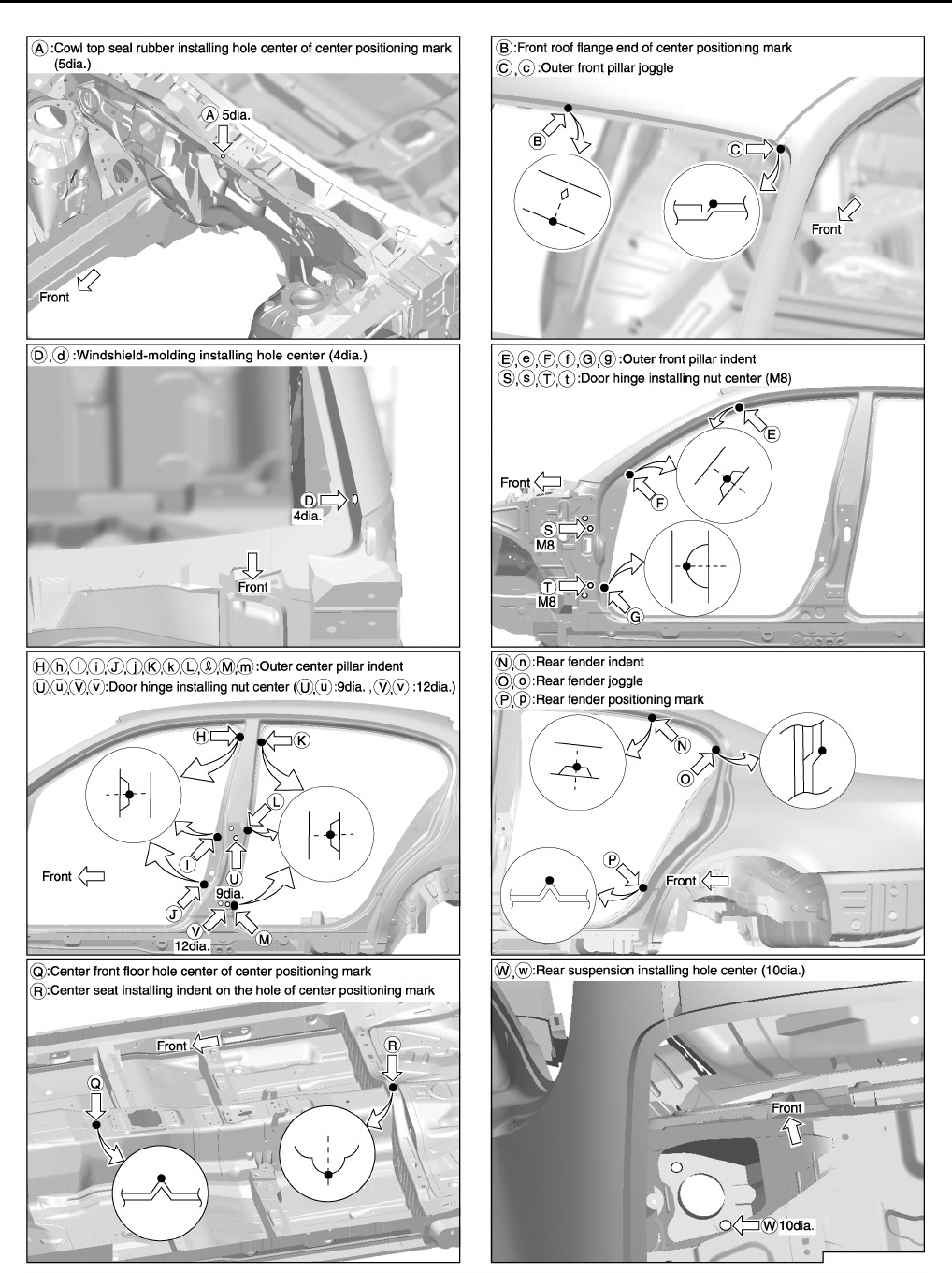
BL-184
BODY REPAIR
Revision; 2004 April 2002 Q45
Measurement Points
PIIA0110E
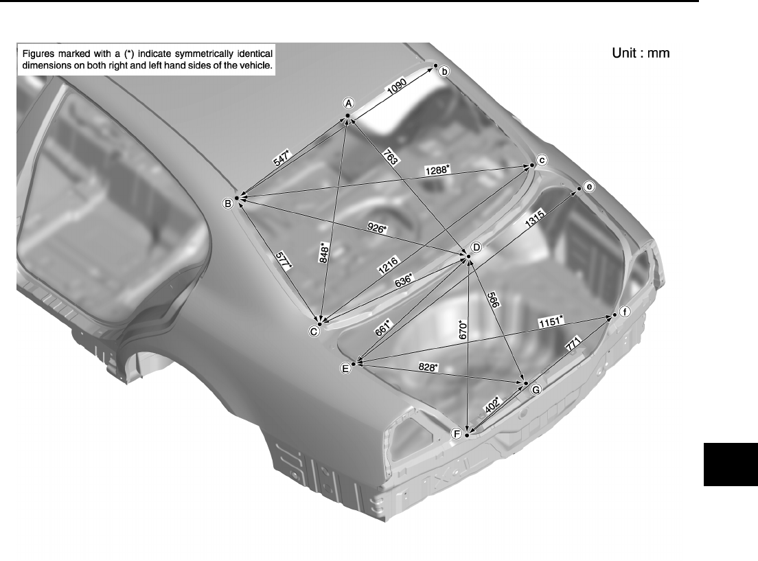
BODY REPAIR
BL-185
C
D
E
F
G
H
J
K
L
M
A
B
BL
Revision; 2004 April 2002 Q45
REAR BODY
Measurement
PIIA0111E
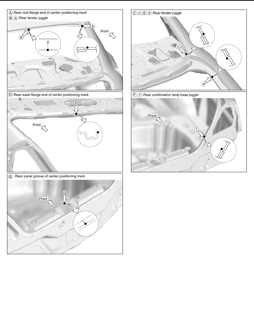
BL-186
BODY REPAIR
Revision; 2004 April 2002 Q45
Measurement Points
PIIA0112E

BODY REPAIR
BL-187
C
D
E
F
G
H
J
K
L
M
A
B
BL
Revision; 2004 April 2002 Q45
Handling Precautions for Plastics
EIS000K8
HANDLING PRECAUTIONS FOR PLASTICS
1. When repairing and painting a portion of the body adjacent to plastic parts, consider their characteristics
(influence of heat and solvent) and remove them if necessary or take suitable measures to protect them.
2. Plastic parts should be repaired and painted using methods suiting the materials,characteristics.
Abbre-
viation Material name
Heat
resisting
temperature
°C(°F)
Resistance to gasoline and
solvents Other cautions
PE Polyethylene 60(140)
Gasoline and most solvents are
harmless if applied for a very
short time (wipe up quickly). Flammable
PVC Polyvinyl Chloride 80(176) Same as above. Poison gas is emitted
when burned.
EPM/
EPDM
Ethylene Propylene (Diene)
rubber 80(176) Same as above. Flammable
TPO/
TPR
Thermoplastic Olefine/
Thermoplastic Rubber 80(176) Same as above. Flammable
PP Polypropylene 90(194) Same as above. Flammable, avoid
battery acid.
UP Polyester thermoset 90(194) Same as above. Flammable
PS Polystyrene 80(176) Avoid solvents. Flammable
ABS Acrylonitrile Butadiene Styrene
resin 80(176) Avoid gasoline and solvents.
AES Acrylonitrile Ethylene Styrene 80(176) Same as above.
PMMA Polymethyl Methacrylate 85(185) Same as above.
AAS Acrylonitrile Acrylic Styrene 85(185) Same as above.
AS Acrylonitrile Styrene 85(185) Same as above.
EVA Polyvinyl Ethyl Acetate 90(194) Same as above.
ASA Acrylonitrile Styrene Acrylate 100(222) Same as above. Flammable
PPO/
PPE Polyphenylene Oxide/
Polyphenylene Ether 110(230) Same as above.
PC Polycarbonate 120(248) Same as above.
PAR Polyacrylate 180(356) Same as above.
L-
LDPE Lenear Low Density PE 45(100) Gasoline and most solvents are
harmless. Flammable
PUR Polyurethane 90(194) Same as above.
TPU Thermoplastic Urethane 110(230) Same as above.
PPC Polypropylene Composite 115(239) Same as above. Flammable
POM Polyacetal 120(248) Same as above. Avoid battery acid.
PBT+P
C
Polybutylene
Terephthalate+Polycarbonate 120(248) Same as above. Flammable
PA Polyamide (Nylon) 140(284) Same as above. Avoid immersing in
water.
PBT Polybutylene Terephthalate 140(284) Same as above.
FRP Fiber Reinforced Plastics 170(338) Same as above. Avoid battery acid.
PET Polyethylene Terephthalate 180(356) Same as above.
PEI Polyetherimide 200(392) Same as above.
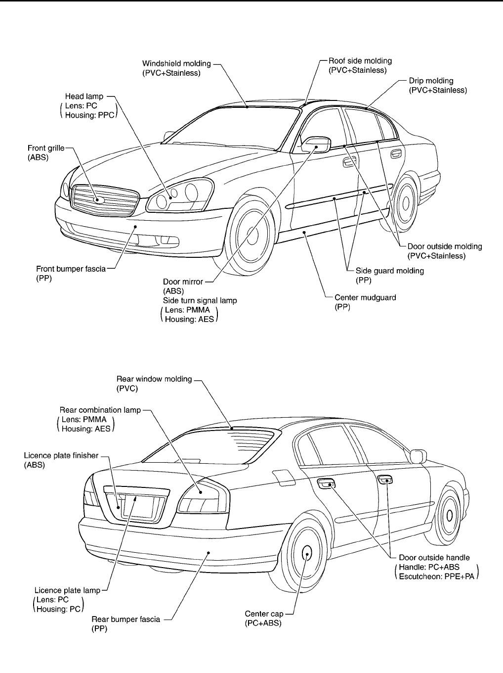
BL-188
BODY REPAIR
Revision; 2004 April 2002 Q45
LOCATION OF PLASTIC PARTS
PIIA0113E
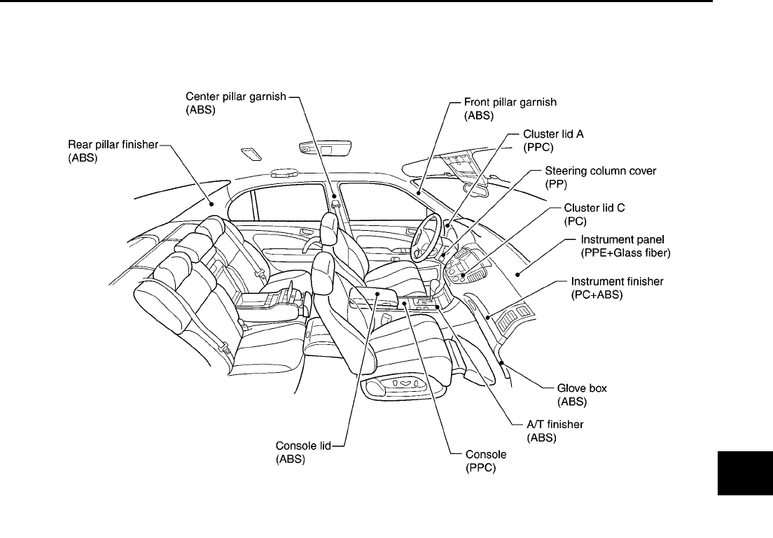
BODY REPAIR
BL-189
C
D
E
F
G
H
J
K
L
M
A
B
BL
Revision; 2004 April 2002 Q45
PIIA0114E

BL-190
BODY REPAIR
Revision; 2004 April 2002 Q45
Precautions in Repairing High Strength Steel
EIS000K9
High strength steel is used for body panels in order to reduce vehicle weight.
Accordingly, precautions in repairing automotive bodies made of high strength steel are described below:
HIGH STRENGTH STEEL (HSS) USED IN NISSAN VEHICLES
SP130 is the most commonly used HSS.
SP150 HSS is used only on parts that require much more strength.
Tensile strength Nissan/Infinity designation Major applicable parts
373 N/mm2
(38kg/mm2,54klb/sq in) SP130
●Front side member assembly
●Upper hoodledge
●Upper pillar hinge brace assembly
●Rear side member extension
●Other reinforcements
785-981 N/mm2
(80-100kg/mm2
114-142klb/sq in)
SP150 ●Front bumper reinforcement
●Rear bumper reinforcement
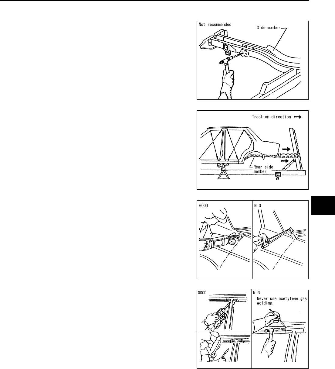
BODY REPAIR
BL-191
C
D
E
F
G
H
J
K
L
M
A
B
BL
Revision; 2004 April 2002 Q45
Read the following precautions when repairing HSS:
1. Additional points to consider
●The repair of reinforcements (such as side members) by heat-
ing is not recommended since it may weaken the component.
When heating is unavoidable, do not heat HSS parts above
550°C (1,022°F).
Verify heating temperature with a thermometer.
(Crayon-type and other similar type thermometer are appro-
priate.)
●When straightening body panels, use caution in pulling any
HSS panel. Because HSS is very strong, pulling may cause
deformation in adjacent portions of the body. In this case,
increase the number of measuring points, and carefully pull
the HSS panel.
●When cutting HSS panels, avoid gas (torch) cutting if possi-
ble. Instead, use a saw to avoid weakening surrounding areas
due to heat. If gas (torch) cutting is unavoidable, allow a mini-
mum margin of 50 mm (1.97in).
●When welding HSS panels, use spot welding whenever possi-
ble in order to minimize weakening surrounding areas due to
heat.
If spot welding is impossible, use M.I.G. welding. Do not use
gas (torch) welding because it is inferior in welding strength.
PIIA0115E
PIIA0116E
PIIA0117E
PIIA0144E
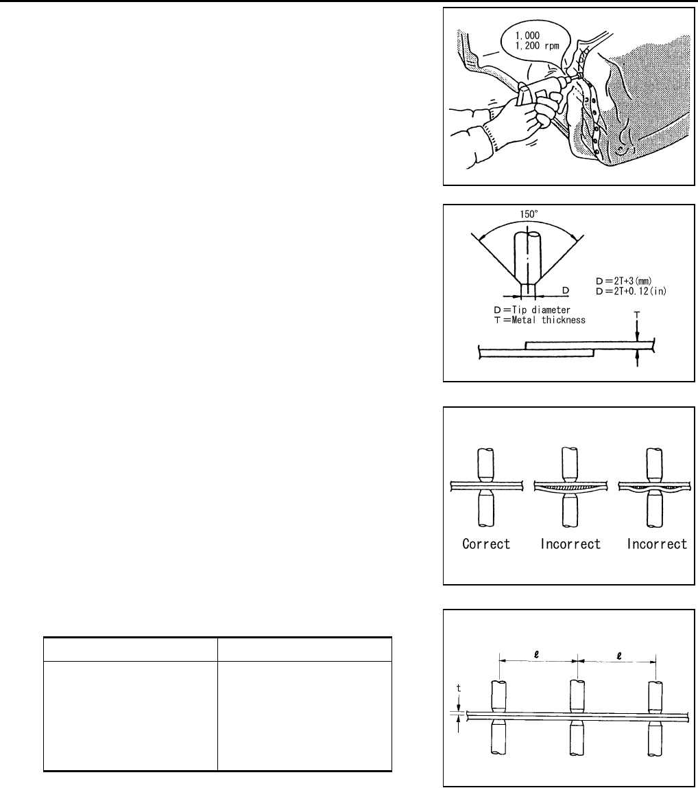
BL-192
BODY REPAIR
Revision; 2004 April 2002 Q45
●The spot weld on HSS panels is harder than that of an ordi-
nary steel panel.
Therefore, when cutting spot welds on a HSS panel, use a
low speed high torque drill (1,000 to 1,200 rpm) to increase
drill bit durability and facilitate the operation.
●SP150 HSS panels with a tensile strength of 785 to 981 N/
mm2(80to100kg/mm
2, 114 to 142 klb/sq in), used as rein-
forcement in the door guard beams, is too strong to repair.
When these HSS parts are damaged, the outer panels also
sustain substantial damage; therefore, the assembly parts
must be replaced.
2. Precautions in spot welding HSS
This work should be performed under standard working condi-
tions. Always note the following when spot welding HSS:
●The electrode tip diameter must be sized properly according
to the metal thickness.
●The panel surfaces must fit flush to each other, leaving no
gaps.
●Follow the specifications for the proper welding pitch. Unit:mm
PIIA0145E
PIIA0146E
PIIA0147E
Thickness (t) Minimum pitch (l)
0.6 (0.024)
0.8 (0.031)
1.0 (0.039)
1.2 (0.047)
1.6 (0.063)
1.8 (0.071)
10 (0.39) or over
12 (0.47) or over
18 (0.71) or over
20 (0.79) or over
27 (1.06) or over
31 (1.22) or over
PIIA0148E

BODY REPAIR
BL-193
C
D
E
F
G
H
J
K
L
M
A
B
BL
Revision; 2004 April 2002 Q45
Replacement Operations
EIS00A5Z
DESCRIPTION
This section is prepared for technicians who have attained a high level of skill and experience in repairing col-
lision-damaged vehicles and also use modern service tools and equipment. Persons unfamiliar with body
repair techniques should not attempt to repair collision-damaged vehicles by using this section.
Technicians are also encouraged to read Body Repair Manual (Fundamentals) in order to ensure that the orig-
inal functions and quality of the vehicle can be maintained. The Body Repair Manual (Fundamentals) contains
additional information, including cautions and warning, that are not including in this manual. Technicians
should refer to both manuals to ensure proper repairs.
Please note that these information are prepared for worldwide usage, and as such, certain procedures might
not apply in some regions or countries.
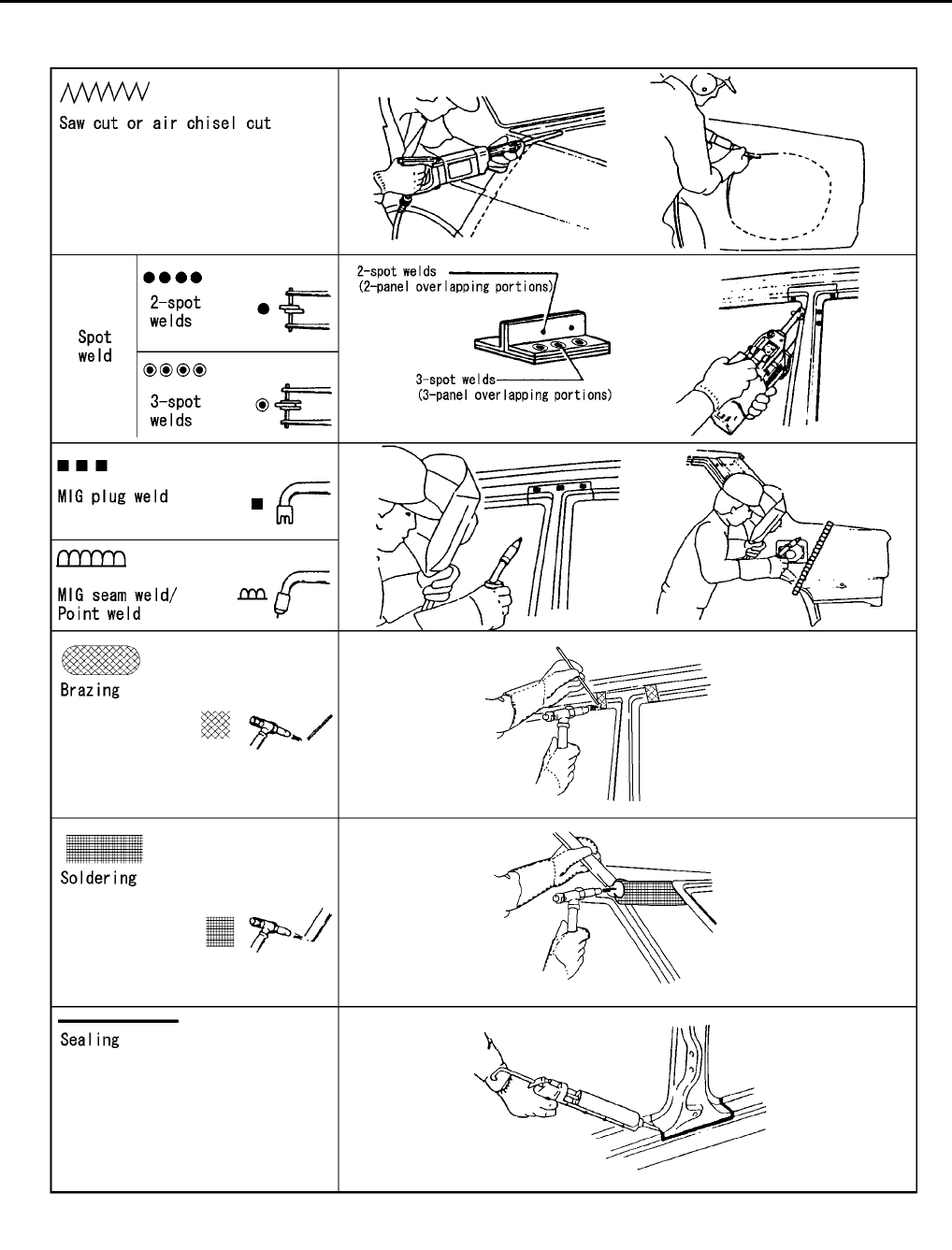
BL-194
BODY REPAIR
Revision; 2004 April 2002 Q45
The symbols used in this section for cutting and welding / brazing operations are shown below.
PIIA0149E
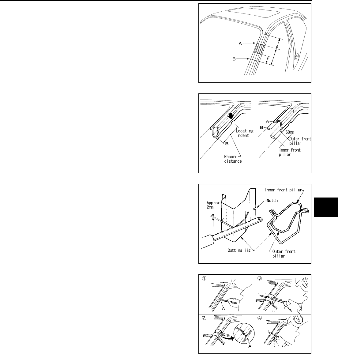
BODY REPAIR
BL-195
C
D
E
F
G
H
J
K
L
M
A
B
BL
Revision; 2004 April 2002 Q45
●Front pillar butt joint can be determined anywhere within shaded
area as shown in the figure. The best location for the butt joint is
at position A due to the construction of the vehicle. Refer to the
front pillar section.
●Determine cutting position and record distance from the locating
indent. Use this distance when cutting the service part. Cut outer
front pillar over 60 mm above inner front pillar cut position.
●Prepare a cutting jig to make outer pillar easier to cut. Also, this
will permit service part to be accurately cut at joint position.
●An example of cutting operation using a cutting jig is as follows.
1. Mark cutting lines.
A: Cut position of outer pillar
B: Cut position of inner pillar
2. Align cutting line with notch on jig. Clamp jig to pillar.
3. Cut outer pillar along groove of jig. (At position A)
4. Remove jig and cut remaining portions.
5. Cut inner pillar at position B in same manner.
PIIA0150E
PIIA0151E
PIIA0152E
PIIA0153E
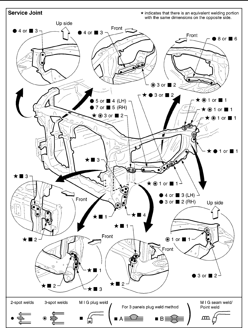
BL-196
BODY REPAIR
Revision; 2004 April 2002 Q45
RADIATOR CORE SUPPORT
SIIA2426E
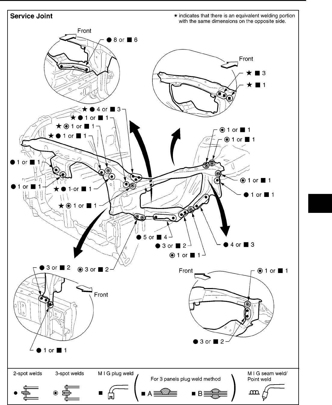
BODY REPAIR
BL-197
C
D
E
F
G
H
J
K
L
M
A
B
BL
Revision; 2004 April 2002 Q45
RADIATOR CORE SUPPORT (PARTIAL REPLACEMENT)
SIIA2427E
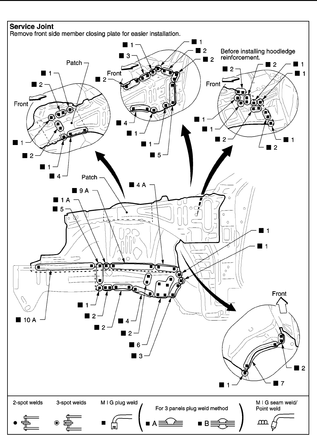
BL-198
BODY REPAIR
Revision; 2004 April 2002 Q45
HOODLEDGE
●Work after radiator core support has been removed.
PIIA0078E
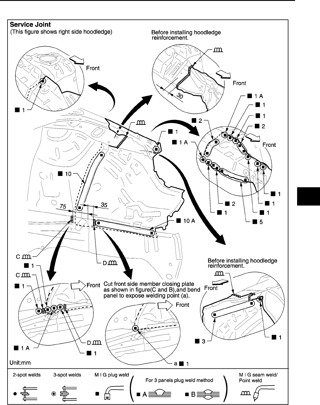
BODY REPAIR
BL-199
C
D
E
F
G
H
J
K
L
M
A
B
BL
Revision; 2004 April 2002 Q45
HOODLEDGE (PARTIAL REPLACEMENT)
●Work after radiator core support has been removed.
PIIA0079E
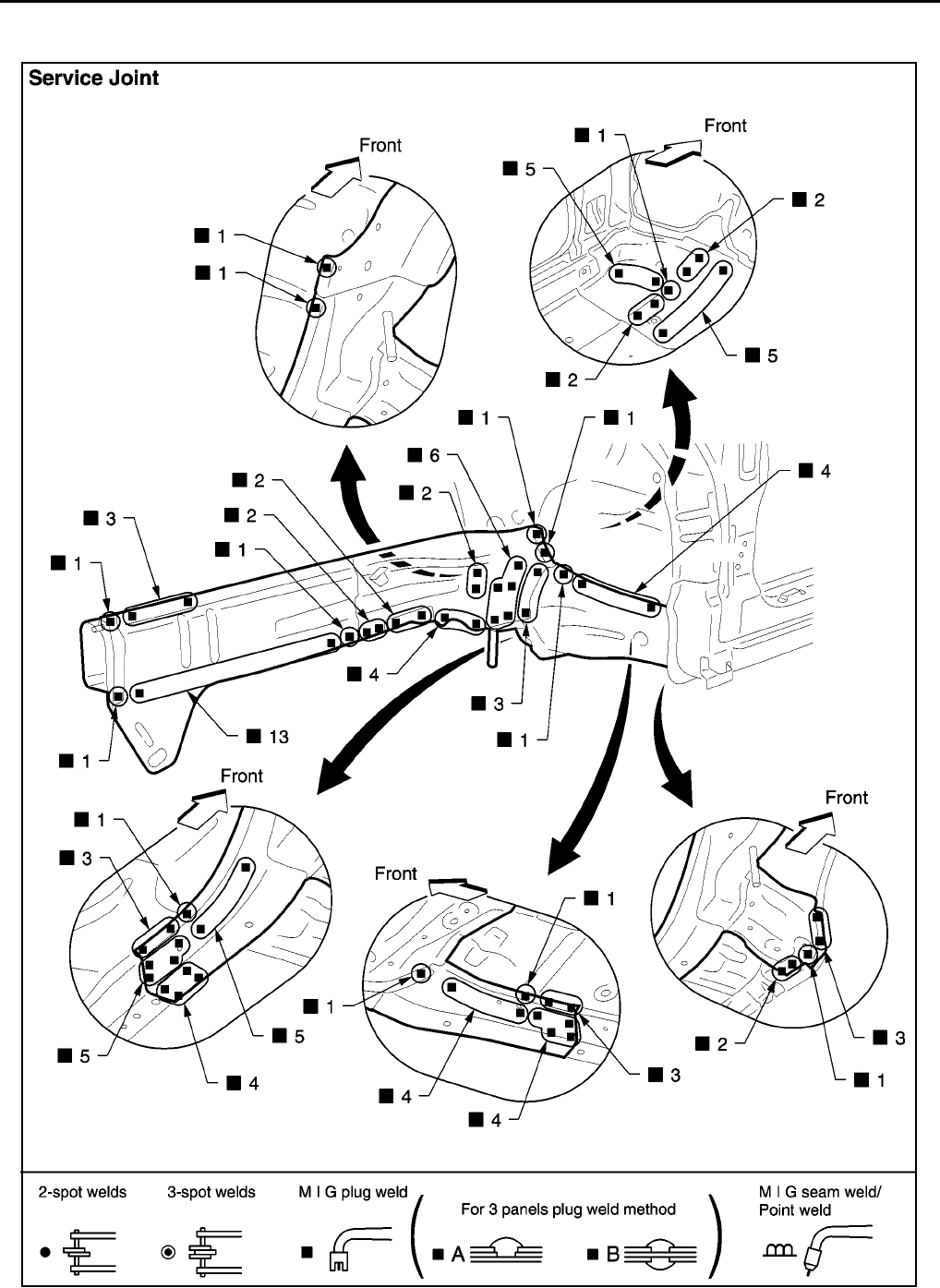
BL-200
BODY REPAIR
Revision; 2004 April 2002 Q45
FRONT SIDE MEMBER
●Work after hoodledge and radiator core support have been removed.
PIIA0080E
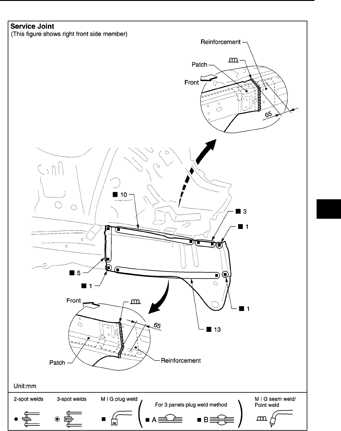
BODY REPAIR
BL-201
C
D
E
F
G
H
J
K
L
M
A
B
BL
Revision; 2004 April 2002 Q45
FRONT SIDE MEMBER (PARTIAL REPLACEMENT)
●Work after radiator core support has been removed.
PIIA0081E
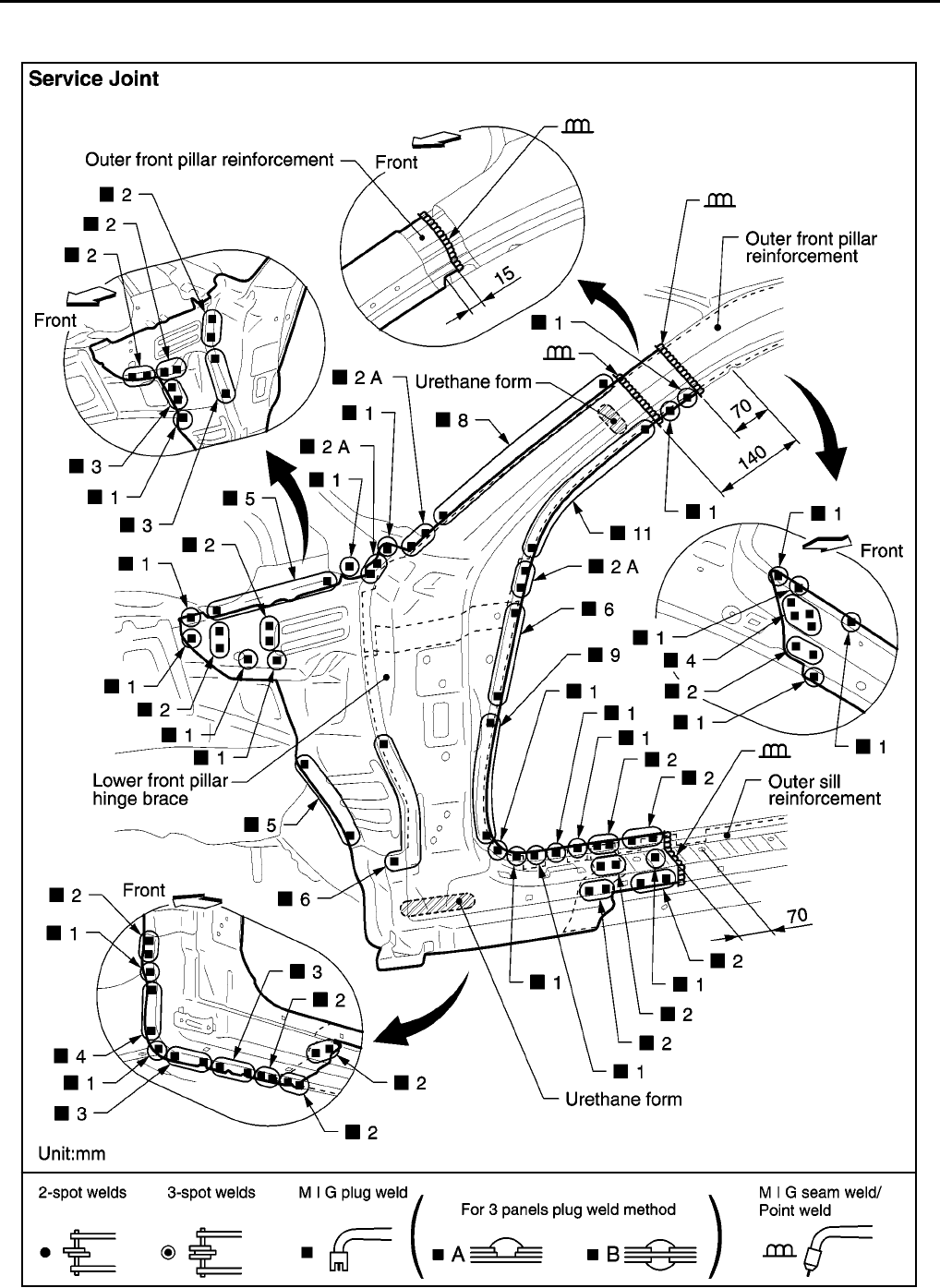
BL-202
BODY REPAIR
Revision; 2004 April 2002 Q45
FRONT PILLAR
●Work after rear hoodledge reinforcement has been removed.
PIIA0082E
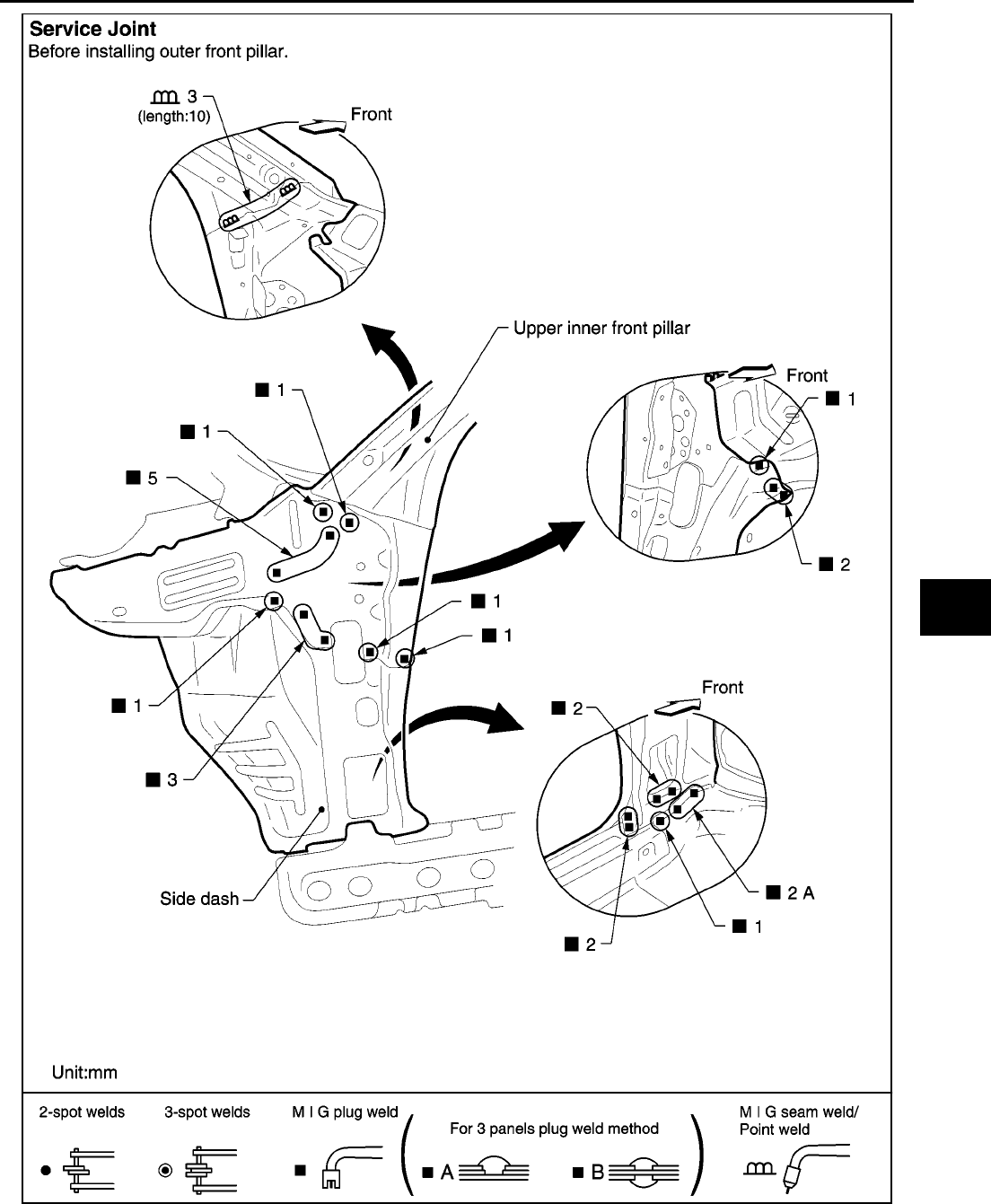
BODY REPAIR
BL-203
C
D
E
F
G
H
J
K
L
M
A
B
BL
Revision; 2004 April 2002 Q45
PIIA0083E
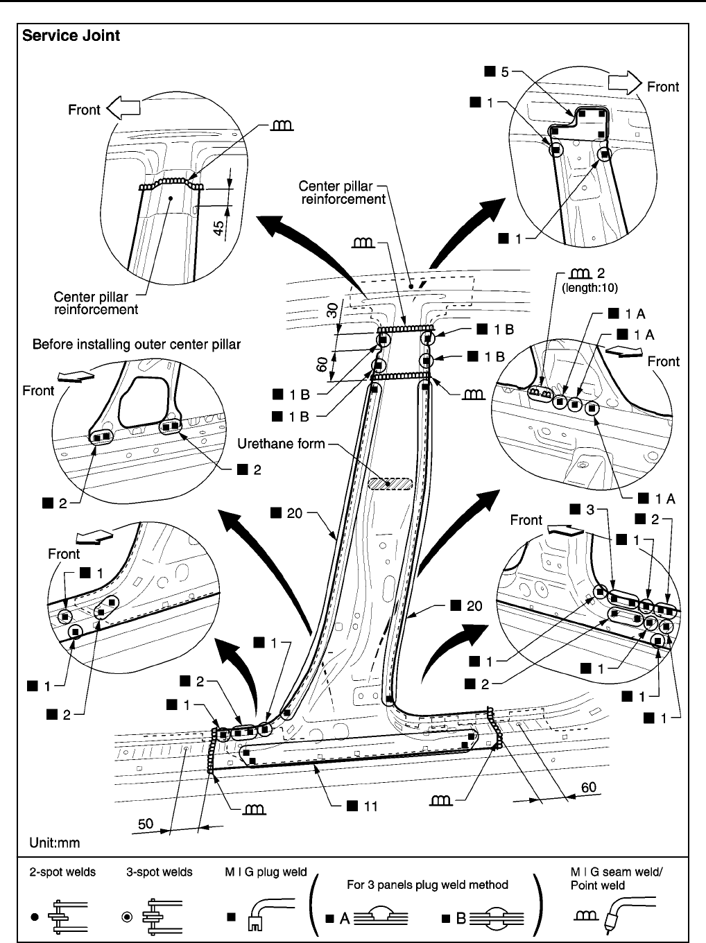
BL-204
BODY REPAIR
Revision; 2004 April 2002 Q45
CENTER PILLAR
PIIA0084E
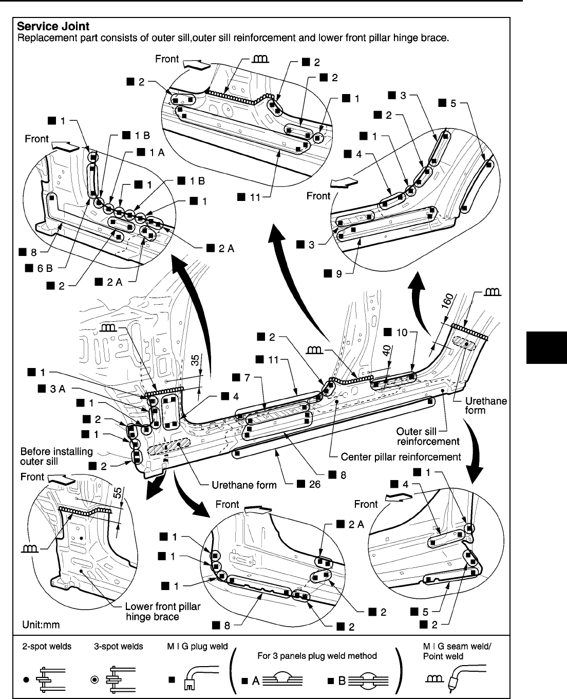
BODY REPAIR
BL-205
C
D
E
F
G
H
J
K
L
M
A
B
BL
Revision; 2004 April 2002 Q45
OUTER SILL
PIIA0085E
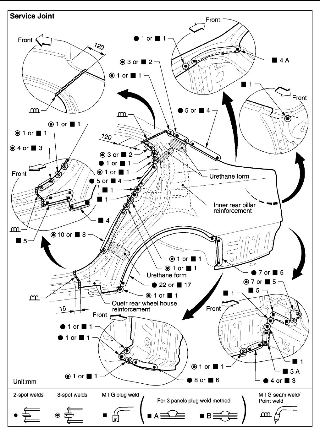
BL-206
BODY REPAIR
Revision; 2004 April 2002 Q45
REAR FENDER
PIIA0086E
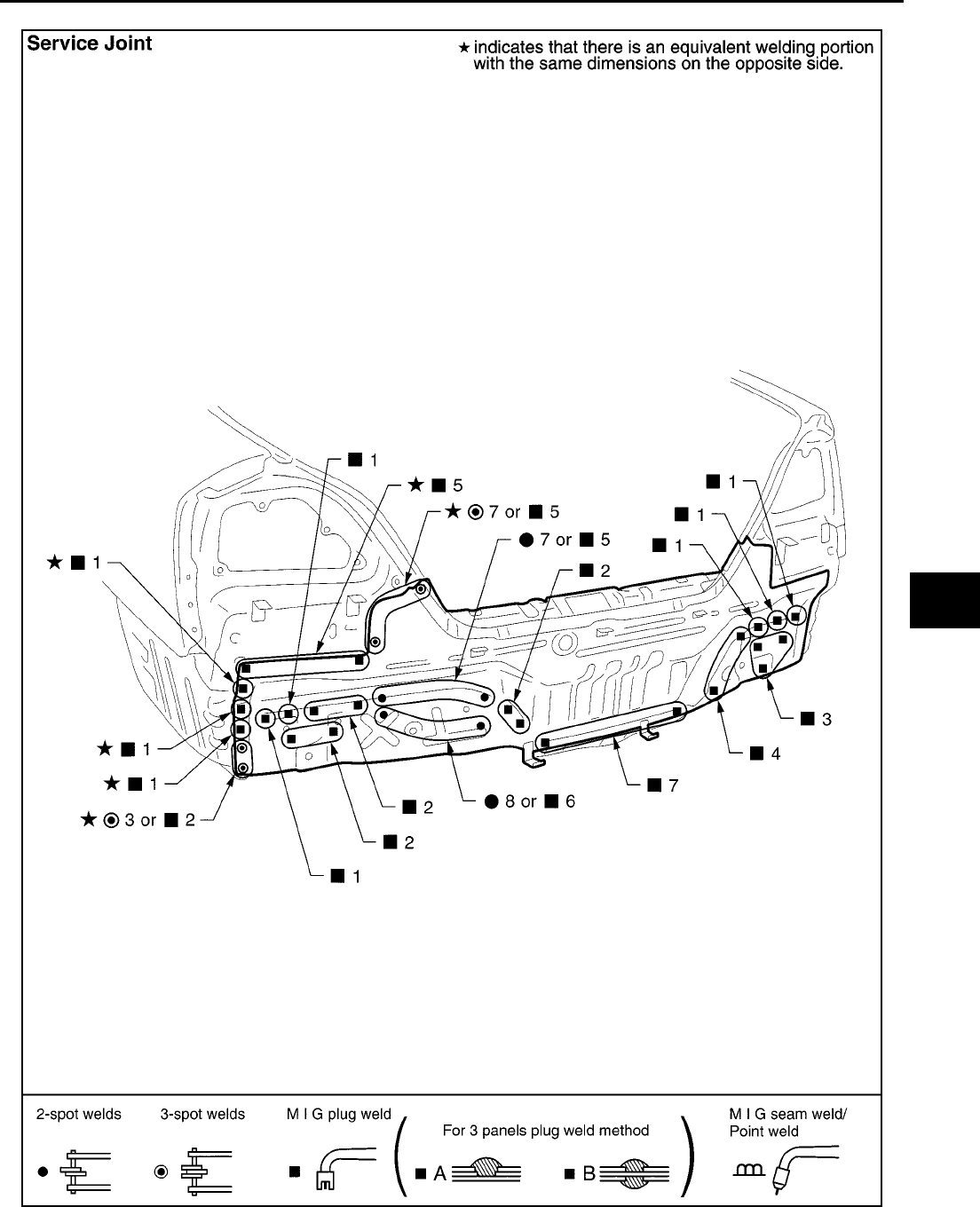
BODY REPAIR
BL-207
C
D
E
F
G
H
J
K
L
M
A
B
BL
Revision; 2004 April 2002 Q45
REAR PANEL
PIIA0087E
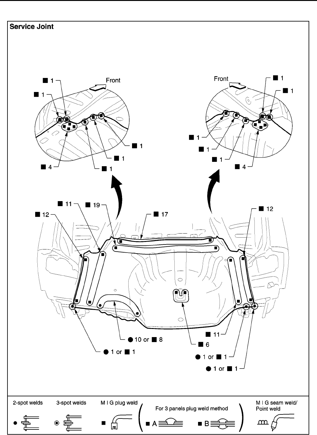
BL-208
BODY REPAIR
Revision; 2004 April 2002 Q45
REAR FLOOR REAR
●Work after rear panel has been removed.
PIIA0088E
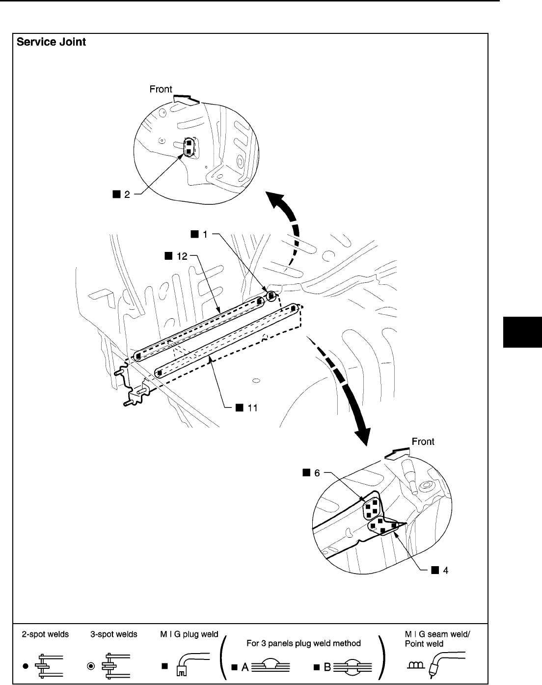
BODY REPAIR
BL-209
C
D
E
F
G
H
J
K
L
M
A
B
BL
Revision; 2004 April 2002 Q45
REAR SIDE MEMBER EXTENSION
●Work after rear panel and rear end crossmember have been removed.
PIIA0089E

BL-210
BODY REPAIR
Revision: 2004 April 2002 Q45
