BRC
User Manual: brc
Open the PDF directly: View PDF ![]() .
.
Page Count: 220 [warning: Documents this large are best viewed by clicking the View PDF Link!]
- QUICK REFERENCE INDEX
- Table of Contents
- ABS
- PRECAUTIONS
- PREPARATION
- SYSTEM DESCRIPTION
- CAN COMMUNICATION
- TROUBLE DIAGNOSIS
- TROUBLE DIAGNOSIS FOR SELF-DIAGNOSTIC ITEMS
- TROUBLE DIAGNOSES FOR SYMPTOMS
- WHEEL SENSORS
- SENSOR ROTOR
- ACTUATOR AND ELECTRIC UNIT (ASSEMBLY)
- ABLS/ABS
- PRECAUTIONS
- PREPARATION
- SYSTEM DESCRIPTION
- CAN COMMUNICATION
- TROUBLE DIAGNOSIS
- TROUBLE DIAGNOSIS FOR SELF-DIAGNOSTIC ITEMS
- Wheel Sensor System Inspection
- Engine System Inspection
- ABS/ABLS Control Unit Inspection
- Solenoid and Change-Over Valve System Inspection
- Actuator Motor, Motor Relay, and Circuit Inspection
- Stop Lamp Switch System Inspection
- ABS/ABLS Control Unit Power and Ground Systems Inspection
- Brake Fluid Level Switch System Inspection
- Pressure Sensor System Inspection
- CAN Communication System Inspection
- TROUBLE DIAGNOSES FOR SYMPTOMS
- WHEEL SENSORS
- SENSOR ROTOR
- ACTUATOR AND ELECTRIC UNIT (ASSEMBLY)
- VDC/TCS/ABS
- PRECAUTIONS
- PREPARATION
- SYSTEM DESCRIPTION
- CAN COMMUNICATION
- TROUBLE DIAGNOSIS
- TROUBLE DIAGNOSIS FOR SELF-DIAGNOSTIC ITEMS
- Wheel Sensor System Inspection
- Engine System Inspection
- ABS/TCS/VDC Control Unit Inspection
- Steering Angle Sensor System
- Yaw Rate/Side/Decel G Sensor System Inspection
- Solenoid and VDC Change-Over Valve System Inspection
- Actuator Motor, Motor Relay, and Circuit Inspection
- Stop Lamp Switch System Inspection
- ABS/TCS/VDC Control Unit Power and Ground Systems Inspection
- Brake Fluid Level Sensor System Inspection
- Pressure Sensor System Inspection
- Steering Angle Sensor Safe Mode Inspection
- CAN Communication System Inspection
- Inspection For Self-diagnosis Result "ST ANGLE SEN SIGNAL"
- Inspection For Self-diagnosis Result "DECEL G SEN SET"
- VDC OFF Indicator lamp Does Not Illuminate
- Component Inspection
- TROUBLE DIAGNOSES FOR SYMPTOMS
- ON-VEHICLE SERVICE
- WHEEL SENSORS
- SENSOR ROTOR
- ACTUATOR AND ELECTRIC UNIT (ASSEMBLY)
- STEERING ANGLE SENSOR
- G SENSOR
- HDC/HSA/VDC/TCS/ABS
- PRECAUTIONS
- PREPARATION
- SYSTEM DESCRIPTION
- CAN COMMUNICATION
- TROUBLE DIAGNOSIS
- TROUBLE DIAGNOSIS FOR SELF-DIAGNOSTIC ITEMS
- Wheel Sensor System Inspection
- Engine System Inspection
- ABS/TCS/VDC Control Unit Inspection
- Steering Angle Sensor System
- Yaw Rate/Side/Decel G Sensor System Inspection
- Solenoid and VDC Change-Over Valve System Inspection
- Actuator Motor, Motor Relay, and Circuit Inspection
- Stop Lamp Switch System Inspection
- ABS/TCS/VDC Control Unit Power and Ground Systems Inspection
- Brake Fluid Level Sensor System Inspection
- Active Booster System Inspection
- Pressure Sensor System Inspection
- Steering Angle Sensor Safe Mode Inspection
- CAN Communication System Inspection
- Inspection For Self-diagnosis Result "ST ANGLE SEN SIGNAL"
- Inspection For Self-diagnosis Result "DECEL G SEN SET"
- VDC OFF Indicator lamp Does Not Illuminate
- Component Inspection
- TROUBLE DIAGNOSES FOR SYMPTOMS
- ABS Works Frequently
- Unexpected Pedal Action
- Long Stopping Distance
- ABS Does Not Work
- Pedal Vibration or ABS Operation Noise
- ABS Warning Lamp Does Not Come On When Ignition Switch Is Turned On
- ABS Warning Lamp Stays On When Ignition Switch Is Turned On
- Vehicle Jerks During TCS/VDC Activation
- Stop Lamp Relay Inspection
- HDC Switch Inspection
- ON-VEHICLE SERVICE
- WHEEL SENSORS
- SENSOR ROTOR
- ACTUATOR AND ELECTRIC UNIT (ASSEMBLY)
- STEERING ANGLE SENSOR
- G SENSOR
- ABS
- POWER SUPPLY ROUTING CIRCUIT
- ELECTRICAL UNITS
- SUPER MULTIPLE JUNCTION (SMJ)
- FUSE BLOCK — JUNCTION BOX (J/B)
- FUSE AND FUSIBLE LINK BOX
- FUSE AND RELAY BOX

BRC-1
BRAKE CONTROL SYSTEM
F BRAKES
CONTENTS
C
D
E
G
H
I
J
K
L
M
SECTION
A
B
BRC
Revision: February 2006 2005 Xterra
ABS
PRECAUTIONS .......................................................... 5
Precautions for Supplemental Restraint System
(SRS) “AIR BAG” and “SEAT BELT PRE-TEN-
SIONER” .................................................................. 5
Precautions for Brake System .................................. 5
Precautions When Using CONSULT-II ..................... 5
CHECK POINTS FOR USING CONSULT-II ......... 5
Precautions for Brake Control .................................. 6
Precautions for CAN System ................................... 6
Wiring Diagrams and Trouble Diagnosis .................. 7
PREPARATION ........................................................... 8
Special Service Tool ................................................. 8
Commercial Service Tools ........................................ 8
SYSTEM DESCRIPTION ............................................ 9
System Components ................................................ 9
ABS Function ........................................................... 9
EBD Function ........................................................... 9
Fail-Safe Function .................................................... 9
ABS/EBD SYSTEM ............................................... 9
Hydraulic Circuit Diagram ...................................... 10
CAN COMMUNICATION ...........................................11
System Description .................................................11
TROUBLE DIAGNOSIS ............................................ 12
How to Perform Trouble Diagnoses for Quick and
Accurate Repair ..................................................... 12
INTRODUCTION ................................................. 12
WORK FLOW ...................................................... 13
CLARIFY CONCERN .......................................... 14
EXAMPLE OF DIAGNOSIS SHEET ................... 14
Component Parts and Harness Connector Location ... 15
Schematic .............................................................. 16
Wiring Diagram — ABS — ..................................... 17
Basic Inspection ..................................................... 21
BRAKE FLUID LEVEL, FLUID LEAK, AND
BRAKE PAD INSPECTION ................................. 21
POWER SYSTEM TERMINAL LOOSENESS
AND BATTERY INSPECTION ............................ 21
ABS WARNING LAMP INSPECTION ................. 21
Warning Lamp and Indicator Timing ...................... 22
Control Unit Input/Output Signal Standard ............. 22
REFERENCE VALUE FROM CONSULT-II ......... 22
CONSULT-II Function (ABS) .................................. 24
CONSULT-II BASIC OPERATION PROCEDURE
... 24
SELF-DIAGNOSIS .............................................. 25
DATA MONITOR ................................................. 27
ACTIVE TEST ..................................................... 28
TROUBLE DIAGNOSIS FOR SELF-DIAGNOSTIC
ITEMS ........................................................................ 30
Wheel Sensor System ............................................ 30
ABS Control Unit Inspection ................................... 31
Solenoid Valve System Inspection ......................... 32
Actuator Motor, Motor Relay, and Circuit Inspection ... 33
ABS Control Unit Power and Ground Systems
Inspection ............................................................... 34
CAN Communication System Inspection ................ 34
TROUBLE DIAGNOSES FOR SYMPTOMS ............ 35
ABS Works Frequently ........................................... 35
Unexpected Pedal Action ....................................... 36
Long Stopping Distance .......................................... 37
ABS Does Not Work ............................................... 37
Pedal Vibration or ABS Operation Noise ................ 37
ABS Warning Lamp Does Not Come On When Igni-
tion Switch Is Turned On ........................................ 38
ABS Warning Lamp Stays On When Ignition Switch
Is Turned On ........................................................... 38
WHEEL SENSORS ................................................... 39
Removal and Installation ........................................ 39
REMOVAL ........................................................... 39
INSTALLATION ................................................... 39
SENSOR ROTOR ..................................................... 40
Removal and Installation ........................................ 40
FRONT ................................................................ 40
REAR (C200) ...................................................... 40
REAR (M226) ...................................................... 40
ACTUATOR AND ELECTRIC UNIT (ASSEMBLY) ... 41
Removal and Installation ........................................ 41
REMOVAL ........................................................... 41
INSTALLATION ................................................... 42

BRC-2
Revision: February 2006 2005 Xterra
ABLS/ABS
PRECAUTIONS ......................................................... 43
Precautions for Supplemental Restraint System
(SRS) “AIR BAG” and “SEAT BELT PRE-TEN-
SIONER” ................................................................. 43
Precautions for Brake System ................................ 43
Precautions When Using CONSULT-II ................... 43
CHECK POINTS FOR USING CONSULT-II ........ 43
Precautions for Brake Control ................................ 44
Precautions for CAN System .................................. 44
Wiring Diagrams and Trouble Diagnosis ................ 45
PREPARATION .........................................................46
Special Service Tool ............................................... 46
Commercial Service Tools ...................................... 46
SYSTEM DESCRIPTION .......................................... 47
System Components .............................................. 47
ABS Function .......................................................... 48
EBD Function .........................................................48
ABLS Function ........................................................ 48
Fail-Safe Function ..................................................48
ABS/EBD SYSTEM ............................................. 48
ABLS SYSTEM .................................................... 48
Hydraulic Circuit Diagram ....................................... 49
CAN COMMUNICATION ...........................................50
System Description ................................................. 50
TROUBLE DIAGNOSIS ............................................51
How to Perform Trouble Diagnoses for Quick and
Accurate Repair ...................................................... 51
INTRODUCTION ................................................. 51
WORK FLOW ...................................................... 52
CLARIFY CONCERN .......................................... 53
EXAMPLE OF DIAGNOSIS SHEET .................... 53
Component Parts and Harness Connector Location ... 54
Schematic ............................................................... 55
Wiring Diagram — ABLS — ................................... 56
Basic Inspection ..................................................... 60
BRAKE FLUID LEVEL, FLUID LEAK, AND
BRAKE PAD INSPECTION ................................. 60
POWER SYSTEM TERMINAL LOOSENESS
AND BATTERY INSPECTION ............................. 60
ABS WARNING LAMP AND SLIP INDICATOR
LAMP INSPECTION ............................................ 60
Warning Lamp and Indicator Timing ....................... 61
Control Unit Input/Output Signal Standard .............. 61
REFERENCE VALUE FROM CONSULT-II ......... 61
CONSULT-II Function (ABS) .................................. 64
CONSULT-II BASIC OPERATION PROCEDURE
... 64
SELF-DIAGNOSIS .............................................. 65
DATA MONITOR .................................................. 68
ACTIVE TEST ..................................................... 70
TROUBLE DIAGNOSIS FOR SELF-DIAGNOSTIC
ITEMS ........................................................................72
Wheel Sensor System Inspection ........................... 72
Engine System Inspection ...................................... 73
ABS/ABLS Control Unit Inspection ......................... 74
Solenoid and Change-Over Valve System Inspec-
tion .......................................................................... 74
Actuator Motor, Motor Relay, and Circuit Inspection ...75
Stop Lamp Switch System Inspection .....................76
ABS/ABLS Control Unit Power and Ground Sys-
tems Inspection .......................................................77
Brake Fluid Level Switch System Inspection ..........78
Pressure Sensor System Inspection .......................78
CAN Communication System Inspection ................80
TROUBLE DIAGNOSES FOR SYMPTOMS .............81
ABS Works Frequently ............................................81
Unexpected Pedal Action ........................................82
Long Stopping Distance ..........................................83
ABS Does Not Work ...............................................83
Pedal Vibration or ABS Operation Noise ................83
ABS Warning Lamp Does Not Come On When Igni-
tion Switch Is Turned On .........................................84
ABS Warning Lamp Stays On When Ignition Switch
Is Turned On ...........................................................84
WHEEL SENSORS ...................................................85
Removal and Installation .........................................85
REMOVAL ............................................................85
INSTALLATION ....................................................85
SENSOR ROTOR ......................................................86
Removal and Installation .........................................86
FRONT .................................................................86
REAR (C200) .......................................................86
REAR (M226) .......................................................86
ACTUATOR AND ELECTRIC UNIT (ASSEMBLY) ...87
Removal and Installation .........................................87
REMOVAL ............................................................87
INSTALLATION ....................................................88
VDC/TCS/ABS
PRECAUTIONS .........................................................89
Precautions for Supplemental Restraint System
(SRS) “AIR BAG” and “SEAT BELT PRE-TEN-
SIONER” .................................................................89
Precautions for Brake System ................................89
Precautions When Using CONSULT-II ...................89
CHECK POINTS FOR USING CONSULT-II ........89
Precautions for Brake Control .................................90
Precautions for CAN System ..................................91
Wiring Diagrams and Trouble Diagnosis .................91
PREPARATION .........................................................92
Special Service Tool ................................................92
Commercial Service Tools ......................................92
SYSTEM DESCRIPTION ...........................................93
System Components ...............................................93
ABS Function ..........................................................94
EBD Function ..........................................................94
TCS Function ..........................................................94
VDC Function ..........................................................94
Fail-Safe Function ...................................................94
ABS/EBD SYSTEM ..............................................95
VDC/TCS SYSTEM .............................................95
Hydraulic Circuit Diagram .......................................95
CAN COMMUNICATION ...........................................96
System Description .................................................96

BRC-3
C
D
E
G
H
I
J
K
L
M
A
B
BRC
Revision: February 2006 2005 Xterra
TROUBLE DIAGNOSIS ............................................ 97
How to Perform Trouble Diagnoses for Quick and
Accurate Repair ..................................................... 97
INTRODUCTION ................................................. 97
WORK FLOW ...................................................... 98
CLARIFY CONCERN .......................................... 99
EXAMPLE OF DIAGNOSIS SHEET ................... 99
Component Parts and Harness Connector Location . 100
Schematic ............................................................ 101
Wiring Diagram — VDC — ................................... 102
Basic Inspection ................................................... 109
BRAKE FLUID LEVEL, FLUID LEAK, AND
BRAKE PAD INSPECTION ............................... 109
POWER SYSTEM TERMINAL LOOSENESS
AND BATTERY INSPECTION .......................... 109
ABS WARNING LAMP, SLIP INDICATOR LAMP
AND VDC OFF INDICATOR LAMP INSPECTION . 109
For Fast and Accurate Diagnosis ..........................110
PRECAUTIONS FOR DIAGNOSIS ....................110
Warning Lamp and Indicator Timing ..................... 111
Control Unit Input/Output Signal Standard ............ 111
REFERENCE VALUE FROM CONSULT-II ........ 111
CONSULT-II Function (ABS) .................................114
CONSULT-II BASIC OPERATION PROCEDURE
..114
SELF-DIAGNOSIS .............................................115
DATA MONITOR ................................................118
ACTIVE TEST ................................................... 121
TROUBLE DIAGNOSIS FOR SELF-DIAGNOSTIC
ITEMS ..................................................................... 123
Wheel Sensor System Inspection ........................ 123
Engine System Inspection .................................... 124
ABS/TCS/VDC Control Unit Inspection ................ 125
Steering Angle Sensor System ............................ 125
Yaw Rate/Side/Decel G Sensor System Inspection . 127
Solenoid and VDC Change-Over Valve System
Inspection ............................................................. 129
Actuator Motor, Motor Relay, and Circuit Inspection . 130
Stop Lamp Switch System Inspection .................. 131
ABS/TCS/VDC Control Unit Power and Ground
Systems Inspection .............................................. 132
Brake Fluid Level Sensor System Inspection ....... 133
Pressure Sensor System Inspection .................... 133
Steering Angle Sensor Safe Mode Inspection ...... 134
CAN Communication System Inspection ............. 135
Inspection For Self-diagnosis Result "ST ANGLE
SEN SIGNAL" ...................................................... 135
Inspection For Self-diagnosis Result "DECEL G
SEN SET" ............................................................. 136
VDC OFF Indicator lamp Does Not Illuminate ..... 136
Component Inspection ......................................... 136
VDC OFF SWITCH ........................................... 136
TROUBLE DIAGNOSES FOR SYMPTOMS .......... 137
ABS Works Frequently ......................................... 137
Unexpected Pedal Action ..................................... 138
Long Stopping Distance ....................................... 139
ABS Does Not Work ............................................. 139
Pedal Vibration or ABS Operation Noise ............. 139
ABS Warning Lamp Does Not Come On When Igni-
tion Switch Is Turned On ......................................140
ABS Warning Lamp Stays On When Ignition Switch
Is Turned On .........................................................140
Vehicle Jerks During TCS/VDC Activation ...........141
ON-VEHICLE SERVICE ..........................................142
Adjustment of Steering Angle Sensor Neutral Posi-
tion ........................................................................142
WITH CONSULT-II ............................................142
WITHOUT CONSULT-II .....................................142
Calibration of Decel G Sensor ..............................142
WHEEL SENSORS .................................................144
Removal and Installation ......................................144
REMOVAL .........................................................144
INSTALLATION .................................................144
SENSOR ROTOR ...................................................145
Removal and Installation ......................................145
FRONT ..............................................................145
REAR (C200) ....................................................145
REAR (M226) ....................................................145
ACTUATOR AND ELECTRIC UNIT (ASSEMBLY) .146
Removal and Installation ......................................146
REMOVAL .........................................................146
INSTALLATION .................................................147
STEERING ANGLE SENSOR ................................148
Removal and Installation ......................................148
G SENSOR ..............................................................149
Removal and Installation ......................................149
REMOVAL .........................................................149
INSTALLATION .................................................149
HDC/HSA/VDC/TCS/ABS
PRECAUTIONS ......................................................150
Precautions for Supplemental Restraint System
(SRS) “AIR BAG” and “SEAT BELT PRE-TEN-
SIONER” ...............................................................150
Precautions for Brake System ..............................150
Precautions When Using CONSULT-II .................150
CHECK POINTS FOR USING CONSULT-II ......150
Precautions for Brake Control ..............................151
Precautions for CAN System ................................152
Wiring Diagrams and Trouble Diagnosis ..............152
PREPARATION .......................................................153
Special Service Tool .............................................153
Commercial Service Tools ....................................153
SYSTEM DESCRIPTION ........................................154
System Components ............................................154
ABS Function ........................................................155
EBD Function .......................................................155
TCS Function ........................................................155
VDC Function .......................................................155
HDC Function .......................................................155
HSA Function .......................................................156
Fail-Safe Function ................................................156
ABS/EBD SYSTEM ...........................................156
HDC/HSA SYSTEM ..........................................156
VDC/TCS SYSTEM ...........................................156
Hydraulic Circuit Diagram .....................................157

BRC-4
Revision: February 2006 2005 Xterra
CAN COMMUNICATION .........................................158
System Description ...............................................158
TROUBLE DIAGNOSIS ..........................................159
How to Perform Trouble Diagnoses for Quick and
Accurate Repair ....................................................159
INTRODUCTION ...............................................159
WORK FLOW ....................................................160
CLARIFY CONCERN ........................................161
EXAMPLE OF DIAGNOSIS SHEET ..................161
Component Parts and Harness Connector Location .162
Schematic .............................................................163
Wiring Diagram — VDC — ...................................164
Basic Inspection ...................................................171
BRAKE FLUID LEVEL, FLUID LEAK, AND
BRAKE PAD INSPECTION ...............................171
POWER SYSTEM TERMINAL LOOSENESS
AND BATTERY INSPECTION ...........................171
ABS WARNING LAMP, SLIP INDICATOR LAMP,
VDC OFF INDICATOR LAMP AND HDC INDI-
CATOR LAMP INSPECTION .............................171
For Fast and Accurate Diagnosis .........................172
PRECAUTIONS FOR DIAGNOSIS ...................172
Warning Lamp and Indicator Timing .....................173
Control Unit Input/Output Signal Standard ............173
REFERENCE VALUE FROM CONSULT-II .......173
CONSULT-II Function (ABS) ................................177
CONSULT-II BASIC OPERATION PROCEDURE
.177
SELF-DIAGNOSIS ............................................178
DATA MONITOR ................................................181
ACTIVE TEST ...................................................184
TROUBLE DIAGNOSIS FOR SELF-DIAGNOSTIC
ITEMS ......................................................................187
Wheel Sensor System Inspection .........................187
Engine System Inspection ....................................188
ABS/TCS/VDC Control Unit Inspection ................189
Steering Angle Sensor System .............................189
Yaw Rate/Side/Decel G Sensor System Inspection .191
Solenoid and VDC Change-Over Valve System
Inspection .............................................................193
Actuator Motor, Motor Relay, and Circuit Inspection .194
Stop Lamp Switch System Inspection ..................195
ABS/TCS/VDC Control Unit Power and Ground
Systems Inspection ..............................................196
Brake Fluid Level Sensor System Inspection .......197
Active Booster System Inspection ........................198
Pressure Sensor System Inspection ....................199
Steering Angle Sensor Safe Mode Inspection ......202
CAN Communication System Inspection ..............202
Inspection For Self-diagnosis Result "ST ANGLE
SEN SIGNAL" .......................................................203
Inspection For Self-diagnosis Result "DECEL G
SEN SET" .............................................................203
VDC OFF Indicator lamp Does Not Illuminate ......203
Component Inspection ..........................................204
VDC OFF SWITCH ............................................204
HDS SWITCH ....................................................204
TROUBLE DIAGNOSES FOR SYMPTOMS ...........205
ABS Works Frequently ..........................................205
Unexpected Pedal Action ......................................206
Long Stopping Distance ........................................207
ABS Does Not Work .............................................207
Pedal Vibration or ABS Operation Noise ..............207
ABS Warning Lamp Does Not Come On When Igni-
tion Switch Is Turned On .......................................208
ABS Warning Lamp Stays On When Ignition Switch
Is Turned On .........................................................208
Vehicle Jerks During TCS/VDC Activation ............209
Stop Lamp Relay Inspection .................................210
HDC Switch Inspection .........................................210
ON-VEHICLE SERVICE ..........................................212
Adjustment of Steering Angle Sensor Neutral Posi-
tion ........................................................................212
WITH CONSULT-II .............................................212
WITHOUT CONSULT-II .....................................212
Calibration of Decel G Sensor ..............................212
WHEEL SENSORS .................................................214
Removal and Installation .......................................214
REMOVAL ..........................................................214
INSTALLATION ..................................................214
SENSOR ROTOR ....................................................215
Removal and Installation .......................................215
FRONT ...............................................................215
REAR .................................................................215
ACTUATOR AND ELECTRIC UNIT (ASSEMBLY) .216
Removal and Installation .......................................216
REMOVAL ..........................................................216
INSTALLATION ..................................................217
STEERING ANGLE SENSOR .................................218
Removal and Installation .......................................218
G SENSOR ..............................................................219
Removal and Installation .......................................219
REMOVAL ..........................................................219
INSTALLATION ..................................................219

PRECAUTIONS
BRC-5
[ABS]
C
D
E
G
H
I
J
K
L
M
A
B
BRC
Revision: February 2006 2005 Xterra
PRECAUTIONS PFP:00001
Precautions for Supplemental Restraint System (SRS) “AIR BAG” and “SEAT
BELT PRE-TENSIONER” EFS005U1
The Supplemental Restraint System such as “AIR BAG” and “SEAT BELT PRE-TENSIONER”, used along
with a front seat belt, helps to reduce the risk or severity of injury to the driver and front passenger for certain
types of collision. This system includes seat belt switch inputs and dual stage front air bag modules. The SRS
system uses the seat belt switches to determine the front air bag deployment, and may only deploy one front
air bag, depending on the severity of a collision and whether the front occupants are belted or unbelted.
Information necessary to service the system safely is included in the SRS and SB section of this Service Man-
ual.
WARNING:
●To avoid rendering the SRS inoperative, which could increase the risk of personal injury or death
in the event of a collision which would result in air bag inflation, all maintenance must be per-
formed by an authorized NISSAN/INFINITI dealer.
●Improper maintenance, including incorrect removal and installation of the SRS, can lead to per-
sonal injury caused by unintentional activation of the system. For removal of Spiral Cable and Air
Bag Module, see the SRS section.
●Do not use electrical test equipment on any circuit related to the SRS unless instructed to in this
Service Manual. SRS wiring harnesses can be identified by yellow and/or orange harnesses or
harness connectors.
Precautions for Brake System EFS005KN
CAUTION:
●Refer to MA-11, "RECOMMENDED FLUIDS AND LUBRICANTS" for recommended brake fluid.
●Never reuse drained brake fluid.
●Be careful not to splash brake fluid on painted areas; it may cause paint damage. If brake fluid is
splashed on painted areas, wash it away with water immediately.
●To clean or wash all parts of master cylinder and disc brake caliper, use clean brake fluid.
●Never use mineral oils such as gasoline or kerosene. They will ruin rubber parts of the hydraulic
system.
●Use flare nut wrench when removing and installing brake
tube.
●If a brake fluid leak is found, the part must be disassembled
without fail. Then it has to be replaced with a new one if a
defect exists.
●Turn the ignition switch OFF and remove the connector of
the ABS actuator and electric unit (control unit) or the bat-
tery terminal before performing the work.
●Always torque brake lines when installing.
●Burnish the brake contact surfaces after refinishing or
replacing rotors, after replacing pads, or if a soft pedal
occurs at very low mileage.
Refer to BR-27, "BRAKE BURNISHING PROCEDURE" (front disc brake) or BR-32, "BRAKE BUR-
NISHING PROCEDURE" (rear disc brake).
WARNING:
●Clean brake pads and shoes with a waste cloth, then wipe with a dust collector.
Precautions When Using CONSULT-II EFS005KO
When connecting CONSULT-II to data link connector, connect them through CONSULT-II CONVERTER.
CAUTION:
If CONSULT-II is used with no connection of CONSULT-II CONVERTER, malfunctions might be
detected in self-diagnosis depending on control unit which carries out CAN communication.
CHECK POINTS FOR USING CONSULT-II
1. Has CONSULT-II been used without connecting CONSULT-II CONVERTER on this vehicle?
●If YES, GO TO 2.
SBR686C
BRC-6
[ABS]
PRECAUTIONS
Revision: February 2006 2005 Xterra
●If NO, GO TO 5.
2. Is there any indication other than indications relating to CAN communication system in the self-diagnosis
results?
●If YES, GO TO 3.
●If NO, GO TO 4.
3. Based on self-diagnosis results unrelated to CAN communication, carry out the inspection.
4. Malfunctions may be detected in self-diagnosis depending on control units carrying out CAN communica-
tion. Therefor, erase the self-diagnosis results.
5. Diagnose CAN communication system. Refer to LAN-21, "CAN COMMUNICATION" .
Precautions for Brake Control EFS005KP
●During ABS operation, the brake pedal may vibrate lightly and a mechanical noise may be heard. This is
normal.
●During HDC operation, a mechanical noise may be heard. This is normal.
●Just after starting vehicle, the brake pedal may vibrate or a motor operating noise may be heard from
engine compartment. This is a normal status of operation check.
●Stopping distance may be longer than that of vehicles without ABS when vehicle drives on rough, gravel,
or snow-covered (fresh, deep snow) roads.
●When an error is indicated by ABS or another warning lamp, collect all necessary information from cus-
tomer (what symptoms are present under what conditions) and check for simple causes before starting
diagnosis. Besides electrical system inspection, check brake booster operation, brake fluid level, and fluid
leaks.
●If incorrect tire sizes or types are installed on the vehicle or brake pads are not Genuine NISSAN parts,
stopping distance or steering stability may deteriorate.
●If there is a radio, antenna or related wiring near control module, ABS function may have a malfunction or
error.
●If aftermarket parts (car stereo, CD player, etc.) have been installed, check for incidents such as harness
pinches, open circuits or improper wiring.
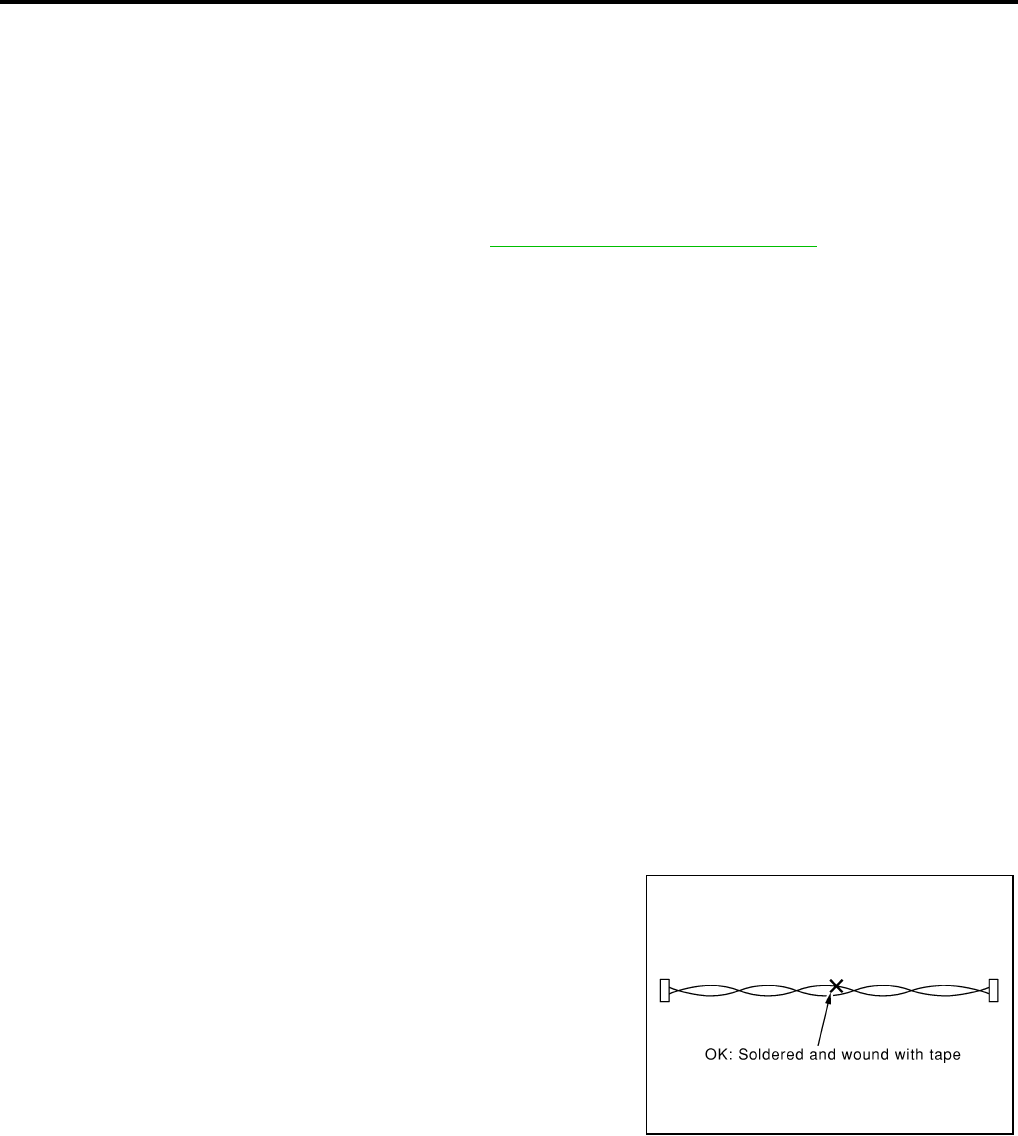
Precautions for CAN System EFS005KQ
●Do not apply voltage of 7.0V or higher to terminal to be measured.
●Maximum open terminal voltage of tester in use must be less than 7.0V.
●Before checking harnesses, turn ignition switch OFF and disconnect battery negative cable.
●Area to be repaired must be soldered and wrapped with tape.
Make sure that fraying of twisted wire is within 110 mm (4.33 in).
PKIA0306E
PRECAUTIONS
BRC-7
[ABS]
C
D
E
G
H
I
J
K
L
M
A
B
BRC
Revision: February 2006 2005 Xterra
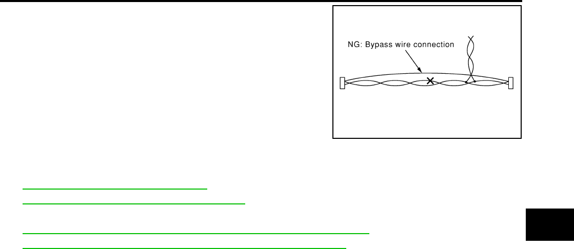
●Do not make a bypass connection to repaired area. (If the circuit
is bypassed, characteristics of twisted wire will be lost.)
Wiring Diagrams and Trouble Diagnosis EFS005KR
When you read wiring diagrams, refer to the following:
●GI-16, "How to Read Wiring Diagrams".
●PG-4, "POWER SUPPLY ROUTING CIRCUIT".
When you perform trouble diagnosis, refer to the following:
●GI-12, "HOW TO FOLLOW TEST GROUPS IN TROUBLE DIAGNOSES".
●GI-28, "How to Perform Efficient Diagnosis for an Electrical Incident".
PKIA0307E
BRC-8
[ABS]
PREPARATION
Revision: February 2006 2005 Xterra
PREPARATION PFP:00002
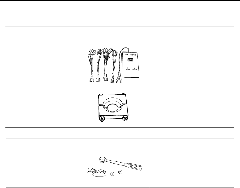
Special Service Tool EFS005KS
The actual shapes of Kent-Moore tools may differ from those of special service tools illustrated here.
Commercial Service Tools EFS005KT
Tool number
(Kent-Moore No.)
Tool name
Description
—
(J-45741)
ABS active wheel sensor tester
Checking operation of ABS active wheel
sensors
205-D002
(—)
Bearing splitter
Removing axle shaft bearing
WFIA0101E
ZZA0700D
Tool name Description
1. Flare nut crowfoot
2. Torque wrench
Removing and installing brake piping
a: 10mm (0.39 in)/12mm (0.47 in)
S-NT360
SYSTEM DESCRIPTION
BRC-9
[ABS]
C
D
E
G
H
I
J
K
L
M
A
B
BRC
Revision: February 2006 2005 Xterra
SYSTEM DESCRIPTION PFP:00000
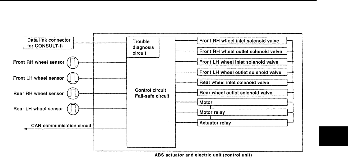
System Components EFS005KU
ABS Function EFS005KV
●The Anti-Lock Brake System detects wheel revolution while braking and improves handling stability during
sudden braking by electrically preventing wheel lockup. Maneuverability is also improved for avoiding
obstacles.
●If the electrical system malfunctions, the Fail-Safe function is activated, the ABS becomes inoperative and
the ABS warning lamp turns on.
●The electrical system can be diagnosed using CONSULT-II.
●During ABS operation, the brake pedal may vibrate lightly and a mechanical noise may be heard. This is
normal.
●Just after starting the vehicle, the brake pedal may vibrate or a motor operating noise may be heard from
engine compartment. This is a normal status of operation check.
●Stopping distance may be longer than that of vehicles without ABS when vehicle drives on rough, gravel,
or snow-covered (fresh, deep snow) roads.
EBD Function EFS005KW
●Electronic Brake Distribution is a function that detects subtle slippages between the front and rear wheels
during braking, and it improves handling stability by electronically controlling the brake fluid pressure
which results in reduced rear wheel slippage.
●If the electrical system malfunctions, the Fail-Safe function is activated, the EBD and ABS become inoper-
ative, and the ABS warning lamp and brake warning lamp are turned on.
●The electrical system can be diagnosed using CONSULT-II.
●During EBD operation, the brake pedal may vibrate lightly and a mechanical noise may be heard. This is
normal.
●Just after starting the vehicle, the brake pedal may vibrate or a motor operating noise may be heard from
engine compartment. This is a normal status of operation check.
Fail-Safe Function EFS005KX
CAUTION:
If the Fail-Safe function is activated, perform the Self Diagnosis for ABS system.
ABS/EBD SYSTEM
In case of an electrical malfunction with the ABS, the ABS warning lamp will turn on. In case of an electrical
malfunction with the EBD system, the brake warning lamp and the ABS warning lamp will turn on.
The system will revert to one of the following conditions of the Fail-Safe function.
WFIA0360E
BRC-10
[ABS]
SYSTEM DESCRIPTION
Revision: February 2006 2005 Xterra
1. For ABS malfunction, only the EBD is operative and the condition of the vehicle is the same condition of
vehicles without ABS system.
2. For EBD malfunction, the EBD and ABS become inoperative, and the condition of the vehicle is the same
as the condition of vehicles without ABS or EBD system.
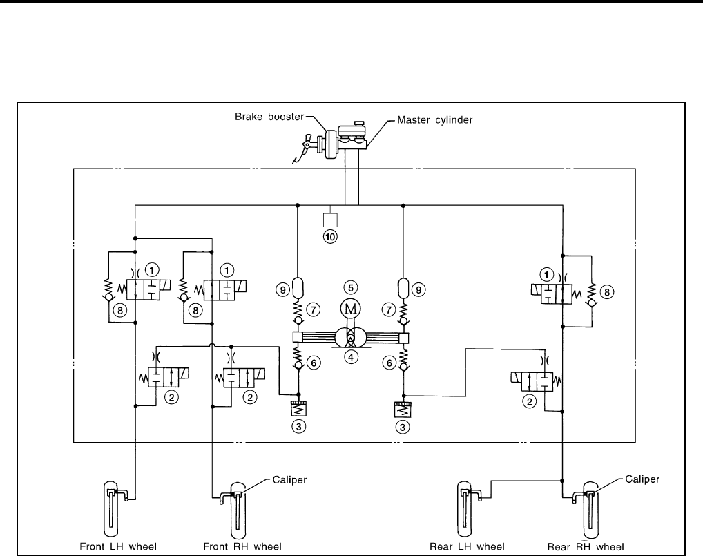
Hydraulic Circuit Diagram EFS005KY
WFIA0369E
1. Inlet solenoid valve 2. Outlet solenoid valve 3. Reservoir
4. Pump 5. Motor 6. Inlet valve
7. Outlet valve 8. Bypass check valve 9. Damper
10. Pressure switch

CAN COMMUNICATION
BRC-11
[ABS]
C
D
E
G
H
I
J
K
L
M
A
B
BRC
Revision: February 2006 2005 Xterra
CAN COMMUNICATION PFP:23710
System Description EFS005KZ
Refer to LAN-21, "CAN COMMUNICATION" .
BRC-12
[ABS]
TROUBLE DIAGNOSIS
Revision: February 2006 2005 Xterra
TROUBLE DIAGNOSIS PFP:00000
How to Perform Trouble Diagnoses for Quick and Accurate Repair EFS005L0
INTRODUCTION
The ABS system has an electronic control unit to control major func-
tions. The control unit accepts input signals from sensors and con-
trols actuator operation. It is also important to check for conventional
problems such as air leaks in the booster or lines, lack of brake fluid,
or other problems with the brake system.
It is much more difficult to diagnose a problem that occurs intermit-
tently rather than continuously. Most intermittent problems are
caused by poor electrical connections or faulty wiring. In this case,
careful checking of suspicious circuits may help prevent the replace-
ment of good parts.
A visual check only may not find the cause of the problem, so a road
test should be performed.
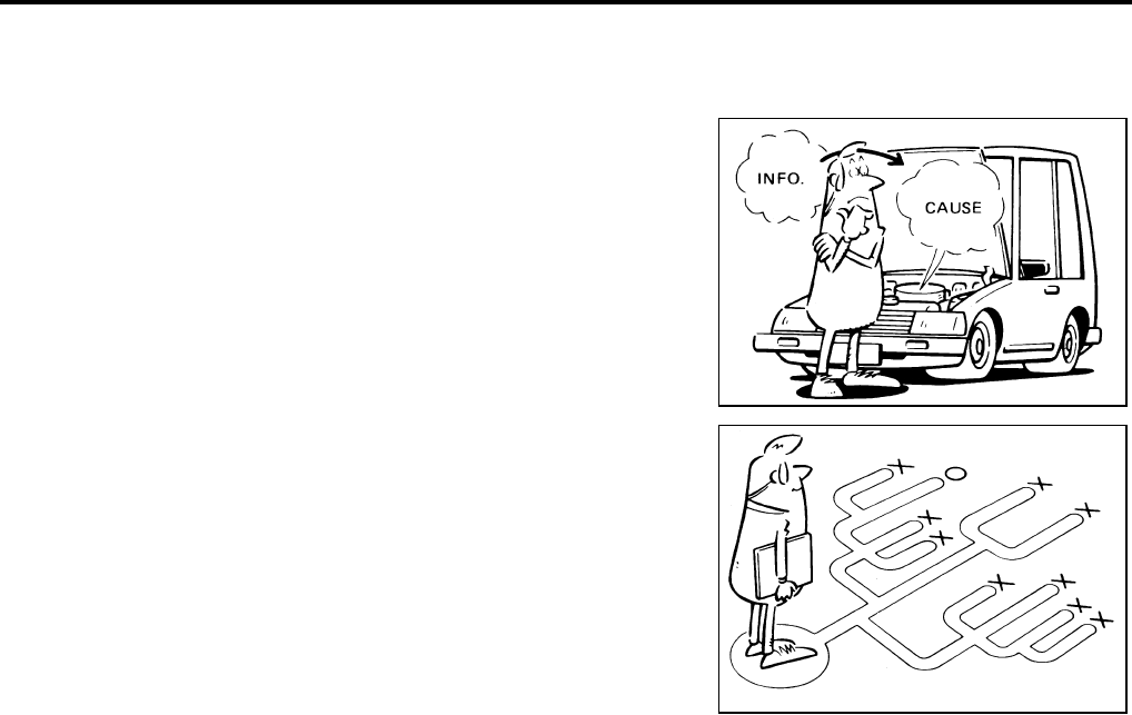
Before undertaking actual checks, take just a few minutes to talk with
a customer who approaches with an ABS complaint. The customer
is a very good source of information on such problems, especially
intermittent ones. Through the talks with the customer, find out what
symptoms are present and under what conditions they occur.
Start your diagnosis by looking for “conventional” problems first. This
is one of the best ways to troubleshoot brake problems on an ABS
equipped vehicle. Also check related Service Bulletins for informa-
tion.
SEF233G
SEF234G
TROUBLE DIAGNOSIS
BRC-13
[ABS]
C
D
E
G
H
I
J
K
L
M
A
B
BRC
Revision: February 2006 2005 Xterra
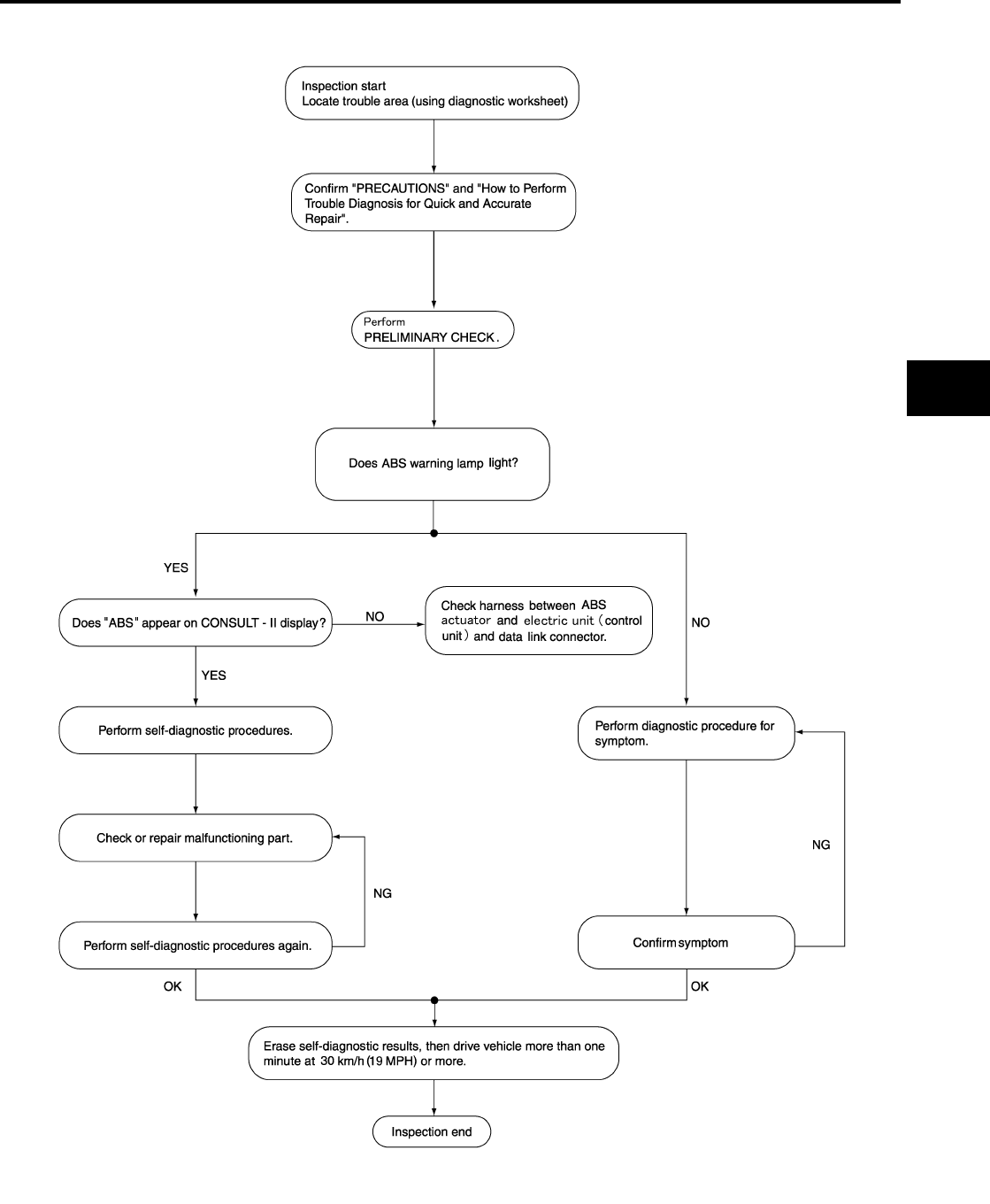
WORK FLOW
LFIA0197E
BRC-14
[ABS]
TROUBLE DIAGNOSIS
Revision: February 2006 2005 Xterra
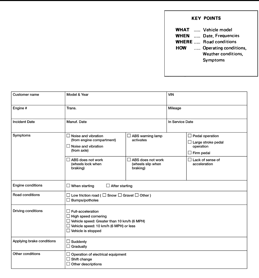
CLARIFY CONCERN
●A customer's description of a vehicle concern may vary depend-
ing on the individual. It is important to clarify the customer's con-
cern.
●Ask the customer about what symptoms are present under what
conditions. Use this information to reproduce the symptom while
driving.
●It is also important to use the diagnosis sheet to understand
what type of trouble the customer is having.
EXAMPLE OF DIAGNOSIS SHEET
SBR339B
WFIA0226E

TROUBLE DIAGNOSIS
BRC-15
[ABS]
C
D
E
G
H
I
J
K
L
M
A
B
BRC
Revision: February 2006 2005 Xterra
Component Parts and Harness Connector Location EFS005L1
WFIA0361E
BRC-16
[ABS]
TROUBLE DIAGNOSIS
Revision: February 2006 2005 Xterra
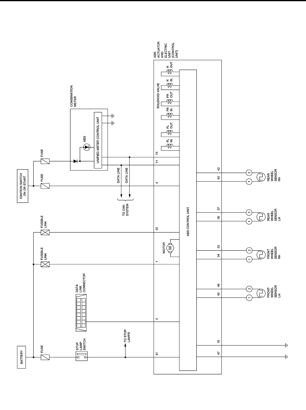
Schematic EFS005L2
WFWA0229E
TROUBLE DIAGNOSIS
BRC-17
[ABS]
C
D
E
G
H
I
J
K
L
M
A
B
BRC
Revision: February 2006 2005 Xterra
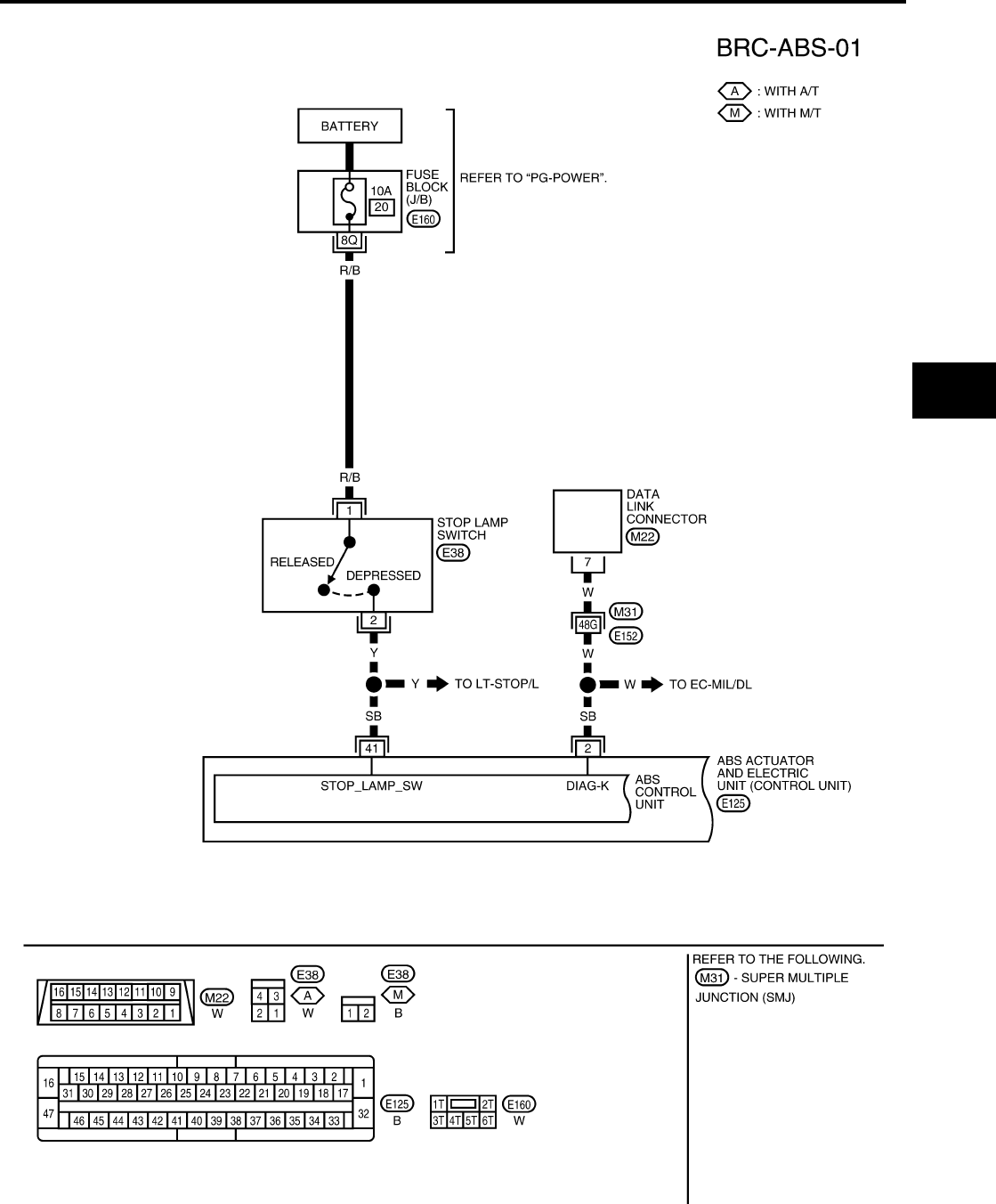
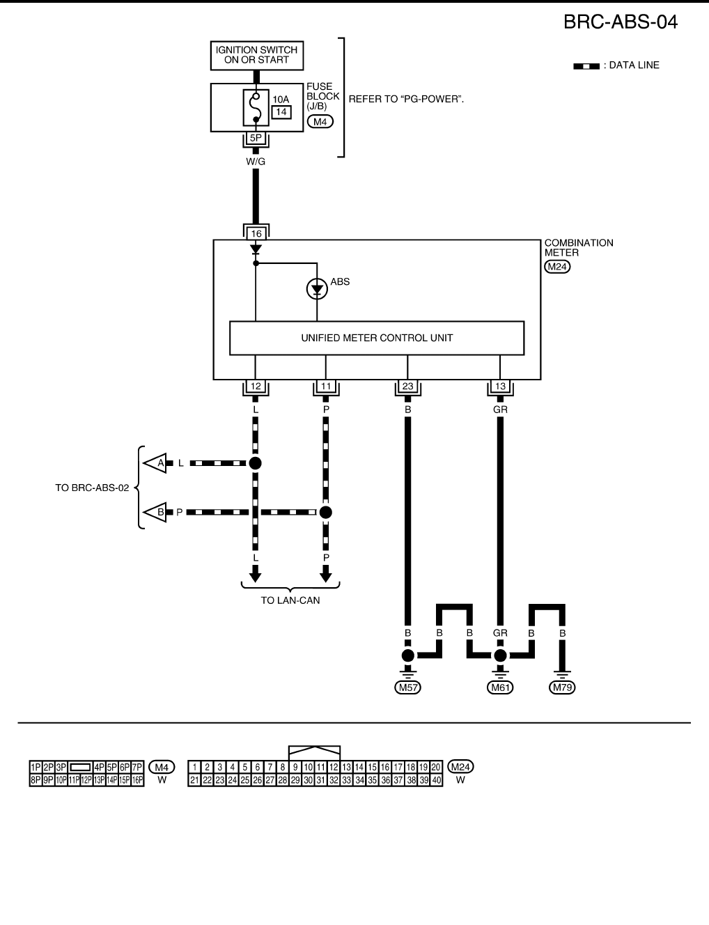
Wiring Diagram — ABS — EFS005L3
WFWA0230E
BRC-18
[ABS]
TROUBLE DIAGNOSIS
Revision: February 2006 2005 Xterra
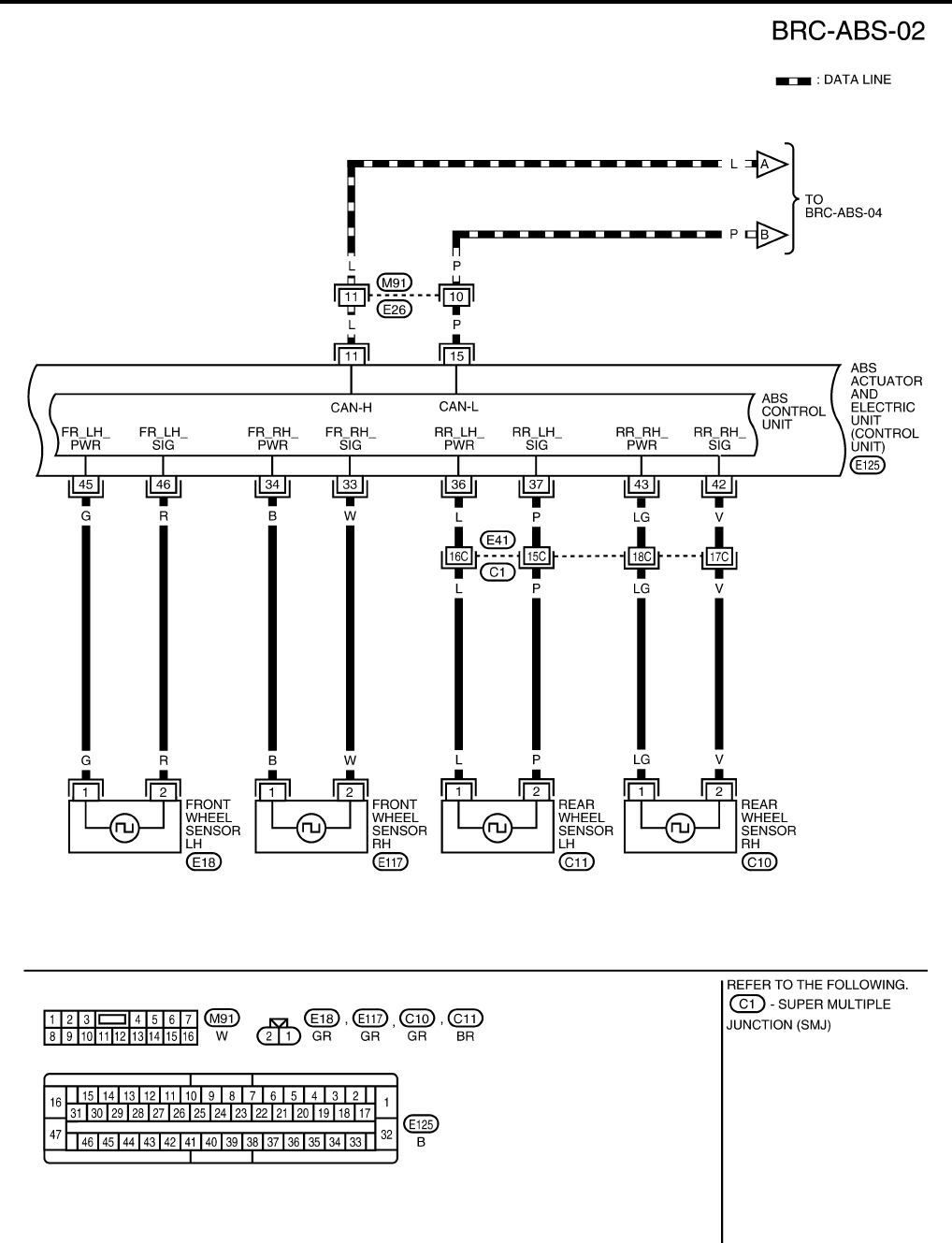
WFWA0231E
TROUBLE DIAGNOSIS
BRC-19
[ABS]
C
D
E
G
H
I
J
K
L
M
A
B
BRC
Revision: February 2006 2005 Xterra
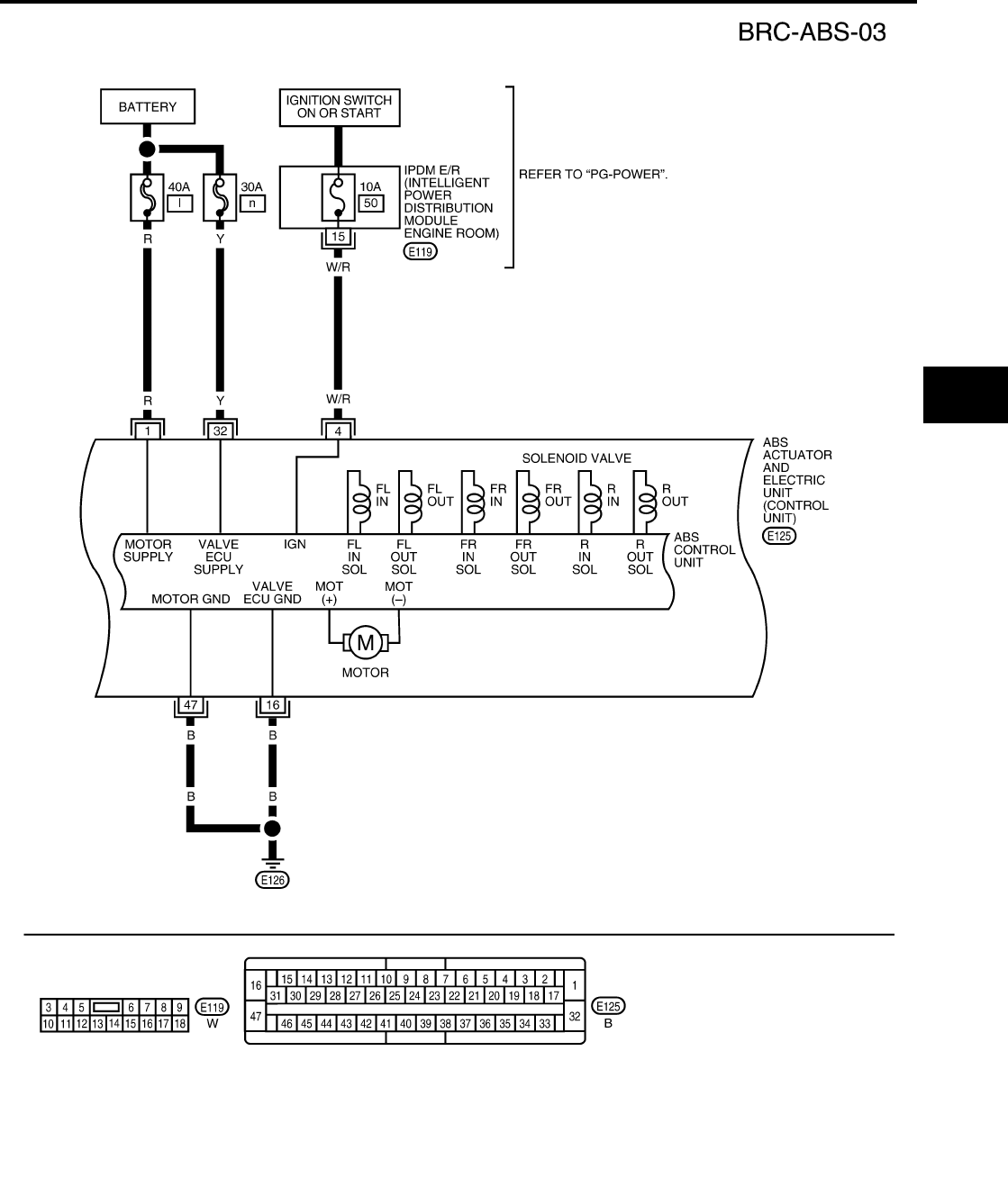
WFWA0232E
BRC-20
[ABS]
TROUBLE DIAGNOSIS
Revision: February 2006 2005 Xterra
WFWA0233E

TROUBLE DIAGNOSIS
BRC-21
[ABS]
C
D
E
G
H
I
J
K
L
M
A
B
BRC
Revision: February 2006 2005 Xterra
Basic Inspection EFS005L4
BRAKE FLUID LEVEL, FLUID LEAK, AND BRAKE PAD INSPECTION
1. Check fluid level in the brake fluid reservoir. If fluid level is low, add fluid.
2. Check the brake piping and around the ABS actuator and electric unit (control unit) for leaks. If there is
leaking or seeping fluid, check the following items.
●If ABS actuator and electric unit (control unit) connection is loose, tighten the piping to the specified
torque and recheck for leaks.
●If there is damage to the connection flare nut or ABS actuator and electric unit (control unit) threads,
replace the damaged part and recheck for leaks.
●When there is fluid leaking or seeping from a fluid connection, use a clean cloth to wipe off the fluid and
recheck for leaks. If fluid is still seeping out, replace the damaged part. If the fluid is leaking at the ABS
actuator and electric unit (control unit), replace the ABS actuator and electric unit (control unit) assem-
bly.
CAUTION:
The ABS actuator and electric unit (control unit) cannot be disassembled and must be replaced
as an assembly.
3. Check the brake pads for excessive wear.
POWER SYSTEM TERMINAL LOOSENESS AND BATTERY INSPECTION
Make sure the battery positive cable, negative cable and ground connection are not loose. In addition, make
sure the battery is sufficiently charged.
ABS WARNING LAMP INSPECTION
1. Make sure ABS warning lamp turns on for approximately 2 seconds when the ignition switch is turned ON.
If it does not, check CAN communications. If there are no errors with the CAN communication system,
check the combination meter. Refer to DI-4, "COMBINATION METERS" .
2. Make sure the lamp turns off approximately 2 seconds after the ignition switch is turned ON. If the lamp
does not turn off, conduct self-diagnosis.
3. Make sure ABS warning lamp turns off approximately 2 seconds after the engine is started. If ABS warn-
ing lamp has not turned off 10 seconds after the engine has been started, conduct self-diagnosis of the
ABS actuator and electric unit (control unit).
4. After conducting the self-diagnosis, be sure to erase the error memory. Refer to BRC-24, "CONSULT-II
Function (ABS)" .

BRC-22
[ABS]
TROUBLE DIAGNOSIS
Revision: February 2006 2005 Xterra
Warning Lamp and Indicator Timing EFS005L5
X: ON
—: OFF
Control Unit Input/Output Signal Standard EFS005L6
REFERENCE VALUE FROM CONSULT-II
CAUTION:
The display shows the control unit calculation data, so a normal value might be displayed even in the
event the output circuit (harness) is open or short circuited.
Condition ABS
warning lamp Remarks
When the ignition switch is OFF – –
After the ignition switch is turned ON for approx. 1 sec-
ond ×–
After the ignition switch is turned ON for approx. 2 sec-
onds –Lamp goes off approx. 2 seconds after the
engine is started.
ABS malfunction
×–
×
When the ABS actuator and electric unit (con-
trol unit) is malfunctioning (power supply or
ground malfunction).
Monitor item Display content
Data monitor Note: Error inspection
checklist
Condition Reference value in
normal operation
FR RH SENSOR
FR LH SENSOR
RR RH SENSOR
RR LH SENSOR
Wheel speed
Vehicle stopped 0 [km/h (MPH)]
BRC-30, "Wheel Sensor
System"
Vehicle running (Note 1)
Almost in accor-
dance with speed-
ometer display
(within ±10%)
BATTERY VOLT
Battery voltage sup-
plied to ABS actuator
and electric unit (con-
trol unit)
Ignition switch ON 10 to 16V
BRC-34, "ABS Control
Unit Power and Ground
Systems Inspection"
CRANKING SIG Cranking status Cranking ON —
Not cranking OFF
STOP LAMP SW Stop lamp switch oper-
ation
Brake pedal depressed ON —
Brake pedal not depressed OFF
ABS WARN LAMP ABS warning lamp ON
condition (Note 2)
ABS warning lamp ON ON BRC-38, "ABS Warning
Lamp Does Not Come
On When Ignition Switch
Is Turned On"
ABS warning lamp OFF OFF
EBD WARN LAMP EBD warning lamp sta-
tus
When EBD warning lamp is on ON BRC-34, "CAN Commu-
nication System Inspec-
tion"
When EBD warning lamp is off OFF
MOTOR RELAY Operation status of
motor and motor relay
Ignition switch ON or running
(ABS not activated) OFF BRC-33, "Actuator Motor,
Motor Relay, and Circuit
Inspection"
Ignition switch ON or engine
running (ABS activated) ON
ACTUATOR RLY Actuator relay opera-
tion status
Vehicle stopped (Ignition
switch ON) OFF BRC-33, "Actuator Motor,
Motor Relay, and Circuit
Inspection"
Vehicle stopped (Engine run-
ning) ON

TROUBLE DIAGNOSIS
BRC-23
[ABS]
C
D
E
G
H
I
J
K
L
M
A
B
BRC
Revision: February 2006 2005 Xterra
Note 1: Confirm tire pressure is normal.
Note 2: ON/OFF timing of ABS warning lamp
ON: For approximately 2 seconds after ignition switch is turned ON, or when a malfunction is detected.
OFF: Approximately 2 seconds after ignition switch is turned ON (when system is in normal operation).
FR LH IN SOL
FR LH OUT SOL
FR RH IN SOL
FR RH OUT SOL
REAR IN SOL
REAR OUT SOL
Solenoid valve opera-
tion
Actuator (solenoid) is active
(“ACTIVE TEST” with CON-
SULT-II) or actuator relay is
inactive (in fail-safe mode).
ON
BRC-32, "Solenoid Valve
System Inspection"
When actuator (solenoid) is
not active and actuator relay is
active (ignition switch ON).
OFF
ABS SIGNAL
EBD SIGNAL Signal status
ABS active
EBD active ON ABS system
EBD system
ABS not active
EBD not active OFF
ABS FAIL SIG
EBD FAIL SIG Fail signal status
ABS fail
EBD fail ON ABS system
EBD system
ABS normal
EBD normal OFF
Monitor item Display content
Data monitor Note: Error inspection
checklist
Condition Reference value in
normal operation
BRC-24
[ABS]
TROUBLE DIAGNOSIS
Revision: February 2006 2005 Xterra
CONSULT-II Function (ABS) EFS005L7
CONSULT-II can display each diagnostic item using the diagnostic test modes shown following.
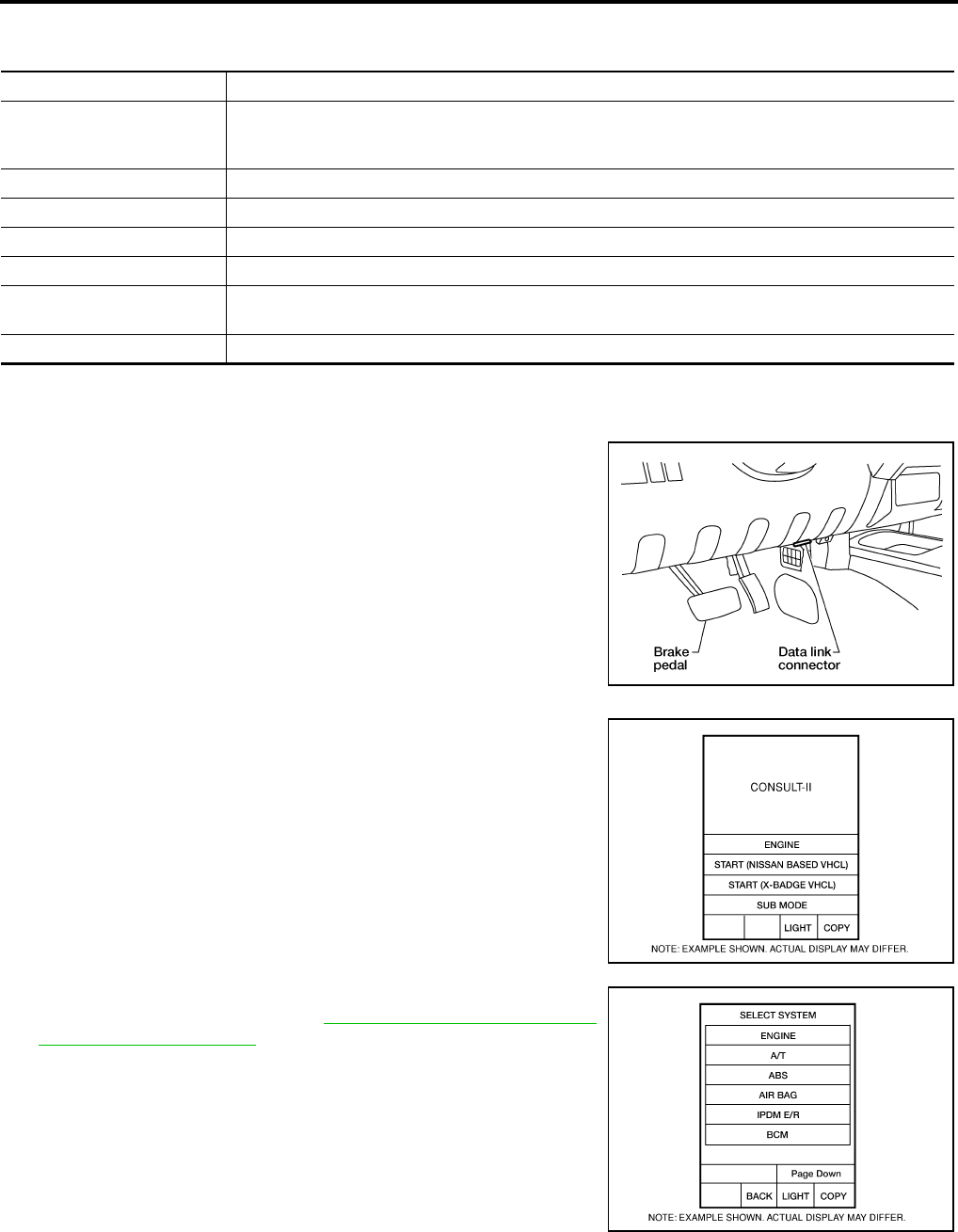
CONSULT-II BASIC OPERATION PROCEDURE
1. Turn ignition switch OFF.
2. Connect CONSULT-II and CONSULT-II CONVERTER to the
data link connector.
CAUTION:
If CONSULT-II is used with no connection of CONSULT-II
CONVERTER, malfunctions might be detected in self-diag-
nosis depending on control unit which carries out CAN
communication.
3. Turn ignition switch ON.
4. Touch “START (NISSAN BASED VHCL)”.
5. Touch “ABS” in the “SELECT SYSTEM” screen.
If “ABS” is not indicated, go to GI-39, "CONSULT-II Data Link
Connector (DLC) Circuit" .
ABS diagnostic mode Description
WORK SUPPORT
Supports inspection and adjustments. Commands are transmitted to the ABS actuator and electric
unit (control unit) for setting the status suitable for required operation, input/output signals are
received from the ABS actuator and electric unit (control unit) and received data is displayed.
SELF-DIAG RESULTS Displays ABS actuator and electric unit (control unit) self-diagnosis results.
DATA MONITOR Displays ABS actuator and electric unit (control unit) input/output data in real time.
CAN DIAG SUPPORT MNTR The result of transmit/receive diagnosis of CAN communication can be read.
ACTIVE TEST Operation of electrical loads can be checked by sending drive signal to them.
FUNCTION TEST Conducted by CONSULT-II instead of a technician to determine whether each system is "OK" or
"NG".
ECU PART NUMBER ABS actuator and electric unit (control unit) part number can be read.
BBIA0538E
BCIA0029E
BCIA0030E

TROUBLE DIAGNOSIS
BRC-25
[ABS]
C
D
E
G
H
I
J
K
L
M
A
B
BRC
Revision: February 2006 2005 Xterra
6. Select the required diagnostic location from the “SELECT DIAG
MODE” screen.
For further information, see the CONSULT-II Operation Manual.
SELF-DIAGNOSIS
Description
If an error is detected in the system, the ABS warning lamp will turn on. In this case, perform self-diagnosis as
follows:
Operation Procedure
1. Turn ignition switch OFF.
2. Connect CONSULT-II and CONSULT-II CONVERTER to the data link connector.
CAUTION:
If CONSULT-II is used with no connection of CONSULT-II CONVERTER, malfunctions might be
detected in self-diagnosis depending on control unit which carries out CAN communication.
3. Turn ignition switch ON.
4. Start engine and drive at approximately 30 km/h (19 MPH) or more for approximately 1 minute.
5. After stopping the vehicle, with the engine running, touch “START (NISSAN BASED VHCL)”, “ABS”,
“SELF-DIAG RESULTS” in order on the CONSULT-II screen.
CAUTION:
If “START (NISSAN BASED VHCL)” is touched immediately after starting the engine or turning on
the ignition switch, “ABS” might not be displayed in the SELECT SYSTEM screen. In this case,
repeat the operation from step 1.
6. The self-diagnostic results are displayed. (If necessary, the self-diagnostic results can be printed out by
touching “PRINT”.)
●When “NO DTC IS DETECTED” is displayed, check the ABS warning lamp.
7. Conduct the appropriate inspection from the display item list, and repair or replace the malfunctioning
component.
8. Start engine and drive at approximately 30 km/h (19 MPH) or more for approximately 1 minute.
CAUTION:
●When a wheel sensor “short-circuit” is detected, if the vehicle is not driven at 30 km/h (19 MPH)
for at least 1 minute, the ABS warning lamp will not turn off even if the malfunction is repaired.
9. Turn ignition switch OFF to prepare for erasing the memory.
10. Start the engine and touch “START (NISSAN BASED VHCL)”, “ABS”, “SELF-DIAG RESULTS”, “ERASE”
in order on the CONSULT-II screen to erase the error memory.
If “ABS” is not indicated, go to GI-39, "CONSULT-II Data Link Connector (DLC) Circuit" .
CAUTION:
If the error memory is not erased, re-conduct the operation from step 5.
11. For the final inspection, drive at approximately 30 km/h (19 MPH) or more for approximately 1 minute and
confirm that the ABS warning lamp is off.
BCIA0031E

BRC-26
[ABS]
TROUBLE DIAGNOSIS
Revision: February 2006 2005 Xterra
Display Item List
Self-diagnostic item Malfunction detecting condition Check system
FR LH SENSOR 1
[C1104]
Circuit of front LH wheel sensor is open, shorted or sensor power
voltage is unusual.
BRC-30, "Wheel Sensor
System" (Note 1)
RR RH SENSOR 1
[C1101]
Circuit of rear RH wheel sensor is open, shorted or sensor power
voltage is unusual.
FR RH SENSOR 1
[C1103]
Circuit of front RH wheel sensor is open, shorted or sensor power
voltage is unusual.
RR LH SENSOR 1
[C1102]
Circuit of rear LH wheel sensor is open, shorted or sensor power
voltage is unusual.
FR LH SENSOR 2
[C1108]
ABS actuator and electric unit (control unit) cannot identify sen-
sor pulses, because of large gap between wheel sensor and sen-
sor rotor.
RR RH SENSOR 2
[C1105]
ABS actuator and electric unit (control unit) cannot identify sen-
sor pulses, because of large gap between wheel sensor and sen-
sor rotor.
FR RH SENSOR 2
[C1107]
ABS actuator and electric unit (control unit) cannot identify sen-
sor pulses, because of large gap between wheel sensor and sen-
sor rotor.
RR LH SENSOR 2
[C1106]
ABS actuator and electric unit (control unit) cannot identify sen-
sor pulses, because of large gap between wheel sensor and sen-
sor rotor.
ABS SENSOR
[C1115] Wheel sensor input is abnormal.
BATTERY VOLTAGE
[ABNORMAL]
[C1109]
ABS actuator and electric unit (control unit) power voltage is too
low.
BRC-34, "ABS Control
Unit Power and Ground
Systems Inspection"
CONTROLLER FAILURE
[C1110]
Internal malfunction of ABS actuator and electric unit (control
unit)
BRC-31, "ABS Control
Unit Inspection"
PUMP MOTOR (Note 3)
[C1111]
During actuator motor operation with ON, when actuator motor
turns OFF or when control line for actuator motor relay is open. BRC-33, "Actuator
Motor, Motor Relay, and
Circuit Inspection"
During actuator motor operation with OFF, when actuator motor
turns ON or when control line for relay is shorted to ground.
G-SENSOR
[C1113] G-sensor is malfunctioning. BRC-31, "ABS Control
Unit Inspection"
FR LH IN ABS SOL
[C1120]
Circuit of front LH IN ABS solenoid is open or shorted, or control
line is open or shorted to power supply or ground.
BRC-32, "Solenoid Valve
System Inspection"
FR LH OUT ABS SOL
[C1121]
Circuit of front LH OUT ABS solenoid is open or shorted, or con-
trol line is open or shorted to power supply or ground.
FR RH IN ABS SOL
[C1122]
Circuit of front RH IN ABS solenoid is open or shorted, or control
line is open or shorted to power supply or ground.
FR RH OUT ABS SOL
[C1123]
Circuit of front RH OUT ABS solenoid is open or shorted, or con-
trol line is open or shorted to power supply or ground.
R-EV
[C1190]
Circuit of rear IN ABS solenoid is open or shorted, or control line
is open or shorted to power supply or ground.
R-AV
[C1191]
Circuit of rear OUT ABS solenoid is open or shorted, or control
line is open or shorted to power supply or ground.
ACTUATOR RLY
[C1140] ABS actuator relay or circuit malfunction.
BRC-33, "Actuator
Motor, Motor Relay, and
Circuit Inspection"

TROUBLE DIAGNOSIS
BRC-27
[ABS]
C
D
E
G
H
I
J
K
L
M
A
B
BRC
Revision: February 2006 2005 Xterra
Note 1. If wheel sensor 2 for each wheel is indicated, check ABS actuator and electric unit (control unit) power
supply voltage in addition to wheel sensor circuit check.
Note 2. If multiple malfunctions are detected including CAN communication line [U1000], perform diagnosis for
CAN communication line first.
Note 3: "ACTUATOR RLY" on the CONSULT-II self-diagnosis results indicates the malfunction of the actuator
motor relay or circuit.
DATA MONITOR
Operation Procedure
1. After turning OFF the ignition switch, connect CONSULT-II and the CONSULT-II CONVERTER to the data
link connector.
CAUTION:
If CONSULT-II is used with no connection of CONSULT-II CONVERTER, malfunctions might be
detected in self-diagnosis depending on control unit which carries out CAN communication.
2. Touch “START (NISSAN BASED VHCL)”, “ABS”, “DATA MONITOR” in order on the CONSULT-II screen.
If “ABS” is not indicated, go to GI-39, "CONSULT-II Data Link Connector (DLC) Circuit" .
CAUTION:
When “START (NISSAN BASED VHCL)” is touched immediately after starting the engine or turning
on the ignition switch, “ABS” might not be displayed in the SELECT SYSTEM screen. In this case,
repeat the operation from step 2.
3. Return to the SELECT MONITOR ITEM screen, and touch “ECU INPUT SIGNALS”, “MAIN SIGNALS” or
“SELECTION FROM MENU”. Refer to the following information.
4. When “START” is touched, the data monitor screen is displayed.
Display Item List
VARIANT CODING
[C1170] V coding is not malfunctioning. BRC-31, "ABS Control
Unit Inspection"
CAN COMM CIRCUIT
[U1000]
●CAN communication line is open or shorted.
●ABS actuator and electric unit (control unit) internal malfunc-
tion
●Battery voltage for ECM is suddenly interrupted for approxi-
mately 0.5 second or more.
BRC-34, "CAN Commu-
nication System Inspec-
tion" (Note 2)
Self-diagnostic item Malfunction detecting condition Check system
Item
(Unit)
Data monitor item selection
Remarks
ECU INPUT
SIGNALS
MAIN
SIGNALS
SELECTION
FROM MENU
FR RH SENSOR
(km/h, MPH) ×××
Wheel speed calculated by front RH
wheel sensor signal is displayed.
FR LH SENSOR
(km/h, MPH) ×××
Wheel speed calculated by front LH
wheel sensor signal is displayed.
RR RH SENSOR
(km/h, MPH) ×××
Wheel speed calculated by rear RH
wheel sensor signal is displayed.
RR LH SENSOR
(km/h, MPH) ×××
Wheel speed calculated by rear LH
wheel sensor signal is displayed.
BATTERY VOLT
(V) ×××
Voltage supplied to ABS actuator
and electric unit (control unit) is dis-
played.
STOP LAMP SW
(ON/OFF) ×××
Stop lamp switch (ON/OFF) status
is displayed.
ABS WARN LAMP
(ON/OFF) –××
ABS warning lamp (ON/OFF) status
is displayed.
EBD WARN LAMP – – ×Brake warning lamp (ON/OFF) sta-
tus is displayed.
FR LH IN SOL
(ON/OFF) –××
Front LH IN ABS solenoid (ON/
OFF) status is displayed.

BRC-28
[ABS]
TROUBLE DIAGNOSIS
Revision: February 2006 2005 Xterra
×: Applicable
–: Not applicable
ACTIVE TEST
CAUTION:
●Do not perform active test while driving.
●Make sure to completely bleed air from the brake system.
●The ABS and brake warning lamps turn on during the active test.
Operation Procedure
1. Connect the CONSULT-II and CONSULT-II CONVERTER to the data link connector and start the engine.
CAUTION:
If CONSULT-II is used with no connection of CONSULT-II CONVERTER, malfunctions might be
detected in self-diagnosis depending on control unit which carries out CAN communication.
2. Touch “START (NISSAN BASED VHCL)” on the display screen.
3. Touch “ABS”.
If “ABS” is not indicated, go to GI-39, "CONSULT-II Data Link Connector (DLC) Circuit" .
4. Touch “ACTIVE TEST”.
FR LH OUT SOL
(ON/OFF) –××
Front LH OUT ABS solenoid (ON/
OFF) status is displayed.
FR RH IN SOL
(ON/OFF) –××
Front RH IN ABS solenoid (ON/
OFF) status is displayed.
FR RH OUT SOL
(ON/OFF) –××
Front RH OUT ABS solenoid (ON/
OFF) status is displayed.
REAR IN SOL
(ON/OFF) ––×Rear IN ABS solenoid (ON/OFF)
status is displayed.
REAR OUT SOL
(ON/OFF) ––×Rear OUT ABS solenoid (ON/OFF)
status is displayed.
MOTOR RELAY
(ON/OFF) –××
ABS motor relay signal (ON/OFF)
status is displayed.
ACTUATOR RLY
(ON/OFF) – ××
ABS actuator relay signal (ON/
OFF) status is displayed.
ABS FAIL SIG
(ON/OFF) ––×ABS fail signal (ON/OFF) status is
displayed.
EBD FAIL SIG
(ON/OFF) ––×EBD fail signal (ON/OFF) status is
displayed.
EBD SIGNAL
(ON/OFF) ––×EBD operation (ON/OFF) status is
displayed.
ABS SIGNAL
(ON/OFF) ––×ABS operation (ON/OFF) status is
displayed.
CRANKING SIG – – ×The input state of the key SW
START position signal is displayed.
Item
(Unit)
Data monitor item selection
Remarks
ECU INPUT
SIGNALS
MAIN
SIGNALS
SELECTION
FROM MENU
TROUBLE DIAGNOSIS
BRC-29
[ABS]
C
D
E
G
H
I
J
K
L
M
A
B
BRC
Revision: February 2006 2005 Xterra
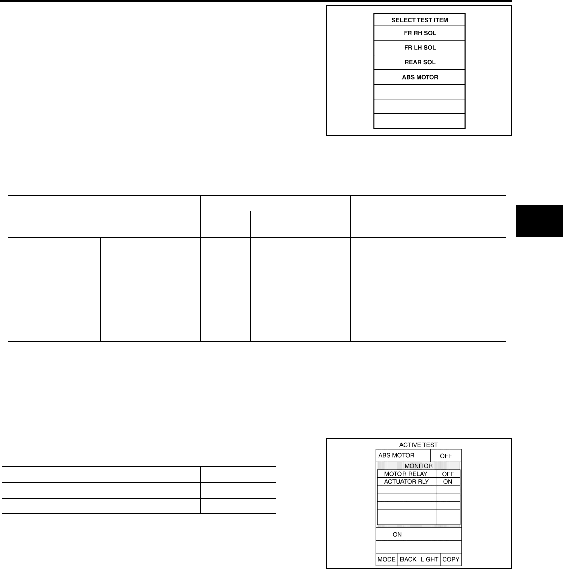
5. The SELECT TEST ITEM screen is displayed.
6. Touch necessary test item.
7. With the “MAIN SIGNALS” display selected, touch “START”.
8. The Active Test screen will be displayed, so conduct the following test.
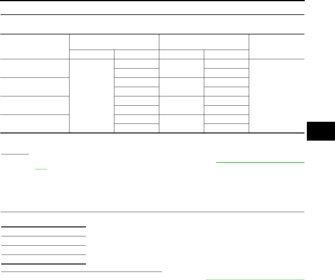
Solenoid Valve Operation Chart
*: ON for 1 to 2 seconds after the touch, and then OFF
NOTE:
●If active test is performed with brake pedal depressed, pedal stroke may change. This is normal.
●“TEST IS STOPPED” is displayed approximately 10 seconds after operation starts.
●After “TEST IS STOPPED” is displayed, to perform test again, repeat Step 6.
ABS Motor
Touch “ON” and “OFF” on the screen. Check that ABS motor relay
operates as shown in table below.
NOTE:
●If active test is performed with brake pedal depressed, pedal
stroke may change. This is normal.
●“TEST IS STOPPED” is displayed approximately 10 seconds
after operation starts.
LBR379
Operation
ABS solenoid valve ABS solenoid valve (ACT)
UP KEEP DOWN UP ACTUA-
TOR UP
ACTUA-
TOR KEEP
FR RH SOL
FR RH ABS SOLE-
NOID (ACT)
FR RH IN SOL OFF ON ON OFF OFF OFF
FR RH OUT SOL OFF OFF ON* OFF OFF OFF
FR LH SOL
FR LH ABS SOLE-
NOID (ACT)
FR LH IN SOL OFF ON ON OFF OFF OFF
FR LH OUT SOL OFF OFF ON* OFF OFF OFF
REAR SOL REAR IN SOL OFF ON ON OFF OFF OFF
REAR OUT SOL OFF OFF ON* OFF OFF OFF
Operation ON OFF
ABS actuator relay ON ON
ABS motor relay ON OFF
SFIA0593E

BRC-30
[ABS]
TROUBLE DIAGNOSIS FOR SELF-DIAGNOSTIC ITEMS
Revision: February 2006 2005 Xterra
TROUBLE DIAGNOSIS FOR SELF-DIAGNOSTIC ITEMS PFP:00000
Wheel Sensor System EFS005L8
INSPECTION PROCEDURE
1. CONNECTOR INSPECTION
Disconnect the ABS actuator and electric unit (control unit) connector E125 and wheel sensor of malfunction-
ing code.
Check the terminals for deformation, disconnection, looseness or damage.
OK or NG
OK >> GO TO 2.
NG >> Repair or replace as necessary. Refer to BRC-41, "Removal and Installation" .
2. CHECK WHEEL SENSOR OUTPUT SIGNAL
1. Connect ABS active wheel sensor tester (J-45741) to wheel sensor using appropriate adapter.
2. Turn on the ABS active wheel sensor tester power switch.
NOTE:
The green POWER indicator should illuminate. If the POWER indicator does not illuminate, replace the
battery in the ABS active wheel sensor tester before proceeding.
3. Spin the wheel of the vehicle by hand and observe the red SENSOR indicator on the ABS active wheel
sensor tester. The red SENSOR indicator should flash on and off to indicate an output signal.
NOTE:
If the red SENSOR indicator illuminates but does not flash, reverse the polarity of the tester leads and
retest.
Does the ABS active wheel sensor tester detect a signal?
YES >> GO TO 3.
NO >> Replace the wheel sensor. Refer to BRC-39, "Removal and Installation" .
3. CHECK TIRES
Check for inflation pressure, wear and size of each tire.
Are tire pressure and size correct and is tire wear within specifications?
YES >> GO TO 4.
NO >> Adjust tire pressure or replace tire(s).
4. CHECK WHEEL BEARINGS
Check wheel bearing axial end play. Refer to FAX-5, "WHEEL BEARING INSPECTION" , RAX-6, "Rear Axle
Bearing" (C200) or RAX-18, "Rear Axle Bearing" (M226).
OK or NG
OK >> GO TO 5.
NG >> Repair or replace as necessary. Refer to FAX-5, "Removal and Installation" , RAX-12, "Removal
and Installation" (C200) or RAX-23, "Removal and Installation" (M226).
5. CHECK WIRING HARNESS FOR SHORT CIRCUIT
1. Disconnect ABS actuator and electric unit (control unit) connec-
tor and wheel sensor connector of malfunction code No.
2. Check resistance between wheel sensor harness connector ter-
minals and ground.
OK or NG
OK >> GO TO 6.
NG >> Repair the circuit.
Continuity should not exist.
WFIA0343E
TROUBLE DIAGNOSIS FOR SELF-DIAGNOSTIC ITEMS
BRC-31
[ABS]
C
D
E
G
H
I
J
K
L
M
A
B
BRC
Revision: February 2006 2005 Xterra
6. CHECK WIRING HARNESS FOR OPEN CIRCUIT
Check continuity between ABS actuator and electric unit (control unit) harness connector and wheel sensor
harness connector.
OK or NG
OK >> Replace the ABS actuator and electric unit (control unit). Refer to BRC-41, "Removal and Installa-
tion" .
NG >> Repair the circuit.
ABS Control Unit Inspection EFS005L9
INSPECTION PROCEDURE
1. SELF-DIAGNOSIS RESULT CHECK
Check self-diagnosis results.
Is the above displayed in the self-diagnosis display items?
YES >> Replace ABS actuator and electric unit (control unit). Refer to BRC-41, "Removal and Installation"
.
NO >> Inspection End.
Wheel sensor
ABS actuator and
electric unit (control unit) Wheel sensor Continuity
Connector Terminal Connector Terminal
Front LH
E125
45 E18 1
Yes
46 2
Front RH 34 E117 1
33 2
Rear LH 37 C11 2
36 1
Rear RH 42 C10 2
43 1
Continuity should exist.
Self-diagnosis results
CONTROLLER FAILURE
G-SENSOR
VARIANT CODING
BRC-32
[ABS]
TROUBLE DIAGNOSIS FOR SELF-DIAGNOSTIC ITEMS
Revision: February 2006 2005 Xterra
Solenoid Valve System Inspection EFS005LA
INSPECTION PROCEDURE
1. SELF-DIAGNOSIS RESULT CHECK
Check self-diagnosis results.
Is the above displayed in the self-diagnosis display items?
YES >> GO TO 2.
NO >> Inspection End.
2. CONNECTOR INSPECTION
1. Disconnect ABS actuator and electric unit (control unit) connector E125.
2. Check the terminals for deformation, disconnection, looseness or damage.
OK or NG
OK >> GO TO 3.
NG >> Repair or replace as necessary.
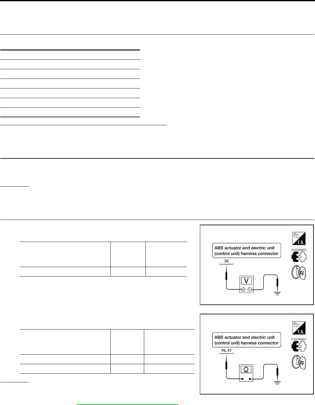
3. CHECKING SOLENOID POWER AND GROUND
1. Check voltage between ABS actuator and electric unit (control
unit) harness connector E125 and body ground.
2. Check resistance between ABS actuator and electric unit (con-
trol unit) harness connector E125 and body ground.
OK or NG
OK >> Perform self-diagnosis again. If the same results
appear, replace ABS actuator and electric unit (control
unit). Refer to BRC-41, "Removal and Installation" .
NG >> Repair the circuit.
Self-diagnosis results
FR LH IN ABS SOL
FR LH OUT ABS SOL
FR RH IN ABS SOL
FR RH OUT ABS SOL
R-EV
R-AV
ABS actuator and electric
unit (control unit) harness
connector E125
Body
ground
Measured
value
(Approx.)
32 — 12V
WFIA0195E
ABS actuator and electric
unit (control unit) harness
connector E125
Body
ground
Measured
value Ω
(Approx.)
16 — 0Ω
47 — 0Ω
WFIA0196E
TROUBLE DIAGNOSIS FOR SELF-DIAGNOSTIC ITEMS
BRC-33
[ABS]
C
D
E
G
H
I
J
K
L
M
A
B
BRC
Revision: February 2006 2005 Xterra
Actuator Motor, Motor Relay, and Circuit Inspection EFS005LB
INSPECTION PROCEDURE
1. CHECKING SELF-DIAGNOSIS RESULTS
Check self-diagnosis results.
Is the above displayed in the self-diagnosis display items?
YES >> GO TO 2.
NO >> Inspection End.
2. CONNECTOR INSPECTION
1. Disconnect ABS actuator and electric unit (control unit) connector E125.
2. Check the terminals for deformation, disconnection, looseness or damage.
OK or NG
OK >> GO TO 3.
NG >> Repair or replace as necessary.
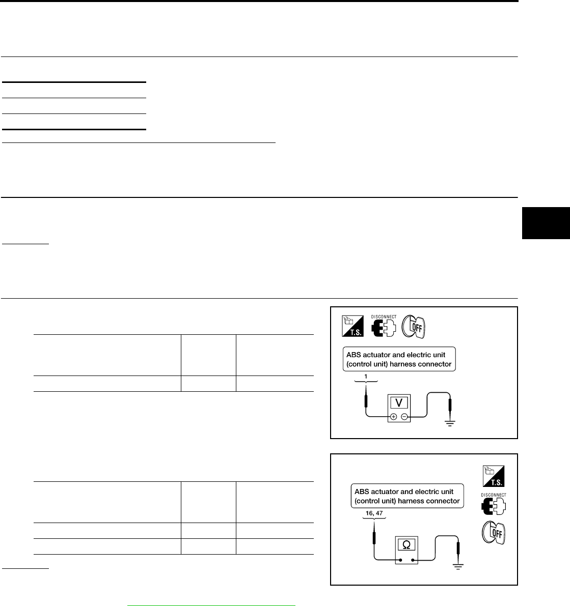
3. CHECKING ABS MOTOR AND MOTOR RELAY POWER SYSTEM
1. Check voltage between ABS actuator and electric unit (control
unit) harness connector E125 and ground.
2. Check resistance between ABS actuator and electric unit (con-
trol unit) connector E125 and ground.
OK or NG
OK >> Perform self-diagnosis again. If the same results
appear, replace ABS actuator and electric unit (control
unit). Refer to BRC-41, "Removal and Installation" .
NG >> Repair the circuit.
Self-diagnosis results
PUMP MOTOR
ACTUATOR RLY
ABS actuator and electric
unit (control unit) harness
connector E125
Body
ground
Measured
value
(Approx.)
1—12V
WFIA0209E
ABS actuator and electric
unit (control unit)
harness connector E125
Body
ground
Measured
value
(Approx.)
16 — 0Ω
47 — 0Ω
WFIA0196E
BRC-34
[ABS]
TROUBLE DIAGNOSIS FOR SELF-DIAGNOSTIC ITEMS
Revision: February 2006 2005 Xterra
ABS Control Unit Power and Ground Systems Inspection EFS005LC
INSPECTION PROCEDURE
1. SELF-DIAGNOSIS RESULT CHECK
Check self-diagnosis results.
Is the above displayed in the self-diagnosis display items?
YES >> GO TO 2.
NO >> Inspection End.
2. CONNECTOR INSPECTION
1. Disconnect the ABS actuator and electric unit (control unit) connector E125.
2. Check the terminals for deformation, disconnection, looseness or damage.
OK or NG
OK >> GO TO 3.
NG >> Repair or replace as necessary.
3. ABS CONTROL UNIT POWER AND GROUND CIRCUIT INSPECTION
Measure the voltage and continuity between the ABS actuator and electric unit (control unit) harness connec-
tor E125 and ground.
OK or NG
OK >> Check the battery for loose terminals, low voltage, etc. Repair as necessary.
NG >> Repair the circuit.
CAN Communication System Inspection EFS005LD
INSPECTION PROCEDURE
1. CHECK CONNECTOR
1. Turn ignition switch OFF, disconnect the ABS actuator and electric unit (control unit) connector and check
the terminals for deformation, disconnection, looseness, and so on. If there is a malfunction, repair or
replace the terminal.
2. Reconnect connector to perform self-diagnosis.
Is "CAN COMM CIRCUIT" displayed in self-diagnosis display items?
YES >> Print out the self-diagnostic results, and refer to LAN-21, "CAN COMMUNICATION" .
NO >> Connector terminal is loose, damaged, open, or shorted.
Self-diagnosis results
BATTERY VOLTAGE
Signal name ABS actuator and electric unit
(control unit)
harness connector E125
Body
ground Measured value
Power supply 1— Battery voltage (Approx. 12V)
32
Ground 16 — Continuity should exist.
47

TROUBLE DIAGNOSES FOR SYMPTOMS
BRC-35
[ABS]
C
D
E
G
H
I
J
K
L
M
A
B
BRC
Revision: February 2006 2005 Xterra
TROUBLE DIAGNOSES FOR SYMPTOMS PFP:99999
ABS Works Frequently EFS005LE
1. CHECK WARNING LAMP ACTIVATION
Make sure warning lamp remains off while driving.
OK or NG
OK >> GO TO 2.
NG >> Carry out self-diagnosis. Refer to BRC-25, "SELF-DIAGNOSIS" .
2. CHECK WHEEL SENSORS
Check the following.
●Wheel sensor mounting for looseness
●Wheel sensors for physical damage
●Wheel sensor connectors for terminal damage or loose connections
●Sensor rotor and mount for physical damage (rear only)
OK or NG
OK >> GO TO 3.
NG >> Repair or replace as necessary.
3. CHECK FRONT AND REAR AXLES
Check front and rear axles for excessive looseness. Refer to FAX-5, "WHEEL BEARING INSPECTION" ,
RAX-6, "Rear Axle Bearing" (C200) or RAX-18, "Rear Axle Bearing" (M226).
OK or NG
OK >> GO TO 4.
NG >> Repair as necessary.
4. CHECK BRAKE FLUID PRESSURE
Check brake fluid pressure distribution.
Refer to BRC-21, "Basic Inspection" .
Is brake fluid pressure distribution normal?
YES >> Inspection End.
NO >> Perform Basic Inspection. Refer to BRC-21, "Basic Inspection" .

BRC-36
[ABS]
TROUBLE DIAGNOSES FOR SYMPTOMS
Revision: February 2006 2005 Xterra
Unexpected Pedal Action EFS005LF
1. CHECK WARNING LAMP ACTIVATION
Make sure warning lamp remains off while driving.
OK or NG
OK >> GO TO 2.
NG >> Carry out self-diagnosis. Refer to BRC-25, "SELF-DIAGNOSIS" .
2. CHECK BRAKE PEDAL STROKE
Check brake pedal stroke.
Is brake pedal stroke excessive?
YES >> Perform Basic Inspection. Refer to BRC-21, "Basic
Inspection" .
NO >> GO TO 3.
3. CHECK CONNECTOR AND BRAKING PERFORMANCE
1. Disable ABS by disconnecting ABS actuator and electric unit (control unit) connector.
2. Drive vehicle and check brake operation.
NOTE:
●Stopping distance may be longer than vehicles without ABS when road condition is slippery.
●Driving the vehicle with the ABS actuator and electric unit (control unit) disconnected may induce DTCs
in electrical control units using CAN communication. After the inspection, clear all DTCs. Refer to LAN-
21, "CAN COMMUNICATION" .
OK or NG
OK >> GO TO 4.
NG >> Perform Basic Inspection. Refer to BRC-21, "Basic Inspection" .
4. CHECK WHEEL SENSORS
Check the following.
●Wheel sensor mounting for looseness
●Wheel sensors for physical damage
●Wheel sensor connectors for terminal damage or loose connections
OK or NG
OK >> Check ABS actuator and electric unit (control unit) connector terminals for deformation, discon-
nection, looseness or damage. Reconnect ABS actuator and electric unit (control unit) harness
connector. Then retest.
NG >> Repair or replace as necessary.
SBR540A

TROUBLE DIAGNOSES FOR SYMPTOMS
BRC-37
[ABS]
C
D
E
G
H
I
J
K
L
M
A
B
BRC
Revision: February 2006 2005 Xterra
Long Stopping Distance EFS005LG
1. CHECK BASE BRAKING SYSTEM PERFORMANCE
1. Disable ABS by disconnecting ABS actuator and electric unit (control unit) connector.
2. Drive vehicle and check brake operation.
NOTE:
●Stopping distance may be longer than vehicles without ABS when road condition is slippery.
●Driving the vehicle with the ABS actuator and electric unit (control unit) disconnected may induce DTCs
in electrical control units using CAN communication. After the inspection, clear all DTCs. Refer to LAN-
21, "CAN COMMUNICATION" .
OK or NG
OK >> Go to BRC-35, "ABS Works Frequently" .
NG >> Perform Basic Inspection. Refer to BRC-21, "Basic Inspection" .
ABS Does Not Work EFS005LH
CAUTION:
The ABS does not operate when the vehicle speed is 10 km/h (6 MPH) or less.
1. CHECK WARNING LAMP ACTIVATION
Turn ignition switch ON and check for warning lamp activation.
●Warning lamp should activate for approximately 2 seconds after turning the ignition switch ON.
OK or NG
OK >> Carry out self-diagnosis. Refer to BRC-25, "SELF-DIAGNOSIS" .
NG >> Go to BRC-38, "ABS Warning Lamp Does Not Come On When Ignition Switch Is Turned On" .
Pedal Vibration or ABS Operation Noise EFS005LI
NOTE:
During ABS activation, pedal vibration may be felt and a noise may be heard. This is normal and does not indi-
cate a malfunction.
1. CHECK SYMPTOM
1. Apply brake.
2. Start engine.
Does the symptom occur only when engine is started?
YES >> Carry out self-diagnosis. Refer to BRC-25, "SELF-DIAGNOSIS" .
NO >> GO TO 2.
2. RECHECK SYMPTOM
Does the symptom occur only when electrical equipment switches (such as headlamps) are turned on?
YES >> Check for radio, antenna or related wiring that is routed too close to the ABS actuator and electric
unit (control unit) and reroute as necessary.
NO >> Go to BRC-35, "ABS Works Frequently" .
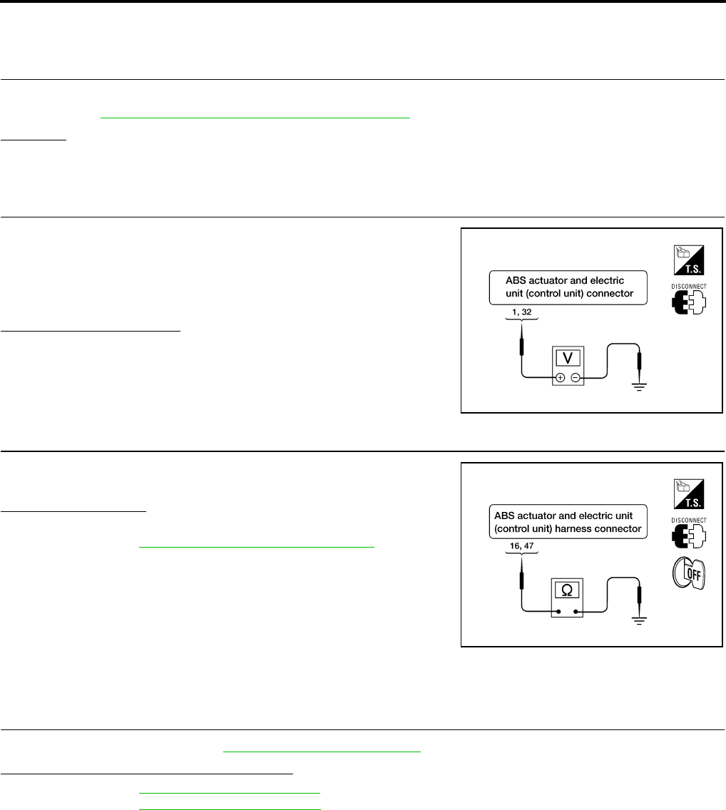
BRC-38
[ABS]
TROUBLE DIAGNOSES FOR SYMPTOMS
Revision: February 2006 2005 Xterra
ABS Warning Lamp Does Not Come On When Ignition Switch Is Turned On EFS005LJ
1. CHECK ABS ACTUATOR AND ELECTRIC UNIT (CONTROL UNIT) FUSES
Check 30A fusible link n and 40A fusible link l for ABS actuator and electric unit (control unit). For fusible link
layout, refer to PG-4, "POWER SUPPLY ROUTING CIRCUIT" .
OK or NG
OK >> GO TO 2.
NG >> If fusible link is blown, be sure to eliminate cause of problem before replacing.
2. CHECK ABS ACTUATOR AND ELECTRIC UNIT (CONTROL UNIT) POWER SUPPLY CIRCUITS
1. Disconnect ABS actuator and electric unit (control unit) connec-
tor.
2. Check voltage between ABS actuator and electric unit (control
unit) connector terminal 1 and ground and terminal 32 and
ground.
Does battery voltage exist?
YES >> GO TO 3.
NO >> Repair harness or connectors between fusible link and
ABS actuator and electric unit (control unit).
3. CHECK ABS ACTUATOR AND ELECTRIC UNIT (CONTROL UNIT) GROUND CIRCUIT
Check continuity between ABS actuator and electric unit (control
unit) connector terminal 16 and ground and terminal 47 and ground.
Does continuity exist?
YES >> Replace ABS actuator and electric unit (control unit).
Refer to BRC-41, "Removal and Installation" .
NO >> Repair harness or connectors between ABS actuator
and electric unit (control unit) and ground.
ABS Warning Lamp Stays On When Ignition Switch Is Turned On EFS005LK
1. CARRY OUT SELF-DIAGNOSIS
Carry out self-diagnosis. Refer to BRC-25, "SELF-DIAGNOSIS" .
Are malfunctions detected in self-diagnosis?
YES >> Refer to BRC-26, "Display Item List" .
NO >> Refer to DI-28, "WARNING LAMPS" .
WFIA0199E
WFIA0196E
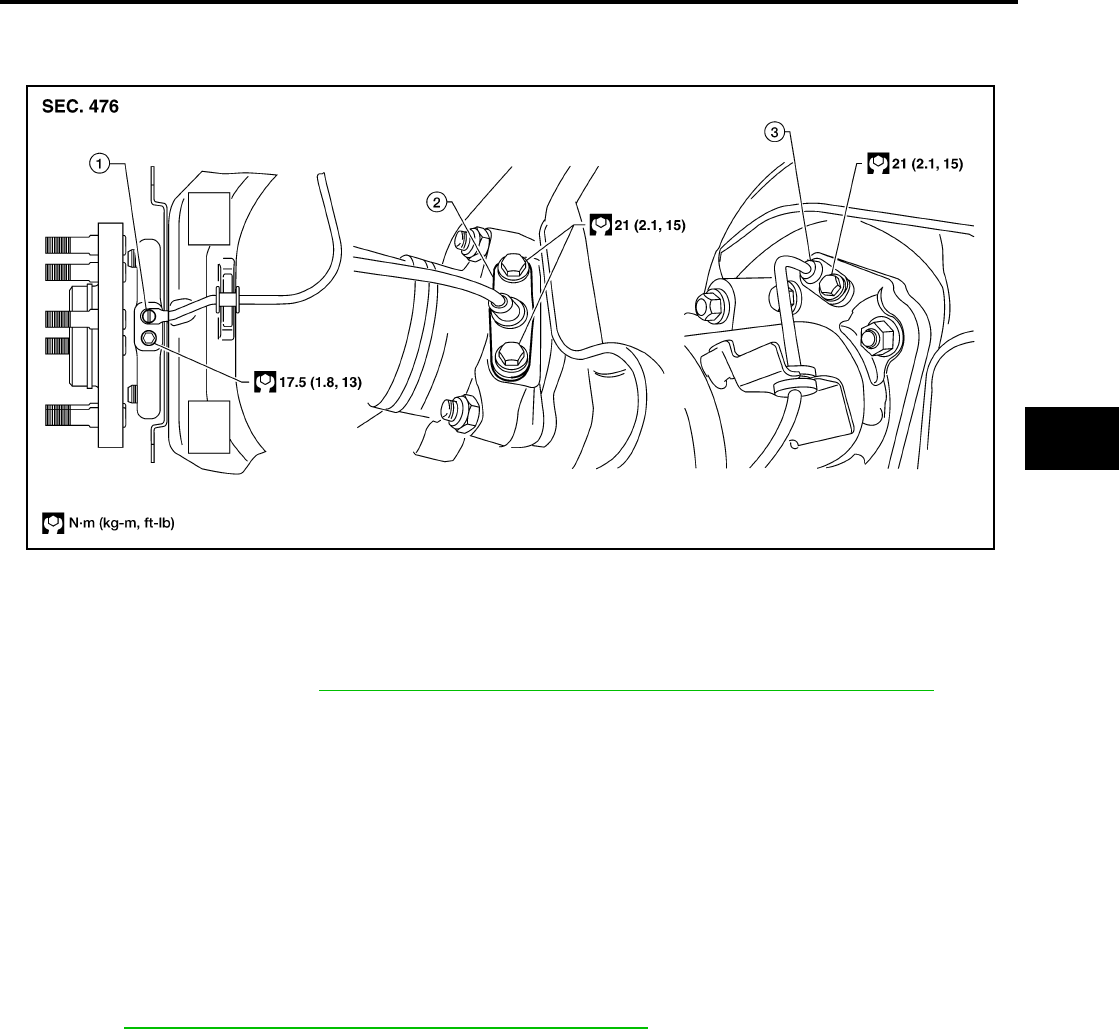
WHEEL SENSORS
BRC-39
[ABS]
C
D
E
G
H
I
J
K
L
M
A
B
BRC
Revision: February 2006 2005 Xterra
WHEEL SENSORS PFP:47910
Removal and Installation EFS005LL
REMOVAL
1. Remove wheel sensor mounting screw(s).
●When removing the front wheel sensor, first remove the disc rotor to gain access to the front wheel sen-
sor mounting bolt. Refer to BR-23, "Removal and Installation of Brake Caliper and Disc Rotor" .
2. Pull out the sensor, being careful to turn it as little as possible.
CAUTION:
●Be careful not to damage sensor edge and sensor rotor teeth.
●Do not pull on the sensor harness.
3. Disconnect wheel sensor harness electrical connector, then remove harness from mounts.
INSTALLATION
●Before installing wheel sensors,
–Inspect wheel sensor assembly and replace if damaged.
–Clean wheel sensor hole and mounting surface with brake cleaner and a lint-free shop rag. Be careful that
dirt and debris do not enter the axle.
–Install a new wheel sensor O-ring, then apply a coat of suitable grease to the O-ring and mounting hole.
Refer to MA-11, "RECOMMENDED FLUIDS AND LUBRICANTS" .
●Installation is in the reverse order of removal.
1. Front wheel sensor 2. Rear wheel sensor (C200) 3. Rear wheel sensor (M226)
WFIA0339E

BRC-40
[ABS]
SENSOR ROTOR
Revision: February 2006 2005 Xterra
SENSOR ROTOR PFP:47970
Removal and Installation EFS005LM
FRONT
The wheel sensor rotors are built into the wheel hubs and are not removable. If damaged, replace wheel hub
and bearing assembly. Refer to FAX-5, "Removal and Installation" .
REAR (C200)
Removal and Installation
It is necessary to disassemble the rear axle to replace the sensor rotor. Perform the axle shaft assembly
removal procedure to replace sensor rotor. Refer to RAX-7, "Removal and Installation" .
REAR (M226)
Removal
1. Remove axle shaft assembly. Refer to RAX-19, "Removal and Installation" .
NOTE:
It is necessary to disassemble the rear axle to replace the sensor rotor.
2. Pull the sensor rotor of off the axle shaft using Tool and a press.
Installation
1. Install new sensor rotor on axle shaft using a suitable length
steel tube and a press. Make sure sensor rotor is fully seated.
CAUTION:
Do not reuse the old sensor rotor.
2. Install axle shaft assembly. Refer to RAX-7, "Removal and
Installation" (C200), or RAX-19, "Removal and Installation"
(M226).
CAUTION:
Do not reuse the axle oil seal. The axle oil seal must be
replaced every time the axle shaft assembly is removed
from the axle shaft housing.
Tool number : 205-D002 ( — )
WFIA0341E
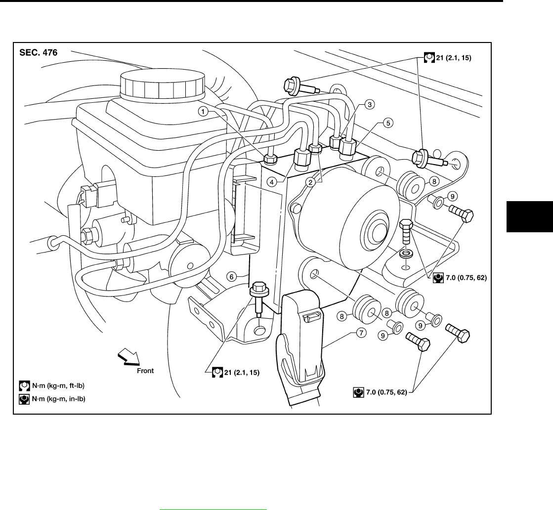
ACTUATOR AND ELECTRIC UNIT (ASSEMBLY)
BRC-41
[ABS]
C
D
E
G
H
I
J
K
L
M
A
B
BRC
Revision: February 2006 2005 Xterra
ACTUATOR AND ELECTRIC UNIT (ASSEMBLY) PFP:47660
Removal and Installation EFS005LN
REMOVAL
1. Disconnect the negative battery terminal.
2. Drain the brake fluid. Refer to BR-9, "Drain and Refill" .
3. Disconnect the actuator harness from the ABS actuator and electric unit (control unit).
CAUTION:
●To remove the brake tubes, use a flare nut wrench to prevent the flare nuts and brake tubes from
being damaged.
●Be careful not to splash brake fluid on painted areas.
4. Disconnect the brake tubes.
5. Remove three bolts and then the ABS actuator and electric unit (control unit).
1. To rear 2. To front left 3. To front right
4. From the master cylinder secondary
side
5. From the master cylinder primary
side
6. ABS actuator and electric unit (con-
trol unit)
7. Harness connector 8. Grommet 9. Collar
WFIA0388E

BRC-42
[ABS]
ACTUATOR AND ELECTRIC UNIT (ASSEMBLY)
Revision: February 2006 2005 Xterra
INSTALLATION
Installation is in the reverse order of removal.
CAUTION:
To install, use a flare nut wrench (commercial service tool).
●Always tighten brake tubes to specification when installing. Refer to BR-11, "BRAKE PIPING AND
HOSE" .
●Never reuse drained brake fluid.
●After installation of the ABS actuator and electric unit (control unit), refill brake system with new
brake fluid. Then bleed the air from the system. Refer to BR-10, "Bleeding Brake System" .

PRECAUTIONS
BRC-43
[ABLS/ABS]
C
D
E
G
H
I
J
K
L
M
A
B
BRC
Revision: February 2006 2005 Xterra
PRECAUTIONS PFP:00001
Precautions for Supplemental Restraint System (SRS) “AIR BAG” and “SEAT
BELT PRE-TENSIONER” EFS005U2
The Supplemental Restraint System such as “AIR BAG” and “SEAT BELT PRE-TENSIONER”, used along
with a front seat belt, helps to reduce the risk or severity of injury to the driver and front passenger for certain
types of collision. This system includes seat belt switch inputs and dual stage front air bag modules. The SRS
system uses the seat belt switches to determine the front air bag deployment, and may only deploy one front
air bag, depending on the severity of a collision and whether the front occupants are belted or unbelted.
Information necessary to service the system safely is included in the SRS and SB section of this Service Man-
ual.
WARNING:
●To avoid rendering the SRS inoperative, which could increase the risk of personal injury or death
in the event of a collision which would result in air bag inflation, all maintenance must be per-
formed by an authorized NISSAN/INFINITI dealer.
●Improper maintenance, including incorrect removal and installation of the SRS, can lead to per-
sonal injury caused by unintentional activation of the system. For removal of Spiral Cable and Air
Bag Module, see the SRS section.
●Do not use electrical test equipment on any circuit related to the SRS unless instructed to in this
Service Manual. SRS wiring harnesses can be identified by yellow and/or orange harnesses or
harness connectors.
Precautions for Brake System EFS005LP
CAUTION:
●Refer to MA-11, "RECOMMENDED FLUIDS AND LUBRICANTS" for recommended brake fluid.
●Never reuse drained brake fluid.
●Be careful not to splash brake fluid on painted areas; it may cause paint damage. If brake fluid is
splashed on painted areas, wash it away with water immediately.
●To clean or wash all parts of master cylinder and disc brake caliper, use clean brake fluid.
●Never use mineral oils such as gasoline or kerosene. They will ruin rubber parts of the hydraulic
system.
●Use flare nut wrench when removing and installing brake
tube.
●If a brake fluid leak is found, the part must be disassembled
without fail. Then it has to be replaced with a new one if a
defect exists.
●Turn the ignition switch OFF and remove the connector of
the ABS actuator and electric unit (control unit) or the bat-
tery terminal before performing the work.
●Always torque brake lines when installing.
●Burnish the brake contact surfaces after refinishing or
replacing rotors, after replacing pads, or if a soft pedal
occurs at very low mileage.
Refer to BR-27, "BRAKE BURNISHING PROCEDURE" (front disc brake) or BR-32, "BRAKE BUR-
NISHING PROCEDURE" (rear disc brake).
WARNING:
●Clean brake pads and shoes with a waste cloth, then wipe with a dust collector.
Precautions When Using CONSULT-II EFS005LQ
When connecting CONSULT-II to data link connector, connect them through CONSULT-II CONVERTER.
CAUTION:
If CONSULT-II is used with no connection of CONSULT-II CONVERTER, malfunctions might be
detected in self-diagnosis depending on control unit which carries out CAN communication.
CHECK POINTS FOR USING CONSULT-II
1. Has CONSULT-II been used without connecting CONSULT-II CONVERTER on this vehicle?
●If YES, GO TO 2.
SBR686C

BRC-44
[ABLS/ABS]
PRECAUTIONS
Revision: February 2006 2005 Xterra
●If NO, GO TO 5.
2. Is there any indication other than indications relating to CAN communication system in the self-diagnosis
results?
●If YES, GO TO 3.
●If NO, GO TO 4.
3. Based on self-diagnosis results unrelated to CAN communication, carry out the inspection.
4. Malfunctions may be detected in self-diagnosis depending on control units carrying out CAN communica-
tion. Therefor, erase the self-diagnosis results.
5. Diagnose CAN communication system. Refer to LAN-21, "CAN COMMUNICATION" .
Precautions for Brake Control EFS005LR
●During ABS operation, the brake pedal may vibrate lightly and a mechanical noise may be heard. This is
normal.
●During HDC operation, a mechanical noise may be heard. This is normal.
●Just after starting vehicle, the brake pedal may vibrate or a motor operating noise may be heard from
engine compartment. This is a normal status of operation check.
●Stopping distance may be longer than that of vehicles without ABS when vehicle drives on rough, gravel,
or snow-covered (fresh, deep snow) roads.
●When an error is indicated by ABS or another warning lamp, collect all necessary information from cus-
tomer (what symptoms are present under what conditions) and check for simple causes before starting
diagnosis. Besides electrical system inspection, check brake booster operation, brake fluid level, and fluid
leaks.
●If incorrect tire sizes or types are installed on the vehicle or brake pads are not Genuine NISSAN parts,
stopping distance or steering stability may deteriorate.
●If there is a radio, antenna or related wiring near control module, ABS function may have a malfunction or
error.
●If aftermarket parts (car stereo, CD player, etc.) have been installed, check for incidents such as harness
pinches, open circuits or improper wiring.
Precautions for CAN System EFS005LS
●Do not apply voltage of 7.0V or higher to terminal to be measured.
●Maximum open terminal voltage of tester in use must be less than 7.0V.
●Before checking harnesses, turn ignition switch OFF and disconnect battery negative cable.
●Area to be repaired must be soldered and wrapped with tape.
Make sure that fraying of twisted wire is within 110 mm (4.33 in).
PKIA0306E

PRECAUTIONS
BRC-45
[ABLS/ABS]
C
D
E
G
H
I
J
K
L
M
A
B
BRC
Revision: February 2006 2005 Xterra
●Do not make a bypass connection to repaired area. (If the circuit
is bypassed, characteristics of twisted wire will be lost.)
Wiring Diagrams and Trouble Diagnosis EFS005LT
When you read wiring diagrams, refer to the following:
●GI-16, "How to Read Wiring Diagrams".
●PG-4, "POWER SUPPLY ROUTING CIRCUIT".
When you perform trouble diagnosis, refer to the following:
●GI-12, "HOW TO FOLLOW TEST GROUPS IN TROUBLE DIAGNOSES".
●GI-28, "How to Perform Efficient Diagnosis for an Electrical Incident".
PKIA0307E

BRC-46
[ABLS/ABS]
PREPARATION
Revision: February 2006 2005 Xterra
PREPARATION PFP:00002
Special Service Tool EFS005LU
The actual shapes of Kent-Moore tools may differ from those of special service tools illustrated here.
Commercial Service Tools EFS005LV
Tool number
(Kent-Moore No.)
Tool name
Description
—
(J-45741)
ABS active wheel sensor tester
Checking operation of ABS active wheel
sensors
205-D002
(—)
Bearing splitter
Removing axle shaft bearing
WFIA0101E
ZZA0700D
Tool name Description
1. Flare nut crowfoot
2. Torque wrench
Removing and installing brake piping
a: 10mm (0.39 in)/12mm (0.47 in)
S-NT360
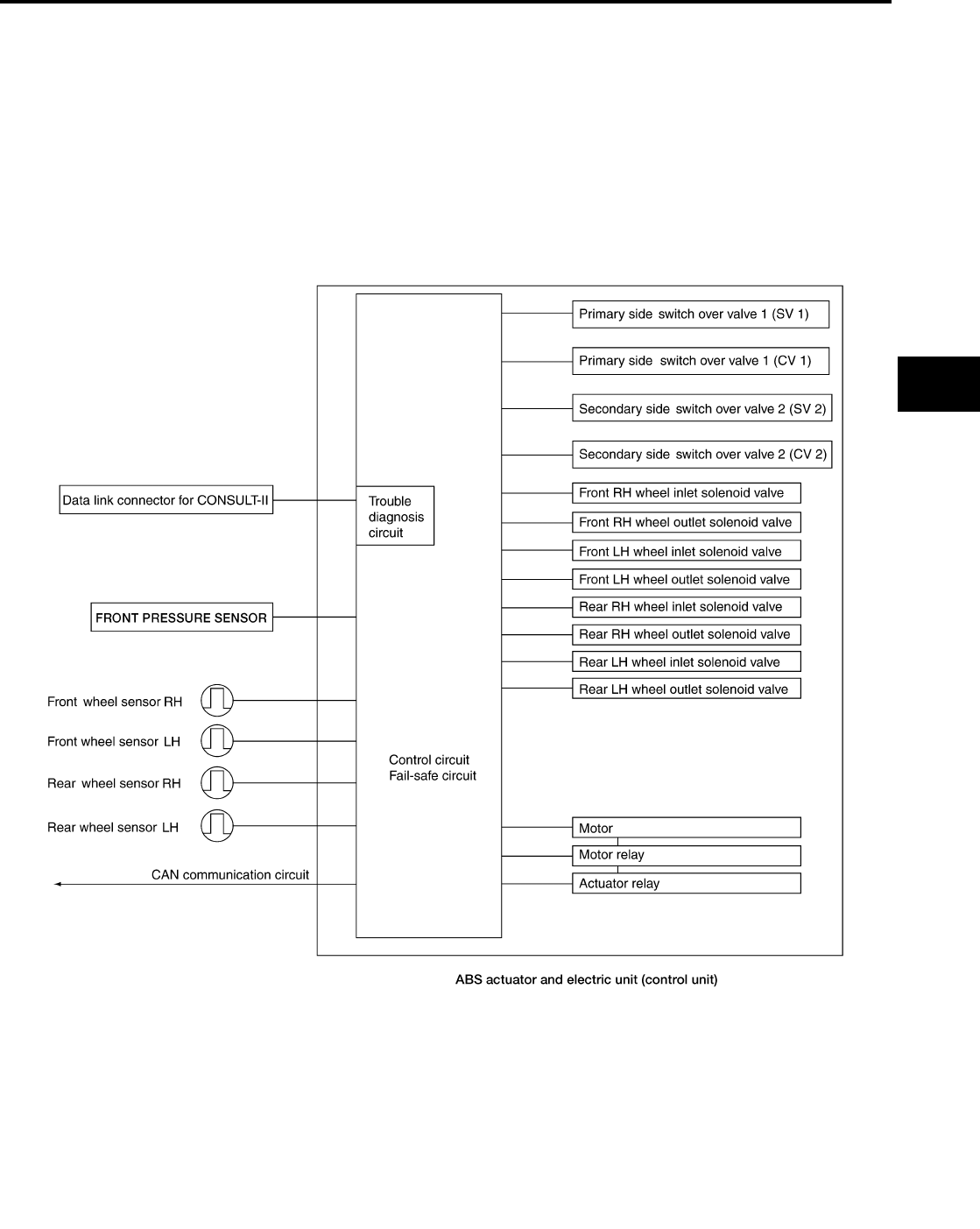
SYSTEM DESCRIPTION
BRC-47
[ABLS/ABS]
C
D
E
G
H
I
J
K
L
M
A
B
BRC
Revision: February 2006 2005 Xterra
SYSTEM DESCRIPTION PFP:00000
System Components EFS005LW
WFIA0362E

BRC-48
[ABLS/ABS]
SYSTEM DESCRIPTION
Revision: February 2006 2005 Xterra
ABS Function EFS005LX
●The Anti-Lock Brake System detects wheel revolution while braking and improves handling stability during
sudden braking by electrically preventing wheel lockup. Maneuverability is also improved for avoiding
obstacles.
●If the electrical system malfunctions, the Fail-Safe function is activated, the ABS becomes inoperative and
the ABS warning lamp turns on.
●The electrical system can be diagnosed using CONSULT-II.
●During ABS operation, the brake pedal may vibrate lightly and a mechanical noise may be heard. This is
normal.
●Just after starting the vehicle, the brake pedal may vibrate or a motor operating noise may be heard from
engine compartment. This is a normal status of operation check.
●Stopping distance may be longer than that of vehicles without ABS when vehicle drives on rough, gravel,
or snow-covered (fresh, deep snow) roads.
EBD Function EFS005LY
●Electronic Brake Distribution is a function that detects subtle slippages between the front and rear wheels
during braking, and it improves handling stability by electronically controlling the brake fluid pressure
which results in reduced rear wheel slippage.
●If the electrical system malfunctions, the Fail-Safe function is activated, the EBD and ABS become inoper-
ative, and the ABS warning lamp and brake warning lamp are turned on.
●The electrical system can be diagnosed using CONSULT-II.
●During EBD operation, the brake pedal may vibrate lightly and a mechanical noise may be heard. This is
normal.
●Just after starting the vehicle, the brake pedal may vibrate or a motor operating noise may be heard from
engine compartment. This is a normal status of operation check.
ABLS Function EFS005LZ
●Active brake limited slip is a function to improve vehicle traction. Spinning of the drive wheels is detected
by the ABS actuator and electric unit (control unit) using inputs from the wheel speed sensors. If wheel
spin occurs, the ABLS system brakes the spinning wheel which distributes the driving power to the other
drive wheel.
●The SLIP indicator lamp turns on to inform the driver of ABLS operation.
●During ABLS operation, the brake pedal may vibrate lightly and a mechanical noise may be heard. This is
normal.
Fail-Safe Function EFS005M0
CAUTION:
If the Fail-Safe function is activated, perform the Self Diagnosis for ABS/ABLS system.
ABS/EBD SYSTEM
In case of an electrical malfunction with the ABS, the ABS warning lamp will turn on. In case of an electrical
malfunction with the EBD system, the brake warning lamp and ABS warning lamp will turn on.
The system will revert to one of the following conditions of the Fail-Safe function.
1. For ABS malfunction, only the EBD is operative and the condition of the vehicle is the same condition of
vehicles without ABS/ABLS system.
2. For EBD malfunction, the EBD and ABS become inoperative, and the condition of the vehicle is the same
as the condition of vehicles without ABS/ABLS or EBD system.
ABLS SYSTEM
In case of an ABLS system malfunction, the SLIP indicator lamp will turn on. The condition of the vehicle is the
same as the condition of vehicles without ABS/ABLS system.

SYSTEM DESCRIPTION
BRC-49
[ABLS/ABS]
C
D
E
G
H
I
J
K
L
M
A
B
BRC
Revision: February 2006 2005 Xterra
Hydraulic Circuit Diagram EFS005M1
WFIA0363E

BRC-50
[ABLS/ABS]
CAN COMMUNICATION
Revision: February 2006 2005 Xterra
CAN COMMUNICATION PFP:23710
System Description EFS005M2
Refer to LAN-21, "CAN COMMUNICATION" .
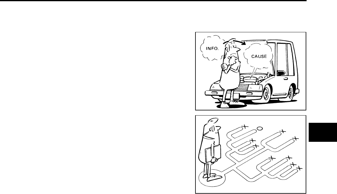
TROUBLE DIAGNOSIS
BRC-51
[ABLS/ABS]
C
D
E
G
H
I
J
K
L
M
A
B
BRC
Revision: February 2006 2005 Xterra
TROUBLE DIAGNOSIS PFP:00000
How to Perform Trouble Diagnoses for Quick and Accurate Repair EFS005M3
INTRODUCTION
The ABS/ABLS system has an electronic control unit to control major
functions. The control unit accepts input signals from sensors and
controls actuator operation. It is also important to check for conven-
tional problems such as air leaks in the booster or lines, lack of
brake fluid, or other problems with the brake system.
It is much more difficult to diagnose a problem that occurs intermit-
tently rather than continuously. Most intermittent problems are
caused by poor electrical connections or faulty wiring. In this case,
careful checking of suspicious circuits may help prevent the replace-
ment of good parts.
A visual check only may not find the cause of the problem, so a road
test should be performed.
Before undertaking actual checks, take just a few minutes to talk with
a customer who approaches with an ABS/ABLS complaint. The cus-
tomer is a very good source of information on such problems, espe-
cially intermittent ones. Through the talks with the customer, find out
what symptoms are present and under what conditions they occur.
Start your diagnosis by looking for “conventional” problems first. This
is one of the best ways to troubleshoot brake problems on an ABS/
ABLS equipped vehicle. Also check related Service Bulletins for
information.
SEF233G
SEF234G
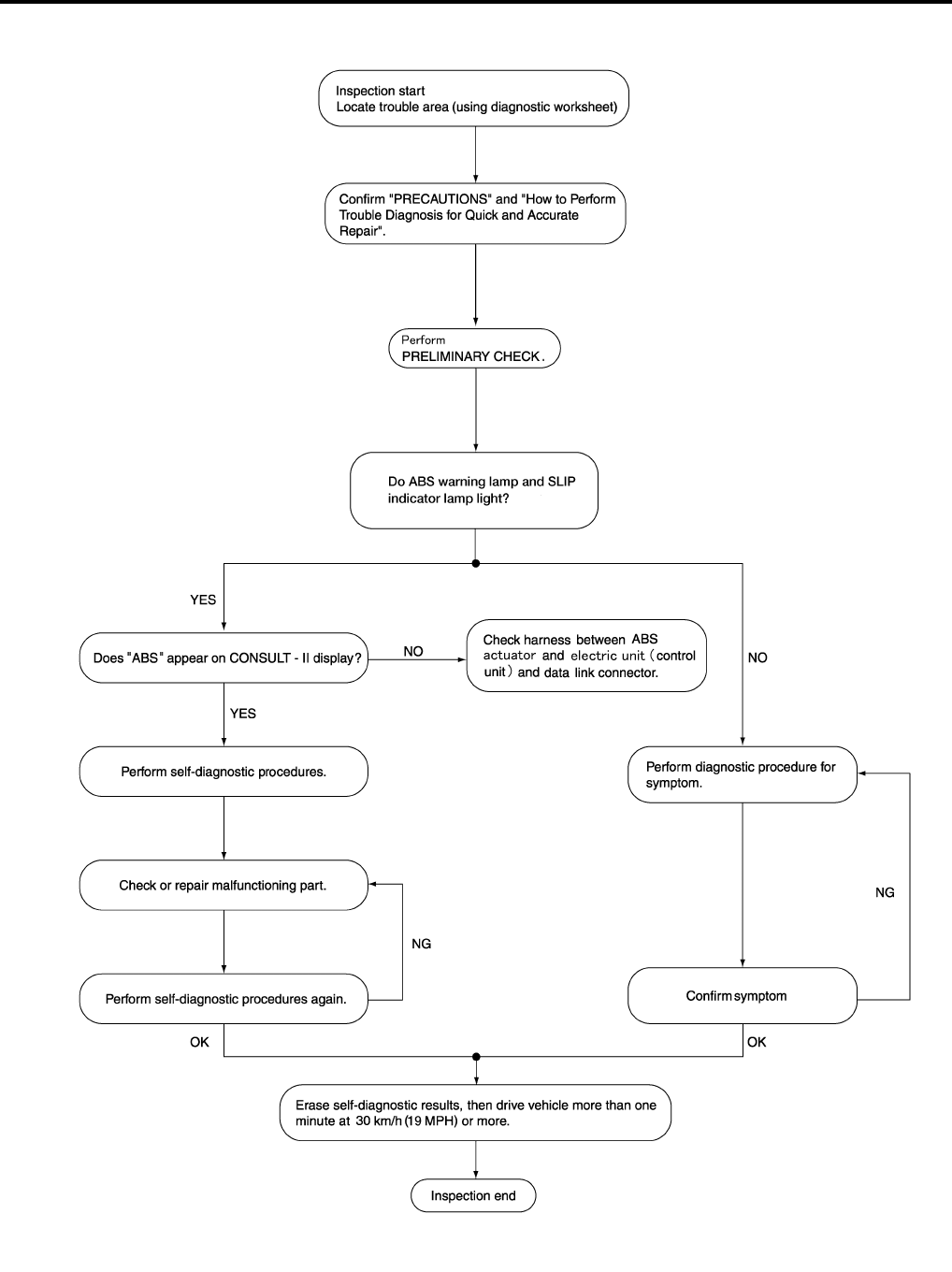
BRC-52
[ABLS/ABS]
TROUBLE DIAGNOSIS
Revision: February 2006 2005 Xterra
WORK FLOW
WFIA0364E

TROUBLE DIAGNOSIS
BRC-53
[ABLS/ABS]
C
D
E
G
H
I
J
K
L
M
A
B
BRC
Revision: February 2006 2005 Xterra
CLARIFY CONCERN
●A customer's description of a vehicle concern may vary depend-
ing on the individual. It is important to clarify the customer's con-
cern.
●Ask the customer about what symptoms are present under what
conditions. Use this information to reproduce the symptom while
driving.
●It is also important to use the diagnosis sheet to understand
what type of trouble the customer is having.
EXAMPLE OF DIAGNOSIS SHEET
SBR339B
WFIA0365E
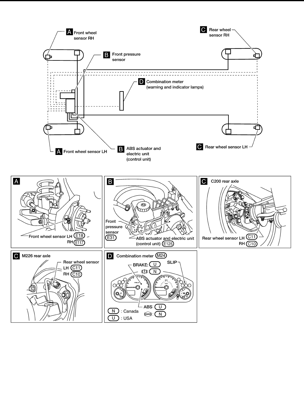
BRC-54
[ABLS/ABS]
TROUBLE DIAGNOSIS
Revision: February 2006 2005 Xterra
Component Parts and Harness Connector Location EFS005M4
WFIA0366E
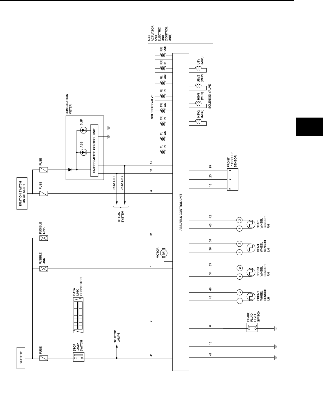
TROUBLE DIAGNOSIS
BRC-55
[ABLS/ABS]
C
D
E
G
H
I
J
K
L
M
A
B
BRC
Revision: February 2006 2005 Xterra
Schematic EFS005M5
WFWA0234E
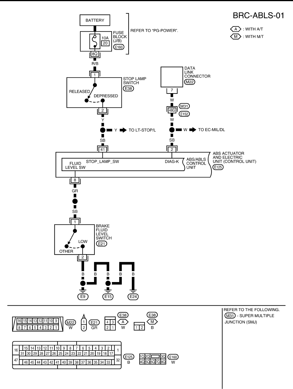
BRC-56
[ABLS/ABS]
TROUBLE DIAGNOSIS
Revision: February 2006 2005 Xterra
Wiring Diagram — ABLS — EFS005M6
WFWA0235E
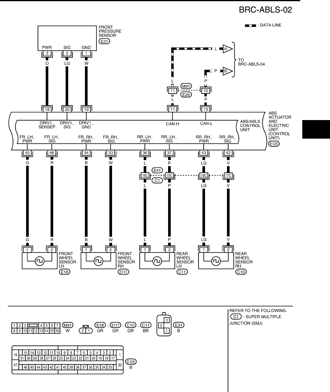
TROUBLE DIAGNOSIS
BRC-57
[ABLS/ABS]
C
D
E
G
H
I
J
K
L
M
A
B
BRC
Revision: February 2006 2005 Xterra
WFWA0236E
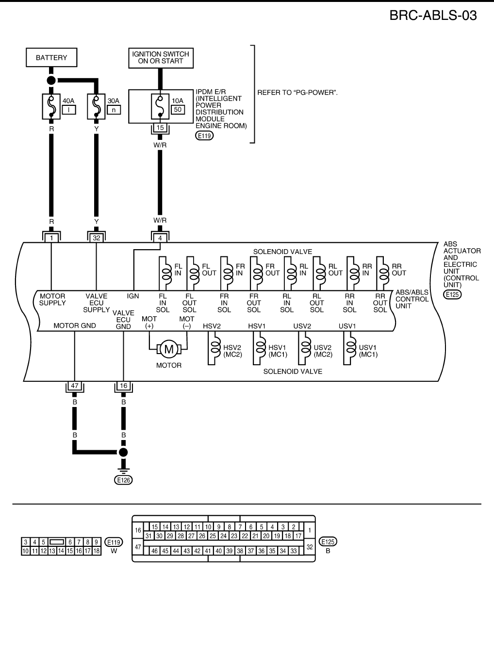
BRC-58
[ABLS/ABS]
TROUBLE DIAGNOSIS
Revision: February 2006 2005 Xterra
WFWA0237E
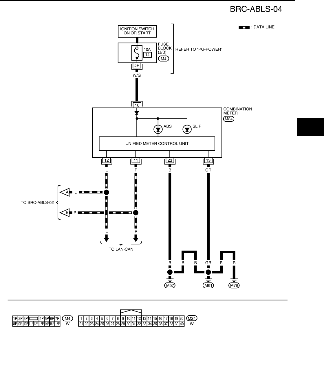
TROUBLE DIAGNOSIS
BRC-59
[ABLS/ABS]
C
D
E
G
H
I
J
K
L
M
A
B
BRC
Revision: February 2006 2005 Xterra
WFWA0238E

BRC-60
[ABLS/ABS]
TROUBLE DIAGNOSIS
Revision: February 2006 2005 Xterra
Basic Inspection EFS005M7
BRAKE FLUID LEVEL, FLUID LEAK, AND BRAKE PAD INSPECTION
1. Check fluid level in the brake fluid reservoir. If fluid level is low, add fluid.
2. Check the brake piping and around the ABS actuator and electric unit (control unit) for leaks. If there is
leaking or seeping fluid, check the following items.
●If ABS actuator and electric unit (control unit) connection is loose, tighten the piping to the specified
torque and recheck for leaks.
●If there is damage to the connection flare nut or ABS actuator and electric unit (control unit) threads,
replace the damaged part and recheck for leaks.
●When there is fluid leaking or seeping from a fluid connection, use a clean cloth to wipe off the fluid and
recheck for leaks. If fluid is still seeping out, replace the damaged part. If the fluid is leaking at the ABS
actuator and electric unit (control unit), replace the ABS actuator and electric unit (control unit) assem-
bly.
CAUTION:
The ABS actuator and electric unit (control unit) cannot be disassembled and must be replaced
as an assembly.
3. Check the brake pads for excessive wear.
POWER SYSTEM TERMINAL LOOSENESS AND BATTERY INSPECTION
Make sure the battery positive cable, negative cable and ground connection are not loose. In addition, make
sure the battery is sufficiently charged.
ABS WARNING LAMP AND SLIP INDICATOR LAMP INSPECTION
1. Make sure ABS warning lamp and SLIP indicator lamp turn on for approximately 2 seconds when the igni-
tion switch is turned ON. If they do not, check CAN communications. If there are no errors with CAN com-
munication system, check combination meter. Refer to DI-4, "COMBINATION METERS" .
2. Make sure the lamps turn off approximately 2 seconds after the ignition switch is turned ON. If the lamps
do not turn off, conduct self-diagnosis.
3. Make sure ABS warning lamp turns off approximately 2 seconds after the engine is started. If ABS warn-
ing lamp has not turned off 10 seconds after the engine has been started, conduct self-diagnosis of the
ABS actuator and electric unit (control unit).
4. After conducting the self-diagnosis, be sure to erase the error memory. Refer to BRC-64, "CONSULT-II
Function (ABS)" .

TROUBLE DIAGNOSIS
BRC-61
[ABLS/ABS]
C
D
E
G
H
I
J
K
L
M
A
B
BRC
Revision: February 2006 2005 Xterra
Warning Lamp and Indicator Timing EFS005M8
X: ON
—: OFF
Control Unit Input/Output Signal Standard EFS005M9
REFERENCE VALUE FROM CONSULT-II
CAUTION:
The display shows the control unit calculation data, so a normal value might be displayed even in the
event the output circuit (harness) is open or short circuited.
Condition ABS
warning lamp
SLIP
indicator lamp Remarks
When the ignition switch is OFF — — —
After the ignition switch is turned ON
for approx. 1 second XX —
After the ignition switch is turned ON
for approx. 2 seconds ——
Lamp goes off approx. 2 seconds
after ignition switch is turned ON.
ABS/ABLS malfunction X X
When the ABS actuator and electric
unit (control unit) is malfunctioning
(power supply or ground malfunc-
tion).
ABLS malfunction — X Only ABLS is malfunctioning (ABS
still functioning).
Monitor item Display content
Data monitor Note: Error inspection
checklist
Condition Reference value in
normal operation
N POSI SIG PNP switch signal ON/
OFF condition
A/T shift position = N position ON
BRC-80, "CAN Commu-
nication System Inspec-
tion"
A/T shift position = other than
N position OFF
P POSI SIG PNP switch signal ON/
OFF condition
A/T shift position P position ON
A/T shift position = other than
P position OFF
R POSI SIG PNP switch signal ON/
OFF condition
A/T shift position R position ON
A/T shift position = other than
R position OFF
SLCT LVR POSI PNP switch signal ON/
OFF condition
A/T shift position = N or P posi-
tion ON
A/T shift position = other than
N or P positions OFF
GEAR A/T gear position
1st gear 1
—
2nd gear 2
3rd gear 3
4th gear 4
5th gear 5
FR RH SENSOR
FR LH SENSOR
RR RH SENSOR
RR LH SENSOR
Wheel speed
Vehicle stopped 0 [km/h (MPH)]
BRC-72, "Wheel Sensor
System Inspection"
Vehicle running (Note 1)
Almost in accor-
dance with speed-
ometer display
(within ±10%)
ACCEL POS SIG
Open/close condition
of throttle valve (linked
with accelerator pedal).
Accelerator pedal not
depressed (ignition switch is
ON)
0% BRC-80, "CAN Commu-
nication System Inspec-
tion"
Depress accelerator pedal
(ignition switch is ON) 0 to 100%

BRC-62
[ABLS/ABS]
TROUBLE DIAGNOSIS
Revision: February 2006 2005 Xterra
2WD/4WD Drive axle 2WD model 2WD —
4WD model 4WD
ENGINE SPEED With engine running
With engine stopped 0 rpm
BRC-73, "Engine System
Inspection"
Engine running
Almost in accor-
dance with
tachometer display
BATTERY VOLT
Battery voltage sup-
plied to ABS actuator
and electric unit (con-
trol unit)
Ignition switch ON 10 to 16V
BRC-77, "ABS/ABLS
Control Unit Power and
Ground Systems Inspec-
tion"
CRANKING SIG Cranking status Cranking ON —
Not cranking OFF
STOP LAMP SW Stop lamp switch oper-
ation
Brake pedal depressed ON BRC-76, "Stop Lamp
Switch System Inspec-
tion"
Brake pedal not depressed OFF
ABS WARN LAMP ABS warning lamp ON
condition (Note 2)
ABS warning lamp ON ON —
ABS warning lamp OFF OFF
MOTOR RELAY Operation status of
motor and motor relay
Ignition switch ON or running
(ABS not activated) OFF
BRC-75, "Actuator Motor,
Motor Relay, and Circuit
Inspection"
Ignition switch ON or engine
running (ABS activated) ON
ACTUATOR RLY Actuator relay opera-
tion status
Vehicle stopped (Ignition
switch ON) OFF
Vehicle stopped (Engine run-
ning) ON
SLIP LAMP SLIP indicator lamp
status (Note 3)
When SLIP indicator lamp is
ON ON
BRC-80, "CAN Commu-
nication System Inspec-
tion"
When SLIP indicator lamp is
OFF OFF
EBD WARN LAMP EBD warning lamp sta-
tus
When EBD warning lamp is
ON ON
When EBD warning lamp is
OFF OFF
FR LH IN SOL
FR LH OUT SOL
FR RH IN SOL
FR RH OUT SOL
RR RH IN SOL
RR RH OUT SOL
RR LH IN SOL
RR LH OUT SOL
Solenoid valve opera-
tion
Actuator (solenoid) is active
(“ACTIVE TEST” with CON-
SULT-II) or actuator relay is
inactive (in fail-safe mode).
ON
BRC-74, "Solenoid and
Change-Over Valve Sys-
tem Inspection"
When actuator (solenoid) is
not active and actuator relay is
active (ignition switch ON).
OFF
CV1
CV2
SV1
SV2
Switch-over valve sta-
tus
When actuator (switch-over
valve) is active (“ACTIVE
TEST” with CONSULT-II) or
actuator relay is inactive (when
in fail-safe mode).
ON
When actuator (switch-over
valve) is not active and actua-
tor relay is active (ignition
switch ON).
OFF
DECEL G-SEN
Longitudinal accelera-
tion detected by Decel
G-Sensor
Vehicle stopped Approx. 0 G
—
Vehicle running -1.7 to 1.7 G
Monitor item Display content
Data monitor Note: Error inspection
checklist
Condition Reference value in
normal operation

TROUBLE DIAGNOSIS
BRC-63
[ABLS/ABS]
C
D
E
G
H
I
J
K
L
M
A
B
BRC
Revision: February 2006 2005 Xterra
Note 1: Confirm tire pressure is normal.
Note 2: ON/OFF timing of ABS warning lamp
ON: For approximately 2 seconds after ignition switch is turned ON, or when a malfunction is detected.
OFF: Approximately 2 seconds after ignition switch is turned ON (when system is in normal operation) and ABLS/ABS function is not
activated.
Note 3: SLIP indicator lamp ON/OFF timing
ON: For approximately 2 seconds after ignition switch is turned ON, or when ABLS function is activated while driving.
OFF: Approximately 2 seconds after ignition switch is turned ON (when system is in normal operation) and ABLS function is not acti-
vated.
PRESS SENSOR
Brake fluid pressure
detected by pressure
sensor
Do not step on the Brake pedal
(When ignition switch is ON) Approx. 0 bar
—
Step on the Brake pedal
(When ignition switch is ON) -40 to 300 bar
FLUID LEV SW ON/OFF status of
brake fluid level switch
When brake fluid level switch
ON ON BRC-78, "Brake Fluid
Level Switch System
Inspection"
When brake fluid level switch
OFF OFF
ABS SIGNAL
EBD SIGNAL
TCS SIGNAL
Signal status
ABS active
EBD active
TCS active
ON ABS system
EBD system
TCS system
ABS not active
EBD not active
TCS not active
OFF
ABS FAIL SIG
EBD FAIL SIG
TCS FAIL SIG
Fail signal status
ABS fail
EBD fail
TCS fail
ON ABS system
EBD system
TCS system
ABS normal
EBD normal
TCS normal
OFF
Monitor item Display content
Data monitor Note: Error inspection
checklist
Condition Reference value in
normal operation

BRC-64
[ABLS/ABS]
TROUBLE DIAGNOSIS
Revision: February 2006 2005 Xterra
CONSULT-II Function (ABS) EFS005MA
CONSULT-II can display each diagnostic item using the diagnostic test modes shown following.
CONSULT-II BASIC OPERATION PROCEDURE
1. Turn ignition switch OFF.
2. Connect CONSULT-II and CONSULT-II CONVERTER to the
data link connector.
CAUTION:
If CONSULT-II is used with no connection of CONSULT-II
CONVERTER, malfunctions might be detected in self-diag-
nosis depending on control unit which carries out CAN
communication.
3. Turn ignition switch ON.
4. Touch “START (NISSAN BASED VHCL)”.
5. Touch “ABS” in the “SELECT SYSTEM” screen.
If “ABS” is not indicated, go to GI-39, "CONSULT-II Data Link
Connector (DLC) Circuit" .
ABS diagnostic mode Description
WORK SUPPORT
Supports inspection and adjustments. Commands are transmitted to the ABS actuator and electric
unit (control unit) for setting the status suitable for required operation, input/output signals are
received from the ABS actuator and electric unit (control unit) and received data is displayed.
SELF-DIAG RESULTS Displays ABS actuator and electric unit (control unit) self-diagnosis results.
DATA MONITOR Displays ABS actuator and electric unit (control unit) input/output data in real time.
CAN DIAG SUPPORT MNTR The result of transmit/receive diagnosis of CAN communication can be read.
ACTIVE TEST Operation of electrical loads can be checked by sending drive signal to them.
FUNCTION TEST Conducted by CONSULT-II instead of a technician to determine whether each system is "OK" or
"NG".
ECU PART NUMBER ABS actuator and electric unit (control unit) part number can be read.
BBIA0538E
BCIA0029E
BCIA0030E
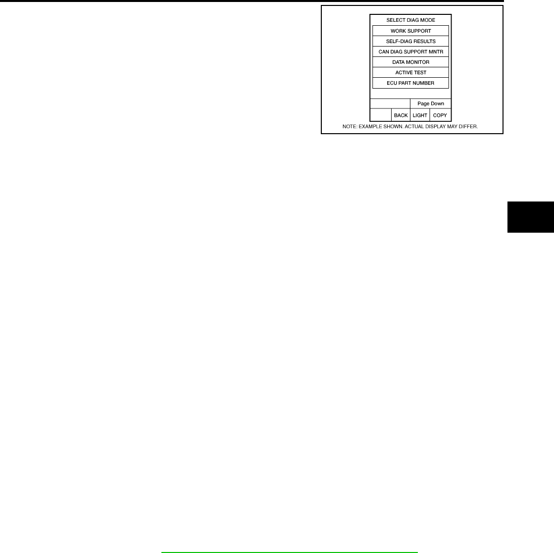
TROUBLE DIAGNOSIS
BRC-65
[ABLS/ABS]
C
D
E
G
H
I
J
K
L
M
A
B
BRC
Revision: February 2006 2005 Xterra
6. Select the required diagnostic location from the “SELECT DIAG
MODE” screen.
For further information, see the CONSULT-II Operation Manual.
SELF-DIAGNOSIS
Description
If an error is detected in the system, the ABS warning lamp will turn on. In this case, perform self-diagnosis as
follows:
Operation Procedure
1. Turn ignition switch OFF.
2. Connect CONSULT-II and CONSULT-II CONVERTER to the data link connector.
CAUTION:
If CONSULT-II is used with no connection of CONSULT-II CONVERTER, malfunctions might be
detected in self-diagnosis depending on control unit which carries out CAN communication.
3. Turn ignition switch ON.
4. Start engine and drive at approximately 30 km/h (19 MPH) or more for approximately 1 minute.
5. After stopping the vehicle, with the engine running, touch “START (NISSAN BASED VHCL)”, “ABS”,
“SELF-DIAG RESULTS” in order on the CONSULT-II screen.
CAUTION:
If “START (NISSAN BASED VHCL)” is touched immediately after starting the engine or turning on
the ignition switch, “ABS” might not be displayed in the SELECT SYSTEM screen. In this case,
repeat the operation from step 1.
6. The self-diagnostic results are displayed. (If necessary, the self-diagnostic results can be printed out by
touching “PRINT”.)
●When “NO DTC IS DETECTED” is displayed, check the ABS warning lamp.
7. Conduct the appropriate inspection from the display item list, and repair or replace the malfunctioning
component.
8. Start engine and drive at approximately 30 km/h (19 MPH) or more for approximately 1 minute.
CAUTION:
●When a wheel sensor “short-circuit” is detected, if the vehicle is not driven at 30 km/h (19 MPH)
for at least 1 minute, the ABS warning lamp will not turn off even if the malfunction is repaired.
9. Turn ignition switch OFF to prepare for erasing the memory.
10. Start the engine and touch “START (NISSAN BASED VHCL)”, “ABS”, “SELF-DIAG RESULTS”, “ERASE”
in order on the CONSULT-II screen to erase the error memory.
If “ABS” is not indicated, go to GI-39, "CONSULT-II Data Link Connector (DLC) Circuit" .
CAUTION:
If the error memory is not erased, re-conduct the operation from step 5.
11. For the final inspection, drive at approximately 30 km/h (19 MPH) or more for approximately 1 minute and
confirm that the ABS warning lamp is off.
BCIA0031E

BRC-66
[ABLS/ABS]
TROUBLE DIAGNOSIS
Revision: February 2006 2005 Xterra
Display Item List
Self-diagnostic item Malfunction detecting condition Check system
FR LH SENSOR 1
[C1104]
Circuit of front LH wheel sensor is open, shorted or sensor power
voltage is unusual.
BRC-72, "Wheel Sensor
System Inspection"
(Note 1)
RR RH SENSOR 1
[C1101]
Circuit of rear RH wheel sensor is open, shorted or sensor power
voltage is unusual.
FR RH SENSOR 1
[C1103]
Circuit of front RH wheel sensor is open, shorted or sensor power
voltage is unusual.
RR LH SENSOR 1
[C1102]
Circuit of rear LH wheel sensor is open, shorted or sensor power
voltage is unusual.
FR LH SENSOR 2
[C1108]
ABS actuator and electric unit (control unit) cannot identify sen-
sor pulses, because of large gap between wheel sensor and sen-
sor rotor.
RR RH SENSOR 2
[C1105]
ABS actuator and electric unit (control unit) cannot identify sen-
sor pulses, because of large gap between wheel sensor and sen-
sor rotor.
FR RH SENSOR 2
[C1107]
ABS actuator and electric unit (control unit) cannot identify sen-
sor pulses, because of large gap between wheel sensor and sen-
sor rotor.
RR LH SENSOR 2
[C1106]
ABS actuator and electric unit (control unit) cannot identify sen-
sor pulses, because of large gap between wheel sensor and sen-
sor rotor.
ABS SENSOR
[C1115] Wheel sensor input is abnormal.
STOP LAMP SW
[C1116] Stop lamp switch or circuit malfunction.
BRC-76, "Stop Lamp
Switch System Inspec-
tion"
DECEL G SEN SET
[C1160] ABS decel sensor adjustment is incomplete. BRC-74, "ABS/ABLS
Control Unit Inspection"

TROUBLE DIAGNOSIS
BRC-67
[ABLS/ABS]
C
D
E
G
H
I
J
K
L
M
A
B
BRC
Revision: February 2006 2005 Xterra
FR LH IN ABS SOL
[C1120]
Circuit of front LH IN ABS solenoid is open or shorted, or control
line is open or shorted to power supply or ground.
BRC-74, "Solenoid and
Change-Over Valve Sys-
tem Inspection"
FR LH OUT ABS SOL
[C1121]
Circuit of front LH OUT ABS solenoid is open or shorted, or con-
trol line is open or shorted to power supply or ground.
RR RH IN ABS SOL
[C1126]
Circuit of rear RH IN ABS solenoid is open or shorted, or control
line is open or shorted to power supply or ground.
RR RH OUT ABS SOL
[C1127]
Circuit of rear RH OUT ABS solenoid is open or shorted, or con-
trol line is open or shorted to power supply or ground.
FR RH IN ABS SOL
[C1122]
Circuit of front RH IN ABS solenoid is open or shorted, or control
line is open or shorted to power supply or ground.
FR RH OUT ABS SOL
[C1123]
Circuit of front RH OUT ABS solenoid is open or shorted, or con-
trol line is open or shorted to power supply or ground.
RR LH IN ABS SOL
[C1124]
Circuit of rear LH IN ABS solenoid is open or shorted, or control
line is open or shorted to power supply or ground.
RR LH OUT ABS SOL
[C1125]
Circuit of rear LH OUT ABS solenoid is open or shorted, or con-
trol line is open or shorted to power supply or ground.
CV1
[C1164]
Front side switch-over solenoid valve (cut valve) is open or
shorted, or control line is open or shorted to power supply or
ground.
CV2
[C1165]
Rear side switch-over solenoid valve (cut valve) is open or
shorted, or control line is open or shorted to power supply or
ground.
SV1
[C1166]
Front side switch-over solenoid valve (suction valve) is open or
shorted, or control line is open or shorted to power supply or
ground.
SV2
[C1167]
Rear side switch-over solenoid valve (suction valve) is open or
shorted, or control line is open or shorted to power supply or
ground.
PUMP MOTOR (Note 3)
[C1111]
During actuator motor operation with ON, when actuator motor
turns OFF or when control line for actuator motor relay is open. BRC-75, "Actuator
Motor, Motor Relay, and
Circuit Inspection"
During actuator motor operation with OFF, when actuator motor
turns ON or when control line for relay is shorted to ground.
BATTERY VOLTAGE
[ABNORMAL]
[C1109]
ABS actuator and electric unit (control unit) power voltage is too
low.
BRC-77, "ABS/ABLS
Control Unit Power and
Ground Systems Inspec-
tion"
G-SENSOR
[C1113]
Longitudinal G-sensor is malfunctioning, or signal line of longitu-
dinal G-sensor is open or shorted.
BRC-74, "ABS/ABLS
Control Unit Inspection"
CONTROLLER FAILURE
[C1110]
Internal malfunction of ABS actuator and electric unit (control
unit)
BRC-74, "ABS/ABLS
Control Unit Inspection"
BR FLUID LEVEL LOW
[C1155]
Brake fluid level drops or circuit between ABS actuator and elec-
tric unit (control unit) and brake fluid level switch is open or
shorted.
BRC-78, "Brake Fluid
Level Switch System
Inspection"
ENGINE SIGNAL 1
[C1130]
Based on the signal from ECM, ABS actuator and electric unit
(control unit) judges that engine fuel cut system is malfunction-
ing.
BRC-73, "Engine Sys-
tem Inspection"
ENGINE SIGNAL 2
[C1131]
Based on the signal from ECM, ABS actuator and electric unit
(control unit) judges that engine fuel cut system is malfunction-
ing.
ENGINE SIGNAL 6
[C1136]
Based on the signal from ECM, ABS actuator and electric unit
(control unit) judges that engine fuel cut system is malfunction-
ing.
ACTUATOR RLY
[C1140] ABS actuator relay or circuit malfunction.
BRC-75, "Actuator
Motor, Motor Relay, and
Circuit Inspection"
Self-diagnostic item Malfunction detecting condition Check system

BRC-68
[ABLS/ABS]
TROUBLE DIAGNOSIS
Revision: February 2006 2005 Xterra
Note 1: If wheel sensor 2 for each wheel is indicated, check ABS actuator and electric unit (control unit) power supply voltage in addition
to wheel sensor circuit check.
Note 2: If multiple malfunctions are detected including CAN communication line [U1000], perform diagnosis for CAN communication line
first.
DATA MONITOR
Operation Procedure
1. After turning OFF the ignition switch, connect CONSULT-II and the CONSULT-II CONVERTER to the data
link connector.
CAUTION:
If CONSULT-II is used with no connection of CONSULT-II CONVERTER, malfunctions might be
detected in self-diagnosis depending on control unit which carries out CAN communication.
2. Touch “START (NISSAN BASED VHCL)”, “ABS”, “DATA MONITOR” in order on the CONSULT-II screen.
If “ABS” is not indicated, go to GI-39, "CONSULT-II Data Link Connector (DLC) Circuit" .
CAUTION:
When “START (NISSAN BASED VHCL)” is touched immediately after starting the engine or turning
on the ignition switch, “ABS” might not be displayed in the SELECT SYSTEM screen. In this case,
repeat the operation from step 2.
3. Return to the SELECT MONITOR ITEM screen, and touch “ECU INPUT SIGNALS”, “MAIN SIGNALS”, or
“SELECTION FROM MENU”. Refer to the following information.
4. When “START” is touched, the data monitor screen is displayed.
Display Item List
PRESS SEN CIRCUIT
[C1142] ABS pressure sense circuit malfunction. BRC-78, "Pressure Sen-
sor System Inspection"
VARIANT CODING
[C1170] V coding is not malfunctioning. BRC-74, "ABS/ABLS
Control Unit Inspection"
ABS DIFLOCK CONTROLLER
NG
[C1187]
Differential lock controller malfunction.
BRC-80, "CAN Commu-
nication System Inspec-
tion"
CAN COMM CIRCUIT
[U1000]
●CAN communication line is open or shorted.
●ABS actuator and electric unit (control unit) internal malfunc-
tion
●Battery voltage for ECM is suddenly interrupted for approxi-
mately 0.5 second or more.
BRC-80, "CAN Commu-
nication System Inspec-
tion" (Note 2)
Self-diagnostic item Malfunction detecting condition Check system
Item
(Unit)
Data monitor item selection
Remarks
ECU INPUT
SIGNALS
MAIN
SIGNALS
SELECTION
FROM MENU
GEAR ×××
Gear position judged by PNP
switch signal is displayed.
FR RH SENSOR
(km/h, MPH) ×××
Wheel speed calculated by front
RH wheel sensor signal is dis-
played.
FR LH SENSOR
(km/h, MPH) ×××
Wheel speed calculated by front LH
wheel sensor signal is displayed.
RR RH SENSOR
(km/h, MPH) ×××
Wheel speed calculated by rear RH
wheel sensor signal is displayed.
RR LH SENSOR
(km/h, MPH) ×××
Wheel speed calculated by rear LH
wheel sensor signal is displayed.
BATTERY VOLT
(V) ×××
Voltage supplied to ABS actuator
and electric unit (control unit) is dis-
played.
N POSI SIG – – ×Shift position judged by PNP switch
signal.

TROUBLE DIAGNOSIS
BRC-69
[ABLS/ABS]
C
D
E
G
H
I
J
K
L
M
A
B
BRC
Revision: February 2006 2005 Xterra
P POSI SIG – – ×Shift position judged by PNP switch
signal.
ACCEL POS SIG
(%) ×–×
Throttle valve open/close status
judged by CAN communication sig-
nal is displayed.
ENGINE SPEED
(rpm) ×××
Engine speed judged by CAN com-
munication signal is displayed.
STOP LAMP SW
(ON/OFF) ×××
Stop lamp switch (ON/OFF) status
is displayed.
ABS WARN LAMP
(ON/OFF) –××
ABS warning lamp (ON/OFF) status
is displayed.
SLIP LAMP
(ON/OFF) –××
SLIP indicator lamp (ON/OFF) sta-
tus is displayed.
FR LH IN SOL
(ON/OFF) –××
Front LH IN ABS solenoid (ON/
OFF) status is displayed.
FR LH OUT SOL
(ON/OFF) –××
Front LH OUT ABS solenoid (ON/
OFF) status is displayed.
RR RH IN SOL
(ON/OFF) –××
Rear RH IN ABS solenoid (ON/
OFF) status is displayed.
RR RH OUT SOL
(ON/OFF) –××
Rear RH OUT ABS solenoid (ON/
OFF) status is displayed.
FR RH IN SOL
(ON/OFF) –××
Front RH IN ABS solenoid (ON/
OFF) status is displayed.
FR RH OUT SOL
(ON/OFF) –××
Front RH OUT ABS solenoid (ON/
OFF) status is displayed.
RR LH IN SOL
(ON/OFF) –××
Rear LH IN ABS solenoid (ON/
OFF) status is displayed.
RR LH OUT SOL
(ON/OFF) –××
Rear LH OUT ABS solenoid (ON/
OFF) status is displayed.
MOTOR RELAY
(ON/OFF) –××
ABS motor relay signal (ON/OFF)
status is displayed.
ACTUATOR RLY
(ON/OFF) – ××
ABS actuator relay signal (ON/
OFF) status is displayed.
CV1
(ON/OFF) ––×
Front side switch-over solenoid
valve (cut valve) (ON/OFF) status is
displayed.
CV2
(ON/OFF) ––×
Rear side switch-over solenoid
valve (cut-valve) (ON/OFF) status
is displayed.
SV1
(ON/OFF) ––×
Front side switch-over solenoid
valve (suction valve) (ON/OFF) sta-
tus is displayed.
SV2
(ON/OFF) ––×
Rear side switch-over solenoid
valve (suction valve) (ON/OFF) sta-
tus is displayed.
TCS FAIL SIG
(ON/OFF) ––×TCS fail signal (ON/OFF) status is
displayed.
ABS FAIL SIG
(ON/OFF) ––×ABS fail signal (ON/OFF) status is
displayed.
EBD FAIL SIG
(ON/OFF) ––×EBD fail signal (ON/OFF) status is
displayed.
Item
(Unit)
Data monitor item selection
Remarks
ECU INPUT
SIGNALS
MAIN
SIGNALS
SELECTION
FROM MENU
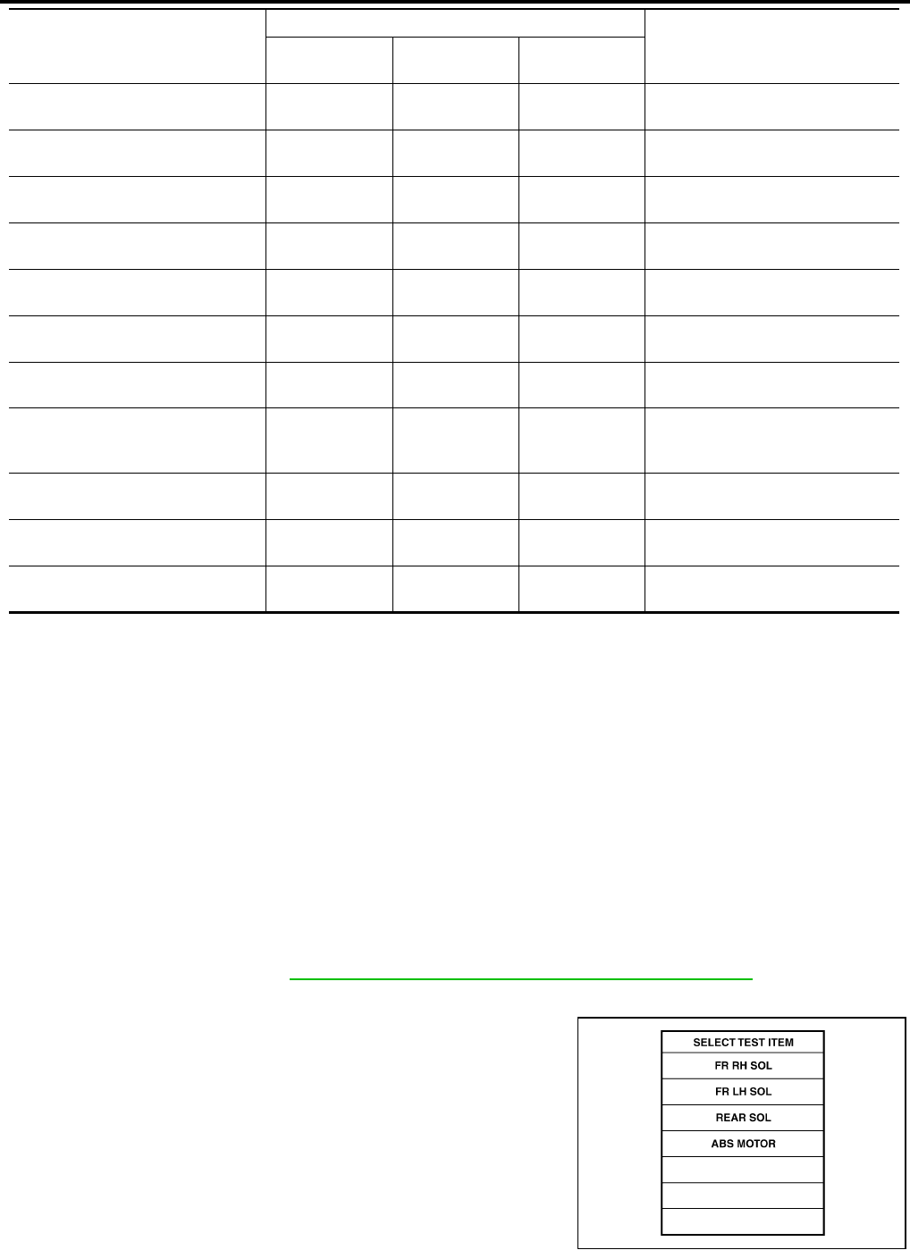
BRC-70
[ABLS/ABS]
TROUBLE DIAGNOSIS
Revision: February 2006 2005 Xterra
×: Applicable
–: Not applicable
ACTIVE TEST
CAUTION:
●Do not perform active test while driving.
●Make sure to completely bleed air from the brake system.
●The ABS and brake warning lamps turn on during the active test.
Operation Procedure
1. Connect the CONSULT-II and CONSULT-II CONVERTER to the data link connector and start the engine.
CAUTION:
If CONSULT-II is used with no connection of CONSULT-II CONVERTER, malfunctions might be
detected in self-diagnosis depending on control unit which carries out CAN communication.
2. Touch “START (NISSAN BASED VHCL)” on the display screen.
3. Touch “ABS”.
If “ABS” is not indicated, go to GI-39, "CONSULT-II Data Link Connector (DLC) Circuit" .
4. Touch “ACTIVE TEST”.
5. The SELECT TEST ITEM screen is displayed.
6. Touch necessary test item.
FLUID LEV SW
(ON/OFF) ×–×Brake fluid level switch (ON/OFF)
status is displayed.
EBD SIGNAL
(ON/OFF) ––×EBD operation (ON/OFF) status is
displayed.
ABS SIGNAL
(ON/OFF) ––×ABS operation (ON/OFF) status is
displayed.
TCS SIGNAL
(ON/OFF) ––×TCS operation (ON/OFF) status is
displayed.
EBD WARN LAMP – – ×Brake warning lamp (ON/OFF) sta-
tus is displayed.
SLCT LVR POSI ×××
Shift position judged by PNP switch
signal.
R POSI SIG – – ×Shift position judged by PNP switch
signal.
2WD/4WD – – ×
It recognizes on software whether it
is 2WD and whether it is in 4WD
state.
PRESS SENSOR ×–×Brake pressure detected by pres-
sure sensor is displayed.
CRANKING SIG – – ×The input state of the key SW
START position signal is displayed.
DECEL G-SEN ×××
Longitudinal acceleration detected
by decel G-sensor is displayed.
Item
(Unit)
Data monitor item selection
Remarks
ECU INPUT
SIGNALS
MAIN
SIGNALS
SELECTION
FROM MENU
LBR379
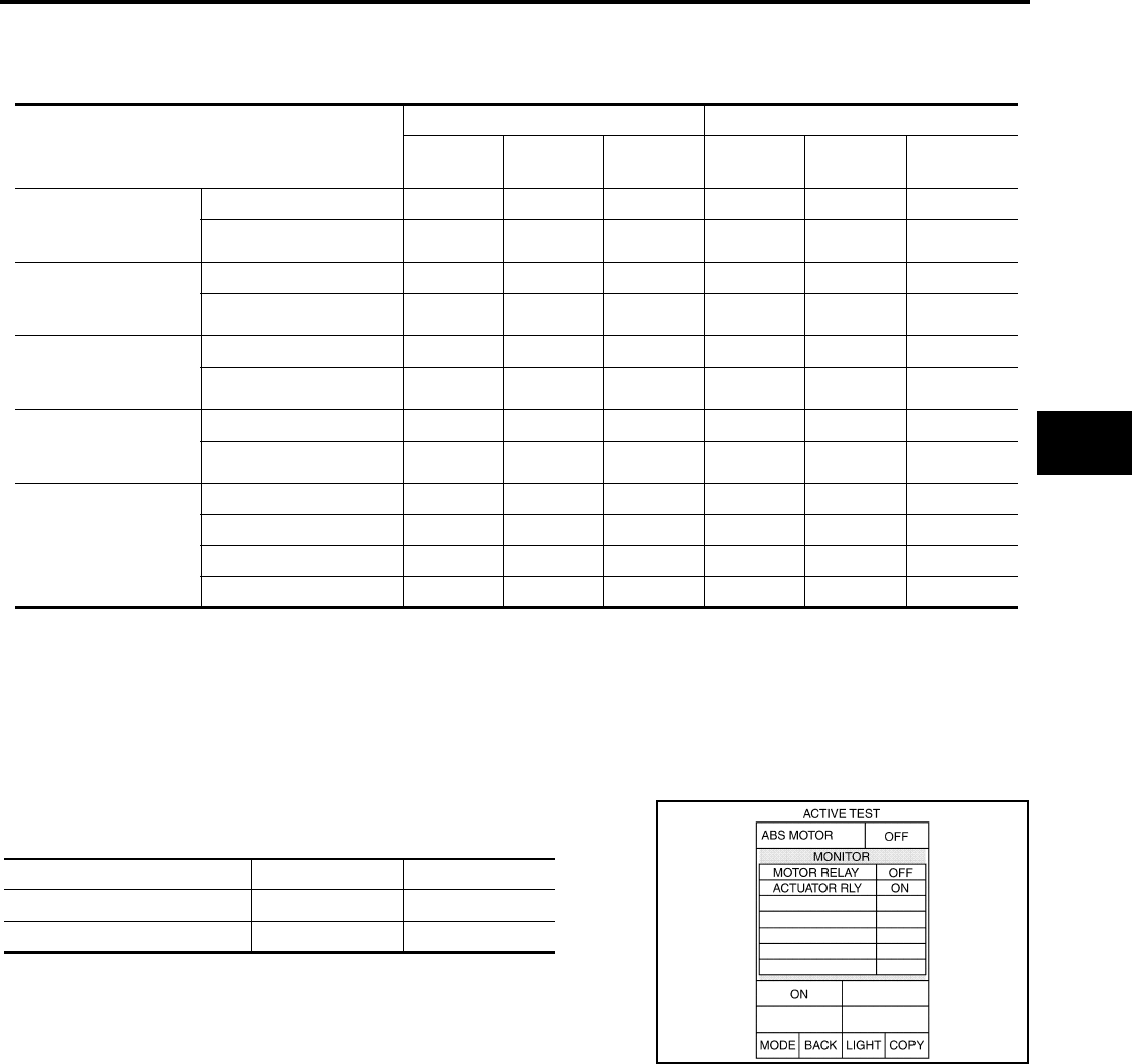
TROUBLE DIAGNOSIS
BRC-71
[ABLS/ABS]
C
D
E
G
H
I
J
K
L
M
A
B
BRC
Revision: February 2006 2005 Xterra
7. With the “MAIN SIGNALS” display selected, touch “START”.
8. The Active Test screen will be displayed, so conduct the following test.
Solenoid Valve Operation Chart
*: ON for 1 to 2 seconds after the touch, and then OFF
NOTE:
●If active test is performed with brake pedal depressed, pedal stroke may change. This is normal.
●“TEST IS STOPPED” is displayed approximately 10 seconds after operation starts.
●After “TEST IS STOPPED” is displayed, to perform test again, repeat Step 6.
ABS Motor
Touch “ON” and “OFF” on the screen. Check that ABS motor relay
operates as shown in table below.
NOTE:
●If active test is performed with brake pedal depressed, pedal
stroke may change. This is normal.
●“TEST IS STOPPED” is displayed approximately 10 seconds
after operation starts.
Operation
ABS solenoid valve ABS solenoid valve (ACT)
UP KEEP DOWN UP ACTUA-
TOR UP
ACTUA-
TOR KEEP
FR RH SOL
FR RH ABS SOLE-
NOID (ACT)
FR RH IN SOL OFF ON ON OFF OFF OFF
FR RH OUT SOL OFF OFF ON* OFF OFF OFF
FR LH SOL
FR LH ABS SOLE-
NOID (ACT)
FR LH IN SOL OFF ON ON OFF OFF OFF
FR LH OUT SOL OFF OFF ON* OFF OFF OFF
RR RH SOL
RR RH ABS SOLE-
NOID (ACT)
RR RH IN SOL OFF ON ON OFF OFF OFF
RR RH OUT SOL OFF OFF ON* OFF OFF OFF
RR LH SOL
RR LH ABS SOLE-
NOID (ACT)
RR LH IN SOL OFF ON ON OFF OFF OFF
RR LH OUT SOL OFF OFF ON* OFF OFF OFF
REAR SOL
RR RH IN SOL OFF ON ON OFF OFF OFF
RR RH OUT SOL OFF OFF ON* OFF OFF OFF
RR LH IN SOL OFF ON ON OFF OFF OFF
RR LH OUT SOL OFF OFF ON* OFF OFF OFF
Operation ON OFF
ABS actuator relay ON ON
ABS motor relay ON OFF
SFIA0593E
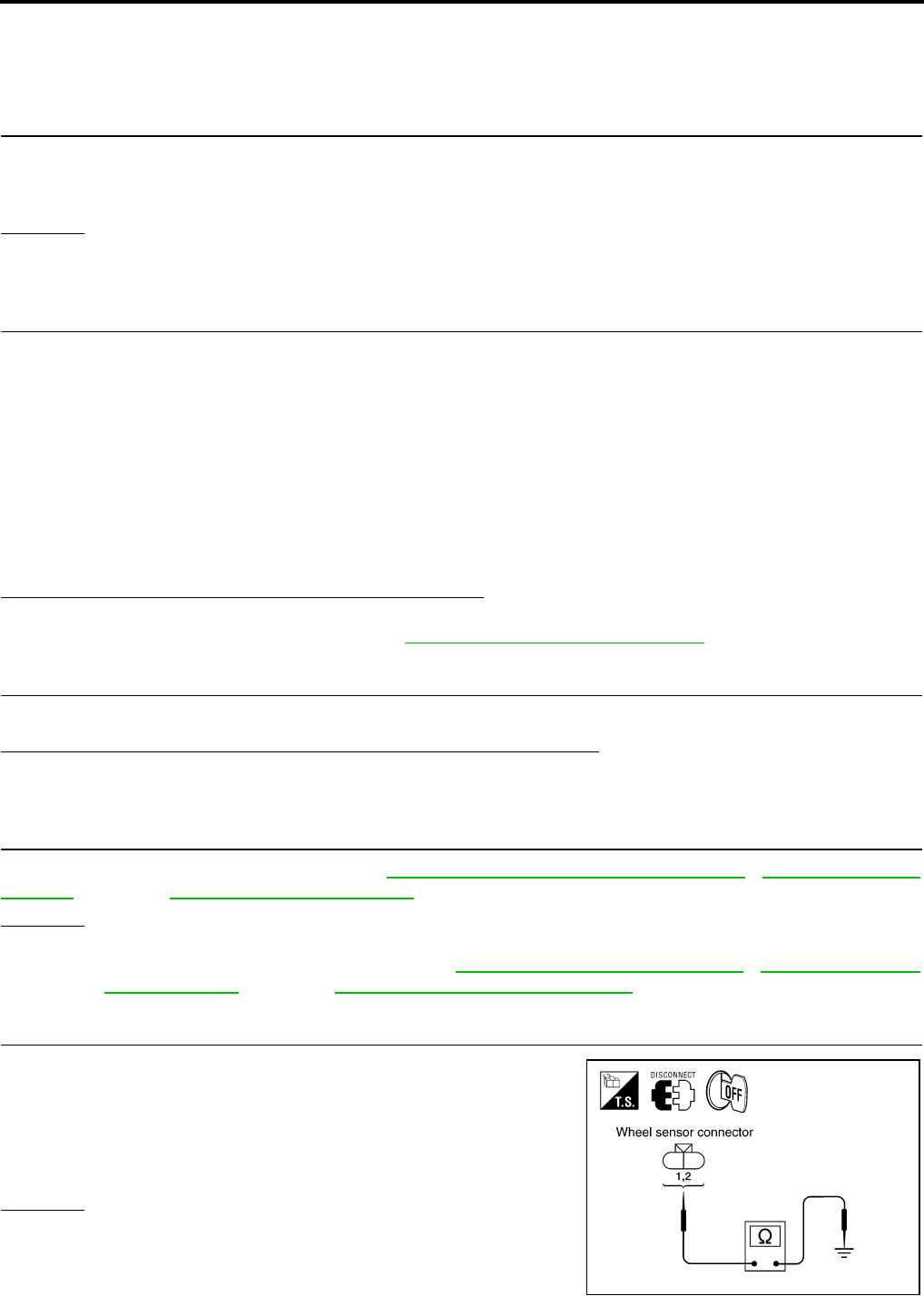
BRC-72
[ABLS/ABS]
TROUBLE DIAGNOSIS FOR SELF-DIAGNOSTIC ITEMS
Revision: February 2006 2005 Xterra
TROUBLE DIAGNOSIS FOR SELF-DIAGNOSTIC ITEMS PFP:00000
Wheel Sensor System Inspection EFS005MB
INSPECTION PROCEDURE
1. CONNECTOR INSPECTION
Disconnect the ABS actuator and electric unit (control unit) connector E125 and wheel sensor of malfunction-
ing code.
Check the terminals for deformation, disconnection, looseness or damage.
OK or NG
OK >> GO TO 2.
NG >> Repair or replace as necessary.
2. CHECK WHEEL SENSOR OUTPUT SIGNAL
1. Connect ABS active wheel sensor tester (J-45741) to wheel sensor using appropriate adapter.
2. Turn on the ABS active wheel sensor tester power switch.
NOTE:
The green POWER indicator should illuminate. If the POWER indicator does not illuminate, replace the
battery in the ABS active wheel sensor tester before proceeding.
3. Spin the wheel of the vehicle by hand and observe the red SENSOR indicator on the ABS active wheel
sensor tester. The red SENSOR indicator should flash on and off to indicate an output signal.
NOTE:
If the red SENSOR indicator illuminates but does not flash, reverse the polarity of the tester leads and
retest.
Does the ABS active wheel sensor tester detect a signal?
YES >> GO TO 3.
NO >> Replace the wheel sensor. Refer to BRC-85, "Removal and Installation" .
3. CHECK TIRES
Check for inflation pressure, wear and size of each tire.
Are tire pressure and size correct and is tire wear within specifications?
YES >> GO TO 4.
NO >> Adjust tire pressure or replace tire(s).
4. CHECK WHEEL BEARINGS
Check wheel bearing axial end play. Refer to FAX-5, "WHEEL BEARING INSPECTION" , RAX-6, "Rear Axle
Bearing" (C200) or RAX-18, "Rear Axle Bearing" (M226).
OK or NG
OK >> GO TO 5.
NG >> Repair or replace as necessary. Refer to FAX-5, "Removal and Installation" , RAX-12, "Removal
and Installation" (C200) or RAX-23, "Removal and Installation" (M226).
5. CHECK WIRING HARNESS FOR SHORT CIRCUIT
1. Disconnect ABS actuator and electric unit (control unit) connec-
tor and wheel sensor connector of malfunction code No.
2. Check resistance between wheel sensor harness connector ter-
minals and ground.
OK or NG
OK >> GO TO 6.
NG >> Repair the circuit.
Continuity should not exist.
WFIA0343E
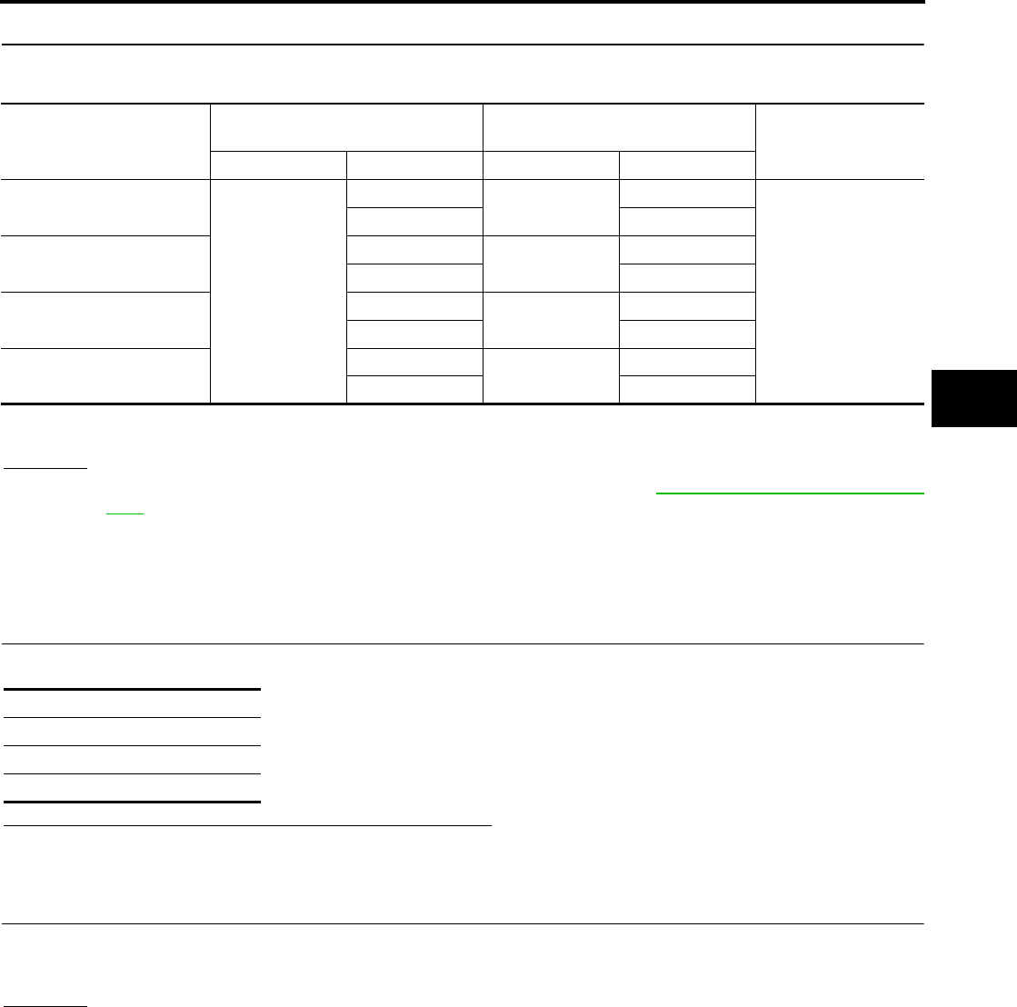
TROUBLE DIAGNOSIS FOR SELF-DIAGNOSTIC ITEMS
BRC-73
[ABLS/ABS]
C
D
E
G
H
I
J
K
L
M
A
B
BRC
Revision: February 2006 2005 Xterra
6. CHECK WIRING HARNESS FOR OPEN CIRCUIT
Check continuity between ABS actuator and electric unit (control unit) harness connector E125 and the mal-
functioning wheel sensor harness connector E18, E117, C10, or C11.
OK or NG
OK >> Replace the ABS actuator and electric unit (control unit). Refer to BRC-87, "Removal and Installa-
tion" .
NG >> Repair the circuit.
Engine System Inspection EFS005MC
INSPECTION PROCEDURE
1. SELF-DIAGNOSIS RESULT CHECK
Check self-diagnosis results.
Is the above displayed in the self-diagnosis display items?
YES >> GO TO 2.
NO >> Inspection End.
2. ENGINE SYSTEM INSPECTION
1. Perform ECM self-diagnosis and repair as necessary.
2. Perform ABS actuator and electric unit (control unit) self-diagnosis again.
OK or NG
OK >> Inspection End.
NG >> Repair or replace as necessary.
Wheel sensor
ABS actuator and
electric unit (control unit) Wheel sensor Continuity
Connector Terminal Connector Terminal
Front LH
E125
45 E18 1
Yes
46 2
Front RH 34 E117 1
33 2
Rear LH 37 C11 2
36 1
Rear RH 42 C10 2
43 1
Continuity should exist.
Self-diagnosis results
ENGINE SIGNAL 1
ENGINE SIGNAL 2
ENGINE SIGNAL 6

BRC-74
[ABLS/ABS]
TROUBLE DIAGNOSIS FOR SELF-DIAGNOSTIC ITEMS
Revision: February 2006 2005 Xterra
ABS/ABLS Control Unit Inspection EFS005MD
INSPECTION PROCEDURE
1. SELF-DIAGNOSIS RESULT CHECK
Check self-diagnosis results.
Is the above displayed in the self-diagnosis display items?
YES >> Replace ABS actuator and electric unit (control unit). Refer to BRC-87, "Removal and Installation"
.
NO >> Inspection End.
Solenoid and Change-Over Valve System Inspection EFS005ME
INSPECTION PROCEDURE
1. SELF-DIAGNOSIS RESULT CHECK
Check self-diagnosis results.
Is the above displayed in the self-diagnosis display items?
YES >> GO TO 2.
NO >> Inspection End.
2. CONNECTOR INSPECTION
1. Disconnect ABS actuator and electric unit (control unit) connector E125.
2. Check the terminals for deformation, disconnection, looseness or damage.
OK or NG
OK >> GO TO 3.
NG >> Repair or replace as necessary.
Self-diagnosis results
CONTROLLER FAILURE
DECEL G SEN SET
G-SENSOR
VARIANT CODING
Self-diagnosis results
FR LH IN ABS SOL
FR LH OUT ABS SOL
RR RH IN ABS SOL
RR RH OUT ABS SOL
FR RH IN ABS SOL
FR RH OUT ABS SOL
RR LH IN ABS SOL
RR LH OUT ABS SOL
CV 1
CV 2
SV 1
SV 2
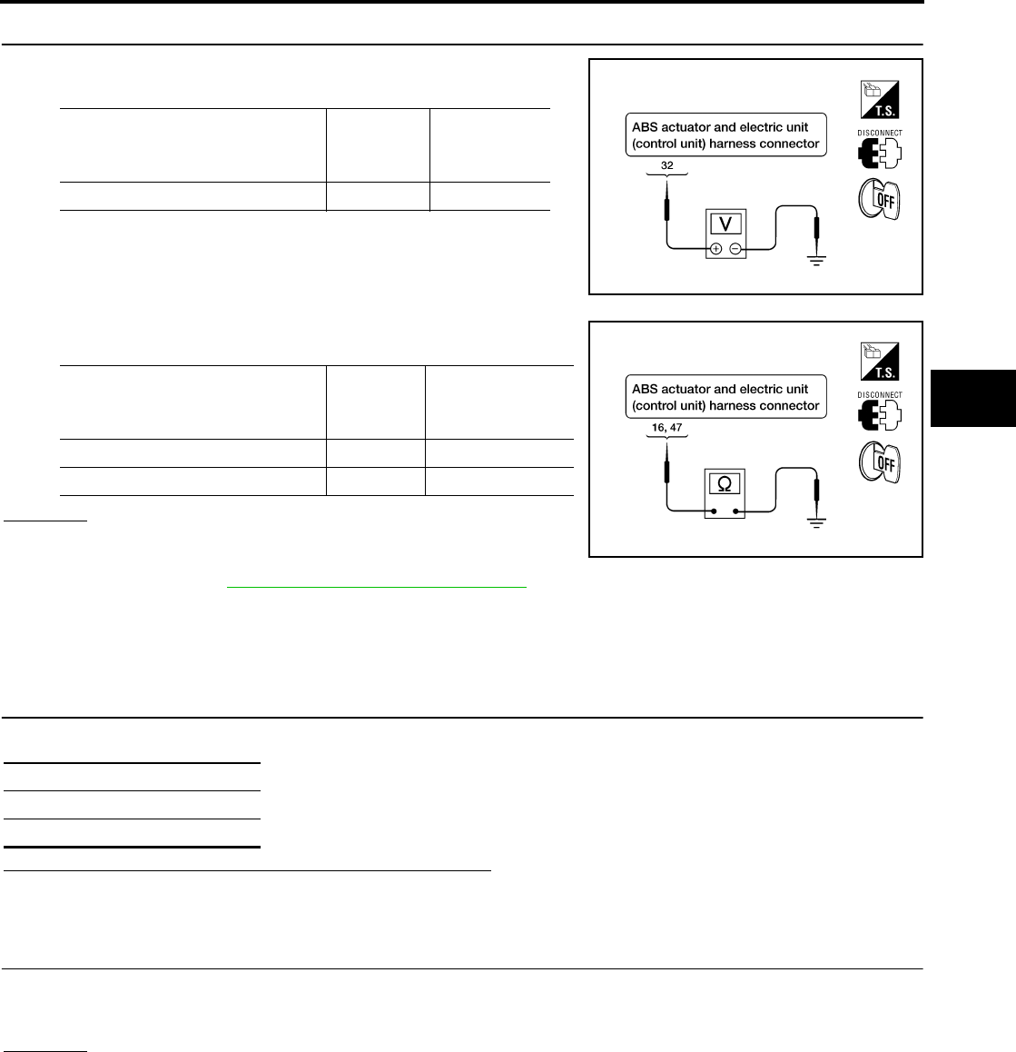
TROUBLE DIAGNOSIS FOR SELF-DIAGNOSTIC ITEMS
BRC-75
[ABLS/ABS]
C
D
E
G
H
I
J
K
L
M
A
B
BRC
Revision: February 2006 2005 Xterra
3. CHECKING SOLENOID POWER AND GROUND
1. Check voltage between ABS actuator and electric unit (control
unit) harness connector E125 and body ground.
2. Check resistance between ABS actuator and electric unit (con-
trol unit) harness connector E125 and body ground.
OK or NG
OK >> Perform self-diagnosis again. If the same results
appear, replace ABS actuator and electric unit (control
unit). Refer to BRC-87, "Removal and Installation" .
NG >> Repair the circuit.
Actuator Motor, Motor Relay, and Circuit Inspection EFS005MF
INSPECTION PROCEDURE
1. CHECKING SELF-DIAGNOSIS RESULTS
Check self-diagnosis results.
Is the above displayed in the self-diagnosis display items?
YES >> GO TO 2.
NO >> Inspection End.
2. CONNECTOR INSPECTION
1. Disconnect ABS actuator and electric unit (control unit) connector E125.
2. Check the terminals for deformation, disconnection, looseness or damage.
OK or NG
OK >> GO TO 3.
NG >> Repair or replace as necessary.
ABS actuator and electric
unit (control unit) harness
connector E125
Body
ground
Measured
value
(Approx.)
32 — 12V
WFIA0195E
ABS actuator and electric
unit (control unit) harness
connector E125
Body
ground
Measured
value Ω
(Approx.)
16 — 0Ω
47 — 0Ω
WFIA0196E
Self-diagnosis results
PUMP MOTOR
ACTUATOR RLY
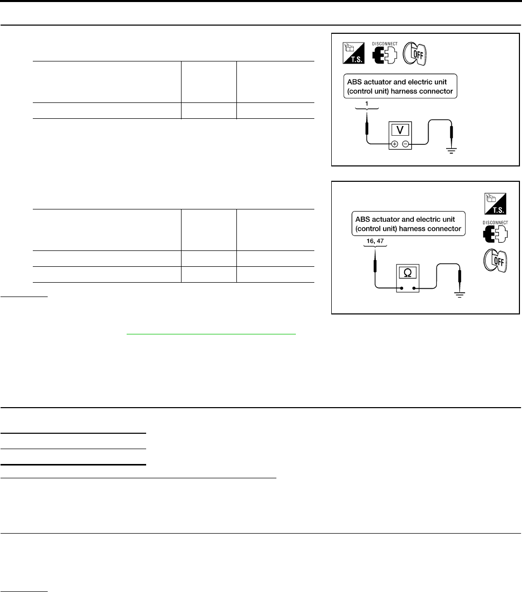
BRC-76
[ABLS/ABS]
TROUBLE DIAGNOSIS FOR SELF-DIAGNOSTIC ITEMS
Revision: February 2006 2005 Xterra
3. CHECKING ABS MOTOR AND MOTOR RELAY POWER SYSTEM
1. Check voltage between ABS actuator and electric unit (control
unit) harness connector E125 and body ground.
2. Check resistance between ABS actuator and electric unit (con-
trol unit) connector E125 and body ground.
OK or NG
OK >> Perform self-diagnosis again. If the same results
appear, replace ABS actuator and electric unit (control
unit). Refer to BRC-87, "Removal and Installation" .
NG >> Repair the circuit.
Stop Lamp Switch System Inspection EFS005MG
INSPECTION PROCEDURE
1. SELF-DIAGNOSIS RESULT CHECK
Check self-diagnosis results.
Is the above displayed in the self-diagnosis display items?
YES >> GO TO 2.
NO >> Inspection End.
2. CONNECTOR INSPECTION
1. Disconnect the ABS actuator and electric unit (control unit) connector E125 and stop lamp switch connec-
tor E38.
2. Check the terminals for deformation, disconnection, looseness or damage.
OK or NG
OK >> GO TO 3.
NG >> Repair or replace as necessary.
ABS actuator and electric
unit (control unit) harness
connector E125
Body
ground
Measured
value
(Approx.)
1—12V
WFIA0209E
ABS actuator and electric
unit (control unit)
harness connector E125
Body
ground
Measured
value Ω
(Approx.)
16 — 0Ω
47 — 0Ω
WFIA0196E
Self-diagnosis results
STOP LAMP SW
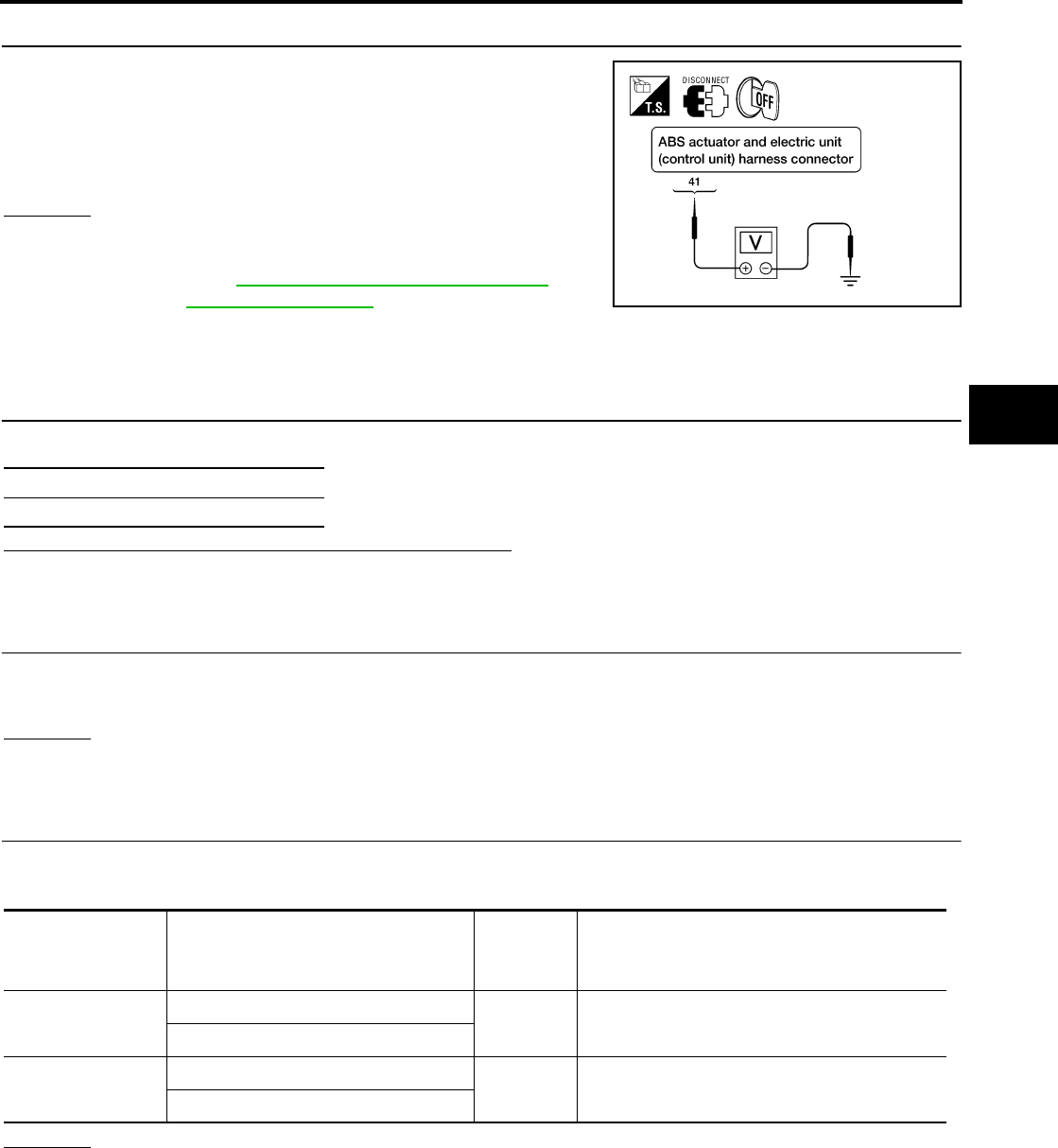
TROUBLE DIAGNOSIS FOR SELF-DIAGNOSTIC ITEMS
BRC-77
[ABLS/ABS]
C
D
E
G
H
I
J
K
L
M
A
B
BRC
Revision: February 2006 2005 Xterra
3. STOP LAMP SWITCH INSPECTION
Check the voltage between the ABS actuator and electric unit (con-
trol unit) harness connector E125 terminal 41 and body ground.
OK or NG
OK >> Perform self-diagnosis again. If the same results
appear, replace ABS actuator and electric unit (control
unit). Refer to BRC-87, "Removal and Installation" .
NG >> Refer to LT-81, "STOP LAMP" .
ABS/ABLS Control Unit Power and Ground Systems Inspection EFS005MH
INSPECTION PROCEDURE
1. SELF-DIAGNOSIS RESULT CHECK
Check self-diagnosis results.
Is the above displayed in the self-diagnosis display items?
YES >> GO TO 2.
NO >> Inspection End.
2. CONNECTOR INSPECTION
1. Disconnect the ABS actuator and electric unit (control unit) connector E125.
2. Check the terminals for deformation, disconnection, looseness or damage.
OK or NG
OK >> GO TO 3.
NG >> Repair or replace as necessary.
3. ABS/ABLS CONTROL UNIT POWER AND GROUND CIRCUIT INSPECTION
Measure the voltage and continuity between the ABS actuator and electric unit (control unit) harness connec-
tor E125 and body ground.
OK or NG
OK >> Check the battery for loose terminals, low voltage, etc. Repair as necessary.
NG >> Repair the circuit.
Brake pedal depressed : Battery voltage
(approx. 12V)
Brake pedal not depressed : Approx. 0V
WFIA0198E
Self-diagnosis results
BATTERY VOLTAGE
Signal name ABS actuator and electric unit
(control unit)
harness connector E125
Body
ground Measured value
Power supply 1— Battery voltage (Approx. 12V)
32
Ground 16 — Continuity should exist.
47

BRC-78
[ABLS/ABS]
TROUBLE DIAGNOSIS FOR SELF-DIAGNOSTIC ITEMS
Revision: February 2006 2005 Xterra
Brake Fluid Level Switch System Inspection EFS005MI
INSPECTION PROCEDURE
1. SELF-DIAGNOSIS RESULT CHECK
1. Check the brake reservoir tank fluid level. If the level is low, add brake fluid.
2. Erase the self-diagnosis results and check the self-diagnosis results.
Is the above displayed in the self-diagnosis display items?
YES >> GO TO 2.
NO >> Inspection End.
2. CONNECTOR INSPECTION
1. Disconnect the ABS actuator and electric unit (control unit) connector E125 and brake fluid level switch
connector E21.
2. Check the terminals for deformation, disconnection, looseness or damage.
OK or NG
OK >> GO TO 3.
NG >> Repair or replace as necessary.
3. CHECK THE HARNESS BETWEEN THE BRAKE FLUID LEVEL SWITCH AND THE ABS ACTUATOR
AND ELECTRIC UNIT (CONTROL UNIT)
Check the continuity between the brake fluid level switch harness connector E21 and the ABS actuator and
electric unit (control unit) harness connector E125.
OK or NG
OK >> Perform self-diagnosis again. If the same results appear, replace ABS actuator and electric unit
(control unit). Refer to BRC-87, "Removal and Installation" .
NG >> Repair the circuit.
Pressure Sensor System Inspection EFS005MJ
INSPECTION PROCEDURE
1. DISPLAY SELF DIAGNOSIS RESULTS
Check self-diagnosis results.
Is the above displayed in the self-diagnosis display items?
YES or NO
YES >> GO TO 2.
NO >> Inspection End.
Self-diagnosis results
BR FLUID LEVEL LOW
ABS actuator and electric unit
(control unit) harness connector
E125
Brake fluid level switch harness
connector E21 Continuity
81Yes
8GroundNo
Ground 2 Yes
Self-diagnosis results
PRESS SEN CIRCUIT

TROUBLE DIAGNOSIS FOR SELF-DIAGNOSTIC ITEMS
BRC-79
[ABLS/ABS]
C
D
E
G
H
I
J
K
L
M
A
B
BRC
Revision: February 2006 2005 Xterra
2. CONNECTOR INSPECTION
1. Turn the ignition switch OFF.
2. Disconnect the front pressure sensor connector E31 and ABS actuator and electric unit (control unit) con-
nector E125 and inspect the terminals for deformation, disconnection, looseness, or damage.
OK or NG
OK >> GO TO 3.
NG >> Repair connector.
3. FRONT PRESSURE SENSOR CIRCUIT INSPECTION
1. Measure the continuity between the ABS actuator and electric unit (control unit) harness connector E125
and front pressure sensor harness connector E31.
2. Measure the continuity between the ABS actuator and electric unit (control unit) harness connector E125
and body ground.
OK or NG
OK >> GO TO 4.
NG >> Repair or replace harness or connector.
4. FRONT PRESSURE SENSOR INSPECTION
1. Reconnect the front pressure sensor and ABS actuator and electric unit (control unit) connectors.
2. Use "DATA MONITOR" to check if the status of "PRESS SENSOR" is normal.
OK or NG
OK >> Inspection End.
NG >> Replace front pressure sensor.
ABS actuator and electric unit
(control unit) harness connector
E125
Front pressure sensor har-
ness connector E31 Continuity
18 3
Yes19 1
20 2
ABS actuator and electric unit
(control unit) harness connector
E125 Body ground Continuity
18
—No19
20
Condition Data monitor display (Approx.)
PRESS SENSOR
When brake pedal is depressed Positive value
When brake pedal is released 0 bar

BRC-80
[ABLS/ABS]
TROUBLE DIAGNOSIS FOR SELF-DIAGNOSTIC ITEMS
Revision: February 2006 2005 Xterra
CAN Communication System Inspection EFS005MK
INSPECTION PROCEDURE
1. CHECK CONNECTOR
1. Turn ignition switch OFF, disconnect the ABS actuator and electric unit (control unit) connector and check
the terminals for deformation, disconnection, looseness, and so on. If there is a malfunction, repair or
replace the terminal.
2. Reconnect connector to perform self-diagnosis.
Is "CAN COMM CIRCUIT" displayed in self-diagnosis display items?
YES >> Print out the self-diagnostic results, and refer to LAN-21, "CAN COMMUNICATION" .
NO >> Connector terminal is loose, damaged, open, or shorted.

TROUBLE DIAGNOSES FOR SYMPTOMS
BRC-81
[ABLS/ABS]
C
D
E
G
H
I
J
K
L
M
A
B
BRC
Revision: February 2006 2005 Xterra
TROUBLE DIAGNOSES FOR SYMPTOMS PFP:99999
ABS Works Frequently EFS005ML
1. CHECK WARNING LAMP ACTIVATION
Make sure warning lamp remains off while driving.
OK or NG
OK >> GO TO 2.
NG >> Carry out self-diagnosis. Refer to BRC-65, "SELF-DIAGNOSIS" .
2. CHECK WHEEL SENSORS
Check the following.
●Wheel sensor mounting for looseness
●Wheel sensors for physical damage
●Wheel sensor connectors for terminal damage or loose connections
●Sensor rotor and mount for physical damage (rear only)
OK or NG
OK >> GO TO 3.
NG >> Repair or replace as necessary.
3. CHECK FRONT AND REAR AXLES
Check front and rear axles for excessive looseness. Refer to FAX-5, "WHEEL BEARING INSPECTION" ,
RAX-6, "Rear Axle Bearing" (C200) or RAX-18, "Rear Axle Bearing" (M226).
OK or NG
OK >> GO TO 4.
NG >> Repair as necessary.
4. CHECK BRAKE FLUID PRESSURE
Check brake fluid pressure distribution.
Refer to BRC-60, "Basic Inspection" .
Is brake fluid pressure distribution normal?
YES >> Inspection End.
NO >> Perform Basic Inspection. Refer to BRC-60, "Basic Inspection" .
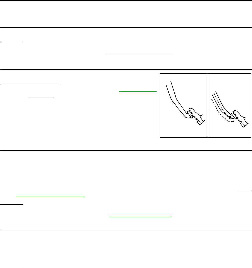
BRC-82
[ABLS/ABS]
TROUBLE DIAGNOSES FOR SYMPTOMS
Revision: February 2006 2005 Xterra
Unexpected Pedal Action EFS005MM
1. CHECK WARNING LAMP ACTIVATION
Make sure warning lamp remains off while driving.
OK or NG
OK >> GO TO 2.
NG >> Carry out self-diagnosis. Refer to BRC-65, "SELF-DIAGNOSIS" .
2. CHECK BRAKE PEDAL STROKE
Check brake pedal stroke.
Is pedal stroke excessive?
YES >> Perform Basic Inspection. Refer to BRC-60, "Basic
Inspection" .
NO >> GO TO 3.
3. CHECK CONNECTOR AND BRAKING PERFORMANCE
1. Disable ABS by disconnecting ABS actuator and electric unit (control unit) connector.
2. Drive vehicle and check brake operation.
NOTE:
●Stopping distance may be longer than vehicles without ABS when road condition is slippery.
●Driving the vehicle with the ABS actuator and electric unit (control unit) disconnected may induce DTCs
in electrical control units using CAN communication. After the inspection, clear all DTCs. Refer to LAN-
21, "CAN COMMUNICATION" .
OK or NG
OK >> GO TO 4.
NG >> Perform Basic Inspection. Refer to BRC-60, "Basic Inspection" .
4. CHECK WHEEL SENSORS
Check the following.
●Wheel sensor mounting for looseness
●Wheel sensors for physical damage
●Wheel sensor connectors for terminal damage or loose connections
OK or NG
OK >> Check ABS actuator and electric unit (control unit) connector terminals for deformation, discon-
nection, looseness or damage. Reconnect ABS actuator and electric unit (control unit) harness
connector. Then retest.
NG >> Repair or replace as necessary.
SBR540A

TROUBLE DIAGNOSES FOR SYMPTOMS
BRC-83
[ABLS/ABS]
C
D
E
G
H
I
J
K
L
M
A
B
BRC
Revision: February 2006 2005 Xterra
Long Stopping Distance EFS005MN
1. CHECK BASE BRAKING SYSTEM PERFORMANCE
1. Disable ABS by disconnecting ABS actuator and electric unit (control unit) connector.
2. Drive vehicle and check brake operation.
NOTE:
●Stopping distance may be longer than vehicles without ABS when road condition is slippery.
●Driving the vehicle with the ABS actuator and electric unit (control unit) disconnected may induce DTCs
in electrical control units using CAN communication. After the inspection, clear all DTCs. Refer to LAN-
21, "CAN COMMUNICATION" .
OK or NG
OK >> Go to BRC-81, "ABS Works Frequently" .
NG >> Perform Basic Inspection. Refer to BRC-60, "Basic Inspection" .
ABS Does Not Work EFS005MO
CAUTION:
The ABS does not operate when the vehicle speed is 10 km/h (6 MPH) or less.
1. CHECK WARNING LAMP ACTIVATION
Turn ignition switch ON and check for warning lamp activation.
●Warning lamp should activate for approximately 2 seconds after turning the ignition switch ON.
OK or NG
OK >> Carry out self-diagnosis. Refer to BRC-65, "SELF-DIAGNOSIS" .
NG >> Go to BRC-84, "ABS Warning Lamp Does Not Come On When Ignition Switch Is Turned On" .
Pedal Vibration or ABS Operation Noise EFS005MP
NOTE:
During ABS activation, pedal vibration may be felt and a noise may be heard. This is normal and does not indi-
cate a malfunction.
1. CHECK SYMPTOM
1. Apply brake.
2. Start engine.
Does the symptom occur only when engine is started?
YES >> Carry out self-diagnosis. Refer to BRC-65, "SELF-DIAGNOSIS" .
NO >> GO TO 2.
2. RECHECK SYMPTOM
Does the symptom occur only when electrical equipment switches (such as headlamps) are turned on?
YES >> Check for radio, antenna or related wiring that is routed too close to the ABS actuator and electric
unit (control unit) and reroute as necessary.
NO >> Go to BRC-81, "ABS Works Frequently" .

BRC-84
[ABLS/ABS]
TROUBLE DIAGNOSES FOR SYMPTOMS
Revision: February 2006 2005 Xterra
ABS Warning Lamp Does Not Come On When Ignition Switch Is Turned On EFS005MQ
1. CHECK ABS ACTUATOR AND ELECTRIC UNIT (CONTROL UNIT) FUSES
Check 30A fusible link n and 40A fusible link l for ABS actuator and electric unit (control unit). For fusible link
layout, refer to PG-4, "POWER SUPPLY ROUTING CIRCUIT" .
OK or NG
OK >> GO TO 2.
NG >> If fusible link is blown, be sure to eliminate cause of problem before replacing.
2. CHECK ABS ACTUATOR AND ELECTRIC UNIT (CONTROL UNIT) POWER SUPPLY CIRCUITS
1. Disconnect ABS actuator and electric unit (control unit) connec-
tor.
2. Check voltage between ABS actuator and electric unit (control
unit) connector terminal 1 and ground and terminal 32 and
ground.
Does battery voltage exist?
YES >> GO TO 3.
NO >> Repair harness or connectors between fusible link and
ABS actuator and electric unit (control unit).
3. CHECK ABS ACTUATOR AND ELECTRIC UNIT (CONTROL UNIT) GROUND CIRCUIT
Check continuity between ABS actuator and electric unit (control
unit) connector terminal 16 and ground and terminal 47 and ground.
Does continuity exist?
YES >> Replace ABS actuator and electric unit (control unit).
Refer to BRC-87, "Removal and Installation" .
NO >> Repair harness or connectors between ABS actuator
and electric unit (control unit) and ground.
ABS Warning Lamp Stays On When Ignition Switch Is Turned On EFS005MR
1. CARRY OUT SELF-DIAGNOSIS
Carry out self-diagnosis. Refer to BRC-65, "SELF-DIAGNOSIS" .
Are malfunctions detected in self-diagnosis?
YES >> Refer to BRC-66, "Display Item List" .
NO >> Refer to DI-28, "WARNING LAMPS" .
WFIA0199E
WFIA0196E

WHEEL SENSORS
BRC-85
[ABLS/ABS]
C
D
E
G
H
I
J
K
L
M
A
B
BRC
Revision: February 2006 2005 Xterra
WHEEL SENSORS PFP:47910
Removal and Installation EFS005MS
REMOVAL
1. Remove wheel sensor mounting screw(s).
●When removing the front wheel sensor, first remove the disc rotor to gain access to the front wheel sen-
sor mounting bolt. Refer to BR-23, "Removal and Installation of Brake Caliper and Disc Rotor" .
2. Pull out the sensor, being careful to turn it as little as possible.
CAUTION:
●Be careful not to damage sensor edge and sensor rotor teeth.
●Do not pull on the sensor harness.
3. Disconnect wheel sensor harness electrical connector, then remove harness from mounts.
INSTALLATION
●Before installing wheel sensors,
–Inspect wheel sensor assembly and replace if damaged.
–Clean wheel sensor hole and mounting surface with brake cleaner and a lint-free shop rag. Be careful that
dirt and debris do not enter the axle.
–Install a new wheel sensor O-ring, then apply a coat of suitable grease to the O-ring and mounting hole.
Refer to MA-11, "RECOMMENDED FLUIDS AND LUBRICANTS" .
●Installation is in the reverse order of removal.
1. Front wheel sensor 2. Rear wheel sensor (C200) 3. Rear wheel sensor (M226)
WFIA0339E
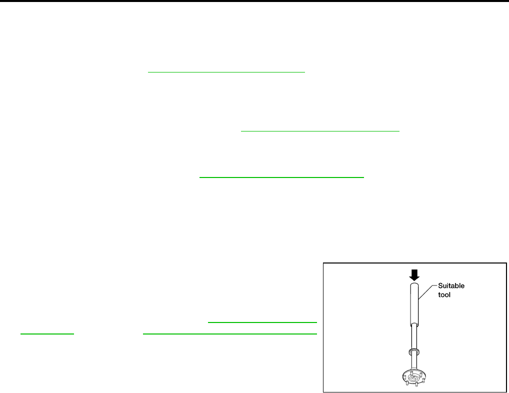
BRC-86
[ABLS/ABS]
SENSOR ROTOR
Revision: February 2006 2005 Xterra
SENSOR ROTOR PFP:47970
Removal and Installation EFS005MT
FRONT
The wheel sensor rotors are built into the wheel hubs and are not removable. If damaged, replace wheel hub
and bearing assembly. Refer to FAX-5, "Removal and Installation" .
REAR (C200)
Removal and Installation
It is necessary to disassemble the rear axle to replace the sensor rotor. Perform the axle shaft assembly
removal procedure to replace sensor rotor. Refer to RAX-7, "Removal and Installation" .
REAR (M226)
Removal
1. Remove axle shaft assembly. Refer to RAX-19, "Removal and Installation" .
NOTE:
It is necessary to disassemble the rear axle to replace the sensor rotor.
2. Pull the sensor rotor of off the axle shaft using Tool and a press.
Installation
1. Install new sensor rotor on axle shaft using a suitable length
steel tube and a press. Make sure sensor rotor is fully seated.
CAUTION:
Do not reuse the old sensor rotor.
2. Install axle shaft assembly. Refer to RAX-7, "Removal and
Installation" (C200), or RAX-19, "Removal and Installation"
(M226).
CAUTION:
Do not reuse the axle oil seal. The axle oil seal must be
replaced every time the axle shaft assembly is removed
from the axle shaft housing.
Tool number : 205-D002 ( — )
WFIA0341E
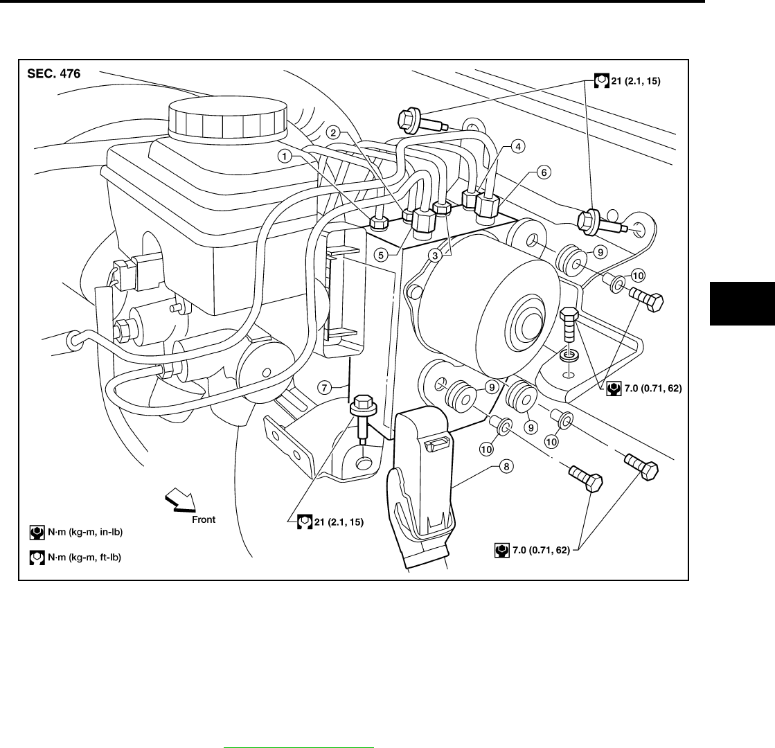
ACTUATOR AND ELECTRIC UNIT (ASSEMBLY)
BRC-87
[ABLS/ABS]
C
D
E
G
H
I
J
K
L
M
A
B
BRC
Revision: February 2006 2005 Xterra
ACTUATOR AND ELECTRIC UNIT (ASSEMBLY) PFP:47660
Removal and Installation EFS005MU
REMOVAL
1. Disconnect the negative battery terminal.
2. Drain the brake fluid. Refer to BR-9, "Drain and Refill" .
3. Disconnect the actuator harness from the ABS actuator and electric unit (control unit).
CAUTION:
●To remove the brake tubes, use a flare nut wrench to prevent the flare nuts and brake tubes from
being damaged.
●Be careful not to splash brake fluid on painted areas.
4. Disconnect the brake tubes.
5. Remove three bolts and then the ABS actuator and electric unit (control unit).
1. To rear left 2. To rear right 3. To front left
4. To front right 5. From the master cylinder secondary
side
6. From the master cylinder primary
side
7. ABS actuator and electric unit (con-
trol unit)
8. Harness connector 9. Grommet
10. Collar
WFIA0389E

BRC-88
[ABLS/ABS]
ACTUATOR AND ELECTRIC UNIT (ASSEMBLY)
Revision: February 2006 2005 Xterra
INSTALLATION
Installation is in the reverse order of removal.
CAUTION:
To install, use a flare nut wrench (commercial service tool).
●Always tighten brake tubes to specification when installing. Refer to BR-11, "BRAKE PIPING AND
HOSE" .
●Never reuse drained brake fluid.
●After installation of the ABS actuator and electric unit (control unit), refill brake system with new
brake fluid. Then bleed the air from the system. Refer to BR-10, "Bleeding Brake System" .
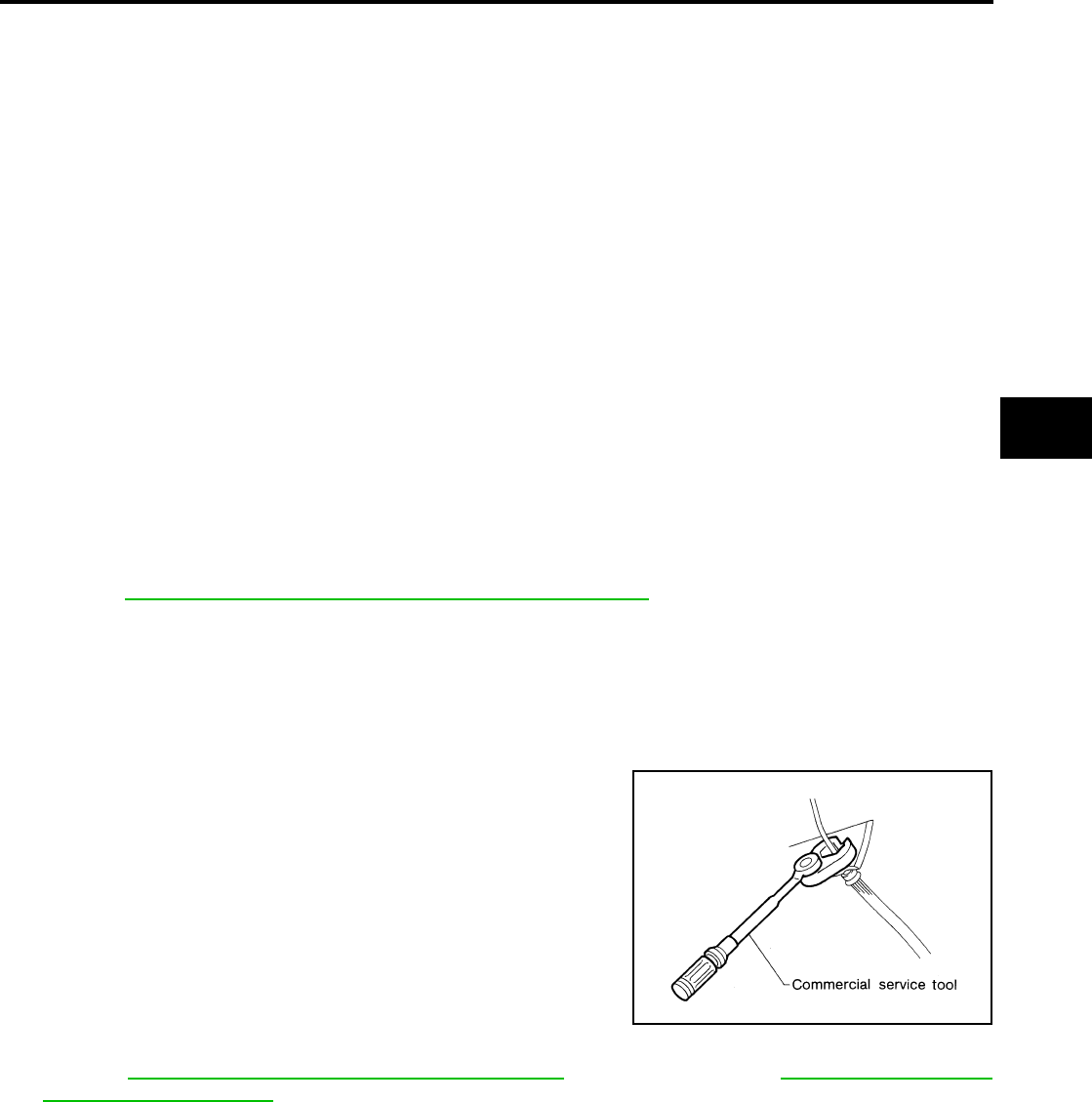
PRECAUTIONS
BRC-89
[VDC/TCS/ABS]
C
D
E
G
H
I
J
K
L
M
A
B
BRC
Revision: February 2006 2005 Xterra
PRECAUTIONS PFP:00001
Precautions for Supplemental Restraint System (SRS) “AIR BAG” and “SEAT
BELT PRE-TENSIONER” EFS005U3
The Supplemental Restraint System such as “AIR BAG” and “SEAT BELT PRE-TENSIONER”, used along
with a front seat belt, helps to reduce the risk or severity of injury to the driver and front passenger for certain
types of collision. This system includes seat belt switch inputs and dual stage front air bag modules. The SRS
system uses the seat belt switches to determine the front air bag deployment, and may only deploy one front
air bag, depending on the severity of a collision and whether the front occupants are belted or unbelted.
Information necessary to service the system safely is included in the SRS and SB section of this Service Man-
ual.
WARNING:
●To avoid rendering the SRS inoperative, which could increase the risk of personal injury or death
in the event of a collision which would result in air bag inflation, all maintenance must be per-
formed by an authorized NISSAN/INFINITI dealer.
●Improper maintenance, including incorrect removal and installation of the SRS, can lead to per-
sonal injury caused by unintentional activation of the system. For removal of Spiral Cable and Air
Bag Module, see the SRS section.
●Do not use electrical test equipment on any circuit related to the SRS unless instructed to in this
Service Manual. SRS wiring harnesses can be identified by yellow and/or orange harnesses or
harness connectors.
Precautions for Brake System EFS005HC
CAUTION:
●Refer to MA-11, "RECOMMENDED FLUIDS AND LUBRICANTS" for recommended brake fluid.
●Never reuse drained brake fluid.
●Be careful not to splash brake fluid on painted areas; it may cause paint damage. If brake fluid is
splashed on painted areas, wash it away with water immediately.
●To clean or wash all parts of master cylinder and disc brake caliper, use clean brake fluid.
●Never use mineral oils such as gasoline or kerosene. They will ruin rubber parts of the hydraulic
system.
●Use flare nut wrench when removing and installing brake
tube.
●If a brake fluid leak is found, the part must be disassembled
without fail. Then it has to be replaced with a new one if a
defect exists.
●Turn the ignition switch OFF and remove the connector of
the ABS actuator and electric unit (control unit) or the bat-
tery terminal before performing the work.
●Always torque brake lines when installing.
●Burnish the brake contact surfaces after refinishing or
replacing rotors, after replacing pads, or if a soft pedal
occurs at very low mileage.
Refer to BR-27, "BRAKE BURNISHING PROCEDURE" (front disc brake) or BR-32, "BRAKE BUR-
NISHING PROCEDURE" (rear disc brake).
WARNING:
●Clean brake pads and shoes with a waste cloth, then wipe with a dust collector.
Precautions When Using CONSULT-II EFS005HD
When connecting CONSULT-II to data link connector, connect them through CONSULT-II CONVERTER.
CAUTION:
If CONSULT-II is used with no connection of CONSULT-II CONVERTER, malfunctions might be
detected in self-diagnosis depending on control unit which carries out CAN communication.
CHECK POINTS FOR USING CONSULT-II
1. Has CONSULT-II been used without connecting CONSULT-II CONVERTER on this vehicle?
●If YES, GO TO 2.
SBR686C

BRC-90
[VDC/TCS/ABS]
PRECAUTIONS
Revision: February 2006 2005 Xterra
●If NO, GO TO 5.
2. Is there any indication other than indications relating to CAN communication system in the self-diagnosis
results?
●If YES, GO TO 3.
●If NO, GO TO 4.
3. Based on self-diagnosis results unrelated to CAN communication, carry out the inspection.
4. Malfunctions may be detected in self-diagnosis depending on control units carrying out CAN communica-
tion. Therefor, erase the self-diagnosis results.
5. Diagnose CAN communication system. Refer to LAN-21, "CAN COMMUNICATION" .
Precautions for Brake Control EFS005HE
●During ABS operation, the brake pedal may vibrate lightly and a mechanical noise may be heard. This is
normal.
●Just after starting vehicle, the brake pedal may vibrate or a motor operating noise may be heard from
engine compartment. This is a normal status of operation check.
●Stopping distance may be longer than that of vehicles without ABS when vehicle drives on rough, gravel,
or snow-covered (fresh, deep snow) roads.
●When an error is indicated by ABS or another warning lamp, collect all necessary information from cus-
tomer (what symptoms are present under what conditions) and check for simple causes before starting
diagnosis. Besides electrical system inspection, check brake booster operation, brake fluid level, and fluid
leaks.
●If incorrect tire sizes or types are installed on the vehicle or brake pads are not Genuine NISSAN parts,
stopping distance or steering stability may deteriorate.
●If there is a radio, antenna or related wiring near control module, ABS function may have a malfunction or
error.
●If aftermarket parts (car stereo, CD player, etc.) have been installed, check for incidents such as harness
pinches, open circuits or improper wiring.
●If the following components are replaced with non-genuine components or modified, the VDC OFF indica-
tor lamp and SLIP indicator lamp may turn on or the VDC system may not operate properly. Components
related to suspension (shock absorbers, struts, springs, bushings, etc.), tires, wheels (exclude specified
size), components related to brake system (pads, rotors, calipers, etc.), components related to engine
(muffler, ECM, etc.), components related to body reinforcement (roll bar, tower bar, etc.).
●Driving with broken or excessively worn suspension components, tires or brake system components may
cause the VDC OFF indicator lamp and the SLIP indicator lamp to turn on, and the VDC system may not
operate properly.
●When the TCS or VDC is activated by sudden acceleration or sudden turn, some noise may occur. The
noise is a result of the normal operation of the TCS and VDC.
●When driving on roads which have extreme slopes (such as mountainous roads) or high banks (such as
sharp curves on a freeway), the VDC may not operate normally, or the VDC warning lamp and the SLIP
indicator lamp may turn on. This is not a problem if normal operation can be resumed after restarting the
engine.
●Sudden turns (such as spin turns, acceleration turns), drifting, etc. with VDC turned off may cause the yaw
rate/side G sensor to indicate a problem. This is not a problem if normal operation can be resumed after
restarting the engine.
●If battery is removed or steering angle sensor is disconnected, power to steering angle sensor is lost and
the screen goes into steering angle sensor safe mode.
●When screen goes into steering angle sensor safe mode, perform "Adjustment of Steering Angle Sensor
Neutral Position" with CONSULT-II and check that VDC OFF indicator turns off. Additionally, perform self-
diagnosis, check that only "Steering Angle Sensor Safe Mode" is shown for self-diagnostic result, and
then delete the memory. (If the self-diagnostic result shows an indication other than "Steering Angle Sen-
sor Safe Mode", repair the relevant part and restart self-diagnosis.) The steering angle sensor is released
and returns to normal condition by performing the above operation.
●When checking, if only "Steering Angle Sensor Safe Mode" is shown in the self-diagnostic result and VDC
OFF indicator is off, delete history of malfunction. This happens when battery power supply is lost and the
screen goes into Steering Angle Sensor Safe Mode, and then screen returns to normal mode automati-
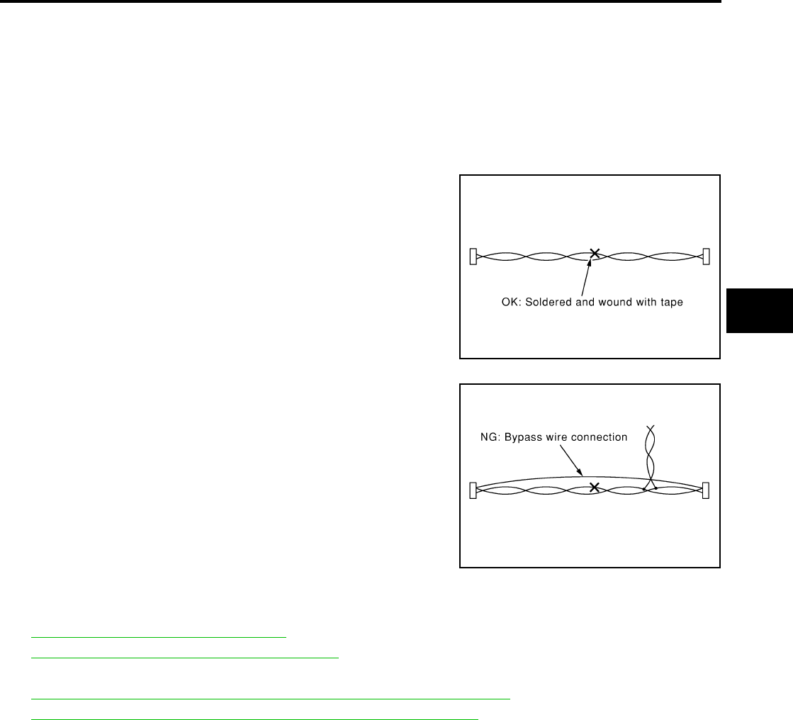
PRECAUTIONS
BRC-91
[VDC/TCS/ABS]
C
D
E
G
H
I
J
K
L
M
A
B
BRC
Revision: February 2006 2005 Xterra
cally by driving the vehicle in a straight forward direction [for approximately 30 seconds at 20 km/h (12
MPH) or more] after power is supplied again.
NOTE:
VDC OFF indicator lamp is on when VDC OFF switch is on.
Precautions for CAN System EFS005HF
●Do not apply voltage of 7.0V or higher to terminal to be measured.
●Maximum open terminal voltage of tester in use must be less than 7.0V.
●Before checking harnesses, turn ignition switch OFF and disconnect battery negative cable.
●Area to be repaired must be soldered and wrapped with tape.
Make sure that fraying of twisted wire is within 110 mm (4.33 in).
●Do not make a bypass connection to repaired area. (If the circuit
is bypassed, characteristics of twisted wire will be lost.)
Wiring Diagrams and Trouble Diagnosis EFS005HG
When you read wiring diagrams, refer to the following:
●GI-16, "How to Read Wiring Diagrams".
●PG-4, "POWER SUPPLY ROUTING CIRCUIT".
When you perform trouble diagnosis, refer to the following:
●GI-12, "HOW TO FOLLOW TEST GROUPS IN TROUBLE DIAGNOSES".
●GI-28, "How to Perform Efficient Diagnosis for an Electrical Incident".
PKIA0306E
PKIA0307E

BRC-92
[VDC/TCS/ABS]
PREPARATION
Revision: February 2006 2005 Xterra
PREPARATION PFP:00002
Special Service Tool EFS005HH
The actual shapes of Kent-Moore tools may differ from those of special service tools illustrated here.
Commercial Service Tools EFS005HI
Tool number
(Kent-Moore No.)
Tool name
Description
—
(J-45741)
ABS active wheel sensor tester
Checking operation of ABS active wheel
sensors
205-D002
(—)
Bearing replacer
Removing sensor rotor
WFIA0101E
ZZA0700D
Tool name Description
1. Flare nut crowfoot
2. Torque wrench
Removing and installing brake piping
a: 10 mm (0.39 in)/12 mm (0.47 in)
S-NT360
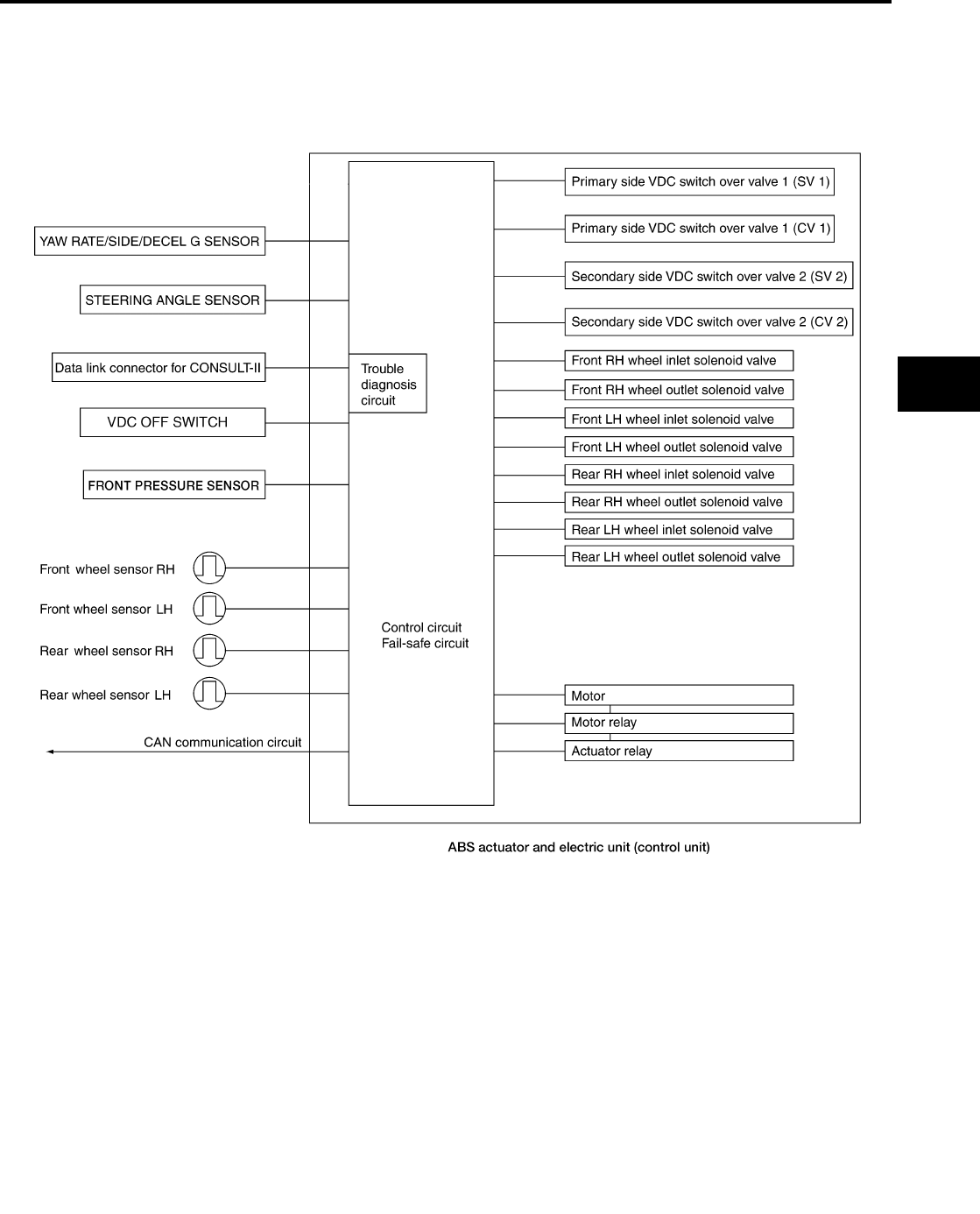
SYSTEM DESCRIPTION
BRC-93
[VDC/TCS/ABS]
C
D
E
G
H
I
J
K
L
M
A
B
BRC
Revision: February 2006 2005 Xterra
SYSTEM DESCRIPTION PFP:00000
System Components EFS005HJ
WFIA0356E

BRC-94
[VDC/TCS/ABS]
SYSTEM DESCRIPTION
Revision: February 2006 2005 Xterra
ABS Function EFS005HK
●The Anti-Lock Brake System detects wheel revolution while braking and improves handling stability during
sudden braking by electrically preventing wheel lockup. Maneuverability is also improved for avoiding
obstacles.
●If the electrical system malfunctions, the Fail-Safe function is activated, the ABS becomes inoperative and
the ABS warning lamp turns on.
●The electrical system can be diagnosed using CONSULT-II.
●During ABS operation, the brake pedal may vibrate lightly and a mechanical noise may be heard. This is
normal.
●Just after starting the vehicle, the brake pedal may vibrate or a motor operating noise may be heard from
engine compartment. This is a normal status of operation check.
●Stopping distance may be longer than that of vehicles without ABS when vehicle drives on rough, gravel,
or snow-covered (fresh, deep snow) roads.
EBD Function EFS005HL
●Electronic Brake Distribution is a function that detects subtle slippages between the front and rear wheels
during braking, and it improves handling stability by electronically controlling the brake fluid pressure
which results in reduced rear wheel slippage.
●If the electrical system malfunctions, the Fail-Safe function is activated, the EBD and ABS become inoper-
ative, and the ABS warning lamp and brake warning lamp are turned on.
●The electrical system can be diagnosed using CONSULT-II.
●During EBD operation, the brake pedal may vibrate lightly and a mechanical noise may be heard. This is
normal.
●Just after starting the vehicle, the brake pedal may vibrate or a motor operating noise may be heard from
engine compartment. This is a normal status of operation check.
TCS Function EFS005HM
●Spinning of the drive wheels is detected by the ABS actuator and electric unit (control unit) using inputs
from the wheel speed sensors. If wheel spin occurs, the drive wheel right and left brake fluid pressure
control and engine fuel cut are activated while the throttle value is restricted to reduce the engine torque
and decrease the amount of wheel spin. In addition, the throttle opening is controlled to achieve the opti-
mum engine torque.
●Depending on road condition, the vehicle may have a sluggish feel. This is normal, because optimum trac-
tion has the highest priority during TCS operation.
●TCS may be activated during sudden vehicle acceleration, wide open throttle acceleration, sudden trans-
mission shifts or when the vehicle is driven on a road with a varying surface friction coefficient.
●The SLIP indicator lamp flashes to inform the driver of TCS operation.
VDC Function EFS005HN
●In addition to the ABS/TCS function, the driver steering amount and brake operation amount are detected
from the steering angle sensor and pressure sensors, and the vehicle's driving status (amount of under
steering/over steering) is determined using inputs from the yaw rate sensor/side G sensor, wheel speed
sensors, etc. and this information is used to improve vehicle stability by controlling the braking and engine
torque application to the wheels.
●The SLIP indicator lamp flashes to inform the driver of VDC operation.
●During VDC operation, the vehicle body and brake pedal may vibrate lightly and a mechanical noise may
be heard. This is normal.
●The VDC OFF indicator lamp and SLIP indicator lamp may turn on when the vehicle is subject to strong
shaking or large vibration, such as when the vehicle is on a turntable or a ship while the engine is running
or on a steep slope. In this case, restart the engine on a normal road and if the VDC OFF indicator lamp
and SLIP indicator lamp turn off, there is no problem.
Fail-Safe Function EFS005HO
CAUTION:
If the Fail-Safe function is activated, perform the Self Diagnosis for ABS/TCS/VDC system.

SYSTEM DESCRIPTION
BRC-95
[VDC/TCS/ABS]
C
D
E
G
H
I
J
K
L
M
A
B
BRC
Revision: February 2006 2005 Xterra
ABS/EBD SYSTEM
In case of an electrical malfunction with the ABS, the ABS warning lamp, VDC OFF indicator lamp and SLIP
indicator lamp will turn on. In case of an electrical malfunction with the EBD system, the BRAKE warning lamp,
ABS warning lamp, VDC OFF indicator lamp and SLIP indicator lamp will turn on.
The system will revert to one of the following conditions of the Fail-Safe function.
1. For ABS malfunction, only the EBD is operative and the condition of the vehicle is the same condition of
vehicles without ABS/TCS/VDC system.
2. For EBD malfunction, the EBD and ABS become inoperative, and the condition of the vehicle is the same
as the condition of vehicles without ABS/TCS/VDC or EBD system.
VDC/TCS SYSTEM
In case of TCS/VDC system malfunction, the VDC OFF indicator lamp and SLIP indicator lamp are turned on
and the condition of the vehicle is the same as the condition of vehicles without TCS/VDC system. In case of
an electrical malfunction with the TCS/VDC system, the ABS control continues to operate normally without
TCS/VDC control.
Hydraulic Circuit Diagram EFS005HP
WFIA0357E

BRC-96
[VDC/TCS/ABS]
CAN COMMUNICATION
Revision: February 2006 2005 Xterra
CAN COMMUNICATION PFP:23710
System Description EFS005HQ
Refer to LAN-21, "CAN COMMUNICATION" .

TROUBLE DIAGNOSIS
BRC-97
[VDC/TCS/ABS]
C
D
E
G
H
I
J
K
L
M
A
B
BRC
Revision: February 2006 2005 Xterra
TROUBLE DIAGNOSIS PFP:00000
How to Perform Trouble Diagnoses for Quick and Accurate Repair EFS005HR
INTRODUCTION
The ABS/TCS/VDC system has an electronic control unit to control
major functions. The control unit accepts input signals from sensors
and controls actuator operation. It is also important to check for con-
ventional problems such as air leaks in the booster or lines, lack of
brake fluid, or other problems with the brake system.
It is much more difficult to diagnose a problem that occurs intermit-
tently rather than continuously. Most intermittent problems are
caused by poor electrical connections or faulty wiring. In this case,
careful checking of suspicious circuits may help prevent the replace-
ment of good parts.
A visual check only may not find the cause of the problem, so a road
test should be performed.
Before undertaking actual checks, take just a few minutes to talk with
a customer who approaches with a ABS/TCS/VDC complaint. The
customer is a very good source of information on such problems,
especially intermittent ones. Through the talks with the customer,
find out what symptoms are present and under what conditions they
occur.
Start your diagnosis by looking for “conventional” problems first. This
is one of the best ways to troubleshoot brake problems on a ABS/
TCS/VDC equipped vehicle. Also check related Service Bulletins for
information.
SEF233G
SEF234G
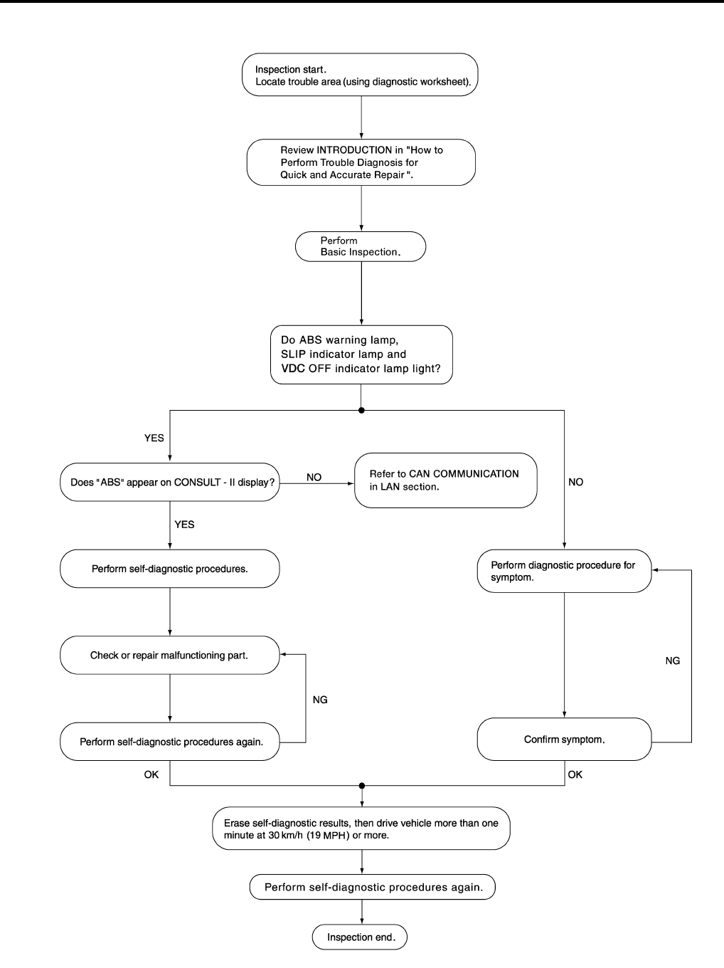
BRC-98
[VDC/TCS/ABS]
TROUBLE DIAGNOSIS
Revision: February 2006 2005 Xterra
WORK FLOW
WFIA0358E
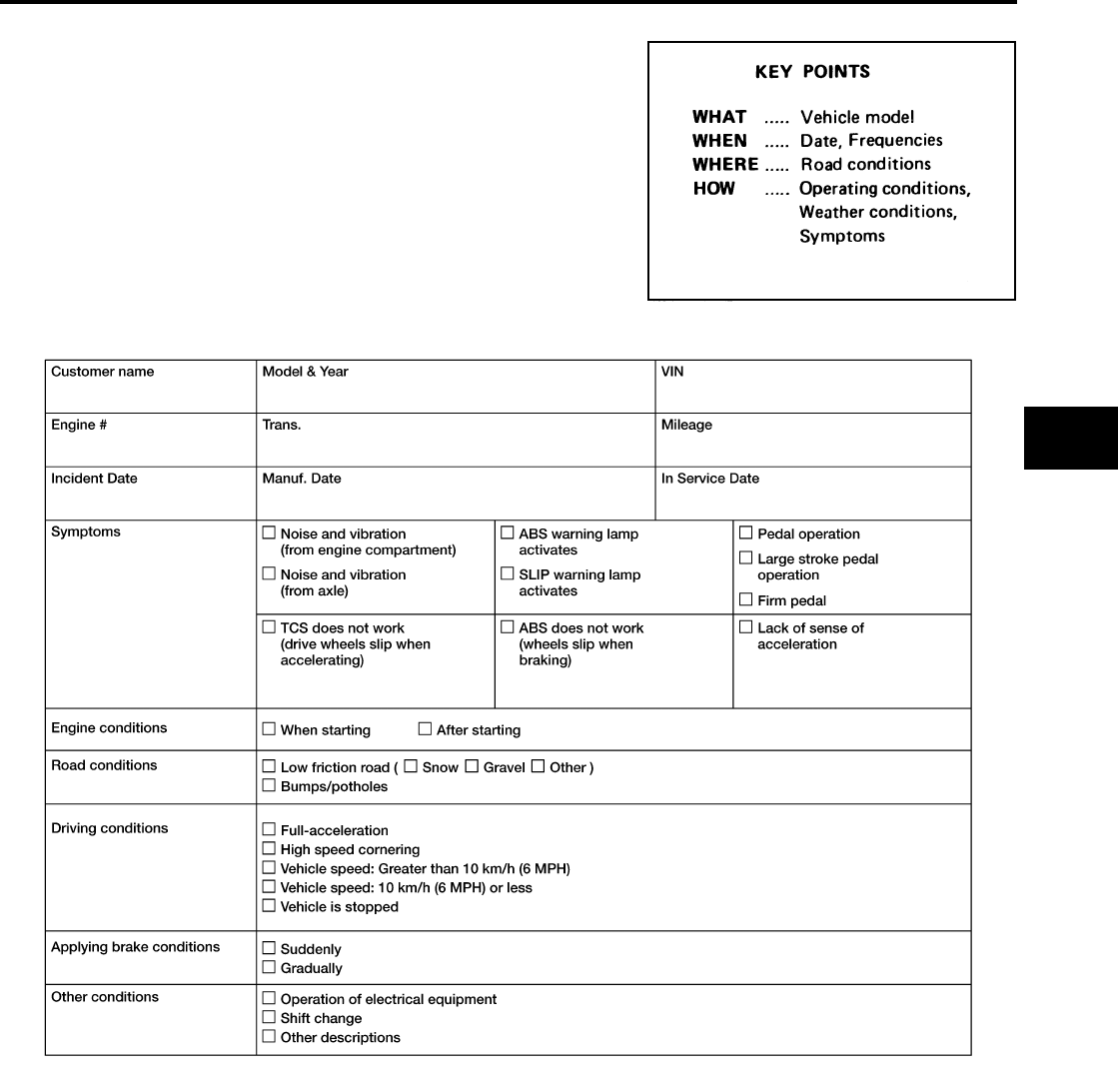
TROUBLE DIAGNOSIS
BRC-99
[VDC/TCS/ABS]
C
D
E
G
H
I
J
K
L
M
A
B
BRC
Revision: February 2006 2005 Xterra
CLARIFY CONCERN
●A customer's description of a vehicle concern may vary depend-
ing on the individual. It is important to clarify the customer's con-
cern.
●Ask the customer about what symptoms are present under what
conditions. Use this information to reproduce the symptom while
driving.
●It is also important to use the diagnosis sheet to understand
what type of trouble the customer is having.
EXAMPLE OF DIAGNOSIS SHEET
SBR339B
WFIA0097E
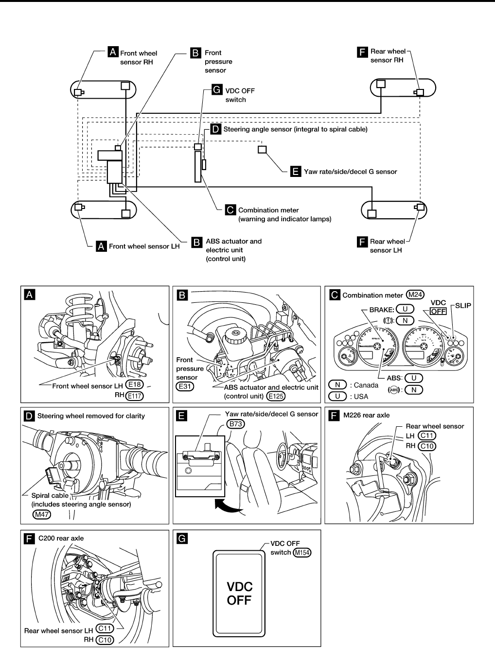
BRC-100
[VDC/TCS/ABS]
TROUBLE DIAGNOSIS
Revision: February 2006 2005 Xterra
Component Parts and Harness Connector Location EFS005HS
WFIA0401E
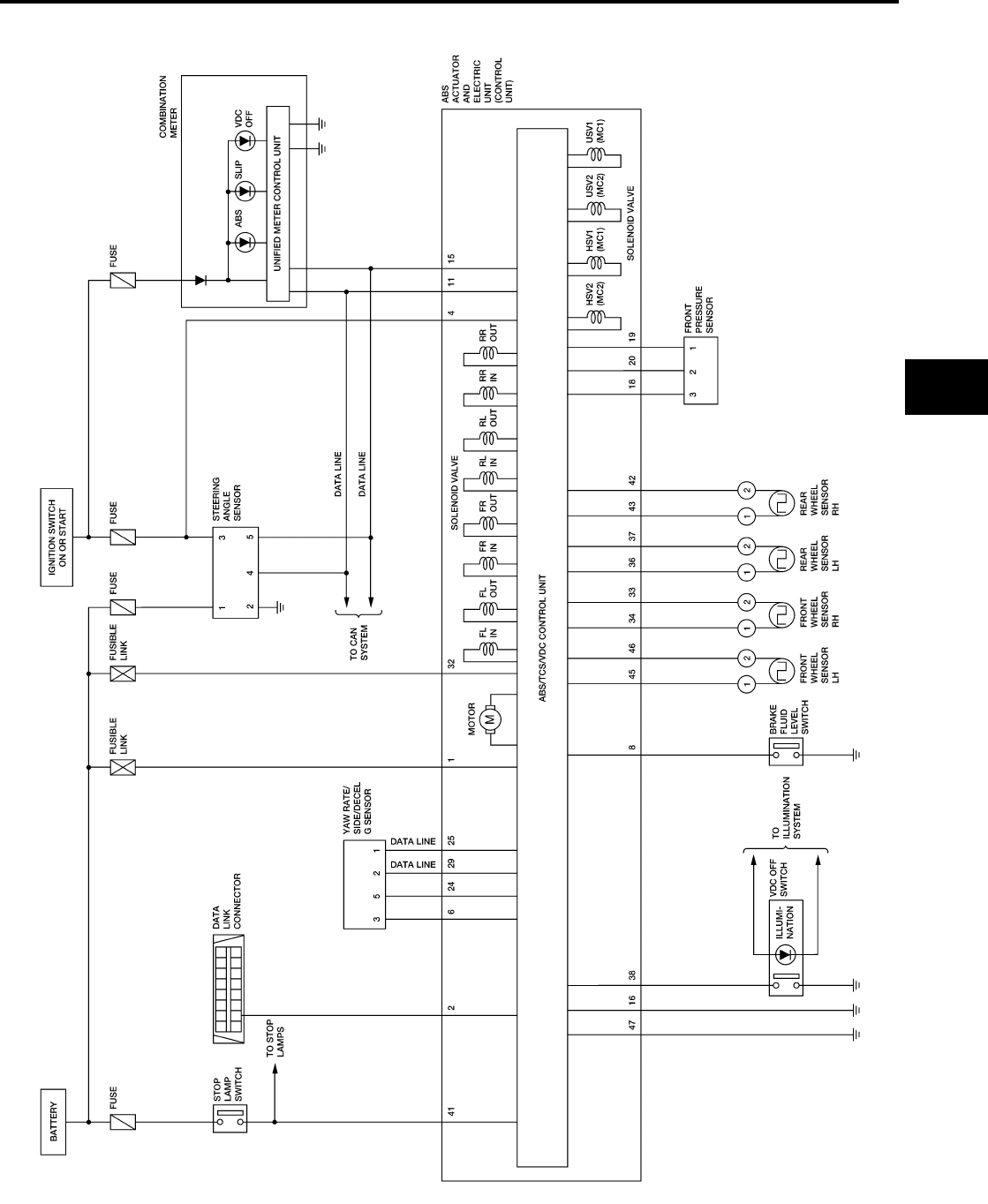
TROUBLE DIAGNOSIS
BRC-101
[VDC/TCS/ABS]
C
D
E
G
H
I
J
K
L
M
A
B
BRC
Revision: February 2006 2005 Xterra
Schematic EFS005HT
WFWA0239E
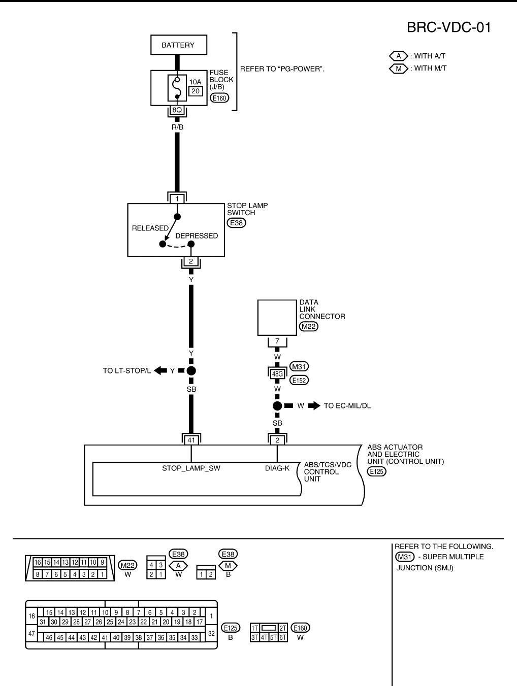
BRC-102
[VDC/TCS/ABS]
TROUBLE DIAGNOSIS
Revision: February 2006 2005 Xterra
Wiring Diagram — VDC — EFS005HU
WFWA0240E
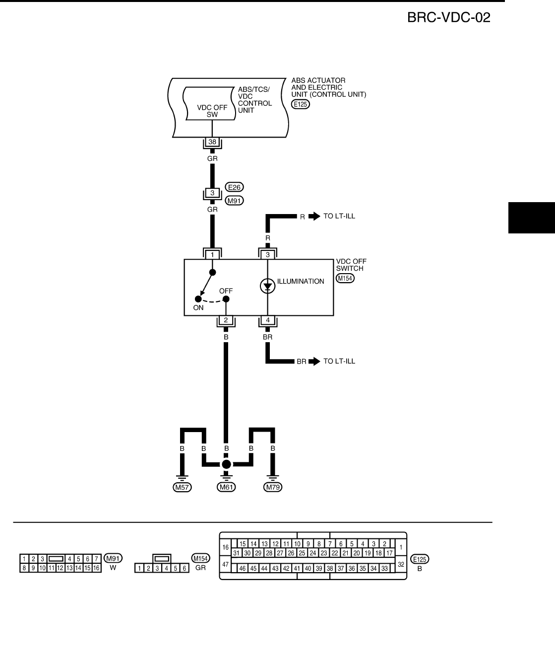
TROUBLE DIAGNOSIS
BRC-103
[VDC/TCS/ABS]
C
D
E
G
H
I
J
K
L
M
A
B
BRC
Revision: February 2006 2005 Xterra
WFWA0241E
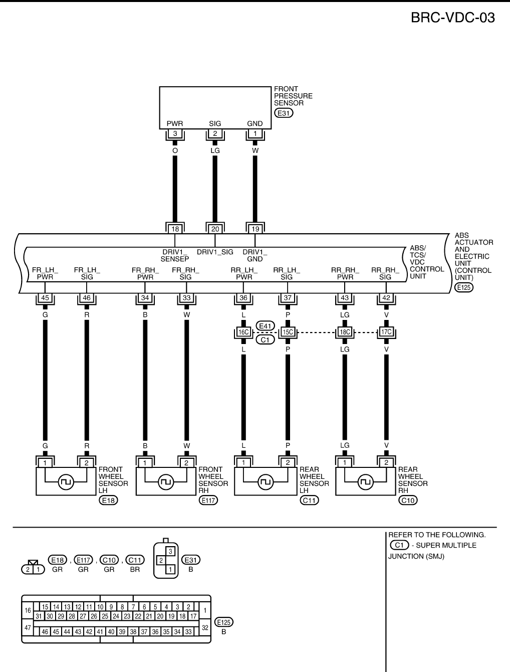
BRC-104
[VDC/TCS/ABS]
TROUBLE DIAGNOSIS
Revision: February 2006 2005 Xterra
WFWA0242E
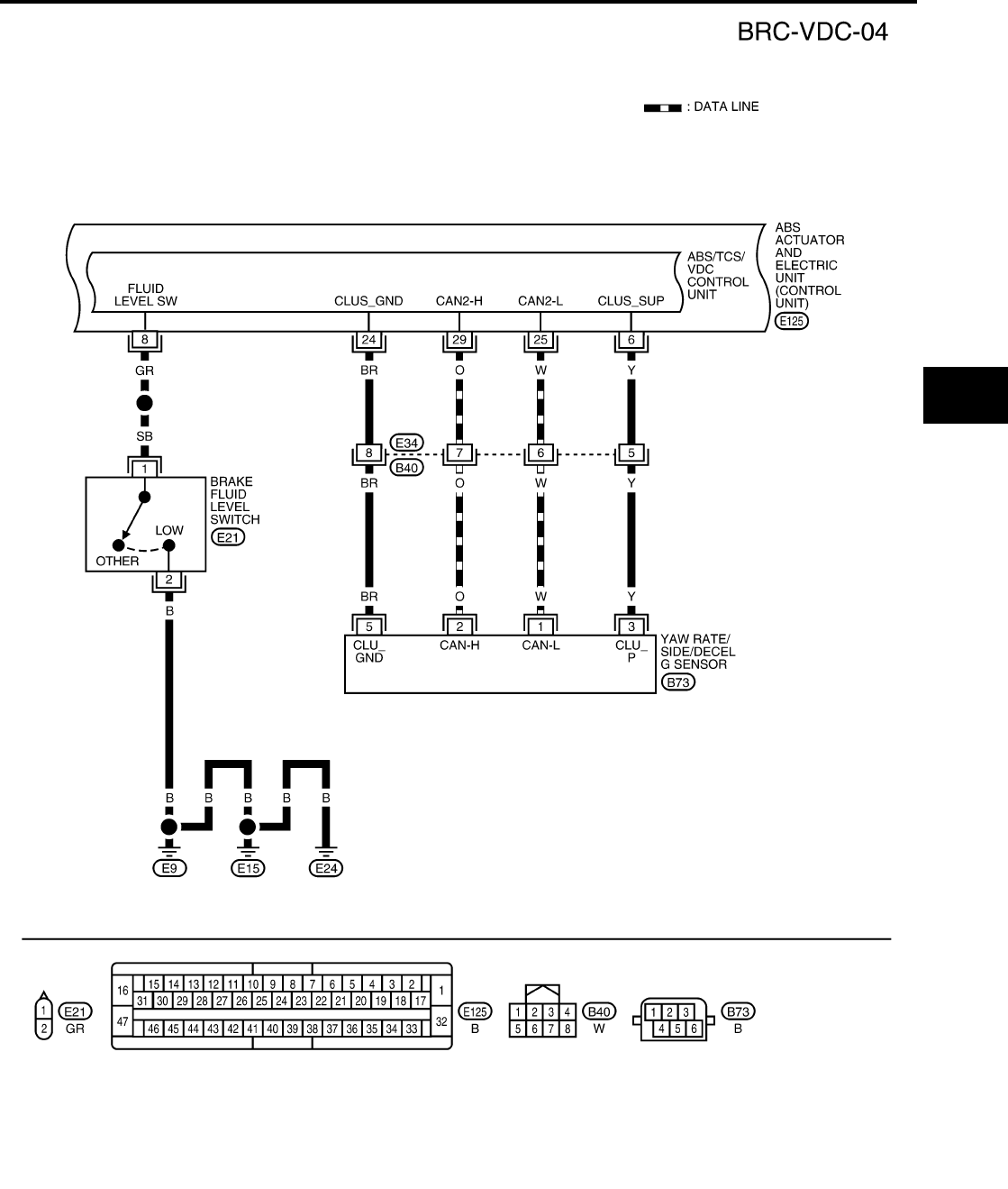
TROUBLE DIAGNOSIS
BRC-105
[VDC/TCS/ABS]
C
D
E
G
H
I
J
K
L
M
A
B
BRC
Revision: February 2006 2005 Xterra
WFWA0243E
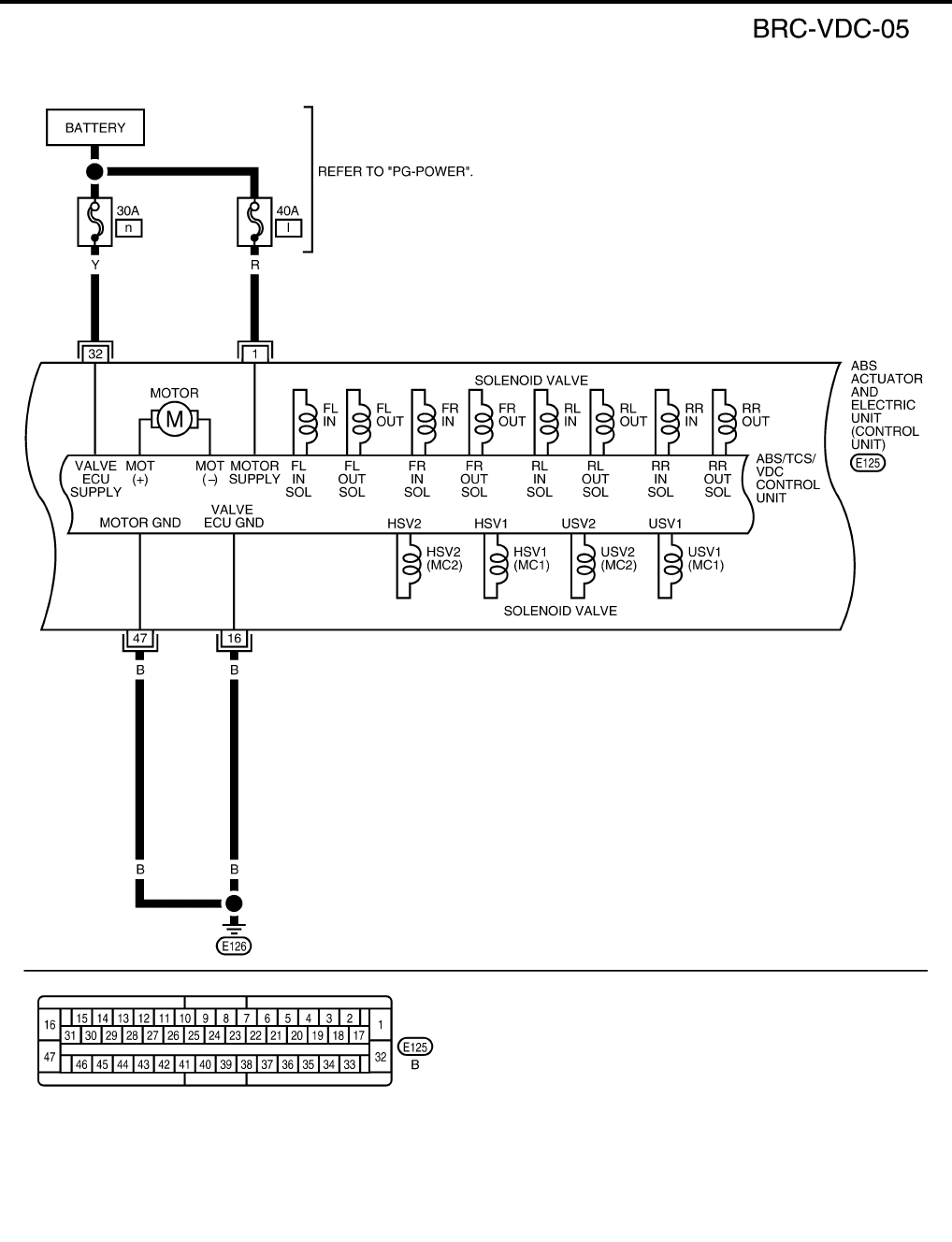
BRC-106
[VDC/TCS/ABS]
TROUBLE DIAGNOSIS
Revision: February 2006 2005 Xterra
WFWA0244E
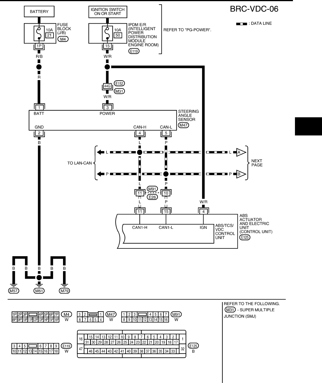
TROUBLE DIAGNOSIS
BRC-107
[VDC/TCS/ABS]
C
D
E
G
H
I
J
K
L
M
A
B
BRC
Revision: February 2006 2005 Xterra
WFWA0245E
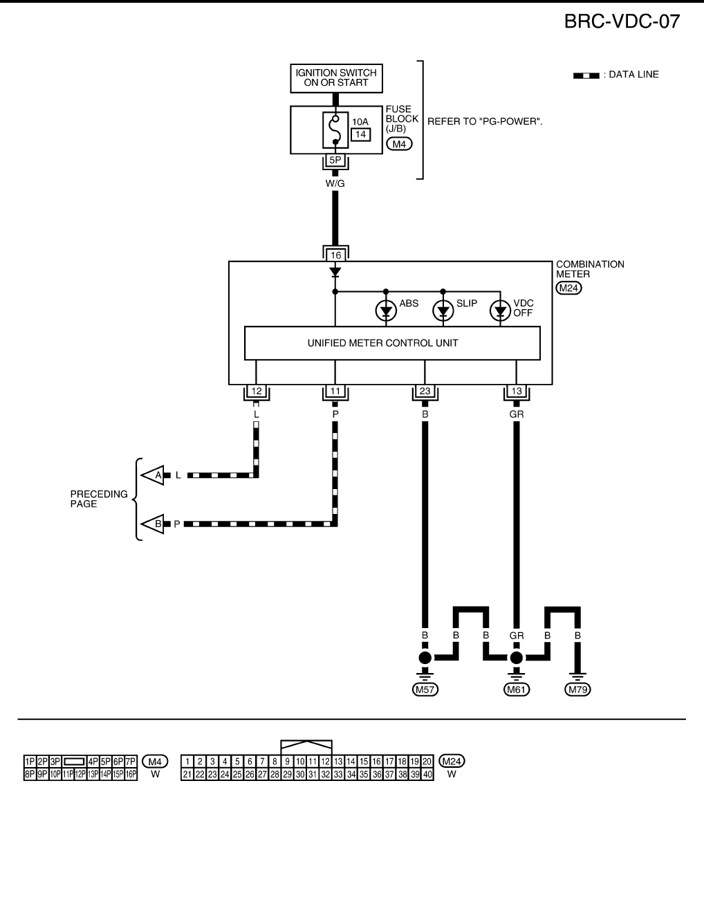
BRC-108
[VDC/TCS/ABS]
TROUBLE DIAGNOSIS
Revision: February 2006 2005 Xterra
WFWA0246E

TROUBLE DIAGNOSIS
BRC-109
[VDC/TCS/ABS]
C
D
E
G
H
I
J
K
L
M
A
B
BRC
Revision: February 2006 2005 Xterra
Basic Inspection EFS005HV
BRAKE FLUID LEVEL, FLUID LEAK, AND BRAKE PAD INSPECTION
1. Check fluid level in the brake fluid reservoir. If fluid level is low, add fluid.
2. Check the brake piping and around the ABS actuator and electric unit (control unit) for leaks. If there is
leaking or seeping fluid, check the following items.
●If ABS actuator and electric unit (control unit) connection is loose, tighten the piping to the specified
torque and recheck for leaks.
●If there is damage to the connection flare nut or ABS actuator and electric unit (control unit) threads,
replace the damaged part and recheck for leaks.
●When there is fluid leaking or seeping from a fluid connection, use a clean cloth to wipe off the fluid and
recheck for leaks. If fluid is still seeping out, replace the damaged part. If the fluid is leaking at the ABS
actuator and electric unit (control unit), replace the ABS actuator and electric unit (control unit) assem-
bly.
CAUTION:
The ABS actuator and electric unit (control unit) cannot be disassembled and must be replaced
as an assembly.
3. Check the brake pads for excessive wear.
POWER SYSTEM TERMINAL LOOSENESS AND BATTERY INSPECTION
Make sure the battery positive cable, negative cable and ground connection are not loose. In addition, make
sure the battery is sufficiently charged.
ABS WARNING LAMP, SLIP INDICATOR LAMP AND VDC OFF INDICATOR LAMP INSPECTION
1. Make sure ABS warning lamp, SLIP indicator lamp and VDC OFF indicator lamp (when VDC OFF switch
is off), turn on for approximately 2 seconds when the ignition switch is turned ON. If they do not, check the
ABS warning lamp, SLIP indicator lamp and VDC OFF indicator lamp. Check CAN communications. If
there are no errors with the CAN communication system, check combination meter. Refer to DI-4, "COM-
BINATION METERS" .
2. Make sure the lamps turn off approximately 2 seconds after the ignition switch is turned ON. If the lamp
does not turn off, conduct self-diagnosis.
NOTE:
●On 4WD vehicles, when the transfer case is placed in 4LO, the VDC system is disabled and the VDC
OFF indicator will turn on.
●If the battery has been disconnected, the TCS/VDC system is initialized and the SLIP and VDC OFF
indicator lamps may not turn off after 2 seconds when the ignition switch is turned ON. In this case,
refer to BRC-115, "SELF-DIAGNOSIS" .
3. With the engine running, make sure the VDC OFF indicator lamp turns on and off when the VDC OFF
switch is turned on and off. If the indicator lamp status does not correspond to switch operation, check the
VDC OFF switch. Refer to BRC-136, "VDC OFF SWITCH" .
4. Make sure ABS warning lamp, SLIP indicator lamp and VDC OFF indicator lamp turn off approximately 2
seconds after the ignition switch is turned ON. If ABS warning lamp, SLIP indicator lamp and VDC OFF
indicator lamp have not turned off 2 seconds after the ignition switch is turned ON, conduct self-diagnosis
of the ABS actuator and electric unit (control unit).
5. After conducting the self-diagnosis, be sure to erase the error memory. Refer to BRC-114, "CONSULT-II
Function (ABS)" .

BRC-110
[VDC/TCS/ABS]
TROUBLE DIAGNOSIS
Revision: February 2006 2005 Xterra
For Fast and Accurate Diagnosis EFS005HW
PRECAUTIONS FOR DIAGNOSIS
●Before performing diagnosis, always read precautions. Refer to BRC-89, "PRECAUTIONS" .
●If ABS actuator and electric unit (control unit), steering angle sensor, steering system parts or suspension
system parts have been replaced, or if alignment has been adjusted, be sure to adjust neutral position of
steering angle sensor before driving. Refer to BRC-142, "Adjustment of Steering Angle Sensor Neutral
Position" .
●After diagnosis is finished, be sure to erase memory. Refer to BRC-115, "SELF-DIAGNOSIS" .
●When checking continuity and voltage between units, be sure to check for disconnection, looseness,
bend, or collapse of connector terminals. If any non-standard condition is found, repair or replace connec-
tor terminals.
●For intermittent symptoms, possible cause is malfunction in harness, harness connector, or terminals.
Move harness, harness connector, and terminals to check for poor connections.
●If a circuit tester is used for the check, be careful not to forcibly extend any connector terminal.
●To use CONSULT-II to perform self-diagnosis of ABS actuator and electric unit (control unit), active tests,
or work support, first stop work, then connect CONSULT-II and select “ABS”.
●CONSULT-II self-diagnosis results are displayed without regard to occurrence timing. In some cases later
ones (timing value is small) appear on the next screen.
●When self-diagnostic results of CONSULT-II show a malfunction, if CONSULT-II active test is performed,
an engine system error may be indicated. In this case, start engine to resume the normal screen.
●VDC/TCS/ABS system electronically controls brake operation and engine output. The following symptoms
may be caused by normal operations:
Symptom Symptom description Result
Motor operation noise
This is noise of motor inside ABS actuator and electric unit (control unit).
Slight noise may occur during VDC, TCS, and ABS operation.
Normal
When the vehicle speed goes over 20 km/h (12.5 mph), the motor and
valves operating noise may be heard. It happens only once after IGN
(ignition) is ON. This is a normal status of the system operation check.
System operation check
noise
When the engine starts, slight “click” noise may be heard from engine
compartment. This is normal and is part of system operation check. Normal
VDC/TCS operation
(SLIP indicator lamp blink-
ing)
TCS may activate momentarily if wheel speed changes when driving
over location where friction coefficient varies, when up/downshifting or
when fully depressing accelerator pedal. Normal
Cancel the VDC/TCS
function for the
inspection on a chas-
sis dynamometer.
For inspection of speedometer or other instruments, press
VDC OFF switch to turn VDC/TCS function off.
When accelerator pedal is depressed on a chassis dynamometer (fixed
front-wheel type), vehicle speed will not increase. This is not normal. It is
result of TCS being activated by stationary front wheels. Warning lamp
may also illuminate to indicate “sensor system error”. This is also nor-
mal, and is the result of the stationary front wheels being detected. To be
certain, restart engine, and drive vehicle at 30 km/h (19 MPH) or more.
Make sure warning lamp does not illuminate.
ABS operation (Longer stop-
ping distance)
On roads with low friction coefficients, such as snowy roads or gravel
roads, vehicles with ABS may require a longer stopping distance. There-
fore, when driving on such roads, avoid overconfidence and keep speed
sufficiently low.
Normal
Insufficient feeling of accel-
eration
Depending on road conditions, driver may feel that feeling of accelera-
tion is insufficient. This is because traction control, which controls the
engine and brakes to achieve optimal traction, has the highest priority
(for safety). As a result, there may be times when acceleration is slightly
less than usual for the same accelerator pedal operation.
Normal

TROUBLE DIAGNOSIS
BRC-111
[VDC/TCS/ABS]
C
D
E
G
H
I
J
K
L
M
A
B
BRC
Revision: February 2006 2005 Xterra
Warning Lamp and Indicator Timing EFS005HX
X: ON
—: OFF
Control Unit Input/Output Signal Standard EFS005HY
REFERENCE VALUE FROM CONSULT-II
CAUTION:
The display shows the control unit calculation data, so a normal value might be displayed even in the
event the output circuit (harness) is open or short circuited.
Condition
ABS
warning
lamp
VDC OFF
indicator
lamp
SLIP
indicator
lamp
Remarks
When the ignition switch is OFF — — — —
After the ignition switch is turned ON for approx. 2
seconds ××× —
After the ignition switch has been turned ON for
approx. 2 seconds ——— —
When the VDC OFF switch is pressed (VDC func-
tion OFF) —×——
ABS/TCS/VDC malfunction ××× —
When the VDC is malfunctioning — ×× —
Monitor item Display content
Data monitor Note: Error inspection
checklist
Condition Reference value in
normal operation
N POSI SIG PNP switch signal ON/
OFF condition
A/T shift position = N position ON BRC-135, "CAN Commu-
nication System Inspec-
tion"
A/T shift position = other than
N positions OFF
P POSI SIG PNP switch signal ON/
OFF condition
A/T shift position P position ON BRC-135, "CAN Commu-
nication System Inspec-
tion"
A/T shift position = other than
P positions OFF
GEAR A/T gear position
1st gear 1
—
2nd gear 2
3rd gear 3
4th gear 4
5th gear 5
FR RH SENSOR
FR LH SENSOR
RR RH SENSOR
RR LH SENSOR
Wheel speed
Vehicle stopped 0 [km/h (MPH)]
BRC-123, "Wheel Sen-
sor System Inspection"
Vehicle running (Note 1)
Almost in accor-
dance with speed-
ometer display
(within ±10%)
ACCEL POS SIG
Open/close condition
of throttle valve (linked
with accelerator pedal).
Accelerator pedal not
depressed (ignition switch is
ON)
0% BRC-135, "CAN Commu-
nication System Inspec-
tion"
Depress accelerator pedal
(ignition switch is ON) 0 to 100%
2WD/4WD Drive axle 2WD model 2WD —
4WD model 4WD
ENGINE SPEED With engine running
With engine stopped 0 RPM
BRC-124, "Engine Sys-
tem Inspection"
Engine running
Almost in accor-
dance with
tachometer display

BRC-112
[VDC/TCS/ABS]
TROUBLE DIAGNOSIS
Revision: February 2006 2005 Xterra
STR ANGLE SIG
Steering angle
detected by steering
angle sensor
Straight-ahead Approx. 0 deg BRC-125, "Steering
Angle Sensor System"
Steering wheel turned –756 to 756 deg
YAW RATE SEN Yaw rate detected by
yaw rate sensor
Vehicle stopped Approx. 0 d/s BRC-127, "Yaw Rate/
Side/Decel G Sensor
System Inspection"
Vehicle running –100 to 100 d/s
SIDE G SENSOR Transverse G detected
by side G-sensor
Vehicle stopped Approx. 0 m/s2BRC-127, "Yaw Rate/
Side/Decel G Sensor
System Inspection"
Vehicle running –16.7 to 16.7 m/s2
BATTERY VOLT
Battery voltage sup-
plied to ABS actuator
and electric unit (con-
trol unit)
Ignition switch ON 10 to 16V
BRC-132, "ABS/TCS/
VDC Control Unit Power
and Ground Systems
Inspection"
OFF SW VDC OFF switch
ON/OFF status
VDC OFF switch ON
(When VDC OFF indicator
lamp is ON)
ON
BRC-136, "VDC OFF
SWITCH"
VDC OFF switch OFF
(When VDC OFF indicator
lamp is OFF)
OFF
ABS WARN LAMP ABS warning lamp ON
condition (Note 2)
ABS warning lamp ON ON —
ABS warning lamp OFF OFF
MOTOR RELAY Operation status of
motor and motor relay
Ignition switch ON or running
(ABS not activated) OFF BRC-130, "Actuator
Motor, Motor Relay, and
Circuit Inspection"
Ignition switch ON or engine
running (ABS activated) ON
ACTUATOR RLY Actuator relay opera-
tion status
Vehicle stopped (Ignition
switch ON) OFF BRC-130, "Actuator
Motor, Motor Relay, and
Circuit Inspection"
Vehicle stopped (Engine run-
ning) ON
OFF LAMP VDC OFF indicator
lamp status (Note 3)
When VDC OFF indicator
lamp is ON ON BRC-135, "CAN Commu-
nication System Inspec-
tion"
When VDC OFF indicator
lamp is OFF OFF
SLIP LAMP SLIP indicator lamp
status (Note 4)
When SLIP indicator lamp is
ON ON BRC-135, "CAN Commu-
nication System Inspec-
tion"
When SLIP indicator lamp is
OFF OFF
FR LH IN SOL
FR LH OUT SOL
FR RH IN SOL
FR RH OUT SOL
RR RH IN SOL
RR RH OUT SOL
RR LH IN SOL
RR LH OUT SOL
Solenoid valve opera-
tion
Actuator (solenoid) is active
(“ACTIVE TEST” with CON-
SULT-II) or actuator relay is
inactive (in fail-safe mode).
ON
BRC-129, "Solenoid and
VDC Change-Over Valve
System Inspection"
When actuator (solenoid) is
not active and actuator relay is
active (ignition switch ON).
OFF
CV1
CV2
SV1
SV2
VDC switch-over valve
status
When actuator (switch-over
valve) is active (“ACTIVE
TEST” with CONSULT-II) or
actuator relay is inactive (when
in fail-safe mode).
ON
When actuator (switch-over
valve) is not active and actua-
tor relay is active (ignition
switch ON).
OFF
Monitor item Display content
Data monitor Note: Error inspection
checklist
Condition Reference value in
normal operation

TROUBLE DIAGNOSIS
BRC-113
[VDC/TCS/ABS]
C
D
E
G
H
I
J
K
L
M
A
B
BRC
Revision: February 2006 2005 Xterra
Note 1: Confirm tire pressure is normal.
Note 2: ON/OFF timing of ABS warning lamp
ON: For approximately 2 seconds after ignition switch is turned ON, or when a malfunction is detected.
OFF: Approximately 2 seconds after ignition switch is turned ON (when system is in normal operation) and VDC/TCS function is not
activated.
Note 3: ON/OFF timing of VDC OFF indicator lamp
ON: For approximately 2 seconds after ignition switch is turned ON, or when a malfunction is detected and VDC OFF switch is ON.
OFF: Approximately 2 seconds after ignition switch is turned ON (when system is in normal operation.) And when VDC OFF switch is
OFF.
Note 4: SLIP indicator lamp ON/OFF timing
ON: For approximately 2 seconds after ignition switch is turned ON, or when a malfunction is detected and VDC/TCS function is acti-
vated while driving.
OFF: Approximately 2 seconds after ignition switch is turned ON (when system is in normal operation) and VDC/TCS function is not
activated.
Flashing: VDC/TCS function is active during driving.
DECEL G-SEN
Longitudinal accelera-
tion detected by Decel
G-Sensor
Vehicle stopped Approx. 0 G BRC-127, "Yaw Rate/
Side/Decel G Sensor
System Inspection"
Vehicle running -1.7 to 1.7 G
PRESS SENSOR
Brake fluid pressure
detected by pressure
sensor
Do not step on the Brake pedal
(When ignition switch is ON) Approx. 0 bar
—
Step on the Brake pedal
(When ignition switch is ON) -40 to 300 bar
FLUID LEV SW ON/OFF status of
brake fluid level switch
When brake fluid level switch
ON ON DI-28, "WARNING
LAMPS"
When brake fluid level switch
OFF OFF
VDC SIGNAL
TCS SIGNAL
ABS SIGNAL
EBD SIGNAL
Signal status
VDC active
TCS active
ABS active
EBD active
ON VDC system
TCS system
ABS system
EBD system
VDC not active
TCS not active
ABS not active
EBD not active
OFF
VDC FAIL SIG
TCS FAIL SIG
ABS FAIL SIG
EBD FAIL SIG
Fail signal status
VDC fail
TCS fail
ABS fail
EBD fail
ON VDC system
TCS system
ABS system
EBD system
VDC normal
TCS normal
ABS normal
EBD normal
OFF
Monitor item Display content
Data monitor Note: Error inspection
checklist
Condition Reference value in
normal operation

BRC-114
[VDC/TCS/ABS]
TROUBLE DIAGNOSIS
Revision: February 2006 2005 Xterra
CONSULT-II Function (ABS) EFS005HZ
CONSULT-II can display each diagnostic item using the diagnostic test modes shown following.
CONSULT-II BASIC OPERATION PROCEDURE
1. Turn ignition switch OFF.
2. Connect CONSULT-II and CONSULT-II CONVERTER to the
data link connector.
CAUTION:
If CONSULT-II is used with no connection of CONSULT-II
CONVERTER, malfunctions might be detected in self-diag-
nosis depending on control unit which carries out CAN
communication.
3. Turn ignition switch ON.
4. Touch “START (NISSAN BASED VHCL)”.
5. Touch “ABS” in the “SELECT SYSTEM” screen.
If “ABS” is not indicated, go to GI-39, "CONSULT-II Data Link
Connector (DLC) Circuit" .
6. Select the required diagnostic location from the “SELECT DIAG MODE” screen.
For further information, see the CONSULT-II Operation Manual.
ABS diagnostic mode Description
WORK SUPPORT
Supports inspection and adjustments. Commands are transmitted to the ABS actuator and electric
unit (control unit) for setting the status suitable for required operation, input/output signals are
received from the ABS actuator and electric unit (control unit) and received data is displayed.
SELF-DIAG RESULTS Displays ABS actuator and electric unit (control unit) self-diagnosis results.
DATA MONITOR Displays ABS actuator and electric unit (control unit) input/output data in real time.
CAN DIAG SUPPORT MNTR The result of transmit/receive diagnosis of CAN communication can be read.
ACTIVE TEST Operation of electrical loads can be checked by sending drive signal to them.
FUNCTION TEST Conducted by CONSULT-II instead of a technician to determine whether each system is "OK" or
"NG".
ECU PART NUMBER ABS actuator and electric unit (control unit) part number can be read.
BBIA0538E
BCIA0029E
BCIA0030E

TROUBLE DIAGNOSIS
BRC-115
[VDC/TCS/ABS]
C
D
E
G
H
I
J
K
L
M
A
B
BRC
Revision: February 2006 2005 Xterra
SELF-DIAGNOSIS
Description
If an error is detected in the system, the ABS warning lamp will turn on. In this case, perform self-diagnosis as
follows:
Operation Procedure
1. Turn ignition switch OFF.
2. Connect CONSULT-II and CONSULT-II CONVERTER to the data link connector.
CAUTION:
If CONSULT-II is used with no connection of CONSULT-II CONVERTER, malfunctions might be
detected in self-diagnosis depending on control unit which carries out CAN communication.
3. Turn ignition switch ON.
4. Start engine and drive at approximately 30 km/h (19 MPH) or more for approximately 1 minute.
5. After stopping the vehicle, with the engine running, touch “START (NISSAN BASED VHCL)”, “ABS”,
“SELF-DIAG RESULTS” in order on the CONSULT-II screen.
CAUTION:
If “START (NISSAN BASED VHCL)” is touched immediately after starting the engine or turning on
the ignition switch, “ABS” might not be displayed in the SELECT SYSTEM screen. In this case,
repeat the operation from step 1.
6. The self-diagnostic results are displayed. (If necessary, the self-diagnostic results can be printed out by
touching “PRINT”.)
●When “NO DTC IS DETECTED” is displayed, check the ABS warning lamp, SLIP indicator lamp and
VDC OFF indicator lamp.
7. Conduct the appropriate inspection from the display item list, and repair or replace the malfunctioning
component.
8. Start engine and drive at approximately 30 km/h (19 MPH) or more for approximately 1 minute.
CAUTION:
●When a wheel sensor “short-circuit” is detected, if the vehicle is not driven at 30 km/h (19 MPH)
for at least 1 minute, the ABS warning lamp will not turn off even if the malfunction is repaired.
9. Turn ignition switch OFF to prepare for erasing the memory.
10. Start the engine and touch “START (NISSAN BASED VHCL)”, “ABS”, “SELF-DIAG RESULTS”, “ERASE”
in order on the CONSULT-II screen to erase the error memory.
If “ABS” is not indicated, go to GI-39, "CONSULT-II Data Link Connector (DLC) Circuit" .
CAUTION:
If the error memory is not erased, re-conduct the operation from step 5.
11. For the final inspection, drive at approximately 30 km/h (19 MPH) or more for approximately 1 minute and
confirm that the ABS warning lamp, SLIP indicator lamp, and VDC OFF indicator lamp are off.

BRC-116
[VDC/TCS/ABS]
TROUBLE DIAGNOSIS
Revision: February 2006 2005 Xterra
Display Item List
Self-diagnostic item Malfunction detecting condition Check system
RR RH SENSOR 1
[C1101]
Circuit of rear RH wheel sensor is open, shorted or sensor power
voltage is unusual.
BRC-123, "Wheel Sen-
sor System Inspection"
(Note 1)
RR LH SENSOR 1
[C1102]
Circuit of rear LH wheel sensor is open, shorted or sensor power
voltage is unusual.
FR RH SENSOR 1
[C1103]
Circuit of front RH wheel sensor is open, shorted or sensor power
voltage is unusual.
FR LH SENSOR 1
[C1104]
Circuit of front LH wheel sensor is open, shorted or sensor power
voltage is unusual.
RR RH SENSOR 2
[C1105]
ABS actuator and electric unit (control unit) cannot identify sen-
sor pulses, because of large gap between wheel sensor and sen-
sor rotor.
RR LH SENSOR 2
[C1106]
ABS actuator and electric unit (control unit) cannot identify sen-
sor pulses, because of large gap between wheel sensor and sen-
sor rotor.
FR RH SENSOR 2
[C1107]
ABS actuator and electric unit (control unit) cannot identify sen-
sor pulses, because of large gap between wheel sensor and sen-
sor rotor.
FR LH SENSOR 2
[C1108]
ABS actuator and electric unit (control unit) cannot identify sen-
sor pulses, because of large gap between wheel sensor and sen-
sor rotor.
ABS SENSOR
[C1115] Wheel sensor input is abnormal.
BATTERY VOLTAGE
[ABNORMAL]
[C1109]
ABS actuator and electric unit (control unit) power voltage is too
low.
BRC-132, "ABS/TCS/
VDC Control Unit Power
and Ground Systems
Inspection"
CONTROLLER FAILURE
[C1110]
Internal malfunction of ABS actuator and electric unit (control
unit)
BRC-125, "ABS/TCS/
VDC Control Unit
Inspection"
PUMP MOTOR (Note 3)
[C1111]
During actuator motor operation with ON, when actuator motor
turns OFF or when control line for actuator motor relay is open. BRC-130, "Actuator
Motor, Motor Relay, and
Circuit Inspection"
During actuator motor operation with OFF, when actuator motor
turns ON or when control line for relay is shorted to ground.
G-SENSOR
[C1113]
Longitudinal G-sensor is malfunctioning, or signal line of longitu-
dinal G-sensor is open or shorted.
BRC-127, "Yaw Rate/
Side/Decel G Sensor
System Inspection"
STOP LAMP SW
[C1116] Stop lamp switch or circuit malfunction.
BRC-131, "Stop Lamp
Switch System Inspec-
tion"

TROUBLE DIAGNOSIS
BRC-117
[VDC/TCS/ABS]
C
D
E
G
H
I
J
K
L
M
A
B
BRC
Revision: February 2006 2005 Xterra
FR LH IN ABS SOL
[C1120]
Circuit of front LH IN ABS solenoid is open or shorted, or control
line is open or shorted to power supply or ground.
BRC-129, "Solenoid and
VDC Change-Over Valve
System Inspection"
FR LH OUT ABS SOL
[C1121]
Circuit of front LH OUT ABS solenoid is open or shorted, or con-
trol line is open or shorted to power supply or ground.
FR RH IN ABS SOL
[C1122]
Circuit of front RH IN ABS solenoid is open or shorted, or control
line is open or shorted to power supply or ground.
FR RH OUT ABS SOL
[C1123]
Circuit of front RH OUT ABS solenoid is open or shorted, or con-
trol line is open or shorted to power supply or ground.
RR LH IN ABS SOL
[C1124]
Circuit of rear LH IN ABS solenoid is open or shorted, or control
line is open or shorted to power supply or ground.
RR LH OUT ABS SOL
[C1125]
Circuit of rear LH OUT ABS solenoid is open or shorted, or con-
trol line is open or shorted to power supply or ground.
RR RH IN ABS SOL
[C1126]
Circuit of rear RH IN ABS solenoid is open or shorted, or control
line is open or shorted to power supply or ground.
RR RH OUT ABS SOL
[C1127]
Circuit of rear RH OUT ABS solenoid is open or shorted, or con-
trol line is open or shorted to power supply or ground.
ENGINE SIGNAL 1
[C1130]
Based on the signal from ECM, ABS actuator and electric unit
(control unit) judges that engine fuel cut system is malfunction-
ing.
BRC-124, "Engine Sys-
tem Inspection"
ENGINE SIGNAL 2
[C1131]
Based on the signal from ECM, ABS actuator and electric unit
(control unit) judges that engine fuel cut system is malfunction-
ing.
ENGINE SIGNAL 3
[C1132]
Based on the signal from ECM, ABS actuator and electric unit
(control unit) judges that engine fuel cut system is malfunction-
ing.
ENGINE SIGNAL 4
[C1133]
Based on the signal from ECM, ABS actuator and electric unit
(control unit) judges that engine fuel cut system is malfunction-
ing.
ENGINE SIGNAL 6
[C1136]
Based on the signal from ECM, ABS actuator and electric unit
(control unit) judges that engine fuel cut system is malfunction-
ing.
ACTUATOR RLY
[C1140] ABS actuator relay or circuit malfunction.
BRC-130, "Actuator
Motor, Motor Relay, and
Circuit Inspection"
PRESS SEN CIRCUIT
[C1142] ABS pressure sensor circuit malfunction.
BRC-133, "Pressure
Sensor System Inspec-
tion"
ST ANGLE SEN CIRCUIT
[C1143]
Neutral position of steering angle sensor is dislocated, or steer-
ing angle sensor is malfunctioning.
BRC-125, "Steering
Angle Sensor System"
ST ANGLE SEN SIGNAL
[C1144]
Neutral position correction of steering angle sensor is not fin-
ished.
BRC-135, "Inspection
For Self-diagnosis
Result "ST ANGLE SEN
SIGNAL""
YAW RATE SENSOR
[C1145]
Yaw rate sensor has generated an error, or yaw rate sensor sig-
nal line is open or shorted. BRC-127, "Yaw Rate/
Side/Decel G Sensor
System Inspection"
SIDE G-SEN CIRCUIT
[C1146]
Lateral G-sensor is malfunctioning, or signal line of lateral G-sen-
sor is open or shorted.
BR FLUID LEVEL LOW
[C1155]
Brake fluid level drops or circuit between ABS actuator and elec-
tric unit (control unit) and brake fluid level switch is open or
shorted.
BRC-133, "Brake Fluid
Level Sensor System
Inspection"
ST ANG SEN COM CIR
[C1156]
CAN communication line or steering angle sensor has generated
an error.
BRC-125, "Steering
Angle Sensor System"
Self-diagnostic item Malfunction detecting condition Check system

BRC-118
[VDC/TCS/ABS]
TROUBLE DIAGNOSIS
Revision: February 2006 2005 Xterra
Note 1. If wheel sensor 2 for each wheel is indicated, check ABS actuator and electric unit (control unit) power
supply voltage in addition to wheel sensor circuit check.
Note 2. If multiple malfunctions are detected including CAN communication line [U1000], perform diagnosis for
CAN communication line first.
Note 3. "ACTUATOR RLY" on the CONSULT-II self-diagnosis results indicates the malfunction of the actuator
motor relay or circuit.
DATA MONITOR
Operation Procedure
1. After turning ignition switch OFF, connect CONSULT-II and the CONSULT-II CONVERTER to the data link
connector.
CAUTION:
If CONSULT-II is used with no connection of CONSULT-II CONVERTER, malfunctions might be
detected in self-diagnosis depending on control unit which carries out CAN communication.
2. Touch “START (NISSAN BASED VHCL)”, “ABS”, “DATA MONITOR” in order on the CONSULT-II screen.
If “ABS” is not indicated, go to GI-39, "CONSULT-II Data Link Connector (DLC) Circuit" .
CAUTION:
When “START (NISSAN BASED VHCL)” is touched immediately after starting the engine or turning
on the ignition switch, “ABS” might not be displayed in the SELECT SYSTEM screen. In this case,
repeat the operation from step 2.
3. Return to the Monitor Item Selection screen, and touch “ECU INPUT SIGNALS”, “MAIN SIGNALS”, or
“SELECTION FROM MENU”. Refer to the following information.
4. When “START” is touched, the data monitor screen is displayed.
DECEL G SEN SET
[C1160] ABS decel sensor adjustment is incomplete.
BRC-136, "Inspection
For Self-diagnosis
Result "DECEL G SEN
SET""
ST ANGL SEN SAFE
[C1163] When steering angle sensor is in safe mode.
BRC-134, "Steering
Angle Sensor Safe Mode
Inspection"
CV1
[C1164]
Front side VDC switch-over solenoid valve (cut valve) is open or
shorted, or control line is open or shorted to power supply or
ground.
BRC-129, "Solenoid and
VDC Change-Over Valve
System Inspection"
CV2
[C1165]
Rear side VDC switch-over solenoid valve (cut valve) is open or
shorted, or control line is open or shorted to power supply or
ground.
SV1
[C1166]
Front side VDC switch-over solenoid valve (suction valve) is
open or shorted, or control line is open or shorted to power sup-
ply or ground.
SV2
[C1167]
Rear side VDC switch-over solenoid valve (suction valve) is open
or shorted, or control line is open or shorted to power supply or
ground.
VARIANT CODING
[C1170] V coding is not malfunctioning.
BRC-125, "ABS/TCS/
VDC Control Unit
Inspection"
CAN COMM CIRCUIT
[U1000]
●CAN communication line is open or shorted.
●ABS actuator and electric unit (control unit) internal malfunc-
tion
●Battery voltage for ECM is suddenly interrupted for approxi-
mately 0.5 second or more.
BRC-135, "CAN Com-
munication System
Inspection" (Note 2)
Self-diagnostic item Malfunction detecting condition Check system

TROUBLE DIAGNOSIS
BRC-119
[VDC/TCS/ABS]
C
D
E
G
H
I
J
K
L
M
A
B
BRC
Revision: February 2006 2005 Xterra
Display Item List
Item
(Unit)
Data monitor item selection
Remarks
ECU INPUT
SIGNALS
MAIN
SIGNALS
SELECTION
FROM MENU
GEAR ×××
Gear position judged by PNP
switch signal is displayed.
FR RH SENSOR
(km/h, MPH) ×××
Wheel speed calculated by front
RH wheel sensor signal is dis-
played.
FR LH SENSOR
(km/h, MPH) ×××
Wheel speed calculated by front LH
wheel sensor signal is displayed.
RR RH SENSOR
(km/h, MPH) ×××
Wheel speed calculated by rear RH
wheel sensor signal is displayed.
RR LH SENSOR
(km/h, MPH) ×××
Wheel speed calculated by rear LH
wheel sensor signal is displayed.
BATTERY VOLT
(V) ×××
Voltage supplied to ABS actuator
and electric unit (control unit) is dis-
played.
N POSI SIG – – ×Shift position judged by PNP switch
signal.
P POSI SIG – – ×Shift position judged by PNP switch
signal.
ACCEL POS SIG
(%) ×–×
Throttle valve open/close status
judged by CAN communication sig-
nal is displayed.
ENGINE SPEED
(rpm) ×××
Engine speed judged by CAN com-
munication signal is displayed.
STR ANGLE SIG
(deg) ×–×Steering angle detected by steering
angle sensor is displayed.
YAW RATE SEN
(d/s) ×××
Yaw rate detected by yaw rate sen-
sor is displayed.
DECEL G SEN
(d/s) ×××
Longitudinal acceleration detected
by decel G-sensor is displayed.
SIDE G-SENSOR
(m/s2 ) ×– ×Transverse acceleration detected
by side G-sensor is displayed.
STOP LAMP SW
(ON/OFF) ×××
Stop lamp switch (ON/OFF) status
is displayed.
OFF SW
(ON/OFF) ×× ×
VDC OFF switch (ON/OFF) status
is displayed.
ABS WARN LAMP
(ON/OFF) –××
ABS warning lamp (ON/OFF) status
is displayed.
SLIP LAMP
(ON/OFF) –××
SLIP indicator lamp (ON/OFF) sta-
tus is displayed.
FR LH IN SOL
(ON/OFF) –××
Front LH IN ABS solenoid (ON/
OFF) status is displayed.
FR LH OUT SOL
(ON/OFF) –××
Front LH OUT ABS solenoid (ON/
OFF) status is displayed.
RR RH IN SOL
(ON/OFF) –××
Rear RH IN ABS solenoid (ON/
OFF) status is displayed.
RR RH OUT SOL
(ON/OFF) –××
Rear RH OUT ABS solenoid (ON/
OFF) status is displayed.
FR RH IN SOL
(ON/OFF) –××
Front RH IN ABS solenoid (ON/
OFF) status is displayed.

BRC-120
[VDC/TCS/ABS]
TROUBLE DIAGNOSIS
Revision: February 2006 2005 Xterra
FR RH OUT SOL
(ON/OFF) –××
Front RH OUT ABS solenoid (ON/
OFF) status is displayed.
RR LH IN SOL
(ON/OFF) –××
Rear LH IN ABS solenoid (ON/
OFF) status is displayed.
RR LH OUT SOL
(ON/OFF) –××
Rear LH OUT ABS solenoid (ON/
OFF) status is displayed.
OFF LAMP
(ON/OFF) –××
OFF Lamp (ON/OFF) status is dis-
played.
MOTOR RELAY
(ON/OFF) –××
ABS motor relay signal (ON/OFF)
status is displayed.
ACTUATOR RLY
(ON/OFF) – ××
ABS actuator relay signal (ON/
OFF) status is displayed.
CV1
(ON/OFF) ––×
Front side switch-over solenoid
valve (cut valve) (ON/OFF) status is
displayed.
CV2
(ON/OFF) ––×
Rear side switch-over solenoid
valve (cut-valve) (ON/OFF) status
is displayed.
SV1
(ON/OFF) ––×
Front side switch-over solenoid
valve (suction valve) (ON/OFF) sta-
tus is displayed.
SV2
(ON/OFF) ––×
Rear side switch-over solenoid
valve (suction valve) (ON/OFF) sta-
tus is displayed.
VDC FAIL SIG
(ON/OFF) ––×VDC fail signal (ON/OFF) status is
displayed.
TCS FAIL SIG
(ON/OFF) ––×TCS fail signal (ON/OFF) status is
displayed.
ABS FAIL SIG
(ON/OFF) ––×ABS fail signal (ON/OFF) status is
displayed.
EBD FAIL SIG
(ON/OFF) ––×EBD fail signal (ON/OFF) status is
displayed.
FLUID LEV SW
(ON/OFF) ×–×Brake fluid level switch (ON/OFF)
status is displayed.
EBD SIGNAL
(ON/OFF) ––×EBD operation (ON/OFF) status is
displayed.
ABS SIGNAL
(ON/OFF) ––×ABS operation (ON/OFF) status is
displayed.
TCS SIGNAL
(ON/OFF) ––×TCS operation (ON/OFF) status is
displayed.
VDC SIGNAL
(ON/OFF) ––×VDC operation (ON/OFF) status is
displayed.
EBD WARN LAMP – – ×Brake warning lamp (ON/OFF) sta-
tus is displayed.
SLCT LVR POSI ×××
Shift position judged by PNP switch
signal.
R POSI SIG – – ×Shift position judged by PNP switch
signal.
2WD/4WD – – ×
It recognizes on software whether it
is 2WD and whether it is in 4WD
state.
Item
(Unit)
Data monitor item selection
Remarks
ECU INPUT
SIGNALS
MAIN
SIGNALS
SELECTION
FROM MENU
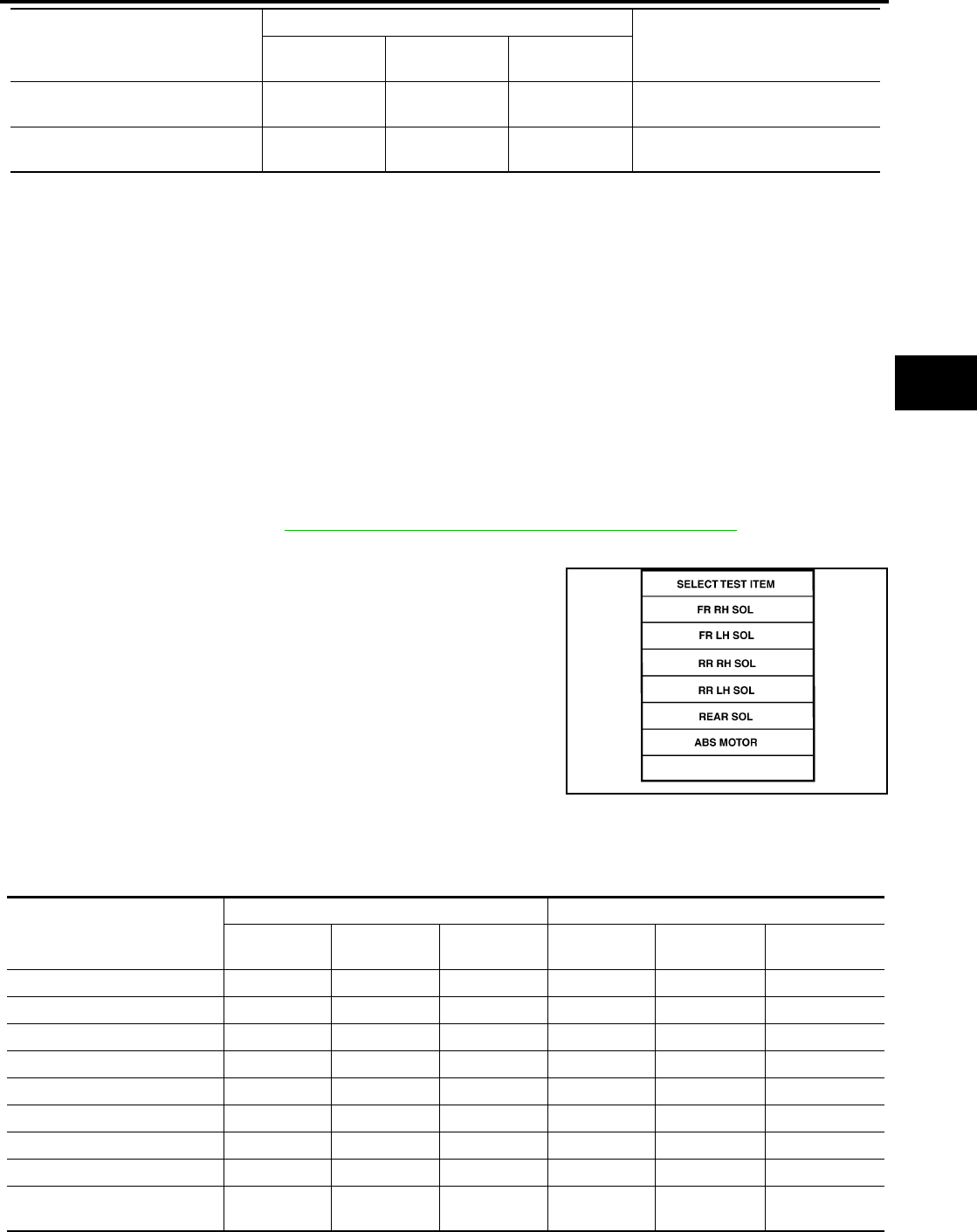
TROUBLE DIAGNOSIS
BRC-121
[VDC/TCS/ABS]
C
D
E
G
H
I
J
K
L
M
A
B
BRC
Revision: February 2006 2005 Xterra
×: Applicable
–: Not applicable
ACTIVE TEST
CAUTION:
●Do not perform active test while driving.
●Make sure to completely bleed air from the brake system.
●The ABS and brake warning lamps turn on during the active test.
Operation Procedure
1. Connect the CONSULT-II and CONSULT-II CONVERTER to the data link connector and start the engine.
CAUTION:
If CONSULT-II is used with no connection of CONSULT-II CONVERTER, malfunctions might be
detected in self-diagnosis depending on control unit which carries out CAN communication.
2. Touch “START (NISSAN BASED VHCL) ” on the display screen.
3. Touch “ABS”.
If “ABS” is not indicated, go to GI-39, "CONSULT-II Data Link Connector (DLC) Circuit" .
4. Touch “ACTIVE TEST”.
5. The test item selection screen is displayed.
6. Touch necessary test item.
7. With the “MAIN SIGNALS” display selected, touch “START”.
8. The Active Test screen will be displayed, so conduct the following test.
Solenoid Valve Operation Chart
PRESS SENSOR ×–×Brake pressure detected by pres-
sure sensor is displayed.
CRANKING SIG – – ×The input state of the key SW
START position signal is displayed.
Item
(Unit)
Data monitor item selection
Remarks
ECU INPUT
SIGNALS
MAIN
SIGNALS
SELECTION
FROM MENU
WFIA0349E
Operation
ABS solenoid valve ABS solenoid valve (ACT)
UP KEEP DOWN UP ACTUATOR
UP
ACTUATOR
KEEP
FR RH IN SOL OFF ON ON OFF OFF OFF
FR RH OUT SOL OFF OFF ON* OFF OFF OFF
FR LH IN SOL OFF ON ON OFF OFF OFF
FR LH OUT SOL OFF OFF ON* OFF OFF OFF
RR RH IN SOL OFF ON ON OFF OFF OFF
RR RH OUT SOL OFF OFF ON* OFF OFF OFF
RR LH IN SOL OFF ON ON OFF OFF OFF
RR LH OUT SOL OFF OFF ON* OFF OFF OFF
Primary side VDC switch over
valve 1 (SV 1) OFF OFF OFF OFF ON* OFF

BRC-122
[VDC/TCS/ABS]
TROUBLE DIAGNOSIS
Revision: February 2006 2005 Xterra
*: ON for 1 to 2 seconds after the touch, and then OFF
NOTE:
●If active test is performed with brake pedal depressed, pedal stroke may change. This is normal.
●“TEST IS STOPPED” is displayed approximately 10 seconds after operation starts.
●After “TEST IS STOPPED” is displayed, to perform test again, repeat Step 6.
ABS MOTOR
Touch “ON” and “OFF” on the screen. Check that ABS motor relay
operates as shown in table below.
NOTE:
●If active test is performed with brake pedal depressed, pedal
stroke may change. This is normal.
●“TEST IS STOPPED” is displayed approximately 10 seconds
after operation starts.
Primary side VDC switch over
valve 1 (CV 1) OFF OFF OFF OFF ON ON
Primary side VDC switch over
valve 2 (SV 1) OFF OFF OFF OFF ON* OFF
Primary side VDC switch over
valve 2 (CV 1) OFF OFF OFF OFF ON ON
Operation
ABS solenoid valve ABS solenoid valve (ACT)
UP KEEP DOWN UP ACTUATOR
UP
ACTUATOR
KEEP
Operation ON OFF
MOTOR RELAY ON OFF
ACTUATOR RELAY ON ON
SFIA0593E

TROUBLE DIAGNOSIS FOR SELF-DIAGNOSTIC ITEMS
BRC-123
[VDC/TCS/ABS]
C
D
E
G
H
I
J
K
L
M
A
B
BRC
Revision: February 2006 2005 Xterra
TROUBLE DIAGNOSIS FOR SELF-DIAGNOSTIC ITEMS PFP:00000
Wheel Sensor System Inspection EFS005I0
INSPECTION PROCEDURE
1. CHECK TIRES
Check for inflation pressure, wear and size of each tire.
Are tire pressure and size correct and is tire wear within specifications?
YES >> GO TO 2.
NO >> Adjust tire pressure or replace tire(s).
2. CONNECTOR INSPECTION
Disconnect the ABS actuator and electric unit (control unit) connector E125 and wheel sensor of malfunction-
ing code.
Check the terminals for deformation, disconnection, looseness or damage.
OK or NG
OK >> GO TO 3.
NG >> Repair or replace as necessary.
3. CHECK SENSOR AND SENSOR ROTOR
●Check the cord of the sensor mount (for looseness, etc.)
●Check sensor rotors for damage (rear only)
●Check wheel bearing axial end play
OK or NG
OK >> GO TO 4.
NG >> Repair or replace as necessary.
4. CHECK WHEEL SENSOR OUTPUT SIGNAL
1. Connect ABS active wheel sensor tester (J-45741) to wheel sensor using appropriate adapter.
2. Turn on the ABS active wheel sensor tester power switch.
NOTE:
The green POWER indicator should illuminate. If the POWER indicator does not illuminate, replace the
battery in the ABS active wheel sensor tester before proceeding.
3. Spin the wheel of the vehicle by hand and observe the red SENSOR indicator on the ABS active wheel
sensor tester. The red SENSOR indicator should flash on and off to indicate an output signal.
NOTE:
If the red SENSOR indicator illuminates but does not flash, reverse the polarity of the tester leads and
retest.
Does the ABS active wheel sensor tester detect a signal?
YES >> GO TO 5.
NO >> Replace the wheel sensor. Refer to BRC-144, "Removal and Installation" .
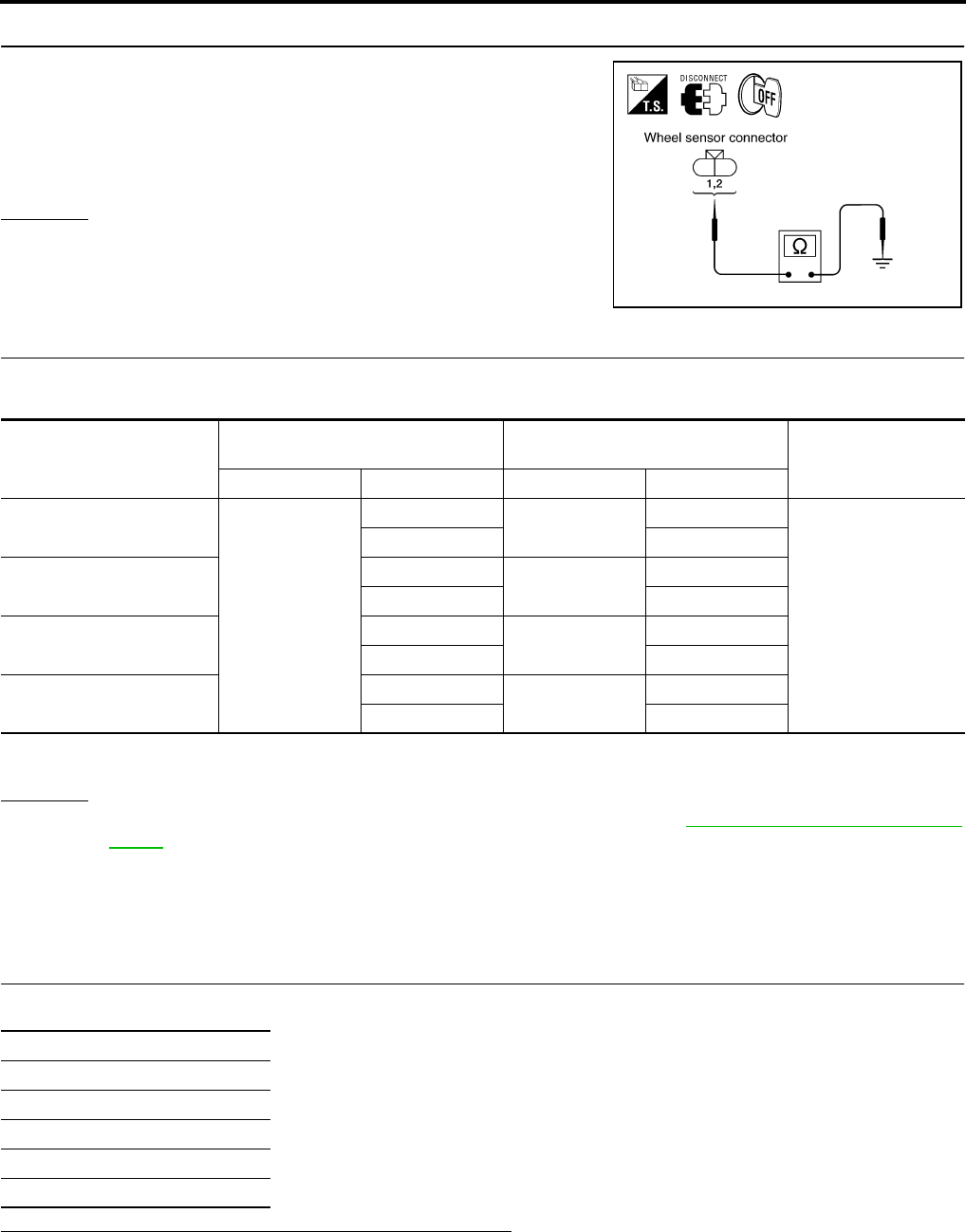
BRC-124
[VDC/TCS/ABS]
TROUBLE DIAGNOSIS FOR SELF-DIAGNOSTIC ITEMS
Revision: February 2006 2005 Xterra
5. CHECK WIRING HARNESS FOR SHORT CIRCUIT
1. Disconnect ABS actuator and electric unit (control unit) connec-
tor and wheel sensor connector of malfunction code No.
2. Check resistance between wheel sensor harness connector ter-
minals and ground.
OK or NG
OK >> GO TO 6.
NG >> Repair the circuit.
6. CHECK WIRING HARNESS FOR OPEN CIRCUIT
Check continuity between ABS actuator and electric unit (control unit) harness connector E125 and the mal-
functioning wheel sensor harness connector E18, E117, C10 or C11.
OK or NG
OK >> Replace the ABS actuator and electric unit (control unit). Refer to BRC-146, "Removal and Instal-
lation" .
NG >> Repair the circuit.
Engine System Inspection EFS005I1
INSPECTION PROCEDURE
1. SELF-DIAGNOSIS RESULT CHECK
Check self-diagnosis results.
Is the above displayed in the self-diagnosis display items?
YES >> GO TO 2.
NO >> Inspection End.
Continuity should not exist.
WFIA0343E
Wheel sensor
ABS actuator and
electric unit (control unit) Wheel sensor Continuity
Connector Terminal Connector Terminal
Front LH
E125
45 E18 1
Yes
46 2
Front RH 34 E117 1
33 2
Rear LH 37 C11 2
36 1
Rear RH 42 C10 2
43 1
Continuity should exist.
Self-diagnosis results
ENGINE SIGNAL 1
ENGINE SIGNAL 2
ENGINE SIGNAL 3
ENGINE SIGNAL 4
ENGINE SIGNAL 6

TROUBLE DIAGNOSIS FOR SELF-DIAGNOSTIC ITEMS
BRC-125
[VDC/TCS/ABS]
C
D
E
G
H
I
J
K
L
M
A
B
BRC
Revision: February 2006 2005 Xterra
2. ENGINE SYSTEM INSPECTION
1. Perform ECM self-diagnosis and repair as necessary.
2. Perform ABS actuator and electric unit (control unit) self-diagnosis again.
OK or NG
OK >> Inspection End.
NG >> Repair or replace as necessary.
ABS/TCS/VDC Control Unit Inspection EFS005I2
INSPECTION PROCEDURE
1. SELF-DIAGNOSIS RESULT CHECK
Check self-diagnosis results.
Is the above displayed in the self-diagnosis display items?
YES >> Replace ABS actuator and electric unit (control unit). Refer to BRC-146, "Removal and Installa-
tion" .
NO >> Inspection End.
Steering Angle Sensor System EFS005I3
INSPECTION PROCEDURE
1. CHECK SELF-DIAGNOSIS RESULT
Check self-diagnosis results.
Is above displayed in self-diagnosis item?
YES >> GO TO 2.
NO >> Inspection End.
2. CHECK CONNECTOR
1. Turn ignition switch OFF.
2. Disconnect steering angle sensor connector M47 and ABS actuator and electric unit (control unit) connec-
tor E125 and check terminals for deformation, disconnection, looseness, or damage. Repair or replace as
necessary.
3. Reconnect connectors and repeat ABS actuator and electric unit (control unit) self-diagnosis.
Is "ST ANGLE SEN CIRCUIT" or "ST ANG SEN COM CIR" displayed?
YES >> GO TO 3.
NO >> Inspection End.
Self-diagnosis results
CONTROLLER FAILURE
VARIANT CODING
Self-diagnosis results
ST ANGLE SEN CIRCUIT
ST ANG SEN COM CIR

BRC-126
[VDC/TCS/ABS]
TROUBLE DIAGNOSIS FOR SELF-DIAGNOSTIC ITEMS
Revision: February 2006 2005 Xterra
3. CHECKING STEERING ANGLE SENSOR POWER AND GROUND
1. Turn ignition switch ON.
2. Check voltage between steering angle sensor harness connec-
tor M47 and body ground.
3. Turn ignition switch OFF.
4. Check resistance between steering angle sensor harness con-
nector M47 and body ground.
OK or NG
OK >> GO TO 4.
NG >> Repair the circuit.
4. CHECK STEERING ANGLE SENSOR HARNESS
1. Check CAN communication system. Refer to LAN-21, "CAN COMMUNICATION" .
2. Turn ignition switch OFF and disconnect steering angle sensor
connector M47 and ABS actuator and electric unit (control unit)
connector E125.
3. Check continuity between ABS actuator and electric unit (control
unit) connector E125 and steering angle sensor connector M47.
OK or NG
OK >> GO TO 5.
NG >> Repair or replace harness.
Terminals Measured
value
(Approx.)
(+)
(-)
Steering angle sensor
connector Terminal
M47 1Ground 12V
312V WFIA0398E
Terminals Measured
value Ω
(Approx.)
(+)
(-)
Steering angle sensor
connector Terminal
M47 2 Ground 0Ω
WFIA0399E
AB
Continuity
Connector Ter-
minal Connector Ter-
minal
ABS actuator and
electric unit (con-
trol unit): E125 11 Steering angle
sensor: M47 4Yes
ABS actuator and
electric unit (con-
trol unit): E125 15 Steering angle
sensor: M47 5Yes
WFIA0400E

TROUBLE DIAGNOSIS FOR SELF-DIAGNOSTIC ITEMS
BRC-127
[VDC/TCS/ABS]
C
D
E
G
H
I
J
K
L
M
A
B
BRC
Revision: February 2006 2005 Xterra
5. CHECK STEERING WHEEL PLAY
Check steering wheel play. Refer to PS-8, "CHECKING STEERING WHEEL PLAY" .
OK or NG
OK >> GO TO 6.
NG >> Adjust steering wheel play.
6. CHECK DATA MONITOR
1. Connect steering angle sensor and ABS actuator and electric unit (control unit) connectors.
2. Use “DATA MONITOR” to check if the status of "STR ANGLE SIG" is normal.
OK or NG
OK >> Perform ABS actuator and electric unit (control unit) self-diagnosis again.
NG >> Replace spiral cable (steering angle sensor) and adjust neutral position of steering angle sensor.
Refer to BRC-142, "Adjustment of Steering Angle Sensor Neutral Position" .
Yaw Rate/Side/Decel G Sensor System Inspection EFS005I4
CAUTION:
Sudden turns (such as spin turns, acceleration turns), drifting, etc. when VDC function is OFF may
cause the yaw rate/side/decel G sensor system to indicate a problem. This is not a problem if normal
operation can be resumed after restarting the engine.
INSPECTION PROCEDURE
1. SELF-DIAGNOSIS RESULT CHECK
Check self-diagnosis results.
CAUTION:
If vehicle is on turntable at entrance to parking garage, or on other moving surface, VDC OFF indicator
lamp may illuminate and CONSULT-II self-diagnosis may indicate yaw rate sensor system malfunction.
However, in this case there is no malfunction in yaw rate sensor system. Take vehicle off of turntable
or other moving surface, and start engine. Results will return to normal.
Is the above displayed in the self-diagnosis display items?
YES >> GO TO 2.
NO >> Inspection End.
2. CONNECTOR INSPECTION
Disconnect the ABS actuator and electric unit (control unit) connector E125 and yaw rate/side/decel G sensor
connector B73.
Check the terminals for deformation, disconnection, looseness or damage.
OK or NG
OK >> GO TO 3.
NG >> Repair or replace as necessary.
Steering condition Data monitor
Straight-ahead –3.5 deg to +3.5 deg
Turn wheel to the right by 90°Approx. - 90deg
Turn wheel to the left by 90°Approx. + 90deg
Self-diagnosis results
YAW RATE SENSOR
SIDE G-SEN CIRCUIT
G-SENSOR
BRC-128
[VDC/TCS/ABS]
TROUBLE DIAGNOSIS FOR SELF-DIAGNOSTIC ITEMS
Revision: February 2006 2005 Xterra
3. YAW RATE/SIDE/DECEL G SENSOR HARNESS INSPECTION
1. Turn off the ignition switch and disconnect yaw rate/side/decel G sensor connector B73 and ABS actuator
and electric unit (control unit) connector E125.
2. Check continuity between the ABS actuator and electric unit (control unit) connector E125 and the yaw
rate/side/decel G sensor connector B73.
OK or NG
OK >> GO TO 4.
NG >> Repair or replace as necessary.
4. YAW RATE/SIDE/DECEL G SENSOR INSPECTION
1. Connect the yaw rate/side/decel G sensor connector B73 and ABS actuator and electric unit (control unit)
connector E125.
2. Use “DATA MONITOR” to check if the yaw rate/side/decel G sensor signals are normal.
OK or NG
OK >> Inspection End.
NG >> Replace the yaw rate/side/decel G sensor. Refer to BRC-149, "Removal and Installation" .
ABS actuator and electric unit
(control unit) harness connector
E125
Yaw rate/side/decel G sensor
harness connector B73 Continuity
63
Yes
24 5
25 1
29 2
Vehicle status Yaw rate sensor
(Data monitor standard) Side G sensor
(Data monitor standard) Decel G Sensor
(Data monitor standard)
When stopped -4 to +4 deg/s -1.1 to +1.1 m/s -0.08 G to +0.08 G
Right turn Negative value Negative value -
Left turn Positive value Positive value -
Speed up - - Negative value
Speed down - - Positive value

TROUBLE DIAGNOSIS FOR SELF-DIAGNOSTIC ITEMS
BRC-129
[VDC/TCS/ABS]
C
D
E
G
H
I
J
K
L
M
A
B
BRC
Revision: February 2006 2005 Xterra
Solenoid and VDC Change-Over Valve System Inspection EFS005I5
INSPECTION PROCEDURE
1. SELF-DIAGNOSIS RESULT CHECK
Check self-diagnosis results.
Is the above displayed in the self-diagnosis display items?
YES >> GO TO 2.
NO >> Inspection End.
2. CONNECTOR INSPECTION
1. Disconnect ABS actuator and electric unit (control unit) connector E125.
2. Check the terminals for deformation, disconnection, looseness or damage.
OK or NG
OK >> GO TO 3.
NG >> Repair or replace as necessary.
Self-diagnosis results
FR LH IN ABS SOL
FR LH OUT ABS SOL
RR RH IN ABS SOL
RR RH OUT ABS SOL
FR RH IN ABS SOL
FR RH OUT ABS SOL
RR LH IN ABS SOL
RR LH OUT ABS SOL
CV 1
CV 2
SV 1
SV 2

BRC-130
[VDC/TCS/ABS]
TROUBLE DIAGNOSIS FOR SELF-DIAGNOSTIC ITEMS
Revision: February 2006 2005 Xterra
3. CHECKING SOLENOID POWER AND GROUND
1. Check voltage between ABS actuator and electric unit (control
unit) harness connector E125 and body ground.
2. Check resistance between ABS actuator and electric unit (con-
trol unit) harness connector E125 and body ground.
OK or NG
OK >> Perform self-diagnosis again. If the same results
appear, replace ABS actuator and electric unit (control
unit). Refer to BRC-146, "Removal and Installation" .
NG >> Repair the circuit.
Actuator Motor, Motor Relay, and Circuit Inspection EFS005I6
INSPECTION PROCEDURE
1. CHECKING SELF-DIAGNOSIS RESULTS
Check self-diagnosis results.
Is the above displayed in the self-diagnosis display items?
YES >> GO TO 2.
NO >> Inspection End.
2. CONNECTOR INSPECTION
1. Disconnect ABS actuator and electric unit (control unit) connector E125.
2. Check the terminals for deformation, disconnection, looseness or damage.
OK or NG
OK >> GO TO 3.
NG >> Repair or replace as necessary.
ABS actuator and electric
unit (control unit)
harness connector E125
Body
ground
Measured
value
(Approx.)
32 — 12V
WFIA0195E
ABS actuator and electric
unit (control unit)
harness connector E125
Body
ground
Measured
value Ω
(Approx.)
16 — 0Ω
47 — 0Ω
WFIA0196E
Self-diagnosis results
PUMP MOTOR
ACTUATOR RLY

TROUBLE DIAGNOSIS FOR SELF-DIAGNOSTIC ITEMS
BRC-131
[VDC/TCS/ABS]
C
D
E
G
H
I
J
K
L
M
A
B
BRC
Revision: February 2006 2005 Xterra
3. CHECKING ABS MOTOR AND MOTOR RELAY POWER SYSTEM
1. Check voltage between ABS actuator and electric unit (control
unit) harness connector E125 and body ground.
2. Check resistance between ABS actuator and electric unit (con-
trol unit) connector E125 and body ground.
OK or NG
OK >> Perform self-diagnosis again. If the same results
appear, replace ABS actuator and electric unit (control
unit). Refer to BRC-146, "Removal and Installation" .
NG >> Repair the circuit.
Stop Lamp Switch System Inspection EFS005I7
INSPECTION PROCEDURE
1. SELF-DIAGNOSIS RESULT CHECK
Check self-diagnosis results.
Is the above displayed in the self-diagnosis display items?
YES >> GO TO 2.
NO >> Inspection End.
2. CONNECTOR INSPECTION
1. Disconnect the ABS actuator and electric unit (control unit) connector E125 and stop lamp switch connec-
tor E38.
2. Check the terminals for deformation, disconnection, looseness or damage.
OK or NG
OK >> GO TO 3.
NG >> Repair or replace as necessary.
ABS actuator and electric
unit (control unit)
harness connector E125
Body
ground
Measured
value
(Approx.)
1—12V
WFIA0209E
ABS actuator and electric
unit (control unit)
harness connector E125
Body
ground
Measured
value Ω
(Approx.)
16 — 0Ω
47 — 0Ω
WFIA0196E
Self-diagnosis results
STOP LAMP SW
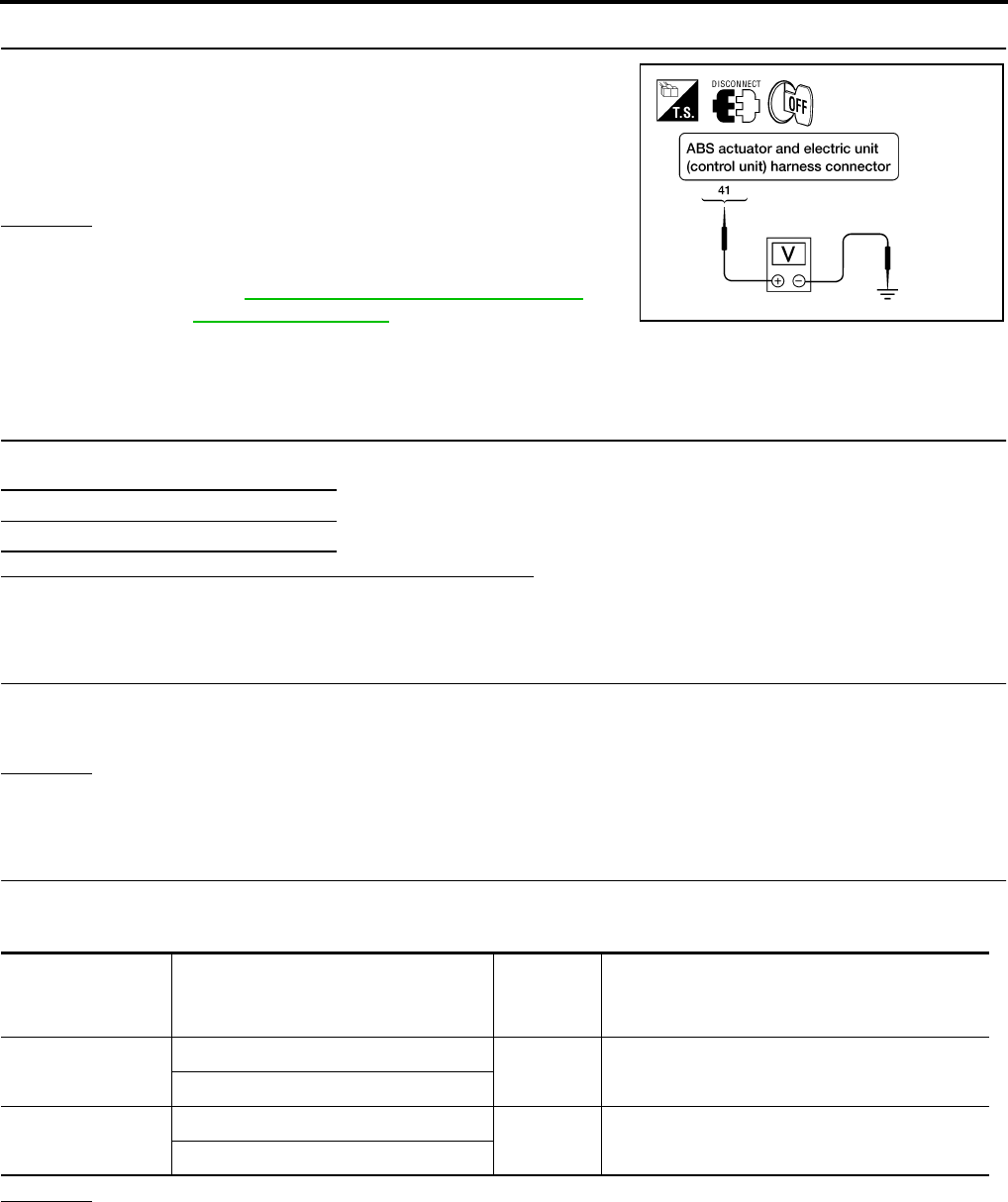
BRC-132
[VDC/TCS/ABS]
TROUBLE DIAGNOSIS FOR SELF-DIAGNOSTIC ITEMS
Revision: February 2006 2005 Xterra
3. STOP LAMP SWITCH INSPECTION
Check the voltage between the ABS actuator and electric unit (con-
trol unit) harness connector E125 terminal 41 and body ground.
OK or NG
OK >> Perform self-diagnosis again. If the same results
appear, replace ABS actuator and electric unit (control
unit). Refer to BRC-146, "Removal and Installation" .
NG >> Refer to LT-81, "STOP LAMP" .
ABS/TCS/VDC Control Unit Power and Ground Systems Inspection EFS005I8
INSPECTION PROCEDURE
1. SELF-DIAGNOSIS RESULT CHECK
Check self-diagnosis results.
Is the above displayed in the self-diagnosis display items?
YES >> GO TO 2.
NO >> Inspection End.
2. CONNECTOR INSPECTION
1. Disconnect the ABS actuator and electric unit (control unit) connector E125.
2. Check the terminals for deformation, disconnection, looseness or damage.
OK or NG
OK >> GO TO 3.
NG >> Repair or replace as necessary.
3. ABS/TCS/VDC CONTROL UNIT POWER AND GROUND CIRCUIT INSPECTION
Measure the voltage and continuity between the ABS actuator and electric unit (control unit) harness connec-
tor E125 and body ground.
OK or NG
OK >> Check the battery for loose terminals, low voltage, etc. Repair as necessary.
NG >> Repair the circuit.
Brake pedal depressed : Battery voltage
(approx. 12V)
Brake pedal not depressed : Approx. 0V
WFIA0198E
Self-diagnosis results
BATTERY VOLTAGE
Signal name ABS actuator and electric unit
(control unit)
harness connector E125
Body
ground Measured value
Power supply 1— Battery voltage (Approx. 12V)
32
Ground 16 — Continuity should exist.
47

TROUBLE DIAGNOSIS FOR SELF-DIAGNOSTIC ITEMS
BRC-133
[VDC/TCS/ABS]
C
D
E
G
H
I
J
K
L
M
A
B
BRC
Revision: February 2006 2005 Xterra
Brake Fluid Level Sensor System Inspection EFS005I9
INSPECTION PROCEDURE
1. SELF-DIAGNOSIS RESULT CHECK
1. Check the brake reservoir tank fluid level. If the level is low, add brake fluid.
2. Erase the self-diagnosis results and check the self-diagnosis results.
Is the above displayed in the self-diagnosis display items?
YES >> GO TO 2.
NO >> Inspection End.
2. CONNECTOR INSPECTION
1. Disconnect the ABS actuator and electric unit (control unit) connector E125 and brake fluid level switch
connector E21.
2. Check the terminals for deformation, disconnection, looseness or damage.
OK or NG
OK >> GO TO 3.
NG >> Repair or replace as necessary.
3. CHECK THE HARNESS BETWEEN THE BRAKE FLUID LEVEL SENSOR AND THE ABS ACTUATOR
AND ELECTRIC UNIT (CONTROL UNIT)
Check the continuity between the brake fluid level switch harness connector E21 and the ABS actuator and
electric unit (control unit) harness connector E125.
OK or NG
OK >> Perform self-diagnosis again. If the same results appear, replace ABS actuator and electric unit
(control unit). Refer to BRC-146, "Removal and Installation" .
NG >> Repair the circuit.
Pressure Sensor System Inspection EFS005IA
INSPECTION PROCEDURE
1. DISPLAY SELF DIAGNOSIS RESULTS
Check self-diagnosis result display item.
Is the self-diagnosis result display item shown above displayed?
YES >> GO TO 2.
NO >> Inspection End.
Self-diagnosis results
BR FLUID LEVEL LOW
ABS actuator and electric unit
(control unit) harness connector
E125
Brake fluid level switch harness
connector E21 Continuity
81Yes
8 Ground No
Ground 2 Yes
Self-diagnosis results
PRESS SEN CIRCUIT
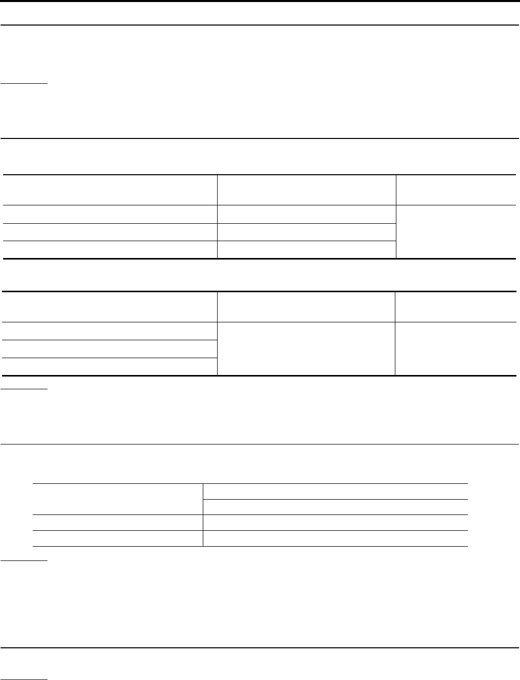
BRC-134
[VDC/TCS/ABS]
TROUBLE DIAGNOSIS FOR SELF-DIAGNOSTIC ITEMS
Revision: February 2006 2005 Xterra
2. CONNECTOR INSPECTION
1. Turn the ignition switch OFF.
2. Disconnect the front pressure sensor connector E31 and ABS actuator and electric unit (control unit) con-
nector E125 and inspect the terminals for deformation, disconnection, looseness, or damage.
OK or NG
OK >> GO TO 3.
NG >> Repair connector.
3. FRONT PRESSURE SENSOR CIRCUIT INSPECTION
1. Measure the continuity between the ABS actuator and electric unit (control unit) harness connector E125
and front pressure sensor harness connector E31.
2. Measure the continuity between the ABS actuator and electric unit (control unit) harness connector E125
and body ground.
OK or NG
OK >> GO TO 4.
NG >> Repair or replace harness or connector.
4. FRONT PRESSURE SENSOR INSPECTION
1. Reconnect the front pressure sensor and ABS actuator and electric unit (control unit) connectors.
2. Use "DATA MONITOR" to check if the status of "PRESS SENSOR" is normal.
OK or NG
OK >> Inspection End.
NG >> Replace front pressure sensor.
Steering Angle Sensor Safe Mode Inspection EFS005IB
INSPECTION PROCEDURE
1. INDICATOR LAMP CHECK
Check that VDC OFF indicator lamp is on.
OK or NG
OK >> GO TO 2.
NG >> GO TO 3.
ABS actuator and electric unit (control
unit) harness connector E125 Front pressure sensor harness
connector E31 Continuity
18 3
Yes19 1
20 2
ABS actuator and electric unit (control
unit) harness connector E125 Body ground Continuity
18
—No19
20
Condition Data monitor display (Approx.)
PRESS SENSOR
When brake pedal is depressed Positive value
When brake pedal is released 0 bar

TROUBLE DIAGNOSIS FOR SELF-DIAGNOSTIC ITEMS
BRC-135
[VDC/TCS/ABS]
C
D
E
G
H
I
J
K
L
M
A
B
BRC
Revision: February 2006 2005 Xterra
2. ADJUSTMENT OF STEERING ANGLE SENSOR NEUTRAL POSITION
Adjust steering angle sensor neutral position. Refer to BRC-142, "Adjustment of Steering Angle Sensor Neu-
tral Position" .
OK or NG
OK >> GO TO 3.
NG >> Check steering angle sensor. Refer to BRC-125, "Steering Angle Sensor System" .
3. INDICATOR LAMP CHECK
Check that VDC OFF indicator lamp is off.
OK or NG
OK >> GO TO 4.
NG >> Perform basic inspection. Refer to BRC-109, "Basic Inspection" .
4. CHECK SELF-DIAGNOSTIC RESULTS
Perform ABS actuator and electric unit (control unit) self-diagnosis.
NOTE:
When self-diagnostic results show items other than those above, perform repair or replacement for the item
indicated and repeat self-diagnosis.
Is the above displayed on self-diagnosis display?
YES >> Erase error memory.
NO >> Inspection End.
CAN Communication System Inspection EFS005IC
INSPECTION PROCEDURE
1. CHECK CONNECTOR
1. Turn ignition switch OFF, disconnect the ABS actuator and electric unit (control unit) connector, and check
the terminals for deformation, disconnection, looseness, and so on. If there is a malfunction, repair or
replace the terminal.
2. Reconnect connector to perform self-diagnosis.
Is "CAN COMM CIRCUIT" displayed in self-diagnosis display items?
YES >> Print out the self-diagnostic results, and refer to LAN-21, "CAN COMMUNICATION" .
NO >> Connector terminal is loose, damaged, open, or shorted.
Inspection For Self-diagnosis Result "ST ANGLE SEN SIGNAL" EFS005ID
INSPECTION PROCEDURE
1. PERFORM SELF-DIAGNOSIS
Perform ABS actuator and electric unit (control unit) self-diagnosis.
Do self-diagnosis results indicate anything other than shown above?
YES >> Perform repair or replacement for the item indicated.
NO >> Perform adjustment of steering angle sensor neutral position. Refer to BRC-142, "Adjustment of
Steering Angle Sensor Neutral Position" . GO TO 2.
Self-diagnosis results
ST ANGL SEN SAFE
Self-diagnosis results
ST ANGLE SEN SIGNAL
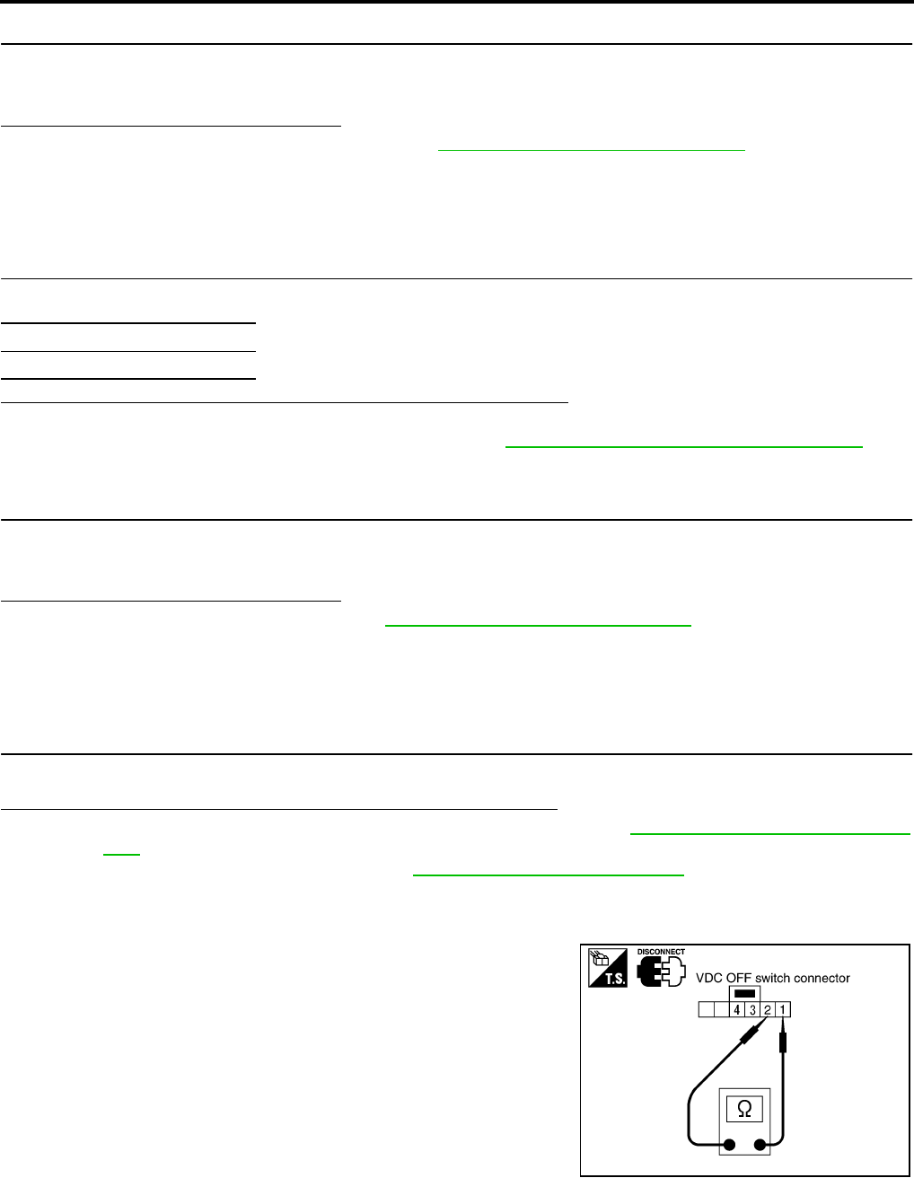
BRC-136
[VDC/TCS/ABS]
TROUBLE DIAGNOSIS FOR SELF-DIAGNOSTIC ITEMS
Revision: February 2006 2005 Xterra
2. PERFORM SELF-DIAGNOSIS AGAIN
1. Turn the ignition switch to OFF and then to ON and erase self-diagnosis results.
2. Perform ABS actuator and electric unit (control unit) self-diagnosis again.
Are any self-diagnosis results displayed?
YES >> Replace steering angle sensor. Refer to BRC-148, "Removal and Installation" .
NO >> Inspection End.
Inspection For Self-diagnosis Result "DECEL G SEN SET" EFS005IE
INSPECTION PROCEDURE
1. PERFORM SELF-DIAGNOSIS
Perform ABS actuator and electric unit (control unit) self-diagnosis.
Do self-diagnosis results indicate anything other than shown above?
YES >> Perform repair or replacement for the item indicated.
NO >> Perform calibration of decel G sensor. Refer to BRC-142, "Calibration of Decel G Sensor" . GO
TO 2.
2. PERFORM SELF-DIAGNOSIS AGAIN
1. Turn the ignition switch to OFF and then to ON and erase self-diagnosis results.
2. Perform ABS actuator and electric unit (control unit) self-diagnosis again.
Are any self-diagnosis results displayed?
YES >> Replace decel G sensor. Refer to BRC-149, "Removal and Installation" .
NO >> Inspection End.
VDC OFF Indicator lamp Does Not Illuminate EFS005IF
INSPECTION PROCEDURE
1. CHECK VDC OFF INDICATOR LAMP
Disconnect ABS actuator and electric unit (control unit) connector E125.
Do the ABS warning lamp and VDC OFF indicator lamp illuminate?
YES >> Replace ABS actuator and electric unit (control unit). Refer to BRC-146, "Removal and Installa-
tion" .
NO >> Replace combination meter. Refer to IP-12, "COMBINATION METER" .
Component Inspection EFS005IG
VDC OFF SWITCH
Check the continuity between terminals 1 and 2.
Self-diagnosis results
DECEL G SEN SET
1 - 2 : Continuity should exist when pushing the
switch.
Continuity should not exist when releasing
the switch.
PFIA0307E

TROUBLE DIAGNOSES FOR SYMPTOMS
BRC-137
[VDC/TCS/ABS]
C
D
E
G
H
I
J
K
L
M
A
B
BRC
Revision: February 2006 2005 Xterra
TROUBLE DIAGNOSES FOR SYMPTOMS PFP:99999
ABS Works Frequently EFS005IH
1. CHECK WARNING LAMP ACTIVATION
Make sure warning lamp remains off while driving.
OK or NG
OK >> GO TO 2.
NG >> Carry out self-diagnosis. Refer to BRC-115, "SELF-DIAGNOSIS" .
2. CHECK WHEEL SENSORS
Check the following.
●Wheel sensor mounting for looseness
●Wheel sensors for physical damage
●Wheel sensor connectors for terminal damage or loose connections
●Sensor rotor and mount for physical damage (rear only)
OK or NG
OK >> GO TO 3.
NG >> Repair or replace as necessary.
3. CHECK FRONT AND REAR AXLES
Check front and rear axles for excessive looseness. Refer to FAX-5, "WHEEL BEARING INSPECTION" ,
RAX-6, "Rear Axle Bearing" (C200) or RAX-18, "Rear Axle Bearing" (M226).
OK or NG
OK >> GO TO 4.
NG >> Repair as necessary.
4. CHECK BRAKE FLUID PRESSURE
Check brake fluid pressure distribution.
Refer to BRC-109, "Basic Inspection" .
Is brake fluid pressure distribution normal?
YES >> Inspection End.
NO >> Perform Basic Inspection. Refer to BRC-109, "Basic Inspection" .

BRC-138
[VDC/TCS/ABS]
TROUBLE DIAGNOSES FOR SYMPTOMS
Revision: February 2006 2005 Xterra
Unexpected Pedal Action EFS005II
1. CHECK WARNING LAMP ACTIVATION
Make sure warning lamp remains off while driving.
OK or NG
OK >> GO TO 2.
NG >> Carry out self-diagnosis. Refer to BRC-115, "SELF-DIAGNOSIS" .
2. CHECK BRAKE PEDAL STROKE
Check brake pedal stroke.
Is pedal stroke excessive?
YES >> Perform Basic Inspection. Refer to BRC-109, "Basic
Inspection" .
NO >> GO TO 3.
3. CHECK CONNECTOR AND BRAKING PERFORMANCE
1. Disable ABS by disconnecting ABS actuator and electric unit (control unit) connector.
2. Drive vehicle and check brake operation.
NOTE:
●Stopping distance may be longer than vehicles without ABS when road condition is slippery.
●Driving the vehicle with the ABS actuator and electric unit (control unit) disconnected may induce DTCs
in electrical control units using CAN communication. After the inspection, clear all DTCs. Refer to LAN-
21, "CAN COMMUNICATION" .
OK or NG
OK >> GO TO 4.
NG >> Perform Basic Inspection. Refer to BRC-109, "Basic Inspection" .
4. CHECK WHEEL SENSORS
Check the following.
●Wheel sensor mounting for looseness
●Wheel sensors for physical damage
●Wheel sensor connectors for terminal damage or loose connections
OK or NG
OK >> Check ABS actuator and electric unit (control unit) connector terminals for deformation, discon-
nection, looseness or damage. Reconnect ABS actuator and electric unit (control unit) harness
connector. Then retest.
NG >> Repair or replace as necessary.
SBR540A

TROUBLE DIAGNOSES FOR SYMPTOMS
BRC-139
[VDC/TCS/ABS]
C
D
E
G
H
I
J
K
L
M
A
B
BRC
Revision: February 2006 2005 Xterra
Long Stopping Distance EFS005IJ
1. CHECK BASE BRAKING SYSTEM PERFORMANCE
1. Disable ABS by disconnecting ABS actuator and electric unit (control unit) connector.
2. Drive vehicle and check brake operation.
NOTE:
●Stopping distance may be longer than vehicles without ABS when road condition is slippery.
●Driving the vehicle with the ABS actuator and electric unit (control unit) disconnected may induce DTCs
in electrical control units using CAN communication. After the inspection, clear all DTCs. Refer to LAN-
21, "CAN COMMUNICATION" .
OK or NG
OK >> Go to BRC-137, "ABS Works Frequently" .
NG >> Perform Basic Inspection. Refer to BRC-109, "Basic Inspection" .
ABS Does Not Work EFS005IK
CAUTION:
The ABS does not operate when the vehicle speed is 10 km/h (6 MPH) or less.
1. CHECK WARNING LAMP ACTIVATION
Turn ignition switch ON and check for warning lamp activation.
●Warning lamp should activate for approximately 2 seconds after turning the ignition switch ON.
OK or NG
OK >> Carry out self-diagnosis. Refer to BRC-115, "SELF-DIAGNOSIS" .
NG >> Go to BRC-140, "ABS Warning Lamp Does Not Come On When Ignition Switch Is Turned On" .
Pedal Vibration or ABS Operation Noise EFS005IL
NOTE:
During ABS activation, pedal vibration may be felt and a noise may be heard. This is normal and does not indi-
cate a malfunction.
1. CHECK SYMPTOM
1. Apply brake.
2. Start engine.
Does the symptom occur only when engine is started?
YES >> Carry out self-diagnosis. Refer to BRC-115, "SELF-DIAGNOSIS" .
NO >> GO TO 2.
2. RECHECK SYMPTOM
Does the symptom occur only when electrical equipment switches (such as headlamps) are turned on?
YES >> Check for radio, antenna or related wiring that is routed too close to the ABS actuator and electric
unit (control unit) and reroute as necessary.
NO >> Go to BRC-137, "ABS Works Frequently" .

BRC-140
[VDC/TCS/ABS]
TROUBLE DIAGNOSES FOR SYMPTOMS
Revision: February 2006 2005 Xterra
ABS Warning Lamp Does Not Come On When Ignition Switch Is Turned On EFS005IM
1. CHECK ABS ACTUATOR AND ELECTRIC UNIT (CONTROL UNIT) FUSES
Check 30A fusible link n and 40A fusible link l for ABS actuator and electric unit (control unit). For fusible link
layout, refer to PG-4, "POWER SUPPLY ROUTING CIRCUIT" .
OK or NG
OK >> GO TO 2.
NG >> If fusible link is blown, be sure to eliminate cause of problem before replacing.
2. CHECK ABS ACTUATOR AND ELECTRIC UNIT (CONTROL UNIT) POWER SUPPLY CIRCUITS
1. Disconnect ABS actuator and electric unit (control unit) connec-
tor.
2. Check voltage between ABS actuator and electric unit (control
unit) connector terminal 1 and ground and terminal 32 and
ground.
Does battery voltage exist?
YES >> GO TO 3.
NO >> Repair harness or connectors between fusible link and
ABS actuator and electric unit (control unit).
3. CHECK ABS ACTUATOR AND ELECTRIC UNIT (CONTROL UNIT) GROUND CIRCUIT
Check continuity between ABS actuator and electric unit (control
unit) connector terminal 16 and ground and terminal 47 and ground.
Does continuity exist?
YES >> Replace ABS actuator and electric unit (control unit).
Refer to BRC-146, "Removal and Installation" .
NO >> Repair harness or connectors between ABS actuator
and electric unit (control unit) and ground.
ABS Warning Lamp Stays On When Ignition Switch Is Turned On EFS005IN
1. CARRY OUT SELF-DIAGNOSIS
Carry out self-diagnosis. Refer to BRC-115, "SELF-DIAGNOSIS" .
Are malfunctions detected in self-diagnosis?
YES >> Refer to BRC-116, "Display Item List" .
NO >> Refer to DI-28, "WARNING LAMPS" .
WFIA0199E
WFIA0196E

TROUBLE DIAGNOSES FOR SYMPTOMS
BRC-141
[VDC/TCS/ABS]
C
D
E
G
H
I
J
K
L
M
A
B
BRC
Revision: February 2006 2005 Xterra
Vehicle Jerks During TCS/VDC Activation EFS005IO
1. ABS ACTUATOR AND ELECTRIC UNIT (CONTROL UNIT) SELF-DIAGNOSIS
Perform ABS actuator and electric unit (control unit) self-diagnosis.
Are self-diagnosis result items displayed?
YES >> After checking and repairing the applicable item, perform the ABS actuator and electric unit (con-
trol unit) self-diagnosis again.
NO >> GO TO 2.
2. ENGINE SPEED SIGNAL INSPECTION
Perform data monitor with CONSULT-II for the ABS actuator and electric unit (control unit).
Is the engine speed at idle 400 rpm or higher?
YES >> GO TO 4.
NO >> GO TO 3.
3. ECM SELF-DIAGNOSIS
Perform ECM self-diagnosis.
Are self-diagnosis result items displayed?
YES >> After checking and repairing the applicable item, perform the ECM self-diagnosis again.
NO >> With A/T, GO TO 4. With M/T, GO TO 5.
4. TCM SELF-DIAGNOSIS
Perform TCM self-diagnosis.
Are self-diagnosis result items displayed?
YES >> After checking and repairing the applicable item, perform the TCM self-diagnosis again.
NO >> GO TO 5.
5. CONNECTOR INSPECTION
Disconnect the ABS actuator and electric unit (control unit) connector and the ECM connectors and check the
terminals for deformation, disconnection, looseness or damage.
OK or NG
OK >> GO TO 6.
NG >> Repair or replace as necessary.
6. CAN COMMUNICATION INSPECTION
Check the CAN communication system. Refer to BRC-135, "CAN Communication System Inspection" .
OK or NG
OK >> Inspection End.
NG >> Refer to LAN-21, "CAN COMMUNICATION" .

BRC-142
[VDC/TCS/ABS]
ON-VEHICLE SERVICE
Revision: February 2006 2005 Xterra
ON-VEHICLE SERVICE PFP:00000
Adjustment of Steering Angle Sensor Neutral Position EFS005IP
After removing/installing or replacing ABS actuator and electric unit (control unit), steering angle sensor, steer-
ing and suspension components which affect wheel alignment or after adjusting wheel alignment, be sure to
adjust neutral position of steering angle sensor before running vehicle.
WITH CONSULT-II
1. Stop vehicle with front wheels in straight-ahead position.
2. Connect CONSULT-II and CONSULT-II CONVERTER to data
link connector on vehicle, and turn ignition switch ON (do not
start engine).
3. Touch “ABS”, “WORK SUPPORT” and “ST ANGLE SENSOR
ADJUSTMENT” on CONSULT-II screen in this order.
4. Touch “START”.
CAUTION:
Do not touch steering wheel while adjusting steering angle
sensor.
5. After approximately 10 seconds, touch “END”. (After approxi-
mately 60 seconds, it ends automatically.)
6. Turn ignition switch OFF, then turn it ON again.
CAUTION:
Do not touch steering wheel while adjusting steering angle
sensor.
7. Run vehicle with front wheels in straight-ahead position, then
stop.
8. Select “DATA MONITOR”, “SELECTION FROM MENU”, and “STR ANGLE SIG” on CONSULT-II screen.
Then check that “STR ANGLE SIG” is within 0±3.5 deg. If value is more than specification, repeat steps 3
to 7.
9. Erase memory of ABS actuator and electric unit (control unit) and ECM.
10. Turn ignition switch to OFF.
WITHOUT CONSULT-II
Set the steering wheel in a straight forward position and drive the vehicle at 10 mph (15 km/h) or more for 10
minutes. When the procedure is complete, the SLIP indicator lamp and VDC OFF indicator lamp will turn off.
Calibration of Decel G Sensor EFS005IQ
After removing/installing or replacing ABS actuator and electric unit (control unit), yaw rate/side/decel G sen-
sor, steering and suspension components which affect wheel alignment or after adjusting wheel alignment, be
sure to calibrate the decel G sensor before running vehicle.
NOTE:
Calibration of decel G sensor requires CONSULT-II.
1. Stop vehicle with front wheels in straight-ahead position.
CAUTION:
●The work should be done on a level area with an unloaded vehicle.
●Keep all the tires inflated to the correct pressures. Adjust the tire pressure to the specified pres-
sure value.
2. Connect CONSULT-II with CONSULT-II CONVERTER to data link connector on vehicle, and turn ignition
switch ON (do not start engine).
BBIA0538E
WFIA0239E

ON-VEHICLE SERVICE
BRC-143
[VDC/TCS/ABS]
C
D
E
G
H
I
J
K
L
M
A
B
BRC
Revision: February 2006 2005 Xterra
CAUTION:
If CONSULT-II is used with no connection of CONSULT-II CONVERTER, malfunctions might be
detected in self-diagnosis depending on control unit which carries out CAN communication.
3. Touch "START (NISSAN BASED VHCL)", "ABS", "WORK SUPPORT" and "DECEL G SEN CALIBRA-
TION" on CONSULT-II screen in this order. Refer to BRC-114, "CONSULT-II BASIC OPERATION PRO-
CEDURE" .
4. Touch "START".
CAUTION:
Set vehicle as shown in the display.
5. After approximately 10 seconds, touch "END". (After approxi-
mately 60 seconds, it ends automatically.)
6. Turn ignition switch OFF, then turn it ON again.
CAUTION:
Be sure to carry out above operation.
7. Run vehicle with front wheels in straight-ahead position, then
stop.
8. Select "DATA MONITOR", "SELECTION FROM MENU", and
"DECEL G SEN" on CONSULT-II screen. Then check that "DECEL G SEN" is within ±0.08G. If value is
more than specification, repeat steps 3 to 7.
9. Erase memory of ABS actuator and electric unit (control unit) and ECM.
10. Turn ignition switch to OFF.
SFIA1162E
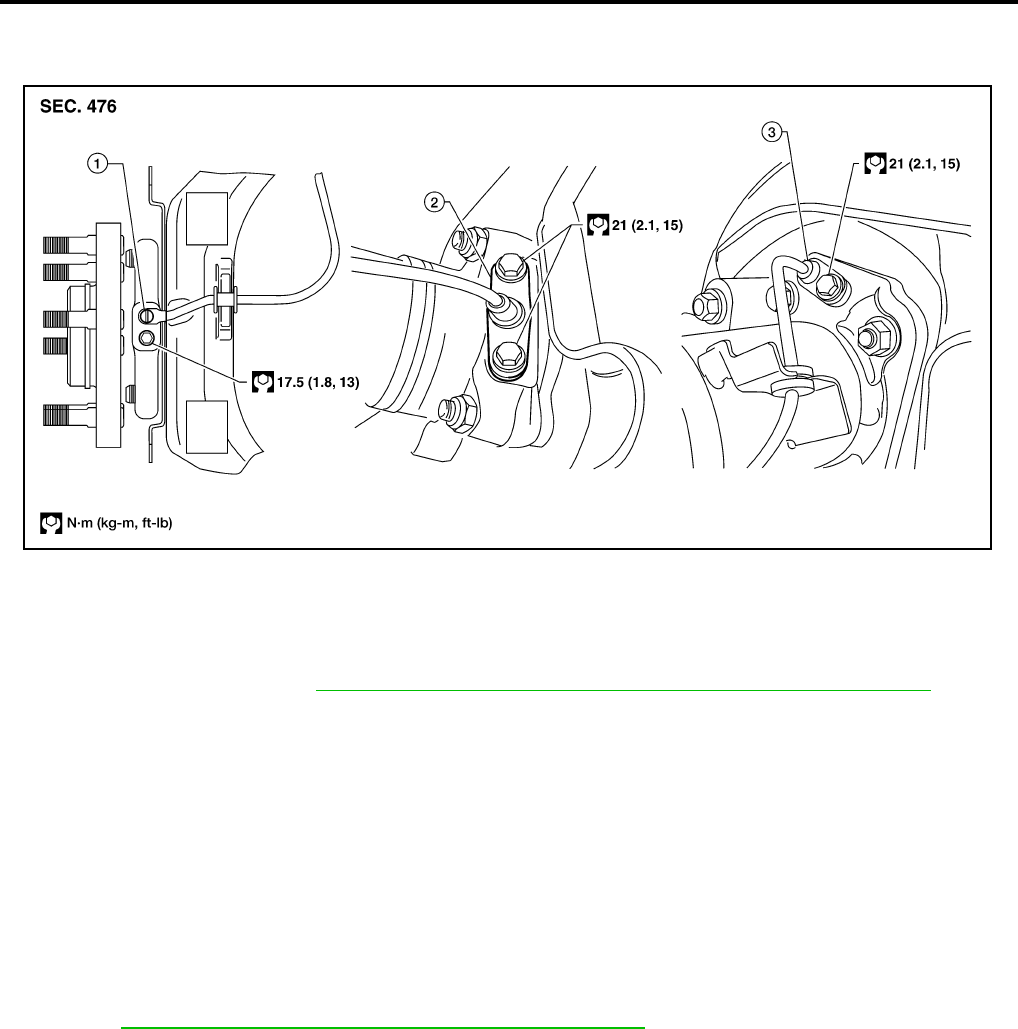
BRC-144
[VDC/TCS/ABS]
WHEEL SENSORS
Revision: February 2006 2005 Xterra
WHEEL SENSORS PFP:47910
Removal and Installation EFS005SF
REMOVAL
1. Remove wheel sensor mounting screw(s).
●When removing the front wheel sensor, first remove the disc rotor to gain access to the front wheel sen-
sor mounting bolt. Refer to BR-23, "Removal and Installation of Brake Caliper and Disc Rotor" .
2. Pull out the sensor, being careful to turn it as little as possible.
CAUTION:
●Be careful not to damage sensor edge and sensor rotor teeth.
●Do not pull on the sensor harness.
3. Disconnect wheel sensor harness electrical connector, then remove harness from mounts.
INSTALLATION
●Before installing wheel sensors,
–Inspect wheel sensor assembly and replace if damaged.
–Clean wheel sensor hole and mounting surface with brake cleaner and a lint-free shop rag. Be careful that
dirt and debris do not enter the axle.
–Install a new wheel sensor O-ring, then apply a coat of suitable grease to the O-ring and mounting hole.
Refer to MA-11, "RECOMMENDED FLUIDS AND LUBRICANTS" .
●Installation is in the reverse order of removal.
1. Front wheel sensor 2. Rear wheel sensor (C200) 3. Rear wheel sensor (M226)
WFIA0339E
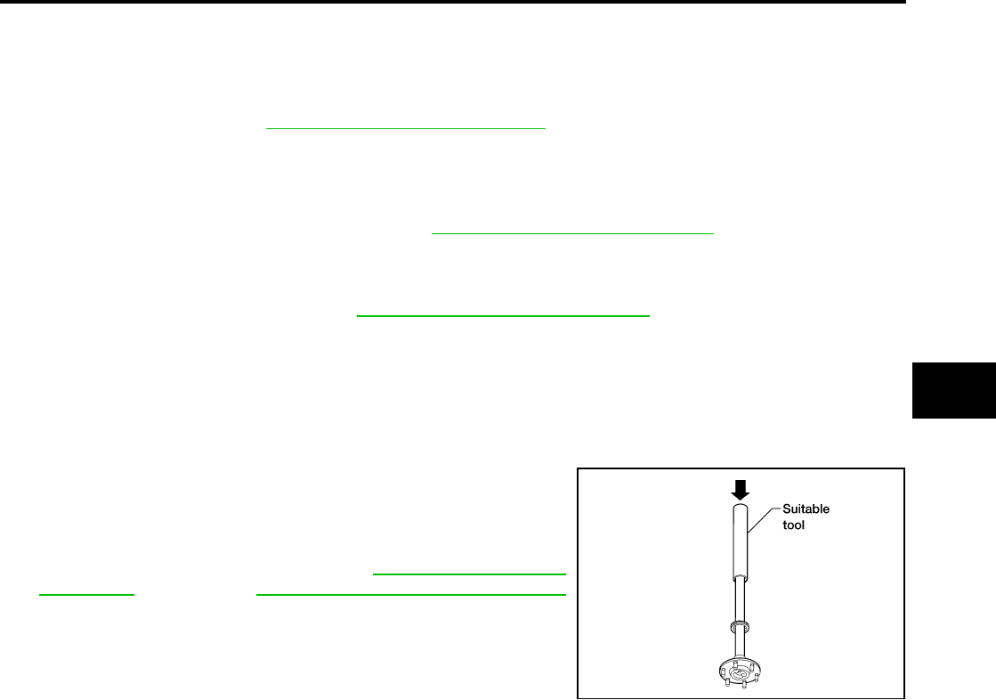
SENSOR ROTOR
BRC-145
[VDC/TCS/ABS]
C
D
E
G
H
I
J
K
L
M
A
B
BRC
Revision: February 2006 2005 Xterra
SENSOR ROTOR PFP:47970
Removal and Installation EFS005SG
FRONT
The wheel sensor rotors are built into the wheel hubs and are not removable. If damaged, replace wheel hub
and bearing assembly. Refer to FAX-5, "Removal and Installation" .
REAR (C200)
Removal and Installation
It is necessary to disassemble the rear axle to replace the sensor rotor. Perform the axle shaft assembly
removal procedure to replace sensor rotor. Refer to RAX-7, "Removal and Installation" .
REAR (M226)
Removal
1. Remove axle shaft assembly. Refer to RAX-19, "Removal and Installation" .
NOTE:
It is necessary to disassemble the rear axle to replace the sensor rotor.
2. Pull the sensor rotor of off the axle shaft using Tool and a press.
Installation
1. Install new sensor rotor on axle shaft using a suitable length
steel tube and a press. Make sure sensor rotor is fully seated.
CAUTION:
Do not reuse the old sensor rotor.
2. Install axle shaft assembly. Refer to RAX-7, "Removal and
Installation" (C200), or RAX-19, "Removal and Installation"
(M266).
CAUTION:
Do not reuse the axle oil seal. The axle oil seal must be
replaced every time the axle shaft assembly is removed
from the axle shaft housing.
Tool number : 205-D002 ( — )
WFIA0341E
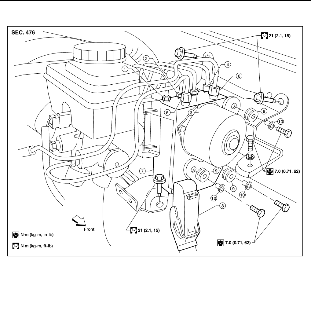
BRC-146
[VDC/TCS/ABS]
ACTUATOR AND ELECTRIC UNIT (ASSEMBLY)
Revision: February 2006 2005 Xterra
ACTUATOR AND ELECTRIC UNIT (ASSEMBLY) PFP:47660
Removal and Installation EFS005SJ
REMOVAL
1. Disconnect the negative battery terminal.
2. Drain the brake fluid. Refer to BR-9, "Drain and Refill" .
3. Disconnect the actuator harness from the ABS actuator and electric unit (control unit).
CAUTION:
●To remove the brake tubes, use a flare nut wrench to prevent the flare nuts and brake tubes from
being damaged.
●Be careful not to splash brake fluid on painted areas.
4. Disconnect the brake tubes.
5. Remove three bolts and then the ABS actuator and electric unit (control unit).
1. To rear left 2. To rear right 3. To front left
4. To front right 5. From the master cylinder secondary
side
6. From the master cylinder primary
side
7. ABS actuator and electric unit (con-
trol unit)
8. Harness connector 9. Grommet
10. Collar
WFIA0389E

ACTUATOR AND ELECTRIC UNIT (ASSEMBLY)
BRC-147
[VDC/TCS/ABS]
C
D
E
G
H
I
J
K
L
M
A
B
BRC
Revision: February 2006 2005 Xterra
INSTALLATION
Installation is in the reverse order of removal.
CAUTION:
To install, use a flare nut wrench (commercial service tool).
●Always tighten brake tubes to specification when installing. Refer to BR-11, "BRAKE PIPING AND
HOSE" .
●Never reuse drained brake fluid.
●After installation of the ABS actuator and electric unit (control unit), refill brake system with new
brake fluid. Then bleed the air from the system. Refer to BR-10, "Bleeding Brake System" .
NOTE:
If the ABS actuator and electric unit (control unit) is replaced, make sure to adjust position of steering angle
sensor. Refer to BRC-142, "Adjustment of Steering Angle Sensor Neutral Position" .

BRC-148
[VDC/TCS/ABS]
STEERING ANGLE SENSOR
Revision: February 2006 2005 Xterra
STEERING ANGLE SENSOR PFP:25554
Removal and Installation EFS005IU
Refer to SRS-44, "Removal and Installation" .
NOTE:
●The steering angle sensor is an integral part of the spiral cable.
●If the ABS actuator and electronic unit (control unit) is replaced, make sure to adjust position of steering
angle sensor. Refer to BRC-142, "Adjustment of Steering Angle Sensor Neutral Position" .
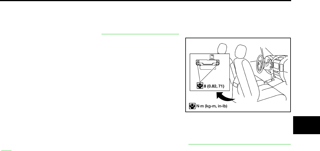
G SENSOR
BRC-149
[VDC/TCS/ABS]
C
D
E
G
H
I
J
K
L
M
A
B
BRC
Revision: February 2006 2005 Xterra
G SENSOR PFP:47930
Removal and Installation EFS005IV
REMOVAL
1. Remove center console. Refer to IP-15, "CENTER CONSOLE" .
2. Remove yaw rate/side/decel G sensor attaching nuts as shown.
●The location of the sensor is the same for all models.
CAUTION:
●Do not use power tools to remove or install yaw rate/side/
decel G sensor.
●Do not drop or strike the yaw rate/side/decel G sensor.
3. Disconnect harness connector and remove the yaw rate/side/
decel G sensor.
INSTALLATION
Installation is in the reverse order of removal.
NOTE:
After performing the above work, calibrate the decel G sensor. Refer to BRC-142, "Calibration of Decel G Sen-
sor" .
WFIA0230E
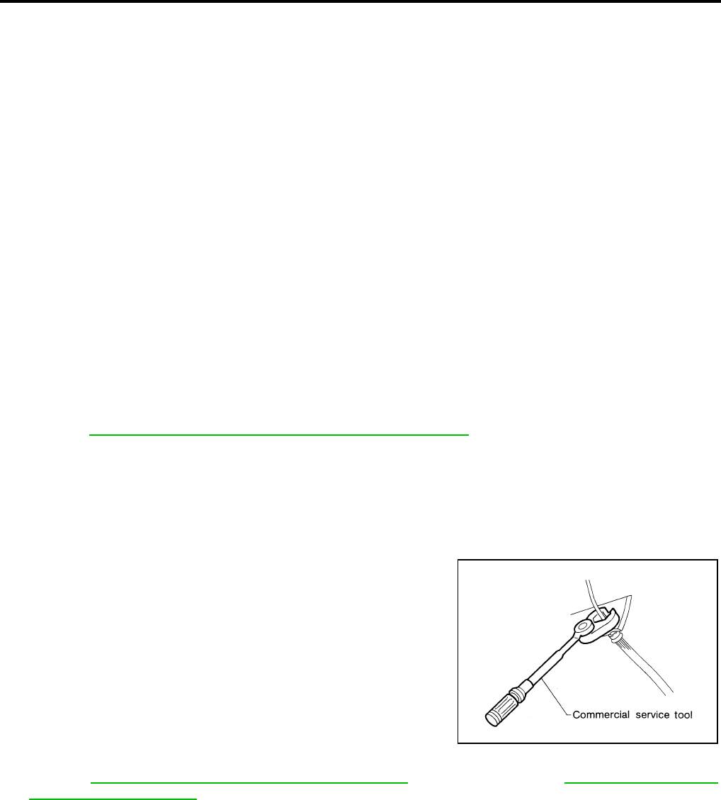
BRC-150
[HDC/HSA/VDC/TCS/ABS]
PRECAUTIONS
Revision: February 2006 2005 Xterra
PRECAUTIONS PFP:00001
Precautions for Supplemental Restraint System (SRS) “AIR BAG” and “SEAT
BELT PRE-TENSIONER” EFS005U4
The Supplemental Restraint System such as “AIR BAG” and “SEAT BELT PRE-TENSIONER”, used along
with a front seat belt, helps to reduce the risk or severity of injury to the driver and front passenger for certain
types of collision. This system includes seat belt switch inputs and dual stage front air bag modules. The SRS
system uses the seat belt switches to determine the front air bag deployment, and may only deploy one front
air bag, depending on the severity of a collision and whether the front occupants are belted or unbelted.
Information necessary to service the system safely is included in the SRS and SB section of this Service Man-
ual.
WARNING:
●To avoid rendering the SRS inoperative, which could increase the risk of personal injury or death
in the event of a collision which would result in air bag inflation, all maintenance must be per-
formed by an authorized NISSAN/INFINITI dealer.
●Improper maintenance, including incorrect removal and installation of the SRS, can lead to per-
sonal injury caused by unintentional activation of the system. For removal of Spiral Cable and Air
Bag Module, see the SRS section.
●Do not use electrical test equipment on any circuit related to the SRS unless instructed to in this
Service Manual. SRS wiring harnesses can be identified by yellow and/or orange harnesses or
harness connectors.
Precautions for Brake System EFS005IX
CAUTION:
●Refer to MA-11, "RECOMMENDED FLUIDS AND LUBRICANTS" for recommended brake fluid.
●Never reuse drained brake fluid.
●Be careful not to splash brake fluid on painted areas; it may cause paint damage. If brake fluid is
splashed on painted areas, wash it away with water immediately.
●To clean or wash all parts of master cylinder and disc brake caliper, use clean brake fluid.
●Never use mineral oils such as gasoline or kerosene. They will ruin rubber parts of the hydraulic
system.
●Use flare nut wrench when removing and installing brake
tube.
●If a brake fluid leak is found, the part must be disassembled
without fail. Then it has to be replaced with a new one if a
defect exists.
●Turn the ignition switch OFF and remove the connector of
the ABS actuator and electric unit (control unit) or the bat-
tery terminal before performing the work.
●Always torque brake lines when installing.
●Burnish the brake contact surfaces after refinishing or
replacing rotors, after replacing pads, or if a soft pedal
occurs at very low mileage.
Refer to BR-27, "BRAKE BURNISHING PROCEDURE" (front disc brake) or BR-32, "BRAKE BUR-
NISHING PROCEDURE" (rear disc brake).
WARNING:
●Clean brake pads and shoes with a waste cloth, then wipe with a dust collector.
Precautions When Using CONSULT-II EFS005IY
When connecting CONSULT-II to data link connector, connect them through CONSULT-II CONVERTER.
CAUTION:
If CONSULT-II is used with no connection of CONSULT-II CONVERTER, malfunctions might be
detected in self-diagnosis depending on control unit which carries out CAN communication.
CHECK POINTS FOR USING CONSULT-II
1. Has CONSULT-II been used without connecting CONSULT-II CONVERTER on this vehicle?
●If YES, GO TO 2.
SBR686C

PRECAUTIONS
BRC-151
[HDC/HSA/VDC/TCS/ABS]
C
D
E
G
H
I
J
K
L
M
A
B
BRC
Revision: February 2006 2005 Xterra
●If NO, GO TO 5.
2. Is there any indication other than indications relating to CAN communication system in the self-diagnosis
results?
●If YES, GO TO 3.
●If NO, GO TO 4.
3. Based on self-diagnosis results unrelated to CAN communication, carry out the inspection.
4. Malfunctions may be detected in self-diagnosis depending on control units carrying out CAN communica-
tion. Therefor, erase the self-diagnosis results.
5. Diagnose CAN communication system. Refer to LAN-21, "CAN COMMUNICATION" .
Precautions for Brake Control EFS005IZ
●During ABS operation, the brake pedal may vibrate lightly and a mechanical noise may be heard. This is
normal.
●During HDC operation, a mechanical noise may be heard. This is normal.
●Just after starting vehicle, the brake pedal may vibrate or a motor operating noise may be heard from
engine compartment. This is a normal status of operation check.
●Stopping distance may be longer than that of vehicles without ABS when vehicle drives on rough, gravel,
or snow-covered (fresh, deep snow) roads.
●When an error is indicated by ABS or another warning lamp, collect all necessary information from cus-
tomer (what symptoms are present under what conditions) and check for simple causes before starting
diagnosis. Besides electrical system inspection, check brake booster operation, brake fluid level, and fluid
leaks.
●If incorrect tire sizes or types are installed on the vehicle or brake pads are not Genuine NISSAN parts,
stopping distance or steering stability may deteriorate.
●If there is a radio, antenna or related wiring near control module, ABS function may have a malfunction or
error.
●If aftermarket parts (car stereo, CD player, etc.) have been installed, check for incidents such as harness
pinches, open circuits or improper wiring.
●If the following components are replaced with non-genuine components or modified, the VDC OFF indica-
tor lamp and SLIP indicator lamp may turn on or the VDC system may not operate properly. Components
related to suspension (shock absorbers, struts, springs, bushings, etc.), tires, wheels (exclude specified
size), components related to brake system (pads, rotors, calipers, etc.), components related to engine
(muffler, ECM, etc.), components related to body reinforcement (roll bar, tower bar, etc.).
●Driving with broken or excessively worn suspension components, tires or brake system components may
cause the VDC OFF indicator lamp and the SLIP indicator lamp to turn on, and the VDC system may not
operate properly.
●When the TCS or VDC is activated by sudden acceleration or sudden turn, some noise may occur. The
noise is a result of the normal operation of the TCS and VDC.
●When driving on roads which have extreme slopes (such as mountainous roads) or high banks (such as
sharp curves on a freeway), the VDC may not operate normally, or the VDC warning lamp and the SLIP
indicator lamp may turn on. This is not a problem if normal operation can be resumed after restarting the
engine.
●Sudden turns (such as spin turns, acceleration turns), drifting, etc. with VDC turned off may cause the yaw
rate/side G sensor to indicate a problem. This is not a problem if normal operation can be resumed after
restarting the engine.
●If battery is removed or steering angle sensor is disconnected, power to steering angle sensor is lost and
the screen goes into steering angle sensor safe mode.
●When screen goes into steering angle sensor safe mode, perform "Adjustment of Steering Angle Sensor
Neutral Position" with CONSULT-II and check that VDC OFF indicator turns off. Additionally, perform self-
diagnosis, check that only "Steering Angle Sensor Safe Mode" is shown for self-diagnostic result, and
then delete the memory. (If the self-diagnostic result shows an indication other than "Steering Angle Sen-
sor Safe Mode", repair the relevant part and restart self-diagnosis.) The steering angle sensor is released
and returns to normal condition by performing the above operation.
●When checking, if only "Steering Angle Sensor Safe Mode" is shown in the self-diagnostic result and VDC
OFF indicator is off, delete history of malfunction. This happens when battery power supply is lost and the
screen goes into Steering Angle Sensor Safe Mode, and then screen returns to normal mode automati-
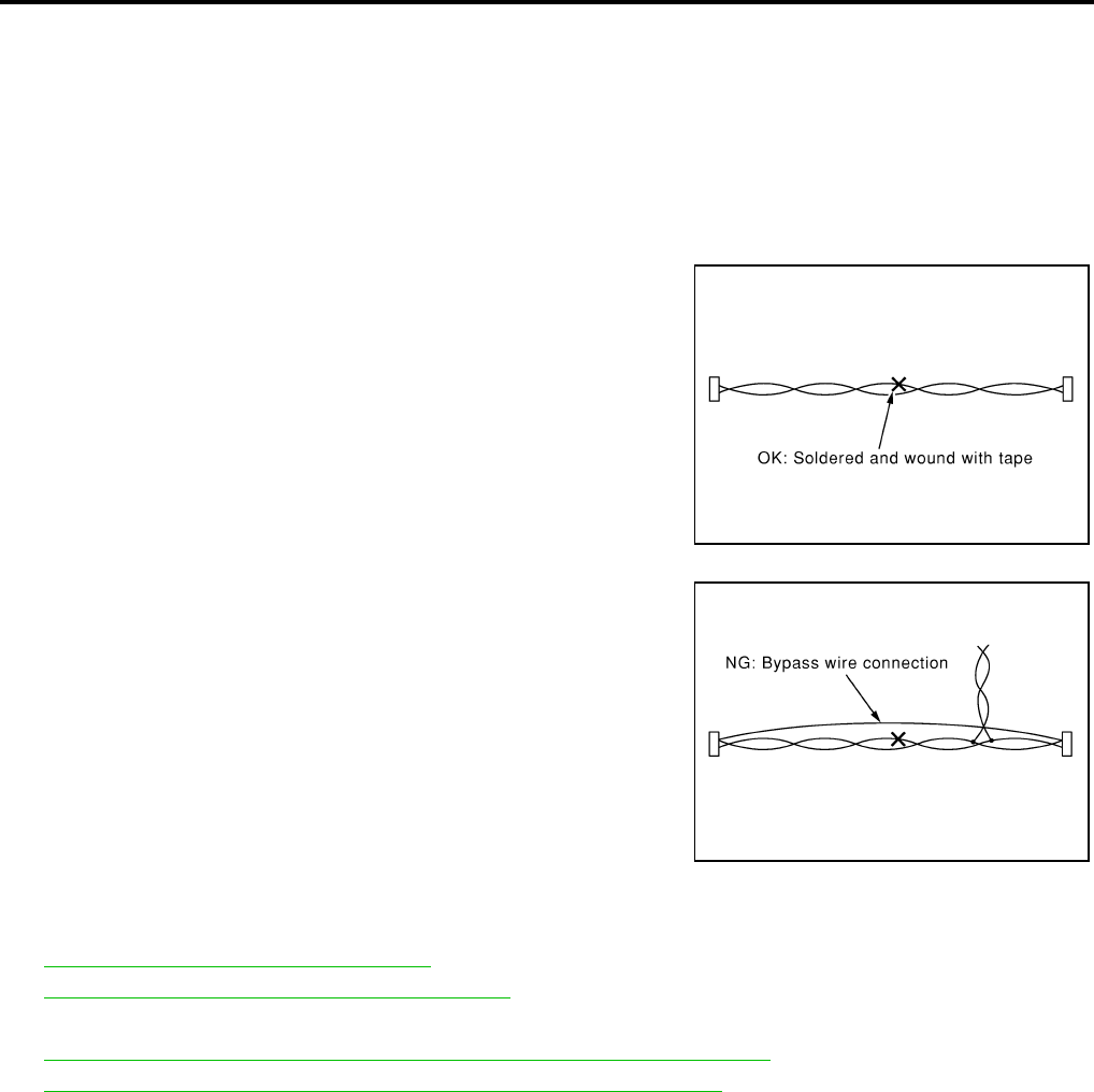
BRC-152
[HDC/HSA/VDC/TCS/ABS]
PRECAUTIONS
Revision: February 2006 2005 Xterra
cally by driving the vehicle in a straight forward direction [for approximately 30 seconds at 20 km/h (12
MPH) or more] after power is supplied again.
NOTE:
VDC OFF indicator lamp is on when VDC OFF switch is on.
Precautions for CAN System EFS005J0
●Do not apply voltage of 7.0V or higher to terminal to be measured.
●Maximum open terminal voltage of tester in use must be less than 7.0V.
●Before checking harnesses, turn ignition switch OFF and disconnect battery negative cable.
●Area to be repaired must be soldered and wrapped with tape.
Make sure that fraying of twisted wire is within 110 mm (4.33 in).
●Do not make a bypass connection to repaired area. (If the circuit
is bypassed, characteristics of twisted wire will be lost.)
Wiring Diagrams and Trouble Diagnosis EFS005J1
When you read wiring diagrams, refer to the following:
●GI-16, "How to Read Wiring Diagrams".
●PG-4, "POWER SUPPLY ROUTING CIRCUIT".
When you perform trouble diagnosis, refer to the following:
●GI-12, "HOW TO FOLLOW TEST GROUPS IN TROUBLE DIAGNOSES".
●GI-28, "How to Perform Efficient Diagnosis for an Electrical Incident".
PKIA0306E
PKIA0307E
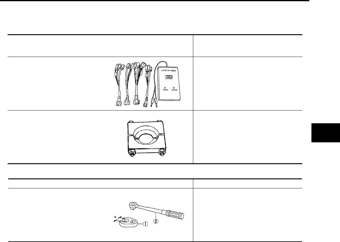
PREPARATION
BRC-153
[HDC/HSA/VDC/TCS/ABS]
C
D
E
G
H
I
J
K
L
M
A
B
BRC
Revision: February 2006 2005 Xterra
PREPARATION PFP:00002
Special Service Tool EFS005J2
The actual shapes of Kent-Moore tools may differ from those of special service tools illustrated here.
Commercial Service Tools EFS005J3
Tool number
(Kent-Moore No.)
Tool name
Description
—
(J-45741)
ABS active wheel sensor tester
Checking operation of ABS active wheel
sensors
205-D002
(—)
Bearing replacer
Removing sensor rotor
WFIA0101E
ZZA0700D
Tool name Description
1. Flare nut crowfoot
2. Torque wrench
Removing and installing brake piping
a: 10 mm (0.39 in)/12 mm (0.47 in)
S-NT360
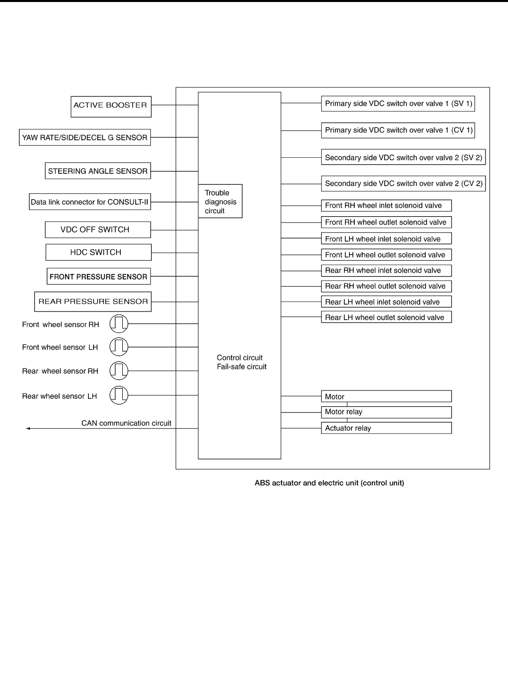
BRC-154
[HDC/HSA/VDC/TCS/ABS]
SYSTEM DESCRIPTION
Revision: February 2006 2005 Xterra
SYSTEM DESCRIPTION PFP:00000
System Components EFS005J4
WFIA0347E

SYSTEM DESCRIPTION
BRC-155
[HDC/HSA/VDC/TCS/ABS]
C
D
E
G
H
I
J
K
L
M
A
B
BRC
Revision: February 2006 2005 Xterra
ABS Function EFS005J5
●The Anti-Lock Brake System detects wheel revolution while braking and improves handling stability during
sudden braking by electrically preventing wheel lockup. Maneuverability is also improved for avoiding
obstacles.
●If the electrical system malfunctions, the Fail-Safe function is activated, the ABS becomes inoperative and
the ABS warning lamp turns on.
●The electrical system can be diagnosed using CONSULT-II.
●During ABS operation, the brake pedal may vibrate lightly and a mechanical noise may be heard. This is
normal.
●Just after starting the vehicle, the brake pedal may vibrate or a motor operating noise may be heard from
engine compartment. This is a normal status of operation check.
●Stopping distance may be longer than that of vehicles without ABS when vehicle drives on rough, gravel,
or snow-covered (fresh, deep snow) roads.
EBD Function EFS005J6
●Electronic Brake Distribution is a function that detects subtle slippages between the front and rear wheels
during braking, and it improves handling stability by electronically controlling the brake fluid pressure
which results in reduced rear wheel slippage.
●If the electrical system malfunctions, the Fail-Safe function is activated, the EBD and ABS become inoper-
ative, and the ABS warning lamp and brake warning lamp are turned on.
●The electrical system can be diagnosed using CONSULT-II.
●During EBD operation, the brake pedal may vibrate lightly and a mechanical noise may be heard. This is
normal.
●Just after starting the vehicle, the brake pedal may vibrate or a motor operating noise may be heard from
engine compartment. This is a normal status of operation check.
TCS Function EFS005J7
●Spinning of the drive wheels is detected by the ABS actuator and electric unit (control unit) using inputs
from the wheel speed sensors. If wheel spin occurs, the drive wheel right and left brake fluid pressure
control and engine fuel cut are activated while the throttle value is restricted to reduce the engine torque
and decrease the amount of wheel spin. In addition, the throttle opening is controlled to achieve the opti-
mum engine torque.
●Depending on road condition, the vehicle may have a sluggish feel. This is normal, because optimum trac-
tion has the highest priority during TCS operation.
●TCS may be activated during sudden vehicle acceleration, wide open throttle acceleration, sudden trans-
mission shifts or when the vehicle is driven on a road with a varying surface friction coefficient.
●The SLIP indicator lamp flashes to inform the driver of TCS operation.
VDC Function EFS005J8
●In addition to the ABS/TCS function, the driver steering amount and brake operation amount are detected
from the steering angle sensor and pressure sensors, and the vehicle's driving status (amount of under
steering/over steering) is determined using inputs from the yaw rate sensor/side G sensor, wheel speed
sensors, etc. and this information is used to improve vehicle stability by controlling the braking and engine
torque application to the wheels.
●The SLIP indicator lamp flashes to inform the driver of VDC operation.
●During VDC operation, the vehicle body and brake pedal may vibrate lightly and a mechanical noise may
be heard. This is normal.
●The ABS warning lamp, VDC OFF indicator lamp and SLIP indicator lamp may turn on when the vehicle is
subject to strong shaking or large vibration, such as when the vehicle is on a turntable or a ship while the
engine is running or on a steep slope. In this case, restart the engine on a normal road and if the ABS
warning lamp, VDC OFF indicator lamp and SLIP indicator lamp turn off, there is no problem.
HDC Function EFS005J9
●The hill descent control system will help maintain vehicle speed when driving under 25-35 km/h (15-21
MPH) on steeper downhill grades. HDC will provide braking allowing the driver to concentrate on steering
while reducing the burden of brake and accelerator operation.

BRC-156
[HDC/HSA/VDC/TCS/ABS]
SYSTEM DESCRIPTION
Revision: February 2006 2005 Xterra
●To operate the system, set the 4WD switch to 4H or 4 LO and push the HDC switch. The HDC indicator in
the combination meter will turn on. While HDC is operating, the stop/tail lamps will illuminate.
●If the accelerator or brake pedal is depressed while the HDC system is on, the system will stop operating.
●During HDC operation, a mechanical noise may be heard. This is normal.
HSA Function EFS005JA
●The HSA system will assist the driver by applying the brake automatically and preventing the vehicle from
rolling backward when starting on an uphill.
●The maximum holding time is 2 seconds. After 2 seconds, the vehicle will begin to roll back gradually and
then HSA will stop operating completely.
Fail-Safe Function EFS005JB
CAUTION:
If the Fail-Safe function is activated, perform the Self Diagnosis for ABS/TCS/VDC system.
ABS/EBD SYSTEM
In case of an electrical malfunction with the ABS, the ABS warning lamp, VDC OFF indicator lamp and SLIP
indicator lamp will turn on. In case of an electrical malfunction with the EBD system, the brake warning lamp,
ABS warning lamp, VDC OFF indicator lamp and SLIP indicator lamp will turn on.
The system will revert to one of the following conditions of the Fail-Safe function.
1. For ABS malfunction, only the EBD is operative and the condition of the vehicle is the same condition of
vehicles without ABS/TCS/VDC system.
2. For EBD malfunction, the EBD and ABS become inoperative, and the condition of the vehicle is the same
as the condition of vehicles without ABS/TCS/VDC or EBD system.
HDC/HSA SYSTEM
●In case of HDC system malfunction, the HDC indicator lamp will remain off even though the HDC switch is
operated and the condition of the vehicle is the same as the condition of vehicles without HDC system.
●In case of HSA system malfunction, the VDC OFF and SLIP indicator lamps are turned on and the condi-
tion of the vehicle is the same as the condition of vehicles without HSA system.
VDC/TCS SYSTEM
In case of TCS/VDC system malfunction, the VDC OFF indicator lamp and SLIP indicator lamp are turned on
and the condition of the vehicle is the same as the condition of vehicles without TCS/VDC system. In case of
an electrical malfunction with the TCS/VDC system, the ABS control continues to operate normally without
TCS/VDC control.
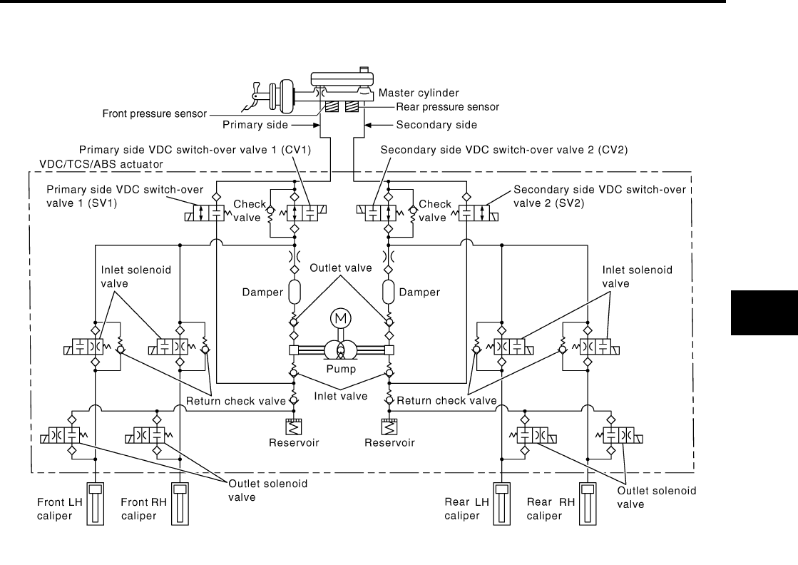
SYSTEM DESCRIPTION
BRC-157
[HDC/HSA/VDC/TCS/ABS]
C
D
E
G
H
I
J
K
L
M
A
B
BRC
Revision: February 2006 2005 Xterra
Hydraulic Circuit Diagram EFS005JC
WFIA0187E

BRC-158
[HDC/HSA/VDC/TCS/ABS]
CAN COMMUNICATION
Revision: February 2006 2005 Xterra
CAN COMMUNICATION PFP:23710
System Description EFS005JD
Refer to LAN-21, "CAN COMMUNICATION" .

TROUBLE DIAGNOSIS
BRC-159
[HDC/HSA/VDC/TCS/ABS]
C
D
E
G
H
I
J
K
L
M
A
B
BRC
Revision: February 2006 2005 Xterra
TROUBLE DIAGNOSIS PFP:00000
How to Perform Trouble Diagnoses for Quick and Accurate Repair EFS005JE
INTRODUCTION
The ABS/TCS/VDC/HDC/HSA system has an electronic control unit
to control major functions. The control unit accepts input signals from
sensors and controls actuator operation. It is also important to check
for conventional problems such as air leaks in the booster or lines,
lack of brake fluid, or other problems with the brake system.
It is much more difficult to diagnose a problem that occurs intermit-
tently rather than continuously. Most intermittent problems are
caused by poor electrical connections or faulty wiring. In this case,
careful checking of suspicious circuits may help prevent the replace-
ment of good parts.
A visual check only may not find the cause of the problem, so a road
test should be performed.
Before undertaking actual checks, take just a few minutes to talk with
a customer who approaches with a ABS/TCS/VDC/HDC/HSA com-
plaint. The customer is a very good source of information on such
problems, especially intermittent ones. Through the talks with the
customer, find out what symptoms are present and under what con-
ditions they occur.
Start your diagnosis by looking for “conventional” problems first. This
is one of the best ways to troubleshoot brake problems on a ABS/
TCS/VDC/HDC/HSA equipped vehicle. Also check related Service
Bulletins for information.
SEF233G
SEF234G

BRC-160
[HDC/HSA/VDC/TCS/ABS]
TROUBLE DIAGNOSIS
Revision: February 2006 2005 Xterra
WORK FLOW
WFIA0337E

TROUBLE DIAGNOSIS
BRC-161
[HDC/HSA/VDC/TCS/ABS]
C
D
E
G
H
I
J
K
L
M
A
B
BRC
Revision: February 2006 2005 Xterra
CLARIFY CONCERN
●A customer's description of a vehicle concern may vary depend-
ing on the individual. It is important to clarify the customer's con-
cern.
●Ask the customer about what symptoms are present under what
conditions. Use this information to reproduce the symptom while
driving.
●It is also important to use the diagnosis sheet to understand
what type of trouble the customer is having.
EXAMPLE OF DIAGNOSIS SHEET
SBR339B
WFIA0097E

BRC-162
[HDC/HSA/VDC/TCS/ABS]
TROUBLE DIAGNOSIS
Revision: February 2006 2005 Xterra
Component Parts and Harness Connector Location EFS005JF
WFIA0402E
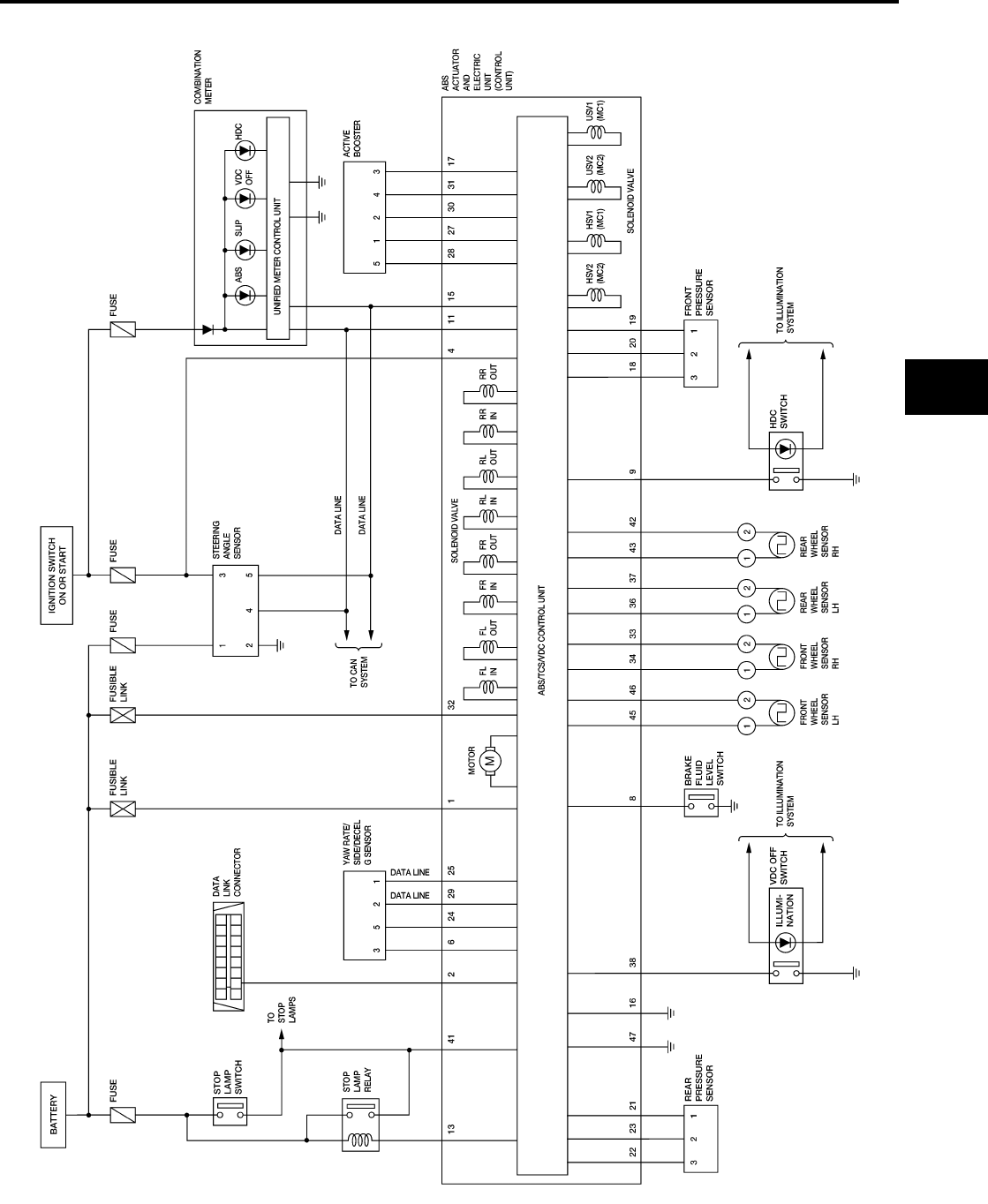
TROUBLE DIAGNOSIS
BRC-163
[HDC/HSA/VDC/TCS/ABS]
C
D
E
G
H
I
J
K
L
M
A
B
BRC
Revision: February 2006 2005 Xterra
Schematic EFS005JG
WFWA0247E
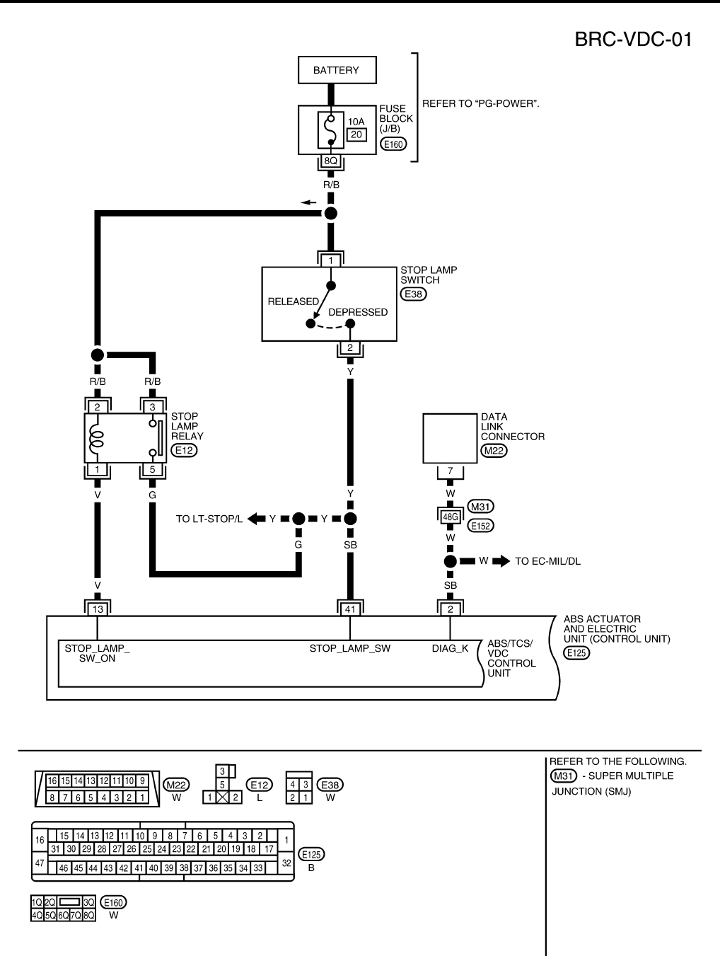
BRC-164
[HDC/HSA/VDC/TCS/ABS]
TROUBLE DIAGNOSIS
Revision: February 2006 2005 Xterra
Wiring Diagram — VDC — EFS005JH
WFWA0248E
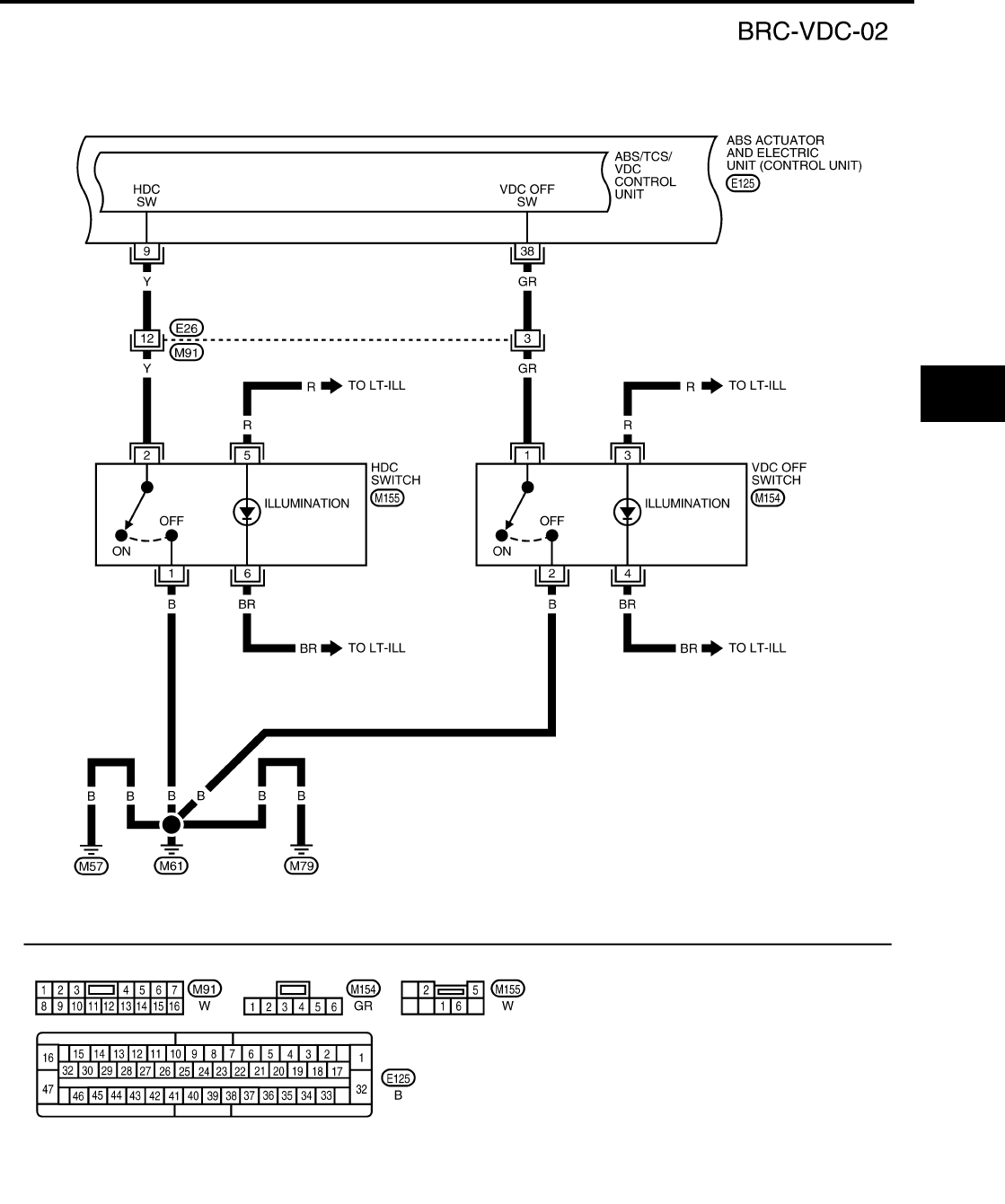
TROUBLE DIAGNOSIS
BRC-165
[HDC/HSA/VDC/TCS/ABS]
C
D
E
G
H
I
J
K
L
M
A
B
BRC
Revision: February 2006 2005 Xterra
WFWA0249E
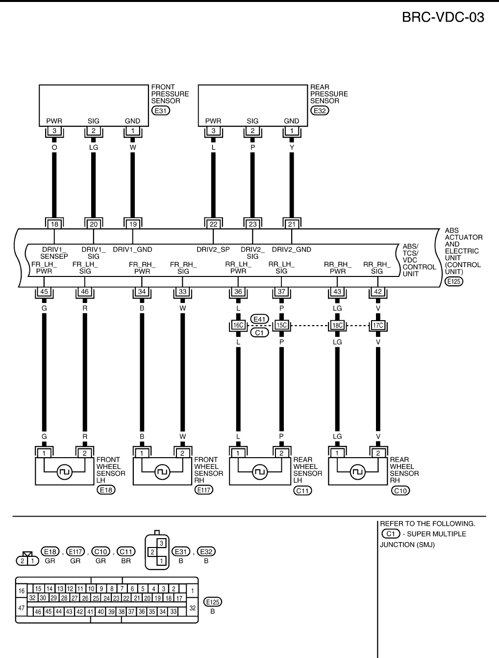
BRC-166
[HDC/HSA/VDC/TCS/ABS]
TROUBLE DIAGNOSIS
Revision: February 2006 2005 Xterra
WFWA0250E
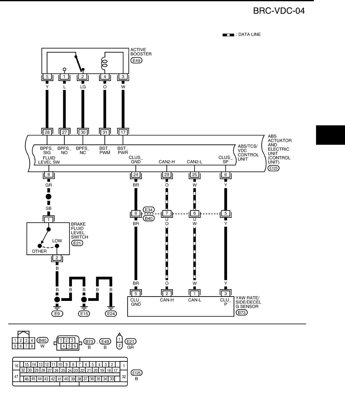
TROUBLE DIAGNOSIS
BRC-167
[HDC/HSA/VDC/TCS/ABS]
C
D
E
G
H
I
J
K
L
M
A
B
BRC
Revision: February 2006 2005 Xterra
WFWA0251E

BRC-168
[HDC/HSA/VDC/TCS/ABS]
TROUBLE DIAGNOSIS
Revision: February 2006 2005 Xterra
WFWA0252E
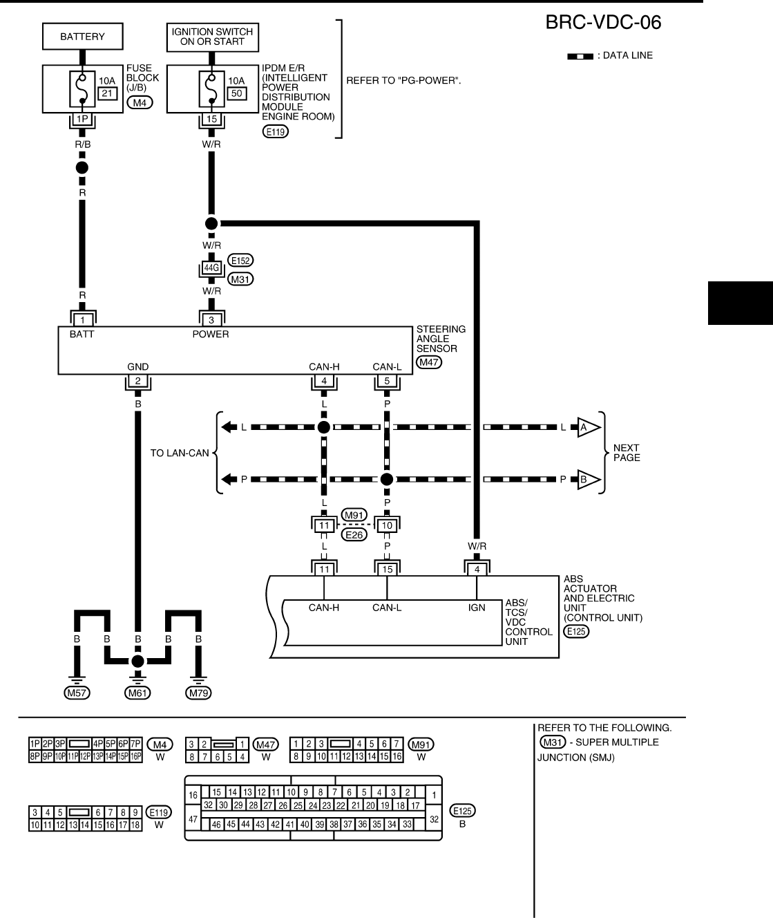
TROUBLE DIAGNOSIS
BRC-169
[HDC/HSA/VDC/TCS/ABS]
C
D
E
G
H
I
J
K
L
M
A
B
BRC
Revision: February 2006 2005 Xterra
WFWA0253E
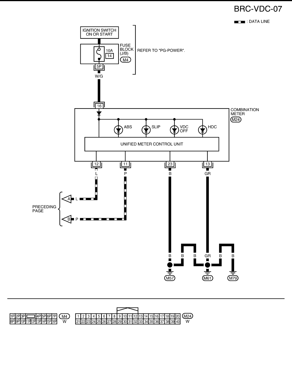
BRC-170
[HDC/HSA/VDC/TCS/ABS]
TROUBLE DIAGNOSIS
Revision: February 2006 2005 Xterra
WFWA0254E

TROUBLE DIAGNOSIS
BRC-171
[HDC/HSA/VDC/TCS/ABS]
C
D
E
G
H
I
J
K
L
M
A
B
BRC
Revision: February 2006 2005 Xterra
Basic Inspection EFS005JI
BRAKE FLUID LEVEL, FLUID LEAK, AND BRAKE PAD INSPECTION
1. Check fluid level in the brake fluid reservoir. If fluid level is low, add fluid.
2. Check the brake piping and around the ABS actuator and electric unit (control unit) for leaks. If there is
leaking or seeping fluid, check the following items.
●If ABS actuator and electric unit (control unit) connection is loose, tighten the piping to the specified
torque and recheck for leaks.
●If there is damage to the connection flare nut or ABS actuator and electric unit (control unit) threads,
replace the damaged part and recheck for leaks.
●When there is fluid leaking or seeping from a fluid connection, use a clean cloth to wipe off the fluid and
recheck for leaks. If fluid is still seeping out, replace the damaged part. If the fluid is leaking at the ABS
actuator and electric unit (control unit), replace the ABS actuator and electric unit (control unit) assem-
bly.
CAUTION:
The ABS actuator and electric unit (control unit) cannot be disassembled and must be replaced
as an assembly.
3. Check the brake pads for excessive wear.
POWER SYSTEM TERMINAL LOOSENESS AND BATTERY INSPECTION
Make sure the battery positive cable, negative cable and ground connection are not loose. In addition, make
sure the battery is sufficiently charged.
ABS WARNING LAMP, SLIP INDICATOR LAMP, VDC OFF INDICATOR LAMP AND HDC INDICA-
TOR LAMP INSPECTION
1. Make sure ABS warning lamp, SLIP indicator lamp, VDC OFF indicator lamp (when VDC OFF switch is
off) and HDC indicator lamp (when HDC switch is off), turn on for approximately 2 seconds when the igni-
tion switch is turned ON. If they do not, check the ABS warning lamp, SLIP indicator lamp, VDC OFF indi-
cator lamp and HDC indicator lamp. Check CAN communications. If there are no errors with the CAN
communication system, check combination meter. Refer to DI-4, "COMBINATION METERS" .
2. Make sure the lamps turn off approximately 2 seconds after the ignition switch is turned ON. If the lamp
does not turn off, conduct self-diagnosis.
NOTE:
●On 4WD vehicles, when the transfer case is placed in 4LO, the VDC system is disabled and the VDC
OFF indicator will turn on.
●If the battery has been disconnected, the TCS/VDC system is initialized and the SLIP and VDC OFF
indicator lamps may not turn off after 2 seconds when the ignition switch is turned ON. In this case,
refer to BRC-178, "SELF-DIAGNOSIS" .
3. With the engine running, make sure the VDC OFF indicator lamp turns on and off when the VDC OFF
switch is turned on and off. If the indicator lamp status does not correspond to switch operation, check the
VDC OFF switch. Refer to BRC-204, "VDC OFF SWITCH" .
4. Turn HDC switch on to confirm that HDC indicator lamp turns on. If HDC indicator lamp does not turn on,
perform self-diagnosis. Refer to BRC-178, "SELF-DIAGNOSIS" .
5. Make sure ABS warning lamp, SLIP indicator lamp, VDC OFF indicator lamp and HDC indicator lamp turn
off approximately 2 seconds after the ignition switch is turned ON. If ABS warning lamp, SLIP indicator
lamp, VDC OFF indicator lamp and HDC indicator lamp have not turned off 2 seconds after the ignition
switch is turned ON, conduct self-diagnosis of the ABS actuator and electric unit (control unit).
6. After conducting the self-diagnosis, be sure to erase the error memory. Refer to BRC-177, "CONSULT-II
Function (ABS)" .

BRC-172
[HDC/HSA/VDC/TCS/ABS]
TROUBLE DIAGNOSIS
Revision: February 2006 2005 Xterra
For Fast and Accurate Diagnosis EFS005JJ
PRECAUTIONS FOR DIAGNOSIS
●Before performing diagnosis, always read precautions. Refer to BRC-150, "PRECAUTIONS" .
●If ABS actuator and electric unit (control unit), steering angle sensor, steering system parts or suspension
system parts have been replaced, or if alignment has been adjusted, be sure to adjust neutral position of
steering angle sensor before driving. Refer to BRC-212, "Adjustment of Steering Angle Sensor Neutral
Position" .
●After diagnosis is finished, be sure to erase memory. Refer to BRC-178, "SELF-DIAGNOSIS" .
●When checking continuity and voltage between units, be sure to check for disconnection, looseness,
bend, or collapse of connector terminals. If any non-standard condition is found, repair or replace connec-
tor terminals.
●For intermittent symptoms, possible cause is malfunction in harness, harness connector, or terminals.
Move harness, harness connector, and terminals to check for poor connections.
●If a circuit tester is used for the check, be careful not to forcibly extend any connector terminal.
●To use CONSULT-II to perform self-diagnosis of ABS actuator and electric unit (control unit), active tests,
or work support, first stop work, then connect CONSULT-II and select “ABS”.
●CONSULT-II self-diagnosis results are displayed without regard to occurrence timing. In some cases later
ones (timing value is small) appear on the next screen.
●When self-diagnostic results of CONSULT-II show a malfunction, if CONSULT-II active test is performed,
an engine system error may be indicated. In this case, start engine to resume the normal screen.
●VDC/TCS/ABS system electronically controls brake operation and engine output. The following symptoms
may be caused by normal operations:
Symptom Symptom description Result
Motor operation noise
This is noise of motor inside ABS actuator and electric unit (control unit).
Slight noise may occur during VDC, TCS, and ABS operation.
Normal
When the vehicle speed goes over 20 km/h (12.5 mph), the motor and
valves operating noise may be heard. It happens only once after IGN
(ignition) is ON. This is a normal status of the system operation check.
System operation check
noise
When the engine starts, slight “click” noise may be heard from engine
compartment. This is normal and is part of system operation check. Normal
VDC/TCS operation
(SLIP indicator lamp blink-
ing)
TCS may activate momentarily if wheel speed changes when driving
over location where friction coefficient varies, when up/downshifting or
when fully depressing accelerator pedal. Normal
Cancel the VDC/TCS
function for the
inspection on a chas-
sis dynamometer.
For inspection of speedometer or other instruments, press
VDC OFF switch to turn VDC/TCS function off.
When accelerator pedal is depressed on a chassis dynamometer (fixed
front-wheel type), vehicle speed will not increase. This is not normal. It is
result of TCS being activated by stationary front wheels. Warning lamp
may also illuminate to indicate “sensor system error”. This is also nor-
mal, and is the result of the stationary front wheels being detected. To be
certain, restart engine, and drive vehicle at 30 km/h (19 MPH) or more.
Make sure warning lamp does not illuminate.
ABS operation (Longer stop-
ping distance)
On roads with low friction coefficients, such as snowy roads or gravel
roads, vehicles with ABS may require a longer stopping distance. There-
fore, when driving on such roads, avoid overconfidence and keep speed
sufficiently low.
Normal
Insufficient feeling of accel-
eration
Depending on road conditions, driver may feel that feeling of accelera-
tion is insufficient. This is because traction control, which controls the
engine and brakes to achieve optimal traction, has the highest priority
(for safety). As a result, there may be times when acceleration is slightly
less than usual for the same accelerator pedal operation.
Normal

TROUBLE DIAGNOSIS
BRC-173
[HDC/HSA/VDC/TCS/ABS]
C
D
E
G
H
I
J
K
L
M
A
B
BRC
Revision: February 2006 2005 Xterra
Warning Lamp and Indicator Timing EFS005JK
X: ON
—: OFF
Control Unit Input/Output Signal Standard EFS005JL
REFERENCE VALUE FROM CONSULT-II
CAUTION:
The display shows the control unit calculation data, so a normal value might be displayed even in the
event the output circuit (harness) is open or short circuited.
Condition
ABS
warning
lamp
VDC OFF
indicator
lamp
SLIP
indicator
lamp
HDC indica-
tor lamp Remarks
When the ignition switch is OFF — — — — —
After the ignition switch is turned
ON for approx. 1 second ×××× —
After the ignition switch has been
turned ON for approx. 2 seconds ———— —
When the VDC OFF switch is
pressed (VDC function OFF) —×—— —
ABS/TCS/VDC malfunction ×××——
When the VDC is malfunctioning — ××——
When HDC switch is pressed (HDC
function ON) ——— ×4H/4L → ON, 2H → Blink
Monitor item Display content
Data monitor Note: Error inspection
checklist
Condition Reference value in
normal operation
N POSI SIG PNP switch signal ON/
OFF condition
A/T shift position = N position ON BRC-202, "CAN Commu-
nication System Inspec-
tion"
A/T shift position = other than
N positions OFF
P POSI SIG PNP switch signal ON/
OFF condition
A/T shift position P position ON BRC-202, "CAN Commu-
nication System Inspec-
tion"
A/T shift position = other than
P positions OFF
GEAR A/T gear position
1st gear 1
—
2nd gear 2
3rd gear 3
4th gear 4
5th gear 5
FR RH SENSOR
FR LH SENSOR
RR RH SENSOR
RR LH SENSOR
Wheel speed
Vehicle stopped 0 [km/h (MPH)]
BRC-187, "Wheel Sen-
sor System Inspection"
Vehicle running (Note 1)
Almost in accor-
dance with speed-
ometer display
(within ±10%)
ACCEL POS SIG
Open/close condition
of throttle valve (linked
with accelerator pedal).
Accelerator pedal not
depressed (ignition switch is
ON)
0% BRC-202, "CAN Commu-
nication System Inspec-
tion"
Depress accelerator pedal
(ignition switch is ON) 0 to 100%
2WD/4WD Drive axle 2WD model 2WD —
4WD model 4WD

BRC-174
[HDC/HSA/VDC/TCS/ABS]
TROUBLE DIAGNOSIS
Revision: February 2006 2005 Xterra
ENGINE SPEED With engine running
With engine stopped 0 RPM
BRC-188, "Engine Sys-
tem Inspection"
Engine running
Almost in accor-
dance with
tachometer display
STR ANGLE SIG
Steering angle
detected by steering
angle sensor
Straight-ahead Approx. 0 deg BRC-189, "Steering
Angle Sensor System"
Steering wheel turned –756 to 756 deg
YAW RATE SEN Yaw rate detected by
yaw rate sensor
Vehicle stopped Approx. 0 d/s BRC-191, "Yaw Rate/
Side/Decel G Sensor
System Inspection"
Vehicle running –100 to 100 d/s
SIDE G SENSOR Transverse G detected
by side G-sensor
Vehicle stopped Approx. 0 m/s2BRC-191, "Yaw Rate/
Side/Decel G Sensor
System Inspection"
Vehicle running –16.7 to 16.7 m/s2
BATTERY VOLT
Battery voltage sup-
plied to ABS actuator
and electric unit (con-
trol unit)
Ignition switch ON 10 to 16V
BRC-196, "ABS/TCS/
VDC Control Unit Power
and Ground Systems
Inspection"
STOP LAMP SW Stop lamp switch oper-
ation
Brake pedal depressed ON BRC-195, "Stop Lamp
Switch System Inspec-
tion"
Brake pedal not depressed OFF
OFF SW VDC OFF switch
ON/OFF status
VDC OFF switch ON
(When VDC OFF indicator
lamp is ON)
ON
BRC-204, "VDC OFF
SWITCH"
VDC OFF switch OFF
(When VDC OFF indicator
lamp is OFF)
OFF
HDC SW HDC switch ON/OFF
status
HDC switch ON
(When HDC indicator lamp is
ON or blink)
ON
BRC-210, "HDC Switch
Inspection"
HDC switch OFF
(When HDC indicator lamp is
OFF)
OFF
STOP LAMP ON RLY Stop lamp relay opera-
tion status
When HDC is operating ON BRC-210, "Stop Lamp
Relay Inspection"
When HDC is not operating OFF
ABS WARN LAMP ABS warning lamp ON
condition (Note 2)
ABS warning lamp ON ON —
ABS warning lamp OFF OFF
MOTOR RELAY Operation status of
motor and motor relay
Ignition switch ON or running
(ABS not activated) OFF BRC-194, "Actuator
Motor, Motor Relay, and
Circuit Inspection"
Ignition switch ON or engine
running (ABS activated) ON
ACTUATOR RLY Actuator relay opera-
tion status
Vehicle stopped (Ignition
switch ON) OFF BRC-194, "Actuator
Motor, Motor Relay, and
Circuit Inspection"
Vehicle stopped (Engine run-
ning) ON
OFF LAMP VDC OFF indicator
lamp status (Note 3)
When VDC OFF indicator
lamp is ON ON BRC-202, "CAN Commu-
nication System Inspec-
tion"
When VDC OFF indicator
lamp is OFF OFF
SLIP LAMP SLIP indicator lamp
status (Note 4)
When SLIP indicator lamp is
ON ON BRC-202, "CAN Commu-
nication System Inspec-
tion"
When SLIP indicator lamp is
OFF OFF
Monitor item Display content
Data monitor Note: Error inspection
checklist
Condition Reference value in
normal operation

TROUBLE DIAGNOSIS
BRC-175
[HDC/HSA/VDC/TCS/ABS]
C
D
E
G
H
I
J
K
L
M
A
B
BRC
Revision: February 2006 2005 Xterra
Note 1: Confirm tire pressure is normal.
Note 2: ON/OFF timing of ABS warning lamp
ON: For approximately 2 seconds after ignition switch is turned ON, or when a malfunction is detected.
FR LH IN SOL
FR LH OUT SOL
FR RH IN SOL
FR RH OUT SOL
RR RH IN SOL
RR RH OUT SOL
RR LH IN SOL
RR LH OUT SOL
Solenoid valve opera-
tion
Actuator (solenoid) is active
(“ACTIVE TEST” with CON-
SULT-II) or actuator relay is
inactive (in fail-safe mode).
ON
BRC-193, "Solenoid and
VDC Change-Over Valve
System Inspection"
When actuator (solenoid) is
not active and actuator relay is
active (ignition switch ON).
OFF
CV1
CV2
SV1
SV2
VDC switch-over valve
status
When actuator (switch-over
valve) is active (“ACTIVE
TEST” with CONSULT-II) or
actuator relay is inactive (when
in fail-safe mode).
ON
When actuator (switch-over
valve) is not active and actua-
tor relay is active (ignition
switch ON).
OFF
DECEL G-SEN
Longitudinal accelera-
tion detected by Decel
G-Sensor
Vehicle stopped Approx. 0 G BRC-191, "Yaw Rate/
Side/Decel G Sensor
System Inspection"
Vehicle running -1.7 to 1.7 G
PRESS SENSOR
Brake fluid pressure
detected by pressure
sensor
Do not step on the Brake pedal
(When ignition switch is ON) Approx. 0 bar
—
Step on the Brake pedal
(When ignition switch is ON) -40 to 300 bar
PRESS SEN 2
Brake fluid pressure
detected by pressure
sensor
Do not step on the Brake pedal
(When ignition switch is ON) Approx. 0 bar
—
Step on the Brake pedal
(When ignition switch is ON) -40 to 300 bar
FLUID LEV SW ON/OFF status of
brake fluid level switch
When brake fluid level switch
ON ON DI-28, "WARNING
LAMPS"
When brake fluid level switch
OFF OFF
VDC SIGNAL
TCS SIGNAL
ABS SIGNAL
EBD SIGNAL
HDC SIGNAL
HSA SIGNAL
Signal status
VDC active
TCS active
ABS active
EBD active
HDC active
HSA active
ON VDC system
TCS system
ABS system
EBD system
HDC system
HSA system
VDC not active
TCS not active
ABS not active
EBD not active
HDC not active
HSA not active
OFF
VDC FAIL SIG
TCS FAIL SIG
ABS FAIL SIG
EBD FAIL SIG
Fail signal status
VDC fail
TCS fail
ABS fail
EBD fail
ON VDC system
TCS system
ABS system
EBD system
VDC normal
TCS normal
ABS normal
EBD normal
OFF
Monitor item Display content
Data monitor Note: Error inspection
checklist
Condition Reference value in
normal operation

BRC-176
[HDC/HSA/VDC/TCS/ABS]
TROUBLE DIAGNOSIS
Revision: February 2006 2005 Xterra
OFF: Approximately 2 seconds after ignition switch is turned ON (when system is in normal operation) and VDC/TCS function is not
activated.
Note 3: ON/OFF timing of VDC OFF indicator lamp
ON: For approximately 2 seconds after ignition switch is turned ON, or when a malfunction is detected and VDC OFF switch is ON.
OFF: Approximately 2 seconds after ignition switch is turned ON (when system is in normal operation.) And when VDC OFF switch is
OFF.
Note 4: SLIP indicator lamp ON/OFF timing
ON: For approximately 2 seconds after ignition switch is turned ON, or when a malfunction is detected and VDC/TCS function is acti-
vated while driving.
OFF: Approximately 2 seconds after ignition switch is turned ON (when system is in normal operation) and VDC/TCS function is not
activated.
Flashing: VDC/TCS function is active during driving.

TROUBLE DIAGNOSIS
BRC-177
[HDC/HSA/VDC/TCS/ABS]
C
D
E
G
H
I
J
K
L
M
A
B
BRC
Revision: February 2006 2005 Xterra
CONSULT-II Function (ABS) EFS005JM
CONSULT-II can display each diagnostic item using the diagnostic test modes shown following.
CONSULT-II BASIC OPERATION PROCEDURE
1. Turn ignition switch OFF.
2. Connect CONSULT-II and CONSULT-II CONVERTER to the
data link connector.
CAUTION:
If CONSULT-II is used with no connection of CONSULT-II
CONVERTER, malfunctions might be detected in self-diag-
nosis depending on control unit which carries out CAN
communication.
3. Turn ignition switch ON.
4. Touch “START (NISSAN BASED VHCL)”.
5. Touch “ABS” in the “SELECT SYSTEM” screen.
If “ABS” is not indicated, go to GI-39, "CONSULT-II Data Link
Connector (DLC) Circuit" .
6. Select the required diagnostic location from the “SELECT DIAG MODE” screen.
For further information, see the CONSULT-II Operation Manual.
ABS diagnostic mode Description
WORK SUPPORT
Supports inspection and adjustments. Commands are transmitted to the ABS actuator and electric
unit (control unit) for setting the status suitable for required operation, input/output signals are
received from the ABS actuator and electric unit (control unit) and received data is displayed.
SELF-DIAG RESULTS Displays ABS actuator and electric unit (control unit) self-diagnosis results.
DATA MONITOR Displays ABS actuator and electric unit (control unit) input/output data in real time.
CAN DIAG SUPPORT MNTR The result of transmit/receive diagnosis of CAN communication can be read.
ACTIVE TEST Operation of electrical loads can be checked by sending drive signal to them.
FUNCTION TEST Conducted by CONSULT-II instead of a technician to determine whether each system is "OK" or
"NG".
ECU PART NUMBER ABS actuator and electric unit (control unit) part number can be read.
BBIA0538E
BCIA0029E
BCIA0030E

BRC-178
[HDC/HSA/VDC/TCS/ABS]
TROUBLE DIAGNOSIS
Revision: February 2006 2005 Xterra
SELF-DIAGNOSIS
Description
If an error is detected in the system, the ABS warning lamp will turn on. In this case, perform self-diagnosis as
follows:
Operation Procedure
1. Turn ignition switch OFF.
2. Connect CONSULT-II and CONSULT-II CONVERTER to the data link connector.
CAUTION:
If CONSULT-II is used with no connection of CONSULT-II CONVERTER, malfunctions might be
detected in self-diagnosis depending on control unit which carries out CAN communication.
3. Turn ignition switch ON.
4. Start engine and drive at approximately 30 km/h (19 MPH) or more for approximately 1 minute.
5. After stopping the vehicle, with the engine running, touch “START (NISSAN BASED VHCL)”, “ABS”,
“SELF-DIAG RESULTS” in order on the CONSULT-II screen.
CAUTION:
If “START (NISSAN BASED VHCL)” is touched immediately after starting the engine or turning on
the ignition switch, “ABS” might not be displayed in the SELECT SYSTEM screen. In this case,
repeat the operation from step 1.
6. The self-diagnostic results are displayed. (If necessary, the self-diagnostic results can be printed out by
touching “PRINT”.)
●When “NO DTC IS DETECTED” is displayed, check the ABS warning lamp, SLIP indicator lamp and
VDC OFF indicator lamp.
7. Conduct the appropriate inspection from the display item list, and repair or replace the malfunctioning
component.
8. Start engine and drive at approximately 30 km/h (19 MPH) or more for approximately 1 minute.
CAUTION:
●When a wheel sensor “short-circuit” is detected, if the vehicle is not driven at 30 km/h (19 MPH)
for at least 1 minute, the ABS warning lamp will not turn off even if the malfunction is repaired.
9. Turn ignition switch OFF to prepare for erasing the memory.
10. Start the engine and touch “START (NISSAN BASED VHCL)”, “ABS”, “SELF-DIAG RESULTS”, “ERASE”
in order on the CONSULT-II screen to erase the error memory.
If “ABS” is not indicated, go to GI-39, "CONSULT-II Data Link Connector (DLC) Circuit" .
CAUTION:
If the error memory is not erased, re-conduct the operation from step 5.
11. For the final inspection, drive at approximately 30 km/h (19 MPH) or more for approximately 1 minute and
confirm that the ABS warning lamp, SLIP indicator lamp, and VDC OFF indicator lamp are off.

TROUBLE DIAGNOSIS
BRC-179
[HDC/HSA/VDC/TCS/ABS]
C
D
E
G
H
I
J
K
L
M
A
B
BRC
Revision: February 2006 2005 Xterra
Display Item List
Self-diagnostic item Malfunction detecting condition Check system
RR RH SENSOR 1
[C1101]
Circuit of rear RH wheel sensor is open, shorted or sensor power
voltage is unusual.
BRC-187, "Wheel Sen-
sor System Inspection"
(Note 1)
RR LH SENSOR 1
[C1102]
Circuit of rear LH wheel sensor is open, shorted or sensor power
voltage is unusual.
FR RH SENSOR 1
[C1103]
Circuit of front RH wheel sensor is open, shorted or sensor power
voltage is unusual.
FR LH SENSOR 1
[C1104]
Circuit of front LH wheel sensor is open, shorted or sensor power
voltage is unusual.
RR RH SENSOR 2
[C1105]
ABS actuator and electric unit (control unit) cannot identify sen-
sor pulses, because of large gap between wheel sensor and sen-
sor rotor.
RR LH SENSOR 2
[C1106]
ABS actuator and electric unit (control unit) cannot identify sen-
sor pulses, because of large gap between wheel sensor and sen-
sor rotor.
FR RH SENSOR 2
[C1107]
ABS actuator and electric unit (control unit) cannot identify sen-
sor pulses, because of large gap between wheel sensor and sen-
sor rotor.
FR LH SENSOR 2
[C1108]
ABS actuator and electric unit (control unit) cannot identify sen-
sor pulses, because of large gap between wheel sensor and sen-
sor rotor.
ABS SENSOR
[C1115] Wheel sensor input is abnormal.
BATTERY VOLTAGE
[ABNORMAL]
[C1109]
ABS actuator and electric unit (control unit) power voltage is too
low.
BRC-196, "ABS/TCS/
VDC Control Unit Power
and Ground Systems
Inspection"
CONTROLLER FAILURE
[C1110]
Internal malfunction of ABS actuator and electric unit (control
unit)
BRC-189, "ABS/TCS/
VDC Control Unit
Inspection"
PUMP MOTOR (Note 3)
[C1111]
During actuator motor operation with ON, when actuator motor
turns OFF or when control line for actuator motor relay is open. BRC-194, "Actuator
Motor, Motor Relay, and
Circuit Inspection"
During actuator motor operation with OFF, when actuator motor
turns ON or when control line for relay is shorted to ground.
G-SENSOR
[C1113]
Longitudinal G-sensor is malfunctioning, or signal line of longitu-
dinal G-sensor is open or shorted.
BRC-191, "Yaw Rate/
Side/Decel G Sensor
System Inspection"
STOP LAMP SW
[C1116] Stop lamp switch or circuit malfunction.
BRC-195, "Stop Lamp
Switch System Inspec-
tion"

BRC-180
[HDC/HSA/VDC/TCS/ABS]
TROUBLE DIAGNOSIS
Revision: February 2006 2005 Xterra
FR LH IN ABS SOL
[C1120]
Circuit of front LH IN ABS solenoid is open or shorted, or control
line is open or shorted to power supply or ground.
BRC-193, "Solenoid and
VDC Change-Over Valve
System Inspection"
FR LH OUT ABS SOL
[C1121]
Circuit of front LH OUT ABS solenoid is open or shorted, or con-
trol line is open or shorted to power supply or ground.
FR RH IN ABS SOL
[C1122]
Circuit of front RH IN ABS solenoid is open or shorted, or control
line is open or shorted to power supply or ground.
FR RH OUT ABS SOL
[C1123]
Circuit of front RH OUT ABS solenoid is open or shorted, or con-
trol line is open or shorted to power supply or ground.
RR LH IN ABS SOL
[C1124]
Circuit of rear LH IN ABS solenoid is open or shorted, or control
line is open or shorted to power supply or ground.
RR LH OUT ABS SOL
[C1125]
Circuit of rear LH OUT ABS solenoid is open or shorted, or con-
trol line is open or shorted to power supply or ground.
RR RH IN ABS SOL
[C1126]
Circuit of rear RH IN ABS solenoid is open or shorted, or control
line is open or shorted to power supply or ground.
RR RH OUT ABS SOL
[C1127]
Circuit of rear RH OUT ABS solenoid is open or shorted, or con-
trol line is open or shorted to power supply or ground.
ENGINE SIGNAL 1
[C1130]
Based on the signal from ECM, ABS actuator and electric unit
(control unit) judges that engine fuel cut system is malfunction-
ing.
BRC-188, "Engine Sys-
tem Inspection"
ENGINE SIGNAL 2
[C1131]
Based on the signal from ECM, ABS actuator and electric unit
(control unit) judges that engine fuel cut system is malfunction-
ing.
ENGINE SIGNAL 3
[C1132]
Based on the signal from ECM, ABS actuator and electric unit
(control unit) judges that engine fuel cut system is malfunction-
ing.
ENGINE SIGNAL 4
[C1133]
Based on the signal from ECM, ABS actuator and electric unit
(control unit) judges that engine fuel cut system is malfunction-
ing.
ENGINE SIGNAL 6
[C1136]
Based on the signal from ECM, ABS actuator and electric unit
(control unit) judges that engine fuel cut system is malfunction-
ing.
ACTUATOR RLY
[C1140] ABS actuator relay or circuit malfunction.
BRC-194, "Actuator
Motor, Motor Relay, and
Circuit Inspection"
PRESS SEN CIRCUIT
[C1142] ABS pressure sensor circuit malfunction.
BRC-199, "Pressure
Sensor System Inspec-
tion"
ST ANGLE SEN CIRCUIT
[C1143]
Neutral position of steering angle sensor is dislocated, or steer-
ing angle sensor is malfunctioning.
BRC-189, "Steering
Angle Sensor System"
ST ANGLE SEN SIGNAL
[C1144]
Neutral position correction of steering angle sensor is not fin-
ished.
BRC-203, "Inspection
For Self-diagnosis
Result "ST ANGLE SEN
SIGNAL""
YAW RATE SENSOR
[C1145]
Yaw rate sensor has generated an error, or yaw rate sensor sig-
nal line is open or shorted. BRC-191, "Yaw Rate/
Side/Decel G Sensor
System Inspection"
SIDE G-SEN CIRCUIT
[C1146]
Lateral G-sensor is malfunctioning, or signal line of lateral G-sen-
sor is open or shorted.
BR FLUID LEVEL LOW
[C1155]
Brake fluid level drops or circuit between ABS actuator and elec-
tric unit (control unit) and brake fluid level switch is open or
shorted.
BRC-197, "Brake Fluid
Level Sensor System
Inspection"
ST ANG SEN COM CIR
[C1156]
CAN communication line or steering angle sensor has generated
an error.
BRC-189, "Steering
Angle Sensor System"
Self-diagnostic item Malfunction detecting condition Check system

TROUBLE DIAGNOSIS
BRC-181
[HDC/HSA/VDC/TCS/ABS]
C
D
E
G
H
I
J
K
L
M
A
B
BRC
Revision: February 2006 2005 Xterra
Note 1. If wheel sensor 2 for each wheel is indicated, check ABS actuator and electric unit (control unit) power
supply voltage in addition to wheel sensor circuit check.
Note 2. If multiple malfunctions are detected including CAN communication line [U1000], perform diagnosis for
CAN communication line first.
Note 3. "ACTUATOR RLY" on the CONSULT-II self-diagnosis results indicates the malfunction of the actuator
motor relay or circuit.
DATA MONITOR
Operation Procedure
1. After turning ignition switch OFF, connect CONSULT-II and the CONSULT-II CONVERTER to the data link
connector.
CAUTION:
If CONSULT-II is used with no connection of CONSULT-II CONVERTER, malfunctions might be
detected in self-diagnosis depending on control unit which carries out CAN communication.
2. Touch “START (NISSAN BASED VHCL)”, “ABS”, “DATA MONITOR” in order on the CONSULT-II screen.
If “ABS” is not indicated, go to GI-39, "CONSULT-II Data Link Connector (DLC) Circuit" .
DECEL G SEN SET
[C1160] ABS decel sensor adjustment is incomplete.
BRC-203, "Inspection
For Self-diagnosis
Result "DECEL G SEN
SET""
ST ANGL SEN SAFE
[C1163] When steering angle sensor is in safe mode.
BRC-202, "Steering
Angle Sensor Safe Mode
Inspection"
CV1
[C1164]
Front side VDC switch-over solenoid valve (cut valve) is open or
shorted, or control line is open or shorted to power supply or
ground.
BRC-193, "Solenoid and
VDC Change-Over Valve
System Inspection"
CV2
[C1165]
Rear side VDC switch-over solenoid valve (cut valve) is open or
shorted, or control line is open or shorted to power supply or
ground.
SV1
[C1166]
Front side VDC switch-over solenoid valve (suction valve) is
open or shorted, or control line is open or shorted to power sup-
ply or ground.
SV2
[C1167]
Rear side VDC switch-over solenoid valve (suction valve) is open
or shorted, or control line is open or shorted to power supply or
ground.
VARIANT CODING
[C1170] V coding is not malfunctioning.
BRC-189, "ABS/TCS/
VDC Control Unit
Inspection"
ABS ACTIVE BOOSTER SV NG
[C1178]
Active booster solenoid is malfunctioning, or signal line of active
booster servo is open or shorted.
BRC-198, "Active
Booster System Inspec-
tion"
ABS ACTIVE BOOSTER
RESPONSE NG
[C1181]
Active booster response is malfunctioning, or signal line of active
booster response is open or shorted.
ABS BRAKE RELEASE SW NG
[C1184]
Brake release switch is malfunctioning, or signal line of brake
release switch is open or shorted.
ABS DIFLOCK CONTROLLER
NG
[C1187]
Differential lock controller malfunction.
BRC-202, "CAN Com-
munication System
Inspection"
ABS BRAKE BOOSTER DEFECT
[C1189] Brake booster is defective or malfunctioning.
BRC-198, "Active
Booster System Inspec-
tion"
CAN COMM CIRCUIT
[U1000]
●CAN communication line is open or shorted.
●ABS actuator and electric unit (control unit) internal malfunc-
tion
●Battery voltage for ECM is suddenly interrupted for approxi-
mately 0.5 second or more.
BRC-202, "CAN Com-
munication System
Inspection" (Note 2)
Self-diagnostic item Malfunction detecting condition Check system

BRC-182
[HDC/HSA/VDC/TCS/ABS]
TROUBLE DIAGNOSIS
Revision: February 2006 2005 Xterra
CAUTION:
When “START (NISSAN BASED VHCL)” is touched immediately after starting the engine or turning
on the ignition switch, “ABS” might not be displayed in the SELECT SYSTEM screen. In this case,
repeat the operation from step 2.
3. Return to the Monitor Item Selection screen, and touch “ECU INPUT SIGNALS”, “MAIN SIGNALS”, or
“SELECTION FROM MENU”. Refer to the following information.
4. When “START” is touched, the data monitor screen is displayed.
Display Item List
Item
(Unit)
Data monitor item selection
Remarks
ECU INPUT
SIGNALS
MAIN
SIGNALS
SELECTION
FROM MENU
GEAR ×××
Gear position judged by PNP
switch signal is displayed.
FR RH SENSOR
(km/h, MPH) ×××
Wheel speed calculated by front
RH wheel sensor signal is dis-
played.
FR LH SENSOR
(km/h, MPH) ×××
Wheel speed calculated by front LH
wheel sensor signal is displayed.
RR RH SENSOR
(km/h, MPH) ×××
Wheel speed calculated by rear RH
wheel sensor signal is displayed.
RR LH SENSOR
(km/h, MPH) ×××
Wheel speed calculated by rear LH
wheel sensor signal is displayed.
BATTERY VOLT
(V) ×××
Voltage supplied to ABS actuator
and electric unit (control unit) is dis-
played.
N POSI SIG – – ×Shift position judged by PNP switch
signal.
P POSI SIG – – ×Shift position judged by PNP switch
signal.
ACCEL POS SIG
(%) ×–×
Throttle valve open/close status
judged by CAN communication sig-
nal is displayed.
ENGINE SPEED
(rpm) ×××
Engine speed judged by CAN com-
munication signal is displayed.
STR ANGLE SIG
(deg) ×–×Steering angle detected by steering
angle sensor is displayed.
YAW RATE SEN
(d/s) ×××
Yaw rate detected by yaw rate sen-
sor is displayed.
DECEL G SEN
(d/s) ×××
Longitudinal acceleration detected
by decel G-sensor is displayed.
SIDE G-SENSOR
(m/s2 ) ×– ×Transverse acceleration detected
by side G-sensor is displayed.
STOP LAMP SW
(ON/OFF) ×××
Stop lamp switch (ON/OFF) status
is displayed.
OFF SW
(ON/OFF) ×× ×
VDC OFF switch (ON/OFF) status
is displayed.
HDC SW
(ON/OFF) ––×HDC switch (ON/OFF) status is
displayed.
ABS WARN LAMP
(ON/OFF) –××
ABS warning lamp (ON/OFF) status
is displayed.
SLIP LAMP
(ON/OFF) –××
SLIP indicator lamp (ON/OFF) sta-
tus is displayed.
FR LH IN SOL
(ON/OFF) –××
Front LH IN ABS solenoid (ON/
OFF) status is displayed.

TROUBLE DIAGNOSIS
BRC-183
[HDC/HSA/VDC/TCS/ABS]
C
D
E
G
H
I
J
K
L
M
A
B
BRC
Revision: February 2006 2005 Xterra
FR LH OUT SOL
(ON/OFF) –××
Front LH OUT ABS solenoid (ON/
OFF) status is displayed.
RR RH IN SOL
(ON/OFF) –××
Rear RH IN ABS solenoid (ON/
OFF) status is displayed.
RR RH OUT SOL
(ON/OFF) –××
Rear RH OUT ABS solenoid (ON/
OFF) status is displayed.
FR RH IN SOL
(ON/OFF) –××
Front RH IN ABS solenoid (ON/
OFF) status is displayed.
FR RH OUT SOL
(ON/OFF) –××
Front RH OUT ABS solenoid (ON/
OFF) status is displayed.
RR LH IN SOL
(ON/OFF) –××
Rear LH IN ABS solenoid (ON/
OFF) status is displayed.
RR LH OUT SOL
(ON/OFF) –××
Rear LH OUT ABS solenoid (ON/
OFF) status is displayed.
OFF LAMP
(ON/OFF) –××
OFF Lamp (ON/OFF) status is dis-
played.
MOTOR RELAY
(ON/OFF) –××
ABS motor relay signal (ON/OFF)
status is displayed.
ACTUATOR RLY
(ON/OFF) – ××
ABS actuator relay signal (ON/
OFF) status is displayed.
CV1
(ON/OFF) ––×
Front side switch-over solenoid
valve (cut valve) (ON/OFF) status is
displayed.
CV2
(ON/OFF) ––×
Rear side switch-over solenoid
valve (cut-valve) (ON/OFF) status
is displayed.
SV1
(ON/OFF) ––×
Front side switch-over solenoid
valve (suction valve) (ON/OFF) sta-
tus is displayed.
SV2
(ON/OFF) ––×
Rear side switch-over solenoid
valve (suction valve) (ON/OFF) sta-
tus is displayed.
VDC FAIL SIG
(ON/OFF) ––×VDC fail signal (ON/OFF) status is
displayed.
TCS FAIL SIG
(ON/OFF) ––×TCS fail signal (ON/OFF) status is
displayed.
ABS FAIL SIG
(ON/OFF) ––×ABS fail signal (ON/OFF) status is
displayed.
EBD FAIL SIG
(ON/OFF) ––×EBD fail signal (ON/OFF) status is
displayed.
FLUID LEV SW
(ON/OFF) ×–×Brake fluid level switch (ON/OFF)
status is displayed.
EBD SIGNAL
(ON/OFF) ––×EBD operation (ON/OFF) status is
displayed.
ABS SIGNAL
(ON/OFF) ––×ABS operation (ON/OFF) status is
displayed.
TCS SIGNAL
(ON/OFF) ––×TCS operation (ON/OFF) status is
displayed.
VDC SIGNAL
(ON/OFF) ––×VDC operation (ON/OFF) status is
displayed.
HDC SIGNAL
(ON/OFF) ––×HDC operation (ON/OFF) status is
displayed.
Item
(Unit)
Data monitor item selection
Remarks
ECU INPUT
SIGNALS
MAIN
SIGNALS
SELECTION
FROM MENU
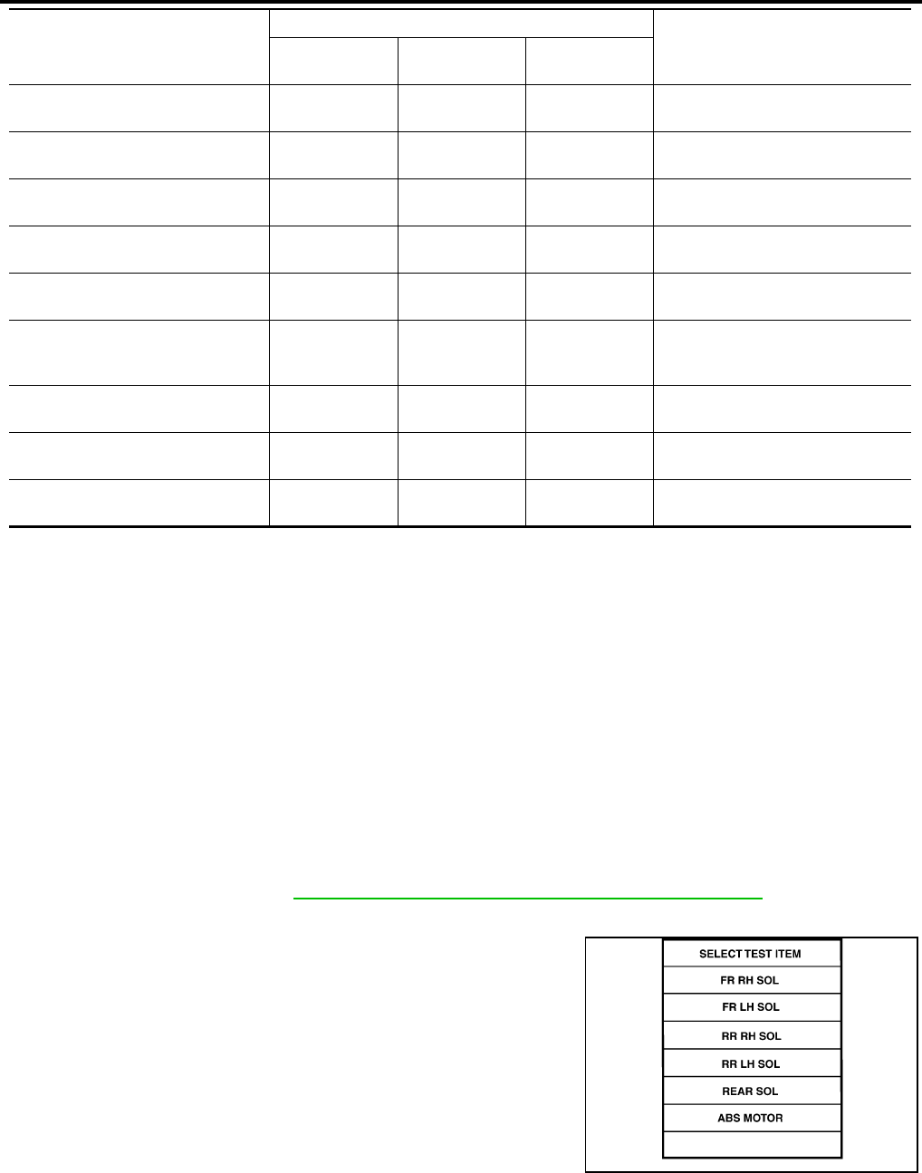
BRC-184
[HDC/HSA/VDC/TCS/ABS]
TROUBLE DIAGNOSIS
Revision: February 2006 2005 Xterra
×: Applicable
–: Not applicable
ACTIVE TEST
CAUTION:
●Do not perform active test while driving.
●Make sure to completely bleed air from the brake system.
●The ABS and brake warning lamps turn on during the active test.
Operation Procedure
1. Connect the CONSULT-II and CONSULT-II CONVERTER to the data link connector and start the engine.
CAUTION:
If CONSULT-II is used with no connection of CONSULT-II CONVERTER, malfunctions might be
detected in self-diagnosis depending on control unit which carries out CAN communication.
2. Touch “START (NISSAN BASED VHCL) ” on the display screen.
3. Touch “ABS”.
If “ABS” is not indicated, go to GI-39, "CONSULT-II Data Link Connector (DLC) Circuit" .
4. Touch “ACTIVE TEST”.
5. The test item selection screen is displayed.
6. Touch necessary test item.
7. With the “MAIN SIGNALS” display selected, touch “START”.
8. The Active Test screen will be displayed, so conduct the following test.
HSA SIGNAL
(ON/OFF) ––×HSA operation (ON/OFF) status is
displayed.
STP LAMP ON RLY – – ×Stop lamp relay signal status is dis-
played
EBD WARN LAMP – – ×Brake warning lamp (ON/OFF) sta-
tus is displayed.
SLCT LVR POSI ×××
Shift position judged by PNP switch
signal.
R POSI SIG – – ×Shift position judged by PNP switch
signal.
2WD/4WD – – ×
It recognizes on software whether it
is 2WD and whether it is in 4WD
state.
PRESS SENSOR ×–×Brake pressure detected by pres-
sure sensor is displayed.
PRESS SEN 2 – – ×Brake pressure detected by pres-
sure sensor is displayed.
CRANKING SIG – – ×The input state of the key SW
START position signal is displayed.
Item
(Unit)
Data monitor item selection
Remarks
ECU INPUT
SIGNALS
MAIN
SIGNALS
SELECTION
FROM MENU
WFIA0349E
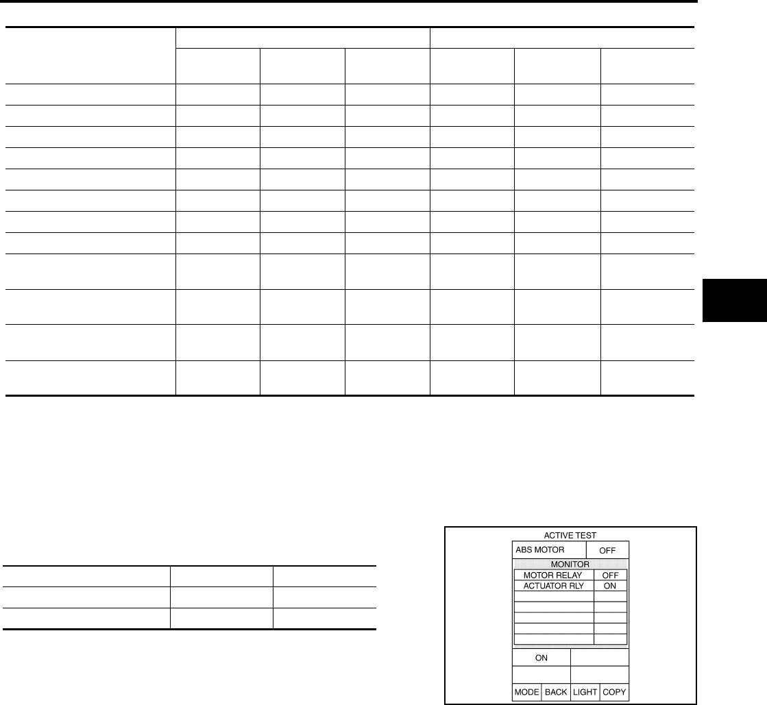
TROUBLE DIAGNOSIS
BRC-185
[HDC/HSA/VDC/TCS/ABS]
C
D
E
G
H
I
J
K
L
M
A
B
BRC
Revision: February 2006 2005 Xterra
Solenoid Valve Operation Chart
*: ON for 1 to 2 seconds after the touch, and then OFF
NOTE:
●If active test is performed with brake pedal depressed, pedal stroke may change. This is normal.
●“TEST IS STOPPED” is displayed approximately 10 seconds after operation starts.
●After “TEST IS STOPPED” is displayed, to perform test again, repeat Step 6.
ABS MOTOR
Touch “ON” and “OFF” on the screen. Check that ABS motor relay
operates as shown in table below.
NOTE:
●If active test is performed with brake pedal depressed, pedal
stroke may change. This is normal.
●“TEST IS STOPPED” is displayed approximately 10 seconds
after operation starts.
BOOSTER DRIVE
CAUTION:
Perform active test subject to the conditions below.
●Do not operate brake pedal during active test.
●Make sure the engine revolution is over 500 rpm.
●Make sure the vehicle is not moving.
Operation
ABS solenoid valve ABS solenoid valve (ACT)
UP KEEP DOWN UP ACTUATOR
UP
ACTUATOR
KEEP
FR RH IN SOL OFF ON ON OFF OFF OFF
FR RH OUT SOL OFF OFF ON* OFF OFF OFF
FR LH IN SOL OFF ON ON OFF OFF OFF
FR LH OUT SOL OFF OFF ON* OFF OFF OFF
RR RH IN SOL OFF ON ON OFF OFF OFF
RR RH OUT SOL OFF OFF ON* OFF OFF OFF
RR LH IN SOL OFF ON ON OFF OFF OFF
RR LH OUT SOL OFF OFF ON* OFF OFF OFF
Primary side VDC switch over
valve 1 (SV 1) OFF OFF OFF OFF ON* OFF
Primary side VDC switch over
valve 1 (CV 1) OFF OFF OFF OFF ON ON
Primary side VDC switch over
valve 2 (SV 1) OFF OFF OFF OFF ON* OFF
Primary side VDC switch over
valve 2 (CV 1) OFF OFF OFF OFF ON ON
Operation ON OFF
MOTOR RELAY ON OFF
ACTUATOR RELAY ON ON
SFIA0593E
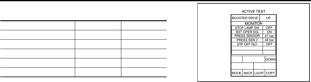
BRC-186
[HDC/HSA/VDC/TCS/ABS]
TROUBLE DIAGNOSIS
Revision: February 2006 2005 Xterra
Touch "UP" and "DOWN" on the screen. Check that booster drive
operates as shown in table below.
NOTE:
"TEST IS STOPPED" is displayed approximately 10 seconds after operation starts.
Operation UP DOWN
STOP LAMP SW ON OFF
BST OPER SIG ON OFF
PRESS SENSOR 50 ± 5 bar 0 bar
PRESS SEN 2 50 ± 5 bar 0 bar
STP OFF RLY OFF OFF
WFIA0350E

TROUBLE DIAGNOSIS FOR SELF-DIAGNOSTIC ITEMS
BRC-187
[HDC/HSA/VDC/TCS/ABS]
C
D
E
G
H
I
J
K
L
M
A
B
BRC
Revision: February 2006 2005 Xterra
TROUBLE DIAGNOSIS FOR SELF-DIAGNOSTIC ITEMS PFP:00000
Wheel Sensor System Inspection EFS005JN
INSPECTION PROCEDURE
1. CHECK TIRES
Check for inflation pressure, wear and size of each tire.
Are tire pressure and size correct and is tire wear within specifications?
YES >> GO TO 2.
NO >> Adjust tire pressure or replace tire(s).
2. CONNECTOR INSPECTION
Disconnect the ABS actuator and electric unit (control unit) connector E125 and wheel sensor of malfunction-
ing code.
Check the terminals for deformation, disconnection, looseness or damage.
OK or NG
OK >> GO TO 3.
NG >> Repair or replace as necessary.
3. CHECK SENSOR AND SENSOR ROTOR
●Check the cord of the sensor mount (for looseness, etc.)
●Check sensor rotors for damage (rear only)
●Check wheel bearing axial end play
OK or NG
OK >> GO TO 4.
NG >> Repair or replace as necessary.
4. CHECK WHEEL SENSOR OUTPUT SIGNAL
1. Connect ABS active wheel sensor tester (J-45741) to wheel sensor using appropriate adapter.
2. Turn on the ABS active wheel sensor tester power switch.
NOTE:
The green POWER indicator should illuminate. If the POWER indicator does not illuminate, replace the
battery in the ABS active wheel sensor tester before proceeding.
3. Spin the wheel of the vehicle by hand and observe the red SENSOR indicator on the ABS active wheel
sensor tester. The red SENSOR indicator should flash on and off to indicate an output signal.
NOTE:
If the red SENSOR indicator illuminates but does not flash, reverse the polarity of the tester leads and
retest.
Does the ABS active wheel sensor tester detect a signal?
YES >> GO TO 5.
NO >> Replace the wheel sensor. Refer to BRC-214, "Removal and Installation" .

BRC-188
[HDC/HSA/VDC/TCS/ABS]
TROUBLE DIAGNOSIS FOR SELF-DIAGNOSTIC ITEMS
Revision: February 2006 2005 Xterra
5. CHECK WIRING HARNESS FOR SHORT CIRCUIT
1. Disconnect ABS actuator and electric unit (control unit) connec-
tor and wheel sensor connector of malfunction code No.
2. Check resistance between wheel sensor harness connector ter-
minals and ground.
OK or NG
OK >> GO TO 6.
NG >> Repair the circuit.
6. CHECK WIRING HARNESS FOR OPEN CIRCUIT
Check continuity between ABS actuator and electric unit (control unit) harness connector E125 and the mal-
functioning wheel sensor harness connector E18, E117, C10 or C11.
OK or NG
OK >> Replace the ABS actuator and electric unit (control unit). Refer to BRC-216, "Removal and Instal-
lation" .
NG >> Repair the circuit.
Engine System Inspection EFS005JO
INSPECTION PROCEDURE
1. SELF-DIAGNOSIS RESULT CHECK
Check self-diagnosis results.
Is the above displayed in the self-diagnosis display items?
YES >> GO TO 2.
NO >> Inspection End.
Continuity should not exist.
WFIA0343E
Wheel sensor
ABS actuator and
electric unit (control unit) Wheel sensor Continuity
Connector Terminal Connector Terminal
Front LH
E125
45 E18 1
Yes
46 2
Front RH 34 E117 1
33 2
Rear LH 37 C11 2
36 1
Rear RH 42 C10 2
43 1
Continuity should exist.
Self-diagnosis results
ENGINE SIGNAL 1
ENGINE SIGNAL 2
ENGINE SIGNAL 3
ENGINE SIGNAL 4
ENGINE SIGNAL 6

TROUBLE DIAGNOSIS FOR SELF-DIAGNOSTIC ITEMS
BRC-189
[HDC/HSA/VDC/TCS/ABS]
C
D
E
G
H
I
J
K
L
M
A
B
BRC
Revision: February 2006 2005 Xterra
2. ENGINE SYSTEM INSPECTION
1. Perform ECM self-diagnosis and repair as necessary.
2. Perform ABS actuator and electric unit (control unit) self-diagnosis again.
OK or NG
OK >> Inspection End.
NG >> Repair or replace as necessary.
ABS/TCS/VDC Control Unit Inspection EFS005JP
INSPECTION PROCEDURE
1. SELF-DIAGNOSIS RESULT CHECK
Check self-diagnosis results.
Is the above displayed in the self-diagnosis display items?
YES >> Replace ABS actuator and electric unit (control unit). Refer to BRC-216, "Removal and Installa-
tion" .
NO >> Inspection End.
Steering Angle Sensor System EFS005JQ
INSPECTION PROCEDURE
1. CHECK SELF-DIAGNOSIS RESULT
Check self-diagnosis results.
Is above displayed in self-diagnosis item?
YES >> GO TO 2.
NO >> Inspection End.
2. CHECK CONNECTOR
1. Turn ignition switch OFF.
2. Disconnect steering angle sensor connector M47 and ABS actuator and electric unit (control unit) connec-
tor E125 and check terminals for deformation, disconnection, looseness, or damage. Repair or replace as
necessary.
3. Reconnect connectors and repeat ABS actuator and electric unit (control unit) self-diagnosis.
Is "ST ANGLE SEN CIRCUIT" or "ST ANG SEN COM CIR" displayed?
YES >> GO TO 3.
NO >> Inspection End.
Self-diagnosis results
CONTROLLER FAILURE
VARIANT CODING
Self-diagnosis results
ST ANGLE SEN CIRCUIT
ST ANG SEN COM CIR
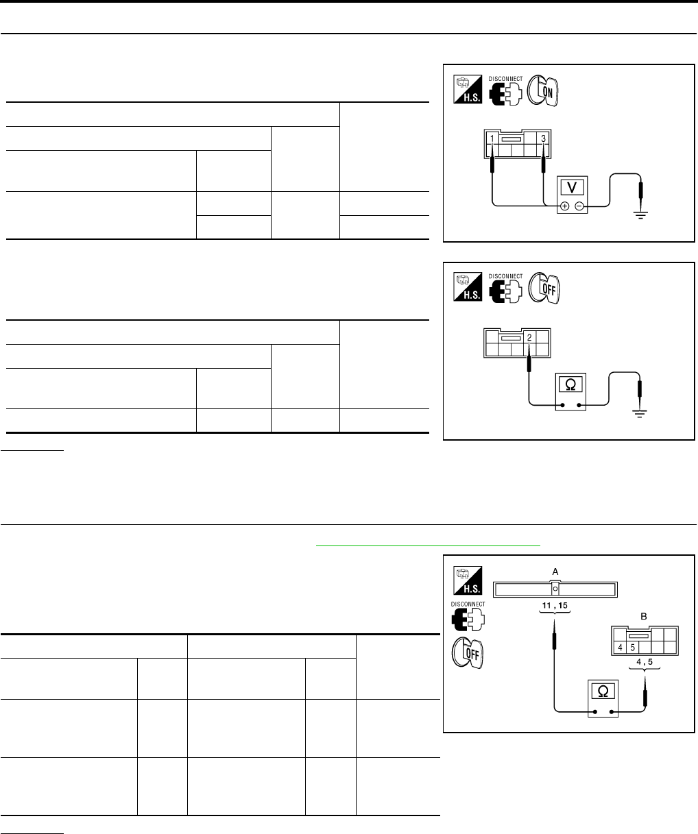
BRC-190
[HDC/HSA/VDC/TCS/ABS]
TROUBLE DIAGNOSIS FOR SELF-DIAGNOSTIC ITEMS
Revision: February 2006 2005 Xterra
3. CHECKING STEERING ANGLE SENSOR POWER AND GROUND
1. Turn ignition switch ON.
2. Check voltage between steering angle sensor harness connec-
tor M47 and body ground.
3. Turn ignition switch OFF.
4. Check resistance between steering angle sensor harness con-
nector M47 and body ground.
OK or NG
OK >> GO TO 4.
NG >> Repair the circuit.
4. CHECK STEERING ANGLE SENSOR HARNESS
1. Check CAN communication system. Refer to LAN-21, "CAN COMMUNICATION" .
2. Disconnect steering angle sensor connector M47 and ABS actu-
ator and electric unit (control unit) connector E125.
3. Check continuity between ABS actuator and electric unit (control
unit) connector E125 and steering angle sensor connector M47.
OK or NG
OK >> GO TO 5.
NG >> Repair or replace harness.
Terminals Measured
value
(Approx.)
(+)
(-)
Steering angle sensor
connector Terminal
M47 1Ground 12V
312V WFIA0398E
Terminals Measured
value Ω
(Approx.)
(+)
(-)
Steering angle sensor
connector Terminal
M47 2 Ground 0Ω
WFIA0399E
AB
Continuity
Connector Ter-
minal Connector Ter-
minal
ABS actuator and
electric unit (con-
trol unit): E125 11 Steering angle
sensor: M47 4Yes
ABS actuator and
electric unit (con-
trol unit): E125 15 Steering angle
sensor: M47 5Yes
WFIA0400E

TROUBLE DIAGNOSIS FOR SELF-DIAGNOSTIC ITEMS
BRC-191
[HDC/HSA/VDC/TCS/ABS]
C
D
E
G
H
I
J
K
L
M
A
B
BRC
Revision: February 2006 2005 Xterra
5. CHECK STEERING WHEEL PLAY
Check steering wheel play. Refer to PS-8, "CHECKING STEERING WHEEL PLAY" .
OK or NG
OK >> GO TO 6.
NG >> Adjust steering wheel play.
6. CHECK DATA MONITOR
1. Connect steering angle sensor and ABS actuator and electric unit (control unit) connectors.
2. Use “DATA MONITOR” to check if the status of "STR ANGLE SIG" is normal.
OK or NG
OK >> Perform ABS actuator and electric unit (control unit) self-diagnosis again.
NG >> Replace spiral cable (steering angle sensor) and adjust neutral position of steering angle sensor.
Refer to BRC-212, "Adjustment of Steering Angle Sensor Neutral Position" .
Yaw Rate/Side/Decel G Sensor System Inspection EFS005JR
CAUTION:
Sudden turns (such as spin turns, acceleration turns), drifting, etc. when VDC function is OFF may
cause the yaw rate/side/decel G sensor system to indicate a problem. This is not a problem if normal
operation can be resumed after restarting the engine.
INSPECTION PROCEDURE
1. SELF-DIAGNOSIS RESULT CHECK
Check self-diagnosis results.
CAUTION:
If vehicle is on turntable at entrance to parking garage, or on other moving surface, VDC OFF indicator
lamp may illuminate and CONSULT-II self-diagnosis may indicate yaw rate sensor system malfunction.
However, in this case there is no malfunction in yaw rate sensor system. Take vehicle off of turntable
or other moving surface, and start engine. Results will return to normal.
Is the above displayed in the self-diagnosis display items?
YES >> GO TO 2.
NO >> Inspection End.
2. CONNECTOR INSPECTION
Disconnect the ABS actuator and electric unit (control unit) connector E125 and yaw rate/side/decel G sensor
connector B73.
Check the terminals for deformation, disconnection, looseness or damage.
OK or NG
OK >> GO TO 3.
NG >> Repair or replace as necessary.
Steering condition Data monitor
Straight-ahead –3.5 deg to +3.5 deg
Turn wheel to the right by 90°Approx. - 90deg
Turn wheel to the left by 90°Approx. + 90deg
Self-diagnosis results
YAW RATE SENSOR
SIDE G-SEN CIRCUIT
G-SENSOR

BRC-192
[HDC/HSA/VDC/TCS/ABS]
TROUBLE DIAGNOSIS FOR SELF-DIAGNOSTIC ITEMS
Revision: February 2006 2005 Xterra
3. YAW RATE/SIDE/DECEL G SENSOR HARNESS INSPECTION
1. Turn off the ignition switch and disconnect yaw rate/side/decel G sensor connector B73 and ABS actuator
and electric unit (control unit) connector E125.
2. Check continuity between the ABS actuator and electric unit (control unit) connector E125 and the yaw
rate/side/decel G sensor connector B73.
OK or NG
OK >> GO TO 4.
NG >> Repair or replace as necessary.
4. YAW RATE/SIDE/DECEL G SENSOR INSPECTION
1. Connect the yaw rate/side/decel G sensor connector B73 and ABS actuator and electric unit (control unit)
connector E125.
2. Use “DATA MONITOR” to check if the yaw rate/side/decel G sensor signals are normal.
OK or NG
OK >> Inspection End.
NG >> Replace the yaw rate/side/decel G sensor. Refer to BRC-219, "Removal and Installation" .
ABS actuator and electric unit
(control unit) harness connector
E125
Yaw rate/side/decel G sensor
harness connector B73 Continuity
63
Yes
24 5
25 1
29 2
Vehicle status Yaw rate sensor
(Data monitor standard) Side G sensor
(Data monitor standard) Decel G Sensor
(Data monitor standard)
When stopped -4 to +4 deg/s -1.1 to +1.1 m/s -0.08 G to +0.08 G
Right turn Negative value Negative value -
Left turn Positive value Positive value -
Speed up - - Negative value
Speed down - - Positive value

TROUBLE DIAGNOSIS FOR SELF-DIAGNOSTIC ITEMS
BRC-193
[HDC/HSA/VDC/TCS/ABS]
C
D
E
G
H
I
J
K
L
M
A
B
BRC
Revision: February 2006 2005 Xterra
Solenoid and VDC Change-Over Valve System Inspection EFS005JS
INSPECTION PROCEDURE
1. SELF-DIAGNOSIS RESULT CHECK
Check self-diagnosis results.
Is the above displayed in the self-diagnosis display items?
YES >> GO TO 2.
NO >> Inspection End.
2. CONNECTOR INSPECTION
1. Disconnect ABS actuator and electric unit (control unit) connector E125.
2. Check the terminals for deformation, disconnection, looseness or damage.
OK or NG
OK >> GO TO 3.
NG >> Repair or replace as necessary.
Self-diagnosis results
FR LH IN ABS SOL
FR LH OUT ABS SOL
RR RH IN ABS SOL
RR RH OUT ABS SOL
FR RH IN ABS SOL
FR RH OUT ABS SOL
RR LH IN ABS SOL
RR LH OUT ABS SOL
CV 1
CV 2
SV 1
SV 2
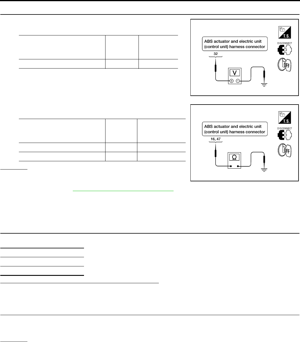
BRC-194
[HDC/HSA/VDC/TCS/ABS]
TROUBLE DIAGNOSIS FOR SELF-DIAGNOSTIC ITEMS
Revision: February 2006 2005 Xterra
3. CHECKING SOLENOID POWER AND GROUND
1. Check voltage between ABS actuator and electric unit (control
unit) harness connector E125 and body ground.
2. Check resistance between ABS actuator and electric unit (con-
trol unit) harness connector E125 and body ground.
OK or NG
OK >> Perform self-diagnosis again. If the same results
appear, replace ABS actuator and electric unit (control
unit). Refer to BRC-216, "Removal and Installation" .
NG >> Repair the circuit.
Actuator Motor, Motor Relay, and Circuit Inspection EFS005JT
INSPECTION PROCEDURE
1. CHECKING SELF-DIAGNOSIS RESULTS
Check self-diagnosis results.
Is the above displayed in the self-diagnosis display items?
YES >> GO TO 2.
NO >> Inspection End.
2. CONNECTOR INSPECTION
1. Disconnect ABS actuator and electric unit (control unit) connector E125.
2. Check the terminals for deformation, disconnection, looseness or damage.
OK or NG
OK >> GO TO 3.
NG >> Repair or replace as necessary.
ABS actuator and electric
unit (control unit)
harness connector E125
Body
ground
Measured
value
(Approx.)
32 — 12V
WFIA0195E
ABS actuator and electric
unit (control unit)
harness connector E125
Body
ground
Measured
value Ω
(Approx.)
16 — 0Ω
47 — 0Ω
WFIA0196E
Self-diagnosis results
PUMP MOTOR
ACTUATOR RLY
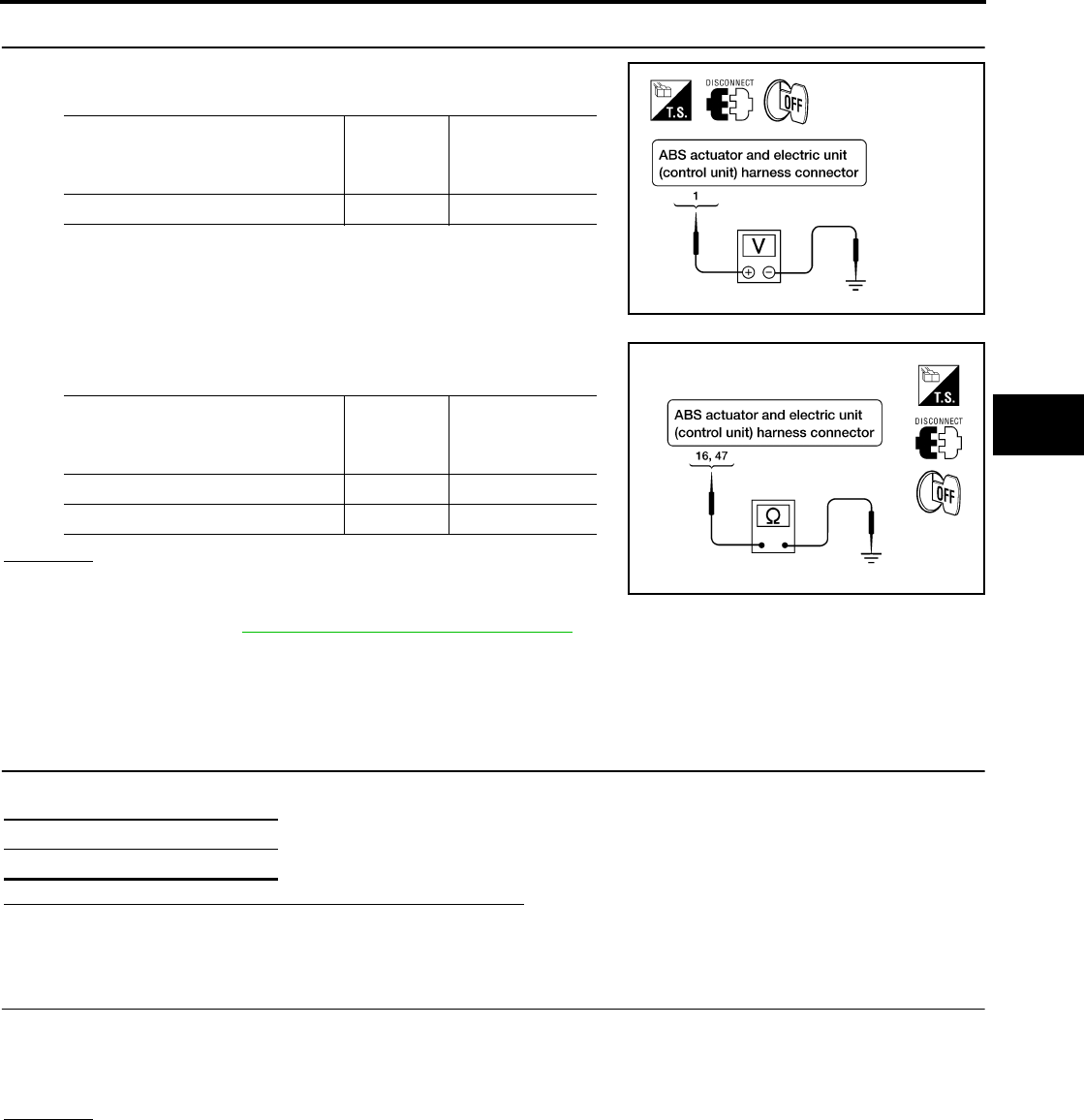
TROUBLE DIAGNOSIS FOR SELF-DIAGNOSTIC ITEMS
BRC-195
[HDC/HSA/VDC/TCS/ABS]
C
D
E
G
H
I
J
K
L
M
A
B
BRC
Revision: February 2006 2005 Xterra
3. CHECKING ABS MOTOR AND MOTOR RELAY POWER SYSTEM
1. Check voltage between ABS actuator and electric unit (control
unit) harness connector E125 and body ground.
2. Check resistance between ABS actuator and electric unit (con-
trol unit) connector E125 and body ground.
OK or NG
OK >> Perform self-diagnosis again. If the same results
appear, replace ABS actuator and electric unit (control
unit). Refer to BRC-216, "Removal and Installation" .
NG >> Repair the circuit.
Stop Lamp Switch System Inspection EFS005JU
INSPECTION PROCEDURE
1. SELF-DIAGNOSIS RESULT CHECK
Check self-diagnosis results.
Is the above displayed in the self-diagnosis display items?
YES >> GO TO 2.
NO >> Inspection End.
2. CONNECTOR INSPECTION
1. Disconnect the ABS actuator and electric unit (control unit) connector E125 and stop lamp switch connec-
tor E38.
2. Check the terminals for deformation, disconnection, looseness or damage.
OK or NG
OK >> GO TO 3.
NG >> Repair or replace as necessary.
ABS actuator and electric
unit (control unit)
harness connector E125
Body
ground
Measured
value
(Approx.)
1—12V
WFIA0209E
ABS actuator and electric
unit (control unit)
harness connector E125
Body
ground
Measured
value Ω
(Approx.)
16 — 0Ω
47 — 0Ω
WFIA0196E
Self-diagnosis results
STOP LAMP SW
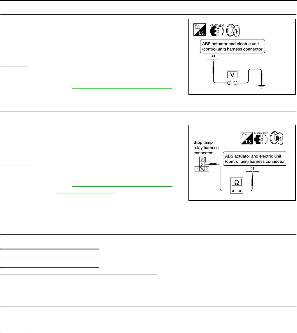
BRC-196
[HDC/HSA/VDC/TCS/ABS]
TROUBLE DIAGNOSIS FOR SELF-DIAGNOSTIC ITEMS
Revision: February 2006 2005 Xterra
3. STOP LAMP SWITCH INSPECTION
Check the voltage between the ABS actuator and electric unit (con-
trol unit) harness connector E125 terminal 41 and body ground.
OK or NG
OK >> Perform self-diagnosis again. If the same results
appear, replace ABS actuator and electric unit (control
unit). Refer to BRC-216, "Removal and Installation" .
NG >> GO TO 4.
4. STOP LAMP RELAY CIRCUIT INSPECTION
1. Disconnect the stop lamp relay harness connector E12.
2. Check the continuity between the ABS actuator and electric unit
(control unit) harness connector E125 terminal 41 and stop lamp
relay harness connector E12 terminal 5.
OK or NG
OK >> Perform self-diagnosis again. If the same results
appear, replace ABS actuator and electric unit (control
unit). Refer to BRC-216, "Removal and Installation" .
NG >> Refer to LT-81, "STOP LAMP" .
ABS/TCS/VDC Control Unit Power and Ground Systems Inspection EFS005JV
INSPECTION PROCEDURE
1. SELF-DIAGNOSIS RESULT CHECK
Check self-diagnosis results.
Is the above displayed in the self-diagnosis display items?
YES >> GO TO 2.
NO >> Inspection End.
2. CONNECTOR INSPECTION
1. Disconnect the ABS actuator and electric unit (control unit) connector E125.
2. Check the terminals for deformation, disconnection, looseness or damage.
OK or NG
OK >> GO TO 3.
NG >> Repair or replace as necessary.
Brake pedal depressed : Battery voltage
(approx. 12V)
Brake pedal not depressed : Approx. 0V
WFIA0198E
Continuity should exist.
WFIA0325E
Self-diagnosis results
BATTERY VOLTAGE
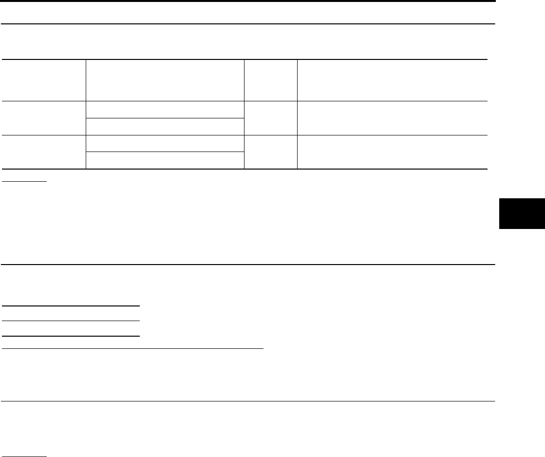
TROUBLE DIAGNOSIS FOR SELF-DIAGNOSTIC ITEMS
BRC-197
[HDC/HSA/VDC/TCS/ABS]
C
D
E
G
H
I
J
K
L
M
A
B
BRC
Revision: February 2006 2005 Xterra
3. ABS/TCS/VDC CONTROL UNIT POWER AND GROUND CIRCUIT INSPECTION
Measure the voltage and continuity between the ABS actuator and electric unit (control unit) harness connec-
tor E125 and body ground.
OK or NG
OK >> Check the battery for loose terminals, low voltage, etc. Repair as necessary.
NG >> Repair the circuit.
Brake Fluid Level Sensor System Inspection EFS005JW
INSPECTION PROCEDURE
1. SELF-DIAGNOSIS RESULT CHECK
1. Check the brake reservoir tank fluid level. If the level is low, add brake fluid.
2. Erase the self-diagnosis results and check the self-diagnosis results.
Is the above displayed in the self-diagnosis display items?
YES >> GO TO 2.
NO >> Inspection End.
2. CONNECTOR INSPECTION
1. Disconnect the ABS actuator and electric unit (control unit) connector E125 and brake fluid level switch
connector E21.
2. Check the terminals for deformation, disconnection, looseness or damage.
OK or NG
OK >> GO TO 3.
NG >> Repair or replace as necessary.
Signal name ABS actuator and electric unit
(control unit)
harness connector E125
Body
ground Measured value
Power supply 1— Battery voltage (Approx. 12V)
32
Ground 16 — Continuity should exist.
47
Self-diagnosis results
BR FLUID LEVEL LOW

BRC-198
[HDC/HSA/VDC/TCS/ABS]
TROUBLE DIAGNOSIS FOR SELF-DIAGNOSTIC ITEMS
Revision: February 2006 2005 Xterra
3. CHECK THE HARNESS BETWEEN THE BRAKE FLUID LEVEL SENSOR AND THE ABS ACTUATOR
AND ELECTRIC UNIT (CONTROL UNIT)
Check the continuity between the brake fluid level switch harness connector E21 and the ABS actuator and
electric unit (control unit) harness connector E125.
OK or NG
OK >> Perform self-diagnosis again. If the same results appear, replace ABS actuator and electric unit
(control unit). Refer to BRC-216, "Removal and Installation" .
NG >> Repair the circuit.
Active Booster System Inspection EFS005JX
INSPECTION PROCEDURE
1. DISPLAY SELF DIAGNOSIS RESULTS
Check self-diagnosis result display item.
Is the self-diagnosis result display item shown above displayed?
YES >> GO TO 2.
NO >> Inspection End.
2. CONNECTOR INSPECTION
1. Turn the ignition switch OFF.
2. Disconnect the active booster connector E49 and ABS actuator and electric unit (control unit) connector
E125 and inspect the terminals for deformation, disconnection, looseness, or damage.
OK or NG
OK >> GO TO 3.
NG >> Repair connector.
ABS actuator and electric unit
(control unit) harness connector
E125
Brake fluid level switch harness
connector E21 Continuity
81Yes
8GroundNo
Ground 2 Yes
Self-diagnosis results
ABS ACTIVE BOOSTER SV NG
ABS ACTIVE BOOSTER RESPONSE NG
ABS BRAKE RELEASE SW NG
ABS BRAKE BOOSTER DEFECT
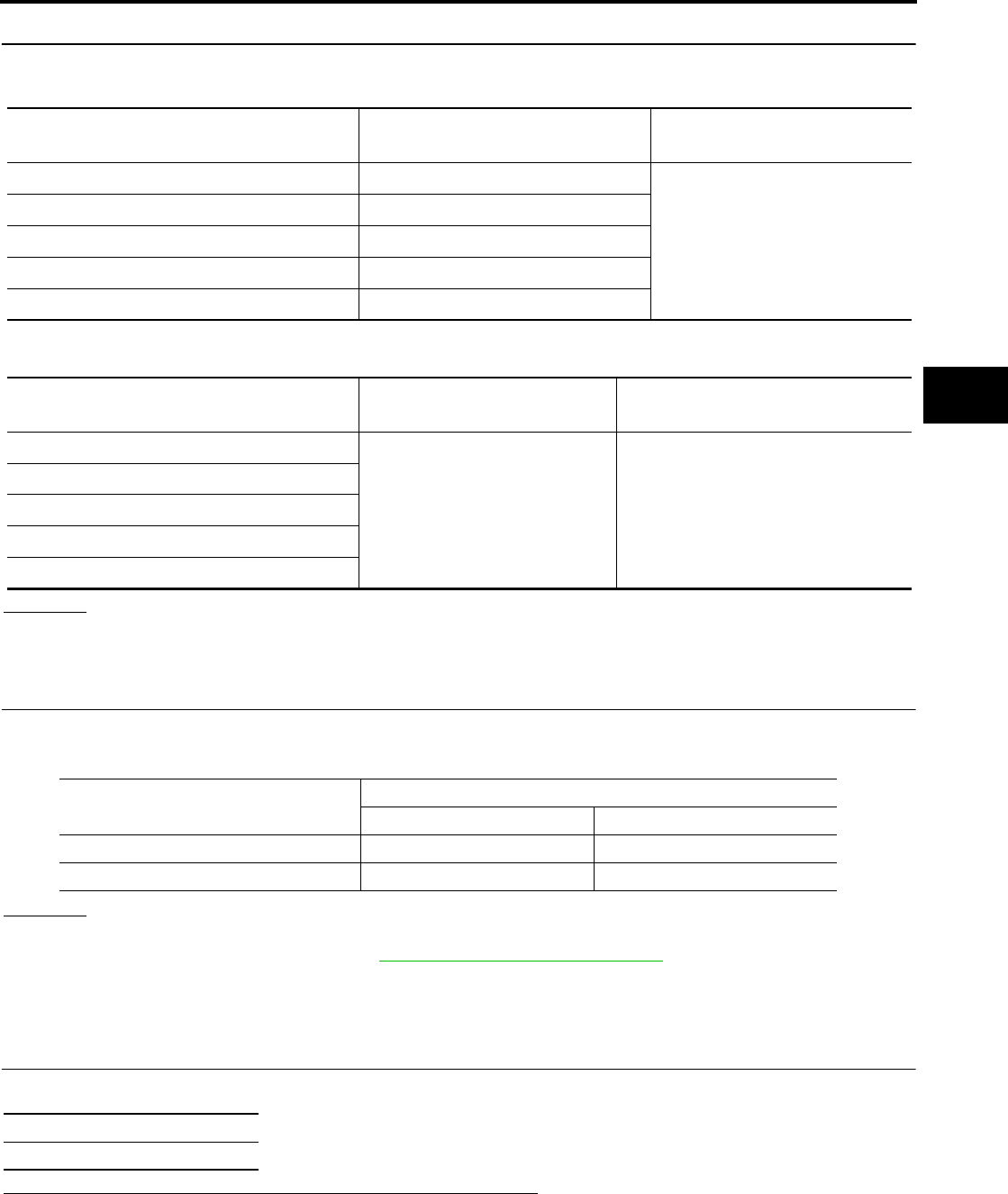
TROUBLE DIAGNOSIS FOR SELF-DIAGNOSTIC ITEMS
BRC-199
[HDC/HSA/VDC/TCS/ABS]
C
D
E
G
H
I
J
K
L
M
A
B
BRC
Revision: February 2006 2005 Xterra
3. ACTIVE BOOSTER CIRCUIT INSPECTION
1. Measure the continuity between the ABS actuator and electric unit (control unit) harness connector E125
and active booster harness connector E49.
2. Measure the continuity between the ABS actuator and electric unit (control unit) harness connector E125
and body ground.
OK or NG
OK >> GO TO 4.
NG >> Repair or replace harness or connector.
4. ACTIVE BOOSTER SENSOR INSPECTION
1. Reconnect the active booster and ABS actuator and electric unit (control unit) connectors.
2. Use "DATA MONITOR" to check if the status of "RELEASE SW NO" and "RELEASE SW NC" is normal.
OK or NG
OK >> Inspection End.
NG >> Replace active booster. Refer to BR-17, "Removal and Installation" .
Pressure Sensor System Inspection EFS005JY
FRONT PRESSURE INSPECTION PROCEDURE
1. DISPLAY SELF DIAGNOSIS RESULTS
Check self-diagnosis result display item.
Is the self-diagnosis result display item shown above displayed?
YES >> GO TO 2.
NO >> Inspection End.
ABS actuator and electric unit (con-
trol unit) harness connector E125 Active booster harness con-
nector E49 Continuity
17 3
Yes
27 1
28 5
30 2
31 4
ABS actuator and electric unit (con-
trol unit) harness connector E125 Body ground Continuity
17
—No
27
28
30
31
Condition Data monitor display
RELEASE SW NO RELEASE SW NC
When brake pedal is depressed ON OFF
When brake pedal is released OFF ON
Self-diagnosis results
PRESS SEN CIRCUIT

BRC-200
[HDC/HSA/VDC/TCS/ABS]
TROUBLE DIAGNOSIS FOR SELF-DIAGNOSTIC ITEMS
Revision: February 2006 2005 Xterra
2. CONNECTOR INSPECTION
1. Turn the ignition switch OFF.
2. Disconnect the front pressure sensor connector E31 and ABS actuator and electric unit (control unit) con-
nector E125 and inspect the terminals for deformation, disconnection, looseness, or damage.
OK or NG
OK >> GO TO 3.
NG >> Repair connector.
3. FRONT PRESSURE SENSOR CIRCUIT INSPECTION
1. Measure the continuity between the ABS actuator and electric unit (control unit) harness connector E125
and front pressure sensor harness connector E31.
2. Measure the continuity between the ABS actuator and electric unit (control unit) harness connector E125
and body ground.
OK or NG
OK >> GO TO 4.
NG >> Repair or replace harness or connector.
4. FRONT PRESSURE SENSOR INSPECTION
1. Reconnect the front pressure sensor and ABS actuator and electric unit (control unit) connectors.
2. Use "DATA MONITOR" to check if the status of "PRESS SENSOR" is normal.
OK or NG
OK >> Inspection End.
NG >> Replace front pressure sensor.
REAR PRESSURE INSPECTION PROCEDURE
1. DISPLAY SELF DIAGNOSIS RESULTS
Check self-diagnosis result display item.
Is the self-diagnosis result display item shown above displayed?
YES >> GO TO 2.
NO >> Inspection End.
ABS actuator and electric unit (control
unit) harness connector E125 Front pressure sensor harness
connector E31 Continuity
18 3
Yes19 1
20 2
ABS actuator and electric unit (control
unit) harness connector E125 Body ground Continuity
18
—No19
20
Condition Data monitor display (Approx.)
PRESS SENSOR
When brake pedal is depressed Positive value
When brake pedal is released 0 bar
Self-diagnosis results
PRESS SEN CIRCUIT

TROUBLE DIAGNOSIS FOR SELF-DIAGNOSTIC ITEMS
BRC-201
[HDC/HSA/VDC/TCS/ABS]
C
D
E
G
H
I
J
K
L
M
A
B
BRC
Revision: February 2006 2005 Xterra
2. CONNECTOR INSPECTION
1. Turn the ignition switch OFF.
2. Disconnect the rear pressure sensor connector E32 and ABS actuator and electric unit (control unit) con-
nector E125 and inspect the terminals for deformation, disconnection, looseness, or damage.
OK or NG
OK >> GO TO 3.
NG >> Repair connector.
3. REAR PRESSURE SENSOR CIRCUIT INSPECTION
1. Measure the continuity between the ABS actuator and electric unit (control unit) harness connector E125
and rear pressure sensor harness connector E32.
2. Measure the continuity between the ABS actuator and electric unit (control unit) harness connector E125
and body ground.
OK or NG
OK >> GO TO 4.
NG >> Repair or replace harness or connector.
4. REAR PRESSURE SENSOR INSPECTION
1. Reconnect the rear pressure sensor and ABS actuator and electric unit (control unit) connectors.
2. Use "DATA MONITOR" to check if the status of "PRESS SEN 2" is normal.
OK or NG
OK >> Inspection End.
NG >> Replace rear pressure sensor.
ABS actuator and electric unit (con-
trol unit) harness connector E125 Rear pressure sensor harness
connector E32 Continuity
21 1
Yes22 3
23 2
ABS actuator and electric unit (con-
trol unit) harness connector E125 Body ground Continuity
21
—No22
23
Condition Data monitor display (Approx.)
PRESS SEN 2
When brake pedal is depressed Positive value
When brake pedal is released 0 bar

BRC-202
[HDC/HSA/VDC/TCS/ABS]
TROUBLE DIAGNOSIS FOR SELF-DIAGNOSTIC ITEMS
Revision: February 2006 2005 Xterra
Steering Angle Sensor Safe Mode Inspection EFS005JZ
INSPECTION PROCEDURE
1. INDICATOR LAMP CHECK
Check that VDC OFF indicator lamp is on.
OK or NG
OK >> GO TO 2.
NG >> GO TO 3.
2. ADJUSTMENT OF STEERING ANGLE SENSOR NEUTRAL POSITION
Adjust steering angle sensor neutral position. Refer to BRC-212, "Adjustment of Steering Angle Sensor Neu-
tral Position" .
OK or NG
OK >> GO TO 3.
NG >> Check steering angle sensor. Refer to BRC-189, "Steering Angle Sensor System" .
3. INDICATOR LAMP CHECK
Check that VDC OFF indicator lamp is off.
OK or NG
OK >> GO TO 4.
NG >> Perform basic inspection. Refer to BRC-171, "Basic Inspection" .
4. CHECK SELF-DIAGNOSTIC RESULTS
Perform ABS actuator and electric unit (control unit) self-diagnosis.
NOTE:
When self-diagnostic results show items other than those above, perform repair or replacement for the item
indicated and repeat self-diagnosis.
Is the above displayed on self-diagnosis display?
YES >> Erase error memory.
NO >> Inspection End.
CAN Communication System Inspection EFS005K0
INSPECTION PROCEDURE
1. CHECK CONNECTOR
1. Turn ignition switch OFF, disconnect the ABS actuator and electric unit (control unit) connector, and check
the terminals for deformation, disconnection, looseness, and so on. If there is a malfunction, repair or
replace the terminal.
2. Reconnect connector to perform self-diagnosis.
Is "CAN COMM CIRCUIT" displayed in self-diagnosis display items?
YES >> Print out the self-diagnostic results, and refer to LAN-21, "CAN COMMUNICATION" .
NO >> Connector terminal is loose, damaged, open, or shorted.
Self-diagnosis results
ST ANGL SEN SAFE

TROUBLE DIAGNOSIS FOR SELF-DIAGNOSTIC ITEMS
BRC-203
[HDC/HSA/VDC/TCS/ABS]
C
D
E
G
H
I
J
K
L
M
A
B
BRC
Revision: February 2006 2005 Xterra
Inspection For Self-diagnosis Result "ST ANGLE SEN SIGNAL" EFS005K1
INSPECTION PROCEDURE
1. PERFORM SELF-DIAGNOSIS
Perform ABS actuator and electric unit (control unit) self-diagnosis.
Do self-diagnosis results indicate anything other than shown above?
YES >> Perform repair or replacement for the item indicated.
NO >> Perform adjustment of steering angle sensor neutral position. Refer to BRC-212, "Adjustment of
Steering Angle Sensor Neutral Position" . GO TO 2.
2. PERFORM SELF-DIAGNOSIS AGAIN
1. Turn the ignition switch to OFF and then to ON and erase self-diagnosis results.
2. Perform ABS actuator and electric unit (control unit) self-diagnosis again.
Are any self-diagnosis results displayed?
YES >> Replace steering angle sensor. Refer to BRC-218, "Removal and Installation" .
NO >> Inspection End.
Inspection For Self-diagnosis Result "DECEL G SEN SET" EFS005K2
INSPECTION PROCEDURE
1. PERFORM SELF-DIAGNOSIS
Perform ABS actuator and electric unit (control unit) self-diagnosis.
Do self-diagnosis results indicate anything other than shown above?
YES >> Perform repair or replacement for the item indicated.
NO >> Perform calibration of decel G sensor. Refer to BRC-212, "Calibration of Decel G Sensor" . GO
TO 2.
2. PERFORM SELF-DIAGNOSIS AGAIN
1. Turn the ignition switch to OFF and then to ON and erase self-diagnosis results.
2. Perform ABS actuator and electric unit (control unit) self-diagnosis again.
Are any self-diagnosis results displayed?
YES >> Replace decel G sensor. Refer to BRC-219, "Removal and Installation" .
NO >> Inspection End.
VDC OFF Indicator lamp Does Not Illuminate EFS005K3
INSPECTION PROCEDURE
1. CHECK VDC OFF INDICATOR LAMP
Disconnect ABS actuator and electric unit (control unit) connector E125.
Do the ABS warning lamp and VDC OFF indicator lamp illuminate?
YES >> Replace ABS actuator and electric unit (control unit). Refer to BRC-216, "Removal and Installa-
tion" .
NO >> Replace combination meter. Refer to IP-12, "COMBINATION METER" .
Self-diagnosis results
ST ANGLE SEN SIGNAL
Self-diagnosis results
DECEL G SEN SET
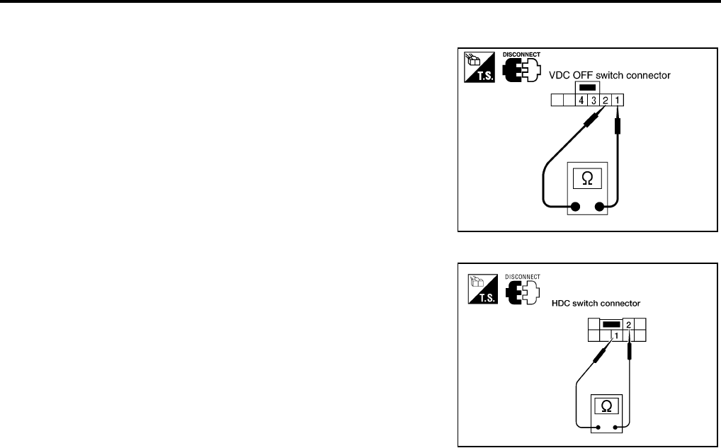
BRC-204
[HDC/HSA/VDC/TCS/ABS]
TROUBLE DIAGNOSIS FOR SELF-DIAGNOSTIC ITEMS
Revision: February 2006 2005 Xterra
Component Inspection EFS005K4
VDC OFF SWITCH
Check the continuity between terminals 1 and 2.
HDS SWITCH
Check the continuity between terminals 1 and 2.
1 - 2 : Continuity should exist when pushing the
switch.
Continuity should not exist when releasing
the switch.
PFIA0307E
1 - 2 : Continuity should exist when pushing the
switch.
Continuity should not exist when releasing
the switch.
WFIA0327E

TROUBLE DIAGNOSES FOR SYMPTOMS
BRC-205
[HDC/HSA/VDC/TCS/ABS]
C
D
E
G
H
I
J
K
L
M
A
B
BRC
Revision: February 2006 2005 Xterra
TROUBLE DIAGNOSES FOR SYMPTOMS PFP:99999
ABS Works Frequently EFS005K5
1. CHECK WARNING LAMP ACTIVATION
Make sure warning lamp remains off while driving.
OK or NG
OK >> GO TO 2.
NG >> Carry out self-diagnosis. Refer to BRC-178, "SELF-DIAGNOSIS" .
2. CHECK WHEEL SENSORS
Check the following.
●Wheel sensor mounting for looseness
●Wheel sensors for physical damage
●Wheel sensor connectors for terminal damage or loose connections
OK or NG
OK >> GO TO 3.
NG >> Repair or replace as necessary.
3. CHECK FRONT AND REAR AXLES
Check front and rear axles for excessive looseness. Refer to FAX-5, "WHEEL BEARING INSPECTION" ,
RAX-6, "Rear Axle Bearing" (C200) or RAX-18, "Rear Axle Bearing" (M226).
OK or NG
OK >> GO TO 4.
NG >> Repair as necessary.
4. CHECK BRAKE FLUID PRESSURE
Check brake fluid pressure distribution.
Refer to BRC-171, "Basic Inspection" .
Is brake fluid pressure distribution normal?
YES >> Inspection End.
NO >> Perform Basic Inspection. Refer to BRC-171, "Basic Inspection" .
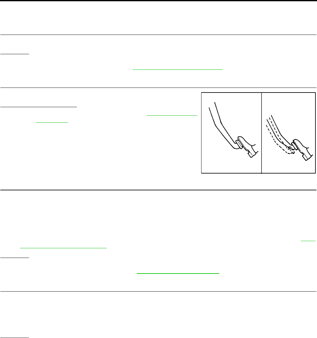
BRC-206
[HDC/HSA/VDC/TCS/ABS]
TROUBLE DIAGNOSES FOR SYMPTOMS
Revision: February 2006 2005 Xterra
Unexpected Pedal Action EFS005K6
1. CHECK WARNING LAMP ACTIVATION
Make sure warning lamp remains off while driving.
OK or NG
OK >> GO TO 2.
NG >> Carry out self-diagnosis. Refer to BRC-178, "SELF-DIAGNOSIS" .
2. CHECK BRAKE PEDAL STROKE
Check brake pedal stroke.
Is pedal stroke excessive?
YES >> Perform Basic Inspection. Refer to BRC-171, "Basic
Inspection" .
NO >> GO TO 3.
3. CHECK CONNECTOR AND BRAKING PERFORMANCE
1. Disable ABS by disconnecting ABS actuator and electric unit (control unit) connector.
2. Drive vehicle and check brake operation.
NOTE:
●Stopping distance may be longer than vehicles without ABS when road condition is slippery.
●Driving the vehicle with the ABS actuator and electric unit (control unit) disconnected may induce DTCs
in electrical control units using CAN communication. After the inspection, clear all DTCs. Refer to LAN-
21, "CAN COMMUNICATION" .
OK or NG
OK >> GO TO 4.
NG >> Perform Basic Inspection. Refer to BRC-171, "Basic Inspection" .
4. CHECK WHEEL SENSORS
Check the following.
●Wheel sensor mounting for looseness
●Wheel sensors for physical damage
●Wheel sensor connectors for terminal damage or loose connections
OK or NG
OK >> Check ABS actuator and electric unit (control unit) connector terminals for deformation, discon-
nection, looseness or damage. Reconnect ABS actuator and electric unit (control unit) harness
connector. Then retest.
NG >> Repair or replace as necessary.
SBR540A

TROUBLE DIAGNOSES FOR SYMPTOMS
BRC-207
[HDC/HSA/VDC/TCS/ABS]
C
D
E
G
H
I
J
K
L
M
A
B
BRC
Revision: February 2006 2005 Xterra
Long Stopping Distance EFS005K7
1. CHECK BASE BRAKING SYSTEM PERFORMANCE
1. Disable ABS by disconnecting ABS actuator and electric unit (control unit) connector.
2. Drive vehicle and check brake operation.
NOTE:
●Stopping distance may be longer than vehicles without ABS when road condition is slippery.
●Driving the vehicle with the ABS actuator and electric unit (control unit) disconnected may induce DTCs
in electrical control units using CAN communication. After the inspection, clear all DTCs. Refer to LAN-
21, "CAN COMMUNICATION" .
OK or NG
OK >> Go to BRC-205, "ABS Works Frequently" .
NG >> Perform Basic Inspection. Refer to BRC-171, "Basic Inspection" .
ABS Does Not Work EFS005K8
CAUTION:
The ABS does not operate when the vehicle speed is 10 km/h (6 MPH) or less.
1. CHECK WARNING LAMP ACTIVATION
Turn ignition switch ON and check for warning lamp activation.
●Warning lamp should activate for approximately 2 seconds after turning the ignition switch ON.
OK or NG
OK >> Carry out self-diagnosis. Refer to BRC-178, "SELF-DIAGNOSIS" .
NG >> Go to BRC-208, "ABS Warning Lamp Does Not Come On When Ignition Switch Is Turned On" .
Pedal Vibration or ABS Operation Noise EFS005K9
NOTE:
During ABS activation, pedal vibration may be felt and a noise may be heard. This is normal and does not indi-
cate a malfunction.
1. CHECK SYMPTOM
1. Apply brake.
2. Start engine.
Does the symptom occur only when engine is started?
YES >> Carry out self-diagnosis. Refer to BRC-178, "SELF-DIAGNOSIS" .
NO >> GO TO 2.
2. RECHECK SYMPTOM
Does the symptom occur only when electrical equipment switches (such as headlamps) are turned on?
YES >> Check for radio, antenna or related wiring that is routed too close to the ABS actuator and electric
unit (control unit) and reroute as necessary.
NO >> Go to BRC-205, "ABS Works Frequently" .

BRC-208
[HDC/HSA/VDC/TCS/ABS]
TROUBLE DIAGNOSES FOR SYMPTOMS
Revision: February 2006 2005 Xterra
ABS Warning Lamp Does Not Come On When Ignition Switch Is Turned On EFS005KA
1. CHECK ABS ACTUATOR AND ELECTRIC UNIT (CONTROL UNIT) FUSES
Check 30A fusible link n and 40A fusible link l for ABS actuator and electric unit (control unit). For fusible link
layout, refer to PG-4, "POWER SUPPLY ROUTING CIRCUIT" .
OK or NG
OK >> GO TO 2.
NG >> If fusible link is blown, be sure to eliminate cause of problem before replacing.
2. CHECK ABS ACTUATOR AND ELECTRIC UNIT (CONTROL UNIT) POWER SUPPLY CIRCUITS
1. Disconnect ABS actuator and electric unit (control unit) connec-
tor.
2. Check voltage between ABS actuator and electric unit (control
unit) connector terminal 1 and ground and terminal 32 and
ground.
Does battery voltage exist?
YES >> GO TO 3.
NO >> Repair harness or connectors between fusible link and
ABS actuator and electric unit (control unit).
3. CHECK ABS ACTUATOR AND ELECTRIC UNIT (CONTROL UNIT) GROUND CIRCUIT
Check continuity between ABS actuator and electric unit (control
unit) connector terminal 16 and ground and terminal 47 and ground.
Does continuity exist?
YES >> Replace ABS actuator and electric unit (control unit).
Refer to BRC-216, "Removal and Installation" .
NO >> Repair harness or connectors between ABS actuator
and electric unit (control unit) and ground.
ABS Warning Lamp Stays On When Ignition Switch Is Turned On EFS005KB
1. CARRY OUT SELF-DIAGNOSIS
Carry out self-diagnosis. Refer to BRC-178, "SELF-DIAGNOSIS" .
Are malfunctions detected in self-diagnosis?
YES >> Refer to BRC-179, "Display Item List" .
NO >> Refer to DI-28, "WARNING LAMPS" .
WFIA0199E
WFIA0196E

TROUBLE DIAGNOSES FOR SYMPTOMS
BRC-209
[HDC/HSA/VDC/TCS/ABS]
C
D
E
G
H
I
J
K
L
M
A
B
BRC
Revision: February 2006 2005 Xterra
Vehicle Jerks During TCS/VDC Activation EFS005KC
1. ABS ACTUATOR AND ELECTRIC UNIT (CONTROL UNIT) SELF-DIAGNOSIS
Perform ABS actuator and electric unit (control unit) self-diagnosis.
Are self-diagnosis result items displayed?
YES >> After checking and repairing the applicable item, perform the ABS actuator and electric unit (con-
trol unit) self-diagnosis again.
NO >> GO TO 2.
2. ENGINE SPEED SIGNAL INSPECTION
Perform data monitor with CONSULT-II for the ABS actuator and electric unit (control unit).
Is the engine speed at idle 400 rpm or higher?
YES >> GO TO 4.
NO >> GO TO 3.
3. ECM SELF-DIAGNOSIS
Perform ECM self-diagnosis.
Are self-diagnosis result items displayed?
YES >> After checking and repairing the applicable item, perform the ECM self-diagnosis again.
NO >> GO TO 4.
4. TCM SELF-DIAGNOSIS
Perform TCM self-diagnosis.
Are self-diagnosis result items displayed?
YES >> After checking and repairing the applicable item, perform the TCM self-diagnosis again.
NO >> GO TO 5.
5. CONNECTOR INSPECTION
Disconnect the ABS actuator and electric unit (control unit) connector and the ECM connectors and check the
terminals for deformation, disconnection, looseness or damage.
OK or NG
OK >> GO TO 6.
NG >> Repair or replace as necessary.
6. CAN COMMUNICATION INSPECTION
Check the CAN communication system. Refer to BRC-202, "CAN Communication System Inspection" .
OK or NG
OK >> Inspection End.
NG >> Refer to LAN-21, "CAN COMMUNICATION" .
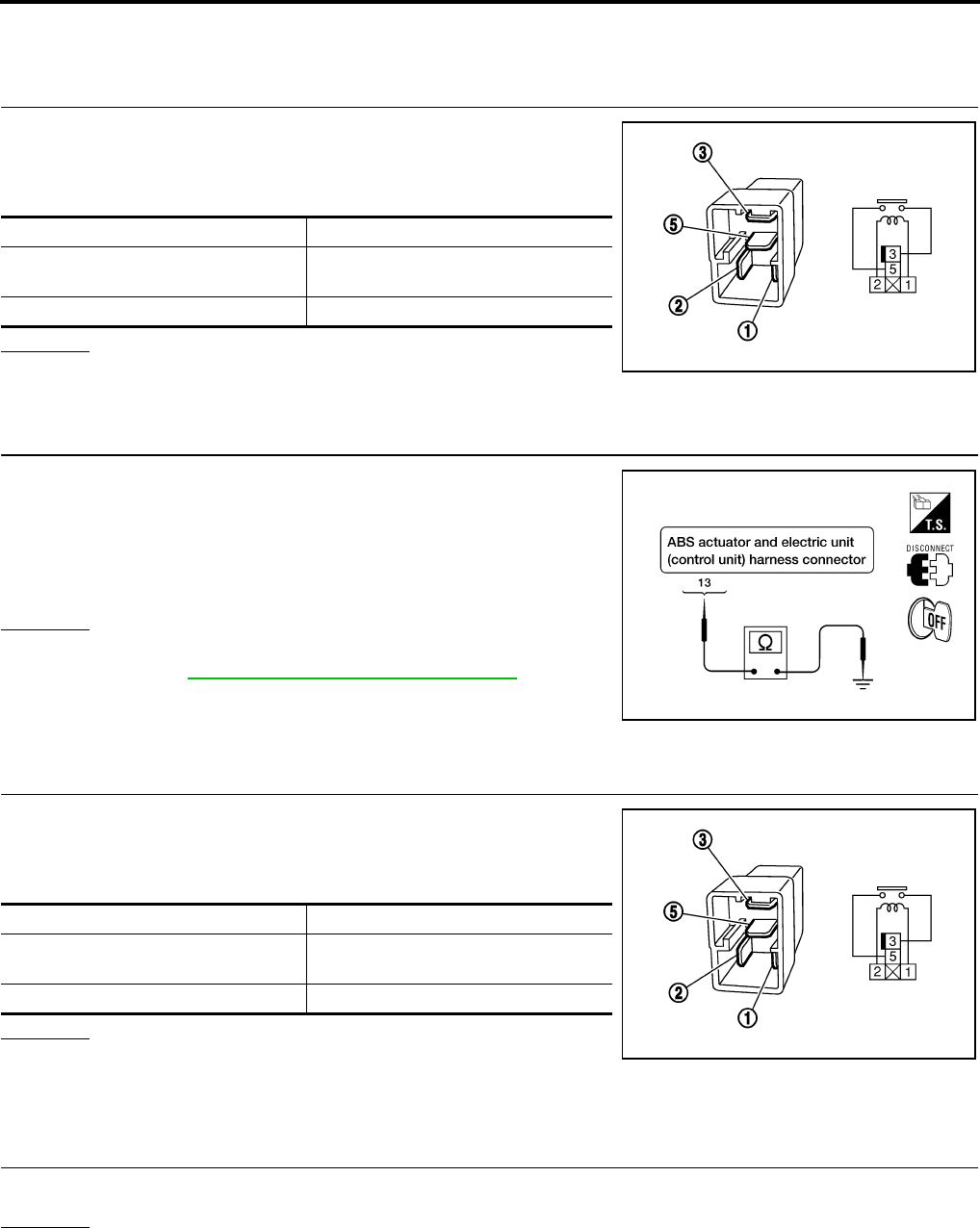
BRC-210
[HDC/HSA/VDC/TCS/ABS]
TROUBLE DIAGNOSES FOR SYMPTOMS
Revision: February 2006 2005 Xterra
Stop Lamp Relay Inspection EFS005KD
STOP LAMPS TURN ON THOUGH HDC DOES NOT FUNCTION
1. INSPECTION OF STOP LAMP RELAY
1. Turn ignition switch OFF.
2. Disconnect stop lamp relay connector E12.
3. Check continuity between stop lamp relay terminals 3 and 5.
OK or NG
OK >> GO TO 2.
NG >> Replace stop lamp relay.
2. INSPECTION OF STOP LAMP RELAY CIRCUIT
1. Disconnect ABS actuator and electric unit (control unit) connec-
tor E125.
2. Check continuity between ABS actuator and electric unit (control
unit) connector E125 terminal 13 and ground.
OK or NG
OK >> Replace ABS actuator and electric unit (control unit).
Refer to BRC-216, "Removal and Installation" .
NG >> Repair or replace harness or connector.
STOP LAMPS DO NOT TURN ON THOUGH HDC FUNCTIONS
1. INSPECTION OF STOP LAMP RELAY
1. Turn ignition switch OFF.
2. Disconnect stop lamp relay connector E12.
3. Check continuity between stop lamp relay terminals 3 and 5.
OK or NG
OK >> Repair the stop lamp circuit.
NG >> Replace stop lamp relay.
HDC Switch Inspection EFS005KE
1. HDC SWITCH INSPECTION
Check if the HDC indicator lamp in the combination meter turns on or flashes when pressing HDC switch.
OK or NG
OK >> Inspection End.
NG >> GO TO 2.
Condition Continuity
12V direct current supply between
terminals 1 and 2 Yes
No current supply No
SEF145X
Continuity should not exist.
WFIA0353E
Condition Continuity
12V direct current supply between
terminals 1 and 2 Yes
No current supply No
SEF145X

TROUBLE DIAGNOSES FOR SYMPTOMS
BRC-211
[HDC/HSA/VDC/TCS/ABS]
C
D
E
G
H
I
J
K
L
M
A
B
BRC
Revision: February 2006 2005 Xterra
2. CHECK HDC SWITCH CIRCUIT
1. Disconnect ABS actuator and electric unit (control unit) connec-
tor E125.
2. Check continuity between ABS actuator and electric unit (control
unit) connector E125 terminal 9 and HDC switch connector
M155 terminal 2.
OK or NG
OK >> GO TO 3.
NG >> Repair or replace harness or connector.
3. CHECK HDC SWITCH GROUND
Check continuity between HDC switch connector M155 terminal 1
and body ground.
OK or NG
OK >> Replace HDC switch.
NG >> Repair or replace harness or connector.
Continuity should exist.
WFIA0354E
Continuity should exist.
WFIA0355E
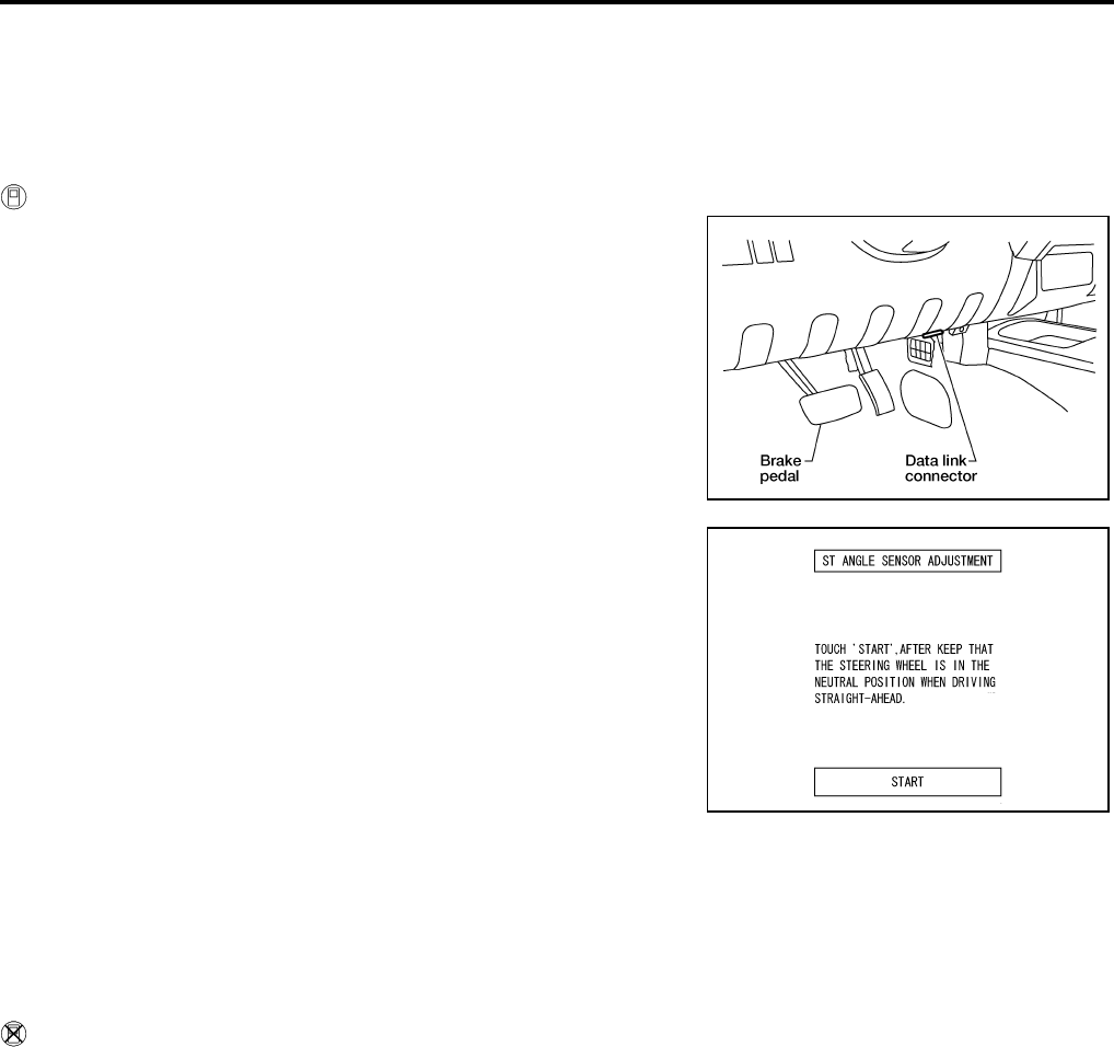
BRC-212
[HDC/HSA/VDC/TCS/ABS]
ON-VEHICLE SERVICE
Revision: February 2006 2005 Xterra
ON-VEHICLE SERVICE PFP:00000
Adjustment of Steering Angle Sensor Neutral Position EFS005KF
After removing/installing or replacing ABS actuator and electric unit (control unit), steering angle sensor, steer-
ing and suspension components which affect wheel alignment or after adjusting wheel alignment, be sure to
adjust neutral position of steering angle sensor before running vehicle.
WITH CONSULT-II
1. Stop vehicle with front wheels in straight-ahead position.
2. Connect CONSULT-II and CONSULT-II CONVERTER to data
link connector on vehicle, and turn ignition switch ON (do not
start engine).
3. Touch “ABS”, “WORK SUPPORT” and “ST ANGLE SENSOR
ADJUSTMENT” on CONSULT-II screen in this order.
4. Touch “START”.
CAUTION:
Do not touch steering wheel while adjusting steering angle
sensor.
5. After approximately 10 seconds, touch “END”. (After approxi-
mately 60 seconds, it ends automatically.)
6. Turn ignition switch OFF, then turn it ON again.
CAUTION:
Do not touch steering wheel while adjusting steering angle
sensor.
7. Run vehicle with front wheels in straight-ahead position, then
stop.
8. Select “DATA MONITOR”, “SELECTION FROM MENU”, and “STR ANGLE SIG” on CONSULT-II screen.
Then check that “STR ANGLE SIG” is within 0±3.5 deg. If value is more than specification, repeat steps 3
to 7.
9. Erase memory of ABS actuator and electric unit (control unit) and ECM.
10. Turn ignition switch to OFF.
WITHOUT CONSULT-II
Set the steering wheel in a straight forward position and drive the vehicle at 10 mph (15 km/h) or more for 10
minutes. When the procedure is complete, the SLIP indicator lamp and VDC OFF indicator lamp will turn off.
Calibration of Decel G Sensor EFS005KG
After removing/installing or replacing ABS actuator and electric unit (control unit), yaw rate/side/decel G sen-
sor, steering and suspension components which affect wheel alignment or after adjusting wheel alignment, be
sure to calibrate the decel G sensor before running vehicle.
NOTE:
Calibration of decel G sensor requires CONSULT-II.
1. Stop vehicle with front wheels in straight-ahead position.
CAUTION:
●The work should be done on a level area with an unloaded vehicle.
●Keep all the tires inflated to the correct pressures. Adjust the tire pressure to the specified pres-
sure value.
2. Connect CONSULT-II with CONSULT-II CONVERTER to data link connector on vehicle, and turn ignition
switch ON (do not start engine).
BBIA0538E
WFIA0239E
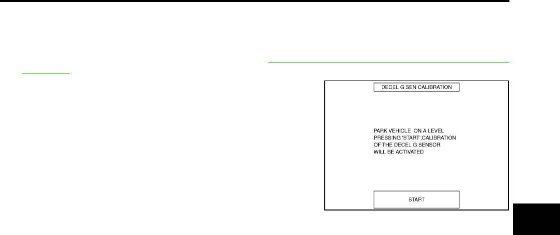
ON-VEHICLE SERVICE
BRC-213
[HDC/HSA/VDC/TCS/ABS]
C
D
E
G
H
I
J
K
L
M
A
B
BRC
Revision: February 2006 2005 Xterra
CAUTION:
If CONSULT-II is used with no connection of CONSULT-II CONVERTER, malfunctions might be
detected in self-diagnosis depending on control unit which carries out CAN communication.
3. Touch "START (NISSAN BASED VHCL)", "ABS", "WORK SUPPORT" and "DECEL G SEN CALIBRA-
TION" on CONSULT-II screen in this order. Refer to BRC-177, "CONSULT-II BASIC OPERATION PRO-
CEDURE" .
4. Touch "START".
CAUTION:
Set vehicle as shown in the display.
5. After approximately 10 seconds, touch "END". (After approxi-
mately 60 seconds, it ends automatically.)
6. Turn ignition switch OFF, then turn it ON again.
CAUTION:
Be sure to carry out above operation.
7. Run vehicle with front wheels in straight-ahead position, then
stop.
8. Select "DATA MONITOR", "SELECTION FROM MENU", and
"DECEL G SEN" on CONSULT-II screen. Then check that "DECEL G SEN" is within ±0.08G. If value is
more than specification, repeat steps 3 to 7.
9. Erase memory of ABS actuator and electric unit (control unit) and ECM.
10. Turn ignition switch to OFF.
SFIA1162E
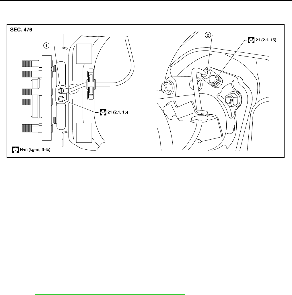
BRC-214
[HDC/HSA/VDC/TCS/ABS]
WHEEL SENSORS
Revision: February 2006 2005 Xterra
WHEEL SENSORS PFP:47910
Removal and Installation EFS005SH
REMOVAL
1. Remove wheel sensor mounting screw(s).
●When removing the front wheel sensor, first remove the disc rotor to gain access to the front wheel sen-
sor mounting bolt. Refer to BR-23, "Removal and Installation of Brake Caliper and Disc Rotor" .
2. Pull out the sensor, being careful to turn it as little as possible.
CAUTION:
●Be careful not to damage sensor edge and sensor rotor teeth.
●Do not pull on the sensor harness.
3. Disconnect wheel sensor harness electrical connector, then remove harness from mounts.
INSTALLATION
●Before installing wheel sensors,
–Inspect wheel sensor assembly and replace if damaged.
–Clean wheel sensor hole and mounting surface with brake cleaner and a lint-free shop rag. Be careful that
dirt and debris do not enter the axle.
–Install a new wheel sensor O-ring, then apply a coat of suitable grease to the O-ring and mounting hole.
Refer to MA-11, "RECOMMENDED FLUIDS AND LUBRICANTS" .
●Installation is in the reverse order of removal.
1. Front wheel sensor 2. Rear wheel sensor
WFIA0405E
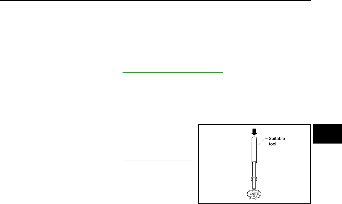
SENSOR ROTOR
BRC-215
[HDC/HSA/VDC/TCS/ABS]
C
D
E
G
H
I
J
K
L
M
A
B
BRC
Revision: February 2006 2005 Xterra
SENSOR ROTOR PFP:47970
Removal and Installation EFS005SI
FRONT
The wheel sensor rotors are built into the wheel hubs and are not removable. If damaged, replace wheel hub
and bearing assembly. Refer to FAX-5, "Removal and Installation" .
REAR
Removal
1. Remove axle shaft assembly. Refer to RAX-19, "Removal and Installation" .
NOTE:
It is necessary to disassemble the rear axle to replace the sensor rotor.
2. Pull the sensor rotor of off the axle shaft using Tool and a press.
Installation
1. Install new sensor rotor on axle shaft using a suitable length
steel tube and a press. Make sure sensor rotor is fully seated.
CAUTION:
Do not reuse the old sensor rotor.
2. Install axle shaft assembly. Refer to RAX-19, "Removal and
Installation" .
CAUTION:
Do not reuse the axle oil seal. The axle oil seal must be
replaced every time the axle shaft assembly is removed
from the axle shaft housing.
Tool number : 205-D002 ( — )
WFIA0341E

BRC-216
[HDC/HSA/VDC/TCS/ABS]
ACTUATOR AND ELECTRIC UNIT (ASSEMBLY)
Revision: February 2006 2005 Xterra
ACTUATOR AND ELECTRIC UNIT (ASSEMBLY) PFP:47660
Removal and Installation EFS005SK
REMOVAL
1. Disconnect the negative battery terminal.
2. Drain the brake fluid. Refer to BR-9, "Drain and Refill" .
3. Disconnect the actuator harness from the ABS actuator and electric unit (control unit).
CAUTION:
●To remove the brake tubes, use a flare nut wrench to prevent the flare nuts and brake tubes from
being damaged.
●Be careful not to splash brake fluid on painted areas.
4. Disconnect the brake tubes.
5. Remove three bolts and then the ABS actuator and electric unit (control unit).
1. To rear left 2. To rear right 3. To front left
4. To front right 5. From the master cylinder secondary
side
6. From the master cylinder primary
side
7. ABS actuator and electric unit (con-
trol unit)
8. Harness connector 9. Grommet
10. Collar
WFIA0389E

ACTUATOR AND ELECTRIC UNIT (ASSEMBLY)
BRC-217
[HDC/HSA/VDC/TCS/ABS]
C
D
E
G
H
I
J
K
L
M
A
B
BRC
Revision: February 2006 2005 Xterra
INSTALLATION
Installation is in the reverse order of removal.
CAUTION:
To install, use a flare nut wrench (commercial service tool).
●Always tighten brake tubes to specification when installing. Refer to BR-11, "BRAKE PIPING AND
HOSE" .
●Never reuse drained brake fluid.
●After installation of the ABS actuator and electric unit (control unit), refill brake system with new
brake fluid. Then bleed the air from the system. Refer to BR-10, "Bleeding Brake System" .
NOTE:
If the ABS actuator and electric unit (control unit) is replaced, make sure to adjust position of steering angle
sensor. Refer to BRC-142, "Adjustment of Steering Angle Sensor Neutral Position" .

BRC-218
[HDC/HSA/VDC/TCS/ABS]
STEERING ANGLE SENSOR
Revision: February 2006 2005 Xterra
STEERING ANGLE SENSOR PFP:25554
Removal and Installation EFS005KK
Refer to SRS-44, "Removal and Installation" .
NOTE:
●The steering angle sensor is an integral part of the spiral cable.
●If the ABS actuator and electronic unit (control unit) is replaced, make sure to adjust position of steering
angle sensor. Refer to BRC-212, "Adjustment of Steering Angle Sensor Neutral Position" .

G SENSOR
BRC-219
[HDC/HSA/VDC/TCS/ABS]
C
D
E
G
H
I
J
K
L
M
A
B
BRC
Revision: February 2006 2005 Xterra
G SENSOR PFP:47930
Removal and Installation EFS005KL
REMOVAL
1. Remove center console. Refer to IP-15, "CENTER CONSOLE" .
2. Remove yaw rate/side/decel G sensor attaching nuts as shown.
●The location of the sensor is the same for all models.
CAUTION:
●Do not use power tools to remove or install yaw rate/side/
decel G sensor.
●Do not drop or strike the yaw rate/side/decel G sensor.
3. Disconnect harness connector and remove the yaw rate/side/
decel G sensor.
INSTALLATION
Installation is in the reverse order of removal.
NOTE:
After performing the above work, calibrate the decel G sensor. Refer to BRC-212, "Calibration of Decel G Sen-
sor" .
WFIA0230E

BRC-220
[HDC/HSA/VDC/TCS/ABS]
G SENSOR
Revision: February 2006 2005 Xterra
