C More Hardware User Manual Getting Started Chapter 1 Ch1
User Manual: Chapter 1 C-more (EA9 Series) Touch Panel User Manual and Product Inserts
Open the PDF directly: View PDF ![]() .
.
Page Count: 16
- Introduction
- Conventions Used
- Product Overview
- Quick Start Steps
- Step 1 – Unpack and Inspect
- Step 2 – Install Optional Hardware Accessories
- Step 3 – Become Familiar with Available Communication Ports
- Step 4 – Install the Programming Software and Develop a Project
- Step 5 – Connect Touch Panel to Computer
- Step 6 – Provide Power to the Touch Panel
- Step 7 – Access the Touch Panel Setup Screens
- Step 8 – Choose Touch Panel to Device Protocol & Cables
- Step 9 – Connect Touch Panel to PLC

1
1
1
GettinG Started
Chapter
Chapter
Chapter
In This Chapter...
Introduction ...................................................................................................................1-2
The Purpose of this Manual ������������������������������������������������������������������������������������������1-2
Supplemental Manuals �������������������������������������������������������������������������������������������������1-2
Technical Support ��������������������������������������������������������������������������������������������������������1-2
Conventions Used .......................................................................................................... 1-3
Key Topics for Each Chapter ����������������������������������������������������������������������������������������� 1-3
Product Overview ..........................................................................................................1-4
Quick Start Steps ...........................................................................................................1-5
Step 1 – Unpack and Inspect ���������������������������������������������������������������������������������������� 1-5
Step 2 – Install Optional Hardware Accessories �������������������������������������������������������������1-6
Step 3 – Become Familiar with Available Communication Ports ������������������������������������1-7
Step 4 – Install the Programming Software and Develop a Project �������������������������������1-8
Step 5 – Connect Touch Panel to Computer ����������������������������������������������������������������1-9
Step 6 – Provide Power to the Touch Panel ����������������������������������������������������������������1-10
Step 7 – Access the Touch Panel Setup Screens����������������������������������������������������������1-12
Step 8 – Choose Touch Panel to Device Protocol & Cables ����������������������������������������1-13
Step 9 – Connect Touch Panel to PLC ������������������������������������������������������������������������1-16

Chapter 1 - Getting Started
1-2 ®
1
2
3
4
5
6
7
8
9
10
11
12
13
14
A
B
C
D
EA9-USER-M Hardware User Manual, 1st Ed. Rev. E
Introduction
The Purpose of this Manual
Thank you for purchasing our C-more® Touch Panel family of products. This manual
describes AutomationDirect.com’s C-more Touch Panels, their specifications, included
components, available accessories and provides you with important information for
installation, connectivity and setup. The manual shows you how install, wire and use the
products. It also helps you understand how to interface the panels to other devices in a
control system.
This user manual contains important information for personnel who will install the touch
panels and accessories, and for the personnel who will be programming the panel. If you
understand control systems that make use of operating interfaces such as the C-more touch
panels, our user manuals will provide all the information you need to get, and keep your
system up and running.
Supplemental Manuals
If you are familiar with industrial control type devices, you may be able to get up and running
with just the aide of the Quick Start Guide that is included with each touch panel. You can
also refer to the On-line help that is available in the C-more programming software for more
information about programming the panel.
Technical Support
We strive to make our manuals the best in the industry. We rely on your feedback to let
us know if we are reaching our goal. If you cannot find the solution to your particular
application, or, if for any reason you need technical assistance, please call us at:
770–844–4200
Our technical support group will work with you to answer your questions. They are available
Monday through Friday from 9:00 A.M. to 6:00 P.M. Eastern Time. We also encourage you
to visit our web site where you can find technical and non-technical information about our
products and our company.
http://c-more.automationdirect.com
Chapter 1 - Getting Started
1-3
®
1
2
3
4
5
6
7
8
9
10
11
12
13
14
A
B
C
D
EA9-USER-M Hardware User Manual, 1st Ed. Rev. E
Conventions Used
When you see the “notepad” icon in the left-hand margin, the paragraph to its immediate right will be a special note.
The word NOTE: in boldface will mark the beginning of the text.
When you see the “exclamation mark” icon in the left-hand margin, the paragraph to its immediate
right will be a warning. This information could prevent injury, loss of property, or even death (in
extreme cases). The word Warning: in boldface will mark the beginning of the text.
Key Topics for Each Chapter
The beginning of each chapter will list the key topics
that can be found in that chapter.
Getting Started
CHAPTER
1
In This Chapter...
.................................................................1-2
...........................................................................1-4Specifications
General Information

Chapter 1 - Getting Started
1-4 ®
1
2
3
4
5
6
7
8
9
10
11
12
13
14
A
B
C
D
EA9-USER-M Hardware User Manual, 1st Ed. Rev. E
Product Overview
Some of the features designed into the product to provide excellent hardware and software are
listed below.
• Analog touch screen (no touch cell boundaries). The touchscreen is designed to respond to a single
touch. If it is touched at multiple points at the same time, an unexpected object may be activated.
• Plenty of memory and methods to get data in/out of the panel
• Overlapping active devices on the touch screen
• 65,536 colors for enhanced graphics
• Screen resolutions up to 1024 X 768 pixel
• HDMI Video Output on 12-inch and 15-inch models.
• Built-in FTP client/server, E-mail client, and Web server
• Audio output port - stereo, requires amplifier and speaker(s) (full feature units only)
• User configurable LED on the front of the panel
• Built-in project simulation; test on PC while developing
• Ethernet 10/100Base-T communications (not available on EA9-T6CL-R)
• 15 pin serial port with RS-232, RS422/485
• 3-wire terminal block RS-485 port and RJ12 RS-232 port (full feature units only)
• Programming via USB or Ethernet (Ethernet not available on EA9-T6CL-R)
• Optional AC/DC power adapter (EA-AC)
• Animation of bitmaps and objects
• Thousands of built-in symbols and Windows fonts
• PID face plate, trending, alarming and a recipe database
• Event Manager to trigger actions based on assigned state changes, schedules, PLC tag names, etc.
setup in a database environment. The event can also trigger a sound byte, initiate a screen capture,
send a data file (FTP), send an E-mail, etc.
• Trend Data logging
• Internet Remote Access
• Customizable label on the front of the panel
Chapter 1 - Getting Started
1-5
®
1
2
3
4
5
6
7
8
9
10
11
12
13
14
A
B
C
D
EA9-USER-M Hardware User Manual, 1st Ed. Rev. E
Quick Start Steps
Step 1 – Unpack and Inspect
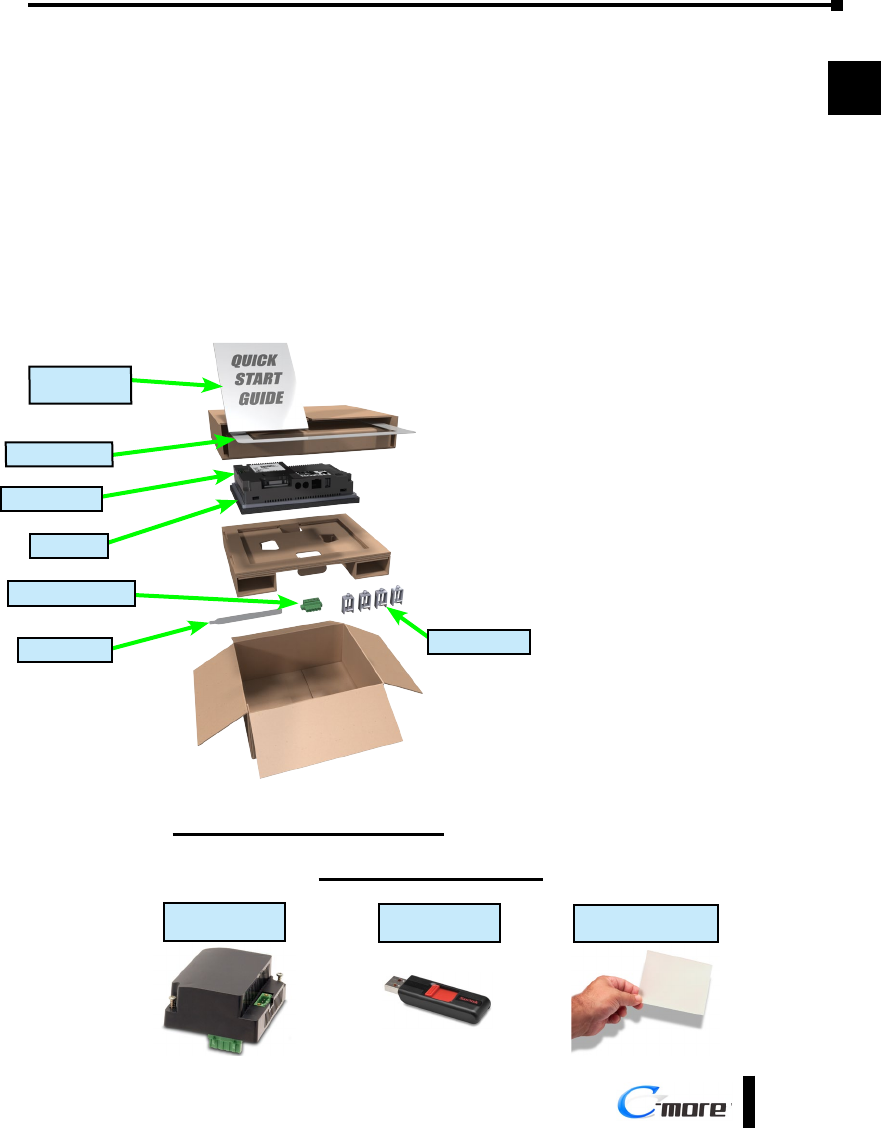
a.) Unpack the C-more Touch Panel from its shipping carton. Included in the carton are the
following:
• C-more Touch Panel
• cutout template
• mounting clips
• DC power connector
• gasket
• logo label
• Quick Start Guide
b.) Unpack any accessories that have
been ordered, such as: AC/DC
Power Adapter, programming cable,
communications cable, etc.
c.) Inspect all equipment for
completeness. If anything is missing
or damaged, immediately call
the AutomationDirect® returns
department @ 1-800-633-0405.
Optional Accessories
AC Power Adapter
EA-AC
USB Pen Drive
USB-FLASH
Protective Screen Cover
EA-x-COV2
*Not included with EA9-T7CL-R and EA9-T7CL.
Shipping Carton Contents
Logo Label*
DC power connector
Cutout Template*
C-more Panel
Mounting Clips
Quick Start
Guide
Gasket
Chapter 1 - Getting Started
1-6 ®
1
2
3
4
5
6
7
8
9
10
11
12
13
14
A
B
C
D
EA9-USER-M Hardware User Manual, 1st Ed. Rev. E
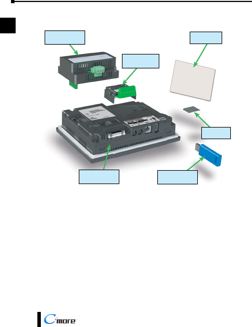
Step 2 – Install Optional Hardware Accessories
C-more Touch Panel
EA-SD-CARD
SD Card
USB-FLASH
USB Pen Drive
EA-AC
AC / DC Power Adapter
EA-x-COV2
Screen Protector
EA-COMCON-3A
DSUB Port Adapter
Chapter 1 - Getting Started
1-7
®
1
2
3
4
5
6
7
8
9
10
11
12
13
14
A
B
C
D
EA9-USER-M Hardware User Manual, 1st Ed. Rev. E
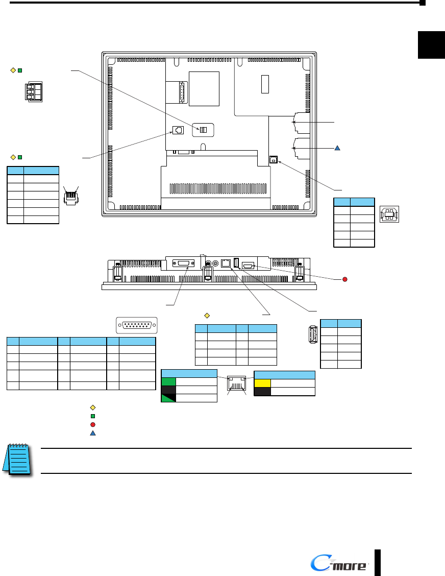
Step 3 – Become Familiar with Available Communication Ports
Note: Device is not available on Base Feature touch panels EA9-T7CL-R and EA9-T15CL-R
Note: Device is only available on touch panels EA9-T12CL and EA9-T15CL.
USB Port - Type B
Programming
21
34
Pin Signal
1 N.C.
D–
D+
GND
2
3
4
ShieldShell
USB Port - Type A
USB Device Options
21 34
Pin Signal
1 Vbus
D–
D+
GND
2
3
4
ShieldSHELL
Ethernet 10/100 Base-T
PLC Communications,
Programming/Download
1 8
Pin Signal
1 TD+
TD–
RD+
do not use
2
3
4
Pin Signal
5 do not use
RD–
N.C.
N.C.
6
7
8
Network Speed LED (Yellow)
On 100M
10MOff
SD Card Slot 1
SD Card Slot 2
HDMI Port Video Out
Note: Device is not available on Base Feature touch panel EA9-T6CL-R
8 1
15 9
Port 1
PLC Serial Communications
RS-232C / RS-485
Pin Signal
1 Frame GND
TXD (232C)
RXD (232C)
VCC
(Supplies +5VDC)
2
3
4
5 Logic GND
Pin Signal Pin Signal
6 LE (for DH485)
CTS (232C)
RTS (232C)
RXD+ (422/485)
7
8
9
10 RXD– (422/485)
11 TXD+ (422/485)
TXD– (422/485)
Term. Resistor
N.C.
12
13
14
15 N.C.
1 6
Pin Signal
1 0V
N.C.
RXD
TXD
2
3
4
Supplies +5VDC5
0V6
Port 3
RJ12 Serial Communication
RS-232C
+
–
Logic Ground
Port 2
Serial Communication
RS-485
Link Status LED (Green)
On Ethernet Linked
No Ethernet Comm.Off
Comm. Activity
Blinking
Green
Note: Device is only available on touch panels EA9-T12CL, EA9-T15CL and EA9-T15CL-R.
NOTE: See Chapter 2: Specifications and Chapter 6: PLC Communications for additional details on the available
communication ports, protocols and cables.
Chapter 1 - Getting Started
1-8 ®
1
2
3
4
5
6
7
8
9
10
11
12
13
14
A
B
C
D
EA9-USER-M Hardware User Manual, 1st Ed. Rev. E
Step 4 – Install the Programming Software and Develop a Project
Following are the minimum system requirements for running C-more Programming
Software, p/n EA9-PGMSW, on a PC:
• Keyboard and Mouse or compatible pointing device
• Super VGA color video adapter and monitor with at least 800 x 600 pixel resolution (1024 x
768 pixel recommended) 64K color minimum
• 300 MB free hard-disk space
• CD-ROM or DVD drive for installing software from the CD
• USB port or Ethernet 10/100 Mbps port for project transfer from software to touch panel
(Ethernet port not available on EA9-T6CL-R)
• Operating System - Windows 7, 8, 8.1 and 10 (32 or 64bit)
Insert the supplied CD into the PC’s CD drive and follow the instructions. If you need
assistance during the software installation, call the AutomationDirect Technical Support team
@ 770-844-4200.
NOTES: Regarding Ethernet access to a C-more panel.
If you intend to take advantage of the methods of remote access to the panel, including the web server, PC remote
access, FTP, iOS or Android app, you need to consider the security exposure in order to minimize the risks to your
process and your C-more panel.
Security measures may include password protection, changing the ports exposed on your network, including a VPN
in your network, and other methods. Security should always be carefully evaluated for each installation. Refer to
Appendix C - Security Considerations for Control Systems Networks.
Chapter 1 - Getting Started
1-9
®
1
2
3
4
5
6
7
8
9
10
11
12
13
14
A
B
C
D
EA9-USER-M Hardware User Manual, 1st Ed. Rev. E
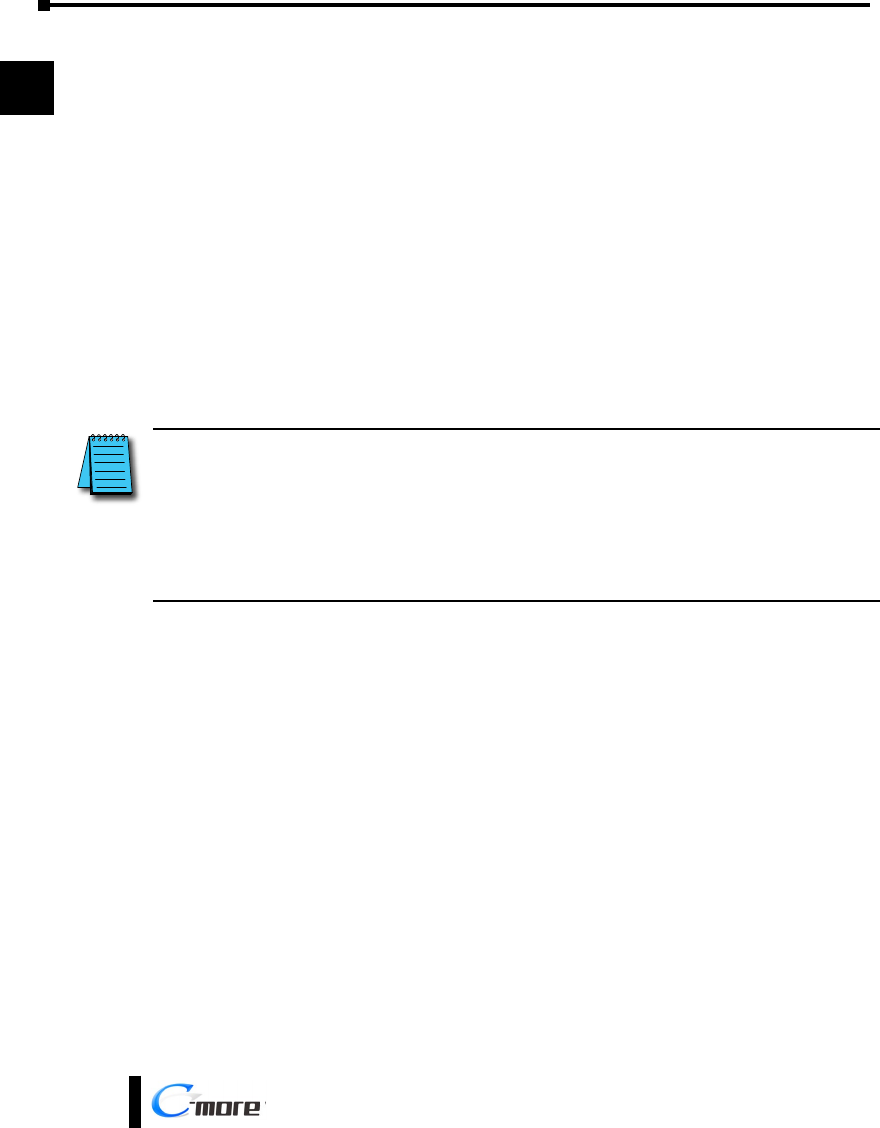
Step 5 – Connect Touch Panel to Computer
• Connect a USB Programming Cable, such as p/n USB-CBL-AB15, from a USB type A port on the
PC to the USB type B programming port on the C-more touch panel
• or connect the C-more touch panel and PC together either directly or via an Ethernet switch, and
CAT5 Ethernet cables (full feature panels only)
USB-CBL-ABxx
USB Cable
PC
C-more
Touch Panel
USB
Port
USB
Port
Stride™
Ethernet Switch
10/100 Base-T
(such as SE2-SW5U)
PC
C-more
Touch Panel
Ethernet
Port
Ethernet CAT5
Cable Auto MDI / MDI-X
Ethernet Port
Ethernet CAT5
Cable
C-more
Touch Panel
Ethernet
Port
PC
Auto MDI / MDI-X
Ethernet Port
Chapter 1 - Getting Started
1-10 ®
1
2
3
4
5
6
7
8
9
10
11
12
13
14
A
B
C
D
EA9-USER-M Hardware User Manual, 1st Ed. Rev. E
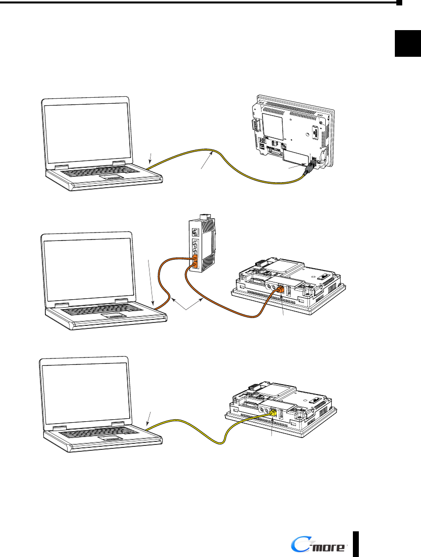
Step 6 – Provide Power to the Touch Panel
• Connect a dedicated 12-24 VDC Class 2 power supply to the DC connector on the rear of the
C-more touch panel, include wiring the ground terminal to a proper equipment ground
• or install a C-more AC/DC Power Adapter, EA-AC, to the rear of the touch panel and connect an
AC voltage source of 100-240 VAC, 50/60Hertz, to its AC connector (see note below)
• then turn on the power source and check the LED status indicators on the front and rear of the
C-more touch panel for proper indication (see next page)
NOTE: A dedicated power supply is recommended. If the power supply also feeds inductive loads such as
solenoids or relays, the transients caused by these loads can affect the operation of the panel or damage panel
components.
NOTE: The AC/DC Power Adapter, EA-AC, is for C-more touch panels only. The adapter is powered from a 100-
240 VAC, 50/60 Hertz power source. The adapter provides 24 VDC @ 1.5 A. Power Fault features help protect data
on an SD memory card during power failures.
12-24 VDC
+
–
GND
Equipment
Ground
Recommended DC Supply Fuse
Panel Size
6“ – 10”
12“ & 15”
2.5 A
4.0 A
MDL2-5
MDL4
Rating ADC p/n
DC-CON Tightening Torque
Power connector screw torque 70.4 oz-in (0.5 Nm)
Power connector mounting torque 56 oz-in (0.4 Nm)
DC Wiring
Tightening Torque
Power supply cable torque 71 - 85 oz-in (0.5 - 0.6 Nm)
Power connector mounting torque 71 - 85 oz-in (0.5 - 0.6 Nm)
Mounting flange screw torque 57 - 71 oz-in (0.4 - 0.5 Nm)
AC Wiring
Recommended AC Supply Fuse
3.0A time delay, ADC p/n: MDL3
L
N
G
100 - 240 VAC
50 / 60 Hz
Warning: Use 60 / 75 °C copper conductors only.
Chapter 1 - Getting Started
1-11
®
1
2
3
4
5
6
7
8
9
10
11
12
13
14
A
B
C
D
EA9-USER-M Hardware User Manual, 1st Ed. Rev. E
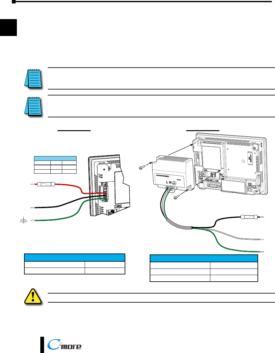
Step 6 – Provide Power to the Touch Panel (cont’d)
C-more LED Status Indicators
Power LED (Green)
On Power On
Power OffOff
User Defined LED (Green, Orange & Red)
Off
Green
Red
Blinking
Red
Blinking
Orange
Blinking
Green
Front View
User Defined
(Refer to online help
file for further details)
Orange
CPU Status LED (Green, Orange & Red)
Off Power Off
Normal – CPU Run StateGreen
Red Memory Error
Watchdog Timer Error
Blinking
Red
Blinking
Orange OS Error
Rear View
Blinking
Green Power Loss Detection
CPU
TxD
Port2
RxD
TxD
Port3
RxD
TxD
Port1 RxD
Serial TxD/RxD LED (Green)
On Comm. is active
No communicationOff
Chapter 1 - Getting Started
1-12 ®
1
2
3
4
5
6
7
8
9
10
11
12
13
14
A
B
C
D
EA9-USER-M Hardware User Manual, 1st Ed. Rev. E
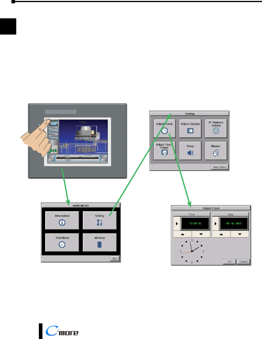
Step 7 – Access the Touch Panel Setup Screens
• Access the Main Menu of the touch panel System Setup Screens by pressing the extreme upper left
corner of the panel display area for three (3) seconds as shown below.
• Adjust the time and date for the panel by pressing the Setting button on the Main Menu, then press
the Adjust Clock button on the Setting screen.
• Use the right pointing arrows for the time or date display to select the unit to change. Use the up
and down arrows to increment or decrement the value for the selected unit.
• Press OK when done to accept the changes to the time and date in the touch panel or press Cancel
to exit the Adjust Clock setup screen without making any changes.
• Press the Main Menu button on the Setting screen and then the Exit button on the Main Menu
screen to return to the application screen.
Chapter 1 - Getting Started
1-13
®
1
2
3
4
5
6
7
8
9
10
11
12
13
14
A
B
C
D
EA9-USER-M Hardware User Manual, 1st Ed. Rev. E
Step 8 – Choose Touch Panel to Device Protocol & Cables
Compatibility Table
Model Protocols
AutomationDirect
Productivity Series Productivity Serial
Productivity Ethernet
Do-more all Do-more Serial
Do-more Ethernet
CLICK Modbus (CLICK)
DL05/DL06 all
K-Sequence
Direct NET
Modbus (Koyo addressing)
H0-ECOM/H0-ECOM100 Direct LOGIC Ethernet
DL105 all K-Sequence
DL205
D2-230 K-Sequence
D2-240 K-Sequence
Direct NET
D2-250/D2-250-1/D2-260
K-Sequence
Direct NET
Modbus (Koyo addressing)
D2-240/D2-250-1/D2-260
Using DCM
Direct NET
Modbus (Koyo addressing)
H2-ECOM/H2-ECOM100 Direct LOGIC Ethernet
DL305
D3-330/330P (Requires the use of a Data Communications Unit) Direct NET
D3-340 Direct NET
D3-350
K-Sequence
Direct NET
Modbus (Koyo addressing)
D3-350 DCM Direct NET
Modbus (Koyo addressing)
DL405
D4-430 K-Sequence
Direct NET
D4-440 K-Sequence
Direct NET
D4-450
K-Sequence
Direct NET
Modbus (Koyo addressing)
All with DCM Direct NET
Modbus (Koyo addressing)
H4-ECOM/H4-ECOM100 Direct LOGIC Ethernet
H2-WinPLC (Think & Do) Live V5.2 or later and Studio any version Think & Do Modbus RTU (serial port)
H2-WinPLC (Think & Do) Live V5.5.1 or later and Studio V7.2.1 or later Think & Do Modbus TCP/IP (Ethernet port)
GS Drives GS Drives Serial
GS Drives TCP/IP (GS-EDRV)
SOLO Temperature Controllers SOLO Temperature Controller
Chapter 1 - Getting Started
1-14 ®
1
2
3
4
5
6
7
8
9
10
11
12
13
14
A
B
C
D
EA9-USER-M Hardware User Manual, 1st Ed. Rev. E
Step 8 – Choose Touch Panel to Device Protocol & Cables (cont’d)
Compatibility Table (cont’d)
Model Protocols
Allen-Bradley
MicroLogix 1000, 1100, 1200, 1400, 1500, SLC 5-01/02/03 DH485/AIC/AIC+
MicroLogix 1000, 1100, 1200, 1400 and 1500
DF1 Half Duplex; DF1 Full DuplexSLC 5-03/04/05
ControlLogix™, CompactLogix™, FlexLogix™
PLC-5 DF1 Full Duplex
ControlLogix, CompactLogix, FlexLogix - Tag Based DF1 Half Duplex; DF1 Full Duplex
ControlLogix, CompactLogix, FlexLogix - Generic I/O Messaging EtherNet/IP Server
ControlLogix, CompactLogix, FlexLogix - Tag Based
EtherNet/IP ClientMicroLogix 1100, 1400 and SLC 5/05, via native Ethernet port
MicroLogix 1000, 1100, 1200, 1400, 1500, SLC 5-03/04/05, all via ENI adapter
GE 90/30, 90/70. Micro 90, VersaMax Micro SNPX
90/30, Rx3i SRTP Ethernet
Mitsubishi
FX Series FX Direct
Q02, Q02H, Q06H, Q12H, Q25H Q CPU
Q, QnA Serial QnA Serial
Q, QnA Ethernet QnA Ethernet
Modicon
984 CPU, Quantum 113 CPU, AEG Modicon Micro Series 110 CPU: 311-xx, 411-xx,
512-xx, 612-xx Modbus RTU
Other devices using Modicon Modbus addressing Modbus RTU
TUModbus TCP/IP
Omron
C200 Adapter, C500 Host Link
CJ1/CS1 Serial FINS
CJ1/CS1 Ethernet
Siemens S7-200 CPU, RS-485 Serial PPI
S7-200 CPU, S7-300 CPU, S7-1200 CPU; Ethernet Ethernet ISO over TCP
Chapter 1 - Getting Started
1-15
®
1
2
3
4
5
6
7
8
9
10
11
12
13
14
A
B
C
D
EA9-USER-M Hardware User Manual, 1st Ed. Rev. E
Step 8 – Choose Touch Panel to Device Protocol & Cables (cont’d)
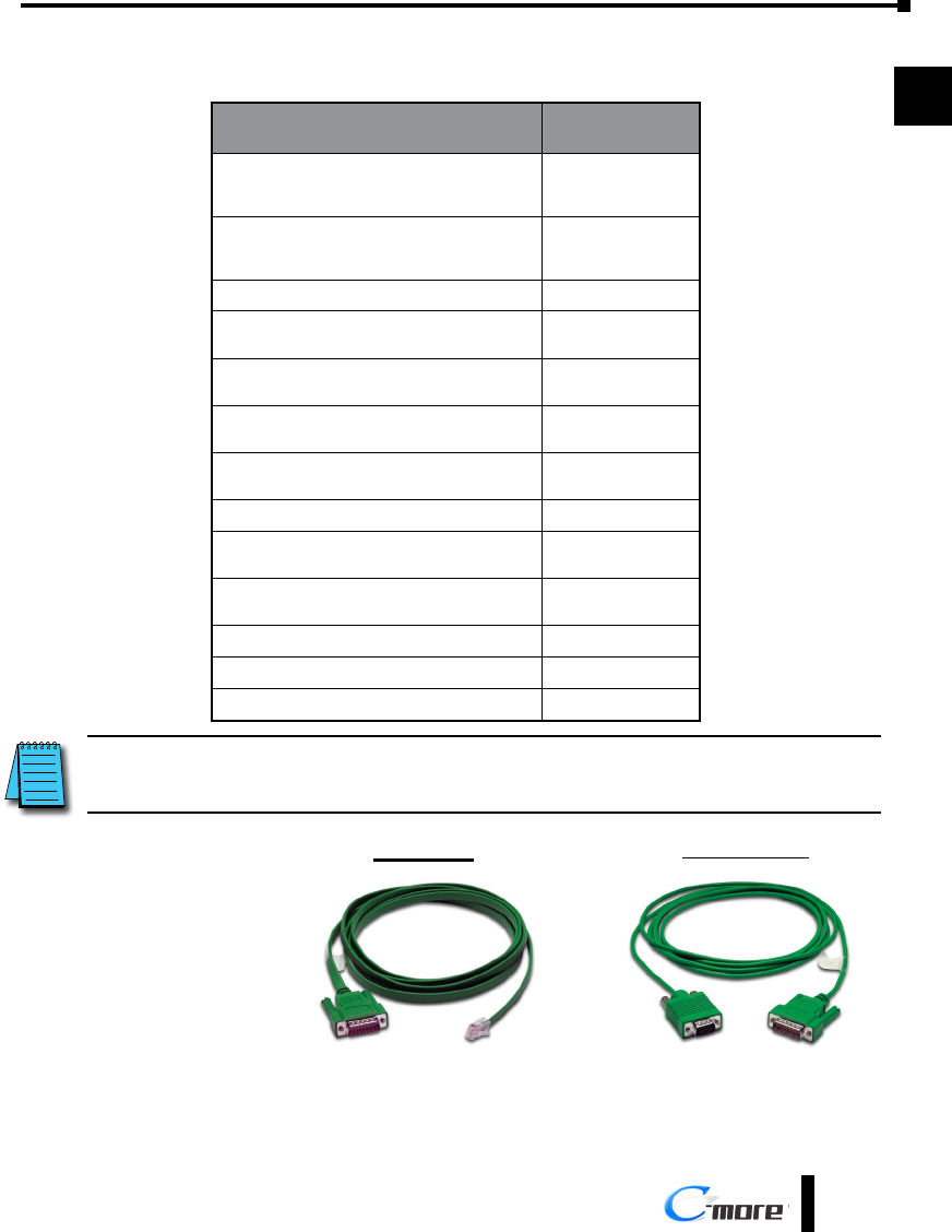
Available cables to connect from PLC to C-more serial Port 1
Purchased Cable
Description
Cable
Part Number
AutomationDirect Productivity Series, Do-more, CLICK,
Direct LOGIC PLC RJ-12 port, DL05, DL06, DL105,
DL205, D3-350, D4-450 & H2-WINPLC (RS-232C) EA-2CBL
Direct LOGIC (VGA Style) 15-pin port
DL06, D2-250 (250-1), D2-260 (RS-232C) EA-2CBL-1
Direct LOGIC PLC RJ-11 port, D3-340 (RS-232C) EA-3CBL
Direct LOGIC DL405 PLC 15-pin D-sub port,
DL405 (RS-232C) EA-4CBL-1
Direct LOGIC PLC 25-pin D-sub port, DL405, D3-350,
DL305 DCU and all DCM’s (RS-232C) EA-4CBL-2
Allen-Bradley MicroLogix 1000, 1100, 1200, 1400,
1500 (RS-232C) EA-MLOGIX-CBL
Allen-Bradley SLC 5-03/04/05, ControlLogix,
CompactLogix, FlexLogix DF1 port (RS-232C) EA-SLC-232-CBL
Allen-Bradley PLC-5 DF1 port (RS-232C) EA-PLC5-232-CBL
Allen-Bradley MicroLogix, SLC 5-01/02/03, PLC5
DH485 port (RS-232C) EA-DH485-CBL
GE 90/30, 90/70, Micro 90, VersaMax Micro
15-pin D-sub port (RS-422A) EA-90-30-CBL
MITSUBISHI FX Series 25-pin port (RS-422A) EA-MITSU-CBL
MITSUBISHI FX Series 8-pin mini-DIN (RS-422A) EA-MITSU-CBL-1
OMRON Host Link (C200 Adapter, C500) (RS-232C) EA-OMRON-CBL
NOTE: The above list of pre-made communications cables may be purchased. See Chapter 6: PLC
Communications for wiring diagrams of additional user constructed cables. Chapter 6 also includes wiring diagrams
for the pre-made cables.
Pre-made cable
EA-2CBL
EA-2CBL-1
examples
Chapter 1 - Getting Started
1-16 ®
1
2
3
4
5
6
7
8
9
10
11
12
13
14
A
B
C
D
EA9-USER-M Hardware User Manual, 1st Ed. Rev. E
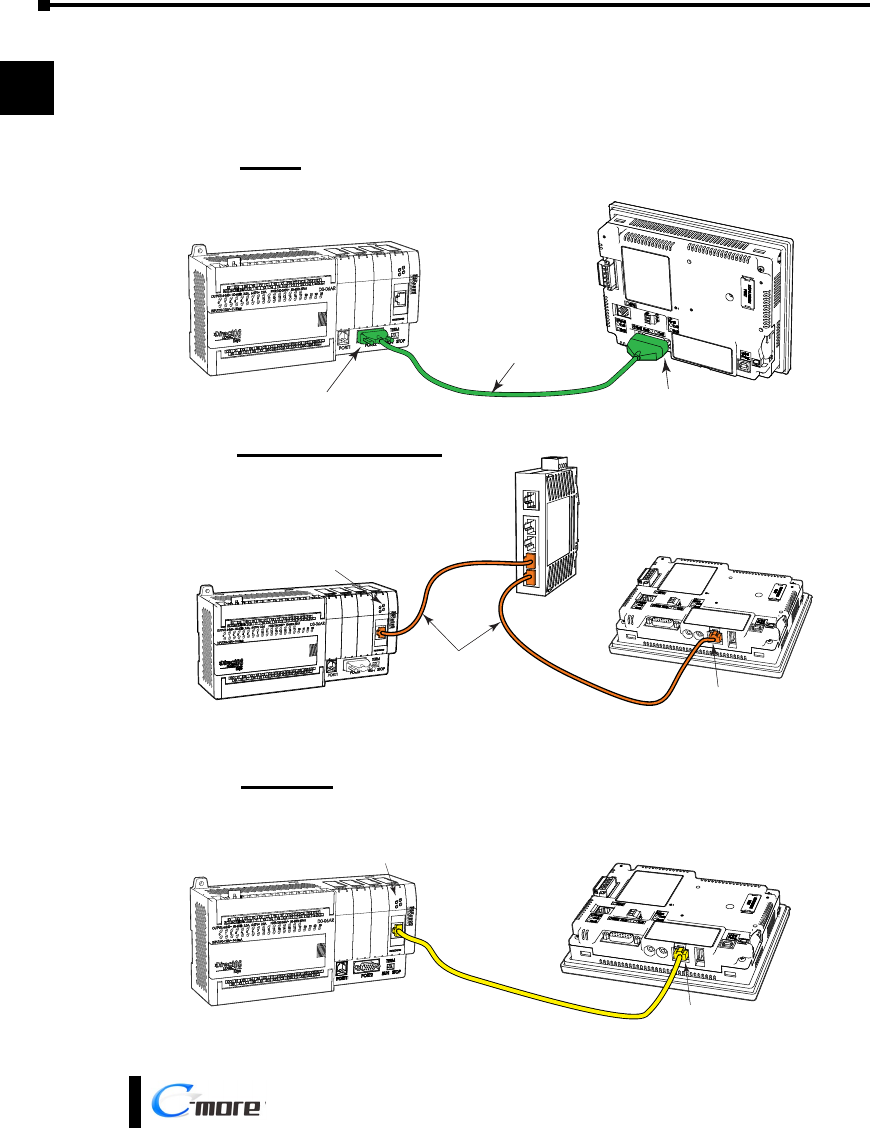
Step 9 – Connect Touch Panel to PLC
• Connect the serial communications cable between the C-more touch panel and the PLC
• or connect the C-more touch panel and PLC together either directly or via an Ethernet switch, and
CAT5 Ethernet cables (full feature panels only)
EA-2CBL-1
DL-06 PLC
C-more
Touch Panel
Port 2 Port 1
Serial
DL06 PLC
Stride™
Ethernet Switch
10/100 Base-T
(such as SE2-SW5U)
H0-ECOM/H0-ECOM100
Ethernet Module
Ethernet CAT5
Cable
C-more
Touch Panel
Auto MDI / MDI-X
Ethernet Port
Ethernet via Switch
DL06 PLC
H0-ECOM/H0-ECOMM100
Ethernet Module
Ethernet CAT5
Cable
Auto MDI / MDI-X
Ethernet Port
C-more
Touch Panel
Ethernet
