Citrex H4 Manual EN
User Manual:
Open the PDF directly: View PDF ![]() .
.
Page Count: 52
- Figure 1: Power supply
- Figure 2: Flow channel
- Figure 3: Differential pressure connector
- Figure 4: High-pressure connector
- Figure 5: Oxygen sensor holder
- Figure 6: Protective cap
- Figure 7: Screwing in the oxygen sensor
- Figure 8: Oxygen sensor cable
- Figure 9: Electrical interfaces
- Figure 10: Replacing the battery
- Figure 11: User controls
- Figure 12: Info display
- Figure 13: Battery indicator
- Figure 14: Ethernet interface
- Figure 15: Trigger
- Figure 16: Gas standard
- Figure 17: Gas type
- Figure 18: Gas humidity
- Figure 19: Setting the X-axis
- Figure 20: O2 calibration
- Figure 21: Profiles
- Figure 22: Numerical readings
- Figure 23: Measurement curves
- Figure 24: Zero calibration
- Figure 25: Screen displays "Calibration Air"
- Figure 26: Screen displays "Calibration Oxygen and Air"
- Figure 27: General measurement setup
- Figure 28: Bad setup
- Figure 29: Measurement setup for checking ventilators
- Figure 30: Measurement setup for gases at high pressure
- Figure 31: Profile editor in Internet Explorer
- Figure 32: Profile editor "configuration"
- Figure 33: Monitoring numerics
- Figure 34: Monitoring panels
- Figure 35: Interface definition
- Figure 36: Trigger
- Figure 37: Delay
- 1 Introduction
- 2 Intended use
- 3 Safety instructions
- 4 Symbol explanation
- 5 Start-up
- 6 Operation
- 7 Calibration
- 8 Connecting the device
- 9 Profile editor
- 10 Configuration tool
- 11 Reading measurement data
- 12 Servicing and care
- 13 Accessories and spare parts
- 14 Disposal
- 15 Directives and approvals
- 16 Specifications
- 17 Appendix
User Manual
CITREXH4

IMT Analytics AG
Gewerbestrasse 8
9470 Buchs (SG)
Switzerland
www.imtanalytics.com
Table of Contents
1 Introduction 5
2 Intended use 6
3 Safety instructions 7
3.1 Representation of hazards, cautions and notes 7
3.2 Personnel 7
3.3 Responsibility and guarantee 7
3.4 Service life 7
4 Symbolexplanation 8
5 Start-up 9
5.1 Power supply 10
5.2 Mechanical connectors 11
5.3 Electrical interfaces 16
5.4 Replacing the CITREX battery 17
6 Operation 18
6.1 Switching the device on/off 18
6.2 Screen lock 18
6.3 Dim screen 18
6.4 User controls 19
6.5 Settings 20
6.6 Numerical readings 23
6.7 Graphical readings 24
6.8 Filter 24
7 Calibration 25
7.1 Zero point 25
7.2 Oxygen (O2) calibration 25
8 Connecting the device 27
8.1 Generalmeasurement setup 27
8.2 Measurement setup for checking ventilators 28
8.3 Measurement setup for gases at high pressure 28
9 Profile editor 29
9.1 Creating a profile 29
10 Configuration tool 31
10.1 PC minimum requirements 31
10.2 Web server 31
10.3 Monitoring option 32
11 Readingmeasurement data 34
11.1 Saving measurement data on the microSD card 34
11.2 Reading the data 34
12 Servicing and care 35
12.1 Preventivecleaning andservicing operations 35
13 Accessories andspare parts 36
13.1 Accessories table 36
14 Disposal 37
15 Directives andapprovals 38
16 Specifications 39
16.1 Measurement parameters 39
16.2 Interface definition 41
16.3 Gas type 42
16.4 Power supply 42
16.5 Battery operation 42
17 Appendix 43
17.1 Principle of flow measurement 43
17.2 Trigger 43
17.3 Measurement parameters and units 45
17.4 Gas standards for flow and volume readings 46
17.5 Conversion factors 47
17.6 List of tables 48
17.7 List of figures 48
17.8 Index 49
Introduction
5
1
IMT Analytics AG
CITREXH4 was developed in order to measure flow and various pressures and thus
calculate a large number of ventilation parameters. CITREXH4is a compact, mobile
and easy-to-operate measuring instrument. The integrated oxygen sensor makes
it possible for users to determine the oxygen concentration. The instrument is con-
trolled using 4 buttons on the front of the device and it has a large number of different
interfaces for data analysis.
The descriptions and instructions in this manual refer to the product CITREX H4.
In this User Manual the unit "sL/min" is based on ambient conditions of 0 °C and
1013.25mbar in accordance with DIN 1343.
This documentation applies to the followingversions:
CITREXH4 software: 4.1.000
CITREXH4 hardware: 4.0
In the case of older or newer versions there may be discrepancies in relation to this
User Manual.
Subject to technical modifications without notice.
Toavoid possible injuries,please read all the safety instructions be-
fore you use the product.
Thedevice is notintended for useoutside a building.
1 Introduction

Intended use
6
2
2
IMT Analytics AG
This product is intended for testing and calibration purposes on medical devices
orsystems thatgenerate gas flows or gas pressures. That includes ventilators and
anaesthetic equipment. The user of the device has received training on how to use
medical equipment and can perform repairs, maintenance and servicing on medical
devices. The device can be used in hospitals, in clinics, at device manufacturers or
at independent service companies that perform repairs or servicing operations on
medical devices.
CITREXH4is intended for use in a laboratory environment. It may only be used out-
side the nursing sector. It must not be used directly on patients or devices that are
connected to patients. The measuring instrument CITREXH4is intended for over-
the-counter sale.
With CITREXH4 you have the solution for measurements in the following areas:
• Flow
• Volume
• Differential pressure
• High pressure
• Ambient pressure
• Oxygen
• Temperature
In addition, various ventilation parameters can be measured:
• Ventilation rate
• Time
• Ratio
• Ti / Tcyc
• Tidal volume
• Minute volume
• Peak flow
• Pressure
• Compliance
• Trigger
CITREXH4 is a measuring instrument for checking and calibrating
ventilators and anaesthetic equipment. It must not be used for patient
monitoring. During patient treatment by the ventilator it is not allowed
to connect to CITREXH4.
It is not allowed to measure liquids with CITREXH4.
2 Intended use
7
Safety instructions
3
IMT Analytics AG
Please read all the safety instructions carefully beforeyou use CITREXH4.
This User Manual uses the representation below to specifically draw attention to
residual risksduring intended use andemphasise important technical requirements.
Information and/or instructions andprohibitions to preventdamage of any kind,as
well as useful tips and information for handling the device, will be indicated by the
following icon:
Work on and with CITREXH4 may only be performed by persons
whohave undergone appropriate technical training andhave the
necessary experience.
The manufacturer accepts no responsibility or guarantee and will exempt itself from
liability claims accordingly if the operator or any third parties:
• Fail to use the device in accordance with its intended use.
• Disregard the specifications.
• Tamper with the device in any way (conversions, modifications or the like).
• Operate the device with accessories that are not listed in theassociatedsets
of product documentation.
Although the device meets high quality and safety standards andit
has been constructed and tested according to the current state of
the art, it is not possible to rule out the risk of injuries with serious
consequencesif the device is used in non-compliance with the in-
tended use (improperly) or is misused.
Therefore please read through this User Manual carefully and keep
this documentation in a readily accessible place close to your device.
The maximum service life of the device has been specified as 10 (ten) years, provided
it is handled properly in accordance with this User Manual.
3 Safety instructions
3.1 Representation of haz-
ards, cautions and notes
3.2 Personnel
3.3 Responsibility and
guarantee
3.4 Service life
Symbol explanation
8
4
IMT Analytics AG
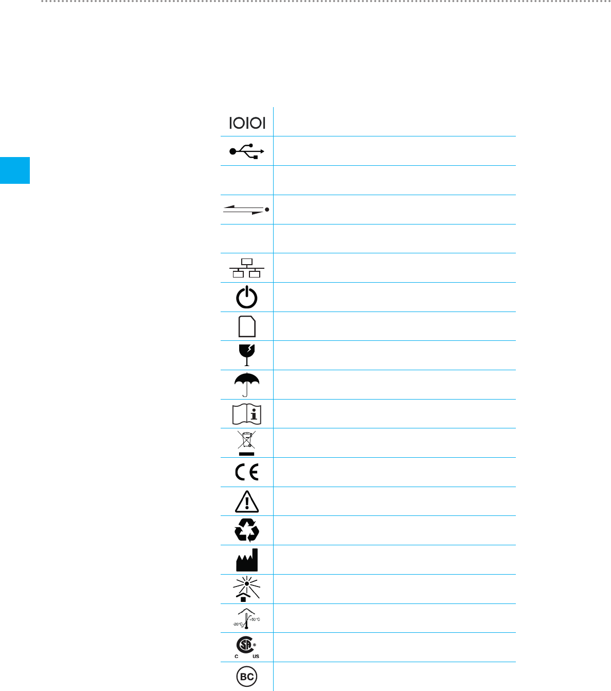
Thesymbols listed belowmayappear on the packaging material,on the device rating
plate and in the User Manual of the CITREXH4 measuring instrument.
RS-232 interface
USB interface
SN BBXXXX Serial number
Analog interface
CAN CAN interface
Ethernet interface
On/Off button
SD card
Fragile contents
Keep dry
Read the User Manual
The device must not be disposed of in household waste
The device is CE approved
Caution: observe the safety instructions in the User Manual
Reusable packaging
Manufacturer's specification and date of manufacture
Keep away from heat
Temperature range for storage and transport
CSA monogram with C/US indicator
California Energy Commission Compliant
Table 1: Symbol explanation
4 Symbolexplanation
9
Start-up
5
IMT Analytics AG
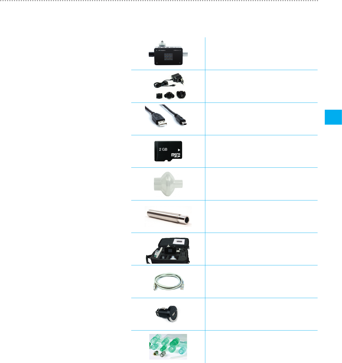
CITREXH4
Power supply plug with country-specific adapters
USB cable
MicroSD card
Dust filter RT019
Laminar inlet pipe
CITREX carrying case
Network cable
Car adapter
Adapter set
Table 2: Scope of delivery
5 Start-up
Start-up
10
5
IMT Analytics AG
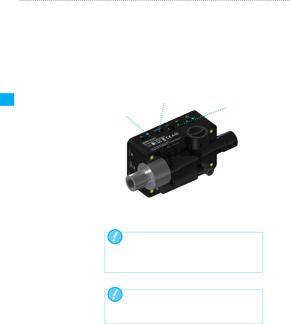
CITREXH4can be operatedfrom the mains or from theintegrated battery.
Power can be supplied via the USB port (Mini B), the analog interface or the CAN
interface on the top of CITREXH4. Use the power supply unit included to charge the
battery or operate the device via the USB port. You will find more information about
power supply and how to configure the plugs in the section "Electrical interfaces".
During the charging process a green battery symbol is lit on the front.
Please connect the power supply unit included to a voltage of 100VAC to 240VAC
with a frequency of 50Hz to 60Hz.
USB port
Analog interface
CAN interface
Figure 1: Power supply
Before switching on, make sure theoperating voltage ofthe power
supply unitagrees with thelocalmains voltage. You will find this
information on the rating plate on the back of the power supply unit.
When operating CITREXH4via the USB port only use the original
power supply unit included!
Thedevice indicates visually and audiblywhen the battery has to be
charged. Please do not store the battery in a depleted state.
Caution: depletion can damage the battery beyond repair!
5.1 Power supply
Start-up
11
5
IMT Analytics AG
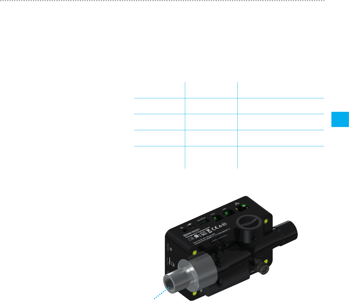
5.2.1 Flow channel
The flow channel can be used bidirectionally. The positive flow direction is from left
to right, viewed from the front of the device. The measurements of volume, flow, gas
temperature, oxygen and channel pressure are taken in the flow channel. The values,
and the ventilation parameters calculated from them, can be displayed on the screen.
You will find the relevant setting options in the section "Operation".
Flow (air) Measuring range ± 300 sL/min
Accuracy ± 1.9 % of reading or ± 0.1 sL/min
Volume Measuring range 0 – 10 sL
Accuracy ± 2 % of reading or ± 0.02 sL
Temperature Measuring range 0 – 50 °C
Accuracy ± 1.75 % of reading or 0.5 °C
Oxygen Measuring range 0 – 100 %
Accuracy ± 1 % O2
Pressure in flow
channel
Measuring range −50 – 150 mbar
Accuracy ± 0.75 % of reading or ± 0.1 mbar
Flow channel
Figure 2: Flow channel
5.2 Mechanical connectors
Start-up
12
5
IMT Analytics AG
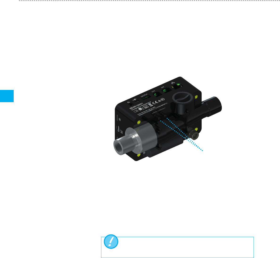
5.2.2 Differential pressure
This pressure connector measures the difference in pressure between the two con-
nectors. If only one connector is used for a measurement, pressure measurement
takes place at ambient pressure. The measuring range is −200 mbar to +200 mbar.
Please comply with the maximum permissible pressure at the connector. The sensor
values from this pressure sensor can be displayed in the menu with the parameter
" PDiff ".
Differential pressure connector
Figure 3: Differential pressure connector
Measuring range ± 200 mbar
Accuracy ± 0.75 % of reading or ± 0.1 mbar
Pressures above 1 bar damage the differential pressure sensor be-
yond repair!
Start-up
13
5
IMT Analytics AG
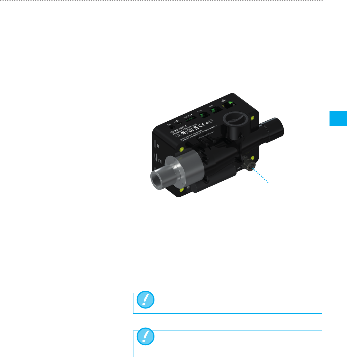
5.2.3 High pressure
The high-pressure connector measures the applied pressure up to 10 bar. It is rec-
ommended that the differential pressure connector be used for measurements up to
200 mbar. It is up to 100 times more accurate. The sensor values measured can be
displayed with the parameter " PHigh ".
The high-pressure connector can be fitted with a DISS adapter for air and oxygen.
You will find the ordering code in the section "Accessories and spare parts".
High-pressure connector
Figure 4: High-pressure connector
Measuring range 0 – 10 bar
Accuracy ± 1 % of reading or 10 mbar
Pressures above 15 bar damage the high-pressure sensor beyond
repair!
Do not use a tool to tighten the adapter on the high-pressure port
since this can damage the plastic casing. Please only tighten manu-
ally.
Start-up
14
5
IMT Analytics AG
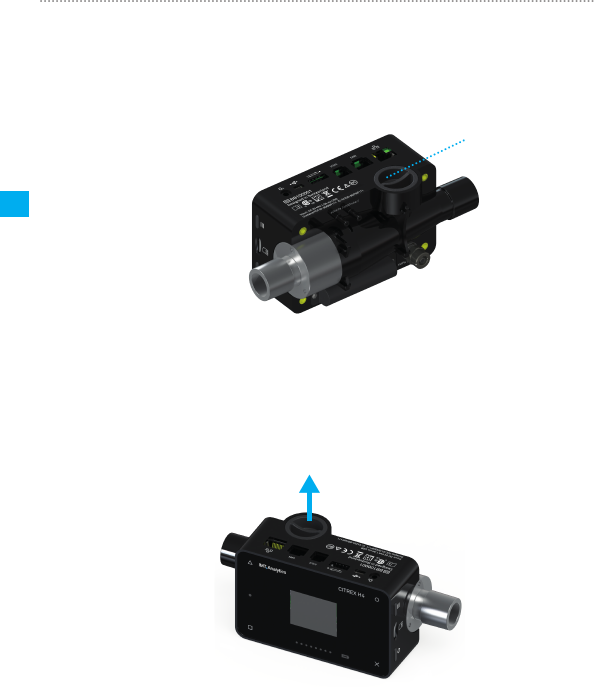
5.2.4 Oxygen sensor
CITREXH4 can measure the oxygen concentration in the flow channel. To do so, an
oxygen sensor is screwed into the appropriate port. The oxygen sensor has to be
connected to the measuring instrument using the cable included. The following steps
explain how to install and replace the oxygen sensor.
Oxygen sensor holder
Figure 5: Oxygen sensor holder
Measuring range 0 – 100 %
Accuracy ± 1 % O2 (absolute)
5.2.5 Installing the oxygen sensor
1. Remove the protective cap from the sensor port of the device.
Figure 6: Protective cap
Start-up
15
5
IMT Analytics AG
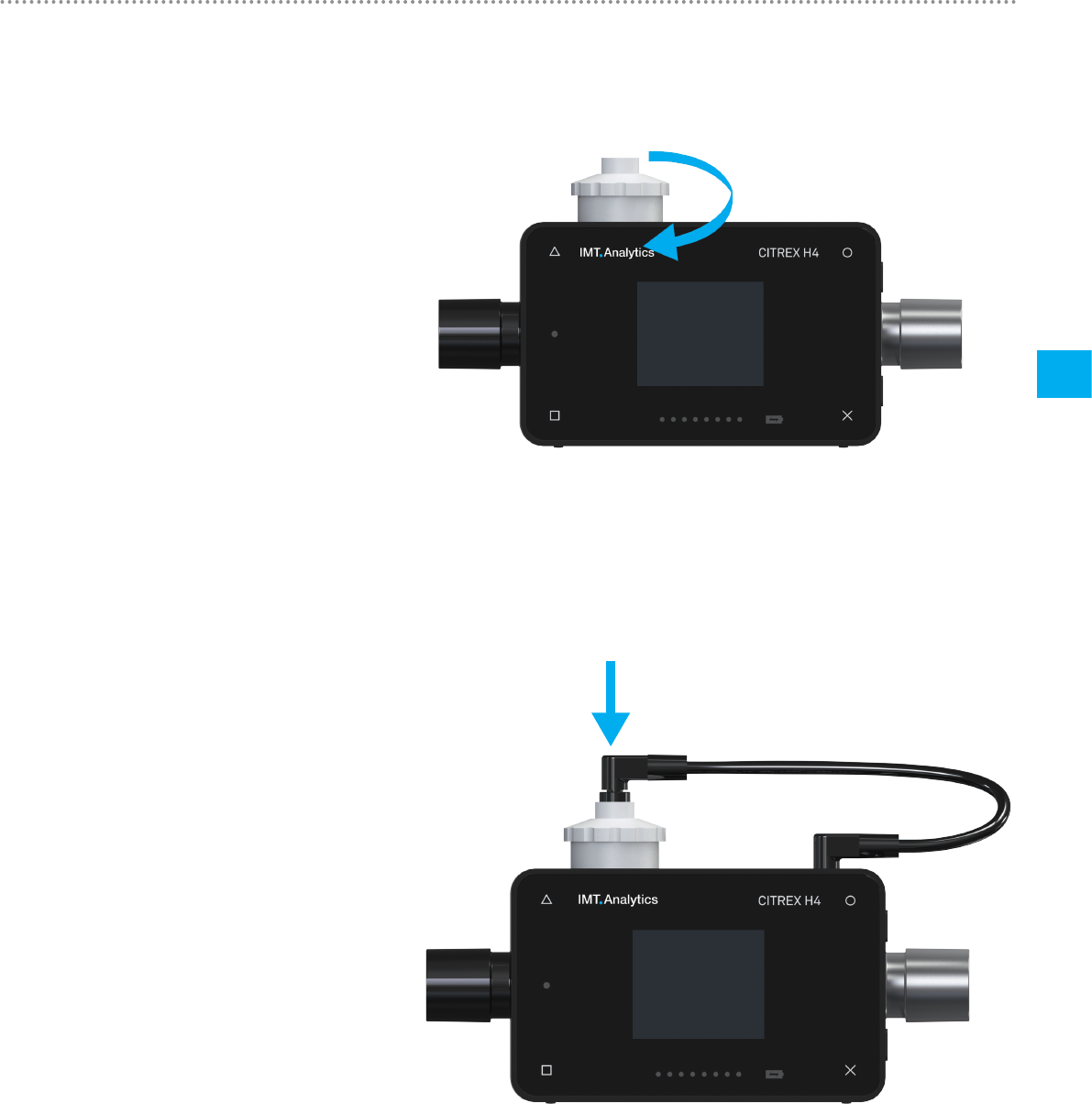
2. Screw the oxygen sensor clockwise into the appropriate port. Make sure the sen-
sor seals off the port and there is no leak.
Figure 7: Screwing in the oxygen sensor
3. Connect the cable included to the oxygen sensor by pushing the cable into the
hole at the top of the sensor until the cable locks into place. Connect the other end
of the cable to CITREXH4 by inserting it into the hole provided, which is labelled
"O2".
Figure 8: Oxygen sensor cable
4. Perform an oxygen calibration. The calibration procedure is described in the sec-
tion "Calibration". Calibration ensures that the measured values of the new sensor
are correct.
Start-up
16
5
IMT Analytics AG
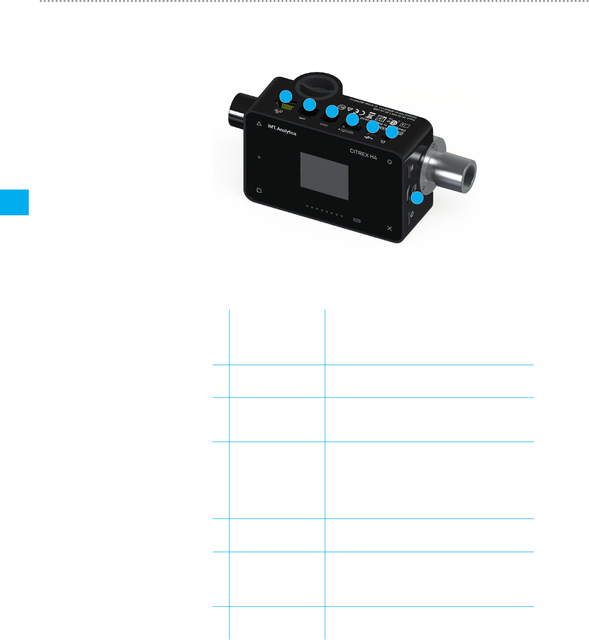
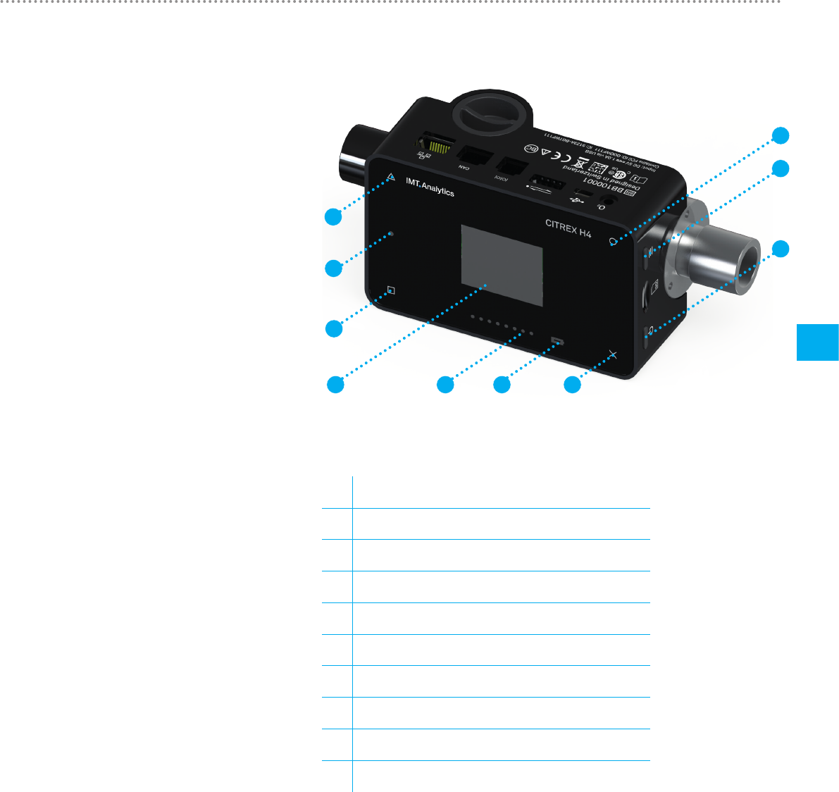
Figure 9 shows the available electrical interfaces of CITREXH4.
1
2
3
4
5
6
7
Figure 9: Electrical interfaces
1MicroSD
card slot
The firmware of CITREXH4is stored on the microSD
card. It also contains customised configurations and test
reports can be saved on the memory card. You will find
more information in the section "Reading measurement
data".
2O2 interface The oxygen sensor is connected to CITREXH4via the
O2 interface. You will find further information on this in the
section "Oxygen sensor".
3USB port The USB port is used to operate the device from the
mains power supply and to charge the device battery but
it can also be used as a data interface. It is a " USB Mini-B
port".
4Analog OUT The Analog Out port is used for reading analog signals. It
is also possible to connect an external trigger. Two ports
are reserved for mains operation and charging the device
battery. You will find the ordering code for the matching
connector in the section "Accessories and spare parts".
You will find additional technical information about the port
in the section "Interface definition".
5RS-232 The RS-232 port is used as a data interface. In the sec-
tion "Interface definition " you will find further information
about the interface.
6CAN The CAN interface is prepared in the device but at present
it is not yet supported by the firmware. The CAN interface
can be used for charging the device battery. You will
find information about the port in the section "Interface
definition".
7Ethernet The Ethernet interface is used to configure the device and
it is used as a data interface. You will find more informa-
tion in the section "Reading measurement data".
Table 3: Description of electrical interfaces
5.3 Electrical interfaces
Start-up
17
5
IMT Analytics AG
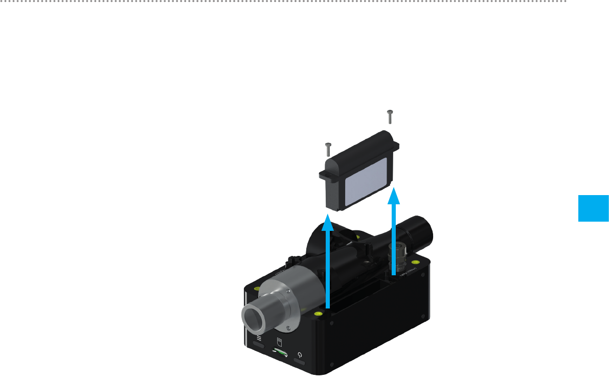
The battery of CITREX H4 can be replaced by the user. To do so, undo the two
screws on the back of the device and remove them. Then the battery can be re-
moved and replaced. Check to make sure the new battery is inserted properly. For
this purpose the terminals must be above one another.
Figure 10: Replacing the battery
5.4 Replacing the CITREX battery

Operation
18
6
IMT Analytics AG
This section describeshow to use the device and whatpossible uses there are.
The device is switched on and off at the On/Off button. Figure 11, section "User
controls",shows where this button is located on the device. To switch CITREXH4on
you must press the On/Off button briefly. You will hear an audible signal. To switch
the device off you must press the On/Off button for about 1second. If the device can
no longer be controlled, you have the option of pressing the On/Off button for about
6seconds. The device is then forced to shut down.
Press the context button on the side of the device for 2 seconds. The screen shows
a message indicating that the screen is locked. To unlock the screen, press and hold
down the context button or one of the four buttons on the front for 2 seconds.
If the device is not operated by the user, the display of CITREXH4 shuts down after
about one minute and the four buttons start to flash. As soon as a button is pressed,
the screen comes on again.
The setting for how long it takes until the display is dimmed can be customised using
the configuration tool. You will find further information on this in the section "Config-
uration tool".
6 Operation
6.1 Switching the device on/off
6.2 Screen lock
6.3 Dim screen
Operation
19
6
IMT Analytics AG
1
2
3
456
8
9
10
7
Figure 11: User controls
1 Change, Edit
2 Context button; long press: key lock on/off
3 On/Off button
4 Menu button; zero point adjustment
5 Charge indicator
6 Flow direction indicator
7 Screen
8 Measurement values
9 Malfunction indicator
10 Display readings and scroll back
Table 4: User controls
6.4 User controls
Operation
20
6
IMT Analytics AG
With the × button you return to the Settings menu. By pressing the button more than
once you can view the various settings of the measuring instrument.
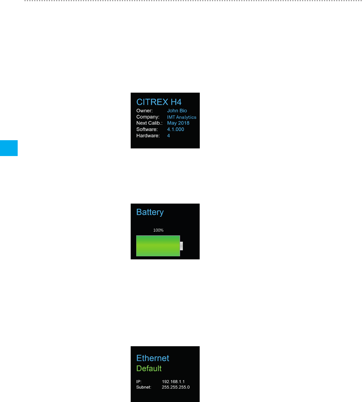
6.5.1 Info display
This display provides information about the owner, the company, the next recom-
mended calibration, the software version and the hardware revision. Settings con-
cerning the owner can be edited with the configuration tool.
Figure 12: Info display
6.5.2 Battery indicator
The battery indicator informs you about the level of the battery charge.
Figure 13: Battery indicator
6.5.3 Ethernet interface
Here it is possible to make various settings for the network connection. With the
button you can choose between the options "DHCP Client", "Default" and "Config-
ured". The setting does not have to be confirmed and it is enabled as soon as it is
visible on the screen. More information about the settings is available in the section
"Web server".
Figure 14: Ethernet interface
6.5 Settings
Operation
21
6
IMT Analytics AG
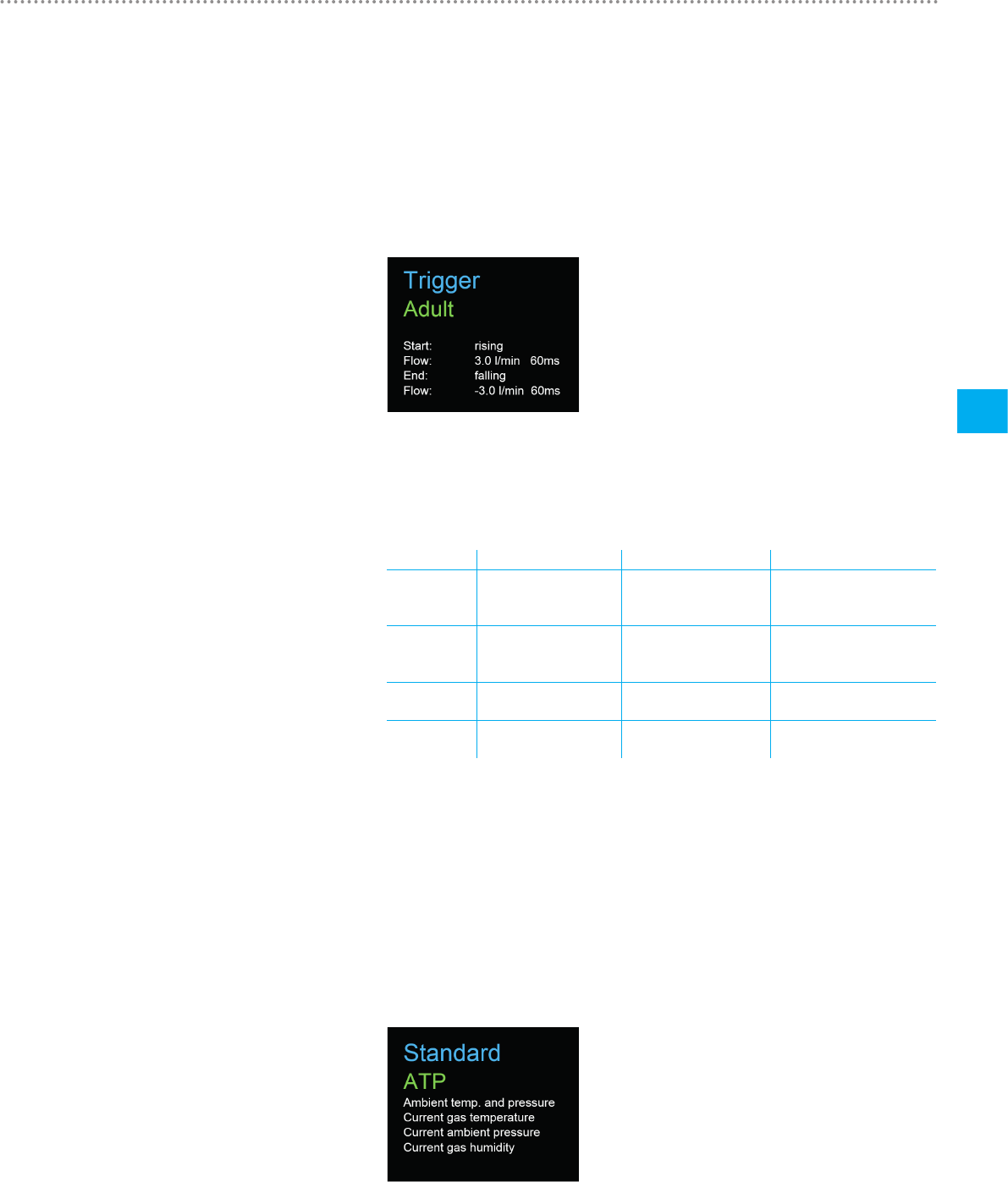
6.5.4 Trigger
With the trigger settings the start and end points of a ventilation parameter are de-
fined. Three preset triggers are available. With the button you can select the trigger
"Adult", "Pediatric" or "High Frequency". The trigger settings do not have to be saved
and they are enabled as soon as they are displayed on the screen. It is possible to
differentiate between flow trigger, pressure trigger and external trigger.
The settings can be changed with the configuration tool. You will find further informa-
tion on this in the section "Configuration tool".
Figure 15: Trigger
The preset trigger settings are defined as follows.
Adult Pediatric High Frequency
Start 3 L/min
Rising edge
1 L/min
Rising edge
3 L/min
Rising edge
Stop − 3 L/min
Falling edge
− 1 L/min
Falling edge
− 3 L/min
Falling edge
Delay 60 ms 60 ms 10 ms
Base flow 0 L/min 0 L/min 0 L/min
Table 5: Trigger settings
6.5.5 Gas standard
The CITREXH4 measuring instrument can convert gas flow and volume readings to
various gas standards and display them. Care must be taken to ensure that on the
measuring instrument the same gas standard is set as the one on the device being
tested. With the button you can switch between the various gas standards. As
soon as a gas standard is displayed, it is enabled. There is a list of available gas
standards in the Appendix in the section "Gas standards for flow and volume read-
ings".
Figure 16: Gas standard
Operation
22
6
IMT Analytics AG
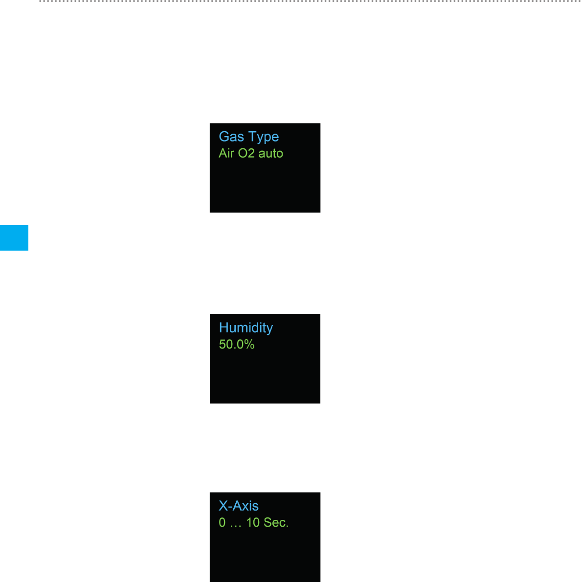
6.5.6 Gas type
Under this menu item the gas type to be measured can be set. With the button you
can switch between gas types. The gas type indicated is enabled and does not have
to be saved. In the section "Gas type" there is an overview of available gas types. Gas
types with adjustable oxygen concentrations, e.g. "Air O2 manual", can be changed
with the configuration tool.
Figure 17: Gas type
6.5.7 Gas humidity
The gas humidity of the gas being measured can be set. This has an impact on gas
flow measurement. With the button the gas humidity can be changed in steps of
10. The value is enabled as soon as it is displayed on the screen.
Figure 18: Gas humidity
6.5.8 Setting the X-axis
Here the time axis of the graph view can be set. 2, 4, 6, 8 and 10 seconds are avail-
able for selection. The setting can be changed with the button.
Figure 19: Setting the X-axis
Operation
23
6
IMT Analytics AG
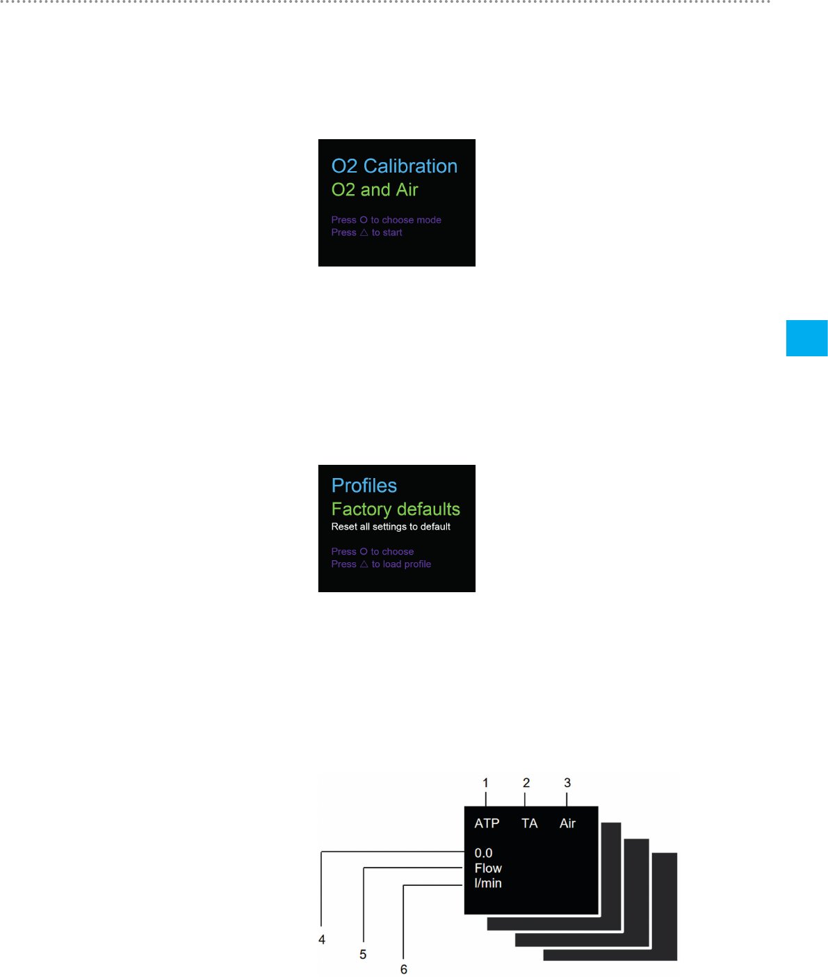
6.5.9 O2 calibration
The process of oxygen calibration is described in the section "Calibration". With the
button you can choose between one-point calibration and two-point calibration.
Press the button to start calibration.
Figure 20: O2 calibration
6.5.10 Profiles
With this settings item it is possible to call up and load the saved and preset profiles.
The button switches between the available profiles and with the button the pro-
files can be loaded. In CITREXH4 the following profiles are already integrated when
delivered: "Factory defaults", "Imperial units" and "Metric units". With the profile editor
you can create and save your own profiles. The procedure is explained to you in the
section "Creating a profile".
Figure 21: Profiles
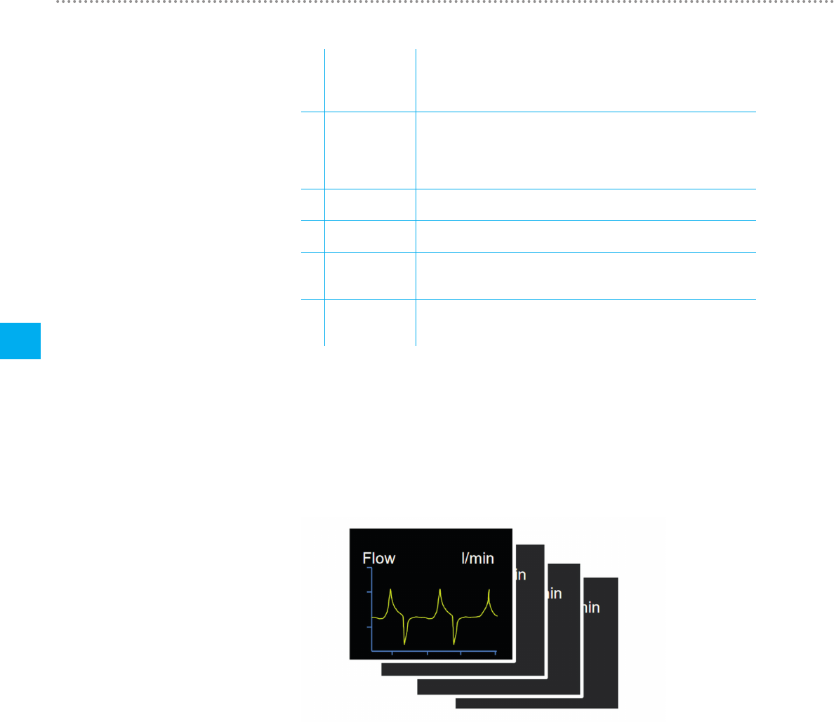
With the button on the front of CITREXH4 you can display the various numerical
readings. If you press more than once, the view on the screen changes. The differ-
ent views can be configured by web server. The web server and how to make the
settings are explained in the section "Web server". 1, 2, 4 and 6 readings can be
displayed in each configured view.
Figure 22: Numerical readings
6.6 Numerical readings
Operation
24
6
IMT Analytics AG
1Gas standard The measured volume readings or gas flow readings can be
displayed with various gas standards. There is a list of standards
in the Appendix in the section "Gas standards for flow and volume
readings".
2Trigger signal The icon appears as soon as a trigger condition is fulfilled. This
means that the time of appearance of the indicator is identified as
the start of inspiration. The indicator appears for 0.5 seconds. If
this signal is not displayed, the trigger settings should be adjusted
for the current ventilation mode.
3Gas type The gas type currently set is displayed as text. It can be custom-
ised on the device under Settings.
4Reading This shows the current reading in the selected unit of measure-
ment.
5Measurement
parameter
Indicates the measurement parameter currently selected. Meas-
urement parameters can be changed in configuration; see section
"Configuration tool".
6Unit of meas-
urement
Indicates the unit of measurement currently selected. Units of
measurement can be changed in configuration; see section "Con-
figuration tool".
Table 6: Numerical values
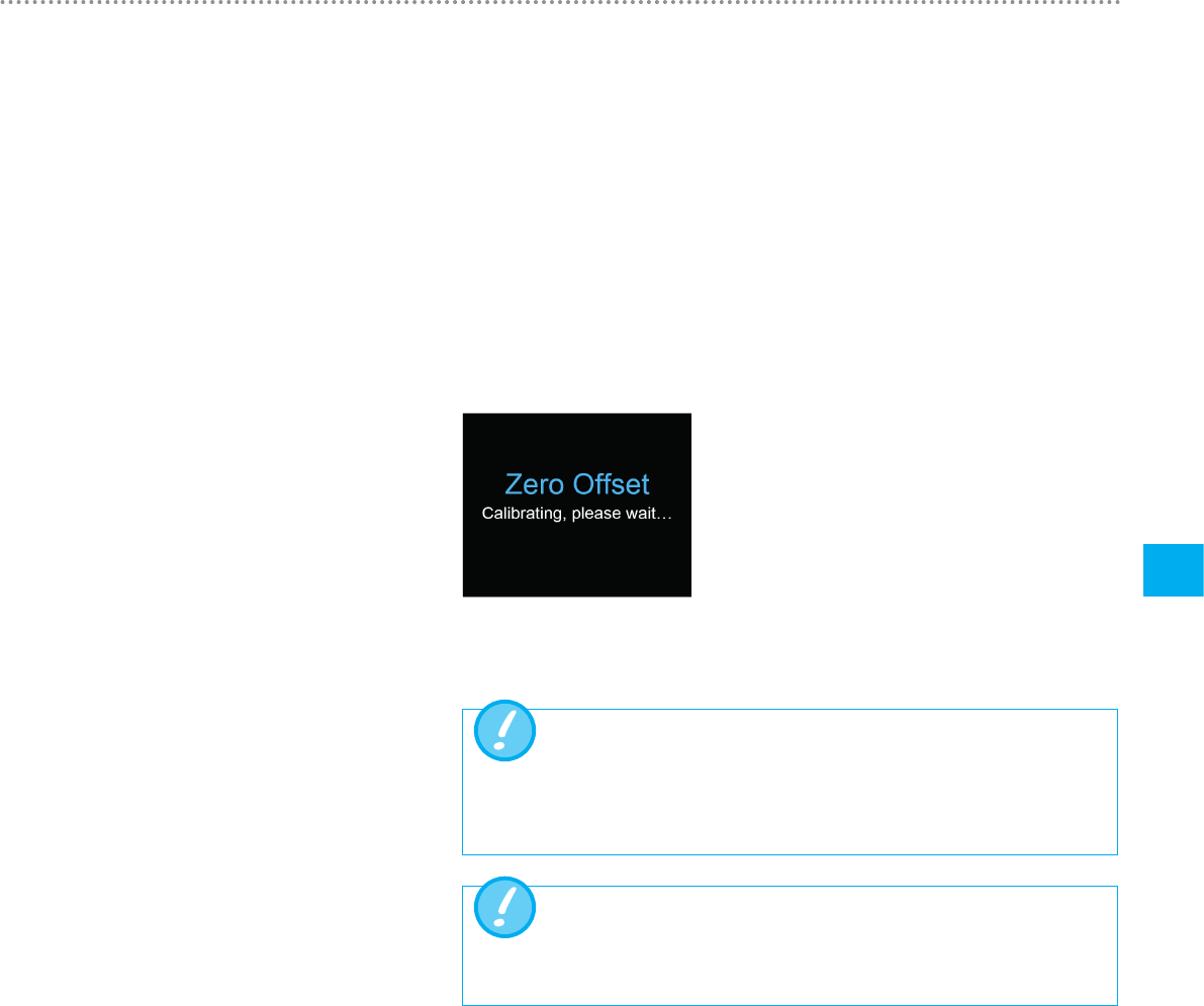
By pressing the icon on the front of CITREXH4, parameters currently being meas-
ured can be displayed in the form of graphs. For each screen view there are one and
two measurement curves available for selection. The relevant parameters and units
of measurement can be set using the configuration tool. You will find a description of
this in the section "Configuration tool".
Figure 23: Measurement curves
The screen of CITREXH4 is refreshed every 0.5 s. The recording of readings takes
place every 5 ms. Since CITREXH4 can record and display readings very quickly, it
is advisable to filter the readings. This is performed using a mean value. The extent to
which a reading is filtered can be set using the configuration tool.
The following filters are available:
• No filter (indication of the last value measured without any threshold)
• Low (mean above 240 ms)
• Medium (mean above 480 ms)
• High (mean above 960 ms)
The "high" filter is set by default.
6.7 Graphical readings
6.8 Filter
25
Calibration
7
IMT Analytics AG
The various calibration options with CITREXH4 are described in this section. To avoid
incorrect measurements you must adhere to the procedures described here.
This adjustment is necessary if indication of the differential pressure sensor (Pdiff), the
high-pressure sensor or a flow through open connection ports shows a value greater
or less than zero. This can occur if there are considerable temperature fluctuations,
or after the warming-up time. Zero calibration resets all values to zero. To perform
zero calibration you must remove all connected tubes from the device. Press the
icon and keep it pressed for approx. 3 seconds. The screen shows a message "Zero
Offset – Calibrating, please wait".
Figure 24: Zero calibration
When you have switched on the device, individual displays may devi-
ate slightly from the zero point until operating temperature has been
reached. Zero calibration should never be performed with the device
cold. Warming-up time is approx. 10 minutes.
During zero calibration there must be no pressure being applied to a
connection port, and care must be taken to ensure that there is no
flow through the flow channel.
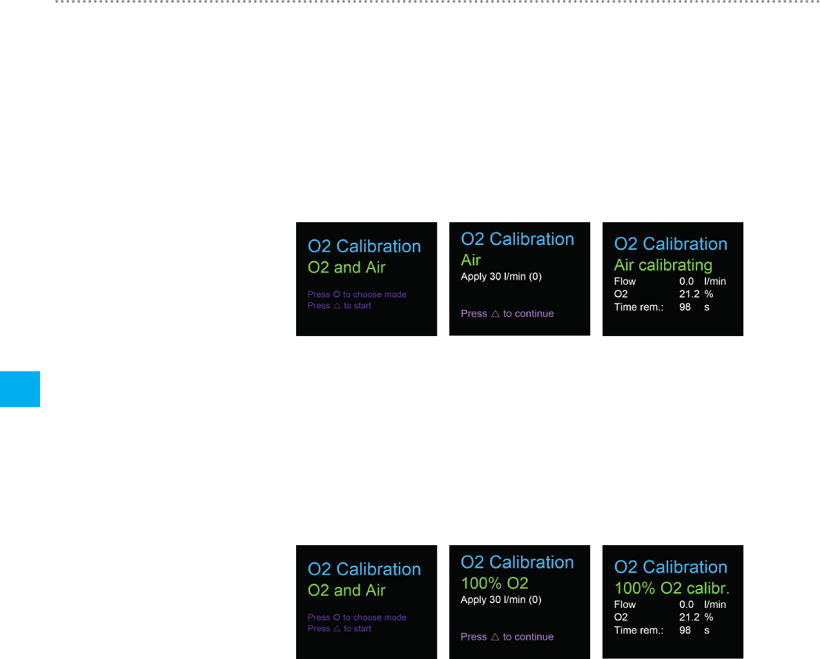
There are two different methods of calibrating the oxygen cell. The variant in which
the oxygen cell is calibrated with air only takes about two minutes. The second vari-
ant consists of calibrating the oxygen cell with air and 100 % oxygen. This so-called
two-point calibration adjusts the oxygen sensor more accurately and takes about
four minutes. Calibration can be selected by pressing the button more than once.
7 Calibration
7.1 Zero point
7.2 Oxygen (O2) calibration
Calibration
26
7
IMT Analytics AG
7.2.1 Calibration with air
Make sure air is flowing through the flow channel at a rate of at least 30 L/min. To start
calibration, press the button until you see the menu item
"O2 Calibration". With the button you can switch between air and air and oxygen
(O2). Select the button until "Air" appears on the screen in green letters. To start
calibration, press the button.
Figure 25: Screen displays "Calibration Air"
7.2.2 Calibration with oxygen and air
For calibration of the oxygen cell with oxygen and air a gas flow of 30 L/min is used
in each case. Press the button until you see the menu item "O2 Calibration". With
the button you can switch between air and air and oxygen (O2). Press the button
until the screen shows "O2 and Air" in green letters. To start calibration, press the
button. Calibration for air and oxygen takes 120 seconds for each one.
Figure 26: Screen displays "Calibration Oxygen and Air"
27
Connecting the device
8
IMT Analytics AG
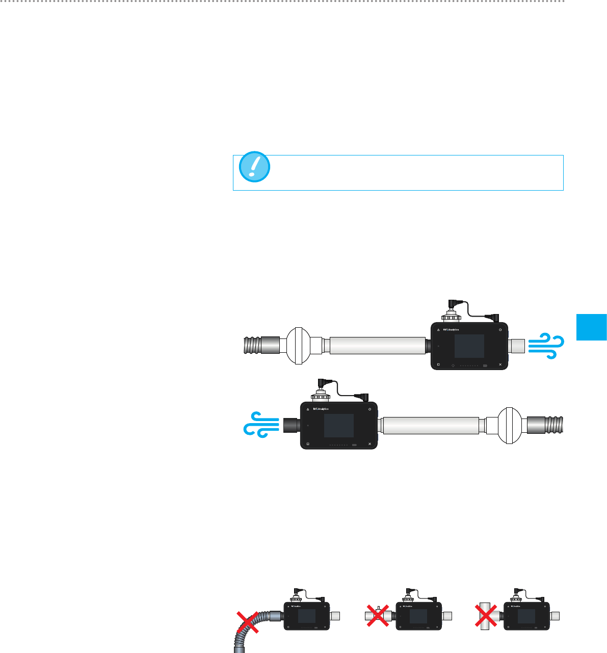
The measurement setup for CITREX H4has an impact on flow measurement. To
obtain results that are as accurate as possible, comply with the instructions in this
section. It is important to ensure that the tubing in the measurement setup does not
have any radii, kinks or dents. You are also recommended to always use the inlet pipe
and the dust filter.
Themeasured gases must befree of oil, greaseand dust.
Thegeneral measurement setup applies to gas flow measurement. The RT019 fil-
ter included and the inlet pipe must be used. This ensures laminar flow to the flow
sensor unit. The filter also prevents dust, oil and grease from contaminating the
CITREXH4measuring instrument and thus prevents discrepancies in measurement
results. The measurement setups shown below are dependent on the direction of
gas flow being measured.
CITREX H4
CITREX H4
CITREX H4
CITREX H4
CITREX H4
EasyLung
CITREX H4
ATPAir O2 man
Ppeak
mbar
PEEP
mbar
25
5
ATPAir O2 man
Ppeak
mbar
PEEP
mbar
25
5
ATPAir O2 man
Ppeak
mbar
PEEP
mbar
25
5
ATPAir O2 man
Ppeak
mbar
PEEP
mbar
25
5
ATPAir O2 man
Ppeak
mbar
PEEP
mbar
25
5
ATPAir O2 man
Ppeak
mbar
PEEP
mbar
25
5
CITREX H4
CITREX H4
CITREX H4
CITREX H4
CITREX H4
EasyLung
CITREX H4
ATPAir O2 man
Ppeak
mbar
PEEP
mbar
25
5
ATPAir O2 man
Ppeak
mbar
PEEP
mbar
25
5
ATPAir O2 man
Ppeak
mbar
PEEP
mbar
25
5
ATPAir O2 man
Ppeak
mbar
PEEP
mbar
25
5
ATPAir O2 man
Ppeak
mbar
PEEP
mbar
25
5
ATPAir O2 man
Ppeak
mbar
PEEP
mbar
25
5
Figure 27: General measurement setup
The measurement setups listed below are unsuitable and produce inaccurate meas-
urement results. Kinks, tees andangle pieces should be avoided in the flow channel.
They cause turbulence in the gas being measured and hence inaccurate or incorrect
measurement results.
Bad setup: Kinks, tees, angle pieces at the device inlet
CITREX H4
CITREX H4
CITREX H4
CITREX H4
CITREX H4
EasyLung
CITREX H4
ATPAir O2 man
Ppeak
mbar
PEEP
mbar
25
5
ATPAir O2 man
Ppeak
mbar
PEEP
mbar
25
5
ATPAir O2 man
Ppeak
mbar
PEEP
mbar
25
5
ATPAir O2 man
Ppeak
mbar
PEEP
mbar
25
5
ATPAir O2 man
Ppeak
mbar
PEEP
mbar
25
5
ATPAir O2 man
Ppeak
mbar
PEEP
mbar
25
5
Figure 28: Bad setup
8 Connecting the device
8.1 Generalmeasurement setup
Connecting the device
28
8
IMT Analytics AG
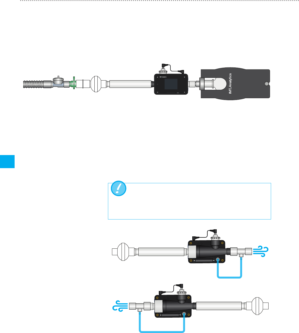
CITREX H4 is ideal for checking ventilators. The best measurement results are
achieved with the measurement setup shown below. Make sure the test lung is con-
nected to the grey aluminium connection port of CITREXH4.
Figure 29: Measurement setup for checking ventilators
CITREXH4compensates for the gas pressure during flow measurement. In the flow
channel, gas pressures up to 150 mbar are compensated. For gases at higher pres-
sures the high-pressure sensor can be used. For this purpose connect the device
outlet to the high-pressure sensor. In the menu "Settings", "Measurement" you must
also switch the "Pressure Compensation" setting to "Pressure High".
In theflow channel, pressures up to 150 mbarcan be compensat-
ed. In conjunction with the high-pressure sensor, pressures up to
300 mbar can be compensated. Pressures in the flow channel above
800 mbar can damage the device.
1MPa (10bar)
1MPa (10bar)
Figure 30: Measurement setup for gases at high pressure
8.2 Measurement setup for
checking ventilators
CITREX H4
CITREX H4
CITREX H4
CITREX H4
CITREX H4
EasyLung
CITREX H4
ATPAir O2 man
Ppeak
mbar
PEEP
mbar
25
5
ATPAir O2 man
Ppeak
mbar
PEEP
mbar
25
5
ATPAir O2 man
Ppeak
mbar
PEEP
mbar
25
5
ATPAir O2 man
Ppeak
mbar
PEEP
mbar
25
5
ATPAir O2 man
Ppeak
mbar
PEEP
mbar
25
5
ATPAir O2 man
Ppeak
mbar
PEEP
mbar
25
5
Breathing circuit Inlet pipe CITREXH4 Test lungFilter
8.3 Measurement setup for gases
at high pressure
29
Profiles
9
IMT Analytics AG
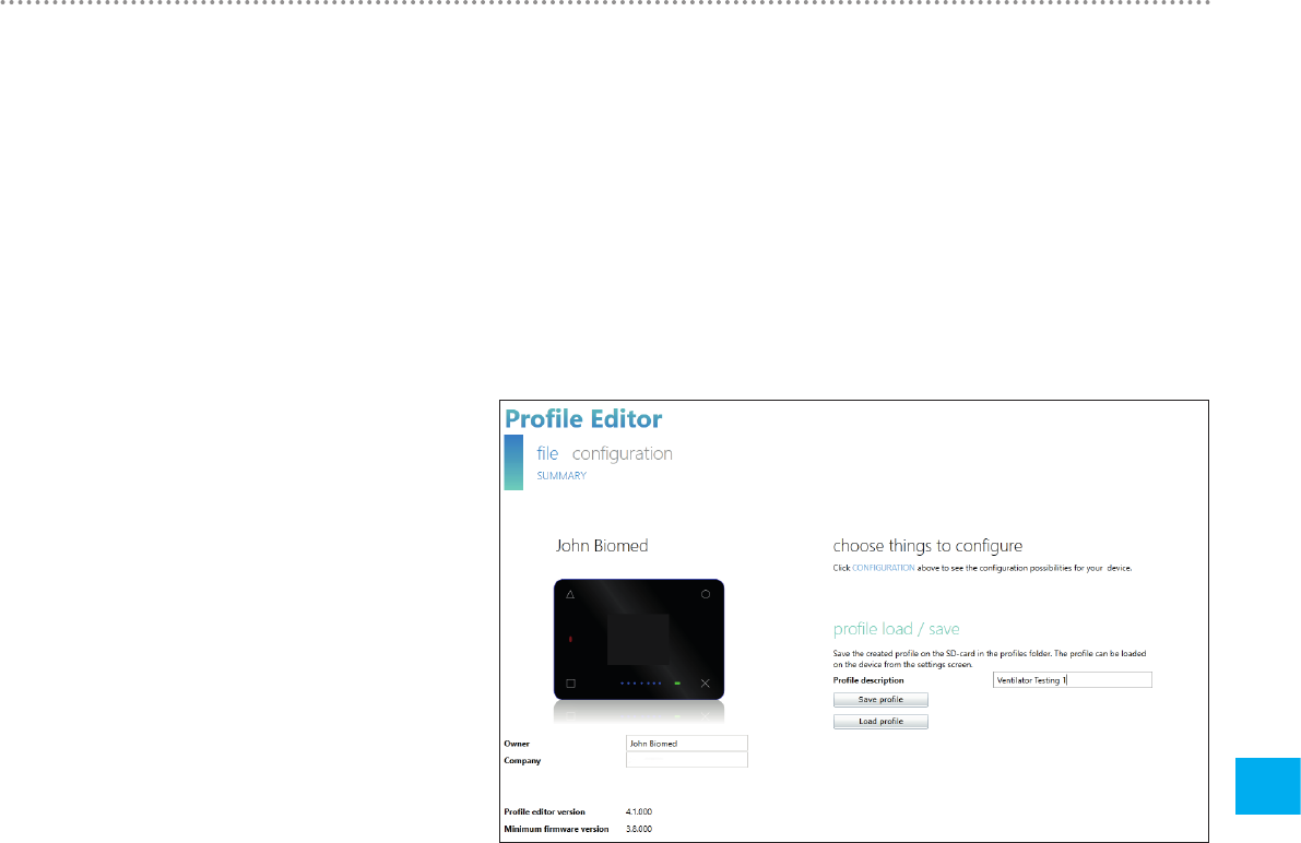
Theuser has the option of saving different profiles to suitpersonal requirements. To
be able to use the profile editor it is essential to have Microsoft Internet Explorer with
the browser plug-in Silverlight.
To create a profile, remove the SD card from CITREXH4 and connect it to your PC
via an SD card reader. Then open the drive of the SD card. There you will find the file
"ProfileEditor.html", which has to be opened using Internet Explorer, resulting in the
picture below.
Figure 31: Profile editor in Internet Explorer
9 Profile editor
9.1 Creating a profile
Profiles
30
9
IMT Analytics AG
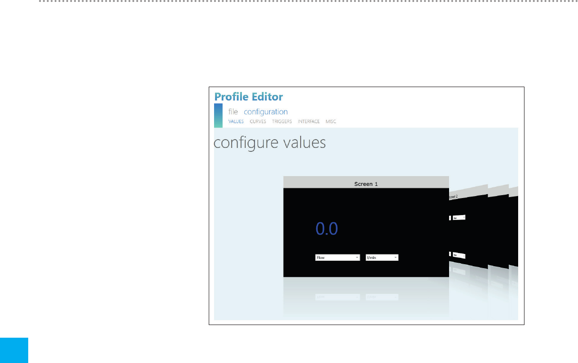
Now you can create a new profile by making the settings in the "configuration" menu.
Figure 32: Profile editor "configuration"
This is where parameters, measurement curves, triggers, interfaces, etc. can be de-
fined. These can be saved, as shown in the picture "Profile editor in Internet Explor-
er". You can also add a description to the profile. Save the new profile with the "Save
profile" button. Save the file in the "Profiles" folder on the SD card. When you have
saved the new profile on the SD card, place the card back in CITREXH4 and start the
device. The newly created profile can be loaded in the "Profiles" menu.

31
Configuration tool
10
IMT Analytics AG
The configuration tool can only be used with Microsoft Internet Explorer.
Microsoft® Silverlight 5 or higher
Windows x86 or x64 (64-bit mode only supports IE) 1.6 GHz or higher
with 512 MB RAM
Macintosh (Intel based) Intel Core Duo 1.83GHz or higher with 512MB RAM
Microsoft® Windows® 10, 8.1, 8, Windows Server 2012, 7, 7 SP1,
Windows Server 2008 SP2, Windows Server 2008 R2 SP1, Vista
Macintosh OS 10.6 (Intel based), MacOS 10.7 – 10.11 (Intel based)
Ethernet network connection
Screen resolution 1024× 768(1280× 1024recommended)
The Ethernet port on CITREXH4 enables access to the device via a network. The
measured real time data can be tracked and analysed on the computer. Settings can
also be made on the device via the web browser using the so-called configuration
tool. To be able to use the web server it is essential to have an installed Internet Ex-
plorer with Microsoft Silverlight 5.
There are three different setting options to establish a connection between
CITREXH4 and a computer. Tap the button until the "Ethernet" menu item ap-
pears. You will find a description of the settings in the following sections.
10.2.1 Default
These are default settings that cannot be changed. These settings are recommended
in order to establish a direct connection to the computer via an Ethernet cable. The
configuration on CITREXH4 is as follows:
IP Address: 192.168.1.1
Subnet Mask: 255.255.255.0
To establish a connection, the network settings on the computer must be changed.
For this purpose open the network settings of the computer, which are located in
the Control Panel. Then open the "Internet Protocol Version 4 (TCP/IPv4)" settings.
Enter an IP address between 192.168.1.2 and 192.168.1.255 and subnet mask
255.255.255.0 in the form on the screen. Confirm with "OK".
Now open Internet Explorer and enter IP address 192.168.1.1 in the address field.
The connection to CITREXH4 is established.
10 Configuration tool
10.1 PC minimum requirements
10.2 Web server
Configuration tool
32
10
IMT Analytics AG
10.2.2 Configured
This setting option is suitable for connecting CITREXH4 to a network that does not
have a DHCP server. Define an IP address and a subnet mask using the configu-
ration tool on CITREXH4. When the settings have been confirmed the device can
be connected up to the network and be accessed using the defined IP address via
Internet Explorer.
10.2.3 DHCP
To connect CITREXH4 to a DHCP server, first connect CITREXH4 to the network. In
the "Ethernet" menu select the setting "DHCP" and confirm it with "OK". With the IP
address shown on the display it is possible to establish a connection to CITREXH4
via Internet Explorer.
In the "Monitoring" menu item it is possible to access the measurement data of
CITREX H4 via the network. Either numerical readings or graphical measurement
curves can be selected.
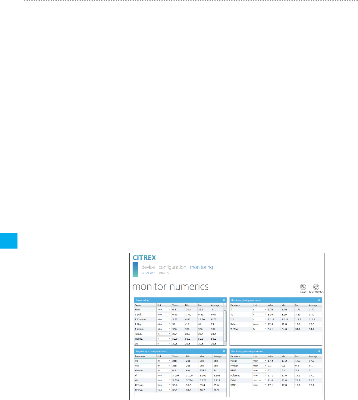
10.3.1 Numerical readings
Here it is possible to directly track real-time measurement data on the computer
monitor. Both current readings and a minimum, a maximum and a mean are calcu-
lated for each reading. Statistical analysis can be restarted by pressing the "Reset"
button. There is also the option of exporting the readings currently being displayed.
To do this, press the "Export" button: an Explorer window opens in which you can
select the storage location and the storage type. There are XML files (*.xml) and CSV
files (*.csv) available for selection.
Figure 33: Monitoring numerics
10.3 Monitoring option
Configuration tool
33
10
IMT Analytics AG
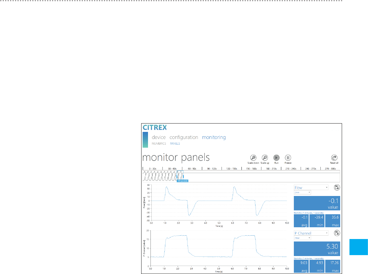
10.3.2 Graphical readings
Here it is possible to directly track real-time curves on the computer monitor. Select
the required reading using the pull-down menu. By pressing the "Run" button it is
also possible to record readings for 300 seconds. Recording can be terminated by
pressing the "Freeze" button. If you have recorded a measurement, you can move
the slider into the desired measuring time in order to analyse the period here. Inciden-
tally, it is not only the displayed measurement curves that are recorded; all the read-
ings available for selection are also recorded. There is also the option of exporting the
measurement curves currently being displayed. To do this, press the "Export" button:
an Explorer window opens in which you can select the storage location. The curves
can be saved in the form of a PNG file.
Figure 34: Monitoring panels
Reading measurement data
34
11
IMT Analytics AG
Thefiles onthe microSDcardmust not be renamed or deleted under
any circumstances.
Measurement datacan be read viathe microSD card,via the Analog
OUTinterface or via the RS-232 interface. For information about
using these interfaces please contact your dealer or IMT Analytics
directly.
Press the button and keep it pressed for approx. 3 seconds. A snapshot of all the
parameters is taken in a CSV file and saved on the SD card.
Thedata can be read directly from the SD card. For this purpose you must discon-
nect the SD card from CITREXH4 by pressing the SD card once. It is possible to
connect the card to your computer directly using an SD card reader.
The memory card of CITREXH4contains the following data and folders.
Folder or file Description
DATA In this directory you will find the readings that have
been saved.
LOGS CITREXH4continuously records information about
its functions and saves it in the form of log files.
This data is only used for remedying malfunctions
and resolving issues.
*.CFG, *.SCR, *.TRG files CFG, SCR and TRG files are required by CIT-
REXH4 to activate internal processes.
Formatter\SetupReportFormatter.bat This batch file is required to format saved data in
an Excel file.
Formatter\AboutReportFormatter.txt This TXT file describes the procedure for format-
ting saved data in an Excel file.
Formatter\ReportFormatter.xlsb This is the actual Excel file template in in which the
saved data is formatted.
Clientaccesspolicy.xml This file is required for the configuration tool.
index.html This file is required for the configuration tool.
USB-Driver\usb_cdc_ser.inf Driver for the USB device identification.
Table 7: Folder structure of CITREXH4
11 Readingmeasurement data
11.1 Saving measurement data on
the microSD card
11.2 Reading the data
35
Servicing and care
12
IMT Analytics AG
Careful servicing in compliance with the instructions is essential for ensuring that
CITREXH4operates safely andefficiently. Only components recommended by the
manufacturer may be used.
It isabsolutely essential tocomply with the guidelines andservicing
instructions issued by thevarious manufacturers.
The servicing operations listed below may only be performed by
persons whoare familiar with CITREXH4. All further repair work may
only be performed by authorised trained professionals. Please also
observe the information issued by the various manufacturers.
Toensure that your deviceoperates with precision and reliabilityfor as long as possi-
ble,it is essential toperform the followingservicing routinesregularly.
12.1.1 During operation
Use of the filter included and the inlet pipe in order to protect the device against con-
tamination. Make sure the device is only used inside a building.
12.1.2 Every 4 weeks
Check the bacterial filter for soiling. For this purpose the inlet and outlet of the filter
must be connected to the differential pressure port using two tees. In this way the
pressure drop above the filter can be measured. The pressure drop must not exceed
a value of 2 mbar at a flow of 60L/min. Otherwise the filter must be replaced.
12.1.3 Every 12 months
Factory calibration and servicing to ensure reliable measurement; it may only be per-
formed by IMT Analytics or an authorised partner.
To have CITREXH4calibrated at the manufacturer's, IMT Analytics, visit the website
www.imtanalytics.com/easycal
The EasyCal service makes it possible for users to have CITREXH4 calibrated and
adjusted quickly and easily. The annual servicing procedure is also performed.
12 Servicing and care
12.1 Preventivecleaning
andservicing operations

Accessories and spare parts
36
13
IMT Analytics AG
On the website www.imtanalytics.com you will find the original spare partsand other
products from IMT Analytics.
Ordering address:
IMT Analytics AG
Gewerbestrasse 8
CH-9470 Buchs, Switzerland
Tel: +41 (0) 81 750 67 10
Email: sales@imtanalytics.com
Orders can also be placed in our Webstore.
Options
302.159.000 Warranty extension (plus 2 years) CITREXH4
Servicing
000.000.012 Calibration & Servicing CITREXH4
000.000.014 Receiving inspection of CITREXH4
302.160.000 Triple Calibration & Servicing Package for CITREXH4
Accessories & Consumables
300.548.000 Adapter set
301.997.000 Car adapter for CITREX
302.077.000 Laminar inlet pipe
304.161.000 Black protective pouch for CITREX
304.161.001 Red protective pouch for CITREX
304.161.002 Blue protective pouch for CITREX
500.030.000 High-pressure adapter DISS O2
500.030.002 High-pressure adapter DISS Air
301.851.000 MicroSD memory card
302.075.000 RS-232 interface cable
301.672.000 Analog output terminal connector
301.655.000 Blind plug for oxygen connector (rubber)
302.178.000 Blind plug for oxygen connector (solid)
301.624.000 Oxygen sensor with mono jack
302.531.000 Bacterial filter RT019
304.714.000 CITREX stand
Spare parts
301.936.000 Carrying case for CITREXH4
301.625.000 Battery for CITREX
301.563.000 Network cable
301.673.000 USB cable for CITREX
301.653.000 Oxygen sensor cable
304.578.000 Power supply plug for CITREX
302.780.000 Flow channel protective cap
Table 8: Accessories
13 Accessories andspare parts
13.1 Accessories table

37
Disposal
14
IMT Analytics AG
Disposal of the deviceis the operator's responsibility. The device can …
• be delivered, carriage free and duty paid, to the manufacturer for disposal.
• behanded over to alicensedprivate or publiccollection company.
• beprofessionally broken downinto its constituent partsby the operator and
berecycled ordisposed ofin accordance withregulations.
In the case of self-disposal the disposal regulations are country-specific and are con-
tained in relevant laws and ordinances. These codes of conduct must be obtained
from the authorities responsible.
In this context, wastes must be recycled or destroyed …
• without endangering human health.
• without using processes or methods that harm theenvironment,especially
water, air, soil,animals and plants.
• without causing noise or odour nuisances.
• without having a detrimental effect on the surroundings or landscape.
14 Disposal

15
Directives and approvals
38 IMT Analytics AG
• CE
• CAN/CSA-C22.2 No. 61010-1-12
• UL Std. No. 61010-1 (3rd Edition)
• IEC 61010-1 2010
• IEC 61326-1 2012
• ETSI EN 301 489-17 V3.1.0
• FCC Part 15, Subpart B, Digital Devices, Emission Class B
CE Declaration of Conformity
2014/35/EU (LVD)
DIRECTIVE 2014/35/EU OF THE EUROPEAN PARLIAMENT AND OF THE COUNCIL
of 26 February 2014 on the harmonisation of the laws of the Member States relating
to the making available on the market of electrical equipment designed for use within
certain voltage limits tested according to EN61010-1:2010
2014/30/EU (EMC)
DIRECTIVE 2014/30/EU OF THE EUROPEAN PARLIAMENT AND OF THE COUNCIL
of 26 February 2014 on the harmonisation of the laws of the Member States relating
to electromagnetic compatibility tested according to EN61326-1:2013
15 Directives andapprovals

39
Specifications
16
IMT Analytics AG
Flow and pressure measurement Measuring range Accuracy
Air and N2
Flow measurement ± 300 sL/min *** ± 1.9 % * or ± 0.1 sL/min **
Temperature compensated Yes
Ambient pressure compensated Yes
Channel pressure compensated Yes −50 – 600 mbar
O2 / air mixtures
Flow measurement ± 300 sL/min *** ± 1.9 % * or ± 0.1 sL/min **
Temperature compensated Yes
Ambient pressure compensated Yes
Channel pressure compensated Yes −50 – 600 mbar
CO2
Flow measurement ± 140 sL/min *** 3 % * or ± 0.1 sL/min **
Temperature compensated Yes 25 – 30 °C
Ambient pressure compensated Yes
Channel pressure compensated Yes −50 – 600 mbar
Heliox (21 % O2/79 % He)
Flow measurement ± 300 sL/min *** ± 4 % * or ± 0.3 sL/min **
Temperature compensated Yes 25 – 30 °C
Ambient pressure compensated Yes
Channel pressure compensated Yes −50 – 600 mbar
N2O / O2 mixtures
Flow measurement ± 80 sL/min *** ± 4 % * or ± 0.3 sL/min **
Temperature compensated Yes 25 – 30 °C
Ambient pressure compensated Yes
Channel pressure compensated Yes −50 – 600 mbar
Pressure
High 0 – 10 bar ± 1 % * or ± 10 mbar **
Difference ± 200 mbar ± 0.75 % * or ± 0.1 mbar **
In flow channel −50 – 150 mbar ± 0.75 % * or ± 0.1 mbar **
Barometer 500 – 1150 mbar ± 1 % * or ± 5 mbar **
Table 9: Measurement parameters
16 Specifications
16.1 Measurement parameters

Specifications
40
16
IMT Analytics AG
Additional readings Measuring range Accuracy
Oxygen concentration
(pressure compensated ≤
150 mbar)
0 – 100 % ± 1 % O2
**
Gas temperature**** 0 – 50 °C ± 1.75 % *
or ± 0.5 °C **
Gas type Air, Air/O2, N2O/O2,
Heliox (21 % O2), N2, CO2
Gas standard ATP, ATPD, ATPS, AP21, STP,
STPH, BTPS, BTPS-A, BTPD,
BTPD-A, 0/1013, 20/981,
15/1013, 25/991, 20/1013,
NTPD, NTPS
Units of measurement
Flow L/min, L/s, cfm, mL/min,
mL/s
Pressure bar, mbar, cmH2O, inH2O,
Torr, inHg, hPa, kPa, mmHg,
PSI
Table 10: Additional readings
It is the larger tolerance that applies: * Tolerance in relation to the reading ** Absolute tolerance
*** Inthis User Manual theunit sL/minis based on ambient conditions of 0 °C and 1013.25mbar (DIN1343)
**** CITREXH4measures gas temperature inside themeasurement channel. While CITREXH4is warming
up, the temperature of the measurement channel, and hence also the temperature of the gas inside
the measurement channel, rises at the same time. The measurement channel volume is relatively small,
even for relatively high volumetric flows (e.g. PIF @ 60 L/min). If the temperature of the gas on entering
CITREXH4is compared with gas temperature in the measurement channel, it becomes evident that the
temperature in the measurement channel is higher. Therefore the temperature of the gas entering the
CITREXH4measurement channel should not be expected to equal the temperature displayed on the
screen because the temperature displayed is measured inside the CITREXH4measurement channel.
Ventilation parameters Measuring range Accuracy
Rate Breaths/min 1 – 1000 breaths/min ± 1 breath or ± 2.5 % **
Time Ti, Te0.05 – 60 s ± 0.02 s
Ratio I:E 1:300 – 300:1 ± 2.5 % *
Ti/Tcyc 0 – 100 % ± 5 % *
Tidal volume Vti, Vte ± 10 sL ± 2 %* or ± 0.20 mL
(> 6 sL/min)**
Peak flow PFInsp/PFExp ± 300 sL/min ± 1.9 % * or ± 0.1 sL/min **
Pressure PPeak, PMean
PEEP, PPlateau,
IPAP
0 – 150 mbar ± 0.75 % * or ± 0.1 mbar **
Compliance CStat 0 – 1000 mL/mbar ± 3 % * or ± 1 mL/mbar **
Trigger Adult, Pediatric,
HFO Flow,
Pressure and
External
Table 11: Ventilation parameters
Specifications
41
16
IMT Analytics AG
General information
Screen 1.7" colour display
Real-time curves Flow, pressure, volume, temperature, oxygen, venti-
lation parameters
Interfaces RS-232, USB, Ethernet, CAN, Analog Out, TTL,
AC input 100 – 240 VAC (50/60 Hz)
Battery operation 4hours
Dimensions (W × D × H) 11.4 × 7 × 6 cm
Weight 0.4 kg
Calibration interval Once a year
Memory card Yes
Operating data
Ambient temperature 15 – 40 °C (59 – 104 °F)
Air humidity 10 – 90 % RH
Ambient pressure 783 – 1150 mbar
Storage and transport conditions −10 – 60 °C (14 – 140 °F) at 5 – 95 % RH
Degree of soiling Degree of soiling 2, to IEC 61010-1
Table 12: General information and operating data
It is the larger tolerance that applies: * Tolerance in relation to the reading ** Absolute tolerance
*** Inthis User Manual theunit sL/minis based on ambient conditions of 0 °C and 1013.25mbar (DIN1343)
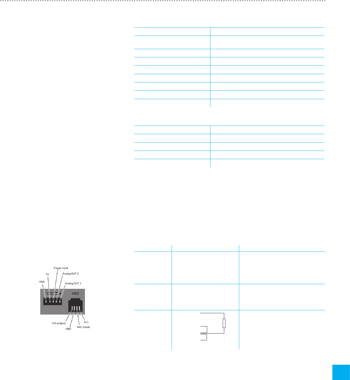
Interface Pin assignment Range
Analog OUT Pin 1: Analog OUT 1
Pin 2: Analog OUT 2
Pin 3: Trigger Input
Pin 4: VIN
Pin 5: GND
0 – 5 VDC ± 1.8 %, load ≥ 5 kΩ
0 – 5 VDC ± 1.8 %, load ≥ 5 kΩ
5 – 24 VDC
12 VDC ± 20 % – 24 VDC ± 20 %
RS-232 Pin 1: NC
Pin 2: RxD (Input)
Pin 3: TxD (Output)
Pin 4: GND
CAN Pin 1: VIN
Pin 2: CANH
Pin 3: CANL
Pin 4:
Pin 5:
Pin 6: GND
12 VDC ± 20 % – 24 VDC ± 20 %
Table 13: Interfaces
Figure 35: Interface definition
16.2 Interface definition
120 Ω
Connectable
terminating resistor

Specifications
42
16
IMT Analytics AG
Thegas type measured must agree with the setting on CITREXH4. Please select the
correct gas type in the settings.
The following gas types are available for selection:
• Air 100 %
• Air/O2-Man. Air/oxygen mixtureaccording to manual input; thedefault is
100 % O2
• Air/O2-Auto. Air/oxygen mixtureaccording tosensor measurement of
internal oxygen cell
• N2O/O2-Man. Nitrous oxide / oxygen mixture according to manual in-
put;the default is 100 % O2
• Heliox 21 % O2 /79% He
• N2 100 %
• CO2 100 %
Standard conditions are understood to mean defined conditions for pressure, tem-
perature and, in some cases, humidity, which constitute the basis for converting the
flow actually measured. Therefore it is essential to check which standard condition
the value displayed will relate to.
The standard currently set is indicated on the numerical and graphical display.
Agas typethat has not been selected properly and agas stand-
ardthat has not been selected properlycan lead tomeasuringerrors
of up to 20 %.
Input voltage of the power supply unit 100 – 240VAC, 50 – 60 Hz
Supply voltage 5VDC
Power input 2.5 – 6 W
Operating time in battery operation 4hours*
Charging the battery A complete charging process takes 5 to 8 h,
depending on which connection port is used
for charging. The service life of the battery is
extended if the battery is charged completely
only after a prompt by the device.
* This operating time is reached in non-networked operation (i.e. the interfaces are not in use or they are
switched off)
16.3 Gas type
16.4 Power supply
16.5 Battery operation
43
Appendix
17
IMT Analytics AG
Flow in the flow channel is determinedbydifferential pressure measurement. To build
up differential pressure a linear flow element is used to provide flow resistance.
Δp = c1 × η × Q + c2 × ρ × Q2
η: dynamic viscosity of the gas [Pa s]
ρ: gas density [kg/m3]
c1, c2: device-specific constants (channel geometry)
Dynamic viscosity
• Theviscosity of the medium is its resistance toflow and shear.
• Viscosity is extremely dependent on temperature.
• Theviscosity of a medium isslightly dependent on the pressure andmoisture
content of the medium.
Density
• Density is the unit for the mass per unit volume of the medium.
• Viscosity is extremely dependent on temperature.
• Theviscosity of a medium isslightly dependent on the pressure andmoisture
content of the medium.
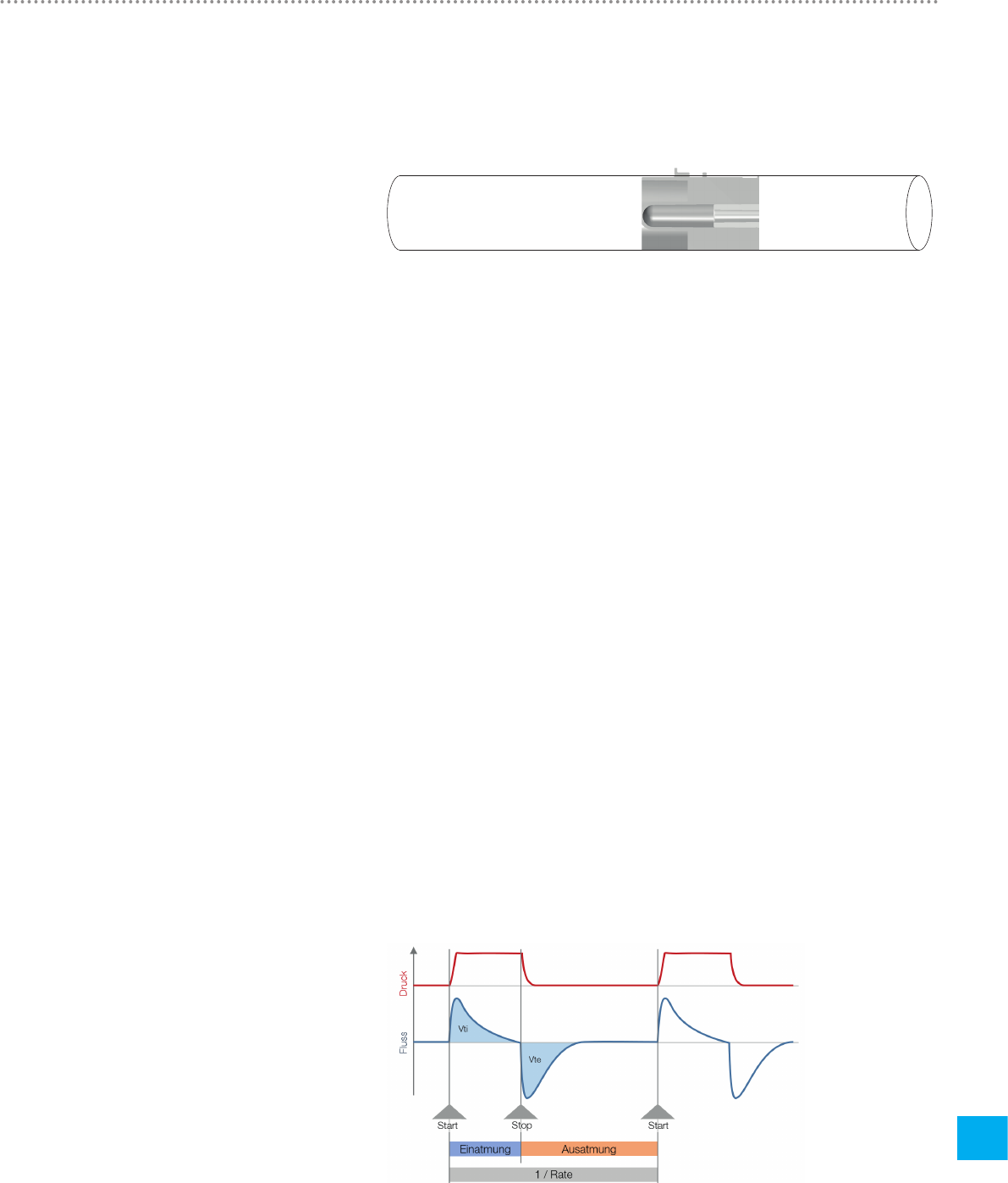
Triggers are used to define start and end points of cyclical signals. With regard to
pressure and flow curves the trigger makes it possible to determine inhalation and
exhalation. The resulting information constitutes the basis for ventilation parameter
calculation. If the trigger is not set properly or if it is not possible to detect a trigger,
the ventilation parameters will be calculated incorrectly or not at all.
Figure 36: Trigger
17.1 Principle of flow measure-
ment
17 Appendix
17.2 Trigger
Appendix
44
17
IMT Analytics AG
17.2.1 Flow trigger
On CITREXH4 a flow trigger can be set. When the set flow is reached, the trigger
is activated. In this context it is essential to specify whether at the start and end of a
cycle the trigger is to be activated by a rising edge or a falling edge. Flow measure-
ment in the flow channel serves as the trigger source. CITREXH4 can be operated
bidirectionally.
17.2.2 Pressure trigger
In the case of a pressure trigger it is the pressure measured in the flow channel that
serves to activate measurement. Whereby the direction of flow is of no consequence.
17.2.3 Base flow
Base flow is a constant flow that must not be included in volume calculation. If, for
example, a system has a defined leak, resulting in a constant discharge of 3 L/min,
those 3 L/min are not included in the inspiratory volume. The 3 L/min can be entered
as a trigger setting so they will not be taken into account.
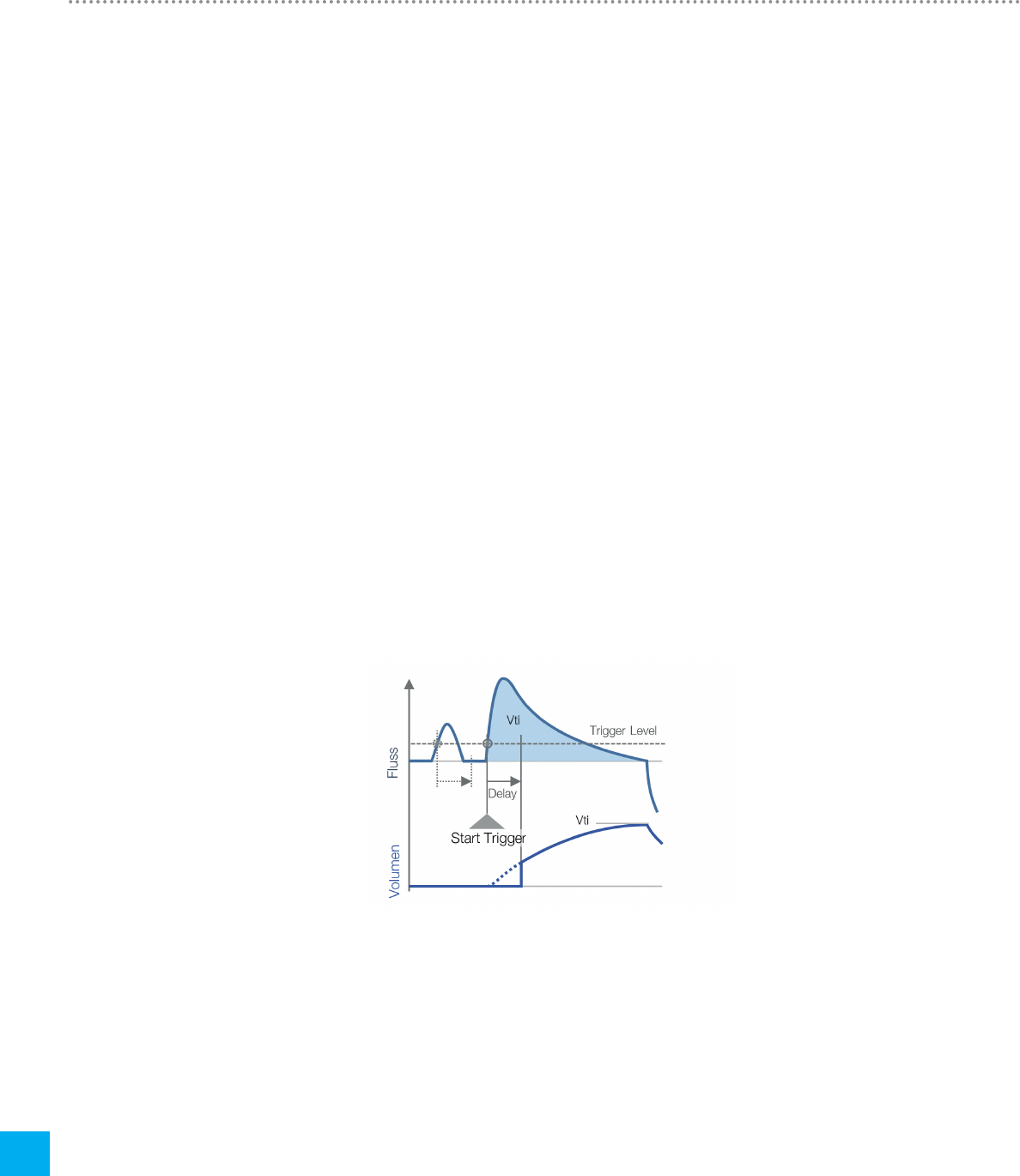
17.2.4 Delay
With a delay it is possible to filter out signal errors or noise and prevent false trigger-
ing. As a result, a trigger is only activated if the set trigger level continues to apply
after the delay time. If the trigger level is no longer reached after the delay time, no
trigger is activated. The delay time can be set.
Figure 37: Delay

Appendix
45
17
IMT Analytics AG
17.3 Measurement parameters and units
Pressure readings Measurement parameter Designation Units of measurement
Ambient pressure
Pressure high
Pressure in flow channel high
Differential pressure
PAtmo
PHigh
PChannel
PDiff
mbar, bar, inH2O, cmH2O, psi,
Torr, inHg, mmHg, hPa, kPa
Flow readings Measurement parameter Designation Units of measurement
Flow Flow L/min, mL/min, cfm, L/s, mL/s
Meteorological readings Measurement parameter Designation Units of measurement
Temperature
Oxygen content
Volume
Temp.
O2
Volume
°C, K, °F
%
mL, L, cf
Gas concentrations Measurement parameter Designation Units of measurement
Gas concentration
Partial pressure
Gas concentration
Partial pressure
%
mbar, bar, inH2O, cmH2O, psi,
Torr, inHg, mmHg, hPa, kPa
Ventilation parameters Measurement parameter Designation Units of measurement
Positive end-expiratory pressure
Mean pressure
Inspiratory positive airway pressure
Maximum pressure
Plateau pressure
Expiratory minute volume
Inspiratory minute volume
Inspiratory peak flow
Expiratory peak flow
Expiratory volume
Inspiratory volume
Ventilation rate
Inspiratory/expiratory ratio
Expiratory time
Inspiratory time
Compliance
PEEP
PMean
IPAP
PPeak
PPlateau
Ve
Vi
PFInsp
PFExp
Vte
Vti
Rate
I:E
Te
Ti
CStat
mbar, bar, inH2O, cmH2O, psi,
Torr, inHg, mmHg, hPa, kPa
L/min, mL/min, cfm, L/s, mL/s
mL, L, cf
mL, L, cf
Breaths/min
s
s
mL/mbar, L/mbar, mL/cmH2O,
mL/cmH2O
Table 14: Measurement parameters and units

Appendix
46
17
IMT Analytics AG
17.4 Gas standards for flow and volume readings
CITREXH4converts the flow and volume readings measured in the device to match the conditions of the standard selected. The
following gas standards are supported by CITREXH4.
Gas standard Abbrevia-
tion Pressure Temperature Relative
humidity
Ambient Temperature and Pressure ATP Current ambient pressure Current
gas temperature
Current
gas humidity
Ambient Temperature and Pressure Dry ATPD Current ambient pressure Current
gas temperature 0 %
Ambient Temperature and Pressure Saturated ATPS Current ambient pressure Current
gas temperature 100 %
Ambient Pressure at 21 °C AP21 Current ambient pressure 21.0 °C (70 °F) Current
gas humidity
Standard Conditions USA STP 1013.25 mbar (760 mmHg) 21.0 °C (70 °F) 0 %
Standard Conditions USA Humid STPH 1013.25 mbar (760 mmHg) 21.0 °C (70 °F) Current
gas humidity
Body Temperature and Pressure, Saturated BTPS Current ambient pressure
+ channel pressure 37.0 °C (99 °F) 100 %
Body Temperature and (Ambient) Pressure Sat-
urated according to ISO 80601-2-12:2011 BTPS-A Current ambient pressure 37.0 °C (99 °F) 100 %
Body Temperature and Pressure Dry BTPD Current ambient pressure
+ channel pressure 37.0 °C (99 °F) 0 %
Body Temperature And (Ambient) Pressure Dry BTPD-A Current ambient pressure 37.0 °C (99 °F) 0 %
Standard Conditions to DIN1343 0/1013 1013.25 mbar (760 mmHg) 0.0 °C (32 °F) 0 %
Standard Conditions to
ISO 1-1975 (DIN 102) 20/981 981 mbar (736 mmHg) 20.0 °C (68 °F) 0 %
API Standard Conditions 15/1013 1013.25 mbar (14.7 psia) 15.0 °C (60 °F) 0 %
Cummings Standard 25/991 991 mbar (500 ft altitude) 25.0 °C (77 °F) 0 %
20 °C/1013 mbar 20/1013 1013.25 mbar (760 mmHg) 20.0 °C (68 °F) 0 %
Normal Temperature and Pressure NTPD 1013.25 mbar (760 mmHg) 20.0 °C (68 °F) 0 %
Normal Temperature and Pressure, Saturated NTPS 1013.25 mbar (760 mmHg) 20.0 °C (68 °F) 100 %
Table 15: Gas standards for flow and volume readings

Appendix
47
17
IMT Analytics AG
Value Equivalent
1 mbar 0.001 bar
100 Pa
1 hPa
0.1 kPa
0.75006 torr (760 torr = 1 atm.)
0.75006 mmHg (at 0 °C)
0.02953 inHg (at 0 °C)
1.01974 cmH2O(at 4 °C)
0.40147 inH2O(at 4 °C)
0.01450 psi, psia
1 bar 1000 mbar
0.1 Pa
1000 hPa
100 kPa
750.06 torr (760 torr = 1 atm.)
750.06 mmHg (at 0 °C)
29.53 inHg (at 0 °C)
1019.74 cmH2O(at 4 °C)
401.47 inH2O(at 4 °C)
14.50 psi, psia
Table 16: Conversion factors
17.5 Conversion factors

Appendix
48
17
IMT Analytics AG
17.6 List of tables
17.7 List of figures
Table 1: Symbol explanation 8
Table 2: Scope of delivery 9
Table 3: Description of electrical interfaces 16
Table 4: User controls 19
Table 5: Trigger settings 21
Table 6: Numerical values 24
Table 7: Folder structure of CITREXH4 34
Table 8: Accessories 36
Table 9: Measurement parameters 39
Table 10: Additional readings 40
Table 11: Ventilation parameters 40
Table 12: General information and operating data 41
Table 13: Interfaces 41
Table 14: Measurement parameters and units 45
Table 15: Gas standards for flow and volume readings 46
Table 16: Conversion factors 47
Figure 1: Power supply 10
Figure 2: Flow channel 11
Figure 3: Differential pressure connector 12
Figure 4: High-pressure connector 13
Figure 5: Oxygen sensor holder 14
Figure 6: Protective cap 14
Figure 7: Screwing in the oxygen sensor 15
Figure 8: Oxygen sensor cable 15
Figure 9: Electrical interfaces 16
Figure 10: Replacing the battery 17
Figure 11: User controls 19
Figure 12: Info display 20
Figure 13: Battery indicator 20
Figure 14: Ethernet interface 20
Figure 15: Trigger 21
Figure 16: Gas standard 21
Figure 17: Gas type 22
Figure 18: Gas humidity 22
Figure 19: Setting the X-axis 22
Figure 20: O2 calibration 23
Figure 21: Profiles 23
Figure 22: Numerical readings 23
Figure 23: Measurement curves 24
Figure 24: Zero calibration 25
Figure 25: Screen displays "Calibration Air" 26
Figure 26: Screen displays "Calibration Oxygen and Air" 26
Figure 27: General measurement setup 27
Figure 28: Bad setup 27
Figure 29: Measurement setup for checking ventilators 28
Figure 30: Measurement setup for gases at high pressure 28
Figure 31: Profile editor in Internet Explorer 29
Figure 32: Profile editor "configuration" 30
Figure 33: Monitoring numerics 32
Figure 34: Monitoring panels 33
Figure 35: Interface definition 41
Figure 36: Trigger 43
Figure 37: Delay 44

Appendix
49
17
IMT Analytics AG
17.8 Index
A
Accessories 36
Analog OUT 16
Approvals 38
B
Battery depletion 10
Battery operation 42
Battery replacing 17
C
Calibration 25
Calibration with air 26
Calibration with oxygen and air 26
CAN 16
CAN interface 10
Care 35
Charging the battery 42
Cleaning 35
Connecting the device 27
Conversion factors 47
D
Default 31
DHCP 32
Differential pressure 12
Dim screen 18
Directives 38
Disposal 37
DISS adapter 13
Dynamic viscosity 43
E
Electrical interfaces 16
Ethernet 16
F
Filter 24
Flow and volume readings 46
Flow channel 11
Flow measurement 43
G
Gas concentrations 45
Gas standard 24
Gas standards 46
Graphical readings 24, 33
H
High pressure 13
I
Intended use 6
Interface definition 41
L
Lock screen 18
M
Measurement data 34
Measurement parameters 39, 45
Measurements 6
Measurement setup 27
Mechanical connectors 11
Meteorological readings 45
MicroSD 16
Monitoring option 32
N
Notes 7
Numerical readings 23, 32
O
O2 25
O2 interface 16
Operating time 42
Operation 18
Options 36
Oxygen 25
Oxygen sensor 14
Oxygen sensor, installing 14
P
PC minimum requirements 31
Personnel 7
Power supply 10, 42
Pressure readings 45
Profile editor 29
Profiles 29
R
RS-232 16
S
Safety instructions 7
Service life 7
Servicing 35
Servicing operations 35
Settings 20
Spare parts 36
Specifications 39
Start-up 9
Switching the device on/off 18
Symbol explanation 8


305.081.000_04, 2018-07
Subject to changes without notice.
IMT Analytics . Gewerbestrasse 8 . 9470 Buchs . Switzerland
T +41 81 750 67 10 . www.imtanalytics.com
