Cmv
User Manual: cmv NITRA Pneumatic Inserts
Open the PDF directly: View PDF ![]() .
.
Page Count: 2
Compact Modular Valves
INSTALLATION AND MAINTENANCE INSTRUCTIONS,
KEEP FOR FUTURE REFERENCE.
Compact Modular Valves Rev. 1-20-17
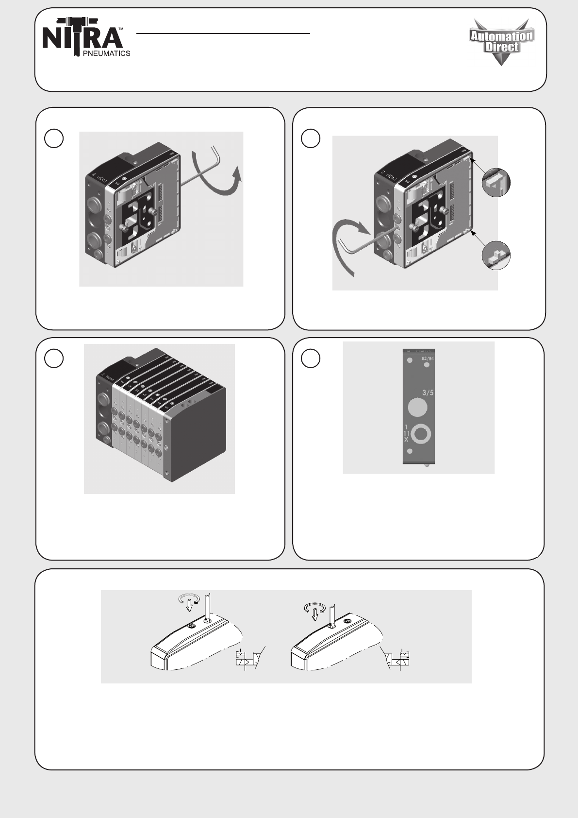
Align first valve with left end plate. Tighten the
rear locking set screw with hex key 2.5 mm to a
torque of 1.5 Nm (13 lb-in)
Tighten the front locking set screw with hex key
2.5 mm to a torque of 1.5 Nm (13 lb-in)
Continue in the same way to assemble the other valves as far
as the end plate. Make sure that the contact fingers of each
valve engages with the successive ones and with the relevant
seat in end plate, verifying also that the gasket is in its seat.
When complete it is necessary to perform a pneumatic test
on the assembly to check general tightness. Plug the valve
output fittings and connect the terminal input fittings marked
with identification numbers 1, 11, X to the supply. The
pressure used for the test must always be between 45-100 psi
[3.1-6.9 bar].
Locking Manual Override Port 2 or 4 pilot-assisted
• Press the manual control in to operate valve then turn it clockwise 90 degrees to lock.
• To unlock rotate the manual control 90 degrees counter clockwise and then release it.
• The valve returns to the home position with the exception of CMV-B2L-XX which remains
switched.
Assembly And Pneumatic Testing:
Manual Controls:
1. 2.
3. 4.
For Technical Assistance Call 770-844-4200
www.AutomationDirect.com - 3505 Hutchinson Rd., Cumming, GA 30040 - 1-800-633-0405
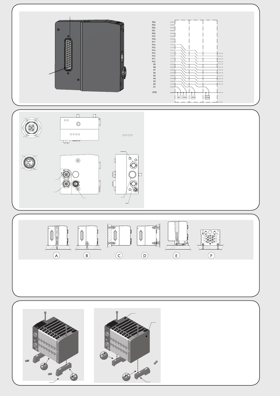
A. Top mount using (2) M4-0.7x45mm socket head cap screws (5.8 Nm [51 lb-in]).
B. / C. Bottom or rear mounting using (2) M5-0.8 (length as needed), (12Nm [106 lb-in]).
D. Face mounting using (2) M5-0.8 (length as needed), (12Nm [106 lb-in]). An opening for the pipes is needed in the plate.
E. DIN rail mounting using 35mm DIN bracket (CMV-ACC04 (2 required) - hardware included).
F. Side mounting using the blind end plate, and (4) M4-0.7 (length as needed), (5.8 Nm [51 lb-in]) threads on the side.
Note: Other mounting positions not recommended.
Mounting the Base:
C
Fitting the DIN brackets
(CMV-ACC04 - 2 required):
Fix the brackets onto both end plates (A
and B) using the screws supplied with the
brackets (12Nm [106 lb-in]). Brackets can be
positioned facing either direction as shown on
C or D.
General Assembly Instructions:
A
B
D
Dual
Solenoid
Sing
l
e
Solenoid
Common
green/black
blue/black
red/brown
white/black
red/blue
black/orange
yellow/red
black/brown
white/red
red/black
brown/white
red/orange
light blue
yellow/white
yellow
red/green
orange
orange/white
green
yellow/black
white
blue/white
brown
green/white
red
Single
Solenoid
Pin 25
Pin 1
General Wiring:
EtherNet/IP enabled inlet plates:
• Use 4-pole M12 cables for both In and Out Ethernet
connections and a 4-pole M8 cable for power.
• Each valve manifold assembly can have a maximum of
16 solenoids.
• Solenoids from left to right (1 through 16) equal bits 0
through 15. i.e. Solenoid 1 will be bit 0.
• Any number of valve manifold assemblies can be “daisy
chained” together on the same network.
A
B
OUT P2
IN P1
POWER SUPPLY
DETAIL A
SCALE 2 : 1
14
32
DETAIL B
SCALE 2 : 1
1
34
2
INLET
SECOND INLET
IF APPLICABLE
EXHAUST
IN / OUT
M12 CONNECTOR
1 = TD+
2 = RD+
3 = TD-
4 = RD-
POWER SUPPLY
M8 CONNECTOR
1 = +24V BUS
2 = +24V VALVE
3 = GND
4 = GND
OUT
IN
LINK/ACT
LINK/ACT
MS
NS
