Control Chokes Brochure
User Manual: Control Chokes Resource Library
Open the PDF directly: View PDF ![]() .
.
Page Count: 16
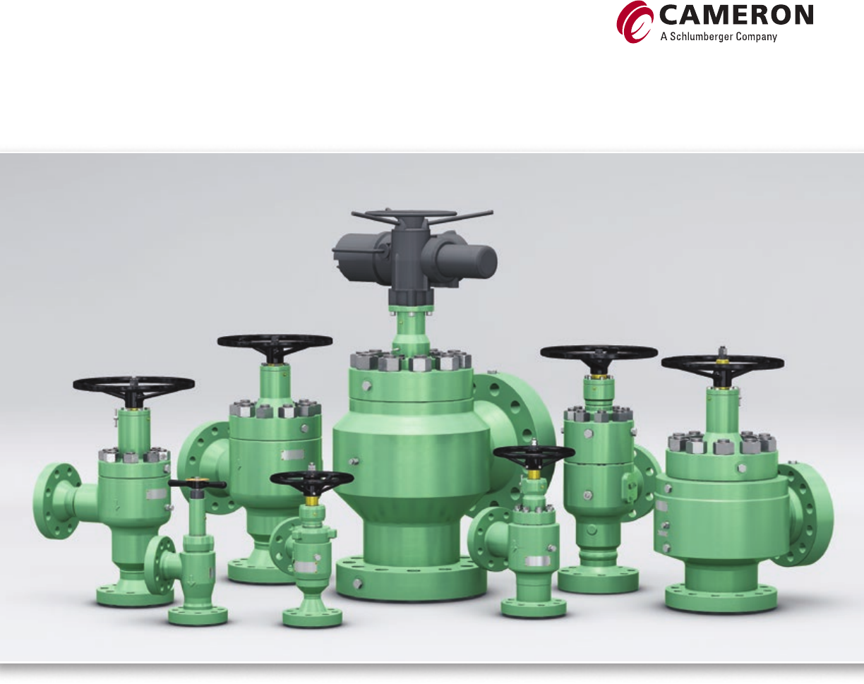
Control Chokes
The industry standard in flow control technology
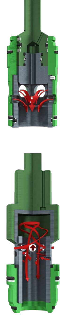
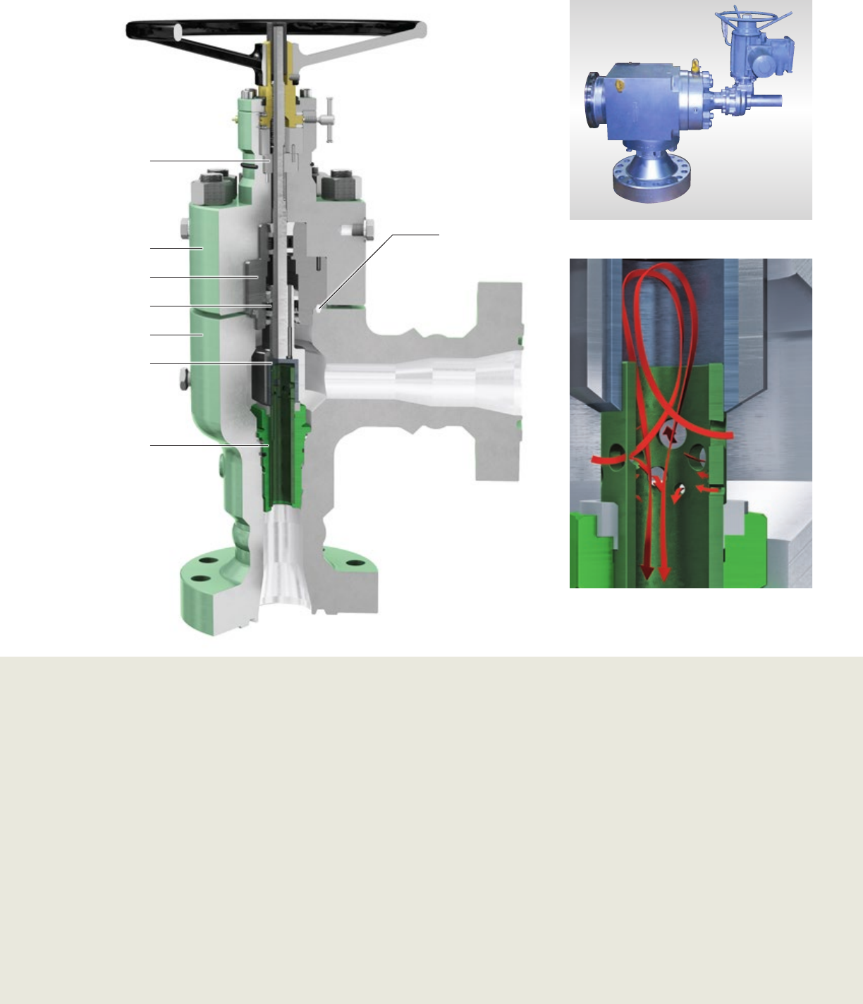
Cameron control choke design
incorporates hydrodynamic energy
dissipation to reduce erosion problems
while ensuring positive flow control.
During service, the flow enters the choke
inlet and circulates around the annulus
between the body and the cage. The cage
has an even distribution of ports that
determine the maximum flow capacity.
The high-velocity fluid streams produced
by the flow collide in the center of the
cage. Since the fluid streams impinge
directly with each other, this enables the
most erosive energy to be dissipated.
This in turn minimizes the risk of erosion
damage to downstream components.
Our control chokes are designed to provide precise flow control throughout
their entire operating range, with a well-proven track record in the field:
■ Suitable for a wide variety of applications, including production,
injection, artificial lift, flowback, storage, etc.
■ Commonly installed on Christmas trees, manifolds, line heaters, offshore
platforms, FPSOs, and other equipment, providing precise flow control
under severe service conditions.
■ Available with plug & cage, external-sleeve or multistage trim types.
■ Multiple flow characteristics, including ‘linear’ or ‘equal percentage’,
with special trim solutions available in response to specific challenges.
■ Special trim solutions include ultra-low Cv, low noise, and well
cleanup types.
■ Control chokes offer a complete solution from startup to late life
conditions, with the flexibility to easily retrofit various trim types as
conditions evolve.
■ Available in manual and actuated configurations, including multiple
actuator types.
Plug & cage trim
External sleeve trim
The plug & cage control choke uses the plug as the controlling element, and throttles
the flow on the internal diameter of the ported cage. The ports in the cage are sized and
arranged to give the most appropriate combination of controllability and flow capacity
for each application.
A major consideration when sizing the choke is the ability to achieve closely
managed well startup while also optimizing capacity towards the end of
well life to maximize production.
The plug & cage design is highly optimized, and incorporates the largest
possible flow area, making it ideal for high-capacity applications.
Plug & cage chokes also are constructed with a solid tungsten carbide plug
tip and inner cage for extended resistance to erosion. It may further be
configured with a solid tungsten carbide wear sleeve in the outlet of the
body to provide enhanced protection in sandy service.
This trim also includes a thick metal outer cage to ensure maximum
protection against solid impacts from debris in the flow.
The combined result is a versatile, robust, erosion-resistant trim with
suitability for a broad range of challenging applications.
Additional features include:
■ Large visual indicator provides position in ⁄-in bean as standard.
■ External grease port lubricates threads and bearings.
■ Stem lock maintains set position.
■ Bleed plug assembly vents pressure before disassembly.
■ Anti-rotation key translates rotation from the drive bushing into linear
movement of the lower stem/flow plug assembly.
■ Two-piece stem is threaded and locked, and is removed from
wellbore fluids.
■ Large annulus area reduces the risk of body and trim erosion caused by
high velocities.
All control chokes are available in manually operated or actuated models.
Custom-designed trim components to suit a wide variety of Cv capacities and flow
characteristics also are available.
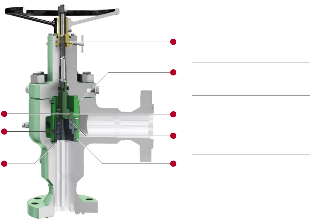
Plug & Cage
1
2
5
8
4
6
3
7
Plug & cage control choke features
1Tungsten carbide plug tip
2Solid tungsten carbide cage provides optimum wear
resistance in erosive conditions
3Metal body-to-bonnet gasket for absolute
pressure containment
4Fully guided plug reduces side loading and vibration
5Self-flushing, pressure-balanced ports reduce stem loads
and actuator output requirements
6Heavy-duty thrust bearings reduce operating torque
7Pressure-balanced seals are a key feature of the pressure-
balanced trim arrangement, reducing operating forces and
enabling greater ease of adjustment
8Outer metal cage provides protection from impact damage
The external sleeve control choke has a sleeve that throttles the flow on the external
diameter of the ported cage. The external sleeve trim is particularly suited for low-
capacity/high pressure-drop applications. The external sleeve is designed specifically for
severely erosive service where the combination of high pressure drops and high sand
concentrations can reduce the life of a choke.
Additional features include:
■ Large visual indicator provides position in ⁄-in bean as standard.
■ External grease port lubricates threads and bearings.
■ Stem lock maintains set position.
■ Bleed plug assembly vents pressure before disassembly.
■ Anti-rotation key translates rotation from the drive bushing into linear
movement of the lower stem/flow plug assembly.
■ Two-piece stem is threaded and locked, and is removed from
wellbore fluids.
■ Large annulus area reduces the risk of body and trim erosion caused by
high velocities.
All control chokes are available in manually operated or actuated models.
Custom-designed trim components to suit a wide variety of Cv capacities and flow
characteristics also are available.
External Sleeve
External sleeve control choke features
1Tungsten carbide-lined external sleeve
2Solid tungsten carbide cage/seat provides optimum wear
resistance in erosive conditions
3Metal body-to-bonnet gasket for absolute
pressure containment
4Reverse angle external sleeve improves flow dynamics
within the trim
5Self-flushing, pressure-balanced ports reduce stem loads
and actuator output requirements
6Heavy-duty thrust bearings reduce operating torque
7Pressure-balanced seals are a key feature of the pressure-
balanced trim arrangement, reducing operating forces and
enabling greater ease of adjustment
1
2
5
4
6
3
7
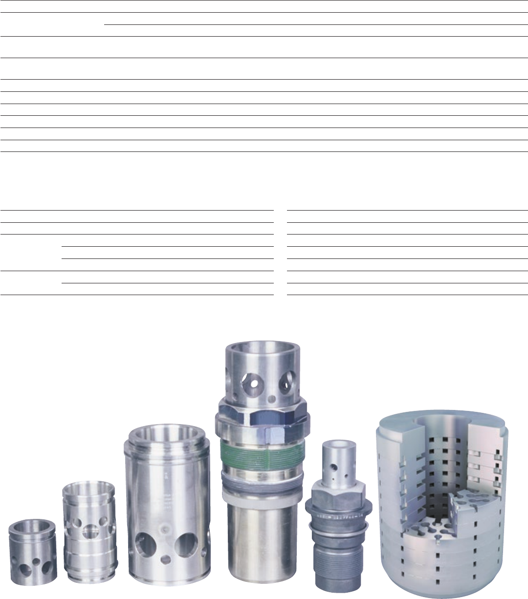
A multistage choke trim is used in applications where high differential pressures result
in unacceptably high noise and vibration levels, especially in gas service. Multistage
trims also are commonly used to prevent cavitation in the case of liquids, particularly
for water injection. The trim works by reducing the pressure over a number of discrete
stages, giving a carefully managed pressure profile. Similarly, it manages the velocities
within the trim, and prevents the occurrence of undesired flow effects such as sonic
velocities and high velocity jetting. In addition to the “concentric cage” type trim
illustrated here, Cameron can provide a number of alternative multistage trim options.
Additional features include:
■ Trim porting and geometry designed to
convert potential energy (i.e., pressure) into
kinetic energy and heat as a result of viscous
energydissipation.
■ Splits the flow into a number of small
streams, reducing the energy levels in
each stream.
■ Large trim surface area increases wall friction
to slow fluid.
■ Directional changes in trim reduce
energy levels.
■ Inter-stage chambers allow fluid expansion to
reduce velocities.
■ Fluid passes through repeated compression
and expansion phases to further reduce
energy levels without high velocities.
■ Pressure-balanced stem and thrust bearings
reduce torque, thus minimizing stem loads,
actuator requirements, and handwheel torque.
■ Large annulus area reduces the risk of body
and trim erosion caused by high velocities.
Multistage Trim
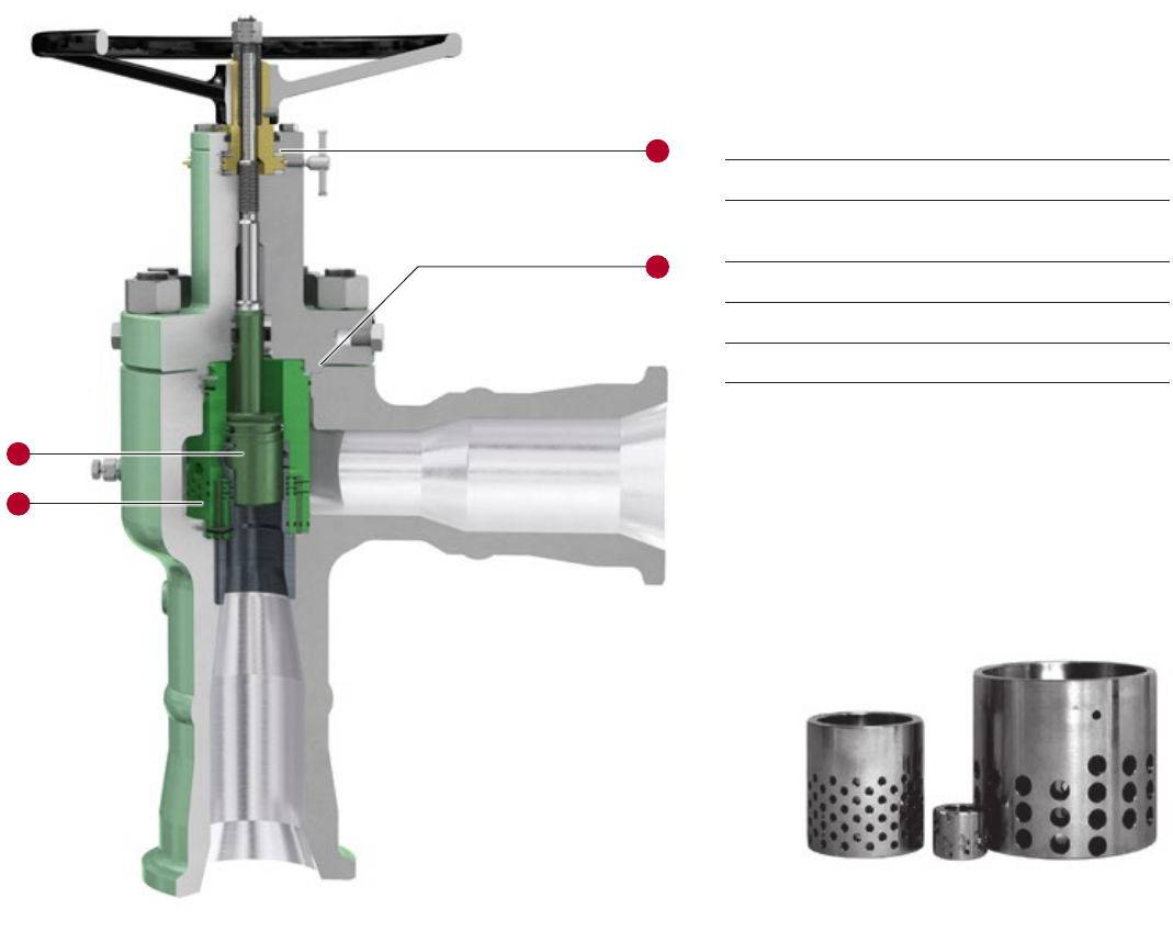
Multistage cage designs
Multistage control choke and trim features
1Metal body-to-bonnet gasket for absolute
pressure containment
2Heavy-duty thrust bearings reduce operating torque
3Fully guided plug reduces side loading and vibration
4Outer flow cage provides protection from impact damage
1
2
4
3
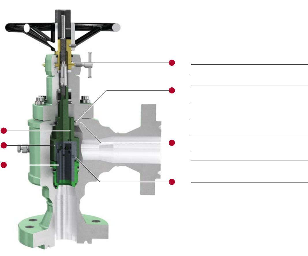
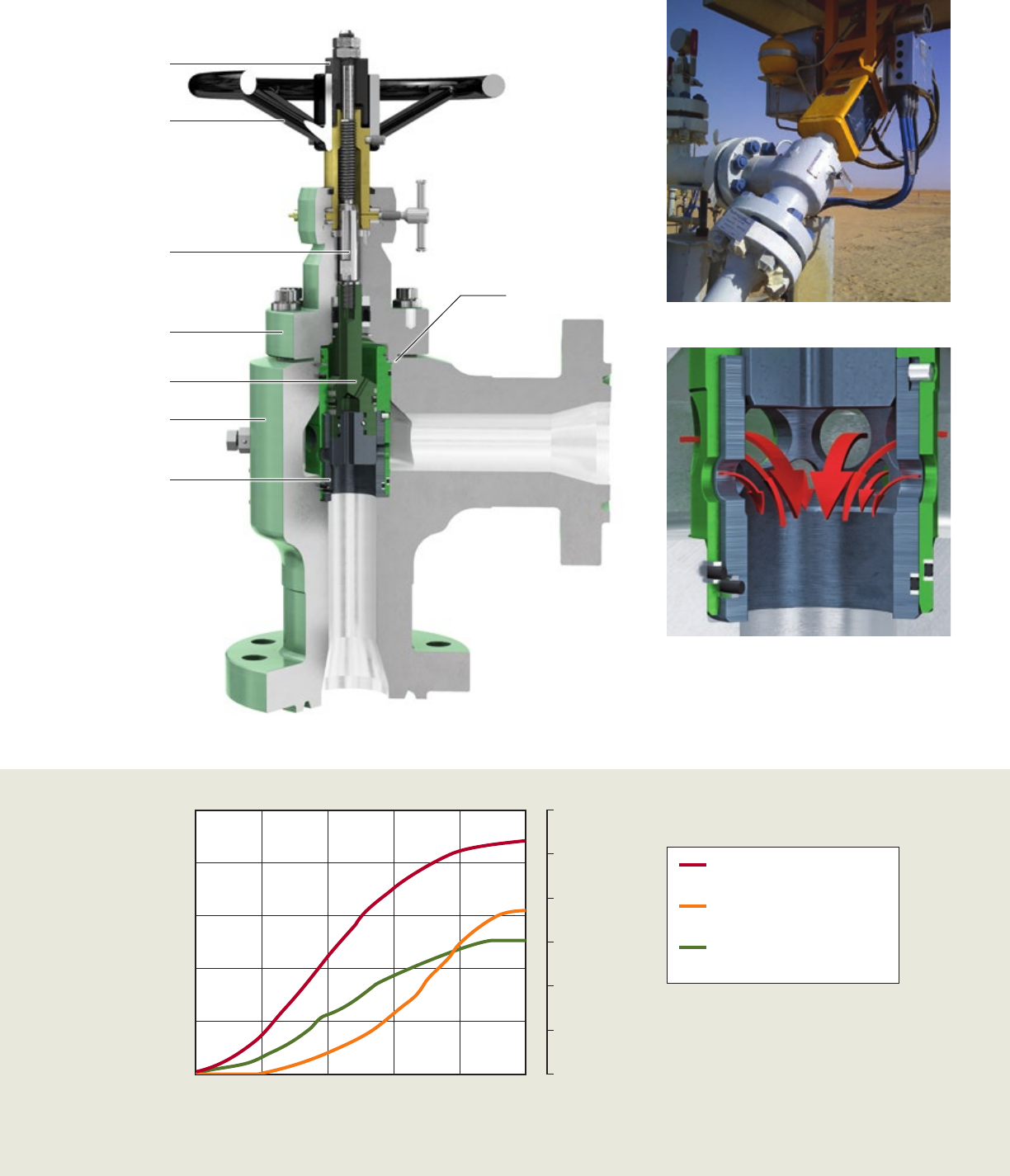
CC15 Control Choke
CC15 choke plug & cage trim
CC15 choke with linear hydraulic actuation
Body
Stem seal
Cage assembly
Plug/stem assembly
Bonnet nut
Bonnet
Position indicator
Handle
CC15 control choke
API 5K/10K, plug & cage
Choke Cv
Percent of travel, %
0 20 40 60 80 100
40
30
20
10
0
80
64
48
32
16
0
Bean size, ⁄ in
CC15 Choke Flow Curves
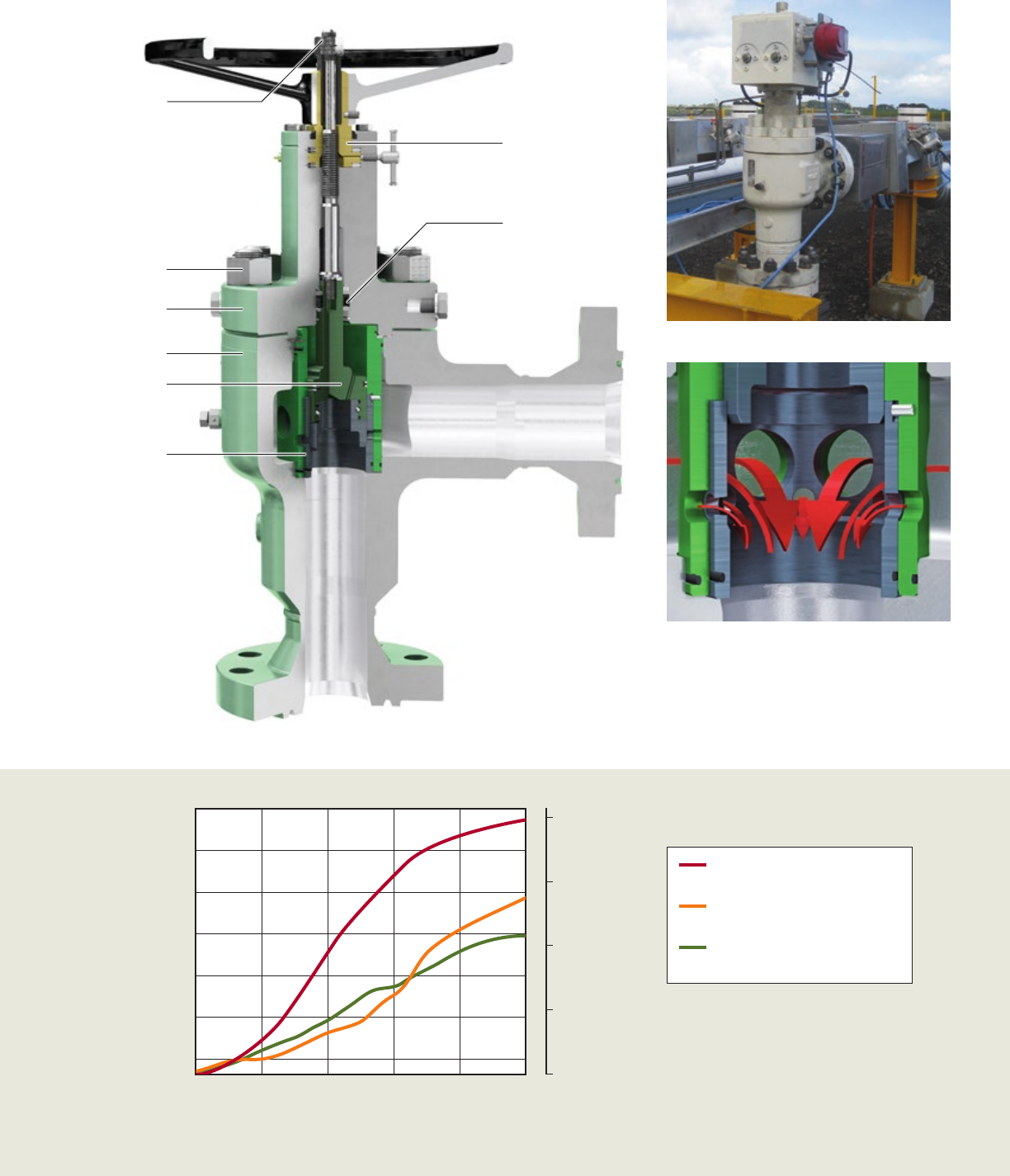
CC20 Control Choke
CC20 choke with pneumatic diaphragm actuation
CC20 choke plug & cage trim
Body
Body bleed port
Cage
Bonnet nut
Bonnet
Position indicator
Locking screw
Plug/lower stem
CC20 control choke
API 5K/10K, plug & cage
CC20 control choke
API 5K/10K, external sleeve
CC20HP HP/HT
API 15K/20K, external sleeve
CC20 Choke Flow Curves
Choke Cv
Percent of travel, %
0 20 40 60 80 100
40
30
20
10
0
80
64
48
32
0
93
Bean size, ⁄ in
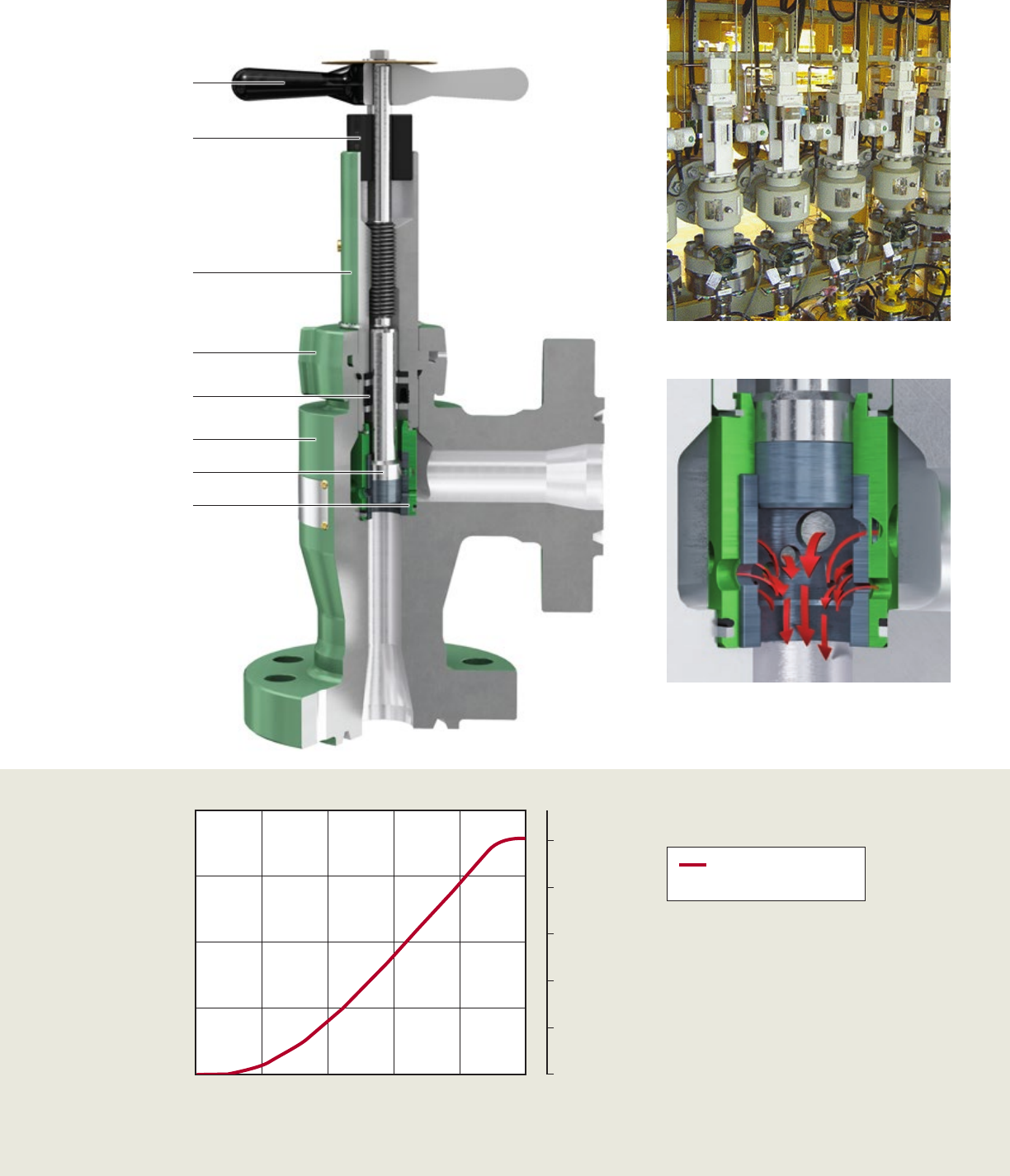
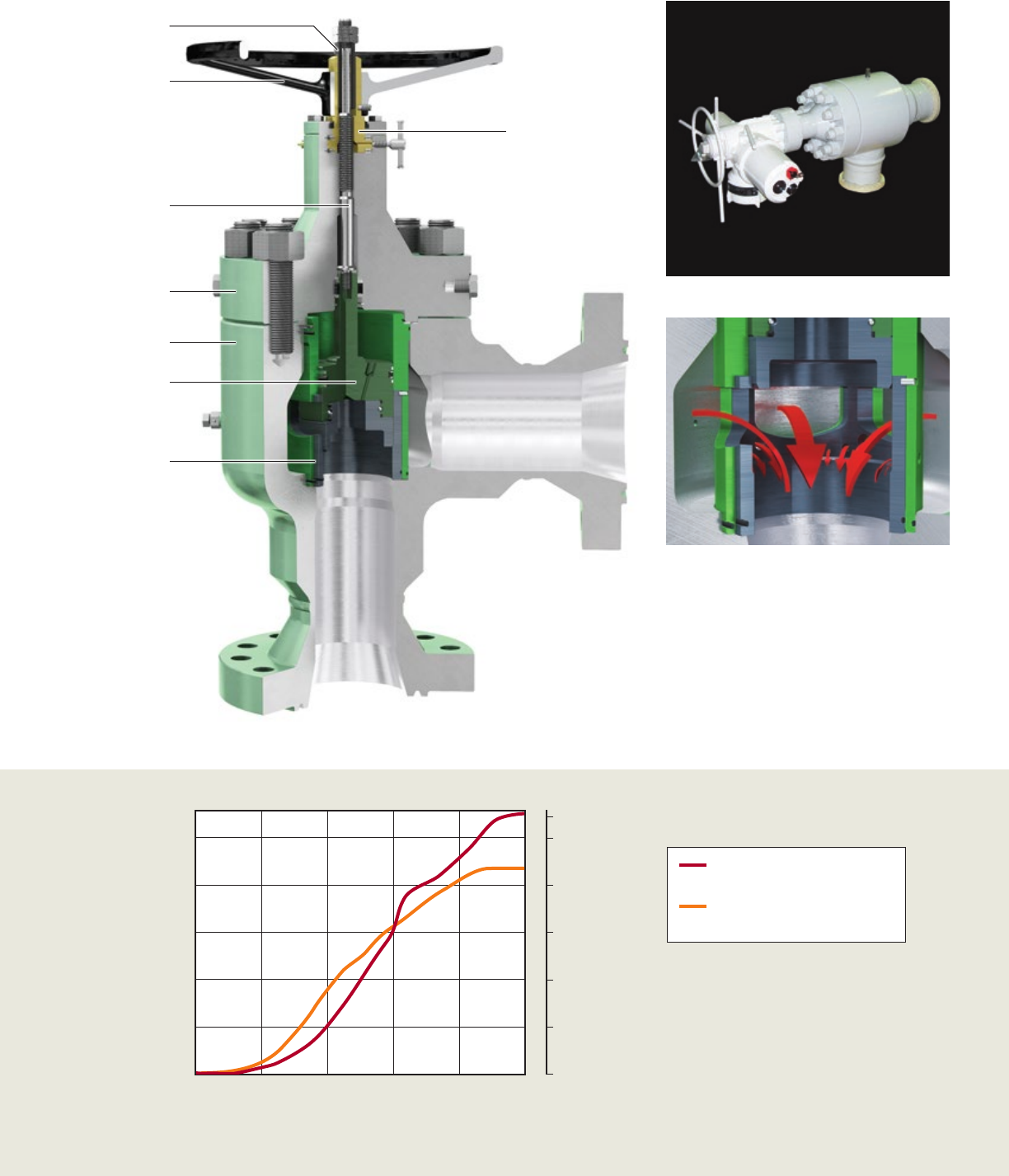
CC30 Control Choke
CC30 choke plug & cage trim
CC30 choke with linear hydraulic actuation
CC30 control choke
API 5K/10K/15K, plug & cage
CC30 control choke
API 5K, external sleeve
CC30HP HP/HT control choke
API 10K/15K, external sleeve
CC30 Choke Flow Curves
Choke Cv
Percent of travel, %
0 20 40 60 80 100
100
80
60
40
20
0
180
150
120
90
60
30
0
Bean size, ⁄ in
Body
Plug/lower stem
Cage assembly
Bonnet
Upper stem
Position Indicator
Handwheel
Bonnet gasket
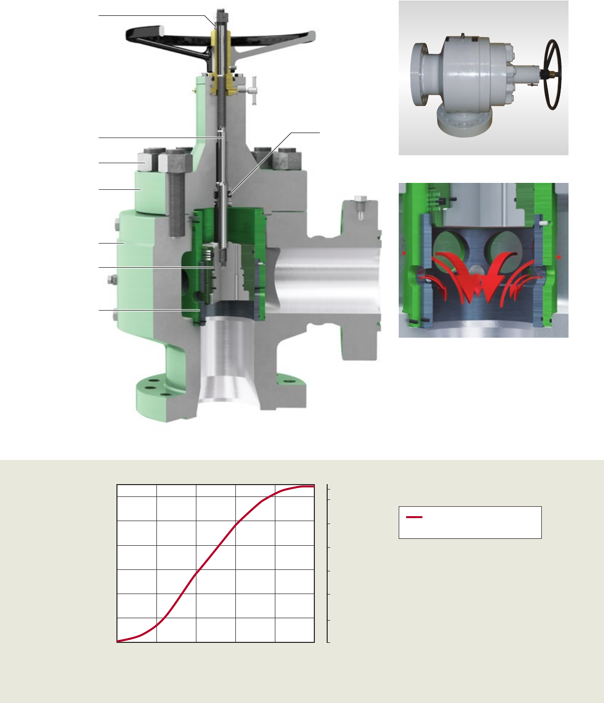
CC40 Control Choke
CC40 choke plug & cage trim
CC40 choke with hydraulic stepping actuation
CC40 choke API 5K/10K/15K,
plug & cage
CC40 choke API 5K,
external sleeve
CC40HP HP/HT choke
API 10K/15K/20K, external sleeve
CC40 Choke Flow Curves
Choke Cv
Percent of travel, %
0 20 40 60 80 100
260
220
180
140
100
60
20
248
192
128
64
0
Bean size, ⁄ in
Body
Plug/lower stem
Cage assembly
Bonnet
Bonnet studs/nut
Stem seal
Stem drive bushing
Jam nuts/
limit stop
CC60 Control Choke
CC60 choke plug & cage trim
CC60 choke with electric actuation
CC60 choke API 5K/10K,
plug & cage, equal percent trim
CC60 choke plug & cage,
linear trim
CC60 Choke Flow Curves
Body
Plug/lower stem
Cage assembly
Bonnet
Upper Stem
Position indicator
Handwheel
Stem drive bushing
Choke Cv
Percent of travel, %
0 20 40 60 80 100
500
400
300
200
100
0
320
256
192
128
64
0
Bean size, ⁄ in
350
CC70 Control Choke
CC70 choke plug & cage trim
CC70 choke
CC70 choke API 5K, plug & cage,
linear trim
CC70 Choke Flow Curves
Body
Cage assembly
Plug assembly
Bonnet
Bonnet Studs/Nut
Stem
Position indicator
Stem seal
Choke Cv
Percent of travel, %
0 20 40 60 80 100
600
500
400
300
200
100
0
384
320
256
192
128
64
0
Bean size, ⁄ in
408

CC80 Control Choke
CC80 choke plug & cage trim
CC80 choke with electric actuation
CC80 choke API 5K, plug & cage,
linear trim
CC80 Choke Flow Curves
Body
Plug
Body bleed port
Cage
Bonnet
Stem
Bonnet adaptor
Choke Cv
Percent of travel, %
0 20 40 60 80 100
1000
800
600
400
200
0
450
350
250
150
50
Bean size, ⁄ in
556
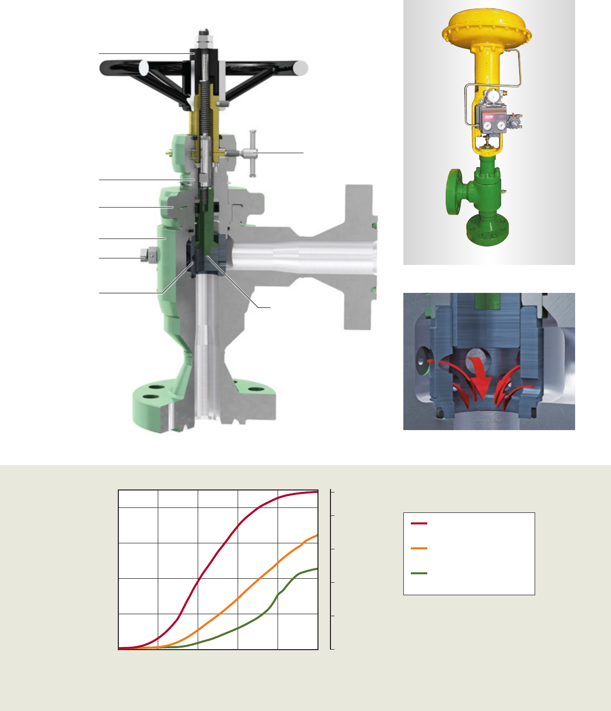
High Temperature and High Pressure
CC20 external sleeve HPHT trim choke
CC20 external sleeve 15k choke with electric actuation
Our range of control chokes includes a series of models engineered specifically for use in
high-pressure, high-temperature service in corrosive/erosive environments. The high-pressure,
high-temperature designs utilize metal seals and non-elastomeric seals. These seals are tested
and qualified to provide high performance and reliability in sour service, with temperatures up to
400degF (204degC) and pressures up to 20,000 psi.
Our chokes are used in high CO2 and H2S, high-chloride, and high-temperature environments, and
employ modern corrosion-resistant alloys (CRAs) to provide trouble-free service life. Low-alloy steel
bodies are lined with nickel alloy 625 in a weld cladding process, providing a thick, impervious layer
of the CRA bonded to the base material.
The other components employ similar corrosion-resistant alloys in their construction.
Body
Stem/sleeve assembly
Seat/cage assembly
Bonnet
Yoke hub
Pressure-balanced seal
Anti-rotation ring
Ring gasket
Cv
Control choke model
CC15 CC20 CC30 CC40 CC60 CC70 CC80
1100
1000
900
800
700
600
500
400
300
200
100
0
Control Choke Sizing and Flow Testing
Choke sizing program
Selection of the correct trim size and type is vital to the successful and
reliable operation of a choke. Cameron offers a computer-based choke
sizing program to optimize choke sizing and selection for the customer.
Based on flow and pressure requirements of the application, the program
analyzes and specifies the optimum choke size and trim configuration.
Features of the choke sizing program include:
■ Capability to size a large number of chokes and flow conditions
■ Modular sizing program structure that enables the addition of new
choke and choke trim data updates as needed
■ Graphics capabilities
■ Project worksheet and Cv curve printouts
■ Choke valve sizing per ANSI/ISA S75.01 specifications
■ Flow testing per ANSI/ISA S75.02 specifications
■ Noise prediction and testing per ANSI/ISA S75.07 specifications
Consult Cameron for additional information.
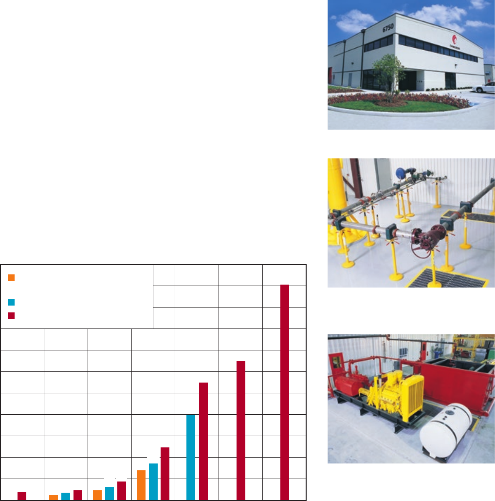
Control Choke Flow Capacity (Cv) Comparison
Note: Standard trims are shown. A full range of trim sizes are available.
The research and testing facility in Houston, Texas.
In addition to testing control chokes across a wide range
of pressures, Cameron measures flow rates and noise in a
flow loop per ISA specifications.
We have an extensive erosion test facility with specially
designed equipment, yielding high differential pressure
capabilities, as well as variable abrasive content flow.
35 23 46
168
245
400
544
649
1006
60 86
34 45
134
High-pressure/high-temperature plug&
cage or external sleeve
External sleeve
Plug & cage
Material Specifications for Choke and Trim
We provide a wide variety of control choke trims capable of Class IV and Class V shutoff per ANSI B16.104 specifications.
Control Choke Valve Standard Materials of Construction
Component API 6A materials class
AA, BB, DD†, EE†CC†, FF HH†
Valve body/bonnet‡AISI 4130 AISI 410, Duplex SS UNS 31803,
Super Duplex SS UNS 32760, A182 F6NM SS
AISI 4130 with Ni-alloy clad
Flange‡AISI 4130/ASTM A350 LF2 AISI 410, Duplex SS UNS 31803,
Super Duplex SS UNS 32760, A182 F6NM SS
AISI 4130 with Ni-alloy clad/
ASTM A350 LF2 with Ni-alloy clad
Stem (wetted) 17-4 pH SS 17-4 pH SS 718 Ni-alloy
Bolting§ASTM 320 L7M ASTM 320 L7M ASTM 320 L7M
Slip-fit gasket PTFE PTFE PTFE
Bonnet gasket 316 SS 316 SS 825 Ni-alloy
Junk ring 316 SS 316 SS 825 Ni-alloy
Retaining ring Ni-alloy, X-750 Ni-alloy, X-750 Ni-alloy, X-750
† Materials meet the requirements of NACE MR-01-75/ISO 15156 specifications.
‡ Pressure-containing components are Charpy impact-tested at or below designed temperature.
§ Bolting can be zinc plated, Xylan® coated, or hot-dip galvanized.
Note: Specifications are subject to change without notice.
Trim Material Selection Based on Material Class and Flow Service
Material class Service Wear components Non-wear components
AA, BB, CC,
DD, EE, FF
Non-erosive 17-4 SS 17-4 SS
Erosive Tungsten carbide 17-4 SS
Cavitation†Stellite® 17-4 SS
HH Non-erosive Ni-alloy 718 Ni-alloy 718
Erosive Tungsten carbide Ni-alloy 718
† Cavitation available by special order.
Available Material for Seals
Seal type Sealing materials
Static-bore O-rings Nitrile†, Viton®, PTFE, CAMLAST*
Static-bore backup rings Nitrile, PTFE
Dynamic-bore T-seals Nitrile†, Viton, Epichloro-Hydrin, CAMLAST
Dynamic-bore wear rings Virgin Peek
Spring-energized lip seal PTFE Elgiloy Spring
† Includes low-temperature nitrile.