Controller
User Manual: controller
Open the PDF directly: View PDF ![]() .
.
Page Count: 124 [warning: Documents this large are best viewed by clicking the View PDF Link!]

263-132281
Power
Supply
Unit
for
Turbo
Molecular
Pump
Model:
EI-D1003M
Model:EI-D1103M
Model
:EI-D1303M
Model:EI-D2003M
Model:EI-D2203M
Model:EI-D2303M
Model:EI-D3203M
Model:EI-D3403M
Model:EI-D4203M
INSTRUCTION
MANUAL
Read
the
instruction
manual
thoroughly
before
you
use
the
product.
Keep
this
instruction
manual
for
future
reference.
SHIMADZU
CORPORATION
Semiconductor
Equipment
Division
:
■;,,:
Introduction
Introduction
Thank
you
for
choosing
the
EI-DxxO3M
Power
Supply
Unit
for
Turbo
Molecular
Pump
(hereafter
referred
to
as "power
supply
unit"
or
"EI-DxxO3M").
Please
read
the
instruction
manual
carefully
before
using
the
power
supply
unit,
and
save
the
instruction
manual
for
future
reference.
This
instruction
manual
explains
detailed
operations
of
the
power
supply
unit
and
cables.
For
instructions
regarding
the
pump
unit,
please
refer
to
the
instruction
manual
for
the
pump
unit
to
be
used.
Standard
type
is
explained
in
this
manual.
For
special
order
type,
please
refer
to
the
out
lines
and
constructions
of
each
specification.
Copyrights
and
Disclaimers
This
document
is
copyrighted
by
Shimadzu
Corporation.
Please
refrain
from
reproducing
or
copying
part
or
all
of
this
document
without
permission
from
Shimadzu.
In
an
effort
to
improve
the
product,
this
document
may
be
revised
in
the
future
without
notice.
Every
effort
has
been
made
to
prepare
an
accurate
and
complete
manual,
but
if
an
error
or
omission
should
be
discovered,
revisions
might
not
be
possible
immediately.
Shimadzu
does
not
take
responsibility
for
any
effects
that
may
result
from
the
use
of
this
manual.
Copyright
©
2003-2006
Shimadzu
Corporation
.All
rights
reserved.
Power
Supply
Unit
INSTRUCTION
MANUAL
c.
~1
Precautions
for
Safe
Operation
Precautions
for
Safe
Operation
The
instruction
manual's
nomenclature
for
warnings
and
precautions
complies
with
the
following
safety
warning
symbols.
WARNING
Indicates
a
potentially
hazardous
situation
whitch,
if
not
avoided,
could
result
in
serious
injuly
or
possibly
death.
CAUTION
NOTICE
Indicates
a
potentially
hazardous
situation
whitch,
if
not
avoided,
may
result
in
minor
to
moderate
injuly
or
equipment
damage.
Emphasizes
additional
information
that
is
provided
to
ensure
the
proper
use
of
this
product.
WARNING
Turbo
molecular
pump
repair
and/or
power
supply
repair
can
be
very
hazardous.
Only
trained
technicians
who
are
authorized
by
Shimadzu
may
do
service
of
products.
0
WARNING
Neither
overhaul
nor
modify
the
pump
proper
and
power
supply
unit
without
admission.
Doing
so
would
impair
safety
of
the
pump
proper.
WARNING
Decisions
on
system
compatibility
should
be
made
by
the
system
designer
or
the
person
deciding
the
specifications
after
conducting
tests
as necessary
The
responsibility
for
guaranteeing
the
expected
performance
and
safety of
the
system
lies
with
the
person
who
decides
system
compatibility.
263-13228
Introduction
CAUTION
The
standard
power
input
voltage
of
the
power
supply
unit
EI-DxxO3M
(the
"xx"
number
indicates
the
model
of
the
corresponding
pump)
is
AC
200
-
240
V
±
10%.
Connect
the
power
supply
unit
to
the
voltage
indicated
on
the
rear
panel
label
only.Connection
of
the
power
supply
unit
to
the
incorrect
input
voltage
can
cause
damage
to
the
equipment.
Supply
the
power
via
a
breaker
(rating
15A).PIease
provide
PE(Protective
Earth)
connection
to
the
terminal
of
a
"PE"
marked
wire
in
final
application.
CAUTION
If
an
EI-DxxO3M
power
supply
unit
is
used
in
combination
with
an
existing
pump
that
was
operated
in
combination
with
a
power
supply
unit
not
having
the
variable
speed
function
(El-
xxO3MD),
the
variable
speed
function
cannot
be
used,
(the "xx"
number
indicates
the
model
of
the
corresponding
pump.)
If
the
power
supply
unit
is
to
be
combined
with
an
existing
pump,
modification
and
operational
inspections
are
necessary.
Please
contact
Shimadzu
for
detailed
information.
CAUTION
The
following
"CAUTIONS"
are
to
prevent
operation
anomalies.
1
.Do
not
interrupt
the
electrical
power
operating
the
turbo
molecular
pump
while
the
turbo
molecular
pump
is
in
operation.
2.Do
not
connect
or
disconnect
the
turbo
molecular
pump
control
cable
during
the
time
the
power
supply
is
"ON".
3.Do
not
operate
any
equipment
{i.e.
drill
motor,
welding
machine,
etc.)
that
produces
electro
magnetic
pollution,
noise,
etc.,
in
the
immediate
proximity
of
an
operating
turbo
molecular
pumping
system
(pump,
power
supply, cables,
etc).
4.When
using
the
variable
speed
function
to
change
the
pump
rotation
rate,
use
a
rotation
rate
that
does
not
cause
resonance
with
other
devices
installed
at
the
site.
Power
Supply
Unit
INSTRUCTION
MANUAL
■"
'..■;'.■:..!■■■:"':■.
■ ■. .■
\
.^.
V
. . . ■
O
Explanation
of
label
A
A
CAUTION
HOT
SURFACEffiSSft
Risk
of burn.
Avoid
contact.
A
A
CAUTION
DO
NOT
REMOVE
COVER.
2«J
16048
A
CAUTION
USE
SPECIRED
CABLE
ONLY.
?6J
I60S0
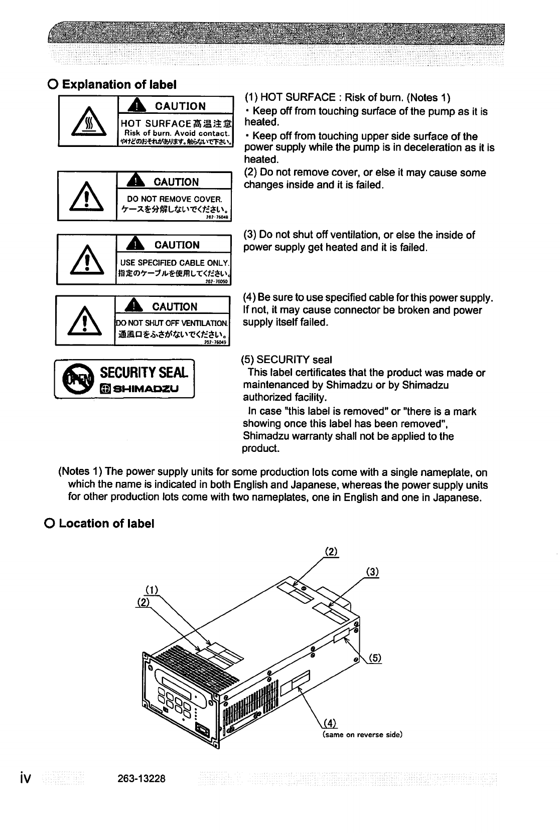
(1)
HOT
SURFACE
:
Risk
of
burn.
(Notes
1)
■
Keep
off
from
touching
surface
of
the
pump
as
it
is
heated.
■
Keep
off
from
touching
upper
side
surface
of
the
power
supply
while
the
pump
is in
deceleration
as
it
is
heated.
(2)
Do
not
remove
cover,
or
else
it
may
cause
some
changes
inside
and
it
is
failed.
(3)
Do
not
shut
off
ventilation,
or
else
the
inside of
power
supply
get
heated
and
it
is
failed.
(4)
Be
sure
to
use
specified
cable
for
this
power
supply.
If
not,
it
may
cause
connector
be
broken
and
power
supply
itself
failed.
(5)
SECURITY
seal
This
label
certificates
that
the
product
was
made
or
maintenanced
by
Shimadzu
or
by
Shimadzu
authorized
facility.
In
case
"this
label
is
removed"
or
"there
is
a
mark
showing
once
this
label
has
been
removed",
Shimadzu
warranty
shall
not
be
applied
to
the
product.
(Notes
1)
The
power
supply
units
for
some
production
lots
come
with
a
single
nameplate,
on
which
the
name
is
indicated
in
both
English
and
Japanese,
whereas
the
power
supply
units
for
other
production
lots
come
with
two
nameplates,
one
in
English
and one
in
Japanese.
O
Location
of
label
A
A
CAUTION
DO
NOT
SHUT
OFF
VENTILATION.
US
P
£&£*<J&l>T?<*:Sl,*.
(1)
(3)
(same
on
reverse
side)
IV
263-13228
en
'i
It
ttn
n
ttttti
i
n
11
Ti
'i
■
m
t»
<■<■<■
»»MMMf^jMM^<
r
i
r
r
■
■
■
i^
■
,
■
!■>
-^rm
*|
t|»l'
'Tgi V**1
**"<^
^jH^
i
tT^
-i
t It li I li 11
■
mi
■
in
■!
■ ■ ■■
i
■
.
■!
J
I. J.
J
JL. ..L JL
...I.
J.
J
J
Jll
J. I..
..L.
-HJijJiiM.Uj
■
!■!■!■■■
■■■
■;■..'
.;■■;■:■
■■
.;.,j\[,■■,■■;■
,.,■■■
■,
■
..■'<■::":"■'
T'f%:i'.-:.':r'.
■,....',.■■.':t.)';
,'■
■■.■'.■lii1!'...'.
\!Mw
,!.'
.',..■.■■,'■:■.■'
■;;■■
'
i'.1'"'H'';-ij:^J|^ii;/-■'■!■:!.■.■■■■;''>'.
.:■.■■;■■'■
.ilj'1:'
:
'.'.:ii.!'!.':<it..1.j.iiv^!Aia.vj
juA'JJ^tuitj:!^.!i:.Vv
»'.*Jal.l^iLLLl"!iliJi!iXii'■~S:'.'i'n'
'"■'■VI'.
iiV'J.':Vi^■■;'J>.".*'
■■
':>''
■
i"i"/-
■
■:.i■
'*■
•■'.
■".
■■
■'.i.''.'...■■::::,■(.'■!<:.i;jr.'j.{il'gj'j.'ViJ^
Introduction
O
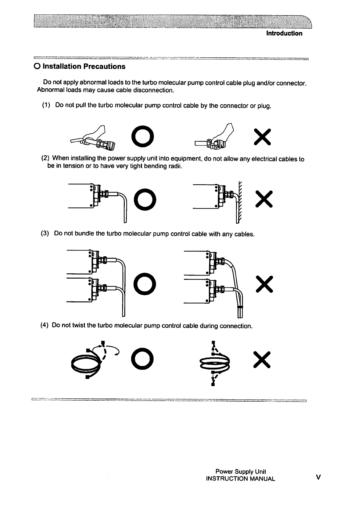
Installation
Precautions
Do
not
apply
abnormal
loads
to
the
turbo
molecular
pump
control
cable
plug
and/or
connector.
Abnormal
loads
may
cause
cable
disconnection.
(1)
Do
not
pull
the
turbo
molecular
pump
control
cable
by
the
connector
or
plug.
Ox
(2)
When
installing
the
power
supply
unit
into
equipment,
do
not allow
any
electrical
cables
to
be
in
tension
or
to
have
very
tight
bending
radii.
O
x
(3)
Do
not
bundle
the
turbo
molecular
pump
control
cable
with
any
cables.
O
X
(4)
Do
not
twist
the
turbo
molecular
pump
control
cable
during
connection.
O
X
Power
Supply
Unit
INSTRUCTION
MANUAL
(&£2£'M
O
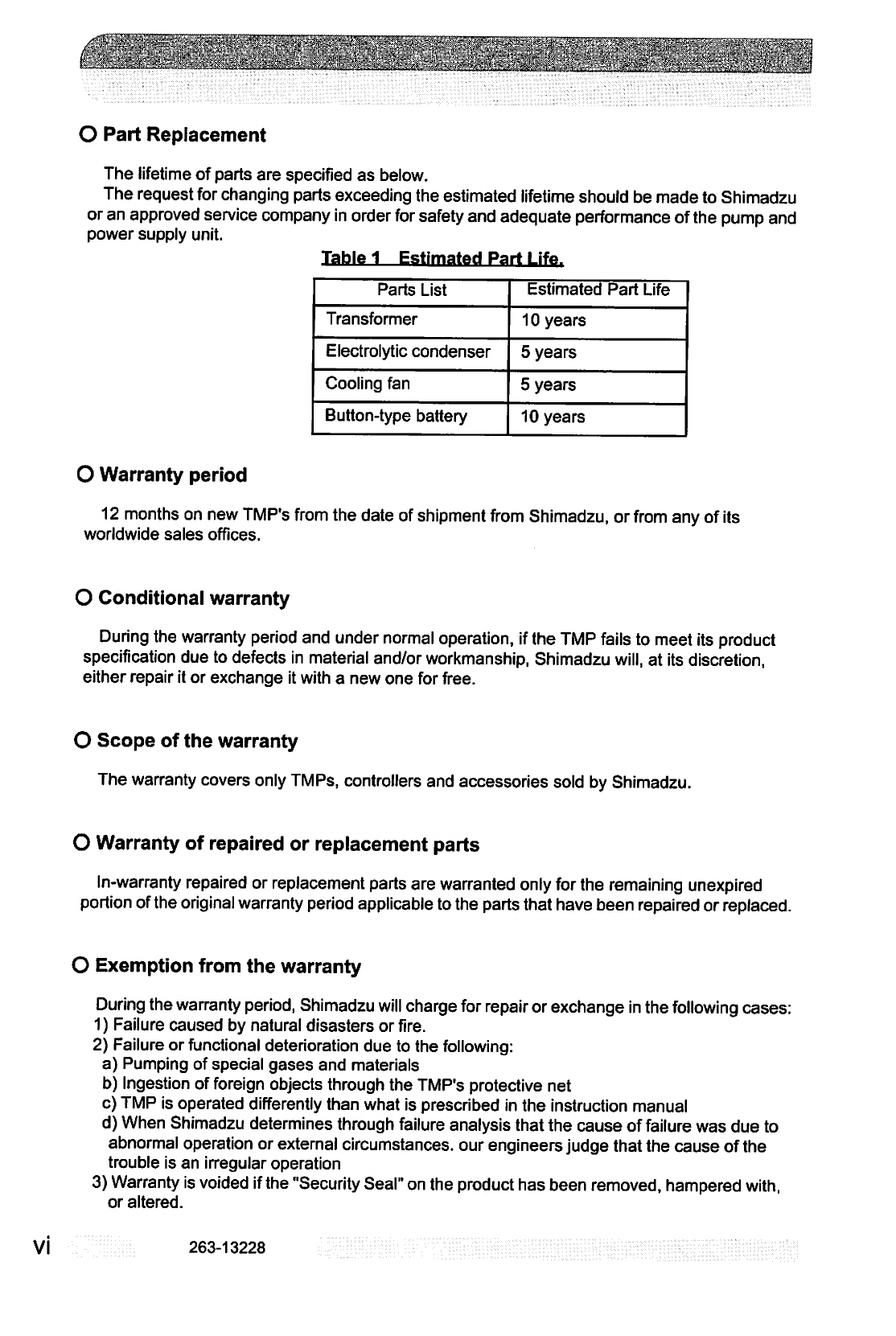
Part
Replacement
The
lifetime
of
parts
are
specified
as
below.
The
request
for
changing
parts
exceeding
the
estimated
lifetime
should
be
made
to
Shimadzu
or
an approved
service
company
in
order
for
safety
and
adequate
performance
of
the
pump
and
power
supply
unit.
Table
1
Estimated
Part
Life
Parts
List
Transformer
Electrolytic
condenser
Cooling
fan
Button-type
battery
Estimated
Part
Life
10
years
5
years
5
years
10
years
O
Warranty
period
12
months
on
new
TMP's
from
the
date
of
shipment
from
Shimadzu,
or
from
any
of
its
worldwide
sales
offices.
O
Conditional
warranty
During
the
warranty
period
and
under
normal
operation,
if
the
TMP
fails
to
meet
its
product
specification
due
to
defects
in
material
and/or
workmanship,
Shimadzu
will,
at
its
discretion,
either repair
it
or
exchange
it
with
a
new
one
for
free.
VI
O
Scope
of
the
warranty
The
warranty
covers
only
TMPs,
controllers
and
accessories
sold
by
Shimadzu.
O
Warranty
of
repaired
or
replacement
parts
In-warranty
repaired
or
replacement
parts
are
warranted
only
for
the
remaining
unexpired
portion
of
the
original
warranty
period
applicable
to
the
parts
that
have
been
repaired
or
replaced.
O
Exemption
from
the
warranty
During
the
warranty
period,
Shimadzu
will
charge
for
repair
or
exchange
in
the
following
cases:
1)
Failure
caused
by
natural
disasters
or
fire.
2)
Failure
or
functional
deterioration
due
to
the
following:
a)
Pumping
of
special
gases
and
materials
b)
Ingestion
of
foreign
objects
through
the
TMP's
protective
net
c)
TMP
is
operated
differently
than
what
is
prescribed
in
the
instruction
manual
d)
When
Shimadzu
determines
through
failure
analysis
that
the
cause
of
failure
was
due
to
abnormal
operation
or
external
circumstances,
our
engineers
judge
that
the
cause
of
the
trouble
is
an
irregular
operation
3)
Warranty
is
voided
if
the
"Security
Seal"
on
the
product
has
been
removed,
hampered
with,
or
altered.
263-13228
■■■■■■
=
'
■■;.■■'
.".-.■:
:.■■-.■■
■;■■.■=.'■.
-.w-
v.
■.■•;■■
<
■
*■
■■"■;:..'*■'■<■
■.■■■.■■.-.-■■■:.
■-■!■■■.
■■■'.
■■■*.-■
.
:
■■*
■■■,■
.■:■■'.:
Introduction
O
Disposal
of
Products
and
Parts
Please
contact
Shimadzu
for
proper
disposal
of
its
products
or
parts.
There
is
a
possibility
to
pollute
the
environment
with
the
material
of
the
parts,
when
you
dispose
this
product
in
an
inap
propriate
way.
O
LIMITATION
OF
LIABILITY
EXCEPT
AS
STATED
HEREIN,
SHIMADZU
MAKES
NO
WARRANTY,
EXPRESSED
OR
IMPLIED (EITHER
IN
FACT
OR
BY
OPERATION
OF
LAW),
STATUTORY
OR
OTHERWISE:
AND,
EXCEPT
AS
STATED
HEREIN,
SHIMADZU
SHALL
HAVE
NO
LIABILITY
FOR
SPECIAL
OR
CONSEQUENTIAL
DAMAGES
OF
ANY
KIND
OR
FROM
ANY
CAUSE
ARISING
OUT
OF
THE
SALE,
INSTALLATION,
OR
USE
OF
ANY
OF
ITS
PRODUCTS.
Power
Supply
Unit
INSTRUCTION
MANUAL
VII

This
page
is
intentionally
left
blank.
VIII
263-13228
Table
of
contents
Table
of
contents
Introduction
Copyrights
and
Disclaimers
j
Precautions
for
Safe
Operation
ii
O
Explanation
of
label
iv
O
Location
of
label
iv
O
Installation
Precautions
v
O
Part
Replacement
vi
O
Warranty
period
vi
O
Conditional
warranty
vi
O
Scope
of
the
warranty
vi
O
Warranty
of
repaired
or
replacement
parts
vi
O
Exemption
from
the
warranty
vi
O
Disposal
of
Products
and
Parts
vii
O
LIMITATION
OF
LIABILITY
vii
Table
of
contents
ix
Section
1
OUTLINE
AND
DESCRIPTIONS
1.1
Outline
2
1.2
Descriptions
3
1.2.1
Power
Supply
Unit
3
1.2.2
Control
Cable
4
1.2.3
Motor
Cable
4
1.2.4
Standard
Accessories
5
Section
2
IDENTIFICATION
AND
FUNCTION
2.1
Power
Supply
Unit
8
Power
Supply
Unit
INSTRUCTION
MANUAL
IX
Table
of
contents
Section
3
CONSTRUCTION
AND
PRINCIPLE
3.1
Power
Supply
Unit
12
Section
4
SPECIFICATIONS
4.1
Power
Supply
Unit
14
4.2
Standards
Fulfilled
16
Section
5
INSTALLATION
5.1
Installation
of
the
Power
Supply
Unit
18
5.1.1
Location
of
the
Power
Supply
Unit
18
5.1.2
Installation
of
the
Power
Supply
Unit
18
5.1.3
Compatibility
with
Previous
Models
21
5.2
Connection
of
Power
Cable
23
5.3
Connection
of
the
Pump
to
the
Power
Supply
Unit
24
Section
6
OPERATION
6.1
Outline
28
6.1.1
Introduction
28
6.1.2
Operation
Flowchart
29
6.2
Start-up
Preparation
35
6.2.1
Start-up
Preparation
Sequence
in
LOCAL
Mode
35
6.2.2
Start-up
Preparation
Sequence
in
REMOTE
Mode
35
6.3
Start-up
36
6.3.1
Start-up
Sequence
in
LOCAL
Mode
36
6.3.2
Start-up
Sequence
in
REMOTE
Mode
36
6.4
Shutting
Down
37
6.4.1
Preparations
Prior
to
Shutting
Down
Operation
37
6.4.2
Shutting
Down
Sequence
in
LOCAL
Mode
37
6.4.3
Shutting
Down
Sequence
in
REMOTE
Mode
38
6.5
Variable
Speed
Operation
39
6.5.1
Outline
39
6.5.2
Operation
from
Start-up
to
Low
Speed
Rotation
40
263-13228
Table
of
contents
6.5.3
Operation
from
Rated
Speed
Rotation
to
Low
Speed
Rotation...
41
6.5.4
Operation
from
Low
Speed
Rotation
to
Rated
Speed
Rotation...
41
6.6
Software
Operation
43
6.7
Remote-Control
Connector
58
6.7.1
Specifications
58
6.7.2
Compatibility
with
Previous
Models
60
6.7.2.1
Replacing
the
EI-xxO3M/MD
Power
Supply
Unit
60
6.7.2.2
Replacing
EI-xxO3MZ
Power
Supply
Units
62
Section
7
TROUBLESHOOTING
7.1
Nothing
Happens
After
an
Operation
is
Made
66
7.2
Power
Failures
67
7.2.1
Power
Failure
Counter-Operation
68
7.3
Vacuum
Pressure
Rise
69
7.4
Abnormal
Noise
and/or
Vibration
69
7.5
Alarm
Detection
Capabilities
69
7.5.1
Movement
in
Alarm
Detection
Capabilities
(ALARM)
69
7.5.2
Movement
in
Alarm
Detection
Capabilities
(WARNING)
70
7.5.3
Reset
Procedure
70
Appendix
A
COMMUNICATIONS
A.1
GENERAL
SPECIFICATION
A-2
A.2
INTERFACE
SPECIFICATION
A-3
A.2.1
RS-232C
A-3
A.2.1.1
Transmission
Specification
A-3
A.2.1.2
Communications
Connector
A-3
A.2.1.3
CABLE
A-3
A.2.2
RS-485
A-5
A.2.2.1
Transmission
Specification
A-5
A.2.2.2
Communications
Connector A-5
A.2.2.3
CABLE
A-5
A.3
POWER
SUPPLY
TO
COMPUTER
CONNECTION
A-7
A.3.1
Communication
Cable
Connection
A-7
A.3.2
Serial
Communications
Baud
Rate
Configuration
A-7
A.3.3
RS-485
Multi-drop
Settings
A-7
A.4
SERIAL
COMMUNICATIONS
PROTOCOL
A-8
A.4.1
Basic
Message
Structure
A-8
Power
Supply
Unit
INSTRUCTION
MANUAL
XI
/■':
■
-
> .
.'■"'■
■■■.
■■''.'
■'■■-
:7
••?.'"■'•■
"I"5"-
•■■■.■■
-:
:
■■■■..
■■";■■.;■
■■■"
~
:-
';■■'■'"':"
"IT"
;
.7
-,-_-.
:-.
"■-■•■--■-■
Table
of
contents
A.4.2
Character
to
Character
Time-out:
0.1
sec A-8
A.4.3
Command
to
Answer
Time-out:
1
sec
A-9
A.4.4
Power
Supply
Command
Send
Retry
Cycles:
5
A-9
A.4.5
Command
Transmission
Specification
A-9
A.4.6
Receiving
Sequence
A-9
A.4.7
Using
the
Checksum
Byte
A-9
A.4.8
Outline
of
Multi-drop
Communications
A-10
A.5
TABLE
OF
COMMANDS
A-11
A.6
COMMAND
DESCRIPTION
A-17
A.6.1
Operation
Mode
A-17
A.6.2
Operation
A-18
A.6.3
Run
Status
A-19
A.6.4
Parameters
A-20
A.6.5
Events
A-20
A.6.6
Timer
A-21
A.6.7
History
A-21
A.6.8
Settings
A-22
A.6.9
Shared
Answer
A-22
A.7
RS-232C
COMMANDS
/
ANSWERS
A-23
A.8
RELATION
OF
LOCAL
MODE
TO
REMOTE
MODE
OPERATIONS
A-26
A.9
TROUBLESHOOTING
A-27
A.9.1
No
Message
can
Transmit
and
Receive
A-27
A.9.2
Sending
and
Receiving
are
Done,
But
Receivable
Messages
are
Invalid
A-27
A.9.3
Characters
Get
Disordered
from
Time
to
Time,
Then
Resulting
in
CHECKSUM
Error
A-27
XII
263-13228
■.■
. •
.-.::'.
;
.
■
.
■
-
■■'■■
•■■■■■:■>-
■■
..
;
'•■■.'
:■■■■■■
■
.■■
■
-
■
■■"
■■.■
.}-.*
■
•
."
■'■
'.•(■■'■■.'.
.'■
-i
S:
■':"■■
'
'.'."'■'
#
•■;■:
.■ '
■
:■,■■..
■■.:■.-
■
:JK
-.
^
;.-.-
-:.
.
■
,1
;:«
■■■■'■■.■■'.■■'■
■
■".*
■"■'-■:':■■■■■:■
"
,.:; .■■■
.
.-.
■
■■.
■"Aj
OUTLINE
AND
DESCRIPTIONS
©
©
©
©
1.1
Outline
1.2
Descriptions
1.2.1
Power
Supply
Unit
1.2.2
Control
Cable
1.2.3
Motor
Cable
1.2.4
Standard
Accessories
SECTION
1
OUTLINE
AND
DESCRIPTIONS
l»
1.1
Outline
£"£■
-y
The
turbo
molecular
pump
is
a
vacuum
pump.
The
turbo
molecular
pump
is
used
with
a
backing
vacuum
pump
to
create
a
high
vacuum
in
a
vacuum
chamber.
Typical
Applications
;
Semiconductor
equipments,
Industrial
equipments,
R&D
applications,
The
other
ultra
high
vacuum
applications.
The
turbo
molecular
pump
(one
standard
set)
consists
of
the
following
items.
Pump
Power
Supply
Unit
Control
Cable
Motor Cable
Standard
Accessories
1
1
1
1
1
Set
The
cable
length
must
be
specified
for
the
magnetic
bearing
cable
and
motor
cable.
(Refer
to
Sections
1.2.2
and
1.2.3.)
263-13228
1.2
Descriptions
M^M^
1.2
Descriptions
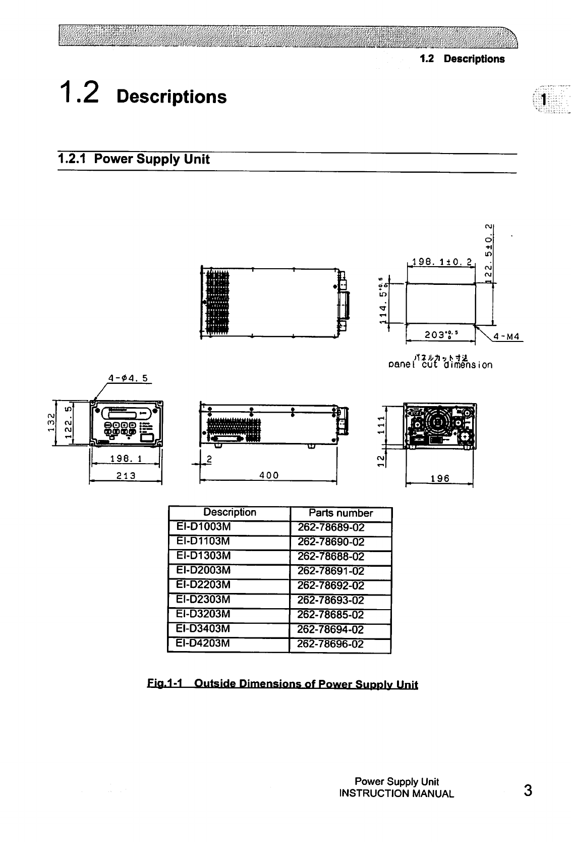
1.2.1
Power
Supply
Unit
4-04.
5
.198.
110,
2
203'S-'
oane!
cut
dimension
rvi
196
Description
EI-D1003M
EI-D1103M
EI-D1303M
EI-D2003M
EI-D2203M
EI-D2303M
EI-D3203M
EI-D3403M
EI-D4203M
Parts
number
262-78689-02
262-78690-02
262-78688-02
262-78691-02
262-78692-02
262-78693-02
262-78685-02
262-78694-02
262-78696-02
Fia.1-1
Outside
Dimp
nsions
of
Power
Supply
Unit
Power
Supply
Unit
INSTRUCTION
MANUAL
SECTION
1
OUTLINE
AND
DESCRIPTIONS
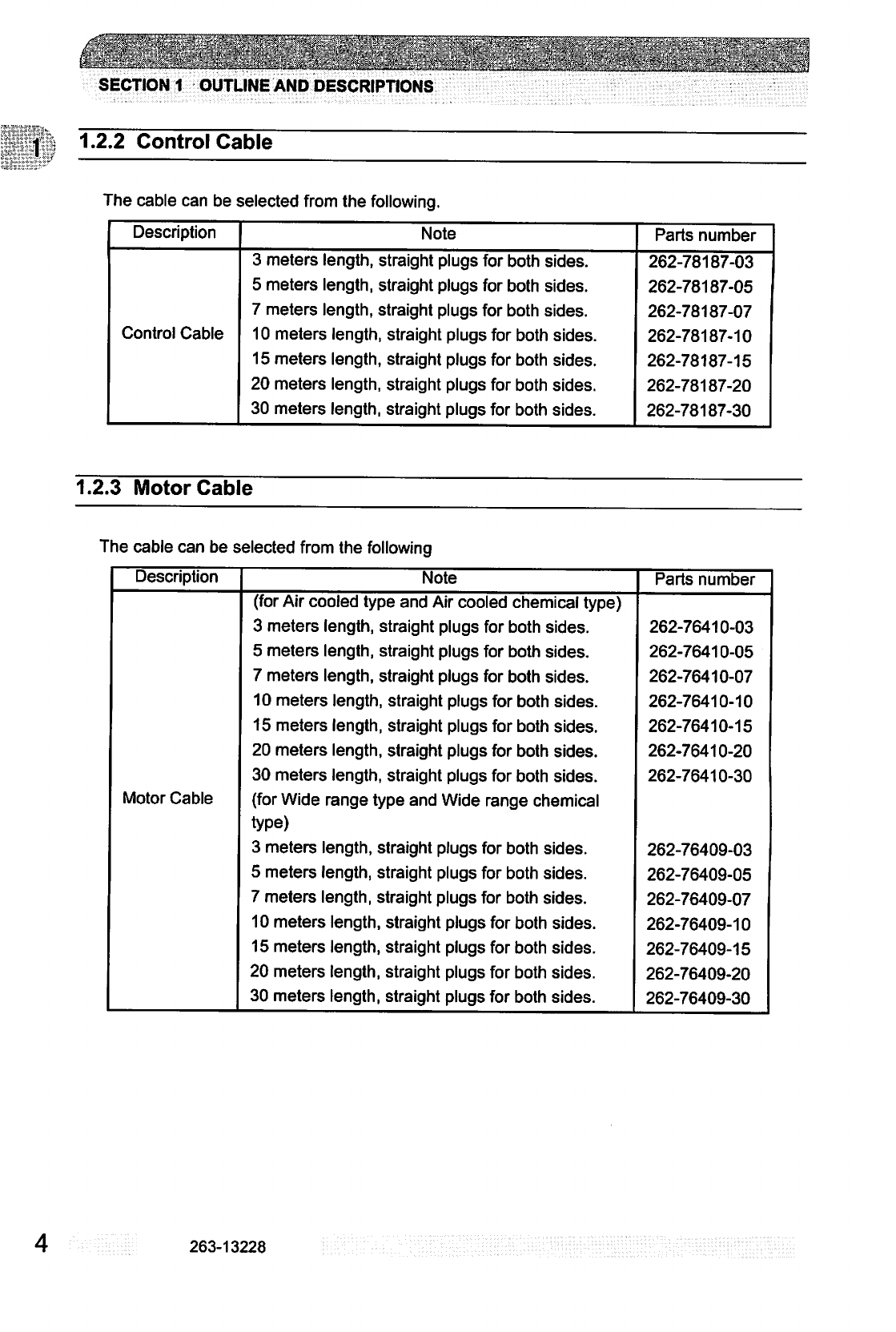
1.2.2
Control
Cable
The
cable
can
be
selected
from
the
following.
Description
Control
Cable
Note
3
meters
length,
straight
plugs
for
both
sides.
5 meters
length,
straight
plugs
for
both
sides.
7
meters
length,
straight
plugs
for
both
sides.
10
meters
length,
straight
plugs
for
both
sides.
15
meters
length,
straight
plugs
for
both
sides.
20
meters
length,
straight
plugs
for
both
sides.
30
meters
length,
straight
plugs
for
both
sides.
Parts
number
262-78187-03
262-78187-05
262-78187-07
262-78187-10
262-78187-15
262-78187-20
262-78187-30
1.2.3
Motor
Cable
The
cable
can
be
selected
from
the
following
Description
Motor Cable
Note
(for
Air
cooled
type
and
Air
cooled
chemical
type)
3
meters
length,
straight
plugs
for
both
sides.
5
meters
length,
straight
plugs
for
both
sides.
7 meters
length,
straight
plugs
for
both
sides.
10 meters
length,
straight
plugs
for
both
sides.
15
meters
length,
straight
plugs
for
both
sides.
20
meters
length,
straight
plugs
for
both
sides.
30
meters
length,
straight
plugs
for
both
sides,
(for
Wide
range
type
and
Wide
range
chemical
type)
3
meters
length,
straight
plugs
for
both
sides.
5
meters
length,
straight
plugs
for
both
sides.
7
meters
length,
straight
plugs
for
both
sides.
10
meters
length,
straight
plugs
for
both
sides.
15 meters
length,
straight
plugs
for
both
sides.
20
meters
length,
straight
plugs
for
both
sides.
30
meters
length,
straight
plugs
for
both
sides.
Parts
number
262-76410-03
262-76410-05
262-76410-07
262-76410-10
262-76410-15
262-76410-20
262-76410-30
262-76409-03
262-76409-05
262-76409-07
262-76409-10
262-76409-15
262-76409-20
262-76409-30
263-13228
*
'
■
.
_■*__...-
.
■. _ _
■_.
i _
._■
_
_■
■
_i_
_
*
"■.
m''T
__■_■
1.2
Descriptions
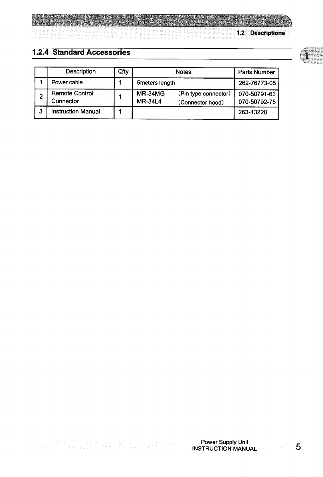
1.2.4
Standard
Accessories
1
2
3
Description
Power
cable
Remote
Control
Connector
Instruction
Manual
Q'ty
1
1
1
Notes
5meters
length
MR-34MG
(Pin
type
connector)
MR-34L4
(Connector
hood)
Parts
Number
262-76773-05
070-50791-63
070-50792-75
263-13228
Power
Supply
Unit
INSTRUCTION
MANUAL

This
page
is
intentionally
left
blank.
263-13228
DENTIFICATION
AND
FUNCTION
©
©
©
e
2.1
Power
Supply
Unit

..........
^r
-^..
-Lj^a^
.
:^._^..^._^
SECTION
2
IDENTIFICATION
AND
FUNCTION
2.1
Power
Supply
Unit
■M
V
XJ
/
/
/ /
mo
i3
36
6)
(15)
C7)
8)
24)
(9
Fia.2-1
Front
Control
Panel
Fia 2-2
Rear
Panel
8
263-13228
2.1
Power
Supply
Unit
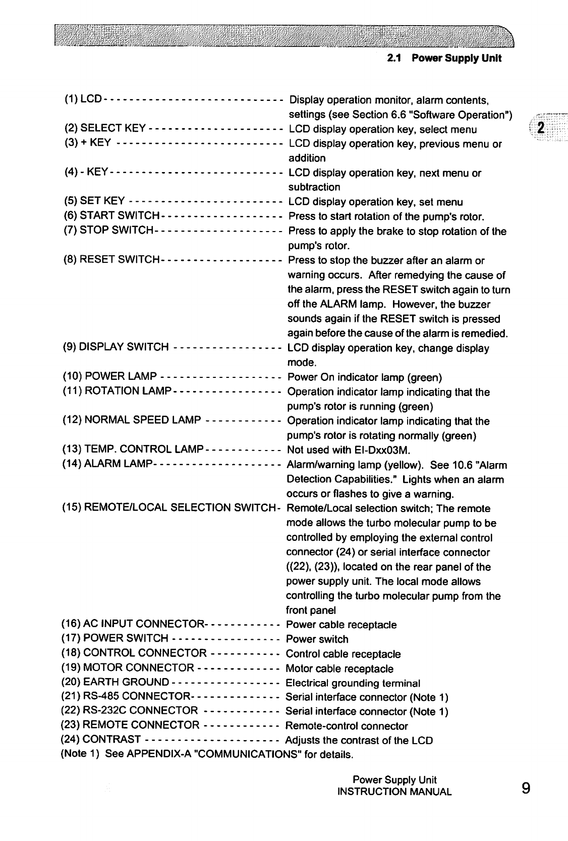
(1)
LCD
Display
operation
monitor,
alarm
contents,
settings
(see
Section
6.6
"Software
Operation")
(2)
SELECT
KEY LCD
display
operation
key,
select
menu
(3)
+
KEY
LCD
display
operation
key,
previous
menu
or
addition
(4)
-
KEY LCD
display
operation
key,
next
menu
or
subtraction
(5)
SET KEY
LCD
display
operation
key,
set
menu
(6)
START
SWITCH
Press
to
start
rotation
of
the
pump's
rotor.
(7)
STOP
SWITCH
Press
to
apply
the
brake
to
stop
rotation
of
the
pump's
rotor.
(8)
RESET
SWITCH
Press
to
stop
the
buzzer
after
an
alarm
or
warning
occurs.
After
remedying
the
cause
of
the
alarm,
press
the
RESET
switch
again
to
turn
off
the
ALARM
lamp.
However,
the
buzzer
sounds
again
if
the
RESET
switch
is
pressed
again
before
the
cause
of
the
alarm
is
remedied.
(9)
DISPLAY
SWITCH
LCD
display
operation
key,
change
display
mode.
(10)
POWER
LAMP
Power
On
indicator
lamp
(green)
(11)
ROTATION
LAMP
Operation
indicator
lamp
indicating
that
the
pump's
rotor
is
running
(green)
(12)
NORMAL
SPEED
LAMP
Operation
indicator
lamp
indicating
that
the
pump's
rotor
is
rotating
normally
(green)
(13)
TEMP.
CONTROL
LAMP
Not
used
with
EI-DxxO3M.
(14)
ALARM
LAMP
Alarm/warning
lamp
(yellow).
See
10.6
"Alarm
Detection
Capabilities."
Lights
when
an
alarm
occurs
or
flashes
to
give
a
warning.
(15)
REMOTE/LOCAL
SELECTION
SWITCH-
Remote/Local
selection
switch;
The
remote
mode
allows
the
turbo
molecular
pump
to
be
controlled
by
employing
the
external
control
connector
(24)
or
serial
interface
connector
((22),
(23)),
located
on
the
rear
panel
of
the
power
supply
unit.
The
local
mode
allows
controlling
the
turbo
molecular
pump
from
the
front
panel
(16)
AC
INPUT
CONNECTOR
Power
cable
receptacle
(17)
POWER
SWITCH
Power
switch
(18)
CONTROL
CONNECTOR
Control
cable
receptacle
(19)
MOTOR
CONNECTOR
Motor
cable
receptacle
(20)
EARTH
GROUND
Electrical
grounding
terminal
(21)
RS-485
CONNECTOR
Serial
interface
connector
(Note
1)
(22)
RS-232C
CONNECTOR
Serial
interface
connector
(Note
1)
(23)
REMOTE
CONNECTOR
Remote-control
connector
(24)
CONTRAST
Adjusts
the
contrast
of
the
LCD
(Note
1)
See
APPENDIX-A
"COMMUNICATIONS"
for details.
Power
Supply
Unit
INSTRUCTION
MANUAL
This
page
is
intentionally
left
blank.
10
263-13228
■■'.-11.:..
-si^
:.*■.■>
.
<■;.■■.■■"'.
■!■.'■..■
■
:■'
.■■,■;:■.■■:.-.•■■■.■■.'-y.^:
'■■.-:•'="
^■■c;:1
■-■li-:-:."'.;
CONSTRUCTION
AND
PRINCIPLE
0
@
©
© © ©
0
3.1
Power
Supply
Unit
SECTION
3
CONSTRUCTION
AND
PRINCIPLE
3.1
Power
Supply
Unit
The
power
supply
unit
is
composed
of
the
magnetic
bearing
control
system
and
the
high
frequency
motor
system
and
does
not
use
back
up
batteries
for
electrical
power
failure.
The
magnetic
bearing
control
system
controls
the
levitation
of
the
rotor
inside
the
turbo
molecular
pump.
The
system
detects
the
rotor
position
by
an
electrical
signal
received
from
the
gap
sensors
and
maintains
the
levitation
by
regulating
the
current
to
the
magnetic
bearings.
The
high
frequency
motor
system
rotates
the
rotor
at
a
rated
rotational
speed.
This
frequency
power
system
converts
AC/single
phase
commercial
power
to
controlled
DC/three
phase
pulsed
power.
The
DC/three
phase
pulsed
power
drives
the
DC
motor
that
is
an
integral
part
of
the
rotor.
If
the
electrical
power
is
interrupted
while
the
rotor
is
in
a
high-speed
rotation,
then
the
motor
becomes
a
generator
to
power
the
magnetic
bearing
system
during
a
power
failure
deceleration
mode;
therefore,
the
need
for
a
battery
backup
system
is
eliminated.
The
power
supply
unit
is
equipped
with
an
RS-232C
and
an
RS-485
serial
interface
and
with
Contact
input/ouitput
to
operate
the
turbo
molecular
pump
from
an
external
source.
The
operational
status
can
be
monitored
and
the
history
retrieved
through
the
RS-232C
and
RS-485.
See
APPENDIX-A
"COMMUNICATIONS"
for
instructions
to
remotely
operate
the
turbo
molecular
pump
using
the
RS-232C
and
RS-485
serial
interface.
The
turbo
molecular
pump,
the
power
supply,
the
control
cable,
and
the
motor
cable
are
respectively
interchangeable
among
any
products
of
the
same
model.
Fig.1-1
shows
the
external
dimensions
of
the
power
supply
unit.
The
power
supply
unit,
control
cable,
motor
cable,
and
the
pump
unit
are
all
mutually
compatible.
However,
only
pumps
and
power
supply
units
with
the
same
series
number
(the "xx"
number)
are
compatible
with
each
other.
12
263-13228
SPECIFICATIONS
siliiiiiii
ftSfj^^ll
■.■'■.'.
:.■
*
■
4.1
Power
Supply
Unit
4.2
Standards
Fulfilled
SECTION
4
SPECIFICATIONS
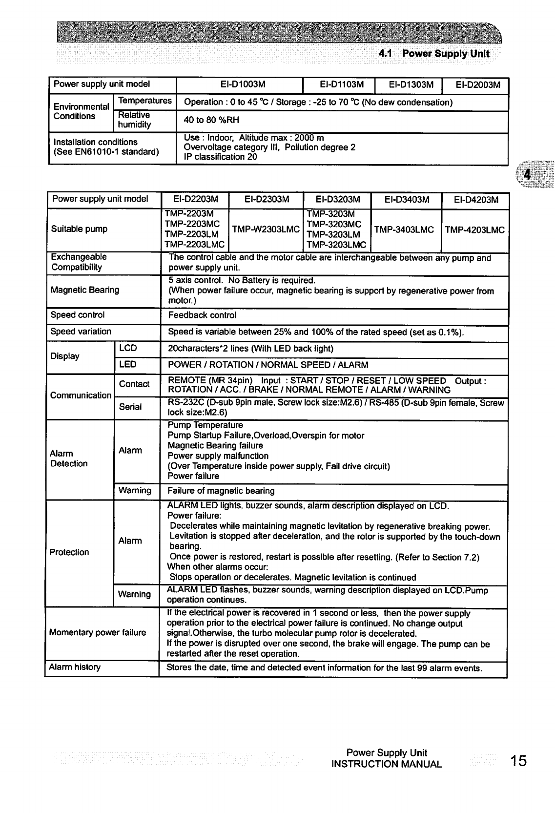
4.1
Power
Supply
Unit
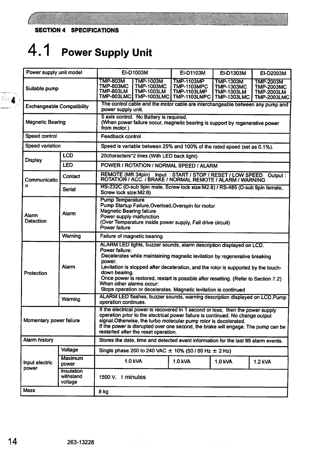
Power
supply
unit
model
Suitable
pump
Exchangeable
Compatibility
Magnetic
Bearing
Speed
control
Speed
variation
Display
Communicatio
n
Alarm
Detection
Protection
LCD
LED
Contact
Serial
Alarm
Warning
Alarm
Warning
Momentary
power
failure
Alarm
history
Input
electric
power
Voltage
Maximum
power
Insulation
withstand
voltage
Mass
EI-D1003M
TMP-803M
TMP-803MC
TMP-803LM
TMP-803LMC
TMP-1003M
TMP-1003MC
TMP-1003LM
TMP-1003LMC
EI-D1103M
TMP-1103MP
TMP-1103MPC
TMP-1103LMP
TMP-1103LMPC
EI-D1303M
TMP-1303M
TMP-1303MC
TMP-1303LM
TMP-1303LMC
EI-D2003M
TMP-2003M
TMP-2003MC
TMP-2003LM
TMP-2003LMC
The
control
cable
and
the
motor
cable
are interchangeable
between
any
pump
and
power
supply
unit.
5
axis
control.
No
Battery
is
required.
(When
power
failure
occur,
magnetic
bearing
is
support
by
regenerative
power
from
motor.)
Feedback
control
Speed
is
variable
between
25%
and
100%
of
the
rated
speed
(set
as
0.1%).
20characters*2
lines
(With
LED
back
light)
POWER
/
ROTATION
/
NORMAL
SPEED
/
ALARM
REMOTE
(MR
34pin)
Input
:
START
/
STOP
/
RESET
/
LOW
SPEED
Output"
ROTATION
/
ACC.
/
BRAKE
/
NORMAL
REMOTE
/
ALARM
/
WARNING
RS-232C
(D-sub
9pin
male,
Screw
lock
size:M2.6)
/
RS-485
(D-sub
9pin female,
Screw
lock
size:M2.6)
Pump
Temperature
Pump
Startup
Failure.Overload.Overspin
for
motor
Magnetic
Bearing
failure
Power
supply
malfunction
(Over
Temperature
inside
power
supply,
Fail
drive
circuit)
Power
failure
Failure
of
magnetic
bearing
ALARM
LED
lights,
buzzer
sounds,
alarm
description
displayed
on
LCD.
Power
failure:
Decelerates
while
maintaining
magnetic
levitation
by
regenerative
breaking
power.
Levitation
is
stopped
after
deceleration,
and
the
rotor
is
supported
by
the
touch
down
bearing.
Once
power
is
restored,
restart
is
possible
after
resetting.
(Refer
to
Section
7.2)
When
other
alarms
occur:
Stops
operation
or
decelerates.
Magnetic
levitation
is
continued
ALARM
LED
flashes,
buzzer
sounds,
warning
description
displayed
on
LCD.Pump
operation
continues.
If
the
electrical
power
is
recovered
in
1
second
or
less,
then
the
power
supply
operation
prior
to
the
electrical
power
failure
is
continued.
No
change
output
signal.Olherwise,
the turbo
molecular
pump
rotor
is
decelerated.
If
the
power
is
disrupted
over
one
second,
the
brake
will
engage.
The
pump
can
be
restarted
after
the
reset operation.
Stores
the
date,
time
and
detected
event
information
for
the
last
99
alarm
events.
Single
phase
200
to
240
VAC
±
10%
(50
/
60
Hz
±
2
Hz)
1.0
kVA
1.0
kVA
1.0
kVA
1.2
kVA
1500
v,
1
minutes
8
kg
14
263-13228
■- - -
—
■■■-
5..-..-
,
,■■,-
^~-^-^^^^-^^
^
^--^^
^-^--■
^
rOT^TTVT^
If
.'t'.'tJClT^JiTIt'Jlti^TjJ^.^
Jt
^1,^1^1.
^-tLtlHTjtL&.T^LJLjCtOUlUL-P-HU-fll-Jl-tHHaULfcmjmi
■
i
:
. ■
■
■.
4.1
Power
Supply
Unit
Power
supply
unit
model
Environmental
Conditions
Temperatures
Relative
humidity
Installation
conditions
(See
EN61010-1
standard)
EI-D1003M
|
EI-D1103M
EI-D1303M
EI-D2003M
Operation
:
0
to
45
°C
/
Storage
:
-25
to
70
°C
(No
dew
condensation)
40
to
80
%RH
Use
:
Indoor,
Altitude
max
:
2000
m
Overvoltage
category
III,
Pollution
degree
2
IP
classification
20
Power
supply
unit
model
Suitable
pump
Exchangeable
Compatibility
Magnetic
Bearing
Speed
control
Speed
variation
Display
Communication
Alarm
Detection
Protection
LCD
LED
Contact
Serial
Alarm
Warning
Alarm
Warning
Momentary
power
failure
Alarm
history
EI-D2203M
TMP-2203M
TMP-2203MC
TMP-2203LM
TMP-2203LMC
EI-D2303M
TMP-W2303LMC
EI-D3203M
TMP-3203M
TMP-3203MC
TMP-3203LM
TMP-3203LMC
EI-D3403M
TMP-3403LMC
EI-D4203M
TMP-4203LMC
The
control
cable
and
the
motor
cable
are
interchangeable
between
any
pump
and
power
supply
unit.
5
axis
control.
No
Battery
is
required.
(When
power
failure
occur,
magnetic
bearing
is
support
by
regenerative
power
from
motor.)
Feedback
control
Speed
is
variable
between
25%
and
100%
of
the
rated
speed
(set
as
0.1%).
20characters*2
lines
(With
LED
back
light)
POWER
/
ROTATION
/
NORMAL
SPEED
/
ALARM
REMOTE
(MR
34pin)
Input
:
START/STOP/RESET/LOW
SPEED
Output:
ROTATION
/
ACC.
/
BRAKE
/
NORMAL REMOTE
/
ALARM
/
WARNING
RS-232C
(D-sub
9pin
male,
Screw
lock
size:M2.6)
/
RS-485
(D-sub
9pin
female.
Screw
lock
size:M2.6)
Pump
Temperature
Pump
Startup
Failure,Overload.Overspin
for
motor
Magnetic
Bearing
failure
Power
supply
malfunction
(Over
Temperature
inside
power
supply,
Fail
drive
circuit)
Power
failure
Failure
of
magnetic
bearing
ALARM
LED
lights,
buzzer
sounds,
alarm
description
displayed
on
LCD.
Power
failure:
Decelerates
while
maintaining
magnetic
levitation
by
regenerative
breaking
power.
Levitation
is
stopped
after
deceleration,
and
the
rotor
is
supported
by
the
touch-down
bearing.
Once
power
is
restored,
restart
is
possible
after resetting.
(Refer
to
Section
7.2)
When
other
alarms
occur:
Stops
operation
or
decelerates.
Magnetic
levitation
is
continued
ALARM
LED
flashes,
buzzer
sounds,
warning
description
displayed
on
LCD.Pump
operation
continues.
If
the
electrical
power
is
recovered
in
1
second
or
less,
then
the
power
supply
operation
prior
to
the
electrical
power
failure
is
continued.
No
change
output
signal.Otherwise,
the turbo
molecular
pump
rotor
is
decelerated.
If
the
power
is
disrupted
over
one
second,
the
brake
will
engage.
The
pump
can be
restarted
after
the
reset
operation.
Stores
the
date,
time
and
detected
event
information
for
the
last
99
alarm
events.
Power
Supply
Unit
INSTRUCTION
MANUAL
15
,•>--:■.■"■.".:•■■■:■.--:■:—
.
;■"■
V.:
■'■■'
:'"':;-
"
:.-'-
: .
'■■■
*■%■■.
'■■' ■
•
'}
:.'■
;.'■■■:-
'
'■.:.
y-:'\.
'"V,:
.
jfV<-,.;-
.:-,
Vj\:\
."!;.
——';
?~—*———
—-
—
—
" -
i
...
-
.
..
.
T.
.....
./"■
.
^
J^r'..
.fi
'.
.rr.n".V
..?. ..'.
■
.
. -
mi
■
n^^ilVr
"^"™
^
-"V-
'■■
■"'■
J
V)
"^^f
SECTION
4
SPECIFICATIONS
Power
supply
unit
model
EI-D2203M
EI-D2303M
EI-D3203M
EI-D3403M EI-D4203M
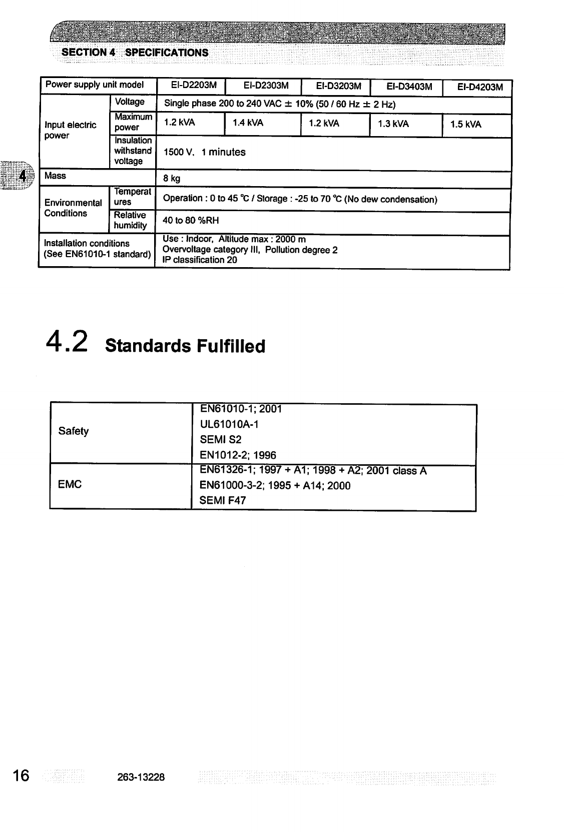
Input
electric
power
Voltage
Maximum
power
Insulation
withstand
voltage
Single
phase
200
to
240
VAC
±
10%
(50
/
60
Hz
±
2
Hz)
1.2
kVA
1.4
kVA
1.2
kVA
1.3
kVA
1500
V.
1
minutes
1.5
kVA
Mass
8
kg
Environmental
Conditions
Temperat
ures
Operation
:
0
to
45
°C
/
Storage
:
-25
to
70
°C
(No
dew
condensation)
Relative
humidity
40
to
80
%RH
Installation
conditions
(See
EN61010-1
standard)
Use:
Indoor,
Altitude
max:
2000
m
Overvoltage
category
III,
Pollution
degree
2
IP
classification
20
4.2
Standards
Fulfilled
Safety
EN61010-1;2001
UL61010A-1
SEMI
S2
EN1012-2;
1996
EMC
EN61326-1;
1997
+
A1;
1998
+
A2;
2001
class
A
EN61000-3-2;
1995 +
A14;
2000
SEMI
F47
16
263-13228
■'■
'£>■■'
.^v
';>.:'-/^-
..:-■■.:■:.
v.
■■?".■.'■
'■-'■.
"-•:■;■■■■■:•
(V;:-..-rv
-:::-
■v,-;
.■;.
v:^-."^-1"
■■•:.
:;
.>;■<;
y1.!/*'*!
■:.':i?-1-!"~^u":;'"..'
INSTALLATION
5.1
Installation
of
the
Power
Supply
Unit
5.1.1
Location
of
the
Power
Supply
Unit
5.1.2
Installation
of
the
Power
Supply
Unit
5.1.3
Compatibility
with
Previous
Models
5.2
Connection
of
Power
Cable
5.3
Connection
of
the
Pump
to
the
Power
Supply
Unit
"
."
■
■■
■"■"■■.
b
■ ' ■ ' '
b
;■'
. .
' ' '
"
' '
'"
—-
- 1
...p..l1.1.1
.■■1.1.1.-.1.1.1lnr1
1
t
in
i-^i
irim
^ ■
SECTION
5
INSTALLATION
5.1
Installation
of
the
Power
Supply
Unit
5.1.1
Location
of the
Power
Supply
Unit
Install
and
anchor
the
power
supply
unit
inside
a
rack,
which
shall
be
located
at
a
place
where
it
is
not
exposed
to
direct
sun
ray
and
well
ventilated.
Avoid
to
locate
it
at
the
following
places.
(1)
Place
where
it
is
very
humid,
dusty
and,
in
addition,
oil
smoke,
vapor,
water,
etc,
are
exist.
(2)
Place
where
the
power
supply
unit
is
exposed
to
direct
sun
ray
and
abnormally
high
temperature
(3)
Place
with
high
amplitude
of
vibration
and
impact
(4)
Near
chemically
active
gas
and
explosive/combustible
gas
(5)
Place
with
strong
magnetic
field
and
electric
field,
noisy
place,
and
place
with
strong
radioactive
ray
(6)
Unventilatable
place
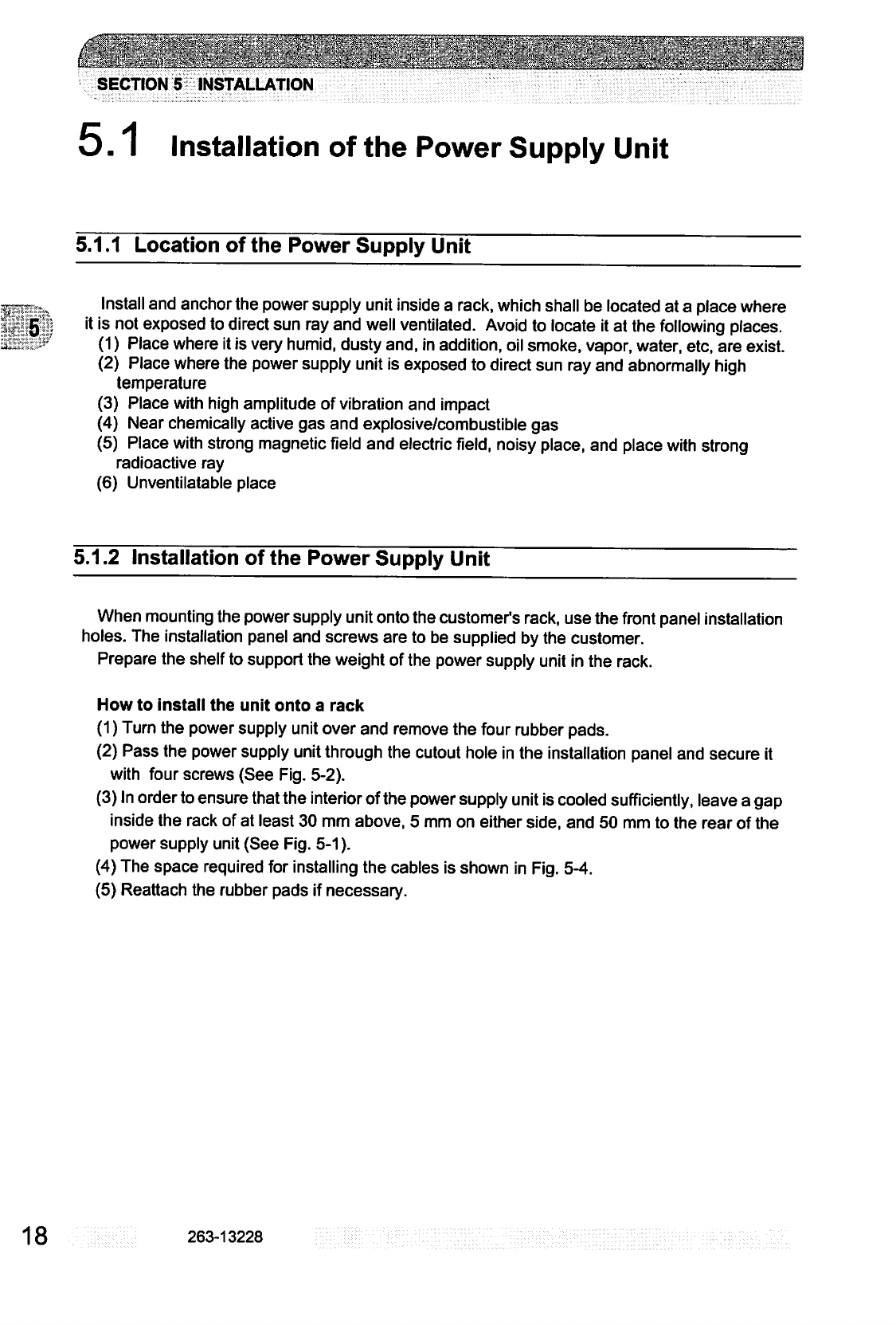
5.1.2
Installation
of
the
Power
Supply
Unit
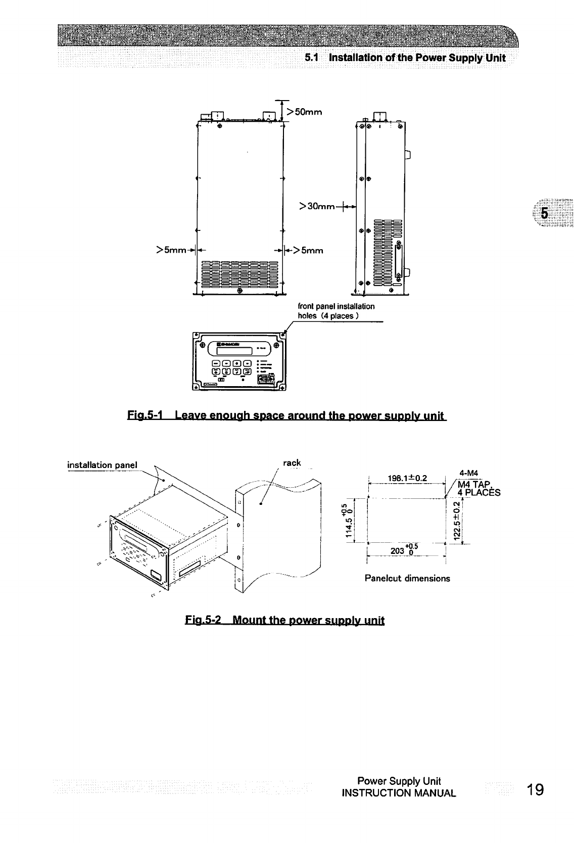
When
mounting
the
power
supply
unit
onto
the
customer's
rack,
use
the
front
panel
installation
holes.
The
installation
panel
and
screws
are
to
be
supplied
by
the
customer.
Prepare
the
shelf
to
support
the
weight
of
the
power
supply
unit
in
the
rack.
How
to
install
the
unit
onto
a
rack
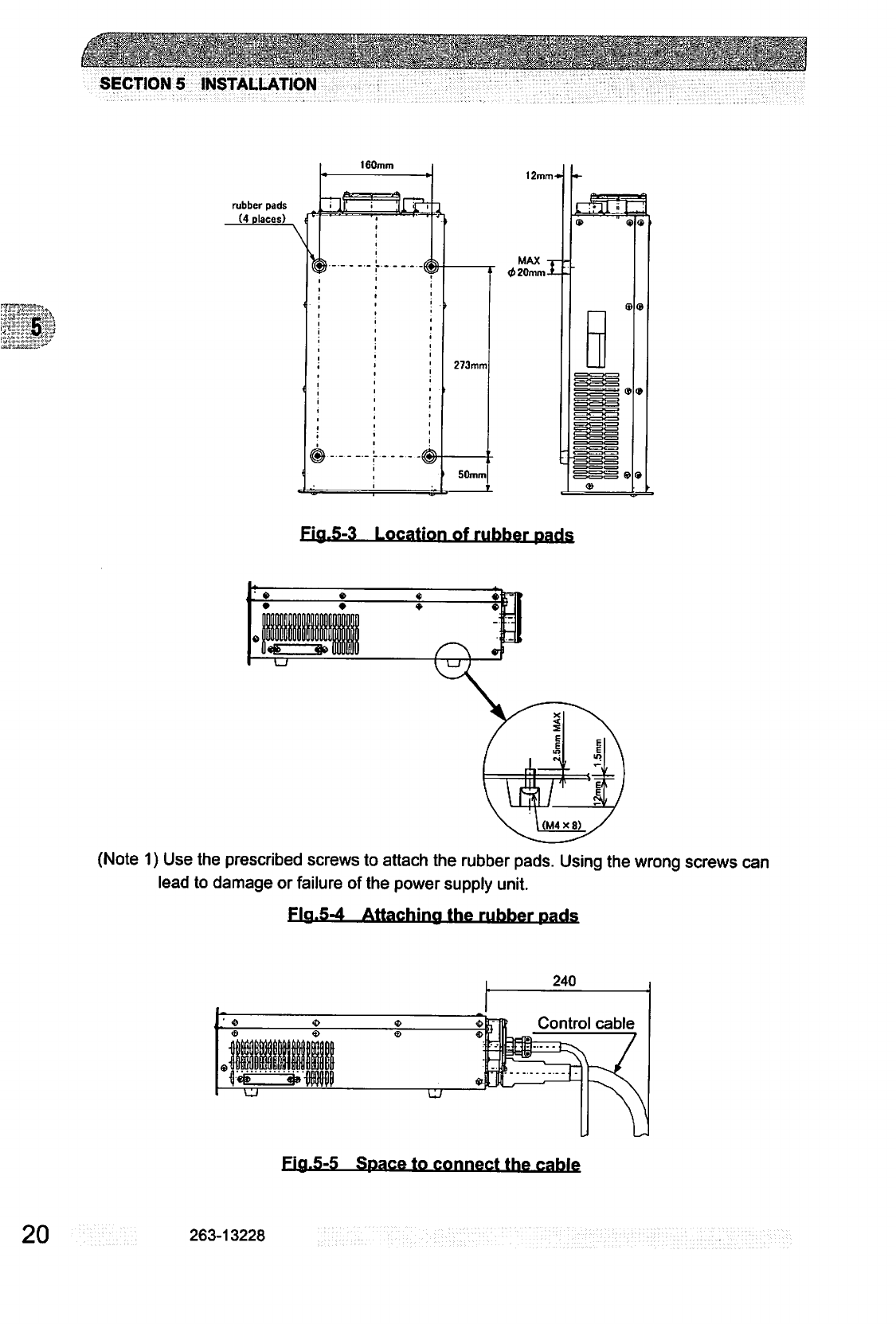
(1)
Turn
the
power
supply
unit
over
and
remove
the
four
rubber
pads.
(2)
Pass
the
power
supply
unit
through
the
cutout
hole
in
the
installation
panel
and
secure
it
with
four
screws
(See
Fig.
5-2).
(3)
In
order
to
ensure
that
the
interior
of
the
power
supply
unit
is
cooled
sufficiently,
leave
a
gap
inside
the
rack
of
at
least
30
mm
above,
5
mm
on
either
side,
and
50
mm
to
the
rear
of
the
power
supply
unit
(See
Fig.
5-1).
(4)
The
space
required
for
installing
the
cables
is
shown
in
Fig.
5-4.
(5)
Reattach
the
rubber
pads
if
necessary.
18
263-13228
Iw
w~V>;>,,i-;3:,~M-
\\:,-,..::r.«,,?.\:ss:..,.j«..'**
.
........i:
:;—■•-....--.:-..,■
■
.-.,
■■-_=
=
.,-■..■■■■,-.■;,.■.-:;;
■::-,■■-.:.
—•;;.-:
~.
5.1
Installation
of
the
Power
Supply
Unit
>50mm
>30mm
-•
«->5mm
front
panel
installation
holes
(4places)
Fia.5-1
Leave
enouah
space
around
the
power
suddIv
unit
installation
panel
rack
4-M4
in
!
198.1
±0.2
j
■..
1
203T
/
4
PLACES
in
Panelcut
dimensions
Fia.5-2
Mount
the
power
sijppIv
unit
Power
Supply
Unit
INSTRUCTION
MANUAL
19
SECTION
5
INSTALLATION
rubber
pads
(4
places)
160mm
273mm
50mm
12mm-»
MAX
-
<t>20mm-
Fia.5-3
Location
of
rubber
Dads
(Note
1)
Use
the
prescribed
screws
to
attach
the
rubber
pads.
Using
the
wrong
screws
can
lead
to
damage
or
failure
of
the
power
supply
unit.
Fla.5-4
Attaching
the
rubber
nads
240
Fia.5-5
Space
to
connect
the
cable
20
263-13228
5.1
Installation
of
the
Power
Supply
Unit
5.1.3
Compatibility
with
Previous
Models
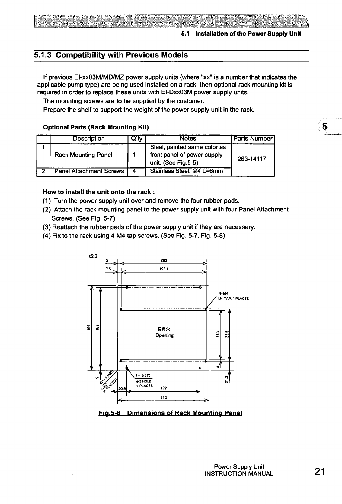
If
previous
EI-xxO3M/MD/MZ
power
supply
units
(where
"xx"
is
a
number
that
indicates
the
applicable
pump
type)
are
being
used
installed
on
a
rack,
then
optional
rack
mounting
kit
is
required
in
order
to
replace
these
units
with
EI-DxxO3M
power
supply
units.
The
mounting
screws
are
to
be
supplied
by
the
customer.
Prepare
the
shelf
to
support
the
weight
of
the
power
supply
unit
in
the
rack.
Optional
Parts
(Rack
Mounting
Kit)
1
2
Description
Rack
Mounting
Panel
Panel
Attachment
Screws
Q'ty
1
4
Notes
Steel,
painted
same
color
as
front
panel
of
power
supply
unit.
(See
Fig.5-5)
Stainless
Steel,
M4
L=6mm
Parts
Number
263-14117
How
to
install
the
unit
onto
the
rack
:
(1)
Turn
the
power
supply
unit
over
and
remove
the
four
rubber
pads.
(2)
Attach
the
rack
mounting
panel
to
the
power
supply
unit
with
four
Panel
Attachment
Screws.
(See
Fig.
5-7)
(3)
Reattach
the
rubber
pads
of
the
power
supply
unit
if
they
are
necessary.
(4)
Fix
to
the
rack
using
4
M4
tap
screws.
(See
Fig.
5-7, Fig.
5-8)
t2.3
203
198.1
Opening
205
213
4-M4
M4TAP.
4
PLACES
Fia.5-6
Dimensions
of
Rack
Mounting
Panel
Power
Supply
Unit
INSTRUCTION
MANUAL
21
SECTION
5
INSTALLATION
POWER
SUPPLY
S3SS3
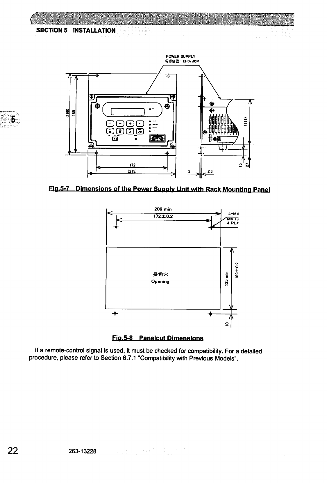
Fiq.5-7
Dimensions
of
the
Power
SuddIv
Unit
with
Rack
Mounting
1
+
206
min
172
±0.2
Opening
1
A
T
4-M4
4
PL/
1
y
o
c
+
o
a
t
Fia.5-8
Panelcut
Dimensions
If
a
remote-control
signal
is
used,
it
must
be
checked
for
compatibility.
For a
detailed
procedure,
please
refer
to
Section
6.7.1
"Compatibility
with
Previous
Models".
22
263-13228
V:;:'
■''■"
'"
■''■■
5.2
Connection
of
Power
Cable
5.2
Connection
of
Power
Cable
NOTICE
The
power
input
voltage
of
the
power
supply
unit
EI-DxxO3M
(the
"xx"
number
indicates
the
model
of
the
corresponding
pump)
is
200
to
240
VAC
±
10%.
Connect
the
power
supply
unit
to
the
voltage
specified
on
the
rear
panel
label
only.Connection
of
the
power
supply
unit
to
the
incorrect
input
voltage
can
cause
damage
to
the
equipment.
Supply
the
power
via
a breaker
(rating
15A).PIease
provide
PE(Protective
Earth)
connection
to
the
terminal
of
a
"PE"
marked
wire
in
final
application.
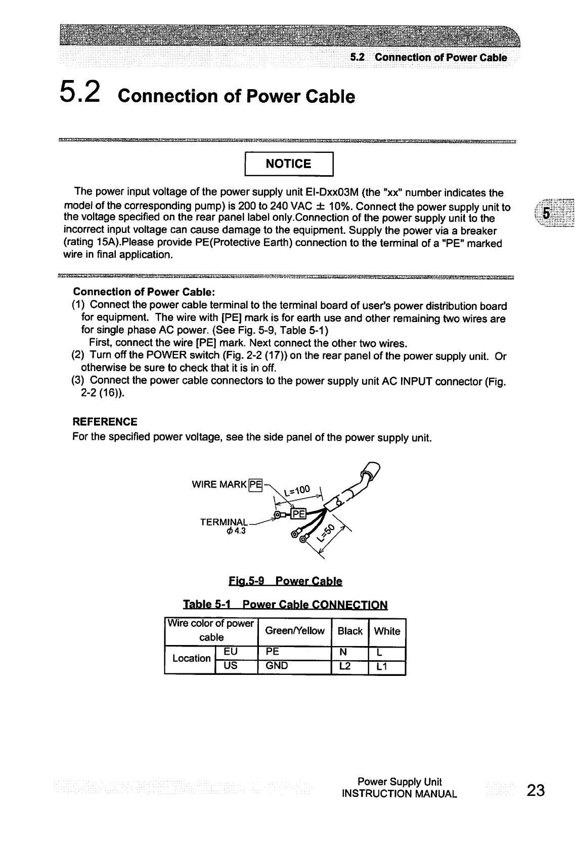
Connection
of
Power
Cable:
(1)
Connect
the
power
cable
terminal
to
the
terminal
board
of user's
power
distribution
board
for
equipment.
The
wire
with
[PE]
mark
is
for
earth
use
and
other
remaining
two
wires
are
for
single
phase
AC
power.
(See
Fig.
5-9,
Table
5-1)
First,
connect
the wire [PE]
mark.
Next
connect
the
other
two
wires.
(2)
Turn
off
the
POWER
switch
(Fig.
2-2
(17))
on
the
rear
panel
of
the
power
supply
unit.
Or
otherwise
be
sure
to
check
that
it
is
in
off.
(3)
Connect
the
power
cable
connectors
to
the
power
supply
unit
AC
INPUT
connector
(Fig.
2-2(16)).
REFERENCE
For
the
specified
power
voltage,
see
the
side
panel
of
the
power
supply
unit.
WIRE
MARK
P\
TERMINAL
04.3
Fig.5-9
Power
Cable
Table
5-1
Power
Cable
CONNECTION
Wire
color
of
power
cable
Location
EU
US
Green/Yellow
PE
GND
Black
N
L2
White
L
L1
Power
Supply
Unit
INSTRUCTION
MANUAL
23
SECTION
5
INSTALLATION
5.3
Connection
of
the
Pump
to
the
Power
Supply
Unit
NOTICE
Insert
straight
the
control
cable
connector
after
checking
its
key
direction.
Inserting
it
in
oblique
direction
would cause
damage
of
the
connector
pins.
After
the
insertion,
turn
the
cable
connector
clockwise
until
the
rotation
lock
clicks.
NOTICE
Don't
disconnect
each
cable
while the
pump
is
running.
Particularly
before
disconnecting
the
control
cable,
Check
complete
shutdown
of
the
pump
by
ROTATION
lamp
goes
out
and,
thereafter,
turn
off
the
POWER
switch.
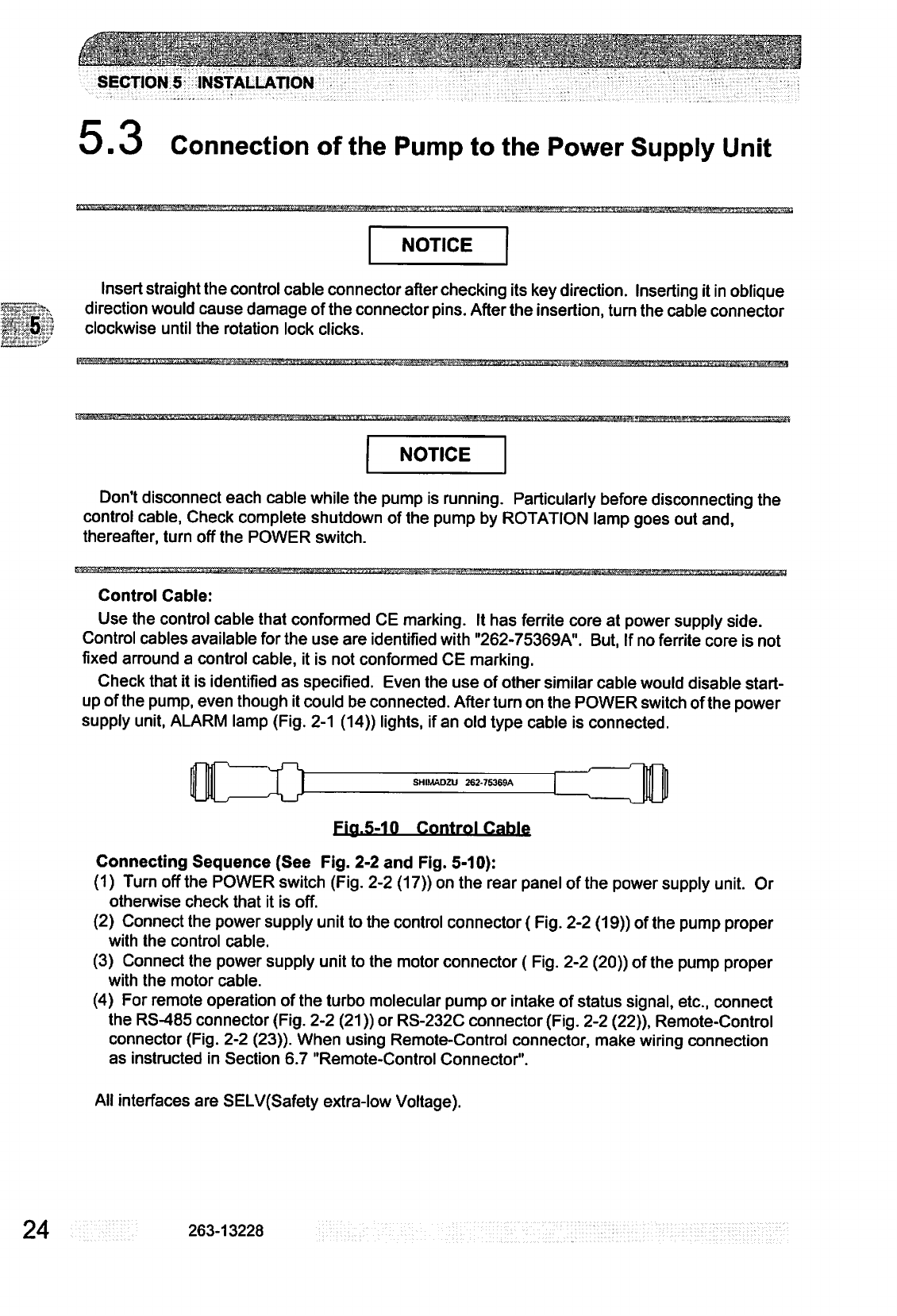
Control
Cable:
Use
the
control
cable
that
conformed
CE
marking.
It
has
ferrite
core
at
power
supply
side.
Control
cables
available
for
the
use
are
identified
with
"262-75369A".
But,
If
no
ferrite
core
is
not
fixed
arround a
control
cable,
it
is
not
conformed
CE
marking.
Check
that
it
is
identified
as
specified.
Even
the
use
of
other
similar
cable
would
disable
start
up
of
the
pump,
even
though
it
could
be
connected.
After
turn
on
the
POWER
switch
of
the
power
supply
unit,
ALARM
lamp
(Fig.
2-1
(14))
lights,
if
an
old
type
cable
is
connected.
SHIMADZU
262-75369A
Fiq.5-10
Control
Cable
Connecting
Sequence
(See
Fig.
2-2
and
Fig.
5-10):
(1)
Turn
off
the
POWER
switch
(Fig.
2-2
(17))
on
the
rear
panel
of
the
power
supply
unit.
Or
otherwise
check
that
it
is
off.
(2)
Connect
the
power
supply
unit
to
the
control
connector
{Fig.
2-2
(19))
of
the
pump
proper
with
the
control
cable.
(3)
Connect
the
power
supply
unit
to
the
motor
connector
(Fig.
2-2
(20))
of
the
pump
proper
with
the
motor
cable.
(4)
For
remote
operation
of
the
turbo
molecular
pump
or
intake
of
status
signal,
etc.,
connect
the
RS-485
connector
(Fig.
2-2
(21))
or
RS-232C
connector
(Fig.
2-2
(22)),
Remote-Control
connector
(Fig.
2-2
(23)).
When
using
Remote-Control
connector,
make
wiring
connection
as
instructed
in
Section
6.7
"Remote-Control
Connector".
All
interfaces
are
SELV(Safety
extra-low
Voltage).
24
263-13228
.:'
'**■■
' ■ "
""ji
'■■•'•
...\..'
.
.*.
■■
.■
""
!
■:>.'■
.;'■
**'
"
.'"
'■■■"
.
■'
".»■
■"'-■»
"r
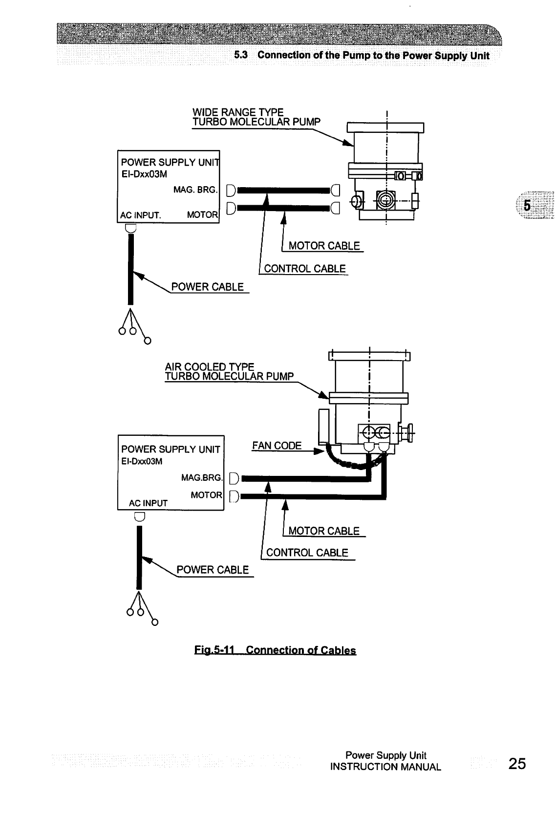
5.3
Connection
of
the
Pump
to
the
Power
Supply
Unit
WIDE
RANGE
TYPE
TURBO
MOLECULAR
PUMP
POWER
SUPPLY
UNIT
EI-DxxO3M
MAG.
BRG.
AC
INPUT.
MOTOR
POWER
CABLE
AIR
COOLED
TYPE
TURBO
MOLECULAR
PUMP
POWER
SUPPLY
UNIT
EI-DxxO3M
AC
INPUT
MAG.BRG.
MOTOR
POWER
CABLE
Fia.5-11
Connection
of
Cables
Power
Supply
Unit
INSTRUCTION
MANUAL
25
c
SECTION
5
INSTALLATION
This
page
is
intentionally
left
blank.
26
263-13228
!
■'■"■'•"'•■:j-j<'.':~:i
■"■■;
'■
J'.v;-"-
.;-.-v:\.~
.-if*'
■""
.:..:::
:.rv.^-
■•--v-vV.,,::y-.
•■■■.'.:-^-:v-'--.-^----;.:it^"--:-.-vi-v-:-*
OPERATION
© © ©
©
© ©
6.1
Outline
6.1.1
Introduction
6.1.2
Operation
Flowchart
6.2
Start-up
Preparation
6.2.1
Start-up
Preparation
Sequence
in
LOCAL
Mode
6.2.2
Start-up
Preparation
Sequence
in
REMOTE
Mode
6.3
Start-up
6.3.1
Start-up
Sequence
in
LOCAL
Mode
6.3.2
Start-up
Sequence
in
REMOTE
Mode
6.4
Shutting
Down
6.5
Variable
Speed
Operation
6.5.1
Outline
6.5.2
Operation
from
Start-up
to
Low
Speed
Rotation
6.5.3
Operation
from
Rated
Speed
Rotation
to
Low
Speed
Rotation
6.5.4
Operation
from
Low
Speed
Rotation
to
Rated
Speed
Rotation
6.6
Software
Operation
6.7
Remote-Control
Connector
6.7.1
Specifications
6.7.2
Compatibility
with
Previous
Models
u~^^~:^-:'..±!^Z^
SECTION
6
OPERATION
6.1
Outline
6
CAUTION
Neither
disconnect
and
reconnect
each
cable
while
the
pump
is
running.
Particularly for
unplugging
the
control
cable
from
the
receptacle,
check
complete
shutdown
of
the
pump
by
ROTATION
lamp
goes
out
and,
thereafter,
turn
off
the
POWER
switch.
CAUTION
Do
not
turn
the
power
off
while
the
pump
is
running.
The
touch-down
bearing
may
need
to
be
replaced
if
the
power
is
turned
off
repeatedly
during
operation.
When
the
power
is
turned
off
while
the
pump
is
rotating,
power
from
regenerative
braking
maintains
the
magnetic
levitation
until
the
rotational
speed
drops.
Levitation
then
stops
and
the
touch-down
bearing
supports
the
rotor.
Consequently, repeated
touch-down
operations
can
reduce
the
life
of
the
bearing.
6.1.1
Introduction
(See
Fig.
2-1
and
Fig.
2-2)
The
LCD
(Fig.
2-1
(1))
displays
the
model
name
of
the
power
supply
unit
corresponding
to
the
pump
model
name
(e.g.
SHIMADZU
EI-DxxO3M)
when
the
power
supply
unit
POWER
switch
(Fig.
2-2
(17))
is
turned
on.
It
then
displays
"SELF
CHECKING"
and
the
power
supply
unit
conducts
self-diagnosis.
If
the
result
is
good,
the
LCD
changes
into
monitor
mode
(See
section
6.6
Software
Operation
(1)),
and
the
power
supply
is
operatable.
But
if
an
alarm
is
delected,
the
LCD
changes
into
alarm
mode
(See
Section
6.6
Software
Operation
(2)),
and
displays
detected
alarm.
28
263-13228
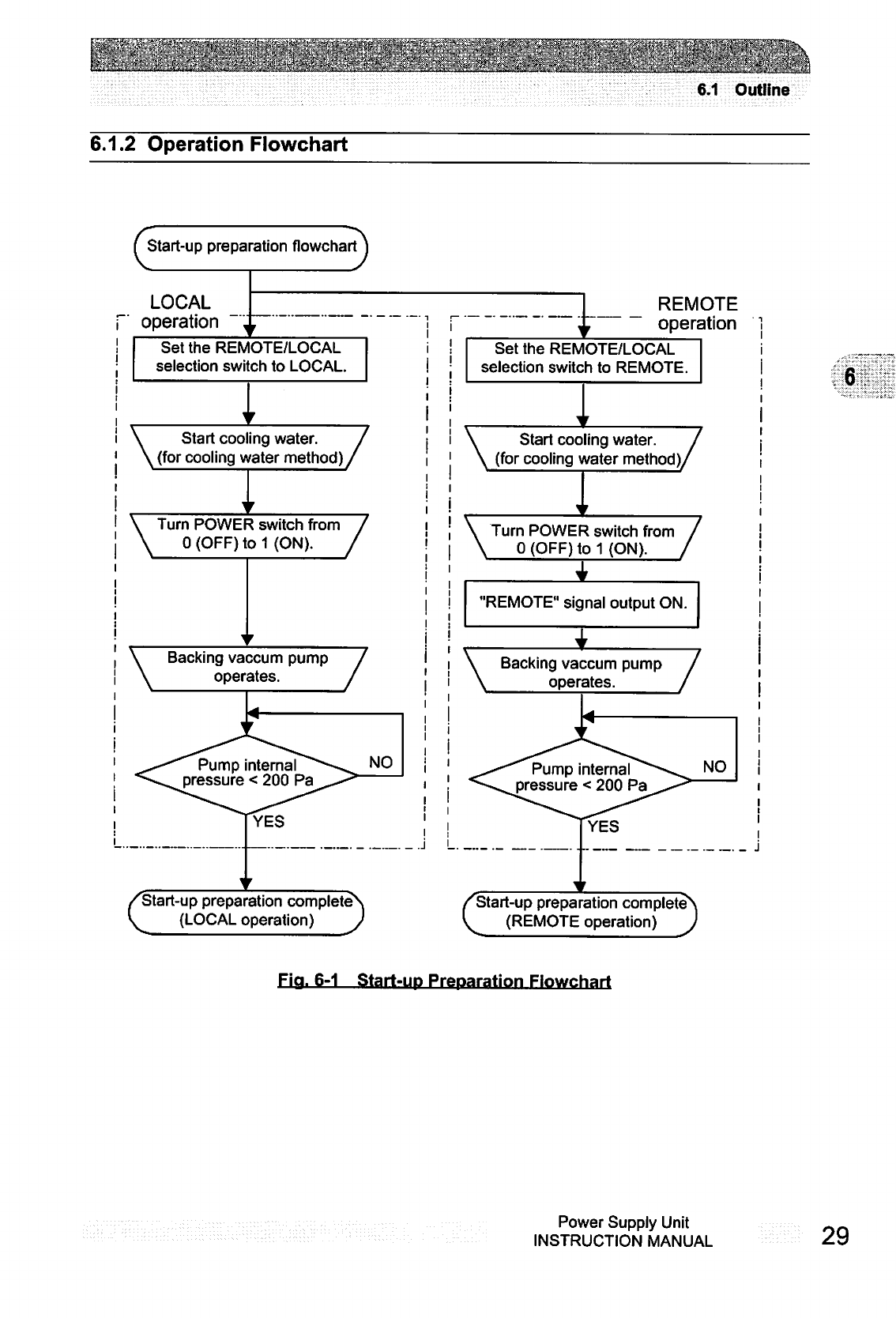
6.1
Outline
6.1.2
Operation
Flowchart
Q
Start-up
preparation
flowchart
LOCAL
operation
Set
the
REMOTE/LOCAL
selection
switch
to
LOCAL.
REMOTE
operation
Set
the
REMOTE/LOCAL
selection
switch
to
REMOTE.
\
Start
cooling
water.
/
(for
cooling
water
method)/
i
\
\
Start
cooling
water
/
(for
cooling
water
method)/
Turn
POWER
switch
from
0
(OFF)
to
1
(ON).
/
! |
\
Turn
POWER
switch
from
/
/
• I
\
0
(OFF)
to
1
(ON).
/
"REMOTE"
signal
output
ON.
Backing
vaccum
pump
\
Backing
vaccum
pump
/
operates.
/
Pump
internal
pressure
<
200
Pa
Pump
internal
pressure
<
200
Pa
c
Start-up
preparation
complete
(LOCAL
operation)
0
C
Start-up
preparation
complete
(REMOTE
operation)
6
Fia.
6-1
Start-up
Preparation
Flowchart
Power
Supply
Unit
INSTRUCTION
MANUAL
29
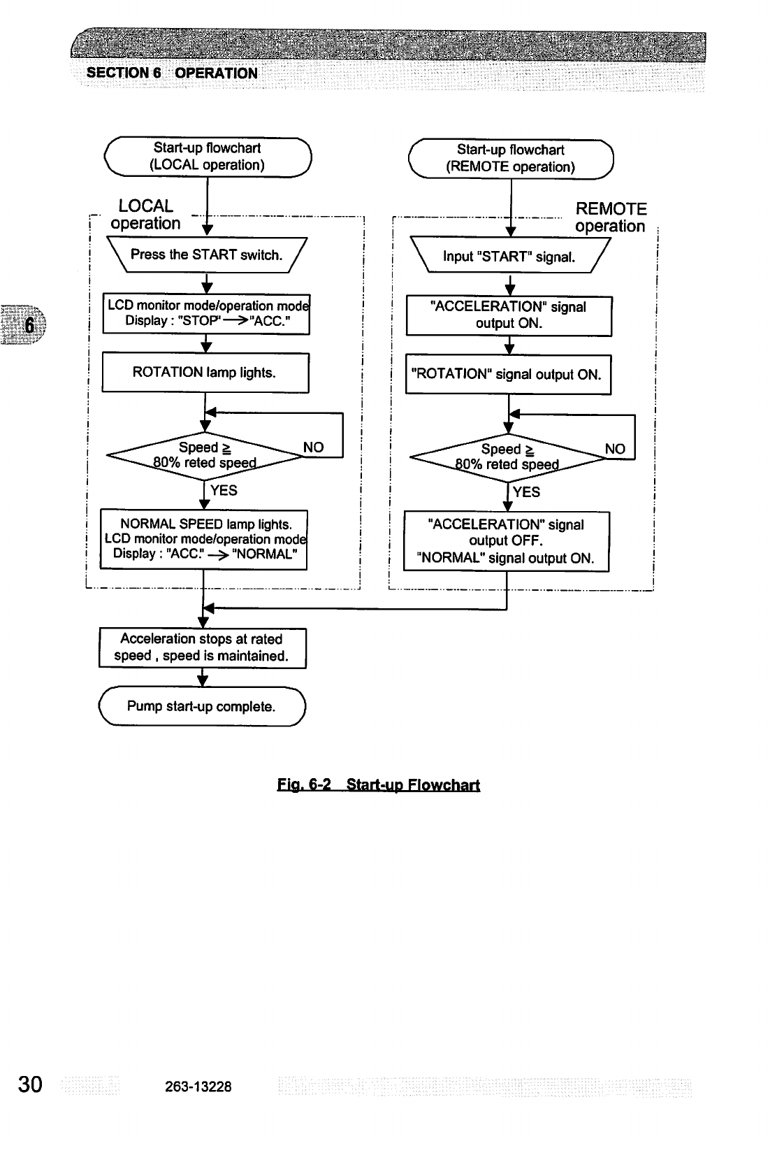
±^^M:^
!i^^
^
SECTION
6
OPERATION
C
Start-up
flowchart
^\
(LOCAL
operation)
J
LOCAL
operation
\
Press
the
START
switch
itch.
/
LCD
monitor
mode/operation
mode
Display:
"STOP1—>"ACC."
ROTATION
lamp
lights.
NORMAL
SPEED
lamp
lights.
LCD
monitor
mode/operation
mode
Display:
"ACC."
->
"NORMAL'
I
(
Start-up
flowchart
(REMOTE
operation)
REMOTE
operation
\
Input
"START"
signal.
/
"ACCELERATION"
signal
output
ON.
"ROTATION"
signal
output
ON.
YES
"ACCELERATION"
signal
output
OFF.
"NORMAL"
signal
output
ON.
Acceleration
stops
at
rated
speed
,
speed
is
maintained.
c
Pump
start-up
complete.
Fia.
6-2
Start-up
Flowchart
30
263-13228
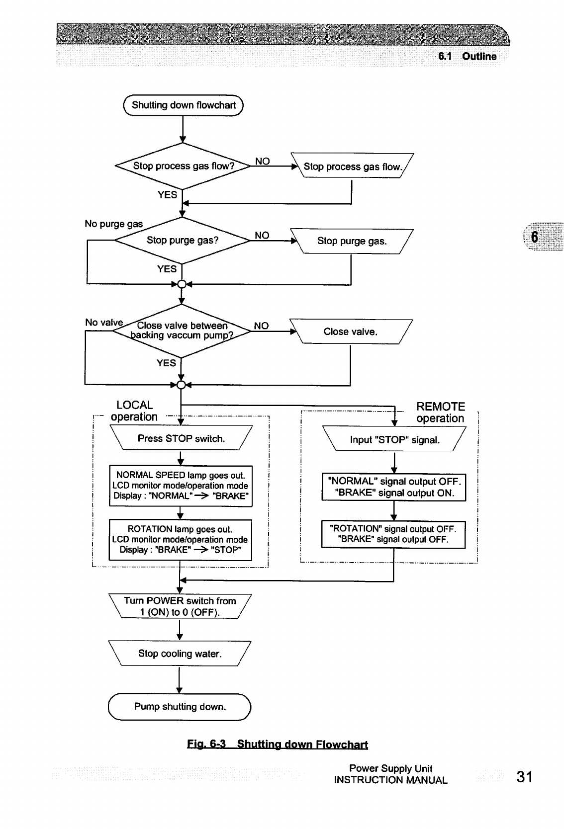
6.1
Outline
f
Shutting
down
flowchart
J
Stop
process
gas
*--■*.
YES
Stop
process
gas
No
purge
gas
No
valve^-gjose
va|ve
betweer
cking
vaccum
LOCAL
—
operation
REMOTE
operation
Press
STOP
switch.
Input
"STOP"
signal.
NORMAL
SPEED
lamp
goes
out.
LCD
monitor
mode/operation
mode
Display
:
"NORMAL"->
"BRAKE"
"NORMAL"
signal
output
OFF
"BRAKE"
signal
output
ON.
ROTATION"
signal
output
OFF
"BRAKE"
signal
output
OFF.
ROTATION
lamp
goes
out.
LCD
monitor
mode/operation
mode
Display
:
"BRAKE"
->
"STOP"
Turn
POWER
switch
from
1
(ON)
to
0
(OFF).
Stop
cooling
water.
c
Pump
shutting
down.
6
Fia.
6-3
Shuttina
down
Flowchart
Power
Supply
Unit
INSTRUCTION
MANUAL
31

^^
'^3^&
5
fc::?'
y^
SECTION
6
OPERATION
6
Speed
setting
flowchart
Start-up
to
low
speed
rotation
(LOCAL
operation)
f
Speed
setting
flowchart
\
f
Start-up
to
low
speed
rotation
]
N.
(REMOTE
operation)
J
X
Set
the
low
speed
value
LCD
setting
mode
^Select
the
LOW
SPEED
mode
using
the
LCD
setting
mode/low
speed
setting.
i
in
the
/
! !
\S
•
/
(Note
1)j
|
\
\
Press
the
START
switch
"?"
is
displayed
after
the
LCD
monitor
mode/speed
display
LCD
monitor
mode/operation
mode
Display:
"STOP'->
"ACC."
ROTATION
lamp
lights.
Speed
%
low-speed
valu
NORMAL
SPEED
lamp
lights.
LCD
monitor
mode/operation
mode
Display
:
"ACC."
->
"NORMAL"
Set
the
low
speed
value
LCD
setting
mode
i
in
the
/
(Nole1)j
\
Input
"LOW
SPEED
itch.
/
! |
\
"
signal.
/
Input
"START"
signal.
"ACCELERATION"
signal
output
ON.
"ROTATION"
signal
output
ON.
NO
"ACCELERATION"
signal
output
OFF.
"NORMAL"
signal
output
ON.
Acceleration
stops
at
the
set
low
speed
value
and
the
speed
is
maintained.
c
Speed
setting
complete.
(Note
1)
After
this
setting
has
been
made
once,
it
does
not
have
to
be
repeated
each
time.
Start-up to
Low
Speed
Rotation
Fia.
6-4
Speed
Setting
Flowchart
32
263-13228
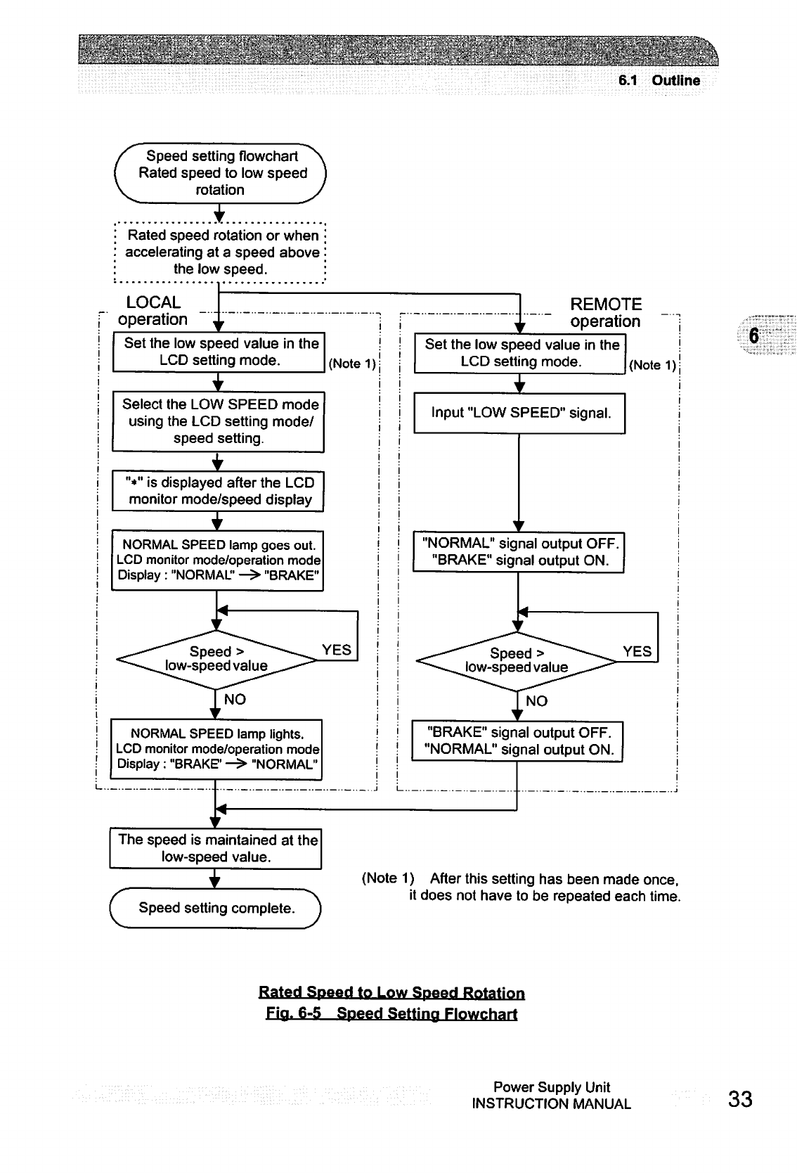
6.1
Outline
r
Speed
setting
flowchart^v
Rated
speed
to
low
speed
]
rotation
J
V
Rated
speed
rotation
or
when
accelerating
at
a
speed
above
the
low
speed.
LOCAL
operation
Set
the
low
speed
value
in
the
LCD
setting
mode.
(Notel);
REMOTE
operation
Set
the
low
speed
value
in
the
LCD
setting
mode.
(Note
1)
Select the
LOW
SPEED
mode
using
the
LCD
setting
mode/
speed
setting.
"*"
is
displayed
after
the
LCD
monitor
mode/speed
display
NORMAL
SPEED
lamp
goes
out.
LCD
monitor
mode/operation
mode
Display
:
"NORMAL"
—>
"BRAKE"
YES
Speed
>
low-speed
value
NORMAL
SPEED
lamp
lights.
LCD
monitor
mode/operation
mode
Display
:
"BRAKE1
—>
"NORMAL"
The
speed
is
maintained
at
the
low-speed
value.
Input
"LOW
SPEED"
signal.
"NORMAL"
signal
output
OFF.
"BRAKE"
signal
output
ON.
YES
Speed
>
low-speed
value
"BRAKE"
signal
output
OFF.
"NORMAL"
signal
output
ON.
6
c
Speed
setting
complete.
(Note
1)
After
this
setting
has
been
made
once,
it
does
not
have
to
be
repeated
each
time.
Rated
Speed
to
Low
Speed
Rotation
Fia.
6-5
Speed
Setting
Flowchart
Power
Supply
Unit
INSTRUCTION
MANUAL
33
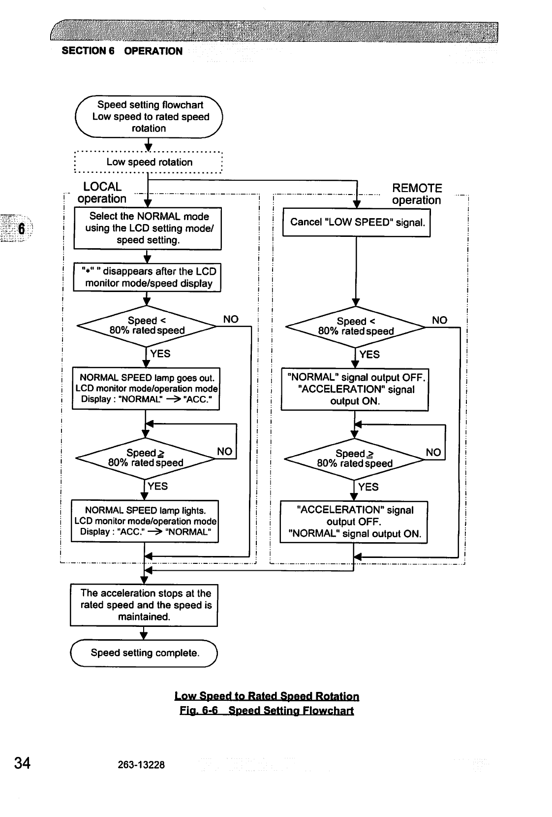
c
SECTION
6
OPERATION
Speed
setting
flowchart
Low
speed
to
rated
speed
rotation
Low
speed
rotation
LOCAL
operation
Select
the
NORMAL
mode
using
the
LCD
setting
mode/
speed
setting.
"♦""
disappears
after
the
LCD
monitor
mode/speed
display
NO
Speed
<
80%
rated
speed
NORMAL
SPEED
lamp
goes
out.
LCD
monitor
mode/operation
mode
Display
:
"NORMAL"
->
"ACC
Speedy
80%
rated
speed
NORMAL
SPEED
lamp
lights.
LCD
monitor
mode/operation
mode
Display
:
"ACC."
->
"NORMAL"
The
acceleration
stops
at
the
rated
speed
and
the
speed
is
maintained.
c
Speed
setting
complete
J
REMOTE
operation
Cancel
"LOW
SPEED"
signal.
NO
Speed
<
80%
rated
speed
YES
"NORMAL"
signal
output
OFF.
"ACCELERATION"
signal
output
ON.
Speed
£
80%
rated
speed
"ACCELERATION"
signal
output
OFF.
"NORMAL"
signal
output
ON.
Low
Speed
to
Rated
Speed
Rotation
Fia.
6-6
Speed
Setting
Flowchart
34
263-13228
6.4
Shutting
Down
6.4
Shutting
Down
CAUTION
After
having
operated
the
turbo
molecular
pump
for
evacuation
of
corrosive
gas,
keep
the
pump
internal
as
vacuumed
even
after
shutdown.
Inflow
of
water
content
in
the
air
to
the
pump
internal
would
cause
rapid
corrosion
trouble of
the
pump
internals.
The
pump
corrosion
may
result
in
damaging
the
vacuum
vessel
interior
and
other
units,
causing
pressure
fluctuation
by
g
stopping
the
pump
and
dispersal
of
parts.
CAUTION
When
reducing
internal
pressure
of
the
turbo
molecular
pump
up
to
around
the
atmospheric
pressure
by
use
of
inert
gas,
etc.,
adjust
the
pressure
reducing
valve
so
that
the
internal
pressure
of
the
same
pump
does
not
exceed
20
kPa
[GAUGE].
For
shut-down
of
the
turbo
molecular
pump,
follow
the
sequence
below.
6.4.1
Preparations
Prior
to
Shutting
Down
Operation
(1)
Check
that
process
gas
inflow
is
in
complete
stop.
When
main
valve
is
provided
between
the
turbo
molecular
pump
and
vacuum
chamber,
close
the
valve,
too.
(2)
When
purge
gas
is
being
fed
into
the
turbo
molecular
pump,
stop
the
gas
feed,
too.
(3)
When
forevacuum
valve
is
provided
between
the
turbo
molecular
pump
and
backing
vacuum
pump,
close
the
valve,
too.
6.4.2
Shutting
Down
Sequence
in
LOCAL
Mode
(1)
Press
the
STOP
switch
(Fig.
2-1
(7))
and
check
that
the
indication
on
the
pump
monitor
mode/operation
mode
LCD
switches
from
"NORMAL"
to
"BRAKE."
Then
the
NORMAL
SPEED
lamp
(Fig.
2-1
(12))
goes
off.
(2)
Wait
until
the
ROTATION
lamp
(Fig.
2-1
(11))
goes
out.
The
pump
monitor
mode/
operation
mode
LCD
switches
from
"BRAKE"
to
"STOP."
(3)
Turn
off
the
power
supply
unit
POWER
switch
(Fig.
2-2
(17)).
(4)
Stop
the
cooling
water
flow.
Power
Supply
Unit
__
INSTRUCTION
MANUAL
o
I
SECTION
6
OPERATION
6.4.3
Shutting
Down
Sequence
in
REMOTE
Mode
(1)
Input
the
"STOP"
signal
(see
Table
6-3)
from
the
remote-control
connector
(Fig.
2-2
(24))
and
check
that
the
"BRAKE"
signal
(see
Table
6-3)
is
ON.
(2)
Wait
until
the
"ROTATION"
signal
(see
Table
6-3)
turns
OFF.
At
this
time,
the
"BRAKE"
signal
(see
Table
6-3)
also
turns
OFF.
(3)
Turn
off
the
power
supply
unit
POWER
switch
(Fig.
2-2
(17)).
(4)
Stop
the
cooling
water
flow.
When
the
turbo
molecular
pump
is
turned
off
after
pumping
a
corrosive
gas,
maintain
a
vacuum
inside
the
turbo
molecular
pump
or
purge
the
interior
of
the
pump
with
an
inert
gas.
Further,
in
such
a
case
when
a
hydraulic
rotary
vacuum
pump
is
used
as
backing
vacuum
pump
and
there
is
possible
reverse
flow
and
diffusion
of
oil
from
the
backing
vacuum
pump,
return
the
pump
internal
pressure
to
atmospheric
pressure
using
dry
nitrogen
gas,
after
complete
shut-down
of
the
pump
[ROTATION
lamp
(Fig.
2-1(11))
goes
out],
to
prevent
the
turbo
molecular
pump
from
being
contaminated
with
oil
vapor.
For
shutting
down
the
turbo
molecular
pump
in
running
at
high
speed
with
infeed
of
dry
nitrogen
gas
to
the
pump,
keep
the
nitrogen
gas
flow
rate at
1500
mL/min
maximum.
REFERENCE
ROTATION
lamp
(Fig.
2-1
(11))
goes
out
or
"ROTATION"
signal
(see
Table
6-3)
turns
off
when
the
pump
rotational
speed
is
60rpm
or
less.
Turning
off
the
POWER
switch
(Fig.
2-2
(17))
permits
the
pump
rotor
to
be
supported
by
the
touch-down
bearings.
38
263-13228
■■*■■
■-;.-■
.■:■■;*
.:.
.■..:
■,■/;,■■.
.
:■.■
•:':■:■
vi;r.yvy;-y;
,_....
.
......
'
■■:
■■■;■
■■
■'."-■'
6.5
Variable
Speed
Operation
6.5
Variable
Speed
Operation
CAUTION
When
using
the
variable
speed
function
to
change
the
pump
rotation
rate,
use
a
rotation
rate
that
does
not
cause
resonance
with
other
devices
installed
at
the
site.
CAUTION
If
an
EI-DxxO3M
power
supply
unit
is
used
in
combination
with
an
existing
pump
that
was
operated
in
combination
with
a
power
supply
unit
not
having
the
variable
speed
function
(El-
xxO3MD),
the
variable
speed
function
cannot
be
used,
(the "xx"
number
indicates
the
model
of
the
corresponding
pump.)
If
the
power
supply
unit
is
to
be
combined
with
an
existing
pump,
modification
and
operational
inspections
are
necessary.
Please
contact
Shimadzu
for
detailed
information.
6.5.1
Outline
(1)
The
rotational
speed
settings
function
sets
the
rotational
speed
by
selecting
between
the
NORMAL
speed
mode
or
LOW
SPEED
mode.
(2)
Select
the
NORMAL
mode
or
LOW
SPEED
mode
by
LOCAL
operation
using
the
setting
mode/rotational
speed
settings/speed
setting
set
value
on
the
LCD
display
or
by
REMOTE
operation
using
the
remote-control
connector
"LOW
SPEED"
signal
input
(see
Table
6-3).
(3)
The
NORMAL
mode
or
LOW
SPEED
mode
selection
can
be
made
before
or
after
start
up.
(See
the
Speed
Setting
Flowcharts
in
Figs.
6-4, 6-5,
and
6-6.)
(4)
Set
the
low
speed
value
between
25%
and
100%
of
the
rated
speed
in
0.1%
increment
with
the
setting
mode/rotational
speed
settings/low
speed
setting
set
value
on
the
LCD
display.
(5)
The
low
speed
value
can
be
set
while
the
pump
is
rotating
in
the
LOW
SPEED
mode.
The
pump
then
accelerates
or
decelerates
to
the
new
set
value
and
maintains
the
set
speed.
(6)
The
time
required
for
the
speed
to
change
is
the
same
as
the
time
for
normal
acceleration
or
deceleration.
For
example,
if
the
low
speed
value
is
set
to
80%
and
the
LOW
SPEED
mode
is
selected
during
normal
rotation,
the
time
for
the
speed
to
drop
to
80%
is
approximately
one-fifth
the
time
required
to
stop
from
rated
speed.
6
Power
Supply
Unit
INSTRUCTION
MANUAL
39
'
.-|J'^:"i*#"!."■"■■■■
■
.:
■.■"'
-.;.'
■
■■■■
■"..*"/'
I".
':*--
"*!■'.■!:."""
'\
'.•"■■■'
"■:.'..
.i"J
■■":
"^
I1'.'11'1"■'...:
■
'}•',•
..
■.
■"
■■*■
"■.■■"
■.
^.'.S^i'/:■-|V•
SECTION
6
OPERATION
6.5.2
Operation
from
Start-up
to
Low
Speed
Rotation
This
is
the
procedure
until
low-speed
rotation
is
achieved
when
the
speed
setting
is
made
with
the
pump
stopped.
LOCAL
Operation
(1)
Start-up
begins
when
the
6.2.1
"Start-up
Preparation
Sequence
in
LOCAL
Mode"
is
complete.
_^
(2)
Set
the
low
speed
value
with
the
setting
mode/rotational
speed
settings/low
speed
setting
:
*\
set
value
on
the
LCD
display.
(See
Section
6.6
"Software
Operation"
(4).)
After
this
setting
rP:.--'
has
been
made
once,
it
does
not
have
to
be
repeated
each
time.
(3)
Select the
LOW
SPEED
mode
using
the
setting
mode/rotational
speed
settings/low
speed
setting
set
value.
(See
Section
6.6
"Software
Operation"
(4).)
(4)
Press
the
START
switch
(Fig.
2-1
(6)).
(5)
While
the
speed
is
changing,
"*"
is
displayed
after
the
monitor
mode/speed
display.
(See
Section
6.6
"Software
Operation"
(1).)
(6)
ACC
is
displayed
on
the
pump
monitor
mode/operation
mode
LCD
and
the
pump
starts
to
accelerate.
After
a
few
seconds
the
ROTATION
lamp
(Fig.
2-1
(11))
lights.
(7)
When
the
rotational
speed
reaches
80%
of
low-speed
value,
the
NORMAL
SPEED
lamp
lights
(Fig.
2-1
(12))
and
the
pump
monitor
mode/operation
mode
LCD
switches
from
"ACC."
to
"NORMAL".
(8)
When
the
pump
speed
reaches
the
set
low
speed
value,
acceleration
stops
and
the
pump
speed
is
maintained.
$6
The
same
operation
occurs
if
the
LOW
SPEED
mode
is
selected
after
the
START
switch
is
pressed
but
before
the
pump
speed
reaches
the
set
low
speed
value.
REMOTE
Operation
(1)
Start-up
begins
when
the
6.2.2
"Start-up
Preparation
Sequence
in
REMOTE
Mode"
is
complete.
(2)
Set
the
low
speed
value
with
the
setting
mode/rotational
speed
settings/low
speed
setting
set
value
on
the
LCD
display.
(See
Section
6.6
"Software
Operation"
(4).)
After
this
setting
has
been
made
once,
it
does
not
have
to
be
repeated
each
time.
(3)
Input
the
"LOW
SPEED"
signal
(see
Table
6-3)
from
the
remote-control
connector
(Fig.
2-
2(23)).
(4)
Input
the
"START"
signal
from
the
remote-control
connector
(Table
6-3).
(5)
The
pump
starts
to
accelerate
when
the
"ACCELERATION"
signal
(see
Table
6-3)
from
the
remote-control
connector
(Fig.
2-2
(23))
turns
ON.
After
a
few seconds
the
"ROTATION"
signal
turns
ON.
(6)
When
the
rotational
speed
reaches
80%
of
low
speed
value,
the
remote-control
connector
"ACCELERATION"
signal
turns
OFF
and
the
"NORMAL"
signal
turns
ON.
(7)
When
the
pump
speed
reaches
the
set
low
speed
value,
acceleration
stops
and
the
pump
speed
is
maintained.
•)K
The
same
operation
occurs
if
the
"LOW
SPEED"
signal
is
input
after
the
"START"
signal
is
input
but
before
the
pump
speed
reaches
the
set
low
speed
value.
40
263-13228
6.5
Variable
Speed
Operation
6.5.3
Operation
from
Rated
Speed
Rotation
to
Low
Speed
Rotation
This
is
the
procedure
to
select
low
speed
operation
during
rated
speed
rotation
or
when
accelerating
at
a
speed above
the
low
speed.(see
Fig.
6-5)
LOCAL
Operation
(1)
Set
the
low
speed
value
with
the
setting
mode/rotational
speed
settings/low
speed
setting
set
value
on
the
LCD
display.
(See
Section
6.6
"Software
Operation"
(4).)
After
this
setting
has
been
made
once,
it
does
not
have
to
be
repeated
each
time.
(2)
Next,
select
the
LOW
SPEED
mode
using
the
setting
mode/rotational
speed
settings/
speed
setting
set
value
on
the
LCD
display.
(See
Section
6.6
"Software
Operation"
(4).)
(3)
While
the
speed
is
changing,
"*"
is
displayed
after
the
monitor
mode/speed
display.
(See
Section
6.6
"Software
Operation"
(1).)
(4)
The
pump
monitor
mode/operation
mode
LCD
switches
from
"NORMAL"
to
"BRAKE"
and
the
pump
starts
to
decelerate.
Then
the
NORMAL
SPEED
lamp
(Fig.
2-1
(12))
goes
off.
(5)
When
the
rotational
speed
reaches
the
set
low
speed
value,
the
NORMAL
SPEED
lamp
lights
and
the
pump
monitor
mode/operation
mode
LCD
switches
from
"BRAKE"
to
"NORMAL."
(6)
The
pump
stops
decelerating
and
the
pump
speed
is
maintained.
%i
A
normal
start-up
and
normal
operation
occurs
if
the
mode
is
reverted
to
NORMAL
speed
before
the
pump
speed
reaches
the
set
low
speed
value.
REMOTE
Operation
(1)
Set
the
low
speed
value
with
the
setting
mode/rotational
speed
settings/low
speed
setting
set
value
on
the
LCD
display.
(See
Section
6.6
"Software
Operation"
(4).)
After
this
setting
has
been
made
once,
it
does
not
have
to
be
repeated
each
time.
(2)
Input
the
"LOW
SPEED"
signal
(see
Table
6-3)
from
the
remote-control
connector
(Fig.
2-
2
(23)).
(3)
The
pump
starts
to
decelerate
when
the
remote-control
connector
"NORMAL"
signal
(see
Table
6-3)
turns
OFF
and
the
"BRAKE"
signal
(see
Table
6-3)
turns
ON.
(4)
When
the
pump
speed
reaches
the
set
low
speed
value,
the
remote-control
connector
"BRAKE"
signal
turns
OFF
and
the
"NORMAL"
signal
turns
ON.
(5)
The
pump
stops
decelerating
and
the
pump
speed
is
maintained.
JK
A
normal
start-up
and
normal
operation
occurs
if
the
"LOW
SPEED"
signal
is
cancelled
before
the
pump
speed
reaches
the
set
low
speed
value.
6.5.4
Operation
from
Low
Speed
Rotation
to
Rated
Speed
Rotation
This
is
the
procedure
to
select
normal
speed
operation
during
low
speed
rotation,
(see
Fig.
6-6)
Power
Supply
Unit
INSTRUCTION
MANUAL
41
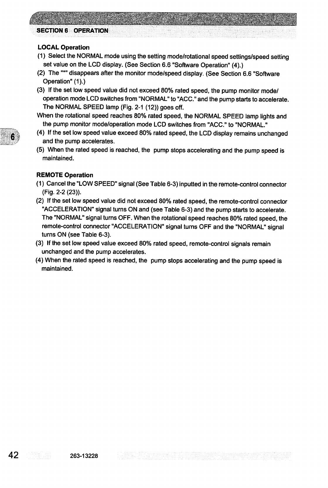
6
i\-:2x.
■:
""..::
" "
" ■-*
!
...■■."
-, ■ ■
■."■ll"
i
.■.'-'■"■-".■*'*■
."
*.
.*
■ :
.":"-■■
SECTION
6
OPERATION
LOCAL
Operation
(1)
Select the
NORMAL
mode
using
the
setting
mode/rotational
speed
settings/speed
setting
set
value
on
the
LCD
display.
(See
Section
6.6
"Software
Operation"
(4).)
(2)
The
"*"
disappears
after
the
monitor
mode/speed
display.
(See
Section
6.6
"Software
Operation"
(1).)
(3)
If
the
set
low
speed
value
did
not
exceed
80%
rated
speed,
the
pump
monitor
mode/
operation
mode
LCD
switches
from
"NORMAL"
to
"ACC."
and
the
pump
starts
to
accelerate.
The
NORMAL
SPEED
lamp
(Fig.
2-1
(12))
goes
off.
When
the
rotational
speed
reaches
80%
rated
speed,
the
NORMAL
SPEED
lamp
lights
and
the
pump
monitor
mode/operation
mode
LCD
switches
from
"ACC."
to
"NORMAL."
(4)
If
the
set
low
speed
value
exceed
80%
rated
speed,
the
LCD
display
remains
unchanged
and
the
pump
accelerates.
(5)
When
the
rated
speed
is
reached,
the
pump
stops
accelerating
and
the
pump
speed
is
maintained.
REMOTE
Operation
(1)
Cancel
the
"LOW
SPEED"
signal
(See
Table
6-3)
inputted
in
the
remote-control
connector
(Fig.
2-2
(23)).
(2)
If
the
set
low
speed
value
did
not
exceed
80%
rated
speed,
the
remote-control
connector
"ACCELERATION"
signal
turns
ON
and
(see
Table
6-3)
and
the
pump
starts to
accelerate.
The
"NORMAL"
signal
turns
OFF.
When
the
rotational
speed
reaches
80%
rated
speed,
the
remote-control
connector
"ACCELERATION"
signal
turns
OFF
and
the
"NORMAL"
signal
turns
ON
(see
Table
6-3).
(3)
If
the
set
low
speed
value
exceed
80%
rated
speed,
remote-control
signals
remain
unchanged
and
the
pump
accelerates.
(4)
When
the
rated
speed
is
reached,
the
pump
stops
accelerating
and
the
pump
speed
is
maintained.
42
263-13228
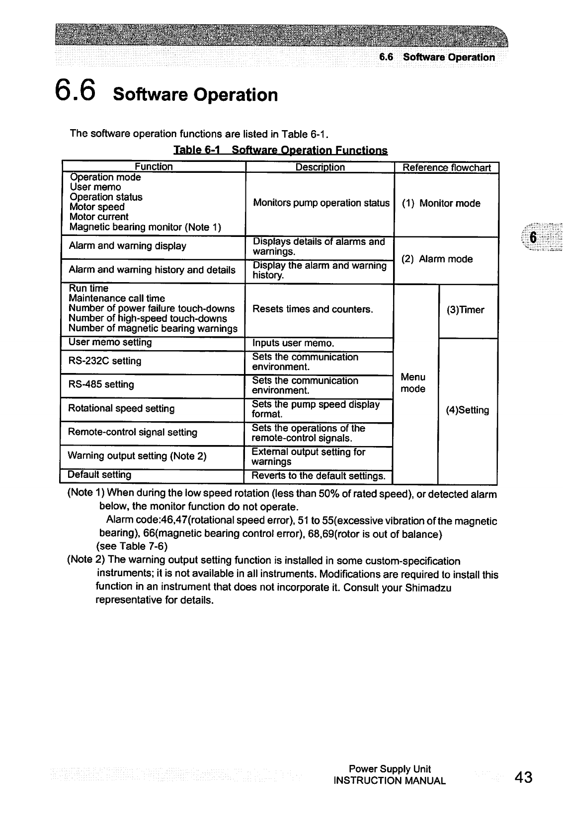
6.6
Software
Operation
O.
u
Software
Operation
The
software
operation
functions
are
listed
in
Table
6-1.
Table
6-1
Software
Operation
Functions
Function
Operation
mode
User
memo
Operation
status
Motor
speed
Motor
current
Magnetic
bearing
monitor
(Note
1)
Alarm
and
warning
display
Alarm
and
warning
history
and
details
Run
time
Maintenance
call
time
Number
of
power
failure
touch-downs
Number
of
high-speed
touch-downs
Number
of
magnetic
bearing
warnings
User
memo
setting
RS-232C
setting
RS-485
setting
Rotational
speed
setting
Remote-control
signal
setting
Warning
output
setting
(Note
2)
Default
setting
Description
Monitors
pump
operation
status
Displays
details
of
alarms
and
warnings.
Display
the
alarm
and
warning
history.
Resets
times
and
counters.
Inputs
user
memo.
Sets
the
communication
environment.
Sets
the
communication
environment.
Sets
the
pump
speed
display
format.
Sets
the
operations
of
the
remote-control
signals.
External
output
setting
for
warnings
Reverts
to
the
default
settings.
Reference
flowchart
(1)
Monitor
mode
(2)
Alarm
mode
Menu
mode
(3)Timer
(4)Setting
(Note
1)
When
during
the
low
speed
rotation
(less
than
50%
of
rated
speed),
or
detected
alarm
below,
the
monitor
function
do
not
operate.
Alarm
code:46,47(rotational
speed
error),
51
to
55(excessive
vibration
of
the
magnetic
bearing),
66(magnetic
bearing
control
error),
68,69(rotor
is
out
of
balance)
(see
Table
7-6)
(Note
2)
The
warning
output
setting
function
is
installed
in
some
custom-specification
instruments;
it
is
not
available
in
all
instruments.
Modifications
are
required
to
install
this
function
in
an
instrument
that
does
not
incorporate
it.
Consult
your
Shimadzu
representative
for
details.
Power
Supply
Unit
INSTRUCTION
MANUAL
43
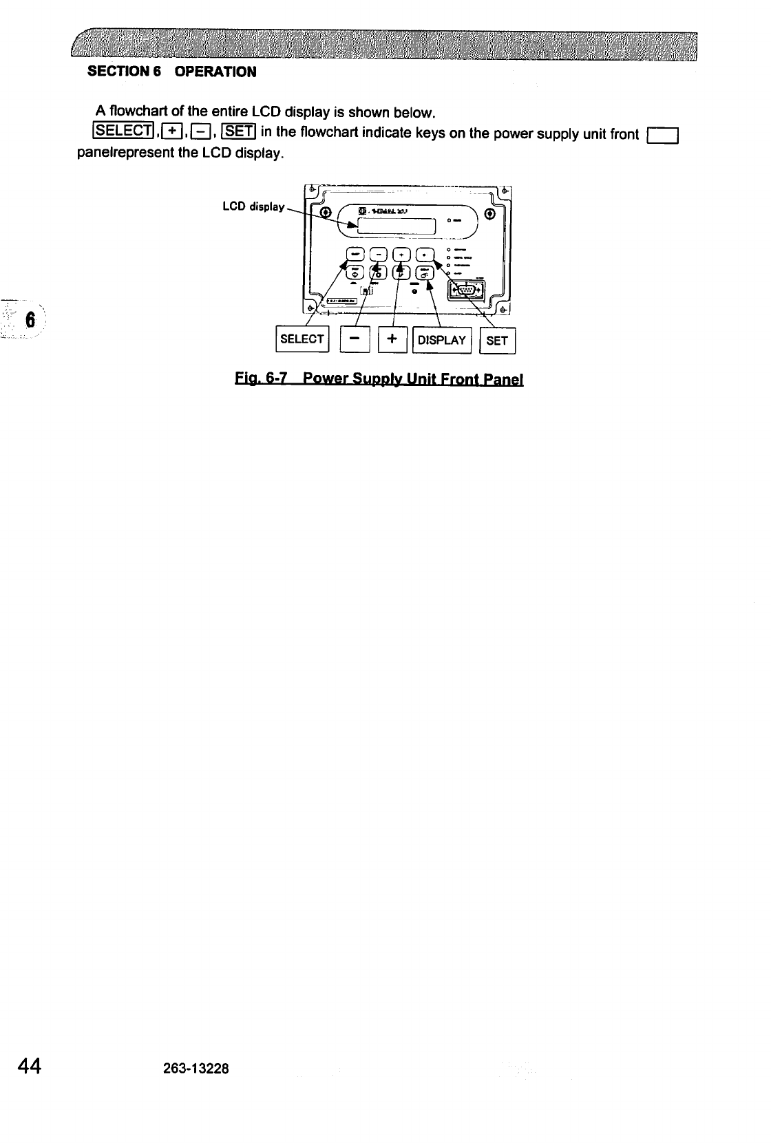
SECTION
6
OPERATION
A
flowchart
of
the
entire
LCD
display
is
shown
below.
ISELECTj.r+I.PI,
ISETI
in
the
flowchart
indicate
keys
on
the
power
supply
unit
front
panelrepresent
the
LCD
display.
LCD
display
6
SELECT
—
+
DISPLAY
SET
Fia.
6-7
Power
SuddIv
Unit
Front
Panel
44
263-13228
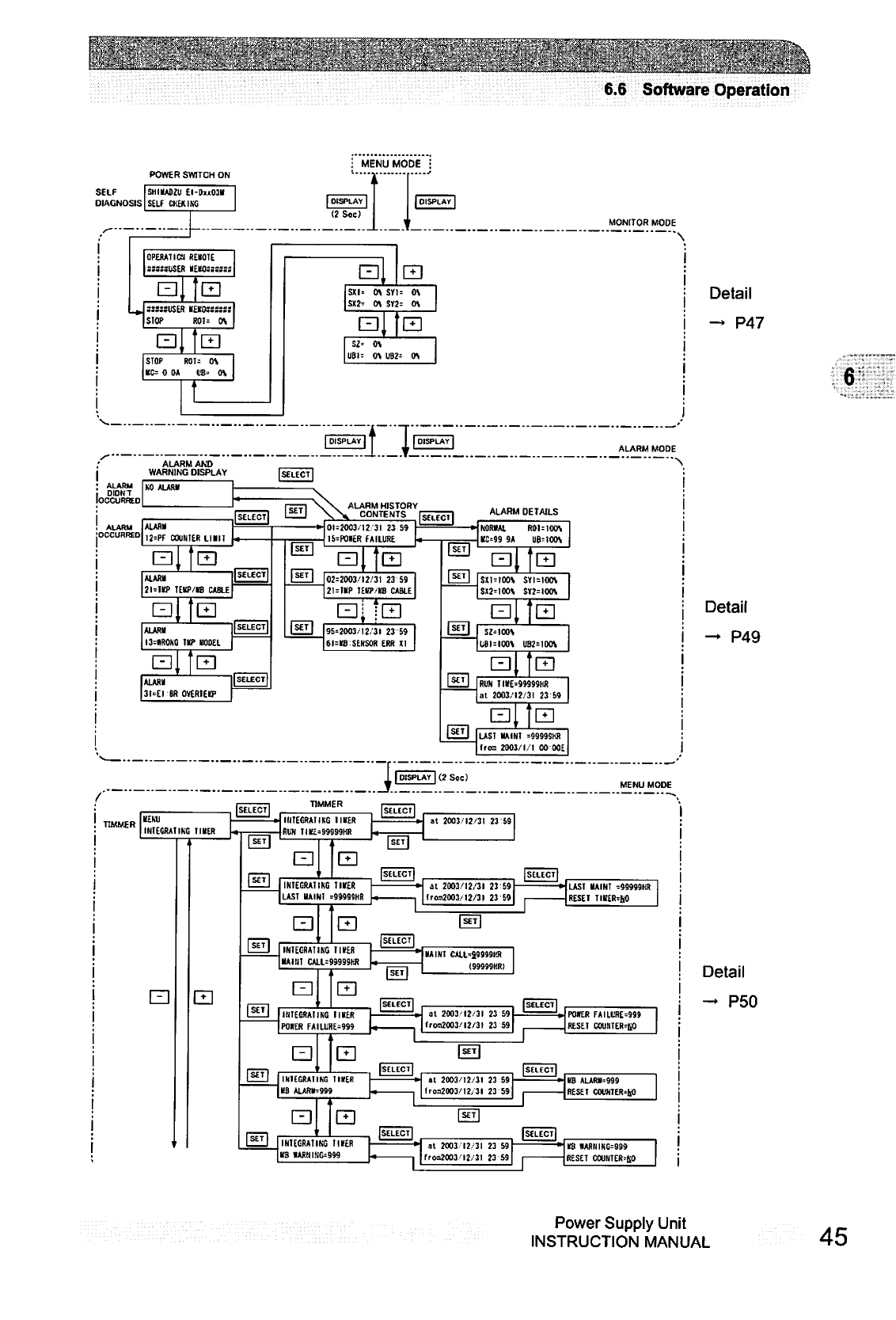
6.6
Software
Operation
POWER
SWITCH
ON
i
MENU
MODE
i
SELF
DIAGNOSIS
SHKA02U
£l-DxO3ll
SELF
CKEKING
|
DISPLAY
|
(2
Sec)
OPERATIC!
REMOTE
assssuSER
HEW::::::
□
S3S3SUSE
SIOP
ED
ED
»KKOMSasj
ROT=
OS
LZI
STOP
ROT=
OS
KC=
0
OA UB'
OS
ED
El
sxi>
o\
sn=
os
ED
SI'
OS
UBI=
OS
UB2=
OS
o
DIDNT
loCCURHEO
ALARM
|ALAR»
[OCCURRED
,j=pf
COUNTEI!
LIMIT
ALARM
AMD
WARNING
DISPLAY
SELECTl
"V\
ALARM
HISTORY
\X
CONTENTS
"
CONTENTS
^n^7
ED
IEHP/IS
CABLE
ALARB
I3=»ROKO
IIP
EODEL
LZI
31'EI'BROVERHQ1
H01=2003/12
31
23
59
-I
I5=PO«ER
FAILURE
[SETJ
I
SET
I
LZI
CD
ALARM
DETAILS
02=2003/12/31
23 59
21=ltP
lECP/KB
CABLE
EJJ?E]
95=2003/12/31
23 69
6l=re SENSOR ERR
XI
|
SET
|
I
SET
I
KORIUl
R0UI0OS
gg 9A
UB=IOOS
a,
m
sxmcxn
syi=ioo\
SX2=IOOS S>2=IOOS
SMOOV
UBI=IO0S UB2=IOOS
ed,
m
RUN
TI«E=99999HR
al
2003/12/31
23
69
ED..'E]
Just
uaini
=9999shr
Ifroa
2003/1/1
OO00E
1
DISPLAY
13
Soc)
TIMMER
TIMMER
tEUI
INIECRA1IM
11
HER
ED
IIITECRMIKC
IKER
RUN
llt£=99999HR
ED
at
2003/12/31
23
69
ED
INIEGRAIIMj
TIKR
LAST
UAINI
=9999SHR
ED
MONrTOR
MODE
ALARM
MODE
at
2003/12/31
23
!
froa2003/!2/3l
23
!
LAST
HAINT
-99999HR
RESEI
TIIIER=KO
El
INTEGRATING
TIICER
■IAIN!
CALL=9999SHIi
ED
MINI
CALI-39999KR
(99999KR!
ED
IINTECRAIIKC
11
HER
|PO«ER
ED
at
2003/12/31
23
59
Iroa2003/I2/3I
23
59
POKER
FAILURE=999
RESET
COUNIER=tiO
INIEGRA1IKG
1IVER
KB
ALARIN999
LZI
at
2003/12/31
23 59
froa20O3/12/3l
23 59
■1KB
ALARIU999
•J
RESET
COUNTER>liO
ED
INTEGRATING
I
HER
KB
«ARUIKG=999
1
at
2003
12
31
23
59
fros>2003
12/31 23
59
KB
«ARBIKC=999
RESET
COUNTER-&O
Detail
—
P47
Detail
—
P49
Detail
-
P50
Power
Supply
Unit
INSTRUCTION
MANUAL
45
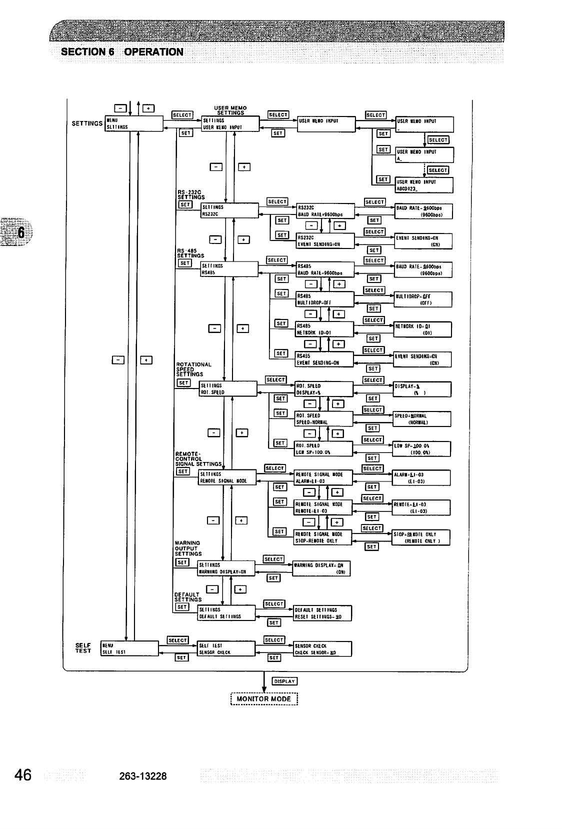
SECTION
6
OPERATION
SETTINGS
•
MONITOR
MODE
j
46
263-13228
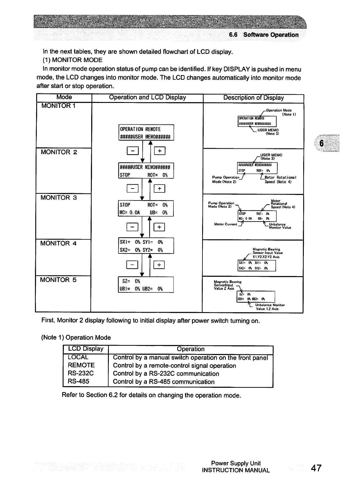
:^'.;s"
*■.'■
';y-:.■■■■■"
;'-"1"'."■■.-L-'--
■"i"-
:.
■
■■.■:..
:-':>
6.6
Software
Operation
In
the
next
tables,
they
are
shown
detailed
flowchart
of
LCD
display.
(1)
MONITOR
MODE
In
monitor
mode
operation
status
of
pump
can
be
identified.
If
key
DISPLAY
is
pushed
in
menu
mode,
the
LCD
changes
into
monitor
mode.
The
LCD
changes
automatically
into
monitor
mode
after
start
or
stop
operation.
Mode
MONITOR
1
MONITOR
2
MONITOR
3
MONITOR
4
MONITOR
5
Operation
and
LCD
Display
OPERATION
REMOTE
#####USER
MEMO######
\
A
i
+
#####USER
MEM0##(r###
STOP
ROT=
0%
-
I
r
i
STOP ROT=
0%
MC=
0.
OA
UB= 0%
i
t
+
SXI=
0%
SYI=
0%
SX2= 0%
SY2=
0%
i
i
r
k
+
SZ= 0%
UB1=
0%
UB2=
0%
Description
of
Display
^Operation
Mode
./
(Note
1)
OPERATION REMOTE
4*IMtiMtv5tR
if
rTft
t$
m
It
IIS
Jl
V
USER
MEM
(Note
USER
ME
/^(Note
3)
STOP
R0I=
(ft
Pump
Operation_/
Ljlotor
Mode
(Note
2)
Speed
o
3)
Rotational
(Note
4)
Pump
Operation
Rotational
Mode
(Note
2)
"^
^/
Speed
(Note
4)
STOP
ROT^
OS
KC-
0 0A UB- OS
Motor
Current
_/'
t_Urtb
Mort
stance
tor
Value
Magnetic
Bearing
Sen$or
Input
Value
/
X1.Y2.X2.Y2Axis
SX1=
OS
S1U
OV
SX2=
OS SY2=
OS
Magnetic
Bearing
Sensorlnput
—.
Vatue
Z
Axis
^
Sh
OS
UBI=
OS US2=
0\
'^_
Unbabnce
Monitor
Value
1.2
Axis
First,
Monitor
2
display
following
to
initial
display
after
power
switch
turning
on.
(Note
1)
Operation
Mode
LCD
Display
LOCAL
REMOTE
RS-232C
RS-485
Control
Control
Control
Control
by
by
by
by
a
a
a
a
Operation
manual
switch
operation
on
the
front
panel
remote-control
signal
operation
RS-232C
communication
RS-485
communication
Refer
to
Section
6.2
for
details
on
changing
the
operation
mode.
Power
Supply
Unit
INSTRUCTION
MANUAL
47
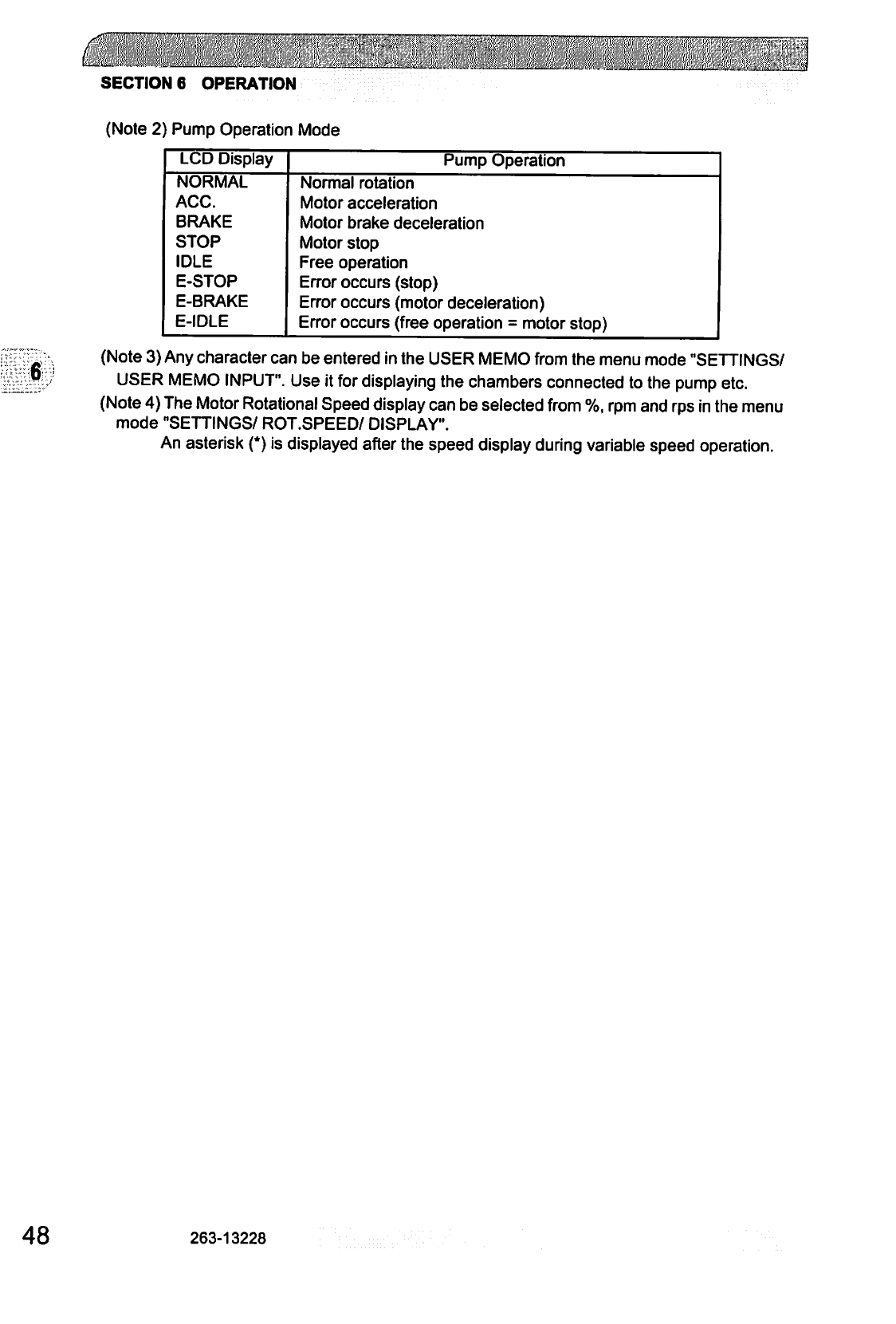
c.
SECTIONS
OPERATION
(Note
2)
Pump
Operation
Mode
LCD
Display
NORMAL
ACC.
BRAKE
STOP
IDLE
E-STOP
E-BRAKE
E-IDLE
Pump
Operation
Normal
rotation
Motor
acceleration
Motor
brake
deceleration
Motor
stop
Free
operation
Error
occurs
(stop)
Error
occurs
(motor
deceleration)
Error
occurs
(free
operation
=
motor
stop)
6
(Note
3)
Any
character
can
be
entered
in
the
USER
MEMO
from
the
menu
mode
"SETTINGS/
USER
MEMO
INPUT".
Use
it
for
displaying
the
chambers
connected
to
the
pump
etc.
(Note
4)
The
Motor
Rotational
Speed
display
can
be
selected
from
%,
rpm
and
rps
in
the
menu
mode
"SETTINGS/
ROT.SPEED/
DISPLAY".
An
asterisk
(*)
is
displayed
after
the
speed
display
during
variable
speed
operation.
48
263-13228
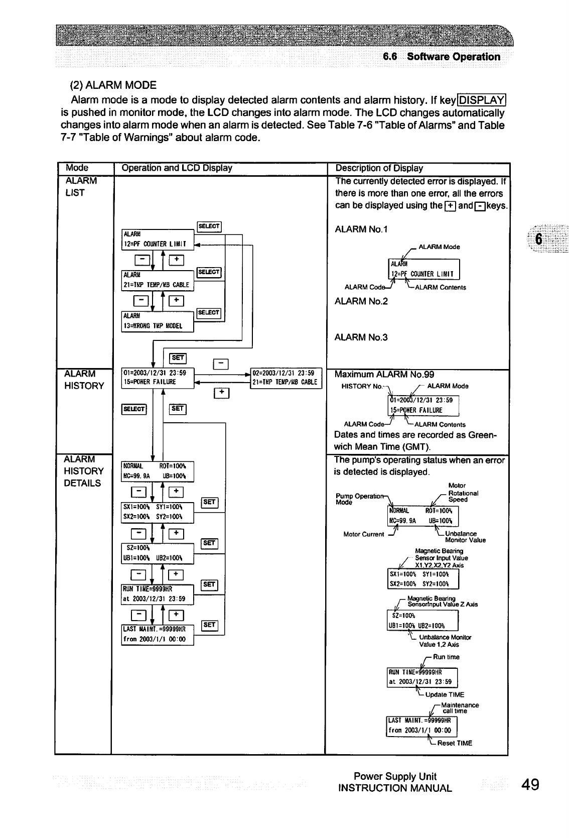
6.6
Software
Operation
(2)
ALARM
MODE
Alarm
mode
is
a
mode
to
display
detected
alarm
contents
and
alarm
history.
If
key|DISPLAY|
is
pushed
in
monitor
mode,
the
LCD
changes
into
alarm
mode.
The
LCD
changes
automatically
changes
into
alarm
mode
when
an
alarm
is
detected.
See
Table
7-6
"Table
of
Alarms"
and
Table
7-7
"Table
of
Warnings"
about
alarm
code.
Mode
Operation
and
LCD
Display
Description
of
Display
ALARM
LIST
ALARM
HISTORY
ALARM
HISTORY
DETAILS
ALARM
12=PF
COUNTER
LIMIT
L31,
ALARM
21=THP
TEMP/KB
CABLE
ALARM
13=ltR0NG
TKP
MODEL
01=2003/12/31
23:59
15=P0WER
FAILURE
NORMAL R0T=10O\
KC=99.9A
a,"
SY1=100\
SX2=100\
Q,,
UB2=100\
a,.
RUN
TIHE=9999HR
at
2003/12/31
23:59
LAST
HAIHT.
=99999HR
from
2003/1/1
00:00
02=2003/12/31
23:59
21=TKP
TEBP/HB
CABLE
The
currently
detected
error
is
displayed.
If
there
is
more
than
one
error,
all
the
errors
can
be
displayed
using the
[T|
andF1
keys
ALARM
No.1
.
ALARM
Mode
!=PF
COUNTER
LIMIT
ALARM
Code-/
ALARM
No.2
ALARM
No.3
ALARM
Contents
Maximum
ALARM
No.99
HISTORY
Nor
ALARM
Mode
i
01=2003/12/31
23:59
15=P0*ER
FAILURE
-v
ALARM
Code-^
*-
ALARM
Contents
Dates
and
times
are
recorded
as
Green
wich
Mean
Time
(GMT).
The
pump's
operating
status
when
an
error
is
detected
is
displayed.
Pump
Opei
Mode
Motor
_
Rotational
/"Speed
ROT=1OO\
UB-1OO\
Motor
Current
-Unbalance
Monitor
Value
Magnetic
Bearing
Sensor
Input
Value
X1,Y2,X2.Y2Axis
SXZ=100%
SY1=100*
SY2=1001i
-
Magnetic
Bearing
Sensormput
Value
Z
Axis
SZ=10tH
UBUIOW
UB2=IOOib
'\_
Unbalance
Monitor
Value
1.2
Axis
/—
Run
time
RUN
TIME=99999HR
at
2003/12/31
23
59
1
-Update
TIME
/—Maintenance
,/
call
time
LAST
MAINT.=99999HR
from
2003/1/1
00:00
'^-
Reset
TIME
Power
Supply
Unit
INSTRUCTION
MANUAL
49
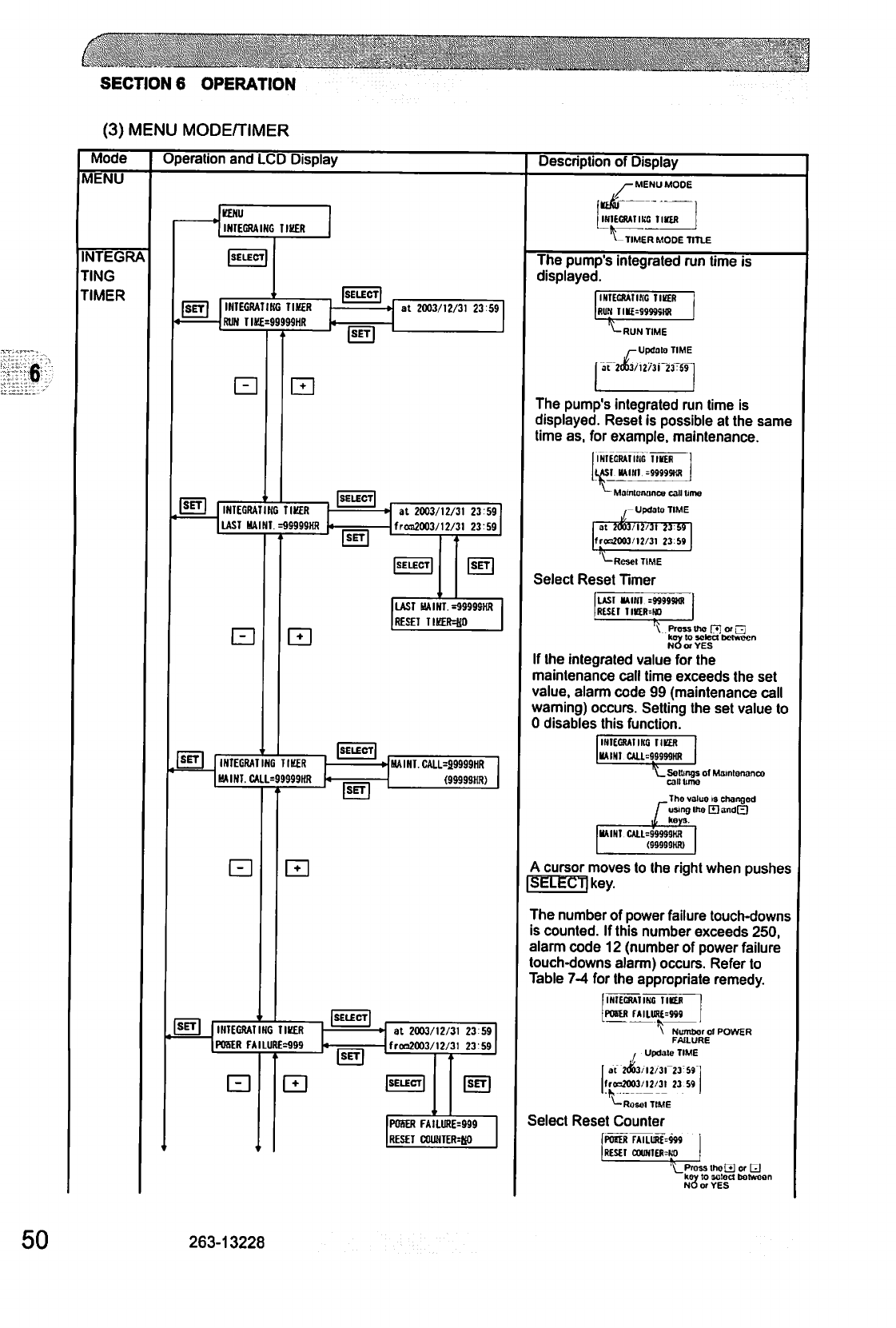
SECTIONS
OPERATION
(3)
MENU
MODE/TIMER
Mode
Operation
and
LCD
Display
Description
of
Display
MENU
INTEGRA
TING
TIMER
6
KNU
INTEGRAING TIBER
INTEGRATING TIMER
RUN
TIME=99999HR
at
2003/12/31
23
59
INTEGRATING TIKER
UST
HAINT
=9S999HH
at
2003/12/31
2359
froa2003/12/31
23:59
LAST
HAINT.
=99999HR
RESET
TIKER=H0
INTEGRATING
TIKER
HAINT.
CALL=99999HR
SET
HAINT.
CALl=29999HR
(99999HR)
INTEGRATING TIKER
POSER
FA
I
LURE=999
LZI
at
2003/12/31
23 59
frco2003/12/31
23 59
POSER
FA1LURE=999
RESET
C0UNTER=K0
/-
MENU
MODE
tiki
INTEGRA!
IKS
llttR
TIMER
MODE
TITLE
The
pump's
integrated
run
time
is
displayed.
INTEGRATING
TIKER
RUN
TIK£=9999SHR
<-
RUN
TIME
/-Update
TIME
^2(»37i2/3r23TSri
The
pump's
integrated
run
time
is
displayed.
Reset
is
possible
at
the
same
time
as,
for
example,
maintenance.
INIECRAIIIIC
IIKER
LAS!
MINI
=9999SHR
-
Maintonancu
call
lime
,-UpdalaTIME
at
2003/12/31 23 59
trcrfOOJ'12/31
23S9
^-Resel
TIME
Select
Reset
Timer
LAST
MAiril
=M999M)
RESEI
1IUR=HO
A
Press
Uw
[71
o>
~
koy
to
select
between
NO
or
YES
If
the
integrated
value
for
the
maintenance
call
time
exceeds
the
set
value,
alarm
code
99
(maintenance
call
warning)
occurs.
Setting
the
set
value
to
0
disables
this
function.
IHIEGRA1IK0
TICK
MAIN!
CAU.=88S99Wt
\_
Settings
of
Matntonanco
call
lime
Tho
value
is
changed
using
IheHandfJb
keys.
KAINT
CALL-99999KR
A
cursor
moves
to
the
right
when
pushes
SELECT]
key.
The
number
of
power
failure
touch-downs
is
counted.
If
this
number
exceeds
250,
alarm
code
12
(number
of
power
failure
touch-downs
alarm)
occurs.
Refer
to
Table
7-4
for
the
appropriate
remedy.
INIECRAIINC
IIKER
POHJ*
r»ILURE=999
V
Numbor
of
POWER
FAILURE
I
Update
TIME
2d63/l2/3l
23S9
fr«20O3/l2/3t
23
59
^-Rosol
TIME
Select
Reset Counter
POOR
rAILUR$=»9
RESET
COUNIERMiO
'\_Prass
thot*]
or
Q
key
to
sotect
botween
NO
or
YES
50
263-13228
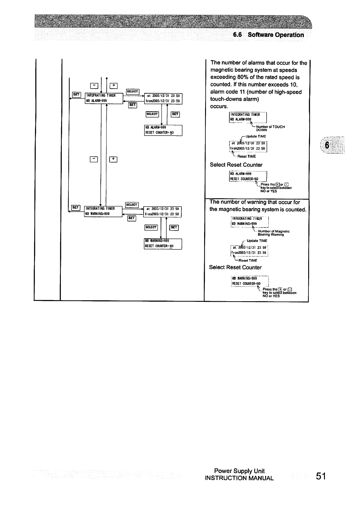
.::■:■:
^;-n;.-
■wm
6.6
Software
Operation
INIEFRAIIIffi
TIBER
KB
ALARH=999
at
2003-12
31
23
59
fr<m2003/t2/3l
23
59
RESET
COUNTED
NO
INTEGRATING
TIMER
US
WARNING=999
at
2003/12/31
23:59
fran2003/!2/3l
23:59
KB
HARNIira=999
reset
oama-
m
The
number
of
alarms
that
occur
for
the
magnetic
bearing
system
at
speeds
exceeding
80%
of
the
rated
speed
is
counted.
If
this
number
exceeds
10,
alarm
code
11
(number
of
high-speed
touch-downs
alarm)
occurs.
INTEGRATING
TIMER
KB
ALAR»=999
-Number
of
TOUCH
DOWN
Update
TIME
|
frora2003/l2/31
23:59
|
fc
_..
J
^-
Reset
TIME
Select
Reset
Counter
KB
*LAR«=999
RESET
COUNIER^O
'\_PrassthoE)wE
key
lo
setecl
between
NO
or
YES
The
number
of
warning
that
occur
for
the
magnetic
bearing
system
is
counted.
Number
of
Magnetic
Bearing
Warning
Update
TIME
I
at
2003,'I2/31
23:59"
!rom2003/12/31
23:59
'—Resel
TIME
Select
Reset Counter
IBB
IMRNING=999
I
RESET
C0W(IER=N0
\ Press
the
E
or
Q
key
lo
solecl
between
NO
or
YES
Power
Supply
Unit
INSTRUCTION
MANUAL
51
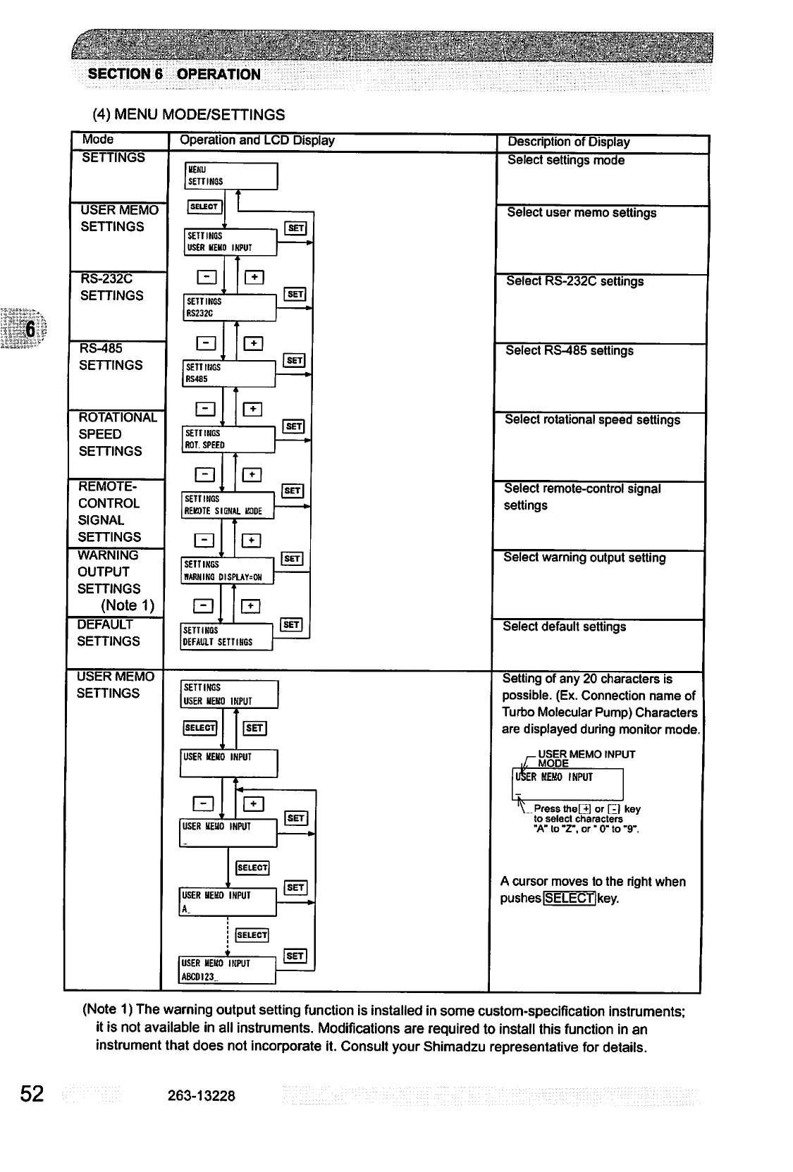
SECTION
6
OPERATION
(4)
MENU
MODE/SETTINGS
Mode
Operation
and
LCD
Display
Description
of
Display
be
I
IINUb
UEKU
SETTINGS
USER
MEMO
SETTINGS
SETTINGS
USER
HEHO
INPUT
RS-232C
SETTINGS
SETTINGS
RS232C
RS-485
SETTINGS
SETTINGS
RS485
ROTATIONAL
SPEED
SETTINGS
SETTINGS
ROT.
SPEED
REMOTE-
CONTROL
SIGNAL
SETTINGS
LZJ
SETTINGS
REKOTE SIGNAL
KODE
WARNING
OUTPUT
SETTINGS
(Notel)
SETTINGS
DARNING
DISPLAYS
DEFAULT
SETTINGS
SETTINGS
DEFAULT
SETTINGS
Select
settings
mode
Select
user
memo
settings
Select
RS-232C
settings
Select
RS-485
settings
Select
rotational
speed
settings
Select
remote-control
signal
settings
Select
warning
output
setting
Select
default
settings
USER
MEMO
SETTINGS
SETTINGS
USER
MEMO
INPUT
USER
MEMO
INPUT
USER
MEMO
INPUT
USER
MEMO
INPUT
A
USER
MEMO
INPUT
ABC0123.
Setting
of
any
20
characters
is
possible.
(Ex.
Connection
name
of
Turbo
Molecular
Pump)
Characters
are
displayed
during
monitor
mode.
._
user
memo
input
i/Tmode
TrSi
ER
MEMO
INPUT
Press
theEl
or
d)
key
to
select
characters
"A"
to
"Z",
or"
0"
to
"9-.
A
cursor
moves
to
the
right
when
pusheslSELECTlkev.
(Note
1)
The
warning
output
setting
function
is
installed
in
some
custom-specification
instruments;
it
is
not
available
in
all
instruments.
Modifications
are
required
to
install
this
function
in
an
instrument
that
does
not
incorporate
it.
Consult
your
Shimadzu
representative
for
details.
52
263-13228
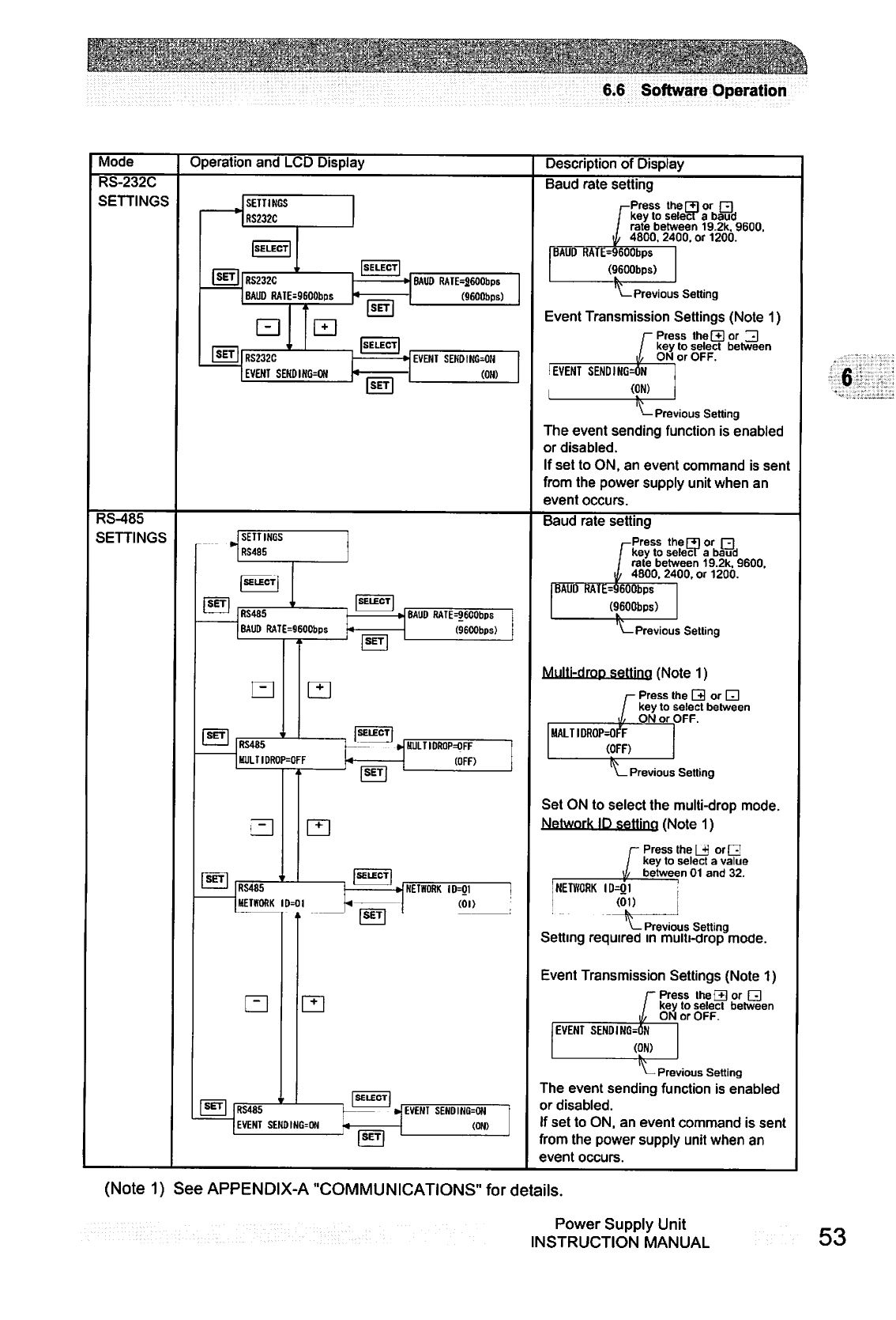
inf^^fr^tiirfWrffiTriTT^^frfiTfra^EJW^^W^
6.6
Software
Operation
Mode
Operation
and
LCD
Display
Description
of
Display
RS-232C
SETTINGS
Baud
rate
setting
SETTINGS
RS232C
-Press
the
[3
or
R
key
to
selecr
a
baud
rate
between
19.2k,
9600.
4800. 2400.
or
1200.
RS232C
BAUD
RAIE-9600bps
BAUD RAIE=2600bps
(SEOObps)
BAUD RATE=9600bp$
(9600bps)
\—Previous
Setting
Event
Transmission
Settings
(Note
1)
RS232C
EVENT
SENDING=ON
EVENT
SEHDING^OH
(OH)
I
EVENT
SENDING
Press
the[+] or
23
key
to
select
between
ON
or
OFF.
(ON)
—
Previous
Setting
The
event
sending
function
is
enabled
or
disabled.
If
set
to
ON,
an
event
command
is
sent
from
the
power
supply
unit
when
an
event
occurs.
RS-485
SETTINGS
Baud
rate
setting
SETTINGS
RS4S5
-Press
the
[3
or
pi
key
to
select
a
baud
rate
between
19.2k,
9600.
4800. 2400,
or
1200.
RS485
BAUD
RATE=96OCbps
BAUD
RATE=96C0bps
(9600bps)
RS465
HULTIDROP=OFF
BAUDRATE=9600bps
(9600bps)
\—Previous
Setting
Multi-drop
setting
(Note
1)
r
Press
the
0
or
Q
key
to
select
between
ON
or
OFF.
MALTIDROP=OFF
>jMULTIDRaP=OFF
(OFF)
(OFF)
Previous
Setting
Set
ON
to
select
the
multi-drop
mode.
Network
ID
setting
(Note
1)
1
Press
the
LJ
orQ
key
to
select
a
value
1/
between
01
and
32.
RS485
METKORK
ID=0l
NETWORK
10=01
(01)
NETWORK
ID=01
(01)
\—
Previous
Setting
Setting
required
in
multi-drop
mode.
Event
Transmission
Settings
(Note
1)
Press
the
[3
or
Q
key
to
select
between
ON
or
OFF.
EVENT
SENDING
(ON)
RS48S
EVENT
SEKOING=ON
EVENT
SENDIHG=ON
(ON)
>—
Previous
Setting
The
event
sending
function
is
enabled
or
disabled.
If
set
to
ON,
an
event
command
is
sent
from
the
power
supply
unit
when
an
event
occurs.
(Note
1)
See
APPENDIX-A
"COMMUNICATIONS"
for
details.
Power
Supply
Unit
INSTRUCTION
MANUAL
53
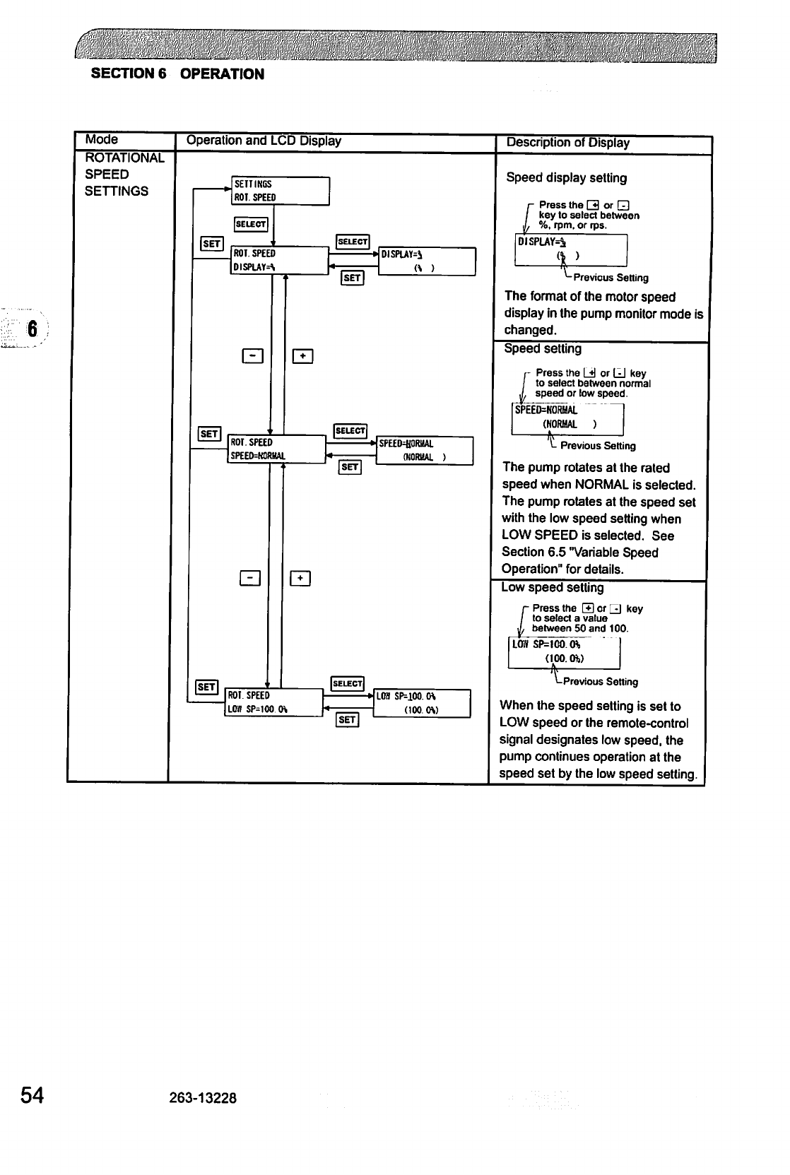
r.
SECTION
6
OPERATION
Mode
ROTATIONAL
SPEED
SETTINGS
Operation
and
LCD
Display
Description
of
Display
SETTINGS
ROT
SPEED
ROT.
SPEED
DISPUTE
DISPLAYS
ROT.
SPEED
SPEED=NOfUJAL
SPEED40RMAI
(NORMAL
)
ROI.
SPEED
LOB SP=1OO
LOS
SP=1OO.
0\
(100
OS)
Speed
display
setting
1
Press
the
Q
or
□
key
to
select
between
j,
%,
rpm.
or
rps.
DISPLAY^
)
"-Previous
Setting
The
format
of
the
motor
speed
display
in
the
pump
monitor
mode
is
changed.
Speed
setting
Press
the
Li)
or
LJ
key
to
select
between
normal
speed
or
low
speed.
SPEED=NORHAL
(NORUAL
)
1
L
Previous
Setting
The
pump
rotates
at
the
rated
speed
when
NORMAL
is
selected.
The
pump
rotates
at
the
speed
set
with
the
low
speed
setting
when
LOW
SPEED
is
selected.
See
Section
6.5
"Variable
Speed
Operation"
for
details.
Low
speed
setting
r
Press
the
H
or
QJ
key
/
to
select
a
value
I
between
50
and
100.
LOW
SP=100.
to
(100.0%)
Previous
Setting
When
the
speed
setting
is
set
to
LOW
speed
or
the
remote-control
signal
designates
low
speed,
the
pump
continues
operation
at
the
speed
set
by
the
low
speed
setting.
54
263-13228
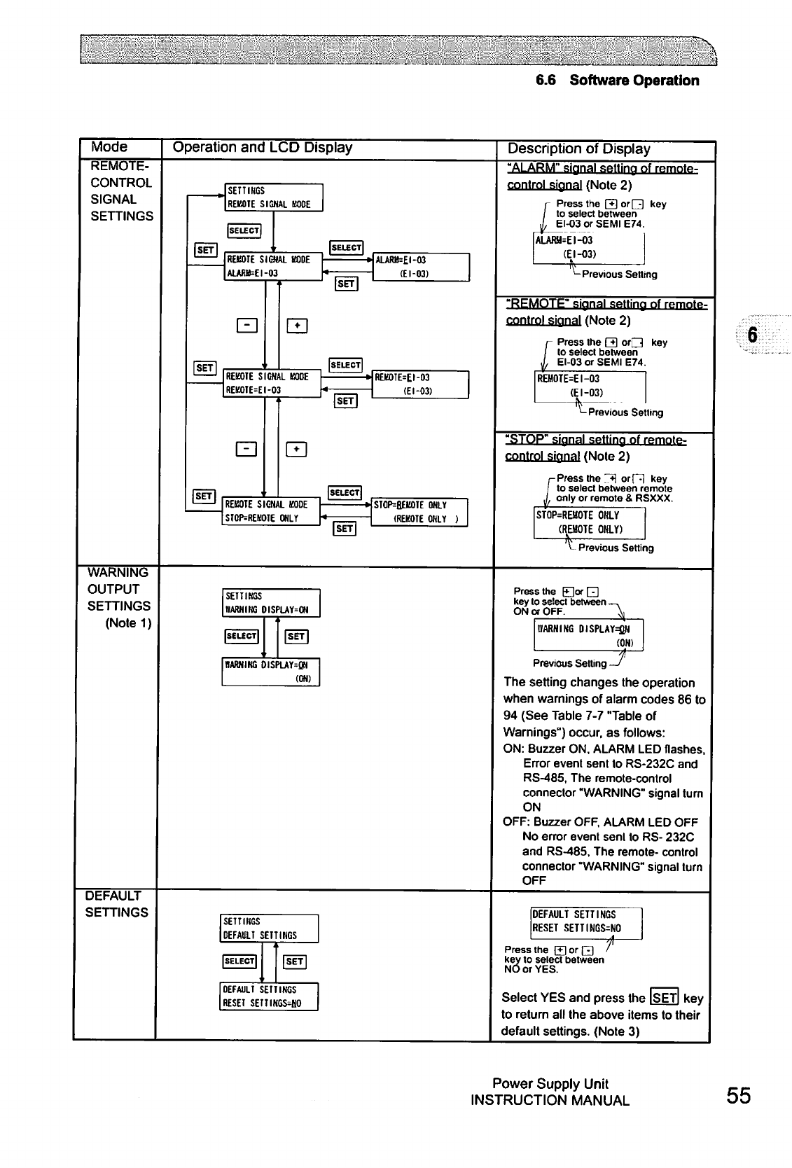
I
6.6
Software
Operation
Mode
REMOTE-
CONTROL
SIGNAL
SETTINGS
WARNING
OUTPUT
SETTINGS
(Note
1)
Operation
and
LCD
Display
SETTINGS
REMOTE
SIGNAL
KOBE
REMOTE
SIGNAL KODE
ALARB=£I-O3
ALARB=£l-03
(El-03)
REMOTE
SIGNAL
MODE
REK0TE=EI-03
REK0TE=EI-03
(El-03)
REKOTE
SIGNAL KODE
ST0P=REKOTE
ONLY
STOP=BEEOTE
ONLY
(REKOTE
ONLY
)
Description
of
Display
"ALARM"
signal
setting
of
remote-
control
signal
(Note
2)
Press
the
[*}
or
Q)
key
to
select
between
EI-O3
or
SEMI
E74.
ALARH=EI-O3
(El-03)
—t
Previous
Setting
"REMOTE"
signal
setting
nf
remote-
control
signal
(Note
2)
Press
the
Q)
oO
key
to
select
between
EI-03
or
SEMI
E74.
REMOTER
I-03
(EI-03)
—h
"-Previous
Setting
"STOP"
signal
setting
of
remntft-
control
signal
(Note
2)
Press
the
j*\
orP)
key
to
select
between
remote
only
or
remote
&
RSXXX.
STOP=REBOTE
ONLY
(REMOTE
ONLY)
(RBI
Previous
Setting
6
SETTINGS
DARNING
DISPLAYS
Press
the
F+]orH
key
to
select
between
_,
ON
or
OFF.
\
DARNING
DISPLAYED
(ON)
HARMING
DISPLAYS
(ON)
f
Previous
Setting
—I
The
setting
changes
the
operation
when
warnings
of
alarm
codes
86
to
94
(See
Table
7-7
"Table
of
Warnings")
occur,
as
follows:
ON:
Buzzer
ON,
ALARM
LED
flashes,
Error
event
sent
to
RS-232C
and
RS-485,
The
remote-control
connector
"WARNING"
signal
turn
ON
OFF:
Buzzer
OFF,
ALARM
LED
OFF
No
error
event
sent
to
RS-
232C
and
RS-485,
The
remote-
control
connector
"WARNING"
signal
turn
OFF
DEFAULT
SETTINGS
SETTINGS
DEFAULT
SETTINGS
DEFAULT
SETTINGS
RESET
SETTINGS=NO
■4-
DEFAULI
SETTINGS
RESET
SETTIHGS-HO
Press
the
[+]
or
Q]
/
key
to
select
between
NO
or
YES.
Select
YES
and
press
the
ISETl
key
to
return
all
the
above
items
to
their
default
settings.
(Note
3)
Power
Supply
Unit
INSTRUCTION
MANUAL
55
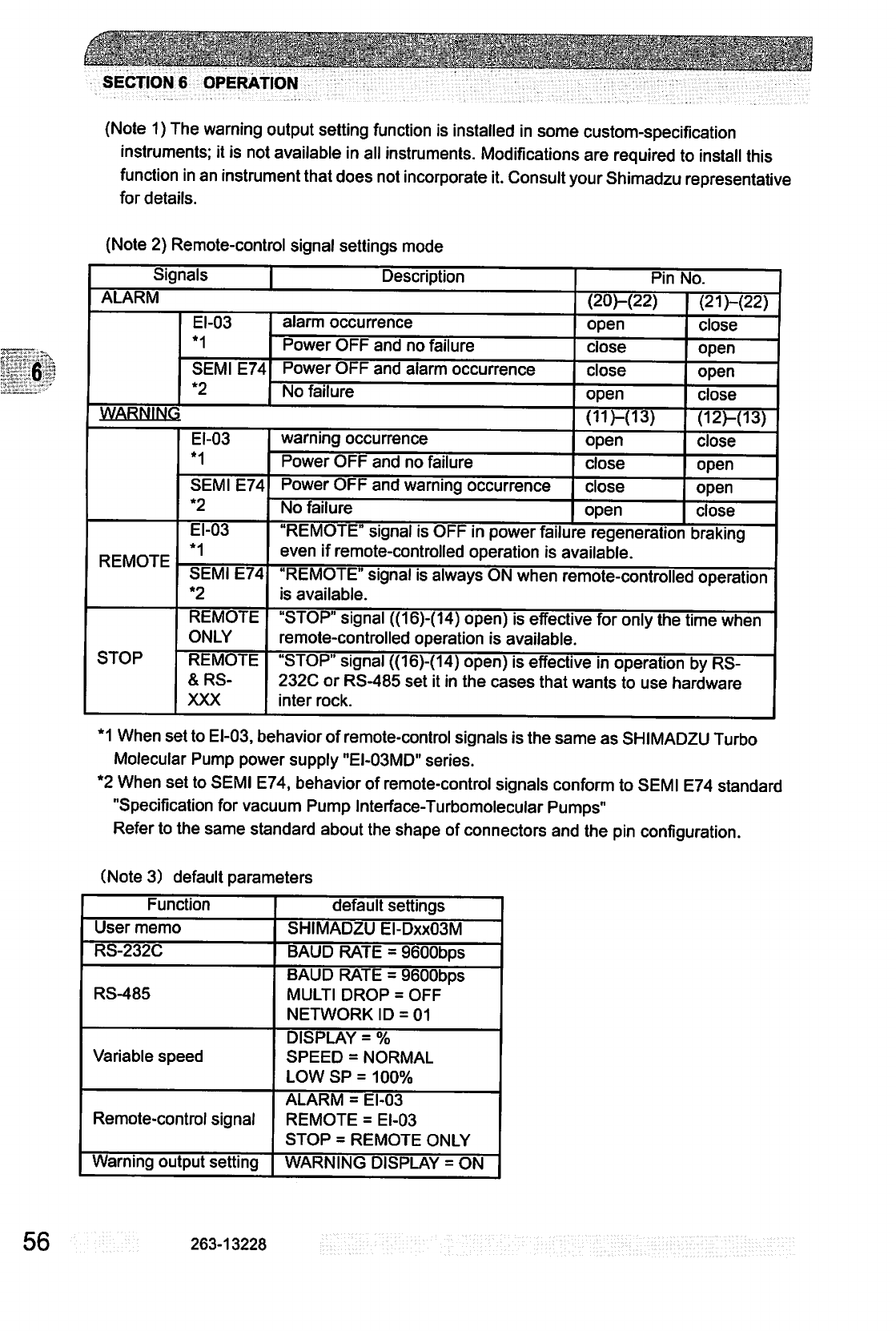
6
SECTION
6
OPERATION
(Note
1)
The
warning
output
setting
function
is
installed
in
some
custom-specification
instruments;
it
is
not
available
in
all
instruments.
Modifications
are
required
to
install
this
function
in
an
instrument
that
does
not
incorporate
it.
Consult
your
Shimadzu
representative
for
details.
(Note
2)
Remote-control
signal
settings
mode
Signals
Description
ALARM
EI-03
*1
SEMI
E74
*2
alarm
occurrence
Power
OFF
and
no
failure
Power
OFF
and
alarm
occurrence
No
failure
WARNING
REMOTE
STOP
EI-03
•1
SEMI
E74
*2
EI-03
*1
SEMI
E74
*2
REMOTE
ONLY
REMOTE
&RS-
XXX
warning
occurrence
Power
OFF
and no
failure
Power
OFF
and
warning
occurrence
No
failure
Pin
No.
(20M22)
open
close
close
open
(11M13)
open
close
close
open
(21)-(22)
close
open
open
close
(12M13)
close
open
open
close
REMOTE"
signal
is
OFF
in
power
failure
regeneration
braking
even
if
remote-controlled
operation
is
available.
"REMOTE"
signal
is
always
ON
when
remote-controlled
operation
is
available.
"STOP"
signal
((16)-(14)
open)
is
effective
for
only
the
time
when
remote-controlled
operation
is
available.
"STOP"
signal
((16)-(14)
open)
is
effective
in
operation
by
RS-
232C
or
RS-485
set
it
in
the
cases
that
wants
to
use
hardware
inter
rock.
*1
When
set
to
EI-03,
behavior
of
remote-control
signals
is
the
same
as
SHIMADZU
Turbo
Molecular
Pump
power
supply
"EI-03MD"
series.
*2
When
set
to
SEMI
E74, behavior
of
remote-control
signals
conform
to
SEMI
E74
standard
"Specification
for
vacuum
Pump
Interface-Turbomolecular
Pumps"
Refer
to
the
same
standard
about
the
shape
of
connectors
and
the
pin
configuration.
(Note
3)
default
parameters
Function
User
memo
RS-232C
RS-485
Variable
speed
Remote-control
signal
Warning
output
setting
default
settings
SHIMADZU
EI-DxxO3M
BAUD
RATE
=
9600bps
BAUD
RATE
=
9600bps
MULTI
DROP
=
OFF
NETWORK
ID
=
01
DISPLAY
=
%
SPEED
=
NORMAL
LOWSP=
100%
ALARM
=
EI-03
REMOTE
=
EI-03
STOP
=
REMOTE
ONLY
WARNING
DISPLAY
=
ON
56
263-13228
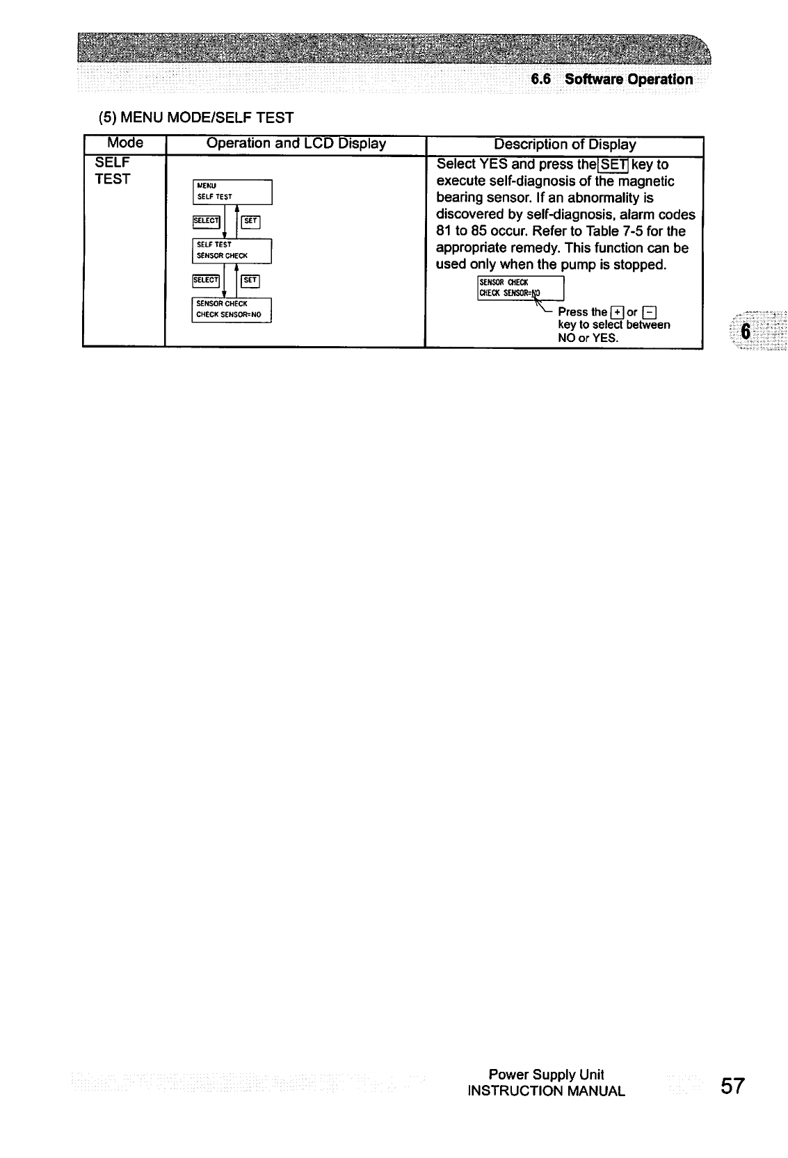
6.6
Software
Operation
(5)
MENU
MODE/SELF
TEST
Mode
Operation
and
LCD
Display
Description
of
Display
SELF
TEST
MENU
SELF
TEST
SELF
TEST
SENSOR
CHECK
Select
YES
and
press
the|SETj
key
to
execute
self-diagnosis
of
the
magnetic
bearing
sensor.
If
an
abnormality
is
discovered
by
self-diagnosis,
alarm
codes
81
to
85
occur.
Refer
to
Table
7-5
for
the
appropriate
remedy.
This
function
can
be
used
only
when
the
pump
is
stopped.
SENSOR
CHECK
CHECK
SENSOR=NO
SENSOR
CHECK
CHECK
:
Press
the
Q
or
Qj]
key
to
select
between
NO
or
YES.
6
Power
Supply
Unit
INSTRUCTION
MANUAL
57
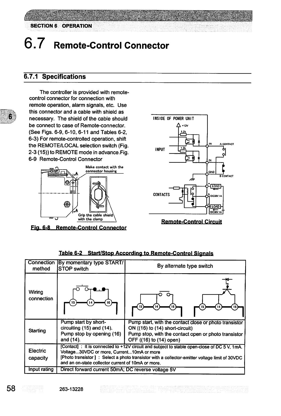
SECTION
6
OPERATION
6.7
Remote-Control
Connector
6.7.1
Specifications
lip
svfi
The
controller
is
provided
with
remote-
control
connector
for
connection
with
remote
operation,
alarm
signals,
etc.
Use
this
connector
and
a
cable
with
shield
as
necessary.
The
shield
of
the
cable
should
be
connect
to
case
of
Remote-connector.
(See
Figs.
6-9,
6-10,
6-11
and
Tables
6-2,
6-3)
For
remote-controlled
operation,
shift
the
REMOTE/LOCAL
selection
switch
(Fig.
2-3
(15))
to
REMOTE
mode
in
advance.Fig.
6-9
Remote-Control
Connector
Make
contact
with
the
connector
housing
Grip
the
cable
shield\
with
the
clamp
Fia.
6-8
Remote-Control
Connector
IN
A
CONTACT
INSIDE
OF
POWER
UNIT
1.2k
Remote-Control
Circuit
Table
6-2
Start/Stop
Accordina
to
Remote-Control
Sianals
Connection
method
By
momentary
type
START/
STOP
switch
By
alternate
type
switch
Wiring
connection
Starting
Pump
start
by
short-
circuiting
(15)
and
(14).
Pump
stop
by opening
(16)
and
(14).
Pump
start,
with
the
contact
close
or
photo
transistor
ON
((16) to
(14)
short-circuit)
Pump
stop,
with
the
contact
open
or
photo
transistor
OFF
((16)
to
(14)
open)
Electric
capacity
[Contact]
:
It
is
connected
to
+12V
circuit
and
subject
to
stable
open-close
of
DC
5
V,
1
mA.
Voltage...30VDC
or
more,
Current...
10mA
or
more
[Photo
transistor
]
:
Select
a
photo
transistor
with
a
collector-emitter
voltage
limit
of
30VDC
and
an
on-state
collector
current
of
10mA
or
more.
Input
rating
Direct
forward
current
50mA;
DC
reverse
voltage
5V
58
263-13228
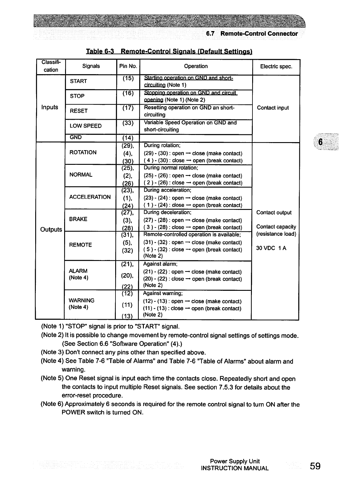
;.',■:
■■;-:..':'V.1
s^
■-■■■'.■::■•"
■■■■■■:
"'i.''-
6.7
Remote-Control
Connector
Table
6-3
Remote-Control
Signals
/Default
Settings!
Classifi
cation
Inputs
Outputs
Signals
START
STOP
RESET
LOW
SPEED
GND
ROTATION
NORMAL
ACCELERATION
BRAKE
REMOTE
ALARM
(Note
4)
WARNING
(Note
4)
Pin
No.
(15)
(16)
(17)
(33)
(14)
(29),
(4),
(30)
(25),
(2),
(26)
(23),
(1).
(24)
(27),
(3),
(28)
(31),
(5),
(32)
(21),
(20),
(22)
(12)
(11)
(13)
Operation
Starting
operation
on
GND
and
short-
circuiting
(Note
1)
Stoppipp
operation
on
GND
and
circuit
opening
(Note
1)
(Note
2)
Resetting
operation
on
GND
an
short-
circuiting
Variable
Speed
Operation
on
GND
and
short-circuiting
During
rotation;
(29)
-
(30):
open
—
close
(make
contact)
(4
)
-
(30):
close
—►
open
(break
contact)
During
normal
rotation;
(25)
-
(26):
open
—
close
(make
contact)
(2
)
-
(26):
close
—
open
(break
contact)
During
acceleration;
(23)
-
(24):
open
—
close
(make
contact)
(1
)
-
(24):
close
—
open
(break
contact)
During
deceleration;
(27)
-
(28):
open
—
close
(make
contact)
(
3
)
-
(28):
close
—
open
(break
contact)
Remote-controlled
operation
is
available;
(31)
-
(32):
open
—
close
(make
contact)
(
5
)
-
(32):
close
—
open
(break
contact)
(Note
2)
Against
alarm;
(21)
-
(22):
open
—
close
(make
contact)
(20)
-
(22):
close
—
open
(break
contact)
(Note
2)
Against
warning;
(12)
-
(13):
open
—
close
(make
contact)
(11)
-
(13):
close
—
open
(break
contact)
(Note
2)
Electric
spec.
Contact
input
Contact
output
Contact
capacity
(resistance
load)
30VDC
1A
6
(Note
1)
"STOP"
signal
is
prior
to
"START"
signal.
(Note
2)
It
is
possible
to
change
movement
by
remote-control
signal
settings
of
settings
mode.
(See
Section
6.6
"Software
Operation"
(4).)
(Note
3)
Don't
connect
any
pins
other
than
specified
above.
(Note
4)
See
Table
7-6
"Table
of
Alarms"
and
Table
7-6
"Table
of
Alarms"
about
alarm
and
warning.
(Note
5)
One
Reset
signal
is
input
each
time
the
contacts
close.
Repeatedly
short
and
open
the
contacts
to
input
multiple
Reset
signals.
See
section
7.5.3
for
details
about
the
error-reset
procedure.
(Note
6)
Approximately
6
seconds
is
required
for
the
remote
control
signal
to
turn
ON
after
the
POWER
switch
is
turned
ON.
Power
Supply
Unit
INSTRUCTION
MANUAL
59
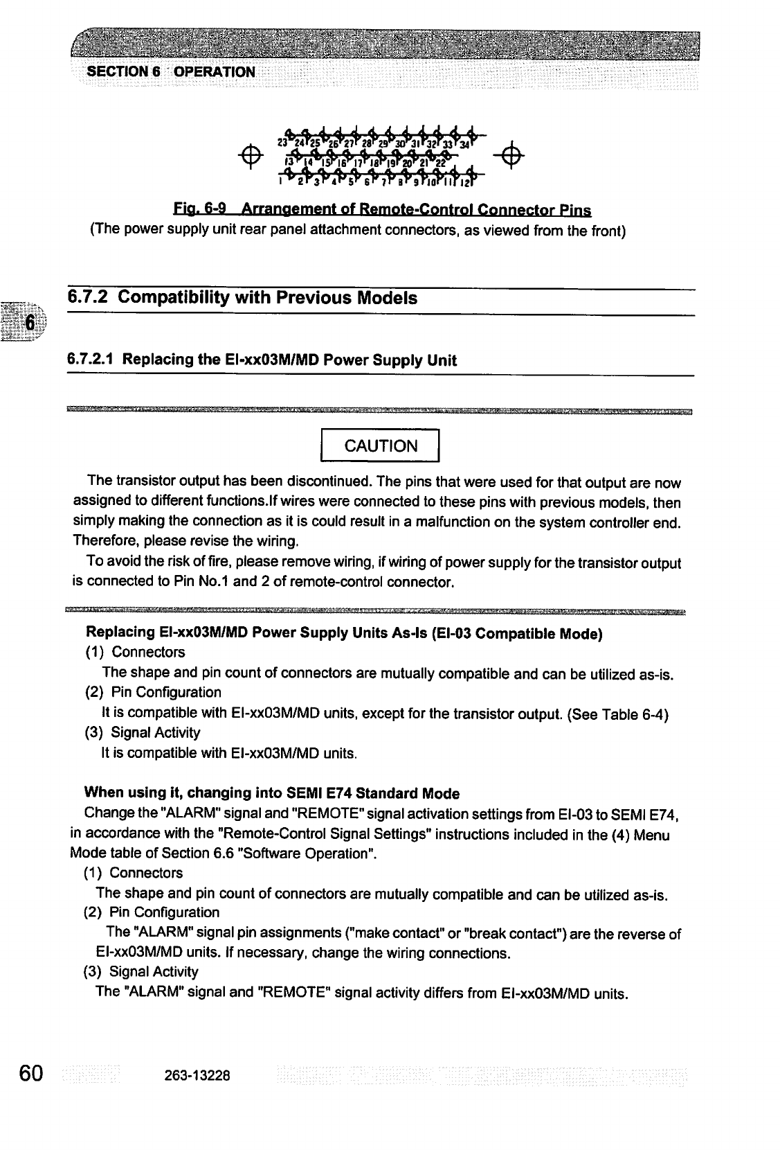
[
..'
...'..•
'■'../
' ■
■:
.;■■./■•■
'.
..
■'■■-■
\'
;f-£
_.'!••_.■
^'-;;
;'■■'■'■':
:■
' ■ ■.,.' '
'•
■'.".
■
.]
j'i..\'
":&'■-.
:.'~'.m\:
■'.
..'■':
""..■■"•'
Vi!':i
■
■■
\:\-
■■'/
';:
SECTION
6
OPERATION
Fig.
6-9
Arrangement
of
Remote-Control
Connector
Pins
(The
power
supply
unit
rear
panel
attachment
connectors,
as viewed
from
the
front)
6.7.2
Compatibility
with
Previous
Models
6.7.2.1
Replacing
the
EI-xxO3M/MD
Power
Supply
Unit
&^
CAUTION
The
transistor
output
has
been
discontinued.
The
pins
that
were
used
for
that
output
are
now
assigned
to
different
functions.lf
wires
were
connected
to
these
pins with
previous
models,
then
simply
making
the
connection
as
it
is
could
result
in
a
malfunction
on
the
system
controller
end.
Therefore,
please
revise
the
wiring.
To
avoid the
risk
of
fire,
please
remove
wiring,
if
wiring of
power
supply
for
the
transistor
output
is
connected
to
Pin
No.1
and
2
of
remote-control
connector.
Replacing
EI-xxO3M/MD
Power
Supply
Units
As-ls
(EI-03
Compatible
Mode)
(1)
Connectors
The
shape
and
pin
count
of
connectors
are
mutually
compatible
and
can
be
utilized
as-is.
(2)
Pin
Configuration
It
is
compatible
with
EI-xxO3M/MD
units,
except
for
the
transistor
output.
(See
Table
6-4)
(3)
Signal
Activity
It
is
compatible
with
EI-xxO3M/MD
units.
When
using
it,
changing
into
SEMI
E74
Standard
Mode
Change
the
"ALARM"
signal
and
"REMOTE"
signal
activation
settings
from
EI-03
to
SEMI
E74,
in
accordance
with
the
"Remote-Control
Signal
Settings"
instructions
included
in
the
(4)
Menu
Mode
table
of
Section
6.6
"Software
Operation".
(1)
Connectors
The
shape
and
pin
count
of
connectors
are
mutually
compatible
and
can
be
utilized
as-is.
(2)
Pin
Configuration
The
"ALARM"
signal
pin
assignments
("make
contact"
or
"break
contact")
are
the
reverse
of
EI-xxO3M/MD
units.
If
necessary,
change
the
wiring
connections.
(3)
Signal
Activity
The
"ALARM"
signal
and
"REMOTE"
signal
activity
differs
from
EI-xxO3M/MD
units.
60
263-13228
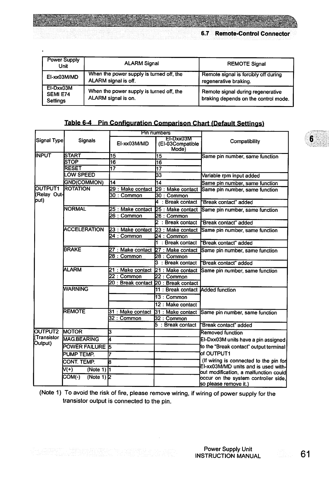
nmkwtwm
_,
6.7
Remote-Control
Connector
Power
Supply
Unit
EI-xxO3M/MD
EI-DxxO3M
SEMI
E74
Settings
ALARM
Signal
When
the
power
supply
is
turned
off,
the
ALARM
signal
is
off.
When
the
power
supply
is
turned
off,
the
ALARM
signal
is
on.
REMOTE
Signal
Remote
signal
is
forcibly
off
during
regenerative
braking.
Remote
signal
during
regenerative
braking
depends
on
the
control
mode.
Table
6-4
Pin
Configuration
Comparison
Chart
/Default
Settinas)
Signal
Type
INPUT
0UTPUT1
(Relay
Out
put)
OUTPUT2
(Transistor
Output)
Signals
START
STOP
RESET
LOW
SPEED
GND(COMMON)
ROTATION
NORMAL
ACCELERATION
BRAKE
ALARM
WARNING
REMOTE
MOTOR
MAG.BEARING
POWER
FAILURE
PUMP
TEMP.
CONT.
TEMP.
V(+)
(Notel)
COM(-)
(Notel)
Kin
numbers
EI-xxO3M/MD
15
16
17
14
29
30
25
26
23
24
27
28
21
22
20
:
Make
contact
:
Common
Make
contact
Common
Make
contact
Common
Make
contact
Common
Make
contact
Common
Break
contact
31
:
32
:
3
i
Make
contact
Common
ti-uxxuawi
(EI-03Compatible
Mode)
15
16
17
33
14
29
30
4
:
25
26
2
;
23
24
1
:
27
28
3
:
21
22
20
11
i
O
2
31
32
5
:
:
Make
contact
:
Common
Break
contact
:
Make
contact
:
Common
Break
contact
:
Make
contact
:
Common
Break
contact
:
Make
contact
Common
Break
contact
Make
contact
Common
Break
contact
Break
contact
Common
Make
contact
Make
contact
Common
Break
contact
Compatibility
Same
pin
number,
same
function
Variable
rpm
input
added
Same
pin
number,
same
function
Same
pin
number,
same
function
"Break
contact"
added
Same
pin
number,
same
function
"Break
contact"
added
Same
pin
number,
same
function
"Break
contact"
added
Same
pin
number,
same
function
'Break
contact"
added
Same
pin
number,
same
function
Added
function
Same
pin
number,
same
function
Break
contact"
added
Removed
function
■l-Dxx03M
units
have
a
pin
assigned
o
the
"Break
contact"
output
terminal
of
OUTPUT1
(If
wiring
is
connected
to
the
pin
for
EI-xxO3M/MD
units
and
is
used
with
out
modification,
a
malfunction
could
occur
on
the
system
controller
side,
o
please
remove
it.)
6
(Note
1)
To
avoid
the
risk
of
fire,
please
remove
wiring,
if
wiring
of
power
supply
for
the
transistor
output
is
connected
to
the
pin.
Power
Supply
Unit
INSTRUCTION
MANUAL
61
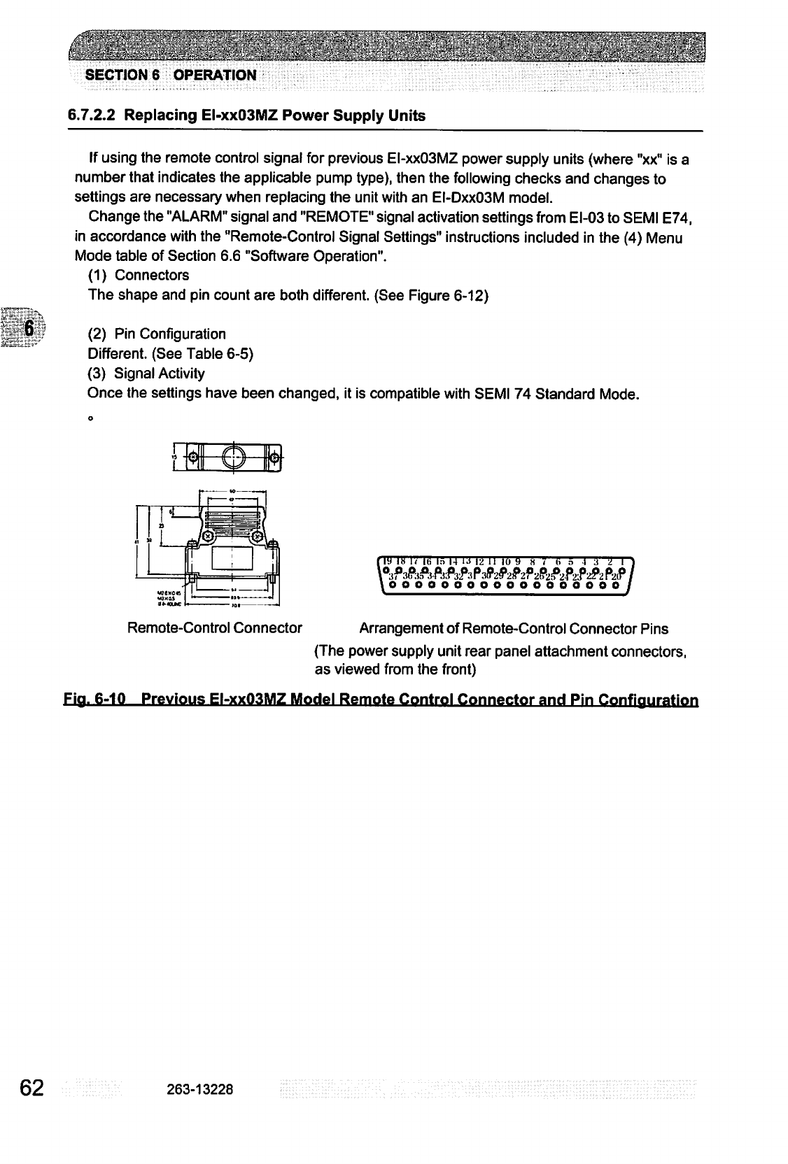
:.fc-y.y*C--^'
:_^....
_..._^_
.^.^..^^..^_^.^^
..^.^....^
SECTION
6
OPERATION
6.7.2.2
Replacing
EI-xxO3MZ
Power
Supply
Units
If
using
the
remote
control
signal
for
previous
EI-xxO3MZ
power
supply
units
(where
"xx"
is
a
number
that
indicates
the
applicable
pump
type),
then
the
following
checks
and
changes
to
settings
are
necessary
when
replacing
the
unit
with
an
EI-DxxO3M
model.
Change
the
"ALARM"
signal
and
"REMOTE"
signal
activation
settings
from
EI-03
to
SEMI
E74,
in
accordance
with
the
"Remote-Control
Signal
Settings"
instructions
included
in
the
(4)
Menu
Mode
table
of
Section
6.6
"Software
Operation".
(1)
Connectors
The
shape
and
pin
count
are
both
different.
(See
Figure
6-12)
(2)
Pin
Configuration
Different.
(See
Table
6-5)
(3)
Signal
Activity
Once
the
settings
have
been
changed,
it
is
compatible
with
SEMI
74
Standard
Mode.
m
in
r«
its
in 14
!■>
12
ii
io
y
a
v
63
n
ooooooooooooooo
n
2
n
£2f>X?
oooy
Remote-Control
Connector
Arrangement
of
Remote-Control
Connector
Pins
(The
power
supply
unit
rear
panel
attachment
connectors,
as
viewed
from
the
front)
Fia.
6-10
Previous
EI-xxO3MZ
Model
Remote
Control
Connector
and
Pin
Confiauration
62
263-13228
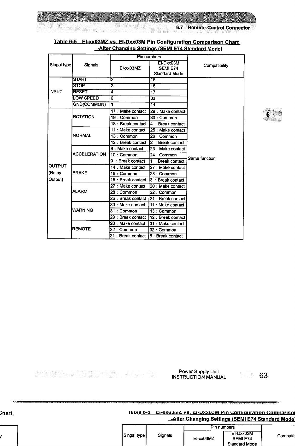
;■■■;".:.■.
.'>:.>.■'
:-
-5-!
'■.■?■•.
■■■■;/-.
.".;■■•..■
'W
.■'■
■.','
'.■.-■■</"■
;■.■.■■='.■'■■
■■,:■■'
•
■„
■.;:■;.';>-
.-,
6.7
Remote-Control
Connector
Table
6-5
EI-xxO3MZ
vs.
EI-DxxO3M
Pin
Configuration
Comparison
Chart
-After
Changing
Settinas
/SEMI
E74
Standard
Mode)
Singal
type
INPUT
OUTPUT
(Relay
Output)
Signals
START
STOP
RESET
LOW
SPEED
GND(COMMON)
ROTATION
NORMAL
ACCELERATION
BRAKE
ALARM
WARNING
REMOTE
Pin
numbers
EI-xxO3M2
2
3
4
6
1
17
:
Make
contact
19
:
Common
18
:
Break
contact
11
:
Make
contact
13
:
Common
12
:
Break
contact
8
:
Make
contact
10
:
Common
9
:
Break
contact
14
:
Make
contact
16
:
Common
15
:
Break
contact
27
:
Make
contact
28
:
Common
26
:
Break
contact
30
:
Make
contact
31
:
Common
29
:
Break
contact
20
:
Make
contact
22
:
Common
21
:
Break
contact
EI-DxxO3M
SEMI
E74
Standard
Mode
15
16
17
33
14
29
:
Make
contact
30
:
Common
4
:
Break
contact
25
:
Make
contact
26
:
Common
2
:
Break
contact
23
:
Make
contact
24
:
Common
1
:
Break
contact
27
:
Make
contact
28
:
Common
3
:
Break
contact
20
:
Make
contact
22
:
Common
21
:
Break
contact
11
:
Make
contact
13
:
Common
12
:
Break
contact
31
:
Make
contact
32
:
Common
5:
Break
contact
Compatibility
Same
function
6
Power
Supply
Unit
INSTRUCTION
MANUAL
63
vs.
fci-UxxujM
Hin
Configuration
Compansoi
-After
Changing
Settinas
(SEMI
E74
Standard
Mode
Singal
type
Signals
Pin
numbers
EI-xxO3M2
EI-DxxO3M
SEMI
E74
Standard
Mode
Compatit

w»"jtf?Sw
This
page
is
intentionally
left
blank.
64
263-13228
■■■■■.;>!->:::^.:/.^;^;::V-
■,■:
TROUBLESHOOTING
o ©
7.1
Nothing
Happens
After
an
Operation
is
Made
7.2
Power
Failures
7.3
Vacuum
Pressure
Rise
7.4
Abnormal
Noise
and/or
Vibration
7.5
Alarm
Detection
Capabilities
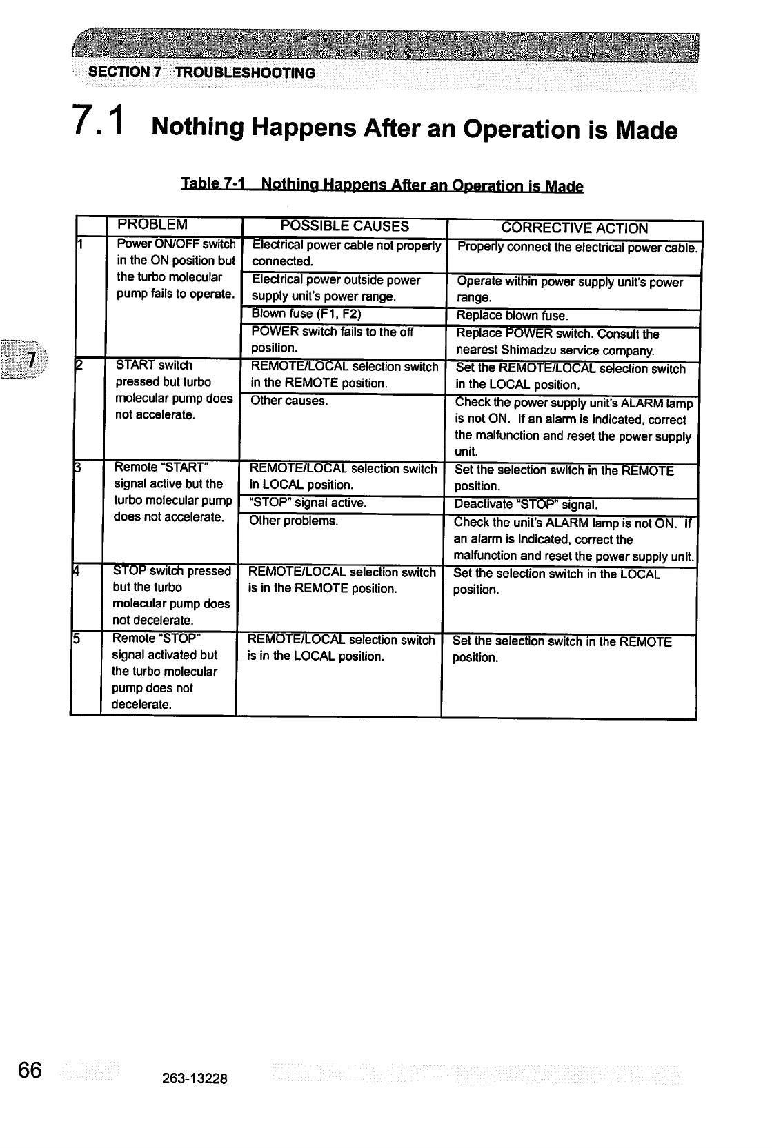
SECTION
7
TROUBLESHOOTING
7.1
Nothing
Happens
After
an
Operation
is
Made
Table
7-1
Nothing
Happens
After
an
Operation
is
PROBLEM
Power
ON/OFF
switcr
in
the
ON
position
but
the
turbo
molecular
pump
fails
to
operate.
START
switch
pressed
but
turbo
molecular
pump
does
not
accelerate.
Remote
"START"
signal active
but
the
turbo
molecular
pump
does
not
accelerate.
STOP
switch
pressed
but the
turbo
molecular
pump
does
not
decelerate.
Remote
"STOP"
signal
activated
but
the
turbo
molecular
pump
does
not
decelerate.
POSSIBLE
CAUSES
Electrical
power
cable
not
properly
connected.
Electrical
power
outside
power
supply
unit's
power
range.
Blown
fuse
(F1,
F2)
POWER
switch
fails
to
the
off
position.
REMOTE/LOCAL
selection
switch
in
the
REMOTE
position.
Other
causes.
REMOTE/LOCAL
selection
switch
in
LOCAL
position.
"STOP"
signal
active.
Other
problems.
REMOTE/LOCAL
selection
switch
is
in
the
REMOTE
position.
REMOTE/LOCAL
selection
switch
is
in
the
LOCAL
position.
CORRECTIVE
ACTION
Properly
connect
the
electrical
power
cable
Operate
within
power
supply
unit's
power
range.
Replace
blown
fuse.
Replace
POWER
switch.
Consult
the
nearest
Shimadzu
service
company.
Set
the
REMOTE/LOCAL
selection
switch
in
the
LOCAL
position.
Check
the
power
supply
unit's
ALARM
lamp
is
not
ON.
If
an
alarm
is
indicated,
correct
the
malfunction
and
reset
the
power
supply
unit.
Set
the
selection
switch
in
the
REMOTE
position.
Deactivate
"STOP"
signal.
Check
the
unit's
ALARM
lamp
is
not
ON.
If
an
alarm
is
indicated,
correct
the
malfunction
and
reset
the
power
supply
unit.
Set
the
selection
switch
in
the
LOCAL
position.
Set
the
selection
switch
in
the
REMOTE
position.
66
263-13228
7.3
Vacuum
Pressure
Rise
7.3
Vacuum
Pressure
Rise
A
rapid
rise
of
vacuum
pressure
in
the
turbo
molecular
pump
causes
the
internal
motor
of
the
turbo
molecular
pump
to
start
braking
and
the
ALARM
lamp
(Fig.
2-3
(14))
lights.
7.4
Abnormal
Noise
and/or
Vibration
Should
the
turbo
molecular
pump
ever
generate
abnormal
noise
and/or
vibration,
the
turbo
molecular
pump
operation
is
to
be
stopped
immediately.
But
there
is
possible
that
a
race
of
touch-down
bearing
(Fig.
3-1
(9))
may
make
sounds
for
seconds
when
the
pump
internal
pressure
gets
back
to
atmospheric
pressure
using
air
(or
non-
activity
gas).
This
phenomena
is
not
abnormal
and
make
no
damage
to
the
pump,
because
the
air
whirlpool
sometimes
occurs
and
then
makes
the
touch-down
bearing
rotate
slightly.
iS^
CAUTION
When
turning
the
POWER
switch
for
the
power
supply
unit
on
or
off,
a
"clunk"
sound
may
be
heard
from
inside
the
pump.
This
sound
is
from
the
rotor
inside
the
pump
being
levitated
or
de-
levitated.
This
is
normal.
7.5
Alarm
Detection
Capabilities
The
fault
detection
functions
shown
in
Table
7-6
"Table
of
Alarms"
and
Table
7-7
"Table
of
Warnings"
are
incorporated
for
protection
in
the
event
of
a
problem
with
the
turbo
molecular
pump
or
power
supply
unit.
When
an
error
is
detected,
check
the
ALARM
lamp
(Fig.
2-3
(14))
and
the
alarm
mode
display
on
the
front
panel
(See
Section
6.6
"Software
Operation"
(2))
and
refer
to
Tables
7-4
and
7-5
for
the
appropriate
remedy.
7.5.1
Movement
in
Alarm
Detection
Capabilities
(ALARM)
1.
ALARM
lamp
(Fig.
2-1
(14))
lights.
2.
Alarm
description
is
displayed
on
LCD.
3.
The
remote-control
connector
"ALARM"
signal
turn
ON.
4.
The
buzzer
sounds.
Power
Supply
Unit
INSTRUCTION
MANUAL
70
SECTION
7
TROUBLESHOOTING
5.
The
pump
start
the
protective
operations
shown
in
Table
7-6
"Table
of
Alarms."
6.
The
detection
error
is
recorded
in
the
error
log.
7.5.2
Movement
in
Alarm
Detection
Capabilities
(WARNING)
The
warning
output
setting
in
the
menu mode
"SETTINGS
/WARNING
DISPLAY"
item
on
the
LCD
changes
the
operation
when
a
warning
occurs.
<When
the
warning
output
setting
is
ON>
1.
ALARM
lamp
(Fig.
2-1
(14))
flashes.
2.
Warning
description
is
displayed
on
LCD.
3.
The
remote-control
connector
"WARNING"
signal
turn
ON.
4.
The
buzzer
sounds.
5.
Pump
operation
continues.
6.
The
detection
error
is
recorded
in
the
error
log.
<When
the
warning
output
setting
is
OFF>
[When
warnings
of
alarm
codes
86
to
94 do
not
occur.]
(See
Table
7-7
"Table
of
Warnings")
The
operation
is
the
same
as
the
warning
output
setting
is
ON.
[When
warnings
of
alarm
codes 86
to
94
occur.]
(See
Table
7-7
"Table
of
Warnings")
(1.
ALARM
lamp
(Fig.
2-1
(14))
does
not
flash.)
2.
Warning
description
is
displayed
on
LCD.
(3.
The
remote-control
connector
"WARNING"
signal
do
not
turn
ON.)
(4.
The
buzzer
does
not
sound.)
5.
Pump
operation
continues.
6.
The
detection
error
is
recorded
in
the
error
log.
7.5.3
Reset
Procedure
1.
The
buzzer
stops
after
the
first
reset operation.
2.
Refer
to
the
Troubleshooting
information
and
eliminate
the
cause
of
the
problem.
3.
Conduct
the
reset
operation
again.
4.
(ALARM)
If
the
problem
has
been
eliminated,
the
ALARM
lamp
(Fig.
2-1
(14))
goes
out,
the
"ALARM"
remote-control
signals
(see
Table
6-3)
turn
OFF
after
an
alarm
was
given,
the
pump
rotor
decelerates
rotational
speed.
(WARNING)
When
the
problem
is
eliminated
after
a
warning
occurred,
pump
operation
continues.
5.
If
the
problem
was
not
completely
eliminated,
the
buzzer
sounds
again
and
the
error
is
detected.
■)K
When
the
buzzer
does
not
sound
and
if
the
warning
output
setting
is
OFF
in
the
menu
mode
SETTINGS/WARNING
DISPLAY
item
on
the
LCD,
the
first
reset
operation
after
a
warning
occurs
is
equivalent
to
the
third
reset
operation.
263-13228
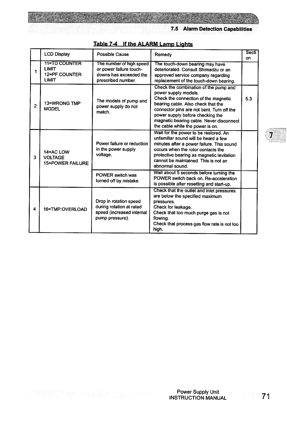
7m«Vffl^i
■■.■■■
■'■'':--:;:-%;'^.v;.Vvi!-;A
7.5
Alarm
Detection
Capabilities
Table
7-4
If
the
ALARM
Lamp
Liahts
1
2
3
4
LCD
Display
11=TD
COUNTER
LIMIT
12=PF
COUNTER
LIMIT
13=WR0NGTMP
MODEL
14=AC
LOW
VOLTAGE
15=POWER
FAILURE
16=TMP:OVERLOAD
Possible
Cause
The
number
of high
speed
or
power
failure
touch
downs
has
exceeded
the
prescribed
number.
The
models
of
pump
and
power
supply
do
not
match.
Power
failure
or
reduction
in
the
power
supply
voltage.
POWER
switch
was
turned
off
by
mistake.
Drop
in
rotation
speed
during
rotation
at
rated
speed
(increased
internal
pump
pressure).
Remedy
The
touch-down
bearing
may
have
deteriorated.
Consult
Shimadzu
or
an
approved
service
company
regarding
replacement
of
the
touch-down
bearing.
Check
the
combination
of
the
pump
and
power
supply
models.
Check
the
connection
of
the
magnetic
bearing
cable.
Also
check
that
the
connector
pins
are
not
bent.
Turn
off
the
power
supply
before
checking
the
magnetic
bearing
cable.
Never
disconnect
the
cable
while
the
power
is
on.
Wait
for
the
power
to
be
restored.
An
unfamiliar
sound
will
be
heard
a few
minutes
after
a
power
failure.
This
sound
occurs
when
the
rotor
contacts
the
protective
bearing
as
magnetic
levitation
cannot
be
maintained.
This
is
not
an
abnormal
sound.
Wait
about 5
seconds
before
turning
the
POWER
switch
back
on.
Re-acceleration
is
possible
after
resetting
and
start-up.
Check
that
the
outlet
and
inlet
pressures
are
below
the
specified
maximum
pressures.
Check
for
leakage.
Check
that
too
much
purge
gas
is
not
flowing.
Check
that
process
gas
flow
rate
is
not
too
high.
Secti
on
5.3
Power
Supply
Unit
INSTRUCTION
MANUAL
71
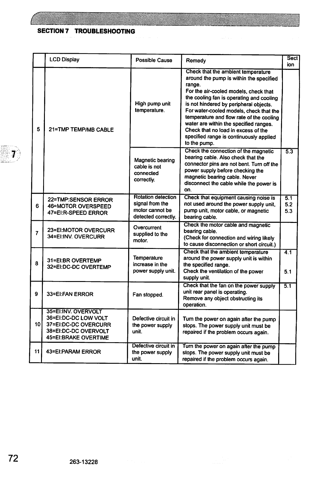
c
SECTION
7
TROUBLESHOOTING
5
6
7
8
9
10
11
LCD
Display
21=TMP
TEMP/MB
CABLE
22=TMP:SENSOR
ERROR
46=MOTOR
OVERSPEED
47=EI:R-SPEED
ERROR
23=EI:MOTOR
OVERCURR
34=EI:INV.
OVERCURR
31=EI:BR
OVERTEMP
32=EI:DC-DC
OVERTEMP
33=EI:FAN
ERROR
35=EI:INV.
OVERVOLT
36=EI:DC-DC
LOW
VOLT
37=EI:DC-DC
OVERCURR
38=EI:DC-DC
OVERVOLT
45=EI:BRAKE
OVERTIME
43=EI:PARAM
ERROR
Possible
Cause
High
pump
unit
temperature.
Magnetic
bearing
cable
is
not
connected
correctly.
Rotation
detection
signal
from
the
motor
cannot
be
detected
correctly.
Overcurrent
supplied
to
the
motor.
Temperature
increase
in
the
power
supply
unit.
Fan
stopped.
Defective
circuit
in
the
power
supply
unit.
Defective
circuit
in
the
power
supply
unit.
Remedy
Check
that
the
ambient
temperature
around
the
pump
is
within
the
specified
range.
For
the
air-cooled
models,
check
that
the
cooling
fan
is
operating
and
cooling
is
not
hindered
by
peripheral
objects.
For
water-cooled
models,
check
that
the
temperature
and
flow
rate
of
the
cooling
water
are
within
the
specified
ranges.
Check
that
no
load
in
excess
of
the
specified
range
is
continuously
applied
to
the
pump.
Check
the
connection
of
the
magnetic
bearing
cable.
Also
check
that
the
connector
pins
are
not
bent.
Turn
off
the
power
supply
before
checking
the
magnetic
bearing
cable.
Never
disconnect
the
cable
while the
power
is
on.
Check
that
equipment
causing
noise
is
not
used
around
the
power
supply
unit,
pump
unit,
motor
cable,
or
magnetic
bearing
cable.
Check
the
motor
cable
and
magnetic
bearing
cable.
(Check
for
connection
and
wiring
likely
to
cause
disconnection
or
short
circuit.)
Check
that
the
ambient
temperature
around
the
power
supply
unit
is
within
the
specified
range.
Check
the
ventilation
of
the
power
supply
unit.
Check
that
the fan
on
the
power
supply
unit
rear
panel
is
operating.
Remove
any
object
obstructing
its
operation.
Turn
the
power
on
again
after
the
pump
stops.
The
power
supply
unit
must
be
repaired
if
the
problem
occurs
again.
Turn
the
power
on
again
after
the
pump
stops.
The
power
supply
unit
must
be
repaired
if
the
problem
occurs
again.
Sect
ion
5.3
5.1
5.2
5.3
4.1
5.1
5.1
72
263-13228
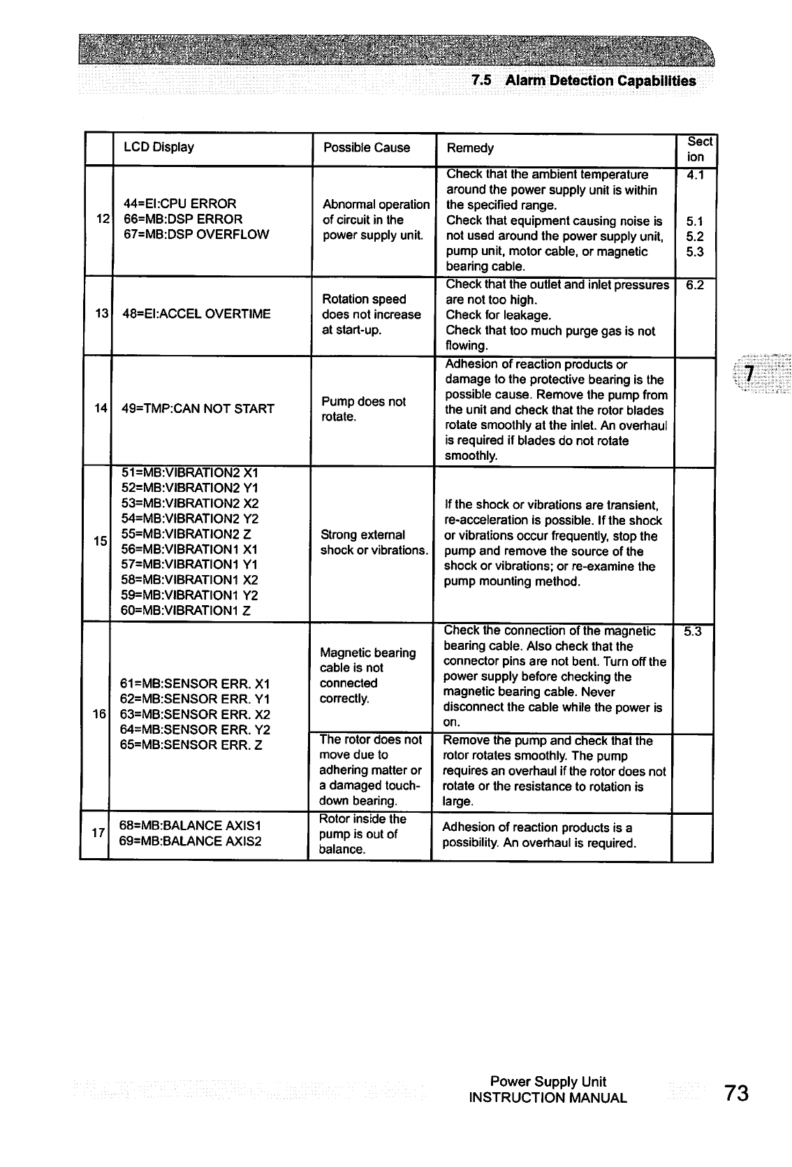
7.5
Alarm
Detection
Capabilities
12
13
14
15
16
17
LCD
Display
44=EI:CPU
ERROR
66=MB:DSP
ERROR
67=MB:DSP
OVERFLOW
48=EI:ACCEL
OVERTIME
49=TMP:CAN
NOT
START
51=MB:VIBRATION2X1
52=MB:VIBRATION2
Y1
53=MB:VIBRATION2
X2
54=MB:VIBRATION2
Y2
55=MB:VIBRATION2
Z
56=MB:VIBRATION1
X1
57=MB:VIBRATION1
Y1
58=MB:VIBRATION1
X2
59=MB:VIBRATION1
Y2
60=MB:VIBRATION1
Z
61=MB:SENSOR
ERR.
X1
62=MB:SENSOR
ERR.
Y1
63=MB:SENSOR
ERR.
X2
64=MB:SENSOR
ERR.
Y2
65=MB:SENSOR
ERR.
Z
68=MB:BALANCE
AXIS1
69=MB:BALANCE
AXIS2
Possible
Cause
Abnormal
operation
of
circuit
in
the
power
supply
unit.
Rotation
speed
does
not
increase
at
start-up.
Pump
does
not
rotate.
Strong
external
shock
or
vibrations.
Magnetic
bearing
cable
is
not
connected
correctly.
The
rotor
does
not
move
due
to
adhering
matter
or
a
damaged
touch
down
bearing.
Rotor
inside
the
pump
is
out
of
balance.
Remedy
Check
that
the
ambient
temperature
around
the
power
supply
unit
is
within
the
specified
range.
Check
that
equipment
causing
noise
is
not
used
around
the
power
supply
unit,
pump
unit,
motor
cable,
or
magnetic
bearing
cable.
Check
that
the
outlet
and
inlet
pressures
are not
too
high.
Check
for
leakage.
Check
that
too
much
purge
gas
is
not
flowing.
Adhesion
of
reaction
products
or
damage
to
the
protective
bearing
is
the
possible
cause.
Remove
the
pump
from
the
unit
and
check
that
the
rotor
blades
rotate
smoothly
at
the
inlet.
An
overhaul
is
required
if
blades
do
not
rotate
smoothly.
If
the
shock
or
vibrations
are
transient,
re-acceleration
is
possible.
If
the
shock
or
vibrations
occur
frequently,
stop
the
pump
and
remove
the
source
of
the
shock
or
vibrations;
or
re-examine
the
pump
mounting
method.
Check
the
connection
of
the
magnetic
bearing
cable.
Also
check
that
the
connector
pins
are
not
bent.
Turn
off
the
power
supply
before
checking
the
magnetic
bearing
cable.
Never
disconnect
the
cable
while the
power
is
on.
Remove
the
pump
and
check
that
the
rotor
rotates
smoothly.
The
pump
requires
an
overhaul
if
the
rotor
does
not
rotate
or
the
resistance
to
rotation
is
large.
Adhesion
of
reaction
products
is
a
possibility.
An
overhaul
is
required.
Sect
ion
4.1
5.1
5.2
5.3
6.2
5.3
Power
Supply
Unit
INSTRUCTION
MANUAL
73
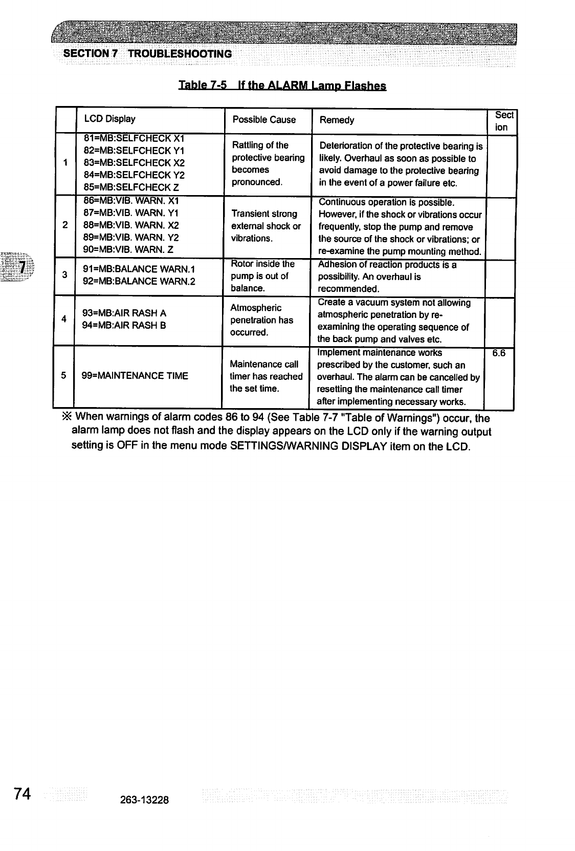
•
"™"r~"
---.-_■':'■
■,
■:■.
:.■■..-.■
■..■:
-.:■-:
:
:.
..;■-
.. f
■
,.
..
.....
...
.T
....
.
■
SECTION
7
TROUBLESHOOTING
Table
7-5
If
the
ALARM
LamD
Flashes
1
2
3
4
5
LCD
Display
81=MB:SELFCHECKX1
82=MB-SELFCHECK
Y1
83=MB:SELFCHECK
X2
84=MB:SELFCHECK
Y2
85=MB:SELFCHECK
Z
86=MB:VIB.
WARN.
X1
87=MB:VIB.
WARN.
Y1
88=MB:VIB.
WARN.
X2
89=MB:VIB.
WARN.
Y2
90=MB:VIB.
WARN.
Z
91=MB:BALANCE
WARN.1
92=MB:BALANCE
WARN.2
93=MB:AIR
RASH A
94=MB:AIR
RASH
B
99=MAINTENANCE
TIME
When
warninas
of
alarm
codes
Possible
Cause
Rattling
of
the
protective
bearing
becomes
pronounced.
Transient
strong
external
shock
or
vibrations.
Rotor
inside
the
pump
is
out
of
balance.
Mimospnsnc
npnptralinn
Hisiq
occurred
Maintenance
call
timer
has
reached
the
set
time.
86
to
94
fSfifi
Tah
Remedy
Deterioration
of
the
protective
bearing
is
likely.
Overhaul
as
soon
as
possible
to
avoid
damage
to
the
protective
bearing
in
the
event
of
a
power
failure
etc.
Continuous
operation
is
possible.
However,
if
the
shock
or
vibrations
occur
frequently,
stop
the
pump
and
remove
the
source
of
the
shock
or
vibrations;
or
re-examine
the
pump
mounting
method.
Adhesion
of
reaction
products
is
a
possibility.
An
overhaul
is
recommended.
Create
a
vacuum
system
not
allowing
atmospheric
penetration
by
re-
examining
the
operating
sequence
of
the
back
pump
and
valves
etc.
Implement
maintenance
works
prescribed
by
the
customer,
such
an
overhaul.
The
alarm
can
be
cancelled
by
resetting
the
maintenance
call
timer
after
implementing
necessary
works.
Ifi
7-7
"Tflhlp
nf
Warninnc'M
nrrnr
th
Sect
ion
6.6
g
(
g)
,
alarm
lamp
does
not
flash
and
the
display
appears
on
the
LCD
only
if
the
warning
output
setting
is
OFF
in
the
menu
mode
SETTINGSA/VARNING
DISPLAY
item
on
the
LCD.
74
263-13228
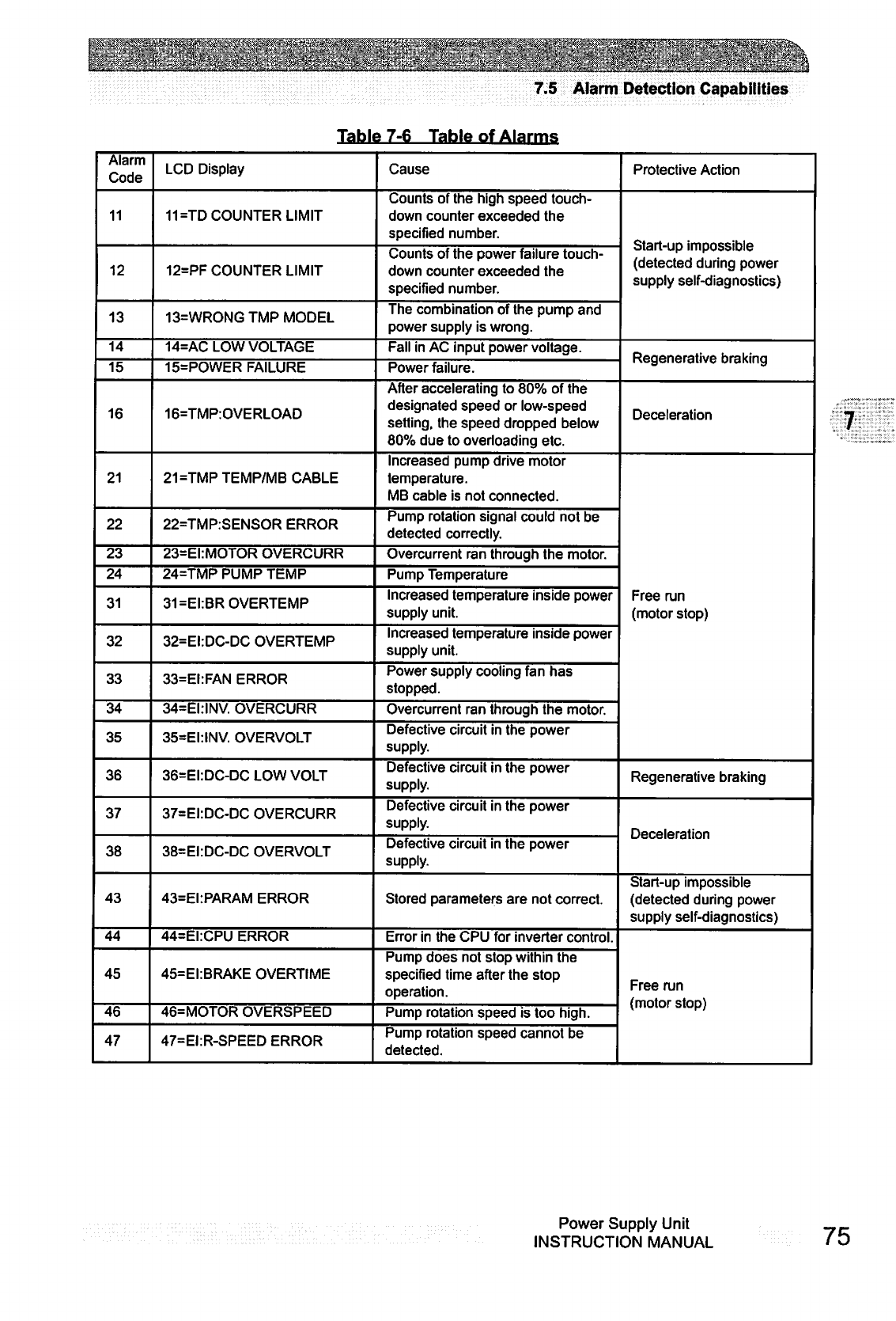
7.5
Alarm
Detection
Capabilities
Table
7-6
Table
of
Alarms
Alarm
Code
11
12
13
14
15
16
21
22
23
24
31
32
33
34
35
36
37
38
43
44
45
46
47
LCD
Display
11=TD
COUNTER
LIMIT
12=PF
COUNTER
LIMIT
13=WR0NGTMP
MODEL
14=AC
LOW
VOLTAGE
15=POWER
FAILURE
16=TMP:OVERLOAD
21=TMP
TEMP/MB
CABLE
22=TMP:SENSOR
ERROR
23=EI:MOTOR
OVERCURR
24=TMP
PUMP TEMP
31=EI:BROVERTEMP
32=EI:DC-DC
OVERTEMP
33=EI:FAN
ERROR
34=EI:INV.
OVERCURR
35=EI:INV.
OVERVOLT
36=EI:DC-DC
LOW
VOLT
37=EI:DC-DC
OVERCURR
38=EI:DC-DC
OVERVOLT
43=EI:PARAM
ERROR
44=EI:CPU
ERROR
45=EI:BRAKE
OVERTIME
46=MOTOR
OVERSPEED
47=EI:R-SPEED
ERROR
Cause
Counts
of
the
high
speed
touch
down
counter
exceeded
the
specified
number.
Counts
of
the
power
failure
touch
down
counter
exceeded
the
specified
number.
The
combination
of
the
pump
and
power
supply
is
wrong.
Fall
in
AC
input
power
voltage.
Power
failure.
After
accelerating
to
80%
of
the
designated
speed
or
low-speed
setting,
the
speed
dropped
below
80%
due
to
overloading
etc.
Increased
pump
drive
motor
temperature.
MB
cable
is
not
connected.
Pump
rotation
signal
could
not
be
detected
correctly.
Overcurrent
ran
through
the
motor.
Pump
Temperature
Increased
temperature
inside
power
supply
unit.
Increased
temperature
inside
power
supply
unit.
Power
supply
cooling
fan
has
stopped.
Overcurrent
ran
through
the
motor.
Defective
circuit
in
the
power
supply.
Defective
circuit
in
the
power
supply.
Defective
circuit
in
the
power
supply.
Defective
circuit
in
the
power
supply.
Stored
parameters
are
not
correct.
Error
in
the
CPU
for
inverter
control.
Pump
does
not
stop
within
the
specified
time
after
the
stop
operation.
Pump
rotation
speed
is
too
high.
Pump
rotation
speed
cannot
be
detected.
Protective
Action
Start-up
impossible
(detected during
power
supply
self-diagnostics)
Regenerative
braking
Deceleration
Free
run
(motor
stop)
Regenerative
braking
Deceleration
Start-up
impossible
(detected
during
power
supply
self-diagnostics)
Free
run
(motor
stop)
Power
Supply
Unit
INSTRUCTION
MANUAL
75
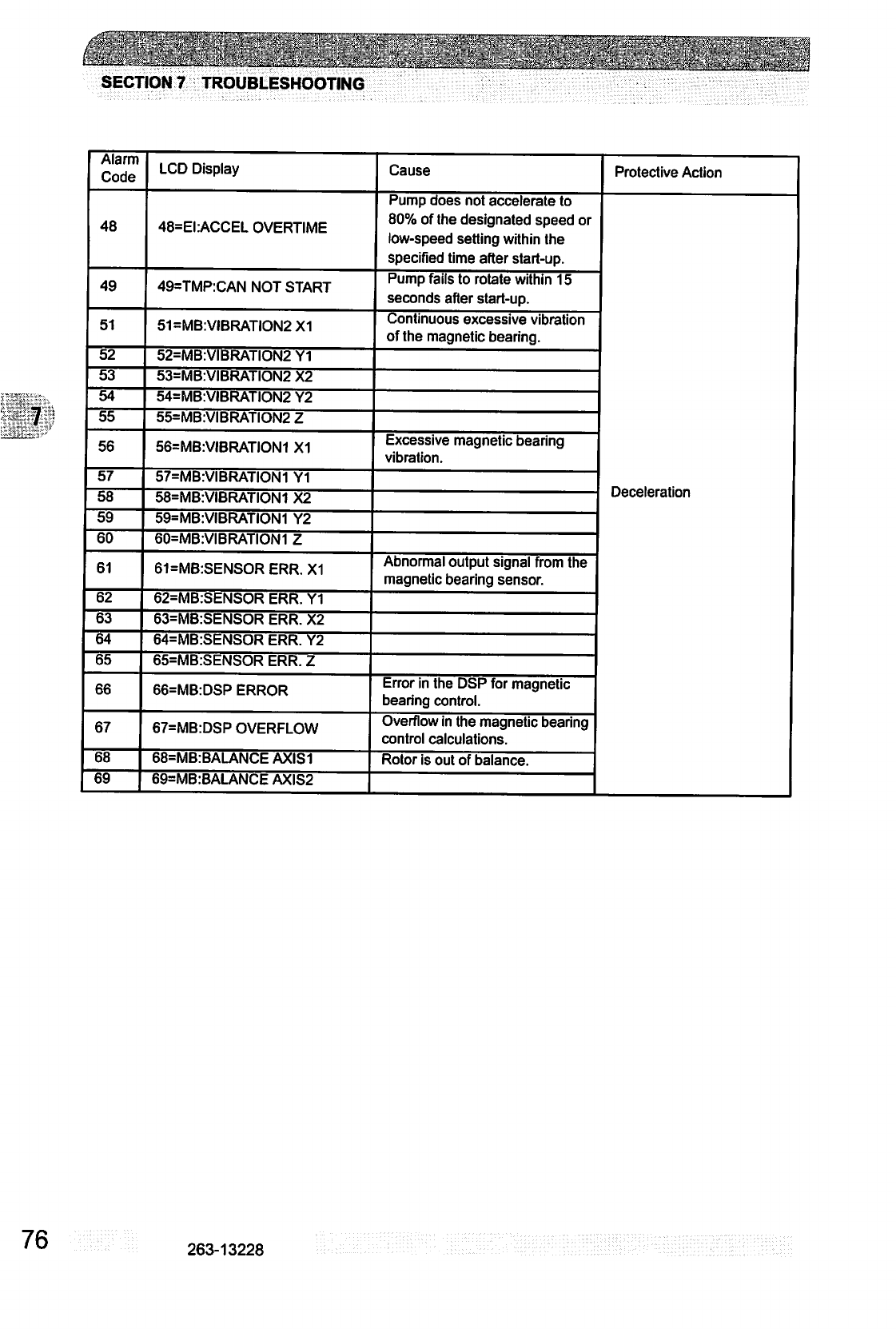
SECTION
7
TROUBLESHOOTING
:>;.v^,o:.
■=■
r
..■
-
.
■;
:■
Alarm
Code
48
49
51
52
53
54
55
56
57
58
59
60
61
62
63
64
65
66
67
68
69
LCD
Display
48=EI:ACCEL
OVERTIME
49=TMP:CAN
NOT
START
51=MB:VIBRATION2X1
52=MB:VIBRATION2
Y1
53=MB:VIBRATION2
X2
54=MB:VIBRATION2
Y2
55=MB:VIBRATION2
Z
56=MB:VIBRATION1
X1
57=MB:VIBRATION1
Y1
58=MB:VIBRATION1
X2
59=MB:VIBRATION1
Y2
60=MB:VIBRATION1
Z
61=MB:SENSOR
ERR.
X1
62=MB:SENSOR
ERR.
Y1
63=MB:SENSOR
ERR.
X2
64=MB:SENSOR
ERR.
Y2
65=MB:SENSOR
ERR.
Z
66=MB:DSP
ERROR
67=MB:DSP
OVERFLOW
68=MB:BALANCE
AXIS1
69=MB:BALANCE
AXIS2
Cause
Pump
does
not
accelerate
to
80%
of
the
designated
speed
or
low-speed
setting
within
the
specified
time
after
start-up.
Pump
fails
to rotate
within
15
seconds
after
start-up.
Continuous
excessive
vibration
of
the
magnetic
bearing.
Excessive
magnetic
bearing
vibration.
Abnormal
output
signal
from
the
magnetic
bearing
sensor.
Error
in
the
DSP
for
magnetic
bearing
control.
Overflow
in
the
magnetic
bearing
control
calculations.
Rotor
is
out
of
balance.
Protective
Action
Deceleration
76
263-13228
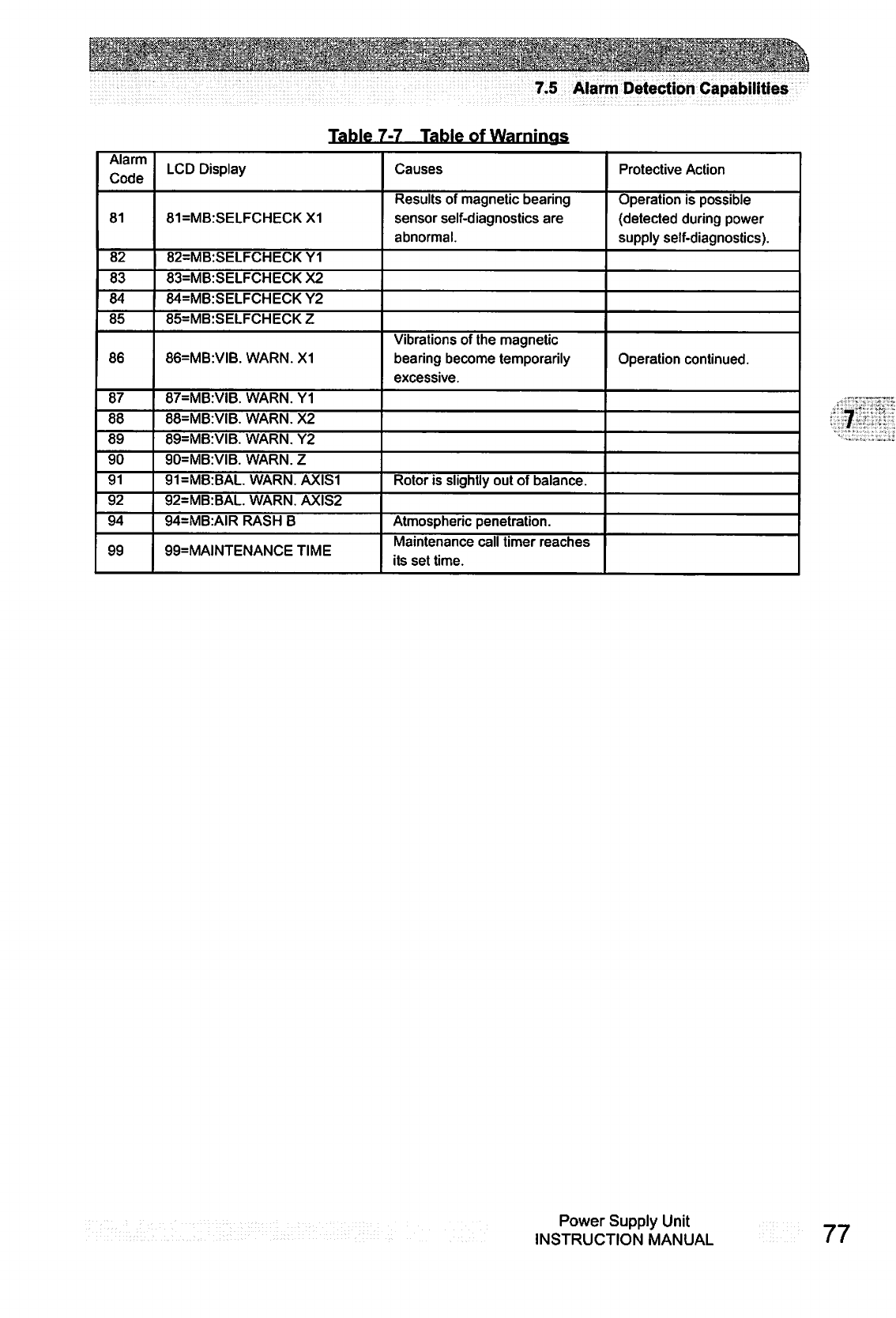
Z
'j^Jjijilc
}^;^dli}i
J^J
L^
7.5
Alarm
Detection
Capabilities
Table
7-7
Table
of
Warnings
Alarm
Code
81
82
83
84
85
86
87
88
89
90
91
92
94
99
LCD
Display
81=MB:SELFCHECKX1
82=MB:SELFCHECK
Y1
83=MB:SELFCHECK
X2
84=MB:SELFCHECK
Y2
85=MB:SELFCHECK
Z
86=MB:VIB.
WARN.
X1
87=MB:VIB.
WARN.
Y1
88=MB:VIB.
WARN.
X2
89=MB:VIB.
WARN.
Y2
90=MB:VIB.
WARN.
Z
91=MB:BAL
WARN.
AXIS1
92=MB:BAL.
WARN.
AXIS2
94=MB:AIR
RASH
B
99=MAINTENANCE
TIME
Causes
Results
of
magnetic
bearing
sensor
self-diagnostics
are
abnormal.
Vibrations
of
the
magnetic
bearing
become
temporarily
excessive.
Rotor
is
slightly
out
of
balance.
Atmospheric
penetration.
Maintenance
call
timer
reaches
its
set
time.
Protective
Action
Operation
is
possible
(detected during
power
supply
self-diagnostics).
Operation
continued.
Power
Supply
Unit
INSTRUCTION
MANUAL
77
This
page
is
intentionally
left
blank.
78
263-13228
■■:-'■■■,':v::v:'r4"I'
■.■;?■
/■■■y,\r.:'■';'.
■:
■■'■'■<
COMMUNICATIONS
A1.
GENERAL
SPECIFICATION
A2.
INTERFACE
SPECIFICATION
A2.1
RS-232C
A2.2
RS-485
A3.
POWER
SUPPLY
TO
COMPUTER
CONNECTION
A3.1
Communication
Cable
Connection
A3.2
Serial
Communications
Baud
Rate
Configuration
A3.3
RS-485
Multi-drop
Settings
A4.
SERIAL
COMMUNICATIONS
PROTOCOL
A5.
TABLE
OF
COMMANDS
A6.
COMMAND
DESCRIPTION
A6.1
Operation
Mode
A6.2
Operation
A6.3
Run
Status
A6.4
Parameters
A6.5
Events
A6.6
Timer
A6.7
History
A6.8
Settings
A6.9
Shared
Answer
A7.
RS-232C
COMMANDS
/
ANSWERS
A8.
RELATION
OF
LOCAL
MODE
TO
REMOTE
MODE
OPERATIONS
A9.
TROUBLESHOOTING
A9.1
No
Message
can
Transmit
and
Receive
A9.2
Sending
and
Receiving
are
Done,
But
Receivable
Messages
are
Invalid
A9.3
Characters
Get
Disordered
from
Time
to
Time,
Then
Resulting
in
CHECKSUM
Error
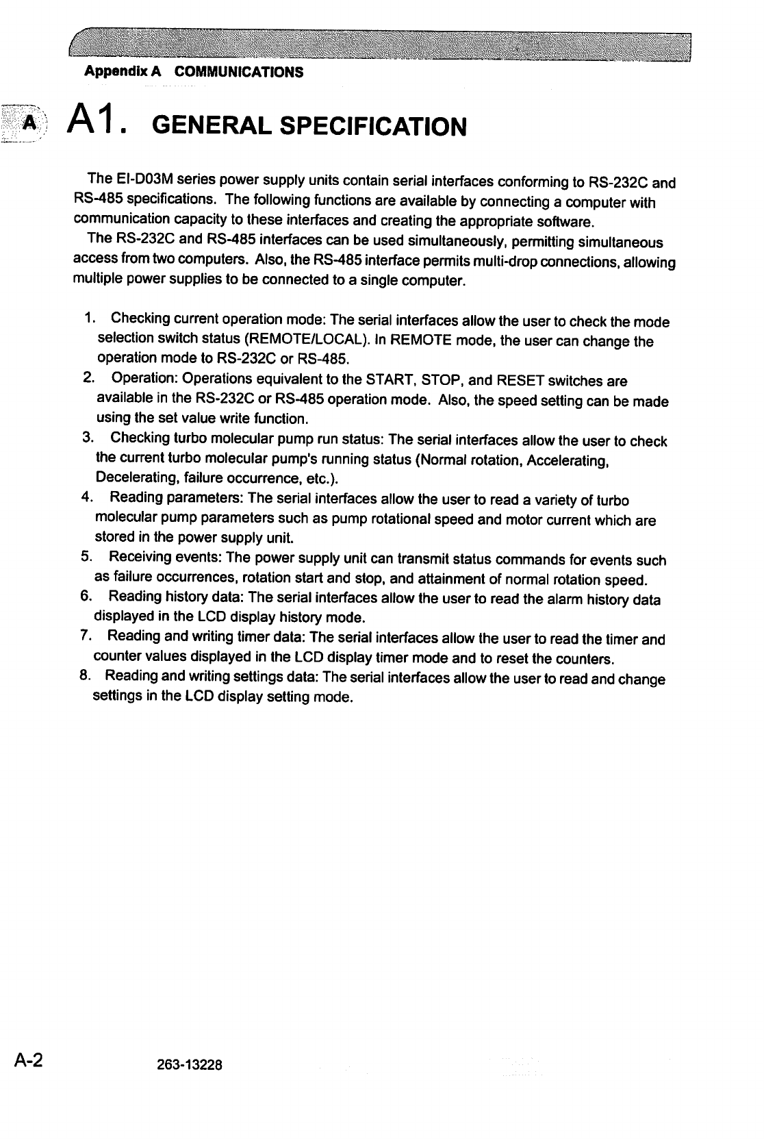
Appendix
A
COMMUNICATIONS
A
A1.
GENERAL
SPECIFICATION
The
EI-D03M
series
power
supply
units
contain
serial
interfaces
conforming
to
RS-232C
and
RS-485
specifications.
The
following
functions
are
available
by
connecting
a
computer
with
communication
capacity
to
these
interfaces
and
creating
the
appropriate
software.
The RS-232C
and
RS-485
interfaces
can
be
used
simultaneously,
permitting
simultaneous
access
from
two
computers.
Also,
the
RS-485
interface
permits
multi-drop
connections,
allowing
multiple
power
supplies
to
be
connected
to
a
single
computer.
1.
Checking
current
operation
mode:
The
serial
interfaces
allow the
user
to
check
the
mode
selection
switch
status
(REMOTE/LOCAL).
In
REMOTE
mode,
the
user
can
change
the
operation
mode
to
RS-232C
or
RS-485.
2.
Operation:
Operations
equivalent
to
the
START, STOP,
and
RESET
switches
are
available
in
the
RS-232C
or
RS-485
operation
mode.
Also,
the
speed
setting
can
be
made
using
the
set
value
write
function.
3.
Checking
turbo
molecular
pump
run
status:
The
serial
interfaces
allow
the
user
to
check
the
current
turbo
molecular
pump's
running
status
(Normal
rotation,
Accelerating,
Decelerating,
failure
occurrence,
etc.).
4.
Reading
parameters:
The
serial
interfaces
allow
the
user
to
read
a
variety
of
turbo
molecular
pump
parameters
such
as
pump
rotational
speed
and
motor
current
which
are
stored
in
the
power
supply
unit.
5.
Receiving
events:
The
power
supply
unit
can
transmit
status
commands
for
events
such
as
failure
occurrences,
rotation
start
and
stop,
and
attainment
of
normal
rotation
speed.
6.
Reading
history
data:
The
serial
interfaces
allow
the
user
to
read
the
alarm
history
data
displayed
in
the
LCD
display
history
mode.
7.
Reading
and
writing
timer
data:
The
serial
interfaces
allow
the
user
to
read
the
timer
and
counter
values
displayed
in
the
LCD
display
timer
mode
and
to
reset
the
counters.
8.
Reading
and
writing
settings
data:
The
serial
interfaces
allow
the
user
to
read
and
change
settings
in
the
LCD
display
setting
mode.
A-2
263-13228
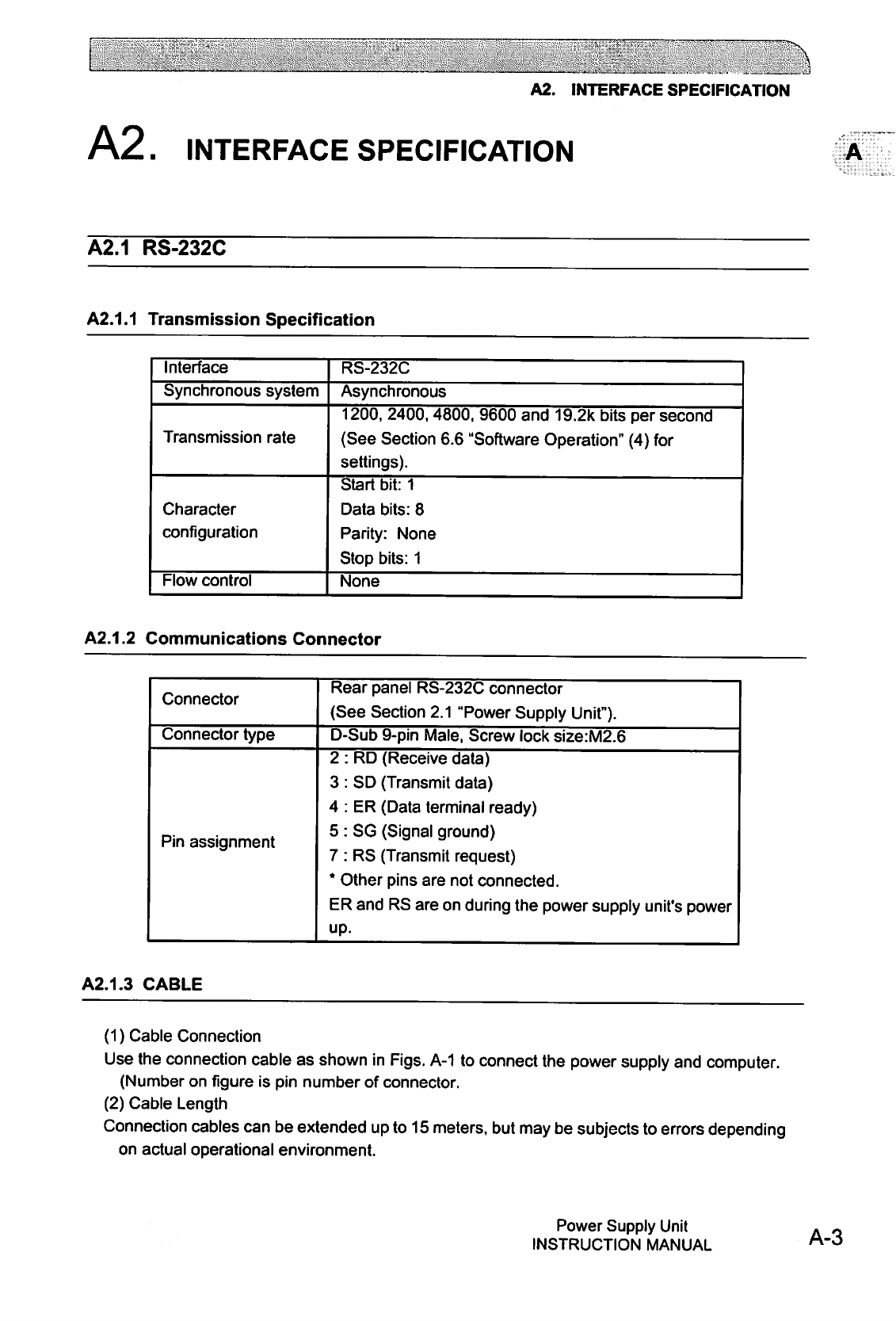
[I
"-N
A2.
INTERFACE
SPECIFICATION
A2.
INTERFACE
SPECIFICATION
A2.1
RS-232C
A2.1.1
Transmission
Specification
Interface
Synchronous
system
Transmission
rate
Character
configuration
Flow
control
RS-232C
Asynchronous
1200,
2400, 4800,
9600
and
19.2k
bits
per
second
(See
Section
6.6
"Software
Operation"
(4)
for
settings).
Start
bit:
1
Data
bits:
8
Parity:
None
Stop
bits:
1
None
A2.1.2
Communications
Connector
Connector
Connector
type
Pin
assignment
Rear
panel
RS-232C
connector
(See
Section
2.1
"Power
Supply
Unit").
D-Sub
9-pin
Male,
Screw
lock
size:M2.6
2
:
RD
(Receive
data)
3
:
SD
(Transmit
data)
4
:
ER
(Data
terminal
ready)
5
:
SG
(Signal
ground)
7
:
RS
(Transmit
request)
*
Other
pins
are
not
connected.
ER
and
RS
are
on
during
the
power
supply
unit's
power
up.
A2.1.3
CABLE
(1)
Cable
Connection
Use
the
connection
cable
as
shown
in
Figs.
A-1
to
connect
the
power
supply
and
computer.
(Number
on
figure
is
pin
number
of
connector.
(2)
Cable
Length
Connection
cables
can
be
extended up
to
15
meters,
but
may
be
subjects
to
errors
depending
on
actual
operational
environment.
Power
Supply
Unit
INSTRUCTION
MANUAL
A-3
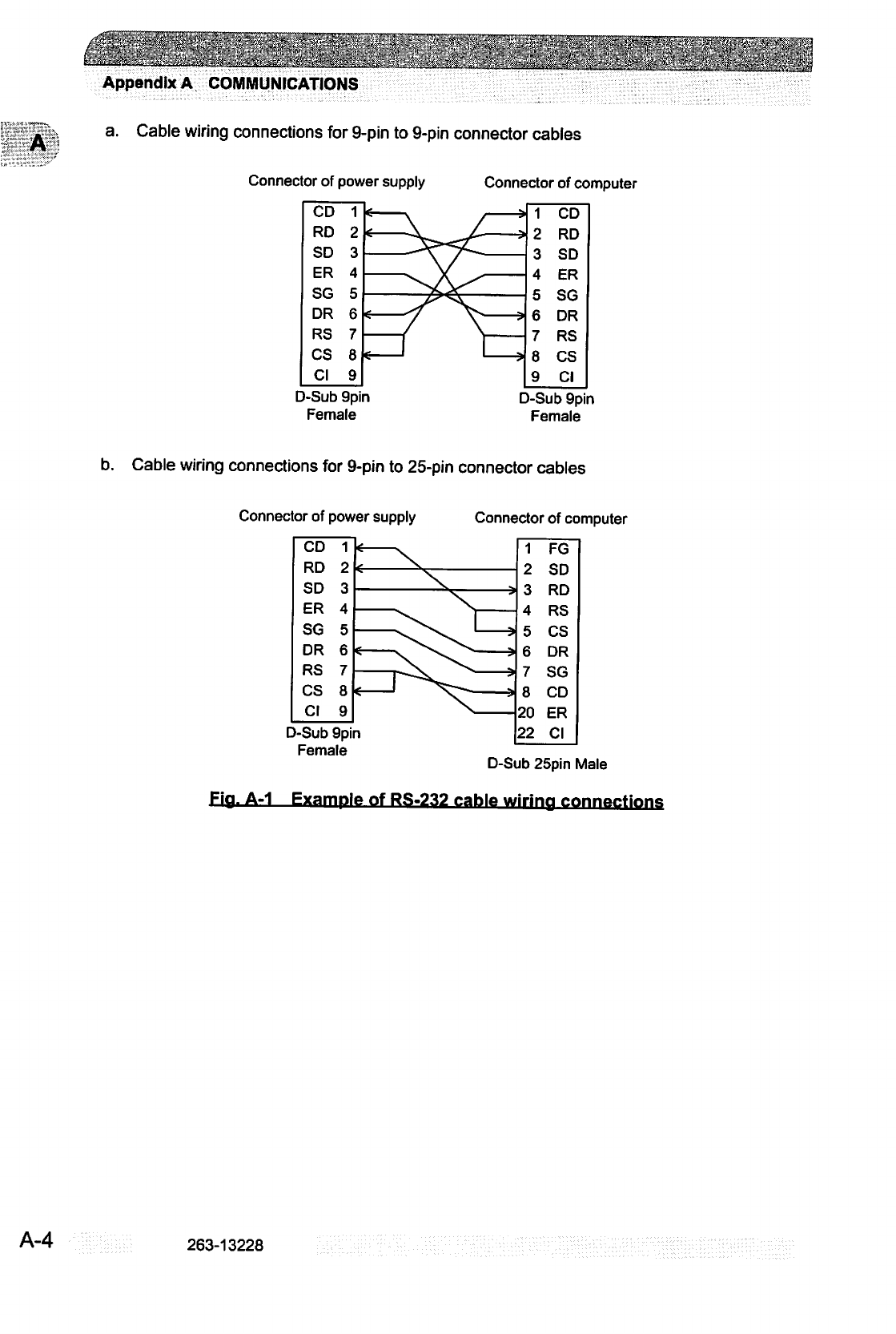
■
■■?'•".'■■
:■■'.'
''■;'.
!'■■
■■■''•:-'
'■'■,■-■'
■■*"■'.'"■
;:
•!.
=!■■': ■...:'
!.;.'•
' ■
'"
.'
'*':■'
':''„•'■
:■,.:'.'.'■■
■-.''!'■''''■'"■■.
'■'',:
"'''■'"•"
j''■'•'\.""•.■•'.
Appendix
A
COMMUNICATIONS
a.
Cable
wiring
connections
for
9-pin
to
9-pin
connector
cables
Connector
of
power
supply
D-Sub
9pin
Female
Connector
of
computer
CD
RD
SD
ER
SG
DR
RS
CS
Cl
1
2
3
4
5
6
7
8
9
e
v
/
*
i
\^^^-
*
—\Y/—
—f
N—
*—I
I—?
1
2
3
4
c
D
6
7
8
9
CD
RD
SD
ER
SG
DR
RS
CS
Cl
D-Sub
9pin
Female
b.
Cable
wiring
connections
for
9-pin
to
25-pin
connector
cables
Connector
of
power
supply
Connector
of
computer
CD
RD
SD
ER
SG
DR
RS
CS
Cl
D-Sub
1
2
3
w
4
5
6
7
8
9
\
—^^
l
*
sT^^
X.
9pin
Female
s
s
3
?
1
2
o
O
4
5
6
7
8
20
22
FG
SD
on
RS
CS
DR
SG
CD
ER
Cl
D-Sub
25pin
Male
Fig.
A-1
Example
of
RS-232
cable
wiring
connprtinns
A-4
263-13228
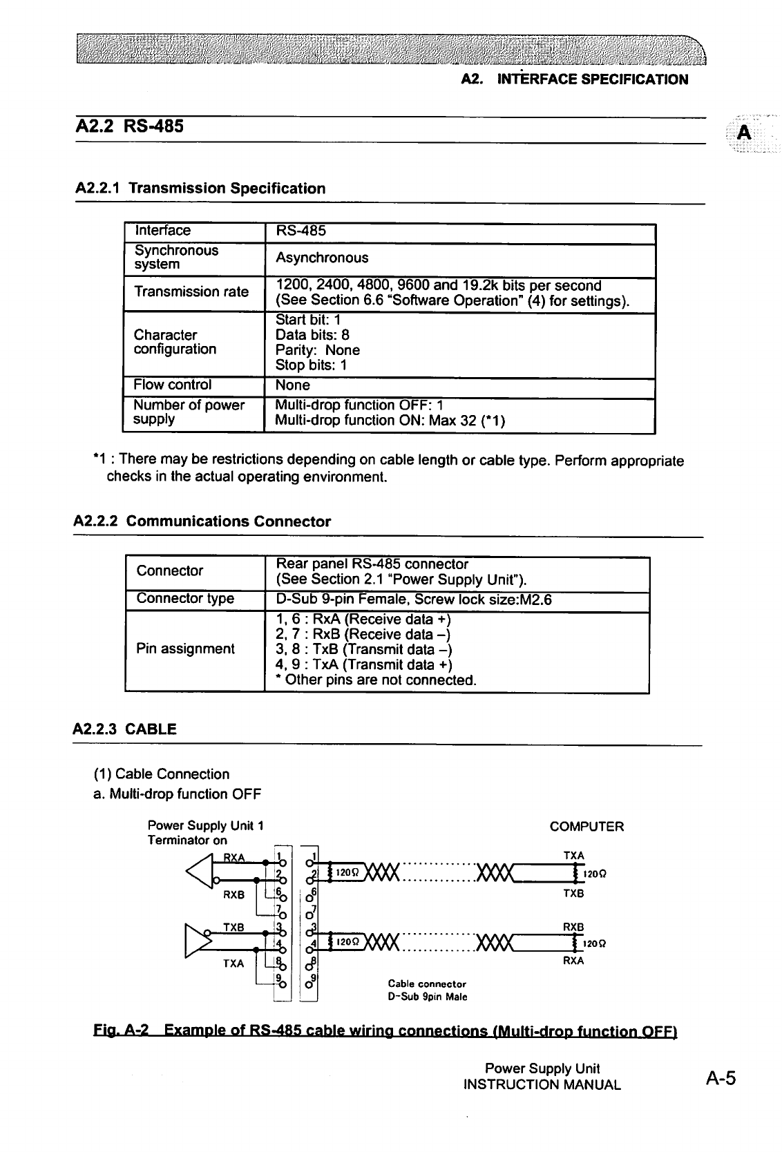
A2.
INTERFACE
SPECIFICATION
A2.2
RS-485
A2.2.1
Transmission
Specification
Interface
Synchronous
system
Transmission
rate
Character
configuration
Flow
control
Number
of
power
supply
RS-485
Asynchronous
1200,
2400,
4800,
9600
and
19.2k
bits
per
second
(See
Section
6.6
"Software
Operation"
(4)
for
settings).
Start
bit:
1
Data
bits:
8
Parity:
None
Stop
bits:
1
None
Multi-drop
function
OFF:
1
Multi-drop
function
ON:
Max
32
(*1)
*1
:
There
may
be
restrictions
depending
on
cable
length
or
cable
type.
Perform
appropriate
checks
in
the
actual
operating
environment.
A2.2.2
Communications
Connector
Connector
Connector
type
Pin
assignment
Rear
panel
RS-485
connector
(See
Section
2.1
"Power
Supply
Unit").
D-Sub
9-pin
Female,
Screw
lock
size:M2.6
1,6:
RxA
(Receive
data
+)
2,
7
:
RxB
(Receive
data
-)
3.
8
:
TxB
(Transmit
data
-)
4,
9
:
TxA
(Transmit
data
+)
*
Other
pins
are
not
connected.
A2.2.3
CABLE
(1)
Cable
Connection
a.
Multi-drop
function
OFF
Power
Supply
Unit
1
Terminator
on
RXA
RXB
TXB
TXA
o6
XXXX
hdoooc:::::::::::::)oooc
Cable
connector
D-Sub
9pin
Male
COMPUTER
TXA
I20Q
TXB
RXB
1200
RXA
Fia.
A-2
Example
of
RS-485
cable
wiring
connections
(Multi-drop
function
OFF)
Power
Supply
Unit
INSTRUCTION
MANUAL
A-5
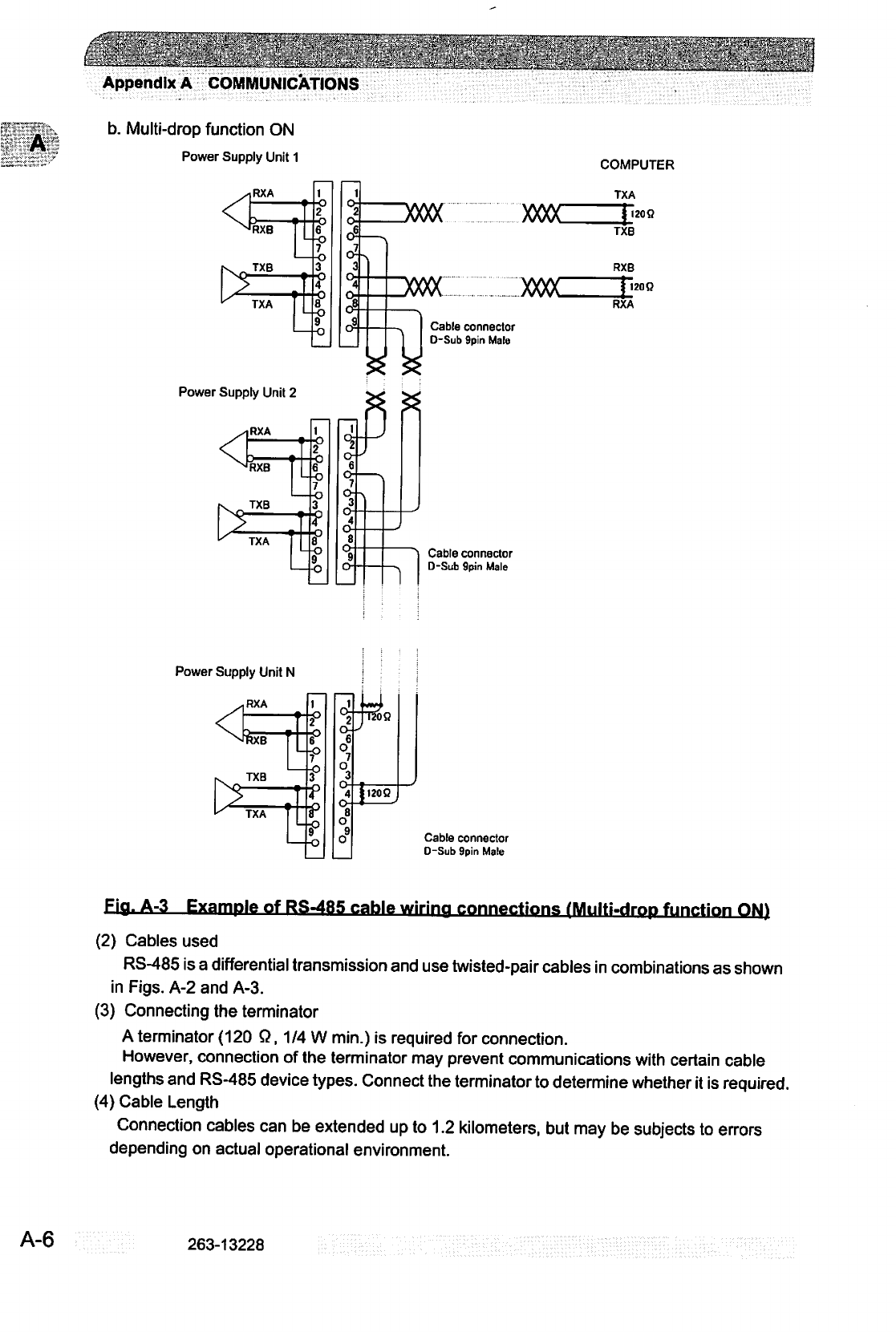
Appendix
A
COMMUNICATIONS
."::■■•
■■
■■'
v
■
.■■
-"
:"
■'.,;■.
""
*
H'i-.V:-'.■.■-■:■-.■■':
b.
Multi-drop
function
ON
Power
Supply
Unit
1
COMPUTER
Szzxxxx
2:idooo(
TXA
XXX)C
xx>oc
I20O
Power
Supply
Unit
2
Cable
connector
D-Sub
9pin
Male
Cable
connector
D-Sub
9pin
Male
TXB
RXB
[120R
RXA
Power
Supply
Unit
N
TXB
TXA
i
°3
O-
8
O
o9
TTSOO
|i20Q
I
—/
Cable
connector
D-Sub
9pin
Male
Fig.
A-3
Example
of
RS-485
cable
wiring
connections
IMulti-drop
function
ON)
(2)
Cables
used
RS-485
is
a
differential
transmission
and
use
twisted-pair
cables
in
combinations
as
shown
in
Figs.
A-2
and
A-3.
(3)
Connecting
the
terminator
A
terminator
(120
Q,
1/4
W
min.)
is
required
for
connection.
However,
connection
of
the
terminator
may
prevent
communications
with
certain
cable
lengths
and
RS-485
device
types.
Connect
the
terminator
to
determine
whether
it
is
required.
(4)
Cable
Length
Connection
cables
can
be
extended
up
to
1.2
kilometers,
but
may
be
subjects
to
errors
depending
on
actual
operational
environment.
A-6
263-13228
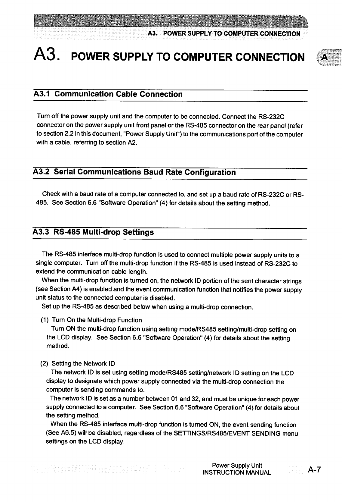
A3.
POWER
SUPPLY
TO
COMPUTER
CONNECTION
A3.
POWER
SUPPLY
TO
COMPUTER
CONNECTION
A
A3.1
Communication
Cable
Connection
Turn
off
the
power
supply
unit
and
the
computer
to
be
connected.
Connect
the
RS-232C
connector
on
the
power
supply
unit
front
panel
or
the
RS-485
connector
on
the
rear
panel
(refer
to
section
2.2
in
this
document,
"Power
Supply
Unit")
to
the
communications
port
of
the
computer
with
a
cable,
referring
to
section
A2.
A3.2
Serial
Communications
Baud
Rate
Configuration
Check
with
a
baud
rate
of
a
computer
connected
to,
and
set
up
a
baud
rate
of
RS-232C
or
RS-
485.
See
Section
6.6
"Software
Operation"
(4)
for
details
about
the
setting
method.
A3.3
RS-485
Multi-drop
Settings
The
RS-485
interface
multi-drop
function
is
used
to
connect
multiple
power
supply
units
to
a
single
computer.
Turn
off
the
multi-drop
function
if
the
RS-485
is
used
instead
of
RS-232C
to
extend
the
communication
cable
length.
When
the
multi-drop
function
is
turned
on,
the
network
ID
portion
of
the
sent
character
strings
(see
Section
A4)
is
enabled
and
the
event
communication
function
that
notifies
the
power
supply
unit
status
to
the
connected
computer
is
disabled.
Set
up
the
RS-485
as
described
below
when
using
a
multi-drop
connection.
(1)
Turn
On
the
Multi-drop
Function
Turn
ON
the
multi-drop
function
using
setting
mode/RS485
setting/multi-drop
setting
on
the
LCD
display.
See
Section
6.6
"Software
Operation"
(4)
for
details
about
the
setting
method.
(2)
Setting
the
Network
ID
The
network
ID
is
set
using
setting
mode/RS485
setting/network
ID
setting
on
the
LCD
display
to
designate
which
power
supply
connected
via
the
multi-drop
connection
the
computer
is
sending
commands
to.
The
network
ID
is
set
as
a
number
between
01
and
32,
and
must
be
unique
for
each
power
supply
connected
to
a
computer.
See
Section
6.6
"Software
Operation"
(4)
for
details
about
the
setting
method.
When
the
RS-485
interface
multi-drop
function
is
turned
ON,
the
event
sending
function
(See
A6.5)
will
be
disabled,
regardless
of
the
SETTINGS/RS485/EVENT
SENDING
menu
settings
on
the
LCD
display.
Power
Supply
Unit
INSTRUCTION
MANUAL

Appendix
A
COMMUNICATIONS
A
A4.
SERIAL
COMMUNICATIONS
PROTOCOL
Communications
software,
between
the
power
supply
and
customer
equipment
should
be
design
according
to
the
following
specifications.
A4.1
Basic
Message
Structure
A
basic
transmit
and
receive
message
begins
with
the
characters
"MJ"
and
ends
with
a
carriage
return
code
(OdH
:
xxH
means
hexadecimal
code).
(See
Table
A-1)
The
first
message
to
be
sent
is
referred
as
the
COMMAND,
while
the
reply
to
the
command
is
referred
as
the
ANSWER.
Table
A-1
Basic
structure
of
Commands
and
Answers
Character
M
J
0
1
X
X
f
f
CR
Hex.
Code
4d
4a
30
31
XX
XX
XX
XX
Od
Description
Command
header
characters
Network
ID
Multi-drop
function
OFF:
01
fixed
Multi-drop
function
ON:
01
to
32
Command
Characters
Sub-command
Characters
Checksum
characters
(Calculation
result
by
Section
A4.7
enters
it.)
Carriage
return
character
Number
Of
Bytes
2
2
2
X
2
1
A4.2
Character
to
Character
Time-out:
0.1
sec.
Delays
between
characters,
in
the
answer
message,
longer
that
0.1
sec,
shall
be
considered
as
a
transmission
line
failure
and
special
considerations
should
be
made
to
re-send
the
message.
A-8
263-13228
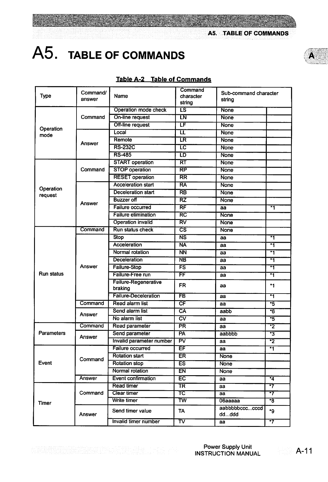
■*r
■"•".':;.;
=.'■■'"'.'
/"' •■"'!>.>■
.■'"■■'■■•"
V^:\
A5.
TABLE
OF
COMMANDS
A5.
TABLE
OF
COMMANDS
Table
A-2
Table
of
Commands
Type
Operation
mode
Operation
request
Run
status
Parameters
Event
Timer
Command/
answer
Command
Answer
Command
Answer
Command
Answer
Command
Answer
Command
Answer
Command
Answer
Command
Answer
Name
Operation
mode
check
On-line
request
Off-line
request
Local
Remote
RS-232C
RS-485
START
operation
STOP
operation
RESET
operation
Acceleration
start
Deceleration
start
Buzzer
off
Failure
occurred
Failure
elimination
Operation
invalid
Run
status
check
Stop
Acceleration
Normal
rotation
Deceleration
Failure-Stop
Failure-Free
run
Failure-Regenerative
braking
Failure-Deceleration
Read
alarm
list
Send
alarm
list
No
alarm
list
Read
parameter
Send
parameter
Invalid
parameter
number
Failure
occurred
Rotation
start
Rotation
stop
Normal
rotation
Event
confirmation
Read
timer
Clear
timer
Write
timer
Send
timer
value
Invalid
timer
number
Command
character
string
LS
LN
LF
LL
LR
LC
LD
RT
RP
RR
RA
RB
RZ
RF
RC
RV
CS
NS
NA
NN
NB
FS
FF
FR
FB
CF
CA
CV
PR
PA
PV
EF
ER
ES
EN
EC
TR
TC
TW
TA
TV
Sub-command
character
string
None
None
None
None
None
None
None
None
None
None
None
None
None
aa
None
None
None
aa
aa
aa
aa
aa
aa
aa
aa
aa
aabb
aa
aa
aabbbb
aa
aa
None
None
None
aa
aa
aa
06aaaaa
aabbbbbccc.cccd
dd...ddd
aa
*1
*1
*1
*1
*1
*1
*1
*1
*1
*5
*6
*5
*2
*3
*2
*1
•4
*7
*7
*8
*9
*7
Power
Supply
Unit
INSTRUCTION
MANUAL
A-11
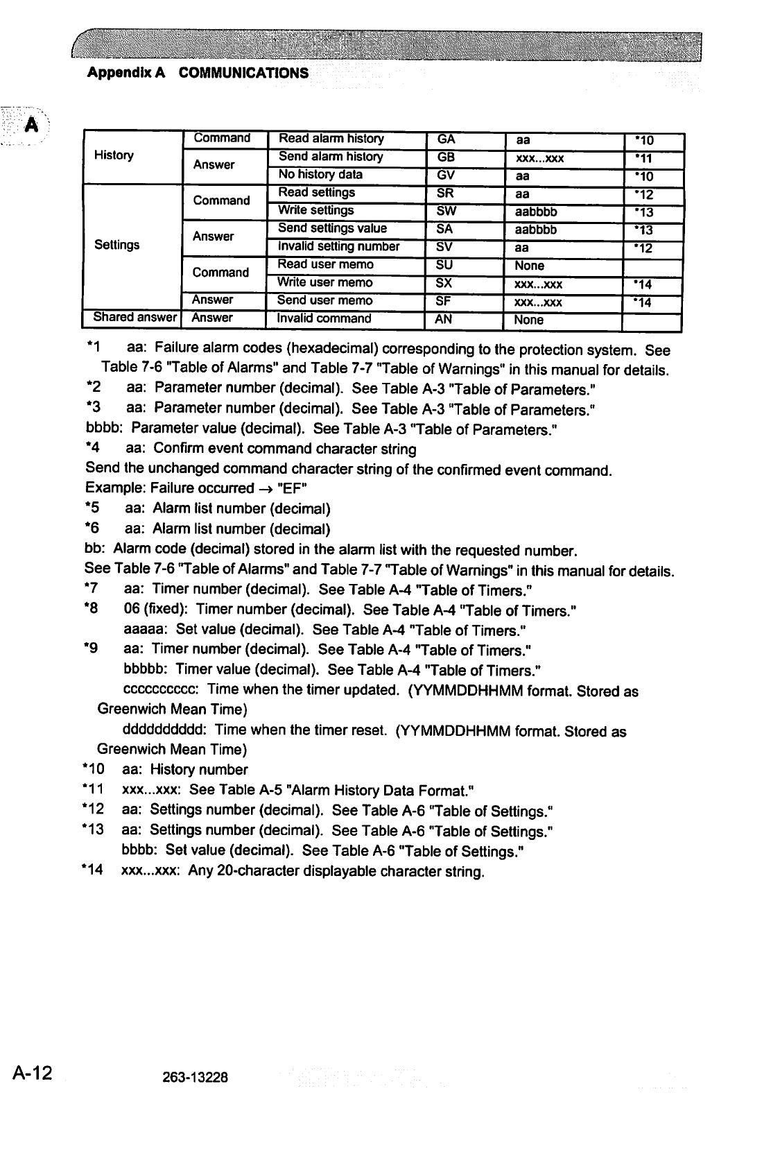
Appendix
A
COMMUNICATIONS
History
Settings
Command
Answer
Command
Answer
Command
Answer
Answer
Read
alarm
history
Send
alarm
history
No
history
data
Read
settings
Write
settings
Send
settings
value
Invalid
setting
number
Read
user
memo
Write
user
memo
Send
user
memo
Invalid
command
GA
GB
GV
SR
SW
SA
sv
su
sx
SF
AN
aa
XXX...XXX
aa
aa
aabbbb
aabbbb
aa
None
XXX...XXX
XXX...XXX
None
•10
•11
•10
•12
•13
*13
*12
*14
*14
*1
aa:
Failure
alarm
codes
(hexadecimal) corresponding
to
the
protection
system.
See
Table
7-6
"Table
of
Alarms"
and
Table
7-7
"Table
of
Warnings"
in
this
manual
for
details.
*2
aa:
Parameter
number
(decimal).
See
Table
A-3
"Table
of
Parameters."
*3
aa:
Parameter
number
(decimal).
See
Table
A-3
"Table
of
Parameters."
bbbb:
Parameter
value
(decimal).
See
Table
A-3
"Table
of
Parameters."
*4
aa:
Confirm
event
command
character
string
Send
the
unchanged
command
character
string
of
the
confirmed
event
command.
Example:
Failure
occurred
->
"EF"
*5
aa:
Alarm
list
number
(decimal)
*6
aa:
Alarm
list
number
(decimal)
bb:
Alarm
code
(decimal)
stored
in
the
alarm
list
with
the
requested
number.
See
Table
7-6
'Table
of
Alarms"
and
Table
7-7
Table
of
Warnings"
in
this
manual
for
details.
*7
aa:
Timer
number
(decimal).
See
Table
A-4
"Table
of
Timers."
*8
06
(fixed):
Timer
number
(decimal).
See
Table
A-4
Table
of
Timers."
aaaaa:
Set
value
(decimal).
See
Table
A-4
Table
of
Timers."
*9
aa:
Timer
number
(decimal).
See
Table
A-4
"Table
of
Timers."
bbbbb:
Timer
value
(decimal).
See
Table
A-4
Table
of
Timers."
cccccccccc:
Time
when
the
timer
updated.
(YYMMDDHHMM
format.
Stored
as
Greenwich
Mean
Time)
dddddddddd:
Time
when
the
timer
reset.
(YYMMDDHHMM
format.
Stored
as
Greenwich
Mean
Time)
*10
aa:
History
number
*11
xxx...xxx:
See
Table
A-5
"Alarm
History
Data
Format."
*12
aa:
Settings
number
(decimal).
See
Table
A-6
Table
of
Settings."
*13
aa:
Settings
number
(decimal).
See
Table
A-6
Table
of
Settings."
bbbb:
Set
value
(decimal).
See
Table
A-6
Table
of
Settings."
*14
xxx...xxx:
Any
20-character
displayable
character
string.
A-12
263-13228

...„,.,........,
A5.
TABLE
OF
COMMANDS
Table
A-3
Table
of
Parameters
No.
01
03
04
05
07
08
09
10
11
21
22
26
27
28
29
30
Name
Model
identification
number
Rotational
speed
Motor
current
Pump
temperature
Temperature
control
function
Temperature
control
set
temperature
Rotational
speed
{%)
Rotational
speed
(%)
Rated
rotational
speed
Axis
1
unbalance
monitor
amount
Axis
2
unbalance
monitor
amount
MB
sensor
output
X1
MB
sensor
output
Y1
MB
sensor
output
X2
MB
sensor
output
Y2
MB
sensor
output
Z
Range
Fixed
0000
to
5000
0000
to
0150
0000
to
0099
0000
to
0002
Fixed
0000
to
0100
0000
to
1000
0000
to
5000
0000
to
100
0000
to
0100
0000
to
0100
0000
to
0100
0000
to
0100
0000
to
0100
0000
to
0100
Description
and
format
Value
representing
the
model.
Example:
EI-D3203M
-+
3203
Rotational
speed
/10
Example:
15000
rpm
-»
1500
Motor
drive
current
x
10
Example:
2.3
A
->
0023
Pump
temperature
45°C
->
0045
(Valid
only
for
a
power
supply
with
a
temperature
control
function.)
Temperature
control
function
setting
status
0000:
Temperature
control
function
on
0001:
Temperature
control
function
off
0002:
Power
supply
has
no
temperature
control
function
Target
value
of
temperature
control
setting
Example:
65°C
-+
0065
(Valid
only
for
a
power
supply
with
a
temperature
control
function.)
Percentage
of
rated
rotational
speed.
Example:
80%
->
0080
Percentage
of
rated
rotational
speed.
(x10)
Example:
80%
-*■
0800
Rated
rotational
speed
/10
Example:
21000
rpm
->
2100
Unbalance
monitor
value
of
magnetic
bearing:
Axis
1
Example:
3%
->
"0003"
Unbalance
monitor
value
of
magnetic
bearing:
Axis
2
Example:
3%
->"0003"
Sensor
output
monitor
value
of
magnetic
bearing:
Axis
X1
Example:
3%
->
"0003"
Sensor
output
monitor
value
of
magnetic
bearing:
Axis
Y1
Example:
3%
->
"0003"
Sensor
output
monitor
value
of
magnetic
bearing:
Axis
X2
Example:
3%
->
"0003"
Sensor
output
monitor
value
of
magnetic
bearing:
Axis
Y2
Example:
3%
->
"0003"
Sensor
output
monitor
value
of
magnetic
bearing:
AxisZ
Example:
3%
->
"0003"
Power
Supply
Unit
INSTRUCTION
MANUAL
A-13
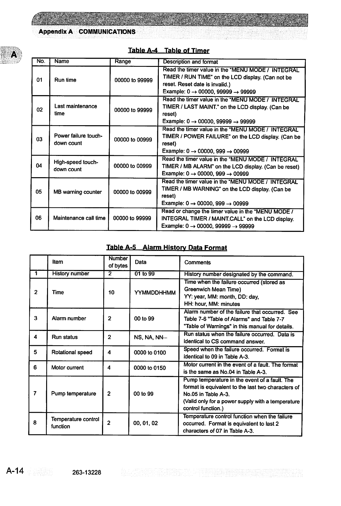
Li-
^
^-\
^^:
:
■■v;,r.■■■"■:■
.-.r^
■.■■■•'.^^rr.
■<■■:::
Appendix
A
COMMUNICATIONS
Table
A-4
Table
of
Timer
No.
01
02
03
04
05
06
Name
Run
time
Last
maintenance
time
Power
failure
touch
down
count
High-speed
touch
down
count
MB
warning
counter
Maintenance
call
time
Range
00000
to
99999
00000
to
99999
00000
to
00999
00000
to
00999
00000
to
00999
00000
to
99999
Description
and
format
Read
the
timer
value
in
the
"MENU
MODE
/
INTEGRAL
TIMER
/
RUN
TIME"
on
the
LCD
display.
(Can
not
be
reset.
Reset
date
is
invalid.)
Example:
0
->
00000,
99999
->
99999
Read
the
timer
value
in
the
"MENU
MODE
/
INTEGRAL
TIMER
/
LAST
MAINT."
on
the
LCD
display.
(Can
be
reset)
Example:
0
->
00000,
99999
->
99999
Read
the
timer
value
in
the
"MENU
MODE
/
INTEGRAL
TIMER
/
POWER
FAILURE"
on
the
LCD
display.
(Can
be
reset)
Example:
0
->
00000,
999
->
00999
Read
the
timer
value
in
the
"MENU
MODE
/
INTEGRAL
TIMER
/
MB
ALARM"
on
the
LCD
display.
(Can
be
reset)
Example:
0
-»
00000,
999
->
00999
Read
the
timer
value
in
the
"MENU
MODE
/
INTEGRAL
TIMER
/
MB
WARNING"
on
the
LCD
display.
(Can
be
reset)
Example:
0
->
00000,
999
->
00999
Read
or
change
the
timer
value
in
the
"MENU
MODE
/
INTEGRAL
TIMER
/
MAINT.CALL"
on
the
LCD
display.
Example: 0
-»
00000,
99999
->
99999
Table
A-5
Alarm
Historv
Data
Format
1
2
3
4
5
6
7
8
Item
History
number
Time
Alarm
number
Run
status
Rotational
speed
Motor
current
Pump
temperature
Temperature
control
function
Number
of
bytes
2
10
2
2
4
4
2
2
Data
01
to
99
YYMMDDHHMM
00
to
99
NS,
NA,
NN-
0000
to
0100
0000
to
0150
00
to
99
00,01,02
Comments
History
number
designated
by
the
command.
Time
when
the
failure
occurred
(stored
as
Greenwich
Mean
Time)
YY:
year,
MM:
month,
DD:
day,
HH:
hour,
MM:
minutes
Alarm
number
of
the
failure
that
occurred.
See
Table
7-6
"Table
of
Alarms"
and
Table
7-7
'Table
of
Warnings"
in
this
manual
for
details.
Run
status
when
the
failure
occurred.
Data
is
identical
to
CS
command
answer.
Speed
when
the
failure
occurred.
Format
is
identical
to
09
in
Table
A-3.
Motor
current
in
the
event
of
a
fault.
The
format
is
the
same
as
No.04
in
Table
A-3.
Pump
temperature
in
the
event
of
a
fault.
The
format
is
equivalent
to
the
last
two
characters
of
No.05
in
Table
A-3.
(Valid
only
for
a
power
supply
with
a
temperature
control
function.)
Temperature
control
function
when
the
failure
occurred.
Format
is
equivalent
to
last
2
characters
of
07
in
Table
A-3.
A-14
263-13228
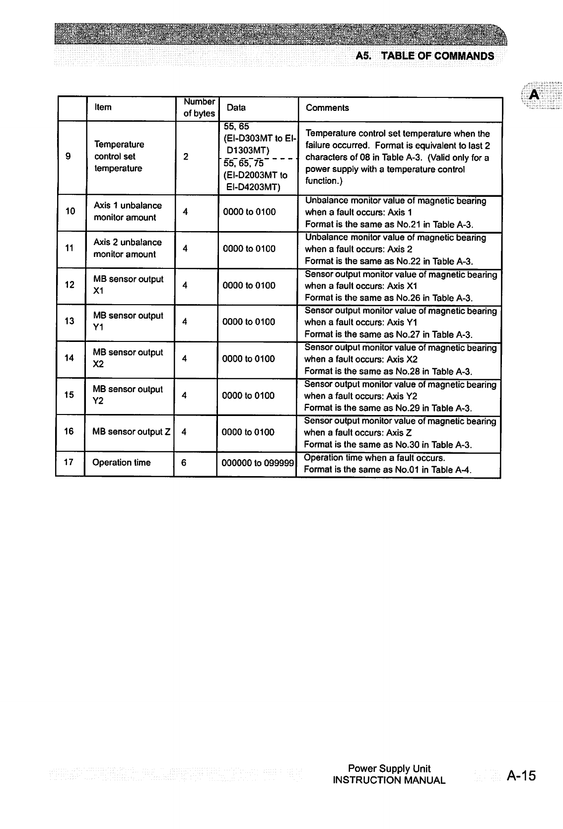
Hj^w^MjjfflM'^ti3tf^yMfrtfvi^mO0frEtf>
ft
r
Ji
rir
w
t
'a'
t
\tX-y'm
.■"_■.■'"V^"
■'(s\{1'.-|>"^^
^-;":';
;"-<;
gjfiE&a
A5.
TABLE
OF
COMMANDS
9
10
11
12
13
14
15
16
17
Item
Temperature
control
set
temperature
Axis
1
unbalance
monitor
amount
Axis
2 unbalance
monitor
amount
MB
sensor
output
X1
MB
sensor
output
Y1
MB
sensor
output
X2
MB
sensor
output
Y2
MB
sensor
output
Z
Operation
time
Number
of
bytes
2
4
4
4
4
4
4
4
6
Data
55,65
(EI-D303MT
to
El-
D1303MT)
55,
65,
75
(EI-D2003MT
to
EI-D4203MT)
0000
to
0100
0000
to
0100
0000
to
0100
0000
to
0100
0000
to
0100
0000
to
0100
0000
to
0100
000000
to
099999
Comments
Temperature
control
set
temperature
when
the
failure
occurred.
Format
is
equivalent
to
last
2
characters
of
08
in
Table
A-3.
(Valid
only
for
a
power
supply
with
a
temperature
control
function.)
Unbalance
monitor
value
of
magnetic
bearing
when
a
fault
occurs:
Axis
1
Format
is
the
same
as
No.21
in
Table
A-3.
Unbalance
monitor
value
of
magnetic
bearing
when
a
fault
occurs:
Axis
2
Format
is
the
same
as
No.22
in
Table
A-3.
Sensor
output
monitor
value
of
magnetic
bearing
when
a
fault
occurs:
Axis
X1
Format
is
the
same
as
No.26
in
Table
A-3.
Sensor
output
monitor
value
of
magnetic
bearing
when
a
fault
occurs:
Axis
Y1
Format
is
the
same
as
No.27
in
Table
A-3.
Sensor
output
monitor
value
of
magnetic
bearing
when
a
fault
occurs:
Axis
X2
Format
is
the
same
as
No.28
in
Table
A-3.
Sensor
output
monitor
value
of
magnetic
bearing
when
a
fault
occurs:
Axis
Y2
Format
is
the
same
as
No.29
in
Table
A-3.
Sensor
output
monitor
value
of
magnetic
bearing
when
a
fault
occurs:
Axis
Z
Format
is
the
same
as
No.30
in
Table
A-3.
Operation
time
when
a
fault
occurs.
Format
is
the
same
as
No.01
in
Table
A-4.
Power
Supply
Unit
INSTRUCTION
MANUAL
A-15

Appendix
A
COMMUNICATIONS
Table
A-6
Table
of
Settinas
No.
01
02
03
04
05
06
07
08
Name
Temperature
control
on/off
Speed
display
format
Rotational
speed
Low
speed
value
"ALARM"
signal
operation
setting
"REMOTE"
signal
operation
setting
"STOP"
signal
operation
setting
Low
rotation
speed
Range
0000
/
0001
0000
to
0002
0000
/
0001
0025
to
0100
0000
/
0001
0000
/
0001
0000
/
0001
0250
to
1000
Description
and
format
Read
or
change
the
set
values
in
the
"MENU
/
SETTINGS
/
TEMP.CONTORL
/
TEMP.CONTROL"
on
the
LCD
display.
0000:
Temperature
control
function
on
0001:
Temperature
control
function
off
(Valid
only
for
a
power
supply
with
a
temperature
control
function.)
Read
or
change
the
set
values
in
the
"MENU
/
SETTINGS
/
ROT.SPEED
/
DISPLAY"
on
the
LCD
display.
0000:
%,
0001:
rpm,
0002:
rps
Read
or
change
the
set
values
in
the
"MENU
/
SETTINGS
/
ROT.SPEED
/
SPEED"
on
the
LCD
display.
0000:
NORMAL,
0001:
LOW
SPEED
Read
or
change
the
set
values
in
the
"MENU
/
SETTINGS
/
ROT.SPEED
/
LOW
SPEED"
on
the
LCD
display.
Example:
25%
-»
0025,100%
->
0100
Read
or
change
the
set
values
in
the
"MENU
/
SETTINGS
/
REMOTE
SIGNAL
MODE
/
ALARM"
on
the
LCD
display.
0000:
SEMI-E74,
0001:
EI-03
Read
or
change
the
set
values
in
the
"MENU
/
SETTINGS
/
REMOTE
SIGNAL
MODE
/
REMOTE"
on
the
LCD
display.
0000:
SEMI-E74,
0001:
EI-03
Read
or
change
the
set
values
in
the
"MENU
/
SETTINGS
/
REMOTE
SIGNAL
MODE
/
STOP"
on
the
LCD
display.
0000:
REMOTE
ONLY,
0001:
REMOTE&RSXXX
Read
or
change
the
set
values
in
the
"MENU
/
SETTINGS
/
ROT.SPEED
/
LOW
SPEED"
on
the
LCD
display.
Example:
25.0%
->
0250,
99.9%
->
0999
A-16
263-13228
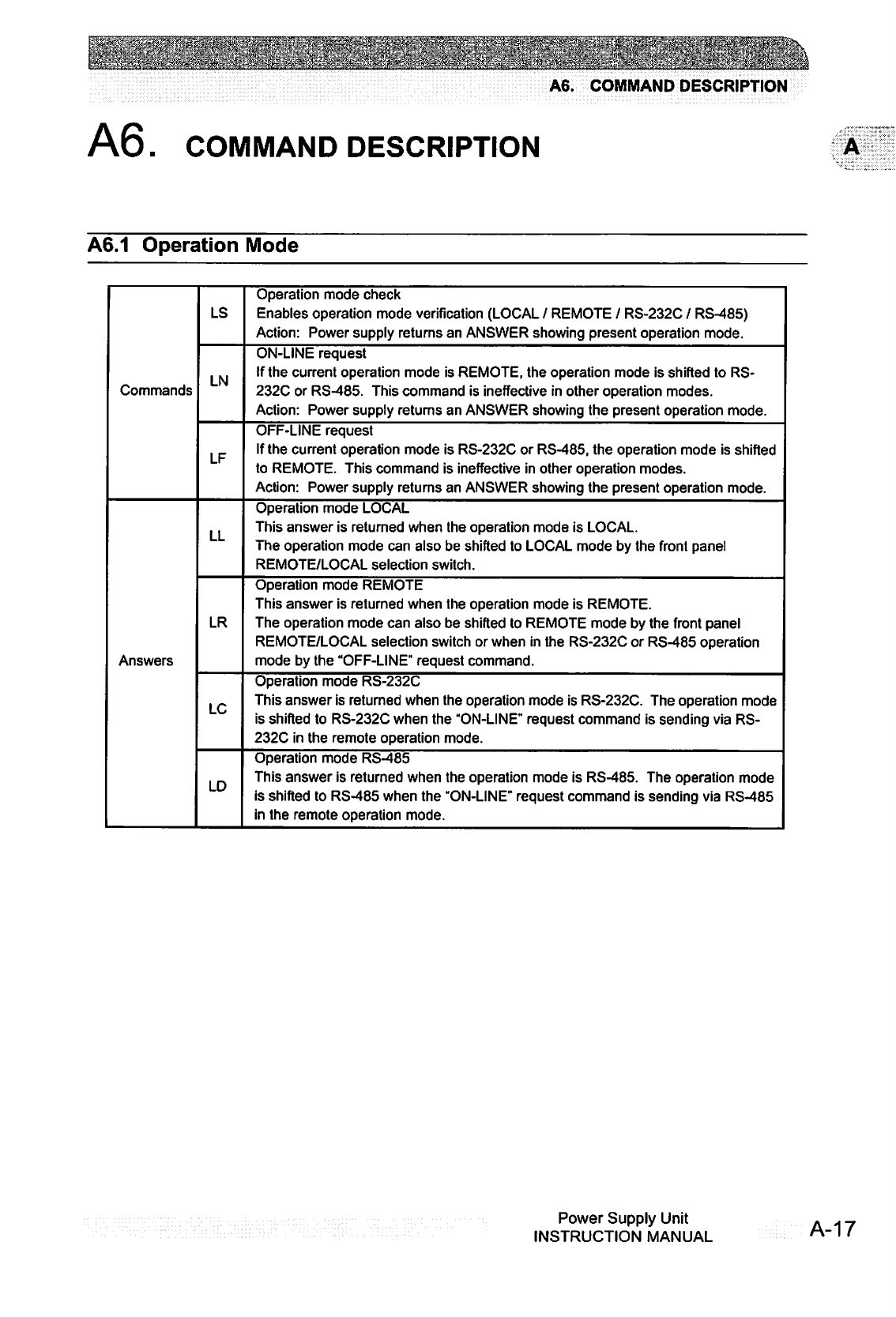
:.-...:
..
■■
".-.■
■V*.'
■
f':'
'~\
'■'.:?*""-■■
'
'
■'
;■
■•".\*.
■.,»■■,■
■-'
A6.
COMMAND
DESCRIPTION
A6.
COMMAND
DESCRIPTION
A6.1
Operation
Mode
Commands
Answers
LS
LN
LF
LL
LR
LC
LD
Operation
mode
check
Enables
operation
mode
verification
(LOCAL
/
REMOTE
/
RS-232C
/
RS-485)
Action:
Power
supply
returns
an
ANSWER
showing
present
operation
mode.
ON-LINE
request
If
the
current
operation
mode
is
REMOTE,
the
operation
mode
is
shifted
to
RS-
232C
or
RS-485.
This
command
is
ineffective
in
other
operation
modes.
Action:
Power
supply
returns
an
ANSWER
showing
the
present
operation
mode.
OFF-LINE
request
If
the
current
operation
mode
is
RS-232C
or
RS-485,
the
operation
mode
is
shifted
to
REMOTE.
This
command
is
ineffective
in
other
operation
modes.
Action:
Power
supply
returns
an
ANSWER
showing
the
present
operation
mode.
Operation
mode
LOCAL
This
answer
is
returned
when
the
operation
mode
is
LOCAL.
The
operation
mode
can
also
be
shifted
to
LOCAL
mode
by
the
front
panel
REMOTE/LOCAL
selection
switch.
Operation
mode
REMOTE
This
answer
is
returned
when
the
operation
mode
is
REMOTE.
The
operation
mode
can
also
be
shifted
to
REMOTE
mode
by
the
front
panel
REMOTE/LOCAL
selection
switch
or
when
in
the
RS-232C
or
RS-485
operation
mode
by
the
"OFF-LINE"
request
command.
Operation
mode
RS-232C
This
answer
is
returned
when
the
operation
mode
is
RS-232C.
The
operation
mode
is
shifted
to
RS-232C
when
the
"ON-LINE"
request
command
is
sending
via
RS-
232C
in
the
remote
operation
mode.
Operation
mode
RS-485
This
answer
is
returned
when
the
operation
mode
is
RS-485.
The
operation
mode
is
shifted
to
RS-485
when
the
"ON-LINE"
request
command
is
sending
via
RS-485
in
the
remote
operation
mode.
Power
Supply
Unit
INSTRUCTION
MANUAL
A-17
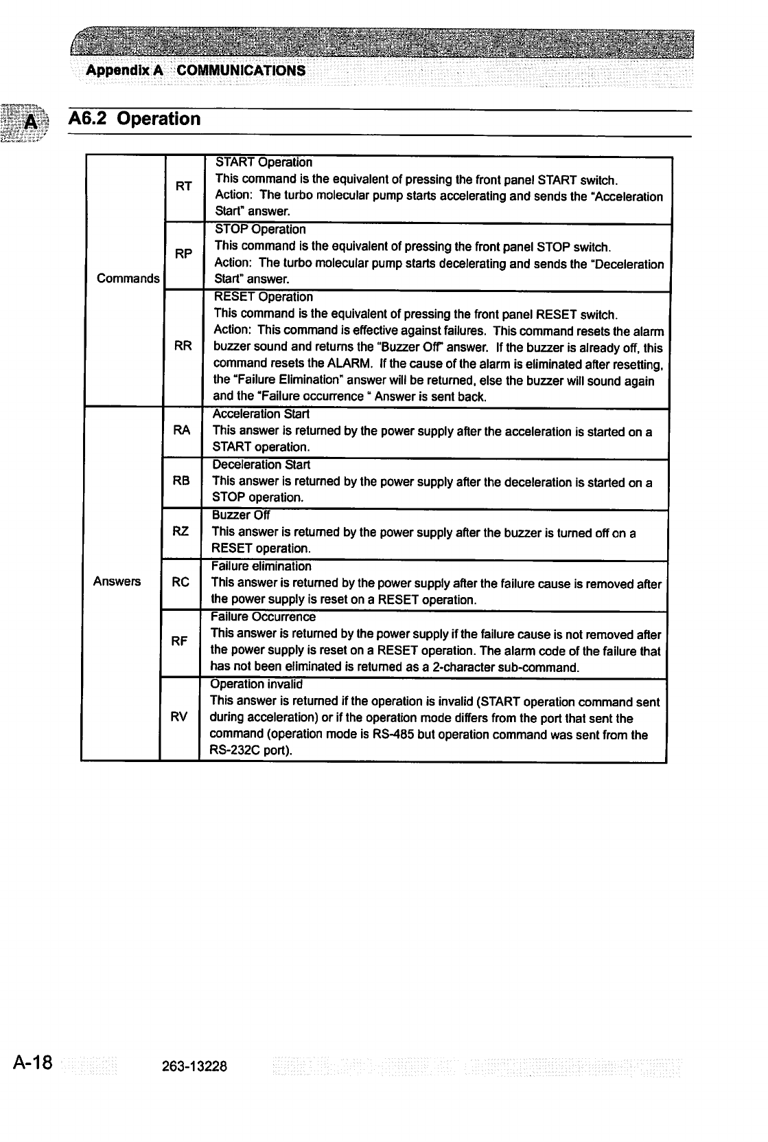
Appendix
A
COMMUNICATIONS
A6.2
Operation
Commands
Answers
RT
RP
RR
RA
RB
R2
RC
RF
RV
START
Operation
This
command
is
the
equivalent
of
pressing
the
front
panel
START
switch.
Action:
The
turbo
molecular
pump
starts
accelerating
and
sends
the
"Acceleration
Start"
answer.
STOP
Operation
This
command
is
the
equivalent
of
pressing
the
front
panel
STOP
switch.
Action:
The
turbo
molecular
pump
starts
decelerating
and
sends
the
"Deceleration
Start"
answer.
RESET
Operation
This
command
is
the
equivalent
of
pressing
the
front
panel
RESET
switch.
Action:
This
command
is
effective
against
failures.
This
command
resets
the
alarm
buzzer
sound
and
returns
the
"Buzzer
Off"
answer.
If
the
buzzer
is
already
off,
this
command
resets the
ALARM.
If
the
cause
of
the
alarm
is
eliminated
after
resetting,
the
"Failure
Elimination"
answer
will
be
returned,
else
the
buzzer
will
sound
again
and
the
"Failure
occurrence"
Answer
is
sent
back.
Acceleration
Start
This
answer
is
returned
by
the
power
supply
after
the
acceleration
is
started
on
a
START
operation.
Deceleration
Start
This
answer
is
returned
by
the
power
supply
after
the
deceleration
is
started
on
a
STOP
operation.
Buzzer
Off
This
answer
is
returned
by
the
power
supply
after
the
buzzer
is
turned
oft
on
a
RESET
operation.
Failure
elimination
This
answer
is
returned
by
the
power
supply
after
the
failure
cause
is
removed
after
the
power
supply
is
reset
on
a
RESET
operation.
Failure
Occurrence
This
answer
is
returned
by
the
power
supply
if
the
failure
cause
is
not
removed
after
the
power
supply
is
reset
on
a
RESET
operation.
The
alarm
code
of
the
failure
that
has
not
been
eliminated
is
returned
as
a
2-character
sub-command.
Operation
invalid
This
answer
is
returned
if
the operation
is
invalid
(START
operation
command
sent
during
acceleration)
or
if
the
operation
mode
differs
from
the
port
that
sent
the
command
(operation
mode
is
RS-485
but
operation
command
was
sent
from
the
RS-232C
port).
A-18
263-13228
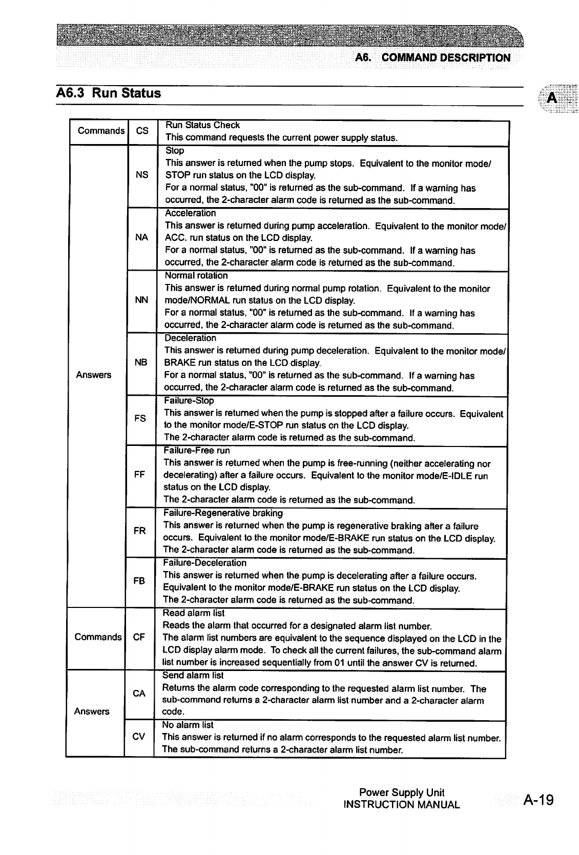
A6.
COMMAND
DESCRIPTION
A6.3
Run
Status
Commands
CS
Run
Status
Check
This
command
requests
the
current
power
supply
status.
NS
NA
NN
NB
Answers
FS
FF
FR
FB
Stop
This
answer
is
returned
when
the
pump
stops.
Equivalent
to
the
monitor
mode/
STOP
run
status
on
the
LCD
display.
For
a
normal
status,
"00"
is
returned
as
the
sub-command.
If
a
warning
has
occurred, the
2-character
alarm
code
is
returned
as
the
sub-command.
Acceleration
This
answer
is
returned
during
pump
acceleration.
Equivalent
to
the
monitor
mode/
ACC.
run
status
on
the
LCD
display.
For
a
normal
status,
"00"
is
returned
as
the
sub-command.
If
a
warning
has
occurred,
the
2-character
alarm
code
is
returned
as
the
sub-command.
Normal
rotation
This
answer
is
returned
during
normal
pump
rotation.
Equivalent
to
the
monitor
mode/NORMAL
run
status
on
the
LCD
display.
For
a
normal
status,
"00"
is
returned
as
the
sub-command.
If
a
warning
has
occurred,
the
2-character
alarm
code
is
returned
as
the
sub-command.
Deceleration
This
answer
is
returned
during
pump
deceleration.
Equivalent
to
the
monitor
mode/
BRAKE
run
status
on
the
LCD
display.
For
a
normal
status,
"00"
is
returned
as
the
sub-command.
If
a
warning
has
occurred,
the
2-character
alarm
code
is
returned
as
the
sub-command.
Failure-Stop
This
answer
is
retumed
when
the
pump
is
stopped
after
a
failure
occurs.
Equivalent
to
the
monitor
mode/E-STOP
run
status
on
the
LCD
display.
The
2-character
alarm
code
is
returned
as
the
sub-command.
Failure-Free
run
This
answer
is
returned
when
the
pump
is
free-running
(neither
accelerating
nor
decelerating)
after
a
failure
occurs.
Equivalent
to
the
monitor
mode/E-IDLE
run
status
on
the
LCD
display.
The
2-character
alarm
code
is
returned
as
the
sub-command.
Failure-Regenerative
braking
This
answer
is
returned
when
the
pump
is
regenerative
braking
after
a
failure
occurs.
Equivalent
to
the
monitor
mode/E-BRAKE
run
status
on
the
LCD
display.
The
2-character
alarm
code
is
returned
as
the
sub-command.
Failure-Deceleration
This
answer
is
returned
when
the
pump
is
decelerating
after
a
failure
occurs.
Equivalent
to
the
monitor
mode/E-BRAKE
run
status
on
the
LCD
display.
The
2-character
alarm
code
is
returned
as
the
sub-command.
Commands
CF
Read
alarm
list
Reads
the
alarm
that
occurred
for
a
designated
alarm
list
number.
The
alarm
list
numbers
are
equivalent
to
the
sequence
displayed
on
the
LCD
in
the
LCD
display
alarm
mode.
To
check
all
the
current
failures,
the
sub-command
alarm
list
number
is
increased
sequentially
from
01
until
the
answer
CV
is
returned.
CA
Answers
Send
alarm
list
Returns
the
alarm
code
corresponding
to
the
requested
alarm
list
number.
The
sub-command
returns
a
2-character
alarm
list
number
and
a
2-character
alarm
code.
CV
No
alarm
list
This
answer
is
returned
if
no
alarm
corresponds
to
the
requested
alarm
list
number.
The
sub-command
returns
a
2-character
alarm
list
number.
Power
Supply
Unit
INSTRUCTION
MANUAL
A-19
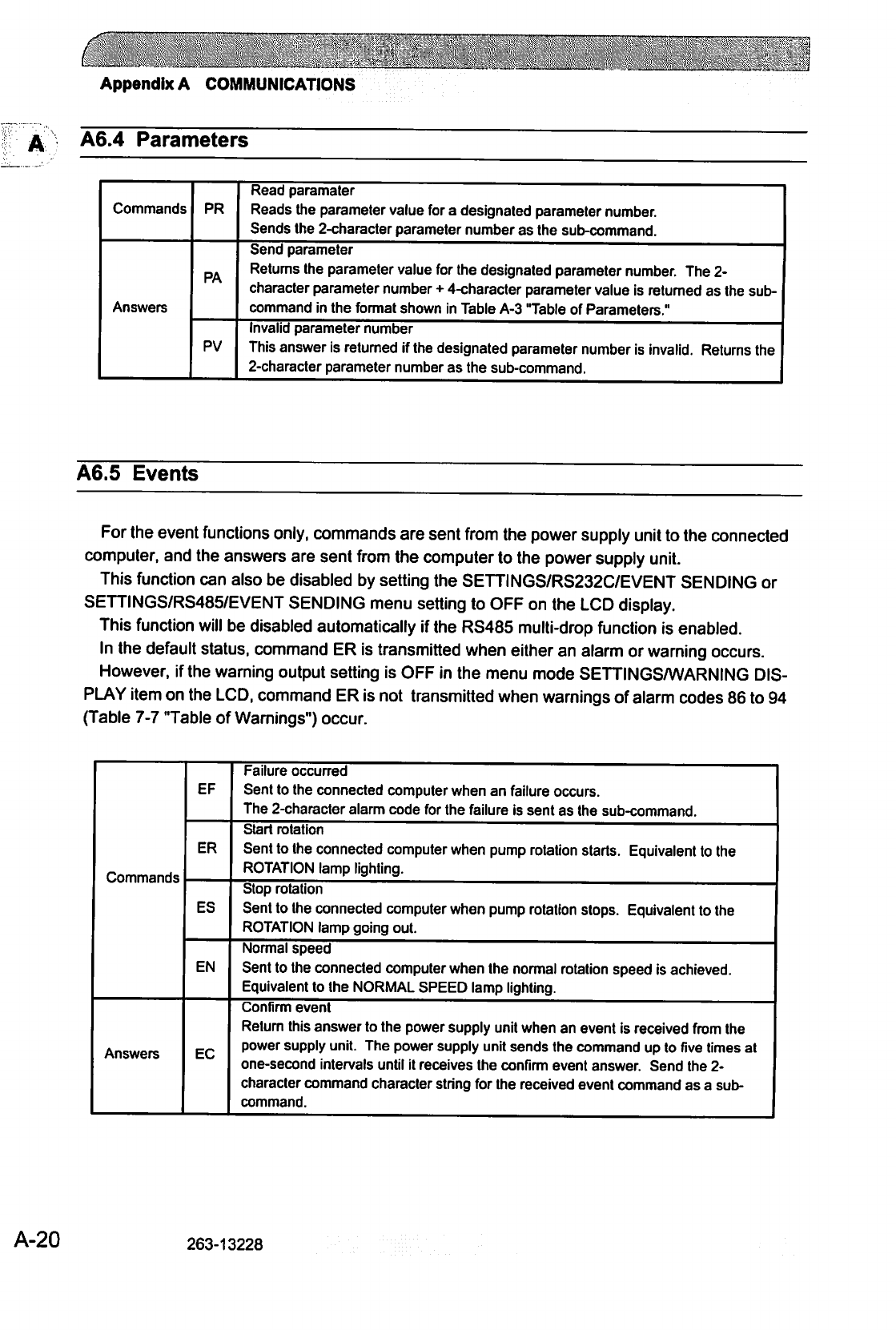
c
Appendix
A
COMMUNICATIONS
A6.4
Parameters
Commands
PR
Read
paramater
Reads
the
parameter
value
for
a
designated
parameter
number.
Sends
the
2-character
parameter
number
as
the
sub-command.
PA
Answers
Send
parameter
Returns
the
parameter
value
for
the
designated
parameter
number.
The
2-
character
parameter
number
+
4-character
parameter
value
is
returned
as
the
sub
command
in
the
format
shown
in
Table
A-3
Table
of
Parameters."
PV
Invalid
parameter
number
This
answer
is
returned
if
the
designated
parameter
number
is
invalid.
Returns
the
2-character
parameter
number
as
the
sub-command.
A6.5
Events
For
the
event
functions
only,
commands
are
sent
from
the
power
supply
unit
to
the
connected
computer,
and
the
answers
are
sent
from
the
computer
to
the
power
supply
unit.
This
function
can
also
be
disabled
by
setting
the
SETTINGS/RS232C/EVENT
SENDING
or
SETTINGS/RS485/EVENT
SENDING
menu
setting
to
OFF
on
the
LCD
display.
This
function
will
be
disabled
automatically
if
the
RS485
multi-drop
function
is
enabled.
In
the
default
status,
command
ER
is
transmitted
when
either
an
alarm
or
warning
occurs.
However,
if
the
warning
output
setting
is
OFF
in
the
menu mode
SETTINGSA/VARNING
DIS
PLAY
item
on
the
LCD,
command
ER
is
not
transmitted
when
warnings
of
alarm
codes
86
to
94
(Table
7-7
Table
of
Warnings")
occur.
Commands
Answers
EF
ER
ES
EN
EC
Failure
occurred
Sent
to
the
connected
computer
when
an
failure
occurs.
The
2-character
alarm
code
for
the
failure
is
sent
as
the
sub-command.
Start rotation
Sent
to
the
connected
computer
when
pump
rotation
starts.
Equivalent
to
the
ROTATION
lamp
lighting.
Stop
rotation
Sent
to
the
connected
computer
when
pump
rotation
stops.
Equivalent
to
the
ROTATION
lamp
going
out.
Normal
speed
Sent
to
the
connected
computer
when
the
normal
rotation
speed
is
achieved.
Equivalent
to
the
NORMAL
SPEED
lamp
lighting.
Confirm
event
Return
this
answer
to
the
power
supply
unit
when
an
event
is
received
from
the
power
supply
unit.
The
power
supply
unit
sends
the
command
up
to
five
times
at
one-second
intervals
until
it
receives
the
confirm
event
answer.
Send
the
2-
character
command
character
string for
the
received
event
command
as a
sub
command.
A-20
263-13228
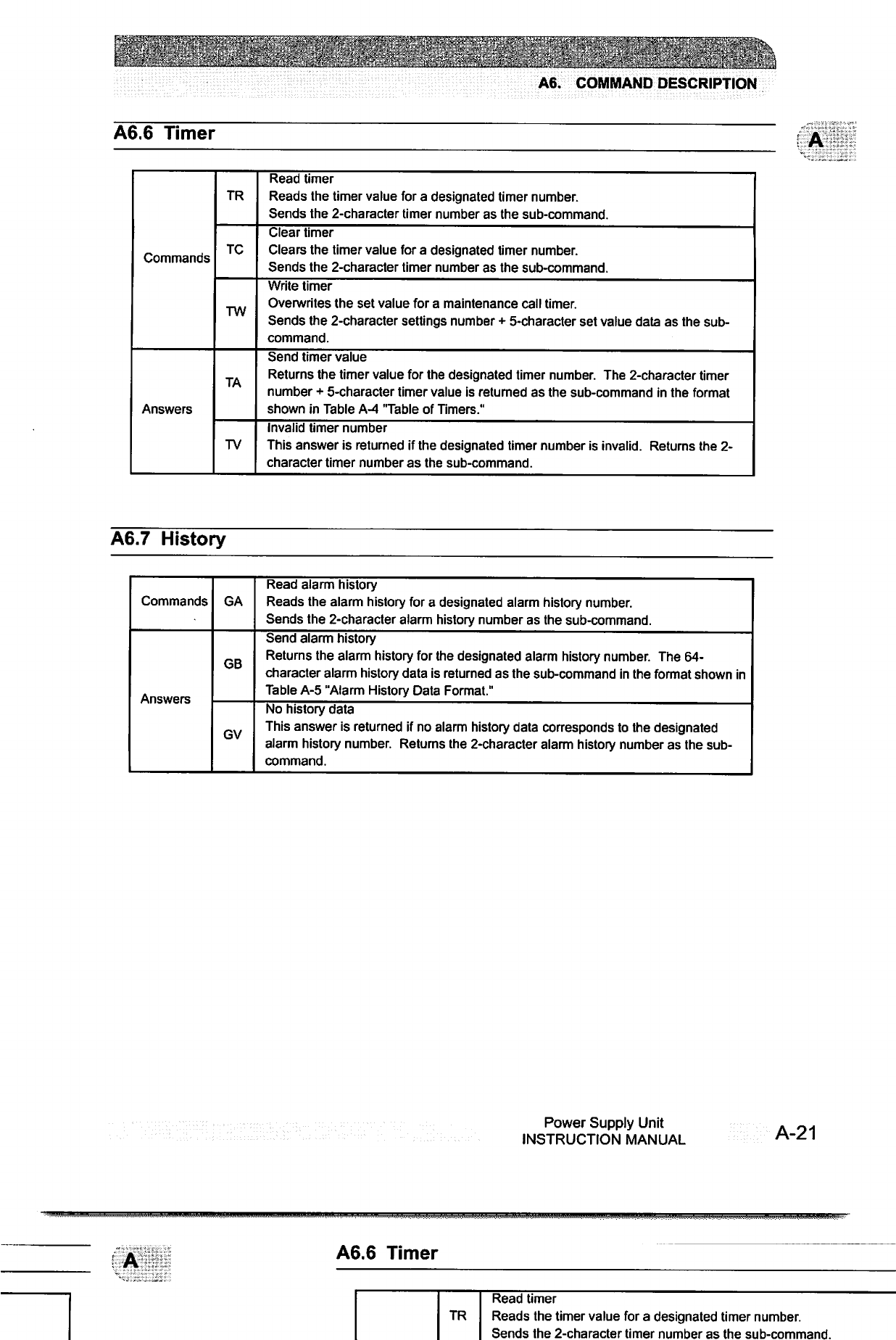
'"■';;
^I''
:'■'
.:
■■.■"-':■.■
:'£?.'";-(
■■.•'
■''•■V
^;.:;C^^'^;-/--;:<-^""?':;:^->"''
A6.
COMMAND
DESCRIPTION
A6.6
Timer
Commands
Answers
TR
TC
TW
TA
TV
Read
timer
Reads
the
timer
value
for
a
designated
timer
number.
Sends
the
2-character
timer
number
as
the
sub-command.
Clear
timer
Clears
the timer
value
for
a
designated
timer
number.
Sends
the
2-character
timer
number
as
the
sub-command.
Write timer
Overwrites
the
set
value
for
a
maintenance
call
timer.
Sends
the
2-character
settings
number
+
5-character
set
value
data
as
the
sub
command.
Send
timer
value
Returns
the
timer
value
for
the
designated
timer
number.
The
2-character
timer
number
+
5-character
timer
value
is
returned
as
the
sub-command
in
the
format
shown
in
Table
A-4
"Table
of
Timers."
Invalid
timer
number
This
answer
is
returned
if
the
designated
timer
number
is
invalid.
Returns
the
2-
character
timer
number
as
the
sub-command.
A6.7
History
Commands
Answers
GA
GB
GV
Read
alarm
history
Reads
the
alarm
history
for
a
designated
alarm
history
number.
Sends
the
2-character
alarm
history
number
as
the
sub-command.
Send
alarm
history
Returns
the
alarm
history
for
the
designated
alarm
history
number.
The
64-
character
alarm
history
data
is
returned
as
the
sub-command
in
the
format
shown
in
Table
A-5
"Alarm
History
Data
Format."
No
history
data
This
answer
is
returned
if
no
alarm
history
data
corresponds
to
the
designated
alarm
history
number.
Returns
the
2-character
alarm
history
number
as
the
sub
command.
Power
Supply
Unit
INSTRUCTION
MANUAL
A-21
A6.6
Timer
TR
Read
timer
Reads
the
timer
value
for
a
designated
timer
number.
Sends
the
2-character
timer
number
as
the
sub-command.
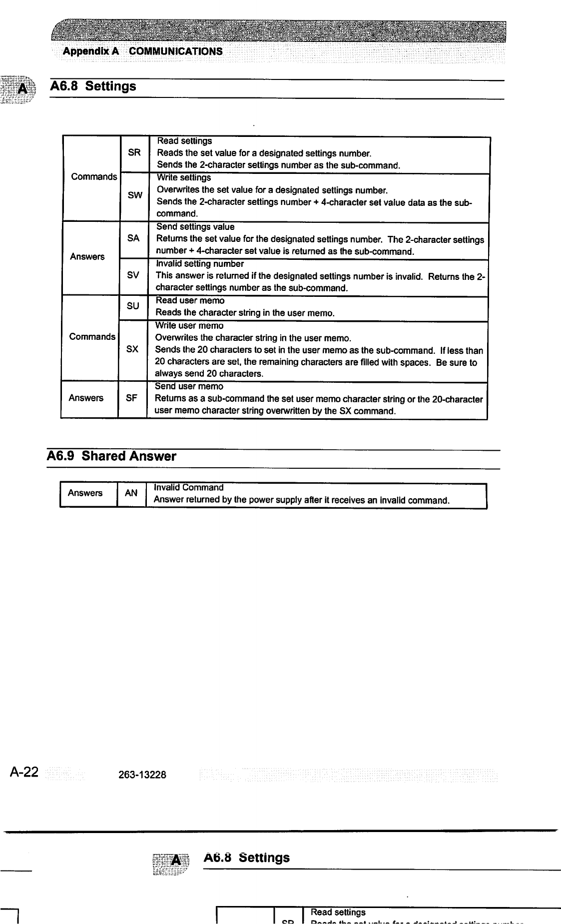
Appendix
A
COMMUNICATIONS
A
A6.8
Settings
Commands
Answers
Commands
Answers
SR
SW
SA
SV
SU
SX
SF
Read
settings
Reads
the
set
value
for
a
designated
settings
number.
Sends
the
2-character
settings
number
as
the
sub-command.
Write
settings
Overwrites
the
set
value
for
a designated
settings
number.
Sends
the
2-character
settings
number
+
4-character
set
value
data
as
the
sub
command.
Send
settings
value
Returns
the
set
value
for
the
designated
settings
number.
The
2-character
settings
number
+
4-character
set
value
is
returned
as
the
sub-command.
Invalid
setting
number
This
answer
is
returned
if
the
designated
settings
number
is
invalid.
Returns
the
2-
character
settings
number
as
the
sub-command.
Read
user
memo
Reads
the
character
string
in
the
user
memo.
Write
user
memo
Overwrites
the
character
string
in
the
user
memo.
Sends
the
20
characters
to
set
in
the
user
memo
as
the
sub-command.
If
less
than
20
characters
are
set,
the
remaining
characters
are
filled
with
spaces.
Be
sure
to
always
send
20
characters.
Send
user
memo
Returns
as
a
sub-command
the
set
user
memo
character
string
or
the
20-character
user
memo
character
string
overwritten
by
the
SX
command.
A6.9
Shared
Answer
Answers
AN
Invalid
Command
Answer
returned
by
the
power
supply
after
it
receives
an
invalid
command.
A-22
263-13228
A6.8
Settings
~1
Read
settings
I
on
I
d.~a~ia
*u_
«
l.._
x—
-i~~:~
a
i
ax:

^k^
*'?
'
':■
A7.
RS-232C
COMMANDS
/
ANSWERS
A7.
RS-232C
COMMANDS
/
ANSWERS
(SEND
AND
RECEIVE
Examples)
Table
A-7
RS-232C
COMMANDS
/
ANSWERS
(SEND
AND
RECEIVE
ExamDlesl
Type
Operation
Mode
TMP
Operation
Computer
(Host)
*1
MJ01LS97$
MJ01LN92S
MJ01LF8AS
MJ01RT9ES
MJ01RP9AS
MJ01RR9CS
Send/
Receive
*2
-»
-
-
*-
-
Power
Supply
MJ01LL90S
MJ01
LR96$
MJ01
LC87$
MJ01LD88S
MJ01LC87$
MJ01LD88S
MJ01LL90$
MJ01LR96S
MJ01LD88S
MJ01LL90S
MJ01RA8BS
MJ01RVA0S
MJ01RB8CS
MJ01RVA0$
MJ01RZA4S
MJ01RF50F5S
MJ01RC8D$
MJ01RVA0S
Description
Operation
Mode
Check
LOCAL
REMOTE
RS-232C
RS-485
ON-LINE
Request
Operation
Mode
Change
Invalid
Request
Invalid
Request
OFF-LINE
Request
Operation
Mode
Change
Invalid
Request
Invalid
Request
START
Operation
Acceleration
Start
Ineffective
Operation
STOP
Operation
Deceleration
Start
Ineffective
Operation
RESET
Operation
Buzzer
Off
Failure
Occurrence
Failure
Eliminated
Ineffective
Operation
Remarks
ON-LINE
request
from
RS-232C
communication
port
Operation
mode
changed
to
RS-232C
ON-LINE
When
in
RS-485
mode
When
in
LOCAL
mode
OFF-LINE
request
from
RS-232C
communication
port
Operation
mode
changed
to
REMOTE
When
in
RS-485
mode
When
in
LOCAL
mode
START
operation
from
RS-
232C
communication
port
When
START
operation
is
ineffective
or
operation
mode
is
not
RS-232C
STOP
operation
from
RS-232C
communication
port
When
STOP
operation
is
ineffective
or
operation
mode
is
not
RS-232C
RESET
operation
from
RS-232C
communication
port
When
a
buzzer
sounded
When
the
failure
was
not
eliminated.
When
the
failure
was
eliminated.
When
RESET
operation
is
ineffective
or
operation
mode
is
not
RS-232C
Power
Supply
Unit
INSTRUCTION
MANUAL
A-23
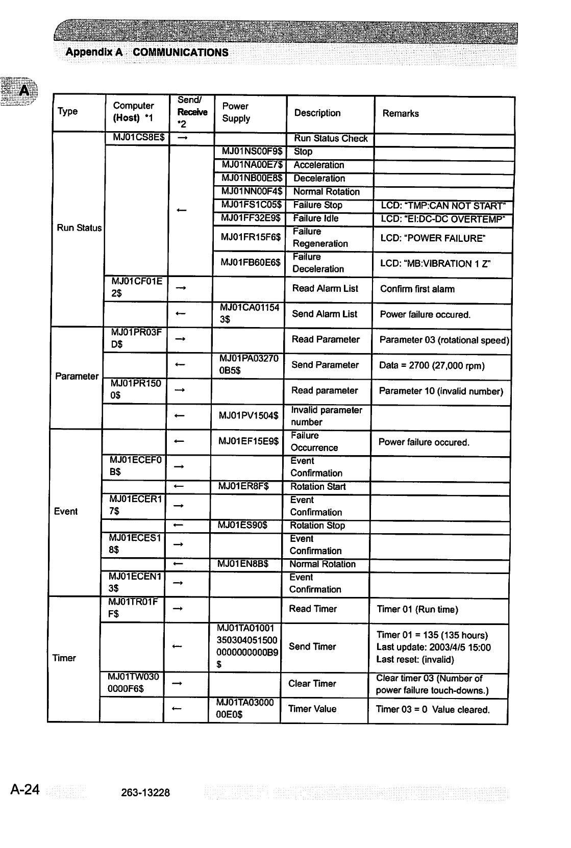
.„___.„.
. .
.„..—.,....__
•■.::■''':':
■
-
-..■■'.■
.■.'■■■.
/:
,■.■;.■■
■'.■.'■'■.■':.■:;
Appendix
A
COMMUNICATIONS
Type
Run
Status
Parameter
Event
Timer
Computer
(Host)
*1
MJ01CS8E$
MJ01CF01E
2$
MJ01PR03F
D$
MJ01PR150
0$
MJ01ECEF0
B$
MJ01ECER1
7$
MJ01ECES1
8$
MJ01ECEN1
3$
MJ01TR01F
F$
MJ01TW030
0000F6$
Send/
Receive
*2
—•
*-
—♦
-
-
-
-
-
Power
Supply
MJ01NS00F9S
MJ01NA00E7S
MJ01NB00E8S
MJ01NN00F4S
MJ01FS1C05$
MJ01FF32E9$
MJ01FR15F6$
MJ01FB60E6S
MJ01CA01154
3$
MJ01PA03270
0B5$
MJ01PV1504S
MJ01EF15E9$
MJ01ER8F$
MJ01ES90$
MJ01EN8B$
MJ01TA01001
350304051500
OOOOO0OO0OB9
$
MJ01TA03000
00E0$
Description
Run
Status
Check
Stop
Acceleration
Deceleration
Normal
Rotation
Failure
Stop
Failure
Idle
Failure
Regeneration
Failure
Deceleration
Read
Alarm
List
Send
Alarm
List
Read
Parameter
Send
Parameter
Read
parameter
Invalid
parameter
number
Failure
Occurrence
Event
Confirmation
Rotation
Start
Event
Confirmation
Rotation
Stop
Event
Confirmation
Normal
Rotation
Event
Confirmation
Read
Timer
Send
Timer
Clear
Timer
Timer
Value
Remarks
LCD:
"TMP:CAN
NOT
START"
LCD:
"EI:DC-DC
OVERTEMP"
LCD:
"POWER
FAILURE"
LCD:
"MB:VIBRATION
1
Z"
Confirm
first
alarm
Power
failure
occured.
Parameter
03
(rotational
speed)
Data
=
2700
(27,000
rpm)
Parameter
10
(invalid
number)
Power
failure
occured.
Timer
01
(Run
time)
Timer
01
=
135
(135
hours)
Last
update:
2003/4/5
15:00
Last
reset:
(invalid)
Clear
timer
03
(Number
of
power
failure
touch-downs.)
Timer
03
= 0
Value
cleared.
A-24
263-13228

^U'itrf/i
tffV^fa'W:^m^;jfr^i^^
A9.
TROUBLESHOOTING
A9.
TROUBLESHOOTING
A9.1
No
Message
can
Transmit
and
Receive
(1)
Start
the
pump
in
LOCAL
mode
and
check
if
the
event
command
of
Rotation
start
can
be
received
in
the
timing
at
which
ROTATION
lamp
lights.
Could
be
received
»
check
if
command
from
connected
computer
can
be
received
or
not,
using
another
computer,
etc.
A
nonsensical
character
string
was
received
»
Go
to
A9.2.
c.
Not
receivable
»
(2)
(2)
Check
the
connection
of
RS-232C
cable
in
reference
to
A2.
Check
the
polarity
of
RS-485
interface,
because
there
is
the
case
that
polarity
is
reverse.
(3)
Check
the
transmission
specification
of
RS-232C
at
computer
side.
A9.2
Sending
and
Receiving
are
Done,
But
Receivable
Messages
are
Invalid
(1)
Check
the
transmission
rate
of
the
power
supply
unit
and
computer.
A9.3
Characters
Get
Disordered
from
Time
to
Time,
Then
Resulting
in
CHECKSUM
Error
(1)
Remove
the
cable
from
equipment
as
noise
source
if
it
runs
near
it.
(2)
When
the
cable
in
use
is
not
a
shield cable,
replace
it
with
the
latter
cable.
When
shield
cable
is
used,
be
sure
to
check
that
it
is
connected
to
the
frame
gland
of
the
connected
computer.
Use
twisted
pair
cable
when
RS-485
is
used.
(3)
When
10
m
or
longer
cable
is
used,
replace
it
with
another
cable
as
short
as
possible.
(4)
Make
the
transmission
rate
smaller
unless
there
is
problem
in
application
program
.
Power
Supply
Unit
INSTRUCTION
MANUAL
This
page
is
intentionally
left
blank.
A-28
263-13228
Index
Index
A
ALARM
69
Alarm
history
14, 15,
49
Alarm
mode
43,
49
c
Control
Cable
4,
24
H
How
to
install
the
unit
onto
a
rack
18
M
Menu mode
43,
50,
52.
57
Monitor
mode
47
Motor Cable
4
P
power
failure
14,
15
Power
switch
9
R
REMOTE
signal
55
remote-control
signal
55
Remote-Control
Signals
59
Reset
Procedure
70
RS-232C
52,
53.
3
RS-485
52.
53, 5
s
SEMI
F47
16
SEMI
S2
16
serial
interface
12.
2
u
UL
16
263-13228
Power
Supply
Unit
INSTRUCTION
MANUAL
lndex-1
This
page
is
intentionally
left
blank.
lndex-2
f
Power
Supply
Unit
INSTRUCTION
MANUAL
263-13228
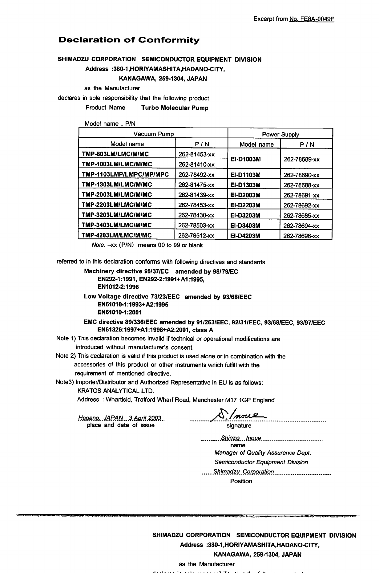
Excerpt
from
No.
FE8A-Q049F
Declaration
of
Conformity
SHIMADZU
CORPORATION
SEMICONDUCTOR
EQUIPMENT
DIVISION
Address
:380-1
,HORIYAMASHITA,HADANO-CITY,
KANAGAWA,
259-1304,
JAPAN
as
the
Manufacturer
declares
in
sole
responsibility
that
the
following
product
Product
Name
Turbo
Molecular
Pump
Model
name
,
P/N
Vacuum
Pump
Model
name
TMP-803LM/LMC/M/MC
TMP-1003LM/LMC/M/MC
TMP-1103LMP/LMPC/MP/MPC
TMP-1303LM/LMC/M/MC
TMP-2003LM/LMC/M/MC
TMP-2203LM/LMC/M/MC
TMP-3203LM/LMC/M/MC
TMP-3403LM/LMC/M/MC
TMP-4203LM/LMC/M/MC
P/N
262-81453-xx
262-81410-xx
262-78492-xx
262-81475-xx
262-81439-xx
262-78453-xx
262-78430-xx
262-78503-xx
262-78512-xx
Power
Supply
Model
name
EI-D1003M
EI-D1103M
EI-D1303M
EI-D2003M
EI-D2203M
EI-D3203M
EI-D3403M
EI-D4203M
P/N
262-78689-xx
262-78690-xx
262-78688-xx
262-78691-xx
262-78692-xx
262-78685-xx
262-78694-xx
262-78696-xx
Note:
-xx
(P/N)
means
00
to
99
or
blank
referred
to
in
this
declaration
conforms
with
following
directives
and
standards
Machinery
directive
98/37/EC
amended
by
98/79/EC
EN292-1:1991,
EN292-2:1991+A1:1995,
EN1012-2:1996
Low
Voltage
directive
73/23/EEC
amended
by
93/68/EEC
EN61010-1:1993+A2:1995
EN61010-1:2001
EMC
directive
89/336/EEC
amended
by
91/263/EEC,
92/31/EEC,
93/68/EEC,
93/97/EEC
EN61326:1997+A1:1998+A2:2001,
class
A
Note
1)
This
declaration
becomes
invalid
if
technical
or
operational
modifications
are
introduced
without
manufacturer's
consent.
Note
2}
This
declaration
is
valid
if
this
product
is
used
alone
or
in
combination
with
the
accessories
of
this
product
or
other
instruments
which
fulfill
with
the
requirement
of
mentioned
directive.
Note3)
Importer/Distributor
and
Authorized
Representative
in
EU
is
as
follows:
KRATOS
ANALYTICAL
LTD.
Address
:
Whartisid,
Trafford
Wharf
Road,
Manchester
M17 1GP
England
A.
JAPAN..3.AML2Q03.
place
and
date
of
issue
signature
ShjnzQ.Jnoue.
name
Manager
of
Quality
Assurance
Dept.
Semiconductor
Equipment
Division
.Corporation
Position
SHIMADZU
CORPORATION
SEMICONDUCTOR
EQUIPMENT
DIVISION
Address
:380-1
,HORIYAMASHITA,HADANO-CITY,
KANAGAWA,
259-1304,
JAPAN
as
the
Manufacturer

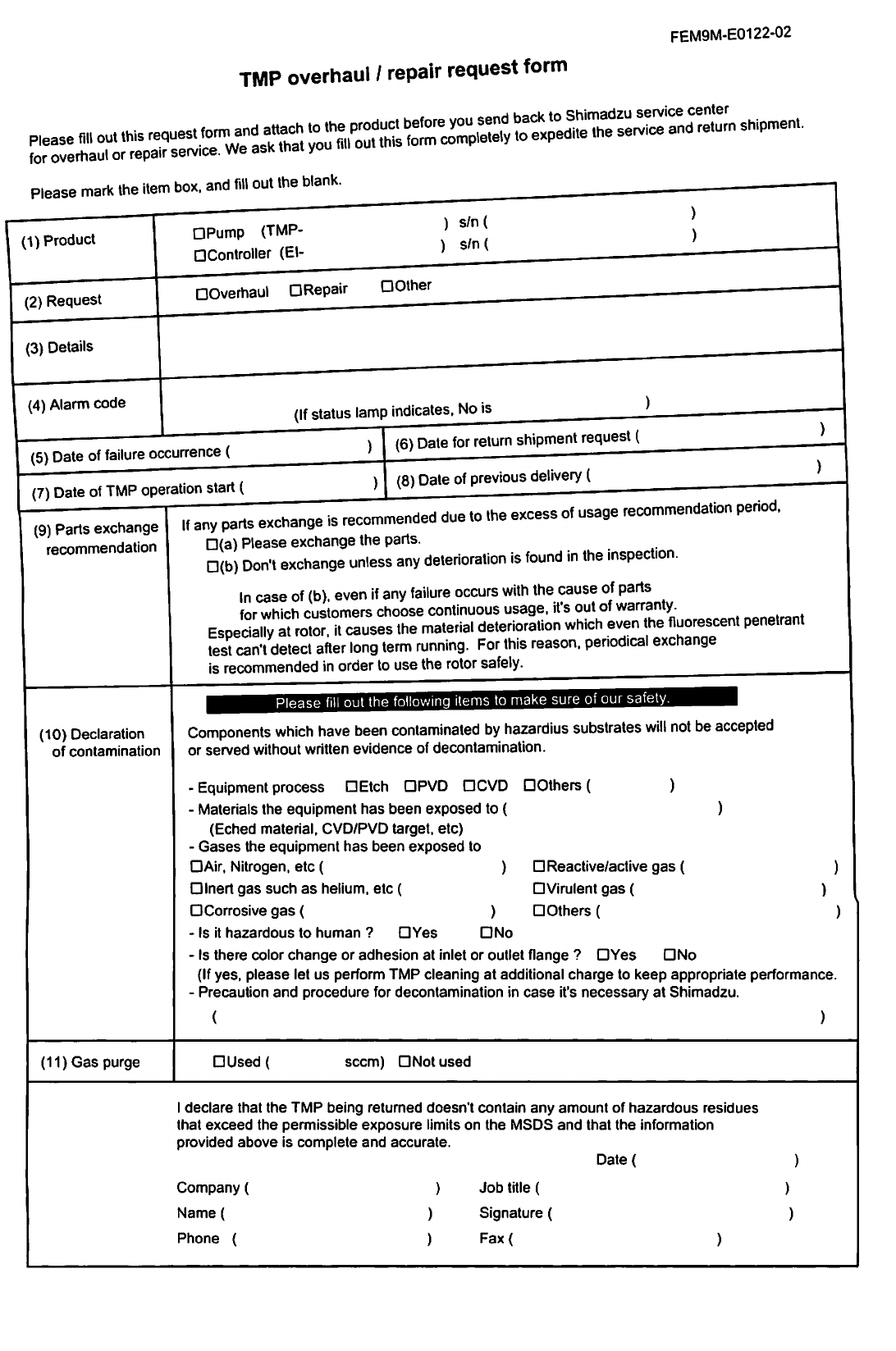
FEM9M-E0122-02
TMP
overhaul
/
repair
request
form
^^
Please
mark
the
item box.
and
fill
out
the
blank.
■
(1)
Product
(2)
Request
QOvemau.
DRepair
DO.her
(3)
Details
(4)
Alarm
code
^_^_———
(5)
Date
of
failure
occurrence
(
(7)
Date
of
TMP
operation
start
(
DPump
(TMP-
DController
(El-
s/n(
s/n(
(9)
Parts
exchange
recommendation
(10)
Declaration
of
contamination
(If
status
lamp
indicates,
No
is
(6)
Date
for
return
shipment
request
(
(8)
Date
of
previous
delivery
(
is
recommended
due
to
the
excess
of
usage
recommendation
period.
If
any
parts
exchange
□(a)
Please
exchange
the
parts.
□(b)
Don't
exchange
unless
any
deterioration
is
found
in
the
inspection.
In
case
of
(b).
even
if
any
failure
occurs
with
the
cause
of
parts
for
which
customers
choose
continuous
usage,
it's
out
of
warranty.
EspedalyaUotor.
it
causes
the
material
deterioration
which
even
the
fluorescent
penetrant
test
can't
detect
after
long
term
running.
For
this
reason,
periodical
exchange
is
recommended
in
order
to
use
the
rotor
safely.
Please
fill
out
the
following
items
to
make
sure
of
our
safety
Components
which
have been
contaminated by
hazardius
substrates
will
not
be
accepted
or
served
without
written
evidence
of
decontamination.
-
Equipment
process
DEtch
DPVD
DCVD
D
Others
( )
-
Materials
the
equipment
has
been
exposed
to
(
)
(Eched
material,
CVD/PVD
target,
etc)
-
Gases
the
equipment
has
been
exposed
to
DAir,
Nitrogen,
etc
( )
DInert
gas
such
as
helium,
etc
(
D
Corrosive
gas
( )
-
Is
it
hazardous
to
human
?
DYes
DNo
-
Is
there
color
change
or
adhesion
at
inlet
or
outlet
flange
?
DYes
DNo
(If
yes,
please
let
us
perform
TMP
cleaning
at
additional
charge
to
keep
appropriate
performance.
-
Precaution
and
procedure
for
decontamination
in
case
it's
necessary
at
Shimadzu.
D
Reactive/active
gas
(
DVirulent
gas
(
D
Others
(
(11)
Gas
purge
DUsed
i
seem)
DNot
used
I
declare
that
the
TMP
being
returned doesn't
contain
any
amount
of
hazardous
residues
that
exceed
the
permissible
exposure
limits
on
the
MSDS
and
that
the
information
provided
above
is
complete
and
accurate.
Date(
Company
(
Name
(
Phone
(
Job
title
(
Signature
(
Fax(
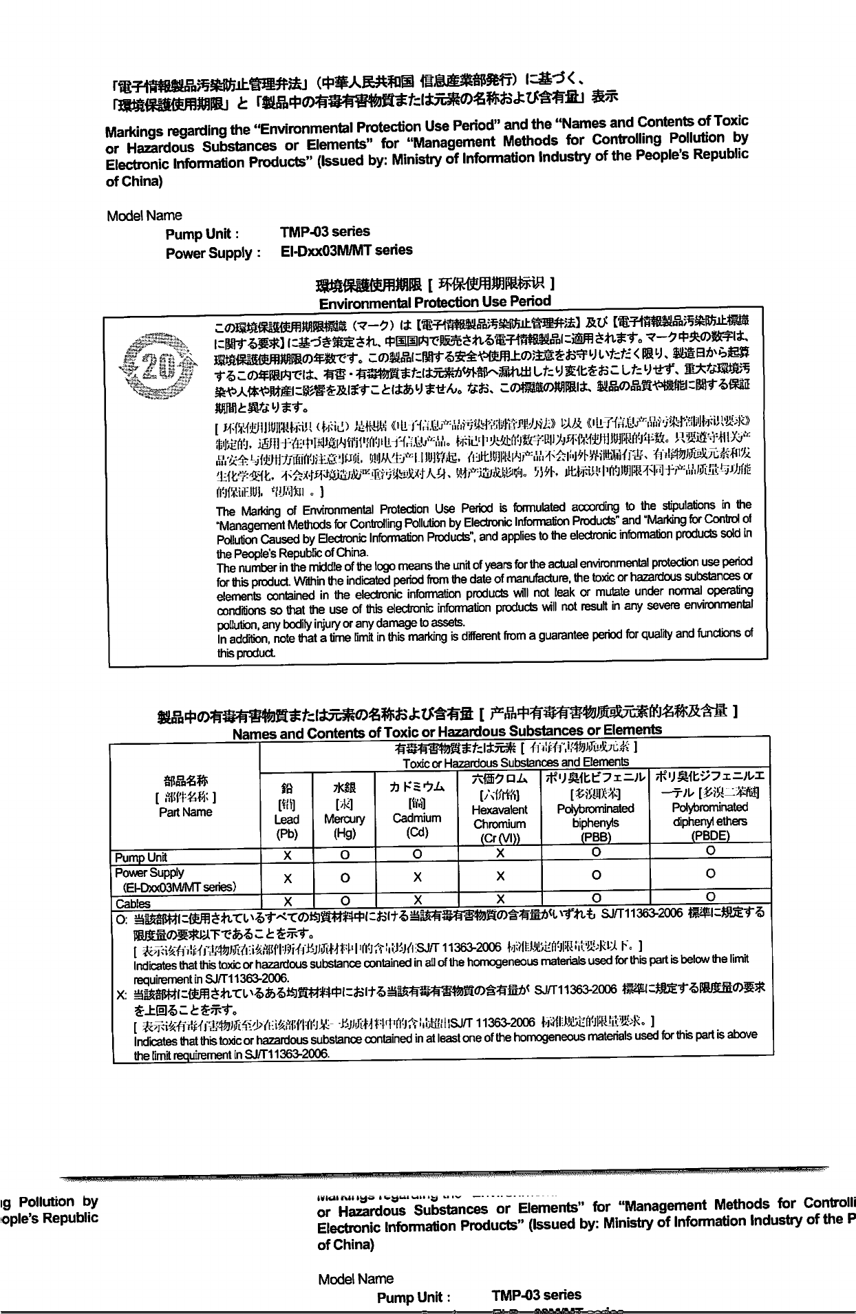
Markinqs
regarding
the
"Environmental
Protection
Use
Period"
and
the
"Names
and
Contents
of
Toxic
or
SrdlSs
Substances
or
Elements"
for
"Management
Methods
for
Confrolhng
Pollute
by
Electronic
Information
Products"
(Issued
by:
Ministry
of
Information
Industry
of
the
People's
Republic
of
China)
Model
Name
Pump
Unit:
TMP-03
series
Power
Supply
:
EI-DxxO3M/MT
series
Environmental
Protection
Use
Period
xxt
mm,
'j'M-
1
(fifiHiW
1
The
Marking
of
Environmental
Protection
Use
Period
is
formulated
according
to
the
stipulations
in
the
"Management
Methods
for
Controlling
Pollution
by
Electronic
Information
Products"
and
"Marking
for
Control
ot
Pollution
Caused
by
Electronic
Information
Products",
and
applies
to
the
electronic
information
producls
sold
in
the
People's
Republic
of
China.
The
number
in
the
middle
of
the
logo
means
the
unit
of
years
for
the
actual
environmental
protection
use
period
for
this
product
Within
the
indicated
period
from
the
date
of
manufacture,
the
toxic
or
hazardous
substances
a
elements
contained
in
the
electronic
information
products
will
not
leak
or
mutate
under
normal
operating
conditions
so
that
the
use
of
this
electronic
information
producls
will
not
result
in
any
severe
environmental
pollution,
any
bodily
injury
or
any
damage
to
assets.
In
addition,
note
that
a
time
limit
in
this
marking
is
different
from
a
guarantee
period
for
quality
and
functions
oi
this
product
Names
and
Contents
of
Toxic
or
Hazardous
Substances
or
Elements
Part
Name
Toxic
or
Hazardous
Substances
and
Elements
Lead
(Pb)
Mercury
(Hg)
Cadmium
(Cd)
Hexavalent
Chromium
(Cr(VI))
Poiybrominated
biphenyte
Poiybrominated
diphenyl
ethers
(PBDE)
Pump
Unit
O
OOO
Power
Supply
(El-DxxO3M/MT
series)
Cabl
OOO
aim
136^2006
Indicates
that
this
toxic
or
hazardous
substance
contained
in
all
of
the
homogeneous
materials
used
for
this
part
is
below
the
limit
Indicates
that
this
toxic
or
hazardous
substance
contained
in
at
least
one
of
the
homogeneous
materials
used
for
this
part
is
above
the
limit
requirement
in
SJ/T11363-2006.
.
ig
Pollution
by
ople's
Republic
or
„««.««-
w—«.
or
Elements"
for
"Management
Methods
for
Controlli
Electronic
Information
Products"
(Issued
by:
Ministry
of
Information
Industry
of
the
P
of
China)
Model
Name
Pump
Unit:
TMP-03
series


SHIMADZU
CORPORATION
SHIMAOZU
CORPORATION.
Intornatinal
Marketing
Division
3
Kanda-NishiWcho
1-chomo.
Chiyoda-ku.
Tokyo
101-8448.
Japan
Phone:81(3)3219-5641
Fax:81(3)3219-S710
SHIMADZU
PRECISION
INSTRUMENTS,
INC.
SEMICONDUCTOR
EQUIPMENT
USA
COMPANY
2340-C
Walsh
Avenue.
Sanla
Clara.
CA95O51.
USA
Phono
1(408)566-0960
Fax
1(408)5660961
hnp7/www.shimadzuv3cuumcom/
KRATOS
ANALYTICAL
LTD.
Whartside.
Trafford
Wharf
Road. Manchester
M17 1GP
U.K.
Phono:44(161)888-4400
Fux
44(161)888^1402
E-mail:vacuum@kratos.co.uk
SHIMADZU
(ASIA
PACIFIC)
PTE
LTD.
16
Science
Parti
Drive
B01-01
The
Pasteur
Singaporo
Science
Park.
Singaporo
118227.
Republic
of
Singaporo
Phone:6S-6778-62S0
Fax:65-6779-2935
SHIMADZU
INTERNATIONAL
TRADING
(SHANGHAI)
Co.,
LTD.
24m
Floor.
Shanghai
XinHualian
Building
No.755
Huaihai
Zhong
Lu.
Shanghai
200020
Phone
86(21)6472-8442
Fax
86(21)6472-8648

SZ
>
