2710 Series, Wide Heavy Duty Trench Drains, Modular Drains Series D2710
User Manual: 2710 Series
Open the PDF directly: View PDF ![]() .
.
Page Count: 2
Assembly ordering Information:
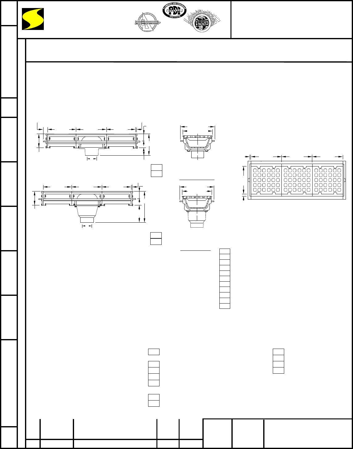
A and B sections are both 12"(305) long. A section
is the outlet section and available in the standard hub
or deep outlet hub (-DH). B section is the extension
section. It is recommended that no more than 5,12"(305)
extension sections on each side of the A outlet section be
used. Each section is 12" (305) long and end plates are
1 1/2"(38) thick including flange. In determining overall
length, multiply 12" (305) x no. of sections and add
3"(76) (thickness of the two end plates).
Free Area
39.3 SQ IN
(254)SQ CM
(Each Section)
REV. DATE DESCRIPTION BY CKD. BY
WEIGHT
POUNDS
VOLUME
CUBIC FEET FIGURE NUMBER
LOCATION
FIGURE
NUMBER
DIMENSIONS ARE SUBJECT TO MANUFACTURERS TOLERANCE AND CHANGE WITHOUT NOTICE WE CAN ASSUME NO RESPONSIBILITY FOR USE OF SUPERSEDED OR VOID DATA
DRAWN BY: CHECKED BY: APPROVED BY:
DATE:
SCALE: SIZE
A
DRAWING NUMBER
WIDE HEAVY DUTY TRENCH DRAINS
HEAVY DUTY MODULAR TRENCH DRAINS
FUNCTION: Used as a ramp drain in loading or parking areas where a wide continuous trench drain is required to handle moderate traffic
loads and serve as a reservoir for large water runoff. Can also be used individually as an area drain (A Section Only).
Note: Apply sealant provided
between each section and end
plate prior to assembling.
REGULARLY FURNISHED:
Duco Cast Iron Flanged Body
Outlet Section A and Flanged
End Plate with Cast Iron Anti-Shift
Loose Set Square Hole Grate.
ΔAdd 1 1/4" (32) when Bronze Top is specified.
Note: B sections are shown above with the A
section for illustrative purposes only. Only the
A section is regularly furnished and additional
B sections must be specified as determined by
figure number.
Shallow Hub Body
FIG. 2710C (-DH) ........CAULK OUTLET
FIG. 2710Y (-DH) ........NO-HUB OUTLET
13 3/4 (350)
12 1/4 (310)
End Section View
13 3/4 (350)
12 1/4 (310)
Fig. 2710C........ CAULK OUTLET
Fig. 2710Y........ NO-HUB OUTLET
End Section View
2710 Series
2710 Series EMB SB McD 11-6-89 NONE S2710 N
12 (305)12 (305)12 (305)3/8 (10)
11 1/4
(285)
Top View
A (Pipe Size) = 03(75), 04(100),
05(125), 06(150) or 08(200)
14 3/8 (365)Δ
8 1/2
(215)
A
12 (305) 12 (305) 12 (305)
3/8 (10)
2 1/4 (57)Δ
Δ5 7/8
(149)
B Section
A Section
B Section
1/2
(13)
2 1/4Δ
(57)
9 3/8 (238)Δ
3 1/2
(89)
A
1 1/2 (38) Typ.
12 (305) 12 (305) 12 (305)
3/8 (10)
B Section
A Section
B Section
A (Pipe Size) = 03(75), 04(100), 05(125), 06(150) or 08(200)
Δ5 7/8
(149)
FIG. 2710 . . . . . "A" Section
FIG. 2711 . . . . . "A" Section
FIG. 2712 . . . . . "A" Section
FIG. 2713 . . . . . "A" Section
FIG. 2714 . . . . . "A" Section
FIG. 2715 . . . . . "A" Section
FIG. 2716 . . . . . "A" Section
FIG. 2717 . . . . . "A" Section
FIG. 2718 . . . . . "A" Section
FIG. 2719 . . . . . "A" Section
FIG. 2720 . . . . . "A" Section
with (1) "B" Section
with (2) "B" Section
with (3) "B" Section
with (4) "B" Section
with (5) "B" Section
with (6) "B" Section
with (7) "B" Section
with (8) "B" Section
with (9) "B" Section
with (10) "B" Section
NOTE: Last digit of figure number designates number of "B" sections.
NOTE: Any figure number other than the 2710 and 2711 must be
furnished with sectional layout when placing order, to insure proper
assembly at jobsite.
Deep Hub Body
K 11-3-97 EMBRev Var. BS
L
M 4-1-14 Revised Text TBW CL
6-22-04 TBWRev Free Area CL
JAY R.
SMITH MFG. CO.
®
MEMBER OF MORRIS GROUP INTERNATIONAL
POST OFFICE BOX 3237
MONTGOMERY, ALABAMA 36109-0237 (USA)
TEL: 334-277-8520 FAX: 334-272-7396 www.jrsmith.com
CUSTOMER
DRIVEN
SMITH
®
MEMBER OF:
®
ASPE
®
S
A
N
I
T
A
R
Y
E
N
G
I
N
E
E
R
I
N
G
P
r
e
v
e
n
t
i
o
n
R
a
t
h
e
r
T
h
a
n
C
u
r
e
SINCE 1926
NOTE: Dimensions shown in
parentheses are in millimeters.
VARIATIONS:
Backwater Valve -V 02(50)
-04"(100) (Deep Hub Body Only)
Deep Hub -DH, Not Available in 08"(200)
Dome Bottom Strainer -DBS
Flashing Clamp -C
Sediment Bucket -B (Deep Hub
Body only)
Vandal Proof Grate -U
Quad Close Trap Seal
(Specify Fig. 2692)
OPTIONAL MATERIALS:
Ductile Iron Grate -M
Galvanized Cast Iron -G
Nickel Bronze Top -NB
Polished Bronze Top -PB
N 7-14-15 Revised Variations TBW CL
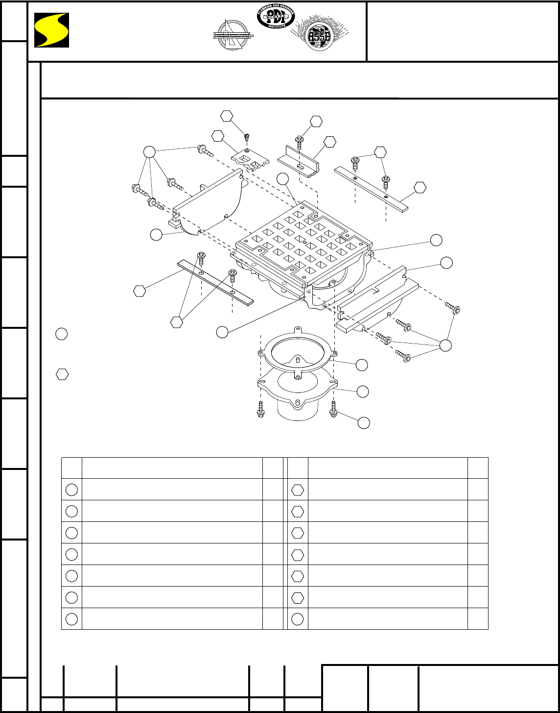
Flashing Flange
5/16(8)-18 x 3/4(19) Bolt with Washer
Body Veneer
5/16(8)-18 x 3/4(19) Bolt with Washer
Grate Veneer
10-24 x 7/16(11) Flat Head Screws
11
1
2
3
4
5
6
7
8
9
10
12
13
8
9
4
3
ASSEMBLY DRAWING
S2710BSNONE D
3-26-90
TD
BS
EMB
2710
Assembly Drawing
A3-91 Added Flange & Boss EMB 2710
Assembly Drawing
1
2
3
4
5
6
7
Flanged Body (Specify)
Grate
Flanged End Plates
5/16(8)-18 x 1 3/4(44) Bolts/Nuts & Washer
Hub (Specify Size)
Gasket
5/16(8)-18 x 1 1/4(32) Bolt & Washer
NO. DESCRIPTION
1
1
2
8
1
1
4
4
8
1
4
1
5
8
9
10
11
12
13
QU.* NO. DESCRIPTION QU.*
NOTES:
Numbers designated
thus are regularly fur-
nished parts.
Numbers designated
thus are variations/
options and must be
specified.
Quanities are per
section.
*
JCS
B6-19-95 Added Millimeters EMB BS
C
D 4-9-08 Revised Callouts TBW AM
11-5-97 Revised Dwg & Callouts EMB BS
14
JAY R.
SMITH MFG. CO.
®
MEMBER OF MORRIS GROUP INTERNATIONAL
POST OFFICE BOX 3237
MONTGOMERY, ALABAMA 36109-0237 (USA)
TEL: 334-277-8520 FAX: 334-272-7396 www.jrsmith.com
CUSTOMER
DRIVEN
SMITH
®
MEMBER OF:
S
A
N
I
T
A
R
Y
E
N
G
I
N
E
E
R
I
N
G
P
r
e
v
e
n
t
i
o
n
R
a
t
h
e
r
T
h
a
n
C
u
r
e
SINCE 1926
REV. DATE DESCRIPTION BY CKD. BY
WEIGHT
POUNDS
VOLUME
CUBIC FEET FIGURE NUMBER
LOCATION
FIGURE
NUMBER
DIMENSIONS ARE SUBJECT TO MANUFACTURERS TOLERANCE AND CHANGE WITHOUT NOTICE WE CAN ASSUME NO RESPONSIBILITY FOR USE OF SUPERSEDED OR VOID DATA
DRAWN BY: CHECKED BY: APPROVED BY:
DATE:
SCALE: SIZE
A
DRAWING NUMBER
Apply Permatex #2 Seal to each end
of each body section 2
14
®
ASPE
®
