3X Data Submittal STEAM
User Manual: 3X
Open the PDF directly: View PDF ![]() .
.
Page Count: 26

3524 East 4th St.
Hutchinson, KS 67501
Phone (620) 662-6693
Fax (620) 662-7586
www.superiorboiler.com
SUBMITTAL DATA
FOR
LOW PRESSURE STEAM

3524 East 4th St.
Hutchinson, KS 67501
Phone (620) 662-6693
Fax (620) 662-7586
www.superiorboiler.com
SUBMITTAL #
TABLE OF CONTENTS
SBW --------------------------- Superior Submittal Policy
SBW --------------------------- Specification Sheet ( 1 Pages)
SBW --------------------------- Boiler Bulletin
SBW Dwg. Boiler R&D Drawing
SBW Dwg. Submittal Wiring Diagram
SBW Form: SBSTC Terms and Conditions of Sale
SBW --------------------------- Warranty
SBW --------------------------- Boiler Unloading Instructions
SBW Form: SBWBOS Extended Outdoor Storage
SBW --------------------------- Boil-Out of a New Unit
SBW --------------------------- Space Requirements to Open
Rear Door
McDonnell-Miller Catalog Page 55 MM 157S Low Water Cut-Off
Apollo No. 70-105-01 Water Column Blowdown Valve
Warrick Form No. E-7 Series 26 Aux. Low Water Cutoff
Form No. D-22 Series 3E Fittings
3524 East 4th St.
Hutchinson, KS 67501
Phone (620) 662-6693
Fax (620) 662-7586
www.superiorboiler.com
SUBMITTAL #
TABLE OF CONTENTS
(Continued)
Honeywell Form 71-2429-2 L404 Pressuretrol Controllers
Honeywell Form 60-2156-1 L4079 Pressuretrol Limit Control
Honeywell Form 60-2152-5 L91 Pressuretrol Controllers
Ashcroft Catalog Page 74 Type 1379AS Pressure Gauge
Kunkle Model 6021 Bronze Safety Valves
PSIG
PSIG
********************************************************************************
ºF
PSI
PSI
COMPLETED BY:
MS
ASHCROFT
FIG. NO.
1379AS
L
X
W/GAUGE/TEST COCK
STEAM GAUGE:
DIAL
RANGE
0-300
PSI
6.00"
W/SYPHON
LS
RS
L404F 1102
10-150
RANGE
FIRING RATE
L91B 1050
1
1
SIZE
N/S
FIG. NO.
RANGE
M
M
OPERATOR
LIMIT
RANGE
RANGE
L4079B 1041
10-150
5-150
1
3-VALVE BY-PASS:
GATE FIG. NO. SIZE
PRESSURE. DO NOT EXCEED
SIZE
SIZE
PSI DROP ACROSS VALVE.
N/S
FIG. NO.
PRESSURE DROP ACROSS VALVE. PUMP SUPPLY PRESSURE
TO BE APPROXIMATELY
PSI ABOVE BOILER OPERATING
IMPORTANT:
PNEUMATIC MOD.
VALVE SELECTION BASED ON MINIMUM
LEVEL CONTROLLER
FIG. NO.
FEEDWATER CONTROL:
X
ON-OFF
N/S
FIG. NO.
ALARM
MODEL
CHEMICAL FEED VALVES:
SURFACE BLOWDOWN VALVE(S):
STOP
FIG. NO.
KUNKLE
SIZE
SET @
SET @
150
N/S
SHIP WEEK OF
RELEASED
DATE
WA&R
1
SPEC SHEET - STEAM
PAGE
S.O. NO.
NAT.BOARD NO.
OF
R&D SHEET
SUBMITTALS REQ'D:
SETS
PROPOSAL
DATE REQ'D:
MANUALS REQ'D:
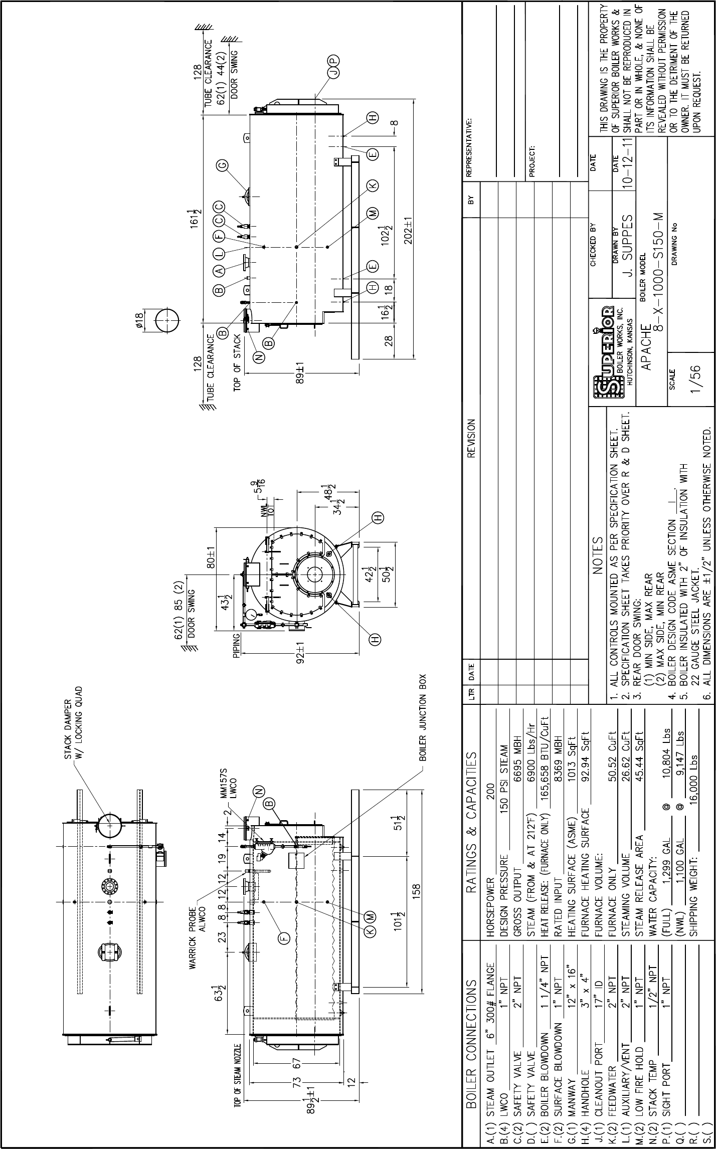
MODEL:
8-X-1000-S150-M
BURNER
GAS PIPING
W.D.
1.25" X 1.50"
I
OUTPUT
SIZE
2
6021GF
STACK DAMPER:
X
W/LOCKING QUAD
SUPERIOR
STACK THERMOMETER
PSI STEAM
N/S
DATE
FIG. NO.
SIZE
BY
N/S
L
FIG. NO.
CUTOFF
X
GAUGE GLASS
RS
AUX. L.W.C.O.:
PRIMARY L.W.C.O.
M
BOILER J-BOX
X
LS
RS
LS
TOP
MODEL
1
WARRICK 26MB1A0F/3E1B
1.00"
X
TOP
M
RS
PREPIPED/SHIPPED LOOSE
L
M
SHIPPED LOOSE
UL LABEL
P
N/A
N/S
FULL FIRETEST
NOT APPLICABLE
CF
SHIPPED MOUNTED
NOT SUPPLIED
CUSTOMER FURNISHED
LOW-FIRE ELECTRICAL TEST ONLY
SIZE
N/S
LEAKAGE RATE
SIZE
N/S
FULL LENGTH SKIMMER
FIG. NO.
N/S
FIG. NO.
FIG. NO.
SIZE
BOTTOM BLOWOFF VALVE(S):
SIZE
X
DATE
CSD-1
N/S
AIR VENT VALVE:
TURBULATORS:
M
BROCK
TYPE
ENG.:
SALES:
BOILER TO MEET THE FOLLOWING CODES:
SEAT
CLASS
RS
VALVE MAKE
FIG. NO.
FEEDWATER VALVE(S):
NOMINAL HP
DESIGN PRESSURE
200
SECTION
OPERATING PRESSURE
LS
GATE:
N/S
PSI STEAM
CHECK:
BLUE
PAINT
NAMEPLATE:
150
X
MBH
W/BEARINGS
JOB:
L
SAFETY VALVE(S):
LOCATION:
SOLD TO:
OIL PIPING
SUBMITTAL NO.
STATUS:
DATE RECEIVED:
RANGE
DIAL
STEM
X
CHAIN OPERATED
X
12 X 12 X 4 NEMA 1
TRI-COCKS
70-105-01
SIZE
WATER COLUMN BLOWDOWN VALVE(S);
MODEL
MM 157S
M
M
APOLLO
HIGH WATER
RS
LS
TOP
SIZE
PSI
M
LS
RS
LS
METERING
GLOBE
********************************************************************************
SIZE
N/S
RS
LS
SIZE
SIZE
ATC
MODEL NO.
M
ELECT.MOD.
INTEGRAL TO LWCO
ATO
REVISIONS
REV.
ORKS,
INC.
Quality
e·
Safety
e
Exceptional
Value
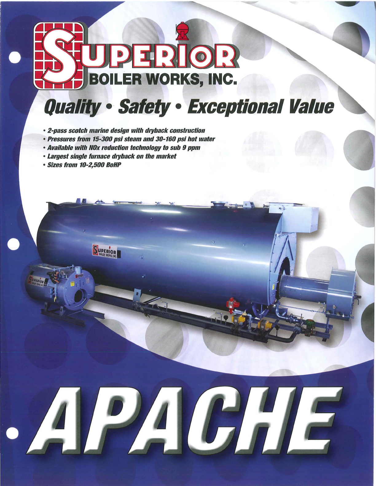
• 2-pass scotch marine design
with
dryback construction
• Pressures from 15-300
psi
steam
and
30-160
psi
hot
water
• Available
with
NOx
reduction technology
to
sub 9
ppm
• Largest single furnace dryback on the market
• Sizes from 10-2,500
BoHP
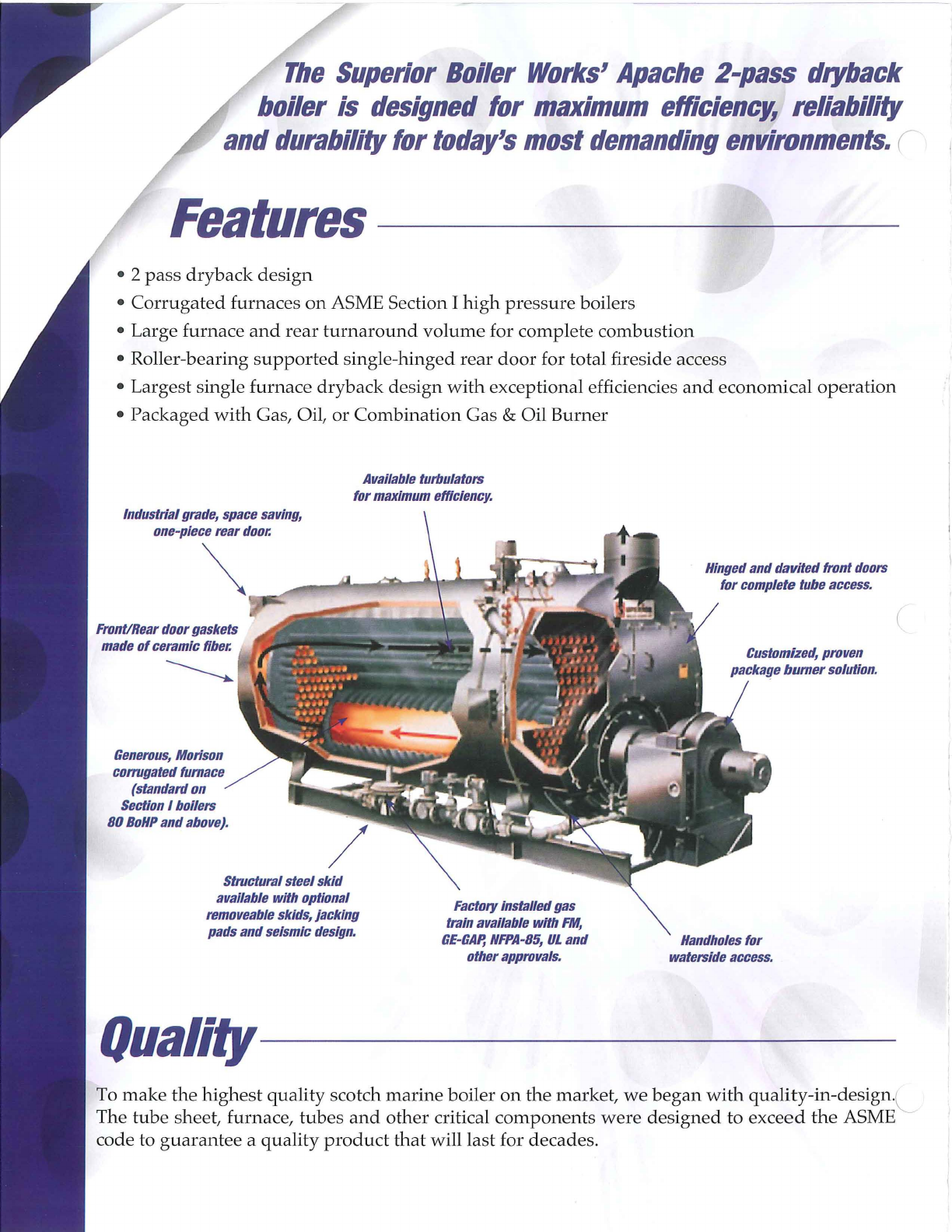
The
Superior
Boiler
Works'
Apache
2-pass
dryback
boiler
is
designed
for
maximum
efficiency,
reliability
and
durability
for
today's
most
demanding
environments.
(
Features
----------
--
----
• 2
pass
dryback
design
•
Corrugated
furnaces
on
ASME Section I
high
pressure
boilers
• Large furnace
and
rear
turnaround
volume
for complete
combustion
• Roller-bearing
supported
single-hinged
rear
door
for total fireside access
• Largest single furnace
dryback
design
with
exceptional efficiencies
and
economical
operation
•
Packaged
with
Gas, Oil,
or
Combination
Gas & Oil
Burner
Available
turbulators
for
maximum
efficiency.
Industrial
grade,
space
saving,
one-piece
rear
door.
~
Front/Rear
door
gaskets
made
of
ceramic
fiber.
Generous,
Morison
corrugated
furnace
(standard
on
Section
I
boilers
80
BoHP
and
above).
Structural
steel
skid
available
with
optional
removeable
skids,
jacking
pads
and
seismic
design.
Factory
installed
gas
train
available
with
FM,
GE
-
GAp,
NFPA-85,
UL
and
other
approvals.
Hinged
and
davited
front
doors
for
complete
tube
access.
Customized,
proven
package
bumer
solution.
Handholes
for
waterside
access.
QuaH~-----------------
To
make
the
highest
quality
scotch
marine
boiler
on
the
market,
we
began
with
quality-in-design
'L
The
tube
sheet, furnace,
tubes
and
other
critical
components
were
designed
to
exceed
the
ASME
code to
guarantee
a
quality
product
that
will last for decades.
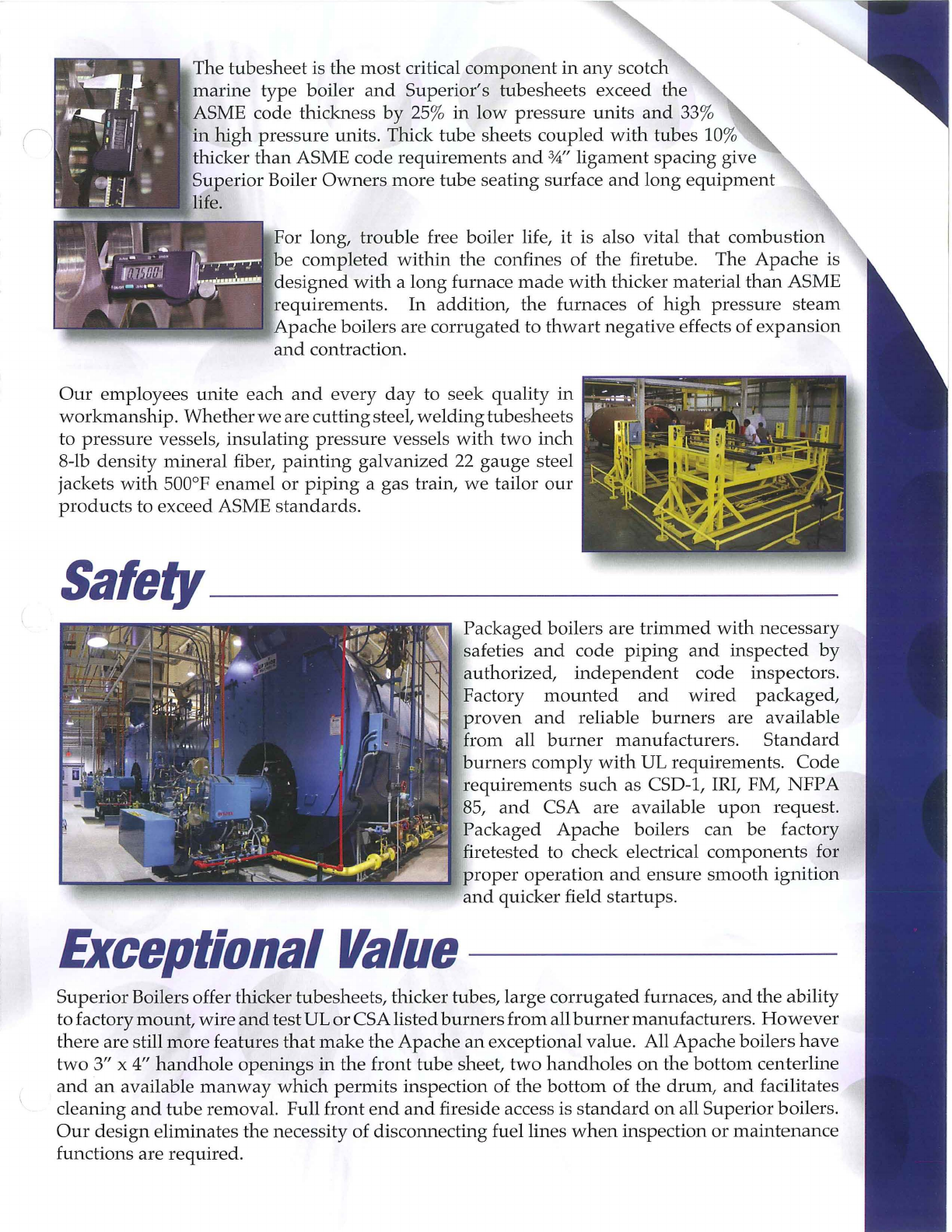
The
tubesheet
is
the
most
critical
component
in
any
scotch
marine
type
boiler
and
Superior's tubesheets exceed
the
ASME code thickness
by
25
%
in
low
pressure
units
and
33%
in
high
pressure
units. Thick tube sheets
coupled
with
tubes 10%
thicker
than
ASME code
requirements
and
3,4"
ligament
spacing give
Superior
Boiler
Owners
more
tube seating surface
and
long
equipment
life.
For long, trouble free boiler life, it is also vital
that
combustion
be
completed
within
the
confines of
the
firetube. The
Apache
is
designed
with
a
long
furnace
made
with
thicker material
than
ASME
requirements
. In addition,
the
furnaces of
high
pressure
steam
Apache
boilers are
corrugated
to
thwart
negative effects of
expansion
and
contraction.
Our
employees
unite
each
and
every
day
to seek quality
in
workmanship.
Whether
we
are
cutting
steel,
welding
tubesheets
to
pressure
vessels, insulating
pressure
vessels
with
two
inch
8-lb density mineral fiber,
painting
galvanized
22
gauge
steel
jackets
with
500°F
enamel
or
piping
a gas train,
we
tailor
our
products
to exceed ASME
standards.
Sare~----------------
Packaged
boilers are
trimmed
with
necessary
safeties
and
code
piping
and
inspected
by
authorized,
independent
code inspectors.
Factory
mounted
and
wired
packaged,
proven
and
reliable
burners
are available
from all
burner
manufacturers.
Standard
burners
comply
with
UL requirements.
Code
requirements
such
as CSD-1, IRI, FM,
NFP
A
85,
and
CSA are available
upon
request.
Packaged
Apache
boilers can be factory
firetested to check electrical
components
for
___
...
proper
operation
and
ensure
smooth
ignition
and
quicker field
startups
.
Exceptional
Value
-----
Superior
Boilers offer thicker tubesheets, thicker tubes, large
corrugated
furnaces,
and
the ability
to factory
mount,
wire
and
test UL
or
CSA listed
burners
from
all
burner
manufacturers.
However
there
are still
more
features
that
make
the
Apache
an
exceptional value. All
Apache
boilers
have
two
3" x 4"
handhole
openings
in
the front
tube
sheet,
two
handholes
on
the
bottom
centerline
and
an
available
manway
which
permits
inspection of
the
bottom
of
the
drum,
and
facilitates
cleaning
and
tube
removal. Full front
end
and
fireside access is
standard
on
all Superior boilers.
Our
design
eliminates
the
necessity of disconnecting fuel lines
when
inspection
or
maintenance
functions are
required
.
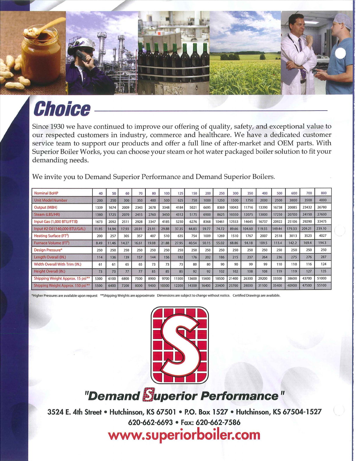
Choice
Since 1930
we
have
continued
to
improve
our
offering of quality, safety,
and
exceptional
value
to
our
respected customers
in
industry, commerce
and
healthcare. We
have
a
dedicated
customer
service
team
to
support
our
products
and
offer a full line of after-market
and
OEM parts.
With
Superior Boiler Works,
you
can choose
your
steam
or
hot
water
packaged
boiler
solution
to fit
your
demanding
needs.
We invite
you
to
Demand
Superior Performance
and
Demand
Superior Boilers.
40 50 60 70 80 100
125
150 200 250 300 350 400 500
600
700 800
200 250 300 350 400 500 625 750 1000 1250 1500 1750 2000 2500
3000
3500 4000
1339 1674 2009 2343 2678 3348 4184
5021
6695 8369 10043 11716 13390 16738 20085 23432 26780
1380 1725 2070 2415 2760 3450 4312 5175 6900 8625 10350 12075 13800 17250 20700 24150 27600
1673 2092
2511
2928 3347 4185 5230 6276 8368
10461
12553 14645 16737 20922 25106 29290 33475
I
nput
#12
Oil
(140,000
BTU/GAL) 11.95 14.
94
17.93 20.
91
23
.
91
29.
88
37.35 44.83 59.77 74.72 89.66 104.60 119.55 149.44 179.33 209.
21
239.
10
200 257 305 357 407 510 635 754 1009 1269 1510 1767 2007 2518 3013 3523 4027
Furnace
Volume
(FT') 8.49 11.46 14.
27
16.
61
19.08 21.88 27.95 40.54 50.15 55.02 68.86 94.18 109.5 113.4 142.2 169.4 194.3
250 250 250 250 250 250 250 250 250 250 250 250 250 250 250 250 250
Length
Overa
ll
(IN.)
114 136 139 157 144 156 182 176 202 186 215 237 264 236 275 276 287
Width
Overall With Trim (
IN
.)
61
61
65
65 73
73 73
80 80 90 90 99 99 110
110
116 124
73 73 77 77 85 85 85 92 92 102 102 108 108 119
119
127 135
Shipping
Weig ht
Appro
x. 15 psi" 5300 6100 6800 7500 8900 9700 11500 13600 15600 18500 21400 26300 29200 33500 38600 43700 51000
Shipping
Wei
ght
Approx. 150 psi " 5500 6400 7200 8000 9400 10300 12200 14300 16400 20400 23700 28000 31100 35400 40900 47500 55100
"Higher
Pressures
are
available
upon
request
**Shipping
Weights
are
approximate Dimens
ions
ar
e subject to
change
without
notice.
Certified
Drawings
are
available.
"Demand
If/
uperior
Performance"
3524
E.
4th
Street
•
Hutchinson,
KS
67501
•
P.O.
Box
1527 •
Hutchinson,
KS
67504-1527
620-662-6693 •
Fax:
620-662-7586
www.superiorboiler.com
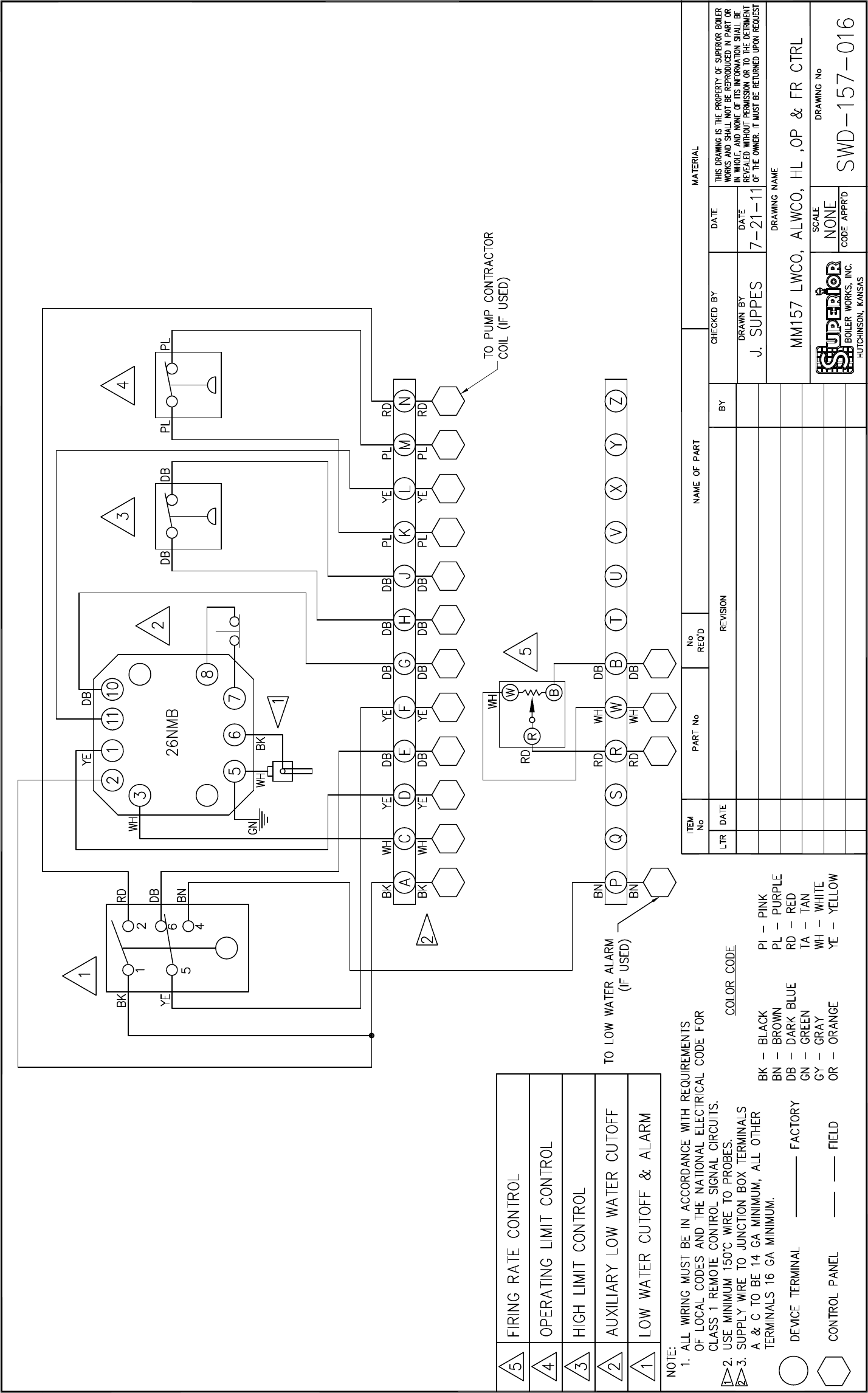
BOILER CONTROLS
55
B
OILER
C
ONTROLS
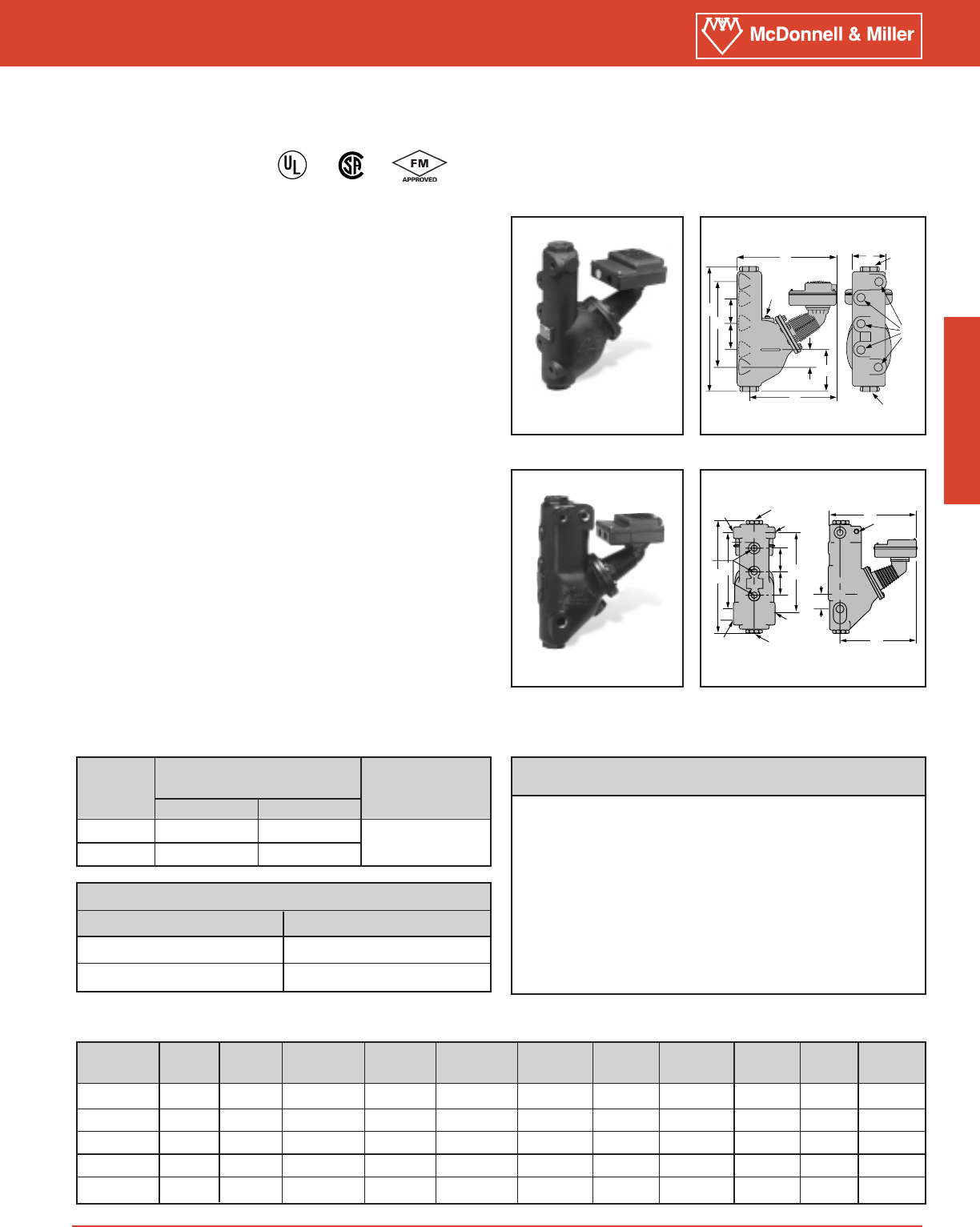
Series 157S
Model 157S-RBP-MD
G
H
E
D
J
C
F
J
K
A
B
LA
B
B
B
GL
AB
A
A
B
C
F
JH
J
D
Series 157S
Low Water Cut-Off/Pump Controllers
Low Water Cut-Offs – Mechanical
For Steam Boilers
®
®
•For residential, commercial and industrial low or high
pressure boiler applications
•For boilers of any steaming capacity
•Monel bellows provides corrosion resistance
•Float chamber with integral water column provided
•`Snap action for high temperature service
–1 Single pole, single throw switch for pump control
–1 Single pole, double throw switch for low water
cut-off and alarm actuation
•Optional features
–Manual reset
–Integral conductance probes for additional levels and
greater operating differential-Model 157S-RBP-MD
–1" or 11⁄4" NPT equalizing tappings
–1⁄2" or 3⁄4" NPT tappings for gauge glass/tri-cock
installations
–BSPT threads
•Maximum pressure 150 psi (10.5 kg/cm2)
•For new electronic 150E Series see page 41
Model 157S-MD
Maximum differential operation
–Prevents nuisance burner shutdowns in low pressure
applications
–Maximum operating pressure 50 psi (3.5 kg/cm2)
–For additional information see page 56
Dimensions, in. (mm)
Ordering Information
Alarm Circuit Rating (Amperes)
Voltage Amps
120 VAC 1
240 VAC 1/2
Electrical Ratings
Cut-off and Pump
Circuits Rating (Amperes)
Voltage Full Load Locked Rotor Pilot Duty
120 VAC 7.4 44.4 345 VA at
240 VAC 3.7 22.2 120 or 240 VAC
Model Part Weight
Number Number Description lbs. (kg)
157S 173502
150S low water cut-off w/water column
39.7 (18.0)
157S-MD 173603 157S w/maximum differential 39.7 (18.0)
157S-A 173702 157S w/alternate tappings 39.5 (17.9)
157S-A-M 173802 157S-A w/manual reset 39.5 (17.9)
157S-M 175402 157S w/manual reset 39.7 (18.0)
157S-M-MD 175412 157S-M w/maximum differential 39.7 (18.0)
157S-R 176220 157S w/alternate tappings 42.0 (19.0)
157S-R-M 177306 157S-R w/manual reset 42.0 (19.0)
157S-RBP-MD 176503 157S w/2 integral conductance probes 51.0 (23.1)
157S-RL 176902 157S w/alternate tappings 42.0 (19.0)
157S-RL-M 177006 157S-RL w/manual reset 42.0 (19.0)
Model A B C D E F G H J K L
NPT NPT NPT
157S 1 1⁄2133⁄8(339) 25⁄16 (59) 415⁄16 (125)
113⁄4(298) 16 (406) 111⁄2(292) 31⁄2(89) 3⁄457⁄8 (149)
157S-A 11⁄43⁄4133⁄8 (339) 25⁄16 (59) 415⁄16 (125)
113⁄4(298) 16 (406) 111⁄2(292) 31⁄2(89) 3⁄457⁄8 (149)
157S-R 1 1⁄2133⁄8 (339) 21⁄4 (57) 57⁄8 (149)
113⁄4(298) 17 (432) 111⁄2(292) 31⁄2(89) 3⁄461⁄4 (159)
157S-RL 11⁄41⁄2139⁄16 (345) 31⁄2 (89) 57⁄8 (149)
113⁄4(298) 17 (432) 123⁄4(324) 31⁄2(89) 3⁄461⁄4(159)
157S-RBP-MD
11⁄2139⁄16 (345) 21⁄4 (57) 57⁄8 (149)
113⁄4(298) 17 (432) 111⁄2(292) 31⁄2(89) NA 121⁄4(324)
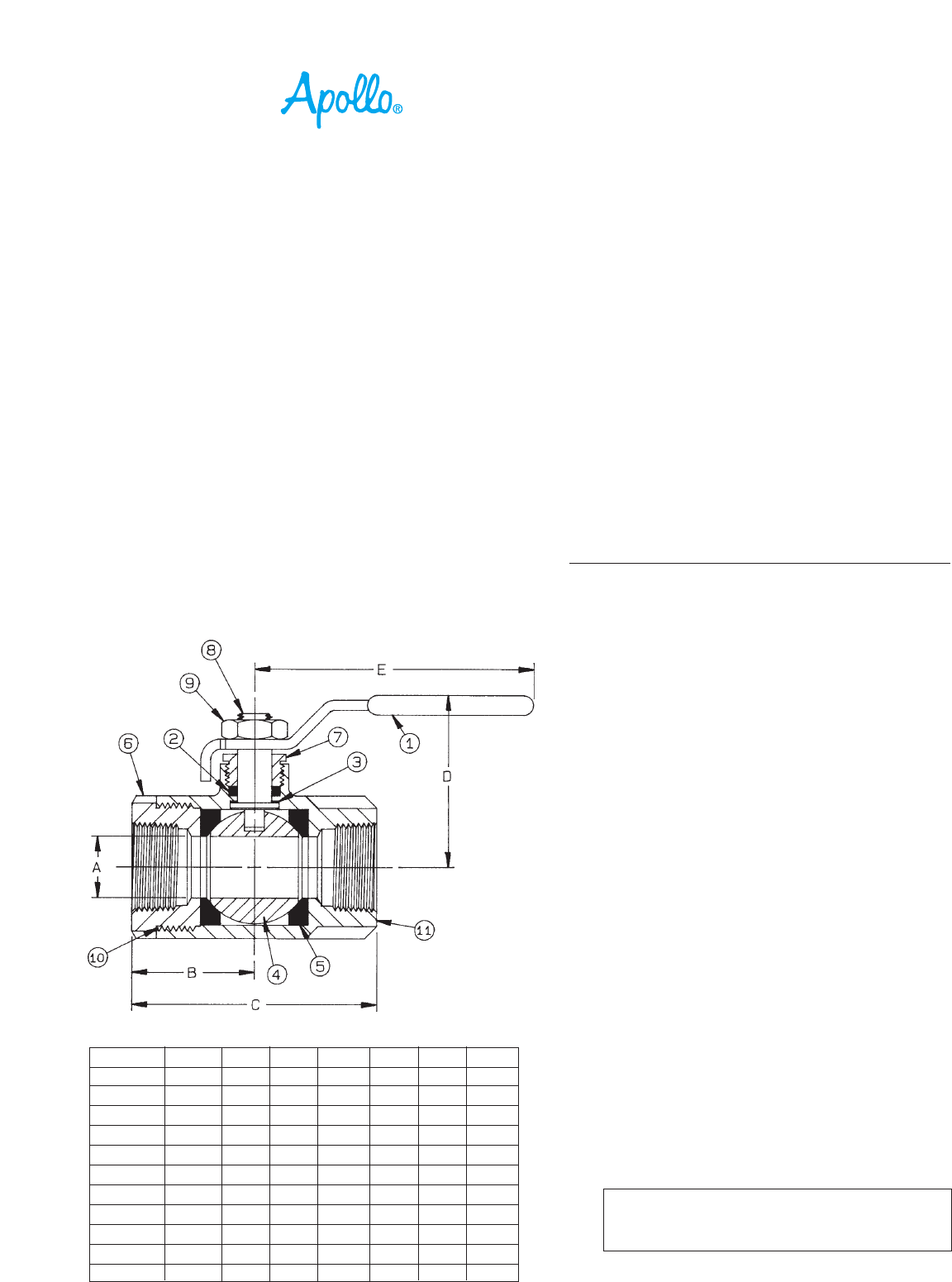
NUMBER SIZE A B C D E Wt.
70-101-01 1/4" .37 1.03 2.06 1.75 3.87 .60
70-102-01 3/8" .37 1.03 2.06 1.75 3.87 .56
70-103-01 1/2" .50 1.12 2.25 1.75 3.87 .63
70-104-01 3/4" .68 1.50 3.00 2.12 4.87 1.39
70-105-01 1" .87 1.68 3.37 2.25 4.87 1.72
70-106-01 1-1/4" 1.00 2.00 4.00 2.62 5.50 3.26
70-107-01 1-1/2" 1.25 2.18 4.37 3.06 8.00 4.61
70-108-01 2" 1.50 2.34 4.68 3.25 8.00 6.06
70-109-01A 2-1/2" 2.00 3.12 6.25 3.72 8.00 17.25
70-100-01 3" 2.50 3.37 6.75 4.12 8.00 18.60
70-10A-01 4" 3.12 3.68 7.37 5.25 10.00 25.50
COPYRIGHT ©2003 CONBRACO IND., INC. – PRINTED IN U.S.A.
70-100 Series
Bronze Ball Valve
Threaded, 600 psig WOG, Cold Non-Shock. 150 psig Saturated Steam. (See referenced P/T charts)
Vacuum Service to 29 inches Hg.
Federal Specification: WW-V-35C, Type: II, Composition: BZ, Style: 3.
MSS SP-110; Ball Valves Threaded, Socket-Welding, Solder Joint, Grooved and Flared Ends.
FEATURES
• Chromium plated ball • Blow-out-proof stem design
• RPTFE seats and stuffing box ring • Adjustable packing gland
STANDARD MATERIAL LIST
1. Lever and grip Steel, zinc plated w/vinyl 7. Gland nut B16
2. Stem packing RPTFE 8. Stem B16
3. Stem bearing RPTFE 9. Lever nut Steel, zinc plated
4. Ball B16, chrome plated 10. Body seal PTFE
5. Seat (2) RPTFE (1-1/4" to 3")
6. Retainer B16 (1/4" to 1") 11. Body B584-C84400
B584-C84400 (1-1/4" to 3")
VARIATIONS AVAILABLE:
70-120 Series (Adjustable Stop Lever)
70-140 Series (316 SS Ball & Stem)
70-150 Series (Balancing Stop)
70-190 Series (Locked Retainer)
OPTIONS AVAILABLE:
(SUFFIX) OPTION SIZES
-02- Stem Grounded 1/4" to 3"
-03- 1-1/4" CS Stem Extension 1/4" to 3"
-04- 2-1/4" CS Stem Extension 1/4" to 3"
-05- Plain Ball 1/4" to 3"
-07- Steel Tee Handle 1/4" to 2"
-08- 90º Reversed Stem 1/4" to 3"
-10- SS Lever & Nut 1/4" to 3"
-14- Side Vented Ball (Uni-Directional) 1/4" to 3"
-15- Wheel Handle, Steel 1/4" to 2"
-16- Chain Lever - Vertical 3/4" to 2"
-17- Rough Chrome Plated - Bronze Valves 1/4" to 3"
-21- UHMWPE Trim (Non-PTFE) 1/4" to 3"
-24- Graphite Packing 1/4" to 3"
-27- SS Latch-Lock Lever & Nut 1/4" to 3"
-30- Cam-Lock and Grounded 1/4" to 2"
-32- SS Tee Handle & Nut 1/4" to 2"
-35- VTFE Trim 1/4" to 3"
-36- SS Hi-Rise Round Handle, SS Nut 1/4" to 2"
-39- SS Hi-Rise Locking Wheel Handle, SS Nut 1/4" to 2"
-40- Cyl-Loc and Grounded 1/4" to 2"
-41- Automatic Drain (Bronze Valves Only) 1/4" to 2"
see page J-8
-45- Less Lever & Nut 1/4" to 3"
-46- Latch Lock Lever - Lock in Closed Position Only 1/4" to 3"
-47- SS Oval Latch-Lock Handle & Nut 1/4" to 1"
-48- SS Oval Handle (No Latch) & Nut 1/4" to 2"
-49- Assembled Dry 1/4" to 3"
-50- 2-1/4" CS Locking Stem Extension 1/4" to 3"
-56- Multifill Seats & Packing 1/4" to 3"
-57- Oxygen Cleaned 1/4" to 3"
-58- Chain Lever - Horizontal 3/4" to 2"
-60- Static Grounded Ball & Stem 1/4" to 3"
-63- NPT x Solder/Socket Weld 3/8" to 3"
-64- 250# Steam Trim 1/4" to 3"
-P01- BSPP (Parallel) Thread Connection 1/4" to 3"
-T01- BSPT (Tapered) Thread Connection 1/4" to 3"
BRONZE BALL VALVE
A-1
For Pressure/Temperature Ratings,
Refer to Page M-8, Graph No. 4
E-7
Visit www.GemsSensors.com for most current information.
XXXXX26M XX XX
1. Series
26M
2. Sensitivity
A – 4.7K
B – 10K
C – 26K
3. Supply Voltage
1 – 120 VAC
3 – 24 VAC 8 – 208/240 VAC
4. Socket Style
A – 11 Pin Octal
5. Enclosure
0 – None
6. Option Package
See page D-36, Chart B for code letter.
7. Time Delay (decreasing level) Option
03-90 seconds
Blank 3 seconds
8. Time Delay (increasing level) Option
00-90 seconds
Blank 0 seconds
D – 50K
E – 100K
2 – 240 VAC
1 – NEMA 1 4 – NEMA 4
B – DIN Mount M – None, Module Only
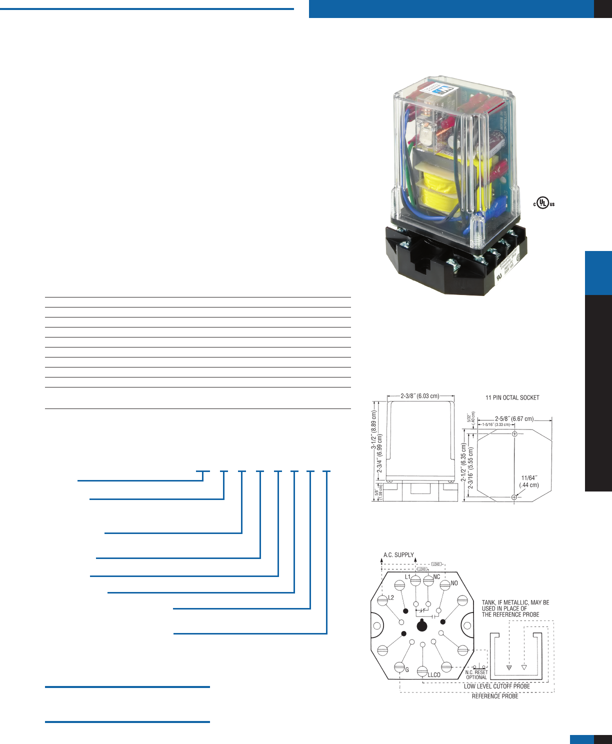
WARRICK CONDUCTIVITY SENSORS
Series 26 Modules
Low-Water Cutoff – Plug-In Modules
Powered Contacts Solid State Reliability
Modular Plug-In Design LED Monitoring
Low Voltage Sensor Time Delays Available
11-Pin Socket Meets CSD1 Requirements
U.L. “Limit Control” Optional Test Feature
Optional Dirty Electrode Detection
Optional Manual Reset Button Feature.
If Level Drops, Control is Deactivated Until Liquid Level
Returns to Normal and Pushbutton is Depressed
Optional Power Outage Feature Ignores Nuisance Outages
and Resets When Power is Restored
Series 26M – General Purpose Control
Series 26M is designed for low-water cutoff protection. This control meets CSD1
requirements for boiler low water cutoff. Series 26M features powered contacts.
If non-powered contacts are required, request information on Series 26NM.
Specifications
Contact Design 1 N.O. & 1 N.C. (powered)
Contact Rating (24/120/240VAC) 10 amp Resistive 1/3 hp
Mode of Operation Direct
Sensitivity 0 - 26K ohm, factory set
Primary Voltage 24 VAC, 120 VAC, 240 VAC1
Secondary Voltage 12 VAC
Temperature -40°F to +150°F (-40°C to +65°C)
Approvals1 U.L. 353 File # MP1430
Terminal Style Screw connector
Options Time Delays, Power Outage, Manual Reset, Test Feature,
Dirty electrode detection; See page E-11 for descriptions
Notes:
1. 240 VAC and 208/240 VAC units do not carry U.L. Limit Control recognition.
Series 26M
Applications
• Low-WaterCutoff
• PointLevel
• Alarms
Dimensions
Note: Controls also available with DIN mount socket.
Wiring
Caution: Contacts are powered. If non-powered contacts are required,
request information on Series 26NM.
Socket Details and Option Availability
are located on web site.
How to Order
Use the Bold characters from the chart below to construct a product code.
lOW-WATER CUTOff
WARRICK CONDUCTIVITY SENSORS
D-21
WARRICK CONDUCTIVITY SENSORS
www.gemssensors.com
D-22
seireS fo.oN
seborP
tnemhcattA
lesseVot
tiudnoC
eziSdaerhTssoB
eziSgnisuoHlanimreT
)˝Hx˝Dx˝W(
E3
1 TPN˝1 TPN˝2/1 4/1-2x4/1-2x4/1-2
2 TPN˝2 TPN˝2/1 8/3-2x4/1-3x4/1-3
3 TPN˝2 TPN˝2/1 8/3-2x4/1-3x4/1-3
4 TPN˝2/1-2 TPN˝2/1 8/3-2x4/1-3x4/1-3
5 TPN˝3 TPN˝4/3 2/1-2x4x4
6 TPN˝3 TPN˝4/3 2/1-2x4x4
7 TPN˝3 TPN˝4/3 2/1-2x4x4
N3
1
˝2/1-1,daptalferauqs˝4/1-2
deruceslessevfopotnieloh.aid
ehttaswercsenihcam01#htiw
erauqs˝2/1-1afosrenroc
TPN˝2/1 4/1-2x4/1-2x4/1-2
2 TPN˝2/1 8/3-2x4/1-3x4/1-3
3 TPN˝2/1 8/3-2x4/1-3x4/1-3
XX3E
Series
3E
Number of Probes1
1 – One
2 – Two
3 – Three
4 – Four
Body Material
A – Cast Iron (3E)
PVC (3N)
B – Red Brass
C – 316 Stainless Steel
5 – Five
6 – Six
7 – Seven
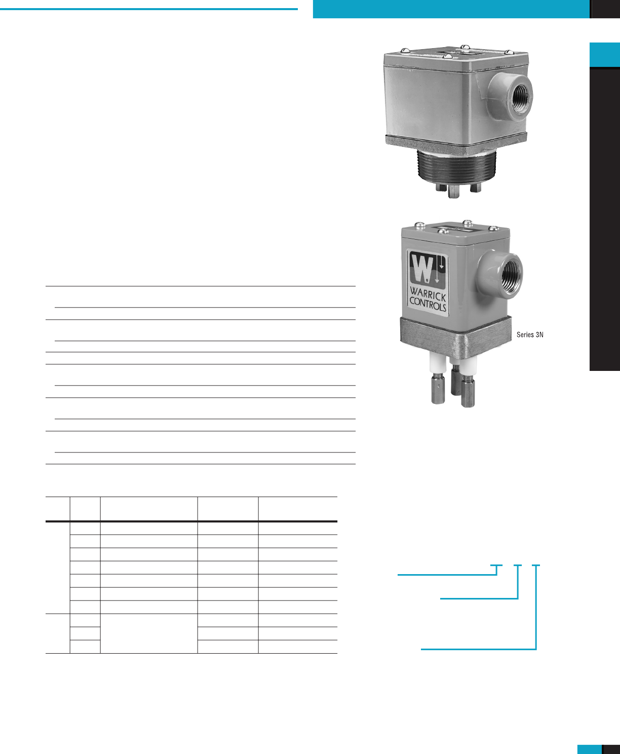
3N
Series 3E – Pipe Thread Attachment
Series 3N – Flat Surface Mounting
Up to 7 Probes
Flat Mounting (3N)
Threaded Attachment (3E)
Available in Various Body Metals
CSA Approved
U.L. Recognized (3E)
FM Approved (3E)
Series 3E ttings are cast metal, pressure-tight assemblies capable
of handling 1-7 probes. Attachment to vessels is accomplished with
external pipe threading. 3E Fittings require the use of 3R rigid or 3W
wire suspended electrodes.
Series 3N ttings accommodate 1-3 probes operating at atmospheric
pressure. The assembly mounts on a at surface atop open tanks
or closed vessels. 3N Fittings require the use of 3R rigid or 3W wire
suspended electrodes.
Speci cations
Type of Connection
Series 3E
Threaded
Series 3N
Flat Surface Mounting
Probes
Series 3E
1 thru 7
Series 3N
1 thru 3
Terminal Housing
Die cast aluminum, epoxy coated
Body Material
Series 3E
Cast iron, red brass, 316 stainless steel
Series 3N
PVC, red brass, 316 stainless steel
Pressure/Temperature
Series 3E
125 psig @ 353°F (cast iron); 250 psig @ 406°F (brass, 316 s.s.)
Series 3N
0 psig @ 150°F (PVC); 0 psig @ 500°F (brass, 316 s.s.)
Approvals
Series 3E
U.L. File # MP2489, Vol. 1, Sec. 2; CSA; FM
Series 3N
CSA File # LR11644
Dimensions
Series 3E
Applications
•
Open Tanks
•
Closed Vessels
•
Water
•
Diluted Corrosive Liquids
How to Order
Use the
Bold
characters from the chart below to
construct a product code.
Notes:
1.
3N features up to three probes only.
2.
Special modi cations available. Consult factory.
Series 3N
FITTINGS AND PROBES
Honeywell
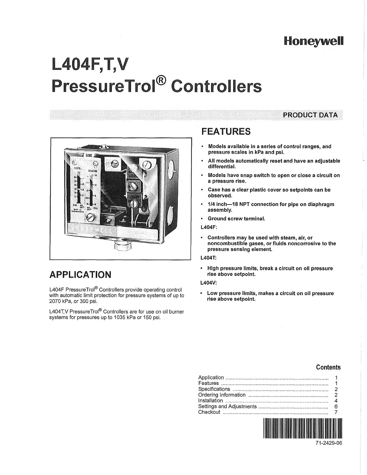
L404F, ,
PressureTrol®
ontrollers
APPLICATION
L404F PressureTrol® Controllers provide operating control
with automatic limit protection for pressure systems
of
up to
2070 kPa, or 300 psi.
L404T,V PressureTrol® Controllers are for use
on
oil burner
systems for pressures up to 1035 kPa or 150 psi.
PRODUCT DATA
FEATURES
• Models available
in
a series of control ranges, and
pressure scales
in
kPa and psi.
• All models automatically reset and have an adjustable
differential.
• Models have snap switch to open or close a circuit on
a pressure rise.
• Case has a clear plastic cover so setpoints can be
observed.
• 1/4
inch-18
NPT connection for pipe on diaphragm
assembly.
• Ground screw terminal.
L404F:
• Controllers may
be
used with steam, air,
or
noncombustible gases, or fluids noncorrosive to the
pressure sensing element.
L404T:
• High pressure limits, break a circuit on oil pressure
rise above setpoint.
L404V:
• Low pressure limits, makes a circuit on oil pressure
rise above setpoint.
Contents
Application ............... ..... ........... ...... ........ ................... ........ 1
Features ........................................................................... 1
Specifications ................................................. .................. 2
Ordering Information ....................... .............. ................... 2
Installation ............ ............................................... ............. 4
Settings and Adjustments .............................. ....
...
............ 6
Checkout .......................................................................... 7
11111111111111111111111
71-2429-06
L404F,
T,
V PRESSURETROL ® CONTROLLERS
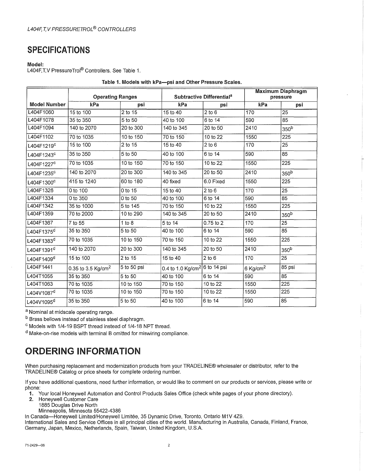
SPECIFICATIONS
Model:
L404F,T,V PressureTrol® Controllers. See Table
1.
Table
1.
Models
with
kPa-psi
and
Other
Pressure Scales.
Maximum Diaphragm
Operating Ranges
Subtractive
Differentiala
pressure
Model
Number
kPa
psi
kPa
psi
kPa
psi
L404F1060
15
to 100 2
to
15
15
to
40 2 to 6 170 25
L404F1078
35
to 350 5
to
50 40 to 100 6 to
14
590
85
L404F1094 140
to
2070 20 to 300 140
to
345 20 to 50 2410 350b
L404F1102 70 to 1035 10 to 150 70
to
150 10 to 22 1550 225
L404F1219c
15
to 100 2 to
15
15
to
40 2 to 6 170 25
L404F1243c
35
to 350 5
to
50 40 to 100 6
to
14
590
85
L404F1227c 70 to 1035 10
to
150 70 to 150
10
to 22 1550 225
L404F1235c 140 to 2070 20
to
300 140
to
345 20 to 50 2410 350b
L404F1300c 415 to 1240 60 to 180 40 fixed 6.0 Fixed 1550 225
L404F1326 o to 100 o to 15 15 to 40 2
to
6 170 25
L404F1334 o to 350 o
to
50 40 to 100 6 to
14
590 85
L404F1342 35 to 1000 5
to
145 70
to
150
10
to 22 1550 225
L404F1359 70 to 2000 10 to 290 140 to 345 20 to 50 2410 350b
L404F1367 7 to
55
1 to 8 5 to 14 0.75
to
2 170 25
L404F1375d 35 to 350 5 to 50 40 to 100 6
to
14
590
85
L404F1383d 70 to 1035 10
to
150 70
to
150
10
to 22 1550 225
L404F1391 d 140 to 2070 20 to 300 140 to 345 20 to 50 2410 350b
L404F1409d
15
to 100 2 to 15
15
to 40 2
to
6 170 25
L404F1441 0.35 to 3.5 Kg/cm2 5
to
50 psi 0.4
to
1.0 Kg/cm2 6 to
14
psi 6 Kg/cm2 85 psi
L404T1055 35 to 350 5
to
50 40
to
100 6 to
14
590
85
L404T1063 70 to 1035 10 to 150 70
to
150
10
to 22 1550 225
L404V1087d 70 to 1035 10
to
150 70 to 150 10 to 22 1550 225
L404V1095d 35 to 350 5 to 50 40 to 100 6
to
14
590
85
a Nominal at midscale operating range.
b Brass bellows instead
of
stainless steel diaphragm.
c Models with 1/4-19 BSPT thread instead
of
1/4-18 NPT thread.
d Make-on-rise models with terminal B omitted for miswiring compliance.
ORDERING INFORMATION
When purchasing replacement and modernization products from your TRADELlNE® wholesaler or distributor, refer to the
TRADELlNE® Catalog or price sheets for complete ordering number.
If
you have additional questions, need further information, or would like to comment
on
our products
or
services, please write
or
phone:
1. Your local Honeywell Automation
and
Control Products Sales Office (check white pages
of
your phone directory).
2.
Honeywell Customer Care
1885 Douglas Drive North
Minneapolis, Minnesota 55422-4386
In
Canada-Honeywell
Limited/Honeywell Limitee, 35 Dynamic Drive, Toronto, Ontario M1V 4Z9.
International Sales and Service Offices
in
all principal cities of the world. Manufacturing
in
Australia, Canada, Finland, France,
Germany, Japan, Mexico, Netherlands, Spain, Taiwan, United Kingdom, U.S.A.
71-2429-06 2
L404F,T,V PRESSURETROL ® CONTROLLERS
Table
2.
Conversion
Table.
Operating Range
Conversions
kg/cm2 kPa psi
0.1
to 1.05 15 to 100 2 to 15
0.4
to
3.5 35 to 350 5 to 50
0.7
to
10.0 70 to 1035 10
to
150
1.5
to
20.0 140 to 2070 20
to
300
Table
3.
Switch
Ratings (Amperes).
Switch
State 120 Vac 240 Vac
Full Load 8.0
5.1
Locked Rotor 48.0 30.6
Pressure Sensing Element: Stainless steel diaphragm (140
to 2070 kPa models) has brass bellows.
Maximum
Ambient
Temperature: 66°C (150°F). Also, refer
to note under Mounting.
Adjustment
Means: Screws on top
of
control case. Scales are
marked
in
psi
or kPa.
Mounting
Means:
1/4
inch-18 NPT connection on diaphragm
assembly; or surface mounts using holes
in
back of case.
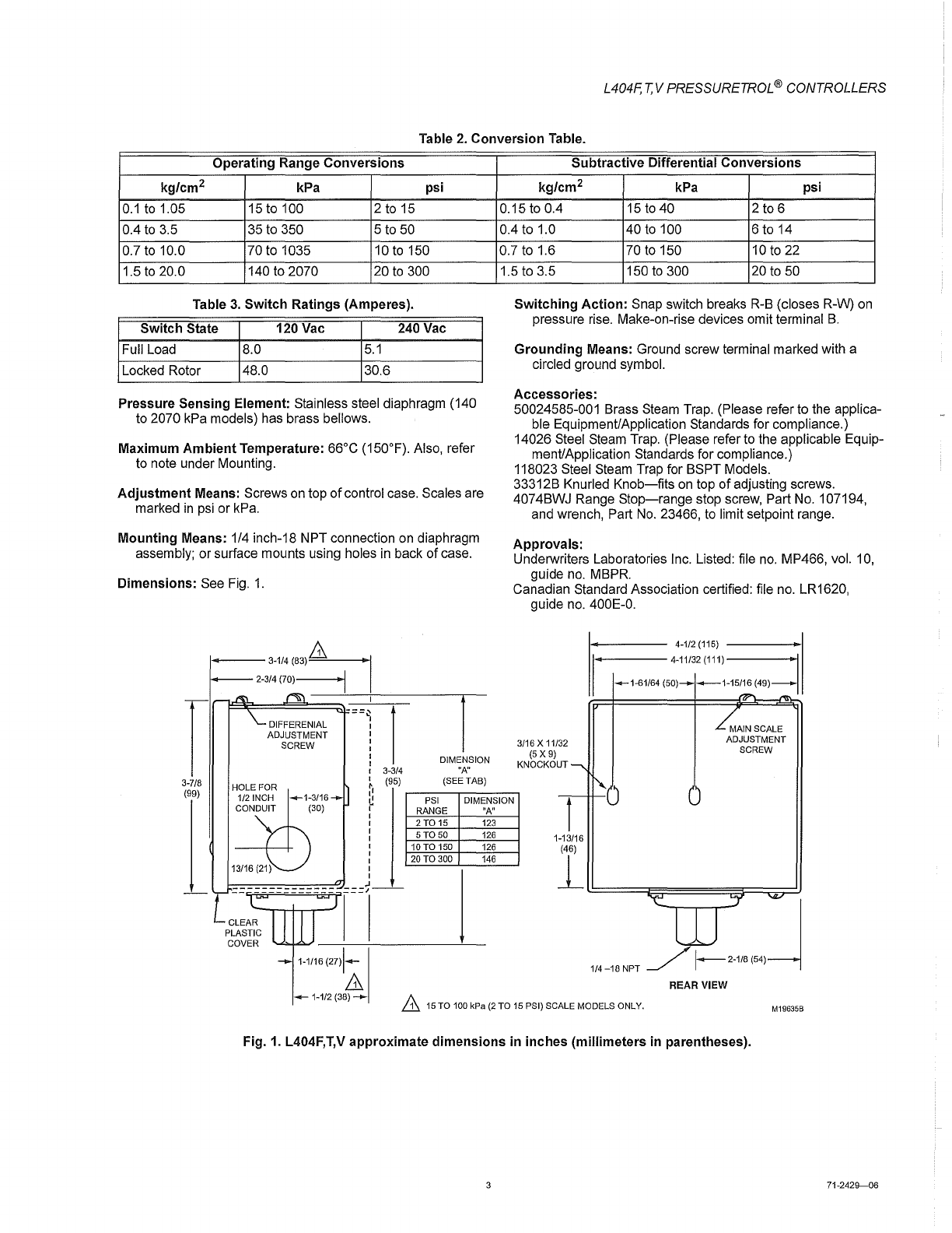
Dimensions: See
Fig.
1.
r
3-1/4(83)~
2-3/4
(70)
-
"I
I
--~--+---------.--
~I?==~~====i;l-
=
=~
HOLE
FOR
I
I
I
I
I
: DIMENSION
I 3-3/4
"A"
Subtractive
Differential
Conversions
kg/cm2 kPa psi
0.15toO.4
15
to
40 2 to 6
0.4 to 1.0 40
to
100 6 to 14
0.7 to 1.6 70 to 150
10
to
22
1.5 to 3.5 150
to
300 20
to
50
Switching
Action:
Snap switch breaks R-B (closes R-W)
on
pressure rise. Make-on-rise devices omit terminal
B.
Grounding
Means: Ground screw terminal marked with a
circled ground symbol.
Accessories:
50024585-001 Brass Steam Trap. (Please refer to the applica-
ble Equipment/Application Standards for compliance.)
14026 Steel Steam Trap. (Please refer to the applicable Equip-
ment/Application Standards for compliance.)
118023 Steel Steam Trap for BSPT Models.
33312B Knurled
Knob-fits
on
top
of
adjusting screws.
4074BWJ Range
Stop-range
stop screw, Part
No.
107194,
and wrench, Part
No.
23466, to limit setpoint range.
Approvals:
Underwriters Laboratories Inc. Listed: file
no.
MP466, vol.
10,
guide
no.
MBPR.
Canadian Standard Association certified: file no. LR1620,
guide
no.
400E-0.
3/16 X 11/32
(5X9)
KNOCKOUT
1_----
4-1/2(115)
--------1
..
1
MAIN
SCALE
ADJUSTMENT
SCREW
3-7/8
(99)
1/2
INCH
__
1-3/16
CONDUIT
(30)
~,
(95)
(SEE
TAB)
~
r--P~SI--~DI~M~EN~S~IO~N~
t
:
RANGE
"A"
I
2T015
123
:
5T050
126
1-13/16
I
10
TO
150 126
:
20
TO
300
146
I
I
---~-----------
r~cl-
~~====~~======~==~~
1-1/16 (27)1---
11
REAR VIEW
___
1-1/2
(38)
----
11
15
TO
100
kPa
(2
TO
15
PSI)
SCALE
MODELS
ONLY.
M19635B
Fig. 1. L404F,T,V
approximate
dimensions
in
inches
(millimeters in parentheses).
71-2429-06
Honeywell
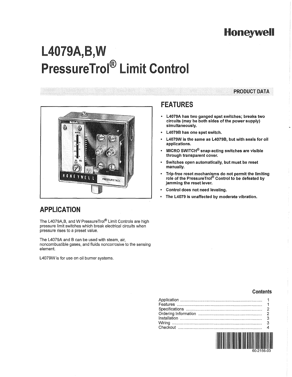
L4079A,B,
PressureTrol®
Limit
Control
APPLICATION
The L4079A,B, and W PressureTrol® Limit Controls are high
pressure limit switches which break electrical circuits when
pressure rises to a preset value.
The L4079A and B can be used with steam,
air,
noncombustible gases, and fluids noncorrosive to the sensing
element.
L4079W
is
for use
on
oil burner systems.
PRODUCT
DATA
FEATURES
• L4079A has two ganged spst switches; breaks two
circuits (may be both sides
of
the power supply)
simultaneously.
o L40798 has one spst switch.
• L4079W is the same as L40798, but with seals for oil
applications.
• MICRO SWITCH® snap-acting switches are visible
through transparent cover.
• Switches open automatically, but must be reset
manually.
• Trip-free reset mechanisms do not permit the limiting
role
of
the PressureTrol® Control to be defeated by
jamming the reset lever.
• Control does not need leveling.
• The L4079
is
unaffected by moderate vibration.
Contents
Application ........................................................... ............. 1
Features ........................................................................... 1
Specifications ................................................................... 2
Ordering Information .... .................................................... 2
Installation ................................................ ...........
...
.......... 3
Wiring ............................................................................... 3
Checkout .......................................................................... 4
L4079A,B, W PRESSURETROL ®
LIMIT
CONTROL
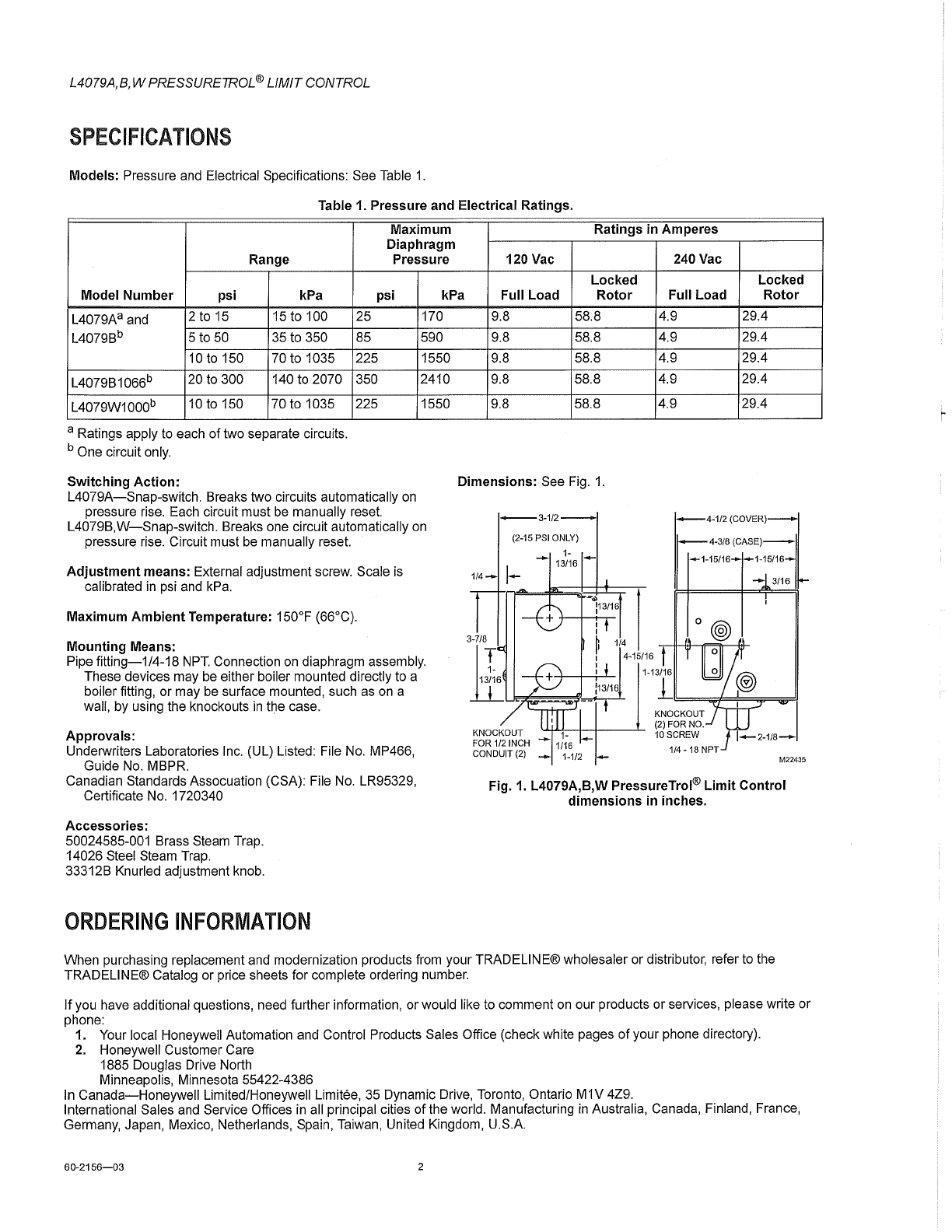
SPECIFICATIONS
Models:
Pressure and Electrical Specifications: See Table
1.
Table 1. Pressure and Electrical Ratings.
Maximum
Ratings
in
Amperes
Diaphragm
Range Pressure 120 Vac 240 Vac
Locked
Locked
Model
Number
psi kPa
psi
kPa Full Load
Rotor
Full
Load
Rotor
L4079Aa and 2 to 15
15
to 100
L4079Bb 5 to 50 35 to 350
10
to
150 70 to 1035
L4079B1066b 20 to 300 140 to 2070
L4079W1000b
10
to 150 70 to 1035
a Ratings apply to each
of
two separate circuits.
b One circuit
only.
Switching
Action:
25
85
225
350
225
L4079A-Snap-switch. Breaks two circuits automatically
on
pressure rise. Each circuit must
be
manually reset.
170
590
1550
2410
1550
L4079B,W-Snap-switch. Breaks one circuit automatically
on
pressure rise. Circuit must
be
manually reset.
Adjustment
means: External adjustment screw. Scale
is
calibrated
in
psi and kPa.
Maximum
Ambient
Temperature: 150°F (66°C).
Mounting
Means:
Pipe
fitting-1/4-18
NPT.
Connection
on
diaphragm assembly.
These devices may
be
either boiler mounted directly to a
boiler fitting, or may
be
surface mounted, such as
on
a
wall, by using the knockouts
in
the case.
Approvals:
Underwriters Laboratories Inc. (UL) Listed: File No. MP466,
Guide No. MBPR.
Canadian Standards Assocuation (CSA): File No. LR95329,
Certificate
No.
1720340
Accessories:
50024585-001 Brass Steam Trap.
14026 Steel Steam Trap.
33312B Knurled adjustment knob.
ORDERING
INFORMATION
9.8 58.8
9.8 58.8
9.8 58.8
9.8 58.8
9.8 58.8
Dimensions:
See Fig.
1.
4.9 29.4
4.9 29.4
4.9 29.4
4.9 29.4
4.9 29.4
4-3/8
(CASE)-
~15/16
-1-15/16
1
~4_1/2
(COVER)
II
-3/16
M22435
Fig.
1.
L4079A,B,W PressureTrol®
Limit
Control
dimensions
in inches.
When purchasing replacement and modernization products from your TRADELlNE® wholesaler or distributor, refer to the
TRADELlNE® Catalog or price sheets for complete ordering number.
If
you have additional questions, need further information, or would like to comment
on
our products or services, please write or
phone:
1. Your local Honeywell Automation and Control Products Sales Office (check white pages
of
your phone directory).
2.
Honeywell Customer Care
1885 Douglas Drive North
Minneapolis, Minnesota 55422-4386
In
Canada-Honeywell
Limited/Honeywell Limitee,
35
Dynamic Drive, Toronto, Ontario M1V 4Z9.
International Sales and Service Offices
in
all principal cities of the world. Manufacturing
in
Australia, Canada, Finland, France,
Germany, Japan, Mexico, Netherlands, Spain, Taiwan, United Kingdom, U.S.A.
60-2156-03
2
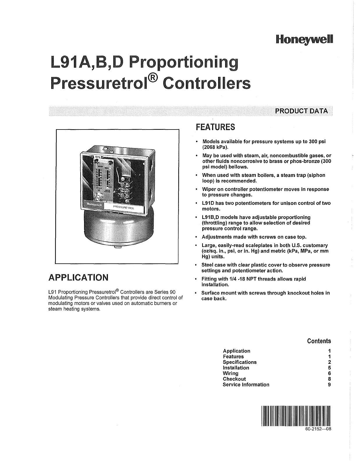
Honeywell
L91
,
,0
Propo
ioning
Pressuretrol®
Controllers
APPLICA
TION
L91
Proportioning Pressuretrol® Controllers are Series 90
Modulating Pressure Controllers that provide direct control
of
modulating motors or valves used
on
automatic burners or
steam heating systems.
PRODUCT DATA
FEATURES
• Models available
for
pressure systems up to 300 psi
(2068 kPa).
• May be used with steam, air, noncombustible gases,
or
other
fluids
noncorrosive
to
brass
or
phos-bronze (300
psi model) bellows.
• When used
with
steam boilers, a steam trap (siphon
loop) is recommended.
• Wiper on controller potentiometer moves in response
to
pressure changes.
•
L91
D has two potentiometers
for
unison control
of
two
motors.
•
L91
B,D models have adjustable proportioning
(throttling) range
to
allow
selection
of
desired
pressure control range.
• Adjustments made
with
screws on case top.
• Large, easily-read scaleplates in both U.S. customary
(oz/sq. in., psi,
or
in. Hg) and metric (kPa,
MPa,
or
mm
Hg) units.
• Steel case with clear plastic cover
to
observe pressure
settings and potentiometer action.
• Fitting with 1/4
-18
NPT threads allows rapid
installation.
• Surface
mount
with screws through
knockout
holes in
case back.
Application
Features
Specifications
Installation
Wiring
Checkout
Service Information
Contents
1
1
2
5
6
8
9
60-2152-08
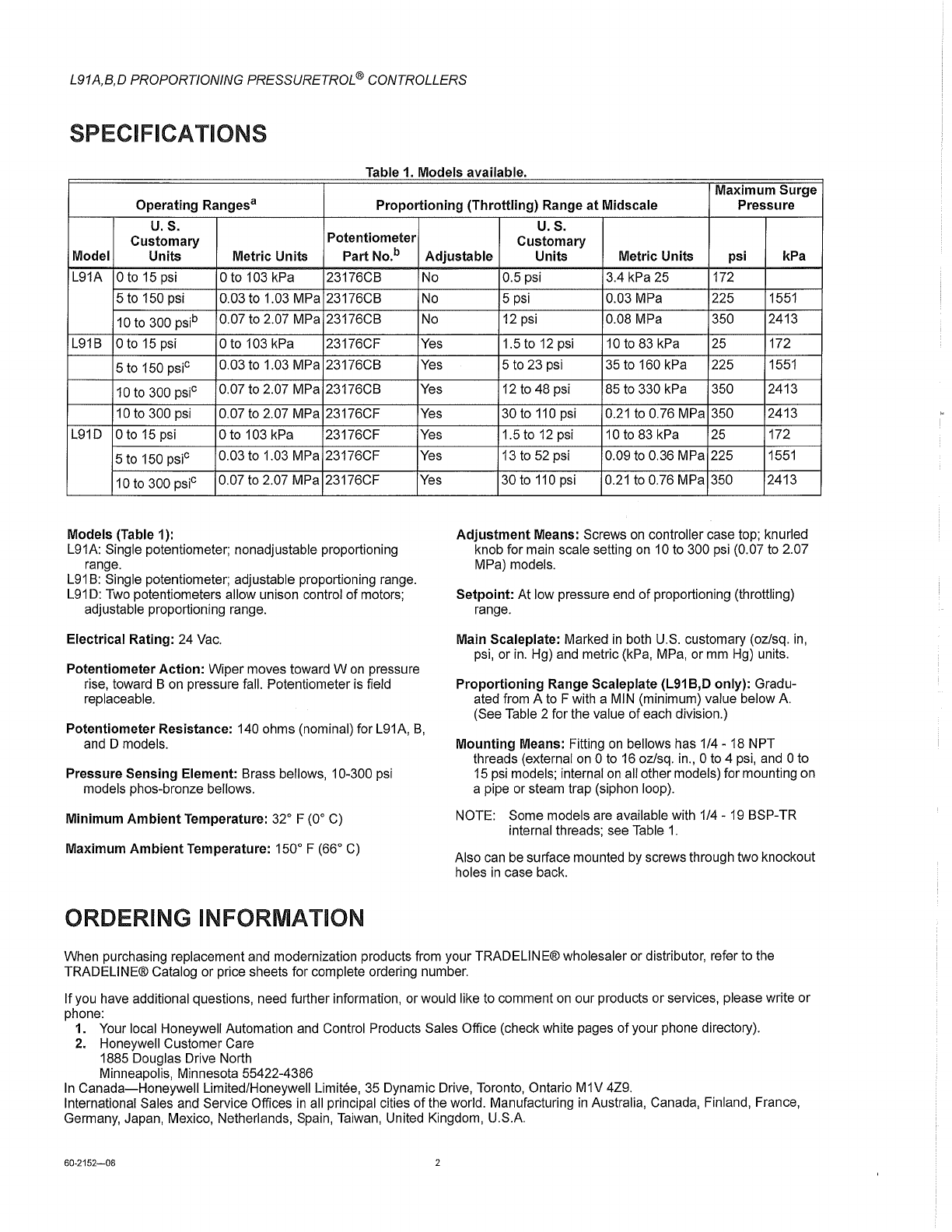
L91A,B,O PROPORTIONING PRESSURETROL ® CONTROLLERS
SPECIFICATIONS
Table 1 Models available
Maximum
Surge
Operating Rangesa
Proportioning
(Throttling)
Range
at
Midscale Pressure
U.S. U.S.
Customary
Potentiometer
Customary
Model
Units
Metric
Units Part No.b
Adjustable
Units Metric Units psi kPa
L91A o
to
15 psi o to 103 kPa 23176CB
5 to 150 psi 0.03 to 1.03 MPa 23176CB
10
to
300 psib 0.07 to 2.07 MPa 23176CB
L91B o to 15 psi o to 103 kPa 23176CF
5 to 150 psic 0.03 to 1.03 MPa 23176CB
10
to
300 psic 0.07 to 2.07 MPa 23176CB
10 to 300 psi 0.07
to
2.07 MPa 23176CF
L91D Oto
15
psi o to 103 kPa 23176CF
5 to 150 psic 0.03 to 1.03 MPa 23176CF
10
to 300 psic 0.07 to 2.07 MPa 23176CF
Models (Table 1):
L91A: Single potentiometer; nonadjustable proportioning
range.
L91
B:
Single potentiometer; adjustable proportioning range.
L91
D:
Two potentiometers allow unison control
of
motors;
adjustable proportioning range.
Electrical Rating: 24
Vac.
Potentiometer
Action:
Wiper moves toward
Won
pressure
rise, toward B on pressure fall. Potentiometer
is
field
replaceable.
No
No
No
Yes
Yes
Yes
Yes
Yes
Yes
Yes
Potentiometer
Resistance: 140 ohms (nominal) for L91A,
B,
and D models.
Pressure
Sensing
Element: Brass bellows, 10-300 psi
models phos-bronze bellows.
Minimum
Ambient
Temperature:
32
0 F (00
C)
Maximum
Ambient
Temperature: 1500 F (660
C)
ORDERING INFORMATION
0.5 psi 3.4 kPa 25 172
5 psi 0.03 MPa 225
1551
12 psi 0.08 MPa 350 2413
1.5to12psi
10
to
83
kPa 25 172
5
to
23 psi
35
to 160 kPa 225
1551
12
to
48 psi
85
to 330 kPa 350 2413
30 to
110
psi 0.21 to 0.76 MPa 350 2413
1.5to
12psi
10 to
83
kPa 25 172
13
to
52 psi 0.09
to
0.36 MPa 225
1551
30 to
110
psi 0.21 to 0.76 MPa 350 2413
Adjustment
Means: Screws
on
controller case top; knurled
knob for main scale setting
on
10 to 300 psi (0.07 to 2.07
MPa) models.
Setpoint:
At low pressure end
of
proportioning (throttling)
range.
Main Scaleplate: Marked
in
both U.S. customary (oz/sq.
in,
psi, or
in.
Hg) and metric (kPa, MPa, or
mm
Hg) units.
Proportioning
Range Scaleplate (L91 B,D only): Gradu-
ated from A to F with a MIN (minimum) value below A
(See Table 2 for the value of each division.)
Mounting
Means: Fitting
on
bellows has 1/4 -
18
NPT
threads (external
on
0
to
16
oz/sq.
in.,
0 to 4
psi,
and 0 to
15
psi models; internal
on
all other models) for mounting on
a pipe or steam trap (siphon loop).
NOTE: Some models are available with 1/4 -
19
BSP-TR
internal threads; see Table
1.
Also can
be
surface mounted by screws through two knockout
holes
in
case back.
When purchasing replacement and modernization products from your TRADELlNE® wholesaler or distributor, refer to the
TRADELlNE® Catalog or price sheets for complete ordering number.
If
you have additional questions, need further information, or would like to comment
on
our products or services, please write
or
phone:
1. Your local Honeywell Automation and Control Products Sales Office (check white pages
of
your phone directory).
2.
Honeywell Customer Care
1885 Douglas Drive North
Minneapolis, Minnesota 55422-4386
In
Canada-Honeywell
Limited/Honeywell Limitee, 35 Dynamic Drive, Toronto, Ontario M1V 4Z9.
International Sales and Service Offices
in
all principal cities
of
the world. Manufacturing
in
Australia, Canada, Finland, France,
Germany, Japan, Mexico, Netherlands, Spain, Taiwan, United Kingdom, U.S.A.
60-2152-08
2
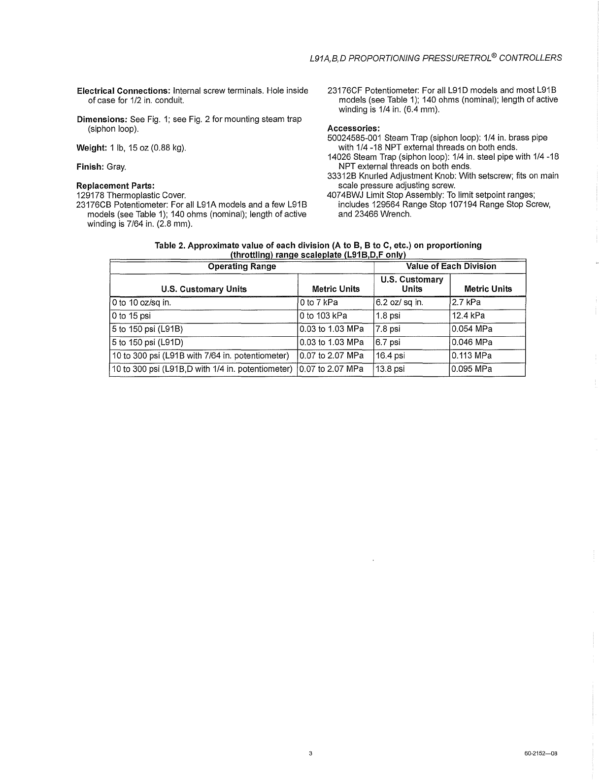
Electrical
Connections:
Internal screw terminals. Hole inside
of
case for 1/2
in.
conduit.
Dimensions:
See
Fig.
1;
see
Fig.
2 for mounting steam trap
(siphon loop).
Weight: 1
Ib,
15
oz (0.88 kg).
Finish:
Gray.
Replacement Parts:
129178 Thermoplastic Cover.
23176CB Potentiometer: For all L91A models and a few L91B
models (see Table
1);
140 ohms (nominal); length
of
active
winding
is
7/64
in.
(2.8 mm).
L91A,B,D PROPORTIONING PRESSURETROL ® CONTROLLERS
23176CF Potentiometer: For all
L91
D models and most L91B
models (see Table
1);
140 ohms (nominal); length
of
active
winding
is
1/4
in.
(6.4 mm).
Accessories:
50024585-001 Steam Trap (siphon loop): 1/4
in.
brass pipe
with 1/4 -18 NPT external threads
on
both ends.
14026 Steam Trap (siphon loop): 1/4 in. steel pipe with 1/4 -18
NPT external threads on both ends.
33312B Knurled Adjustment Knob: With setscrew; fits
on
main
scale pressure adjusting screw.
4074BWJ Limit Stop Assembly:
To
limit setpoint ranges;
includes 129564 Range Stop 107194 Range Stop Screw,
and 23466 Wrench.
Table
2.
Approximate
value
of
each
division
(A
to
e,
e
to
C,
etc.)
on
proportioning
(throttlina)
ranae
scaleplate
(L91 e D F
onlv)
Operating
Range Value
of
Each
Division
U.S.
Customary
U.S.
Customary
Units
Metric
Units Units Metric Units
o
to
10
oz/sq in. o to 7 kPa 6.2 oz/
sq
in.
2.7 kPa
Ot015psi
o to 103 kPa 1.8 psi 12.4 kPa
5
to
150 psi
(L91
B)
0.03 to 1.03 MPa 7.8 psi 0.054 MPa
5
to
150 psi (L91D) 0.03 to 1.03 MPa 6.7 psi 0.046 MPa
10 to 300 psi
(L91
B with 7/64
in.
potentiometer) 0.07
to
2.07 MPa 16.4 psi 0.113 MPa
10
to 300 psi
(L91
B,D with 1/4 in. potentiometer) 0.07
to
2.07 MPa 13.8 psi 0.095 MPa
3
60·2152-08
L91A,B,O PROPORTIONING PRESSURETROL ® CONTROLLERS
60-2152-08
L91A,B,D
--
4-112
(114.3)
(COVERr------
4-11/32
(110.3)
(CASE)
__
1 ....
--
3-57/64
(98.;B)---
__
1
3-13/32
(86.5)----
...
1
1-5/32
(29.4)
/
1-3/16
(30.2)
1-1/16
(27.0)
&!
, I
,
3-23132
(27.8)
,
(94.5)
10
TO
300
OTO
15
1-13/16
~~~~===t==~~==~
01
0
)
,-I
, '
, '
" '
-1-
,.
,
3-7/8
(98.4)
2-5/64
(52.8)
1_1/16-=1
(27.0)
DIM
B
(SEE
TABULATION
&
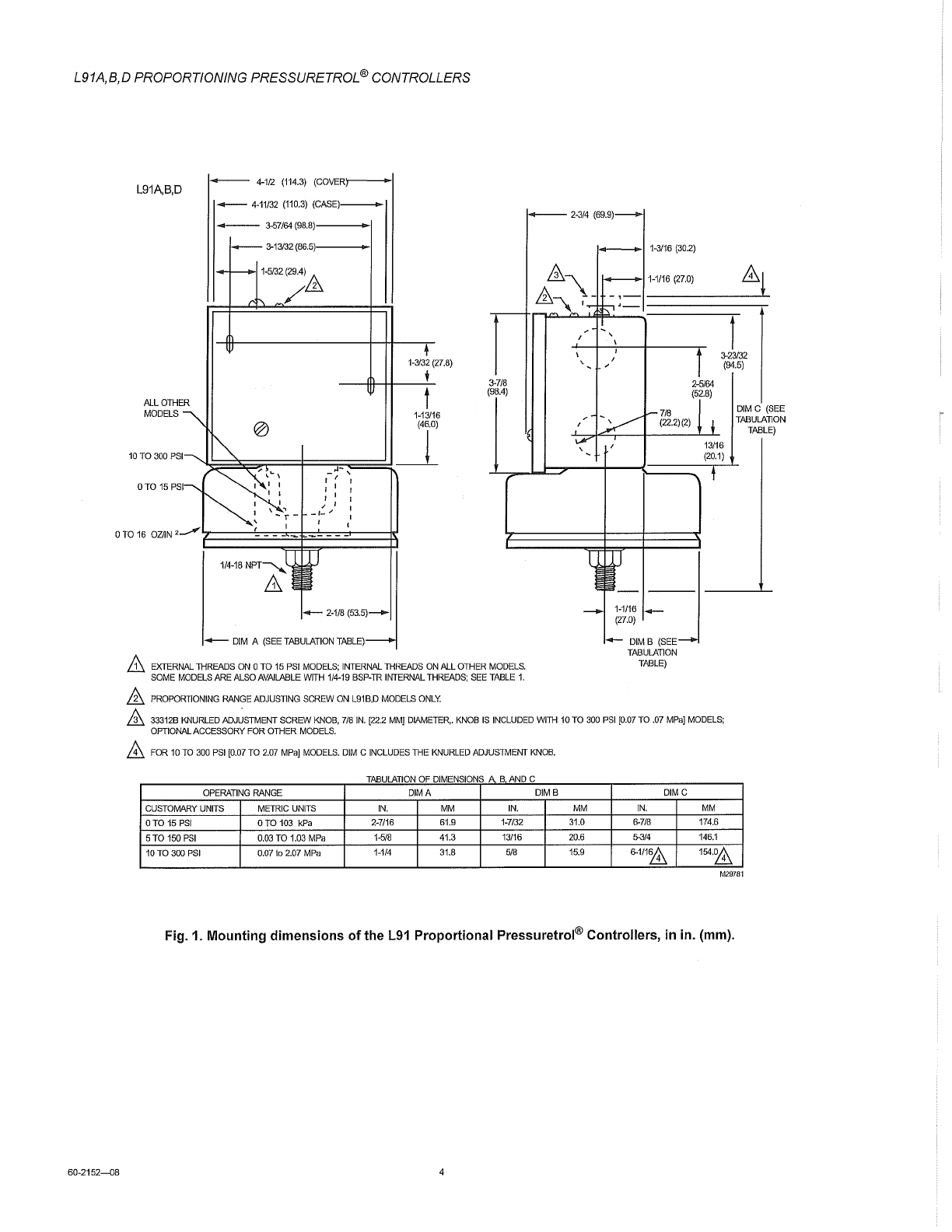
EXTERNAL
THREADS
ON
0
TO
15
PSI
MODELS;
INTERNAL
THREADS
ON
ALL
OTHER
MODELS.
TABLE)
SOME
MODELS
ARE
ALSO
AVAILABLE
WITH
1/4-19
BSP-TR
INTERNAL
THREADS;
SEE
TABLE
1.
&
PROPORTIONING
RANGE
ADJUSTING
SCREW
ON
L91B,D
MODELS
ONLY.
.&.
33312B
KNURLED
ADJ~STMENT
SCREW
KNOB,
7/8
IN.
[22.2
MMj
DIAMETER,.
KNOB
IS
INCLUDED
WITH
10
TO
300
PSI
[0.07
TO
.07
MPaj
MODELS;
OPTIONAL
ACCESSORY
FOR
OTHER
MODELS.
&
FOR
10
TO
300
PSI
[0.07
TO
2.07
MPaj
MODELS.
DIM
C
INCLUDES
THE
KNURLED
ADJUSTMENT
KNOB.
TABULATION
OF
DIMENSIONS
A B
AND
C
OPERATING
RANGE
DIMA DIMB DIMC
CUSTOMARY
UNITS
METRIC
UNITS
IN.
MM
IN.
MM
IN.
MM
OTO
15
PSI
OTO
103
kPa
2-7/16
61.9
1-7/32
31.0
fH/8
174.6
5TO
150
PSI
0.03
TO
1.03
MPa
1-5/8
41.3
13/16
20.6
5-3/4
146.1
10
TO
300
PSI
0.07
to
2.07
MPa
1-114
31.8
5/8
15.9
6-1/1~
154.~
DIM
C
(SEE
TABULATION
TABLE)
M29781
Fig. 1. Mounting dimensions
of
the L9i Proportional Pressuretrol® Controllers,
in
in. (mm).
74
Consult factory for guidance in product selection
Phone (203) 385-0217, Fax (203) 385-0602 or
visit our web site at www.ashcroft.com
BOURDON SYSTEM SELECTION
Ordering Bourdon Tube & Tip Material
(1)
Socket Tube Range Selection NPT
Code
(all joints TIG welded except “A”)
Material Type Limits (psi) Conn.
(2)
A
Phosphor Bronze
A Phosphor Bronze
A
Brass C-Tube 12/1000
1
/
4
/4/
,
1
⁄
1
⁄
1
2
⁄2⁄
Tube-Brass Tip, Silver Brazed
A
Tube-Brass Tip, Silver Brazed
A
R 316L stainless steel 1019 steel
C-Tube 12/1500
1
/
4
/4/
,
1
⁄
1
⁄
1
2
⁄2⁄
Helical 2000/20,000
1
/
4
/4/
,
1
⁄
1
⁄
1
2
⁄2⁄
S 316L stainless steel 316 stainless steel
C-Tube 12/1500
1
/
4
/4/
,
1
⁄
1
⁄
1
2
⁄2⁄
Helical 2000/20,000
1
/
4
/4/
,
1
⁄
1
⁄
1
2
⁄2⁄
P
(4)
K Monel Monel 400
C-Tube 15/1500
1
/
4
/4/
,
1
⁄
1
⁄
1
2
⁄2⁄
Helical 2000
/30,000
1
/
4
/4/
,
1
⁄
1
⁄
1
2
⁄2⁄
5
)
WW Inconel 718 316 stainless steel Helical 50/80/100,000
(3)(6)
1
⁄
1⁄
1
4
⁄4⁄
high press.
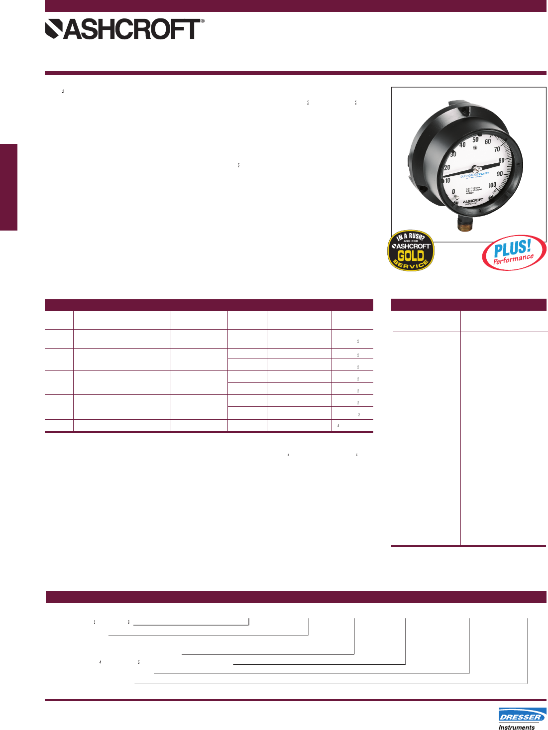
Type 1379 Duragauge
®
pressure
® pressure
®
gauge is offered in 4
1
⁄
1⁄
1
2
⁄2⁄
,
˝ 6˝ and 8
,˝ 6˝ and 8,
1
⁄
1⁄
1
2
⁄2⁄
˝
dials sizes.
This rugged, solid-front aluminum
case gauge is tops in its fi eld. It is
available as a weatherproof hermet-
ically sealed or liquid-fi lled version
in 4
1
⁄
1
⁄
1
2
⁄2⁄
˝ and 6˝ sizes in pressures to
30,000 psi. Like the 1279, it can be
easily fi eld converted from the weath-
erproof version to either the sealed or
liquid-fi lled version using an optional
kit. Ranges 50,000, 80,000 and
100,000 psi are available in 6˝
hermetically sealed and liquid-fi lled
cases. All size cases are coated
with black epoxy which will withstand
most environmental conditions.
MADE IN U.S.A.
Duragauge
®
Pressure Gauge
Type 1379, ASME B 40.1
Grade 2A (±0.5% of span)
TO ORDER THIS 1379 DURAGAUGE:
Select: 45 1379 SS* 04L XXX 100#
1. Dial size–4
1
⁄
1⁄
1
2
⁄2⁄
˝, 6˝, or 8
1
⁄
1⁄
1
2
⁄2⁄
˝
2. Case type–1379
Ring–threaded reinforced polypropylene
3
. Bourdon system selection ordering code
4. Connection–
1
⁄
1⁄
1
4
⁄4⁄
NPT (02),
1
⁄
1⁄
1
2
⁄2⁄
NPT (04), Lower (L), Back (B)
5. Optional features–see page 239
6. Standard pressure range
7. Accessories–see pages 233-238
(
*
) “S” denotes solid front case design
STANDARD RANGES
Pressure Compound
psi
psi
0/15 30 in.Hg/15 psi
0/30 30 in.Hg/30 psi
0/60 30 in.Hg/60 psi
0/100 30 in.Hg/100 psi
0/160 30 in.Hg/150 psi
0/200 30 in.Hg/300 psi
0/300
0/400
Vacuum
0/600 30/0 in.Hg
0/800 34/0 ft H
2
O
0/1000
0/1500
0/2000
0/3000
0/5000
0/10,000
0/20,000
0/30,000
0/50,000
0/80,000
0/100,000
NOTE:
Equivalent standard
kg/cm
2
, and kPa metric
ranges are available.
(4) Use for applications where NACE standard MR-01-75 is
specifi ed.
(5) 30,000 psi offered with
1
⁄
1
⁄
1
4
⁄4⁄
high pressure connection,
1
⁄
1
⁄
1
2
⁄2⁄
NPT
optional.
(6) Offered hermetically sealed as standard. Liquid fi llable
optional.
(1) For selection of the correct Bourdon system material, see the
media application table on page 243.
(2) Other connections available on application.
(3) 50,000-100,000 psi available in 6˝ 1379 lower and back
connection only.
. Bourdon system selection ordering code
• 4
1
/
1
/
1
2
/2/
˝ full-size bourdon tube
• Patented Duratube™ with as-welded-
tube construction controls stress
for longer life
• “Round Cap Tip” construction
lowers stresses for longer life
• Easily adjustable, self-locking
micrometer pointer
• Exclusive Tefl on coated 400 series
stainless steel rotary movement
for longer life
• New PLUS!
™
• New PLUS!™
• New PLUS!
Performance Option:
™ Performance Option:
™
- Liquid-fi lled performance in a dry
gauge
- Fights vibration and pulsations
without liquid-fi lled headaches
- See pages 6-7 for details
- Order as option XLL
• Epoxy-coated system for superior
corrosion resistance
KUNKLE
Features
• O-ring seats available for exception
al
leak-
free performance, reduced maintenance
cost, multiple cycl
es
w
it
h tight shutoff,
improved seating integrity.
• Wide hex on valve nozzle provides
wrenching service clearance for easy
in
sta
ll
atio
n.
• Dual control rings offer easy adjustabil
it
y
fo
r precise open
in
g with minimum preopen
or simmer and exact blowdown control.
• Pivot .between disc and sp
rin
g corrects
misalignment and compensates for spring
side thru
st.
• Grooved piston model disc reduces s
li
d
in
g
area and friction.
• Each Kunkle valve is tested and
in
spected
for pressure setting and leakage.
Model Descriptions
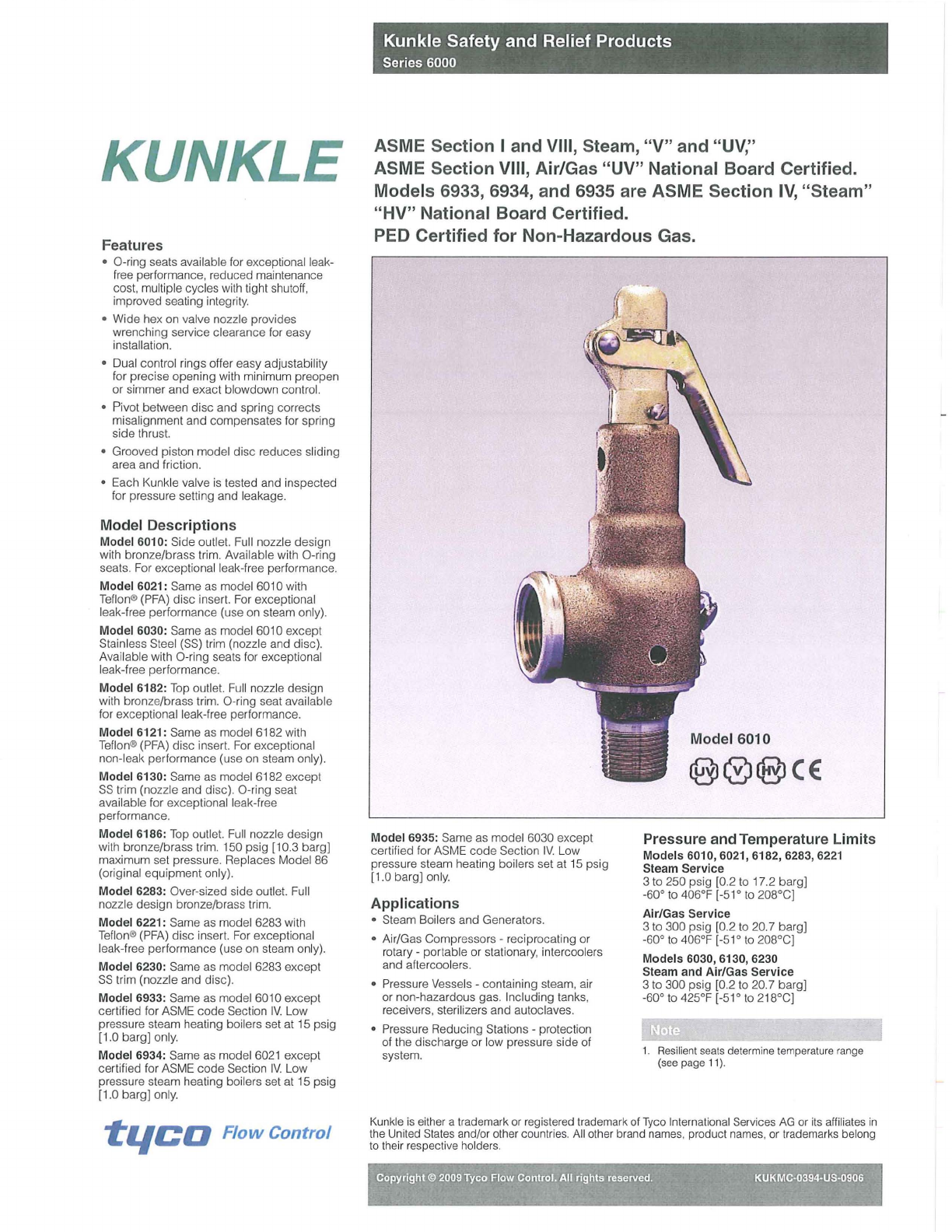
Model 6010: Side outlet.
Fu
ll
nozzle design
with bronze/brass trim. Ava
il
able with O-ring
seat
s.
For excepl
io
nal leak-fr
ee
performance.
Model 6021: Same
as
model 6010 with
Te
flon®
(P
FA) disc inser
t.
For exceptional
leak-free performance (use on steam only).
Model 6030: Same as model 6010 except
Stainless Steel
(SS)
trim (nozzle and disc).
Avail
ab
le with O-ring seats for exceptional
leak-
fr
ee
performance.
Model
6182:
Top
ou
tl
et.
Full nozzle design
with bronze
/b
rass trim. O-ring seat available
for exceptional l
ea
k-free pe
rf
ormance.
Model 6121: Same as model 6182
wi
th
Te
flon® (PFA) disc inse
rt.
For exceptional
non-leak performance (use on steam only).
Model
6130: Same
as
model 6182 except
SS
trim (nozzle and disc). O-ring seat
ava
il
able for exceptional leak-free
performance.
Model 6186: T
op
ou
tl
et. Fu
ll
nozzle design
with bronze/brass trim. 150 psig [10
.3
bargj
maximum set pressur
e.
Replaces Model 86
(original equipment
on
l
y).
Model 6283: Over-sized side
ou
tl
et. Full
nozzle design bronze/brass trim.
Model 6221:
Sa
me
as
model 6283
wi
th
Teflon® (
PFA)
disc insert. For excep
ti
onal
leak-fr
ee
performance (use on steam only).
Model 6230: Same
as
model 6283 except
SS
trim (nozzle and disc).
Model
6933:
Sa
me as model 6010 except
certified
fo
r ASME code Sect
io
n
IV.
Low
pressure steam heating boilers set at 15 psig
[1.0 bargj
on
l
y.
Model 6934: Same
as
model 6021 except
certified for ASME code Section I
V.
Low
pr
essure steam heating boilers set at 15 psig
[1
.0 bargj on
ly.
-tileD
Flow
Control
Kunkle Safety and Relief Products
Series 6000
ASME Section I and VIII, Steam, "V" and
"UV,"
ASME Section VIII, Air/Gas "UV" National Board Certified.
Models 6933, 6934, and 6935 are ASME Section
IV,
"Steam"
"HV" National Board Certified.
PED Certified for Non-Hazardous Gas.
Model 6935: Same as model 6030 except
certifi ed for ASME code Sec
ti
on I
V.
Low
pressure steam heat
in
g boilers set at 15 psig
[1.0 bar
gj
o
nl
y.
Applications
• Steam Bo
il
ers and Generators.
• Air/G
as
Compressors - reciprocating or
rotary -portable or stationary, intercoolers
and aftercoolers.
•
Pr
essure Vessels - co
nt
aining steam, a
ir
or non-hazardous gas. Including t
an
ks,
receivers, sterilizers
an
d
au
toclaves.
•
Pr
essure Reducing Stations - protect
ion
of t
he
discharge or low pressure side of
system.
Model
6010
Pressure and Temperature Limits
Models 6010, 6021, 6182, 6283, 6221
Steam Service
3 to 250 psig [0.2 to 17.2
bargj
-60°
to
406°F [-51° to 208°C]
Air/Gas Service
3 to 300 psig [0.2 to 20.7
ba
r
gj
-60°
to
406°F [-51 °
to
208°C]
Models 6030, 6130, 6230
Steam and Air/Gas Service
3
to
300 psig [0.2 to 20.7 bargj
-60° to 425°F [-51° to 218°C]
1. R
esilient
seats
determine
te
mperatu
re
rang
e
(see
page
11
).
Kunkle
is
either a
tr
ademark
or
registered trademark of Tyco International
Se
rvices
AG
or i
ts
aff
ili
a
tes
in
t
he
Un
it
ed
States and/or other coun
tr
ies.
All
other brand name
s,
pr
o
du
ct names, or tradema
rk
s belong
to
th
e
ir
respecti
ve
ho
ld
er
s.
:;.-
:,.;
."
..
,;.
,:r'"
~-""',:..··;;;:r.I~._
':~}.~)'
."
-_
',.,
0-"'
t,;;
Copyright © 2009
Tyco
Flow Control.
All
rights reserved. KUKMC-0394-U5-0906
Kunkle Safety and Relief Products
Series
6000
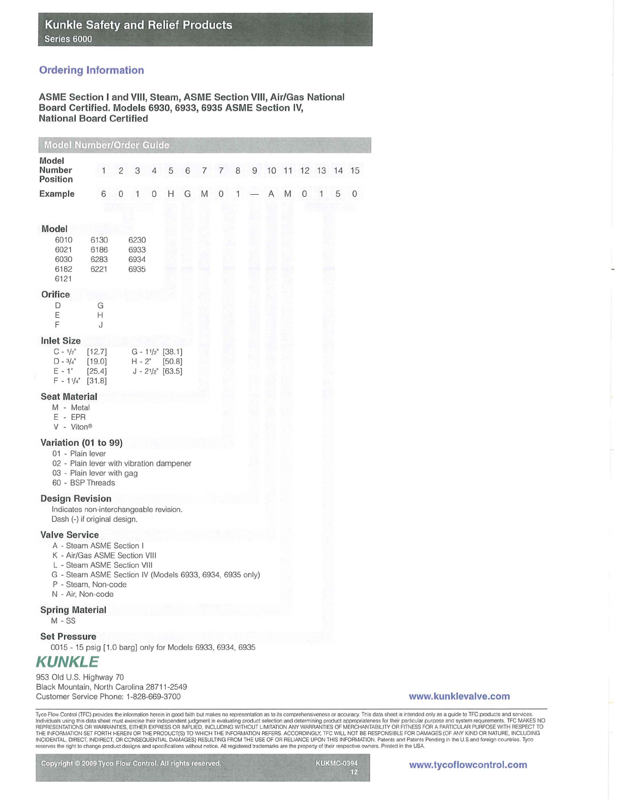
Ordering
Information
ASME Section I and VIII, Steam, ASME Section VIII, Air/Gas National
Board Certified. Models 6930, 6933, 6935 ASME Section
IV,
National Board Certified
, Model Number/Order Guide . .
'~
",
...
,-
.
Model
Number
Position
2 3 4 5 6 7 7 8 9
10
11
12 13 14 15
Example
Model
60
10
6021
6030
6182
6121
Orifice
6 0
6130
6
18
6
6283
6221
D G
E H
F J
Inlet Size
C -
'/2"
D - 3/.
E - 1·
F - 11/.
[12.7]
[1
9.0]
[25.4]
[3
1.
8]
Seat Material
M - Metal
E -
EPR
V Viton®
Variation
(01
to 99)
01
-Plain lever
6230
6933
6934
6935
o H G M 0
G-11/2'
[38,1]
H -
2"
[50.8]
J -
21/2'
[63.5]
02 - Plain lever with vibration dampener
03 -Plain lever with gag
60 -
BSP
Threads
Design Revision
Indicates non
-i
nterchangeable revision.
Dash
(-)
if original design.
Valve Service
A - Steam ASM E Section I
K - Air/Gas ASME Sec
ti
on
VIII
L - Steam ASME Secti
on
V
III
G - Steam ASME Secti
on
IV (Models 6933, 6934, 6935 only)
P - Steam, Non-code
N - Air, Non-code
Spring Material
M -
SS
Set Pressure
0015 -
15
psig
[1
.0 bargj only for Models 6933, 6934, 6935
KUNKLE
953 Old U.S. Highway
70
Black Mountain, North Carolina 28711-2549
Customer
Se
rvice Phone:
1-
828-669-3700
A M 0 5 0
www.kunklevalve.com
Tyeo
Fl
ow
Control
(TFC)
provides
the
information
here
in
in
good
fa
i
th
but
makes
no
representation
as
to i
ts
comprehens
iveness
or
accuracy
. T
hi
s
da
ta
sheet
IS
i
nte
nd
ed
only
as
a
guide
to
TFC
produc
ts
and
services.
Ind
ivid
uals
using
thiS
data
sheet
m
ust
exercise
the
ir
ind
epen
dent
judgment
in
evaluating
prod
uct
selection
and
determ
i
ning
produc
t
appropriateness
for
their
particular
p
urpose
and
system
requirements.
TFC
MAKES
NO
REPRESENTATIONS
OR
WARRANTIES.
EITHER
EXPRESS
OR
IMPLIED,
INCLUDING
WITHO
UT
LIMITATION
ANY
WARRANTIES
OF
MERCHANTABILITY
OR
FI
TNESS
FOR
A
PAR
TICULAR
PURPOSE
W
ITH
RESPECT
TO
THE
IN
FORMAT
IO
N
SET
FORTH
HEREIN
OR
THE
PRODUCT(S)
TO
WHICH
THE
I
NFORMA
TION
REFERS
,
ACCORDINGLY.
TFC
WILL
NOT
BE
RESPONSIBLE
FOR
DAMAGES
(OF
ANY
KIND
OR
NATURE,
INCLUDING
INCIDENTAL.
DIRECT
,
IND
I
RECT,
OR
CONSEOUENT
I
AL
DAMAGES)
RESULTING
FROM
TH
E
USE
OF
OR
RELIANCE
UPON
THIS
INFORMATION
,
Palenls
and
Pat
ents
Pend
i
ng
in
t
he
U.S.
and
foreig
n
cou
ntri
es
,
Ty
eo
r
ese
rv
es
th
e
rig
ht
to
change
product
designs
and
speci
f
icat
i
ons
without
notice
.
All
registered
trademarks
are
the
prop
erl
y
of
the
ir
respect
ive
owners
.
Pr
i
nted
in
the
USA.
~',
...
" Copyright ©
2009
Tyco
Flow
Control.
A"
rights reserved. KUKMC-0394
~
12 www.tycoflowcontrol.com
