Designers Guide To Low Power RF LPRF
User Manual:
Open the PDF directly: View PDF ![]() .
.
Page Count: 64

2
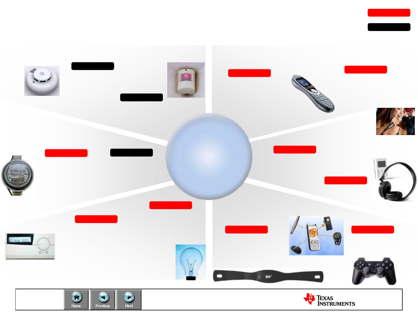
Smart Metering
Alarm and Security
Home Automation & Lighting
Remote Controls
Medical, Health & HID
Wireless Audio
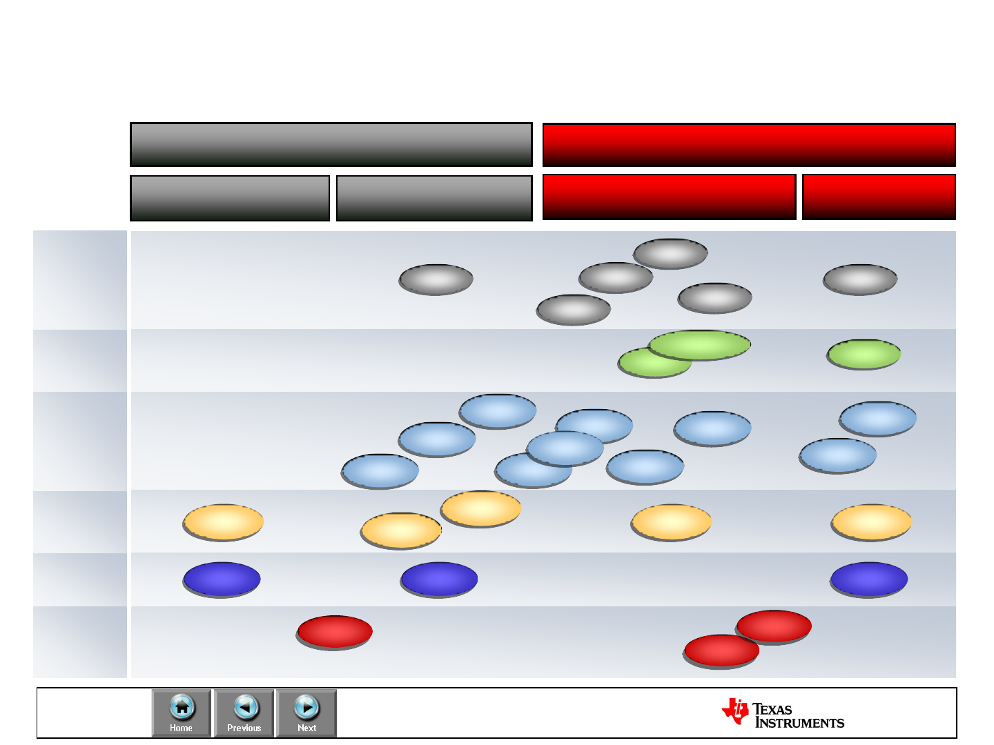
Low-Power RF
TI Low-Power RF at a glance…
PurePath™ Wireless
Coming Soon
High Quality
Wireless Audio
CC8520
2.4 GHz Range Extender
CC259x
Sub 1 GHz Transceiver
+ MSP430 MCU,
500 Kbps
-112dBm sensitivity
CC1101
Narrowband
12.5 KHz channel spacing
-118dBm sensitivity
CC1020
Sub 1 GHz SoC
32KB Flash, USB 2.0
0.3 uA sleep current
CC111x
ZigBee
System on Chip
IEEE 802.15.4 compliant
+ CC259x Range Extenders
CC2530
2.4 GHz Transceiver
+MSP430 MCU
Proprietary solution
CC2500
Network Processor
fully certified ZigBee Pro
Software Stack
CC2530ZNP
RF4CE
IEEE 802.15.4 compliant
System on Chip
RemoTI SW
CC2530
2.4 GHz Radio
Complete SoC,
32 KB Flash, USB
CC251x
Location Tracking
System on Chip
Solutions
CC2431
CC2.4 GHz
Sub 1 GHz
Bluetooth Low Energy
Coming Soon
BLE compliant SoC
CC2540


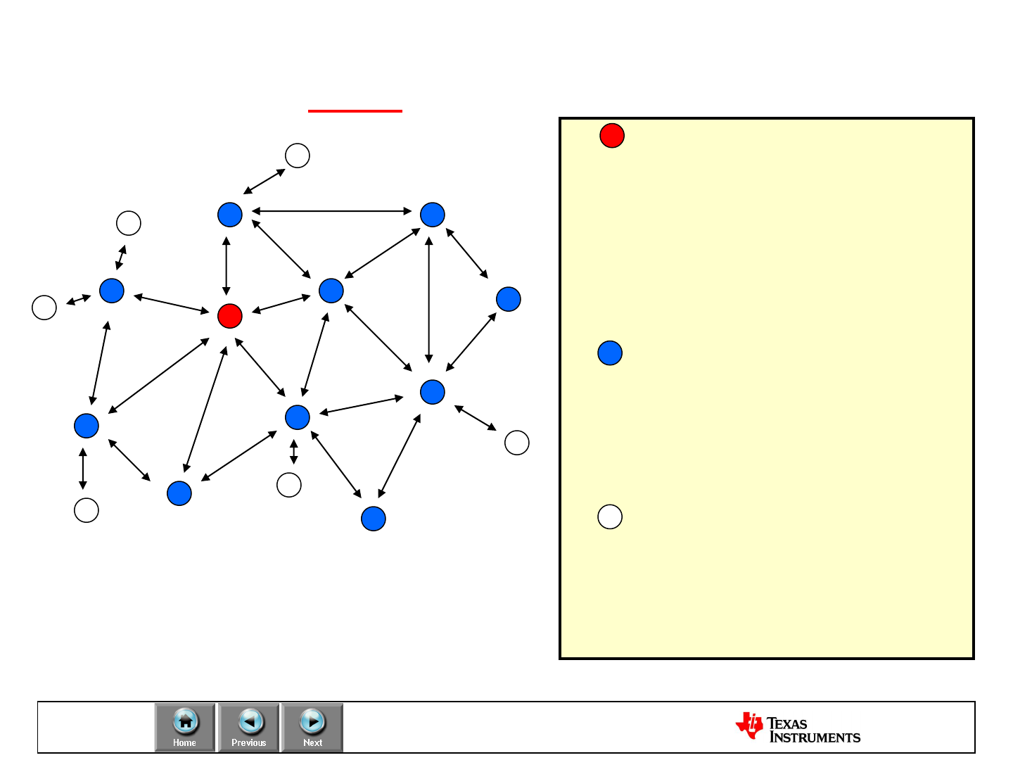
Define
Network Topology: ZigBee Mesh
ZigBee Coordinator
Starts the Network
Routes packets
Manages security
Associates Routers and End
Devices
Example: Heating Central
ZigBee Router
Routes packets
Associates Routers and End
Devices
Example: Light
ZigBee End Device
Sleeps most of the time
Can be battery powered
Does not route
Example: Light switch
Devices are pre-programmed for
their network function
Coordinator can be removed

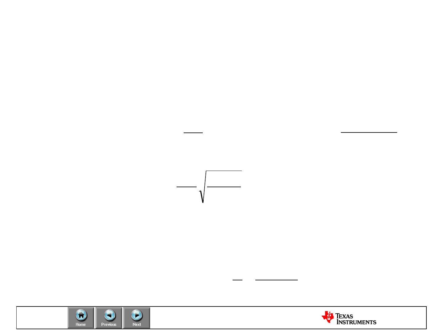
Define
Range and Data rate: Range propagation
•How far can TX and RX be apart from each other?
• Friis’ transmission equation for free space propagation:
or
–Ptis the transmitted power, Pris the received power
–Gtis the transmitter, Gris the receiver antenna gain
–d is the distance between transmitter and receiver, or the range
–Lambda is the wavelength
22
2
)4( d
GGP
Prtt
r
-
dGGPP rttr log20
4
log20
-
r
rtt
P
GGP
d
-
4
Frequency
light of Speed
f
c
-

Define
Range and Data rate: “Real life”
Compared to the estimated range we should get in theory here are
some ”real life” rules and experiences on RF range:
•120 dB link budget at 433 MHz gives approximately 2000 meters
(TI rule of thumb)
• Based on the emperical results above and Friis’ equation estimates
on real range can be made
•Rule of Thumb:
–6 dB improvement ~ twice the distance
–Double the frequency ~ half the range (433 MHz longer range than 868
MHz)

Define
Range and Data rate: Important factors
•Antenna (gain, sensitivity to body effects etc.)
•Sensitivity: Lowest input power with acceptable link
quality (typically 1% PER)
•Channel Selectivity: How well a chip works in an
environment with interference
•Output power
•Environment (Line of sight, obstructions, reflections,
multi-path fading)
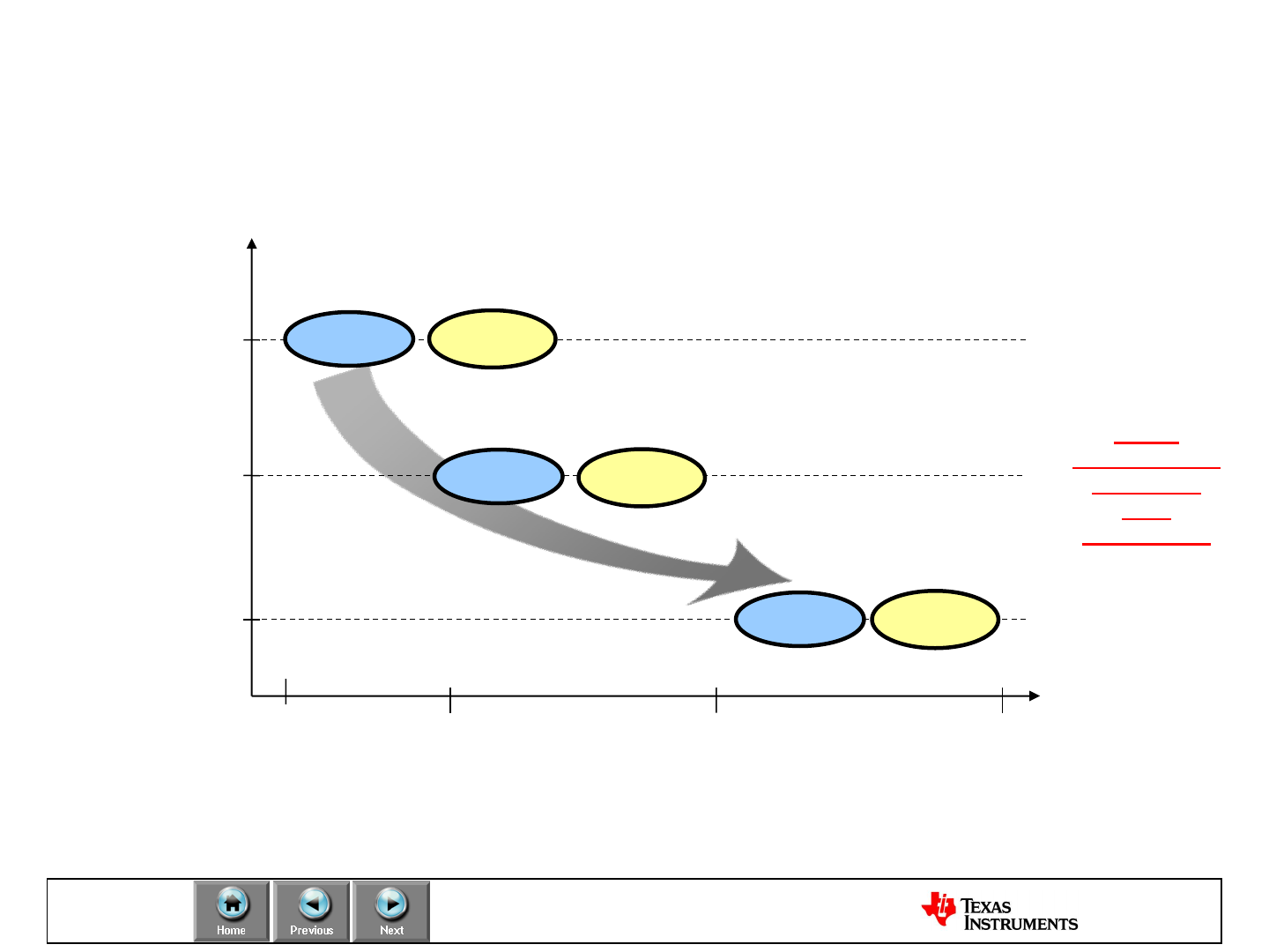
Define
Range and Data rate: Estimated LOS
2.4kBps
Data Rate
10m 10000m Range
100m 1000m
Note: These examples should be taken as a rough estimation as the final design is
highly dependent on the antenna, frequency, output power and other parameters.
250kBps
38.4kBps
2.4 GHz 868 / 915
MHz
2.4 GHz
2.4 GHz
Test Example:
CC1101 with 0dBm output power, 250KBps,
Johannson Balun, 915MHz, Dipole Antenna
Range: 290m
See also
Design Note:
Range
Measurements
in an Open
Field
Environment
868 / 915
MHz
868 / 915
MHz
Define
Power Consumption
Low Power characteristics and features of TI’s RF devices:
–Low sleep current
–Minimum MCU activity
–RX/TX turn around time
–Adaptive output power using RSSI
–Fast crystal start-up time
–Fast PLL calibration (and settling)
–Carrier sense recognition
–Low RX peak current
–Minimum duty cycle
–Wake on radio (new devices)
Define
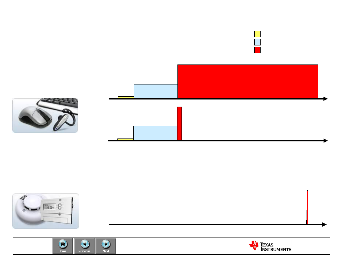
Power Consumption: Application Scenarios Crystal Oscilator
Start-up Calibration
RX/TX mode
time
Long Packet Length
Radio power dominating
time
Short Packet Length
Calibration power dominating
Low duty-cycle transmission
Sleep power dominating
time
High duty cycle applications:
•Active radio current consumption
•RX/TX and Calibration
Low duty cycle applications:
•MCU sleep current
•Regulator quiescent current
•Average radio current consumption
Define
Power Consumption: Low-Power Essentials
•Use the lowest possible duty cycle
–Send data only when needed, do not send more data than
necessary
–Use the highest data rate you can (trade-off vs. range)
–Watch out for protocol-related overhead
•Use the lowest possible voltage
–RF chips have reduced current draw at lower voltages
–Low voltage degrades RF performance
–Above not a problem if on-chip regulator
•Use a switch-mode regulator with low quiescent current to
maximize battery lifetime
Define
Power Consumption: Example
CC2500 Typicals:
Vcc Range: 1.8V to 3.6V
WOR Sleep Current: 900nA
Idle Current: 1.5mA
FSTXon Current: 7.4mA
Rx Current: 15mA @ 2.4kB/s
Tx Current: 21mA @ 0dB
MSP430F2274 Typicals:
Vcc Range: 1.8V to 3.6V
Sleep Current: 0.1uA @ 3V
32kOsc Current: 0.9uA @ 3V
CPU off Current: 90uA @ 3V
Active Current: 390uA @ 3V
The Challenge of Powering a LPRF System


Select
Choose the right RF solution
How to choose the perfect RF solution:
•Does the application need to associate with
an existing system?
•What kind of software protocols fit the
application best?
•Are there regulations to be considered?
•How much time/resources are available to
get the product to market?

Select
Proprietary or Standard
TI LPRF offers several low power RF solutions by
providing the required Hardware and Software.
As a result there is no need to promote any
specific low power RF protocol as the solution for
all applications.
However, it is important to make the customer
choose the best fitting protocol for the targeted
application in order to get optimal performance
and meet expectations.
Select
Proprietary or Standard
Solution
Layer
RF Frequency
Physical Layer
Lower Layer Protocol
Higher Layer Protocol
Application
SimpliciTI
Design Freedom
Design Freedom
SimpliciTI
CC111x, CC251x
MSP430+CC1101
or CC2500
2.4 GHz
Sub 1 GHz
Proprietary
Design Freedom
Design Freedom
Design Freedom
all LPRF devices
2.4 GHz
Sub 1 GHz
IEEE 802.15.4
Design Freedom
Design Freedom
TI MAC
2.4 GHz
CC2530
CC2430
MSP430+CC2520
RF4CE
Design Freedom
Remo TI
TI MAC
2.4 GHz
CC2530
CC2530ZNP
ZigBee
Design Freedom
Z-Stack +
Simple API
TI MAC
2.4 GHz
CC2530
CC2430
Select
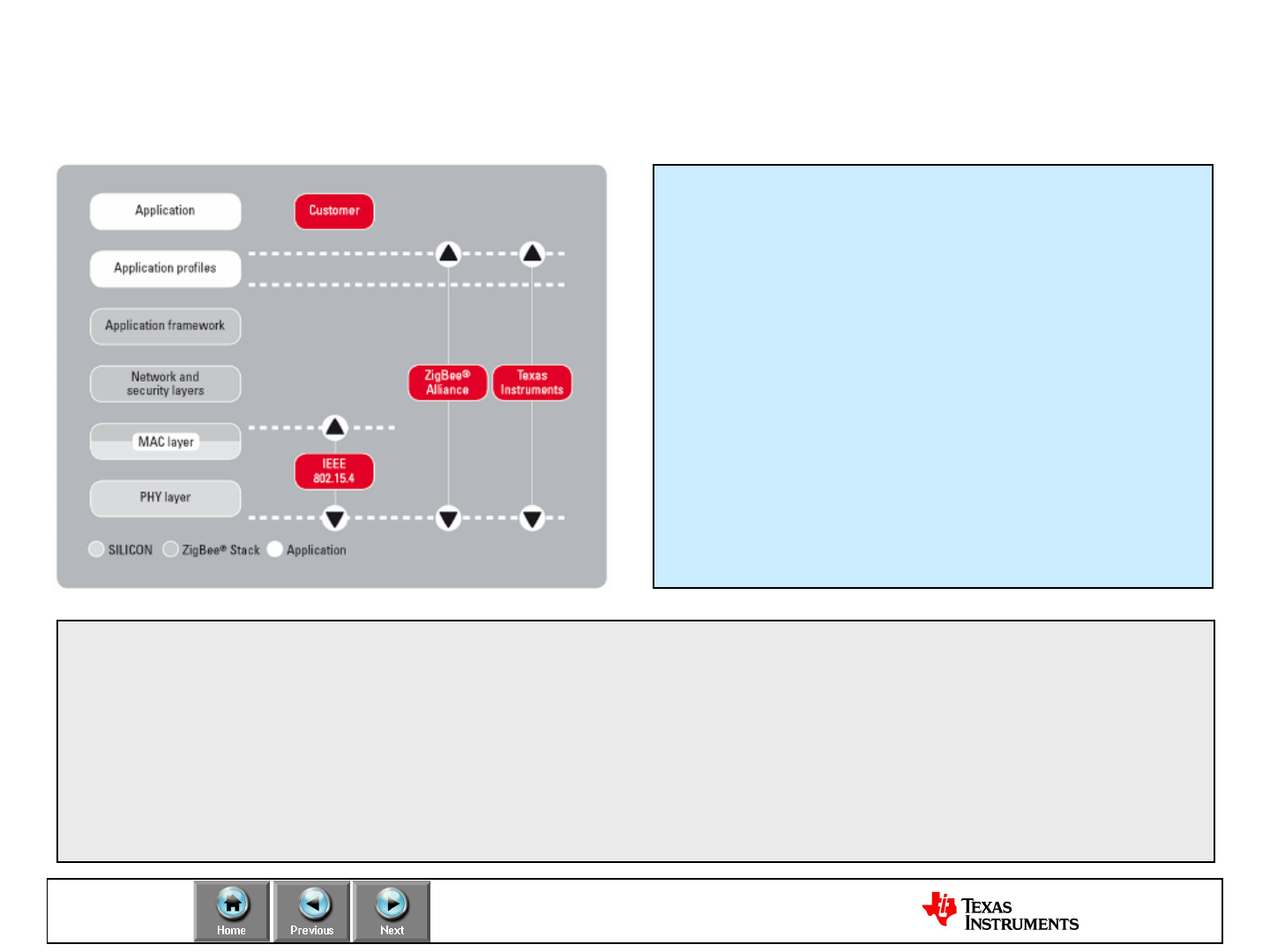
Proprietary or Standard: ZigBee
“The ZigBee Alliance is an association of companies working
together to enable reliable, cost-effective, low-power, wirelessly
networked monitoring and control products based on an open
global standard”
Source: ZigBee Alliance homepage
Promoters of the ZigBee alliance are:

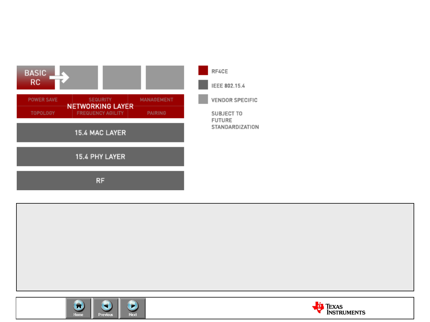
Select
Proprietary or Standard: RF4CE
•Founding Members
•Invited Contributors
The RF4CE industry consortium has been formed to develop a new
protocol that will further the adoption of radio frequency remote controls
for audio visual devices.
The consortium will create a standardized specification for radio
frequency-based remote controls that deliver richer communication,
increased reliability and more flexible use.
Visit www.rf4ce.org for more information on the RF4CE consortium
Visit www.ti.com/rf4ce for more information on TI’s RF4CE solution
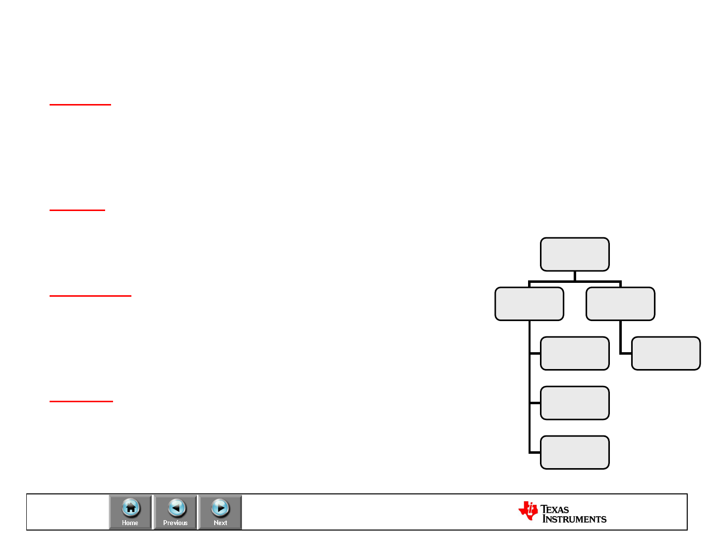
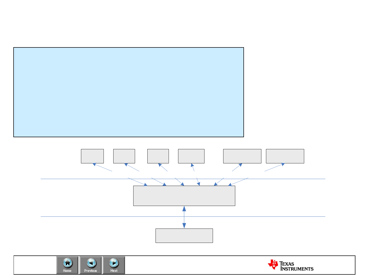
Select
Protocol Software
•Z-Stack - ZigBee Protocol Stack from TI
–Mesh networking
–Golden Unit certification for ZigBee-2006, ZigBee-2007 and ZigBee PRO
–Supports multiple platforms including the CC2530ZNP, CC2530 and CC2520+MSP430 platforms
–ZigBee 2007/PRO available on MSP430 platform
•TIMAC
–A standardized wireless protocol for battery-powered and/or mains powered nodes
–Suitable for applications with low data-rate requirements
–Support for IEEE 802.15.4-2003/2006
•SimpliciTI Network Protocol –RF Made Easy
–A simple low-power RF network protocol aimed
at small RF networks
–Typical for networks with battery operated devices
that require long battery life, low data rate and low duty cycle
•RemoTI Remote control
–RF4CE is built on the well-tested, reliable software, the TIMAC,
which is based on the IEEE 802.15.4 protocol stack and
runs in millions of devices worldwide
All software solutions can be downloaded free from TI web
LPRF
Protocol SW
Point-to-point
&Star network Mesh network
topology
IEEE802.15.4
TIMAC ZigBee
Z-Stack
SimpliciTI
Remo TI
Select
Protocol Software: ZigBee™ Z-Stack
Key Benefits:
•Self healing (Mesh networks)
•Low node cost
•Easy to deploy (low installation cost)
•Supports large networks
(hundreds of nodes)
•Intended for monitoring &
control applications
•Standardized protocol (interoperability)
•Application
• ZigBee™ Stack
–Network functionality
•IEEE 802.15.4
–Physical layer/Radio
–Standardized point to point link
• ZigBee™ devices from TI
–CC2480 (network processor)
–CC243x System on Chip
–CC253x System on Chip
Select
Protocol Software: SimpliciTI
NWK
Ping Link Freq Customer
App
Port 0x01 Port 0x20Port 0x03Port 0x02
Join
Port 0x05
Customer
App
Port 0x21
MRFI
Minimal RF interface
Application
Network
Data Link/
PHY
•Low Power: a TI proprietary low-power RF network protocol
•Low Cost: uses < 8K FLASH, 1K RAM depending on
configuration
•Flexible: simple star w/ extendor and/or p2p communication
•Simple: Utilizes a very basic core API
•Low Power: Supports sleeping devices
Supported LPRF devices:
MSP430+CC1101/CC2500
/CC2520,
CC1110/CC1111,
CC2510/CC2511,
CC2430, CC2530
Select
Protocol Software: RemoTI
The RemoTI protocol:
-Based on IEEE 802.15.4
-Includes a thin NWK layer
-Command Set Interface
RemoTI (RF4CE) Standard Includes:
-Frequency agility for multi-channel operation to avoid interference
-A mechanism for secure transactions
-A power save mechanism for power efficient implementations
-A simple and intuitive pairing mechanism

Select
Regulations: 2.4 GHz ISM band
The 2400–2483.5 MHz band is available for
license-free operation in most countries
•2.4 GHz Pros
–Same solution for all markets without SW/HW alterations
–Large bandwidth available, allows many separate channels
and high datarates
–100% duty cycle is possible
–More compact antenna solution than below 1 GHz
•2.4 GHz Cons
–Shorter range than a sub 1 GHz solution (with the same
current consumption)
–Many possible interferers are present in the band

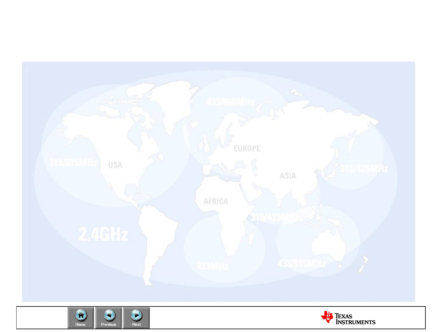
Select
Regulations: Sub 1GHz ISM bands
The ISM bands under 1 GHz are not world-wide.
Limitations vary a lot from region to region and getting
a full overview is not an easy task
•Sub 1GHz Pros
–Better range than 2.4 GHz with the same output power and
current consumption
–Lower frequencies have better penetration through concrete and
steel (buildings and office environments) compared to 2.4 GHz
•Sub 1GHz Cons
–No worldwide solution possible. Since different bands are used
in different regions a custom solution has to be designed for
each area
–Duty cycle restrictions in some regions

Select
Regulations: Sub 1GHz ISM bands
902-928 MHz is the main frequency band in the US
•The 260-470 MHz range is also available, but with more limitations
The 902-928 MHz band is covered by FCC CFR 47, part 15
Sharing of the bandwidth is done in the same way as for 2.4 GHz:
•Higher output power is allowed if you spread your transmitted power and don’t
occupy one channel all the timeFCC CFR 47 part 15.247 covers wideband
modulation
•Frequency Hopping Spread Spectrum (FHSS) with ≥50 channels are allowed
up to 1 W, FHSS with 25-49 channels up to 0.25 W
•Direct Sequence Spread Spectrum (DSSS) and other digital modulation
formats with bandwidth above 500 kHz are allowed up to 1W
FCC CFR 47 part 15.249
• ”Single channel systems” can only transmit with ~0.75 mW output power

Select
Regulations: Unlicensed ISM/SRD bands
USA/Canada:
–260 –470 MHz (FCC Part 15.231; 15.205)
–902 –928 MHz (FCC Part 15.247; 15.249)
–2400 –2483.5 MHz (FCC Part 15.247; 15.249)
Europe:
–433.050 –434.790 MHz (ETSI EN 300 220)
–863.0 –870.0 MHz (ETSI EN 300 220)
–2400 –2483.5 MHz (ETSI EN 300 440 or ETSI EN 300 328)
Japan:
–315 MHz (Ultra low power applications)
–426-430, 449, 469 MHz (ARIB STD-T67)
–2400 –2483.5 MHz (ARIB STD-T66)
–2471 –2497 MHz (ARIB RCR STD-33)
ISM = Industrial, Scientific and Medical
SRD = Short Range Devices


35
Design
LPRF Product Portfolio
Software
Protocol
Processor
System
on Chip
Transceiver
Transmitter
RF
Front End
Narrowband Proprietary
Sub 1 GHz
ZigBee/ RF4CE/ 15.4/ BLE
2.4 GHz
Proprietary
CC1110
CC1111
CC430 CC2540
CC243x
CC2480
CC2590
CC2591
CC1150CC1070 CC2550
CC1020 CC1100E CC2520 CC2500
CC2510
CC2511
SimpliciTI
TIMAC
ZigBee SimpliciTI
CC1190
CC1101
CC2530ZNP
RF4CE
CC2531
CC8520
CC2530
NEW
preview
preview
preview
BLE preview
CC2533preview
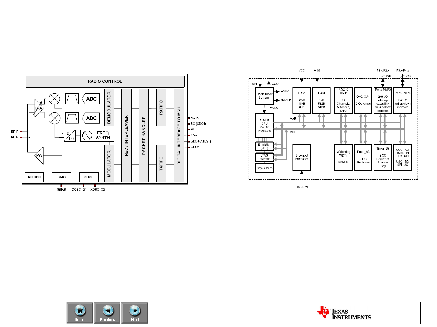
Design
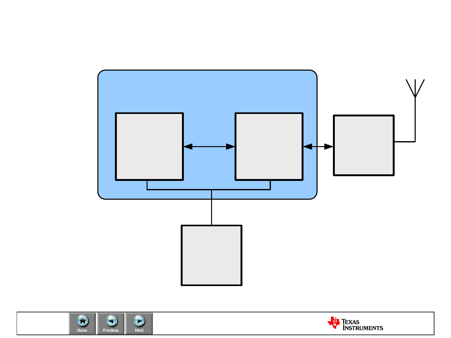
Block diagram of LPRF application example
MCU
MSP430
RF
Transceiver
CC1101, C1020,
CC2500,
CC2480*, CC2520
Antenna
LPRF System on Chip
CC111x / CC251x / CC243x / CC253x / CC430
PA \ LNA
CC2590
CC2591
Power
Supply
TPS76933
SPI
Minimum BOM:
•LPRF System on Chip or
MSP430 MCU + RF transceiver
•Antenna (PCB) & RF matching
components
•Battery or power supply
Additional components:
•CC259x range extender
•Whip or chip antenna to
improve RF performance
*ZigBee network processor
Design
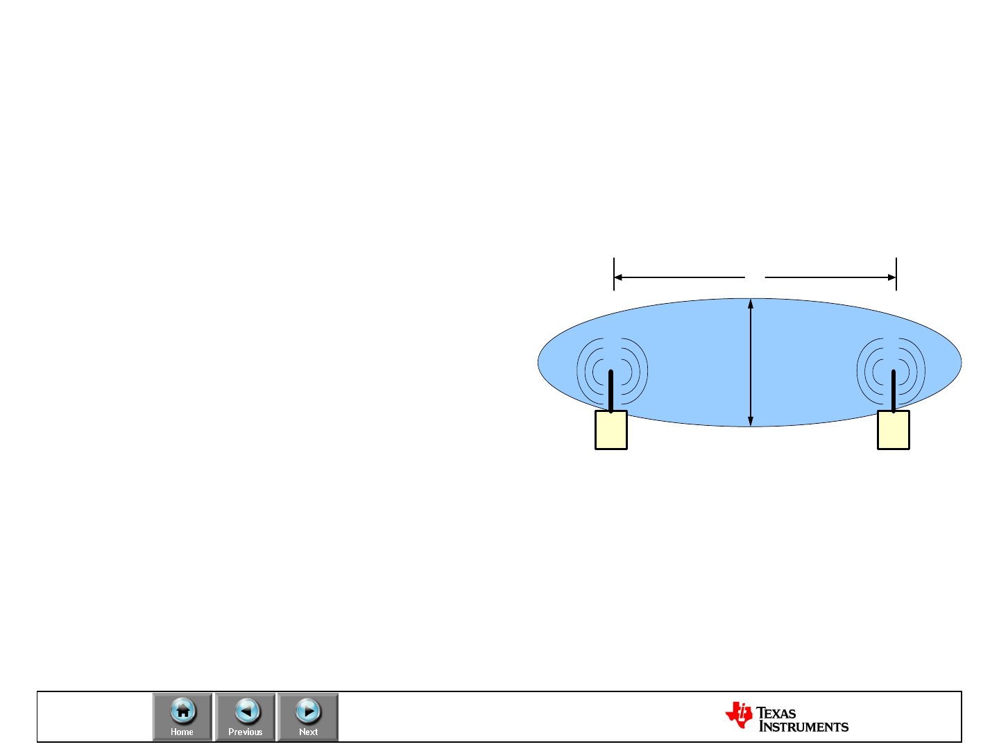
Antenna Design
The antenna is a key component for the
successful design of a wireless
communication system
The purpose of an antenna is to provide
two way transmission of data
electromagnetically in free space
•Transform electrical signals into RF
electromagnetic waves,
propagating into free space
(transmit mode)
•Transform RF electromagnetic
waves into electrical signals
(receive mode)
Transmit mode Receive mode
TX RX
2h
d
Low Power RF
Transmit / Receive System
Design
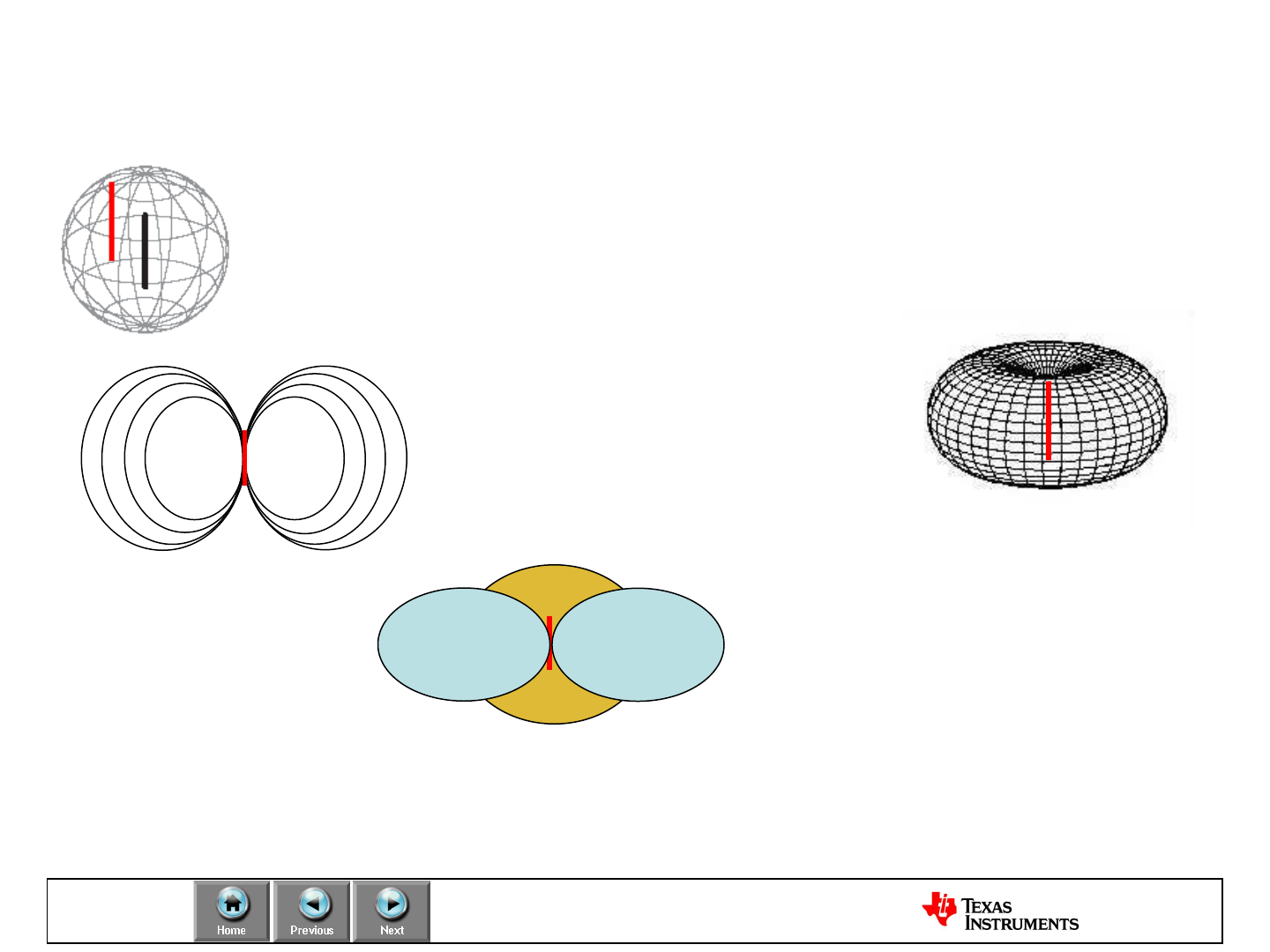
Antenna Design
An Isotropic Antenna is a
theoretical antenna that
radiates a signal equally
in all directions.
A Dipole Antenna is commonly
used in wireless systems and
can be modeled similarly to a
doughnut
The Dipole represents a
directional antenna with a further
reach in the X&Y Plane (at the
cost of a smaller reach in the Z
plane) to the Isotropic.
Power measurements are referenced to isotropic antenna (dBi) as a theoretical model
for comparison with all other antennas
Power Measurements of a Dipole Antenna (dBd) = 2.14 dBi.

Design
Antenna Design: Types
Two fundamental connection types for low power RF systems
Single-ended antenna connection
–Usually matched to 50 ohm
–Requires a balun if the Chipcon-chip has a differential output
–Easy to measure the impedance with a network analyzer
–Easy to achieve high performance
Differential antenna connection
–Can be matched directly to the impedance at the RF pins
–Can be used to reduce the number of external components
–Complicated to make good design, might need to use a simulation
–Difficult to measure the impedance
–Possible to achieve equivalent performance of single-ended
Design
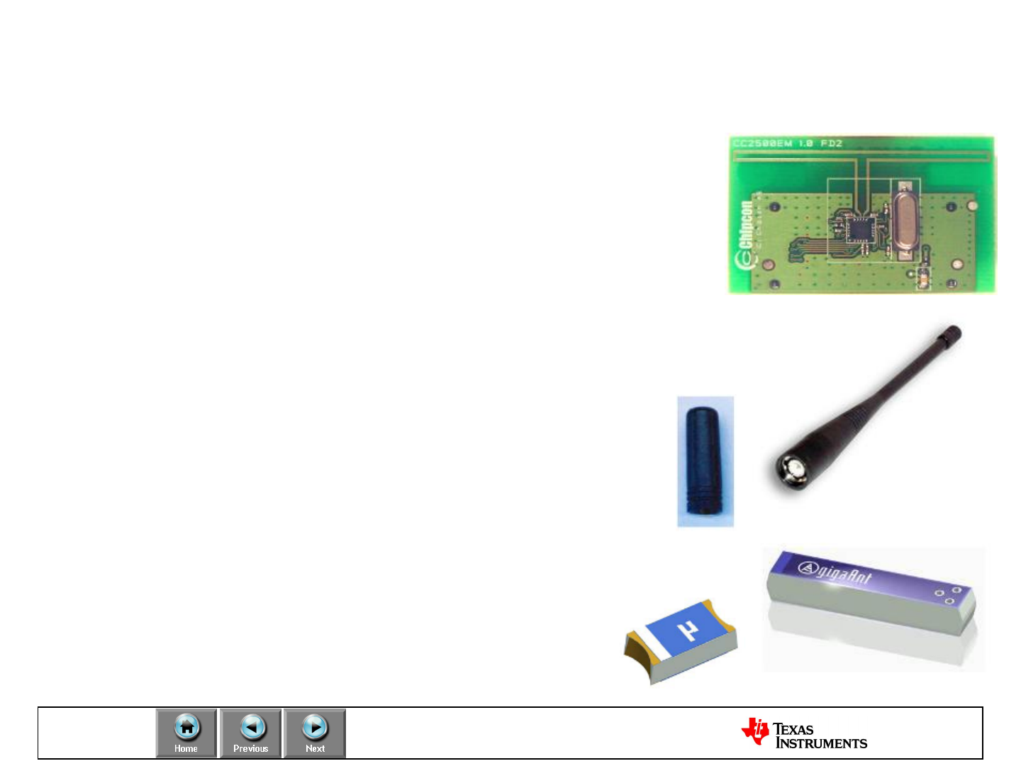
Antenna Design: Types
PCB antennas
•No extra cost development
•Requires more board area
•Size impacts at low frequencies and certain applications
•Good to high range
•Requires skilled resources and software
Whip antennas
•Cost from (starting~ $1)
•Best for matching theoretical range
•Size not limiting application
Chip antennas
•Less expensive (below $1)
•Lower range
Design
Antenna Design: Frequency vs. Size
Lower frequency increases the antenna range
•Reducing the frequency by a factor of two doubles the range
Lower frequency requires a larger antenna
• λ/4 at 433 MHz is 17.3 cm (6.81 in)
• λ/4 at 915 MHz is 8.2 cm (3.23 in)
• λ/4 at 2.4 GHz is 3.1 cm (1.22 in)
A meandered structure can be used to reduce the size
• λ/4 at 2.4 GHz
Design
Antenna Design: TI Resources
General Antennas
•AN003: SRD Antennas (SWRA088)
•Application Report ISM-Band and
Short Range Device Antennas (SWRA046A)
2.4 GHz
•AN040: Folded Dipole for CC24xx (SWRA093)
•AN043: PCB antenna for USB dongle (SWRA0117d)
•DN001: Antenna measurement with network analyzer (SWRA096)
•DN004: Folded Dipole Antenna for CC25xx (SWRA118)
•DN0007: Inverted F Antenna for 2.4 GHz (SWRU120b)
•AN058: Antenna Selection Guide (SWRA161)
•AN048: Chip Antenna (SWRA092b)
868/915 MHz
•DN008: 868 and 915 MHz PCB antenna (SWRU121)
•DN016: 915 MHz Antenna Design (SWRA160)
•DN023: 868 MHz and 915 MHz PCB inverted-F antenna (SWRA228)
Design
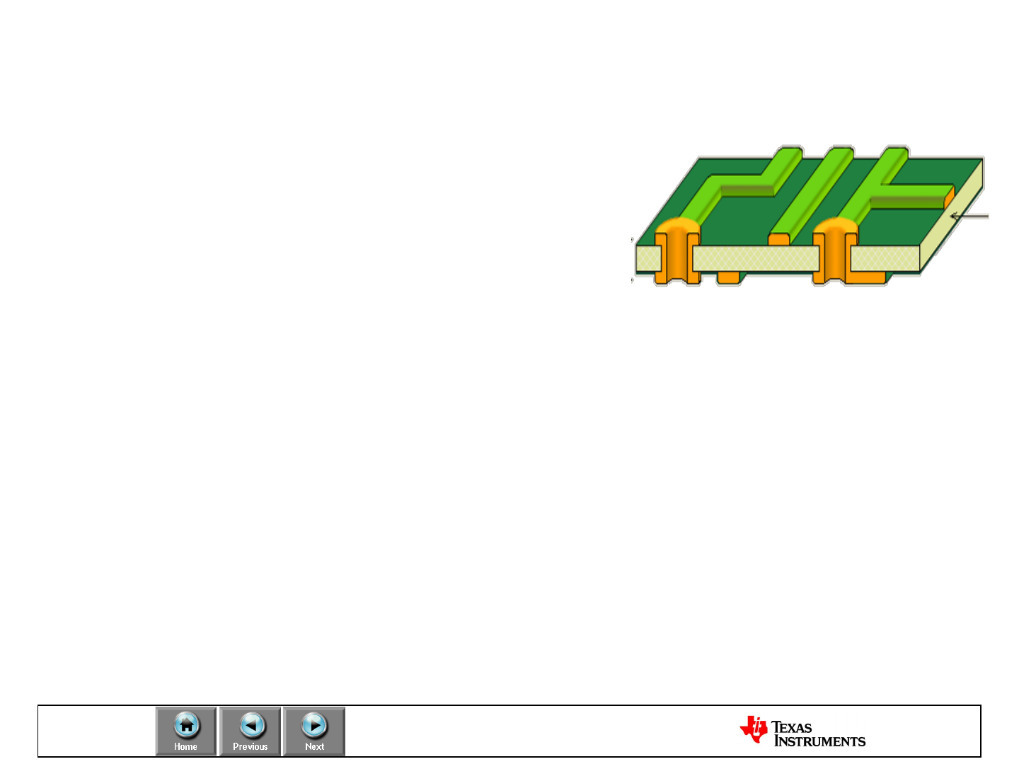
PCB Layout: Rules of thumb for RF Layout
•Keep via inductance as low as
possible. Usually means larger
holes or multiple parallel holes)
•Keep top ground continuous as
possible. Similarly for bottom ground.
•Make the number of return paths equal for both digital
and RF
–Current flow is always through least impedance path. Therefore
digital signals should not find a lower impedance path through the
RF sections.
•Compact RF paths are better, but observe good RF
isolation between pads and or traces.

Design
PCB Layout: Do’s and Don’ts of RF Layout
•Keep copper layer continuous for grounds. Keep connections to supply
layers short
•Use SMT 402 packages which have higher self-resonance and lower
package parasitic components.
•Use the chips star point ground return
•Avoid ground loops at the component level and or signal trace.
•Use vias to move the PCB self resonance higher than signal frequencies
•Keep trace and components spacing nothing less than 12 mils
•Keep via holes large at least 14.5 mils
•Separate high speed signals (e.g. clock signals) from low speed signals,
digital from analog. Placement is critical to keep return paths free of
mixed signals.
•Route digital signals traces so antenna field lines are not in parallel to
lines of magnetic fields.
•Keep traces length runs under a ¼ wavelength when possible.
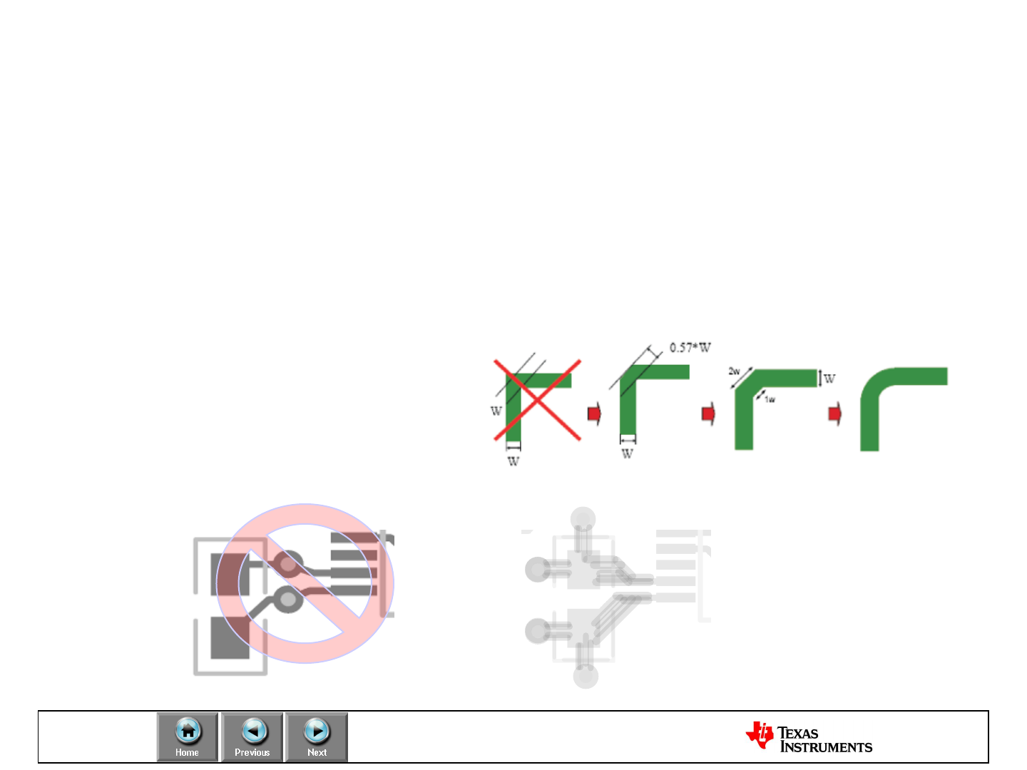
Design
PCB Layout: Do’s and Don’ts of RF Layout
•Avoid discontinuities in ground layers
•Keep vias spacing to mimimize E fields that acts as current barriers,
good rule to follow keep spacing greater than 5.2 x greater than hole
diameter for separations.
• Don’t use sharp right angle bends
•Do not have vias
between bypass caps
Poor Bypassing Good Bypassing
Design
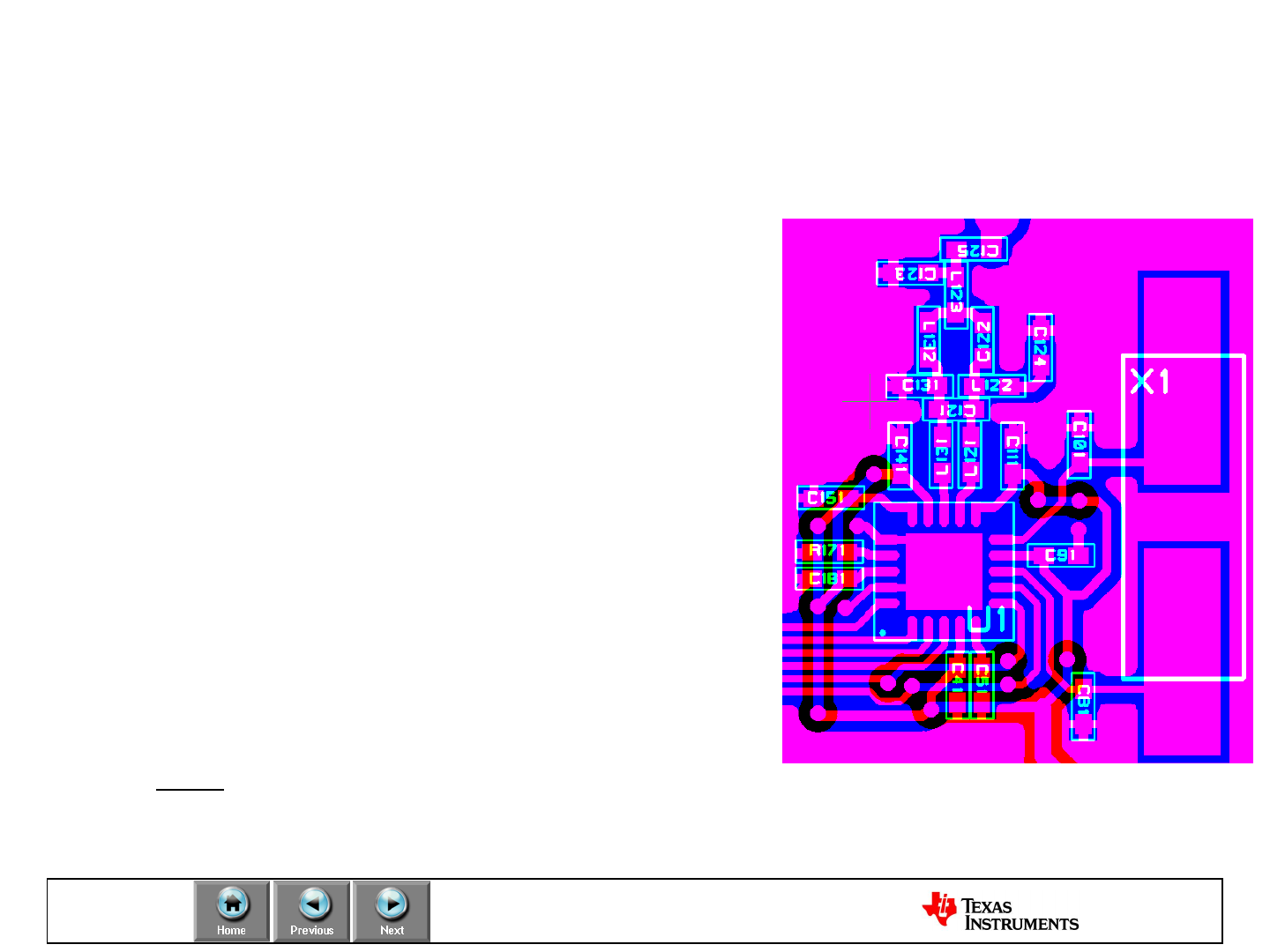
PCB Layout: Example
Copy (for example) the CC1100EM reference design!
–Use the exact same values and placement on
decoupling capacitors and matching components.
–Place vias close to decoupling capacitors.
–Ensure 50 ohm trace from balun to antenna.
–Remember vias on the ground pad under the
chip.
–Use the same distance between the balun on
layer 1 and the ground layer beneath.
–Implement a solid ground layer under the RF
circuitry.
–Ensure that useful test pins are available on the
PCB.
–Connect ground on layer 1 to the ground plane
beneath with several vias.
–Note: different designs for 315/433 MHz and
868/915 MHz
Layout: CC1100EM 868/915MHz reference design
Design
PCB Layout: RF Licensing
Design guidelines to meet the RF regulation requirements:
•Place Decoupling capacitors close to the DC supply lines of the IC
•Design a solid ground plane and avoid cutouts or slots in that area
•Use a low-pass or band-pass filter in the transmit path to suppress the
harmonics sufficiently
•Choose the transmit frequency such that the harmonics do not fall into
restricted bands
•In case of shielding may be necessary filter all lines leaving the shielded case
with decoupling capacitors to reduce spurious emissions.
•Chose values of decoupling capacitors in series resonance with their parasitic
inductance at the RF frequency that needs to be filtered out
•Design the PLL loop filter carefully according to the data rate requirements
•In case of a battery driven equipment, use a brownout detector to switch off
the transmitter before the PLL looses lock due to a low battery voltage

Design
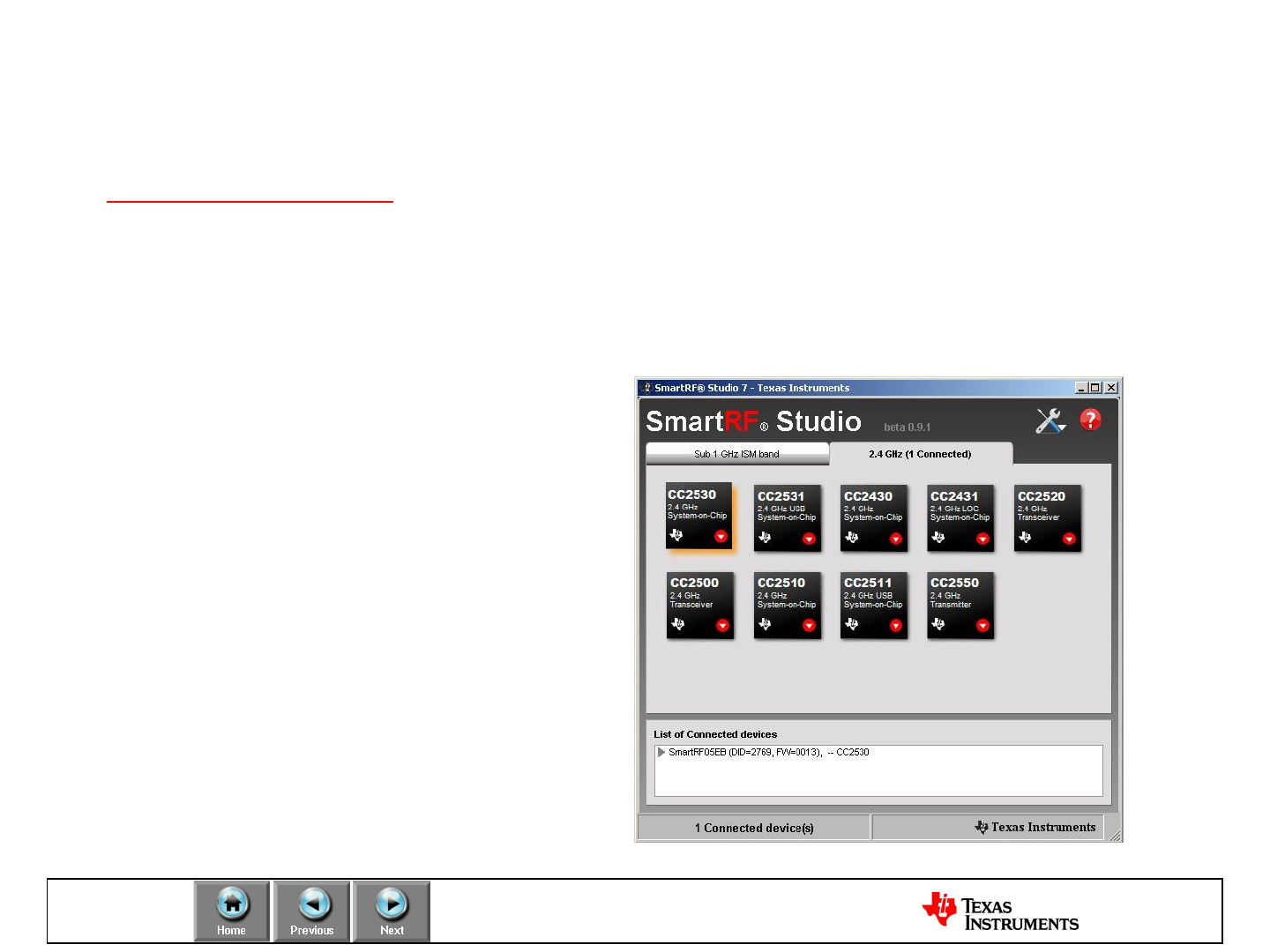
Development Tools: SmartRF® Studio
•SmartRF® Studio is a PC application to be used together with TI’s
development kits for ALL CCxxxx RF-ICs.
•Converts user input to associated chip register values
–RF frequency
–Data rate
–Output power
•Allows remote control/
configuration of the RF chip
when connected to a DK
•Supports quick and simple
performance testing
–Simple RX/TX
–Packet RX/TX
–Packet Error Rate (PER)


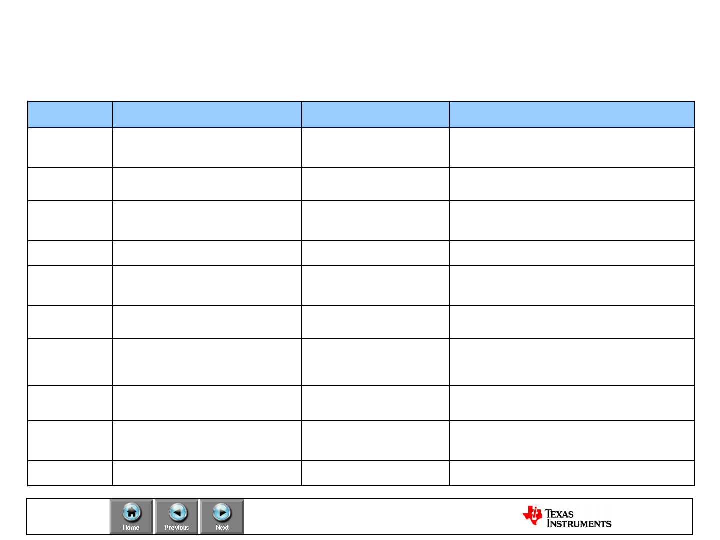
Design
Development Tools: Kits Overview
Part Number Short Description Development Kit Evaluation Modules
CC1020
CC1070 Narrowband RF Transceiver
Narrowband RF Transmitter CC1020-CC1070DK433
CC1020-CC1070DK868 CC1020EMK433 / CC1020EMK868
CC1070EMK433 / CC1070EMK868
CC1101 <1 GHz Transceiver CC1101DK433 /
CC1101DK868 CC1101EMK433 / CC1101EMK868
CC1110
CC1111 8051 MCU + <1 GHz Radio
8051 MCU + <1 GHz Radio + USB CC1110-CC1111DK
CC1110DK-MINI-868 CC1110EMK433 / CC1110EMK868
CC1111EMK868
CC2500 2.4 GHz Transceiver CC2500-CC2550DK CC2500EMK
CC2510
CC2511 8051 MCU + 2.4 GHz Radio
8051 MCU + 2.4 GHz Radio + USB CC2510-CC2511DK
CC2510DK-MINI CC2510EMK
CC2511EMK
CC2520 IEEE 802.15.4 compliant
Transceiver CC2520DK CC2520EMK
CC2530
CC2531 8051 MCU + IEEE 802.15.4
8051 MCU + IEEE 802.15.4 + USB
CC2530DK
CC2530ZDK
RemoTI-CC2530DK CC2530EMK
CC2531EMK
CC1190 PA/LNA RF frontend CC1190EMK-915
CC2591 PA/LNA RF frontend CC2591EMK, CC2430-CC2591EMK
CC2520-CC2591EMK, CC2530-CC2591EMK
CC2590 PA/LNA RF frontend CC2590EMK, CC2430-CC2590EMK


Test
Coexistence
Coexistence of RF systems:
•How well does the radio operate in environments with
interferers
•Selectivity and saturation important factors
•The protocol also plays an important part
–Frequency hopping or frequency agility improves co-
existing with stationary sources like WLAN
–Listen Before Talk used to avoid causing collisions
•GOOD COEXISTENCE = RELIABILITY
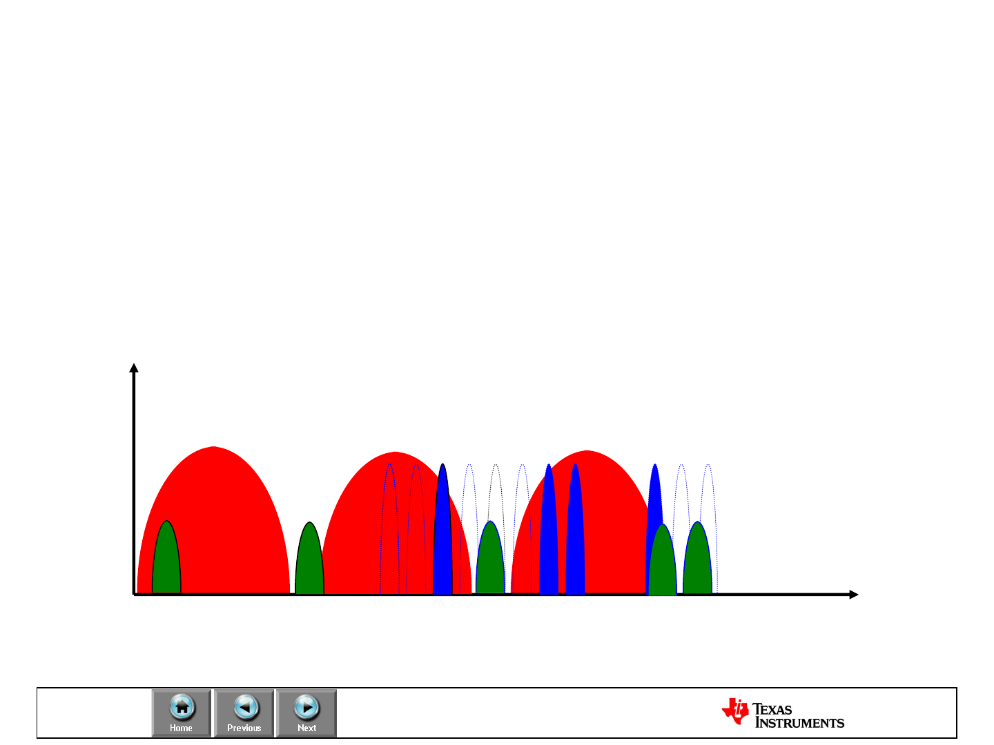
Test
Coexistence
Power
Frequency
WLAN vs ZigBee vs Bluetooth
2.4 GHz
CH1 CH6 CH11
CH11 CH15 CH20 CH25 CH26
Due to the world-wide availability the 2.4GHz ISM band it is getting
more crowded day by day.
Devices such as Wi-Fi, Bluetooth, ZigBee, cordless phones,
microwave ovens, wireless game pads, toys, PC peripherals, wireless
audio devices and many more occupy the 2.4 GHz frequency band.
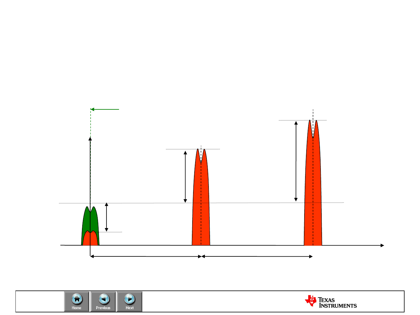
Test
Coexistence: Selectivity / Channel rejection
How good is the receiver at handling interferers at same frequency and
close by frequencies?
Desired signal / Interferer
Co-channel
rejection
[dB]
Desired channel
Frequency
Channel
separation
Adjacent
channel
rejection
[dB]
Channel
separation
Alternate
channel
rejection
[dB]
Power

Test
Production Test
Good quality depends highly on a good Production Line Test. Therefore a
Strategy tailored to the application should be put in place. Here are some
recommandations for RF testing:
•Send / receive test
•Signal strength
•Output power
•Interface test
•Current consumption (especially in RX mode)
•Frequency accuracy

TI will not obsolete a product for “convenience” (JESD48B Policy)
In the event that TI can no longer build a part, we offer one of the most generous policies
providing the following information:
–Detailed Description
–PCN Tracking Number
–TI Contact Information
–Last Order Date (12 months after notification)
–Last Delivery Date
(+6 month after order period ends)
–Product Identification (affected products)
–Identification of Replacement product, if applicable
TI will review each case individually to ensure a smooth transition
Produce
TI Obsolescence Policy
TI complies with JESD46C Policy and will provide the following information a
minimum of 90 days before the implementation of any notifiable change:
•Detailed Description
•Change Reason
•PCN Tracking Number
•Product Identification (affected products)
•TI Contact Information
•Anticipated (positive/negative) impact on Fit, Form, Function, Quality & Reliability
•Qualification Plan & Results (Qual, Schedule if results are not available)
•Sample Availability Date
•Proposed Date of Production Shipment
Produce
TI Product Change Notification
Produce
Quality: TI Quality System Manual (QSM)
•TIs Semiconductor Group Quality System is among the finest and most
comprehensive in the world. This Quality System satisfied customer needs
long before international standards such as ISO-9001 existed, and our internal
requirements go far beyond ISO-9001.
•The Quality System Manual (QSM) contains the 26 top-level SCG requirement
documents.... What must be done.... for its worldwide manufacturing base to
any of our global customers.
•Over 200 Quality System Standards (QSS), internal to TI, exist to support the
QSM by defining key methods... How to do things... such as product
qualification, wafer-level reliability, SPC, and acceptance testing.
•The Quality System Manual is reviewed routinely to ensure its alignment with
customer requirements and International Standards.

IMPORTANT NOTICE
Texas Instruments Incorporated and its subsidiaries (TI) reserve the right to make corrections, modifications, enhancements, improvements,
and other changes to its products and services at any time and to discontinue any product or service without notice. Customers should
obtain the latest relevant information before placing orders and should verify that such information is current and complete. All products are
sold subject to TI’s terms and conditions of sale supplied at the time of order acknowledgment.
TI warrants performance of its hardware products to the specifications applicable at the time of sale in accordance with TI’s standard
warranty. Testing and other quality control techniques are used to the extent TI deems necessary to support this warranty. Except where
mandated by government requirements, testing of all parameters of each product is not necessarily performed.
TI assumes no liability for applications assistance or customer product design. Customers are responsible for their products and
applications using TI components. To minimize the risks associated with customer products and applications, customers should provide
adequate design and operating safeguards.
TI does not warrant or represent that any license, either express or implied, is granted under any TI patent right, copyright, mask work right,
or other TI intellectual property right relating to any combination, machine, or process in which TI products or services are used. Information
published by TI regarding third-party products or services does not constitute a license from TI to use such products or services or a
warranty or endorsement thereof. Use of such information may require a license from a third party under the patents or other intellectual
property of the third party, or a license from TI under the patents or other intellectual property of TI.
Reproduction of TI information in TI data books or data sheets is permissible only if reproduction is without alteration and is accompanied
by all associated warranties, conditions, limitations, and notices. Reproduction of this information with alteration is an unfair and deceptive
business practice. TI is not responsible or liable for such altered documentation. Information of third parties may be subject to additional
restrictions.
Resale of TI products or services with statements different from or beyond the parameters stated by TI for that product or service voids all
express and any implied warranties for the associated TI product or service and is an unfair and deceptive business practice. TI is not
responsible or liable for any such statements.
TI products are not authorized for use in safety-critical applications (such as life support) where a failure of the TI product would reasonably
be expected to cause severe personal injury or death, unless officers of the parties have executed an agreement specifically governing
such use. Buyers represent that they have all necessary expertise in the safety and regulatory ramifications of their applications, and
acknowledge and agree that they are solely responsible for all legal, regulatory and safety-related requirements concerning their products
and any use of TI products in such safety-critical applications, notwithstanding any applications-related information or support that may be
provided by TI. Further, Buyers must fully indemnify TI and its representatives against any damages arising out of the use of TI products in
such safety-critical applications.
TI products are neither designed nor intended for use in military/aerospace applications or environments unless the TI products are
specifically designated by TI as military-grade or "enhanced plastic." Only products designated by TI as military-grade meet military
specifications. Buyers acknowledge and agree that any such use of TI products which TI has not designated as military-grade is solely at
the Buyer's risk, and that they are solely responsible for compliance with all legal and regulatory requirements in connection with such use.
TI products are neither designed nor intended for use in automotive applications or environments unless the specific TI products are
designated by TI as compliant with ISO/TS 16949 requirements. Buyers acknowledge and agree that, if they use any non-designated
products in automotive applications, TI will not be responsible for any failure to meet such requirements.
Following are URLs where you can obtain information on other Texas Instruments products and application solutions:
Products Applications
Amplifiers amplifier.ti.com Audio www.ti.com/audio
Data Converters dataconverter.ti.com Automotive www.ti.com/automotive
DLP® Products www.dlp.com Communications and www.ti.com/communications
Telecom
DSP dsp.ti.com Computers and www.ti.com/computers
Peripherals
Clocks and Timers www.ti.com/clocks Consumer Electronics www.ti.com/consumer-apps
Interface interface.ti.com Energy www.ti.com/energy
Logic logic.ti.com Industrial www.ti.com/industrial
Power Mgmt power.ti.com Medical www.ti.com/medical
Microcontrollers microcontroller.ti.com Security www.ti.com/security
RFID www.ti-rfid.com Space, Avionics & www.ti.com/space-avionics-defense
Defense
RF/IF and ZigBee® Solutions www.ti.com/lprf Video and Imaging www.ti.com/video
Wireless www.ti.com/wireless-apps
Mailing Address: Texas Instruments, Post Office Box 655303, Dallas, Texas 75265
Copyright © 2010, Texas Instruments Incorporated
