Dpm1 A Lp_insert Lp Insert
User Manual: dpm1-a-lp_insert ProSense Digital Panel Meter User Manuals and Product Inserts - AutomationDirect
Open the PDF directly: View PDF ![]() .
.
Page Count: 2
3505 HUTCHINSON ROAD
CUMMING, GA 30040-5860
Digital Panel Meter
DPM1 Series
Models:
DPM1-A-LP
WARNING: To minimize the risk of potential safety problems, you
should follow all applicable local and national codes that regulate
the installation and operation of your equipment. These codes vary
from area to area and it is your responsibility to determine which
codes should be followed, and to verify that the equipment, instal-
lation, and operation are in compliance with the latest revision of
these codes.
Equipment damage or serious injury to personnel can result
from the failure to follow all applicable codes and standards. We
do not guarantee the products described in this publication are
suitable for your particular application, nor do we assume any
responsibility for your product design, installation, or operation.
If you have any questions concerning the installation or operation of
this equipment, or if you need additional information, please call us
at 1-800-633-0405 or 770-844-4200.
This publication is based on information that was available at the
time it was printed. At Automationdirect.com® we constantly strive
to improve our products and services, so we reserve the right to make
changes to the products and/or publications at any time without
notice and without obligation. This publication may also discuss
features that may not be available in certain revisions of the product.
WARNING! Electric shock danger
1. Keep away from high-voltage and high-frequency environment
during the installation to prevent interference. Avoid using the
device in environments which contain: (a) dust or corrosive gas;
(b) high humidity or high radiation; (c) shock or vibration
2. Make sure the input power is switched off when installing or
uninstalling the DPM1 to prevent harm to personnel or equip-
ment.
3. Before switching on the input power, check the signal connec-
tion, e.g. the input voltage and polarity. Voltage that is too high
may cause damage to the DPM1.
4. Front cover should be cleaned only with a soft cloth soaked in neutral
soap product. DO NOT USE SOLVENTS.
Instructions
Wiring Terminals
24mm
48mm
40mm
Fixing clip
Sealing gasket
DPM1 Meter
Panel mounting surface
Dimensions and Mounting
Features
• 48 x 24mm 1/32 DIN
• 4 digit (-1999 to 9999) red LED display
• Selectable decimal point
• Process (4-20mA DC)
• Loop powered
• Display scaling or process teaching modes
• Configuration for direct or reverse acting linear
processes
• Total configuration lock out
To install the instrument, prepare a 45mm x 22mm panel
cut-out and slide the unit inwards making sure to place the
sealing gasket between the front side panel and the front
bezel.
While holding the unit in place, put the fixing clip around
case and slide it until it reaches the panel at the rear side.
Press slightly to fasten the clip to the latching slots on the
case and get the unit fully assembled and close fitted to
achieve a good seal.
To remove the instrument from the panel, pull the rear
fixing clip latching tabs outwards until they are disengaged,
then slide the fixing clip back over the case.
This instrument conforms with the following community directives: EMC
2004/108/CE. Refer to the instructions in this insert to preserve safety protections
To guarantee electromagnetic compatibility, the following guidelines should
followed:
• Use shielded cable for signal wiring.
• Cable cross-section must be ≥0.25mm²
Connection Terminal
w
Installation
Dimensions 48 x 24 x 40mm (1/32 DIN)
Panel Cutout 45 x 22mm
(Max. panel thickness 7mm)
Case Material Polycarbonate UL 94 V-0
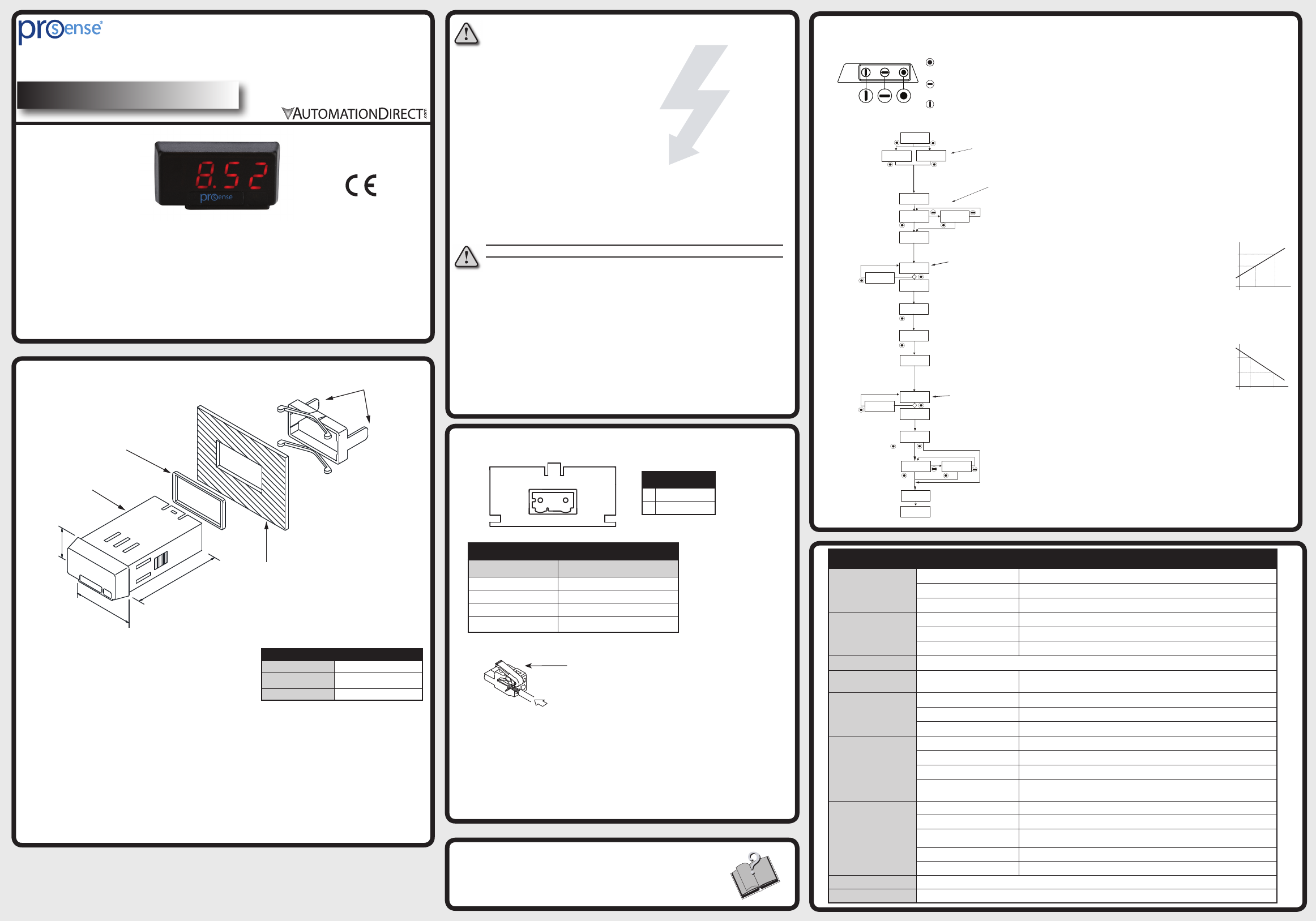
ENTER: Enters configuration and
validates data and parameters.
UP: Increases value of blinking digit in
configuration.
SHIFT: Selects mode or shifts blinking digit
in configuration.
(Bottom View)
Programming Keys
Configuration
Additional Help and Support
• For additional technical support and questions, call our
Technical Support team @ 1-800-633-0405 or
770-844-4200
-+
CN1
1 2
CN1
1(-) 4-20mA loop
2 (+) 4-20mA loop
Technical Specifications
Input
Range 4-20mA
Resolution ±0.01mA
Impedance 10Ω
Accuracy
(@ 23ºC ±5ºC)
Maximum error ±(0.1% of reading ÷3 digits)
Temperature coefficient 100 ppm/ºC
Warm-Up time 5 minutes
Power Supply Loop powered
Voltage Drop on Input
Loop 4-20 mA <5V
Conversion
Technique Single slope
Resolution 16 bits
Conversion rate 62 times per second
Display
Range -1999 to 9999, selectable decimal point position
Type 4 digit 10mm (0.4”), red
Display refresh rate 2 times per second
Display/input overrange indication 0vE
Environmental
Conditions
Operating temperature -10ºC to +60ºC (14ºF to 140ºF)
Storage temperature -25ºC to +85ºC (-13ºF to 185ºF)
Relative humidity
(non-condensing) <95% @ 40ºC (104ºF)
Maximum altitude 2000m
Frontal protection degree IP65
Environmental Air No corrosive gases permitted
Agency Approvals CE
5 sec.
LC 0: Access to programming unlocked.
LC 1: Access to programming totally locked
Parameter values can be viewed but not changed.
SCAL: InP1 and InP2 values entered manually
using programming keys.
tEAC: InP1 and InP2 values entered by introducing
actual process values. Input signal device must be
connected to meter and operational.
InP1: Input signal value corresponding to desired display value dSP1.
dSP1: Display value corresponding to InP1.
dSP2: Display value cooresponding to InP2.
InP2: Input signal value corresponding to desired display
value dSP2.
Err: Error with
programmed
parameter
Save values
.
Enter desired value for dSP1.
Enter desired value for dSP2.
Select desired decimal point position.
Pro: Programming mode displays if
configuration menus are unlocked (LC=0).
dAtA: Data mode displays if configuration
menus are locked (LC=1). Parameter
values can be viewed but not changed.
Run mode
Run mode
Display configuration
SCAL: Manually enter desired value for InP1.
tEAC: Drive process to actual value desired for InP1.
SCAL: Manually enter desired value for InP2.
tEAC: Drive process to actual value desired for InP2. For best
accuracy InP2 value should be as far from InP1 value as possible
Err: Error with
programmed
parameter
Copyright 2016, Automationdirect.com Incorporated/All Rights Reserved Worldwide
Instructions: DPM1-A-LP
Terminal
Connector CN1
Wire cross section 0.08 to 2.5mm² (28 to 12 AWG)
Strip length 8 to 9mm
Manufacturer Wago 231-302/026-000
Cage clamp connection Insertion tool or screwdriver with 0.5 mm x
3.0 mm blade
Insertion Tool (included with meter)
Insert wires into the proper terminal while using
the insertion tool to open the clip inside the
connector. Release the insertion tool to fix wire
to the terminal.
display2
display1
entrada1 entrada2
entrada2
entrada1
display1
display2
escala
inversa
DSP 2
DSP 1
DSP 1
DSP 2
INP 1 INP 2
INP 1 INP 2
Direct Acting Process
Display Value
Display Value
Reverse Acting Process
Input Signal
Input Signal
P.2
Instructions: DPM1-A-LP
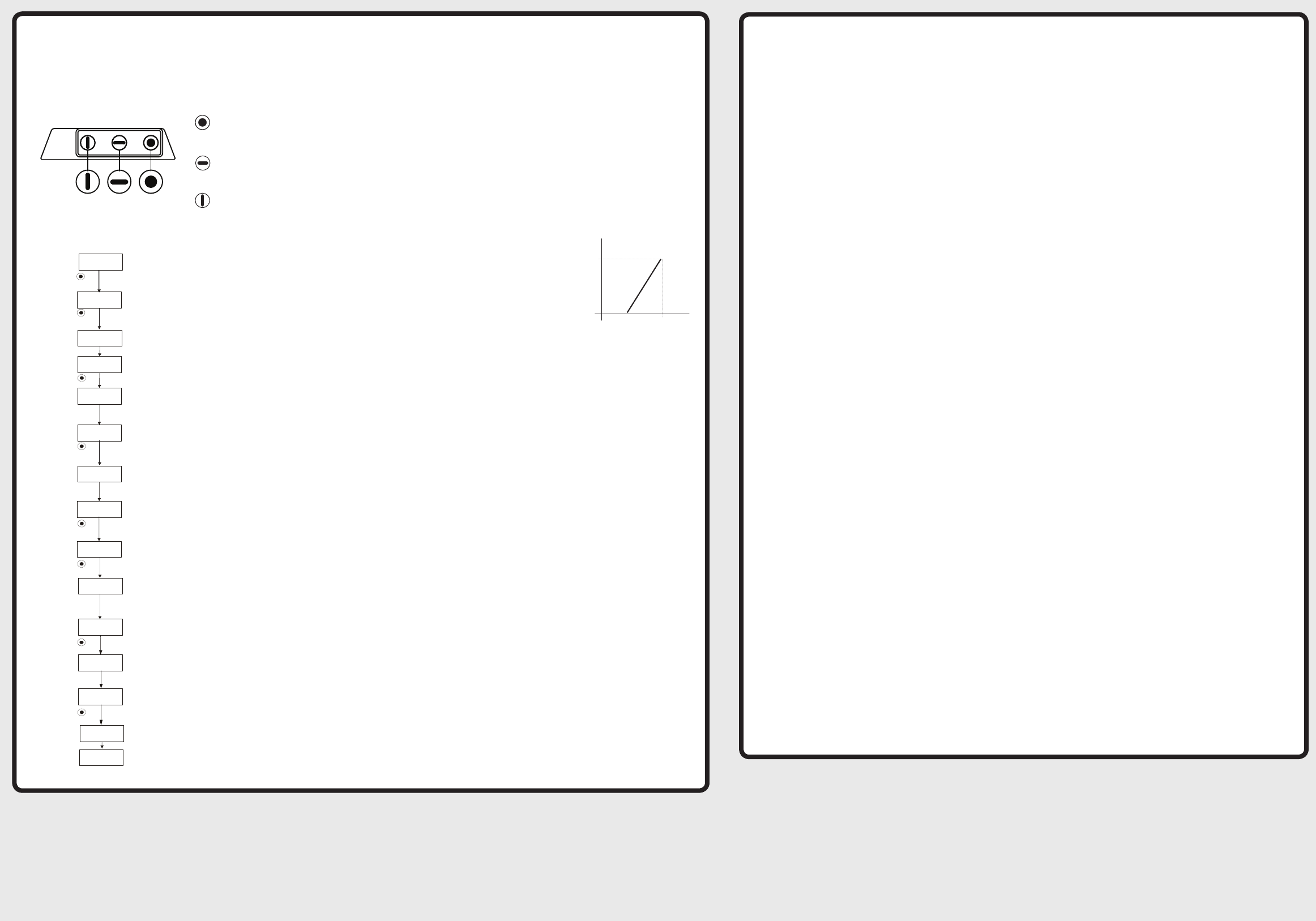
InP1 and InP2 values entered manually
using programming keys.
Input signal value corresponding to desired display value dSP1.
Display value corresponding to InP1.
Display value corresponding to InP2.
Input signal value corresponding to desired display
value dSP2.
Save values
.
.
.
Enter desired value for dSP1.
0 for this example
Enter desired value for dSP2.
100.0 for this example
Select desired decimal point position.
xxx.x for this example
Programming mode
Run mode
Run mode
Manually enter desired value for InP1.
4mA for this example
Manually enter desired value for InP2.
20 mA for this example
ENTER: Enters configuration and
validates data and parameters.
UP: Increases value of blinking digit in
configuration.
SHIFT: Selects mode or shifts blinking digit
in configuration.
(Bottom View)
Programming Keys
Display configuration
DSP 2
100.0
DSP 1
0.0
Direct Acting Process
Display Value
Input Signal
INP 1
4.0 mA
INP 2
20.0 mA
Notes
Model DPM1-A-LP Example Application:
4-20mA input, 0.0 to 100.0 display (direct acting process using Scale Mode)
