FC 35B Insert
User Manual: fc-35b Signal Conditioner Inserts and Manuals - AutomationDirect
Open the PDF directly: View PDF ![]() .
.
Page Count: 2
3505 HUTCHINSON ROAD
CUMMING, GA 30040-5860
FC-35B Unipolar Voltage or Current to
Bipolar Voltage Signal Conditioner
Product Guide
The FC-35B is a DIN-rail or side-mount, selec-
table unipolar input to bipolar output signal
conditioner with isolation between input and
output, and isolation between 24-volt power
and input/output. The FC-35B field config-
urable isolated signal conditioner is useful in
eliminating ground loops and interfacing
sensors to PLC analog input modules. It trans-
lates unipolar voltage inputs or current inputs
to bipolar voltage outputs. The input and
output signal levels are selected via DIP
switches. In addition, the outputs can be either
a direct conversion of the inputs or an inversion
(a reverse acting operation). The user also has
the option of customizing the input OFFSET
(zero) and SPAN (full scale) adjustments that
can be set to a percentage of the full scale via a
pushbutton on the front panel.
Description:
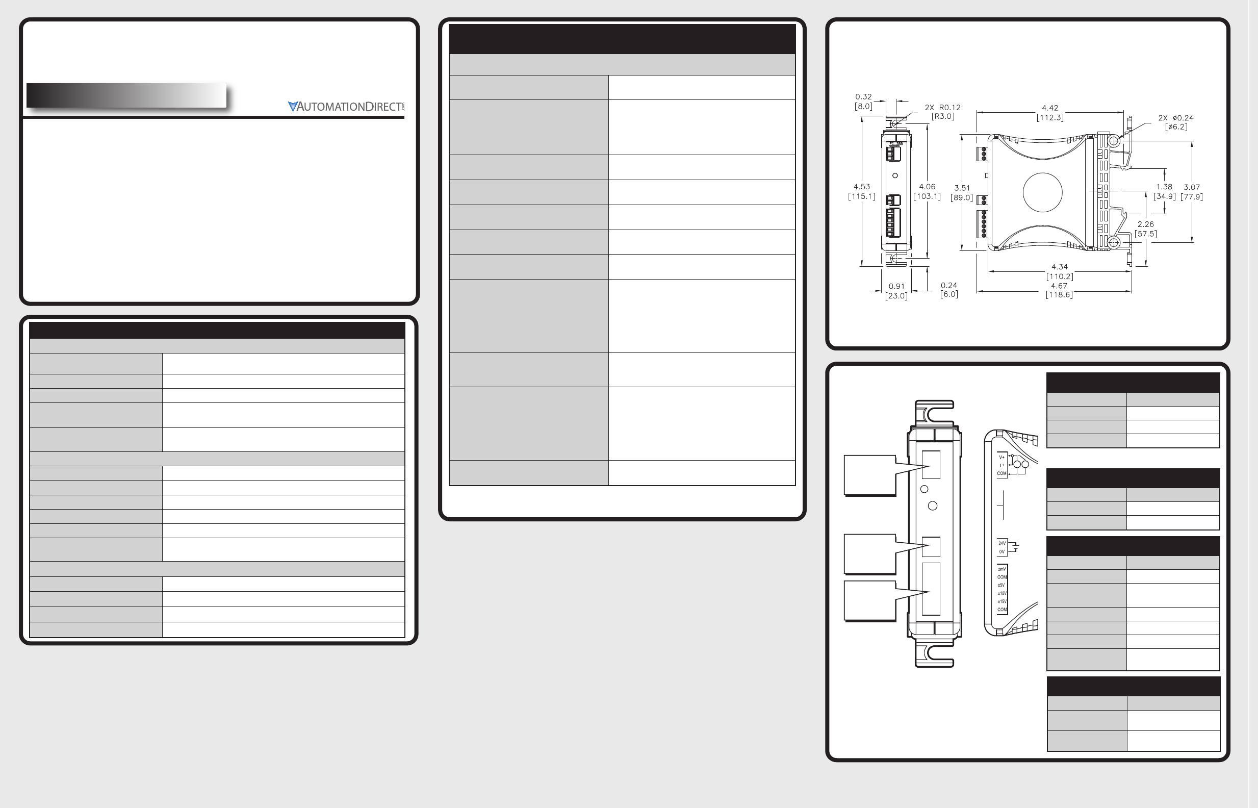
Dimensions
inches [mm]
P.1
Input Terminal Block
Faceplate Label Description
V+ Voltage In
I+ Current In
COM Common
Wiring Connections
External Power Terminal Block
Faceplate Label Description
24 V 24 VDC ±10% (Class 2)
0V 0V
Output Terminal Block
Faceplate Label Description
±mV ±50 mV or ±100 mV Output
COM COM Connection
(used with mV signals)
±5V ±5V Output
±10V ±10 V Output
±15V ±15 V Output
COM COM Connection
(used with non-mV signals)
Output
Signals
Power
Input
Signals
D
24V
0V
V+
I+
COM
±mV
COM
±5V
±10V
±15V
DIAG
CAL
FC-35B
COM
I
PROGRAM MODE
SW 8 = 1
FACTORY DEFAU
HOLD 10 SEC
POWER
24V±10
40mA
CLASS2
mA
+
INPU
OUTPUT
V
Specifications
Input Specifications
Input Ranges 0-5V, 0-10V, 0-20 mA, 4-20 mA (DIP Switch
Selectable/Invertable)
Input Impedance 410 kilohm voltage input, 250 ohm current input
Protection Type, Component Polarity Protection Diode
External DC Power Required 24 VDC ±10%, 40 mA, Class 2
User Calibration Range OFFSET (zero): 0-20% (e.g. 0-1.0V / 5V mode)
SPAN (full-scale): 80-102% (e.g. 4.0 - 5.1V / 5V mode)
Output Specifications
Output Ranges ±50 mV, ±100 mV, ±5V, ±10V, ±15V
Load Impedance 2kilohm Minimum
Sample Duration Time 10 ms
Maximum Inaccuracy 0.1% FSO @ 25°C (1.0% 50 mV / 100 mV)
Accuracy vs. Temperature ±60 PPM of Full Scale/ °C Maximum
Output Current ±50 mV/±100 mV @ 2.5mA max,
±5V, ±10V, ±15V @ 7.5mA max
Terminal Block Specifications
Field Wiring Removable Screw Type Terminal Block
Number of Positions 2 (Dinkle: EC350V-02P), 3 (Dinkle: EC350V-03P), 6 (Dinkle: EC350V-06P)
Wire Range 28-14 AWG solid or stranded conductor; wire strip length 1/4” (6-7mm)
Screw Torque 1.7 inch-pounds (0.19 Nm)
Specifications (continued)
General Specifications
Surrounding Air Temperature 0to 60°C (32 to 140°F)
IEC 60068-2-14 (Test Nb, Thermal Shock)
Storage Temperature
-20 to 70°C (-4 to 158°F)
IEC 60068-2-1 (Test Ab, Cold)
IEC 60068-2-2 (Test Bb, Dry Heat)
IEC 60068-2-14 (Test Na, Thermal Shock)
Humidity 5to 95% (non-condensing)
IEC 60068-2-30 (Test Db, Damp Heat)
Environmental Air No corrosive gases permitted
(EN61131-2 pollution degree 1)
Vibration MIL STD 810C 514.2
IEC 60068-2-6 (Test Fc)
Shock MIL STD 810C 516.2
IEC 60068-2-27 (Test Ea)
Insulation Resistance >10M @ 500 VDC
Noise Immunity
NEMA ICS3-304
IEC 61000-4-2 (ESD)
Impulse 1000V @ 1µS pulse
IEC 61000-4-4 (FTB)
RFI, (145 MHz, 440 MHz 5W @ 15 cm)
IEC 61000-4-3 (RFI)
Weight 0.3lbs
Isolation
1800 VDC Power to Input
1800 VDC Power to Output
1800 VDC Input to Output
*applied for 1 second (100% tested)
Agency Approvals UL508*, File Number: E157382, CE
* In order to comply with UL508 Class 2 standards the supplied power must be less than 26 VDC and fused at a
maximum of 3 amps.
Switch/LED Labels
Faceplate Label Description
DIAG Diagnostic LED flashing
indication
CAL Push button switch input to
initiate calibration, etc.
NOTE: V+ and I+ must be jumpered for Current input
Version: Rev. A
September, 2014
DIP Switches Located
Under Cover
INPUTS
0-5 V
0-10 V
0-20 mA
4-20 mA
1
1
0
1
0
2
1
1
0
0
3
1
0
1
1
OUTPUTS
±50 mV
±100 mV
±5 V
±10 V
±15 V
5
1
0
1
0
1
6
1
1
0
0
1
7
1
1
1
1
0
PROGRAM MODE
SW8=1
FACTORY DEFAULT
HOLD 10 SEC
87654321
0
1
POWER
24V±10%
40mA
CLASS2
mA
+
INPUT
OUTPUT
FC-35B
SIGNAL CONDITIONER
ISOLATED
V OR mA INPUT
BIPOLAR V OUTPUT
INVERT INPUTS SW 4 = 1
V
DIP Switch - 1, 2, 3
Input Ranges 1 2 3
0-5V 111
0-10 V 010
0-20 mA 101
4-20 mA 001
DIP Switch - 5, 6, 7
Output Ranges 5 6 7
±50 mV 111
±100 mV 011
±5V 101
±10 V 001
±15 V 110
DIP Switch - 4, 8
Input Connection Options 4 8
Invert Acting 10
Calibration Enable 01
DIAGNOSTIC LED
CALIBRATION BUTTON
24V
0V
V+
I+
COM
±mV
COM
±5V
±10V
±15V
DIAG
CAL
FC-35B
COM
DIP Switch Settings Status Indicators
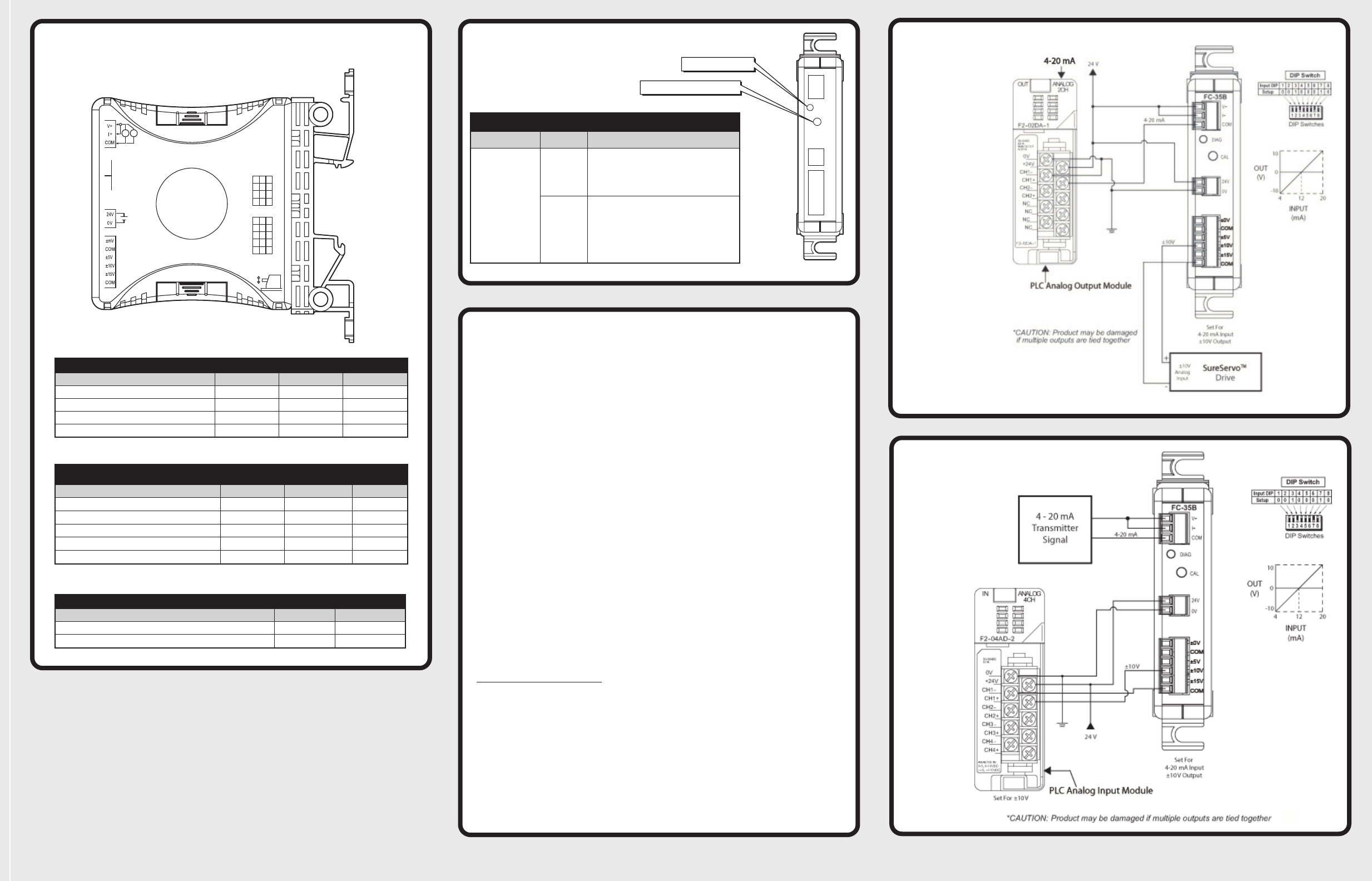
DC Motor Drive
4-20 mA IN to ±10 V OUT
P.2
4-20 mA IN to ±10V OUT
Typical Application #1
Status Indicators
Indicator Status Description
Diagnostic LED
Normal
Operation
The Diagnostic LED blinks at a propor-
tional rate to the selected input signal
level. This indicates that the unit is opera-
tional and functioning within spec.
Calibration
When performing field calibration or a re-
store to the factory calibration, the LED is
used for indication of the internal calibra-
tion process and will provide feedback (as
described under “User OFFSET and
SPAN Calibration) to the user if they have
selected an invalid input range.
User OFFSET and SPAN Calibration
Application adjustments to calibrate the input signal level:
1) Select the input and output signal modes via the dipswitches.
2) Connect 24 volt power to the signal conditioner.
3) Connect the mmiinniimmuumm(OFFSET) input signal level desired.
4) Move Switch 8 “CAL EN” to ON, press and hold the CAL pushbutton and
release after approximately 3 seconds. The DIAG LED comes ON steady
once pressed. If the pushbutton is held >3 seconds, the LED will turn off indi-
ating the User Cal feature is no longer available. The unit returns to normal
processing of input data and another press needs to occur to recapture the
input minimum value if a User Cal is desired. If the pushbutton is released in
<3 seconds, the minimum input value will not be captured and another press
needs to occur. If the push button is pressed longer than 10 seconds, the unit
will go into “Restore Factory Cal” mode.
5) If the input is within the user calibration, once the pushbutton is released at 3
seconds, the LED will flash 2-3 times. If the input is out of range, the LED will
flash several times rapidly. If the out of range occurs, the input needs to be
adjusted to the allowable range. In order to remove the User Cal, press and
hold the pushbutton for > 10 seconds.
6) Move the Switch 8 “Cal En” to OFF. Connect the maximum (SPAN) input
signal level desired and repeat steps 4 and 5.
7) Move Switch 8 “CAL EN” to OFF.
Restore Factory Calibration
1) Move switch 8 “CAL EN” to ON, press and hold CAL pushbutton.
Once the push button is held and released after 10 seconds, the LED
will flash several times indicating a valid restore has taken place. The
unit has now been returned to factory calibration. If the push button
is released before the 10 seconds has expired, the press will be
ignored and go back to regular signal processing based on previous
calibration coefficients.
2) Move Switch 8 “CAL EN” to OFF.
3) Start conversion with no power cycle required.
Typical Application #2
