980146 Cover_P2 Ginsu GU10 &file=980146
User Manual: 980146-Ginsu-GU10
Open the PDF directly: View PDF ![]() .
.
Page Count: 54
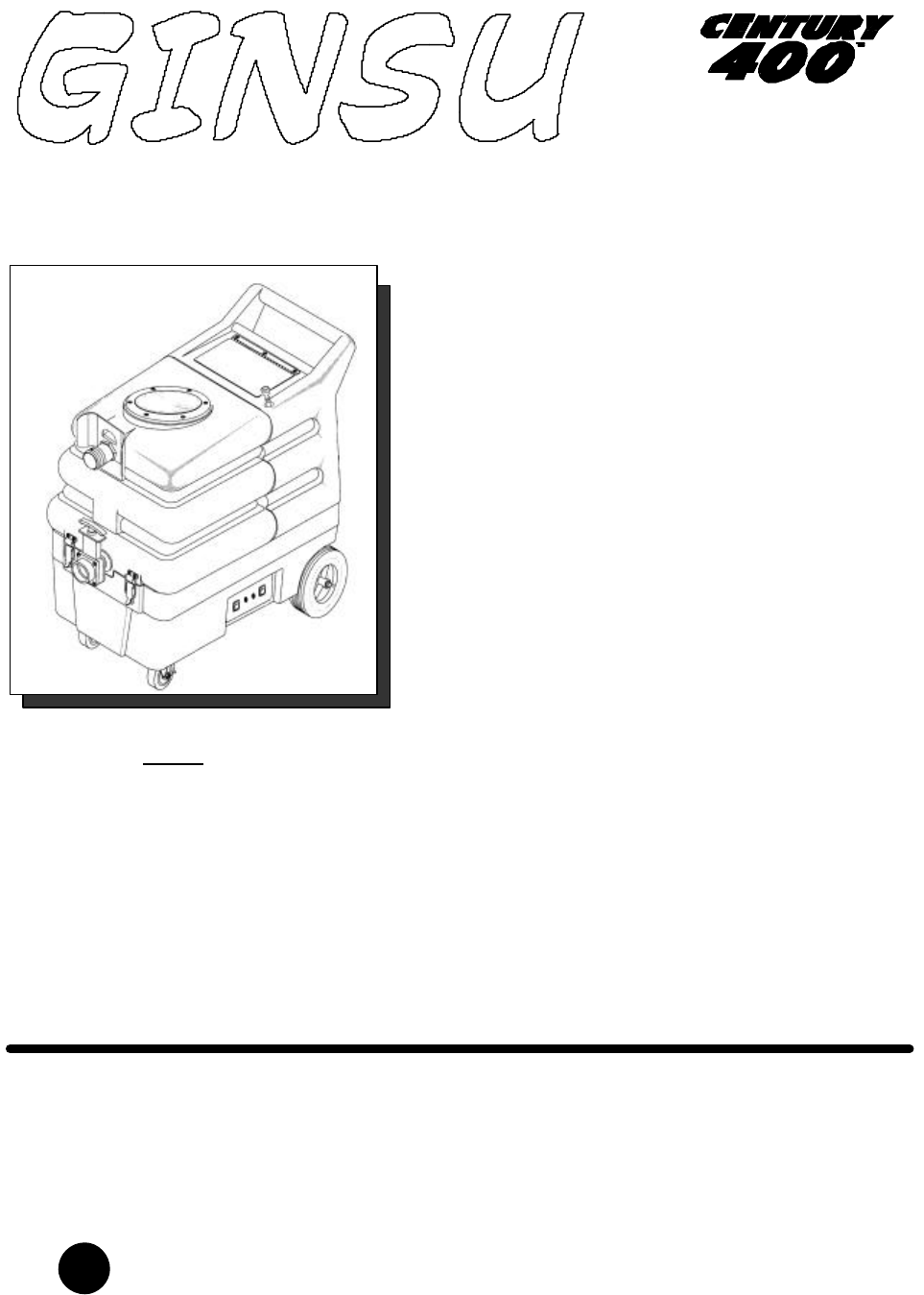
Operating Instructions
SPECIALTY SURFACE CLEANING MACHINE
980146 12/02/05
J
Read these instructions before using the machine
MODELS:
GU10

MACHINE DATA LOG
980146 02/07/04
2
OVERVIEW
The Ginsu is a multi-functional cleaning machine intended for commercial use. The appliance applies chemical at
low pressure and uses high pressure to clean with. Then the soiled water is vacuumed back into the recovery
tank.
YOUR DEALER
Name: ____________________________________________________________________________
Address: __________________________________________________________________________
Phone Number: ____________________________________________________________________
MODEL _______________________________________
DATE OF PURCHASE __________________________
SERIAL NUMBER ______________________________
SALES REPRESENTATIVE # _____________________

TABLE OF CONTENTS
980146 02/07/04
3
Machine Data Log................................................2
Table of Contents.................................................3
HOW TO USE THIS MANUAL
How to use this Manual........................................1-1
SAFETY
Important Safety Instructions ...............................2-1
Hazard Intensity Level..........................................2-2
Grounding Instructions.........................................2-3
Safety Label Location...........................................2-4
OPERATIONS
Technical Specifications.......................................3-1
How the Machine Works. .....................................3-2
Components.........................................................3-3
Controls................................................................3-4
Machine Operation...............................................3-6
Chemical Operations............................................3-8
MAINTENANCE
Maintenance.........................................................4-1
Float Shut-Off ................................................4-2
Strainer ..........................................................4-2
Circuit Breakers .............................................4-2
Vacuum Motor Replacement.........................4-3
Vacuum Motor Brush Replacement...............4-3
Solution Pump Replacement.........................4-4
Regulating Unloader......................................4-5
Periodic/Daily Maintenance..................................4-6
Service Schedule. ................................................4-6
Machine Troubleshooting.....................................4-7
GROUP PARTS LIST
Base ................................................................... 5-1
Controls.............................................................. 5-3
Labels & Straps.................................................. 5-5
Recovery Tank ................................................... 5-7
Solution Hoses & Fittings ................................... 5-9
Solution Pump & Motor ...................................... 5-11
Solution Prime Pump.......................................... 5-13
Solution Tank ..................................................... 5-15
Vacuum Motor.................................................... 5-17
Tools – Standard................................................ 5-19
Wiring – Schematic ............................................ 5-21
Suggested Spare Parts...................................... 5-22
Low Flow Spray Gun Option .............................. 5-23
Grout Cleaner Option ......................................... 5-25
High Pressure Wand Option .............................. 5-27
Carpet Tool Option............................................. 5-29
Warranty............................................................. 5-31
HOW TO USE THIS MANUAL
980146 02/07/04
1-1
This manual contains the following sections:
- HOW TO USE THIS MANUAL
- SAFETY
- OPERATIONS
- MAINTENANCE
- PARTS LIST
The HOW TO USE THIS MANUAL section will tell
you how to find important information for ordering
correct repair parts.
Parts may be ordered from authorized dealers.
When placing an order for parts, the machine model
and machine serial number are important. Refer to
the MACHINE DATA box which is filled out during
the installation of your machine. The MACHINE
DATA box is located on the inside of the front cover
of this manual.
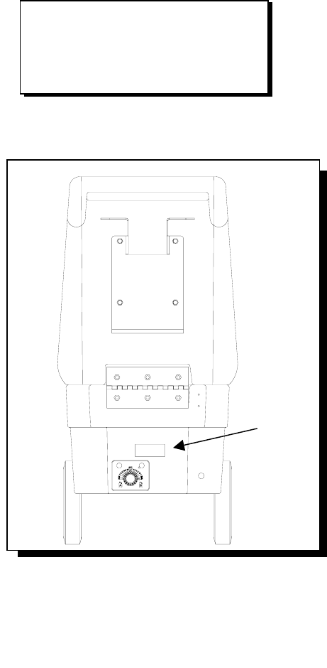
The model and serial number of your machine is on
the bottom back-end of the machine.
The SAFETY section contains important information
regarding hazard or unsafe practices of the
machine. Levels of hazards is identified that could
result in product or personal injury, or severe injury
resulting in death.
The OPERATIONS section is to familiarize the
operator with the operation and function of the
machine.
The MAINTENANCE section contains preventive
maintenance to keep the machine and its
components in good working condition. They are
listed in this general order:
- Vacuum Motor
- Solution Pump
- Daily Maintenance
- Periodic Maintenance
- Service Schedule
- Machine Troubleshooting
The PARTS LIST section contains assembled parts
illustrations and corresponding parts list. The parts
lists include a number of columns of information:
- REF – column refers to the reference
number on the parts illustration.
- PART NO. – column lists the part
number for the part.
- QTY – column lists the quantity of the
part used in that area of the machine.
- DESCRIPTION – column is a brief
description of the part.
- SERIAL NO. FROM – column indicates
the first machine the part number is
applicable to. When the machine design
has changed, this column will indicate
serial number of applicable machine.
The main illustration shows the most
current design of the machine. The
boxed illustrations show older designs. If
column has an asterisk (*), call
manufacturer for serial number.
- NOTES – column for information not
noted by the other columns.
NOTE: If a service or option kit is installed on your
machine, be sure to keep the KIT INSTRUCTIONS
which came with the kit. It contains replacement
parts numbers needed for ordering future parts.
NOTE: The 98# on the lower left corner of the front
cover is the part number for this manual.
MODEL _____________________________________
DATE OF PURCHASE ________________________
SERIAL NUMBER ____________________________
SALES REPRESENTATIVE # ___________________

980146 02/07/04 2-1
IMPORTANT SAFETY INSTRUCTIONS
When using an electrical appliance, basic precaution
must always be followed, including the following:
READ ALL INSTRUCTIONS BEFORE USING THIS MACHINE.
This machine is for commercial use.
To reduce the risk of fire, electric shock, or injury:
Connect to a properly grounded outlet. See Grounding Instructions.
Do not leave the machine unattended. Unplug machine from outlet when not in use and before maintenance or
service.
Do not allow machine to be used as a toy. Close attention is necessary when used near children.
Do not point spray gun at people.
Use only as described in this manual. Use only manufacturer’s recommended components and attachments.
Do not use damaged electrical cord or plug. Follow all instructions in this manual concerning grounding the
machine. If the machine is not working properly, has been dropped, damaged, left outdoors, or dropped into
water, return it to an authorized service center.
Do not pull or carry machine by electrical cord, use as a handle, close a door on cord, or pull cord around sharp
edges or corners.
Do not run machine over cord. Keep cord away from heated surfaces.
Do not unplug machine by pulling on cord. To unplug, grasp the electrical plug, not the electrical cord.
Do not handle the electrical plug or machine with wet hands.
Do not operate the machine with any openings blocked. Keep openings free of debris that may reduce airflow.
Do not vacuum anything that is burning or smoking, such as cigarettes, matches, or hot ashes.
This machine is not suitable for picking up health endangering dust.
Turn off all controls before unplugging.
Machine can cause a fire when operating near flammable vapors or materials. Do not operate this machine near
flammable fluids, dust or vapors.
This machine is suitable for commercial use, for example in hotels, schools, hospitals, factories, shops
and offices for more than normal housekeeping purposes.
Maintenance and repairs must be done by qualified personnel.
If foam or liquid comes out of machine, switch off immediately.
SAVE THESE INSTRUCTIONS
!
WARNING:

HAZARD INTENSITY LEVEL
980146 02/07/04
2-2
The following symbols are used throughout this guide as indicated in their descriptions:
HAZARD INTENSITY LEVEL
There are three levels of hazard intensity identified by signal words -WARNING and CAUTION and FOR
SAFETY. The level of hazard intensity is determined by the following definitions:
WARNING - Hazards or unsafe practices which COULD result in severe personal injury or death.
CAUTION - Hazards or unsafe practices which could result in minor personal injury or product or property
damage.
FOR SAFETY: To Identify actions which must be followed for safe operation of equipment.
Report machine damage or faulty operation immediately. Do not use the machine if it is not in proper operating
condition. Following is information that signals some potentially dangerous conditions to the operator or the
equipment. Read this information carefully. Know when these conditions can exist. Locate all safety devices on
the machine. Please take the necessary steps to train the machine operating personnel.
FOR SAFETY:
DO NOT OPERATE MACHINE:
Unless Trained and Authorized.
Unless Operation Guide is Read and understood.
In Flammable or Explosive areas.
In areas with possible falling objects.
WHEN SERVICING MACHINE:
Avoid moving parts. Do not wear loose clothing; jackets, shirts, or sleeves when working on the machine. Use
Windsor approved replacement parts.
!WARNING
!CAUTION
GROUNDING INSTRUCTIONS
980146 02/07/04 2-
3
THIS PRODUCT IS FOR COMMERCIAL USE
ONLY.
ELECTRICAL:
In the USA, this machine operates on a standard 15
amp 115V, 60 Hz, A.C. power circuit. The amp,
hertz, and voltage are listed on the data label found
on each machine. Using voltages above or below
those indicated on the data label will cause serious
damage to the motors.
EXTENSION CORDS:
If an extension cord is used, the wire size must be at
least one size larger than the power cord on the
machine, and must be limited to 50 feet (15.5m) in
length.
GROUNDING INSTRUCTIONS:
This appliance must be grounded. If it should
malfunction or break down, grounding provides a
path of least resistance for electric current to reduce
the risk of electric shock. This appliance is equipped
with a cord having an equipment-grounding
conductor and grounding plug. The plug must be
inserted into an appropriate outlet that is properly
installed and grounded in accordance with all local
codes and ordinances.
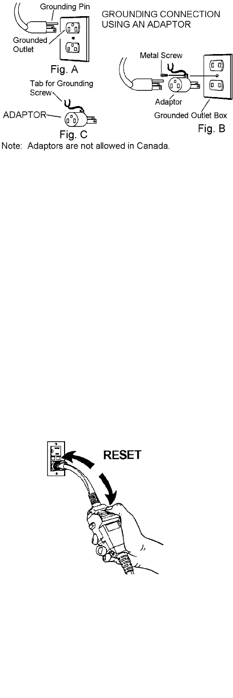
This appliance is for use on a nominal 120-volt
circuit, and has a grounded plug that looks like the
plug in “Fig. A”. A temporary adaptor that looks like
the adaptor in “Fig. C” may be used to connect this
plug to a 2-pole receptacle as shown in “Fig. B”, if a
properly grounded outlet is not available. The
temporary adaptor should be used only until a
properly grounded outlet (Fig. A) can be installed by
a qualified electrician. The green colored rigid ear,
lug, or wire extending from the adaptor must be
connected to a permanent ground such as a
properly grounded outlet box cover. Whenever the
adaptor is used, it must be held in place by a metal
screw.
Improper connection of the equipment-
grounding conductor can result in a risk of
electric shock. Check with a qualified electrician
or service person if you are in doubt as to
whether the outlet is properly grounded. Do not
modify the plug provided with the appliance - if it
will not fit the outlet; have a proper outlet
installed by a qualified electrician.
GROUND-FAULT CIRCUIT-INTERRUPTER
PROTECTION
This machine is provided with a (GFCI) built into the
plug of the power supply cord. This device provides
additional protection from the risk of electric shock.
Should replacement of the plug or cord become
necessary, use only identical replacement parts that
include GFCI protection. If the GFCI is not the
AUTOMATIC RESET TYPE, it must be manually
TESTED and RESET each time the cleaning system
is plugged in. Press firmly to assure internal spring
activates switch. Push “test“ then push “reset”. Motor
will not start if GFCl does not reset. Check circuit
breakers or outlet. If circuit breaker is not tripped
and unit will not reset, contact local service center.
SAFETY LABEL LOCATION
980146 02/07/04
2-4
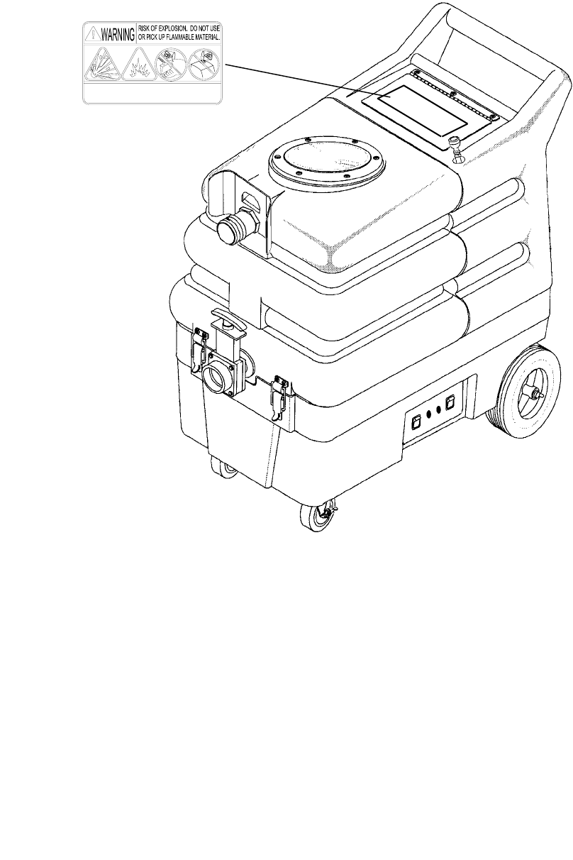
NOTE: These drawings indicate the location of safety labels on the machine. If, at any time, the labels become
illegible contact your C400 representative for prompt replacement.
WARNING:
TO REDUCE THE RISK OF ELECTRIC SHOCK, USE
INDOORS ONLY AND ALWAYS INSTALL FLOAT BEFORE
ANY WET PICK-UP OPERATION. USE ONLY DETERGENT
INTENDED FOR CLEANING CARPETS.
WARNING LABEL, 500009
TECHNICAL SPECIFICATIONS
980146 02/07/04 3-1
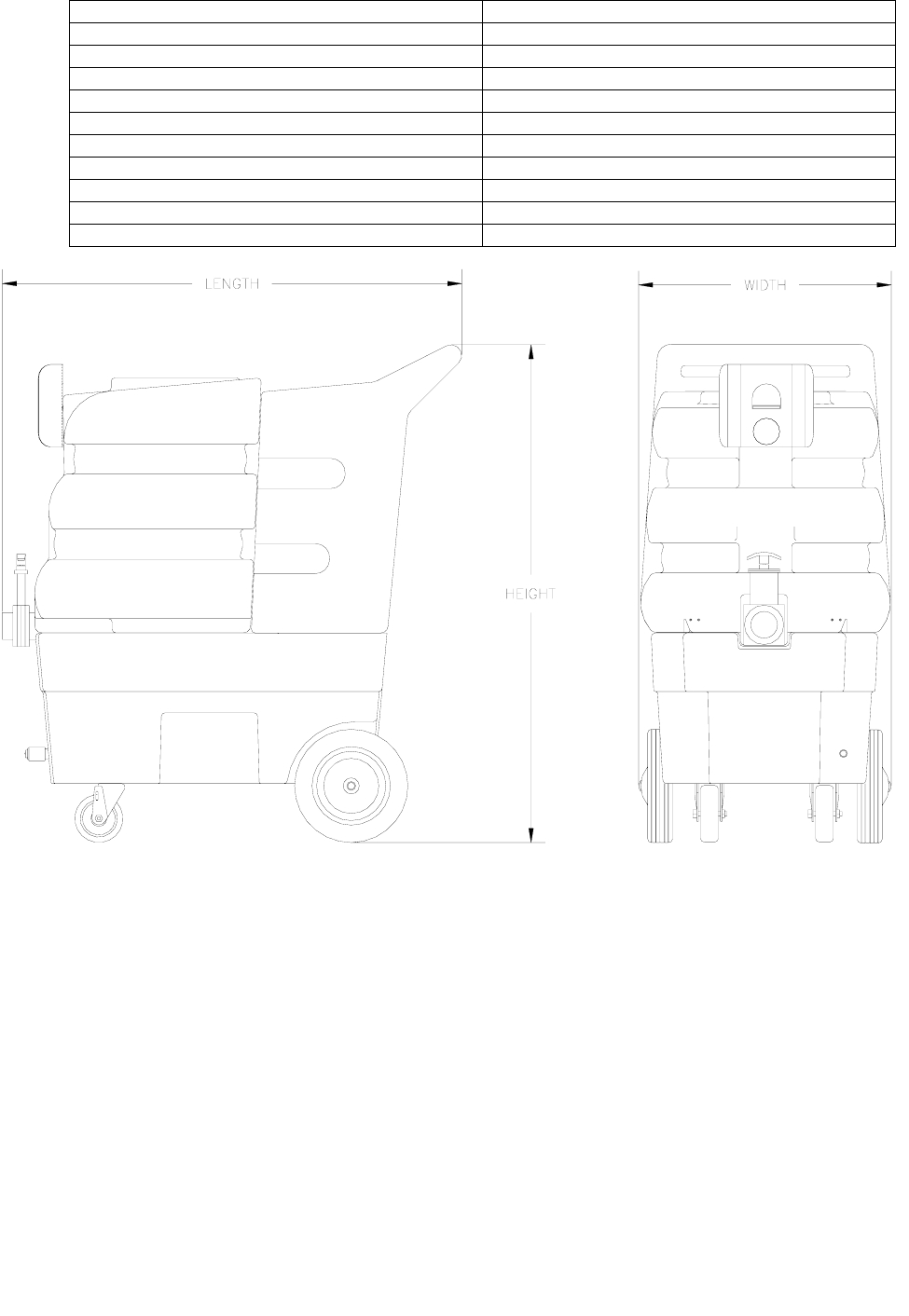
ITEM DIMENSION/CAPACITY
Electrical 115V 60HZ 11A
Electric Vacuum Motor 2 STAGE
Solution Pump 500PSI
Solution Capacity 10 gal. (38L)
Recovery Capacity 11 gal. (42L)
Dimensions – Weight (Empty) 106 lbs. (48kgs)
Dimensions - Length 36 in. (914mm)
Dimensions - Height 36 in. (914mm)
Dimensions - Width 22 in. (589mm)
Power Cable 50 ft. (15.24M)
SPECIAL NOTES:
The sound pressure level at 1m from the machine was measured to be 76 dBA. This was a nearfield, broadband
measurement taken in a typical industrial environment on a tile floor. This appliance contains no possible source
of impact noise. The instantaneous sound pressure is below 63 Pa.
The weighted root mean square acceleration at the operator’s arms was measured to be below 2.5m/s2. This was
a tri-axial, third-octave-band measurement made during normal operation on a composite tile floor. The
measurement and related calculations were made in accordance with ANSI S3.34-T986.

HOW THE MACHINE WORKS
980146 02/07/04
3-2
This machine is a multi-functional cleaning machine
intended for commercial use. The appliance applies
chemical at low pressure and uses high pressure to
clean with. Then the soiled water is vacuumed back
into the recovery tank.
The machine's primary systems are the clean water
system, recovery system, chemical system and
pressure washer system.
The function of the clean water system is to store
clean water and deliver it to the available tools. The
clean water system consists of the clean water tank,
strainer and check valve. The clean water tank
stores water until it is delivered to the tools. The
strainer protects the check valve and pump from
debris. The check valve prevents the water from
flowing back into the tank.
The function of the recovery system is to vacuum the
soiled water back into the recovery tank. The
recovery system consists of the wand and wheeled
squeegee, vacuum motor, float shut-off and
recovery tank. The wand and wheeled squeegee
wipes the dirty solution off the floor. The vacuum
motor provides suction to draw the dirty solution off
the floor and into the recovery tank. The float shut-
off protects the vacuum fan from over filling. The
recovery tank stores the dirty solution.
The function of the chemical system is to dispense
chemical into the clean water system. The chemical
system consists of the chemical reservoir, chemical
cap and a chemical-metering selector. The chemical
reservoir stores and dispenses chemical into the
clean water system. The chemical-metering selector
meters the amount of chemical and selects between
chemical A or B and turn chemical off.
The function of the pressure washer system is to
clean fixtures and other surfaces. The pressure
washer system consists of a pump, high-pressure
hose and spray gun. The pump delivers cleaning
solution to the tools. The high-pressure hose
connects the pump to the spray gun. The spray gun
is an adjustable Hi-Lo that applies clean water and
chemical to the surface being cleaned.
The function of the auto fill system is to be able to
connect a garden hose to a constant water source.
The valve and float inside the tank will automatically
turn the water flow on and off to keep the tank full.
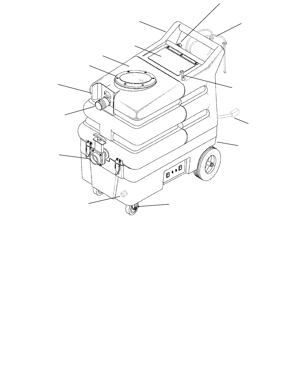
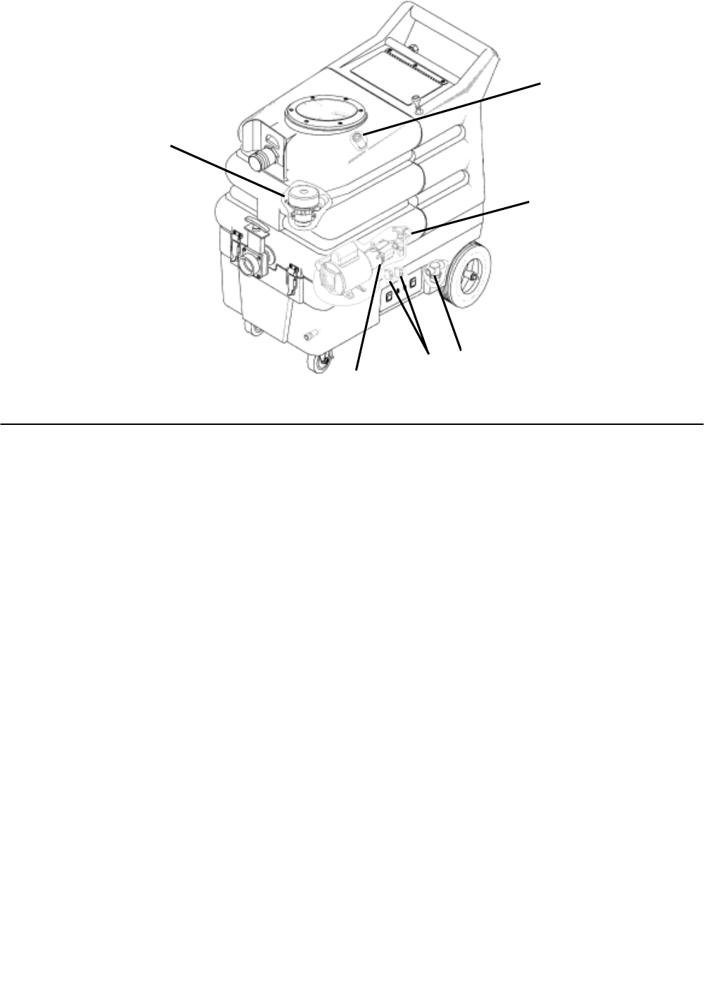
COMPONENTS
980146 12/04/04 3-
3
SOLUTION TAN
K
SOLUTION
TANK LID
RECOVERY TAN
K
RECOVERY
TANK LID
VACUUM
A
CCESSORY TOOL
HOOK-UP
SOLUTION
A
CCESSORY TOOL
HOOK-UP
RECOVERY TAN
K
DRAIN VALVE
BASE ASSEMBLY
SOLUTION TANK
FILL HOSE
CASTER LOCK
HOSE
STORAGE
CHEMICAL
SIPHON CAPS
ELECTRICAL
CORD
AUTO SOLUTION FILL
CONNECTION
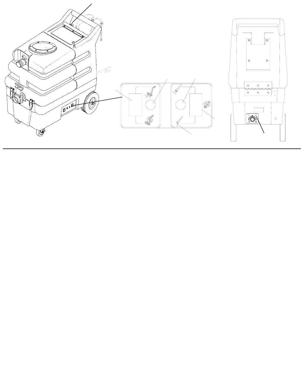
CONTROLS
980146 12/04/04
3-4
1. Vacuum Switch
2. Vacuum Circuit Breaker
3. Pump Circuit Breaker
4. Pump Switch
5. Prime Pump Switch
6. Chemical Selector and Metering Valve
7. Solution Auto Fill Connection
1
23
4
5
7
6

CONTROLS
980146 02/07/04 3-
5
1. VACUUM SWITCH
Turns the vacuum motor On and Off.
2. VACUUM CIRCUIT BREAKER
10 Amp. Protects the vacuum motor.
3. PUMP CIRCUIT BREAKER
6 Amp. Protects the pump motor.
4. PUMP SWITCH
Turns the pump On and Off.
5. PRIME PUMP SWITCH
Primes the solution pump if necessary.
6. CHEMICAL SELECTOR AND METERING
VALVE
Meters the amount of chemical being dispensed
and selects between chemical A or chemical B
and OFF.
7. SOLUTION AUTO FILL CONNECTION
The valve and float inside the tank automatically
turn the water flow on and off to keep the tank
full. Use only with normal city water pressure.
Connect hose to wall faucet. Remove cap from
machine hose connection and connect hose.
Turn on water faucet to desired flow rate.
OPERATIONS
980146 12/04/04
3-6
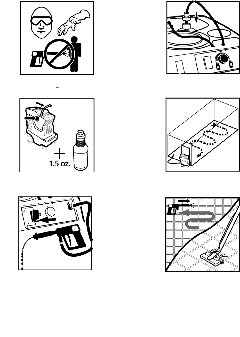
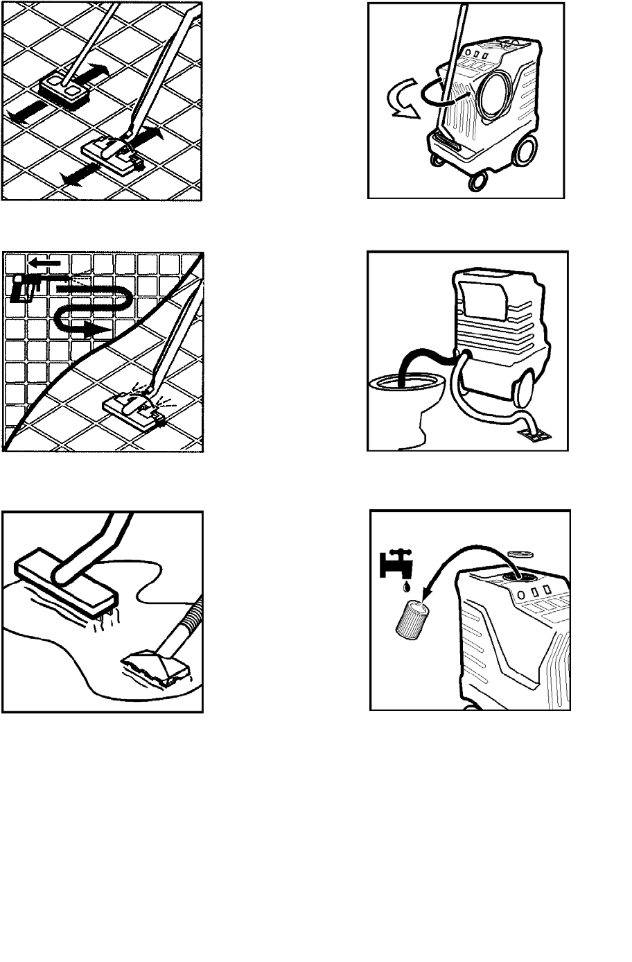
FILLING THE MACHINE
Do not put defoamer, solvents spotter or
prespray chemicals in the solution tank.
1. Always use gloves and eye protection. Never
spray solution towards people.
2. To fill Use fill hose or pour directly into solution
tank. Use COLD WATER. Add 1 ½ oz of
GinsuRinse to each full solution tank.
3. If needed prime pump by sealing gun to vacuum
port and spraying directly at low pressure.
4. Attach the adapter cap and intake hose to the
Chemical bottle. Refer to the Chemical Label for
the desired dilution.
5. Position the machine in the door way,
lock front casters. Start at furthest point in the
room and work towards the door.
6. Always Spray chemical using low pressure.
OPERATIONS
980146 02/07/04 3-
7
7. Use brush or grout tool for heavy soiled areas.
8. Turn Chemical off. Pressure clean by rinsing
surfaces at high pressure.
9. Use Squeegee or Gulper tool to remove
standing water.
10. Store and secure hoses and tools neatly.
11. Drain machine at proper disposal areas. Use
pressure gun to rinse and clean recovery tank.
12. When using dry filter, gently remove and wash
with water after every use. Allow to dry before
re-using.

OPERATIONS
980146 02/07/04
3-8
Care must be exercised in the use of all
chemicals. Chemicals are poisonous and can
pose a health risk. Read and follow
manfacturers instructions regarding dangers
and correct usages.
The internal parts of the pump used in the machine
are suitable for use with most carpet cleaning
chemicals. But they are susceptible to chemical
attack from some cleaning substances, such as
hydrocarbon solvents and chlorinated bleaches.
These non-compatible materials are not of the type
used for carpet cleaning.
Only use chemicals approved for use with this
machine. Use of non-compatible chemicals may
cause machine damage and will not be covered
under the warranty. Carefully read ingredients on
manfacturer’s label before using any product in this
machine.
Do not let pump run dry.
Do not let pump run unattended.
CHEMICALS
Suitable Chemicals
A
lkalis
Detergents
Hydroxides
Soaps
Vinegar
Non-Compatible
A
ldehydes
A
romatics Hydrocarbons
SP Butyls
Carbon Tetrachloride
Clorox*
Chlorinated Bleaches
Chlorinated Hydrocarbons
Lysol*
Methyl Ethel Ketone (MEK)
Perchorethylene (perc)
Phenolics
Trichlorethylene
D-Limonene
MAINTENANCE
980146 02/07/04 4-1
1. Float Shut-Off
2. Strainer
3. Circuit Breakers
4. Vacuum Motor
5. Pump
6. Adjustable Unloader Valve
1
2
3
5
6
4

MAINTENANCE
980146 02/07/04
4-2
1. FLOAT SHUT-OFF
The float shut-off is located inside the recovery
tank. The purpose of the float shut-off is to
notify the user that the recovery tank is full.
Remove daily and clean any debris for
maximum airflow.
2. STRAINER
The strainer is located on the lower right side
between the front and rear wheels. The strainer
protects the check valve and pump from debris.
If there is little or no solution flow to the ground,
check the stainer for debris. Drain the solution
tank and clean the solution strainer. To remove
the strainer, turn the bottom part of the strainer
counterclockwise until the bottom is separated.
Clean out the debris from the wire mesh and
reassemble. Make sure the o-ring gasket is in
place when reassembled.
3. CIRCUIT BREAKERS
Circuit breakers interrupt the flow of power in the
event of an electrical overload. When a circuit
breaker is tripped, reset it by pressing the
exposed button. If a circuit breaker continues to
trip, the cause of the electrical overload should
be found and corrected.
6 Amp. Protects the pump motor.
10 Amp. Protects the vacuum
motor.
MAINTENANCE
980146 02/19/04 4-
3
4. VACUUM MOTOR
(Refer to vacuum group in the parts section of
manual).
ONLY QUALIFIED MAINTENANCE PERSONNEL
ARE TO PERFORM THE FOLLOWING REPAIRS.
VACUUM MOTOR REPLACEMENT
1. Turn off all switches and unplug machine.
2. Drain tanks and remove all chemicals and
accessories.
3. Unlatch two front latches and hinge tanks back.
4. Locate the vacuum motor wires and disconnect
at the connector.
5. Remove the vacuum motor.
6. Reverse process to install.
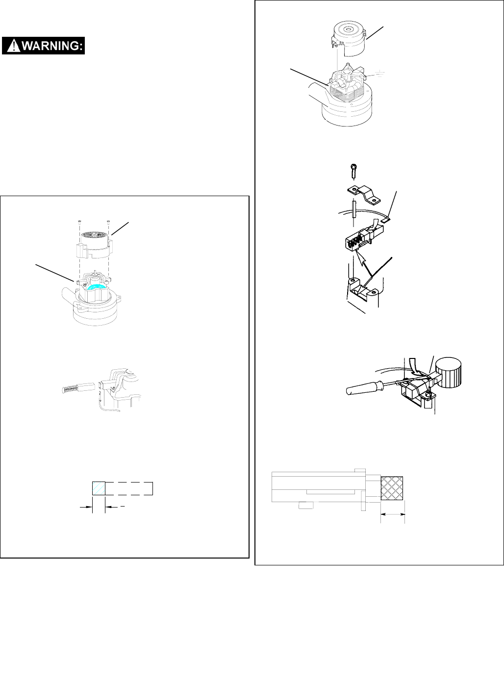
Vacuum Motor Carbon Brushes Replacement (Windsor)
WARNING: The green
ground wire must be
attached for safe
operation. See wiring
diagram.
End Cap
Carbon
Brushes
If armature commutator is grooved, extremely pitted or not
concentric, the motor will need to be replaced or sent to a
qualified service center.
Important:
These brushes wear quicker as the length shortens due to
increased heat. Spring inside brush housing will damage
motor if brushes are allowed to wear away completely.
Periodically check the length of the carbon brushes. Replace
both carbon brushes when either is less than 3/8" (9.5mm)
long.
3
8 [9.5mm]
Important:
These brushes wear quicker as the length shortens due to
increased heat. Spring inside brush housing will damage
motor if brushes are allowed to wear away completely.
Periodically check the length of the carbon brushes. Replace
both carbon brushes when either is less than 3/8" (9.5mm)
long.
3/8 (9.5mm)
Vacuum Motor Carbon Brushes Replacement (Ametek)
Note: When replacing carbon brushes loosen wire terminal
BEFORE removing screws on bracket.
Note:
Place
stop in
groove.
Wire
Terminal
WARNING: The green
ground wire must be
attached for safe operation.
See wiring diagram.
End Cap
Carbon
Brushes
Wire Terminal
If armature commutator is grooved, extremely pitted or not
concentric, the motor will need to be replaced or sent to a
qualified service center.
MAINTENANCE
980146 02/07/04
4-4
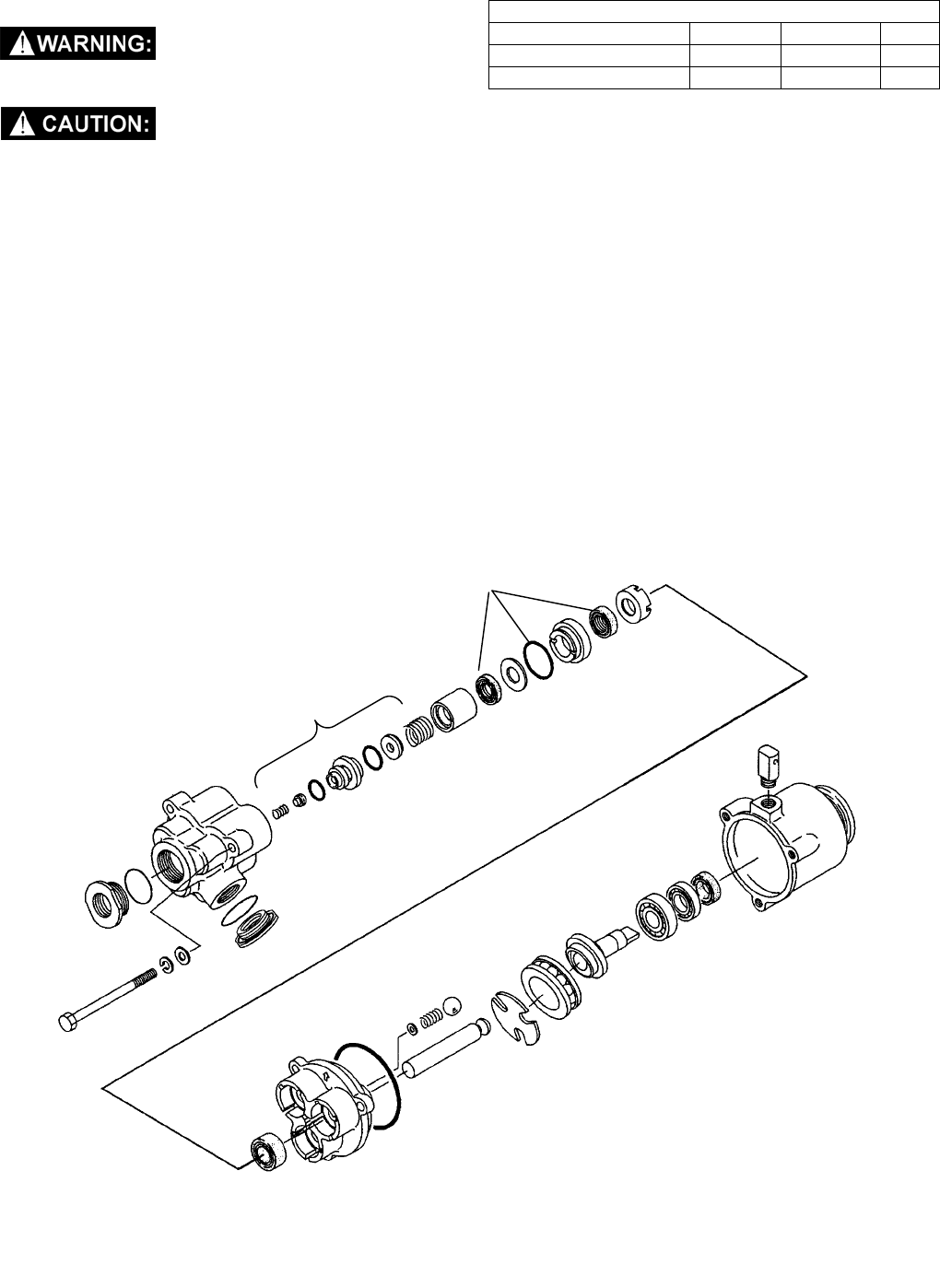
5. PUMP
ONLY QUALIFIED MAINTENANCE PERSONNEL
ARE TO PERFORM THE FOLLOWING REPAIRS.
DO NOT OVERTIGHTEN THE RTP PUMP.
SOLUTION PUMP REPLACEMENT
1. Turn off all switches and unplug machine.
2. Drain tanks and remove all chemicals and
accessories.
3. Unlatch two front latches and hinge tanks back.
4. Remove the solution hoses from the fittings on
the pump.
5. Remove the clamp that fastens the pump to the
motor.
6. Reverse process to install.
TORQUE CHART
ITEM SIZE IN. LBS Nm
PUMP INLET 1/2” 25 3
CLAMP SCREW 10-32 20 2.4
PUMP SEAL KIT
#47434
PUMP VALVE KIT
#47435
MAINTENANCE
980146 02/07/04 4-
5
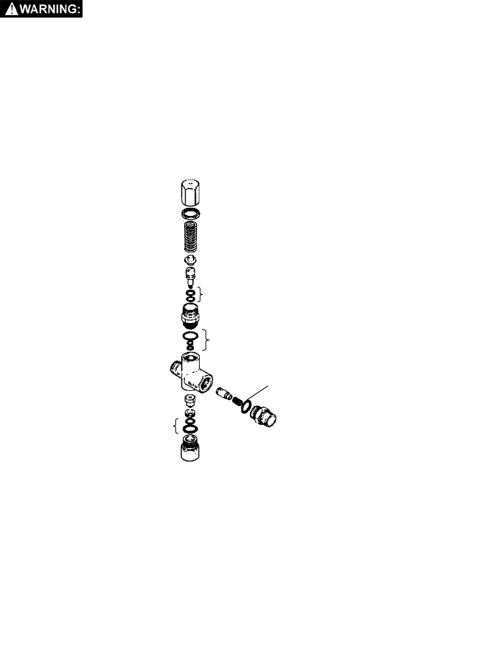
6. REGULATING UNLOADER
ONLY QUALIFIED MAINTENANCE PERSONNEL ARE TO PERFORM THE FOLLOWING REPAIRS.
UNLOADER REPLACEMENT
1. Turn off all switches and unplug machine.
2. Drain tanks and remove all chemicals and accessories.
3. Unhook front latches and tilt tanks back so inside of base frame is exposed.
4. Remove the solution hoses from the fittings on the pump.
5. Remove the unloader.
6. Reverse process to install.
NOTE: Kit #47436 includes all o-rings marked with an asterisk (*) below.
*
*
*
INLET
BYPASS
OUTLET
*

MAINTENANCE
980146 02/07/04
4-6
PERIODIC MAINTENANCE
Twice a month, flush a white vinegar solution (one
quart vinegar to two gallons of water) or anti-
browning solution (mixed as directed) through the
machine. This will prevent build-up of alkaline
residue in the system. If spray jets become clogged,
remove the spray tips, wash them thoroughly, and
blow dry.
NOTE: Do not use pins, wires, etc. to clean nozzles
as this could destroy the spray pattern.
Periodically inspect all hoses, electrical cables and
connections on your machine. Frayed or cracked
hoses should be repaired or replaced to eliminate
vacuum or solution pressure loss. The electrical
cable must be well insulated and cable connector
screw kept tight. If the cable insulation is broken or
frayed, repair or replace immediately. Don’t take
chances with elctrical fire or shock.
DAILY/REGULAR MAINTENANCE
Before making any adjustments to the machine,
disconnect the power cord from the electrical source.
1. Empty unused cleaning solution from the
solution tank.
2. Inspect and clean filter screen in solution tank.
3. Flush pumping system with 4 to 7 liters of clean
water.
4. After each use, rinse tank with fresh water.
Periodically inspect the recovery tank and
decontaminate if necessary, using a Hospital Grade
Virucide or a 10-1 bleach to water solution. Waste
water should be disposed of properly.
5. Remove filter to clean. Filters used for wet pick-
up including striper must be thoroughly cleaned
before being allowed to dry.
6. Check spray jets for full spray pattern.
NOTE: Worn filters can affect vacuum
performance. Replace the filter when it becomes
worn out and normal cleaning will not restore
vac performance.
SERVICE SCHEDULE DAILY WEEKLY QUARTERLY
Check machine for cord damage *
Check recovery dome and gasket for damage and
cleanliness *
Check hoses for wear, blockages, or damage *
Check handles, switches, and knobs for damage *
Check vac motor intake filter and clean *
Run one gallon of water through system *
Clean out recovery tank and check float valve to make
sure it moves freely *
Clean out solution tank and remove and clean vacuum
intake screen *
Clean outside of all tanks and check for damage *
Run vac motor for at least one minute to allow motor to
dry *
Store with dome off tank to allow the tank to dry *
Check all bearings for noise *
Check all gaskets for wear and leakage *
Check vacuum intake screen for damage; replace if
necessary *
Check pump pressure; observe spray pattern and
check with gauge if necessary *
Check and clean solution screen *
Check cables for fraying *
Check overall performance of machine *
Check vac motor carbon brushes *

MAINTENANCE
980146 02/07/04 4-
7
PROBLEM CAUSE SOLUTION
Dead electrical circuit Check building circuit breaker or fuse box.
Loss of Power Faulty power cord Replace
Equipment not grounding Follow grounding instructions exactly
Receptacle not grounded Contact an electrician to check building’s wiring
Electrical shock
Internal wiring problem Have a trained service technician check machine’s
wiring
Worn motor brushes Replace
Motor worn out Replace
Vac motor speed varies
or doesn’t run Faulty switch Replace
Loose vacuum dome Center and seal dome over tank
Vacuum circuit breaker
tripped. Reset breaker.
Crack in dome of poor joint Replace or repair using acrylic plastic cement only
Lint or dirt clogging
vacuum screen With power off clean screen
Loose cuffs on vacuum
hose Tighten cuffs turning counterclockwise
Vac motor seals leaking Replace
Floor tool vac chamber
clogged Wash out with hose. Pick lint out with a wire
Loss of vacuum
Vac motor, hose, or dome
gasket Replace
Pump inlet screen plugged Clean inlet screen
Pump circuit breaker
tripped. Reset breaker.
Faulty pump switch. Call for service.
Faulty pump motor. Call for service.
Pump air locked Press trigger to open valve on cleaning wand to
relieve air
Pump runs no solution
Internal or external
solution line damaged and
leaking Replace
Jet orifice on cleaning
wand is to large Total jet opening for 100 psi should be .06 to .08
Internal pump components
wearing out Replace, see pump kit components (pg 4-3)
Note: Operation of pump using a wand or hand tool with an orifice of less than .06
will cause pump to cavitate or pulsate and could result in premature wear of pump
components.
Pump runs, loss of
pressure
Check valves in pump
head for particles or cuts in
seals
Take piston from BPR and lubricate with Superlube.
If problem still exists change BPR kit
Unit not plugged in Connect unit to 3 prong grounded outlet
Pump will not run Loose wiring See dealer
Solution hose fitting hard
to connect Corrosion on fittings. Clean with steel wool. Soak in acetic acid (white
vinegar). Lubricate lightly with silicone base lubricant.
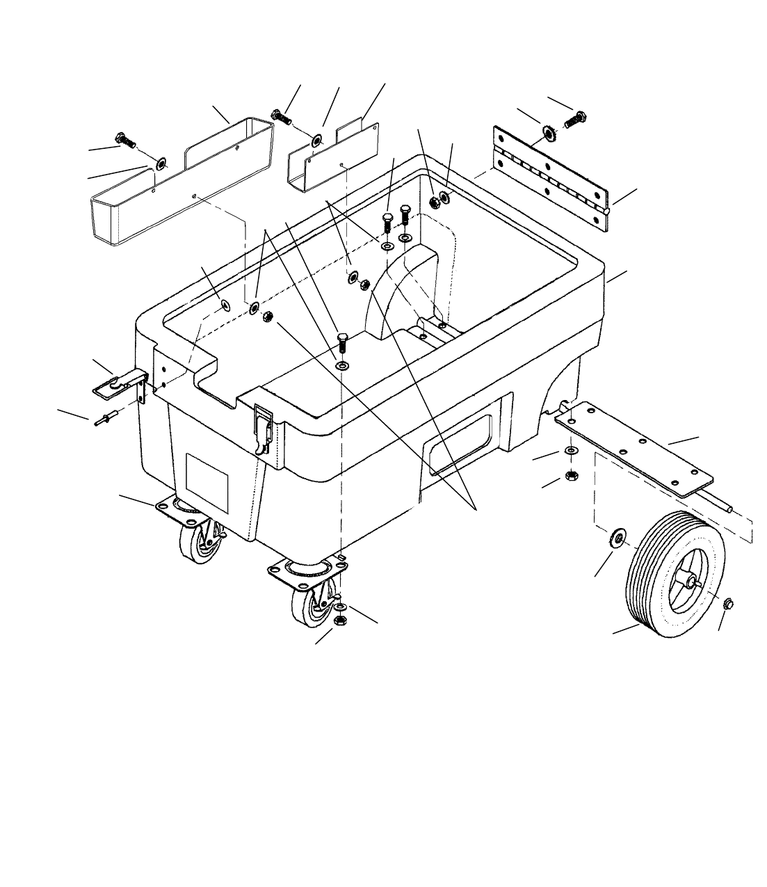
BASE
980146 03/31/04
5-1
1
3
2
1
2
3
8
3
1
7
6
5
4
2
13
3
11
10 9
3
12
1
3
14
15
3
2
3
2

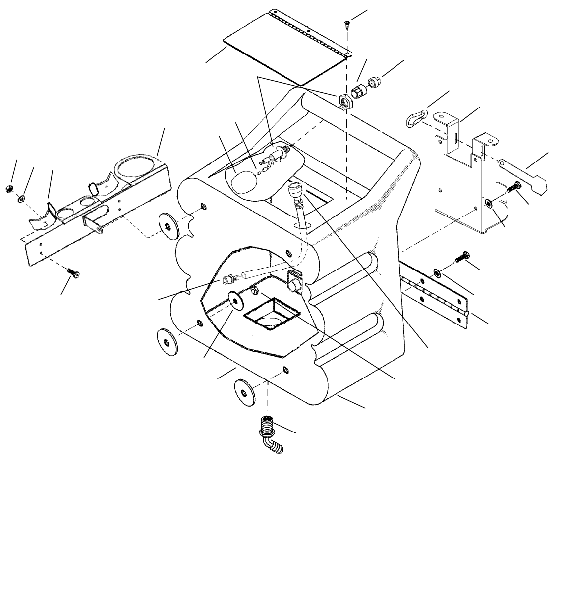
BASE
980146 02/07/04 5-
2
REF PART NO. QTY DESCRIPTION SERIAL NO.
FROM NOTES:
1 57245 21 NUT, 1/4-20 HEX NYLOCK SS
2 70015 21 SCR, 1/4-20 X 3/4 HHCS SS NP
3 87013 42 WASHER, 1/4 ID X 5/8 OD SS
4 87095 4 WASHER, #10 FLAT PLTD
5 140-05 2 DRAW PULL LATCH STD.
6 280-02 4 RIVET AL. 3/16 X 1/2 CLOSED
7 18044 2 CASTER, 4” SWIVEL W/ BRAKE
8 87080 2 WASHER, .5 X 1.25 FLAT GR8 PLT
9 57196 2 NUT, 1/2 PUSH-ON DOME CAP
10 040-06 2 WHEEL 8" BLK CENTERED HUB
11 56-502068 1 AXLE ASSEMBLY
12 75443 1 BASE
13 46-802536 1 HINGE, SOL & VAC TANK 4" X 8"
14 140668 1 BRKT, TOOL BASE
15 75444 1 TRAY, 15 X 2 X 4
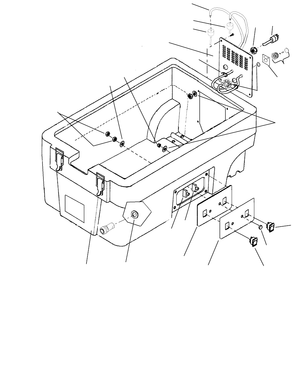
CONTROLS
980146 12/04/04
5-3
23
4
1
2
3
17 16
15
14
12 11
10
5 6
7
7
13
18
8
9
19
21
22
20

CONTROLS
980146 12/04/04 5-
4
REF PART NO. QTY DESCRIPTION SERIAL NO.
FROM NOTES:
1 620013 1 PLATE, REAR METERING
2 270699 2 CAP, CHEM FEED W/DIP TUBE 1000136313 * SEE NOTE
3 39205 2 HOSE, 1/4 NYLOBRAID X 57”
4 70547 4 SCR, 10-32 X 1 PPHMS BLK
5 73505 1 STRAIN RELIEF, 1/2 NPT TRUMPET
6 23214 1 CORD SET, 14/3 X 60”
7 84187 1 VALVE, CHEMICAL METERING
8 87018 8 WASHER, #10 X 9/16OD
9 57090 8 NUT, 10-32 HEX NYLOCK SS
10 14942 2 BOOT, 3/8 CIRCUIT BREAKER
11 72128 1 SWITCH, DPDT 2-POSITION ROCKER
12 500813 1 LABEL, SWITCH PANEL
13 620014 1 PLATE, SWITCH PANEL
14 14832 1 BREAKER, 6A VDE CIRCUIT
15 14635 1 BREAKER, 10A CIRCUIT
16 390-09A 1 WASHER, 9/16 S/S USS-THICK
17 22015 1 COUPLER, 1/4 QD
18 500812 1 LABEL, CHEM PANEL
19 72126 1 SWITCH, DPDT 3-POSITION ROCKER
20 27051 2 CABLE TIE, 11.38” UL/CSA
21 87016 1 WASHER, #10 LOCK EXT STAR SS
22 57104 2 NUT, 10-32 W/STAR WASHER PLTD
* SEE SUGGESTED CHEMICAL LIST, SECTION 3 (OPERATIONS).
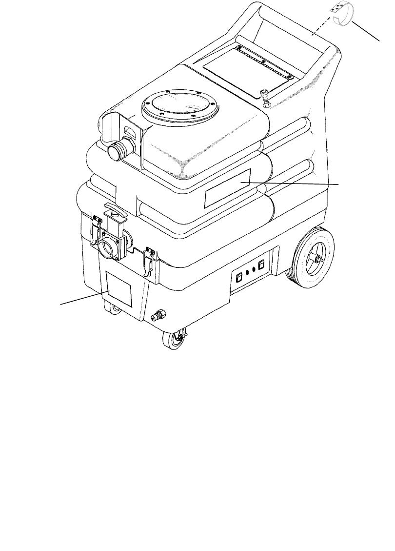
LABELS & STRAPS
980146 02/07/04
5-5
1
2
3

LABELS & STRAPS
980146 03/31/04 5-
6
REF PART NO. QTY DESCRIPTION SERIAL NO.
FROM NOTES:
1 500794 1 LABEL, C400 LOGO
2 500811 2 LABEL, MAIN GINSU
3 320-05 1 STRAP, VELCRO
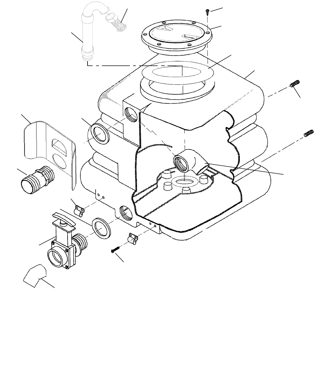
RECOVERY TANK
980146 02/07/04
5-7
10
115
14
13
12
11
8
9
2
4
5
6
3
7
3

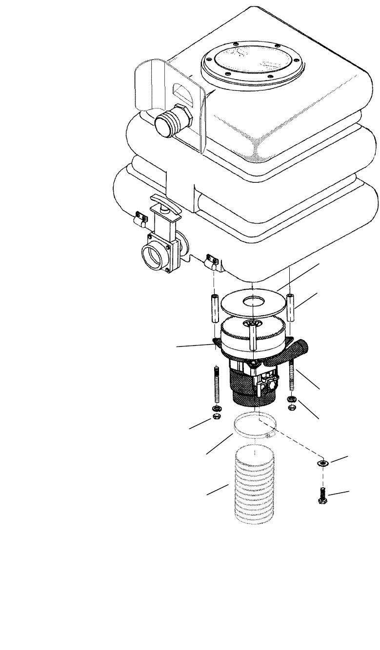
RECOVERY TANK
980146 10/17/05 5-
8
REF PART NO. QTY DESCRIPTION SERIAL NO.
FROM NOTES:
1 090-12A 1 FLOAT CAGE ASSY COMPLETE SLIP
2 78489 1 VAC, STACK ASM.
3 35256 2 GASKET, DUMP VALVE
4 140669 1 BRKT, HOSE
5 260-33 1 HOSEBARB, 1.5 MPT X 1.5
6 140-05 2 DRAW PULL LATCH STD.
7 15-808123 1 DUMP VALVE, 2”
8 11-800444 1 ELBOW, 2” 45D PVC SCH40
9 70683 4 SCR, 10-32 X 3/8 PPHMS SS NP
10 31002 1 ELBOW, 1.5 FPT X FS PVC
11 81491 4 SET SCR, 5/16-18 X 1.5 CP SS
12 75445 1 TANK, RECOVERY
13 35255 1 GASKET, TANK LID
14 260-64A 1 ACCESS COVER CLEAR 6" W/RIM
15 70546 6 SCR, 8 X 3/4 PFHT/S BLK ZINC
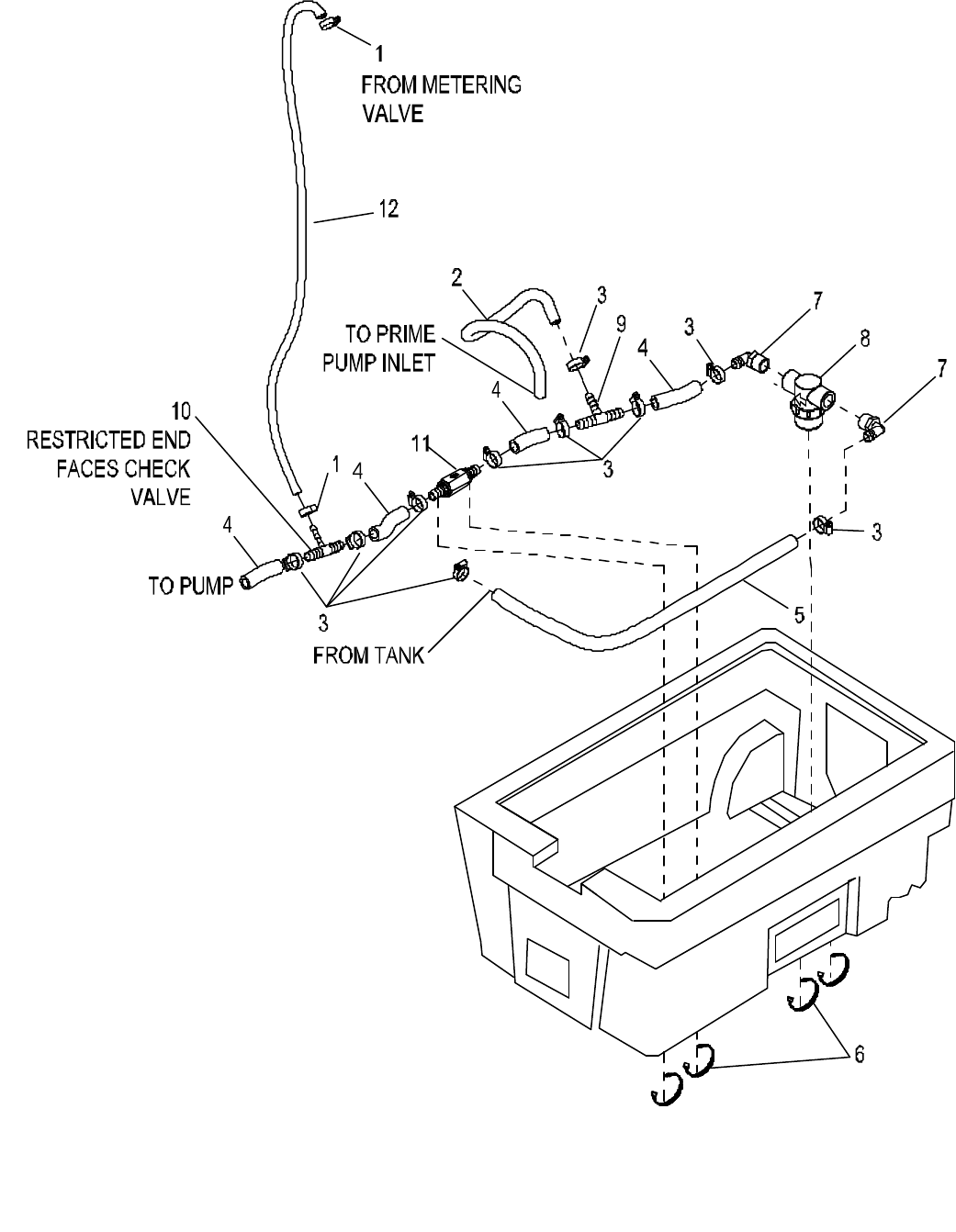
SOLUTION HOSES & FITTINGS
980146 11/05/04
5-9

SOLUTION HOSES & FITTINGS
980146 11/05/04 5-1
0
REF PART NO. QTY DESCRIPTION SERIAL NO.
FROM NOTES:
1 20016 2 CLAMP, 1/4 ID HOSE 1000134745
2 39413 1 HOSE, 3/8 NYLOBRAID X 17”
3 20042 10 CLAMP, 3/8 HOSE (D-SLOT)
4 39629 4 HOSE, 1/2 WIRE BOUND X 3”
5 39631 1 HOSE, 1/2 WIRE BOUND X 25
6 27051 4 CABLE TIE, 11.38” UL/CSA
7 40039 2 HOSEBARB, 1/2 MPT X 1/2 HOSE 90
8 730262 1 STRAINER, 1/2 FPT 80 MESH
- 73785 - SCREEN, 80 MESH SERVICE ONLY
- 27372 - CAP, STRAINER 26/32 SERVICE ONLY
- 59021 - O-RING, FILTER SEAL RON-VIK SERVICE ONLY
9 830147 1 HOSEBARB, 1/2 X 1/2 X 3/8 TEE
10 78561 1 TEE, CHEMICAL SIPHON
11 84188 1 VALVE, CHECK 1/2 HOSEBARB
12 39634 1 HOSE, 1/4 NYLOBRAID X 23”
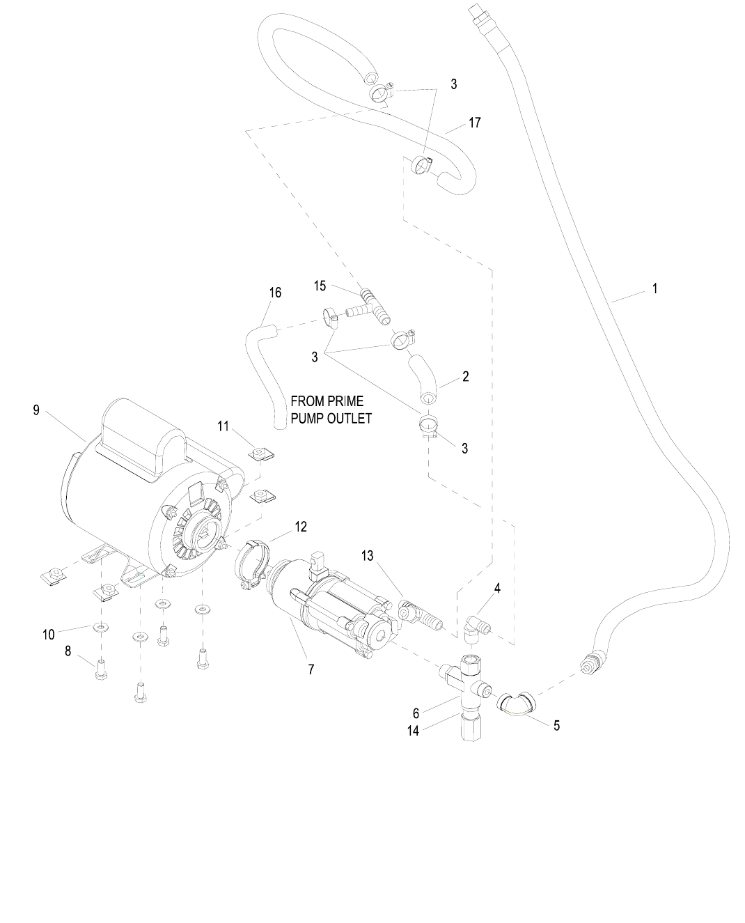
SOLUTION PUMP & MOTOR
980146 03/31/04
5-11

SOLUTION PUMP & MOTOR
980146 03/31/04 5-1
2
REF PART NO. QTY DESCRIPTION SERIAL NO.
FROM NOTES:
1 39695 1 HOSE, HP 50 1/4 MPT X 1/4 MPT
2 39549 1 HOSE, 1/2 WIRE BOUND X 5”
3 20042 5 CLAMP, 3/8 HOSE (D-SLOT)
4 40027 1 HOSEBARB, 3/8 MPT X 1/2 90º DL
5 31018 1 ELBOW, 3/8 FPT X 1/4 FPT
6 84190 1 VALVE, REGULATING UNLOADER
7 65230 1 PUMP, 500 PSI 1GPM
8 70015 4 SCR, 1-4-20 X 3/4 HHCS SS NP
9 53265 1 MOTOR, 115V 1/3HP PUMP
10 87013 4 WASHER, 1/4 ID C 5/8 OD SS
11 57123 4 NUT, 1/4-20 CAPTIVE (.074 W)
12 20105 1 CLAMP, PUMP TO MOUNT SERVICE ONLY
13 40068 1 HOSEBARB, 3/8” NPT X 1/2 TEE DL
14 730259 1 SPACER, .88 OD X .719 ID X .385 L
15 830147 1 HOSEBARB, 1/2 X 1/2 X 3/8 TEE
16 39361 1 HOSE, 3/8 NYLOBRAID X 7.5”
17 39541 1 HOSE, 1/2 WIRE BOUND X 32”
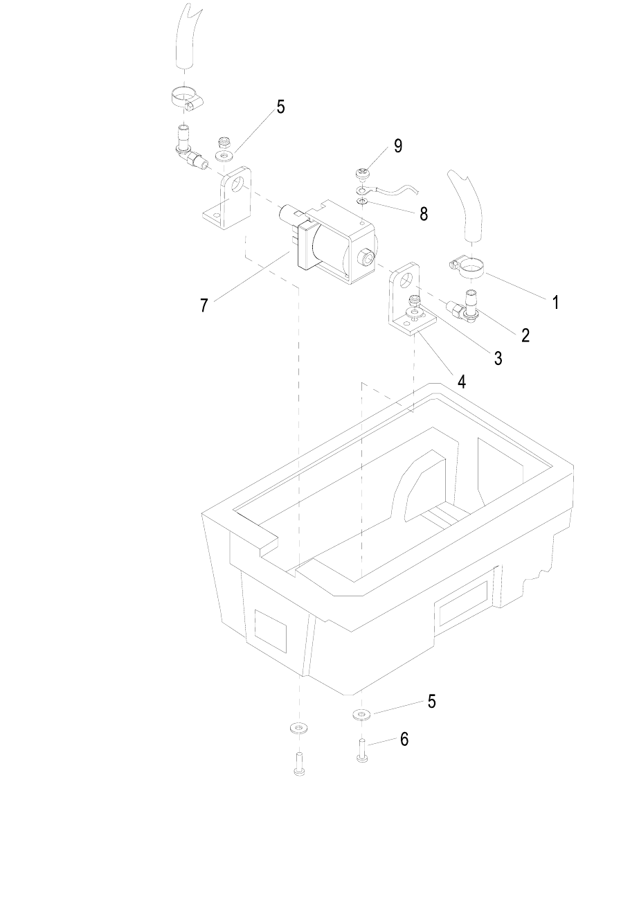
SOLUTION PRIME PUMP
980146 03/31/04
5-13

SOLUTION PRIME PUMP
980146 02/07/04 5-1
4
REF PART NO. QTY DESCRIPTION SERIAL NO.
FROM NOTES:
1 20042 2 CLAMP, 3/8 HOSE (D-SLOT)
2 40066 2
HOSEBARB, 1/8 NPT X 3/8 90° PLAST
3 57245 2 NUT, 1/4-20 HEX NYLOCK SS
4 140446 2 BRKT, PVC FLOJET PUMP L-SHAPE
5 87013 4 WASHER, 1/4 ID X 5/8 OD SS
6 70015 2 SCR, 1/4-20 X 3/4 HHCS SS NP
7 250-78 1 PUMP, 110/120 60HZ FLOJET
8 87016 1 WASHER, #10 LOCK EXT STAR SS
9 70323 1 SCR, 10-32 X 1/4 PHTR PLTD
SOLUTION TANK
980146 03/31/04
5-15
17
7
16
10
8
22
21
23
1
4
3
4
5
6
2
3
9
15
14
13
12
11
20
18
19
25
24

SOLUTION TANK
980146 03/31/04 5-1
6
REF PART NO. QTY DESCRIPTION SERIAL NO.
FROM NOTES:
1 70222 3 SCR, #8 X 1/2 PPHST BLK
2 140666 1 BRKT, CHEM BOTTLE
3 70020 7 SCR, 1/4-20 X 1/2 HHCS SS
4 87013 7 WASHER, 1/4 ID X 5/8 OD SS
5 46-802536 1 HINGE, SOL & VAC TANK 4" X 8"
6 75446 1 TANK, SOLUTION
7 40039 1 HOSEBARB, 1/2MPT X 1/2 HOSE 90
8 35182 4 GASKET, FRAME
9 57023 4 NUT, 5/16-18 HEX NYLOCK SS
10 87222 4 WASHER, SEAL 5/16 X 3/4 OD
11 40077 1 HOSEBARB, 3/4MPT X 1/2 HOSE
12 39633 1 HOSE ASM., SOLUTION FILL
13 66405 1 PIN, BOTTLE LOCK
14 730232 2 STRAP, 1.5” X 8.00” VELCRO
15 70683 4 SCR, 10-32 X 3/8 PPHMS SS NP
16 140667 1 BRKT, TOOL HOLDER
17 56-502072 1 LID, SOLUTION TANK
18 41386 1 HOOK, SAFETY CLIP
19 34419 1 FITTING, PLUG GARDEN HOSE
20 34420 1 FITTING, GARDEN HOSE F X 1/2FPT
21 15-808110 1 VALVE, FLOAT
22 70251 1 SET SCR, 1/4-20 X 1.0 PLTD DL
23 19-807014 1 BALL, FLOAT
24 57104 4 NUT, 10-32 W/STAR WASHER PLTD
25 87018 4 WASHER, #8 INT. STAR
VACUUM MOTOR
980146 03/31/04
5-17
2
6
1
3
4
5
7
8
9
10

VACUUM MOTOR
980146 03/31/04 5-1
8
REF PART NO. QTY DESCRIPTION SERIAL NO.
FROM NOTES:
1 35166 1 GASKET, VAC MOTOR
2 065-92 3 VAC SPACER, 2-1/4
3 70814 3 STUD, 1/4-20 X 4.5 SS
4 87013 3 WASHER, 1/4ID X 5/8OD SS
5 57105 3 NUT, 1/4-20 HEX W/ STAR WASHER
6 360-04A 1 VAC MOTOR, 120V 5.7 2 ST TD
- 360-04B - BRUSHES, VACUUM FOR 116392-00 SERVICE ONLY
- 140687 - BRUSH SET, 120V VAC WINDSOR 1000121568 SERVICE ONLY
7 20092 1 CLAMP, 3.5” WORM GEAR
8 39697 1 HOSE, 3.15 ID X 7.0L VENT
9 87016 1 WASHER, #10 LOCK EXT STAR
10 70191 1 SCR, 10-24 X 1/2 HHTC TYPE 23
TOOLS - STANDARD
980146 02/07/04
5-19

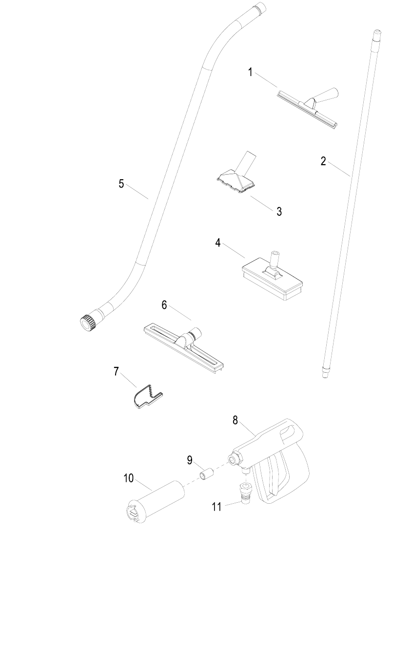
TOOLS - STANDARD
980146 02/07/04 5-
20
REF PART NO. QTY DESCRIPTION SERIAL NO.
FROM NOTES:
1 02478 1 TOOL, HAND SQUEEGEE
2 02477 1 TOOL, SCRUB BRUSH HANDLE
3 02475 1 TOOL, GULPER
4 02479 1 TOOL, TILE BRUSH
5 02480 1 TOOL, ALUMINUM WAND
6 02473 1 TOOL, WHEELED SQUEEGEE
7 02481 1 TOOL, DOOR WEDGE
8 36233 1 GUN, PRESSURE WASH
9 56014 1 NIPPLE, 1/4 CLOSE
10 58005 1 NOZZLE, ADJUSTABLE HI-LO
11 56012 1 NIPPLE, 1/4 FPT QD
12 39578 1 HOSE ASM, 1/4HP SLTN 25 FT NOT SHOWN
13 39637 1 HOSE ASM, 1.5 X 30 FT NOT SHOWN
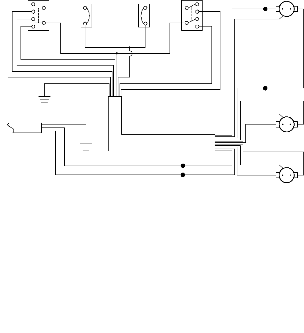
WIRING - SCHEMATIC
980146 12/02/05
5-21
1F
3F
BLK
3A
1A 1C
3C
BLK 9
8
WHT
BLK
6
4
7
5
WHT
WHT
BLK
BLK
2
880420880420
WHT BLK
9
8
2
GRN/YLW
GRN 6
2
7
2
5 4
WHT
BLKBLK
WHT
PANEL
GROUND
PANEL
GROUND
41492
PRIMING
PUMP
WHT
GRN/YLW
BLK
BLK
WHT
GRN/YLW
GRN/YLW
WHT
BLK
PUMP
MOTOR
VACUUM
MOTOR
POWER
VACUUM
CIRCUIT
BREAKER
10 AMP
VACUUM
SWITCH
PUMP
CIRCUIT
BREAKER
6 AMP
PUMP
SWITCH

WIRING - SCHEMATIC
980146 05/22/04 5-2
2
REF PART NO. QTY DESCRIPTION SERIAL NO.
FROM NOTES:
1 880420 2 WIRE, 5” BLK/14 76022 X 76022
2 41492 1 HARNESS, COMPASS
3A 23214 1 CORD SET, 14/3 X 60” NOT SHOWN
3B 23716 1 CORD SET, 14/3 X 31 *
4 23215 1 CORD SET, 14/3 X 50’ GFCI YLW NOT SHOWN
SUGGESTED SPARE PARTS
PART NO. DESCRIPTION SERIAL NO.
FROM NOTES:
47419 KIT, SQUEEGEE TOOL BLADES
730262 STRAINER, 1/2 FPT 80 MESH
360-04B BRUSHES, VAC FOR 116392-00
140687 BRUSH SET, 120V VAC WINDSOR 1000121568
53266 VAC MOTOR ASM, 115V W/ TERM
14942 BOOT, 3/8 CIRCUIT BREAKER
14832 BREAKER, 6A VDE CIRCUIT
14635 BREAKER, 10A CIRCUIT
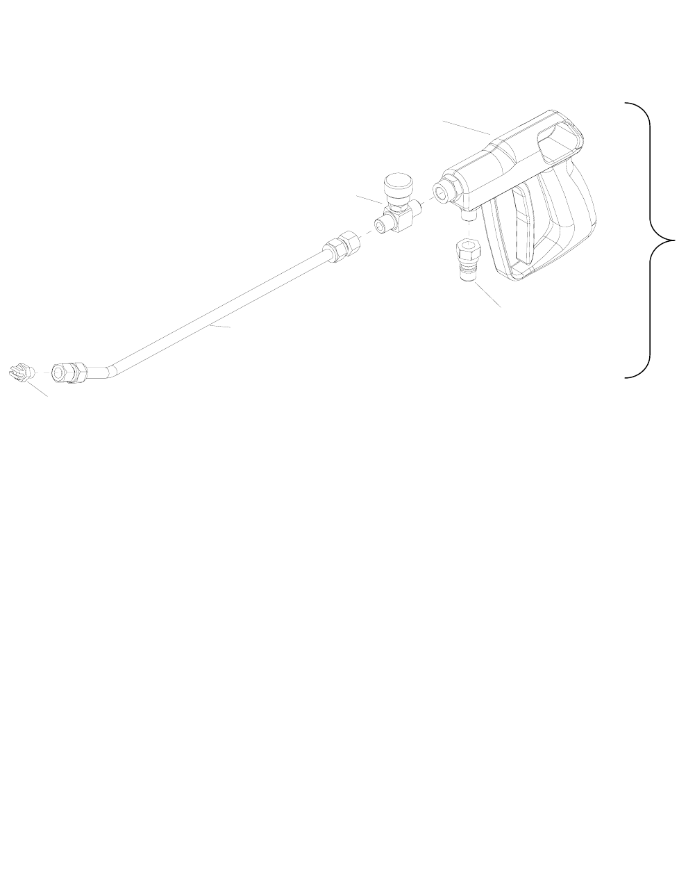
TOOLS – LOW FLOW SPRAY GUN OPTION
980146 02/07/04
5-23
5
4
3
1
2
6

TOOLS – LOW FLOW SPRAY GUN OPTION
980146 02/07/04 5-2
4
REF PART NO. QTY DESCRIPTION SERIAL NO.
FROM NOTES:
1 84186 1 VALVE, FLOW ADJUSTMENT 84186
2 36233 1 GUN, PRESSURE WASH 36233
3 56012 1 NIPPLE, 1/4 FPT QD 56012
4 51389 1 LANCE, SPRAY GUN 51389
5 44078 1 JET, 1/ H-VV 8003 44078
6 47427 REF KIT, LOW FLOW SPRAY GUN 47427
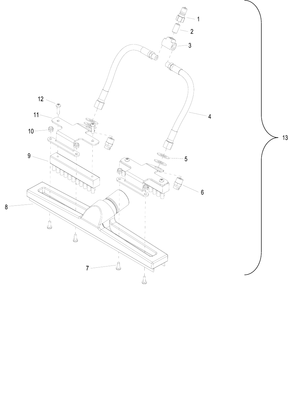
TOOLS – GROUT CLEANER OPTION
980146 02/07/04
5-25

TOOLS – GROUT CLEANER OPTION
980146 02/07/04 5-2
6
REF PART NO. QTY DESCRIPTION SERIAL NO.
FROM NOTES:
1 270-11A 1 NIPPLE, 1/8 FPT QD MALE BRASS
2 56032 1 NIPPLE, 1/8 CLOSE
3 11-800133 1 TEE, 1/8 BR
4 39639 2 HOSE, 1/8 MPT X 1/4 FPT X 8L
5 87015 4 WASHER, 9/16 ID X 1.06 OD SS
6 44079 2 JET, 1/4 MEG 15015
7 70088 4 SCR, 10-32 X 1/2 PPHMS SS NP
8 02476 1 TOOL, GROUT CLEANER
9 140653 2 BRUSH, FLOOR TOOL
10 57090 4 NUT, 10-32 HEX NYLOCK SS
11 140652 2 BRKT, BRUSH MOUNT
12 70626 4 SCR, #10 X 3/4 PPHST HI-LO BLK
13 47431 REF KIT, GROUT CLEANER
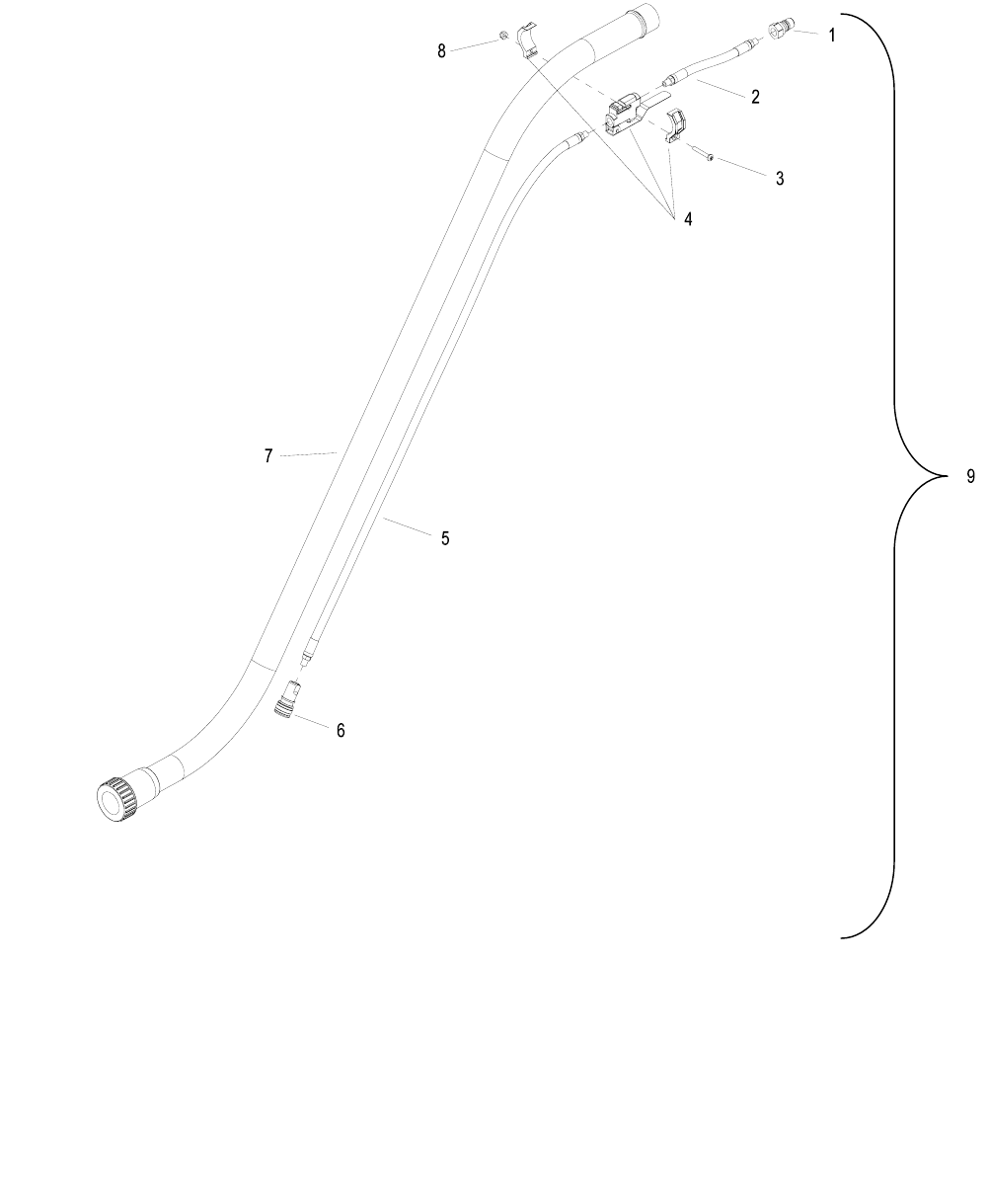
TOOLS – HIGH PRESSURE WAND OPTION
980146 02/07/04
5-27

TOOLS – HIGH PRESSURE WAND OPTION
980146 02/07/04 5-2
8
REF PART NO. QTY DESCRIPTION SERIAL NO.
FROM NOTES:
1 56012 1 NIPPLE, 1/4 FPT QD
2 39641 1 HOSE, 1/8 MPT X 1/8 MPT X 6 L
3 70195 1 SCR, 10-32 X 1.25 PPHMS SS
4 84189 1 VALVE, 500 PSI W/ CLAMP
5 39640 1 HOSE, 1/8 MPT X 1/8 MPT X 38L
6 270-11 1 NIPPLE, 1/8 FPT QD FEM BRASS
7 02480 1 TOOL, ALUMINUM WAND
8 57090 1 NUT, 10-32 HEX NYLOCK SS
9 47432 REF KIT, HIGH PRESSURE WAND
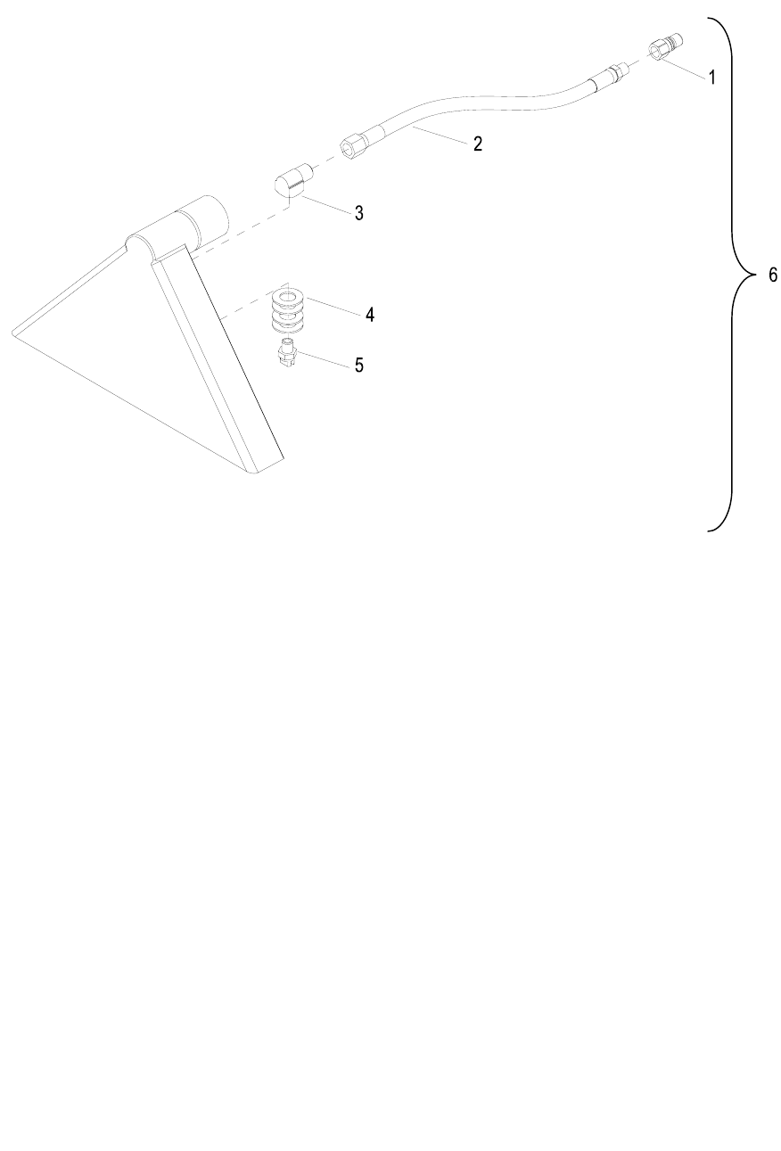
TOOLS – CARPET TOOL OPTION
980146 02/07/04
5-29

TOOLS-CARPET TOOL OPTION
980146 02/07/04 5-3
0
REF PART NO. QTY DESCRIPTION SERIAL NO.
FROM NOTES:
1 270-11A 1 NIPPLE, 1/8 FPT QD MALE BRASS
2 39642 1 HOSE, 1/8 MPT X 1/4 FPT X 12L
3 31016 1 ELBOW, 1/4 NPT STREET
4 87015 4 WASHER, 9/16 ID X 1.06 OD SS
5 44080 1 JET, 1/4 H-VV 11003
6 47433 REF KIT, CARPET TOOL

LIMITED WARRANTY
The foregoing constitutes Century 400’s entire warranty and no other warranty, liability,
contingency or responsibility, direct, indirect, consequential or in any way connected with the
sale or operation of Century 400 machines or chemical products, either as expressed or
implied, will be honored.
CONDITIONS OF WARRANTY
This warranty shall not extend to any Century 400 product showing effects of misuse, abuse,
disassembly, alteration, lack of proper maintenance, corrosive chemicals, improper voltage,
accident damage, unauthorized repairs, use of other than genuine Century 400 parts and
material, fire, flood, freezing, normal wear or other cause beyond Century 400’s control.
LIMITED LIFETIME HOUSING WARRANTY
We, Century 400, hereby warranty our polyethylene machine housing for life to the original
distributor against cracking, leaking or deterioration. The limited lifetime warranty is offered to
the original owner only. Any transfer in ownership will void warranty. Additional terms and
conditions of the limited lifetime warranty on the housing are as follows: Ninja, Sensei, Spot
Plus, Hurricane and Turbomist will receive a full lifetime 100% replacement warranty. The RT-
Tanks will receive a (1) year 100% replacement warranty; all other polyethylene housings will
receive a full (5) year 100% replacement warranty, followed by 50% replacement value for life.
WARRANTY ON CHEMICAL USE
Improper use of chemicals voids warranty and Century 400’s liability. Defoamer is to be used in
all Century 400 machines. Dry cleaning solvents cannot be used in any Century 400 machine. If
used, fire and/or pump damage could result. White vinegar should be pumped through the
machine (1) time a week to prevent mineral scaling.
PARTS WARRANTY
Parts for Century 400 equipment shall have a (1) year replacement warranty from the date of
purchase for conditions considered normal wear, excluding any and all freight charges.
90 DAY UNLIMITED WARRANTY
Any equipment showing defect of any type within the first 90 days from date of purchase will
have an unlimited warranty which includes parts, freight, and 100% of labor costs. No labor or
freight will be covered after 90 days from the date of purchase.
LIMITED 90 DAY WARRANTY
The following parts, considered expendable under normal use, will be covered by warranty for
90 days from the date of purchase: quick disconnects, o-rings, seals, diaphragms, gaskets,
grommets, thermostats, brass fittings, hoses, etc. This warranty will include parts only.
USE OF PARTS NOT APPROVED BY CENTURY 400 WILL VOID ALL
WARRANTIES.
NOTICE: Failure to complete and return the warranty card within (10)
days of receipt of machine by purchaser will void all warranties.
z 2000 Century 400, Inc. All rights reserved. REVISED-A 02/01/01
Century 400, Inc., 325 S. Price Road, Chandler, AZ 85224 USA
Phone:
(
800
)
752-1777 Fax:
(
480
)
786-5724
