AquaCat Owners Manual Aquacat_c79 &file=aquacat C79
User Manual: aquacat_c79
Open the PDF directly: View PDF ![]() .
.
Page Count: 53
6AQUA CifTMANUAL
INDEX
PAGE
2,
2A,
3,
3Ao
4,
4A,
4B,
5,
6A,
6B,
6C,
6D,
7,
7A,
7B,
7C,
7De
8,
9,
9A.
10a
11n
12,
INI)EX
WARRANTY POLICY
WARRANTY CLAIMS FORMS
PARTS ORDER INSTRUCTIONS
PARTS ORDER INSTRUCTIONS
SPECIFICATIONS
SPECIFICATIONS
SPECIFICATIONS
GENERAL INFORMATION
MAINTENANCE
MAINTENANCE LOG
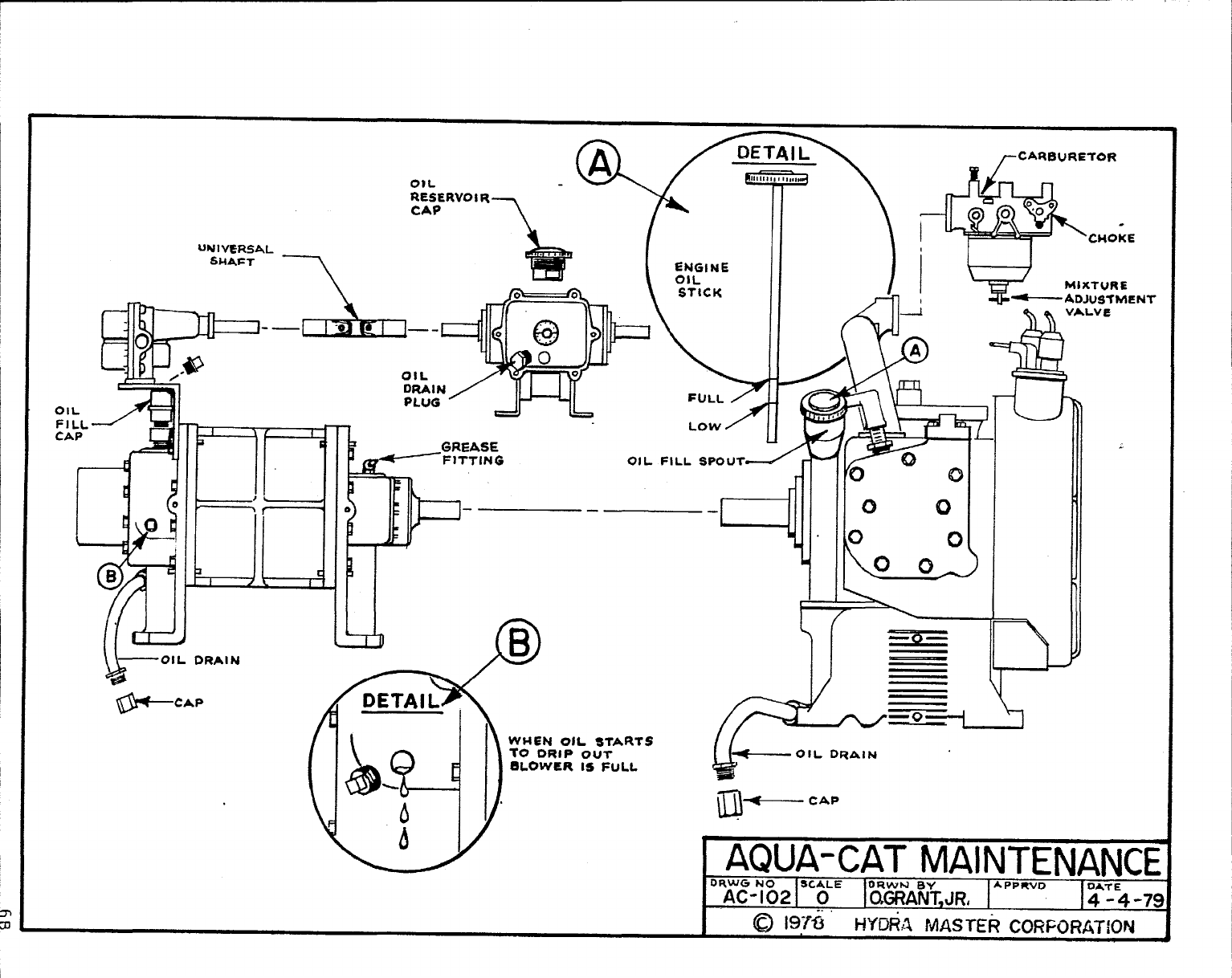
AQUA CAT MAINTENANCE DRAWING
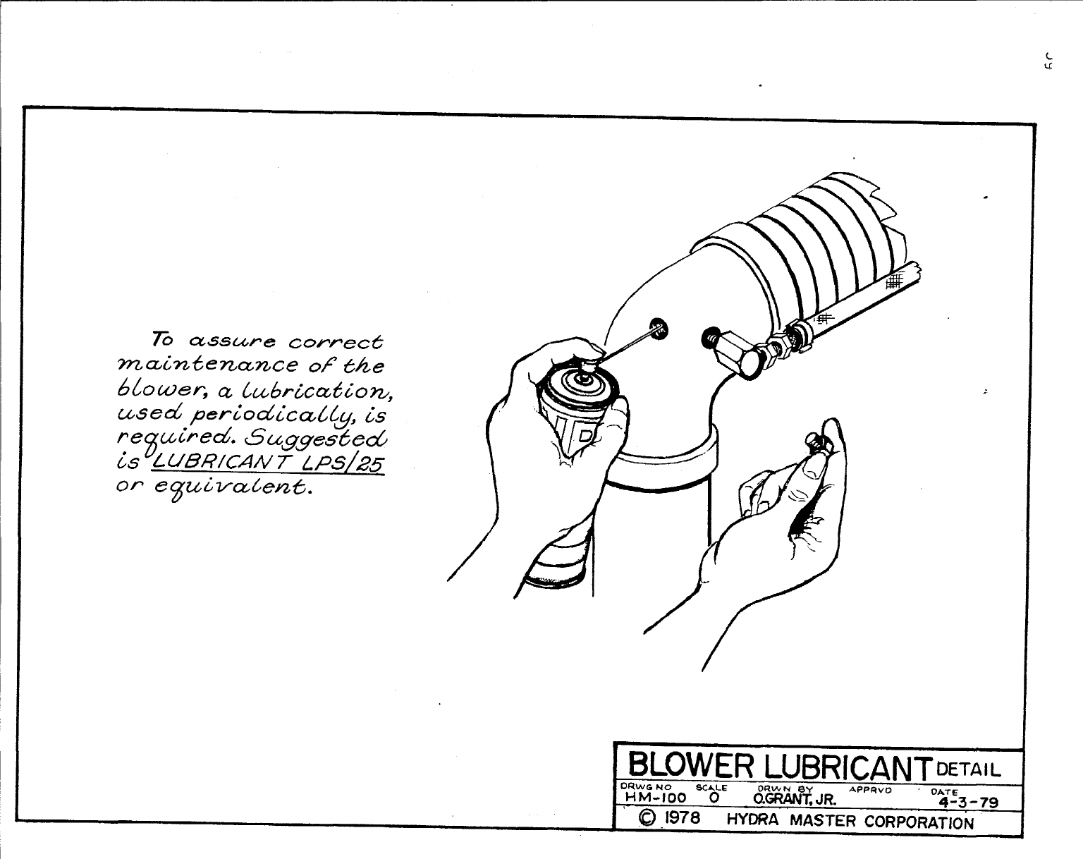
BLOWER LUBRICANT DRAWING
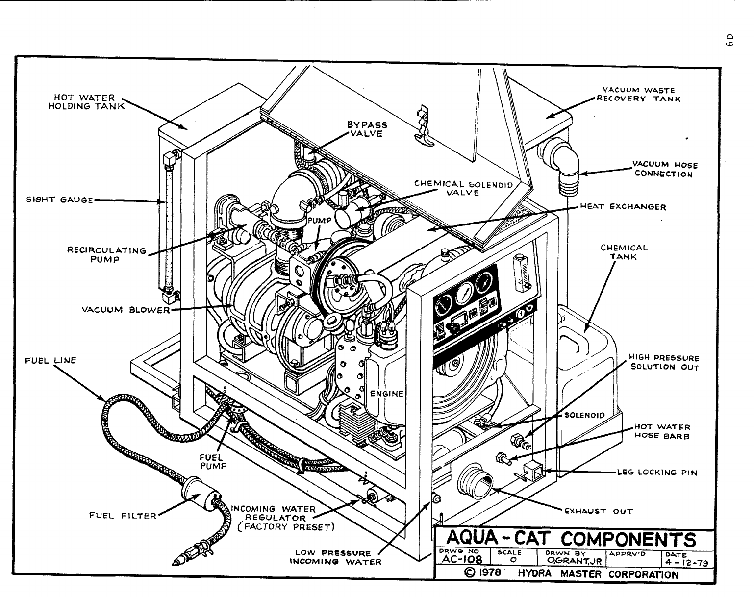
AQUA CAT COMPONENT DRAWING
TRUCK PREPARATION INSTRUCTIONS
UNIT LOCATION #l
UNIT LOCATION #2
TRUCK PREPARATION DRAWING
FLOOR GAS HOOK-UP DRAWING
OPERATING PRECAUTIONS
FREEZE PROTECTION PROCEDURE
FREEZE PROTECTION PROCEDURE
TROUBLESHOOTING -ENGINE
TROUBLESHOOTING -BLOWER
TROUBLESHOOTING -PUMP/COUPLER
1
—
–—
INDEXCONT,
b .<
PAGE
13, TROUBLESHOOTING -PRESSURE LOSS
14, TROUBLESHOOTING -CHEMICAL FLOW LOSS
15, TROUBLESHOOTING -WATER FLOW
16, TROUBLESHOOTING -OVERWETTING
PRODUCT SUPPORT BULLETINS -SEE PRODUCT SUPPORT BULLETIN INDEX
17,
18a
19,
20,
21,
22,
23,
24,
25,
26,
27,
28,
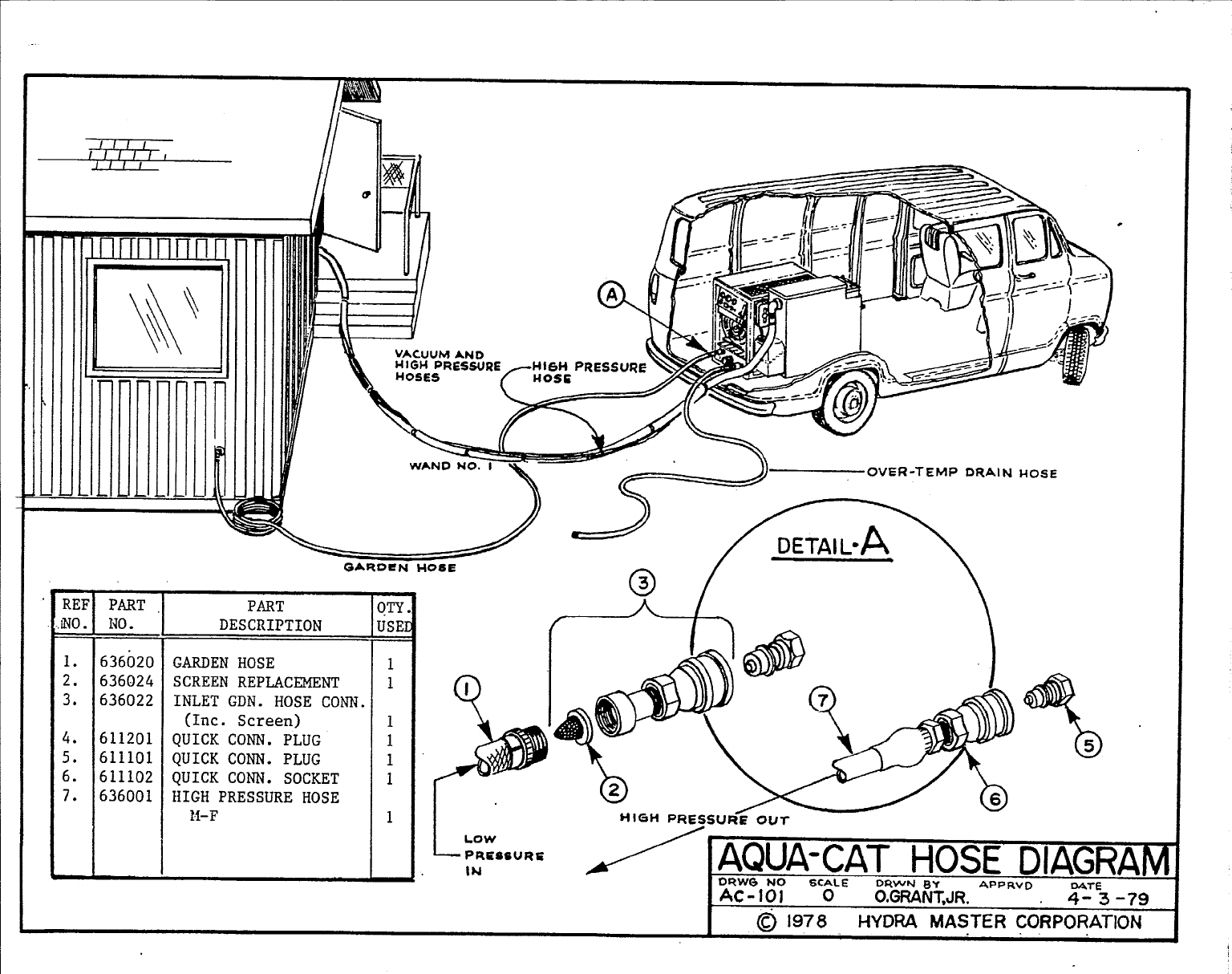
AQUA CAT HOSE DIAGRAMS
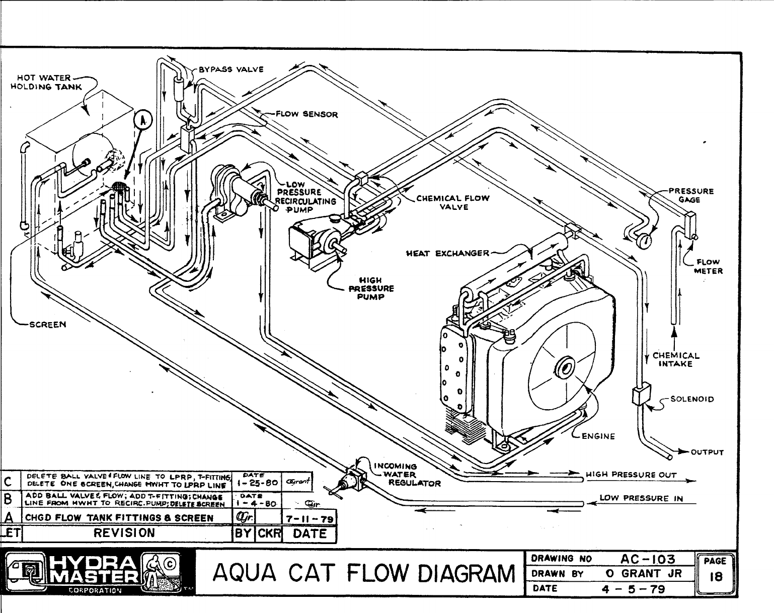
AQUA CAT FLOW DIAGRAM
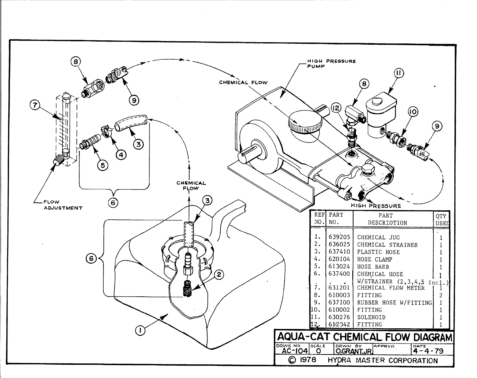
AQUA CAT CHEMICAL FLOW DIAGRAM
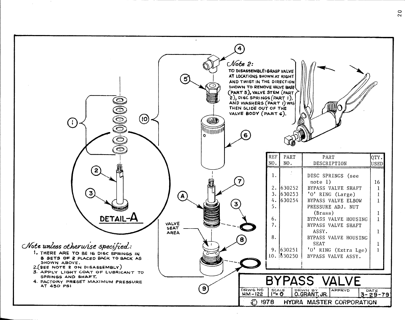
BY-PASS VALVE DRAWING
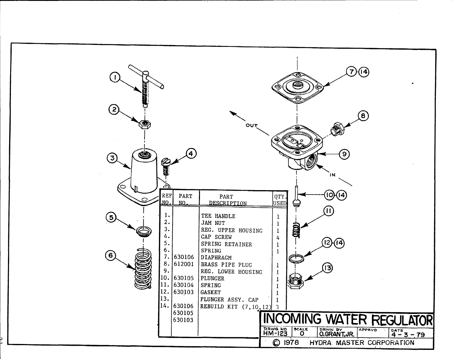
INCOMING WATER REGULATOR DRAWING
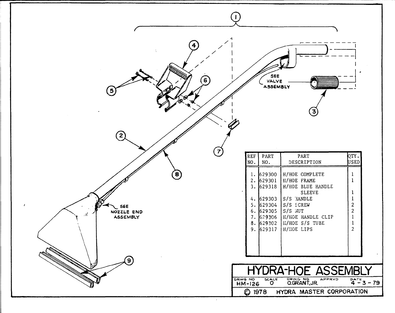
HYDRA-HOE ASSEMBLY DRAWING
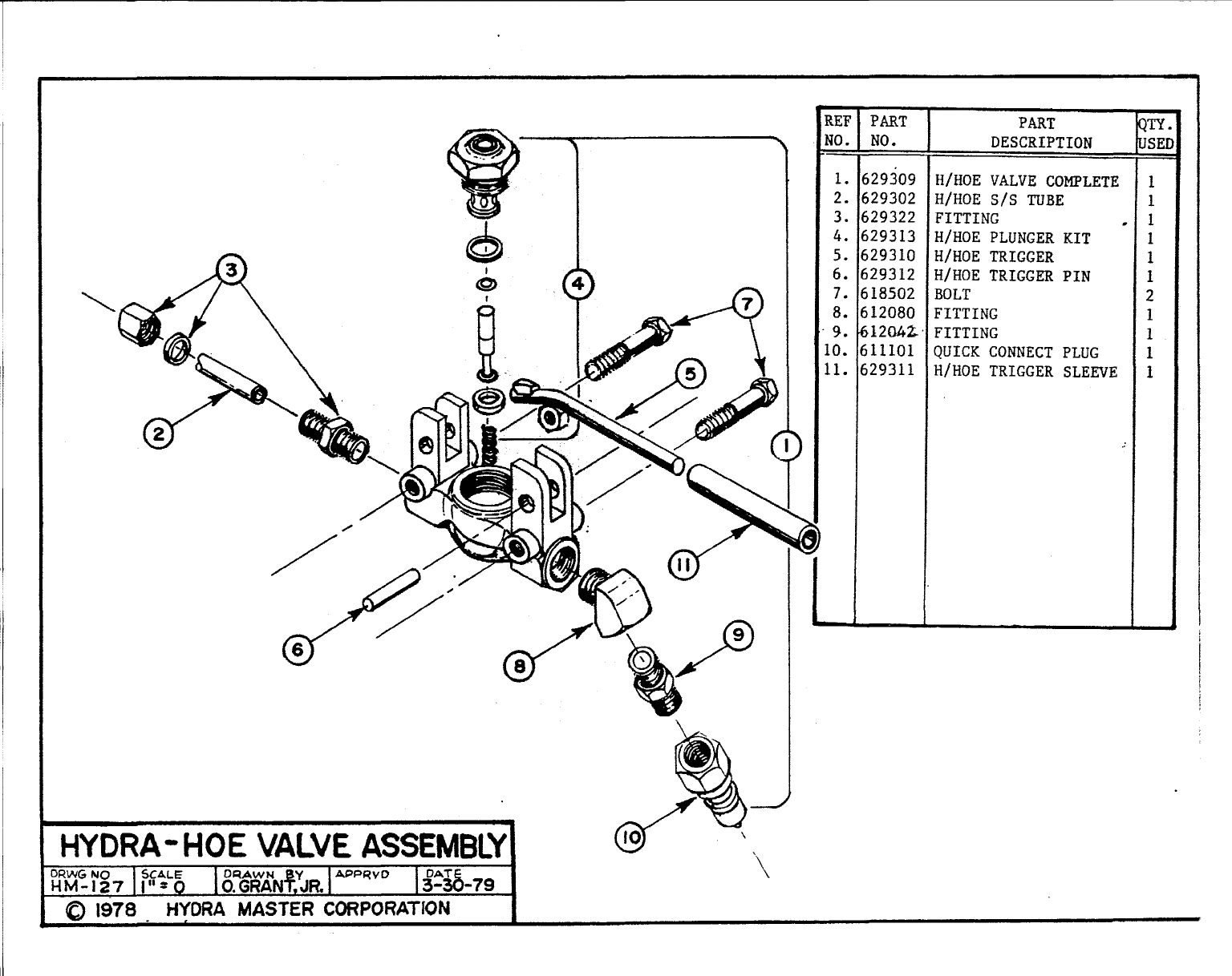
HYDRA-HOE VALVE ASSEMBLY DRAWING
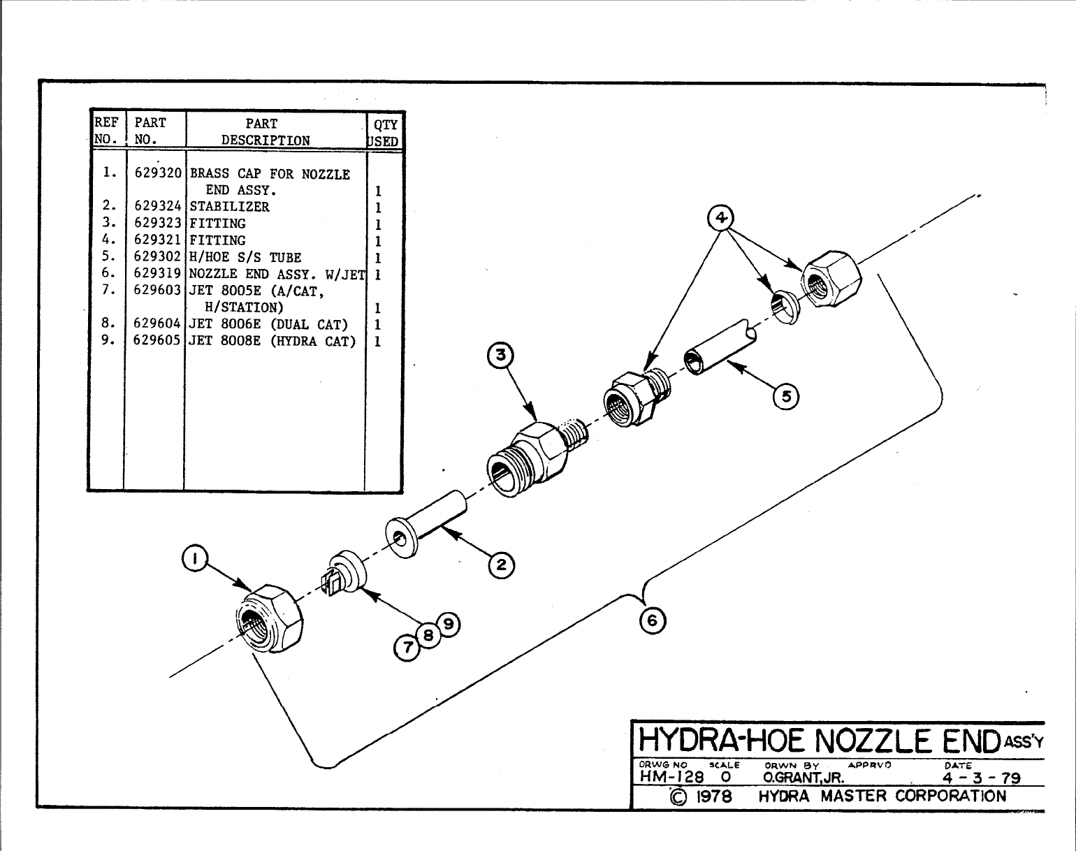
HYDRA-HOE NOZZLE END ASSEMBLY DRAWING
AQUA CAT
AQUA CAT
AQ(IA CAT
AQUA CAT
EXHAUST DRAWING
HEAT EXCHANGER DRAWING
FUEL SYSTEM DRAWING
ELECTRICAL DRAWING
ONAN ENGINE MANUAL
ONAN ENGINE PARTS 8SERVICE CATALOG
PUMP MANUAL
PRODUCT SHEETS
ADVERTISING &PROMOTIONAL AIDS
1A
I
@,,.
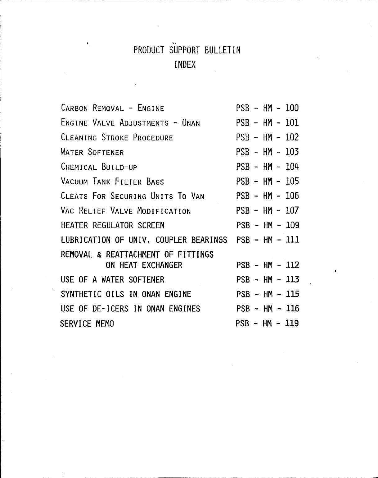
PRODUCTSUPPORTBULLETIN
INDEX
CARBON REMOVAL -ENGINE PSB - HM - I.00
IENGINE VALVE ADJUSTMENTS -ONAN PSB - HI!- 101
ICLEANING STROKE PROCEDURE PSB - HM - 102
IWATER SOFTENER PSB - HM - 103
CHEMICAL BUILD-UP PSB - HM -104
VACUUM TANK FILTER BAGS PSB - HM - 105
CLEATS FOR SECURING UNITS To VAN PSB - HM - 106
IVAC RELIEF VALVE MODIFICATION PSB - H1’1- 107
IHEATER REGULATOR SCREEN PSB - HM - 109
LUBRICATION OF UNIV, COUPLER BEARINGS PSB - HM - 111
REMOVAL & REATTACHMENT OF FITTINGS
ON HEAT EXCHANGER PSB - HM - 112 *
USE OF A WATER SOFTENER PSB - HM - 113 .
SYNTHETIC OILS IN ONAN ENGINE PSB - HM - 115
IUSE OF DE-ICERS IN ONAN ENGINES PSB - HM - 116
SERVICE MEMO PSB - HM -119
*
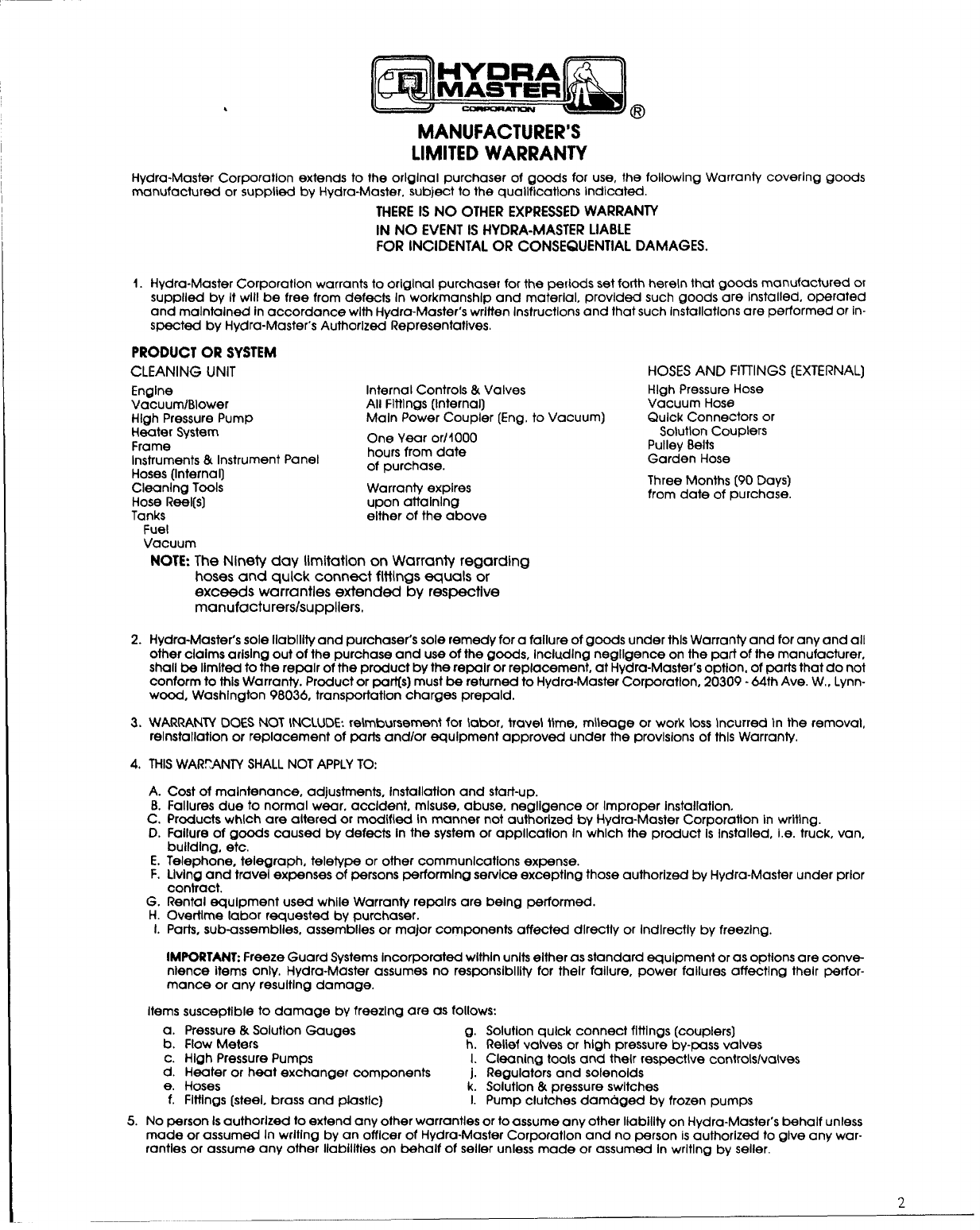
MANUFACTURER’S -
LIMITED WARRANTY
Hydra-Master ~orporatlon extends to the orlglnal purchaser of goods fOr use, the fOllOwlng WarranlY COVerln9 goods
manufactured or supplied by Hydra-Master, subject to the qualifications indicated.
THEREIS NO OTHEREXPRESSEDWARRANTY
IN NO EVENTIS HYDRA-MASTERLIABLE
FOR INCIDENTALOR CONSEQUENTIALDAMAGES.
1. Hydra-Master corporation warrants to original purchaser for the periods set forth herein that goods manufactured or
supplled by It wIII be free from defects In workmanship and material, provided such goods crre Installed, operated
and maintained in accordance with Hydra-Master’s written Instructions and fhat such installations are performed or in-
spected by Hydra-Master’s Authorized Representatives.
PRODUCTOR SYSTEM
CLEANING UNIT HOSESAND HITINGS (EXTERNAL]
Engine
VacuumlBlower
High Pressure Pump
Heater System
Frame
Instruments &Instrument Panel
Hoses (Internal]
Cleanlng Tools
Hose Reel(s]
Tanks
Fuel
Vacuum
Internal Controls &Valves
All Fittings (Internal)
Main Power coupler [Eng, to Vacuum)
One Year or11000
hours from date
of purchase.
Warranty expires
upon aftalnlng
either of the above
High Pressure Hose
Vacuum Hose
Quick Connectors or
Solutlon Couplers
Pulley Belts
Garden Hose
Three Months [90 Days)
from date of purchase.
2.
3.
4.
NOTE:The Ninety day limitation on Warranty regarding
hoses and quick connect fittings equals or
exceeds warranties extended by respective
manufacturers/suppliers,
Hydra-Master’s sole Ilabllify and purchaser’s sole remedy for afaiiure of goods under this Warranfy and for any and all
other ciaims arising out of the purchase and use of the goods, includlng negligence on the part of the manufacturer,
shall be limited to the repair of the product by the repair or replacement, at Hydra-Master’s option, of parts that do not
conform to this Warranty. Product or part(s) must be returned to HydraMaster Corporation, 20309- 64th Ave. W,, Lynn-
wood, Washington 98036, transporfatlon charges prepaid,
WARRANTY DOES NOT INCLUDE: reimbursement for iabor, travel t}me, mileage or work ~osskmurred In the removal,
reinstallation or replacement of parts and/or equipment approved under the provisions of this Warranty.
THISWARPANIY SHALL NOT APPLY TO:
A. Cost of maintenance, adjustments, installation and start-up.
B. Failures due to normal wear, accident, misuse, abuse, negligence or Improper installation,
C. Products which are altered or modified in manner not authorized by Hydra-Master Corporation in writing.
D. Failure of goods caused by defects in the system or application in which the product is Installed, i.e. truck, van,
building, etc.
E. Telephone, telegraph, telety~ or other communications expense.
F. Living and travei expenses of persons performing service excepting those authorized by Hydra-Master under prior
contract.
G. Rentai equipment used whiie Warranty repairs are being performed.
H. Overtime labor requested by purchaser.
1. Parts, sub-assemblies, assemblies or major components affected dkectly or indlrecfly by freezing.
IMPORTANT: Freeze Guard Systems incorporated within units either as standard equipment or as options are conve-
nience items only, Hydra-Master assumes no respansibllify for their failure, power failures affecting their perfor-
mance or any resultlng damage.
Items susceptible to damage by freezing are as followS
a. Pressure &Solutlon Gauges
b. Flow Meters g. Solufion quick connect fltfings (couplers]
h. Reiief valves or high pressure by-pass valves
c. High Pressure Pumps LCleaning tools and their respective controls/valves
d. Heater or heat exchanger components j. Regulators and solenolds
e. Hoses k. Solution &pressure switches
f. Fittings (steel, brass and PJastlc) 1. Pump clutches damaged by frozen pumps
5. No @rson Is authorized to extend any other warranties or fo assume any other Iiabillfy on Hydra-Master’s behalf unless
made or assumed In writing by an officer of HydraMaster Corporation and no person is authorized to give any war-
ranties or assume any ofher liabilities on behalf of seller unless made or assumed In writing by seller.
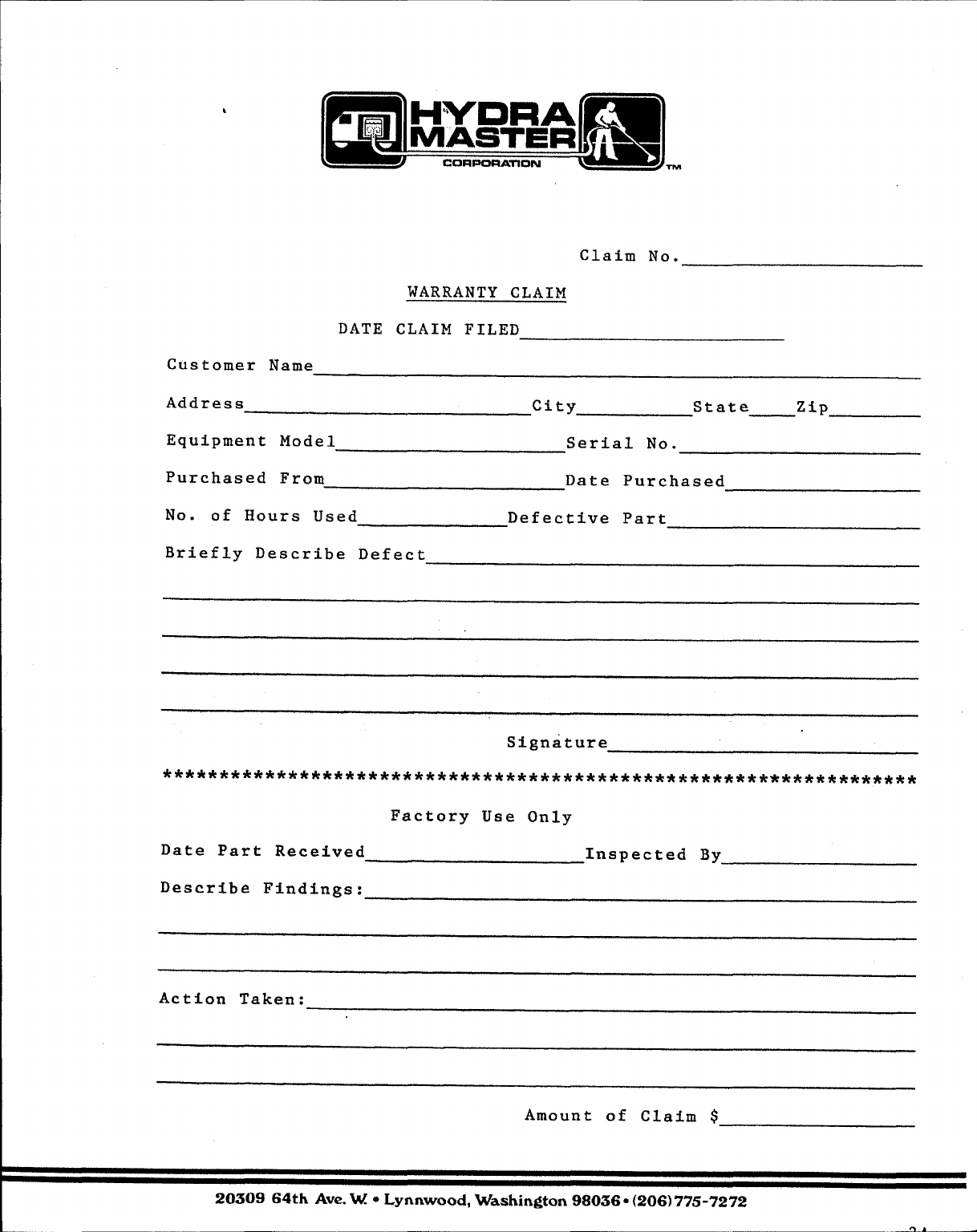
DATE
Customer Name
Claim
WARRANTY CLAIM
CLAIM FILED
No.
Address city State zip
Equipment Model Serial No.
Purchased From Date Purchased
No. of Hours Used Defective Part
Briefly Describe Defect
Signature
******************************************************************
Factory Use Only
Date Part Received Inspected By
Describe Findings:
Action Taken:
Amount of Claim $
2030964th Ave. W@Lynnwood, Washington98036 ●(206)775-7272
,..
@
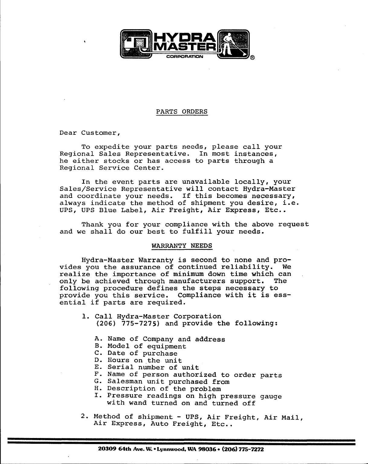
PARTS ORDERS
Dear Customer,
To expedite your parts needs, please call your
Regional Sales Representative. In most instances,
he either stocks or has access to parts through a
Regional Service Center.
In the event parts are unavailable locally, your
Sales/Service Representative will contact Hydra-Master
and coordinate your needs. If this becomes necessary,
always indicate the method of shipment you desire, i.e.
UPS, UPS Blue Label, Air Freight, Air Express, Etc..
Thank you for your compliance with the above request
and we shall do our best to fulfill your needs.
WARRANTY NEEDS
Hydra-Master Warranty is second to none and pro-
vides you the assurance of continued reliability. We
realize the importance of minimum down time which can
only be achieved through manufacturers support. The
following procedure defines the steps necessary to
provide you this service. Compliance with i.t i.s ess-
ential if parts are required.
1. Call Hydra-Master Corporation
(206) 775-7275) and provide the following:
A.
B.
c.
D.
E.
F.
G.
H.
I.
Name of Company and address
Model of equipment
Date of purchase
Hours on the unit
Serial number of unit
Name of person authorized to order parts
Salesman unit purchased from
Description of the problem
Pressure readings on high pressure crau~e
with wand turned on and-tu~ned off - -
2. Method of shipment - UPS, Air Freight, Air Mail,
Air Express, Auto Freight, Etc..
2030964thAve. W.*Lynnwood,WA 93036.(206)775-7272
3. DO NOT give malfunctioning part(s) to a sales/
service representative. All parts must be re-
,turned, freight prepaid, to Hydra-Master Corp-
oration for evaluation.
Hydra-Master’s warranty policy provides parts with-
out charge for thirty days to customer maintaining good
credit rating. Malfunctioning parts must be returned
directly to Hydra-Master Corporation for final dispo-
sition. Un-approved warranty evaluations and/or failure
to return part(s) for warranty consideration will result
in appropriate charges. Detailed instructions always
accompany each shipment to outline both your obligations
and options to the warranty procedure.
Any questions you have regarding the warranty pro–
gram should be directed to service personnel at Hydra-
Master Corporation. We shall endeavor to be fair in
our evaluation of your warranty claim and always pro-
vide you a complete analysis of our findings.
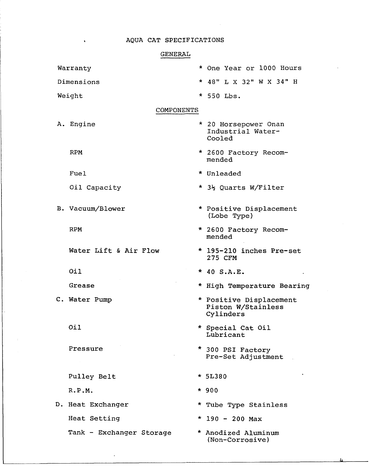
9AQUA CAT SPECIFICATIONS
Warranty
Dimensions
Weight
A. Engine
B.
c.
D.
GENERAL
*
*
*
COMPONENTS
*
RPM *
Fue 1 *
Oil Capacity *
Vacuum/Blower *
RPM *
Water Lift & Air Flow *
Oil
Grease
Water Pump
Oil
Pressure
Pulley Belt
R.P.M.
*
*
*
*
*
*
*
Heat Exchanger *
Heat Setting *
Tank - Exchanger Storage *
One Year or 1000 Hours
48” L x 32” W x 34” H
550 Lbs.
20 Horsepower Onan
Industrial Water-
Cooled
2600 Factory Recom-
mended
Unleaded
3+ Quarts W/Filter
Positive Displacement
(Lobe Type)
2600 Factory Recom-
mended
195-210 inches Pre-set
275 CFM
40 S.A.E.
High Temperature Bearing
Positive Displacement
Piston W/Stainless
Cylinders
Special Cat Oil
Lubricant
300 PSI Factory
Pre-Set Adjustment
5L380
900
Tube Type Stainless
190 -200 Max
Anodized Aluminum
(Non-Corrosive)
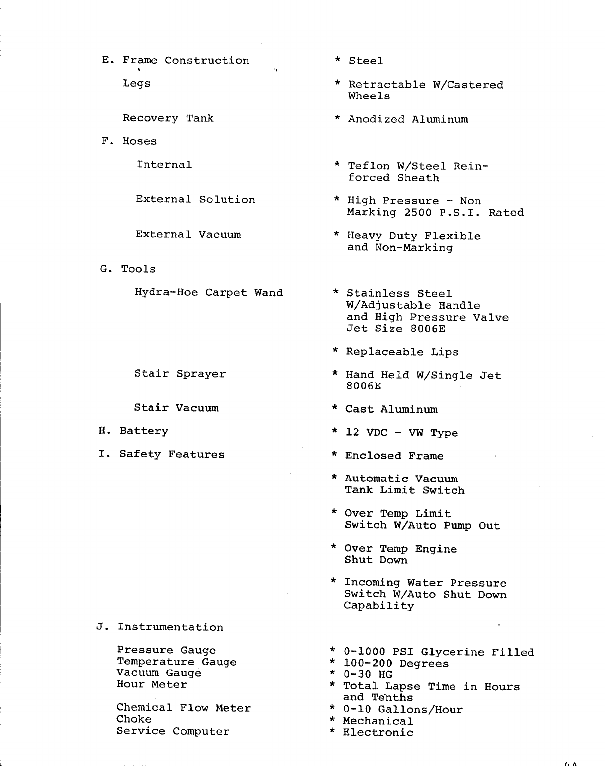
E. Frame
*
Legs
Construction *
,,
*
Steel
Retractable W/Castered
Recovery Tank *
F. Hoses
G.
J.
Internal *
External Solution *
External Vacuum *
Tools
Hydra-Hoe Carpet Wand *
Stair Sprayer
Stair Vacuum
H. Battery
I. Safety Features
Instrumentation
*
*
*
*
*
*
*
*
*
Pressure Gauge *
Temperature Gauge *
Vacuum Gauge *
Hour Meter *
Chemical Flow Meter *
Choke *
Service Computer *
Wheels
Anodized Aluminum
Teflon W/Steel Rein-
forced Sheath
High Pressure - Non
Marking 2500 P.S.I. Rated
Heavy Duty Flexible
and Non-Marking
Stainless Steel
W/Adjustable Handle
and High Pressure Valve
Jet Size 8006E
Replaceable Lips
Hand Held W/Single Jet
8006E
Cast Aluminum
12 VDC - VW Type
Enclosed Frame
Automatic Vacuum
Tank Limit Switch
Over Temp Limit
Switch W/Auto Pump Out
Over Temp Engine
Shut Down
Incoming Water Pressure
Switch W/Auto Shut Down
Capability
0-1000 PSI Glycerine Filled
100-200 Degrees
0-30 HG
Total Lapse Time in Hours
and Te”nths
0-10 Gallons/Hour
Mechanical
Electronic
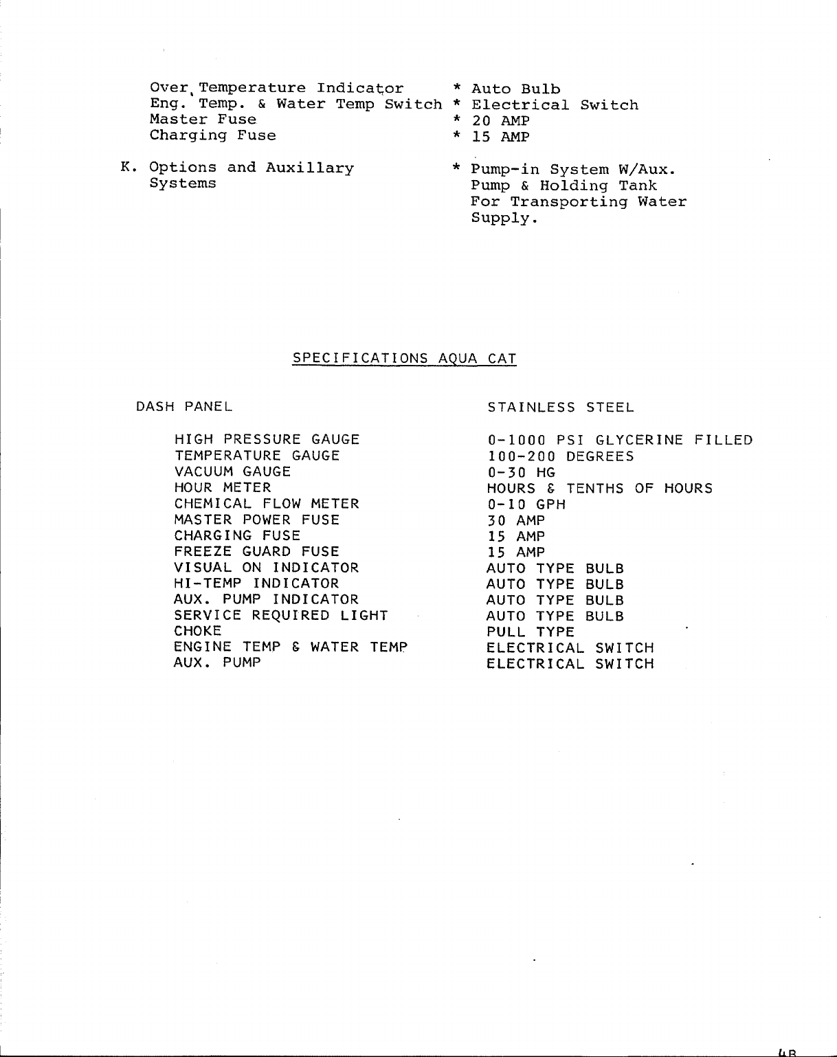
K.
Over, ’l?emperature Indicator * Auto Bulb
Eng. Temp. & Water Temp Switch * Electrical Switch
Master Fuse *20 AMP
Charging Fuse * 15 AMP
Options and Auxillary * Pump-in System W/Aux.
Systems Pump & Holding Tank
For Transporting Water
supply .
DASH PANEL
SPECIFICATIONS AQUA CAT
HIGH PRESSURE GAUGE
TEMPERATURE GAUGE
VACUUM GAUGE
HOUR METER
CHEMICAL FLOW METER
MASTER POWER FUSE
CHARGING FUSE
FREEZE GUARD FUSE
VISUAL ON INDICATOR
HI-TEMP INDICATOR
AUX. PUMP INDICATOR
SERVICE REQUIRED LIGHT
CHOKE
ENGINE TEMP &WATER TEMP
AUX. PUMP
STAINLESS STEEL
0-1000 PSI GLYCERINE FILLED
100-200 DEGREES
0-30 HG
HOURS &TENTHS OF HOURS
0-10 GPH
30 AMP
15 AMP
15 AMP
AUTO TYPE BULB
AUTO TYPE BULB
AUTO TYPE BULB
AUTO TYPE BULB
PULL TYPE
ELECTRICAL SWITCH
ELECTRICAL SWITCH
flri
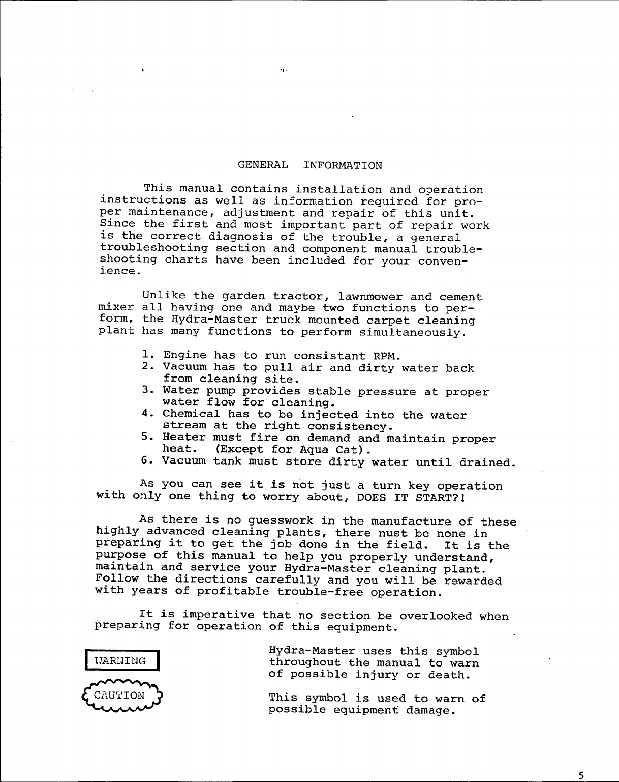
GENERAL INFORMATION
This manual contains installation and operation
instructions as well as information required for pro-
per maintenance, adjustment and repair of this unit.
Since the first and most important part of repair work
is the correct diagnosis of the trouble, a general
troubleshooting section and component manual trouble-
shooting charts have been included for your conven-
ience.
Unlike the garden tractor, lawnmower and cement
mixer all having one and maybe two functions to per-
form, the Hydra-Master truck mounted carpet cleaning
plant has many functions to perform simultaneously.
1.
2.
3.
4.
5.
6.
As
Engine has to run consistent RPM.
Vacuum has to pull air and dirty water back
from cleaning site.
Water pump provides stable pressure at proper
water flow for cleaning.
Chemical has to be injected into the water
stream at the right consistency.
Heater must fire on demand and maintain proper
heat. (Except for Aqua Cat).
Vacuum tank must store dirty water until drained.
you can see it is n’ot just a turn key operation
with only one thing to worry about, DOES IT S~AR~?l
As there is no guesswork in the manufacture of these
highly advanced cleaning plants, there nust be none in
preparing it to get the job done in the field. It is the
purpose of this manual to help you properly understand,
maintain and service your Hydra-Master cleaning plant.
Follow the directions carefully and you will be rewarded
with years of profitable trouble-free operation.
It is imperative that no section be overlooked when
preparing for operation of this equipment.
=
Hydra-Master uses this symbol
throughout the manual to warn
of possible injury or death.
=
This symbol is used to warn of
possible equipment damage.
MAINTAIN GOOD PROFIT - WITH GOOD MAINTENANCE
In the past 3years, we at Hydra-Master have become alarmed at the
increasing number of calls pertaining to service problems.
Our findings are that 85% of all down time is a direct result of poor
maintenance habits. If maintenance is a difficult function to schedule
into your busy operation, here is one important parallel that may in-
fluence your thinking toward maintenance procedure:
Each hour of machine operation is equal to 75 miles of driving.
A5+ hour average day equals 31O 11’ti.leS.
An average 5 day week or 27+ hours = 2062.5 miles.
Each month an average of 8660 miles is put on the machine.
One year of average machine operation is equal to 103,920 miles.
Compare this to your car and the maintenance you would give it
for this many miles of trouble-free driving!
Enclosed is a maintenance log sheet that should be attached to the
machine and kept in force by a responsible operator.
GOOD PROFITS
HYDRA-MASTER
AND GOOD MAINTENANCE GO HAND IN HAND
WANTS YOU TO BE A TROUBLE-FREE DRIVER!
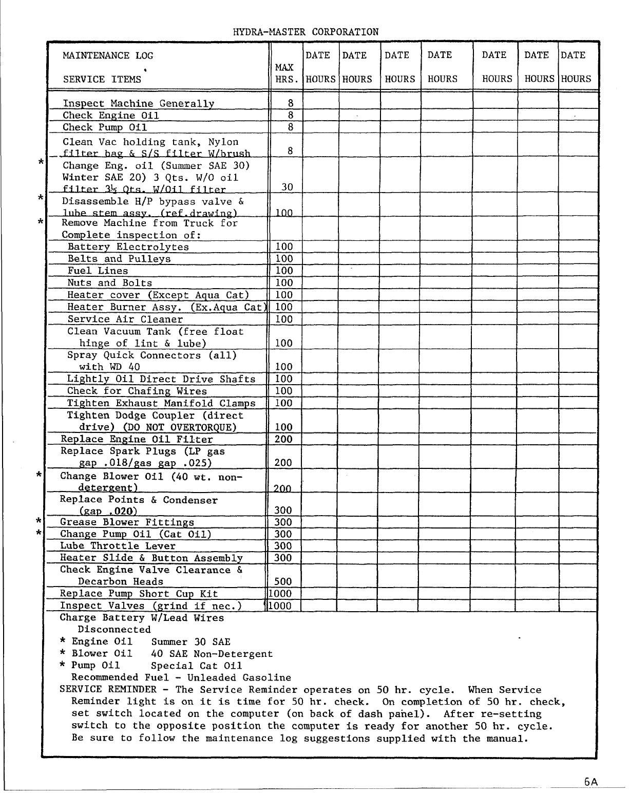
HYDRA-MASTER CORPOUTION
MAINTENANCE LOG DATE DATE DATE DATE DATE DATE DATE
SERVICE ITEMS’ HRS. HOURS HOURS HOURS HOURS HOURS HOURS HOURS
Inspect Machine Generally 8
Check Engine Oil 8
Check Pump Oil 8
Glean Vac holding tank, Nylon
fi~rer bag & S/S fi.1.L~rWlbrush 8
Change Eng. oil (Summer SAE 30)
Winter SAE 20) 3 Qts. W/O oil
fi L.@r %Qtis. W/OiJ_.<@r .
.. — — —
30
Disassemble H/P bypass valve &
c?) 1(30
Remove Machine from Truck for
Complete inspection of:
Battery Electrolytes 100
Belts and Pulleys 100
Fuel Lines 100
Nuts and Bolts 100
Heater cover (Except Aqua Cat) 100
Heater Burner Assy. (Ex.Aqua Cat) 100
Service Air Cleaner 100
Clean Vacuum Tank (free float
hinge of lint & lube) 100
Spray Quick Connectors (all)
with WD 40 100
Lightly Oil Direct Drive Shafts 100
Check for Chafing Wires 100
Tighten Exhaust Manifold Clamps 100
Tighten Dodge Coupler (direct
drive) (DO NOT OVERTORQUE) 100
Replace Engine Oil Filter 200
Replace Spark Plugs (LP gas
gap .018/gas gap .025} 200
Change Blower Oil (40 wt. non-
deter~ent) 200
Replace Points & Condenser
(fZP, 020) 300
Greas~ Blower Fittings 300
Change Pump Oil (Cat Oil) 300
Lube Throttle Lever 300
Heater Slide & Button Assembly 300
Check Engine Valve Clearance &
Decarbon Heads 500
Replace Pump Short Cup Kit 1000
Inspect Valves (grind if net.) 1000
Charge Battery W/Lead Wires
Disconnected
* Engine Oil Summer 30 SAE
* Blower Oil 40 SAE Non-Detergent
* Pump Oil Special Cat Oil
Recommended Fuel - Unleaded Gasoline
SERVICE REMINDER - The Service Reminder operates on 50 hr. cycle. When Service
Reminder light is on it is time for 50 hr. check. On completion of 50 hr. check,
set switch located on the computer (on back of dash panel). After re-setting
switch to the opposite position the computer is ready for another 50 hr. cycle.
Be sure to follow the maintenance log suggestions supplied with the manual.
J
!i4-
r=
.
II’M
I
I1+
I
111111i
)z
~
WV
@I
I
Ad
[al AL——I
th-l II ~Ir-nn JI \‘W
,I
i
mL Ii
flR
/ /\ 1, \1>!
SIGH
FUEL
-HEAT EXCHANGER
CHEMICAL
TANK
I
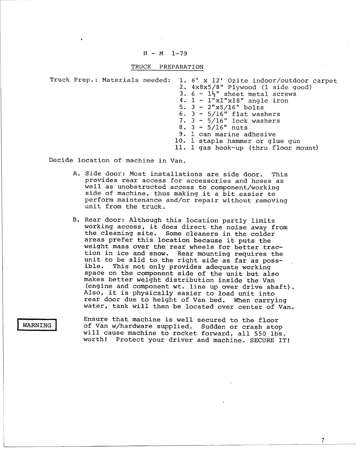
H- M 1-79
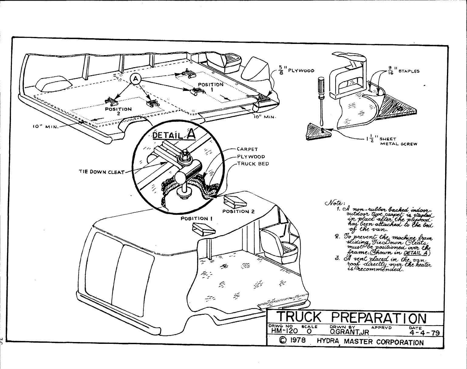
TRUCK PREPARATION
Truck Prep.: Materials needed: 1. 6’ x 12’ Ozite indoor/outdoor carpet
2. 4x8x5/8° Plywood (1 side good)
3.6- 1+” sheet metal screws
4.1- l“xI’’xI8” angle iron
5.3- 2“x5/16” bolts
6.3- 5/16” flat washers
7.3- 5/16” lock washers
8.3- 5/16” nuts
9. 1 can marine adhesive
10. 1 staple hammer or glue gun
11. 1 gas hook-up (thru floor mount)
Decide location of machine in Van.
A.
B.
EEEl
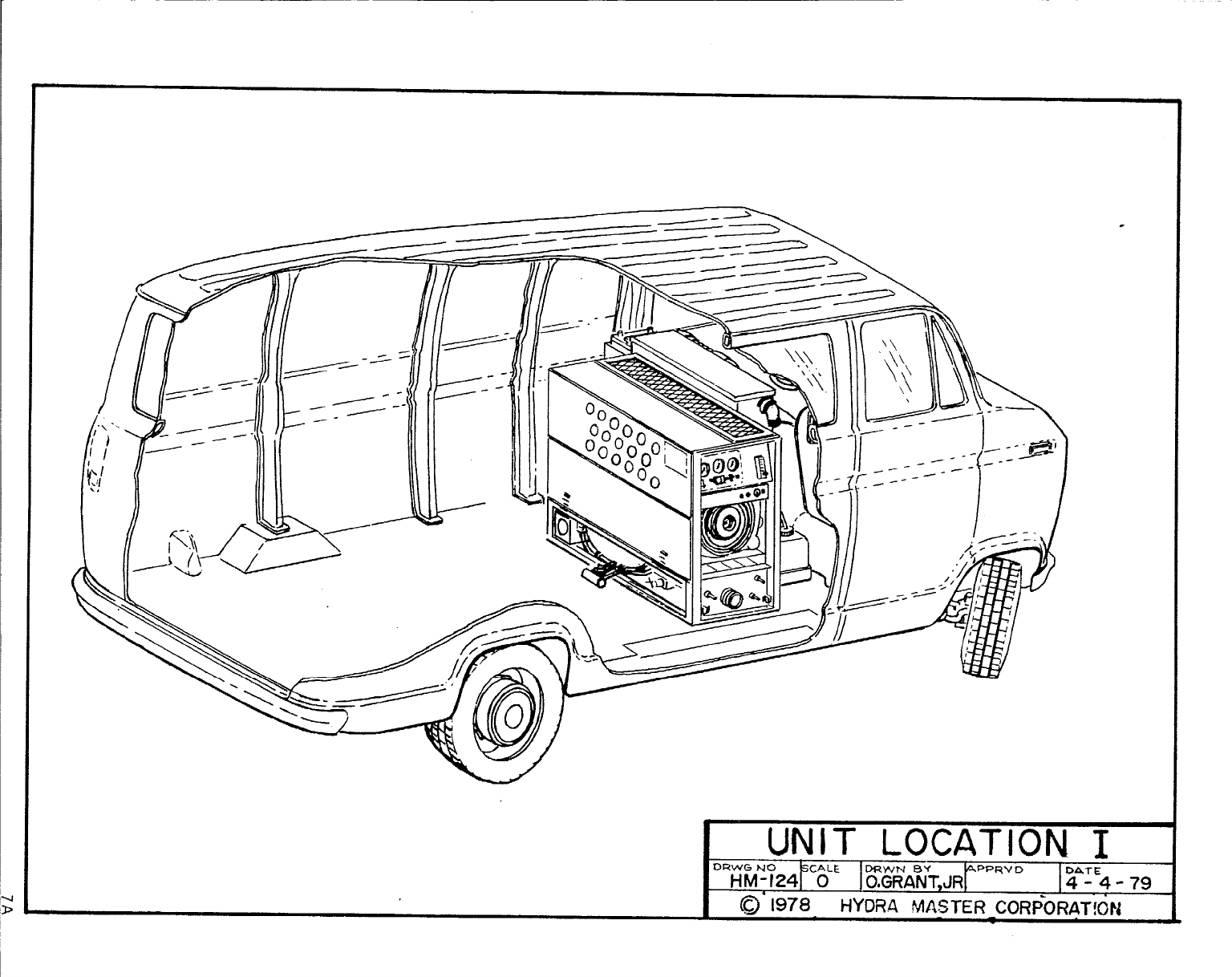
Side door: Most installations are side door. This
provides rear access for accessories and hoses as
well as unobstructed access to component/working
side of machine, thus making it a bit easier to
perform maintenance and/or repair without removing
unit from the truck.
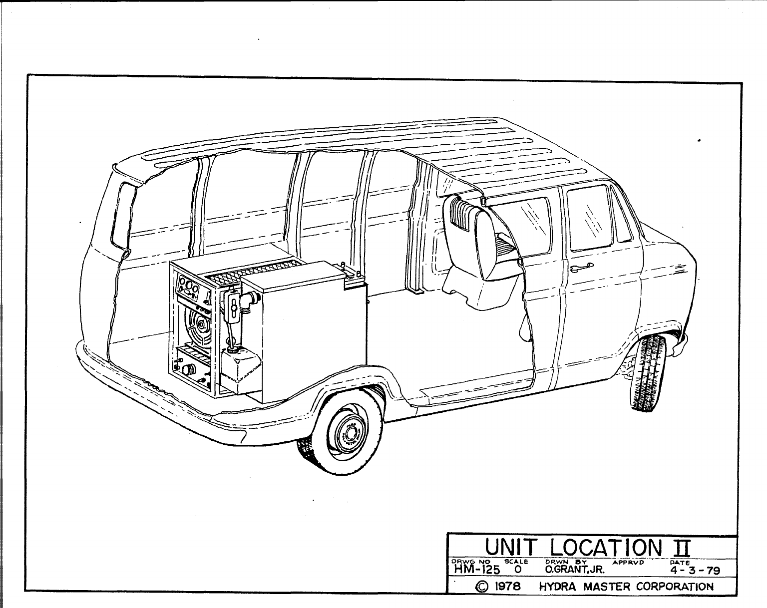
Rear door: Although this location partly limits
working access, it does direct the noise away from
the cleaning site. Some cleaners in the colder
areas prefer this location because it puts the
weight mass over the rear wheels for better trac-
tion in ice and snow. Rear mounting requires the
unit to be slid to the right side as far as POSS-
ible. This not only provides adequate working
space on the component side of the unit but also
makes better weight distribution inside the Van
(engine and component wt. line up over drive shaft).
Also, it is physically easier to load unit into
rear door due to height of Van bed. When carrying
water, tank will then be located over center of Van.
Ensure that machine is well secured to the floor
of Van w/hardware supplied. Sudden or crash stop
will cause machine to rocket forward, all 550 lbs.
worth ! Protect your driver and machine. SECURE IT!
/’
I
II
L&-—u- _\’sJ&$#
%
,,
,1
‘J - -
–.\A. -.r- . .
~\ ‘
. \\,\
\\
\\
‘i
\\\
/(i l\k===f=sii~ _
\\ \
1LF==\‘
y
–====J-====(
\\ \‘\ \
_’___—/ \\
\‘,~<
7A
.
UNIT LOCATION II
—-——..._
D~y@J&
5CA& D&NAwN~JR. .A?PRwD DATE
4“3-79
@1978 HYDRA MASTER CORPORATION 1
.
7,-
a&-
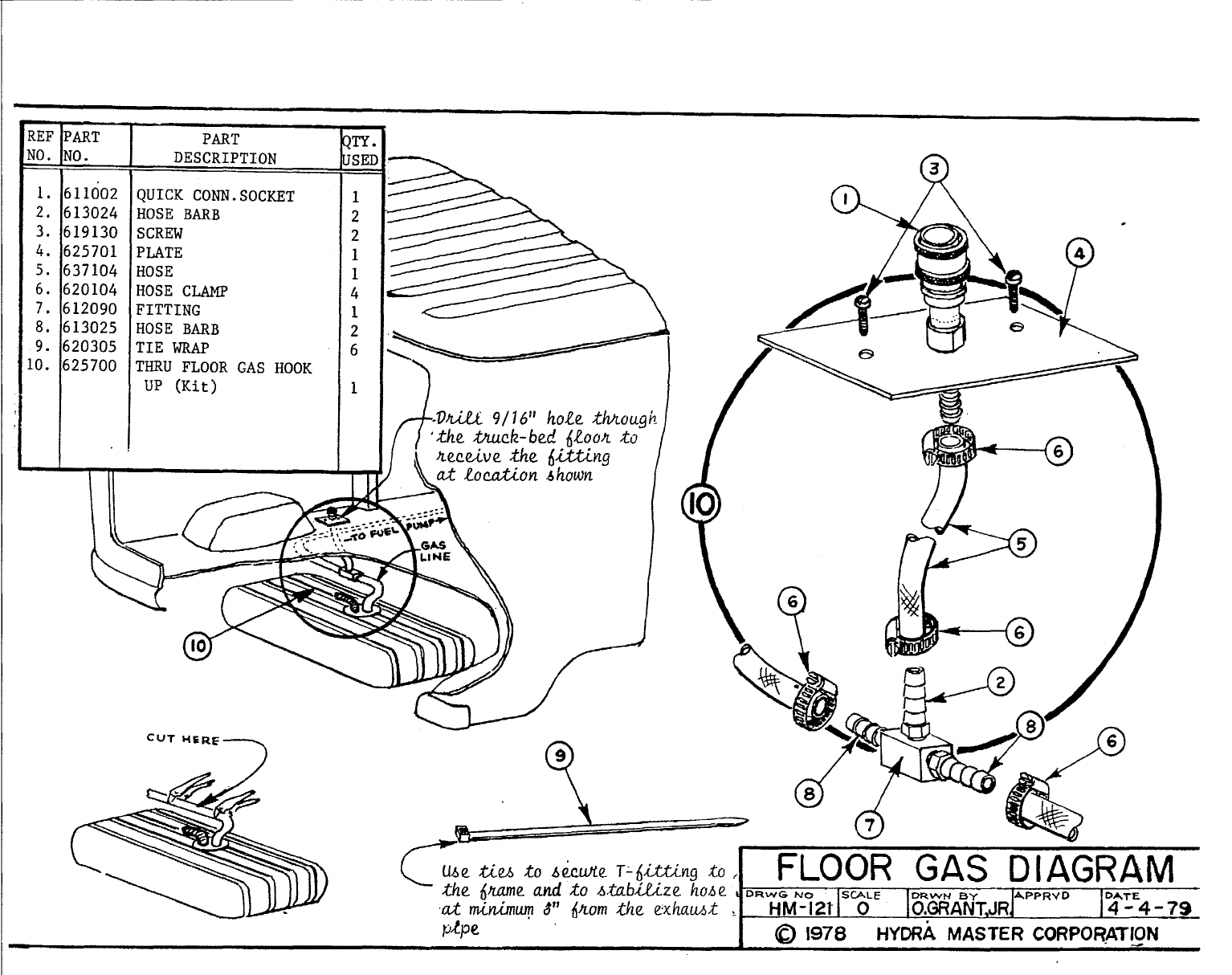
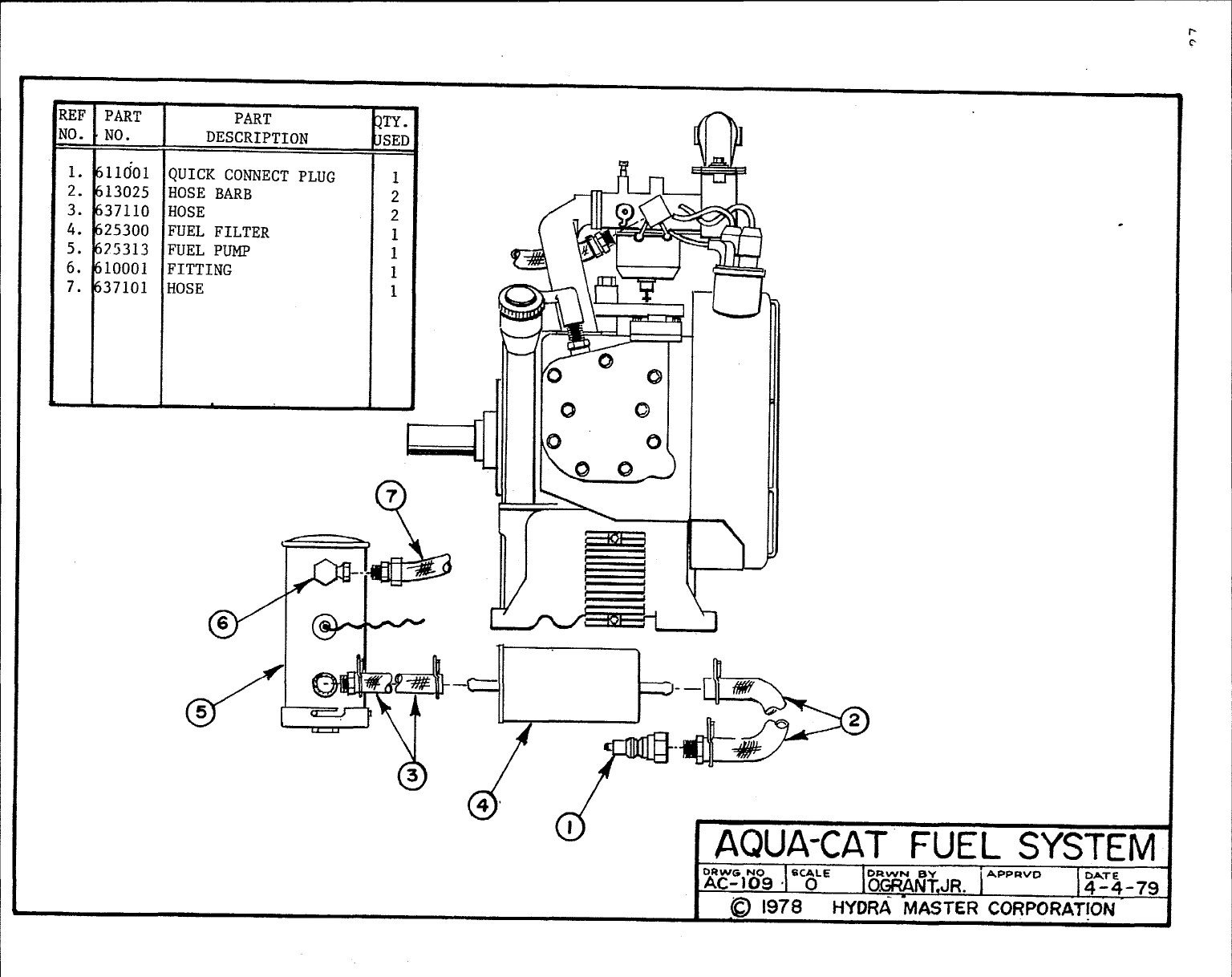
1. 611002
2. 613024
3. 619130
4. 625701
5. 637104
6. 620104
7. 612090
8. 613025
9. 620305
.0.625700
I
PART
DESCRIPTION
QUICK CONN.SOCKET
HOSE BARB
SCREW
PLATE
HOSE
HOSE CW
FITTING
HOSE BARB
TIE WRAP
THRU FLOOR GAS HOOK
UP (Kit)
!TY ,
ISEI
-
1
2
2
1
1
4
1
2
6
1
‘f-r
n
/-Lrfi!a77”
(3
8—w
(Q
43
.
Uba Z%M 10 b&.Mf? T- @%@g Xo , FLOOR GAS DIAGRAM
the@am(zand
iO Atabi-tizehohe ,DF(wG NO S@.LE
al rninhq 8“ @om the Exhutik ,HM-12A o]?WANT,JRPPPRV” 14-4-79
DATE
/J+2 I@1978 HYDRA MASTER CORPORATION
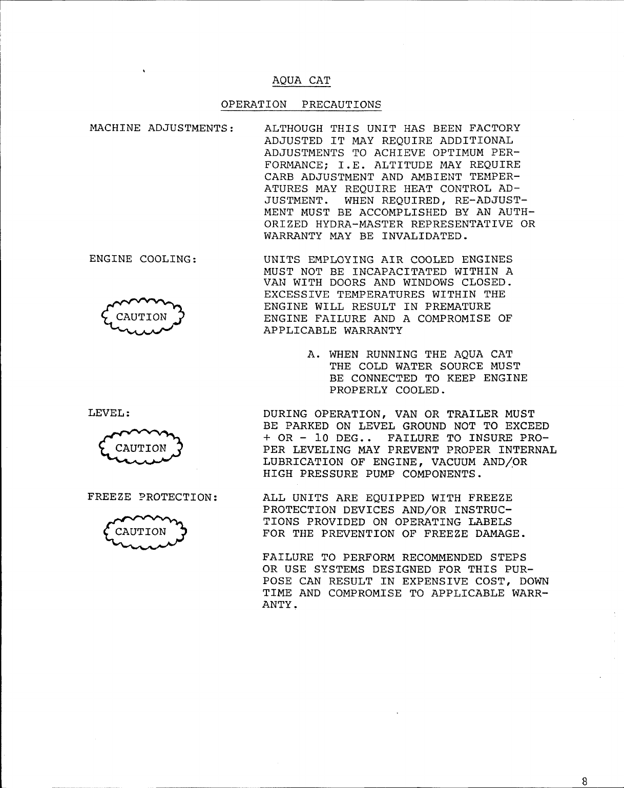
AQUA CAT
OPERATION PRECAUTIONS
MACHINE ADJUSTMENTS: ALTHOUGH THIS UNIT HAS BEEN FACTORY
ADJUSTED IT MAY REQUIRE ADDITIONAL
ADJUSTMENTS TO ACHIEVE OPTIMUM PER-
FORMANCE ; I.E. ALTITUDE MAY REQUIRE
CARB ADJUSTMENT AND AMBIEIJT TEMPER-
ATURES MAY REQUIRE HEAT CONTROL AD-
JUSTMENT. WHEN REQUIRED, RE-ADJUST–
MENT MUST BE ACCOMPLISHED BY AN AUTH-
ORIZED HYDRA-MASTER REPRESENTATIVE OR
WARRANTY MAY BE INVALIDATED.
ENGINE COOLING: UNITS EMPLOYING AIR COOLED ENGINES
MUST NOT BE INCAPACITATED WITHIN A
VAld WITH DOORS AND WINDOWS CLOSED.
EXCESSIVE TEMPERATURES WITHIN THE
ENGINE WILL RESULT IN PREMATURE
ENGINE FAILURE AND A COMPROMISE OF
APPLICABLE WARRANTY
A. WHEN RUNNING THE AQUA CAT
THE COLD WATER SOURCE MUST
BE CONNECTED TO KEEP ENGINE
PROPERLY COOLED.
LEVEL : DURING OPERATION, VAN OR TRAILER MUST
-
BE PARKED ON LEVEL GROUND NOT TO EXCEED
+ OR - 10 DEG.. FAILURE TO INSURE PRO-
PER LEVELING MAY PREVENT PROPER INTERNAL
LUBRICATION OF ENGINE, VACUUM AND/,OR
HIGH PRESSURE PUMP COMPONENTS.
FREEZE PROTECTION: ALL UNITS ARE EQUIPPED WITH FREEZE
PROTECTION DEVICES AND/OR INSTRUC-
a
TIONS PROVIDED ON OPERATING LABELS
FOR THE PREVENTION OF FREEZE DAMAGE.
FAILURE TO PERFORM RECOMMENDED STEPS
OR USE SYSTEMS DESIGNED FOR THIS PUR-
POSE CAN RESULT IN EXPENSIVE COST, DOWN
TIME AND COMPROMISE TO APPLICABLE WARR-
ANTY .
8
FREEZE PROTECTION PROCEDURE
Protecting the Aqua Cat from accidental freezing is a
relatively easy task if the following procedure is complied
with. Failure to adopt it in sub-freezing climates may
result in costly repair or replacement of components.
1. Drain the water from the hot water recirculating
tank with the drain hose provided.
2. Pour 5 gallons of 50/50 antifreeze and water into
the recirculating hot water holding tank. Lid on
tank must be removed to perform this step and then
replaced.
NOTE: Antifreeze solution must be checked with
each use to ensure safe levels are main-
tained since dilution will occur. It is
recommended that levels are monitored
frequently and antifreeze added as nec-
essary to provide an added ten degree
margin of safety.
3. To effectively pump antifreeze solutions throughout
fittings, hoses, engine, pumps, etc. , start unit
without incoming water attached and with safety
pressure switch locked out using the switch provided
for this purpose located on the dash panel.
4. With solution hoses and cleaning tool attached, draw
antifreeze solution or alcohol through the chemical
flow meter and hoses for 20 - 30 seconds. Unit is
effectively freeze guarded when antifreeze solution
starts to discharge from cleaning tool.
5. Prior to turning unit off, move rocker lock-out
switch to its opposite setting to open the over-
temperature solenoid on the hot water discharge
line. This ensures total elimination of water
from all remaining water lines.
6. Prior to starting future cleaning operations the
following must be performed.
9
A. Drain antifreeze solutions into a 5 gallon
sealed container and save for future use.
t
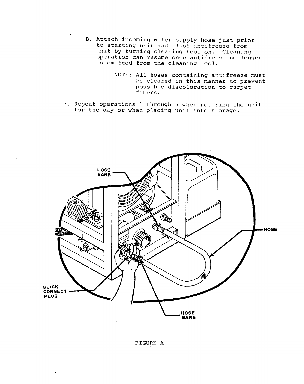
B. Attach incoming water supply hose just prior
to starting unit and flush antifreeze from
unit by turning cleaning tool on. Cleaning
operation can resume once antifreeze no longer
is emitted from the cleaning tool.
NOTE: All hoses containing antifreeze must
be cleared in this manner to prevent
possible discoloration to carpet
fibers.
7. Repeat operations 1 through 5 when retiring the unit
for the day or when placing unit into storage.
MHOSE
\HOSE
BARB
FIGURE A
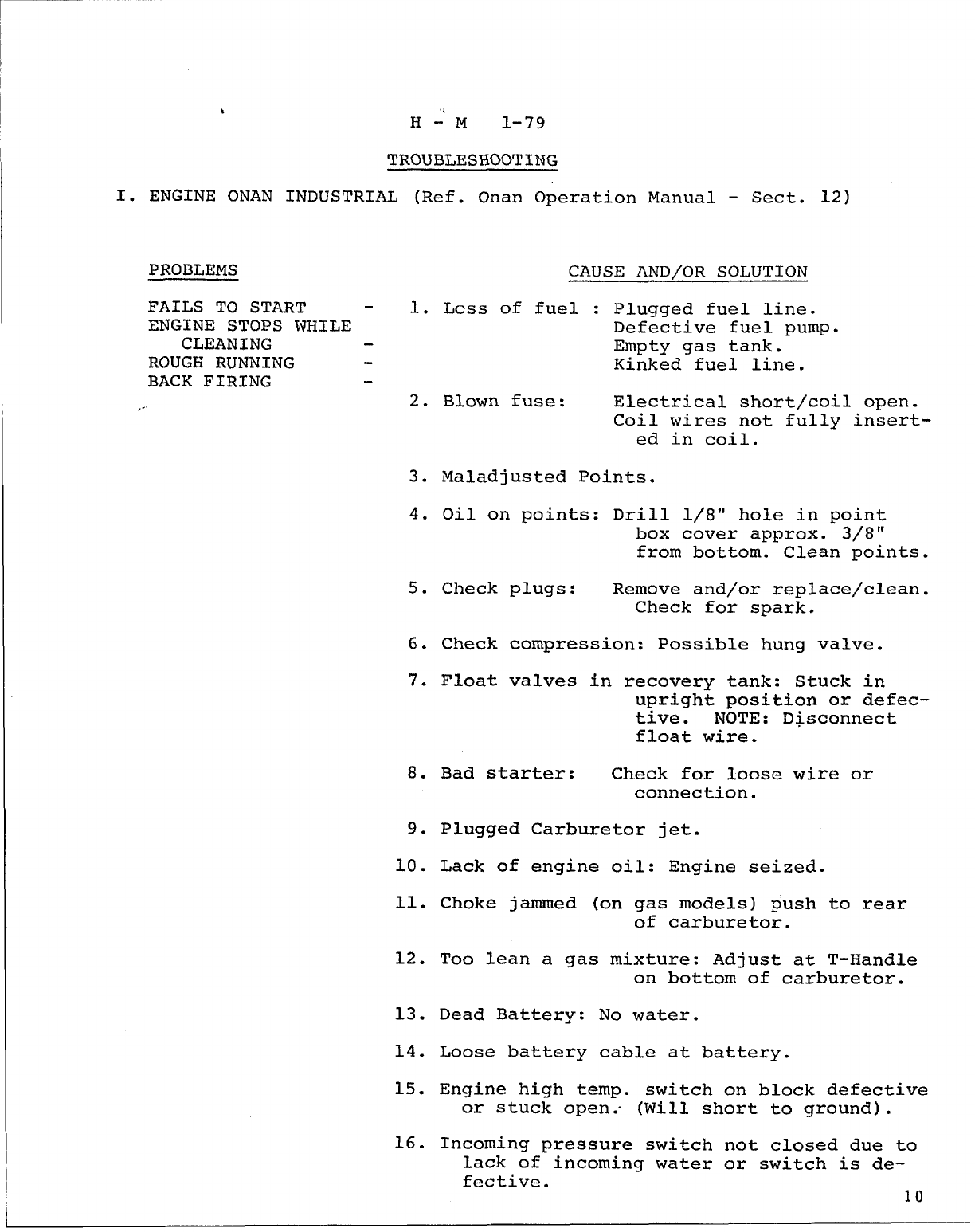
TROUBLESHOOTING
I. ENGINE ONAN INDUSTRIAL (Ref. Onan Operation Manual - Sect. 12)
PROBLEMS
FAILS TO START - 1.
ENGINE STOPS WHILE
CLEANING
ROUGH RUNNING
BACK FIRING
2.
3.
4.
5.
6.
7.
8.
9.
10.
11.
12.
13.
14.
15.
16.
CAUSE AND/OR SOLUTION
Loss of fuel : Plugged fuel line.
Defective fuel pump.
Empty gas tank.
Kinked fuel line.
Blown fuse: Electrical short\coil open.
Coil wires not fully insert-
ed in coil.
Maladjusted Points.
Oil on points: Drill 1/8” hole in point
box cover approx. 3/8”
from bottom. Clean points.
Check plugs: Remove and/or replace/clean.
Check for spark.
Check compression: Possible hung valve.
Float valves
Bad starter:
in recovery tank: Stuck in
upright position or defec-
tive. NOTE: Disconnect
float wire.
Check for loose wire or
connection.
Plugged Carburetor jet.
Lack of engine oil: Engine seized.
Choke jammed (on gas models) push to rear
of carburetor.
Too lean a gas mixture: Adjust at T-Handle
on bottom of carburetor.
Dead Battery: No water.
Loose battery cable at battery.
Engine high temp. switch on block defective
or stuck open.. (Will short to ground).
Incoming pressure switch not closed due to
lack of-incoming water or switch is de-
fective. 10
I
I
I
11
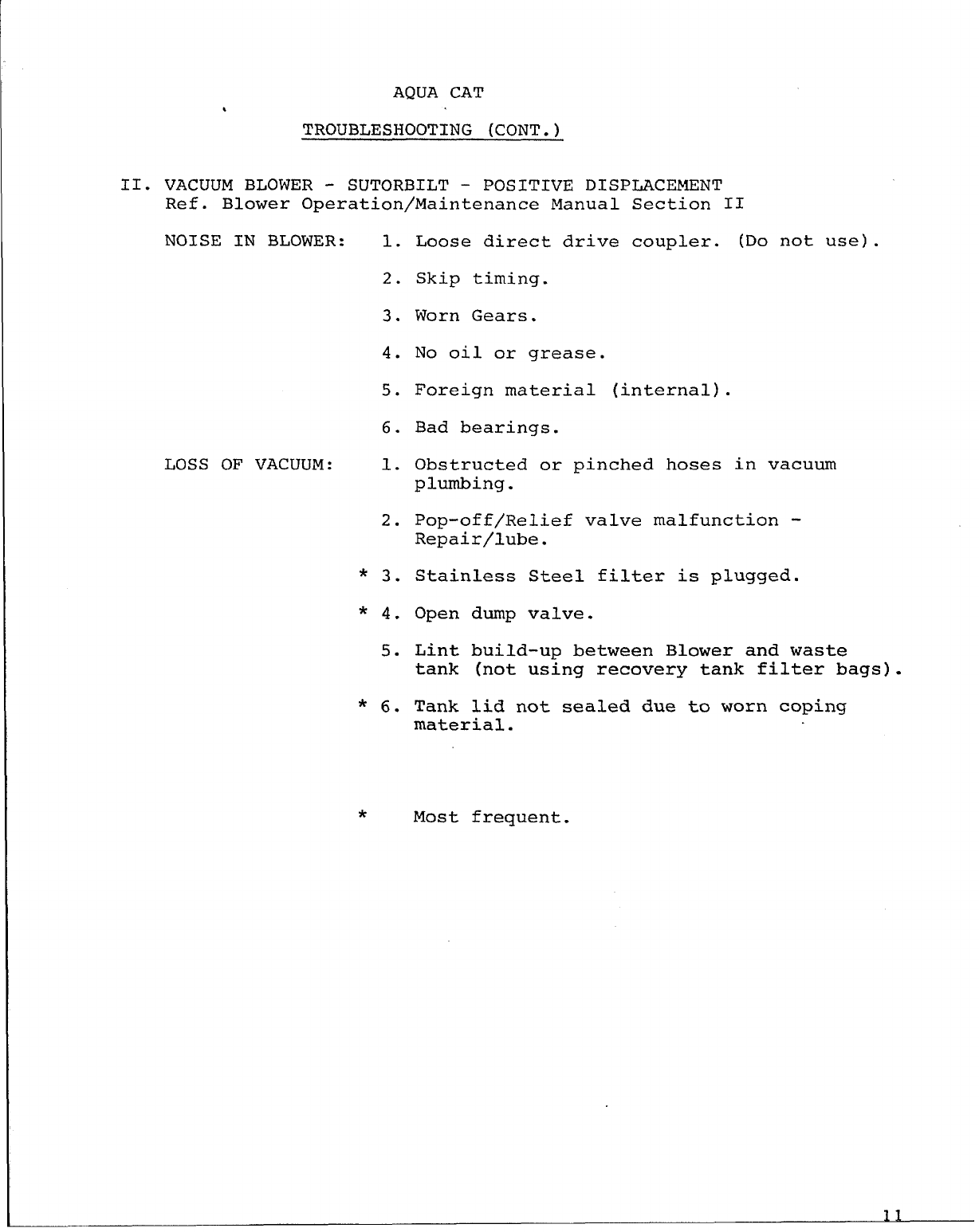
AQUA CAT
t
TROUBLESHOOTING (CONT.)
II. VACUUM BLOWER - SUTORBILT - POSITIVE DISPLACEMENT
Ref. Blower Operation/Maintenance Manual Section II
NOISE IN BLOWER: 1.
2.
3.
4.
5.
6.
LOSS OF VACUUM: 1.
2.
* 3.
* 4.
5.
* 6.
Loose direct drive coupler. (Do not use) .
Skip timing.
Worn Gears.
No oil or grease.
Foreign material (internal).
Bad bearings.
Obstructed or pinched hoses in vacuum
plumbing.
Pop-off/Relief valve malfunction -
Repair/lube.
Stainless Steel filter is plugged.
Open dump valve.
Lint build-up between Blower and waste
tank (not using recovery tank filter bags).
Tank lid not sealed due to worn coping
material.
*Most frequent.
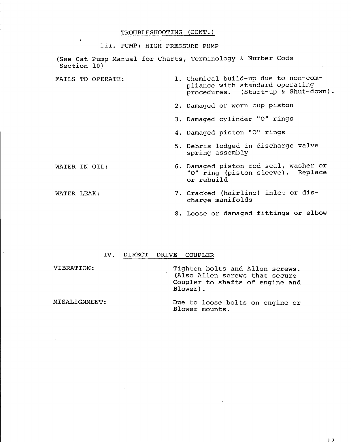
TROUBLESHOOTING (CONT.)
t
III. PUMP: HIGH PRESSURE PUMP
(See Cat Pump Manual for Charts, Terminology & Number Code
Section 10)-
FAILS TO OPERATE: 1.
2.
3.
4.
5.
WATER IN OIL:
WATER LEAK:
6.
7.
8.
Chemical build-up due to non-com-
pliance with standard operating
procedures. (Start-up & Shut-down).
Damaged or worn cup piston
Damaged cylinder “O” rings
Damaged piston “O” rings
Debris lodged in discharge valve
spring assembly
Damaged piston rod seal, washer or
“O” ring (piston sleeve). Replace
or rebuild
Cracked (hairline) inlet or dis-
charge manifolds
Loose or damaged fittings or elbow
Iv. DIRECT DRIVE COUPLER
VIBIWTION: Tighten bolts and Allen screws.
(Also Allen screws that secure
Coupler to shafts of engine and
Blower) .
MISALIGNMENT : Due to loose bolts on engine or
Blower mounts.
*
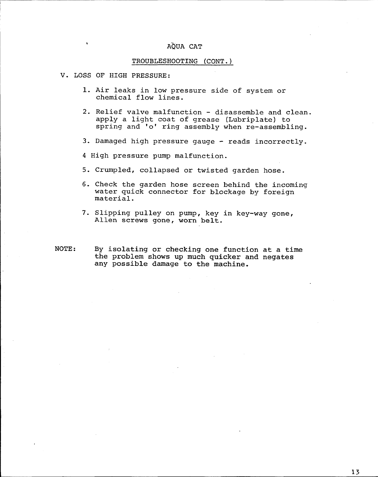
V. LOSS OF HIGH
A~UA CAT
TROUBLESHOOTING (CONT.)
PRESSURE:
1. Air leaks in low pressure side of system or
chemical flow lines.
2. Relief valve malfunction - disassemble and clean.
apply a light coat of grease (Lubriplate) to
spring and ‘o’ ring assembly when re-assembling.
3. Damaged high pressure gauge - reads incorrectly.
4 High pressure pump malfunction.
5.
6.
7.
NOTE :
Crumpled, collapsed or twisted garden hose.
Check the garden hose screen behind the incoming
water quick connector for blockage by foreign
material.
Slipping pulley on pump, key in key-way gone,
Allen screws gone, worn belt.
By isolating or checking one function at a time
the problem shows up much quicker and negates
any possible damage to the machine.
13
.>
TROUBLESHOOTING (CONT.)
VI .LOSS OF CHEMICAL FLOW:
1.
2.
3.
4.
5.
6.
7.
8.
NOTE :
Plugged filter
Crimped hoses.
screen in chemical jug. (5 gal.)
Jammed flow meter float ball at bottom of meter,
usually due to chemical build-up.
Improper mixing of chemicals.
Low or improper flow of water through system/measure
water flow at cleaning tool. This flow should measure
1.5 gallons per minute with machine running at 300 PSI.
Broken wire to chemical solenoid on top of Cat pump.
Clogged solenoid valve.
Flow switch malfunction.
Again we remind
consistent high you that chemical flow depends on
pressure flow to the cleaning tool.
14
A@A CAT
TROUBLESHOOTING (CONT.)
VII. FREEZING: WATER FLOW
If unit has been exposed to freezing conditions, the
entire water flow may be affected. Prior to trying to start,
attach water supply and thoroughly check for leaks or mal-
functions.
Freezing - Loss of or reduced solution flow. (The following
are possible and/or probable problems which occur during
freezing) .
DAMAGED: Quick connect couplers - replace
Incoming water regulator and incoming
pressure switch - replace
Heater water flow regulator - rebuild
(Except Aqua Cat).
Expanded, warped or cracked inlet or
discharge manifolds on Cat pump. (Hi
pressure/Lo pressure) Ref. #31,54 Cat
Pump Manual.
Broken and/or damaged seals or retainers
on pump piston rod assemblies, Ref.
Inlet Manifold.
Hi-pressure relief valve warped.
Cracked chemical check valve - (Except
Aqua Cat) .
Cracked chemical flow meter.
Expanded valve damage to trigger assem-
blies on all cleaning tools. (Plunger). “
NOTE : On Aqua Cat, check heat exchanger for any
cracks or leaks. Also check solenoids
and hoses where applicable.
Inspect all fittings and hoses for leaks
or damage.
H-M 1-79
VIII OVER - WETTING
Over-wetting is annoying to all concerned and sometimes
leaves abad impression of the cleaning process used.
There
1.
2.
3.
4.
5.
6.
are several areas that will cause over-wetting:
Too few vacuum strokes or improper vacuum strokes.
Obstructed, kinked or cut hoses.
Vacuum tank drain valve left partially open.
Clogged vacuum blower filter.
Cleaning a heavily foam-saturated carpet without
defoamer. (We recommend crystal type).
Vacuum relief valve not operating properly, due
to wear and misalignment, or adjustment may be
required to increase vacuum to original factory
setting. (14-15 HG).
NOTE : 1979 model has vacuum relief valve built in to -
tank lid and has been preset at the factory.
IF.
.
@
~jj HYDRA No. PSB-HM-1OO
%MASTER Date: 8-11-77
%CORPORATION
PRODUCT SUPPORT BULLETIN
Service/Parts/ Publications
Model(s): HYDRA-CAT, BOB-CAT Section Insert#:
&AQUA CAT
Subject: CARBON REMOVAL - ENGINE
Units operating on regular gasoline require carbon
removal from combustion chambers approximately every 500
hours as defined by the Onan Service Manual. Failure to
comply will void the engine manufacturers warranty and
could result in unnecessary expense and costly down time.
The cost to perform carbon removal is relatively inexpen-
sive but does vary throughout the country. Normally
this service must be scheduled with the Onan Service
Center in the same manner as tune-ups, etc..
2030964thAve. W.*Lynnwood,WA 98036.(206)775-7272
No. PSB-HM-~()]
Date: January 1977
TM
PRODUCT SUPPORT BULLETIN
Service/Parts/ Publications
Model(s): ALL Section Insert#+:
Subject: ONAN ENGINE VALVE ADJUSTMENTS
To ensure continued reliability from the ONAN engines
incorporated in our units, it is NECESSARY to adjust both
intake and exhaust valves after 300 hours of use. Fai~
to comp~with this suggestion m~necessi=te a valve
repair after 500 hours of use and can compromise engine
warranty during the warranty period.
The condition which will often occur if valves are
not adjusted is power loss and damage to valves and valve
seats.
Instructions for preventive maintenance procedures,
i.e. tune-up, oil changes, carburetor breather filter, fuel
adjustment, valve adjustments, etc. are outlined in the ONAN
Service Manual contained in the Hydra-Master Manual. Your
local small engine service shops as well as ONAN Service
Centers are qualified to perform necessary adjustments.
2030964thAve. W.@Lynnwood,WA 98036.(206)775-7272
FIWDRA4 No. PSB-HM-102
MASTE= ~dd?: JANUARY
1~7~
CORPORATION
PRODUCT SUPPORT BULLETIN
Service/Parts/Publications
Model(s): ALL Section Insert#$:
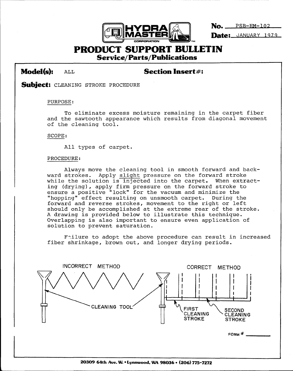
Subject: CLEANING STROKE PROCEDURE
PURPOSE :
To eliminate excess moisture remaining in the carpet fiber
and the sawtooth appearance which results from diagonal movement
of the cleaning tool.
SCOPE :
All types of carpet.
PROCEDURE:
Always move the cleaning tool in smooth forward and back-
ward strokes. Apply slight pressure on the forward stroke
while the solution is injected into the carpet. When extract-
ing (drying) , apply firm pressure on the forward stroke to
ensure a positive “lock” for the vacuum and minimize the
“hopping” effect resulting on unsmooth carpet. During the
forward and reverse strokes, movement to the right or left
should only be accomplished at the extreme rear of the stroke.
A drawing is provided below to illustrate this technique.
Overlapping is also important to ensure even application of
solution to prevent saturation.
F-.ilure to adopt the above procedure can result in increased
fiber shrinkage, brown out, and longer drying periods.
INCORRECT METHOD CORRECT METHOD
II I
KzaCLEANING TOOL
STROKE STROKE
L
FORM #
2030964thAve. W.*Lynnwood,WA 9?3036*(206)775-7272
No. PSB-HM-103
Date:~
m
PRODUCT SUPPORT BULLETIN
Service/Parts/ Publications
Model(s): ALL Section hsert#:
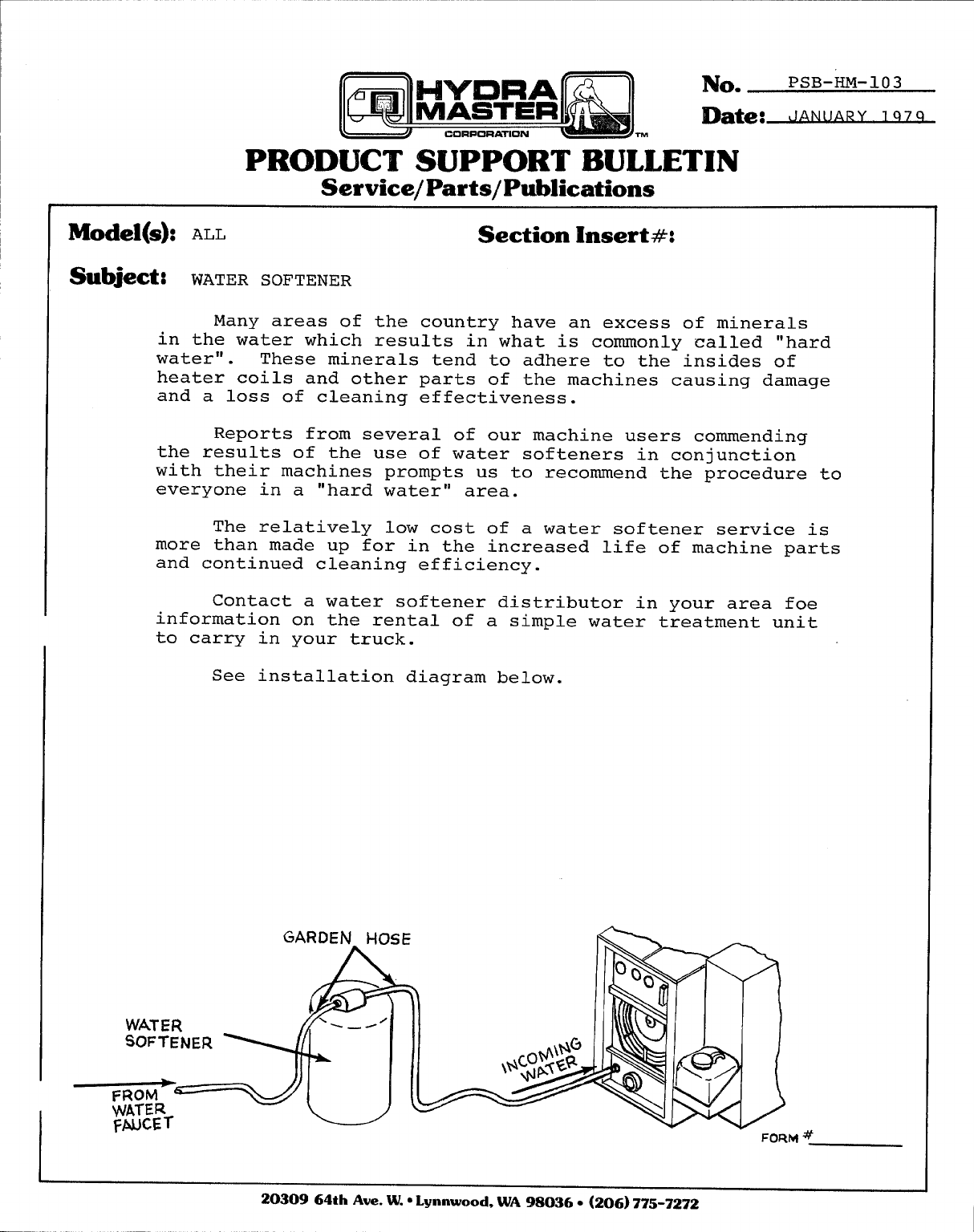
Subject: WATER SOFTENER
Many areas of the country have an excess of minerals
in the water which results in what is commonly called “hard
water” . These minerals tend to adhere to the insides of
heater coils and other parts of the machines causing damage
and a loss of cleaning effectiveness.
Reports from several of our machine users commending
the results of the use of water softeners in conjunction
with their machines prompts us to recommend the procedure to
everyone in a “hard water” area.
The relatively low cost of a water softener service is
more than made up for in the increased life of machine parts
and continued cleaning efficiency.
Contact a water softener distributor in your area foe
information on the rental of a simple water treatment unit
to carry in your truck.
See installation diagram below.
FORM #
2030964thAve. W.*Lynnwood,WA 98036.(206)775-7272
No. PsB-HM-lo4
Date:~
m
PRODUCT SUPPORT BULLETIN
Service/Parts/Publications
Model(s): ALL Section Insert#:
Subject: CHEMICAL BUILD–UP
TO SAVE TIME AND MONEY, REMEMBER PROTECTIVE MAINTENANCE
IS THE KEY TO MANY SUCCESSFUL OPERATIONS. SOME OF OUR
CUSTOMERS ARE NEGLECTING TO FLUSH THEIR MACHINES AFTER 40
HOURS OF USE. REMEMBER, BECAUSE OF THE DIFFERENT TYPES
OF CHEMICALS, WATER CONDITIONS, AND HEAT, CHEMICAL BUILD-
UP MAY OCCUR. TO FIGHT THIS PROBLEM, FLUSH THE MACHINE
ONCE AWEEK OR EVERY 35 -40 HOURS WITH VINEGAR. FOLLOW
THESE INSTRUCTIONS: WHILE MACHINE IS RUNNING, PLACE CHEM-
ICAL FEED HOSE IN ABOTTLE OF WHITE VINEGAR AND TURN ON TOOL
93THE VINEGAR WILL BE PULLED THROUGH THE SYSTEM. DO NOT
LEAVE IN SYSTEM ANY LONGER THAN 45 MINUTES OR DAMAGE MAY
OCCUR TO INTERNAL COMPONENTS. FLUSH WITH CLEAR WARM WATER
IN THE SAME MANNER AS THE VINEGER WAS INJECTED. THIS WILL
BREAKDOWN BUILD-UP AND PREVENT COSTLY DOWN TIME, AND LONGER
LIFE FOR YOUR MACHINE.
WHITE VINEGAR IS AMILD ACID AND WILL CONTRIBUTE TO THE
REMOVAL/BREAKDOWN OF EXCESSIVE CHEMICAL BUILD-UP IN COMPON–
ENTS SUCH AS HOSES, FITTINGS AND HEATERS.
I
I2030964thAve. W.oLynnwood,WA 98036.(206)775-7272
No. pSB-HM-105
Date: JANUARY 1979
‘?Ibl
PRODUCT SUPPORT BULLETIN
Service/Parts/ Publications
Model(s): ALL Section lnsert#:
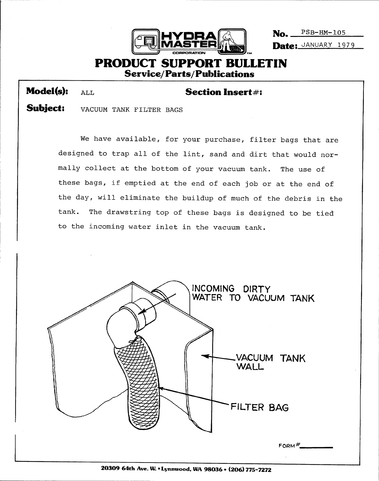
Subject: VACUUM TANK FILTER BAGS
We have available, for your purchase,
designed to trap all of the lint, sand and
really collect at the bottom of your vacuum
filter bags that are
dirt that would nor-
tank. The use of
these bags, if emptied at the end of each job or at the end of
the day, will eliminate the buildup of much of the debris in the
tank. The drawstring top of these bags is designed to be tied
to the incoming water inlet in the vacuum tank.
//
II \.
INCOMING CMl?TY
WATER TO VACUUM TAN
(~
MTANK
BAG
‘K
FORM #
2030964thAve. W.*Lynnwood,WA 98036-(206)775-7272
No. PSB-HM-106
Date: April, 1979
TM
PRODUCT SUPPORT BULLETIN
Service/Parts/ Publications
Model(s): Section hsert#:
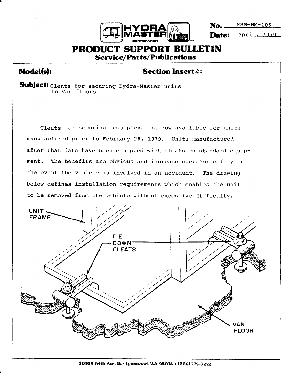
Subject: Cleats for securing Hydra-Master units
to Van floors
Cleats for securing equipment are now available for units
manufactured prior to February 28, 1979. Units manufactured
after that date have been equipped with cleats as standard equip-
ment. The benefits are obvious and increase operator safety in
the event the vehicle is involved in an accident. The drawing
below defines installation requirements which enables the unit
to be removed from the vehicle without excessive difficulty.
2030964thAve. W.*Lynnwood,WA 9S036*( 206)775-7272
No. PSB-HM-107
Date: A~ri.1~1979
TM
PRODUCT SUPPORT BULLETIN
Service/Parts/ Publications
Model(s): Section hsert#:
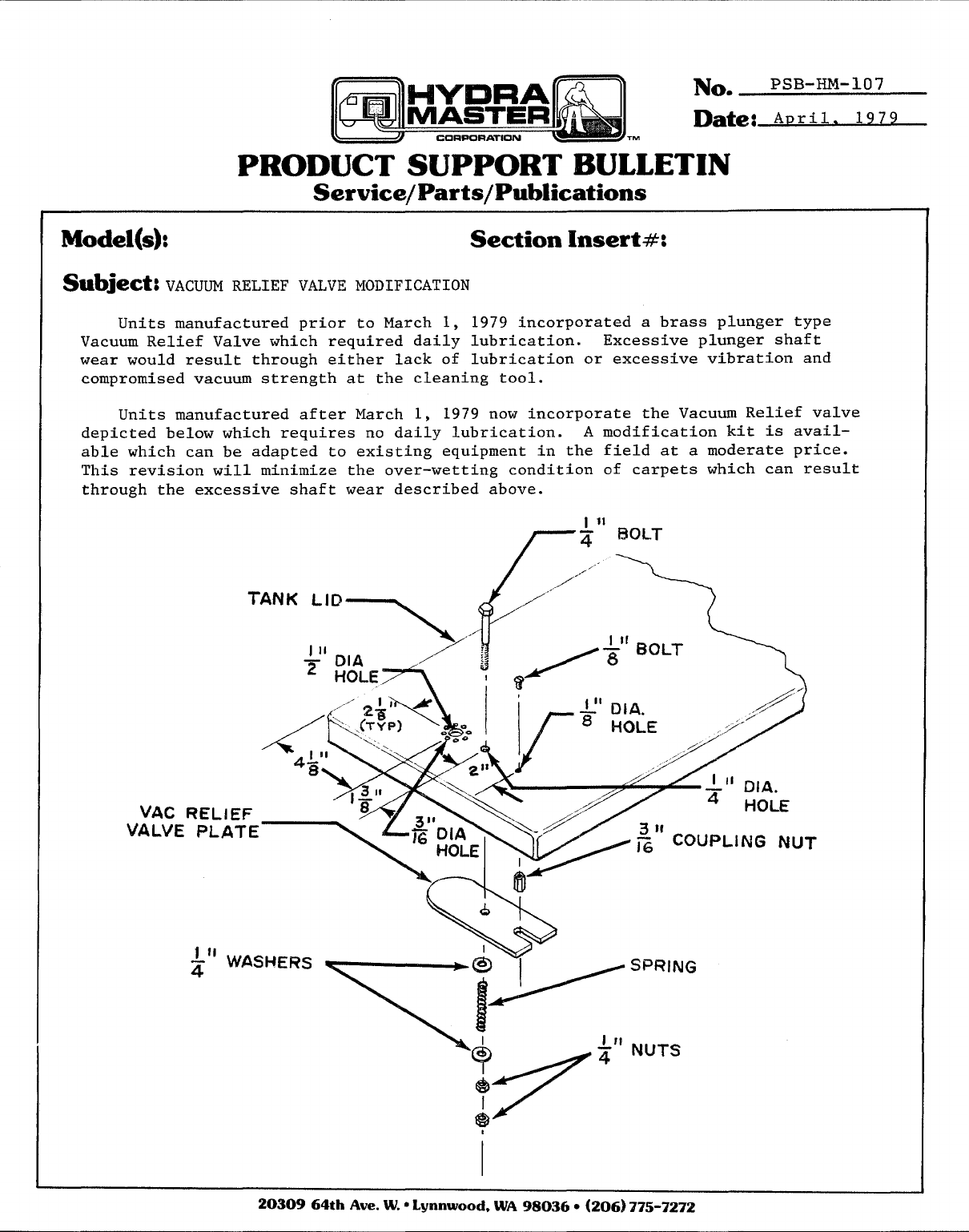
Subject: VACUUM RELIEF VALVE MODIFICATION
Units manufactured prior to March 1, 1979 incorporated a brass plunger type
Vacuum Relief Valve which required daily lubrication. Excessive plunger shaft
wear would result through either lack of lubrication or excessive vibration and
compromised vacuum strength at the cleaning tool.
Units manufactured after March 1, 1979 now incorporate the Vacuum Relief valve
depicted below which requires no daily lubrication. A modification kit is availa-
ble which can be adapted to existing equipment in the field at a moderate price.
This revision will minimize the over-wetting condition of carpets which can result
through the excessive shaft wear described above.
ZU3UY64thAve. W.”Lynnwood, WA98036*(206J 775-7272
...
No. 119
Date: ‘ay 1,980
w
PRODUCT SUPPORT BULLETIN
Service/Parts/ Publications
Model(s): Aqm-mt Section Insert #:
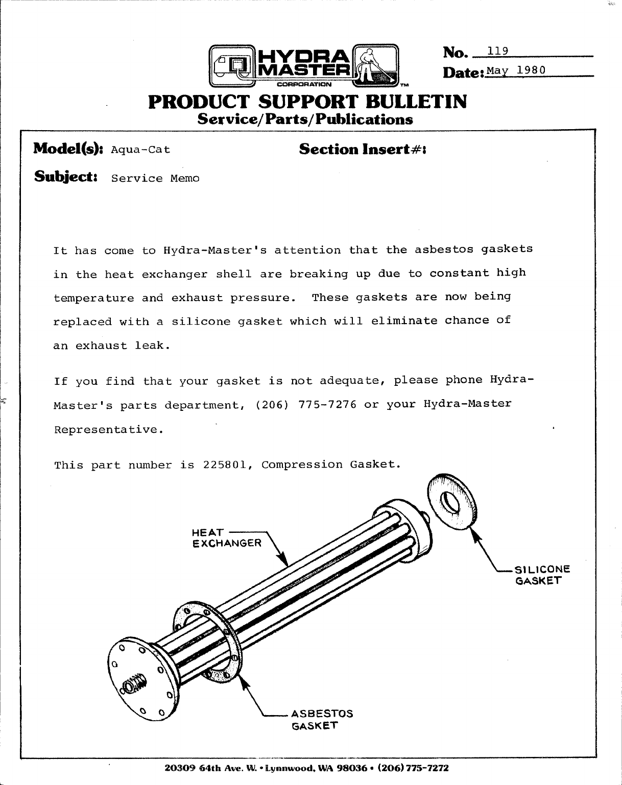
Subject: Service Memo
It has come to Hydra-Master’s attention that the asbestos gaskets
in the heat exchanger shell are breaking up due to constant high
temperature and exhaust pressure. These gaskets are now being
replaced with a silicone gasket which will eliminate chance of
an exhaust leak.
If you find that your gasket is not adequate, please phone Hydra-
Master’s parts department, (206) 775-7276 or your Hydra-Master
Representative. .
This part number is 225801, Compression Gasket. m
“-’”n
EXCHANGER ///.
SILICONE?
GASKET
‘L_ASBESTOS
GASKET
203@364th Ave. W.*Kyamwood,WA 980360(206)775-7272
/IiI
O“f-J!
A
.lRiw#H I I
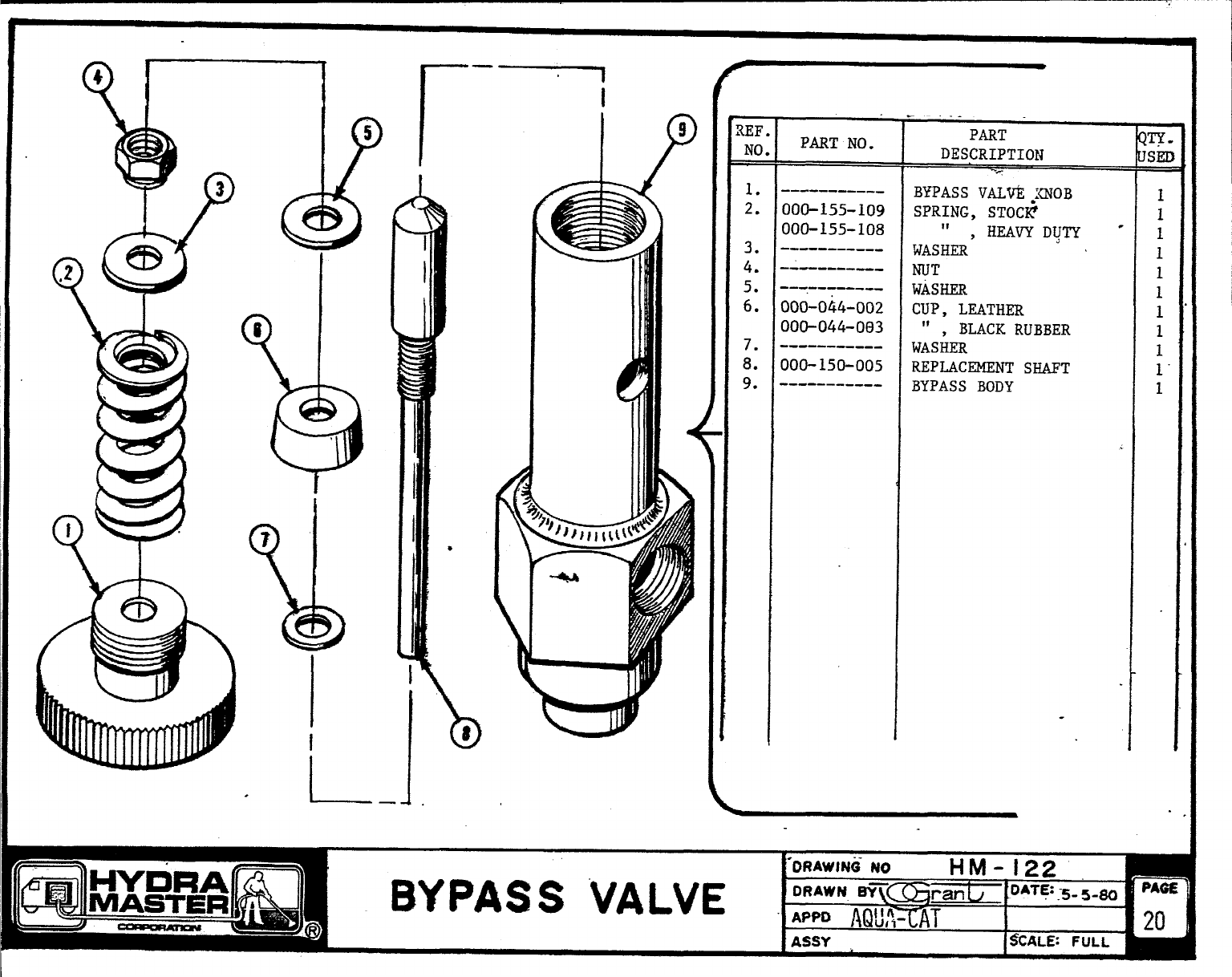
1.
2.
3.
4.
5.
6.
7.
636020
636024
636022
611201
611101
611102
636001
REF PART PART OTY
No. No. DESCRIPTION USEI
GARDEN HOSE
SCREEN REPLACEMENT
INLET GDN. HOSE CONN.
(Inc. Screen)
QUICK CONN. PLUG
QUICK CONN. PLUG
QUICK CONN. SOCKET
HIGH PRESSURE HOSE
1
1
1
1
1
1
1
/
II
HOSE
‘)
%5
Li&SURG /AQuA-cAT IiosE DIAGRAM
DIWW3 NO SCALE DQwhl BY
CW?AN~JR. ~pp’vo DATE
Ac-IO] O4-3-79
~1978 HYDRA MASTER CORPORATION
\\
LHIGH
mESSURE
PUMP
r. . .
ET]” “-- ‘-”- REViSION- -II
\\\ -PFiESSURE
%\ Gu-s
mVELETE ShLL VALVE~ F- LINE TO LPRP ,T-WIM& @AT!S
b. D&ETE CW E6CuEeN, WAN= HVWT TO LPRP I.INF i.~.8ol ~-q .JBLm
400 BALL VALVEE FLOW; ADD T-= ITTIN5; CHAMW
3L,?JE,- “W14T
T* FUXIRC.P”UP:GE,C,,-,H ,v-
r
.—
-
\
1?
FLOW
METER
i
pC“HEMICAL
tNTAK E
P
SOLENOI C)
JT
-- I1t
6OATE
1’-4-S0 Q?- ,LOW PRESSURE IN
Iv
AICHGD FLOW TANK FITTINGS& SCREEN I@] 17-11-79
BY]CKid DATE
II I 1I1
1
0RAWlNf3 MO
n.
AQUA CAT FLOW DIAGRAM DRAWN Sy () %;;:% :‘z
DATE 4- 5-79
(a HIGH PRESSURE
r
PUMP m
1
o
ml
/-
(---cc
\ DETAIL-A ~
I
UK% u7&ssa%erzke t5pect&&Z:
1. THERE ARE TO BE 16 D16C SPRINGS IN
8SETS OF 2PLACED -K TO OACK AS
SHOW NABOVE.
2.<SEE NOTE ZON DISASSEMBLY)
3. APPLY LIGHT cc%%~ OF LU6RICANT TO
SPRINGS AkND SHAFT.
4. FACTORY PRESET MAXi MUM PRESSURE
Al 45o PSI
IP7
‘L I\
3
---
m
w
1.I
I
2. 630252
3, 630253
4. 630254
5.
6.
7.
8.
9. 630251
10.1~30250
PART
DESCRIPTION
DISC SPRINGS (see
note 1)
BYPASS VALVE SHAFT
‘O’ RING (Large)
BYPASS VALVE ELBOW
PRESSUREADJ. NUT
(Brass)
BYPASS VALVE HOUSING
BYPASS VALVE SHAFT
ASSY.
BYPASS VALVE HOUSING
SEAT
‘O’ RING (Extra Lge)
BYPASS VALVE ASSY.
!TY .
[SEC
=
16
1
1
1
1
1
1
1
1
cl’’”:
~- BYI%SS VALVE
9DRw GNO DRWN BY APPRVD DATE
14M-122 3-29-79
i@!978 HYDRA MA~TEF? (XRP(3PATKJN 4
Q
I
-)
.
N~ZZLE END
ASSEMBLY
d
3
{EF PART PART QTY.
io .NO. DESCRIPTION USED
1. 629300 H/HOE COMPLETE 1
2. 629301 H/HOE FMME 1
3. 629318 H/HOE BLUE HANDLE
SLEEVE 1
4. 629303 S/S 3A.NDLE 1
5. 629304 S/S :CREW 2
6. 6293o5 S/S iTl_JT 2
7. 629306 H/HGE HANDLE CLIP 1
8. 629X!2 il/HOZS/S TUBE 1
9. 629317 H/EOE LIPS 2
@1978 HYDRA MASTER CORPORATION
iiiiim(’
.-&/-W
HYDRA- HOE VANE ASSEMBLY w
t\
JRwG NO \
HM-12T :f:’% 81$%2N+.YJR. ‘ppQvo Im-79
REFI PART
NO. INO.
I
I
1. 629309
2. 629302
3. 629322
4.
5.
6.
7.
8.
!3.
10.
11.
629313
629310
629312
618502
612080
‘612042
611101
629311
PART
DESCRIPTION
H/HOE VALVE COMPLETE
H/HOE S/S TUBE
FITTING .
H/HOE PLUNGER KIT
H/HOE TRIGGER
H/HOE TRIGGER PIN
BOLT
FITTING
FITTING
QUICK CONNECT PLUG
H/HOE TRIGGER SLEl?VE
QTY
USEI
-
1
1
1
1
1
1
2
1
1
1
1
,1I
‘Q 1978 HYORA MASTER CORPORATION I
LEF PART PART Qll
Jo. NO. DESCRIPTION JSEI
1. 629320 BRASS CAP FOR NOZZLE
END ASSY. 1
2. 629324 STABILIZER 1
3. 629323 FITTING I
4. 629321 FITTING 1
5. 629302 H/HOE S/S TUBE 1
6. 629319 NOZZLE END ASSY. W/JET 1
7. 629603 JET 8o05E {A/cAT,
HISTATION) 1
8. 629604 JET 8006E (DUAL CAT) 1
9. 629605 JET 8008E (HYDRA CAT) 1
1
r
)
1‘~ 1978 HYDRA MASTER CORPORATION
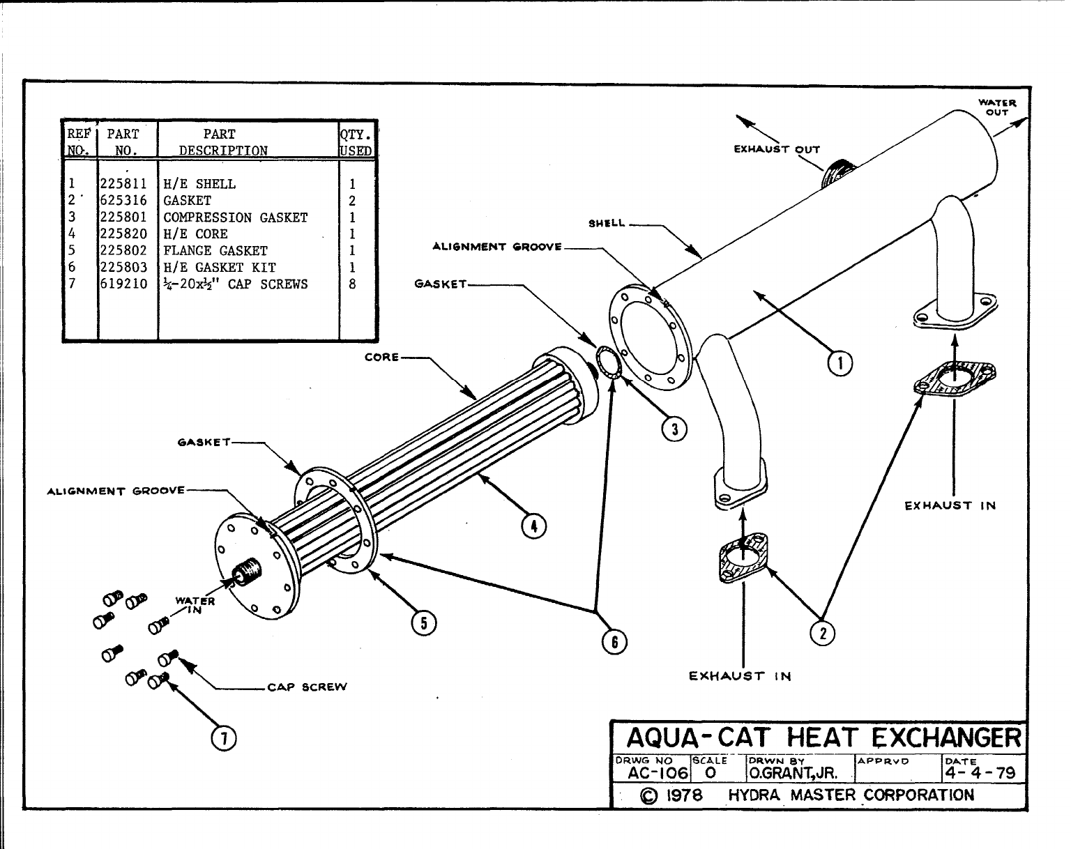
REF
1
(3.
12
2“ 6
32
42
52
62
76
PART PART
NO. DESCRIPTION
25811 H/E SHELL
25316 GASKET
25801 COMPRESSIONGASKET
25820 H/E CORE
25802 FLANGE GASKET
25803 HfE GASKET KIT
19210 ~-20$5° CAP SCREWS
IL
TY.
SEC
[
1
2
1
1
1
1
8
AL16NME?uT
GASKET—
GROOVE
“’’”x
AL1 GM EXHAUST IN
IAQUA- CAT HEAT EXCHANGER
—APPRv ODA.7 E
O.GRANT,JR. 4-4-79
I@1978 HYDRA MASTER CORPORATION
b
J’ifyJ ~lfj:
1
:b+(1I-G={ Ir“mmmid-iL!&?
\
WWD ,1, Ial /- “Aim’s
#
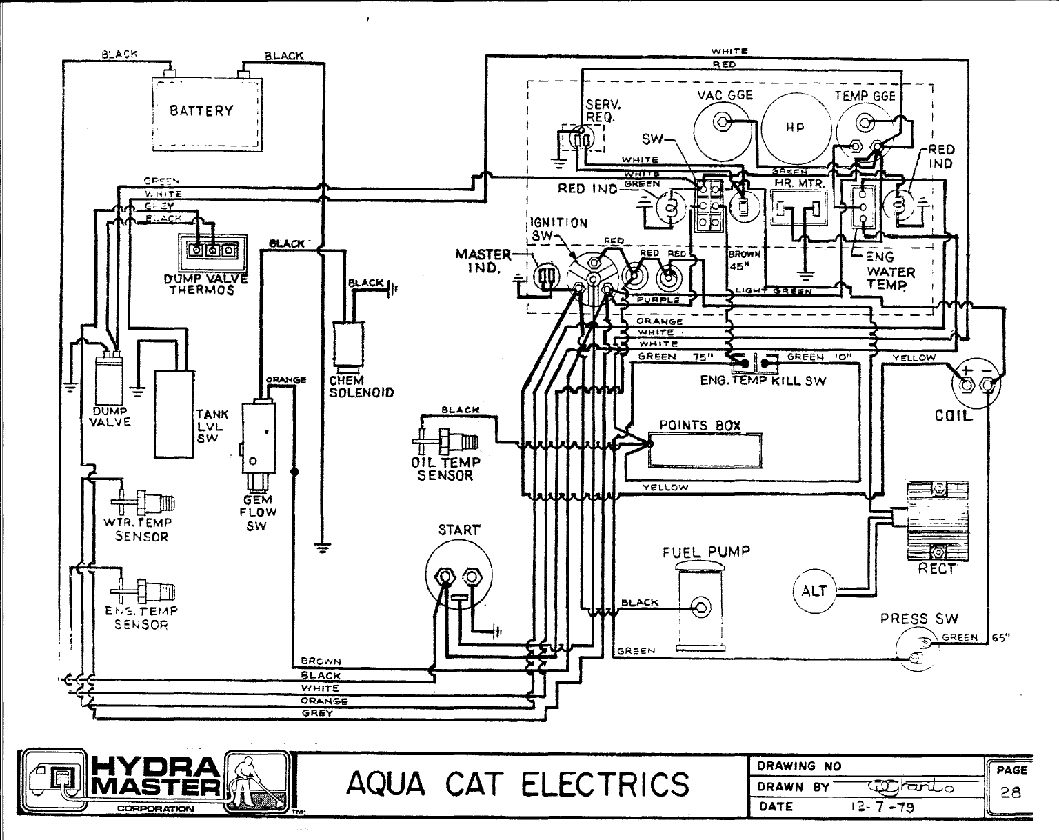
IWHITE
RED
!:
IBATTERY :
i’ I
----
~lGNtTION
‘Lsw-
MMJ’TQER,‘.-
.
a
~
BLACK
L–. 4
YELLOW
\\+ (,
i. —.—___ —r. —— —___ —_-
LORAhl GE %
WHITE
GREEt.J 10t’
ENG.EMP KILL SW
E
L
COIL
m
b
WTR. rEMP
I!r
GEM
FLOW
Sw START’
SENSOR
1Yi!E
.0
/1 PRESS SW
[~, GREEE4 65”
;REEN ~
13RCWN J4
BLACK 1
VfiiiTE 4
ORANGE
-——
ORAWING NO
AQUA CAT ELECTRICS “E
PAGE
DRAWN BY o2a
DATE 12-7 -Tg
.
(
,
I
. . . . . . .
\
.
—.
I
UJ
>
A
a
>
