Fire Lite.ms 9200ud.ms 9200ude
User Manual: fire-lite.ms-9200ud.ms-9200ude
Open the PDF directly: View PDF ![]() .
.

Fire Alarm Control Panel
MS-9200UD/MS-9200UDE
PN: 51906:A ECN 02-398
IMPORTANT! The SLC Manual Document #51309 must be referenced in addition to this
manual when installing or servicing the Fire Alarm Control Panel.
Document #51906
12/10/02 Revision: A
LimWarLg.p65 01/10/2000
An automatic fire alarm system–typically made up of smoke
detectors, heat detectors, manual pull stations, audible warn-
ing devices, and a fire alarm control with remote notification
capability–can provide early warning of a developing fire.
Such a system, however, does not assure protection against
property damage or loss of life resulting from a fire.
The Manufacturer recommends that smoke and/or heat detec-
tors be located throughout a protected premise following the
recommendations of the current edition of the National Fire
Protection Association Standard 72 (NFPA 72),
manufacturer's recommendations, State and local codes, and
the recommendations contained in the Guide for Proper Use
of System Smoke Detectors, which is made available at no
charge to all installing dealers. A study by the Federal Emer-
gency Management Agency (an agency of the United States
government) indicated that smoke detectors may not go off in
as many as 35% of all fires. While fire alarm systems are de-
signed to provide early warning against fire, they do not guar-
antee warning or protection against fire. A fire alarm system
may not provide timely or adequate warning, or simply may not
function, for a variety of reasons:
Smoke detectors may not sense fire where smoke cannot
reach the detectors such as in chimneys, in or behind walls, on
roofs, or on the other side of closed doors. Smoke detectors
also may not sense a fire on another level or floor of a build-
ing. A second-floor detector, for example, may not sense a
first-floor or basement fire.
Particles of combustion or "smoke" from a developing fire
may not reach the sensing chambers of smoke detectors be-
cause:
• Barriers such as closed or partially closed doors, walls, or
chimneys may inhibit particle or smoke flow.
• Smoke particles may become "cold," stratify, and not reach
the ceiling or upper walls where detectors are located.
• Smoke particles may be blown away from detectors by air
outlets.
• Smoke particles may be drawn into air returns before
reaching the detector.
The amount of "smoke" present may be insufficient to alarm
smoke detectors. Smoke detectors are designed to alarm at
various levels of smoke density. If such density levels are not
created by a developing fire at the location of detectors, the
detectors will not go into alarm.
Smoke detectors, even when working properly, have sensing
limitations. Detectors that have photoelectronic sensing
chambers tend to detect smoldering fires better than flaming
fires, which have little visible smoke. Detectors that have ion-
izing-type sensing chambers tend to detect fast-flaming fires
better than smoldering fires. Because fires develop in differ-
ent ways and are often unpredictable in their growth, neither
type of detector is necessarily best and a given type of detec-
tor may not provide adequate warning of a fire.
Smoke detectors cannot be expected to provide adequate
warning of fires caused by arson, children playing with
matches (especially in bedrooms), smoking in bed, and violent
explosions (caused by escaping gas, improper storage of
flammable materials, etc.).
Heat detectors do not sense particles of combustion and
alarm only when heat on their sensors increases at a prede-
termined rate or reaches a predetermined level. Rate-of-rise
heat detectors may be subject to reduced sensitivity over time.
For this reason, the rate-of-rise feature of each detector
should be tested at least once per year by a qualified fire pro-
tection specialist.
Heat detectors are designed to protect
property, not life.
IMPORTANT!
Smoke detectors must be installed in the
same room as the control panel and in rooms used by the sys-
tem for the connection of alarm transmission wiring, communi-
cations, signaling, and/or power.
If detectors are not so lo-
cated, a developing fire may damage the alarm system, crip-
pling its ability to report a fire.
Audible warning devices such as bells may not alert people
if these devices are located on the other side of closed or
partly open doors or are located on another floor of a building.
Any warning device may fail to alert people with a disability or
those who have recently consumed drugs, alcohol or medica-
tion. Please note that:
•Strobes can, under certain circumstances, cause seizures
in people with conditions such as epilepsy.
•Studies have shown that certain people, even when they
hear a fire alarm signal, do not respond or comprehend the
meaning of the signal. It is the property owner's responsibil-
ity to conduct fire drills and other training exercise to make
people aware of fire alarm signals and instruct them on the
proper reaction to alarm signals.
•In rare instances, the sounding of a warning device can
cause temporary or permanent hearing loss.
A fire alarm system will not operate without any electrical
power. If AC power fails, the system will operate from standby
batteries only for a specified time and only if the batteries
have been properly maintained and replaced regularly.
Equipment used in the system may not be technically com-
patible with the control. It is essential to use only equipment
listed for service with your control panel.
Telephone lines needed to transmit alarm signals from a
premise to a central monitoring station may be out of service
or temporarily disabled. For added protection against tele-
phone line failure, backup radio transmission systems are rec-
ommended.
The most common cause of fire alarm malfunction is inade-
quate maintenance. To keep the entire fire alarm system in
excellent working order, ongoing maintenance is required per
the manufacturer's recommendations, and UL and NFPA stan-
dards. At a minimum, the requirements of Chapter 7 of NFPA
72 shall be followed. Environments with large amounts of
dust, dirt or high air velocity require more frequent mainte-
nance. A maintenance agreement should be arranged
through the local manufacturer's representative. Maintenance
should be scheduled monthly or as required by National and/
or local fire codes and should be performed by authorized pro-
fessional fire alarm installers only. Adequate written records
of all inspections should be kept.
While a fire alarm system may lower insurance
rates, it is not a substitute for fire insurance!
Fire Alarm System Limitations

LimWarLg.p65 01/10/2000
WARNING -
Several different sources of power can be con-
nected to the fire alarm control panel.
Disconnect all sources
of power before servicing. Control unit and associated equip-
ment may be damaged by removing and/or inserting cards,
modules, or interconnecting cables while the unit is energized.
Do not attempt to install, service, or operate this unit until this
manual is read and understood.
CAUTION -
System Reacceptance Test after Software
Changes.
To ensure proper system operation, this product
must be tested in accordance with NFPA 72 Chapter 7 after
any programming operation or change in site-specific soft-
ware. Reacceptance testing is required after any change, ad-
dition or deletion of system components, or after any modifica-
tion, repair or adjustment to system hardware or wiring.
All components, circuits, system operations, or software func-
tions known to be affected by a change must be 100% tested.
In addition, to ensure that other operations are not inadvert-
ently affected, at least 10% of initiating devices that are not
directly affected by the change, up to a maximum of 50 de-
vices, must also be tested and proper system operation veri-
fied.
This system meets NFPA requirements for operation at
0-49° C/32-120° F and at a relative humidity of 85% RH (non-
condensing) at 30° C/86° F. However, the useful life of the
system's standby batteries and the electronic components
may be adversely affected by extreme temperature ranges
and humidity. Therefore, it is recommended that this system
and all peripherals be installed in an environment with a nomi-
nal room temperature of 15-27° C/60-80° F.
Verify that wire sizes are adequate for all initiating and
indicating device loops. Most devices cannot tolerate more
than a 10% I.R. drop from the specified device voltage.
Like all solid state electronic devices, this system may
operate erratically or can be damaged when subjected to light-
ning-induced transients. Although no system is completely
immune from lightning transients and interferences, proper
grounding will reduce susceptibility.
Overhead or outside
aerial wiring is not recommended, due to an increased sus-
ceptibility to nearby lightning strikes.
Consult with the Techni-
cal Services Department if any problems are anticipated or
encountered.
Disconnect AC power and batteries prior to removing or in-
serting circuit boards. Failure to do so can damage circuits.
Remove all electronic assemblies prior to any drilling, filing,
reaming, or punching of the enclosure. When possible, make
all cable entries from the sides or rear. Before making modifi-
cations, verify that they will not interfere with battery, trans-
former, and printed circuit board location.
Do not tighten screw terminals more than 9 in-lbs.
Over-tightening may damage threads, resulting in reduced
terminal contact pressure and difficulty with screw terminal
removal.
Though designed to last many years, system components
can fail at any time. This system contains static-sensitive
components. Always ground yourself with a proper wrist strap
before handling any circuits so that static charges are re-
moved from the body. Use static-suppressive packaging
to protect electronic assemblies removed from the unit.
Follow the instructions in the installation, operating, and
programming manuals. These instructions must be followed
to avoid damage to the control panel and associated
equipment. FACP operation and reliability depend upon
proper installation by authorized personnel.
Adherence to the following will aid in problem-free
installation with long-term reliability:
WARNING: This equipment generates, uses, and can
radiate radio frequency energy and if not installed and
used in accordance with the instruction manual, may
cause interference to radio communications. It has
been tested and found to comply with the limits for class
A computing device pursuant to Subpart B of Part 15 of
FCC Rules, which is designed to provide reasonable
protection against such interference when operated in a
commercial environment. Operation of this equipment in
a residential area is likely to cause interference, in which
case the user will be required to correct the interference
at his own expense.
Canadian Requirements
This digital apparatus does not exceed the Class A
limits for radiation noise emissions from digital
apparatus set out in the Radio Interference Regulations
of the Canadian Department of Communications.
Le present appareil numerique n'emet pas de bruits
radioelectriques depassant les limites applicables aux
appareils numeriques de la classe A prescrites dans le
Reglement sur le brouillage radioelectrique edicte par le
ministere des Communications du Canada.
FCC Warning
Installation Precautions
4MS-9200UD PN 51906:A 12/10/02
Notes
MS-9200UD P/N: 51906:A 12/10/02 5
SECTION 1: Product Description ........................................................................................................................12
1.1: Features and Options...................................................................................................................................12
1.2: Specifications ..............................................................................................................................................14
1.2.1: Current Availability...........................................................................................................................15
1.3: Controls and Indicators ...............................................................................................................................16
1.4: Circuits ........................................................................................................................................................17
1.5: Digital Alarm Communicator/Transmitter..................................................................................................17
1.6: Components.................................................................................................................................................18
1.6.1: Intelligent Addressable Detectors: Newer Series..............................................................................18
1.6.2: Intelligent Addressable Modules: Newer Series ...............................................................................19
1.6.3: 300 Series Intelligent Addressable Devices......................................................................................20
1.6.4: Addressable Device Accessories.......................................................................................................20
1.7: Optional Modules........................................................................................................................................21
1.8: Accessories..................................................................................................................................................21
1.8.1: PK-Plus Programming Utility...........................................................................................................21
1.8.2: Dress Panel........................................................................................................................................21
1.8.3: Battery Box .......................................................................................................................................22
1.8.4: Battery Charger .................................................................................................................................22
1.8.4.1 CHG-75 Battery Charger ........................................................................................................22
1.8.4.2 CHG-120F Battery Charger ....................................................................................................22
1.8.5: Annunciators .....................................................................................................................................23
1.9: Getting Started.............................................................................................................................................24
1.10: Telephone Requirements and Warnings ....................................................................................................25
1.10.1: Telephone Circuitry.........................................................................................................................25
1.10.2: Digital Communicator.....................................................................................................................25
1.10.3: Telephone Company Rights and Warnings .....................................................................................26
SECTION 2: Installation .......................................................................................................................................27
2.1: Mounting Backbox......................................................................................................................................27
2.2: Mounting Transformer ................................................................................................................................28
2.3: Power...........................................................................................................................................................31
2.3.1: AC Power and Earth Ground Connection.........................................................................................31
2.3.2: Battery Power....................................................................................................................................31
2.3.3: DC Power Output Connection ..........................................................................................................31
2.4: Relays ..........................................................................................................................................................32
2.5: Notification Appliance Circuits ..................................................................................................................32
2.5.1: Configuring NACs ............................................................................................................................33
2.5.2: Style Y (Class B) NAC Wiring .........................................................................................................33
2.5.3: Style Z (Class A) NAC Wiring ........................................................................................................34
2.6: Remote Synchronization Output .................................................................................................................34
2.7: UL Power-limited Wiring Requirements ....................................................................................................35
2.8: Digital Communicator.................................................................................................................................36
2.9: Optional Module Installation ......................................................................................................................37
2.9.1: 4XTMF Transmitter Module Installation..........................................................................................38
2.9.2: Printer/PC..........................................................................................................................................40
2.9.3: Digital Communicator and Annunciators .........................................................................................41
2.9.3.1 ACM-8RF Relay Control Module ..........................................................................................41
2.9.3.2 BRKT-9600 Universal Bracket Installation ............................................................................41
2.9.3.3 ACM and AFM Series Annunciators ......................................................................................43
SECTION 3: Programming ...................................................................................................................................44
3.1: Programming Data Entry ............................................................................................................................44
3.2: User Programming ......................................................................................................................................45
3.3: Initial Power-up...........................................................................................................................................46
Table of Contents
Table of Contents
6 MS-9200UD P/N: 51906:A 12/10/02
3.4: Programming Screens Description ..............................................................................................................46
3.5: Programming and Passwords ......................................................................................................................46
3.6: Master Programming Level.........................................................................................................................48
3.6.1: Autoprogram .....................................................................................................................................49
3.6.2: Point Program....................................................................................................................................50
3.6.2.1 Detector Programming ............................................................................................................50
3.6.2.1.1 Add Detector ........................................................................................................................50
3.6.2.1.2 Delete Detector .....................................................................................................................51
3.6.2.1.3 Edit Detector ........................................................................................................................51
3.6.2.2 Module Programming .............................................................................................................60
3.6.2.2.1 Add Module .........................................................................................................................60
3.6.2.2.2 Delete Module ......................................................................................................................61
3.6.2.2.3 Edit Module Screen for Monitor Module .............................................................................61
3.6.2.2.4 Edit Module Screen for Control Modules ............................................................................70
3.6.3: Zone Setup.........................................................................................................................................77
3.6.3.1 Enable ......................................................................................................................................77
3.6.3.2 Disable .....................................................................................................................................78
3.6.3.3 Zone 97, 98 and 99 ..................................................................................................................78
3.6.3.4 Zones Installed ........................................................................................................................79
3.6.3.5 Zones Enabled .........................................................................................................................79
3.6.3.6 Zones Disabled ........................................................................................................................79
3.6.3.7 Zone Type ...............................................................................................................................80
3.6.3.8 Zones Available ......................................................................................................................81
3.6.4: Loop Setup ........................................................................................................................................81
3.6.4.1 Style .........................................................................................................................................81
3.6.4.2 Loop Protocol ..........................................................................................................................81
3.6.5: System Setup.....................................................................................................................................82
3.6.5.1 Trouble Reminder ...................................................................................................................83
3.6.5.2 Banner .....................................................................................................................................83
3.6.5.3 Time-Date ...............................................................................................................................84
3.6.5.3.1 Time .....................................................................................................................................84
3.6.5.3.2 Date ......................................................................................................................................85
3.6.5.3.3 Clock Format ........................................................................................................................85
3.6.5.3.4 Daylight Savings Time .........................................................................................................85
3.6.5.4 Timers .....................................................................................................................................86
3.6.5.4.1 PAS (Positive Alarm Sequence) Delay ................................................................................86
3.6.5.4.2 Pre-signal Delay ...................................................................................................................87
3.6.5.4.3 Waterflow Delay ..................................................................................................................87
3.6.5.4.4 AC Loss Delay .....................................................................................................................88
3.6.5.5 NAC (Notification Appliance Circuit) ....................................................................................88
3.6.5.5.1 Enabled .................................................................................................................................89
3.6.5.5.2 Type ......................................................................................................................................90
3.6.5.5.3 Silenceable ...........................................................................................................................90
3.6.5.5.4 Auto Silence .........................................................................................................................91
3.6.5.5.5 Coding (only for NACs not programmed as Sync Strobe Type) .........................................91
3.6.5.5.6 Zone ......................................................................................................................................92
3.6.5.5.7 Silence Inhibited ...................................................................................................................92
3.6.5.5.8 Sync Type .............................................................................................................................92
3.6.5.6 Relays ......................................................................................................................................93
3.6.5.7 Canadian Option ......................................................................................................................94
3.6.5.8 Waterflow Silenceable ............................................................................................................94
3.6.6: Verify Loop .......................................................................................................................................94
3.6.7: History...............................................................................................................................................95
3.6.7.1 View Events ............................................................................................................................95
3.6.7.2 Erase History ...........................................................................................................................95
3.6.8: Walktest .............................................................................................................................................96
MS-9200UD P/N: 51906:A 12/10/02 7
Table of Contents
3.6.9: Option Modules................................................................................................................................97
3.6.9.1 Annunciators/UDACT ............................................................................................................97
3.6.9.2 Onboard DACT .......................................................................................................................98
3.6.9.2.1 Onboard DACT Enable ........................................................................................................98
3.6.9.2.2 Primary Phone ......................................................................................................................99
3.6.9.2.3 Secondary Phone ..................................................................................................................99
3.6.9.2.4 Service Terminal ..................................................................................................................100
3.6.9.2.5 Central Station ......................................................................................................................102
3.6.9.2.6 Trouble Call Limit (Dialer Runaway Prevention) ...............................................................103
3.6.9.2.7 Manual Dial Mode ...............................................................................................................115
3.6.9.3 Printer/PC ................................................................................................................................116
3.6.10: Password Change ............................................................................................................................117
3.6.11: Clear Program .................................................................................................................................118
3.6.12: Program Check................................................................................................................................119
3.7: Maintenance Programming Level ...............................................................................................................121
3.7.1: Disable Point .....................................................................................................................................122
3.7.2: History...............................................................................................................................................123
3.7.3: Program Check..................................................................................................................................124
3.7.4: Walktest.............................................................................................................................................125
3.7.5: System...............................................................................................................................................125
3.7.6: Zone Setup ........................................................................................................................................127
SECTION 4: Operating Instructions ....................................................................................................................129
4.1: Panel Control Buttons .................................................................................................................................129
4.1.1: Acknowledge/Step ............................................................................................................................129
4.1.2: Alarm Silence....................................................................................................................................129
4.1.3: Drill/Hold 2 Sec ................................................................................................................................129
4.1.4: Reset..................................................................................................................................................129
4.2: LED Indicators ............................................................................................................................................130
4.3: Normal Operation........................................................................................................................................131
4.4: Trouble Operation .......................................................................................................................................131
4.5: Alarm Operation..........................................................................................................................................133
4.6: Supervisory Operation.................................................................................................................................134
4.7: Process Monitor Operation..........................................................................................................................135
4.8: Hazard/Tornado Condition Operation .........................................................................................................135
4.9: Medical Alert Condition Operation.............................................................................................................135
4.10: NAC Operation .........................................................................................................................................135
4.11: Programmed Zone Operation ....................................................................................................................136
4.12: Disable/Enable Operation .........................................................................................................................136
4.13: Waterflow Circuits Operation ...................................................................................................................136
4.14: Detector Functions ....................................................................................................................................136
4.15: Time Functions: Real-Time Clock ............................................................................................................136
4.16: Synchronized NAC Operation ..................................................................................................................137
4.17: Coded Operation .......................................................................................................................................137
4.18: Presignal ....................................................................................................................................................137
4.19: Positive Alarm Sequence ..........................................................................................................................138
4.20: Special System Timers ..............................................................................................................................139
4.20.1: Silence Inhibit Timer.......................................................................................................................139
4.20.2: Autosilence Timer ...........................................................................................................................139
4.20.3: Trouble Reminder ...........................................................................................................................139
4.20.4: Waterflow Retard Timer..................................................................................................................139
4.20.5: Alarm Verification (None or One Minute)......................................................................................140
4.21: Walktest.....................................................................................................................................................140
4.22: Read Status................................................................................................................................................141
4.22.1: System Point ...................................................................................................................................142
Table of Contents
8 MS-9200UD P/N: 51906:A 12/10/02
4.22.2: Zones ...............................................................................................................................................143
4.22.3: Power...............................................................................................................................................144
4.22.4: Trouble Reminder............................................................................................................................145
4.22.5: Timers..............................................................................................................................................145
4.22.6: NAC ................................................................................................................................................146
4.22.7: Relays ..............................................................................................................................................146
4.22.8: Program Check................................................................................................................................147
4.22.9: History.............................................................................................................................................147
4.22.10: Annunciators .................................................................................................................................148
4.22.11: Phone Line.....................................................................................................................................148
4.22.12: Central Station...............................................................................................................................149
4.22.13: Service Terminal............................................................................................................................150
4.22.14: Printer/PC ......................................................................................................................................150
4.22.15: Print ...............................................................................................................................................151
4.22.16: Time-Date......................................................................................................................................153
SECTION 5: Central Station Communications ...................................................................................................154
5.1: Transmittal Priorities ...................................................................................................................................157
SECTION 6: Remote Site Upload/Download .......................................................................................................159
6.1: Downloading Program.................................................................................................................................159
6.1.1: Security Features ...............................................................................................................................160
6.2: Downloading Initiated at Control Panel ......................................................................................................162
6.3: Downloading Initiated at a Service Terminal ..............................................................................................162
6.4: Uploading Initiated at a Service Terminal...................................................................................................163
SECTION 7: Power Supply Calculations .............................................................................................................164
7.1: Overview .....................................................................................................................................................164
7.2: Calculating the AC Branch Circuit..............................................................................................................164
7.3: Calculating the System Current Draw.........................................................................................................165
7.3.1: Overview ...........................................................................................................................................165
7.3.2: How to Use Table 7.3 on page 166 to Calculate System Current Draw ...........................................165
7.4: Calculating the Battery Size ........................................................................................................................167
7.4.1: NFPA Battery Requirements .............................................................................................................167
7.4.2: Selecting and Locating Batteries.......................................................................................................167
APPENDIX A: Software Zones ............................................................................................................................168
A.1: Correlations ...............................................................................................................................................168
APPENDIX B: Default Programming .................................................................................................................174
APPENDIX C: NFPA Standard-Specific Requirements ...................................................................................175
APPENDIX D: Wire Requirements .....................................................................................................................179

MS-9200UD PN 51906:A 12/10/02 9
It is imperative that the installer understand the requirements of the Authority Having Jurisdiction
(AHJ) and be familiar with the standards set forth by the following regulatory agencies:
• Underwriters Laboratories Standards
• NFPA 72 National Fire Alarm Code
NFPA Standards
NFPA 72 National Fire Alarm Code
NFPA 70 National Electrical Code
Underwriters Laboratories Documents:
UL 38 Manually Actuated Signaling Boxes
UL 217 Smoke Detectors, Single and Multiple Station
UL 228 Door Closers–Holders for Fire Protective Signaling Systems
UL 268 Smoke Detectors for Fire Protective Signaling Systems
UL 268A Smoke Detectors for Duct Applications
UL 346 Waterflow Indicators for Fire Protective Signaling Systems
UL 464 Audible Signaling Appliances
UL 521 Heat Detectors for Fire Protective Signaling Systems
UL 864 Standard for Control Units for Fire Protective Signaling Systems
UL 1481 Power Supplies for Fire Protective Signaling Systems
UL 1610 Central Station Burglar Alarm Units
UL 1638 Visual Signaling Appliances
UL 1971 Signaling Devices for Hearing Impaired
Other:
EIA-232E Serial Interface Standard
EIA-485 Serial Interface Standard
NEC Article 250 Grounding
NEC Article 300 Wiring Methods
NEC Article 760 Fire Protective Signaling Systems
Applicable Local and State Building Codes
Requirements of the Local Authority Having Jurisdiction (LAHJ)
Fire•Lite Documents:
Fire•LiteDevice Compatibility Document #15384
SLC Wiring Manual Document #51309
AFM-16ATF & AFM-32AF Document #15970
AFM-16AF Annunciator Document #15210
ACS Series Annunciators Document #51480
CHG-120F Battery Charger Document #50888
CHG-75 Battery Charger Document #51315
LDM Series Lamp Driver Modules Document #50055
LCD-80F Remote Fire Annunciator Document #51338
ACM-8RF Relay Control Module Document #50362
Before proceeding, the installer should be familiar with the following documents.
10 MS-9200UD PN 51906:A 12/10/02
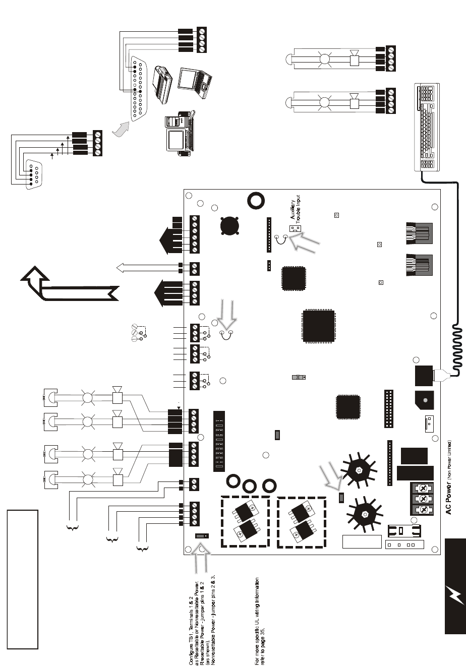
PS2 Keyboard Interface DACT Phone Line Jacks
(Non Power Limited)
DB9F
Resettable Power - 24 VDC filtered, power-limited
(0.500 amps maximum) to smoke detectors (IDC).
Supervision required.
Nonresettable or Resettable Power
Jumper selectable by JP4, 24 VDC filtered,
power-limited (0.500 amps maximum)
Supervision required. Nonresettable
Power suitable for powering annunciators,
Resettable Power suitable for powering
smoke detectors..
NAC #1 & #2
Style Z (Class A)
2.5 amps max. per circuit.
JP6 configured for Class A
using NACKEY card.
(Power Limited)
NAC #1 NAC #2
NAC #1, #2, #3 & #4, Style Y (Class B) (Power Limited)
2.5 amps max. per circuit. JP6 configured
for Class B using NACKEY card.
(See Style Z illustrated near right edge of board).
Contact Ratings:
2.0 amps @ 30 VDC (resistive)
0.5 amps @ 30 VAC (resistive)
Contacts shown below in normal
condition (AC power with no alarm,
trouble or supervisory activity).
A Fail Safe Trouble
relay switches to the
NO position during
trouble conditions and
under loss of all power.
For EDP-listed equipment or
personal computer with FACP
Upload/Download Utility.
50 foot maximum within same room.
Refer to the SLC Wiring
Manual for detailed
information on wiring
addressable devices
for Style 4, 6 and 7.
ACS (EIA-485)
to ACS Annunc.
(power-limited,
supervised)
ELRs 4.7K, ½W
DC Power Outputs (24 VDC)
Supervise with a power supervision relay A77-716B
Battery
Basic System Connections
Notification Appliance Circuits
Notification Appliance Circuits
2 Programmable Relays &
1 Fixed Trouble Relay
EIA-232
to printer or
personal computer
SLC Loop
OR
OR
B
+B
+
B
-
B
-
A
+A
+
A
-
A
-
NO NC C NC NO CNO NC C
Alarm* Trouble
Supervisory*
5 4 3 2 1
9 8 7 6
Green
Black
White
Red
T
XR
C
V
TB8 (option to DB-25)
TB3
TB8
TB8
TB4
5 4 3 2 1
25 24 23 22 21 20 19 18 17 16 15 14
9 8 7 613 12 11 10
CAUTION! HIGH VOLTAGE
NC NO C
+
+
+
+
+
+
120 VAC, 60 HZ, 3.0 amps
220/240 VAC, 50 Hz, 1.5 amps
24 VDC, nonpower-limited
18 Amp Hour maximum
T
XR
C
V
D
T
R
G
N
D
G
N
D
+ 24V -
NON-RST
POWER
+ 24V -
RST
POWER
REMOTE PWR
SUPPLY SYNC NAC 1 CLASS A
NAC 1 & 3 CLASS B
NAC 2 CLASS A
NAC 2 & 4 CLASS B
RELAY 3 RELAY 1
HOT NEUT EARTH
- +
BATTERY
LCD DISPLAY
REMOVE TO
DISABLE GND. FLT.
CUT TO
MONITOR
4XTMF
KISSOFF
PRI. ACTIVE SEC. ACTIVE
SEC. PHONE LINE
PRI. PHONE LINE
4XTMF
MINI DIN
KEYBOARD CONN.
KEYPAD
I/F
RELAY 2
TRANSFORMER 1
TRANSFORMER 2
+ -
B+ A+ A- B- B+ A+ A- B-
1B+ 3B+ 3B- 1B- 2B+ 4B+ 4B- 2B-
NO NC C NO NC C NO NC C B+ A+ B- A- A B
ACS
SHIELDSLCSLC
SLC
SLC
OUT+ IN+ OUT- IN-
TB5 TB6 TB8 TB9 TB10
JP2
JP3
SW1
JP7
JP5
JP6
1
2
3
TB11
J10
J3
J13 J12
J7
J5
J1 J4
J9
J6
J11
CAUTION!
HIGH VOLTAGE
(* )Factory default relay programming
shield
B
+B
-
BA
+A
-
A
TERM
(EIA-485)
to LCD-80F
I
N
+
O
U
T
+
I
N
-
O
U
T
-
+
-
Remove this jumper
to disable the FACP
battery charger when
using external charger.
Transformer 2 Connector
Transformer 1 Connector
Flash Memory Load Enable Switch.
UP is normal position for switch.
DOWN position allows loading of
factory software upgrades.
Cut this jumper to enable
Supervisory relay when
4XTMF module is installed
Cut this jumper to supervise
the 4XTMF module when
installed (see J5 & J6)
To disable ground fault detection,
remove jumper/shunt from JP7
Configure NACs for Claa A or
Class B wiring using NACKEY
card. Factory default is Class B.
NAC #1 NAC #3
NAC
Number
-
++
+
+
B
+B
-
11
B
+B
-
33
NAC #4 NAC #2
B
+B
-
++
++
++
B
+B
-
22
44
TB3 TB4 TB7
2
1
2
1
4
3
+ +
- -
TB1 TB2
JP4
+
-
+
+
D
T
R
Remote Synchronization Output
24 VDC filtered, supervised and power-limited.
0.040 amps maximum, follows NAC1 control circuit.
Requires 4.7kohm End-of-Line resistor.
068'31$
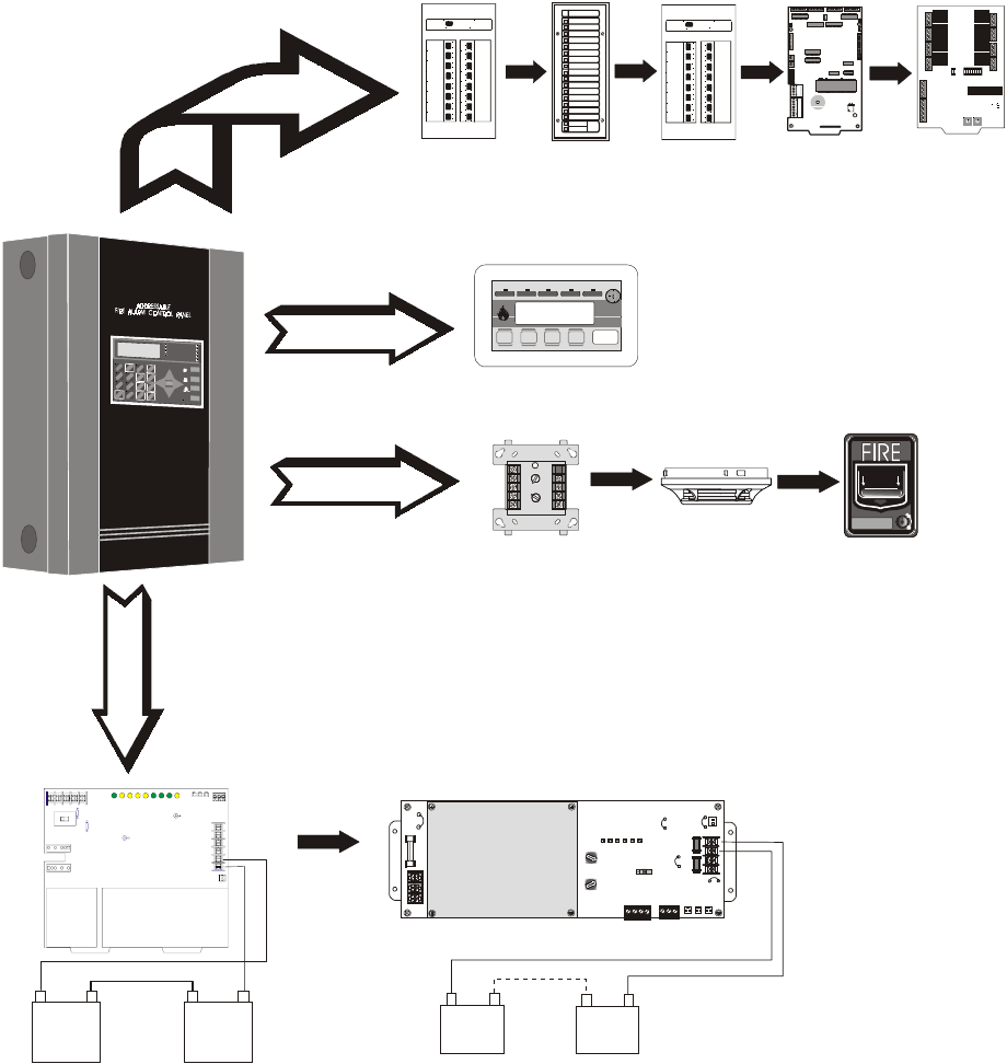
Peripheral Devices and Their Documents:
1
Ack/ Step Silence Rese t
Drill
Hold 2 sec.
-
+
-
+
JP1
JP3
SW1
JP4
TB 3 TB 4
TB 2
ENABLE
AC DELAY
16 HR
DELAY
TENS
ONES
CUT F OR
240VAC
GND FLT
DISABLE
AM-1 ENABLE
ADDR ESS
ON OFF
AM-1
JP5
JP2
F1 F2
J4
J1 J2 J3
F3
TB 1
HOT
OUT
+
BAT
+ OU T
-
BAT
-
EARTHNEUT
15 15
A- B- A+ B+ NC NO C
0
439 2
6
1
578
12
13
15
14
10
11
0
439 26
1
578
12
13
15
14
10
11
LCD-80F
Doc. #51338
AFM-16AF
Doc. #15210
LDM-32F
Doc. #50055
AFM-16ATF &
AFM-32AF
Doc. #15970
ACM-16ATF &
ACM-32ATF
Doc. # 51480
ACM-8RF
Doc. #50362
Addressable Devices and SLC Wiring
Doc. #51309
CHG-120F Charger
Doc. #50888
TERM (EIA-485)
Annunciators
ACS (EIA-485)
Annunciators
SLC Loop
Battery Connector
92udperi.cdr
CHG-75 Charger
Doc. # 51315
3URGXFW'HVFULSWLRQ )HDWXUHVDQG2SWLRQV
068'31$
SECTION 1 Product Description
The Fire•Lite MS-9200UD is a combination FACP (Fire Alarm Control Panel) and
DACT (Digital Alarm Communicator/Transmitter) all on one circuit board. This
compact, cost effective, intelligent addressable control panel has an extensive list of
powerful features. The combination of Fire•Lite’s newer series devices and legacy 300
Series devices, along with the MS-9200UD FACP, offer the latest in fire protection
technology. The power supply and all electronics are contained on a single circuit
board housed in a metal cabinet, providing a complete fire control system for most
applications. Optional modules, which plug into the main circuit board, are available
for special functions. Available accessories include LED, graphic and LCD
annunciators, reverse polarity/city box transmitter, local and remote upload/download
software and remote power expansion.
The integral DACT transmits system status (alarms, troubles, AC loss, etc.) to a Central
Station via the public switched telephone network. It also allows remote and local
programming of the control panel using the PK-Plus Upload/Download utility. In
addition, the control panel may be programmed or interrogated off-site via the public
switched telephone network. Any personal computer with Windows 95 or greater,
and compatible modem with a speed of 14.4 kbps or faster and Fire•Lite Upload/
Download software kit PK-Plus, may serve as a Service Terminal. This allows
download of the entire program or upload of the entire program, history file, walktest
data, current status and system voltages.
Note: Unless otherwise specified, the term MS-9200UD is used in this manual to refer
to both the MS-9200UD and the MS-9200UDE FACPs (Fire Alarm Control Panels).
Inventory
When the MS-9200UD shipment is received, check to make certain that all parts have
been included in the shipment. The MS-9200UD shipment should consist of one of
each of the following:
✓main circuit board with display
✓backbox with door
✓plastic bag containing screws, cables, key, etc.
✓manual
1.1 Features and Options
• Built-in DACT (Digital Alarm Communicator/Transmitter)
• Single addressable SLC loop which meets NFPA Style 4, 6 and 7 requirements
• 198 addressable device capacity (99 detectors and 99 control/relay/monitor
modules)
• 99 software zones
• Onboard NACs (Notification Appliance Circuits) which can be configured as
four Style Y (Class B) or two Style Z (Class A) circuits
• 3.0 amps total power for NACs and 24 VDC auxiliary power outputs expandable
to 6.0 amps
• 3.6 amps total system power (includes battery charger) expandable to 6.6 amps
• Two programmable relay outputs and one fixed trouble relay
• Synchronization output for remote power supply applications
• Built-in Programmer
• Telephone Line Active LEDs
• Communication Confirmation (Kissoff) LED
• Touchtone/Rotary dialing
• Programmable Make/Break Ratio
)HDWXUHVDQG2SWLRQV 3URGXFW'HVFULSWLRQ
068'31$
• EIA-232 Printer/PC interface (variable baud rate)
• 80-character LCD display (backlit)
• Real-time clock/calendar with daylight savings time control
• History file with 1,000 event capacity
• Advanced fire technology features:
✓Automatic drift compensation
✓Maintenance alert
✓Detector sensitivity test capability (NFPA 72 compliant)
✓Automatic device type-code verification
✓Point trouble identification
• Waterflow selection per module point
• Alarm verification selection per detector point
• Walktest, silent or audible
• PAS (Positive Alarm Sequence) and Pre-signal per point (NFPA 72 compliant)
• Silence inhibit timer option per NAC
• Autosilence timer option per NAC
• Continuous, March Time, Temporal or California code for main circuit board
NACs with two-stage capability
• Selectable strobe synchronization per NAC
• Remote Acknowledge, Alarm Silence, Reset and Drill via addressable modules,
AFM annunciators or LCD-80F Remote annunciator
• Auto-program (learn mode) reduces installation time. Reports two devices set to
the same address
• Password and key-protected nonvolatile memory
• User programmable password
• Fully programmable from local keypad or optional keyboard
• Upload/Download (local or remote) of program and data via integral DACT
• SLC operates up to 10,000 ft. (3,000 m) with twisted, shielded wire or 3,000 ft
(900 m) with untwisted, unshielded wire
• Compatible with Fire•Lite’s newer series devices
✓CP350, CP355: addressable Ionization Smoke Detector
✓SD350(T), SD355(T), AD355: addressable Photo Smoke Detector (T= with
Thermal Sensor)
✓H350(R), H355(R), H355HT: Fast Response Heat Detector (R=Rate-of-Rise
option, HT=High Temperature 190RF)
✓D350P(R): addressable Photo Duct Detector (R=alarm relay option)
✓B501BH & B501BHT Sounder Base
✓B224RB Relay Base
✓B224BI Isolator Base
✓MMF-300: Monitor Module
✓MMF-300-10: Monitor Module (10 Input Class B or 5 Input Class A)
✓MDF-300: Dual Monitor Module (uses two consecutive SLC addresses)
✓MMF-301: Miniature Monitor Module
✓MMF-302: 2-wire Detector Module
✓MMF-302-6: 2-wire Detector Module (6 Input Class B or 3 Input Class A)
✓CMF-300: Control Module
✓CMF-300-6: Control Module (6 Output Class B or 3 Output Class A)
✓CRF-300: Relay Module
✓CRF-300-6: Relay Module (6 Form-C relays)
✓BG-12LX: Manual Pull Station
✓I300: Isolator Module
Product Description Specifications
14 MS-9200UD PN 51906:A 12/10/02
• Compatible with legacy Fire•Lite 300 Series devices:
✓CP300: addressable Ionization Smoke Detector
✓SD300(T): addressable Photoelectric Smoke Detector (T= Thermal Sensor)
✓C304: Control Module
✓M300: Monitor Module
✓M301: Miniature Monitor Module
✓M302: 2-wire Detector Module
✓BG-10LX: Manual Pull Station
• Optional 4XTMF module (conventional reverse polarity/city box transmitter)
• Annunciators:
✓ACM Series-LED Zone Annunciators
✓LDM Graphic Annunciator Series
✓LCD-80F Liquid Crystal Display point annunciator
✓ACM-8RF Relay Module
1.2 Specifications
Refer to Illustration on page 10 for terminal locations and connections.
AC Power - TB11
MS-9200UD: 120 VAC, 60 Hz, 3.0 amps
MS-9200UDE: 240 VAC, 50 Hz, 1.5 amps
Wire size: minimum 14 AWG (2.00 mm2) with 600 V insulation
Battery (Lead Acid Only) - J9
Maximum Charging Circuit: Normal Flat Charge - 27.6 VDC @ 0.80 amp
Maximum Battery Charger Capacity: 18 Amp Hour (MS-9200UD cabinet holds
maximum of two 18 Amp Hour batteries. For greater than 25 Amp Hour up to 120
Amp Hour batteries, use the CHG-75 or CHG-120F Battery Charger and BB-55F
Battery Box.
Note: Jumper JP5, on the FACP main circuit board, must be removed to disable the
FACP battery charger when using an external battery charger.
Communication Loop - TB10
24 VDC nominal, 27.6 VDC maximum
Maximum length is 10,000 ft. (3,000 m) total twisted, shielded pair length or 3,000 ft.
(900 m) untwisted, unshielded pair length
Maximum loop current is 400 mA (short circuit) or 100 mA (normal)
Maximum loop resistance is 40 ohms
Supervised and power-limited circuit requires ferrite bead per FCC requirement
Refer to SLC Loop manual for wiring information
Notification Appliance Circuits - TB3 & TB4
Each Terminal Block provides connections for two Style Y (Class B) or one Style Z
(Class A) for a total of Four Style Y (Class B) or two Style Z (Class A) NACs
Style is configured using NACKEY card plugged into JP6 on main board
Power-limited circuitry
Maximum voltage drop in wiring: 2.0 VDC
Nominal operating voltage: 24 VDC
Current-limit: fuseless, electronic, power-limited circuitry
Maximum signaling current per circuit: 2.5 amps (see Figure 1.1 on page 15)
End-of-Line Resistor: 4.7 kΩ, ½ watt (P/N 71252 UL listed) for Style Y (Class B) NAC
Refer to Fire•Lite Device Compatibility Document for listed compatible devices
Two Programmable Relays and One Fixed Trouble Relay - TB5, TB6 & TB7
Contact rating: 2.0 amps @ 30 VDC (resistive), 0.5 amps @ 30 VAC (resistive)
Form-C relays
Refer to Figure 2.6 on page 32 for information on power-limited relay circuit wiring
Specifications Product Description
MS-9200UD PN 51906:A 12/10/02 15
Nonresettable Power (24 VDC Nominal) - TB1, Terminals 1 (+) & 2 (-)
Jumper selectable (JP4) for conversion to resettable power output
Maximum ripple voltage: 10mVRMS
Total DC current available from each output is up to 0.5 amps (see Figure 1.1)
Power-limited circuit requires ferrite bead per FCC requirements
Four-Wire Resettable Smoke Detector Power (24 VDC nominal) - TB3,
Terminals 3 (+) & 4 (-)
Maximum ripple voltage: 10 mVRMS
Up to 0.5 amps is available for powering 4-wire smoke detectors (see Figure 1.1)
Power-limited circuit requires ferrite bead per FCC requirements
Refer to Fire•Lite Device Compatibility Document for listed compatible devices
Remote Sync Output - TB2
Remote power supply synchronization output
24 VDC nominal
Maximum current is 40 mA
End-of-Line Resistor: 4.7KΩ
Output linked to NAC 1 control
Supervised and power-limited circuit requires ferrite bead per FCC requirements
EIA-485 (TERM) or EIA-232 (ACS) - TB8
EIA-485 Terminal Mode annunciator connections: Terminal 1 (Out +), 2 (In +),
3 (Out -), 4 (In -)
EIA-232 PC/Printer applications connections: Terminal 1 (Transmit), 2 (Receive),
3 (Ground)
EIA-485 (ACS) - TB9
ACS annunciator connector, Terminal 1 (+) and Terminal 2 (-), requires ferrite bead
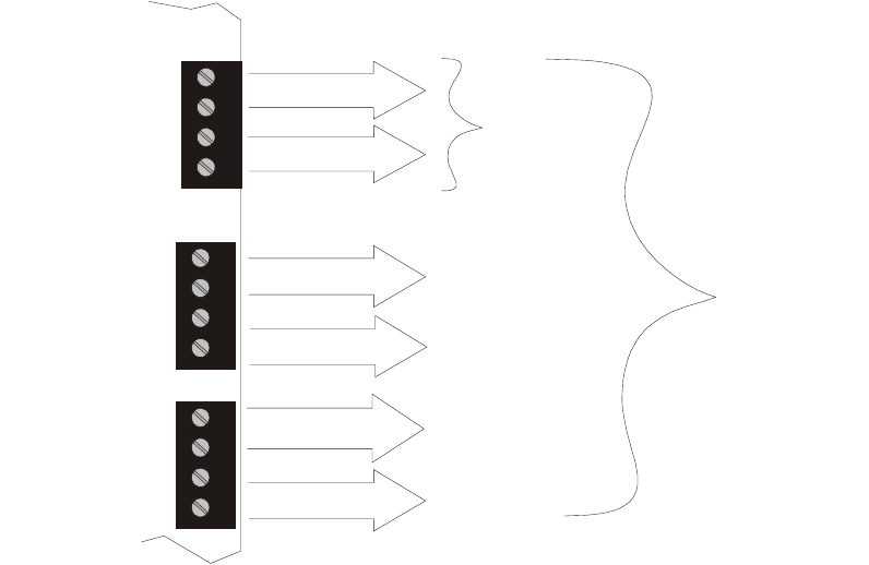
1.2.1 Current Availability
The following figure illustrates the maximum current that is possible for each panel
circuit and the total current available from the FACP with optional second transformer.
0.5 amps max
per circuit
0.5 amps max
per circuit
2.5 amps max
per circuit
2.5 amps max
per circuit
2.5 amps max
per circuit
2.5 amps max
per circuit
Resettable Power
for 4-Wire Smoke Detectors
Nonresettable or
Resettable Power
NAC #1
NAC #3
NAC #2
NAC #4
Standby
1 amp max
per panel
Alarm
6 amps max
per panel
1
2
3
4
1
2
3
4
1
2
3
4
TB3
TB4
TB1
Figure 1.1 Current Availability
powerdist9200ud.cdr
Refer to the battery calculations section for additional information.
Note: If NACs are
configured as two Style Z
(Class A) circuits, each
circuit can handle 2.5
amps maximum.
6.0 amps with optional second
XRM-24(E) transformer.
3.0 amps max. with only
standard transformer installed.

3URGXFW'HVFULSWLRQ &RQWUROVDQG,QGLFDWRUV
068'31$
1.3 Controls and Indicators
LCD Display
The FACP uses an 80-character
(4 lines X 20 characters) high
viewing angle LCD display. The
display includes a long life LED
backlight that remains illuminated. If
AC power is lost and the system is
not in alarm, the LED backlight will turn off to conserve batteries.
LED Indicators
LED indicators are provided to annunciate the following conditions:
• AC Power (green)
• Fire Alarm (red)
• Supervisory (yellow)
• Trouble (yellow)
• Maintenance/presignal (yellow)
• Alarm Silenced signals (yellow)
• Disabled (yellow)
• Battery fault (yellow)
• Ground fault (yellow)
Key Panel
Mounted on the main circuit board, the key panel includes a window for the LCD
display and LED indicators as listed above. The key panel, which is visible with the
cabinet door closed, has 25 keys, including a 16 key alpha-numeric pad similar to a
telephone keypad.
Function keys:
• Acknowledge/Step
• Alarm Silence
• Drill
• Reset (lamp test)
Service/program keys:
• Keys labeled 1 to 9
• * key
• # key
• 0 (recall) key
•1st Event key
• Clear key
• Escape key
• Mode key
• Four cursor keys (up, down, left and right)
• Enter key
Local Piezo Sounder
A piezo sounder provides separate and distinct pulse rates for alarm, trouble and
supervisory conditions.
FIRE-LITE ALARMS INC
SYSTEM ALL NORMAL
10:00A 012102
1
4
*
2
5
0
3
6
#
1
st
EVENT
ABC DEF
GHI JKL MNO
PRS TUV WXY
QZ
-/.
CLR
78 9
ESC
ENTER
RECALL
ACK/STEP
ALARM
SILENCE
DRILL
HOLD 2 SEC
RESET
MODE
MAINTENANCE
ALARM
SILENCED
DISABLED
BATTERY
GROUND
SUPERVISORY
TROUBLE
AC POWER
FIRE ALARM
Figure 1.2 Membrane/Display Panel
9600kypd.cdr

&LUFXLWV 3URGXFW'HVFULSWLRQ
068'31$
1.4 Circuits
SLC Communication Loop
One SLC loop is provided standard on the FACP main circuit board. The SLC loop,
configurable for NFPA Style 4, 6 or 7, provides communication to addressable
detectors, monitor (initiating device) and control (output device) modules. Refer to the
SLC Wiring manual for information on wiring devices.
Output Circuits
The following output circuits are available on the FACP:
• 24 VDC Resettable (smoke detector power) output - 0.5 amps maximum
• 24 VDC Nonresettable or Resettable power output - 0.5 amps maximum
• 24 VDC Battery Charger (up to 18 AH batteries)
NAC (Notification Appliance Circuits)
NACs configurable for four Style Y (Class B) or two Style Z (Class A) using NACKEY
card in JP6, are provided with various programmable features.
Relays
One fixed and two fully programmable Form-C dry contact relays are provided. The
fixed fail-safe relay monitors system trouble and the two programmable relays are
factory default programmed for system alarm and system supervisory. Contacts are
rated 2.0 amps @ 30 VDC (resistive) and 0.5 amps @ 30 VAC (resistive). The
programmable relays can be programmed for the following operations:
• fire alarm
• trouble
• supervisory
• supervisory auto-resettable
• DACT communication failure
• process monitor
• process monitor auto-resettable
• hazard alert
• medical alert
•AC loss
1.5 Digital Alarm Communicator/Transmitter
Two modular phone jacks allow easy connection to telephone lines. Modular jacks are
labeled PH1 for Primary Phone Line and PH2 for Secondary Phone Line. Two
telephone line active red LEDs are provided as well as a green Kissoff LED. The
integral digital communicator provides the following functions:
• Line Seizure: takes control of the phone lines disconnecting any premises phones
• Off/On Hook: performs on and off-hook status to the phone lines
• Listen for dial tone: 440 Hz tone typical in most networks
• Dialing the Central Station(s) number: default is Touch-Tone, programmable to
rotary
• For tone burst or touchtone type formats: discern proper Ack and Kissoff tone(s).
The frequency and time duration of the tone(s) varies with the transmission
format. The control panel will adjust accordingly.
• Communicate in the following formats:
✓12 Tone Burst types: 20 pps
(3+1, 4+1, 4+2, 3+1 Exp., 4+1 Exp., 4+2 Exp.)
✓3 Touchtone Types
4+1 Ademco Express
4+2 Ademco Express
Ademco Contact ID
Reference
Manual
Product Description Components
18 MS-9200UD PN 51906:A 12/10/02
1.6 Components
Main Circuit Board
The main circuit board contains the system’s CPU, power supply, other primary
components and wiring interface connectors. The 4XTMF option module plugs in and
is mounted to the main circuit board. The circuit board is delivered in the MS-9200UD
kit and must be mounted to the backbox (refer to circuit board illustration on page 10).
Cabinet
The MS-9200UD cabinet is red with a navy blue front overlay.
The backbox provides space for two batteries (up to 18 Amp
Hour). Ample knockouts are provided for system wiring. Also
available is an optional dress panel, which mounts to the inside
of the cabinet (required by ULC for Canadian installations).
The dress panel must be installed to meet FM requirements.
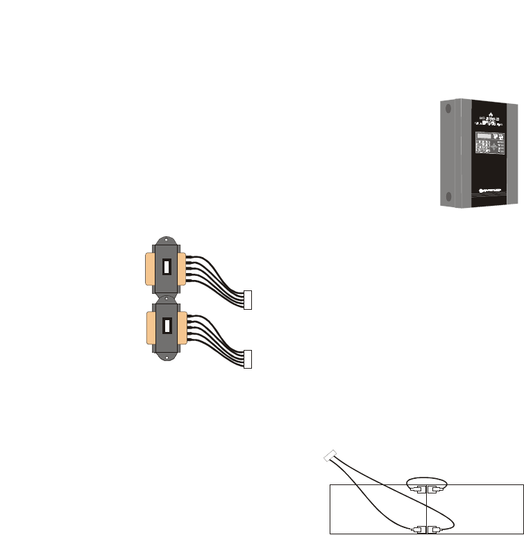
Transformer Assembly
One 100VA transformer is provided standard
with the panel (3.6 amps maximum). An
optional 100 VA transformer XRM-24
(XRM-24E for the MS-9200UDE) is available
to provide maximum system and accessory
power (6.6 amp total).
Batteries
The MS-9200UD cabinet provides space for
two batteries (up to 18 Amp Hour). Batteries
larger than 18 Amp Hour require an external
charger such as the CHG-75 or CHG-120F
and a UL listed battery box such as the BB-
55F. Batteries must be ordered separately.
1.6.1 Intelligent Addressable Detectors: Newer Series
Intelligent, addressable detectors provide information to the control panel on an SLC
Signaling Line Circuit (refer to the SLC Wiring Manual for detailed information on
device installation, wiring and operation). This allows the control panel to continually
process the information to determine the status (alarm, trouble, maintenance or normal)
of each detector. Each detector responds to an SLC address that is set in the detector
head using built-in rotary decimal switches. Note that a blinking LED on an intelligent
detector indicates communication between the detector and the control panel. Refer to
the Fire•Lite Device Compatibility Document for a list of approved detectors.
Smoke Detectors (Photoelectric)
The SD350 is an intelligent, addressable low profile photoelectric smoke detector
which provides smoke sensing technology. The SD350T includes a 135o fixed thermal
sensor.
Smoke Detector (Ionization)
The CP350 is an intelligent, addressable low profile ionization smoke detector which
measures the level of combustion products in its chamber using the ‘ionization
principle.’
See Page
ms9200UD.cdr
Standard
XRM-24(E)
Optional
XRM-24(E)
9200xfor.cdr
-
-
+
+
Battery Cable P/N 75287
9200batt.cdr

&RPSRQHQWV 3URGXFW'HVFULSWLRQ
068'31$
Smoke Detector (Duct)
The D350P is an intelligent, addressable photoelectric duct smoke detector. The
D350RP includes an alarm relay.
Heat Detectors
The H350 is an intelligent heat detector with a thermistor sensing circuit for fast
response, designed to provide open area protection with 50 foot (15 m) spacing
capability. The H350R incorporates a thermal Rate-of-Rise circuit of 15RF (9.4RC).
Detector Bases
The B501BH is a standard sounder base and the B501BHT is a temporal tone sounder
base for intelligent, addressable smoke detectors.
The B224RB is a relay base with one Form-C relay for intelligent, addressable smoke
detectors. It may be used to control auxiliary functions.
The B224BI is an isolator base for intelligent, addressable smoke detectors. It
functions similar to the I300 isolator module which allows loops to operate under fault
conditions and automatically restore when the fault is removed.
1.6.2 Intelligent Addressable Modules: Newer Series
The newer series of Control Modules and Monitor Modules provide an interface
between the control panel and conventional notification and initiating devices. Each
module can be set to respond to an address with built-in rotary switches. A blinking
LED on a monitor module indicates communication between the module and the
control panel. These devices can also be used when installed on older systems. Refer
to the Fire•Lite Device Compatibility Document for a list of approved notification and
initiating devices.
Monitor Modules
The MMF-300, MMF-300-10, MDF-300, MMF-302 and MMF-302-6 are addressable
monitor modules for monitoring conventional initiating devices. The MMF-300 is used
for normally open contact alarm initiating devices, such as manual pull stations, four-
wire smoke detectors, heat detectors, waterflow, security contacts and supervisory
devices. The MMF-300-10 functions the same as the MMF-300 except it provides 10
Class B or 5 Class A inputs. The MDF-300 is a dual monitor module (Class B only)
which occupies two consecutive SLC addresses, with each module functionally the
same as the MMF-300. The MMF-302 is used primarily for two-wire smokes detectors
in addition to normally open contact devices. The MMF-302-6 functions the same as
the MMF-302 except it provides 6 Class B or 3 Class A inputs. The supervised IDCs
(Initiating Device Circuits) can be wired to the modules as NFPA Style B (Class B) or
Style D (Class A) circuits. The modules are supplied with a thermoplastic cover for
mounting to a 4-inch mounting box.
Monitor Module (miniature)
The addressable MMF-301 module is functionally similar to an MMF-300 but offered
in a smaller package for mounting directly in the electrical box of the monitored device.
Control Module
The CMF-300 and CMF-300-6 are an addressable Control Modules used to connect
NACs (Notification Appliance Circuits) to power and supervise compatible, UL-listed
notification appliances. The CMF-300 provides one Class B or Class A output while
the CMF-300-6 provides 6 Class B or 3 Class A outputs. The NACs can be wired to the
module as supervised NFPA Style Y (Class B) or Style Z (Class A) circuits. The
modules are supplied with a thermoplastic cover for mounting to a 4-inch square
mounting box.
Reference
Manual
3URGXFW'HVFULSWLRQ &RPSRQHQWV
068'31$
Relay Module
The CRF-300 and CRF-300-6 are a Control Relay Modules which are functionally
similar to the CMF-300 but used as Form-C relay modules. The CRF-300 provides one
Form-C relay while the CRF-300-6 provides six Form-C relays.
Isolator Module
The I300 loop isolator module is an automatic switch which opens the circuit voltage to
the SLC loop branch(es) whenever a wire-to-wire short circuit is detected on that loop.
The remainder of the communications loop leading up to the I300 will continue to
operate, unaffected by the short. The isolator module is bidirectional, meaning that it
can detect a fault condition between the input SLC terminals or output SLC terminals.
The I300 is required to meet NFPA Style 7 requirements.
Detector Annunciator
The RA400Z is a remote single LED annunciator that can be wired directly to an
addressable detector for annunciation of that detector’s alarm status.
Manual Pull Station
The BG-12LX is an addressable manual pull station featuring a key-lock reset. The
pull station responds to an address set by the installer using the built-in rotary decimal
switches on the pull station. The manual pull station includes the Fire•Lite key.
1.6.3 300 Series Intelligent Addressable Devices
Fire•Lite’s 300 Series Intelligent Addressable Devices are fully compatible with the
MS-9200UD FACP. The address of 300 Series devices cannot be set above 99.
Compatible devices include:
• SD300 Photoelectric Detector
• SD300T Photoelectric Detector with Thermal Sensor
• CP300 Ionization Detector
• M300 Monitor Module
• M301 Miniature Monitor Module
• M302 2-wire Monitor Module
• C304 Control/Relay Module
• BG-10LX Manual Pull Station
1.6.4 Addressable Device Accessories
End-of-Line Resistor Assembly Fire•Lite P/N R-47K
The 47 kΩ End-of-Line Resistor assembly (P/N: R-47K) is used to supervise the
MMF-300, MDF-300, MMF-301 and CMF-300 module circuits. The 3.9 kΩ End-of-
Line Resistor assembly is used to supervise the MMF-302 module circuit. The resistors
are included with each module.
Power Supervision Relay
The UL listed End-of-Line power supervision relay is used to supervise the power to 4-
wire smoke detectors and notification appliances.
N-ELR Mounting Plate
The N-ELR is a single End-of-Line resistor plate. An ELR, which is supplied with each
module and fire alarm control panel, is mounted to the ELR plate. Resistors mounted to
the N-ELR plate can be used for the supervision of a monitor and control module
circuit.

Optional Modules Product Description
MS-9200UD PN 51906:A 12/10/02 21
1.7 Optional Modules
The MS-9200UD main circuit board includes option module connectors for the
following module:
4XTMF Transmitter Module
The 4XTMF provides a supervised output for local energy municipal box transmitter,
alarm and trouble reverse polarity. It includes a disable switch and disable trouble
LED. A jumper on the module is used to select an option which allows the reverse
polarity circuit to open with a system trouble condition if no alarm condition exists.
The module plugs into connectors J5 and J6 which are located near the right edge the
main circuit board. When the 4XTMF module is installed, Jumper JP3, on the main
circuit board, must be cut to allow supervision of the module.
1.8 Accessories
1.8.1 PK-Plus Programming Utility
The PK-Plus Programming Utility can be used to program an MS-9200UD directly
from most IBM compatible computers, including laptops and portables, equipped with
a serial port. MS-9200UD program files can also be created and stored on the PC and
then downloaded to the control panel. The PK-Plus Kit includes the MS-9200UD
Windows-based Programming Utility software on CD-ROM with on-line help file. A
serial cable (P/N: PRT/PK-CABLE), which must be purchased separately, is required
for connection of the PC to the RS-232 (PC/Printer) terminals at TB8 of the MS-
9200UD main circuit board. Refer to the illustration on page 10 and the section titled
"Printer/PC" on page 40, for the location and connections to this terminal.
1.8.2 Dress Panel
An optional dress panel is available for the MS-9200UD. The dress panel restricts
access to the system wiring while allowing access to the key panel.
CAUTION: HIGH VOLTAGE UNDER PANEL
!! WARNING !!
SEVERAL DIFFERENT SOURCES OF POWER
CAN BE CONNECTED TO THIS CONTROL UNIT
DISCONNECT ALL SOURCES O F POWER BEFORE SERVICING
dp9600.cdr

3URGXFW'HVFULSWLRQ $FFHVVRULHV
068'31$
1.8.3 Battery Box
BB-26
The BB-26 battery box may be used to house up to two 26 AH batteries and the
CHG-75 Battery Charger. The battery box is red and is provided with knockouts.
BB-55F
The BB-55F battery box may be used to house two 25 AH batteries, two 60 AH
batteries or one 100 AH battery. When the CHG-120F is mounted in the BB-55F, two
25 AH or one 60 AH battery may also be housed in the battery box.
1.8.4 Battery Charger
1.8.4.1 CHG-75 Battery Charger
7KH&+*LVFDSDEOHRIFKDUJLQJXSWR$+OHDGDFLGEDWWHULHVZLWKWKH06
8')$&37KH)$&3EDWWHU\FKDUJHUPXVWEHGLVDEOHGE\UHPRYLQJMXPSHU
-3ZKHQXVLQJWKH&+*7KHFKDUJHUDQGXSWR$+EDWWHULHVFDQEHKRXVHG
LQWKH)LUH/LWH%%EDWWHU\ER[/DUJHUEDWWHULHVDQGWKHFKDUJHUFDQEHKRXVHG
LQWKH)LUH/LWH%%)EDWWHU\ER[ZKLFKFDQEHPRXQWHGXSWRIHHWDZD\IURP
WKHFRQWUROSDQHO5HIHUWRWKH&+*0DQXDOIRUDGGLWLRQDOLQIRUPDWLRQ
1.8.4.2 CHG-120F Battery Charger
7KH&+*)LVFDSDEOHRIFKDUJLQJXSWR$+OHDGDFLGEDWWHULHVZLWKWKH
068')$&37KH)$&3EDWWHU\FKDUJHUPXVWEHGLVDEOHGE\UHPRYLQJ
MXPSHU-3ZKHQXVLQJWKH&+*)7KHEDWWHULHVDQGFKDUJHUFDQEHKRXVHGLQ
WKH)LUH/LWH%%)EDWWHU\ER[ZKLFKFDQEHPRXQWHGXSWRIHHWDZD\IURPWKH
FRQWUROSDQHO1RWHWKDWZKHQXVLQJWKH%%)IRUKRXVLQJWKHFKDUJHUDQG
EDWWHULHVJUHDWHUWKDQ$+PXOWLSOH%%)VDUHUHTXLUHG5HIHUWRWKH
&+*)0DQXDOIRUDGGLWLRQDOLQIRUPDWLRQ
Reference
Manual

$FFHVVRULHV 3URGXFW'HVFULSWLRQ
068'31$
1.8.5 Annunciators
ACM Series LED Zone Type Annunciators
The ACM Series Annunciators remotely display alarm and trouble status as well as
system status. In addition, they can provide remote Acknowledge, Silence, Reset and
Drill functions. For more detailed information, refer to the appropriate annunciator
manual. Following is a list of annunciators which can be used with the MS-9200UD.
•ACM-16ATF Annunciator Control Module annunciates 16 zones with 16 red
alarm LEDs and 16 yellow trouble LEDs. In addition, it has a System Trouble
LED, an On Line/Power LED and a local piezo sounder. It also has switches for
FACP Acknowledge, Silence, Reset and Drill. It has rotary address switches and
will accept up to three AEM-16ATF Expanders.
•AEM-16ATF Annunciator Expander Module annunciates 16 zones with 16 red
alarm LEDs and 16 yellow trouble LEDs
•AFM-16ATF Annunciator Fixed Module annunciates 16 zones with 16 red
alarm LEDs and 16 yellow trouble LEDs. In addition, it has a System Trouble
LED, an On Line/Power LED and a local piezo sounder. It also has switches for
FACP Acknowledge, Silence, Reset and Drill. It is fixed at address ‘1.’
•ACM-32AF Annunciator Control Module annunciates 32 alarm zones with 32
red LEDs. In addition, it has a System Trouble LED, an On Line/Power LED
and a local piezo sounder. It also has a switch for local piezo silence. It has
rotary address switches and will accept one AEM-32AF Expander.
•AEM-32AF Annunciator Expander Module annunciates 32 alarm zones with 32
red LEDs
•AFM-16AF Annunciator Fixed Module annunciates 16 alarm zones with 16 red
alarm LEDs. In addition, it has a System Trouble LED, an On Line/Power LED
and a local piezo sounder. It also has a switch for local piezo silence. It is fixed
at address ‘1.’
•AFM-32AF Annunciator Fixed Module annunciates 32 alarm zones with 32 red
LEDs.
Reference
Manual

3URGXFW'HVFULSWLRQ *HWWLQJ6WDUWHG
068'31$
LCD-80F Remote Fire Annunciator
The LCD-80F annunciator is a compact 80-character backlit LCD remote fire
annunciator that is capable of displaying English language text. It mimics the display
on the control panel and will annunciate device type, point alarm, trouble or
supervisory condition, zone assignment plus any custom alpha labels programmed into
the FACP. The annunciator also provides system status LEDs to display AC Power,
Alarm, Trouble, Supervisory and Alarm Silenced conditions. Additionally, the LCD-
80F is capable of remotely performing critical system functions such as Acknowledge,
Silence, Reset and Drill.
Communications between the control panel and the annunciator is accomplished over a
serial interface employing the EIA-485 communication standard. Up to 32 LCD-80F
annunciators may be connected to the EIA-485 circuit. The annunciators may be
powered from the host FACP or a remote UL listed filtered power supply such as the
Fire•Lite FCPS Series. For more detailed information, refer to the LCD-80F manual.
LDM Series Lamp Driver Modules (Graphic Annunciator)
The LDM Series Lamp Driver Modules, which consist of the LDM-32F master and
LDM-E32F expander modules, are used to provide an interface to a custom graphic
LED annunciator. The master module provides power and control for a maximum of
three expander modules. The LDM-32F and LDM-E32F have output connectors which
are used to drive lamps or LEDs and input connectors which are used for remote switch
functions. Refer to the LDM Series Lamp Driver Modules manual for a complete
description.
1.9 Getting Started
The following is a brief summary of the minimal steps involved in bringing an MS-
9200UD on-line:
• Install Backbox and Main Circuit Board (refer to "Mounting Backbox" on page
27)
• Address and Install Intelligent Devices (refer to the SLC Wiring Manual)
• Enter Autoprogramming (refer to "Autoprogram" on page 49)
• Resolve Programming Conflicts
• Go to Point Program to Enter Specific Data (refer to "Point Program" on page
50). Use the right and left arrow keys to navigate between devices.
Reference
Manual
Reference
Manual
7HOHSKRQH5HTXLUHPHQWVDQG:DUQLQJV 3URGXFW'HVFULSWLRQ
068'31$
7HOHSKRQH5HTXLUHPHQWVDQG:DUQLQJV
7HOHSKRQH&LUFXLWU\
5LQJHU(TXLYDOHQFH1XPEHU5(1 %
$&,PSHGDQFH0HJD2KP
&RPSOLHVZLWK)&&3DUW
0DWHVZLWK5-;0DOH&RQQHFWRU
6XSHUYLVLRQ7KUHVKROGOHVVWKDQYROWVIRUPLQXWHV
7KH5(1LVXVHGWRGHWHUPLQHWKHTXDQWLW\RIGHYLFHVZKLFKPD\EHFRQQHFWHGWRWKH
WHOHSKRQHOLQH([FHVVLYH5(1VRQWKHWHOHSKRQHOLQHPD\UHVXOWLQWKHGHYLFHVQRW
ULQJLQJLQUHVSRQVHWRDQLQFRPLQJFDOO,QPRVWEXWQRWDOODUHDVWKHVXPRIWKH5(1V
VKRXOGQRWH[FHHGILYH7REHFHUWDLQRIWKHQXPEHURIGHYLFHVWKDWPD\EHFRQ
QHFWHGWRWKHOLQHDVGHWHUPLQHGE\WKHWRWDO5(1VFRQWDFWWKHWHOHSKRQHFRPSDQ\WR
GHWHUPLQHWKHPD[LPXP5(1IRUWKHFDOOLQJDUHD
'LJLWDO&RPPXQLFDWRU
%HIRUHFRQQHFWLQJWKHFRQWUROSDQHOWRWKHSXEOLFVZLWFKHGWHOHSKRQHQHWZRUNWKH
LQVWDOODWLRQRIWZR5-;MDFNVLVQHFHVVDU\,IWURXEOHLVH[SHULHQFHGZLWKWKLVHTXLS
PHQWIRUUHSDLURUZDUUDQW\LQIRUPDWLRQSOHDVHFRQWDFW
0DQXIDFWXUHU )LUH/LWH$ODUPV,QF
2QH)LUH/LWH3ODFH
1RUWKIRUG&7
3URGXFW0RGHO1XPEHU068'
)&&5HJLVWUDWLRQ1XPEHU86:$/%8'
5LQJHU(TXLYDOHQFH%
1RWH7KLVHTXLSPHQWFRPSOLHVZLWK3DUWRIWKH)&&UXOHVDQGWKH
UHTXLUHPHQWVDGRSWHGE\WKH$&7$2QWKHLQVLGHRIWKH)$&3GRRULVD
ODEHOWKDWFRQWDLQVDPRQJRWKHULQIRUPDWLRQDSURGXFWLGHQWLILHULQWKH
IRUPDW86$$$(47;;;;,IUHTXHVWHGWKLVQXPEHUPXVWEH
SURYLGHGWRWKHWHOHSKRQHFRPSDQ\
Alarm dialing equipment must be able to seize the telephone line and place a call in an
emergency situation. It must be able to do this even if other equipment (telephone,
answering system, computer modem, etc.) already has the telephone line in use. To do
so, alarm dialing equipment must be connected to a properly installed RJ31X jack that
is electrically in series with and ahead of all other equipment attached to the same
telephone line. If there are any questions concerning these instructions, consult the
telephone company or a qualified installer about installing the RJ31X jack and alarm
dialing equipment. Refer to "Digital Communicator" on page 36 for an illustration of
the proper installation of this equipment.
3URGXFW'HVFULSWLRQ 7HOHSKRQH5HTXLUHPHQWVDQG:DUQLQJV
068'31$
7HOHSKRQH&RPSDQ\5LJKWVDQG:DUQLQJV
7KHWHOHSKRQHFRPSDQ\XQGHUFHUWDLQFLUFXPVWDQFHVPD\WHPSRUDULO\GLVFRQWLQXH
VHUYLFHVDQGRUPDNHFKDQJHVLQLWVIDFLOLWLHVVHUYLFHVHTXLSPHQWRUSURFHGXUHVZKLFK
PD\DIIHFWWKHRSHUDWLRQRIWKLVFRQWUROSDQHO+RZHYHUWKHWHOHSKRQHFRPSDQ\LV
UHTXLUHGWRJLYHDGYDQFHQRWLFHRIVXFKFKDQJHVRULQWHUUXSWLRQV
,IWKHFRQWUROSDQHOFDXVHVKDUPWRWKHWHOHSKRQHQHWZRUNWKHWHOHSKRQHFRPSDQ\
UHVHUYHVWKHULJKWWRWHPSRUDULO\GLVFRQWLQXHVHUYLFH$GYDQFHQRWLILFDWLRQZLOOEH
SURYLGHGH[FHSWLQFDVHVZKHQDGYDQFHQRWLFHLVQRWSUDFWLFDO,QVXFKFDVHVQRWLILFD
WLRQZLOOEHSURYLGHGDVVRRQDVSRVVLEOH7KHRSSRUWXQLW\ZLOOEHJLYHQWRFRUUHFWDQ\
SUREOHPVDQGWRILOHDFRPSODLQWZLWKWKH)&&LI\RXEHOLHYHLWLVQHFHVVDU\
'2127&211(&77+,6352'8&772&2,17(/(3+21(*5281'67$5725
3$57</,1(6(59,&(6
:KHQWKHFRQWUROSDQHODFWLYDWHVSUHPLVHSKRQHVZLOOEHGLVFRQQHFWHG
7ZRVHSDUDWHSKRQHOLQHVDUHUHTXLUHG'RQRWFRQQHFWERWKWHOHSKRQHLQWHUIDFHVWRWKH
VDPHWHOHSKRQHOLQH
7KHFRQWUROSDQHOPXVWEHFRQQHFWHGWRWKHSXEOLFVZLWFKHGWHOHSKRQHQHWZRUN
XSVWUHDPDVILUVWGHYLFHRIDQ\SULYDWHWHOHSKRQHV\VWHPDWWKHSURWHFWHGSUHPLVHV
$SOXJDQGMDFNXVHGWRFRQQHFWWKLVHTXLSPHQWWRWKHSUHPLVHVZLULQJDQGWHOHSKRQH
QHWZRUNPXVWFRPSO\ZLWKWKHDSSOLFDEOH)&&3DUWUXOHVDQGUHTXLUHPHQWVDGRSWHG
E\$&7$7KLVHTXLSPHQWLVGHVLJQHGWREHFRQQHFWHGWRWKHWHOHSKRQHQHWZRUNRUSUH
PLVHVZLULQJXVLQJDFRPSOLDQW5-;PDOHPRGXODUSOXJDQGFRPSDWLEOHPRGXODU
MDFNWKDWLVDOVRFRPSOLDQW
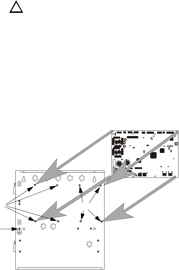
0RXQWLQJ%DFNER[ ,QVWDOODWLRQ
068'31$
SECTION 2 Installation
The cabinet may be either semi-flush or surface mounted. The cabinet mounts using
two key slots and two 0.250” (6.35 mm) diameter holes located in the backbox. The
key slots are located at the top of the backbox and the two securing holes at the bottom.
Carefully unpack the system and check for shipping damage. Mount the cabinet in a
clean, dry, vibration-free area where extreme temperatures are not encountered. The
area should be readily accessible with sufficient room to easily install and maintain the
panel. Locate the top of the cabinet approximately 5 feet (1.5 m) above the floor with
the hinge mounting on the left. Determine the number of conductors required for the
devices to be installed. Sufficient knockouts are provided for wiring convenience.
Select the appropriate knockout(s) and pull the conductors into the box. All wiring
should be in accordance with the National and/or Local codes for fire alarm systems.
2.1 Mounting Backbox
The circuit board contains static-sensitive components. Always ground yourself with a
proper wrist strap before handling any boards so that static charges are removed from
the body. Use static suppressive packaging to protect electronic assemblies.
✓Mark and predrill holes in the wall for the top two keyhole mounting bolts
using the dimensions illustrated in Figure 2.3 on page 29
✓Install two upper fasteners in the wall with the screw heads protruding
✓Using upper ‘keyholes,’ place backbox over the two screws, level and secure
✓Mark and drill the lower two holes
✓Install remaining fasteners and tighten
✓Screw supplied standoffs onto mounting studs in locations indicated below
✓When the location is dry and free of construction dust, install the main circuit
board by aligning the 8 mounting holes in the circuit board with the 8
mounting standoffs in the backbox as illustrated below
✓Secure the circuit board to the standoffs with the supplied screws as indicated
in following figure
!
See Page
+ 24V -
NON-RST
POWER
+ 24V -
RST
POWER
REMOTE PWR
SUPPLY SYNCNAC 1 CLASS A
NAC 1 & 3 CLASS B
NAC 2 CLASS A
NAC 2 & 4 CLASS B
RELAY 3 RELAY 1
HOT NEU T EA RTH
- +
BATTERY
LCD DISPLAY
REMOVE TO
DISABLE G ND. FLT.
CU T TO
MONITOR
4XTMF
KISSOFF
PRI. ACT IVE SEC. ACTIVE
SEC. PH ONE LIN EPRI. PHO NE LINE
4XTMF
MINI DIN
KEYB OAR D CO NN .
KEYPAD
I/F
RELAY 2
TRANSFORME R 1
TRANSFOR MER 2
+ - B+ A+ A- B- B+ A+ A- B-
1B+ 3B+ 3B- 1B- 2B+ 4B+ 4B- 2B-
NO NC C NO NC C NO NC C B+ A+ B- A- A B
ACS
SHIELDSLC
SLCSLCSLC
OU T+ IN+ OUT- IN-
TB1 TB2 TB3 TB4 TB 7 TB5 TB6 TB8 TB9 TB10
JP 4
JP 1
JP 2
JP 3
SW1
JP 7
JP 5
JP 6
1
2
3
1 2 3
TB11
J10
J3
J13 J12
J7
J5
J1 J4
J9
J6
J11
CAUTION!
HIG H VOLTAG E
Figure 2.1 MS-9200UD Main Circuit Board Installation
MS-9200UD Backbox
MS-9200UD Main Circuit Board
mounting studs mounting studs
92udbdmn.cdr
grounding stud
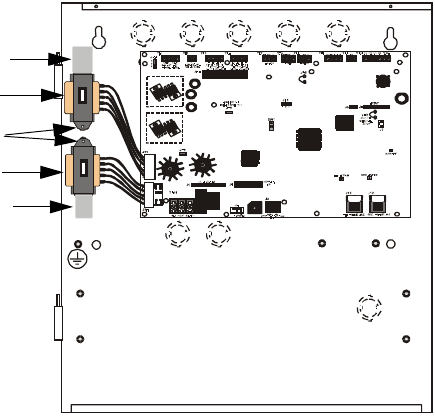
,QVWDOODWLRQ 0RXQWLQJ7UDQVIRUPHU
068'31$
2.2 Mounting Transformer
One XRM-24(E) transformer is supplied standard with the control panel. An optional
second XRM-24(E) transformer can be ordered and installed to provide maximum
system power. Install the transformers in the locations indicated in the following
illustration.
1. Mount the Standard XRM-24 Transformer in the lower transformer mounting
location by positioning the wiring connector to the right as illustrated in the
following figure.
2. Slide the bottom transformer mounting bracket into the embossed mounting
pocket as illustrated.
3. Secure the top transformer mounting bracket to the mounting stud with the
supplied screw.
4. If the optional second XRM-24 Transformer is being installed, mount it in the
upper transformer mounting location by positioning the wiring connector to the
right as illustrated in the following figure.
5. Slide the top transformer mounting bracket into the embossed mounting pocket
as illustrated.
6. Secure the bottom transformer mounting bracket to the mounting stud with the
supplied screw.
7. Connect the Standard XRM-24 Transformer plug to Transformer 1 Connector
J10 on the FACP main circuit board
8. Connect the Optional XRM-24 Transformer plug to Transformer 2 Connector J11
on the FACP main circuit board.
9. Complete the installation as detailed in the following sections.
Figure 2.2 Transformer Mounting
Standard XRM-24 Transformer
Optional XRM-24 Transformer
Mounting Pocket
Mounting Pocket
Mounting Studs
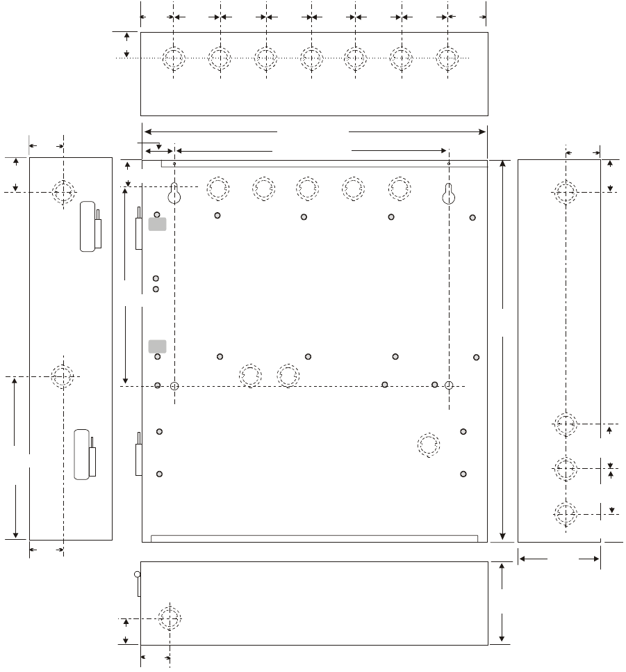
Mounting Transformer Installation
MS-9200UD PN 51906:A 12/10/02 29
1.75“
4.45 cm
4.128 cm 4.128 cm
1.625“ (4.128 cm)
1.625“
15.5“ (39.37 cm)
47.0cm
18.5“
1.63“
4.128 cm
1.50“ (3.81 cm)
1.75“
4.45 cm
12.07 cm
4.75“
12.00“ (30.48 cm)
1.62“ (4.11 cm)
1.63“
4.1 cm
1.62“ 4.1cm
1.62“
1.75“
2.00“
2.00“
2.00“2.00“
2.00“
5.1 cm
2.00“
10.0“
25.4 cm
4.75“
12.07 cm
17.35 cm
6.83“
4.1cm
1.583“
4.45cm
1.75“
4.45cm
1.75“
1.453“ (3.69 cm)
Figure 2.3 MS-9200UD Cabinet Mounting
9600encl.cdr
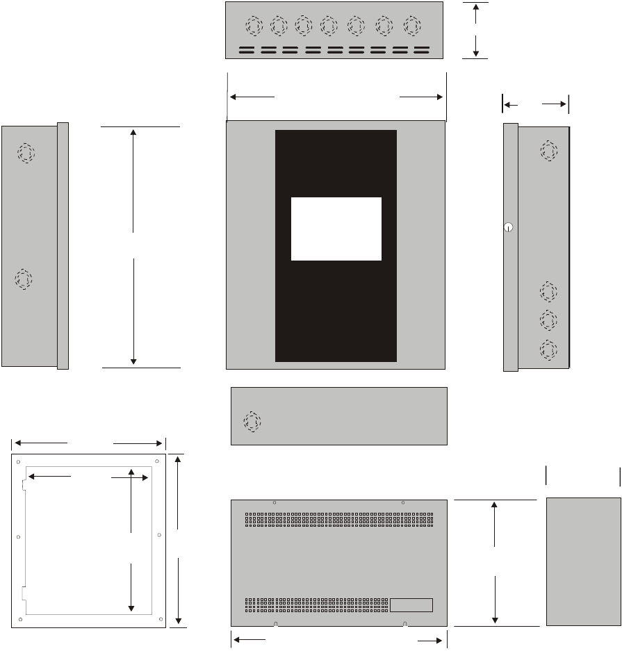
Installation Mounting Transformer
30 MS-9200UD PN 51906:A 12/10/02
Top
Left Side Right Side
Bottom
Depth = 4.75"
(12.07 cm)
Battery Box = 8.5"
(21.59 cm)
Battery Box = 14.34" (36.42 cm)
Trim Ring
P/N:FC-TR
21.620"
(54.92 cm)
18.625"
(47.308 cm)
15.625"
(39.688 cm)
18.620"
(47.3 cm)
Door = 18.67" (47.43 cm)
Backbox = 18.5" (47.0 cm)
Depth =
4.78"
(12.14 cm)
Door = 15.78" (40.08 cm)
Backbox = 15.5" (39.37 cm)
Depth = 4.37" (11.1 cm)
Figure 2.4 MS-9200UD Cabinet Dimensions
9600cab.cdr
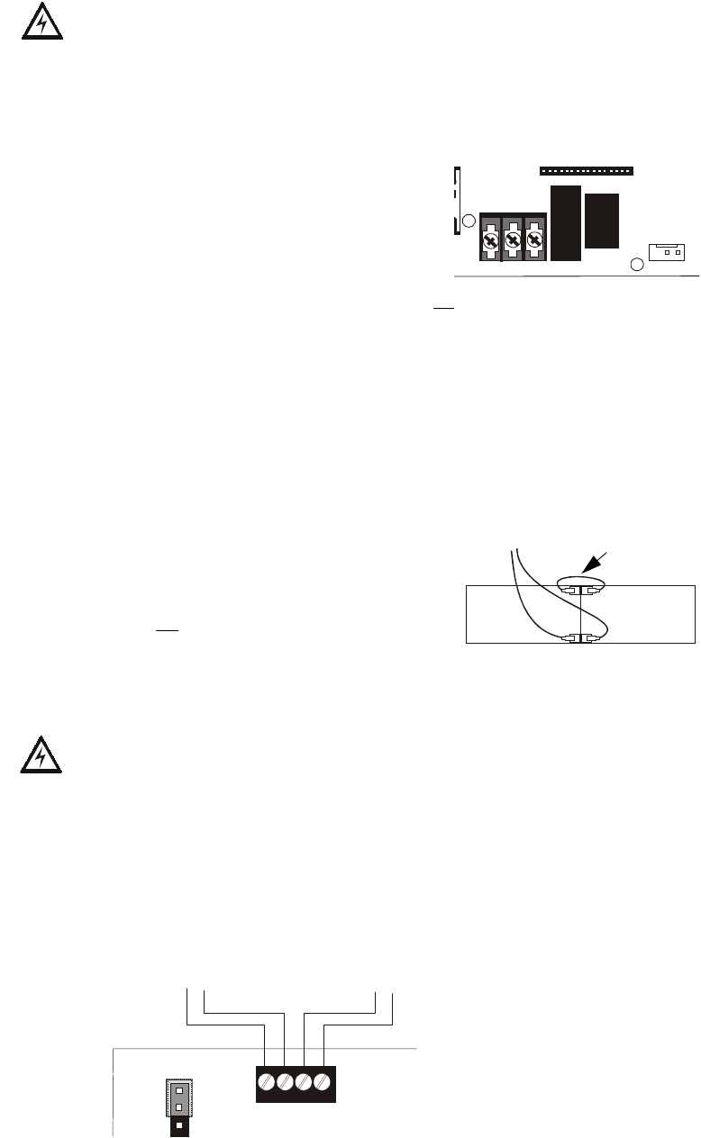
Power Installation
MS-9200UD PN 51906:A 12/10/02 31
2.3 Power
WARNING: Several different sources of power can be connected to this panel.
Disconnect all sources of power before servicing. The panel and associated equipment
may be damaged by removing and/or inserting cards, modules or interconnecting
cables while this unit is energized.
2.3.1 AC Power and Earth Ground Connection
Primary power required for the FACP is 120 VAC,
60 Hz, 3.0 amps for the MS-9200UD or 240 VAC,
50 Hz, 1.5 amps for the MS-9200UDE.
Overcurrent protection for this circuit must comply
with Article 760 of the National Electrical Code
(NEC) and/or local codes. Use 14 AWG (2.00
mm2) or larger wire with 600 volt insulation rating.
Make certain that the AC mains circuit breaker is off before wiring any connections
between the mains and the control panel. Connect wiring from the AC mains to TB11
on the FACP, being careful to observe proper connections.
Connect a wire from the grounding stud in the cabinet to a known solid earth ground in
the building. Refer to Figure 2.1 on page 27 for location of the stud. This connection is
vital for maintaining the control panel’s immunity to unwanted transients generated by
lightning and electrostatic discharge. Apply AC power to the panel only after the
system is completely installed and visually checked. Note that AC power must be
applied to the panel before installing the battery interconnect cable (refer to the
following section).
2.3.2 Battery Power
Before connecting the batteries to the FACP, make
certain that the interconnect cable between the
batteries is not connected. Do not connect the
interconnect cable until the system is completely
installed. Observe polarity when connecting the batteries. Connect the battery cable to
J9 on the main circuit board. Refer "Power Supply Calculations" on page 165, for
calculation of the correct battery rating.
WARNING: Battery contains sulfuric acid which can cause severe burns to the skin
and eyes and can destroy fabrics. If contact is made with sulfuric acid, immediately
flush the skin or eyes with water for 15 minutes and seek immediate medical attention.
2.3.3 DC Power Output Connection
All DC power outputs are power-limited and require a ferrite bead per FCC
requirements (refer to "UL Power-limited Wiring Requirements" on page 35).
HOT NE UT EA RTH
- +
BATTERY
LCD DISPLAY
TB11
J1 J4
J9
-
-
+
+
Interconnect
Cable
See Page
+ - + -
1
2
3
1 2 3 4
Figure 2.5 Power Outputs - 24 VDC
Power-limited Resettable or Nonresettable Power
0.5 amperes max., 24 VDC nominal filtered, resettable
or nonresettable power can be drawn from TB1
Terminals 1(+) and 2(-)
Power-limited Resettable Power
0.5 amperes max., 24 VDC nominal filtered, resettable power can
be drawn from TB1 Terminals 3(+) and 4(-)
92udtb1.cdr
JP4 TB1
JP4 is used to configure TB1,
Terminals 1 & 2 for:
• Resettable Power - jumper pins 1 and
2 of JP4 as shown
• Nonresettable Power - jumper pins 2
& 3 of JP4
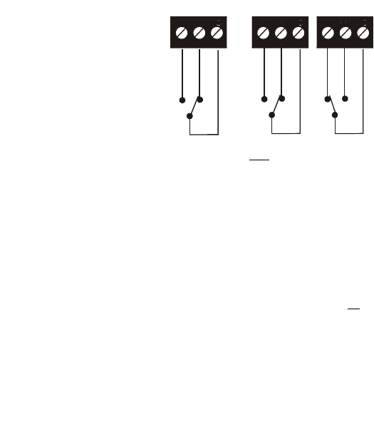
,QVWDOODWLRQ 5HOD\V
068'31$
2.4 Relays
The FACP provides two programmable Form-C relays and one fixed fail-safe Form-C
trouble relay, all with contacts rated for 2.0 amps @ 30 VDC (resistive) or 0.5 amps @
30 VAC (resistive).
Note that relay connections may be power-limited or nonpower-limited, provided that
0.25” spacing is maintained between conductors of power-limited and nonpower-
limited circuits. Refer to UL Power-limited wiring requirements.
2.5 Notification Appliance Circuits
The control panel provides four Style Y (Class B) or two Style Z (Class A) NACs
(Notification Appliance Circuits). Each circuit is capable of 2.5 amps of current. Total
current in alarm for all external devices cannot exceed 6.0 amps (refer to "Calculating
the System Current Draw" on page 165). Use UL listed 24 VDC notification
appliances only. Circuits are supervised and power-limited. Refer to the Fire•Lite
Device Compatibility Document for a listing of compatible notification appliances.
The NACs, which are located on the main circuit board, may be expanded via the
Fire•Lite FCPS Series field charger/power supplies.
The following sections describe the configuration and wiring of Style Y and Style Z
Notification Appliance Circuits on the MS-9200UD main circuit board. The NACs are
configured for Style Y (Class B) from the factory. Refer to "Configuring NACs" on
page 33 for information on changing the NAC configuration to Style Z (Class A).
RELAY 3 RELAY 1 RELAY 2
NO NC C NO NC C NO NC C
Figure 2.6 Relay Terminals
Relay contacts shown with power applied to panel and
no active troubles, alarms or supervisories
TB7
Note that the programmable relay labeled as
Relay 1 is factory default programmed as
Alarm and programmable Relay 3 is factory
default programmed as Supervisory.
The relay labeled Relay 2 is fixed as a
Trouble relay and cannot be changed. It is a
fail-safe relay which will transfer on any
trouble or total power failure.
92udreyp.cdr
TB5 TB6
Reference
Manual
See Page
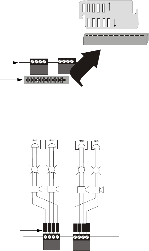
1RWLILFDWLRQ$SSOLDQFH&LUFXLWV ,QVWDOODWLRQ
068'31$
2.5.1 Configuring NACs
The Notification Appliance Circuits on the main circuit board are configured for Style
Y (Class B) or Style Z (Class A) by properly orienting the NACKEY card in JP6 which
is located at the top of the main circuit board near the NAC terminal blocks TB3 and
TB4. The default configuration is for Style Y (Class B). Refer to Figure 2.7 for
information on installing the NACKEY card.
2.5.2 Style Y (Class B) NAC Wiring
CLASS A
CLASS B
NACKEY -PCA
NACKEY -PCA
Figure 2.7 NAC Configuration Using NACKEY
NACKEY Card
JP6
Top edge of MS-9200UD
Main Circuit Board
• Style Z (Class A) - install NACKEY into JP6 with
Class A pointing down toward circuit board as
illustrated to the right.
• Style Y (Class B) - install NACKEY into JP6 with
Class B pointing down toward circuit board .
NACKEY must be inserted with text side facing in
toward center of main circuit board as illustrated to
the right. It is keyed to prevent incorrect insertion.
NACKEY card slot
JP6
TB3 TB4
92nackey.cdr
B
+B
+
B
-
B
-
11
-
++
++
++
++
++
++
B
+B
-
B
+B
-
33 22
44
Figure 2.8 NAC Style Y (Class B) Wiring
4 Style Y (Class B) Notification Appliance Circuits, supervised and power-limited - 4.7 kΩ, ½ watt P/N:71252 UL listed
Polarized Bells Polarized Bells
Polarized HornsPolarized Horns
Polarized Strobes
Notification Appliance Circuit
polarity shown in alarm state
Dummy Load all unused circuit
TB4
9200nacy.cdr
Polarized Strobes
circuit number
NAC 1 NAC 3 NAC 4 NAC 2
TB3
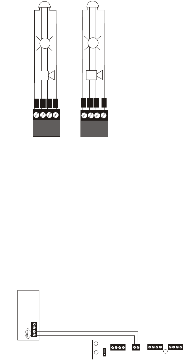
Installation Remote Synchronization Output
34 MS-9200UD PN 51906:A 12/10/02
2.5.3 Style Z (Class A) NAC Wiring
2.6 Remote Synchronization Output
Synchronization is a feature that controls the activationof notification appliances in
such a way that all devices will turn on and off at exactly the same time. This is
particularly critical when activating strobes which must be synchronized to avoid
random activation and a potential hazard to individuals. Devices connected directly to
the control panel’s NACs can be synchronized as described in "Type" on page 90.
Notification appliances connected to remote power sources may require
synchronization with the FACP’s devices. This can be accomplished by connecting the
Remote Synchronization Output from TB2 of the MS-9200UD to a compatible sync
input of a power supply such as the FCPS-24FS6/8. The 24 VDC, 40 mA signal from
TB2 follows, that is mimics, the signal on NAC1. This allows the devices connected to
the power supply to be synchronized with the devices connected to NAC1 on the FACP.
The Remote Synchronization Output is power-limited and supervised and requires a
ferrite bead (refer to "UL Power-limited Wiring Requirements" on page 35). A 4.7 kΩ
resistor must be connected to the end of the wiring at the remote power supply.
B
+B
+
B
-
B
-
A
+A
+
A
-
A
-
+
+
+
+
+
+
2 Style Z (Class A) Notification Appliance Circuits,
supervised and power-limited
Polarized Bell
Polarized Horn
Polarized Horn
Notification Appliance Circuit
polarity shown in alarm state
Polarized Bell
Polarized Strobe Polarized Strobe
Figure 2.9 NAC Style Z (Class A) Wiring
9200nacz.cdr
NAC 1 NAC 2
TB3 TB4
+ 24V -
NON-RST
POWER
+ 24V -
RST
POWER
REMOTE PWR
SUPPLY SYNC
+ -
B+ A+ A- B- B+ A+ A- B-
1B+ 3B+ 3B - 1B- 2B+ 4B+ 4B - 2B-
TB1 TB2 TB3 TB4
JP4
1
2
3
Figure 2.10 Remote Sync Output
Remote Power Supply
MS-9200UD
Remote Sync Output
Sync Input
4.7 kΩ ELR
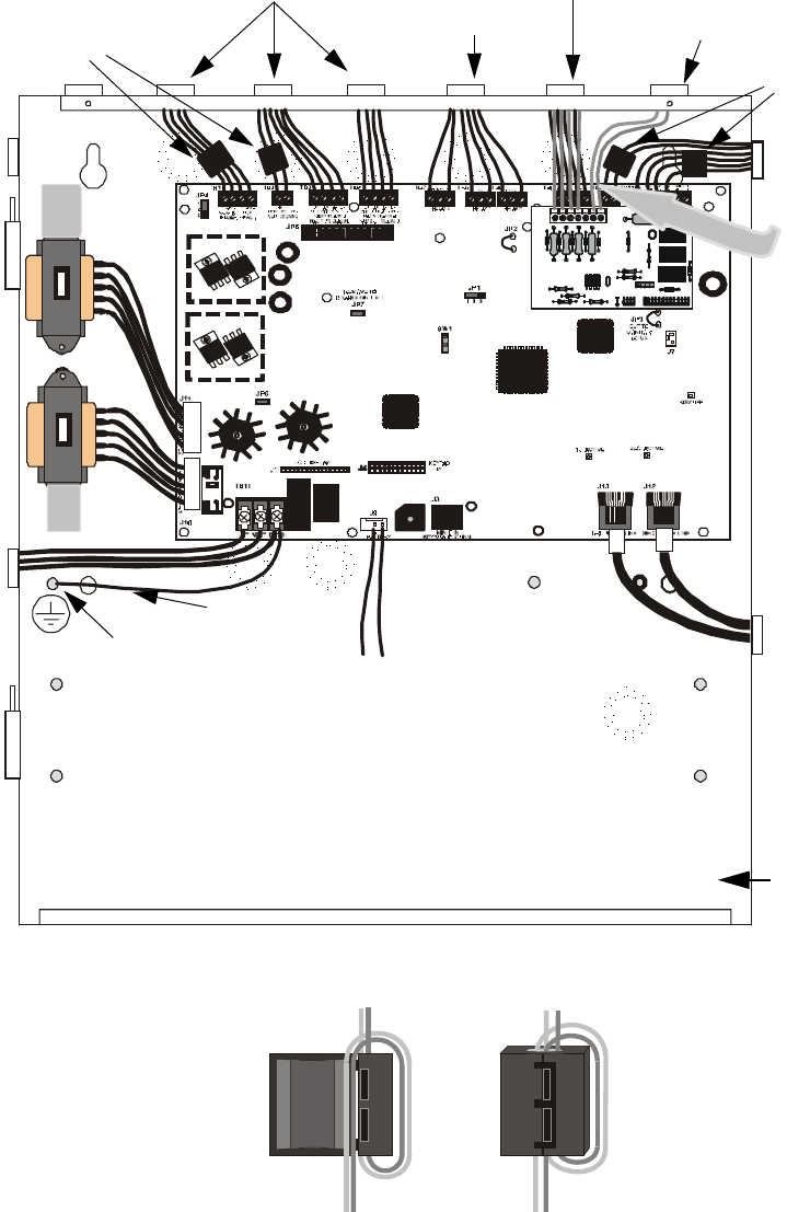
UL Power-limited Wiring Requirements Installation
MS-9200UD PN 51906:A 12/10/02 35
2.7 UL Power-limited Wiring Requirements
Power-limited and nonpower-limited circuit wiring must remain separated in the
cabinet. All power-limited circuit wiring must remain at least 0.25” (6.35 mm) away
from any nonpower-limited circuit wiring and nonpower-limited circuit wiring must
enter and exit the cabinet through different knockouts and/or conduits. A typical wiring
diagram for the MS-9200UD is shown below.
),*85(7\SLFDO8/3RZHUOLPLWHG:LULQJ5HTXLUHPHQWV
3RZHUOLPLWHG&LUFXLWV 3RZHUOLPLWHG&LUFXLWV
1RQSRZHUOLPLWHG&LUFXLWV
3RZHUOLPLWHG&LUFXLWV
1RQSRZHUOLPLWHG
&LUFXLWV
$&3RZHU
*URXQGLQJ6WXG
XGXOSZFGU
1RQSRZHUOLPLWHG&LUFXLWV
7R%DWWHULHV
maintain minimum 0.25”
between power-limited
and nonpower-limited
circuits wiring
*URXQG6WUDS
)HUULWH%HDGV
)HUULWH%HDGV
Wrap wire around ferrite bead as shown. Close ferrite bead.
*Ferrite Bead Installation
Per FCC requirements, ferrite beads are required for the DC Power Outputs, Remote Power Supply Sync, ACS Output and SLC Circuit.
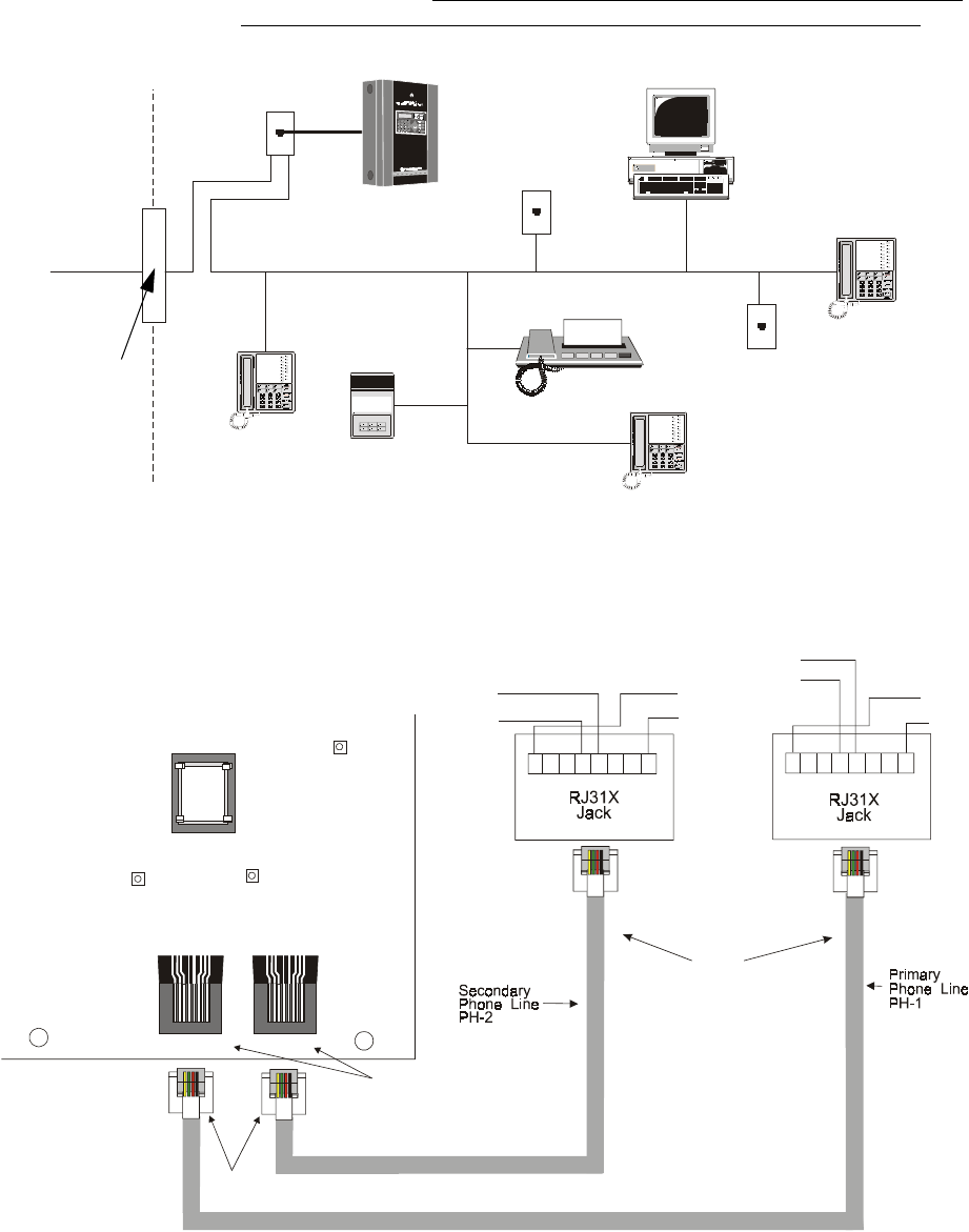
,QVWDOODWLRQ 'LJLWDO&RPPXQLFDWRU
068'31$
2.8 Digital Communicator
7ZRLQGHSHQGHQWWHOHSKRQHOLQHVFDQEHFRQQHFWHGWRWKHFRQWUROSDQHO7HOHSKRQHOLQH
FRQWUROFRPPDQGLVPDGHSRVVLEOHYLDGRXEOHOLQHVHL]XUHDVZHOODVXVDJHRIDQ5-;
VW\OHLQWHUFRQQHFWLRQ1RWHWKDWLWLVFULWLFDOWKDWWKHSDQHOVGLJLWDOFRPPXQLFDWRUEH
ORFDWHGDVWKHILUVWGHYLFHRQWKHLQFRPLQJWHOHSKRQHFLUFXLWWRSURSHUO\IXQFWLRQ
7KHFRQWUROSDQHOVGLJLWDOFRPPXQLFDWRULVEXLOWLQWRWKHPDLQFLUFXLWERDUG
&RQQHFWLRQDQGZLULQJRIWZRSKRQHOLQHVLVUHTXLUHGDVVKRZQEHORZ
MS-9200UD
Figure 2.1 DACT Installation
Customer Premises Equipment and Wiring
Telephone
Line
MS-9200UD
Network
Service
Provider’s
Facilities
Network
Demarcation
Point
RJ31X
Jack
Unused
RJ-11 Jack
Unused
RJ-11 Jack
Telephone
Telephone
Telephone Answering
System
Fax Machine
Computer
Modular Female
Connectors
Male Plug
Connectors
7 foot
Cable
MCBL-7
(ordered
separately)
Note:Shorting bars
inside RJ31X Jack
removed during
male plug insertion
1234567
78
123456 8
Tip
Tip
Ring
Ring
Green Wire
Green Wire
To premise phones To premise phones
Red Wire
Red Wire
Ring Ring
(Primary Lines)
Incoming Telco
Phone Lines
(Secondary Lines)
Incoming Telco
Phone Lines
Tip Tip
KISSOFF
PRI. ACTIVE SEC. ACTIVE
SEC. PHONE LINE
PRI. PHONE LINE
J13 J12
Figure 2.2 Wiring Phone Jacks
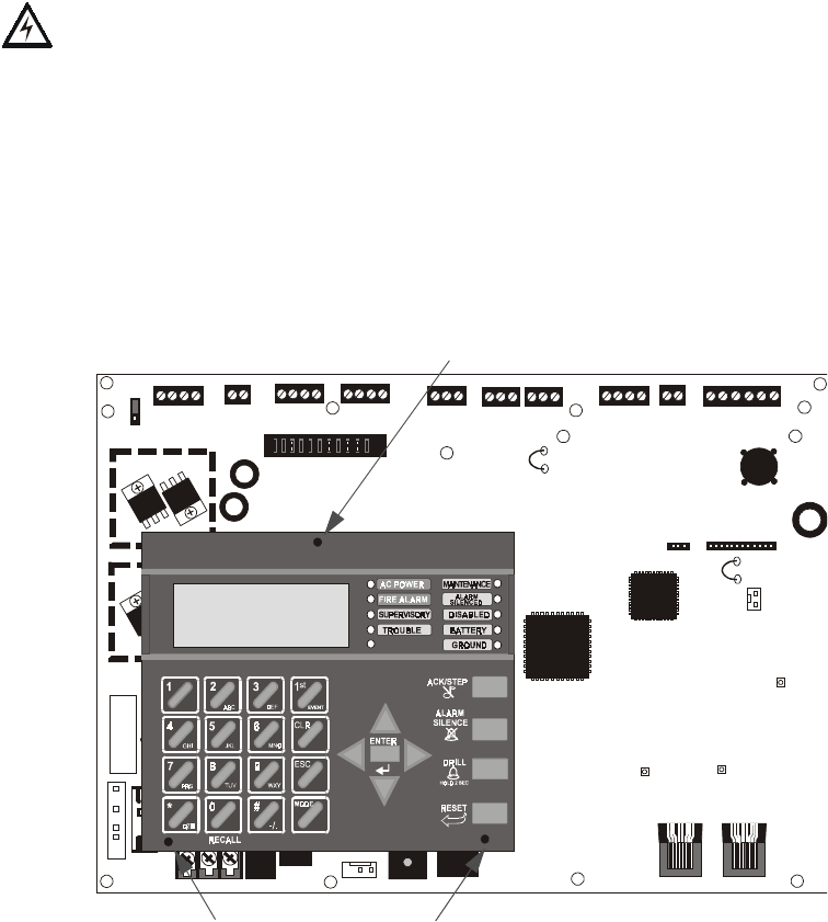
2SWLRQDO0RGXOH,QVWDOODWLRQ ,QVWDOODWLRQ
068'31$
2.9 Optional Module Installation
WARNING! Disconnect all sources of power (AC and DC) before installing or
removing any modules or wiring.
MS-9200UD Keypad/Display Removal
Removal of the keypad/display is normally not necessary. If, however, it becomes
necessary to replace the keypad/display or access jumpers JP5 and JP7 or switch SW1,
the Keypad/Display can be removed by inserting a Phillips screwdriver into each of the
three holes located in the flexible covering of the Keypad/Display and loosening the
three mounting screws. Note that it is not necessary to disconnect the cables between
the Keypad/Display and the main circuit board unless the unit itself is being replaced.
Carefully lift the Keypad/Display and rest the unit at the bottom of the main circuit
board.
+ 24V -
NON-RST
POWER
+ 24V -
RST
POWER
REMOTE PWR
SUPPLY SYNC NAC 1 CLASS A
NAC 1 & 3 CLASS B
NAC 2 CLASS A
NAC 2 & 4 CLASS B
RELAY 3 RELAY 1
HOT NEUT EARTH
- +
BATTERY
LCD DISPLAY
REMOVE TO
DISABLE GND. FLT.
CUT TO
MONITOR
4XTMF
KISSOFF
PRI. ACTIVE SEC. ACTIVE
SEC. PHONE LINE
PRI. PHONE LINE
4XTMF
MINI DIN
KEYBOARD CONN.
KEYPAD
I/F
RELAY 2
TRANSFORMER 1
TRAN SFORMER 2
+ -
B+ A + A- B- B+ A+ A- B-
1B+ 3B+ 3B- 1B- 2B+ 4B+ 4B- 2B-
NO NC C NO NC C NO NC C B+ A+ B- A - A B
ACS
SHIEL DSLCSLC
SLCSLC
OUT+ IN+ OUT- IN-
TB1 TB2 TB3 TB4 TB7 TB5 TB6 TB8 TB9 TB10
JP4
JP1
JP2
JP3
SW1
JP7
JP5
JP6
1
2
3
1 2 3
TB11
J10
J3
J13 J12
J7
J5
J1 J4
J9
J6
J11
CAUTION!
HIGH VOLTAGE
Figure 2.3 Keypad/Display Removal
Mounting Screw Access Hole
Mounting Screw Access Holes
96dact1.cdr
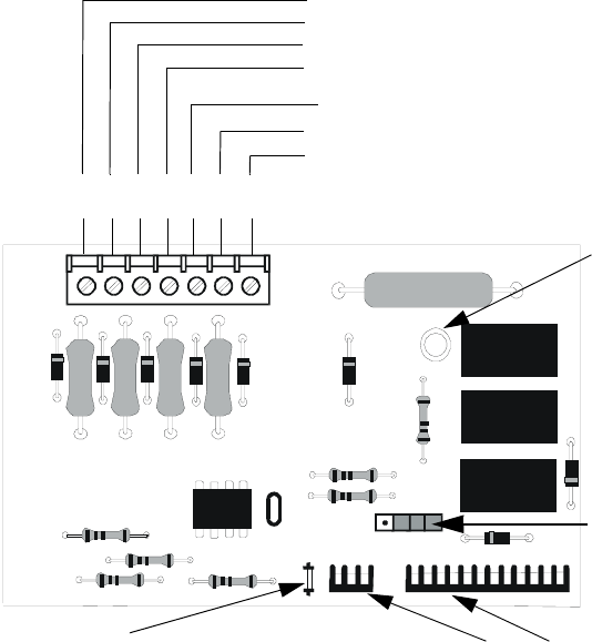
,QVWDOODWLRQ 2SWLRQDO0RGXOH,QVWDOODWLRQ
068'31$
2.9.1 4XTMF Transmitter Module Installation
The 4XTMF provides a supervised output for a local energy municipal box transmitter
in addition to alarm and trouble reverse polarity. A jumper option allows the reverse
polarity circuit to open with a system trouble condition if no alarm condition exists. A
disable switch allows disabling of the transmitter output during testing to prevent
accidental calling of the monitoring service.
Local Energy Municipal Box Service (NFPA 72 Auxiliary Fire Alarm Systems):
Supervisory Current: 5.0 mA
Trip Current: 350 mA (subtracted from notification appliance power)
Coil Voltage: 3.65 VDC
Maximum Coil Resistance: 14.6 ohms
Maximum allowable wire resistance between panel and trip coil: 3 ohms
Municipal Box wiring can leave the building
Remote Station Service (NFPA 72 Remote Station Fire Alarm Systems) - Intended
for connection to a polarity reversal circuit or a Remote Station receiving unit
having compatible ratings:
Maximum load for each circuit: 10 mA
Reverse polarity output voltage: 24 VDC
Remote Alarm and Remote Trouble wiring can leave the building
Before installing the module, place the disconnect switch to the right (disconnect)
position to prevent accidental activation of the municipal box. Note that a Disconnect
LED will illuminate after the module is installed in the MS-9200UD. In addition, the
System Trouble LED will turn on to indicate the Disconnect condition.
Figure 2.4 4XTMF Transmitter Module
Connect to FACP J10 & J11
Disconnect Switch
shown in disconnect
position
TBL Jumper
}Remote Alarm (power-limited)*
}Remote Trouble (power-limited)*
No connection
}Municipal Box (nonpower-limited)*
1 2 3 4 5 6 7
+ - + - + -
Polarities are shown for module activation
Note: 4XTMF Module is not suitable for
transmitting reverse polarity supervisory signal.
* Wiring from these
terminals can exit the
protected premises.
Dummy load terminals
6 and 7 (4.7kΩ, ¼ watt
resistor) if Municipal
Box is not connected.
Disconnect LED
4xtmfl.cdr
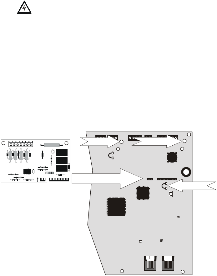
Optional Module Installation Installation
MS-9200UD PN 51906:A 12/10/02 39
The following steps must be followed when installing the 4XTMF module:
1. Remove all power (Primary and Secodary) from the FACP before installing
4XTMF
2. Cut jumper JP3 on the main circuit board to allow the control panel to supervise
the 4XTMF module
3. Carefully plug the connectors on the 4XTMF module into connectors J5 and J6
on the MS-9200UD main circuit board, being careful not to bend any pins
4. Secure 4XTMF module to standoffs with supplied screws.
5. Reapply power to the FACP
6. For proper 4XTMF operation, the output relays must be programmed for the
factory default settings: Alarm Relay 1, Trouble Relay 2 and Supervisory Relay 3
7. When the installation has been complete, enable the 4XTMF module by sliding
the disconnect switch to the left
8. Test system for proper operation
NOTE: Jumper JP2 on the MS-9200UD main circuit board can be used to configure the FACP
supervisory relay for operation with the 4XTMF module. Relay 3 at TB5 must be
programmed as a supervisory relay.
Cutting JP2 will allow the 4XTMF to generate a trouble if the supervisory contact opens
Leaving JP2 in will prevent generation of a trouble if the supervisory contact opens
RELAY 1
CUT TO
MONITOR
4XTMF
KISSOFF
PRI. ACTIVE SEC. ACTIVE
SEC. PHONE LINE
PRI. PHONE LINE
4XTMF
RELAY 2
NO NC C NO NC C B+ A+ B- A- A B
ACS
SHIELDSLC
SLCSLCSLC
OUT+ IN+ OUT- IN-
TB5 TB6 TB8 TB9 TB10
JP1
JP2
JP3
1 2 3
J13 J12
J7
J5 J6
Figure 2.5 4XTMF Connectors to MS-9200UD Connectors
J5 & J6 Connectors
Cut Jumper JP3
Standoff Standoff
4XTMF
MS-9200UD
92ud4xtm.cdr
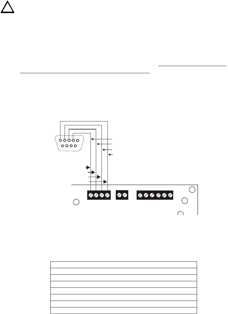
Installation Optional Module Installation
40 MS-9200UD PN 51906:A 12/10/02
2.9.2 Printer/PC
A serial printer or a PC (personal computer) may be connected to TB8 Terminals 1 - 4
on the FACP. The printer can be used to provide a hard-copy printout of real-time
events, history file and walktest data. An IBM compatible PC can be connected to
provide local FACP programming capabilities using the PK-Plus programming utility.
Installation of either device requires panel programming to allow the FACP to
communicate with the device.
CAUTION! Do not connect a printer or PC to the MS-9200UD FACP if a ground fault
exists on the control panel. Circuit damage may result. Remove all power (Primary
and Secodary) before installing or removing any wiring.
Installation
Remote printers and PCs require separate primary power. Also required is the PRT/
PK-CABLE which is an interface cable prewired to a DB9F connector. Wire the PRT/
PK-CABLE to TB8 Terminals 1 - 4 as illustrated in the following figure. Connect the
DB9F connector to the printer or PC serial EIA-232 port. If a nine-pin serial connector
is not available on the printer or PC, use a DB25 adapter. Make certain that the DB25
adapter does not swap the Transmit and Receive lines. Apply power to the FACP and
printer or PC. Note that a ground fault may occur on the FACP, dependent on the
printer or PC being used, due to this connection. For this reason, it is important that
there be no preexisting ground fault on the panel.
Note that the printer may or may not be supervised as determined by user
programming. Refer to "Printer/PC" on page 116.
Printer Configuration
Refer to the documentation supplied with the printer for pertinent information about
printer setup. Set the printer’s options as listed in the following table:
PC Configuration
The Windows-based PK-Plus Programming Utility Kit contains CD-ROM with on-line
help file.
COMMUNICATION SETUP
BUFFER: LARGE
DATA BITS: 7
PAR I TY: EVEN
STOP BIT: 1 STOP
BAUD RATE: 2400/4800/9600
AUTOMATIC LINE FEED NO
AUTOMATIC CARRIAGE RETURN NO
!
Black
RCV
DTR
GRND
TX
5 4 3 2 1
9 8 7 6
White
Green
Red
B+ A+ B- A - A B
ACS
SHI ELDSLCSLC
SLC
SLC
OUT+ IN+ OUT- IN-
TB8 TB9 TB10
PRT/PK-CABLE
9600tb7a.cdr
Figure 2.6 Serial Printer and Computer Connections
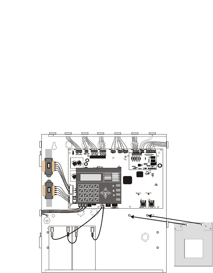
2SWLRQDO0RGXOH,QVWDOODWLRQ ,QVWDOODWLRQ
068'31$
2.9.3 Digital Communicator and Annunciators
2.9.3.1 ACM-8RF Relay Control Module
7KH$&05)PRGXOHSURYLGHVHLJKW)RUP&UHOD\VZLWKFRQWDFWVUDWHGIRU
DPSV:KHQLQVWDOOHGZLWKDQ068')$&3WKH$&05)PRGXOHVSURYLGH
UHOD\DFWLYDWLRQIRUHDFKRIWKHSRVVLEOH)$&3]RQHVSOXVVSHFLDOIXQFWLRQV
2SWLRQVH[LVWWRDOORZIRUDODUPRQO\RUDODUPDQGWURXEOHDFWLYDWLRQSHU]RQH
2XWSXWDFWLYDWLRQIRUJHQHUDODODUPJHQHUDOWURXEOHJHQHUDOVXSHUYLVRU\1$&
IDXOW$&IDLOZDONWHVWVWDUWDQGEDWWHU\WURXEOHDUHDOVRDYDLODEOH7KH$&05)
FDQEHPRXQWHGUHPRWHO\LQDQ$%65)DQQXQFLDWRUVXUIDFHPRXQWEDFNER[RULQ
WKHSDQHOFDELQHWXVLQJWKH31%5.78QLYHUVDO%UDFNHW5HIHUWRWKH
$&05)PDQXDOIRULQIRUPDWLRQRQVHWWLQJPRGXOHVZLWFKHVIRUDGGUHVVLQJDQG
UHOD\IXQFWLRQV
2.9.3.2 BRKT-9600 Universal Bracket Installation
7KHRSWLRQDO%5.78QLYHUVDO%UDFNHWFDQEHXVHGWRPRXQWVSHFLILFPRGXOHV
LQVLGHWKH068'FDELQHW7KH%5.7PRXQWVWRWZRVWXGVORFDWHGLQ
WKHORZHUULJKWFRUQHURIWKHFRQWUROSDQHOFDELQHWDVLOOXVWUDWHGEHORZ,WLVVHFXUHG
WRWKH3(0VWXGVRQWKHEDFNZDOORIWKHFDELQHWZLWKWZRVXSSOLHGKH[QXWV
,03257$17:KHQWKH%5.7LVLQVWDOOHGWKH068'FDELQHWFDQ
KROGDPD[LPXPRIWZR$PS+RXUEDWWHULHVZLWKWKHRULHQWDWLRQLOOXVWUDWHG
Reference
Manual
1
4
*
2
5
0
3
6
#
1
st
EVEN T
ABC DEF
GHI JKL MNO
PRS TUV WXY
QZ
-/.
CLR
78 9
ESC
ENTER
RECALL
ACK/STEP
ALARM
SILENCE
DRILL
HOLD 2 SEC
RESET
MODE
MAINT ENANCE
GROUND
BATTERY
DISABLED
ALARM
SILENCED
TROUBLE
SUPERVISORY
FIRE ALARM
AC POWER
Figure 2.7 BRKT-9600 Bracket Installation
Mount BRKT-9600 to PEM
studs on back of cabinet
using supplied hex nuts.
MS-9200UD Cabinet
92brkmnt.cdr
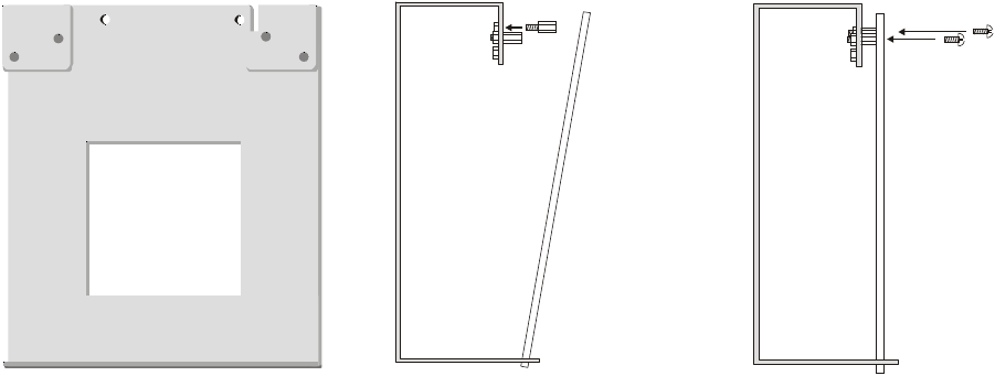
,QVWDOODWLRQ 2SWLRQDO0RGXOH,QVWDOODWLRQ
068'31$
0RGXOH,QVWDOODWLRQRQ%5.7
7KHIROORZLQJPRGXOHVFDQEHLQVWDOOHGLQVLGHWKH068'FDELQHWXVLQJWKH
%5.78QLYHUVDO%UDFNHW
✓UDACT-F Digital Alarm Communicator/Transmitter - installs at standoff
location (A)
✓ACM-8RF Annunciator Control Module (Relay) - installs at standoff location
(A)
5HIHUWRWKHDSSURSULDWHPRGXOHPDQXDOIRUGHWDLOHGLQIRUPDWLRQRQPRGXOH
RSHUDWLRQDQGZLULQJ
1. Install the two supplied standoffs in location (A) as indicated in Step 1 of the
following illustration
2. Position the module bottom in the slot located in the bottom of the BRKT-9600
as indicated in Step 2 of the following illustration
3. Secure the module to the standoffs installed in the top of the BRKT-9600 with
two mounting screws as indicated in Step 3 of the following illustration
4. Refer to the appropriate module manual for detailed information on wiring the
module for power, communication, etc.
5. Install a maximum of two 12 Amp Hour batteries with the orientation illustrated
in Figure 2.7. Larger batteries require a separate UL listed battery box
1RWH'RQRWEULQJZLULQJRUFRQGXLWLQWRWKHERWWRPRIWKHFDELQHWIRUWKLV
DSSOLFDWLRQ
Figure 2.8 BRKT-9600 Module Installation Steps
Step 1 Step 2 Step 3
(A) (A)
Slot
module module
BRKT-9600 BRKT-9600 BRKT-9600
mounting
screws
standoffs
96brcksd.cdr
9600brkt.cdr

2SWLRQDO0RGXOH,QVWDOODWLRQ ,QVWDOODWLRQ
068'31$
2.9.3.3 ACM and AFM Series Annunciators
$&0DQG$)06HULHV$QQXQFLDWRUVSURYLGHYLVXDOLQGLFDWLRQVRI)$&3VWDWXVLQ
UHPRWHORFDWLRQV5HIHUWRWKHDSSURSULDWHDQQXQFLDWRUPDQXDOIRULQIRUPDWLRQRQ
LQVWDOODWLRQZLULQJDQGRSHUDWLRQ
$QQXQFLDWRUDGGUHVVLQJLVVSHFLILFWRWKH068'FRQWUROSDQHO7KHIROORZLQJ
WDEOHGHVFULEHVWKHDQQXQFLDWRUDGGUHVVHVDQGWKHFRUUHVSRQGLQJDGGUHVVDEOH
GHYLFHVWKDWZLOOEHDQQXQFLDWHGDWHDFKDQQXQFLDWRUDGGUHVV
7KH068'PXVWEHSURJUDPPHGIRUWKHDQQXQFLDWRUVLQVWDOOHGRQWKHV\VWHP
5HIHUWR$QQXQFLDWRUV8'$&7RQSDJHIRULQIRUPDWLRQRQDQQXQFLDWRU
SURJUDPPLQJ0DNHFHUWDLQWRSURJUDPWKHDQQXQFLDWRUDGGUHVVHVWKDWKDYHEHHQ
SK\VLFDOO\LQVWDOOHGRQWKHV\VWHP
1RWH7KH*HQHUDO6\VWHP6WDWXV3RLQWVLQFOXGHWKHIROORZLQJ
• General Alarm
• General Trouble
• General Supervisory
• Alarm Silenced
• System Off Normal
•AC Loss
• Battery Fault
• NAC Fault
ACM Annunciator Address Annunciator Displays the Following Points
1 8 General System Status Points & Zones 1 - 56
2 Zones 57 - 99 & 4 NACs
3 SLC Loop, Module Addresses 1 - 64
4 not used
5 SLC Loop, Module Addresses 65 - 99
6 not used
7 not used
8 SLC Loop, Detector Addresses 1 - 64
9 not used
10 SLC Loop, Detector Addresses 65 - 99
11 not used
12 not used
13 not used
14 not used
15 not used
16 not used
17 not used
18 not used
19 not used
20 8 General System Status Points & Zones 1 - 56
21 Zones 57 - 99 & 4 NACs
22 SLC Loop, Module Addresses 1 - 64
23 not used
24 SLC Loop, Module Addresses 65 - 99
25 not used
26 not used
27 SLC Loop, Detector Addresses 1 - 64
28 not used
29 SLC Loop, Detector Addresses 65 - 99
30 not used
31 not used
32 not used

3URJUDPPLQJ 3URJUDPPLQJ'DWD(QWU\
068'31$
SECTION 3 Programming
3.1 Programming Data Entry
Programming can be accomplished using the MS-9200UD keypad or by connecting an
optional standard computer keyboard. The keyboard can be connected to the PS-2
connector J3 on the control panel main circuit board.
The information presented in this section refers to programming the MS-9200UD via
the onboard keypad. If an optional computer keyboard is connected to the MS-9200UD
main circuit board, the following table describes the keyboard keys which correspond
to the onboard keypad keys.
Keypad Keys Computer Keyboard Keys
1st Event Home
CLR Delete
ESC Esc
RECALL Insert
**
##
A - Z A - Z
0 - 9 0 - 9
(on QZ key) Space bar
——
//
••
ENTER Enter
ACK/STEP F1
SILENCE F2
DRILL F3
RESET F4

8VHU3URJUDPPLQJ 3URJUDPPLQJ
068'31$
3.2 User Programming
The MS-9200UD is completely field programmable and requires no special software
skills. While programming the MS-9200UD, the fire protection capabilities of the
control panel are enabled.
Site-specific programming may be accomplished in three ways:
•Autoprogramming Feature - This is a convenient method for quickly bringing
the FACP addressable SLC devices on-line without the necessity of
programming each device individually. Refer to "Autoprogram" on page 49 for
a detailed description of Autoprogramming
• Manual programming or editing, using the FACP keypad or a PC keyboard
• Off-line Programming and Editing Feature - allows creation and editing of site-
specific custom programs using a Windows-based computer. For programs
requiring a large amount of data entry, this method may be preferred. A PK-Plus
programming kit can be ordered for this purpose
The System All Normal screen will be displayed in a programmed system with no active
alarms, troubles or supervisories, as illustrated below:
Programming, Read Status and Manual Dial mode can be entered while the panel is in
any mode of operation. If the panel is in alarm, the alarm condition must be
acknowledged before entering any other mode. To access any of the programming or
read status features, the Enter or Mode key must be pressed, which will cause the LCD
to display the following:
Pressing 1, while this screen is being displayed, will cause the control panel to enter the
Read Status Mode which allows the user to view the programmed features and status of
the control panel The Read Status feature is not password protected. Refer to "Read
Status" on page 141 for a detailed description of this feature.
Pressing 2 will select user Programming Mode which may only be accomplished by an
authorized person. After pressing 2, a screen will prompt for a password. After
entering the correct password, the user may select from a list of programming options.
Pressing 3 will select the Manual Dial Mode which allows the user to enter a
troubleshoot mode of operation.
Exit Programming, Read Status and Manual Dial Mode
The programmer can exit any mode by repeatedly pressing the keypad ESC (Escape)
key until the display reads System All Normal. Note that the data which is entered
during Programming mode is not saved until the programmer exits this mode by
repeatedly pressing the ‘ESC’ key. If the Reset key is pressed or power is lost before
exiting Programming mode, all data just entered will be lost.
!
!
!
FIRE-LITE ALARMS INC
SYSTEM ALL NORMAL
10:00A 012102
1=READ STATUS MODE
2=PROGRAMMING MODE
3=MANUAL DIAL MODE
See Page

3URJUDPPLQJ ,QLWLDO3RZHUXS
068'31$
User Programming Levels
There are two user programming levels:
• User Master Program Level 1 is used for programming panel specific data
relating to device types, zoning, messages, control panel functions, etc.
• User Maintenance Program Level 2 is used by a qualified operator to access
features such as Disable/Enable, View and Clear History, Walktest and System
Time Change.
3.3 Initial Power-up
The following sections describe the initial programming procedures for a new system.
The same procedures are used to modify programming in an existing system.
After completing the wiring of addressable devices to the SLC, apply power to the
control panel. If the addressable devices have not yet been programmed into the FACP,
their LEDs will not flash and the following trouble message will be displayed.
3.4 Programming Screens Description
Three options are available when the Enter key is pressed: Read Status, Programming
and Manual Dial Mode. The Read Status and Programming options have multiple
functions or features which may be chosen. To view all of the choices, it is necessary
that the programmer scroll through a number of additional subscreens. These
selections are displayed on multiple screens to make them more readable for the
programmer. Refer to "Master Programming Level" on page 48, for additional
information on the various screens.
The title of the main option screen will always be displayed at the top of the subscreens
for the programmer’s convenience. If additional subscreens exist, an Up or Down
arrow will be displayed in the upper right corner of the screen being viewed. The
programmer can then press the keypad Up or Down arrow key to view the new
subscreen. To select one of the choices in a screen, the programmer presses the keypad
numerical key corresponding to the desired choice.
Note that subscreens may also have multiple options which require viewing more than
one screen. The same process, as detailed in the previous paragraphs, is followed to
view all option choices.
3.5 Programming and Passwords
There are two factory set programming passwords which will access the Programming
screens as indicated in the following examples. From either of the screens, access to
specific system and device features or programming may be obtained. All user
programming entries are stored in nonvolatile memory. The factory set passwords can
be changed by the user as described in "Password Change" on page 117. If an invalid
password is entered, the blinking cursor will return to the first password character
position. To exit Programming, Read Status or Manual Dial mode at any time, press
the ESC (Escape) key repeatedly. Note that Programming mode must be exited using
the ESC key in order to store the program data entered during this mode. If the Reset
key is pressed or power is lost before exiting Programming mode, the data just entered
will not be saved.
TROUBL IN SYSTEM
NO DEVICES INSTALLED
09:03A 012102
See Page
See Page

3URJUDPPLQJDQG3DVVZRUGV 3URJUDPPLQJ
068'31$
To access user Programming mode, press the Enter or Mode key. The LCD will display
the following:
To enter the user Programming mode, press 2. The display will read as follows:
Entering the Master level password (default 00000) will cause the following screen to
appear:
If the Maintenance level password (default 11111) is entered, the following screen will
appear:
Note that in the two preceding screens, an arrow appears to inform the programmer that
additional options can be viewed by pressing the keypad down arrow key.
1=READ STATUS MODE
2=PROGRAMMING MODE
3=MANUAL DIAL MODE
PROGRAMMING
ENTER PASSWORD
*****
PROGRAMMING
1=AUTOPROGRAM
2=POINT PROGRAM
3=ZONE SETUP
PROGRAMMING
1=POINT PROGRAM
2=HISTORY
3=PROGRAM CHECK

3URJUDPPLQJ 0DVWHU3URJUDPPLQJ/HYHO
068'31$
3.6 Master Programming Level
When the Master Program Level password is entered, the control panel will enter user
Programming mode. In this mode, the piezo sounder remains off, the trouble relay is
activated and the system Trouble LED flashes until Programming mode is exited. The
following display will appear:
The down arrow which appears in the display indicates that additional programming
choices can be viewed by pressing the down arrow key on the keypad. If a down and
up arrow appear in the display, pressing the ‘down’ arrow key will display the
subsequent Programming Screens as illustrated below while pressing the ‘up’ arrow
key will display the previous screen.
PROGRAMMING
1=AUTOPROGRAM
2=POINT PROGRAM
3=ZONE SETUP
Programming Screen #1
PROGRAMMING
1=LOOP SETUP
2=SYSTEM SETUP
3=VERIFY LOOP
PROGRAMMING
1=HISTORY
2=WALKTEST
3=OPTION MODULES
PROGRAMMING
1=PASSWORD CHANGE
2=CLEAR PROGRAM
3=PROGRAM CHECK
Programming Screen #2
Programming Screen #3
Programming Screen #4

0DVWHU3URJUDPPLQJ/HYHO 3URJUDPPLQJ
068'31$
3.6.1 Autoprogram
Pressing 1 while viewing Programming Screen #1, will select the Autoprogram option,
which prompts the control panel to poll all devices installed on the SLC loop. The
primary purpose of autoprogramming is to allow the installer a fast and easy way to
bring the system on-line as quickly as possible. The first time the system is powered-
up, it should be autoprogrammed.
If the system is already programmed and Autoprogram is initiated, the system will only
add default values for newly installed devices.
When Autoprogram is selected, the control panel will begin autoprogramming the
system by communicating with each addressable device installed on the SLC loop.
While autoprogramming, the panel will display the following:
When Autoprogramming is completed, the control panel will display the type and
quantity of each device installed on the SLC loop similar to the following display:
In the preceding example, the display indicates that the SLC Loop has 55 addressable
detectors, 35 monitor modules and 30 control modules installed.
Pressing the ESC key will return the display to Programming Screen #1.
PROGRAMMING
1=AUTOPROGRAM
2=POINT PROGRAM
3=ZONE SETUP
Programming Screen #1
AUTOPROGRAM
AUTOPROGRAMMING!
PLEASE WAIT
Autoprogram Progress Screen
# OF DET LOOP1 055
# OF MON LOOP1 035
# OF CON LOOP1 030
Autoprogram Result Screen #1

3URJUDPPLQJ 0DVWHU3URJUDPPLQJ/HYHO
068'31$
3.6.2 Point Program
The Point Program option allows the programmer to add a new addressable device to an
SLC loop, delete an existing device from a loop or change the programming for an
existing device. Pressing 2, while viewing Programming Screen #1, will select the
Point Program option and display the following screen:
3.6.2.1 Detector Programming
3UHVVLQJZKLOHYLHZLQJWKH3RLQW3URJUDP6FUHHQZLOODOORZWKHSURJUDPPHUWR
DGGGHOHWHRUFKDQJHWKHSURJUDPPLQJRIDQDGGUHVVDEOHGHWHFWRU7KHIROORZLQJ
VFUHHQZLOOEHGLVSOD\HGE\WKHFRQWUROSDQHO
3.6.2.1.1 Add Detector
3UHVVLQJZKLOHYLHZLQJWKH'HWHFWRU6FUHHQZLOOGLVSOD\WKHIROORZLQJVFUHHQ
ZKLFKDOORZVWKHSURJUDPPHUWRDGGDQHZGHWHFWRUDGGUHVVWRSURJUDPPLQJ
$IODVKLQJFXUVRUZLOODSSHDULQWKHSRVLWLRQRIWKHILUVWDVWHULVNWRWKHOHIW7KH
SURJUDPPHUNH\VLQWKHWKUHHGLJLWGHWHFWRUDGGUHVVVXFKDV
:KHQWKHODVWGLJLWLVNH\HGLQWKHIROORZLQJVFUHHQZLOOEHGLVSOD\HG
7KHSURJUDPPHUFDQFRQWLQXHDGGLQJGHWHFWRUVE\SUHVVLQJWKH(6&NH\ZKLFKZLOO
UHWXUQWKHGLVSOD\WRWKH$GG'HWHFWRU6FUHHQ
PROGRAMMING
1=AUTOPROGRAM
2=POINT PROGRAM
3=ZONE SETUP
Programming Screen #1
POINT PROGRAM
SELECT TYPE
1=DETECTOR
2=MODULE
Point Program Screen
DETECTOR
1=ADD
2=DELETE
3=EDIT
Detector Screen
ADD DETECTOR
ENTER DETECTOR#
***
Add Detector Screen
ADD DETECTOR
DETECTOR# 005
IS ADDED

0DVWHU3URJUDPPLQJ/HYHO 3URJUDPPLQJ
068'31$
3.6.2.1.2 Delete Detector
3UHVVLQJLQWKH'HWHFWRU6FUHHQZLOOGLVSOD\WKH'HOHWH'HWHFWRU6FUHHQZKLFK
DOORZVWKHSURJUDPPHUWRGHOHWHDVSHFLILFGHWHFWRU
$IODVKLQJFXUVRUZLOODSSHDULQWKHSRVLWLRQRIWKHILUVWDVWHULVNWRWKHOHIW7KH
SURJUDPPHUNH\VLQWKHWKUHHGLJLWGHWHFWRUDGGUHVVVXFKDV:KHQWKHODVW
GLJLWLVNH\HGLQWKHIROORZLQJVFUHHQZLOOEHGLVSOD\HG
7KHSURJUDPPHUFDQFRQWLQXHGHOHWLQJGHWHFWRUVE\SUHVVLQJWKH(6&NH\ZKLFK
ZLOOUHWXUQWKHGLVSOD\WRWKH'HOHWH'HWHFWRU6FUHHQ
3.6.2.1.3 Edit Detector
TKHSURJUDPPHUFDQFKDQJHDGHWHFWRUVH[LVWLQJRUIDFWRU\GHIDXOWSURJUDPPLQJE\
SUHVVLQJLQWKH'HWHFWRU6FUHHQ7KHIROORZLQJVFUHHQZLOOEHGLVSOD\HG
$IODVKLQJFXUVRUZLOODSSHDULQWKHSRVLWLRQRIWKHILUVWDVWHULVNWRWKHOHIW7KH
SURJUDPPHUNH\VLQWKHWKUHHGLJLWGHWHFWRUDGGUHVVVXFKDV
:KHQWKHODVWGLJLWLVNH\HGLQLIWKHVHOHFWHGDGGUHVVKDVQRWEHHQDGGHGWR
SURJUDPPLQJDVFUHHQVKRZLQJLQIRUPDWLRQDERXWDGHYLFHZLWKWKHKLJKHVWDGGUHVV
WKDWLVLQVWDOOHGZLOOEHGLVSOD\HG
,IQRGHWHFWRUVKDYHEHHQLQVWDOOHGRQWKHORRSWKHIROORZLQJZLOOEHGLVSOD\HG
DETECTOR
1=ADD
2=DELETE
3=EDIT
Detector Screen
DELETE DETECTOR
ENTER DETECTOR#
***
Delete Detector Screen
DELETE DETECTOR
DETECTOR# 005
IS DELETED
EDIT DETECTOR
ENTER POINT ADDRESS
***
Edit Detector Screen
NO DETECTOR
INSTALLED
Edit Detector Screen #1

3URJUDPPLQJ 0DVWHU3URJUDPPLQJ/HYHO
068'31$
,IWKHVHOHFWHGDGGUHVVKDVEHHQDGGHGWRSURJUDPPLQJGHYLFHVXPPDU\VFUHHQV
ZLOOEHGLVSOD\HG7KHVHVFUHHQVDOORZWKHSURJUDPPHUWRYLHZDOOGHYLFHVHWWLQJV
DWDVLQJOHJODQFH3UHVVLQJWKHOHIWRUULJKWDUURZNH\VZLOODOORZWKHSURJUDPPHU
WRUDSLGO\YLHZWKHGHYLFHVDWWKHSUHYLRXVRUQH[WDGGUHVVLILQVWDOOHG
,IDGHWHFWRUVXFKDVDSKRWRHOHFWULFGHWHFWRUZLWKWKHVHOHFWHGDGGUHVVLVQRW
SK\VLFDOO\LQVWDOOHGRQWKH6/&RUKDVDFRPPXQLFDWLRQIDXOWEXWWKHDGGUHVVLV
SURJUDPPHGLQWKHV\VWHPWKHIROORZLQJVFUHHQZLOOEHGLVSOD\HG
,IWKHVHOHFWHGDGGUHVVKDVEHHQDGGHGWRSURJUDPPLQJDQGDGHWHFWRUVXFKDVD
SKRWRHOHFWULFGHWHFWRUZLWKWKHVHOHFWHGDGGUHVVLVSK\VLFDOO\LQVWDOOHGRQWKH6/&
DQGLVFRPPXQLFDWLQJZLWKWKHFRQWUROSDQHOWKHIROORZLQJZLOOEHGLVSOD\HG
7RFKDQJHWKHSURJUDPPLQJIRUWKHGLVSOD\HGGHWHFWRUSUHVVWKHNH\ERDUGµGRZQ
DUURZNH\WRYLHZWKH(GLW'HWHFWRUVFUHHQV
,QWKHSUHFHGLQJH[DPSOH
✓Normal - indicates that the detector with the selected address is physically
installed on the SLC and communicating with the control panel (enabled)
✓<ADJ><NOUN> - represents the adjective and noun, which have been
programmed, describing the location of the displayed device
✓ZNNN - represents the first of five possible software zones that the detector is
assigned to (NNN = the three digit zone number from 000 - 099)
✓V or * - indicates whether or not alarm verification is enabled (V = alarm
verification enabled and * = alarm verification disabled)
✓1D017 - represents the Loop, Device type and Device address (1 = SLC Loop,
D=Detector and 017 = Detector Address 017)
TROUBL SMOKE(PHOTO)
<ADJ><NOUN>
ZNNN
* 1D017
Edit Detector Screen #1
NORMAL SMOKE (PHOTO)
<ADJ><NOUN>
ZNNN
V 1D017
Edit Detector Screen #1

0DVWHU3URJUDPPLQJ/HYHO 3URJUDPPLQJ
068'31$
7KHIROORZLQJH[DPSOHVVKRZWKHHGLWLQJRIDSKRWRHOHFWULFsmoke detector with
address 017, located on the SLC loop:
(QDEOH'LVDEOH'HWHFWRU
7R(QDEOHRU'LVDEOHWKHGHWHFWRUSUHVVWKHNH\ZKLOHYLHZLQJWKH(GLW'HWHFWRU
6FUHHQ(DFKSUHVVRIWKHNH\ZLOOWRJJOHWKHVFUHHQEHWZHHQ(QDEOHG<HVDQG
(QDEOHG1R,I(QDEOHG1RLVVHOHFWHGWKHGHWHFWRUZLOOQRWEHSROOHGE\WKHFRQWURO
SDQHOSUHYHQWLQJWKHGHWHFWRUIURPUHSRUWLQJDODUPVDQGWURXEOHVWRWKHSDQHO7KH
FRQWUROSDQHOZLOOGLVSOD\WKHGHYLFHW\SHDQGDGGUHVVZKLFKKDVEHHQGLVDEOHGDQG
ZLOOWXUQRQWKH7URXEOH/('DQG'LVDEOH/('
EDIT DETECTOR 1D017
1=ENABLED YES
2=TYPE SMOKE(PHOTO)
3=VERIFICATION OFF
Edit Detector Screen #2
EDIT DETECTOR 1D017
1=WALKTEST NO
2=PAS NO
3=PRE-SIGNAL NO
Edit Detector Screen #3
EDIT DETECTOR 1D017
1=ZONE ASSIGNMENT
00 ** ** ** **
Edit Detector Screen #4
Edit Detector Screen #5
EDIT DETECTOR 1D017
1=NOUN/ADJECTIVE
2=DESCRIPTION
********************
EDIT DETECTOR
1=ENABLED
2=TYPE
3=VERIFICATION
Edit Detector Screen #2

3URJUDPPLQJ 0DVWHU3URJUDPPLQJ/HYHO
068'31$
7\SH
7RVHOHFWWKHW\SHRIGHWHFWRUEHLQJSURJUDPPHGSUHVVWKHNH\ZKLOHYLHZLQJWKH
(GLW'HWHFWRU6FUHHQ7KLVZLOOFDXVHWKHFRQWUROSDQHOWRGLVSOD\WKHIROORZLQJ
'HWHFWRU7\SH6FUHHQV
:KLOHYLHZLQJHLWKHU'HWHFWRU7\SHVFUHHQVHOHFWWKHW\SHRIGHWHFWRUEHLQJ
SURJUDPPHGE\SUHVVLQJWKHFRUUHVSRQGLQJNH\ERDUGQXPEHUNH\7KHGLVSOD\ZLOO
UHWXUQWR(GLW'HWHFWRU6FUHHQDQGLQGLFDWHWKHVHOHFWLRQQH[WWRWKH7\SHRSWLRQ
1RWH,IDGHWHFWRULVVHOHFWHGWREHD683(59'8&73W\SHLWZLOOIXQFWLRQOLNHD
VXSHUYLVRU\SRLQWQRWDILUHDODUPSRLQW7KHVXSHUYLVRU\/('DQGVXSHUYLVRU\
UHOD\ZLOODFWLYDWHQRWWKHILUHDODUP/('RUDODUPUHOD\LIWKHGHWHFWRUVHQVHV
VPRNH
9HULILFDWLRQ
$ODUPYHULILFDWLRQLVXVHGWRFRQILUPWKDWDVPRNHGHWHFWRUDFWLYDWLRQLVDWUXHDODUP
FRQGLWLRQDQGQRWDIDOVHDODUP7KLVIHDWXUHLVVHOHFWHGE\SUHVVLQJZKLOHYLHZLQJ
WKH(GLW'HWHFWRU6FUHHQVRWKDWWKHGLVSOD\UHDGV9HULILFDWLRQ2Q(DFKWLPHWKH
NH\LVSUHVVHGWKHGLVSOD\ZLOOWRJJOHEHWZHHQ9HULILFDWLRQ2QDQG9HULILFDWLRQ
2II)RUDGHWDLOHGGHVFULSWLRQUHIHUWR$ODUP9HULILFDWLRQ1RQHRU2QH0LQXWH
RQSDJH
:DONWHVW
7KH:DONWHVWIHDWXUHDOORZVRQHSHUVRQWRWHVWWKHV\VWHPGHYLFHVZLWKRXWWKH
QHFHVVLW\RIPDQXDOO\UHVHWWLQJWKHFRQWUROSDQHODIWHUHDFKGHYLFHDFWLYDWLRQ7R
HQDEOHDGHYLFHIRUWKH:DONWHVWIHDWXUHSUHVVZKLOHYLHZLQJWKH(GLW'HWHFWRU
6FUHHQXQWLOWKHGLVSOD\UHDGV:DONW H VW<HV(DFKSUHVVRIWKHNH\ZLOOFDXVH
WKHGLVSOD\WRWRJJOHEHWZHHQ:DONWH V W<H VDQG:DONW H VW1 R5HIHUWR:DONWHVWRQ
SDJH
3$6
7KH3$63RVLWLYH$ODUP6HTXHQFHRSWLRQZLOOSURJUDPWKHGHWHFWRUWRGHOD\SDQHO
DFWLYDWLRQLQFOXGLQJDODUPUHOD\DQGFRPPXQLFDWRUIRUDSHULRGRIVHFRQGVSOXV
DSURJUDPPDEOHWLPHRIXSWRPLQXWHV=RQHKRZHYHUZLOODFWLYDWH
LPPHGLDWHO\DQGPD\EHXVHGWRFRQQHFWDVLJQDOLQJGHYLFHWRLQGLFDWH3$6
DFWLYDWLRQGRQRWXVHD1RWLILFDWLRQ$SSOLDQFH&LUFXLWIRUWKLVSXUSRVH7RHQDEOH
WKH3$6IHDWXUHSUHVVZKLOHYLHZLQJWKH(GLW'HWHFWRU6FUHHQXQWLOWKHGLVSOD\
UHDGV3$ 6 <H V (DFKSUHVVRIWKHNH\ZLOOFDXVHWKHGLVSOD\WRWRJJOHEHWZHHQ3$ 6
<HVDQG3$ 6 1 R 5HIHUWR3RVLWLYH$ODUP6HTXHQFHRQSDJH
EDIT DETECTOR
1=ENABLED
2=TYPE
3=VERIFICATION
Edit Detector Screen #2 DETECTOR TYPE
1=SMOKE(PHOTO)
2=SMOKE (ION)
3=HEAT DETECT
Detector Type Screen #1
DETECTOR TYPE
1=SMOKE-DUCT-P
2=SUPERV DUCTP
Detector Type Screen #2
See Page
EDIT DETECTOR
1=WALKTEST
2=PAS
3=PRE-SIGNAL
Edit Detector Screen #3
See Page

0DVWHU3URJUDPPLQJ/HYHO 3URJUDPPLQJ
068'31$
)RUH[DPSOHLIDGHWHFWRUZLWKDGGUHVVLVWREHFRQILJXUHGIRU3$6RSHUDWLRQ
✓Select PAS Yes when editing the detector set to address 005
✓Program the desired zone or zones to be activated by this detector, in this
example Z001
✓Program an output, such as a control module that is to be activated by detector
005 by assigning the same zone to it; in this example Z001
✓Program an output, such as a control module, for PAS activation by assigning
zone Z97 to it. This control module may be connected to a signaling device
used to indicate a PAS condition (do not use a Notification Appliance Circuit
for this purpose)
✓Enable zones Z001 and Special Purpose Zone PAS 97 and set the PAS delay
timer to some value
:LWKWKHSUHFHGLQJSURJUDPVHWWLQJVZKHQWKHGHWHFWRUZLWKDGGUHVVLV
DFWLYDWHG]RQH=ZLOOFDXVHLWVDVVRFLDWHGFRQWUROPRGXOHWRDFWLYDWH
LPPHGLDWHO\VRXQGLQJWKHFRQQHFWHG3$6VLJQDOLQJGHYLFH)ROORZLQJWKH3$6
GHOD\WLPH]RQH=ZLOOFDXVHLWVDVVRFLDWHGFRQWUROPRGXOHWRDFWLYDWHDQGWKH
FRQWUROSDQHOZLOOLQLWLDWHDQDODUPFRQGLWLRQ
3UHVLJQDO
7KH3UHVLJQDORSWLRQSURJUDPVWKHGHWHFWRUWRGHOD\SDQHODFWLYDWLRQIRUD
SUHSURJUDPPHGWLPHGHOD\RIXSWRWKUHHPLQXWHVZKLOHDOORZLQJIRUYLVXDO
YHULILFDWLRQE\DSHUVRQ1RWHWKDWWKHDODUPUHOD\DQGFRPPXQLFDWRUZLOOUHVSRQG
WRWKHLQLWLDODODUPLPPHGLDWHO\,QDGGLWLRQ=RQHZLOODFWLYDWH7KLV]RQHFDQ
EHSURJUDPPHGWRDFRQWUROPRGXOHZKLFKPD\EHXVHGWRDFWLYDWHDVRXQGHURU
LQGLFDWRUZKLFKWKHLQVWDOOHUGHVLJQDWHVDVD3UHVLJQDOLQGLFDWLRQGRQRWXVHD
1RWLILFDWLRQ$SSOLDQFH&LUFXLWIRUWKLVSXUSRVHTo enable the Pre-signal feature,
press 3 while viewing Edit Detector Screen #3 until the display reads Pre-signal
Yes. Each press of the 3 key will cause the display to toggle between Pre-signal Yes
and Pre-signal No. Refer to 3UHVLJQDORQSDJH.
)RUH[DPSOHLIDGHWHFWRUZLWKDGGUHVVLVWREHFRQILJXUHGIRU3UH6LJQDO
RSHUDWLRQ
✓Select Pre-signal Yes when editing the detector set to address 005
✓Program the desired zone or zones to be activated by this detector, in this
example Z001
✓Program an output, such as a control module that is to be activated by detector
005 by assigning the same zone to it; in this example Z001
✓Program an output, such as a control module, for Pre-signal activation by
assigning zone Z98 to it. This control module may be connected to a signaling
device used to indicate a Pre-signal condition GRQRWXVHD1RWLILFDWLRQ
$SSOLDQFH&LUFXLWIRUWKLVSXUSRVH
✓Enable zones Z001 and Special Purpose Zone Pre-signal 98 and set the Pre-
signal delay timer to some value
:LWKWKHSUHFHGLQJSURJUDPVHWWLQJVZKHQWKHGHWHFWRUZLWKDGGUHVVLV
DFWLYDWHG]RQH=ZLOOFDXVHLWVDVVRFLDWHGFRQWUROPRGXOHWRDFWLYDWH
LPPHGLDWHO\VRXQGLQJWKHFRQQHFWHGVLJQDOLQJGHYLFHWRLQGLFDWHWKH3UHVLJQDO
FRQGLWLRQ)ROORZLQJWKH3UHVLJQDOGHOD\WLPH]RQH=ZLOOFDXVHLWVDVVRFLDWHG
FRQWUROPRGXOHWRDFWLYDWHDQGWKHFRQWUROSDQHOZLOOLQLWLDWHDQDODUPFRQGLWLRQ
EDIT DETECTOR
1=WALKTEST
2=PAS
3=PRE-SIGNAL
Edit Detector Screen #3
See Page

3URJUDPPLQJ 0DVWHU3URJUDPPLQJ/HYHO
068'31$
=RQH$VVLJQPHQW
$PD[LPXPRIILYH]RQHVFDQEHSURJUDPPHGWRHDFKDGGUHVVDEOHGHWHFWRU
3UHVVLQJZKLOHYLHZLQJ(GLW'HWHFWRU6FUHHQGLVSOD\VWKHIROORZLQJVFUHHQ
1RWHWKDW=UHSUHVHQWVWKH=RQH1XPEHUVFRUUHVSRQGLQJWRWKLVGHYLFH7KH
IDFWRU\GHIDXOWIRUDQXQSURJUDPPHGGHYLFHLV=IRUJHQHUDODODUP]RQH$
IODVKLQJFXUVRUZLOODSSHDURQWKHILUVWWRWKHOHIW(QWHUWKHWZRGLJLWQXPEHU
FRUUHVSRQGLQJWRWKH]RQHWKDWLVWREHDVVLJQHGWRWKLVGHYLFH7KHFXUVRUPRYHVWR
WKHQH[W=GHVLJQDWLRQ&RQWLQXHHQWHULQJ]RQHDVVLJQPHQWVRUWKHUHPDLQLQJ
]RQHVFDQEHOHIWEODQNRUSURJUDPPHGDVJHQHUDODODUP]RQH=:KHQDOO
GHVLUHGFKDQJHVKDYHEHHQPDGHSUHVVWKH(QWHUNH\WRVWRUHWKH]RQHDVVLJQPHQWV
7KHGLVSOD\ZLOOUHWXUQWRWKH(GLW'HWHFWRU6FUHHQ1RWHWKDWWKHOHIWDQGULJKW
DUURZNH\VFDQEHXVHGWRQDYLJDWHWKURXJKWKH]RQHVDQGWKH&/($5NH\FDQEH
XVHGWRTXLFNO\FOHDUD]RQH
1RXQ$GMHFWLYH
7KH1RXQ$GMHFWLYHVHOHFWLRQDOORZVWKHSURJUDPPHUWRHQWHUVSHFLILFGHVFULSWRUV
DERXWWKHGHWHFWRUFXUUHQWO\EHLQJSURJUDPPHG3UHVVLQJZKLOHYLHZLQJ(GLW
'HWHFWRU6FUHHQZLOOFDXVHWKHIROORZLQJVFUHHQWREHGLVSOD\HG
EDIT DETECTOR
1=ZONE ASSIGNMENT
00 ** ** ** **
Edit Detector Screen #4 ZONE ASSIGNMENT
Z00 Z** Z** Z** Z**
Zone Assignment Screen
See Page
EDIT DETECTOR
1=NOUN/ADJECTIVE
2=DESCRIPTION
*****************
Edit Detector Screen #5 1=STANDARD ADJECTIVE
2=STANDARD NOUN
3=CUSTOM ADJECTIVE
4=CUSTOM NOUN
Noun/Adjective Screen

0DVWHU3URJUDPPLQJ/HYHO 3URJUDPPLQJ
068'31$
3UHVVLQJZKLOHYLHZLQJWKH1RXQ$GMHFWLYH6FUHHQZLOOFDXVHWKHIROORZLQJ
VFUHHQVWREHGLVSOD\HG1RWHWKDWWKHNH\ERDUGGRZQDUURZNH\PXVWEHSUHVVHG
WRVHHDOOWKH$GMHFWLYHVFUHHQVPress the number corresponding to the adjective
that is to be used as a descriptor for the location of the detector currently being
programmed. When an adjective has been selected, it will appear at the top of the
display as indicated by the asterisks.
1=STANDARD ADJECTIVE
2=STANDARD NOUN
3=CUSTOM ADJECTIVE
4=CUSTOM NOUN
Noun/Adjective Screen
**********************
1=NORTH
2=SOUTH
3=EAST
Adjective Screen #1
**********************
1=WEST
2=FRONT
3=CENTER
Adjective Screen #2
**********************
1=REAR
2=UPPER
3=LOWER
Adjective Screen #3
*********************
1=MAIN
2=FIRST
3=2ND
Adjective Screen #4
**********************
1=3RD
2=4TH
3=5TH
Adjective Screen #5
**********************
1=FLOOR4
2=FLOOR5
3=ROOM
Adjective Screen #7
**********************
1=FLOOR1
2=FLOOR2
3=FLOOR3
Adjective Screen #6

3URJUDPPLQJ 0DVWHU3URJUDPPLQJ/HYHO
068'31$
3UHVVLQJZKLOHYLHZLQJWKH1RXQ$GMHFWLYH6FUHHQZLOOFDXVHWKHIROORZLQJ
VFUHHQVWREHGLVSOD\HG1RWHWKDWWKHNH\ERDUGGRZQDUURZNH\PXVWEHSUHVVHG
WRVHHDOOWKH1RXQVFUHHQVPress the number corresponding to the noun that is to
be used as a descriptor for the location of the detector currently being programmed.
When a noun has been selected, it will appear at the top of the display as indicated
by the asterisks.
1=STANDARD ADJECTIVE
2=STANDARD NOUN
3=CUSTOM ADJECTIVE
4=CUSTOM NOUN
Noun/Adjective Screen
**********************
1=BASEMENT
2=BOILER RM
3=CLASSROOM
Noun Screen #1
**********************
1=CLOSET
2=CORRIDOR
3=ELECTRIC RM
Noun Screen #2
**********************
1=ELEVATOR
2=ENTRANCE
3=FLOOR
Noun Screen #3
**********************
1=GARAGE
2=HALLWAY
3=HVAC RM
Noun Screen #4
**********************
1=KITCHEN
2=LOBBY
3=OFFICE
Noun Screen #5
**********************
1=STAIRWAY
2=STOREROOM
3=WING
Noun Screen #7
**********************
1=PATIENT
2=RESTROOM
3=ROOM
Noun Screen #6
**********************
1=ZONE
Noun Screen #8

0DVWHU3URJUDPPLQJ/HYHO 3URJUDPPLQJ
068'31$
3UHVVLQJRUZKLOHYLHZLQJWKH1RXQ$GMHFWLYH6FUHHQZLOOGLVSOD\VFUHHQV
VLPLODUWRWKHSUHYLRXV$GMHFWLYHDQG1RXQ6FUHHQV7KHQHZVFUHHQVZLOOOLVW
FXVWRP$GMHFWLYHVDQG1RXQVZKLFKKDYHEHHQSURJUDPPHGLQWRWKHFRQWUROSDQHO
XVLQJWKH3.3OXVSURJUDPPLQJNLW7KHVHGHVFULSWRUVDUHVHOHFWHGDVGHVFULEHGLQ
WKHSUHYLRXVVHFWLRQV
'HVFULSWLRQ
7KH'HVFULSWLRQVHOHFWLRQDOORZVWKHSURJUDPPHUWRHQWHUDGGLWLRQDOLQIRUPDWLRQ
DERXWWKHGHWHFWRUFXUUHQWO\EHLQJSURJUDPPHG7KLVLQIRUPDWLRQZLOOEHGLVSOD\HG
DVSDUWRIWKHGHYLFHODEHORQWKHGLVSOD\3UHVVLQJZKLOHYLHZLQJ(GLW'HWHFWRU
6FUHHQZLOOFDXVHWKHIROORZLQJVFUHHQWREHGLVSOD\HG
$IODVKLQJFXUVRUZLOODSSHDUDWWKHILUVWDVWHULVNWRWKHOHIW7KHSURJUDPPHUFDQ
HQWHUDGGLWLRQDOGHVFULSWLYHLQIRUPDWLRQDERXWWKHGHYLFHEHLQJSURJUDPPHG7KLV
LQIRUPDWLRQZLOODSSHDURQWKHGLVSOD\DORQJZLWKWKHVWDQGDUGGHYLFHODEHO
LQIRUPDWLRQ
$PD[LPXPRIFKDUDFWHUVLQFOXGLQJVSDFHVFDQEHHQWHUHG7RHQWHU
DOSKDQXPHULFFKDUDFWHUVIURPWKHNH\SDGUHSHDWHGO\SUHVVWKHDSSURSULDWHNH\XQWLO
WKHGHVLUHGFKDUDFWHULVGLVSOD\HGLQWKHILUVWSRVLWLRQ)RUH[DPSOHWRHQWHUWKH
OHWWHU%SUHVVWKH$%&NH\WKUHHWLPHVWRWRJJOHWKURXJKWKHFKDUDFWHUV$DQG
%3UHVVWKHULJKWDUURZNH\WRPRYHWKHFXUVRURQHSRVLWLRQWRWKHULJKWDQGUHSHDW
WKHSURFHVVWRHQWHUWKHQH[WFKDUDFWHU7RHQWHUDVSDFHSUHVVWKH4=NH\IRXU
WLPHVXQWLODEODQNDSSHDUVLQWKHGHVLUHGSRVLWLRQ:KHQDOOFKDUDFWHUVKDYHEHHQ
HQWHUHGSUHVVWKH(QWHUNH\WRVWRUHWKHLQIRUPDWLRQ7KHGLVSOD\ZLOOUHWXUQWRWKH
(GLW'HWHFWRU6FUHHQGLVSOD\LQJWKHQHZLQIRUPDWLRQDWWKHERWWRPRIWKHVFUHHQ
5HFDOO,QFUHPHQW)XQFWLRQ
,QDGGLWLRQWKHXVHUPD\XVHWKH5HFDOO,QFUHPHQWIXQFWLRQDWDQ\WLPHZKHQWKH
FXUVRULVRQWKHILUVWOHWWHURIWKH'HVFULSWLRQ$GMHFWLYHRU1RXQILHOGDVIROORZV
• If the zero key is pressed, a 0 is placed in the first letter position
• If the zero key is then pressed a second time with no intervening key actions, the
entire field is replaced with the field entered for the previous device programmed,
and the cursor moves to the last character of the field (Recall function). The
Recalled Adjective or Noun field may now be changed letter-by-letter
• If the zero key is pressed again with no other intervening key actions and the last
character in the field is a number 0-9, the number is incremented by one. If the
last character is a letter, it changes to a 0. If the last character goes from 9 to 0
and the characters to the left of the last character are also numbers, they are also
incremented (overflow)
• The above increment function may be repeated with each press of the zero key
1=STANDARD ADJECTIVE
2=STANDARD NOUN
3=CUSTOM ADJECTIVE
4=CUSTOM NOUN
Noun/Adjective Screen
EDIT DETECTOR
1=NOUN/ADJECTIVE
2=DESCRIPTION
Edit Detector Screen #5
DESCRIPTION 1D002
1=NOUN/ADJECTIVE
********************
Adjective/Noun Screen

3URJUDPPLQJ 0DVWHU3URJUDPPLQJ/HYHO
068'31$
$VDQH[DPSOHWKHXVHUFRXOGTXLFNO\HQWHUµ)/5BB5220B¶DVIROORZV
1. The cursor is on the first letter of the Adjective field. Press the zero key twice to
display FLR_3
2. With the cursor on the first letter of the Noun field, press the zero key twice to
recall the display ROOM_304. The cursor automatically jumps from the first to
the last letter of the Noun field
3. With the cursor on the last letter of the Noun field, press the zero key again to
increment the room number to 305
4. Press the right arrow key to advance the zone field
5. Select a zone number from 00 to 99. Z00 (default zone) is the general alarm
zone. Z01 through Z99 may be selected to link software zones
3.6.2.2 Module Programming
3UHVVLQJZKLOHYLHZLQJ3RLQW3URJUDP6FUHHQZLOODOORZWKHSURJUDPPHUWR
DGGGHOHWHRUFKDQJHWKHSURJUDPPLQJRIDQDGGUHVVDEOHPRGXOH7KHIROORZLQJ
VFUHHQZLOOEHGLVSOD\HGE\WKHFRQWUROSDQHO
3.6.2.2.1 Add Module
3UHVVLQJZKLOHYLHZLQJWKH0RGXOHV6FUHHQZLOOGLVSOD\WKHIROORZLQJVFUHHQ
ZKLFKDOORZVWKHSURJUDPPHUWRDGGDQHZPRGXOHDGGUHVVWRSURJUDPPLQJ
$IODVKLQJFXUVRUZLOODSSHDULQWKHSRVLWLRQRIWKHILUVWDVWHULVNWRWKHOHIW7KH
SURJUDPPHUNH\VLQWKHWKUHHGLJLWPRGXOHDGGUHVVVXFKDV
:KHQWKHODVWGLJLWLVNH\HGLQWKHIROORZLQJVFUHHQZLOOEHGLVSOD\HG
3UHVVLQJIRU&RQWURO0RGXOHRUIRU0RQLWRU0RGXOHZLOOFDXVHWKHIROORZLQJ
POINT PROGRAM
SELECT TYPE
1=DETECTOR
2=MODULE
Point Program Screen #2
MODULES
1=ADD
2=DELETE
3=EDIT
Modules Screen
ADD MODULE
ENTER MODULE#
***
Add Module Screen #1
ADD MODULE
1=CONTROL
2=MONITOR
Add Module Screen #2

0DVWHU3URJUDPPLQJ/HYHO 3URJUDPPLQJ
068'31$
VFUHHQWREHGLVSOD\HG
7KHSURJUDPPHUFDQFRQWLQXHDGGLQJPRGXOHVE\SUHVVLQJWKH(6&RUOHIWDUURZ
NH\ZKLFKZLOOUHWXUQWKHGLVSOD\WRWKH$GG0RGXOH6FUHHQ
3.6.2.2.2 Delete Module
3UHVVLQJLQWKH0RGXOHV6FUHHQZLOOGLVSOD\WKH'HOHWH0RGXOH6FUHHQZKLFK
DOORZVWKHSURJUDPPHUWRGHOHWHDVSHFLILFPRGXOH
$IODVKLQJFXUVRUZLOODSSHDULQWKHSRVLWLRQRIWKHILUVWDVWHULVNWRWKHOHIW8VLQJ
WKHSDQHONH\SDGNH\LQWKHPRGXOHDGGUHVVVXFKDV:KHQWKHODVWGLJLWLV
NH\HGLQWKHIROORZLQJFRQILUPDWLRQWKDWWKHPRGXOHKDVEHHQGHOHWHGZLOOEH
GLVSOD\HG
3.6.2.2.3 Edit Module Screen for Monitor Module
7KHSURJUDPPHUFDQFKDQJHDPRGXOHVH[LVWLQJRUIDFWRU\GHIDXOWSURJUDPPLQJE\
SUHVVLQJLQWKH0RGXOHV6FUHHQ7KHIROORZLQJVFUHHQZLOOEHGLVSOD\HG
$IODVKLQJFXUVRUZLOODSSHDULQWKHSRVLWLRQRIWKHILUVWDVWHULVNWRWKHOHIW7KH
ADD MODULE
MODULE# 005
IS ADDED
Add Module Screen #3
MODULES
1=ADD
2=DELETE
3=EDIT
Modules Screen
DELETE MODULE
ENTER MODULE#
***
Delete Module Screen
DELETE MODULE
MODULE# 005
IS DELETED
EDIT MODULE
ENTER MODULE ADDRESS
***
Edit Module Screen

3URJUDPPLQJ 0DVWHU3URJUDPPLQJ/HYHO
068'31$
SURJUDPPHUNH\VLQWKHWKUHHGLJLWPRGXOHDGGUHVVVXFKDV:KHQWKHODVWGLJLW
LVNH\HGLQLIWKHVHOHFWHGDGGUHVVKDVQRWEHHQDGGHGWRSURJUDPPLQJDVFUHHQ
VKRZLQJLQIRUPDWLRQDERXWWKHKLJKHVWDGGUHVVWKDWLVLQVWDOOHGZLOOEHGLVSOD\HG,I
QRPRGXOHVDUHLQVWDOOHGRQWKHORRSWKHIROORZLQJVFUHHQZLOOEHGLVSOD\HG
,IWKHVHOHFWHGDGGUHVVKDVEHHQDGGHGWRSURJUDPPLQJEXWDPRGXOHVXFKDVD
PRQLWRUPRGXOHZLWKWKHVHOHFWHGDGGUHVVLVQRWSK\VLFDOO\LQVWDOOHGRQWKH6/&RU
KDVDFRPPXQLFDWLRQIDXOWWKHIROORZLQJVFUHHQZLOOEHGLVSOD\HG
,IWKHVHOHFWHGDGGUHVVKDVEHHQDGGHGWRSURJUDPPLQJDQGDPRGXOHVXFKDVD
PRQLWRUPRGXOHZLWKWKHVHOHFWHGDGGUHVVLVSK\VLFDOO\LQVWDOOHGRQWKH6/&DQGLV
FRPPXQLFDWLQJZLWKWKHFRQWUROSDQHOWKHIROORZLQJVFUHHQZLOOEHGLVSOD\HG
7RFKDQJHWKHSURJUDPPLQJIRUWKHGLVSOD\HGPRGXOHSUHVVWKHNH\ERDUGGRZQ
DUURZNH\WRYLHZWKHIROORZLQJ(GLW0RQLWRUVFUHHQV,QWKHSUHFHGLQJH[DPSOH
✓Normal - indicates that the module with the selected address is physically
installed on the SLC and communicating with the control panel (enabled)
✓<ADJ><NOUN> - represents the adjective and noun, which have been
programmed, describing the location of the displayed device
✓ZNNN - represents the first of five possible software zones that the module is
assigned to (NNN = the two digit zone number from 000 - 099)
✓1M012 - represents the Loop, Device type and Device address (1 = SLC Loop
1, M=Module and 012 = Module Address 012)
✓W or * - indicates whether or not the device is programmed for Walktest (W =
programmed for walktest, * = not programmed for walktest).
NO MODULE
INSTALLED
Edit Module Screen
TROUBL MONITOR
<ADJ><NOUN>
ZNNN
* 1M012
NORMAL MONITOR
<ADJ><NOUN>
ZNNN
W 1M012

0DVWHU3URJUDPPLQJ/HYHO 3URJUDPPLQJ
068'31$
,IWKHVHOHFWHGDGGUHVVFRUUHVSRQGVWRDFRQWUROPRGXOHDVFUHHQGLVSOD\LQJ
LQIRUPDWLRQDERXWWKHFRQWUROPRGXOHZLWKWKHVHOHFWHGDGGUHVVZLOOEHGLVSOD\HGDV
VKRZQLQ(GLW0RGXOH6FUHHQIRU&RQWURO0RGXOHVRQSDJH
,IWKHVHOHFWHGDGGUHVVFRUUHVSRQGVWRDPRQLWRUPRGXOHDVFUHHQGLVSOD\LQJ
LQIRUPDWLRQDERXWWKHPRGXOHZLWKWKHVHOHFWHGDGGUHVVZLOOEHGLVSOD\HGDV
LOOXVWUDWHGLQWKHIROORZLQJ
See Page
NORMAL MONITOR
<ADJ><NOUN>
ZNNN
1M012
EDIT MONITOR 1M012
1=ENABLED YES
2=TYPE MONITOR
Edit Monitor Screen #2
EDIT MONITOR 1M012
1=PRE-SIGNAL NO
2=PAS NO
Edit Monitor Screen #3
EDIT MONITOR 1M012
1=WALKTEST YES
2=ZONE ASSIGNMENT
00 ** ** ** **
Edit Monitor Screen #4
EDIT MONITOR 1M012
1=ADJECTIVE/NOUN
2=DESCRIPTION
********************
Edit Monitor Screen #5

3URJUDPPLQJ 0DVWHU3URJUDPPLQJ/HYHO
068'31$
(QDEOH'LVDEOH0RGXOH
7R(QDEOHRU'LVDEOHWKHPRQLWRUPRGXOHSUHVVWKHNH\ZKLOHYLHZLQJWKH(GLW
0RGXOH6FUHHQ(DFKSUHVVRIWKHNH\ZLOOWRJJOHWKHVFUHHQEHWZHHQ(QDEOHG
<HVDQG(QDEOHG1R,I(QDEOHG1RLVVHOHFWHGWKHPRGXOHZLOOQRWEHSROOHGE\WKH
FRQWUROSDQHOSUHYHQWLQJWKHPRGXOHIURPUHSRUWLQJDODUPVDQGWURXEOHVWRWKH
SDQHO7KHFRQWUROSDQHOZLOOLQGLFDWHDV\VWHPWURXEOHFRQGLWLRQDQGWKH'LVDEOH
/('ZLWKWXUQRQLIDQ\GHYLFHVDUHGLVDEOHG
7\SH0RQLWRU
8VLQJWKH3.3OXV8SORDG'RZQORDGXWLOLW\SURJUDPXQLTXHXVHUGHILQHGPRQLWRU
W\SHVFDQEHFUHDWHGDQGORDGHGLQWRWKH)$&3IRUODWHUXVH7KH)$&3UHVSRQVHWR
WKHDFWLYDWLRQRIDXVHUGHILQHGW\SHLVWKHVDPHDVPRVWSUHYLRXVVWDQGDUGW\SHVLQ
WKHOLVWWKXVDOORZLQJDYDULHW\RIXVHUGHILQHGW\SHVDQGUHVSRQVHV7RVHOHFWWKH
W\SHRIPRQLWRUPRGXOHEHLQJSURJUDPPHGSUHVVWKHNH\ZKLOHYLHZLQJWKH(GLW
0RQLWRU6FUHHQ7KLVZLOOFDXVHWKHFRQWUROSDQHOWRGLVSOD\WKHIROORZLQJ
0RQLWRU7\SH6FUHHQV
EDIT MONITOR
1=ENABLED
2=TYPE MONITOR
Edit Monitor Screen #2
MONITOR TYPE
1=PULL-STATION
2=USER-DEFINED-1
3=WATERFLOW
Monitor Type Screen #1
MONITOR TYPE
1=USER-DEFINED-3
2=FUTURE USE
3=USER-DEFINED-4
Monitor Type Screen #3
Monitor Type Screen #4
MONITOR TYPE
1=USER-DEFINED-6
2=MEDIC-ALERT
3=USER-DEFINED-7
Monitor Type Screen #6
MONITOR TYPE
1=SMOKE-CONVENTIONAL
2=HEAT-DETECTOR
3=USER-DEFINED-5
Monitor Type Screen #5
MONITOR TYPE
1=HAZARD-ALERT
2=USER-DEFINED-8
3=TORNADO-ALERT
Monitor Type Screen #7
MONITOR TYPE
1=TAMPER
2=SUPERVISORY
3=SUPERVISORY-AR
MONITOR TYPE
1=USER-DEFINED-9
2=USER-DEFINED-10
3=USER-DEFINED-11
Monitor Type Screen #8
MONITOR TYPE
1=USER-DEFINED-2
2=MONITOR
3=BLANK
Monitor Type Screen #2
Note: For the SUPERVISORY-AR selection, AR refers to AutoResettable

0DVWHU3URJUDPPLQJ/HYHO 3URJUDPPLQJ
068'31$
:KLOHYLHZLQJRQHRIWKH0RQLWRU7\SHVFUHHQVVHOHFWWKHW\SHRIPRQLWRUPRGXOH
EHLQJSURJUDPPHGE\SUHVVLQJWKHFRUUHVSRQGLQJNH\SDGQXPEHUNH\7KHGLVSOD\
ZLOOUHWXUQWRWKH(GLW0RQLWRU6FUHHQZKLFKZLOOVKRZWKHQHZW\SHVHOHFWLRQ
0RQLWRUPRGXOHW\SHVHOHFWLRQZLOODIIHFWWKHIXQFWLRQRIWKHSRLQWDVIROORZV
MONITOR TYPE
1=DRILL-SWITCH
2=PAS-BYPASS
3=USER-DEFINED-14
Monitor Type Screen #12
Monitor Type Screen #11
MONITOR TYPE
1=ACK-SWITCH
2=SIL-SWITCH
3=RESET-SWITCH
Monitor Type Screen #9
MONITOR TYPE
1=POWER-MONITOR
2=TROUBLE-MONITOR
3=USER-DEFINED-12
Monitor Type Screen #10
MONITOR TYPE
1=PROC-MON
2=PROCMON-AR
3=USER-DEFINED-13
Note: For the PROCMON-AR selection, PROCMON refers to Process Monitor and AR refers to AutoResettable
Monitor Type Action When Activated
Pull-Station Fire Alarm
User-Defined-1 Fire Alarm
Waterflow Fire Alarm Delayed (uses waterflow delay)
User-Defined-2 Fire Alarm Delayed (uses waterflow delay)
Monitor Fire Alarm
Blank Fire Alarm
User-Defined-3 Fire Alarm
Future Use Future Use
User-Defined-4 Supervisory on partial short, Fire Alarm on full short
Smoke-Conventional Fire Alarm
Heat-Detector Fire Alarm
User-Defined-5 Fire Alarm
User-Defined-6 Fire Alarm
Medic-Alert Supervisory, latching
User-Defined-7 Supervisory, latching
Hazard-Alert Supervisory, latching
User-Defined-8 Supervisory, latching
Tornado-Alert Supervisory, latching
User-Defined-9 Supervisory, latching
User-Defined-10 Supervisory, latching
User-Defined-11 Supervisory, latching
Tamper Supervisory, nonlatching (tracking)
Supervisory Supervisory, latching
Supervisory-AR Supervisory, nonlatching (tracking)
Power-Monitor AC Fault
Trouble-Monitor Trouble
User-Defined-12 Trouble
Proc-Mon Piezo
Procmon-Auto Piezo, nonlatching (tracking)
User-Defined-13 Piezo, nonlatching (tracking)
Ack-Switch Acts like panel Acknowledge Key
Sil-Switch Acts like panel Alarm Silence Key
Reset-Switch Acts like panel Reset Key
Drill-Switch Acts like panel Drill Key
PAS-Bypass PAS Disable
User-Defined-14 PAS Disable
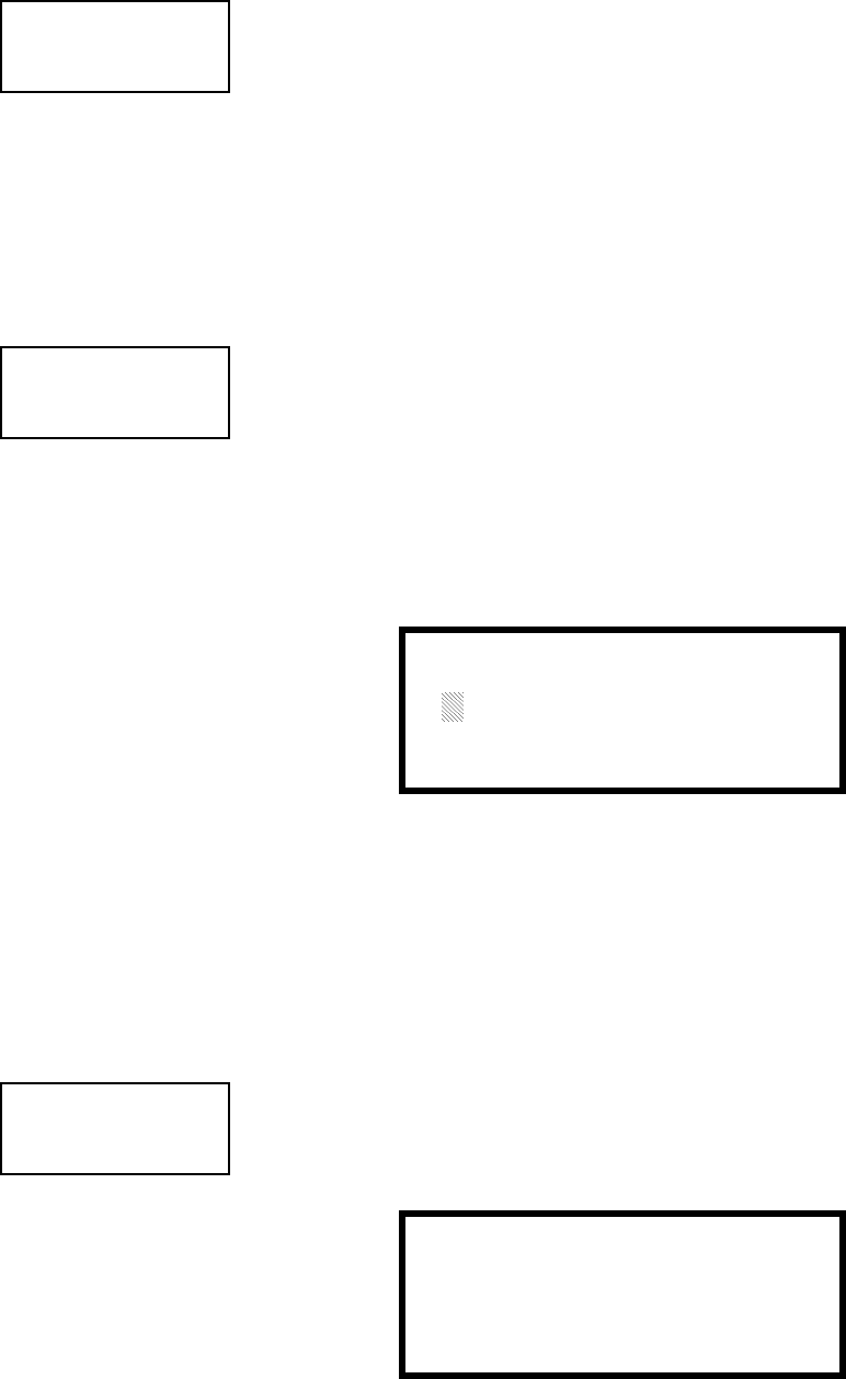
3URJUDPPLQJ 0DVWHU3URJUDPPLQJ/HYHO
068'31$
3UHVLJQDO
To enable the Pre-signal feature, press 1 while viewing Edit Monitor Screen #3 until
the display reads Pre-signal Yes. Each press of the 1 key will cause the display to
toggle between Pre-signal Yes and Pre-signal No. Refer to "Presignal" on page 137
for additional information.
3$6
7RHQDEOHWKH3$6IHDWXUHSUHVVZKLOHYLHZLQJWKH(GLW'HWHFWRU6FUHHQXQWLO
WKHGLVSOD\UHDGV3$ 6 <H V (DFKSUHVVRIWKHNH\ZLOOFDXVHWKHGLVSOD\WRWRJJOH
EHWZHHQ3$ 6 <H V DQG3$ 6 1 R 5HIHUWR3RVLWLYH$ODUP6HTXHQFHRQSDJHIRU
DGGLWLRQDOLQIRUPDWLRQ
:DONWHVW
7KH:DONWHVWIHDWXUHDOORZVRQHSHUVRQWRWHVWWKHV\VWHPGHYLFHVZLWKRXWWKH
QHFHVVLW\RIPDQXDOO\UHVHWWLQJWKHFRQWUROSDQHODIWHUHDFKGHYLFHDFWLYDWLRQ7R
HQDEOHGHYLFHVZKLFKDUHFRQQHFWHGWRDPRQLWRUPRGXOHIRUWKH:DONWHVWIHDWXUH
SUHVVZKLOHYLHZLQJWKH(GLW0RQLWRU6FUHHQXQWLOWKHGLVSOD\UHDGV:DO NWHV W
<HV(DFKSUHVVRIWKHNH\ZLOOFDXVHWKHGLVSOD\WRWRJJOHEHWZHHQ:DONWHVW<HV
DQG:DONWHVW1R5HIHUWR:DONWHVWRQSDJHIRUDGGLWLRQDOLQIRUPDWLRQ
=RQH$VVLJQPHQW
$PD[LPXPRIILYH]RQHVFDQEHSURJUDPPHGWRHDFKDGGUHVVDEOHPRQLWRUPRGXOH
3UHVVLQJZKLOHYLHZLQJ(GLW0RQLWRU6FUHHQGLVSOD\VWKHIROORZLQJVFUHHQ
1RWHWKDW=UHSUHVHQWVWKH=RQH1XPEHUVFRUUHVSRQGLQJWRWKLVGHYLFH7KH
IDFWRU\GHIDXOWIRUDQXQSURJUDPPHGGHYLFHLV=IRUJHQHUDODODUP]RQH$
IODVKLQJFXUVRUZLOODSSHDURQWKHILUVWWRWKHOHIW(QWHUWKHWZRGLJLWQXPEHU
FRUUHVSRQGLQJWRWKH]RQHWKDWLVWREHDVVLJQHGWRWKLVGHYLFH7KHFXUVRUPRYHVWR
WKHQH[W=GHVLJQDWLRQ&RQWLQXHHQWHULQJ]RQHDVVLJQPHQWVRUWKHUHPDLQLQJ
]RQHVFDQEHOHIWEODQNRUSURJUDPPHGDVJHQHUDODODUP]RQHV=:KHQDOO
GHVLUHGFKDQJHVKDYHEHHQPDGHSUHVVWKH(QWHUNH\WRVWRUHWKH]RQHDVVLJQPHQWV
7KHGLVSOD\ZLOOUHWXUQWRWKH(GLW0RQLWRU6FUHHQ
1RXQ$GMHFWLYH
7KH1RXQ$GMHFWLYHVHOHFWLRQDOORZVWKHSURJUDPPHUWRHQWHUVSHFLILFGHVFULSWRUV
DERXWWKHPRQLWRUPRGXOHFXUUHQWO\EHLQJSURJUDPPHG3UHVVLQJZKLOHYLHZLQJ
(GLW0RQLWRU6FUHHQZLOOFDXVHWKHIROORZLQJVFUHHQWREHGLVSOD\HG
EDIT MONITOR
1=PRE-SIGNAL
2=PAS
Edit Monitor Screen #3
See Page
See Page
EDIT MONITOR
1=WALKTEST
2=ZONE ASSIGNMENT
00 ** ** ** **
Edit Monitor Screen #4
MON ZONE ASSIGN
Z00 Z** Z** Z** Z**
Zone Assignment Screen
EDIT MONITOR
1=NOUN/ADJECTIVE
2=DESCRIPTION
*****************
Edit Monitor Screen #5
1=STANDARD ADJECTIVE
2=STANDARD NOUN
3=CUSTOM ADJECTIVE
4=CUSTOM NOUN
Noun/Adjective Screen

0DVWHU3URJUDPPLQJ/HYHO 3URJUDPPLQJ
068'31$
Pressing 1 while viewing the Noun/Adjective Screen will cause the following
screen(s) to be displayed. Note that the keyboard down arrow key must be pressed
to see all the Adjective screens. Press the number corresponding to the adjective
that is to be used as a descriptor for the location of the monitor module currently
being programmed.
1=STANDARD ADJECTIVE
2=STANDARD NOUN
3=CUSTOM ADJECTIVE
4=CUSTOM NOUN
Noun/Adjective Screen
**********************
1=NORTH
2=SOUTH
3=EAST
Adjective Screen #1
**********************
1=WEST
2=FRONT
3=CENTER
Adjective Screen #2
**********************
1=REAR
2=UPPER
3=LOWER
Adjective Screen #3
**********************
1=MAIN
2=FIRST
3=2ND
Adjective Screen #4
**********************
1=3RD
2=4TH
3=5TH
Adjective Screen #5
**********************
1=FLOOR 4
2=FLOOR 5
3=ROOM
Adjective Screen #7
**********************
1=FLOOR 1
2=FLOOR 2
3=FLOOR 3
Adjective Screen #6

3URJUDPPLQJ 0DVWHU3URJUDPPLQJ/HYHO
068'31$
3UHVVLQJZKLOHYLHZLQJWKH1RXQ$GMHFWLYH6FUHHQZLOOFDXVHWKHIROORZLQJ
VFUHHQVWREHGLVSOD\HG1RWHWKDWWKHNH\ERDUGGRZQDUURZNH\PXVWEHSUHVVHG
WRVHHDOOWKH1RXQVFUHHQVPress the number corresponding to the noun that is to
be used as a descriptor for the location of the monitor module currently being
programmed.
3UHVVLQJRUZKLOHYLHZLQJWKH1RXQ$GMHFWLYH6FUHHQZLOOGLVSOD\VFUHHQV
VLPLODUWRWKHSUHYLRXV$GMHFWLYHDQG1RXQ6FUHHQV7KHQHZVFUHHQVZLOOOLVW
&XVWRP$GMHFWLYHVDQG1RXQVZKLFKKDYHEHHQSURJUDPPHGLQWRWKHFRQWUROSDQHO
XVLQJWKH3.3OXVSURJUDPPLQJNLW
1=STANDARD ADJECTIVE
2=STANDARD NOUN
3=CUSTOM ADJECTIVE
4=CUSTOM NOUN
Noun/Adjective Screen
**********************
1=BASEMENT
2=BOILER RM
3=CLASSROOM
Noun Screen #1
**********************
1=CLOSET
2=CORRIDOR
3=ELECTRIC RM
Noun Screen #2
**********************
1=ELEVATOR
2=ENTRANCE
3=FLOOR
Noun Screen #3
**********************
1=GARAGE
2=HALLWAY
3=HVAC RM
Noun Screen #4
**********************
1=KITCHEN
2=LOBBY
3=OFFICE
Noun Screen #5
**********************
1=STAIRWAY
2=STOREROOM
3=WING
Noun Screen #7
**********************
1=PATIENT
2=RESTROOM
3=ROOM
Noun Screen #6
**********************
1=ZONE
Noun Screen #8

0DVWHU3URJUDPPLQJ/HYHO 3URJUDPPLQJ
068'31$
'HVFULSWLRQ
7KH'HVFULSWLRQVHOHFWLRQDOORZVWKHSURJUDPPHUWRHQWHUDGGLWLRQDOLQIRUPDWLRQ
DERXWWKHPRQLWRUPRGXOHFXUUHQWO\EHLQJSURJUDPPHG7KLVLQIRUPDWLRQZLOOEH
GLVSOD\HGDVSDUWRIWKHGHYLFHODEHORQWKH/&'GLVSOD\3UHVVLQJZKLOHYLHZLQJ
(GLW0RQLWRU6FUHHQZLOOFDXVHWKHIROORZLQJVFUHHQWREHGLVSOD\HG
$IODVKLQJFXUVRUZLOODSSHDUDWWKHILUVWDVWHULVNWRWKHOHIW7KHSURJUDPPHUFDQ
HQWHUDGGLWLRQDOGHVFULSWLYHLQIRUPDWLRQDERXWWKHGHYLFHEHLQJSURJUDPPHG7KLV
LQIRUPDWLRQZLOODSSHDURQWKH/&'GLVSOD\DORQJZLWKWKHVWDQGDUGGHYLFHODEHO
LQIRUPDWLRQ
$PD[LPXPRIFKDUDFWHUVLQFOXGLQJVSDFHVFDQEHHQWHUHG7RHQWHU
DOSKDQXPHULFFKDUDFWHUVIURPWKHNH\SDGUHSHDWHGO\SUHVVWKHDSSURSULDWHNH\XQWLO
WKHGHVLUHGFKDUDFWHULVGLVSOD\HGLQWKHILUVWSRVLWLRQ)RUH[DPSOHWRHQWHUWKH
OHWWHU%SUHVVWKH$%&NH\WKUHHWLPHVWRWRJJOHWKURXJKWKHFKDUDFWHUV$DQG
%3UHVVWKHULJKWDUURZNH\WRPRYHWKHFXUVRURQHSRVLWLRQWRWKHULJKWDQGUHSHDW
WKHSURFHVVWRHQWHUWKHQH[WFKDUDFWHU7RHQWHUDVSDFHSUHVVWKH4=NH\IRXU
WLPHVXQWLODEODQNDSSHDUVLQWKHGHVLUHGSRVLWLRQ:KHQDOOFKDUDFWHUVKDYHEHHQ
HQWHUHGSUHVVWKH(QWHUNH\WRVWRUHWKHLQIRUPDWLRQ7KHGLVSOD\ZLOOUHWXUQWRWKH
(GLW0RQLWRU6FUHHQGLVSOD\LQJWKHQHZLQIRUPDWLRQDWWKHERWWRPRIWKHVFUHHQ
5HFDOO,QFUHPHQW)XQFWLRQ
,QDGGLWLRQWKHXVHUPD\XVHWKH5HFDOO,QFUHPHQWIXQFWLRQDWDQ\WLPHZKHQWKH
FXUVRULVRQWKHILUVWOHWWHURIWKH$GMHFWLYHRU1RXQILHOGDVIROORZV
• If the zero key is pressed, a 0 is placed in the first letter position
• If the zero key is then pressed a second time with no intervening key actions, the
entire Adjective field is replaced with the field entered for the previous device
programmed, and the cursor moves to the last character of the field (Recall
function). The Recalled Adjective or Noun field may now be changed letter-by-
letter
• If the zero key is pressed again with no other intervening key actions and the last
character in the field is a number 0-9, the number is incremented by one. If the
last character is a letter, it changes to a 0. If the last character goes from 9 to 0
and the characters to the left of the last character are also numbers, they are also
incremented (overflow)
• The above increment function may be repeated with each press of the zero key
EDIT MONITOR
1=NOUN/ADJECTIVE
2=DESCRIPTION
*****************
Edit Monitor Screen #5
DESCRIPTION 1M012
1=NOUN/ADJECTIVE
********************
Noun/Adjective Screen

3URJUDPPLQJ 0DVWHU3URJUDPPLQJ/HYHO
068'31$
$VDQH[DPSOHWKHXVHUFRXOGTXLFNO\HQWHUµ)/5BB5220¶DVIROORZV
1. The cursor is on the first letter of the Adjective field. Press the zero key twice to
display FLR_3
2. With the cursor on the first letter of the Noun field, press the zero key twice to
recall the display ROOM_304. The cursor automatically jumps from the first to
the last letter of the Noun field
3. With the cursor on the last letter of the Noun field, press the zero key again to
increment the room number to 305
4. Press the right arrow key to advance the zone field
5. Select a zone number from 00 to 99. Z00 (default zone) is the general alarm
zone. Z01 through Z99 may be selected to link software zones
3.6.2.2.4 Edit Module Screen for Control Modules
7KHSURJUDPPHUFDQFKDQJHDPRGXOH¶VH[LVWLQJRUIDFWRU\GHIDXOWSURJUDPPLQJE\
SUHVVLQJLQWKH0RGXOHV6FUHHQ7KHIROORZLQJVFUHHQZLOOEHGLVSOD\HG
$IODVKLQJFXUVRUZLOODSSHDULQWKHSRVLWLRQRIWKHILUVWDVWHULVNWRWKHOHIW
7KHSURJUDPPHUNH\VLQWKHWKUHHGLJLWPRGXOHDGGUHVVVXFKDV:KHQWKHODVW
GLJLWLVNH\HGLQLIWKHVHOHFWHGDGGUHVVFRUUHVSRQGVWRDFRQWUROPRGXOHDVFUHHQ
GLVSOD\LQJLQIRUPDWLRQDERXWWKHFRQWUROPRGXOHZLWKWKHVHOHFWHGDGGUHVVZLOOEH
GLVSOD\HGDVLOOXVWUDWHGLQWKHIROORZLQJ
,QWKHSUHFHGLQJH[DPSOH
✓Normal - indicates that the module with the selected address is physically
installed on the SLC and communicating with the control panel (enabled)
✓<ADJ><NOUN> - represents the adjective and noun, which have been
programmed, describing the location of the displayed device
✓Control - indicates that the selected module is a control module
✓S or * - represents Silenceable (S) or Nonsilenceable (*)
✓W or * - represents Waterflow Timer Delay (W = Waterflow Timer Delay
enabled, * = Waterflow Timer Delay disabled)
✓ZNNN - represents the first of five possible software zones that the module is
assigned to (NNN = the three digit zone number from 000 - 099)
✓1M002 - represents the Loop, Device type and Device address (1 = SLC Loop,
M=Module and 002 = Module Address 02)
MODULES
1=ADD
2=DELETE
3=EDIT
Modules Screen
EDIT MODULE
ENTER MODULE ADDRESS
***
Edit Module Screen
NORMAL CONTROL
<ADJ><NOUN>
ZNNN
SW 1M002
Edit Control Screen #1

0DVWHU3URJUDPPLQJ/HYHO 3URJUDPPLQJ
068'31$
7RFKDQJHWKHSURJUDPPLQJIRUWKHGLVSOD\HGPRGXOHSUHVVWKHNH\ERDUGGRZQ
DUURZNH\WRYLHZWKHIROORZLQJ(GLW&RQWUROVFUHHQV
(QDEOH'LVDEOH0RGXOH
7R(QDEOHRU'LVDEOHWKHFRQWUROPRGXOHSUHVVWKHNH\ZKLOHYLHZLQJWKH(GLW
&RQWURO6FUHHQ(DFKSUHVVRIWKHNH\ZLOOWRJJOHWKHVFUHHQEHWZHHQ(QDEOHG
<HVDQG(QDEOHG1R,I(QDEOHG1RLVVHOHFWHGWKHPRGXOHZLOOQRWEHSROOHGE\WKH
FRQWUROSDQHOSUHYHQWLQJWKHPRGXOHIURPDFWLYDWLQJLWVRXWSXWGHYLFHV7KHFRQWURO
SDQHOZLOOLQGLFDWHDV\VWHPWURXEOHFRQGLWLRQDQGWKH'LVDEOH/('ZLOOWXUQRQLI
DQ\GHYLFHVDUHGLVDEOHG
EDIT CONTROL
1=ENABLED YES
2=TYPE CONTROL
3=SILENCEABLE YES
Edit Control Screen #2
EDIT CONTROL
1=WALKTEST YES
2=ZONE ASSIGNMENT
00 ** ** ** **
Edit Control Screen #3
EDIT CONTROL
1=NOUN/ADJECTIVE
2=DESCRIPTION
********************
Edit Control Screen #4
EDIT CONTROL
1=ENABLED
2=TYPE
3=SILENCEABLE
Edit Control Screen #2

3URJUDPPLQJ 0DVWHU3URJUDPPLQJ/HYHO
068'31$
7\SH
7RVHOHFWWKHW\SHRIFRQWUROPRGXOHEHLQJSURJUDPPHGSUHVVWKHNH\ZKLOH
YLHZLQJWKH(GLW&RQWURO6FUHHQ7KLVZLOOFDXVHWKHFRQWUROSDQHOWRGLVSOD\WKH
IROORZLQJ&RQWURO7\SH6FUHHQV
:KLOHYLHZLQJRQHRIWKH&RQWURO7\SHVFUHHQVVHOHFWWKHW\SHRIFRQWUROPRGXOH
EHLQJSURJUDPPHGE\SUHVVLQJWKHFRUUHVSRQGLQJNH\SDGQXPEHUNH\7KHGLVSOD\
ZLOOUHWXUQWRWKH(GLW&RQWURO6FUHHQDQGLQGLFDWHWKHQHZW\SHVHOHFWLRQ
1RWH$FRQWUROPRGXOHVHWWRWKH5HVHWWDEOH3RZHUW\SHZLOOIROORZWKHPDLQFLUFXLW
ERDUG9'&UHVHWWDEOHSRZHUXQOHVVWKHFRQWUROPRGXOHLVGLVDEOHG
7KHIROORZLQJWDEOHFRQWDLQVFRQWUROPRGXOHW\SHFRGHVDQGWKHLUIXQFWLRQV
Control Type Special Function
Blank None
Bell Circuit None
Horn Circuit None
Sounders None
Relay Ignore Open Circuit
Strobe Circuit None
Control None
Resettable Power Relay Type - Ignore Open Circuit
EDIT CONTROL
1=ENABLED
2=TYPE
3=SILENCEABLE
Edit Control Screen #2
CONTROL TYPE
1=BLANK
2=BELL-CIRCUIT
3=HORN-CIRCUIT
Control Type Screen #1
CONTROL TYPE
1=CONTROL
2=RESETTABLE POWER
Control Type Screen #3
CONTROL TYPE
1=SOUNDERS
2=RELAY-1FC
3=STROBE-CKT
Control Type Screen #2

0DVWHU3URJUDPPLQJ/HYHO 3URJUDPPLQJ
068'31$
6LOHQFHDEOH
7KH6LOHQFHDEOHVHOHFWLRQDOORZVWKHSURJUDPPHUWRVHOHFWZKHWKHURXWSXWGHYLFHV
FRQQHFWHGWRWKHFRQWUROPRGXOHFDQEHVLOHQFHGHLWKHUE\SUHVVLQJWKH$ODUP
6LOHQFHNH\RUE\HQDEOLQJ$XWRVLOHQFH3UHVVLQJWKHNH\ZKLOHYLHZLQJ(GLW
&RQWURO6FUHHQZLOOHQDEOHWKH6LOHQFHDEOHIHDWXUHFDXVLQJWKHGLVSOD\WRUHDG
6LOHQFHDEOH<HV5HSHDWHGSUHVVHVRIWKHNH\ZLOOFDXVHWKHGLVSOD\WRWRJJOH
EHWZHHQ6LOHQFHDEOH<HVDQG6LOHQFHDEOH1R
:DONWHVW
7KH:DONWHVWIHDWXUHDOORZVRQHSHUVRQWRWHVWWKHV\VWHPGHYLFHVZLWKRXWWKH
QHFHVVLW\RIPDQXDOO\UHVHWWLQJWKHFRQWUROSDQHODIWHUHDFKGHYLFHDFWLYDWLRQ7R
HQDEOHGHYLFHVZKLFKDUHFRQQHFWHGWRDFRQWUROPRGXOHIRUWKH:DONWHVWIHDWXUH
SUHVVZKLOHYLHZLQJWKH(GLW&RQWURO6FUHHQXQWLOWKHGLVSOD\UHDGV:DO NWHV W
<HV(DFKSUHVVRIWKHNH\ZLOOFDXVHWKHGLVSOD\WRWRJJOHEHWZHHQ:DONWHVW<HV
DQG:DONWHVW1R5HIHUWR:DONWHVWRQSDJHIRUDGGLWLRQDOLQIRUPDWLRQ
=RQH$VVLJQPHQW
$PD[LPXPRIILYH]RQHVFDQEHSURJUDPPHGWRHDFKDGGUHVVDEOHFRQWUROPRGXOH
3UHVVLQJZKLOHYLHZLQJ(GLW&RQWURO6FUHHQGLVSOD\VWKHIROORZLQJVFUHHQ
1RWHWKDW=UHSUHVHQWVWKH=RQH1XPEHUVFRUUHVSRQGLQJWRWKLVGHYLFH7KH
IDFWRU\GHIDXOWIRUDQXQSURJUDPPHGGHYLFHLV=IRUJHQHUDODODUP]RQH$
IODVKLQJFXUVRUZLOODSSHDURQWKHILUVWWRWKHOHIW(QWHUWKHWZRGLJLWQXPEHU
FRUUHVSRQGLQJWRWKH]RQHWKDWLVWREHDVVLJQHGWRWKLVGHYLFH7KHFXUVRUPRYHVWR
WKHQH[W=GHVLJQDWLRQ&RQWLQXHHQWHULQJ]RQHDVVLJQPHQWVRUWKHUHPDLQLQJ
]RQHVFDQEHOHIWEODQNRUSURJUDPPHGDVJHQHUDODODUP]RQHV=:KHQDOO
GHVLUHGFKDQJHVKDYHEHHQPDGHSUHVVWKH(QWHUNH\WRVWRUHWKH]RQHDVVLJQPHQWV
7KHGLVSOD\ZLOOUHWXUQWRWKH(GLW&RQWURO6FUHHQ
1RXQ$GMHFWLYH
7KH1RXQ$GMHFWLYHVHOHFWLRQDOORZVWKHSURJUDPPHUWRHQWHUVSHFLILFGHVFULSWRUV
DERXWWKHFRQWUROPRGXOHFXUUHQWO\EHLQJSURJUDPPHG3UHVVLQJZKLOHYLHZLQJ
(GLW&RQWURO6FUHHQZLOOFDXVHWKHIROORZLQJVFUHHQWREHGLVSOD\HG
EDIT CONTROL
1=ENABLED
2=TYPE
3=SILENCEABLE
Edit Control Screen #2
EDIT CONTROL
1=WALKTEST
2=ZONE ASSIGNMENT
00 ** ** ** **
Edit Control Screen #3
ZONE ASSIGNMENT
Z00 Z** Z** Z** Z**
Zone Assignment Screen
EDIT CONTROL
1=NOUN/ADJECTIVE
2=DESCRIPTION
Edit Control Screen #4
1=STANDARD ADJECTIVE
2=STANDARD NOUN
3=CUSTOM ADJECTIVE
4=CUSTOM NOUN
Noun/Adjective Screen

3URJUDPPLQJ 0DVWHU3URJUDPPLQJ/HYHO
068'31$
3UHVVLQJZKLOHYLHZLQJWKH1RXQ$GMHFWLYH6FUHHQZLOOFDXVHWKHIROORZLQJ
VFUHHQVWREHGLVSOD\HG1RWHWKDWWKHNH\ERDUGGRZQDUURZNH\PXVWEHSUHVVHG
WRVHHDOOWKH$GMHFWLYHVFUHHQVPress the number corresponding to the adjective
that is to be used as a descriptor for the location of the control module currently
being programmed.
1=STANDARD ADJECTIVE
2=STANDARD NOUN
3=CUSTOM ADJECTIVE
4=CUSTOM NOUN
Noun/Adjective Screen
**********************
1=NORTH
2=SOUTH
3=EAST
Adjective Screen #1
**********************
1=WEST
2=FRONT
3=CENTER
Adjective Screen #2
**********************
1=REAR
2=UPPER
3=LOWER
Adjective Screen #3
**********************
1=MAIN
2=FIRST
3=2ND
Adjective Screen #4
**********************
1=3RD
2=4TH
3=5TH
Adjective Screen #5
**********************
1=FLOOR 4
2=FLOOR 5
3=ROOM
Adjective Screen #7
**********************
1=FLOOR 1
2=FLOOR 2
3=FLOOR 3
Adjective Screen #6

0DVWHU3URJUDPPLQJ/HYHO 3URJUDPPLQJ
068'31$
3UHVVLQJZKLOHYLHZLQJWKH1RXQ$GMHFWLYH6FUHHQZLOOFDXVHWKHIROORZLQJ
VFUHHQVWREHGLVSOD\HG1RWHWKDWWKHNH\ERDUGGRZQDUURZNH\PXVWEHSUHVVHG
WRVHHDOOWKH1RXQVFUHHQVPress the number corresponding to the noun that is to
be used as a descriptor for the location of the control module currently being
programmed.
3UHVVLQJRUZKLOHYLHZLQJWKH1RXQ$GMHFWLYH6FUHHQZLOOGLVSOD\VFUHHQV
VLPLODUWRWKHSUHYLRXV$GMHFWLYHDQG1RXQ6FUHHQV7KHQHZVFUHHQVZLOOOLVW
&XVWRP$GMHFWLYHVDQG1RXQVZKLFKKDYHEHHQSURJUDPPHGLQWRWKHFRQWUROSDQHO
XVLQJWKH3.3OXVSURJUDPPLQJNLW
1=STANDARD ADJECTIVE
2=STANDARD NOUN
3=CUSTOM ADJECTIVE
4=CUSTOM NOUN
Noun/Adjective Screen
**********************
1=BASEMENT
2=BOILER RM
3=CLASSROOM
Noun Screen #1
**********************
1=CLOSET
2=CORRIDOR
3=ELECTRIC RM
Noun Screen #2
**********************
1=ELEVATOR
2=ENTRANCE
3=FLOOR
Noun Screen #3
**********************
1=GARAGE
2=HALLWAY
3=HVAC RM
Noun Screen #4
**********************
1=KITCHEN
2=LOBBY
3=OFFICE
Noun Screen #5
**********************
1=STAIRWAY
2=STOREROOM
3=WING
Noun Screen #7
**********************
1=PATIENT
2=RESTROOM
3=ROOM
Noun Screen #6
**********************
1=ZONE
Noun Screen #8

3URJUDPPLQJ 0DVWHU3URJUDPPLQJ/HYHO
068'31$
'HVFULSWLRQ
7KH'HVFULSWLRQVHOHFWLRQDOORZVWKHSURJUDPPHUWRHQWHUDGGLWLRQDOLQIRUPDWLRQ
DERXWWKHFRQWUROPRGXOHFXUUHQWO\EHLQJSURJUDPPHG7KLVLQIRUPDWLRQZLOOEH
GLVSOD\HGDVSDUWRIWKHGHYLFHODEHORQWKHGLVSOD\3UHVVLQJZKLOHYLHZLQJ(GLW
&RQWURO6FUHHQZLOOFDXVHWKHIROORZLQJVFUHHQWREHGLVSOD\HG
$IODVKLQJFXUVRUZLOODSSHDUDWWKHILUVWDVWHULVNWRWKHOHIW7KHSURJUDPPHUFDQ
HQWHUDGGLWLRQDOGHVFULSWLYHLQIRUPDWLRQDERXWWKHGHYLFHEHLQJSURJUDPPHG7KLV
LQIRUPDWLRQZLOODSSHDURQWKHGLVSOD\DORQJZLWKWKHVWDQGDUGGHYLFHODEHO
LQIRUPDWLRQ
$PD[LPXPRIFKDUDFWHUVLQFOXGLQJVSDFHVFDQEHHQWHUHG7RHQWHU
DOSKDQXPHULFFKDUDFWHUVIURPWKHNH\SDGUHSHDWHGO\SUHVVWKHDSSURSULDWHNH\XQWLO
WKHGHVLUHGFKDUDFWHULVGLVSOD\HGLQWKHILUVWSRVLWLRQ)RUH[DPSOHWRHQWHUWKH
OHWWHU%SUHVVWKH$%&NH\WKUHHWLPHVWRWRJJOHWKURXJKWKHFKDUDFWHUV$DQG
%3UHVVWKHULJKWDUURZNH\WRPRYHWKHFXUVRURQHSRVLWLRQWRWKHULJKWDQGUHSHDW
WKHSURFHVVWRHQWHUWKHQH[WFKDUDFWHU7RHQWHUDVSDFHSUHVVWKH4=NH\IRXU
WLPHVXQWLODEODQNDSSHDUVLQWKHGHVLUHGSRVLWLRQ:KHQDOOFKDUDFWHUVKDYHEHHQ
HQWHUHGSUHVVWKH(QWHUNH\WRVWRUHWKHLQIRUPDWLRQ7KHGLVSOD\ZLOOUHWXUQWRWKH
(GLW&RQWURO6FUHHQGLVSOD\LQJWKHQHZLQIRUPDWLRQDWWKHERWWRPRIWKHVFUHHQ
5HFDOO,QFUHPHQW)XQFWLRQ
,QDGGLWLRQWKHXVHUPD\XVHWKH5HFDOO,QFUHPHQWIXQFWLRQDWDQ\WLPHZKHQWKH
FXUVRULVRQWKHILUVWOHWWHURIWKH$GMHFWLYHRU1RXQILHOGDVIROORZV
• If the zero key is pressed, a 0 is placed in the first letter position
• If the zero key is then pressed a second time with no intervening key actions, the
entire Adjective field is replaced with the field entered for the previous device
programmed, and the cursor moves to the last character of the field (Recall
function). The Recalled Adjective or Noun field may now be changed letter-by-
letter
• If the zero key is pressed again with no other intervening key actions and the last
character in the field is a number 0-9, the number is incremented by one. If the
last character is a letter, it changes to a 0. If the last character goes from 9 to 0
and the characters to the left of the last character are also numbers, they are also
incremented (overflow)
• The above increment function may be repeated with each press of the zero key
$VDQH[DPSOHWKHXVHUFRXOGTXLFNO\HQWHUµ)/5BB5220¶DVIROORZV
1. The cursor is on the first letter of the Adjective field. Press the zero key twice to
display FLR_3
2. With the cursor on the first letter of the Noun field, press the zero key twice to
recall the display ROOM_304. The cursor automatically jumps from the first to
the last letter of the Noun field
3. With the cursor on the last letter of the Noun field, press the zero key again to
increment the room number to 305
4. Press the right arrow key to advance the zone field
5. Select a zone number from 00 to 99. Z00 (default zone) is the general alarm
zone. Z01 through Z99 may be selected to link software zones
EDIT CONTROL
1=ADJECTIVE/NOUN
2=DESCRIPTION
Edit Control Screen #4
DESCRIPTION 1M002
1=NOUN/ADJECTIVE
********************
Adjective/Noun Screen
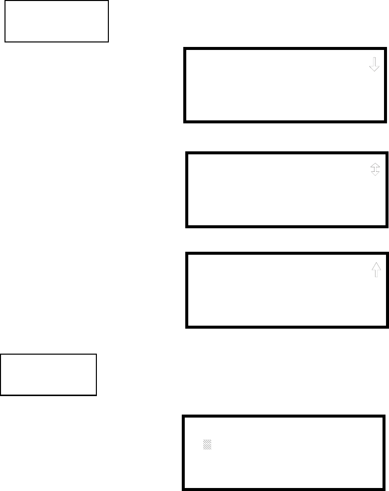
0DVWHU3URJUDPPLQJ/HYHO 3URJUDPPLQJ
068'31$
3.6.3 Zone Setup
Pressing 3 while viewing Programming Screen #2 will access the Zone Setup screens as
illustrated below:
3.6.3.1 Enable
Pressing 1 for Enable, while viewing Zone Setup Screen #1, will display the
following screen:
7KLVVFUHHQVDOORZVWKHSURJUDPPHUWRHQDEOH]RQHVRQHDWDWLPH$IODVKLQJ
FXUVRUDSSHDUVQH[WWRWKH=SURPSWLQJWKHSURJUDPPHUWRHQWHUDWZRGLJLW]RQH
QXPEHU:KHQWKHVHFRQGGLJLWLVHQWHUHGWKH]RQHZLOOEHHQDEOHGDQG
WKHFXUVRUUHWXUQVWRWKHRULJLQDOSRVLWLRQQH[WWRWKH=$QRWKHU]RQHFDQWKHQEH
HQDEOHG
PROGRAMMING
1=AUTOPROGRAM
2=POINT PROGRAM
3=ZONE SETUP
Programming Screen #2
ZONE SETUP
1=ENABLE
2=DISABLE
3=ZONE 97 98 99
Zone Setup Screen #1
ZONE SETUP
1=ZONES INSTALLED
2=ZONES ENABLED
3=ZONES DISABLED
Zone Setup Screen #2
ZONE SETUP
1=ZONE TYPES
2=ZONES AVAILABLE
Zone Setup Screen #3
ZONE SETUP
1=ENABLE
2=DISABLE
3=ZONE 97 98 99
Zone Setup Screen #1
ZONE TO ENABLE
Z
Enable Screen

3URJUDPPLQJ 0DVWHU3URJUDPPLQJ/HYHO
068'31$
3.6.3.2 Disable
Pressing 2 for Disable, while viewing Zone Setup Screen #1, displays the following:
7KLVVFUHHQDOORZVWKHSURJUDPPHUWRGLVDEOH]RQHVRQHDWDWLPH$IODVKLQJ
FXUVRUDSSHDUVQH[WWRWKH=SURPSWLQJWKHSURJUDPPHUWRHQWHUDWZRGLJLW]RQH
QXPEHU:KHQWKHVHFRQGGLJLWLVHQWHUHGWKH]RQHZLOOEHGLVDEOHGDQG
WKHFXUVRUZLOOUHWXUQWRWKHRULJLQDOSRVLWLRQQH[WWRWKH=$QRWKHU]RQHFDQWKHQ
EHGLVDEOHG
3.6.3.3 Zone 97, 98 and 99
3UHVVLQJIRU=RQHDQGZKLOHYLHZLQJ=RQH6HWXS6FUHHQZLOO
GLVSOD\WKHIROORZLQJVFUHHQ
=RQHVDQGFDQEHSURJUDPPHGIRUQRUPDO]RQHRSHUDWLRQRUIRUVSHFLDO
SXUSRVHDSSOLFDWLRQV,QWKHDERYHLOOXVWUDWLRQWKHWKUHH]RQHVDUHVKRZQ2II
ZKLFKPHDQVWKH\FDQEHSURJUDPPHGWRIXQFWLRQLQWKHVDPHPDQQHUDVDOORWKHU
]RQHVE\DVVLJQLQJWKHPWRLQSXWDQGRXWSXWGHYLFHVLQWKH3URJUDPPLQJ=RQH
$VVLJQPHQW6FUHHQ
3UHVVLQJZLOOFDXVHWKHGLVSOD\WRFKDQJHWR3$62Q(DFKSUHVVRIWKHNH\
ZLOOFDXVHWKHGLVSOD\WRWRJJOHEHWZHHQ3$62QDQG3$62II:KHQ=RQH
LVSURJUDPPHG2QD3$63RVLWLYH$ODUP6HTXHQFHDFWLYDWLRQRIDQ\GHYLFHZLOO
FDXVH=RQHWRDFWLYDWH%\DVVLJQLQJ=RQHWRDFRQWUROPRGXOHLQWKH
3URJUDPPLQJ=RQH$VVLJQPHQW6FUHHQDQRXWSXWGHYLFHFRQQHFWHGWRWKHFRQWURO
PRGXOHFDQEHXVHGWRLQGLFDWHD3$6FRQGLWLRQLQWKHFRQWUROSDQHO'RQRWDVVLJQ
=RQHWRD1RWLILFDWLRQ$SSOLDQFH&LUFXLWZKHQXVLQJWKLV]RQHWRLQGLFDWHD3$6
FRQGLWLRQ$WWHPSWLQJWRGRVRZLOOJHQHUDWHDQHUURUPHVVDJHDQGZLOOEH
SUHYHQWHGE\VRIWZDUHFKHFNV
3UHVVLQJZLOOFDXVHWKHGLVSOD\WRFKDQJHWR3UHVLJQDO2Q(DFKSUHVVRIWKH
NH\ZLOOFDXVHWKHGLVSOD\WRWRJJOHEHWZHHQ3UHVLJQDO2QDQG3UHVLJQDO
2II:KHQ=RQHLVSURJUDPPHG2QD3UHVLJQDODFWLYDWLRQRIDQ\GHYLFHZLOO
FDXVH=RQHWRDFWLYDWH%\DVVLJQLQJ=RQHWRDFRQWUROPRGXOHLQWKH
3URJUDPPLQJ=RQH$VVLJQPHQW6FUHHQDQRXWSXWGHYLFHFRQQHFWHGWRWKHFRQWURO
PRGXOHFDQEHXVHGWRLQGLFDWHD3UHVLJQDOFRQGLWLRQLQWKHFRQWUROSDQHO'RQRW
DVVLJQ=RQHWRD1RWLILFDWLRQ$SSOLDQFH&LUFXLWZKHQXVLQJWKLV]RQHWRLQGLFDWH
D3UHVLJQDOFRQGLWLRQ$WWHPSWLQJWRGRVRZLOOJHQHUDWHDQHUURUPHVVDJHDQGZLOO
EHSUHYHQWHGE\VRIWZDUHFKHFNV
=RQHLQVSHFLDOSXUSRVHPRGHLVUHVHUYHGIRUIXWXUHXVHDQGKDVQRHIIHFW
ZONE SETUP
1=ENABLE
2=DISABLE
3=ZONE 97 98 99
Zone Setup Screen #1 ZONE TO DISABLE
Z
Disable Screen
SPEC PURPOSE ZONE
1=PAS 97 OFF
2=PRESIGNAL 98 OFF
3=ZONE 99 OFF
Zone 97, 98 and 99 Screen

0DVWHU3URJUDPPLQJ/HYHO 3URJUDPPLQJ
068'31$
3.6.3.4 Zones Installed
Pressing 1 for Zones Installed, while viewing Zone Setup Screen #2, will display a
screen similar to the following:
This display will show all of the zones that have been programmed into the control
panel. Note that an up and/or down arrow may appear in the upper right corner of
the display, indicating that additional screens of zone information exists. Press the
up or down arrow keys to view the additional zones.
3.6.3.5 Zones Enabled
Pressing 2 for Zones Enabled, while viewing Zone Setup Screen #2, will display a
screen similar to the following:
This display will show all of the zones that are enabled in the control panel. Note
that an up and/or down arrow may appear in the upper right corner of the display,
indicating that additional screens of zone information exists. Press the up or down
arrow keys to view the additional zones.
3.6.3.6 Zones Disabled
Pressing 3 for Zones Disabled, while viewing Zone Setup Screen #2, will display a
screen similar to the following:
This display will show all of the zones that are disabled in the control panel. Note
that an up and/or down arrow may appear in the upper right corner of the display,
indicating that additional screens of zone information exists. Press the up or down
arrow keys to view the additional zones.
ZONE SETUP
1=ZONES INSTALLED
2=ZONES ENABLED
3=ZONES DISABLED
Zone Setup Screen #2
ZONES INSTALLED
00 01 02 03 04 05
Zones Installed Screen
ZONES ENABLED
00 01 02 04 05 06 07
08 09 10 11 12 13 14
15 16 17 18 19 20 21
Zones Enabled Screen
ZONES DISABLED
03
Zones Disabled Screen

3URJUDPPLQJ 0DVWHU3URJUDPPLQJ/HYHO
068'31$
3.6.3.7 Zone Type
Zone Types must be programmed only if a DACT, programmed for zone reporting,
is installed on the control panel. Pressing 1 for Zone Types, while viewing Zone
Setup Screen #3, will display a screen similar to the following:
This display will show the system zones (default and user programmed) and their
associated types. Note that an up and/or down arrow will appear in the upper right
corner of the display, indicating that additional screens of zone information exists.
Press the up or down arrow keys to view zones Z00 through Z99.
=RQHW\SHVFDQEHFKDQJHGE\SUHVVLQJWKHNH\SDGQXPEHUNH\FRUUHVSRQGLQJWRWKH
]RQHLQHDFK=RQHV,QVWDOOHG6FUHHQ$YDLODEOH]RQHW\SHVZLOOEHGLVSOD\HGLQWKH
UHVXOWDQWVFUHHQV)RUH[DPSOHWRFKDQJHWKH]RQHW\SHIRU]RQH=LQWKHVFUHHQ
LOOXVWUDWHGDERYHSUHVV7KHIROORZLQJVFUHHQVZLOOEHGLVSOD\HG
7RFKDQJHWKH]RQHW\SHIRU=WR3XOO6WDWLRQVFUROOWKHGLVSOD\XQWLO=RQH7\SH
3URJUDP6FUHHQLVGLVSOD\HG3UHVVWRSURJUDP]RQH=DVD3XOO6WDWLRQ
]RQH7KHGLVSOD\ZLOOUHWXUQWRWKH=RQHV,QVWDOOHG6FUHHQVKRZLQJ]RQH=DQG
WKH3XOO6WDWLRQSURJUDPW\SH5HSHDWWKHSURFHGXUHIRUHDFK]RQHWREHFKDQJHG
,03257$17,Q=RQH7\SH3URJUDP6FUHHQVHOHFWLQJ:$7(5)/2:ZLOO
DVVLJQD:DWHUIORZVLOHQFHDEOH]RQHW\SHWRWKHVHOHFWHG]RQH$Q\VLJQDOLQJ
GHYLFHVSURJUDPPHGWRWKHVDPH]RQHFDQEHVLOHQFHGE\SUHVVLQJWKH$ODUP6LOHQFH
NH\RUE\XVLQJWKHDXWRVLOHQFHIHDWXUH
7RSURJUDPDZDWHUIORZFLUFXLWDVQRQVLOHQFHDEOHUHIHUWR6\VWHP6HWXSRQSDJH
1RWH=RQH7\SHVDUHRQO\UHOHYDQWIRU&HQWUDO6WDWLRQUHSRUWLQJ&KDQJLQJD]RQH
W\SHZLOORQO\FKDQJHKRZLWLVUHSRUWHGWRWKH&HQWUDO6WDWLRQ
ZONE SETUP
1=ZONE TYPES
2=ZONES AVAILABLE
Zone Setup Screen #3
ZONE TYPE PROG
1=Z00 MONITOR
2=Z01 MONITOR
3=Z02 MONITOR
Zones Installed Screen
ZONE TYPE PROG
1=MONITOR
2=SMOKE PHOTO
3=WATERFLOW
Zone Type Program Screen #1
ZONE TYPE PROG
1=MEDICAL
2=HAZARD
3=TAMPER
Zone Type Program Screen #3
ZONE TYPE PROG
1=SUPERVISORY
2=PROC. MON
3=SMOKE ION
Zone Type Program Screen #4
ZONE TYPE PROG
1=HEAT
2=PULL STATION
3=DUCT
Zone Type Program Screen #2

0DVWHU3URJUDPPLQJ/HYHO 3URJUDPPLQJ
068'31$
3.6.3.8 Zones Available
3UHVVLQJZKLOHYLHZLQJ=RQH6HWXS6FUHHQZLOOGLVSOD\DVFUHHQVLPLODUWRWKH
IROORZLQJ
7KHGLVSOD\ZLOOVKRZDOORIWKH]RQHVWKDWDUHVWLOODYDLODEOHIRUSURJUDPPLQJ1RWH
WKDWDQXSDQGRUGRZQDUURZPD\DSSHDULQWKHXSSHUULJKWFRUQHURIWKHGLVSOD\
LQGLFDWLQJWKDWDGGLWLRQDOVFUHHQVRI]RQHLQIRUPDWLRQH[LVWV3UHVVWKHXSRUGRZQ
DUURZNH\WRYLHZDGGLWLRQDOVFUHHQV
3.6.4 Loop Setup
Loop Setup allows the programmer to configure the SLC Loop for NFPA Style 4, 6 or 7
wiring and to select the loop protocol. Pressing 1 while viewing Programming Screen
#2 will cause the following screen to be displayed:
3.6.4.1 Style
7RSURJUDPWKH6/&6W\OHIRUWKHVHOHFWHGORRSSUHVVIRU6W\OHZKLOHYLHZLQJ
/RRS6HWXS6FUHHQ,QWKHSUHFHGLQJH[DPSOHWKHFRQWUROSDQHOLVSURJUDPPHGIRU
6W\OH6/&ZLULQJDVLQGLFDWHGE\WKHWRWKHULJKWRI6W\OHLQWKHGLVSOD\7R
FKDQJHWKHZLULQJVW\OHSUHVVWRWRJJOHWKHGLVSOD\WRUHDG6W\OH(DFKSUHVVRI
WKHNH\ZLOOFDXVHWKHGLVSOD\WRWRJJOHEHWZHHQ6W\OHDQG6W\OHNote that,
when programming the Loop Style, the programmer can only select between Style 4
and Style 6. To program a system for Style 7 wiring, the programmer must select the
Loop Setup for Style 6. Style 7 wiring is the same as Style 6 with the added
requirement that each addressable device on the loop must have a pair of isolator
modules, one on each side.
3.6.4.2 Loop Protocol
/RRS3URWRFROUHIHUVWRWKH6/&ORRSPRGHRIRSHUDWLRQ$WWKHSUHVHQWWLPHWKH
RQO\PRGHDYDLODEOHLV&/,3&ODVVLF/RRS,QWHUIDFH3URWRFROZKLFKLVXVHGIRUWKH
ROGHUOHJDF\DGGUHVVDEOHGHYLFHVVXFKDVWKH06HULHVPRGXOHVDQGGHWHFWRUV
1RWHWKDWWKHOHJDF\GHYLFHVFDQRSHUDWHRQO\LQ&/,3PRGHZKLOHWKHQHZHU
GHYLFHVDUHFRPSDWLEOHZLWK&/,3DQGDQ\IXWXUHPRGHVRIRSHUDWLRQ3UHVVLQJ
ZKLOHYLHZLQJWKH/RRS6HWXS6FUHHQZLOOKDYHQRHIIHFWRQSURJUDPPLQJDWWKLV
WLPH
'HYLFH$GGUHVVLQJ
,WLVLPSRUWDQWWRQRWHWKDWWKH068'DGGUHVVDEOHGHYLFHFDSDFLW\LV
GHWHFWRUVDQGFRQWUROPRQLWRUPRGXOHV1HZHUGHYLFHVFDQEHVHWWRDGGUHVVHV
KLJKHUWKDQEXWWKHVHDGGUHVVHVZLOOQRWIXQFWLRQZLWKWKH068'
1RWHWKDW,WLVSHUPLVVLEOHWRPL[ROGDQGQHZGHYLFHVRQWKHVDPHORRS
ZONE SETUP
1=ZONE TYPES
2=ZONES AVAILABLE
Zone Setup Screen #3
ZONES AVAILABLE
01 02 03 04 05 06 07
08 09 10 11 12 13 14
15 16 17 18 19 20 21
PROGRAMMING
1=LOOP SETUP
2=SYSTEM SETUP
3=VERIFY LOOP
Programming Screen #2
LOOP SETUP
1=STYLE 4
2=PROTOCOL CLIP
Loop Setup Screen

3URJUDPPLQJ 0DVWHU3URJUDPPLQJ/HYHO
068'31$
3.6.5 System Setup
System Setup allows the programmer to configure the following control panel features:
•Trouble Reminder: This feature, when enabled, provides an audible reminder that
an alarm or trouble still exists on the FACP after the control panel has been
silenced. The control panel piezo sounder will pulse once every 15 seconds
during an alarm and every two minutes during a trouble condition, after the
Alarm Silence or Acknowledge key is pressed. The piezo will continue to sound
at these rates until the alarm or trouble condition is cleared. If the trouble
condition is not cleared within 24 hours, the panel will reactivate the trouble
sounder and retransmit the trouble condition to the central station if connected.
•Banner: This option allows the user to change the top two lines of the LCD
display from the factory default readout of FIRE-LITE ALARMS INC to a user
defined readout when the control panel is in Normal condition.
•Time-Date: This feature allows the programmer to set the time, display format
(24 hr or 12 hr), date and daylight savings time feature into the FACP memory
•Timers: This option allows the programmer to set the PAS (Positive Alarm
Sequence) time delay, Pre-Signal time delay and Waterflow time delay.
•NACs: This feature allows the programmer to configure the control panel
Notification Appliance Circuits for a variety of options, such as circuit type,
silenceable/nonsilenceable, autosilence, coding, silence inhibit, zone assignment
and enable/disable.
•Relays: This option allows programming of two onboard relays for activation by
various control panel events, such as alarm, trouble, supervisory, etc.
•Canadian Option: This option allows the automatic programming of ionization
smoke detector sensitivity thresholds to Canadian specifications.
•Waterflow Silenceable: This option provides the ability to silence any output
circuit activated by a monitor module programmed as a waterflow type.
Pressing 2 for System Setup, while viewing Programming Screen #2, will cause the
following screens to be displayed:
PROGRAMMING
1=LOOP SETUP
2=SYSTEM SETUP
3=VERIFY LOOP
Programming Screen #2
SYSTEM SETUP
1=TROUBLE REM OFF
2=BANNER
3=TIME-DATE
System Setup Screen #1
SYSTEM SETUP
1=TIMERS
2=NAC
3=RELAYS
System Setup Screen #2
SYSTEM SETUP
1=CANADIAN OPT. OFF
2=WATERFLOW SIL. NO
System Setup Screen #3

0DVWHU3URJUDPPLQJ/HYHO 3URJUDPPLQJ
068'31$
3.6.5.1 Trouble Reminder
7KH7URXEOH5HPLQGHUIHDWXUHVFDXVHVWKHFRQWUROSDQHOSLH]RWRVRXQGDUHPLQGHU
µEHHS¶IRUDODUPVDQGWURXEOHVDIWHUWKHSDQHOKDVEHHQVLOHQFHG5HIHUWR6\VWHP
6HWXSRQSDJHIRUDGHWDLOHGGHVFULSWLRQRIWKLVIHDWXUH3UHVVLQJZKLOH
YLHZLQJ6\VWHP6HWXS6FUHHQZLOOFDXVHWKHGLVSOD\WRWRJJOHWR7URXEOH5HP
2QZKLFKHQDEOHVWKLVIHDWXUH(DFKSUHVVRIWKHNH\ZLOOFDXVHWKHGLVSOD\WR
WRJJOHEHWZHHQ7URXEOH5HP2QDQG7URXEOH5HP2II
3.6.5.2 Banner
7KHWRSOLQHRIWKHGLVSOD\ZKLFKDSSHDUVZKHQWKHFRQWUROSDQHOLVLQQRUPDOPRGH
FDQEHFKDQJHGE\XVLQJWKH%DQQHURSWLRQ3UHVVLQJZKLOHYLHZLQJ6\VWHP6HWXS
6FUHHQZLOOFDXVHWKHIROORZLQJWREHGLVSOD\HG
3UHVVLQJZKLOHYLHZLQJWKH%DQQHU6FUHHQZLOOVHOHFWWKHIDFWRU\GHIDXOWEDQQHU
VHWWLQJDQGGLVSOD\WKHIROORZLQJVFUHHQ
3UHVVLQJWKH(QWHUNH\ZLOOVWRUHWKLVVHOHFWLRQLQQRQYRODWLOHPHPRU\DQGUHWXUQWKH
GLVSOD\WRWKH%DQQHU6FUHHQ
3UHVVLQJZKLOHYLHZLQJWKH%DQQHU6FUHHQZLOOFDXVHWKHIROORZLQJVFUHHQVWREH
GLVSOD\HG
See Page
BANNER
1=FACTORY
2=USER DEFINED
Banner Screen
BANNER
1=FACTORY
2=USER DEFINED
Banner Screen
FACTORY BANNER
FIRE-LITE ALARMS INC
Factory Banner Screen
USER DEFINED BANNER
PRESS ENTER IF OK
User Defined Banner Screen #1
USER BANNER - LINE 2
PRESS ENTER IF OK
************
User Defined Banner Screen #2
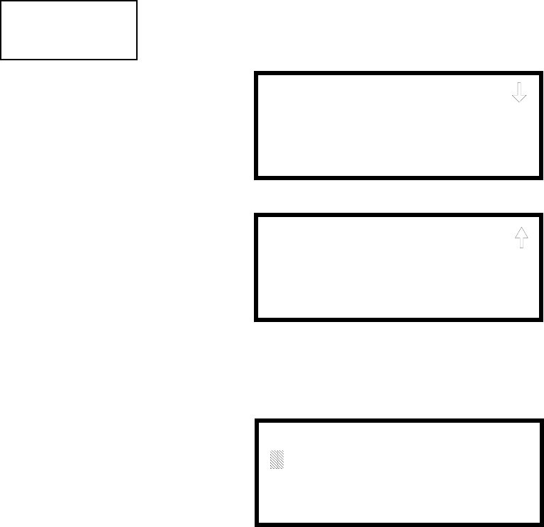
3URJUDPPLQJ 0DVWHU3URJUDPPLQJ/HYHO
068'31$
7KHVHVFUHHQVDOORZWKHSURJUDPPHUWRHQWHUDWZROLQHFXVWRPEDQQHU$IODVKLQJ
FXUVRUZLOODSSHDULQWKHERWWRPOHIWFRUQHURIHDFKGLVSOD\$PD[LPXPRI
FKDUDFWHUVLQFOXGLQJVSDFHVFDQEHHQWHUHGLQWRHDFKVFUHHQIRUDWRWDORIWZROLQHV
ZLWKFKDUDFWHUV$IWHUHQWHULQJXSWRFKDUDFWHUVLQWKHILUVWVFUHHQSUHVV(QWHU
WRYLHZWKHVHFRQGVFUHHQ(QWHUXSWRFKDUDFWHUVLQWKHVHFRQGVFUHHQLQWKH
VDPHPDQQHURUMXVWSUHVV(QWHULIDVHFRQGEDQQHUOLQHLVQRWEHLQJHQWHUHG7R
TXLFNO\FOHDUWKHFXUUHQWEDQQHUSUHVVWKH&/5NH\
7RHQWHUDOSKDQXPHULFFKDUDFWHUVIURPWKHNH\SDGUHSHDWHGO\SUHVVWKHDSSURSULDWH
NH\XQWLOWKHGHVLUHGFKDUDFWHULVGLVSOD\HGLQWKHILUVWSRVLWLRQ)RUH[DPSOHWR
HQWHUWKHOHWWHU%SUHVVWKH$%&NH\WKUHHWLPHVWRWRJJOHWKURXJKWKHFKDUDFWHUV
$DQG%3UHVVWKHULJKWDUURZNH\WRPRYHWKHFXUVRURQHSRVLWLRQWRWKHULJKW
DQGUHSHDWWKHSURFHVVWRHQWHUWKHQH[WFKDUDFWHU7RHQWHUDVSDFHSUHVVWKH4=
NH\IRXUWLPHVWRSODFHDEODQNLQWKHGHVLUHGSRVLWLRQ:KHQDOOFKDUDFWHUVKDYH
EHHQHQWHUHGSUHVVWKH(QWHUNH\WRVWRUHWKHLQIRUPDWLRQ7KHGLVSOD\ZLOOUHWXUQWR
WKH%DQQHU6FUHHQ
3.6.5.3 Time-Date
7KHFRQWUROSDQHOWLPHDQGGDWHFDQEHFKDQJHGE\SUHVVLQJZKLOHYLHZLQJWKH
6\VWHP6HWXS6FUHHQ7KHIROORZLQJVFUHHQZLOOEHGLVSOD\HG
3.6.5.3.1 Time
7RFKDQJHWKHWLPHSUHVVZKLOHYLHZLQJWKH7LPH'DWH6FUHHQ7KHIROORZLQJ
VFUHHQZLOOEHGLVSOD\HG
$IODVKLQJFXUVRULVORFDWHGWRZDUGWKHWRSOHIWRIWKHGLVSOD\%HORZWKHFXUVRULV
WKHFXUUHQWWLPH7RFKDQJHWKHWLPHHQWHUWKHWZRGLJLWKRXUVIROORZHGE\WKHWZR
GLJLWPLQXWHV7KHFXUVRUZLOOPRYHRQHSRVLWLRQWRWKHULJKWHDFKWLPHDGLJLWLV
HQWHUHG$IWHUWKHODVWPLQXWHVGLJLWLVHQWHUHGWKHFXUVRUZLOODJDLQPRYHRQH
SRVLWLRQWRWKHULJKW$WWKLVSRLQWHQWHUIRU$0RUIRU307KHGLVSOD\ZLOO
WKHQUHWXUQWRWKH7LPH'DWH6FUHHQZKLFKZLOOVKRZWKHQHZWLPHHQWU\,IDQHUURU
LVPDGHZKLOHHQWHULQJDGLJLWSUHVVWKH&/5NH\WRGHOHWHWKHHQWLUHHQWU\DQG
EHJLQQLQJDJDLQ
SYSTEM SETUP
1=TROUBLE REM
2=BANNER
3=TIME-DATE
System Setup Screen #1
TIME AND DATE
1=TIME 10:00 AM
2=DATE 04-07-2002
3=CLOCK FORMAT 12HR
Time-Date Screen #1
TIME AND DATE
1=DAYLIGHT SAVINGS
Time-Date Screen #2
ENTER TIME
10:00 AM
1=AM 2=PM
Time Screen
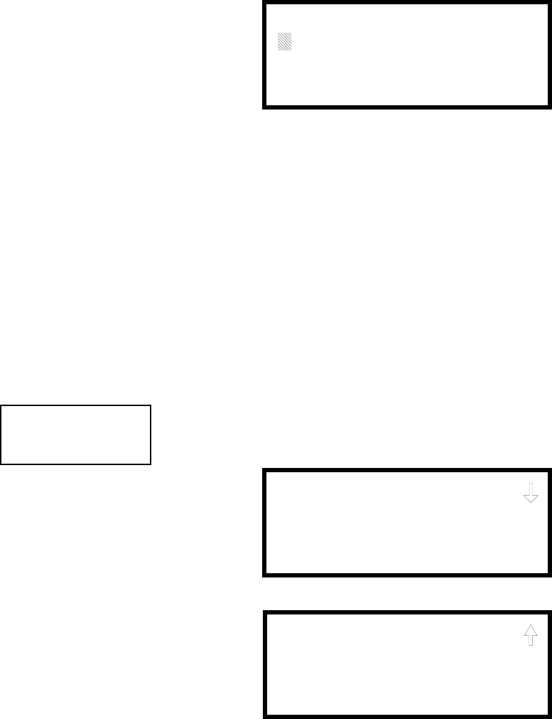
0DVWHU3URJUDPPLQJ/HYHO 3URJUDPPLQJ
068'31$
3.6.5.3.2 Date
7RFKDQJHWKHGDWHSUHVVZKLOHYLHZLQJWKH7LPH'DWH6FUHHQ7KHIROORZLQJ
VFUHHQZLOOEHGLVSOD\HG
$IODVKLQJFXUVRULVORFDWHGWRZDUGWKHWRSOHIWRIWKHGLVSOD\%HORZWKHFXUVRULV
WKHFXUUHQWGDWH7RFKDQJHWKHGDWHHQWHUWKHWZRGLJLWPRQWKIROORZHGE\WKHWZR
GLJLWGD\DQGWKHQWKHWZRGLJLW\HDUIRUIRUHWF7KHFXUVRU
ZLOOPRYHRQHSRVLWLRQWRWKHULJKWHDFKWLPHDGLJLWLVHQWHUHG$IWHUWKHODVW\HDU
GLJLWLVHQWHUHGWKHGLVSOD\ZLOOUHWXUQWRWKH7LPH'DWH6FUHHQZKLFKZLOOVKRZWKH
QHZGDWHHQWU\,IDQHUURULVPDGHZKLOHHQWHULQJDGLJLWSUHVVWKH&/5NH\WR
GHOHWHWKHHQWLUHHQWU\DQGEHJLQQLQJDJDLQ
3.6.5.3.3 Clock Format
7KHFORFNFDQEHFRQILJXUHGWRGLVSOD\KRXU$030RUKRXUPLOLWDU\
WLPH3UHVVLQJZKLOHYLHZLQJWKH7LPH'DWHVFUHHQZLOOFDXVHWKHGLVSOD\WR
WRJJOHEHWZHHQ+5DQG+56HOHFW+5IRUKRXUGLVSOD\RU+5IRU
KRXUGLVSOD\
1RWH,IWKHFORFNLVFKDQJHGWRKRXUPLOLWDU\IRUPDWWKHGDWHZLOOFKDQJHWR
WKH(XURSHDQVWDQGDUGRI'D\0RQWK<HDUIRUGLVSOD\SXUSRVHVRQO\
3.6.5.3.4 Daylight Savings Time
3UHVVLQJZKLOHYLHZLQJ7LPH'DWH6FUHHQZLOOFDXVHWKHIROORZLQJVFUHHQVWR
EHGLVSOD\HG
3UHVVLQJZKLOHYLHZLQJ'D\OLJKW6DYLQJV6FUHHQZLOOFDXVHWKHGLVSOD\WR
WRJJOHEHWZHHQ(QDEOHG<HVDQG(QDEOHG1R7KHFRQWUROSDQHOZLOODXWRPDWLFDOO\
XSGDWHWKHWLPHIRUGD\OLJKWVDYLQJVWLPHZKHQ(QDEOHG<HVLVVHOHFWHG
3UHVVLQJZKLOHYLHZLQJ'D\OLJKW6DYLQJV6FUHHQZLOOGLVSOD\DQRWKHUVFUHHQ
ZKLFKDOORZVWKHSURJUDPPHUWRVHOHFWWKHPRQWKWKDWGD\OLJKWVDYLQJVWLPHZLOO
EHJLQ,QWKLVVXEVFUHHQSUHVVLQJZLOOVHOHFW0DUFKZLOOVHOHFW$SULODQGZLOO
VHOHFW0D\
ENTER DATE
MONTH DAY YEAR
04-07-2002
Date Screen
TIME AND DATE
1=DAYLIGHT SAVINGS
Time & Date Screen #2
DAYLIGHT SAVINGS
1=ENABLED YES
2=START MONTH APR
3=START WEEK WEEK-1
Daylight Savings Screen #1
Daylight Savings Screen #2
DAYLIGHT SAVINGS
1=END MONTH OCT
2=END WEEK LAST-W

3URJUDPPLQJ 0DVWHU3URJUDPPLQJ/HYHO
068'31$
3UHVVLQJZKLOHYLHZLQJ'D\OLJKW6DYLQJV6FUHHQZLOOGLVSOD\WZRVXEVFUHHQV
ZKLFKDOORZWKHSURJUDPPHUWRVHOHFWWKHZHHNRIWKHPRQWKWKDWGD\OLJKWVDYLQJV
WLPHZLOOEHJLQ,QWKHILUVWVXEVFUHHQSUHVVLQJZLOOVHOHFWWKHILUVWZHHNZLOO
VHOHFWWKHVHFRQGZHHNDQGZLOOVHOHFWWKHWKLUGZHHNZKLOHLQWKHVHFRQGVXE
VFUHHQSUHVVLQJZLOOVHOHFWWKHIRXUWKZHHNDQGZLOOVHOHFWWKHODVWZHHNRIWKH
VHOHFWHGPRQWK
3UHVVLQJZKLOHYLHZLQJ'D\OLJKW6DYLQJV6FUHHQZLOOGLVSOD\DQRWKHUVFUHHQ
ZKLFKDOORZVWKHSURJUDPPHUWRVHOHFWWKHPRQWKWKDWGD\OLJKWVDYLQJVWLPHZLOO
HQG,QWKLVVXEVFUHHQSUHVVLQJZLOOVHOHFW6HSWHPEHUZLOOVHOHFW2FWREHUDQG
ZLOOVHOHFW1RYHPEHU
3UHVVLQJZKLOHYLHZLQJ'D\OLJKW6DYLQJV6FUHHQZLOOGLVSOD\WZRVXEVFUHHQV
ZKLFKDOORZWKHSURJUDPPHUWRVHOHFWWKHZHHNRIWKHPRQWKWKDWGD\OLJKWVDYLQJV
WLPHZLOOHQG,QWKHILUVWVXEVFUHHQSUHVVLQJZLOOVHOHFWWKHILUVWZHHNZLOO
VHOHFWWKHVHFRQGZHHNDQGZLOOVHOHFWWKHWKLUGZHHNZKLOHLQWKHVHFRQGVXE
VFUHHQSUHVVLQJZLOOVHOHFWWKHIRXUWKZHHNDQGZLOOVHOHFWWKHODVWZHHNRIWKH
VHOHFWHGPRQWK
3.6.5.4 Timers
7LPHUGHOD\VIRU3$63UHVLJQDODQGZDWHUIORZDFWLYDWLRQFDQEHSURJUDPPHGE\
SUHVVLQJZKLOHYLHZLQJ6\VWHP6HWXS6FUHHQ7KHIROORZLQJVFUHHQZLOOEH
GLVSOD\HG
3.6.5.4.1 PAS (Positive Alarm Sequence) Delay
7KHIDFWRU\GHIDXOWVHWWLQJIRU3$6LVIRUQRGHOD\7RVHOHFWD3$6GHOD\RI
WRVHFRQGVIRUDOOGHYLFHVSURJUDPPHGIRU3$6SUHVVZKLOHYLHZLQJ7LPHU
6FUHHQ7KHIROORZLQJGLVSOD\ZLOODSSHDU
$IODVKLQJFXUVRULVSRVLWLRQHGLQWKHORZHUOHIWFRUQHURIWKHGLVSOD\(QWHUDGHOD\
WLPHFRQVLVWLQJRIWKUHHGLJLWVVXFKDVIRUILYHVHFRQGV8SRQHQWHULQJWKHWKLUG
GLJLWWKHWLPHGHOD\ZLOOEHVWRUHGLQWKHFRQWUROSDQHOPHPRU\DQGWKHGLVSOD\ZLOO
UHWXUQWRWKH'HOD\6FUHHQZKLFKZLOOLQGLFDWHWKHQHZGHOD\WLPH
SYSTEM SETUP
1=TIMERS
2=NAC
3=RELAYS
System Setup Screen #2
TIMERS
1=PAS DELAY 000
2=PRE SIGNAL 000
3=WATERFLOW 000
Timer Screen #1
TIMERS
1=AC LOSS DELAY 000
Timer Screen #2
TIMERS
1=PAS DELAY 000
2=PRE SIGNAL 000
3=WATERFLOW 000
Timer Screen #1
PAS DELAY
RANGE 0-180 SECONDS
PAS Delay Screen

0DVWHU3URJUDPPLQJ/HYHO 3URJUDPPLQJ
068'31$
3.6.5.4.2 Pre-signal Delay
7KHIDFWRU\GHIDXOWVHWWLQJIRU3UHVLJQDOGHOD\LVIRUQRGHOD\7RVHOHFWD3UH
VLJQDOGHOD\RIWRVHFRQGVIRUDOOGHYLFHVSURJUDPPHGIRU3UHVLJQDOSUHVV
ZKLOHYLHZLQJ7LPHU6FUHHQ7KHIROORZLQJVFUHHQZLOOEHGLVSOD\HG
$IODVKLQJFXUVRULVSRVLWLRQHGLQWKHORZHUOHIWFRUQHURIWKHGLVSOD\(QWHUDGHOD\
WLPHFRQVLVWLQJRIWKUHHGLJLWVVXFKDVIRUQLQHVHFRQGV8SRQHQWHULQJWKH
WKLUGGLJLWWKHWLPHGHOD\ZLOOEHVWRUHGLQWKHFRQWUROSDQHOPHPRU\DQGWKHGLVSOD\
ZLOOUHWXUQWRWKH'HOD\6FUHHQZKLFKZLOOLQGLFDWHWKHQHZGHOD\WLPH
1RWHWKDWWKH)$&3FDQEHSURJUDPPHGIRUHLWKHU3$6RU3UHVLJQDORSHUDWLRQQRW
ERWK)RUWKLVUHDVRQLIWKH3$6'HOD\WLPHULVVHWZLWKDYDOXHJUHDWHUWKDQ
DQGWKHQWKH3UH6LJQDO'HOD\WLPHULVVHWZLWKDYDOXHJUHDWHUWKDQWKH3$6
'HOD\WLPHUZLOOEHDXWRPDWLFDOO\UHVHWWR2QO\RQHRIWKHWZRWLPHUVFDQKDYH
DGHOD\WLPHVHWIRULW
3.6.5.4.3 Waterflow Delay
$GHOD\FDQEHDGGHGSULRUWRGHFODULQJDZDWHUIORZW\SHRIDODUP%HFDUHIXOWR
LQFOXGHDQ\EXLOWLQGHOD\VRIWKHZDWHUIORZGHYLFH7KHIDFWRU\GHIDXOWVHWWLQJIRU
:DWHUIORZGHOD\LVIRUQRGHOD\7RVHOHFWD:DWHUIORZGHOD\RIWR
VHFRQGVIRUDOOGHYLFHVSURJUDPPHGIRU:DWHUIORZGHOD\SUHVVZKLOHYLHZLQJ
7LPHU6FUHHQ7KHIROORZLQJVFUHHQZLOOEHGLVSOD\HG
$IODVKLQJFXUVRULVSRVLWLRQHGLQWKHORZHUOHIWFRUQHURIWKHGLVSOD\(QWHUDGHOD\
WLPHFRQVLVWLQJRIWZRGLJLWVVXFKDVIRUWZHQW\ILYHVHFRQGV8SRQHQWHULQJWKH
VHFRQGGLJLWWKHWLPHGHOD\ZLOOEHVWRUHGLQWKHFRQWUROSDQHOPHPRU\DQGWKH
GLVSOD\ZLOOUHWXUQWRWKH'HOD\6FUHHQZKLFKZLOOLQGLFDWHWKHQHZGHOD\WLPH
PRESIGNAL DELAY
RANGE 0-180 SECONDS
Pre-signal Delay Screen
TIMER
1=PAS DELAY 000
2=PRE SIGNAL 000
3=WATERFLOW 000
Timer Screen #1
WATERFLOW DELAY
RANGE 0-90 SECONDS
Waterflow Delay Screen

3URJUDPPLQJ 0DVWHU3URJUDPPLQJ/HYHO
068'31$
3.6.5.4.4 AC Loss Delay
7KHUHSRUWLQJRIDORVVRI$&SRZHUWRDFHQWUDOVWDWLRQFDQEHGHOD\HGE\
SURJUDPPLQJWKHOHQJWKRIWKHGHVLUHGGHOD\3UHVVZKLOHYLHZLQJ7LPHU6FUHHQ
WRGLVSOD\WKHIROORZLQJ
3UHVVLQJZKLOHYLHZLQJ$&/RVV'HOD\6FUHHQZLOOSURJUDPWKH)$&3WR
WUDQVPLWDQ$&/RVVUHSRUWLPPHGLDWHO\WRWKHFHQWUDOVWDWLRQ
3UHVVLQJZKLOHYLHZLQJ$&/RVV'HOD\6FUHHQZLOOGLVSOD\WKHIROORZLQJ
$IODVKLQJFXUVRUZLOODSSHDULQWKHORZHUOHIWFRUQHURIWKHGLVSOD\7\SHWKHWZR
GLJLW$&ORVVUHSRUWLQJGHOD\LQKRXUVWRKRXUGHOD\:KHQWKHVHFRQGGLJLW
LVHQWHUHGWKHGLVSOD\ZLOOUHWXUQWR$&/RVV'HOD\6FUHHQ
,PSRUWDQW)RU&HQWUDO6WDWLRQDSSOLFDWLRQV$&/RVV5HSRUWLQJ'HOD\PXVWEHVHW
WRDGHOD\YDOXHUDQJLQJIURPWRKRXUV)RU5HPRWH6WDWLRQDSSOLFDWLRQV$&
/RVV5HSRUWLQJ'HOD\PXVWEHVHWWRDGHOD\YDOXHUDQJLQJIURPWRKRXUV
1RWH$&/RVV'HOD\DOVRDSSOLHVWRDQ\SURJUDPPDEOHRXWSXWUHOD\SURJUDPPHG
IRUµ$&/RVV
3.6.5.5 NAC (Notification Appliance Circuit)
7KHRSWLRQVIRUWKH1$&VRQWKHFRQWUROSDQHOPDLQFLUFXLWERDUGFDQEHFRQILJXUH
E\SUHVVLQJZKLOHYLHZLQJ6\VWHP6HWXS6FUHHQ7KHIROORZLQJVFUHHQVZLOO
EHGLVSOD\HG
7KH1RWLILFDWLRQ$SSOLDQFH&LUFXLWVFDQEHFRQILJXUHGLQGHSHQGHQWO\E\SUHVVLQJ
IRU1$&IRU1$&IRU1$&RUIRU1$&
1RWHWKDW 1$&DQG 1$&ZLOOEHGLVSOD\HGDQGFDQEHSURJUDPPHG
UHJDUGOHVVRIKRZWKH1$&.(<FDUGLVLQVWDOOHG7KHLUSURJUDPPLQJKRZHYHUZLOO
KDYHQRHIIHFWLIWKH1$&.(<FDUGLVLQVWDOOHGIRU&ODVV$RSHUDWLRQ
TIMER
1=AC LOSS DELAY
Timer Screen #2
AC LOSS DELAY
1=NO DELAY
2=ENTER DELAY
AC Loss Delay Screen #1
AC LOSS DELAY
RANGE 00-23
AC Loss Delay Screen #2
SYSTEM SETUP
1=TIMERS
2=NAC
3=RELAYS
System Setup Screen #2
NACS
1=NAC 1 3=NAC 3
2=NAC 2 4=NAC 4
NAC Selection Screen

0DVWHU3URJUDPPLQJ/HYHO 3URJUDPPLQJ
068'31$
7KHIROORZLQJVFUHHQVZLOOEHGLVSOD\HGIRUHDFKVHOHFWLRQ
3.6.5.5.1 Enabled
3UHVVLQJZKLOHYLHZLQJ1$&6FUHHQZLOOFDXVHWKHGLVSOD\WRFKDQJHWR
(QDEOHG1R7KLVZLOOSUHYHQWWKHVHOHFWHGPDLQFLUFXLWERDUG1$&IURPDFWLYDWLQJ
LWVGHYLFHV(DFKSUHVVRIWKHNH\ZLOOFDXVHWKHGLVSOD\WRWRJJOHEHWZHHQ
(QDEOHG<HVDQG(QDEOHG1R
1RWH7KHSURJUDPPLQJIRU1$&ZLOOGHWHUPLQHWKHRSHUDWLRQRIWKHUHPRWH
SRZHUVXSSO\V\QF
NAC #
1=ENABLED YES
2=TYPE BELL
3=SILENCEABLE YES
NAC Screen #1
NAC #
1=ZONE
00 00 00 00 00
2=SIL INHIBITED NO
NAC Screen #2
NAC #
1=AUTO SILENCE 00
2=CODING
TEMPORAL
NAC Screen #3
NAC #
1=SYNC TYPE S
NAC Screen #4

3URJUDPPLQJ 0DVWHU3URJUDPPLQJ/HYHO
068'31$
3.6.5.5.2 Type
7KHPDLQFLUFXLWERDUG1$&W\SHFDQEHSURJUDPPHGE\SUHVVLQJZKLOHYLHZLQJ
1$&6FUHHQ7KHIROORZLQJVFUHHQVZLOOEHGLVSOD\HG
6HOHFWWKH1$&GHYLFHW\SHE\SUHVVLQJWKHQXPEHUFRUUHVSRQGLQJWRWKHW\SHLQWKH
DSSURSULDWHVFUHHQDVVKRZQDERYH:KHQWKHVHOHFWLRQLVPDGHWKHGLVSOD\ZLOO
UHWXUQWR1$&6FUHHQ
7KHIROORZLQJWDEOHFRQWDLQV1$&W\SHFRGHVDQGWKHLUIXQFWLRQV
3.6.5.5.3 Silenceable
3UHVVLQJZKLOHYLHZLQJ1$&6FUHHQZLOOFDXVHWKHGLVSOD\WRFKDQJHWR
6LOHQFHDEOH1R7KLVZLOOSUHYHQWWKHVHOHFWHGPDLQFLUFXLWERDUG1$&IURPEHLQJ
VLOHQFHGE\SUHVVLQJWKH$ODUP6LOHQFHNH\RUE\WKH$XWR6LOHQFHIHDWXUH(DFK
SUHVVRIWKHNH\ZLOOFDXVHWKHGLVSOD\WRWRJJOHEHWZHHQ6LOHQFHDEOH<HVDQG
6LOHQFHDEOH1R
Important: When a Notification Appliance Circuit with a mix of audible and visual
devices is programmed for silenceable and the synchronization feature is selected,
only the audible devices will be turned off if the Silence key is pressed or if the
Autosilence feature is enabled. The visual devices (strobes, etc.) will continue to
operate.
NAC Type Code Special Function
Bell None
Horn None
Strobe None
Synced Strobe Synchronized to manufacturer
Audible None
Siren Circuit None
Blank None
NAC #
1=ENABLED
2=TYPE
3=SILENCEABLE
NAC Screen #1 NAC TYPE
1=BELL
2=HORN
3=STROBE
Type Screen #1
NAC TYPE
1=FUTURE
2=SIREN CIRCUIT
3=BLANK
Type Screen #2
NAC TYPE
1=SYNCED STROBE
2=FUTURE
3=AUDIBLE
Type Screen #3

0DVWHU3URJUDPPLQJ/HYHO 3URJUDPPLQJ
068'31$
3.6.5.5.4 Auto Silence
7KH$XWR6LOHQFHIHDWXUHZKHQHQDEOHGDXWRPDWLFDOO\VLOHQFHVDOOPDLQFLUFXLW
ERDUGVLOHQFHDEOHQRWLILFDWLRQDSSOLDQFHVDIWHUDSURJUDPPHGOHQJWKRIWLPH7R
HQDEOHWKLVIHDWXUHDQGSURJUDPWKHWLPHGHOD\EHIRUH$XWR6LOHQFHDFWLYDWLRQSUHVV
ZKLOHYLHZLQJ1$&6FUHHQ7KHIROORZLQJVFUHHQVZLOOEHGLVSOD\HG
7RGLVDEOHWKH$XWR6LOHQFHIHDWXUHSUHVVIRU1RZKLOHYLHZLQJ$XWR6LOHQFH
6FUHHQ7RHQDEOHWKH$XWR6LOHQFHIHDWXUHSUHVVWKHQXPEHUFRUUHVSRQGLQJWR
WKHWLPHGHOD\ZKLFKZLOOHODSVHEHIRUH$XWR6LOHQFHDFWLYDWHV7KLVLQIRUPDWLRQ
ZLOOEHVWRUHGLQPHPRU\DQGWKHGLVSOD\ZLOOUHWXUQWR1$&6FUHHQ
1RWH$OOVLOHQFHDEOHFRQWUROPRGXOHVDVZHOODVWKHUHPRWHSRZHUVXSSO\V\QFZLOO
EHFRQWUROOHGE\WKH$XWRVLOHQFHWLPHUIRU1$&
3.6.5.5.5 Coding (only for NACs not programmed as Sync Strobe Type)
7KH&RGLQJIHDWXUHDOORZVWKHSURJUDPPHUWRVHOHFWWKHW\SHRIRXWSXWWKDWWKHPDLQ
FLUFXLWERDUGQRWLILFDWLRQDSSOLDQFHVZLOOJHQHUDWHZKHQDFWLYDWHG3UHVVLQJZKLOH
YLHZLQJ1$&6FUHHQZLOOFDXVHWKHIROORZLQJGLVSOD\VWRDSSHDU
NAC #
1=AUTO SILENCE
2=CODING
TEMPORAL
NAC Screen #2
AUTO SILENCE
1=NO
2=5 MINUTES
3=10 MINUTES
Auto Silence Screen #1
AUTO SILENCE
1=30 MINUTES
Auto Silence Screen #2
AUTO SILENCE
1=15 MINUTES
2=20 MINUTES
3=25 MINUTES
Auto Silence Screen #3
CODING
1=STEADY
2=MARCH TIME
3=CALIFORNIA
Coding Screen #1
CODING
1=TEMPORAL
2=TWO STAGE
Coding Screen #2
3URJUDPPLQJ 0DVWHU3URJUDPPLQJ/HYHO
068'31$
7KHSURJUDPPHUFDQVHOHFWWKHQRWLILFDWLRQDSSOLDQFHRXWSXWE\SUHVVLQJWKHQXPEHU
FRUUHVSRQGLQJWRWKHGHVLUHGRXWSXW7KHFRGLQJVHOHFWLRQVDUH
• Steady - a continuous output with no coding
• March Time - 120 ppm (pulse-per-minute) output
• California - 10 seconds on and 5 seconds off
• Temporal - ½ second on, ½ second off, ½ second on, ½ second off, ½ second on,
1½ second off
• Two Stage - 20 ppm (pulse-per-minute) for five minutes followed by on steady
6HOHFWLRQRIRQHRIWKHDERYHRSWLRQVZLOOFDXVHWKHFRQWUROSDQHOWRVWRUHWKH
LQIRUPDWLRQLQPHPRU\DQGUHWXUQWKHGLVSOD\WR1$&6FUHHQZKLFKZLOOGLVSOD\
WKHQHZFRGLQJFKRLFH
3.6.5.5.6 Zone
$PD[LPXPRIILYH]RQHVFDQEHSURJUDPPHGWRHDFKPDLQFLUFXLWERDUG1$&
3UHVVLQJZKLOHYLHZLQJ1$&6FUHHQGLVSOD\VWKHIROORZLQJVFUHHQ
1RWHWKDW=UHSUHVHQWVWKH=RQH1XPEHUVFRUUHVSRQGLQJWRWKHVHOHFWHG1$&
7KHIDFWRU\GHIDXOWIRUDQXQSURJUDPPHGGHYLFHLV=IRUJHQHUDODODUP]RQH$
IODVKLQJFXUVRUZLOODSSHDURQWKHILUVWWRWKHOHIW(QWHUWKHWZRGLJLWQXPEHU
FRUUHVSRQGLQJWRWKH]RQHWKDWLVWREHDVVLJQHGWRWKLV1$&7KHFXUVRUPRYHVWR
WKHQH[W=GHVLJQDWLRQ&RQWLQXHHQWHULQJ]RQHDVVLJQPHQWVRUWKHUHPDLQLQJ
]RQHVFDQEHOHIWEODQNRUSURJUDPPHGDVJHQHUDODODUP]RQH=:KHQDOO
GHVLUHGFKDQJHVKDYHEHHQPDGHSUHVVWKH(QWHUNH\WRVWRUHWKH]RQHDVVLJQPHQWV
7KHGLVSOD\ZLOOUHWXUQWRWKH1$&6FUHHQZKLFKZLOOVKRZWKH]RQHDVVLJQPHQWV
MXVWHQWHUHG
3.6.5.5.7 Silence Inhibited
7KH6LOHQFH,QKLELWIHDWXUHZKHQHQDEOHGSUHYHQWVWKHVLOHQFLQJRIWKHVHOHFWHG
PDLQFLUFXLWERDUG1$&IRUDSHULRGRIRQHPLQXWH5HVHWWLQJWKH)$&3ZLOODOVR
EHSUHYHQWHGIRURQHPLQXWHZKLOHWKH1$&SURJUDPPHGIRUVLOHQFHLQKLELWLV
DFWLYDWHG3UHVVLQJZKLOHYLHZLQJ1$&6FUHHQZLOOFDXVHWKHGLVSOD\WR
FKDQJHIURPWKHIDFWRU\GHIDXOWRI6LOHQFH,QKLELW1RWR6LOHQFH,QKLELW<HV(DFK
SUHVVRIWKHNH\ZLOOFDXVHWKHGLVSOD\WRWRJJOHEHWZHHQWKHWZRRSWLRQV
3.6.5.5.8 Sync Type
,IV\QFKURQL]HGVWUREHVZHUHVHOHFWHGDVWKH7\SHRIGHYLFHLQVWDOOHGWKHW\SHRI
V\QFKURQL]DWLRQPXVWEHVHOHFWHGLQWKLVRSWLRQ3UHVVLQJZKLOHYLHZLQJ1$&
6FUHHQZLOOFDXVHWKHIROORZLQJVFUHHQWREHGLVSOD\HG
3UHVVLQJZKLOHYLHZLQJWKLVVFUHHQZLOOVHOHFW6\VWHP6HQVRUV\QFKURQL]DWLRQ
ZLOOVHOHFW:KHHORFNDQGZLOOVHOHFW*HQWH[
NAC #
1=ZONE
00 00 00 00 00
2=SIL INHIBITED NO
NAC Screen #3
ZONE ASSIGNMENT
Z00 Z** Z** Z** Z**
Zone Screen
NAC #
1=SYNC TYPE
NAC Screen #4
NAC SYNC TYPE
1=SYSTEM SENSOR
2=WHEELOCK
3=GENTEX

0DVWHU3URJUDPPLQJ/HYHO 3URJUDPPLQJ
068'31$
3.6.5.6 Relays
3UHVVLQJZKLOHYLHZLQJ6\VWHP6HWXS6FUHHQZLOODOORZWKHSURJUDPPHUWR
FRQILJXUHWZRRIWKHWKUHHPDLQFLUFXLWERDUG)RUP&UHOD\V7KHIROORZLQJVFUHHQ
ZLOOEHGLVSOD\HG
7RSURJUDP5HOD\RU5HOD\SUHVVWKHQXPEHUFRUUHVSRQGLQJWRWKHVHOHFWHG
UHOD\1RWHWKDW5HOD\LVIL[HGDVD7URXEOHUHOD\6HOHFWLQJ5HOD\ZLOOKDYHQR
HIIHFWRQLWVSURJUDPPLQJ7KHIROORZLQJVFUHHQZLOODSSHDUIRUHDFKUHOD\WREH
SURJUDPPHG
3UHVVLQJIRU7\SHZKLOHYLHZLQJWKH5HOD\6FUHHQZLOOFDXVHWKHIROORZLQJ
VFUHHQVWREHGLVSOD\HG
:KLOHYLHZLQJWKHVHOHFWHGVFUHHQSUHVVWKHQXPEHUFRUUHVSRQGLQJWRWKHGHVLUHG
UHOD\W\SHWRSURJUDPWKHPDLQFLUFXLWERDUGUHOD\7KHFKRLFHZLOOEHVWRUHGLQ
PHPRU\DQGWKHGLVSOD\ZLOOUHWXUQWRWKH5HOD\7\SH6FUHHQZKLFKZLOOVKRZWKH
SURJUDPPHGW\SHFKRLFH3UHVVWKH(VFDSHNH\WRUHWXUQWRWKH5HOD\V6HOHFWLRQ
6FUHHQDQGUHSHDWWKHSUHFHGLQJSURFHGXUHIRUWKHUHPDLQLQJUHOD\V
1RWH$5LQ683(59,625<$5DQG352&021$5LQGLFDWHV$XWR5HVHWWDEOH
ZKLFKPHDQVWKDWWKHUHOD\ZLOOQRWODWFKZKHQHLWKHURIWKHVHFRQGLWLRQVRFFXU,I
WKHFRUUHVSRQGLQJFRQGLWLRQLVFOHDUHGWKHUHOD\ZLOOUHWXUQWRLWVQRUPDOVWDWH
ZLWKRXWWKHQHFHVVLW\RIUHVHWWLQJWKHFRQWUROSDQHO
SYSTEM SETUP
1=TIMERS
2=NAC
3=RELAYS
System Setup Screen #2
RELAYS
1=RELAY 1
2=RELAY 2
3=RELAY 3
Relays Selection Screen
RELAY #
1=TYPE
ALARM
Relay Type Screen
RELAY
1=ALARM
2=SUPERVISORY
3=SUPERVISORY AR
Relay Screen #1
RELAY
1=TROUBLE
2=COMM FAIL
3=PROCESS_MON
Relay Screen #2
RELAY
1=PROCMON AR
2=AC LOSS
3=HAZARD
Relay Screen #3
RELAY
1=MEDICAL
Relay Screen #4

3URJUDPPLQJ 0DVWHU3URJUDPPLQJ/HYHO
068'31$
3.6.5.7 Canadian Option
3UHVVLQJZKLOHYLHZLQJ6\VWHP6HWXS6FUHHQZLOODOORZWKHSURJUDPPHUWR
FRQILJXUHWKHV\VWHPWRDXWRPDWLFDOO\PRQLWRUDGGUHVVDEOHLRQL]DWLRQVPRNH
GHWHFWRUVHQVLWLYLW\XVLQJ&DQDGLDQVSHFLILFDWLRQV7KHGLVSOD\ZLOOFKDQJHWR
&DQDGLDQ2SW2Q(DFKSUHVVRIWKHNH\ZLOOFDXVHWKHGLVSOD\WRWRJJOHEHWZHHQ
&DQDGLDQ2SW2QDQG&DQDGLDQ2SW2II
3.6.5.8 Waterflow Silenceable
3UHVVLQJZKLOHYLHZLQJ6\VWHP6HWXS6FUHHQZLOODOORZWKHSURJUDPPHUWR
FRQILJXUHWKHV\VWHPIRUVLOHQFHDEOHRQQRQVLOHQFHDEOHZDWHUIORZFLUFXLWV(DFK
SUHVVRIWKHNH\ZLOOWRJJOHWKHGLVSOD\EHWZHHQ:DWHUIORZ6LO1RDQG:DWHUIORZ
6LO<HV:KHQ:DWHUIORZ6LO1RLVVHOHFWHGDOORXWSXWGHYLFHVDVVRFLDWHGZLWKD
ZDWHUIORZW\SHLQSXWGHYLFHZLOOEHQRQVLOHQFHDEOH:KHQ:DWHUIORZ6LO<HVLV
VHOHFWHGDOORXWSXWGHYLFHVDVVRFLDWHGZLWKDZDWHUIORZW\SHLQSXWGHYLFHZLOOEH
VLOHQFHDEOH
3.6.6 Verify Loop
Pressing 3 while viewing Programming Screen #2, will select the Verify Loop option.
During loop verification, the FACP polls each device on the SLC to determine if the
device is communicating and whether or not it responds with the proper type
identification. The following screen will be displayed while verification is in progress:
When Loop verification has been completed, the display will indicate that the system is
OK or, if problems have been detected, any device type programming errors. Use the
up and down arrow keys to view all detected errors.
SYSTEM SETUP
1=CANADIAN OPT. OFF
2=WATERFLOW SIL. NO
System Setup Screen #3
SYSTEM SETUP
1=CANADIAN OPT. OFF
2=WATERFLOW SIL. NO
Relays Selection Screen
PROGRAMMING
1=LOOP SETUP
2=SYSTEM SETUP
3=VERIFY LOOP
Programming Screen #2
VERIFYING LOOPS
PLEASE WAIT
Verification Progress Screen

0DVWHU3URJUDPPLQJ/HYHO 3URJUDPPLQJ
068'31$
3.6.7 History
The History option allows an authorized user to view or erase events which have
occurred in the control panel. Pressing 1 while viewing Programming Screen #3 will
display the History options as shown in the following display:
3.6.7.1 View Events
3UHVVLQJZKLOHYLHZLQJWKH+LVWRU\6FUHHQZLOODOORZWKHXVHUWRVHOHFWWKHHYHQWV
WREHYLHZHGDVLOOXVWUDWHGLQWKHIROORZLQJ
:KLOHGLVSOD\LQJWKH9LHZ(YHQWVVFUHHQSUHVVWRYLHZDOOHYHQWVWRYLHZRQO\
DODUPVRUWRYLHZRWKHUHYHQWV8VHWKHXSDQGGRZQDUURZNH\VWRVFUROOWKURXJK
DOORIWKHGLVSOD\HGHYHQWV
3.6.7.2 Erase History
7KH(UDVH+LVWRU\RSWLRQDOORZVDXVHUWRHUDVHDOOHYHQWVIURPWKHKLVWRU\ILOH7KLV
ZLOOSURYLGHDFOHDQVODWHLQRUGHUWRXVHWKHKLVWRU\ILOHWRWUDFNIXWXUHHYHQWV
3UHVVLQJZKLOHYLHZLQJWKH+LVWRU\6FUHHQZLOOGLVSOD\WKHIROORZLQJVFUHHQ
3UHVVLQJZKLOHYLHZLQJWKH(UDVH+LVWRU\6FUHHQZLOOHUDVHDOOHYHQWVIURPWKH
+LVWRU\ILOH'XULQJWKLVSURFHVVWKHGLVSOD\ZLOOUHDGDVIROORZV
$IWHUWKH+LVWRU\ILOHKDVEHHQHUDVHGWKHGLVSOD\ZLOOUHWXUQWRWKH+LVWRU\6FUHHQ
PROGRAMMING
1=HISTORY
2=WALKTEST
3=OPTION MODULES
Programming Screen #3
HISTORY
1=VIEW EVENTS
2=ERASE HISTORY
History Screen
HISTORY
1=VIEW EVENTS
2=ERASE HISTORY
History Screen HISTORY
1=VIEW ALL
2=VIEW ALARMS
3=VIEW OTHER EVENTS
View Events Screen
ERASE HISTORY
PROCEED ?
1=YES 2=NO
Erase History Screen
ERASING HISTORY
PLEASE WAIT
Erase History Wait Screen

3URJUDPPLQJ 0DVWHU3URJUDPPLQJ/HYHO
068'31$
3.6.8 Walktest
Walktest allows an individual to test the fire alarm system without the necessity to reset
the control panel after each device activation. Pressing 2 while viewing the
Programming Screen #3 will cause the following Walktest options to be displayed:
To perform a silent walktest which will not sound the NACs, press 1 while viewing the
Walktest Screen. To perform an audible walktest, which will sound the NACs, press 2
while viewing the Walktest Screen. When either option is chosen, the panel will enter
Walktest Mode and the following screen will be displayed:
The user can now perform a one-person walktest by activating devices throughout the
system. As each device is activated, the screen will display the information about the
activated device as shown below. Note that the colon (:) in the time is replaced with an
asterisk (*) to distinguish the walktest screen from an actual alarm screen.
After completion of the Walktest, press the Esc (Escape) key to exit Walktest Mode and
return to the Walktest Screen. The results of the Walktest can now be viewed by
pressing 3 while viewing the Walktest Screen. The following screen will be displayed:
Use the up and down arrow keys to view all of the walktest results which will be
displayed as illustrated in the preceding screen. Note that the Walktest log is stored in
RAM. If all power (AC and DC) is removed from the FACP, the Walktest log
information will be lost. This information is also overwritten when subsequent
walktests are performed.
PROGRAMMING
1=HISTORY
2=WALKTEST
3=OPTION MODULES
Programming Screen #3
WALKTEST
1=SILENT
2=AUDIBLE
3=VIEW RESULT
Walktest Screen
UNIT IN WALKTEST
Walktest Active Screen
ALARM PULL STATION
<ADJ> <NOUN>
Z000
10*00A 010801 1M001
WALKTEST RESULTS
View Result Screen

0DVWHU3URJUDPPLQJ/HYHO 3URJUDPPLQJ
068'31$
3.6.9 Option Modules
Options available for the MS-9200UD include ACM Series, Graphic and LCD
annunciators, printer connection for acquiring hardcopy printouts of panel data and PC
(Personal Computer) connection for uploading and downloading panel data.
Pressing 3 while viewing Programming Screen #3 will display the following screen:
Note that PR4800 in the display indicates that a supervised printer, configured for 4800
baud, has been previously programmed into the system.
3.6.9.1 Annunciators/UDACT
3UHVVLQJZKLOHYLHZLQJWKH2SWLRQV6FUHHQZLOOFDXVHWKHFRQWUROSDQHOWRGLVSOD\
WKHIROORZLQJVFUHHQV
$7HUPLQDO0RGHDQQXQFLDWRUDQG$&60RGHDQQXQFLDWRUFDQEHLQVWDOOHGLQWKH
068'V\VWHP7RHQDEOHDQ\RIWKHVHGHYLFHVSUHVVWKHQXPEHU
FRUUHVSRQGLQJWRWKHVHOHFWHGGHYLFHVKRZQLQ$QQXQFLDWRU6FUHHQVRWKDW<HV
DSSHDUVLQWKHGLVSOD\WRWKHULJKWRIWKHGHYLFH(DFKSUHVVRIWKHFRUUHVSRQGLQJ
QXPEHUNH\ZLOOFDXVHWKHGLVSOD\WRWRJJOHEHWZHHQ(QDEOHG<HVDQG(QDEOHG1R
1RWHV
1. The LCD-80F is a Terminal Mode annunciator. To enable the MS-9200UD for
LCD-80F operation, program Term Enabled to Yes.
2. The Terminal Mode annunciator (LCD-80F) and the Printer/PC use the same
TB8 terminal block on the MS-9200UD main circuit board. Only one device can
be connected at one time, therefore, programming Term Enabled to Yes will
disable any Printer/PC communications.
PROGRAMMING
1=HISTORY
2=WALKTEST
3=OPTION MODULES
Programming Screen #3
OPTION MODULES
1=ANNUNCIATORS/UDACT
2=ONBOARD DACT
3=PRINTER/PC PR4800
Options Screen
ANNUNCIATOR
1=TERM ENABLED YES
2=ACS ENABLED YES
3=UDACT YES
Annunciator Screen #1
ANNUNCIATOR
1=ACS INSTALLED
Annunciator Screen #2

3URJUDPPLQJ 0DVWHU3URJUDPPLQJ/HYHO
068'31$
,IDQ$&6DQQXQFLDWRULVLQVWDOOHGSUHVVZKLOHYLHZLQJ$QQXQFLDWRU6FUHHQWR
VHOHFWDGGUHVVHVIRUWKH$&6DQQXQFLDWRUV7KHIROORZLQJVFUHHQZLOOEHGLVSOD\HG
3UHVVLQJWKHGRZQDUURZNH\ZLOODOORZWKHSURJUDPPHUWRYLHZDGGLWLRQDOVFUHHQV
GLVSOD\LQJ$GGUHVVHV7RVHOHFWRQHRUPRUHDGGUHVVHVIRUWKHLQVWDOOHG$&6
DQQXQFLDWRUVSUHVVWKHQXPEHUNH\FRUUHVSRQGLQJWRWKHDGGUHVVLQHDFKVFUHHQ
7KHGLVSOD\IRUWKHVHOHFWHGDGGUHVVZLOOFKDQJHIURP1RWR<HV (DFKSUHVVRIWKH
QXPEHUNH\ZLOOFDXVHWKHGLVSOD\WRWRJJOHEHWZHHQ1RDQG<HV
3.6.9.2 Onboard DACT
The Onboard DACT (Digital Alarm Communicator/Transmitter) provides
communication to a central station. Pressing 2 while viewing the Option Module
Screen will cause the following screens to be displayed:
3.6.9.2.1 Onboard DACT Enable
7RHQDEOHWKHRQERDUG'$&7SUHVVZKLOHYLHZLQJ2QERDUG'$&76FUHHQ
XQWLOWKHGLVSOD\UHDGV(QDEOHG<HV7KHGLVSOD\ZLOOWRJJOHEHWZHHQ(QDEOHG<HV
DQG(QDEOHG1RZLWKHDFKSUHVVRIWKHNH\
ANNUNCIATOR
1=ADDRESS 1 YES
2=ADDRESS 2 NO
3=ADDRESS 3 NO
ACS Installed Screen
OPTION MODULES
1=ANNUNCIATORS/UDACT
2=ON BOARD DACT
3=PRINTER/PC
Option Module Screen
ON BOARD DACT
1=ENABLED YES
2=PRIMARY PHONE
3=SECONDARY PHONE
On Board DACT Screen #1
ON BOARD DACT
1=SERVICE TERMINAL
2=CENTRAL STATION
3=MANUAL DIAL MODE
On Board DACT Screen #2

0DVWHU3URJUDPPLQJ/HYHO 3URJUDPPLQJ
068'31$
3.6.9.2.2 Primary Phone
3UHVVZKLOHYLHZLQJ2Q%RDUG'$&76FUHHQWRSURJUDPWKHW\SHRISULPDU\
SKRQHOLQHEHLQJFRQQHFWHGWRWKH'$&77KHIROORZLQJVFUHHQZLOOEHGLVSOD\HG
7RVHOHFWWKHW\SHSUHVVZKLOHYLHZLQJWKH3ULPDU\3KRQH/LQHVFUHHQ7KH
IROORZLQJVFUHHQZLOOEHGLVSOD\HG
3UHVVWRVHOHFW7RXFKWRQHGLDOLQJWRVHOHFW5RWDU\GLDOLQJZLWKDPDNHEUHDN
UDWLRRIRUWRVHOHFW5RWDU\GLDOLQJZLWKDPDNHEUHDNUDWLRRI
3.6.9.2.3 Secondary Phone
3UHVVZKLOHYLHZLQJ2Q%RDUG'$&76FUHHQWRSURJUDPWKHW\SHRIVHFRQGDU\
SKRQHOLQHEHLQJFRQQHFWHGWRWKH'$&77KHIROORZLQJVFUHHQZLOOEHGLVSOD\HG
7RVHOHFWWKHW\SHSUHVVZKLOHYLHZLQJWKH6HFRQGDU\3KRQH/LQHVFUHHQ7KH
IROORZLQJVFUHHQZLOOEHGLVSOD\HG
3UHVVWRVHOHFW7RXFKWRQHGLDOLQJWRVHOHFW5RWDU\GLDOLQJZLWKDPDNHEUHDN
UDWLRRIRUWRVHOHFW5RWDU\GLDOLQJZLWKDPDNHEUHDNUDWLRRI
ON BOARD DACT
PRIMARY PHONE LINE
1=TYPE TOUCHTONE
Primary Phone Line Screen
PHONE LINE
1=TOUCHTONE
2=ROTARY 67/33
3=ROTARY 62/38
Primary Phone Type Screen
ON BOARD DACT
1=ENABLED
2=PRIMARY PHONE
3=SECONDARY PHONE
On Board DACT Screen #1 ON BOARD DACT
SECONDARY PHONE LINE
1=TYPE TOUCHTONE
Secondary Phone Line Screen
PHONE LINE
1=TOUCHTONE
2=ROTARY 67/33
3=ROTARY 62/38
Secondary Phone Type Screen

3URJUDPPLQJ 0DVWHU3URJUDPPLQJ/HYHO
068'31$
3.6.9.2.4 Service Terminal
7KH068'FDQEHSURJUDPPHGUHPRWHO\IURPD3&XVLQJDPRGHPDQG
WHOHSKRQHOLQH,QIRUPDWLRQFDQDOVREHUHWULHYHGIURPWKH)$&3XVLQJWKHVDPH
PHWKRG7KH8SORDG'RZQORDGRSWLRQDOORZVDQRSHUDWRUWRVHWWKHQHFHVVDU\
SDUDPHWHUVWRDOORZWKHXSORDGLQJDQGGRZQORDGLQJRIGDWDEHWZHHQWKH)$&3DQG
3&7KH6HUYLFH7HUPLQDOVHOHFWLRQSURYLGHVWKHPHDQVIRUHQWHULQJWKHVH
SDUDPHWHUV
3UHVVLQJZKLOHYLHZLQJ2Q%RDUG'$&76FUHHQZLOOFDXVHWKHIROORZLQJ
VFUHHQVWRDSSHDU
3.6.9.2.4.1 Panel ID
7KH3DQHO,GHQWLILFDWLRQ1XPEHULVDGLJLWFRGHYDOLGGLJLWVEHLQJDQG$)
WKDWLVXVHGWRLGHQWLI\WKHLQVWDOOHG)$&3,WLVLPSRUWDQWWRSURJUDPWKLVFRGHLQWR
WKH)$&3WKHILUVWWLPHWKDWGRZQORDGLQJLVSHUIRUPHGVRWKDWWKHFDOOHG6HUYLFH
7HUPLQDOFDQLGHQWLI\WKHFRQWUROSDQHO7KHIDFWRU\GHIDXOWLV
7RSURJUDPWKH3DQHO,'SUHVVZKLOHYLHZLQJ6HUYLFH7HUPLQDO6FUHHQ7KH
IROORZLQJVFUHHQZLOOEHGLVSOD\HG
$IODVKLQJFXUVRUZLOODSSHDULQWKHORZHUOHIWFRUQHURIWKHGLVSOD\(QWHUDGLJLW
FRGHXVLQJWKHGLJLWVDQGRUWKHOHWWHUV$)E\HQWHULQJWKHILUVWFKDUDFWHU
3UHVVWKHULJKWDUURZNH\WRPRYHWKHFXUVRUWRWKHVHFRQGSRVLWLRQDQGHQWHUWKH
VHFRQGFKDUDFWHU)ROORZWKHVDPHSURFHGXUHWRHQWHUWKHUHPDLQLQJFKDUDFWHUV
$IWHUHQWHULQJWKHIRXUWKFKDUDFWHUSUHVVWKHULJKWDUURZNH\DQGWKHQSUHVVWKH
(QWHUNH\WRVWRUHWKH3DQHO,'QXPEHU
ON BOARD DACT
1=SERVICE TERMINAL
2=CENTRAL STATION
3=MANUAL DIAL MODE
On Board DACT Screen #2
SERVICE TERMINAL
1=PANEL ID 0000
2=TERMINAL 1
3=TERMINAL 2
Service Terminal Screen #1
SERVICE TERMINAL
1=RING COUNT 3
Service Terminal Screen #2
PANEL ID
4 CHARACTER 0-F
Panel ID Screen

0DVWHU3URJUDPPLQJ/HYHO 3URJUDPPLQJ
068'31$
3.6.9.2.4.2 Terminal 1 and Terminal 2
6HUYLFH7HUPLQDOLVJHQHUDOO\GHVLJQDWHGDVWKH)$&3SULPDU\SKRQHOLQHXVHG
IRUUHFHLYLQJSKRQHFDOOVIURPWKHVHUYLFHWHUPLQDO3&EHLQJXVHGIRUUHPRWH
SURJUDPPLQJ6HUYLFH7HUPLQDOLVUHIHUUHGWRDVWKHVHFRQGDU\SKRQHOLQH
3UHVVLQJIRU7HUPLQDORUIRU7HUPLQDOZKLOHYLHZLQJ6HUYLFH7HUPLQDO
6FUHHQZLOOGLVSOD\WKHIROORZLQJVFUHHQ
3KRQH1XPEHU6HUYLFH7HUPLQDO
7KH6HUYLFH7HUPLQDO3KRQH1XPEHUZLOOEHXVHGE\WKHFRQWUROSDQHOWRFRQWDFW
WKHVHUYLFHWHUPLQDO3UHVVLQJZKLOHYLHZLQJWKH6HUYLFH7HUPLQDO6FUHHQZLOO
FDXVHWKHIROORZLQJVFUHHQWREHGLVSOD\HG
$IODVKLQJFXUVRUZLOODSSHDULQWKHORZHUOHIWFRUQHU(QWHUWKHSKRQHQXPEHUIRU
WKHVHUYLFHWHUPLQDOE\NH\LQJLQWKHILUVWGLJLWSUHVVLQJWKHOHIWDUURZNH\DQG
HQWHULQJWKHVHFRQGGLJLW&RQWLQXHWKLVSURFHVVXQWLODOOGHVLUHGQXPEHUVKDYHEHHQ
HQWHUHGPD[LPXPRIFKDUDFWHUV3UHVVWKH(QWHUNH\WRVWRUHWKHSKRQHQXPEHU
LQPHPRU\DQGUHWXUQWKHGLVSOD\WRWKH6HUYLFH7HUPLQDO6FUHHQ
9DOLGHQWULHVDUHDQG$)ZLWKWKHQXPHULFGLJLWVDVGLDOHGQXPEHUVDQG
OHWWHUVUHSUHVHQWLQJWKHIROORZLQJIXQFWLRQV
• A = * on a Touchtone phone keypad
• B = # on a Touchtone phone keypad
• C = look for secondary dial tone for up to two seconds (then dial anyway)
• D = three second pause
• E = five second pause
• F = end of phone number (F is automatically entered for unused entry
positions)
SERVICE TERMINAL
1=PANEL ID
2=TERMINAL 1
3=TERMINAL 2
Service Terminal Screen #1
SERVICE TERMINAL #
1=PHONE NUMBER
Service Terminal # Screen
PHONE NUMBER
20 NUMBERS MAXIMUM
Printer-PC Screen

3URJUDPPLQJ 0DVWHU3URJUDPPLQJ/HYHO
068'31$
3.6.9.2.4.3 Ring Count
7KHULQJFRXQWGHVLJQDWHVWKHQXPEHURIULQJVDOORZHGRQWKHSKRQHOLQHSULRUWR
DQVZHULQJDQLQFRPLQJFDOOIURPDVHUYLFHWHUPLQDO7KHIDFWRU\GHIDXOWLVZKLFK
PHDQVWKHFRQWUROSDQHOZLOOQRWDQVZHUDQLQFRPLQJFDOOXQWLOULQJVDUHGHWHFWHG
7KLVHQWU\PD\EHSURJUDPPHGIRUWRULQJV$VHWWLQJRISUHYHQWVWKHSDQHO
IURPDQVZHULQJLQFRPLQJFDOOV
7RFKDQJHWKH5LQJ&RXQWSUHVVZKLOHYLHZLQJWKH6HUYLFH7HUPLQDO6FUHHQ
7KHIROORZLQJVFUHHQZLOOEHGLVSOD\HG
$IODVKLQJFXUVRUZLOODSSHDULQWKHORZHUOHIWFRUQHURIWKHGLVSOD\(QWHUWKHWZR
GLJLWULQJFRXQWZKLFKFDQEHDYDOXHEHWZHHQDQG$IWHUWKHVHFRQGGLJLWLV
HQWHUHGWKHGLVSOD\ZLOOUHWXUQWRWKH6HUYLFH7HUPLQDOVFUHHQ
3.6.9.2.5 Central Station
&HQWUDO6WDWLRQSURJUDPPLQJFRQILJXUHVWKHFRQWUROSDQHO'$&7IRUFRQWDFWLQJWKH
FHQWUDOVWDWLRQ3UHVVLQJZKLOHYLHZLQJ2Q%RDUG'$&76FUHHQZLOOFDXVHWKH
IROORZLQJVFUHHQVWREHGLVSOD\HG
3.6.9.2.5.1 Reporting Enable
7RHQDEOHWKH'$&7IRUUHSRUWLQJ)$&3DFWLYLW\WRWKHFHQWUDOVWDWLRQSUHVVZKLOH
YLHZLQJ&HQWUDO6WDWLRQ6FUHHQVRWKHGLVSOD\UHDGV5HSRUWLQJ(QDEOHG(DFK
SUHVVRIWKHNH\ZLOOWRJJOHWKHGLVSOD\EHWZHHQ5HSRUWLQJ'LVDEOHGDQG
5HSRUWLQJ(QDEOHG
SERVICE TERMINAL
1=RING COUNT
Service Terminal Screen #2
RING COUNT
0-25 RANGE
Ring Count Screen
ON BOARD DACT
1=SERVICE TERMINAL
2=CENTRAL STATION
3=MANUAL DIAL MODE
On Board DACT Screen #2
CENTRAL STATION
1=REPORTING DISABLED
2=REPORT BACKUP
3=CALL LIMIT
Central Station Screen #1
CENTRAL STATION
1=PRIMARY
2=SECONDARY
3=REPORT STYLE
Central Station Screen #2

0DVWHU3URJUDPPLQJ/HYHO 3URJUDPPLQJ
068'31$
3.6.9.2.5.2 Backup Reporting
7KH'$&7FDQEHSURJUDPPHGWRWUDQVPLWUHSRUWVWRSULPDU\DQGRUVHFRQGDU\
FHQWUDOVWDWLRQSKRQHQXPEHUVDVDEDFNXS3UHVVZKLOHYLHZLQJ&HQWUDO6WDWLRQ
6FUHHQWRGLVSOD\WKHIROORZLQJVFUHHQ
3UHVVWRKDYHDOOUHSRUWVWUDQVPLWWHGWRWKHFHQWUDOVWDWLRQVHFRQGDU\SKRQHQXPEHU
DVDEDFNXSRQO\LIWKHSULPDU\SKRQHOLQHIDLOVWRWUDQVPLWDOOUHSRUWVWRERWKWKH
SULPDU\DQGVHFRQGDU\SKRQHQXPEHUVDOORIWKHWLPHRUWRVHQGUHSRUWVWRWKHILUVW
DYDLODEOHSKRQHQXPEHU
3.6.9.2.6 Trouble Call Limit (Dialer Runaway Prevention)
7KH&DOO/LPLWRSWLRQOLPLWVWKHQXPEHURI'$&7WURXEOHFDOOVWRWKH&HQWUDO
6WDWLRQWRDSURJUDPPHGDPRXQWEHWZHHQDQGIRUHDFKXQLTXHWURXEOHZLWKLQ
DKRXUSHULRG6HSDUDWHOLPLWFRXQWHUVNHHSWUDFNRIHDFKXQLTXHW\SHRIWURXEOH
1RWHWKDWWKHQXPEHURISKRQHOLQHFRPPXQLFDWLRQIDXOWVFDOOHGWRWKH&HQWUDO
6WDWLRQDUHQRWOLPLWHGE\WKLVIHDWXUH1RVXEVHTXHQWUHVWRUDOPHVVDJHLVVHQWWRWKH
&HQWUDO6WDWLRQVIRUDSDUWLFXODUWURXEOHZKRVHFDOOOLPLWKDVEHHQUHDFKHG/RFDO
'$&7DQQXQFLDWLRQZLOOVWLOOWUDFNWKHSDUWLFXODUWURXEOHDQGUHVWRUDO
7RVHWWKH7URXEOH&DOO/LPLWSUHVVZKLOHYLHZLQJ&HQWUDO6WDWLRQ6FUHHQ7KH
IROORZLQJVFUHHQZLOOEHGLVSOD\HG
(QWHUDYDOXHEHWZHHQDQGWKHQSUHVV(QWHUWRVHWWKH&DOO/LPLWWRWKLVYDOXH
BACKUP REPORTING
1=BACKUP ONLY
2=BOTH
3=FIRST AVAILABLE
Backup Reporting Screen
TROUBLE CALL LIMIT
00-99 RANGE
*
Backup Reporting Screen

3URJUDPPLQJ 0DVWHU3URJUDPPLQJ/HYHO
068'31$
3.6.9.2.6.1 Central Station Primary and Secondary Phone Numbers
3UHVVLQJIRU3ULPDU\RUIRU6HFRQGDU\ZLOOGLVSOD\WKHIROORZLQJVFUHHQV
Note that the following information must be entered for both the Primary and
Secondary Central Station Phone Numbers.
CENTRAL STATION
1=PRIMARY
2=SECONDARY
3=REPORT STYLE
Central Station Screen #2 CENTRAL STATION #
1=TEST TIME INT 24
2=ACCOUNT CODE 0000
3=24HR TST TIME 0021
Primary/Secondary Screen #1
CENTRAL STATION
1=PHONE NUMBER
Primary/Secondary Screen #2
CENTRAL STATION
1=COMM FORMAT
ADEMCO_CONTACT_ID
Primary/Secondary Screen #3
CENTRAL STATION
1=EVENT CODES
Primary/Secondary Screen #4

0DVWHU3URJUDPPLQJ/HYHO 3URJUDPPLQJ
068'31$
7HVW7LPH,QWHUYDO
3UHVVLQJZKLOHYLHZLQJ3ULPDU\6HFRQGDU\6FUHHQZLOOFDXVHWKHIROORZLQJ
VFUHHQVWREHGLVSOD\HG
7KHWHVWUHSRUWVHQWWRWKH&HQWUDO6WDWLRQSKRQHQXPEHUPD\EHVHQWRQFHHYHU\
RUKRXUV6HOHFWWKHGHVLUHG7HVW7LPH,QWHUYDOE\SUHVVLQJWKH
FRUUHVSRQGLQJGLJLWLQWKHVFUHHQVVKRZQDERYH
$FFRXQW&RGH
3UHVVLQJZKLOHYLHZLQJ3ULPDU\6HFRQGDU\6FUHHQZLOOFDXVHWKHIROORZLQJ
VFUHHQWREHGLVSOD\HG
7KH$FFRXQW&RGHZKLFKLVDVVLJQHGE\D&HQWUDO6WDWLRQGHSHQGVRQWKH
FRPPXQLFDWLRQIRUPDWEHLQJXVHG7KH$FFRXQW&RGHVFUHHQZLOOKDYHDIODVKLQJ
FXUVRULQWKHORZHUOHIWFRUQHU(QWHUWKHVXSSOLHGDFFRXQWFRGHXVLQJDQG$)
NH\V
CENTRAL STATION
1=TEST TIME INT
2=ACCOUNT CODE
3=24HR TST TIME
Primary/Secondary Screen #1
TEST TIME INTERVAL
1=24 HOURS
2=12 HOURS
3=8 HOURS
Test Time Interval Screen #1
TEST TIME INTERVAL
1=6 HOURS
Test Time Interval Screen #2
ACCOUNT CODE
4 CHAR RANGE 0-F
Account Codes Screen

3URJUDPPLQJ 0DVWHU3URJUDPPLQJ/HYHO
068'31$
+RXU7HVW7LPH
3UHVVLQJZKLOHYLHZLQJ3ULPDU\6HFRQGDU\6FUHHQZLOOFDXVHWKHIROORZLQJ
VFUHHQWREHGLVSOD\HG
8VHWKH+RXU7HVW7LPHVFUHHQWRSURJUDPWKHWLPHWKDWWKH'$&7ZLOOWUDQVPLW
WKH+RXU7HVWWRWKH&HQWUDO6WDWLRQ$IODVKLQJFXUVRUZLOODSSHDULQWKHORZHU
OHIWFRUQHURIWKHVFUHHQ(QWHUDIRXUGLJLWQXPEHUUHSUHVHQWLQJWKHWHVWWLPHXVLQJ
PLOLWDU\WLPH PLGQLJKWDQG 30
Phone Number
3UHVVLQJZKLOHYLHZLQJ3ULPDU\6HFRQGDU\6FUHHQZLOOFDXVHWKHIROORZLQJ
VFUHHQWREHGLVSOD\HG
7KH3KRQH1XPEHUVFUHHQLVXVHGWRHQWHUWKH&HQWUDO6WDWLRQSKRQHQXPEHUWKDW
WKH'$&7ZLOOEHFRQWDFWLQJ$PD[LPXPRIFKDUDFWHUVFDQEHHQWHUHGZLWK
YDOLGHQWULHVEHLQJDQG$)ZKHUH$ % & ORRNIRUVHFRQGDU\GLDO
WRQHIRUXSWRVHFRQGVWKHQGLDODQ\ZD\' VHFRQGSDXVH( VHFRQGSDXVH
DQG) HQGRISKRQHQXPEHUPXVWEHHQWHUHGDWHQGRISKRQHQXPEHU
$IODVKLQJFXUVRUZLOODSSHDULQWKHORZHUOHIWFRUQHURIWKHVFUHHQ(QWHUWKHILUVW
GLJLWWKHQSUHVVWKHULJKWDUURZNH\WRPRYHWKHFXUVRUWRWKHULJKWRQHSRVLWLRQ
(QWHUWKHVHFRQGGLJLWDQGUHSHDWWKHSURFHVVXQWLODOOGLJLWVDUHHQWHUHG3UHVVWKH
(QWHUNH\WRVWRUHWKHSKRQHQXPEHULQPHPRU\
(QWHUWKHGLJLWVDV\RXZRXOGOLNHWKHQXPEHUWREHGLDOHG)RUH[DPSOHLILW¶V
QHFHVVDU\WRGLDOEHIRUHGLDOLQJDQXPEHURXWVLGHWKHEXLOGLQJ\RXPD\ZLVKWR
SDXVHDIWHUGLDOLQJ(QWHUIROORZHGE\'IRUDWKUHHVHFRQGSDXVHRU(IRUDILYH
VHFRQGSDXVHWKHQWKHSKRQHQXPEHUIROORZHGE\DQ)WRLQGLFDWHWKHHQGRIWKH
QXPEHU
CENTRAL STATION
1=TEST TIME INT
2=ACCOUNT CODE
3=24HR TST TIME
Primary/Secondary Screen #1 24 HOUR TEST TIME
RANGE 0000-2359
24 Hour Test Time Screen
CENTRAL STATION
1=PHONE NUMBER
Primary/Secondary Screen #2 PHONE NUMBER
20 NUMBERS MAXIMUM
Phone Number Screen

0DVWHU3URJUDPPLQJ/HYHO 3URJUDPPLQJ
068'31$
Communication Format
3UHVVLQJZKLOHYLHZLQJ3ULPDU\6HFRQGDU\6FUHHQZLOOFDXVHWKHIROORZLQJ
VFUHHQVWREHGLVSOD\HG
CENTRAL STATION
1=COMM FORMAT
Primary/Secondary Screen #3 COMM FORMAT
1=ADEMCO EXPRESS 4P1
2=ADEMCO EXPRESS 4P2
3=3P1S C18 A23
Comm Format Screen #1
COMM FORMAT
1=3P1E C18 A23
2=3P1S C19 A14
3=3P1E C19 A14
Comm Format Screen #2
COMM FORMAT
1=4P1S C18 A23
2=4P1E C18 A23
3=4P1S C19 A14
Comm Format Screen #3
COMM FORMAT
1=4P1E C19 A14
2=4P2S C18 A23
3=4P2E C18 A23
Comm Format Screen #4
COMM FORMAT
1=4P2S C19 A14
2=4P2E C19 A14
3=ADEMCO CONTACT ID
Comm Format Screen #5

Programming Master Programming Level
108 MS-9200UD PN 51906:A 12/10/02
The Communication Format is determined by the type of receiver that the DACT is
transmitting to. Consult your Central Station for proper selection or consult our
factory representatives. For any format chosen, the control panel automatically
programs all of the event codes.
Select the Communication Format by pressing the corresponding number key while
viewing the appropriate Comm Format screen. The following table describes each
format:
Event Codes
Pressing 1 while viewing Primary/Secondary Screen #4 will cause the following
screen to be displayed:
Pressing the down arrow key allows viewing of all Events associated with the
selected Communication Format. Pressing the number corresponding to the event
displayed in each screen will display its default event code which can be customized
by the programmer. For example, pressing 1 for Pull Station will display the
following screen which allows the Event Code to be changed from the default
value.
The tables on the following pages list all of the Events and their default Event
Codes for the various Communication Formats.
Table 3.1 Communication Formats
Screen Selection Communication Format Description
ADEMCO EXPRESS 4P1 4+1 Ademco Express Standard, DTMF, 1400/2300 ACK
ADEMCO EXPRESS 4P2 4+2 Ademco Express Standard, DTMF, 1400/2300 ACK
3P1S C18 A23 3+1 Standard 1800 Hz Carrier, 2300 Hz ACK
3P1E C18 A23 3+1 Expanded 1800 Hz Carrier, 2300 Hz ACK
3P1S C19 A14 3+1 Standard 1900 Hz Carrier, 1400 Hz ACK
3P1E C19 A14 3+1 Expanded 1900 Hz Carrier, 1400 Hz ACK
4P1S C18 A23 4+1 Standard 1800 Hz Carrier, 2300 Hz ACK
4P1E C18 A23 4+1 Expanded 1800 Hz Carrier, 2300 Hz ACK
4P1S C19 A14 4+1 Standard 1900 Hz Carrier, 1400 Hz ACK
4P1E C19 A14 4+1 Expanded 1900 Hz Carrier, 1400 Hz ACK
4P2S C18 A23 4+2 Standard 1800 Hz Carrier, 2300 Hz ACK
4P2E C18 A23 4+2 Expanded 1800 Hz Carrier, 2300 Hz ACK
4P2S C19 A14 4+2 Standard 1900 Hz Carrier, 1400 Hz ACK
4P2E C19 A14 4+2 Expanded 1900 Hz Carrier, 1400 Hz ACK
ADEMCO CONTACT ID Contact ID, DTMF, 1400/2300 ACK
CENTRAL STATION
1=EVENT CODES
Primary/Secondary Screen #4 EVENT CODES
1=PULL STATION
2=MON-USER-DEF-1
3=WATERFLOW
Event Code Screen
PULL STATION
ALARM 000
Event Code Screen

Master Programming Level Programming
MS-9200UD PN 51906:A 12/10/02 109
3+1, 4+1 Express and 4+1 Standard
The information shown in Table 3.2 is automatically programmed for the Central
Station phone number Event Codes when any of these Formats are selected. Enter 0
for an Event Code Setting to disable the report.
Table 3.2 Event Codes
Event Description Event Code Settings
Active Restoral
PULL STATION 1 E
MON-USER-DEF-1 1 E
WATERFLOW 1 E
MON-USER-DEF-2 1 E
SMOKE (PHOTO) 1 E
DET-USER-DEF-1 1 E
SMOKE (ION) 1 E
DET-USER-DEF-2 1 E
HEAT DETECT 1 E
DET-USER-DEF-3 1 E
SMOKE DUCT-P 1 E
DET-USER-DEF-4 1 E
DUCT SUPERVISORY 8 E
DET-USER-DEF-5 8 E
not used 0 0
not used 0 0
not used 0 0
not used 0 0
MONITOR 1 E
MON-USER-DEF-3 1 E
not used 0 0
not used 0 0
SMOKE CONVEN 1 E
MON-USER-DEF-5 1 E
HEAT DETECT 1 E
MON-USER-DEF-6 1 E
MEDIC ALERT 0 0
MON-USER-DEF-7 0 0
HAZARD ALERT 0 0
MON-USER-DEF-8 0 0
TORNADO ALRT 0 0
MON-USER-DEF-9 0 0
not used 0 0
not used 0 0
TAMPER 8 E
MON-USER-DEF-11 8 E
MON SUPERVISORY 8 E
MON-USER-DEF-12 8 E
MON SUPERV AUTO 8 E
MON-USER-DEF-13 8 E
POWER MON 6 A
MON-USER-DEF-14 6 A
TROUBLE MON 6 A
MON-USER-DEF-15 6 A
PROCESS MON 0 0

Programming Master Programming Level
110 MS-9200UD PN 51906:A 12/10/02
MON-USER-DEF-16 0 0
PROCMON AR 0 0
MON-USER-DEF-17 0 0
not used 0 0
not used 0 0
POINT_FAULT F D
POINT_DISABLE 4 5
AC_FAIL 9 9
DRILL 9 9
SLC OPEN FAULT 6 A
SLC SHORT FAULT 6 A
not used 0 0
not used 0 0
GROUND FAULT 6 A
LOW BATTERY 6 A
NO_BATTERY 6 A
TELCO LINE 1 6 A
TELCO LINE 2 6 A
COMM FAULT 1 6 A
COMM FAULT 2 6 A
TOTAL COMM FLT 0 0
PRINTER FAULT 6 A
NAC 1 FAULT 6 A
NAC 2 FAULT 6 A
NAC 3 FAULT 6 A
NAC 4 FAULT 6 A
not used 0 0
VOICE EVACUATION 6 A
ACS FAULT 6 A
LCD_80F FAULT 6 A
NAC 1 DISABLE 4 5
NAC 2 DISABLE 4 5
NAC 3 DISABLE 4 5
NAC 4 DISABLE 4 5
MEMORY FAULT 6 A
CHARGER FAULT 6 A
OPTION CARD 1 FAULT 6 A
REMOTE SYNC FAULT 6 A
not used 0 0
ZONE DISABLE 4 5
NAC_KEY_FLT 6 A
NO_DEVICES_INSTLLD 6 A
OFF_NORMAL_MESSAGE 6 A
24_HOUR_TEST 9 0
24 HOUR ABNORMAL TES F 0
UPDOWN REQUEST 7 0
UPLOAD SUCCESS 7 0
DOWNLOAD SUCCESS 7 0
UPDOWN FAILURE 7 0
GENERAL_ALARM 1 E
GENERAL_SUPERVISORY 8 E
Table 3.2 Event Codes (continued)

Master Programming Level Programming
MS-9200UD PN 51906:A 12/10/02 111
4+2 Standard, 4+2 Express, 3 + 1, 4 + 1 and 4+2 Expanded Formats
The information shown in Table 3.3 is automatically programmed for the Central
Station phone number Event Codes when any of these Formats are selected. Enter
00 for an Event Code Setting to disable the report.
Table 3.3 Event Codes
Event Description Event Code Settings
Active Restoral
PULL STATION 11 E1
MON-USER-DEF-1 11 E1
WATERFLOW 11 E1
MON-USER-DEF-2 11 E1
SMOKE (PHOTO) 11 E1
DET-USER-DEF-1 11 E1
SMOKE (ION) 11 E1
DET-USER-DEF-2 11 E1
HEAT DETECT 11 E1
DET-USER-DEF-3 11 E1
SMOKE DUCT-P 11 E1
DET-USER-DEF-4 11 E1
DUCT SUPERVISORY 81 E1
DET-USER-DEF-5 81 E1
not used 00 00
not used 00 00
not used 00 00
not used 00 00
MONITOR 11 E1
MON-USER-DEF-3 11 E1
not used 00 00
not used 00 00
SMOKE CONVEN 11 E1
MON-USER-DEF-5 11 E1
HEAT DETECT 11 E1
MON-USER-DEF-6 11 E1
MEDIC ALERT 00 00
MON-USER-DEF-7 00 00
HAZARD ALERT 00 00
MON-USER-DEF-8 00 00
TORNADO ALRT 00 00
MON-USER-DEF-9 00 00
not used 00 00
not used 00 00
TAMPER 81 E1
MON-USER-DEF-11 81 E1
MON SUPERVISORY 81 E1
MON-USER-DEF-12 81 E1
MON SUPERV AUTO 81 E1
MON-USER-DEF-13 81 E1
POWER MON 81 E1
MON-USER-DEF-14 81 E1
TROUBLE MON 81 E1
MON-USER-DEF-15 81 E1
PROCESS MON 00 00

Programming Master Programming Level
112 MS-9200UD PN 51906:A 12/10/02
MON-USER-DEF-16 00 00
PROCMON AR 00 00
MON-USER-DEF-17 00 00
not used 00 00
not used 00 00
POINT_FAULT F1 D1
POINT_DISABLE 41 51
AC_FAIL 92 93
DRILL 97 98
SLC OPEN FAULT 43 53
SLC SHORT FAULT 44 54
not used 00 00
not used 00 00
GROUND FAULT 61 A1
LOW BATTERY 62 A2
NO_BATTERY 63 A3
TELCO LINE 1 64 A4
TELCO LINE 2 65 A5
COMM FAULT 1 6A AA
COMM FAULT 2 6B AB
TOTAL COMM FLT 00 00
PRINTER FAULT 6C AC
NAC 1 FAULT 66 A6
NAC 2 FAULT 67 A7
NAC 3 FAULT 68 A8
NAC 4 FAULT 69 A9
not used 00 00
VOICE EVACUATION 00 00
ACS FAULT 6D AD
LCD_80F FAULT 6E AE
NAC 1 DISABLE 4B 5B
NAC 2 DISABLE 4C 5C
NAC 3 DISABLE 4D 5D
NAC 4 DISABLE 4E 5E
MEMORY FAULT 46 56
CHARGER FAULT 47 57
OPTION CARD 1 FAULT 48 58
REMOTE SYNC FAULT 49 59
not used 00 00
ZONE DISABLE 42 52
NAC_KEY_FLT 4B 5B
NO_DEVICES_INSTLLD 4A 5A
OFF_NORMAL_MESSAGE 6F AF
24_HOUR_TEST 99 00
24 HOUR ABNORMAL TES FB 00
UPDOWN REQUEST 71 00
UPLOAD SUCCESS 72 00
DOWNLOAD SUCCESS 73 00
UPDOWN FAILURE 74 00
GENERAL_ALARM 11 E1
GENERAL_SUPERVISORY 81 E2
Table 3.3 Event Codes (continued)

Master Programming Level Programming
MS-9200UD PN 51906:A 12/10/02 113
Ademco Contact ID Format
The information shown in Table 3.4 is automatically programmed for the Central
Station phone number Event Codes when Ademco Contact ID Format is selected.
Enter 000 for an Event Code Setting to disable the report.
Table 3.4 Event Codes
Event Description Event Code Settings
Active
PULL STATION 115
MON-USER-DEF-1 115
WATERFLOW 113
MON-USER-DEF-2 113
SMOKE (PHOTO) 111
DET-USER-DEF-1 111
SMOKE (ION) 111
DET-USER-DEF-2 111
HEAT DETECT 114
DET-USER-DEF-3 114
SMOKE DUCT-P 116
DET-USER-DEF-4 116
DUCT SUPERVISORY 200
DET-USER-DEF-5 200
not used 000
not used 000
not used 000
not used 000
MONITOR 110
MON-USER-DEF-3 110
not used 000
not used 000
SMOKE CONVEN 111
MON-USER-DEF-5 111
HEAT DETECT 114
MON-USER-DEF-6 114
MEDIC ALERT 100
MON-USER-DEF-7 100
HAZARD ALERT 150
MON-USER-DEF-8 150
TORNADO ALRT 150
MON-USER-DEF-9 150
not used 000
not used 000
TAMPER 144
MON-USER-DEF-11 144
MON SUPERVISORY 200
MON-USER-DEF-12 200
MON SUPERV AUTO 200
MON-USER-DEF-13 200
POWER MON 330
MON-USER-DEF-14 330
TROUBLE MON 000
MON-USER-DEF-15 000
PROCESS MON 000

Programming Master Programming Level
114 MS-9200UD PN 51906:A 12/10/02
MON-USER-DEF-16 000
PROCMON AR 000
MON-USER-DEF-17 000
not used 000
not used 000
POINT_FAULT 380
POINT_DISABLE 570
AC_FAIL 301
DRILL 604
SLC OPEN FAULT 371
SLC SHORT FAULT 372
not used 000
not used 000
GROUND FAULT 310
LOW BATTERY 302
NO_BATTERY 311
TELCO LINE 1 351
TELCO LINE 2 352
COMM FAULT 1 354
COMM FAULT 2 355
TOTAL COMM FLT 000
PRINTER FAULT 336
NAC 1 FAULT 321
NAC 2 FAULT 322
NAC 3 FAULT 326
NAC 4 FAULT 327
not used 000
VOICE EVACUATION 337
ACS FAULT 333
LCD_80F FAULT 334
NAC 1 DISABLE 521
NAC 2 DISABLE 522
NAC 3 DISABLE 526
NAC 4 DISABLE 527
MEMORY FAULT 304
CHARGER FAULT 300
OPTION CARD 1 FAULT 331
REMOTE SYNC FAULT 332
not used 000
ZONE DISABLE 570
NAC_KEY_FLT 300
NO_DEVICES_INSTLLD 380
OFF_NORMAL_MESSAGE 308
24_HOUR_TEST 602
24 HOUR ABNORMAL TES 608
UPDOWN REQUEST 411
UPLOAD SUCCESS 416
DOWNLOAD SUCCESS 412
UPDOWN FAILURE 413
GENERAL_ALARM 110
GENERAL_SUPERVISORY 200
Table 3.4 Event Codes (continued)

Master Programming Level Programming
MS-9200UD PN 51906:A 12/10/02 115
Report Style
Pressing 3 while viewing Central Station Screen #2 will cause the Report Style
display to toggle between Point and Zone. Setting the Report Style to Point will
program the DACT to report individual point status to the Central Station. The
control panel is capable of monitoring a total of 198 addressable devices. Setting
the Report Style to Zone will program the DACT to report zone status to the Central
Station. The control panel is capable of monitoring a total of 99 individual zones.
Notes:
1. Detector Address 01 will be reported to the Central Station as Point 01,
Detector Address 02 as Point 02, with reports continuing in a similar fashion all
the way up to Detector Address 99 which will be reported as Point 99.
2. Module Address 01 will be reported to the Central Station as Point 160,
Module Address 02 will be reported to the Central Station as Point 161, with
reports continuing in a similar fashion all the way up to Module Address 99
which will be reported as Point 258.
3.6.9.2.7 Manual Dial Mode
Pressing 3 while viewing On Board DACT Screen #2 will cause the following
screen to be displayed:
Pressing 1 for Primary Phone or 2 for Secondary Phone will display the following
screen:
Pressing 1 for Go Off Hook will cause the DACT to access the selected phone line
(similar to taking the phone handset off the cradle). The selected phone line’s red
Active LED will turn on.
Pressing 2 for Dial Digit(s) will display a screen which allows the user to key in the
phone number to be dialed. The first digit is keyed in and then the right arrow key
is pressed to move the cursor to the next position. The next digit is keyed in and the
process is repeated until all digits have been entered. Pressing the Enter key will
cause the number just entered to be dialed.
Pressing 3 for Go On Hook will cause the DACT to hang-up, deselecting the
previously selected phone line. The phone line’s red Active LED will turn off.
CENTRAL STATION
1=PRIMARY
2=SECONDARY
3=REPORT STYLE POINT
Central Station Screen #2
ON BOARD DACT
1=SERVICE TERMINAL
2=CENTRAL STATION
3=MANUAL DIAL MODE
On Board DACT Screen #2 MANAUL DIAL MODE
1=PRIMARY PHONE
2=SECONDARY PHONE
MANAUL DIAL MODE
1=GO OFF HOOK
2=DIAL DIGIT(S)
3=GO ON HOOK

Programming Master Programming Level
116 MS-9200UD PN 51906:A 12/10/02
3.6.9.3 Printer/PC
A Printer or a PC can be connected to the control panel. Pressing 3 while viewing
the Option Module Screen will cause the following screen to appear:
Pressing 1 while viewing the Printer-PC Screen will program the control panel for
an unsupervised (NO SU) printer. The display will change to the Printer Baud Rate
Screen as shown below.
Pressing 2 while viewing the Printer-PC Screen will program the control panel for a
supervised (SU) printer. Printer supervision, when enabled, will typically detect the
removal of the printer cable and will detect when the printer power has been turned
off. Depending upon the brand of printer, other errors such as paper empty or
printer off-line may be detected.
The following screen will appear, which allows the programmer to select the baud
rate for the printer communication:
Pressing the number key corresponding to the desired baud rate (2 for 4800 Baud
for example) will program the control panel for the selected baud rate and return the
display to the Option Module Screen which will indicate Printer/PC PR4800 for a
supervised printer installed at 4800 baud rate.
Pressing 3 while viewing the Printer-PC Screen will program the control panel for a
PC connection. The display will return to the Option Module Screen which will
indicate Printer/PC PC for personal computer installed.
Note: The LCD-80F and the Printer/PC use the same TB8 terminal block. Only
one device can be used at any one time. Setting any option in the Printer/PC screen
to Yes will disable communications with the LCD-80F. The printer must be installed
in the same room and within 50 feet of the FACP.
OPTION MODULES
1=ANNUNCIATORS/UDACT
2=ON BOARD DACT
3=PRINTER/PC NO
Option Module Screen PRINTER-PC
1=PRINTER NO SU NO
2=PRINTER SU YES
3=PC NO
Printer-PC Screen
PRINTER BAUD RATE
1=2400 BAUD
2=4800 BAUD
3=9600 BAUD
Printer Baud Rate Screen

Master Programming Level Programming
MS-9200UD PN 51906:A 12/10/02 117
3.6.10 Password Change
The factory set passwords, which have been programmed into the control panel, can be
changed by selecting the Password Change option. Pressing 1 while viewing
Programming Screen #4 will cause the following screen to be displayed:
Press 1 to change the Master Programming Level password or 2 to change the
Maintenance Level password. Note that the passwords will not be displayed on
LCD-80F annunciators.
The following screen will appear when either change option is selected:
A flashing cursor will appear in the center of the display. Enter a new five digit
password (such as 10101 for the Master Level). After the fifth digit is entered, the
following screen will be displayed:
Pressing the Enter key will program the new password into the control panel and return
the display to the Password Change Screen.
PROGRAMMING
1=PASSWORD CHANGE
2=CLEAR PROGRAM
3=PROGRAM CHECK
Programming Screen #4
PASSWORD CHANGE
1=MASTER
2=MAINTENANCE
Password Change Screen
ENTER NEW FIVE DIGIT
PASSWORD
Enter Password Screen
NEW MASTER
PASSWORD IS 10101
PRESS ENTER IF OK
Password Change Screen

Programming Master Programming Level
118 MS-9200UD PN 51906:A 12/10/02
3.6.11 Clear Program
Pressing 2 while viewing Programming Screen #4, will select the Clear Program
option. This will cause the LCD to display the following screen:
Pressing 1, for Whole System while viewing the Clear Program Screen #1, will clear all
general system programming options and all programmed addressable devices from the
nonvolatile memory of the FACP. This function is useful when the control panel is first
installed, prior to autoprogramming. Note that it is necessary to autoprogram after
using the Clear Whole System function.
Pressing 2, for ALL POINTS while viewing the Clear Program Screen #1, will clear all
programming related to the SLC loop and connected addressable devices.
Before executing any of the Clear commands listed above, the control panel will
provide a warning to the user by prompting with the following display:
Pressing 1 will cause the control panel to carry out the selected clear option. Pressing 2
will prevent programming from being cleared.
PROGRAMMING
1=PASSWORD CHANGE
2=CLEAR PROGRAM
3=PROGRAM CHECK
Programming Screen #4 CLEAR PROGRAM
1=WHOLE SYSTEM
2=ALL POINTS
Clear Program Screen #1
See Page
WARNING!
SYSTEM CHANGE
PROCEED?
1=YES 2=NO

Master Programming Level Programming
MS-9200UD PN 51906:A 12/10/02 119
3.6.12 Program Check
The Program Check feature allows the programmer to view the zones which have been
programmed to the Notification Appliance Circuits on the control panel but have not
been programmed to Initiating Devices as well as other circuits with no input or output
correlations. Pressing 3 while viewing Programming Screen #4 will cause the
following screen to be displayed:
Pressing 1 while viewing the Program Check screen will display an NAC screen similar
to the following.
The example above indicates that NAC 1 has been programmed to Zones 25, 31, 44, 55
and 67 but no input devices have been programmed to any of these zones. Use the up
and down arrow keys to view all the NAC zones without input assignments for NAC 1,
NAC2, NAC 3 and NAC 4.
Note: If the NACs have been configured for Class A in the Setup option, only NAC1
and NAC 2 will display test information. NAC 3 and NAC 4 will display asterisks (*)
and will not be included in the test.
PROGRAMMING
1=PASSWORD CHANGE
2=CLEAR PROGRAM
3=PROGRAM CHECK
Programming Screen #4
PROGRAMCHECK
1=NACS NO INPUT
2=ZONES NO INPUT
3=ZONES NO OUTPUT
PROGRAMCHECK
1=NACS NO INPUT
2=ZONES NO INPUT
3=ZONES NO OUTPUT
Program Check Screen
NACS NO INPUT
NAC 1
25 31 44 55 67

Programming Master Programming Level
120 MS-9200UD PN 51906:A 12/10/02
Pressing 2 while viewing the Program Check screen will display a screen similar to the
following:
The Zone No Input screen allows the programmer to view the zones which have not
been programmed to at least one input device (not including general alarm Zone 00).
The example in the preceding screen indicates that Zones 05, 07, 09, 10 and 11 have
been programmed to an addressable module (control module in this example) with an
address of 001 on loop 1 but have not been programmed to any input devices. Use the
up and down arrow keys to view all the zones without input assignments.
Pressing 3 while viewing Program Check screen will cause a screen similar to the
following to be displayed:
The Zone No Output feature allows the programmer to view the zones which have not
been programmed to at least one output device (not including general alarm Zone 00).
The example in the preceding screen indicates that Zones 05, 07, 09, 10 and 11 have
been programmed to an addressable detector with an address of 001 on loop 1 but have
not been programmed to any output devices. Use the up and down arrow keys to view
all the zones without output assignments.
ZONES NO INPUT
05 07 09 10 11 1M001
ZONES NO OUTPUT
05 07 09 10 11 1D001

Maintenance Programming Level Programming
MS-9200UD PN 51906:A 12/10/02 121
3.7 Maintenance Programming Level
To access Maintenance Programming mode, press the Enter key. The LCD will display
the following:
To enter the Maintenance Programming mode, press 2. The display will read as
follows:
When the Maintenance level password (default 11111) is entered, the following screen
will appear:
Note that in the preceding screens, an arrow appears to inform the programmer that
additional options can be viewed by pressing the keypad down arrow key, as shown in
the following screen.
1=READ STATUS
2=PROGRAMMING
PROGRAMMING
ENTER PASSWORD
PROGRAMMING
1=POINT PROGRAM
2=HISTORY
3=PROGRAM CHECK
PROGRAMMING
1=WALKTEST
2=SYSTEM
3=ZONE SETUP

Programming Maintenance Programming Level
122 MS-9200UD PN 51906:A 12/10/02
3.7.1 Disable Point
Pressing 1 for Point Program, while viewing Maintenance Screen #1 will cause the
following screens to be displayed:
Select the device type by pressing 1 for an addressable detector or 2 for an addressable
module. The operator will be prompted to enter the three digit device address as shown
in the following example for a detector:
A flashing cursor will appear in the bottom left corner of the display, prompting for the
three digit device address. When the third digit is enter, 001 for example, a screen will
appear which will allow enabling or disabling of the selected point, as illustrated in the
following example:
Pressing 1 repeatedly will cause the display to toggle between Enabled Yes and Enabled
No.
PROGRAMMING
1=POINT PROGRAM
2=HISTORY
3=PROGRAM CHECK
Maintenance Screen #1 POINT PROGRAM
1=DETECTOR
2=MODULE
Device Select Screen
EDIT DETECTOR
ENTER POINT ADDRESS
***
Address Select Screen
EDIT DETECTOR 1D001
1=ENABLED YES
Enable/Disable Select Screen

Maintenance Programming Level Programming
MS-9200UD PN 51906:A 12/10/02 123
3.7.2 History
Pressing 2 while viewing Maintenance Screen #1 will cause the following screen to be
displayed:
The History feature allows the operator to view control panel events which have been
stored in a history file in memory and erase the contents of the history file
Pressing 1 while viewing the History screen will cause the following screen to be
displayed:
To view all the events which have occurred in the control panel since the history file
was last erased, press 1 while viewing the Events screen. To view only alarms which
have occurred, press 2 while viewing the Events screen. To view events other than
alarms, press 3. The most recent event will be displayed on the screen. To view all of
the selected events, press the up or down arrow keys to scroll through the list of events.
If no events have occurred, the display will read NO EVENTS IN HISTORY.
Pressing 2 while viewing the History Screen will cause the following screen to be
displayed:
Pressing 1 while viewing the Erase History Screen will cause the message ERASING
HISTORY, PLEASE WAIT to be displayed. The display will then return to the History
Screen. Pressing 2 will cause the display to return to the History Screen without
erasing the History file.
PROGRAMMING
1=POINT PROGRAM
2=HISTORY
3=PROGRAM CHECK
Maintenance Screen #1 HISTORY
1=VIEW EVENTS
2=ERASE HISTORY
History Screen
HISTORY
1=VIEW ALL
2=VIEW ALARMS
3=VIEW OTHER EVENTS
Events Screen
ERASE HISTORY
PROCEED ?
1=YES 2=NO
Erase History Screen

Programming Maintenance Programming Level
124 MS-9200UD PN 51906:A 12/10/02
3.7.3 Program Check
Pressing 3 while viewing Maintenance Screen #1 will cause the following screen to be
displayed:
The Program Check feature allows the programmer to view the zones which have been
programmed to the Notification Appliance Circuits on the control panel but have not
been programmed to Initiating Devices as well as other circuits with no input or output
correlations. Pressing 1 while viewing Program Check screen will cause a screen
similar to the following to be displayed.
The example above indicates that NAC 1 has been programmed to Zones 25, 31, 44, 55
and 67 but no input devices have been programmed to any of these zones. Use the up
and down arrow keys to view all the NAC zones without input assignments for both
NAC 1, NAC 2, NAC 3 and NAC 4.
Note: If the NACs have been configured for Class A in the Setup option, only NAC 1
and NAC2 will display test information. NAC 3 and NAC 4 will display asterisks (*)
and will not be included in the test.
Pressing 2 while viewing the Program Check screen will display a screen similar to the
following:
The Zone No Input screen allows the programmer to view the zones which have not
been programmed to at least one input device (not including general alarm Zone 00).
The example in the preceding screen indicates that Zones 05, 07, 09, 10 and 11 have
been programmed to an addressable module (control module in this example) with an
address of 001 on loop 1 but have not been programmed to any input devices. Use the
up and down arrow keys to view all the zones without input assignments.
PROGRAMMING
1=POINT PROGRAM
2=HISTORY
3=PROGRAM CHECK
Maintenance Screen #1 PROGRAMCHECK
1=NACS NO INPUT
2=ZONES NO INPUT
3=ZONE NO OUTPUT
Program Check Screen
NACS NO INPUT
NAC 1
25 31 44 55 67
ZONES NO INPUT
05 07 09 10 11 1M001

Maintenance Programming Level Programming
MS-9200UD PN 51906:A 12/10/02 125
Pressing 3 while viewing Program Check screen will cause a screen similar to the
following to be displayed:
The Zone No Output feature allows the programmer to view the zones which have not
been programmed to at least one output device (not including general alarm Zone 00).
The example in the preceding screen indicates that Zones 05, 07, 09, 10 and 11 have
been programmed to an addressable detector with an address of 001 on loop 1 but have
not been programmed to any output devices. Use the up and down arrow keys to view
all the zones without output assignments.
3.7.4 Walktest
To perform a walktest, press 1 while viewing Maintenance Screen #2. The following
screen will be displayed:
The operator can press 1 to perform a silent walktest or 2 to perform an audible
walktest. The display will read UNIT IN WALKTEST. To end the Walktest, press the
Esc (Escape) key.
Pressing 3 after the walktest has been completed, will allow the operator to view the
results of the walktest.
3.7.5 System
To program the time and date into the control panel, press 2 while viewing Maintenance
Screen #2. The following display will appear:
ZONES NO OUTPUT
05 07 09 10 11 1D001
PROGRAMMING
1=WALKTEST
2=SYSTEM
3=ZONE SETUP
Maintenance Screen #2 WALKTEST
1=SILENT
2=AUDIBLE
3=VIEW RESULT
Walktest Screen
SYSTEMS
1=TIME/DATE
System Screen

Programming Maintenance Programming Level
126 MS-9200UD PN 51906:A 12/10/02
Pressing 1 while viewing the System Screen will cause the following screen to be
displayed:
To change the time, press 1 to display the following screen:
A flashing cursor will appear on the left side of the display. Enter the four digit number
corresponding to the time (0000 - 1259). When the fourth digit is entered, the cursor
will move one position to the right. Press 1 for AM or 2 for PM to complete entering
the time. The display will return to the Time and Date Screen displaying the new time.
To change the date, press 2 while viewing the Time and Date Screen. The following
screen will be displayed:
A flashing cursor will appear on the left side of the display. Enter the two digit month,
two digit day and four digit year. The cursor will move one position to the right after
each entry. When the fourth digit of the year has been entered, the display will return to
the Time and Date Screen which will show the new date.
TIME AND DATE
1=TIME 01:00 AM
2=DATE 01-01-2001
12HR
Time and Date Screen
ENTER TIME
01:00 AM
1=AM 2=PM
Time Screen
ENTER DATE
MONTH DAY YEAR
01-01-2001
Date Screen

Maintenance Programming Level Programming
MS-9200UD PN 51906:A 12/10/02 127
3.7.6 Zone Setup
Pressing 3 while viewing Maintenance Screen #2 will display the following screen:
Pressing 1 while viewing Zone Setup screen will display the following screen:
A flashing cursor appears to the right of the Z. To enable a zone, enter the two digit
zone number (00 - 99). After the second digit is entered, the zone will be enabled and
the cursor will return to the original position. The next zone to be enabled can then be
entered. Press Esc (Escape) to return to the previous screen.
Pressing 2 while viewing Zone Setup screen will display the following screen:
A flashing cursor appears to the right of the Z. To disable a zone, enter the two digit
zone number (00 - 99). After the second digit is entered, the zone will be disabled and
the cursor will return to the original position. The next zone to be disabled can then be
entered. Press Esc (Escape) to return to the previous screen.
PROGRAMMING
1=WALKTEST
2=SYSTEM
3=ZONE SETUP
Maintenance Screen #2 ZONE SETUP
1=ENABLE
2=DISABLE
3=ZONE 97 98 99
Zone Setup Screen
ZONE TO ENABLE
Z
Enable Screen
ZONE TO DISABLE
Z
Disable Screen

Programming Maintenance Programming Level
128 MS-9200UD PN 51906:A 12/10/02
Pressing 3 while viewing Zone Setup screen will display the following screen:
Zones 97, 98 and 99 can be programmed for normal zone operation or for special
purpose applications. In the above illustration, the three zones are shown Off,
which means they can be programmed to function in the same manner as all other
zones, by assigning them to input and output devices in the Programming Zone
Assignment Screen.
Pressing 1 will cause the display to change to PAS 97 On. Each press of the 1 key
will cause the display to toggle between PAS 97 On and PAS 97 Off. When Zone 97
is programmed On, a PAS (Positive Alarm Sequence) activation of any device will
cause Zone 97 to activate. By assigning Zone 97 to a control module in the
Programming Zone Assignment Screen, an output device connected to the control
module can be used to indicate a PAS condition in the control panel. Do not assign
Zone 97 to a Notification Appliance Circuit when using this zone to indicate a PAS
condition.
Pressing 2 will cause the display to change to Pre-signal 98 On. Each press of the 2
key will cause the display to toggle between Pre-signal 98 On and Pre-signal 98
Off. When Zone 98 is programmed On, a Pre-signal activation of any device will
cause Zone 98 to activate. By assigning Zone 98 to a control module in the
Programming Zone Assignment Screen, an output device connected to the control
module can be used to indicate a Pre-signal condition in the control panel. Do not
assign Zone 98 to a Notification Appliance Circuit when using this zone to indicate
a Pre-signal condition.
Zone 99, in special purpose mode, is reserved for future use and has no effect.
SPEC PURPOSE ZONE
1=PAS 97 OFF
2=PRE-SIGNAL 98 OFF
3=FUTURE 99 OFF
Disable Screen
Panel Control Buttons Operating Instructions
MS-9200UD PN 51906:A 12/10/02 129
SECTION 4 Operating Instructions
4.1 Panel Control Buttons
4.1.1 Acknowledge/Step
The first press of the Acknowledge/Step key silences the piezo sounder, changes
flashing LEDs to steady and also changes the status field on the LCD display from
capital letters to small letters. When the piezo is silenced, an acknowledge message is
sent to the printer and the history file. Multiple active events are scrolled on the display
at a three second rate. Acknowledge also sends a silence piezo command to the optional
annunciators connected to the FACP.
When more than one event exists, the first press of the Acknowledge/Step key
functions as described in the preceding paragraph. The second press of the key stops
the scrolling and holds the event on the display for one minute. Subsequent pressing of
the key steps through each active event.
4.1.2 Alarm Silence
The Alarm Silence key performs the same functions as Acknowledge/Step. In addition,
if an alarm exists, it turns off all silenceable NACs (Notification Appliance Circuits)
and causes the Alarm Silenced LED to turn on. It also sends an ‘alarm silenced’
message to the printer, history file and optional annunciators. A subsequent new alarm
will resound the system NACs. Note that the Alarm Silenced LED is turned off by
pressing the Reset key, the Drill key or subsequent activation of the NACs.
4.1.3 Drill/Hold 2 Sec
When the Drill key is held for a minimum of two seconds (time required to prevent
accidental activations), the FACP turns on both main panel NAC outputs and all
silenceable circuits such as control modules that are programmed as silenceable, and
turns off the Alarm Silenced LED if it was previously on. The EVAC IN SYSTEM
message is shown on the LCD display. The same message is sent to the printer and
history file. The Alarm Silence key can be used to turn off all silenceable NAC outputs
following activation by the Drill key.
4.1.4 Reset
Pressing and releasing the Reset key turns off all control modules and NACs,
temporarily turns off resettable power to 4-wire detectors, causes a RESET IN SYSTEM
message to be displayed on the LCD and sends the same message to the printer and
history file. It also performs a lamp test by turning on all LEDs (except the Ground
LED), piezo sounder and LCD display segments after the Reset key is released. Any
alarm or trouble that exists after a reset will resound the system.
Operating Instructions LED Indicators
130 MS-9200UD PN 51906:A 12/10/02
4.2 LED Indicators
The nine LED indicators, which are located on the front panel, operate as follows:
AC Power
This is a green LED which illuminates if AC power is applied to the FACP. A loss of
AC power will turn off this LED
Fire Alarm
This red LED flashes when one or more alarms occur. It illuminates steady when the
Acknowledge/Step or Alarm Silence key is pressed. The Fire Alarm LED turns off
when the Reset key is pressed. The LED will remain off if all alarms have been cleared.
Supervisory
This is a yellow LED that flashes when one or more supervisory conditions occur, such
as a sprinkler valve tamper condition. It illuminates steady when the Acknowledge/Step
or Alarm Silence key is pressed. It turns off when the Reset key is pressed and remains
off if all supervisory alarms have been cleared.
Trouble
This is a yellow LED that flashes when one or more trouble conditions occur. It stays
on steady when the Acknowledge/Step or Alarm Silence key is pressed. The LED turns
off when all trouble conditions are cleared. This LED will also illuminate if the
microprocessor watchdog circuit is activated.
Maintenance
This is a yellow LED that flashes to indicate that a smoke detector requires cleaning or
replacement due to an invalid chamber reading or excessive drift.
Alarm Silenced
This is a yellow LED that turns on after the Alarm Silence key is pressed while an alarm
condition exists. It turns off when the Drill or Reset key is pressed.
Disabled
This is a yellow LED that flashes to indicate that a zone, NAC, detector or module has
been temporarily disabled in programming by the user.
Battery
This is a yellow LED that flashes to indicate a low battery voltage condition.
Ground
This is a yellow LED that flashes to indicate a ground fault condition.
Primary Line Active
This is a red LED that indicates the primary phone line is active.
Secondary Line Active
This is a red LED that indicates the secondary phone line is active
Kiss-off
This is a green LED that blinks when a Central Station has acknowledged receipt of
each transmitted message or when a portion of upload or download data has been
accepted from a Service Terminal

Normal Operation Operating Instructions
MS-9200UD PN 51906:A 12/10/02 131
4.3 Normal Operation
With no alarms or troubles in the system, the display message is System All Normal
along with the current time and date as shown below. To set the time and date, refer to
the appropriate section in this manual.
The MS-9200UD performs the following functions at regular intervals while in Normal
mode:
✓Monitors AC input voltage and battery voltage
✓Monitors and reports status of SLC loop, option cards and control panel
✓Polls all devices on the SLC loop and flashes each device LED while checking
for valid replies, alarms, troubles, etc.
✓Refreshes LCD display and updates time
✓Scans control panel keypad for key presses
✓Performs autotest for all SLC devices
✓Tests memory
✓Updates and reads all communications busses (EIA-485, EIA-232, etc.)
4.4 Trouble Operation
With no alarms in the system, the detection of a trouble will cause the following:
• The piezo to pulse 1 second On and 1 second Off
• The system Trouble LED to flash one second On and one second Off
• The trouble relay to activate
•TROUBL with device type, noun/adjective, address and trouble description will
appear on the LCD display
• The same message, along with the time and date, is sent to the optional printer
and the history buffer.
• Communicate the trouble conditions to the Central Station
• Terminate upload or download communications
Note that specific troubles will initiate additional actions; for example, loss of AC
power will turn off the AC Power LED, a ground fault will turn on the Ground LED,
etc.
FIRE-LITE ALARMS INC
SYSTEM ALL NORMAL
10:00A 012102

Operating Instructions Trouble Operation
132 MS-9200UD PN 51906:A 12/10/02
Addressable Smoke Detectors, Monitor Modules and Control Modules
For addressable devices connected to the SLC loop, the following is a typical message
that could appear on the LCD display for a device trouble:
The information displayed in the above example provides the following information:
• First line in display:
✓The type of event; in this example TROUBL indicating a device trouble
✓Device type identifier; in this example, SMOKE (PHOTO) indicates a
Photoelectric smoke detector. Other device type identifiers which can be
displayed include SMOKE (ION) for Ionization Detector, HEAT for Heat
Detector, CONTROL for Control Module and MONITOR for Monitor Module,
PULL STATION for a manual pull box, etc. Refer to "Edit Detector" on page
51, "Edit Module Screen for Monitor Module" on page 61 and "Edit Module
Screen for Control Modules" on page 70 for information on additional device
types.
• Second line in display:
✓<ADJ>; refers to the user programmed adjective descriptor from library list
resident in the control panel or custom entry via PC.
✓<NOUN>; refers to the user programmed noun descriptor from library list
resident in the control panel or custom entry via PC.
• Third line in display: INVREP indicates an invalid reply from the addressable
device. Other possible troubles include:
❒ SHORT - indicating a shorted circuit on an addressable device
❒OPEN - indicating an open circuit on an addressable device
❒DIRTY1 - maintenance alert indicating that a detector is near but below the
allowed alarm limit and is in need of maintenance before the performance is
compromised
❒DIRTY2 - maintenance alert indicating that a detector needs immediate
maintenance since it has been within 80% of its alarm threshold for 24
hours
❒INVREP - maintenance alert indicating a hardware problem in the detector
❒TEST F - indicating a detector has failed the automatic test operation which
functionally checks its sensing chamber and electronics
❒INV ID - indicating that an incorrect device code (Type ID) has been
programmed for an installed device (for example, Photo has been
programmed but an Ion detector has been installed)
❒SW TBL - indicating a module has failed the testing of its Class A switching
relay
• Fourth line in display:
✓Time; the current time in this example is 10:00A which represents 10:00 AM
✓Date; the current month, day and year in this example is 01 for January, 08 for
the 8th day of the month and 01 for the year 2001
✓Device Address; 1D001 in this example 1 represents SLC Loop, D represents
a detector and 001 represents device address 001
TROUBL SMOKE (PHOTO)
<ADJ> <NOUN>
INVREP
10:00A 010801 1D001

Alarm Operation Operating Instructions
MS-9200UD PN 51906:A 12/10/02 133
Pressing the Acknowledge/Step or Alarm Silence key will cause the pulsing piezo to
silence and the system Trouble LED to change from flashing to on steady. This block
acknowledgment occurs regardless of the number of troubles, alarms and supervisory
events active in the system. When the Acknowledge/Step key is pressed and at least one
new alarm or trouble exists in the system, the ‘acknowledge’ message is sent to the
printer and history file. If the trouble clears, either before or after the Acknowledge/
Step key is pressed, the ‘clear trouble’ message is sent to the printer and history file.
If all troubles clear and there are no supervisory or fire conditions active in the system,
the system returns to normal mode operation and the System All Normal message is
shown on the LCD display and sent to the history and printer files. The auto-restore
feature will restore cleared troubles even if the troubles were never acknowledged.
Note that pressing the Alarm Silence key when only troubles exist in the system will
have the same effect as pressing the Acknowledge/Step key except the Alarm Silenced
LED will light.
If multiple trouble conditions exist in the system, they will be automatically scrolled on
the LCD display at a three second rate. If a combination of alarms, troubles and/or
supervisory conditions simultaneously occur in the system, only the alarms are scrolled
on the display.
4.5 Alarm Operation
Alarm operation is similar to trouble operation with the following differences:
• The piezo sounder produces a steady output as opposed to a pulsed output
• The Fire Alarm LED flashes 1 second On and 1 second Off
• The LCD displays Alarm along with the device name, type, address, adjective/
noun, associated zones and time/date
• Communicate the alarm to the Central Station
• Alarms latch and are not allowed to clear automatically
• Alarms activate software zones if so programmed
• Timers for Silence Inhibit, Autosilence and Trouble Reminder are started
• Alarms activate the general alarm relay and general alarm zone Z00
• The trouble relay is not activated
• Store event in history buffer
• Terminate upload or download communications
A typical alarm display would be as illustrated below:
Note that the device type, which in this example is PULL STATION, can be any other
programmable alarm type.
The information displayed in the above example provides the following information:
• First line in display:
✓The type of event; in this example ALARM indicating an alarm condition
✓Device type identifier; in this example, PULL STATION indicates a manual
pull box. Other device type identifiers which can be displayed include
SMOKE (ION) for Ionization Detector, HEAT for Heat Detector, CONTROL
for Control Module and MONITOR for Monitor Module, PULL STATION for
a manual pull box, etc. Refer to "Edit Detector" on page 51, "Edit Module
Screen for Monitor Module" on page 61 and "Edit Module Screen for Control
Modules" on page 70 for information on additional device types.
ALARM PULL STATION
<ADJ> <NOUN>
Z000
10:00A 010801 1M001

Operating Instructions Supervisory Operation
134 MS-9200UD PN 51906:A 12/10/02
• Second line in display:
✓<ADJ>; refers to the user programmed adjective descriptor from library list
resident in the control panel or custom entry via PC.
✓<NOUN>; refers to the user programmed noun descriptor from library list
resident in the control panel or custom entry via PC.
• Third line in display: Z000 indicates the zone programmed to this device which,
in this example, is general alarm Zone 000. Note that a single device can be
programmed to five different zones but only the first zone will be displayed.
• Fourth line in display:
✓Time; the current time in this example is 10:00A which represents 10:00 AM
✓Date; the current month, day and year in this example is 01 for January, 08 for
the 8th day of the month and 01 for the year 2001
✓Device Address; 1M001 in this example 1 represents SLC Loop, M represents
a module and 001 represents device address 001
4.6 Supervisory Operation
Supervisory operation is similar to alarm operation but with the following differences:
• The piezo sounder pulses ½ second On and ½ second Off
• The Supervisory LED flashes ½ second On and ½ second Off
• The LCD displays the status label Active Supervisory along with the device
name, type, address, adjective/noun, associated zones and time/date
• Communicate the supervisory condition to the Central Station
• The supervisory relay is activated
• The alarm relay is not activated
• Silenced alarms are resounded
• Timers are not started
• Store event in history buffer
• Terminate upload or download communications
A typical Supervisory event would be displayed as illustrated in the following:
Note that, like alarms, supervisory signals latch (except when programmed for
supervisory autoresettable) and can be assigned to software zones. Supervisory alarms
do not cause resound as do other alarm conditions. Open circuits in supervisory wiring
are processed by the control panel the same way as other trouble conditions. Refer to
"Alarm Operation" on page 133, for a description of the information displayed on the
control panel LCD.
ACTIVE SUPERVISORY
<ADJ> <NOUN>
Z000
10:00A 010801 1M001

Process Monitor Operation Operating Instructions
MS-9200UD PN 51906:A 12/10/02 135
4.7 Process Monitor Operation
Process Monitor operation will initiate the following events:
• The piezo sounder pulses ¼ second On and ¼ second Off
• The LCD displays a process monitor message along with the device name, type,
address, adjective/noun, associated zones and time/date
• Communicate the process monitor condition to the Central Station
• Relays programmed for process monitoring will be activated
• The alarm relay is not activated
• Silenced alarms are not resounded
• Timers are not started
• Store event in history buffer
Note that, like supervisories, process monitor signals latch (except when programmed
for process monitor autoresettable) and can be assigned to software zones.
4.8 Hazard/Tornado Condition Operation
Hazard/Tornado Condition operation will initiate the following events:
• The piezo sounder pulses ½ second On, ½ second Off
• The LCD displays a hazard message along with the device name, type, address,
adjective/noun, associated zones and time/date
• Communicate the hazard condition to the Central Station
• Relays programmed for hazard will be activated
• The alarm relay is not activated
• Silenced alarms are resounded
• Timers are not started
• Store event in history buffer
• Supervisory LED flashes ½ second On, ½ second Off
Hazard conditions latch. They can be assigned to software zones.
4.9 Medical Alert Condition Operation
Medical Alert Condition operation will initiate the following events:
• The piezo sounder ½ second On, ½ second Off
• The LCD displays a medical alert message along with the device name, type,
address, adjective/noun, associated zones and time/date
• Communicate the medical alert condition to the Central Station
• Relays programmed for medical alert will be activated
• The alarm relay is not activated
• Silenced alarms are resounded
• Timers are not started
• Store event in history buffer
• Supervisory LED flashes ½ second On, ½ second Off
Medical alert conditions latch. They can be assigned to software zones.
4.10 NAC Operation
There are four Style Y (Class B) or two Style Z (Class A) programmable NACs
(Notification Appliance Circuits) resident on the MS-9200UD main circuit board. All
NACs may be programmed as silenceable or nonsilenceable and may also be
programmed for steady or coded operation. Coded operation provides a choice
between March Time, Temporal or California coding.
Operating Instructions Programmed Zone Operation
136 MS-9200UD PN 51906:A 12/10/02
4.11 Programmed Zone Operation
Each addressable detector and monitor module can be assigned to a maximum of five software
alarm zones. A general alarm zone Z00 may be listed for output (control) points, but it is not
necessary to list Z00 for input points, since this is the default zone for all alarm input devices. Zone
Z00 is not activated by supervisory points.
When an input device alarms and is not disabled, it activates all software zones assigned to it. An
output device that is not disabled is turned on when any of the software zones to which it is
programmed become active. Only alarms, hazards/tornado alerts can turn on any of the four main
NACs.
4.12 Disable/Enable Operation
Input points which are disabled do not cause an alarm or any zone activation. Disabled output
points are held in the off state. All disabled points are treated as if they were in trouble, with the
exception being the status label that will be displayed is DISABL.
4.13 Waterflow Circuits Operation
If an alarm exists from a monitor module point that has a waterflow type code and its mapped NAC
control module outputs are programmed for nonsilenceable operation, the Alarm Silence key will
not function. Also, any output zone activated by a waterflow device will not be silenceable if the
Waterflow Silenceable option is set to NO in system programming.
4.14 Detector Functions
Maintenance Alert
Each addressable detector is monitored by the control panel for its maintenance status. If a detector
is near but below the allowed alarm limit, a ‘maintenance alert’ message will automatically be
displayed, signaling that the detector is in need of servicing.
Automatic Test Operation
An automatic test of an addressable detector is performed each minute, resulting in a complete SLC
loop test in approximately 5 hours (if the loop has the maximum number of devices installed). The
detector’s sensing chamber and electronics are functionally tested for normal, safe operation. A
trouble message is displayed upon failure of this test. A System Reset will clear this trouble.
Type Code Supervision
The FACP monitors addressable hardware device codes at slow intervals. Mismatch of any type
code, compared to the system program, will cause a device trouble.
System Alarm Verification
The control panel may be programmed to perform alarm verification to help eliminate the nuisance
of false alarms. Alarm verification applies to smoke detectors only.
Smoke Detector Data
Smoke detector data is monitored by the FACP, eliminating the need to test the sensitivity of each
detector at its location. A printout of each detector’s data can be retrieved from the FACP using an
optional printer or Windows© HyperTerminal. Detector sensing ability can decrease with age and
should be monitored as part of a system’s routine maintenance.
4.15 Time Functions: Real-Time Clock
The MS-9200UD includes a crystal-based clock that provides time of day, date and day of week.
Time is displayed as 12 or 24 hour time with month/day/year and is stored in RAM. Daylight
savings time change-over is programmable and automatic. If both AC and battery are lost, the time
must be reset.
Synchronized NAC Operation Operating Instructions
MS-9200UD PN 51906:A 12/10/02 137
4.16 Synchronized NAC Operation
Synchronization is a panel feature that controls the activation of notification appliances
in such a way that all devices will turn on and off at exactly the same time. This is
particularly critical when activating strobes which must be synchronized to avoid
random activation and a potential hazard or confusion. The FACP can be programmed
to operate with a variety of manufacturer’s devices. NAC synchronization can only be
supported properly by the Remote Power Supply Sync Terminal, which follows NAC 1
programming.
Important: When a Notification Appliance Circuit with a mix of audible and visual
devices is programmed for silenceable and the synchronization feature is selected, only
the audible devices will be turned off if the Silence key is pressed. The visual devices
(strobes, etc.) will continue to operate.
4.17 Coded Operation
The NAC circuits resident on the control panel main circuit board can be programmed
for coded operation. The available pulse rates which can be programmed for coded
operation are as follows:
• Continuous: Steady output with no pulsing
• March Time: Pulses at 120 ppm (pulses per minute)
• Temporal Code: Pulses at ½ second On, ½ second Off, ½ second On, ½
second Off, ½ second On, 1½ second Off
• California Code: 10 seconds On, 5 seconds Off
• Two-Stage Pulses at 20 ppm (pulses per minute) for 5 minutes and
then changes to on steady
4.18 Presignal
Presignal option programs an initiating device to delay the activation of NACs and/or
control modules while allowing visual verification by a person. Once a detector or
monitor module triggers an alarm, the onboard piezo sounds immediately, but the
NACs are not activated for a user programmed time duration of up to three minutes.
Note that the alarm relay and communicator will respond to the initial alarm
immediately. In addition, Zone 98 will activate. This zone can be programmed to a
control module which may be used to activate a sounder or indicator which the installer
designates as a Presignal indication. Do not assign Zone 98 to a Notification Appliance
Circuit when using this zone to indicate a Pre-signal condition.
After the programmed delay, the NACs will activate if the source of the alarm is not
cleared. Note that if a second alarm occurs during the programmed time delay, the
alarm will be processed immediately, causing activation of the appropriate output
zones. The events which occur upon Presignal activation are as follows:
✓onboard piezo sounds immediately
✓control panel LCD display will indicate a presignal event and the active point
✓control points programmed to Zone 98 will activate
✓annunciators (if enabled) will sound the local piezo, and pulse the alarm LED
and zone LED
✓outputs (NACs and control modules) of associated zones will be inhibited
from activating for a user programmed time delay of up to three minutes
✓second alarm occurring anytime during the time delay will cause immediate
activation of all associated outputs
Presignal does not affect monitor modules programmed as waterflow, supervisory,
process monitoring or remote switches. Presignal operation requires the approval of
the local Authority Having Jurisdiction.

Operating Instructions Positive Alarm Sequence
138 MS-9200UD PN 51906:A 12/10/02
4.19 Positive Alarm Sequence
PAS (Positive Alarm Sequence) option will program an initiating device to delay panel activation
(including alarm relay and communicator) for a period of 15 seconds. Zone 97, however, will
activate immediately and may be used to connect a signaling device to indicate PAS activation. Do
not assign Zone 97 to a Notification Appliance Circuit when using this zone to indicate a PAS
condition.
When a detector or monitor module triggers an alarm, the onboard piezo sounds immediately, but
the NACs are prevented from activating for 15 seconds. This inhibit time is factory set and cannot
be changed. Pressing the Alarm Silence or Acknowledge/Step key during the 15 second inhibit
time will silence the piezo sounder and start a timer which prevents activation of NACs for an
additional time duration which can be user programmed for up to three minutes. After the
programmed delay, the NACs will activate if the source of the alarm is not cleared. Note that if a
second alarm occurs during either time delay, the alarm will be processed immediately, causing
activation of the appropriate output zones. The events which occur upon PAS activation are as
follows:
✓onboard piezo sounds immediately
✓control panel LCD display will indicate a presignal event and the active point
✓control points programmed to Zone 97 will activate
✓annunciators (if enabled) will sound the local piezo, and pulse the alarm LED and zone
LED
✓outputs (NACs and control modules) of associated zones will be inhibited from activating
for a factory set duration of 15 seconds
✓pressing the Alarm Silence or Acknowledge/Step key will start a timer which inhibits
output activation for additional time delay of up to three minutes which is user
programmable
✓second alarm occurring anytime during either time delay will cause immediate activation
of all associated outputs
PAS does not affect monitor modules programmed as waterflow, supervisory, process monitoring
or remote switches. PAS operation requires the approval of the local Authority Having
Jurisdiction.
Note that the PAS BYPASS monitor type code, when activated, will inhibit the PAS capability until
the PAS BYPASS monitor is deactivated. While PAS is inhibited, signaling devices will
immediately place the control panel into alarm. This feature may be employed by wiring a
normally open device, such as a switch, to a monitor module which has been programmed for PA S
BYPASS.
!

Special System Timers Operating Instructions
MS-9200UD PN 51906:A 12/10/02 139
4.20 Special System Timers
4.20.1 Silence Inhibit Timer
This option, if selected, prevents the Alarm Silence key from functioning for 60 seconds following
an alarm. A new alarm during the initial 60 second period will not cause the timer to restart with a
new 60 seconds. Silence Inhibit operation requires the approval of the local Authority Having
Jurisdiction.
4.20.2 Autosilence Timer
If Autosilence is selected, the notification appliances, programmed as silenceable, will
automatically be silenced after a programmable duration of from 5 to 30 minutes. Pressing the
Drill key will restart the timer. Autosilence operation requires the approval of the local Authority
Having Jurisdiction.
4.20.3 Trouble Reminder
If selected, this feature causes a reminding ‘beep’ every 15 seconds during an alarm (after the
Alarm Silence key is pressed) and every two minutes during a trouble condition (after the
Acknowledge/Step or Alarm Silence key is pressed). The ‘beeps’ from the onboard piezo sounder
will occur until the alarm or fault is cleared.
Note that if the trouble is not cleared within 24 hours, the piezo will resound, indicating that the
trouble condition still exists.
4.20.4 Waterflow Retard Timer
If selected, this option will delay the activation of a waterflow type alarm for a programmable time
duration from 1 to 90 seconds. This delay is in addition to any time delay inherent in the waterflow
device. This feature requires the approval of the local Authority Having Jurisdiction.
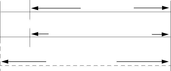
Operating Instructions Walktest
140 MS-9200UD PN 51906:A 12/10/02
4.20.5 Alarm Verification (None or One Minute)
If alarm verification is selected, an addressable smoke detector's alarm is ignored for a retard time
of 13 seconds and the detector's alarm condition is automatically reset. There will be no alarm
indication at the FACP during the Retard period. A confirmation period of 47 seconds follows,
during which a subsequent alarm from the same detector will cause the panel to immediately
activate the appropriate outputs and indicate the alarm condition at the FACP. If a different detector
alarms any time during the first detector's verification period, the panel will immediately activate
all appropriate outputs and indicate the alarm condition at the FACP. If no additional detector
alarms occur within 60 seconds of the first alarm (13 second retard plus 47 second confirmation),
the timer resets and the panel is ready to verify any new detector alarms which may occur.
Note: Alarm Verification is available only for addressable smoke detectors, not conventional smoke
detectors.
4.21 Walktest
Walktest is a feature which allows one person to test the fire alarm system. An audible walktest
will momentarily sound the Notification Appliance Circuits in the building and store the walktest
information in a file at the panel. A silent walktest will not sound the NACs but will store the
walktest information in a file which can be viewed at the panel. Disabled NAC devices will not
activate during walktest.
Alarm/Shorted Condition
When in audible Walktest, the panel responds to each new alarm and activates its programmed
control outputs for four seconds, if those outputs have been programmed for silenceable activation.
It also stores each alarm in the walktest history file which can be sent to an optional printer. The
stored display will be the same as if the device actually activated except the colon (:) in the time
stamp is replaced with an asterisk (*).
Open Condition
Addressable devices as well as all main circuit board NACs are monitored for fault conditions
during Walktest mode. When a new trouble condition occurs, the FACP will activate all NACs and
control modules programmed for Walktest, then shut them off after eight seconds.
While in Walktest, the trouble relay is activated and the system Trouble LED flashes (as in all of
the Program and status change operations). The alarm relay is not activated.
60 sec.
13 sec.
0 sec.
CONFIRMATION (47 seconds)
RETARD
Alarm Ignored Control Panel Processes Alarm if Same Detector is Still in Alarm
Control Panel Immediately Processes Alarm
Detector Alarm Verification
(Retard + Confirmation)
Detector Goes Into Alarm
Different Detector Alarms
During First Detector's
Verification Period
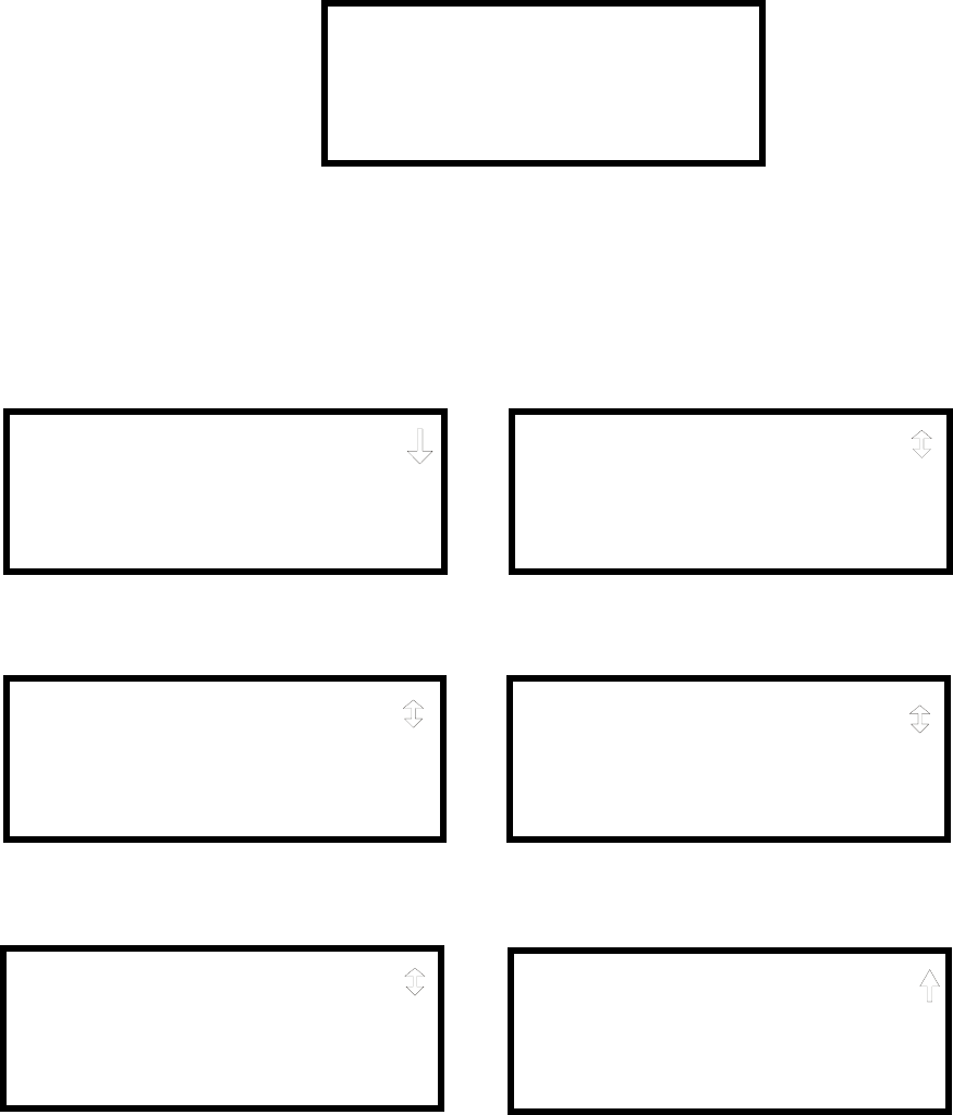
Read Status Operating Instructions
MS-9200UD PN 51906:A 12/10/02 141
4.22 Read Status
Read Status functions do not require a password. The control panel will continue to provide fire
protection while in Read Status mode. This mode can be entered while the control panel is in alarm
or trouble. If a new alarm or trouble occurs during these functions, the Read Status is exited to
prevent confusion.
Read Status Entry
When the operator presses the control panel Enter key, the LCD will display the following:
Pressing 1, while this screen is being displayed, will cause the control panel to enter the Read
Status mode which allows the user to view and print the programmed features and status of the
control panel.
The following screens will be displayed:
1=READ STATUS MODE
2=PROGRAMMING MODE
3=MANUAL DIAL MODE
READ STATUS
1=SYSTEM POINT
2=ZONES
3=POWER
READ STATUS
1=TROUBLE REMINDER
2=TIMERS
3=NACS
Read Status Screen #1
Read Status Screen #2
READ STATUS
1=RELAYS
2=PROGRAM CHECK
3=HISTORY
Read Status Screen #3
READ STATUS
1=ANNUNCIATORS
2=PHONE LINE
3=CENTRAL STATION
Read Status Screen #4
READ STATUS
1=SERVICE TERMINAL
2=PRINTER/PC
3=PRINT
Read Status Screen #5
READ STATUS
1=TIME-DATE
Read Status Screen #6
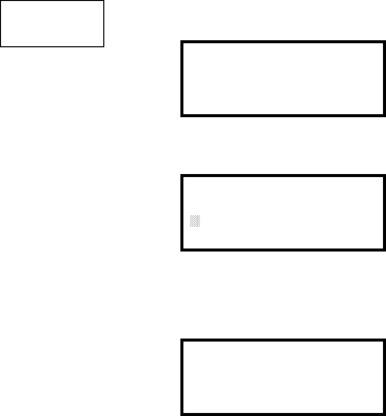
Operating Instructions Read Status
142 MS-9200UD PN 51906:A 12/10/02
4.22.1 System Point
Pressing 1 while viewing Read Status Screen #1 will cause the following screen to be
displayed:
The operator selects the type of device which is to be viewed by pressing 1 for Detector
or 2 for Module. If 1 is pressed, the display will change to the following screen:
Entering the three digit detector address will cause the control panel to display the
current status of the selected device. For example, if a detector with address 001 on the
SLC loop is entered, a display similar to the following will appear:
The information in the preceding display includes:
•NORMAL - the present status (could also be ALARM, TROUBL, DISABL, etc.)
•SMOKE (PHOTO) - the device type which is a photoelectric smoke detector
(could also be ION for ionization smoke detector)
•NORTH CLASSROOM - the Adjective/Noun label for this device
•Z005 - the first of five possible assigned software zones
•1D001 - 1 = SLC Loop, D = Detector, 001 = Address 001
• V - Alarm Verification Enabled (V = Yes, * = No)
• S - Silenceable for control modules (S = Yes, * = No)
• W - Walktestable for control and monitor modules (W = Yes, * = No)
READ STATUS
1=SYSTEM POINT
2=ZONES
3=POWER
Read Status Screen #1 READ SYSTEM POINT
SELECT TYPE
1=DETECTOR
2=MODULE
READ SYSTEM POINT
ENTER DETECTOR#
***
NORMAL SMOKE(PHOTO)
NORTH CLASSROOM
Z005
V 1D001

Read Status Operating Instructions
MS-9200UD PN 51906:A 12/10/02 143
Pressing the down arrow key, while viewing the screen shown above, will allow the
operator to view additional programming information about the selected device, such
as:
• Enable/Disable Status
• Device Type
• Alarm Verification On/Off (for detectors)
• Walktest Yes/No
• PAS (Positive Alarm Sequence) Yes/No (for detectors and monitor modules)
• Pre-Signal Yes/No (for detectors and monitor modules)
• Zone Assignments (five maximum)
• Adjective/Noun descriptor
• Silenceable Yes/No (for control modules)
4.22.2 Zones
Pressing 2 while viewing Read Status Screen #1 will cause the following screens to be
displayed:
From the preceding screens, the control panel operator can view:
•Zones Installed - all software zones programmed into the system (99 maximum)
•Zones Enabled - all software zones that are enabled
•Zones Disabled - all software zones that have been disabled
•Special Purpose - on or off programming for Special Purpose Zones 97 reserved
for PAS, 98 reserved for Pre-signal and 99 reserved for future use
•Zone Type - the Type assigned to each installed zone (default is Alarm)
READ STATUS
1=SYSTEM POINT
2=ZONES
3=POWER
Read Status Screen #1 ZONES
1=ZONES INSTALLED
2=ZONES ENABLED
3=ZONES DISABLED
Zones Screen #1
ZONES
1=SPECIAL PURPOSE
2=ZONE TYPE
Zones Screen #2

Operating Instructions Read Status
144 MS-9200UD PN 51906:A 12/10/02
4.22.3 Power
Pressing 3 while viewing Read Status Screen #1 will cause the following screens to be
displayed:
A real-time display of the control panel voltages can be used to determine if a problem
exists in the system. Note that Power Screen #3 will only be displayed if the NACKEY
NAC option card is installed, in JP8 of the main circuit board, for Class B operation.
The following table lists the circuit being measured, possible conditions and their
respective voltage ranges:
Circuit Condition Voltage Range
Battery
Normal Battery (nominal) 27.05 to 28.15 VDC
Low Battery 20.0 to 20.8 VDC
No Battery 0 to 18.36 VDC
24V Resettable Normal 21.25 to 27.50 VDC
24V Nonresettable Normal 21.25 to 27.50 VDC
Charger Normal 21.87 to 29.84 VDC
NAC 1 or NAC 2
Normal -1.3 to -1.6 VDC
Open Circuit -2.3 to -2.5 VDC
Short Circuit 0 to 1.0 VDC
POWER
BATTERY 27.21V
24 V RST 25.31
Power Screen #1
POWER
CHARGER 28.36V
NAC 1 -1.49V
NAC 2 -1.49V
Power Screen #2
POWER
NAC 3 -1.49V
NAC 4 -1.49V
Power Screen #3

Read Status Operating Instructions
MS-9200UD PN 51906:A 12/10/02 145
4.22.4 Trouble Reminder
Pressing 1 while viewing Read Status Screen #2 will display the following screen:
The screen indicates whether the Trouble Reminder feature is On or Off.
4.22.5 Timers
Pressing 2 while viewing Read Status Screen #2 will cause the following Timer screens
to be displayed:
These screens will indicate the delay time, in seconds, for each of the first three
possible delay options. The AC Loss Delay time is displayed in hours.
READ STATUS
1=TROUBLE REMINDER
2=TIMERS
3=NAC
Read Status Screen #2
TROUBLE REMINDER
TROUBLE REM ON
TIMERS
PAS DELAY 000
PRE SIGNAL 000
WATERFLOW 000
TIMERS
AC LOSS DELAY 4

Operating Instructions Read Status
146 MS-9200UD PN 51906:A 12/10/02
4.22.6 NAC
Pressing 3 while viewing Read Status Screen #2 will display the following screen:
Note that 3=NAC 3 and 4=NAC 4 will always be displayed regardless of how the
NACKEY NAC option card is installed.
The operator can press 1 to view the programmed options for NAC 1, 2 to view the
programmed options for NAC 2, 3 to view the programmed options for NAC 3 or 4 to
view the programmed options for NAC 4. The resulting screens will display the
following information:
• Enable/Disable Status
• Circuit Type (Bell, Strobe, etc.)
• Silenceable/Nonsilenceable
• Auto Silence Enable/Disable and time delay (in minutes)
• Coding Selection (Temporal, Steady, etc.)
• Zone Assignments
• Silence Inhibit Enabled/Disabled
• Synchronization Type (System Sensor, Wheelock or Gentex)
4.22.7 Relays
Pressing 1 while viewing Read Status Screen #3 will display the following screen:
The operator can view the programmed option for each relay by pressing the
corresponding number key.
NAC
1=NAC 1 3=NAC 3
2=NAC 2 4=NAC 4
READ STATUS
1=RELAYS
2=PROGRAM CHECK
3=HISTORY
Read Status Screen #3 RELAY
1=RELAY 1
2=RELAY 2
3=RELAY 3

Read Status Operating Instructions
MS-9200UD PN 51906:A 12/10/02 147
4.22.8 Program Check
Pressing 2 while viewing Read Status Screen #3 will cause a screen similar to the
following to be displayed:
Pressing 1 while viewing the Program Check screen will display a screen which will
indicate if any input zones have not been programmed to one of the Notification
Appliance Circuits. Use the up and down arrow keys to view all NACs.
Pressing 2 while viewing the Program Check screen will display a screen which will
indicate if any output zones have not been programmed to at least one input zone. Use
the up and down arrow keys to view all zones.
Pressing 3 while viewing the Program Check screen will display a screen which will
indicate if any input zones have not been programmed to at least one output zone. Use
the up and down arrow keys to view all zones.
4.22.9 History
Pressing 3 while viewing Read Status Screen #3 will display the following screen:
The operator can view all events which have been stored in the history file, only alarms
or other events, such as troubles or supervisories, by pressing the corresponding
number key.
PROGRAM CHECK
1=NACS NO INPUT
2=ZONES NO INPUT
3=ZONES NO OUTPUT
HISTORY
1=VIEW ALL
2=VIEW ALARMS
3=VIEW OTHER EVENTS

Operating Instructions Read Status
148 MS-9200UD PN 51906:A 12/10/02
4.22.10 Annunciators
Pressing 1 while viewing Read Status Screen #4 will display the following screens:
Annunciator Screen #1 indicates if Terminal Mode, ACS Mode and UDACT options
are enabled or disabled. Pressing ‘1’ while viewing Annunciator Screen #2 allows the
operator to view the ACS Mode Annunciator addresses which have been programmed
into the control panel.
4.22.11 Phone Line
Pressing 2 while viewing Read Status Screen #4 will display the following screen:
This screen indicates the both the Primary and Secondary phone lines have been
configured for touchtone dialing operation.
READ STATUS
1=ANNUNCIATORS
2=PHONE LINE
3=CENTRAL STATION
Read Status Screen #4 ANNUNCIATORS
TERM ENABLED YES
ACS ENABLED YES
UDACT ENABLED NO
ANNUNCIATORS
1=ACS ADDRESS
Annunciator Screen #1
Annunciator Screen #2
PHONE LINE
PRIMARY TOUCHTONE
SECONDARY TOUCHTONE

Read Status Operating Instructions
MS-9200UD PN 51906:A 12/10/02 149
4.22.12 Central Station
Pressing 3 while viewing Read Status Screen #4 will display the following screens:
Central Station Screen #1 indicates whether the Central Station Reporting is enabled or
disabled, if the Reports will be sent to one or both the Primary and Secondary Central
Station phone numbers and the Call Limit for DACT trouble calls within a 24 hour
period. Central Station Screen #2 provides information on the Primary and Secondary
Central Station programming which includes:
• Test Time Interval
• Account Code
• 24 Hour Test Time
• Phone Number
• Communication Format
• Event Codes
READ STATUS
1=ANNUNCIATORS
2=PHONE LINE
3=CENTRAL STATION
Read Status Screen #4
CENTRAL STATION
REPORTING ENABLED
REPORT BOTH
CALL LIMIT 10
Central Station Screen #1
CENTRAL STATION
1=PRIMARY
2=SECONDARY
3=REPORT STYLE
Central Station Screen #2

Operating Instructions Read Status
150 MS-9200UD PN 51906:A 12/10/02
4.22.13 Service Terminal
Pressing 1 while viewing Read Status Screen #5 will display the following screens:
The Panel ID number is displayed as the first item in Service Terminal Screen #1.
To view the phone number for each Service Terminal, press 2 for Terminal 1 or 3 for
Terminal 2 while viewing Service Terminal Screen #1.
The Ring Count is displayed in Service Terminal Screen #2.
4.22.14 Printer/PC
Pressing 2 while viewing Read Status Screen #5 will display the following screens:
The display will inform the operator as to whether the control panel is configured for a
printer or a PC. In the example above, PR4800 indicates that the panel is configured for
a printer with a baud rate of 4,800.
READ STATUS
1=SERVICE TERMINAL
2=PRINTER/PC
3=PRINT
Read Status Screen #5 SERVICE TERMINAL
PANEL ID
2=TERMINAL 1
3=TERMINAL 2
SERVICE TERMINAL
RING COUNT
Service Terminal Screen #1
Service Terminal Screen #2
PRINTER PC
PRINTER PC PR4800
START BIT
STOP BIT
PRINTER PC
DATA BITS
PARITY
Printer/PC Screen #1
Printer/PC Screen #2

Read Status Operating Instructions
MS-9200UD PN 51906:A 12/10/02 151
4.22.15 Print
To print program data or control panel status, press 3 while viewing Read Status Screen
#5. The following screens will be displayed:
Pressing 1 while viewing Print Screen #1 allows the user to print the History file which
will detail all of the system activities since the file was last cleared from memory.
Pressing 2 while viewing Print Screen #1 allows the user to print the Walktest log
which will detail all of the system activations during walktest since the log was last
cleared. Refer to "Walktest" on page 96 for additional information on the display.
Pressing 3 while viewing Print Screen #1 allows the user to print the detector data for
each addressable smoke detector connected to the system. A printout, similar to the
following example, will be generated if an optional printer is connected to the FACP.
Chamber Value
The Chamber value should be within the indicated range for the following smoke
detectors:
• SD350(T), D350P(R) and SD300(T) Addressable Photoelectric Smoke
Detectors: 405 - 2100 (obscuration of 1.00%/ft to 3.66%/ft.)
• CP350 and CP300 Addressable Ionization Smoke Detectors: 750 - 2100
(obscuration of 0.50%/ft. to 1.44%/ft.)
If the addressable smoke detector’s Chamber reading is not within the acceptable range,
clean the detector and check the Chamber value again. If the reading is still not within
the acceptable range, immediately replace the detector.
READ STATUS
1=SERVICE TERMINAL
2=PRINTER/PC
3=PRINT
Read Status Screen #5 PRINT
1=HISTORY
2=WALKTEST LOG
3=DETECTOR DATA
PRINT
1=EXIT PRINTING
Print Screen #2
Print Screen #1
DEVICE# DEVICE TYPE %DRIFT COMP CHAMBER TIME/DATE
1D001 SMOKE (PHOTO) 20 1281 12:01AM 01-08-2001
1D002 SMOKE (PHOTO) 20 1281 12:01AM 01-08-2001
1D003 SMOKE (PHOTO) 21 1259 12:01AM 01-08-2001
1D004 SMOKE (PHOTO) 20 1309 12:02AM 01-08-2001
1D005 SMOKE (PHOTO) 21 1281 12:02AM 01-08-2001
1D006 SMOKE (PHOTO) 20 1322 12:02AM 01-08-2001
1D007 SMOKE (PHOTO) 20 1280 12:02AM 01-08-2001
1D008 SMOKE (PHOTO) 20 1215 12:02AM 01-08-2001
1D009 SMOKE (PHOTO) 20 1310 12:02AM 01-08-2001
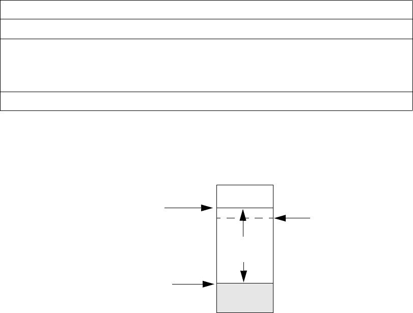
Operating Instructions Read Status
152 MS-9200UD PN 51906:A 12/10/02
Drift Compensation
Drift compensation uses software algorithms that identify and compensate for long-
term changes in the data readings from each addressable smoke detector. These long-
term changes in detector data readings are typically caused by dirt and dust
accumulation inside the smoke chamber. Drift compensation performs the following
functions:
• Allows a smoke detector to retain its original ability to detect actual smoke and
resist false alarms, even as dirt and dust accumulate
• Reduces maintenance requirements by allowing the control panel to
automatically perform the periodic sensitivity measurements required by NFPA
Standard 72
The FACP software also provides filters to remove transient noise signals, usually
caused by electrical interference.
Maintenance Alert
The software determines when the drift compensation for a detector reaches an
unacceptable level that can compromise detector performance. When a detector
reaches an unacceptable level, the control panel indicates a maintenance alert. Table
4.1 summarizes the three levels of maintenance alert:
Figure 4.1 illustrates a graphic representation of the maintenance levels:
Maintenance Level FACP Status Displays Indicates
Low Chamber Value INVREP A hardware problem in the detector
Maintenance Alert DIRTY1 Dust accumulation that is near but below the
allowed limit. DIRTY 1 indicates the need for
maintenance before the performance of the detector
is compromised
Maintenance Urgent DIRTY2 Dust accumulation above the allowed limit.
Table 4.1 Maintenance Alert Levels
Figure 4.1 Diagram of Maintenance Levels
DIRTY
Acceptable
Range
Maintenance
Urgent Maintenance
Alert
Low Chamber
Reading LOW
VA L U E

Read Status Operating Instructions
MS-9200UD PN 51906:A 12/10/02 153
4.22.16 Time-Date
The operator can view the daylight savings time and the month and week when daylight
savings time will begin and end. Pressing 1 while viewing Read Status Screen #6 will
display the following screens:
READ STATUS
1=TIME-DATE
Read Status Screen #6
DAYLIGHT SAVINGS
ENABLED YES
START MONTH APR
START WEEK WEEK-1
DAYLIGHT SAVINGS
END MONTH OCT
END WEEK LAST-W
Central Station Communications Read Status
154 MS-9200UD PN 51906:A 12/10/02
SECTION 5 Central Station Communications
The control panel transmits zone and system status reports to Central Stations via the
public switched telephone network. Two supervised telephone line connections are
made to interface the control panel to the telephone lines. Two optional 7 foot
telephone cords are available for this purpose and can be purchased separately.
The control panel supervises both telephone lines for proper voltage. A delay of two
minutes will occur before a fault in either phone line connection is reported as a trouble.
When a fault is detected, an audible trouble signal will sound, the yellow trouble LED
will blink, the LCD display will indicate the phone line trouble and the trouble
condition will be reported to the Central Station over the remaining operational phone
line.
The control panel comes with line seizure capability provided for both the primary and
secondary telephone line interfaces. Any time that the control panel needs to make a
call to a Central Station, line seizure will disconnect any local premises phones sharing
the same telephone line.
All transmissions to the Central Stations will be sent over the primary phone line. In
the event of noisy phone lines, transmissions will be sent over the backup secondary
phone line.
Two phone numbers must be programmed, the primary Central Station phone number
and the secondary Central Station phone number. All system reports will be
transmitted to the primary Central Station phone number. Reports will automatically be
sent to the secondary Central Station phone number if attempts to transmits to the
primary Central Station phone number are unsuccessful. If 10 total attempts to
communicate are unsuccessful, a Communicator Failure report will be displayed. Note
that as an option, all reports may also be sent to the secondary Central Station phone
number.
The MS-9200UD meets NFPA 72 National Fire Code reporting requirements for: (a)
the type of signal, (b) condition and (c) location of the reporting premises. The general
priority reporting structure is:
1. Zone Alarms and Restores
2. Zone Troubles and Restores
3. System Troubles and Restores
4. 24-hour Test

Read Status Central Station Communications
MS-9200UD PN 51906:A 12/10/02 155
The control panel is capable of reporting detailed messages depending upon the format
in use. Table 5.1 shows the reporting structure for all formats.
Refer to Table 5.2 for an explanation of each letter code in Table 5.1 . Refer to Table
5.3 for a list of compatible receivers.
Table 5.1 Format Selection
Format Format Format Format
Report 3+1/4+1/Standard
4+1 Express
3+1/4+1/Expanded 4+2/Standard
4+2 Express
4+2/Expanded
Alarm SSS(S) A SSS(S) A
AAA(A) Z
SSSS AA2 SSSS AZ
Alarm Restore SSS(S) RA SSS(S) RA
RARARA(RA) Z
SSSS RARA2 SSSS RAZ
Zone Trouble
(Zone Open)
SSS(S) TZ SSS(S) TZ
TZTZTZ(TZ) Z
SSSS TZTZ2 SSSS TZZ
Zone Trouble Restore SSS(S) RTZ SSS(S) RTZ
RTZRTZRTZ(RTZ) Z
SSSS RTZRTZ2 SSSS RTZZ
System Trouble SSS(S) TS SSS(S) TS
TSTSTS(TS) Y
SSSS TSTS2 SSSS TSY
System Trouble Restore SSS(S) RTS SSS(S) RTS
RTSRTSRTS(RTS) Y
SSSS RTSRTS2 SSSS RTSY
Zone Disable SSS(S) DZ SSS(S) DZ
DZDZDZ(DZ) Z
SSSS DZDZ2 SSSS DZZ
Zone Disable Restore SSS(S) RDZ SSS(S) RDZ
RDZRDZRDZ(RDZ) Z
SSSS RDZRDZ2 SSSS RDZZ
Low Battery SSS(S) L SSS(S) L
LLL(L) L2
SSSS LL2 SSSS LL2
Low Battery Restore SSS(S) RL SSS(S) RL
RLRLRL(RL) RL2
SSSS RLRL2 SSSS RLRL2
AC Loss SSS(S) P SSS(S) P
PPP(P) P2
SSSS PP2 SSSS PP2
AC Loss Restore SSS(S) RP SSS(S) RP
RPRPRP(RP) RP2
SSSS RPRP2 SSSS RPRP2
Fire Drill SSS(S) FD SSS(S) FD
FDFDFD(FD) FD2
SSSS FDFD2 SSSS FDFD2
Fire Drill Restore SSS(S) RFD SSS(S) RFD
RFDRFDRFD(RFD) RFD2
SSSS RFDRFD2 SSSS RFDRFD2
Supervisory Condition SSS(S) V SSS(S) V
VVV(V) Z
SSSS VV2 SSSS VZ
Supervisory Condition
Restore
SSS(S) RV SSS(S) RV
RVRVRV(RV) Z
SSSS RVRV2 SSSS RVZ
Test Report SSS(S) X SSS(S) X SSSS XX2 SSSS XX2
Upload or Download SSS(S) UD SSS(S) UD SSS UDUD2 SSS UDUD2
Central Station Communications Read Status
156 MS-9200UD PN 51906:A 12/10/02
Note: For Expanded Reporting, the control panel automatically adds the digit
corresponding to the zone number and the second digit corresponding to any system
trouble condition. Only the first digit is programmable.
Table 5.2 Format Selection Address Explanation
Where
SSS or SSSS = Subscriber ID
A = Alarm (1st digit)
A2 = Alarm (2nd digit)
Z = Zone Number
RA = Alarm Restore (1st digit)
RA2 = Alarm Restore (2nd digit)
TZ = Zone Trouble (1st digit)
TZ2 = Zone Trouble (2nd digit)
RTZ = Zone Trouble Restore (1st digit)
RTZ2 = Zone Trouble Restore (2nd digit)
TS = System Trouble (1st digit)
TS2 = System Trouble (2nd digit)
RTS = System Trouble Restore (1st digit)
RTS2 = System Trouble Restore (2nd digit)
DZ = Zone Disable (1st digit)
DZ2 = Zone Disable (2nd digit)
RDZ = Zone Disable Restore (1st digit)
RDZ2 = Zone Disable Restore (2nd digit)
L = Low Battery (1st digit)
L2 = Low Battery (2nd digit)
RL = Low Battery Restore (1st digit)
RL2 = Low Battery Restore (2nd digit)
P=AC Loss (1st digit)
P2 = AC Loss (2nd digit)
RP = AC Loss Restore (1st digit)
RP2 = AC Loss Restore (2nd digit)
FD = Fire Drill (1st digit)
FD2 = Fire Drill (2nd digit)
RFD = Fire Drill Restore (1st digit)
RFD2 = Fire Drill Restore (2nd digit)
V = Supervisory Condition (1st digit)
V2 = Supervisory Condition (2nd digit)
RV = Supervisory Condition Restore (1st digit)
RV2 = Supervisory Condition Restore (2nd digit)
X = Test Report (1st digit)
X2 = Test Report (2nd digit)
Y = A trouble corresponding to the following:
7 = Ground Fault
8 = Low Battery
9 = not used
A = Telco Primary Line Fault
B = Telco Secondary Line Fault
C = Main Bell Fault, Annunciator Bell
D = Communication Fault to Primary Number
E = Communication Fault to Secondary Number
F = System Off Normal Fault/System Fault (Slave Operation, see Chapter 6)
UD = Upload/download (1st digit)
UD2 = Upload/download (2nd digit)
Transmittal Priorities Central Station Communications
MS-9200UD PN 51906:A 12/10/02 157
5.1 Transmittal Priorities
The integral communicator transmits highest priority events first. Events, in terms of
priority, are listed below in descending order:
1. Alarms (highest priority level)
✓Pull stations
✓Waterflow
✓Smoke detector
✓Other alarm types
2. Supervisory Zone
3. System Troubles
✓Zone disabled
✓Fire drill
✓AC fail (after delay)
✓Zonal faults
✓Earth fault
✓Low battery
✓Telephone line fault
✓Notification Appliance Circuits fault
✓Communication trouble
✓Annunciator trouble
✓System off normal
4. Restoral Reports
✓Zone alarm
✓Supervisory
✓Zone(s) enabled
✓Fire drill
✓AC
✓Zone fault
✓Earth
✓Battery
✓Telephone line
✓Notification Appliance Circuits
✓Communication
✓Annunciator trouble
✓System off normal
5. 24 Hour Test (lowest priority)
Red LEDs are provided on the circuit board to identify which telephone line is
activated. Also, a green LED labeled Kissoff will turn on whenever the control panel
has successfully transmitted reports to the Central Station. The Kissoff LED may turn
on several times during communications with a Central Station.

Central Station Communications Transmittal Priorities
158 MS-9200UD PN 51906:A 12/10/02
The table below shows UL listed receivers which are compatible with the MS-9200UD.
1. With 685-8 Line Card with Rev. 4.4d software
2. With 9002 Line Card Rev. 9035 software or 9032 Line Card with 9326A
software
3. Rev. 4.0 software
4. FBI CP220FB Rec-11 Line Card with Rev. 2.6 software and a memory card with
Rev. 3.8 software
5. Model 6500 with Rev. 600 software
6. Mode 6000 with Rev. 204 software
7. With Rev. B control card at Rev. 1.4 software and Rev. C line card at Rev. 1.5
software
8. Model 2 only
9. Version 1.62 software
Table 5.3 Compatible UL Listed Receivers
Format #
(Addresses 16 & 42)
Ademco
685 (1)
Silent Knight
9000 (2)
ITI
CS-4000 (3)
FBI
CP220FB
Osborne Hoffman
Models 1 & 2
Radionics
6000 (6)
Radionics
6500 (5)
Sescoa
3000R (7)
Surguard
MLR-2 (9)
0 4+1 Ademco Express ✔✔ ✔
1 4+2 Ademco Express ✔✔✔
(8) ✔
2 3+1/Standard/1800/2300 ✔✔✔ ✔
(4) ✔✔✔✔✔
3 3+1/Expanded/1800/2300 ✔✔✔ ✔
(4) ✔✔✔
4 3+1/Standard/1900/1400 ✔✔ ✔
(4) ✔✔✔
5 3+1/Expanded/1900/1400 ✔✔ ✔
(4) ✔✔✔
6 4+1/Standard/1800/2300 ✔✔✔ ✔
(4) ✔✔✔✔
7 4+1/Expanded/1800/2300 ✔✔ ✔
(4) ✔✔✔
8 4+1/Standard/1900/1400 ✔✔ ✔
(4) ✔✔✔
9 4+1/Expanded/1900/1400 ✔✔ ✔
(4) ✔✔✔
A 4+2/Standard/1800/2300 ✔✔✔ ✔
(4) ✔✔✔✔
B 4+2/Expanded/1800/2300 ✔✔ ✔
(4) ✔✔✔
C 4+2/Standard/1900/1400 ✔✔ ✔
(4) ✔✔✔
D 4+2/Expanded/1900/1400 ✔✔ ✔
(4) ✔✔✔
E Ademco Contact ID ✔✔✔ ✔
FNot Used
Downloading Program Remote Site Upload/Download
MS-9200UD PN 51906:A 12/10/02 159
SECTION 6 Remote Site Upload/Download
The control panel may be programmed or interrogated off-site via the public switched
telephone network. Any personal computer with Windows™ 95 or greater, with a 14.4
Kbaud compatible modem and Fire•Lite Upload/Download software kit P/N PK-Plus,
may serve as a Service Terminal. This allows download of the entire program or upload
of the entire program, history file, walktest data, current status, system voltages, time
and date.
CAUTION: After successfully downloading a program, make certain to perform the
following steps:
1. Print out all programmed data via Print Mode or manually view programmed
entries and compare to intended program data
2. Test all affected panel operations
3. Immediately correct any problems found
6.1 Downloading Program
The first time that the control panel is downloaded (whether initiated at the jobsite or
remotely), a secret code is loaded in by a Service Terminal. Future upload or download
requests cause verification of the secret code by the control panel before processing of
data is allowed. If the secret code is not verified, the control panel will terminate the
request.
While the control panel is communicating with the Service Terminal, one of the
DACT’s red phone line active LEDs will remain on steady. At the conclusion of a
successful download, the green Kissoff LED will turn on steady for five seconds and the
red phone line active LED will turn off.
In order to download the panel (whether initiated at the jobsite or remotely), the
following must be true:
✓The control panel must be in the Normal Mode of operation. Downloading is
not possible if the panel is in any other mode
✓There cannot be any active communications ongoing with a Central Station
receiver
✓All active events must be successfully 'kissed-off' by the Central Station(s).
The communicator must be in a standby state with no new information waiting
to be transmitted to a Central Station
Two basic communication mechanisms are supported as follows:
• Download with callback - the Service Terminal calls the control panel. The
control panel answers the call, confirms the calling party then hangs up. The
Service Terminal then waits for a callback from the control panel. After the
control panel calls the Central Station and successfully reports that a request for
downloading has been received, the control panel calls the Service Terminal
back. Upon secret code verification, data transfers occur. When the data
transfers are completed and the Service Terminal disconnects from the control
panel, the panel calls the Central Station back to confirm either successful or
unsuccessful results.
• Download with callback disabled - the Service Terminal calls the control panel.
No hang-up sequence occurs. Data transfers proceed.
Note that Callback enable/disable is controlled by the master user at the Service
Terminal on a per call basis.

Remote Site Upload/Download Downloading Program
160 MS-9200UD PN 51906:A 12/10/02
Anytime a download with callback is initiated, the first thing the control panel will do is
one of the following:
• contact the primary Central Station
• contact the primary and secondary Central Stations
• contact the first available Central Station phone number
Once contact has been established, the control panel will report a ‘request for upload/
download’ message. Following ‘kissoff’ of the request by the Central Station(s), the
control panel will then call the appropriate Service Terminal and begin the downloading
process.
Any time a download with callback disabled is initiated, the control panel and the
Service Terminal will communicate and transfer data without first contacting a Central
Station. When the data transfers are completed and the control panel disconnects from
the Service Terminal, the control panel will call the Central Station and report one of
the following conditions:
• Upload/download request received
• Upload and/or download request successful
• Upload/download failed
To prevent the 'request for upload/download' message(s) from being reported to the
Central Station(s), make certain to disable all upload/download reports back to both
Central Stations.
During the downloading process, the fire protection remains active. Should a system
trouble or alarm condition occur, the control panel immediately terminates
downloading and processes the trouble or alarm locally and transmits the information
to the Central Station(s).
6.1.1 Security Features
Remote site upload and download with the control panel has been carefully designed to
include key security features to ensure proper functionality. The key features are listed
and explained below.
Secret Code Verification
A secret code is stored in the control panel by a Service Terminal to prevent
unauthorized access. The secret code is created at the Service Terminal by the master
user and cannot be viewed or changed by anyone other than a master user. Viewing of
the secret code is prohibited at the control panel. Prior to allowing an upload or
download of data, the control panel will verify the secret code transmitted by the
Service Terminal.
Time-out at Control Panel
Upon answering an incoming call on either the primary or secondary Central Station
phone line, the control panel will listen for a modem connection signal. If this signal is
not received within 30 seconds, the control panel will disconnect the call. Upon
successful connection (secret code verified and callback completed if applicable), if no
communication occurs within five minutes, the panel will disconnect the call.
Callback to Service Terminal
Any time the control panel is requested to allow an upload or download, it will confirm
the source of the incoming call, hang-up and call back the calling party (Service
Terminal phone number).
Downloading Program Remote Site Upload/Download
MS-9200UD PN 51906:A 12/10/02 161
Panel Identification Number
The panel identification number is typically used to identify the panel to the Service
Terminal when the control panel calls the Service Terminal. If more than one call
comes into the Service Terminal, the control panel ID number is used to sort out the
calling parties.
Another use of this code allows for identical secret codes to be placed into multiple
control panels at one jobsite, using the panel ID number to distinguish between the
individual panels.
Error Checking
As each block of data is received by the control panel, it is checked for accuracy. If an
error is detected, the block is retransmitted until correct, up to a maximum of four
times. If the Secret Code is not verified and four errors occur, the call is disconnected
and the report that the upload/download was not successful is called to the Central
Station(s).
Central Station Acknowledge
There is an option, referred to as the ‘callback’ option, whereby the control panel will
report to one or both Central Stations that a request for uploading or downloading has
been received prior to processing the call. If the Central Station(s) does not
acknowledge receipt of this request, uploading or downloading is prohibited. If
acknowledged by the Central Station(s), another message is transmitted, informing the
Central Station(s) that:
• Downloading was successful
• Uploading was successful
• Uploading/downloading was not successful
Central Station Data Protection
The primary and secondary Central Station phone numbers, communications format,
account code, test time and programmable event codes are vital Central Station
information. These blocks of data are protected from partial programming due to faulty
phone connections, line noise and other errors. This prevents the panel from being
confused due to a wrong phone number, account code, test time and most critical
formatting errors.
Remote Site Upload/Download Downloading Initiated at Control Panel
162 MS-9200UD PN 51906:A 12/10/02
6.2 Downloading Initiated at Control Panel
Before initiating the download procedure, make certain that the control panel is:
✓In Normal Mode
✓Central Station communications are off
✓The communicator is in the standby state (red phone line active LEDs are off
and Kissoff LEDs are off)
Place the control panel into Program Mode and program one or both of the Service
Terminal phone numbers. It is also advisable at this time to program the Panel
Identification Number. This will allow the Service Terminal to easily identify incoming
calls.
Program the control panel for download operation. The control panel will now call the
appropriate Service Terminal phone number and the downloading process will begin.
Once the called Service Terminal identifies the incoming call (control panel), the
downloading process is allowed to continue. Downloading progresses until all
programmed information has been successfully loaded into the control panel.
6.3 Downloading Initiated at a Service Terminal
Before initiating the download procedure, make certain that the control panel is:
✓In Normal Mode
✓Central Station communications are off
✓The communicator is in the standby state (red phone line active LEDs are off
and Kissoff LEDs are off)
Once the control panel accepts/answers an incoming call, the panel will:
1. Establish basic modem connection
2. Verify secret code and panel identification number
3. Verify callback vs. no callback request from the service terminal. If callback is
requested, steps 4 through 9 will occur. If no callback is requested, only steps 8
and 9 will occur
4. Identify the Service Terminal location
5. Hang-up/disconnect call
6. Call the Central Station(s) and transmit a request for upload/download message
(if programmed to do so). If this message is accepted, the control panel will
proceed to the next step
7. Return call to Service Terminal
8. After security clearance, begin downloading
9. Upon completion of download, call Central Station(s) back and report either a
successful download or failed upload/download message (if programmed to do
so)

Uploading Initiated at a Service Terminal Remote Site Upload/Download
MS-9200UD PN 51906:A 12/10/02 163
6.4 Uploading Initiated at a Service Terminal
Items that may be uploaded from the control panel to a Service Terminal are:
• All programmed data plus the real-time clock, time and date
• Entire Walktest data file
• Troubleshoot Mode system voltages
• Entire event History file
• Current system status
Uploading is possible at any time provided the following conditions are true:
✓The control panel must be in the Normal Mode of operation. Uploading is not
possible if the panel is in any other mode
✓There cannot be any active communications ongoing with a Central Station
receiver
✓All active events must be successfully 'kissed-off' by the Central Station (the
communicator must be in a standby state with no new information waiting to
be transmitted to a Central Station)
Once an incoming call is accepted/answered by the control panel, the panel will:
1. Establish basic modem connection
2. Verify secret code and panel identification number
3. Verify callback vs. no callback request from the service terminal. If callback is
requested, steps 4 through 9 will occur. If no callback is requested, only steps 8
and 9 will occur
4. Identify the Service Terminal location
5. Hang-up/disconnect call
6. Call the Central Station(s) and transmit a request for upload/download message
(if programmed to do so). If this message is accepted, the control panel will
proceed to the next step
7. Return call to Service Terminal
8. After security clearance, begin uploading
9. Upon completion of upload, call Central Station(s) back and report either a
successful upload or failed upload/download message (if programmed to do so).
During the uploading process, the fire protection remains active. Should a system
trouble or alarm condition occur, the control panel immediately terminates uploading
and processes the trouble or alarm locally and transmits the information to the Central
Station(s).

Power Supply Calculations Overview
164 MS-9200UD PN 51906:A 12/10/02
SECTION 7 Power Supply Calculations
7.1 Overview
This section contains instructions and tables for calculating power supply currents in
alarm and standby conditions. This is a four-step process, consisting of the following:
1. Calculating the total amount of AC branch circuit current required to operate the
system
2. Calculating the power supply load current for non-fire and fire alarm conditions
and calculating the secondary (battery) load
3. Calculating the size of batteries required to support the system if an AC power
loss occurs
4. Selecting the proper batteries for your system
7.2 Calculating the AC Branch Circuit
The control panel requires connection to a separate, dedicated AC branch circuit, which
must be labeled FIRE ALARM. This branch circuit must connect to the line side of
the main power feed of the protected premises. No other non-fire alarm equipment may
be powered from the fire alarm branch circuit. The branch circuit wire must run
continuously, without any disconnect devices, from the power source to the control
panel. Overcurrent protection for this circuit must comply with Article 760 of the
National Electrical Codes as well as local codes. Use 14 AWG (2.00 mm2) wire with
600 volt insulation for this branch circuit.
Use Table 7.1 , to determine the total amount of current, in AC amperes (A), that must
be supplied to the system.
Table 7.1 AC Branch Circuit Requirements
Device Type Number of
Devices
Current Draw
(AC amps)
Total Current
per Device
MS-9200UD
or
MS-9200UDE
1X
3.00
or
1.50
=
CHG-75 [ ] X 2.05 =
CHG-120F [ ] X 2.00 =
[ ] X [ ] =
Sum Column for AC Branch Current Required =

Calculating the System Current Draw Power Supply Calculations
MS-9200UD PN 51906:A 12/10/02 165
7.3 Calculating the System Current Draw
7.3.1 Overview
The control panel must be able to power all internal and external devices continuously during the
non-fire alarm condition. To calculate the non-fire alarm load on the system power supply when
primary power is applied, use Calculation Column 1 in Table 7.3 on page 166. The control panel
must support a larger load current during a fire alarm condition. To calculate the fire alarm load on
the power supply, use Calculation Column 2 in Table 7.3 on page 166. The secondary power
source (batteries) must be able to power the system during a primary power loss. To calculate the
non-fire alarm load on the secondary power source, use Calculation Column 3 in Table 7.3 on page
166.
When calculating current draw and the battery size, note the following:
• ‘Primary’ refers to the main power source for the control panel
• ‘Secondary’ refers to the control panel’s backup batteries
• All currents are given in amperes (A). Table 7.2 shows how to convert milliamperes and
microamperes to full amperes.
7.3.2 How to Use Table 7.3 on page 166 to Calculate System Current
Draw
Use Table 7.3 on page 166 to calculate current draws as follows:
1. Enter the quantity of devices in all three columns
2. Enter the current draw where required. Refer to the Fire•Lite Device Compatibility
Document for compatible devices and their current draw
3. Calculate the current draws for each in all columns
4. Sum the total current for each column
5. Copy the totals from Column 2 and Column 3 to Table 7.4 on page 167
Following are the types of current that can be entered into Table 7.3 on page 166:
✓Calculation Column 1 - The primary supply current load that the control panel must
support during a non-fire alarm condition, with AC power applied.
✓Calculation Column 2 - The primary supply current load that the control panel must
support during a fire alarm condition, with AC power applied.
✓Calculation Column 3 - The standby current drawn from the batteries in a non-fire alarm
condition during a loss of AC power.
Table 7.2 Converting to Full Amperes
To convert... Multiply Example
Milliamperes (mA) to
amperes (A) mA x 0.001 3 mA x 0.001 = 0.003A
Microamperes (µA) to
amperes (A) µA x 0.000001 300 µA x 0.000001 = 0.0003 A
Power Supply Calculations Calculating the System Current Draw
166 MS-9200UD PN 51906:A 12/10/02
Table 7.3 contains columns for calculating current draws. For each column, calculate
the current and enter the total (in amperes) in the bottom row. When finished, copy the
totals from Calculation Column 2 and Calculation Column 3 to Table 7.4 on page 167.
Table 7.3 System Current Draw Calculations
Device Type
Calculation Column 1
Primary, Non-Fire Alarm Current
(amps)
Calculation Column 2
Primary, Fire Alarm Current
(amps)
Calculation Column 3
Secondary, Non-Fire Alarm Current
(amps)
Qty X[current draw]= Total Qty X [current draw] = Total Qty X[current draw]= Total
Main Circuit Board 1 X[0.300]= 0.300 1 X[0.325]= 0.325 1 X[0.255]= 0.255
ACM-8RF [ ] X[0.030]= [ ] X[0.158]1=[ ] X[0.030]=
ACM-16ATF
ACM-32AF [ ] X[0.040] [ ] X[0.056]2=[ ] X[0.040]=
AEM-16ATF
AEM-32AF [ ] X[0.002] [ ] X[0.018]2=[ ] X[0.002]=
AFM-16ATF
AFM-32AF [ ] X[0.040] [ ] X[0.056]2=[ ] X[0.040]=
AFM-16AF [ ] X[0.025] [ ] X[0.065]2=[ ] X[0.025]=
UDACT-F [ ]
1 max. X[0.040] [ ] X[0.075]= [ ] X[0.040]=
LDM-32F [ ] X[0.040] [ ] X[0.056]3=[ ] X[0.040]=
LDM-E32F [ ] X[0.002] [ ] X[0.018]= [ ] X[0.002]=
LCD-80F [ ] X[0.064] [ ] X[0.064]= [ ] X[0.025]=
4XTMF [ ] X[0.005]= [ ] X[0.011]4=[ ] X[0.005]=
4-wire Detector Heads [ ] X[ ]5=[ ] X[ ]= [ ] X[ ]=
Power Supervision
Relays6[ ] X[0.025]= [ ] X[0.025]= [ ] X[0.025]=
CP350 [ ] X[0.00030]=
maximum alarm draw
for all devices 0.400
[ ] X[0.00030]=
SD350 [ ] X[0.00030]= [ ] X[0.00030]=
SD350T [ ] X[0.00030]= [ ] X[0.00030]=
H350 [ ] X[0.00030]= [ ] X[0.00030]=
H350R [ ] X[0.00030]= [ ] X[0.00030]=
D350P [ ] X[0.00030]= [ ] X[0.00030]=
D350RP [ ] X[0.00030]= [ ] X[0.00030]=
B501BH & B501BHT7 [ ] X[0.001]= [ ] X[0.001]=
B224RB Relay Base [ ] X[0.00050]= [ ] X[0.00050]=
B224BI Isolator Base [ ] X[0.00045]= [ ] X[0.00045]=
MMF-300 [ ] X[0.00040]= [ ] X[0.00040]=
MMF-300-10 [ ] X[0.00350]= [ ] X[0.00350]=
MDF-300 [ ] X[0.00075]= [ ] X[0.00075]=
MMF-301 [ ] X[0.000375]= [ ] X[0.000375]=
MMF-302 [ ] X[0.00027]= [ ] X[0.00027]=
MMF-302-6 [ ] X[0.00200]= [ ] X[0.00200]=
BG-12LX [ ] X[0.00023]= [ ] X[0.00023]=
CMF-300 [ ] X[0.00039]= [ ] X[0.00039]=
CMF-300-6 [ ] X[0.00225]= [ ] X[0.00225]=
CRF-300 [ ] X[0.00027]= [ ] X[0.00027]=
CRF-300-6 [ ] X[0.00145]= [ ] X[0.00145]=
I300 [ ] X[0.00040]= [ ] X[0.00040]=
NAC #18[ ] X[ ]=
NAC #2 [ ] X[ ]=
NAC #3 [ ] X[ ]=
NAC #4 [ ] X[ ]=
Current Draw from TB3
(nonalarm9)[ ]= [ ] [ ]= [ ] [ ]=
Sum each column10
for totals Primary Non-Alarm = Primary Alarm = Secondary Non-Alarm =
Table Footnote
1. All eight ACM-8RF relays activated on a single module.
2. All annunciator LEDs on
3. LDM-32F with LEDs on
4. If using the Reverse Polarity Alarm output, add 0.005 amps; if using the Reverse Polarity Trouble output, add
another 0.005 amps.
5. Refer to the Device Compatibility Document for standby current.
6. Must use compatible listed Power Supervision Relay.
7. Maximum alarm current for each sounder base is 0.015 amps which must be supplied by aux. 24VDC source.
8. Current limitation of Terminal TB3 & TB4 circuits is 2.5 amps per NAC.
9. The total standby current must include both the nonresettable/resettable (TB1 Terminals 1 & 2) and resettable
(TB1 Terminals 3 & 4) power. Caution must be taken to ensure that current drawn from these outputs during
alarm does not exceed maximum ratings specified. Current limitations of TB3 & TB4 circuits is 2.5 amps per
NAC output and 0.5 amps per auxiliary power output
10.Total current draw listed above cannot exceed 6.0 amps.

Calculating the Battery Size Power Supply Calculations
MS-9200UD PN 51906:A 12/10/02 167
7.4 Calculating the Battery Size
Use Table 7.4 to calculate the total Standby and Alarm load in ampere hours (AH).
This total load determines the battery size (in AH), required to support the control panel
under the loss of AC power. Complete Table 7.4 as follows:
1. Enter the totals from Table 7.3 on page 166, Calculation Columns 2 and 3 where
shown
2. Enter the NFPA Standby and Alarm times (refer to ‘NFPA Requirements’ below)
3. Calculate the ampere hours for Standby and Alarm, then sum the Standby and
Alarm ampere hours
4. Multiply the sum by the derating factor of 1.2 to calculate the proper battery size
(in AH)
5. Write the ampere hour requirements on the Protected Premises label located
inside the cabinet door
7.4.1 NFPA Battery Requirements
• NFPA 72 Local and Proprietary Fire Alarm Systems require 24 hours of standby
power followed by 5 minutes in alarm
• NFPA 72 Central, Auxiliary and Remote Station Fire Alarm Systems require 60
hours of standby followed by 5 minutes in alarm. Batteries installed in a system
powered by a generator need to provide at least 4 hours of standby power
7.4.2 Selecting and Locating Batteries
Select batteries that meet or exceed the total ampere hours calculated in Table 7.4 . The
control panel can charge batteries in the 7 AH to 18 AH range. The control panel
cabinet is capable of housing batteries up to 18 AH. Batteries larger than 18 AH require
a UL listed external battery charger and cabinet such as the BB-26, BB-55F or other UL
listed external battery cabinet.
Table 7.4 Total Secondary Power Requirements at 24 VDC
Secondary Standby Load
(total from Table 7.3 Calculation
Column 3)
[ ]
Required Standby Time
(24 or 60 hours)
X[ ] = AH
Primary Alarm Load
(total from Table 7.3 Calculation
Column 2)
[ ]
Required Alarm Time
(for 5 min., enter 0.084,
for 10 min., enter 0.168)
X[ ] = AH
Sum of Standby and Alarm Ampere Hours = AH
Multiply by the Derating Factor X 1.2
Battery Size, Total Ampere Hours Required = AH
Software Zones Correlations
168 MS-9200UD PN 51906:A 12/10/02
APPENDIX A Software Zones
A.1 Correlations
Setup and configuration of an addressable system is different than a conventional
system. In a conventional system, assignment of input devices (smoke detectors, pull
stations, heat detectors, etc.) to zones is accomplished through wiring. The wiring is
direct from clearly marked panel terminals to any device assigned to a particular zone.
Connection of output devices (horns, bells, strobes, etc.) in a conventional system is
accomplished by direct wiring of the output devices to Notification Appliance Circuit
terminals.
In an addressable system, a minimum of a single pair of wires (SLC communication
loop) is used to connect all addressable input and output devices. Communications
between the FACP (Fire Alarm Control Panel) and all addressable devices takes place
over the wire pair which originates from the FACP. Software programming is used to
configure the system as opposed to direct wiring. Zone assignments are created via
software means, hence the term software zones.
Setup of an MS-9200UD software zone is accomplished by panel programming. Each
addressable device can be assigned to a maximum of five software zones. Each
software zone, however, may have from 1 to 991 addressable input devices assigned to
it and from 1 to 991 addressable output devices assigned to it.
Monitor and control modules comprise one group of 991 addresses, with each module
having a unique address from 1 to 991. Detectors comprise a separate group of 991
addresses, each detector having a unique address from 1 to 991 in its group. Be careful
not to duplicate addresses within any one group (modules and detectors). Refer to the
following page for an example of zoning.
In the example on the following page:
• Zone 01 has the following addressable devices assigned to it:
✓SD350 smoke detectors with addresses 01 and 02
✓MMF-300 monitor module with address 01
✓MMF-302 monitor module with address 02 and 03
✓CMF-300 control modules with addresses 05, 06, 07, 09 and 13
• Zone 02 has the following addressable devices assigned to it:
✓MMF-302 monitor module with addresses 02 and 03
✓CP350 smoke detectors with addresses 03 and 04
✓CMF-300 control modules with addresses 08, 09 and 10
• Zone 03 has the following addressable devices assigned to it:
✓SD350 smoke detectors with addresses 05, 06 and 07
✓MMF-302 control module with address 04
✓CMF-300 control modules with addresses 09, 11 and 12
The example points out some of the key assignment features of the MS-9200UD.
Addresses of detectors are not duplicated. Addresses of monitor and control modules
are not duplicated. The control module with address 09 is assigned to three software
zones (providing floor above and floor below). Be careful to properly plan the
installation prior to installing any devices.
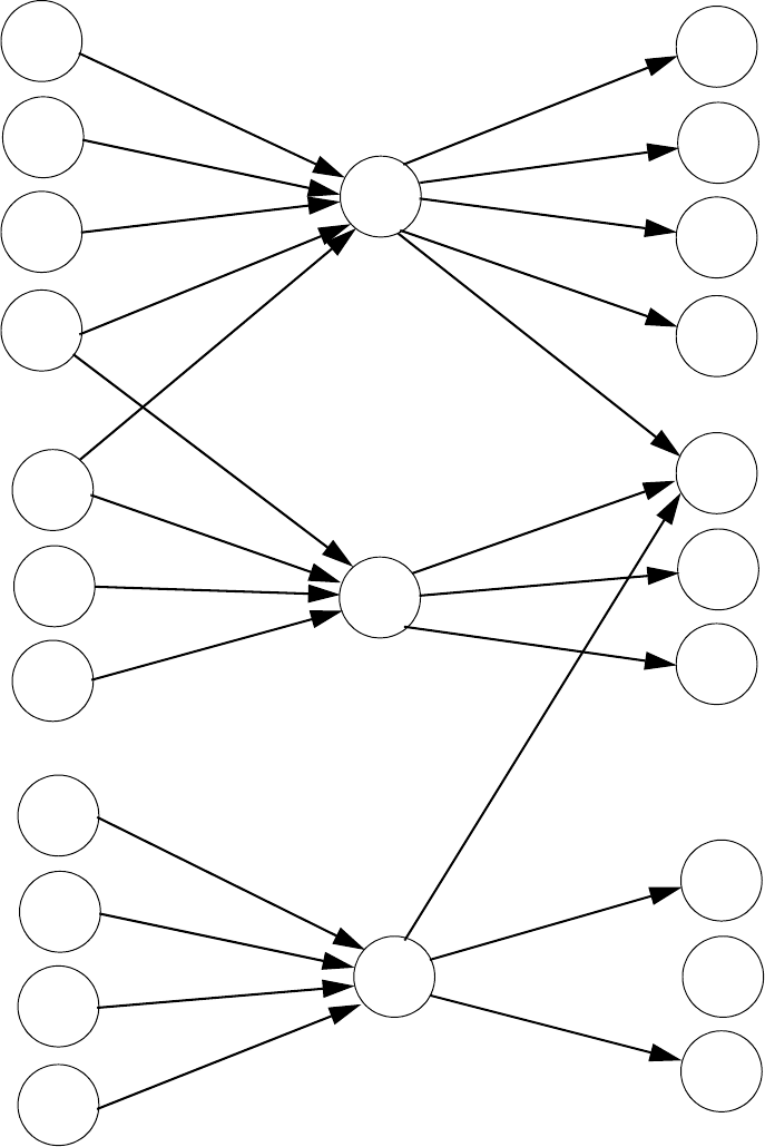
Correlations Software Zones
MS-9200UD PN 51906:A 12/10/02 169
Correlation of Input and Output Zones
The zone correlations which are shown graphically above are also presented in Table
A.1 on page 170 and Table A.2 on page 171.
Input Devices Zones Output Devices
ZONE
01
ZONE
02
ZONE
03
SD350
01
SD350
02
MMF-300
01
MMF-302
02
MMF-302
03
CP350
03
CP300
04
SD350
05
SD350
06
SD350
07
MMF-302
04
CMF-300
06
CMF-300
05
CMF-300
07
CMF-300
09
CMF-300
08
CMF-300
10
CMF-300
11
CMF-300
12
CMF-300
13

Software Zones Correlations
170 MS-9200UD PN 51906:A 12/10/02
Table A.1 Detector Programming Sheet Example
DETECTOR ZONE ASSIGNMENT
Address Device
Type
Zone
Number
ADJ/NOUN Address Device
Type
Zone
Number
ADJ/NOUN
01 SD350 1 FIRST HALL 51
02 SD350 1 ELEV. LOBBY 52
03 CP350 2 2ND FLOOR 53
04 CP350 2 ROOM 210 54
05 SD350 3 3RD FLOOR 55
06 SD350 3 MEZZANINE 56
07 SD350 3 MECH. ROOM 57
08 58
09 59
10 60
11 61
12 62
13 63
14 64
15 65
16 66
17 67
18 68
19 69
20 70
21 71
22 72
23 73
24 74
25 75
26 76
27 77
28 78
29 79
30 80
31 81
32 82
33 83
34 84
35 85
36 86
37 87
38 88
39 89
40 90
41 91
42 92
43 93
44 94
45 95
46 96
47 97
48 98
49 99
50

Correlations Software Zones
MS-9200UD PN 51906:A 12/10/02 171
Table A.2 Module Programming Sheet Example
MONITOR/CONTROL MODULE ZONE ASSIGNMENT
Address Device
Type
Zone
Number
ADJ/
NOUN
Address Device
Type
Zone
Number
ADJ/NOUN
01 MMF-300 1 51
02 MMF-302 1, 2 52
03 MMF-302 1, 2 53
04 MMF-302 3 54
05 CMF-300 1 55
06 CMF-300 1 56
07 CMF-300 1 57
08 CMF-300 2 58
09 CMF-300 1, 2, 3 59
10 CMF-300 2 60
11 CMF-300 3 61
12 CMF-300 3 62
13 CMF-300 1 63
14 64
15 65
16 66
17 67
18 68
19 69
20 70
21 71
22 72
23 73
24 74
25 75
26 76
27 77
28 78
29 79
30 80
31 81
32 82
33 83
34 84
35 85
36 86
37 87
38 88
39 89
40 90
41 91
42 92
43 93
44 94
45 95
46 96
47 97
48 98
49 99
50

Software Zones Correlations
172 MS-9200UD PN 51906:A 12/10/02
Table A.3 Blank Detector Programming Sheet - 1 of 2
DETECTOR ZONE ASSIGNMENT
Address Device
Type
Zone
Number
ADJ/
NOUN
Address Device
Type
Zone
Number
ADJ/NOUN
01 51
02 52
03 53
04 54
05 55
06 56
07 57
08 58
09 59
10 60
11 61
12 62
13 63
14 64
15 65
16 66
17 67
18 68
19 69
20 70
21 71
22 72
23 73
24 74
25 75
26 76
27 77
28 78
29 79
30 80
31 81
32 82
33 83
34 84
35 85
36 86
37 87
38 88
39 89
40 90
41 91
42 92
43 93
44 94
45 95
46 96
47 97
48 98
49 99
50

Correlations Software Zones
MS-9200UD PN 51906:A 12/10/02 173
Table A.4 Blank Module Programming Sheet - 1 of 2
MONITOR/CONTROL MODULE ZONE ASSIGNMENT
Address Device
Type
Zone
Number
ADJ/
NOUN
Address Device
Type
Zone
Number
ADJ/NOUN
01 51
02 52
03 53
04 54
05 55
06 56
07 57
08 58
09 59
10 60
11 61
12 62
13 63
14 64
15 65
16 66
17 67
18 68
19 69
20 70
21 71
22 72
23 73
24 74
25 75
26 76
27 77
28 78
29 79
30 80
31 81
32 82
33 83
34 84
35 85
36 86
37 87
38 88
39 89
40 90
41 91
42 92
43 93
44 94
45 95
46 96
47 97
48 98
49 99
50

Default Programming Correlations
174 MS-9200UD PN 51906:A 12/10/02
APPENDIX B Default Programming
The following table provides a list of the programming options and their factory default
settings.
Program Option Factory Default Program Option Factory Default
Detector Programming Not Installed Daylight Savings Yes
Detector Type Smoke-Photo Month Start Daylight Savings April
Detector Verification Off Week Start Daylight Savings 1st Week
Detector Walktest Yes Month End Daylight Savings October
Detector PAS No Week End Daylight Last Week
Detector Presignal No Verification No
Detector Zone Assign. 000 only (future)
Detector Adj/Noun none PAS Timer 0
Module Programming Not Installed Presignal Timer 0
Module Type Monitor Waterflow Retard Timer 0
Module Walktest Yes NAC 1, 2, 3 & 4 Enable Enabled
Module PAS No NAC 1, 2, 3 & 4 Silenceable Yes
Module Presignal No NAC 1, 2, 3 & 4 Type Bell
Module Zone Assign. 000 only NAC 1, 2, 3 & 4 Sync Type System Sensor
Module Adj/Noun none NAC 1, 2, 3 & 4 Autosilence 0
Zone 0 Enable Enabled NAC 1, 2, 3 & 4 Coding Steady
Zone 1 Enable Enabled NAC 1, 2, 3 & 4 Zones Zone 000 only
Zone 2 Enable Enabled NAC 1, 2, 3 & 4 Silence Inhibit 0
Zone 3 Enable Enabled Relay 1 Alarm
.........................through.......... ..................... Relay 2 Trouble (fixed)
Zone 96 Enable Enabled Relay 3 Supervisory
Zones 97, 98 & 99 Enabled (future) No
(future) Annunciator Terminal Mode No
Loop Style Style 4 Annunciator ACS Mode
Loop Protocol CLIP UDACT No
Trouble Reminder Off ACS Installed No
Banner Fire•Lite Onboard DACT No
Time Format 12 Hr Printer-PC No
Hours Setting 12 Printer Baud 9600
Minutes Setting 00
Second Settings 00
AM-PM Setting AM
Month Setting 01
Day Setting 01
Year Setting 00
Correlations NFPA Standard-Specific Requirements
MS-9200UD PN 51906:A 12/10/02 175
APPENDIX C NFPA Standard-Specific Requirements
The Fire•Lite MS-9200UD has been designed for use in commercial, industrial and
institutional applications and meets the requirements for service under the National Fire
Protection Association (NFPA) Standards outlined in this Appendix. The minimum
system components required for compliance with the appropriate NFPA standard are
listed below:
MS-9200UD Control Panel
Contains the main control board, cabinet (backbox and door), main power supply
transformer and power supply.
Batteries
Refer to "Power Supply Calculations" on page 164, for Standby Power Requirements.
Initiating Devices
Connected to one of the control panel's Initiating Device Circuits.
Notification Appliances
Connected to the control panel's Notification Appliance Circuits via a control module.
The following additional equipment is needed for compliance with the NFPA 72
standards listed below:
NFPA 72 NATIONAL FIRE ALARM STANDARDS FOR:
NFPA 72 Central Station Service (Protected Premises Unit) or Remote Station
Service
Onboard Digital Alarm Communicator Transmitter for connection to a
compatible listed Central Station DACR or Protected Premises
Receiving Unit. This unit must be installed as outlined in "Digital
Alarm Communicator/Transmitter" on page 17.
OR
4XTMF Transmitter Module for connection to the Fire•Lite RS82
Remote Station Receiver. See Figure C.2, “Remote Station Connection
Using 4XTMF Module,” on page 177, for installation instructions for
this unit.
NFPA 72 Auxiliary Fire Alarm System
4XTMF Transmitter Module for connection to a compatible listed Local Energy
Municipal Box. This unit must be installed as illustrated in the section titled "4XTMF
Transmitter Module Installation" on page 38 and as outlined in Figure C.1, “Municipal
Box Connected to 4XTMF Transmitter Module,” on page 176.
NFPA 72 Proprietary Fire Alarm System
MS-9200UD Alarm, Trouble and Supervisory contacts connected to Transmitter(s).
See Figure C.3, “Proprietary Protective Signaling System,” on page 178, for installation
instructions for this unit.
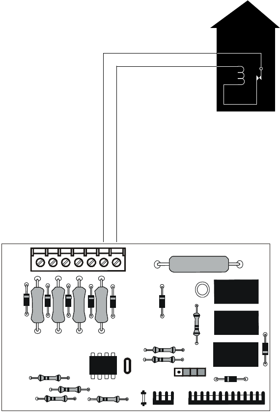
NFPA Standard-Specific Requirements Correlations
176 MS-9200UD PN 51906:A 12/10/02
NFPA 72 Auxiliary Fire Alarm System
All connections are power-limited and supervised. This application is not suitable for
separate transmission of sprinkler supervisory or trouble conditions.
Notes:
1. 3 ohms maximum loop resistance allowed for wiring from control panel to
Municipal Box.
2. Cut JP3 on the MS-9200UD main circuit board to supervise placement of
4XTMF module and circuit.
3. Cut JP2 on the MS-9200UD main circuit board to enable FACP Supervisory
relay.
4. Refer to "4XTMF Transmitter Module Installation" on page 38 for detailed
information.
Figure C.1 Municipal Box Connected to 4XTMF Transmitter Module
FIRE
Gamewell Model M34-56
Local Energy Municipal Box
Polarities shown in alarm condition
+
Nonpower-limited
Municipal Box
Circuit
+
-
-
4XTMF
Figure C.4 Municipal Box Connected to 4XTMF Transmitter Module
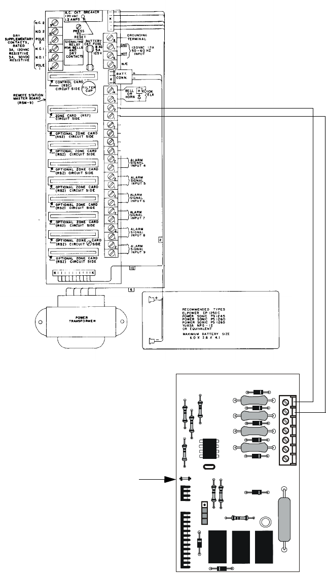
Correlations NFPA Standard-Specific Requirements
MS-9200UD PN 51906:A 12/10/02 177
NFPA 72 Remote Station Protective Signaling System
Notes:
1. Cut Jumper JP3 on the MS-9200UD main circuit board to supervise placement of
the 4XTMF module.
2. Refer to "4XTMF Transmitter Module Installation" on page 38 for detailed
information.
Fire•Lite RS82 Remote Station Receiver UL listed.
Refer to Fire•Lite Instruction Manual for Remote Station
Receiver Model RS82.
+ -
Polarity Shown is
Normal Standby
4XTMF Transmitter Module
Cutting TBL Jumper allows the
reverse polarity circuit to open
with a system trouble condition
if no alarm condition exists.
Power-limited
Figure C.2 Remote Station Connection Using 4XTMF Module
+
-
(Dummy load with a 4.7K
Ω
, ¼ watt
resistor when no connection is made)
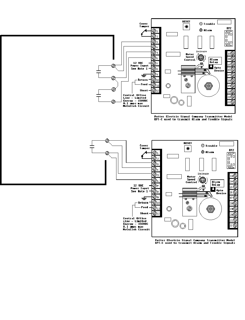
NFPA Standard-Specific Requirements Correlations
178 MS-9200UD PN 51906:A 12/10/02
NFPA 72 Proprietary Protective Signaling Systems
Figure C.3 Proprietary Protective Signaling System
Form-C relay contact programmed to
activate on Supervisory condition.
Form-C Trouble contact which will
automatically activate on any Trouble
condition.
Form-C Alarm contact programmed to
activate on General Alarm.
MS-9200UD Main Board
MS-9200UD Addressable Fire Control Panel
Notes:
1. Connection between the MS-9200UD and the
transmitter are supervised by the transmitter.
2. This MS-9200UD/Transmitter arrangement
can be employed for NFPA 72 Proprietary
Protective Signaling System.

Correlations Wire Requirements
MS-9200UD PN 51906:A 12/10/02 179
APPENDIX D Wire Requirements
T-tapping of the SLC loop wiring is allowed for 2-wire (Style 4) configurations. The
total resistance of any branch cannot exceed 40 ohms. The total wire length of all
branches cannot exceed 10,000 feet (3,000 m).
Connecting external system accessories to the MS-9200UD main circuits must be
carefully considered to ensure proper operation. It is important to use the correct type
of wire, wire gauge and wire run length for each MS-9200UD circuit. Reference the
chart below to specify wire requirements and limitations for each MS-9200UD circuit.
Note: If the SLC loop is to be run in conduit with Notification Appliance Circuits, the
risk of encountering problems can be greatly reduced by exclusively employing
electronic sounders (such as MA/SS-24D) instead of more electronically noisy
notification appliances such as electromechanical bells or horns.
Table D.1 MS-9200UD Wire Specifications
CIRCUIT CONNECTIONS WIRE REQUIREMENTS
Circuit Type Circuit Function Wire Type and Limitations
Recommended
Max. Distance
Feet (meters)
Wire Gauge and Compatible Brands
SLC loop
(power-limited)
Connects to
Addressable
Devices
Twisted, shielded pair, 40
ohms maximum per length
of Style 6 and 7 loops. 40
ohms per branch maximum
for Style 4 loops1
10,000 (3,000 m)
8,000 (2,400 m)
4,875 (1,450 m)
3,225 (980 m)
12 AWG (3.25 mm2): Genesis 4410,
Signal 98230, Belden 9583, WPW999
14 AWG (2.00 mm2):Genesis 4408 & 4608
Signal 98430, Belden 9581, WPW995
16 AWG (1.30 mm2): Genesis 4406 & 4606
Signal 98630, Belden 9575, WPW991
Direct Burial Cable Isotec NP713110VNQ-S
18 AWG (0.75 mm2): Genesis 4402 & 4602
Signal 98300, Belden 9574, WPW975
Direct Burial Cable Isotec NP714110VNQ-S
Untwisted, unshielded pair 3,000 (900 m) 12-18 AWG (3.25 - 0.75 mm2)
ACS/TERM
(EIA-485)
(power-limited)
Connects to
annunciator
modules
Twisted, shielded pair with a
characteristic impedance of
120 ohms
6,000 (1,800 m) 18 AWG (0.75 mm2)
EIA-232
(power-limited)
connects to
remote printer
and PC computer
Twisted, shielded pair 50 (15 m) 18 AWG (0.75 mm2) minimum
MMF-300 and
MMF-301
(power-limited)
Initiating Device
Circuit
Maximum loop wire
resistance is 40 ohms for the
MMF-300 and 20 ohms for
the MMF-301
2,500 (760 m) 12-18 AWG (3.25 - 0.75 mm2)
MMF-302
(power-limited)
Initiating Device
Circuit
No more than a 2.4 volt drop
allowed at end of circuit.
Maximum loop wire
resistance is 25 ohms
2,500 (760 m) 12-18 AWG (3.25 - 0.75 mm2)
CMF-300
(power-limited)
Notification
Appliance
Circuit
In alarm, no more than a 1.2
volt drop allowed at end of
circuit
Distance limitation
set by 1.2 volt
maximum line
drop
12-18 AWG (3.25 - 0.75 mm2)
24 VDC
filtered
resettable
(power-limited)
Connects to
4-wire smoke
detectors
No more than 1.2 volt drop
allowed from supply source
to end of any branch
Distance limitation
set by 1.2 volt
maximum line
drop
12-18 AWG (3.25 - 0.75 mm2)
24 VDC
nonresettable
(power-limited)
Connects to
control modules,
annunciators and
accessories
No more than 1.2 volt drop
allowed from supply source
to end of any branch
Distance limitation
set by 1.2 volt
maximum line
drop
12-18 AWG (3.25 - 0.75 mm2)
CHG-120F or
CHG-75
Remote
secondary power
source
12 AWG (3.25 mm2) in
conduit
20 (6 m) 12-18 AWG (3.25 - 0.75 mm2)
Table Footnote
1. When using untwisted, unshielded wire, full conduit is recommended for optimum EMI/RFI protection.
180 MS-9200UD PN 51906:A 12/10/02
Notes
MS-9200UD PN 51906:A 12/10/02 181
Index
Numerics
24 Hour Test Time 106
300 Series addressable devices 20
4XTMF module 177, 178
coil resistance 38
current 38
installation 38
installation steps 39
see also Transmitter Module 14, 21
supervisory relay config. 39
voltage 38
A
AC Branch Circuit
calculations 165
AC Loss Delay 88
AC Power 31
current 14
current, maximum 31
voltage 14
wiring 14, 31
Account Code 105
Acknowledge/Step 16, 130
ACM 23
ACM LED annunciator 43
ACM Series
see also annunciator 23
ACM-16ATF Annunciator 23
ACM-32AF Annunciator 23
ACM-8RF 14
contact rating 41
mounting to BRKT-9600 42
see also Relay Control Module 41
ACS LED annunciator 14
add Detector 50
add Module 60
addressable 12
addressable detectors
see also detectors 14
Addressable Device Accessories 20
addressable modules 19
see also modules 13
addressing
annunciators 43
see also device addressing 81
see also module or detector addressing 19
Adjective
control module 74
list 57
monitor module 67
multiple entries 59
AEM-16ATF Annunciator 23
AEM-32AF Annunciator 23
AFM annunciator 43
AFM-16AF Annunciator 23
AFM-16ATF Annunciator 23
AFM-32AF Annunciator 23
Alarm 134
Alarm Silence 16, 130
alarm verification 13, 54, 137, 141
annunciator 23
ACM 14, 43
ACM-8RF 14
LCD-80F 14
LDM Graphic 14
annunciator addressing 43
annunciator, graphic
see also LDM Series 24
annunciator, remote
see also LCD-80F 24
Automatic Test Operation 137
Autoprogramming 13, 45, 49
Autosilence 13, 140
NAC 91
auxiliary DC power 31
B
backbox 18
see also cabinet 30
Backup Reporting 103
Banner 82
setting 83
battery 18
cable connection 31
charger 17
charger capacity 14
Charging Circuit 14
see also secondary power 14, 31
battery box 22
battery charger 22
disable 14
external 22
baud rate 117
BB-55F
see also battery box 18, 22
BG-10LX
see also manual pull station 20
BG-12LX
see also manual pull station 20
BRKT-9600
bracket installation 41, 42
C
C304 Control/Relay Module 20
cabinet 18
dimensions 29, 30
cabinet mounting 27
Calculate System Current Draw 166
Calculating the Battery Size 168
Callback 161
Canadian Option 82, 94
Central Station 102, 162
account code 105
communications 155
phone number 106
Phone Numbers 104
report style 116
182 MS-9200UD PN 51906:A 12/10/02
Index
CHG-120F
see also battery charger 22
see also remote battery charger 14
CHG-75
see also battery charger 22
see also remote battery charger 14
Clasic Loop Interface Protocol 81
Class A 19, 32
Class B 19, 32
NAC wiring 33
CLIP mode
see also Classic Loop Interface Protocol 81
Clock Format 85
CMF-300 control module 19
Coded Operation 138
Coding
NAC 91
communications format 107, 108
Control Buttons 130
control module 19
description display 76
display 70
edit 70
enable/disable 71
noun 75
noun/adjective 73, 74
silenceable 73
type 72
type codes 72
Correlations 169
CP300 Ionization Detector 20
CP350 18
CRF-300 relay module 20
current
AC Power 31
availability 15
maximum 15
Current Draw Calculations 167
D
D350P 19
D350R 19
DACT
enable 98
onboard 98
data
see also detector data and sensitivity 137
Data Entry
via computer keyboard 44
via keypad 44
data values
see also detector data and sensitivity 13
Date setting 85
Daylight Savings Time 85
DC power
nonresettable 31
resettable 31
see also auxiliary DC power 31
Default Programming 175
Delete Detector 51
Delete Module 61
Description
control module 76
detector label 59
monitor module 69
Detector 14
add 50
adding description 56
delete 51
edit 51
enable/disable 53
screen display 52
type 54
verification 54
Detector Annunciator 20
detector data 137, 152, 153
acceptable range 152
printout 152
Detector Programming 50
device addressing 81
Digital Communicator 25
dimensions
cabinet 29
DIRTY1 153
DIRTY2 153
Disable 78
Disable Point
Maintenance Level 123
Downloading 160, 163
dress panel 18, 21
drift compensation 13, 153
definition 153
Drill 16, 130
E
earth ground 31
edit
control module 70
detector 51
detector screens 52
module, monitor 61
EIA-232 40
for PC/Printer connection 15
see also Printer/PC interface 13
EIA-485
for ACS annunciators 15
for LCD-80F 15
Enable 77
Enable/Disable
control module 71
detector 53
module, monitor 64
End-of-Line Resistor Assembly 20
Enter key 47
Erase History 95
Error Checking 162
MS-9200UD PN 51906:A 12/10/02 183
Index
event codes 108
exiting
programming 45, 46
Read Status 45, 46
F
FACP
see also Fire Alarm Control Panel 12
Features 12
Fire Alarm Control Panel
see also FACP 12
Format Selection Address 156
Form-C relay 17, 32, 41
G
general alarm zone 66
see also zone Z00 56
ground fault 40
H
H350 19
H350R 19
Hazard Condition 136
History 95
erase 95
Maintenance Level 124
view events 95
History file 13
I
I300
see also Isolator Module 20
Indicators 16
Installation 27
intelligent 12
Inventory 12
INVREP 153
Isolator Module 20
K
Key Panel 16
function keys 16
service/program keys 16
keyboard and keypad 44
Keypad/Display
removal and installation 37
L
lamp test 16
LCD display 13, 16
LCD-80F annunciator 14, 24
LDM Series annunciator 24
LDM-32 Graphic Annunciator 14
LED
AC Power 131
Alarm Silenced 131
Battery 131
Disabled 131
Fire Alarm 131
Ground 131
Kiss-off 131
Maintenance 131
Primary Line Active 131
Secondary Line Active 131
see also Indicators 16
Supervisory 131
Trouble 131
LED annunciator 23
Local Energy Municipal Box Service 38
Loop Setup 81
M
M300 Monitor Module 20
M301 Miniature Monitor Module 20
M302 2-wire Monitor Module 20
main circuit, mounting 27
Maintenance Alert 13, 137
levels 153
maintenance alert 153
Maintenance Program Level 2 46, 122
Manual Dial Mode 116
Manual programming 45
Manual Pull Station 20
Master Program Level 1 46, 48
MDF-300 monitor module 19
Medical Alert 136
MMF-300 monitor module 19
MMF-300-10 19
MMF-301 monitor module (miniature) 19
MMF-302 monitor module 19
Mode key 47
Module 13
add 60
addressing 19
delete 61
edit monitor 61
enable/disable 64
see also addressable modules 19
Module Programming 60
Monitor module 19
adjective 67
enable/disable 64
noun 68
noun/adjective 66
type 64
type action 65
Type list 64
type selection 65
Mounting
cabinet 27
main circuit board 27
municipal box transmitter
see also 4XTMF module 38
N
NAC 14, 17, 88, 90, 136
Auto Silence 91
coded 138
coding 91
current 14
End-of-Line Resistor 14
power 12
184 MS-9200UD PN 51906:A 12/10/02
Index
see also Notification Appliance Circuit 12, 32
silence inhibit 92
silenceable 90
Style configuration 33
Style Y wiring diagram 33
synchronized 138
type codes 90
voltage drop 14
voltage, operating 14
wiring Style 32
NAC enable/disable 89
NAC options 82
NACKEY card 33
N-ELR Mounting Plate 20
NFPA 72 Auxiliary Fire Alarm System 176, 177
NFPA 72 Central Station Service (Protected Premises
Unit) or Remote Station Service 176
NFPA 72 Proprietary Fire Alarm System 176
NFPA 72 Proprietary Protective Signaling Systems 179
NFPA 72 Remote Station Protective Signaling System
178
NFPA Battery Requirements 168
NFPA Standard 176
nonpower-limited
relay connections 32
Nonresettable Power 17
current 15, 31
nonsilenceable
waterflow 80, 94
Normal 132
normal display 45
Notification Appliance Circuit 14, 88
see also NAC 12, 32
Noun
list 58
monitor module 68
multiple entries 59
Noun/Adjective 56, 58
control module 73
monitor module 66
O
Off-line Programming 45
Operating Instructions 130
Operation
alarm 134
disable/enable 137
hazard condition 136
medical alert 136
NAC 136
normal 132
process monitor 136
programmed zone 137
supervisory 135
trouble 132
waterflow 137
Option Modules 21, 37, 97
annunciators/UDACT 97
Printer/PC 117
Options 12
Output Circuits 17
P
Panel ID 100
Panel Identification Number 162
PAS 55, 78, 139
see also Positive Alarm Sequence 13, 54
selection 66
PAS BYPASS 139
PAS timer 86
Password 13, 46
change 118
Maintenance Level 2 47, 122
Master Level 1 47
PC (personal computer)
configuration 40
connection 40
ground fault 40
Phone Number 106
Piezo
see also sounder 16
PK-Plus Programming Utility 21
Point Program 50
Positive Alarm Sequence 54, 139
see also PAS 13
power
NAC 12
nonresettable 15
resettable smoke 15
system 12
power supply calculations 165
power-limited
relay connections 32
Power-up
first time 46
Pre-signal 13, 55, 78
function 138
selection 66
Pre-signal Delay timer 87
Pre-signal timer 86
Primary Phone 99
primary power
see also AC Power 31
printer
baud rate 117
configuration 40
connection 40
ground fault 40
setup 40
Printer/PC interface 13
Process Monitor 136
Program
check 120
check correlations 120
clear 119
Program Check
MS-9200UD PN 51906:A 12/10/02 185
Index
Maintenance Level 125
program keys
see also Key Panel 16
Programming 44, 45
autoprogramming 45
exiting 45
factory default 175
Level 1 46
Level 2 46
manual 45
Master Level 1 48
modules 60
off-line computer 45
via computer keyboard 44
via panel keypad 44
Programming Levels 46
Programming Screens 46
Programming Sheet 171, 172, 173
Programming Utility
see also PK-Plus 21
PRT/PK-CABLE
for PC/Printer connection 40
R
RA400Z
see also detector annunciator 20
Read Status 45, 142
annunciators 149, 150
exiting 45
history 148
NAC 147
power 145
Print 152
printer/PC 151
program check 148
relay 147
system point 143
Time-Date 154
timers 146
trouble reminder 146
zones 144
Real-Time Clock 137
Recall/Increment Function 59, 69, 76
Receivers 159
Relay 14, 17, 32, 93
connections 32
contact rating 14, 17, 32
fixed 32
Form-C 14, 93
programmable 12, 17, 32
programming 93
selections 93
trouble 12, 17, 32
Relay Control Module
see also ACM-8RF 41
relay module 20
Relay options 82
Remote Station Service 38
remote switch functions 13
remote sync output 15
Remote Synchronization 34
REN
see also Ringer Equivalence Number 25
Report Style 116
Reporting Enable 102
Reset 16, 130
Resettable Power 17, 31
current 31
see also Smoke Detector Power 15
Ring Count 102
Ringer Equivalence Number 25
S
SD300 Photoelectric Detector 20
SD300T Photoelectric Detector 20
SD350 18
SD350T 18
Secondary Phone 99
Secondary Power Requirements 168
Secret Code 161
Security Features 161
sensitivity 137, 153
see also smoke detector sensitivity 137
Service Terminal 100, 101
Signal rate 13
Signaling Line Circuit
see also SLC 14
Silence Inhibit 13, 92, 140
Silenceable
control module 73
NAC 90
waterflow 94
silenceable circuits
synchronized signals 90
Silenceable waterflow 80
SLC 13, 17
current 14
reference manual 14
resistance 14
see also Signaling Line Circuit 12, 14
Style 17
voltage 14
wiring length 14
SLC Loop Protocol 81
SLC Style 81
smoke detector
chamber reading 152
data 137, 152
sensitivity 13, 137
Smoke Detector Power
current 15
Software Zones 12, 169
sounder 16
Specifications 14
strobe synchronization 13
Style 12
186 MS-9200UD PN 51906:A 12/10/02
Index
Style B 19
Style D 19
Style Y 19, 32
NAC wiring 33
NC configuration 33
Style Z 19, 32
NAC configuration 33
wiring 34
subscreen 46
Supervisory 135
supervisory relay
configuring for 4XTMF 39
sync
programming 89
see also synchronization 92
sync output 15
current 15
End-of-Line resistor 15
voltage 15
synchronization 34, 138, 147
by manufacturer 92
programming 92
see also strobe synchronization 13
synchronized 138
synchronized signals 138
and silenceable circuits 90
System
Maintenance Level 126
System Point 143
system power 12
System Setup 82
T
Telephone Circuitry 25
Telephone Company
Rights and Warnings 26
telephone line 36
Terminal 101, 102
Test Time Interval 105, 106
Time and Date
Maintenance Level 127
Time setting 84
Time-Date setting 82, 84
Time-out 161
Timers 82
Transformer Assembly 18
Transmittal Priorities 158
Transmitter Module 38
see also 4XTMF module 21
Trouble 132
trouble display 133
trouble relay 12
Trouble Reminder 82, 140, 146
trouble responses 133
Type
control module 72
detector 54
monitor module 64
NAC 90
type code
control module 72
supervision 137
verification 13
U
UDACT-F
mounting to BRKT-9600 42
UL power-limited wiring requirements 35
see also power-limited and nonpower-limited 32
Upload/Download 160
Uploading 164
V
Verification
detector 54
Verify Loops 94
View Events 95
voltage
measurements 145
ranges 145
W
Walktest 13, 54, 73, 96
audible 96
Maintenance Level 126
operation 141
selection 66
silent 96
waterflow
nonsilenceable 80, 94
silenceable 80, 94
Waterflow Delay timer 86, 87
Waterflow Retard Timer 140
Waterflow Silenceable 82
Wire Requirements 180
wiring
AC Power 31
earth ground 31
NAC Style Y 33
NAC Style Z 34
wiring control modules
see also Style Y or Style Z 19
wiring modules
see also Style B or Style D 19
wiring Style 12
X
XRM-24
see Transformer
Z
Z00 56, 66
Z97
PAS zone 55
Z98 55
Zone 97 78
Zone 98 78
Zone Assignment 56, 66, 92
control module 73
Zone Setup 77
MS-9200UD PN 51906:A 12/10/02 187
Index
Maintenance Level 128
zone type 80
list 80
Zone Z97 55
Zone Z98
pre-signal zone 55
Zones 144, 169
see also software zones 12
Zones Disabled 79
Zones Enabled 79
Zones Installed 79
zones per device 56
068'31$
Notes
068'31$
Notes
068'31$
Notes
LimWarLg.p65 01/10/2000
The manufacturer warrants its products to be free from defects in materials and workmanship
for eighteen (18) months from the date of manufacture, under normal use and service. Products
are date-stamped at time of manufacture. The sole and exclusive obligation of the manufacturer
is to repair or replace, at its option, free of charge for parts and labor, any part which is
defective in materials or workmanship under normal use and service. For products not under
the manufacturer's date-stamp control, the warranty is eighteen (18) months from date of
original purchase by the manufacturer's distributor unless the installation instructions or catalog
sets forth a shorter period, in which case the shorter period shall apply. This warranty is void
if the product is altered, repaired, or serviced by anyone other than the manufacturer or its
authorized distributors, or if there is a failure to maintain the products and systems in which
they operate in a proper and workable manner. In case of defect, secure a Return Material
Authorization form from our customer service department. Return product, transportation
prepaid, to the manufacturer.
This writing constitutes the only warranty made by this manufacturer with respect to its
products. The manufacturer does not represent that its products will prevent any loss by fire
or otherwise, or that its products will in all cases provide the protection for which they are
installed or intended. Buyer acknowledges that the manufacturer is not an insurer and assumes
no risk for loss or damages or the cost of any inconvenience, transportation, damage, misuse,
abuse, accident, or similar incident.
THE MANUFACTURER GIVES NO WARRANTY, EXPRESSED OR IMPLIED, OF
MERCHANTABILITY, FITNESS FOR ANY PARTICULAR PURPOSE, OR OTHERWISE
WHICH EXTEND BEYOND THE DESCRIPTION ON THE FACE HEREOF. UNDER
NO CIRCUMSTANCES SHALL THE MANUFACTURER BE LIABLE FOR ANY LOSS
OF OR DAMAGE TO PROPERTY, DIRECT, INCIDENTAL, OR CONSEQUENTIAL,
ARISING OUT OF THE USE OF, OR INABILITY TO USE THE MANUFACTURER'S
PRODUCTS. FURTHERMORE, THE MANUFACTURER SHALL NOT BE LIABLE FOR
ANY PERSONAL INJURY OR DEATH WHICH MAY ARISE IN THE COURSE OF, OR
AS A RESULT OF, PERSONAL, COMMERCIAL, OR INDUSTRIAL USE OF ITS
PRODUCTS.
This warranty replaces all previous warranties and is the only warranty made by the
manufacturer. No increase or alteration, written or verbal, of the obligation of this warranty
is authorized.
Limited Warranty

World Headquarters
One Fire-Lite Place, Northford, CT 06472-1653 USA
203-484-7161 • Fax 203-484-7118
www.firelite.com
