G0495X M
User Manual: G0495X
Open the PDF directly: View PDF ![]() .
.
Page Count: 64

COPYRIGHT © APRIL, 2015 BY GRIZZLY INDUSTRIAL, INC. REVISED JULY, 2017 (MN)
WARNING: NO PORTION OF THIS MANUAL MAY BE REPRODUCED IN ANY SHAPE
OR FORM WITHOUT THE WRITTEN APPROVAL OF GRIZZLY INDUSTRIAL, INC.
#BL17352 PRINTED IN TAIWAN
The following changes were recently made to this machine since the owner's manual was printed:
• Redesigned front digital readout and rear digital sensor.
• Front digital readout takes AA batteries instead of AAA batteries. Rear sensor requires no battery.
• Updated instructions for using digital readout. Rear sensor no longer has separate controls.
• Changed magnetic switch contactor appearance, color of capacitor and motor wires, and wiring
diagram.
Aside from this information, all other content in the owner's manual applies and MUST be read and under-
stood for your own safety. IMPORTANT: Keep this update with the owner's manual for future reference.
For questions or help, contact our Tech Support at (570) 546-9663 or techsupport@grizzly.com.
READ THIS FIRST
Revised Inventory
Box 1 Qty
N. AA Batteries (not shown) ............................ 2
Revised Base Parts
168-4V2
168-3V2
REF PART # DESCRIPTION
168-3V2** P0495X168-3V2 DIGITAL SENSOR V2.03.15
168-4V2 P0495X168-4V2 CAP SCREW M5-.8 X 6
168-5 P0495X168-5 PHLP HD SCR M3-.5 X 12
168-16 P0495X168-16 DIGITAL SENSOR BRACKET
Revised Table Parts
REF PART # DESCRIPTION
72V2 P0495X072V2 MAGNETIC DRO BRACKET ASSY V2.03.15
72V2-1 P0495X072V2-1 MAGNETIC DRO BRACKET
72V2-2 P0495X072V2-2 MAGNETIC STRIP (SET OF 2)
72V2
72V2-1
72V2-2
Digital Readout Batteries
Two AA batteries install into the control panel for
the digital readout to function. Follow the instruc-
tions on Page 18 in the Owner's Manual in the
same manner for AAA batteries.
Revised Stand Parts
REF PART # DESCRIPTION
141V2 P0495X141V2 DIGITAL READOUT BRACKET V2.03.15
142V2 P0495X142V2 FLAT HD SCR M3-.5 X 6
147V2** P0495X147V2 DIGITAL READOUT ASSEMBLY V2.03.15
147-1V2 P0495X147-1V2 BATTERY AA V2.03.15
149V2 P0495X149V2 SWITCH PLATE V2.03.15
189 P0495X189 STRAIN RELIEF 1/2"-3/4" SNAP-IN ST
149V2
142V2
189
B
147V2
141V2
147-1V2
** PART 147V2 INCLUDES PART 168-3V2.
For questions or help with this product contact Tech Support at (570) 546-9663 or techsupport@grizzly.com
Model G0495X
***IMPORTANT UPDATE***
For Machines Mfd. Since 05/16
and Owner's Manual Revised 11/13
-2- G0495X Update (Mfd. Since 5/16)
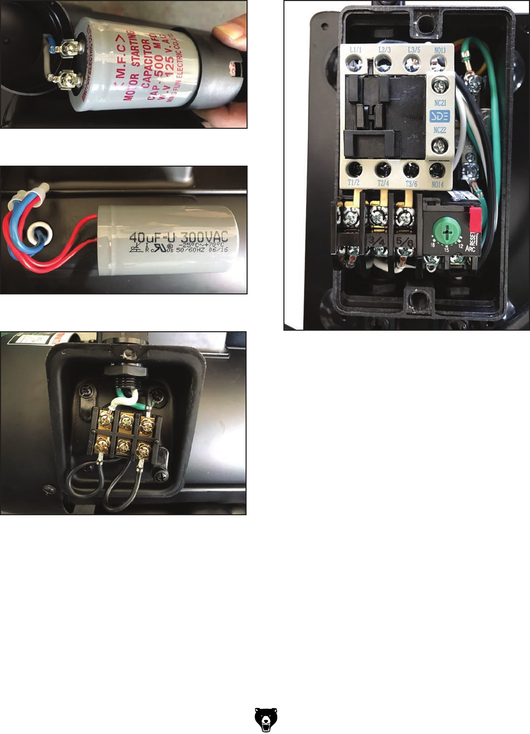
Revised Run Capacitor Wiring
Revised Start Capacitor Wiring Revised Magnetic Switch
Revised Junction Box Wiring

G0495X Update (Mfd. Since 5/16) -3-
A1
A2
Ground
AMP
RESET
96 98
1/2
T1/2 T3/6 NO14
3/4
T2/4
L1/1 L3/5 NO13
L2/3
5/6
95
12
15
18
OFF
SDE
MA-18
RA-20
Hot
Hot
Ground
6-20 Plug
(As Recommended)
220
VAC
G
START
Ground
STOP
POWER
CONTROL PANEL (viewed from behind)
MAGNETIC
SWITCH
DIGITAL
READOUT
Ground
220V
MOTOR
The motor wiring shown here is
current at the time of printing, but it
may not match your machine.
Always use the wiring diagram
inside the motor junction box.
13 14
21
22 21
14 22 13
X1 X2
Run
Capacitor
40MFD
300VAC
Start
Capacitor
500MFD
125VAC
NC 22
NC 21
(2 AA Batteries)
1
1.5V,
357/303
Battery
SENSOR
G0495X Revised Wiring Diagram
See Figure 73
See Figure 72

-4- G0495X Update (Mfd. Since 5/16)
MENU/RETURN: Toggles between ORG and
MAIN menu. ORG establishes the zero point for
absolute values shown on the digital readout.
ABS/REL: Toggles between absolute and relative
modes. Absolute mode shows the total depth of
cut in relation to an absolute zero point. Relative
mode shows how much the table has moved up
or down in relation to an arbitrarily chosen zero
point. To select relative mode, press the ABS/REL
button until REL is displayed. To return to absolute
mode, press the ABS/REL button again.
For example, to use absolute and relative
modes:
1. Follow Steps 1–4 in Calibrating Infeed
Table on Page 41 of Owner's Manual.
2. Press MENU/RETURN button to display
ORG.
3. Press ZERO/ENTER button twice. This sets
an absolute zero point and returns you to
main menu.
4. Move infeed table down until display reads
0.125" (the max cut allowed).
5. Press ABS/REL button to toggle to relative
mode, press ZERO/ENTER button to set
arbitrary zero point, then move infeed table
up -0.010".
6. Press ABS/REL button to toggle back to
absolute mode. The screen displays 0.115",
the total depth of cut relative to absolute zero
point set in Step 2.
Digital Readout
To use zero or enter modes:
1. Make sure two included AA batteries are
installed in control panel (refer to Page 18 in
Owner's Manual, for installation instructions).
2. Press ABS/REL button to enter absolute
mode.
3. Raise or lower infeed table to desired cutting
depth.
4. Press ABS/REL button to enter relative mode.
5. Press ZERO/ENTER button to reset digital
readout to 0.000.
MM/INCH: Toggles between inch and metric
measurements.
ZERO/ENTER: Push to reset display to 0.000 in
relative mode. Follow Step 2 in the prior example
to reset display to 0.000 in absolute mode.
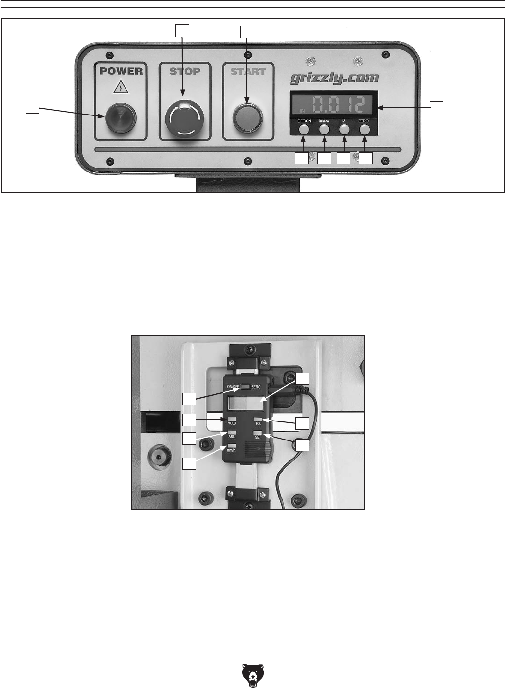
Figure 1. Digital readout.
ZERO/
ENTER
mm/inch
MENU/
RETURN
ABS/REL
Calibrating Rear Sensor
The rear DRO sensor and magnetic strip can be
calibrated to ensure optimum accuracy of the
DRO. Complete the steps below after installing
new batteries in the DRO.
To calibrate rear sensor:
1. Raise the infeed bed up all the way.
2. Press MENU/RETURN button once, then
press ABS/REL or MM/INCH button until
TUNE displays on DRO with icon.
3. Press ZERO/ENTER button. The icon
flashes. TUNE — displays. Quickly proceed
to next step.
Note: If no action is taken within 30 seconds,
the screen returns to normal mode.
4. Use outfeed handwheel to lower, raise, and
lower bed again within 30 seconds.
TUNE — — displays and flashes
rapidly. This indicates calibration procedure
is complete. The screen returns to normal
mode.

MODEL G0495X
8" JOINTER
w/DIGITAL READOUT
OWNER'S MANUAL
(For models manufactured since 6/11)
COPYRIGHT © MARCH, 2008 BY GRIZZLY INDUSTRIAL, INC., REVISED NOVEMBER, 2013 (TR)
WARNING: NO PORTION OF THIS MANUAL MAY BE REPRODUCED IN ANY SHAPE
OR FORM WITHOUT THE WRITTEN APPROVAL OF GRIZZLY INDUSTRIAL, INC.
#BL10436 PRINTED IN TAIWAN V2.11.13

This manual provides critical safety instructions on the proper setup,
operation, maintenance, and service of this machine/tool. Save this
document, refer to it often, and use it to instruct other operators.
Failure to read, understand and follow the instructions in this manual
may result in fire or serious personal injury—including amputation,
electrocution, or death.
The owner of this machine/tool is solely responsible for its safe use.
This responsibility includes but is not limited to proper installation in
a safe environment, personnel training and usage authorization,
proper inspection and maintenance, manual availability and compre-
hension, application of safety devices, cutting/sanding/grinding tool
integrity, and the usage of personal protective equipment.
The manufacturer will not be held liable for injury or property damage
from negligence, improper training, machine modifications or misuse.
Some dust created by power sanding, sawing, grinding, drilling, and
other construction activities contains chemicals known to the State
of California to cause cancer, birth defects or other reproductive
harm. Some examples of these chemicals are:
• Lead from lead-based paints.
• Crystalline silica from bricks, cement and other masonry products.
• Arsenic and chromium from chemically-treated lumber.
Your risk from these exposures varies, depending on how often you
do this type of work. To reduce your exposure to these chemicals:
Work in a well ventilated area, and work with approved safety equip-
ment, such as those dust masks that are specially designed to filter
out microscopic particles.
Table of Contents
INTRODUCTION ............................................... 2
Contact Info.................................................... 2
Manual Accuracy ........................................... 2
Machine Data Sheet ...................................... 3
Identification ................................................... 5
Control Panel & Digital Sensor Features ....... 6
SECTION 1: SAFETY ....................................... 7
Safety Instructions for Machinery .................. 7
Additional Safety Instructions for Jointers ..... 9
SECTION 2: POWER SUPPLY ...................... 10
SECTION 3: SETUP ....................................... 12
Unpacking .................................................... 12
Items Needed for Setup ............................... 12
Inventory ...................................................... 13
Cleanup ........................................................ 14
Site Considerations ...................................... 15
Moving & Placing Jointer ............................. 16
Anchoring to Floor ....................................... 16
Dust Collection ............................................. 17
Setting Outfeed Table Height ...................... 17
Digital Readout Batteries ............................. 18
Test Run ...................................................... 19
Recommended Adjustments ........................ 20
SECTION 4: OPERATIONS ........................... 21
Basic Jointer Controls .................................. 21
Digital Sensor & Readout ............................ 23
Stock Inspection & Requirements................ 26
Squaring Stock............................................. 27
Surface Planing............................................ 28
Edge Jointing ............................................... 29
Bevel Cutting................................................ 30
Rabbet Cutting ............................................. 31
SECTION 5: ACCESSORIES ......................... 32
SECTION 6: MAINTENANCE ......................... 34
Schedule ...................................................... 34
Cleaning ....................................................... 34
Unpainted Cast Iron ..................................... 34
Lubrication ................................................... 34
SECTION 7: SERVICE ................................... 35
Troubleshooting ........................................... 35
Checking/Adjusting Table Parallelism ......... 37
Replacing Carbide Inserts ........................... 40
Setting Infeed Table ..................................... 41
Calibrating Infeed Table ............................... 41
Calibrating Digital Sensor & Readout .......... 42
Cutterhead Guard ........................................ 42
Setting Fence Stops .................................... 43
V-Belt ........................................................... 45
Pulley Alignment .......................................... 46
Electrical Components ................................. 47
Wiring Diagram ............................................ 48
Fence Parts Breakdown & List .................... 49
Base Parts Breakdown & List ...................... 50
Table Parts Breakdown & List ..................... 51
Stand Parts Breakdown & List ..................... 52
Stand Parts List ........................................... 53
Label Placement .......................................... 54
WARRANTY & RETURNS ............................. 57

-2- Model G0495X (Mfd. Since 6/11)
INTRODUCTION
We are proud to provide a high-quality owner’s
manual with your new machine!
We
made every effort to be exact with the
instruc-
tions, specifications, drawings, and photographs
contained inside. Sometimes we make mistakes,
but
our policy of continuous improvement
also
means that
sometimes the machine
you receive
will be slightly different than what is shown in
the manual
.
If you find this to be the case, and the difference
between the manual and machine leaves you
confused about a procedure
, check our website
for an updated version. W
e post current
manuals
and
manual updates for free on our website at
www.grizzly.com
.
Alternatively, you can call our Technical Support
for help. Before calling, please write down the
Manufacture Date
and Serial Number
stamped
into the machine ID label (see below). This infor-
mation helps us determine if updated documenta-
tion is available for your machine.
Manufacture Date
Serial Number
Manual Accuracy
We stand behind our machines. If you have
any questions or need help, use the information
below to contact us. Before contacting, please get
the serial number and manufacture date of your
machine. This will help us help you faster.
Grizzly Technical Support
1203 Lycoming Mall Circle
Muncy, PA 17756
Phone: (570) 546-9663
Email: techsupport@grizzly.com
We want your feedback on this manual. What did
you like about it? Where could it be improved?
Please take a few minutes to give us feedback.
Grizzly Documentation Manager
P.O. Box 2069
Bellingham, WA 98227-2069
Email: manuals@grizzly.com
Contact Info

Model G0495X (Mfd. Since 6/11) -3-
The information contained herein is deemed accurate as of 11/11/2013 and represents our most recent product specifications.
Due to our ongoing improvement efforts, this information may not accurately describe items previously purchased. PAGE 1 OF 3Model G0495X
MACHINE DATA
SHEET
Customer Service #: (570) 546-9663 · To Order Call: (800) 523-4777 · Fax #: (800) 438-5901
MODEL G0495X 8" X 84" JOINTER WITH EXCLUSIVE
DIGITAL HEIGHT READOUT
Product Dimensions:
Weight.............................................................................................................................................................. 596 lbs.
Width (side-to-side) x Depth (front-to-back) x Height..................................................................... 83 x 24-1/2 x 44 in.
Footprint (Length x Width)..................................................................................................................... 45-3/4 x 15 in.
Shipping Dimensions:
Type.......................................................................................................................................................... Wood Crate
Content........................................................................................................................................................... Machine
Weight.............................................................................................................................................................. 796 lbs.
Length x Width x Height....................................................................................................................... 87 x 28 x 43 in.
Must Ship Upright................................................................................................................................................... Yes
Electrical:
Power Requirement........................................................................................................... 220V, Single-Phase, 60 Hz
Prewired Voltage.................................................................................................................................................. 220V
Full-Load Current Rating........................................................................................................................................ 15A
Minimum Circuit Size.............................................................................................................................................. 20A
Connection Type....................................................................................................................................... Cord & Plug
Power Cord Included.............................................................................................................................................. Yes
Power Cord Length................................................................................................................................................. 6 ft.
Power Cord Gauge......................................................................................................................................... 12 AWG
Plug Included........................................................................................................................................................... No
Recommended Plug Type..................................................................................................................................... 6-20
Switch Type............................................................................................ Control Panel w/Magnetic Switch Protection
Motors:
Main
Type................................................................................................................. TEFC Capacitor-Start Induction
Horsepower................................................................................................................................................ 3 HP
Phase............................................................................................................................................ Single-Phase
Amps............................................................................................................................................................ 15A
Speed................................................................................................................................................ 3450 RPM
Power Transfer ............................................................................................................................... V-Belt Drive
Bearings..................................................................................................... Shielded & Permanently Lubricated
Main Specifications:
Cutting Capacities
Bevel Jointing............................................................................................................................. 0 – 45 deg. L/R
Maximum Width of Cut................................................................................................................................ 8 in.
Maximum Depth of Cut............................................................................................................................. 1/8 in.
Minimum Workpiece Length...................................................................................................................... 10 in.
Minimum Workpiece Thickness................................................................................................................ 1/2 in.
Maximum Rabbeting Depth...................................................................................................................... 1/2 in.
Number of Cuts Per Minute..................................................................................................................... 28,000
Machine Data Sheet

-4- Model G0495X (Mfd. Since 6/11)
The information contained herein is deemed accurate as of 11/11/2013 and represents our most recent product specifications.
Due to our ongoing improvement efforts, this information may not accurately describe items previously purchased. PAGE 2 OF 3Model G0495X
Fence Information
Fence Length............................................................................................................................................. 38 in.
Fence Width.......................................................................................................................................... 1-1/2 in.
Fence Height......................................................................................................................................... 4-3/4 in.
Fence Stops............................................................................................................................. 45, 90, 135 deg.
Cutterhead Information
Cutterhead Type........................................................................................................................................ Spiral
Cutterhead Diameter........................................................................................................................... 3-1/16 in.
Number of Cutter Spirals.................................................................................................................................. 4
Number of Indexable Cutters.......................................................................................................................... 36
Cutterhead Speed............................................................................................................................. 7000 RPM
Cutter Insert Information
Cutter Insert Type.................................................................................................................. Indexable Carbide
Cutter Insert Length................................................................................................................................. 15 mm
Cutter Insert Width................................................................................................................................... 15 mm
Cutter Insert Thickness........................................................................................................................... 2.5 mm
Table Information
Table Length........................................................................................................................................ 82-1/2 in.
Table Width........................................................................................................................................... 8-1/8 in.
Table Thickness.................................................................................................................................. 3-5/16 in.
Floor to Table Height................................................................................................................................. 31 in.
Table Adjustment Type..................................................................................................................... Handwheel
Table Movement Type.................................................................................................................. Parallelogram
Construction
Base..................................................................................................................................................... Cast Iron
Body Assembly.................................................................................................................................... Cast Iron
Cabinet.................................................................................................................................... Pre-formed Steel
Fence Assembly.................................................................................................................................. Cast Iron
Guard.......................................................................................................................................... Die Cast Metal
Table....................................................................................................................... Precision Ground Cast Iron
Paint........................................................................................................................................... Powder Coated
Other Information
Number of Dust Ports....................................................................................................................................... 1
Dust Port Size.............................................................................................................................................. 4 in.
Other Specifications:
Country Of Origin ............................................................................................................................................. Taiwan
Warranty ........................................................................................................................................................... 1 Year
Approximate Assembly & Setup Time ........................................................................................................ 45 Minutes
Serial Number Location .................................................................................................. ID Label on Front of Cabinet
ISO 9001 Factory .................................................................................................................................................. Yes
CSA Certified .......................................................................................................................................................... No

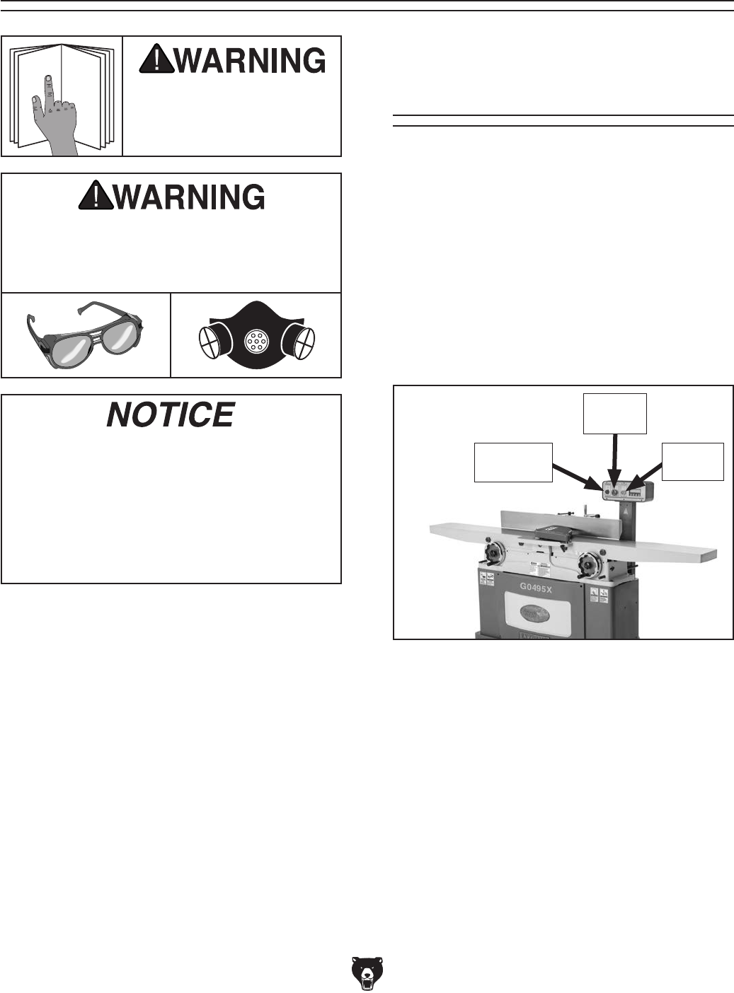
Model G0495X (Mfd. Since 6/11) -5-
Figure 1. G0495X identification.
A. Outfeed Table
B. Fence
C. Rabbeting Extension
D. Cutterhead Guard
E. Fence Tilt Handle
F. Control Panel with Digital Readout
G. Depth Scale
H. Infeed Table
Identification
BCDEF
G H I J K
L
M
N
A
I. Fence Adjustment Wheel
J. Fence Lock
K. Tilt Lock
L. Digital Sensor
M. Infeed Depth Stops
N. Infeed Handwheel
O. Outfeed Handwheel
P. Outfeed Depth Stops
P
O
-6- Model G0495X (Mfd. Since 6/11)
Control Panel & Digital Sensor Features
Figure 2. Control panel and digital readout features.
A. POWER Light
B. STOP Button
C. START Button
D. OFF/ON Button
E. IN/MM Button
F. M Button
G. ZERO Button
H. Digital Display
A
BC
E F GD
Figure 3. Infeed table digital sensor and
controls.
H
I. ON/OFF/ZERO Button
J. HOLD Button
K. ABS Button
L. MM/IN Button
M. SET Button
N. TOL Button
O. Digital Readout
I
J
K
L
O
N
M

Model G0495X (Mfd. Since 6/11) -7-
ELECTRICAL EQUIPMENT INJURY RISKS. You
can be shocked, burned, or killed by touching live
electrical components or improperly grounded
machinery. To reduce this risk, only allow qualified
service personnel to do electrical installation or
repair work, and always disconnect power before
accessing or exposing electrical equipment.
DISCONNECT POWER FIRST.
Always discon-
nect machine from power supply BEFORE making
adjustments, changing tooling, or servicing machine.
This prevents an injury risk from unintended startup
or contact with live electrical components.
EYE PROTECTION. Always wear ANSI-approved
safety glasses or a face shield when operating or
observing machinery to reduce the risk of eye
injury or blindness from flying particles. Everyday
eyeglasses are NOT approved safety glasses.
OWNER’S MANUAL. Read and understand this
owner’s manual BEFORE using machine.
TRAINED OPERATORS ONLY. Untrained oper-
ators have a higher risk of being hurt or killed.
Only allow trained/supervised people to use this
machine. When machine is not being used, dis-
connect power, remove switch keys, or lock-out
machine to prevent unauthorized use—especially
around children. Make workshop kid proof!
DANGEROUS ENVIRONMENTS. Do not use
machinery in areas that are wet, cluttered, or have
poor lighting. Operating machinery in these areas
greatly increases the risk of accidents and injury.
MENTAL ALERTNESS REQUIRED. Full mental
alertness is required for safe operation of machin-
ery. Never operate under the influence of drugs or
alcohol, when tired, or when distracted.
For Your Own Safety, Read Instruction
Manual Before Operating This Machine
The purpose of safety symbols is to attract your attention to possible hazardous conditions.
This manual uses a series of symbols and signal words intended to convey the level of impor-
tance of the safety messages. The progression of symbols is described below. Remember that
safety messages by themselves do not eliminate danger and are not a substitute for proper
accident prevention measures. Always use common sense and good judgment.
Indicates a potentially hazardous situation which, if not avoided,
MAY result in minor or moderate injury. It may also be used to alert
against unsafe practices.
Indicates a potentially hazardous situation which, if not avoided,
COULD result in death or serious injury.
Indicates an imminently hazardous situation which, if not avoided,
WILL result in death or serious injury.
This symbol is used to alert the user to useful information about
proper operation of the machine.
NOTICE
Safety Instructions for Machinery
SECTION 1: SAFETY

-8- Model G0495X (Mfd. Since 6/11)
WEARING PROPER APPAREL. Do not wear
clothing, apparel or jewelry that can become
entangled in moving parts. Always tie back or
cover long hair. Wear non-slip footwear to avoid
accidental slips, which could cause loss of work-
piece control.
HAZARDOUS DUST. Dust created while using
machinery may cause cancer, birth defects, or
long-term respiratory damage. Be aware of dust
hazards associated with each workpiece material,
and always wear a NIOSH-approved respirator to
reduce your risk.
HEARING PROTECTION. Always wear hear-
ing protection when operating or observing loud
machinery. Extended exposure to this noise
without hearing protection can cause permanent
hearing loss.
REMOVE ADJUSTING TOOLS. Tools left on
machinery can become dangerous projectiles
upon startup. Never leave chuck keys, wrenches,
or any other tools on machine. Always verify
removal before starting!
USE CORRECT TOOL FOR THE JOB. Only use
this tool for its intended purpose—do not force
it or an attachment to do a job for which it was
not designed. Never make unapproved modifica-
tions—modifying tool or using it differently than
intended may result in malfunction or mechanical
failure that can lead to personal injury or death!
AWKWARD POSITIONS. Keep proper footing
and balance at all times when operating machine.
Do not overreach! Avoid awkward hand positions
that make workpiece control difficult or increase
the risk of accidental injury.
CHILDREN & BYSTANDERS. Keep children and
bystanders at a safe distance from the work area.
Stop using machine if they become a distraction.
GUARDS & COVERS. Guards and covers reduce
accidental contact with moving parts or flying
debris. Make sure they are properly installed,
undamaged, and working correctly.
FORCING MACHINERY. Do not force machine.
It will do the job safer and better at the rate for
which it was designed.
NEVER STAND ON MACHINE. Serious injury
may occur if machine is tipped or if the cutting
tool is unintentionally contacted.
STABLE MACHINE. Unexpected movement dur-
ing operation greatly increases risk of injury or
loss of control. Before starting, verify machine is
stable and mobile base (if used) is locked.
USE RECOMMENDED ACCESSORIES. Consult
this owner’s manual or the manufacturer for rec-
ommended accessories. Using improper acces-
sories will increase the risk of serious injury.
UNATTENDED OPERATION. To reduce the
risk of accidental injury, turn machine OFF and
ensure all moving parts completely stop before
walking away. Never leave machine running
while unattended.
MAINTAIN WITH CARE. Follow all maintenance
instructions and lubrication schedules to keep
machine in good working condition. A machine
that is improperly maintained could malfunction,
leading to serious personal injury or death.
CHECK DAMAGED PARTS. Regularly inspect
machine for any condition that may affect safe
operation. Immediately repair or replace damaged
or mis-adjusted parts before operating machine.
MAINTAIN POWER CORDS. When disconnect-
ing cord-connected machines from power, grab
and pull the plug—NOT the cord. Pulling the cord
may damage the wires inside. Do not handle
cord/plug with wet hands. Avoid cord damage by
keeping it away from heated surfaces, high traffic
areas, harsh chemicals, and wet/damp locations.
EXPERIENCING DIFFICULTIES. If at any time
you experience difficulties performing the intend-
ed operation, stop using the machine! Contact our
Technical Support at (570) 546-9663.

Model G0495X (Mfd. Since 6/11) -9-
Additional Safety Instructions for Jointers
JOINTER INJURY RISKS. Familiarize yourself
with the main injury risks associated with joint-
ers—always use common sense and good judge-
ment to reduce your risk of injury. Main injury
risks from jointers: amputation/lacerations from
contact with the moving cutterhead, entangle-
ment/crushing injuries from getting caught in
moving parts, blindness or eye injury from flying
wood chips, or impact injuries from workpiece
kickback.
KICKBACK. Know how to reduce the risk of kick-
back and kickback-related injuries. “Kickback”
occurs during the operation when the workpiece is
ejected from the machine at a high rate of speed.
Kickback is commonly caused by poor workpiece
selection, unsafe feeding techniques, or improper
machine setup/maintenance. Kickback injuries
typically occur as follows: (1) operator/bystanders
are struck by the workpiece, resulting in impact
injuries (i.e., blindness, broken bones, bruises,
death); (2) operator’s hands are pulled into blade,
resulting in amputation or severe lacerations.
GUARD REMOVAL. Except when rabbeting,
never remove guards during operation or while
connected to power. Always replace guard after
rabbeting. You could be seriously injured if you
accidentally touch the spinning cutterhead or
get entangled in moving parts. Before removing
sawdust, turn jointer OFF and disconnect power
before clearing. Immediately replace guards.
DULL/DAMAGED KNIVES/INSERTS. Only use
sharp, undamaged knives/inserts. Dull, damaged
or rusted knives/inserts increase risk of kickback.
OUTFEED TABLE ALIGNMENT. To reduce the
risk of kickback and personal injuries, keep the
outfeed table even with the knives/inserts at top
dead center (the highest point during rotation).
If the outfeed table is set too low, the workpiece
may rock against the cutterhead. If the table is set
too high, the workpiece may hit the outfeed table
and get stuck over the cutterhead.
INSPECTING STOCK. To reduce the risk of
kickback injuries or machine damage, thoroughly
inspect and prepare the workpiece before cutting.
Verify the workpiece is free of nails, staples, loose
knots or other foreign material. Workpieces with
minor warping should be surface planed first with
the cupped side facing the infeed table.
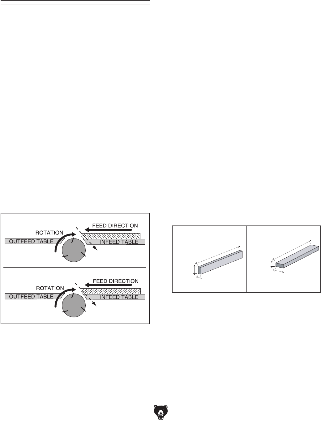
GRAIN DIRECTION. Jointing against the grain
or end grain increases the required cutting force,
which could produce chatter or excessive chip
out, and lead to kickback.
CUTTING LIMITATIONS. To reduce the risk of
accidental cutterhead contact or kickback, never
perform jointing, planing, or rabbeting cuts on
pieces smaller than 8" long, 3⁄4" wide, or 1⁄4" thick.
MAXIMUM CUTTING DEPTH. To reduce the risk
of kickback, never cut deeper than 1⁄8" per pass.
PUSH BLOCKS. To reduce the risk of accidental
cutterhead contact, always use push blocks when
planing materials less than 3" high or wide. Never
pass your hands directly over the cutterhead with-
out a push block.
WORKPIECE SUPPORT. To reduce accidental
cutterhead contact and kickback, support work-
piece continuously during operation. Position and
guide workpiece with fence; support long or wide
stock with auxiliary stands.
FEED WORKPIECE PROPERLY. To reduce the
risk of kickback, never start jointer with workpiece
touching cutterhead. Allow cutterhead to reach
full speed before feeding. Never back work toward
the infeed table.
SECURE KNIVES/INSERTS. Loose knives or
improperly set inserts can become dangerous
projectiles or cause machine damage. Always
verify knives/inserts are secure and properly
adjusted before operation. Straight knives should
never project more than 1⁄8" (0.125") from cutter-
head body.

-10- Model G0495X (Mfd. Since 6/11)
SECTION 2: POWER SUPPLY
Availability
Before installing the machine, consider the avail-
ability and proximity of the required power supply
circuit. If an existing circuit does not meet the
requirements for this machine, a new circuit must
be installed. To minimize the risk of electrocution,
fire, or equipment damage, installation work and
electrical wiring must be done by an electrican or
qualified service personnel in accordance with all
applicable codes and standards.
Electrocution, fire, or
equipment damage may
occur if machine is not
correctly grounded and
connected to the power
supply.
Full-Load Current Rating
The full-load current rating is the amperage a
machine draws at 100% of the rated output power.
On machines with multiple motors, this is the
amperage drawn by the largest motor or sum of all
motors and electrical devices that might operate
at one time during normal operations.
Full-Load Current Rating ................... 15 Amps
The full-load current is not the maximum amount
of amps that the machine will draw. If the machine
is overloaded, it will draw additional amps beyond
the full-load rating.
If the machine is overloaded for a sufficient length
of time, damage, overheating, or fire may result—
especially if connected to an undersized circuit.
To reduce the risk of these hazards, avoid over-
loading the machine during operation and make
sure it is connected to a power supply circuit that
meets the requirements in the following section.
For your own safety and protection of
property, consult an electrician if you are
unsure about wiring practices or electrical
codes in your area.
Note: The circuit requirements listed in this man-
ual apply to a dedicated circuit—where only one
machine will be running at a time. If this machine
will be connected to a shared circuit where mul-
tiple machines will be running at the same time,
consult a qualified electrician to ensure that the
circuit is properly sized for safe operation.
A power supply circuit includes all electrical
equipment between the breaker box or fuse panel
in the building and the machine. The power sup-
ply circuit used for this machine must be sized to
safely handle the full-load current drawn from the
machine for an extended period of time. (If this
machine is connected to a circuit protected by
fuses, use a time delay fuse marked D.)
Circuit Information
Circuit Requirements
This machine is prewired to operate on a power
supply circuit that has a verified ground and meets
the following requirements:
Nominal Voltage ........................................220V
Cycle ..........................................................60 Hz
Phase ........................................... Single-Phase
Power Supply Circuit ......................... 20 Amps
Plug/Receptacle ............................. NEMA 6-20
Model G0495X (Mfd. Since 6/11) -11-
Improper connection of the equipment-grounding
wire can result in a risk of electric shock. The
wire with green insulation (with or without yellow
stripes) is the equipment-grounding wire. If repair
or replacement of the power cord or plug is nec-
essary, do not connect the equipment-grounding
wire to a live (current carrying) terminal.
Check with a qualified electrician or service per-
sonnel if you do not understand these grounding
requirements, or if you are in doubt about whether
the tool is properly grounded. If you ever notice
that a cord or plug is damaged or worn, discon-
nect it from power, and immediately replace it with
a new one.
Extension Cords
We do not recommend using an extension cord
with this machine.
If you must use an extension
cord, only use it if absolutely necessary and only
on a temporary basis.
Extension cords cause voltage drop, which may
damage electrical components and shorten motor
life. Voltage drop increases as the extension cord
size gets longer and the gauge size gets smaller
(higher gauge numbers indicate smaller sizes).
Any extension cord used with this machine must
contain a ground wire, match the required plug
and receptacle, and meet the following require-
ments:
Minimum Gauge Size ...........................12 AWG
Maximum Length (Shorter is Better).......50 ft.
Grounding Requirements
This machine MUST be grounded. In the event
of certain malfunctions or breakdowns, grounding
reduces the risk of electric shock by providing a
path of least resistance for electric current.
This machine is equipped with a power cord
that has an equipment-grounding wire and a
grounding plug. The plug must only be inserted
into a matching receptacle (outlet) that is prop-
erly installed and grounded in accordance with all
local codes and ordinances.
No adapter should be used with the
required plug. If the plug does not fit the
available receptacle, or the machine must
be reconnected for use on a different type
of circuit, the reconnection must be made
by a qualified electrician and comply with all
local codes and ordinances.
Serious injury could occur if you connect
the machine to power before completing the
setup process. DO NOT connect to power
until instructed later in this manual.
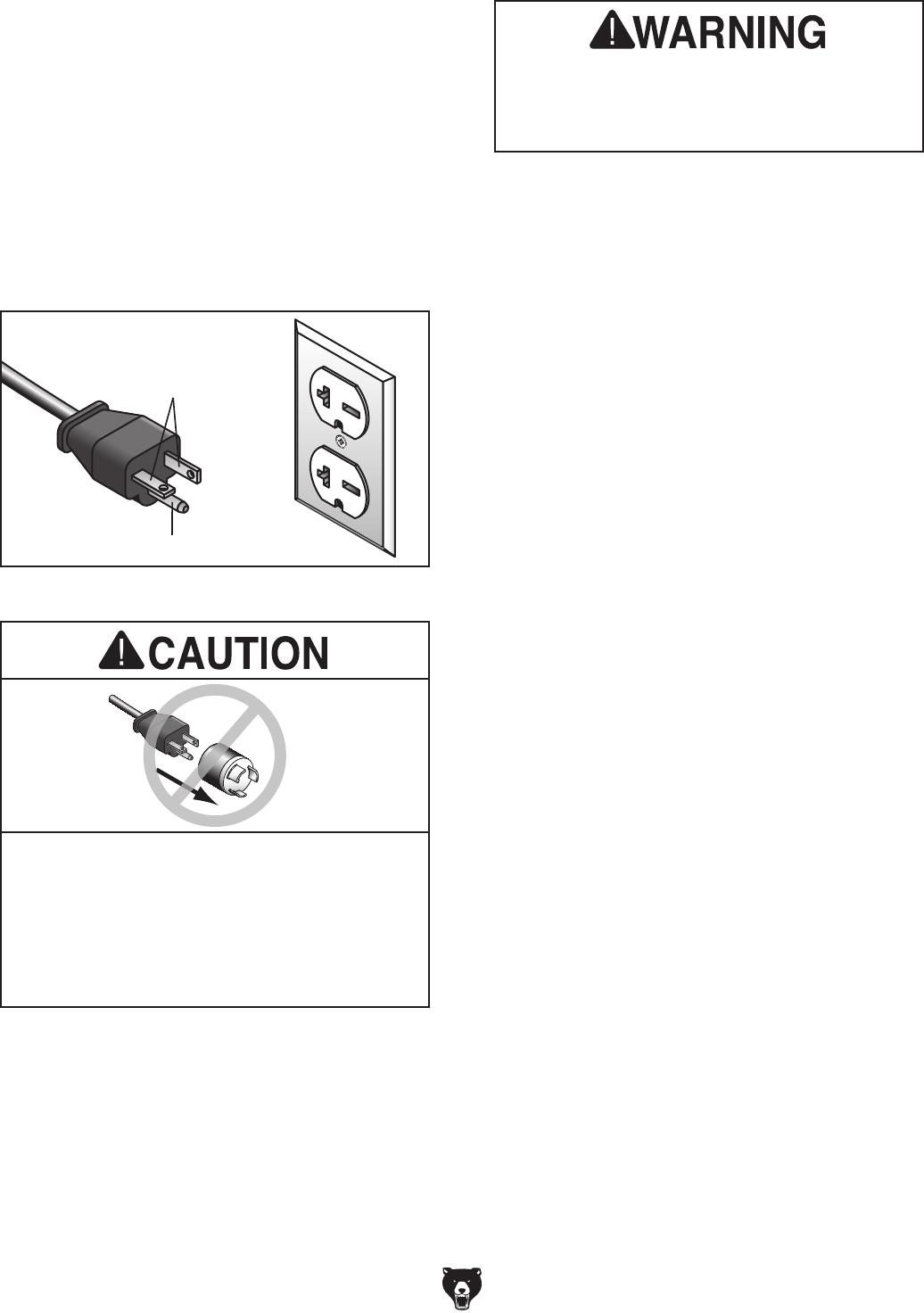
Figure 4. Typical 6-20 plug and receptacle.
Grounding Prong
Current Carrying Prongs
6-20 PLUG
GROUNDED
6-20 RECEPTACLE

-12- Model G0495X (Mfd. Since 6/11)
SECTION 3: SETUP
The following items are needed to complete the
setup process, but are not included with your
machine:
Description Qty
• Safety Glasses (for each person) ............... 1
• Straightedge 4' (or longer) .......................... 1
• Dust Collection System .............................. 1
• 4" Dust Hose (length as needed) ............... 1
• 4" Hose Clamp ........................................... 1
• Forklift, Hoist, or Boom Crane .................... 1
• Lifting Straps (1000 lb. Capacity Min.) ....... 2
Items Needed for
Setup
Your machine was carefully packaged for safe
transportation. Remove the packaging materials
from around your machine and inspect it. If you
discover any damage, please call us immediately
at (570) 546-9663
for advice.
Save the containers and all packing materials for
possible inspection by the carrier or its agent.
Otherwise, filing a freight claim can be difficult.
When you are completely satisfied with the condi-
tion of your shipment, inventory the contents.
Unpacking

Model G0495X (Mfd. Since 6/11) -13-
Box 1 Qty
A. Jointer Assembly (not shown) .................... 1
B. Hex Wrench 3mm ....................................... 1
C. Hex Wrench 4mm ....................................... 1
D. Hex Wrench 5mm ....................................... 1
E. Hex Wrench 6mm ....................................... 1
F. Hex Wrench 8mm ....................................... 1
G. Open End Wrench 12/14mm ...................... 1
H. Open End Wrench 14/17mm ...................... 1
I. Phillips Head Screwdriver........................... 1
J. Push Blocks ................................................ 2
K. T-Handle T-25 Torx Driver ......................... 2
L. Inserts 15 x 15 x 2.5 ................................... 5
M. Flat Head Torx Screws #10-32 ................. 10
N. AAA Batteries (not shown) ......................... 2
Figure 5. Tools inventory.
B
C
D
E
F
G
H
I
J
Figure 6. Spiral cutterhead hardware.
K
L
M
NOTICE
If you cannot find an item on this list, care-
fully check around/inside the machine and
packaging materials. Often, these items get
lost in packaging materials while unpack-
ing or they are pre-installed at the factory.
Inventory
The following is a list of items shipped with your
machine. Before beginning setup, lay these items
out and inventory them.
If any non-proprietary parts are missing (e.g. a
nut or a washer), we will gladly replace them; or
for the sake of expediency, replacements can be
obtained at your local hardware store.

-14- Model G0495X (Mfd. Since 6/11)
The unpainted surfaces of your machine are
coated with a heavy-duty rust preventative that
prevents corrosion during shipment and storage.
This rust preventative works extremely well, but it
will take a little time to clean.
Be patient and do a thorough job cleaning your
machine. The time you spend doing this now will
give you a better appreciation for the proper care
of your machine's unpainted surfaces.
There are many ways to remove this rust preven-
tative, but the following steps work well in a wide
variety of situations. Always follow the manufac-
turer’s instructions with any cleaning product you
use and make sure you work in a well-ventilated
area to minimize exposure to toxic fumes.
Before cleaning, gather the following:
• Disposable rags
• Cleaner/degreaser (WD•40 works well)
• Safety glasses & disposable gloves
• Plastic paint scraper (optional)
Basic steps for removing rust preventative:
1.
Put on safety glasses.
2.
Coat the rust preventative with a liberal
amount of cleaner/degreaser, then let it soak
for 5–10 minutes.
3.
Wipe off the surfaces. If your cleaner/degreas-
er is effective, the rust preventative will wipe
off easily. If you have a plastic paint scraper,
scrape off as much as you can first, then wipe
off the rest with the rag.
4.
Repeat Steps 2–3 as necessary until clean,
then coat all unpainted surfaces with a quality
metal protectant to prevent rust.
Gasoline and petroleum
products have low flash
points and can explode
or cause fire if used to
clean machinery. Avoid
using these products
to clean machinery.
Many cleaning solvents
are toxic if inhaled. Only
work in a well-ventilated
area.
NOTICE
Avoid chlorine-based solvents, such as
acetone or brake parts cleaner, that may
damage painted surfaces.
T23692—Orange Power Degreaser
A great product for removing the waxy shipping
grease from your machine during clean up.
Figure 7. T23692 Orange Power Degreaser.
Cleanup

Model G0495X (Mfd. Since 6/11) -15-
Site Considerations
Weight Load
Refer to the Machine Data Sheet for the weight
of your machine. Make sure that the surface upon
which the machine is placed will bear the weight
of the machine, additional equipment that may be
installed on the machine, and the heaviest work-
piece that will be used. Additionally, consider the
weight of the operator and any dynamic loading
that may occur when operating the machine.
Space Allocation
Consider the largest size of workpiece that will
be processed through this machine and provide
enough space around the machine for adequate
operator material handling or the installation of
auxiliary equipment. With permanent installations,
leave enough space around the machine to open
or remove doors/covers as required by the main-
tenance and service described in this manual.
See below for required space allocation.
Physical Environment
The physical environment where the machine is
operated is important for safe operation and lon-
gevity of machine components. For best results,
operate this machine in a dry environment that is
free from excessive moisture, hazardous chemi-
cals, airborne abrasives, or extreme conditions.
Extreme conditions for this type of machinery are
generally those where the ambient temperature
range exceeds 41°–104°F; the relative humidity
range exceeds 20–95% (non-condensing); or the
environment is subject to vibration, shocks, or
bumps.
Electrical Installation
Place this machine near an existing power source.
Make sure all power cords are protected from
traffic, material handling, moisture, chemicals,
or other hazards. Make sure to leave access to
a means of disconnecting the power source or
engaging a lockout/tagout device, if required.
Lighting
Lighting around the machine must be adequate
enough that operations can be performed safely.
Shadows, glare, or strobe effects that may distract
or impede the operator must be eliminated.
Children or untrained people
may be seriously injured by
this machine. Only install in an
access restricted location.
Figure 8. Minimum working clearances.
83"
241/2"
-16- Model G0495X (Mfd. Since 6/11)
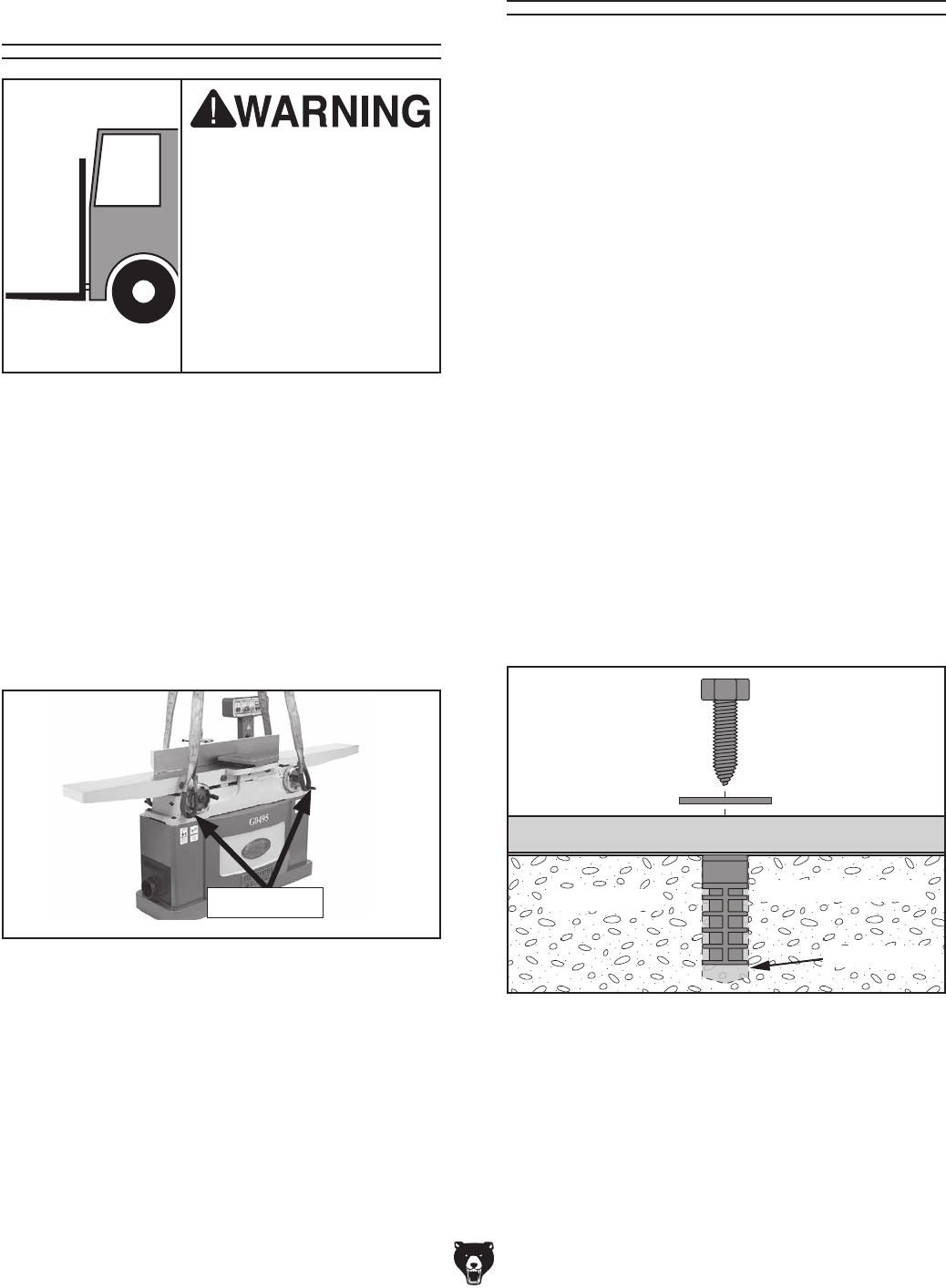
The Model G0495X requires the use of lifting
equipment such as a forklift, engine hoist, or
boom crane. DO NOT try to lift the machine by
hand.
To lift the jointer:
1. Unbolt the jointer from the pallet.
2. Wrap lifting straps around the lifting rods, as
shown in Figure 9.
Moving & Placing
Jointer
The Model G0495X is a
heavy machine. Serious
personal injury may occur
if safe moving methods
are not used. To be safe,
get assistance and use
power equipment to move
the shipping crate and
remove the machine from
the crate.
Figure 9. Model G0495X supported evenly by
two lifting straps.
3. With lifting straps positioned evenly, lift the
jointer off of the pallet and place it in the
desired location.
Lifting Rods
Anchoring machinery to the floor prevents tipping
or shifting and reduces vibration that may occur
during operation, resulting in a machine that runs
slightly quieter and feels more solid.
If the machine will be installed in a commercial or
workplace setting, or if it is permanently connect-
ed (hardwired) to the power supply, local codes
may require that it be anchored to the floor.
If not required by any local codes, fastening the
machine to the floor is an optional step. If you
choose not to do this with your machine, we rec-
ommend placing it on machine mounts, as these
provide an easy method for leveling and they have
vibration-absorbing pads.
Anchoring to Floor
Lag shield anchors with lag screws (see below)
are a popular way to anchor machinery to a con-
crete floor, because the anchors sit flush with the
floor surface, making it easy to unbolt and move
the machine later, if needed. However, anytime
local codes apply, you MUST follow the anchoring
methodology specified by the code.
Machine Base
Concrete
Lag Screw
Lag Shield Anchor
Flat Washer
Drilled Hole
Figure 10. Popular method for anchoring
machinery to a concrete floor.
Anchoring to Concrete Floors
Model G0495X (Mfd. Since 6/11) -17-
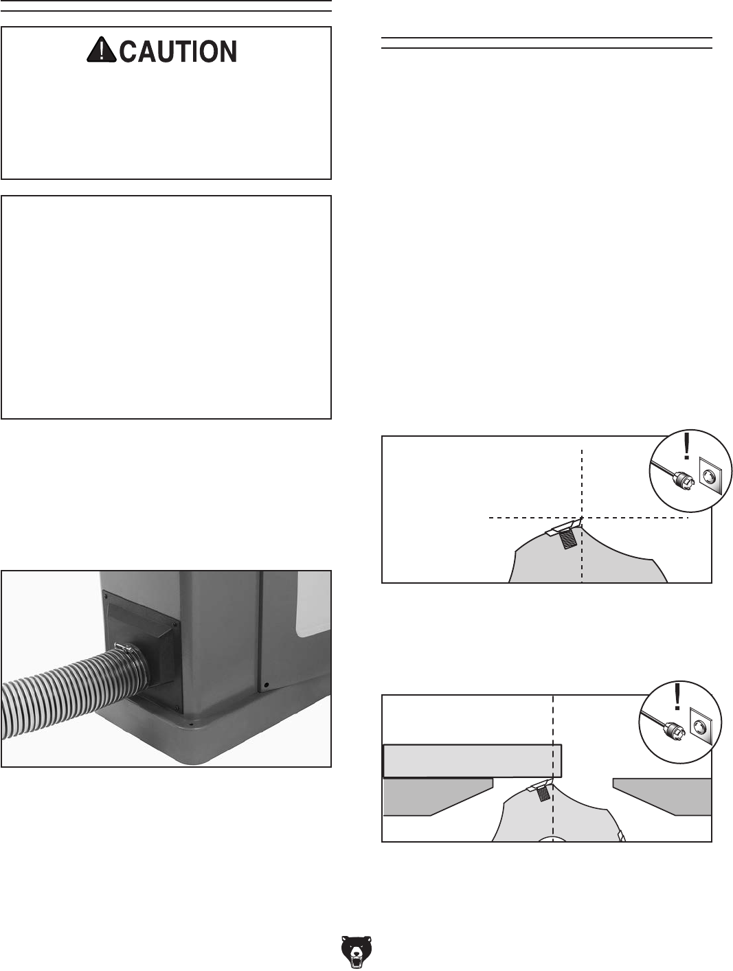
Figure 11. Dust hose attached to dust port.
Dust Collection
To connect the machine to a dust collector:
1. Fit a 4" dust hose that is connected to a dust
collector over the dust port, as shown in
Figure 11, and secure in place with a hose
clamp.
DO NOT operate the Model G0495X without
an adequate dust collection system. This
jointer creates substantial amounts of wood
dust while operating. Failure to use a dust
collection system can result in short and
long-term respiratory illness.
Recommended CFM at Dust Port: 400 CFM
Do not confuse this CFM recommendation with
the rating of the dust collector. To determine
the CFM at the dust port, you must consider
these variables: (1) CFM rating of the dust col-
lector, (2) hose type and length between the
dust collector and the machine, (3) number
of branches or wyes, and (4) amount of other
open lines throughout the system. Explaining
how to calculate these variables is beyond the
scope of this manual. Consult an expert or pur-
chase a good dust collection "how-to" book.
2. Tug the hose to make sure it does not come
off.
Note: A tight fit is necessary for proper per-
formance.
Figure 12. Cutterhead insert at top-dead-center.
Top Dead
Center
Bottom Dead
Center
Setting Outfeed
Table Height
The outfeed table height MUST be level with the
carbide inserts when they are at top-dead-center.
If the outfeed table is set too low, the workpiece
will be tapered from front to back. If the outfeed
table is set too high, the workpiece will hit the edge
of the outfeed table during operation, increasing
the chance of kickback.
To set the outfeed table height:
1. DISCONNECT JOINTER FROM POWER!
2. Move the cutterhead guard out of the way or
remove it, and remove the V-belt guard.
3. Place a straightedge on the outfeed table
so it extends over the cutterhead and rotate
the cutterhead pulley until one of the carbide
inserts is at top-dead-center (TDC), as shown
in Figure 12.
4. When correctly set, the carbide insert will just
touch the straightedge when the insert is at
its highest point of rotation (Figure 13).
Figure 13. Using a straightedge to align outfeed
table height with insert at TDC.
Straightedge
Outfeed Infeed

-18- Model G0495X (Mfd. Since 6/11)
—If your outfeed table is correctly set, no
adjustments are necessary.
—If the insert lifts the straightedge off the
table or the table is below the straightedge,
loosen the outfeed table lock and outfeed
table positive stop bolts and jam nuts
(Figure 1, Page 5) and adjust the outfeed
table height with the handwheel until the
straightedge just touches a insert at its
highest point of rotation.
Tip: Some advanced woodworkers have found
that they can virtually eliminate snipe by set-
ting the outfeed table in the following manner:
Repeat Steps 1-4 using a freshly exposed
insert. Then lower the outfeed table slightly so
the insert lifts the straightedge off the table.
Place a ruler next to the straightedge and rotate
the cutterhead, watching how far the carbide
insert pulls the straightedge. Adjust the outfeed
table and recheck until the straightedge only
moves 5⁄32".
5. Lock the outfeed table, lock the outfeed table
positive stop bolts, and reinstall the cutterhead
guard (Page 42) and V-belt guards.
Digital Readout
Batteries
You must install two AAA batteries into the control
panel for the digital readout to function.
To install the AAA batteries in the control
panel:
1. Unscrew the thumb knob on the rear door
on the back of the control panel, loosen the
Phillips head screw, then swing the door
open.
2. Open the battery holder cover, install the
included batteries, then close the cover.
Note: It may help to loosen the screws on the
front of the panel securing the digital readout
bracket to open the battery cover.
3. Close the rear access door, tighten the
Phillips head screw, then install the thumb
knob.
Figure 14. Rear access door on control panel
(cutaway view for clarity).
Thumb Knob
Access Door
Battery HolderBracket
Phillips Head Screw
Model G0495X (Mfd. Since 6/11) -19-
Test Run
Once assembly is complete, test run the machine
to ensure it is properly connected to power and
safety components function properly.
If you find an unusual problem during the test run,
immediately stop the machine, disconnect it from
power, and fix the problem BEFORE operating the
machine again. The
Troubleshooting
table in the
SERVICE section of this manual can help.
DO NOT start machine until all preceding
setup instructions have been performed.
Operating an improperly setup machine
may result in malfunction or unexpect-
ed results that can lead to serious injury,
death, or machine/property damage.
Serious injury or death can result from
using this machine BEFORE understanding
its controls and related safety information.
DO NOT operate, or allow others to operate,
machine until the information is understood.
To test run the machine:
1. Make sure you understand the safety instruc-
tions at the beginning of the manual and that
the machine is setup properly.
2. Make sure all tools and objects used during
setup are cleared away from the machine.
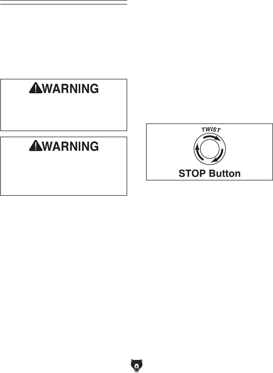
Figure 15. Resetting the STOP button.
3. Connect the machine to the power source.
The power light will illuminate.
—If the light does not illuminate, check the
power connection.
4. Push the STOP button in, then twist it clock-
wise so it pops out. When the STOP button
pops out, the switch is reset and ready for
operation (see Figure 15).

-20- Model G0495X (Mfd. Since 6/11)
For your convenience, the adjustments listed
below have been performed at the factory and
no further setup is required to operate your
machine.
However, because of the many variables involved
with shipping, we recommend that you at least
verify the following adjustments to ensure the
best possible results from your new machine.
Step-by-step instructions for these adjustments
can be found in SECTION 7: SERVICE.
Factory adjustments that should be verified:
1. Table Parallelism (Page 37).
2. Infeed Table Calibration (Page 41).
3. Digital Sensor and Readout Calibration
(Page 42).
4. Fence Stop Settings (Page 43).
5. Verify V-Belt Tension Adjustment (Page 45).
Recommended
Adjustments
5. Verify that the machine is operating correctly
by pushing the START button.
—When operating correctly, the machine
runs smoothly with little or no vibration or
rubbing noises.
— Investigate and correct strange or unusual
noises or vibrations before operating the
machine further. Always disconnect the
machine from power when investigating or
correcting potential problems.
6. Press the STOP button to stop the machine.
7. WITHOUT resetting the switch, press the
START button. The machine should not start.
—If the machine does not start, the STOP
button safety feature is working correctly.
The test run is complete.
—If the machine does start (with the STOP
button pushed in), immediately disconnect
power to the machine. The STOP button
safety feature is not working correctly. This
safety feature must work properly before
proceeding with regular operations. Call
Tech Support for help.
Model G0495X (Mfd. Since 6/11) -21-
SECTION 4: OPERATIONS
Basic Jointer
Controls
This section covers the basic controls used during
routine operations.
START Button: Starts motor only if the STOP
button is popped out.
STOP Button: Disables the START button.
Enable the START button by twisting the STOP
button until it pops out.
POWER Light: Indicates machine is correctly
plugged into the power source.
Figure 16. START/STOP button locations.
POWER
Light
START
Button
STOP
Button
To reduce your risk of
serious injury, read this
entire manual BEFORE
using machine.
To reduce risk of eye injury from flying
chips or lung damage from breathing dust,
always wear safety glasses and a respirator
when operating this machine.
If you are not experienced with this type
of machine, WE STRONGLY RECOMMEND
that you seek additional training outside of
this manual. Read books/magazines or get
formal training before beginning any proj-
ects. Regardless of the content in this sec-
tion, Grizzly Industrial will not be held liable
for accidents caused by lack of training.
-22- Model G0495X (Mfd. Since 6/11)
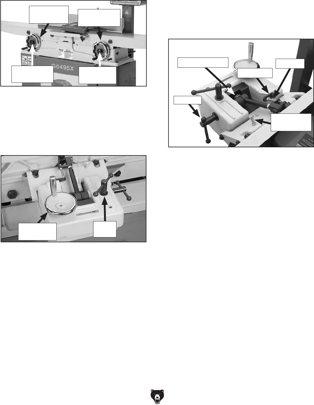
Fence Movement: The fence has a lock that
keeps it in position (Figure 18). To move the
fence, loosen the lock and turn the fence adjust-
ment wheel to slide the fence where needed, then
retighten the lock.
Figure 18. Fence lock location.
Fence Tilting: The tilt lock (Figure 19) secures
the fence at any position in the available range.
The stop block locks the fence for 90° cuts. Two
positive stops stop the fence at 45° inward and
45° outward for common bevel cuts. Even when
the fence is resting against the positive stops, the
tilt lock must be tightened before cutting. Also, the
stop block must be disengaged for 45° outward
bevel cuts.
Figure 19. Tilt lock and stop block locations.
Figure 17. Table control locations.
Table Movement: To move the infeed or outfeed
tables, loosen the table locks (Figure 17), move
the tables with the infeed or outfeed handwheels
(Figure 16), then tighten the table locks.
Outfeed
Table Lock
Tilt Lock
Infeed
Table Lock
Adjustment
Wheel
Fence
Lock
45° Outward
Stop
Stop Block
90° Stop
45° Inward Stop
Outfeed
Handwheel Infeed
Handwheel

Model G0495X (Mfd. Since 6/11) -23-
The digital readout is used in conjunction with
the digital sensor to display the selected cutting
depth. Before using the digital sensor and read-
out, verify calibration on the infeed table (Page
41), digital sensor, and digital readout (Page 42).
Make sure the digital sensor is turned ON before
using the digital readout, otherwise the readout
will not work.
Below is a summary of the features on the rear
digital sensor (Figure 20) and digital readout on
the control panel (Figure 25, Page 25).
Figure 20. Digital sensor.
ON/OFF/ZERO: Turns digital sensor ON or OFF
when pressed for five seconds. Push for two sec-
onds to reset the sensor to 0.000.
HOLD: Freezes the digital display at the current
value.
ABS: Toggles between absolute and incremental
values. Absolute mode shows the total depth of cut
in relation to an absolute zero point. Incremental
mode shows how much the table has moved up or
down relative to an arbitrarily chosen zero point.
To select incremental mode, press the ABS but-
ton, INC is displayed. To return to absolute mode,
press the ABS button, INC disappears.
Digital Sensor &
Readout
Digital Sensor
ABS
mm/in
TOL
SET
HOLD
ON/OFF/ZERO
2. While holding SET, move the cursor to the
fourth digit, then release the SET button
when the desired digit blinks.
MM/IN: Toggles between inch and metric display
units.
SET: Recalls a stored numerical value.
For example, to set the preset to 00.063":
1. Move the infeed table to the desired depth of
cut. In ABS mode press ZERO, then press
SET. On the screen SET will blink and "+" will
appear (Figure 21).
0
000
SET
IN
+0
.
Figure 21. Initial SET mode screen.
For example, to use ABS and incremental
modes:
1. Press the ZERO button in ABS mode, then
move the infeed table down until the display
reads 0.125" (the max cut allowed).
2. Press the ABS button to toggle to INC mode,
press the ZERO button to set the arbitrary
zero point, then move the infeed table up
-0.010".
3. Press the ABS button to toggle back to ABS
mode. The screen displays 0.115", the total
depth of cut relative to the absolute zero point
set in Step 1.
3. Press SET six times to increase the value to
6.
4. Hold SET to move the cursor to the fifth digit,
release the SET button, then press it three
times to change the value to 3, as shown in
Figure 22.

-24- Model G0495X (Mfd. Since 6/11)
3
600
SET
IN
+0
.
Figure 22. Set value entered.
3. Hold the TOL button down and move the
cursor right three digits until the digit flashes,
then press TOL once to increase the value to
00.100".
4. Hold TOL down to move the cursor right one
digit until it flashes, then press TOL twice
to change that digit to 2 so the value reads
+00.120".
5. Repeat Step 4 in a similar manner to change
the next digit to 5 so the display value is now
+00.125".
Figure 23. Setting upper limit.
0
000
SET
IN
+0
.
0
000
SET
IN
+0
.
Figure 24. Setting lower limit.
TOL: Use to set the tolerance limits.
In ABS mode, first set the reference dimension,
then set the upper and lower tolerance values.
While setting the tolerance limits, you will not be
able to use the sensor to measure depth of cut.
The upper tolerance limit value must be greater
than the lower limit value, otherwise an error code
(E-01) will appear. If this happens, press ZERO to
return to ABS mode.
For example, to set the reference dimension at
00.063", upper tolerance at 00.125", and lower
tolerance at 00.000":
1. Follow the instructions for setting the refer-
ence dimension to 00.063" on Page 23, then
enter ABS mode.
2. Press the TOL button. SET flashes and
is displayed, indicating the upper limit mode
setting, as shown in Figure 23.
7. To select a lower limit value of +00.000", hold
the TOL button down and move the cursor to
SET, then press TOL again. The tolerances
are set.
8. Raise and lower the infeed table to verify the
tolerance settings.
—If the infeed table is raised or lowered
between 00.125" and 00.000", OK displays
on the screen.
—If the infeed table is lowered below 00.125"
the appears.
—If the infeed table is raised above 00.000"
the appears with a "–".
9. To change the tolerance limits, repeat Steps
2-7.
10. To exit TOL mode, briefly press the TOL but-
ton until all TOL mode icons disappear and
only the preset value 00.063" appears.
5. Hold SET down until "SET" blinks on the dis-
play, then press SET again to set the value.
The preset value can be set positive (+) or nega-
tive (–). When the "+" flashes, press SET to toggle
between "–" and "+".
6. Hold the TOL button down and move the cur-
sor until SET flashes, then press TOL again.
SET flashes and is displayed, indicating the
lower limit mode, as shown in Figure 24.

Model G0495X (Mfd. Since 6/11) -25-
Figure 25. Digital readout.
OFF/ON: Turns digital display ON or OFF.
IN/MM: Toggles between inch and metric mea-
surements.
M: Toggles display between the relative value on
the digital readout and the value displayed on the
rear sensor.
ZERO: Push to reset the display to 0.000.
Digital Readout
in/mm ZERO
M
OFF/ON
To use the digital readout:
1. Make sure the two included AAA batteries
are installed in the control panel (refer to
Page 18, for installation instructions).
2. Turn the digital sensor ON, then turn ON the
digital readout.
Note: If the rear sensor is not turned ON first,
the front digital readout will display an error
code.
3. Raise or lower the infeed table to the desired
cutting depth. The digital readout displays the
table height measured by the rear sensor.
4. Press the ZERO button to reset the digital
readout. This new zero point is only shown
on the front display.
5. Adjust the table height to the new cutting
depth.
6. Press the M button to switch the digital read-
out back to display the rear digital sensor
cutting depth. This will delete the zero point
set in Step 3.
-26- Model G0495X (Mfd. Since 6/11)
Here are some rules to follow when choosing
and jointing stock:
• DO NOT joint or surface plane stock that
contains large or loose knots. Injury to the
operator or damage to the workpiece can
occur if a knot becomes dislodged during the
cutting operation.
• DO NOT joint or surface plane against the
grain direction. Cutting against the grain
increases the likelihood of stock kickback, as
well as tear-out on the workpiece.
• Jointing and surface planing with the
grain produces a better finish and is safer
for the operator. Cutting with the grain is
described as feeding the stock on the jointer
so the grain points down and toward you as
viewed on the edge of the stock (Figure 26).
Note: If the grain changes direction along the
edge of the board, decrease the cutting depth
and make additional passes.
Stock Inspection &
Requirements
Figure 26. Correct and incorrect grain align-
ment with cutterhead.
With Grain
Against Grain
CORRECT
INCORRECT
• Only process natural wood fiber through
your jointer. Never joint MDF, particle board,
plywood, laminates, drywall, metal, stone,
tile, glass, plastic or other synthetically made
materials.
• Scrape all glue off of boards before joint-
ing.
• Remove foreign objects from the stock.
Make sure that any stock you process with
the jointer is clean and free of any dirt,
nails, staples, tiny rocks or any other foreign
objects, which if they hit the inserts and are
drawn into the dust collector, may cause a
fire hazard. The particles may also damage
the inserts. Wood stacked on a concrete floor
can have small pieces of stone or concrete
pressed into the surface.
• Make sure all stock is sufficiently dried
before jointing. Wood with a moisture con-
tent over 20% will cause unnecessary wear
on the inserts and poor cutting results. Excess
moisture can also hasten rust and corrosion.
• Make sure your workpiece exceeds the
minimum dimension requirements (Figure
27) before edge jointing or surface plan-
ing, or it may break or kick back during
the operation!
Figure 27. Minimum dimensions for edge jointing
and surface planing (jointer).
1⁄2" Min.
1" Min.
12" Min. 12" Min.
1⁄2" Min.
1" Min.
Model G0495X (Mfd. Since 6/11) -27-
Squaring stock involves four steps performed
in the order below:
1. Surface Plane on the Jointer—The concave
face of the workpiece is surface planed flat with
the jointer.
Previously
Surface
Planed Face
2. Surface Plane on a Thickness Planer—The
opposite face of the workpiece is surface planed
flat with a thickness planer.
3. Edge Joint on the Jointer—The concave edge
of the workpiece is jointed flat with the jointer.
15
30
45
Previously
Jointed Edge
4. Rip Cut on a Table Saw—The jointed edge of
the workpiece is placed against a table saw fence
and the opposite edge cut off.
Squaring Stock
-28- Model G0495X (Mfd. Since 6/11)
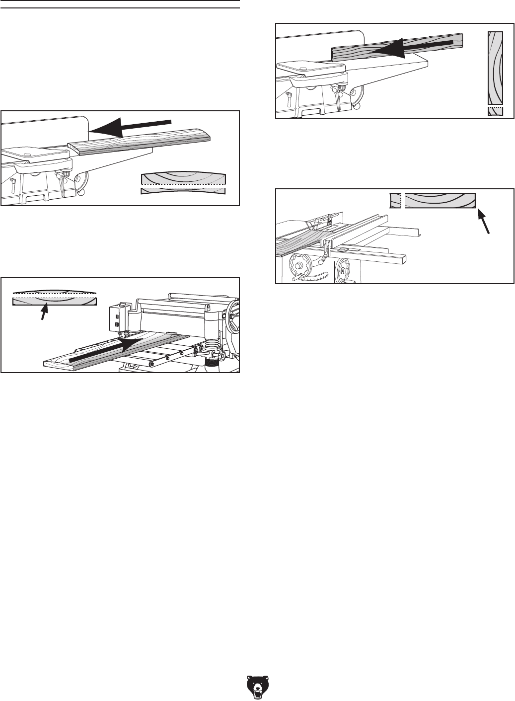
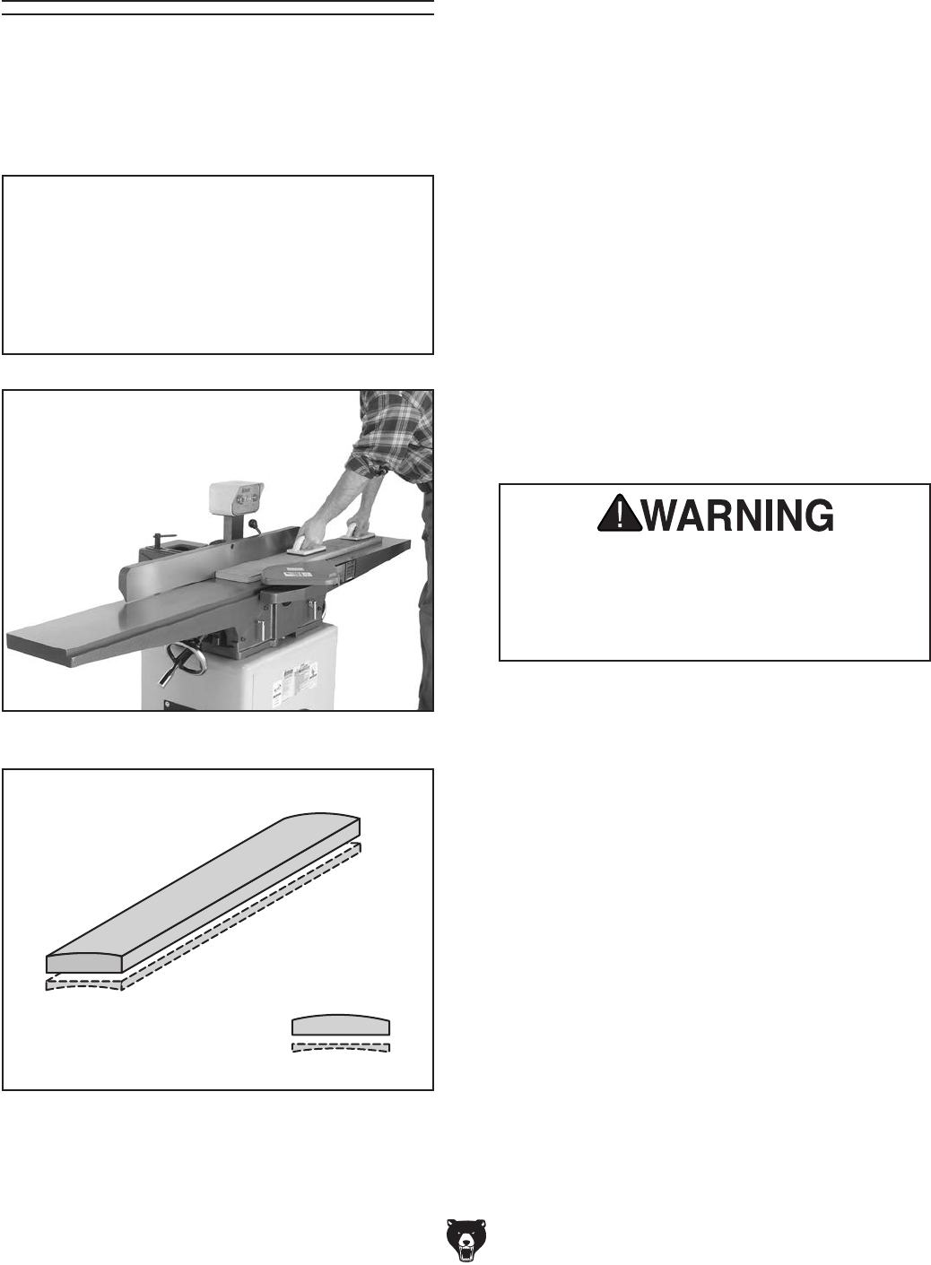
The purpose of surface planing on the jointer is
to make one flat face on a piece of stock (see
Figures 28 & 29). This is a necessary step when
preparing a workpiece to be run through a planer
when squaring stock.
NOTICE
If you are not experienced with a jointer,
set the depth of cut to 0", and practice
feeding the workpiece across the tables as
described. This procedure will better pre-
pare you for the actual operation.
Figure 29. Illustration of surface planing results.
Figure 28. Typical surface planing operation.
Surface Planing To surface plane on the jointer:
1. Read and understand SECTION 1: SAFETY
at the beginning of this manual.
2. Make sure your stock has been inspected
for dangerous conditions as described in the
Stock Inspection & Requirements instruc-
tions, beginning on Page 26.
3. Set the cutting depth for your operation.
(We suggest 1⁄32" for surface planing, using a
more shallow depth for hard wood species or
for wide stock.)
4. Make sure your fence is set to 90˚.
5. If your workpiece is cupped (warped), place
it so the concave side is face down on the
surface of the infeed table.
6. Start the jointer.
7. With a push block in each hand, press the
workpiece against the table and fence with
firm pressure, and feed the workpiece over
the cutterhead.
Note: If your leading hand (with push block)
gets within 4" of the cutterhead, lift it up and
over the cutterhead, and place the push
block on the portion of the workpiece that is
on the outfeed table. Now, focus your pres-
sure on the outfeed end of the workpiece
while feeding, and repeat the same action
with your trailing hand when it gets within 4"
of the cutterhead. To keep your hands safe,
DO NOT let them get closer than 4" from the
cutterhead when it is moving!
8. Repeat Step 7 until the entire surface is
flat.
Failure to use push blocks when surface
planing may result in cutterhead contact,
which will cause serious personal injury.
Always use push blocks to protect your
hands when surface planing on the jointer.

Model G0495X (Mfd. Since 6/11) -29-
To edge joint on the jointer:
1. Read and understand SECTION 1: SAFETY
at the beginning of this manual.
2. Make sure your stock has been inspected
for dangerous conditions as described in the
Stock Inspection & Requirements instruc-
tions, beginning on Page 26.
3. Set the cutting depth for your operation.
(We suggest between 1⁄16" and 1⁄8" for edge
jointing, using a more shallow depth for hard
wood species or for wide stock.)
4. Make sure the fence is set to 90˚.
5. If your workpiece is cupped (warped), place
it so the concave edge is face down on the
surface of the infeed table.
6. Start the jointer.
7. With a push block in your leading hand,
press the workpiece against the table and
fence with firm pressure. Use your trailing
hand to guide the workpiece through the cut,
and feed the workpiece over the cutterhead.
Note: If your leading hand gets within 4"
of the cutterhead, lift it up and over the
cutterhead, and place it on the portion of
the workpiece that is over the outfeed table.
Now, focus your pressure on the outfeed end
of the workpiece while feeding, and repeat
the same action with your trailing hand when
it gets within 4" of the cutterhead. To keep
your hands safe, DO NOT let them get closer
than 4" from the cutterhead when it is mov-
ing!
8. Repeat Step 7 until the entire edge is flat.
The purpose of edge jointing is to produce a fin-
ished, flat-edged surface (see Figures 30 & 31)
that is suitable for joinery or finishing. It is also a
necessary step when squaring rough or warped
stock.
Figure 31. Illustration of edge jointing results.
NOTICE
If you are not experienced with a jointer,
set the depth of cut to 0", and practice
feeding the workpiece across the tables as
described below. This procedure will better
prepare you for the actual operation.
Figure 30. Typical edge jointing operation.
Edge Jointing
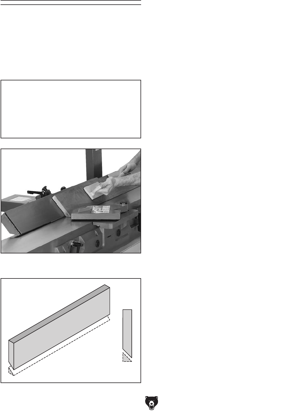
-30- Model G0495X (Mfd. Since 6/11)
The purpose of bevel cutting is to cut a specific
angle into the edge of a workpiece (see Figures
32 & 33).
The Model G0495X has preset fence stops at 45˚
inward, 90˚, and 45˚ outward (135˚). If your situ-
ation requires a different angle, the fence can be
locked anywhere between these angles.
To bevel cut on the jointer:
1. Read and understand SECTION 1: SAFETY
at the beginning of this manual.
2. Make sure your stock has been inspected
for dangerous conditions as described in the
Stock Inspection & Requirements instruc-
tions, beginning on Page 26.
3. Set the cutting depth for your operation. (We
suggest between 1⁄16" and 1⁄8" for bevel cut-
ting, using a more shallow depth for hard
wood species or for wide stock.)
4. Make sure your fence is set to the angle of
your desired cut.
5. If your workpiece is cupped (warped), place
it so the concave edge is face down on the
surface of the infeed table.
6. Start the jointer.
7. With a push block in your leading hand
(Figure 32), press the workpiece against
the table and fence with firm pressure, and
feed the workpiece over the cutterhead.
Note: If your leading hand gets within 4"
of the cutterhead, lift it up and over the
cutterhead, and place the push block on
the portion of the workpiece that is on the
outfeed table. Now, focus your pressure on
the outfeed end of the workpiece while feed-
ing, and repeat the same action with your
trailing hand when it gets within 4" of the
cutterhead. To keep your hands safe, DO
NOT let them get closer than 4" from the
cutterhead when it is moving!
8. Repeat Step 7 until the angled cut is satis-
factory to your needs.
Figure 33. Illustration of bevel cutting results.
NOTICE
If you are not experienced with a jointer,
set the depth of cut to zero, and practice
feeding the workpiece across the tables as
described below. This procedure will better
prepare you for the actual operation.
Figure 32. Typical bevel cutting operation, fence
stop at 45˚ outward.
Bevel Cutting

Model G0495X (Mfd. Since 6/11) -31-
To rabbet cut on the jointer:
1. Read and understand SECTION 1: SAFETY
at the beginning of this manual.
2. Make sure your stock has been inspected
for dangerous conditions as described in the
Stock Inspection & Requirements instruc-
tions, beginning on Page 26.
3. Set the cutting depth for your operation. (We
suggest between 1⁄16" and 1⁄8" for rabbet cut-
ting.
4. Remove the cutterhead guard.
5. Make sure your fence is moved forward, so
the amount of infeed/outfeed table exposed
is the same as the size of your rabbet. Also,
make sure your fence is set to 90˚.
6. Start the jointer.
7. With a push block in each hand, press the
workpiece against the table and fence with
firm pressure, and feed the workpiece over
the cutterhead.
When the cutterhead guard is removed,
attempting any other cut besides a rabbet
directly exposes the operator to the moving
cutterhead. Always replace the cutterhead
guard after rabbet cutting!
Note: If your leading hand gets within 4" of the
cutterhead, lift it up and over the cutterhead,
and place the push block on the portion of the
workpiece that is on the outfeed table. Now,
focus your pressure on the outfeed end of
the workpiece while feeding, and repeat the
same action with your trailing hand when it
gets within 4" of the cutterhead. To keep your
hands safe, DO NOT let them get closer than
4" from the cutterhead when it is moving!
8. Repeat Step 7 until the your rabbet is cut to
depth.
The purpose of rabbet cutting is to remove a
section of the workpiece edge (see Figures 34
& 35). When combined with another rabbet cut
edge, the rabbet joints create a simple, yet strong
method of joining stock.
Figure 35. Illustration of rabbet cutting effects
and a few sample joints.
NOTICE
If you are not experienced with a jointer,
set the depth of cut to 0", and practice
feeding the workpiece across the tables as
described below. This procedure will better
prepare you for the actual operation.
Figure 34. Typical rabbet cutting operation.
Rabbet Cutting
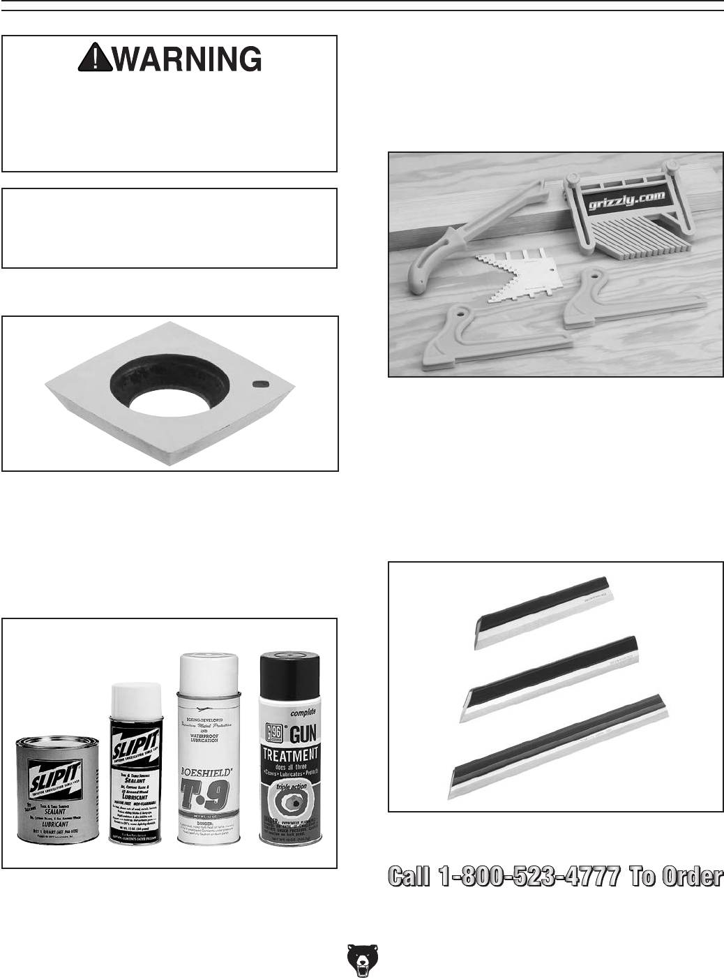
-32- Model G0495X (Mfd. Since 6/11)
SECTION 5: ACCESSORIES
ACCESSORIES
H8029—5 Piece Safety Kit
This kit has four essential jigs. Includes two
push blocks, push stick, featherboard and com-
bination saw and router gauge. Featherboard
fits 3⁄8" x 3⁄4" miter slots. Made of high visibility
yellow plastic.
Figure 37. H8029 5 Piece Safety Kit.
Figure 38. Straightedges.
G9643—8" Precision Straightedge
G9644—12" Precision Straightedge
H2675—16" Precision Straightedge
These grade 00 heavy-duty stainless steel
straightedges are manufactured to DIN874 stan-
dards for professional results in set-up and
inspection work.
G5562—SLIPIT® 1 Qt. Gel
G5563—SLIPIT® 12 oz Spray
G2871—Boeshield® T-9 12 oz Spray
G2870—Boeshield® T-9 4 oz Spray
H3788—G96® Gun Treatment 12 oz Spray
H3789—G96® Gun Treatment 4.5 oz Spray
Figure 36. Recommended products for protect-
ing unpainted cast iron/steel parts on machinery.
Installing unapproved accessories may
cause machine to malfunction, resulting in
serious personal injury or machine damage.
To reduce this risk, only install accessories
recommended for this machine by Grizzly.
NOTICE
Refer to our website or latest catalog for
additional recommended accessories.
H9893—10 pk. Carbide Inserts 15x15x2.5mm

Model G0495X (Mfd. Since 6/11) -33-
G9256—6" Dial Caliper
G9257—8" Dial Caliper
G9258—12" Dial Caliper
Required for jointing, planing, or sanding to criti-
cal tolerances. These traditional dial calipers are
accurate to 0.001" and can measure outside
surfaces, inside surfaces, and heights/depths.
Features stainless steel, shock resistant construc-
tion and a dust proof display. An absolute treat for
the perfectionist!
Figure 40. Grizzly® Dial Calipers.
Figure 39. Half-mask respirator with disposable
cartridge filters.
T20514—Small Half-Mask Respirator
T20515—Medium Half-Mask Respirator
T20516—Large Half-Mask Respirator
T20511—Pre-Filter P100
T20539—Cartridge Filter 2PK P100
T20541—Cartridge Filter 2PK P100 & O Vapor
Wood and other types of dust can cause severe
respiratory damage. If you work around dust every-
day, a half-mask respirator can greatly reduce
your risk. Compatible with safety glasses!
T20501—Face Shield Crown Protector 4"
T20502—Face Shield Crown Protector 7"
T20503—Face Shield Window
T20452—"Kirova" Anti-Reflective S. Glasses
T20451—"Kirova" Clear Safety Glasses
H0736—Shop Fox® Safety Glasses
H7194—Bifocal Safety Glasses 1.5
H7195—Bifocal Safety Glasses 2.0
H7196—Bifocal Safety Glasses 2.5
Figure 41. Eye protection assortment.
T20451
H0736
T20452
T20502
T20503
H7194
T21992—Power Twist® V-Belt - 1⁄2" x 48"
Smooth running with less vibration and noise
than solid belts. The Power Twist® V-belt can be
customized in minutes to any size—just add or
remove sections to fit your needs. Size: 1⁄2" x 48";
replaces all "A" sized V-belts. Requires two Power
Twist ® V-belts to replace the stock V-belt on the
Model G0495X.
Figure 42. T21992 Power Twist® V-Belt.

-34- Model G0495X (Mfd. Since 6/11)
SECTION 6: MAINTENANCE
Always disconnect power
to the machine before
performing maintenance.
Failure to do this may
result in serious person-
al injury.
For optimum performance from your machine,
follow this maintenance schedule and refer to any
specific instructions given in this section.
Daily Check:
• Vacuum all dust on and around the
machine.
• Wipe down tables and all other unpainted
cast iron with a metal protectant.
• Worn or damaged wires.
• Any other unsafe condition.
Monthly Check:
• V-belt tension, damage, or wear.
• Clean/vacuum dust build up.
• Replace batteries in control panel and digital
sensor as needed.
Schedule
Cleaning the Model G0495X is relatively easy.
Vacuum excess wood chips and sawdust, and
wipe off the remaining dust with a dry cloth. If any
resin has built up, use a resin dissolving cleaner
to remove it. Treat all unpainted cast iron and steel
with a non-staining lubricant after cleaning.
Cleaning
Protect the unpainted cast iron surfaces on the
table by wiping the table clean after every use—
this ensures moisture from wood dust does not
remain on bare metal surfaces.
Unpainted Cast Iron
Since all bearings on the G0495X are sealed and
permanently lubricated, simply leave them alone
until they need to be replaced. DO NOT lubricate
them.
Below is a list of components that require periodic
lubrication. Be careful not to over-lubricate these
components. Large amounts of lubricant will
attract sawdust, causing the metal components to
gum up and bind.
Lubrication
Fence: Place one or two drops of light machine oil
on the fence pivot points (Figure 43) as needed.
Figure 43. Fence lubrication locations.
Gears: Use a small brush to apply multi-purpose
grease to the worm gear shafts and gears (Parts
96, 82 and 83) indicated on Page 50.
Keep tables rust-free with regular applications of
products like G96® Gun Treatment, SLIPIT®, or
Boeshield® T-9 (see Section 5: Accessories on
Page 32 for more details).

Model G0495X (Mfd. Since 6/11) -35-
Review the troubleshooting and procedures in this section to fix or adjust your machine if a problem devel-
ops. If you need replacement parts or you are unsure of your repair skills, then feel free to call our Technical
Support at (570) 546-9663.
SECTION 7: SERVICE
Troubleshooting
Motor & Electrical
Symptom Possible Cause Possible Solution
Machine does not
start or a breaker
trips.
1. Emergency stop push-button is engaged/
faulty.
2. Wiring is open/has high resistance.
3. Motor START button or STOP switch is at
fault.
4. Fuse has blown.
5. Power supply switched OFF or is at fault.
6. Start capacitor is at fault.
7. Thermal overload relay has tripped.
8. Wall fuse/circuit breaker is blown/tripped.
9. Contactor not getting energized/has burnt
contacts.
10. Motor is at fault.
1. Rotate clockwise slightly until it pops out/replace it.
2. Check for broken wires or disconnected/corroded
connections, and repair/replace as necessary.
3. Replace faulty START OR STOP switch.
4. Correct short/replace fuse on control panel.
5. Ensure power supply is switched on; ensure power
supply has the correct voltage.
6. Test/replace if faulty.
7. Turn cut-out dial to increase working amps and
push the reset pin. Replace if tripped multiple times.
Reduce workload on machine or test and replace
motor. If motor is OK, replace relay.
8. Ensure circuit size is suitable for this machine;
correct for short. Reset/replace fuse or breaker.
9. Test for power on all legs and contactor operation.
Replace unit if faulty.
10. Test/repair/replace.
Machine stalls or is
underpowered.
1. Feed rate/cutting speed too fast for task.
2. Workpiece material is not suitable for this
machine.
3. Belt slipping.
4. Motor connection is wired incorrectly.
5. Motor bearings are at fault.
6. Contactor not getting energized or has poor
contacts.
7. Motor has overheated.
8. Motor is at fault.
1. Decrease feed rate/cutting speed.
2. Only cut wood products; make sure moisture content
is below 20% and there are no foreign materials in
the workpiece.
3. Replace bad belt, align pulleys, and re-tension.
4. Correct motor wiring connections.
5. Test by rotating shaft; rotational grinding/loose shaft
requires bearing replacement.
6. Test for power on all legs and contactor operation.
Replace if faulty.
7. Clean off motor, let cool, and reduce workload.
8. Test/repair/replace.
Machine has
vibration or noisy
operation.
1. Motor or component is loose.
2. Inserts are at fault.
3. V-belt worn or loose.
4. Pulley is loose.
5. Motor mount loose/broken.
1. Inspect/replace stripped or damaged bolts/nuts, and
re-tighten with thread locking fluid.
2. Rotate or replace inserts causing problem.
3. Inspect/replace belt with a new one (refer to Page
45).
4. Realign/replace shaft, pulley, setscrew, and key as
required.
5. Tighten/replace.

-36- Model G0495X (Mfd. Since 6/11)
Symptom Possible Cause Possible Solution
Machine has
vibration or noisy
operation.
6. Machine is incorrectly mounted or sits
unevenly.
7. Motor fan is rubbing on fan cover.
8. Motor bearings are at fault.
9. Cutterhead bearings at fault.
6. Tighten/replace anchor studs in floor; relocate/shim
machine.
7. Replace dented fan cover; replace loose/damaged
fan.
8. Test by rotating shaft; rotational grinding/loose shaft
requires bearing replacement.
9. Replace bearing(s)/realign cutterhead.
Symptom Possible Cause Possible Solution
Tables are hard to
adjust.
1. Table lock is engaged or partially engaged.
2. Table stops blocking movement.
1. Completely loosen the table lock.
2. Loosen/reset table positive stops.
Table
Symptom Possible Cause Possible Solution
Excessive snipe
(gouge in the end
of the board that is
uneven with the rest
of the cut).
1. Outfeed table is set too low.
2. Operator pushing down on end of
workpiece.
1. Align outfeed table with cutterhead insert at top dead
center (Page 17).
2. Reduce/eliminate downward pressure on that end of
workpiece.
Workpiece stops in
the middle of the
cut.
1. Outfeed table is set too high. 1. Align outfeed table with cutterhead insert at top dead
center (Page 17).
Chipping. 1. Knots or conflicting grain direction in wood.
2. Nicked or chipped insert.
3. Feeding workpiece too fast.
4. Taking too deep of a cut.
1. Inspect workpiece for knots and grain (Page 26);
only use clean stock.
2. Rotate insert to expose sharp edge; replace insert
(Page 40).
3. Slow down the feed rate.
4. Take a smaller depth of cut. (Always reduce cutting
depth when surface planing or working with hard
woods.)
Fuzzy Grain. 1. Wood may have high moisture content or
surface wetness.
2. Dull inserts.
1. Check moisture content and allow to dry if moisture
is too high.
2. Replace inserts (Page 40).
Long lines or ridges
that run along the
length of the board
1. Nicked or chipped insert. 1. Rotate insert to expose sharp edge; replace insert
(Page 40).
Uneven insert
marks, wav y
surface, chatter
marks across board
face.
1. Feeding workpiece too fast. 1. Slow down the feed rate.
Board edge is
concave or convex
after jointing.
1. Board not held with even pressure on infeed
and outfeed table during cut.
2. Board started too uneven.
3. Board has excessive bow or twist along its
length.
4. Insufficient number of passes.
1. Hold board with even pressure as it moves over the
cutterhead.
2. Take partial cuts to remove the extreme high spots
before doing a full pass.
3. Surface plane one face so there is a good surface to
position against the fence.
4. It may take 3 to 5 passes to achieve a perfect edge,
depending on the starting condition of the board and
the depth of cut.
Cutting

Model G0495X (Mfd. Since 6/11) -37-
If the tables are not parallel with the cutterhead or
each other, then poor cutting results and kickback
can occur.
Tools Needed Qty
Straightedge ...................................................... 1
Wrench or Socket 12mm .................................. 1
Wrench or Socket 32mm ................................... 1
Adjustable Wrench 10" ...................................... 1
Hex Wrench 4mm .............................................. 1
Duct Tape .......................................................... 1
Electrical Parts Cleaner ..................................... 1
Checking Outfeed Table
1. DISCONNECT JOINTER FROM POWER!
2. Put on leather gloves.
3. Remove the cutterhead guard and the fence.
4. Loosen the outfeed table lock located at the
front of the machine, then loosen the jam
nuts and positive stop bolts located under the
outfeed table (see Figure 44).
Straightedge
Outfeed Table
5. Place the straightedge on the outfeed table
so it hangs over the cutterhead, then lower
the outfeed table until the straightedge just
touches the cutterhead body, as shown in
Figure 45 (rotate the cutterhead if neces-
sary).
6. Place the straightedge in the positions shown
in Figure 46. In each position, the straight-
edge should touch the cutterhead body and
sit flat on the outfeed table.
Black Lines Represent
Straightedge Positions
From Overhead View
—If the straightedge touches the cutterhead
and sits flat across the outfeed table in
each position, then the outfeed table is
already parallel with the cutterhead. Check
the infeed table to make sure that it is par-
allel with the outfeed table.
—If the straightedge does not touch the
cutterhead and sit flat on the outfeed table
in any of the positions, then the outfeed
table is not parallel with the cutterhead.
Correct the outfeed table parallelism, then
correct the infeed table parallelism.
Figure 45. Adjusting outfeed table even with
cutterhead body.
Figure 46. Straightedge positions for verifying if
outfeed table is parallel with cutterhead.
Checking/Adjusting
Table Parallelism
Figure 44. Outfeed table positive stop bolts.
Jam Nut
Stop Bolts
Jam Nut

-38- Model G0495X (Mfd. Since 6/11)
Adjusting Table Parallelism
For safe and proper cutting results, the tables
must be parallel to the cutterhead. Adjusting them
to be parallel is a task of precision and patience,
and may take up to one hour to complete. Luckily,
this is considered a permanent adjustment and
should not need to be repeated for the life of the
machine.
Due to the complex nature of this task, we rec-
ommend that you double check the current table
positions to make sure that they really need to be
adjusted before starting.
The tables have four eccentric bushings under
each corner that allow the tables to be adjusted
parallel. These eccentric bushings are locked in
place by set screws and adjust when rotated.
The correct order for adjusting the table parallel-
ism is to first adjust the outfeed table parallel with
the cutterhead to within 0.010"-0.012", then adjust
the infeed table parallel with the outfeed table.
When setting the outfeed table, all measurements
must be made from the cutterhead body—not the
inserts.
Checking Infeed Table
1. Follow all the steps for checking the outfeed
table parallelism to first make sure that the
outfeed table is parallel with the cutterhead.
2. Raise the outfeed table higher than the
cutterhead.
3. Loosen the infeed table jam nuts and positive
stop bolts shown in Figure 47.
Straightedge
Outfeed Table Infeed Table
Figure 48. Infeed and outfeed tables set evenly.
5. Place the straightedge in the positions shown
in Figure 49. In each position, the straight-
edge should sit flat against both the outfeed
table and the infeed table.
Black Lines Represent
Straightedge Positions
from Overhead View
—If the straightedge sits flat against both
the infeed and outfeed table in each of the
positions, then the tables are parallel. Set
both table heights (Pages 17 & 41) and
replace the cutterhead guard.
—If the straightedge does not sit flat against
both the infeed and outfeed table in any
of the positions, then follow the Adjusting
Table Parallelism instructions.
Figure 49. Straightedge positions for checking
infeed/outfeed table parallelism.
4. Place the straightedge halfway across the
infeed table and halfway over the outfeed
table, and adjust the infeed table even with
the outfeed table, as shown in Figure 48.
Figure 47. Infeed table positive stop bolts.
Jam Nut Jam Nut
Stop Bolts

Model G0495X (Mfd. Since 6/11) -39-
IMPORTANT: The steps below are intended to be
performed in succession with the steps involved
in checking the outfeed table. Do not continue
until you have followed those steps.
To adjust the table parallelism:
1. Place the straightedge on the outfeed table
so it hangs over the cutterhead, then lower
the outfeed table until the straightedge just
touches the cutterhead body, as shown in
Figure 45 (rotate the cutterhead if neces-
sary).
2. Remove the screw cover (Figure 50) cover-
ing each set screw on the outfeed table.
Note: It may help to clean the screw covers
with electrical parts cleaner. Push duct tape
firmly against the cover, then pull straight
up.
Figure 51. Front eccentric bushings.
Figure 52. Rear eccentric bushings.
3. Loosen each set screw (Figure 50) two turns.
4. Place the straightedge in one of the positions
shown in Figure 46, and adjust the table by
turning the eccentric bushings (Figures 51 &
52) as needed with an adjustable wrench so
that the straightedge touches the cutterhead
while lying flat across the outfeed table.
Repeat this step with each of the remaining
straightedge positions as many times as nec-
essary until the outfeed table is parallel with
the cutterhead to within 0.010"-0.012".
Note: Setting the outfeed table parallel to the
cutterhead within 0.010"-0.012" will produce
high quality results. Going lower than this
number will produce minimal gain.
Figure 50. Screw cover and set screw location.
5. Tighten the set screws and replace the screw
covers on the outfeed table.
6. Remove each of the four screw covers on
the infeed table, and loosen the set screws
underneath.
7. Place the straightedge halfway across the
infeed table and halfway over the outfeed
table, then adjust the infeed table even with
the outfeed table, as shown in Figure 48.
Straightedge
Outfeed Table Infeed Table
Figure 53. Infeed and outfeed tables adjusted
even.
Screw Cover
Set Screw
(Out of View)

-40- Model G0495X (Mfd. Since 6/11)
Replacing Carbide
Inserts
Tools Needed: Qty
T-Handle Wrench w/T-25 Torx Bit ..................... 1
The cutterhead is equipped with 36 indexable car-
bide inserts. Each insert can be rotated to reveal
any one of its four cutting edges. Therefore, if one
cutting edge becomes dull or damaged, simply
rotate it 90˚ to reveal a fresh cutting edge (Figure
54).
In addition, each insert has a reference dot on
one corner. As the insert is rotated, the reference
dot location can be used as an indicator of which
edges are used and which are new. When the
reference dot revolves back around to its starting
position, the insert should be replaced.
To rotate or change a carbide insert:
1. DISCONNECT JOINTER FROM POWER!
2. Remove any sawdust from the head of the
carbide insert Torx screw.
3. Remove the Torx screw and carbide insert.
4. Clean all dust and dirt off the insert and the
cutterhead pocket from which the insert was
removed, and replace the insert so a fresh,
sharp edge is facing outward.
Note: Proper cleaning is critical to achieving
a smooth finish. Dirt or dust trapped between
the insert and cutterhead will slightly raise the
insert, and make noticeable marks on your
workpieces the next time you cut.
5. Lubricate the Torx screw threads with a
light machine oil, wipe the excess oil off the
threads, and torque the Torx screw to 48-50
inch/pounds.
Note: Excess oil may squeeze between the
insert and cutterhead or in the screw hole,
thereby lifting the insert or screw slightly and
affecting workpiece finishes.
Figure 54. Insert rotating sequence.
Reference Dot
8. Place the straightedge in one of the posi-
tions shown in Figure 49, and adjust the
eccentric bushings under the infeed table so
the straightedge lies flat against both tables.
Repeat this step with each of the remaining
straightedge positions as many times as nec-
essary until the infeed table is parallel with
the outfeed table.
9. Tighten the set screws and replace the cov-
ers on the infeed table.
10. Set the outfeed table height (refer to Setting
Outfeed Table on Page 17).
11. Reinstall the cutterhead guard and fence.

Model G0495X (Mfd. Since 6/11) -41-
The infeed table on the Model G0495X has
positive stop bolts that, when properly set up,
allow the operator to quickly adjust the infeed
table between finish/final cuts and shaping/heavy
cuts.
We recommend setting the minimum depth of cut
to 1⁄32" and the maximum depth of cut to 1⁄8" for
most operations. DO NOT exceed 1⁄8" cut per
pass on this machine or the risk of kickback
and serious injury will be greatly increased!
Each positive stop bolt (Figure 55) controls the
top or bottom range of the table movement. The
jam nuts lock the positive stop bolts in position so
they won't move during operation.
Setting Infeed Table
Figure 55. Infeed table positive stop bolts.
Top Height
Jam Nut Jam Nut
Figure 56. Infeed table adjusted even with
outfeed table.
Straightedge
InfeedOutfeed
Calibrating Infeed
Table
The depth scale on the infeed table can be cali-
brated or "zeroed" if it is not correct.
Tools Needed Qty
Straightedge ...................................................... 1
Wrench 12mm ................................................... 1
To calibrate the depth scale:
1. Set the outfeed table height as described in
Setting Outfeed Table Height on Page 17.
2. Move the cutterhead guard out of the way.
3. Place a straightedge across the infeed and
outfeed tables.
4. Adjust the infeed table until it is level with the
outfeed table, as illustrated in Figure 56.
5. Follow instructions on Page 42 to calibrate
the digital sensor and readout so both dis-
play 0.000.
Bottom
Height
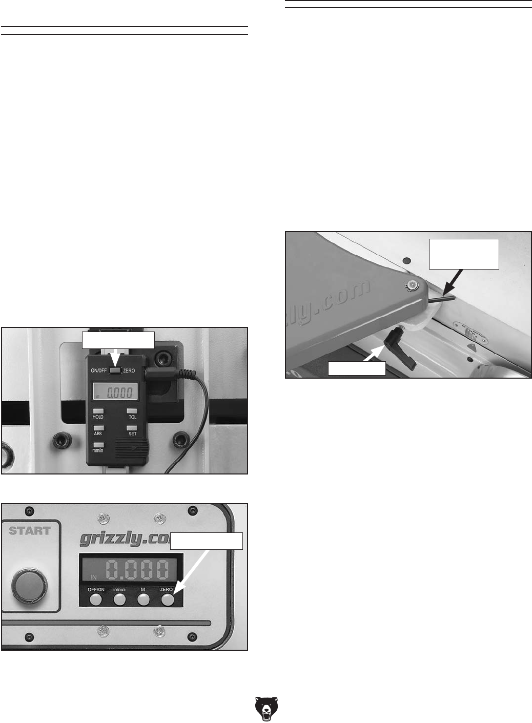
-42- Model G0495X (Mfd. Since 6/11)
Calibrating Digital
Sensor & Readout
The digital readout on the control panel displays
the depth of cut using the sensor located on the
back of the jointer. The sensor requires a 1.5V
type 357/303 silver oxide button cell battery and
the display requires two AAA batteries. The 1.5 V
battery is preinstalled at the factory but the AAA
battery must be installed (refer to Page 18, for
installation instructions). To conserve the batter-
ies, turn the displays OFF when not in use.
To calibrate the sensor and display:
1. Follow Steps 1-5 on Page 41 for calibrating
the infeed table.
2. Turn ON the rear sensor, then turn ON the
front digital readout.
3. Press the ZERO buttons on the sensor and
front display, as shown in Figures 57 & 58.
Figure 57. Sensor zero button.
Figure 58. Digital readout zero button.
ZERO Button
ZERO Button
Figure 59. Guard mounted with spring tang in
the correct position for proper return tension.
Cutterhead Guard
3. Test the guard by pulling it back and letting
go.
—The guard should quickly snap back over
the cutterhead without dragging across the
table. If it does, tighten the shaft lock.
—If the guard drags across the table, raise
it until it won't drag, then tighten the shaft
lock.
—If the guard does not snap back, remove
it and repeat Steps 1 & 2, increasing the
spring tension as needed.
The cutterhead guard comes pre-installed for
shipping, but it may need to be adjusted if the
guard does not quickly snap back against the
fence when pulled out and let go.
To adjust the cutterhead guard:
1. Loosen the shaft lock (Figure 59) and remove
the cutterhead guard.
2. Wind the tang on the torsion spring clockwise
a quarter turn, and slide the guard shaft into
the casting so the spring tang points toward
the main table but does not overlap it, as
shown in Figure 59.
Shaft Lock
Torsion
Spring Tang
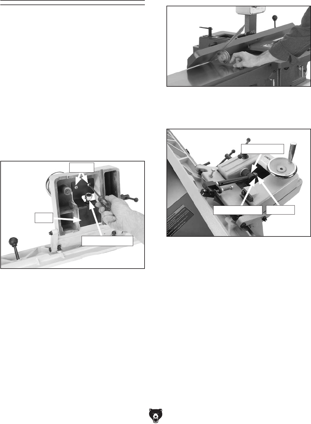
Model G0495X (Mfd. Since 6/11) -43-
The fence stops simplify the task of adjusting the
fence to 45˚ inward, 90˚, and 45˚ outward (135˚).
Tools Needed Qty
45° Square ........................................................ 1
90° Square ........................................................ 1
Sliding Bevel ...................................................... 1
Wrench 12mm ................................................... 1
Wrench 24mm ................................................... 1
Phillips Screwdriver ........................................... 1
To set the 45˚ inward fence stop:
1. Remove the fence assembly from the jointer,
remove the Phillips head screws from the
plate shown in Figure 60 under the fence
carriage. The plate must be removed to
access the adjustment nuts.
Setting Fence Stops
Figure 61. Example of adjusting fence 45˚
inward.
Figure 60. Removing plate to access inward
fence stop.
Adjustment Nuts
Screws
Plate
2. Reinstall the fence assembly on the jointer.
5. Adjust the 45˚ inward fence stop nut until
it makes contact with the back of the shaft
bracket.
6. Retighten the jam nut loosened in Step 4.
7. Remove the fence assembly, reinstall the
plate with the screws removed in Step 1, then
reinstall the fence assembly.
Figure 62. 45˚ inward fence stop jam nut.
4. Loosen the jam nut shown in Figure 62.
3. Using a 45˚ square, adjust the fence to the
45˚ inward position, as shown in Figure 61.
Fence Stop Nut
Shaft Bracket
Jam Nut
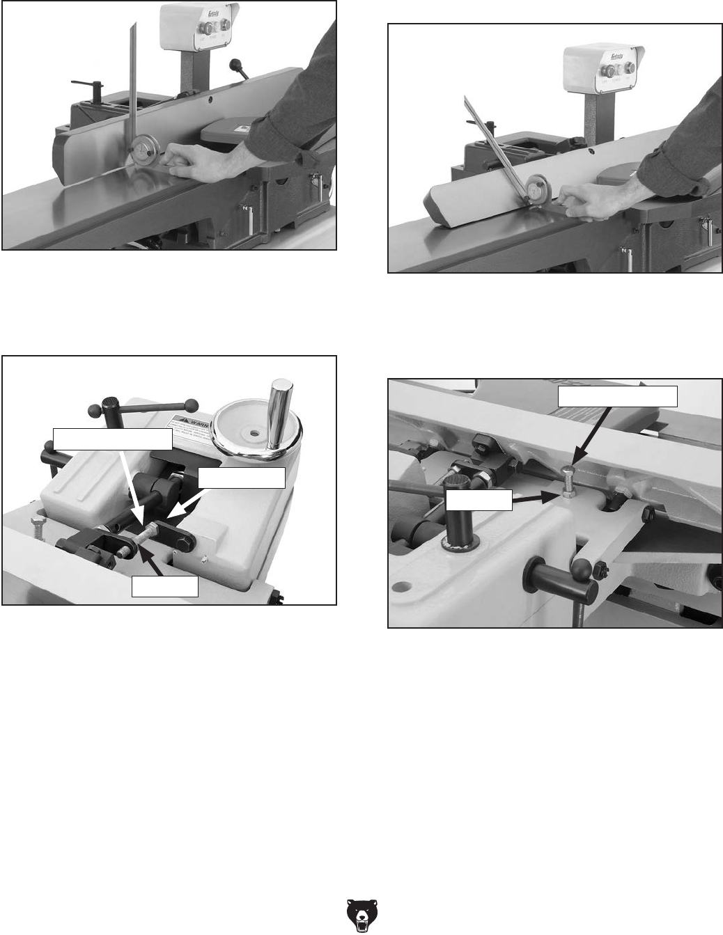
-44- Model G0495X (Mfd. Since 6/11)
Figure 64. 90˚ stop block engaged.
3. Loosen the jam nut on the 90˚ fence stop bolt
(Figure 64).
4. Adjust the 90˚ fence stop bolt until it makes
contact with the 90˚ stop block.
5. Retighten the jam nut loosened in Step 3.
Stop Block
Jam Nut
Fence Stop Bolt
2. Flip the 90˚ stop block into the position shown
in Figure 64.
To set the 45˚ outward fence stop:
1. Using a sliding bevel adjusted to 135˚, adjust
the fence to the 135˚ (45˚ outward) position,
as shown in Figure 65.
3. Adjust the 45˚ outward fence stop bolt until it
makes contact with the back of the fence.
4. Retighten the jam nut loosened in Step 2.
Figure 66. 45˚ outward fence stop jam nut.
Jam Nut
Fence Stop Bolt
2. Loosen the jam nut on the 45˚ outward fence
stop bolt (Figure 66).
Figure 65. Adjusting fence 45˚ outward.
To set the 90˚ fence stop:
1. Using a 90˚ square, adjust the fence to the
90˚ position, as shown in Figure 63.
Figure 63. Adjusting fence to 90˚.
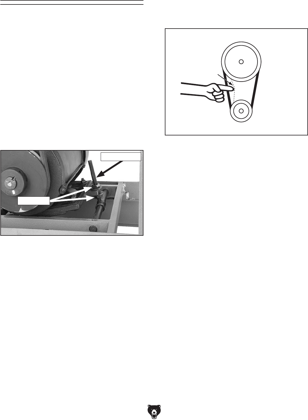
Model G0495X (Mfd. Since 6/11) -45-
V-Belt
V-belt removal and replacement involves remov-
ing the V-belt, rolling it off of the pulleys, replacing
it with a new belt, then retensioning it.
Consider replacing the stock belt with a Power
Twist V-belt (see Page 32, Figure 42) to reduce
vibration and noise, and increase belt lifespan.
To adjust/replace the V-belt:
1. DISCONNECT JOINTER FROM POWER!
2. Remove the rear access panel and V-belt
guard.
3. Using a 17mm wrench, loosen the fasteners
on the tension rod shown in Figure 67.
Figure 67. Fasteners needed to be loosened for
V-belt replacement.
Tension Rod
4. Lift the motor up, slide the V-belt off of the
motor and cutterhead pulleys, and replace it
with a new one.
Pulley
Deflection
Pulley
Figure 68. Checking V-belt tension.
1⁄2"
5. Lower the motor and adjust the V-belt ten-
sion with the tension rod fasteners so there is
approximately 1/2" deflection when the belt is
pushed with moderate pressure, as shown in
Figure 68.
6. Replace the rear access panel and the V-belt
guard.
Fasteners
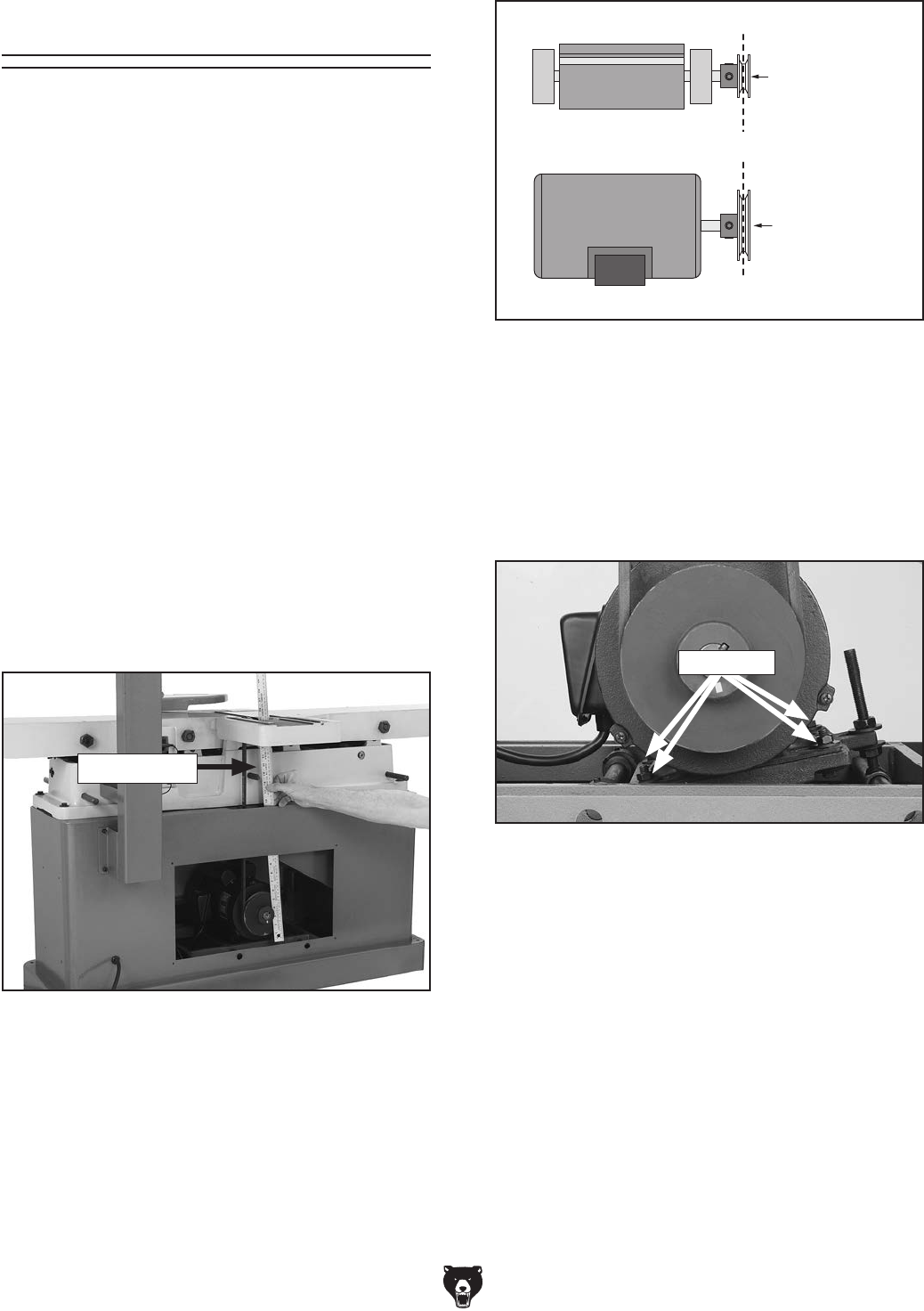
-46- Model G0495X (Mfd. Since 6/11)
— If the pulleys are aligned, go to Step 8.
— If the pulleys are NOT aligned, perform
Steps 4–8.
4. Loosen the motor mount fasteners shown in
Figure 71.
Figure 70. Pulleys aligned.
Cutterhead
Pulley
Motor
Pulley
Alignment
Figure 71. Motor mount fasteners.
5. Shift the motor horizontally as needed to align
the motor pulley with the cutterhead pulley.
6. Tighten the motor mount fasteners. The
V-belt should be parallel and aligned as
shown in Figure 70.
7. Reinstall the fence assembly, rear access
panel, and V-belt guard.
Pulley Alignment
Pulley alignment is another important factor in
power transmission and belt life. The pulleys
should be parallel to each other and in the same
plane (coplaner) for optimum performance.
Each pulley can be adjusted by loosening the
motor mount fasteners, sliding the motor in or out,
and retightening the fasteners to lock the motor
pulley in place.
Tools Needed: Qty
Wrench or Socket 17mm ................................... 1
To align the pulleys:
1. DISCONNECT JOINTER FROM POWER!
2. Remove the rear access cover, V-belt guard
and the fence assembly.
3. Place a straightedge against both pulleys
(Figure 69) and check to make sure that they
are aligned and that the V-belt is straight up
and down (see Figure 70).
Figure 69. Checking belt alignment.
Fasteners
Straightedge
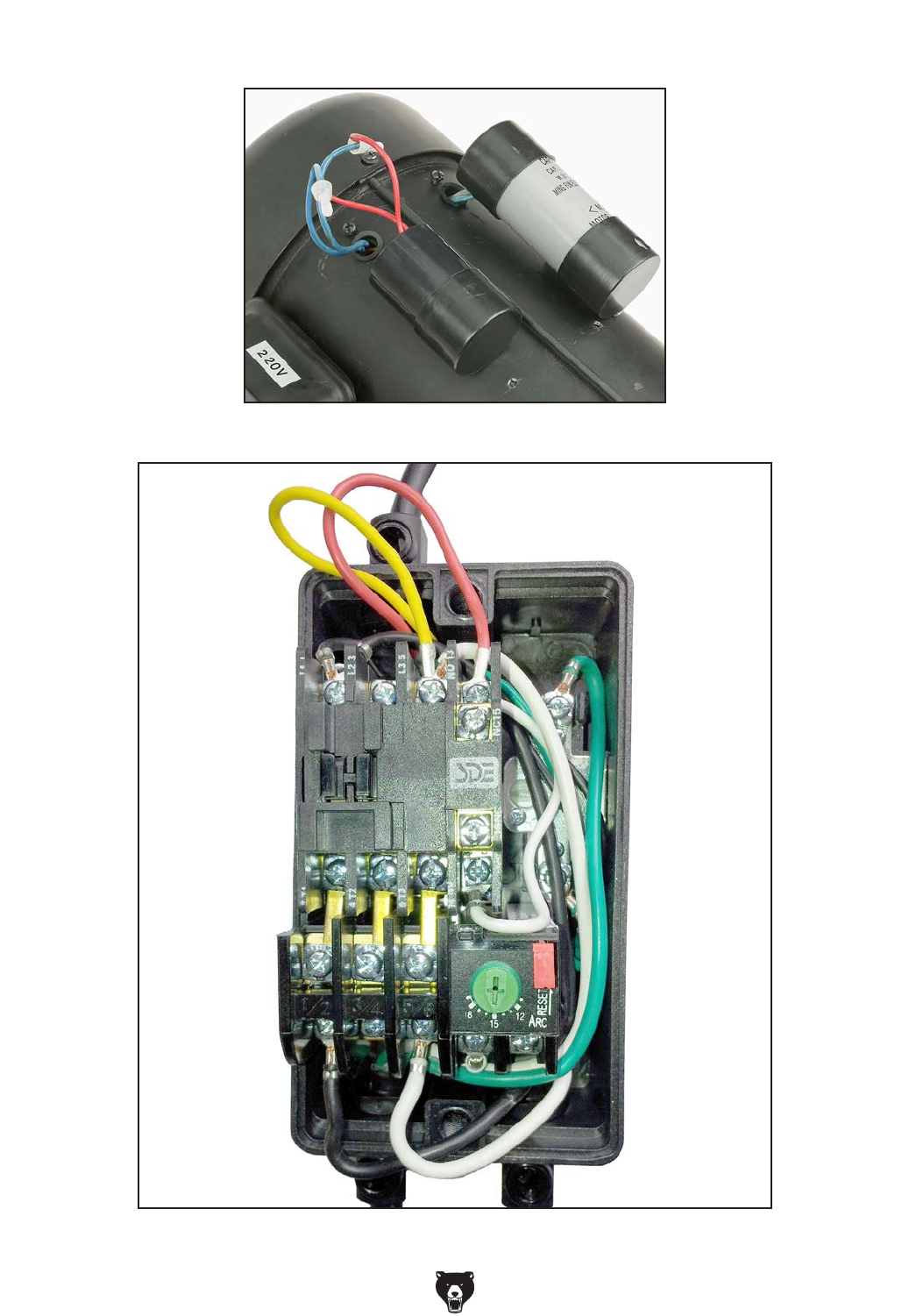
Model G0495X (Mfd. Since 6/11) -47-
Electrical Components
Figure 72. Capacitor wiring.
Figure 73. Magnetic switch wiring.
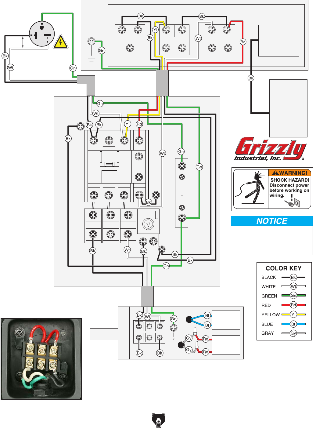
-48- Model G0495X (Mfd. Since 6/11)
A
A2
Ground
AMP
RESET
96 98
1/2
2/T1 6/T3 14
3/4
4/T2
1/L1 5/L3 13
3/L2
5/6
95
12
15
18
OFF
SDE
MA-18
RA-20
Hot
Hot
Ground
6-20 Plug
(As Recommended)
220
VAC
G
START
Ground
STOP
POWER
CONTROL PANEL (viewed from behind)
MAGNETIC
SWITCH
DIGITAL
READOUT
Ground
220V
MOTOR
The motor wiring shown here is
current at the time of printing, but it
may not match your machine.
Always use the wiring diagram
inside the motor junction box.
13 14
21
22 21
14 22 13
X1 X2
Run
Capacitor
40MFD
300VAC
Start
Capacitor
500MFD
125VAC
NO 16
NO 15
(2 AAA Batteries)
1
1.5V,
357/303
Battery
SENSOR
Wiring Diagram
See Figure 73
See Figure 72
Figure 74. Junction box wiring.
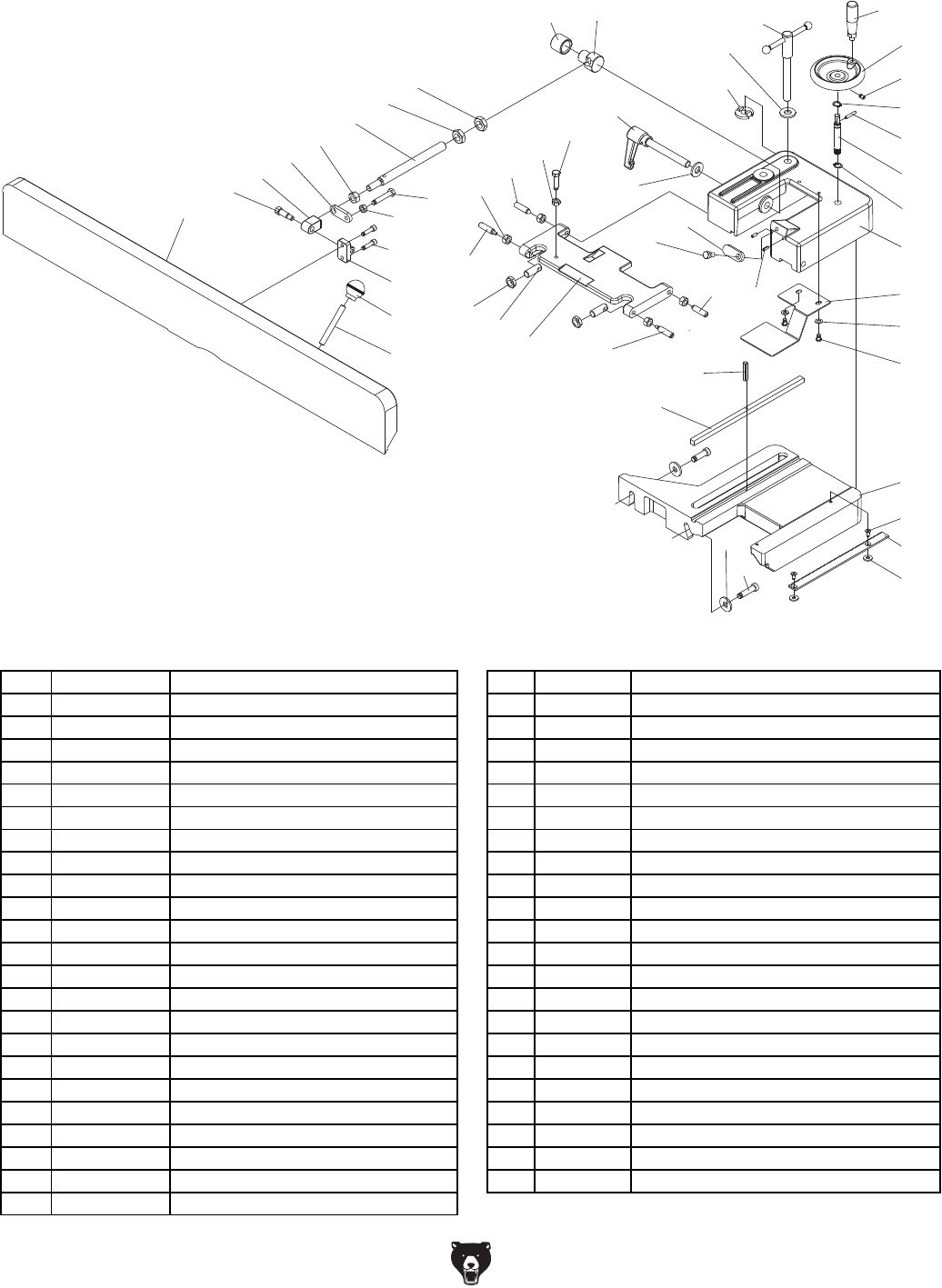
Model G0495X (Mfd. Since 6/11) -49-
34
25
36
42
39
41
40
38
37
29
24
33
26
31
32
30
23
22
28
36
27
26
35
18
15
19
17
155
16
15
14
3
9
6
8
7
2
4
3
5
1
69
139
139
27
12
13
20
21
11
10
157
156
Fence Parts Breakdown & List
REF PART # DESCRIPTION REF PART # DESCRIPTION
1 P0495X001 HANDWHEEL 25 P0495X025 HEX BOLT 5/16-18 X 1-1/4
2 P0495X002 SET SCREW 1/4-20 X 3/8 26 P0495X026 HEX NUT 5/16-18
3 P0495X003 EXT RETAINING RING 15MM 27 P0495X027 SPECIAL BOLT
4 P0495X004 ROLL PIN 4 X 25 28 P0495X028 HEX NUT 3/8-16
5 P0495X005 GEAR SHAFT 29 P0495X029 HEX BOLT 5/16-18 X 1-3/4
6 P0495X006 FENCE BRACKET 30 P0495X030 CAP SCREW 1/4-20 X 1
7 P0495X007 PLATE 31 P0495X031 BRACKET
8 P0495X008 FLAT WASHER 6MM 32 P0495X032 HANDLE
9 P0495X009 CAP SCREW 1/4-20 X 3/8 33 P0495X033 SHAFT
10 P0495X010 TABLE BRACKET 34 P0495X034 PIVOT NUT
11 P0495X011 FLAT HD SCR M5-.8 X 12 35 P0495X035 COLLAR
12 P0495X012 BAR 36 P0495X036 HEX NUT 5/16-18
13 P0495X013 FLAT WASHER 6MM 37 P0495X037 ROD
14 P0495X014 LOCKING HANDLE ASSEMBLY 38 P0495X038 HEX NUT 7/16-14
15 P0495X015 SPECIAL WASHER 39 P0495X039 STOP TAB
16 P0495X016 FENCE LOCK NUT 40 P0495X040 ADAPTER
17 P0495X017 ROLL PIN 4 X 12 41 P0495X041 ADAPTER SCREW
18 P0495X018 STOP BLOCK 42 P0495X042 FENCE
19 P0495X019 SPECIAL BOLT 5/16-18 X 3/8 69 P0495X069 FENCE ADJUSTMENT WHEEL HANDLE
20 P0495X020 CAP SCREW 3/8-16 X 1-1/4 139 P0495X139 BOLT
21 P0495X021 FLAT WASHER 10MM 155 P0495X155 TILT LOCK
22 P0495X022 FENCE HINGE 156 P0495X156 KEY 9.5 x 9.5 x 268
23 P0495X023 SPECIAL BOLT 157 P0495X157 ROLL PIN 4 x 14
24 P0495X024 HEX NUT 1/2-20
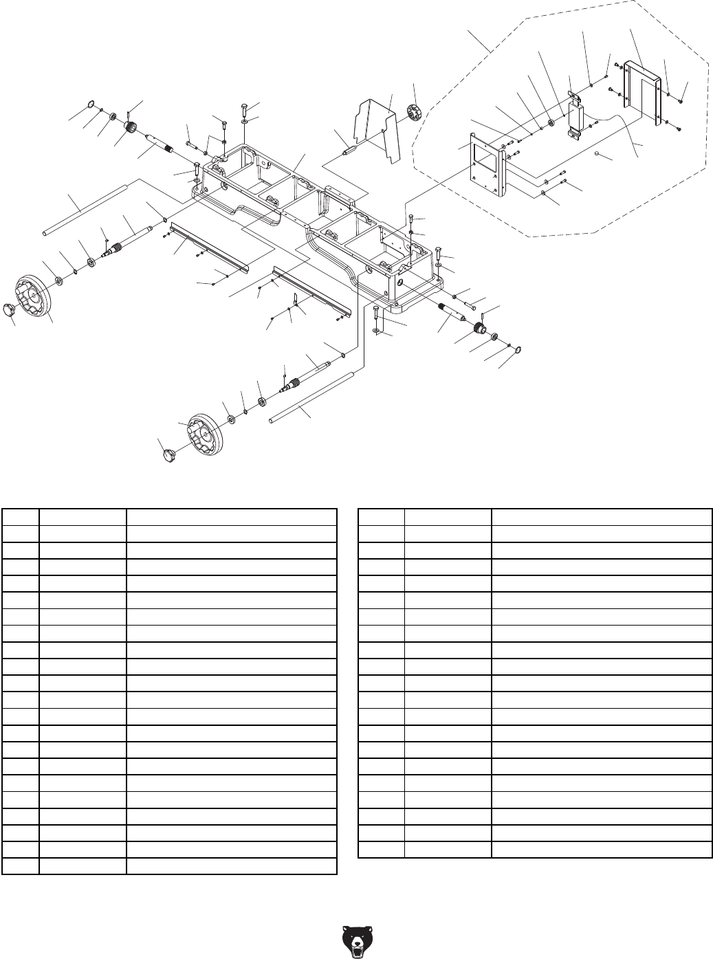
-50- Model G0495X (Mfd. Since 6/11)
Base Parts Breakdown & List
90
98
89
91
89
90
89
90
91
77
78
79
90
89
3
95 96 3
96
95
94
93
92
83
82
81
53
80
26
87
4
83
82
81
53
80
4
87
88
26
26
88
140
3
94
3
140
92 93
154
154
100
100158
144
145 100
154
168-2
168-15
168-11
168-12
168 168-14
168-4
168-10
168-3
168-5
168-13
168-7
168-8
168-10
168-9
168-9
168-6
90
98
89
91
89
90
8990
91
77
78
79
90
89
3
9596 3
96
95
94
93
92
8382815380
26874
83
82
81
53
80
4
87
88
26
26
88
123
84
140
3
94
3
140
92
93
154 100
144
145 100
154
59
147
A
171
172
173
73
168
115
97
158
164
166
167
75
156
143 74
157
158
159
160
122 168
168-2
161
162
161
122
169 163
170
A
B
B
169 9
131
174
REF PART # DESCRIPTION REF PART # DESCRIPTION
3 P0495X003 EXT RETAINING RING 15MM 100 P0495X100 FLAT WASHER 5MM
4 P0495X004 ROLL PIN 4 X 25 140 P0495X140 BUSHING
26 P0495X026 HEX NUT 5/16-18 144 P0495X144 RIGHT DUST PLATE
53 P0495X053 EXT RETAINING RING 9MM 145 P0495X145 LEFT DUST PLATE
77 P0495X077 KNOB 154 P0495X154 PHLP HD SCR 10-24 X 1/4
78 P0495X078 GUARD COVER 158 P0495X158 POINTER
79 P0495X079 DOUBLE-END STUD 168 P0495X168 SENSOR ASSEMBLY
80 P0495X080 INT RETAINING RING 25MM 168-2 P0495X168-2 CORD
81 P0495X081 BALL BEARING 6000ZZ 168-3 P0495X168-3 DIGITAL SENSOR W/SLIDING SHAFT
82 P0495X082 PINION GEAR 168-4 P0495X168-4 CAP SCREW M5-.8 X 8
83 P0495X083 SHAFT 168-5 P0495X168-5 PHLP HD SCR M3-.5 X 12
87 P0495X087 HEX BOLT 5/16-18 X 1-3/4 168-6 P0495X168-6 PHLP HD SCR M5-.8 X 8
88 P0495X088 HEX BOLT 5/16-18 X 1 168-7 P0495X168-7 BALL BEARING 606
89 P0495X089 HEX BOLT 3/8-16 X 2 168-8 P0495X168-8 BUSHING
90 P0495X090 FLAT WASHER 10MM 168-9 P0495X168-9 FLAT WASHER 5MM
91 P0495X091 LIFTING ROD 168-10 P0495X168-10 FLAT WASHER 3MM
92 P0495X092 LOCKING NUT 168-11 P0495X168-11 CAP SCREW 5/16-18 X 3/4
93 P0495X093 HANDWHEEL ASSEMBLY 168-12 P0495X168-12 FLAT WASHER 8MM
94 P0495X094 BALL BEARING 6002ZZ 168-13 P0495X168-13 PLATE
95 P0495X095 KEY 5 X 5 X 10 168-14 P0495X168-14 COVER
96 P0495X096 SPIRAL GEAR SHAFT 168-15 P0495X168-15 BATTERY 1.5V SILVER OXIDE 357/303
98 P0495X098 BASE
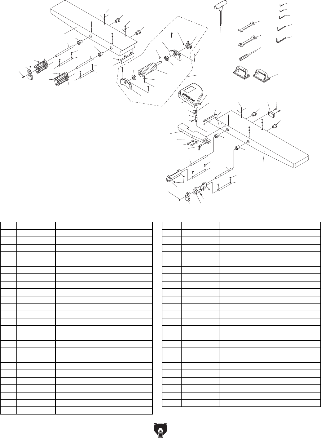
Model G0495X (Mfd. Since 6/11) -51-
133
178
176
175
48 9
50
58
57
56
55
52
51
53
49 54
61
44
44
47 43
76
44
44
68
66
63
67
65
64
71
68
65
68
66
62
72 84
179
177
180
181
186V2
184
9
127
45
45-1
45-2
45-3
45-4
45-5
45-6
45-7
45-8 45-9
45-10
46 44
62
64
70
68
65
68
66
65
44
63
68
66
67
47 43
76
44
44
47 43
76
48
Table Parts Breakdown & List
REF PART # DESCRIPTION REF PART # DESCRIPTION
9 P0495X009 CAP SCREW 1/4-20 X 3/8 58 P0495X058 CUTTERHEAD GUARD LOCK HANDLE
43 P0495X043 SET SCREW 5/16-18 X 3/8 61 P0495X061 FRONT TABLE
44 P0495X044 ECCENTRIC BUSHING 62 P0495X062 SHAFT
45 P0495X045 SP CUTTERHEAD ASSEMBLY 63 P0495X063 SHAFT
45-1 P0495X045-1 SPIRAL CUTTERHEAD 64 P0495X064 BRACKET
45-2 P0495X045-2 CARBIDE INSERTS 15 X 15 X 2.5 65 P0495X065 SET SCREW 5/16-18 X 1/2
45-3 P0495X045-3 FLAT HD TORX SCR #10-32 X 1/2 66 P0495X066 ROD SHAFT
45-4 P0495X045-4 LEFT BEARING SUPPORT BLOCK 67 P0495X067 ROD BRACKET
45-5 P0495X045-5 BALL BEARING 6203ZZ 68 P0495X068 CAP SCREW 1/4-20 X 3/4
45-6 P0495X045-6 KEY 5 X 5 X 30 70 P0495X070 LEFT ELEVATE BRACKET
45-7 P0495X045-7 RIGHT BEARING SUPPORT BLOCK 71 P0495X071 RIGHT ELEVATE BRACKET
45-8 P0495X045-8 SET SCREW M4-.7 X 10 72 P0495X072 SENSOR MOUNT BLOCK
45-9 P0495X045-9 CUTTERHEAD PULLEY 76 P0495X076 SCREW COVER
45-10 P0495X045-10 BALL BEARING 6203ZZ 84 P0495X084 CAP SCREW 5/16-18 X 3/4
46 P0495X046 REAR TABLE 127 P0495X127 CAP SCREW 5/16-18 X 1-3/4
47 P0495X047 BUSHING 133 P0495X133 PUSH BLOCK
48 P0495X048 CHIPBREAKER 175 P0495X175 HEX WRENCH 3MM
49 P0495X049 BLADE GUARD 176 P0495X176 HEX WRENCH 4MM
50 P0495X050 ROLL PIN 6 X 28 177 P0495X177 HEX WRENCH 5MM
51 P0495X051 SHAFT 178 P0495X178 HEX WRENCH 6MM
52 P0495X052 ROLL PIN 5 X 40 179 P0495X179 HEX WRENCH 8MM
53 P0495X053 EXT RETAINING RING 9MM 180 P0495X180 WRENCH 12 X 14
54 P0495X054 TORSION SPRING 181 P0495X181 WRENCH 14 X 17
55 P0495X055 FENCE LINK 184 P0495X184 PHILLIPS SCREWDRIVER #1
56 P0495X056 FLAT WASHER 10MM 186V2 P0495X186V2 T-HANDLE T-25 TORX DRIVER V2.06.11
57 P0495X057 HEX BOLT 3/8-16 X 1-1/4

-52- Model G0495X (Mfd. Since 6/11)
86
85
108
8
113
115
114
111
110
25
106
107
105
104
104
21
21
26
109
107
103 2
2
103
102
117
118
128
121
90
124
101
60
125
112 182
182
126
146
148
120
116
149 150
151 152
119
100
99
8
122
99
100
153
115
147
147-1
141
142
102-2
102-1 102-3
102-4
102-7
102-5
102-6
125-3
125-2
125-4
125-5
125-6
125-7
125-1
102-8
102-11
102-10
102-9
161
163
162
Stand Parts Breakdown & List

Model G0495X (Mfd. Since 6/11) -53-
REF PART # DESCRIPTION REF PART # DESCRIPTION
2 P0495X002 SET SCREW 1/4-20 X 3/8 117 P0495X117 FLAT HD SCR 1/4-20 X 3/4
8 P0495X008 FLAT WASHER 6MM 118 P0495X118 REAR ACCESS PLATE
60 P0495X060 SWITCH PLATE 119 P0495X119 CONTROL PANEL COVER
85 P0495X085 CAP 120 P0495X120 STRAIN RELIEF NB-2430
86 P0495X086 CAP SCREW M6-1 X 10 121 P0495X121 SWITCH BRACKET ASSEMBLY
99 P0495X099 CAP SCREW M5-.8 X 8 122 P0495X122 CAP SCREW 1/4-20 X 1/2
101 P0495X101 V-BELT A-51 124 P0495X124 STRAIN RELIEF NB-1722
102 P0495X102 MOTOR 3HP 220V 1-PH 125 P0495X125 MAGNETIC SWITCH
102-1 P0495X102-1 FAN COVER 125-1 P0495X125-1 MAG SWITCH BACK COVER
102-2 P0495X102-2 FAN 125-2 P0495X125-2 CONTACTOR SDE MA-18 220V
102-3 P0495X102-3 S CAPACITOR COVER 125-3 P0495X125-3 OL RELAY SDE RA-20 12-18A
102-4 P0495X102-4 S CAP 500M 125V 1-1/2 X 3-1/2 125-4 P0495X125-4 MAG SWITCH FRONT COVER
102-5 P0495X102-5 R CAPACITOR COVER 125-5 P0495X125-5 NYLON SCREW M10-1.5 X 22
102-6 P0495X102-6 R CAP 40M 300V 1-1/2 X 2-3/8 125-6 P0495X125-6 POWER CORD 12G 3C
102-7 P0495X102-7 JUNCTION BOX 125-7 P0495X125-7 CONTROL PANEL CORD 16AWG X 5C
102-8 P0495X102-8 CENTRIFUGAL SWITCH 126 P0495X126 STRAIN RELIEF SB8R-1
102-9 P0495X102-9 MOTOR PULLEY 128 P0495X128 STAND
102-10 P0495X102-10 SET SCREW 1/4-20 X 3/8 141 P0495X141 DIGITAL READOUT BRACKET
102-11 P0495X102-11 KEY 5 X 5 X 45 142 P0495X142 FLAT HD SCR M3-.5 X 8
103 P0495X103 SHAFT 146 P0495X146 PHLP HD SCR M5-.8 X 8
104 P0495X104 HEX NUT M10-1.5 147 P0495X147 DIGITAL READOUT ASSEMBLY
105 P0495X105 ADJUSTING SHAFT 147-1 P0495X147-1 BATTERY AAA
106 P0495X106 MOTOR PLATE 148 P0495X148 MOTOR CORD 12AWG X 3C
107 P0495X107 FLAT WASHER 8MM 149 P0495X149 SWITCH PLATE
108 P0495X108 SET SCREW M6-1 X 8 150 P0495X150 LIGHT 250V 1.2W JG18
109 P0495X109 COLLAR 151 P0495X151 STOP SWITCH
110 P0495X110 PHLP HD SCREW 1/4-20 X 1/2 152 P0495X152 START SWITCH
111 P0495X111 DUST CHUTE 153 P0495X153 EXT TOOTH WASHER 4MM
112 P0495X112 HEX BOLT 3/8-16 X 6 161 P0495X161 ACCESS DOOR
113 P0495X113 HEX NUT M5-.8 162 P0495X162 SPECIAL SCREW
114 P0495X114 FRONT COVER 163 P0495X163 KNOB M6-1
115 P0495X115 PHLP HD SCR M4-.7 X 8 182 P0495X182 STRAIN RELIEF
116 P0495X116 BUTTON HD CAP SCR M4-.7 X 12
Stand Parts List
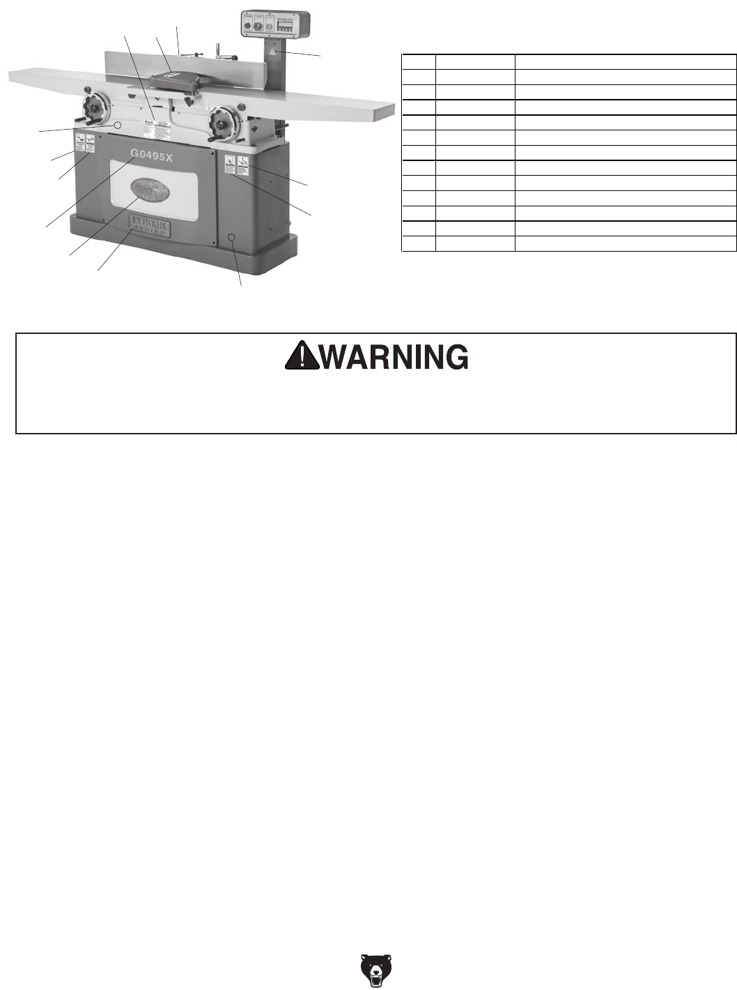
-54- Model G0495X (Mfd. Since 6/11)
200 201 202
203
204
205
206
207
208
209
210
211
212
Label Placement
REF PART # DESCRIPTION
200 P0495X200 MACHINE ID LABEL
201 PLABEL-29 CUTTERHEAD GUARD LABEL
202 P0495X202 FENCE/CUTTERHEAD LABEL
203 PLABEL-14 ELECTRICITY LABEL
204 PLABEL-36 DISCONNECT 220V POWER LABEL
205 PLABEL-12A READ MANUAL-VERTICAL NS 7/05 LABEL
206 PPAINT-1 "GRIZZLY GREEN" TOUCH-UP PAINT
207 P0495X207 EXTREME SERIES PLATE
208 G8589 GRIZZLY NAMEPLATE-LARGE
209 P0495X209 MODEL # LABEL
210 PLABEL-11 SAFETY GLASSES 2" X 3-5/16" LABEL
211 P0495X211 EAR PROTECTION/RESPIRATOR LABEL
212 PPAINT-11 "PUTTY" TOUCH-UP PAINT
Safety labels help reduce the risk of serious injury caused by machine hazards. If any label comes
off or becomes unreadable, the owner of this machine MUST replace it in the original location
before resuming operations. For replacements, contact (800) 523-4777 or www.grizzly.com.

CUT ALONG DOTTED LINE
Name _____________________________________________________________________________
Street _____________________________________________________________________________
City _______________________ State _________________________ Zip _____________________
Phone # ____________________ Email _________________________________________________
Model # ____________________ Order # _______________________ Serial # __________________
WARRANTY CARD
The following information is given on a voluntary basis. It will be used for marketing purposes to help us develop
better products and services. Of course, all information is strictly confidential.
1. How did you learn about us?
____ Advertisement ____ Friend ____ Catalog
____ Card Deck ____ Website ____ Other:
2. Which of the following magazines do you subscribe to?
3. What is your annual household income?
____ $20,000-$29,000 ____ $30,000-$39,000 ____ $40,000-$49,000
____ $50,000-$59,000 ____ $60,000-$69,000 ____ $70,000+
4. What is your age group?
____ 20-29 ____ 30-39 ____ 40-49
____ 50-59 ____ 60-69 ____ 70+
5. How long have you been a woodworker/metalworker?
____ 0-2 Years ____ 2-8 Years ____ 8-20 Years ____20+ Years
6. How many of your machines or tools are Grizzly?
____ 0-2 ____ 3-5 ____ 6-9 ____10+
7. Do you think your machine represents a good value? _____Yes _____No
8. Would you recommend Grizzly Industrial to a friend? _____Yes _____No
9. Would you allow us to use your name as a reference for Grizzly customers in your area?
Note: We never use names more than 3 times. _____Yes _____No
10. Comments: _____________________________________________________________________
_________________________________________________________________________________
_________________________________________________________________________________
_________________________________________________________________________________
____ Cabinetmaker & FDM
____ Family Handyman
____ Hand Loader
____ Handy
____ Home Shop Machinist
____ Journal of Light Cont.
____ Live Steam
____ Model Airplane News
____ Old House Journal
____ Popular Mechanics
____ Popular Science
____ Popular Woodworking
____ Precision Shooter
____ Projects in Metal
____ RC Modeler
____ Rie
____ Shop Notes
____ Shotgun News
____ Today’s Homeowner
____ Wood
____ Wooden Boat
____ Woodshop News
____ Woodsmith
____ Woodwork
____ Woodworker West
____ Woodworker’s Journal
____ Other:

TAPE ALONG EDGES--PLEASE DO NOT STAPLE
FOLD ALONG DOTTED LINE
FOLD ALONG DOTTED LINE
GRIZZLY INDUSTRIAL, INC.
P.O. BOX 2069
BELLINGHAM, WA 98227-2069
Place
Stamp
Here
Name_______________________________
Street_______________________________
City______________State______Zip______
Send a Grizzly Catalog to a friend:

WARRANTY & RETURNS
Grizzly Industrial, Inc. warrants every product it sells for a period of 1 year to the original purchaser from
the date of purchase. This warranty does not apply to defects due directly or indirectly to misuse, abuse,
negligence, accidents, repairs or alterations or lack of maintenance. This is Grizzly’s sole written warranty
and any and all warranties that may be implied by law, including any merchantability or fitness, for any par-
ticular purpose, are hereby limited to the duration of this written warranty. We do not warrant or represent
that the merchandise complies with the provisions of any law or acts unless the manufacturer so warrants.
In no event shall Grizzly’s liability under this warranty exceed the purchase price paid for the product and
any legal actions brought against Grizzly shall be tried in the State of Washington, County of Whatcom.
We shall in no event be liable for death, injuries to persons or property or for incidental, contingent, special,
or consequential damages arising from the use of our products.
To take advantage of this warranty, contact us by mail or phone and give us all the details. We will then issue
you a “Return Number,’’ which must be clearly posted on the outside as well as the inside of the carton. We
will not accept any item back without this number. Proof of purchase must accompany the merchandise.
The manufacturers reserve the right to change specifications at any time because they constantly strive to
achieve better quality equipment. We make every effort to ensure that our products meet high quality and
durability standards and we hope you never need to use this warranty.
Please feel free to write or call us if you have any questions about the machine or the manual.
Thank you again for your business and continued support. We hope to serve you again soon.