GS4 AC Drives Quick Start Guide DURApulse Drive Qsp
User Manual: DURApulse GS4 AC Drive Quick-Start Guide DURApulse GS4 AC Drives User Manual
Open the PDF directly: View PDF ![]() .
.
Page Count: 9
Page 1
DURApulse GS4 AC Drive Quick-Start Guide – 1st Ed, Rev.B 09/19/2017
DURApulse GS4 AC Drive Quick-Start Guide
GS4_QSP_1edRevB 09/19/2017
GS4 AC Drives Installation Instructions
Sensorless Vector Control Variable Frequency Drive
• Please read this instruction sheet thoroughly before installation and keep this instruction sheet.
• To ensure the safety of operators and equipment, only qualified personnel familiar with AC drives should
install, wire, program, and operate the GS4 drive. Always read this instruction sheet thoroughly before using
the GS4 drive, especially the WARNING, DANGER and CAUTION notes. If you have any questions, please contact
AutomationDirect.
PLEASE READ PRIOR TO INSTALLATION FOR SAFETY
DANGER
• The ground terminal of the GS4 drive must be grounded correctly. The grounding method
must comply with the laws of the country where the GS4 drive is to be installed.
• After power has been turned off, the capacitors in the GS4 drive may retain a charge for
several minutes. To prevent personal injury, visually verify that the “CHARGE” LED has
turned off. Then measure to confirm that the DC bus voltage level between terminals (+1)
and (-) is less than 25VDC before touching any terminals. (Will take at least 5 minutes for
most GS4 models; 10 minutes for GS4 models ≥40hp.)
• The CMOS ICs on the internal circuit boards of the GS4 drive are sensitive to static electricity.
Please DO NOT touch the circuit boards with your bare hands before taking anti-static
measures. Never disassemble the internal components or circuits.
• If wiring changes must be made, turn off power to the GS4 drive before making those
changes. Allow the internal DC bus capacitors in the GS4 drive sufficient time to discharge
prior to making changes in power or control wiring. Failure to do so may result in short
circuit and fire. To ensure personal safety, allow DC bus voltage to discharge to a safe level
before making wiring changes to the GS4 drive.
• DO NOT install the GS4 drive in locations subject to high temperature, direct sunlight, or
flammable materials.
WARNING
• Never apply power to the output terminals U/T1, V/T2, W/T3 of the GS4 drive. If a fault
occurs during operation of the GS4 drive, refer to the fault code descriptions and corrective
actions to reset the fault before attempting to operate the GS4 drive.
• DO NOT use Hi-pot test for internal components. The semi-conductors in the GS4 drive are
easily damaged by high voltage.
CAUTION
• Long motor lead lengths may result in reflective wave due to impedance mismatch between
the motor cable and the motor. Reflective wave may damage the insulation of the motor.
To avoid the possibility of reflective wave damage, use an inverter-rated motor with an
insulation rating of 1600 volts. A load reactor installed between the GS4 drive and motor
will help to mitigate reflective wave.
• Nominal supply voltage to the GS4 drive should be less than or equal to 240 volts AC for
GS4-2xxx models, and less than or equal to 480 volts AC for GS4-4 models.
• Nominal supply current capacity should be less than or equal to 5kA RMS for GS4 models of
40hp or less, and less than or equal to 10kA RMS for GS4 models of 40hp and larger.
• The GS4 drive must be installed in a clean, well-ventilated and dry location, free from
corrosive gases or liquids.
• The GS4 drive must be stored within an ambient temperature range from –25°C to +75°C,
and relative humidity range of 0% to 90% without condensation.
• Do not apply AC power to the GS4 drive with the front cover removed. Following a fault of
the GS4 drive, wait 5 seconds before pressing the RESET key.
• To improve power factor, install a line reactor ahead of the GS4 drive. Do not install power
correction capacitors in the main AC supply circuit to the GS4 drive to prevent drive faults
due to over-current.
Minimum Wiring
• AC input power to L1, L2, L3 (for single-phase input, use two of the terminals) (For applicability of 1-phase input
power, please refer to Chapter 1 of the DURApulse GS4 AC Drives User Manual at AutomationDirect.com.)
• Ground from the power supply
• Drive power to the motor (U, V, W on T1, T2, T3) (For use with 3-phase motors only!)
• Ground to the motor
• STO1 and STO2 (both must be wired through appropriate N.C. safety-rated contacts to SCM1 and SCM2)
With this minimal wiring, the drive can be operated via the keypad to test the motor and drive installation.
See the “Parameter Quick-Start Set Up” (page 3) section to configure the drive for keypad operation.
Recommended Safety Wiring
We strongly recommend that customers use the STO safety feature.
The Safe Torque Off (STO) function turns off the power supplied to the motor through the hardware, so
that the motor cannot produce torque. This method of removing power from the motor is considered an
emergency stop, also known as “coast to stop.”
To use this feature, disconnect the appropriate factory-installed jumpers and wire a safety relay, safety PLC,
or E-Stop pushbutton as shown. See “GS4 with Sinking Digital Inputs” (page 1) for wiring using the GS4
internal power supply, or Appendix E of the GS4 user manual for wiring using an external power supply.
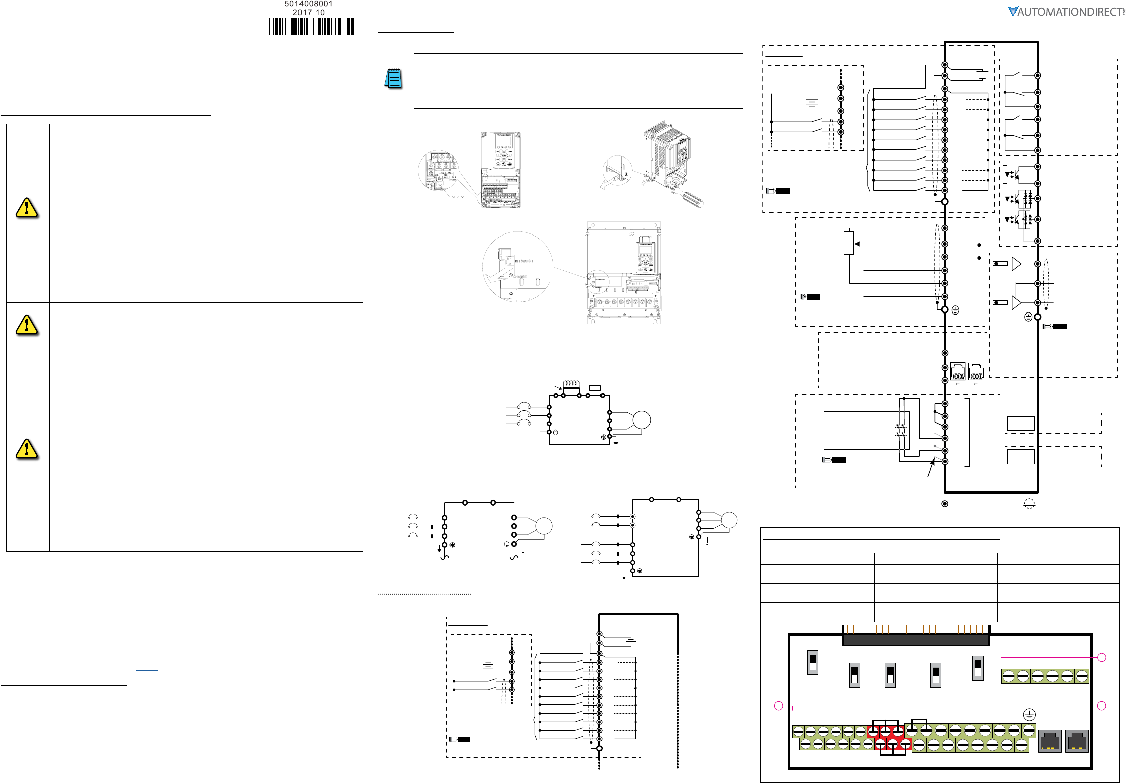
Wiring Diagrams
RFI Jumper Removal
If the power distribution system supplying the GS4 AC drive is a floating (IT) or an asymmetric
ground system, the RFI jumper must be removed.
Removing the RFI jumper uncouples the internal RFI capacitor (filter capacitor) between the GS4
drive frame and circuitry to avoid damaging those circuits and (according to IEC 61800-3) to reduce
ground leakage current.
GS4 Frame A through C
GS4 Frame D0 through G
Mains Wiring (Power Circuit)
For main (power) wiring terminal specifications, Please refer to “Specifications for Wiring Terminals –
Main-Circuit Terminals” (page 6).
GS4 Frame A through C
Brake resistor
(optional)
DC choke
(optional)
R(L1)
S(L2)
T(L3)
(L1)
(L2)
(L3)
U(T1)
V(T2)
W(T3)
+2 B1 B2
+1
-
Jumper
AC Motor
3 Ø
IM
Mains Wiring Diagram
for frames
A thru C
3-phase power is provided
For connection of Dynamic Braking Units and separate control power (large-frame drives only).
GS4 Frame D
3Ø
IM
Motor
U(T1)
V(T2)
W(T3)
-/DC-+1/DC+
R(L1)
S(L2)
T(L3)
R(L1)
S(L2)
T(L3)
Fuse/No Fuse Breaker
NFB
Wiring diagram for frame D
3-phase power is provided
DC+/DC- are for optional
Dynamic Braking Unit wiring
(do not connect a braking resistor
directly to these terminals)
GS4 Frames E and Larger
Motor
U(T1)
V(T2)
W(T3)
-/DC-+1/DC+
r1
s1
R
S
R(L1)
S(L2)
T(L3)
R(L1)
S(L2)
T(L3)
Fuse/No Fuse Breaker
NFB
Wiring diagram for frame E and above
3-phase power is provided
Separate control power:
for 230V (GS4-2xxx): 200–240VAC
for 460V (GS4-4xxx): 380–480VAC
DC+/DC- are for optional Dynamic Braking Unit wiring
(do not connect a braking resistor directly to these terminals)
3Ø
IM
Control-Circuit Wiring
GS4 with Sourcing Digital Inputs
SOURCING Mode (field devices are sinking)
FWD/STOP* **
REV/STOP* **
Multi-step 1*
Multi-step 2*
Multi-step 3*
Multi-step 4*
N/A*
N/A*
N/A*
N/A*
+
DCM
+24V
FWD
DIC
REV
DI1
DI2
DI3
DI4
DI5
DI6
DI7
DI8
Factory Settings
Internal
Power
Supply
NOTE
* Do NOT apply mains voltage directly to above terminals.
** If P4.09 = 1, FWD/REV direction is controlled by analog input only.
+
FWD/STOP* **
REV/STOP* **
Multi-step 1*
DCM
+24V
FWD
DIC
REV
Wiring if using
an external
power supply
+24V
The rest of the control wiring is the same as for SINKING mode.
Internal P.S. = 200mA max
GS4 with Sinking Digital Inputs
Control terminalsShielded leads & Cable
SINKING Mode (field devices are sourcing)
Communication
extension card
Option
Slot 1
5kΩ
3
2
1
Option
Slot 3
81 81
Pin 1~2, 7, 8: open or no connection
Pin 3, 6:GND
Pin 4:SG-
Pin 5:SG+
FWD/STOP* **
REV/STOP* **
Multi-step 1*
Multi-step 2*
Multi-step 3*
Multi-step 4*
N/A*
Multi-Function Output Terminals
I/O & RELAY
extension card
N/A*
N/A*
N/A*
+
AO1
SGND
SG+
SG-
DO1
DO2
DOC
FO
DCM
DCM
R1O
R2O
R2C
R2
+24V
FWD
DIC
REV
DI1
DI2
DI3
DI4
DI5
DI6
DI7
DI8
AO2
R1
R1C
+10V
-10V
AI1*
AI2*
AI3
ACM ACM
Factory Settings
RJ
45-1
RJ
45-2
Analog Signal Common
Analog Output 2 Terminal
0~10VDC / 4~20mA
Analog Output 1 Terminal
0~10VDC / -10~+10V
0~10V / 0~20mA / 4~20mA
0~10V / -10 to +10V
+10V / 20mA
-10V / 20mA
Analog Signal Common
Modbus RS-485
BACnet
Internal
Power
Supply
NOTE
* Do NOT apply mains voltage directly to above terminals.
** If P4.09 = 1, FWD/REV direction is controlled by analog input only.
SW3*
SW4*
* Ensure that the physical switches for AI1 and AI2
(located above the control terminal blocks) are
set for the correct voltage/current configuration.
NOTE
SW1*
SW2*
SCM1
STO1
+24V
STO2
ECM
Safety Relay,
Safety PLC,
or
E-Stop PB
(2 NC contacts required)
SCM2
NOHC
NOHC
Red
STO
Terminals
*
* Remove factory-installed short-circuit
jumper from +24V–STO1–STO2 when
using STO function with internal +24VDC.
NOTE
See User Manual Appendix E
for STO details.
* Ensure that the physical
switches for AO1 and AO2
(located above the control
terminal blocks) are set for
the correct voltage/current
configuration.
NOTE
0~10V / 0~20mA / 4~20mA
Resistive Load:
250VAC / 3A (N.O.)
250VAC / 3A (N.C.)
Inductive Load:
250VAC / 1.2A (N.O.)
250VAC / 1.2A (N.C.)
Estimate at COS (0.4)
Resistive Load:
30VDC / 5A (N.O.)
30VDC / 3A (N.C.)
+
FWD/STOP* **
REV/STOP* **
Multi-step 1*
DCM
+24V
FWD
DIC
REV
Wiring if using
an external
power supply
Internal P.S. = 200mA max
Digital Output terminals
5~48 VDC / 50mA
Digital Output terminals
5~48 VDC / 50mA
Multi-Function Output
Frequency terminals
5~30VDC / 30mA 100kHz
Digital Output common
Specifications for Wiring Terminals – Control Circuit
GS4-xxxx All Models; All Frame Sizes
Terminal Wire Gauge Torque
A24–16 AWG
[0.20–1.31 mm2]
5kg·cm
[4.3 lb·in]
B26–16 AWG
[0.13–1.31 mm2]
8kg·cm
[6.9 lb·in]
C24–16 AWG
[0.20–1.31 mm2]
2kg·cm
[1.7 lb·in]
FWD DI1 DI3 DI5 DI7 SGND
DCM REV DI2 DI4 DI6 DI8 SG+ SG-
0~10V
-10~10V
SW1
SW2
RJ45-1RJ45-2
SW3 SW4
SW5
0~10V
0/4~20mA
AO2
AO1 0~10V
0/4~20mA
AI1
0/4~20mA
0~10V
AI2
Open
120Ω
485
Control circuit board is removable from the GS4 (for ease of wiring)
R2 R1O
R1CR1R2OR2C
A
BC
AO1 D01AI3AI1+10V D02D02
STO1 +24V
STO2
AO2 DOCACMAI2-10V FO SCM1 ECM
SCM2
+24V DIC
G S 4 1
Page 2
DURApulse GS4 AC Drive Quick-Start Guide – 1st Ed, Rev.B 09/19/2017
DURApulse GS4 AC Drive Quick-Start Guide
GS4_QSP_1edRevB 09/19/2017
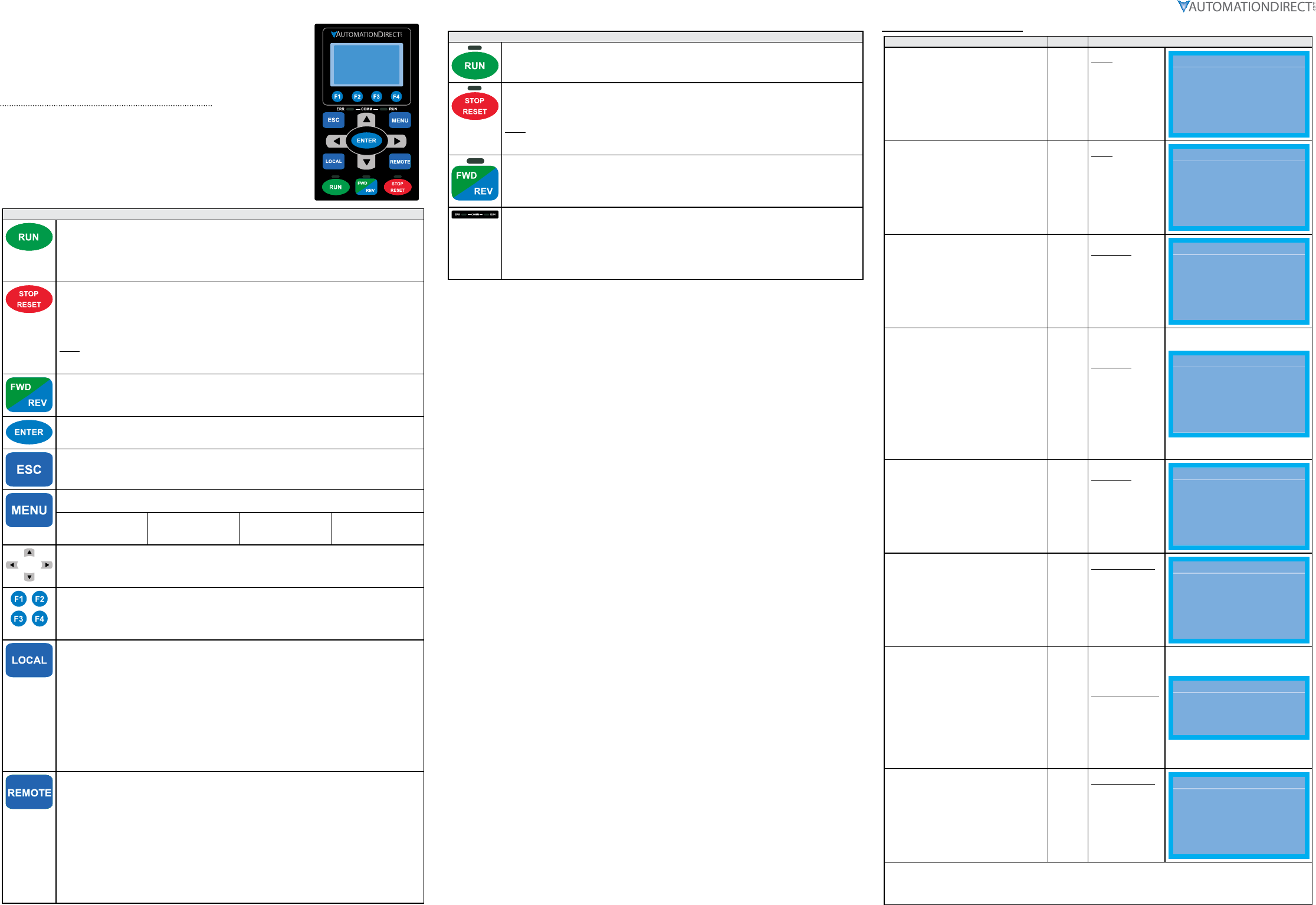
Digital Keypad Functions and Indications
Description of the functions of the keys and indicators of the GS4 AC Drive
Keypad.
Descriptions of Keypad Functions
RUN Key
• Valid only when the source of operation command is from the keypad.
• The RUN LED light (above the button) turns ON when the drive is running.
• RUN can be pressed even when drive is in process of stopping.
• When in “LOCAL” mode, RUN is valid only when the source of operation command is from the
keypad.
STOP/RESET Key
This key has the highest processing priority in any situation.
• When the drive receives a STOP command, whether or not the drive is in operation or stop
status, the drive will execute a "STOP" command.
• The RESET key can be used to reset the drive after a fault occurs. For those faults that can't be
reset by the RESET key, see the fault records after pressing MENU key for details.
N OTE: The ability to STOP the drive from the keypad is effective ONLY if the drive is configured to
RUN and/or STOP from the keypad. Keypad STOP can be disabled by parameters such as P3.00,
P3.01, P3.03~P3.16.
Operation Direction Key
• This key controls only the operation direction and does NOT activate the drive.
FWD: forward. REV: reverse.
• Refer to the LED descriptions for more details.
ENTER Key
Press ENTER to go to the next menu level. If it is the last level, then press ENTER to execute the
command.
ESC Key
The ESC key function serves to leave the current menu and return to the last menu. It also
functions as a return key while in the sub-menu.
MENU Key
Press MENU to return to the Main Menu. Menu Content:
1) Param Setup
2) Quick Start
3) Keypad Lock
4) Fault Record
5) PLC
6) Copy Param
7) Copy PLC
8) Displ Setup
9) Time Setup
10) Language
11) Start-up
Direction: Left/Right/Up/Down
• In the numeric value setting mode, the arrows are used to move the cursor and change the
numeric value.
• In the menu/text selection mode, the arrows are used for item selection.
Function Keys
• F1 is JOG function.
• The F2, F3 keys are reserved for future use. The F4 key is used to ADD parameters to the user-
defined My-Menu Quick-Start Menu. (See “My Menu” in the Quick-Start section of the GS4 User
Manual, “Chapter3: Keypad Operation and Quick-Start” for more information).
LOCAL Key
• This key causes the drive to follow the LOCAL (2nd source) settings for frequency command and
operation.* The factory settings of both source of Local frequency and Local operation are the
Digital Keypad.
• Pressing the LOCAL key with the drive stopped will switch the operation and frequency to
the LOCAL source (P3.01 and P4.01). Pressing the LOCAL key with the drive running can be
configured to keep running or to stop upon transition. See P3.58 for more information.
• The selected mode, LOCAL or REMOTE, will be displayed on the GS4-KPD.
• When P3.58=0 then LOCAL correlates to HAND mode. The Digital Input Definition must not be
set to 33 (LOC/REM Switch).
* Refer to P3.58 for more detail and other options on how the drive behaves when switching between
LOCAL and REMOTE. Refer to P3.00, P3.01, P4.00 and P4.01 for defining LOCAL and REMOTE sources
of operation and frequency.
REMOTE Key
• This key causes the drive to follow the REMOTE (1st source) settings for frequency command and
operation.* The factory settings of both source of Remote frequency and Remote operation are
the Digital Keypad.
• Pressing the REMOTE key with the drive stopped will switch the operation and frequency to the
REMOTE source. Pressing the REMOTE key with the drive running can be configured to keep
running or to stop upon transition. See P3.58 for more information.
• The selected mode, LOCAL or REMOTE, will be displayed on the GS4-KPD.
• When P3.58=0 then LOCAL correlates to HAND mode. The Digital Input definition must not be
set to 33 (LOC/REM Switch).
* Refer to P3.58 for more detail and other options on how the drive behaves when switching between
LOCAL and REMOTE. Refer to P3.00, P3.01, P4.00 and P4.01 for defining LOCAL and REMOTE sources
of operation and frequency.
Descriptions of LED Functions
Steady ON: Drive is running.
Blinking: Drive is stopping or in base block.
Steady OFF: Drive is not currently executing an operational (RUN) command.
Steady ON: Drive is stopped or in the process of stopping.
Blinking: Drive is in standby; selected speed reference source is at zero.
(If expecting movement, confirm that a speed reference is present.)
Steady OFF: Drive is not currently executing an operational (STOP) command.
N OTE: The ability to STOP the drive from the keypad is effective ONLY if the drive is configured to
RUN and/or STOP from the keypad. Keypad STOP can be disabled by parameters such as P3.00,
P3.01, P3.03~P3.16.
Operation Direction LED
• Green light is on: The drive is running forward or will run forward when given a run command.
• Red light is on: The drive is running backwards or will run backwards when given a run
command.
• Alternating green/red light: The drive is changing direction.
ERR_COMM_RUN
These LEDs represent the status of RS-485 communication through COM port 1.
RUN-LED Flashing: RS-485 is transferring
ERR- LED Red: Latest Tx or Rx failed
Off: Latest Tx or RX = OK
Flashing: Please check the RS-485 master for proper configuration/communication, and
also check the PLC code for proper operation if serial comm is enabled inside the PLC.
Keypad Navigation Example
Instruction Press Key Display Will Show
Press “MENU” key to access the GS4
settings menu. MENU
Menu
1:Param Setup
2:Quick Start
3:Keypad Lock
...
9:Time Setup
10:Language
11:Start-up
Menu
▲1: Param Setup
▼
2: Quick Start
3: Keypad Lock
Use the “Down” arrow key to scroll down
to select #2, the Quick-Start groups of
parameter settings.
▼
Menu
1:Param Setup
2:Quick Start
3:Keypad Lock
...
9:Time Setup
10:Language
11:Start-up
Menu
1: Param Setup
▲2: Quick Start
▼
3: Keypad Lock
Press “ENTER” key to access the Quick-
Start menus. ENTER
Quick Start
1:Basic Config
2:Control I/O
3:Enhancements
4:Protection
5:PID
6:My Menu
Quick Start
▼1: Basic Config
2: Control I/O
3: Enhancements
Use the Up or Down arrows to select the
appropriate Quick-Start group.
The display shows only three groups at a
time, but the unseen groups come onto
the display as you continue arrrowing
Down (or Up).
Group #1 (Basic Config) has the settings
that you are required to adjust (Volts,
Amps, Start/Stop method, etc.). Each
successive Quick-Start group has more
options and features, which may or may
not need to be configured, depending
upon the application.
▼
Quick Start
1:Basic Config
2:Control I/O
3:Enhancements
4:Protection
5:PID
6:My Menu
Quick Start
2: Control I/O
3: Enhancements
▲4: Protection
▼
Use the Up or Down arrows to select the
“Basic Config” Quick-Start parameter
settings group.
▲
▼
Quick Start
1:Basic Config
2:Control I/O
3:Enhancements
4:Protection
5:PID
6:My Menu
Quick Start
▼1: Basic Config
2: Control I/O
3: Enhancements
Press “ENTER” key to access the “Basic
Config” Quick-Start parameter settings
group.
ENTER
Basic Con :P00.00
01:Mtr1 Max Vo
02:Mtr1 Amps Ra
03:Mtr1 Base Hz
...
17:Derate Meth
18:Duty Selecti
19:Param Reset
Basic Con: P00.00
▲01: Mtr1 Max Vo
▼
02: Mtr1 Amps Ra
03: Mtr1 Base Hz
Press “ENTER” key to set P0.00, Motor
1 Maximum Output Voltage Output,
which is the 1st parameter of the “Basic
Configuration” Quick-Start group.
One digit of the parameter variable will be
blinking.
Use the Up and Down arrow keys to adjust
the blinking digit to your desired value,
and use the right and left arrow keys to
change which digit is blinking (settable).
Press “ENTER” key to enter your new
parameter value.
ENTER
00.00 V
230.0
Mtr1 Max VoltOut
0.0~255.00
00.00 V
230.0
Mtr1 Max VoltOut
0.0~255.0
Press “ESC” key to return to the “Basic
Configuration” screen. ESC
Basic Con :P00.00
01:Mtr1 Max Vo
02:Mtr1 Amps Ra
03:Mtr1 Base Hz
...
17:Derate Meth
18:Duty Selecti
19:Param Reset
Basic Con: P00.00
▲01: Mtr1 Max Vo
▼
02: Mtr1 Amps Ra
03: Mtr1 Base Hz
Scroll sequentially through the rest of the parameters in the “Basic Configuration” Quick-Start group, and set those
parameters as needed for your application.
After changing all of the applicable parameters, press “MENU” key to return to the Menu screen, and then press
“ESC” key to return to the home screen.
Page 3
DURApulse GS4 AC Drive Quick-Start Guide – 1st Ed, Rev.B 09/19/2017
DURApulse GS4 AC Drive Quick-Start Guide
GS4_QSP_1edRevB 09/19/2017
Quick-Start Introduction – How To Get Started
Automationdirect.com would like to thank you for your purchase of the Durapulse GS4 AC drive. The GS4 drive
is a state-of-the-art, full-featured AC drive. The Quick-Start Guide below will introduce you to many of the GS4
drive features and help you configure the GS4 drive in a minimum amount of time.
STO (Safe Torque Off) / Emergency Stop
The GS4 drive offers Safe Torque Off (STO) functionality, instead of a standard Emergency Stop circuit. STO
provides the ability to immediately turn off the output of the GS4 drive in the event of an emergency, without
the need for an emergency stop contactor between the drive and motor.
Please see P6.71 (STO Alarm Latch) in Quick-Start “Protection” Menu #4 (page 4).
Please see the Control-Circuit Wiring diagrams (page 1) for how to wire the STO circuit. From the factory,
the GS4 STO terminals are jumpered and the STO circuitry of the drive is bypassed. STO is recommended for
personnel safety.
After wiring the drive (but before applying power), the first thing you should do is press the E-stop button (or
otherwise break the safety circuit) and verify that the circuit between the STO1/STO2 terminals and the STO
+24V terminal is not connected. If these circuits are open, the STO feature will stop all power from going to the
motor and there will be no danger of unexpected movement when you power up the drive.
Powering Up the GS4 Drive
Apply AC line power to the GS4 drive, but don’t engage the safety circuit yet (keep the E-stop PB pushed in).
Starting, Stopping, and Controlling the Speed of the GS4 Drive
The GS4 drive keypad includes both LOCAL and REMOTE control modes. Out of the box, both LOCAL and
REMOTE modes of operation (selected by the buttons on the keypad) are set to use the keypad buttons to RUN
and STOP the drive and vary the drive speed. The drive can also be configured to run from potentiometers,
external pushbuttons, Ethernet communication, etc.
Do not attempt to run the motor yet. Certain parameters (especially the motor protection parameters) must
be set first.
Configure the Drive / Quick-Start Menus
The Quick-Start Menus below (press MENU on the keypad, then scroll to “Quick Start”) will guide you through
those parameters typically used in most applications. You can also navigate to any of these parameters
through the “Param Setup” menu. (Refer to page 2 for information and instructions for using the Digital
Keypad.)
All applications need to configure the parameters in the “Basic Configuration” quick start menu. At minimum,
you MUST configure these motor parameters in the “Basic Configuration” menu before operating the drive:
• P0.00 Motor1 Max Output Voltage (this will typically be either 230V or 460V)
• P0.01 Motor1 Rated Amps (depends on the motor)
• P0.04 Motor1 Max Output Frequency (this will typically be 50Hz or 60Hz)
Your application will dictate which parameters need to be configured. It is NOT necessary to configure every
parameter in a Quick-Start Menu or go through each Quick-Start Menu. Use only those you need.
Menu Descriptions:
12) Basic Configuration (page 3)
Parameters in this menu are necessary to configure and protect the motor, and to define the basic control
modes of the GS4 drive. All applications should set these parameters.
13) Control I/O (page 3)
Parameters in this menu define which analog inputs and multi-speed digital inputs will control the GS4 drive.
These parameters work in conjunction with P3.00, P3.01, P4.00, P4.01 from Menu #1.
14) Enhancements (page 4)
Parameters in this menu include those parameters used to enhance or refine the operation of the GS4 drive
with features such as S-Curve, Jog Speed, Skip Frequencies, DC Injection, etc.
15) Protection (page 4)
Parameters in this menu include advanced GS4 drive protection parameters. These parameters define how
the GS4 drive will respond to certain fault conditions and whether the GS4 drive will attempt to automatically
recover.
16) PID (page 4)
Parameters in this menu are for PID control and configuration of the GS4 keypad in engineering units. More
detailed information can be found in Parameter Groups 7 and 8.
After configuring the minimum settings, you can now engage the safety circuit. The RUN and STOP buttons
should Start and Stop the drive. To adjust the output frequency, use the arrows keys to cursor to the “F”
(Frequency) setting. Press ENTER to adjust the drive’s Frequency setpoint (Up/Down arrows increase/
decrease; Left/Right arrows change the cursor position).
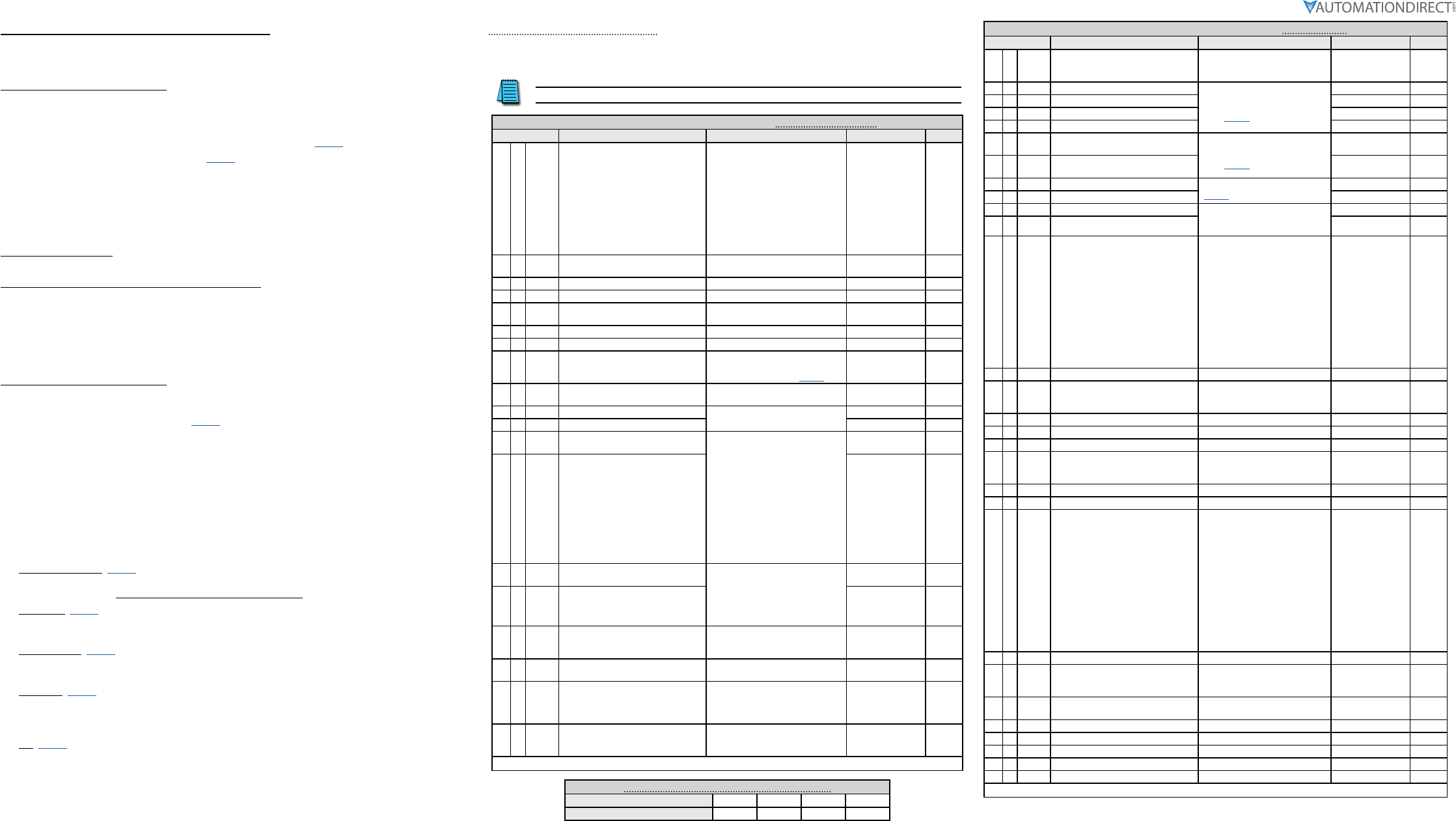
Parameter Quick-Start Set Up
DURApulse GS4 AC Drives offer a “Quick-Start” parameter setup from the keypad for some of the most
common drives applications. Choose “Quick-Start” from the menu, and then select one of the five menus
described in the following table. Then set the applicable parameters for that application as shown.
Please refer to the user manual if you need more detailed information about the parameters.
DURApulse GS4 Quick-Start Parameter Settings #1 – Basic Configuration
Parameter Description Settings Default User
19 P9.08
Restore to Default *
* If configuring the GS4 drive for
the first time, it is not necessary to
Restore the Default configuration.
0: no function
1: Parameter Lock
2: no function
3: no function
4: no function
5: Reset kWh Display to Zero
6: Reset PLC (clear PLC)
7: no function
8: no function
9: Reset 50Hz Default
10: Reset 60Hz Default
0
1P0.00 Motor 1 Maximum Output Voltage 230V: 0.0~255.0V
460V: 0.0~510.0V
GS4 -2xxx: 230.00
GS4 -4xxx: 460.00
2P0.01 Motor 1 Rated Current 10~120% drive rated Amps 90% rated I of GS4
3P0.02 Motor 1 Base Frequency 0.00~600.00 Hz 60.00
4♦P0.03 Motor 1 Rated RPM 0 to (120 x P0.02/P0.09)-1 17 10 (60Hz 4-pole)
14 10 (50Hz 4-pole)
5P0.04 Drive Maximum Output Frequency 0~600.00 Hz 50.00/60.00
6♦P0.08 Motor 1 Rated Horsepower (HP) 0.00~655.35hp Rated hp of GS4
7P0.09 Motor 1 Number of Poles
2 to (120 x P0.02/P0.03)
See “Motor Base Speeds and
Number of Poles” table (page 3)
4
8♦P1.00 Stop Method 0: Ramp to stop
1: Coast to stop 0
9♦P1.01 Acceleration Time 1 P1.15=0: 0.00~600.00 sec
P1.15=1: 0.0~6000.0 sec
10.00
10 ♦P1.02 Deceleration Time 1 10.00
11 P3.00 1st Source of Operation Command
[Remote]
0: Digital Keypad
1: External Terminal; Keypad/RS-485
STOP is enabled
2: External Terminal; Keypad/RS-485
STOP is disabled
3: RS485 (Modbus/BACnet); Keypad
STOP is enabled
4: RS485 (Modbus/BACnet); Keypad
STOP is disabled
5: Comm Card; Keypad STOP is
enabled
6: Comm Card; Keypad STOP is
disabled
0
12 P3.01 2nd Source of Operation Command
[Local] 0
13 ♦P4.00 1st Source of Frequency Command
[Remote]
0: Digital Keypad
1: RS485 Communication
(Modbus/BACnet)
2: Analog Input
3: External UP/DOWN Terminal
4: Comm Card
0
14 ♦P4.01 2nd Source of Frequency Command
[Local] 0
15 ♦P6.00 Electronic Thermal Overload Relay
(Motor 1)
0: Constant Torque
1: Variable Torque
2: Inactive
1
16 ♦P6.01 Electronic Thermal Characteristic
(Motor 1) 30.0~600.0 sec 60.0
17 P6.33 Drive Derating Method
0: Constant rated current
1: Constant carrier frequency
2: Constant rated current (with
higher current limit)
0
18 ♦P6.34 Variable/Constant Torque Duty
Selection
0: VT, 3-phase input
1: CT, 3-phase input
2: CT, 230V 1-phase input
0
♦ The diamond bullet symbol indicates a parameter that can be set during operation.
Motor Base Speeds and Number of Poles for P0.09
Motor Synchronous Speed (RPM) 900 1200 1800 3600
Number of Motor Poles (#) 8 6 4 2
DURApulse GS4 Quick-Start Parameter Settings #2 – Control I/O
Parameter Description Settings Default User
1P3.02 2/3 Wire Operation Mode
0: 2-wire mode 1 (Fwd, Rev)
1: 2-wire mode 2 (Run, Direction)
2: 3-wire mode
0
2P3.03 Multi-Function Input (DI1)
see
“Multi-Function Input Settings”
table (page 5)
1
3P3.04 Multi-Function Input (DI2) 2
4P3.05 Multi-Function Input (DI3) 3
5P3.06 Multi-Function Input (DI4) 4
6♦P3.17 Multi-Function Output Terminal 1
(Relay 1) see
“Multi-Function Output Settings“
table (page 5)
11
7♦P3.18 Multi-Function Output Terminal 2
(Relay 2) 1
8♦P4.02 Analog Input 1 (AI1) Function see “Analog Input Settings” table
(page 5)
1
9♦P4.03 Analog Input 2 (AI2) Function 0
10 ♦P4.05 AI1 – I/V Selection 0: AI_v Selection (0~10V)
1: AI_i Selection (4~20mA)
2: AI_i Selection (0~20mA)
0
11 ♦P4.06 AI2 – I/V Selection 1
12 ♦P4.09 Analog Frequency Command for
Reverse Run
0: Negative Frequency Input is
Disabled.
Forward and reverse motions
are controlled by digital keypad
or by external terminal.
1: Negative Frequency Input is
Enabled.
Forward motion when positive
frequency; reverse motion when
negative frequency.
Forward and reverse motions
are not controlled by digital
keypad or by external terminal.
0
13 ♦P4.10 AI1 Input Bias (Offset) -100.0% to +100.0% 0
14 ♦P4.11 AI1 Input Bias (Offset) Polarity
0: NO Offset
1: Positive Offset
2: Negative Offset
0
15 ♦P4.12 AI1 Input Gain -500.0% to +500.0% 100.0
16 ♦P4.13 AI1 Filter 0.00~20.00 sec 0.01
17 ♦P4.15 AI2 Input Bias (Offset) -100.0% to +100.0% 0
18 P4.16 AI2 Input Bias (Offset) Polarity
0: NO Offset
1: Positive Offset
2: Negative Offset
0
19 ♦P4.17 AI2 Input Gain -500.0% to +500.0% 100.0
20 ♦P4.18 AI2 Filter 0.00~20.00 sec 0.01
21 ♦P4.50 Analog Output 1 (AO1)
0: Output Frequency (Hz)
1: Frequency Command (Hz)
2: Motor Speed (Hz)
3: Output Current (Arms)
4: Output Voltage (V)
5: DC Bus Voltage (V)
6: Power Factor (%)
7: Power (% Rated)
8: AI1 (%)
9: AI2 (%)
10: AI3 (%)
11: As 485 AO
12: As COM Card AO
13: Fixed Value
0
22 ♦P4.51 AO1 Gain 0.0~500.0% 100.0
23 ♦P4.52 AO1 Negative Value Handle
0: Absolute Value
1: 0V When Negative
2: Offset 5V = 0 Value
0
24 P4.53 AO1 0~20mA/4~20mA Selection 0: 0~20mA
1: 4~20mA 0
25 P4.60 AO1 Output Constant Level 0.00~100.00% 0.00
26 ♦P5.01 Multi-Speed 1 0.00~600.00 Hz 0.0
27 ♦P5.02 Multi-Speed 2 0.00~600.00 Hz 0.0
28 ♦P5.03 Multi-Speed 3 0.00~600.00 Hz 0.0
29 ♦P5.04 Multi-Speed 4 0.00~600.00 Hz 0.0
♦ The diamond bullet symbol indicates a parameter that can be set during operation.
Page 4
DURApulse GS4 AC Drive Quick-Start Guide – 1st Ed, Rev.B 09/19/2017
DURApulse GS4 AC Drive Quick-Start Guide
GS4_QSP_1edRevB 09/19/2017
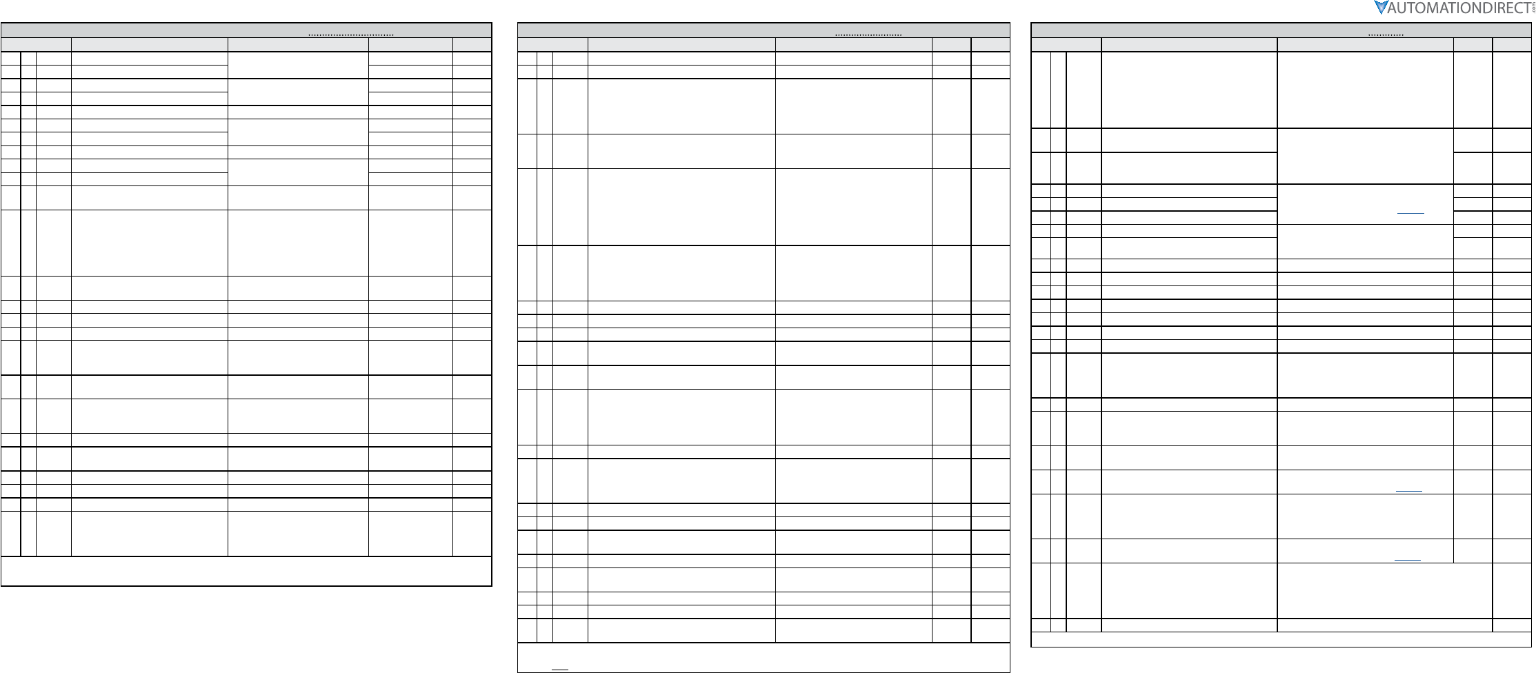
DURApulse GS4 Quick-Start Parameter Settings #3 – Enhancements
Parameter Description Settings Default User
1♦P1.09 S-curve Accel Time 1 P1.15=0: 0.00~25.00 sec
P1.15=1: 0.0~250.0 sec
0.20
2♦P1.10 S-curve Decel Time 1 0.20
3♦P1.13 Jog Acceleration Time P1.15=0: 0.00~600.00 sec
P1.15=1: 0.0~6000.0 sec
10.00
4♦P1.14 Jog Deceleration Time 10.00
5♦P5.00 Jog Frequency 0.00~600.00 Hz 6.0
6P1.19 Skip Frequency 1 Upper Limit 0.00~600.00 Hz 0.00
7P1.20 Skip Frequency 1 Lower Limit 0.00
8♦P1.25 DC Injection Current Level 0~100% 0
9♦P1.26 DC Injection Time During Start-up 0.0~60.0 sec 0.0
10 ♦P1.27 DC Injection Time During Stopping 0.0
11 ♦P1.28 Start-Point for DC Injection During
Stopping 0.00~600.00 Hz 0.00
12 P2.00 Volts/Hertz Settings
0: General Purpose
1: High Starting Torque (TQR)
2: Fans and Pumps
3: Custom
4: 1.5 Power Curve *
5: Square Curve *
0
13 ♦P2.01 Slip Compensation Gain 0.00~10.00 0. 00 (V/Hz mode)
1. 00 (Vector mode)
14 ♦P2.25 Slip Compensation Filter 0.001~10.000 sec 0.100
15 ♦P2.02 Torque Compensation Gain 0~10 0
16 ♦P2.03 Torque Compensation Filter 0.001~10.000 sec 0.5
17 P2.10 PWM Carrier Frequency 2~15 kHz
model specific;
refer to param.
details
18 ♦P2.11 Control Mode 0: V/Hz Open Loop Control
1: SVC Sensorless 0
19 P2.18 Zero Speed Select
0: Standby
1: Zero Hold
2: Fmin (Min Hz Output)
0
20 ♦P6.25 Upper Limit of Output Frequency 0.00~600.00 Hz 600.00
21 ♦P2.23 Automatic Energy-Saving Operation 0: Disable
1: Enable 0
22 ♦P2.24 Power Saving Gain 10~1000% 100
23 ♦P2.26 Slip Deviation Level 0.0~100.0 0.0
24 ♦P2.27 Slip Deviation Detection time 0.0~10.0 1.0
25 ♦P2.28 Slip Deviation Treatment
0: Warn and continue OP
1: Warn and Ramp to Stop
2: Warn and Coast to stop
3: No Warn
0
♦ The diamond bullet symbol indicates a parameter that can be set during operation.
* Energy Saving Power Curves For Fans & Pumps. (P2.00 settings 4 & 5)
DURApulse GS4 Quick-Start Parameter Settings #4 – Protection
Parameter Description Settings Default User
1♦P6.04 Auto Restart after Fault 0~10 0
2♦P6.05 Reset Time for Auto Restart after fault 0.0~6000.0 sec 60.0
3♦P6.06 Base Block Speed Search after Fault (oc,ov,bb)
0: Disable
1: Speed search starts with current
speed reference
2: Speed search starts with minimum
output frequency
0
4♦P6.09 Fwd/Rev Direction Inhibit
0: Enable Fwd/Rev
1: Disable Reverse Operation
2: Disable Forward Operation
0
5♦P6.13 Auto Adjustable Accel/Decel
0: Linear Accel/Decel
1: Auto Accel, Linear Decel
2: Linear Accel, Auto Decel
3: Auto Accel, Auto Decel
4: Auto Accel/Decel Stall Prevention
(limited by P1.01~P1.08 and
P1.13~P1.14)
0
6♦P6.14 Over-torque Detection Mode (OT1)
0: Disable
1: Enable during at speed
2: Enable during at speed and Stop
3: Enable during OP
4: Enable during OP and Stop
0
7♦P6.15 Over-torque Detection Level (OT1) 10~200% 120
8♦P6.16 Over-torque Detection Time (OT1) 0.1~60.0 sec 0.1
9♦P6.26 Lower Limit of Output Frequency 0.00~600.00 Hz 0.00
10 ♦P6.28 Dynamic Braking Voltage Level * 230V: 350.0~450.0 VDC
460V: 700.0~900.0 VDC
390.0
780.0
11 ♦P6.29 Line Start Lockout 0: Enable start-up lockout
1: Disable start-up lockout 0
12 ♦P6.31 Cooling Fan Control
0: Always ON
1: Fan OFF 1 minute after Stop
2: Run fan ON/Stop fan OFF
3: Heat sink temperature
4: Always OFF
0
13 P6.32 PWM Fan Speed 0~100% 60
14 P6.45 Output Phase Loss (OPhL) Detection Selection
0: Warn and continue to operate
1: Warn and ramp to stop
2: Warn and coast to stop
3: No warning
3
15 P6.46 Output Phase Loss Detection time 0.000~65.535 sec 0.500
16 P6.47 Output Phase Loss Current Detection Level 0.00~100.00% (of max current) 1.00
17 P6.49 Input Phase Loss Treatment 0: Warn and ramp to stop
1: Warn and coast to stop 0
18 P6.69 Input Phase Loss Detection Time 0.00~600.00 sec 0.20
19 P6.70 Input Phase Loss Ripple Detection 230V models: 0.0~160.0 VDC
460V models: 0.0~320.0 VDC
30.0
60.0
20 P6.50 GFF Detect Current Level (% of INV I-Rated) 0.0~100.0% 60.0
21 P6.51 GFF Low Pass Filter Gain 0.00~655.35 0.10
22 ♦P6.71 STO Alarm Latch 0: STO Alarm Latch
1: STO Alarm no Latch 0
♦ The diamond bullet symbol indicates a parameter that can be set during operation.
* Valid only for 230V models below 30hp and 460V models below 40hp. (P6.28)
DURApulse GS4 Quick-Start Parameter Settings #5 – PID
Parameter Description Settings Default User
1♦P7.00 PID Action/Mode
0: PID Disabled
1: PID Reverse Local/Remote
2: PID Forward Local/Remote
3: PID Reverse Remote Only
4: PID Forward Remote Only
5: PID Reverse Local Only
6: PID Forward Local Only
0
2♦P4.00 1st Source of Frequency Command
[Remote]
0: Digital Keypad
1: RS485 Communication (Modbus/BACnet)
2: Analog Input
3: External UP/DOWN Terminal
4: Comm Card
2
3♦P4.01 2nd Source of Frequency Command [Local] 0
4♦P4.02 Analog Input 1 (AI1) Function see
“Analog Input Settings” table (page 5)
1
5♦P4.03 Analog Input 2 (AI2) Function 0
6♦P4.04 Analog Input 3 (AI3) Function 0
7♦P4.05 AI1 – I/V Selection 0: AI_v Selection (0~10V)
1: AI_i Selection (4~20mA)
2: AI_i Selection (0~20mA)
0
8♦P4.06 AI2 – I/V Selection 1
9♦P7.03 PID Feedback Gain 0.00 to 300.00% 100.00
10 ♦P7.04 PID Offset Value -100.0% to +100.0% 0.0
11 ♦P7.13 Proportional Gain 0.0~100.0 1.0
12 ♦P7.14 Integral Time 0.00~100.00 sec 1.00
13 ♦P7.15 Derivative Value 0.00~1.00 sec 0.00
14 ♦P7.18 PID Output Frequency Limit 0.0~110.0% 100.0
15 ♦P7.20 Feedback Signal Detection Time 0.0~3600.0 sec 0.0
16 P7.21 PID Feedback Loss
0: Warn and Continue Operation
1: Warn and Ramp to Stop
2: Warn and Coast to Stop
3: Warn and Operate at Last Frequency
0
17 ♦P7.22 PID Feedback Loss Speed Level Default 0.00~400.00 Hz 0.00
18 P7.25 PID Mode Selection
0: Old PID mode, Kp, Kp*Ki, Kp*Kd
1: New PID mode, Kp, Ki, Kd are
independent
0
19 P7.26 PID Reverse Enable 0: PID can't change command direction
1: PID can change command direction 0
20 ♦P8.00 User Display see
“User Display Settings” table (page 5)
21 ♦P8.01 Start-up Display Selection
0: Freq Setpoint
1: Output Hz
2: User Display (P8.00)
3: Output Amps
22 P8.02 User Defined Format see
“User Defined Format” table (page 5)
23 P8.03 User Defined Max
0: Disable
0~65535 (when P8.02 set to no decimal place)
0.0~6553.5 (when P8.02 set to 1 decimal place)
0.00~655.35 (when P8.02 set to 2 decimal place)
0.000~65.535 (when P8.02 set to 3 decimal place)
0
24 P8.04 User Defined Setpoint 0~65535 0
♦ The diamond bullet symbol indicates a parameter that can be set during operation.
Page 5
DURApulse GS4 AC Drive Quick-Start Guide – 1st Ed, Rev.B 09/19/2017
DURApulse GS4 AC Drive Quick-Start Guide
GS4_QSP_1edRevB 09/19/2017
Parameter Settings Tables
Multi-Function Input Settings for P3.03~P3.10
0: no function
1: Multi-Speed/PID Multi-Setpoint bit 1
2: Multi-Speed/PID Multi-Setpoint bit 2
3: Multi-Speed/PID Multi-Setpoint bit 3
4: Multi-Speed bit 4
5: Reset
6: JOG
7: Accel/Decel speed inhibit (Speed
Hold)
8: 1st~4th Accel/Decel time selection,
bit 0
9: 1st~4th Accel/Decel time selection,
bit 1
10: Emergency Stop EF Input by P3.56
(EF error)
11: Base Block Input
12: Drive Output OFF
13: Disable Auto Accel/Decel Time
14: Switch between drive settings 1 and 2
15: Operation speed command from AI1
16: Operation speed command from AI2
17: Operation speed command from AI3
18: Forced Ramp Stop by P3.56 (no error)
19: Digital Freq Up Command
20: Digital Freq Down Command
21: PID function Disable
22: Clear counter
23: Increment counter value (DI6 only)
24: FWD JOG
25: REV JOG
26: Emergency Stop EF1 (Coast stop)(EF1
error)
27: Signal Confirmation for Y-connection
28: Signal Confirmation for Delta
connection
29: Disable EEPROM Write
30: Forced Coast Stop
31: Hand Contact for HOA Control
32: Auto Contact for HOA Control
33: LOCAL/REMOTE Selection
34: Drive Enable
35: Decel Energy Backup (DEB) Enable
36: PLC Mode select bit0
37: PLC Mode select bit1
38: Output MCR Auxiliary
Confirmation
39: reserved
40: Fire mode and force drive run
41: Fire mode and maintain operation
42: Disable all motors
43: Disable Motor #1
44: Disable Motor #2
45: Disable Motor #3
46: Disable Motor #4
47: Disable Motor #5
48: Disable Motor #6
49: Disable Motor #7
50: Disable Motor #8
Multi-Function Output Settings for P3.17~P3.20
0: no function
1: AC Drive Running
2: At Frequency Setpoint
3: At Speed 1 (P3.32)
4: At Speed 2 (P3.34)
5: At Zero Speed Including Drive Running
6: At Zero Speed Drive not Running
7: Over Torque Level 1
8: Over Torque Level 2
9: Drive Ready
10: Low Voltage warning (Lv)
11: Error indication (All faults, Except for
Lv Stop)
12: Brake Release Function (P3.51)
13: Over-temp Warning
14: Dynamic Braking Output
15: PID deviation error
16: Over Slip (oSL)
17: Middle Count Value Attained (P3.45)
18: Final Count Value Attained (P3.44)
19: Base Block Indication
20: Warning Output
21: Over Voltage Alarm
22: Oc Stall Alarm
23: Ov Stall Alarm
24: External Control Mode
25: Forward Command
26: Reverse Command
27: Above Current Output (≥ P3.52)
28: Below Current Output (< P3.52)
29: Wye Connected Command
30: Delta Connected Command
31: Zero Speed at Drive Running
32: Zero Speed including Drive Stop
33: Fault Option 1 (P11.00)
34: Fault Option 2 (P11.01)
35: Fault Option 3 (P11.02)
36: Fault Option 4 (P11.03)
37: At Speed (Setpoint include 0Hz)
38: Brake Function
39: Under Ampere (Low Current)
40: UVW Motor Contactor Enable
41: DEB active
42: Brake Released at Stop
43: RS485 Digital Output
44: COM Card Digital Output
45: Fire Mode Indication
46: Fire Bypass Indication
47: Motor #1 Selected
48: Motor #2 Selected
49: Motor #3 Selected
50: Motor #4 Selected
51: Motor #5 Selected
52: Motor #6 Selected
53: Motor #7 Selected
54: Motor #8 Selected
55: Mtr1/Mtr2 Nameplate Parameters
Select
56: Safety N.O. STO A
57: Safety N.C. STO B
58: Above Frequency Output (≥ P3.53)
59: Below Frequency Output (< P3.53)
Analog Input Settings for P4.02~P4.04
0: no function
1: Frequency Command/PID Setpoint REMOTE (see P4.00)
2: Frequency Command/PID Setpoint LOCAL (see P4.01)
3: Frequency Command/PID Setpoint REMOTE & LOCAL
4: reserved
5: PID Feedback Signal
6: PTC Thermistor Input Value
7: PID Offset (Input)
8~10: reserved
11: PT100 Thermistor Input Value
User Display Settings for P8.00
0: Output Amps
1: Counter Value
2: Actual Freq
3: DC Bus Voltage
4: Output Voltage
5: Power Factor
6: Output Power
7: Calculated RPM
8~9: reserved
10: PID Feedback %
11: AI1 %
12: AI2 %
13: AI3 %
14: IGBT Temperature
15: Cap Temperature
16: DI Input Status
17: DO Output Status
18: Multi-Speed Step
19: CPU DI Status
20: CPU DO Status
21~24: reserved
25: Overload %
26: Ground Fault %
27: DC Bus Ripple
28: PLC D1043 Value
29: reserved
30: User-Defined
31: Out Hz x P8.05
32~33: reserved
34: Fan Speed
35: reserved
36: Carrier Frequency
37: reserved
38: Drive Status
39: reserved
40: reserved
41: kWh
42: PID Reference
43: PID Offset
44: PID Output Hz
User Defined Format Settings for P8.02
Bi ts 0~3:
User defined decimal place:
0000b: no decimal place
0001b: one decimal place
0010b: two decimal place
0011b: three decimal place
Bi ts 4~9: User defined unit:
000xh: Hz
001xh: rpm
002xh: %
003xh: kg
004xh: m/s
005xh: kW
006xh: hp
007xh: ppm
008xh: 1/m
009xh: kg/s
00Axh: kg/m
00Bxh: kg/h
00Cxh: lb/s
00Dxh: lb/m
00Exh: lb/h
00Fxh: ft/s
Bi ts 4~9: (continued)
User defined unit:
011xh: m
012xh: ft
013xh: °C
014xh: °F
015xh: mbar
016xh: bar
017xh: Pa
018xh: kPa
019xh: mWG
01Axh: inWG
01Bxh: ftWG
01Cxh: psi
01Dxh: atm
01Exh: L/s
01Fxh: L/m
Bi ts 4~9: (continued)
User defined unit:
020xh: L/h
021xh: m3/s
022xh: m3/h
023xh: gpm
024xh: cfm
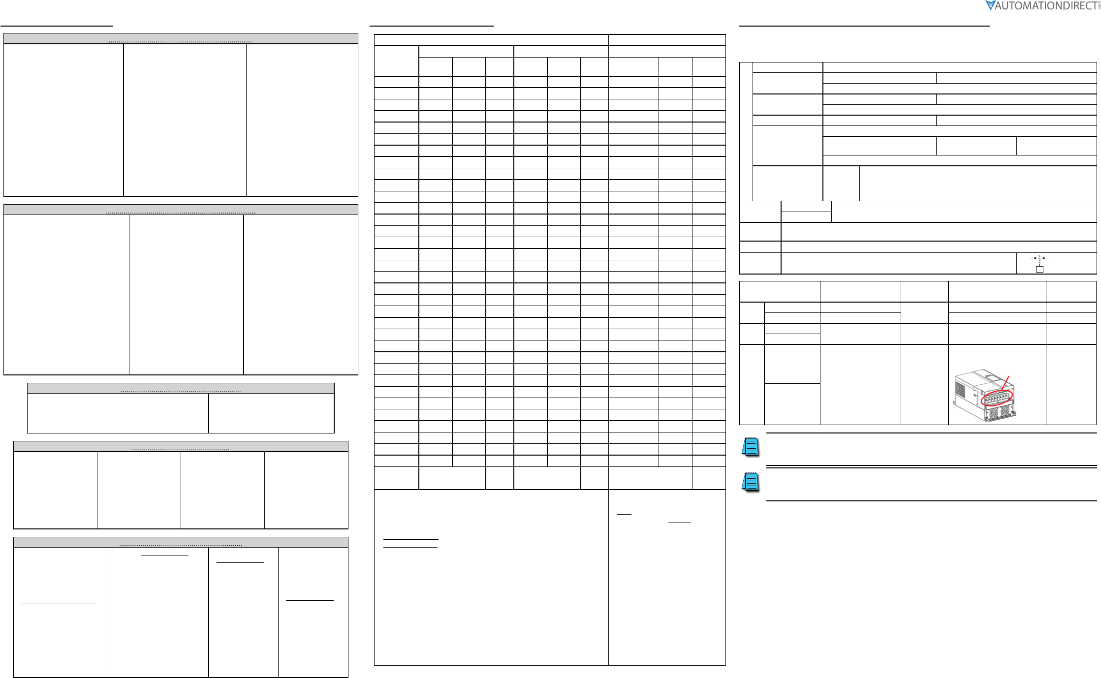
Cooling and Heat Dissipation
Airflow Rate for Cooling Power Dissipation
Model
Number
Flow Rate (cfm) Flow Rate (m3/hr) Power Dissipation (Watt)
External Internal Total External Internal Total Loss External
(Heat sink) Internal Total
GS4-21P0 – – – – – – 33 27 61
GS4-22P0 14 – 14 24 – 24 56 31 88
GS4-23P0 14 – 14 24 – 24 79 36 115
GS4-25P0 10 – 10 17 – 17 113 46 159
GS4-27P5 40 14 54 68 24 92 197 67 264
GS4-2010 66 14 80 112 24 136 249 86 335
GS4-2015 58 14 73 99 24 124 409 121 529
GS4-2020 166 12 178 282 20 302 455 161 616
GS4-2025 166 12 178 282 20 302 549 184 733
GS4-2030 166 12 178 282 20 302 649 216 865
GS4-2040 179 30 209 304 51 355 913 186 1099
GS4-2050 179 30 209 304 51 355 1091 220 1311
GS4-2060 228 73 301 387 124 511 1251 267 1518
GS4-2075 228 73 301 387 124 511 1401 308 1709
GS4-2100 246 73 319 418 124 542 1770 369 2139
GS4-41P0 – – – – – – 33 25 59
GS4-42P0 – – – – – – 45 29 74
GS4-43P0 14 – 14 24 – 24 71 33 104
GS4-45P0 10 – 10 17 – 17 103 38 141
GS4-47P5 10 – 10 17 – 17 134 46 180
GS4-4010 40 14 54 68 24 92 216 76 292
GS4-4015 66 14 80 112 24 136 287 93 380
GS4-4020 58 14 73 99 24 124 396 122 518
GS4-4025 99 21 120 168 36 204 369 138 507
GS4-4030 99 21 120 168 36 204 476 158 635
GS4-4040 126 21 147 214 36 250 655 211 866
GS4-4050 179 30 209 304 51 355 809 184 993
GS4-4060 179 30 209 304 51 355 929 218 1147
GS4-4075 179 30 209 304 51 355 1156 257 1413
GS4-4100 186 30 216 316 51 367 1408 334 1742
GS4-4125 257 73 330 437 124 561 1693 399 2092
GS4-4150 223 73 296 379 124 503 2107 491 2599
GS4-4175 224 112 336 381 190 571 2502 579 3081
GS4-4200 289 112 401 491 190 681 3096 687 3783
GS4-4250 –454 –771 –4589
GS4-4300 454 771 5772
• External Flow Rate is across the heat sink.
• Internal Flow Rate is through the chassis.
• Published flow rates are the result of active cooling using fans, factory
installed in the drive.
• Unpublished flow rates ( - ) are the result of passive cooling in drives
without factory installed fans.
• The required airflow shown in the chart is for installing a single GS4 drive
in a confined space.
• When installing multiple GS4 drives, the required air volume would be
the required air volume for a single GS4 drive multiplied by the number
of GS4 drives.
• When calculating power
dissipation (Watt Loss), use the
Total value if the drive is foot
mounted, or the Internal value
if the drive is flange mounted.
Where only a total value is
published, these models cannot be
flange mounted. Heat dissipation
shown in the chart is for installing
a single GS4 drive in a confined
space.
• When installing multiple drives,
the volume of heat/power
dissipation should be the heat/
power dissipated by a single GS4
drive multiplied by the number of
GS4 drives.
• Heat dissipation for each model
is calculated by rated voltage,
current and default carrier
frequency.
Environment for Operation, Storage, and Transportation
DO NOT expose the GS4 drive to environments that contain dust, direct sunlight, corrosive/inflammable gases,
high humidity, liquids, or high vibration. The salt in the air must be less than 0.01 mg/cm2 throughout the
year.
Environment
Installation Location IEC60364-1/IEC60664-1 Pollution degree 2, Indoor use only
Surrounding
Temperature
Storage: -25°C to +70°C Transportation: -25°C to +70°C
Non-condensation, non-frozen
Rated Humidity Operation: Max. 90% Storage/Transportation: Max. 95%
No condense water
Air Pressure Operation/Storage: 86 to 106 kPa Transportation: 70 to 106 kPa
Pollution Level
IEC721-3-3
Operation:
Class 3C2; Class 3S2
Storage:
Class 2C2; Class 2S2
Transportation:
Class 1C2; Class 1S2
No concentrate
Altitude Operation
If the GS4 drive is installed at altitudes of 0~1000m, follow normal operation
restriction. If installed at altitudes of 1000~3000m, decrease 2% of rated
current or lower 0.5°C of temperature for every 100m increase in altitude.
Maximum altitude for Corner Grounded is 2000m.
Package
Drop
Storage ISTA procedure 1A (according to weight) IEC60068-2-31
Transportation
Vibration 1.0mm, peak-to-peak value range from 2Hz to 13.2 Hz; 0.7G~1.0G range from 13.2Hz to 55Hz; 1.0G
range from 55Hz to 512 Hz. Comply with IEC 60068-2-6.
Impact IEC/EN 60068-2-27
Operation
Position Max. allowed offset angle ±10° (under normal installation position)
10° 10°
Frame Top cover Conduit Box Protection Level Operation
Temperature
A~C 230V: 1.0~30HP With top cover removed Standard
conduit plate
IP20 / UL Open Type -10~50°C
460V: 1.0~40HP With top cover in place IP20 / UL Type1 / NEMA1 -10~40°C
D0~G 230V: >30HP N/A With conduit
box IP20 / UL Type1 / NEMA1 -10~40°C
460V: >40HP
D0~G
230V: >30HP
N/A Without
conduit box
IP00 / IP20 / UL Open Type
Only the circled area is IP00.
Other parts
are IP20.
-10~50°C
460V: >40HP
To prevent personal injury, please make sure that the case and wiring are installed according to these
instructions. The figures in these instructions are only for reference. They may be slightly different from
the one you have, but it will not affect your customer rights.
These installation instructions may be revised without prior notice. The most recent edition can be
downloaded from the AutomationDirect web site at any time:
http://www.automationdirect.com/static/manuals/index.html.
Page 6
DURApulse GS4 AC Drive Quick-Start Guide – 1st Ed, Rev.B 09/19/2017
DURApulse GS4 AC Drive Quick-Start Guide
GS4_QSP_1edRevB 09/19/2017
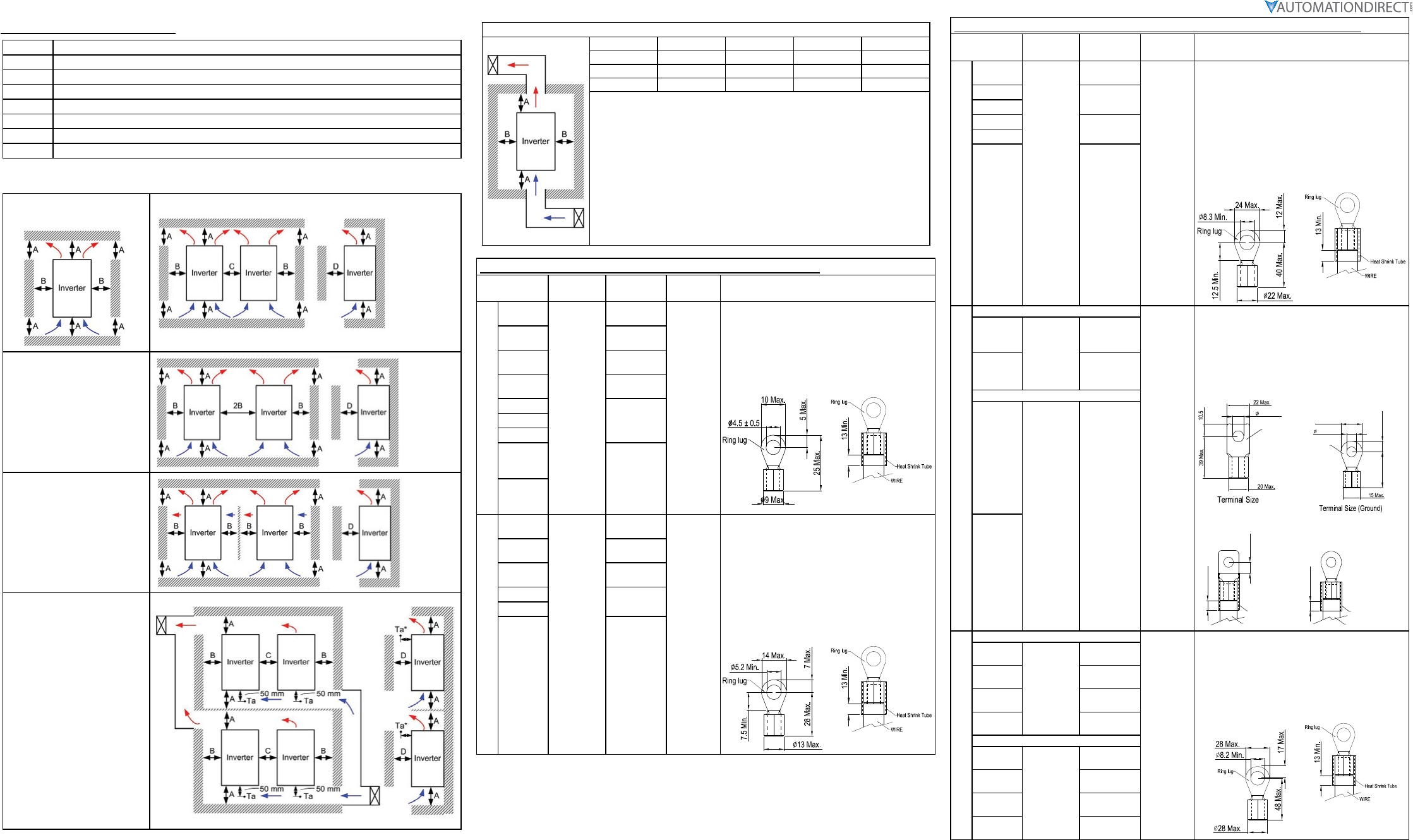
Minimum Mounting Clearances
Frame A GS4-21P0; GS4-41P0; GS4-22P0; GS4-42P0; GS4-23P0; GS4-43P0; GS4-25P0; GS4-45P0; GS4-47P5
Frame B GS4-27P5; GS4-2010; GS4-4010; GS4-2015; GS4-4015; GS4-4020
Frame C GS4-2020; GS4-2025; GS4-4025; GS4-2030; GS4-4030; GS4-4040
Frame D0 GS4-4050; GS4-4060
Frame D GS4-2040; GS4-2050; GS4-4075; GS4-4100
Frame E GS4-2060; GS4-2075; GS4-2100; GS4-4125; GS4-4150
Frame F GS4-4175; GS4-4200
Frame G GS4-4250; GS4-4300
← (Blue Arrow) Inflow ← (Red Arrow) Outflow
(Frame A~G)
Single drive:
Independent installation.
(Frame A, B, C, G)
Multiple drives:
Independent horizontal installation.
(Frame D0, D, E, F)
Multiple drives:
Independent horizontal installation.
Install a barrier between the drives.
(Frame A~G)
Multiple drives:
Independent installation.
Ta: Frame A~G
(inflow air temperature)
It is suggested to install a barrier
between the drives. Adjust
the size of the barrier until the
temperature of the fan on the
inflow side is lower than the
operation temperature. This barrier
is to prevent the lower drives’ hot
exhaust from going straight into
the upper drives’ intake.
(Refer to the right figure)
Operation temperature is the
temperature measured 50mm away
from the inflow side of the fan.
Minimum Mounting Clearance
Frame A (mm / in) B (mm / in) C (mm / in) D (mm / in)
A~C 60 / 2.4 30 / 1.2 10 / 0.4 0 / 0
D0~F 100 / 4.0 50 / 2.0 n/a 0 / 0
G 200 / 7.9 100 / 4.0 n/a 0 / 0
Note:
• The mounting clearances shown in figure to the left are NOT for installing the
GS4 drive in a confined space (such as cabinet or electric box). When installed in
a confined space, in addition to the minimum mounting clearances, ventilation
equipment or air conditioning should be installed to keep the surrounding
temperature lower than the operation temperature.
• The following table shows heat dissipation and required air volume when installing
a single GS4 drive in a confined space. When installing multiple drives, the required
air volume shall be multiplied by the number of GS4 drives.
• Refer to the chart (Air flow rate for cooling) for ventilation equipment design and
selection.
• Refer to the chart (Power Dissipation) for air conditioner design and selection.
• If GS4 drives in frames sizes A thru D are installed with clearance dimensions less
than specified, the cooling fans in these models may not adequately cool the drive.
Specifications for Wiring Terminals – Main-Circuit Terminals
Drive Models Max Wire
Gauge
Min Wire
Gauge
Torque
(±10%) Note
Frame A
GS4-21P0
8 AWG
(8.4 mm2)
14 AWG
(2.1 mm2)
M4
20 kg·cm
(17.4 lb·in)
(1.96 N·m)
UL installations must use 600V, 75°C or 90°C wire.
Please use copper wire only.
(Fig. 1) The usage of ring terminals should comply
with this specification.
(Fig. 2) The figure shows the specification of insulated
heat shrink tubing that complies with UL
(600C, YDPU2).
Figure 1: Figure 2:
GS4-22P0 12 AWG
(3.3 mm2)
GS4-23P0 10 AWG
(5.3 mm2)
GS4-25P0 8 AWG
(8.4 mm2)
GS4-41P0
14 AWG
(2.1 mm2)
GS4-42P0
GS4-43P0
GS4-45P0
10 AWG
(5.3 mm2)
GS4-47P5
Frame B
GS4-27P5
4 AWG
(21.2 mm2)
8 AWG
(8.4 mm2)
M5
35 kg·cm
(30.4 lb·in)
(3.43 N·m)
Terminal D+[+2 & +1]: Torque 45 Kg·cm [39.0 lb·in]
(4.415 N·m) (±10%)
Use 600V, 90°C wire for UL installation of GS4-2015
install if ambient temperature exceeds 45°C.
UL installations of other models must use 600V, 75°C
or 90°C wire. Please use copper wire only.
(Fig. 1) The usage of ring terminals should comply
with this specification.
(Fig. 2) The figure shows the specification of insulated
heat shrink tubing that complies with UL
(600C, YDPU2).
Figure 1: Figure 2:
GS4-2010 6 AWG
(13.3 mm2)
GS4-2015 4 AWG
(21.2 mm2)
GS4-4010 8 AWG
(8.4 mm2)
GS4-4015
GS4-4020 6 AWG
(13.3 mm2)
Specifications for Wiring Terminals – Main-Circuit Terminals (continued)
Drive Models Max Wire
Gauge
Min Wire
Gauge
Torque
(±10%) Note
Frame C
GS4-2020
1/0 AWG
(53.5 mm2)
1 AWG
(42.4 mm2)
M8
80 kg·cm
(69.4 lb·in)
(7.85 N·m)
Terminal D+[+2 & +1]: Torque 90 Kg-cm [78.2 lb-in.]
(8.83Nm) (±10%)
Use 600V, 90°C wire for UL installation of GS4-2030
install if ambient temperature exceeds 40°C.
UL installations of other models must use 600V, 75°C
or 90°C wire. Please use copper wire only.
(Fig. 1) The usage of ring terminals should comply
with this specification.
(Fig. 2) The figure shows the specification of insulated
heat shrink tubing that complies with UL (600C,
YDPU2).
Figure 1: Figure 2:
GS4-2025 1/0 AWG
(53.5 mm2)
GS4-2030
GS4-4025 4 AWG
(21.2 mm2)
GS4-4030
GS4-4040 2 AWG
(33.6 mm2)
Frame D0
For models without conduit box
M8
81.6 kg·cm
(70.8 lb·in)
(8N·m)
UL installations must use 600V, 75°C or 90°C wire.
Please use copper wire only.
(Fig. 1) The usage of ring terminals should comply
with this specification.
(Fig. 2) Ground wire spec: 2AWG*2 [33.6mm2*2]
(Fig. 3) The figure shows the specification of insulated
heat shrink tubing that complies with UL
(600C, YDPU2).
GS4-4050
2/0 AWG
(67.4 mm2)
1/0 AWG
(53.5 mm2)
GS4-4060 2/0 AWG
(67.4 mm2)
For models with conduit box Figure 1:
+0
-2
8.2 Min.
Ring lug
Figure 2:
Ring lug
22 Max.
8.2 Min.
11 Max.
32 Max.
GS4-4050
2/0 AWG
(67.4 mm2)
1/0 AWG
(53.5 mm2)
GS4-4060
Figure 3:
WIRE
Heat Shrink Tube
13 Min.
WIRE
Heat Shrink Tube
13 Min.
13¡ Ó1.5
Frame D
For models without conduit box
M8
200 kg·cm
(173 lb·in)
(19.62 N·m)
UL installations must use 600V, 75°C or 90°C wire.
Please use copper wire only.
(Fig. 1) The usage of ring terminals should comply
with this specification.
(Fig. 2) The figure shows the specification of insulated
heat shrink tubing that complies with UL
(600C, YDPU2).
Figure 1:
Figure 2:
GS4-2040
300 MCM
(152 mm2)
4/0 AWG
(107 mm2)
GS4-2050 250 MCM
(127 mm2)
GS4-4075 3/0 AWG
(85mm2)
GS4-4100 300 MCM
(152 mm2)
For models with conduit box
GS4-2040
4/0 AWG
(107 mm2)
3/0 AWG
(85 mm2)
GS4-2050 4/0 AWG
(107 mm2)
GS4-4075 2/0 AWG
(67.4 mm2)
GS4-4100 4/0 AWG
(107 mm2)
Page 7
DURApulse GS4 AC Drive Quick-Start Guide – 1st Ed, Rev.B 09/19/2017
DURApulse GS4 AC Drive Quick-Start Guide
GS4_QSP_1edRevB 09/19/2017
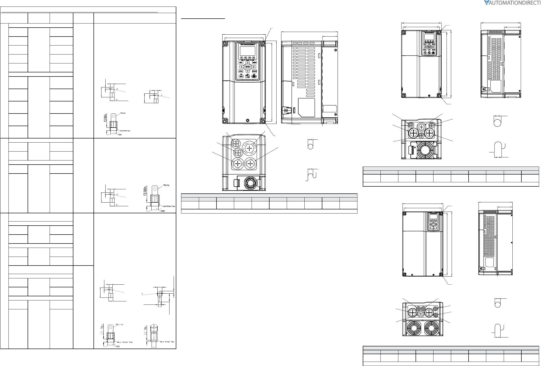
Specifications for Wiring Terminals – Main-Circuit Terminals (continued)
Drive Models Max Wire
Gauge
Min Wire
Gauge
Torque
(±10%) Note
Frame E
For models without conduit box
M8
200 kg·cm
(173 lb·in)
(19.62 N·m)
UL installations must use 600V, 75°C or 90°C wire.
Please use copper wire only.
(Fig. 1) The usage of ring terminals should comply
with this specification.
(Fig. 2) Grounding wire specification:
• 300MCM*2 [152 mm2*2]
• Torque M8 180 kg·cm
[156 lb·in] (17.64 N·m) (±10%)
(Fig. 3) The figure shows the specification of insulated
heat shrink tubing that complies with UL
(600C, YDPU2).
Figure 1:
31MAX.
8.2MIN.
26.5MAX.
70MAX.
16
+0
-4
Figure 2:
8.2MIN.
65.0MAX.
17.0MAX.
28.0MAX.
Figure 3:
GS4-2060
300 MCM*2
(152 mm2*2)
1/0 AWG*2
(53.5 mm2*2)
GS4-2075 3/0 AWG*2
(85 mm2*2)
GS4-2100 4/0 AWG*2
(107 mm2*2)
GS4-4125 1/0 AWG*2
(53.5 mm2*2)
GS4-4150 3/0 AWG*2
(85 mm2*2)
For models with conduit box
GS4-2060
4/0 AWG*2
(107 mm2*2)
1/0 AWG*2
(53.5 mm2*2)
GS4-2075 2/0 AWG*2
(67.4 mm2*2)
GS4-2100 3/0 AWG*2
(85 mm2*2)
GS4-4125 1/0 AWG*2
(53.5 mm2*2)
GS4-4150 2/0 AWG*2
(67.4 mm2*2)
Frame F
For models without conduit box
M8
200kg·cm
(173 lb·in)
(19.62 N·m)
UL installations must use 600V, 75°C or 90°C wire.
Please use copper wire only.
Grounding wire specification:
300MCM*2 [152 mm2*2].
(Fig. 1) The usage of ring terminals should comply
with this specification.
(Fig. 2) The figure shows the specification of insulated
heat shrink tubing that complies with UL
(600C, YDPU2).
Figure 1:
31MAX.
8.2MIN.
26.5MAX.
70MAX.
16
+0
-4
Figure 2:
GS4-4175 300 MCM*2
(152 mm2*2)
4/0 AWG*2
(107 mm2*2)
GS4-4200 300 MCM*2
(152 mm2*2)
For models with conduit box
GS4-4175
4/0 AWG*2
(107 mm2*2)
3/0 AWG*2
(85mm2*2)
GS4-4200 4/0 AWG*2
(107 mm2*2)
Frame G
For main circuit terminals:
R/L11, R/L12, S/L21, S/L22, T/L31, T/L32
M8
200 kg·cm
(173 lb·in)
(19.62 N·m)
Use 600V, 90°C wired for UL installation for GS4-4300;
install in ambient temperature that exceeds 45°C.
UL installations of other models must use 600V, 75°C
or 90°C wire.
Please use copper wire only.
(Fig. 1) The usage of ring terminals for R/L11, R/L12,
S/L21, S/L22, T/L31, and T/L32 should comply
with this specification.
(Fig. 2) The usage of ring terminals for U/T1, V/T2, W/
T3, +1/DC+, and -/DC- should comply with
this specification.
(Fig. 3 & 4) The figure shows the specification of
insulated heat shrink tubing that complies
with UL (600C, YDPU2).
Figure 1:
31MAX.
Ø8.2MIN.
Ø26.5MAX.
54MAX.
16
+0
-4
Figure 2:
42.0(MAX.)
12.2(MIN.)
21.0(MAX.)
70.0(MAX.)
42.0(MAX.)
Figure 3:
Figure 4:
For models without conduit box
GS4-4250 300 MCM*4
(152 mm2*4)
2/0 AWG*4
(67.4 mm2*4)
GS4-4300 3/0 AWG*4
(85mm2*4)
For models with conduit box
GS4-4250 300 MCM*4
(152 mm2*4)
1/0 AWG*4
(53.5 mm2*4)
GS4-4300 2/0 AWG*4
(67.4 mm2*4)
For main circuit terminals:
U/T1, V/T2, W/T3, +1/DC+, -/DC-
M12
408 kg·cm
(354 lb·in)
(40 N·m)
For models without conduit box
GS4-4250 500 MCM*2
(253 mm2*2)
400 MCM*2
(203 mm2*2
GS4-4300 500 MCM*2
(253mm2*2)
For model with conduit box
GS4-4250
500 MCM*2
(253 mm2*2)
300 MCM*2
(152 mm2*2)
GS4-4300 400 MCM*2
(203 mm2*2)
Dimension Diagrams
GS4 Frame A
Units = mm [in]
W1
W
H1
H
D
Ø3
Ø3
D1
Ø1
Ø1
Ø2
S1
S1
See Detail A
See Detail B
Detail A (Mounting Hole)
Detail B (Mounting Hole)
Frame A: GS4-21P0; GS4-22P0, GS4-23P0, GS4-25P0, GS4-41P0, GS4-42P0, GS4-43P0, GS4-45P0, GS4-47P5
W H D W1 H1 D1* S1 Φ1 Φ2 Φ3
130.0
[5.12]
250.0
[9.84]
170.0
[6.69]
116.0
[4.57]
236.0
[9.29]
45.8
[1.80]
6.2
[0.24]
22.2
[0.87]
34.0
[1.34]
28.0
[1.10]
*D1 = Flange mounting.
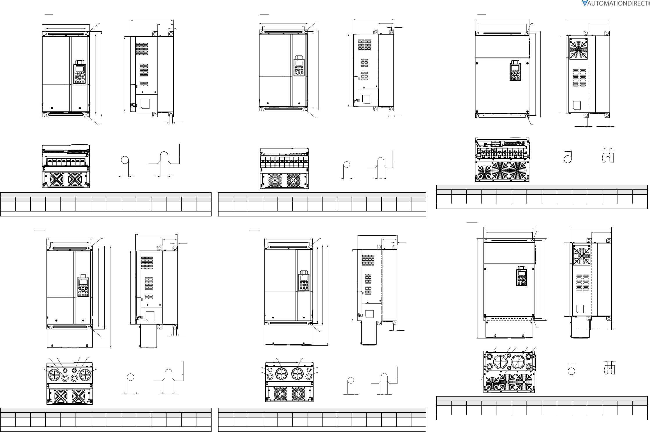
Dimension Diagrams
GS4 Frame B
Units = mm [in]
Detail A (Mounting Hole)
Detail B (Mounting Hole)
See Detail A
See Detail B
S1
S1
D1
Ø3
Ø1
Ø2
Ø1
Ø3
Ø1
D
W
H
W1
H1
Frame B: GS4-27P5, GS4-2010, GS4-2015, GS4-4010, GS4-4015, GS4-4020
W H D W1 H1 D1* S1 Φ1 Φ2 Φ3
190.0
[7.48]
320.0
[12.60]
190.0
[7.48
173.0
[6.81]
303.0
[11.93]
77.9
[3.07]
8.5
[0.33
22.2
[0.87]
34.0
[1.34]
28.0
[1.10]
*D1 = Flange mounting.
GS4 Frame C
Units = mm [in]
W1
W
H1
H
D
Ø1
Ø1
Ø3
Ø1
Ø1
Ø2
Ø3
D1
S1
S1
Detail A (Mounting Hole)
Detail B (Mounting Hole)
See Detail A
See Detail B
Frame C: GS4-2020, GS4-2025, GS4-2030, GS4-4025, GS4-4030, GS4-4040
W H D W1 H1 D1* S1 Φ1 Φ2 Φ3
250.0
[9.84]
400.0
[15.75]
210.0
[8.27]
231.0
[9.09]
381.0
[15.00]
92.9
[3.66]
8.5
[0.33]
22.2
[0.87]
34.0
[1.34]
34.0
[1.34]
*D1 = Flange mounting.
Page 8
DURApulse GS4 AC Drive Quick-Start Guide – 1st Ed, Rev.B 09/19/2017
DURApulse GS4 AC Drive Quick-Start Guide
GS4_QSP_1edRevB 09/19/2017
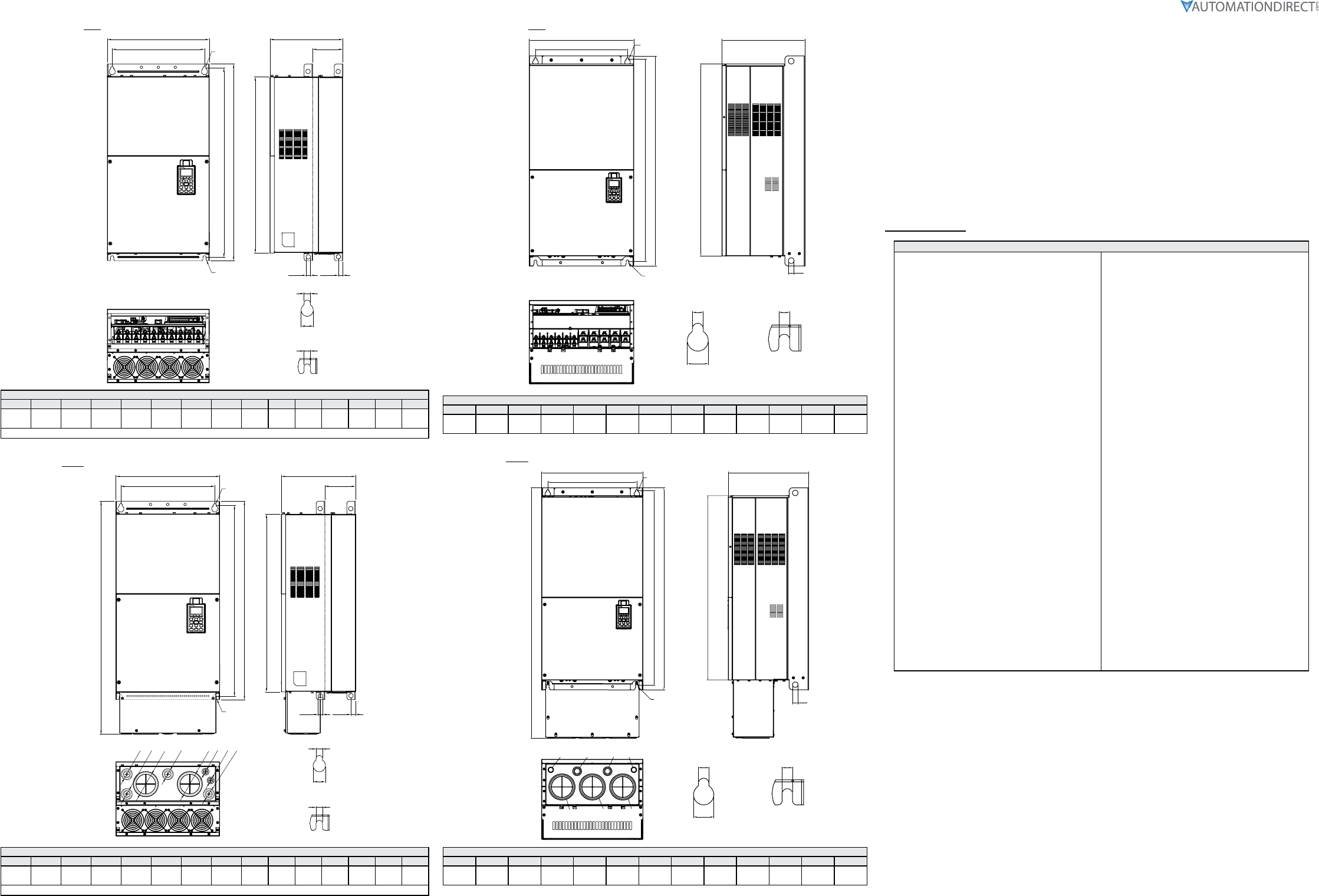
GS4 Frame D0 (without conduit box)
Units = mm [in]
S1
S1
DETAIL A
(MOUNTING HOLE)
DETAIL B
(MOUNTING HOLE)
W
W1
H1
H2
SEE DETAIL A
SEE DETAIL B
D
D1
S2
D2
H3
Frame D0: GS4-4050, GS4-4060
W H D W1 H1 H2 H3 D1* D2 S1 S2 Φ1 Φ2 Φ3
280.0
[11.02] –255.0
[10.04]
235.0
[9.25]
500.0
[19.69]
475.0
[18.70]
442.0
[17.40]
94.2
[3.71]
16.0
[0.63]
11.0
[0.43]
18.0
[0.71] –––
*D1 = Flange mounting.
GS4 Frame D0 (with conduit box)
Units = mm [in]
W
W1
H
H1
H2
SEE DETAIL A
SEE DETAIL B
D
D1
S2
D2
H3
S1
S1
DETAIL A
(MOUNTING HOLE)
DETAIL B
(MOUNTING HOLE)
Ø1
Ø2
Ø3
Ø3
Ø2
Ø1
Frame D0 – with Conduit Box (Option): GS4-4050, GS4-4060
W H D W1 H1 H2 H3 D1* D2 S1 S2 Φ1 Φ2 Φ3
280.0
[11.02]
614.4
[24.19]
255.0
[10.04]
235.0
[9.25]
500.0
[19.69]
475.0
[18.70]
442.0
[17.40]
94.2
[3.71]
16.0
[0.63]
11.0
[0.43]
18.0
[0.71]
62.7
[2.47]
34.0
[1.34]
22.0
[0.87]
*D1 = Flange mounting.
GS4 Frame D (without conduit box)
Units = mm [in]
W
W1
H1
H2
S1S1
SEE DETAIL A
DETAIL A
(MOUNTING HOLE)
DETAIL B
(MOUNTING HOLE)
SEE DETAIL B
D
H3
D1
S2
D2
Frame D: GS4-2040, GS4-2050, GS4-4075, GS4-4100
W H D W1 H1 H2 H3 D1* D2 S1 S2 Φ1 Φ2 Φ3
330.0
[12.99] –275.0
[10.83]
285.0
[11.22]
550.0
[21.65
525.0
[20.67]
492.0
[19.37
107.2
[4.22]
16.0
[0.63]
11.0
[0.43]
18.0
[0.71] –––
*D1 = Flange mounting.
GS4 Frame D (with conduit box)
Units = mm [in]
W
W1
Ø1
Ø2
Ø3
H
H1
H2
S1S1
SEE DETAIL A
DETAIL A
(MOUNTING HOLE)
DETAIL B
(MOUNTING HOLE)
SEE DETAIL B
Ø3
Ø2
Ø1
D
H3
D1
S2
D2
Frame D – with Conduit Box (Option): GS4-2040, GS4-2050, GS4-4075, GS4-4100
W H D W1 H1 H2 H3 D1* D2 S1 S2 Φ1 Φ2 Φ3
330.0
[12.99]
688.3
[27.10]
275.0
[10.83]
285.0
[11.22]
550.0
[21.65
525.0
[20.67]
492.0
[19.37
107.2
[4.22]
16.0
[0.63]
11.0
[0.43]
18.0
[0.71]
76.2
[3.00]
34.0
[1.34]
22.0
[0.87]
*D1 = Flange mounting.
GS4 Frame E (without conduit box)
Units = mm [in]
W1
W
H2
H1
H3
D1
D
See Detail A
See Detail B
Detail A
(Mounting Hole)
Detail B
(Mounting Hole)
S3 D2
S1 S2
Frame E: GS4-2060, GS4-2075, GS4-2100, GS4-4125, GS4-4150
W H D W1 H1 H2 H3 D1* D2 S1,S2 S3 Φ1 Φ2 Φ3
370.0
[14.57] –300.0
[11.81]
335.0
[13.19]
589
[23.19]
560.0
[22.05]
528.0
[20.80]
143.0
[5.63]
18.0
[0.71]
13.0
[0.51]
18.0
[0.71] – – –
*D1 = Flange mounting.
GS4 Frame E (with conduit box)
Units = mm [in]
W1
W
H2
H1
H3
H
D1
D
See Detail A
See Detail B
Detail A
(Mounting Hole)
Detail B
(Mounting Hole)
S1 S2
S3 D2
Ø2
Ø3
Ø1
Ø3
Ø2
Ø2
Ø1
Ø2
Frame E – with Conduit Box (Option): GS4-2060, GS4-2075, GS4-2100, GS4-4125, GS4-4150
W H D W1 H1 H2 H3 D1* D2 S1,S2 S3 Φ1 Φ2 Φ3
370.0
[14.57]
715.8
[28.18]
300.0
[11.81]
335.0
[13.19]
589
[23.19]
560.0
[22.05]
528.0
[20.80]
143.0
[5.63]
18.0
[0.71]
13.0
[0.51]
18.0
[0.71]
22.0
[0.87]
34.0
[1.34]
92.0
[3.62]
*D1 = Flange mounting.
Page 9
DURApulse GS4 AC Drive Quick-Start Guide – 1st Ed, Rev.B 09/19/2017
DURApulse GS4 AC Drive Quick-Start Guide
GS4_QSP_1edRevB 09/19/2017
GS4 Frame F (without conduit box)
Units = mm [in]
H1
H2
S1
S1
W
W1
S2
See Detail A
See Detail B
Detail A (Mounting Hole)
Detail B (Mounting Hole)
D2
D
D1
H3
S3
Frame F: GS4-4175, GS4-4200
W H D W1 H1 H2 H3 D1* D2 S1 S2 S3 Φ1 Φ2 Φ3
420.0
[16.54] –300.0
[11.81]
380.0
[14.96]
800.0
[31.50]
770.0
[30.32]
717.0
[28.23]
124.0
[4.88]
18.0
[0.71]
13.0
[0.51]
25.0
[0.98]
18.0
[0.71] – – –
*D1 = Flange mounting.
GS4 Frame F (with conduit box)
Units = mm [in]
H1
H2
S1
S1
D2
W
W1
D
D1
H3
H
S2
S3
Ø3
Ø2
Ø1
Ø2
Ø2
Ø
2
Ø3
Ø1
See Detail A
See Detail B
Detail A (Mounting Hole)
Detail B (Mounting Hole)
Frame F – with Conduit Box (Option): GS4-4175, GS4-4200
W H D W1 H1 H2 H3 D1* D2 S1 S2 S3 Φ1 Φ2 Φ3
420.0
[16.54]
940.0
[37.00]
300.0
[11.81]
380.0
[14.96]
800.0
[31.50]
770.0
[30.32]
717.0
[28.23]
124.0
[4.88]
18.0
[0.71]
13.0
[0.51]
25.0
[0.98]
18.0
[0.71]
92.0
[3.62]
35.0
[1.38]
22.0
[0.87]
*D1 = Flange mounting.
GS4 Frame G (without conduit box)
Units = mm [in]
W1
W
H2
H1
H3
D
S3
See Detail A
See Detail B
Detail A
(Mounting Hole)
Detail B
(Mounting Hole)
S1 S1
S2
Frame G: GS4-4250, GS4-4300
W H D W1 H1 H2 H3 S1 S2 S3 Φ1 Φ2 Φ3
500.0
[19.69] –397.0
[15.63]
440.0
[217.32]
1000.0
[39.37]
963.0
[37.91]
913.6
[35.97]
13.0
[0.51]
26.5
[1.04]
27.0
[1.06] –––
GS4 Frame G (with conduit box)
Units = mm [in]
W1
W
H2
H1
H
H3
D
S3
See Detail A
See Detail B
Detail A
(Mounting Hole)
Detail B
(Mounting Hole)
S1
S2
S1
Ø1 Ø2 Ø2 Ø1
Ø3 Ø3 Ø3
Frame G – with Conduit Box (Option): GS4-4250, GS4-4300
W H D W1 H1 H2 H3 S1 S2 S3 Φ1 Φ2 Φ3
500.0
[19.69]
1240.2
[48.83]
397.0
[15.63]
440.0
[217.32]
1000.0
[39.37]
963.0
[37.91]
913.6
[35.97]
13.0
[0.51]
26.5
[1.04]
27.0
[1.06]
22.0
[0.87]
34.0
[1.34]
117.5
[4.63]
GS4 Fault Codes
Fault Codes
0: No Error
1: Overcurrent during Accel (ocA)
2: Overcurrent during Decel (ocd)
3: Overcurrent during normal speed (ocn)
4: Ground Fault (GFF)
5: IGBT short circuit (occ)
6: Overcurrent during Stop (ocS)
7: Overvoltage during Accel (ovA)
8: Overvoltage during Decel (ovd)
9: Overvoltage during normal speed (ovn)
10: Overvoltage during Stop (ovS)
11: Low voltage during Accel (LvA)
12: Low voltage during Decel (Lvd)
13: Low voltage during normal speed (Lvn)
14: Low voltage during Stop (LvS)
15: Input phase loss (OrP)
16: IGBT Overheat 1 (oH1)
17: Cap Overheat 2 (oH2)
18: Thermister 1 open (tH1o)
19: Thermister 2 open (tH2o)
20: Power Reset Off (PWR)
21: Overload (oL) (150% 1Min, Inverter)
22: Motor1 Thermal Overload (EoL1)
23: Motor2 Thermal Overload (EoL2)
24: Motor Overheat-PTC (oH3)
25: reserved
26: Over Torque 1 (ot1)
27: Over Torque 2 (ot2)
28: Under current (uc)
29: reserved
30: EEPROM write error (cF1)
31: EEPROM read error (cF2)
32: reserved
33: U phase current sensor detection error (cd1)
34: V phase current sensor detection error (cd2)
35: W phase current sensor detection error (cd3)
36: CC Hardware Logic error 0 (Hd0)
37: OC Hardware Logic error 1 (Hd1)
38: OV Hardware Logic error 2 (Hd2)
39: OCC Hardware Logic error 3 (Hd3)
40: Motor auto tune error (AuE)
41: PID Feedback loss (AFE)
42~47: reserved
48: Analog input signal loss (ACE)
49: External Fault (EF)
50: Emergency Stop (EF1)
51: Base Block (bb)
52: Password Error (Pcod)
53: Software Code lock (ccod)
54: PC Command error (CE1)
55: PC Address error (CE2)
56: PC Data error (CE3)
57: PC Slave error (CE4)
58: PC Communication Time Out (CE10)
59: PC Keypad Time out (CP10)
60: Braking Transistor Fault (bf)
61: Y-Delta connection Error (ydc)
62: Decel Energy Backup Error (dEb)
63: Over Slip Error (oSL)
64: Electromagnet switch error (ryF)
65~71: reserved
72: STO Loss1 (STL1)
STO1~SCM1 internal hardware detect error
73: ES1 Emergency Stop (S1)
74: In Fire Mode (Fire)
75: reserved
76: Safety Torque Off function active (STO)
77: STO Loss2 (STL2)
STO2~SCM2 internal hardware detect error
78: STO Loss3 (STL3) – STO1~SCM1 and STO2~SCM2
internal hardware detect errors
79: U Phase Short (Uoc)
80: V Phase Short (Voc)
81: W Phase Short (Woc)
82: U Phase Loss (UPHL)
83: V Phase Loss (VPHL)
84: W Phase Loss (WPHL)
85~89: reserved
90: PLC Force Stop (FStp)
91~98: reserved
99: CPU Command error (TRAP)
100~110: reserved
111: reserved
