Product Detail Manual GW
User Manual: gw
Open the PDF directly: View PDF ![]() .
.
Page Count: 122 [warning: Documents this large are best viewed by clicking the View PDF Link!]
- QUICK REFERENCE INDEX
- Table of Contents
- PRECAUTIONS
- PREPARATION
- SQUEAK AND RATTLE TROUBLE DIAGNOSES
- WINDSHIELD GLASS
- POWER WINDOW SYSTEM
- Component Parts and Harness Connector Location
- System Description
- CAN Communication System Description
- CAN Communication Unit
- Schematic
- Wiring Diagram — WINDOW —
- Terminal and Reference Value for BCM
- Terminal and Reference Value for Power Window Main Switch
- Terminal and Reference Value for (Front and Rear) Power Window Sub-Switch
- CONSULT-II Function (BCM)
- Work Flow
- Trouble Diagnosis Symptom Chart
- BCM Power Supply and Ground Circuit Check
- Power Window Main Switch Power Supply Circuit Check
- Power Window Sub-Switch (Front Passenger Side) Power Supply and Ground Circuit Check
- Power Window Sub-Switch (Rear LH or RH) Power Supply and Ground Circuit Check
- Power Window Motor (Front Driver Side) Circuit Check
- Power Window Motor (Front Passenger Side) Circuit Check
- Power Window Motor (Rear LH or RH) Circuit Check
- Encoder Circuit Check (Driver Side)
- Encoder Circuit Check (Passenger Side)
- Encoder Circuit Check (Rear LH or RH)
- Door Switch Check
- Front Door Key Cylinder Switch Check
- Power Window Serial Link Check (Passenger Side)
- Power Window Serial Link Check (Rear LH or RH)
- Power Window Lock Switch Check
- SIDE WINDOW GLASS
- REAR WINDOW GLASS AND MOLDING
- FRONT DOOR GLASS AND REGULATOR
- REAR DOOR GLASS AND REGULATOR
- INSIDE MIRROR
- REAR WINDOW DEFOGGER
- Component Parts and Harness Connector Location
- System Description
- CAN Communication System Description
- CAN Communication Unit
- Schematic
- Wiring Diagram — DEF —
- Terminal and Reference Value for BCM
- Terminal and Reference Value for IPDM E/R
- CONSULT-II Inspection Procedure
- Work Flow
- Trouble Diagnoses Symptom Chart
- BCM Power Supply and Ground Circuit Check
- Rear Window Defogger Switch Circuit Check
- Rear Window Defogger Power Supply Circuit Check
- Rear Window Defogger Circuit Check
- Door Mirror Defogger Power Supply Circuit Check
- Driver Side Door Mirror Defogger Circuit Check
- Passenger Side Door Mirror Defogger Circuit Check
- Filament Check
- Filament Repair
- REVERSE INTERLOCK DOOR MIRROR SYSTEM
- Component Parts and Harness Connector Location
- System Description
- CAN Communication System Description
- CAN Communication Unit
- Schematic
- Wiring Diagram —MIRROR—
- Terminals and Reference Values for Automatic Drive Positioner Control Unit
- Terminals and Reference Values for Driver Seat Control Unit
- CONSULT-II Function (AUTO DRIVE POS.)
- Work Flow
- Symptom Chart
- Check Changeover Switch Circuit
- Check Mirror Switch Circuit Check
- Check Mirror Motor Circuit Check
- Check Mirror Sensor Circuit Check
- Check A/T Control Device R Position Circuit
- DOOR MIRROR
- POWER SUPPLY ROUTING CIRCUIT
- ELECTRICAL UNITS
- SUPER MULTIPLE JUNCTION (SMJ)
- FUSE BLOCK - JUNCTION BOX (J/B)
- FUSE, FUSIBLE LINK AND RELAY BOX

GW-1
GLASSES, WINDOW SYSTEM & MIRRORS
I BODY
CONTENTS
C
D
E
F
G
H
J
K
L
M
SECTION GW A
B
GW
Revision: 2006 January 2006 M35/M45
GLASSES, WINDOW SYSTEM & MIRRORS
PRECAUTIONS .......................................................... 3
Precautions for Supplemental Restraint System
(SRS) “AIR BAG” and “SEAT BELT PRE-TEN-
SIONER” .................................................................. 3
Precautions for Procedures without Cowl Top Cover ..... 3
Handling for Adhesive and Primer ........................... 3
PREPARATION ........................................................... 4
Special Service Tools ............................................... 4
Commercial Service Tools ........................................ 4
SQUEAK AND RATTLE TROUBLE DIAGNOSES ..... 5
Work Flow ................................................................ 5
CUSTOMER INTERVIEW ..................................... 5
DUPLICATE THE NOISE AND TEST DRIVE ....... 6
CHECK RELATED SERVICE BULLETINS ........... 6
LOCATE THE NOISE AND IDENTIFY THE
ROOT CAUSE ...................................................... 6
REPAIR THE CAUSE ........................................... 6
CONFIRM THE REPAIR ....................................... 7
Generic Squeak and Rattle Troubleshooting ........... 7
INSTRUMENT PANEL .......................................... 7
CENTER CONSOLE ............................................. 7
DOORS ................................................................. 7
TRUNK .................................................................. 8
SUNROOF/HEADLINING ..................................... 8
SEATS ................................................................... 8
UNDERHOOD ....................................................... 8
Diagnostic Worksheet .............................................. 9
WINDSHIELD GLASS ...............................................11
Removal and Installation .........................................11
REMOVAL ............................................................11
INSTALLATION ................................................... 12
POWER WINDOW SYSTEM .................................... 13
Component Parts and Harness Connector Location ... 13
System Description ................................................ 13
MANUAL OPERATION ....................................... 14
AUTO OPERATION ............................................ 16
POWER WINDOW SERIAL LINK ....................... 16
POWER WINDOW LOCK ................................... 16
RETAINED POWER OPERATION ...................... 16
ANTI-PINCH SYSTEM ........................................ 17
INITIALIZATION .................................................. 17
FAIL-SAFE CONTROL ........................................ 18
POWER WINDOW CONTROL BY THE KEY
CYLINDER SWITCH ........................................... 18
CAN Communication System Description .............. 19
CAN Communication Unit ....................................... 19
Schematic ............................................................... 20
Wiring Diagram — WINDOW — ............................. 21
Terminal and Reference Value for BCM ................. 27
Terminal and Reference Value for Power Window
Main Switch ............................................................ 28
Terminal and Reference Value for (Front and Rear)
Power Window Sub-Switch .................................... 29
CONSULT-II Function (BCM) ................................. 30
WORK SUPPORT ............................................... 31
DATE MONITOR ................................................. 31
Work Flow ............................................................... 32
Trouble Diagnosis Symptom Chart ......................... 32
BCM Power Supply and Ground Circuit Check ...... 34
Power Window Main Switch Power Supply Circuit
Check ..................................................................... 35
Power Window Sub-Switch (Front Passenger Side)
Power Supply and Ground Circuit Check ............... 36
Power Window Sub-Switch (Rear LH or RH) Power
Supply and Ground Circuit Check .......................... 37
Power Window Motor (Front Driver Side) Circuit
Check ..................................................................... 38
Power Window Motor (Front Passenger Side) Cir-
cuit Check ............................................................... 39
Power Window Motor (Rear LH or RH) Circuit Check ... 40
Encoder Circuit Check (Driver Side) ....................... 42
Encoder Circuit Check (Passenger Side) ............... 45
Encoder Circuit Check (Rear LH or RH) ................. 48
Door Switch Check ................................................. 52
Front Door Key Cylinder Switch Check .................. 54
Power Window Serial Link Check (Passenger Side) ... 56
Power Window Serial Link Check (Rear LH or RH) ... 58
Power Window Lock Switch Check ........................ 58

GW-2
Revision: 2006 January 2006 M35/M45
SIDE WINDOW GLASS ............................................59
Removal and Installation ........................................ 59
REMOVAL ........................................................... 59
INSTALLATION .................................................... 60
REAR WINDOW GLASS AND MOLDING ................61
Removal and Installation ........................................ 61
REMOVAL ........................................................... 61
INSTALLATION .................................................... 62
FRONT DOOR GLASS AND REGULATOR .............63
Removal and Installation ........................................ 63
DOOR GLASS .....................................................63
REGULATOR ASSEMBLY .................................. 64
Disassembly and Assembly .................................... 65
REGULATOR ASSEMBLY .................................. 65
Inspection after Installation ..................................... 65
SYSTEM INITIALIZATION ................................... 65
INSPECT THE FUNCTION OF THE ANTI-
PINCH SYSTEM. ................................................. 65
FITTING INSPECTION ........................................ 66
REAR DOOR GLASS AND REGULATOR ...............67
Removal and Installation ........................................ 67
DOOR GLASS .....................................................67
REGULATOR ASSEMBLY .................................. 68
Disassembly and Assembly .................................... 70
REGULATOR ASSEMBLY .................................. 70
Inspection after Installation ..................................... 70
SYSTEM INITIALIZATION ................................... 70
INSPECT THE FUNCTION OF THE ANTI-
PINCH SYSTEM .................................................. 70
FITTING INSPECTION ........................................ 70
INSIDE MIRROR .......................................................71
Wiring Diagram –I/MIRR– ....................................... 71
Removal and Installation ........................................ 72
REMOVAL ........................................................... 72
INSTALLATION .................................................... 72
REAR WINDOW DEFOGGER ..................................73
Component Parts and Harness Connector Location ... 73
System Description ................................................. 73
CAN Communication System Description .............. 75
CAN Communication Unit ....................................... 75
Schematic ............................................................... 76
Wiring Diagram — DEF — ..................................... 77
Terminal and Reference Value for BCM ................. 81
Terminal and Reference Value for IPDM E/R ......... 81
CONSULT-II Inspection Procedure ......................... 82
DATA MONITOR .................................................. 83
ACTIVE TEST ..................................................... 83
Work Flow ............................................................... 84
Trouble Diagnoses Symptom Chart ........................84
BCM Power Supply and Ground Circuit Check ......85
Rear Window Defogger Switch Circuit Check .........86
Rear Window Defogger Power Supply Circuit
Check ......................................................................86
Rear Window Defogger Circuit Check ....................88
Door Mirror Defogger Power Supply Circuit Check ...89
Driver Side Door Mirror Defogger Circuit Check .....91
Passenger Side Door Mirror Defogger Circuit Check
...92
Filament Check .......................................................94
Filament Repair .......................................................94
REPAIR EQUIPMENT .........................................94
REPAIRING PROCEDURE .................................95
REVERSE INTERLOCK DOOR MIRROR SYSTEM ...96
Component Parts and Harness Connector Location ...96
System Description .................................................96
OPERATION CONDITIONS ................................96
MIRROR UNGLE MEMORY FUNCTION ............96
REVERSE INTERLOCK DOOR MIRROR SYS-
TEM OPERATION ...............................................97
CAN Communication System Description ..............97
CAN Communication Unit .......................................97
Schematic ...............................................................98
Wiring Diagram —MIRROR— ................................99
Terminals and Reference Values for Automatic
Drive Positioner Control Unit .................................104
Terminals and Reference Values for Driver Seat
Control Unit ...........................................................105
CONSULT-II Function (AUTO DRIVE POS.) ........106
CONSULT-II INSPECTION PROCEDURE ........106
DATA MONITOR ................................................107
ACTIVE TEST ....................................................107
Work Flow .............................................................108
Symptom Chart .....................................................108
Check Changeover Switch Circuit ........................109
Check Mirror Switch Circuit Check ....................... 111
Check Mirror Motor Circuit Check .........................113
Check Mirror Sensor Circuit Check .......................116
Check A/T Control Device R Position Circuit ........119
DOOR MIRROR .......................................................120
Automatic Drive Positioner Interlocking Door Mirror .120
Removal and Installation .......................................120
REMOVAL ..........................................................120
INSTALLATION ..................................................120
Disassembly and Assembly ..................................121
DISASSEMBLY ..................................................121
ASSEMBLY ........................................................122
PRECAUTIONS
GW-3
C
D
E
F
G
H
J
K
L
M
A
B
GW
Revision: 2006 January 2006 M35/M45
PRECAUTIONS PFP:00001
Precautions for Supplemental Restraint System (SRS) “AIR BAG” and “SEAT
BELT PRE-TENSIONER” NIS00216
The Supplemental Restraint System such as “AIR BAG” and “SEAT BELT PRE-TENSIONER”, used along
with a front seat belt, helps to reduce the risk or severity of injury to the driver and front passenger for certain
types of collision. This system includes seat belt switch inputs and dual stage front air bag modules. The SRS
system uses the seat belt switches to determine the front air bag deployment, and may only deploy one front
air bag, depending on the severity of a collision and whether the front occupants are belted or unbelted.
Information necessary to service the system safely is included in the SRS and SB section of this Service Man-
ual.
WARNING:
●To avoid rendering the SRS inoperative, which could increase the risk of personal injury or death
in the event of a collision which would result in air bag inflation, all maintenance must be per-
formed by an authorized NISSAN/INFINITI dealer.
●Improper maintenance, including incorrect removal and installation of the SRS, can lead to per-
sonal injury caused by unintentional activation of the system. For removal of Spiral Cable and Air
Bag Module, see the SRS section.
●Do not use electrical test equipment on any circuit related to the SRS unless instructed to in this
Service Manual. SRS wiring harnesses can be identified by yellow and/or orange harnesses or
harness connectors.
Precautions for Procedures without Cowl Top Cover NIS00217
When performing the procedure after removing cowl top cover, cover
the lower end of windshield with urethane, etc.
Handling for Adhesive and Primer NIS00218
●Do not use an adhesive which is past its usable date. Shelf life of this product is limited to six months after
the date of manufacture. Carefully adhere to the expiration or manufacture date printed on the box.
●Keep primers and adhesive in a cool, dry place. Ideally, they should be stored in a refrigerator.
●Open the seal of the primer and adhesive just before application. Discard the remainder.
●Before application, be sure to shake the primer container to stir the contents. If any floating material is
found, do not use it.
●If any primer or adhesive contacts the skin, wipe it off with gasoline or equivalent and wash the skin with
soap.
●When using primer and adhesive, always observe the precautions in the instruction manual.
PIIB3706J
GW-4
PREPARATION
Revision: 2006 January 2006 M35/M45
PREPARATION PFP:00002
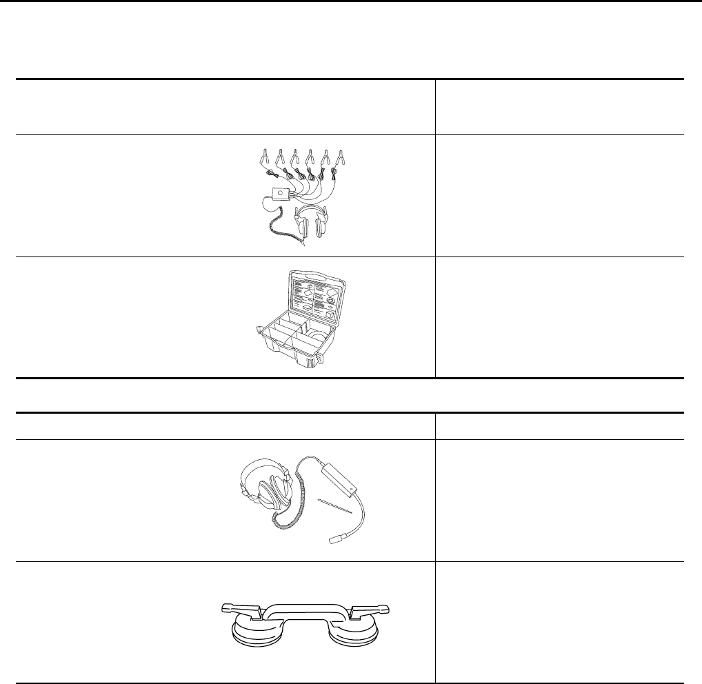
Special Service Tools NIS00219
The actual shapes of Kent-Moore tools may differ from those of special service tools illustrated here.
Commercial Service Tools NIS0021A
Tool number
(Kent-Moore No.)
Tool name
Description
(J-39570)
Chassis ear Locating the noise
(J-43980)
NISSAN Squeak and
Rattle Kit
Repairing the cause of noise
SIIA0993E
SIIA0994E
Tool name Description
Engine ear Locating the noise
Suction lifter Holding the door glass
SIIA0995E
PIIB1805J
SQUEAK AND RATTLE TROUBLE DIAGNOSES
GW-5
C
D
E
F
G
H
J
K
L
M
A
B
GW
Revision: 2006 January 2006 M35/M45
SQUEAK AND RATTLE TROUBLE DIAGNOSES PFP:00000
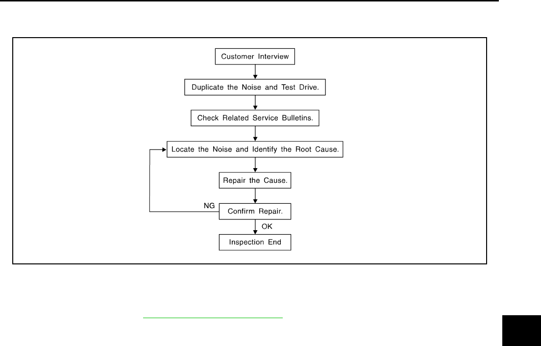
Work Flow NIS0021B
CUSTOMER INTERVIEW
Interview the customer if possible, to determine the conditions that exist when the noise occurs. Use the Diag-
nostic Worksheet during the interview to document the facts and conditions when the noise occurs and any
customer's comments; refer to GW-9, "Diagnostic Worksheet" . This information is necessary to duplicate the
conditions that exist when the noise occurs.
●The customer may not be able to provide a detailed description or the location of the noise. Attempt to
obtain all the facts and conditions that exist when the noise occurs (or does not occur).
●If there is more than one noise in the vehicle, be sure to diagnose and repair the noise that the customer
is concerned about. This can be accomplished by test driving the vehicle with the customer.
●After identifying the type of noise, isolate the noise in terms of its characteristics. The noise characteristics
are provided so the customer, service adviser and technician are all speaking the same language when
defining the noise.
●Squeak —(Like tennis shoes on a clean floor)
Squeak characteristics include the light contact/fast movement/brought on by road conditions/hard sur-
faces=higher pitch noise/softer surfaces=lower pitch noises/edge to surface=chirping
●Creak—(Like walking on an old wooden floor)
Creak characteristics include firm contact/slow movement/twisting with a rotational movement/pitch
dependent on materials/often brought on by activity.
●Rattle—(Like shaking a baby rattle)
Rattle characteristics include the fast repeated contact/vibration or similar movement/loose parts/missing
clip or fastener/incorrect clearance.
●Knock —(Like a knock on a door)
Knock characteristics include hollow sounding/sometimes repeating/often brought on by driver action.
●Tick—(Like a clock second hand)
Tick characteristics include gentle contacting of light materials/loose components/can be caused by driver
action or road conditions.
●Thump—(Heavy, muffled knock noise)
Thump characteristics include softer knock/dead sound often brought on by activity.
●Buzz—(Like a bumble bee)
Buzz characteristics include high frequency rattle/firm contact.
●Often the degree of acceptable noise level will vary depending upon the person. A noise that you may
judge as acceptable may be very irritating to the customer.
●Weather conditions, especially humidity and temperature, may have a great effect on noise level.
SBT842

GW-6
SQUEAK AND RATTLE TROUBLE DIAGNOSES
Revision: 2006 January 2006 M35/M45
DUPLICATE THE NOISE AND TEST DRIVE
If possible, drive the vehicle with the customer until the noise is duplicated. Note any additional information on
the Diagnostic Worksheet regarding the conditions or location of the noise. This information can be used to
duplicate the same conditions when you confirm the repair.
If the noise can be duplicated easily during the test drive, to help identify the source of the noise, try to dupli-
cate the noise with the vehicle stopped by doing one or all of the following:
1) Close a door.
2) Tap or push/pull around the area where the noise appears to be coming from.
3) Rev the engine.
4) Use a floor jack to recreate vehicle “twist”.
5) At idle, apply engine load (electrical load, half-clutch on M/T models, drive position on A/T models).
6) Raise the vehicle on a hoist and hit a tire with a rubber hammer.
●Drive the vehicle and attempt to duplicate the conditions the customer states exist when the noise occurs.
●If it is difficult to duplicate the noise, drive the vehicle slowly on an undulating or rough road to stress the
vehicle body.
CHECK RELATED SERVICE BULLETINS
After verifying the customer concern or symptom, check ASIST for Technical Service Bulletins (TSBs) related
to that concern or symptom.
If a TSB relates to the symptom, follow the procedure to repair the noise.
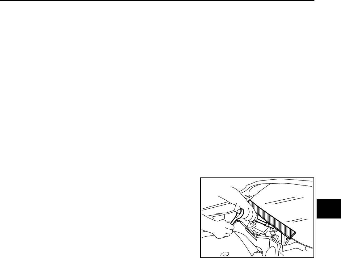
LOCATE THE NOISE AND IDENTIFY THE ROOT CAUSE
1. Narrow down the noise to a general area. To help pinpoint the source of the noise, use a listening tool
(Chassis Ear: J-39570, Engine Ear and mechanics stethoscope).
2. Narrow down the noise to a more specific area and identify the cause of the noise by:
●removing the components in the area that you suspect the noise is coming from.
Do not use too much force when removing clips and fasteners, otherwise clips and fastener can be broken
or lost during the repair, resulting in the creation of new noise.
●tapping or pushing/pulling the component that you suspect is causing the noise.
Do not tap or push/pull the component with excessive force, otherwise the noise will be eliminated only
temporarily.
●feeling for a vibration with your hand by touching the component(s) that you suspect is (are) causing the
noise.
●placing a piece of paper between components that you suspect are causing the noise.
●looking for loose components and contact marks.
Refer to GW-7, "Generic Squeak and Rattle Troubleshooting" .
REPAIR THE CAUSE
●If the cause is a loose component, tighten the component securely.
●If the cause is insufficient clearance between components:
–separate components by repositioning or loosening and retightening the component, if possible.
–insulate components with a suitable insulator such as urethane pads, foam blocks, felt cloth tape or ure-
thane tape. A Nissan Squeak and Rattle Kit (J-43980) is available through your authorized Nissan Parts
Department.
CAUTION:
Do not use excessive force as many components are constructed of plastic and may be damaged.
NOTE:
Always check with the Parts Department for the latest parts information.
The following materials are contained in the Nissan Squeak and Rattle Kit (J-43980). Each item can be
ordered separately as needed.
URETHANE PADS [1.5 mm (0.059 in) thick]
Insulates connectors, harness, etc.
76268-9E005: 100 ×135 mm (3.94 ×5.31 in)/76884-71L01: 60 ×85 mm (2.36 ×3.35 in)/76884-
71L02: 15 ×25 mm (0.59 ×0.98 in)
INSULATOR (Foam blocks)
Insulates components from contact. Can be used to fill space behind a panel.
73982-9E000: 45 mm (1.77 in) thick, 50 ×50 mm (1.97 ×1.97 in)/73982-
50Y00: 10 mm (0.39 in) thick, 50 ×50 mm (1.97 ×1.97 in)

SQUEAK AND RATTLE TROUBLE DIAGNOSES
GW-7
C
D
E
F
G
H
J
K
L
M
A
B
GW
Revision: 2006 January 2006 M35/M45
INSULATOR (Light foam block)
80845-71L00: 30 mm (1.18 in) thick, 30 ×50 mm (1.18 ×1.97 in)
FELT CLOTHTAPE
Used to insulate where movement does not occur. Ideal for instrument panel applications.
68370-4B000: 15 ×25 mm (0.59 ×0.98 in) pad/68239-13E00: 5 mm (0.20 in) wide tape roll
The following materials, not found in the kit, can also be used to repair squeaks and rattles.
UHMW (TEFLON) TAPE
Insulates where slight movement is present. Ideal for instrument panel applications.
SILICONE GREASE
Used in place of UHMW tape that will be visible or not fit. Will only last a few months.
SILICONE SPRAY
Use when grease cannot be applied.
DUCT TAPE
Use to eliminate movement.
CONFIRM THE REPAIR
Confirm that the cause of a noise is repaired by test driving the vehicle. Operate the vehicle under the same
conditions as when the noise originally occurred. Refer to the notes on the Diagnostic Worksheet.
Generic Squeak and Rattle Troubleshooting NIS0021C
Refer to Table of Contents for specific component removal and installation information.
INSTRUMENT PANEL
Most incidents are caused by contact and movement between:
1. The cluster lid A and instrument panel
2. Acrylic lens and combination meter housing
3. Instrument panel to front pillar garnish
4. Instrument panel to windshield
5. Instrument panel mounting pins
6. Wiring harnesses behind the combination meter
7. A/C defroster duct and duct joint
These incidents can usually be located by tapping or moving the components to duplicate the noise or by
pressing on the components while driving to stop the noise. Most of these incidents can be repaired by apply-
ing felt cloth tape or silicon spray (in hard to reach areas). Urethane pads can be used to insulate wiring har-
ness.
CAUTION:
Do not use silicone spray to isolate a squeak or rattle. If you saturate the area with silicone, you will
not be able to recheck the repair.
CENTER CONSOLE
Components to pay attention to include:
1. Shifter assembly cover to finisher
2. A/C control unit and cluster lid C
3. Wiring harnesses behind audio and A/C control unit
The instrument panel repair and isolation procedures also apply to the center console.
DOORS
Pay attention to the:
1. Finisher and inner panel making a slapping noise
2. Inside handle escutcheon to door finisher
3. Wiring harnesses tapping
4. Door striker out of alignment causing a popping noise on starts and stops
Tapping or moving the components or pressing on them while driving to duplicate the conditions can isolate
many of these incidents. You can usually insulate the areas with felt cloth tape or insulator foam blocks from
the Nissan Squeak and Rattle Kit (J-43980) to repair the noise.

GW-8
SQUEAK AND RATTLE TROUBLE DIAGNOSES
Revision: 2006 January 2006 M35/M45
TRUNK
Trunk noises are often caused by a loose jack or loose items put into the trunk by the owner.
In addition look for:
1. Trunk lid dumpers out of adjustment
2. Trunk lid striker out of adjustment
3. The trunk lid torsion bars knocking together
4. A loose license plate or bracket
Most of these incidents can be repaired by adjusting, securing or insulating the item(s) or component(s) caus-
ing the noise.
SUNROOF/HEADLINING
Noises in the sunroof/headlining area can often be traced to one of the following:
1. Sunroof lid, rail, linkage or seals making a rattle or light knocking noise
2. Sunvisor shaft shaking in the holder
3. Front or rear windshield touching headlining and squeaking
Again, pressing on the components to stop the noise while duplicating the conditions can isolate most of these
incidents. Repairs usually consist of insulating with felt cloth tape.
SEATS
When isolating seat noise it's important to note the position the seat is in and the load placed on the seat when
the noise is present. These conditions should be duplicated when verifying and isolating the cause of the
noise.
Cause of seat noise include:
1. Headrest rods and holder
2. A squeak between the seat pad cushion and frame
3. The rear seatback lock and bracket
These noises can be isolated by moving or pressing on the suspected components while duplicating the con-
ditions under which the noise occurs. Most of these incidents can be repaired by repositioning the component
or applying urethane tape to the contact area.
UNDERHOOD
Some interior noise may be caused by components under the hood or on the engine wall. The noise is then
transmitted into the passenger compartment.
Causes of transmitted underhood noise include:
1. Any component mounted to the engine wall
2. Components that pass through the engine wall
3. Engine wall mounts and connectors
4. Loose radiator mounting pins
5. Hood bumpers out of adjustment
6. Hood striker out of adjustment
These noises can be difficult to isolate since they cannot be reached from the interior of the vehicle. The best
method is to secure, move or insulate one component at a time and test drive the vehicle. Also, engine RPM
or load can be changed to isolate the noise. Repairs can usually be made by moving, adjusting, securing, or
insulating the component causing the noise.
SQUEAK AND RATTLE TROUBLE DIAGNOSES
GW-9
C
D
E
F
G
H
J
K
L
M
A
B
GW
Revision: 2006 January 2006 M35/M45
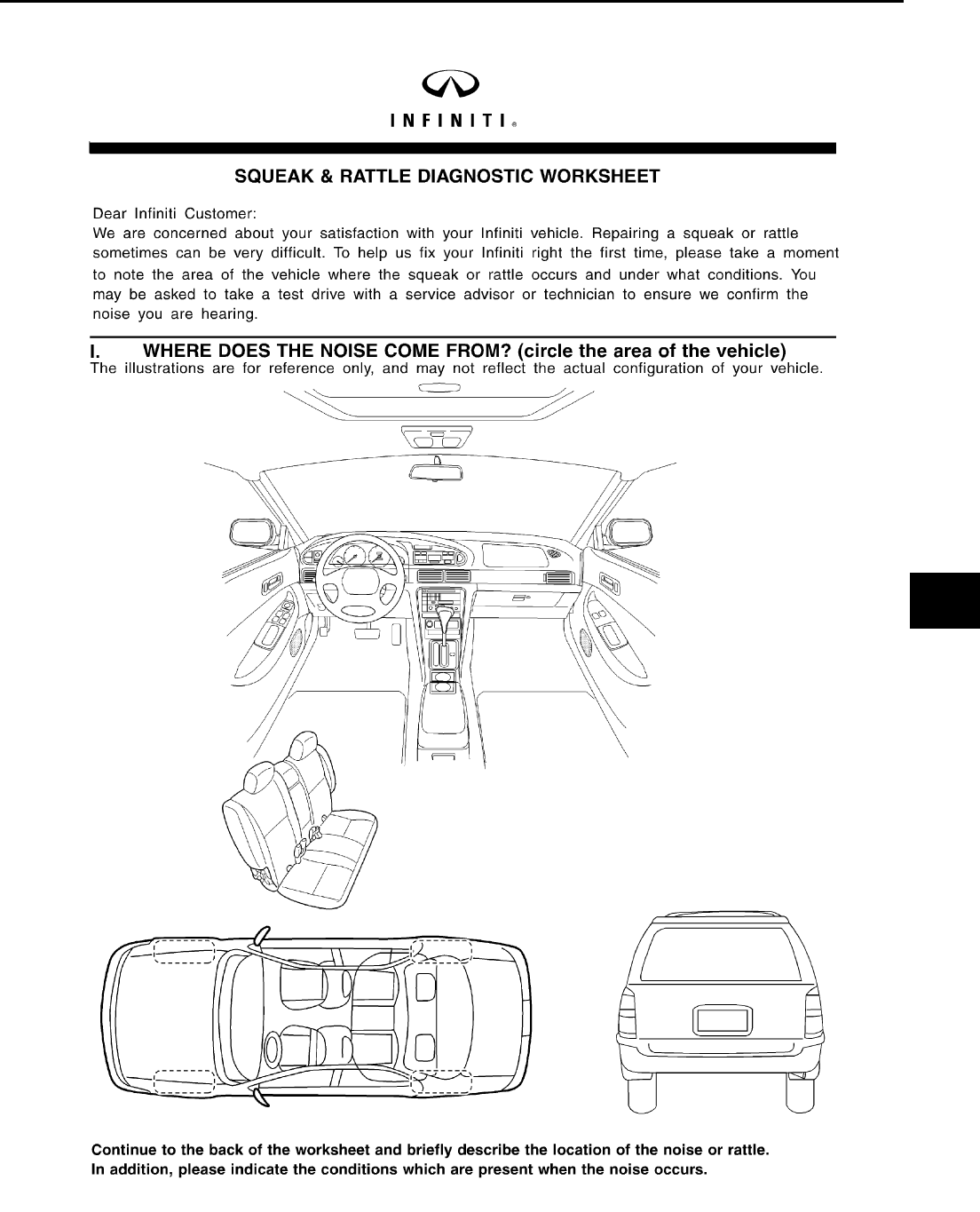
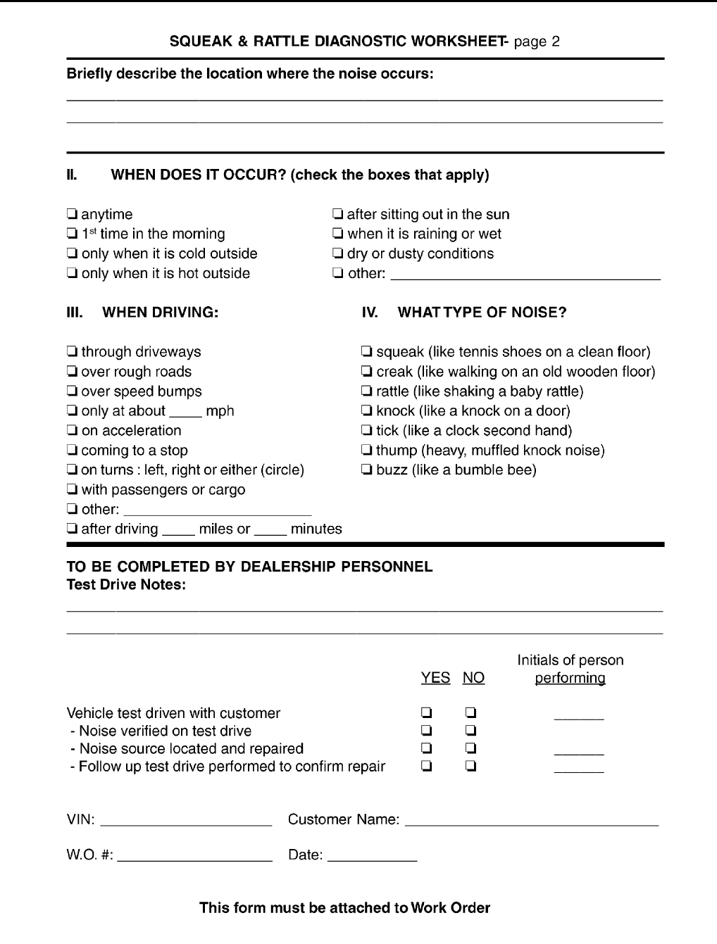
Diagnostic Worksheet NIS0021D
SBT860
GW-10
SQUEAK AND RATTLE TROUBLE DIAGNOSES
Revision: 2006 January 2006 M35/M45
SBT844
WINDSHIELD GLASS
GW-11
C
D
E
F
G
H
J
K
L
M
A
B
GW
Revision: 2006 January 2006 M35/M45
WINDSHIELD GLASS PFP:72712
Removal and Installation NIS0021E
REMOVAL
1. Remove the front pillar garnish. Refer to EI-37, "BODY SIDE TRIM" .
2. Partially remove the headlining (front edge). Refer to EI-52, "HEADLINING" .
3. Remove the front wiper arms. Refer to WW-42, "Removal and Installation of Front Wiper Arms, Adjust-
ment of Wiper Arms Stop Location" .
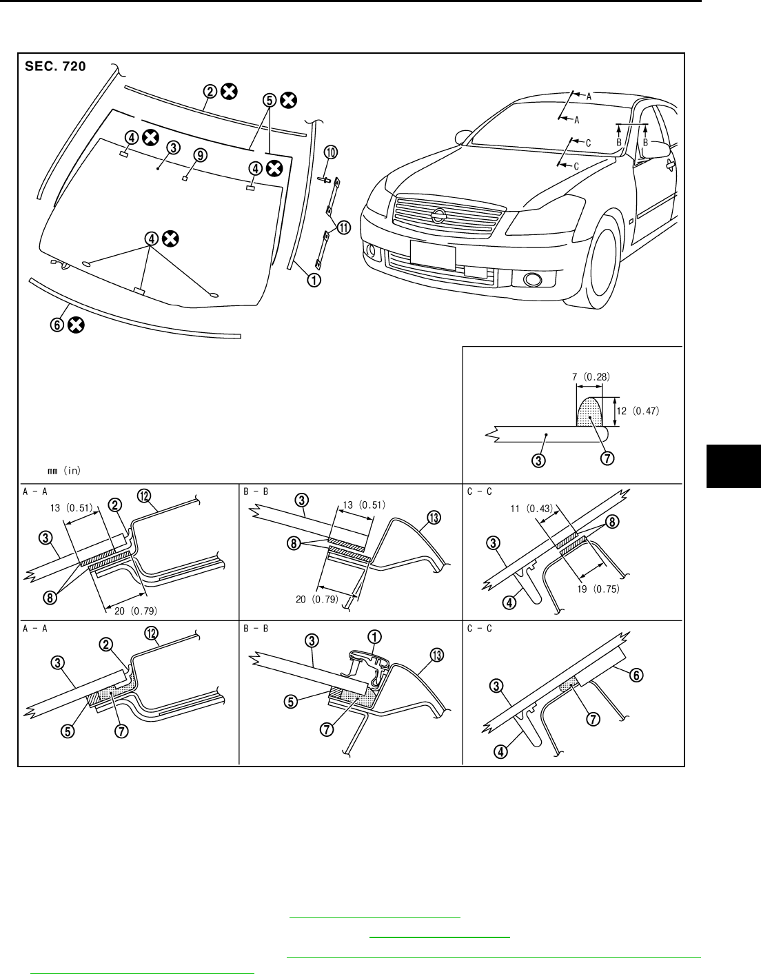
PIIB3284J
1. Roof side molding 2. Windshield molding (upper) 3. Windshield glass
4. Spacer 5. Dam rubber 6. Insulator
7. Adhesive 8. Primer 9. Mirror base
10. Rivet 11. Fastener 12. Roof panel
13. Body side outer panel
GW-12
WINDSHIELD GLASS
Revision: 2006 January 2006 M35/M45
4. Remove the cowl top cover. Refer to EI-18, "COWL TOP" .
5. Remove roof side molding. Refer to EI-25, "ROOF SIDE MOLDING" .
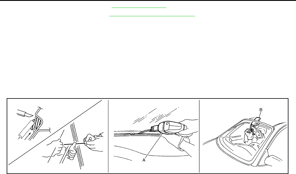
6. Apply a protective tape around the windshield glass to protect the painted surface from damage.
After removing moldings, remove glass using piano wire or power cutting tool A and an inflatable pump bag B.
●If a windshield glass is to be reused, mark the body and the glass with mating marks.
WARNING:
When cutting the glass from the vehicle, always wear safety glasses and heavy gloves to help pre-
vent glass splinters from entering your eyes or cutting your hands.
CAUTION:
●When a windshield glass is to be reused, do not use a cutting knife or power cutting tool.
●Be careful not to scratch the glass when removing.
●Do not set or stand the glass on its edge. Small chips may develop into cracks.
INSTALLATION
●The dam rubber should be installed in position.
●Use a genuine Nissan Urethane Adhesive Kit (if available) or equivalent and follow the instructions fur-
nished with it.
●While the urethane adhesive is curing, open a door window. This will prevent the glass from being forced
out by passenger room air pressure when a door is closed.
●The molding must be installed securely so that it is in position and leaves no gap.
●Inform the customer that the vehicle should remain stationary until the urethane adhesive has completely
cured (preferably 24 hours). Curing time varies with temperature and humidity.
WARNING:
●Keep heat and open flames away as primers and adhesive are flammable.
●The materials contained in the kit are harmful if swallowed, and may irritate skin and eyes. Avoid
contact with the skin and eyes.
●Use in an open, well ventilated location. Avoid breathing the vapors. They can be harmful if
inhaled. If affected by vapor inhalation, immediately move to an area with fresh air.
●Driving the vehicle before the urethane adhesive has completely cured may affect the perfor-
mance of the windshield in case of an accident.
CAUTION:
●Do not use an adhesive which is past its usable term. Shelf life of this product is limited to six
months after the date of manufacture. Carefully adhere to the expiration or manufacture date
printed on the box.
●Keep primers and adhesive in a cool, dry place. Ideally, they should be stored in a refrigerator.
●Do not leave primers or adhesive cartridge unattended with their caps open or off.
●The vehicle should not be driven for at least 24 hours or until the urethane adhesive has com-
pletely cured. Curing time varies depending on temperature and humidity. The curing time will
increase under lower temperature and lower humidity.
Repairing Water Leaks for Windshield
Leaks can be repaired without removing and reinstalling glass.
If water is leaking between the urethane adhesive material and body or glass, determine the extent of leakage.
This can be done by applying water to the windshield area while pushing glass outward.
To stop the leak, apply primer (if necessary) and then urethane adhesive to the leak point.
PIIB5779E
POWER WINDOW SYSTEM
GW-13
C
D
E
F
G
H
J
K
L
M
A
B
GW
Revision: 2006 January 2006 M35/M45
POWER WINDOW SYSTEM PFP:25401
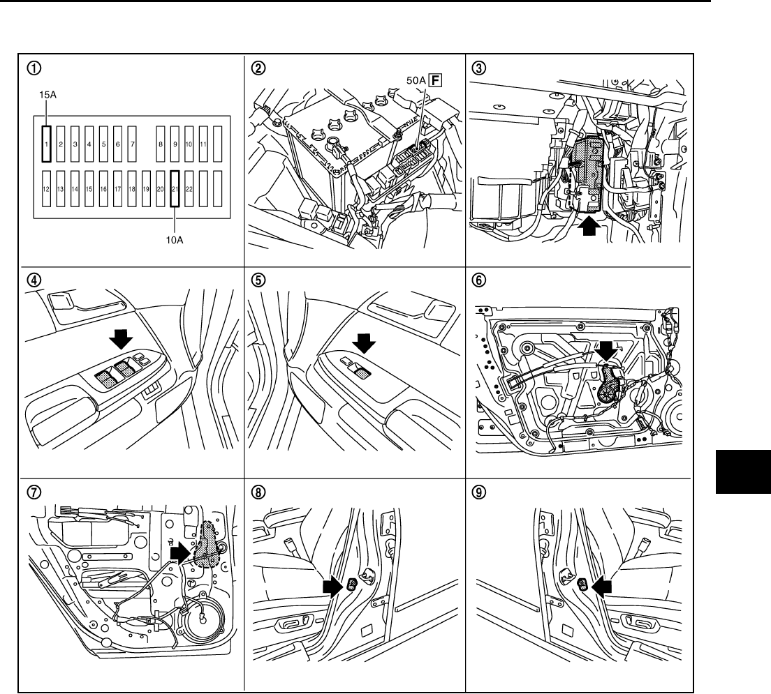
Component Parts and Harness Connector Location NIS0021F
System Description NIS0021G
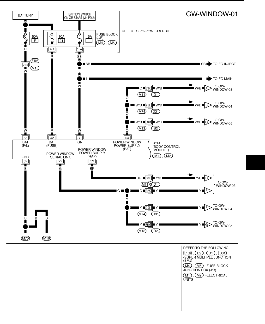
Power is supplied at all time
●through 50A fusible link (letter F , located in the fuse and fusible link box)
●to BCM terminal 55, and
●through BCM terminal 54
●to power window main switch terminal 19
●to power window sub-switch (front passenger side) terminal 10
●to power window sub-switch (rear LH and RH) terminal 10.
●through 10A fuse [No. 21, located in the fuse block (J/B)]
PIIB6097E
1. Fuse block (J/B) 2. Fusible link 3. BCM M1, M2, M3
4. Power window main switch D10,
D11 5. Power window sub-switch D46 6. Power window motor (front driver
side) D12
7. Power window motor (rear LH) D58 8. Front door switch driver side B11 9. Front door switch passenger side
B35

GW-14
POWER WINDOW SYSTEM
Revision: 2006 January 2006 M35/M45
●to BCM terminal 42.
With ignition switch in ON or START position,
Power is supplied
●through 15A fuse [No. 1, located in the fuse block (J/B)]
●to BCM terminal 38, and
●through BCM terminal 53
●to power window main switch terminal 10
Ground supplied
●to BCM terminal 52
●through body grounds M16 and M70.
●to power window main switch terminal 17
●through body grounds M16 and M70.
●to power window sub-switch (front passenger side) terminal 11
●through body grounds M16 and M70.
●to power window sub-switch (rear LH and RH) terminal 11
●through body grounds B5, B40 and B131.
MANUAL OPERATION
Front Driver Side Door
WINDOW UP
When the front LH switch in the power window main switch is pressed in the up position,
Power is supplied
●through power window main switch terminal 8
●to power window motor (front driver side) terminal 2.
Ground is supplied
●to power window motor (front driver side) terminal 1
●through power window main switch terminal 11.
Then, the motor raises the window until the switch is released.
WINDOW DOWN
When the front LH switch in the power window main switch is pressed in the down position
Power is supplied
●through power window main switch terminal 11
●to power window motor (front driver side) terminal 1.
Ground is supplied
●to power window motor (front driver side) terminal 2
●through power window main switch terminal 8.
Then, the motor lowers the window until the switch is released.

POWER WINDOW SYSTEM
GW-15
C
D
E
F
G
H
J
K
L
M
A
B
GW
Revision: 2006 January 2006 M35/M45
Front Passenger Side Door
POWER WINDOW SUB-SWITCH (FRONT PASSENGER SIDE) OPERATION
WINDOW UP
When the power window sub-switch (front passenger side) is pressed in the up position
Power is supplied
●through power window sub-switch (front passenger side) terminal 8
●to power window motor (front passenger side) terminal 2.
Ground is supplied
●to power window motor (front passenger side) terminal 1
●through power window sub-switch (front passenger side) terminal 9.
Then, the motor raises the window until the switch is released.
WINDOW DOWN
When the power window sub-switch (front passenger side) is pressed in the down position
Power is supplied
●through power window sub-switch (front passenger side) terminal 9
●to power window motor (front passenger side) terminal 1.
Ground is supplied
●to power window motor (front passenger side) terminal 2
●through power window sub-switch (front passenger side) terminal 8.
Then, the motor lowers the window until the switch is released.
POWER WINDOW MAIN SWITCH OPERATION
Signal is sent
●though power window main switch terminal 14.
●to power window sub-switch (front passenger side) terminal 16
The operation of power window after receive the signal is as same as operate the power window with power
window sub-switch (front passenger side).
Rear Door (LH or RH)
POWER WINDOW SUB-SWITCH (REAR LH OR RH) OPERATION
WINDOW UP
When the power window sub-switch (rear LH or RH) is pressed in the up position
Power is supplied
●through power window sub-switch (rear LH or RH) terminal 8
●to power window motor (rear LH or RH) terminal 1.
Ground is supplied
●to power window motor (rear LH or RH) terminal 2
●through power window sub-switch (rear LH or RH) terminal 9.
Then, the motor raises the window until the switch is released.
WINDOW DOWN
When the power window sub-switch (rear LH or RH) is pressed in the down position
Power is supplied
●through power window sub-switch (rear LH or RH) terminal 9
●to power window motor (rear LH or RH) terminal 2.
Ground is supplied
●to power window motor (rear LH or RH) terminal 1
●through power window sub-switch (rear LH or RH) terminal 8.
Then, the motor lowers the window until the switch is released.
POWER WINDOW MAIN SWITCH OPERATION
Signal is sent
●though power window main switch terminal 14.
●to power window sub-switch (rear LH or RH) terminal 16
The operation of power window after receive the signal is as same as operate the power window sub-switch
(rear LH or RH).

GW-16
POWER WINDOW SYSTEM
Revision: 2006 January 2006 M35/M45
AUTO OPERATION
The power window AUTO feature enables the driver to open or close the window without holding the window
switch in the down or up position.
POWER WINDOW SERIAL LINK
Power window main switch, any power window sub-switches and BCM transmit and receive the signal by
power window serial link.
The under mentioned signal is transmitted from BCM to power window main switch and power window sub-
switches.
●Keyless power window down signal.
The under mentioned signal is transmitted from power window main switch to power window sub-switch (front
passenger side)
●Front passenger side door window operation signal.
●Power window control by key cylinder switch signal.
●Power window lock signal.
●Retained power operation signal.
The under mentioned signal is transmitted from power window main switch to power window sub-switch (rear
LH or RH)
●Rear LH or RH side door window operation signal.
●Power window control by key cylinder switch signal.
●Power window lock signal.
●Retained power operation signal.
POWER WINDOW LOCK
The power window lock is designed to lock operation of all windows except for driver side door window.
When the lock position, the power window lock signal is transmitted to any power window sub-switches by
power window serial link. This prevents the power window motors from operating.
RETAINED POWER OPERATION
When the ignition switch is turned to the OFF position from ON or START position.
Power is supplied for 45 seconds
●through BCM terminal 53
●to power window main switch terminal 10.
When power and ground are supplied, the BCM continues to be energized, and the power window can be
operated.
The retained power operation is canceled when the driver or passenger side door is opened.
RAP signal period can be changed by CONSULT-II. Refer to GW-30, "CONSULT-II Function (BCM)" .
POWER WINDOW SYSTEM
GW-17
C
D
E
F
G
H
J
K
L
M
A
B
GW
Revision: 2006 January 2006 M35/M45
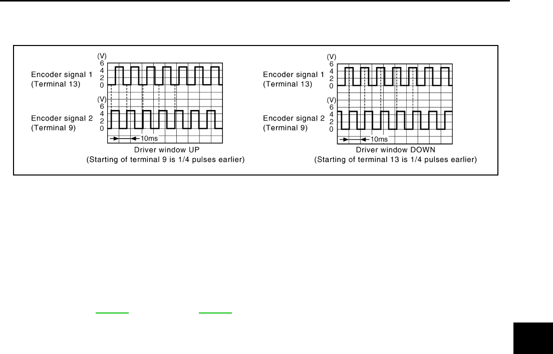
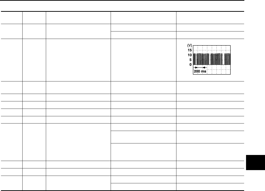
ANTI-PINCH SYSTEM
Power window main switch and each power window sub-switch recognizes and controls the door glass condi-
tion by reading encoder signals 1 and 2.
If a door glass is subject to a certain resistance due to a foreign material obstruction during the following close
operation.
●automatic close operation when ignition switch is in the “ON” position
●automatic close operation during retained power operation
●Key cylinder switch close operation during retained power operation
The power window switch reads encoder signal 1, It stops UP operation of the motor, and sends a signal for
down operation to lower the window by a certain amount (150mm, 5.91 in)
INITIALIZATION
Perform the initialization when the following operations are performed or when the auto up operation is not
performed. Refer to GW-65 (Front door), GW-70 (Rear door).
●When the power supply to the power window main switch, power window sub-switch or each power win-
dow motor is cut off by the removal of battery terminal or the battery fuse is blown.
●Disconnection and connection of power window main switch or each power window sub-switch harness
connector.
●Removal and installation of regulator assembly.
●Removal and installation of motor from regulator assembly.
●Operation of regulator assembly as an independent unit.
●Removal and installation of glass.
●Removal and installation of door glass run.
CAUTION:
The following operations are not performed under the condition that the initialization is not per-
formed yet.
●Auto up operation
●Anti-pinch function
●Key cylinder switch close operation
PIIB5952E

GW-18
POWER WINDOW SYSTEM
Revision: 2006 January 2006 M35/M45
FAIL-SAFE CONTROL
The encoder signal detects the up / down speed / detection of door glass. If the malfunction is detected to the
encoder signal or the difference between the glass fully closed position (memorized in power window main
switch or power window sub-switch) and the actual glass position is detected, it shifts into the fail-safe control
It is shifts into the fail-safe control, the initialization is not performed and the following function is not activated
●Auto up operation
●Anti-pinch function
It is shifts into the fail-safe control, performed the initialization to resume normal operation condition.
POWER WINDOW CONTROL BY THE KEY CYLINDER SWITCH
When ignition key switch is OFF, front power window can be opened or closed by turning the key cylinder
switch UNLOCK / LOCK position more than 1.5 second over condition.
●Power window can be opened as the door key cylinder is kept fully turning to the UNLOCK position.
●Power window can be closed as the door key cylinder is kept fully turning to the LOCK position.
The power window DOWN stops when the following operations are carried out.
●While performing open / close the window, power window is stopped at the position as the door key cylin-
der is placed on NEUTRAL.
●When the ignition switch is turned ON while the power window DOWN is operated.
DTC Condition
Pulse sensor detects malfunction During the glass opening/closing operation, a pulse signal is continuously
detected for the specified terms or more
Both pulse sensors detect malfunction During the glass opening/closing operation, both pulse signals are not
detected for the specified values or more
Pulse direction malfunction
The following condition is detected for the specified values or more. The
pulse signal (detected during glass open/close operation) detects the
opposite direction to the driving direction of power window motor.
Glass recognized position malfunction 1
During the glass opening/closing operation, the difference between the
glass fully closed position (memorized in power window main switch or
power window sub-switch) and the actual glass position is detected for
the specified values or more.
Glass recognized position malfunction 2 During the glass opening/closing operation, a pulse count is detected that
is above the glass full stroke
Glass fully closed position not updated malfunction Continuously perform the glass open/close operation (with the glass not
fully closed) at the specified value (approx. 10 time) or more

POWER WINDOW SYSTEM
GW-19
C
D
E
F
G
H
J
K
L
M
A
B
GW
Revision: 2006 January 2006 M35/M45
CAN Communication System Description NIS0021H
CAN (Controller Area Network) is a serial communication line for real time application. It is an on-vehicle mul-
tiplex communication line with high data communication speed and excellent error detection ability. Many elec-
tronic control units are equipped onto a vehicle, and each control unit shares information and links with other
control units during operation (not independent). In CAN communication, control units are connected with 2
communication lines (CAN H line, CAN L line) allowing a high rate of information transmission with less wiring.
Each control unit transmits/receives data but selectively reads required data only.
CAN Communication Unit NIS0021I
Refer to LAN-34, "CAN Communication Unit" .
GW-20
POWER WINDOW SYSTEM
Revision: 2006 January 2006 M35/M45
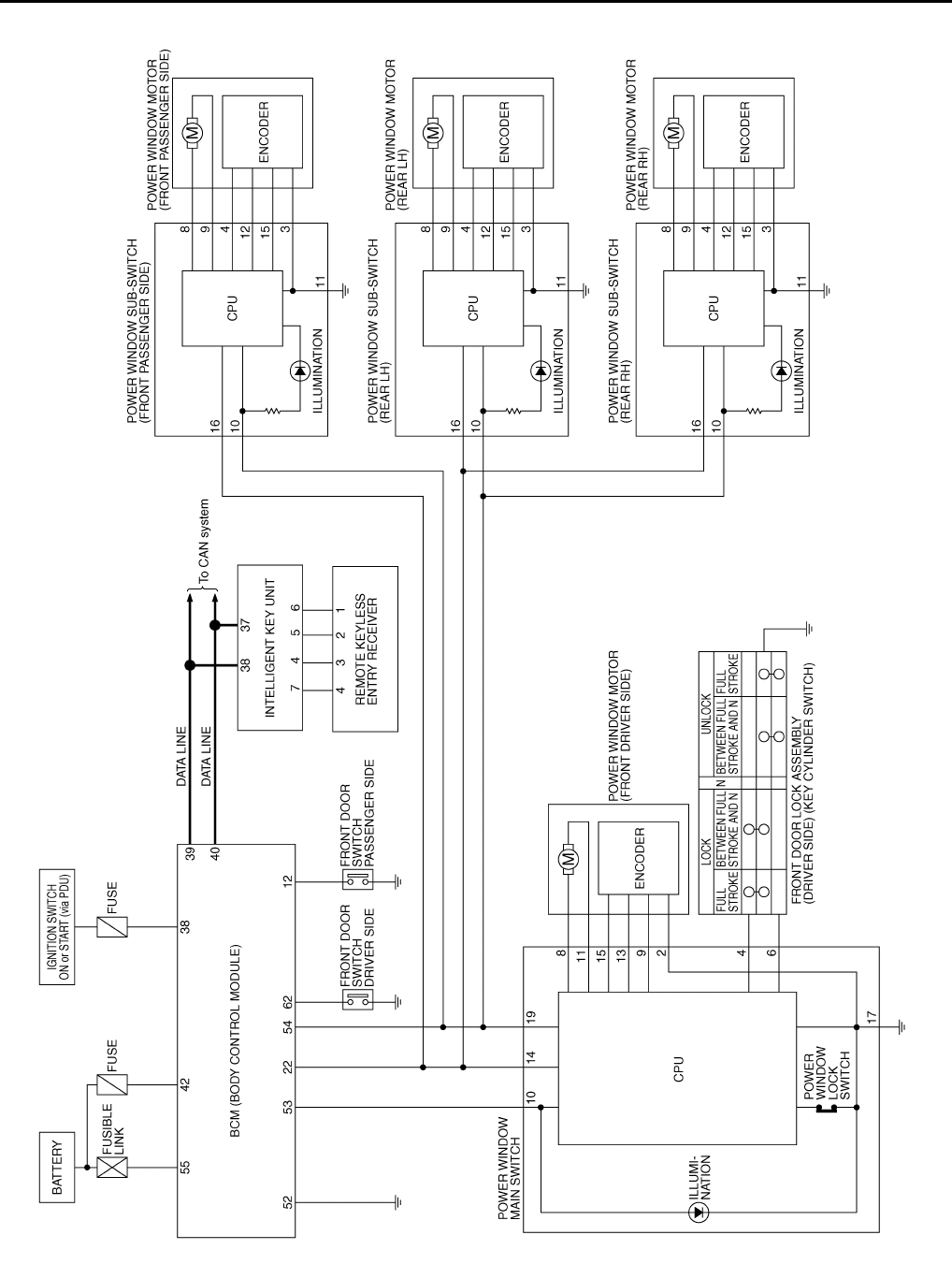
Schematic NIS0021J
TIWT1344E
POWER WINDOW SYSTEM
GW-21
C
D
E
F
G
H
J
K
L
M
A
B
GW
Revision: 2006 January 2006 M35/M45
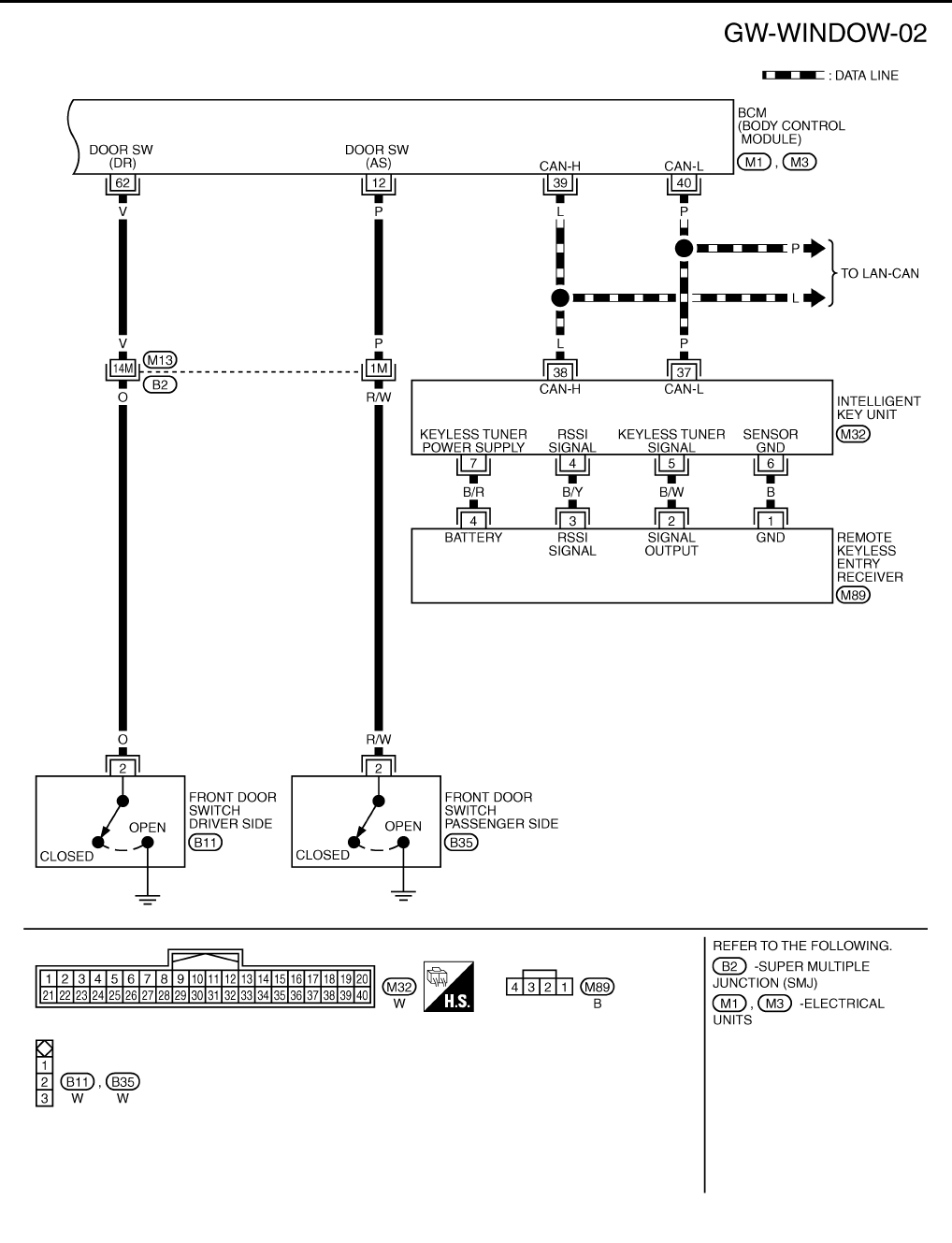
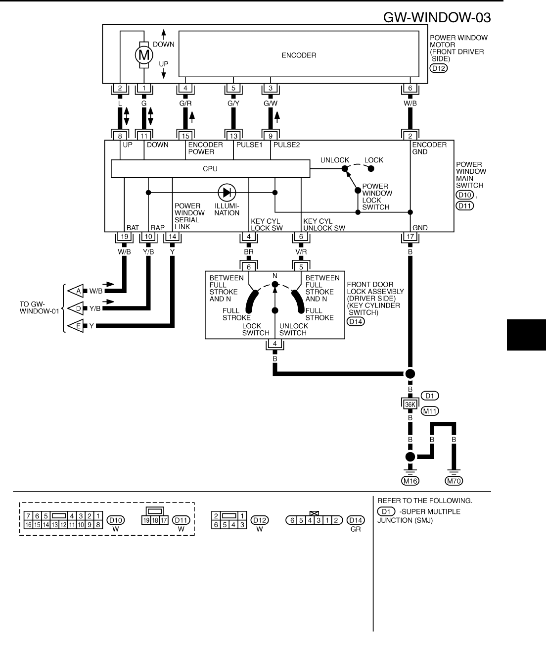
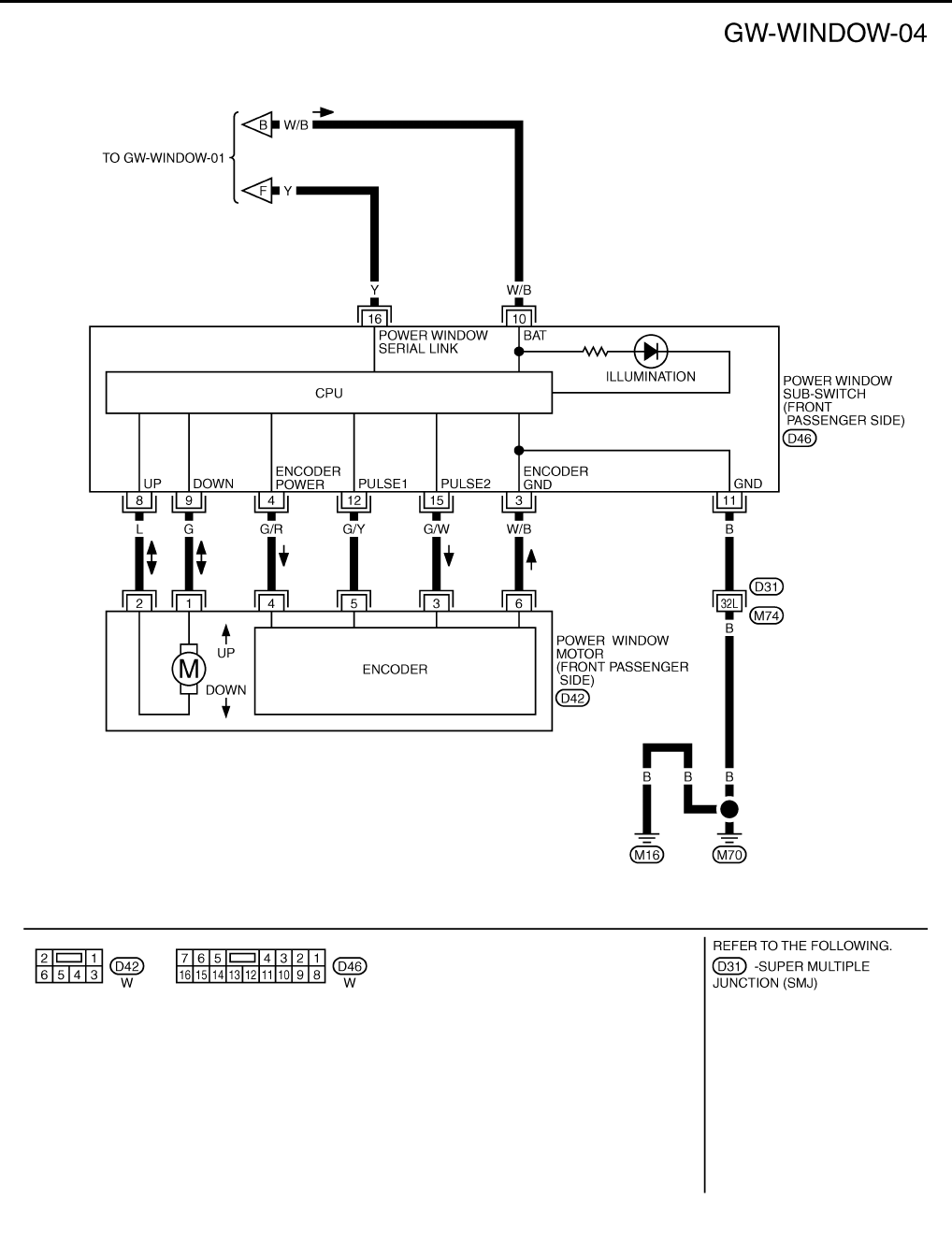
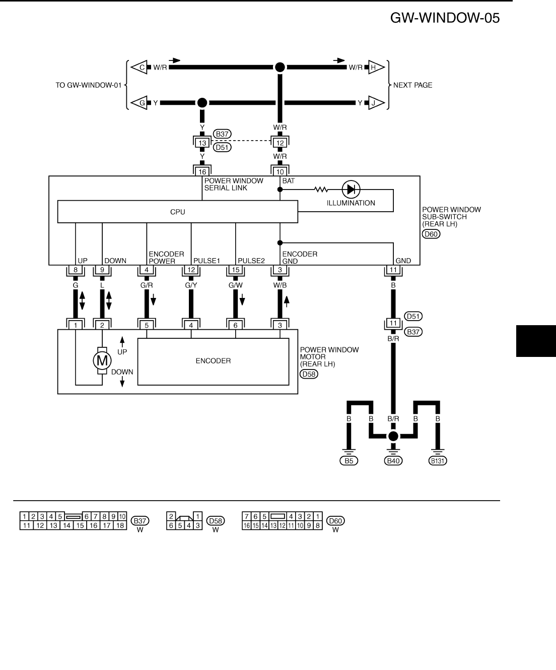
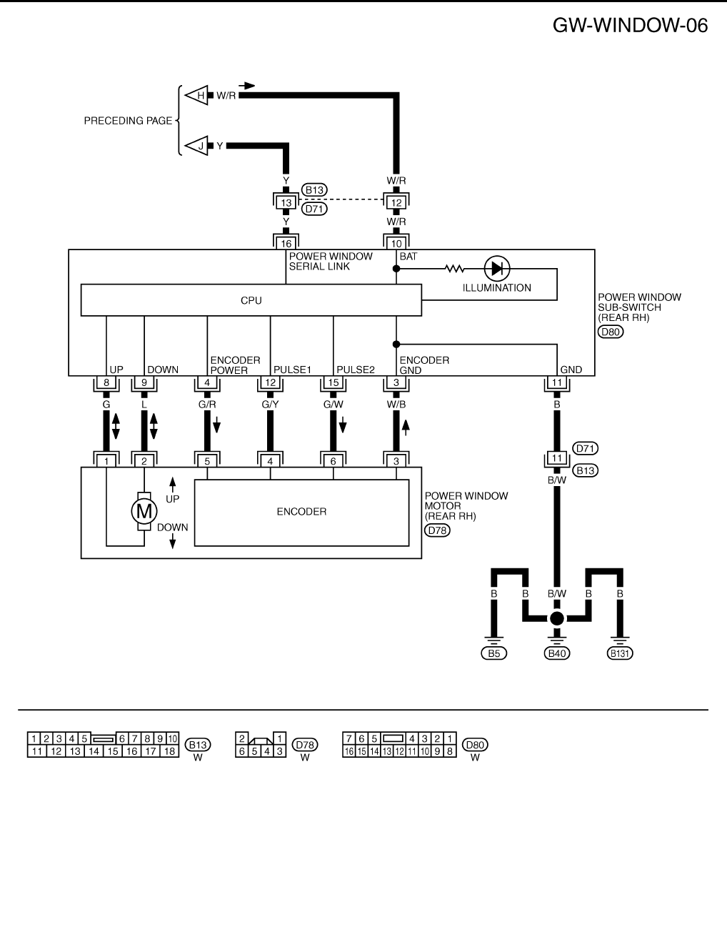
Wiring Diagram — WINDOW — NIS0021K
TIWT1345E
GW-22
POWER WINDOW SYSTEM
Revision: 2006 January 2006 M35/M45
TIWT1346E
POWER WINDOW SYSTEM
GW-23
C
D
E
F
G
H
J
K
L
M
A
B
GW
Revision: 2006 January 2006 M35/M45
TIWT1347E
GW-24
POWER WINDOW SYSTEM
Revision: 2006 January 2006 M35/M45
TIWT1348E
POWER WINDOW SYSTEM
GW-25
C
D
E
F
G
H
J
K
L
M
A
B
GW
Revision: 2006 January 2006 M35/M45
TIWT1349E
GW-26
POWER WINDOW SYSTEM
Revision: 2006 January 2006 M35/M45
TIWT1350E
POWER WINDOW SYSTEM
GW-27
C
D
E
F
G
H
J
K
L
M
A
B
GW
Revision: 2006 January 2006 M35/M45
Terminal and Reference Value for BCM NIS0021L
Terminal Wire color Item Condition Voltage [V]
(Approx.)
12 P Front door switch
passenger side signal
ON (Open) 0
OFF (Close) Battery voltage
22 G Power window serial link IGN SW ON or power window
timer operating.
38 W Ignition switch (ON or START) Ignition switch
(ON or START position) Battery voltage
39 L CAN - H — —
40 P CAN - L — —
42 P Power source (Fuse) — Battery voltage
52 B Ground — 0
53 BR Rap signal
IGN SW ON Battery voltage
Within 45 second after ignition
switch is turned to OFF Battery voltage
When driver side or passenger
side door is opened daring
retained power operation
0
54 O Power window power supply — Battery voltage
55 W Power source (Fusible link) — Battery voltage
62 V Front door switch
driver side signal
ON (Open) 0
OFF (Close) Battery voltage
PIIA2344J
GW-28
POWER WINDOW SYSTEM
Revision: 2006 January 2006 M35/M45
Terminal and Reference Value for Power Window Main Switch NIS0021M
Terminal Wire color Item Condition Voltage [V]
(Approx.)
2 W/B Encoder ground — 0
4BR
Door key cylinder switch
LOCK signal
Key position
(Neutral → Locked) 5 → 0
6V/R
Door key cylinder switch
UNLOCK signal
Key position
(Neutral → Unlocked) 5 → 0
8L
Front driver side power window
motor UP signal
When front LH switch in
power window main switch is
UP at operated.
Battery voltage
9 G/W Encoder pulse signal 2 When power window motor oper-
ates.
10 Y/B Rap signal
IGN SW ON Battery voltage
Within 45 second after ignition
switch is turned to OFF Battery voltage
When driver side or passenger
side door is opened daring
retained power operation
0
11 G Front driver side power window
motor DOWN signal
When front LH switch in
power window main switch is
DOWN at operated.
Battery voltage
13 G/Y Encoder pulse signal 1 When power window motor oper-
ates.
14 Y Power window serial link IGN SW ON or power window
timer operating.
15 G/R Encoder power supply When ignition switch ON or power
window timer operates. 10
17 B Ground — 0
19 W/B Battery power supply — Battery voltage
OCC3383D
OCC3383D
PIIA2344J

POWER WINDOW SYSTEM
GW-29
C
D
E
F
G
H
J
K
L
M
A
B
GW
Revision: 2006 January 2006 M35/M45
Terminal and Reference Value for (Front and Rear) Power Window Sub-Switch
NIS0021N
( ): Power window sub-switch (rear LH or RH)
Terminal Wire color Item Condition Voltage [V]
(Approx.)
3 W/B Encoder ground — 0
4 G/R Encoder power supply When ignition switch ON or power
window timer operates 10
8L
(G)
Power window motor
UP signal
When power window motor is
UP at operated. Battery voltage
9G
(L)
Power window motor
DOWN signal
When power window motor is
DOWN at operated. Battery voltage
10 W/B
(W/R) Battery power supply — Battery voltage
11 B Ground — 0
12 G/Y Encoder pulse signal 1 When power window motor oper-
ates.
15 G/W Encoder pulse signal 2 When power window motor oper-
ates.
16 Y Power window serial link IGN SW ON or power window
timer operating.
OCC3383D
OCC3383D
PIIA2344J
GW-30
POWER WINDOW SYSTEM
Revision: 2006 January 2006 M35/M45
CONSULT-II Function (BCM) NIS0021O
CONSULT-II can display each diagnostic item using the diagnostic test modes shown following.
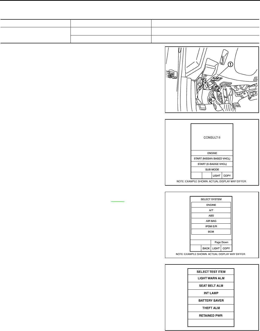
1. Turn ignition switch “ON”.
2. Connect “CONSULT-II and CONSULT-II CONVERTER” to the
data link connector (1).
3. Turn ignition switch “ON”.
4. Touch “START (NISSAN BASED VHCL)”.
5. Touch “BCM”.
If “BCM” is not indicated, go to Refer to GI-40 , “CONSULT-II
Date Link Connector (DLC) Circuit”
6. Touch “RETAINED PWR”.
BCM diagnostic test item Check item diagnostic test mode Content
RETAINED PWR Work support Changes setting of each function.
Data monitor Displays the input data of BCM in real time.
PBIB2712E
BCIA0029E
BCIA0030E
LIIA0163E
POWER WINDOW SYSTEM
GW-31
C
D
E
F
G
H
J
K
L
M
A
B
GW
Revision: 2006 January 2006 M35/M45
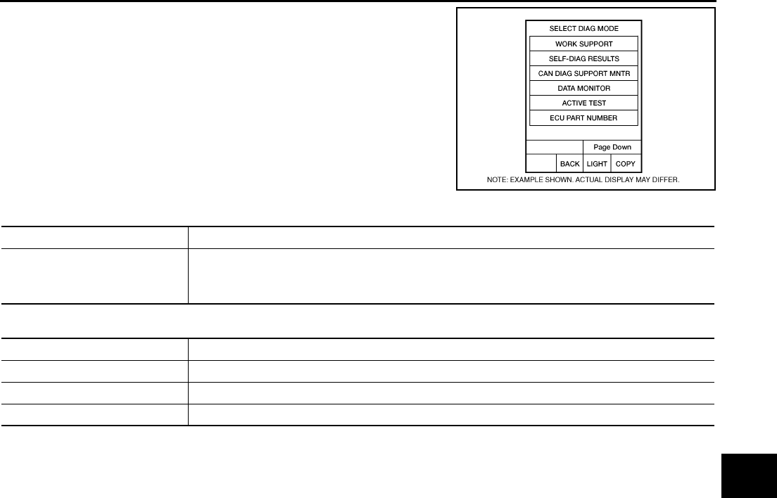
7. Select diagnosis mode.
“ACTIVE TEST”, “WORK SUPPORT” and “DATA MONITOR”
are available.
WORK SUPPORT
DATE MONITOR
BCIA0031E
Work item Description
RETAINED PWR
Rap signal’s power supply period can be changed by mode setting. Selects rap signal’s power
supply period between three steps
●MODE1 (45 sec.) / MODE2 (OFF) / MODE 3 (2 min.).
Work item Description
IGN ON SW Indicates (ON / OFF) condition of ignition switch
DOOR SW–DR Indicates (ON / OFF) condition of front door switch driver side
DOOR SW–AS Indicates (ON / OFF) condition of front door switch passenger side
GW-32
POWER WINDOW SYSTEM
Revision: 2006 January 2006 M35/M45
Work Flow NIS0021P
1. Check the symptom and customer's requests.
2. Understand the outline of system. Refer to GW-13, "System Description"
3. According to the trouble diagnosis chart, repair or replace the cause of the malfunction.
Refer to GW-32, "Trouble Diagnosis Symptom Chart"
4. Does power window system operate normally? Yes, GO TO 5, If No, GO TO 3.
5. INSPECTION END
Trouble Diagnosis Symptom Chart NIS0021Q
●Make sure other systems using the signal of the following systems operate normally.
Symptom Repair order Refer to page
None of the power windows can be operated using any switch.
1. BCM power supply and ground circuit check GW-34
2. Power window main switch power supply and
ground circuit check GW-35
3. Power window serial link check GW-56
Driver side power window alone does not operate.
1. Power window motor (front driver side) circuit
check GW-38
2. Replace power window main switch —
Front passenger side power window alone does not operate.
1. Power window main switch power supply and
ground circuit check GW-35
2. Power window sub-switch (front passenger
side) power and ground circuit check GW-36
3. Power window serial link check GW-56
4. Power window motor (front passenger side) cir-
cuit check GW-39
5. Replace BCM BCS-17
Rear LH or RH side power window alone does not operate
1. Power window sub-switch (rear LH or RH)
power and ground circuit check GW-37
2. Power window serial link check (rear LH or RH) GW-58
3. Power window motor (rear LH or RH) circuit
check GW-40
4. Replace rear power window switch (LH or RH) —
Anti-pinch system does not operate normally (driver side)
1. Initialization GW-65
2. Door window sliding part malfunction
●A foreign material adheres to window glass
or glass run rubber.
●Glass run rubber wear or deformation.
●Sash is tilted too much, or no enough.
—
3. Encoder circuit check (driver side) GW-42
Anti-pinch system does not operate normally (passenger side)
1. Initialization GW-65
2. Door window sliding part malfunction
●A foreign material adheres to window glass
or glass run rubber.
●Glass run rubber wear or deformation.
●Sash is tilted too much, or no enough.
—
3. Encoder circuit check (passenger side) GW-45

POWER WINDOW SYSTEM
GW-33
C
D
E
F
G
H
J
K
L
M
A
B
GW
Revision: 2006 January 2006 M35/M45
Anti-pinch system does not operate normally (rear LH or RH)
1. Initialization GW-70
2. Door window sliding part malfunction
●A foreign material adheres to window glass
or glass run rubber.
●Glass run rubber wear or deformation.
●Sash is tilted too much, or no enough.
—
3. Encoder circuit check (rear LH or RH) GW-48
Power window retained power operation does not operate
properly
1. Check the retained power operation mode set-
ting. GW-31
2. Door switch check GW-52
3. Replace BCM. BCS-17
Does not operate by key cylinder switch
1. Initialization GW-65
2. Door key cylinder switch check GW-54
3. Replace power window main switch —
Power window lock switch does not function Power window lock switch check GW-58
Auto operation does not operate but manual operate normally
(driver side)
1. Initialization GW-65
2. Encoder circuit check (driver side) GW-42
3. Replace power window main switch —
Auto operation does not operate but manual operate normally
(passenger side)
1. Initialization GW-65
2. Encoder circuit check (passenger side) GW-45
3. Replace front power window switch (passenger
side) —
Auto operation does not operate but manual operate normally
(rear LH or RH)
1. Initialization GW-70
2. Encoder circuit check (rear LH or RH) GW-48
3. Replace rear power window switch (LH or RH) —
Symptom Repair order Refer to page
GW-34
POWER WINDOW SYSTEM
Revision: 2006 January 2006 M35/M45
BCM Power Supply and Ground Circuit Check NIS0021R
1. CHECK FUSE
●Check 15A fuse [No. 1, located in fuse block (J/B)]
●Check 10A fuse [No. 21, located in fuse block (J/B)]
●Check 50A fusible link (letter F , located in the fuse and fusible link box).
NOTE:
Refer to GW-13, "Component Parts and Harness Connector Location" .
OK or NG
OK >> GO TO 2.
NG >> If fuse is blown out, be sure to eliminate cause of malfunction before installing new fuse. Refer to
PG-3, "POWER SUPPLY ROUTING CIRCUIT" .
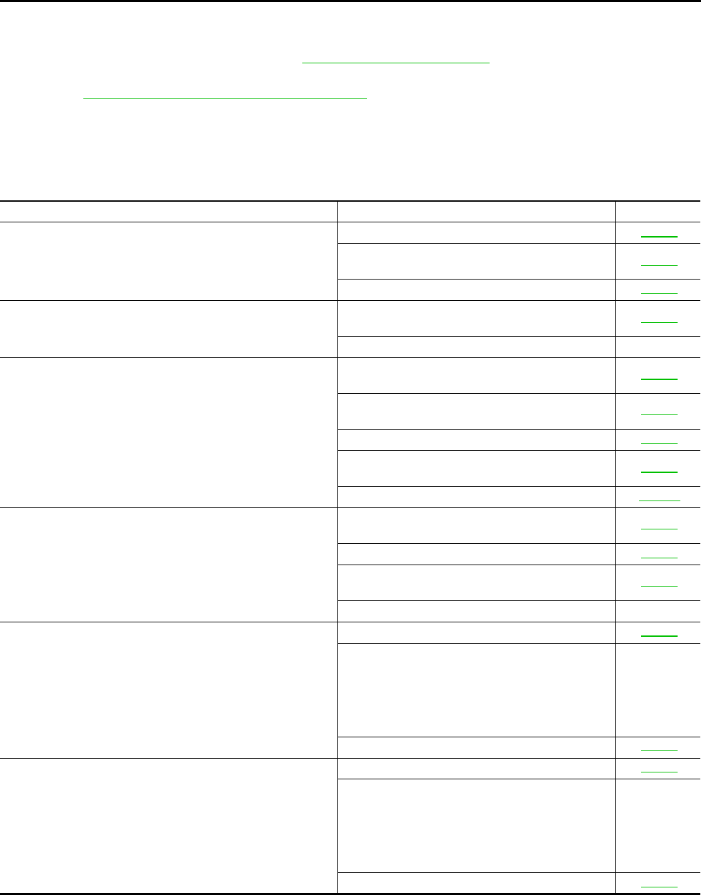
2. CHECK POWER SUPPLY CIRCUIT
Check voltage between BCM connector and ground.
OK or NG
OK >> GO TO 3.
NG >> Check BCM power supply circuit for open or short.
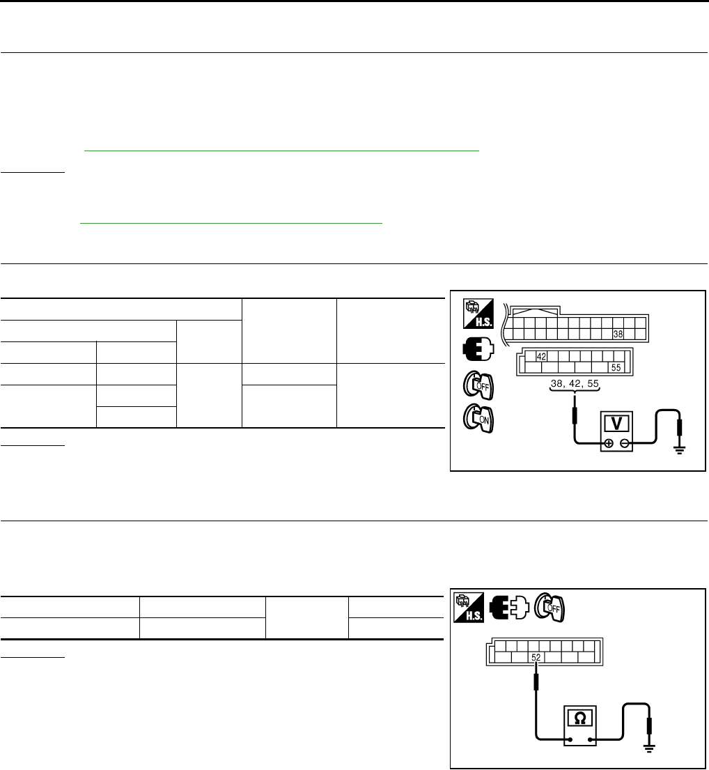
3. CHECK GROUND CIRCUIT
1. Turn ignition switch OFF.
2. Disconnect BCM connector.
3. Check continuity between BCM connector and ground.
OK or NG
OK >> Power supply and ground circuit are OK.
NG >> Check BCM ground circuit for open or short.
Terminals Condition of
ignition switch
Voltage (V)
(Approx.)
(+) (–)
BCM connector Terminal
M1 38
Ground
ON
Battery voltage
M2 42 OFF
55
PIIB5934E
BCM connector Terminal Ground Continuity
M2 52 Yes
PIIB5935E
POWER WINDOW SYSTEM
GW-35
C
D
E
F
G
H
J
K
L
M
A
B
GW
Revision: 2006 January 2006 M35/M45
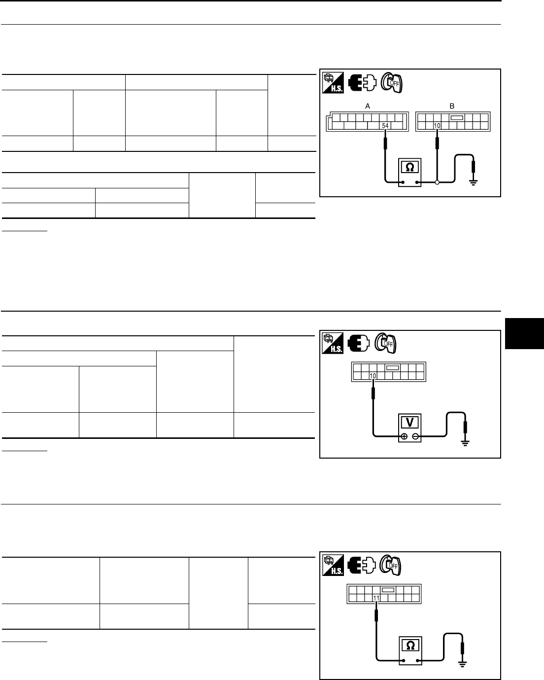
Power Window Main Switch Power Supply Circuit Check NIS0021S
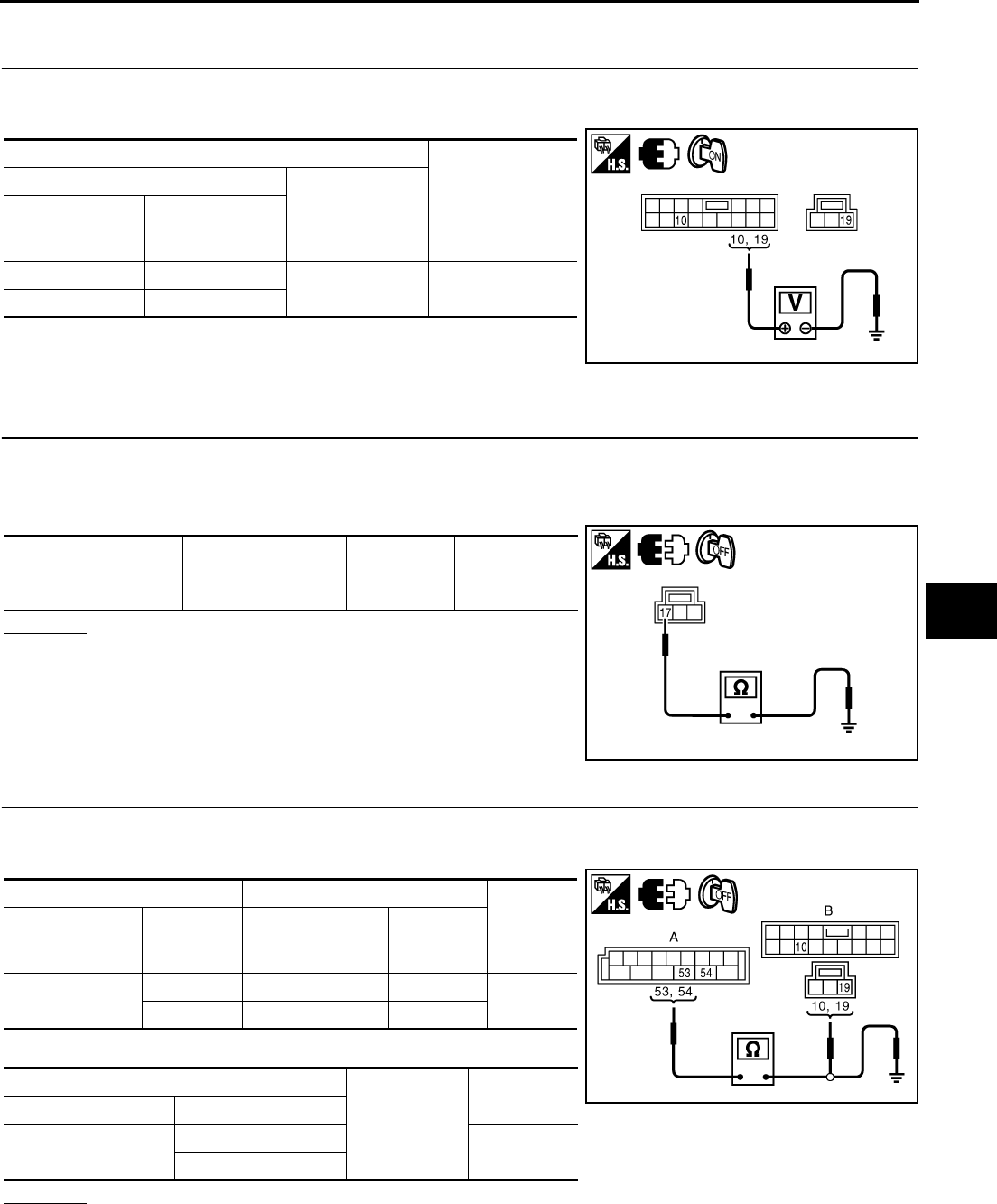
1. CHECK POWER SUPPLY CIRCUIT
1. Turn ignition switch ON.
2. Check voltage between power window main switch connector and ground.
OK or NG
OK >> GO TO 2.
NG >> GO TO 3.
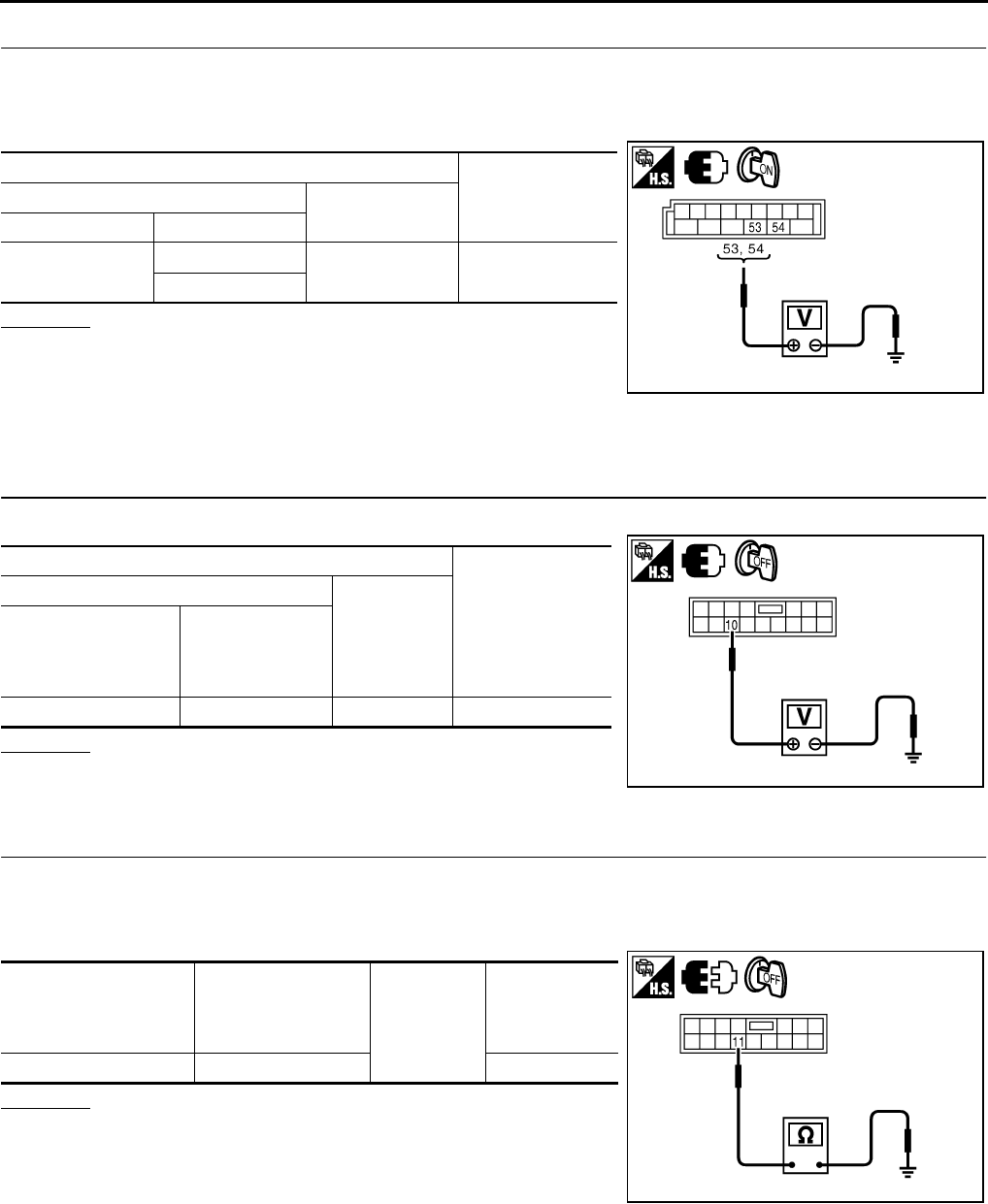
2. CHECK GROUND CIRCUIT
1. Turn ignition switch OFF.
2. Disconnect power window main switch connector.
3. Check continuity between power window main switch connector and ground.
OK or NG
OK >> Power window main switch power supply and ground
circuit are OK.
NG >> Repair or replace harness.
3. CHECK HARNESS CONTINUITY
1. Disconnect BCM and power window main switch connector.
2. Check continuity between BCM connector and power window main switch connector.
3. Check continuity between BCM connector and ground.
OK or NG
OK >> GO TO 4.
NG >> Repair or replace harness.
Terminal
Voltage (V)
(Approx.)
(+)
(–)
Power window
main switch
connector
Terminal
D10 10 Ground Battery voltage
D11 19
PIIB5936E
Power window main
switch connector Terminal Ground Continuity
D11 17 Yes
PIIB5937E
AB
Continuity
BCM connector Terminal
Power window
main switch
connector
Terminal
M2 53 D10 10 Yes
54 D11 19
A
Ground
Continuity
BCM connector Terminal
M2 53 No
54
PIIB5938E
GW-36
POWER WINDOW SYSTEM
Revision: 2006 January 2006 M35/M45
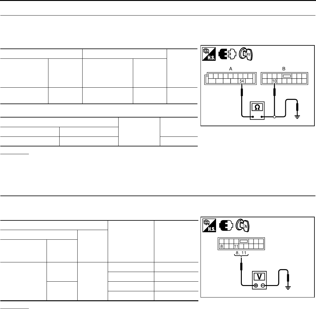
4. CHECK BCM OUTPUT SIGNAL
1. Connect BCM connector.
2. Turn ignition switch ON.
3. Check voltage between BCM connector and ground.
OK or NG
OK >> Check condition of harness and connector.
NG >> Replace BCM.
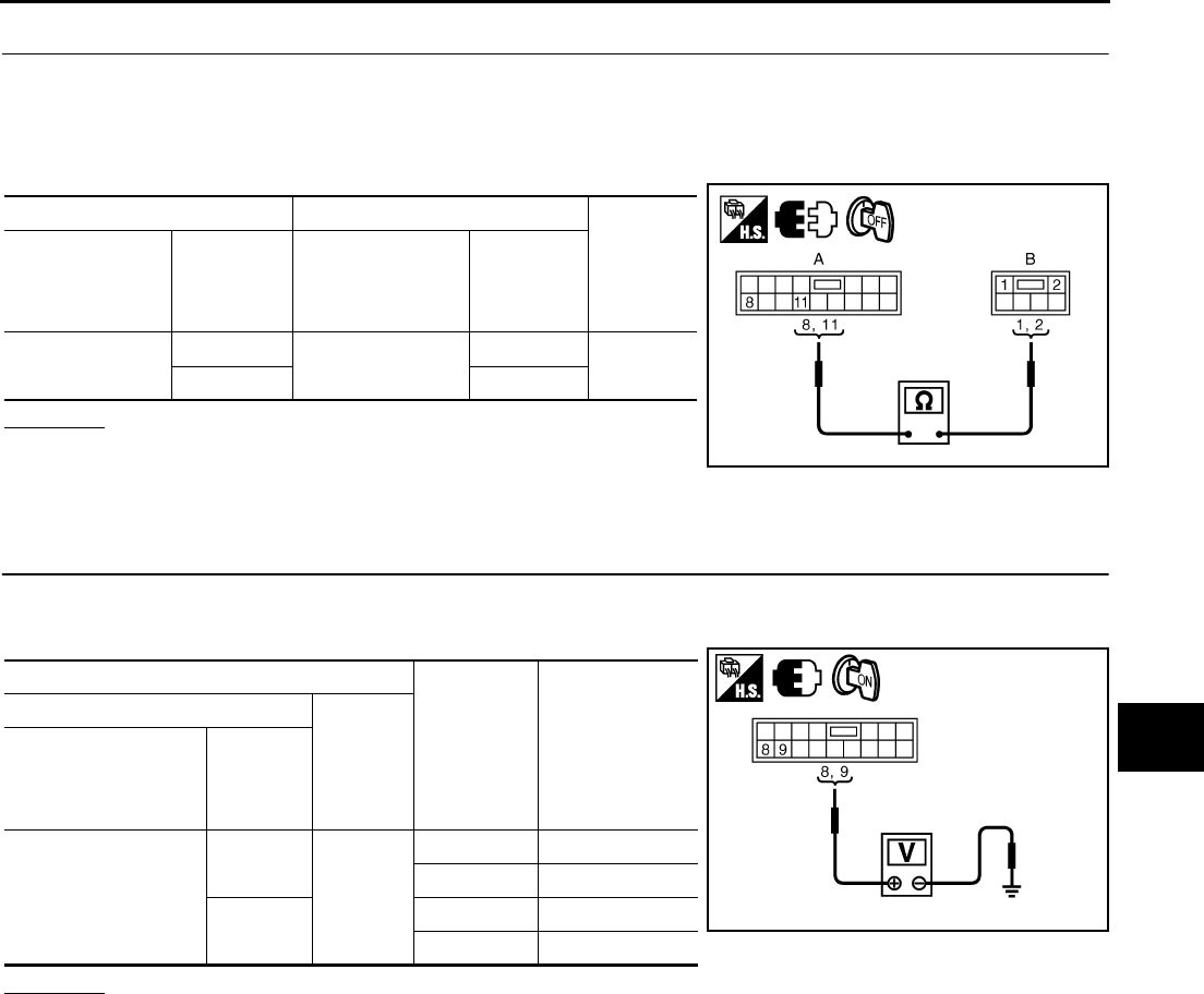
Power Window Sub-Switch (Front Passenger Side) Power Supply and Ground
Circuit Check NIS0021T
1. CHECK POWER SUPPLY CIRCUIT
Check voltage between power window sub-switch (front passenger side) connector and ground.
OK or NG
OK >> GO TO 2.
NG >> GO TO 3.
2. CHECK GROUND CIRCUIT
1. Turn ignition switch OFF.
2. Disconnect power window sub-switch (front passenger side) connector.
3. Check continuity between power window sub-switch (front passenger side) connector and ground.
OK or NG
OK >> Power window sub-switch (front passenger side) power
supply and ground circuit are OK.
NG >> Repair or replace harness.
Terminals Voltage (V)
(Approx.)
(+) (–)
BCM connector Terminal
M2 53 Ground Battery voltage
54
PIIB5939E
Terminal
Voltage (V)
(Approx.)
(+)
(–)
Power window
sub-switch
(front passenger side)
connector
Terminal
D46 10 Ground Battery voltage
PIIB5940E
Power window
sub-switch
(front passenger side)
connector
Terminal Ground Continuity
D46 11 Yes
PIIB5941E
POWER WINDOW SYSTEM
GW-37
C
D
E
F
G
H
J
K
L
M
A
B
GW
Revision: 2006 January 2006 M35/M45
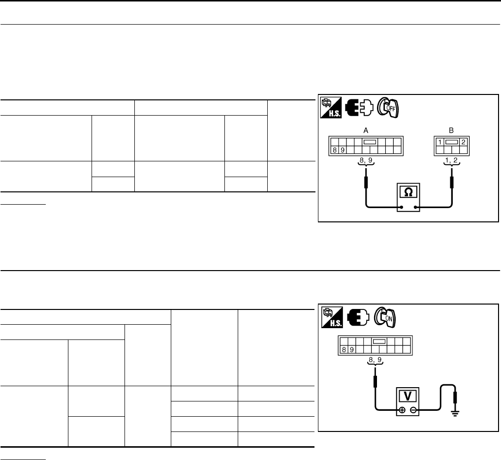
3. CHECK HARNESS CONTINUITY
1. Disconnect BCM and power window sub-switch (front passenger side) connector.
2. Check continuity between BCM connector and power window sub-switch (front passenger side) connec-
tor.
3. Check continuity between BCM connector and ground.
OK or NG
OK >> Check condition of harness and connector.
NG >> Repair or replace harness.
Power Window Sub-Switch (Rear LH or RH) Power Supply and Ground Circuit
Check NIS0021U
1. CHECK POWER SUPPLY
Check voltage between power window sub-switch (rear LH or RH) connector and ground.
OK or NG
OK >> GO TO 2.
NG >> GO TO 3.
2. CHECK GROUND CIRCUIT
1. Turn ignition switch OFF.
2. Disconnect power window sub-switch (rear LH or RH) connector.
3. Check continuity between power window sub-switch (rear LH or RH) connector and ground.
OK or NG
OK >> Power window sub-switch (rear LH or RH) power supply
and ground circuit are OK. Refer to symptom chart.
NG >> Repair or replace harness.
AB
Continuity
BCM connector Terminal
Power window
sub-switch
(front passenger side)
connector
Terminal
M2 54 D46 10 Yes
A
Ground Continuity
BCM connector Terminal
M2 54 No
PIIB5942E
Terminal
Voltage (V)
(Approx.)
(+)
(–)
Power window
sub-switch
(rear LH or RH)
connector
Terminal
D60 (LH)
D80 (RH) 10 Ground Battery voltage
PIIB5940E
Power window
sub-switch
(rear LH or RH)
connector
Terminal
Ground
Continuity
D60 (LH)
D80 (RH) 11 Yes
PIIB5941E
GW-38
POWER WINDOW SYSTEM
Revision: 2006 January 2006 M35/M45
3. CHECK HARNESS CONTINUITY
1. Turn ignition switch OFF.
2. Disconnect BCM and power window sub-switch (rear LH or RH) connector.
3. Check continuity between BCM connector and power window sub-switch (rear LH or RH) connector.
4. Check continuity between BCM connector and ground.
OK or NG
OK >> Check condition of harness and connector.
NG >> Repair or replace harness.
Power Window Motor (Front Driver Side) Circuit Check NIS0021V
1. CHECK POWER WINDOW MAIN SWITCH OUTPUT SIGNAL
1. Turn ignition switch ON.
2. Check voltage between power window main switch connector and ground.
OK or NG
OK >> GO TO 2.
NG >> Replace power window main switch.
AB
Continuity
BCM connector Terminal
Power window
sub-switch
(rear LH or RH)
connector
Terminal
M2 54 D60 (LH)
D80 (RH) 10 Yes
A
Ground Continuity
BCM connector Terminal
M2 54 No
PIIB5942E
Terminal
Window
Condition
Voltage (V)
(Approx.)
(+)
(–)
Power window
main switch
connector
Terminal
D10
8
Ground
UP Battery voltage
DOWN 0
11 UP 0
DOWN Battery voltage PIIB5943E
POWER WINDOW SYSTEM
GW-39
C
D
E
F
G
H
J
K
L
M
A
B
GW
Revision: 2006 January 2006 M35/M45
2. CHECK HARNESS CONTINUITY
1. Turn ignition switch OFF.
2. Disconnect power window main switch and power window motor (front driver side) connector.
3. Check continuity between power window main switch connector and power window motor (front driver
side).
OK or NG
OK >> Replace power window motor (front driver side).
NG >> Repair or replace harness.
Power Window Motor (Front Passenger Side) Circuit Check NIS0021W
1. CHECK POWER WINDOW SUB-SWITCH (FRONT PASSENGER SIDE) OUTPUT SIGNAL
1. Turn ignition switch ON.
2. Check voltage between power window sub-switch (front passenger side) connector and ground.
OK or NG
OK >> GO TO 2.
NG >> Replace front power window sub-switch (front passenger side).
AB
Continuity
Power window
main switch
connector
Terminal
Power window
motor
(front driver side)
connector
Terminal
D10 8D12 2Yes
11 1
PIIB5944E
Terminal
Window
condition
Voltage (V)
(Approx.)
(+)
(–)
Power window sub-
switch
(front passenger side)
connector
Terminal
D46
8
Ground
UP Battery voltage
DOWN 0
9UP 0
DOWN Battery voltage
PIIB5945E
GW-40
POWER WINDOW SYSTEM
Revision: 2006 January 2006 M35/M45
2. CHECK HARNESS CONTINUITY
1. Turn ignition switch OFF.
2. Disconnect power window sub-switch (front passenger side) and power window motor (front passenger
side) connector.
3. Check continuity between power window sub-switch (front passenger side) connector and power window
motor (front passenger side) connector.
OK or NG
OK >> Replace power window motor (front passenger side).
NG >> Repair or replace harness.
Power Window Motor (Rear LH or RH) Circuit Check NIS0021X
1. CHECK POWER WINDOW SUB-SWITCH REAR OUTPUT SIGNAL
1. Turn ignition switch ON.
2. Check voltage between power window sub-switch (rear LH or RH) connector and ground.
OK or NG
OK >> GO TO 2.
NG >> Replace power window sub-switch (rear LH or RH).
AB
Continuity
Power window
sub-switch
(front passenger side)
connector
Terminal
Power window
motor
(front passenger side)
connector
Terminal
D46 8D42 2Yes
91
PIIB5946E
Terminal
Window
condition
Voltage (V)
(Approx.)
(+)
(–)
Power window
sub-switch
(rear LH or RH)
connector
Terminal
D60 (LH)
D80 (RH)
8
Ground
UP Battery voltage
DOWN 0
9UP 0
DOWN Battery voltage
PIIB5945E
POWER WINDOW SYSTEM
GW-41
C
D
E
F
G
H
J
K
L
M
A
B
GW
Revision: 2006 January 2006 M35/M45
2. CHECK HARNESS CONTINUITY
1. Turn ignition switch OFF.
2. Disconnect power window sub-switch (rear LH or RH) and power window motor (rear LH or RH) connec-
tor.
3. Check continuity between power window sub-switch (rear LH or RH) connector and power window motor
(rear LH or RH) connector.
OK or NG
OK >> Replace power window motor (rear LH or RH).
NG >> Repair or replace harness.
AB
Continuity
Power window
sub-switch
(rear LH or RH)
connector
Terminal
Power window
motor
(rear LH or RH)
connector
Terminal
D60 (LH)
D80 (RH)
8D58 (LH)
D78 (RH)
1Yes
92
PIIB5961E
GW-42
POWER WINDOW SYSTEM
Revision: 2006 January 2006 M35/M45
Encoder Circuit Check (Driver Side) NIS0021Y
1. CHECK POWER WINDOW MOTOR (FRONT DRIVER SIDE) POWER SUPPLY
1. Turn ignition switch ON.
2. Check voltage between power window motor (front driver side) connector and ground.
OK or NG
OK >> GO TO 3.
NG >> GO TO 2.
2. CHECK HARNESS CONTINUITY 1
1. Turn ignition switch OFF.
2. Disconnect power window main switch and power window motor (front driver side).
3. Check continuity between power window main switch connector and power window motor (front driver
side) connector.
4. Check continuity between power window main switch connector
and ground.
OK or NG
OK >> Replace power window main switch.
NG >> Repair or replace harness.
Terminal
Voltage (V)
(Approx.)
(+)
(–)
Power window
motor
(front driver side)
connector
Terminal
D12 4 Ground 10
PIIB5947E
AB
Continuity
Power window main
switch connector Terminal
Power window
motor
(front driver side)
connector
Terminal
D10 15 D12 4 Yes
A
Ground Continuity
Power window main
switch connector Terminal
D10 15 No
PIIB5948E
POWER WINDOW SYSTEM
GW-43
C
D
E
F
G
H
J
K
L
M
A
B
GW
Revision: 2006 January 2006 M35/M45
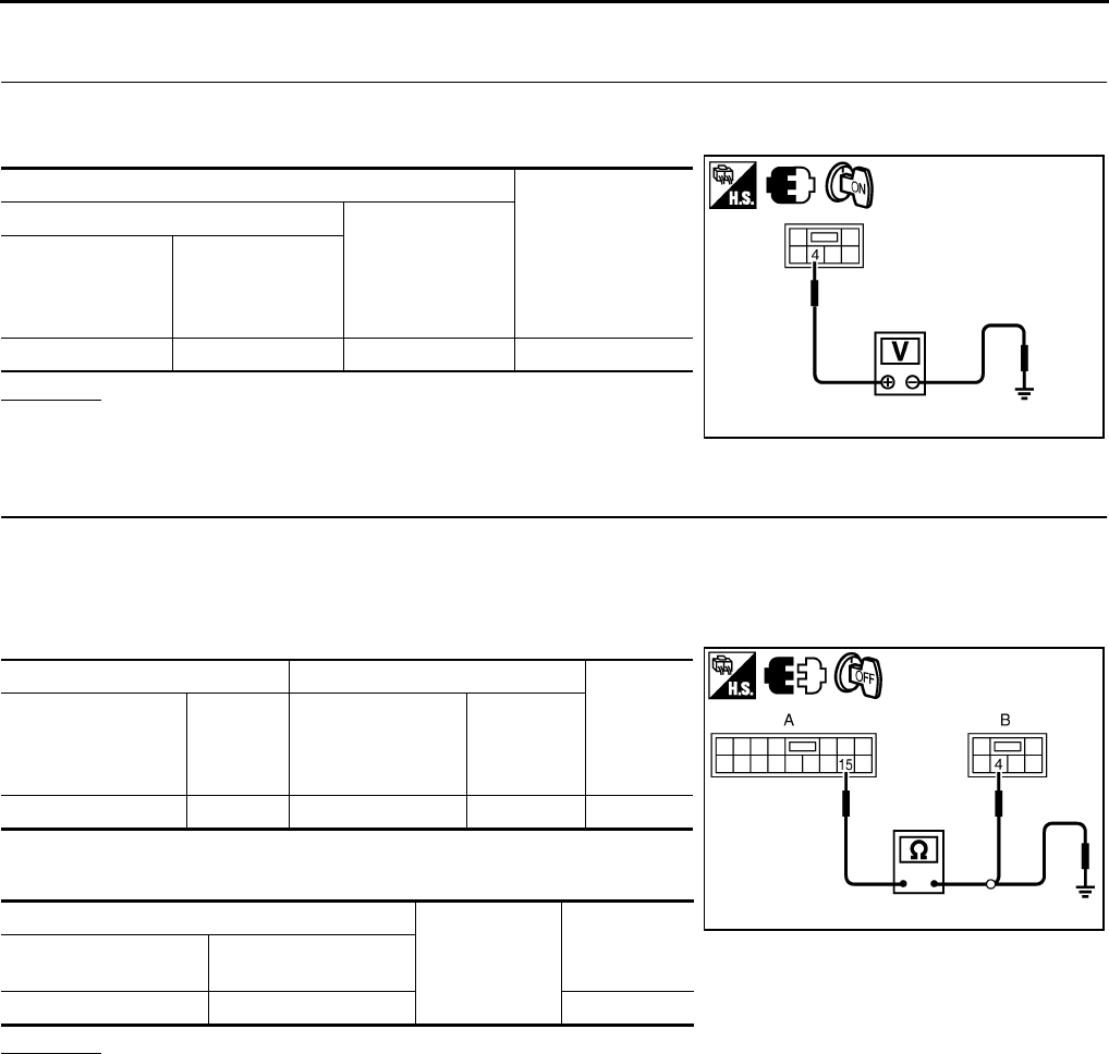
3. CHECK GROUND CIRCUIT
1. Turn ignition switch OFF.
2. Disconnect power window motor (front driver side) connector.
3. Check continuity between power window motor (front driver side) connector and ground.
OK or NG
OK >> GO TO 5.
NG >> GO TO 4.
4. CHECK HARNESS CONTINUITY 2
1. Disconnect power window main switch connector.
2. Check continuity between power window main switch connector and power window motor (front driver
side) connector.
OK or NG
OK >> Replace power window main switch.
NG >> Repair or replace harness.
Power window motor
(front driver side)
connector
Terminal Ground Continuity
D12 6 Yes
PIIB5949E
AB
Continuity
Power window main
switch connector Terminal
Power window
motor
(front driver side)
connector
Terminal
D10 2 D12 6 Yes
PIIB5950E
GW-44
POWER WINDOW SYSTEM
Revision: 2006 January 2006 M35/M45
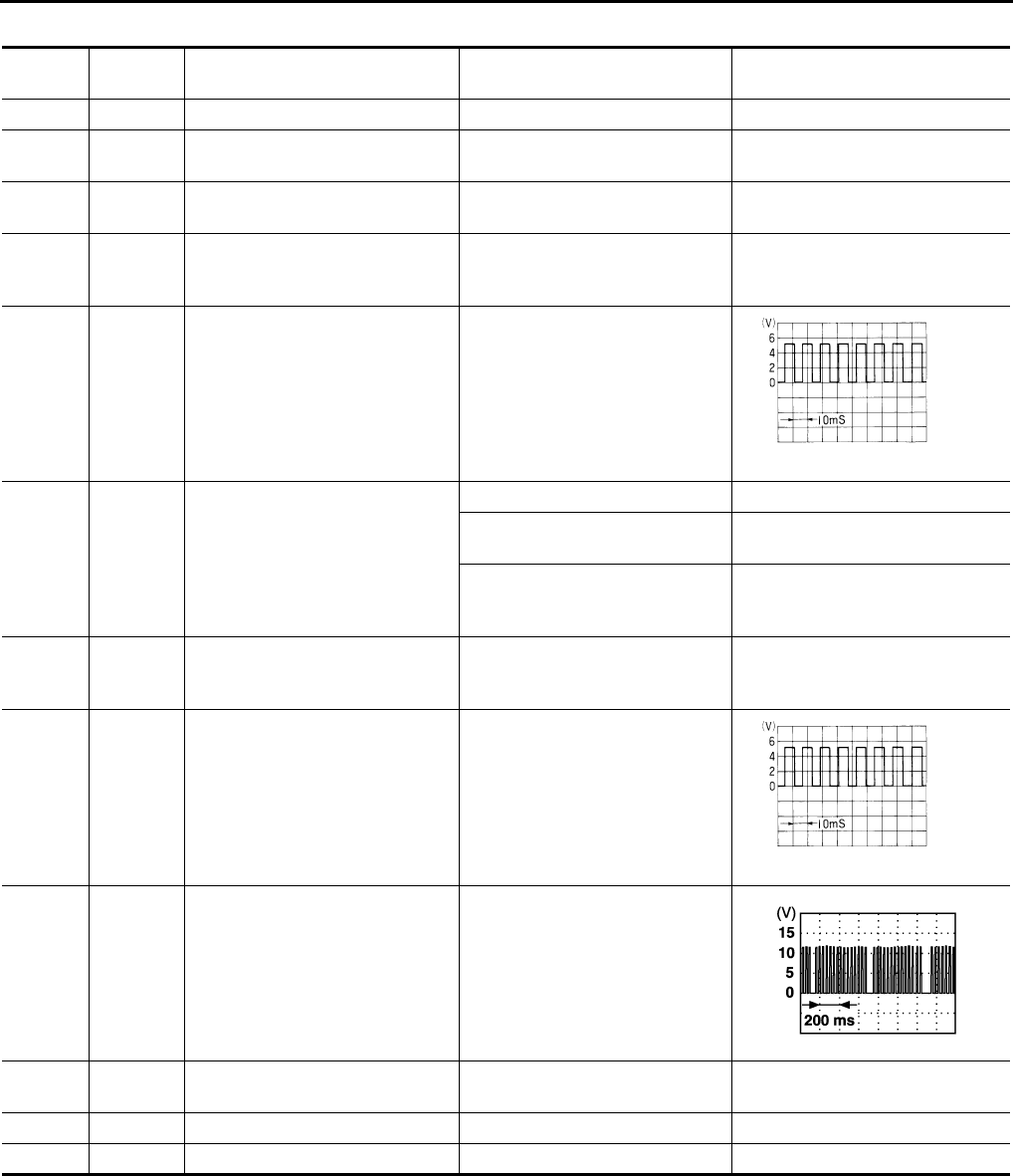
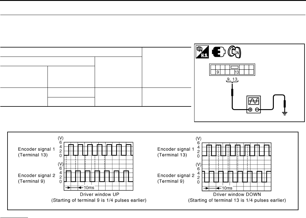
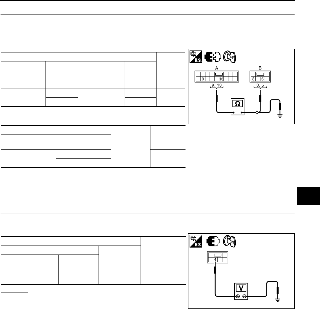
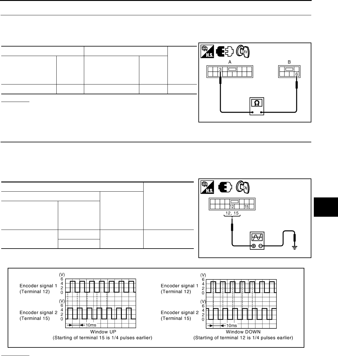
5. CHECK ENCODER SIGNAL
1. Connect power window motor (front driver side) connector.
2. Turn ignition switch ON.
3. Check signal between power window main switch connector and ground with oscilloscope.
OK or NG
OK >> Replace power window main switch.
NG >> GO TO 6.
Terminals
Signal
(Reference value)
(+)
(–)
Power window
main switch
connector
Terminal
D10 9Ground Refer to following
signal
13
PIIB5951E
PIIB5952E
POWER WINDOW SYSTEM
GW-45
C
D
E
F
G
H
J
K
L
M
A
B
GW
Revision: 2006 January 2006 M35/M45
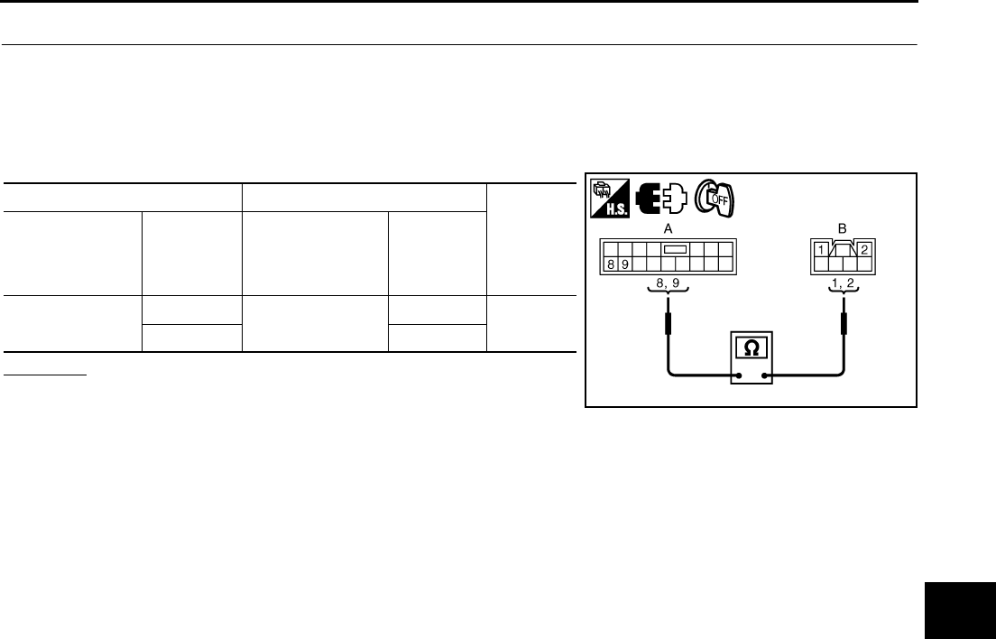
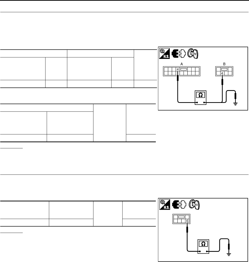
6. CHECK HARNESS CONTINUITY 3
1. Turn ignition switch OFF.
2. Disconnect power window main switch and power window motor (front driver side) connector.
3. Check continuity between power window main switch connector and power window motor (front driver
side) connector.
4. Check continuity between power window main switch connector
and ground.
OK or NG
OK >> Replace power window motor (front driver side).
NG >> Repair or replace harness.
Encoder Circuit Check (Passenger Side) NIS0021Z
1. CHECK POWER WINDOW MOTOR (FRONT PASSENGER SIDE) POWER SUPPLY
1. Turn ignition switch ON.
2. Check voltage between power window motor (front passenger side) connector and ground.
OK or NG
OK >> GO TO 3.
NG >> GO TO 2.
AB
Continuity
Power window
main switch
connector
Terminal
Power window
motor
(front driver side)
connector
Terminal
D10 9D12 3Yes
13 5
A
Ground
Continuity
Power window main
switch connector Terminal
D10 9No
13
PIIB5953E
Terminal
Voltage (V)
(Approx.)
(+)
(–)
Power window motor
(front passenger side)
connector
Terminal
D42 4 Ground 10
PIIB5962E
GW-46
POWER WINDOW SYSTEM
Revision: 2006 January 2006 M35/M45
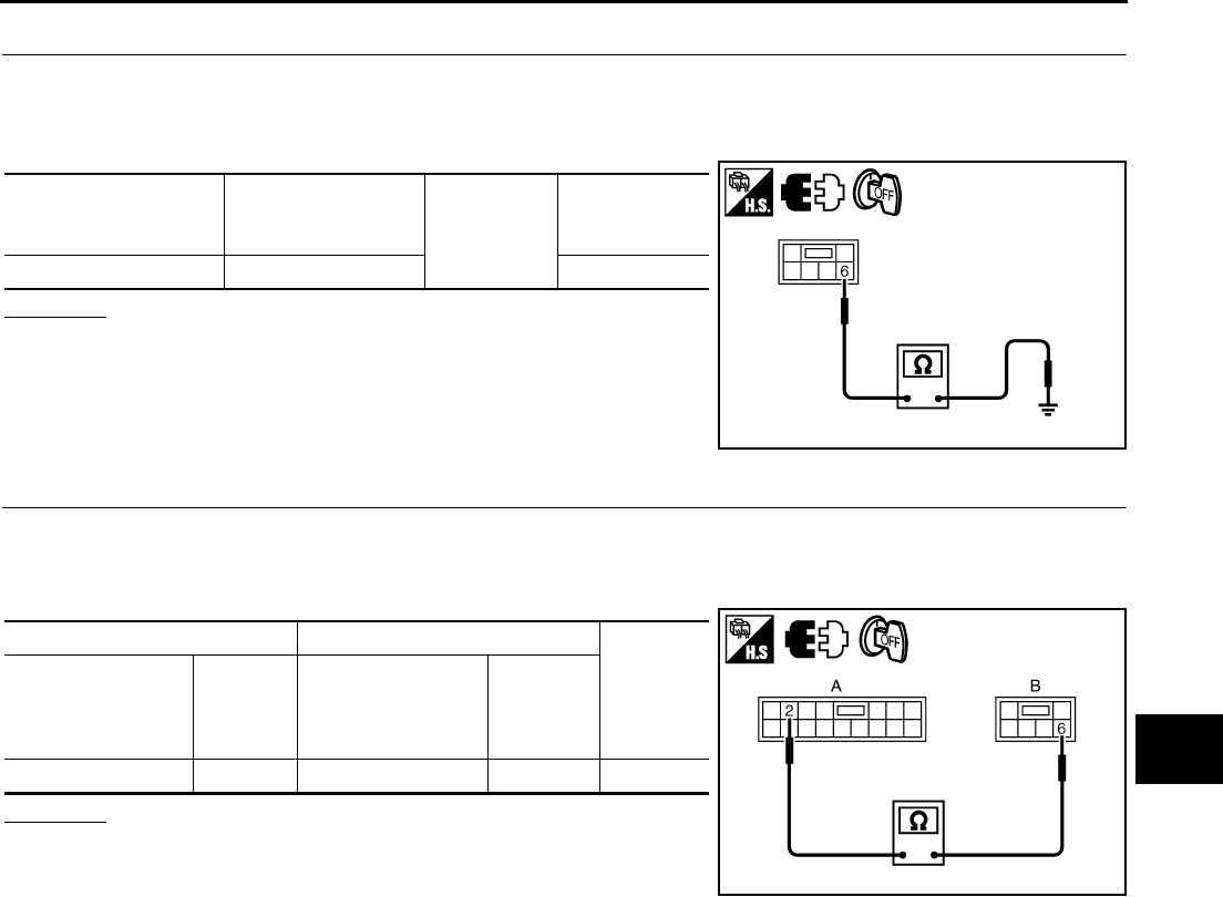
2. CHECK HARNESS CONTINUITY 1
1. Turn ignition switch OFF.
2. Disconnect power window sub-switch (front passenger side) and power window motor (front passenger
side) connector.
3. Check continuity between power window sub-switch (front passenger side) connector and power window
motor (front passenger side) connector.
4. Check continuity between power window sub-switch (front pas-
senger side) connector and ground.
OK or NG
OK >> Replace power window sub-switch (front passenger side).
NG >> Repair or replace harness.
3. CHECK GROUND CIRCUIT
1. Turn ignition switch OFF.
2. Disconnect power window motor (front passenger side) connector.
3. Check continuity between power window motor (front passenger side) connector and ground.
OK or NG
OK >> GO TO 5.
NG >> GO TO 4.
AB
Continuity
Power window sub-
switch
(front passenger side)
connector
Terminal
Power window motor
(front passenger side)
connector
Terminal
D46 4 D42 4 Yes
A
Ground Continuity
Power window
sub-switch
(front passenger side)
connector
Terminal
D46 4 No
PIIB5963E
Power window motor
(front passenger side)
connector
Terminal Ground Continuity
D42 6 Yes
PIIB5964E
POWER WINDOW SYSTEM
GW-47
C
D
E
F
G
H
J
K
L
M
A
B
GW
Revision: 2006 January 2006 M35/M45
4. CHECK HARNESS CONTINUITY 2
1. Disconnect power window sub-switch (front passenger side) connector.
2. Check continuity between power window sub-switch (front passenger side) connector power window
motor (front passenger side) connector.
OK or NG
OK >> Replace power window sub-switch (front passenger
side).
NG >> Repair or replace harness.
5. CHECK ENCODER SIGNAL
1. Connect power window motor (front passenger side) connector.
2. Turn ignition switch ON.
3. Check signal between power window sub-switch (front passenger side) connector and ground with oscillo-
scope.
OK or NG
OK >> Replace power window sub-switch (front passenger side).
NG >> GO TO 6.
AB
Continuity
Power window
sub- switch
(front passenger side)
connector
Terminal
Power window
motor
(front passenger side)
connector
Terminal
D463D426Yes
PIIB5965E
Terminal
Signal
(Reference value)
(+)
(–)
Power window
sub-switch
(front passenger side)
connector
Terminal
D46 12 Ground Refer to following
signal
15
PIIB5966E
PIIB5954E
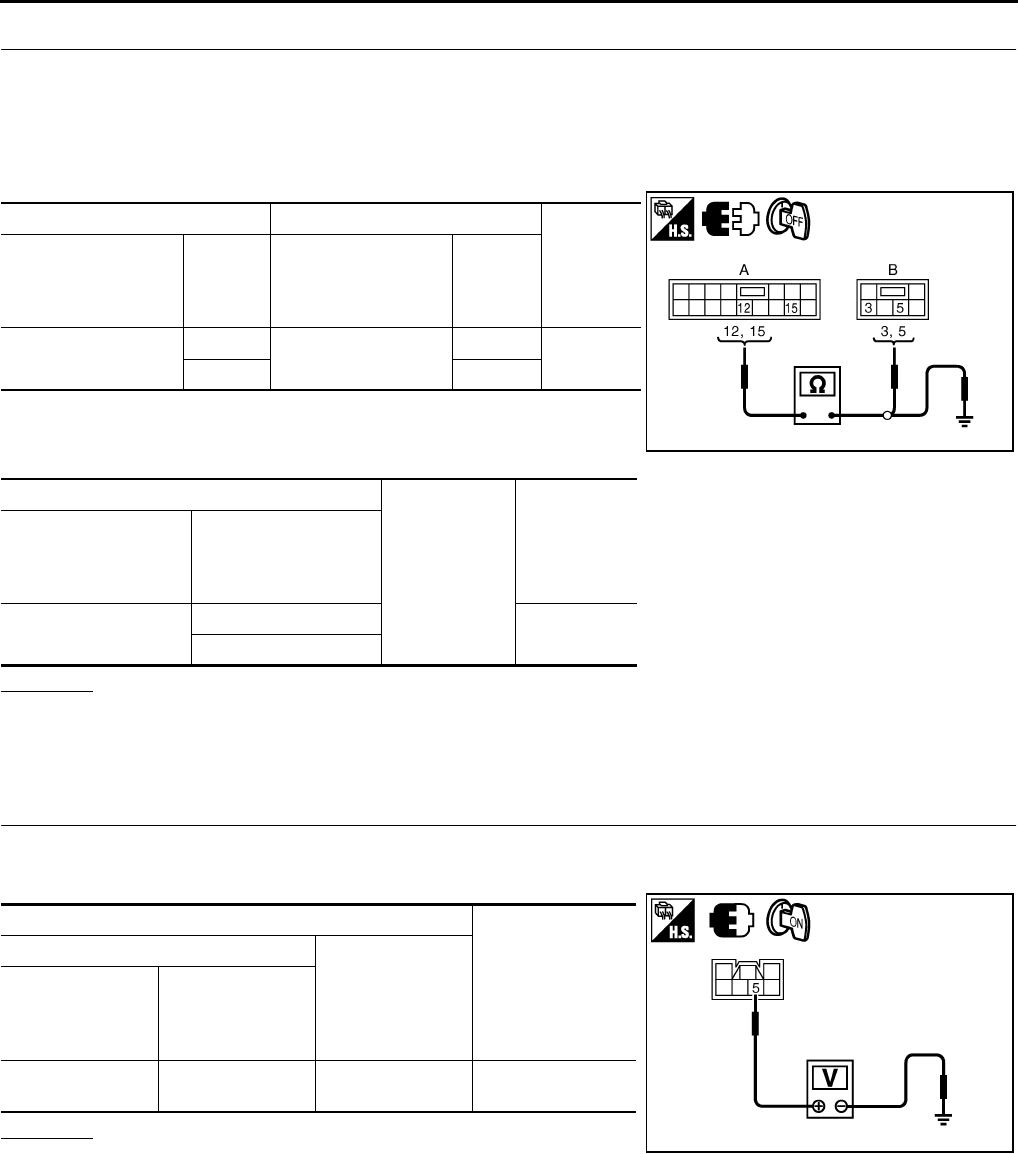
GW-48
POWER WINDOW SYSTEM
Revision: 2006 January 2006 M35/M45
6. CHECK HARNESS CONTINUITY 3
1. Turn ignition switch OFF.
2. Disconnect power window sub-switch (front passenger side) and power window motor (front passenger
side) connector.
3. Check continuity between power window sub-switch (front passenger side) connector and power window
motor (front passenger side) connector.
4. Check continuity between power window sub-switch (front pas-
senger side) connector and power window motor (front passen-
ger side) connector.
OK or NG
OK >> Replace power window motor (front passenger side).
NG >> Repair or replace harness.
Encoder Circuit Check (Rear LH or RH) NIS00220
1. CHECK POWER WINDOW MOTOR (REAR LH OR RH) POWER SUPPLY
1. Turn ignition switch ON.
2. Check voltage between power window motor (rear LH or RH) connector and ground.
OK or NG
OK >> GO TO 3.
NG >> GO TO 2.
AB
Continuity
Power window
sub- switch
(front passenger side)
connector
Terminal
Power window
motor
(front passenger side)
connector
Terminal
D46 12 D42 5Yes
15 3
A
Ground
Continuity
Power window
sub-switch
(front passenger side)
connector
Terminal
D46 12 No
15
PIIB5967E
Terminal
Voltage (V)
(Approx.)
(+)
(–)
Power window
motor
(rear LH or RH)
connector
Terminal
D58 (LH)
D78 (RH) 5 Ground 10
PIIB5968E
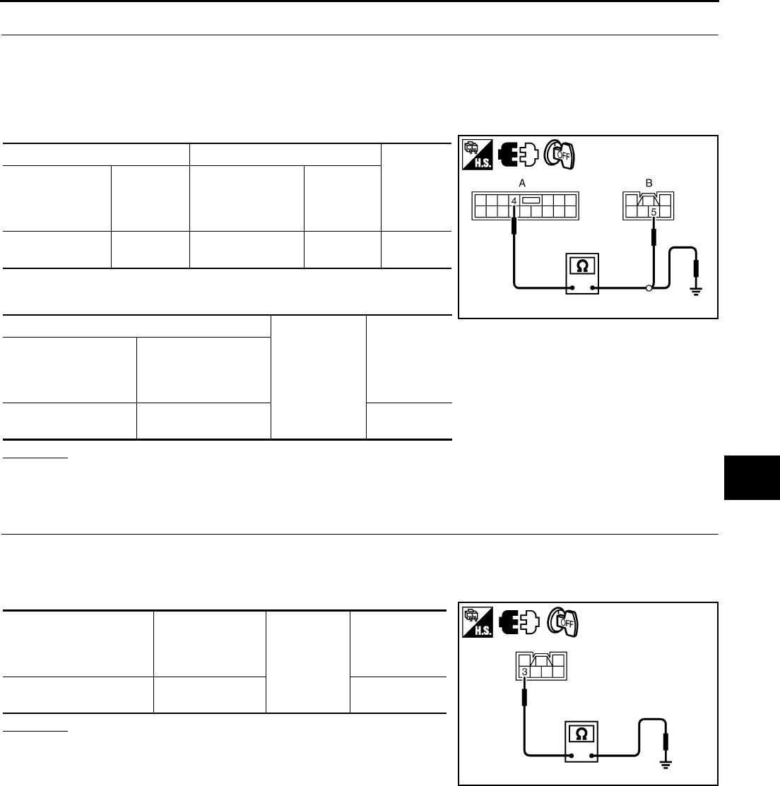
POWER WINDOW SYSTEM
GW-49
C
D
E
F
G
H
J
K
L
M
A
B
GW
Revision: 2006 January 2006 M35/M45
2. CHECK HARNESS CONTINUITY 1
1. Turn ignition switch OFF.
2. Disconnect power window sub-switch (rear LH or RH) and power window motor (rear LH or RH) connec-
tor.
3. Check continuity between power window sub-switch (rear LH or RH) connector and power window motor
(rear LH or RH) connector.
4. Check continuity between power window sub-switch (rear LH or
RH) connector and ground.
OK or NG
OK >> Replace power window sub-switch (rear LH or RH).
NG >> Repair or replace harness.
3. CHECK GROUND CIRCUIT
1. Turn ignition switch OFF.
2. Disconnect power window motor (rear LH or RH) connector.
3. Check continuity between power window motor (rear LH or RH) connector and ground.
OK or NG
OK >> GO TO 5.
NG >> GO TO 4.
AB
Continuity
Power window
sub- switch
(rear LH or RH)
connector
Terminal
Power window
motor
(rear LH or RH)
connector
Terminal
D60 (LH)
D80 (RH) 4D58 (LH)
D78 (RH) 5Yes
A
Ground
Continuity
Power window
sub- switch
(rear LH or RH)
connector
Terminal
D60 (LH)
D80 (RH) 4No
PIIB5969E
Power window
motor
(rear LH or RH)
connector
Terminal
Ground
Continuity
D58 (LH)
D78 (RH) 3Yes
PIIB5970E
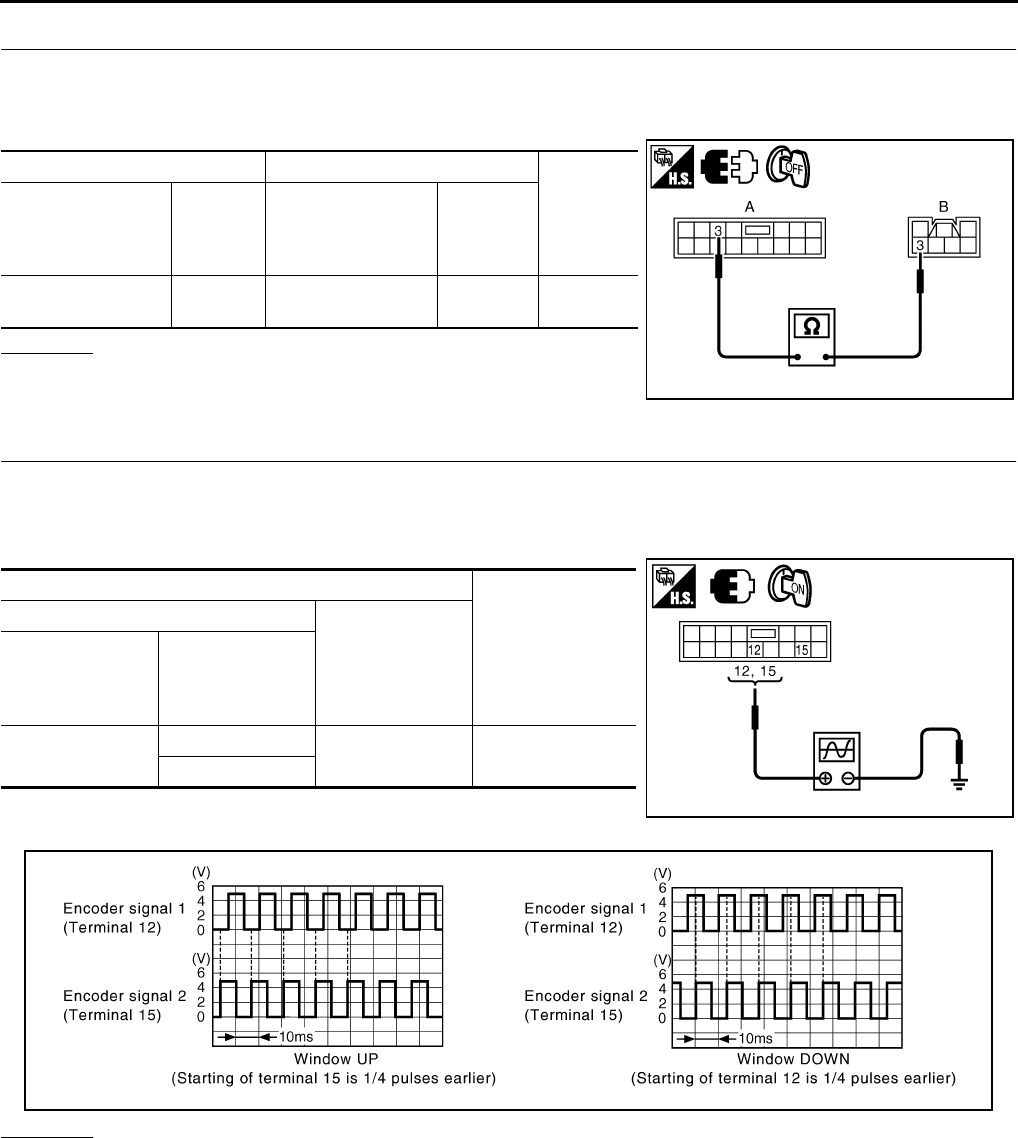
GW-50
POWER WINDOW SYSTEM
Revision: 2006 January 2006 M35/M45
4. CHECK HARNESS CONTINUITY 2
1. Disconnect power window sub-switch (rear LH or RH) connector.
2. Check continuity between power window sub-switch (rear LH or RH) connector and power window motor
(rear LH or RH) connector.
OK or NG
OK >> Replace power window sub-switch (rear LH or RH).
NG >> Repair or replace harness.
5. CHECK ENCODER SIGNAL
1. Connect power window motor (rear LH or RH) connector.
2. Turn ignition switch ON.
3. Check signal between power window sub-switch (rear LH or RH) connector and ground with oscilloscope.
OK or NG
OK >> Replace power window sub-switch (rear LH or RH).
NG >> GO TO 6.
AB
Continuity
Power window
sub- switch
(rear LH or RH)
connector
Terminal
Power window
motor
(rear LH or RH)
connector
Terminal
D60 (LH)
D80 (RH) 3D58 (LH)
D78 (RH) 3Yes
PIIB5971E
Terminals
Signal
(Reference value)
(+)
(–)
Power window
sub- switch
(rear LH or RH)
connector
Terminal
D60 (LH)
D80 (RH)
12 Ground Refer to following
signal
15
PIIB5966E
PIIB5954E
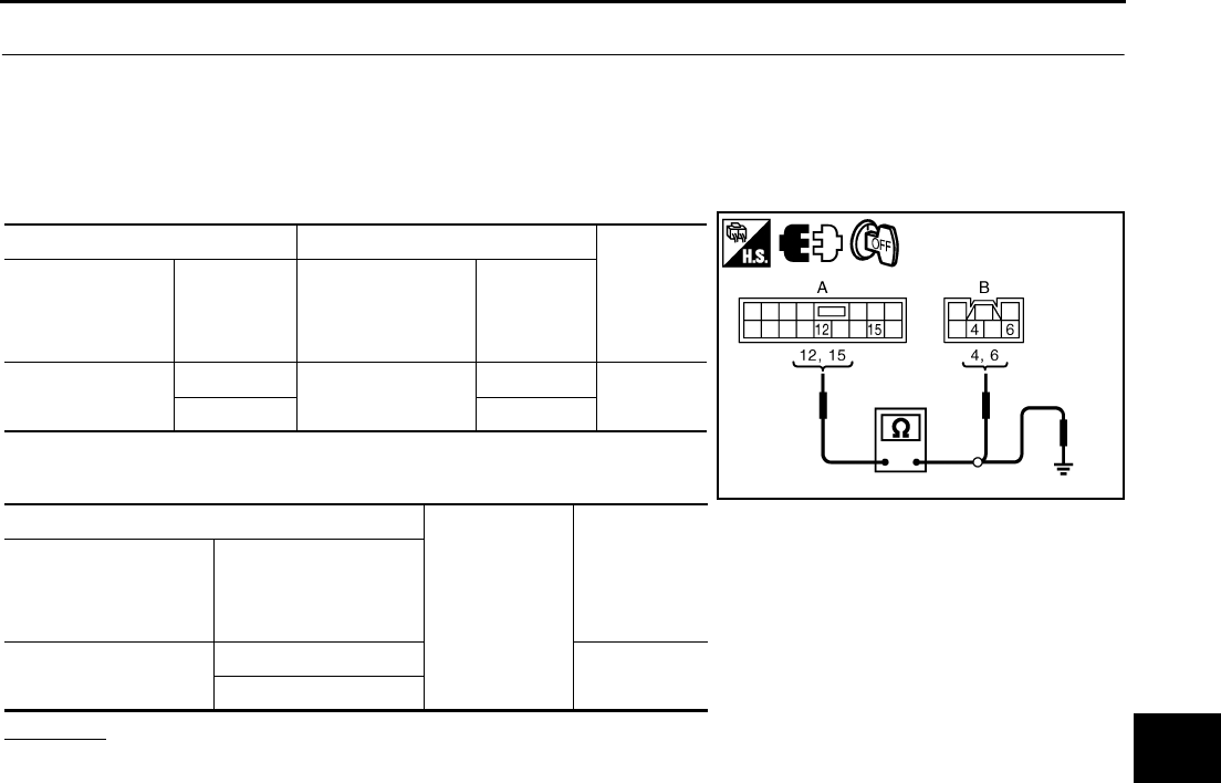
POWER WINDOW SYSTEM
GW-51
C
D
E
F
G
H
J
K
L
M
A
B
GW
Revision: 2006 January 2006 M35/M45
6. CHECK HARNESS CONTINUITY 3
1. Turn ignition switch OFF.
2. Disconnect power window sub-switch (rear LH or RH) and power window motor (rear LH or RH) connec-
tor.
3. Check continuity between power window sub-switch (rear LH or RH) connector and power window motor
(rear LH or RH) connector.
4. Check power window sub-switch (rear LH or RH) connector and
ground.
OK or NG
OK >> Replace power window motor (rear LH or RH).
NG >> Repair or replace harness.
AB
Continuity
Power window
sub- switch
(rear LH or RH)
connector
Terminal
Power window
motor
(rear LH or RH)
connector
Terminal
D60 (LH)
D80 (RH)
12 D58 (LH)
D78 (RH)
4Yes
15 6
A
Ground
Continuity
Power window
sub- switch
(rear LH or RH)
connector
Terminal
D60 (LH)
D80 (RH)
12 No
15
PIIB5972E
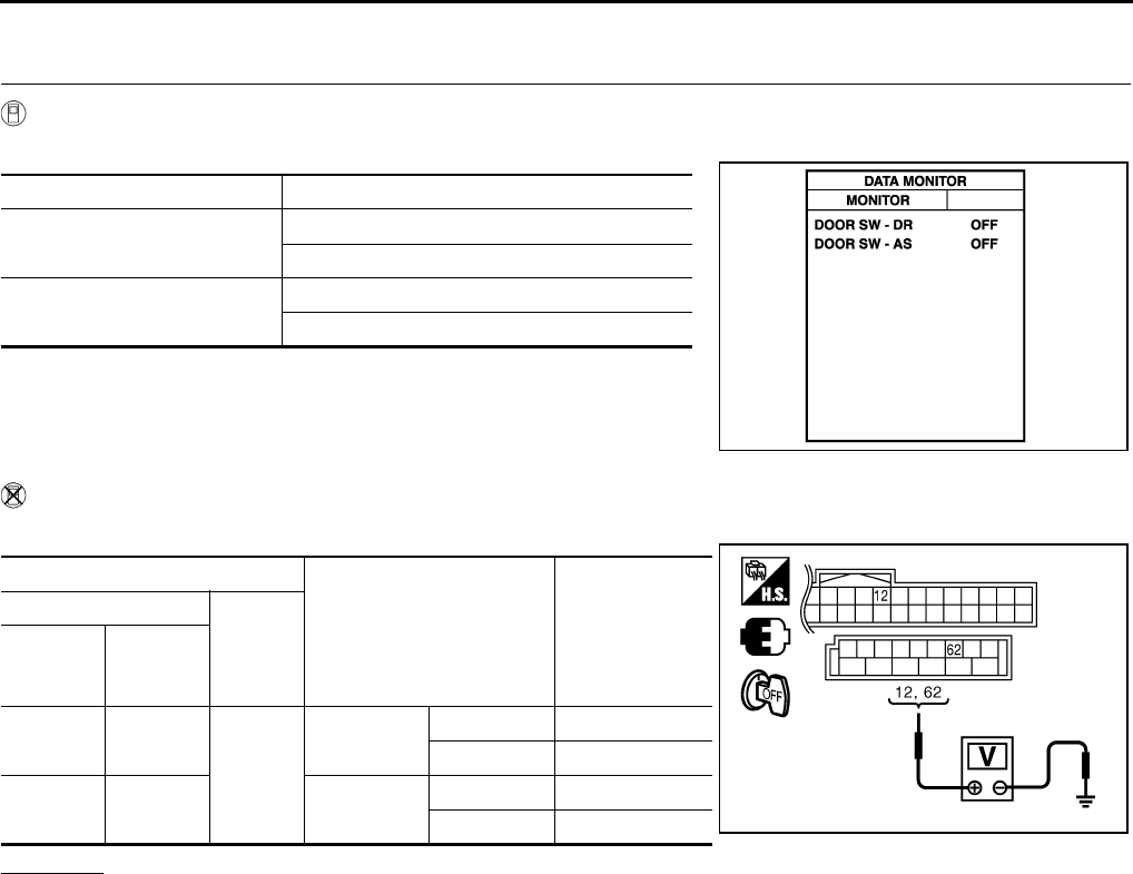
GW-52
POWER WINDOW SYSTEM
Revision: 2006 January 2006 M35/M45
Door Switch Check NIS00221
1. CHECK DOOR SWITCH INPUT SIGNAL
With CONSULT-II
Check (“DOOR SW-DR” and “DOOR SW-AS”) in “DATA MONITOR” mode with CONSULT-II.
Without CONSULT-II
Check voltage between BCM connector and ground.
OK or NG
OK >> Door switch circuit is OK.
NG >> GO TO 2.
Monitor item Condition
DOOR SW-DR OPEN : ON
CLOSE : OFF
DOOR SW-AS OPEN : ON
CLOSE : OFF
PIIA2464E
Terminals
Door condition Voltage (V)
(Approx.)
(+)
(–)
BCM
connec-
tor
Terminal
M1 12
Ground
Passenger
side
OPEN 0
CLOSE Battery voltage
M3 62 Driver side OPEN 0
CLOSE Battery voltage PIIB5955E
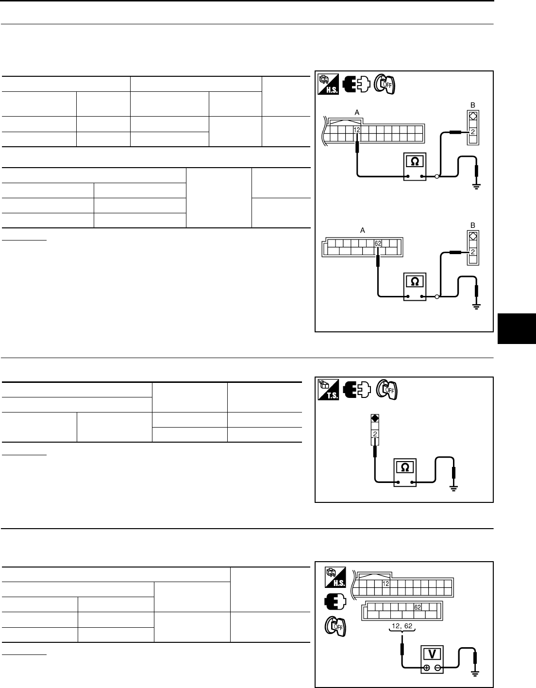
POWER WINDOW SYSTEM
GW-53
C
D
E
F
G
H
J
K
L
M
A
B
GW
Revision: 2006 January 2006 M35/M45
2. CHECK HARNESS CONTINUITY
1. Turn ignition switch OFF.
2. Disconnect BCM and door switch connector.
3. Check continuity between BCM connector and door switch connector.
4. Check continuity between BCM connector ground.
OK or NG
OK >> GO TO 3.
NG >> Repair or replace harness.
3. CHECK DOOR SWITCH
Check door switches.
OK or NG
OK >> GO TO 4.
NG >> Replace malfunction door switch.
4. CHECK BCM OUTPUT SIGNAL
1. Connect BCM connector.
2. Check voltage between BCM connector ground.
OK or NG
OK >> Further inspection is necessary, Refer to symptom
chart.
NG >> Replace BCM.
AB
Continuity
BCM connector Terminal Door switch
connector Terminal
M1 12 B35 2Yes
M3 62 B11
A
Ground
Continuity
BCM connector Terminal
M1 12 No
M3 62
PIIB5976E
Terminal Door switch Continuity
Door switches
2Ground part of
door switch
Pushed No
Released Yes
PIIB5977E
Terminal Voltage (V)
(Approx.)
(+) (–)
BCM connector Terminal
M1 12 Ground Battery voltage
M3 62
PIIB5955E
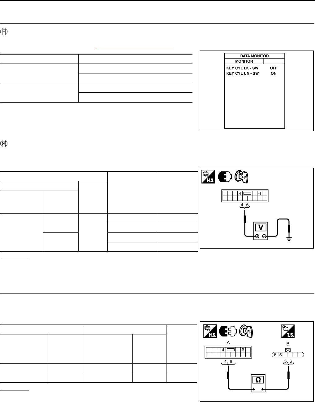
GW-54
POWER WINDOW SYSTEM
Revision: 2006 January 2006 M35/M45
Front Door Key Cylinder Switch Check NIS00222
1. CHECK DOOR KEY CYLINDER SWITCH INPUT SIGNAL
With CONSULT-II
Check (“KEY CYL LK-SW”, “KEY CYL UN-SW”) in “DATA MONITOR” mode for “POWER DOOR ROCK SYS-
TEM” with CONSULT-II. Refer to GW-31, "DATE MONITOR"
Without CONSULT-II
1. Turn ignition switch OFF.
2. Check voltage between power window main switch connector and ground.
OK or NG
OK >> Further inspection is necessary. Refer to symptom chart.
NG >> GO TO 2.
2. CHECK HARNESS CONTINUITY
1. Disconnect power window main switch and front door key lock assembly (driver side) connector.
2. Check continuity between power window main switch connector and front door lock assembly (driver side)
connector.
OK or NG
OK >> GO TO 3.
NG >> Repair or replace harness.
Monitor item Condition
KEY CYL LK-SW Lock : ON
Neutral / Unlock : OFF
KEY CYL UN-SW Unlock : ON
Neutral / Lock : OFF
PIIA6285E
Terminals
Key position Voltage (V)
(Approx.)
(+)
(–)
Power window
main switch
connector
Terminal
D10
4
Ground
Lock 0
Neutral / Unlock 5
6Unlock 0
Neutral / Lock 5 PIIB5956E
AB
Continuity
Power window
main switch
connector
Terminal
Front door lock
assembly
(driver side)
connector
Terminal
D10 4D14 6Yes
65
PIIB5973E
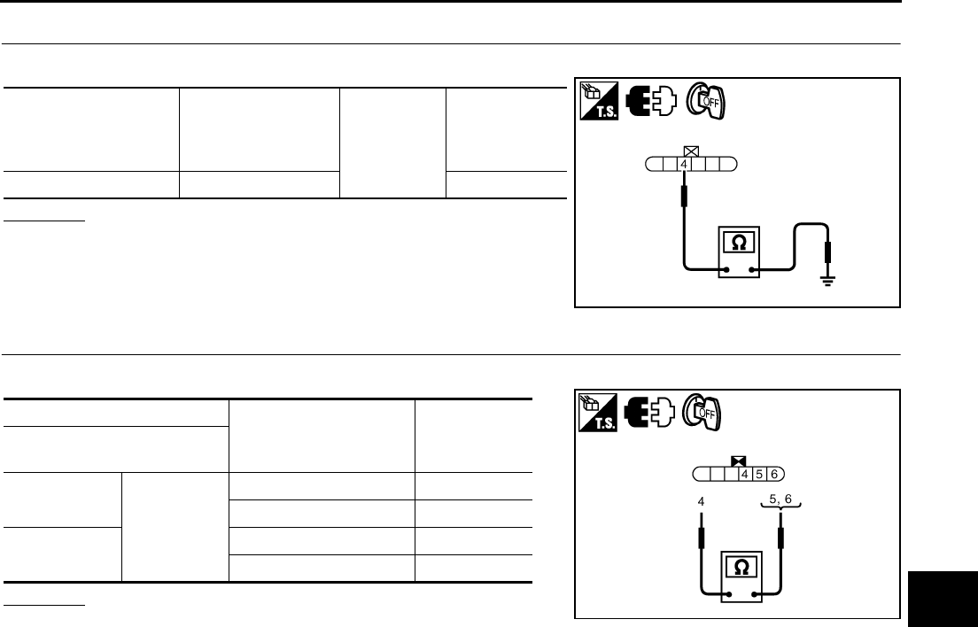
POWER WINDOW SYSTEM
GW-55
C
D
E
F
G
H
J
K
L
M
A
B
GW
Revision: 2006 January 2006 M35/M45
3. CHECK DOOR KEY CYLINDER SWITCH GROUND
Check continuity between front door lock assembly (driver side) connector ground.
OK or NG
OK >> GO TO 4.
NG >> Repair or replace harness.
4. CHECK DOOR KEY CYLINDER SWITCH
Check front door lock assembly (driver side).
OK or NG
OK >> Further inspection is necessary. Refer to symptom
chart.
NG >> Replace front door key cylinder (driver side) switch.
Front door lock
assembly
(driver side)
connector
Terminal Ground Continuity
D14 4 Yes
PIIB5974E
Terminal
Key position Continuity
Front door lock assembly
(driver side)
5
4
Unlock Yes
Neutral / Lock No
6Lock Yes
Neutral / Unlock No
PIIB5975E
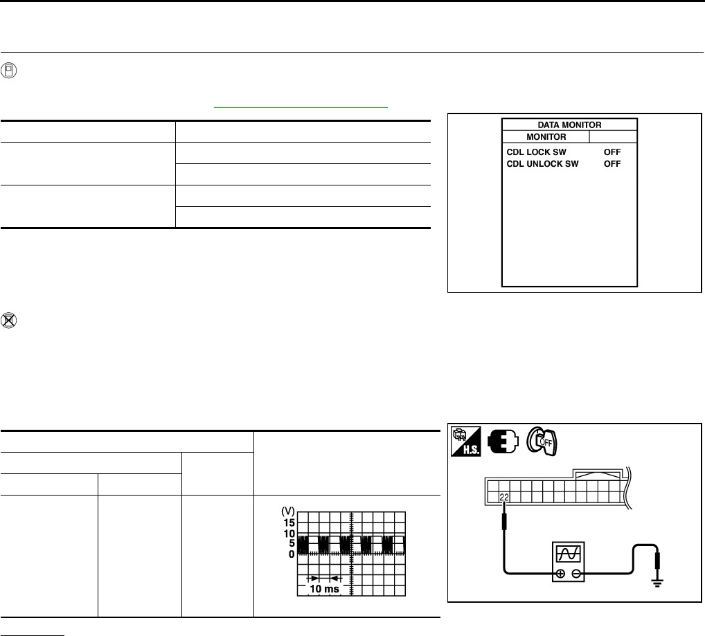
GW-56
POWER WINDOW SYSTEM
Revision: 2006 January 2006 M35/M45
Power Window Serial Link Check (Passenger Side) NIS00223
1. CHECK POWER WINDOW SWITCH OUTPUT SIGNAL
With CONSULT-II
Check (“CDL LOCK SW ”, “CDL UNLOCK SW”) in DATA MONITOR mode for “POWER DOOR LOCK SYS-
TEM” with CONSULT-II. Refer to GW-31, "DATE MONITOR" .
Without CONSULT-II
1. Remove key from ignition switch, and the door of driver side and passenger side is closed.
2. Check signal between BCM connector and ground with oscilloscope when door lock and unlock switch
(driver side and passenger side) is turned “LOCK” or “UNLOCK”.
3. Make sure signals which are shown in the figure below can be detected during 10 second just after door
lock and unlock switch (driver side and passenger side) is turned “LOCK” or “UNLOCK”.
OK or NG
OK >> Power window serial link is OK.
NG >> GO TO 2.
Monitor item Condition
CDL LOCK SW LOCK : ON
UNLOCK : OFF
CDL UNLOCK SW LOCK : OFF
UNLOCK : ON
PIIA7068E
Terminal Signal
(Reference value)
(+) (–)
BCM connector Terminal
M1 22 Ground
PIIB5957E
PIIA1297E
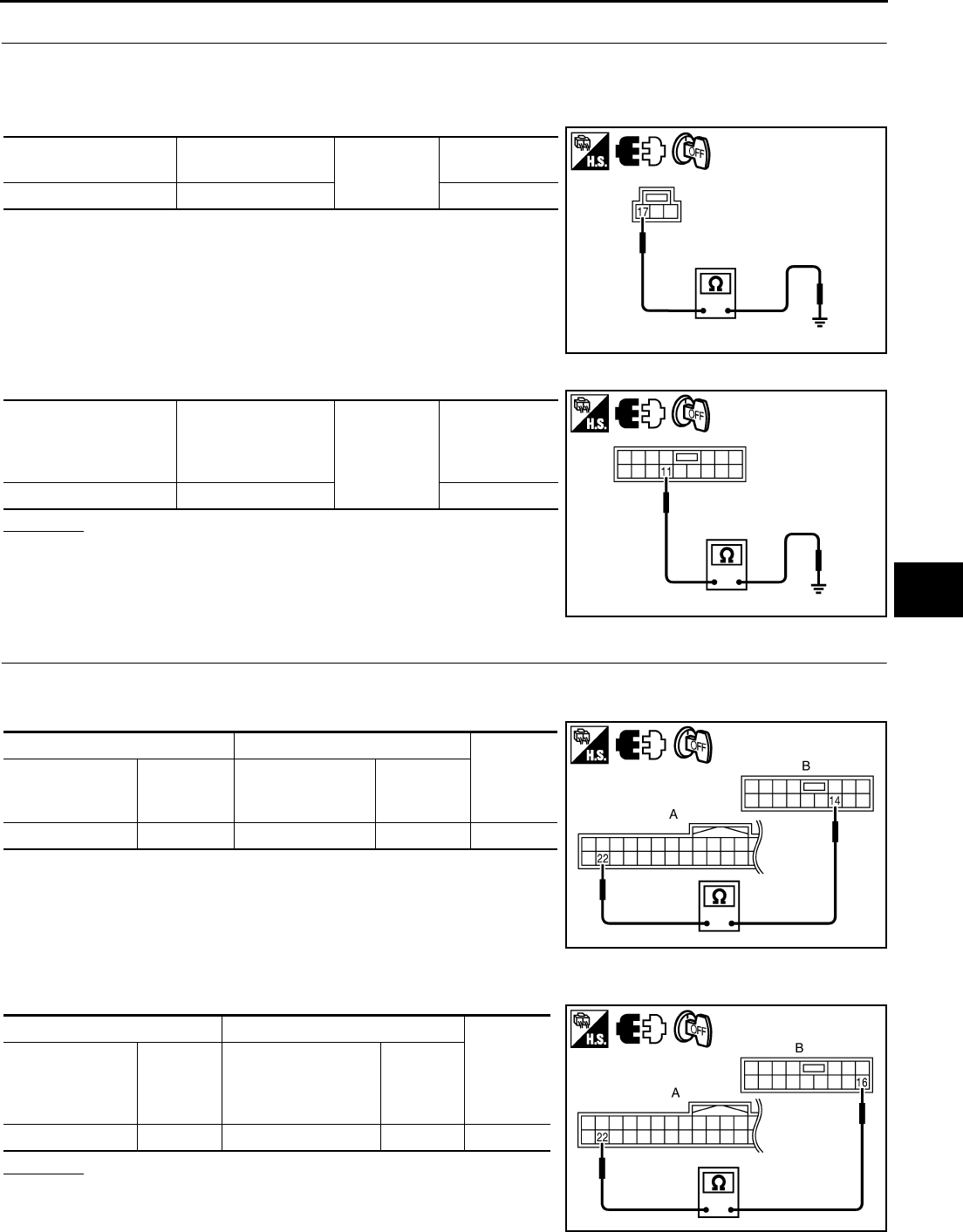
POWER WINDOW SYSTEM
GW-57
C
D
E
F
G
H
J
K
L
M
A
B
GW
Revision: 2006 January 2006 M35/M45
2. CHECK POWER WINDOW SWITCH GROUND
1. Turn ignition switch OFF.
2. Disconnect power window main switch and front power window switch (passenger side) connector.
3. Check continuity between power window main switch connector and ground.
4. Check continuity between power window sub-switch (front passenger side) connector and ground.
OK or NG
OK >> GO TO 3.
NG >> Repair or replace harness.
3. CHECK POWER WINDOW SERIAL LINK CIRCUIT
1. Disconnect BCM connector.
2. Check continuity between BCM connector and power window main switch connector.
3. Check continuity between BCM connector and power window sub-switch (front passenger side) connec-
tor.
OK or NG
OK >> Replace power window main switch.
NG >> Repair or replace harness.
Power window main
switch connector Terminal Ground Continuity
D11 17 Yes
PIIB5937E
Power window
sub-switch
(front passenger side)
connector
Terminal Ground Continuity
D46 11 Yes
PIIB5941E
AB
Continuity
BCM connector Terminal
Power window
main switch
connector
Terminal
M1 22 D10 14 Yes
PIIB5958E
AB
Continuity
BCM connector Terminal
Power window
sub- switch
(front passenger side)
connector
Terminal
M1 22 D46 16 Yes
PIIB5959E
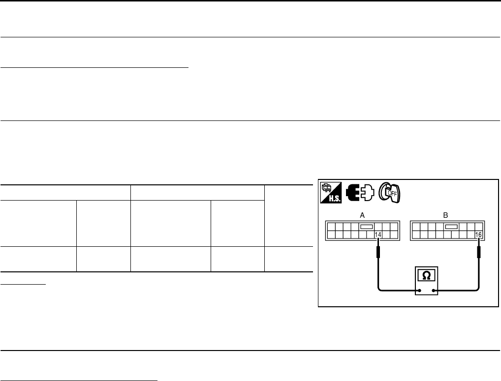
GW-58
POWER WINDOW SYSTEM
Revision: 2006 January 2006 M35/M45
Power Window Serial Link Check (Rear LH or RH) NIS00224
1. CHECK POWER WINDOW SWITCH
Change with operative power window sub-switch (rear LH or RH).
Whether operates normally is confirmed?
YES >> Replace power window sub-switch (rear LH or RH).
NO >> GO TO 2.
2. CHECK HARNESS CONTINUITY
1. Turn ignition switch OFF.
2. Disconnect power window main switch and power window sub-switch (rear LH or RH) connector.
3. Check continuity between power window main switch connector and power window sub-switch (rear LH or
RH) connector.
OK or NG
OK >> Replace power window main switch.
NG >> Repair or replace harness.
Power Window Lock Switch Check NIS00225
1. CHECK POWER WINDOW LOCK SIGNAL
Exchanges for a normal power window main switch, and operation is checked.
Does power window lock operate?
YES >> Replace power window main switch.
NO >> Check condition of harness and connector.
AB
Continuity
Power window
main switch
connector
Terminal
Power window
sub- switch
(rear LH or RH)
connector
Terminal
D10 14 D60 (LH)
D80 (RH) 16 Yes
PIIB5960E
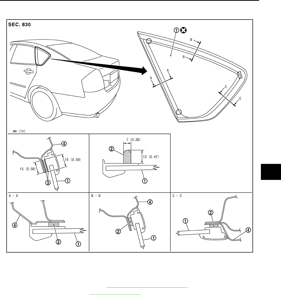
SIDE WINDOW GLASS
GW-59
C
D
E
F
G
H
J
K
L
M
A
B
GW
Revision: 2006 January 2006 M35/M45
SIDE WINDOW GLASS PFP:83300
Removal and Installation NIS00226
REMOVAL
1. Remove the rear pillar finisher. Refer to .EI-41, "REAR PILLAR FINISHER"
2. Remove the headlining. Refer to EI-52, "HEADLINING" .
3. Apply protective tape around the side window to protect the painted surface from damage.
4. Remove the side window glass using piano wire or power cutting tool and an inflatable pump bag.
WARNING:
When cutting the glass from the vehicle, always wear safety glasses and heavy gloves to help pre-
vent glass splinters from entering your eyes or cutting your hands.
CAUTION:
●Be careful not to scratch the glass when removing.
●Do not set or stand the glass on its edge. Small chips may develop into cracks.
PIIB3285J
1. Side window glass 2. Adhesive 3. Primer
4. Body side outer panel

GW-60
SIDE WINDOW GLASS
Revision: 2006 January 2006 M35/M45
INSTALLATION
●Use a genuine Nissan Urethane Adhesive Kit (if available) or equivalent and follow the instructions fur-
nished with it.
●While the urethane adhesive is curing, open a door window. This will prevent the glass from being forced
out by passenger room air pressure when a door is closed.
●The molding must be installed securely so that it is in position and leaves no gap.
●Inform the customer that the vehicle should remain stationary until the urethane adhesive has completely
cured (preferably 24 hours). Curing time varies with temperature and humidity.
WARNING:
●Keep heat and open flames away as primers and adhesive are flammable.
●The materials contained in the kit are harmful if swallowed, and may irritate skin and eyes. Avoid
contact with the skin and eyes.
●Use in an open, well ventilated location. Avoid breathing the vapors. They can be harmful if
inhaled. If affected by vapor inhalation, immediately move to an area with fresh air.
●Driving the vehicle before the urethane adhesive has completely cured may affect the perfor-
mance of the side window in case of an accident.
CAUTION:
●Do not use an adhesive which is past its usable term. Shelf life of this product is limited to six
months after the date of manufacture. Carefully adhere to the expiration or manufacture date
printed on the box.
●Keep primers and adhesive in a cool, dry place. Ideally, they should be stored in a refrigerator.
●Do not leave primers or adhesive cartridge unattended with their caps open or off.
●The vehicle should not be driven for at least 24 hours or until the urethane adhesive has com-
pletely cured. Curing time varies depending on temperature and humidity. The curing time will
increase under lower temperature and lower humidity.
Repairing Water Leaks
Leaks can be repaired without removing and reinstalling glass.
If water is leaking between the urethane adhesive material and body or glass, determine the extent of leakage.
This can be done by applying water to the side window area while pushing glass outward.
To stop the leak, apply primer (if necessary) and then urethane adhesive to the leak point.
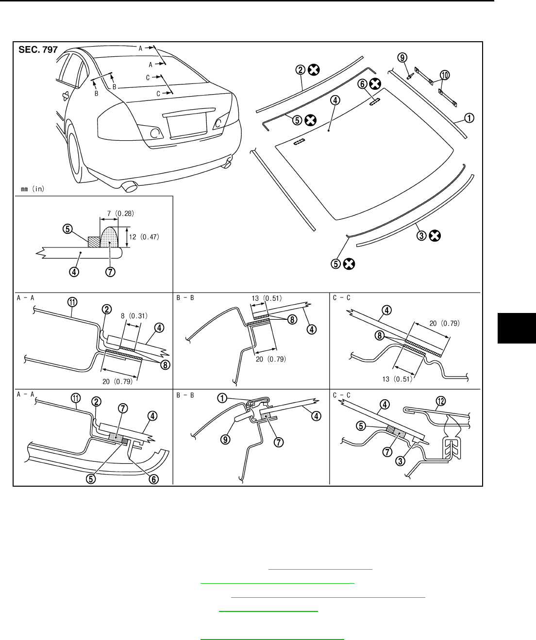
REAR WINDOW GLASS AND MOLDING
GW-61
C
D
E
F
G
H
J
K
L
M
A
B
GW
Revision: 2006 January 2006 M35/M45
REAR WINDOW GLASS AND MOLDING PFP:79712
Removal and Installation NIS00227
REMOVAL
1. Remove rear seatback and rear seat cushion. Refer to SE-172, "REAR SEAT" .
2. Remove the rear pillar finisher. Refer to EI-41, "REAR PILLAR FINISHER" .
3. Remove the rear parcel shelf finisher. Refer to EI-42, "REAR PARCEL SHELF FINISHER" .
4. Remove the rear of the headlining. Refer to EI-52, "HEADLINING" .
5. Remove the connectors and grounds for the rear window defogger and printed antenna.
6. Remove the roof side molding. Refer to EI-25, "ROOF SIDE MOLDING" .
1. Roof side molding 2. Rear window molding (upper) 3. Rear window molding (lower)
4. Rear window glass 5. Dam rubber 6. Spacer
7. Adhesive 8. Primer 9. Rivet
10. Fastener 11. Roof panel 12. Trunk lid outer panel
PIIB3286J
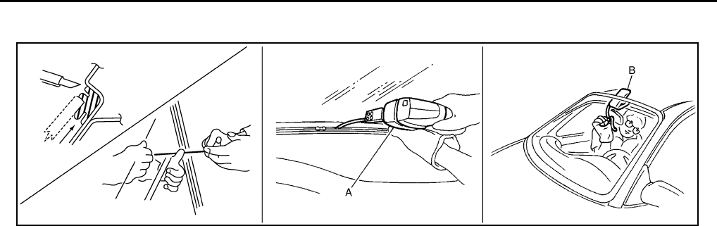
GW-62
REAR WINDOW GLASS AND MOLDING
Revision: 2006 January 2006 M35/M45
7. After removing molding using pliers, remove glass using piano wire or power cutting tool A and an inflat-
able pump bag B.
●If a rear window glass is reused, mark the body and the glass with mating marks.
WARNING:
When cutting the glass from the vehicle, always wear safety glasses and heavy gloves to help pre-
vent glass splinters from entering your eyes or cutting your hands.
CAUTION:
●When a rear window glass is reused, do not use a cutting knife or power cutting tool.
●Be careful not to scratch the glass when removing.
●Do not set or stand the glass on its edge. Small chips may develop into cracks.
INSTALLATION
●The dam rubber should be installed in position.
●Use a genuine Nissan Urethane Adhesive Kit (if available) or equivalent and follow the instructions fur-
nished with it.
●While the urethane adhesive is curing, open a door window. This will prevent the glass from being forced
out by passenger compartment air pressure when a door is closed.
●The molding must be installed securely so that it is in position and leaves no gap.
●Inform the customer that the vehicle should remain stationary until the urethane adhesive has completely
cured (preferably 24 hours). Curing time varies with temperature and humidity.
WARNING:
●Keep heat and open flames away as primers and adhesive are flammable.
●The materials contained in the kit are harmful if swallowed, and may irritate skin and eyes. Avoid
contact with the skin and eyes.
●Use in an open, well ventilated location. Avoid breathing the vapors. They can be harmful if
inhaled. If affected by vapor inhalation, immediately move to an area with fresh air.
●Driving the vehicle before the urethane adhesive has completely cured may affect the perfor-
mance of the rear window in case of an accident.
CAUTION:
●Do not use an adhesive which is past its usable term. Shelf life of this product is limited to six
months after the date of manufacture. Carefully adhere to the expiration or manufacture date
printed on the box.
●Keep primers and adhesive in a cool, dry place. Ideally, they should be stored in a refrigerator.
●Do not leave primers or adhesive cartridge unattended with their caps open or off.
●The vehicle should not be driven for at least 24 hours or until the urethane adhesive has com-
pletely cured. Curing time varies depending on temperature and humidity. The curing time will
increase under lower temperature and lower humidity.
PIIB5779E
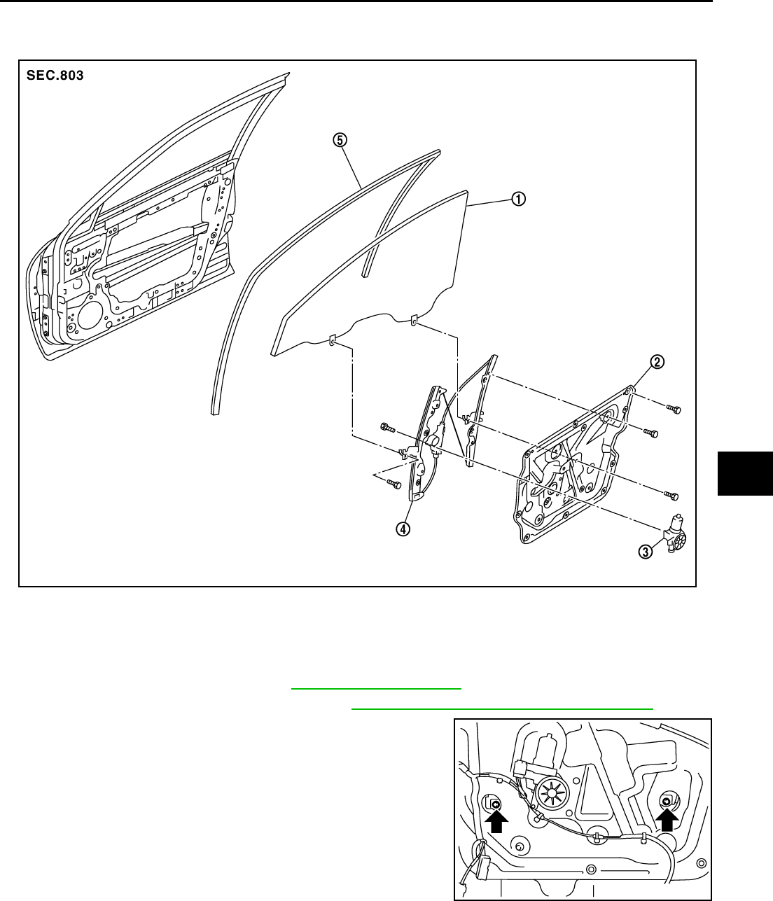
FRONT DOOR GLASS AND REGULATOR
GW-63
C
D
E
F
G
H
J
K
L
M
A
B
GW
Revision: 2006 January 2006 M35/M45
FRONT DOOR GLASS AND REGULATOR PFP:80300
Removal and Installation NIS00228
DOOR GLASS
Removal
1. Remove the front door finisher. Refer to EI-34, "DOOR FINISHER" .
2. Remove the front door sash cover inner. Refer to EI-36, "FRONT DOOR SASH COVER INNER"
3. Operate the power window main switch to raise/lower the door
window until the glass mounting bolts can be seen.
4. Remove the glass mounting bolts.
1. Door glass 2. Module assembly 3. Power window motor
4. Regulator assembly 5. Door glass run
PIIB3287J
PIIB3288J
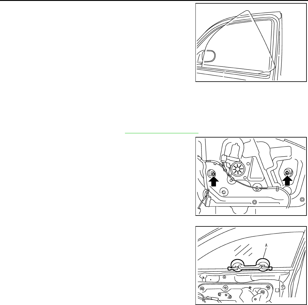
GW-64
FRONT DOOR GLASS AND REGULATOR
Revision: 2006 January 2006 M35/M45
5. While holding the door glass, raise it at the rear end to pull the
glass out of the sash toward the inside of the door.
Installation
Install in the reverse order of removal.
REGULATOR ASSEMBLY
Removal
1. Remove the front door finisher. Refer to EI-34, "DOOR FINISHER" .
2. Operate the power window main switch to raise/lower the door
window until the glass mounting bolts can be seen.
3. Remove the glass mounting bolts.
4. Raise up the door glass and hold with a suction lifter A.
5. Remove the mounting bolts, and remove the module assembly.
6. Disconnect the harness connector for the module assembly, and unclip the harness from the inside.
Installation
Install in the reverse order of removal.
SIIA1779J
PIIB3288J
PIIB3510J
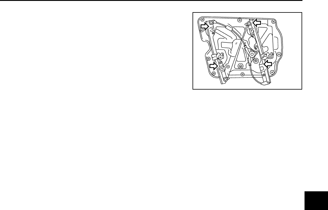
FRONT DOOR GLASS AND REGULATOR
GW-65
C
D
E
F
G
H
J
K
L
M
A
B
GW
Revision: 2006 January 2006 M35/M45
Inspection after Removal
Check the regulator assembly for the following items. If a malfunc-
tion is detected, replace or grease it.
●Wire wear
●Regulator deformation
●Grease condition for each sliding part
The arrows in the figure show the application points of the multi-pur-
pose grease.
Disassembly and Assembly NIS00229
REGULATOR ASSEMBLY
Disassembly
1. Remove power window motor from module assembly.
2. Remove regulator assembly from module assembly.
Assembly
Assemble in the reverse order of disassembly.
Inspection after Installation NIS0022A
SYSTEM INITIALIZATION
If any of the following work has been done, initialize the system.
●Electric power supply to power window switch or motor is interrupted by blown fuse or disconnecting bat-
tery cable, etc.
●Removal and installation of the regulator assembly.
●Removal and installation of the motor from the regulator assembly.
●Removal and installation of the harness connector of the power window switch.
●Operate the regulator assembly as a unit.
●Removal and installation of the door glass.
●Removal and installation of the door glass run.
Initialization
After installing each component to the vehicle, follow the steps below.
1. Disconnect the minus terminal of battery or disconnect power window switch's harness connector tempo-
rarily, then reconnect after at least 1 minute.
2. Turn ignition switch ON.
3. Open the window to its full width by operating the power window switch. (Exclude this pocedure if the win-
dow is already fully opened)
4. Fully draw the power window switch in up direction (auto close position) and hold, keep holding the switch
even when window is completely closed and then release afeter 3 second has passed.
5. Inspection of the anti-pinch system function.
NOTE:
Initialization may be cancelled with continuous opening and closing operation.In this case, initialize the
system.
INSPECT THE FUNCTION OF THE ANTI-PINCH SYSTEM.
1. Fully open the door glass.
2. Place a wooden piece (wooden hammer handle etc.) at near fully closed position.
3. Carry out fully closing operation with auto up switch.
●Check that the glass reverses without pinching the wooden piece, is lowered approx.150 mm (5.91 in) or
for 2 seconds and then stops.
●The glass should not be raised with power window main switch operated while it is reversing or lowering.
PIIB3290J

GW-66
FRONT DOOR GLASS AND REGULATOR
Revision: 2006 January 2006 M35/M45
CAUTION:
●Do not inspect with pinching a part of worker's body, a hand etc. Work carefully not to be pinched.
●Check that auto up function is normal before inspection following the system initialization.
FITTING INSPECTION
●Make sure the glass is securely fit into the glass run groove.
●Lower the glass slightly [approx. 10 to 20 mm (0.39 to 0.79 in)] and make sure the clearance to the sash is
parallel. If the clearance between the glass and sash is not parallel, loosen the regulator mounting bolts,
guide rail mounting bolts, and glass and guide rail mounting bolts to correct the glass position.
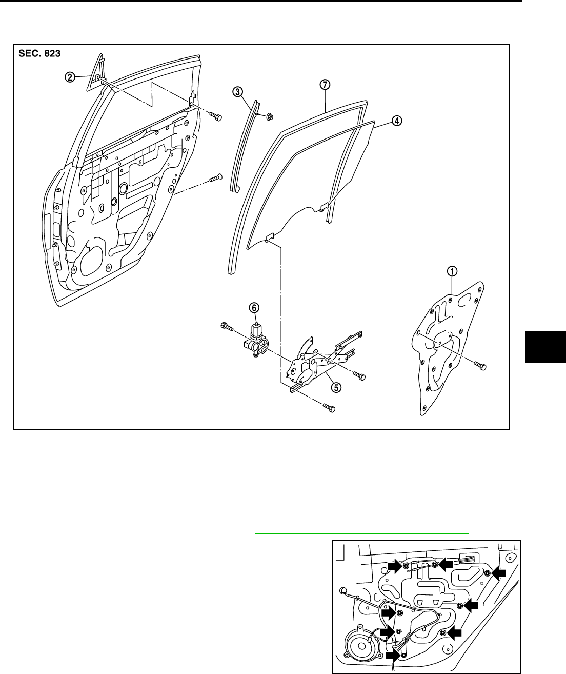
REAR DOOR GLASS AND REGULATOR
GW-67
C
D
E
F
G
H
J
K
L
M
A
B
GW
Revision: 2006 January 2006 M35/M45
REAR DOOR GLASS AND REGULATOR PFP:82300
Removal and Installation NIS0022B
DOOR GLASS
Removal
1. Remove the rear door finisher. Refer to EI-34, "DOOR FINISHER" .
2. Remove the rear door sash cover inner. Refer to EI-36, "REAR DOOR SASH COVER INNER" .
3. Remove the rear door inner frame.
1. Rear door inner frame 2. Outer corner cover 3. Lower sash
4. Door glass 5. Regulator assembly 6. Power window motor
7. Door glass run
PIIB3293J
PIIB3294J
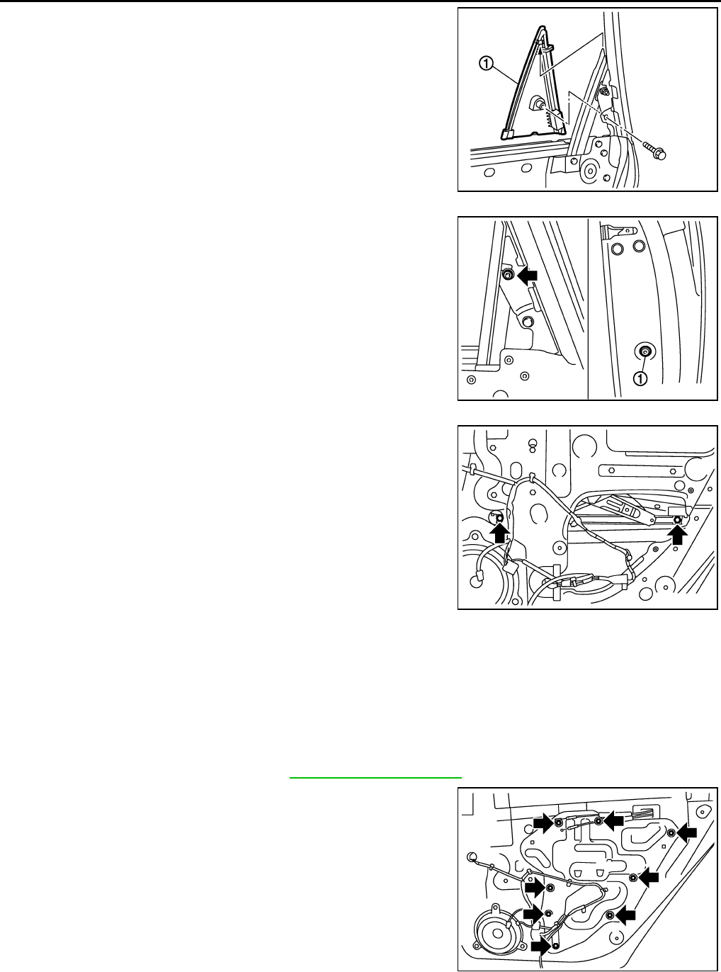
GW-68
REAR DOOR GLASS AND REGULATOR
Revision: 2006 January 2006 M35/M45
4. Remove the fixing bolt and pull up the outer corner cover (1) to
remove outward.
5. Remove the rear door sash fixing nut and the door side TORX
bolt (T30) (1).
6. Remove the harness clip and pull out the rear door sash from
the door panel.
7. Operate the power window switch to raise/lower the door win-
dow until the glass mounting bolts can be seen.
8. Remove the glass mounting bolts.
9. Remove the door glass from the inside of door panel.
10. Remove the door glass run.
Installation
Install in the reverse order of removal.
REGULATOR ASSEMBLY
Removal
1. Remove the rear door finisher. Refer to EI-34, "DOOR FINISHER" .
2. Remove the rear door inner frame.
PIIB3295J
PIIB3296J
PIIB3297J
PIIB3294J
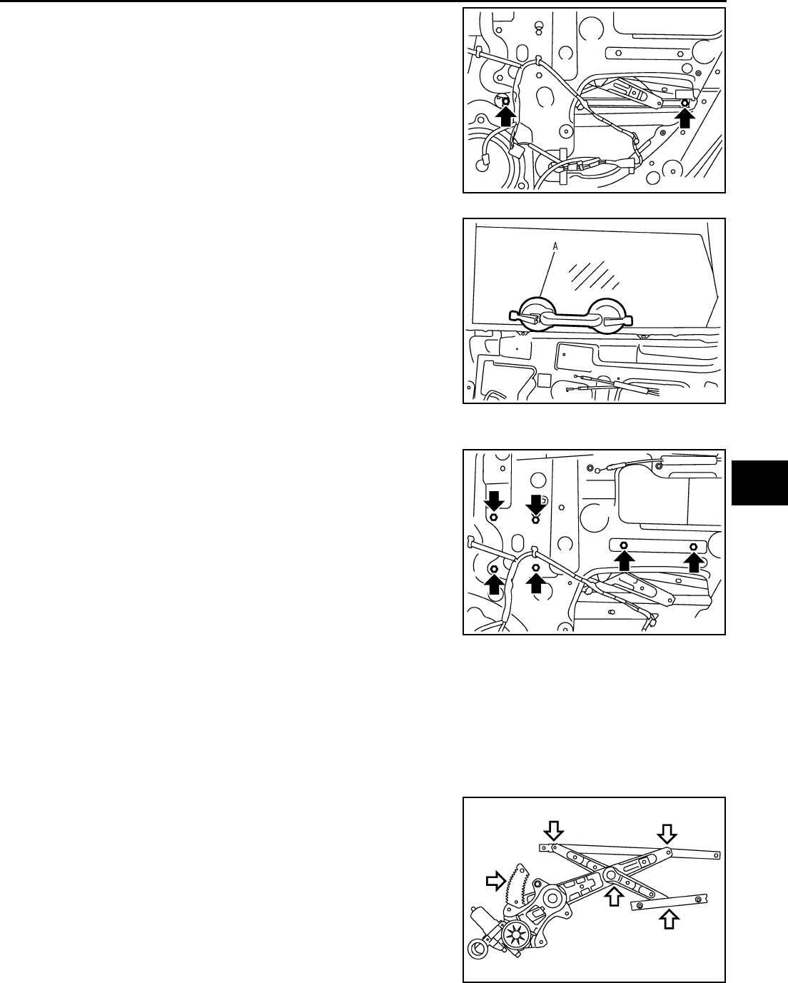
REAR DOOR GLASS AND REGULATOR
GW-69
C
D
E
F
G
H
J
K
L
M
A
B
GW
Revision: 2006 January 2006 M35/M45
3. Operate the power window switch to raise/lower the door win-
dow until the glass mounting bolts can be seen.
4. Remove the glass mounting bolts.
5. Raise up the door glass and hold with a suction lifter A.
6. Disconnect the connector for the regulator assembly.
7. Remove the regulator mounting bolts, and remove the regulator
from the door panel.
Installation
Install in the reverse order of removal.
Inspection after Removal
Check the regulator assembly for the following items. If a malfunction is detected, replace or grease it.
●Gear wear
●Regulator deformation
●Grease condition for each sliding part
The arrows in the figure show the application points of the multi-pur-
pose grease.
PIIB3297J
PIIB3511J
PIIB3298J
PIIB3299J

GW-70
REAR DOOR GLASS AND REGULATOR
Revision: 2006 January 2006 M35/M45
Disassembly and Assembly NIS0022C
REGULATOR ASSEMBLY
Disassembly
Remove power window motor from regulator assembly.
Assembly
Assemble in the reverse order of disassembly.
Inspection after Installation NIS0022D
SYSTEM INITIALIZATION
If any of the following work has been done, initialize the system.
●Electric power sauce to power window switch or motor is interrupted by broken fuse or disconnecting bat-
tery cable, etc.
●Removal and installation of the regulator assembly.
●Removal and installation of the motor from the regulator assembly.
●Removal and installation of the harness connector of the power window switch.
●Operate the regulator assembly as a unit.
●Removal and installation of the door glass.
●Removal and installation of the door glass run.
Initialization
After installing each component to the vehicle, follow the steps below.
1. Disconnect the minus terminal of battery or disconnect power window switch's harness connector tempo-
rarily, then reconnect after at least 1 minute.
2. Turn ignition switch ON.
3. Open the window to its full width by operating the power window switch. (Exclude this pocedure if the win-
dow is already fully opened)
4. Fully draw the power window switch in up direction (auto close position) and hold, keep holding the switch
even when window is completely closed and then release afeter 3 second has passed.
5. Inspection of the anti-pinch system function.
NOTE:
Initialization may be cancelled with continuous opening and closing operation.In this case, initialize the
system.
INSPECT THE FUNCTION OF THE ANTI-PINCH SYSTEM
1. Fully open the door glass.
2. Place a wooden piece (wooden hammer handle etc.) at near fully closed position.
3. Carry out fully closing operation with auto up switch.
●Check that the glass reverses without pinching the wooden piece, is lowered approx.150mm (5.91in) or
for 2 seconds and then stops.
●The glass should not be raised with power window main switch operated while it is reversing or lowering.
CAUTION:
●Do not inspect with pinching a part of worker's body, a hand etc. Work carefully not to be pinched.
●Check that auto up function is normal before inspection following the system initialization.
FITTING INSPECTION
●Make sure the glass is securely fit into the glass run groove.
●Lower the glass slightly [approx. 10 to 20 mm (0.39 to 0.79 in)], and make sure the clearance to the sash
is parallel. If the clearance between the glass and sash is not parallel, loosen the regulator mounting bolts,
guide rail mounting bolts, and glass and carrier plate mounting bolts to correct the glass position.
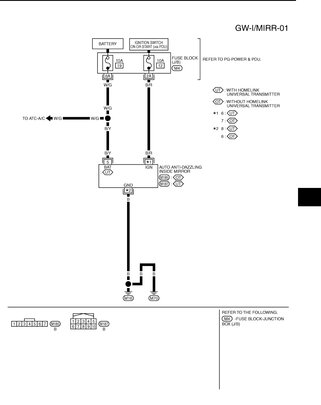
INSIDE MIRROR
GW-71
C
D
E
F
G
H
J
K
L
M
A
B
GW
Revision: 2006 January 2006 M35/M45
INSIDE MIRROR PFP:96321
Wiring Diagram –I/MIRR– NIS0022E
TIWT1351E
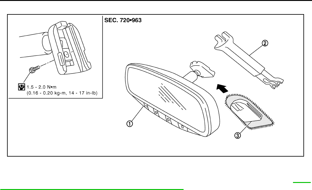
GW-72
INSIDE MIRROR
Revision: 2006 January 2006 M35/M45
Removal and Installation NIS0022F
CAUTION:
Apply Genuine Mirror Adhesive or equivalent to bonding surface of mounting bracket. Refer to GI-48,
"RECOMMENDED CHEMICAL PRODUCTS AND SEALANTS" .
REMOVAL
1. Remove inside mirror finisher (if equipped).
2. Remove screw of mirror base.
3. Slide the mirror upward to remove.
4. Disconnect the connector (if equipped).
INSTALLATION
Install in the reverse order of removal.
1. Inside mirror 2. Inside mirror finisher (if equipped) 3. Mirror base
PIIB5780E
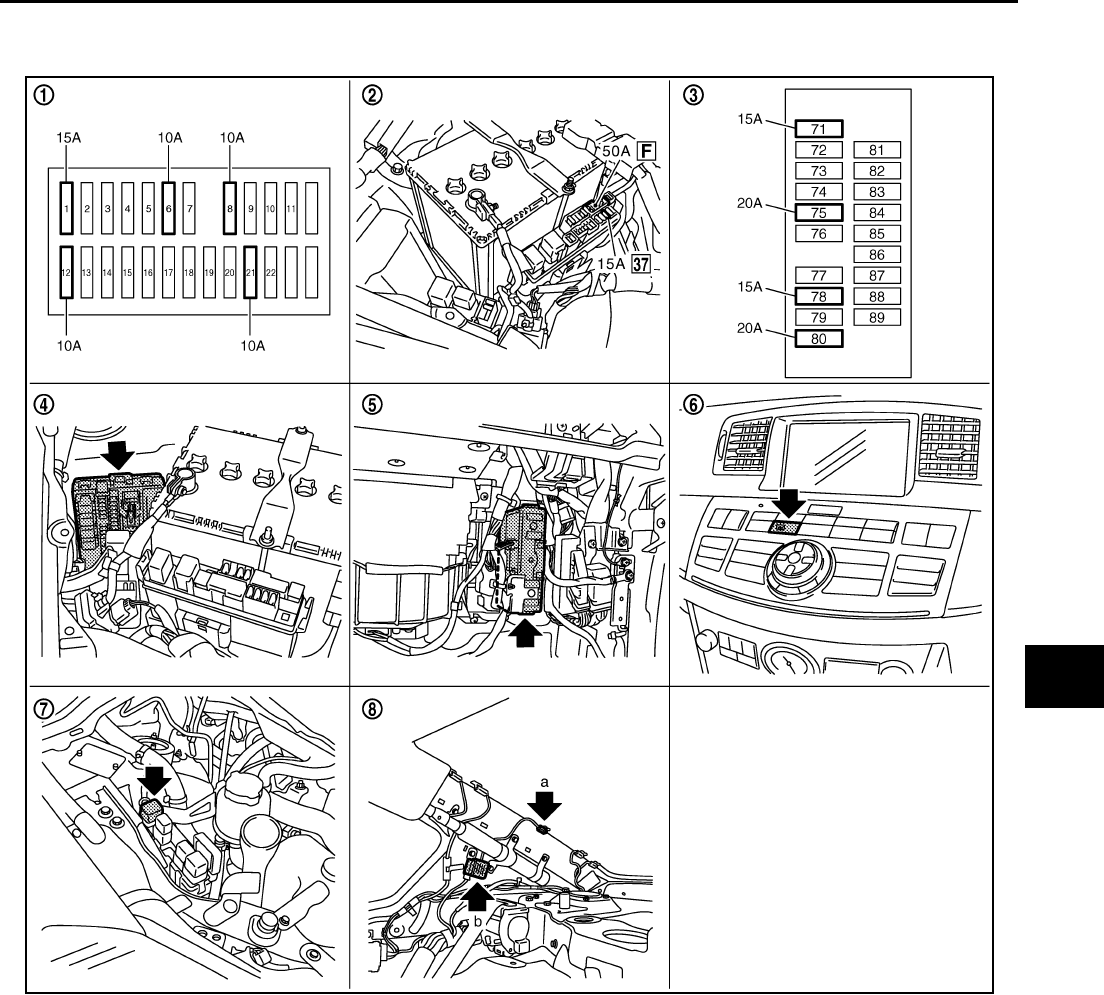
REAR WINDOW DEFOGGER
GW-73
C
D
E
F
G
H
J
K
L
M
A
B
GW
Revision: 2006 January 2006 M35/M45
REAR WINDOW DEFOGGER PFP:25350
Component Parts and Harness Connector Location NIS0022G
System Description NIS0022H
The rear window defogger system is controlled by BCM and IPDM E/R.
The rear window defogger operates only for approximately 15 minutes.
Power is at all times supplied
●through 20A fuse [No. 75, located in the IPDM E/R]
●to rear window defogger relay terminals 6,
●through 20A fuse [No. 80, located in the IPDM E/R]
●to rear window defogger relay terminals 3,
●through 15A fuse [No. 37, located in the fuse and fusible link box
●to multi-function switch terminal 1,
PIIB6098E
1. Fuse block (J/B) 2. Fuse and fusible link box 3. Fuse block (in IPDM E/R)
4. IPDM E/R E4, E8, E9 5. BCM M1, M2 6. Rear window defogger switch (in
multi function switch) M69
7. Rear window defogger relay E36 8. a : Rear window defogger B604
b : Condenser B49

GW-74
REAR WINDOW DEFOGGER
Revision: 2006 January 2006 M35/M45
●through 50A fusible link (letter F , located in the fuse and fusible link box)
●to BCM terminal 55,
●through 10A fuse [No. 21, located in the fuse block (J/B)]
●to BCM terminal 42.
With the ignition switch turned to ON or START position,
Power is supplied
●through 15A fuse [No. 1, located in the fuse block (J/B)]
●to BCM terminal 38.
●through 10A fuse [No. 12, located in the fuse block (J/B)]
●to rear window defogger relay terminal 1.
With the ignition switch turned to ACC or ON position,
●through 10A fuse [No. 6, located in the fuse block (J/B)]
●to multi-function switch terminal 2.
Ground is supplied
●to BCM terminal 52
●through body grounds M16 and M70,
●to multi-function switch terminal 14
●through body grounds M16 and M70,
●to IPDM E/R terminals 38 and 51
●through body grounds E22 and E43.
When rear window defogger switch in multi-function switch is turned to ON.
Then multi-function switch recognizes that rear window defogger switch is turned to ON.
Then it sends rear window defogger switch signals to AV control unit (without navigation system) or NAVI con-
trol unit (with navigation system) via AV line.
When AV control unit (without navigation system) or NAVI control unit (with navigation system) receives rear
window defogger switch signals, and display on the screen.
Then AV control unit (without navigation system) or NAVI control unit (with navigation system) recognizes that
rear window defogger switch is turned to ON.
Then it sends rear window defogger switch signal to BCM via DATA LINE (CAN H, CAN L).
Then BCM recognizes that rear window defogger switch signal.
Then it sends rear window defogger request signal to IPDM E/R via DATA LINE (CAN H, CAN L).
When IPDM E/R receives rear window defogger switch signals,
Ground is supplied
●to rear window defogger relay terminal 2
●through IPDM E/R terminal 57
●through IPDM E/R terminal 51
●through body grounds E22 and E43.
And then rear window defogger relay is energized.
When rear window defogger relay is turned ON, signals are transmitted.
●through rear window defogger relay terminals 5 and 7
●through condenser terminal 1
●to rear window defogger terminal 1
Rear window defogger terminal 2 is grounded through grounds B702.
With power and ground supplied, rear window defogger filaments heat and defog the rear window.
When rear window defogger relay is turned to ON,
Power is supplied
●through rear window defogger relay terminals 5 and 7
●through fuse block (J/B) terminal 2C
●through 10A fuse [No. 8, located in the fuse block (J/B)] and
●through fuse block (J/B) terminal 5B
●to door mirror (LH and RH) terminal 4.
Door mirror (LH and RH) terminal 8 is grounded through body grounds M16 and M70.

REAR WINDOW DEFOGGER
GW-75
C
D
E
F
G
H
J
K
L
M
A
B
GW
Revision: 2006 January 2006 M35/M45
With power and ground supplied, door mirror defogger filaments heat and defog the mirror.
CAN Communication System Description NIS0022I
CAN (Controller Area Network) is a serial communication line for real time application. It is an on-vehicle mul-
tiplex communication line with high data communication speed and excellent error detection ability. Many elec-
tronic control units are equipped onto a vehicle, and each control unit shares information and links with other
control units during operation (not independent). In CAN communication, control units are connected with 2
communication lines (CAN H line, CAN L line) allowing a high rate of information transmission with less wiring.
Each control unit transmits/receives data but selectively reads required data only.
CAN Communication Unit NIS0022J
Refer to LAN-34, "CAN Communication Unit" .
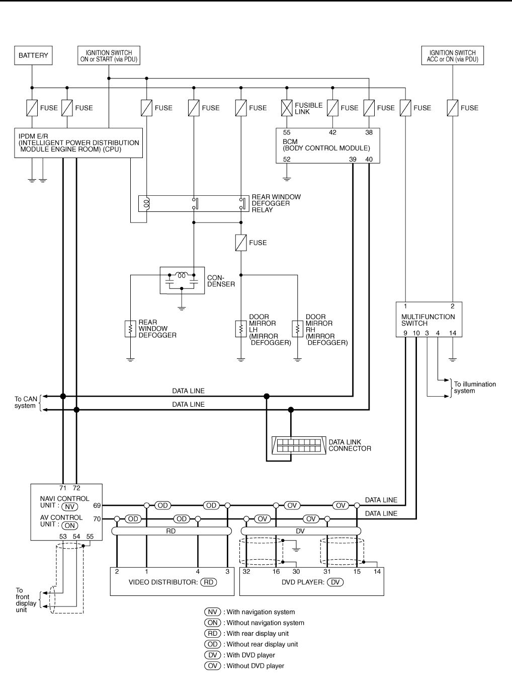
GW-76
REAR WINDOW DEFOGGER
Revision: 2006 January 2006 M35/M45
Schematic NIS0022K
TIWT1352E
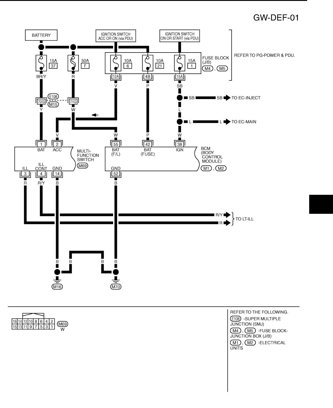
REAR WINDOW DEFOGGER
GW-77
C
D
E
F
G
H
J
K
L
M
A
B
GW
Revision: 2006 January 2006 M35/M45
Wiring Diagram — DEF — NIS0022L
TIWT1353E
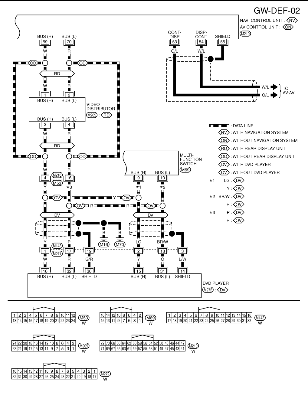
GW-78
REAR WINDOW DEFOGGER
Revision: 2006 January 2006 M35/M45
TIWT1354E
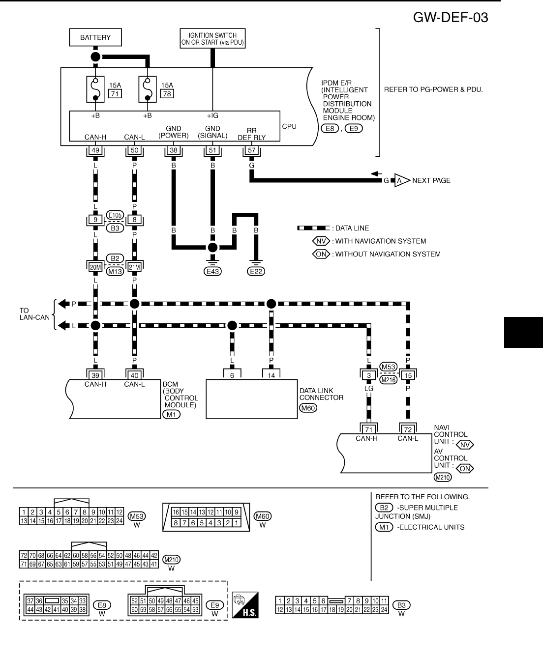
REAR WINDOW DEFOGGER
GW-79
C
D
E
F
G
H
J
K
L
M
A
B
GW
Revision: 2006 January 2006 M35/M45
TIWT1355E
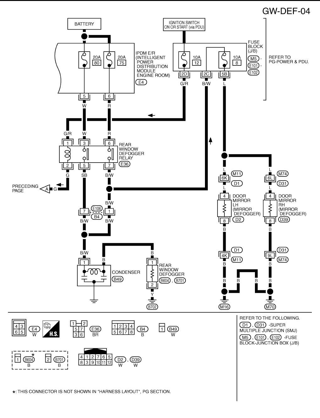
GW-80
REAR WINDOW DEFOGGER
Revision: 2006 January 2006 M35/M45
TIWT1356E

REAR WINDOW DEFOGGER
GW-81
C
D
E
F
G
H
J
K
L
M
A
B
GW
Revision: 2006 January 2006 M35/M45
Terminal and Reference Value for BCM NIS0022M
Terminal and Reference Value for IPDM E/R NIS0022N
Terminal Wire color Item Condition Voltage (V)
(Approx.)
38 W Ignition switch ON or START Ignition switch (ON or START position) Battery voltage
39 L CAN− H——
40 P CAN− L——
42 P Power source (Fuse) — Battery voltage
52 B Ground — 0
55 W Power source (Fusible link) — Battery voltage
Terminal Wire color Item Condition Voltage (V)
(Approx.)
5 W Battery power supply — Battery voltage
6 R Battery power supply — Battery voltage
38 B Ground (Power) — 0
49 L CAN− H——
50 P CAN− L——
51 B Ground (Signal) — 0
57 G Rear window defogger relay
control signal
When rear window defogger switch is ON. 0
When rear window defogger switch is OFF. Battery voltage
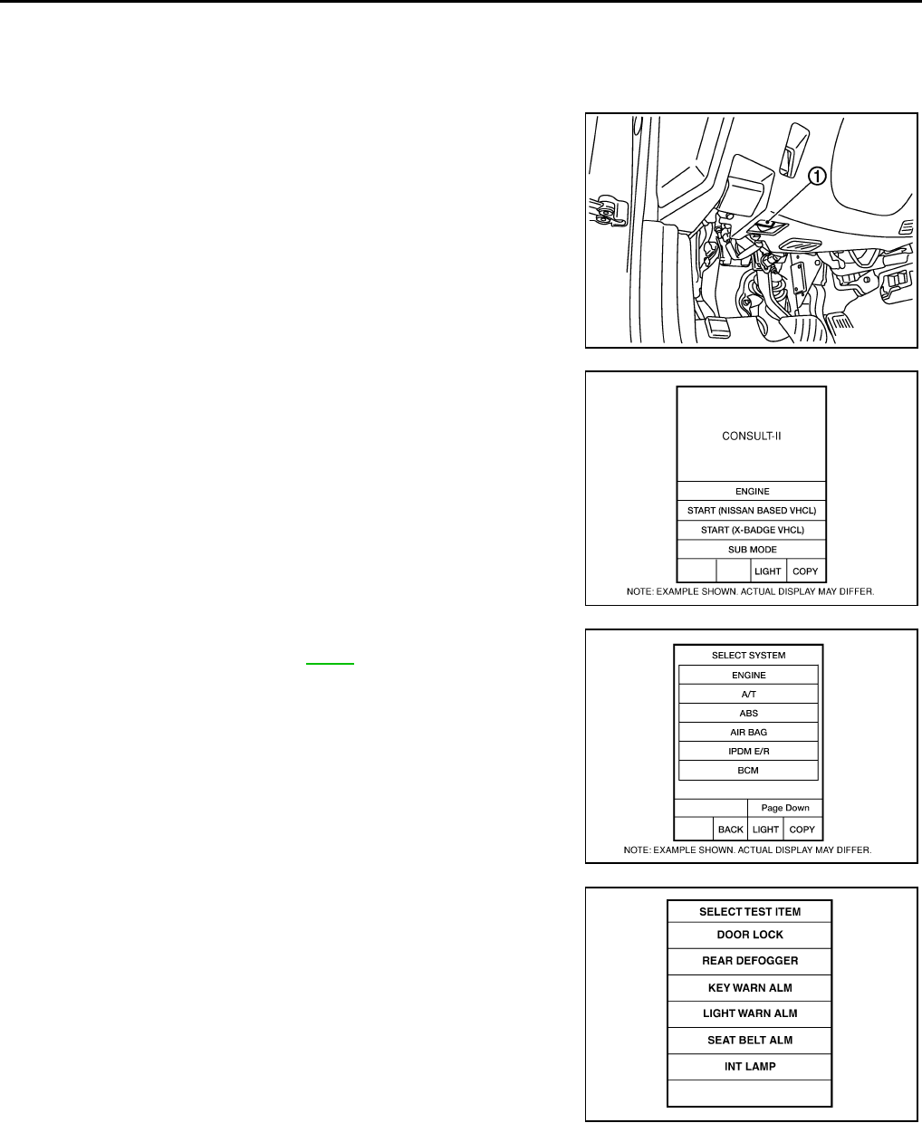
GW-82
REAR WINDOW DEFOGGER
Revision: 2006 January 2006 M35/M45
CONSULT-II Inspection Procedure NIS0022O
CAUTION:
If CONSULT-II is used with no connection of CONSULT-II CONVERTER, malfunctions might be
detected in self-diagnosis depending on control unit which carry out CAN communication.
1. Turn ignition switch “OFF”.
2. Connect “CONSULT-II” and CONSULT-II CONVERTER to data
link connector (1).
3. Turn ignition switch “ON”.
4. Touch “START (NISSAN BASED VHCL)”.
5. Touch “BCM”.
If “BCM” is not indicated, go to GI-40 , “CONSULT-II Date Link
Connector (DLC) Circuit”
6. Touch “REAR DEFOGGER”.
PBIB2712E
BCIA0029E
BCIA0030E
LIIA0153E

REAR WINDOW DEFOGGER
GW-83
C
D
E
F
G
H
J
K
L
M
A
B
GW
Revision: 2006 January 2006 M35/M45
7. Select diagnosis mode,“DATA MONITOR” and “ACTIVE TEST”
are available.
DATA MONITOR
Display Item List
ACTIVE TEST
Display Item List
BCIA0031E
Monitor item Content
REAR DEF SW Displays “Press (ON)/others (OFF)” status determined with the rear window defogger switch.
IGN ON SW Displays “IGN (ON)/OFF” status determined with the ignition switch signal.
Test item Content
REAR DEFOGGER Gives a drive signal to the rear window defogger relay to activate it.

GW-84
REAR WINDOW DEFOGGER
Revision: 2006 January 2006 M35/M45
Work Flow NIS0022P
1. Check the symptom and customer's requests.
2. Understand the outline of system. Refer to GW-73, "System Description" .
3. According to the trouble diagnosis chart, repair or replace the cause of the malfunction. Refer to GW-84,
"Trouble Diagnoses Symptom Chart" .
4. Does rear window defogger operate normally? YES: GO TO 5, NO: GO TO 3.
5. INSPECTION END.
Trouble Diagnoses Symptom Chart NIS0022Q
Make sure other systems using the signal of the following systems operate normally.
*1: With navigation system
*2: Without navigation system
Symptom Diagnoses / Service procedure Refer to page
Rear window defogger and door mirror defogger do not
operate.
1. BCM power supply and ground circuit check. GW-85
2. IPDM E/R auto active test check PG-24
3. Rear window defogger switch circuit check GW-86
4. Rear window defogger power supply circuit check GW-86
5. Replace IPDM E/ R PG-31
Rear window defogger does not operate but both of door
mirror defogger operate.
1. Rear window defogger circuit check GW-88
2. Filament check GW-94
Both of door mirror defogger does not operated but rear
window defogger operates. 1. Door mirror defogger power supply circuit check GW-89
Driver side door mirror defogger does not operate. 1. Driver side door mirror defogger circuit check GW-91
Passenger side door mirror defogger does not operate. 1. Passenger side door mirror defogger circuit check GW-92
Rear window defogger switch does not light, and rear win-
dow defogger is not displayed on the display.
But rear window defogger operates.
1. Rear window defogger signal check AV-253*1
AV-108*2
Rear window defogger switch does not light, but rear win-
dow defogger operates 1. Replace multi-function switch ATC-124
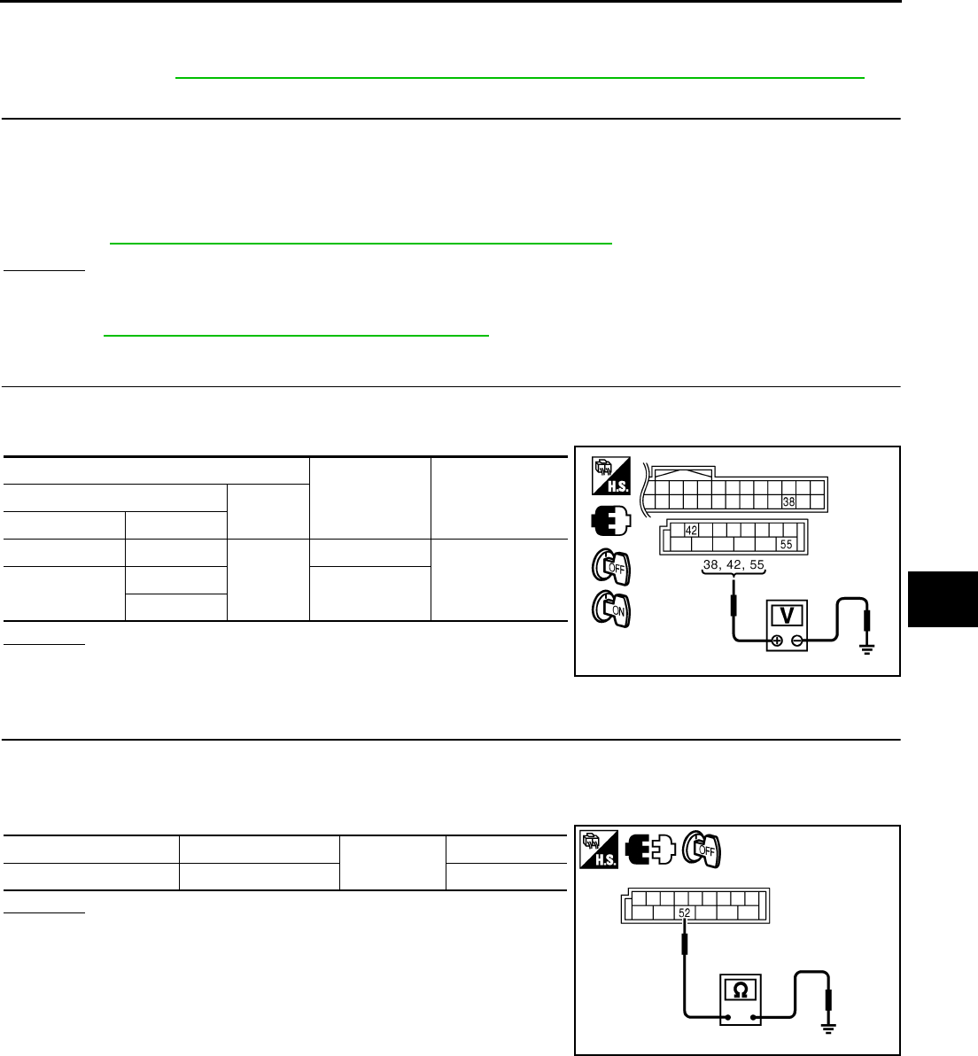
REAR WINDOW DEFOGGER
GW-85
C
D
E
F
G
H
J
K
L
M
A
B
GW
Revision: 2006 January 2006 M35/M45
BCM Power Supply and Ground Circuit Check NIS0022R
First perform the “SELF-DIAG RESULTS” in “BCM” with CONSULT-II, when perform the each trouble
diagnosis. Refer to BCS-15, "CAN Communication Inspection Using CONSULT-II (Self-Diagnosis)" .
1. CHECK FUSE
●Check 15A fuse [No.1, located in the fuse block (J/B)]
●Check 10A fuse [No.21, located in the fuse block (J/B)]
●Check 50A fusible link (letter F located in the fuse and fusible link box).
NOTE:
Refer to GW-73, "Component Parts and Harness Connector Location" .
OK or NG
OK >> GO TO 2.
NG >> If fuse is blown out, be sure to eliminate cause of malfunction before installing new fuse. Refer to
PG-3, "POWER SUPPLY ROUTING CIRCUIT" .
2. CHECK POWER SUPPLY CIRCUIT
1. Turn ignition switch ON.
2. Check voltage between BCM connector and ground.
OK or NG
OK >> GO TO 3.
NG >> Check BCM power supply circuit for open or short.
3. CHECK GROUND CIRCUIT
1. Turn ignition switch OFF.
2. Disconnect BCM connector.
3. Check continuity between BCM connector and ground.
OK or NG
OK >> Power supply and ground circuit are OK.
NG >> Check BCM ground circuit for open or short.
Terminals Condition of
ignition switch
Voltage (V)
(Approx.)
(+) (–)
BCM connector Terminal
M1 38
Ground
ON
Battery voltage
M2 42 OFF
55
PIIB5934E
BCM connector Terminal Ground Continuity
M2 52 Yes
PIIB5935E
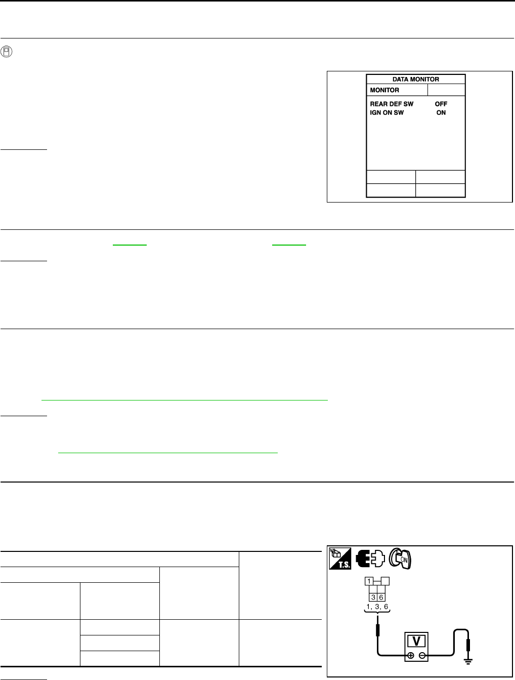
GW-86
REAR WINDOW DEFOGGER
Revision: 2006 January 2006 M35/M45
Rear Window Defogger Switch Circuit Check NIS0022S
1. CHECK REAR WINDOW DEFOGGER SWITCH OPERATION
With CONSULT-II
Check (“REAR DEF SW”, “IGN ON SW”) in DATA MONITOR mode with CONSULT-II.
OK or NG
OK >> Rear window defogger switch is OK.
NG >> GO TO 2.
2. CHECK AV LINE
Check AV line. Refer to AV-253 (with navigation system), AV-108 (without navigation system).
OK or NG
OK >> Check the condition of harness and connector.
NG >> The diagnosis is continued.
Rear Window Defogger Power Supply Circuit Check NIS0022T
1. CHECK FUSE
●Check 10A fuse [No.12, located in the fuse block (J/B)]
●Check 20A fuse (No.75, located in the IPDM E/R)
●Check 20A fuse (No.80, located in the IPDM E/R)
NOTE:
Refer to GW-73, "Component Parts and Harness Connector Location" .
OK or NG
OK >> GO TO 2.
NG >> If fuse is blown out, be sure to eliminate cause of malfunction before installing new fuse, refer to
PG-3, "POWER SUPPLY ROUTING CIRCUIT" .
2. CHECK POWER SUPPLY CIRCUIT
1. Turn ignition switch OFF.
2. Remove rear window defogger relay.
3. Turn ignition switch ON.
4. Check voltage between rear window defogger relay connector and ground.
OK or NG
OK >> GO TO 3.
NG >> Repair or replace harness between fuse block (J/B) and rear window defogger relay.
When rear window defogger switch is turned to ON
REAR DEF SW : ON
When ignition switch is turned to ON
IGN ON SW : ON
PIIA2373E
Terminals
Voltage (V)
(Approx.)
(+)
(–)
Rear window
defogger relay
connector
Terminal
E36
1
Ground Battery voltage3
6
PIIB5994E
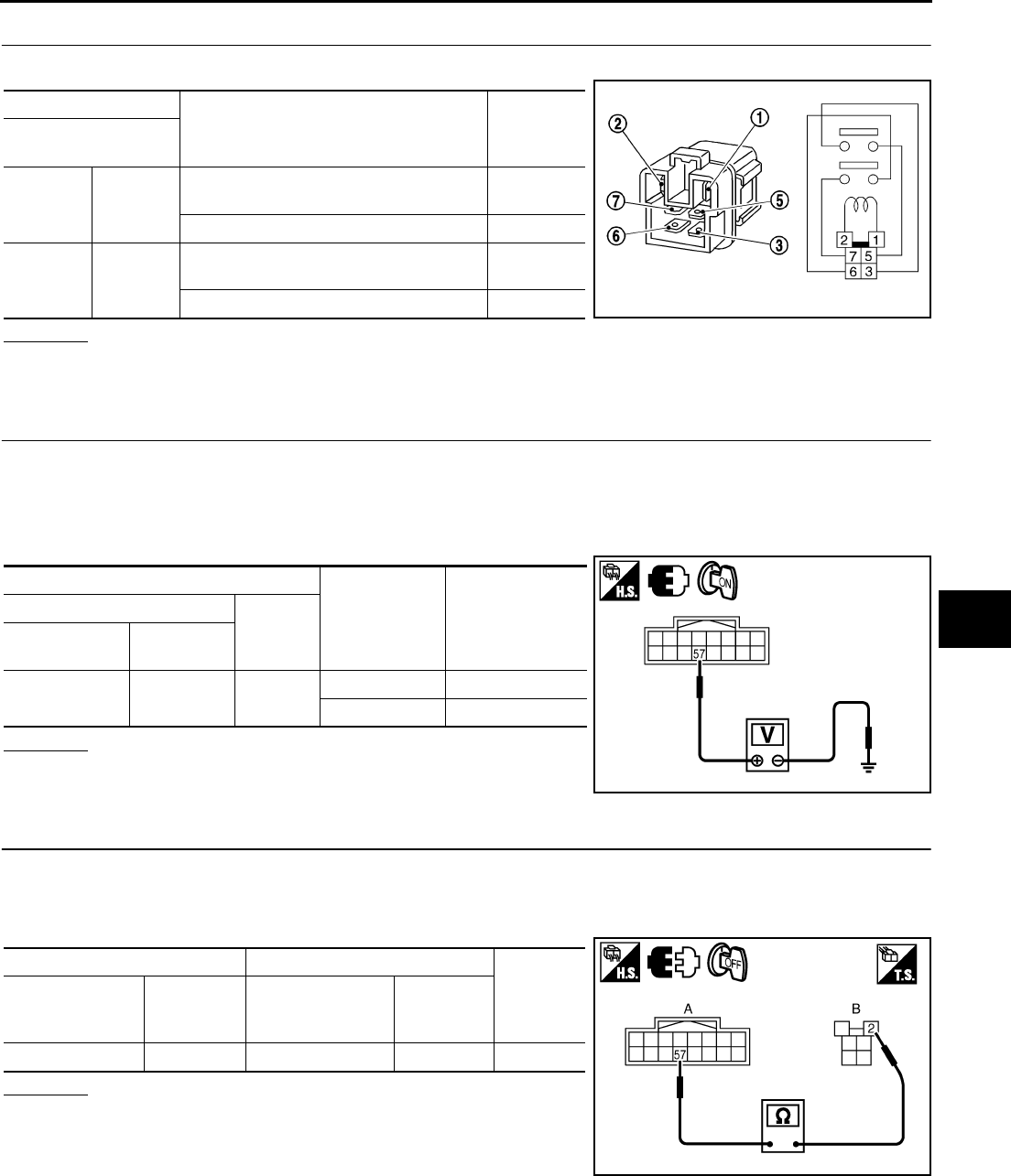
REAR WINDOW DEFOGGER
GW-87
C
D
E
F
G
H
J
K
L
M
A
B
GW
Revision: 2006 January 2006 M35/M45
3. CHECK REAR WINDOW DEFOGGER RELAY
Check rear window defogger relay.
OK or NG
OK >> GO TO 4.
NG >> Replace rear window defogger relay.
4. CHECK REAR WINDOW DEFOGGER RELAY GROUND CIRCUIT
1. Turn ignition switch OFF.
2. Install rear window defogger relay.
3. Turn ignition switch ON.
4. Check voltage between IPDM E/R connector and ground.
OK or NG
OK >> Rear window defogger power supply circuit is OK.
NG >> GO TO 5.
5. CHECK HARNESS CONTINUITY
1. Turn ignition switch OFF.
2. Disconnect IPDM E/R connector and rear window defogger relay.
3. Check continuity between IPDM E/R connector and rear window defogger relay connector.
OK or NG
OK >> GO TO 6.
NG >> Repair or replace harness.
Terminal
Condition Continuity
Rear window
defogger relay
35
12V direct current supply between termi-
nals 1 and 2. Yes
No current supply No
67
12V direct current supply between termi-
nals 1 and 2. Yes
No current supply No SEC202B
Terminals Condition of
rear window
defogger switch
Voltage (V)
(Approx.)
(+)
(–)
IPDM E/R
connector Terminal
E9 57 Ground ON (pressed) 0
OFF Battery voltage
PIIB5982E
AB
Continuity
IPDM E/R
connector Terminal
Rear window
defogger relay
connector
Terminal
E9 57 E36 2 Yes
PIIB5983E
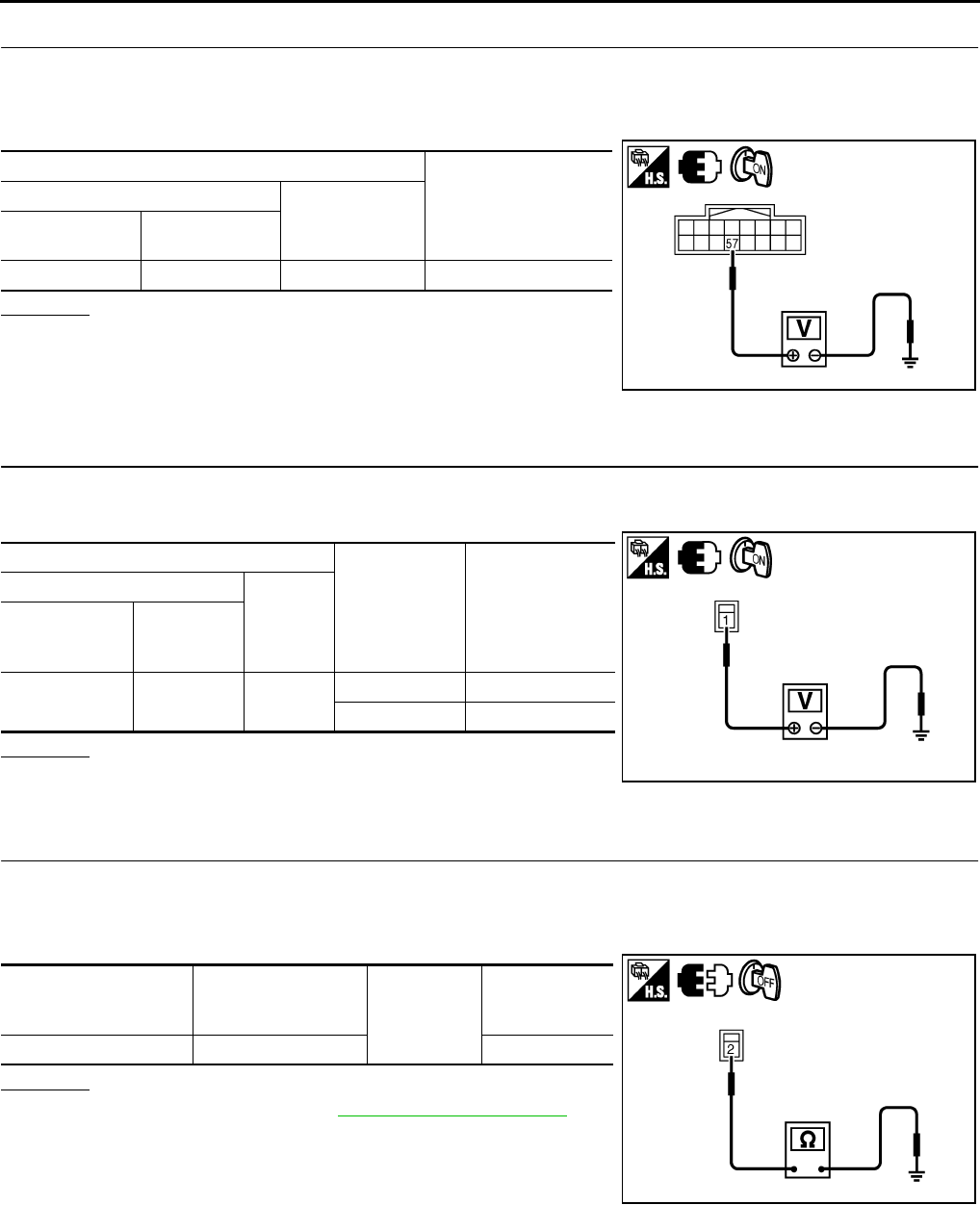
GW-88
REAR WINDOW DEFOGGER
Revision: 2006 January 2006 M35/M45
6. CHECK REAR WINDOW DEFOGGER RELAY OUTPUT SIGNAL
1. Connect IPDM E/R connector and rear window defogger relay.
2. Turn ignition switch ON.
3. Check voltage between IPDM E/R connector and ground.
OK or NG
OK >> Check condition of harness and connector.
NG >> Replace IPDM E/R.
Rear Window Defogger Circuit Check NIS0022U
1. CHECK POWER SUPPLY CIRCUIT
1. Turn ignition switch ON.
2. Check voltage between rear window defogger connector and ground.
OK or NG
OK >> GO TO 2.
NG >> GO TO 3.
2. CHECK GROUND CIRCUIT
1. Turn ignition switch OFF.
2. Disconnect rear window defogger connector.
3. Check continuity between rear window defogger connector and ground.
OK or NG
OK >> Check filament. Refer to GW-94, "Filament Check"
●If filament is OK, check condition of harness and con-
nector.
●If filament is NG, repair filament.
NG >> Repair or replace harness between rear window defog-
ger and ground.
Terminals
Voltage (V)
(Approx.)
(+)
(–)
IPDM E/R
connector Terminal
E9 57 Ground Battery voltage
PIIB5982E
Terminals
Condition of
rear window
defogger switch
Voltage (V)
(Approx.)
(+)
(–)
Rear window
defogger
connector
Terminal
B604 1 Ground ON Battery voltage
OFF 0
PIIB5984E
Rear window
defogger
connector
Terminal Ground Continuity
B701 2 Yes
PIIB5985E
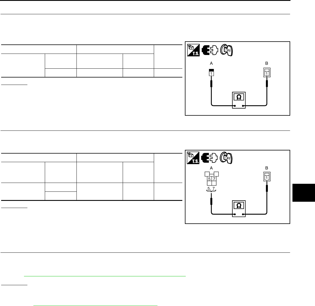
REAR WINDOW DEFOGGER
GW-89
C
D
E
F
G
H
J
K
L
M
A
B
GW
Revision: 2006 January 2006 M35/M45
3. CHECK HARNESS CONTINUITY 1
1. Turn ignition switch OFF.
2. Disconnect condenser and rear window defogger connector.
3. Check continuity between condenser and rear window defogger connector.
OK or NG
OK >> GO TO 4.
NG >> Replace condenser.
4. CHECK HARNESS CONTINUITY 2
1. Remove rear window defogger relay.
2. Check continuity between rear window defogger relay connector and condenser connector.
OK or NG
OK >> Check the condition of harness and connector.
NG >> Replace or repair harness between rear window defog-
ger relay and condenser.
Door Mirror Defogger Power Supply Circuit Check NIS0022V
1. CHECK FUSE
●Check 10A fuse [No.8, located in fuse block (J/B)]
NOTE:
Refer to GW-73, "Component Parts and Harness Connector Location" .
OK or NG
OK >> GO TO 2.
NG >> If fuse is blown out, be sure to eliminate cause of malfunction before installing new fuse. Refer to
PG-3, "POWER SUPPLY ROUTING CIRCUIT" .
AB
Continuity
Condenser Terminal Rear window
defogger connector Terminal
1B6041Yes
PIIB5986E
AB
Continuity
Rear window
defogger relay
connector
Terminal Condenser
connector Terminal
E36 5B49 1 Yes
7
PIIB5987E
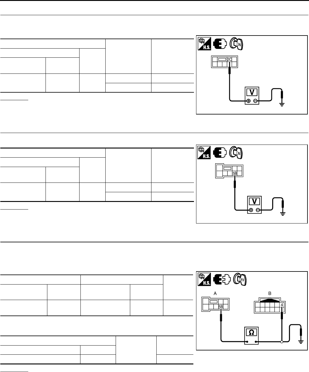
GW-90
REAR WINDOW DEFOGGER
Revision: 2006 January 2006 M35/M45
2. CHECK POWER SUPPLY CIRCUIT 1
1. Turn ignition switch ON.
2. Check voltage between fuse block (J/B) connector and ground.
OK or NG
OK >> GO TO 3.
NG >> Repair or replace harness.
3. CHECK POWER SUPPLY CIRCUIT 2
Check voltage between fuse block (J/B) connector and ground.
OK or NG
OK >> GO TO 4.
NG >> Replace fuse block (J/B).
4. CHECK DOOR MIRROR CIRCUIT
1. Turn ignition switch OFF.
2. Disconnect fuse block (J/B) and door mirror connector.
3. Check continuity between fuse block (J/B) connector and door mirror connector.
4. Check continuity between fuse block (J/B) connector and
ground.
OK or NG
OK >> GO TO 5.
NG >> Repair or replace harness between fuse block (J/B) and malfunctioning door mirror connector.
Terminals Condition of rear
window defogger
switch
Voltage (V)
(Approx.)
(+)
(–)
Fuse block
connector Terminal
E101 2C Ground ON Battery voltage
OFF 0
PIIB5993E
Terminals Condition of rear
window defogger
switch
Voltage (V)
(Approx.)
(+)
(–)
Fuse block
connector Terminal
M5 5B Ground ON Battery voltage
OFF 0
PIIB5992E
AB
Continuity
Fuse block
connector Terminal Door mirror
connector Terminal
M5 5B D2 (LH)
D39 (RH) 4Yes
A
Ground Continuity
Fuse block connector Terminal
M5 5B No
PIIB5988E
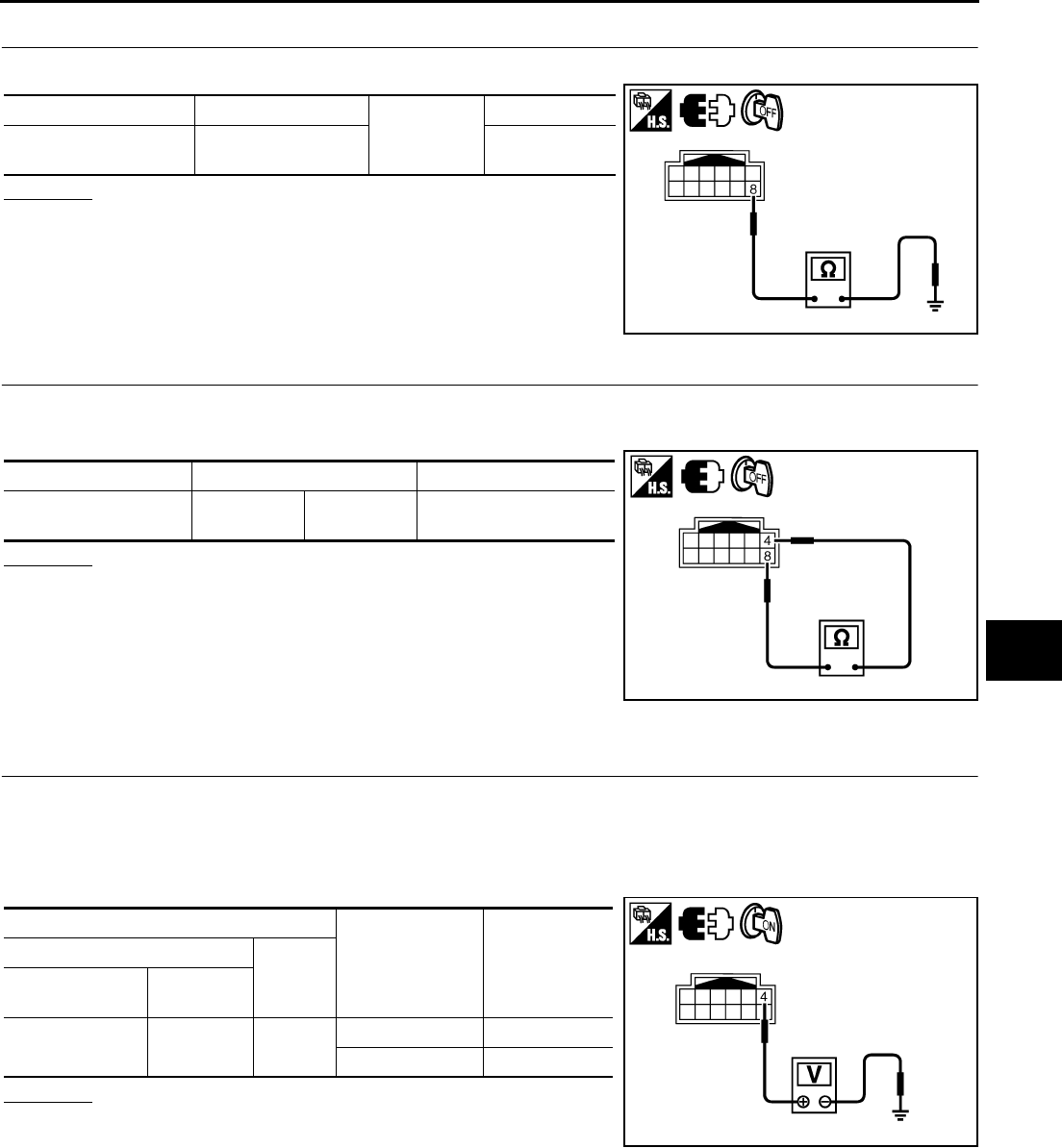
REAR WINDOW DEFOGGER
GW-91
C
D
E
F
G
H
J
K
L
M
A
B
GW
Revision: 2006 January 2006 M35/M45
5. CHECK GROUND CIRCUIT
Check continuity between door mirror connector and ground.
OK or NG
OK >> GO TO 6.
NG >> Repair or replace harness.
6. CHECK DOOR MIRROR DEFOGGER
1. Connect door mirror connector.
2. Check door mirror.
OK or NG
OK >> Check condition of harness and connector.
NG >> Replace malfunctioning door mirror.
Driver Side Door Mirror Defogger Circuit Check NIS0022W
1. CHECK POWER SUPPLY CIRCUIT
1. Turn ignition switch OFF.
2. Disconnect door mirror LH connector.
3. Turn ignition switch ON.
4. Check voltage between door mirror LH connector and ground.
OK or NG
OK >> GO TO 2.
NG >> Repair or replace harness between fuse block (J/B) and
door mirror LH.
Door mirror connector Terminal
Ground
Continuity
D2 (LH)
D39 (RH) 8Yes
PIIB5989E
Door mirror connector Terminal Continuity
D2 (LH)
D39 (RH) 48 Yes
PIIB5990E
Terminals Condition of rear
window defogger
switch
Voltage (V)
(Approx.)
(+)
(–)
Door mirror LH
connector Terminal
D2 4 Ground ON Battery voltage
OFF 0
PIIB5991E
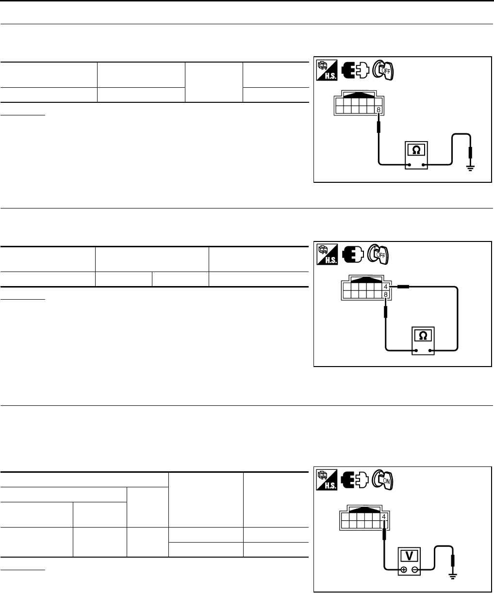
GW-92
REAR WINDOW DEFOGGER
Revision: 2006 January 2006 M35/M45
2. CHECK GROUND CIRCUIT
1. Turn ignition switch OFF.
2. Check continuity between door mirror LH connector and ground.
OK or NG
OK >> GO TO 3.
NG >> Repair or replace harness between door mirror LH and
ground.
3. CHECK DOOR MIRROR DEFOGGER
1. Connector door mirror LH connector.
2. Check door mirror LH.
OK or NG
OK >> Check condition of harness and connector.
NG >> Replace door mirror LH.
Passenger Side Door Mirror Defogger Circuit Check NIS0022X
1. CHECK POWER SUPPLY CIRCUIT
1. Turn ignition switch OFF.
2. Disconnect door mirror RH connector.
3. Turn ignition switch ON.
4. Check voltage between door mirror RH connector and ground.
OK or NG
OK >> GO TO 2.
NG >> Repair or replace harness between fuse block (J/B) and
door mirror RH.
Door mirror LH
connector Terminal Ground Continuity
D2 8 Yes
PIIB5989E
Door mirror LH
connector Terminal Continuity
D2 4 8 Yes
PIIB5990E
Terminals Condition of rear
window defogger
switch
Voltage (V)
(Approx.)
(+)
(–)
Door mirror RH
connector Terminal
D39 4 Ground ON Battery voltage
OFF 0
PIIB5991E
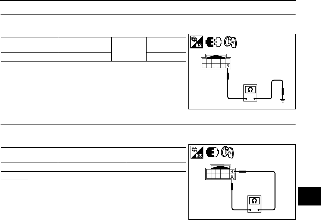
REAR WINDOW DEFOGGER
GW-93
C
D
E
F
G
H
J
K
L
M
A
B
GW
Revision: 2006 January 2006 M35/M45
2. CHECK GROUND CIRCUIT
1. Turn ignition switch OFF.
2. Check continuity between door mirror RH connector and ground.
OK or NG
OK >> GO TO 3.
NG >> Repair or replace harness between door mirror RH and
ground.
3. CHECK DOOR MIRROR DEFOGGER
1. Connector RH door mirror connector.
2. Check door mirror RH.
OK or NG
OK >> Check condition of harness and connector.
NG >> Replace door mirror.
Door mirror RH
connector Terminal Ground Continuity
D39 8 Yes
PIIB5989E
Door mirror RH
connector Terminal Continuity
D39 4 8 Yes
PIIB5990E
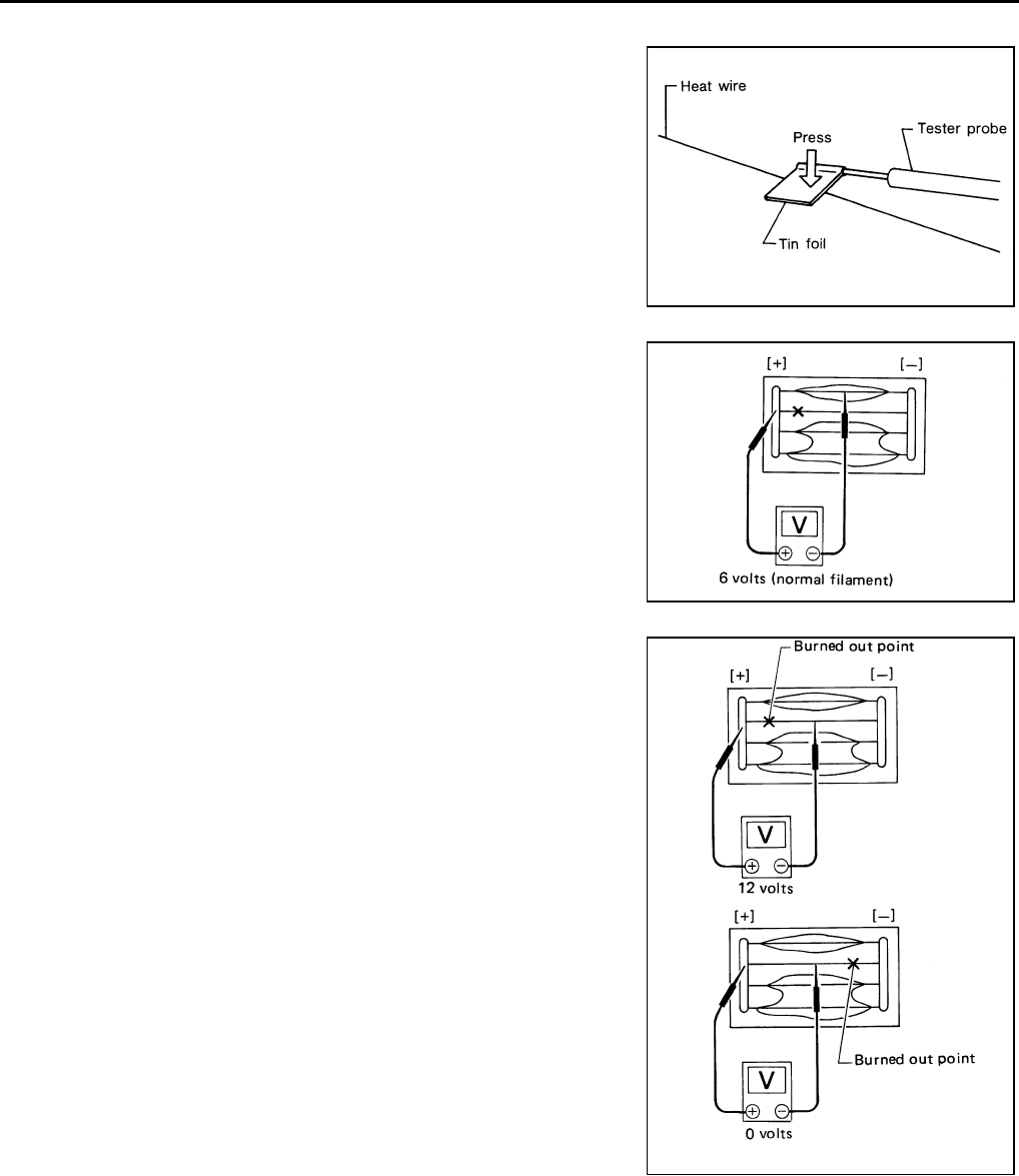
GW-94
REAR WINDOW DEFOGGER
Revision: 2006 January 2006 M35/M45
Filament Check NIS0022Y
1. When measuring voltage, wrap tin foil around the top of the neg-
ative probe. Then press the foil against the wire with your finger.
2. Attach probe circuit tester (in Volt range) to middle portion of
each filament.
3. If a filament is burned out, circuit tester registers 0 or battery
voltage.
4. To locate burned out point, move probe to left and right along fil-
ament. Test needle will swing abruptly when probe passes the
point.
Filament Repair NIS0022Z
REPAIR EQUIPMENT
●Conductive silver composition (Dupont No. 4817 or equivalent)
●Ruler 30 cm (11.8 in) long
●Drawing pen
●Heat gun
●Alcohol
●Cloth
SEL122R
SEL263
SEL265
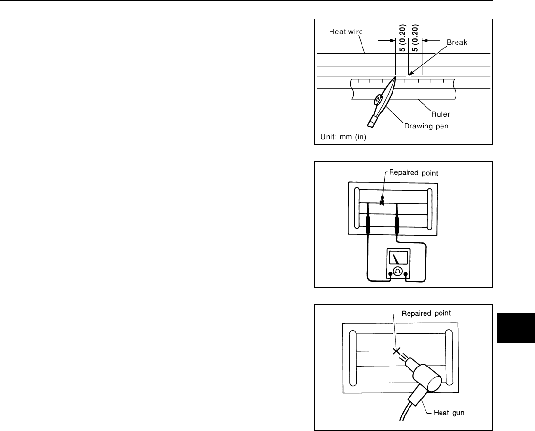
REAR WINDOW DEFOGGER
GW-95
C
D
E
F
G
H
J
K
L
M
A
B
GW
Revision: 2006 January 2006 M35/M45
REPAIRING PROCEDURE
1. Wipe broken heat wire and its surrounding area clean with a
cloth dampened in alcohol.
2. Apply a small amount of conductive silver composition to tip of
drawing pen.
Shake silver composition container before use.
3. Place ruler on glass along broken line. Deposit conductive silver
composition on break with drawing pen. Slightly overlap existing
heat wire on both sides [preferably 5 mm (0.20 in)] of the break.
4. After repair has been completed, check repaired wire for conti-
nuity. This check should be conducted 10 minutes after silver
composition is deposited.
Do not touch repaired area while test is being conducted.
5. Apply a constant stream of hot air directly to the repaired area
for approximately 20 minutes with a heat gun. A minimum dis-
tance of 3 cm (1.2 in) should be kept between repaired area and
hot air outlet.
If a heat gun is not available, let the repaired area dry for 24
hours.
PIIA0215E
SEL012D
SEL013D
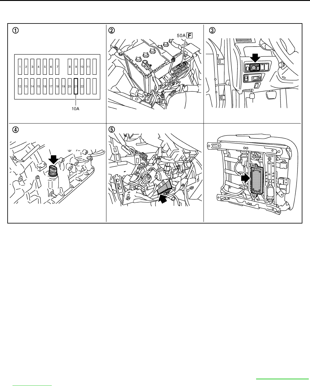
GW-96
REVERSE INTERLOCK DOOR MIRROR SYSTEM
Revision: 2006 January 2006 M35/M45
REVERSE INTERLOCK DOOR MIRROR SYSTEM PFP:28548
Component Parts and Harness Connector Location NIS00230
System Description NIS00231
Select one of the door mirror faces by change over switch, and then set the selected mirror face downward/
inward.
This operation is synchronized with the R position operation of A/T control device.
OPERATION CONDITIONS
●Ignition switch : ON
●Changeover switch : Select either left or right
●A/T control device : R position
During the reverse interlock door mirror system, if all of the above conditions are not satisfied, mirror face
returns to original angle.
MIRROR UNGLE MEMORY FUNCTION
●During the reverse interlock door mirror operation, the mirror angle can be changed. After adjustment, the
mirror face positions can be memorized (2 positions). For memory setting, Refer to SE-12, "MEMORY
OPERATION"
●Initial setting is downward 7°, inward 1° (both of left and right)
Power supplied at all times
●through 50A fusible link (letter F, located in the fuse block and fusible link)
●to automatic drive positioner control unit terminal 39 and
●to driver seat control unit terminal 33.
PIIB6099E
1. Fuse block (J/B) 2. Fusible link 3. Door mirror remote control switch
M95
4. TCM (A/T assembly) F42 5.
Automatic drive positioner control
unit M6, M7 (view with the instra-
ment lower panel LH removed)
6. Driver seat control unit B204, B205

REVERSE INTERLOCK DOOR MIRROR SYSTEM
GW-97
C
D
E
F
G
H
J
K
L
M
A
B
GW
Revision: 2006 January 2006 M35/M45
●through 10A fuse [No.21, located in the fuse block (J/B)]
●to automatic drive positioner control unit terminal 34 and
●to driver seat control unit terminal 40.
Ground is supplied
●to automatic drive positioner control unit terminals 40 and 48.
●through body grounds M16 and M70.
●to driver seat control unit terminals 32 and 48.
●through body grounds B5, B40 and B131.
●to door mirror remote control switch terminal 13
●through body grounds M16 and M70.
REVERSE INTERLOCK DOOR MIRROR SYSTEM OPERATION
●When the ignition switch is in ON position, A/T control device into R position. Then TCM (in A/T assembly)
detects it and sends the A/T shift position signal to the driver seat control unit via DATA LINE (CAN H,
CAN L).
●When selecting either left and right changeover switch, the automatic drive position control unit judges
which door mirror is selected according to the voltage of terminals 2 and 18. And then, it sends the signal
to driver seat control unit via communication signal.
●When the driver seat control unit receives the A/T shift position signal and changeover switch signal, it
sends the operation signal to the automatic drive positioner control unit using the communication signal so
that the each mirror sensor voltage stays in a specified value.
●Door mirror (RH) selected
Supply the power from terminals 14, 15 and 30 to door mirror (RH) terminals 5, 6 and 7 so that the voltage
of terminals 5 and 21 stays in a specified value. Then, adjust the mirror angle.
●Door mirror (LH) selected
Supply the power from terminals 16, 31 and 32 to door mirror (LH) terminals 5, 6 and 7 do that the voltage
of terminals 6 and 22 is the specified value. Then, adjust the mirror angle.
CAN Communication System Description NIS00232
CAN (Controller Area Network) is a serial communication line for real time application. It is an on-vehicle mul-
tiplex communication line with high data communication speed and excellent error detection ability. Many elec-
tronic control units are equipped onto a vehicle, and each control unit shares information and links with other
control units during operation (not independent). In CAN communication, control units are connected with 2
communication lines (CAN H line, CAN L line) allowing a high rate of information transmission with less wiring.
Each control unit transmits/receives data but selectively reads required data only.
CAN Communication Unit NIS00233
Refer to LAN-34, "CAN Communication Unit" .
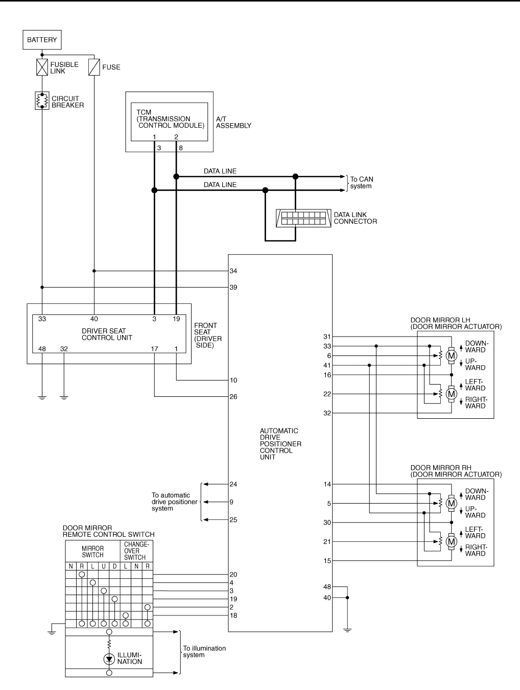
GW-98
REVERSE INTERLOCK DOOR MIRROR SYSTEM
Revision: 2006 January 2006 M35/M45
Schematic NIS00234
TIWT1357E
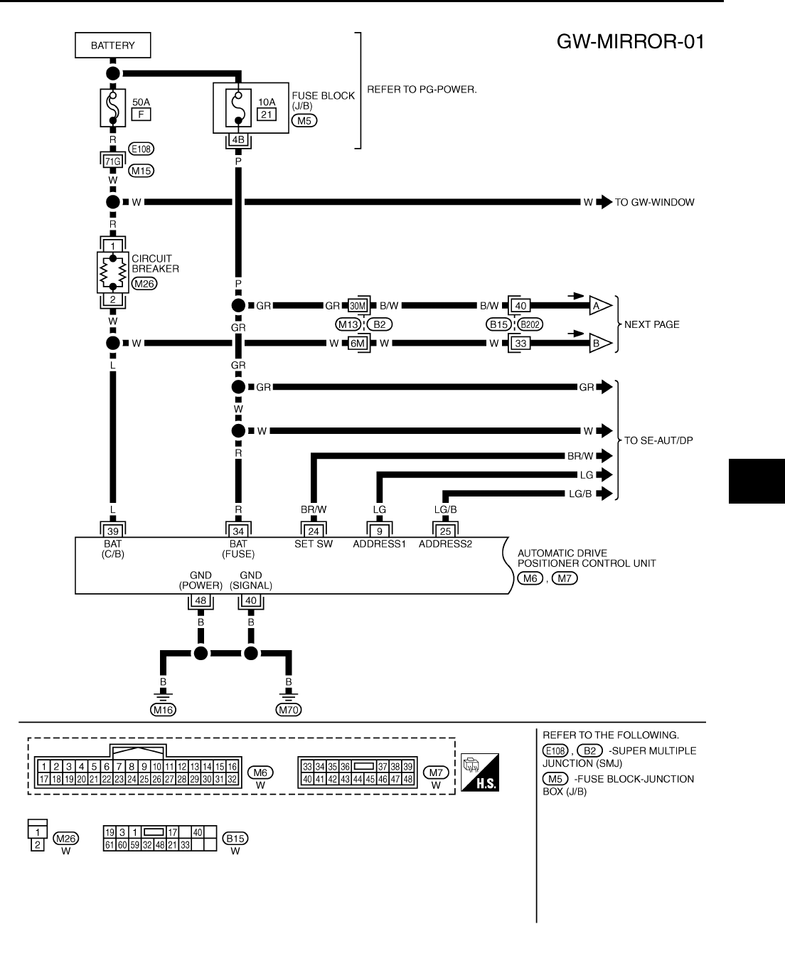
REVERSE INTERLOCK DOOR MIRROR SYSTEM
GW-99
C
D
E
F
G
H
J
K
L
M
A
B
GW
Revision: 2006 January 2006 M35/M45
Wiring Diagram —MIRROR— NIS00235
TIWT1358E
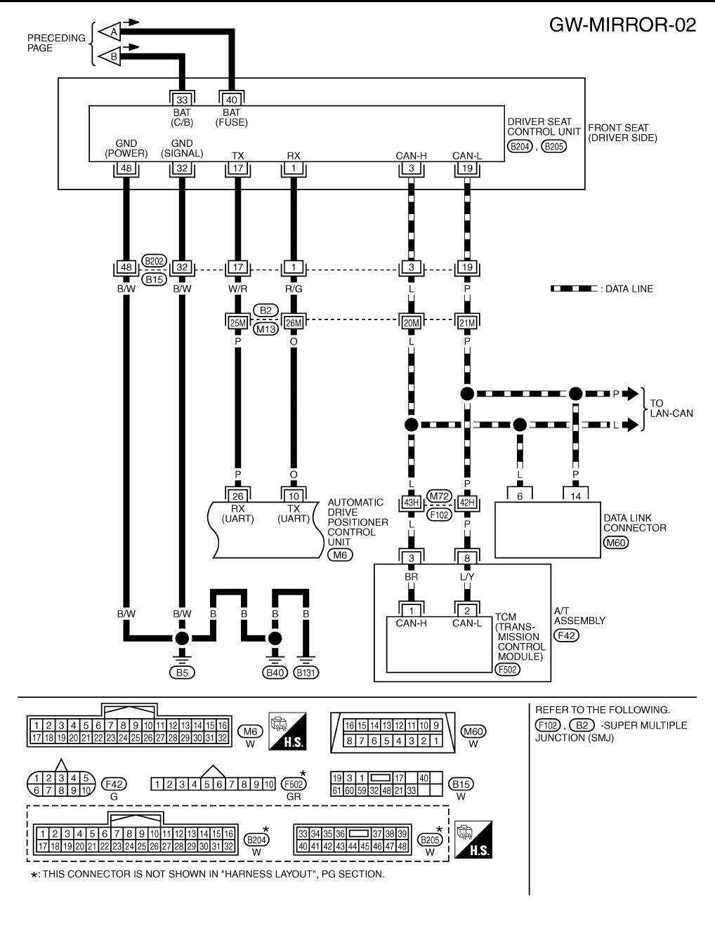
GW-100
REVERSE INTERLOCK DOOR MIRROR SYSTEM
Revision: 2006 January 2006 M35/M45
TIWT1359E
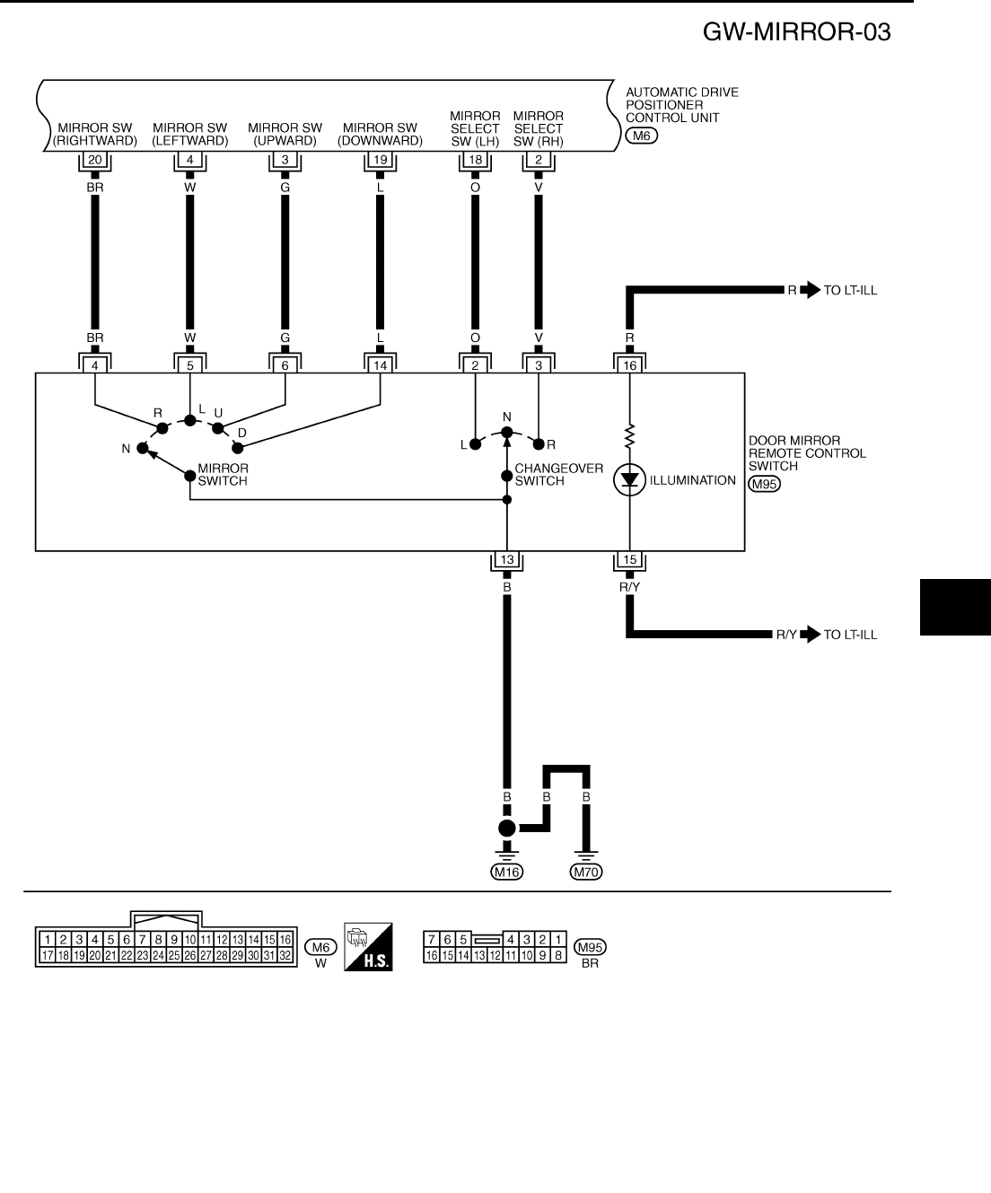
REVERSE INTERLOCK DOOR MIRROR SYSTEM
GW-101
C
D
E
F
G
H
J
K
L
M
A
B
GW
Revision: 2006 January 2006 M35/M45
TIWT1360E
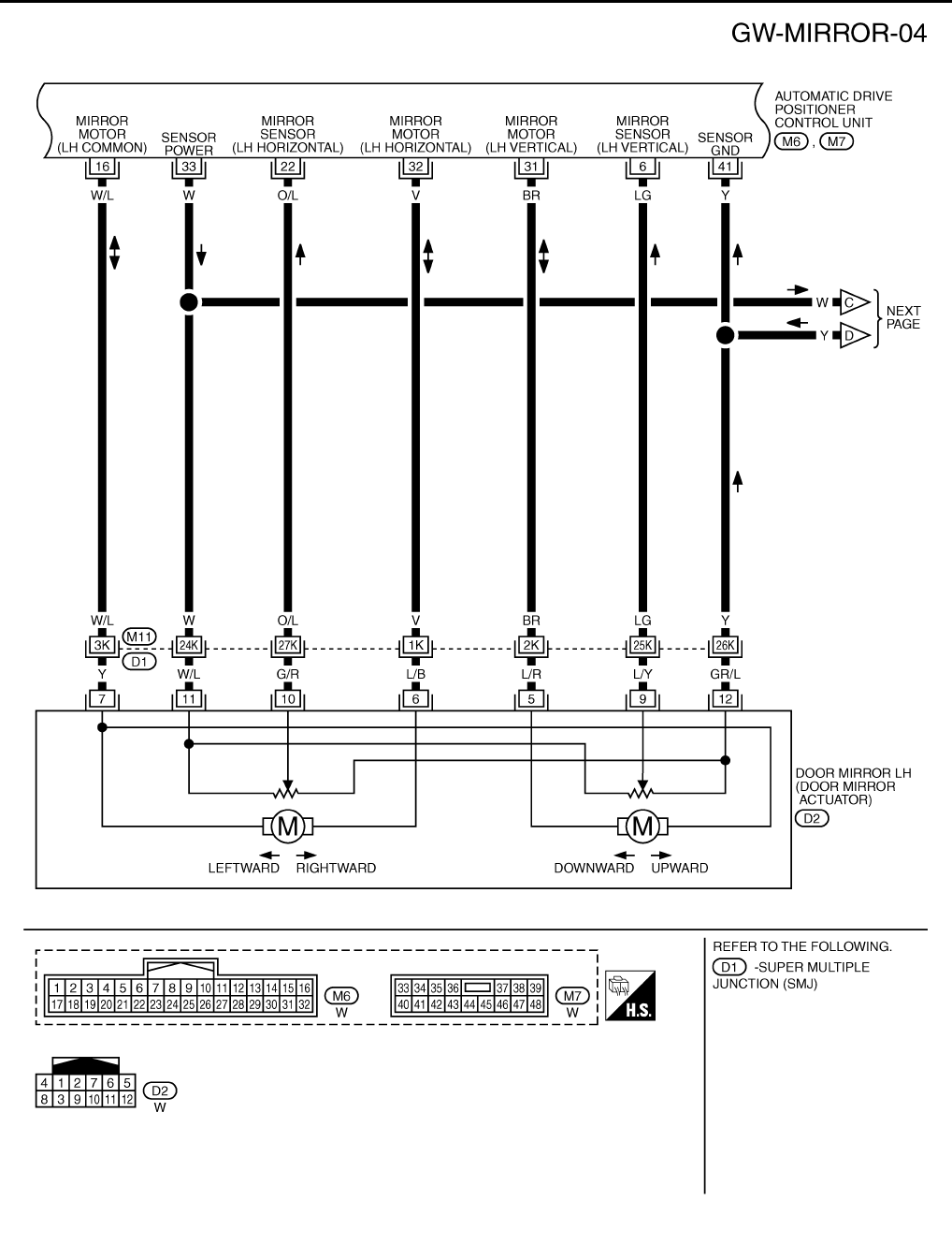
GW-102
REVERSE INTERLOCK DOOR MIRROR SYSTEM
Revision: 2006 January 2006 M35/M45
TIWT1361E
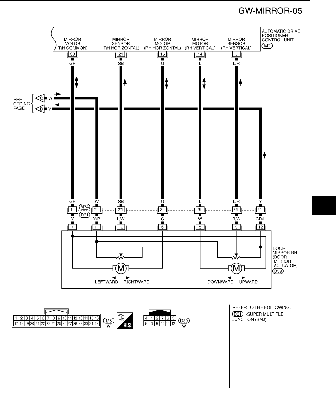
REVERSE INTERLOCK DOOR MIRROR SYSTEM
GW-103
C
D
E
F
G
H
J
K
L
M
A
B
GW
Revision: 2006 January 2006 M35/M45
TIWT1362E
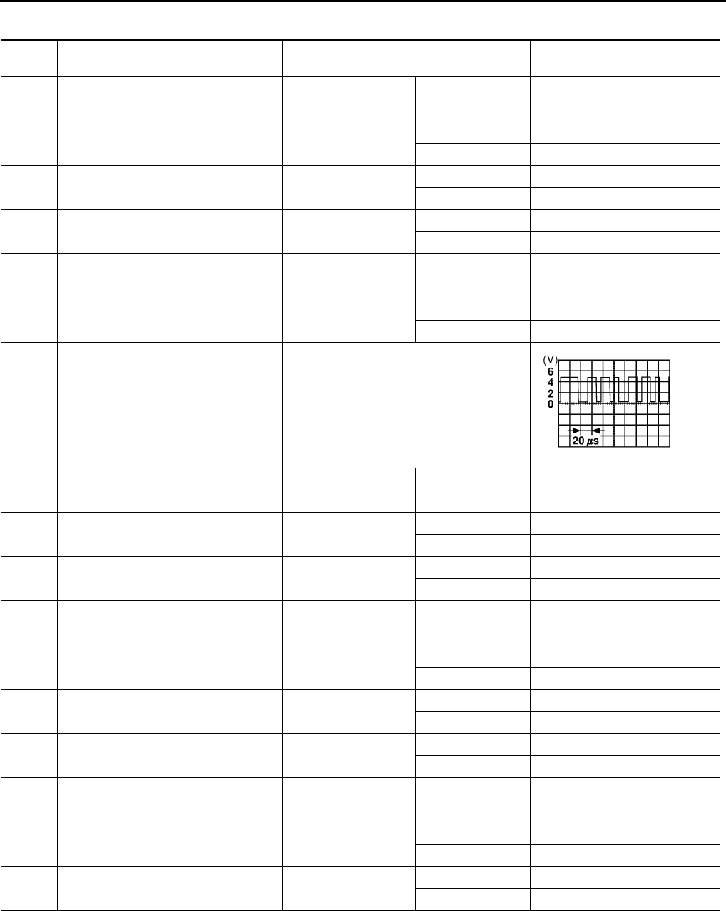
GW-104
REVERSE INTERLOCK DOOR MIRROR SYSTEM
Revision: 2006 January 2006 M35/M45
Terminals and Reference Values for Automatic Drive Positioner Control UnitNIS00236
Termi-
nal
Wire
color Item Condition Voltage (V)
(Approx.)
2V
Changeover switch
RH signal
When changeover
switch position
RH 0
Other than above 5
3G
Mirror switch
UP signal
When mirror switch
position
UP 0
Other than above 5
4W
Mirror switch
LEFT signal
When mirror switch
position
LEFT 0
Other than above 5
5L/R
Door mirror RH sensor
vertical signal
When door mirror RH
mirror face position
Close to perk 4.2
Close to valley 0.5
6LG
Door mirror LH sensor
vertical signal
When door mirror LH
mirror face position
Close to perk 4.2
Close to valley 0.5
9 LG Seat memory switch 1 signal Seat memory switch 1 : ON 0
: OFF 5
10 O UART LINE (TX) Tilt switch operated
14 L Door mirror RH mirror motor
UP signal
When door mirror RH
mirror motor operation
UP Battery voltage
Other than above 0
15 G Door mirror RH mirror motor
LEFT signal
When door mirror RH
mirror motor operation
LEFT Battery voltage
Other than above 0
16 W/L Door mirror LH mirror motor
RIGHT or DOWN signal
When door mirror LH
mirror motor operation
RIGHT or DOWN Battery voltage
Other than above 0
18 O Changeover switch
LH signal
When changeover
switch position
LH 0
Other than above 5
19 L Mirror switch DOWN signal When mirror switch
position
DOWN 0
Other than above 5
20 BR Mirror switch RIGHT signal When mirror switch
position
RIGHT 0
Other than above 5
21 SB Door mirror RH sensor
horizontal signal
When door mirror RH
mirror face position
Close to left edge 3.5
Close to right edge 0.5
22 O/L Door mirror LH sensor
horizontal signal
When door mirror LH
mirror face position
Close to left edge 0.5
Close to right edge 3.5
24 BR/W Set switch signal Set switch : ON 0
: OFF 5
25 LG/B Seat memory switch 2 signal Seat memory switch 2 : ON 0
: OFF 5
SKIA0175E
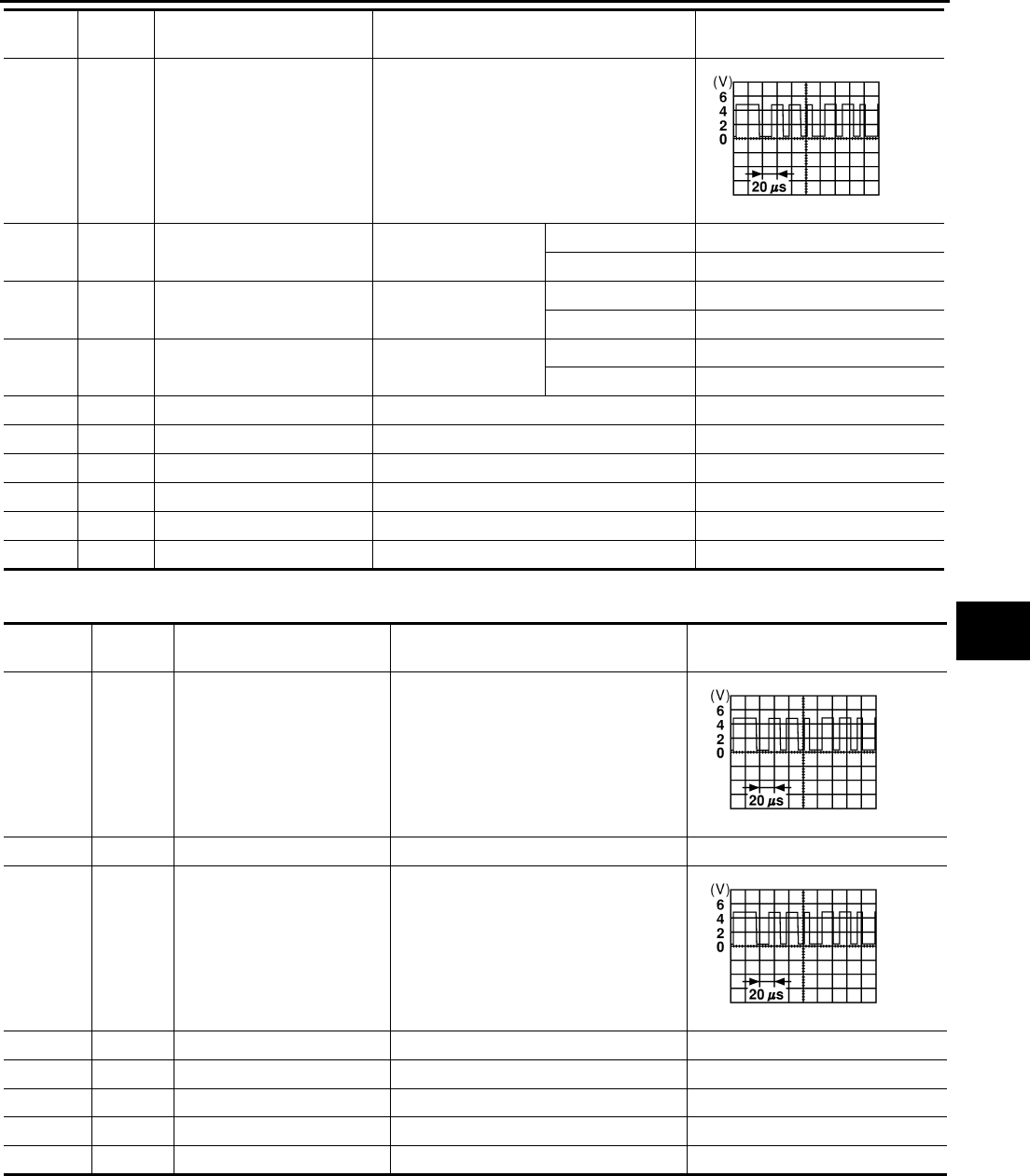
REVERSE INTERLOCK DOOR MIRROR SYSTEM
GW-105
C
D
E
F
G
H
J
K
L
M
A
B
GW
Revision: 2006 January 2006 M35/M45
Terminals and Reference Values for Driver Seat Control Unit NIS00237
26 P UART LINE (RX) Tilt switch operated
30 GR Door mirror LH mirror motor
RIGHT or DOWN signal
When door mirror LH
mirror motor operation
RIGHT or DOWN Battery voltage
Other than above 0
31 BR Door mirror LH mirror motor
UP signal
When door mirror LH
mirror motor operation
UP Battery voltage
Other than above 0
32 T Door mirror LH mirror motor
LEFT signal
When door mirror LH
mirror motor operation
LEFT Battery voltage
Other than above 0
33 W Mirror sensor power supply — Battery voltage
34 R Power supply (fuse) — Battery voltage
39 L Power supply (fusible link) — Battery voltage
40 B Ground (signal) — 0
41 Y Sensor ground — 0
48 B Ground (power) — 0
Termi-
nal
Wire
color Item Condition Voltage (V)
(Approx.)
SKIA0175E
Terminal Wire
color Item Condition Voltage (V)
(Approx.)
1 R/G UART LINE (RX) Tilt switch operated
3 L CAN-H — —
17 W/R UART LINE (TX) Tilt switch operated
19 P CAN-L — —
32 B/W Ground (signal) — 0
33 W Power supply (fusible link) — Battery voltage
40 B/W Power supply (fuse) — Battery voltage
48 B/W Ground (power) — 0
SKIA0175E
SKIA0175E
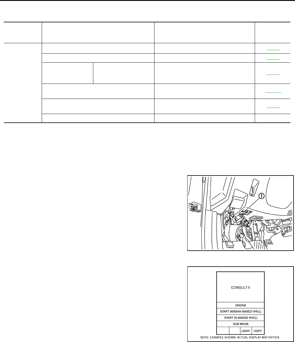
GW-106
REVERSE INTERLOCK DOOR MIRROR SYSTEM
Revision: 2006 January 2006 M35/M45
CONSULT-II Function (AUTO DRIVE POS.) NIS00238
CONSULT-II can display each diagnostic item using the diagnostic test modes shown following.
*1: For setting automatic drive positioner functions only.
*2: During vehicle driving, do not perform active test.
CONSULT-II INSPECTION PROCEDURE
CAUTION:
If CONSULT-II is used with no connection of CONSULT-II CONVERTER, malfunctions might be
detected in self-diagnosis depending on control unit which carry out CAN communication.
1. Turn ignition switch “OFF”.
2. Connect “CONSULT-II” and “CONSULT-II CONVERTER” to the
data link connector (1).
3. Turn ignition switch “ON”.
4. Touch “START (NISSAN BASED VHCL)”.
CONSULT-II
diagnosis
items
Inspection item, self-diagnosis mode Content Refer to page
AUTO DRIVE
POSITIONER
WORK SUPPORT*1Changes the setting for each function. SE-38
SELF–DIG RESULTS Check the self-diagnosis results. SE-36
DATA MONITOR Selection from menu
Displays the input data to driver seat control
unit and automatic driving positioned control
unit on real-time basis.
SE-37
CAN DIAGNOSTIC SUPPORT MONITOR The results of transmit / receive diagnosis of
CAN communication can be read LAN-20
ACTIVE TEST*2 Gives a drive signal to a load to check the
operation. SE-38
DRIVER SEAT CONTROL UNIT PART NUMBER Displays driver seat control unit part No. —
PBIB2712E
BCIA0029E
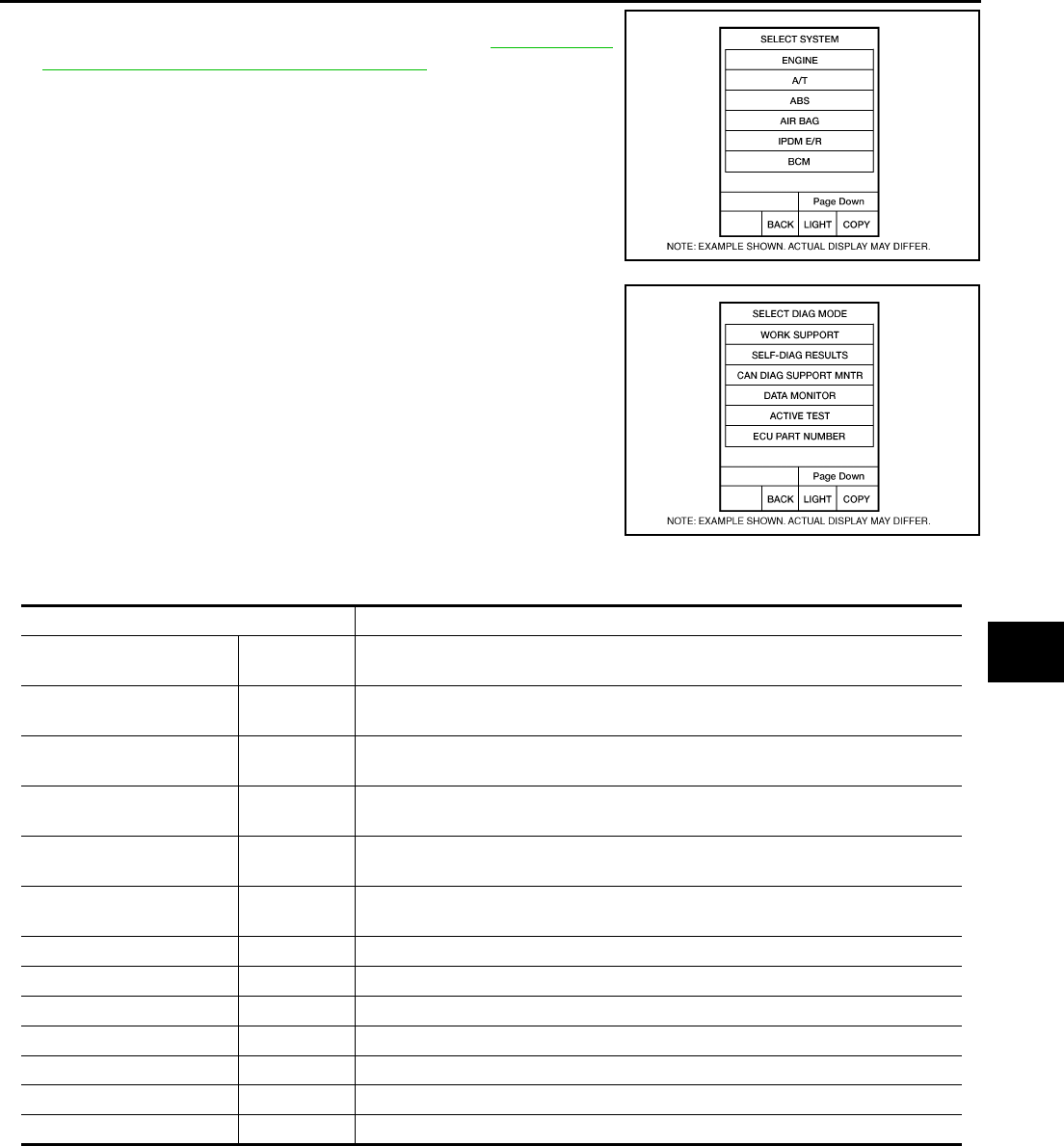
REVERSE INTERLOCK DOOR MIRROR SYSTEM
GW-107
C
D
E
F
G
H
J
K
L
M
A
B
GW
Revision: 2006 January 2006 M35/M45
5. Touch “AUTO DRIVE POS” and “BCM”.
If “AUTO DRIVE POS.” is not indicated, refer to GI-40, "CON-
SULT-II Data Link Connector (DLC) Circuit" .
6. Select diagnosis mode.
“DATA MONITOR”, “ACTIVE TEST”, “SELF-DIAG RESULTS“,
“ECU PART NUMBER” and “WORK SUPPORT” are available.
DATA MONITOR
Selection from Menu
ACTIVE TEST
CAUTION:
During vehicle driving, do not perform active test.
NOTE:
If active test is performed, reset seat memory and key fob interlock drive positioner after performing work.
BCIA0030E
BCIA0031E
Monitor item [OPERATION or UNIT] Contents
MIR CON SW–UP “ON/OFF” ON/OFF status judged from the door mirror remote control switch (UP) signal is
displayed.
MIR CON SW–DN “ON/OFF” ON/OFF status judged from the door mirror remote control switch (DOWN) signal
is displayed.
MIR CON SW–RH “ON/OFF” ON/OFF status judged from the door mirror remote control switch (RIGHT) signal
is displayed.
MIR CON SW–LH “ON/OFF” ON/OFF status judged from the door mirror remote control switch (LEFT) signal s
displayed.
MIR CHNG SW–R “ON/OFF” ON/OFF status judged from the door mirror remote control switch (switching to
RIGHT) signal is displayed.
MIR CHNG SW–L “ON/OFF” ON/OFF status judged from the door mirror remote control switch (switching to
LEFT) signal is displayed.
SET SW “ON/OFF” ON/OFF status judged from the setting switch signal is displayed.
MEMORY SW1 “ON/OFF” ON/OFF status judged from the seat memory switch 1 signal is displayed.
MEMORY SW2 “ON/OFF” ON/OFF status judged from the seat memory switch 2 signal is displayed.
MIR/SE RH R–L “V” Voltage output from RH door mirror sensor (LH/RH) is displayed.
MIR/SE RH U–D “V” Voltage output from RH door mirror sensor (UP/DOWN) is displayed.
MIR/SE LH R–L “V” Voltage output from LH door mirror sensor (LH/RH) is displayed.
MIR/SE LH U–D “V” Voltage output from LH door mirror sensor (UP/DOWN) is displayed.
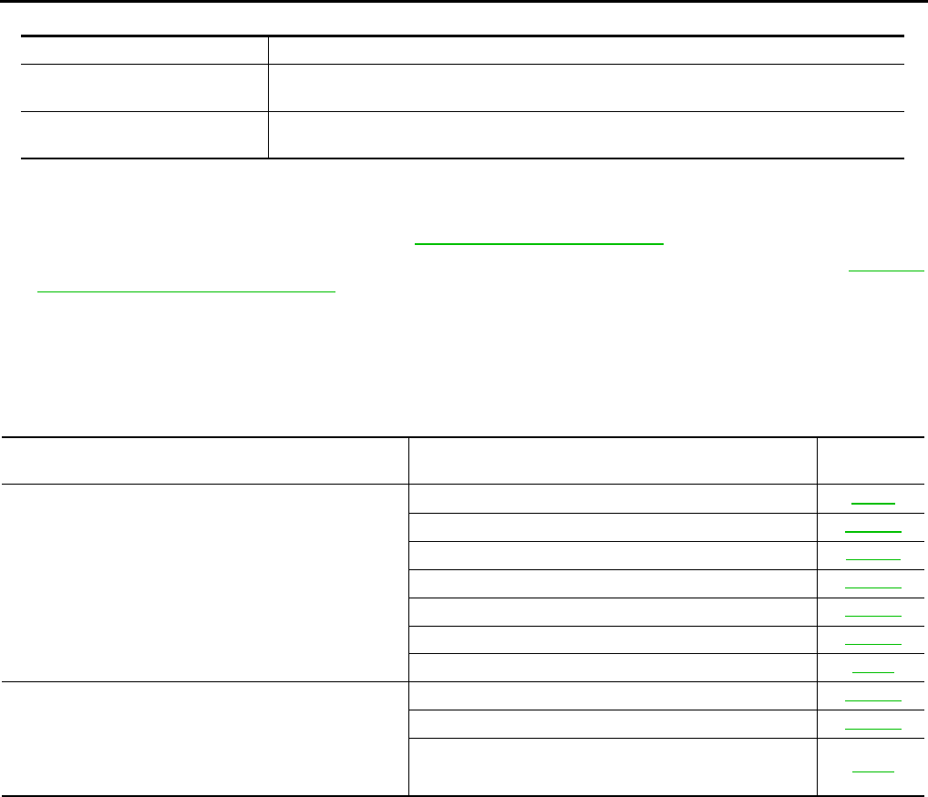
GW-108
REVERSE INTERLOCK DOOR MIRROR SYSTEM
Revision: 2006 January 2006 M35/M45
Display Item List
Work Flow NIS00239
1. Check the symptom and customer's requests.
2. Understand the system description. Refer to GW-96, "System Description" .
3. According to the trouble diagnosis chart, repair or replace the cause of the malfunction. Refer to GW-109,
"Check Changeover Switch Circuit" .
4. Does reverse interlock door mirror system operate normally?
Yes , GO TO 5.
No, GO TO 3.
5. INSPECTION END
Symptom Chart NIS0023A
Test item Description
MIRROR MOTOR RH The RH mirror motor moves the mirror UP/DOWN and LEFT/RIGHT by receiving the drive
signal.
MIRROR MOTOR LH The LH mirror motor moves the mirror UP/DOWN and LEFT/RIGHT by receiving the drive
signal.
Symptom Diagnoses / service procedure Reference
page
Reverse interlock door mirror does not operate.
1. Check seat set switch circuit SE-80
2. Check changeover switch circuit GW-109
3. Check mirror switch circuit GW-111
4. Check A/T control device R position signal circuit GW-119
5. Check mirror motor circuit GW-113
6. Check mirror sensor circuit GW-116
7. Replace automatic drive positioner control unit SE-11
●At reverse interlock door mirror system operation, mir-
ror angle is not in the setting position
●After finishing the reverse interlock door mirror system.
Operation, mirror angle does not return to the original
position
1. Check mirror sensor circuit GW-116
2. Check A/T control device R position signal circuit GW-119
3. Replace automatic drive positioner control unit SE-11
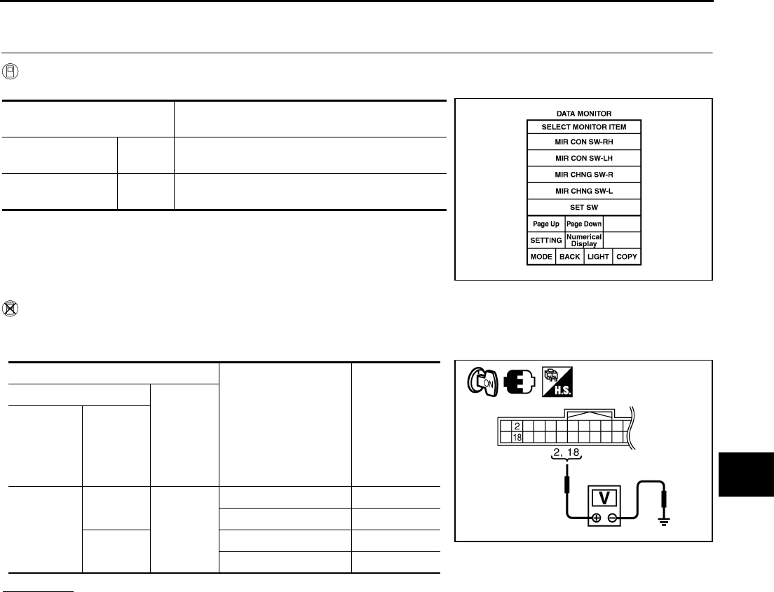
REVERSE INTERLOCK DOOR MIRROR SYSTEM
GW-109
C
D
E
F
G
H
J
K
L
M
A
B
GW
Revision: 2006 January 2006 M35/M45
Check Changeover Switch Circuit NIS0023B
1. CHECK CHANGEOVER SWITCH SIGNAL
With CONSULT-II
Check the operation on (MIR CHNG SW-R” or “MIR CHNG SW-L) in the DATA MONITOR.
Without CONSULT-II
1. Turn ignition switch ON.
2. Check voltage between automatic drive positioner control unit connector and ground.
OK or NG
OK >> Changeover switch circuit is OK.
NG >> GO TO 2.
Monitor item
[OPERATION or UNIT] Contents
MIR CHNG SW–R “ON/
OFF”
ON/OFF status judged from the changeover
switch (switching to RIGHT) signal is displayed.
MIR CHNG SW–L “ON/
OFF”
ON/OFF status judged from the changeover
switch (switching to LEFT) signal is displayed.
PIIA0191E
Terminals
Change over switch
condition
Voltage (V)
(Approx.)
(+)
(-)
Automatic
drive posi-
tioner con-
trol unit
connector
Terminal
M6
2
Ground
RIGHT 0
Other than above 5
18 LEFT 0
Other than above 5
PIIB6015E
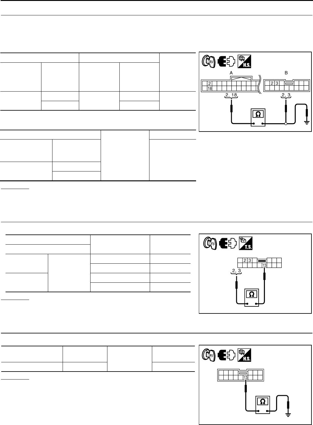
GW-110
REVERSE INTERLOCK DOOR MIRROR SYSTEM
Revision: 2006 January 2006 M35/M45
2. CHECK HARNESS CONTINUITY
1. Turn ignition switch OFF.
2. Disconnect automatic drive positioner control unit and door mirror remote control switch connector.
3. Check continuity between automatic drive positioner control unit connector and door mirror remote control
switch connector.
4. Check continuity between automatic drive positioner control unit
connector and ground.
OK or NG
OK >> GO TO 3.
NG >> Repair or replace harness.
3. CHECK CANGEOVER SWITCH
Check door mirror remote control switch.
OK or NG
OK >> GO TO 4.
NG >> Replace door mirror remote control switch.
4. CHECK DOOR MIRROR REMOTE CONTROL SWITCH GROUND CIRCUIT
Check continuity between door mirror remote control switch connector and ground.
OK or NG
OK >> GO TO 5.
NG >> Repair or replace harness.
AB
Continuity
Automatic
drive posi-
tioner control
unit connector
Terminal
Door mirror
remote control
switch
connector
Terminal
M6 2M95 3Yes
18 2
A
Ground
Continuity
Automatic drive
positioner control
unit connector
Terminal
No
M6 2
18
PIIB6016E
Terminal Change over switch
condition Continuity
Door mirror remote control switch
2
13
LEFT Yes
Other than above No
3RIGHT Yes
Other than above No
PIIB6017E
Door mirror remote
control switch connector Terminal Ground Continuity
M95 13 Yes
PIIB6018E
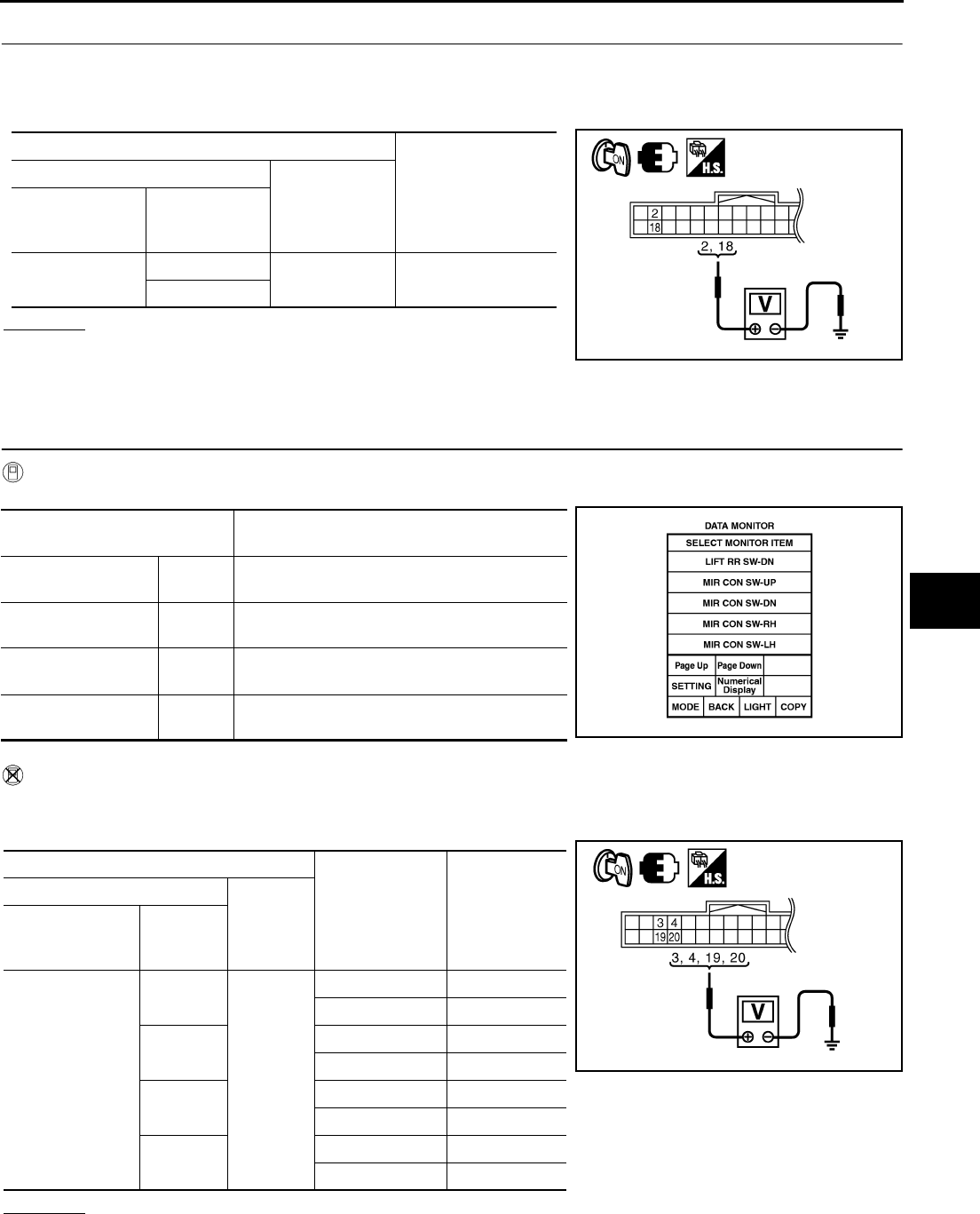
REVERSE INTERLOCK DOOR MIRROR SYSTEM
GW-111
C
D
E
F
G
H
J
K
L
M
A
B
GW
Revision: 2006 January 2006 M35/M45
5. CHECK AUTOMATIC DRIVE POSITIONER CONTROL UNIT OUTPUT SIGNAL
1. Connect automatic drive positioner control unit connector.
2. Turn ignition switch ON.
3. Check voltage between automatic drive positioner control unit connector and ground.
OK or NG
OK >> Check the condition of harness and connector.
NG >> Replace automatic drive positioner control unit.
Check Mirror Switch Circuit Check NIS0023C
1. CHECK MIRROR SWITCH SIGNAL
With CONSULT-II
Check the operation on “(MIR CON SW–UP/DN) and (MIR CON SW–RH/LH) in the DATA MONITOR.
Without CONSULT-II
1. Turn ignition switch to ON position.
2. Check voltage between automatic drive positioner control unit connector and ground.
OK or NG
OK >> Mirror switch circuit is OK.
NG >> GO TO 2.
Terminals
Voltage (V)
(Approx.)
(+)
(-)
Automatic drive
positioner control
unit connector
Terminal
M6 2Ground 5
18
PIIB6015E
Monitor item
[OPERATION or UNIT] Contents
MIR CON SW–UP “ON/
OFF”
ON/OFF status judged from the mirror switch
(UP) signal is displayed.
MIR CON SW–DN “ON/
OFF”
ON/OFF status judged from the mirror switch
(DOWN) signal is displayed.
MIR CON SW–RH “ON/
OFF”
ON/OFF status judged from the mirror switch
(RIGHT) signal is displayed.
MIR CON SW–LH “ON/
OFF”
ON/OFF status judged from the mirror switch
(LEFT) signal s displayed. PIIA0199E
Terminals
Mirror switch
Condition
Voltage (V)
(Approx.)
(+)
(–)
Automatic drive
positioner control
unit connector
Terminal
M6
3
Ground
UP 0
Other than above 5
4LEFT 0
Other than above 5
19 DOWN 0
Other than above 5
20 RIGHT 0
Other than above 5
PIIB6019E
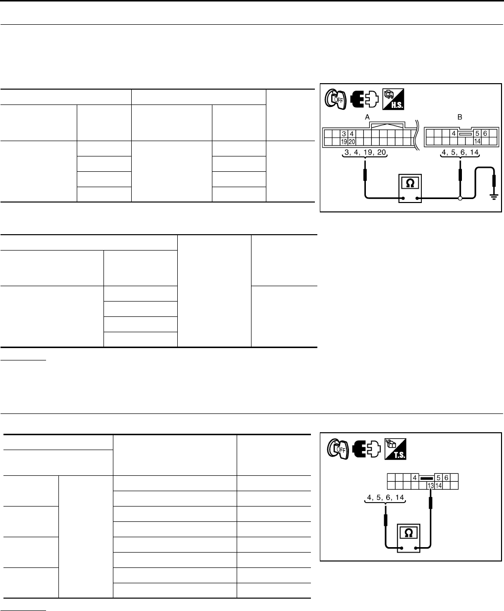
GW-112
REVERSE INTERLOCK DOOR MIRROR SYSTEM
Revision: 2006 January 2006 M35/M45
2. CHECK HARNESS CONTINUITY
1. Turn ignition switch OFF.
2. Disconnect automatic drive positioner control unit and door mirror remote control switch connector.
3. Check continuity between automatic drive positioner control unit connector and door mirror remote control
switch connector.
4. Check continuity between automatic drive positioner control unit
connector and ground.
OK or NG
OK >> GO TO 3.
NG >> Repair or replace harness.
3. CHECK DOOR MIRROR SWITCH
Check door mirror remote control switch.
OK or NG
OK >> GO TO 4.
NG >> Replace door mirror remote control switch.
AB
Continuity
Automatic drive
positioner control
unit connector
Terminal
Door mirror remote
control switch
connector
Terminal
M6
3
M95
6
Yes
45
19 14
20 4
A
Ground
Continuity
Automatic drive posi-
tioner control unit con-
nector
Terminal
M6
3
No
4
19
20
PIIB6020E
Terminal
Mirror switch condition Continuity
Door mirror remote
control switch
4
13
RIGHT Yes
Other than above No
5LEFT Yes
Other than above No
6UP Yes
Other than above No
14 DOWN Yes
Other than above No
PIIB6021E

REVERSE INTERLOCK DOOR MIRROR SYSTEM
GW-113
C
D
E
F
G
H
J
K
L
M
A
B
GW
Revision: 2006 January 2006 M35/M45
4. CHECK AUTOMATIC DRIVE POSITIONER CONTROL UNIT OUTPUT SIGNAL
1. Connect automatic drive positioner control unit connector.
2. Turn ignition switch ON.
3. Check voltage between automatic drive positioner control unit and ground.
OK or NG
OK >> Check the condition of harness and connector.
NG >> Replace automatic drive positioner control unit.
Check Mirror Motor Circuit Check NIS0023D
1. CHECK MIRROR MOTOR FUNCTION
With CONSULT-II
Check the operation with (MIRROR MOTOR RH, MIRROR MOTOR LH) in the ACTIVE TEST.
Without CONSULT-II
1. Turn ignition switch to ON position.
2. Check voltage between door mirror connector and ground.
OK or NG
OK >> Mirror motor circuit is OK.
NG >> GO TO 2.
Terminals
Voltage (V)
(Approx.)
(+)
(-)
Automatic drive
positioner control
unit connector
Terminal
M6
3
Ground 5
4
19
20 PIIB6019E
Test item Description
MIRROR MOTOR LH The LH mirror motor moves the mirror UP/DOWN and
LEFT/RIGHT by receiving the drive signal.
MIRROR MOTOR RH The RH mirror motor moves the mirror UP/DOWN and
LEFT/RIGHT by receiving the drive signal.
PIIB6022E
Terminals
Mirror switch
Condition
Voltage (V)
(Approx.)
(+)
(–)
Door mirror
connector Terminal
D2 (RH)
D39 (LH)
5
Ground
UP Battery voltage
Other than above 0
6LEFT Battery voltage
Other than above 0
7DOWN / RIGHT Battery voltage
Other than above 0
PIIB6031E

GW-114
REVERSE INTERLOCK DOOR MIRROR SYSTEM
Revision: 2006 January 2006 M35/M45
2. CHECK HARNESS CONTINUITY
1. Turn ignition switch OFF.
2. Disconnect automatic drive positioner control unit connector and door mirror connector.
3. [Door mirror LH]
–Check continuity between automatic drive positioner control unit connector and door mirror LH connector.
–Check continuity between automatic drive positioner control unit
connector and ground.
4. [Door mirror RH]
–Check continuity between automatic drive positioner control unit connector and door mirror RH connector.
–Check continuity between automatic drive positioner control unit
connector and ground.
OK or NG
OK >> GO TO 3.
NG >> Repair or replace harness.
AB
Continuity
Automatic
drive posi-
tioner control
unit connector
Terminal Door mirror
LH connector Terminal
M6
16
D2
7
Yes31 5
32 6
A
Ground
Continuity
Automatic drive
positioner control
unit connector
Terminal
M6
16
No31
32
AB
Continuity
Automatic
drive posi-
tioner control
unit connector
Terminal Door mirror
RH connector Terminal
M6
14
D39
5
Yes15 6
30 7
A
Ground
Continuity
Automatic drive
positioner control
unit connector
Terminal
M6
14
No15
30
PIIB6023E
PIIB6024E
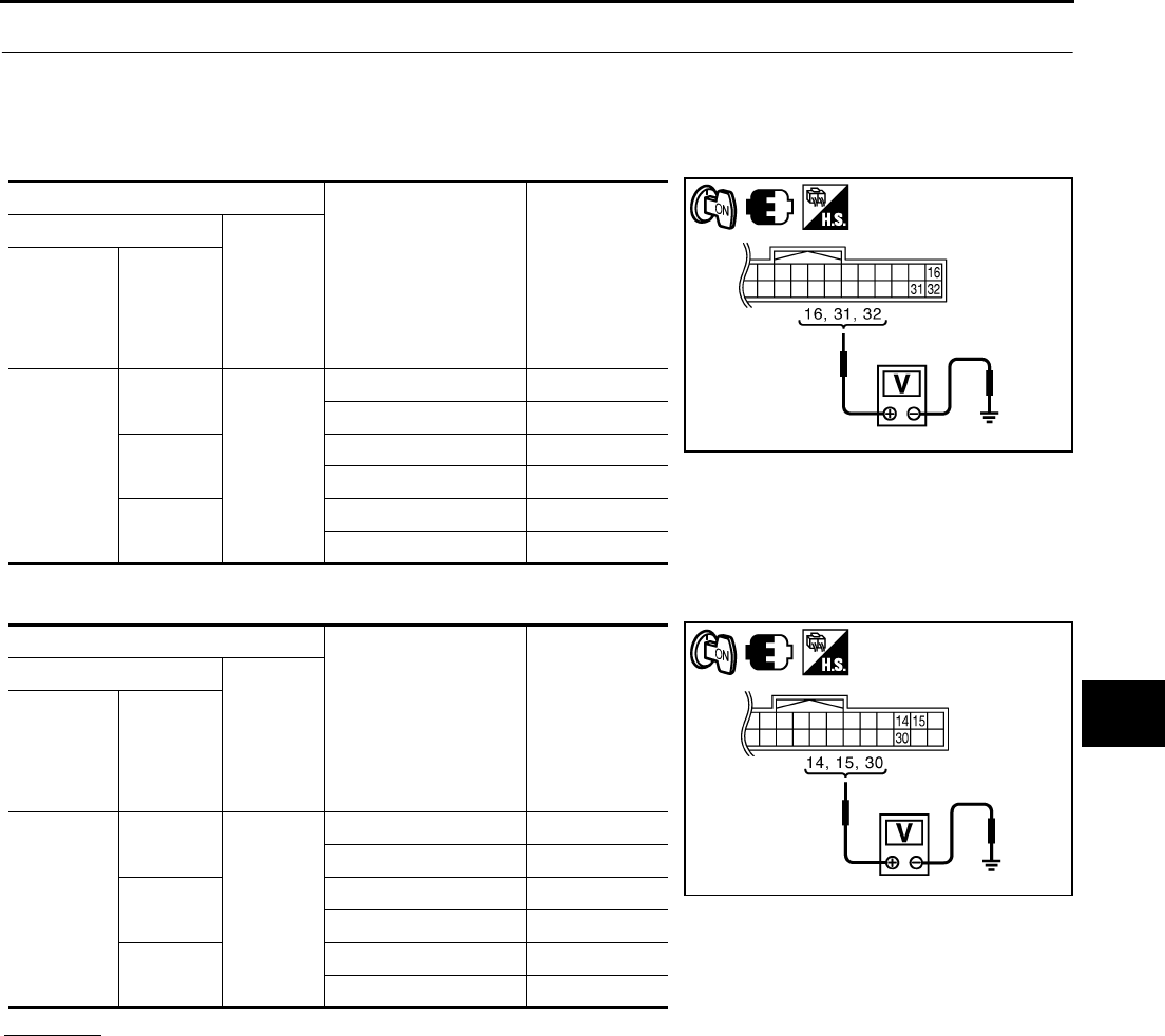
REVERSE INTERLOCK DOOR MIRROR SYSTEM
GW-115
C
D
E
F
G
H
J
K
L
M
A
B
GW
Revision: 2006 January 2006 M35/M45
3. CHECK AUTOMATIC DRIVE POSITIONER CONTROL UNIT OUTPUT SIGNAL
1. Connect automatic drive positioner control unit connector.
2. Turn ignition switch ON.
3. [Door mirror LH]
Check voltage between automatic drive positioner control unit connector and ground.
4. [Door mirror RH]
Check voltage between automatic drive positioner control unit connector and ground.
OK or NG
OK >> Replace malfunction door mirror actuator.
NG >> Replace automatic drive positioner control unit.
Terminals
Mirror switch condition Voltage (V)
(Approx.)
(+)
(-)
Automatic
drive posi-
tioner con-
trol unit
connector
Terminal
M6
16
Ground
DOWN / RIGHT Battery voltage
Other than above 0
31 UP Battery voltage
Other than above 0
32 LEFT Battery voltage
Other than above 0
Terminals
Mirror switch condition Voltage (V)
(Approx.)
(+)
(-)
Automatic
drive posi-
tioner con-
trol unit
connector
Terminal
M6
14
Ground
UP Battery voltage
Other than above 0
15 LEFT Battery voltage
Other than above 0
30 DOWN / RIGHT Battery voltage
Other than above 0
PIIB6025E
PIIB6026E
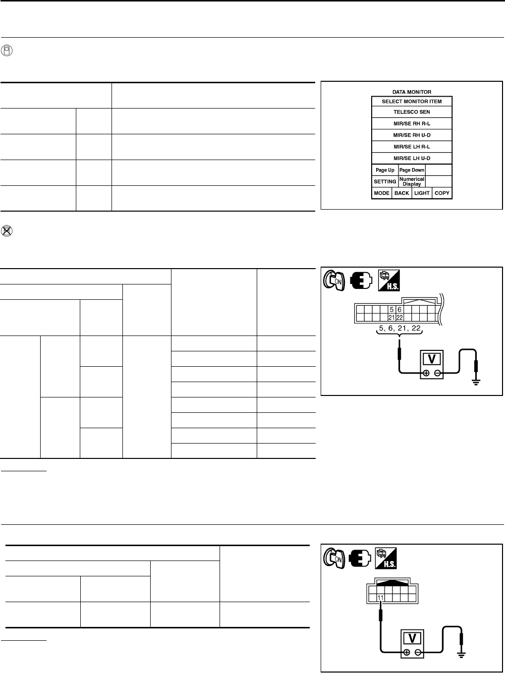
GW-116
REVERSE INTERLOCK DOOR MIRROR SYSTEM
Revision: 2006 January 2006 M35/M45
Check Mirror Sensor Circuit Check NIS0023E
1. CHECK MIRROR SENSOR INSPECTION
With CONSULT-II
Check the voltage on (MIR/SE LH R–L, MIR/SE LH U–D, MIR/SE RH R–L, MIR/SE RH U–D) in the DATA
MONITOR.
Without CONSULT-II
1. Turn ignition switch ON.
2. Check voltage between automatic drive positioner control unit connector and ground.
OK or NG
OK >> Mirror sensor LH circuit is OK.
NG >> GO TO 3.
2. CHECK MIRROR SENSOR POWER SUPPLY 1
Check voltage between door mirror connector and ground.
OK or NG
OK >> GO TO 5.
NG >> GO TO 3.
Monitor item
[OPERATION or UNIT] Contents
MIR/SE LH R–L “V” Voltage output from door mirror LH horizontal sensor
(LH/RH) is displayed.
MIR/SE LH U–D “V” Voltage output from door mirror LH vertical sensor
(UP/DOWN) is displayed.
MIR/SE RH R–L “V” Voltage output from door mirror RH horizontal sensor
(LH/RH) is displayed.
MIR/SE RH U–D “V” Voltage output from door mirror RH vertical sensor
(UP/DOWN) is displayed. PIIA0197E
Terminals
Mirror face position Voltage (V)
(Approx.)
(+)
(-)
Automatic drive
positioner control
unit connector
Terminal
M6
Door
mirror
RH side
5
Ground
Close to perk 4.2
Close to valley 0.5
21 Close to left edge 3.5
Close to right edge 0.5
Door
mirror
LH side
6Close to perk 4.2
Close to valley 0.5
22 Close to left edge 0.5
Close to right edge 3.5
PIIB6027E
Terminals
Voltage (V)
(Approx.)
(+)
(-)
Door mirror
connector Terminal
D2 (LH)
D39 (RH) 11 Ground Battery voltage
PIIB6032E
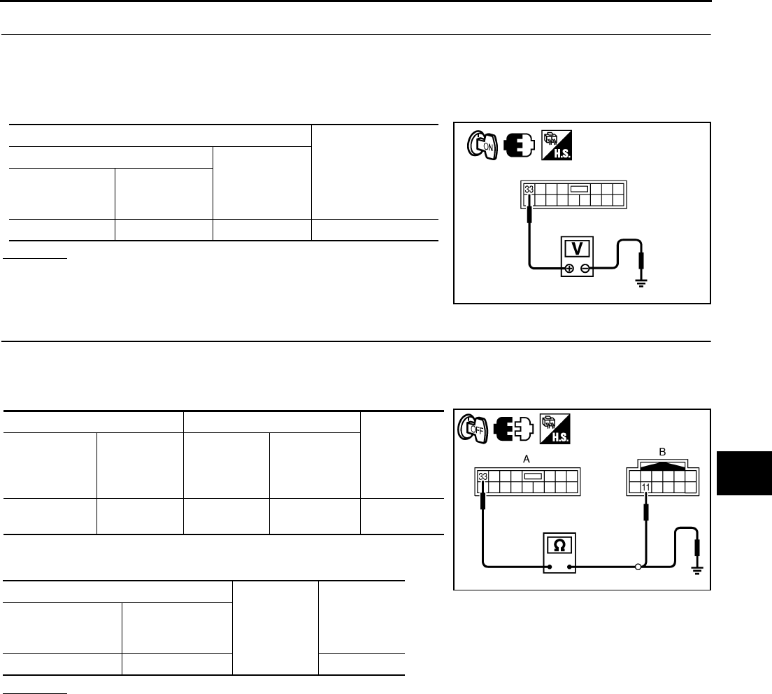
REVERSE INTERLOCK DOOR MIRROR SYSTEM
GW-117
C
D
E
F
G
H
J
K
L
M
A
B
GW
Revision: 2006 January 2006 M35/M45
3. CHECK MIRROR SENSOR POWER SUPPLY 2
1. Turn ignition switch OFF.
2. Disconnect door mirror connector.
3. Turn ignition switch ON.
4. Check voltage between automatic drive positioner control unit connector and ground.
OK or NG
OK >> GO TO 4.
NG >> Replace automatic drive positioner control unit.
4. CHECK HARNESS CONTINUITY 1
1. Turn ignition switch OFF.
2. Disconnect automatic drive positioner control unit connector.
3. Check continuity between automatic drive positioner control unit connector and door mirror connector.
4. Check continuity between automatic drive positioner control unit
connector and ground.
OK or NG
OK >> Check the condition of harness and connector.
NG >> Repair or replace harness.
Terminals
Voltage (V)
(Approx.)
(+)
(-)
Automatic drive
positioner control
unit connector
Terminal
M7 33 Ground Battery voltage
PIIB6028E
AB
Continuity
Automatic
drive posi-
tioner control
unit connector
Terminal Door mirror
connector Terminal
M7 33 D2 (LH)
D39 (RH) 11 Yes
A
Ground Continuity
Automatic drive
positioner control
unit connector
Terminal
M7 33 No
PIIB6033E
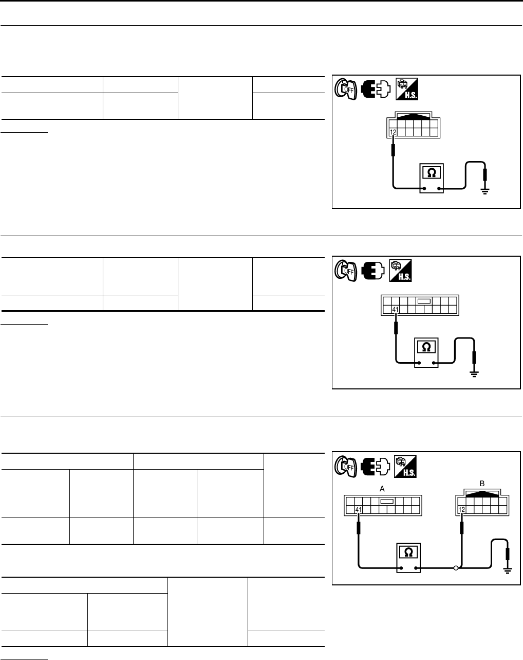
GW-118
REVERSE INTERLOCK DOOR MIRROR SYSTEM
Revision: 2006 January 2006 M35/M45
5. CHECK MIRROR SENSOR GROUND 1
1. Turn ignition switch OFF.
2. Disconnect door mirror connector.
3. Check continuity between door mirror connector and ground.
OK or NG
OK >> GO TO 8.
NG >> GO TO 6.
6. CHECK MIRROR SENSOR GROUND 2
Check continuity between automatic drive positioner control unit connector and ground.
OK or NG
OK >> GO TO 7.
NG >> Replace auto drive positioner control unit.
7. CHECK HARNESS CONTINUITY 2
1. Disconnect automatic drive positioner control unit connector.
2. Check continuity between automatic drive positioner control unit connector and door mirror connector.
3. Check continuity between automatic drive positioner control unit
connector and door mirror connector.
OK or NG
OK >> Check the condition of the harness and connector.
NG >> Repair or replace harness between automatic drive positioner control unit and door mirror.
Door mirror connector Terminal
Ground
Continuity
D2 (LH)
D39 (RH) 12 Yes
PIIB6034E
Automatic drive posi-
tioner control unit con-
nector
Terminal Ground Continuity
M7 41 Yes
PIIB6029E
AB
Continuity
Automatic
drive posi-
tioner control
unit connector
Terminal Door mirror
connector Terminal
M7 41 D2 (LH)
D39 (RH) 12 Yes
A
Ground Continuity
Automatic drive
positioner control
unit connector
Terminal
M7 41 Yes
PIIB6035E
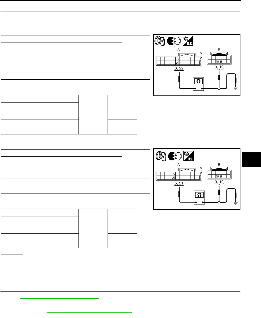
REVERSE INTERLOCK DOOR MIRROR SYSTEM
GW-119
C
D
E
F
G
H
J
K
L
M
A
B
GW
Revision: 2006 January 2006 M35/M45
8. CHECK HARNESS CONTINUITY 3
1. Disconnect automatic drive positioner control unit connector and door mirror connector.
2. [Door mirror LH]
–Check continuity between automatic drive positioner control unit connector and door mirror LH connector.
–Check continuity between automatic drive positioner control unit
connector and ground.
3. [Door mirror RH]
–Check continuity between automatic drive positioner control unit connector and door mirror RH connector.
–Check continuity between automatic drive positioner control unit
connector and ground.
OK or NG
OK >> Check the condition of harness and connector.
NG >> Repair or replace harness between automatic drive positioner control unit and door mirror con-
nector.
Check A/T Control Device R Position Circuit NIS0023F
1. CHECK R POSITION SIGNAL
Refer to AT-186, "A/T INDICATOR CIRCUIT"
OK or NG
OK >> Refer to SE-36, "SELF-DIAGNOSIS RESULTS"
NG >> Refer to AT-186, "A/T INDICATOR CIRCUIT"
AB
Continuity
Automatic
drive posi-
tioner control
unit connector
Terminal Door mirror
LH connector Terminal
M6 6D2 9Yes
22 10
A
Ground
Continuity
Automatic drive
positioner control
unit connector
Terminal
M6 6No
22
AB
Continuity
Automatic
drive posi-
tioner control
unit connector
Terminal Door mirror
RH connector Terminal
M6 5D39 9Yes
21 10
A
Ground
Continuity
Automatic drive
positioner control
unit connector
Terminal
M6 5No
21
PIIB6036E
PIIB6030E
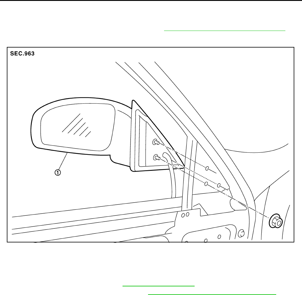
GW-120
DOOR MIRROR
Revision: 2006 January 2006 M35/M45
DOOR MIRROR PFP:96301
Automatic Drive Positioner Interlocking Door Mirror NIS0023G
Automatic drive positioner interlocking door mirror. Refer to SE-11, "AUTOMATIC DRIVE POSITIONER" .
Removal and Installation NIS0023H
CAUTION:
Be careful not to damage the mirror bodies.
REMOVAL
1. Remove the front door finisher. Refer to EI-34, "DOOR FINISHER" .
2. Remove the front door sash cover inner. Refer to EI-36, "FRONT DOOR SASH COVER INNER" .
3. Remove the door mirror harness connector.
4. Remove the door mirror mounting nuts, and remove the door mirror assembly.
INSTALLATION
Install in the reverse order of removal.
1. Door mirror assembly
PIIB3300J
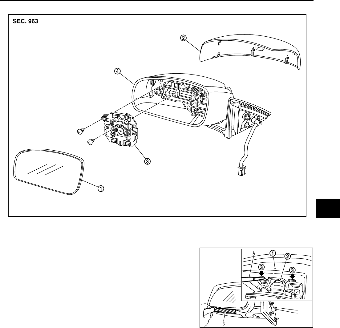
DOOR MIRROR
GW-121
C
D
E
F
G
H
J
K
L
M
A
B
GW
Revision: 2006 January 2006 M35/M45
Disassembly and Assembly NIS0023I
DISASSEMBLY
1. Place the mirror body with mirror glass facing upward.
2. Put a strip of protective tape B on mirror body.
3. As shown in the figure, insert a small slotted screwdriver A into
the recess between mirror base (mirror holder)(1) and mirror
holder bracket (2) and push up two pawls (3) to remove mirror
holder lower half side.
NOTE:
When pushing up pawls do not attempt to use one recess only,
be sure to push up with both recesses.
Insert screwdriver into recesses, and push up while rotating
(twist) to make work easier.
4. Remove two terminals of mirror heater attachment.
5. Lightly lift up lower side of mirror surface from mirror surface, and detach two pawls of upper side as if
pulling it out. Remove mirror surface from mirror body.
NOTE:
Be certain not to allow grease on sealing agent in center of mirror body assembly (actuator) or back side
of mirror surface (mirror holder).
1. Mirror housing 2. Mirror cover 3. Power unit
4. Mirror (mirror holder)
PIIB5782E
PIIB8320J
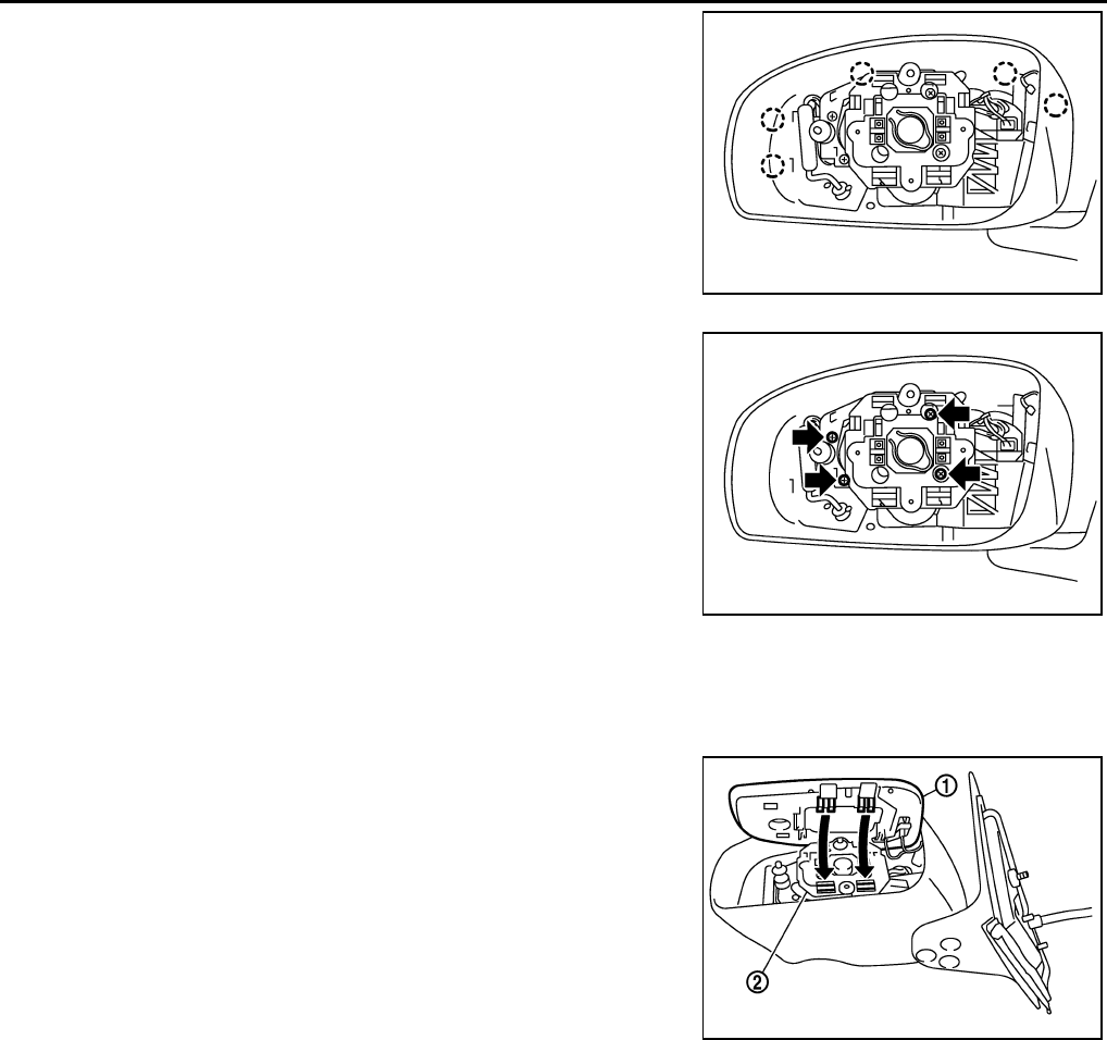
GW-122
DOOR MIRROR
Revision: 2006 January 2006 M35/M45
6. Remove the clips and mirror cover from the housing.
7. Remove the screws and power unit from the housing.
ASSEMBLY
1. Install the power unit.
2. Install the mirror cover.
3. Place mirror holder bracket and mirror body assembly (actuator) in a horizontal position.
4. Connect two terminals of heater installed mirror.
5. Fit the upper two pawls on the mirror face (1) onto the mirror
holder bracket (2) first, then press the lower side of mirror face
until a click sound is heard to engage the lower pawls.
NOTE:
After installation, visually make sure lower two pawls are
securely engaged from the bottom of mirror face.
PIIB3302J
PIIB3303J
PIIB3306J
