Product Detail Manual GW
User Manual: gw
Open the PDF directly: View PDF ![]() .
.
Page Count: 126 [warning: Documents this large are best viewed by clicking the View PDF Link!]
- QUICK REFERENCE INDEX
- Table of Contents
- PRECAUTIONS
- PREPARATION
- SQUEAK AND RATTLE TROUBLE DIAGNOSES
- WINDSHIELD GLASS
- REAR WINDOW GLASS AND MOLDING
- POWER WINDOW SYSTEM
- Component Parts and Harness Connector Location
- System Description
- CAN Communication System Description
- Schematic (King Cab)
- Wiring Diagram — WINDOW — (King Cab)
- Terminal and Reference Value for Main Power Window and Door Lock/Unlock Switch (King Cab)
- Terminal and Reference Value for Power Window and Door Lock/Unlock Switch RH (King Cab)
- Terminal and Reference Value for BCM (King Cab)
- Schematic (Crew Cab)
- Wiring Diagram — WINDOW — (Crew Cab)
- Terminal and Reference Value for Main Power Window and Door Lock/Unlock Switch (Crew Cab)
- Terminal and Reference Value for Power Window and Door Lock/Unlock Switch RH (Crew Cab)
- Terminal and Reference Value for BCM (Crew Cab)
- Work Flow
- CONSULT-II Function (BCM)
- Trouble Diagnoses Symptom Chart (King Cab)
- Trouble Diagnoses Symptom Chart (Crew Cab)
- BCM Power Supply and Ground Circuit Check
- Main Power Window and Door Lock/Unlock Switch Power Supply and Ground Circuit Check (King Cab)
- Main Power Window and Door Lock/Unlock Switch Power Supply and Ground Circuit Check (Crew Cab)
- Power Window and Door Lock/Unlock Switch RH Power Supply and Ground Circuit Check
- Front Power Window Motor LH Circuit Check
- Power Window Motor RH Circuit Check
- Limit Switch Circuit Check Front LH (King Cab)
- Limit Switch Circuit Check Front LH (Crew Cab)
- Limit Switch Circuit Check Front RH
- Encoder Circuit Check Front LH (King Cab)
- Encoder Circuit Check Front LH (Crew Cab)
- Encoder Circuit Check Front RH
- Door Switch Check
- Front Door Lock Assembly LH (Key Cylinder Switch) Check (King Cab)
- Front Door Lock Assembly LH (Key Cylinder Switch) Check (Crew Cab)
- Power Window Serial Link Check Front LH and RH (King Cab)
- Power Window Serial Link Check Front LH and RH (Crew Cab)
- Rear Power Window Motor LH Circuit Check (Crew Cab)
- Rear Power Window Motor RH Circuit Check (Crew Cab)
- Rear Power Drop Glass Circuit Check
- Rear Power Drop Glass Up Relay Check
- Rear Power Drop Glass Down Relay Check
- FRONT DOOR GLASS AND REGULATOR
- REAR DOOR GLASS AND REGULATOR
- SIDE WINDOW GLASS
- INSIDE MIRROR
- REAR WINDOW DEFOGGER
- Component Parts and Harness Connector Location
- System Description
- CAN Communication System Description
- Schematic
- Wiring Diagram — DEF —
- Terminal and Reference Values for BCM
- Terminal and Reference Values for IPDM E/R
- Work Flow
- CONSULT-II Function (BCM)
- Trouble Diagnoses Symptom Chart
- BCM Power Supply and Ground Circuit Check
- Rear Window Defogger Switch Circuit Check
- Rear Window Defogger Circuit Check
- Door Mirror Defogger Power Supply Circuit Check (Without Automatic Drive Positioner)
- Door Mirror Defogger Power Supply Circuit Check (With Automatic Drive Positioner)
- Door Mirror LH Defogger Circuit Check (Without Automatic Drive Positioner)
- Door Mirror LH Defogger Circuit Check (With Automatic Drive Positioner)
- Door Mirror RH Defogger Circuit Check (Without Automatic Drive Positioner)
- Door Mirror RH Defogger Circuit Check (With Automatic Drive Positioner)
- Rear Window Defogger Signal Check
- Filament Check
- Filament Repair
- DOOR MIRROR
- ELECTRICAL UNITS
- SUPER MULTIPLE JUNCTION (SMJ)
- FUSE BLOCK-JUNCTION BOX(J/B)
- FUSE AND FUSIBLE LINK BOX
- FUSE AND RELAY BOX

GW-1
GLASSES, WINDOW SYSTEM & MIRRORS
IBODY
CONTENTS
C
D
E
F
G
H
J
K
L
M
SECTION
A
B
GW
Revision: October 2004 2005 Titan
PRECAUTIONS .......................................................... 3
Precautions for Supplemental Restraint System
(SRS) “AIR BAG” and “SEAT BELT PRE-TEN-
SIONER” .................................................................. 3
Handling for Adhesive and Primer ........................... 3
Trouble Diagnosis Precaution .................................. 3
PREPARATION ........................................................... 4
Special Service Tool ................................................. 4
Commercial Service Tool ......................................... 4
SQUEAK AND RATTLE TROUBLE DIAGNOSES..... 5
Work Flow ................................................................ 5
CUSTOMER INTERVIEW ..................................... 5
DUPLICATE THE NOISE AND TEST DRIVE ....... 6
CHECK RELATED SERVICE BULLETINS ........... 6
LOCATE THE NOISE AND IDENTIFY THE
ROOT CAUSE ...................................................... 6
REPAIR THE CAUSE ........................................... 6
CONFIRM THE REPAIR ....................................... 7
Generic Squeak and Rattle Troubleshooting ........... 7
INSTRUMENT PANEL .......................................... 7
CENTER CONSOLE ............................................. 7
DOORS ................................................................. 7
TRUNK .................................................................. 8
SUNROOF/HEADLINING ..................................... 8
OVERHEAD CONSOLE (FRONT AND REAR)..... 8
SEATS ................................................................... 8
UNDERHOOD ....................................................... 8
Diagnostic Worksheet .............................................. 9
WINDSHIELD GLASS ...............................................11
Removal and Installation .........................................11
REMOVAL ............................................................11
INSTALLATION ....................................................11
REAR WINDOW GLASS AND MOLDING ............... 13
Removal and Installation ........................................ 13
FIXED AND SLIDING REAR WINDOW GLASS... 13
REAR WINDOW GLASS AND REGULATOR ..... 15
SETTING AFTER INSTALLATION ...................... 17
REPAIRING WATER LEAKS FOR REAR WIN-
DOW GLASS ...................................................... 18
POWER WINDOW SYSTEM .................................... 19
ComponentPartsandHarnessConnectorLocation... 19
System Description ................................................. 20
KING CAB ........................................................... 20
CREW CAB ......................................................... 20
KING CAB ........................................................... 20
CREW CAB ......................................................... 20
MANUAL OPERATION ........................................ 21
AUTO OPERATION ............................................. 23
POWER WINDOW SERIAL LINK ....................... 23
POWER WINDOW LOCK ................................... 24
RETAINED POWER OPERATION ...................... 24
ANTI-PINCH SYSTEM ........................................ 24
POWER WINDOW CONTROL BY THE FRONT
DOOR LOCK ASSEMBLY LH (KEY CYLINDER
SWITCH) ............................................................. 24
CAN Communication System Description .............. 24
Schematic (King Cab) ............................................. 25
Wiring Diagram — WINDOW — (King Cab) ........... 26
Terminal and Reference Value for Main Power Win-
dow and Door Lock/Unlock Switch (King Cab) ....... 31
Terminal and Reference Value for Power Window
and Door Lock/Unlock Switch RH (King Cab) ........ 31
Terminal and Reference Value for BCM (King Cab)... 33
Schematic (Crew Cab) ........................................... 34
Wiring Diagram — WINDOW — (Crew Cab) ......... 35
Terminal and Reference Value for Main Power Win-
dow and Door Lock/Unlock Switch (Crew Cab) ...... 43
Terminal and Reference Value for Power Window
and Door Lock/Unlock Switch RH (Crew Cab) ....... 44
TerminalandReference Valuefor BCM(Crew Cab)... 45
Work Flow ............................................................... 46
CONSULT-II Function (BCM) ................................. 46
CONSULT-II INSPECTION PROCEDURE .......... 46
ACTIVE TEST ..................................................... 47
WORK SUPPORT ............................................... 47
DATA MONITOR ................................................. 47
Trouble Diagnoses Symptom Chart (King Cab) ..... 48
Trouble Diagnoses Symptom Chart (Crew Cab) .... 49
BCM Power Supply and Ground Circuit Check ...... 50
Main Power Window and Door Lock/Unlock Switch

GW-2
Revision: October 2004 2005 Titan
PowerSupplyandGroundCircuitCheck(KingCab)... 51
Main Power WindowandDoor Lock/Unlock Switch
Power Supply and Ground Circuit Check (Crew
Cab) ........................................................................ 52
Power Window and Door Lock/Unlock Switch RH
Power Supply and Ground Circuit Check ............... 53
Front Power Window Motor LH Circuit Check ........ 55
Power Window Motor RH Circuit Check ................. 55
Limit Switch Circuit Check Front LH (King Cab) ..... 56
Limit Switch Circuit Check Front LH (Crew Cab) .... 58
Limit Switch Circuit Check Front RH ....................... 59
Encoder Circuit Check Front LH (King Cab) ........... 61
Encoder Circuit Check Front LH (Crew Cab) .......... 63
Encoder Circuit Check Front RH ............................ 65
Door Switch Check ................................................. 67
FrontDoorLockAssemblyLH(KeyCylinderSwitch)
Check (King Cab) ................................................... 69
FrontDoorLockAssemblyLH(KeyCylinderSwitch)
Check (Crew Cab) .................................................. 71
Power Window Serial Link Check Front LH and RH
(King Cab) .............................................................. 73
Power Window Serial Link Check Front LH and RH
(Crew Cab) ............................................................. 76
Rear Power Window Motor LHCircuitCheck(Crew
Cab) ........................................................................ 78
RearPowerWindowMotorRHCircuitCheck(Crew
Cab) ........................................................................ 80
Rear Power Drop Glass Circuit Check ................... 81
Rear Power Drop Glass Up Relay Check ............... 82
Rear Power Drop Glass Down Relay Check .......... 83
FRONT DOOR GLASS AND REGULATOR ............. 85
Removal and Installation ........................................ 85
FRONT DOOR GLASS ....................................... 85
FRONT DOOR GLASS REGULATOR ................ 86
SETTING AFTER INSTALLATION ...................... 86
REAR DOOR GLASS AND REGULATOR ............... 88
Rear Door Glass ..................................................... 88
REMOVAL ........................................................... 88
INSTALLATION .................................................... 88
FITTING INSPECTION ........................................ 88
Rear Door Glass Regulator .................................... 90
REMOVAL ........................................................... 90
INSPECTION AFTER REMOVAL ........................ 90
INSTALLATION .................................................... 90
SIDE WINDOW GLASS ............................................91
Removal ................................................................. 91
Installation ............................................................... 91
Repairing Water Leaks for Side Window Glass ...... 92
INSIDE MIRROR .......................................................93
Wiring Diagram — I/MIRR — .................................93
Removal and Installation .........................................94
REAR WINDOW DEFOGGER ..................................95
ComponentPartsandHarnessConnectorLocation...95
System Description .................................................96
CAN Communication System Description ..............97
Schematic ...............................................................98
Wiring Diagram — DEF — ......................................99
Terminal and Reference Values for BCM ..............102
Terminal and Reference Values for IPDM E/R ......102
Work Flow .............................................................102
CONSULT-II Function (BCM) ................................103
CONSULT-IIBASICOPERATIONPROCEDURE
.103
DATA MONITOR ................................................104
ACTIVE TEST ....................................................104
Trouble Diagnoses Symptom Chart ......................104
BCM Power Supply and Ground Circuit Check ....106
Rear Window Defogger Switch Circuit Check .......107
Rear Window Defogger Circuit Check ..................108
Door Mirror Defogger Power Supply Circuit Check
(Without Automatic Drive Positioner) ....................110
Door Mirror Defogger Power Supply Circuit Check
(With Automatic Drive Positioner) .........................112
Door Mirror LH Defogger Circuit Check (Without
Automatic Drive Positioner) ..................................114
Door Mirror LH Defogger Circuit Check (With Auto-
matic Drive Positioner) ..........................................115
Door Mirror RH Defogger Circuit Check (Without
Automatic Drive Positioner) ..................................116
Door Mirror RH Defogger Circuit Check (With Auto-
matic Drive Positioner) ..........................................117
Rear Window Defogger Signal Check ..................118
Filament Check .....................................................118
Filament Repair .....................................................119
REPAIR EQUIPMENT .......................................119
REPAIRING PROCEDURE ...............................119
DOOR MIRROR .......................................................121
Wiring Diagram — MIRROR — ............................121
Wiring Diagram — H/MIRR — ..............................122
Door Mirror Assembly ...........................................124
STANDARD MIRROR ........................................124
TRAILER TOW MIRROR ...................................125
Door Mirror Glass ..................................................125
REMOVAL ..........................................................125
INSTALLATION ..................................................126

PRECAUTIONS
GW-3
C
D
E
F
G
H
J
K
L
M
A
B
GW
Revision: October 2004 2005 Titan
PRECAUTIONS PFP:00001
Precautions for Supplemental Restraint System (SRS) “AIR BAG” and “SEAT
BELT PRE-TENSIONER”
EIS004BY
The Supplemental Restraint System such as “AIR BAG”and “SEAT BELT PRE-TENSIONER”,usedalong
with a front seat belt, helps to reduce the risk or severity of injury to the driver and front passenger for certain
types of collision. This system includes seat belt switch inputs and dual stage front air bag modules. The SRS
system uses the seat belt switches to determine the front air bag deployment, and may only deploy one front
air bag, depending on the severity of a collision and whether the front occupants are belted or unbelted.
Information necessary to service the system safely is included in the SRS and SB section of this Service Man-
ual.
WARNING:
●To avoid rendering the SRS inoperative, which could increase the risk of personal injury or death
in the event of a collision which would result in air bag inflation, all maintenance must be per-
formed by an authorized NISSAN/INFINITI dealer.
●Improper maintenance, including incorrect removal and installation of the SRS, can lead to per-
sonal injury caused by unintentional activation of the system. For removal of Spiral Cable and Air
Bag Module, see the SRS section.
●Do not use electrical test equipment on any circuit related to the SRS unless instructed to in this
Service Manual. SRS wiring harnesses can be identified by yellow and/or orange harnesses or
harness connectors.
Handling for Adhesive and Primer
EIS004BZ
●Do not use an adhesive which is past its usable date. Shelf life of this product is limited to six months after
the date of manufacture. Carefully adhere to the expiration or manufacture date printed on the box.
●Keep primers and adhesive in a cool, dry place. Ideally, they should be stored in a refrigerator.
●Open the seal of the primer and adhesive just before application. Discard the remainder.
●Before application, be sure to shake the primer container to stir the contents. If any floating material is
found, do not use it.
●If any primer or adhesive contacts the skin, wipe it off with gasoline or equivalent and wash the skin with
soap.
●When using primer and adhesive, always observe the precautions in the instruction manual.
Trouble Diagnosis Precaution
EIS004C0
Whenyoureadwiringdiagrams,refertothefollowing:
●GI-14, "HowtoReadWiringDiagrams"
●PG-4, "POWER SUPPLY ROUTING CIRCUIT"
When you perform trouble diagnosis, refer to the following:
●GI-11, "HOW TO FOLLOW TEST GROUPS IN TROUBLE DIAGNOSES"
●GI-27, "How to Perform Efficient Diagnosis for an Electrical Incident"
Check for any service bulletins before servicing the vehicle.
GW-4
PREPARATION
Revision: October 2004 2005 Titan
PREPARATION PFP:00002
Special Service Tool
EIS004C1
The actual shapes of Kent-Moore tools may differ from those of special service tools illustrated here.
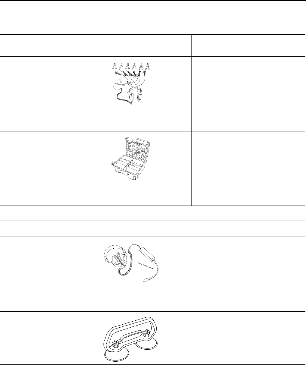
Commercial Service Tool
EIS004C2
Tool number
(Kent-Moore No.)
Tool name
Description
—
(J-39570)
Chassis ear
Locating the noise
—
(J-43980)
NISSAN Squeak and Rattle
Kit
Repairing the cause of noise
SIIA0993E
SIIA0994E
(Kent-Moore No.)
Tool name Description
(J-39565)
Engine ear
Locating the noise
(—)
Suction Lifter
Holding door glass
SIIA0995E
LIIA1991E
SQUEAK AND RATTLE TROUBLE DIAGNOSES
GW-5
C
D
E
F
G
H
J
K
L
M
A
B
GW
Revision: October 2004 2005 Titan
SQUEAK AND RATTLE TROUBLE DIAGNOSES PFP:00000
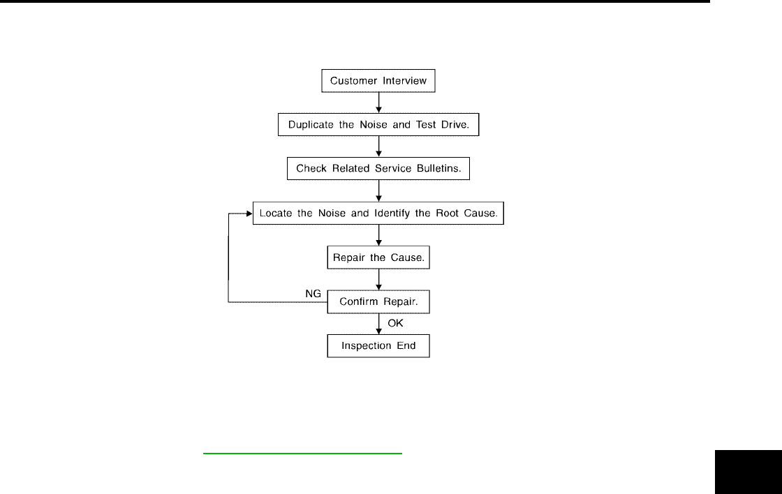
Work Flow
EIS004C3
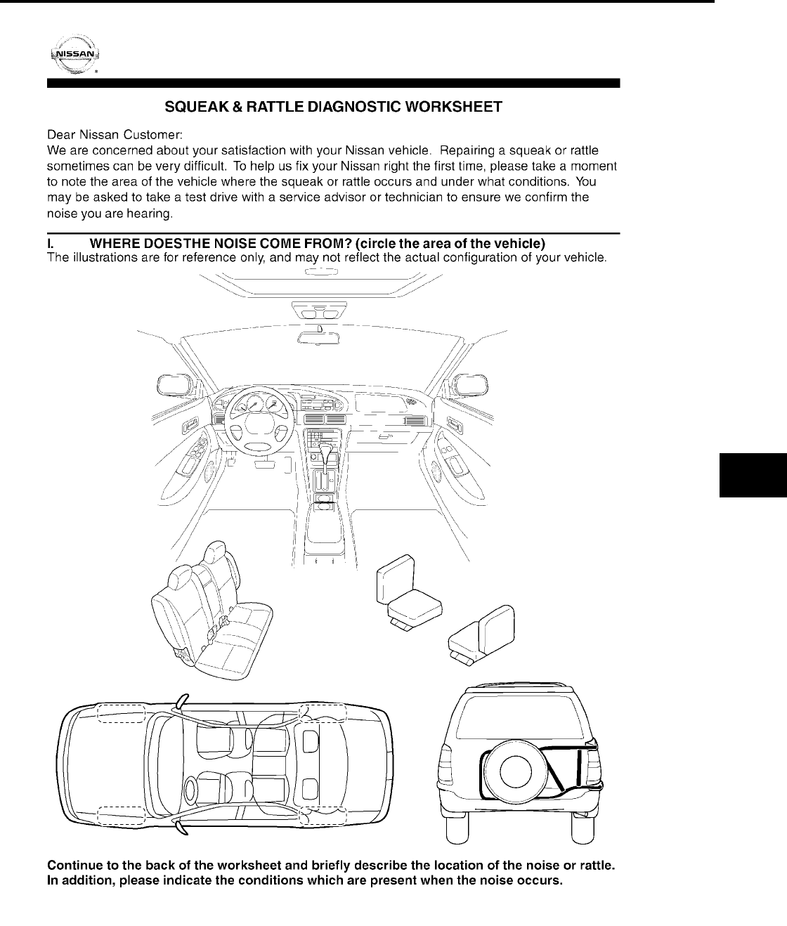
CUSTOMER INTERVIEW
Interview the customer if possible, to determine the conditions that exist when the noise occurs. Use the Diag-
nostic Worksheet during the interview to document the facts and conditions when the noise occurs and any
customer's comments; refer to GW-9, "Diagnostic Worksheet". This information is necessary to duplicate the
conditions that exist when the noise occurs.
●Thecustomermaynotbeabletoprovideadetaileddescriptionorthelocationofthenoise.Attemptto
obtain all the facts and conditions that exist when the noise occurs (or does not occur).
●If there is more than one noise in the vehicle, be sure to diagnose and repair the noise that the customer
is concerned about. This can be accomplished by test driving the vehicle with the customer.
●After identifying the type of noise, isolate the noise in terms of its characteristics. The noise characteristics
are provided so the customer, service adviser and technician are all speaking the same language when
defining the noise.
●Squeak —(Like tennis shoes on a clean floor)
Squeak characteristics include the light contact/fast movement/brought on by road conditions/hard sur-
faces = higher pitch noise/softer surfaces = lower pitch noises/edge to surface = chirping.
●Creak—(Like walking on an old wooden floor)
Creak characteristics include firm contact/slow movement/twisting with a rotational movement/pitch
dependent on materials/often brought on by activity.
●Rattle—(Like shaking a baby rattle)
Rattle characteristics include the fast repeated contact/vibration or similar movement/loose parts/missing
clip or fastener/incorrect clearance.
●Knock —(Likeaknockonadoor)
Knock characteristics include hollow sounding/sometimes repeating/often brought on by driver action.
●Tick—(Like a clock second hand)
Tick characteristics include gentle contacting of light materials/loose components/can be caused by driver
action or road conditions.
●Thump—(Heavy, muffled knock noise)
Thump characteristics include softer knock/dead sound often brought on by activity.
●Buzz—(Like a bumble bee)
Buzz characteristics include high frequency rattle/firm contact.
●Often the degree of acceptable noise level will vary depending upon the person. A noise that you may
judge as acceptable may be very irritating to the customer.
●Weather conditions, especially humidity and temperature, may have a great effect on noise level.
SBT842

GW-6
SQUEAK AND RATTLE TROUBLE DIAGNOSES
Revision: October 2004 2005 Titan
DUPLICATE THE NOISE AND TEST DRIVE
If possible, drive the vehicle with the customer until the noise is duplicated. Note any additional information on
the Diagnostic Worksheet regarding the conditions or location of the noise. This information can be used to
duplicate the same conditions when you confirm the repair.
If the noise can be duplicated easily during the test drive, to help identify the source of the noise, try to dupli-
cate the noise with the vehicle stopped by doing one or all of the following:
1) Close a door.
2) Tap or push/pull around the area where the noise appears to be coming from.
3) Rev the engine.
4) Use a floor jack to recreate vehicle “twist”.
5) At idle, apply engine load (electrical load, half-clutch on M/T model, drive position on A/T model).
6) Raise the vehicle on a hoist and hit a tire with a rubber hammer.
●Drive the vehicle and attempt to duplicate the conditions the customer states exist when the noise occurs.
●If it is difficult to duplicate the noise, drive the vehicle slowly on an undulating or rough road to stress the
vehicle body.
CHECK RELATED SERVICE BULLETINS
After verifying the customer concern or symptom, check ASIST for Technical Service Bulletins (TSBs) related
to that concern or symptom.
If a TSB relates to the symptom, follow the procedure to repair the noise.
LOCATE THE NOISE AND IDENTIFY THE ROOT CAUSE
1. Narrow down the noise to a general area.To help pinpoint the source of the noise, use a listening tool
(Chassis Ear: J-39570, Engine Ear: J-39565 and mechanic's stethoscope).
2. Narrow down the noise to a more specific area and identify the cause of the noise by:
●removing the components in the area that you suspect the noise is coming from.
Do not use too much force when removing clips and fasteners, otherwise clips and fasteners can be bro-
ken or lost during the repair, resulting in the creation of new noise.
●tapping or pushing/pulling the component that you suspect is causing the noise.
Do not tap or push/pull the component with excessive force, otherwise the noise will be eliminated only
temporarily.
●feeling for a vibration with your hand by touching the component(s) that you suspect is (are) causing the
noise.
●placing a piece of paper between components that you suspect are causing the noise.
●looking for loose components and contact marks.
Refer to GW-7, "Generic Squeak and Rattle Troubleshooting".
REPAIR THE CAUSE
●If the cause is a loose component, tighten the component securely.
●If the cause is insufficient clearance between components:
–separate components by repositioning or loosening and retightening the component, if possible.
–insulate components with a suitable insulator such as urethane pads, foam blocks, felt cloth tape or ure-
thane tape. A NISSAN Squeak and Rattle Kit (J-43980) is available through your authorized NISSAN
Parts Department.
CAUTION:
Do not use excessive force as many components are constructed of plastic and may be damaged.
Always check with the Parts Department for the latest parts information.
The following materials are contained in the NISSAN Squeak and Rattle Kit (J-43980). Each item can be
ordered separately as needed.
URETHANE PADS [1.5 mm (0.059 in) thick]
Insulates connectors, harness, etc.
76268-9E005: 100×135 mm (3.94×5.31 in)/76884-71L01: 60×85 mm (2.36×3.35 in)/76884-71L02: 15×25
mm (0.59×0.98 in)
INSULATOR (Foam blocks)
Insulates components from contact. Can be used to fill space behind a panel.
73982-9E000: 45 mm (1.77 in) thick, 50×50 mm (1.97×1.97 in)/73982-50Y00: 10 mm (0.39 in) thick,
50×50 mm (1.97×1.97 in)
INSULATOR (Light foam block)

SQUEAK AND RATTLE TROUBLE DIAGNOSES
GW-7
C
D
E
F
G
H
J
K
L
M
A
B
GW
Revision: October 2004 2005 Titan
80845-71L00: 30 mm (1.18 in) thick, 30×50 mm (1.18×1.97 in)
FELT CLOTH TAPE
Used to insulate where movement does not occur. Ideal for instrument panel applications.
68370-4B000: 15×25 mm (0.59×0.98 in) pad/68239-13E00: 5 mm (0.20 in) wide tape roll. The following
materials not found in the kit can also be used to repair squeaks and rattles.
UHMW (TEFLON) TAPE
Insulates where slight movement is present. Ideal for instrument panel applications.
SILICONE GREASE
Used instead of UHMW tape that will be visible or not fit.
Note: Will only last a few months.
SILICONE SPRAY
Use when grease cannot be applied.
DUCT TAPE
Use to eliminate movement.
CONFIRM THE REPAIR
Confirm that the cause of a noise is repaired by test driving the vehicle. Operate the vehicle under the same
conditions as when the noise originally occurred. Refer to the notes on the Diagnostic Worksheet.
Generic Squeak and Rattle Troubleshooting
EIS004C4
Refer to Table of Contents for specific component removal and installation information.
INSTRUMENT PANEL
Most incidents are caused by contact and movement between:
1. The cluster lid A and instrument panel
2. Acrylic lens and combination meter housing
3. Instrument panel to front pillar garnish
4. Instrument panel to windshield
5. Instrument panel mounting pins
6. Wiring harnesses behind the combination meter
7. A/C defroster duct and duct joint
These incidents can usually be located by tapping or moving the components to duplicate the noise or by
pressing on the components while driving to stop the noise. Most of these incidents can be repaired by apply-
ing felt cloth tape or silicone spray (in hard to reach areas). Urethane pads can be used to insulate wiring har-
ness.
CAUTION:
Do not use silicone spray to isolate a squeak or rattle. If you saturate the area with silicone, you will
notbeabletorechecktherepair.
CENTER CONSOLE
Components to pay attention to include:
1. Shifter assembly cover to finisher
2. A/C control unit and cluster lid C
3. Wiring harnesses behind audio and A/C control unit
The instrument panel repair and isolation procedures also apply to the center console.
DOORS
Pay attention to the:
1. Finisher and inner panel making a slapping noise
2. Inside handle escutcheon to door finisher
3. Wiring harnesses tapping
4. Door striker out of alignment causing a popping noise on starts and stops
Tapping or moving the components or pressing on them while driving to duplicate the conditions can isolate
many of these incidents. You can usually insulate the areas with felt cloth tape or insulator foam blocks from
the NISSAN Squeak and Rattle Kit (J-43980) to repair the noise.

GW-8
SQUEAK AND RATTLE TROUBLE DIAGNOSES
Revision: October 2004 2005 Titan
TRUNK
Trunk noises are often caused by a loose jack or loose items put into the trunk by the owner.
In addition look for:
1. Trunk lid bumpers out of adjustment
2. Trunk lid striker out of adjustment
3. The trunk lid torsion bars knocking together
4. A loose license plate or bracket
Most of these incidents can be repaired by adjusting, securing or insulating the item(s) or component(s) caus-
ing the noise.
SUNROOF/HEADLINING
Noisesinthesunroof/headliningareacanoftenbetracedtooneofthefollowing:
1. Sunroof lid, rail, linkage or seals making a rattle or light knocking noise
2. Sun visor shaft shaking in the holder
3. Front or rear windshield touching headliner and squeaking
Again, pressing on the components to stop the noise while duplicating the conditions can isolate most of these
incidents. Repairs usually consist of insulating with felt cloth tape.
OVERHEAD CONSOLE (FRONT AND REAR)
Overhead console noises are often caused by the console panel clips not being engaged correctly. Most of
these incidents are repaired by pushing up on the console at the clip locations until the clips engage.
In addition look for:
1. Loose harness or harness connectors.
2. Front console map/reading lamp lense loose.
3. Loose screws at console attachment points.
SEATS
When isolating seat noise it's important to note the position the seat is in and the load placed on the seat when
the noise is present. These conditions should be duplicated when verifying and isolating the cause of the
noise.
Cause of seat noise include:
1. Headrest rods and holder
2. A squeak between the seat pad cushion and frame
3. The rear seatback lock and bracket
These noises can be isolated by moving or pressing on the suspected components while duplicating the con-
ditions under which the noise occurs. Most of these incidents can be repaired by repositioning the component
or applying urethane tape to the contact area.
UNDERHOOD
Some interior noise may be caused by components under the hood or on the engine wall. The noise is then
transmitted into the passenger compartment.
Causes of transmitted underhood noise include:
1. Any component mounted to the engine wall
2. Components that pass through the engine wall
3. Engine wall mounts and connectors
4. Loose radiator mounting pins
5. Hood bumpers out of adjustment
6. Hood striker out of adjustment
These noises can be difficult to isolate since they cannot be reached from the interior of the vehicle. The best
method is to secure, move or insulate one component at a time and test drive the vehicle. Also, engine RPM
or load can be changed to isolate the noise. Repairs can usually be made by moving, adjusting, securing, or
insulating the component causing the noise.
SQUEAK AND RATTLE TROUBLE DIAGNOSES
GW-9
C
D
E
F
G
H
J
K
L
M
A
B
GW
Revision: October 2004 2005 Titan
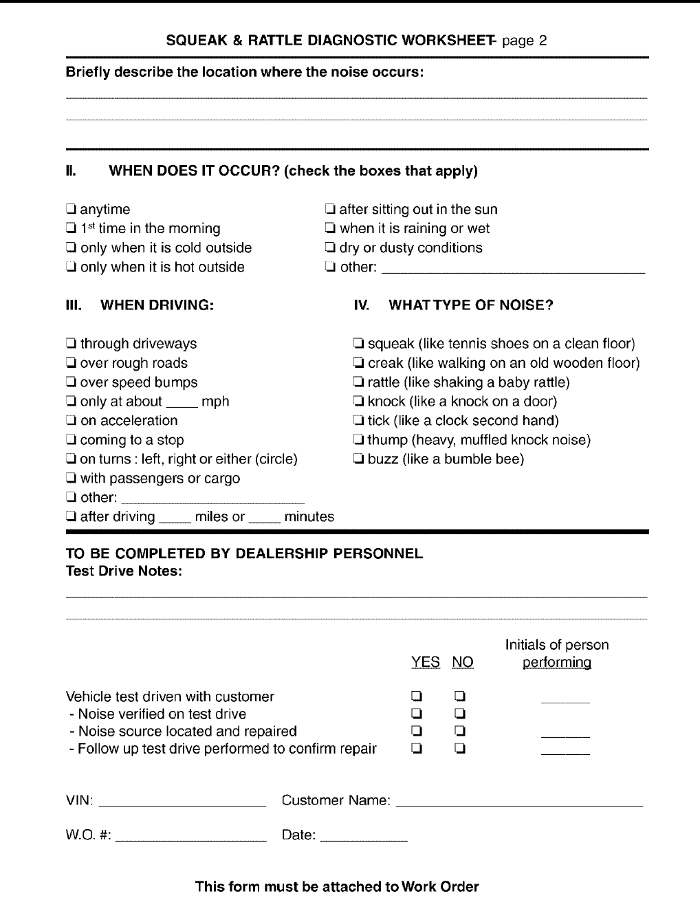
Diagnostic Worksheet
EIS004C5
LIWA0276E
GW-10
SQUEAK AND RATTLE TROUBLE DIAGNOSES
Revision: October 2004 2005 Titan
SBT844
WINDSHIELD GLASS
GW-11
C
D
E
F
G
H
J
K
L
M
A
B
GW
Revision: October 2004 2005 Titan
WINDSHIELD GLASS PFP:72712
Removal and Installation
EIS004C6
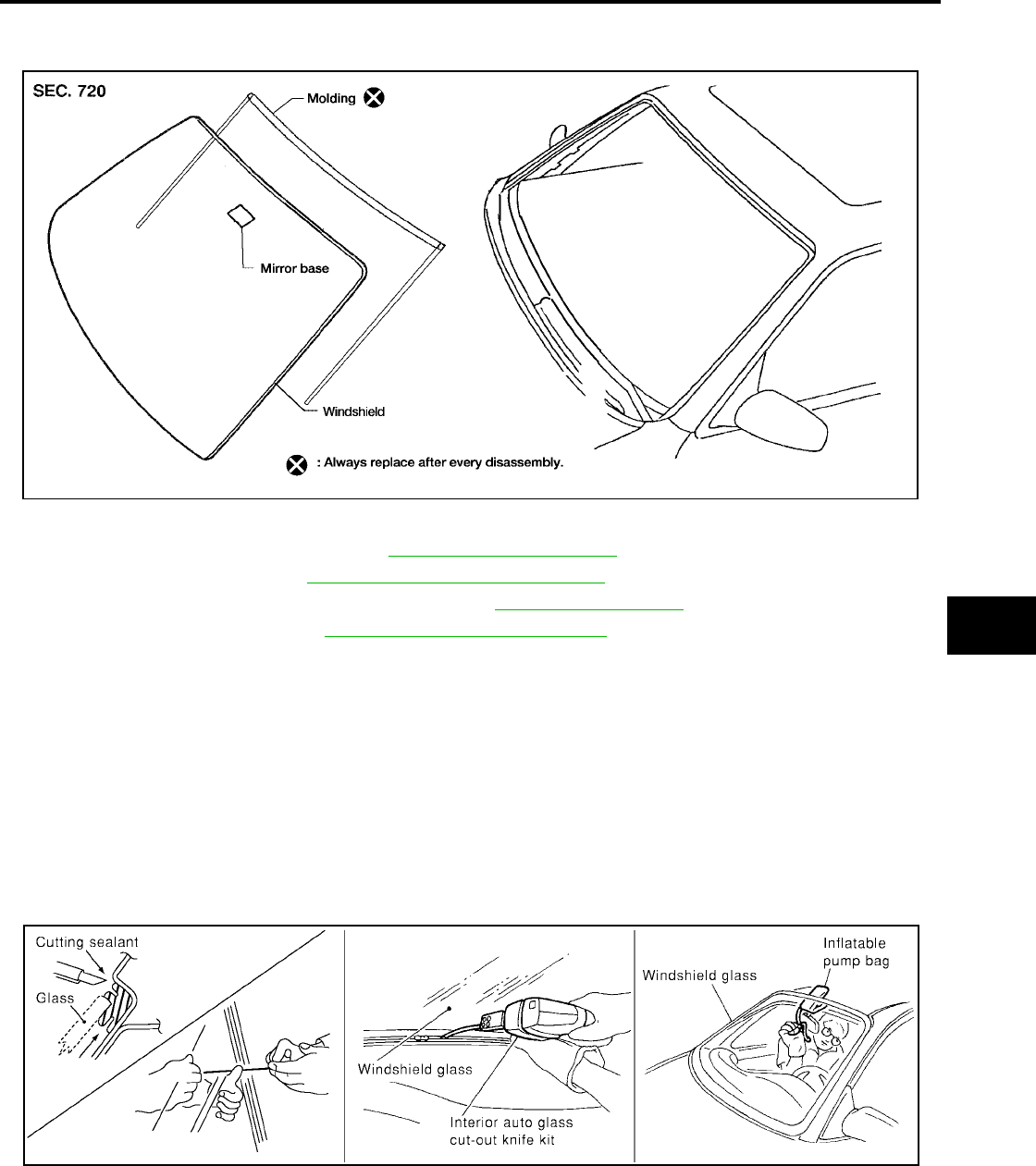
REMOVAL
1. Remove the front pillar garnish. Refer to EI-36, "BODY SIDE TRIM".
2. Remove inside mirror. Refer to GW-94, "Removal and Installation".
3. Partially remove the headlining (front edge). Refer to EI-43, "HEADLINING".
4. Remove cowl top cover. Refer to EI-21, "Removal and Installation".
5. Apply a protective tape around the windshield glass to protect the painted surface from damage.
●Remove glass using piano wire or power cutting tool and an inflatable pump bag.
●If the windshield glass is to be reused, mark the body and the glass with mating marks.
WARNING:
When cutting the glass from the vehicle, always wear safety glasses and heavy gloves to help prevent
glass splinters from entering your eyes or cutting your hands.
CAUTION:
●When the windshield glass is to be reused, do not use a cutting knife or power cutting tool.
●Be careful not to scratch the glass when removing.
●Do not set or stand glass on its edge. Small chips may develop into cracks.
INSTALLATION
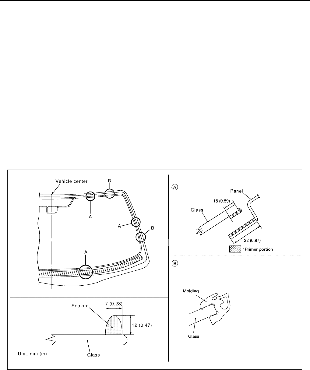
●Use a genuine NISSAN Urethane Adhesive Kit (if available) or equivalent and follow the instructions fur-
nished with it.
●While the urethane adhesive is curing, open a door window. This will prevent the glass from being forced
out by passenger compartment air pressure when a door is closed.
LIIA0652E
PIIA0186E
GW-12
WINDSHIELD GLASS
Revision: October 2004 2005 Titan
●The molding must be installed securely so that it is in position and leaves no gap.
●Inform the customer that the vehicle should remain stationary until the urethane adhesive has completely
cured (preferably 24 hours). Curing time varies with temperature and humidity.
●Install parts removed.
WARNING:
●Keep heat and open flames away as primers and adhesive are flammable.
●The materials contained in the kit are harmful if swallowed, and may irritate skin and eyes. Avoid
contact with the skin and eyes.
●Use in an open, well ventilated location. Avoid breathing the vapors. They can be harmful if
inhaled. If affected by vapor inhalation, immediately move to an area with fresh air.
●Driving the vehicle before the urethane adhesive has completely cured may affect the perfor-
mance of the windshield in case of an accident.
CAUTION:
●Do not use an adhesive which is past its usable term. Shelf life of this product is limited to six
months after the date of manufacture. Carefully adhere to the expiration or manufacture date
printed on the box.
●Keep primers and adhesive in a cool, dry place. Ideally, they should be stored in a refrigerator.
●Do not leave primers or adhesive cartridge unattended with their caps open or off.
●The vehicle should not be driven for at least 24 hours or until the urethane adhesive has com-
pletely cured. Curing time varies depending on temperature and humidities. The curing time will
increase under lower temperatures and lower humidities.
Repairing Water Leaks for Windshield
Leaks can be repaired without removing and reinstalling glass.
If water is leaking between the urethane adhesive material and body or glass, determine the extent of leakage.
This can be done by applying water to the windshield area while pushing glass outward.
To stop the leak, apply primer (if necessary) and then urethane adhesive to the leak point.
LIIA1115E
REAR WINDOW GLASS AND MOLDING
GW-13
C
D
E
F
G
H
J
K
L
M
A
B
GW
Revision: October 2004 2005 Titan
REAR WINDOW GLASS AND MOLDING PFP:79712
Removal and Installation
EIS004C7
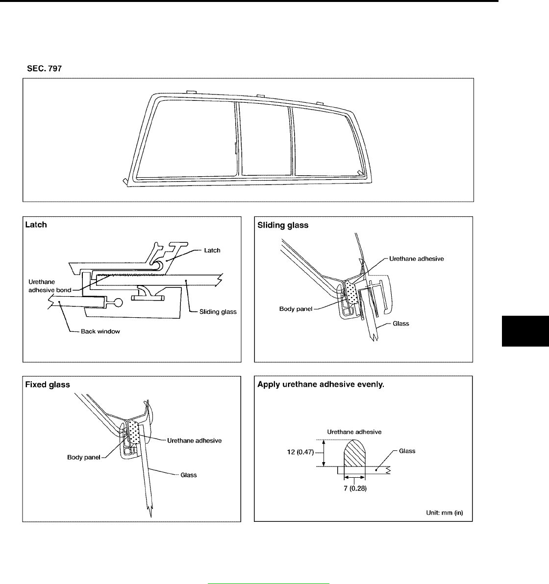
FIXED AND SLIDING REAR WINDOW GLASS
Removal
1. Remove the rear pillar finishers. Refer to EI-36, "BODY SIDE TRIM".
2. If the rear window glass is to be reused, mark the body and the glass with mating marks.
LIIA1243E
GW-14
REAR WINDOW GLASS AND MOLDING
Revision: October 2004 2005 Titan
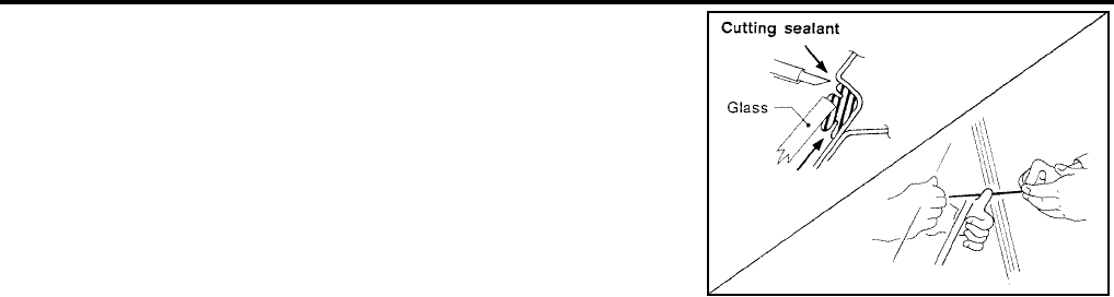
3. Remove glass using piano wire or power cutting tool and an
inflatable pump bag.
WARNING:
When cutting the glass from the vehicle, always wear safety
glasses and heavy gloves to help prevent glass splinters from
entering your eyes or cutting your hands.
CAUTION:
●When the rear window glass is to be reused, do not use a
cutting knife or power cutting tool.
●Be careful not to scratch the glass when removing.
●Do not set or stand the glass on its edge. Small chips may
develop into cracks.
Installation
●Use a genuine NISSAN Urethane Adhesive Kit (if available) or equivalent and follow the instructions fur-
nished with it.
●While the urethane adhesive is curing, open a door window. This will prevent the glass from being forced
out by passenger compartment air pressure when a door is closed.
●The molding must be installed securely so that it is in position and leaves no gap.
●Check gap along bottom to confirm that glass does not contact sheet metal.
●Inform the customer that the vehicle should remain stationary until the urethane adhesive has completely
cured (preferably 24 hours). Curing time varies with temperature and humidity.
●Install parts removed.
WARNING:
●Keep heat and open flames away as primers and adhesive are flammable.
●The materials contained in the kit are harmful if swallowed, and may irritate skin and eyes. Avoid
contact with the skin and eyes.
●Use in an open, well ventilated location. Avoid breathing the vapors. They can be harmful if
inhaled. If affected by vapor inhalation, immediately move to an area with fresh air.
●Driving the vehicle before the urethane adhesive has completely cured may affect the perfor-
mance of the rear window in case of an accident.
CAUTION:
●Do not use an adhesive which is past its usable term. Shelf life of this product is limited to six
months after the date of manufacture. Carefully adhere to the expiration or manufacture date
printed on the box.
●Keep primers and adhesive in a cool, dry place. Ideally, they should be stored in a refrigerator.
●Do not leave primers or adhesive cartridge unattended with their caps open or off.
●The vehicle should not be driven for at least 24 hours or until the urethane adhesive has com-
pletely cured. Curing time varies depending on temperature and humidity. The curing time will
increase under lower temperatures and lower humidities.
SBF034B
REAR WINDOW GLASS AND MOLDING
GW-15
C
D
E
F
G
H
J
K
L
M
A
B
GW
Revision: October 2004 2005 Titan
REAR WINDOW GLASS AND REGULATOR
Removal
1. Remove the rear seats. Refer to SE-100, "REAR SEAT" .
2. Remove the headliner. Refer to EI-43, "HEADLINING".
3. Remove the back panel finisher. Refer to EI-36, "BODY SIDE TRIM".
4. Remove the sealing screen.
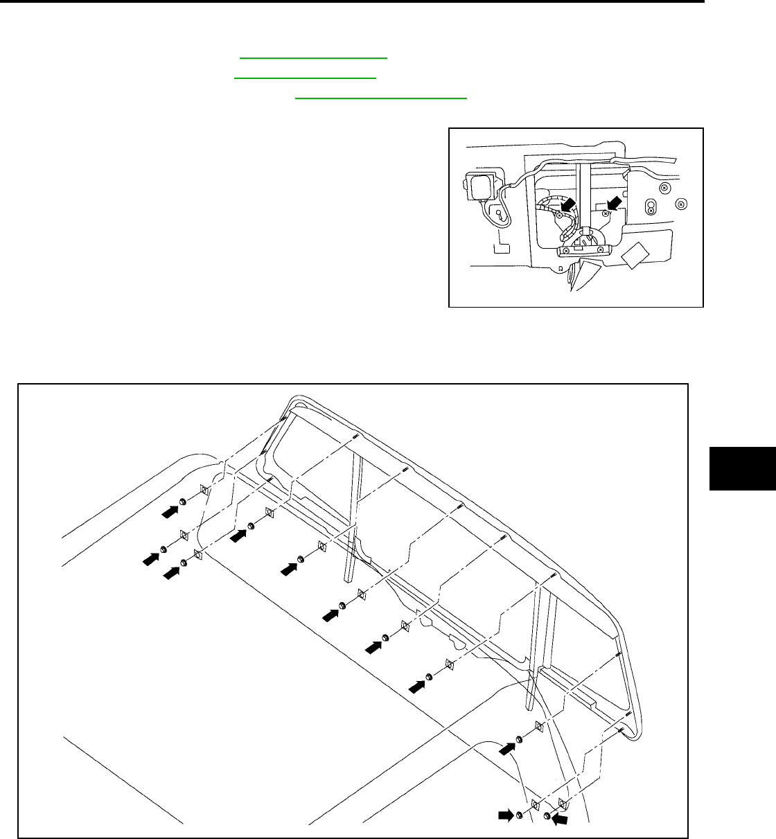
5. Lower the window and remove the rear window glass bolts.
6. Raise the window and hold it in place with tape.
7. Disconnect the rear window defogger harness connector.
8. Remove the rear window glass assembly.
9. Disconnect the rear window motor wiring harness connector.
LIIA1826E
LIIA1828E
GW-16
REAR WINDOW GLASS AND MOLDING
Revision: October 2004 2005 Titan
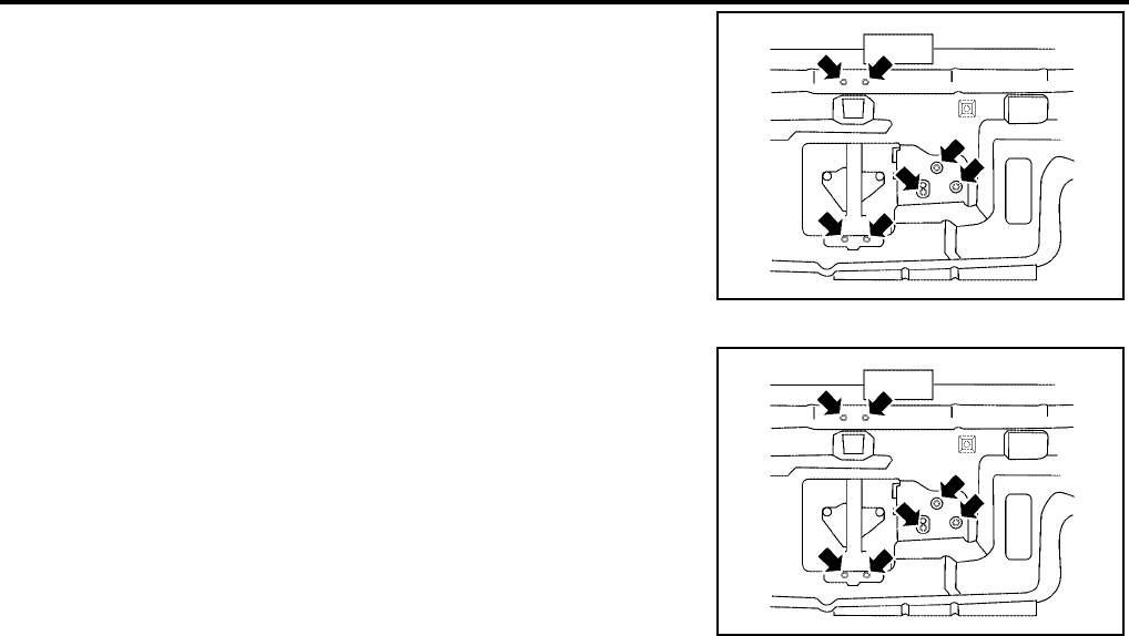
10. Remove the bolts and the regulator and motor assembly.
Installation
1. Position the regulator and motor assembly and install the bolts.
2. Connect the rear window motor wiring harness connector.
3. Install the rear window.
●While installing the rear window, make sure that the bottom clips are engaged on the back panel, then
rotate the glass into position.
–If reusing the existing window assembly, clean the opening and assembly, then apply new butyl to the
window assembly.
–If installing a new window, clean the opening and remove the plastic liner from the butyl on the new win-
dow assembly.
LIIA1827E
Regulator and motor
assembly 7.5N·m(0.76Kg-m,66in-lb)
LIIA1827E
REAR WINDOW GLASS AND MOLDING
GW-17
C
D
E
F
G
H
J
K
L
M
A
B
GW
Revision: October 2004 2005 Titan
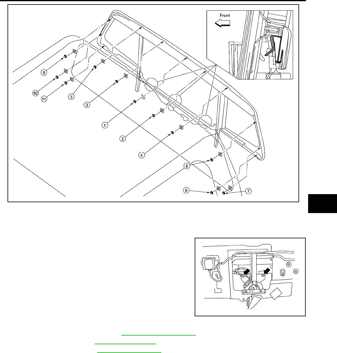
4. Connect the rear window defogger.
5. Lower the window and install the rear window glass bolts.
6. Install the sealing screen.
7. Install the back panel finisher. Refer to EI-36, "BODY SIDE TRIM".
8. Install the headliner. Refer to EI-43, "HEADLINING".
9. Install the rear seats. Refer to SE-100, "REAR SEAT".
SETTING AFTER INSTALLATION
Setting of Limit Switch
If any of the following operations are performed the limit switch must be reset.
●Motor operation when not installed in the vehicle.
●Removal and installation of the regulator.
●Removal and installation of the motor from the regulator.
●Removal and installation of the glass.
Rear window assembly
nuts 3.0 N·m (0.31 Kg-m, 27 in-lb)
Rear window glass bolts 6.0 N·m (0.61 Kg-m, 53 in-lb)
LIIA1829E
LIIA1826E
GW-18
REAR WINDOW GLASS AND MOLDING
Revision: October 2004 2005 Titan
●Removal and installation of the glass run.
Resetting
After installing each component, perform the following procedure to reset the limit switch.
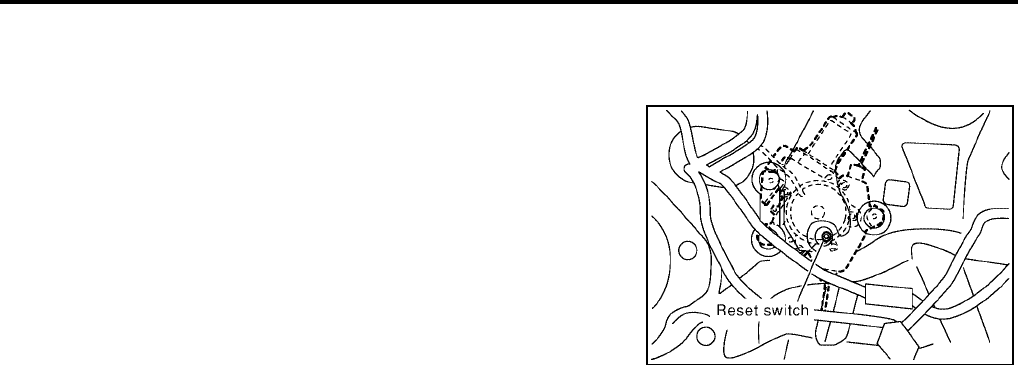
1. Raise the glass to the top.
2. While pressing and holding the reset switch, lower the glass to
the bottom.
3. Release the reset switch. Verify that the reset switch returns to
the original position, if not pull the switch using suitable tool.
4. Raise the glass to the top position
CAUTION:
Do not operate the glass automatically to raise the glass to the
top position.
REPAIRING WATER LEAKS FOR REAR WINDOW GLASS
Leaks can be repaired without removing or reinstalling glass.
If water is leaking between butyl adhesive material and body or glass, determine the extent of leakage.
This can be done by applying water to the rear window area while pushing glass outward.
To stop leak, apply primer (if necessary) and then butyl adhesive to the leak point.
SIIA0347E
POWER WINDOW SYSTEM
GW-19
C
D
E
F
G
H
J
K
L
M
A
B
GW
Revision: October 2004 2005 Titan
POWER WINDOW SYSTEM PFP:25401
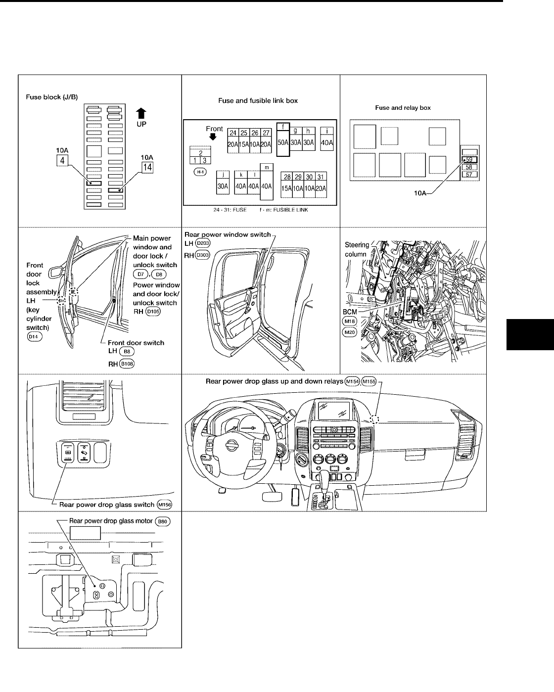
Component Parts and Harness Connector Location
EIS004C8
LIIA1985E

GW-20
POWER WINDOW SYSTEM
Revision: October 2004 2005 Titan
System Description
EIS004C9
KING CAB
Power is supplied at all times
●from 50A fusible link (letter f, located in the fuse and fusible link box)
●to BCM terminal 70
●through BCM terminal 69
●to main power window and door lock/unlock switch terminal 1
●to power window and door lock/unlock switch RH terminal 10.
With ignition switch in ON or START position, power is supplied
●through 10A fuse (No. 59, located in the fuse and relay box)
●to BCM terminal 38
●through BCM terminal 68
●to main power window and door lock/unlock switch terminal 10.
CREW CAB
Power is supplied at all times
●from 50A fusible link (letter f, located in the fuse and fusible link box)
●to BCM terminal 70
●through BCM terminal 69
●to main power window and door lock/unlock switch terminal 19
●to power window and door lock/unlock switch RH terminal 10
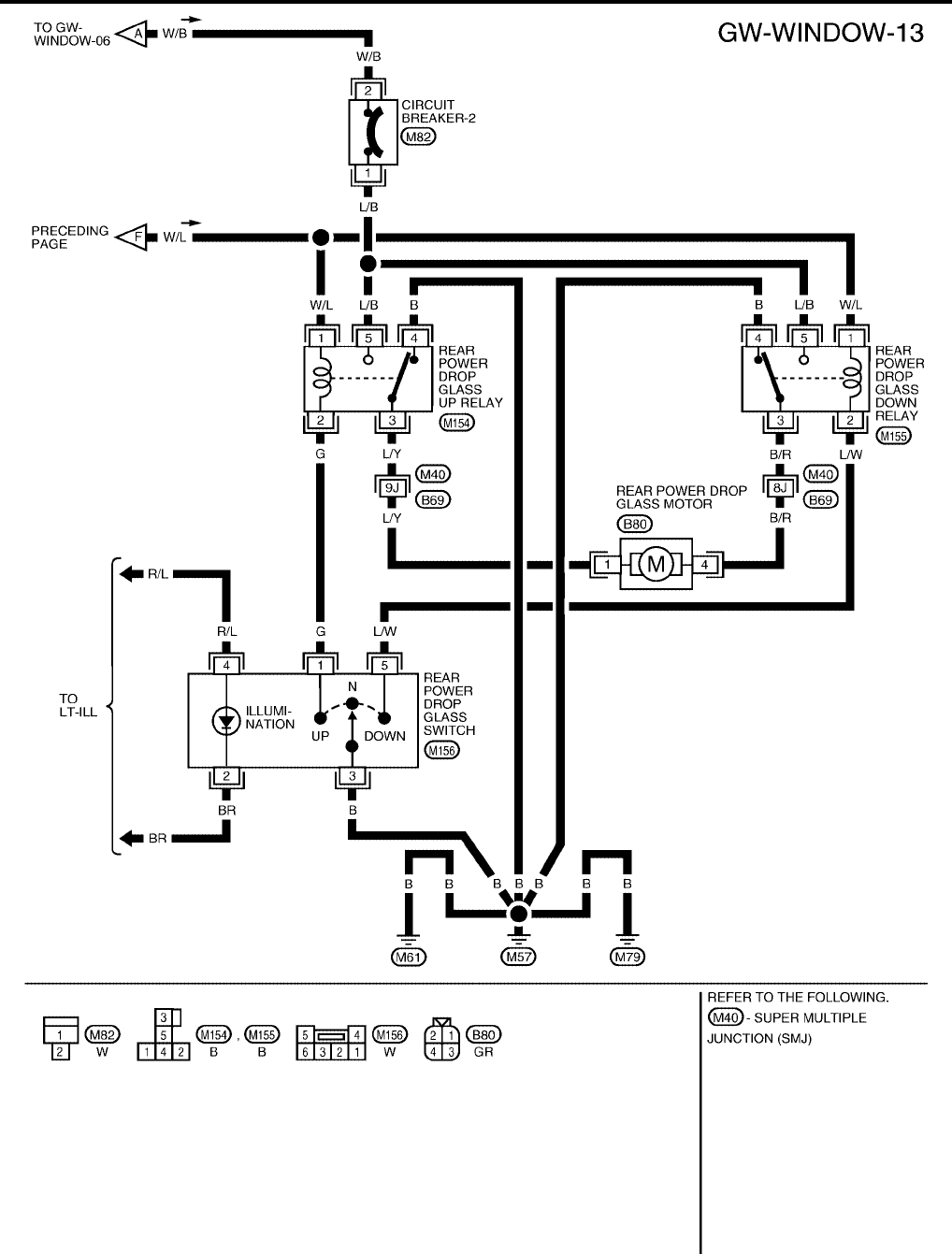
●to circuit breaker-2 terminal 2
●through circuit breaker-2 terminal 1
●to rear power drop glass up and down relays terminal 5.
With ignition switch in ON or START position, power is supplied
●through 10A fuse (No. 59, located in the fuse and relay box)
●to BCM terminal 38
●through BCM terminal 68
●to main power window and door lock/unlock switch terminal 10
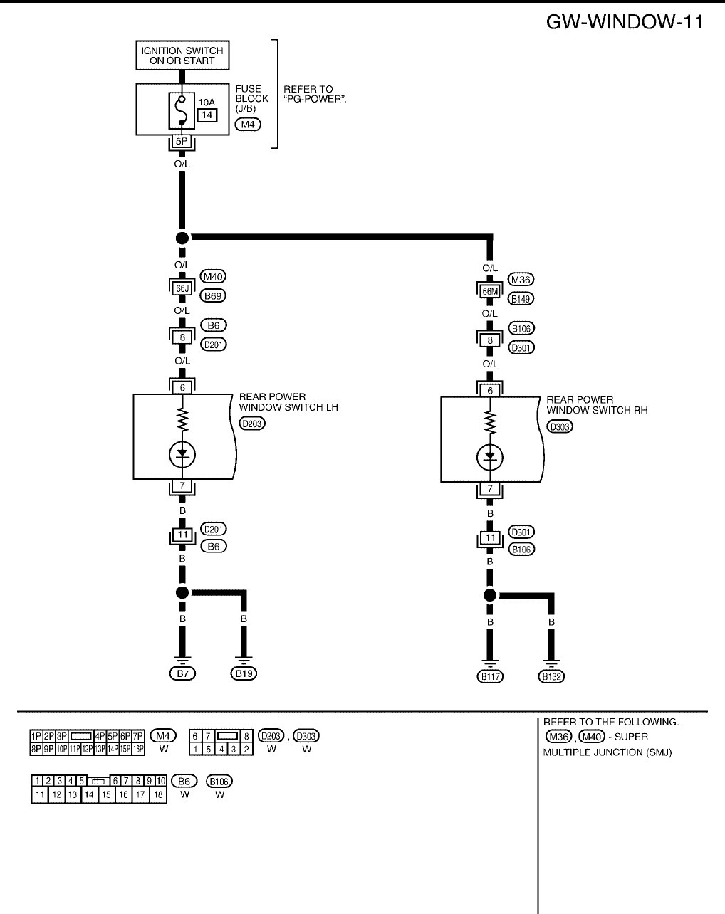
●to rear power window switches LH and RH terminal 1
●to rear power drop glass up and down relays terminal 1.
KING CAB
With ignition switch in ON or START position,
Ground is supplied
●to BCM terminal 67
●to main power window and door lock/unlock switch terminal 15
●to power window and door lock/unlock switch RH terminal 11
●through body grounds M57, M61 and M79.
CREW CAB
With ignition switch in ON or START position,
Ground is supplied
●to BCM terminal 67
●to main power window and door lock/unlock switch terminal 17
●to power window and door lock/unlock switch RH terminal 11
●to rear power drop glass up and down relays terminal 4
●to rear power drop glass switch terminal 3
●through body grounds M57, M61 and M79.

POWER WINDOW SYSTEM
GW-21
C
D
E
F
G
H
J
K
L
M
A
B
GW
Revision: October 2004 2005 Titan
MANUAL OPERATION
Front Driver Side Door
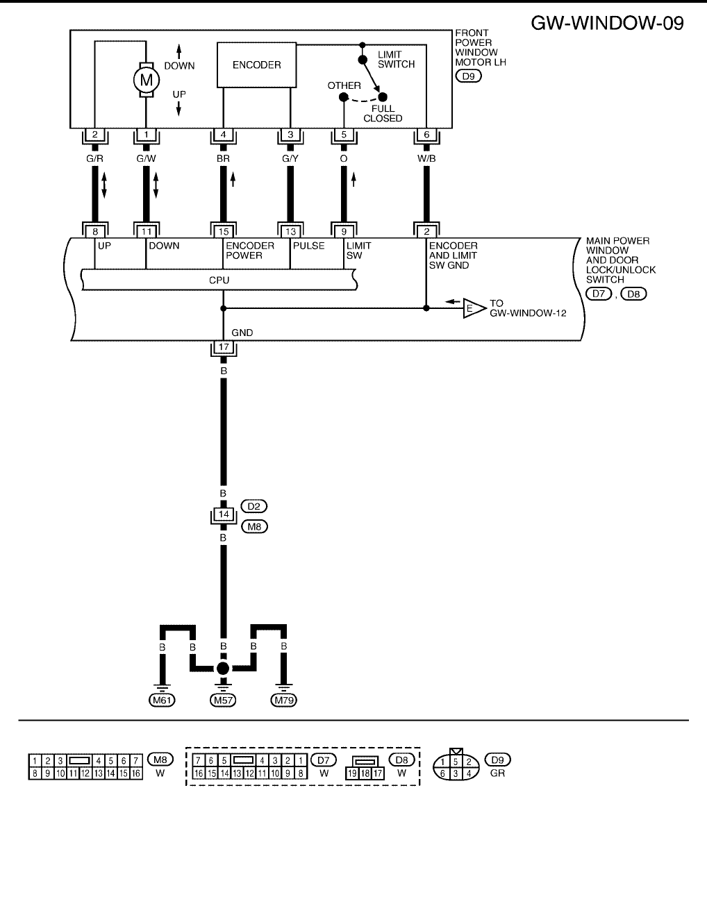
WINDOW UP
When the front LH switch in the main power window and door lock/unlock switch is pressed in the up position,
power is supplied
●through main power window and door lock/unlock switch terminal 8
●to front power window motor LH terminal 2.
Ground is supplied
●through main power window and door lock/unlock switch terminal 11
●to front power window motor LH terminal 1.
Then, the motor raises the window until the switch is released.
WINDOW DOWN
When the front LH switch in the main power window and door lock/unlock switch is pressed in the down posi-
tion, power is supplied
●through main power window and door lock/unlock switch terminal 11
●to front power window motor LH terminal 1.
Ground is supplied
●through main power window and door lock/unlock switch terminal 8
●to front power window motor LH terminal 2.
Then, the motor lowers the window until the switch is released.
Front Passenger Side Door
POWER WINDOW AND DOOR LOCK/UNLOCK SWITCH RH OPERATION
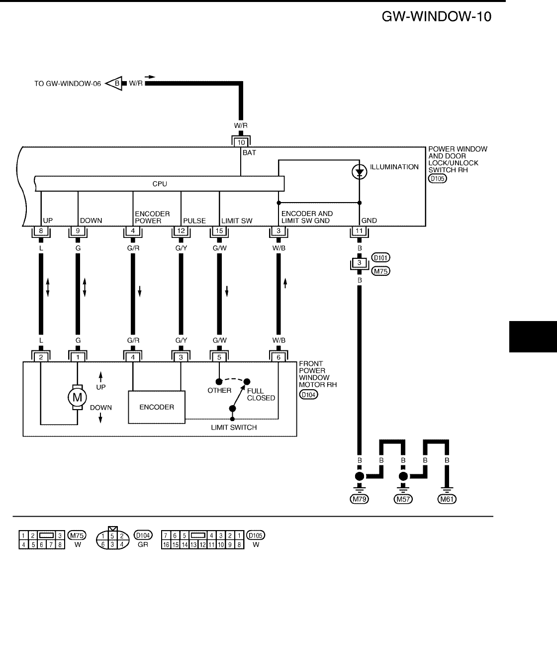
WINDOW UP
When the power window and door lock/unlock switch RH is pressed in the up position, power is supplied
●through power window and door lock/unlock switch RH terminal 8
●to front power window motor RH terminal 2.
Ground is supplied
●through power window and door lock/unlock switch RH terminal 9
●to front power window motor RH terminal 1.
Then, the motor raises the window until the switch is released.
WINDOW DOWN
When the power window and door lock/unlock switch RH is pressed in the down position, power is supplied
●through power window and door lock/unlock switch RH terminal 9
●to front power window motor RH terminal 1.
Ground is supplied
●through power window and door lock/unlock switch RH terminal 8
●to front power window motor RH terminal 2.
Then, the motor lowers the window until the switch is released.
King Cab
MAIN POWER WINDOW AND DOOR LOCK/UNLOCK SWITCH OPERATION
Signal is sent
●through main power window and door lock/unlock switch terminal 12
●to power window and door lock/unlock switch RH terminal 16.
The operation of power window after receiving the signal is the same as operating the power window with
power window and door lock/unlock switch RH.
Crew Cab
MAIN POWER WINDOW AND DOOR LOCK/UNLOCK SWITCH OPERATION
Signal is sent
●through main power window and door lock/unlock switch terminal 14
●to power window and door lock/unlock switch RH terminal 16.
The operation of power window after receiving the signal is the same as operating the power window with
power window and door lock/unlock switch RH.

GW-22
POWER WINDOW SYSTEM
Revision: October 2004 2005 Titan
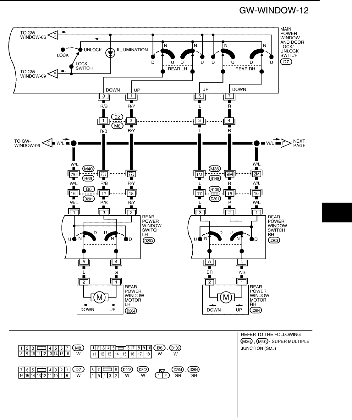
Rear Door (Crew Cab LH or RH)
REAR POWER WINDOW SWITCH LH OR RH OPERATION
WINDOW UP
When the rear power window switch LH or RH is pressed in the up position, power is supplied
●through rear power window switch LH or RH terminal 5
●to rear power window motor LH or RH terminal 2.
Ground is supplied
●through rear power window switch LH or RH terminal 4
●to rear power window motor LH or RH terminal 1.
Then, the motor raises the window until the switch is released.
WINDOW DOWN
When the rear power window switch LH or RH is pressed in the down position, power is supplied
●through rear power window switch LH or RH terminal 4
●to rear power window motor LH or RH terminal 1.
Ground is supplied
●through rear power window switch LH or RH terminal 5
●to rear power window motor LH or RH terminal 2.
Then, the motor lowers the window until the switch is released.
MAIN POWER WINDOW AND DOOR LOCK/UNLOCK SWITCH OPERATION
WINDOW UP
When the main power window and door lock/unlock switch (rear LH) is pressed in the up position, power is
supplied
●through main power window and door lock/unlock switch terminal 1
●to rear power window switch LH terminal 2
●through rear power window switch LH terminal 5
●to rear power window motor LH terminal 2.
Ground is supplied
●through main power window and door lock/unlock switch terminal 3
●to rear power window switch LH terminal 3
●through rear power window switch LH terminal 4
●to rear power window motor LH terminal 1.
Then, the motor raises the window until the switch is released.
When the main power window and door lock/unlock switch (rear RH) is pressed in the up position, power is
supplied
●through main power window and door lock/unlock switch terminal 5
●to rear power window switch RH terminal 3
●through rear power window switch RH terminal 5
●to rear power window motor RH terminal 2.
Ground is supplied
●through main power window and door lock/unlock switch terminal 7
●to rear power window motor RH terminal 2
●through rear power window switch RH terminal 4
●to rear power window motor RH terminal 1.
Then, the motor raises the window until the switch is released.
WINDOW DOWN
When the main power window and door lock/unlock switch (rear LH) is pressed in the down position, power is
supplied
●through main power window and door lock/unlock switch terminal 3
●to rear power window switch LH terminal 3
●through rear power window switch LH terminal 4
●to rear power window motor LH terminal 1.

POWER WINDOW SYSTEM
GW-23
C
D
E
F
G
H
J
K
L
M
A
B
GW
Revision: October 2004 2005 Titan
Ground is supplied
●through main power window and door lock/unlock switch terminal 1
●to rear power window switch LH terminal 2
●through rear power window switch LH terminal 5
●to rear power window motor LH terminal 2.
Then, the motor raises the window until the switch is released.
When the main power window and door lock/unlock switch (rear RH) is pressed in the down position, power is
supplied
●through main power window and door lock/unlock switch terminal 7
●to rear power window switch RH terminal 2
●through rear power window switch RH terminal 4
●to rear power window motor RH terminal 1.
Ground is supplied
●through main power window and door lock/unlock switch terminal 5
●to rear power window switch RH terminal 3
●through rear power window switch RH terminal 5
●to rear power window motor RH terminal 2.
Then, the motor raises the window until the switch is released.
REAR POWER DROP GLASS UP
When the rear power drop glass switch is pressed in the up position, ground is supplied
●to rear power drop glass up relay terminal 2.
Then, rear power drop glass up relay is energized. Power is supplied
●through rear power drop glass up relay terminal 3
●to rear power drop glass motor terminal 1.
Ground is supplied
●to rear power drop glass down relay terminal 4
●through rear power drop glass down relay terminal 3
●to rear power drop glass motor terminal 4.
Then, the motor raises the glass until the switch is released.
REAR POWER DROP GLASS DOWN
When the rear power drop glass switch is pressed in the DOWN position, ground is supplied
●to rear power drop glass down relay terminal 2.
Then, rear power drop glass down relay is energized. Power is supplied
●through rear power drop glass down relay terminal 3
●to rear power drop glass motor terminal 4.
Ground is supplied
●to rear power drop glass up relay terminal 4
●through rear power drop glass up relay terminal 3
●to rear power drop glass motor terminal 1.
Then, the motor lowers the glass until the switch is released.
AUTO OPERATION
The power window AUTO feature enables the driver to open or close the window without holding the window
switch in the down or up position.
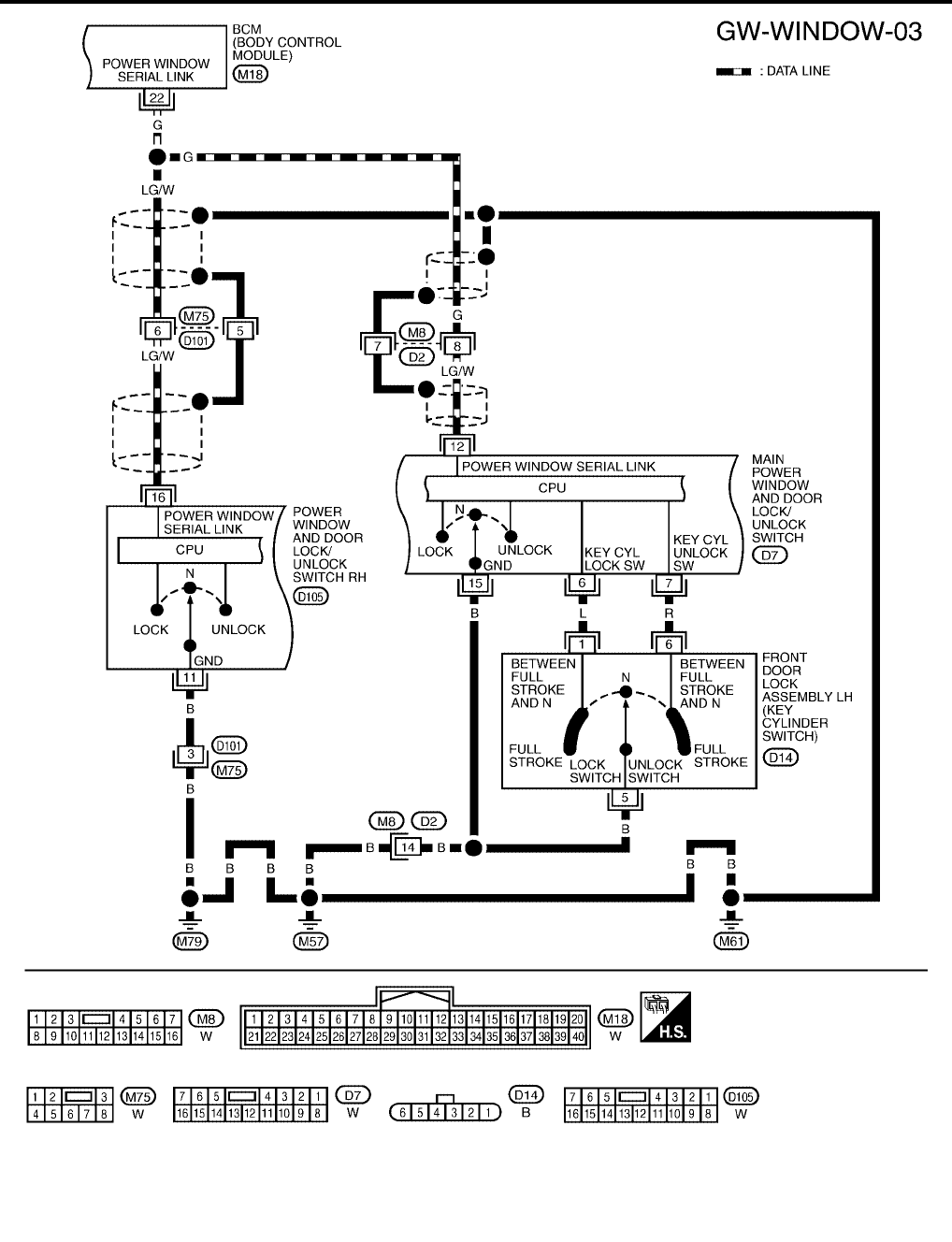
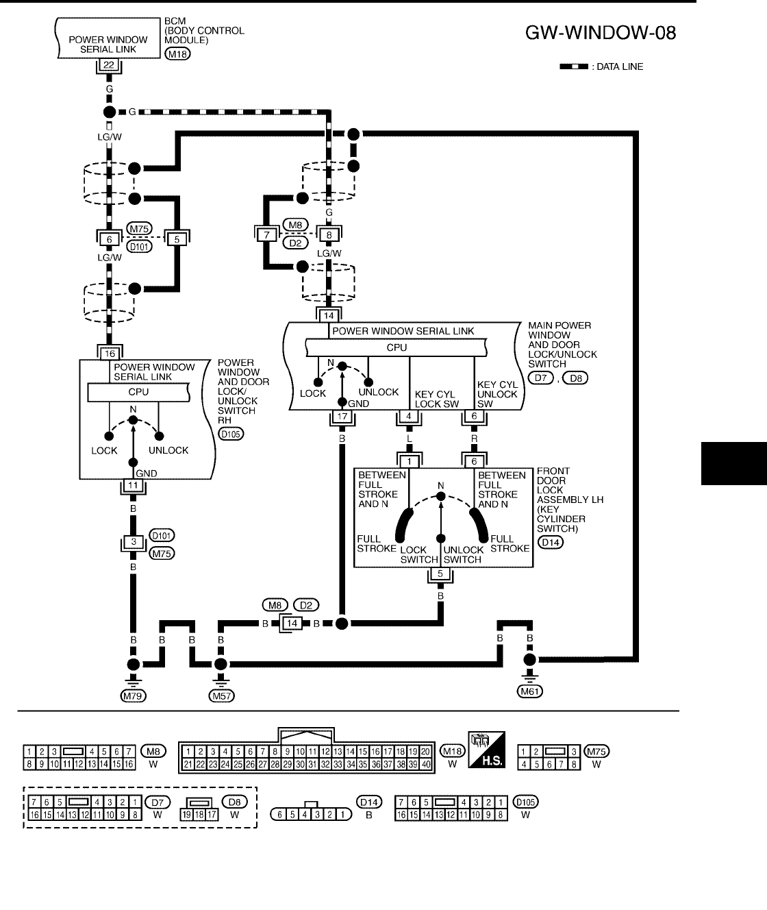
POWER WINDOW SERIAL LINK
Main power window and door lock/unlock switch, power window and door lock/unlock switch RH, and BCM
transmit and receive the signal by power window serial link.
The signal is transmitted from BCM to main power window and door lock/unlock switch and power window and
door lock/unlock switch RH
●Keyless power window down signal.

GW-24
POWER WINDOW SYSTEM
Revision: October 2004 2005 Titan
The signal is transmitted from main power window and door lock/unlock switch to power window and door
lock/unlock switch RH
●Front door window RH operation signal.
●Power window control by key cylinder switch signal.
●Power window lock signal.
●Retained power operation signal.
POWER WINDOW LOCK
The power window lock is designed to lock operation of all windows except for front door window LH.
When in the lock position, the power window lock signal is transmitted to power window and door lock/unlock
switch RH by power window serial link. This prevents the front power window motor RH from operating.
RETAINED POWER OPERATION
WhentheignitionswitchisturnedtotheOFFpositionfromONorSTARTposition.
Power is supplied for 45 seconds
●to main power window and door lock/unlock switch terminal 10
●from BCM terminal 68.
When power and ground are supplied, the BCM continues to be energized, and the power window can be
operated.
The retained power operation is canceled when the front LH or front RH door is opened.
RAP signal period can be changed by CONSULT-II. Refer to GW-46, "CONSULT-II Function (BCM)".
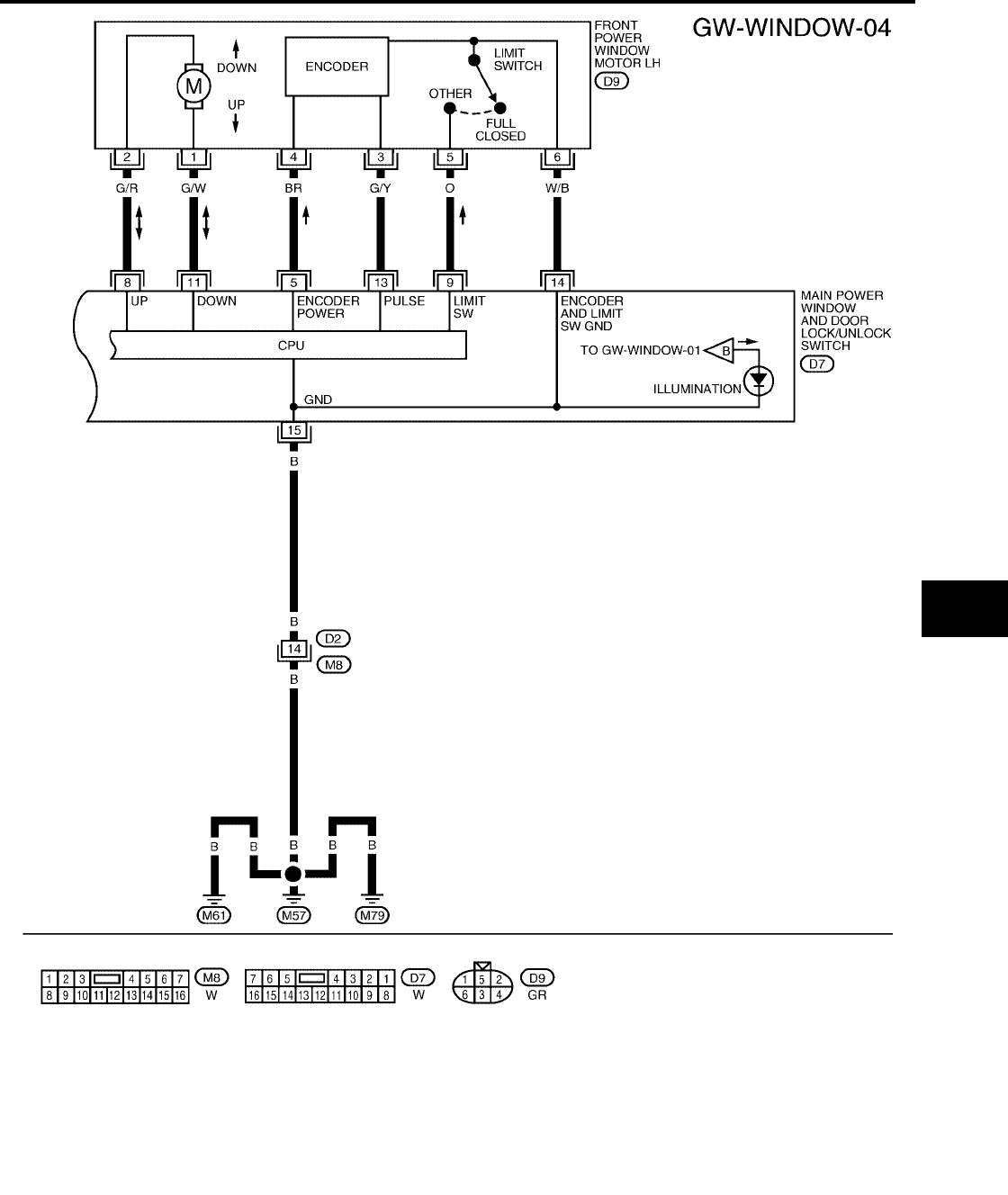
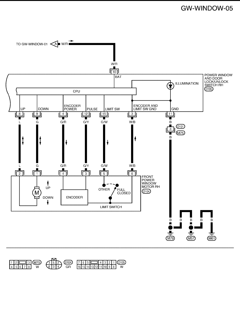
ANTI-PINCH SYSTEM
Main power window and door lock/unlock switch and power window and door lock/unlock switch RH monitor
the power window motor operation and the power window position (full closed or other) for front LH and front
RH power window by the signals from encoder and limit switch in front power window motor LH and RH.
When main power window and door lock/unlock switch or power window and door lock/unlock switch RH
detects interruption during the following close operation,
●automatic close operation when ignition switch is in the ON position
●automatic close operation during retained power operation
Main power window and door lock/unlock switch or power window and door lock/unlock switch RH controls
each front power window motor for open and the power window will be lowered about 150 mm (5.91 in).
POWER WINDOW CONTROL BY THE FRONT DOOR LOCK ASSEMBLY LH (KEY CYLINDER
SWITCH)
When ignition switch is OFF, front power window LH and RH can be opened or closed by turning the front door
key cylinder LH to the UNLOCK/LOCK position for more than 3 seconds.
●Front power windows can be opened as the door key cylinder is kept fully turned to the UNLOCK position.
●Front power windows can be closed as the door key cylinder is kept fully turned to the LOCK position.
●While performing open/close operation for the windows, power window is stopped when the door key cyl-
inder is placed in the NEUTRAL position.
●When the ignition switch is turned ON while the power window opening operation is performed, the power
window opening stops.
CAN Communication System Description
EIS004CA
Refer to LAN-7, "CAN COMMUNICATION".
POWER WINDOW SYSTEM
GW-25
C
D
E
F
G
H
J
K
L
M
A
B
GW
Revision: October 2004 2005 Titan
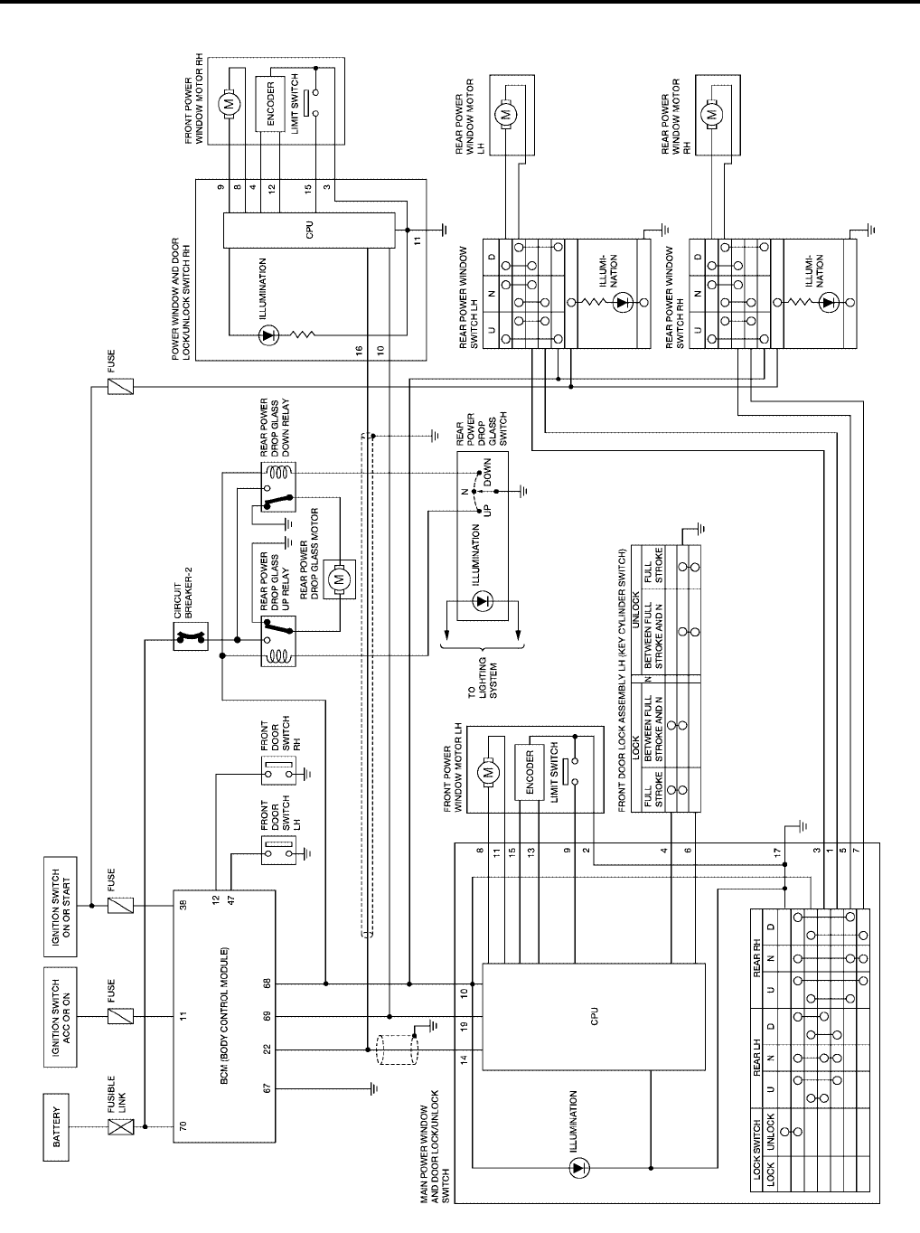
Schematic (King Cab)
EIS004CB
WIWA0610E
GW-26
POWER WINDOW SYSTEM
Revision: October 2004 2005 Titan
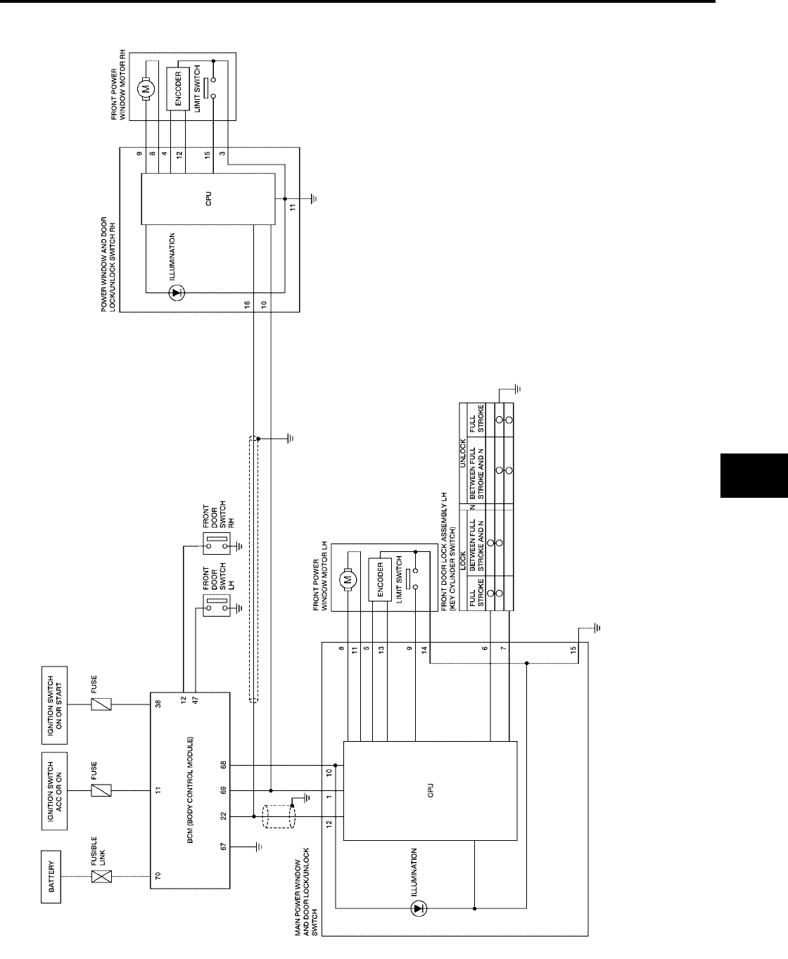
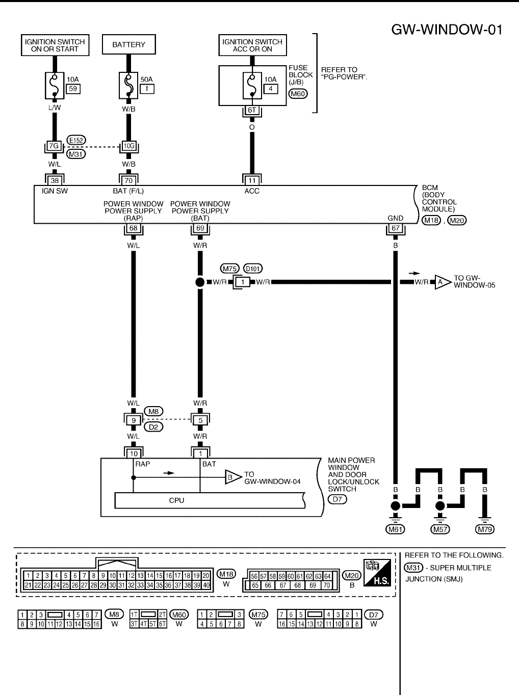
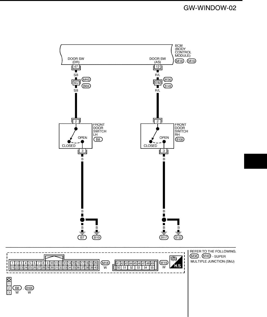
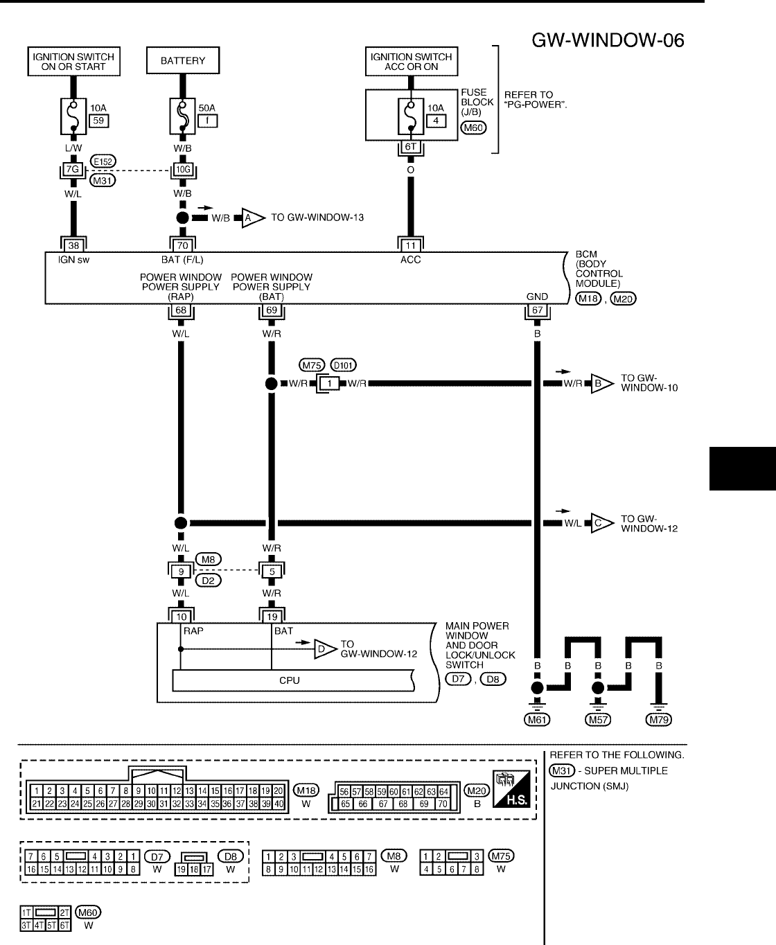
Wiring Diagram — WINDOW — (King Cab)
EIS004CC
WIWA0611E
POWER WINDOW SYSTEM
GW-27
C
D
E
F
G
H
J
K
L
M
A
B
GW
Revision: October 2004 2005 Titan
WIWA0612E
GW-28
POWER WINDOW SYSTEM
Revision: October 2004 2005 Titan
WIWA0613E
POWER WINDOW SYSTEM
GW-29
C
D
E
F
G
H
J
K
L
M
A
B
GW
Revision: October 2004 2005 Titan
WIWA0614E
GW-30
POWER WINDOW SYSTEM
Revision: October 2004 2005 Titan
WIWA0615E
POWER WINDOW SYSTEM
GW-31
C
D
E
F
G
H
J
K
L
M
A
B
GW
Revision: October 2004 2005 Titan
Terminal and Reference Value for Main Power Window and Door Lock/Unlock
Switch (King Cab)
EIS004CD
Terminal and Reference Value for Power Window and Door Lock/Unlock Switch
RH (King Cab)
EIS004CE
Terminal Wire Color Item Condition Voltage (V)
(Approx.)
1 W/R Battery power supply —Battery voltage
5 BR Encoder power supply When ignition switch ON or
power window timer operates 10
6L
Front door lock assembly LH (key
cylinder switch) lock signal
Key position
(Neutral →Locked) 5→0
7R
Front door lock assembly LH (key
cylinder switch) unlock signal
Key position
(Neutral →Unlocked) 5→0
8G/R
Front power window motor LH UP
signal
When power window motor is
operated UP Battery voltage
9 O Limit switch signal
Driver side door window is
between fully-open and just
before fully-closed position (ON)
0
Driver side door window is
between just before fully-closed
position and fully-closed position
(OFF)
5
10 W/L RAP signal
When ignition switch ON Battery voltage
Within 45 seconds after ignition
switch is turned to OFF Battery voltage
More than 45 seconds after igni-
tion switch is turned to OFF 0
When front door LH or RH open
or power window timer operates 0
11 G/W Front power window motor LH
DOWN signal
When power window motor is
operated DOWN Battery voltage
12 LG/W Power window serial link When ignition switch ON or
power window timer operates
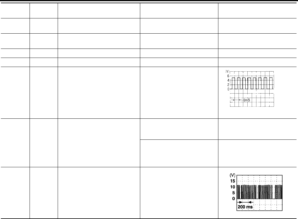
13 G/Y Encoder pulse signal When power window motor oper-
ates
14 W/B Limit switch and encoder ground —0
15 B Ground —0
PIIA2344J
OCC3383D
Terminal Wire Color Item Condition Voltage (V)
(Approx.)
3 W/B Limit switch and encoder ground —0
4 G/R Encoder power supply When ignition switch ON or
power window timer operates 10
GW-32
POWER WINDOW SYSTEM
Revision: October 2004 2005 Titan
8L
Front power window motor RH UP
signal
When power window motor is
operated UP Battery voltage
9G
Front power window motor RH
DOWN signal
When power window motor is
operated DOWN Battery voltage
10 W/R Battery power supply —Battery voltage
11 B Ground —0
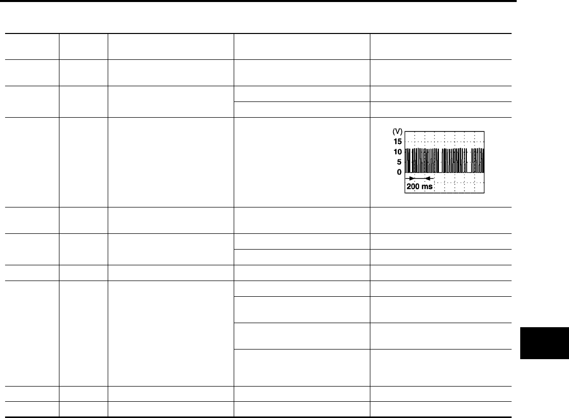
12 G/Y Encoder pulse signal When power window motor oper-
ates
15 G/W Limit switch signal
Passenger side door window is
between fully-open and just
before fully-closed position (ON)
0
Passenger side door window is
between just before fully-closed
position and fully-closed position
(OFF)
5
16 LG/W Power window serial link When ignition switch is ON or
power window timer operating
Terminal Wire Color Item Condition Voltage (V)
(Approx.)
OCC3383D
PIIA2344J
POWER WINDOW SYSTEM
GW-33
C
D
E
F
G
H
J
K
L
M
A
B
GW
Revision: October 2004 2005 Titan
Terminal and Reference Value for BCM (King Cab)
EIS004CF
Terminal Wire Color Item Condition Voltage (V)
(Approx.)
11 O Ignition switch (ACC or ON) Ignition switch
(ACC or ON position) Battery voltage
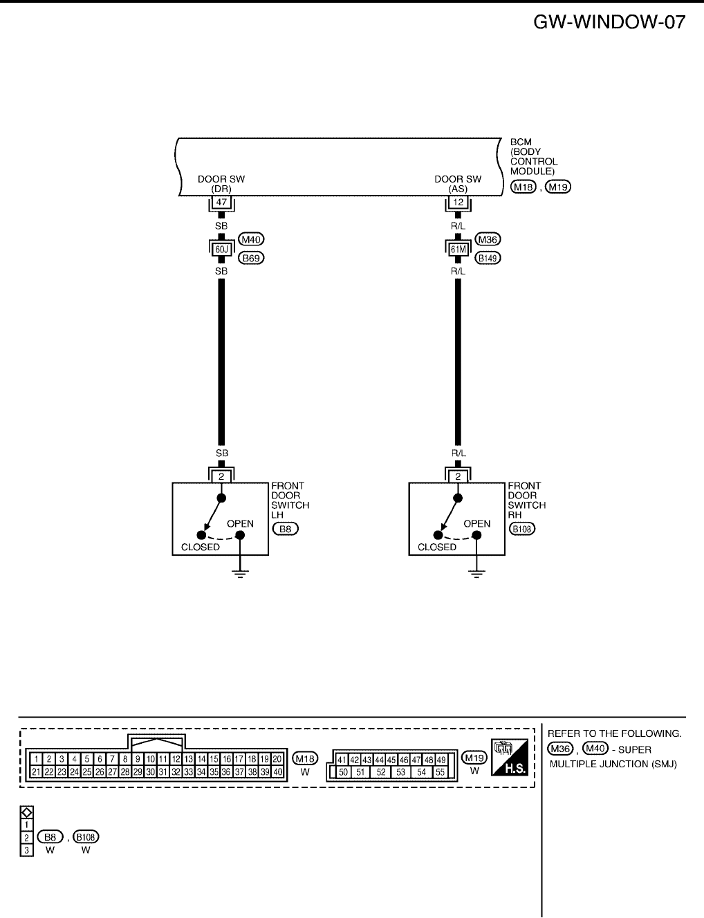
12 R/L Front door switch RH signal ON (Open) Battery voltage
OFF (Close) 0
22 G Power window serial link When ignition switch ON or
power window timer operates
38 W/L Ignition switch (ON or START) Ignition switch
(ON or START position) Battery voltage
47 SB Front door switch LH signal ON (Open) Battery voltage
OFF (Close) 0
67 B Ground —0
68 W/L RAP signal
When ignition switch ON Battery voltage
Within 45 seconds after ignition
switch is turned to OFF Battery voltage
More than 45 seconds after igni-
tion switch is turned to OFF 0
When front door LH or RH is
open or power window timer
operates
0
69 W/R Power window power supply —Battery voltage
70 W/B Battery power supply —Battery voltage
PIIA2344J
GW-34
POWER WINDOW SYSTEM
Revision: October 2004 2005 Titan
Schematic (Crew Cab)
EIS004CG
WIWA0616E
POWER WINDOW SYSTEM
GW-35
C
D
E
F
G
H
J
K
L
M
A
B
GW
Revision: October 2004 2005 Titan
Wiring Diagram — WINDOW — (Crew Cab)
EIS004CH
WIWA0617E
GW-36
POWER WINDOW SYSTEM
Revision: October 2004 2005 Titan
WIWA0618E
POWER WINDOW SYSTEM
GW-37
C
D
E
F
G
H
J
K
L
M
A
B
GW
Revision: October 2004 2005 Titan
WIWA0619E
GW-38
POWER WINDOW SYSTEM
Revision: October 2004 2005 Titan
WIWA0620E
POWER WINDOW SYSTEM
GW-39
C
D
E
F
G
H
J
K
L
M
A
B
GW
Revision: October 2004 2005 Titan
WIWA0621E
GW-40
POWER WINDOW SYSTEM
Revision: October 2004 2005 Titan
WIWA0622E
POWER WINDOW SYSTEM
GW-41
C
D
E
F
G
H
J
K
L
M
A
B
GW
Revision: October 2004 2005 Titan
WIWA0623E
GW-42
POWER WINDOW SYSTEM
Revision: October 2004 2005 Titan
LIWA0529E

POWER WINDOW SYSTEM
GW-43
C
D
E
F
G
H
J
K
L
M
A
B
GW
Revision: October 2004 2005 Titan
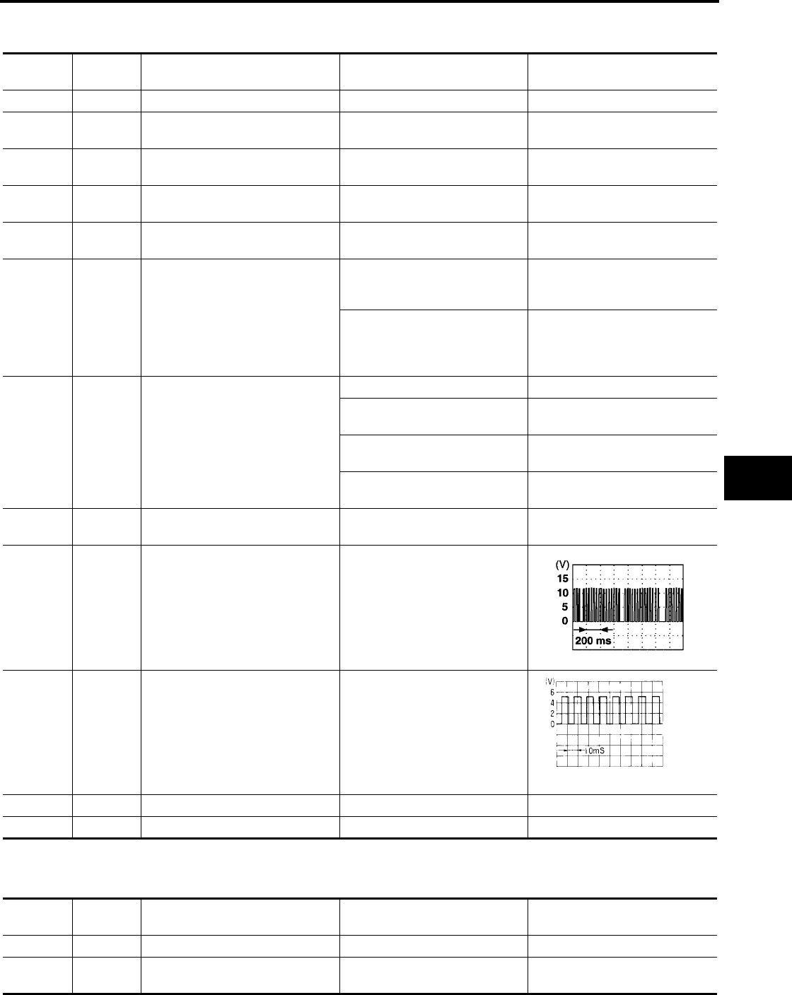
Terminal and Reference Value for Main Power Window and Door Lock/Unlock
Switch (Crew Cab)
EIS004CI
Terminal Wire Color Item Condition Voltage (V)
(Approx.)
1R/Y
Rear power window LH
UP signal
When rear LH switch in
main power window and door
lock/unlock switch is operated
UP
Battery voltage
2 W/B Limit switch and encoder ground —0
3R/B
Rear power window LH
DOWN signal
When rear LH switch in
main power window and door
lock/unlock switch is operated
DOWN
Battery voltage
4L
Front door lock assembly LH (key
cylinder switch) lock signal
Key position
(Neutral →Locked) 5→0
5L
Rear power window RH
UP signal
When rear RH switch in
main power window and door
lock/unlock switch is operated
UP
Battery voltage
6R
Front door lock assembly LH (key
cylinder switch) unlock signal
Key position
(Neutral →Unlocked) 5→0
7R
Rear power window RH
DOWN signal
When rear RH switch in
main power window and door
lock/unlock switch is operated
DOWN
Battery voltage
8G/R
Front power window motor LH UP
signal
When power window motor is
operated UP Battery voltage
9 O Limit switch signal
Driver side door window is
between fully-open and just
before fully-closed position (ON)
0
Driver side door window is
between just before fully-closed
position and fully-closed position
(OFF)
5
10 W/L RAP signal
When ignition switch ON Battery voltage
Within 45 seconds after ignition
switch is turned to OFF Battery voltage
More than 45 seconds after igni-
tion switch is turned to OFF 0
When front door LH or RH open
or power window timer operates 0
11 G/W Front power window motor LH
DOWN signal
When power window motor is
operated DOWN Battery voltage
13 G/Y Encoder pulse signal When power window motor oper-
ates
OCC3383D
GW-44
POWER WINDOW SYSTEM
Revision: October 2004 2005 Titan
Terminal and Reference Value for Power Window and Door Lock/Unlock Switch
RH (Crew Cab)
EIS004CJ
14 LG/W Power window serial link When ignition switch ON or
power window timer operates
15 BR Encoder power supply When ignition switch ON or
power window timer operates 10
17 B Ground —0
19 W/R Battery power supply —Battery voltage
Terminal Wire Color Item Condition Voltage (V)
(Approx.)
PIIA2344J
Terminal Wire Color Item Condition Voltage (V)
(Approx.)
3 W/B Limit switch and encoder ground —0
4 G/R Encoder power supply When ignition switch ON or
power window timer operates 10
8L
Front power window motor RH UP
signal
When power window motor is
operated UP Battery voltage
9G
Front power window motor RH
DOWN signal
When power window motor is
operated DOWN Battery voltage
10 W/R Battery power supply —Battery voltage
11 B Ground —0
12 G/Y Encoder pulse signal When power window motor oper-
ates
15 G/W Limit switch signal
Passenger side door window is
between fully-open and just
before fully-closed position (ON)
0
Passenger side door window is
between just before fully-closed
position and fully-closed position
(OFF)
5
16 LG/W Power window serial link When ignition switch is ON or
power window timer operating
OCC3383D
PIIA2344J

POWER WINDOW SYSTEM
GW-45
C
D
E
F
G
H
J
K
L
M
A
B
GW
Revision: October 2004 2005 Titan
Terminal and Reference Value for BCM (Crew Cab)
EIS004CK
Terminal Wire Color Item Condition Voltage (V)
(Approx.)
11 O Ignition switch (ACC or ON) Ignition switch
(ACC or ON position) Battery voltage
12 R/L Front door switch RH signal ON (Open) Battery voltage
OFF (Close) 0
22 G Power window serial link When ignition switch ON or
power window timer operates
38 W/L Ignition switch (ON or START) Ignition switch
(ON or START position) Battery voltage
47 SB Front door switch LH signal ON (Open) Battery voltage
OFF (Close) 0
67 B Ground —0
68 W/L RAP signal
When ignition switch ON Battery voltage
Within 45 seconds after ignition
switch is turned to OFF Battery voltage
More than 45 seconds after igni-
tion switch is turned to OFF 0
When front door LH or RH is
open or power window timer
operates
0
69 W/R Power window power supply —Battery voltage
70 W/B Battery power supply —Battery voltage
PIIA2344J
GW-46
POWER WINDOW SYSTEM
Revision: October 2004 2005 Titan
Work Flow
EIS004CL
1. Check the symptom and customer's requests.
2. Understand the outline of system. Refer to GW-20, "System Description".
3. According to the trouble diagnosis chart, repair or replace the cause of the malfunction.
Refer to GW-48, "Trouble Diagnoses Symptom Chart (King Cab)",GW-49, "Trouble Diagnoses Symptom
Chart (Crew Cab)".
4. Does power window system operate normally? Yes, GO TO 5, If No, GO TO 3.
5. Inspection End.
CONSULT-II Function (BCM)
EIS004CM
CONSULT-II can display each diagnostic item using the diagnostic test modes shown following.
CONSULT-II INSPECTION PROCEDURE
CAUTION:
If CONSULT-II is used with no connection of CONSULT-II CONVERTER, malfunctions might be
detected in self-diagnosis depending on control unit which carries out CAN communication.
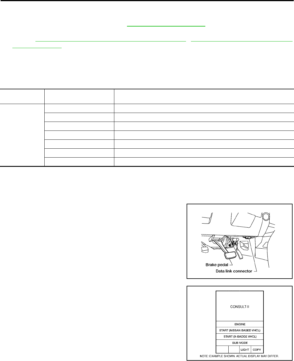
1. Connect CONSULT-II and CONSULT-II CONVERTER to the
data link connector.
2. Turn ignition switch ON.
3. Touch “START (NISSAN BASED VHCL)”.
BCM diagnostic
test item Diagnostic mode Content
Inspection by part
WORK SUPPORT Changes setting of each function.
DATA MONITOR Displays BCM input/output data in real time.
ACTIVE TEST Operation of electrical loads can be checked by sending drive signal to them.
SELF-DIAG RESULTS Displays BCM self-diagnosis results.
CAN DIAG SUPPORT MNTR The results of transmit/receive diagnosis of CAN communication can be read.
ECU PART NUMBER BCM part number can be read.
CONFIGURATION Performs BCM configuration read/write functions.
BBIA0369E
BCIA0029E
POWER WINDOW SYSTEM
GW-47
C
D
E
F
G
H
J
K
L
M
A
B
GW
Revision: October 2004 2005 Titan
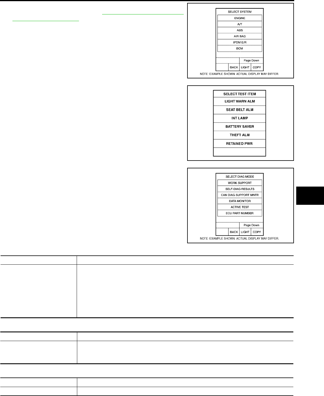
4. Touch “BCM”.
If “BCM”is not indicated, refer to GI-38, "CONSULT-II Data Link
Connector (DLC) Circuit".
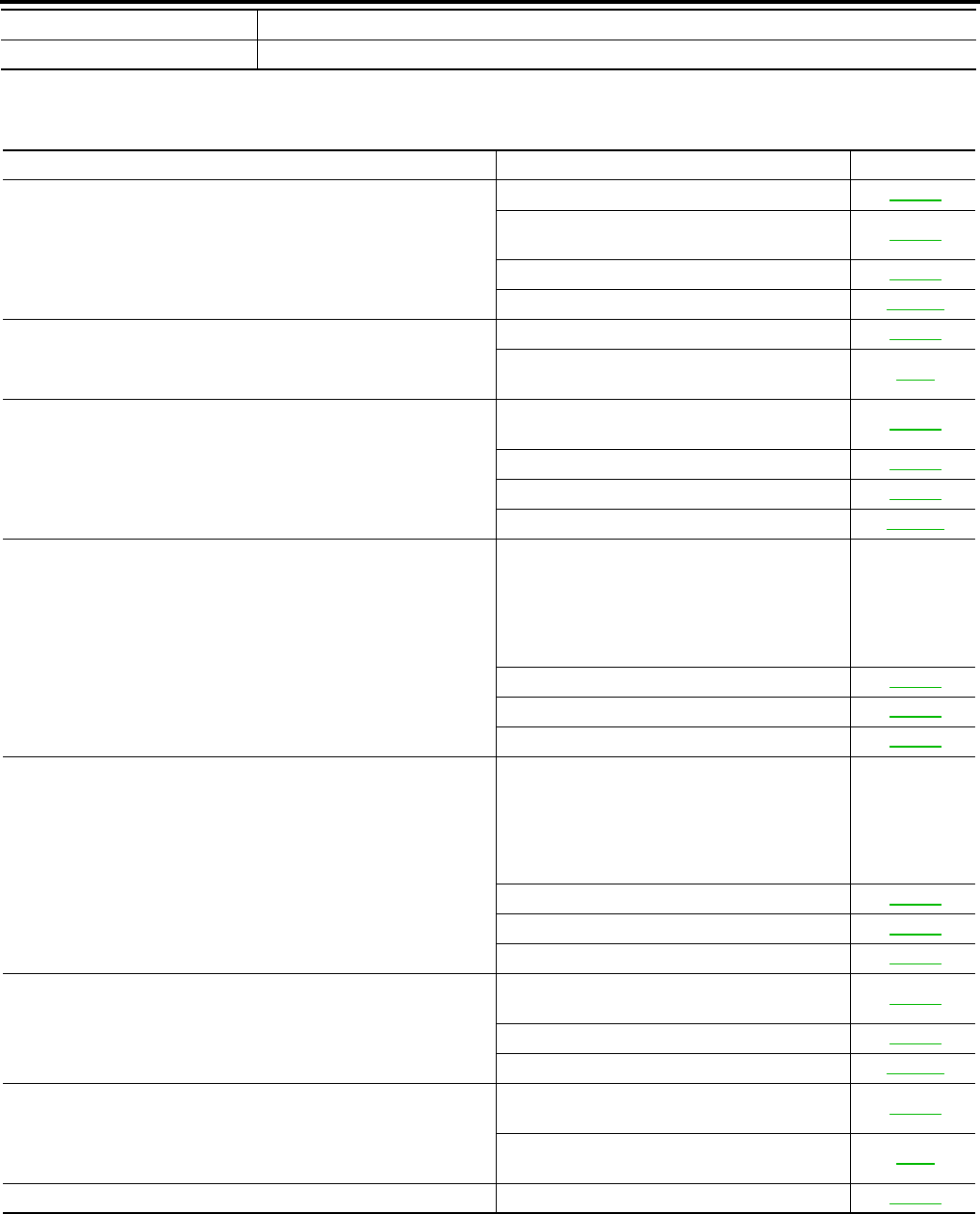
5. Touch “RETAINED PWR”.
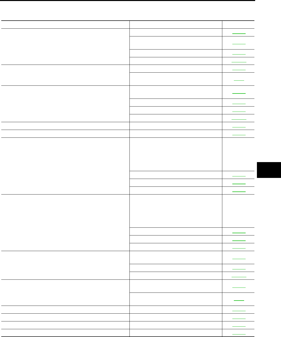
6. Select diagnosis mode.
“WORK SUPPORT”, "DATA MONITOR" and “ACTIVE TEST”
are available.
ACTIVE TEST
WORK SUPPORT
DATA MONITOR
BCIA0030E
LIIA0163E
BCIA0031E
Test Item Description
RETAINED PWR
This test is able to supply RAP signal (power) from BCM (body control module) to power window
system and power sunroof system (if equipped). Those systems can be operated when turning on
“RETAINED PWR”on CONSULT-II screen even if the ignition switch is turned OFF.
NOTE:
During this test, CONSULT-II can be operated with ignition switch in OFF position. “RETAINED
PWR”should be turned “ON”or “OFF”on CONSULT-II screen when ignition switch is ON. Then
turn ignition switch OFF to check retained power operation. CONSULT-II might be stuck if
“RETAINED PWR”is turned “ON”or “OFF”on CONSULT-II screen when ignition switch is OFF.
Work item Description
RETAINED PWR
RAP signal’s power supply period can be changed by mode setting. Selects RAP signal’s power
supply period between three steps
●MODE1 (45 sec.) / MODE2 (OFF) / MODE 3 (2 min.).
Work item Description
IGN ON SW Indicates (ON / OFF) condition of ignition switch
GW-48
POWER WINDOW SYSTEM
Revision: October 2004 2005 Titan
Trouble Diagnoses Symptom Chart (King Cab)
EIS004CN
●Check that other systems using the signal of the following systems operate normally.
DOOR SW-DR Indicates (ON / OFF) condition of front door switch driver side
DOOR SW-AS Indicates (ON / OFF) condition of front door switch passenger side
Symptom Repair order Refer to page
None of the power windows can be operated using any switch
1. BCM power supply and ground circuit check GW-50
2. Main power window and door lock/unlock
power supply and ground circuit check GW-51
3. Power window serial link check GW-73
4. Replace BCM. BCS-19
Front power window LH alone does not operate
1. Front power window motor LH circuit check GW-55
2. Replace main power window and door lock/
unlock switch EI-32
Front power window RH alone does not operate
1. Power window and door lock/unlock switch
RH power supply and ground circuit check GW-53
2. Power window serial link check GW-73
3. Front power window motor RH circuit check GW-55
4. Replace BCM. BCS-19
Anti-pinch system does not operate normally (LH)
1. Door window sliding part malfunction
●A foreign material adheres to window glass
or glass run rubber.
●Glass run rubber wear or deformation.
●Sash is tilted too much, or not enough.
—
2. Limit switch adjusting GW-86
3. Limit switch circuit check LH GW-56
4. Encoder circuit check LH GW-61
Anti-pinch system does not operate normally (RH)
1. Door window sliding part malfunction
●A foreign material adheres to window glass
or glass run rubber.
●Glass run rubber wear or deformation.
●Sash is tilted too much, or not enough.
—
2. Limit switch adjusting GW-86
3. Limit switch circuit check RH GW-59
4. Encoder circuit check RH GW-65
Power window retained power operation does not operate properly
1. Check the retained power operation mode
setting. GW-47
2. Door switch check GW-67
3. Replace BCM. BCS-19
Does not operate by front door lock assembly LH (key cylinder
switch)
1. Front door lock assembly LH (key cylinder
switch) check GW-69
2. Replace main power window and door lock/
unlock switch EI-32
Power window lock switch does not function 1. Power window lock switch circuit check GW-73
POWER WINDOW SYSTEM
GW-49
C
D
E
F
G
H
J
K
L
M
A
B
GW
Revision: October 2004 2005 Titan
Trouble Diagnoses Symptom Chart (Crew Cab)
EIS004CO
●Check that other systems using the signal of the following systems operate normally.
Symptom Repair order Refer to page
None of the power windows can be operated using any switch
1. BCM power supply and ground circuit check GW-50
2. Main power window and door lock/unlock
power supply and ground circuit check GW-51
3. Power window serial link check GW-76
4. Replace BCM. BCS-19
Front power window LH alone does not operate
1. Front power window motor LH circuit check GW-55
2. Replace main power window and door lock/
unlock switch EI-32
Front power window RH alone does not operate
1. Power window and door lock/unlock switch
RH power supply and ground circuit check GW-53
2. Power window serial link check GW-76
3. Front power window motor RH circuit check GW-55
4. Replace BCM. BCS-19
Rear power window LH alone does not operate 1. Rear power window motor LH circuit check GW-78
Rear power window RH alone does not operate 1. Rear power window motor RH circuit check GW-80
Anti-pinch system does not operate normally (Front LH)
1. Door window sliding part malfunction
●A foreign material adheres to window glass
or glass run rubber.
●Glass run rubber wear or deformation.
●Sash is tilted too much, or not enough.
—
2. Limit switch adjusting GW-86
3. Limit switch circuit check LH GW-58
4. Encoder circuit check LH GW-63
Anti-pinch system does not operate normally (Front RH)
1. Door window sliding part malfunction
●A foreign material adheres to window glass
or glass run rubber.
●Glass run rubber wear or deformation.
●Sash is tilted too much, or not enough.
—
2. Limit switch adjusting GW-86
3. Limit switch circuit check RH GW-59
4. Encoder circuit check RH GW-65
Power window retained power operation does not operate properly
1. Check the retained power operation mode
setting. GW-47
2. Door switch check GW-67
3. Replace BCM. BCS-19
Does not operate by front door lock assembly LH (key cylinder
switch)
1. Front door lock assembly LH (key cylinder
switch) check GW-71
2. Replace main power window and door lock/
unlock switch EI-32
Power window lock switch does not function 1. Power window lock switch circuit check GW-76
Rear power drop glass does not operate 1. Rear power drop glass circuit check GW-81
Rear power drop glass does not open 1. Rear power drop glass DOWN relay check GW-83
Rear power drop glass does not close 1. Rear power drop glass UP relay check GW-82
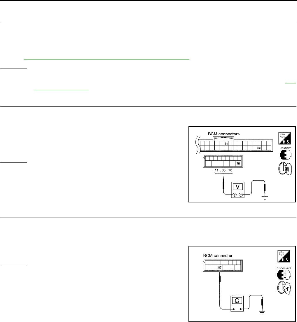
GW-50
POWER WINDOW SYSTEM
Revision: October 2004 2005 Titan
BCM Power Supply and Ground Circuit Check
EIS004CP
1. CHECK FUSE AND FUSIBLE LINK
Check 50A fusible link (letter flocated in the fuse and fusible link box).
Check 10A fuse [No. 4, located in the fuse block (J/B)].
Check 10A fuse (No. 59, located in the fuse and relay box).
NOTE:
Refer to GW-19, "Component Parts and Harness Connector Location".
OK or NG
OK >> GO TO 2.
NG >> If fuse is blown, be sure to eliminate cause of malfunction before installing new fuse. Refer toPG-
3, "PRECAUTIONS"
2. CHECK POWER SUPPLY CIRCUIT
1. Turn ignition switch ON.
2. Check voltage between BCM connector M18, M20 terminals 38, 70 and ground.
OK or NG
OK >> GO TO 3.
NG >> Repair or replace harness.
3. CHECK GROUND CIRCUIT
1. Turn ignition switch OFF.
2. Disconnect BCM.
3. Check continuity between BCM connector M20 terminal 67 and ground.
OK or NG
OK >> Power supply and ground circuit is OK.
NG >> Repair or replace harness.
11 (O) - Ground : Battery voltage
38 (W/L) - Ground : Battery voltage
70 (W/B) - Ground : Battery voltage
WIIA0504E
67 (B) - Ground : Continuity should exist.
LIIA0915E
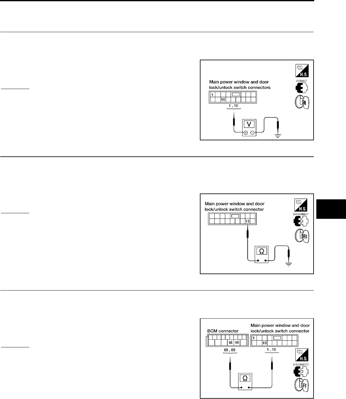
POWER WINDOW SYSTEM
GW-51
C
D
E
F
G
H
J
K
L
M
A
B
GW
Revision: October 2004 2005 Titan
Main Power Window and Door Lock/Unlock Switch Power Supply and Ground
Circuit Check (King Cab)
EIS004CQ
1. CHECK POWER SUPPLY CIRCUIT
1. Turn ignition switch ON.
2. Check voltage between main power window and door lock/unlock switch connector D7 terminals 1, 10
and ground.
OK or NG
OK >> GO TO 2.
NG >> GO TO 3.
2. CHECK GROUND CIRCUIT
1. Turn ignition switch OFF.
2. Disconnect main power window and door lock/unlock switch.
3. Check continuity between main power window and door lock/unlock switch connector D7 terminal 15 and
ground.
OK or NG
OK >> Power supply and ground circuit are OK.
NG >> Repair or replace harness.
3. CHECK MAIN POWER WINDOW AND DOOR LOCK/UNLOCK SWITCH POWER SUPPLY CIRCUIT
1. Disconnect BCM.
2. Check continuity between BCM connector M20 terminals 68, 69 and main power window and door lock/
unlock switch connector D7 terminals 1, 10.
OK or NG
OK >> GO TO 4.
NG >> Repair or replace harness.
1 (W/R) - Ground : Battery voltage
10 (W/L) - Ground : Battery voltage
LIIA0603E
15 (B) - Ground : Continuity should exist.
LIIA0604E
68 (W/L) - 10 (W/L) : Continuity should exist.
69 (W/R) - 1 (W/R) : Continuity should exist.
WIIA0505E
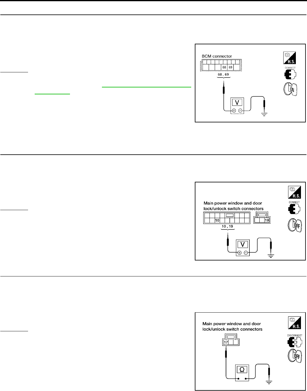
GW-52
POWER WINDOW SYSTEM
Revision: October 2004 2005 Titan
4. CHECK BCM OUTPUT SIGNAL
1. Connect BCM.
2. Turn ignition switch ON.
3. Check voltage between BCM connector M20 terminals 68, 69 and ground.
OK or NG
OK >> Check the condition of the harness and the connector.
NG >> Replace BCM. Refer to BCS-19, "Removal and Installa-
tion of BCM".
Main Power Window and Door Lock/Unlock Switch Power Supply and Ground
Circuit Check (Crew Cab)
EIS004CR
1. CHECK POWER SUPPLY CIRCUIT
1. Turn ignition switch ON.
2. Check voltage between main power window and door lock/unlock switch connector D7 terminal 10, D8
terminal 19 and ground.
OK or NG
OK >> GO TO 2.
NG >> GO TO 3.
2. CHECK GROUND CIRCUIT
1. Turn ignition switch OFF.
2. Disconnect main power window and door lock/unlock switch.
3. Check continuity between main power window and door lock/unlock switch connector D8 terminal 17 and
ground.
OK or NG
OK >> Power supply and ground circuit are OK.
NG >> Repair or replace harness.
68 (W/L) - Ground : Battery voltage
69(W/R)-Ground :Batteryvoltage
LIIA0917E
10 (W/L) - Ground : Battery voltage
19(W/R)-Ground :Batteryvoltage
LIIA0307E
17 (B) - Ground : Continuity should exist.
LIIA1253E
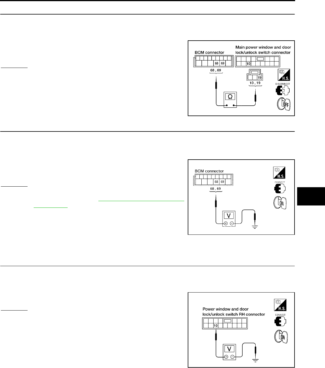
POWER WINDOW SYSTEM
GW-53
C
D
E
F
G
H
J
K
L
M
A
B
GW
Revision: October 2004 2005 Titan
3. CHECK MAIN POWER WINDOW AND DOOR LOCK/UNLOCK SWITCH POWER SUPPLY CIRCUIT
1. Disconnect BCM.
2. Check continuity between BCM connector M20 terminals 68, 69 and main power window and door lock/
unlock switch connector D7 terminal 10 and D8 terminal 19.
OK or NG
OK >> GO TO 4.
NG >> Repair or replace harness.
4. CHECK BCM OUTPUT SIGNAL
1. Connect BCM.
2. Turn ignition switch ON.
3. Check voltage between BCM connector M20 terminals 68, 69 and ground.
OK or NG
OK >> Check the condition of the harness and the connector.
NG >> Replace BCM. Refer to BCS-19, "Removal and Installa-
tion of BCM".
Power Window and Door Lock/Unlock Switch RH Power Supply and Ground
Circuit Check
EIS004CS
1. CHECK POWER SUPPLY CIRCUIT
1. Turn ignition switch ON.
2. Check voltage between power window and door lock/unlock switch RH connector D105 terminal 10 and
ground.
OK or NG
OK >> GO TO 2.
NG >> GO TO 3.
68 (W/L) - 10 (W/L) : Continuity should exist.
69 (W/R) - 19 (W/R) : Continuity should exist.
WIIA0506E
68 (W/L) - Ground : Battery voltage
69 (W/R) - Ground : Battery voltage
LIIA0917E
10 (W/R) - Ground : Battery voltage
LIIA1257E
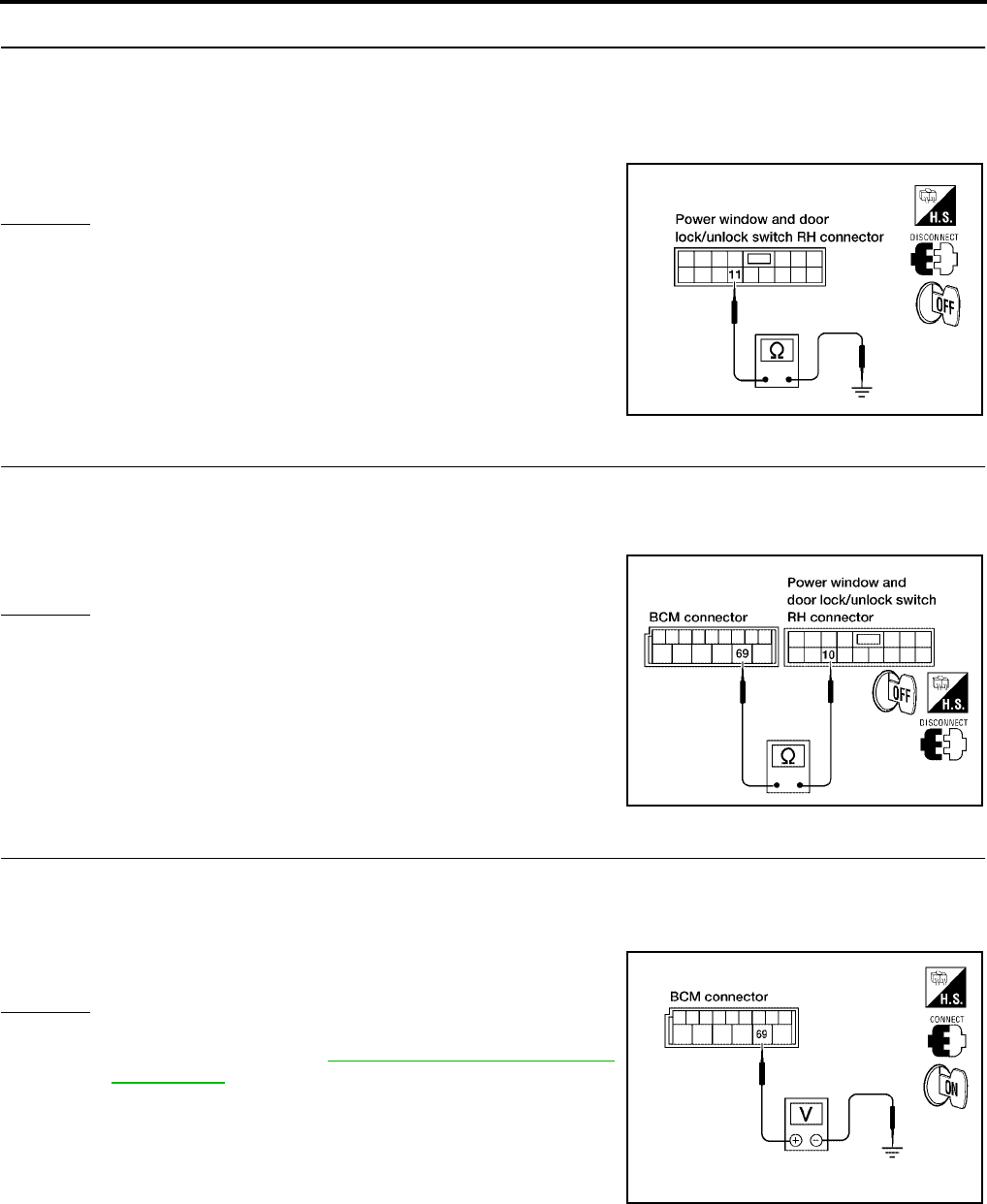
GW-54
POWER WINDOW SYSTEM
Revision: October 2004 2005 Titan
2. CHECK GROUND CIRCUIT
1. Turn ignition switch OFF.
2. Disconnect power window and door lock/unlock switch RH.
3. Check continuity between power window and door lock/unlock switch RH connector D105 terminal 11 and
ground.
OK or NG
OK >> Power supply and ground circuit are OK.
NG >> Repair or replace harness.
3. CHECK POWER WINDOW SWITCH RH POWER SUPPLY CIRCUIT
1. Disconnect BCM.
2. Check continuity between BCM connector M20 terminal 69 and power window and door lock/unlock
switch RH connector D105 terminal 10.
OK or NG
OK >> GO TO 4.
NG >> Repair or replace harness.
4. CHECK BCM OUTPUT SIGNAL
1. Connect BCM.
2. Turn ignition switch ON.
3. Check voltage between BCM connector M20 terminal 69 and ground.
OK or NG
OK >> Check the condition of the harness and the connector
NG >> Replace BCM. Refer to BCS-19, "Removal and Installa-
tion of BCM".
11 (B) - Ground : Continuity should exist.
LIIA1258E
69 (W/R) - 10 (W/R) : Continuity should exist.
WIIA0507E
69 (W/R) - Ground : Battery voltage
WIIA0508E
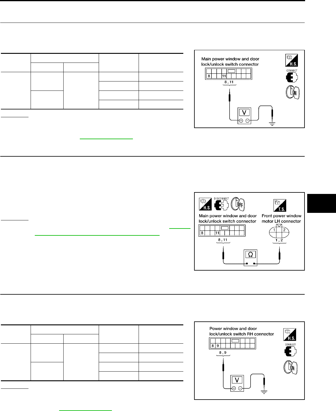
POWER WINDOW SYSTEM
GW-55
C
D
E
F
G
H
J
K
L
M
A
B
GW
Revision: October 2004 2005 Titan
Front Power Window Motor LH Circuit Check
EIS004CT
1. CHECK MAIN POWER WINDOW AND DOOR LOCK/UNLOCK SWITCH OUTPUT SIGNAL
1. Turn ignition switch ON.
2. Check voltage between main power window and door lock/unlock switch connector D7 terminals 8, 11 and
ground.
OK or NG
OK >> GO TO 2.
NG >> Replace main power window and door lock/unlock
switch. Refer to EI-32, "Front Door".
2. CHECK POWER WINDOW MOTOR CIRCUIT
1. Turn ignition switch OFF.
2. Disconnect main power window and door lock/unlock switch and front power window motor LH.
3. Check continuity between main power window and door lock/unlock switch connector D7 terminals 8, 11
and front power window motor LH connector D9 terminals 1, 2.
OK or NG
OK >> Replace front power window motor LH. Refer to GW-85,
"FRONT DOOR GLASS AND REGULATOR".
NG >> Repair or replace harness.
Power Window Motor RH Circuit Check
EIS004CU
1. CHECK POWER WINDOW AND DOOR LOCK/UNLOCK SWITCH RH OUTPUT SIGNAL
1. Turn ignition switch ON.
2. Check voltage between power window and door lock/unlock switch RH connector D105 terminals 8, 9 and
ground.
OK or NG
OK >> GO TO 2.
NG >> Replace power window and door lock/unlock switch RH.
Refer to EI-32, "Front Door".
Connector Terminals (Wire color) Condition Voltage (V)
(Approx.)
(+) (-)
D7
8 (G/R)
Ground
UP Battery voltage
DOWN 0
11 (G/W) UP 0
DOWN Battery voltage
LIIA0317E
8 (G/R) - 2 (G/R) : Continuity should exist.
11 (G/W) - 1 (G/W) : Continuity should exist.
LIIA1260E
Connector Terminals (Wire color) Condition Voltage (V)
(Approx.)
(+) (-)
D105
9(G)
Ground
UP 0
DOWN Battery voltage
8(L) UP Battery voltage
DOWN 0
LIIA1261E
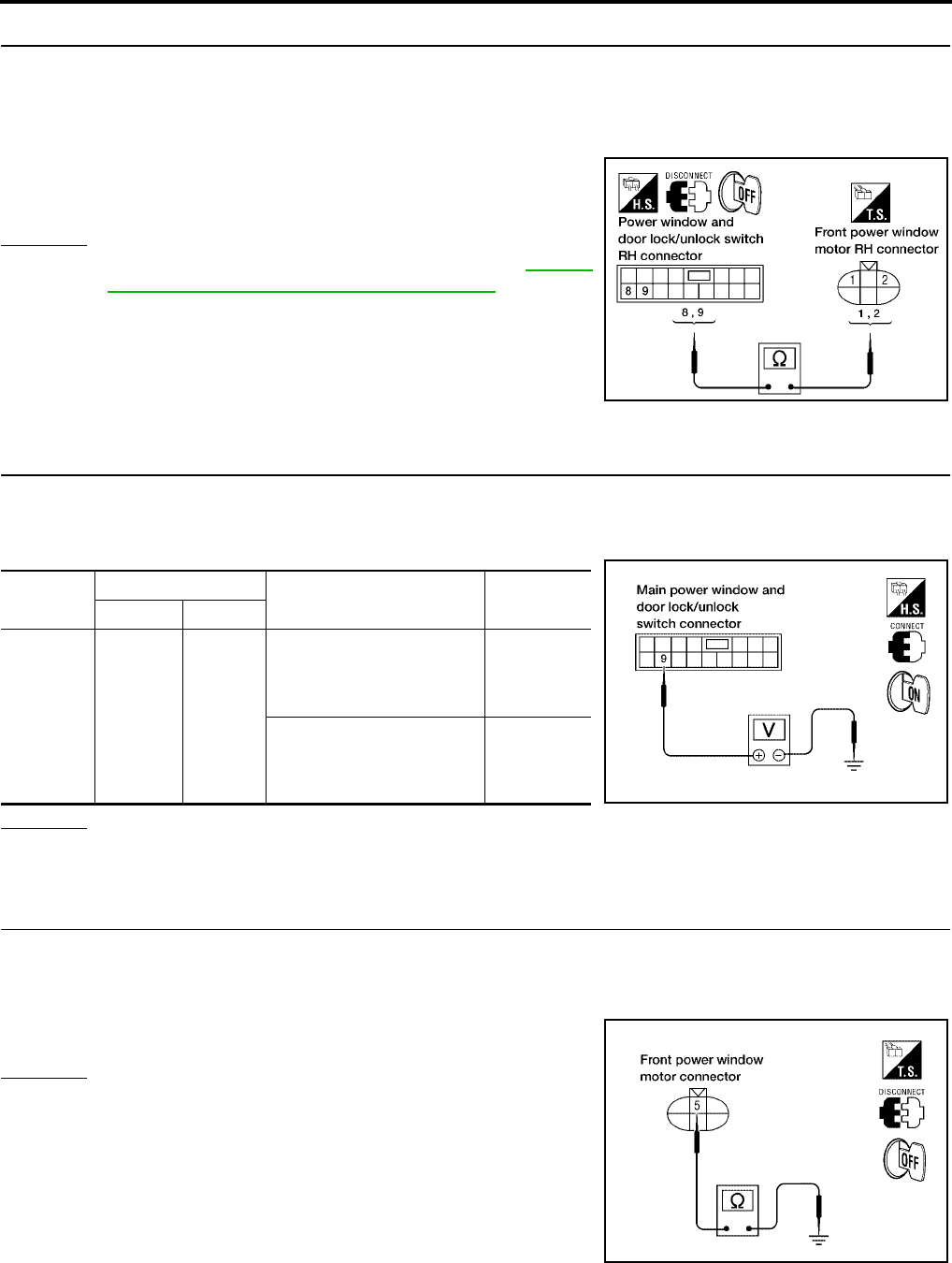
GW-56
POWER WINDOW SYSTEM
Revision: October 2004 2005 Titan
2. CHECK FRONT POWER WINDOW MOTOR RH CIRCUIT
1. Turn ignition switch OFF.
2. Disconnect front power window motor RH and power window and door lock/unlock switch RH.
3. Check continuity between power window and door lock/unlock switch RH connector D105 terminals 8, 9
and front power window motor RH connector D104 terminals 1, 2.
OK or NG
OK >> Replace front power window motor RH. Refer to GW-85,
"FRONT DOOR GLASS AND REGULATOR".
NG >> Repair or replace harness.
Limit Switch Circuit Check Front LH (King Cab)
EIS004CV
1. CHECK MAIN POWER WINDOW AND DOOR LOCK/UNLOCK SWITCH LIMIT SIGNAL
1. Turn ignition switch ON.
2. Check voltage between main power window and door lock/unlock switch connector D7 terminal 9 and
ground.
OK or NG
OK >> Limit switch circuit is OK.
NG >> GO TO 2.
2. CHECK FRONT POWER WINDOW MOTOR LH LIMIT SIGNAL
1. Turn ignition switch OFF.
2. Disconnect front power window motor LH.
3. Check continuity between front power window motor LH connector D9 terminal 5 and ground.
OK or NG
OK >> GO TO 3.
NG >> GO TO 5.
8 (L) - 2 (L) : Continuity should exist.
9 (G) - 1 (G) : Continuity should exist.
LIIA1262E
Connector Terminal (Wire color) Condition Voltage (V)
(Approx.)
(+) (-)
D7 9 (O) Ground
Driver side door window is
between fully-open and just
before fully-closed position
(ON)
0
Driver side door window is
between just before fully-
closed position and fully-
closed position (OFF)
5
LIIA0339E
5 (O) - Ground : Continuity should exist.
WIIA0509E
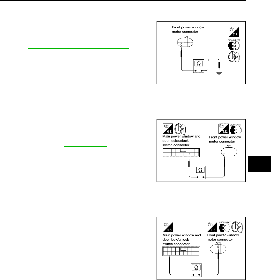
POWER WINDOW SYSTEM
GW-57
C
D
E
F
G
H
J
K
L
M
A
B
GW
Revision: October 2004 2005 Titan
3. CHECK LIMIT SWITCH GROUND CIRCUIT
Check continuity between front power window motor LH connector D9 terminal 6 and ground.
OK or NG
OK >> Replace front power window motor LH. Refer to GW-85,
"FRONT DOOR GLASS AND REGULATOR".
NG >> GO TO 4.
4. CHECK HARNESS CONTINUITY
1. Disconnect main power window and door lock/unlock switch.
2. Check continuity between front power window motor LH connector D9 terminal 6 and main power window
and door lock/unlock switch connector D7 terminal 14.
OK or NG
OK >> Replace main power window and door lock/unlock
switch. Refer to EI-32, "Front Door".
NG >> Repair or replace harness.
5. CHECK HARNESS CONTINUITY
1. Disconnect main power window and door lock/unlock switch.
2. Check continuity between front power window motor LH connector D9 terminal 5 and main power window
and door lock/unlock switch connector D7 terminal 9.
OK or NG
OK >> Replace main power window and door lock/unlock
switch. Refer to EI-32, "Front Door".
NG >> Repair or replace harness.
6 (W/B) - Ground : Continuity should exist.
LIIA0923E
6 (W/B) - 14 (W/B) : Continuity should exist.
WIIA0510E
5 (O) - 9 (O) : Continuity should exist.
LIIA0925E
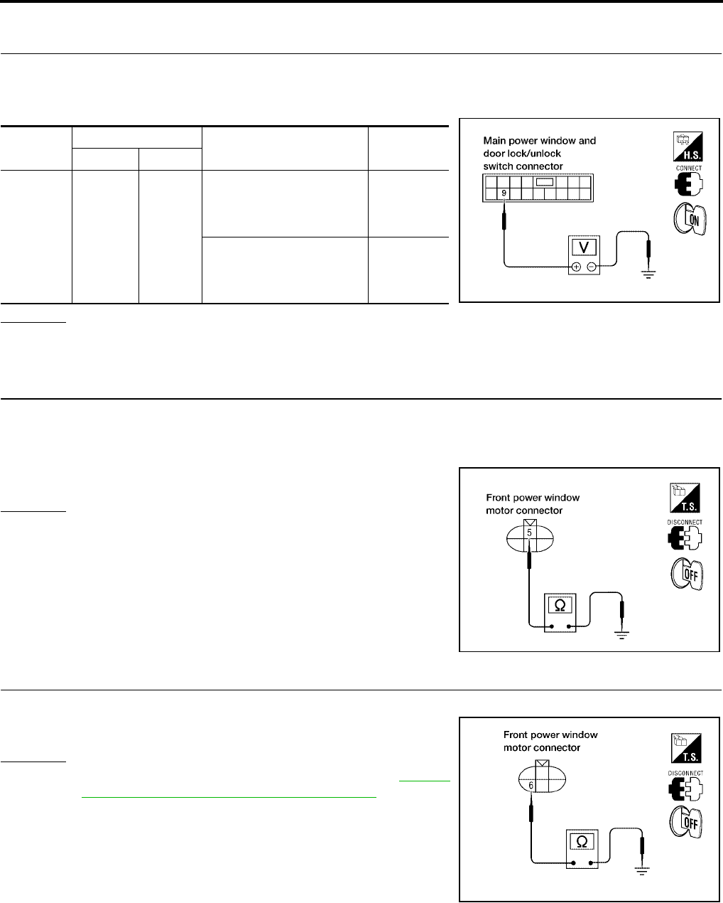
GW-58
POWER WINDOW SYSTEM
Revision: October 2004 2005 Titan
Limit Switch Circuit Check Front LH (Crew Cab)
EIS004CW
1. CHECK MAIN POWER WINDOW AND DOOR LOCK/UNLOCK SWITCH LIMIT SIGNAL
1. Turn ignition switch ON.
2. Check voltage between main power window and door lock/unlock switch connector D7 terminal 9 and
ground.
OK or NG
OK >> Limit switch circuit is OK.
NG >> GO TO 2.
2. CHECK FRONT POWER WINDOW MOTOR LH LIMIT SIGNAL
1. Turn ignition switch OFF.
2. Disconnect front power window motor LH.
3. Check continuity between front power window motor LH connector D9 terminal 5 and ground.
OK or NG
OK >> GO TO 3.
NG >> GO TO 5.
3. CHECK LIMIT SWITCH GROUND CIRCUIT
Check continuity between front power window motor LH connector D9 terminal 6 and ground.
OK or NG
OK >> Replace front power window motor LH. Refer to GW-85,
"FRONT DOOR GLASS AND REGULATOR".
NG >> GO TO 4.
Connector Terminal (Wire color) Condition Voltage (V)
(Approx.)
(+) (-)
D7 9 (O) Ground
Driver side door window is
between fully-open and just
before fully-closed position
(ON)
0
Driver side door window is
between just before fully-
closed position and fully-
closed position (OFF)
5
LIIA0339E
5 (O) - Ground : Continuity should exist.
WIIA0509E
6 (W/B) - Ground : Continuity should exist.
LIIA0923E
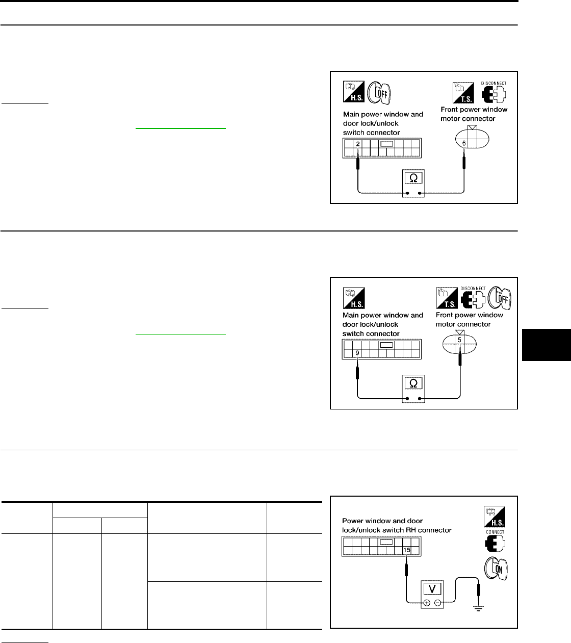
POWER WINDOW SYSTEM
GW-59
C
D
E
F
G
H
J
K
L
M
A
B
GW
Revision: October 2004 2005 Titan
4. CHECK HARNESS CONTINUITY
1. Disconnect main power window and door lock/unlock switch.
2. Check continuity between front power window motor LH connector D9 terminal 6 and main power window
and door lock/unlock switch connector D7 terminal 2.
OK or NG
OK >> Replace main power window and door lock/unlock
switch. Refer to EI-32, "Front Door".
NG >> Repair or replace harness.
5. CHECK HARNESS CONTINUITY
1. Disconnect main power window and door lock/unlock switch.
2. Check continuity between front power window motor LH connector D9 terminal 5 and main power window
and door lock/unlock switch connector D7 terminal 9.
OK or NG
OK >> Replace main power window and door lock/unlock
switch. Refer to EI-32, "Front Door".
NG >> Repair or replace harness.
Limit Switch Circuit Check Front RH
EIS004CX
1. CHECK POWER WINDOW AND DOOR LOCK/UNLOCK SWITCH RH LIMIT SIGNAL
1. Turn ignition switch ON.
2. Check voltage between power window and door lock/unlock switch RH connector D105 terminal 15 and
ground.
OK or NG
OK >> Limit switch circuit is OK.
NG >> GO TO 2.
6 (W/B) - 2 (W/B) : Continuity should exist.
WIIA0511E
5 (O) - 9 (O) : Continuity should exist.
LIIA0925E
Connector Terminals (Wire color) Condition Voltage (V)
(Approx.)
(+) (-)
D105 15 (G/W) Ground
Passenger side door window
is between fully-open and
just before fully-closed posi-
tion (ON)
0
Passenger side door window
is between just before fully-
closed position and fully-
closed position (OFF)
5
LIIA1263E
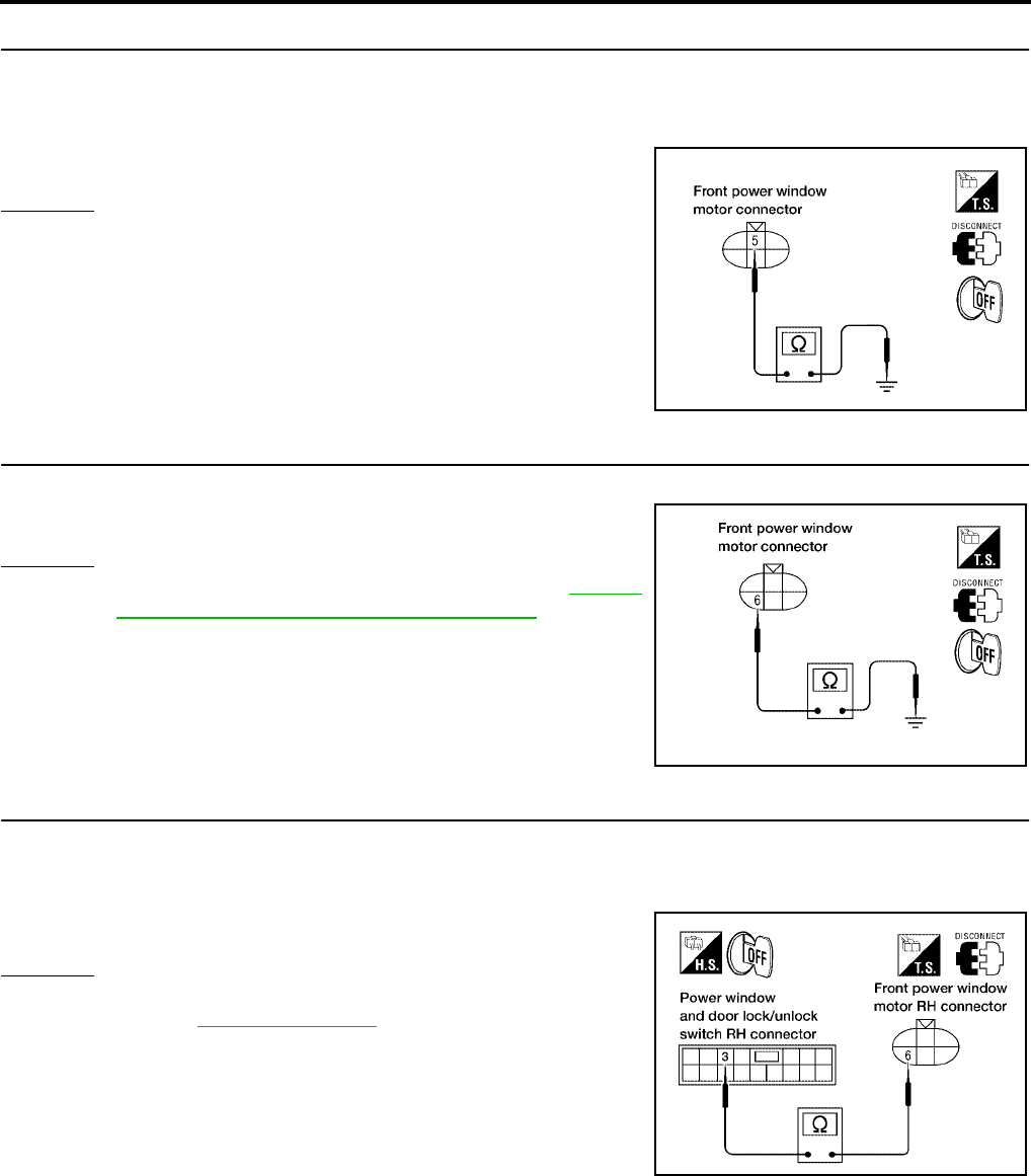
GW-60
POWER WINDOW SYSTEM
Revision: October 2004 2005 Titan
2. CHECK LIMIT SWITCH GROUND CIRCUIT
1. Turn ignition switch OFF.
2. Disconnect front power window motor RH.
3. Check continuity between front power window motor RH connector D104 terminal 5 and ground.
OK or NG
OK >> GO TO 3.
NG >> GO TO 5.
3. CHECK LIMIT SWITCH GROUND CIRCUIT
Check continuity between front power window motor RH connector D104 terminal 6 and ground.
OK or NG
OK >> Replace front power window motor RH. Refer to GW-85,
"FRONT DOOR GLASS AND REGULATOR".
NG >> GO TO 4.
4. CHECK HARNESS CONTINUITY
1. Disconnect power window and door lock/unlock switch RH.
2. Check continuity between front power window motor RH connector D104 terminal 6 and power window
and door lock/unlock switch RH connector D105 terminal 3.
OK or NG
OK >> Replace power window and door lock/unlock switch RH.
Refer to EI-32, "Front Door".
NG >> Repair or replace harness.
5 (G/W) - Ground : Continuity should exist.
WIIA0509E
6 (W/B) - Ground : Continuity should exist.
LIIA0923E
6 (W/B) - 3 (W/B) : Continuity should exist.
WIIA0512E
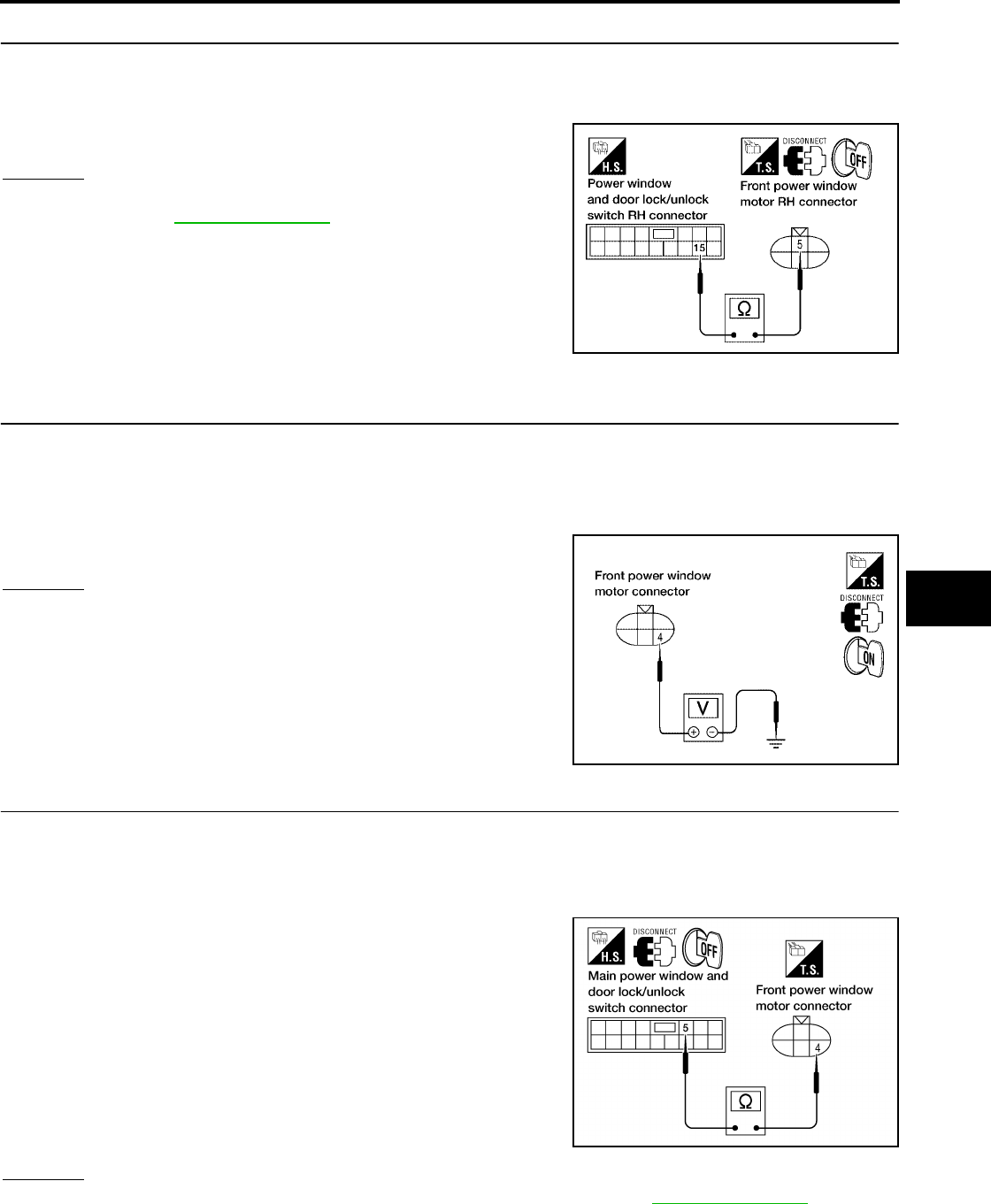
POWER WINDOW SYSTEM
GW-61
C
D
E
F
G
H
J
K
L
M
A
B
GW
Revision: October 2004 2005 Titan
5. CHECK HARNESS CONTINUITY
1. Disconnect power window and door lock/unlock switch RH.
2. Check continuity between power window and door lock/unlock switch RH connector D105 terminal 15 and
front power window motor RH connector D104 terminal 5.
OK or NG
OK >> Replace power window and door lock/unlock switch RH.
Refer to EI-32, "Front Door".
NG >> Repair or replace harness.
Encoder Circuit Check Front LH (King Cab)
EIS004CY
1. CHECK FRONT POWER WINDOW MOTOR LH POWER SUPPLY
1. Turn ignition switch OFF.
2. Disconnect front power window motor LH.
3. Turn ignition switch ON.
4. Check voltage between front power window motor LH connector D9 terminal 4 and ground.
OK or NG
OK >> GO TO 3.
NG >> GO TO 2.
2. CHECK HARNESS CONTINUITY
1. Turn ignition switch OFF.
2. Disconnect main power window and door lock/unlock switch.
3. Check continuity between front power window motor LH connector D9 terminal 4 and main power window
and door lock/unlock switch connector D7 terminal 5.
OK or NG
OK >> Replace main power window and door lock/unlock switch. Refer to EI-32, "Front Door".
NG >> Repair or replace harness.
15 (G/W) - 5 (G/W) : Continuity should exist.
LIIA1265E
4 (BR) - Ground : Approx. 10V
WIIA0513E
4 (BR) - 5 (BR) : Continuity should exist.
LIIA1160E
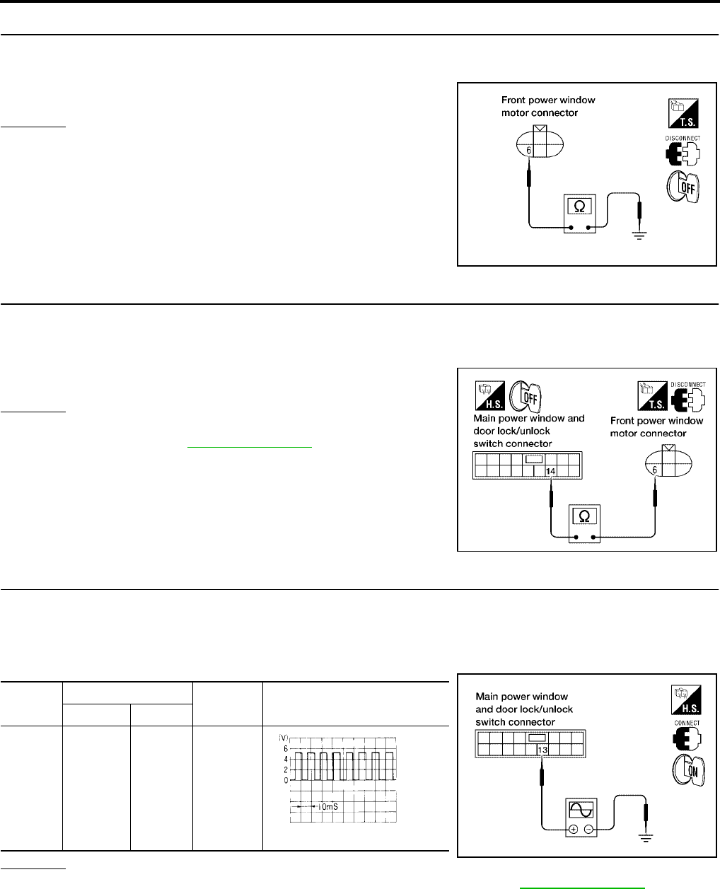
GW-62
POWER WINDOW SYSTEM
Revision: October 2004 2005 Titan
3. CHECK ENCODER GROUND
1. Turn ignition switch OFF.
2. Check continuity between front power window motor LH connector D9 terminal 6 and ground.
OK or NG
OK >> GO TO 5.
NG >> GO TO 4.
4. CHECK ENCODER GROUND CIRCUIT
1. Disconnect main power window and door lock/unlock switch.
2. Check continuity between front power window motor LH connector D9 terminal 6 and main power window
and door lock/unlock switch connector D7 terminal 14.
OK or NG
OK >> Replace main power window and door lock/unlock
switch. Refer to EI-32, "Front Door".
NG >> Repair or replace harness.
5. CHECK ENCODER SIGNAL
1. Connect front power window motor LH.
2. Turn ignition switch ON.
3. Check the signal between main power window and door lock/unlock switch connector and ground with
oscilloscope.
OK or NG
OK >> Replace main power window and door lock/unlock switch. Refer to EI-32, "Front Door".
NG >> GO TO 6.
6 (W/B) - Ground : Continuity should exist.
LIIA0923E
6 (W/B) - 14 (W/B) : Continuity should exist.
WIIA0510E
Connec-
tor
Terminals (Wire color) Condition Signal
(+) (-)
D7 13 (G/Y) Ground Opening
LIIA0364E
OCC3383D
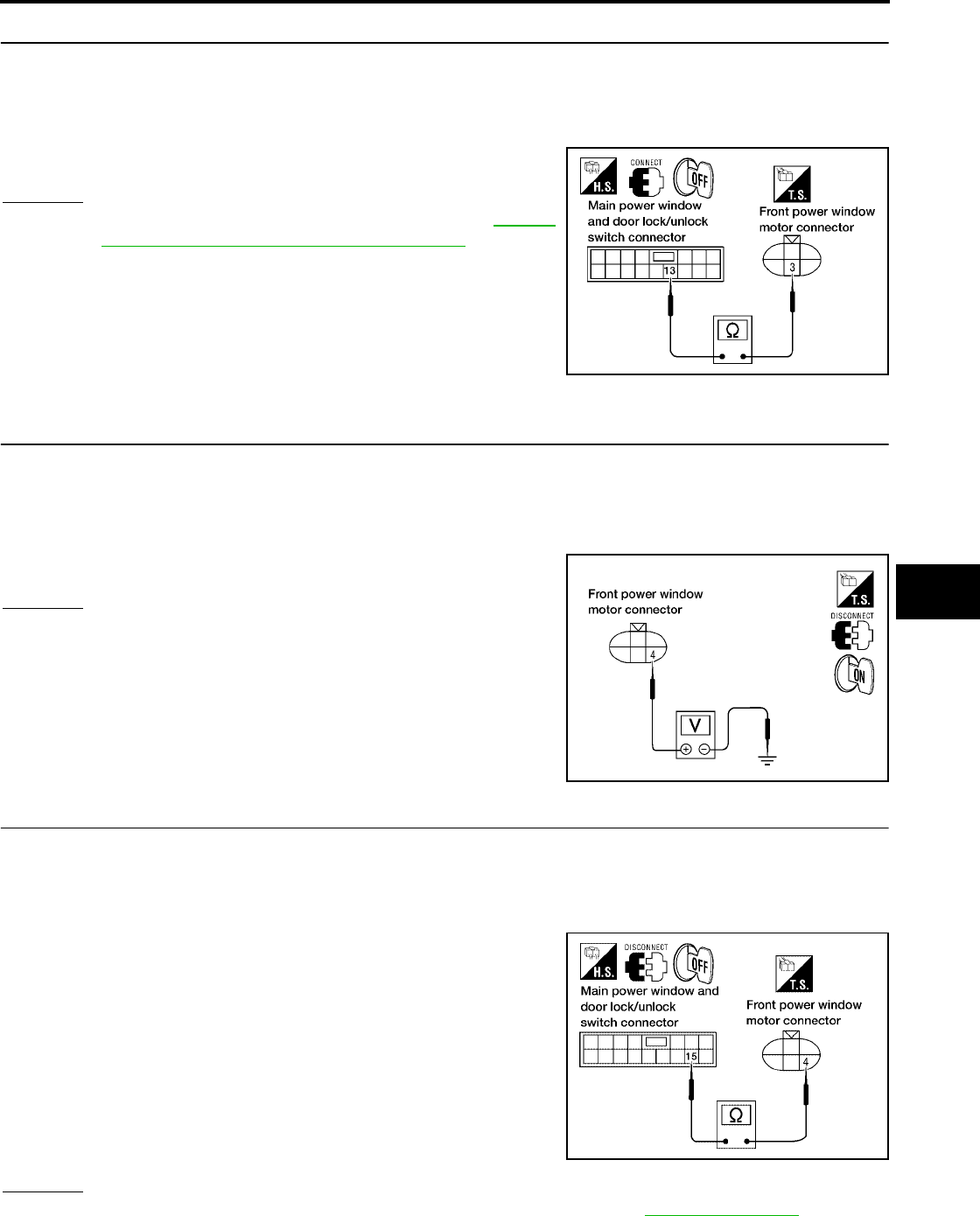
POWER WINDOW SYSTEM
GW-63
C
D
E
F
G
H
J
K
L
M
A
B
GW
Revision: October 2004 2005 Titan
6. CHECK ENCODER CIRCUIT
1. Turn ignition switch OFF.
2. Disconnect front power window motor LH and main power window and door lock/unlock switch.
3. Check continuity between front power window motor LH connector D9 terminal 3 and main power window
and door lock/unlock switch connector D7 terminal 13.
OK or NG
OK >> Replace front power window motor LH. Refer to GW-85,
"FRONT DOOR GLASS AND REGULATOR".
NG >> Repair or replace harness.
Encoder Circuit Check Front LH (Crew Cab)
EIS004CZ
1. CHECK FRONT POWER WINDOW MOTOR LH POWER SUPPLY
1. Turn ignition switch OFF.
2. Disconnect front power window motor LH.
3. Turn ignition switch ON.
4. Check voltage between front power window motor LH connector D9 terminal 4 and ground.
OK or NG
OK >> GO TO 3.
NG >> GO TO 2.
2. CHECK HARNESS CONTINUITY
1. Turn ignition switch OFF.
2. Disconnect main power window and door lock/unlock switch.
3. Check continuity between front power window motor LH connector D9 terminal 4 and main power window
and door lock/unlock switch connector D7 terminal 15.
OK or NG
OK >> Replace main power window and door lock/unlock switch. Refer to EI-32, "Front Door".
NG >> Repair or replace harness.
3 (G/Y) - 13 (G/Y) : Continuity should exist.
LIIA0937E
4 (BR) - Ground : Approx. 10V
WIIA0513E
4 (BR) - 15 (BR) : Continuity should exist.
LIIA0936E
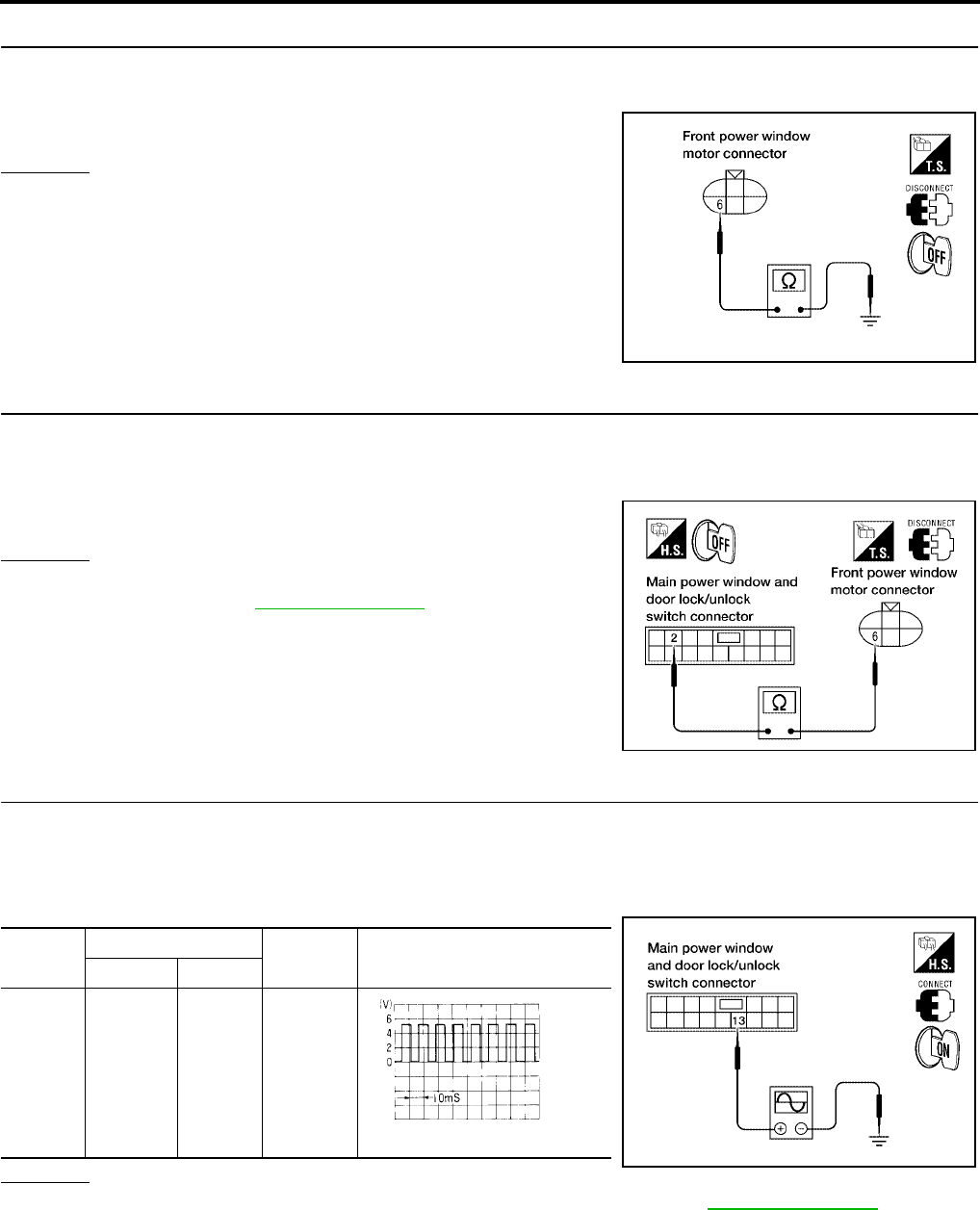
GW-64
POWER WINDOW SYSTEM
Revision: October 2004 2005 Titan
3. CHECK ENCODER GROUND
1. Disconnect front power window motor LH.
2. Check continuity between front power window motor LH connector D9 terminal 6 and ground.
OK or NG
OK >> GO TO 5.
NG >> GO TO 4.
4. CHECK ENCODER GROUND CIRCUIT
1. Disconnect main power window and door lock/unlock switch.
2. Check continuity between front power window motor LH connector D9 terminal 6 and main power window
and door lock/unlock switch connector D7 terminal 2.
OK or NG
OK >> Replace main power window and door lock/unlock
switch. Refer to EI-32, "Front Door".
NG >> Repair or replace harness.
5. CHECK ENCODER SIGNAL
1. Connect front power window motor LH.
2. Turn ignition switch ON.
3. Check the signal between main power window and door lock/unlock switch connector and ground with
oscilloscope.
OK or NG
OK >> Replace main power window and door lock/unlock switch. Refer to EI-32, "Front Door".
NG >> GO TO 6.
6 (W/B) - Ground : Continuity should exist.
LIIA0923E
6 (W/B) - 2 (W/B) : Continuity should exist.
WIIA0511E
Connec-
tor
Terminals (Wire color) Condition Signal
(+) (-)
D7 13 (G/Y) Ground Opening
LIIA0364E
OCC3383D
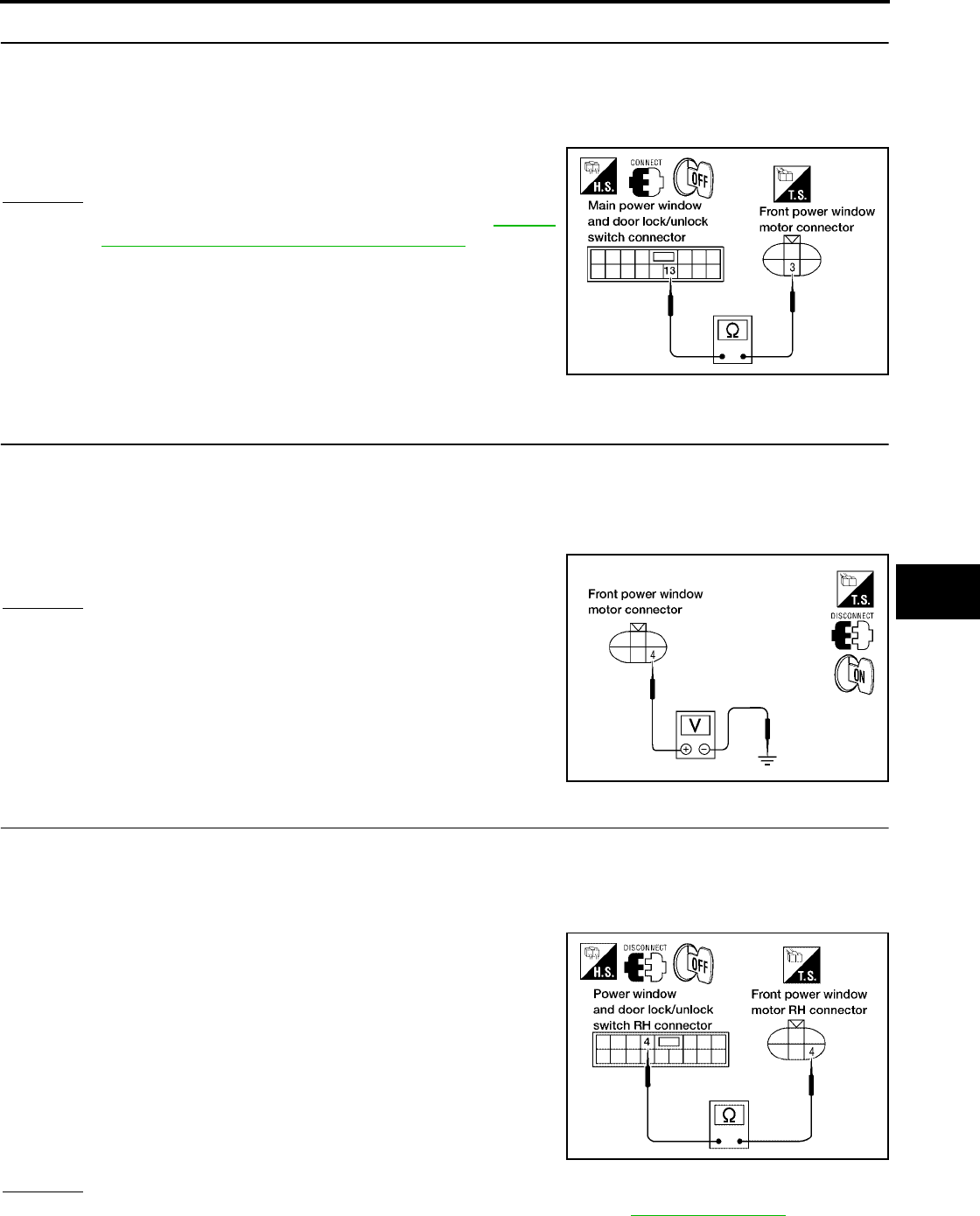
POWER WINDOW SYSTEM
GW-65
C
D
E
F
G
H
J
K
L
M
A
B
GW
Revision: October 2004 2005 Titan
6. CHECK ENCODER CIRCUIT
1. Turn ignition switch OFF.
2. Disconnect front power window motor LH and main power window and door lock/unlock switch.
3. Check continuity between front power window motor LH connector D9 terminal 3 and main power window
and door lock/unlock switch connector D7 terminal 13.
OK or NG
OK >> Replace front power window motor LH. Refer to GW-85,
"FRONT DOOR GLASS AND REGULATOR".
NG >> Repair or replace harness.
Encoder Circuit Check Front RH
EIS004D0
1. CHECK FRONT POWER WINDOW MOTOR RH POWER SUPPLY
1. Turn ignition switch OFF.
2. Disconnect front power window motor RH.
3. Turn ignition switch ON.
4. Check voltage between front power window motor RH connector D104 terminal 4 and ground.
OK or NG
OK >> GO TO 3.
NG >> GO TO 2.
2. CHECK HARNESS CONTINUITY
1. Turn ignition switch OFF.
2. Disconnect front power window motor RH and power window and door lock/unlock switch RH.
3. Check continuity between front power window motor RH connector D104 terminal 4 and power window
and door lock/unlock switch RH connector D105 terminal 4.
OK or NG
OK >> Replace power window and door lock/unlock switch RH. Refer to EI-32, "Front Door".
NG >> Repair or replace harness.
3 (G/Y) - 13 (G/Y) : Continuity should exist.
LIIA0937E
4 (G/R) - Ground : Approx. 10V
WIIA0513E
4 (G/R) - 4 (G/R) : Continuity should exist.
LIIA1266E
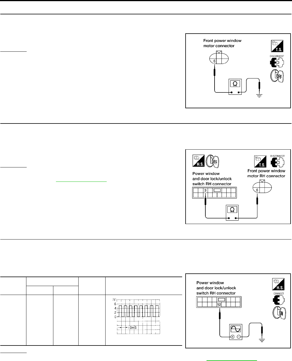
GW-66
POWER WINDOW SYSTEM
Revision: October 2004 2005 Titan
3. CHECK ENCODER GROUND
1. Turn ignition switch OFF.
2. Check continuity between front power window motor RH connector D104 terminal 6 and ground.
OK or NG
OK >> GO TO 5.
NG >> GO TO 4.
4. CHECK ENCODER GROUND CIRCUIT
1. Disconnect power window and door lock/unlock switch RH.
2. Check continuity between front power window motor RH connector D104 terminal 6 and power window
and door lock/unlock switch RH connector D105 terminal 3.
OK or NG
OK >> Replace power window and door lock/unlock switch RH.
Refer to EI-32, "Front Door".
NG >> Repair or replace harness.
5. CHECK ENCODER SIGNAL
1. Connect front power window motor RH.
2. Turn ignition switch ON.
3. Check the signal between power window and door lock/unlock switch RH connector and ground with
oscilloscope.
OK or NG
OK >> Replace power window and door lock/unlock switch RH. Refer to EI-32, "Front Door".
NG >> GO TO 6.
6 (W/B) - Ground : Continuity should exist.
LIIA0923E
6 (W/B) - 3 (W/B) : Continuity should exist.
WIIA0512E
Connec-
tor
Terminals (Wire color) Condition Signal
(+) (-)
D105 12 (G/Y) Ground Opening
LIIA1267E
OCC3383D
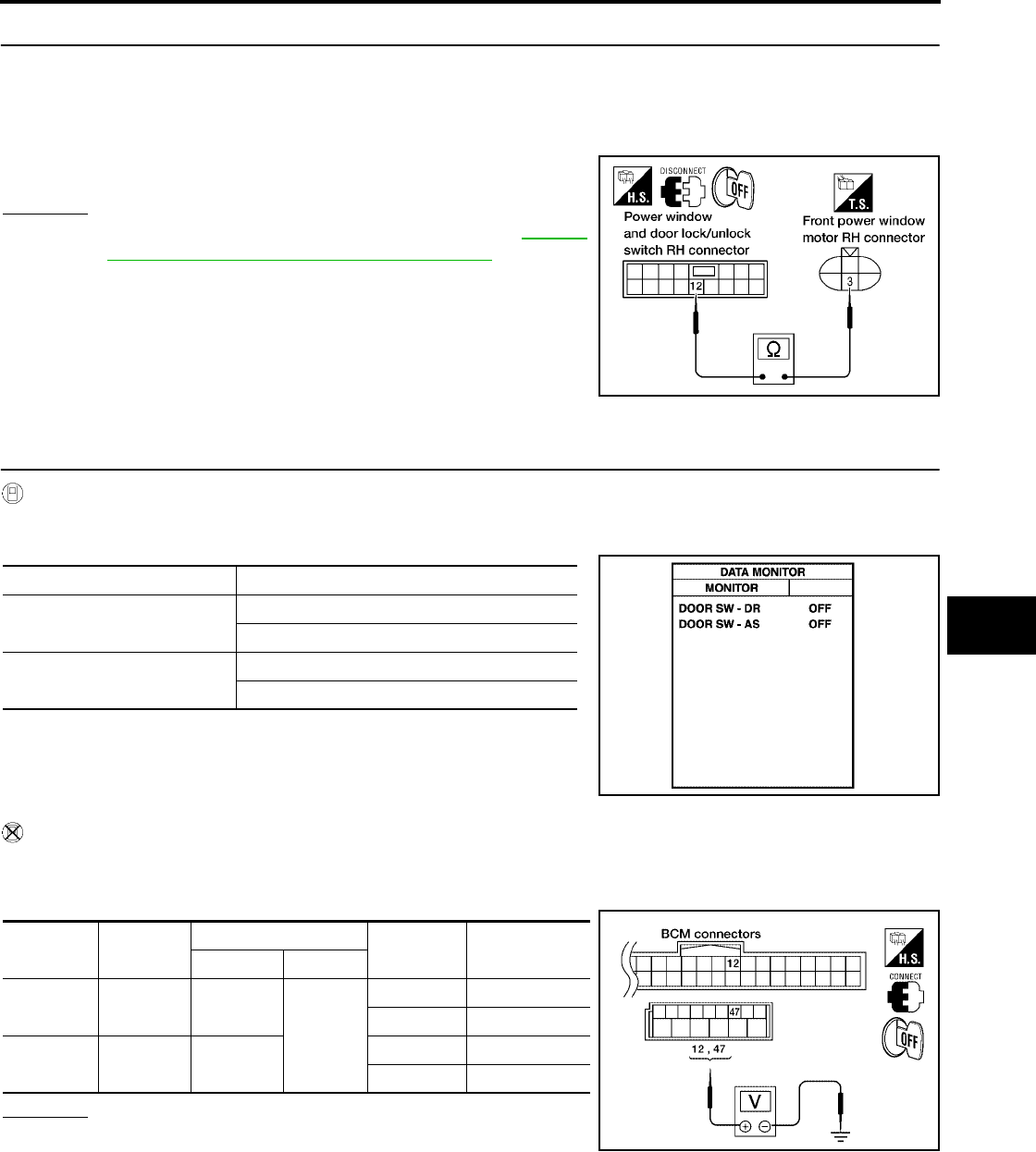
POWER WINDOW SYSTEM
GW-67
C
D
E
F
G
H
J
K
L
M
A
B
GW
Revision: October 2004 2005 Titan
6. CHECK ENCODER CIRCUIT
1. Turn ignition switch OFF.
2. Disconnect front power window motor RH and power window and door lock/unlock switch RH.
3. Check continuity between front power window motor RH connector D104 terminal 3 and power window
and door lock/unlock switch RH connector D105 terminal 12.
OK or NG
OK >> Replace front power window motor RH. Refer to GW-85,
"FRONT DOOR GLASS AND REGULATOR".
NG >> Repair or replace harness.
Door Switch Check
EIS004D1
1. CHECK FRONT DOOR SWITCH INPUT SIGNAL
With CONSULT-II
Check front door switches (“DOOR SW-DR”and “DOOR SW-AS”)in“DATA MONITOR”mode with CON-
SULT-II.
Without CONSULT-II
1. Turn ignition switch OFF.
2. Check voltage between BCM connector and ground.
OK or NG
OK >> Front door switches are OK.
NG >> GO TO 2.
3 (G/Y) - 12 (G/Y) : Continuity should exist.
LIIA1268E
Monitor item Condition
DOOR SW-DR OPEN : ON
CLOSE : OFF
DOOR SW-AS OPEN : ON
CLOSE : OFF
PIIA2464E
Item Connector Terminals (Wire color) Condition Voltage (V)
(Approx.)
(+) (–)
Front RH M19 12 (R/L)
Ground
OPEN 0
CLOSE Battery voltage
Front LH M20 47 (SB) OPEN 0
CLOSE Battery voltage
WIIA0515E
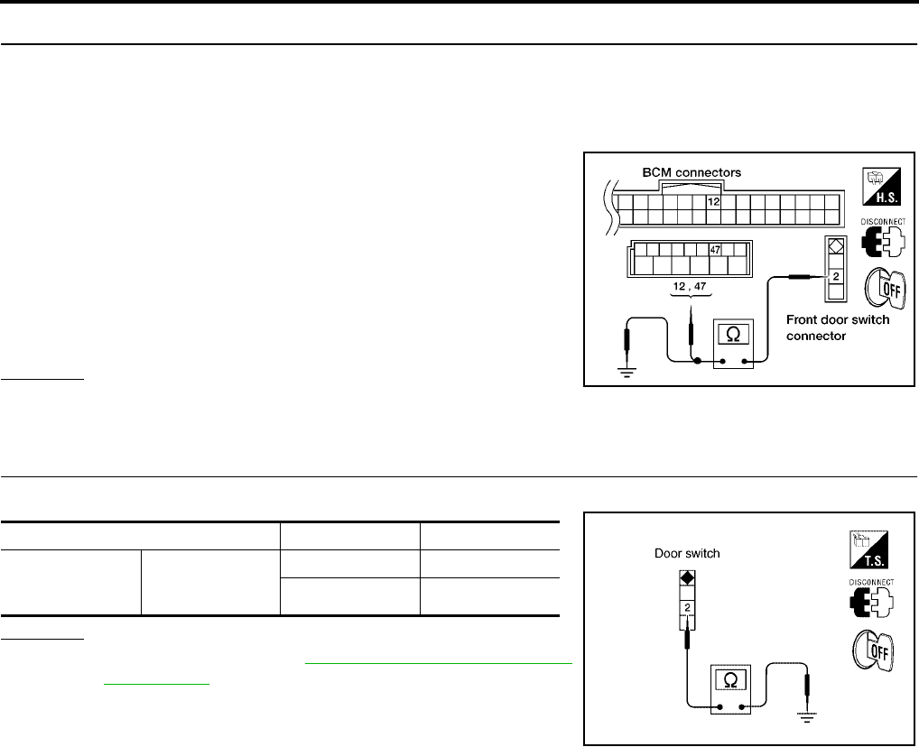
GW-68
POWER WINDOW SYSTEM
Revision: October 2004 2005 Titan
2. CHECK FRONT DOOR SWITCH CIRCUIT
1. Turn ignition switch OFF.
2. Disconnect front door switch LH or RH and BCM.
3. Check continuity between front door switch connector B8 (LH) or B108 (RH) terminal 2 and BCM connec-
tor M19 terminal 47 (LH) or connector M18 terminal 12 (LH).
4. Check continuity between front door switch connector B8 (LH)
or B108 (RH) terminal 2 and ground.
OK or NG
OK >> GO TO 3.
NG >> Repair or replace harness.
3. CHECK DOOR SWITCH
Check continuity between each front door switch terminal 2 and body ground part of front door switch.
OK or NG
OK >> Replace BCM. Refer to BCS-19, "Removal and Installa-
tion of BCM".
NG >> Replace malfunctioning front door switch.
Front door switch LH
2 (SB) - 47 (SB) : Continuity should exist.
Front door switch RH
2 (R/L) - 12 (R/L) : Continuity should exist.
2 (SB or R/L) - Ground : Continuity should not exist.
LIIA0947E
Terminal Door switch Continuity
2
Body ground part
of front door
switch
Pushed No
Released Yes
LIIA0948E
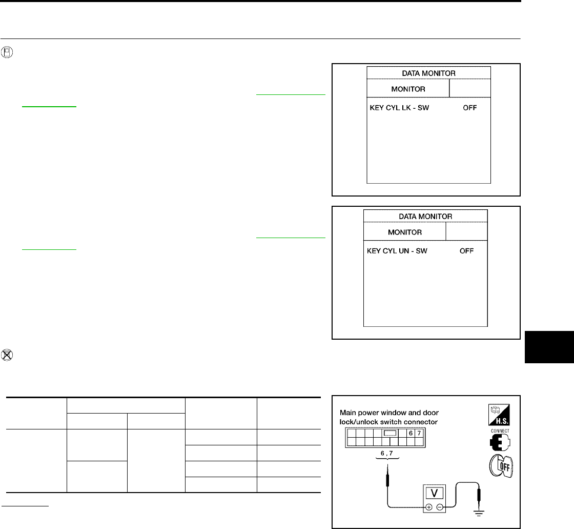
POWER WINDOW SYSTEM
GW-69
C
D
E
F
G
H
J
K
L
M
A
B
GW
Revision: October 2004 2005 Titan
Front Door Lock Assembly LH (Key Cylinder Switch) Check (King Cab)
EIS004D2
1. CHECK FRONT DOOR LOCK ASSEMBLY LH (KEY CYLINDER SWITCH) INPUT SIGNAL
With CONSULT-II
●Check front door lock assembly LH (key cylinder switch) (“KEY
CYL LK SW”)in“DATA MONITOR”mode for “POWER DOOR
LOCK SYSTEM”with CONSULT-II. Refer to BL-33, "DATA
MONITOR".
●Check front door lock assembly LH (key cylinder switch) (“KEY
CYL UN-SW”)in“DATA MONITOR”mode for “POWER DOOR
LOCK SYSTEM”with CONSULT-II. Refer to BL-33, "DATA
MONITOR".
Without CONSULT-II
1. Turn ignition switch OFF.
2. Check voltage between main power window and door lock/unlock switch connector and ground.
OK or NG
OK >> Front door lock assembly LH (key cylinder switch) is OK.
NG >> GO TO 2.
“KEY CYL LK-SW” should be “ON” when key inserted
in door key cylinder is turned to lock.
LIIA0047E
“KEY CYL UN-SW” should be “ON” when key inserted
in door key cylinder was turned to unlock.
LIIA0050E
Connector Terminals (Wire color) Key position Voltage (V)
(Approx.)
(+) (–)
D7
6(L)
Ground
Neutral / Lock 5
Lock 0
7(R) Neutral / Unlock 5
Unlock 0
LIIA1161E

GW-70
POWER WINDOW SYSTEM
Revision: October 2004 2005 Titan
2. CHECK FRONT DOOR LOCK ASSEMBLY LH (KEY CYLINDER SWITCH) CIRCUIT
1. Turn ignition switch OFF.
2. Disconnect main power window and door lock/unlock switch and front door lock assembly LH (key cylin-
der switch).
3. Check continuity between main power window and door lock/
unlock switch connector D7 terminals 6, 7 and front door lock
assembly LH (key cylinder switch) connector D14 terminals 1, 6.
OK or NG
OK >> GO TO 3.
NG >> Repair or replace harness.
3. CHECK FRONT DOOR LOCK ASSEMBLY LH (KEY CYLINDER SWITCH) GROUND
Check continuity between front door lock assembly LH (key cylinder switch) connector D14 terminal 5 and
ground.
OK or NG
OK >> GO TO 4.
NG >> Repair or replace harness.
4. CHECK FRONT DOOR LOCK ASSEMBLY LH (KEY CYLINDER SWITCH)
Check continuity between front door lock assembly LH (key cylinder switch) terminals 1, 6 and 5.
OK or NG
OK >> Replace main power window and door lock/unlock
switch. Refer to EI-32, "Front Door".
NG >> Replace front door lock assembly LH (key cylinder
switch). Refer to BL-127, "Removal and Installation".
7 (R) - 6 (R) : Continuity should exist.
6 (L) - 1 (L) : Continuity should exist.
LIIA1602E
5 (B) - Ground : Continuity should exist.
WIIA0516E
Terminals Key position Continuity
6
5
Neutral / Lock No
Unlock Yes
1Neutral / Unlock No
Lock Yes
WIIA0517E

POWER WINDOW SYSTEM
GW-71
C
D
E
F
G
H
J
K
L
M
A
B
GW
Revision: October 2004 2005 Titan
Front Door Lock Assembly LH (Key Cylinder Switch) Check (Crew Cab)
EIS004D3
1. CHECK FRONT DOOR LOCK ASSEMBLY LH (KEY CYLINDER SWITCH) INPUT SIGNAL
With CONSULT-II
●Check front door lock assembly LH (key cylinder switch) (“KEY
CYL LK SW”)in“DATA MONITOR”mode for “POWER DOOR
LOCK SYSTEM”with CONSULT-II. Refer to BL-33, "DATA
MONITOR".
●Check front door lock assembly LH (key cylinder switch) (“KEY
CYL UN-SW”)in“DATA MONITOR”mode for “POWER DOOR
LOCK SYSTEM”with CONSULT-II. Refer to BL-33, "DATA
MONITOR".
Without CONSULT-II
1. Turn ignition switch OFF.
2. Check voltage between main power window and door lock/unlock switch connector and ground.
OK or NG
OK >> Front door lock assembly LH (key cylinder switch) is OK.
NG >> GO TO 2.
“KEY CYL LK-SW” should be “ON” when key inserted
in door key cylinder is turned to lock.
LIIA0047E
“KEY CYL UN-SW” should be “ON” when key inserted
in door key cylinder was turned to unlock.
LIIA0050E
Connector Terminals (Wire color) Key position Voltage (V)
(Approx.)
(+) (–)
D7
6(R)
Ground
Neutral / Lock 5
Lock 0
4(L) Neutral / Unlock 5
Unlock 0
LIIA1269E
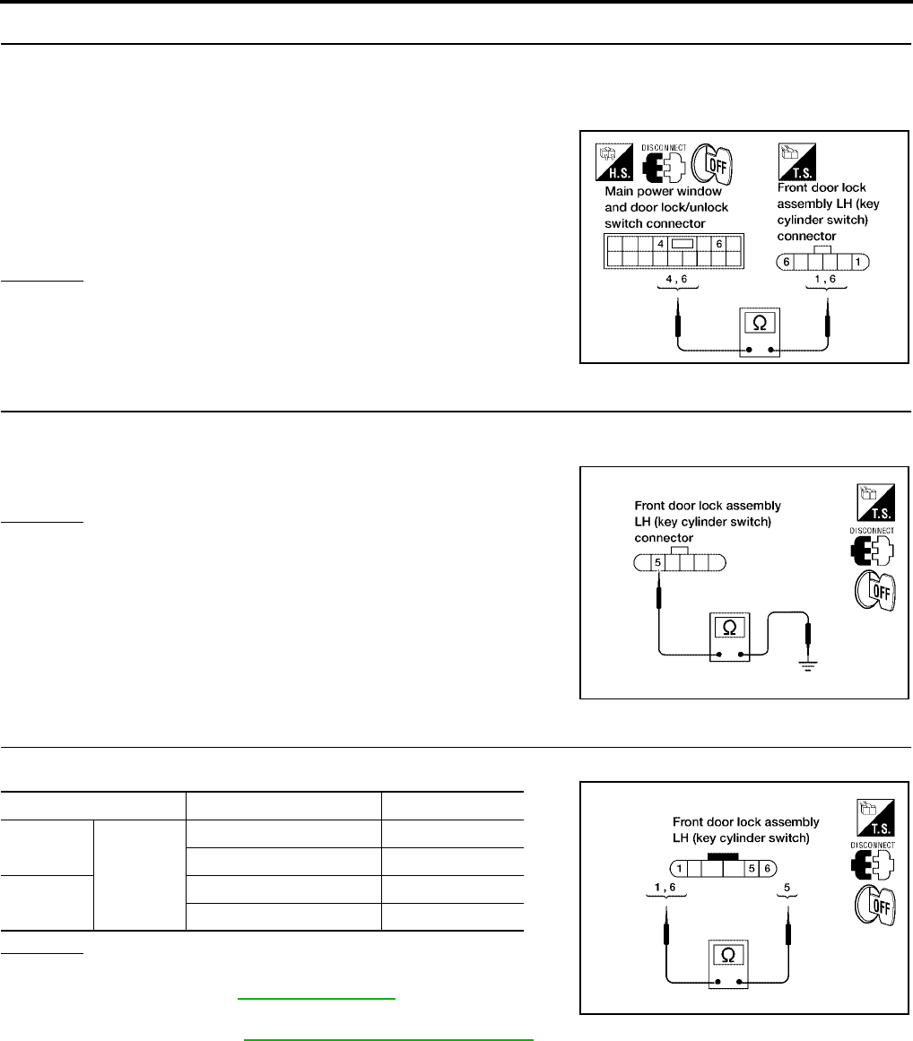
GW-72
POWER WINDOW SYSTEM
Revision: October 2004 2005 Titan
2. CHECK FRONT DOOR LOCK ASSEMBLY LH (KEY CYLINDER SWITCH) CIRCUIT
1. Turn ignition switch OFF.
2. Disconnect main power window and door lock/unlock switch and front door lock assembly LH (key cylin-
der switch).
3. Check continuity between main power window and door lock/
unlock switch connector D7 terminals 4, 6 and front door lock
assembly LH (key cylinder switch) connector D14 terminals 1, 6.
OK or NG
OK >> GO TO 3.
NG >> Repair or replace harness.
3. CHECK FRONT DOOR LOCK ASSEMBLY LH (KEY CYLINDER SWITCH) GROUND
Check continuity between front door lock assembly LH (key cylinder switch) connector D14 terminal 5 and
ground.
OK or NG
OK >> GO TO 4.
NG >> Repair or replace harness.
4. CHECK FRONT DOOR LOCK ASSEMBLY LH (KEY CYLINDER SWITCH)
Check continuity between front door lock assembly LH (key cylinder switch) terminals 1, 6 and 5.
OK or NG
OK >> Replace main power window and door lock/unlock
switch. Refer to EI-32, "Front Door".
NG >> Replace front door lock assembly LH (key cylinder
switch). Refer to BL-127, "Removal and Installation".
6 (R) - 6 (R) : Continuity should exist.
4 (L) - 1 (L) : Continuity should exist.
LIIA1571E
5 (B) - Ground : Continuity should exist.
WIIA0516E
Terminals Key position Continuity
6
5
Neutral / Lock No
Unlock Yes
1Neutral / Unlock No
Lock Yes
WIIA0517E
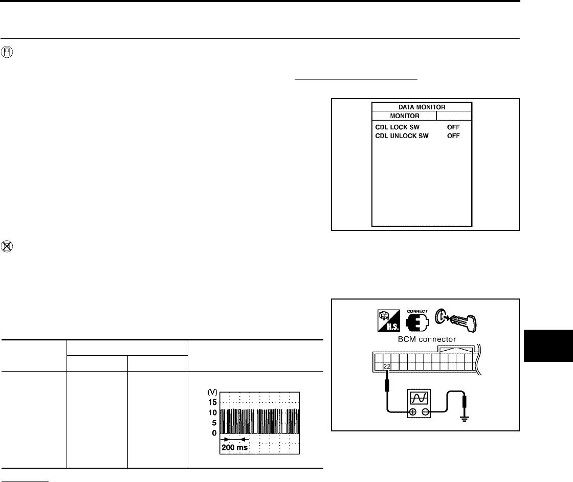
POWER WINDOW SYSTEM
GW-73
C
D
E
F
G
H
J
K
L
M
A
B
GW
Revision: October 2004 2005 Titan
Power Window Serial Link Check Front LH and RH (King Cab)
EIS004D4
1. CHECK SERIAL LINK OUTPUT SIGNAL
With CONSULT-II
Check door lock/unlock switch (CDL LOCK SW”,“CDL UNLOCK SW”)in“DATA MONITOR”mode for
“POWER DOOR LOCK SYSTEM”with CONSULT-II. Refer to BL-33, "DATA MONITOR".
●When door lock and unlock switch is turned to LOCK
●When door lock and unlock switch is turned to UNLOCK
Without CONSULT-II
1. Remove key from ignition switch, and make sure the driver side and passenger side doors are closed.
2. Check the signal between BCM connector and ground with oscilloscope when door lock and unlock
switch (front LH and front RH) is turned to “LOCK”or “UNLOCK”.
3. Make sure signals which are shown in the figure below can be
detected during 10 second just after door lock and unlock switch
(front LH and front RH) is turned to “LOCK”or “UNLOCK”.
OK or NG
OK >> GO TO 2.
NG >> GO TO 3.
CDL LOCK SW : ON
CDL UNLOCK SW : ON
PIIA6538E
Connector Terminals (Wire color) Signal
(+) (–)
M18 22 (G) Ground PIIA6379E
PIIA2344E
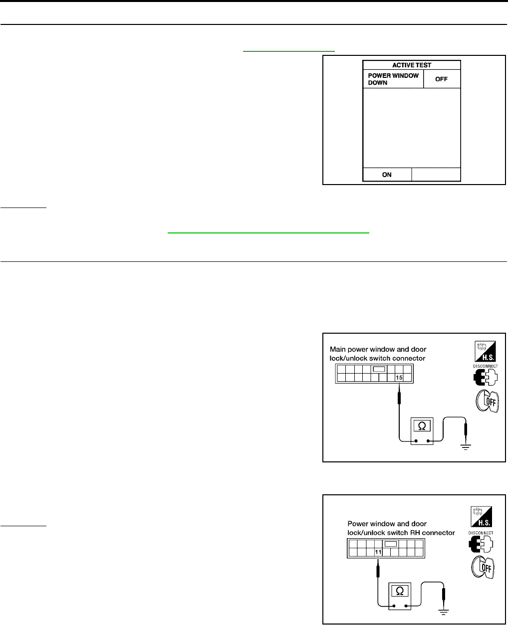
GW-74
POWER WINDOW SYSTEM
Revision: October 2004 2005 Titan
2. CHECK BCM OUTPUT SIGNAL
Check power window serial link (“POWER WINDOW DOWN”)in“ACTIVE TEST”mode for "REMOTE KEY-
LESS ENTRY SYSTEM" with CONSULT-II. Refer to BL-71, "Active Test".
OK or NG
OK >> Further inspection is necessary. Refer to symptom chart.
NG >> Replace BCM. Refer to BCS-19, "Removal and Installation of BCM".
3. CHECK POWER WINDOW SWITCH GROUND
1. Turn ignition switch OFF.
2. Disconnect main power window and door lock/unlock switch and power window and door lock/unlock
switch RH.
3. Check continuity between main power window and door lock/unlock switch connector D7 terminal 15 and
ground.
4. Check continuity between power window and door lock/unlock switch RH connector D105 terminal 11 and
ground.
OK or NG
OK >> GO TO 4.
NG >> Repair or replace harness.
When “ACTIVE TEST” is executed, the driver side
and passenger side windows should lower.
PIIA3080E
15 (B) - Ground : Continuity should exist.
LIIA0604E
11 (B) - Ground : Continuity should exist.
LIIA1270E
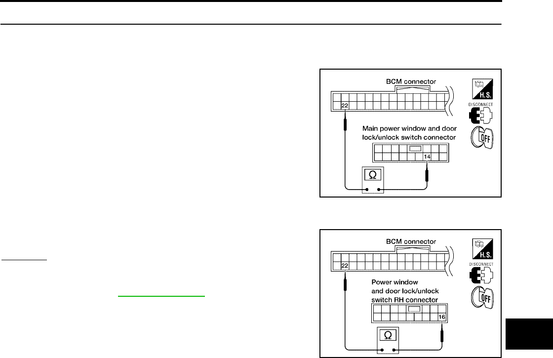
POWER WINDOW SYSTEM
GW-75
C
D
E
F
G
H
J
K
L
M
A
B
GW
Revision: October 2004 2005 Titan
4. CHECK POWER WINDOW SERIAL LINK CIRCUIT
1. Disconnect BCM.
2. Check continuity between BCM connector M18 terminal 22 and main power window and door lock/unlock
switch connector D7 terminal 12.
3. Check continuity between BCM connector M18 terminal 22 and power window and door lock/unlock
switch RH connector D105 terminal 16.
OK or NG
OK >> Replace main power window and door lock/unlock
switch or power window and door lock/unlock switch
RH. Refer to EI-32, "Front Door".
NG >> Repair or replace harness.
22 (G) - 12 (LG/W) : Continuity should exist.
WIIA0518E
22 (G) - 16 (LG/W) : Continuity should exist.
WIIA0519E
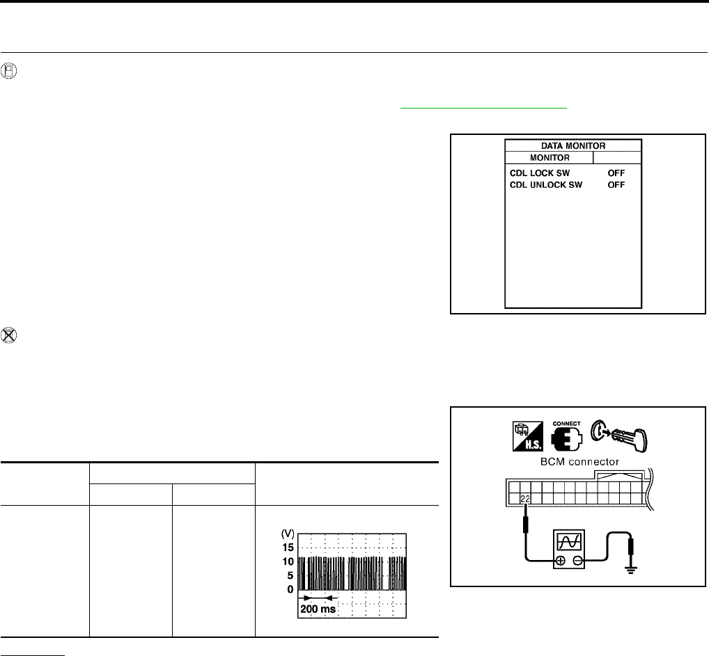
GW-76
POWER WINDOW SYSTEM
Revision: October 2004 2005 Titan
Power Window Serial Link Check Front LH and RH (Crew Cab)
EIS004D5
1. CHECK SERIAL LINK OUTPUT SIGNAL
With CONSULT-II
Check door lock/unlock switch (CDL LOCK SW”,“CDL UNLOCK SW”)in“DATA MONITOR”mode for
“POWER DOOR LOCK SYSTEM”with CONSULT-II. Refer to BL-33, "DATA MONITOR".
●When door lock and unlock switch is turned to LOCK
●When door lock and unlock switch is turned to UNLOCK
Without CONSULT-II
1. Remove key from ignition switch, and make sure the driver side and passenger side doors are closed.
2. Check the signal between BCM connector and ground with oscilloscope when door lock and unlock
switch (front LH and front RH) is turned to “LOCK”or “UNLOCK”.
3. Make sure signals which are shown in the figure below can be
detected during 10 second just after door lock and unlock switch
(front LH and front RH) is turned to “LOCK”or “UNLOCK”.
OK or NG
OK >> GO TO 2.
NG >> GO TO 3.
CDL LOCK SW : ON
CDL UNLOCK SW : ON
PIIA6538E
Connector Terminals (Wire color) Signal
(+) (–)
M18 22 (G) Ground PIIA6379E
PIIA2344E
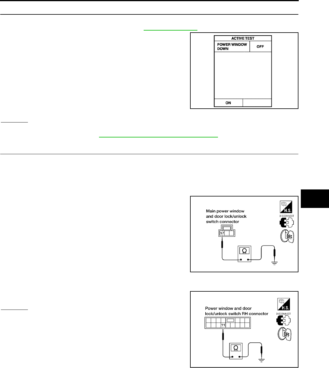
POWER WINDOW SYSTEM
GW-77
C
D
E
F
G
H
J
K
L
M
A
B
GW
Revision: October 2004 2005 Titan
2. CHECK BCM OUTPUT SIGNAL
Check power window serial link (“POWER WINDOW DOWN”)in“ACTIVE TEST”mode for "REMOTE KEY-
LESS ENTRY SYSTEM" with CONSULT-II. Refer to BL-71, "Active Test".
OK or NG
OK >> Further inspection is necessary. Refer to symptom chart.
NG >> Replace BCM. Refer to BCS-19, "Removal and Installation of BCM".
3. CHECK POWER WINDOW SWITCH GROUND
1. Turn ignition switch OFF.
2. Disconnect main power window and door lock/unlock switch and power window and door lock/unlock
switch RH.
3. Check continuity between main power window and door lock/unlock switch connector D8 terminal 17 and
ground.
4. Check continuity between power window and door lock/unlock switch RH connector D105 terminal 11 and
ground.
OK or NG
OK >> GO TO 4.
NG >> Repair or replace harness.
When “ACTIVE TEST” is executed, the driver side
and passenger side windows should lower.
PIIA3080E
17 (B) - Ground : Continuity should exist.
LIIA0392E
11 (B) - Ground : Continuity should exist.
LIIA1270E
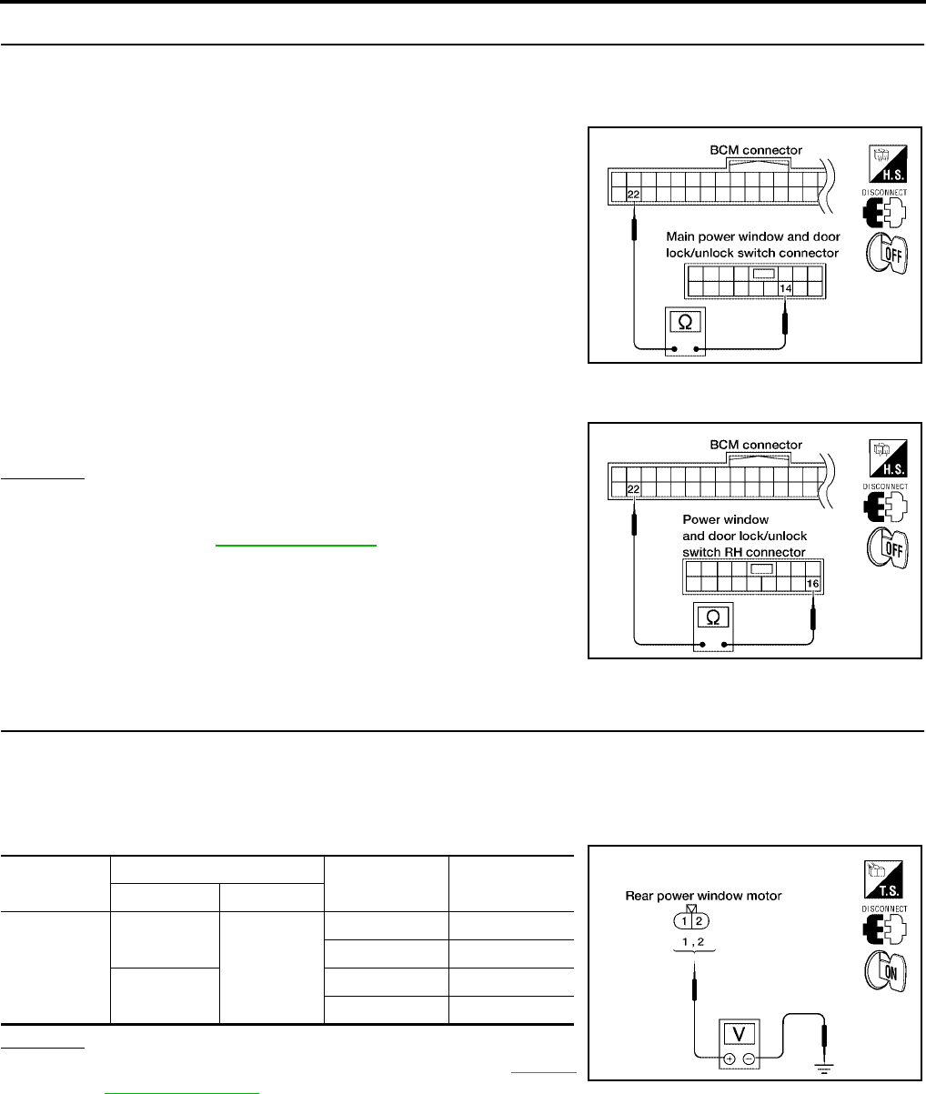
GW-78
POWER WINDOW SYSTEM
Revision: October 2004 2005 Titan
4. CHECK POWER WINDOW SERIAL LINK CIRCUIT
1. Disconnect BCM.
2. Check continuity between BCM connector M18 terminal 22 and main power window and door lock/unlock
switch connector D7 terminal 14.
3. Check continuity between BCM connector M18 terminal 22 and power window and door lock/unlock
switch RH connector D105 terminal 16.
OK or NG
OK >> Replace main power window and door lock/unlock
switch or power window and door lock/unlock switch
RH. Refer to EI-32, "Front Door".
NG >> Repair or replace harness.
Rear Power Window Motor LH Circuit Check (Crew Cab)
EIS004D6
1. CHECK REAR POWER WINDOW SWITCH LH OUTPUT SIGNAL
1. Turn ignition switch OFF.
2. Disconnect rear power window motor LH.
3. Turn ignition switch ON.
4. Check voltage between rear power window motor LH connector D204 terminals 1, 2 and ground.
OK or NG
OK >> Replace rear power window motor LH. Refer to GW-88,
"Rear Door Glass".
NG >> GO TO 2
22 (G) - 14 (LG/W) : Continuity should exist.
WIIA0518E
22 (G) - 16 (LG/W) : Continuity should exist.
WIIA0519E
Connector Terminals (Wire color) Condition Voltage (V)
(Approx.)
(+) (-)
D204
2(L)
Ground
UP Battery voltage
DOWN 0
1(G) UP 0
DOWN Battery voltage
LIIA0323E
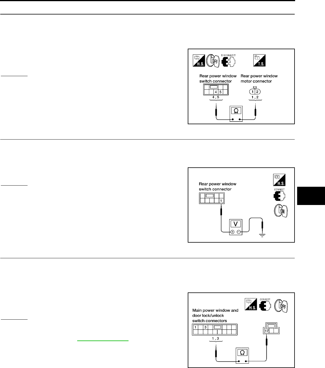
POWER WINDOW SYSTEM
GW-79
C
D
E
F
G
H
J
K
L
M
A
B
GW
Revision: October 2004 2005 Titan
2. CHECK REAR POWER WINDOW MOTOR LH CIRCUIT
1. Turn ignition switch OFF.
2. Disconnect rear power window switch LH.
3. Check continuity between rear power window switch LH connector D203 terminals 4, 5 and rear power
window motor LH connector D204 terminals 1, 2.
OK or NG
OK >> GO TO 3
NG >> Repair or replace harness.
3. CHECK POWER SUPPLY
1. Connect rear power window switch LH.
2. Turn ignition switch ON.
3. Check voltage between rear power window switch LH connector D203 terminal 1 and ground.
OK or NG
OK >> GO TO 4.
NG >> Repair or replace harness.
4. CHECK MAIN POWER WINDOW AND DOOR LOCK/UNLOCK SWITCH OUTPUT SIGNAL
1. Turn ignition switch OFF.
2. Confirm that power window lock switch is in unlocked position.
3. Check continuity between main power window and door lock/unlock switch connector D7 terminals 1, 3
and connector D8 terminal 17.
OK or NG
OK >> Repair or replace harness.
NG >> Replace main power window and door lock/unlock
switch. Refer to EI-32, "Front Door".
4 (G) - 1 (G) : Continuity should exist.
5 (L) - 2 (L) : Continuity should exist.
WIIA0520E
1 (W/L) - Ground : Battery voltage
LIIA0325E
1 (R/Y) – 17 (B) : Continuity should exist.
3 (R/B) – 17 (B) : Continuity should exist.
LIIA0949E
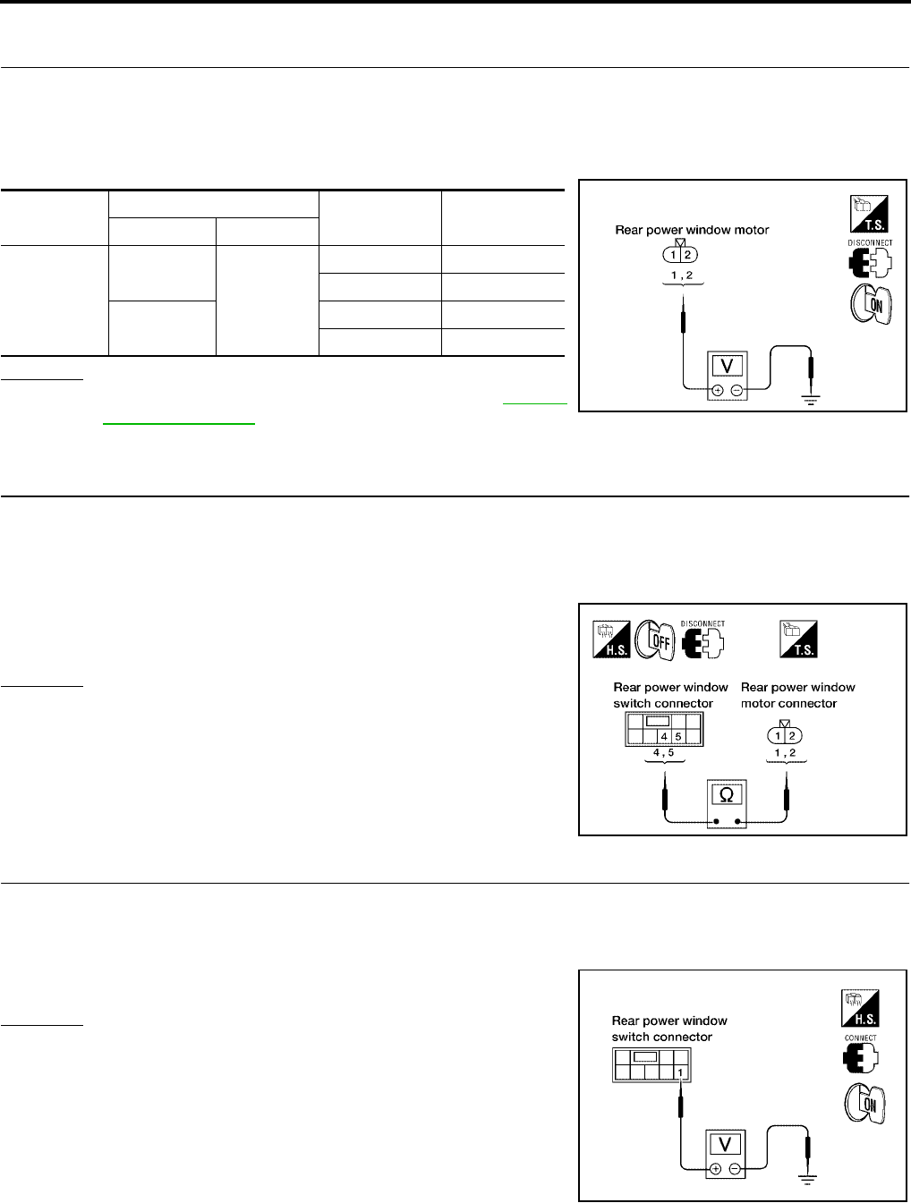
GW-80
POWER WINDOW SYSTEM
Revision: October 2004 2005 Titan
Rear Power Window Motor RH Circuit Check (Crew Cab)
EIS004D7
1. CHECK REAR POWER WINDOW SWITCH RH OUTPUT SIGNAL
1. Turn ignition switch OFF.
2. Disconnect rear power window motor RH.
3. Turn ignition switch ON.
4. Check voltage between rear power window motor RH connector D304 terminals 1, 2 and ground.
OK or NG
OK >> Replace rear power window motor RH. Refer to GW-88,
"Rear Door Glass".
NG >> GO TO 2.
2. CHECK REAR POWER WINDOW MOTOR RH CIRCUIT
1. Turn ignition switch OFF.
2. Disconnect rear power window switch RH.
3. Check continuity between rear power window switch RH connector D303 terminals 4, 5 and rear power
window motor RH connector D304 terminals 1, 2.
OK or NG
OK >> GO TO 3.
NG >> Repair or replace harness.
3. CHECK POWER SUPPLY
1. Connect rear power window switch RH.
2. Turn ignition switch ON.
3. Check voltage between rear power window switch RH connector D303 terminal 1 and ground.
OK or NG
OK >> GO TO 4.
NG >> Repair or replace harness.
Connector Terminals (Wire color) Condition Voltage (V)
(Approx.)
(+) (-)
D304
2(BR)
Ground
UP Battery voltage
DOWN 0
1 (Y/B) UP 0
DOWN Battery voltage
LIIA0323E
4 (Y/B) - 1 (Y/B) : Continuity should exist.
5 (BR) - 2 (BR) : Continuity should exist.
WIIA0520E
1 (W/L) - Ground : Battery voltage
LIIA0325E
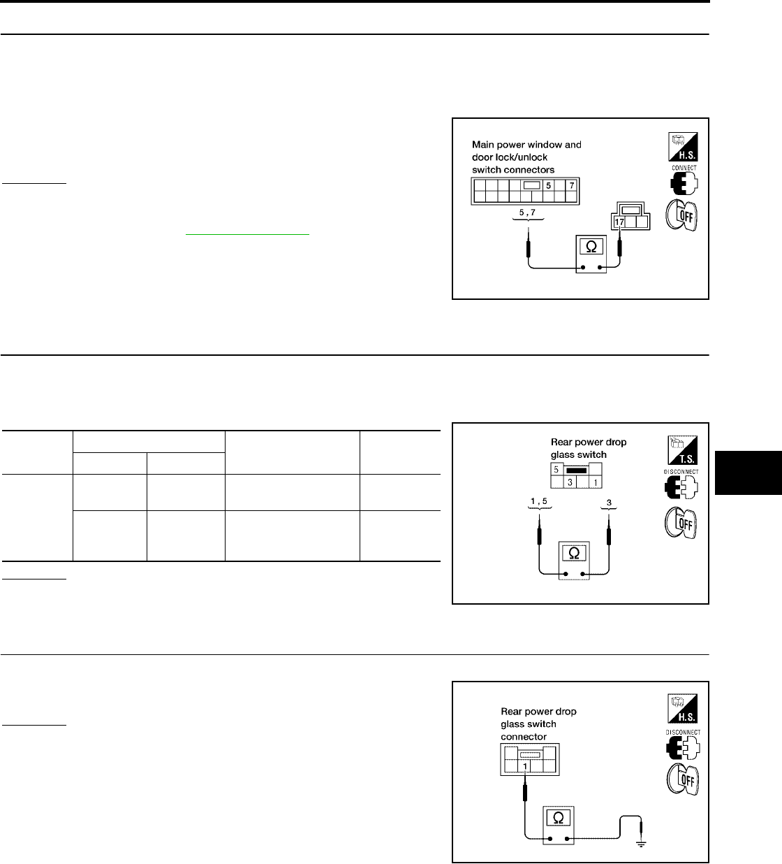
POWER WINDOW SYSTEM
GW-81
C
D
E
F
G
H
J
K
L
M
A
B
GW
Revision: October 2004 2005 Titan
4. CHECK MAIN POWER WINDOW AND DOOR LOCK/UNLOCK SWITCH OUTPUT SIGNAL
1. Turn ignition switch OFF.
2. Confirm that power window lock switch is in unlocked position.
3. Check continuity between main power window and door lock/unlock switch connector D7 terminals 5, 7
and connector D8 terminal 17.
OK or NG
OK >> Repair or replace harness.
NG >> Replace main power window and door lock/unlock
switch. Refer to EI-32, "Front Door".
Rear Power Drop Glass Circuit Check
EIS00590
1. CHECK REAR POWER DROP GLASS SWITCH OPERATION
1. Turn ignition switch OFF.
2. Disconnect rear power drop glass switch.
3. Check continuity between rear power drop glass switch terminals 1, 3 and 5.
OK or NG
OK >> GO TO 2.
NG >> Replace rear power drop glass switch.
2. CHECK REAR POWER DROP GLASS SWITCH GROUND CIRCUIT HARNESS CONTINUITY
Check continuity between rear power drop glass switch connector M156 terminal 3 and ground.
OK or NG
OK >> GO TO 3.
NG >> Repair or replace harness.
5 (L) - 17 (B) : Continuity should exist.
7 (R) - 17 (B) : Continuity should exist.
WIIA0521E
Connector Terminal Condition Continuity
(+) (–)
M156
13
Rear power drop glass
switch is pressed UP. Yes
53
Rear power drop glass
switch is pressed
DOWN.
Yes
LIIA1840E
3 (B) - Ground : Continuity should exist.
LIIA1841E
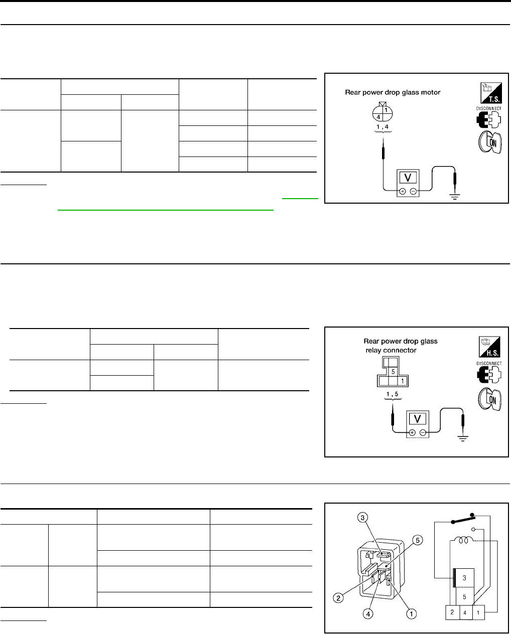
GW-82
POWER WINDOW SYSTEM
Revision: October 2004 2005 Titan
3. CHECK REAR POWER DROP GLASS SIGNAL
1. Disconnect rear power drop glass motor.
2. Turn ignition switch ON.
3. Check voltage between rear power drop glass motor connector B80 terminals 1, 4 and ground.
OK or NG
OK >> Replace rear power drop glass motor. Refer to GW-15,
"REAR WINDOW GLASS AND REGULATOR".
NG >> Repair or replace harness.
Rear Power Drop Glass Up Relay Check
EIS00591
1. CHECK REAR POWER DROP GLASS UP RELAY POWER SUPPLY CIRCUIT
1. Turn ignition switch OFF.
2. Disconnect rear power drop glass up relay.
3. Turn ignition switch ON.
4. Check voltage between rear power drop glass up relay connector and ground.
OK or NG
OK >> GO TO 2.
NG >> Repair or replace harness.
2. CHECK REAR POWER DROP GLASS UP RELAY
Check continuity between rear power drop glass down relay terminals 3 and 4, 3 and 5.
OK or NG
OK >> GO TO 3.
NG >> Replace rear power drop glass up relay.
Connector Terminals (Wire color) Condition Voltage (V)
(Approx.)
(+) (–)
B80
1(L/Y)
Ground
Up Battery voltage
Down 0
4(B/R) Up 0
Down Battery voltage
LIIA1842E
Connector Terminals (Wire color) Voltage (V)
(Approx.)
(+) (–)
M154 1(W/L) Ground Battery voltage
5(L/B)
LIIA1843E
Terminal Condition Continuity
34
12V direct current supply
between terminals 1 and 2 No
No current supply Yes
35
12V direct current supply
between terminals 1 and 2 Yes
No current supply No
WIIA0291E
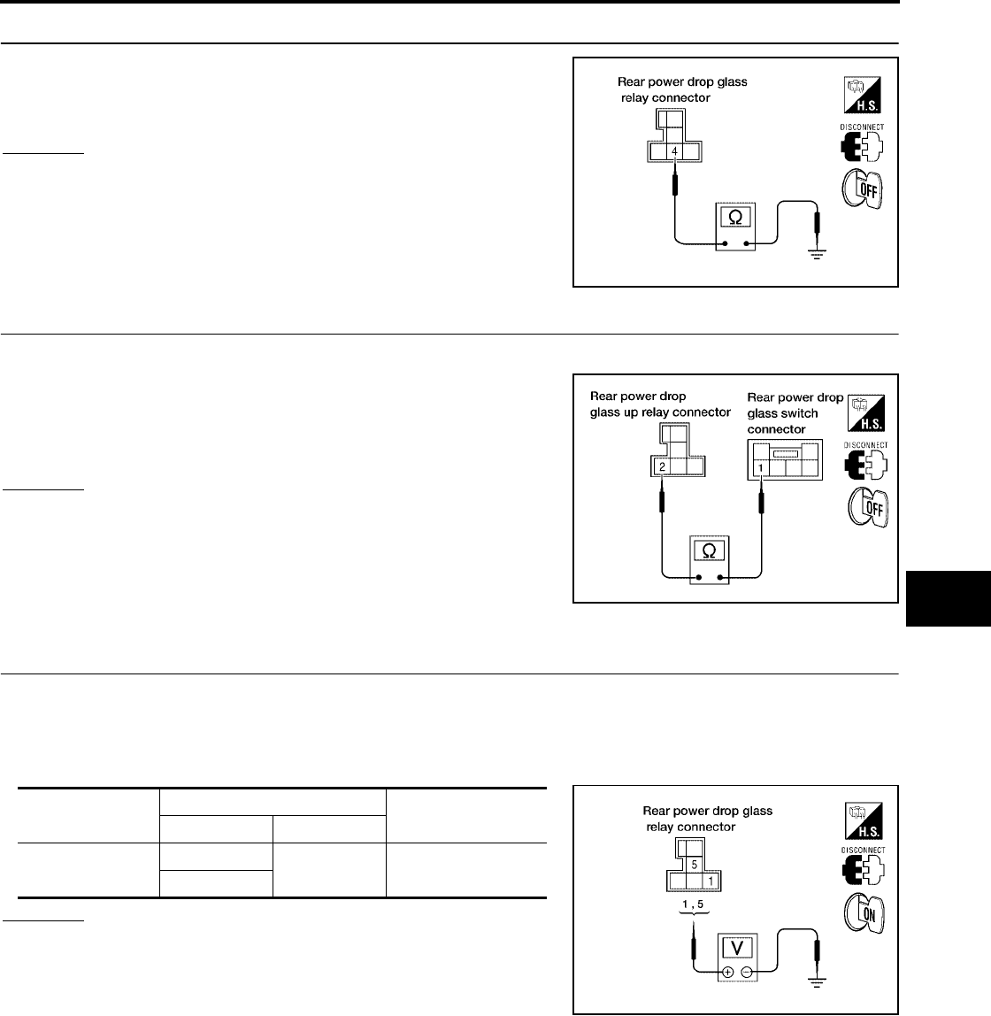
POWER WINDOW SYSTEM
GW-83
C
D
E
F
G
H
J
K
L
M
A
B
GW
Revision: October 2004 2005 Titan
3. CHECK REAR POWER DROP GLASS UP RELAY GROUND CIRCUIT
Check continuity between rear power drop glass up relay connector
M154 terminal 4 and ground.
OK or NG
OK >> GO TO 4.
NG >> Repair or replace harness.
4. CHECK REAR POWER DROP GLASS UP RELAY CIRCUIT
1. Disconnect rear power drop glass switch.
2. Check continuity between rear power drop glass up relay con-
nector M154 terminal 2 and rear power drop glass switch con-
nector M156 terminal 1.
OK or NG
OK >> Replace rear power drop glass switch.
NG >> Repair or replace harness.
Rear Power Drop Glass Down Relay Check
EIS00592
1. CHECK REAR POWER DROP GLASS UP RELAY POWER SUPPLY CIRCUIT
1. Turn ignition switch OFF.
2. Disconnect rear power drop glass down relay.
3. Turn ignition switch ON.
4. Check voltage between rear power drop glass down relay connector and ground.
OK or NG
OK >> GO TO 2.
NG >> Repair or replace harness.
4 (B) - Ground : Continuity should exist.
LIIA1844E
2 (G) - 1 (G) : Continuity should exist.
LIIA1845E
Connector Terminals (Wire color) Voltage (V)
(Approx.)
(+) (–)
M155 1(W/L) Ground Battery voltage
5(L/B)
LIIA1843E
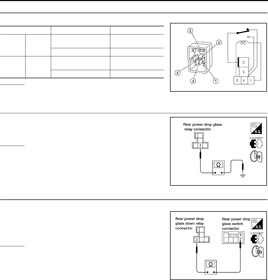
GW-84
POWER WINDOW SYSTEM
Revision: October 2004 2005 Titan
2. CHECK REAR POWER DROP GLASS DOWN RELAY
Check continuity between rear power drop glass down relay terminals 3 and 4, 3 and 5.
OK or NG
OK >> GO TO 3.
NG >> Replace rear power drop glass down relay.
3. CHECK REAR POWER DROP GLASS DOWN RELAY GROUND CIRCUIT
Check continuity between rear power drop glass down relay connec-
tor M155 terminal 4 and ground.
OK or NG
OK >> GO TO 4.
NG >> Repair or replace harness.
4. CHECK REAR POWER DROP GLASS DOWN RELAY CIRCUIT
1. Disconnect rear power drop glass switch.
2. Check continuity between rear power drop glass down relay
connector M155 terminal 2 and rear power drop glass switch
connector M156 terminal 5.
OK or NG
OK >> Replace rear power drop glass switch.
NG >> Repair or replace harness.
Terminal Condition Continuity
34
12V direct current supply
between terminals 1 and 2 No
No current supply Yes
35
12V direct current supply
between terminals 1 and 2 Yes
No current supply No
WIIA0291E
4 (B) - Ground : Continuity should exist.
LIIA1844E
2 (L/W) - 5 (L/W) : Continuity should exist.
WIIA0522E
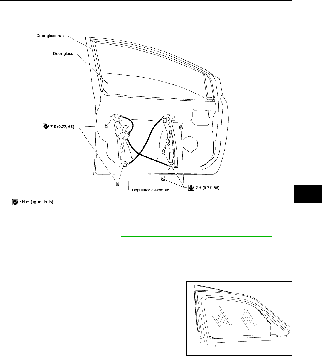
FRONT DOOR GLASS AND REGULATOR
GW-85
C
D
E
F
G
H
J
K
L
M
A
B
GW
Revision: October 2004 2005 Titan
FRONT DOOR GLASS AND REGULATOR PFP:80300
Removal and Installation
EIS00622
FRONT DOOR GLASS
Removal
1. Remove the front door speaker. Refer to AV-65, "Removal and Installation of Front Door Speaker".
2. Remove the hole cover over rear glass bolt.
3. Operate the power window main switch to raise/lower the door window until the glass bolts can be seen.
4. Remove the inside seal.
5. Remove the glass bolts.
6. While holding the front door glass, raise it at the rear end and
pull the glass out of the sash toward the outside of the door.
Installation
Installation is in the reverse order of removal.
LIIA0959E
LIIA1687E
Glass bolts : 6.1 N·m (0.62 kg-m, 54 in-lb)
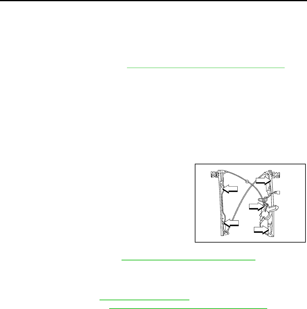
GW-86
FRONT DOOR GLASS AND REGULATOR
Revision: October 2004 2005 Titan
Fitting Inspection
●Check that the glass is securely fit into the glass run groove.
●Lower the glass slightly [approximately 10 to 20 mm (0.39 to 0.79 in)] and check that the clearance to the
sash is parallel. If the clearance between the glass and sash is not parallel, loosen the regulator bolts,
guide rail bolts, and glass and guide rail bolts to correct the glass position.
FRONT DOOR GLASS REGULATOR
Removal
1. Remove the front door speaker. Refer to AV-65, "Removal and Installation of Front Door Speaker".
2. Remove the hole cover over rear glass bolt.
3. Operate the power window main switch to raise/lower the door window until the glass bolts can be seen.
4. Removetheinsideseal.
5. Remove the glass bolts.
6. Raise the front door glass and hold it in place with suitable tool.
7. Disconnect the harness connector from the regulator assembly.
8. Remove the bolts and the regulator assembly.
Disassembly And Assembly
Remove the regulator motor from the regulator assembly.
Inspection After Removal
Check the regulator assembly for the following items. If a malfunc-
tion is detected, replace or grease it.
●Wire wear
●Regulator deformation
●Grease condition for each sliding part
The arrows in the figure show the application points of the body
grease.
Installation
1. Install the regulator assembly. Refer to GW-86, "FRONT DOOR GLASS REGULATOR".
2. Connect the harness connector to the regulator assembly.
3. Align the glass and install the glass bolts.
4. Reset the limit switch. Refer to GW-86, "Setting of Limit Switch".
5. Install front door speaker. Refer to AV-65, "Removal and Installation of Front Door Speaker".
SETTING AFTER INSTALLATION
Setting of Limit Switch
If any of the following work has been done, set the limit switch (integrated in the motor).
●Removal and installation of the regulator.
●Removal and installation of the motor from the regulator.
●Removal and installation of the glass.
●Removal and installation of the glass run.
Resetting
After installing each component, perform the following procedure to reset the limit switch.
LIIA0670E
Glass bolts : 6.1 N·m (0.62 kg-m, 54 in-lb)
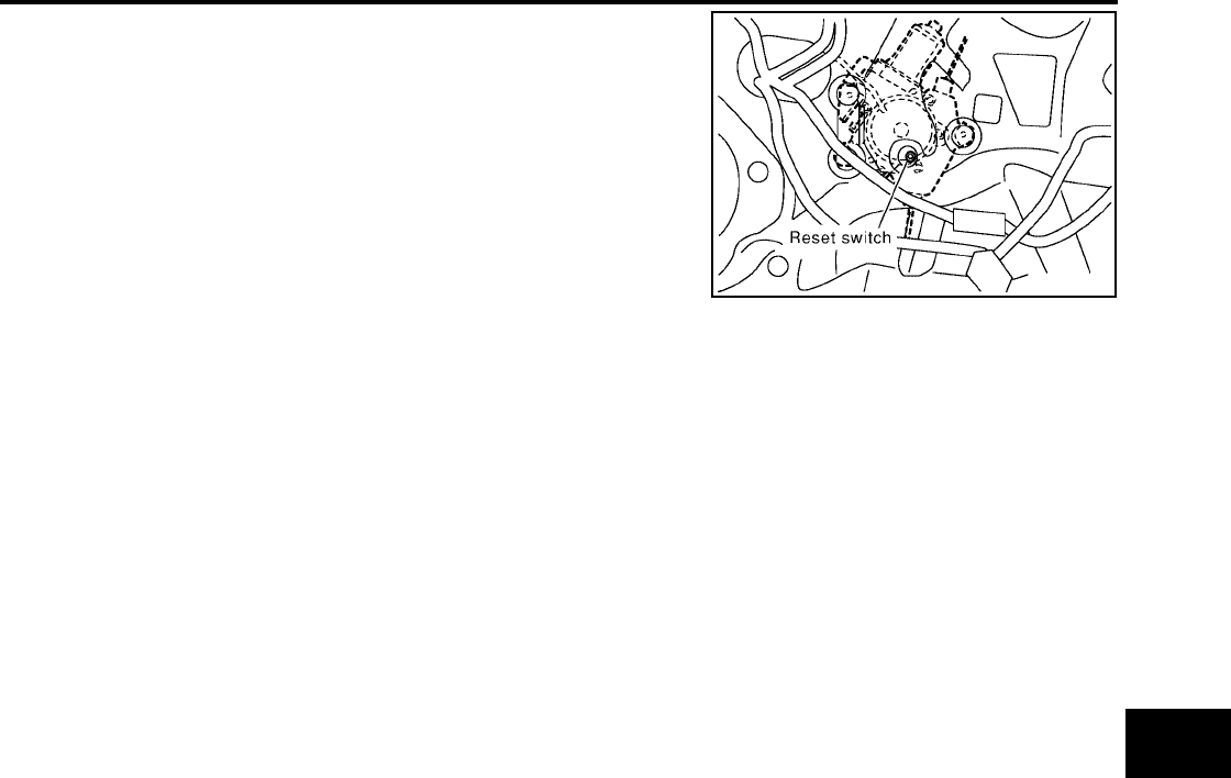
FRONT DOOR GLASS AND REGULATOR
GW-87
C
D
E
F
G
H
J
K
L
M
A
B
GW
Revision: October 2004 2005 Titan
1. Raise the glass to the top position.
2. While pressing and holding the reset switch, lower the glass to
the bottom position.
3. Release the reset switch. Verify that the reset switch returns to
the original position, if not, pull the switch using suitable tool.
4. Raise the glass to the top position.
CAUTION:
Do not operate the glass automatically to raise the glass to the
top position.
SIIA0347E
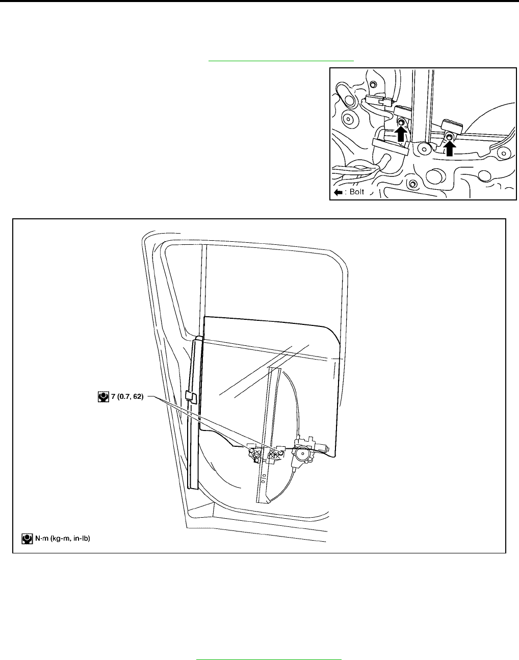
GW-88
REAR DOOR GLASS AND REGULATOR
Revision: October 2004 2005 Titan
REAR DOOR GLASS AND REGULATOR PFP:82300
Rear Door Glass
EIS004DA
REMOVAL
1. Remove the rear door finisher. Refer to EI-33, "Rear Door - Crew Cab".
2. Operate the power window switch to raise/lower the door win-
dow until the glass bolts can be seen.
3. Removetheinsideseal.
4. Remove the glass run from the partition glass.
5. Remove the partition sash bolt (lower) and screw (upper) to
remove the sash.
6. Remove the glass bolts and the glass.
7. Remove the partition glass from the panel.
INSTALLATION
1. Install the partition glass in the panel.
2. Install the partition sash.
3. Install the glass from outside to ensure that it is in both the front and rear glass channels. Tighten glass
the bolts to the specified torque.
4. Install the inside seal.
5. Install the rear door finisher. Refer to EI-33, "Rear Door - Crew Cab".
FITTING INSPECTION
●Check that the glass is securely fit into the glass run groove.
SIIA0290E
LIIA0960E
Glass bolts : 6.1 N·m (0.62 kg-m, 54 in-lb)

REAR DOOR GLASS AND REGULATOR
GW-89
C
D
E
F
G
H
J
K
L
M
A
B
GW
Revision: October 2004 2005 Titan
●Lower the glass slightly [approximately 10 to 20 mm (0.39 to 0.79 in)], and check that the clearance to the
sash is parallel. If the clearance between the glass and sash is not parallel, loosen the regulator bolt,
guide rail bolts, and glass and carrier plate bolts to correct the glass position.
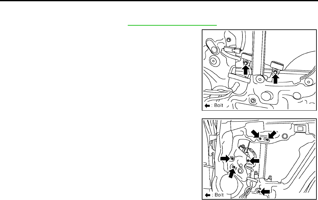
GW-90
REAR DOOR GLASS AND REGULATOR
Revision: October 2004 2005 Titan
Rear Door Glass Regulator
EIS0062K
REMOVAL
1. Remove the rear door finisher. Refer to EI-33, "Rear Door - Crew Cab".
2. Operate the power window switch to raise/lower the door win-
dow until the glass bolts can be seen.
3. Removetheinsideseal.
4. Remove the glass bolts, raise the glass and hold in place with
suitable tool.
5. Remove the bolts and the regulator and guide channel from the
panel.
6. Disconnect the connector for the regulator assembly.
INSPECTION AFTER REMOVAL
Check the regulator assembly for the following items. If a malfunction is detected, replace or grease it.
●Gear wear
●Regulator deformation
●Spring damage
●Grease condition for each sliding part
INSTALLATION
Installation is in the reverse order of removal.
SIIA0290E
SIIA0291E
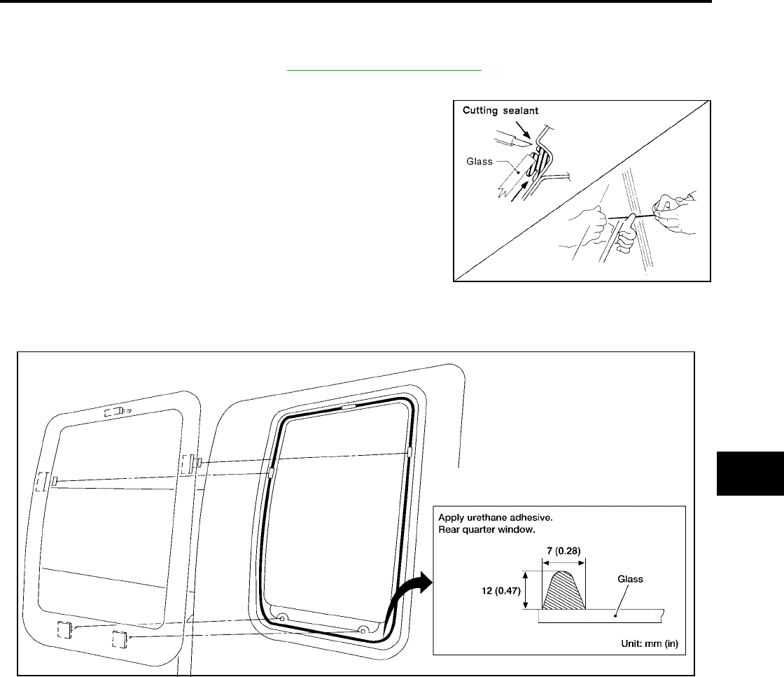
SIDE WINDOW GLASS
GW-91
C
D
E
F
G
H
J
K
L
M
A
B
GW
Revision: October 2004 2005 Titan
SIDE WINDOW GLASS PFP:83300
Removal
EIS004DB
1. Remove the rear door finisher. Refer to EI-34, "Rear Door - King Cab".
2. If the window glass is to be reused, mark the body and the glass with mating marks.
3. Remove glass using piano wire or power cutting tool and an
inflatable pump bag.
WARNING:
When cutting the glass from the vehicle, always wear safety
glasses and heavy gloves to help prevent glass splinters from
entering your eyes or cutting your hands.
CAUTION:
●When the side window glass is to be reused, do not use a
cutting knife or power cutting tool.
●Be careful not to scratch the glass when removing.
●Do not set or stand the glass on its edge. Small chips may
develop into cracks.
Installation
EIS00596
●Use a genuine NISSAN Urethane Adhesive Kit or equivalent and follow the instructions furnished with it.
●While the urethane adhesive is curing, open a door window. This will prevent the glass from being forced
out by passenger compartment air pressure when a door is closed.
●Check gap along bottom to confirm that glass does not contact sheet metal.
●Inform the customer that the vehicle should remain stationary until the urethane adhesive has completely
cured (preferably 24 hours). Curing time varies with temperature and humidity.
●Install removed parts.
WARNING:
●Keep heat and open flames away as primers and adhesive are flammable.
●The materials contained in the kit are harmful if swallowed, and may irritate skin and eyes. Avoid
contact with the skin and eyes.
●Use in an open, well ventilated location. Avoid breathing the vapors. They can be harmful if
inhaled. If affected by vapor inhalation, immediately move to an area with fresh air.
●Driving the vehicle before the urethane adhesive has completely cured may affect the perfor-
mance of the glass in case of an accident.
SBF034B
LIIA1244E

GW-92
SIDE WINDOW GLASS
Revision: October 2004 2005 Titan
CAUTION:
●Do not use an adhesive which is past its usable term. Shelf life of this product is limited to six
months after the date of manufacture. Carefully adhere to the expiration or manufacture date
printed on the box.
●Keep primers and adhesive in a cool, dry place. Ideally, they should be stored in a refrigerator.
●Do not leave primers or adhesive cartridge unattended with their caps open or off.
●The vehicle should not be driven for at least 24 hours or until the urethane adhesive has com-
pletely cured. Curing time varies depending on temperature and humidity. The curing time will
increase under lower temperatures and lower humidities.
Repairing Water Leaks for Side Window Glass
EIS00597
Leaks can be repaired without removing or reinstalling glass.
If water is leaking between urethane adhesive material and body or glass, determine the extent of leakage.
This can be done by applying water to the side window area while pushing glass outward.
To stop leak, apply primer (if necessary) and then urethane adhesive to the leak point.
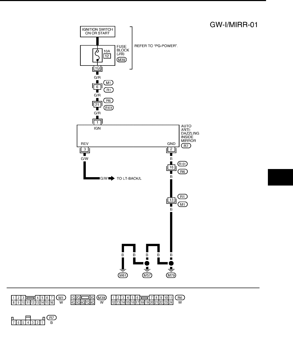
INSIDE MIRROR
GW-93
C
D
E
F
G
H
J
K
L
M
A
B
GW
Revision: October 2004 2005 Titan
INSIDE MIRROR PFP:96321
Wiring Diagram — I/MIRR —
EIS004DC
WIWA0628E
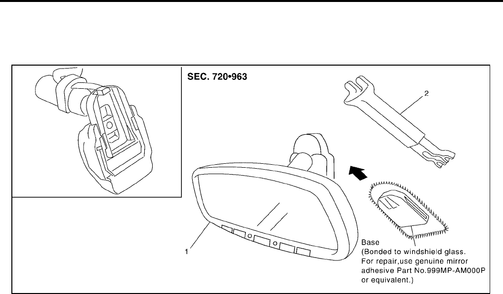
GW-94
INSIDE MIRROR
Revision: October 2004 2005 Titan
Removal and Installation
EIS004DD
1. Remove connector cover.
2. Slide the mirror upward to remove.
3. Disconnect the connector.
Installation is in the reverse order of removal.
1. Inside mirror 2. Inside mirror finisher
LIIA0277E
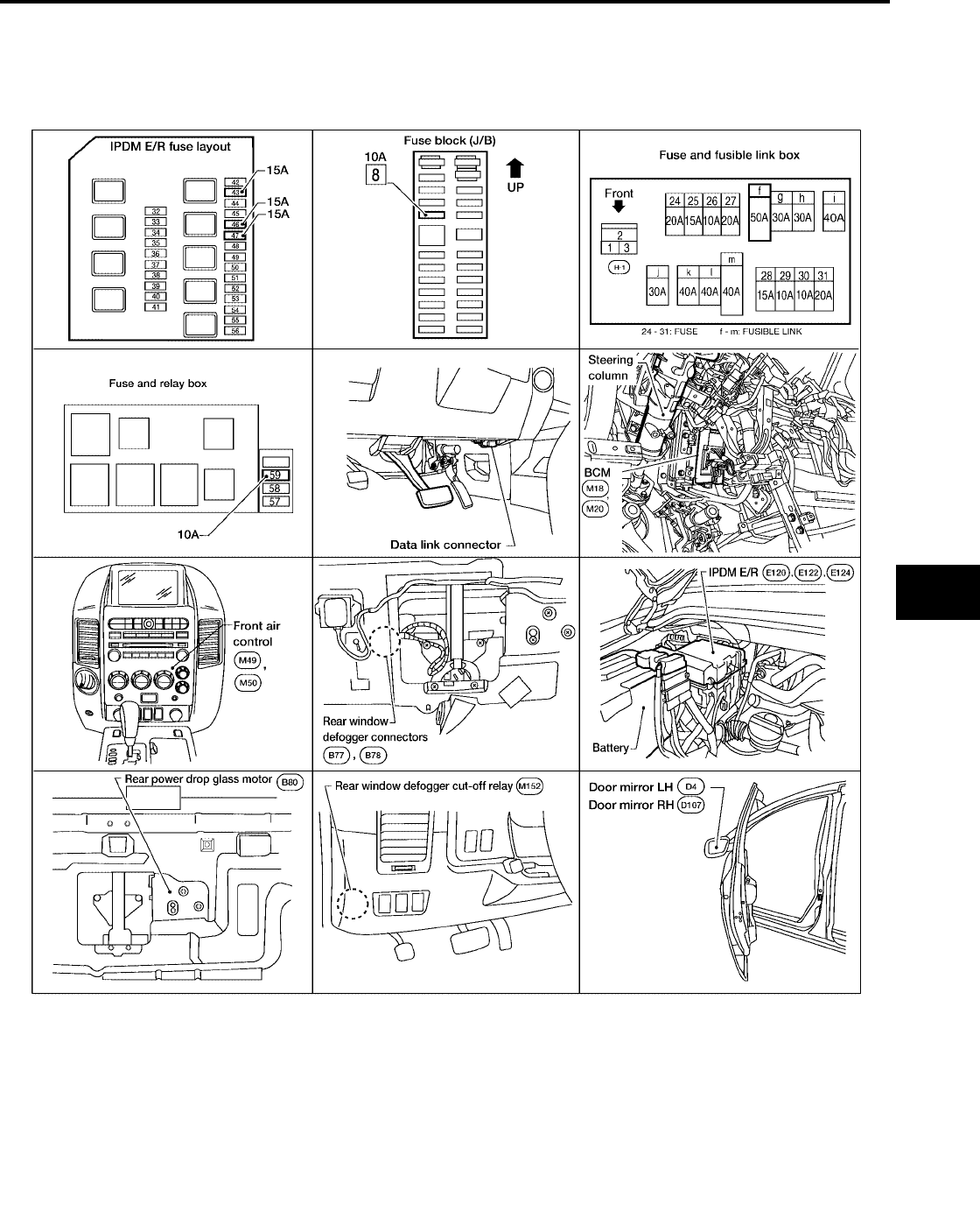
REAR WINDOW DEFOGGER
GW-95
C
D
E
F
G
H
J
K
L
M
A
B
GW
Revision: October 2004 2005 Titan
REAR WINDOW DEFOGGER PFP:25350
Component Parts and Harness Connector Location
EIS0059S
LIIA1986E

GW-96
REAR WINDOW DEFOGGER
Revision: October 2004 2005 Titan
System Description
EIS0059T
The rear window defogger system is controlled by BCM (body control module) and IPDM E/R (intelligent
power distribution module engine room).
The rear window defogger operates only for approximately 15 minutes.
Power is supplied at all times
●through 15A fuse (Nos. 46 and 47, located in the IPDM E/R)
●to rear window defogger relay (located in the IPDM E/R), and
●through 15A fuse (No. 43, located in the IPDM E/R) (with heated mirrors)
●to heated mirror relay (located in the IPDM E/R) (with heated mirrors), and
●through 50A fusible link (letter f, located in the fuse and fusible link box)
●to BCM terminal 70.
With the ignition switch turned to ON or START position, power is supplied
●through ignition switch
●to rear window defogger relay (located in the IPDM E/R), and
●through 10A fuse (No. 59, located in the fuse and relay box)
●to BCM terminal 38, and
●through 10A fuse [No. 8, located in the fuse block (J/B)]
●to front air control terminal 11.
Ground is supplied
●to BCM terminal 67
●to front air control terminal 1
●through body grounds M57, M61 and M79
●to IPDM E/R terminals 38 and 59
●through body grounds E9, E15 and E24.
When front air control (rear window defogger switch) is turned to ON, ground is supplied
●to BCM terminal 9
●through front air control terminal 11
●through front air control terminal 1
●through body grounds M57, M61 and M79.
Then rear window defogger switch is illuminated.
Then BCM recognizes that rear window defogger switch is turned to ON.
Then it sends rear window defogger switch signals to IPDM E/R and display control unit (with navigation) or
display unit (without navigation) via CAN communication (CAN-H, CAN-L).
When display control unit (with navigation) or display unit (without navigation) receives rear window defogger
switch signals, and is displayed on the screen.
When IPDM E/R receives rear window defogger switch signals, ground is supplied
●to rear window defogger relay (located in the IPDM E/R)
●through IPDM E/R terminals 38 and 59
●through body grounds E9, E15 and E24.
Then, rear window defogger relay is energized.
With power and ground supplied, rear window defogger filaments heat and defog the rear window.
If the rear power drop glass is lowered while the rear window defogger is ON, the rear window defogger will
turn OFF. The rear window defogger will turn ON when the rear power drop glass is raised to the closed posi-
tion if the rear window defogger switch is ON.
When rear window defogger relay is turned to ON, (with door mirror defogger), power is supplied
●through heated mirror relay (located in the IPDM E/R)
●through IPDM E/R terminal 23
●to door mirror defogger (LH and RH) terminal 10 (with automatic drive positioner), terminal 4 (without
automatic drive positioner).
Door mirror defogger (LH and RH) is grounded through body grounds M57, M61 and M79.
With power and ground supplied, rear window defogger filaments heat and defog the rear window and door
mirror defogger filaments heat and defog the mirror.

REAR WINDOW DEFOGGER
GW-97
C
D
E
F
G
H
J
K
L
M
A
B
GW
Revision: October 2004 2005 Titan
CAN Communication System Description
EIS0059U
Refer to LAN-7, "CAN COMMUNICATION"
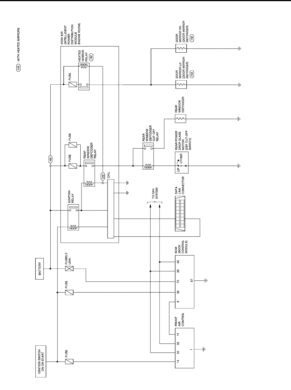
GW-98
REAR WINDOW DEFOGGER
Revision: October 2004 2005 Titan
Schematic
EIS0059V
WIWA0624E
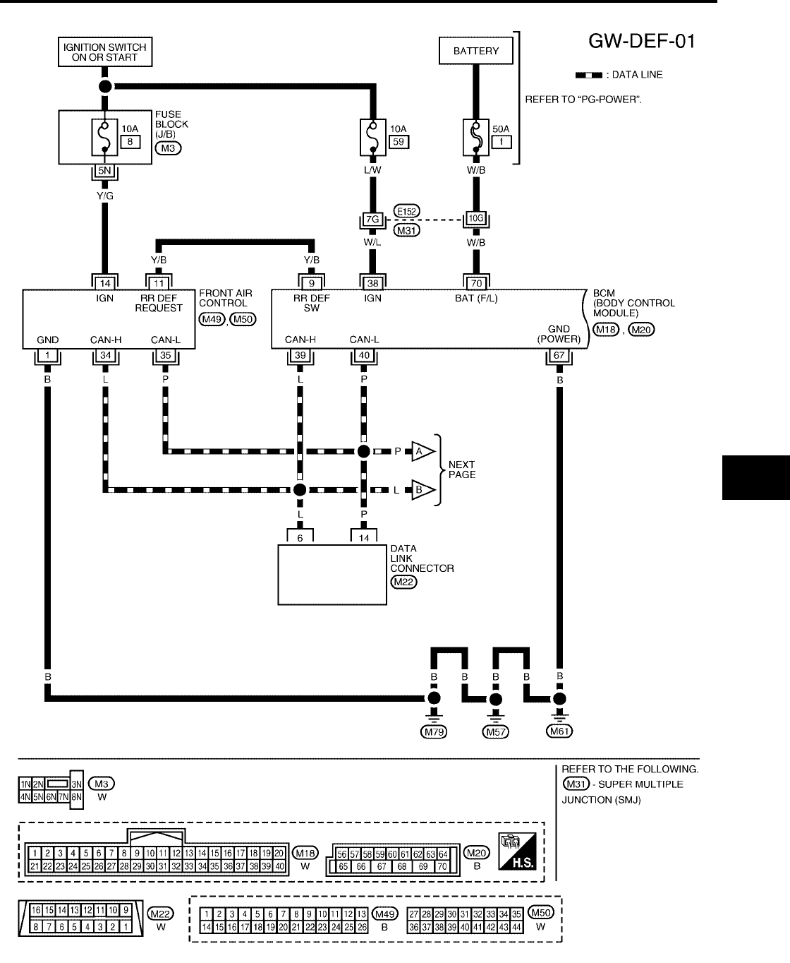
REAR WINDOW DEFOGGER
GW-99
C
D
E
F
G
H
J
K
L
M
A
B
GW
Revision: October 2004 2005 Titan
Wiring Diagram — DEF —
EIS0059W
WIWA0625E
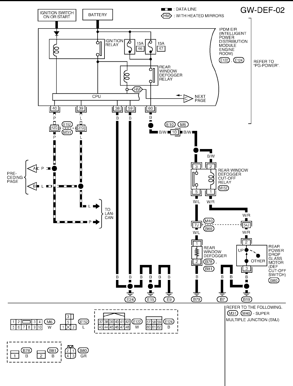
GW-100
REAR WINDOW DEFOGGER
Revision: October 2004 2005 Titan
WIWA0626E
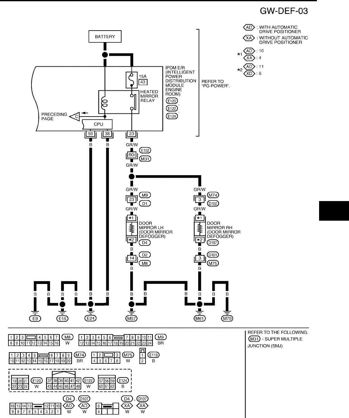
REAR WINDOW DEFOGGER
GW-101
C
D
E
F
G
H
J
K
L
M
A
B
GW
Revision: October 2004 2005 Titan
WIWA0627E

GW-102
REAR WINDOW DEFOGGER
Revision: October 2004 2005 Titan
Terminal and Reference Values for BCM
EIS0059X
Terminal and Reference Values for IPDM E/R
EIS0059Y
Work Flow
EIS0059Z
1. Check the symptom and customer's requests.
2. Understand the outline of system. Refer to GW-96, "System Description".
3. According to the trouble diagnosis chart, repair or replace the cause of the malfunction. Refer to GW-104,
"Trouble Diagnoses Symptom Chart".
4. Does rear window defogger operate normally? YES: GO TO 5, NO: GO TO 3.
5. Inspection End.
Terminal Wire color Item Condition Voltage (V)
(Approx.)
9Y/B
Rear window defogger
switch signal
When rear window defogger switch is pressed. 0
When rear window defogger switch is OFF. 5
38 W/L Ignition switch ON or START Ignition switch (ON or START position) Battery voltage
39 L CAN-H ——
40 P CAN-L ——
67 B Ground —0
70 W/B Battery power supply —Battery voltage
Terminal Wire color Item Condition Voltage (V)
(Approx.)
23 GR/W Heated mirror relay output
signal
When rear window defogger switch is ON. Battery voltage
When rear window defogger switch is OFF. 0
38 B Ground (Power) —0
39 L CAN-H ——
40 P CAN-L ——
59 B Ground (Signal) —0
60 B Rear window defogger output
signal
When rear window defogger switch is ON. Battery voltage
When rear window defogger switch is OFF. 0
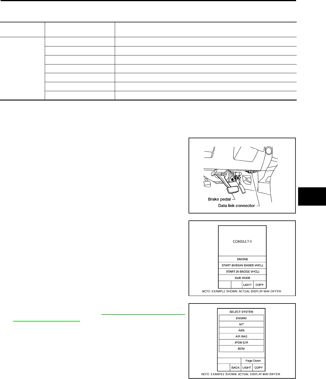
REAR WINDOW DEFOGGER
GW-103
C
D
E
F
G
H
J
K
L
M
A
B
GW
Revision: October 2004 2005 Titan
CONSULT-II Function (BCM)
EIS005A0
CONSULT-II can display each diagnostic item using the diagnostic test modes shown following.
CONSULT-II BASIC OPERATION PROCEDURE
CAUTION:
If CONSULT-II is used with no connection of CONSULT-II CONVERTER, malfunctions might be
detected in self-diagnosis depending on control unit which carry out CAN communication.
1. Turn ignition switch OFF.
2. Connect CONSULT-II and CONSULT-II CONVERTER to data
link connector.
3. Turn ignition switch ON.
4. Touch “START (NISSAN BASED VHCL)”.
5. Touch “BCM”.
If “BCM”is not indicated, go to GI-38, "CONSULT-II Data Link
Connector (DLC) Circuit".
BCM diagnostic
test item Diagnostic mode Content
Inspection by part
WORK SUPPORT Changes setting of each function.
DATA MONITOR Displays BCM input/output data in real time.
ACTIVE TEST Operation of electrical loads can be checked by sending drive signal to them.
SELF-DIAG RESULTS Displays BCM self-diagnosis results.
CAN DIAG SUPPORT MNTR The results of transmit/receive diagnosis of CAN communication can be read.
ECU PART NUMBER BCM part number can be read.
CONFIGURATION Performs BCM configuration read/write functions.
BBIA0369E
BCIA0029E
BCIA0030E
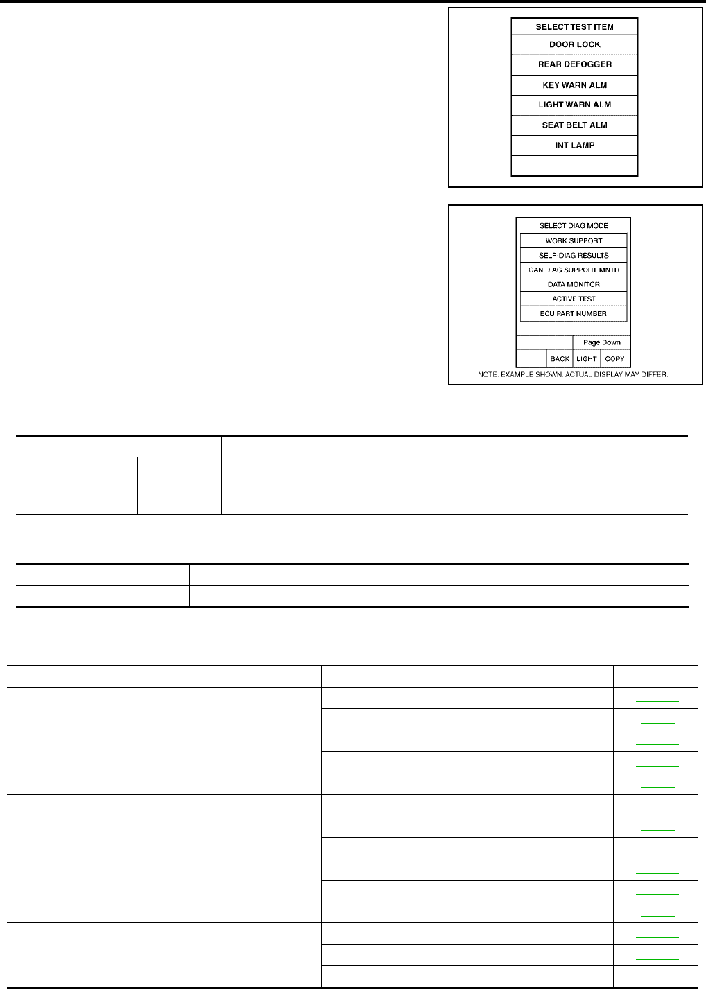
GW-104
REAR WINDOW DEFOGGER
Revision: October 2004 2005 Titan
6. Touch “REAR DEFOGGER”.
7. Select diagnosis mode, “DATA MONITOR”and “ACTIVE TEST”.
DATA MONITOR
Display Item List
ACTIVE TEST
Display Item List
Trouble Diagnoses Symptom Chart
EIS005A1
●Make sure other systems using the signal of the following systems operate normally.
LIIA0153E
BCIA0031E
Monitor item “Operation”Content
REAR DEF SW “ON/OFF”Displays “Press (ON)/others (OFF)”status determined with the rear window defogger
switch.
IGN ON SW “ON/OFF”Displays “IGN (ON)/OFF”status determined with the ignition switch signal.
Test item Content
REAR WINDOW DEFOGGER Gives a drive signal to the rear window defogger to activate it.
Symptom Diagnoses / Service procedure Refer to page
Rear window defogger and door mirror defoggers do not
operate. (With heated mirrors)
1. BCM power supply and ground circuit check GW-106
2. IPDM E/R auto active test check PG-22
3. Rear window defogger switch circuit check GW-107
4. Rear window defogger circuit check GW-108
5. Replace IPDM E/R PG-28
Rear window defogger does not operate.
(Without heated mirrors)
1. BCM power supply and ground circuit check GW-106
2. IPDM E/R auto active test check PG-22
3. Rear window defogger switch circuit check GW-107
4. Rear window defogger circuit check GW-108
5. Filament check GW-118
6. Replace IPDM E/R PG-28
Rear window defogger does not operate but both of door
mirror defoggers operate. (With heated mirrors)
1. Rear window defogger circuit check GW-108
2. Filament check GW-118
3. Replace IPDM E/R PG-28
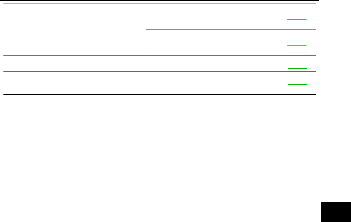
REAR WINDOW DEFOGGER
GW-105
C
D
E
F
G
H
J
K
L
M
A
B
GW
Revision: October 2004 2005 Titan
Both door mirror defoggers do not operate but rear window
defogger operates. (With heated mirrors)
1. Door mirror defogger power supply circuit check GW-110,
GW-112
2. Replace IPDM E/R PG-28
Door mirror LH defogger does not operate. 1. Door mirror LH defogger circuit check GW-114,
GW-115
Door mirror RH defogger does not operate. 1. Door mirror RH defogger circuit check GW-116,
GW-117
Rear window defogger switch does not light, and rear win-
dow defogger is not shown on the display, but rear window
defogger operates.
1. Rear window defogger switch circuit check GW-107
Symptom Diagnoses / Service procedure Refer to page
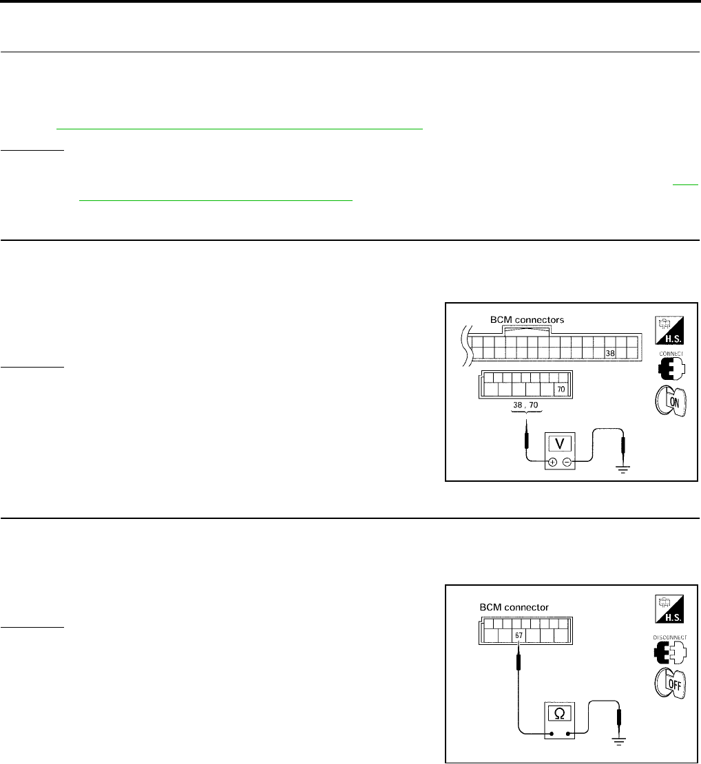
GW-106
REAR WINDOW DEFOGGER
Revision: October 2004 2005 Titan
BCM Power Supply and Ground Circuit Check
EIS005A2
1. CHECK FUSE AND FUSIBLE LINK
●Check 10A fuse (No.59, located in the fuse and relay box)
●Check 50A fusible link (letter f, located in the fuse and fusible link box)
NOTE:
Refer to GW-106, "BCM Power Supply and Ground Circuit Check".
OK or NG
OK >> GO TO 2.
NG >> If fuse is blown, be sure to eliminate cause of malfunction before installing new fuse. Refer to PG-
4, "POWER SUPPLY ROUTING CIRCUIT".
2. CHECK POWER SUPPLY CIRCUIT
1. Turn ignition switch ON.
2. Check voltage between BCM connector M18, M20 terminals 38, 70
and ground.
OK or NG
OK >> GO TO 3.
NG >> Repair or replace harness.
3. CHECK GROUND CIRCUIT
1. Turn ignition switch OFF.
2. Disconnect BCM.
3. Check continuity between BCM connector M20 terminal 67 and ground.
OK or NG
OK >> BCM power supply and ground circuit is OK.
NG >> Repair or replace harness.
70 (W/B) - Ground : Battery voltage
38 (W/L) - Ground : Battery voltage
LIIA0914E
67 (B) - Ground : Continuity should exist.
LIIA0915E
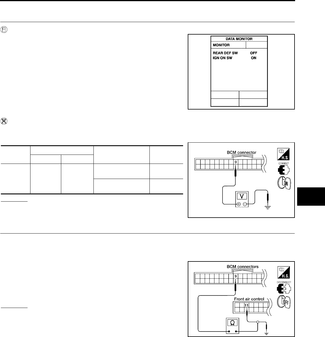
REAR WINDOW DEFOGGER
GW-107
C
D
E
F
G
H
J
K
L
M
A
B
GW
Revision: October 2004 2005 Titan
Rear Window Defogger Switch Circuit Check
EIS005A3
1. CHECK REAR WINDOW DEFOGGER SWITCH OPERATION
With CONSULT-II
Check (“REAR DEF SW”,“IGN ON SW”) in DATA MONITOR mode
with CONSULT-II.
Without CONSULT-II
1. Turn ignition switch ON.
2. Check voltage between BCM connector and ground.
OK or NG
OK >> Rear window defogger switch check is OK.
NG >> GO TO 2.
2. CHECK REAR WINDOW DEFOGGER SWITCH CIRCUIT HARNESS CONTINUITY
1. Turn ignition switch OFF.
2. Disconnect BCM and front air control.
3. Check continuity between BCM connector M18 terminal 9 and front air control connector M49 terminal 11.
4. Check continuity between BCM connector M18 terminal 9 and
ground
OK or NG
OK >> GO TO 3.
NG >> Repair or replace harness.
When rear window defogger switch is turned to ON
REAR DEF SW : ON
When ignition switch is turned to ON
IGNONSW :ON
PIIA2373E
Connector Terminal (Wire color) Condition Voltage (V)
(Approx.)
(+) (–)
M18 9 (Y/B) Ground
Rear window defogger
switch is pressed. 0
Rear window defogger
switch is OFF. 5
WIIA0523E
9 (Y/B) - 11 (Y/B) : Continuity should exist.
9 (Y/B) - Ground : Continuity should not exist.
LIIA2035E
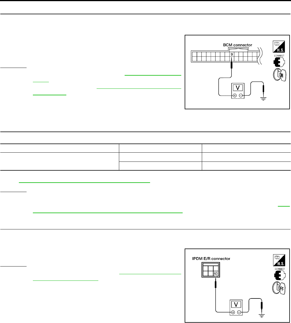
GW-108
REAR WINDOW DEFOGGER
Revision: October 2004 2005 Titan
3. CHECK BCM OUTPUT SIGNAL
1. Connect BCM.
2. Turn ignition switch ON.
3. Check voltage between BCM connector M18 terminal 9 and
ground.
OK or NG
OK >> Replace front air control. Refer to MTC-95, "CONTROL
UNIT".
NG >> Replace BCM. Refer to BCS-19, "Removal and Installa-
tion of BCM".
Rear Window Defogger Circuit Check
EIS005A4
1. CHECK FUSES
Check if any of the following fuses for IPDM E/R are blown.
NOTE:
Refer to GW-95, "Component Parts and Harness Connector Location".
OK or NG
OK >> GO TO 2.
NG >> If fuse is blown, be sure to eliminate cause of malfunction before installing new fuse, refer to GW-
95, "Component Parts and Harness Connector Location".
2. CHECK REAR WINDOW DEFOGGER RELAY OUTPUT SIGNAL
1. Turn ignition switch ON.
2. Check voltage between IPDM E/R connector E124 terminal 60 and ground.
OK or NG
OK >> Replace IPDM E/R. Refer to PG-28, "Removal and
Installation of IPDM E/R".
NG >> GO TO 3.
9 (Y/B) - Ground : Approx. 5
WIIA0523E
COMPONENT PARTS AMPERE FUSE NO.
IPDM E/R 15A 46
15A 47
60 (B) - Ground : Battery voltage
WIIA0525E
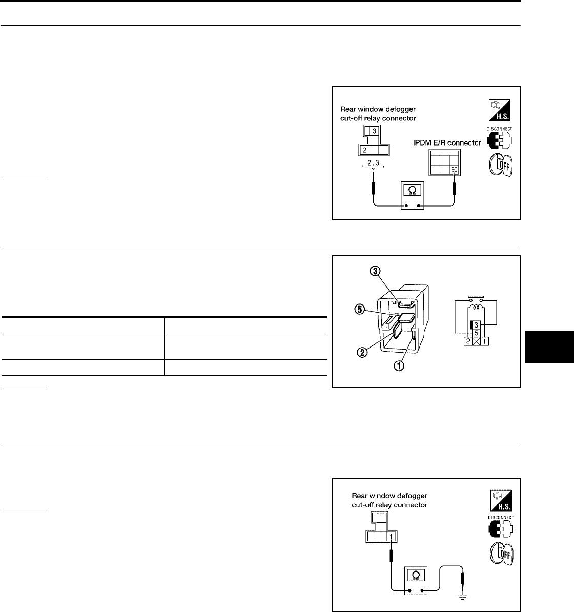
REAR WINDOW DEFOGGER
GW-109
C
D
E
F
G
H
J
K
L
M
A
B
GW
Revision: October 2004 2005 Titan
3. CHECK REAR WINDOW DEFOGGER POWER CIRCUIT HARNESS CONTINUITY
1. Turn ignition switch OFF.
2. Disconnect IPDM E/R and rear window defogger cut-off relay.
3. Check continuity between IPDM E/R connector E124 terminal 60 and rear window defogger cut-off relay
connector M152 terminal 2.
4. Check continuity between IPDM E/R connector E124 terminal
60 and rear window defogger cut-off relay connector M152 ter-
minal 3.
OK or NG
OK >> GO TO 4.
NG >> Repair or replace harness.
4. INSPECTION OF REAR POWER WINDOW DEFOGGER CUT-OFF RELAY
1. Turn ignition switch OFF.
2. Disconnect rear window defogger cut-off relay.
3. Check continuity between rear window defogger cut-off relay
terminals 3 and 5.
OK or NG
OK >> GO TO 5.
NG >> Replace rear window defogger cut-out relay.
5. CHECK REAR WINDOW DEFOGGER CUT-OFF RELAY GROUND CIRCUIT
1. Place rear power drop glass in the closed (UP) position.
2. Check continuity between rear window defogger cut-off relay connector M152 terminal 1 and ground.
OK or NG
OK >> GO TO 7.
NG >> GO TO 6.
2 (B/W) - 60 (B/W) : Continuity should exist.
3 (B/W) - 60 (B/W) : Continuity should exist.
LIIA1987E
Condition Continuity
12V direct current supply between
terminals 1 and 2 Yes
No current supply No
SEF145X
1 (W/R) - Ground : Continuity should exist.
LIIA1988E
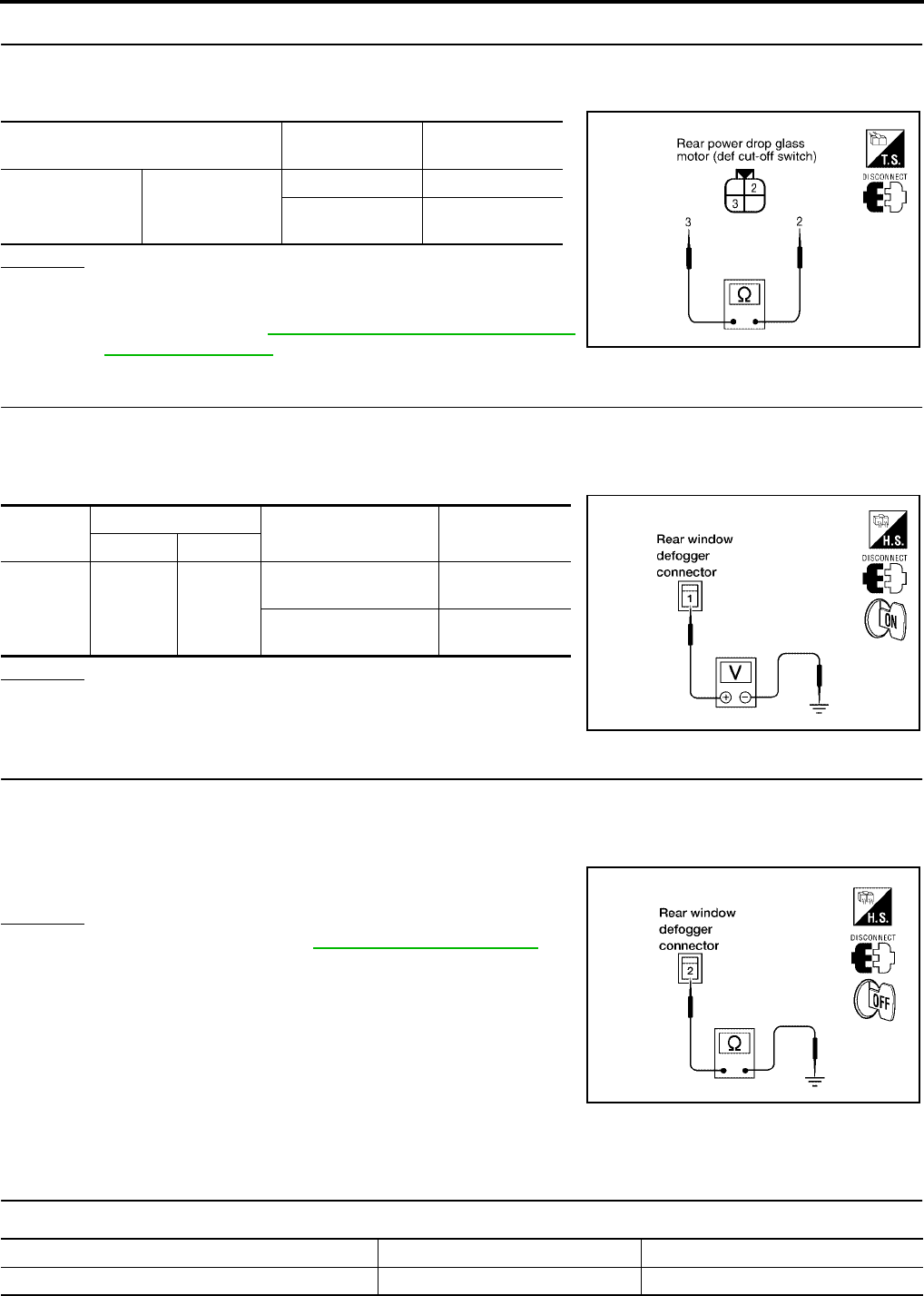
GW-110
REAR WINDOW DEFOGGER
Revision: October 2004 2005 Titan
6. CHECK REAR POWER DROP GLASS MOTOR (DEF CUT-OFF SWITCH)
1. Disconnect rear power drop glass motor (def cut-off switch).
2. Check continuity between rear power drop glass motor (def cut-off switch) terminals 2 and 3.
OK or NG
OK >> Repair or replace harness.
NG >> Replace rear power drop glass motor (def cut-off
switch). Refer to GW-15, "REAR WINDOW GLASS
AND REGULATOR".
7. CHECK REAR WINDOW DEFOGGER POWER SUPPLY CIRCUIT
1. Disconnect rear window defogger.
2. Turn ignition switch ON.
3. Check voltage between rear window defogger connector B77 terminal 1 and ground.
OK or NG
OK >> GO TO 8.
NG >> Repair or replace harness.
8. CHECK REAR WINDOW DEFOGGER GROUND CIRCUIT
1. Disconnect rear window defogger ground.
2. Turn ignition switch OFF.
3. Check continuity between rear window defogger connector B78 terminal 2 and ground.
OK or NG
OK >> Check filament. Refer to GW-118, "Filament Check".
●If filament is OK.
Check the condition of the harness and the connector.
●If filament is NG.
Repair filament.
NG >> Repair or replace harness.
Door Mirror Defogger Power Supply Circuit Check (Without Automatic Drive
Positioner)
EIS005A6
1. CHECK FUSE
Check if the following fuse for IPDM E/R is blown.
Terminal Rear power drop
glass position Continuity
23
Closed (UP) Yes
Open (DOWN)
more than 18 mm No
LIIA1989E
Connector Terminal (Wire color) Condition Voltage (V)
(Approx.)
(+) (–)
B77 1 (W/L) Ground
Rear window defogger
switch ON. Battery voltage
Rear window defogger
switch OFF. 0
LIIA1847E
2 (B) - Ground : Continuity should exist.
LIIA1848E
COMPONENT PARTS AMPERE FUSE NO.
IPDM E/R 15A 43
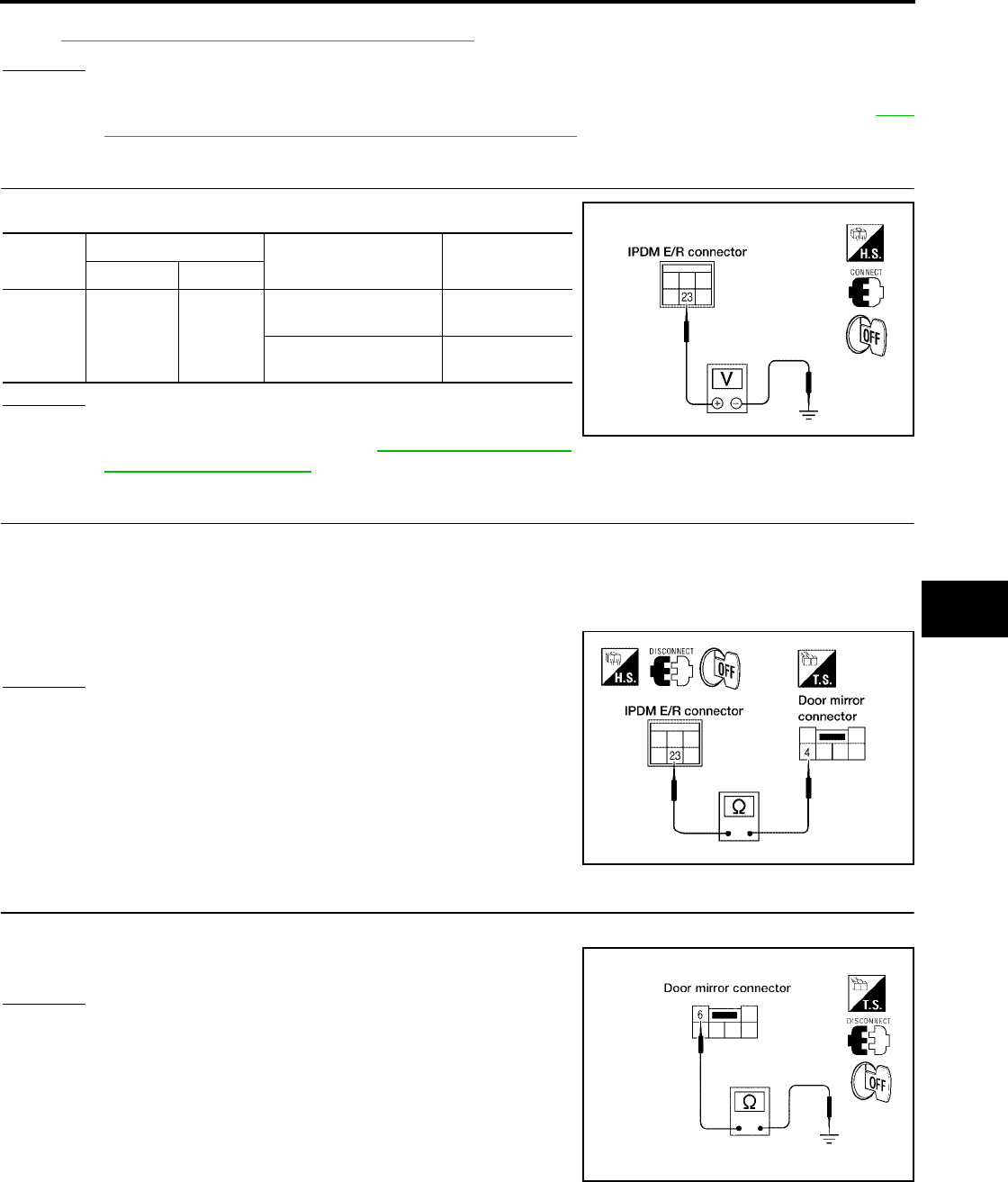
REAR WINDOW DEFOGGER
GW-111
C
D
E
F
G
H
J
K
L
M
A
B
GW
Revision: October 2004 2005 Titan
NOTE:
Refer to GW-95, "Component Parts and Harness Connector Location".
OK or NG
OK >> GO TO 2.
NG >> If fuse is blown, be sure to eliminate cause of malfunction before installing new fuse. Refer to GW-
95, "Component Parts and Harness Connector Location".
2. CHECK DOOR MIRROR DEFOGGER POWER SUPPLY CIRCUIT
Check voltage between IPDM E/R connector and ground.
OK or NG
OK >> GO TO 3.
NG >> Replace IPDM E/R. Refer to PG-28, "Removal and
Installation of IPDM E/R".
3. CHECK DOOR MIRROR DEFOGGER CIRCUIT
1. Turn ignition switch OFF.
2. Disconnect IPDM E/R and door mirror LH or RH.
3. Check continuity between IPDM E/R connector E120 terminal 23 and door mirror connector D4 (LH) or
D107 (RH) terminal 4.
OK or NG
OK >> GO TO 4.
NG >> Repair or replace harness.
4. CHECK DOOR MIRROR DEFOGGER GROUND CIRCUIT
Check continuity between each door mirror connector D4 (LH) or D107 (RH) terminal 6 and ground.
OK or NG
OK >> GO TO 5.
NG >> Repair or replace harness.
Connec-
tor
Terminal (Wire color) Condition Voltage (V)
(Approx.)
(+) (–)
E120 23 (GR/W) Ground
Rear window defogger
switch ON Battery voltage
Rear window defogger
switch OFF 0
WIIA0526E
23 (GR/W) - 4 (GR/W) : Continuity should exist.
WIIA0527E
6 (B) - Ground : Continuity should exist.
LIIA0970E
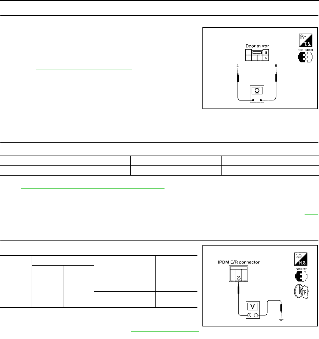
GW-112
REAR WINDOW DEFOGGER
Revision: October 2004 2005 Titan
5. CHECK DOOR MIRROR DEFOGGER
Check continuity between each door mirror terminals 4 and 6.
OK or NG
OK >> Repair or replace harness.
NG >> Replace malfunctioning door mirror LH or RH. Refer to
GW-124, "Door Mirror Assembly".
Door Mirror Defogger Power Supply Circuit Check (With Automatic Drive Posi-
tioner)
EIS005A7
1. CHECK FUSE
Check if the following fuse for IPDM E/R is blown.
NOTE:
Refer to GW-95, "Component Parts and Harness Connector Location".
OK or NG
OK >> GO TO 2.
NG >> If fuse is blown, be sure to eliminate cause of malfunction before installing new fuse. Refer to GW-
95, "Component Parts and Harness Connector Location".
2. CHECK DOOR MIRROR DEFOGGER POWER SUPPLY CIRCUIT
Check voltage between IPDM E/R connector and ground.
OK or NG
OK >> GO TO 3.
NG >> Replace IPDM E/R. Refer to PG-28, "Removal and
Installation of IPDM E/R".
4 - 6 : Continuity should exist.
WIIA0528E
COMPONENT PARTS AMPERE FUSE NO.
IPDM E/R 15A 43
Connector Terminal (Wire color) Condition Voltage (V)
(Approx.)
(+) (–)
E120 23 (GR/W) Ground
Rear window defogger
switch ON Battery voltage
Rear window defogger
switch OFF 0
WIIA0526E
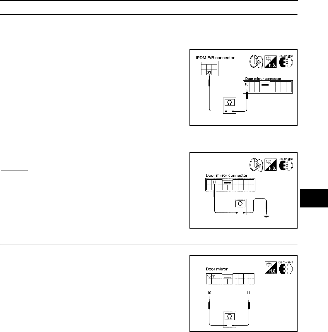
REAR WINDOW DEFOGGER
GW-113
C
D
E
F
G
H
J
K
L
M
A
B
GW
Revision: October 2004 2005 Titan
3. CHECK DOOR MIRROR DEFOGGER CIRCUIT
1. Turn ignition switch OFF.
2. Disconnect IPDM E/R and door mirror LH or RH.
3. Check continuity between IPDM E/R connector E120 terminal 23 and door mirror connector D4 (LH) or
D107 (RH) terminal 10.
OK or NG
OK >> GO TO 4.
NG >> Repair or replace harness.
4. CHECK DOOR MIRROR DEFOGGER GROUND CIRCUIT
Check continuity between each door mirror connector D4 (LH) or D107 (RH) terminal 11 and ground.
OK or NG
OK >> GO TO 5.
NG >> Repair or replace harness.
5. CHECK DOOR MIRROR DEFOGGER
Check continuity between each door mirror terminals 10 and 11.
OK or NG
OK >> Repair or replace harness.
NG >> Replace malfunctioning door mirror LH or RH.
23 (GR/W) - 10 (GR/W) : Continuity should exist.
WIIA0529E
11 (B) - Ground : Continuity should exist.
WIIA0530E
10 - 11 : Continuity should exist.
WIIA0531E
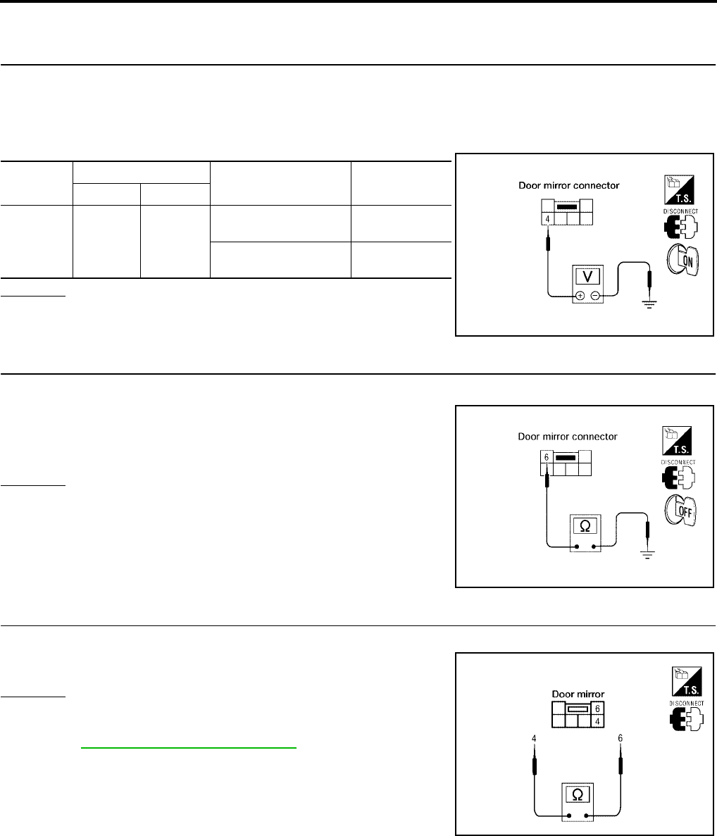
GW-114
REAR WINDOW DEFOGGER
Revision: October 2004 2005 Titan
Door Mirror LH Defogger Circuit Check (Without Automatic Drive Positioner)
EIS005A8
1. CHECK DOOR MIRROR DEFOGGER POWER SUPPLY CIRCUIT
1. Turn ignition switch OFF.
2. Disconnect door mirror LH.
3. Turn ignition switch ON.
4. Check voltage between door mirror LH connector and ground.
OK or NG
OK >> GO TO 2.
NG >> Repair or replace harness.
2. CHECK DOOR MIRROR DEFOGGER GROUND CIRCUIT
1. Turn ignition switch OFF.
2. Check continuity between door mirror LH connector D4 terminal
6 and ground.
OK or NG
OK >> GO TO 3.
NG >> Repair or replace harness.
3. CHECK DOOR MIRROR DEFOGGER
Check continuity between each door mirror terminals 4 and 6.
OK or NG
OK >> Repair or replace harness.
NG >> Replace malfunctioning door mirror LH or RH. Refer to
GW-124, "Door Mirror Assembly".
Connector Terminal (Wire color) Condition Voltage (V)
(Approx.)
(+) (–)
D4 4 (GR/W) Ground
Rear window defogger
switch ON Battery voltage
Rear window defogger
switch OFF 0
WIIA0532E
6 (B) - Ground : Continuity should exist.
LIIA0970E
4 - 6 : Continuity should exist.
WIIA0528E
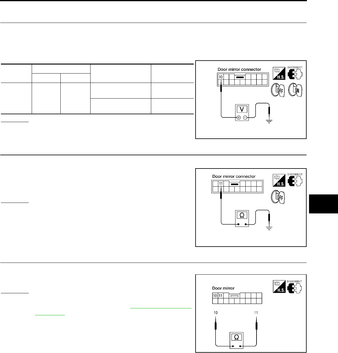
REAR WINDOW DEFOGGER
GW-115
C
D
E
F
G
H
J
K
L
M
A
B
GW
Revision: October 2004 2005 Titan
Door Mirror LH Defogger Circuit Check (With Automatic Drive Positioner)
EIS005A9
1. CHECK DOOR MIRROR DEFOGGER POWER SUPPLY CIRCUIT
1. Turn ignition switch OFF.
2. Disconnect door mirror LH.
3. Turn ignition switch ON.
4. Check voltage between door mirror LH connector and ground.
OK or NG
OK >> GO TO 2.
NG >> Repair or replace harness.
2. CHECK DOOR MIRROR DEFOGGER GROUND CIRCUIT
1. Turn ignition switch OFF.
2. Check continuity between door mirror LH connector D4 terminal
11 and ground.
OK or NG
OK >> GO TO 3.
NG >> Repair or replace harness.
3. CHECK DOOR MIRROR DEFOGGER
Check continuity between door mirror terminals 10 and 11.
OK or NG
OK >> Repair or replace harness.
NG >> Replace door mirror LH. Refer to GW-124, "Door Mirror
Assembly".
Connector Terminal (Wire color) Condition Voltage (V)
(Approx.)
(+) (–)
D4 10
(GR/W) Ground
Rear window defogger
switch ON Battery voltage
Rear window defogger
switch OFF 0
LIIA1456E
11 (B) - Ground : Continuity should exist.
LIIA1458E
10 - 11 : Continuity should exist.
WIIA0531E
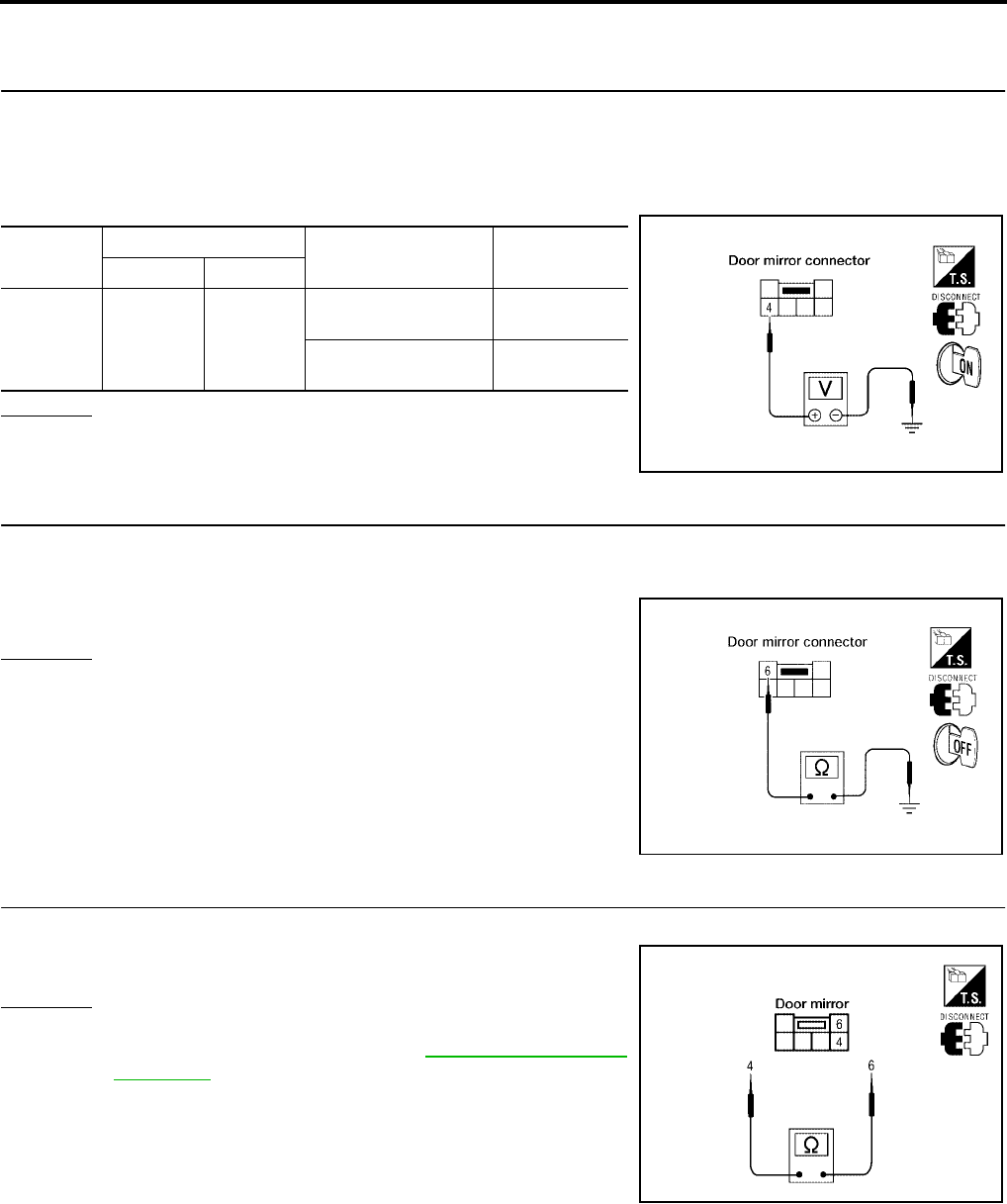
GW-116
REAR WINDOW DEFOGGER
Revision: October 2004 2005 Titan
Door Mirror RH Defogger Circuit Check (Without Automatic Drive Positioner)
EIS005AA
1. CHECK DOOR MIRROR DEFOGGER POWER SUPPLY CIRCUIT
1. Turn ignition switch OFF.
2. Disconnect door mirror RH.
3. Turn ignition switch ON.
4. Check voltage between door mirror RH connector and ground.
OK or NG
OK >> GO TO 2.
NG >> Repair or replace harness.
2. CHECK DOOR MIRROR DEFOGGER GROUND CIRCUIT
1. Turn ignition switch OFF.
2. Check continuity between door mirror RH connector D107 terminal 6 and ground.
OK or NG
OK >> GO TO 3.
NG >> Repair or replace harness.
3. CHECK DOOR MIRROR DEFOGGER
Check continuity between each door mirror terminals 4 and 6.
OK or NG
OK >> Repair or replace harness.
NG >> Replace door mirror RH. Refer to GW-124, "Door Mirror
Assembly".
Connector Terminal (Wire color) Condition Voltage (V)
(Approx.)
(+) (–)
D107 4 (GR/W) Ground
Rear window defogger
switch ON Battery voltage
Rear window defogger
switch OFF 0
WIIA0532E
6 (B) - Ground : Continuity should exist.
LIIA0970E
4 - 6 : Continuity should exist.
WIIA0528E
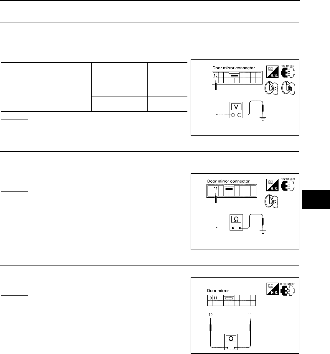
REAR WINDOW DEFOGGER
GW-117
C
D
E
F
G
H
J
K
L
M
A
B
GW
Revision: October 2004 2005 Titan
Door Mirror RH Defogger Circuit Check (With Automatic Drive Positioner)
EIS005AB
1. CHECK DOOR MIRROR DEFOGGER POWER SUPPLY CIRCUIT
1. Turn ignition switch OFF.
2. Disconnect door mirror RH.
3. Turn ignition switch ON.
4. Check voltage between door mirror RH connector and ground.
OK or NG
OK >> GO TO 2.
NG >> Repair or replace harness.
2. CHECK DOOR MIRROR DEFOGGER GROUND CIRCUIT
1. Turn ignition switch OFF.
2. Check continuity between door mirror RH connector D107 terminal 11 and ground.
OK or NG
OK >> GO TO 3.
NG >> Repair or replace harness.
3. CHECK DOOR MIRROR DEFOGGER
Check continuity between each door mirror terminals 10 and 11.
OK or NG
OK >> Repair or replace harness.
NG >> Replace door mirror RH. Refer to GW-124, "Door Mirror
Assembly".
Connector Terminal (Wire color) Condition Voltage (V)
(Approx.)
(+) (–)
D107 10 (GR/W) Ground
Rear window defogger
switch ON Battery voltage
Rear window defogger
switch OFF 0
LIIA1456E
11 (B) - Ground : Continuity should exist.
LIIA1458E
10 - 11 : Continuity should exist.
WIIA0531E
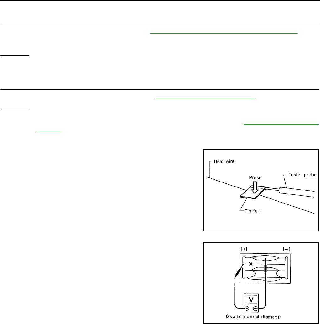
GW-118
REAR WINDOW DEFOGGER
Revision: October 2004 2005 Titan
Rear Window Defogger Signal Check
EIS005AC
1. CHECK AV COMMUNICATION LINE
AV communication line check is executed. Refer to BCS-8, "CAN Communication System Description".
OK or NG
OK >> GO TO 2.
NG >> Replace display control unit.
2. CHECK CAN COMMUNICATION LINE
CAN communication line check is executed. Refer to LAN-7, "CAN COMMUNICATION"
OK or NG
OK >> Check the condition of the harness and the connector.
NG >> In addition, it is necessary to check CAN communication line. Refer to LAN-7, "CAN COMMUNI-
CATION"
Filament Check
EIS005AD
1. When measuring voltage, wrap tin foil around the top of the neg-
ative probe.Then press the foil against the wire with your finger.
2. Attach probe circuit tester (in Volt range) to middle portion of
each filament.
Is rear window defogger displayed on the display?
SEL122R
SEL263
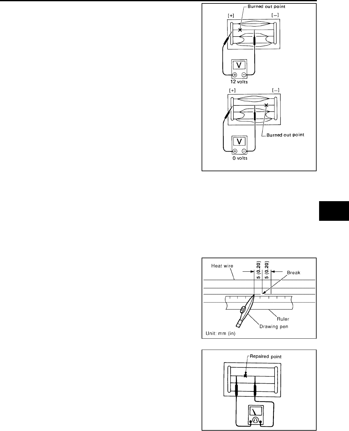
REAR WINDOW DEFOGGER
GW-119
C
D
E
F
G
H
J
K
L
M
A
B
GW
Revision: October 2004 2005 Titan
3. If a filament is burned out, circuit tester registers 0 or battery
voltage.
4. To locate burned out point, move probe to left and right along fil-
ament. Test needle will swing abruptly when probe passes the
point.
Filament Repair
EIS005AE
REPAIR EQUIPMENT
●Conductive silver composition (DuPont No. 4817 or equivalent)
●Ruler 30 cm (11.8 in) long
●Drawing pen
●Heat gun
●Alcohol
●Cloth
REPAIRING PROCEDURE
1. Wipe broken heat wire and its surrounding area clean with a
cloth dampened in alcohol.
2. Apply a small amount of conductive silver composition to tip of
drawing pen.
Shake silver composition container before use.
3. Place ruler on glass along broken line. Deposit conductive silver
composition on break with drawing pen. Slightly overlap existing
heat wire on both sides [preferably 5 mm (0.20 in)] of the break.
4. After repair has been completed, check repaired wire for conti-
nuity. This check should be conducted 10 minutes after silver
composition is deposited.
Do not touch repaired area while test is being conducted.
SEL265
PIIA0215E
SEL012D
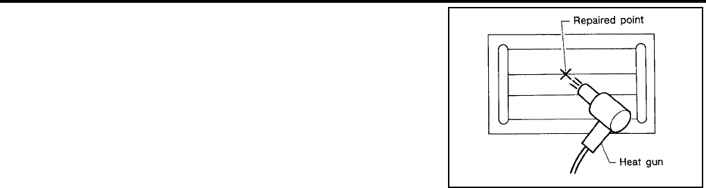
GW-120
REAR WINDOW DEFOGGER
Revision: October 2004 2005 Titan
5. Apply a constant stream of hot air directly to the repaired area
for approximately 20 minutes with a heat gun. A minimum dis-
tance of 3 cm (1.2 in) should be kept between repaired area and
hot air outlet.
If a heat gun is not available, let the repaired area dry for 24
hours.
SEL013D
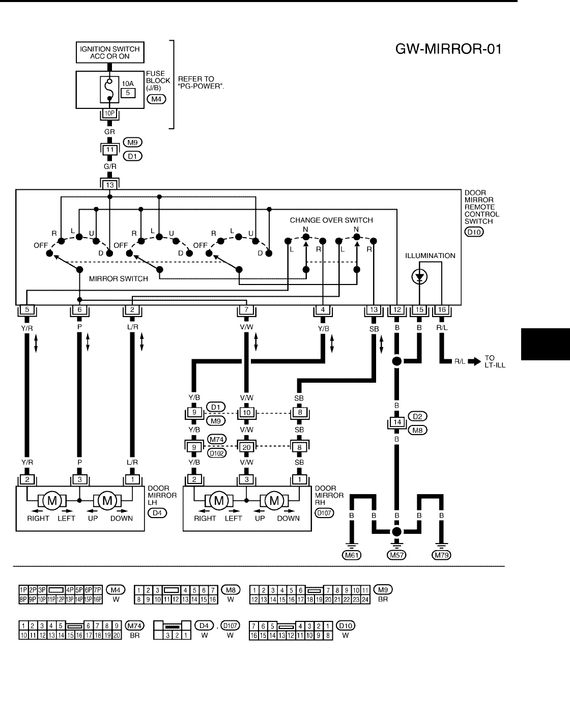
DOOR MIRROR
GW-121
C
D
E
F
G
H
J
K
L
M
A
B
GW
Revision: October 2004 2005 Titan
DOOR MIRROR PFP:96301
Wiring Diagram — MIRROR —
EIS004DE
WIWA0629E
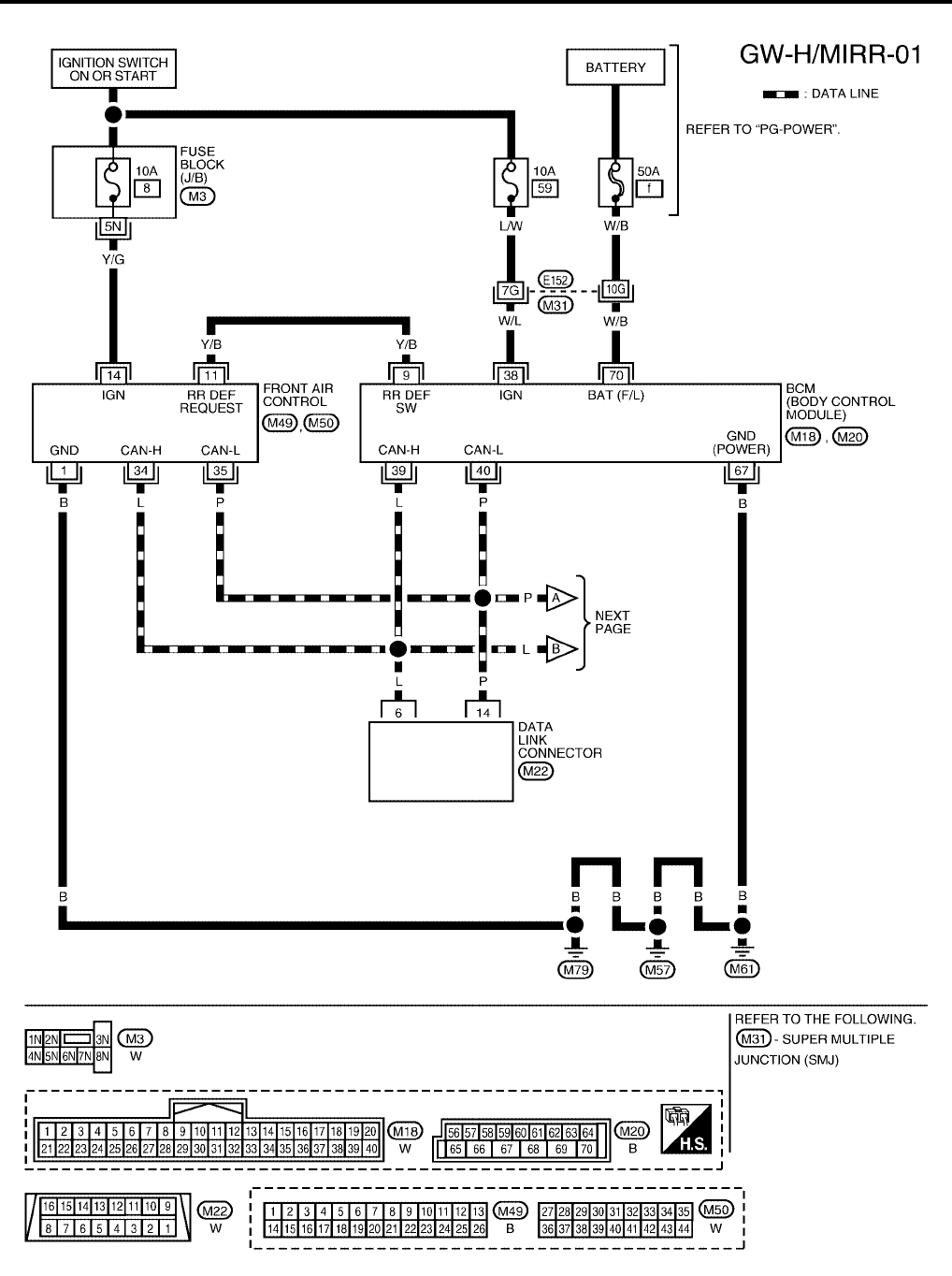
GW-122
DOOR MIRROR
Revision: October 2004 2005 Titan
Wiring Diagram — H/MIRR —
EIS004DF
WIWA0630E
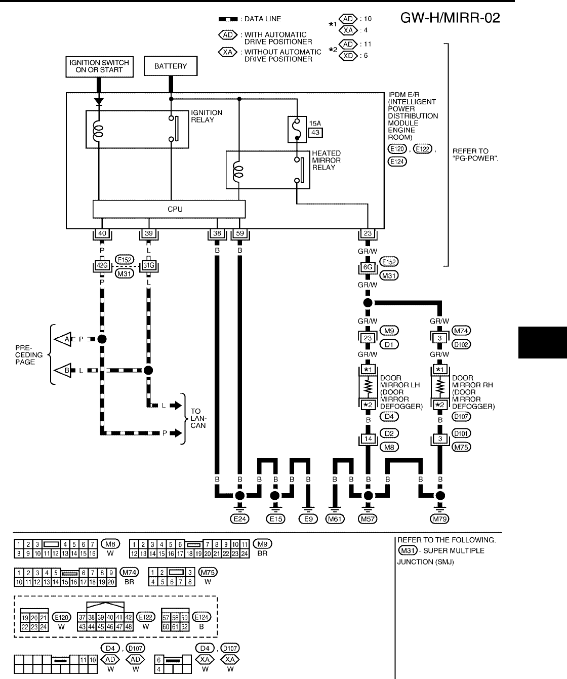
DOOR MIRROR
GW-123
C
D
E
F
G
H
J
K
L
M
A
B
GW
Revision: October 2004 2005 Titan
LIWA0530E
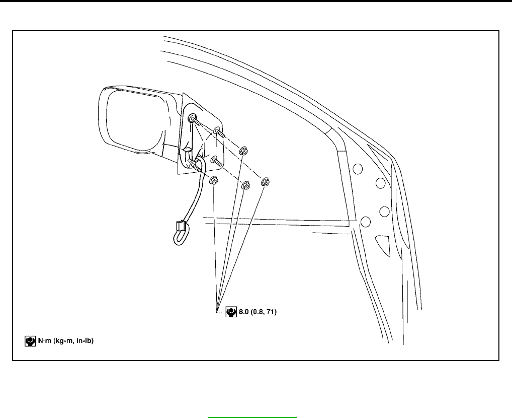
GW-124
DOOR MIRROR
Revision: October 2004 2005 Titan
Door Mirror Assembly
EIS004DG
STANDARD MIRROR
Removal and Installation
NOTE:
Be careful not to damage the mirror bodies.
1. Remove the front door finisher. Refer to EI-32, "Front Door".
2. Disconnect the mirror electrical connector.
3. Remove the door mirror assembly.
Installation is in the reverse order of removal.
LIIA1570E
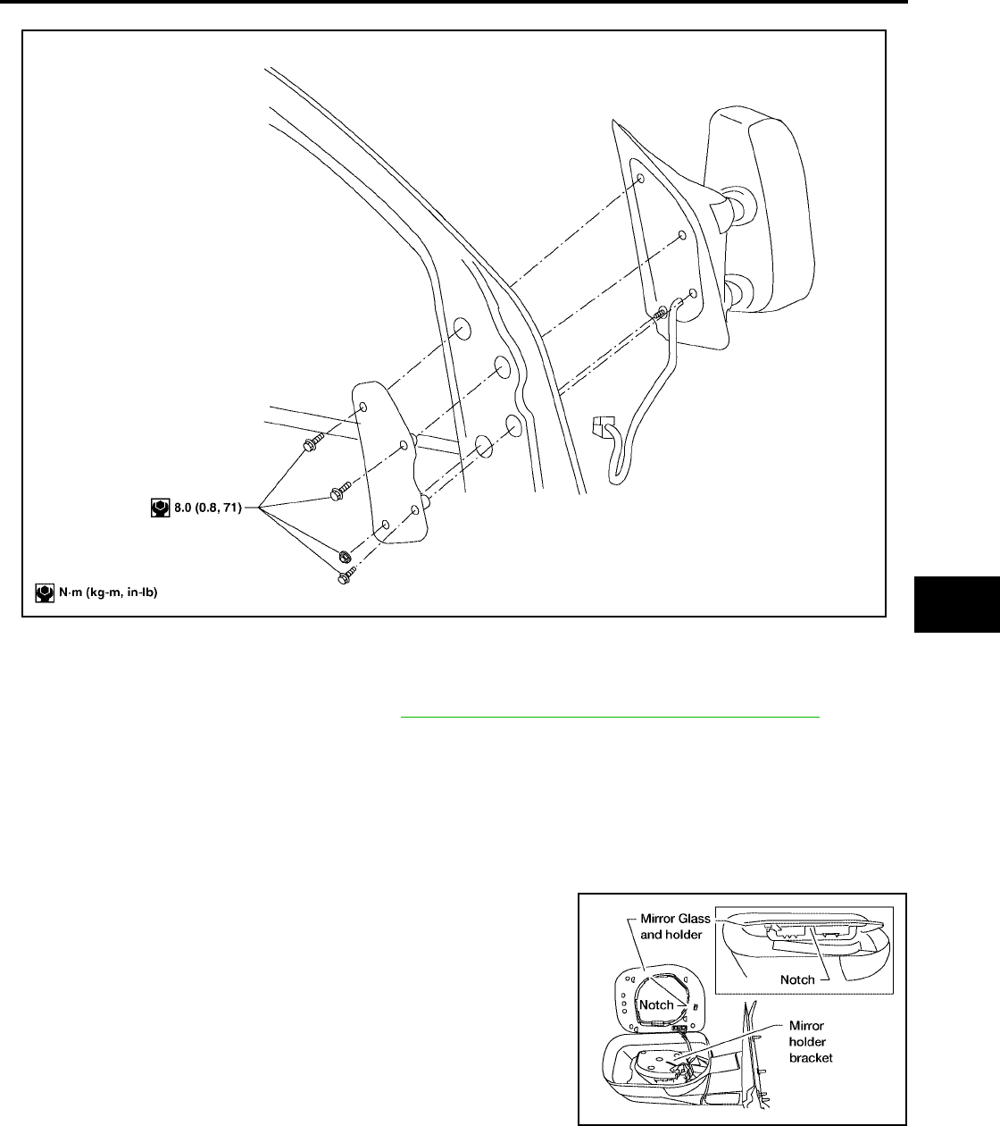
DOOR MIRROR
GW-125
C
D
E
F
G
H
J
K
L
M
A
B
GW
Revision: October 2004 2005 Titan
TRAILER TOW MIRROR
Removal
NOTE:
Be careful not to damage the mirror bodies.
1. Remove the front door sash cover. Refer to AV-66, "Removal and Installation of Front Tweeter".
2. Remove the door mirror harness connector.
3. Remove the door mirror mounting nuts, and remove the door mirror assembly.
Installation
Installation is in the reverse order of removal.
Door Mirror Glass
EIS004DH
REMOVAL
1. Set mirror assembly mirror glass upward.
2. Apply protective tape to mirror housing.
3. Insert a screwdriver at notch and gently pry mirror glass and
holder from mirror holder bracket.
4. Disconnect two electrical connectors from mirror glass and
holder.
LIIA1619E
LIIA1591E
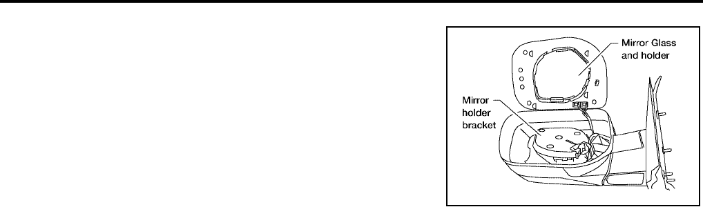
GW-126
DOOR MIRROR
Revision: October 2004 2005 Titan
INSTALLATION
1. Set mirror holder bracket and mirror glass and holder in the hor-
izontal position.
2. Connect two electrical connectors to the back of the mirror
holder.
3. Align mirror glass and holder with mirror holder bracket and
push mirror glass and holder onto mirror holder bracket.
4. Rotate mirror to ensure proper installation.
LIIA1592E
