ImproX (ECII) Ethernet Controller Impro_ixp400i Impro Ixp400i
User Manual: impro_ixp400i
Open the PDF directly: View PDF ![]() .
.
Page Count: 14
1
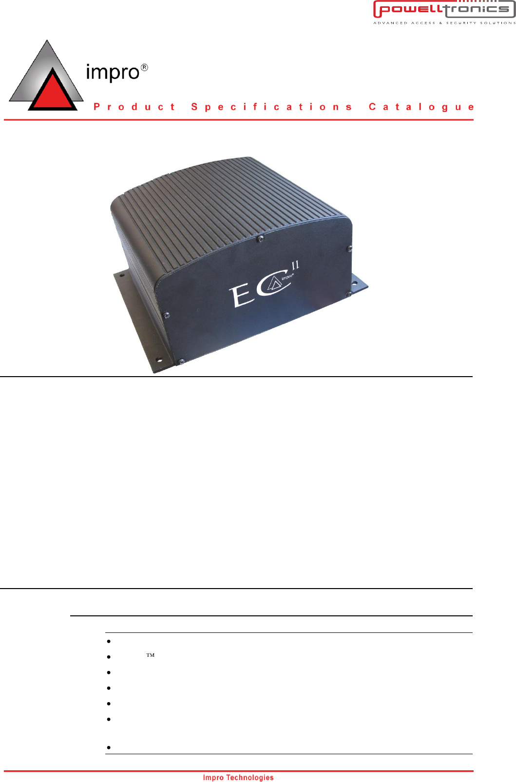
ImproX ECII
ImproX (ECII) Ethernet Advanced Controller
Overview
Introduction
The ImproX (ECII) Ethernet Advanced Controller is a fully Ethernet compatible Controller for use in
the IXP400i Access Control System.
The Controller boasts both an RS485 Controller Port (Port 1) and an Ethernet Port allowing use of
either. When connected to the Ethernet Port the Controller offers communication speeds and capacity
not yet seen in similar systems.
The Controller comes standard with an RS485 Terminal Port (Port 2) (able to support up to 32 full Anti-
passback doors), on-board Diagnostic LEDs and a 6 V 3 Ahr System Backup Battery. The Battery
allows off-line operation of up to 6 hours.
The ImproX (ECII) Ethernet Advanced Controller is the next generation of Ethernet hardware
promoting quick and easy installation across a LAN or WAN with bandwidth friendly communication
protocol.
Key Features
Hardware
ARM920T Microprocessor Core operating at 200 mips (million instructions per second).
Linux Operating System.
64 MB SDRAM Memory.
8 MB Flash Memory.
LEDs indicate transmit and receive line activity for diagnostics.
A Real Time Clock (RTC) with a 3 V Lithium Backup Battery (providing 5 years stand-by
operation).
Remote Firmware download capability.
www.powelltronics.com

2
Part Number: XEC900-0-0-GB-XX
Supports a secure logon when changing Controller Configuration settings using the
Ethernet Discovery Utility software.
An Ethernet Controller Port for connection to an Ethernet Switch or Hub (or other
network device).
An RS485 Controller Bus Port for connection to other ImproX (ECII) Ethernet Controllers.
An RS485 Terminal Bus Port for connection to up to 64 Terminal Fixed Addresses.
Operation from power inputs in the range 10 V DC to 30 V DC.
Configurable, dynamic memory capable of storing up to 300 000 Tagholders and up to
1 000 000 buffered transactions.
Robust, Aluminium enclosure.
Fully incorporated uninterrupted Power Supply with trickle charge and battery
management.
Incorporated 6 V 3 Ahr Sealed Lead Acid Battery providing 6 hours full operation.
Power Input Fail and Battery Low signal reporting.
48 Hour Hibernation Mode for extended battery backup of the ImproX (ECII) Ethernet
Controllers database (including transactions).
When used with ImproNet V7.4 Software
Tags per person: 8.
Tagholder Access Groups per Tag: 10.
Access Groups total: 10 000.
Active System Events: 8 000.
Actions: 50 000.
Approvals
CE Approved.
FCC Approval Pending.

3
Part Number: XEC900-0-0-GB-XX
Specifications
Physical
Dimensions
Length
:
168 mm (7 in).
Width
:
197 mm (8 in).
Height
:
89 mm (4 in).
Approximate Weight
:
2 kg (4 lb) Battery included.
Cabinet Material
:
Aluminium.
Colour
:
Black.
Environmental
Temperature
Operating
:
-10oC to +50oC (+14oF to +122oF).
Storage
:
-15oC to +50oC (+5oF to +122oF).
Humidity Range
:
0 to 95% relative humidity at +40oC (+104oF) non-
condensing.
Approvals (Test Information)
:
EN 301 489-3
EN 304 489-1
Dust and Splash Resistance
:
Designed to work in an indoor (dry) environment similar
to IP30. The Controller is, therefore, NOT sealed
against water.
Drop Endurance
:
2 m (7 ft) drop (in packaging).
Electrical
Power Requirements
Input Voltage
:
10 V DC to 30 V DC.
Power Requirements
Current (mA)
Power (W)
Supply Voltage 10 V DC
(Maximum)
:
420
4.2
Supply Voltage 30 V DC
(Maximum)
:
140
4.2
Permissible Input Supply
Ripple Voltage (Max)
:
1 V PP at 50 Hz.
Power Input Protection
:
Reverse polarity on DC power inputs, over-voltage and
over-current protection are provided on the Controller.
Ethernet Port
Connection
:
Standard Ethernet RJ45 connector.
10/100 Mbps, half or full duplex.
Protocol
:
TCP/IP, UDP.

4
Part Number: XEC900-0-0-GB-XX
NOTE: The RS485 1 (Controller) Port connection details only apply to ImproX ECII Controllers
with Firmware V7.16 upwards.
RS485 1 (Controller) Port
Configuration
:
38 400 Default.
Electrical Interface
:
RS485.
Baud Rates
:
9 600, 19 200, 28 800, 38 400 and 57 600 selectable
via the Communications Protocol.
Data Format
:
8 data bits, no parity, 1 stop bit.
Communications Protocol
:
ImproX Secure Communications Protocol.
Line Termination
:
Provision is made for line termination.
Default Mode
:
Receive Mode.
RS485 2 (Terminal) Port
Configuration
:
38 400 Default.
Electrical Interface
:
RS485.
Baud Rates
:
9 600, 19 200, 28 800, 38 400, 57 600 and 76 800
selectable via the Protocol.
Data Format
:
8 data bits, no parity, 1 stop bit.
Communications Protocol
:
ImproX Secure Communications Protocol.
Line Termination
:
Provision is made for line termination.
Default Mode
:
Receive Mode.
Memory
RAM (Non-volatile)
:
64 MBytes.
Flash ROM
:
8 MBytes.
Real Time Clock (RTC) Backup
Battery
Battery Type
:
1 x 3 V, CR2032, Lithium cell Battery.
Battery Life
:
5 Years (with power OFF).
System Battery
Battery Type
:
6 V 3 Ahr Sealed Lead Acid Battery.
Size
Length
:
133 mm (5 in).
Width
:
34 mm (1 in).
Height
:
65 mm (3 in) (Including the terminals).
Approximate Weight
:
650 g (23 oz).
Battery Life
:
4-6 Hours uninterrupted operation.
48 Hours Power Shutdown (Hibernation Mode).
Anti-tamper Protection
:
2 Internal switches.
Factory Default Settings
Test Modes
Power-on Self-test
:
RAM, Flash-ROM, RTC.
Baud Rate
RS485 1 (Controller) Port
:
38 400.
RS485 2 (Terminal) Port
:
38 400.
5
Part Number: XEC900-0-0-GB-XX
Operator or Installer Interfaces
Diagnostic LED Indicators
Power-on LED
:
Red LED (internally visible).
Incoming RS485 1 (Controller)
:
Flashing Green LED (internally visible).
Outgoing RS485 1 (Controller)
:
Flashing Red LED (internally visible).
Incoming RS485 2 (Terminal)
:
Flashing Green LED (internally visible).
Outgoing RS485 2 (Terminal)
:
Flashing Red LED (internally visible).
Link Speed LED (Ethernet)
:
Flashing Red LED (internally visible).
Duplex Mode LED (Ethernet)
:
Flashing Red LED (internally visible).
Link Active LED (Ethernet)
:
Flashing Red LED (internally visible).
CPU Usage
:
Red LED (internally visible).
On = Idle, Off = Busy.
CPU Running
:
Red LED (internally visible).
On = Yes, Off = No.
CPU Fault
:
Red LED (internally visible).
On = Fault Condition, Off = Ok.
Installation Information
Accessories
Find the following when unpacking the Controller:
An ImproX ECII Controller housed in a Black, powder coated, Aluminium extruded
Cabinet. The Cabinet consists of a Top Cover and a Base sealed at each end with a
Mild Steel End Plate, secured with 5 Thread Cutter Screws (M3 x 8 mm).
A 6 V 3 Ahr Sealed Lead Acid Backup Battery (Installed).
A 3 V, CR2032, Lithium cell Battery.
Four Wood Screws (3.5 mm x 25 mm).
Four Wall Plugs (7 mm).
A MAC Address Label.
An extra Fixed Address Label.

6
Part Number: XEC900-0-0-GB-XX
General
Remember the following when installing your ImproX ECII Controller:
Communications Distance
RS485 1 (Controller Port) and RS485 2 (Terminal Port)
The RS485 communications distance between the ImproX ECII Controller and the LAST ImproX Unit
in a cable run, MUST NOT exceed 1 km (1 090 yd). Achieve this by using good quality screened
twisted pair Mylar cable, EARTHED on one side.
Ethernet Port
The Ethernet Controller plugs into an Ethernet Switch or Hub (or other network device), cable runs for
this must conform to ethernet cabling specifications.
Termination Resistors for RS485 Bus Communications
Long transmission lines or multiple “star” connections, may cause communication problems. Placing
the Terminating Resistor Jumper Link in the LAST UNIT AT THE END OF THE CABLE RUN should
solve the problem (depending on the bus). Refer to Figure 1 on page 8.
EARTH Connection
In conditions where excessive noise is present connect the ImproX ECII Controller to a good EARTH
point. Using either of the RS485 Ports, connect the EARTH Lead to the “SHD” Terminal. Mains
EARTH can be used, but electrical noise may persist. The EARTH Lead to the ImproX ECII Controller
should have a minimum cross-sectional area of 1 mm2 (0.001 in2) and can be either solid or stranded.
First Time Use of the Controller
CAUTION: Insert the supplied 3 V Lithium Real Time Clock Backup Battery into the Battery
Holder BEFORE powering up the ImproX ECII Controller.
Installing the Real Time Clock Backup Battery
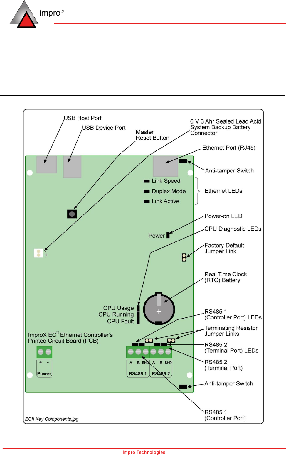
The Battery Holder is located in the bottom right-hand side of the ImproX ECII Controllers Printed
Circuit Board (PCB), directly above the RS485 2 (Terminal Port).
1. Remove the Controllers Top Cover.
2. Slide the supplied 3 V, CR2032, Lithium cell Battery under the metal clip of the Battery
Holder, with the "+" Terminal facing UP.
3. Pull the plastic clip AWAY from the Battery Holder and press the Battery firmly into the
Battery Holder.
7
Part Number: XEC900-0-0-GB-XX
Connecting the System Backup Battery
1. Attach the Battery Fly Lead to the System Backup Battery Connector (see Figure 1 for
Key Component Positions).
2. Attach the Controller’s Top Cover.
Mounting the Controller
CAUTION: Make certain that you mount the Controller on a vibration-free surface.
Select the mounting position of the ImproX ECII Controller, considering accessibility and routing of
wires.
Secure the Controller to the mounting surface, using four suitable screws and wall plugs (supplied),
nuts and bolts or rivets.
Replacing the 6 V 3 Ahr Lead Acid System Backup Battery
1. Remove the Controller’s Top Cover.
2. Remove the Controller’s back End Plate.
3. Disconnect the Battery Fly Lead Spade Terminals from the old Battery.
4. Slide the old Battery out of the Battery Compartment.
CAUTION: Ensure that you maintain the correct polarity of the Battery Fly Lead Spade
Terminals. Red wire to Positive (+) and Black wire to Negative (-).
5. Slide the new Battery into the Battery Compartment.
6. Reconnect the Battery Fly Lead Spade Terminals to the new Battery.
7. Attach the Controller’s back End Plate.
8. Attach the Controller’s Top Cover.
8
Part Number: XEC900-0-0-GB-XX
Electrical Connections
Controller Layout
Figure 1: Key Component Positions
9
Part Number: XEC900-0-0-GB-XX
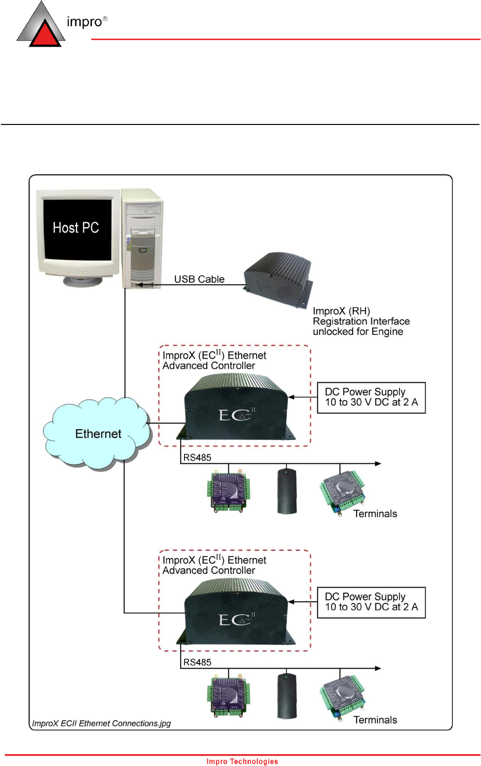
Connecting the ImproX ECII Controller
Figure 2 and Figure 3 show the ImproX ECII Controllers relationship with the rest of the ImproX
product range.
Figure 2: Ethernet Configuration Diagram

10
Part Number: XEC900-0-0-GB-XX
Figure 3: RS485 Configuration Diagram

11
Part Number: XEC900-0-0-GB-XX
Figure 4 shows typical connection options for the ImproX ECII Controller.
Figure 4: Typical Electrical Connections
NOTE: DO NOT connect (daisy chain) additional RS485 Controllers on Port 2, as the System will
NOT Auto-ID these Controllers.

12
Part Number: XEC900-0-0-GB-XX
Power Shutdown
The ImproX ECII Controller’s 6 V 3 Ahr Sealed Lead Acid Backup Battery provides between 4-6 hours
of uninterrupted power. Five minutes after the Battery Low signals received by the Controller, the
Controller switches to Hibernation Mode (low power). Hibernation Mode provides a further 48 hours of
database (including transactions) memory retention.
Master Reset
The ImproX ECII Controller can be restarted manually, without removing the power connections, by
pressing the Master Reset button (See Figure 1 for Key Component Positions)..
Restoring Factory Default Settings
If you assign an invalid IP address to the ImproX ECII Controller, it will not be able to communicate. To
correct the problem, restore the Controllers factory default settings as follows:
CAUTION: This will restore the firmware to the version set when shipped from the factory.
If you have upgraded the Controllers firmware since installation, ensure that
you upgrade again immediately.
1. Power up the ImproX ECII Controller.
2. After 30 seconds, place a link across the pins of the Factory Default Jumper Link (LK4).
(See Figure 1 for Key Component Positions).
3. After 5 seconds, remove the Link.
13
Part Number: XEC900-0-0-GB-XX
Unit Address Information
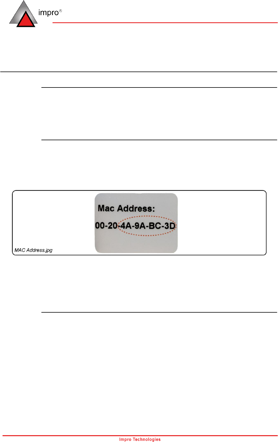
Fixed Address Label
The last 8 digits of the MAC Address, that is 4A-9A-BC-3D (see Figure 5), translate to the products
Fixed Address used by the System Software.
Attach the loose Fixed Address Label (packaged with the Controller) in position on the Unit Location
Chart (or your sketched site plan).
MAC Address Label
Each ImproX ECII Controller is supplied with a separate MAC Address Label, much like the one shown
in Figure 5, which uniquely identifies each Controller.
Attach the extra loose MAC Address Label, alongside the Fixed Address Label, to the Unit Location
Chart enclosed (or your sketched site plan).
Figure 5: Sample MAC Address Label
When the system installation is complete and all the units are represented on the Unit Location Chart
(or your sketched site plan) by their Fixed Address and MAC Address Labels, file the document for
future reference.
IP Address
NOTE: All ImproX ECII Controllers have the same IP Address (192.168.100.1). In the absence of a
DHCP server, plug each Controller into the network individually and set the static IP
Address.
14
Part Number: XEC900-0-0-GB-XX
Guarantee or Warranty
This product conforms to our Guarantee or Warranty details placed on our Web Site, to read further
please go to www.impro.net.
Ordering Information
Order the ImproX (ECII) Ethernet Controller using the XEC900-0-0-GB-XX Impro part number.
This manual is applicable to the ImproX (ECII) Ethernet Controller, XEC900-0-0-GB-03.
(The last two digits of the Impro stock code indicate the issue status of the product).
XEC350-0-0-GB-02
Issue 03
May 2008
ImproX ECII\Product Specification Catalogue\
LATEST ISSUE\XECII-psc-en-03.docx
