Safemaster STS Safety Switch And Key Interlock System Mounting Operating Instruction Installationmanual
User Manual: Safemaster STS Safety switch and key interlock system mounting and operating instruction Dold Trapped Key ation - AutomationDirect
Open the PDF directly: View PDF ![]() .
.
Page Count: 28
SAFEMASTER STS
Our experience. Your safety.
Mounting and
operating instruction
Modular safety switches and key transfer
systems for the highest requirements.

2Mounting- and operating instruction SAFEMASTER STS / 03.02.16 en / 639
Index
1. General .............................................................................................................................................................................................3
1.1 Safety notes ..............................................................................................................................................................................3
1.2 Mounting rules and type numbering .........................................................................................................................................3
1.3 Key transfer plan .......................................................................................................................................................................4
1.4 Recommended mounting position ............................................................................................................................................4
1.5 Recommended ergonomic mounting height .............................................................................................................................4
1.6 Safety condition of the modules during assembly / modification...............................................................................................5
1.7 Operating a module during composition of a unit .....................................................................................................................5
2. Mounting...........................................................................................................................................................................................6
2.1 Actuator modules and key modules .......................................................................................................................................... 6
2.2 Modifying a unit or extending ....................................................................................................................................................6
2.3 Units and a safety guards .........................................................................................................................................................7
2.4 Option module ...........................................................................................................................................................................8
2.5 Escape release .......................................................................................................................................................................10
2.6 Mounting dimensions of actuators and actuator modules .......................................................................................................11
2.7 Power Interlocking ................................................................................................................................................................... 12
3. Circuit diagrams and connection examples ....................................................................................................................................14
3.1 Circuit diagrams for switching modules (SX-, SV-, RX-, RV-modules) ....................................................................................14
3.2 Circuit diagrams for solenoid locking modules (ZRX, YRX, ZAX, YAX-modules) .................................................................... 15
3.3 Terminal designation option module .......................................................................................................................................18
3.4 Connection examples Power Interlocking ...............................................................................................................................19
4. Operation ........................................................................................................................................................................................21
4.1 Mechanical Units .....................................................................................................................................................................21
4.2 Switch units with locking mechanism ......................................................................................................................................21
4.3 Solenoid locking module with auxiliary release .......................................................................................................................21
4.4. Solenoid locking module with emergency release ..................................................................................................................21
4.5 Solenoid locking module with escape release ........................................................................................................................22
4.6 F-Kit ........................................................................................................................................................................................23
4.7 Power Interlocking ................................................................................................................................................................... 24
5. Cleaning .........................................................................................................................................................................................26
6. Lubrication ......................................................................................................................................................................................26
7. Test ................................................................................................................................................................................................27
7.1 System blocking as safety function .........................................................................................................................................27
8. Repairs ...........................................................................................................................................................................................27
Frequently asked questions – FAQs .................................................................................................................................................27
3Mounting- and operating instruction SAFEMASTER STS / 03.02.16 en / 639
F < 50 N
v < 500 mm/s
All technical data in this list relate to the state at the moment of edition. We reserve the right
for technical improvements and changes at any time.
Mounting- and operating instruction
Safety switch- and key interlock system
SAFEMASTER STS
1.1 Safety notes
1. General
ATTENTION!
Please read these mounting instructions before starting the installation. Mounting, electrical connection and test must only be carried out
by trained staff that have read these instructions and have a full understanding of their content. Before installing the system the user has
to decide if the suggested key transfer plan solution fulfils the application requirements and that the gates are secured according to the
relative standards. The suggested key transfer plan has been designed and forms one solution based on the requirements as advised to
Dold.
For a safe installation all the available mounting points must be used. When making changes to an existing system please take care to follow the
mounting rules as described in this document. Do not remove or re-adjust any parts inside the (electrical) units. Please note that the mechanical
modules have two cleaning holes. Please make sure that at least one hole remains open so that dirt can exit. Please make sure that appropriate
seals are used for all the cable entries. The connection (integration of electrical modules) must be carried out according to the required safety
category DIN EN ISO 13849-1. A validation in conformity with DIN EN ISO 13849-2 is mandatory. Before starting the system it must be checked for
function according to the corresponding key transfer plan. After completing the tests the covers of the electrical units must then be fitted and fixed
with the appropriate screws. Maximum torque = 1 Nm ± 0.1 Nm. Please make sure that the front covers of the electrical units are mounted properly
before operation. Only when the lids are mounted correctly, function and protection class will be as specified.
It is recommended to carry out planned maintenance min. twice a year to remove dirt and other contaminants from the units to keep the system
working correctly. In case of intense fouling, cleaning should be carried out more often.
ATTENTION!
Do not use grease for lubrication! If lubrication is necessary please check the table on page 14 for chosing the lubricant.
Please also pay attention to the standards DIN EN ISO 14119, DIN EN ISO 13849-1 and DIN ISO 12100.
For correct mounting and usage of devices with Auxiliary-, Emergency-, or Escape release, refer to the requirements of DIN EN ISO 14119
Please contact DOLD if you have any doubts or questions regarding the installation.
Take notice of the requirements of EN ISO14119:2013 in reference to foreseeable manipulation, especially to §7.1 and 7.2
Upon installation electric modules must be connected to the ground, to avoid any potential differences.
The statements and safety notes contained in these mounting instructions must be strictly adhered too.
1.2 Mounting rules and type numbering
The type identification of a combined unit is built up from the bottom module to the top.
Mechanical key module numbers are added together, e.g. on a mechanical lock with 2 keys to be inserted (10 + 10) and one to be extracted (01).
This sums up to be 21. At the upper end of the mechanical guard lock an actuator module (A) is required. The type reference for this assembly is
then, M21A.
An M module should always be mounted on the open end of a unit.
If a key module 10, a padlock module W or an actuator module K is mounted directly on a switch or on a solenoid locking switch, the position of the
key or actuator has to be monitored for category 3 or 4 as shown in wiring examples 3 and 4 on page 15 and 16.
Above a B, D, K and E actuator module there should always be mounted one or more mechanical modules or an M end module.
Below A, B, D, K and E actuator modules there should always be mounted one or more mechanical modules or an electrical module.
Products of the SAFEMASTER STS plastic series are indicated with a /K at the end of the type name.
Example: M10A/K, Key module 01/K, Actuator module B/K, End module M/K.
0258068
The STS-system made of stainless steel can be within limitation used as mechanical stop.
Follow values must not be exceeded:
• F = 50 N
• v = 500 mm/s
ATTENTION!
The STS-system made of plastic must not be used as mechanical stop.
4Mounting- and operating instruction SAFEMASTER STS / 03.02.16 en / 639
ZRH02M
M10BM
M10BM
•
•
1.
2.
3. 4.
5. 6. 7.
0° 90° / 270° 180°
To p
To p
90 cm ± 20 cm
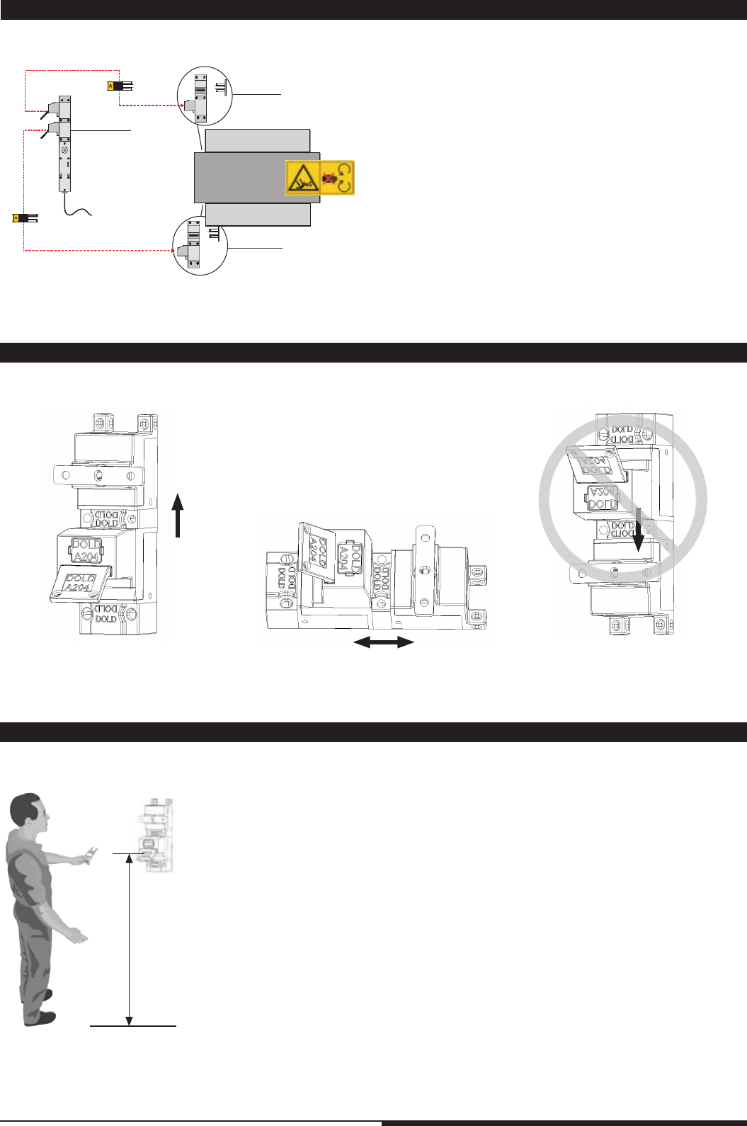
For assembly, mounting and function testing a key transfer plan must be used.
Dold will be happy to assist you creating one.
1.4 Recommended mounting position
1.3 Key transfer plan
1.5 Recommended ergonomic mounting height
Hatch 2
Hatch 1
Mixer
Example ZRH02M with 2 x M10BM
1. When the machine is in safe mode and the solenoid lock is released,
the 1st key can be removed.
2. Removal of the key can be monitored and a signal can be
integrated into the machine control.
3. Key is inserted into mechanical lock.
4. Hatch 1 can be opened
5. Only when the 1st key is removed, the 2nd key can be obtained.
6. 2nd key is inserted into mechanical lock.
7. Hatch 2 can be opened.
To restart the machine, steps 7-1 have to be processed in reverse order.
Both keys have the same code and can operate both covers.
5Mounting- and operating instruction SAFEMASTER STS / 03.02.16 en / 639
1.6 Safety condition of the modules during assembly / modification
Module State
Switch module SX / SV switched off
Switch module RX / RV switched off
Solenoid locking switch ZR_ / YR_ (closed circuit operation) switched off, operate solenoid manually
Solenoid locking switch ZA_ / YA_ (open circuit operation) switched off
Key module 10 / 10S key inserted, at mounting on RX, RV or Y-modules the key is extracted
Key module 01 / 01S key extracted
Padlock module V key extracted
Padlock module W key inserted, see key module 10, 10S
Actuator module A / B / D actuator extracted
Actuator module K / E actuator inserted, at mounting on RX, RV or Y- modules the der actuator is extracted
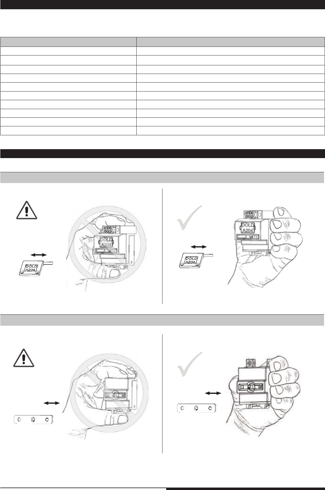
1.7 Operating a module during composition of a unit
Function check of the modules 10, 10S, 01, 01S, B, D, K, E, V and W
Function check module A
Example: Module A
Example: Module 10
When assembling or modifying STS-units, the individual modules must be in a safe condition, as described in the table below.
Safety mounting state of the modules
6Mounting- and operating instruction SAFEMASTER STS / 03.02.16 en / 639
M4058_c
30°
3.
2.
1.
4.
To p
To p
5.
M4057_d
30°
7.
6.
To p
To p
To p
M4379_a
606060
30
To p
To p
To p
A
A
M4380_a
1.
3.
2.
To p
To p
To p
M4377_b
8.
9.
30°
To p
To p
To p
M4378_a
10.
11.
To p
To p
To p
30°
1.
4.
2.
3.
To p
To p
7.
5.
30° 6.
To p
To p
To p
To p
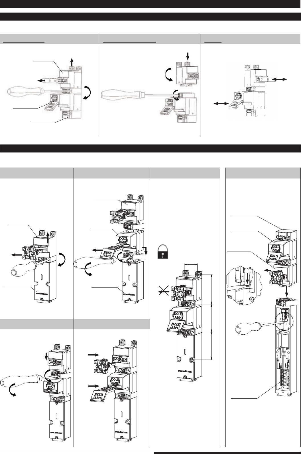
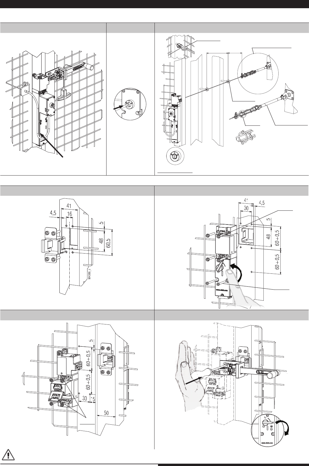
2.1 Actuator modules and key modules
Example M10A; module A rotated at 90°
C: Test
2.2 Modifying a unit or extending
Example STS-SXA into STS-SX01A
A: Disassembling B: Rotation / Mounting
A: Disassembling
C: Mounting D: Insert acuator and key
E: Test Example: ZR_B01M
Dimension tolerance ± 2%
Module A
SX-module
Module M
Module 01
Module B
ZR_-module
Special case: ZR_ / YR_ Modul
Module M
Module 10
B: Add 01 module
Module A
Module 01
SX-module
Module A
2. Mounting
7Mounting- and operating instruction SAFEMASTER STS / 03.02.16 en / 639
M4381_a
60
12060
30
M4382_a
A
A
M4383_a
1.
2.
1.
M4384_a
M4385_a
M4 x 50 mm
V4A / AISI 316L
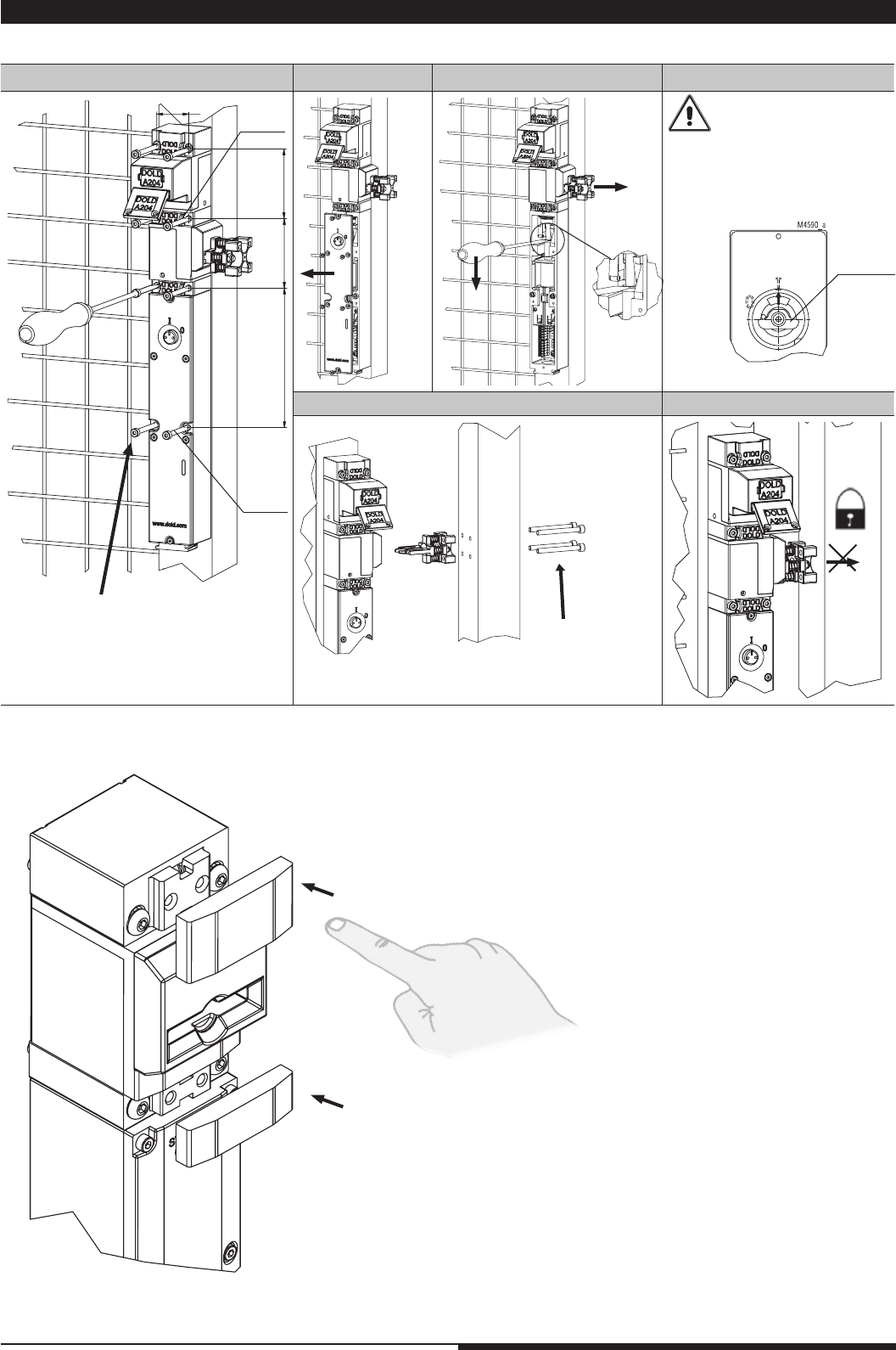
2.3 Units and a safety guards
Example STS-ZRHB01M; All threads and cut-outs in a guard have to be made by the user
F: Test
Dimension tolerance ± 2%
e.g. M5
Mount lid only when key
or actuator is removed e.g
actuator
and horizontal eccentric
tappet 1 (Position 1) of the
manual / e-stop / emer-
gency unlocking
Actuators should be mounted in a way,
that they are not constantly under stress in
closed state.
A: Unit mounting
E: Mount actuator
B: Remove lid C: Release actuator
coded
coded
D: Lid mounting
Cover inside
eccentric
position 1
8Mounting- and operating instruction SAFEMASTER STS / 03.02.16 en / 639
M4891_a
60
60
120
240
M4892_a
C
A
B
1.
2.
3.
1. mount option module on fence frame
2. place seal (O-ring 24 x 1.5)
3. mount swicth or solenoid lock (here e.g. ZRH01A)
1. plug pcb adapter into the terminals of the switch (C) or solenoid lock
(A) and (B)
2. run connection cable through the opening and plug it in PCB
adapter and PCB.
A - A; B - B; C - C
A: Mounting
2.4 Option module
B: Connecting connection set
9Mounting- and operating instruction SAFEMASTER STS / 03.02.16 en / 639
M4893_a
K
M4896_a
M4897_a
1. connect shortened wires to the terminals
2. mount coded terminal blocks to the
connection pins in the option module
plug the 14-pole connectioncable from the
front cover to the pin connector in the
option module
1. place and srew the front cover of the switch /
solenoid lock.
2. place and screw the front cover to the option
module
Attention!
No wire between front plate and
enclosure
C: Connecting control signals D: Connect front plate E: Mount front plate
10 Mounting- and operating instruction SAFEMASTER STS / 03.02.16 en / 639
M4389_c
M4390_b
M4391_b
2.
1.
M4386_a
M4415_a
M4387_d
2-3m 1m
M
4518_a
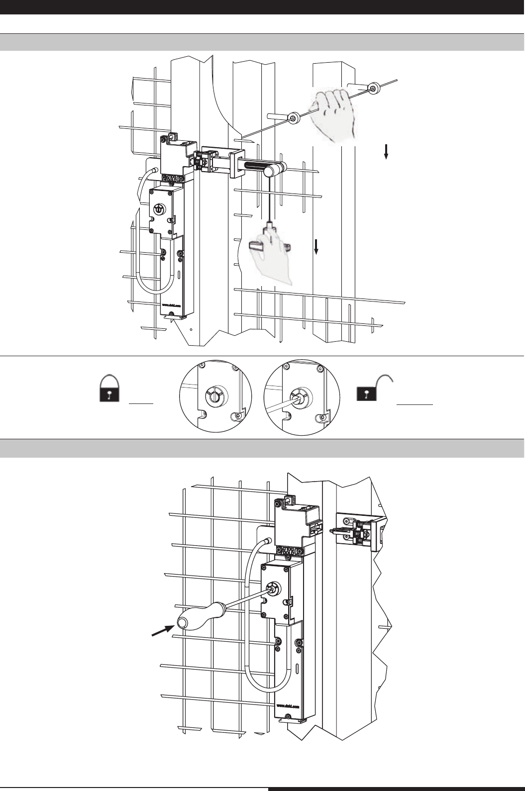
2.5 Escape release
Example STS-ZRFA
Example STS-F-Kit (escape release kit)
A: Mounting of the steel rope B: Press
activation bolt
Dimension tolerance ± 1% Dimension tolerance ± 2%
A: Mounting of frame profile insert B: Mounting of the SVBM-unit
C: Mounting of the mechanical unit on the door D: Fixing the actuator
Fix actuator through the hole with
a strong hit until 2.
Frame profile 50 mm x 50 mm
Adjust rope with rope tensioner until active position is reached.
Please make sure that the hooks of the spring are correctly
fixed when installing the tensioning system.
C: Tensioning of steel rope
coded
coded
coded
radii ≥ 60 mm
tensioner system
active position
eyebolt
rope tensioner
spring
idler pulley
Units based on solenoid modules with emergency release (e.g. ZRN-), escape release (e.g.ZRF-) and the escape release kit (STS-F-Kit)
have to be installed/protected in a way that unintended opening of the lock is avoided
11 Mounting- and operating instruction SAFEMASTER STS / 03.02.16 en / 639
M4431_c
27,9
60
44
30
5
5,3
51
822
32,1
15
5
6
12
56
5
37
M4432_a
27,9
20
M5
60
30
32,1
30
15 5
16
5 10
5
10
20
30
30
81
M4433_b
27,9
60
MAX 15
4,5
32,1
16
15
30
4,5
15 10 27
20 10
51
184
M4434_b
27,9
60
30
51
55,5
24
48,7
M5x10
6,5
4,5
27,75
32,1
15 5
12
6
5,5
7,25
80
6
95
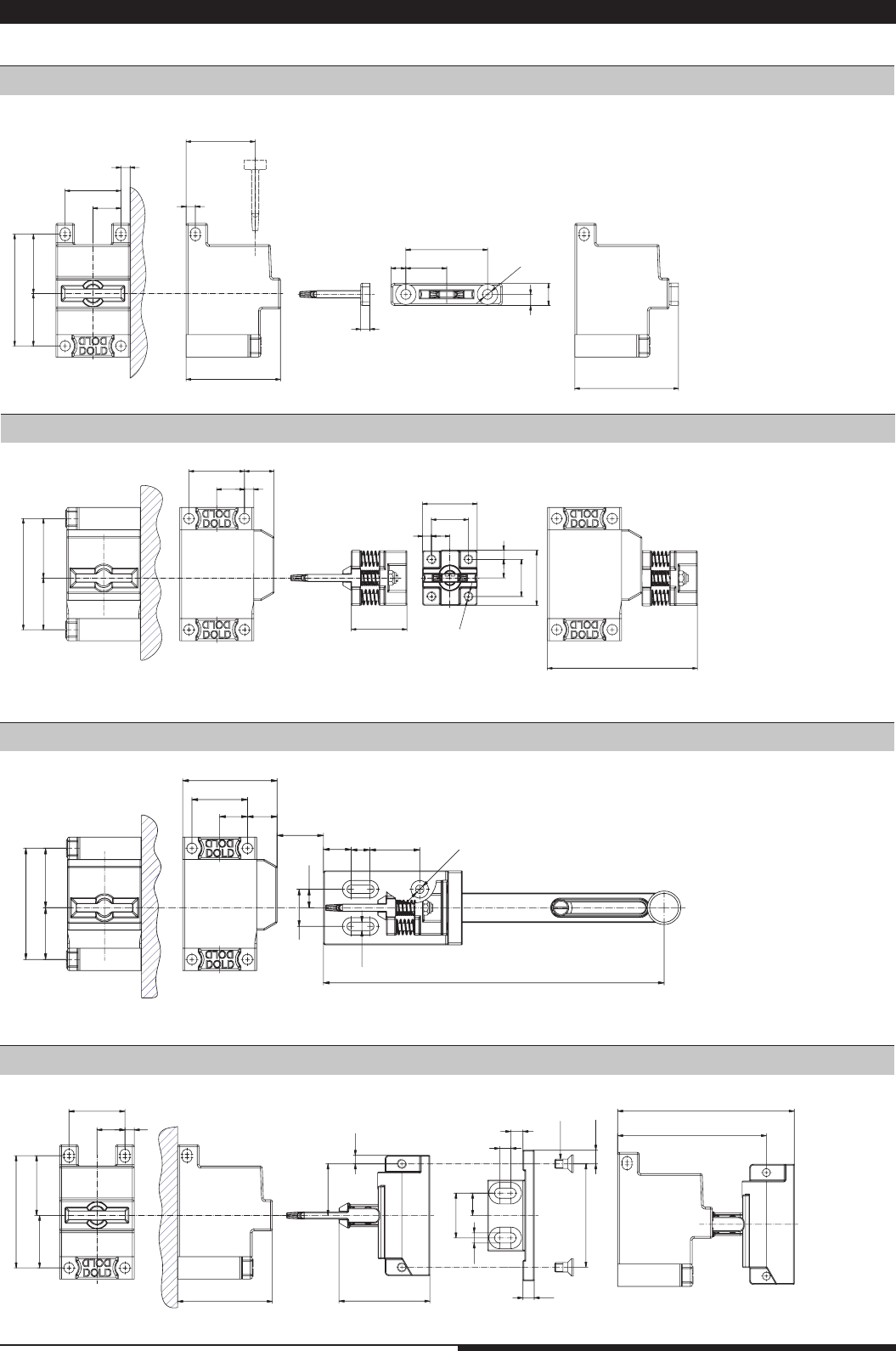
2.6 Mounting dimensions of actuators and actuator modules
Actuator module A + standard actuator T
Actuator module B + actuator C
Actuator module B + actuator CS
Actuator module A + actuator J
Dimension tolerance ± 2%
Dimension tolerance ± 2%
Dimension tolerance ± 2%
Dimension tolerance ± 2%
12 Mounting- and operating instruction SAFEMASTER STS / 03.02.16 en / 639
M4673_a
60
45
35
60
45
35
R2
5,5
206,6
60,5
5,5
360,5
M4674_a
60
45
35
60
45
35
R2
5,5
206,6
60,5
421
121
2x60,5=
5,5
M4675_a
60
45
35
60
45
35
R2
5,5
206,6
60,5
481,5
181,5
3x60,5=
5,5
M4710_a
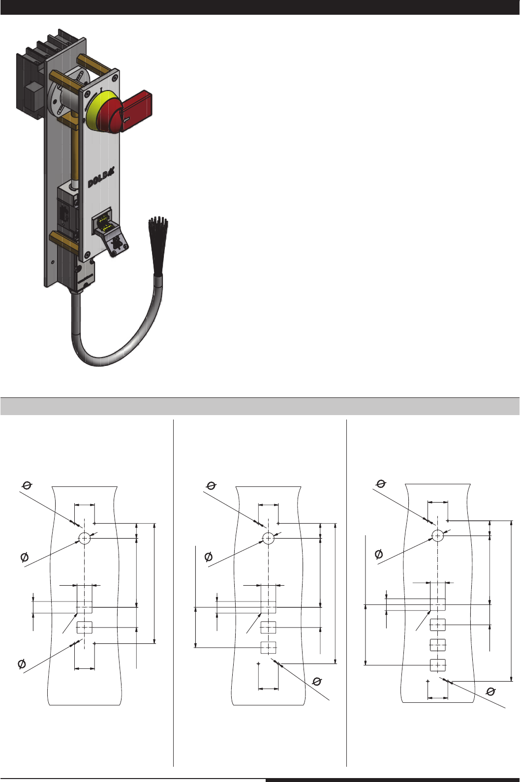
2.7 Power Interlocking
Dimensions / Drilling plan control cabinet
13 Mounting- and operating instruction SAFEMASTER STS / 03.02.16 en / 639
M4677_b
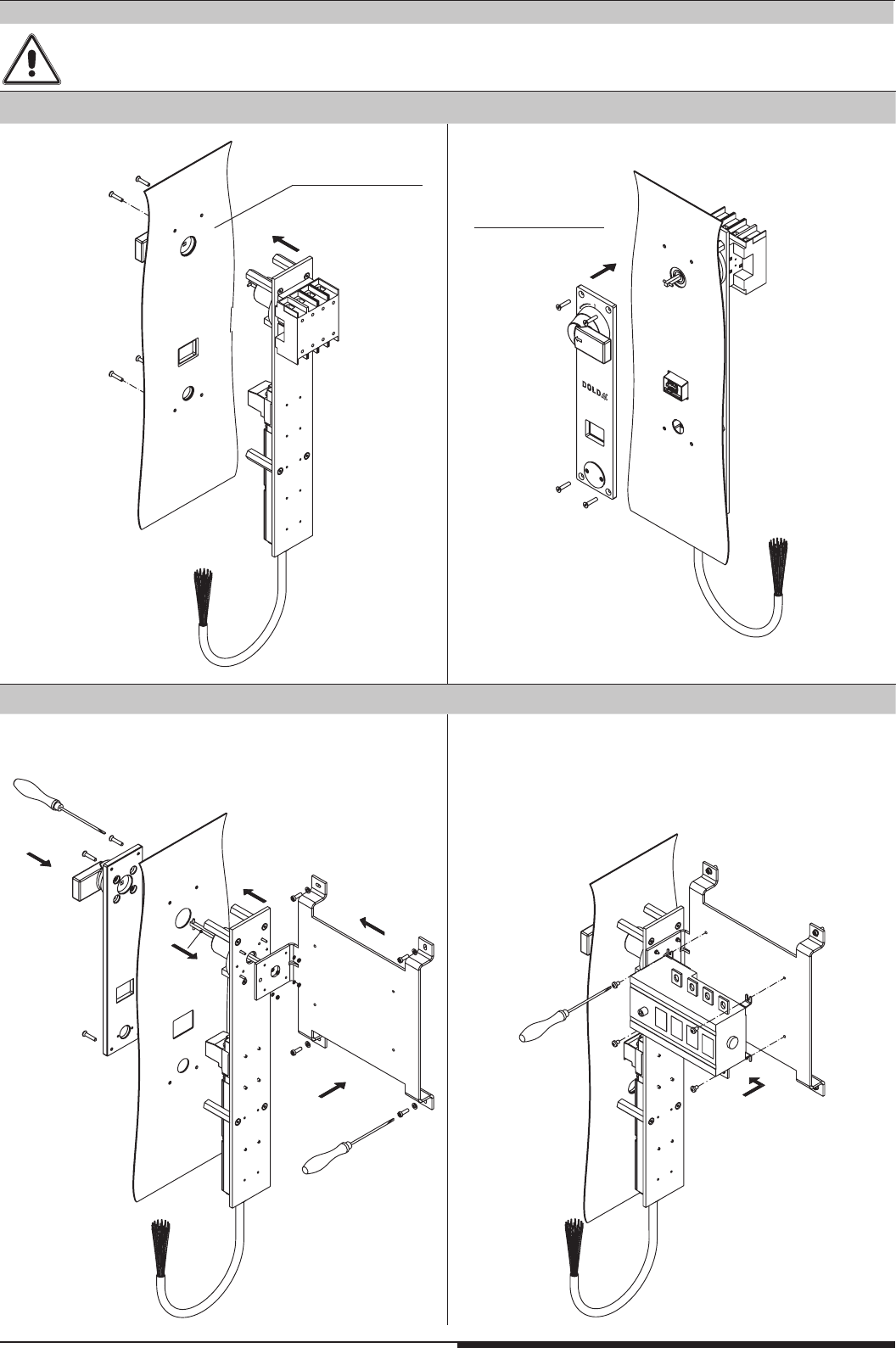
1.
2.
M4678_b
3.
1.
3.
2.
4.
M4679_a
5.
M4680_b
Before mounting, the key must be removed. To this purpose the disconnector switch must be in the “off” position and the locking switch
is to be unlocked via the auxiliary release. For devices without locking function it is sufficient switching the disconnector switch in the “off”
position.
Mounting remarks
cabinet inside
cabinet outside
Versions 25 ... 125 A
Versions 160 ... 800 A
14 Mounting- and operating instruction SAFEMASTER STS / 03.02.16 en / 639
L1(+)
M9890_c
N(-)
A2(-) S21(-)
A1(+)
STS-Solenoid locking mode
emergency stop module LG5924.48
13 33
14 34
23 41
24 42
22
24
32
21
31
red
green
9
11
10
7
8
4
5
6
12
K3
K3
M
Y1 Y2
K3
On
14
12
11
3
1
2
12
22
14
24
32
11
21
31
rot
grün
1
3
9
11
10
7
8
4
5
6
12
2
M9713_g
L1
L1
M9889_c
N
A2(-)
A1(+) S11 S33 S34 S12 S22 S21
STS-Solenoid locking mode
13
14
..
23
..
24
On
22
24
32
21
31
red
green
911 10 7 8 45612
K1 K2
K1
K1
K2
K2
M
14
12 11
31
2
emergency stop module LG5925
1_
2_
3_
4_
5_
6_
_ 7
_ 8
_ 9
_ 10
_ 11
_ 12
input module BG5913.08/02MF0 control unit
BH5911
X1
(-)
X2S12 S14 S22 S24 S32 S34 S42 S44
58 (-)48
waitingfor start,
error
errorindication,
enabling active
M9891_d
LC
trans-
mitter
--
++
L+
L-
E-Stop
OSSD
STS-Solenoid locking mode
12
22
14
24
32
11
21
31
red
green
31911 10 7 8 4 56122
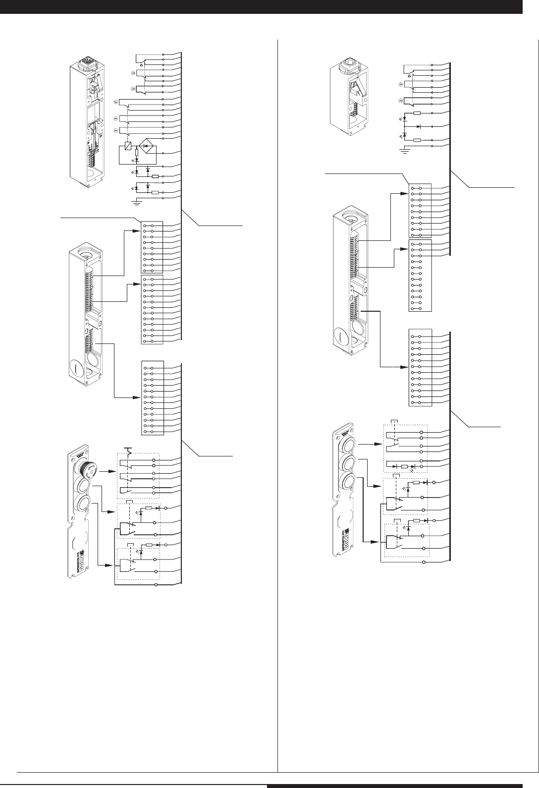
3. Circuit diagrams and connection examples
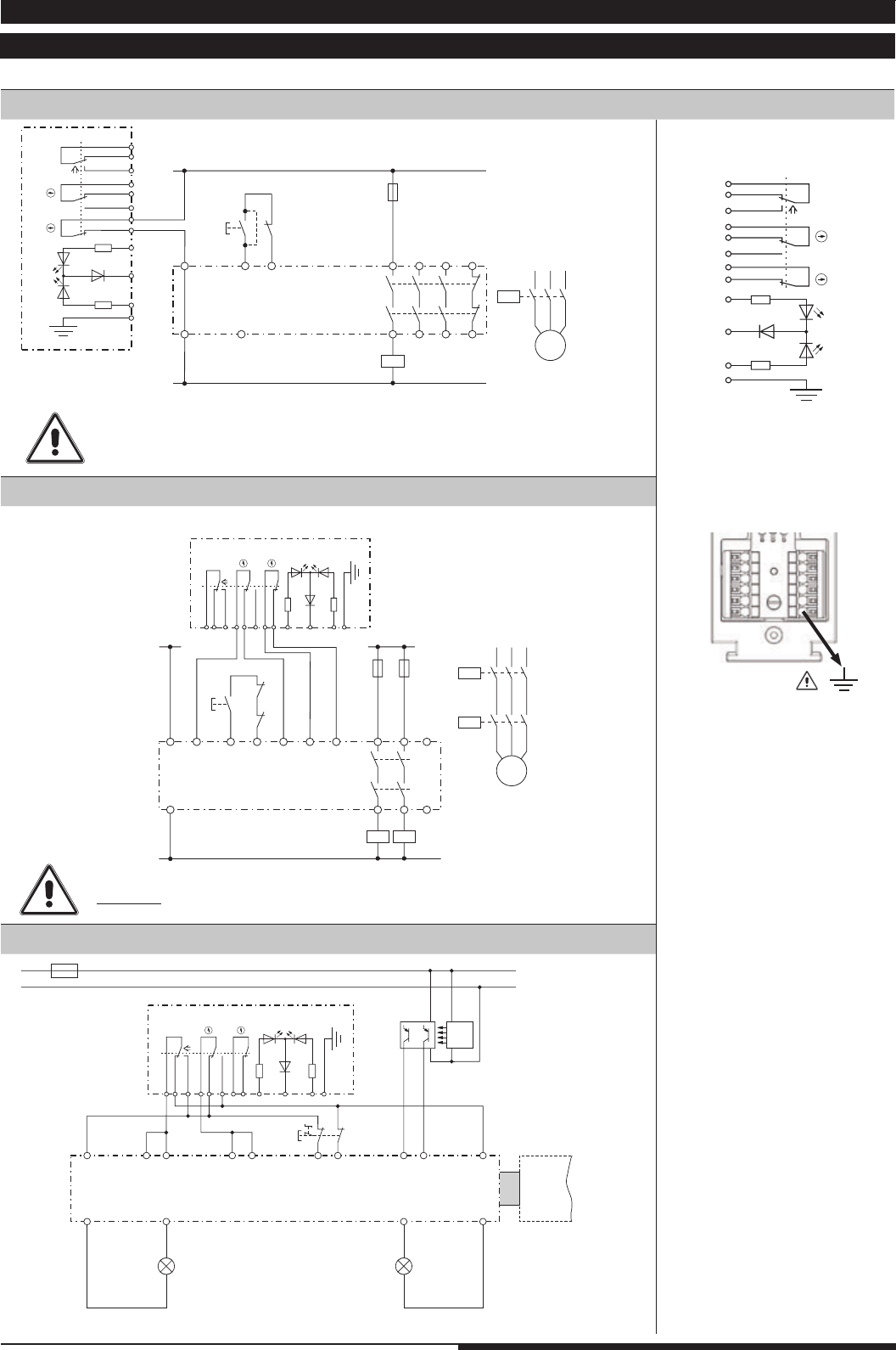
3.1 Circuit diagrams for switching modules (SX-, SV-, RX-, RV-modules)
When monitoring of the key or door position is required,
terminals 7 and 8 must be used!!!
At 2-channel redundant monitoring of the key or door position
d o n o t connect to terminal 10!!!
All examples shown in active state
Key- /
door position
Signalling
Active state SX-Module
Non-active state RX-Module
2.) STS-switching module (SX-Module) + 2-channel E-stop-modulel (LG 5925)
1.) STS-switching module (SX-Module) + 1-channel E-stop-module (LG 5924.48)
3.) STS-switching module (SX-Module) + input module (BG5913); exclusive OR circuit with C/O contact
15 Mounting- and operating instruction SAFEMASTER STS / 03.02.16 en / 639
L1 L1
M10809
N
A2(-)
A1(+) S11 S33 S34 S12 S22 S21
STS-Locking module
emergency stop module LG5925
13
14
..
23
..
24
on
32164520 19 11 9108 7171816152423222112
K1 K2
K1
K1
K2
K2
M
22
24
42
32
62
21
41
51
52
54
31
61
yellow
red
green
12
14 11
22
24
42
32
62
21
41
51
52
54
31
61
gelb
rot
grün
6
4
5
20
19
11
9
10
8
7
17
18
16
15
24
23
22
21
12
M9712_h
12
14 11
1
3
2
1 _
2 _
3 _
4 _
5 _
6 _
7 _
8 _
9 _
10 _
11 _
12 _
_ 13
_ 14
_ 15
_ 16
_ 17
_ 18
_ 19
_ 20
_ 21
_ 22
_ 23
_ 24
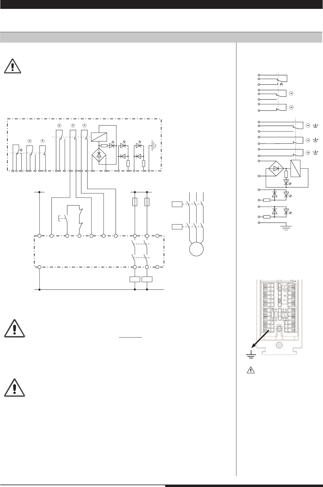
3.2 Circuit diagrams for solenoid locking modules (ZRX, YRX, ZAX, YAX-modules)
All examples shown in active state
Minimum wiring for 2-channel monitoring
Key- /
Door position
Solenoid / Signalling Solenoid position
Active state ZR_-module
Non-active state YR_-Module
1.) STS-solenoid locking module (ZRX-module) + 2-channel E-stop module (
LG 5925)
For single channel monitoring
terminals 7 and 8 or 17 and 18 must a l w a y s be used!!!.
The contacts of the door or keyposition must only be used for additional purposes.
They are intended to be used for extended feedback e.g. set-up mode
(see example on page 16).
On dual channel redundant monitoring of the lock position and using the changeover
contact 9, 10 and 11, the terminal 10 must not be used.
At antivalent monitoring terminal 9 must not be connected.
In applications where the key or door position is monitored dual channel,
terminal 5 must not be connected (see wiring example page 16)
16 Mounting- and operating instruction SAFEMASTER STS / 03.02.16 en / 639
L+
L -
Warten auf Start
Fehler
Fehleranzeige,
Freigabe aktiv
T2
T3
T4
T1
Warten auf Start
Fehler
Fehleranzeige,
Freigabe aktiv
Not-Aus
BWS
Sender
--
++
OSSD
A1+
Y1 X11
Y2 S12S11S13S14
X12
X11T1
T2
T3
T4
X12 X1
X2 S12S14S22S24S32S34S42S44
Steuereinheit
BH5911
(Zugeordnet zu seinen
Ausgängen)
A2-
(-)
13233334
24
14
58
(-)
48
K1 K2
Geschwindigkeits-
Reduzierung
Eingangsmodul
BG5913.08/02MF0
(Zugeordnet zum BG5912)
(-)
58
(-)
48
14
22
12
24
42
32
62
11
21
41
51
52
54
31
61
gelb
grün
rot
A1+
Y1
Y2
Ausgangs-
modul
BG5912
132333
34
24
14
K1
K2
Maschinenfreigabe 34
44
3
2
1
6
4
5
20
19
11
9
10
8
7
17
18
16
15
24
23
22
21
12
M9810_g
STS-Zuhaltemodul
22
24
42
32
62
21
41
51
52
54
31
61
gelb
rot
grün
6
4
5
20
19
11
9
10
8
7
17
18
16
15
24
23
22
21
12
M9712_h
12
14 11
1
3
2
1 _
2 _
3 _
4 _
5 _
6 _
7 _
8 _
9 _
10 _
11 _
12 _
_ 13
_ 14
_ 15
_ 16
_ 17
_ 18
_ 19
_ 20
_ 21
_ 22
_ 23
_ 24
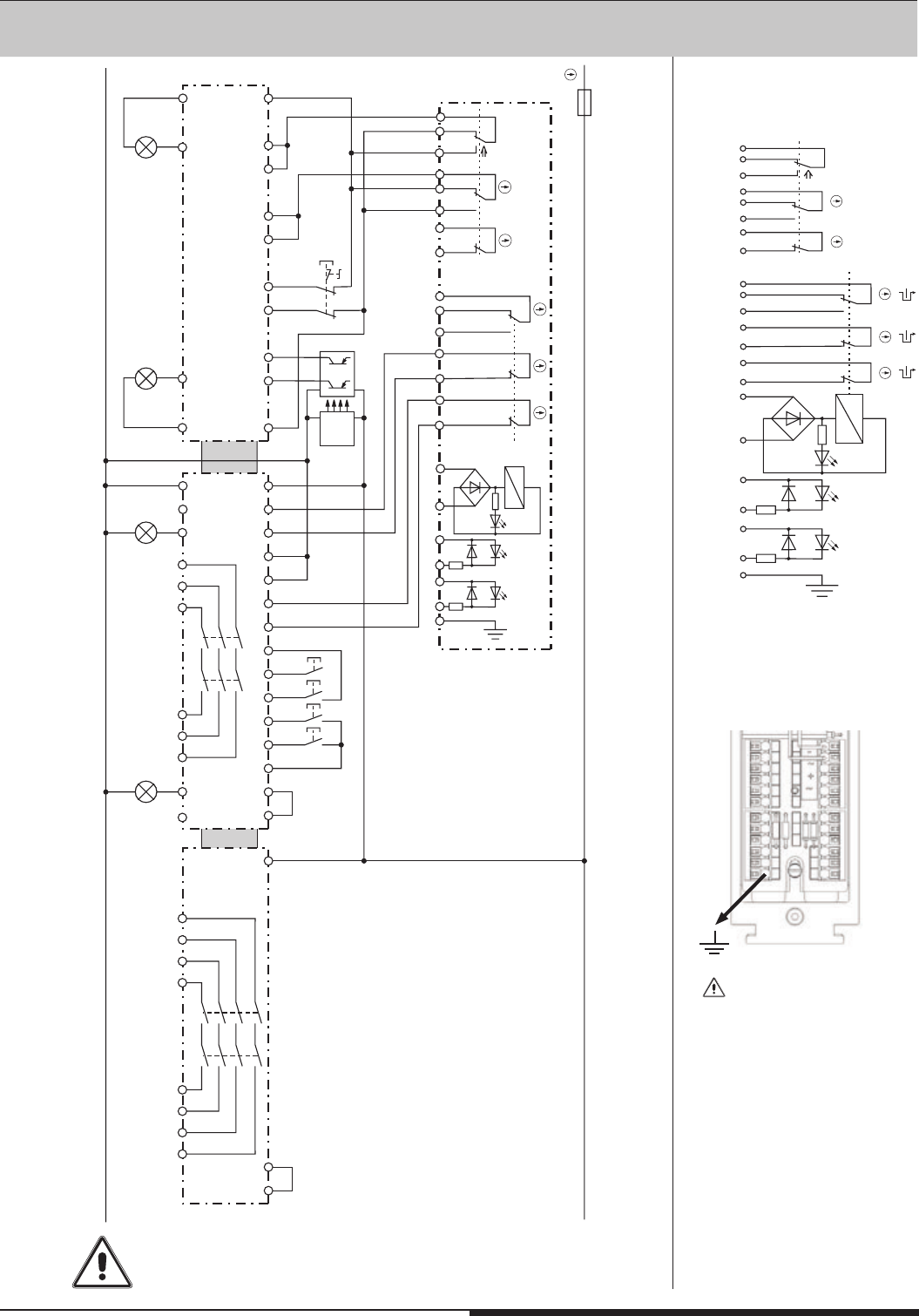
When monitoring of the key or door position is required,
terminals 19 and 20 must be used.
All examples shown in active state
Key- /
Door position
Solenoid / Signalling Solenoid position
Active state ZR_-module
Non-acttive state YR_-Module
2.) STS-solenoid locking module (ZRX-Modul) + SAFEMASTER M (input module BH 5913, control Unit BH 5911, output module BG 5912)
State: Door closed and locked. Suitable for applications with set-up operation (door closed but not locked)
and full operation (door closed and locked).
17 Mounting- and operating instruction SAFEMASTER STS / 03.02.16 en / 639
LH5946
standstill monitor
L1 L+
A1 S11 S21 S22
13 S12
23
L2 L-
L3
A2
L1
A1
L2
A2 11 23 33
Q2
L3 12 24 34 14S33 24S34
LG5925
emergency stop module
Q1
K1
K2
Q2
M11565
I> I> I>
M
3~
17 9715
18 10 A2 14 24
A1 13 23
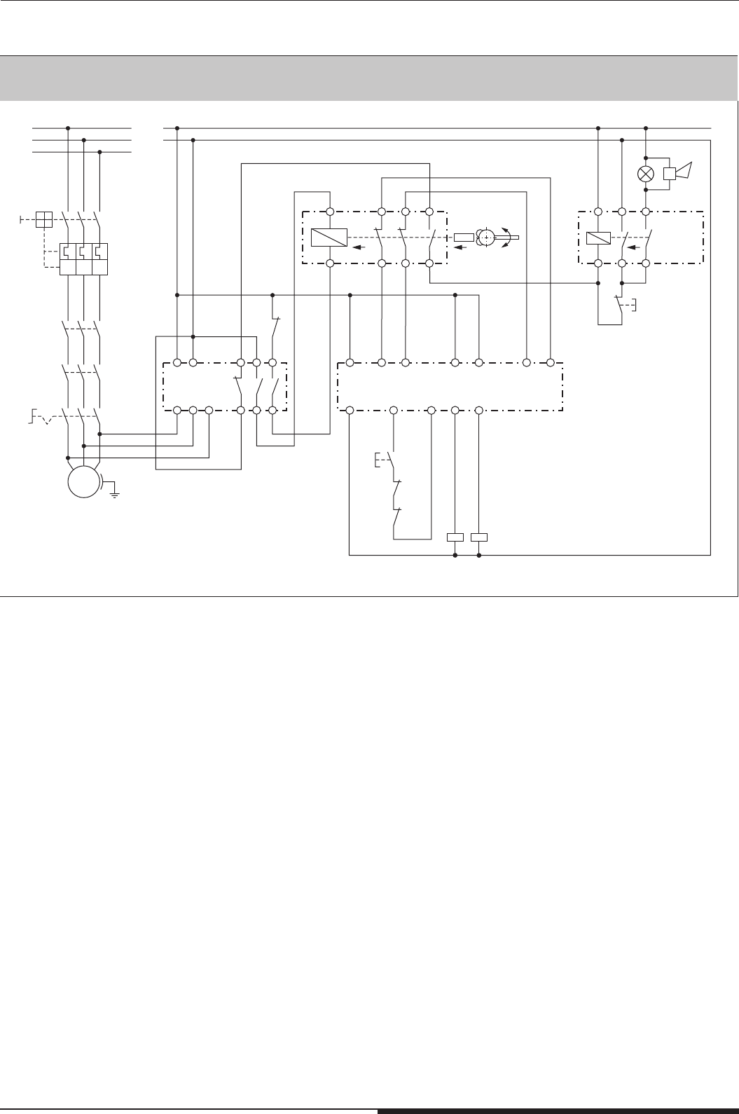
Escape-
Emergency- Release
Auxiliary-
IK3079.02
Reset
Alarm
Alarm
816
K1
K2
Ein
K1 K2
ZRH03M
Locking
with coded key
All examples shown in active state
3.) STS-Zuhaltungen mit Hilfs- oder Notenriegelung oder Fluchtentsperrung zusammen mit einer akkustischen und visuellen Alarmierung.
18 Mounting- and operating instruction SAFEMASTER STS / 03.02.16 en / 639
T5
T4
T6
T1
T3
T2
T11
T10
T9
T8
T7
T12
T6
T5
T4
T3
T2
T10
T9
T8
T7
T12
T11
T1
1
8
7
5
2
10
18
17
16
15
12
24
22
6
4
3
9
19
11
20
21/23
M4914_a
ge
rt
gr
15
24
21/23
22
21/23
12
11
9
10
8
7
17
18
16
3
2
1
6
4
5
19
20
T12
ws
ws
Option module
ST2451.001
Locking module ZRH
connection by
connection set
solenoid lock
ST2453.1
(see variants
and accessories)
Flat cable
(included)
double cage clamp terminal
T6
T1
T5
T4
T3
T2
T11
T10
T9
T8
T7
T12
T6
T5
T4
T3
T2
T10
T9
T8
T7
T12
T11
T1
M4941_b
T12
1
8
7
5
2
10
12
6
4
3
9
11
gr
4
5
6
12
3
2
1
9
11
10
8
7
rt
ws
ws
ws
Switch module SX
Option module
ST2451.002
connection by
connection set
switch ST2453.1
(see variants
and accessories)
double cage clamp terminal
Flat cable
(included)
3.3 Terminal designation option module
19 Mounting- and operating instruction SAFEMASTER STS / 03.02.16 en / 639
Q1
-
M11214
M
POWER
INTERLOCKING
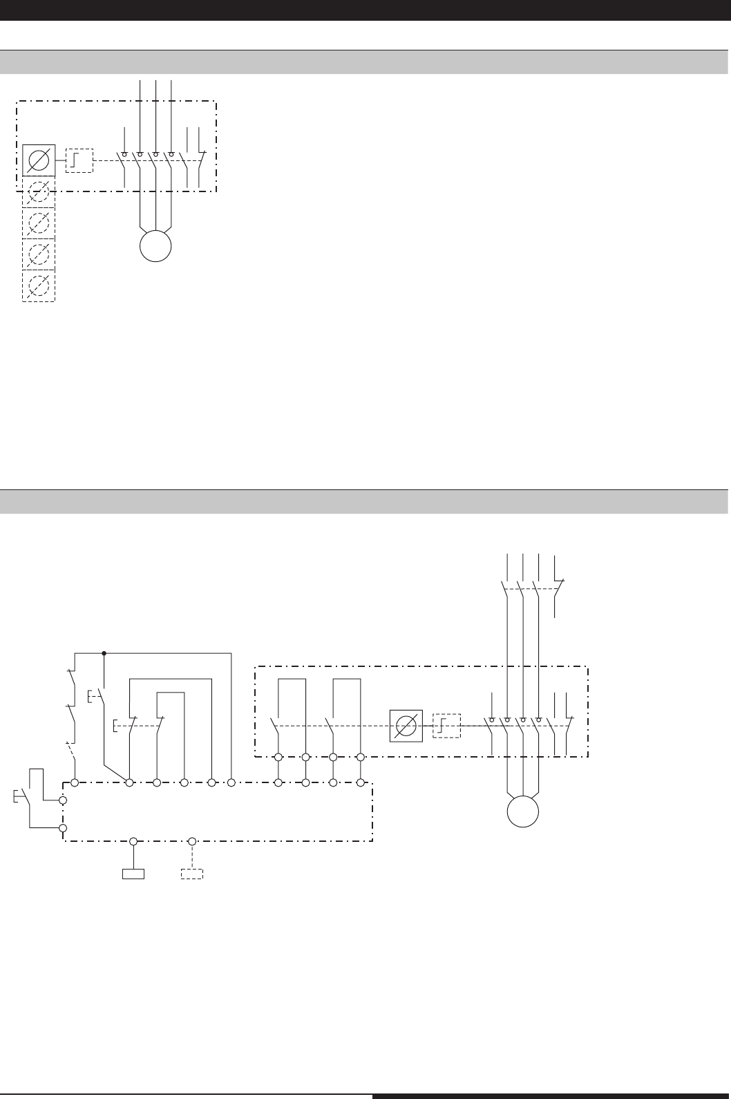
3.4 Connection examples Power Interlocking
Power Interlocking with monitoring function.
After disconnecting the load isolator 1 key can be removed immediately. This key is equipped, in addition, with monitoring contacts. If necessary, they
can be included in a safety circuit together with an auxiliary contact of the switch disconnector.
Power Interlocking without monitoring function and without redundancy (Stop 0).
After disconnecting the load isolator 1 to 5 keys can be removed.
All application examples are in zero voltage state
1.) Application example with mechanical design
2.) Application example with a switching version
M11216_a
L1 L2 L3
-
K1
YX
Q1
M
11987
(K2 not shown)
POWER INTERLOCKING
on
RES
A1
S11 S12 S22 ST2S21ST1
emergency
stop
on
K1
Y
K2
S42 S31 S32S41
14 24
K1 K2
UG6970
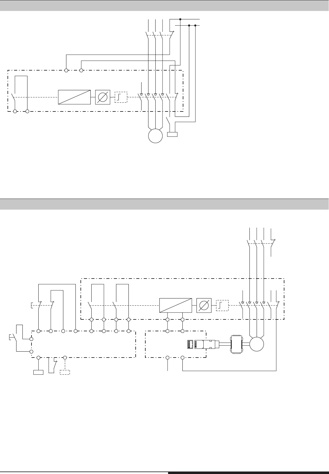
20 Mounting- and operating instruction SAFEMASTER STS / 03.02.16 en / 639
L1 L2 L3 L-
L+ (24V)
K1
Q1
M11147
M
18
15 16
X
X
W
Y
17
POWER INTERLOCKING
K1
Disconnected state, magnet energized (24 V), key inserted and removable.
Power Interlocking where standstill monitoring, time delay or other monitoring functions can be added.
The key can be removed only after disconnecting the load isolator and release by the magnet.
Disconnected state, solenoid energized (24 V), key inserted and removable.
Power Interlocking with monitoring function and mechanical redundancy;
- Stop 0 over Q1;
- Stop 1 over circuit logic
L1 L2 L3
-
K1
Q1
M11218
M
S22 S42S11 S31 S32
14
13
24
23
+24V
S12
18 15 16
1787
S21 S41
14 24
(K2 not shown)
POWER INTERLOCKING
K1 K2
UG6970
on
emergency
stop
RES
A1
Encoder
UH5947 EO
RJ45
3.) Application example with a solenoid locking version
4.) Application example with a solenoid locking version
21 Mounting- and operating instruction SAFEMASTER STS / 03.02.16 en / 639
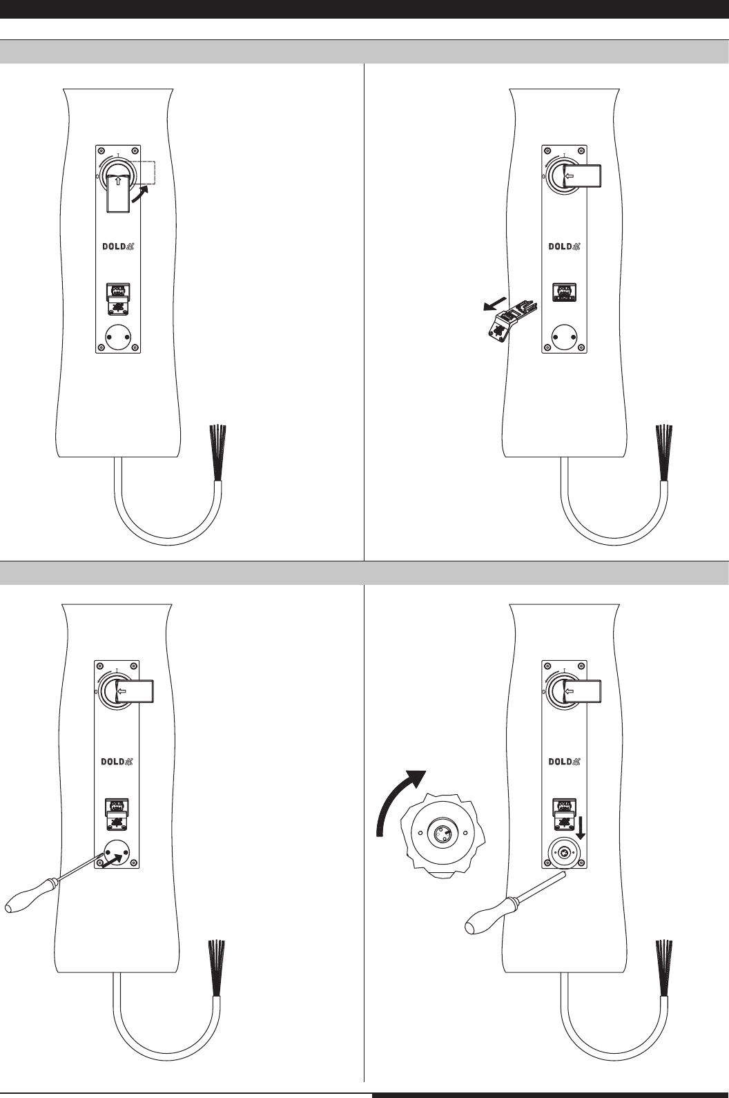
klick
klick
1.
2.
M4392_a
M4393_a
1.
2.
M ≤ 1Nm
E
M4400_a
2.
1.
M ≤ 1Nm
E
M4399_a
M4394_a
M4395_a
1.
2.
M4939_a
4. Operation
Example
: ZRNA
Example
: SVA
Release
Lock
Long-nose
pliers
Example
: ZRHA
Lock Release
Lock Release
Example
: M10A
Before returning to normal operation, the protective function must have been reactivated.
Alternatively
snake eye
screw driver M4
(from 01.09.14)
4. 1. Mechanical Units 4. 2. Switch units with locking mechanism
4. 3. Solenoid locking module with auxiliary release 4. 4. Solenoid locking module with emergency release
SAFEMASTER STS-units are parts of the DOLD safety switch and key interlock system. When supplied by DOLD it comes always with a key ex-
change plan (see page 4). The specifications stated in the key exchange plan have to be observed implicitly. The operation of the SAFEMASTER
STS-units has to be done according to the data sheets.
Before using the system the operator has to make him selve acquainted with the operating sequence state in the key exchange plan. The coding of
the keys and locks make sure that the system can only be operated in the defined sequence. Keys, actuators and padlock modules must only be
operated manually. Tools must not be used for operation!
1. Push the key in fully, until it latches.
The latching is only to keep keys and actuators in position and
prevents ejection.
22 Mounting- and operating instruction SAFEMASTER STS / 03.02.16 en / 639
M4396_c
1.
2.
M4415_a
2.
M4397_b
Example: ZRFA
Activation
Reset
Release
Lock
1. The STS-ZRFA has to be reseted before it is ready for use.
3. Active postion is reached automatically.
If not please check the rope and rope tension, see page 10; C: Tensioning of steel rope.
4. 5. Solenoid locking module with escape release
23 Mounting- and operating instruction SAFEMASTER STS / 03.02.16 en / 639
1.
M4416_a
M4391_b
2.
3.
Activation
Example: STS-F-Kit
1. To reset the system, the actuator has to be removed according to the procedure.
See also page 10; D: Fixing the actuator.
2. Door can be opened and allows escape.
Handle should reach active
position automatically
Reset
4.6 F-Kit
24 Mounting- and operating instruction SAFEMASTER STS / 03.02.16 en / 639
1.
M4681_a
2.
M4682_a
M4683_b
1.
A
M4684_c
A
60°
2.
3.
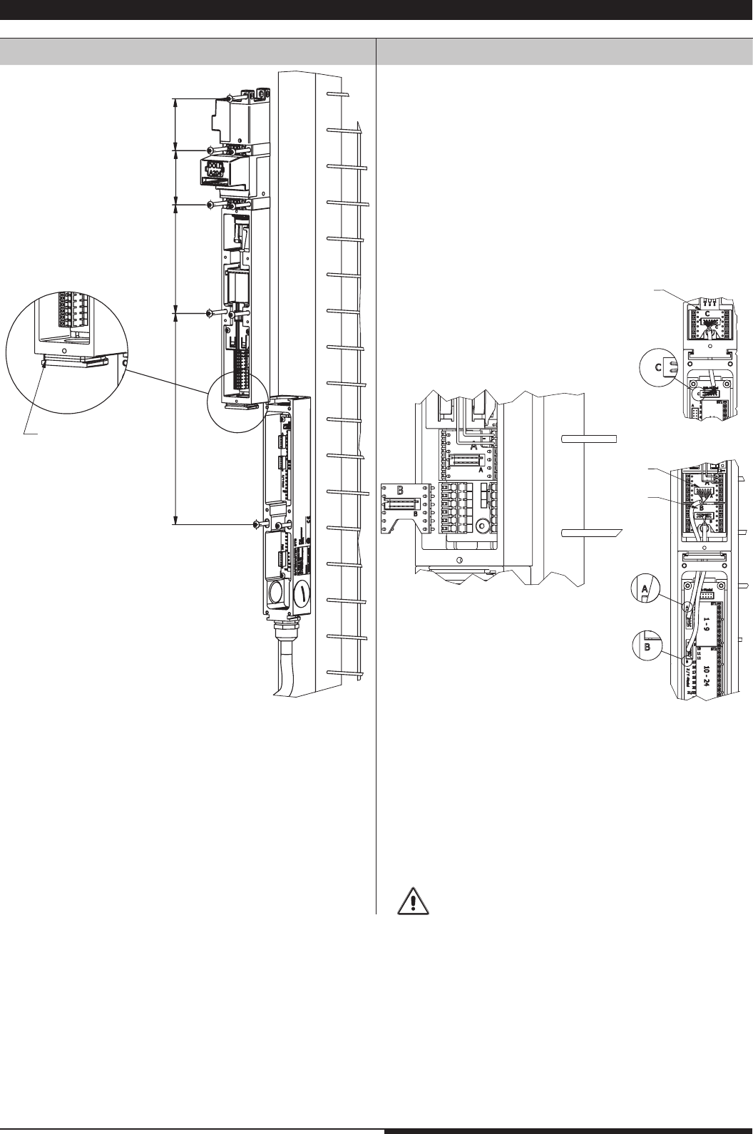
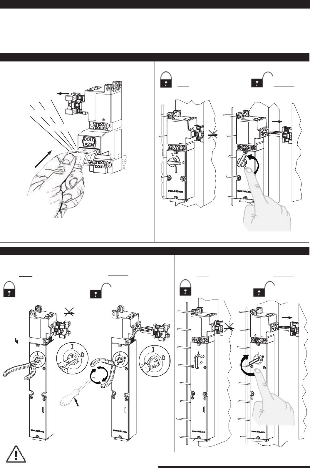
4.7 Power Interlocking
Switching off (all models)
Auxiliary release (variants with electromechanical locking function)
1. Disconnect energy via
switch disconnector
1. remove cover when
energy is disconnected
2. activate auxiliary
release
3. key can be removed
2. Remove key, this locks
switch disconnector
in off position
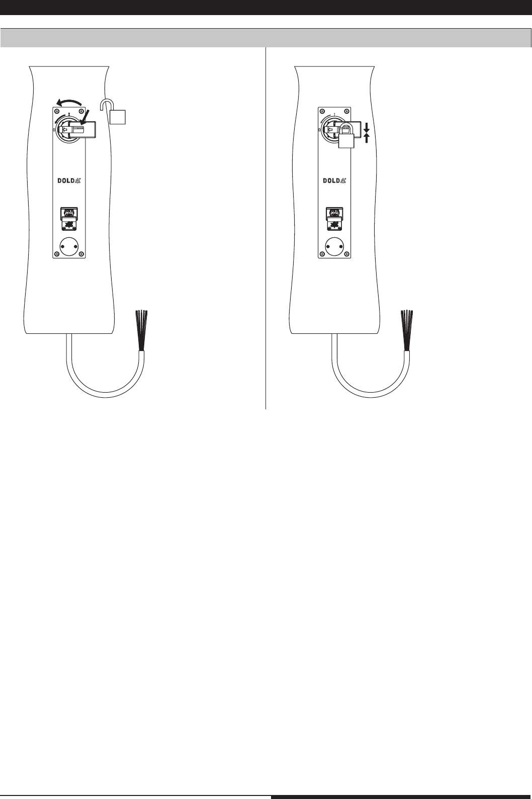
25 Mounting- and operating instruction SAFEMASTER STS / 03.02.16 en / 639
2.
1.
M4685_b
3.
M4686_b
LOTO facility (all variants )
4.7 Power Interlocking
4.8 Usage
26 Mounting- and operating instruction SAFEMASTER STS / 03.02.16 en / 639
A simple way to apply the lubricant is by using spray cans. They allow to lubricate the relevant parts oft he mechanic modules through the actuator slots.
Using high visconse gease or oil may cause dirt to adhere, whitch may influence the operation.
In any case we recommend performing your own test to find the most efficient lubricant for your application. Please take also into account the viscosity
of the lubricant and the influence of the operating temperature. To high viscosity could result in malfunction.
Of course we are willing to assist you selecting. Please do not hesitate to adress us with your questions!
In most applications, due to the construction and the selected materials, SAFEMASTER STS does not require lubrication. Still, there are special ca-
ses in which additional lubrication would be wise. In those cases it is necessary to select the right lubricant for the application.
6. Lubrication
Notes
SAFEMASTER STS-units work best in clean condition. Contamination can be normally removed by compressed air or water. When using cleaning
agents they have to be rinsed off afterwards, especially if aggressive chemicals like phosphoric acid are used. If this is not observed, units may be
damaged.
Dogged fouling may be removed with brake cleaner. Please observe the notices by the manufacturer.
In case of coarse fouling e.g. partially hardened concrete, mechanical devices may be cleaned with a high-pressure steam cleaner
- The key and module label plates should not be damaged.
- The high pressure of the water may damage the seals of electrical devices.
When using a steam cleaner extra care is required.
After such type of cleaning it may be necessary to grease the device. Aditional information may be found in the Table to select the right lubricant.
5. Cleaning
Table to select the right lubricant
Type of
pollution Example Clinging dirt Recommendation
for lubricant Remark
Dry dust cement, flying ashes, stone,
lime no Graphite powder; slide coating on
graphite or PTFE base Do not use grease!
Mud concret, flying ashes,
water with lime content yes
Gear spray with MOS2 and
graphite, Molycote spray, surface
active oil
Humid dust Wood dust, chips yes
Slide coating on graphite, MOS2,
or PTFE base, in some cases
surface active oil
Do not use grease!
Clinging dust Asphalt yes surface active oil Do not use graphite!
Acids and bases Additives in detergents e.g.
acids or brine
no,
caustic Greasing oil or grease spray
Surface rust Rust dust no Flow grease on EP base, corrosi-
on protective spray with additive Use with rust film
Icing Sleet yes Silicone spray,
penetrating oil Mount cover

27 Mounting- and operating instruction SAFEMASTER STS / 03.02.16 en / 639
SAFEMASTER STS-systems have to be tested regularly. This test must include the following elements:
1. Visual inspection of the units regarding cleanness: removing of all contaminations
2. Visual inspection of the fixtures: Possibly tighten the screws
3. Visual inspection regarding damage and wear: Function test
4. Function test according to the key exchange plan: Also try to insert at least 1 key into a wrong key module. This must not be possible!
In the case of faulty functions the machine has to be stopped/ secured. Remove system blockings or get it repaired.
If the operators are acquainted to the system and know the installation and operating manual, every actuation of the system can be regarded as test.
The yearly test (PL a to d) or monthly test (PL e) as described in the data sheets have to be performed in any case.
Nearly all faults can be temporarily remediated by a replacement kit or by replacing actuator modules. Faulty units can also be sent to DOLD for re-
pair. To accelerate the repair procedures please attach always a copy of the key exchange plan, or indicate the DOLD SAFEMASTER-STS Project
number.
Do not in any case disassemble a module, as every returned module is examined by us. Also it will lose warranty, if within warranty period. In case of
unprofessional assembly, the safe function of the unit can not be guaranted due to faulty assembly.
7. Test
7.1 System blocking as safety function
8. Repairs
SAFEMASTER STS-units have a failure diagnostic safety function. This makes the units to go into blocked state when failures are detected and
they cannot be operated after that. This function can be reseted when the fault is removed and the units are not damaged (reset function).
Procedure in case of system blocking
In the case of a system blocking we recommend the following procedure:
1. Make sure that all inserted keys, padlock modules and actuators are in the correct position and inserted correctly. (See module status page 3)
2. Start the reset procedure. Try to insert manually the blocked keys or actuators individually. Do not operate several keys or actuators at the same
time; it can prevent reset function. If after the 5th try the unit is not reseted, it has a fault.
3. Try to localize the reason for the failure, e.g. bent parts, contamination, objects in the unit. If it was possible to remove the fault,
repeat the reset procedure. Under certain circumstances greasing may help.
If after a few tries the SAFEMASTER STS-unit does not reset, there is an irremovable fault and the unit has to be repaired.
An electrical module cannot be joined with a mechanical module. The bayonet ring cannot be turned as described in the manual. What can
be done?
When not mounted to mechanical modules, the electrical modules of SAFEMASTER STS return to a safe switched off state and will not mount to
mechanical units unless actuated by hand. If a solenoid locking switch is used with closed circuit operation the locking solenoid must be pushed as
described in the example for ZR_-modules.
Any objects between the modules must be removed!
Mechanical modules cannot be joined. The bayonet ring cannot be turned as described in the manual. What can be done?
Both modules must be in the correct safe state, i. e. with a key module “10” the key must be inserted, with a key module “01” the key must be extracted.
You will find more information about the mounting rules on the Table Assembly / modifying - safety mounting state of the modules on page 3, 5 or 6.
How do I read the type numbers?
Please refer to the corresponding product key - table in the design guide
How can I make sure that the system works correctly?
Check the system by using the key transfer plan to detect possible false positioning or incorrect mounting of units.
One unit is blocked, why?
All SAFEMASTER STS units are able to detect internal faults. If a fault is detected the units go into a safe state which blocks the system. If the fault
can be removed when the unit is in the safe state, e. g. by adjusting the mountings on a distorted surface to reduce tension. The units can then be
reset by inserting and removing the key or actuator several times. (see sect. 7.1 page 26).
Key cannot be extracted or pushed in
Please check the label of the key and the key module, they must correspond. Also make sure, using the key exchange plan, that the key can be ope-
rated in the intended way. If the key cannot be extracted or pushed while operating it correctly, please make sure the key or actuator below or above
is inserted fully. (see sect. 4.1).
Frequently asked questions – FAQs
E. DOLD & SÖHNE KG
Postfach 1251 • D-78114 Furtwangen
Phone +49 7723 6540 • Fax +49 7723 654356
dold-relays@dold.com • www.dold.com
Innovative
Safety Concepts
DOLD offers an integrated safety concept for
complete solutions under one roof, which have
already been successfully implemented world-
wide for many decades.
From monofunctional safety control gear for
simple safety applications to multifunctional,
modular safety systems, DOLD develops
tailor-made solutions for protecting people and
plant.
We would be more than happy to tell you about
our additional safety solutions.
Our experience. Your safety.
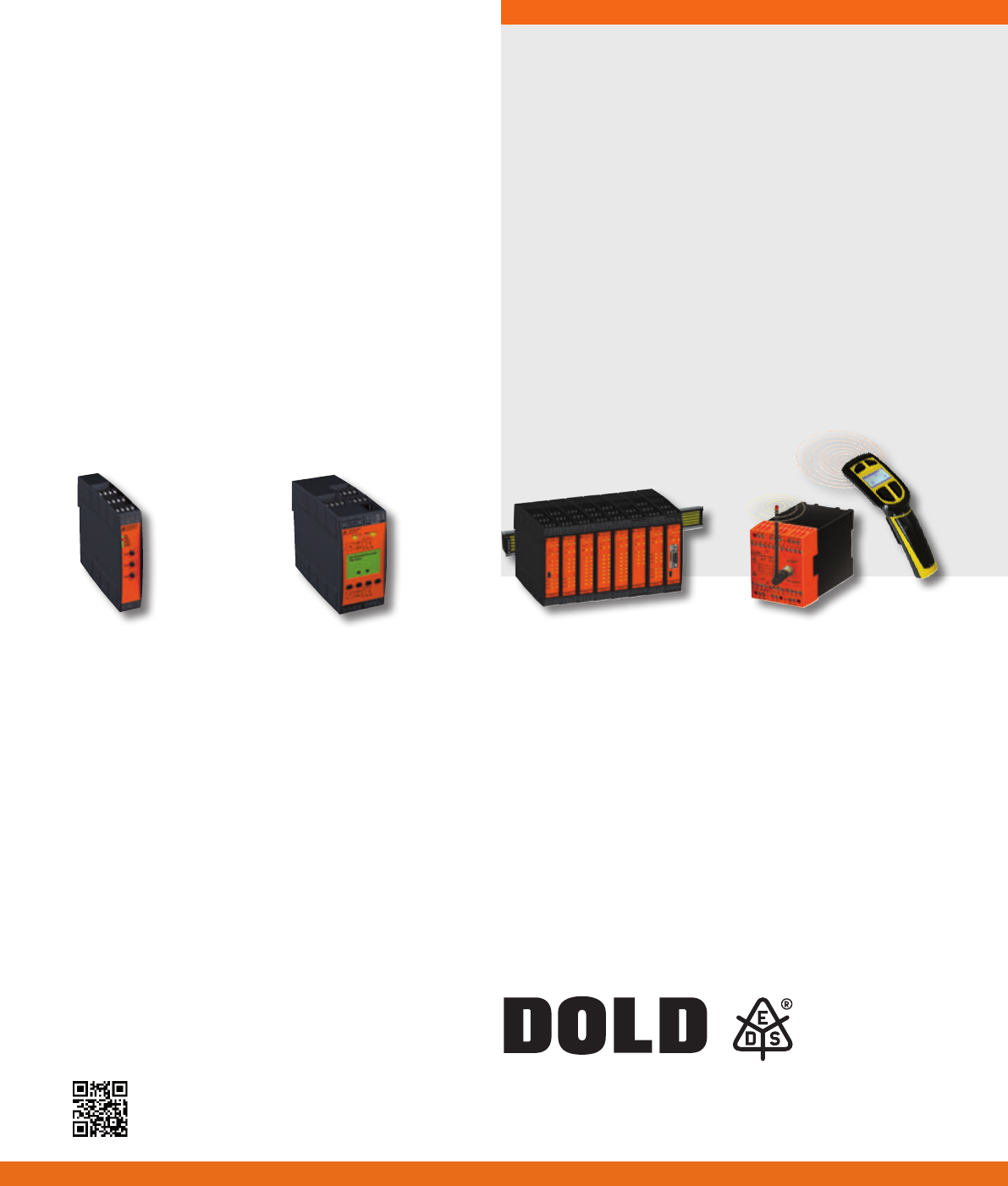
SAFEMASTER - The right solution for every application.
SAFEMASTER S
The SAFEMASTER S series
speed sensing device en-
sures increased productivity
and safety for your service
personnel thanks to a com-
bination of safe speed and
stand-still monitoring.
SAFEMASTER W
SAFEMASTER W, the wire-
less companion for your
safety. You can use it to shut
down dangerous move-
ments within a fraction of a
second. The wireless safety
system consists of a radio
controlled safety switch, a
handheld transmitter and an
optional infrared receiver.
SAFEMASTER C
The multifunctional UG 6970
safety module from the SAFE-
MASTER C family by DOLD
monitors two independent
safety functions. You can make
any desired choice from the
following basic functions:
emergency stop, safety gate,
two-hand controls, safety
mat/safety edge, antivalent
switch and light barrier.
SAFEMASTER PRO
The modular and programable
safety system SAFEMASTER
PRO monitors all safety cir-
cuits in your machine and sys-
tems – easy, exible and safe.
The amount of input and out-
puts on the central control
unit can be expanded at any
time using extension modules.
Mounting- and operating instruction / 160203 / xxx / Translation of the german original
