LIBRETTO Strabuc 918 GB.fh11 Istr_strabuc918_gb Istr Strabuc918 Gb
User Manual: istr_strabuc918_gb
Open the PDF directly: View PDF ![]() .
.
Page Count: 16
LIBRETTO Strabuc 918 GB.fh11 17-06-2008 11:58 Pagina 1
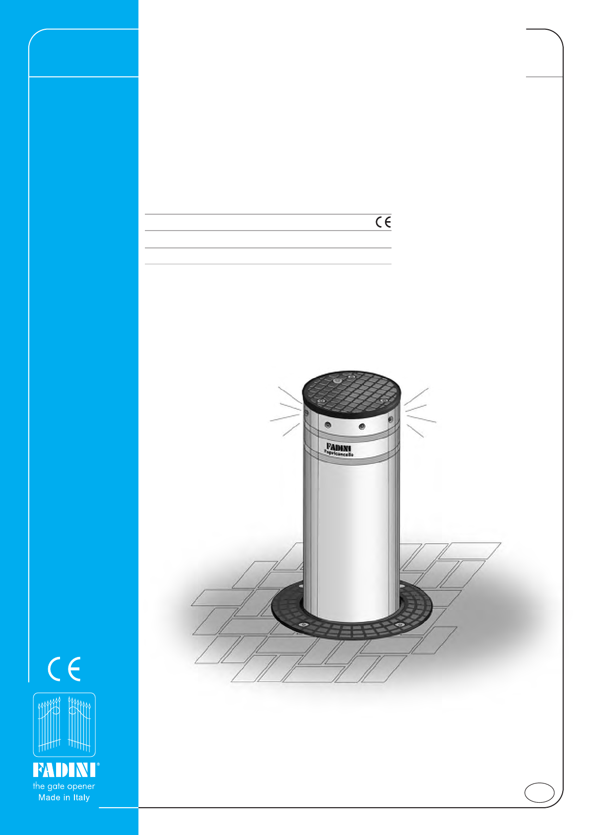
STRABUC 918
Fully retracting cylindrical
traffic control post
Regulation-compliant oil-hydraulic operator
With cylindrical container to be cemented
Painted and stainless steel post version
GB
Instruction manual
LIBRETTO Strabuc 918 GB.fh11 17-06-2008 11:58 Pagina 2
2
INSTRUCTIONS TO BE FOLLOWED BEFORE INSTALLING THE OPERATOR
PRELIMINARY WARNINGS ON SAFETY AND GOOD OPERATION
Before commencing operator installation, it is essential to remember:
- That installation, checking, testing, risk analysis and subsequent maintenance work must be performed by authorised, qualified technicians.
- This operator has been designed for the use described in this manual only, and using at least the safety, control and indication accessories
as here recommended.
- Any other application not explicitly indicated in this manual could cause malfunction, damage or personal injury.
- To check that the ground is stable, to avoid subsequent settling or deformation in the traffic control post installation area.
- To check that there are no nearby buried utility pipes.
- To check that there are no sources of electromagnetic disturbance in the immediate vicinity of and below the installation accessories such
as to conceal or influence the magnetic/electromagnetic detection of the metal detectors and/or other electronic system control and
management appliances.
- To check that the mains supply and voltage to the electric motor is 230V±10% at 50Hz.
- The power supply to the Strabuc 918’s built-in motor must be made using electricity cables with a 1.5 mm2 section for a maximum distance of
50 metres. For distances of over 50 metres, use electric cables with sections suited to the installation.
- Always use the original components indicated by the manufacturer to replace elements or accessories.
- Meccanica Fadini declines all responsibility for improper use not specifically indicated in this manual and any malfunction deriving from the
use of materials or accessories other than those indicated by the manufacturer.
- The manufacturer reserves the right to make changes to this manual without giving notice
!
The manufacturer, Meccanica Fadini, is not responsible for non-observance of good installation
practice and applications not indicated in this manual.
FOR OPTIMAL APPLICATION AND USE OF THE STRABUC 918 PLEASE READ THE INSTRUCTIONS AND CONSULT EXPLANATORY DIAGRAMS.
IMPORTANT: ALL INSTALLATION OPERATIONS MUST BE PERFORMED BY A QUALIFIED TECHNICIAN, IN OBSERVANCE OF THE EN 12453 - EN 12445
SAFETY REGULATIONS AND MACHINERY DIRECTIVE 98/37/EC.
CAREFUL RISK ANALYSIS IS REQUIRED UNDER APPLICABLE REGULATIONS
GENERAL COMMENTS
STRABUC 918 is a fully retractable, belowground, oil-hydraulic steel traffic control post intended to prevent unauthorised vehicular access.
It is an oil-hydraulic operator with a built-in hydraulic main unit.
The Elpro S40 electronic programmer is installed externally, in a protected place.
The traffic control post comes with a series of accessories that guarantee the necessary safety and the required operations, in order to make the
operator suitable for installation in all public and private settings.
!
®
ISTRUZIONI DA ESEGUIRE PRIMA DELL'INSTALLAZIONE DELL'AUTOMAZIONE
LIBRETTO Strabuc 918 GB.fh11 17-06-2008 11:58 Pagina 3
3
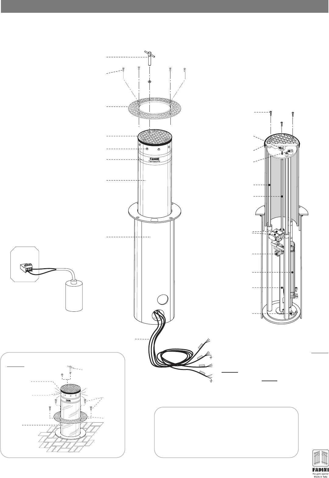
COMPONENTS OF THE RETRACTING OIL-HYDRAULIC POST OPERATOR
oil-hydraulic
traffic control post
20 μF
20μF External capacitor
- to be fitted -
AB
Elpro S40
Universal triangular-
recessed release key
Cover flange
Electrical wires
Flanged cylindrical
container
Post cap with rubber edge
9x indicator LEDs
Amber colour
Type approved retro-
reflecting adhesive
Fully retractable steel
post with thickness of
4mm or stainless steel
version - on request
M10x50 stainless steel
hexagonal socket head
clamping screws
10 metres
of electric cable
Section of the
Strabuc 918
Release solenoid valve
(Optional on request): the
column lowers completely in
blackout conditions
Limit switches
Hydraulic
main unit
Oil-hydraulic
piston
Manual release
Manual
release tap
Eyebolt for hitching
and hoisting
3x Guide rods
M10x40 stainless steel
hexagonal socket head
cover-fastening screws
Piston rod
Rubber edge
STRABUC
1 - Limit switch
2 - 230V main unit power supply
3 -
230V voltage to LEDs and buzzer
(Optional on request)
4 - 230V Solenoid valve (
optional
on request)
STRABUC 918 STAINLESS STEEL
Stainless steel version of the traffic control post, differing from
the painted version in that the retractable post only is made of
stainless steel, the rest of the operator has identical applicative
and functional installation characteristics as the painted version
of the Strabuc 918. Pic.2.
Painted version
PIC. 2
PIC. 1
Release key
Finishing
seal
LED lights
Post
STAINLESS
STEEL
Screws
Collar
STRABUC 918
®
LIBRETTO Strabuc 918 GB.fh11 17-06-2008 11:58 Pagina 4
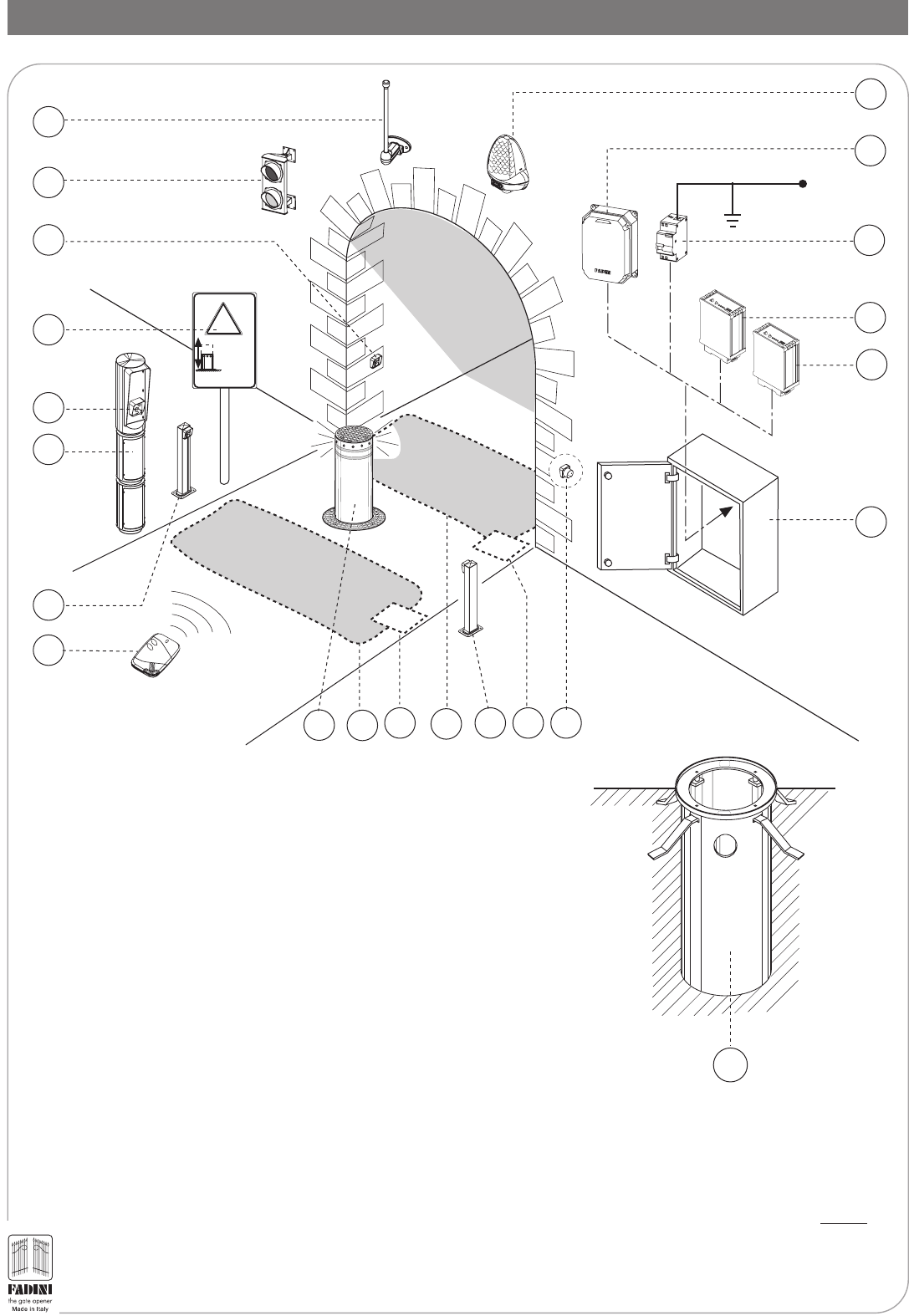
OPTIONAL AND RECOMMENDED ACCESSORIES FOR COMPLETE INSTALLATION
STRABUC
FADINI
l'apricancello
made in Italy
List of all operative accessories available:
1 - Miri 4 flashing light
2 - Elpro S40 electronic programmer with Siti 63 radio receiver
3 - Differential thermomagnet switch with 0.03A sensitivity (not provided)
4 - Entry metal detector
5 - Exit metal detector
6 - Anti-intrusion cabinet
7 - Polo 44 recess-mounted photoelectric cell receiver
8 - Sealed electric connection box with inductive coil (not provided)
9 - Post for Polo 44 photoelectric cell projector
10 - Below-ground exit inductive coil (not provided)
11 - below-ground entry inductive coil (not provided)
12 - Strabuc 918
13 - Siti 63 Transmitter
14 - Post for Polo 44 photoelectric cell receiver
15 - Visual 344 control accessory housing post
16 - Prit 19 key switch
17 - Post moving hazard-warning indicator
18 - Recess-mounted Polo 44 photoelectric cell projector
19 - Two-light traffic lights
20 - Birio A8 wall-mounted aerial
21 - Strabuc 918 housing to be cemented into the ground (standard issue)
Siti
1
2
3
4
5
7
230V ±10% 50 Hz
6
10
11 89
13
14
15
8
12
17
18
21
!
retractable
traffic
control post
16
19
20
PIC. 3
4
Cylindrical
container
®
LIBRETTO Strabuc 918 GB.fh11 17-06-2008 11:58 Pagina 5
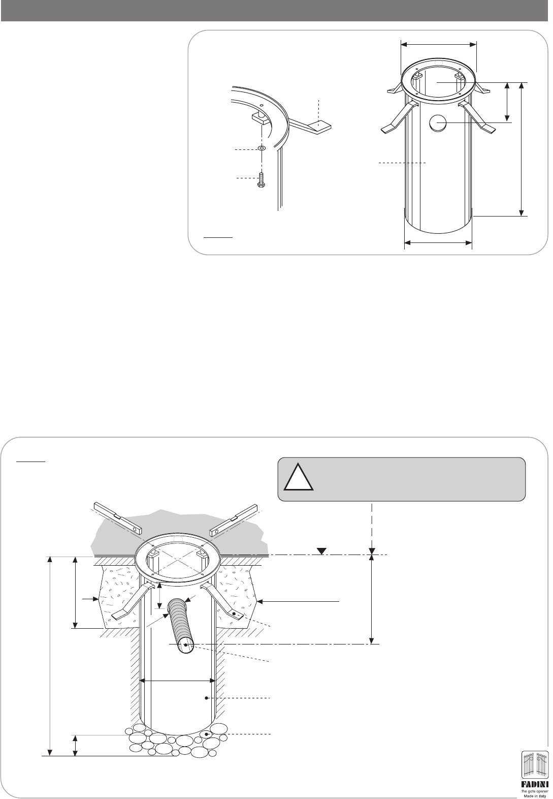
INSTALLATION OF THE CYLINDRICAL HOUSING TO BE CEMENTED INTO THE GROUND
- Assemble the support plates to be
cemented into the ground by fitting them
inside the slots in the cylindrical container
and fasten them by the provided screws
(Pic.4)
- Dig a hole measuring 80x80cm and approximately 1.20 m deep, where the Strabuc 918 is to be installed: these measurements are adequate
for inserting and cementing the cylindrical container at ground level (Pic.5).
Simultaneously, it is important to dig a hole in the ground to take a corrugated flexible pipe (max Ø50mm) to the cylindrical container, passing
through the hole as provided in the container, in order to house the electric wires to be connected to the Elpro S40 electronic programmer
(to be installed in a protected place).
- Before positioning the cylindrical container, arrange a 20 cm-deep layer of pebbles for rainwater drainage.
It is important that once the cylindrical container has been placed on the pebbles, the upper portion is flush with the ground level.
IMPORTANT: Take care to avoid power or water pipes when digging. Arrange a water drainage layer beneath the dig.
IMPORTANT: Once the housing has been positioned, before cementing, use a spirit level to ensure that it is absolutely level, to allow perfect
vertical movement of the traffic control post.
M10x35
Screws
Washer
Support plate to be
cemented underground
STRABUC
FADINI
l'apricancello
made in Italy
1035
Ø462
325
Ø405
Cylindrical
container
PIC. 4
IMPORTANT: The flooring or tarmac must be level
with the container upper edge.
!
STRABUC
FADINI
l'apricancello
made in Italy
Strabuc housing
Pipe, minimum Ø50, for housing electric
wires connected to the electric programmer
Support plates to be
cemented
Pebble layer for water drainage
0.0
Concrete cast
80 x 80 cm
32cm
Ø8 cm
Ø40.5cm
Hole depth approximately 120-125 cm
Spirit level
15-20cm
32cm
30cm approx.
PIC. 5
5
= cylindrical container =
®
Spirit level
LIBRETTO Strabuc 918 GB.fh11 17-06-2008 11:58 Pagina 6
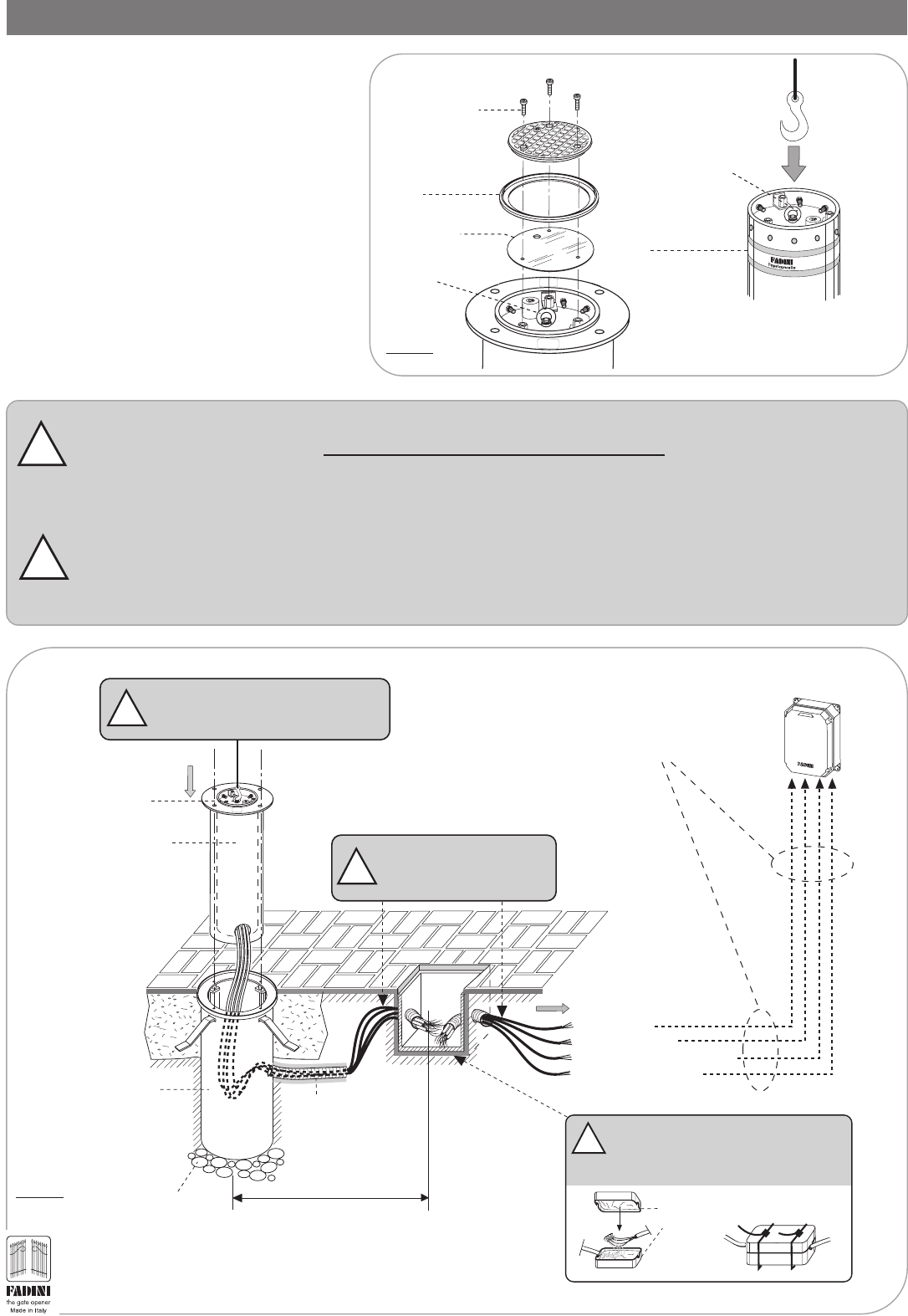
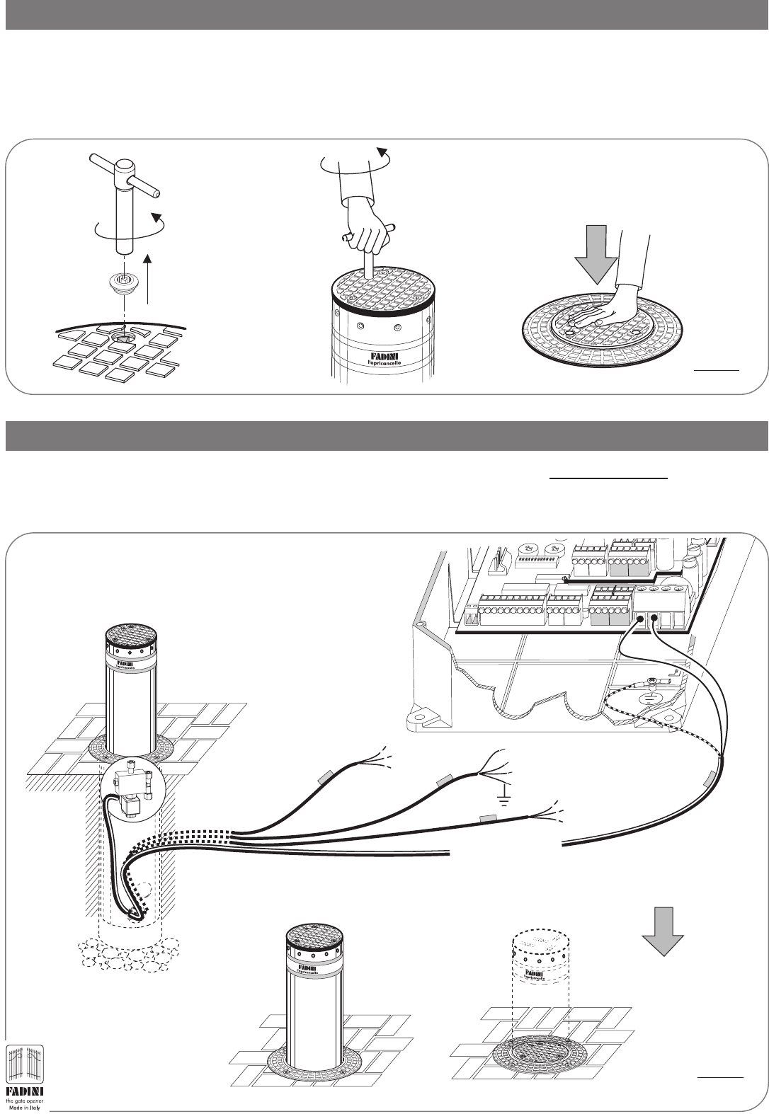
INSTALLATION OF THE STRABUC 918 TRAFFIC CONTROL POST
Once the cement has set, proceed with installation
of the Strabuc 918 inside the cylindrical container.
For this operation, it is necessary to use equipment
suitable for hoisting and then placing it in the post
seat, by hitching to the eyebolt on the top of the
retracting post cover, having unscrewed and removed
the three screws and the cover.
Before placing the Strabuc 918 inside the cylindrical
container, pass all the electric wires through the
corrugated tube connected to the Elpro S40
programmer: for this initial phase, use a pull out to
be passed through the pipe first (Pic.6 and Pic.7).
!
ATTENTION: as Strabuc 918 comes complete with a series of electric cables, each one 10 metres long, during all these
Strabuc 918 installation operations, never tug at or charge electric wires for any reason. During Strabuc 918 maintenance
or removal operations DO NOT CUT THE ELECTRIC WIRES, remove them from the pipes.
ATTENTION: measure the distance between the Strabuc 918 installed and the Elpro S40 programmer: once the Strabuc 918
has been positioned and fastened, all the electric cables must rest freely on the bottom of the cylindrical housing. If the
distance is greater, the wires should be extended using sealed joints (junction boxes) inside an accessible dividing box,
according to good installation practice: this will prevent malfunctions and will guarantee efficient operation over time.
!
PIC. 7
Pull the electric cables to the
Elpro S40 programmer
without tugging
!
Underground wiring housed inside a
corrugated pipe
1 - Limit switches
2 - Power supply 230V
3 - LED and buzzer power (optional)
4 - Solenoid valve (optional)
Elpro S40
STRABUC
Corrugated flexible tube
Pebble drainage layer
Eyebolt
LOWER
Strabuc 918
Cylindrical
container
~6 - 8 metres
Cylindrical
container
cemented into
the ground
For distances greater than 10 metres,
make extensions using sealed junction
boxes inside an accessible dividing box
!
Seal the junction
boxes using bands.
Junction
boxes
!
Align the traffic post cylinder holes with
those in the cylindrical container cemented
into the ground
6
®
M10x40 hexagonal
socket head post cover-
fastening screws
Rubber
edge
Eyebolt
STRABUC
FADINI
l'apricancello
made in Italy
Under the retractable post
cover, there is an eyebolt
for easy hoisting
Eyebolt
Retractable post
PIC. 6
Drilled flange
for edge tightening
LIBRETTO Strabuc 918 GB.fh11 17-06-2008 11:58 Pagina 7
INSTALLAZIONE DEL DISSUASORE STRABUC 918
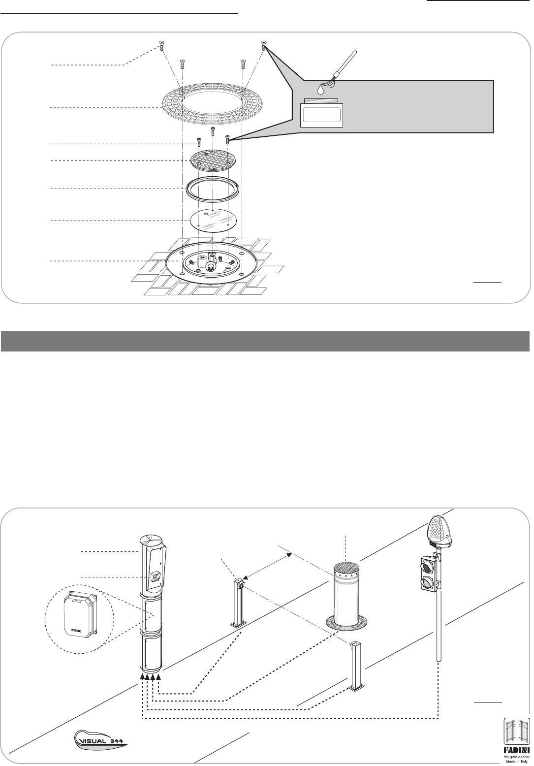
Once all the electric wires have been put in place, terminate by fastening the Aluminium collar and the Cover: lubricate the fixing screws
of the collar and retractable post cover using grease (Pic. 8).
ARRANGING THE SAFETY AND CONTROL ACCESSORIES
All safety and control accessories must be installed according to minimum recommended distances from the Strabuc 918 and these
distances must be strictly observed in order to obtain effective installation.
ARRANGEMENT OF THE PHOTOELECTRIC CELLS
The photoelectric cells must be installed at a minimum working distance as indicated in Pic. 9.
ARRANGEMENT OF VISUAL 344 - Pic. 9 -
The 2 or 3-module Visual 344 is a metal accessory used to house the Elpro S40 in exposed positions, in those installation situations in
which the programmer cannot be wall- or recess-mounted. It has also been designed for the installation of possible control accessories
such as intercom systems or key switches, in the immediate vicinity of the Strabuc 918 (pic. 9).
min. 1.0 m
Photoelectric cells
Polo 44
Strabuc 918
Prit 19
Visual 344
Elpro S40
Traffic lights
Miri 4
Underground wiring housed inside a corrugated sheath
PIC. 9
7
®
PREDISPOSIZIONE DEGLI ACCESSORI DI SICUREZZA E DI COMANDO
STRABUC
FADINI
l'apricancello
made in Italy
PIC. 8
IMPORTANT: LUBRICATE THE FOUR
CLAMPING SCREWS IN THE COLLAR AND
THE THREE COVER SCREWS WITH GREASE
GREASE
Screws for fastening cover
M10x35 stainless steel
hexagonal socket headed screws
Collar fastening screws
M10x50 Stainless steel
hexagonal socket head screws
Aluminium collar
Aluminium cover
Drilled flange
for rubber edge tightening
Strabuc 918 inside the
Cylindrical container
Rubber edge

LIBRETTO Strabuc 918 GB.fh11 17-06-2008 11:58 Pagina 8
PIC. 10
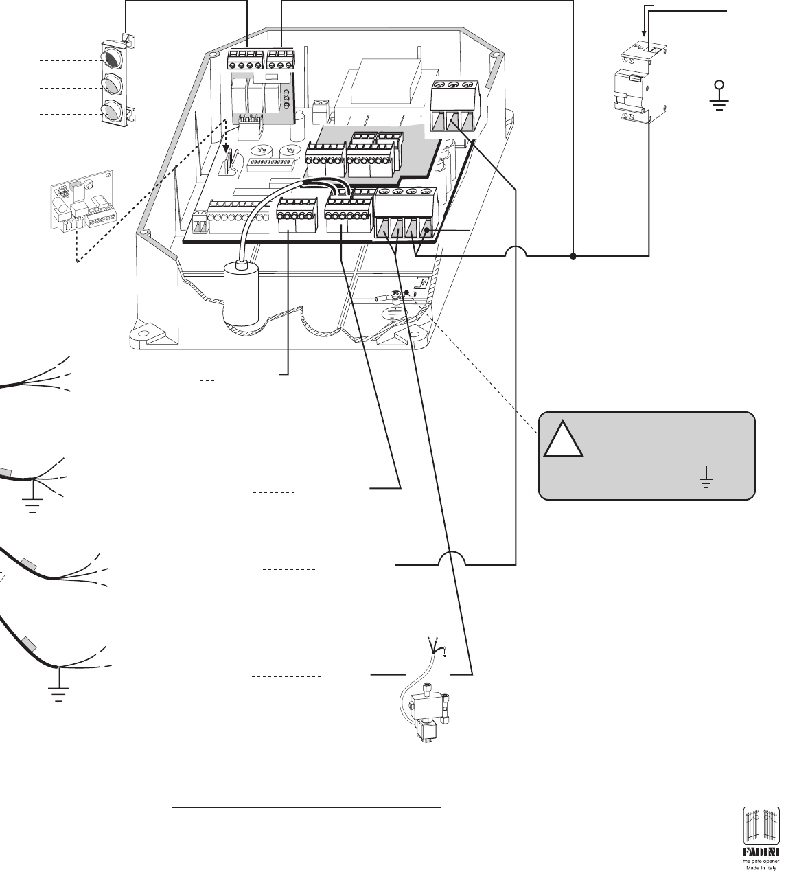
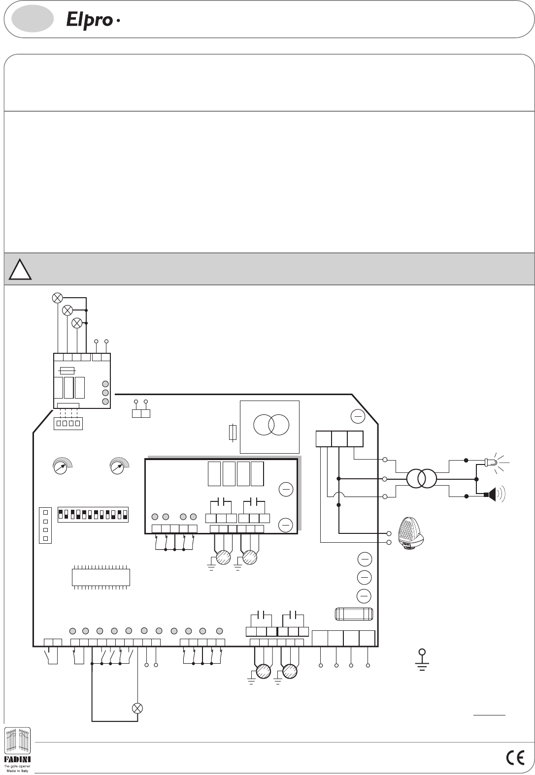
WIRING TO THE ELPRO S40 PROGRAMMER
Once the electric wires have been laid and positioned and the oil-hydraulic unit with the retractable post has been fixed, position the
electronic programmer and make the electrical connections (as indicated in pic.10), by connecting just one Strabuc 918.
It is important to connect a 20μF capacitor (provided) to the terminals "A and B", located above terminals 16 - 17 - 18 (position "1" on the
card). Pic.11.
Limit switch connections are made using wire n°1 Limit switches to terminals 11-12-13 (pic. 11) with the “blue” common to terminal 13.
The Electric Motor connections are powered by wire n°2 at 230V. If the Electric Motor does not raise the post, switch over the black
and brown wires to terminals 17 and 18, leaving the blue wire connected to terminal n°16. Pic.11.
The LED connections are made using cable n°3, with dark blue and brown wires to terminals 52 and 53, respectively (pic. 12 page 10)
A Buzzer (optional) is available, powered by wire n°3, which sounds as the post rises and lowers. Wiring to be performed as indicated
in pic.12 on page 10.
If one wants the column to lower automatically in the event of a power failure, order the traffic control post complete with Solenoid valve
(optional), powered by electrical wire n°4 at 230V. (pic. 20 page 14)
!Important: in the event of shortage of power supply to the motor, connect
another 12.5μF capacitor in parallel with the previous 20μF one.
n°
Dividing box for the flexible
corrugated tube housing the
electric wires
12.5 μF
AB
20 μF
Additional
capacitor
- to be fitted - Standard issue
capacitor
- to be fitted -
8
Strabuc 918
installed
®
LIBRETTO Strabuc 918 GB.fh11 17-06-2008 11:58 Pagina 9
70/1
The Elpro S40 programmer should be installed in a dry, protected place, inside its own container or, in the case of additional components for operating
the control and safety accessories, it should be housed inside a cabinet certified for external use (not provided by the Manufacturer).
- The Elpro S40 programmer is powered using electric wires with a 1.5mm2 section, with a cut-off differential switch for a maximum length of 50 metres.
For distances of over 50 metres we recommend using electric cables with appropriate sections according to good installation practice. For all accessories
external to the electric panel, electric cables with 1mm2 wires may be used.
- The three-light traffic lights must be connected by a four x 1.5mm2 wire electric cable and the 230 Volt powered card to terminals 60 - 61 on the plug-in
card. Pic.11.
Limit switch
11 - 12 - 13
Power supply
Main unit 230V 16 - 17 - 18
230V voltage to LEDs 51 - 52 - 53
and buzzer
(Optional on request)
230V solenoid valve -built-in
(Optional on request) 22 - 23
22 23 24 25
11 12 13 14 15 16 17 18 19 20 21
26 27 28 29 30 31 32 33 34 35 36
51 52 53
1 2 3 4 5 6 7 8 9
63 64 65 66 60 61
RED
YELLOW
GREEN
230V ±10%
50 Hz
Apply a high sensitivity
differential
Thermo magnet switch
type 0.03 A
20 μF
Connect all yellow-green
wires to earth in this terminal.
!
1°R
2°R
Siti
Siti 63 Plug-in radio
receiver
Black - 17
Blue - 16
Brown - 18
n°1
n°2
n°3
n°4
1
PIC. 11
Black
Brown
Blue
9
- neutral
- phase
neutral
“Elpro S40” electronic programmer
®
LIBRETTO Strabuc 918 GB.fh11 17-06-2008 11:58 Pagina 10
General description: The electronic panel Elpro S40 is fitted with a microprocessor to manage up to four retractable traffic control
posts in the Strabuc series. With its single-phase 230V power supply, it satisfies the Low Voltage LV 93/68/EC and Electromagnetic
Compatibility EMC 93/68/EC safety standards and should therefore be installed by a qualified technician in compliance with
applicable regulations.
4555
Drwg. No.
PROGRAMMER FOR UP TO 4 RETRACTABLE TRAFFIC CONTROL POSTS
WITH OR WITHOUT LIMIT SWITCH
S40
GB
PIC. 12
!
IMPORTANT: earth the system by means of the dedicated terminal in the bottom on the right-hand side of the Elpro S40
card container (Pic.12 and Pic.13).
10
Elpro S40 stands out for its ability to monitor system faults and malfunctions (ISC).
ISC= Integrated Supervision Circuit is a special Elpro S40 feature that monitors the whole electronic board aimed at detecting any
component faults, or system accessory malfunction, if the operator is fitted with a release solenoid valve this allows the retractable
post to lower.
The Elpro S40 programmer should be installed in a dry, protected place, inside its own container or, in the case of additional components
for operating the control and safety accessories, it should be housed inside a Visual 344 or a cabinet certified for external use.
- The Elpro S40 programmer is powered using electric wires with a 1.5mm2 section, with a cut-off differential switch over a maximum
distance of 50 metres. For distances of over 50 metres we recommend using electric cables with appropriate sections according
to good installation practice. For all accessories external to the electric panel, electric cables with 1mm2 wires may be used.
- The three-light traffic lights must be connected by a 4 x 1.5mm2 wire electric cable and the 230 Volt powered card to terminals 60-61 -
on the plug-in card. Pic.12.
N. B. For all explanations on functions and electric wiring we recommend consulting the Instruction Manual, Drawing 4555.
®
OUTPUT 24V 250mA for max. load:
- 2 pairs of photoelectric cells
- 1 Radio Receiver
CONNECTOR FOR 3 LIGHT
TRAFFIC LIGHTS, MAX
100W PER BULB
174 10
285
396
SUPPORT FOR
PLUG-IN RADIO
CARD
PHOTOELECTRIC CELL
OR MAGNETIC COIL
ELPRO S 40
PAUSE
Time
1s - 180s
T2
-
+
Operating
Time 1s - 22s
T1
-
+
L1 L6 L7
L3 L8
L4 L5
L2 L9 L10 L11
Contact terminal
Pedestrian passage
Traffic control post M1 MOTOR
Indicator light 24V 3W max
Fuse Motor M1
F1= 5A
Fuse Motor M2
F2= 5A
M4 CLOSING LIMIT SWITCH
(Post raised)
M3 OPENING LIMIT SWITCH
(Post lowered)
M3 CLOSING LIMIT SWITCH
(Post raised)
M4 OPENING LIMIT SWITCH
(Post lowered)
Secondary Fuse
Transformer
F4= 2A
Fuse for Solenoid Valve,
Buzzer, Flashing Light
and LED F5=1A
DIP-SWITCH
ON
OFF
1 456 7823 91011 12
PANEL POWER
SUPPLY 230V ±10%
50Hz SINGLE PHASE
18
16 17 21
M1
M1 MOTOR
1
st
traffic control post
for pedestrian access
19 20
M2
M2 MOTOR
2
nd
traffic control post
COMMON
11 12 13
M1 CLOSING LIMIT SWITCH
(Post raised)
14 15
M2 OPENING LIMIT SWITCH
(Post lowered)
M1 OPENING LIMIT SWITCH
(Post lowered)
M2 CLOSING LIMIT SWITCH
(Post raised)
Capacitor 20μF M1
Input P
57 58
24V dc OUTPUT
+-
55 56
TRANSFORMER
12
Primary Fuse
Transformer
F3= 630mA
NEUTRAL
N
PHASE
F
SOLENOID VALVE
230V 50Hz POWER SUPPLY
Anti-disturbance filter
COMMON
Elpro S40
Capacitor 20μF M2
Fuse
M4 Motor
F6= 5A
Fuse
M3 Motor
F7= 5A
26 27 28 29 30
L12 L13 L14 L15
AA BB
M3 MOTOR
3
rd
traffic control post
33
31 32 36
M3
34 35
M4
34
Cond. 20μF
M3
Cond. 20μF
M4
20VA 50/60Hz
M3O M3C M4O M4C
2322 24 25
ABAB
Red
Yellow
Green
Red
Yellow
Green
1A fuse
Power supply
230V 50Hz
Common
63 64 65 66 60 61
51 52 53
FLASHING LIGHT
230V 100W max
COMMON
l'apricancello
Earth
Connection
RADIO
STOP
CLOSE
OPEN
COMMON
COMMON
COMMON
COMMON
COMMON
M4 MOTOR
4
th
traffic control post
Black
Brown
Common Blue
BUZZER
(optional)
INDICATOR
LEDs
230V
100W MAX 12V dc
12V dc
Common Blue
Black Brown
230V
100W MAX
-
-
+

LIBRETTO Strabuc 918 GB.fh11 17-06-2008 11:58 Pagina 11
PIC. 13
RED
YELLOW
GREEN
22 23 24 25
16 17 18 19 20 21
11 12 13 14 15
26 27 28 29 30 31 32 33 34 35 36
M1
16 17 18 19 20 21
M2
M3
31 32 33
M4
34 35 36
M1 Limit switch
M2 Limit switch
11 12 13
13 14 15
M3 Limit switch
26 27 28
M4 Limit switch
28 29 30
Photoelectric cells
63 64 65 66 60 61
Key switch
Prit 19
3-light
traffic lights
1 2 3 4 5 6 7 8 9
Photoelectric cells
20 μF
20 μF
20 μF
20 μF
1
2
3
4
230V ±10%
50 Hz
High sensitivity
differential
thermo-magnet switch,
type 0.03 A
1.0m
1°R
2°R
Siti
Siti 63 Plug-in radio
receiver
Anti-intrusion
cabinet (optional)
230 Volt
Outside
photoelectric cells
Inside
photoelectric cells
1.0m
11
- neutral
- phase
Electronic
Card
“Elpro S40”
- neutral
- phase
neutral
phase
= Strabuc 918 =
®

LIBRETTO Strabuc 918 GB.fh11 17-06-2008 11:58 Pagina 12
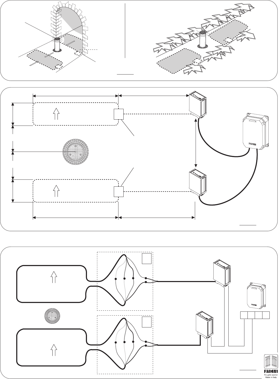
ARRANGING THE MAGNETIC COILS
IMPORTANT: check that there are no sources of disturbance such as to conceal or influence the magnetic/electromagnetic detections
of any metal detector coils in the immediate vicinity of the installation accessories.
The magnetic coil safety accessory is always activated to detect transiting road vehicles. It prevents the Strabuc 918 from rising when
vehicles pass over the coils.
A hole with a maximum depth of 10 cm must be prepared as shown in Pic. 14 (the hole must be rectangular with the long side perpendicular
to the direction of movement). Alternative arrangements may be used to suit installation requirements, however the coil characteristics
must always be respected (see relative instruction sheet).
Specifications should always be observed for correct magnetic coil operation.
The coil is made using a multipolar electric cable, with four x 1.5 mm2 wires, connected to form a single wire.
Bury and cement in place the corrugated sheath (A) large enough to house a 4-wire multipolar electrical cable (B). The two ends must then be connected
and sealed inside a dividing box (C) to the bipolar cable (D) made to pass through another corrugated sheath (A) connected to the Detector (E)
close to the "Elpro S40" programmer.
Once this phase has been completed, the electrical wiring must be performed inside the dividing box as shown in Pic. 15: the individual wires in the
multipolar cable (B) must be connected in series, creating a single unipolar cable with two end wires to be connected to the Detector (E) through the
bipolar cable (D).
IMPORTANT: To obtain an absolutely safe installation, install one coil at the entry to the access to be blocked by the
Strabuc 918 and one at the exit (page 13).
50 cm
3.0 metres
Entry
min. 80 cm
ma
ximum
5 metr
es
10 cm
10 cm
Strabuc 918
Dividing box (C) for wiring between multipolar
cable (B) with the bipolar cable (D) for
connection to the Detector (E)
(D)
(A)
(A)
(B)
10 cm
10 cm
(D)
Hole in the ground to house the
magnetic coil
(B)
(B) (D)
1
blue
red
Buried coil
Electrical wiring inside a dividing box (C), using the
multipolar cable (B) to make a single unipolar cable to
be connected to the cable (D) to the Detector (E) and
then the Elpro S40
1
2
3
4
4
3
2
3 metres
50 cm
(B)
(D)
Vehicle
Detector (E)
Elpro S40
(E)
PIC. 15
PIC. 14
12
(E)
Vehicle presence
Detector (E) inside
the anti-intrusion
cabinet
®
LIBRETTO Strabuc 918 GB.fh11 17-06-2008 11:58 Pagina 13
ARRANGEMENT OF A PAIR OF MAGNETIC COILS AT THE ENTRY AND AT THE EXIT
For installations requiring a pair of magnetic coils (one at the entry and one at the exit as shown in Pic.16), for each one a hole must be
prepared as shown in Pic.17, to arrange two dividing boxes "E" (Entry) and "U" (Exit) for the coil wiring (Pic.18), following the minimum
distances indicated.
Exit coil
3.0 metres
50 cm
Strabuc 918
50 cm
3.0 metres
Entry coil
E
U
ELPRO S40
Exit
metal detector
Exit metal detector
2 dividing boxes for magnetic
coil wiring (see Pic. 18)
- Sealed junction boxes
- Magnetic coil "U"= Exit
- Magnetic coil "E"= Entry
min. 80 cm
min. 80 cm
Plan view of the coil position in relation to
Strabuc 918
The electric wiring between the Detectors and the Elpro S40 Programmer are shown in Pic.18.
min. 20 cm
max 5.0 metres
max 5.0 metres
Entry metal detector
l
'
a
p
r
ic
a
n
c
e
ll
o
F
A
D
I
N
I
Exit
coil
Entry
coil
Entry
coil
Exit
coil
l
'
a
p
r
ic
a
n
c
e
ll
o
F
A
D
I
N
I
PIC. 16
PIC. 17
1234
1
blue
red
1
2
3
4
4
3
2
1
blue
red
1
2
3
4
4
3
2
ELPRO S40
U
E
Entry coil
Exit coil
Entry metal detector NC
contact
Exit metal detector
NC contact
PIC. 18
13
®
LIBRETTO Strabuc 918 GB.fh11 17-06-2008 11:58 Pagina 14
22 23 24 25
11 12 13 14 15 16 17 18 19 20 21
26 27 28 29 30 31 32 33 34 35 36
51 52 53
63 64 65 66 60 61
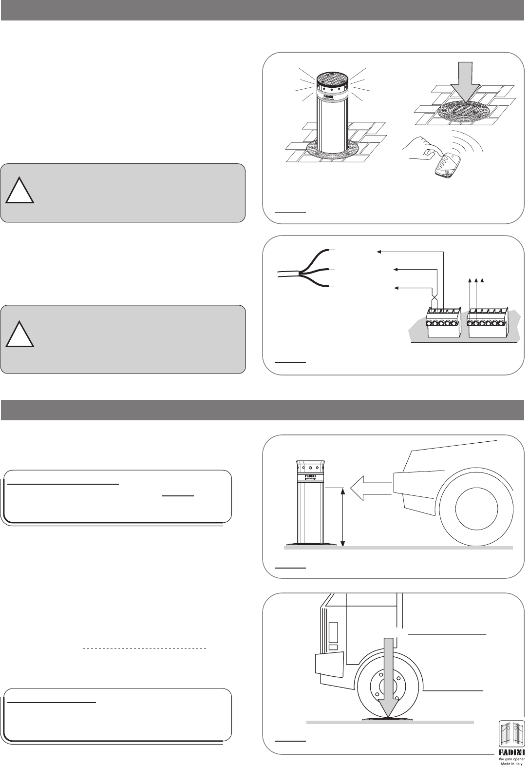
The traffic control post is fitted with a system for manual post lowering. The universal triangular-recess key provided removes the
protection plug and subsequently releases the retracting traffic control post, which lowers to pavement level with simple manual
pressure. Pic.19.
Once the post has been lowered manually, it only rises again following an electrical command impulse.
MANUAL TRAFFIC CONTROL POST RELEASE OPERATIONS
70/1
1 2 3 4 5 6 7 8 9
Elpro S40
Strabuc 918 with solenoid valve
(optional available on request)
Limit switch
Cable
LED voltage
Cable
Power failure:
it lowers
automatically
Post raised
when powered
In the version fitted with solenoid valve, the manual release feature is not necessary as the post automatically lowers to ground level in
the event of a power failure. To allow the solenoid valve to work, connect the wires of the electric cable labelled “SOLENOID VALVE”
(N° 4), which comes from the Strabuc, directly to terminals 22 and 23 of the Elpro S40 programmer (Pic. 20).
Main unit
Power cable
22 23 24 25
16 17 18 19 20 21
11 12 13 14 15
31 32 33 34 35 36
26 27 28 29 30
Solenoid valve cable
(optional on request)
STRABUC 918 WITH SOLENOID VALVE
PIC. 20
n°1
n°2
n°3
n°4
Manual lowering of the post
Insert and turn the
Release key
PIC. 19
14
®
LIBRETTO Strabuc 918 GB.fh11 17-06-2008 11:58 Pagina 15
STATIC LOAD RESISTANCE
The static load acting on the Strabuc 918 when completely
lowered is considered as the weight a 20˙000 Kg lorry exerts
when parked on or passing over the traffic control post.
Practical tests with fully laden lorries have confirmed this result
Maximum static load 20˙000 Kg
20˙000Kg
Maximum shock resistance:
upon collision, a vehicle travelling at 60 Km/h deforms
the Strabuc 918 traffic control post to such an extent that
the whole post needs to be replaced (Pic. 23).
stroke 700mm
v (Km/h)
b (mm)
M (Kg)
VIOLENT COLLISION RESISTANCE
Technical theoretical calculation table (Ref. Table Drawing 3703).
STRABUC 918 TRAFFIC CONTROL POST RESISTANCE DATA
Static load resistance:
with the post lowered, Strabuc 918 is able to resist a fully
laden lorry weighing 20˙000 Kg parked on top of it. Pic.24.
FIRST OPERATION MANOEUVRES OF THE STRABUC 918
Having terminated installation of the traffic control post and all
the safety and control accessories with the respective wiring to
the Elpro S40 programmer, and having completed thorough risk
analysis, the first operation manoeuvres can be performed. If
you have a radio transmitter, encode the radio receiver according
to the relative instructions before giving the command to raise
the retractable post, or give the manoeuvre command using a
key switch (pic. 21).
!
ATTENTION: it is important to establish whether
the traffic control post is open or closed depending
on whether it leaves the access free or blocks it
(Pic.21).
!
ATTENTION: If the limit switch and electric motor
wiring is not correct, exchange the wires in the
corresponding traffic control post terminals, leaving
the common in place (Pic.22).
Strabuc 918 in raised position:
Access Closed A command causes the Strabuc 918
post to lower: Access Open
During first use, it is important to check whether the wiring of
the rising and lowering limit switches and the electric motor
power supply is correct and corresponds to the "open" and
"closed" positions of the traffic control post (pic. 22).
11 12 13 14 15 16 17 18 19 20 21
Fixed common
Closing limit switch
Opening limit switch
Elpro S40 terminals
ATTENTION: do not power the system until all the wiring needed for operation has been performed.
Siti
Electric motor
1st traffic control post
Cable for 1st motor limit switch
exchange cables 11 and 12
13
11
12
PIC. 21
PIC. 22
PIC. 23
PIC. 24
15
®
PRIME MANOVRE DI FUNZIONAMENTO DELLO STRABUC 918
DATI DI RESISTENZA DEL DISSUASORE STRABUC 918
LIBRETTO Strabuc 918 GB.fh11 17-06-2008 11:58 Pagina 16
06-2008
CHECKS AND MAINTENANCE:
For optimal performance of the system over time and operation in compliance with safety
regulations, correct maintenance and checks must be performed on both the operator, the
electronic equipment constituting the installation and wiring by qualified technicians:
- Oil-hydraulic operator: maintenance check every 6 months.
- Electronic equipment and safety systems: a monthly maintenance check
The growth of MECCANICA FADINI has always been based on the development of guaranteed
products thanks to our TOTAL QUALITY CONTROL system, which ensures constant quality
standards, updated knowledge of the European Standards and compliance with their
requirements, in view of an ongoing commitment to improvement.
WARNINGS
- Before performing installation, conduct Risk Analysis and operate using devices compliant with EN 12445 and EN 12453 safety regulations
- Packaging materials such as cardboard, nylon, polystyrene, etc. should be disposed of using specialised waste collection firms
- If the operator is removed, do not cut the electric wires, rather remove them from the terminal board loosening the clamping screws inside the dividing box
- Disconnect the main switch before opening the lid of the electric cable dividing box.
- The whole operator must be earthed using the yellow/green electric cable.
ELECTRIC MOTOR
Output ..............................................................................0.25KW (0.33HP)
Power consumption..........................................................330W
Power supply voltage .......................................................230V±10%
Frequency ........................................................................50Hz
Absorbed current..............................................................1.8A
Intermittent service ..........................................................S3
OIL-HYDRAULIC MAIN UNIT
Hydraulic pump.................................................................P10
Operating pressure ..........................................................2 MPa (20bar)
Operating temperature.....................................................-20°C +80°C
Hydraulic oil type..............................................................OIL Fadini
Protection class ................................................................IP54
OIL-HYDRAULIC PISTON
Piston diameter ...............................................................30 mm
Rod diameter ...................................................................16 mm
Net rod travel ...................................................................740 mm
Rod exit time ....................................................................6 sec.
Calibrated thrust...............................................................18 daN
FEATURES
Service cycle 6s Ascent - 30s Dwell - 6s Descent - 30s Dwell:
Full cycle time...................................................................72 seconds
Full Ascent - Dwell - Descent - Dwell cycles ..................N°50/hour
Annual cycles (considering 8-hour working day) ............N° 146˙000
Complete weight of Strabuc 918 ....................................128Kg
Protection class - Strabuc 918 .........................................IP67
LED power supply.............................................................230V 50Hz
LED lights..........................................................................24V
Painted post RAL 1028 - MELON YELLOW -
Post material ......................................................................Fe360 steel/ AISI 304 stainless steel 4 (optional)
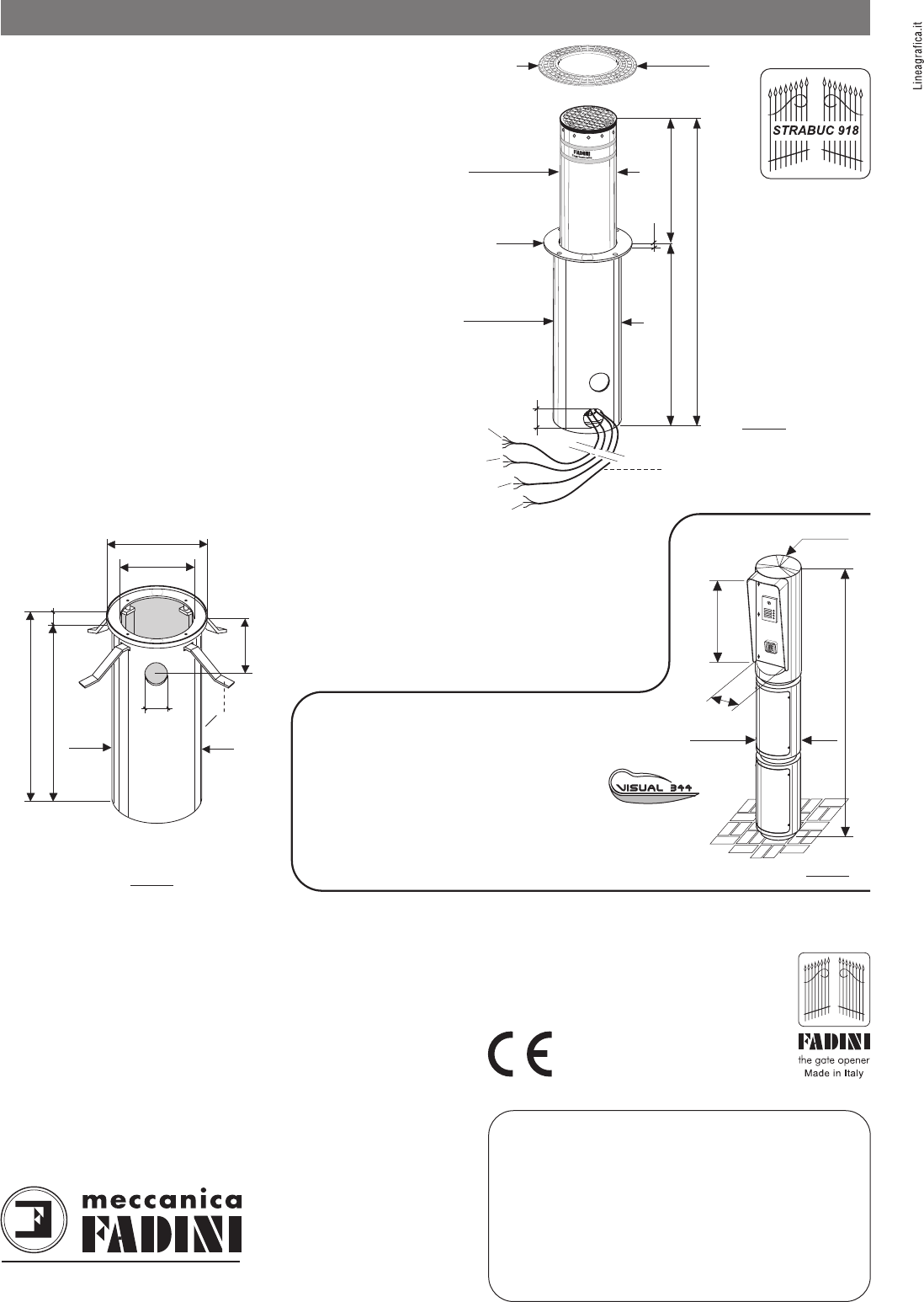
10
Ø 275
Ø 425
Ø 325
thickness
6 mm
Ø 450
700920
1
'
620
Ø100
STRABUC
1
2
3
Bundle of 4 electric cables,
10 metres long each
thickness
4 mm
The manufacturer reserves the right to make amendments to this manual without prior
notice and declines all responsibility for any errors, personal injury or damage to property.
For Dealer’s use only
CYLINDRICAL CONTAINER - to be cemented - pic.26
Material .............................................."FE" sheet steel
Treatment ..........................................Cataphoresis
Calandered sheet metal thickness.....1.5 mm
Fixing flange thickness. ......................10mm
4x Support plate clamping bolts.........M10x35
4x Washers.........................................Ø10
4x support plates ...............................flat 40x10
Total weight........................................25Kg
TECHNICAL SPECIFICATIONS VISUAL 344 - pic.27
Material...........................................Fe 360 Steel
Panel material ................................Aluminium
Individual height of basic module ...542 mm
Height with three modules..............1˙890 mm
Weight.............................................70Kg
Protection class ...............................IP53
Colour...............................................RAL 7016 Anthracite Gray
Shock resistance .............................5˙000 J (500Kg at 1 m)
STRABUC
FADINI
l'apricancello
made in Italy
ø80
Ø345
Ø462
ø405
25
325
1'035
1'010
= 40x10
CYLINDRICAL CONTAINER
- to be cemented -
1'890
560
200
ø 275
13
46
5
789
E
0
R
2
F A D I N I
ø 275
Via Mantova, 177/A - 37053 Cerea (Verona) Italy
Tel. +39 0442 330422 r.a. - Fax +39 0442 331054
e-mail: info@fadini.net - www.fadini.net
s.n.c.
®
EUROPEAN MARKING CERTIFYING
CONFORMITY TO THE ESSENTIAL
REQUISITES OF THE DIRECTIVE 98/37/EC
PIC. 26 PIC. 27
PIC. 25
®
AUTOMATIC GATE MANUFACTURERS
STRABUC 918 TECHNICAL FEATURES
