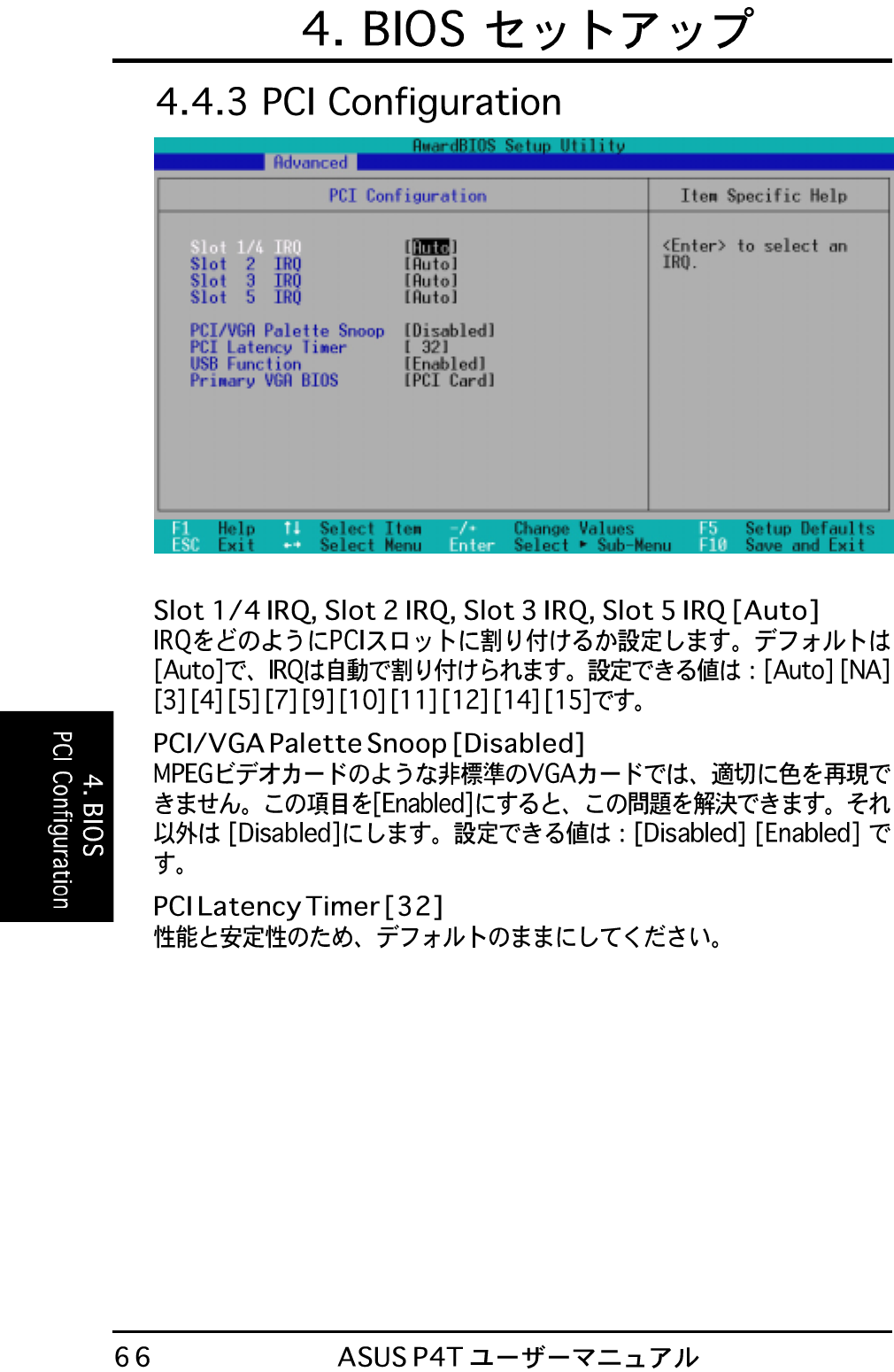
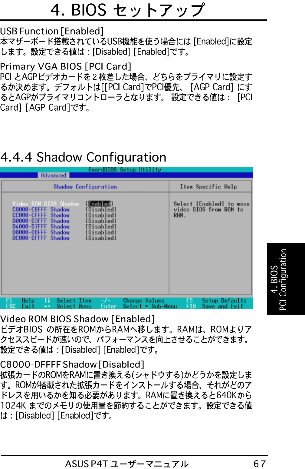
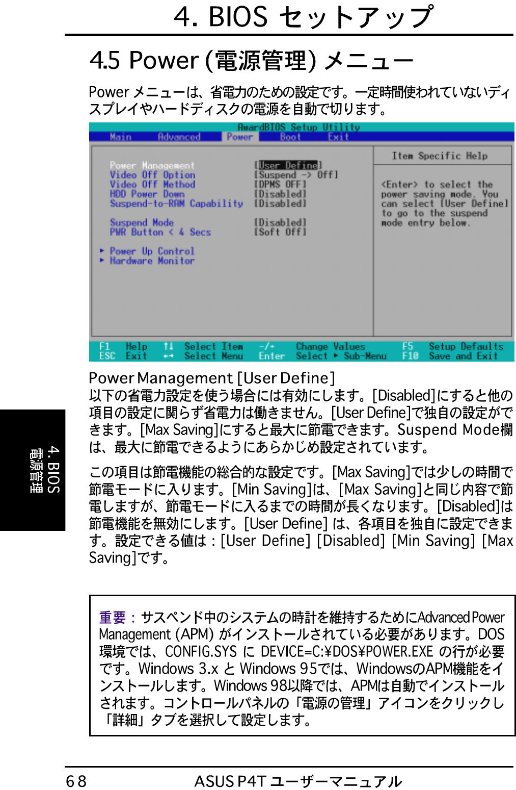
J659_p4t J659 P4t
User Manual: j659_p4t
Open the PDF directly: View PDF ![]() .
.
Page Count: 120 [warning: Documents this large are best viewed by clicking the View PDF Link!]

®

FCC & DOC COMPLIANCE
This device complies with FCC Rules Part 15. Operation is subject to the following
two conditions:
• This device may not cause harmful interference, and
• This device must accept any interference received, including interference that
may cause undesired operation.
This equipment has been tested and found to comply with the limits for a Class B
digital device, pursuant to Part 15 of the FCC Rules. These limits are designed to
provide reasonable protection against harmful interference in a residential installa-
tion. This equipment generates, uses and can radiate radio frequency energy and, if
not installed and used in accordance with manufacturer's instructions, may cause
harmful interference to radio communications. However, there is no guarantee that
interference will not occur in a particular installation. If this equipment does cause
harmful interference to radio or television reception, which can be determined by
turning the equipment off and on, the user is encouraged to try to correct the interfer-
ence by one or more of the following measures:
• Re-orient or relocate the receiving antenna.
• Increase the separation between the equipment and receiver.
• Connect the equipment to an outlet on a circuit different from that to which the
receiver is connected.
• Consult the dealer or an experienced radio/TV technician for help.
WARNING! Any changes or modifications to this product not expressly ap-
proved by the manufacturer could void any assurances of safety or performance
and could result in violation of Part 15 of the FCC Rules.
Reprinted from the Code of Federal Regulations #47, part 15.193, 1993. Washington DC: Office of the
Federal Register, National Archives and Records Administration, U.S. Government Printing Office.
Canadian Department of Communications Statement
This digital apparatus does not exceed the Class B limits for radio noise emissions
from digital apparatus set out in the Radio Interference Regulations of the Canadian
Department of Communications.
This Class B digital apparatus complies with Canadian ICES-003.
Cet appareil numérique de la classe B est conforme à la norme NMB-003 du Canada.
14
16 814
18
19
12
21
22
23
24
6
15
20
3
11
72 5
10 91317
1
1
1
24.4cm (9.60in)
30.5cm (12.0in)
PS/2KBMS
T: Mouse
B: Keyboard
MAIN_FAN
CHASSIS
PCI1
PCI2
PCI4
PCI3
PANEL
FLOPPY
SECONDARY IDE
PRIMARY IDE
Intel I/O
Controller
Hub
(ICH2)
P4T
PCI_FAN
DIP
Switches
®
LED
Accelerated Graphics Port (AGP Pro)
ASUS
ASIC
with
Hardware
Monitor
CR2032 3V
Lithium Cell
CMOS Power
CLRTC
SCSILED
Socket 423
USB
T: Port1
B: Port
2
COM1
PARALLEL PORT
COM2
Intel 850
Memory
Controller
Hub (MCH)
PCI5
RIMMB2 (16/18 bit, 184-pin module)
RIMMB1 (16/18 bit, 184-pin module)
ATX Power Connector
4Mbit
Firmware
Hub
USB2
WOL
RIMMA2 (16/18 bit, 184-pin module)
RIMMA1 (16/18 bit, 184-pin module)
Multi
I/O
AUX Power
Connector
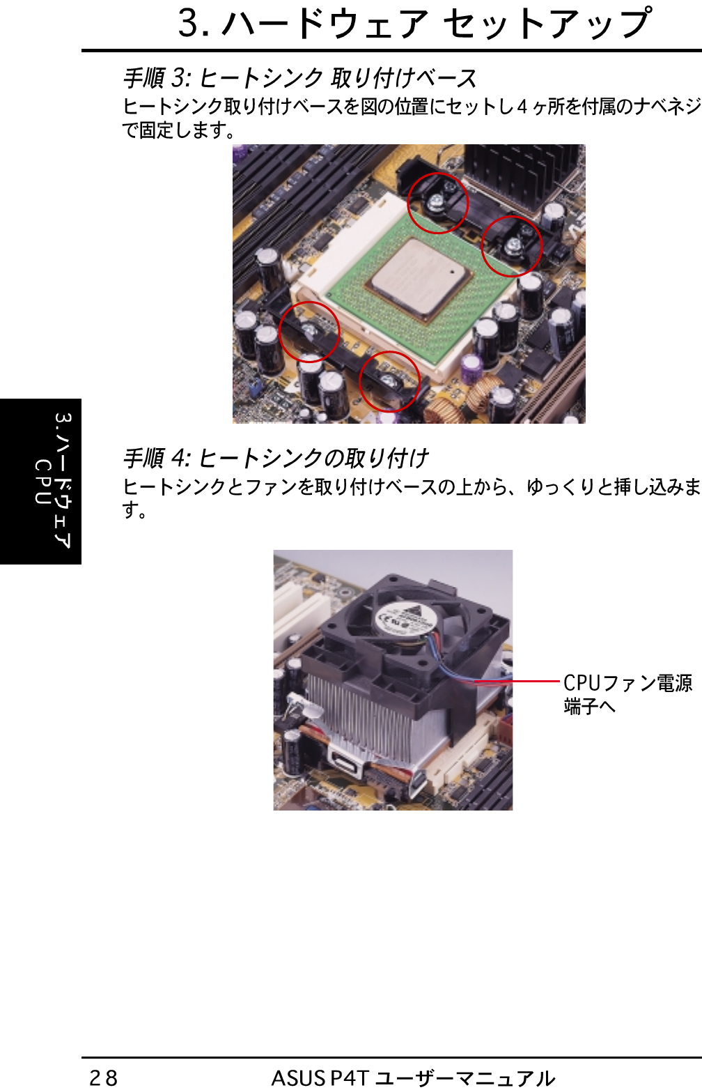
CPU_FAN
ATX12V
USBPWR
JEN
IR
SMB
HDDLED
WOR
Top:
RJ-45
TR2
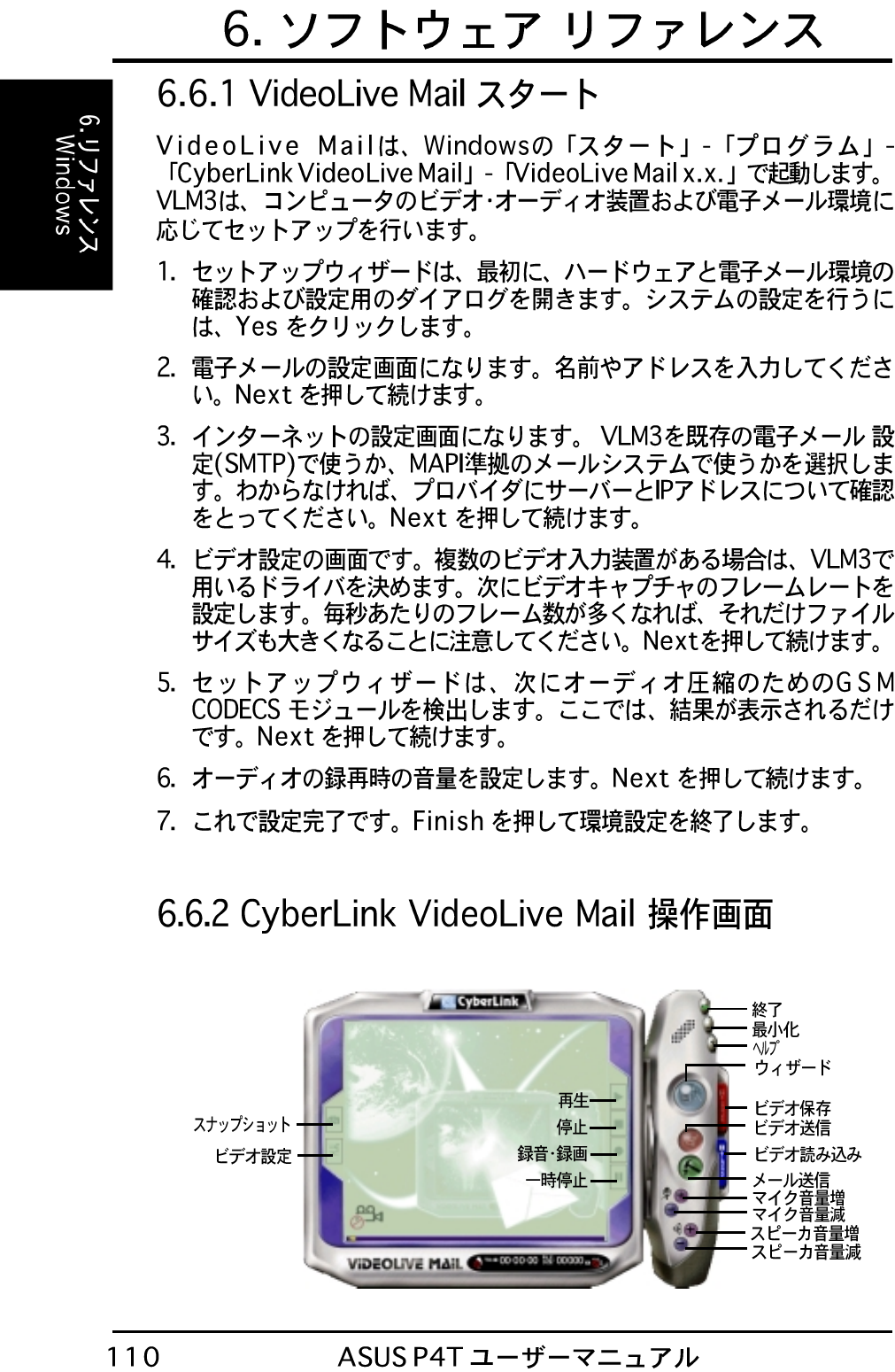
P4T Onboard LED
ON OFF
Standby
Power Powered
Off
P4T
®
P4T DIP Switches
P4T
®
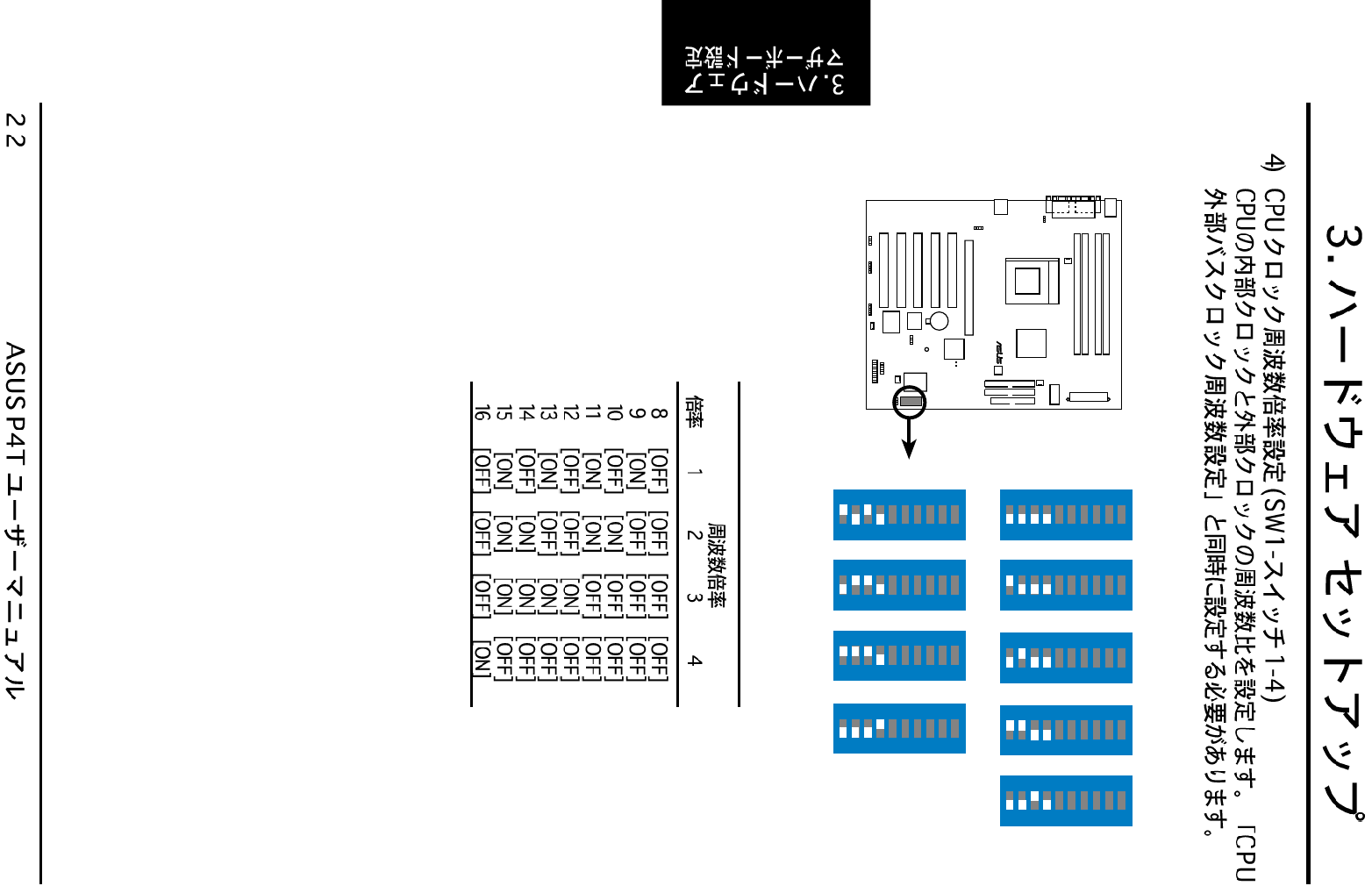
1. Frequency Multiple
2. Frequency Multiple
3. Frequency Multiple
4. Frequency Multiple
5. Reserved
6. Frequency Selection
7. Frequency Selection
8. Frequency Selection
9. Frequency Selection
10. Frequency Selection
OFF
ON
12345678910
ON
SW1
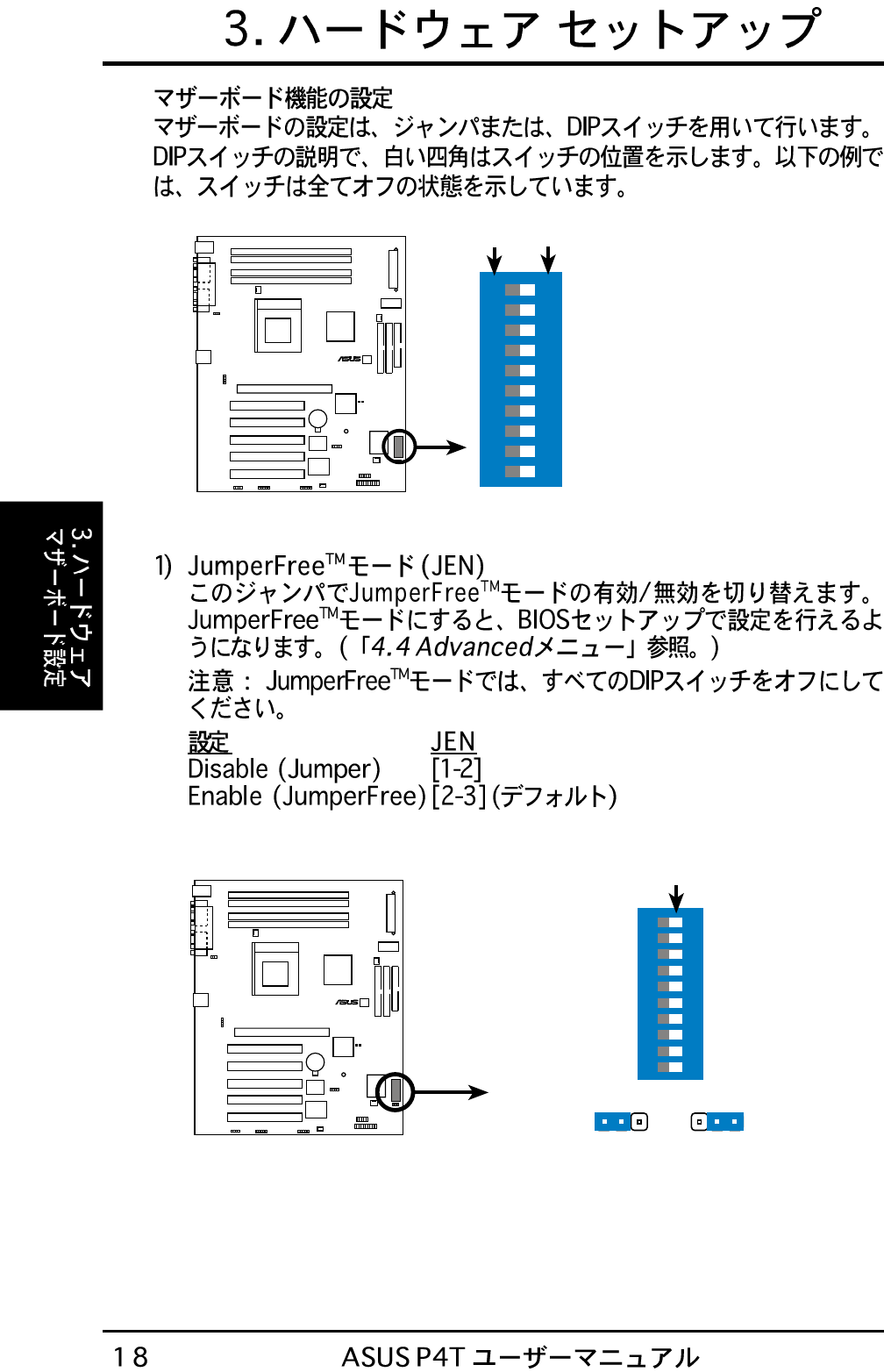
P4T JumperFree™ Mode Setting
P4T
®
Jumper JumperFree
12 23
JEN
OFF
ON
12345678910
SW1
P4T
®
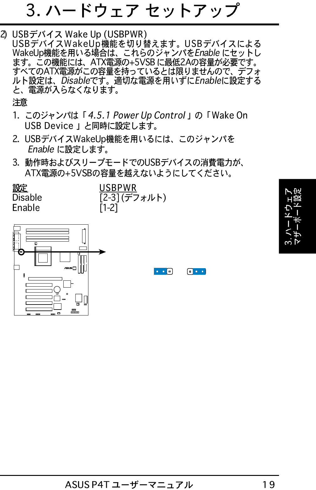
P4T USB Device Wake Up
Disable
(Default)
Enable
1223
USBPWR
P4T
®
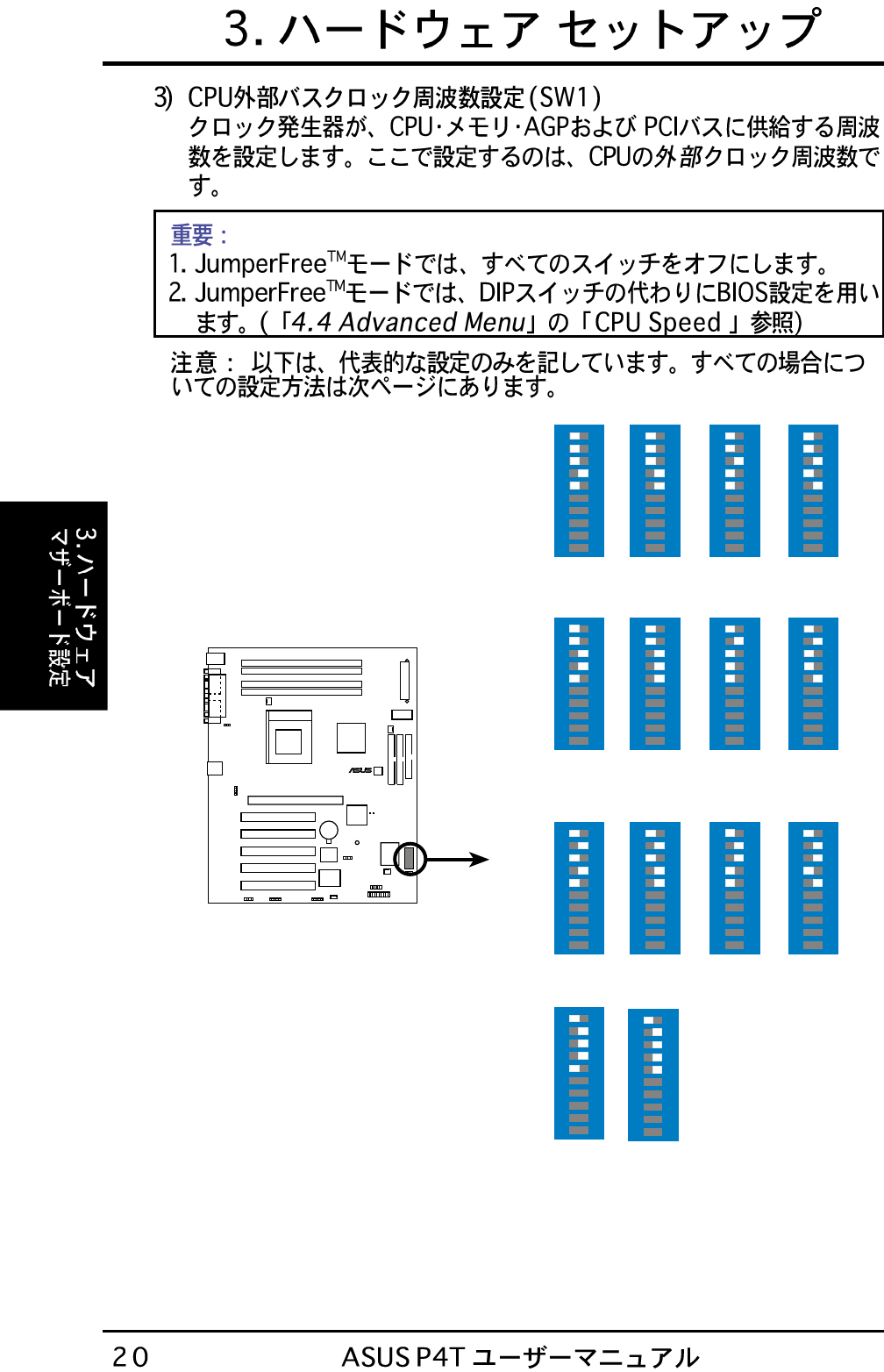
P4T CPU
External Frequency Selection
CPU/DRAM
PCI BUS →
→
CPU/DRAM
PCI BUS →
→
CPU/DRAM
PCI BUS →
→
122.0MHz
40.7MHz
112.0MHz
37.3MHz 115.0MHz
38.3MHz
108.0MHz
36.0MHz
120.0MHz
40.0MHz
118.0MHz
39.3MHz
130.0MHz
43.3.0MHz
110.0MHz
36.7MHz
133.0MHz
44.3MHz
CPU/DRAM
PCI BUS →
→100.0MHz
33.3MHz
ON
12345678910
ON
12345678910
ON
12345678910
ON
12345678910
ON
12345678910
ON
12345678910
ON
12345678910
ON
12345678910
ON
12345678910
ON
12345678910
103.0MHz
34.3MHz
ON
12345678910
105.0MHz
35.0MHz
ON
12345678910
ON
12345678910
ON
12345678910
125.0MHz
41.7MHz 128.0MHz
42.7MHz
SW1
P4T
®
P4T CPU External
Clock (BUS) Frequency
Selection
8.0x
ON
12345678910
SW1
9.0x
ON
12345678910
10.0x
ON
12345678910
11.0x
ON
12345678910
12.0x
ON
12345678910
13.0x
ON
12345678910
14.0x
ON
12345678910
15.0x
ON
12345678910
16.0x
ON
12345678910
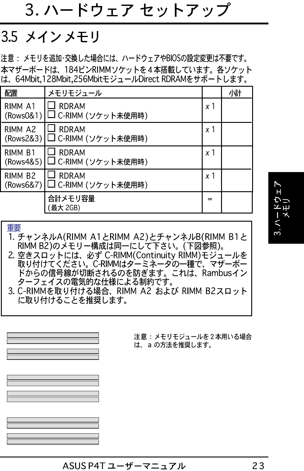
RIMMA1
RIMMA2
RIMMB1
RIMMB2
128MB RDRAM
128MB RDRAM
C-RIMM
C-RIMM
a.
RIMMA1
RIMMA2
RIMMB1
RIMMB2
128MB RDRAM
128MB RDRAM
128MB RDRAM
128MB RDRAM
c.
RIMMA1
RIMMA2
RIMMB1
RIMMB2
128MB RDRAM
128MB RDRAM
C-RIMM
C-RIMM
b.
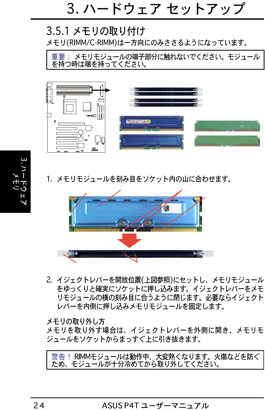
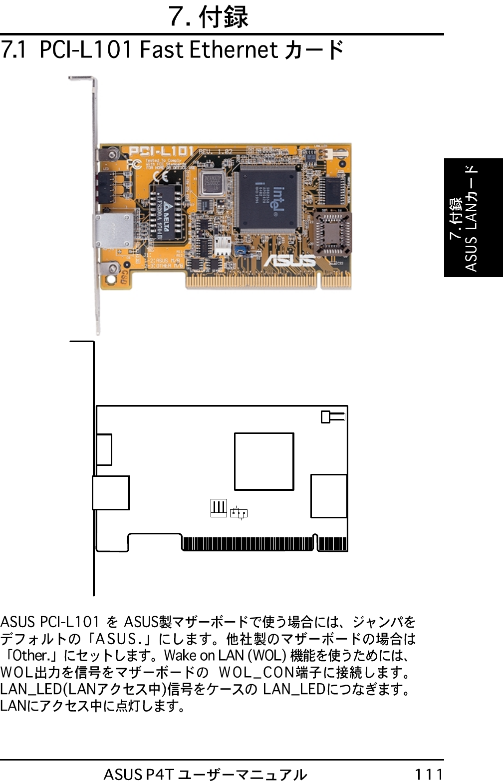
NOTCH KEYS
CONNECTORS
RDRAM (with heat spreader)MOUNTING NOTCH
RIBS (inside socket)
EJECTOR (TOP VIEW)
P4T
®
P4T 184-Pin RIMM Sockets
RIMM Sockets
Channel A
Channel B
RIMMA2
RIMMA1
RIMMB2
RIMMB1
C-RIMM
RIMM with Heat Spreader
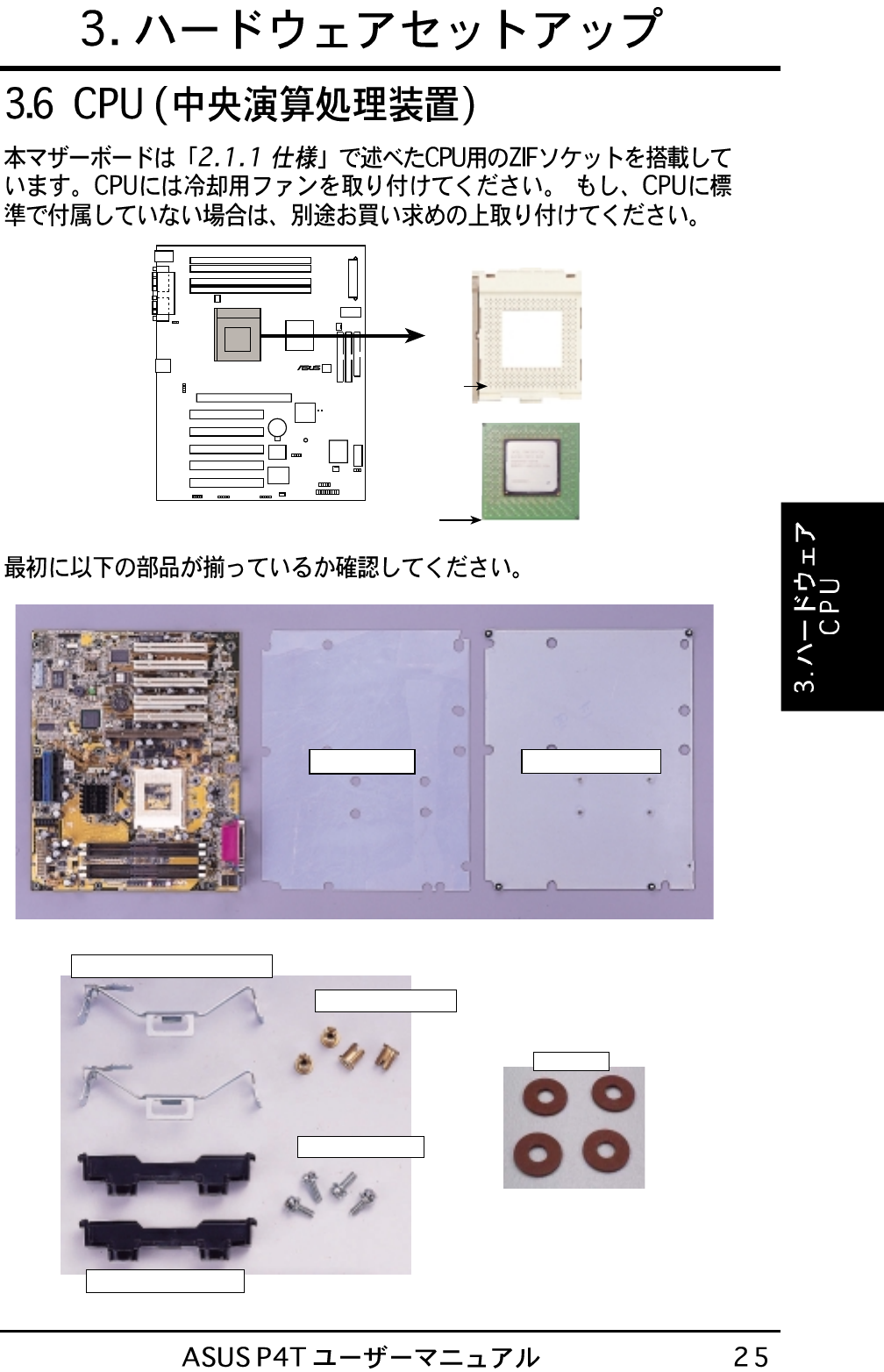
P4T Socket 423
P4T
®
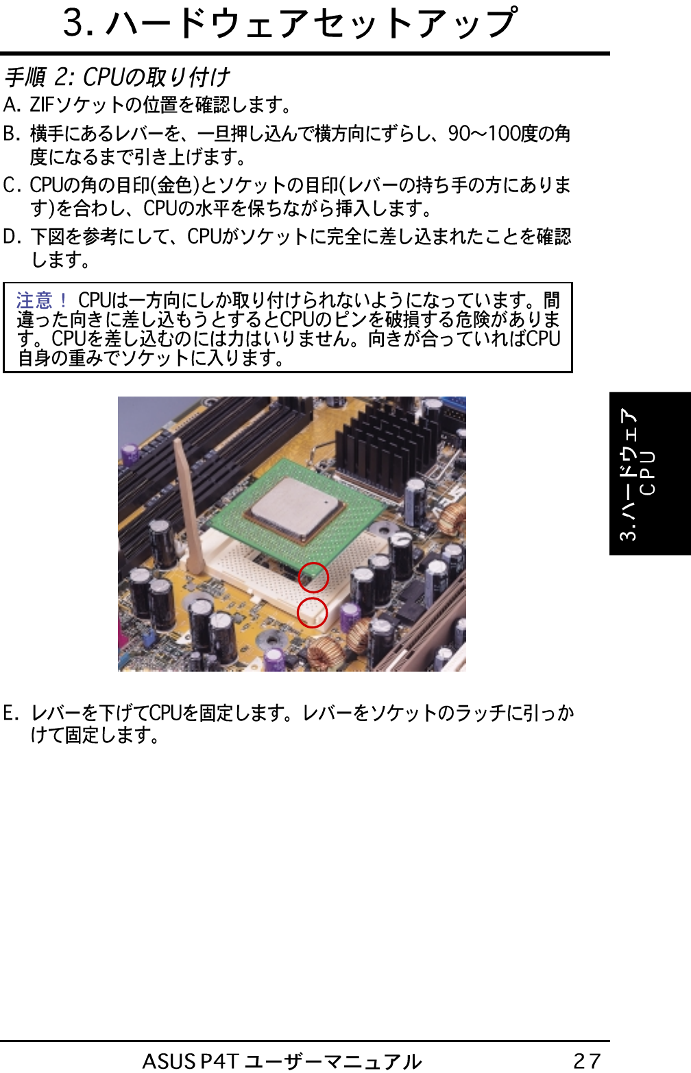
Gold Arrow
Pin 1
Pentium 4
Processor
Pin 1
Rubber Pad Metal Baseboard
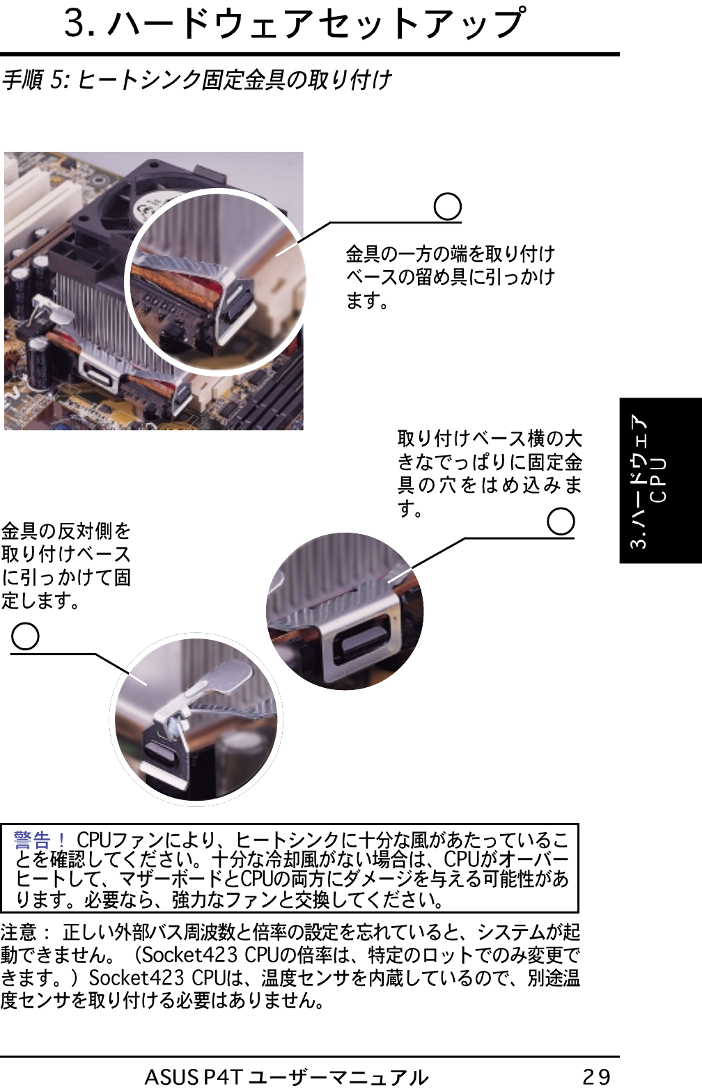
2 Metal heatsink retaining clips
4 Copper captive nuts
4 Pan Head screws
2 Heatsink support bases
4 Washers
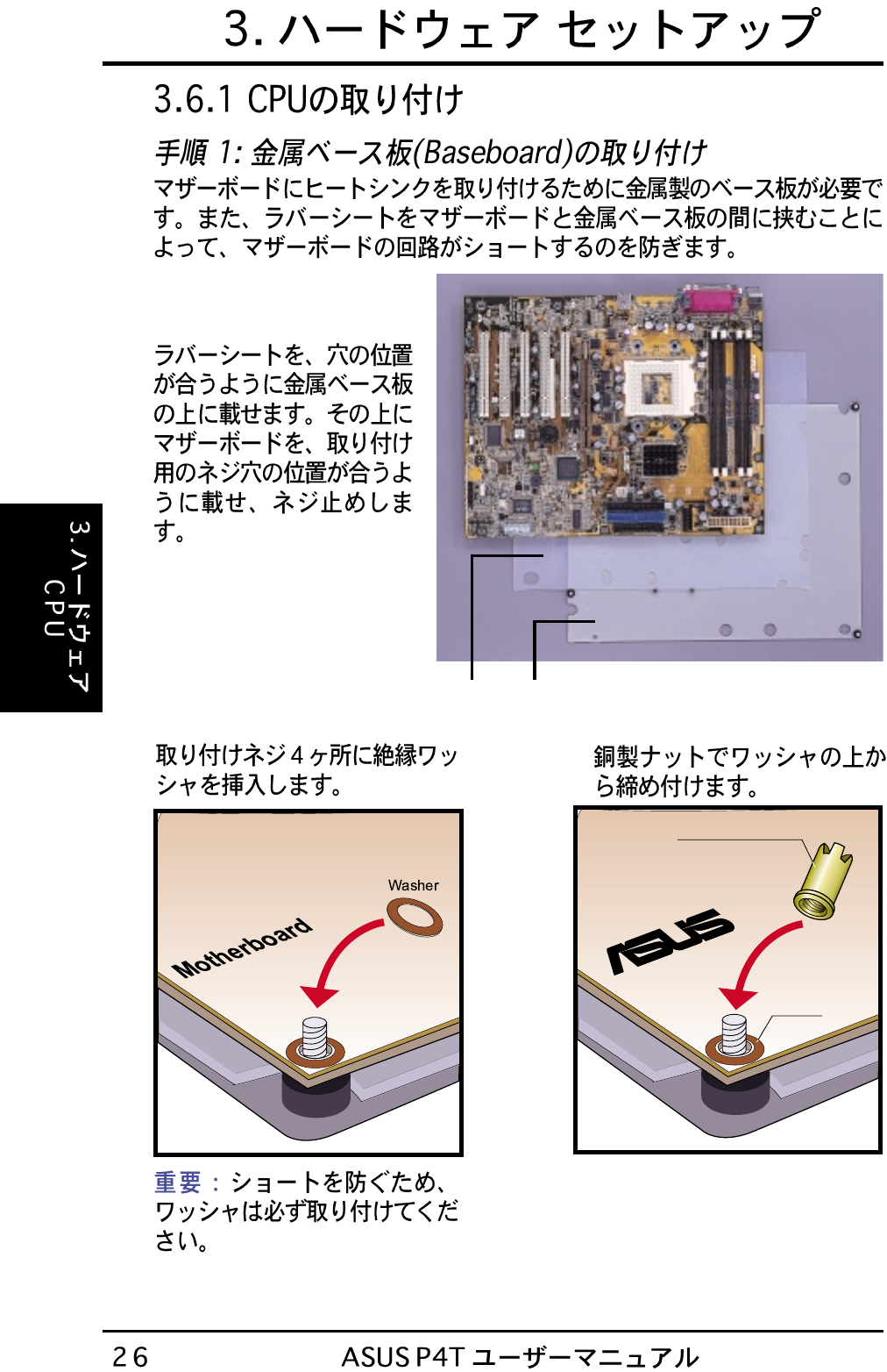
Rubber Pad Metal Baseboard
Washer
Copper captive nut
®
Motherboard
1
1
2
3
2
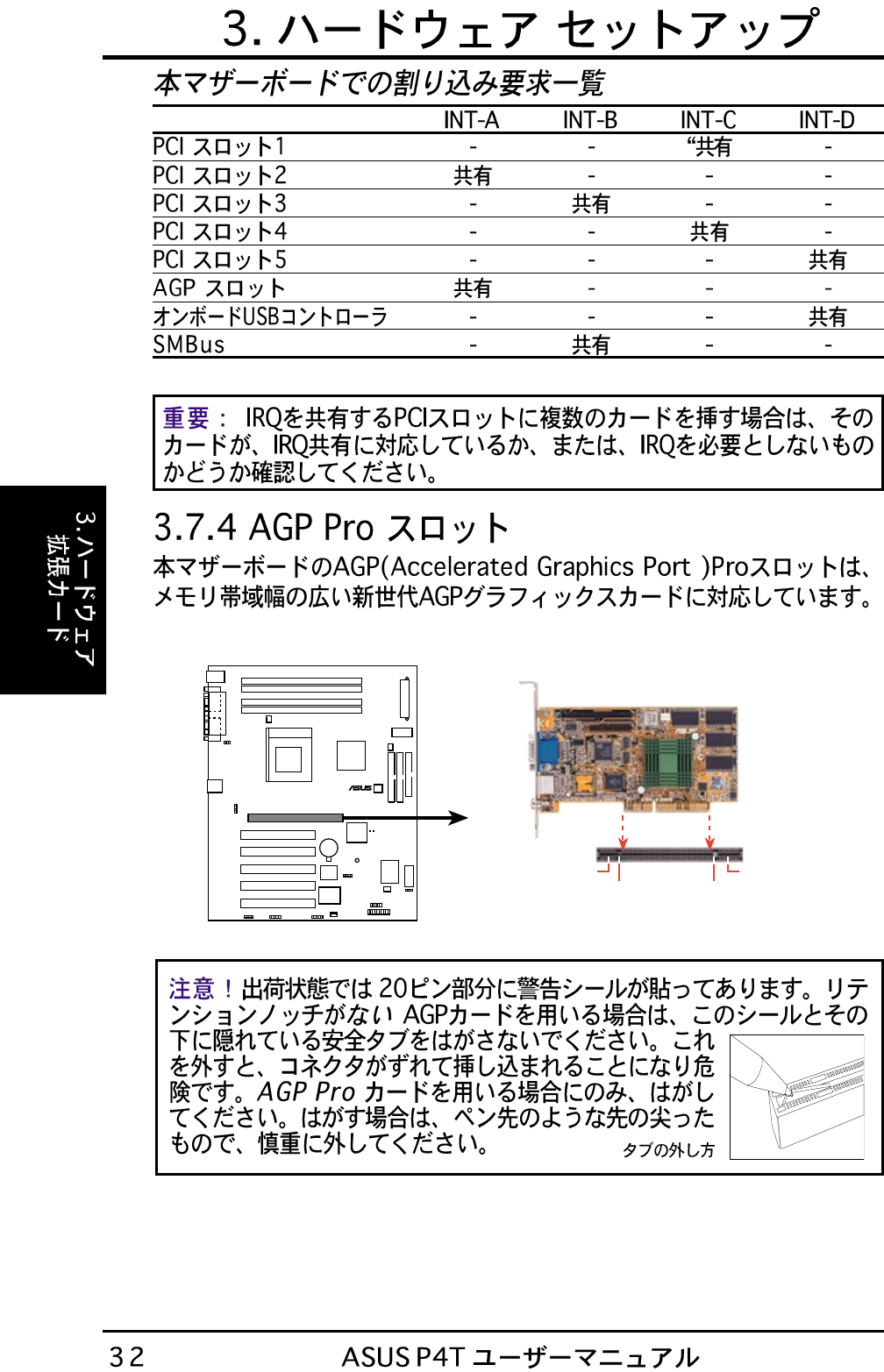
P4T Accelerated Graphics Port (AGP PRO)
TOP VIEW
Rib (inside slot) Rib
20-pin bay 28-pin bay
AGP Card without Retention Notch
P4T
®
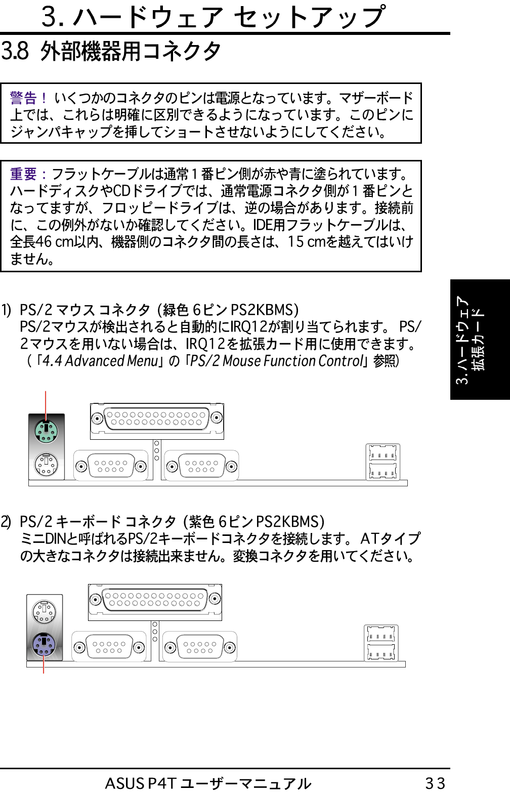
PS/2 Mouse (6-pin Female)
PS/2 Keyboard (6-pin Female)
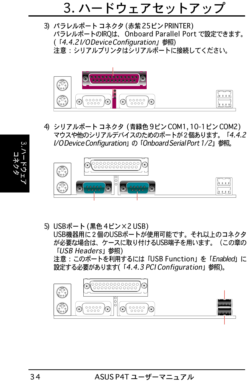
Parallel Port (25-pin Female)
COM2COM1
Serial Ports (9-pin Male)
USB 2
USB 1
P4T
®
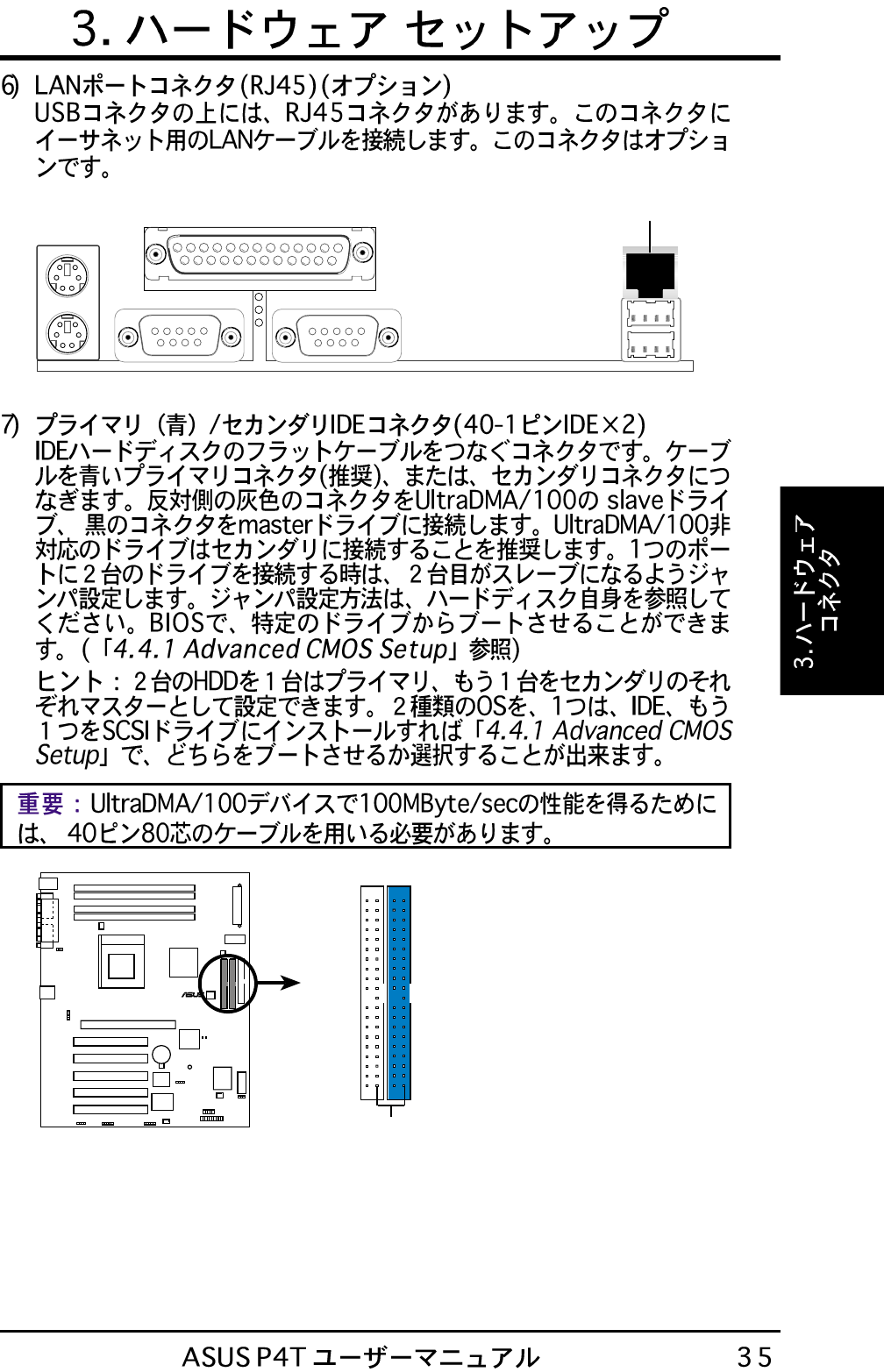
P4T IDE Connectors
NOTE: Orient the red markings
(usually zigzag) on the IDE
ribbon cable to PIN 1.
Secondary IDE Connector
PIN 1
Primary IDE Connector
RJ-45 Port
P4T
®
NOTE: Orient the red markings on
the floppy ribbon cable to PIN 1.
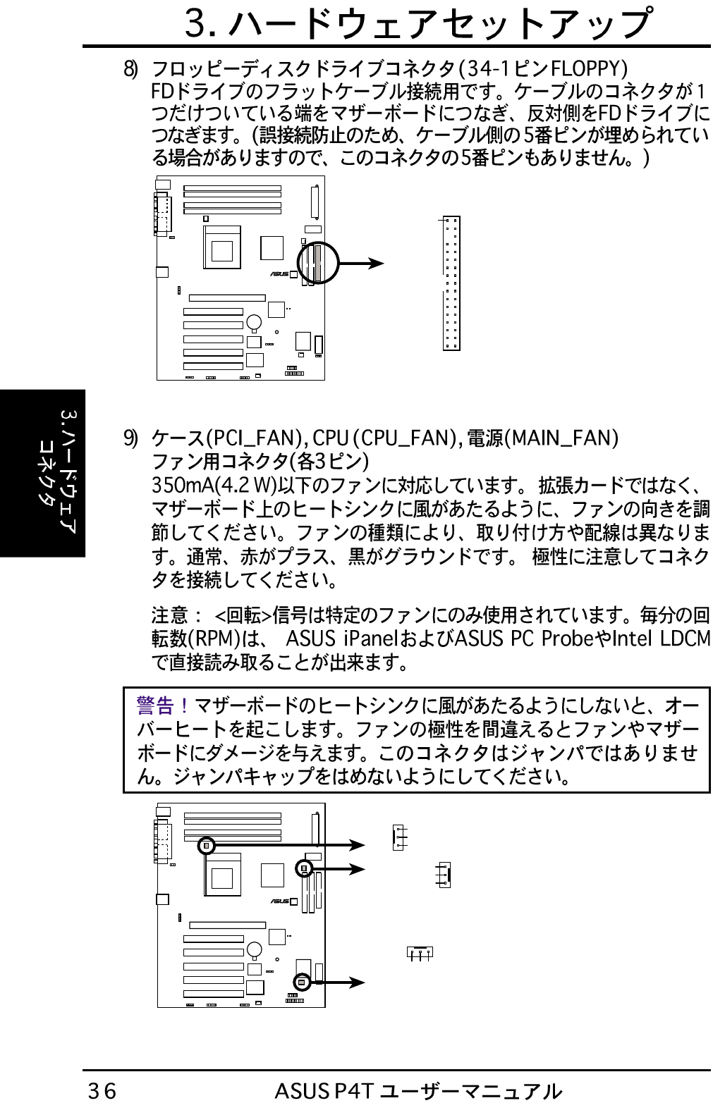
P4T Floppy Disk Drive Connector
PIN 1
FLOPPY
P4T
®
P4T 12-Volt Cooling Fan Power
MAIN_FAN
CPU_FAN
GND
Rotation
+12V
PCI_FAN
GND
Rotation
+12V
GND
Rotation
+12V
(for power supply fan)
(for chassis fan)
SMBCLK
Ground
SMBDATA
+5V
1
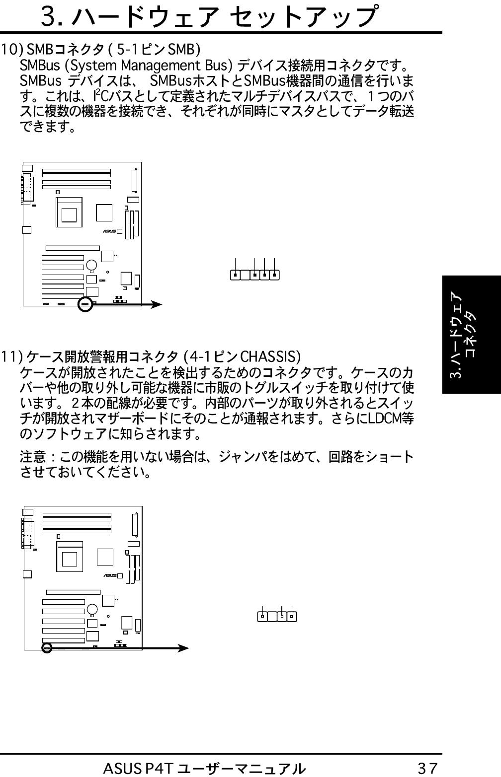
P4T SMBus Connector
SMB
P4T
®
P4T Chassis Open Alarm Lead
P4T
®
+5VSB_MB
Chassis Signal
GND
CHASSIS
1
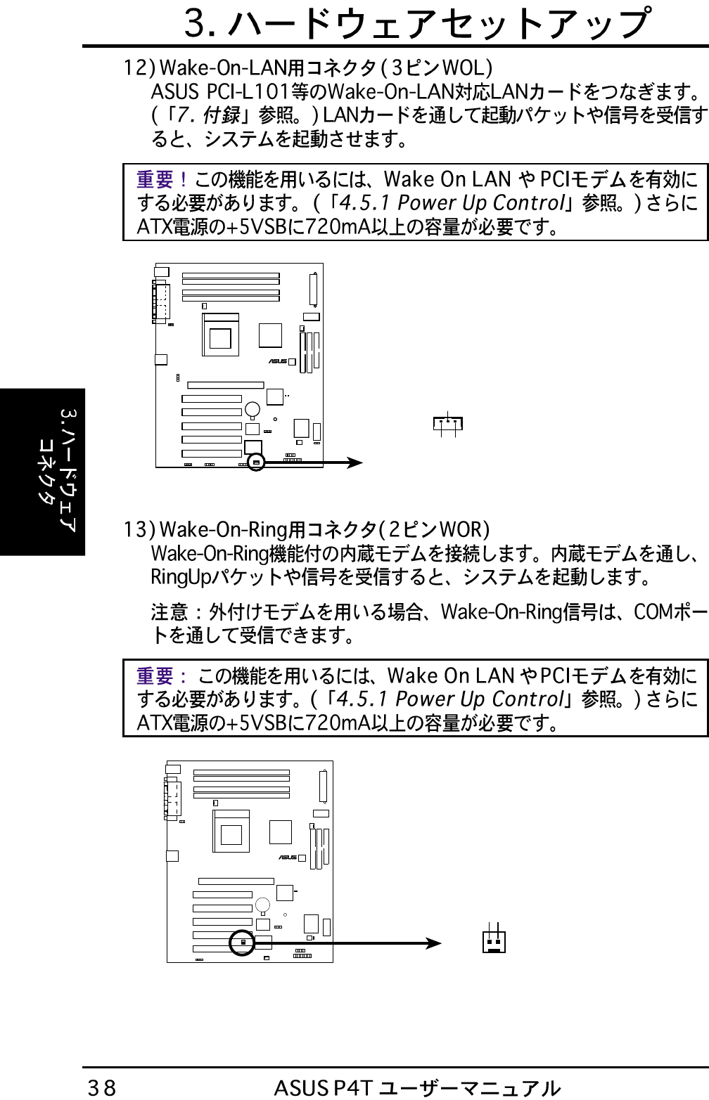
P4T Wake-On-LAN Connector
IMPORTANT: Requires an ATX power
supply with at least 720mA +5 volt
standby power
+5 Volt Standby
PME
Ground
WOL
P4T
®
P4T
®
P4T Wake-On-Ring Connector
Ring# Ground
21
WOR
P4T
®
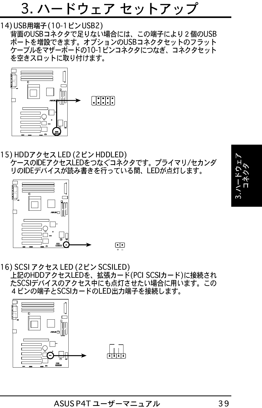
P4T USB Headers
USB2
15
610
1: USB Power
2: USBP2–
3: USBP2+
4: GND
5: NC
6: USB Power
7: USBP3–
8: USBP3+
9: GND
P4T Hard Disk Drive Activity LED
TIP: If the case-mounted LED
does not light, try reversing the
2-pin plug.
HDDLED
P4T
®
+
1
P4T SCSI LED Connector SCSILED
P4T
®
-
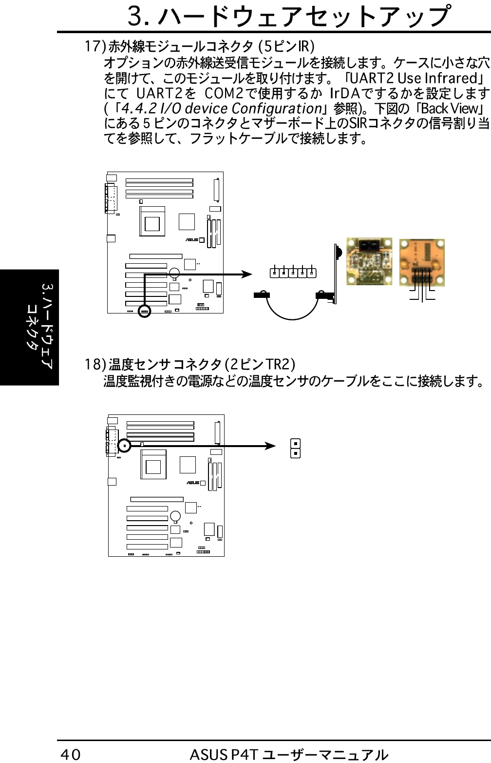
Front View Back View
+5V
IRTX
IRRX
(NC)
GND
+5V
IRRX
IRTX
(NC)
GND
IR
1
P4T Infrared Module Connector
P4T
®
P4T Thermal Sensor Connector
P4T
®
TR2
Thermal
Sensor
Connector
P4T
®
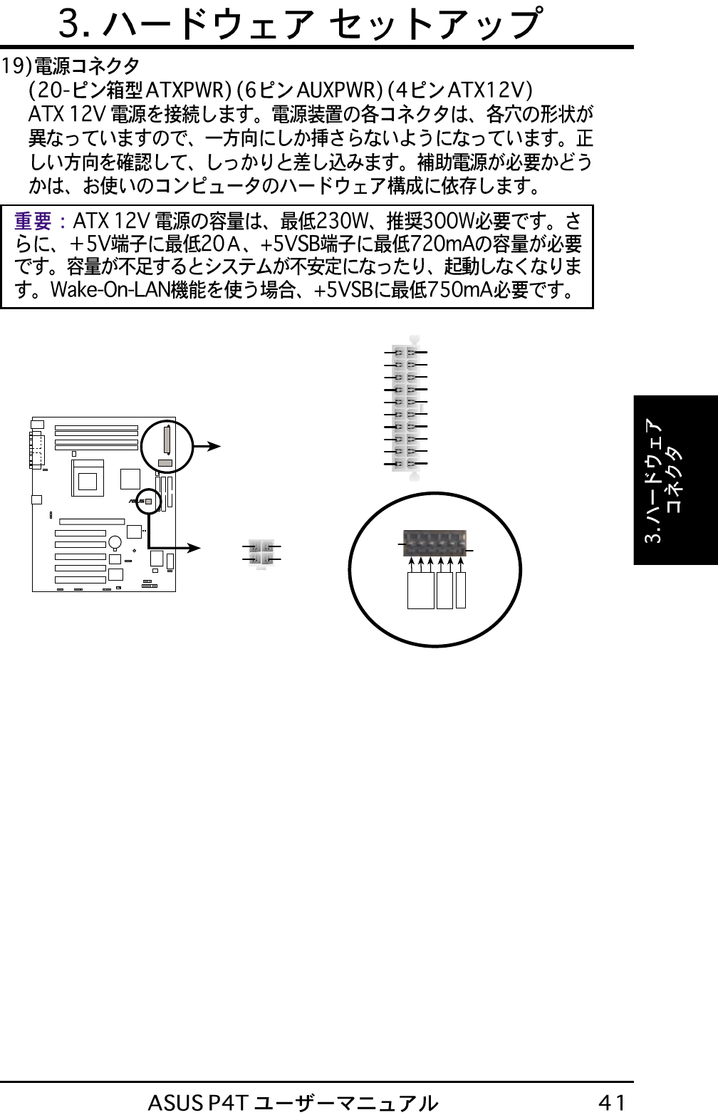
P4T ATX & Auxiliary
Power Connectors AUXPWR
ATX12V
+12V DC
COM
+12V DC
COM Pin 1
ATXPWR
+5VDC
+5VDC
-5VDC
COM
COM
COM
PS_ON#
COM
-12VDC
+3.3VDC
COM
+3.3VDC
+12VDC
+5VSB
PWR_OK
COM
+5VDC
COM
+5VDC
+3.3VDC
Pin 1
Pin 1
COM
+3V
+5V
Key
P4T
®
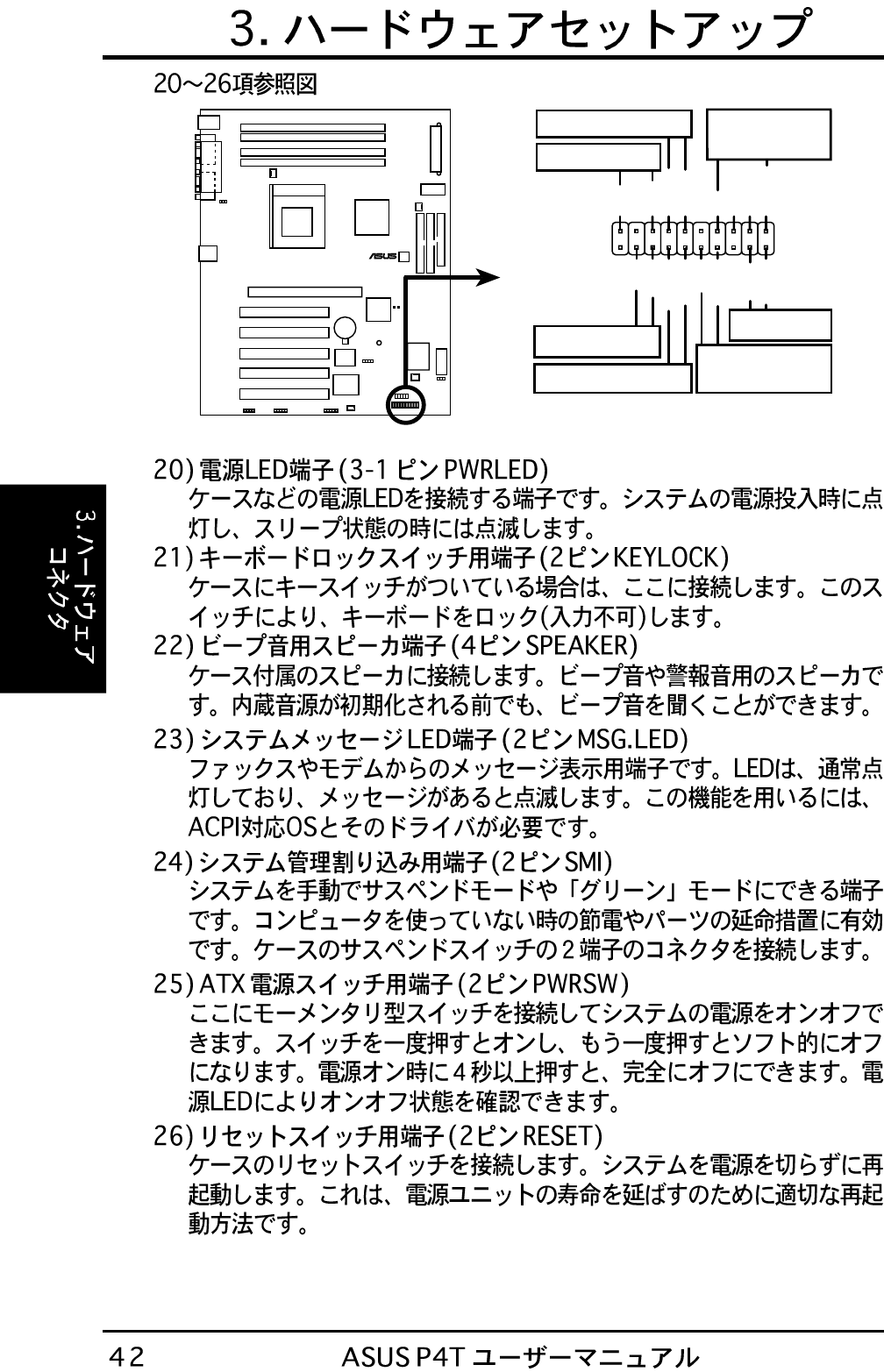
P4T System Panel Connectors
* Requires an ATX power supply.
PLED
Ground
MLED
PWR
+5 V
Keylock
+5V
Speaker
Speaker
Connector
Power LED
Ground
+5 V
Reset SW
SMI Lead
Message LED
ExtSMI#
Ground
Reset
Ground
Ground
Ground
Keyboard Lock
ATX Power
Switch*
P4T
®
P4T Clear RTC RAM
Short solder points
to Clear CMOS
CLRTC
Intel I/O
Controller
Hub
(ICH2)
LAN Activity
Output Signal
RJ45
LEDs
Motherboard type
Wake on LAN
Output Signal
ASUS
Other
Intel
Chipset