Lmi Volume 18_rev5 TDS 281 W 18
User Manual: TDS 281 W
Open the PDF directly: View PDF ![]() .
.
Page Count: 109 [warning: Documents this large are best viewed by clicking the View PDF Link!]
Toll Free: 877.548.5900
Phone: 847.752.2700
Email: sales@livorsi.com
www.livorsi.com
Volume 18

2
Table of Contents
Actuators - please visit website
Battery Boxes - Optima 105
Beverage Holders 107
Cleats 92
Color Options 21
Controls
DTS Controls 10
Electronic Side Mount 12
Platinum Series 6
Side Mount Control - Mechanical 15
Hardware and Accessories 17
Dash Designer 4
Dash Panels 4
Data Gateways 61
Drive Showers 103
Dock Lines/Fender Lines 93
Fire Extinguisher and Mounts 106
Foot Pedal- Electronic 13
Gauge Accessories
Bezels 57
Visor rims 56
Gauge Hardware37
Gauge Styles 20
Gauges
Depth Finder 40
GPS Speedometer with Odometer 39
Industrial 22
Mega and Race 28
Raw Water Flow Gauge 41
Vantage View®43
GPS Antennas/Receivers 38
Grab Handles 106
Hatch Actuators 80
Indicators
LED Position Indicator 72
Mechanical Indicators 82
Led Lighting
Navigation Lights 100
Underwater LED Lighting 97
Mufflers - Sound Elimination 101
NMEA®2000 Harnessing 60
Senders - Fuel or Water Level 59
Sea Strainers 104
Steering Wheel Hub Adapter 92
Steering Wheels 85
Switches 94
Trim Panels 84
Wire Harness Solutions 14

3
Distributors
CALIFORNIA
CP Performance
5725 Redwood Dr
Rohnert Park, CA 94928
Phone: 800.225.9871
Fax: 707.585.2935
Email: sales@cpperformance.com
www.cpperformance.com
Teague Custom Marine, Inc.
28115 Avenue Stanford
Valencia, CA 91355
Phone: 661.295.7000
Fax: 661.295.7007
Email: sales@teaguecustommarine.com
www.teaguecustommarine.com
FLORIDA
Doller Offshore Marine
3115 N 29th Ave
Hollywood, FL 33020
Phone: 954.237.0332
Fax: 954.237.0341
Email: mindi@dolleroffshore.com
www.dolleroffshore.com
KE Performance
11 Industry Drive
Palm Coast, FL 32137
Phone: 386.446.0660
Fax: 386.445.1122
Email: sales@keitheickert.com
www.keperf.com
Land N Sea
3131 N Andrews Ave
Pompano, FL 33064
Phone: 800.432.7652
Fax: 800.942.1947
Email: eddieb@landnsea.com
www.landnsea.com
Lewis Marine
220 SW 32nd Street
Fort Lauderdale, FL 33315
Phone: 800.327.3792
Fax: 954.463.7715
Email: sales@lewismarine.com
www.lewismarine.com
Speed & Custom Marine
4168 Old Federal Road
Quincy, FL 32351
Phone: 850.875.0381
Fax: 850.875.0371
Email: sncmarine@tds.net
www.speedncustommarine.com
715 Center Street
Grayslake, IL 60030
Toll Free: 877.548.5900
Phone: 847.752.2700
Fax: 847.752.2415
Email: sales@livorsi.com
www.livorsi.com
TEXAS
Victory Marine
5311 FM 646 East
Dickinson, TX 77539
Phone: 713.910.2000
Fax: 281.559.4936
Email: sales@victorymarine.com
www.victorymarine.com
NEW YORK
Lewis Marine Supply
PO Box 2103 Greenport
Long Island, NY 11944
Phone: 631.447.1078
Fax: 631.477.3783
Email: sales@lewismarine.com
www.lewismarine.com
Nisonger Marine
225 Hoyt Avenue
Mamaroneck, NY 10543
Phone: 866.849.2858
Fax: 914.381.1435
Email: info@nisonger.com
www.nisongermarine.com
WISCONSIN
Mercury Marine
W 6250 W Pioneer Rd
Fond du Lac, WI 54936
Phone: 920.929.5040
Fax: 920.929.5893
www.mercurymarine.com
INTERNATIONAL SALES
Cala Marine Corp.
13540 SW 135 AVE, #201
Miami, FL 33186
PHONE: 305.254.0214
FAX: 305.254.0344
International Boating LTD
2890 Dundee Road
Northbrook, IL 60062
Phone: 847.564.9945
Fax: 847.564.9951
Email: ibs@marine-exporter.com
www.marine-exporter.com
Land N Sea- Midwest, Inc.
8698 Escarpment Way
Milton Ontario L9T 0M1 Canada
Phone: 905.636.4771
www.landnsea.com
Land N Sea
Latin America & Caribbean
11650 Interchange Circle N.
Miramar, FL 33025
Phone: 954.744.3560
Fax: 954.744.3599
www.landnsea.com
BRAZIL
P3LSCO
R do Niquel 118/21
São Paulo - SP- Brazil
Phone: 55 11 5535 8615
Email: p3lsco@gmail.com
If you do not see what you are
looking for or have a custom
application, please give us a call.
4
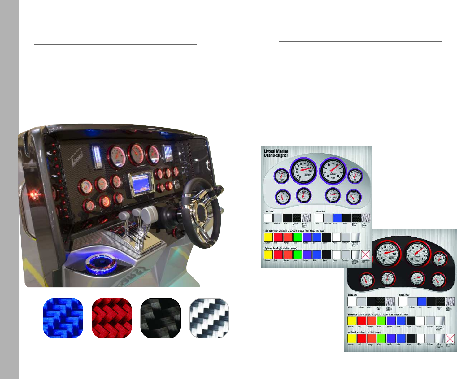
DashDesigner
Visit www.livorsi.com where you'll find the
Livorsi DashDesigner. This interactive tool lets
you select some of our custom options. Or,
check out our Custom Gauge Gallery to see
some of our customer’s creations.
carbon
Fiber
silver
carbon
fiber
blue red
Our panels are available in real carbon fiber.
Send us a dimensional drawing, or your old panel and
we'll recreate it.
Toll Free: 877.548.5900
Phone: 847.752.2700
Dash Panels
5
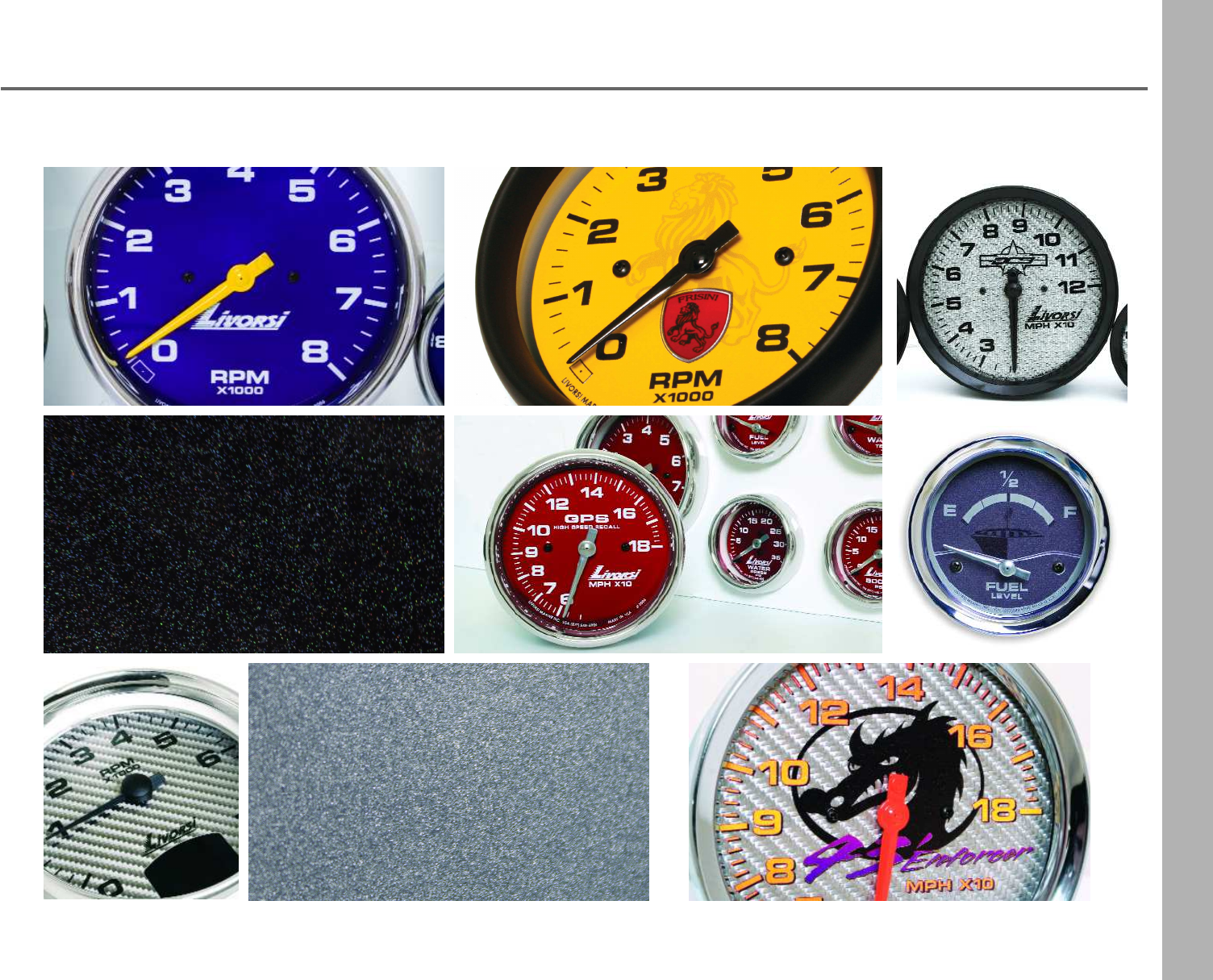
Custom Gauges
New Color
Black Stardust
New Color
Gun Metal
6
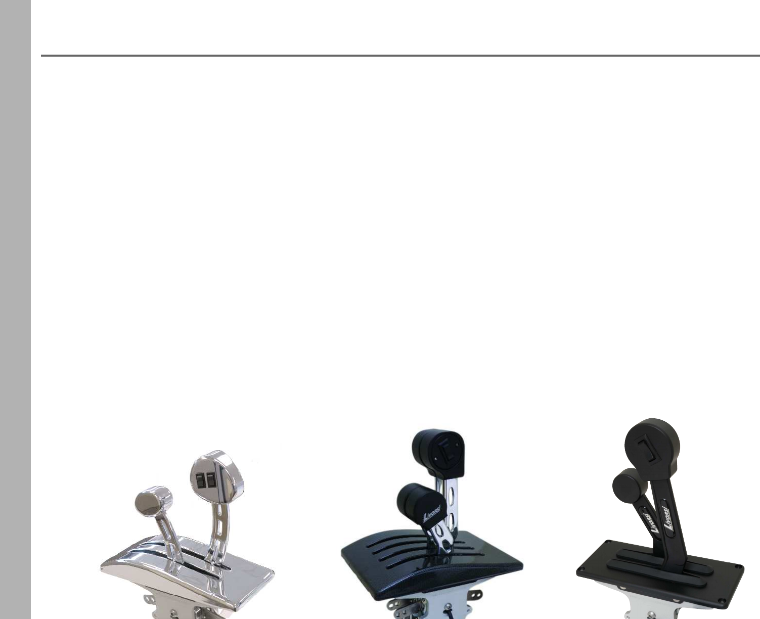
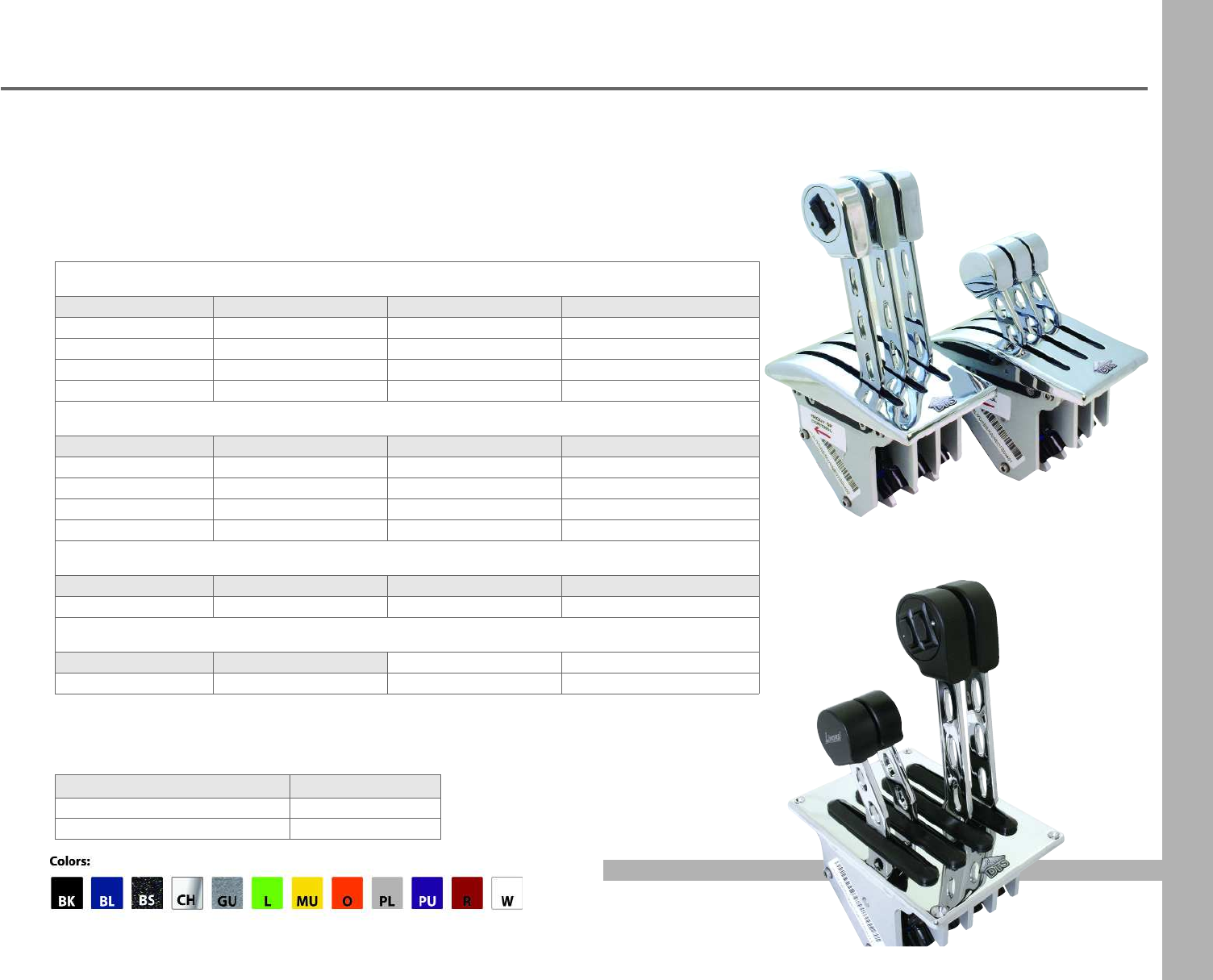
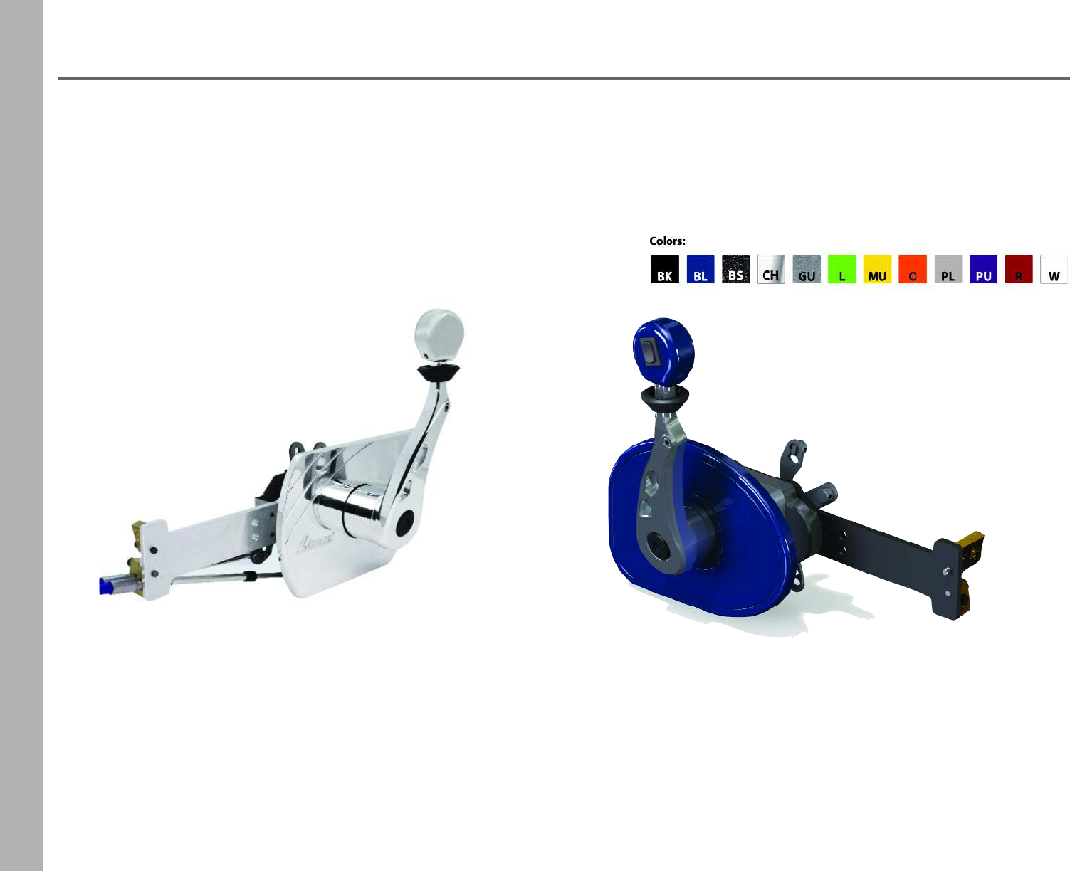
Platinum Series Controls
Available in three throttle/shift configurations:
•Fully Mechanical
•Fully Electric
•Mechanical/Electric (Hybrid)
Designed to be ergonomically comfortable to the operator while being lighter and more compact
for fitting into tight spaces. The Platinum Series is finished with a two coat process which
prevents corrosion and can be configured for single or multiple engine's for Drives,Transmissions,
Jet Drives or Buckets.
Configurations include one or any combination of the below:
•The use of mechanical 33C or 43C cables for mechanical levers
•Electric configurations use compact direct driven angular sensors,
0-5 Volt electronic sensors or a PWM signal
•The use of a micro switch - for electronic transmission shifting
•Single, twin and triple in-handle trim switch available
•Check with the engine manufacturer or Livorsi Marine for electric control compatibility
Arched Billet Standard
7
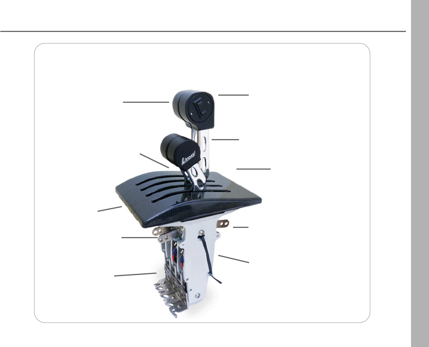
Platinum Series Controls
Fully Mechanical Billet Throttle Control
with Contour base in Carbon Fiber
Adjustable
detent and friction
Billet aluminum and
stainless steel construction
makes these controls tough
and lightweight
Corrosion resistant: two layers process
anodized base coat
powder coat finish
Shorter base depth:
mechanical units 8.125"
electric units 6.5"
Mechanical levers
use 33C or 43C
series cables
Electrical configurations
use compact direct driven
angular sensors
Ergonomically
designed knobs
for long hours of
comfortable operation
Shorter handles-
easily fits in tight spaces
Flat or contour base in
chrome, carbon fiber or
power coat finish
In-handle single, dual or
triple trim switch available
Check with the engine manufacturer or Livorsi Marine for electric control compatibility.
8
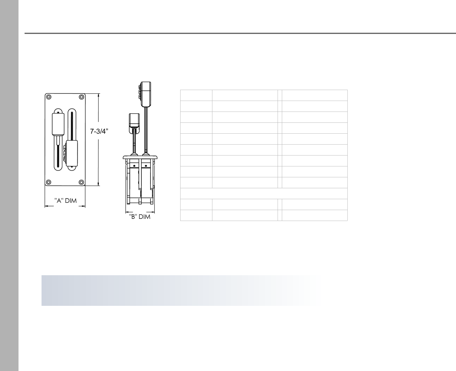
Platinum Series Controls
Dimensions
Handles Overall SizeCutout Size
A DIM B DIM
12-1/4” x 7-3/4” 1-7/8” x 6-1/2”
23-11/32” x 7-3/4” 2-7/8” x 6-1/2”
34-7/16” x 7-3/4” 3-7/8” x 6-1/2”
45-17/32” x 7-3/4” 4-7/8” x 6-1/2”
56-15/32” x 7-3/4” 5-7/8” x 6-1/2”
67-9/16” x 7-3/4” 6-7/8” x 6-1/2”
89-9/16” x 7-3/4” 8-7/8” x 6-1/2”
Depth Mechanical / Hybrid Electric
8.125” 6.5”
For a list of part numbers please refer to our price list available online.
9
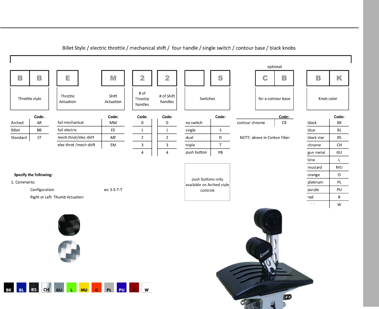
Platinum Series Controls
Build Your Part Number
Carbon Fiber Base Options
black carbon fiber
silver carbon fiber BBEM22SCBBK
Powder Coat Options
10
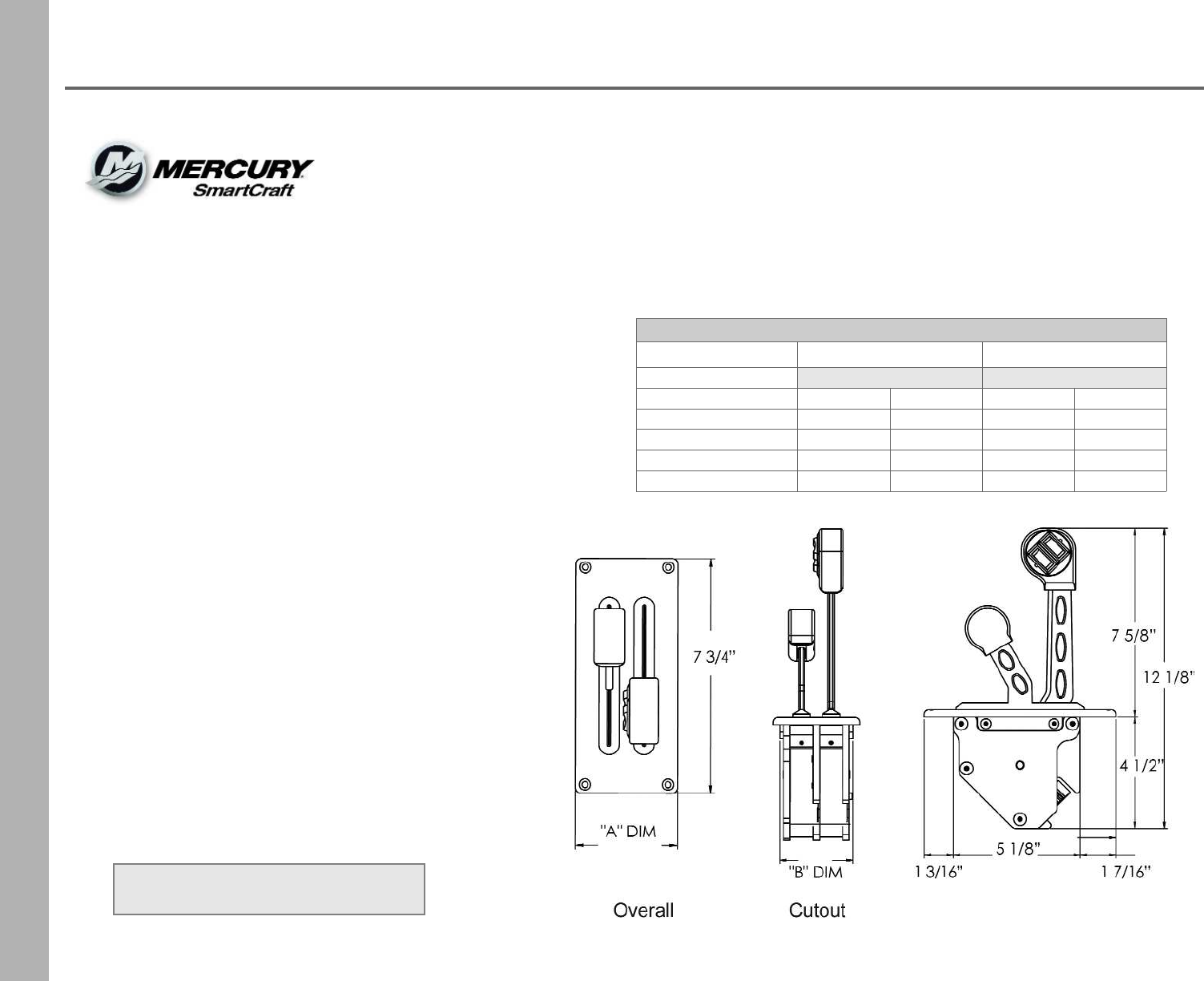
Livorsi SmartCraft® DTS
Digital Throttle & Shift
Compatible with:
•Mercury DTS equipped engines
•Verado 150 - 400 SCI
•Mercruiser 5.0L - 8.2L
•Optimax 225
•Mercury Racing 520, 565, 1100, 1350, 1650
•and Cummins engines that are DTS capable
Dimensions
Number of Handles Overall Cutout
ADIM B DIM
2 handle 3 3/8 in. 7 3/4 in. 2 7/8 in. 5 1/8 in.
3 handle 4 1/2 in. 7 3/4 in. 4 1/64 in. 5 1/8 in.
4 handle 5 11/16 in. 7 3/4 in. 5 3/16 in. 5 1/8 in.
6 handle 8 in. 7 3/4 in. 7 1/2 in. 5 1/8 in.
8 handle 10 5/16 in. 7 3/4 in. 9 13/16 in. 5 1/8 in.
These DTS controls are smaller and lighter: constructed of
stainless steel and billet aluminum for years of dependable
service. The user has the ability to adjust tension for each
handle. The ergonomically designed knobs feature your choice
of single or twin drive trim switches or momentary up and
down switches.
•A license from Mercury allows Livorsi to combine
DTS technology with the options and quality of Livorsi controls
•Designed for direct drive of the triple redundancy position pots
•Eliminates the need for mechanical cables
•Engineered for smooth shifting and throttling
•Single, twin, triple, and quad control configurations are
available in a variety of styles and colors.
Shadow Mode Available
11
Livorsi SmartCraft® DTS
Digital Throttle & Shift
Chrome Base
Number of Handles No Switch Single Switch Dual Switch
2 handle DTSBB11 + color DTSBB11S + color DTSBB11D + color
4 handle DTSBB22 + color DTSBB22S + color DTSBB22D + color
6 handle DTSBB33 + color DTSBB33S + color DTSBB33D + color
8 handle DTSBB44 + color DTSBB44S + color DTSBB44D + color
Powder Coat Base
Number of Handles No Switch Single Switch Dual Switch
2 handle DTSBB11PC + color DTSBB11SPC + color DTSBB11DPC + color
4 handle DTSBB22PC + color DTSBB22SPC + color DTSBB22DPC + color
6 handle DTSBB33PC + color DTSBB33SPC + color DTSBB33DPC + color
8 handle DTSBB44PC + color DTSBB44SPC + color DTSBB44DPC + color
Mercury DTS Rigging Kits
Single Engine Twin Engine Triple Engine Quad Engine
84-892955K04 84-893378K04 892955K32 Order (4) Single Engine
Mercury Shadow Mode Rigging Kits
Triple Engine Quad Engine
8M8025983 8M8025984
Optional Contour Base
For a contour base add the following code after the control part number:
Shadow Mode
Shadow mode available for automatic throttle synchronization for triple or quad
engine applications; where two throttle levers operate three engines or four
engines. Requires appropriate Mercury shadow mode rigging kit.
split throttle/shift
configurations available
Description Part Number
chrome contour base CB
powder coat contour base CBPC
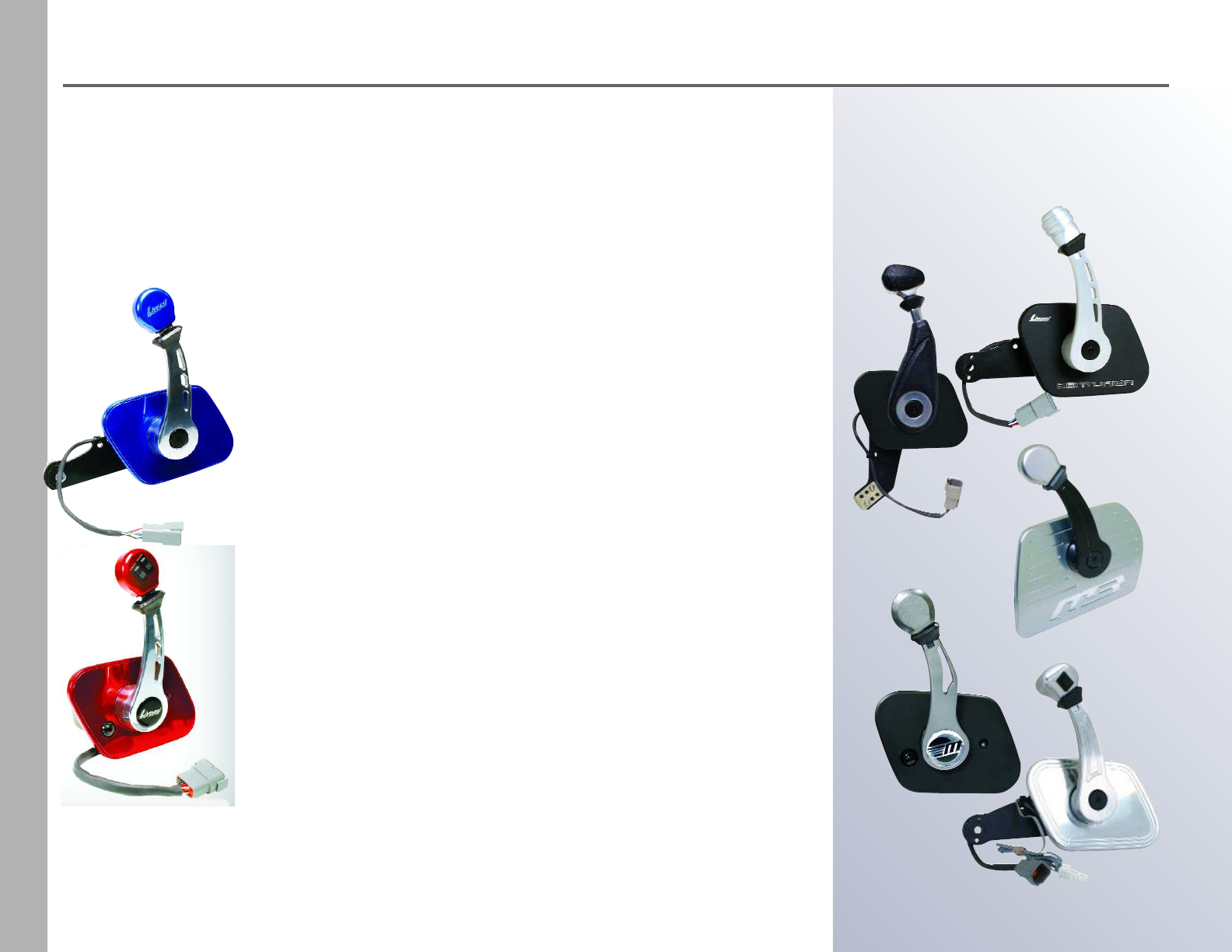
Electronic Sidemount Controls - Livorsi Design Capabilities
12
Nautique
MB Sports
Centurion
Malibu
Tigé
Livorsi Marine provides customized
controls to
a number of builders:
Both Versions Feature:
•Adjustable friction settings for throttle and shift detent
•Single or twin trim switches available to actuate wake tabs or drives
•Constructed to exceed ABYC standards
•Compatible with PCM, Ilmor and Indmar engines that support
electronic throttle and shift control
Livorsi EMC Controls
(Electronic Throttle & Mechanical Shift)
•Uniquely designed for engine applications that utilize
electronic throttle control yet require a cable to shift the
transmission, drive, or outboard
•Throttle - Features a dual redundancy potentiometer that is
fully programmable, allowing you to customize the amount
of throttle output throughout the entire range
•Shift - Compatible with 33C or 43C cables
Livorsi EEC Controls (Electronic Throttle & Shift)
•Fully electronic controls that provide a smoother and safer
ride with lightning fast shifting and throttling at your
fingertips
•Throttle - Features a dual redundancy potentiometer that is
fully programmable, allowing you to customize the amount
of throttle output throughout the entire range
•Shift - Military grade switches provide reliable gear position
feedback to the engine controller
•Push button for throttle only mode with LED indication
The electronic controls shown below are designed for specific OEM builders and cannot be
sold at the retail level. We show these products here to highlight our design capabilities.
If you are an OEM and you require a new control for your application, please call or email us.
We welcome the opportunity of designing a product for you.
13
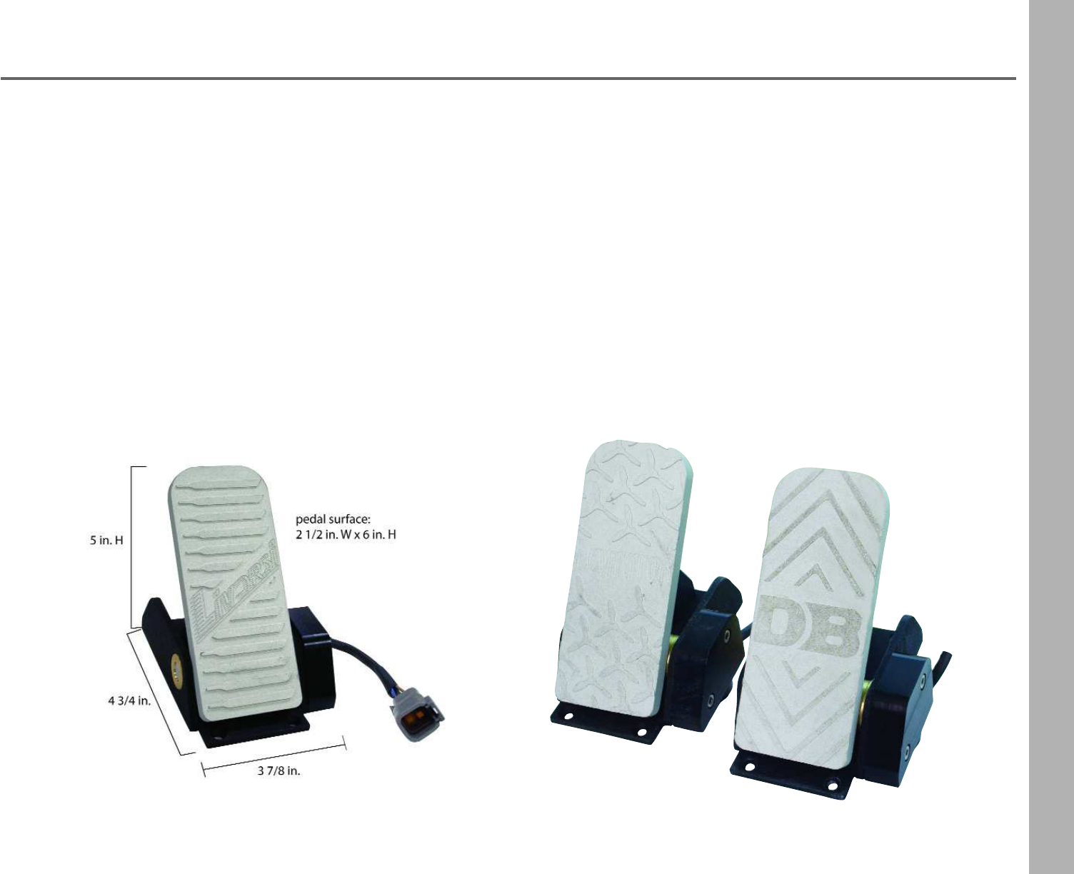
Electronic Foot Pedals - Livorsi Design Capabilities
Diamondback Airboats
Levitator Engines
•Currently designed to control marine engines that utilize electronic throttle control
•These pedals may be calibrated for MEFI5 and 6 engines
•This completely electronic design eliminates problematic cables from bow to stern
•A sensor is used to send throttle position information from the pedal to the ECU on the engine
•Fully sealed to IP68 specifications, this sensor is waterproof and highly durable
•Plug and play waterproof Deutsch connectors simplify installation
•Solid rugged design, made of billet aluminum with an anodized finish to prevent corrosion
•Aggressive anti-slip features are built right into the pedal for confident non-slip throttling
•Private Labeling available
The electronic controls shown below are designed for specific OEM builders and cannot be
sold at the retail level. We show these products here to highlight our design capabilities.
If you are an OEM and you require a new control for your application, please call or email us.
We welcome the opportunity of designing a product for you.
14
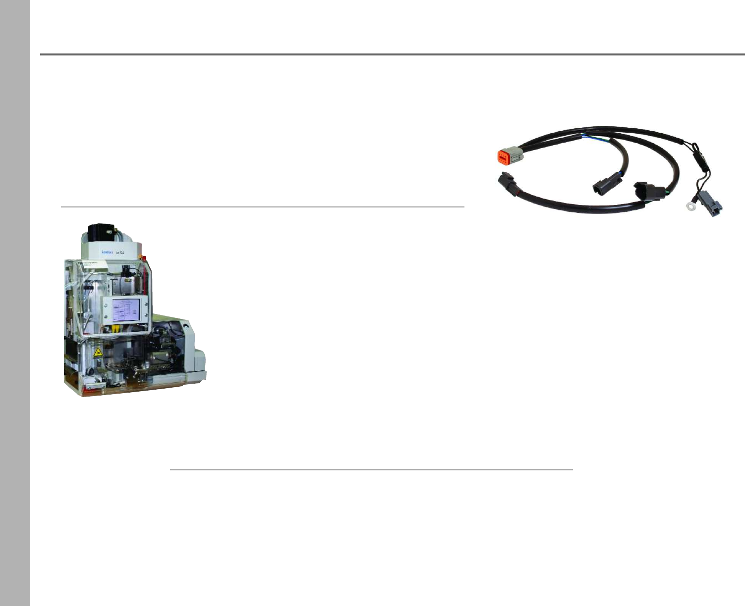
Custom Wire Harness Solutions
Cutter/Stripper
Cuts and strips wire and cable to precise programmed length.
individual wires · multi-conductor cable · wire braid · phone wire · full strip · half strip · partial strip
Wire Terminal Crimper
A semi-automated machine that provides precise and consistent compression of wire terminals,
ensuring accurate in-process crimp height, crimp force and strips. Terminal types include: Molex · AMP
· Deutsch · Hirose · Others
Ultrasonic Wire Welder
Helps reduce design time and component costs by integrating 100% quality monitored ultrasonic splice
welded wires into your wire and cable harnesses. High electrical integrity with strong metallurgical
bonds ensures a reliable connection between various gauges of wire.
Livorsi utilizes state-of-the-art equipment from top manufac-
turers like Komax, Stapla, Cami and Shimpo.
Komax BT 722 wire
terminal crimper with
crimp force technology
•Engineering design support to help maximize efficiencies
•Electro-mechanical assembly, process development, fabrication and testing
•Semi-automated wire and cable cutting and stripping for quick change-over
•Ultrasonic wire welding
•Semi-automated terminal crimping
•Custom wire labels to identify individual wires; decreases assembly time and errors
•Soldering
In addition to in-process quality assurance, we perform 100%
quality control final testing on all wire harness assemblies.
•Cable Eye Testing
•Pull Force Gauge
•LCD Video Microscope
•Value Added Wire Assembly
We can supply all harnesses
needed for your OEM boat appli-
cations.
Livorsi is ready to meet your short to medium run mechanical and electrical
cable assembly requirements.
Mechanical Side Mount Control
15
Single handle-dual function control operates both throttle and shift.
Suitable for any type of boat with outboards, inboards, I/Os or jet boats.
•In-handle trim switch for drives and diverters
•Can be installed on either port or starboard side,
with a vertical or horizontal cable entry
•Contains a positive lock-in neutral to prevent accidental gear engagement
•Accepts 33C type cables as well as Mercury, Yamaha, Evinrude and others
•Includes a cable connection kit and neutral safety switch
•Available in all the Livorsi powder coated colors
Control Bezel
•The optional bezel adapts a Mercury 3000 or 4000 side mount
shifter cutout to fit this control
•Available in a platinum powder coat finish, other Livorsi colors
available at an extra charge
Description Part Number
side mount control
with cable connection kit SMC + color
control bezel platinum SMCBPL
control bezel in another color SMCB + color
Cutout -Installation Diagram
DISCONTINUED
DISCONTINUED
16
Mechanical Sidemount Controls
Tow Sport Control (Ski Boats)
• Customizable
– Branding
– Colors
• Backfittable
– Replaces Teleflex MV3
Runabout Control
• Customizable
– Branding
– Colors
• Backfittable
– Replaces Mercury MPC GEN II Panel Mount controls
– Replaces Teleflex CH2200 + CH2300 controls
Mechanical Sidemount Features
•Now with a shorter throw - 180 degrees
•Supports outboard and sterndrive configurations with 33C cables
• Built in single trim switch controls drives, tabs wake plate, etc.
•Adjustable friction settings for throttle and shift detent
•Pull up collar design prevents accidental reverse or forward engagement
•Center button disengages shift for throttle only mode
• Available in all the standard Livorsi colors
•Custom colors available upon request
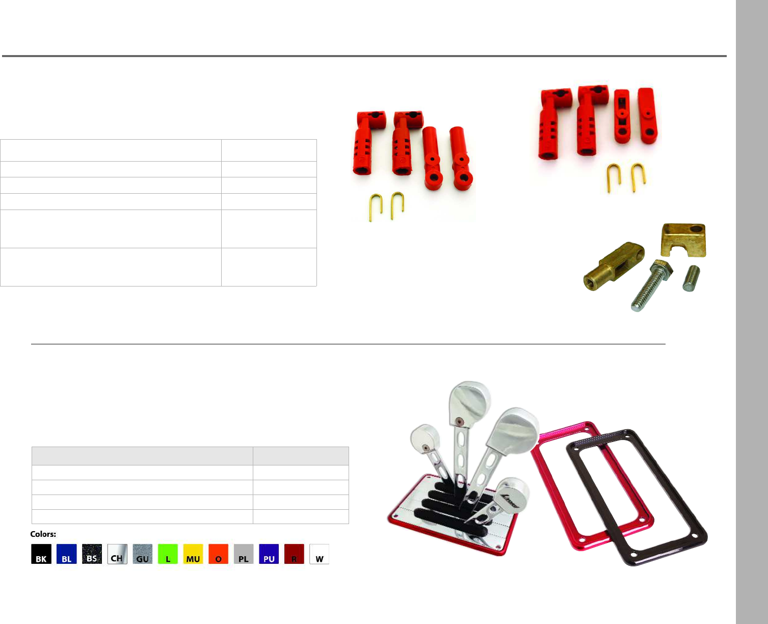
17
Control Hardware & Accessories
dual with wires
and plate
Triple Trim Switch - bolt on
•Trim multiple drives or tabs without
taking your hands off the throttle
•Ergonomic design keeps throttling arm relaxed
•Aircraft style bolt-on adds a total of 3 switches
•For left or right handed applications
•Made of billet aluminum
•Fits standard or billet controls
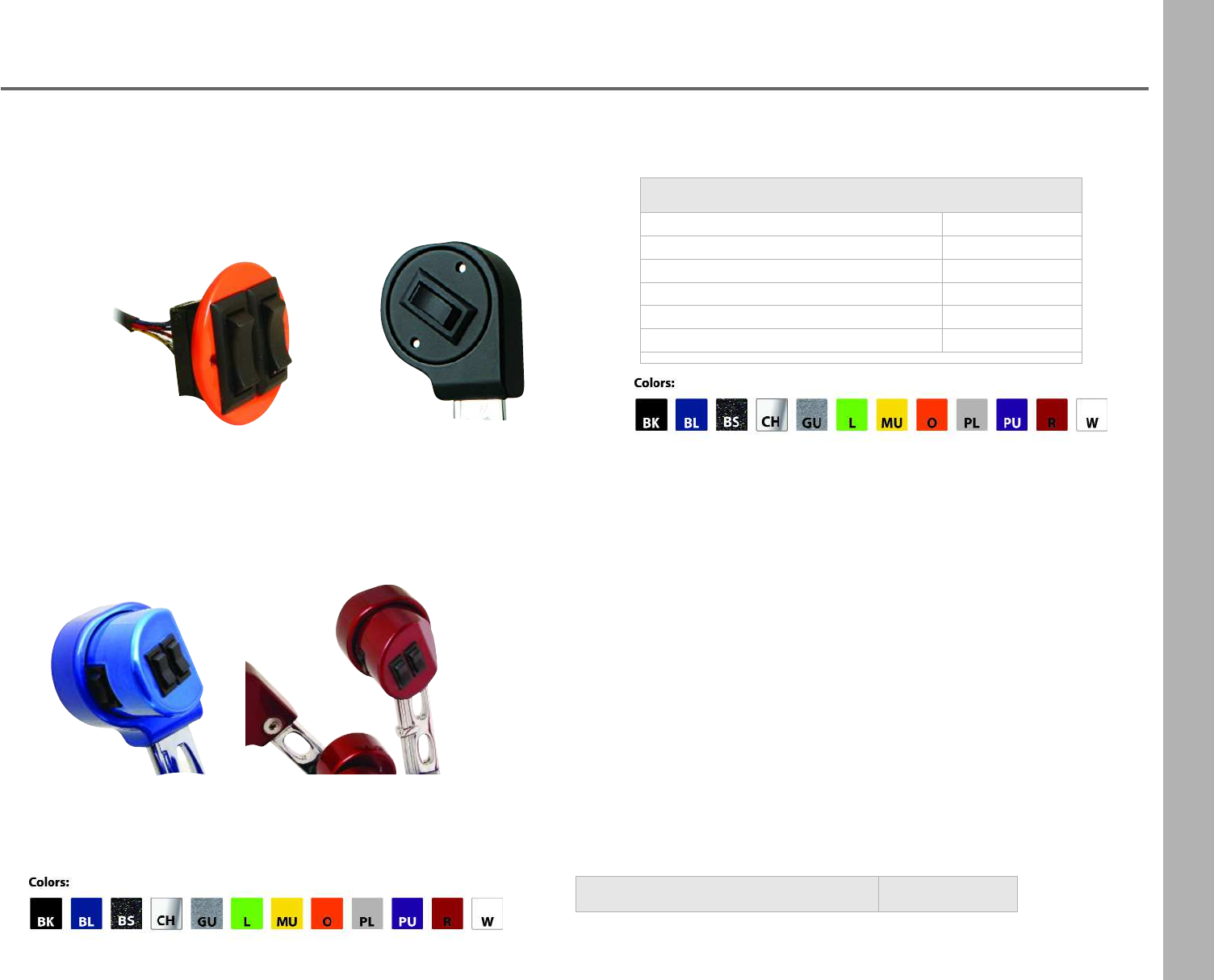
Trim Switches
single no wires TSSO
single w/ wires TSSW
single w/ wires & plate TSSWP + color
single w/ wire, plate & back plate TSSWPB + color
dual w/ wires & plate TSDWP + color
dual w/ wires, plate & back plate TSDWPB + color
Trim Switches
•Replacements for Standard, Billet or ETS Controls
•These switches will not work on Mercury controls
Triple Trim Switch TTS + color
18
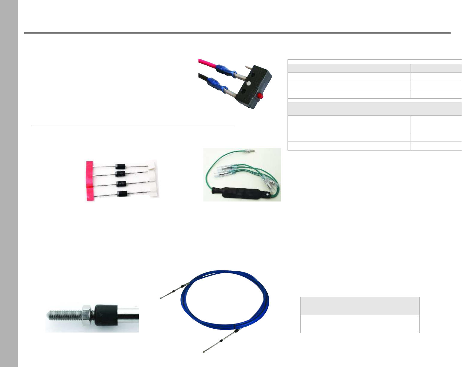
Neutral Safety Switch
•Allows you to start engine only when in neutral
•Included at no charge with your control order
•One needed for each shift
Diode Kits
•3 amp
•1000V
Neutral Safety Switches
switch only NSS
switch with wire assembly NSSA
switch with wire assembly and screws NSSAK
Diodes
diode kit- diodes only
4 piece kit for twin engine DK
diode plug in harness- twin DKH2
diode plug in harness- triple DKH3
33C Series Cables
•Sold in two foot increments
•Sizes range from 10 feet to 38 feet
•Use with Livorsi controls or mechanical indicators
•Stainless steel core
•Chrome plated brass
•3 1/4” throw
•Thread size 10x32
Part Number
CA + LENGTH
19
Control Hardware & Accessories
Throttle Bezels
•For standard, billet, ETS and arched controls
•Measures 8 1/4” long
•Width varies depending on the number of handles
•Sold separately from controls
Description Part Number
2 handle bezel TB2 + color
3 handle bezel (requires 2 week lead time) TB3 + color
4 handle bezel TB4 + color
6 handle bezel TB6 + color
Description Part Number
Mercury OB 1 shift/1 throttle CCKOBM
Mercury I/O 1 shift/1 throttle CCKIO
OMC OB 1 shift/1 throttle CCKOBO
Cable Connection Kit
(included at n/c with
control order)
CCK30
Cable Connection Kit
for 43C series cables CCK40
Cable Adapter Kits
•1 kit needed for 1 throttle/1 shift lever
CCK30 shown here
CCKIO
CCKOBM
20
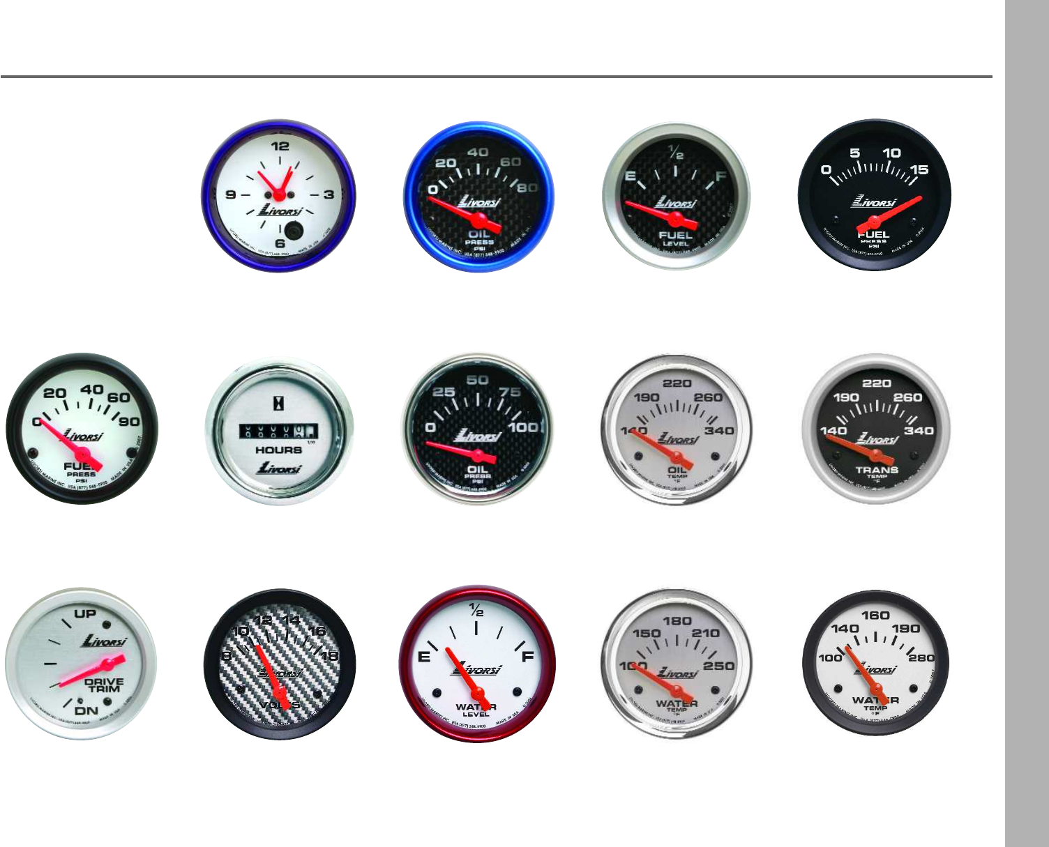
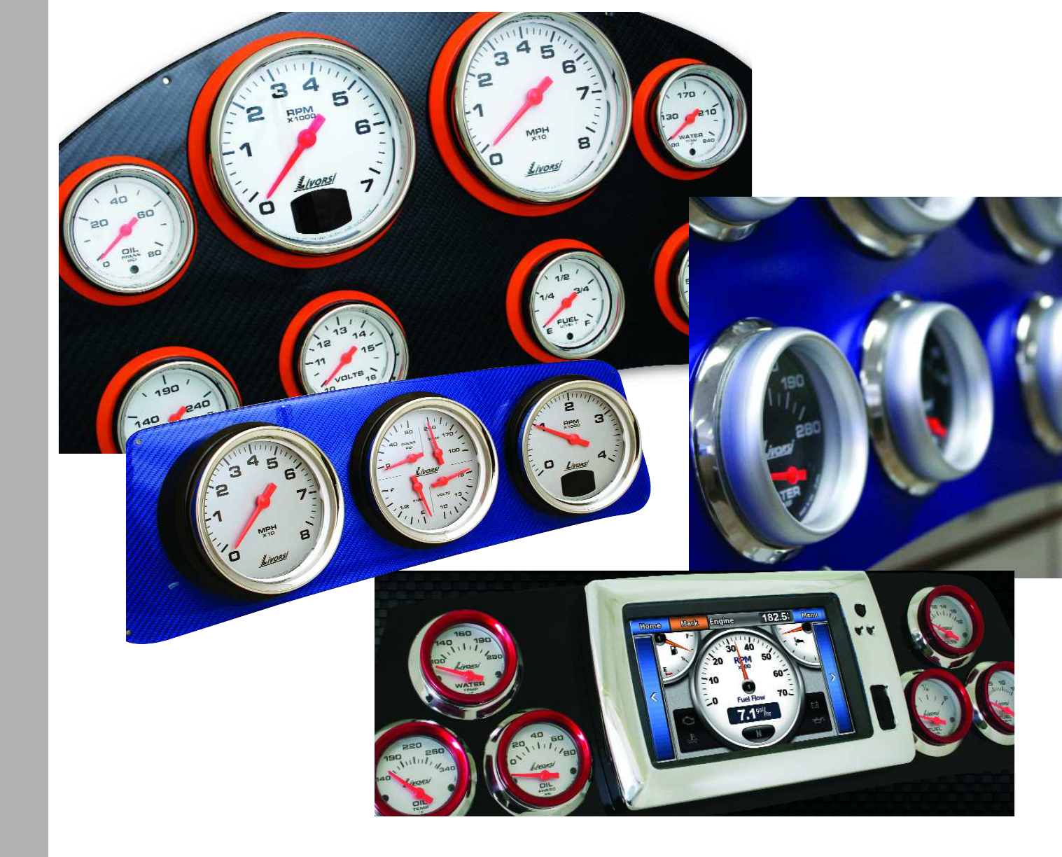
Gauge Styles
Industrial
Mega & Race
dials: platinum, white or black
rims: Mega or Race
Page 43
dials: black, platinum,
carbon fiber, silver
carbon fiber or white
rims: Mega or Race
Page 28
Vantage View
dials: black or white
rims: SAE rim
Page 22
21
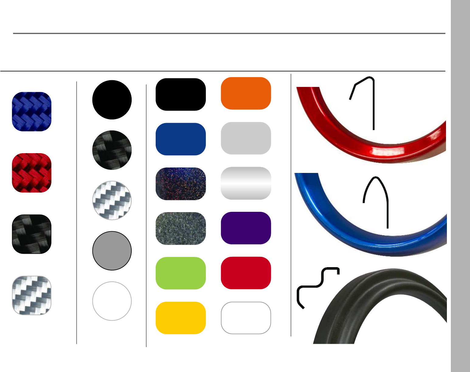
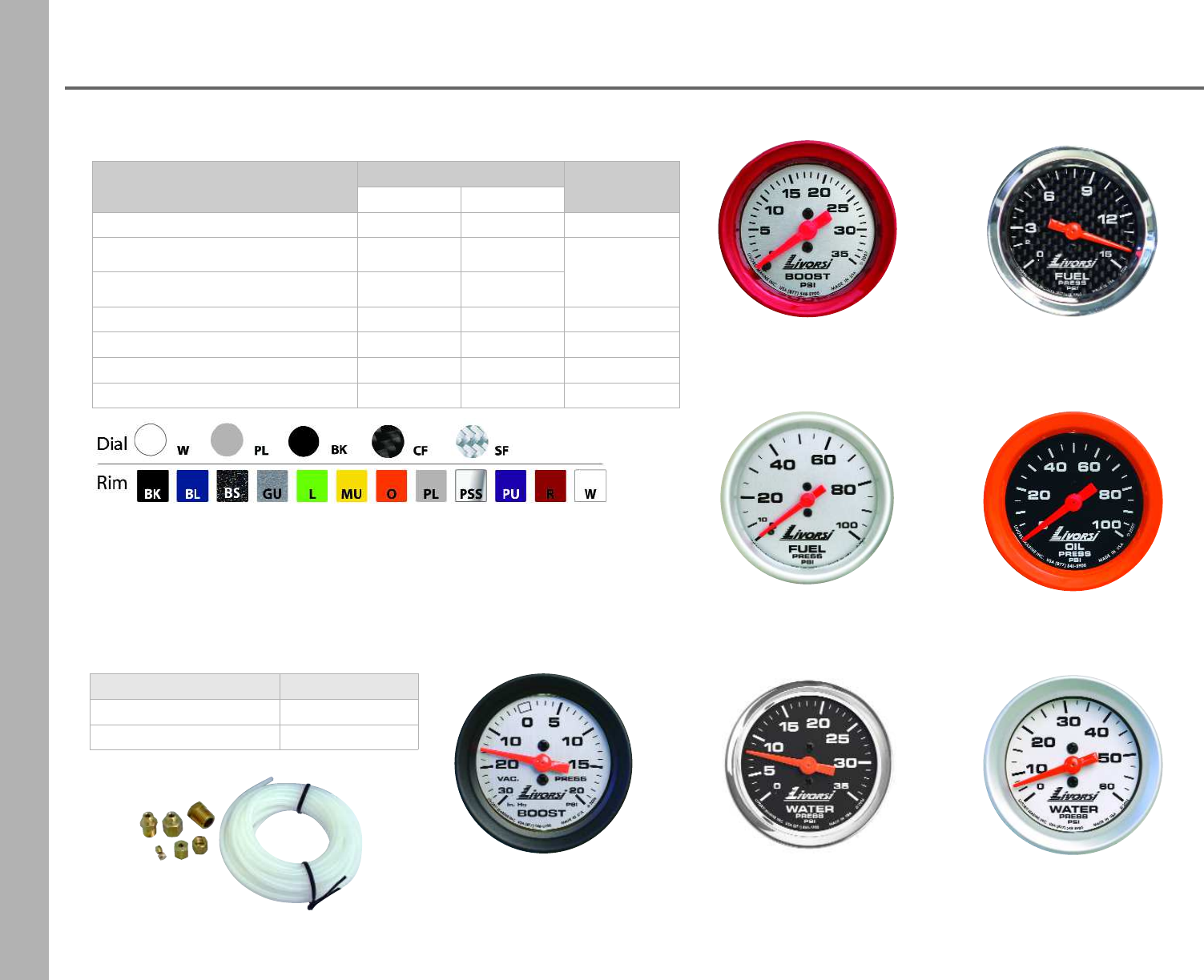
Color Options
carbon Fiber
CF
silver carbon fiber
SF
blue carbon fiber
red carbon fiber
carbon fiber- CF
platinum- PL
white- W
silver carbon fiber- SF
* black- BK
Dash Panels
* black - BK
blue - BL
gun metal - GU
lime - L
mustard - MU
orange - O
platunum - PL
purple - PU
polished
stainless
steel -
PSS
red - R
white - W
black
stardust -
BS
* Black gloss finish available upon request
Powder Coat ColorsDials Rim Styles
Race Rim
SAE Rim
Mega Rim
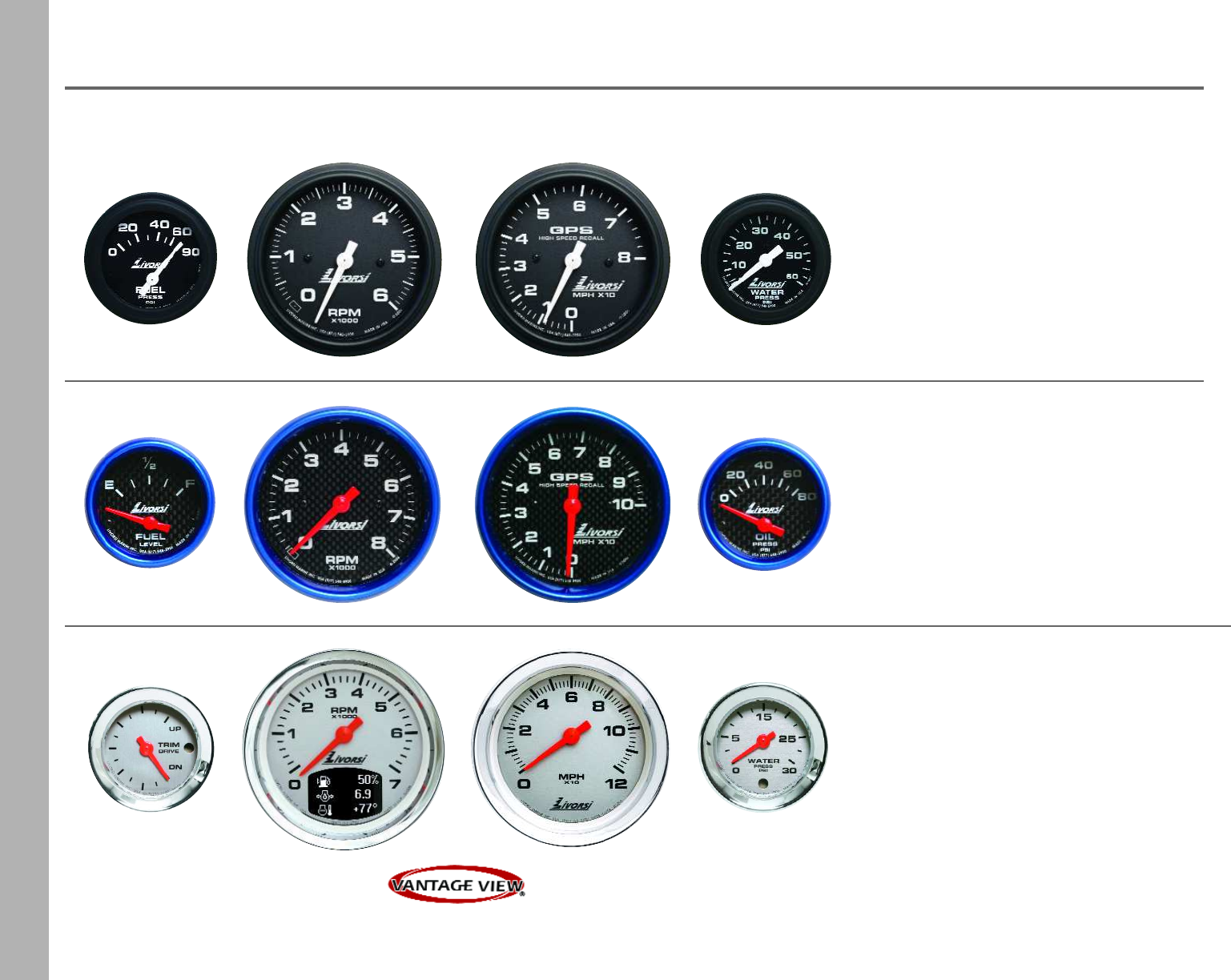
22
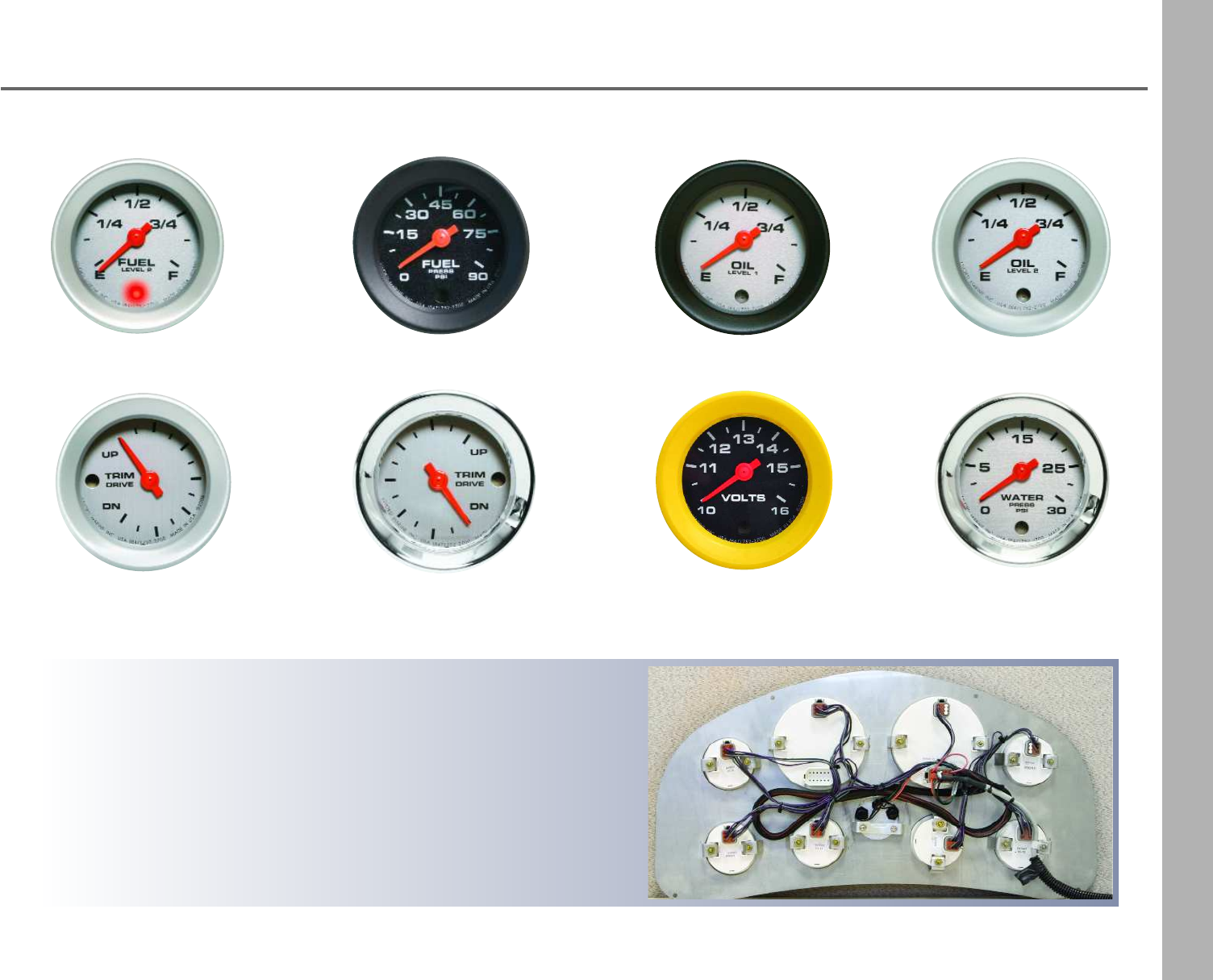
Industrial Series
Analog Gauges
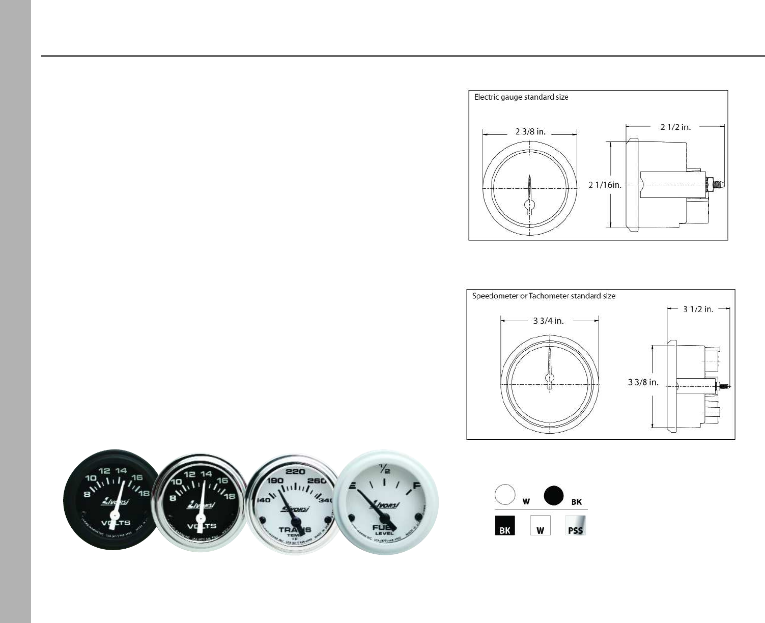
Industrial Series Features
•Standard gauge sizes
•Plug-in connectors are waterproof and resist salt corrosion
•Gauges are encased in non-ferrous hardware
•Red LED lighting is standard
•Available in 12 or 24 volt system
•Powder coated pointers are fade resistant
•SAE rims in flat black, white or stainless steel
Dial
Rim
The Industrial series was designed with the industrial equipment,
workboats, pleasure boats and vehicles in mind.
Industrial Series gauges are easy to install with the use of plug-in
Deutsch connectors that significantly decrease rigging time. The plug-in
connectors are waterproof and resist salt corrosion and dust intrusion.
These gauges feature fade resistant powder coated pointers; SAE rims
in a powder coat finish or in polished stainless steel. These finishes
protect the rims and make them extremely resilient in harsh weather
environments.
23
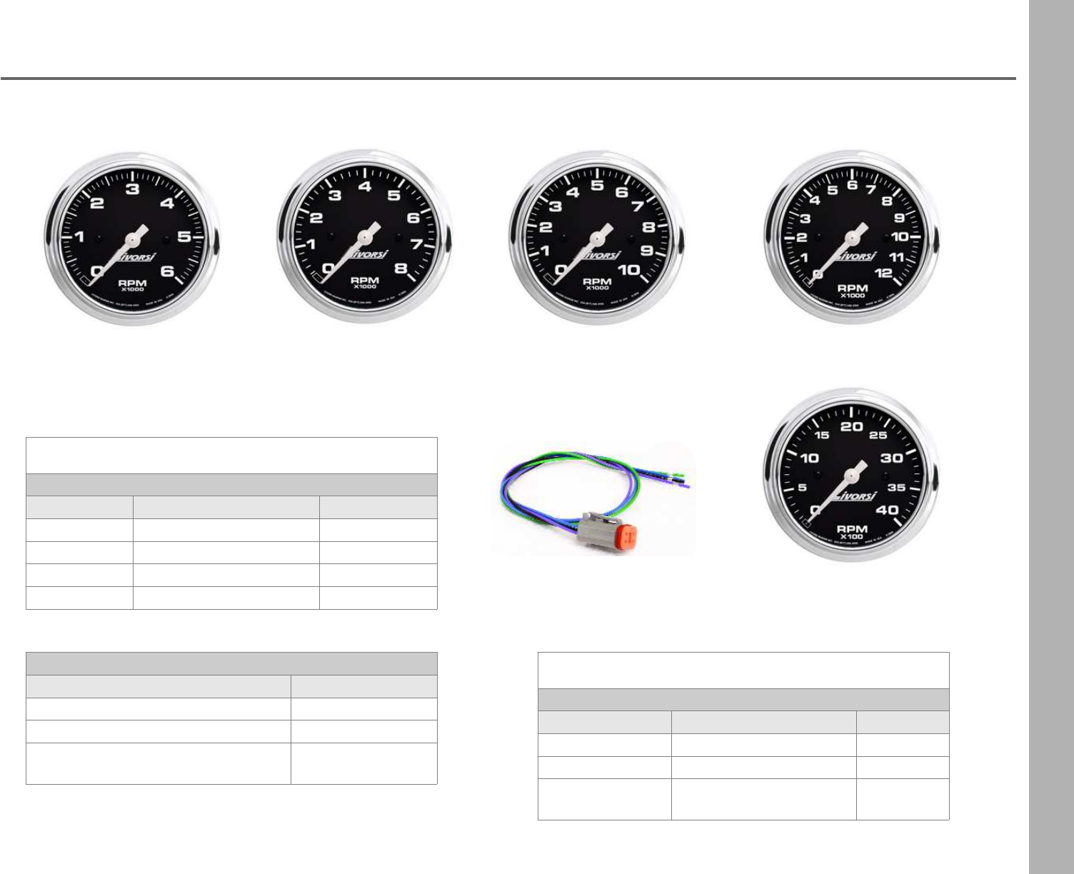
Industrial Series
Tachometers
4,000 RPM
6,000 RPM 8,000 RPM 12,000 RPM
10,000 RPM
DCH
cutout size: 3 3/8” overall size:3 3/4”
Tachometers - Gas
Description Base Part Number Requires
6,000 RPM DCS6000 DCH harness
8,000 RPM DCS8000 DCH harness
10,000 RPM DCS10000 DCH harness
12,000 RPM DCS12000 DCH harness
cutout size: 3 3/8” overall size:3 3/4”
Tachometers- Diesel 4000 RPM
Description Base Part Number Requires
alt driven DC4000DA DCH harness
mag probe driven DC4000MPD DCH harness
mechanical signal
generator driven DC4000MSGD DCH harness
Tachometer Hardware
Description Part Number
DCH harness 12V 24” lead DCH
DCH harness 24V 24” lead DCH24
DCH harness 12V w/ tach filter,
reduces needle bounce, 24” lead DCTFH
Gas tachometers are compatible with:
4, 6, & 8 cylinder, V-10 & Merc O/B 6 pulse/12 pole
24
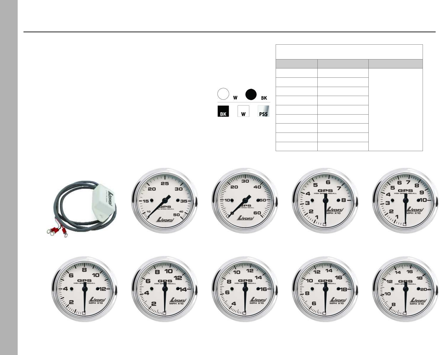
Industrial Series
GPS Speedometers
•Livorsi GPS Speedometers require a NMEA 0183 antenna/receiver.
Included with GPS Speedometer
•speedometer
•memory recall
•harness
Included with GPS Speedometer Kit
•speedometer
•memory recall
•harness
•GPS antenna
- antenna mounts with a 1/4” screw
- antenna dimensions: 2 ¾" L x 2 3/8" W x 7/8" H
cutout size: 3 3/8” overall size:3 3/4”
Description Base Part Number Notes
50 MPH GPSS50
For a GPS Kit,
add the letter “K”
after the MPH.
60 MPH GPSS60
80 MPH GPSS80
100 MPH GPSS100
120 MPH GPSS120
140 MPH GPSS140
160 MPH GPSS160
180 MPH GPSS180
200 MPH GPSS200
Dial
Rim
50 MPH 80 MPH 100 MPH
120 MPH 140 MPH 160 MPH 180 MPH
60 MPH
200 MPH
GPS antenna
25
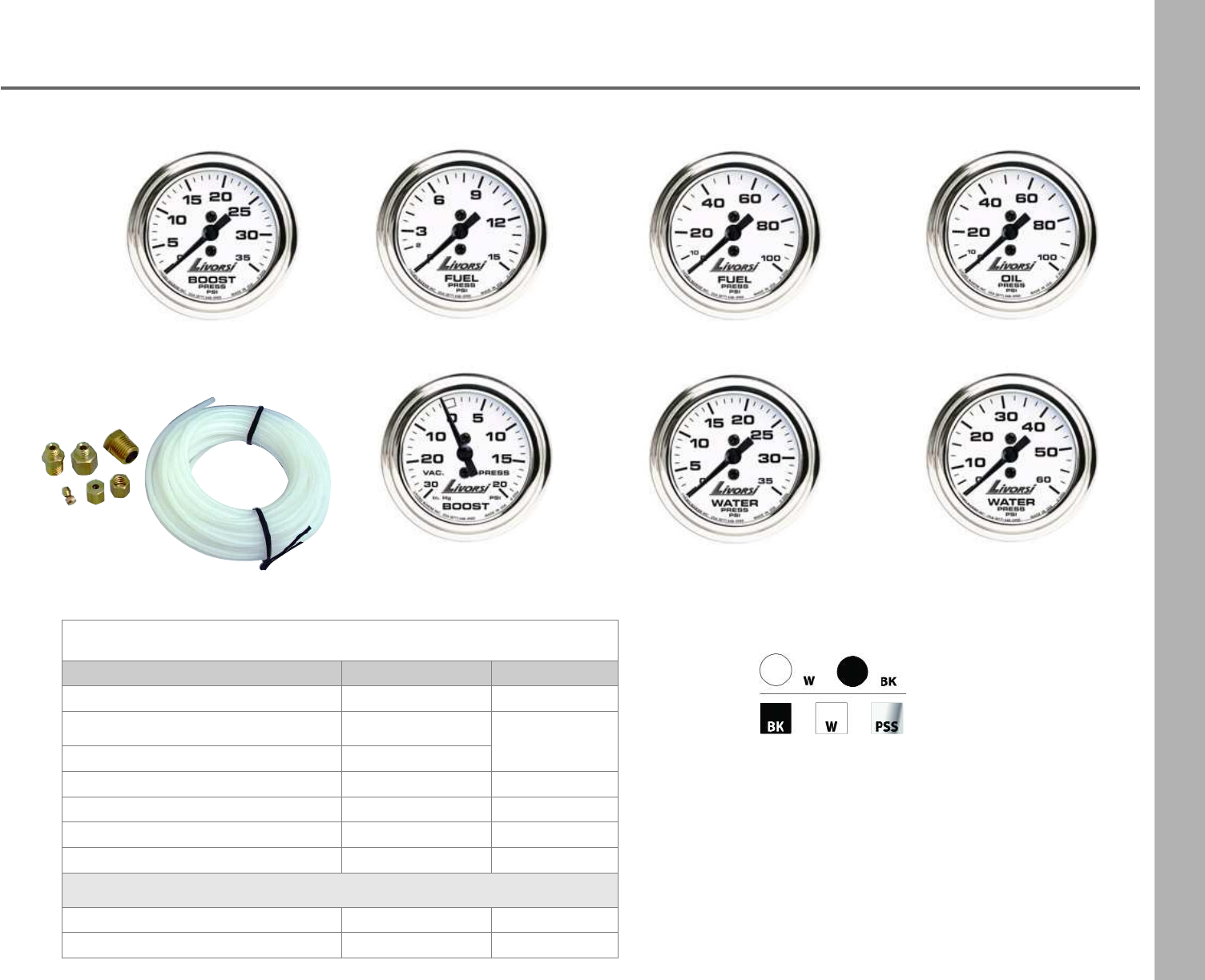
Industrial Series
Mechanical Gauges
vacuum boost water pressure 0-35 PSI water pressure 0-60 PSI
boost 0-35 PSI fuel pressure 0-15 PSI fuel pressure 0-100 PSI oil pressure 0-100 PSI
hose kit
Dial
Rim
cutout size: 2 1/16” overall size: 2 3/8”
Description Base Part Number Requires
Boost 0-35 PSI DCSMB35 hose kit
Fuel Pressure 0-15 PSI DCSMFP fuel hoses n/a
Fuel Pressure 0-100 PSI DCSMFP100
Oil Pressure 0-100 PSI DCSMOP hose kit
Vacuum/Boost 30 in hg/boost20 DCSMVB hose kit
Water Pressure 0-35 PSI DCSMWP hose kit
Water Pressure 0-60 PSI DCSMWP60 hose kit
Hose Kits - not to be used with fuel
10 feet of hose and fittings HKA
25 feet of hose and fittings HK
26
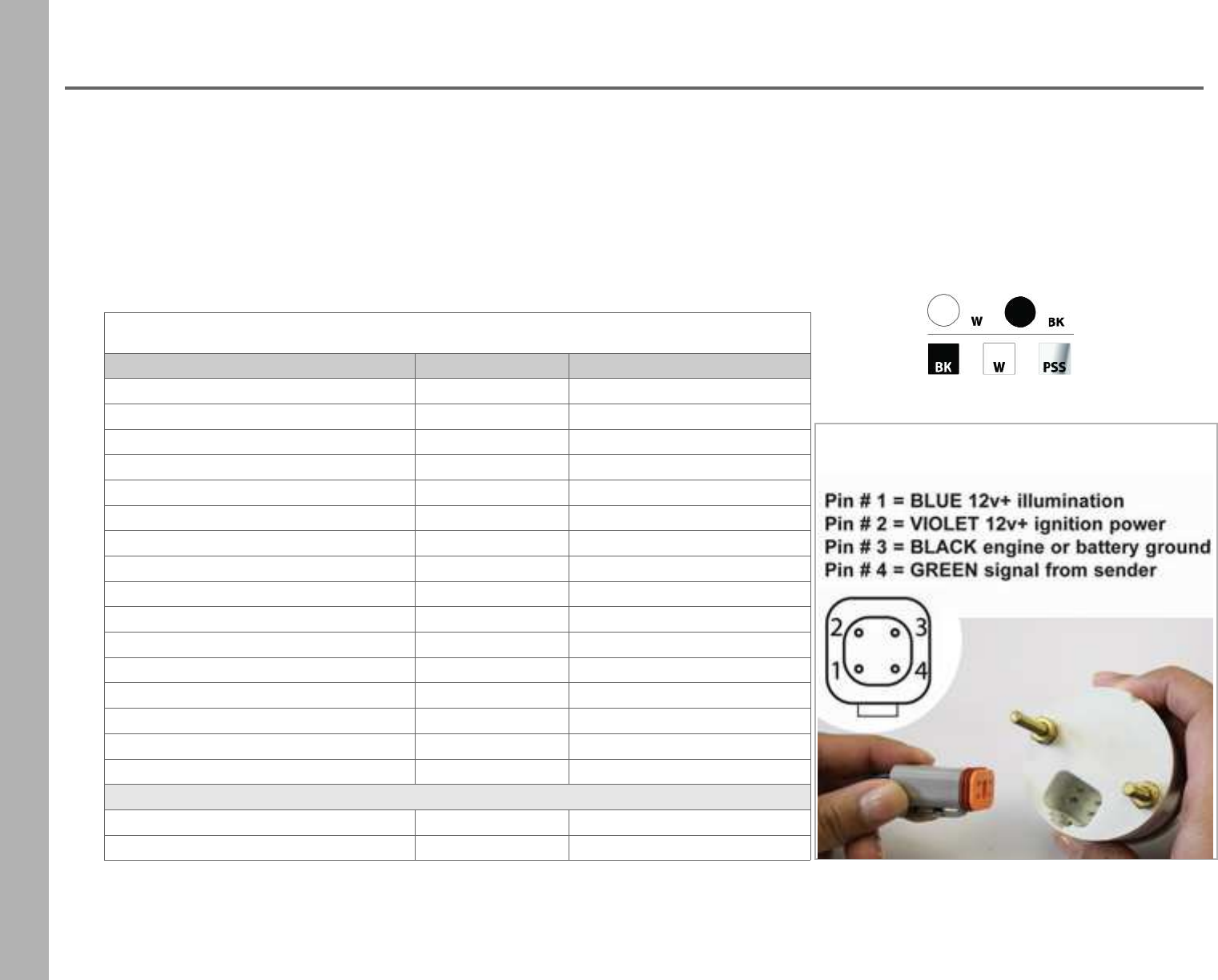
Industrial Series
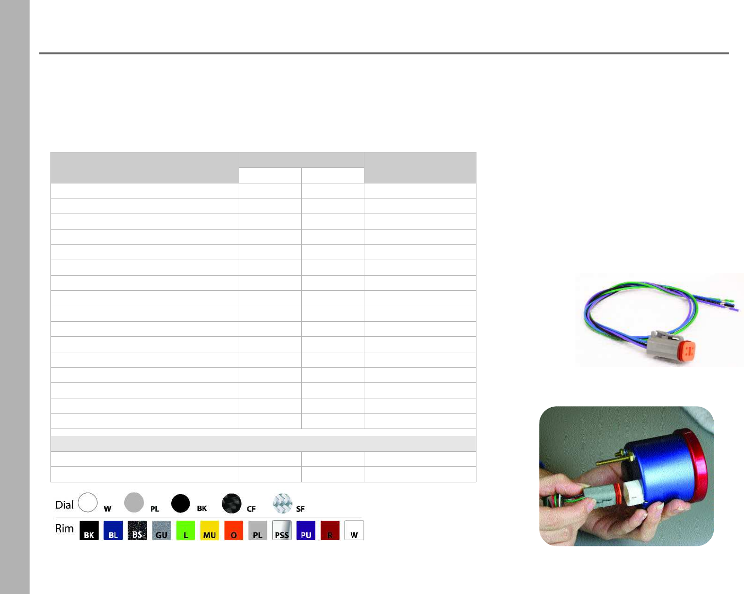
DCH Harness
Dial
Rim
* Note: Available with Mega or Race Rim only.
Electric Gauges
•These electric gauges require the use of a four pin connector wire harness
(unless otherwise noted) that we call a DCH harness.
•We offer these harnesses pre-assembled with labed wire leads, 24 inches in length.
cutout size: 2 1/16” overall size: 2 3/8”
Description Base Part Number Requires
Boost 60 PSI DCSB60 -
Fuel Level 0-90 OHMS DCSFLGM DCH/DCH24, fuel level sender
Fuel Level 240-33 OHMS DCSFL DCH/DCH24, fuel level sender
Fuel Pressure 0-15 PSI DCSFP DCH/DCH24, GSFP/WP
Fuel Pressure 0-90 PSI DCSFP90 DCH/DCH24, GSFP60/90
Hourmeter HM * -
Oil Pressure 0-80 PSI DCSOP80 DCH/DCH24, GSOP80
Oil Temperature 140-340° F DCSOTDCH/DCH24, GSOT1/8
Transmission Temp 140-340° F DCSTTDCH/DCH24, GSOT1/8
Trimmeter Merc & Yamaha 10-90 OHMS DCSTMM DCH/DCH24
Trimmeter OMC 88-1 OHMS DCSTMO DCH/DCH24
Voltmeter 8-18V DCSVM DCH/DCH24
Voltmeter 18-32V DCSVM24 DCH/DCH24
Water Level DCSWL DCH/DCH24, water level sender
Water Temperature 100-250° F DCSWTADCH/DCH24, GSOT1/8
Water Temperature 100-280° F DCSWT DCH/DCH24, GSWT1/8
DCH Harnesses- pre-assembled
12 volt system, 24 inch leads DCH
24 volt system, 24 inch leads DCH24
27
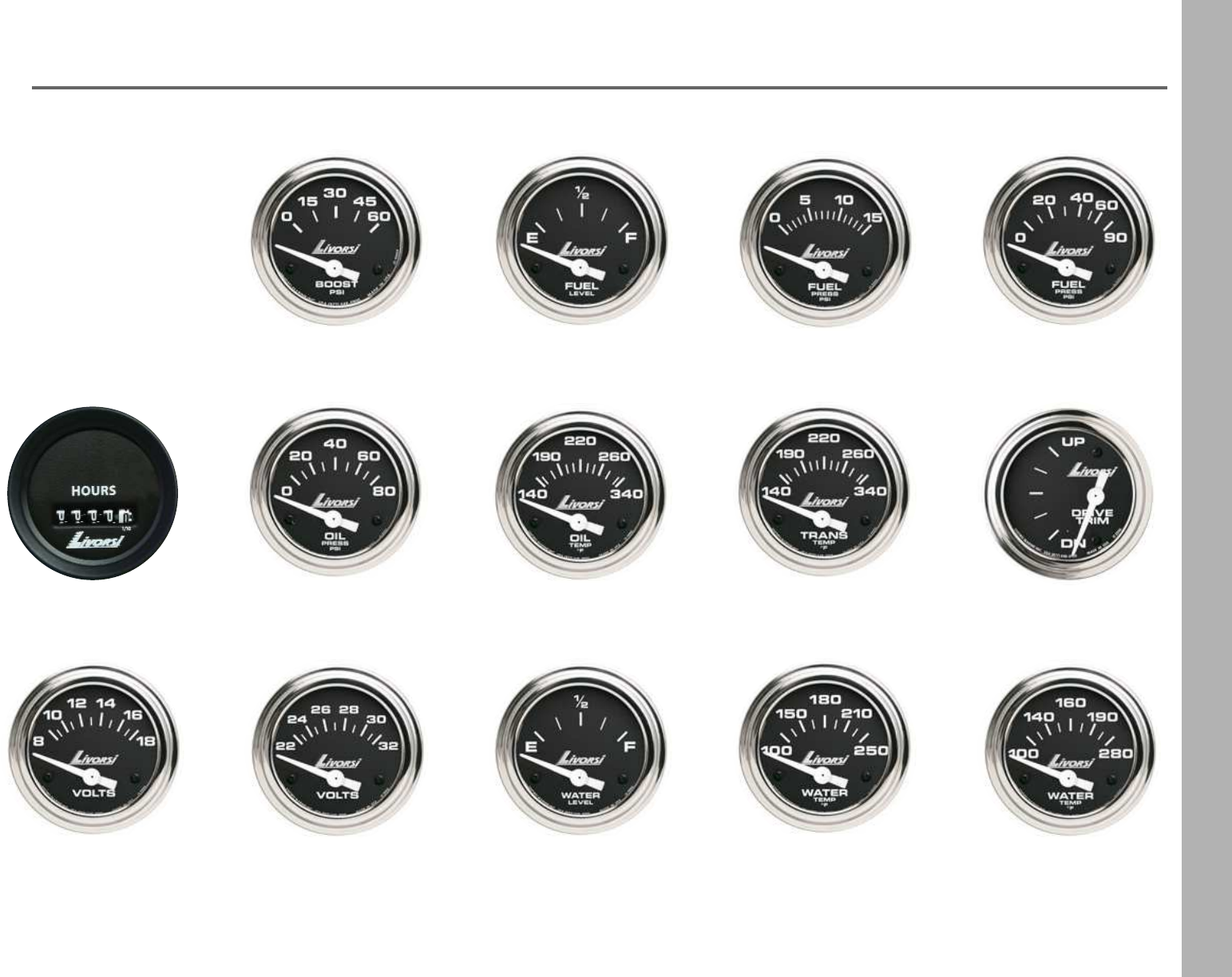
Industrial Series
Electric Gauges
fuel pressure 0-90 PSI
hourmeter * oil pressure 0-80 PSI oil temperature
140-340° F transmission temp
140-340° F trimmeter
voltmeter 8-18 V voltmeter 8-32 V water level water temperature
100-250° F water temperature
100-280° F
fuel pressure 0-15 PSIboost 60 PSI fuel level
28
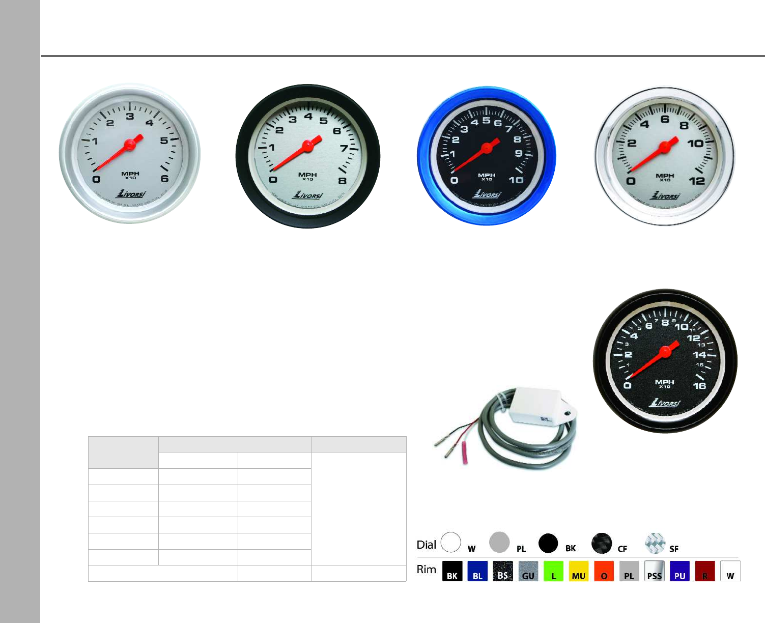
Mega & Race Series
Analog Gauges
Features
•Standard size or oversize
•Plug-in connectors are waterproof and resist salt corrosion
•Gauges are encased in non-ferrous hardware
•Red LED lighting is standard; for easy viewing in low light conditions
•Available in 12 or 24 volt system
•Your choice of rim style: Mega or Race
Custom Options
•Dial color
•Needle color
•Private label
29
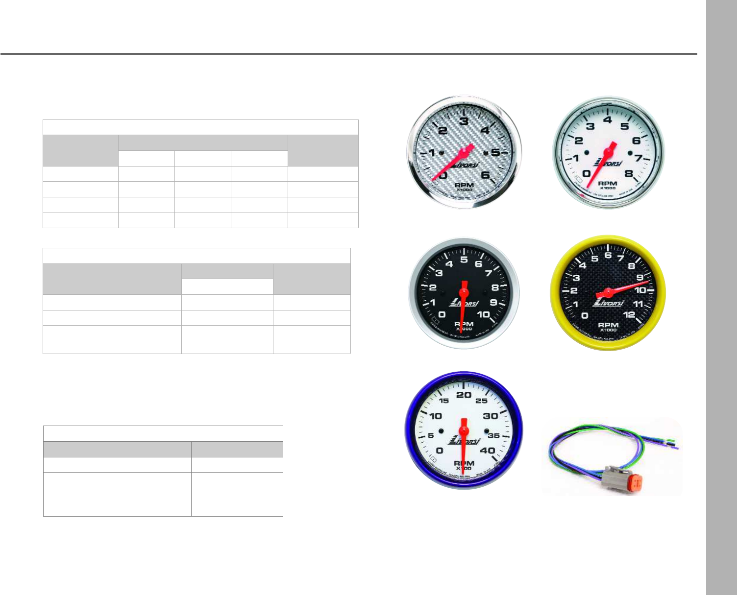
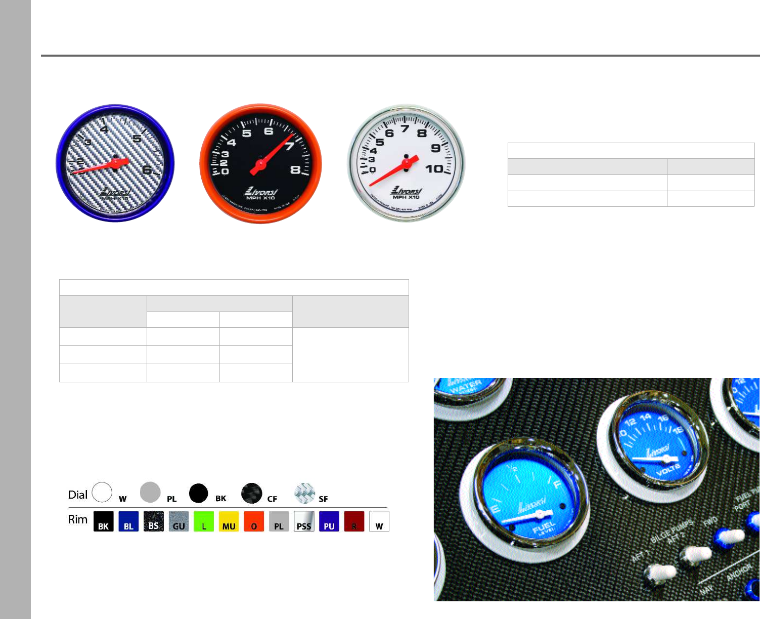
Mega & Race Series
Tachometers
6000 RPM 8000 RPM
12000 RPM10000 RPM
4000 RPM
Gas Tachometers
Description Part Number Requires
2 5/8” 3 3/8” 4 5/8”
6,000 RPM -DCS6000 DCL6000 DCH harness
8,000 RPM MT8000 DCS8000 DCL8000 DCH harness
10,000 RPM -DCS10000 DCL10000 DCH harness
12,000 RPM -DCS12000 -DCH harness
Diesel Tachometers
Description Part Number Requires
3 3/8”
4,000 RPM alt driven DC4000 DA DCH harness
4,000 RPM mag probe driven DC4000 MPD DCH harness
4,000 RPM mech signal
generator driven DC4000 MSGD DCH harness
Gas Tachometers are compatible with:
4, 6, & 8 cylinder, V-10, Merc O/B, 6 pulse/12 pole
Tachometer Hardware
Description Part Number
DCH harness 12V 24” lead DCH
DCH harness 24V 24” lead DCH24
DCH harness 12V w/ tach filter,
reduces needle bounce DCTFH DCH
4 Pin Connector & Wire Harness
•24 inches in length
•Pre-assembled and labeled
30
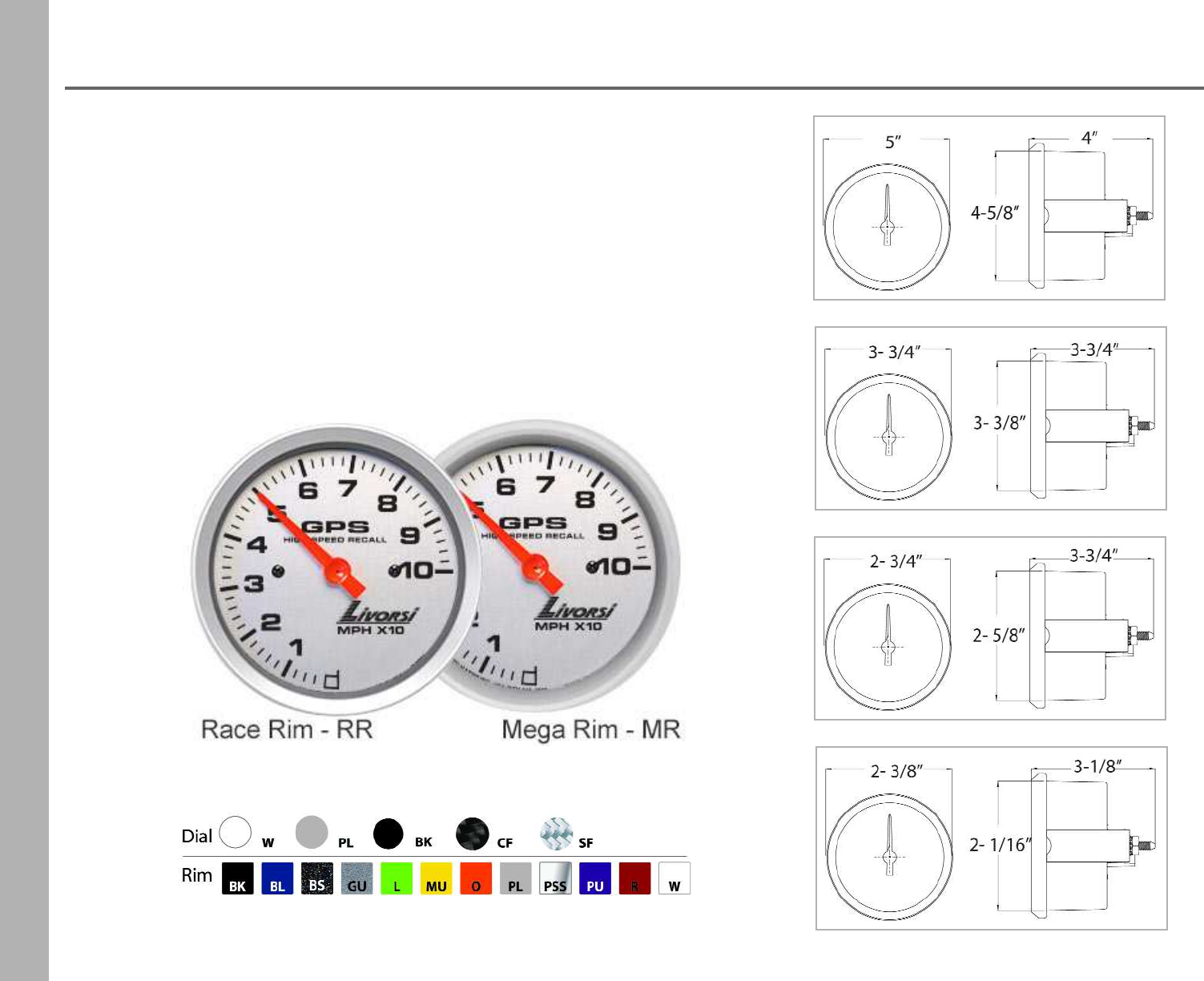
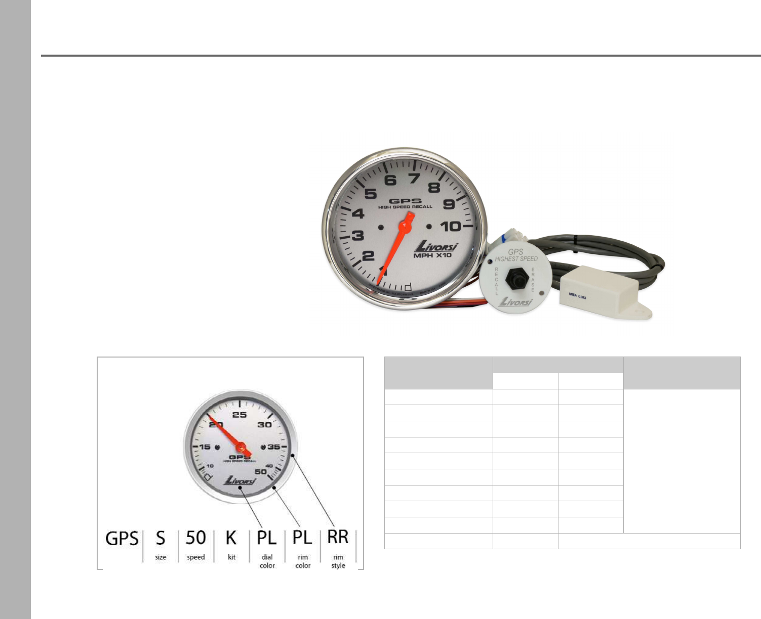
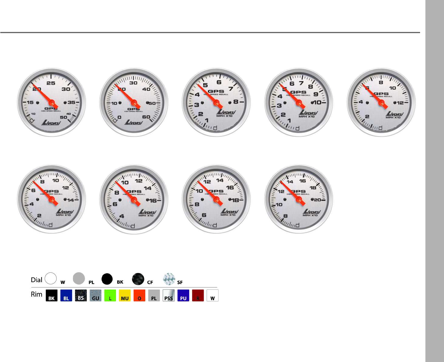
Mega & Race Series
GPS Speedometers
Build your part number:
GPSSQ310X antenna
•Mounts with a 1/4” screw
•Dimensions: 2 ¾" L x 2 3/8" W x 7/8" H
•Fast 10 Hz 10x per second update
•4 ft harness and ring terminals
Purchase GPS Speedometer only, you get:
•speedometer
•memory recall
•harness for power, ground and back lighting
Description Part Number Requires
3 3/8” 4 5/8”
50 MPH GPSS50 GPSL50
For a GPS Kit,
add the letter “K”
after the MPH.
60 MPH GPSS60 GPSL60
80 MPH GPSS80 GPSL80
100 MPH GPSS100 GPSL100
120 MPH GPSS120 GPSL120
140 MPH GPSS140 GPSL140
160 MPH GPSS160 GPSL160
180 MPH GPSS180 GPSL180
200 MPH GPSS200 GPSL200
GPS antenna GPSSQ310X NMEA 0183 antenna - square body
GPS Speedometer Kit includes
•speedometer
•memory recall
•harness for power, ground and back lighting
•NMEA 0183 antenna - GPSSQ310X
31
Mega & Race Series
GPS Speedometers
50 MPH 80 MPH 100 MPH 120 MPH
140 MPH 160 MPH 180 MPH
60 MPH
200 MPH
32
Mega & Race Series
Speedometers
DCMS60 DCMS80 DCMS100
Dry Speedometers
Description
Part Number
Requires 3 3/8” 4 5/8”
60 MPH DCMS60 pitot tube, hose &
mounts
Add “K1” for a kit
80 MPH DCMS80 DCML80
100 MPH DCMS100 DCML100
Speedometer Hoses
Description Part Number
1/8” ID push on high pressureGCH1/8
1/4” ID push on high pressureGCH1/4
You may request dials in any of our
powdercoat colors, extra fees apply.
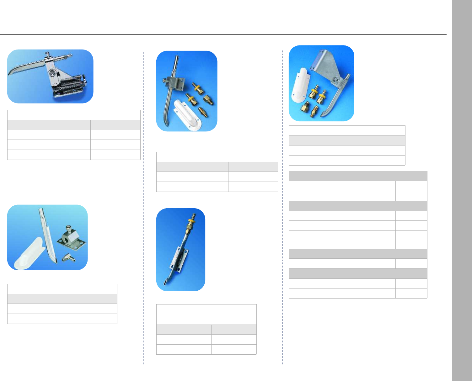
33
Mechanical Speedometer Hardware
Mechanical
Speedometers
Low Profile Blade Assembly
Description Part Number
regular GCRB1A
90° angle GCRB1A90
Blades
standard blade 7” GCT1
blade 5” for GCRB1A / RBM2A GCRB
Thru hull fittings
2” x 1/8” NPT THF21/8
4” X 1/8” NPT THF41/8
90° fitting 1/8” NPT
male push lock x 1/4” ID push lock GCF6
Blade mounts
tube or blade mount GCM3
Hoses
1/8” ID push on high pressureGCH1/8
1/4” ID push on high pressureGCH1/4
Recoil Blade Kickup
Description Part Number
blade only 5” GCRB
blade fitting 1/4” ID hose GCF8
blade fitting 1/8” ID hose GCPM1/8 Blade Assembly Standard
Description Part Number
universal bolt pattern GCM1A
Mercury bolt pattern GCM2A
Mercury Reverse
Mount Assembly
Description Part Number
with fittings GLRMA
with out fittings GLRM
Kick Up Mount
Description Part Number
1/4” ID hose GLM1A
1/8” ID hose GLM1A1/8
34
Mega & Race Series
DCH harness
Description Part Number Requires
2 1/16” 2 5/8”
Clock -DCC DCH harness
Fuel Level 0-90 ohms DCSFLGM DCFLGM DCH, fuel level sender
Fuel Level 240-33 ohms DCSFL DCFL DCH, fuel level sender
Fuel Pressure 0-15 PSI DCSFP DCFP DCH, GSFP/WP
Fuel Pressure 0-90 PSI DCSFP90 DCFP90 DCH, GSFP60/90
Hourmeter HM - -
Oil Pressure 0-80 PSI DCSOP80 DCOP80 DCH, GSOP80
Oil Pressure 0-100 PSI DCSOP DCOP DCH, GSOP
Oil Temperature 140-340° F DCSOTDCOTDCH, GSOT1/8
Transmission Temp 140-340° F DCSTTDCTTDCH, GSOT1/8
Trimmeter Merc & Yamaha 10-90 ohms DCSTMM DCTMM DCH
Trimmeter OMC 88-1 ohms DCSTMO DCTMO DCH
Voltmeter 8-18V DCSVM DCVM DCH
Water Level DCSWL DCWL DCH
Water Temperature 100-250° F DCSWTADCWTADCH, GSOT1/8
Water Temperature 100-280° F DCSWT DCWT DCH, GSWT1/8
DCH Harnesses
12 volt system, 24 inch leads DCH
24 volt system, 24 inch leads DCH24
Electric Gauges
•These electric gauges require the use of a four pin connector wire harness
(unless otherwise noted) that we call a DCH harness.
•We offer these harnesses pre-assembled with labed wire leads, 24 inches in length.
35
Mega & Race Series
Electric Gauges
water temperature 280 F
clock
hourmeter
fuel level fuel pressure 15 PSI
fuel pressure 90 PSI transmission temperatureoil pressure 100 PSI oil temperature
trimmeter voltmeter water level water temperature 250 F
oil pressure 80 PSI
36
Mega & Race Series
Mechanical Gauges
fuel pressure 15 PSIboost
oil pressure 100 PSIfuel pressure 100 PSI
water pressure 35 PSIvacuum boost water pressure 60 PSI
Description Part Number Requires
2 1/16” 2 5/8”
Boost 0-35 PSI DCSMB35 DCMB35 hose kit
Fuel Pressure 0-15 PSI DCSMFP DCMFP
fuel hoses n/a
Fuel Pressure 0-100 PSI DCSMFP100 DCMFP100
Oil Pressure 0-100 PSI DCSMOP DCMOP hose kit
Vacuum/Boost 30 in hg/boost 20 DCSMVB DCMVB hose kit
Water Pressure 0-35 PSI DCSMWP DCMWP hose kit
Water Pressure 0-60 PSI DCSMWP60 DCMWP60 hose kit
Description Part Number
25 feet with fittings HK
10 feet with fittings HKA
Hose Kit
•not for fuel
•use with mechanical gauges
•1/8” ID
37
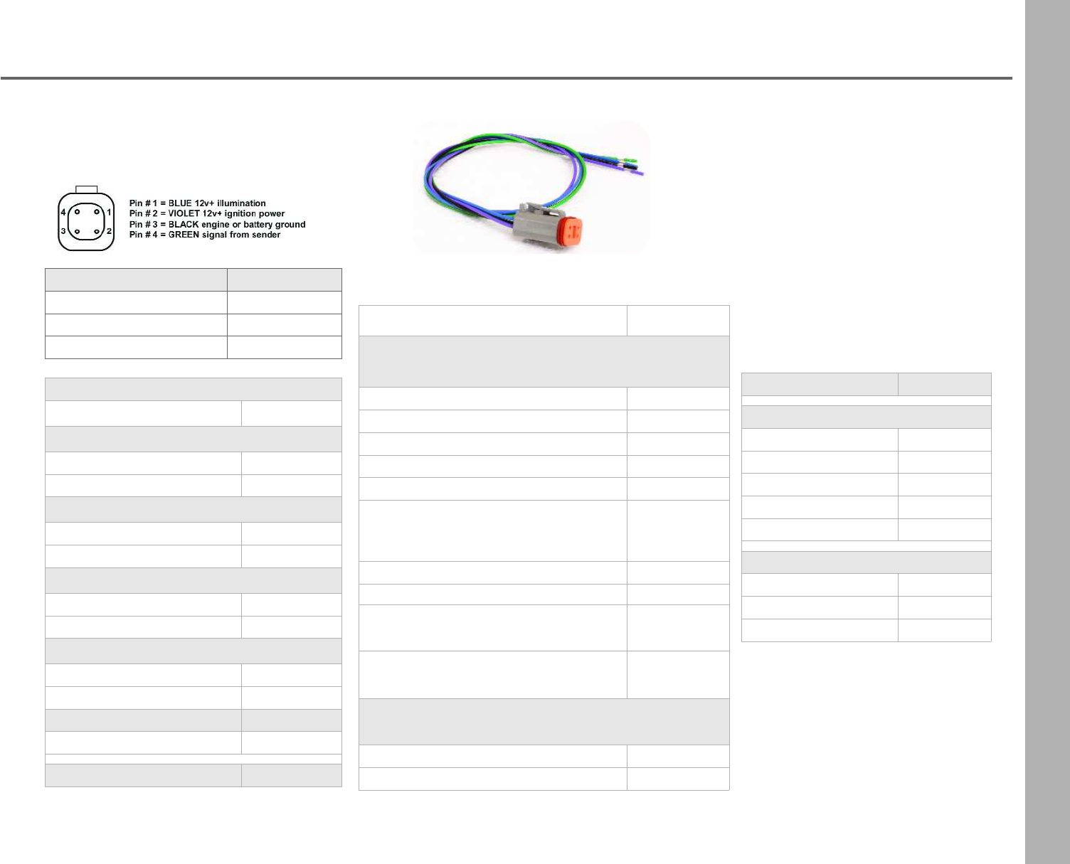
Gauge Hardware
4 Pin Connector & Wire Harness
•24 inches in length
•Pre-assembled and labeled
DCH Harness Part Number
12 volt system DCH
24 volt system DCH24
12 volts w/ tach filter DCTFH
Connector Parts
Description Part Number
2 Pin - mechanical lights
2 pin connector plug DC2CPLUG
2 pin connector wedge lock DC2CWL
4 Pin - electrical gauges
4 pin connector plug DC4CPLUG
4 pin connector wedge lock DC4CWL
8 Pin - power distribution
8 pin connector plug DC8CPLUG
8 pin connector wedge lock DC8CWL
12 Pin - power distribution
12 pin connector plug DC12CPLUG
12 pin connector wedge lock DC12CWL
dummy plug DCDP
contacts for 16 gauge wireDCC1416
Hand Crimper DCHCS
DCH
Description Part Number
LED Wedge
amber 12.8V LEDWA
blue 12.8V LEDWBL
green 12.8V LEDWG
red 12.8V LEDWRB
white 12.8V LEDWW
Clamshells
for 1/4” id hose black GCCS1/4BK
for 1/4” id hose white GCCS1/4W
for 1/2” id hose white GCCS1/2W
Description Part Number
Senders
Fuel Pressure 0-60 PSI / 0-90 PSI GSFP60/90
Fuel & Water Pressure 0-15 PSI GSFP/WP
Isolated Ground for Water TemperatureGSWT1/8I
Oil Pressure 0-80 PSI GSOP80
Oil Pressure 0-100 PSI GSOP
Oil / Water Temperature 100-320°F
Water Temperature 100-250°F
1/8” thread
GSOT1/8
Pressure 400 PSI GSP400
Water Temperature- Merc OB KitGSWTM
Water Temperature 100-280°F
1/8” thread GSWT1/8
Bushing Kit
1 /4”, 3/8” and 1/2” fittings GSBKK1
Hose Kit for Mechanical Gauges
not to be used with fuel, 1/8 in ID
10 feet of hose and fittings HKA
25 feet of hose and fittings HK
38
GPS Antennas
GPS Antenna
Part Number: GPSSQ3
•Antenna is NMEA 0183 compliant
•2 3/4” L x 2 3/8” W x 7/8” H
•Standard 1-second 1HZ update
•4 ft harness and ring terminals
•It is recommended to use this model number for full
compliance with Livorsi GPS speedometers
•Compatible with SmartCraft®
GPS Antenna for Vantage View®
Part Number: GPSRAQ3VV
•Antenna is NMEA 0183 compliant
•2 3/4” L x 2 3/8” W x 7/8” H
•Standard 1-second 1HZ update
•4 ft harness and ring terminals
•Pre-terminated for quick connection to the Vantage
View Master Harness
•It is recommended to use this model number for full
compliance with Livorsi Vantage View®speedometers
GPS Antenna for non-GPS speedometers
Part Number: GPSESQ3
•Antenna is NMEA 0183 compliant
•2 3/4” L x 2 3/8” W x 7/8” H
•Fast 10 Hz 10x update -8/16 pulse output
•4 ft harness and ring terminals
•For use with existing automotive or commercial electric
speedos (non-GPS speedo heads)
GPS Antenna with 10X per second update
Part Number: GPSSQ310X
•Antenna is NMEA 0183 compliant
•2 3/4” L x 2 3/8” W x 7/8” H
•Fast 10 Hz 10x per second update
•4 ft harness and ring terminals
39
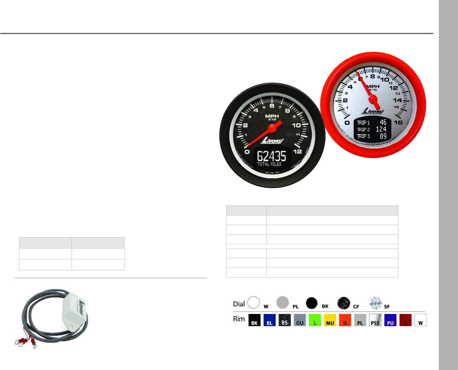
GPS Speedometer w/ Odometer
For automotive or marine applications, this stand alone GPS
speedometer is a digital gauge with an analog readout and a built in
LCD odometer. Designed to be hassle free, this gauge relies on GPS
satellite signals to display accurate speed and miles traveled, so
there is no need to calibrate this gauge with gear ratios or tire size.
Gauge Features
•Digital odometer helps you determine your GPM
•Eliminates the need for cables
•No calibration required
•LCD displays odometer and 3 resettable trip odometers
•10x update for accurate readings
•120 MPH or 160 MPH
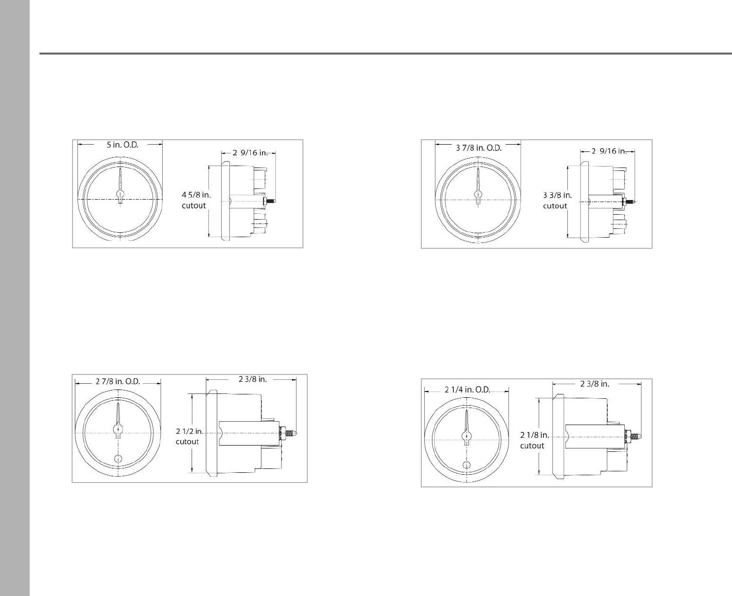
cutout sizeoverall size
3 3/8” 3 3/4”
4 5/8” 5”
Gauge Kit Includes:
•Gauge head
•GPS antenna with 10 Hz 10x update
•Switch
•Harness
•Mounting hardware
GPS Antenna 10X Update
•Antenna is NMEA 0183 compliant
•2 3/4” L x 2 3/8” W x 7/8” H
•Fast 10 Hz 10x update
•4 ft harness and ring terminals
Part Number: GPSSQ310X
Description Gauge Kit Part Number
3 3/8” cutout
120 MPH GPSSO120K + dial color + rim color + style
160 MPH GPSSO160K + dial color + rim color + style
4 5/8” cutout
120 MPH GPSLO120K + dial color + rim color + style
160 MPH GPSLO160K + dial color + rim color + style
40
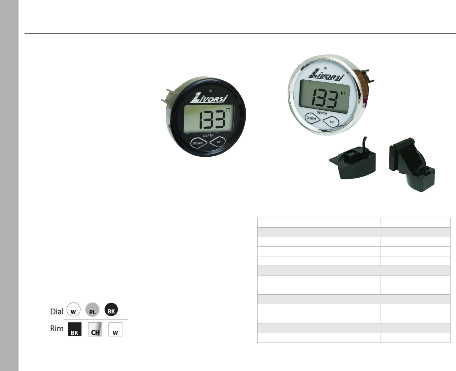
Depth Finder Gauge
Shoot Thru
(uses epoxy)
Transom
Gauge Features
•Larger LCD digits
•Algorithmic programming
•Instant depth updates
•Easy touch programming
•Keel offset
•English & Metric readings
•Dual depth alarms
•Advanced warning system
•Memory retention
•Polarized LCD
•Plug & Play connectors
•Red LED alarm light
Gauges Specs
•1 7/8" cutout, 2 1/2" overall
•Green backlighting
•11-14Vdc
•Readout: min. -2.5 feet / max. 200 feet
•Red LED and blinking LCD icons for alarms
•Transuders have 30" lead
Gauge Kit Includes
•gauge
•transducer
•mounting brackets
•epoxy (for shoot thru only)
Description Part Number
Depth Only Gauge
head only DFG + color rim
Kit - Gauge and shoot thru transducer DFGKST + color rim
Kit - Gauge and transom mount transducer DFGKTR + color rim
Transducers - Depth Only
shoot thru transducer TST
transom mount transducer TTR
Depth - Air - Water Gauge
head only DISCONTINUED
Kit - Gauge and Transom mount transducer DISCONTINUED
Transducers - Depth Air Water
transom mount transducer DISCONTINUED
41
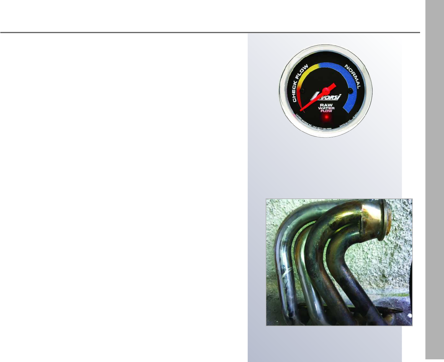
Raw Water Flow System
The Raw Water Flow System
prevents this from happening
The Raw Water Flow system indicates your engine's water flow volume. This
system warns you of a potential problem or danger that would otherwise not
be indicated by a water pressure gauge alone, thus preventing cosmetic and
structural damage to expensive exhaust headers, intercoolers and other
cooling systems.
What is Water Flow?
Water flow is a real indication of water surging through a cooling system such
as: exhaust headers, sea strainers, impellers, Gen sets, intercoolers and any
other marine or industrial applications that utilize water flow.
Why You Need It
Don't confuse water flow with water pressure; as many OEM engine manufac-
turers measure water pressure in different areas of the motor. This number
may not be telling you the real story of water flow. Your water pressure can
be constant from the first day you bought your new boat.
The danger may be lurking in the water flow which could be caused by
•a plugged heat exchanger
•extensive debris build-up in the intercooler or sea strainer
•a kinked hose
•worn impeller
•water pickups not collecting enough water for cooling system
These may be the culprits causing the good water pressure reading, when in
actuality there is poor water flow. Low water flow results in; cosmetic and
structural damage to expensive exhaust headers caused by burned impellers
and/or the clogging and damage of intercoolers or strainers.
Safe guard your cooling system from costly damage with Livorsi's
Raw Water Flow System
42
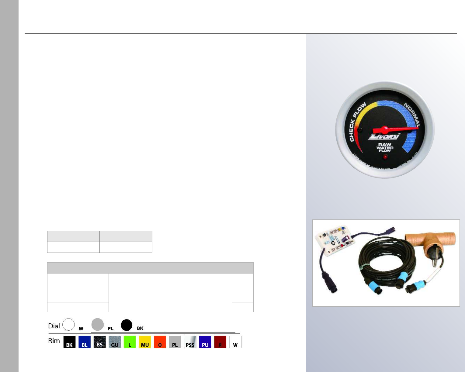
Raw Water Flow System
Water Flow Kits
Tee Fitting SizeBase Part Number
1 inch I.D. hose
WFG + dial color + rim color + rim style
1
1.25 inch I.D. hose 1.25
1.5 inch I.D. hose 1.50
How It Works
Calibration is set at idle and at wide open throttle (WOT). This will generate
the cooling system's normal operating range. When water flow rises or drops
more than 20% from that range (regardless of RPM), it will trip the alarm
illuminating the built-in LED light; an optional audible alarm may be added.
The LED light shines with intensity, making it visible in direct sunlight.
Easy to Install
This kit is easy to install, Livorsi Marine offers three Tee sizes to fit your
system. Mount the Tee in-line on the output side of a sea strainer or sea
pump. The paddle wheel sensor installs in the Tee sending information to be
processed on a circuit board that is mounted behind the dash panel. The
wheel paddle can be easily removed for inspection and locks back into place
once finished. This system trouble-free to install and with little maintenance
to perform.
cutout sizeoverall size
2 5/8” 2 3/4”
Raw Water Flow system consists of:
•2 5/8" panel mounted gauge with internal warning light
•Bronze Tee
•PCB board
•Harness
•Paddle wheel transducer
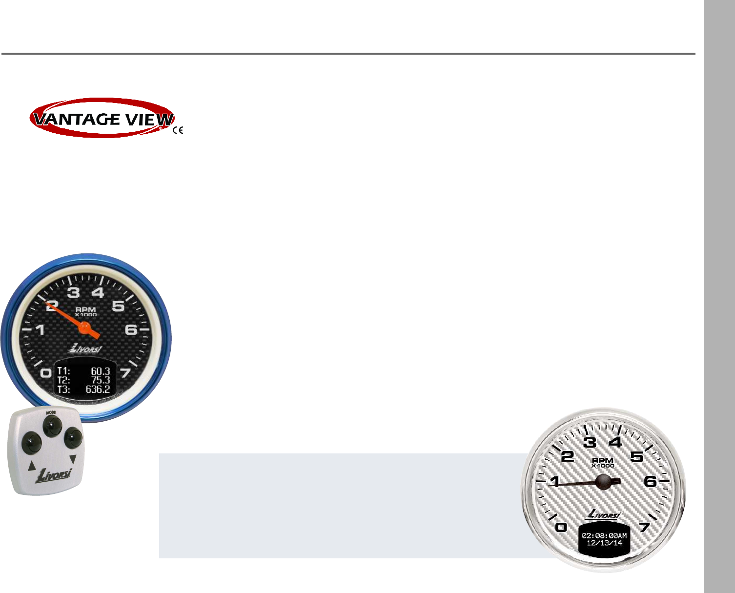
Vantage View®
43
Can Bus Gauges
The Vantage View® system comprises of a Master Tachometer that reads information
directly from the ECM/ECU. The Master Tachometer contains a LCD screen in which the
user is able to view the performance data, Faults and Warnings of the boat or vehicle.
All Vantage View® gauges utilize 270° digital stepper motors that accurately display
data in real time. While these instruments are digital, they were designed with the
traditional styling of analog gauges. Fluorescent fade resistant pointers and large bold
graphics make these instruments easy to ready at a glance.
User programmable warning alarms, simplified rigging and rugged construction makes
this line of instruments an exceptional tool for monitoring the performance of a vehicle,
workboat or powerboat.
Each engine requires its own Master Tach
and daisy chains to slave gauges
•Each LCD displays up to 10 engine functions such as
water temp, oil press, GPH, etc.
•Designed to work with SmartCraft®, NMEA 2000®,
SAE J1939 and GM MEFI protocols
•For automotive, industrial or marine applications
•Control module may be mounted in location of your
choosing to navigate through the LCD screen
• Available in sizes 2, 3, 4 and 5"
For
SmartCraft®,
NMEA 2000®,
SAE J1939 and
GM MEFI engines
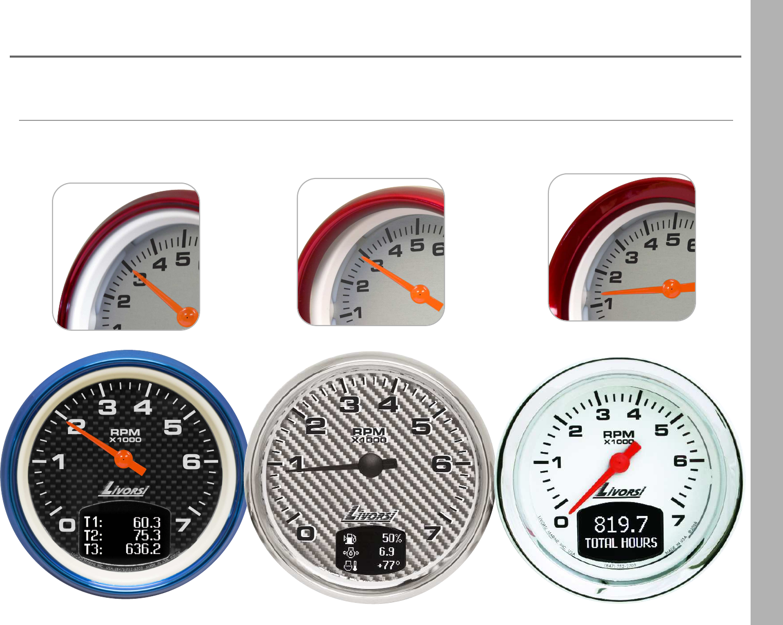
NEW FOR 2015!
Carbon Fiber and Silver Carbon Fiber dials
We've added the popular carbon fiber and silver carbon
fiber dial option to our Vantage View gauge series.
44
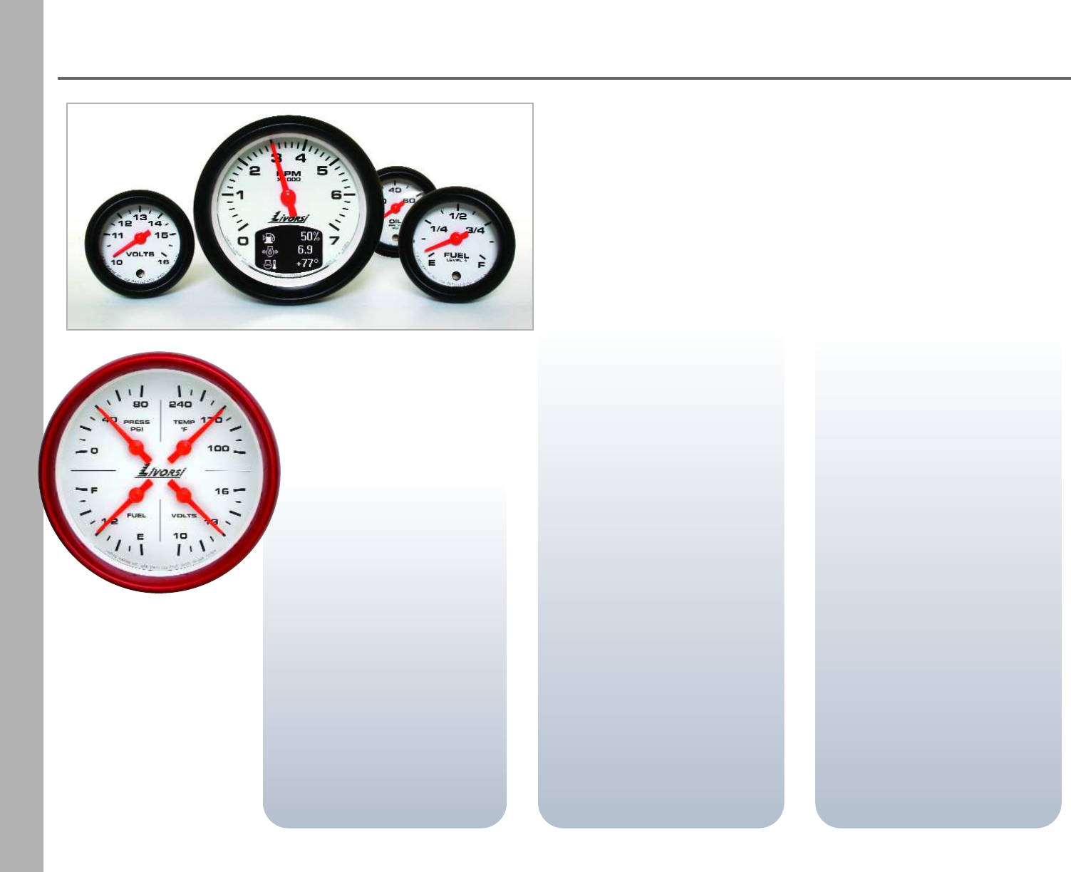
Vantage View®
Four Function Gauge
The 4-in-1 gauge saves you
dash space by combining 4
essential functions into one 5"
gauge: oil pressure, water
temperature, volts and fuel
level.
Speed
Vantage View® reads both
CAN (NMEA 2000® and SAE
J1939) and serial (NMEA
0183) based speed inputs.
Programmable Alarms
In addition to factory set Fault
and Warnings, users can tailor
up to 15 alarms to their
individual needs. When
triggered, pop-up alerts
appear on the LCD screen and
the bright LED warning light
illuminates on the corre-
sponding slave gauge.
Pop Up Alerts
Enabling of popup alerts for
faults, warnings or alarms
provides a highly visible alert
screen when a fault, warning
or alarm occurs. Popups may
be enabled for engine trim/tabs
brings up a trim detail screen
when a change in trim position
occurs. Vantage View® even
displays Engine Diagnostic
Codes for J1939.
Faults and Warnings
Vantage View® alerts you of
Faults and Warnings with
blinking icons on the Master
Tachometer LCD screen.
Faults are a problem reported
by the ECM/ECU that warrants
stopping the engine. Warnings
alert you of potential problems
as reported by the ECM/ECU.
Fuel Tank and Engine
Trim Calibration
The Vantage View® system is
the ability to calibrate the fuel
tank and engine trim, ensuring
utmost accuracy. The Master
Tachometer can monitor up to
two fuel tanks with the option
to use an analog signal or
CAN Bus information. The
Engine Trim feature also
allows for one analog or one
CAN Bus signal.
45
Vantage View®
Can Bus Gauges
Low Profile Rim Race Rim
Mega Rim
Rim Options
46
Vantage View®
Can Bus Gauges
Master Tach, Slave Speedometer or Four in One
2-1/2” Slave Gauges
Master Tach or Slave Speedometer or Four in One
2-1/8” Slave Gauges and FWA gauge
47
Vantage View®
Can Bus Gauges
Each engine requires its own Master Tachometer
•LCD displays up to 10,000 RPM
•Up to 6 slave gauges may be daisy chained to the Master Tachometer
•Marine configured tachs display “Total Hours”
•Automotive/industrial configured tachs display “Total Miles”
•Have the ability to record and reset three trip logs
•The user can set up 10 parameters of their choice to display in the main
screens. Choose between single or three parameter display.
Menu navigation requires the use of the either a control pod (controls up to 4
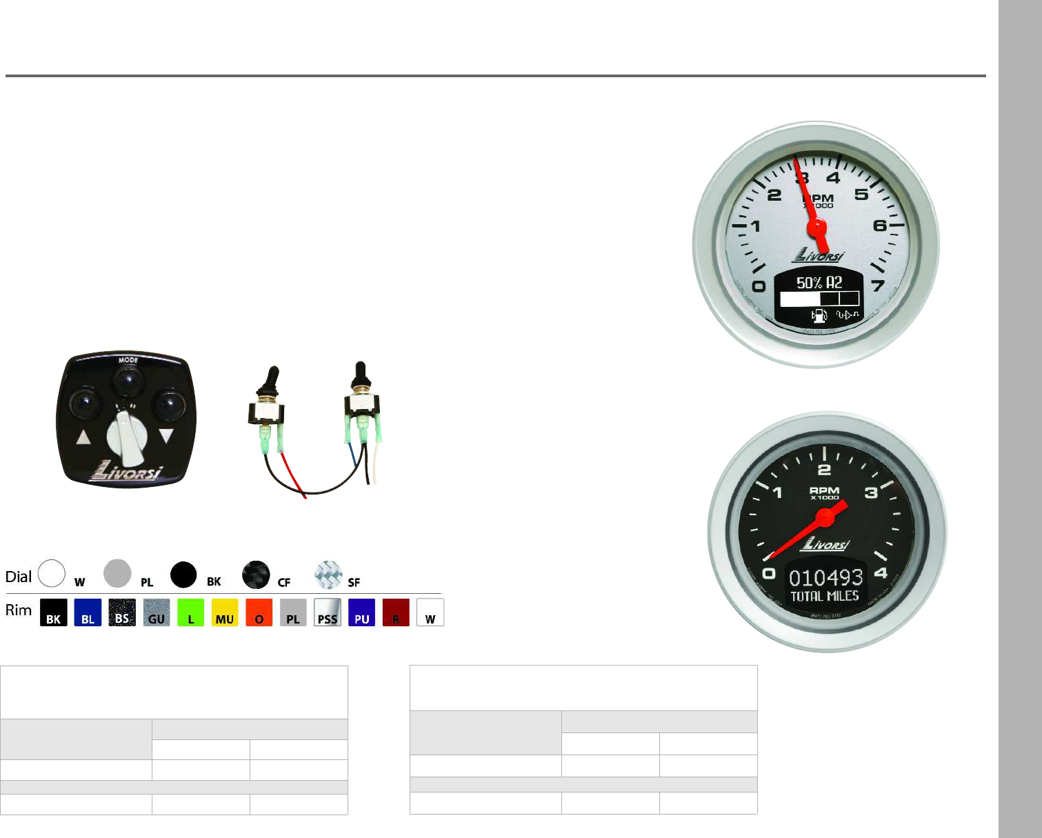
engines) or the VV switch control module.
Master Tachometer -
NMEA 2000®, J1939 & MEFI4 protocol
Description Part Number
3 3/8” 4 5/8”
4000 RPM VJS4K VJL4K
7000 RP VJS7K VJL7K
Master Tachometer - SmartCraft®protocol
Description Part Number
3 3/8” 4 5/8”
4000 RPM VSCS4K VSCL4K
7000 RPM VSCS7K VSCL7K
VJS4KBKPLR
VJS7KPLPLR
switch control module
control pod
48
Vantage View®
Analog Input- Resistance Ranges
Description Resistance Ranges- ohms
Fuel Level 1 240-33, 10-180, 0-90
Fuel Level 2 240-33, 10-180, 0-90
Fresh Water Level 240-33, 10-180, 0-90
Waste Water Level 240-33, 10-180, 0-90
Engine Oil Level 240-33, 10-180, 0-90
Transmission Oil Level 240-33, 10-180, 0-90
Hydraulic Oil Level 240-33, 10-180, 0-90
Coolant Level 240-33, 10-180, 0-90
Washer Fluid Level 240-33, 10-180, 0-90
Generic Level 240-33, 10-180
Boost Pressure240-33, 10-180
Block Pressure240-33, 10-180
Fuel Delivery Pressure240-33, 10-180
Engine Oil Pressure240-33, 10-180
Transmission Oil Pressure240-33, 10-180
Hydraulic Oil Pressure240-33, 10-180
Brake Application Pressure240-33, 10-180
Brake Primary Pressure240-33, 10-180
Brake Secondary Pressure240-33, 10-180
Generic Pressure240-33, 10-180
Outside Air Temperature10K Thermistor (Airmar T-80)
Inside Air Temperature10K Thermistor (Airmar T-80)
Water Temperature10K Thermistor (Airmar T-80)
Trim 240-33, 10-180, 0-90, 167-10
Steering Angle 240-33, 10-180, 0-90
Rudder Angle 240-33, 10-180, 0-90
Front Air Pressure240-33, 10-180, 0-90
Rear Air Pressure240-33, 10-180, 0-90
Faults or Warnings
Description Faults or
Warnings
Warning Over Heat Over-heat W
Warning Low Oil PressureLow Oil Press W
Warning Low Voltage Low Voltage W
Warning High Voltage High Voltage W
Warning Over Speed Over Speed W
Warning Water in Fuel Fuel W
Warning Guardian ActiveGuard ActiveW
Warning Check Engine Check Engine W
Oil FaultOil F
Guardian/Check Engine FaultGuard/Ck Eng F
CAN FaultCAN Bus F
Water in Fuel FaultFuel F
Voltage FaultVoltage F
Coolant Temperature FaultCoolant Temp F
49
Vantage View®
Can Bus Gauges
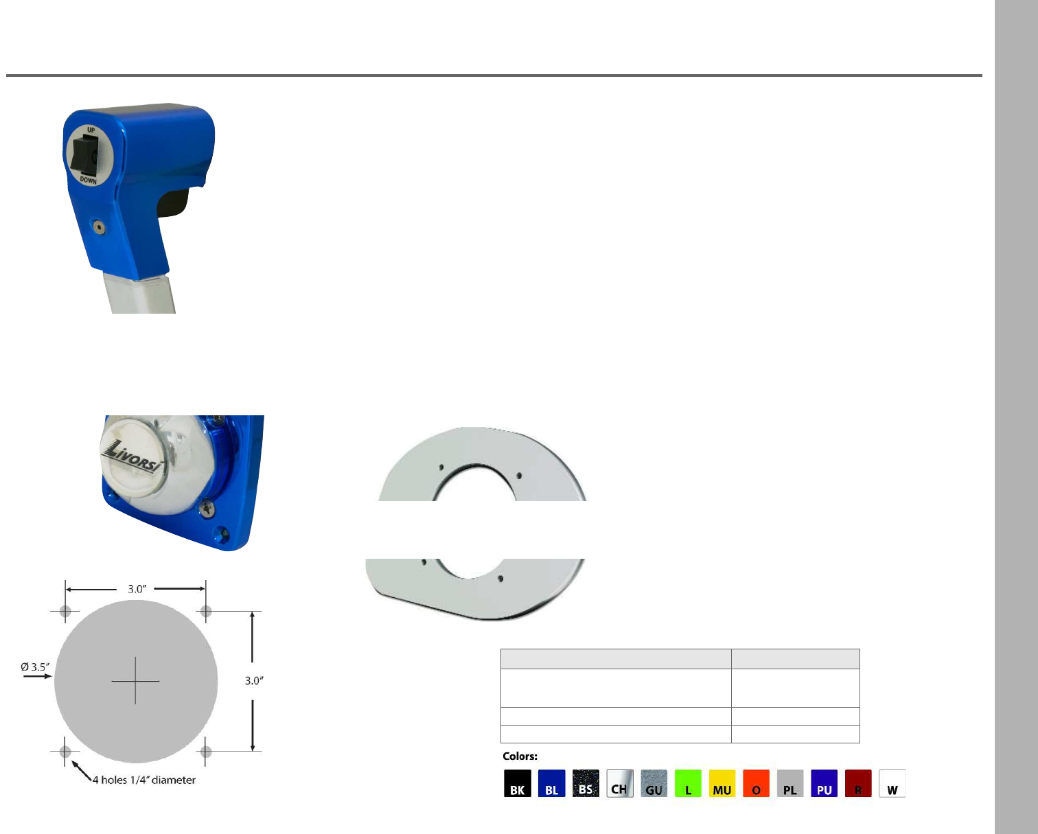
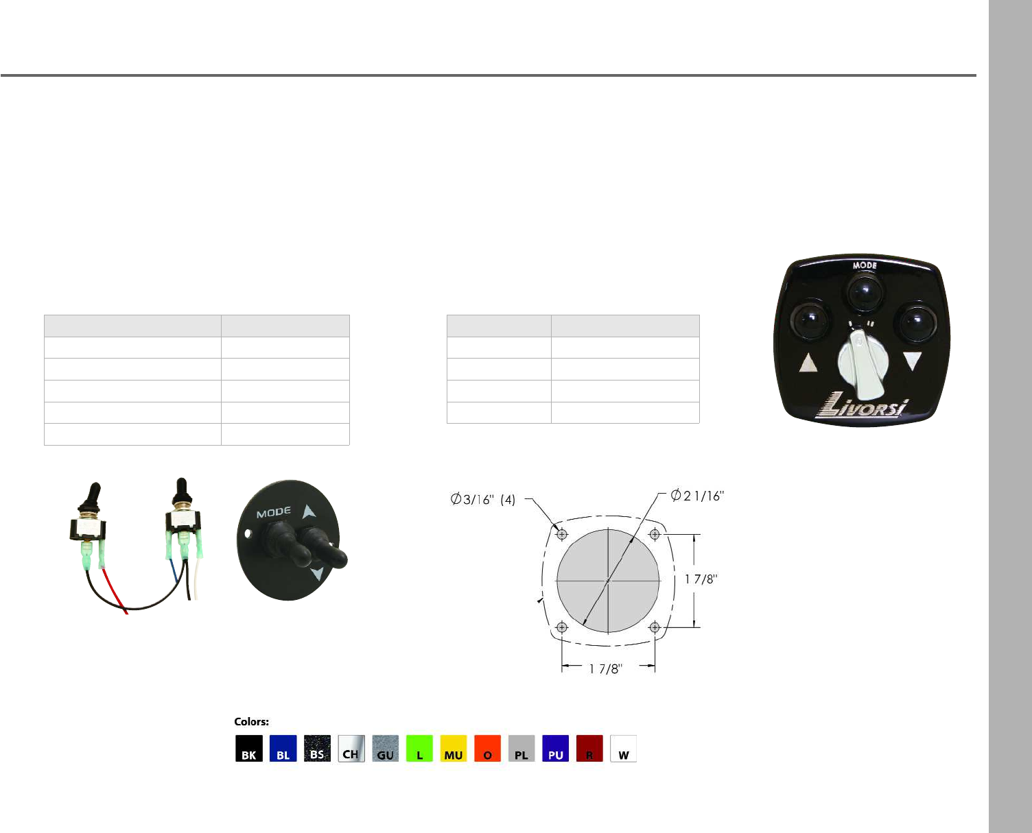
Control Pod Dimensions Control Pod
twin engine
switch control module switch control
module with
optional plate
Description Part Number
single engine VVCPSA + color
twin engine VVCPTA + color
triple engine VVCPTRA + color
quad engine VVCPQA + color
Description Part Number
switch control module VVSAW
plate only (2 3/4 in diam.)PSSP + color
mode switch only TSMF
up/down switch only TSMFM
black switch boot TSRBBK
Single Engine Switch Control Module
•Controls one Master Tachometer
•One assembly needed per engine
•Requires two 1/2 in. cutout for toggle switches
VVSAW assembly includes:
•Two switches & two boots
•DCC contacts for easy installation
Control Pod
•Control up to 4 Master Tachometers with one pod
•Uses waterproof momentary buttons
•Twin, triple and quad control pods have a polished selector knob
to toggle between Master Tachometers
50
Vantage View®
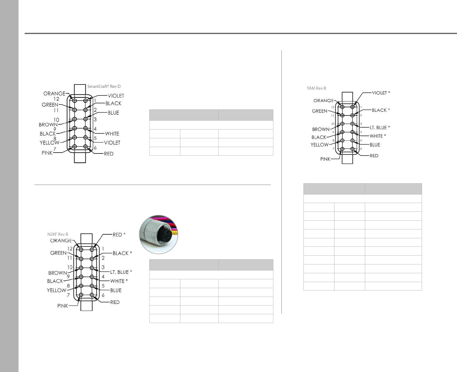
Harnessing
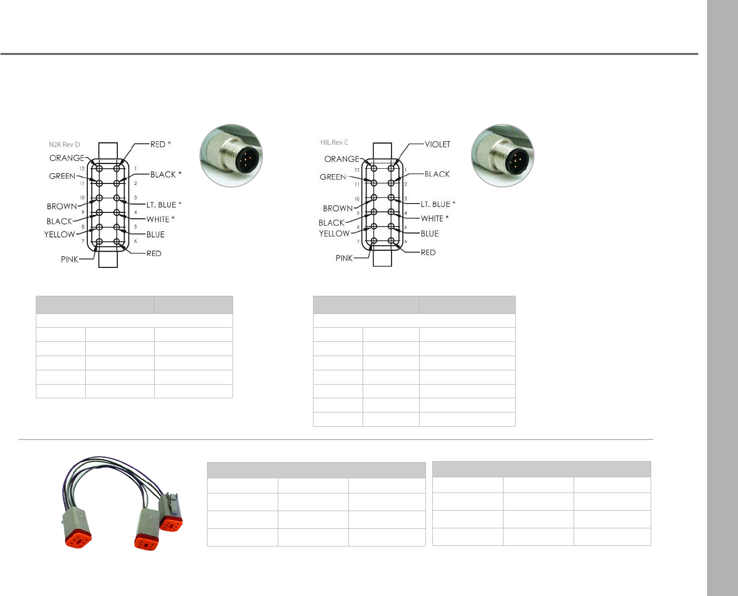
SAE J1939/Indmar Master Harness
length: 36 in. ± .5 in.
Part Number VVMHJI
Wire Label
Number Color Label
1Violet Switched Positive
2 Black Ground
3Lt. Blue CAN L
4White CAN H
5 Blue Lighting
6 Red Battery
7Pink Analog
8 Yellow NMEA 0183
9-12 -to amp connector
SmartCraft®Master Harness
length: 36 in. ± .5 in.
Part Number VVMHSC
Wire Label
Number Color Label
7Pink Analog
8 Yellow NMEA 0183
NMEA 2000®Micro C Female Master Harness
length: 36 in. ± .5 in.
Part Number VVMHN2KF
Wire Label
Number Color Label
5 Blue Lighting
6 Red Battery
7Pink Analog
8 Yellow NMEA 0183
51
Vantage View®
Harnessing
Short Slave Harness
Description Length Part Number
2 gauge 17 in. VVSH2S
4 gauge 37 1/2 in. VVSH4S
6 gauge 54 1/2 in. VVSH6S
Long Slave Harness
Description Length Part Number
2 gauge 27 1/2 in. VVSH2L
4 gauge 53 1/2 in. VVSH4L
6 gauge 78 1/2 in. VVSH6L
Part Number VVMHN2K
Wire Label
Number Color Label
5 Blue Lighting
6 Red Battery
7Pink Analog
8 Yellow NMEA 0183
Part Number VVMHIL
Wire Label
Number Color Label
1Violet Switched Positive
2 Black Ground
5 Blue Lighting
6 Red Battery
7Pink Analog
8 Yellow NMEA 0183
NMEA 2000®Micro C Male Master Harness
length: 36 in. ± .5 in.
Ilmor Micro C Male Master Harness
length: 36 in. ± .5 in.
52
Vantage View®
Slave Speedometers
120 MPH 100 MPH 80 MPH 60 MPH
160MPH
The speedo receives data from the Master Tach which can be from the following:
•CAN message
•Paddle wheel
•GPS signal- uses the A/D digital input available on the Master Tach.
The GPS source must be wired to the proper pin of the 12 pin connector
of the Master Tach.
Both the paddle wheel and GPS antenna must be NMEA 0183 compliant.
Note: Vantage View requires the use of GPS antenna part number: GPSRAQ3VV.
Other GPS antenna models may not work with Vantage View.
Description Part Number
3 3/8” 4 5/8”
For a kit add “K”
after the MPH
60 MPH VJS60 VJL60
80 MPH VJS80 VJL80
100 MPH VJS100 VJL100
120 MPH VJS120 VJL120
160 MPH VJS160 VJL160
180 MPH VJS180 VJL180
GPS antenna for Vantage View GPSRAQ3VV
53
Vantage View®
Slave Gauges
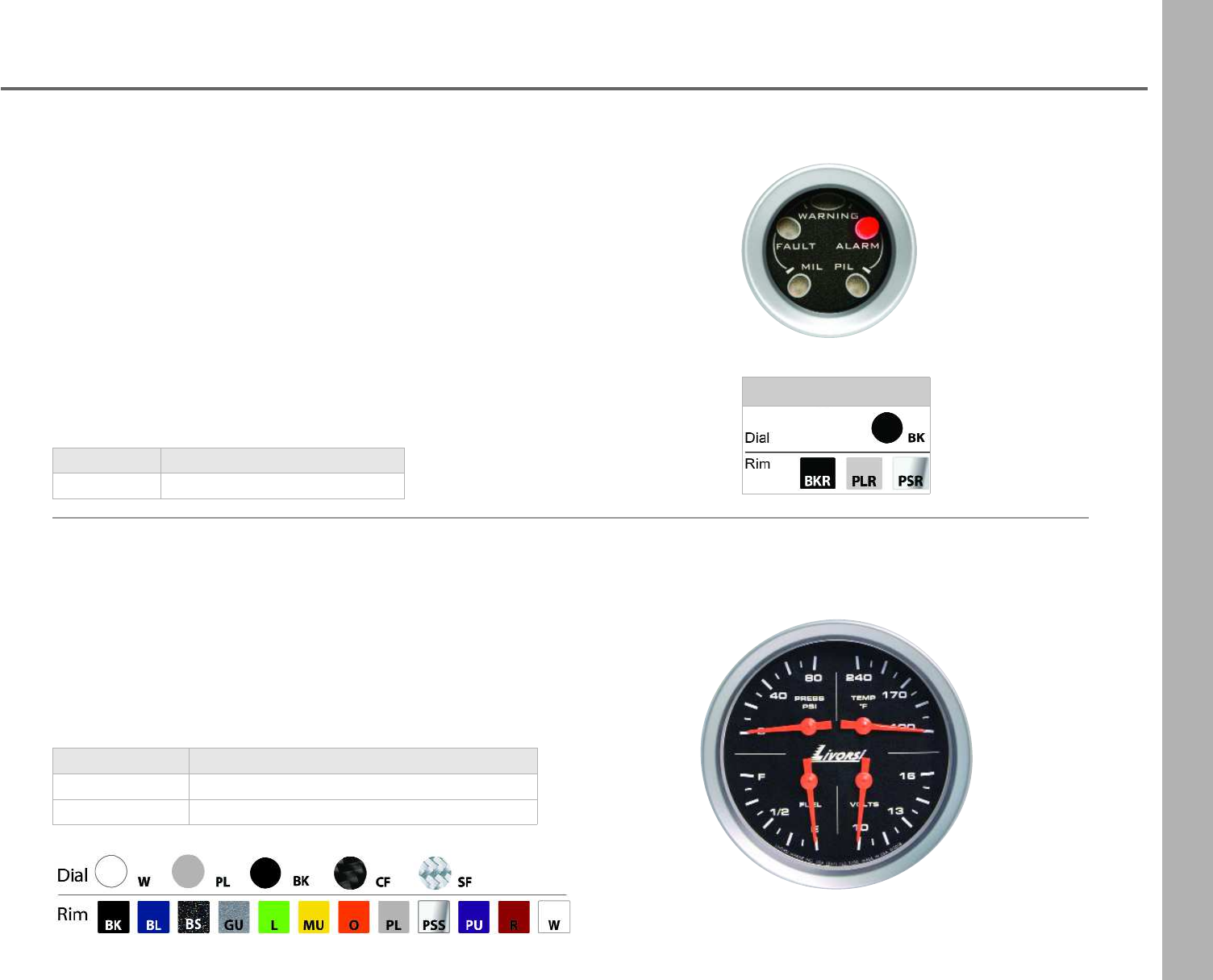
FWAGauge
This gauge provides five discrete illuminated visual indicators and multiple
outputs. Outputs include a dedicated audible alarm and one set of relay output
contacts for secondary alarms or additional engine protection devices.
This FWA gauge is needed in order for Vantage View®to receive built in Faults
and Warnings from Cummins Diesel engines when a Diesel View display is not
present.
FWA gauge will work on all engine protocols except for
Mercury Gas SmartCraft®engines.
Available with a black dial only. 2 1/8” cutout
Four Function Gauge
Save dash space with this four function gauge:
•Oil pressure
•Water temperature
•Volts
•Fuel level
Description Part Number
fwa gauge VJSFWABK + rim color + style
Description Part Number
3 3/8” cutout VJS4K + dial color+ rim color + rim style
4 5/8” cutout VVJNI4F + dial color+ rim color + rim style
Color Codes
54
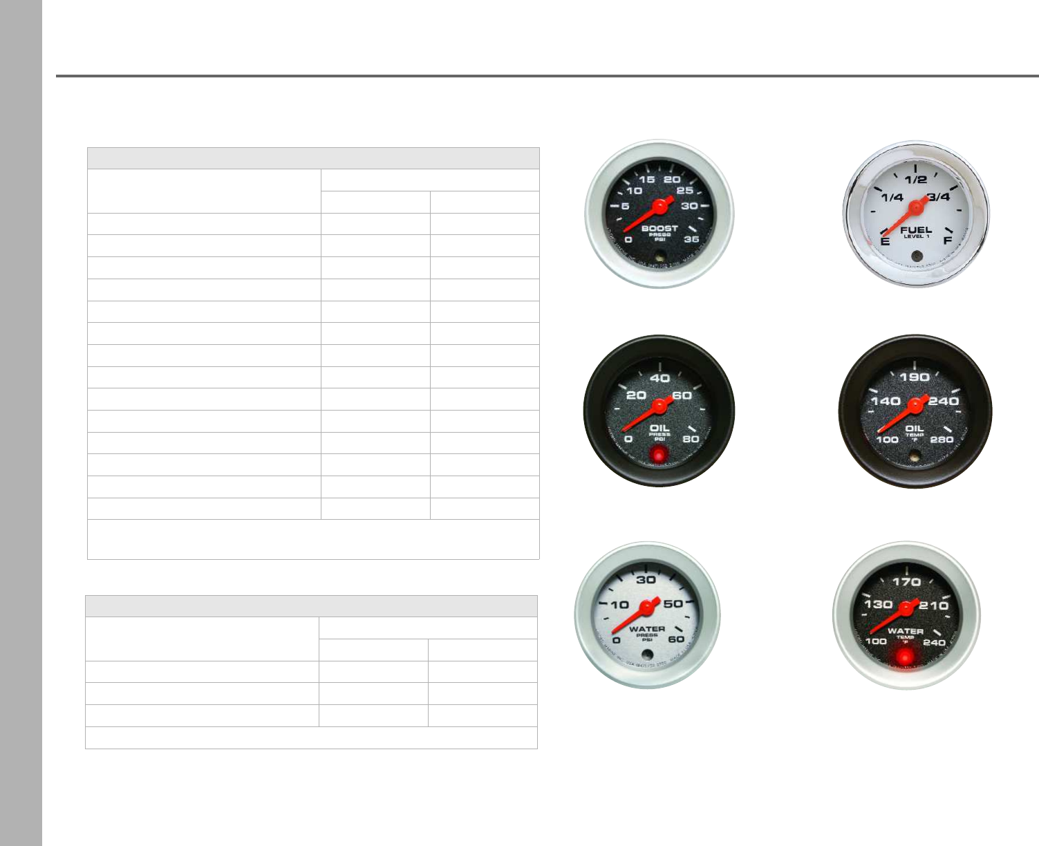
Vantage View®
Slave Gauges
boost 0-35 PSI fuel level 1
oil pressure 0-80 PSI oil temperature 100-280° F
water pressure 0-60 PSI water temperature 100-240° F
NMEA 2000®, SmartCraft®, GM MEFI and J1939
Description Part Number
Small 2 1/8” Large 2 1/2”
boost 0-35 PSI VJSB VJLB
fuel level 1 VVJNISFL1 VVJNILFL1
fuel level 2* VVJNISFL2 VVJNILFL2
fuel pressure 90 PSI VJSFP90 VJLFP90
oil level 1 VVJNISOL1 VVJNILOL1
oil level 2* VVJNISOL2 VVJNILOL2
oil pressure 0-80 PSI VVJNISOP VVJNILOP
oil temperature 0-280°F VVJNISOT VVJNILOT
trim drive port (left) VVJNISTDP VVJNILTDP
trim drive stbd (right) VVJNISTDS VVJNILTDS
voltmeter 10-16V VVJNISVM VVJNILVM
water pressure 30 PSI VVJNISWP30 VVJNILWP30
water pressure 60 PSI VVJNISWP60 VVJNILWP60
water temperature 100-240°F VVJNISWT VVJNILWT
Note: * Available for Smartcraft only
NMEA 2000®- Ilmor compliant
Description Part Number
Small 2 1/8” Large 2 1/2”
voltmeter- alternator 10-16V VVNISVMA VVNILVMA
water pressure 30 PSI VNSWP30C VNLWP30C
water pressure 60 PSI -VNLWP60C
55
Vantage View®
Slave Gauges
fuel level 2 oil level 1 oil level 2
trim drive port (left) trim drive starboard (right) voltmeter 10-16 water pressure 0-30 PSI
fuel pressure 0-90 PSI
Vantage View Slave Gauges
•Slave gauges must be connected to the Master Tachometer
via the slave harness daisy chain
•270 degree sweep with digital stepper motors
•LED warning lights illuminate when programmed alarms are triggered
(setup through the Master Tachometer)
•Fluorescent orange pointers
•Back lit with red LED lighting
56
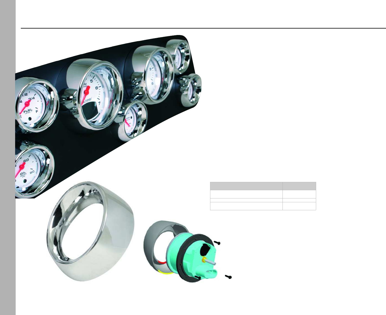
Visor Rims
Fits gauges with Part Number
2 1/8” or 2 1/16” cutout VR218CH
3 3/8” cutout VR338CH
Livorsi Visor Rims instantly adds character and dimension to
your existing dash. Made of polycarbonate material with a
beautiful chrome finish, tough enough to withstand salt
water conditions. These rims are made to fit gauges with
SAE or low profile rims.
NOTE: Will not work over Mega or Race rims
without alterations made by Livorsi Marine, Inc.
•Fits gauges with SAE rim or low profile rims
•Rotate at any angle for the desired look
•Directly attaches to the gauge, screws included
•Corrosion proof PC/ABS construction
•Chrome finish only
The visor Rim attaches by slipping the rim
from the front of the gauge and slipping the
bracket from behind, secure the bracket to
the rim with screws and your done.
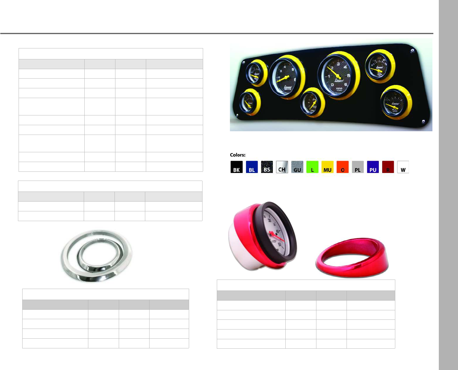
57
Bezels
Flat Bezels
Angled Bezels
Fits a... Cutout Overall Part Number
standard gauge 2 1/16” 2 3/4” AG216 + color
monster gauge 2 5/8” 3 1/4” AG258 + color
speedo/tach 3 3/8” 4 1/4” AG338 + color
liquid speedo 4” 5” AG400 + color
monster GPS/tach 4 5/8” 5 1/2” AG458 + color
Stainless Steel Flat Bezels
Fits a... Cutout Overall Part Number
standard gauges 2 1/16” 2 13/16” FL216SS
monster gauges 2 5/8” 3 3/8” FL258SS
speedo/tach 3 3/8” 3 3/4” FL338SS
monster GPS/tach 4 5/8” 5 11/16” FL458SS
Angled bezels allow for a fish eye view
of your gauges, left, right, up or down.
polish finish
Flat Bezels
Fits a... Cutout Overall Part Number
ignition switch 3 /4” 15/16” FL34 + color
cigarette lighter 7/8” 1 3/8” FL78 + color
standard gauges 2 1/16” 2 3/4” FL216 + color
round GPS antenna &
recall switch plate 2 1/8” 2 3/4” FLGPSRS + color
monster gauges 2 5/8” 3 1/4” FL258 + color
speedo/tach 3 3/8” 4 1/4” FL338 + color
adapts 3 5/8” or 4” to
a 3 3/8” cutout 3 3/8” 4 1/2” FLGPS + color
liquid speedo 4” 5” FL400 + color
monster GPS/tach 4 5/8” 5 1/2” FL458 + color
Slim Line Bezels
Fits a... Cutout Overall Part Number
standard gauge 2 1/16” 2 1/2” FL216S + color
speedo/tach 3 3/8” 3 15/16” FL338S + color
58
59
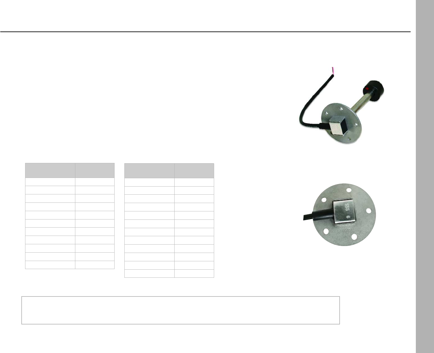
Fuel and Water Level Senders
standard 5 bolt pattern
240-33 ohms
Sender Length Part Number
4 inch SFW4
5 inch SFW5
5.5 inch SFW5.5
6 inch SFW6
7 inch SFW7
8 inch SFW8
9 inch SFW9
10 inch SFW10
11 inch SFW11
12 inch SFW12
13 inch SFW13
240-33 ohms
Sender Length Part Number
14 inch SFW14
16 inch SFW16
18 inch SFW18
20 inch SFW20
22 inch SFW22
24 inch SFW24
26 inch SFW26
28 inch SFW28
30 inch SFW30
32 inch SFW32
34 inch SFW34
36 inch SFW36
Other resistance outputs, lengths or senders with a 1 ¼" NPT are available upon request.
An electronic sender suitable for gas, diesel and water.
•Constructed to meet/exceed all applicable ISO, NMMA, ABYC and USCG standards
•Standard SAE 5 hole pattern
•Constructed of 316 stainless steel
•Fully insulated to protect against voltage inside the tank
•The float is the only moving part of the sensor minimizing mechanical failure
How It Works
Measurement is achieved by a series of reed switches positioned inside the level tube. The
float with built in magnets then triggers the reed relays generating a potential - free
resistance with an ohm value that increases or decreases.
60
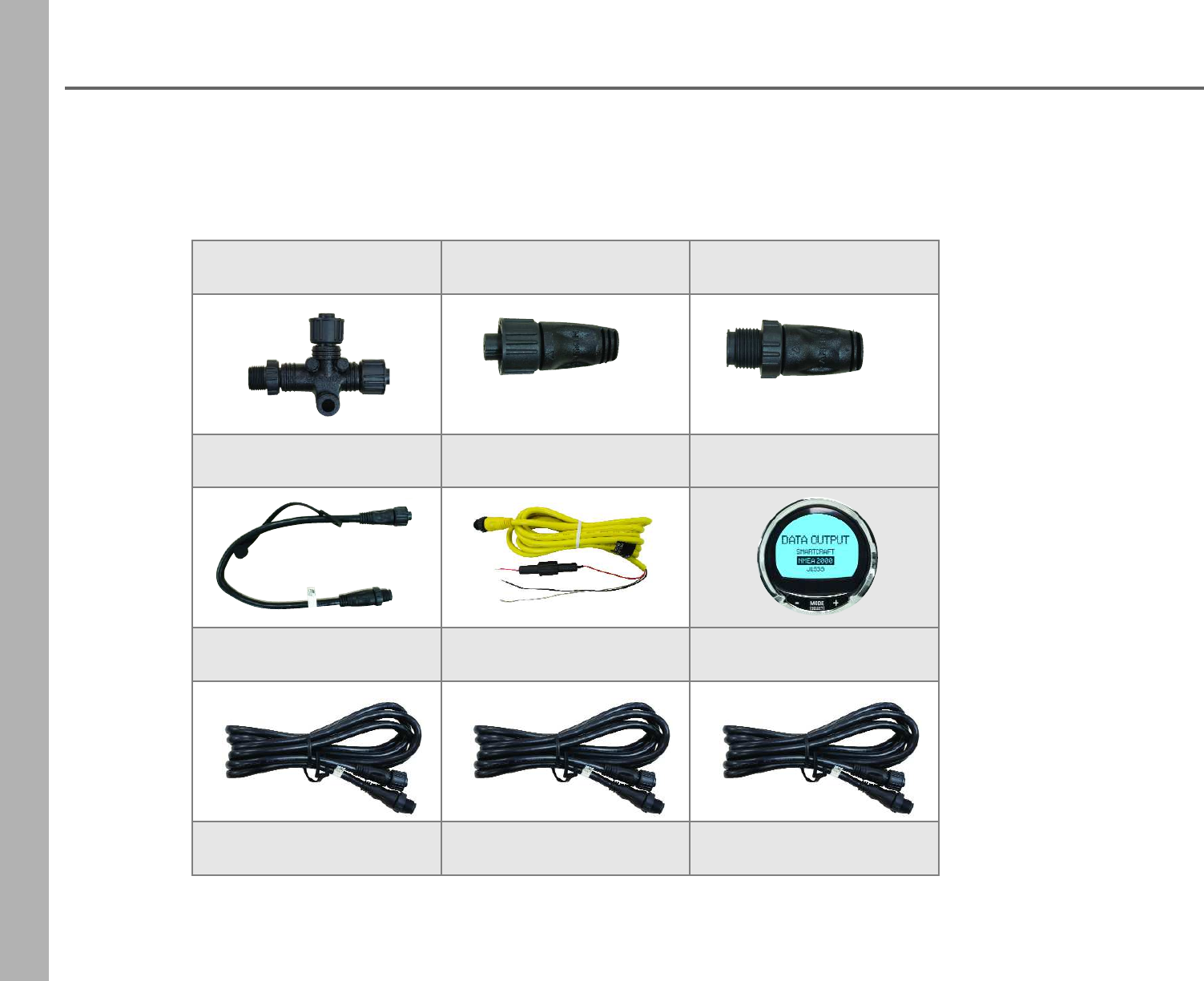
NMEA 2000®Harness
Livorsi can supply you with the necessary cables and connectors to expand your NMEA 2000®network.
Below is a chart of in-stock parts, for more options please call Livorsi Marine for pricing and availability.
single T connector
Part Number: 010-11078-00
120 Ohm female terminator
Part Number: 010-11081-00
120 Ohm male terminator
Part Number:010-11080-00
backbone/drop cable 2 ft
Part Number: 000-10068-001
single power cable
Part Number: 010-11079-00
MercMonitor
page 62
backbone/drop cable 6 ft
Part Number: 010-11076-00
backbone/drop cable 18 ft
Part Number: 010-11076-01
backbone/drop cable 30 ft
Part Number: 010-11076-02
61
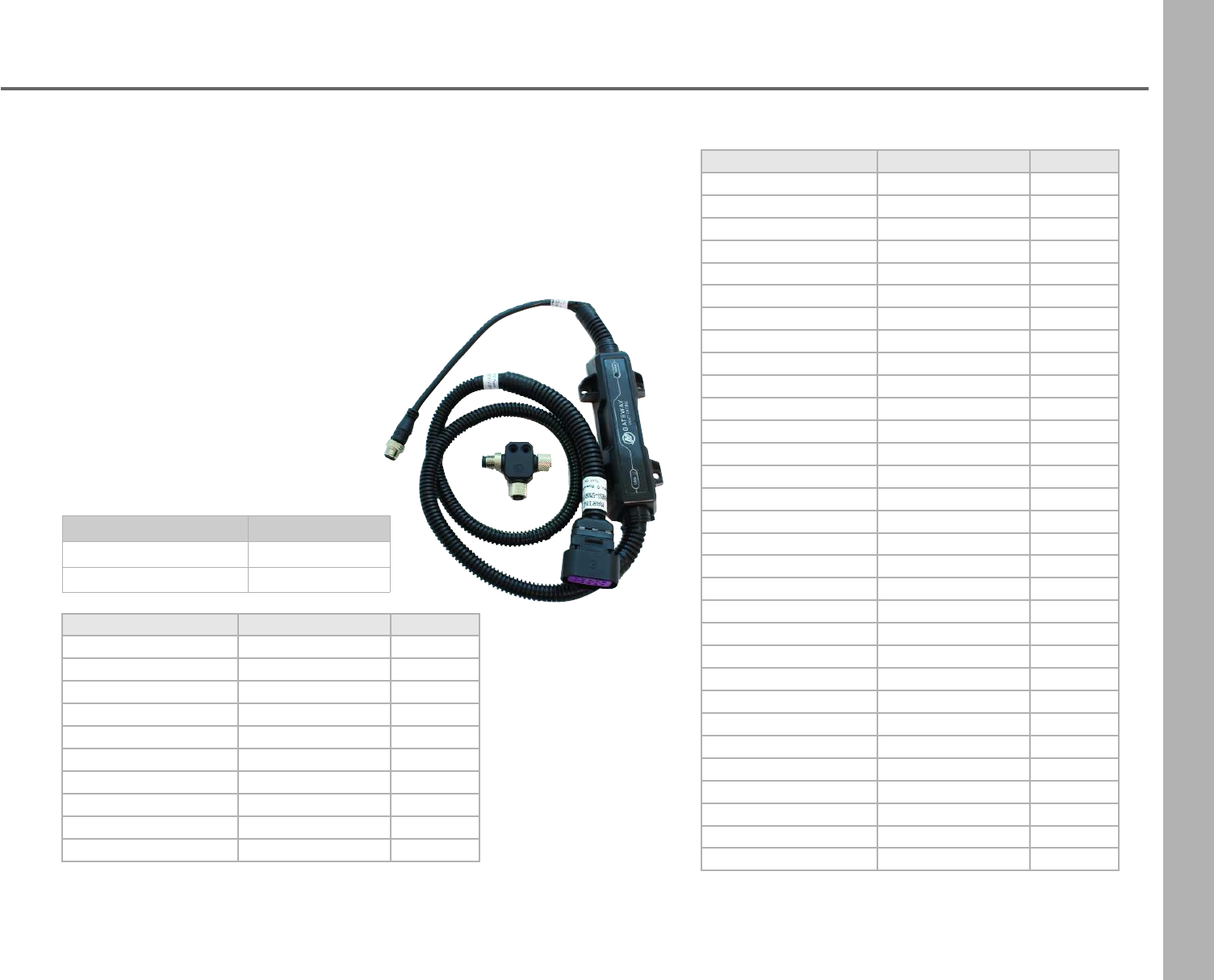
Mercury In Line Gateways
Description Part Number
single engine gateway SEGCANP
multi-engine gateway MEGCANP
Signal NMEA2K PGN Mode
RPM 127498 / 0x1F20A RX / TX
Coolant Pressure127489 / 0x1F201 RX / TX
Speed 128259 / 0x1F503 RX / TX
RPM 127488 / 0x1F200 RX / TX
Voltage 127489 / 0x1F201 RX / TX
Coolant Temperature127489 / 0x1F201 RX / TX
Fuel Pressure127489 / 0x1F201 RX / TX
Fuel Level 127505 / 0x1F211 RX / TX
Fuel Tank Size127505 / 0x1F211 RX / TX
Fuel Flow 127489 / 0x1F201 RX / TX
Oil Pressure127489 / 0x1F201 RX / TX
Oil Temperature127489 / 0x1F201 RX / TX
Gear Temp 127493 / 0x1F205 RX / TX
Gear Pressure127493 / 0x1F205 RX / TX
Boost Pressure127488 / 0x1F200 RX / TX
Trim Position 127488 / 0x1F200 RX / TX
Rudder Angle 127245 / 0x1F10D RX / TX
Depth 128267 / 0x1F50B RX / TX
Depth Offset 128267 / 0x1F50B RX / TX
Sea Water Temp 130310 / 0x1FD06 RX / TX
Engine hours 127489 / 0x1F201 RX / TX
Manufacturer ID 060928 / 0xEE00 RX / TX
Alarm Data 127489 / 0x1F201 RX / TX
Tabs 130576 / 0x1FE10 RX / TX
Battery 127508 / 0x1F214 RX / TX
ISO Acknowledge 059392 / 0x0E800 RX / TX
Course Over Ground 129026 / 0x9F802 RX / TX
Speed Over Ground 129026 / 0x9F802 RX / TX
GPS Position 129025 / 0x1F801 RX / TX
Address Claim 060928 / 0x0EE00 RX / TX
Product Info126996 / 0x1F014 RX / TX
Signal J1939 PGN Mode
RPM 61444 / 0xF004 TX
Voltage 65271 / 0xFEF7 TX
Coolant Temperature 65262 / 0xFEEE TX
Fuel Level 65276 / 0xFEFC TX
Fuel Flow 65266 / 0xFEF2 TX
Oil Pressure65263 / 0xFEEF TX
Boost Pressure65270 / 0xFEF6 TX
Engine Hours 65253 / 0xFEE5 TX
Manufacturer ID 61182 / 0xEEFE TX
Alarm Data 65226 / 0xFECA TX
Included with Gateway
•Module
•4 mounting screws
•N2K Tee
•installation instructions
The new Mercury Gateway converts SmartCraft®engine and
system data to NMEA 2000®protocol for use on non-Mercury
gauges and displays such as our LED Position Indicators.
Note: Gateway will not provide operation power for devices on the
NMEA 2000® network.
62
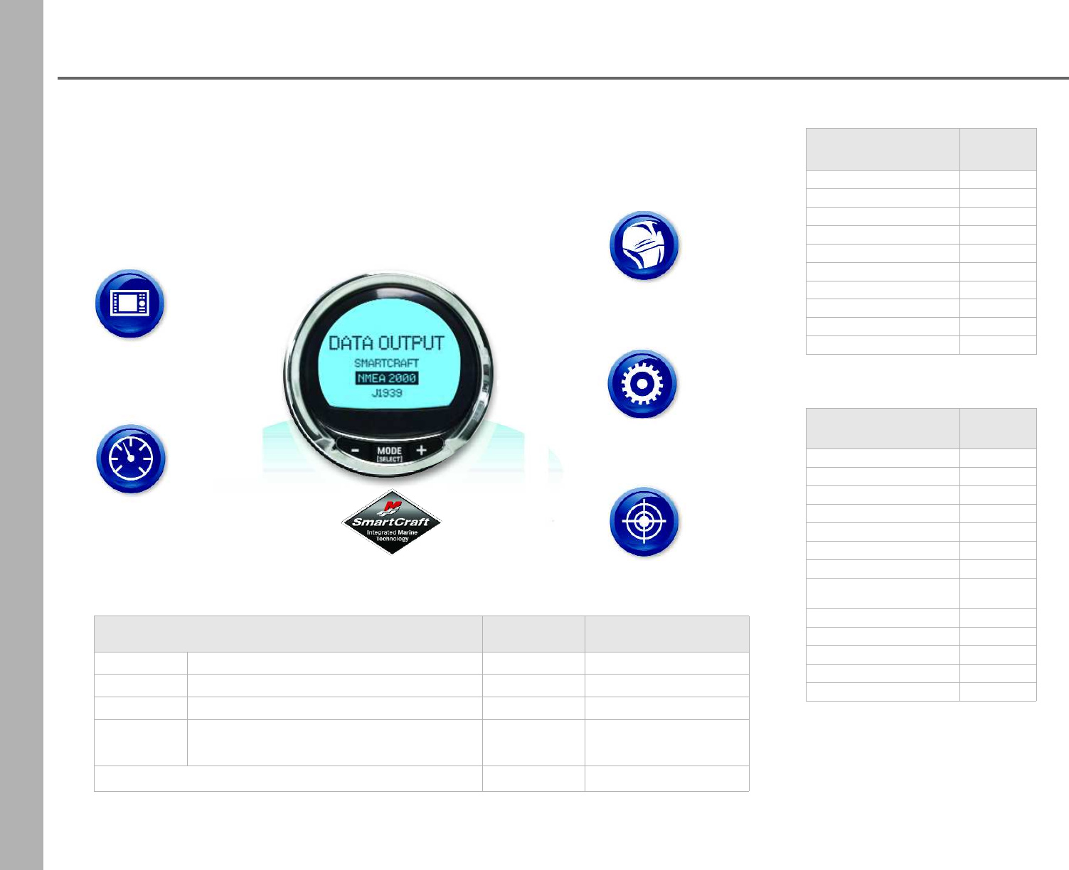
SmartCraft MercMonitor
featuring Mercury®Gateway
Engines
NMEA 2000®
Outboards &
Sterndrives
Systems
Trim Tabs &
Depth Sounders
GPS
Chartplotters
Pucks/Receivers
Gauges
NMEA 2000®
compatible
Displays
NMEA 2000®
compatible
MercMonitor featuring the Mercury® Gateway converts SmartCraft® engine and system data to
NMEA 2000®/J1939 protocol for use on NMEA 2000®/J1939 multi-function displays and gauges.
The ECO-Screen feature constantly monitors engine RPM, boat speed, fuel consumption and
engine trim‡ to automatically calculate and guide you to your best fuel economy settings. No
calibration required.
Merc Monitor Kits Part Number Notes:
Data Level 1 Single Engine- Troll Control- NMEA 2000 879337K51 Race Rim sold separtely
Data Level 2 Single Engine- RPM SmartTow- NMEA 2000 879338K51 Race Rim included
Data Level 3 Multi Engine- RPM SmartTow- NMEA 2000 879337K52 Race Rim included
Data Level 3 Multi Engine- SmartTow Pro- NMEA 2000 879339K51 Race Rim included
Race Rim for MercMonitor - chrome MMRRCH
NOTE: This MercMonitor is needed to transmit SmartCraft®information to our LED Position Indicators
Cutout: 3 3/8” Overall: 3 3/4”
NMEA 2000®/J1939†
Out/In Supported Data Level
RPM 1 · 2 · 3
Voltage 1 · 2 · 3
Oil Pressure 1 · 2 · 3
Coolant Temperature 1 · 2 · 3
Tank Level Fuel 1 · 2 · 3
Trim Position 1 · 2 · 3
Water Pressure 1 · 2 · 3
GPS Speed/COG/
Lat-Lon (in only) 1 · 2 · 3
Check Engine Alarm 1 · 2 · 3
Fuel Flow 2 · 3
Engine Hours 2 · 3
Boost Pressure52 · 3
Oil Temperature52 · 3
NMEA 2000®Only
Out/In Supported Data Level
Multiple Tank Levels 2 · 3
Tabs 2 · 3
Depth 2 · 3
Sea Water Temp 2 · 3
Paddle speed 2 · 3
Pitot Speed 2 · 3
Rudder Angle 3
Gear Pressure63
Gear Temp63
Fuel Pressure 3
5 Available on Mercury Verado
† J1939 limits signals and data levels
6 Available on Cummins MerCruiser Diesel Engines
†† Digital Trim sender required for full functionality.
63
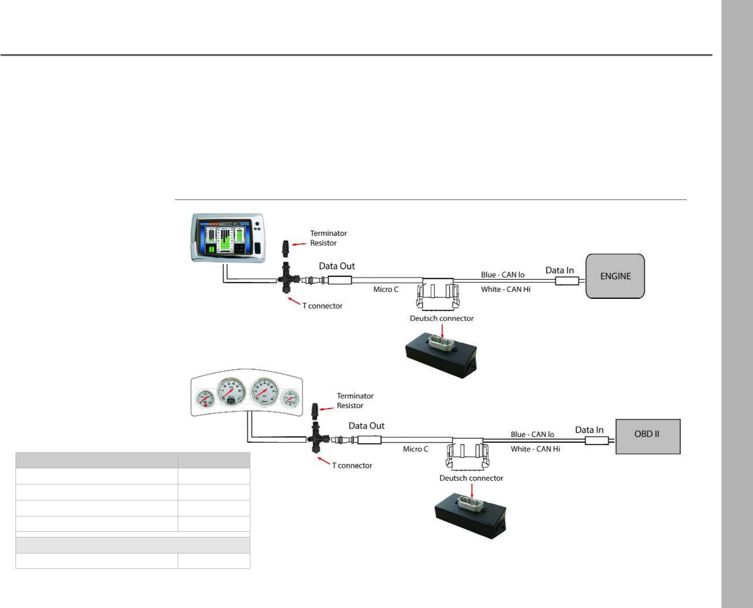
Data Gateway (Automotive/Marine)
With the Livorsi Data Gateway you can export CAN (Controller Area Network) engine data to a NMEA 2000® device and display
engine data. For use with Vantage View® gauges or a NMEA 2000® navigation device such as Garmin, Lowrance or
Raymarine. Please note that engine data is only transmitted if there is a sensor to support it.
Use this gateway to translate information to our state of the art Vantage View® Gauges.
Livorsi's Data Gateway simply plugs into a standard NMEA 2000® Tee connector which can be hooked directly to your device.
On the engine side it will interface via CAN+ / CAN- wires to gather the info and send it off to a screen and or gauges.
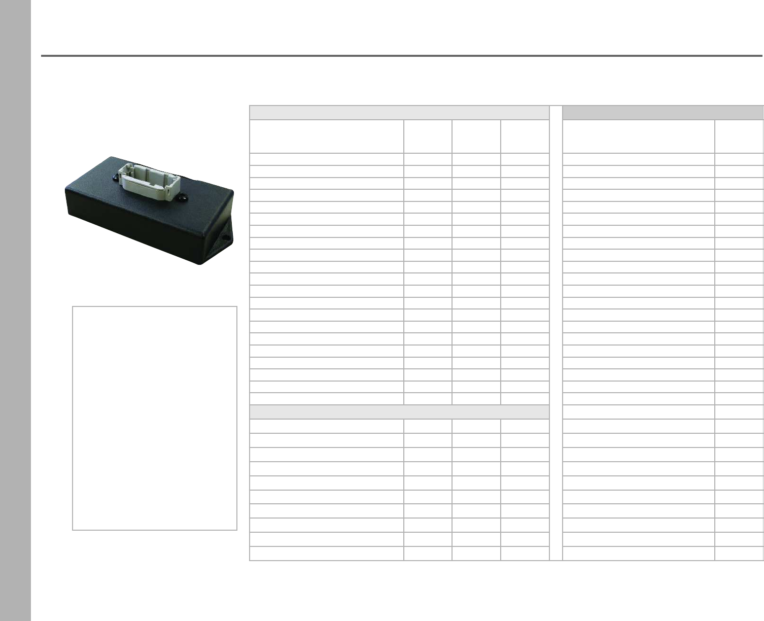
Gateway Model Description Part Number
MEFI to NMEA2K LGM4N2K
J1939 to NMEA2K LGJN2K
MoTeC to NMEA2K LGMN2K
OBD2 to J1939 (GM only) LGOBDJ
Harness
Deutsch/Micro C, 36 inch harness GATEWH
Possible Configurations
NMEA 2000
Capable Devices
SAE J1939
Capable Devices
64
Data Gateway (Automotive/Marine)
NMEA 2000 Output Parameters (Tx) SAE J1939 Output Parameters (Tx)
Input Parameter(Rx) MEFI4A MEFI4B MEFI5/6
(J1939) Input Parameter (Rx) OBDII
Air TemperatureXX X Air TemperatureX
Barometric PressureX X X Barometric PressureX
Battery Potential X X X Battery Potential X
Boost PressureX X X Boost PressureX
Engine Coolant TemperatureX X X Engine Coolant TemperatureX
Engine Coolant PressureX X X Engine Coolant Pressure
Engine Fuel Rate X X X Engine Fuel Rate X
Engine Hourmeter X X X Engine Hourmeter
Engine Inlet Air Temp Engine Inlet Air Temp X
Engine Percent Load NA (EEC2)2NA (EEC2)2X1 Engine Percent Load X
Engine Oil PressureX X X Engine Oil PressureX
Engine Oil TemperatureX X X Engine Oil TemperatureX
Engine Speed X X X Engine Speed X
Engine Percent Torque NA (EEC2)2NA (EEC2)2Engine Percent Torque
Fuel Level Fuel Level X
Fuel Pressure NA (EFL/P1)2NA (EFL/P1)2XFuel Pressure X
Run Time Since Start Run Time Since Start X
Throttle Position NA (LFE)2NA (LFE)2X1Throttle Position X
Vehicle Distance (Since DTC clear) Vehicle Distance (Since DTC clear) X
Vessel Speed X X NA (MEFI4B)2Vessel Speed X
Current Gear Current Gear X
Engine Discrete Status:
Check Engine X X
Rev Limit Exceeded X X
Low Oil PressureX
Low System Voltage X
Low Oil Level X
General Warning 1 X
General Warning 2 X
Low Fuel PressureX
Emergency Stop Mode X
Engine Over Temp X
Your engine application may or may not output all of the parameters listed below. Contact your engine manufacturer for a detailed list.
NMEA backbone cables,
Tfittings and power cable
may be required if you are
not tying into an existing
backbone.
Please note that a
terminating resistor is
required for the system to
perform as designed.
Please see page 60
for harness accessories.
65
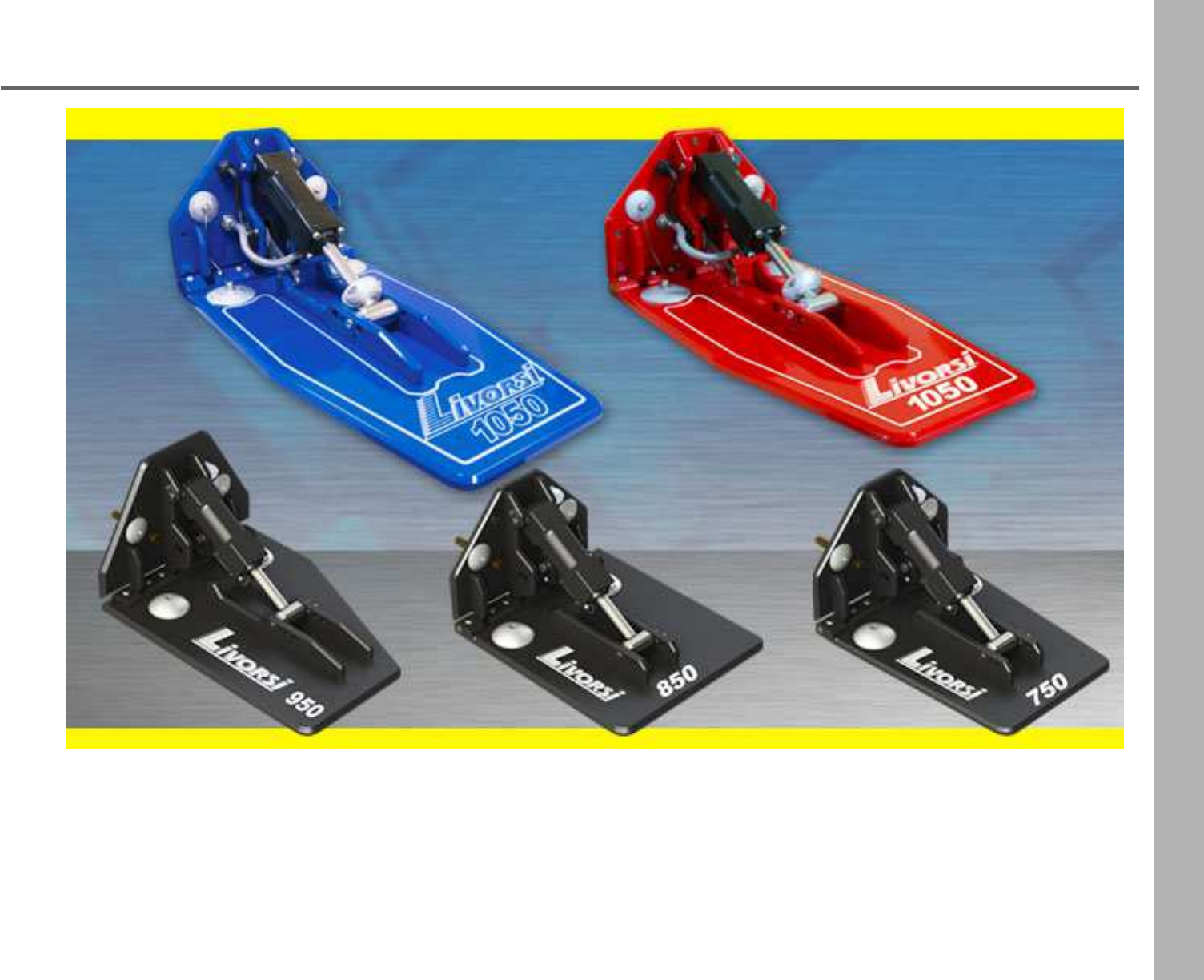
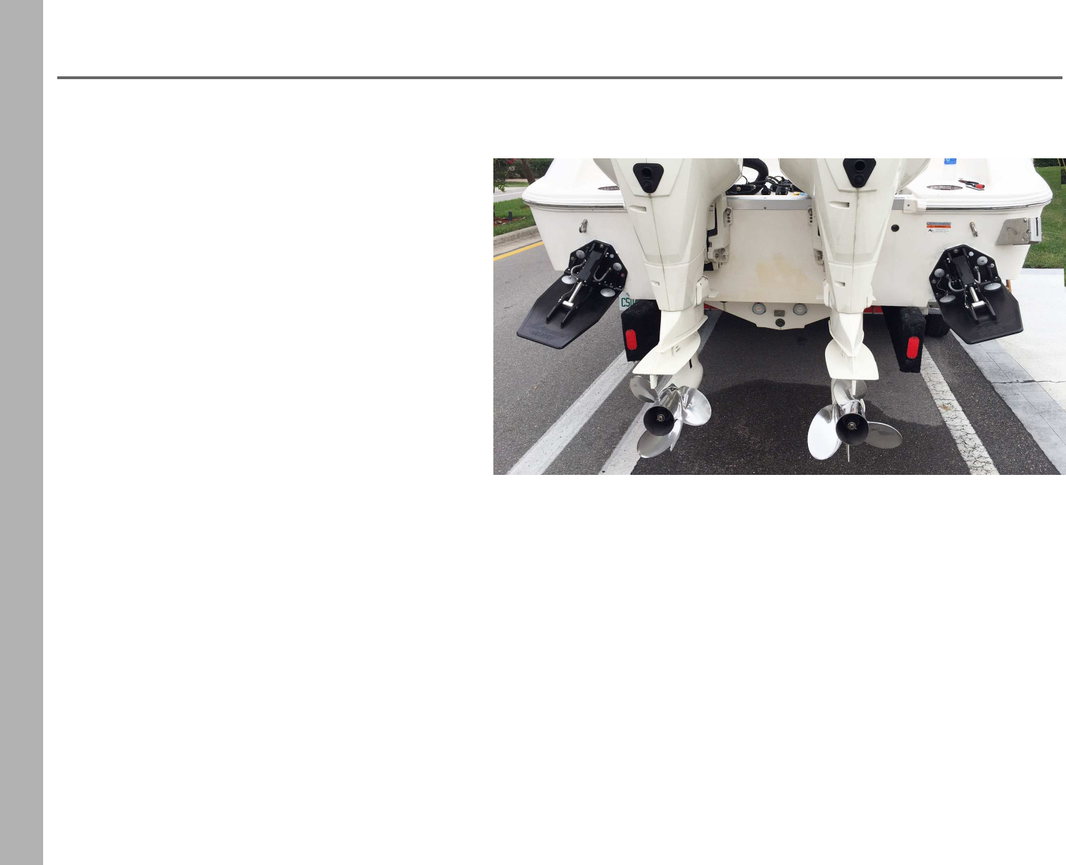
Hydraulic Billet Trim Tabs
Available with a powder coat finish and custom logos
66
Hydraulic Billet Trim Tabs
Features
• For use on boats 20 - 50 feet
• Mil-Spec hard coat anodized topped with a
powder coat finish to prevent corrosion
• Choose between LED electronic position
indication (plug and play) or mechanical position
indication (uses 33C cables)
• Electronic models are compatible with
NMEA 2000® compliant systems and Mercury
VesselView®
• The electronic IP68 sensor plugs directly to
Livorsi's LED Position Indicator
• Tabs are CNC machined from billet aluminum,
no casting
• Bolt patterns include Mercury and a smaller Livorsi bolt pattern for center consoles
• All hinge pins and hardware are stainless steel
• Adjustable transom angles without the use of special tools
• Hydraulic cylinders are designed for 1500 PSI working pressure with dual seals, cylinders may be serviced
• Five anodes for complete saltwater protection
• Available in 11 powder coat colors and private labeling
• Models are available for performance boats, center consoles, cruisers, run-abouts, workboats and military boats
1050 Trim Tab model show here
67
Hydraulic Billet Trim Tabs
Trim Tab Kits include:
•Two billet tabs
•Two pumps
•Mounting hardware
•Harnesses
•Thru hull fittings
Stainless steel braided hoses are purchased separately. Four
hoses are needed for one kit, two per cylinder.
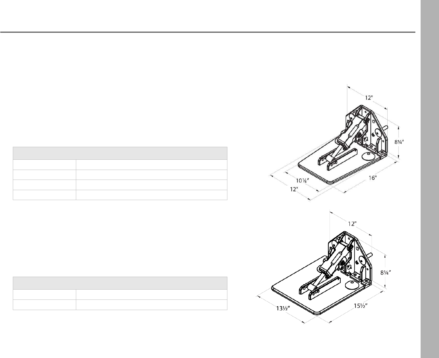
850 Military Kits
TTK850ML Mechanical cable - Livorsi Transom Plate 16X14"
TTK850EL Electric Trim - Livorsi Transom Plate 16X14"
750 Performance Kits
TTK750ML Mechanical cable - Livorsi Transom Plate 16X10"
TTK750MM Mechanical cable - Merc Transom Plate 16X10"
TTK750EL Electric Trim - Livorsi Transom Plate 16X10"
TTK750EM Electric Trim - Livorsi Transom Plate 16X10"
750 Model
850 Model
68
Hydraulic Billet Trim Tabs
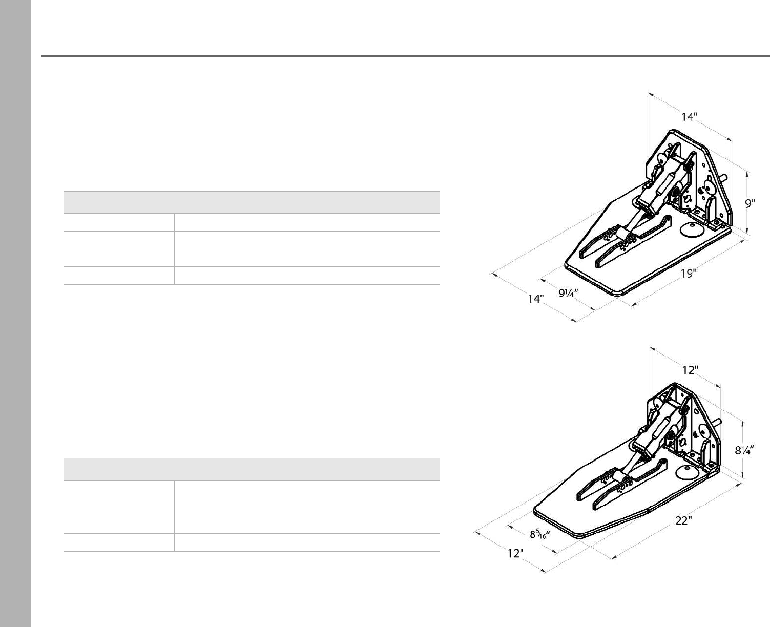
950 Mercury Replacement Kits for 280S
TTK950ML Mechanical cable - Livorsi Transom Plate 20X9"
TTK950MM Mechanical cable - Merc Transom Plate 20X9"
TTK950EL Electric Trim - Livorsi Transom Plate 20X9"
TTK950EM Electric Trim - Merc Transom Plate 20X9"
1050 Performance Kits
TTK1050ML Mechanical cable - Livorsi Transom Plate 22X10"
TTK1050MM Mechanical cable - Merc Transom Plate 22X10"
TTK1050EL Electric Trim - Livorsi Transom Plate 22X10"
TTK1050EM Electric Trim - Merc Transom Plate 22X10"
950 Model
1050 Model
69
Hydraulic Billet Trim Tabs
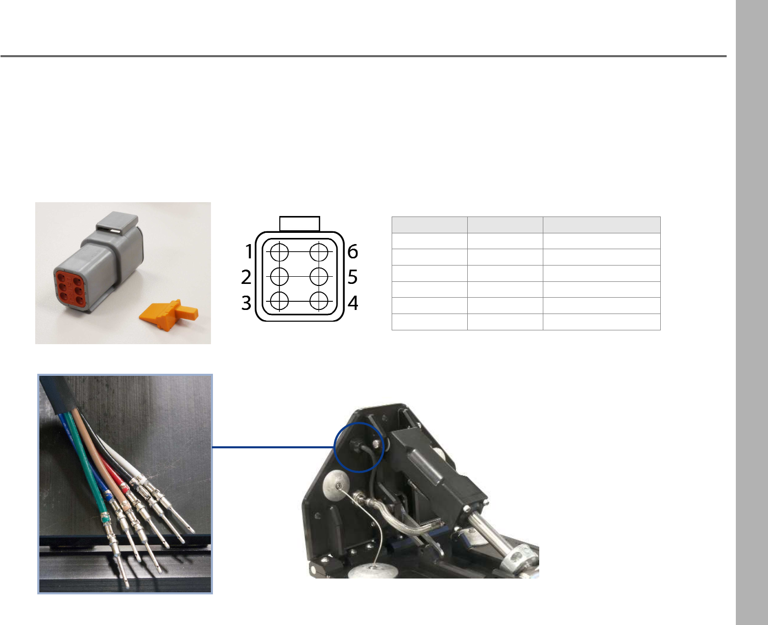
• Electronic models are compatible with NMEA2000® compliant systems and Mercury VesselView®
• The electronic IP68 sensor plugs directly to Livorsi's LED Position Indicator
Pin Number Wire Color Description
1Red PPS1 (5V)
2White PPS2 (5V)
3Blue PPS1 Signal
4Black PPS1 Ground
5Green PPS2 Ground
6 Tan PPS2 Signal
70
Hydraulic Pumps
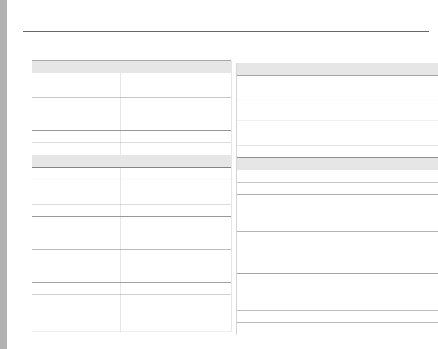
Pump Specifications
Motor 24 VDC
3-wire reversing continuous ground
with thermal breaker
Hydraulic Pump 2 gear drive
.0321 CIPR (cubic inches per revolution)
Voltage Rating 24V
Max Pressure Up 1200 PSI
Max Pressure Down 1200 PSI
Solenoid Specifications
Solenoid type 24V, 65A continuous duty
Special Applications Marine
Insulated/Ground Insulated
NO/NC Normally Open
Circuitry Single pole, single throw
UL Marine & CE ISO 8846 Marine Yes
Operating Temperature range -40° to + 85°C
(-40° to + 185°F)
Battery studs 5/16 - 24
Battery stud torque 35 in-lbs max (4.0 Nm)
ContactsCopper
Coil studs 10 - 32
Coil stud torque 15 in-lbs max (1.7 Nm)
Pump Specifications
Motor 12 VDC
3-wire reversing continuous
ground with thermal breaker
Hydraulic Pump 2 gear drive
.0321 CIPR (cubic inches per revolution)
Voltage Rating 12V
Max Pressure Up 1200 PSI
Max Pressure Down 1200 PSI
Solenoid Specifications
Solenoid type 12V, 65A continuous duty
Special Applications Marine
Insulated/Ground Insulated
NO/NC Normally Open
Circuitry Single pole, single throw
UL Marine & CE ISO 8846
Marine N/A
Operating Temperature range -40° to + 85°C
(-40° to + 185°F)
Battery studs 5/16 - 24
Battery stud torque 35 in-lbs max (4.0 Nm)
ContactsCopper
Coil studs 10 - 32
Coil stud torque 15 in-lbs max (1.7 Nm)
Pump Assembly Kit 24V
Part Number: PAK24V
Pump Assembly Kit 12V
Part Number: PAK12V-1
71
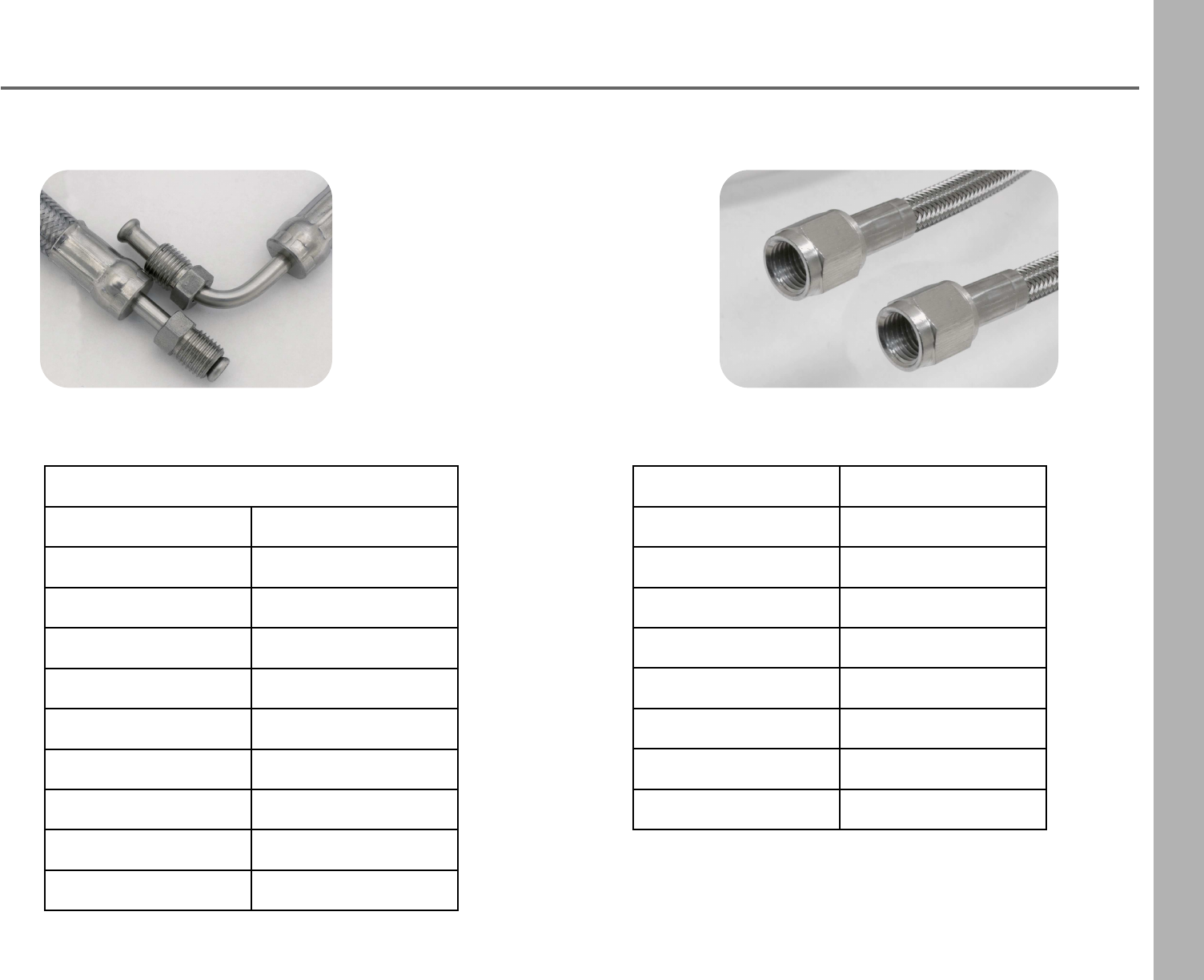
Stainless Steel Braided Hoses
Inverted Flare Hose Ends SAE J514 37° Flare Ends
Inverted Flare Hose Ends
Length Part Number
30 inches SSBH30IN-1
36 inches SSBH36IN-1
48 inches SSBH48IN-1
60 inches SSBH60IN-1
72 inches SSBH72IN-1
90 inches SSBH90IN-1
19 feet SSBH19FT-1
21 feet SSBH21FT-1
26 feet SSBH26FT-1
SAE J514 37° Flare Ends
Length Part Number
30 inches SSBH30IN
34 inches SSBH34IN
60 inches SSBH60IN
90 inches SSBH90IN
19 feet SSBH19FT
21 feet SSBH21FT
26 feet SSBH26FT
72
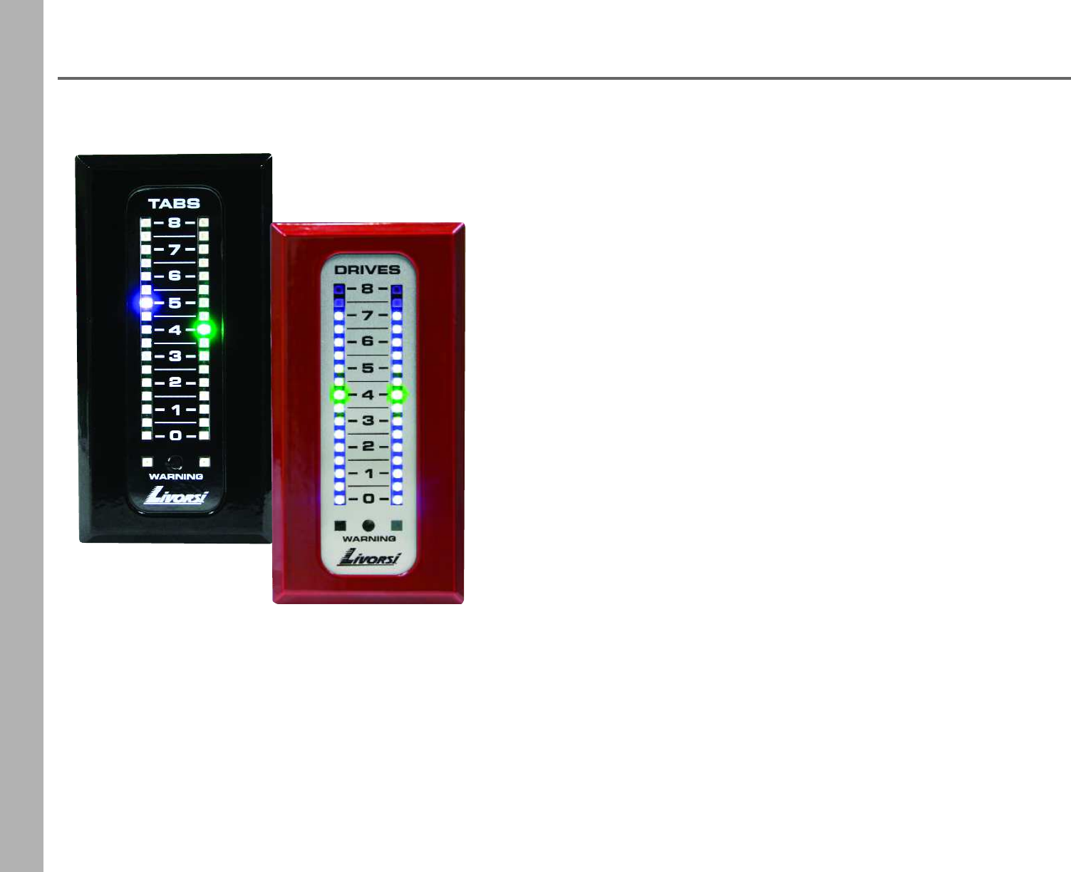
Adjustable Position LED Indicators
Compatible With:
•NMEA 2000® (Rx + Tx) Devices •SmartCraft® (with Gateway)
•J1939 (Rx + Tx) Devices •0-5 Volt Sensors
•Resistive Sensors (ohms)
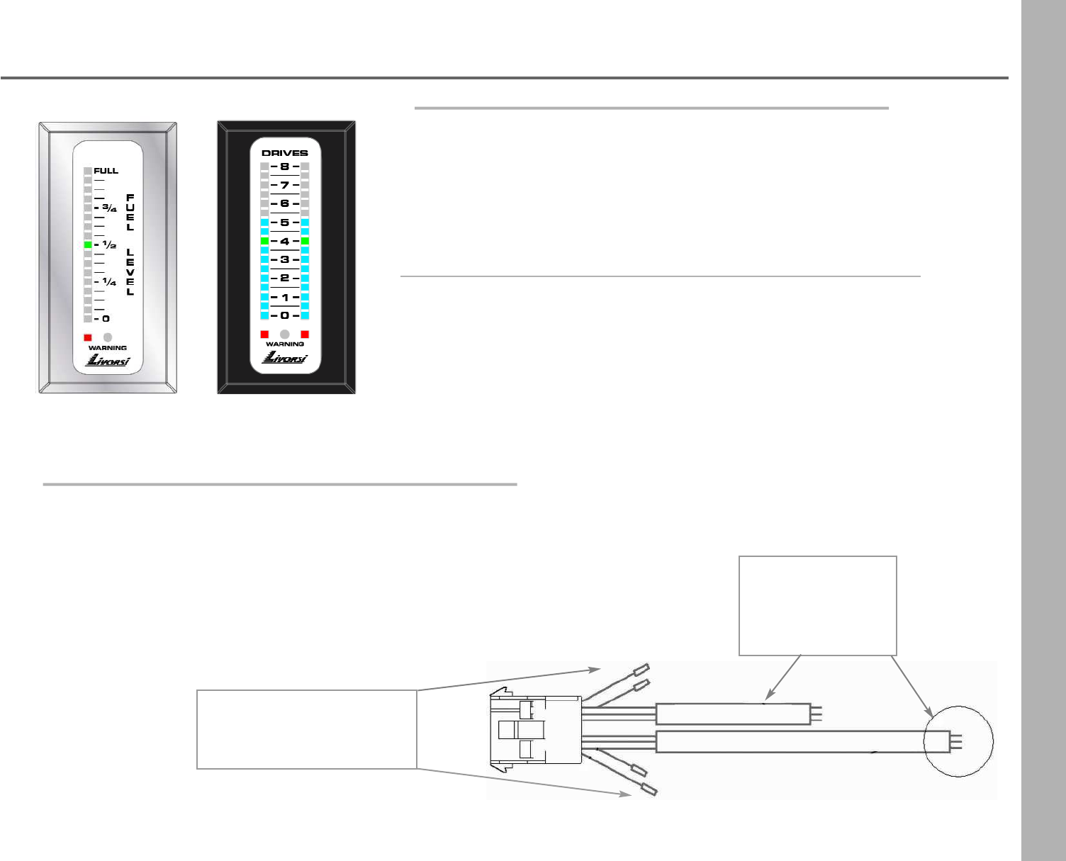
Displays position for tabs, drives, jackplates, rudder indicator, fuel and water level
What sets these displays apart from anything else is the single middle green
LED. During calibration, this LED display can be set to indicate 50% of
actuator travel, fuel level or whatever you are monitoring.
What makes it so special is that it allows you to establish the optimum
running angle - or sweet spot (not at 50%), to dial-in the vessel for optimal
running efficiency so the novice boater always runs at the correct trim.
No matter what information you are looking to display (fuel level, drive trim, tab position, etc.), the data is
brought into the communication network with plug and play harnessing and is received (Rx) via the network
cable to the LED indicator for display.
The LED indicator can also transmit (Tx) this information via CAN bus to other compatible displays such as
Garmin, Lowrance or Raymarine via NMEA 2000®, SmartCraft® (with Gateway) or J1939 protocols.
73
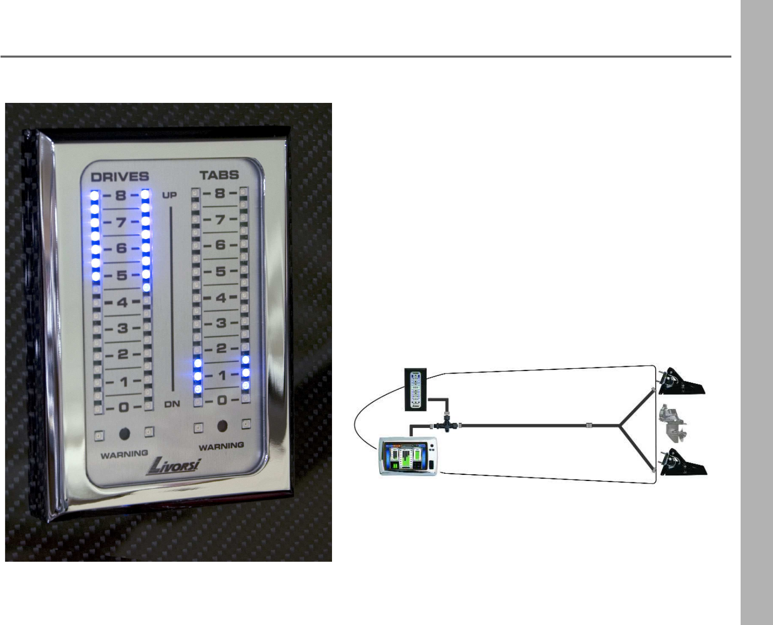
Adjustable Position LED Indicators
If your boat is already transmitting (Tx) NMEA 2000® data (tabs,
drives, fuel level, water level, rudder angle, etc.), simply plug the
indicator into the NMEA 2000® backbone to begin displaying the
desired feature on the indicator.
74
Adjustable Position LED Indicators
•Simple plug and play installation,
eliminates clumsy cables
•No cables means, no loss of motion
•All electronics are environmentally sealed
•Has the ability to compensate for
non-linear tanks giving you accurate readings
•0-5 volt or resistive type sensors (adjustable)
•1 to 4 slot configurations, vertical or horizontal
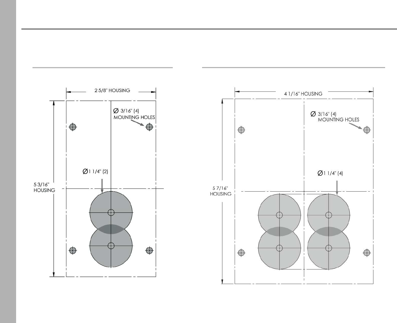
1 or 2 slot indicator: 2 5/8” W x 5 3/16” H overall
requires (2) 1-1/4” cutouts for wiring
3 or 4 slot indicator: 4 1/16” W x 5 7/16” H overall
requires (4) 1-1/4” cutouts for wiring
Dimensions
Calibration is performed via the proximity/photo sensor on the
front of the indicator
Inputs may be calibrated using either a 2 or 3 point method:
minimum / maximum – or minimum / maximum / center
running point (green LED)
This indicator has the ability to compensate for non-linear
tanks (fuel or water), giving you accurate readings
Wide input supply voltage of 7-24 VDC, with reverse polarity protection
Power Supply
Calibration
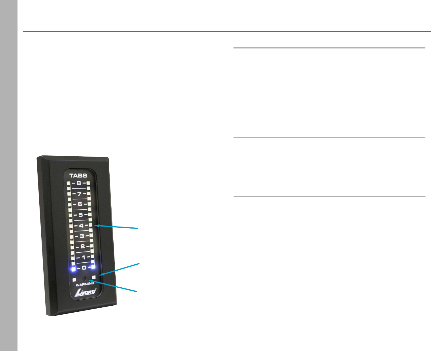
warning LED
with optional sender
proximity/photo sensor
(calibration “button”)
running point
(sweet spot)
75
Adjustable Position LED Indicators
pointer style fill bar
ground and switch/warning
input wires for warning LED
Connects to 0-5
volts or resistive
type sensors.
Pointer Style-
one LED pointer displays your position/level
Fill Bar type-
multiple LEDs lit in a row, beginning from the top or bottom
The green LED in the center may be calibrated to show optimal level
position for Drives,Tabs, etc.
The red LED at the bottom of the indicator can be used as
a warning light
Built-in light sensor automatically adjusts to ambient light with 250
brightness intensity levels
LED Lighting Options Include:
Each slot accommodates two analog inputs. One analog
input drives the indicator bar, the other drives the optional
red warning LED located at the bottom of the slot.
Warnings may include (but are not limited to):
Oil pressure, water temperature or low fuel with optional
switch to close sensor.
Analog Inputs
76
Adjustable Position LED Indicators
1 & 2 slot 3 & 4 slot
Dimensions
77
Adjustable Position LED Indicators
Voltage or Resistance Sensors
Tabs, drives, jack plates, fuel level, water level and rudder indicator applications must have a
resistance or voltage type sensor present for this system to operate. Below are some of the options.
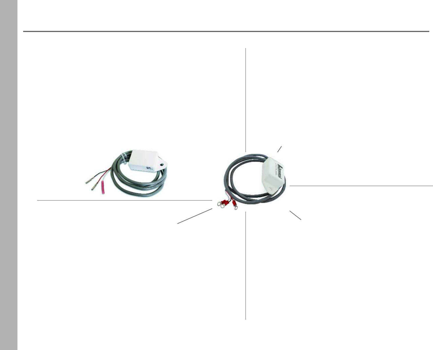
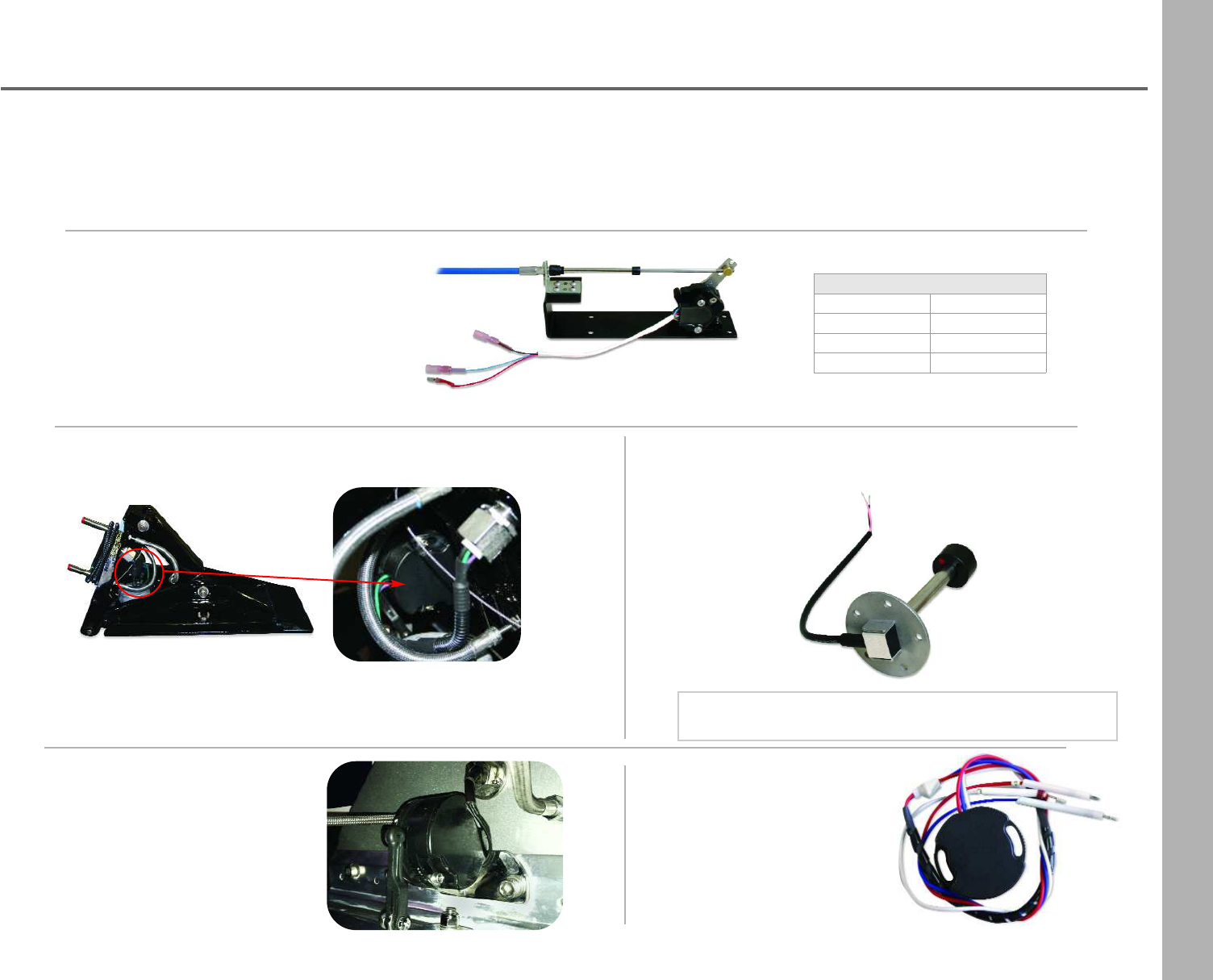
Mechanical to Electric Converter 0-5 Volts
(cable not included)
Converts the mechanical signal to an
electric signal. Bolts on the inside of the
transom with a short cable to the unit.
Mounted pot on Mercury trim tab 0-5 Volts
NOTE: Must know at time of placing your order,
if sensor is a 2 or 3 wire sensor
Tabs 2010 or newer should contain the 5 volt sensor
Tabs 2006-2010 model Number’s 280S and 380S should
have a bracket to add the sensor
Mercury drive pot 0-5 Volts
Part Number: 863187A1
Please contact your nearest
Mercury dealer.
Retrofitted tabs
Mercury pot 0-5 Volts
Please contact your
nearest Mercury dealer.
Fuel or water level resistive type sensors 240/33 ohms
33 Series Cables
3 ftCA3
4 ftCA4
5 ftCA5
6 ftCA6
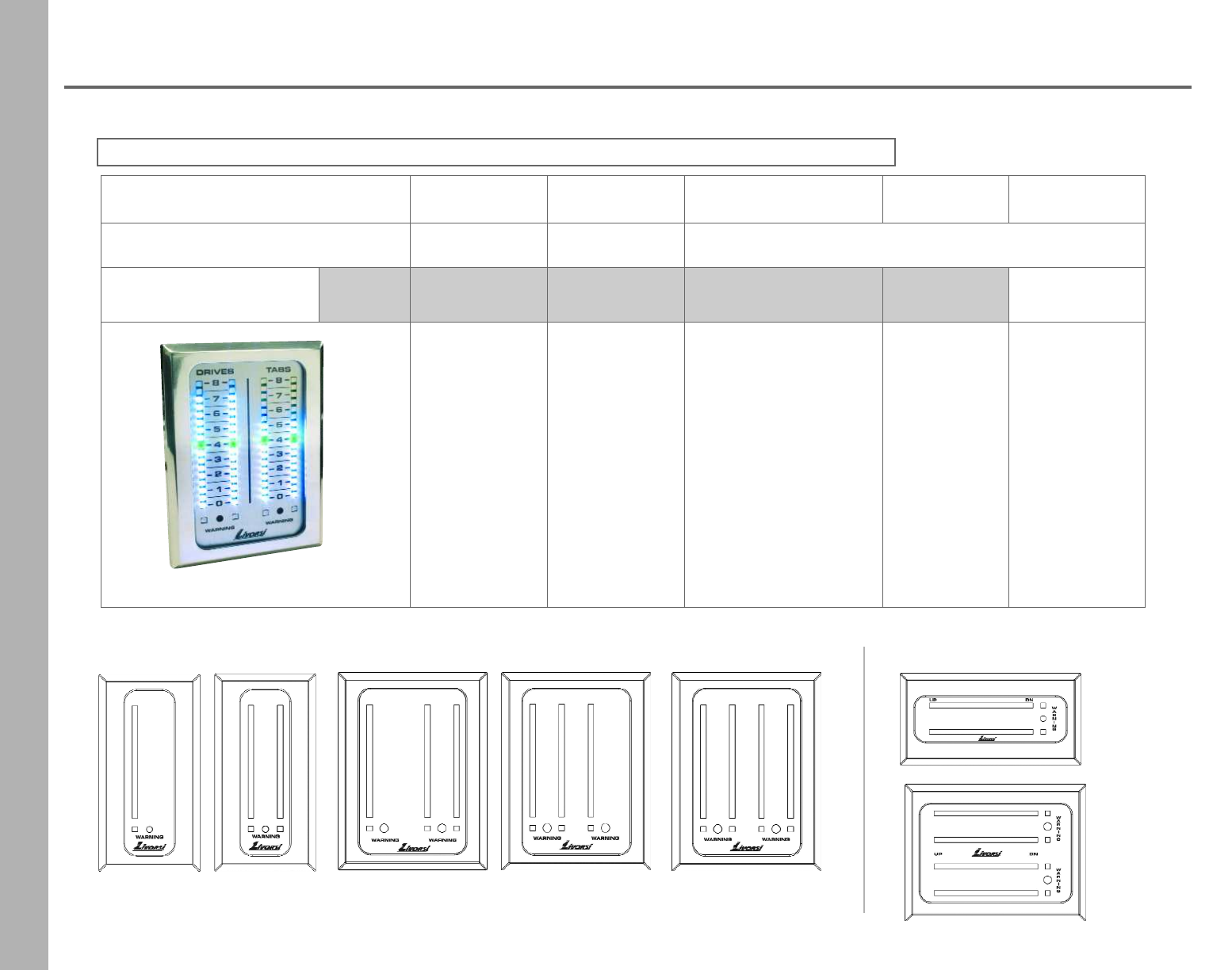
78
Adjustable Position LED Indicators
Building Your Indicator Part Number
NOTE: A 50% restocking fee will be charged for all returned Adjustable Position LED Indicators.
FIRST
ITEM DATA SECOND
ITEM DATA CARD COLOR FRAME
COLOR ORIENTATION
1 or 2 slot 3 or 4 slot
Part Number Example ALEDI 2D 2T PL CH V
1 Drive = 1D
2 Drives = 2D
1 Tab = 1T
2 Tabs = 2T
1 Fuel = 1F
2 Fuel = 2F
1 Jack Plate = 1J
2 Jack Plate = 2J
1 Rudder = 1R
2 Rudder = 2R
1 Drive = 1D
2 Drives = 2D
3 Drives = 3D
4 Drives = 4D
1 Tab = 1T
2 Tabs = 2T
3 Tabs = 3T
4 Tabs = 4T
1 Fuel = 1F
2 Fuel = 2F
1 Jack Plate = 1J
2 Jack Plate = 2J
Black = BK
Carbon Fiber = CF
Platinum = PL
Silver Carbon Fiber = SF
White = W
Black = BK
Blue = BL
Chrome = CH
Lime = L
Mustard = MU
Orange = O
Platinum = PL
Purple = PU
Red = R
White = W
Vertical = V
Horizontal = H
Vertical Orientation Examples
ALEDI2D2TPLCH
Horizontal Orientation Examples
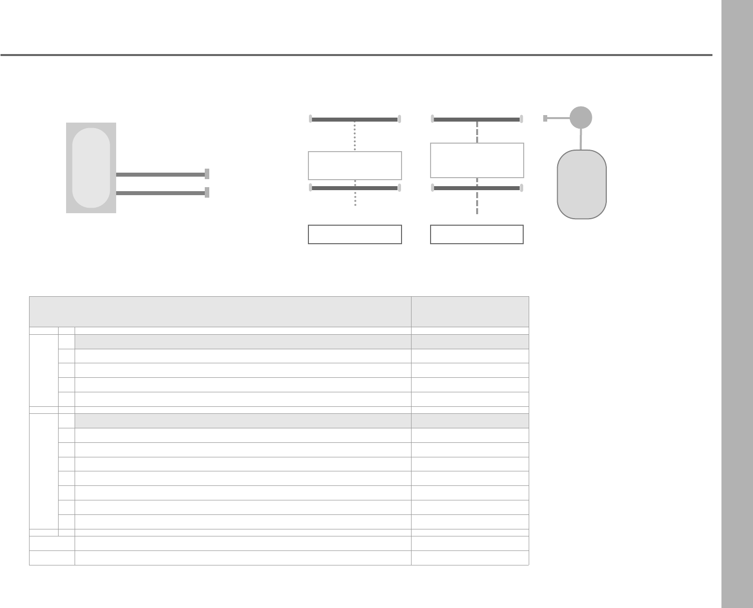
79
Adjustable Position LED Indicators
Parts To Order
Main Harness Jumper Harness
32
LEDHSA20
3 & 4 slot requires
two harnesses
Sensor
LEDEXT10
Engine/
Drive/
Tank
3 & 4 slot may require
two harnesses
Harness Options Part Number
2
Main Harness to Jumper Harness
aMain Harness 20 feet LEDHSA20
bMain Harness 25 feet LEDHSA25
cMain Harness 30 feet LEDHSA30
dMain Harness 40 feet LEDHSA40
3
Jumper Harness to Sensor Input
a Tab/Drive/Fuel Jumper Single 5 feet LEDHEXTS
b Tabs/Drives/Fuel Jumper Dual 10 feet LEDHEXT10
c Tabs/Drives/Fuel Jumper Dual 15 feet LEDHEXT15
dMercury SmartCraft® Drive Jumper Single (Y Cable) 5 feet LEDHYS
eMercury SmartCraft® Drive Jumper Dual (Y Cable) 5 feet LEDHYD5
fMercury SmartCraft® Drive Jumper Dual (Y Cable) 10 feet LEDHYD10
gMercury SmartCraft® Drive Jumper Dual (Y Cable) 15 feet LEDHYD15
Mechanical to Electric Converter 0-5 Voltscall for part number
1
Indicator
4 slot example:
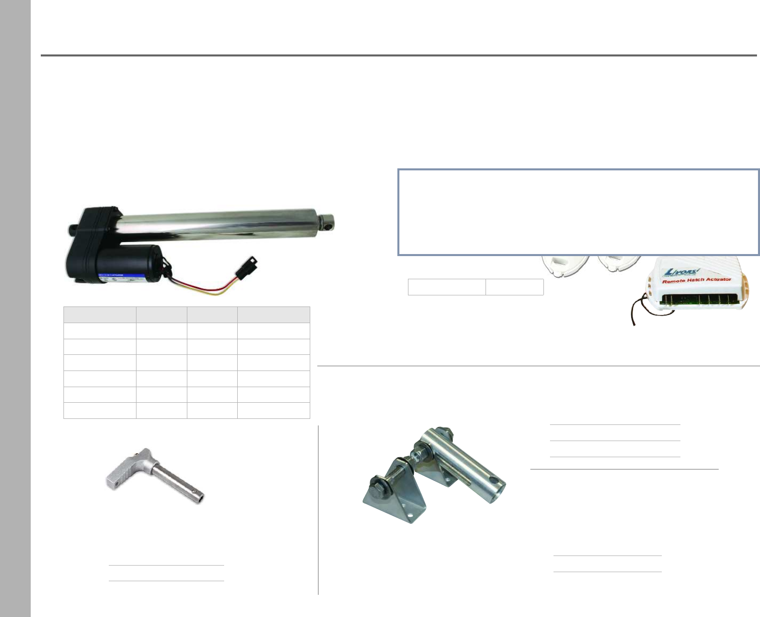
80
Hatch Actuators
Description Closed Open Part Number
4” throw 10.32” 14.32” SSA4
8 ” throw 14.32” 22.32” SSA8
12” throw 18.32” 30.32” SSA12
16” throw 22.32” 38.32” SSA16
18” throw 24.32” 42.32” SSA18
24” throw 30.32” 54.32” SSA24
•Safe working load limit of 400lbs.
•Heavy duty sealed ball bearing motor allows for locking of
hatches, so it won't open at high speeds
•Marine grade stainless steel housing
•Lifts 2X as fast and has 2X the power of other electric actuators
•Cleaner and more cost-effective alternative to hydraulic and
pneumatic models
•Provides consistent performance throughout its lifetime
•12 VDC
Hatch Actuator Remote
•Specifically designed for hatch lifting
•Opens hatches from 300 feet away
•Can be used on most hatch motors electric or hydraulic
•Isolated channels prevent damage to the hatch motor
•Use on boats with 2 separate hatches- a relay kit is needed
•Receiver module can be mounted under the dash, wired to the
hatch switch or directly to the motor while keeping the manual
switch functional
Kit includes:
•1 receiver
•2 white remotes
Part Number WHAR
Quick Release Pin
•stainless steel & aluminum
Part Number HAQRP
Mounting Kit
Part Number HAMK
Kit includes:
•bracket
•sleeve
•washers & bolts
Brackets can be sold separately.
Washers and bolts not included.
stainless steel
bracket
aluminum
adjustable bracket
bracket HAB
adjustable bracket HABT
HATCH ACTUATOR REMOTE
DISCONTINUED
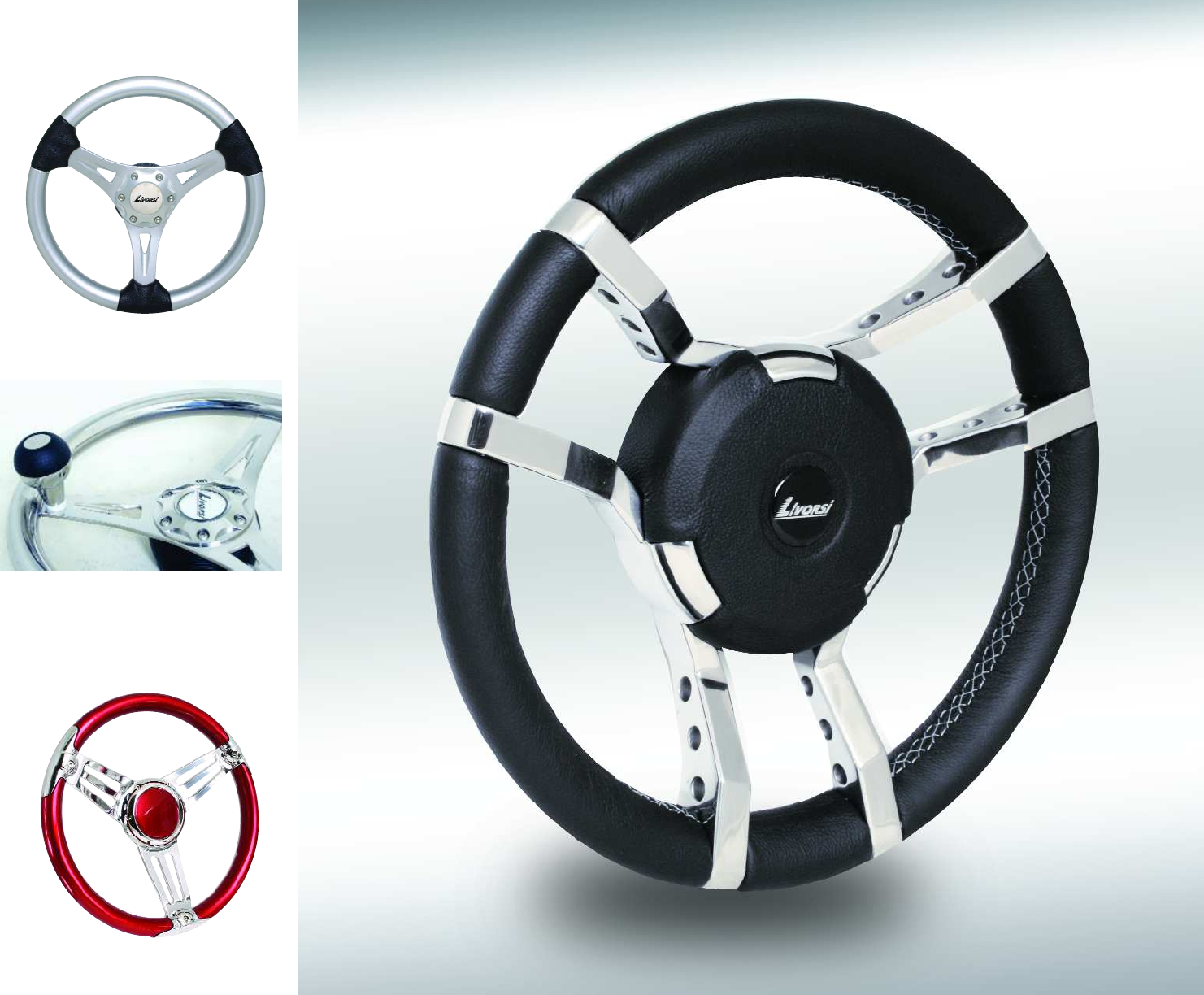
81
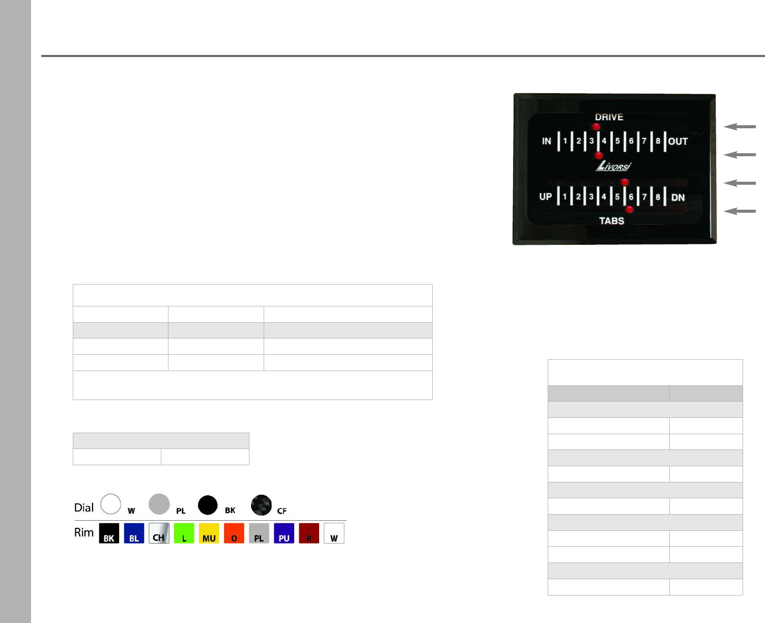
82
Mechanical Indicators
Ultra Thin
ultra thin
UMI2D2TBKBK
horizontal layout, right entry
standard pointers
Indicators w/ Fluorescent Pointers
Part Numbers
Number of drives Number of tabs
1 drive2 tabs UMI1D2T + card + frame color
2 drives 2 tabs UMI2D2T + card + frame color
Specify:
direction of cable entry, horizontal or vertical layout
Ultra Thin face dimensions
3 or 4 slot 3 3/4” W x 5” H
Livorsi indicators feature a no-slack spring load assist, eliminating slack in
the cable giving you a faster indication of your drives and tabs.
•Dash mounted indicator
•Fluorescent red pointers
•Aluminum and composite construction
•Adaptable to any actuator with 3 1/4” throw
Set Back Kit
•Allows switches to be mounted at cable entry area on your dash
Indicator Parts
Description Part Number
Indicator Cards
3 slot UIC3 + color
4 slot UIC4 + color
Frames
3 or 4 UIF34 + color
Windows
3, 4 or 5 slot IW34
Pointer Kit with Springs
2 slot IPK2
4 slot IKP4
Set Back Kit
2 inches set back SBK
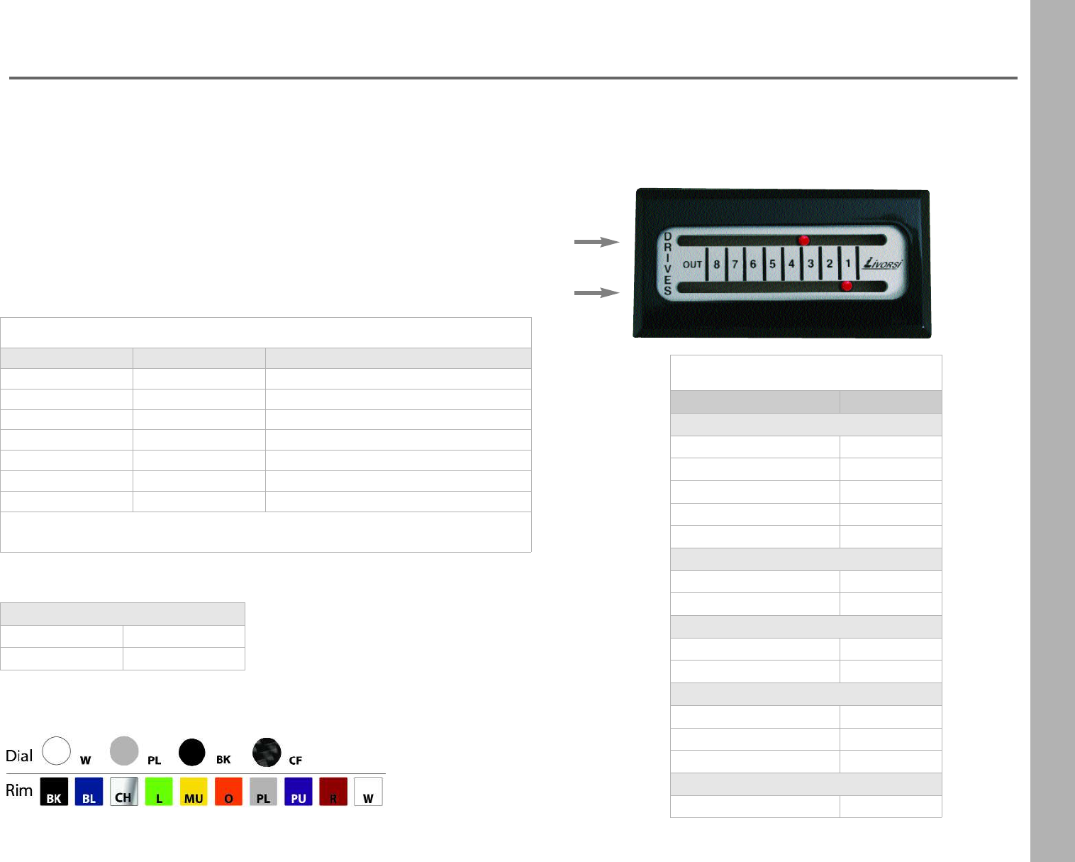
83
Mechanical Indicators
Standard Size
•Dash mount indicator
•Fluorescent red pointers
•Aluminum and composite construction
•Adaptable to any actuator with 3 1/4” throw
Set Back Kit
•Allows switches to be mounted at cable entry area on your dash
Standard size dimensions
1 or 2 slot 2 1/2” W x 5” H
3, 4 or 5 slot 5” W x 5” H
Indicators w/ Fluorescent Pointers
Number of drives Number of tabs Part Number
0 drives 2 tabs MI2T + card + frame color
1 drives 0 tabs MI1D + card + frame color
1 drives 2 tabs MI1D2T + card + frame color
2 drives 0 tabs MI2D + card + frame color
2 drives 2 tabs MI2D2T + card + frame color
3 drives 0 tabs MI3D + card + frame color
3 drives 2 tabs MI3D2T + card + frame color
Specify:
direction of cable entry, horizontal or vertical layout
Indicator Parts
Description Part Number
Indicator Cards
1 slot 1SIC + color
2 slot 2SIC + color
3 slot 3SIC + color
4 slot 4SIC + color
5 slot 5SIC + color
Frames
1 or 2 slot IF12 + color
3, 4 or 5 slot IF345 + color
Windows
1 or 2 slot IW12
3, 4 or 5 slot IW345
Pointer Kit with Springs
2 slot IPK2
4 slot IKP4
5 slot IKP5
Set Back Kit
2 inches set back SBK
standard
MI2DPLBK
horizontal layout, left entry
standard pointers
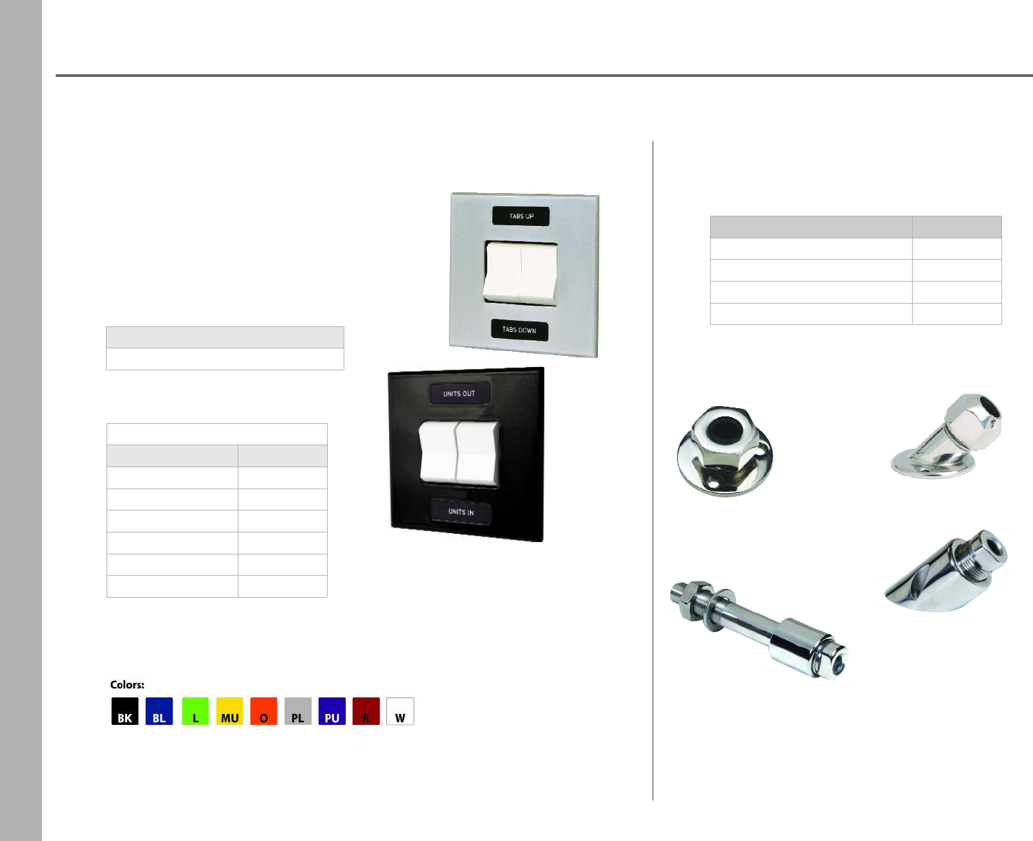
84
Trim Panels
•Military spec rocker switches
•Sealed and waterproof
•No exposed screws
•Powder coated aluminum
When ordering specify
•Panel color
•Switch cover colors:
red, white or translucent
Unwired Panels
Description Part Number
1 drive 2 tabs UTP1D2T
2 drives UTP2D
2 drives/override UTP2DO
3 drives UTP3D
2 tabs UTP2T
2 tabs/override UTP2TO
Panel Dimensions
3 3/4” x 3 3/4”
THF
THA
THFB
THAB
Description Part Number
stainless steel 90° THF
stainless steel 45° THA
solid billet stainless steel 90° THFB
solid billet stainless steel 45° THAB
Cable Thru Hull Fittings
for 33 C Series Cables
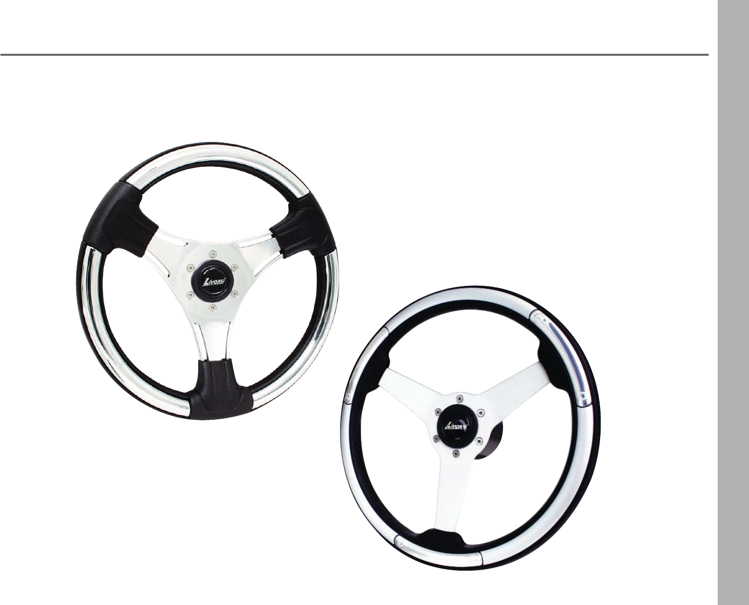
85
Steering Wheels
•13.5” diameter
•6 bolt pattern
•10-32 thread pitch
Kit Includes:
•2 1/4” black hub
•Center cap
•Mounting screws
Momo Linosa - MLSW
•Brushed spokes
•Chrome accents
Momo Budelli - MBSWP
•Leather like grips
•Polished spokes
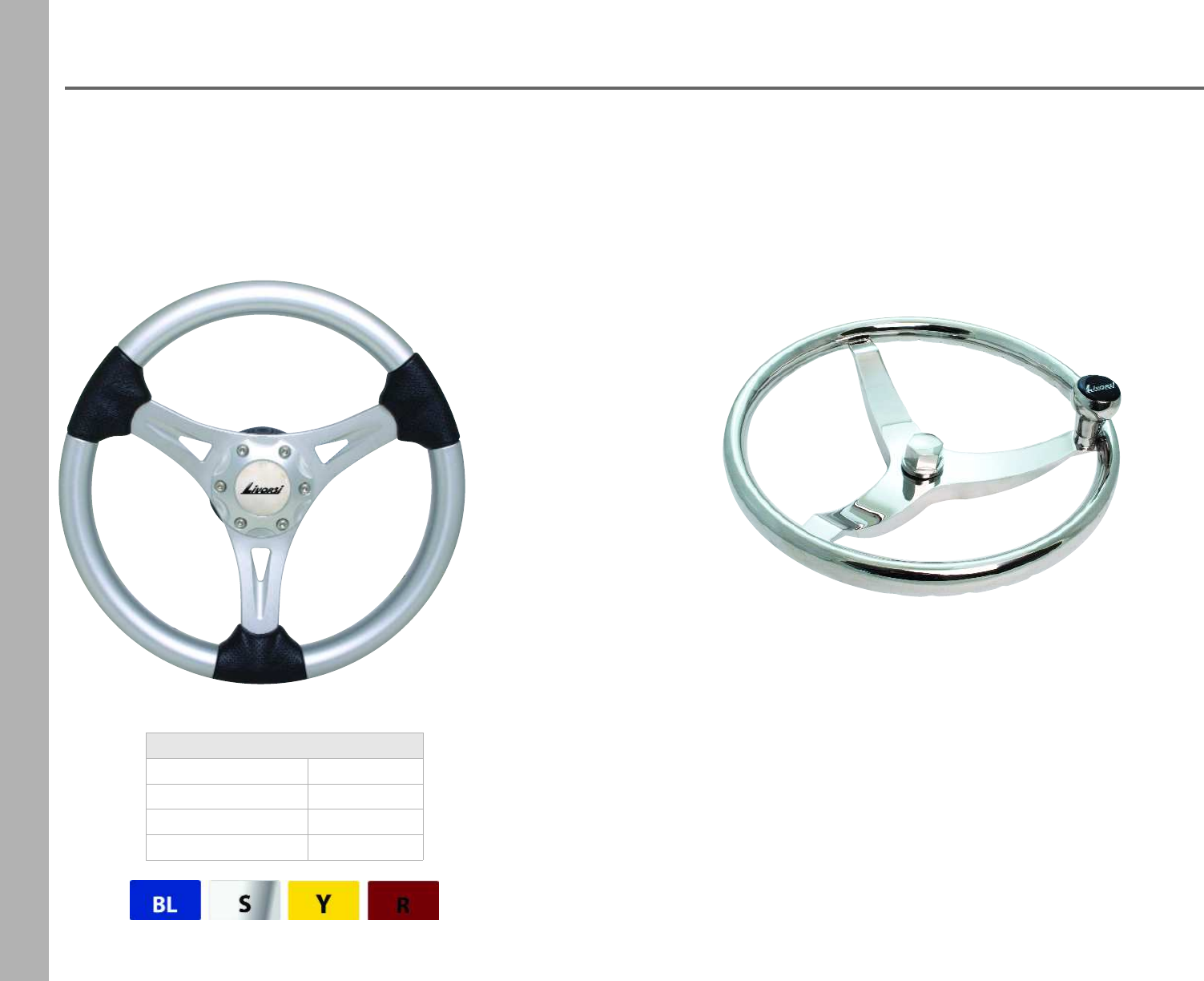
86
Gussi Steering Wheels
•polished aluminum spokes with tear drop design
•black urethane grips
•diameter: 13.5”
•available in blue, red, yellow and silver
•fits ¾" rounded shaft with keys
blue wheel GWASBL
silver wheel GWASS
yellow wheel GWASY
red wheel GWASR
Part Number: GWSSFK
•stainless steel polish finish
•stainless steel spokes with tear drop design
•Stainless steel speed knob
•diameter: 13.5 "
•fits ¾" rounded shaft with keys
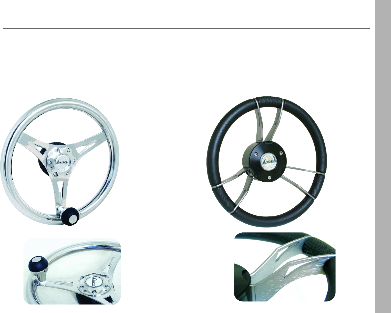
87
Gussi Steering Wheels
Part Number: GWSSK
•stainless steel polish finish
•stainless steel spokes with tear drop design
•Stainless steel speed knob with
leather like accent
•diameter: 13.5 "
•fits ¾" rounded shaft with keys
Part Number: GWBAS
•anodized aluminum spokes
•black anodized hub
•black urethane grips
•diameter: 13.5”
•fits ¾" rounded shaft with keys
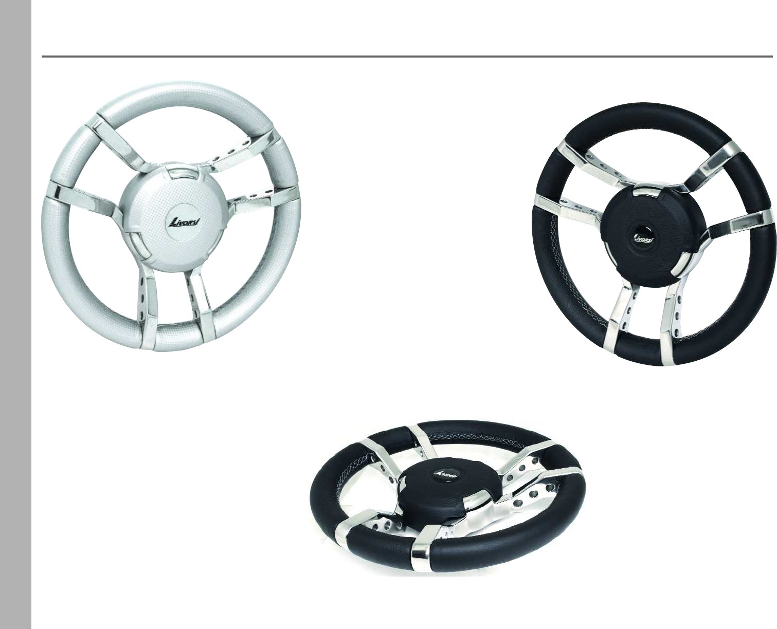
88
Gussi Steering Wheels
•solid cast stainless steel spokes
•wrapped with black marine leather or
marine carbon fiber urethane
•stainless steel center pad
•diameter: 13.5”
•fits ¾" rounded shaft with keys
GWSSSFL GWSSBKL
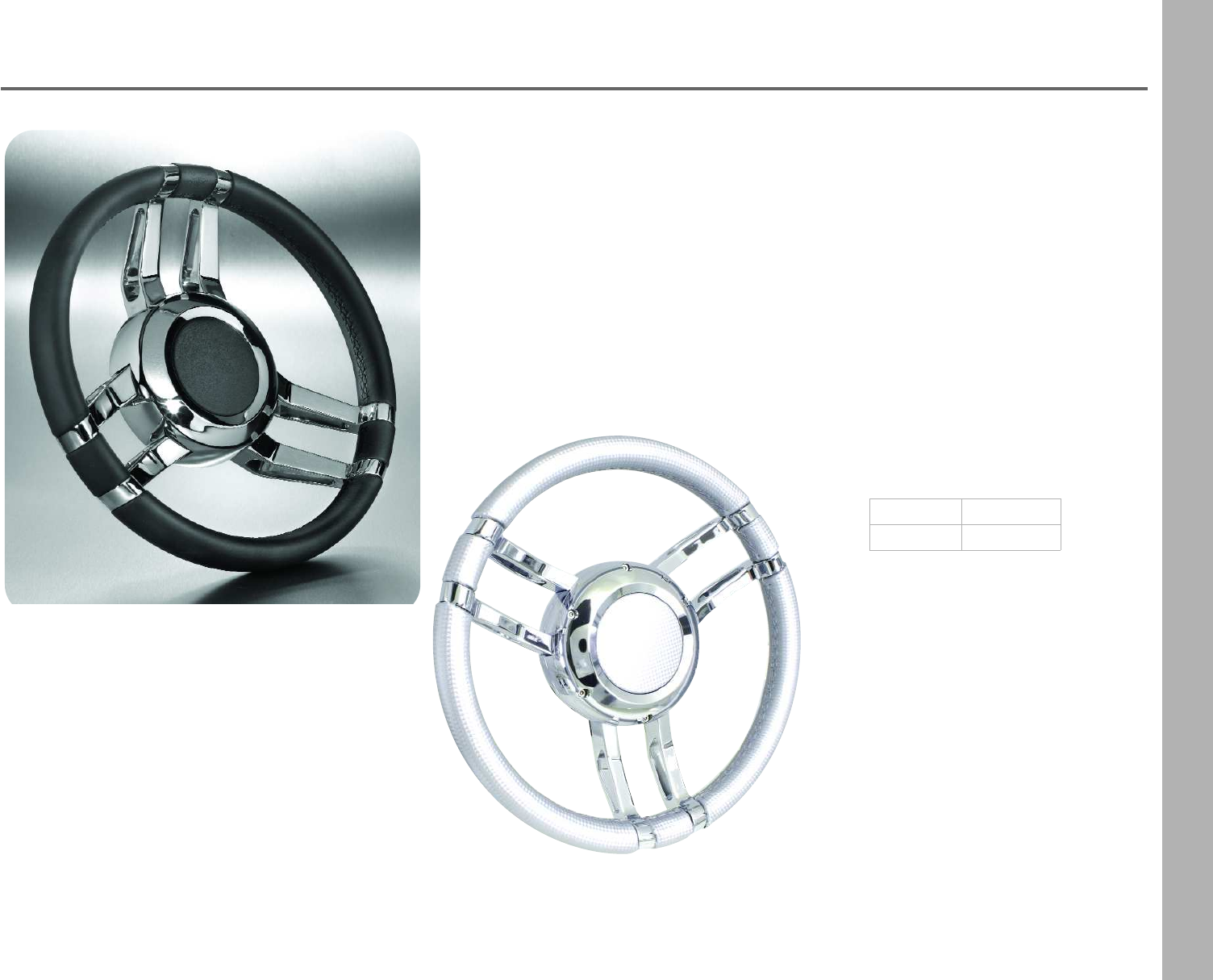
89
Isotta Steering Wheels
•6 bolt pattern
•10-32 thread pitch
•13.5” diameter
•Black wheel is wrapped in
genuine leather
Kit Includes:
•Hub
•Center cap
•Mounting screws
black ISWKCBK
silver ISWKCSF
Isotta Carlotta
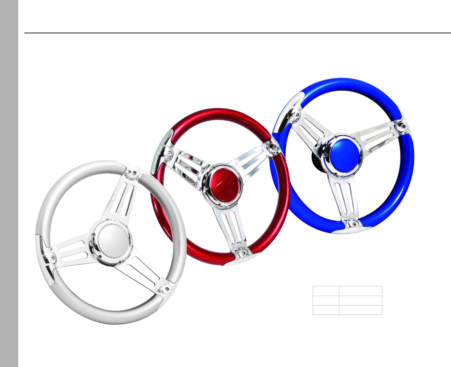
90
Isotta Steering Wheels
•6 bolt pattern
•10-32 thread pitch
•13.5” diameter
Kit Includes:
•Hub
•Center cap
•Mounting screws
blue ISWKABL
red ISWKAR
silver ISWKAS
Isotta Aria
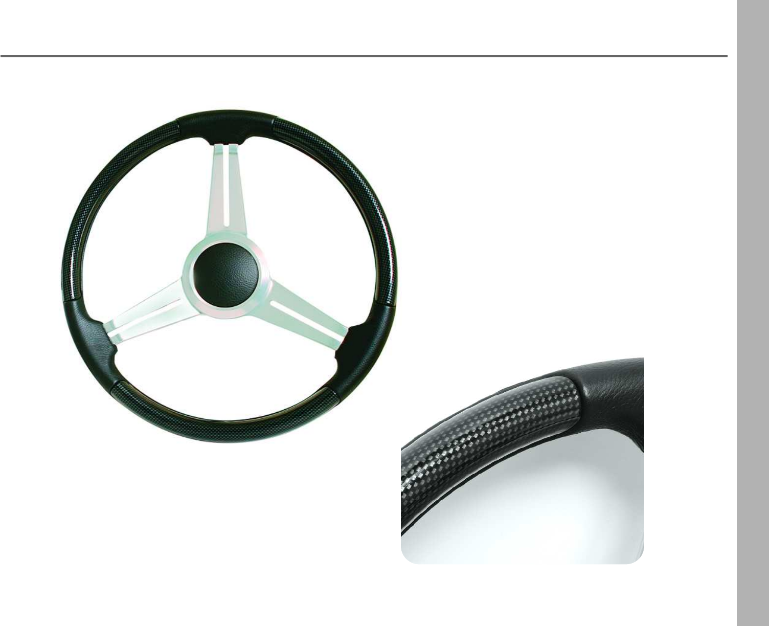
91
Isotta Steering Wheels
Part Number: ISWK13CFBK
•brushed spokes
•carbon fiber pattern
•leather-like grips and center cap
•diameter: 13.5”
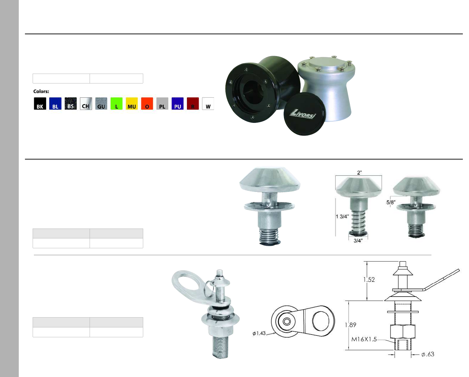
92
Hub Adapter
Cleats
Description Part Number
mushroom cleat MC
Mushroom Cleat
•Secure your fender lines to these mushroom cleats
•For fresh water or salt water conditions
•Easy installation, requires 3/4" cutout, 2" overall
•Stainless steel with a polished finish
Quick Release Fender Cleat
•Quick release pin for fenders
•Not intended for mooring
•Made of 316 stainless steel
•1.43" base
Description Part Number
fender cleat QPC
•For use with Isotta or Momo steering wheels
•3” deep
•powder coat finish
Part Number HA + color
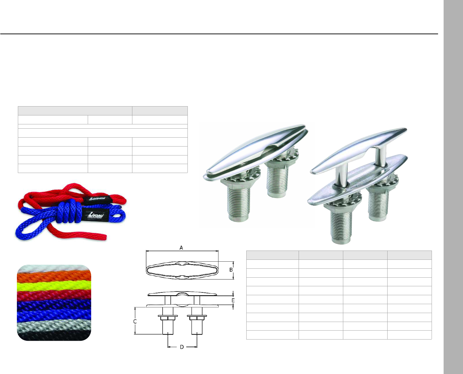
93
Pull Up Cleats
•Sleek design is easy to install and eliminates the need
for drainage cups and hoses
•Mounded base design allows water to run off the cleat
•Made of marine grade 316 stainless steel for strength
•Polished finish for a long lasting shine
Part Number PUC4 PUC6 PUC8
Weight .8 lbs 1.2 lbs 2.56 lbs
A - Length 4.5” 6” 8”
B - Width 1.15” 1.5” 2”
C - Depth 2” 2.3” 3.1”
D - Clearance .75” 1” 1.25”
E - Leg Distance 1.8” 2.4” 3.2”
Hole Size3/4” 7/8” 1”
Max Line Size1/2” diam. 3/4” diam. 1” diam.
Thread Size3/4 - 16 7/8 - 14 1 1/2 - 14
•Oversized loops
•Made of water resistant polypropylene
•Will not mildew
•Extremely flexible and resists knotting
Description Part Number
Fender Lines 1/2” thick 7 feet long FL127 + color
Dock Lines
1/2” thick 15 feet long DL1215 + color
1/2” thick 20 feet long DL1220 + color
5/8” thick 25 feet long DL5825 + color
5/8” thick 30 feet long DL5830 + color
Fender Lines and Dock Lines
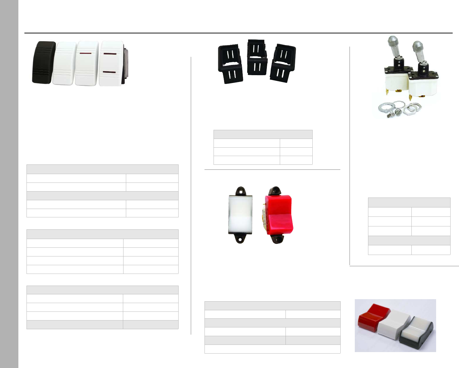
94
Switches
MCR
MCW
MCTR
Single Pole- Lighted
on/offRSSNFL + color
on/off/on RSSNFNL + color
Single Pole- Non Lighted
mom on/offRSSMF + color
mom on/off/mom on RSSMFM + color
Double Pole
on/on- non lighted white RSDNNW + color
on/off- lighted RSDNFL + color
on/off/on- lighted RSDNFNL + color
mom on/off/mom on -non lighted RSDMFM + color
Switch Covers Only
no light SCNL + color
1 light SC1L + color
2 lights SC2L + color
Cover Removal Tool SCRTL
Black & White Rocker Switches
•dust & moisture protected
•snap bracket mounting hole
•20 amps at 12 VDC
•1/4” push-on connectors
•83” x 1.450” cutout
•available in black (BK) or white (W)
Military Rocker Switches
•military type specs
•environmentally sealed
•5 amps at 28 VDC
•.94” X 1.51” cutout
Mounting Modules
for Black & White Rocker Switches
•snap together
•available in black only
Mounting Modules
end EMM
center CMM
plug MMP
single pole
mom on/off/mom on MRSSMFM + color
double pole
mom on/off/mom on MRSDMFM + color
military cover only MC + color
covers available: red, white or translucent
Military Toggle Switches
•military type specs
•environmentally sealed
•15 amps at 28 VDC
•1/2” cutout
•screw terminals
•lift / lock lever
Single Pole
on/offMTSSNF
on/off/on MTSSNFN
mom on/offMTSSMF
Double Pole
on/offMTSDNF
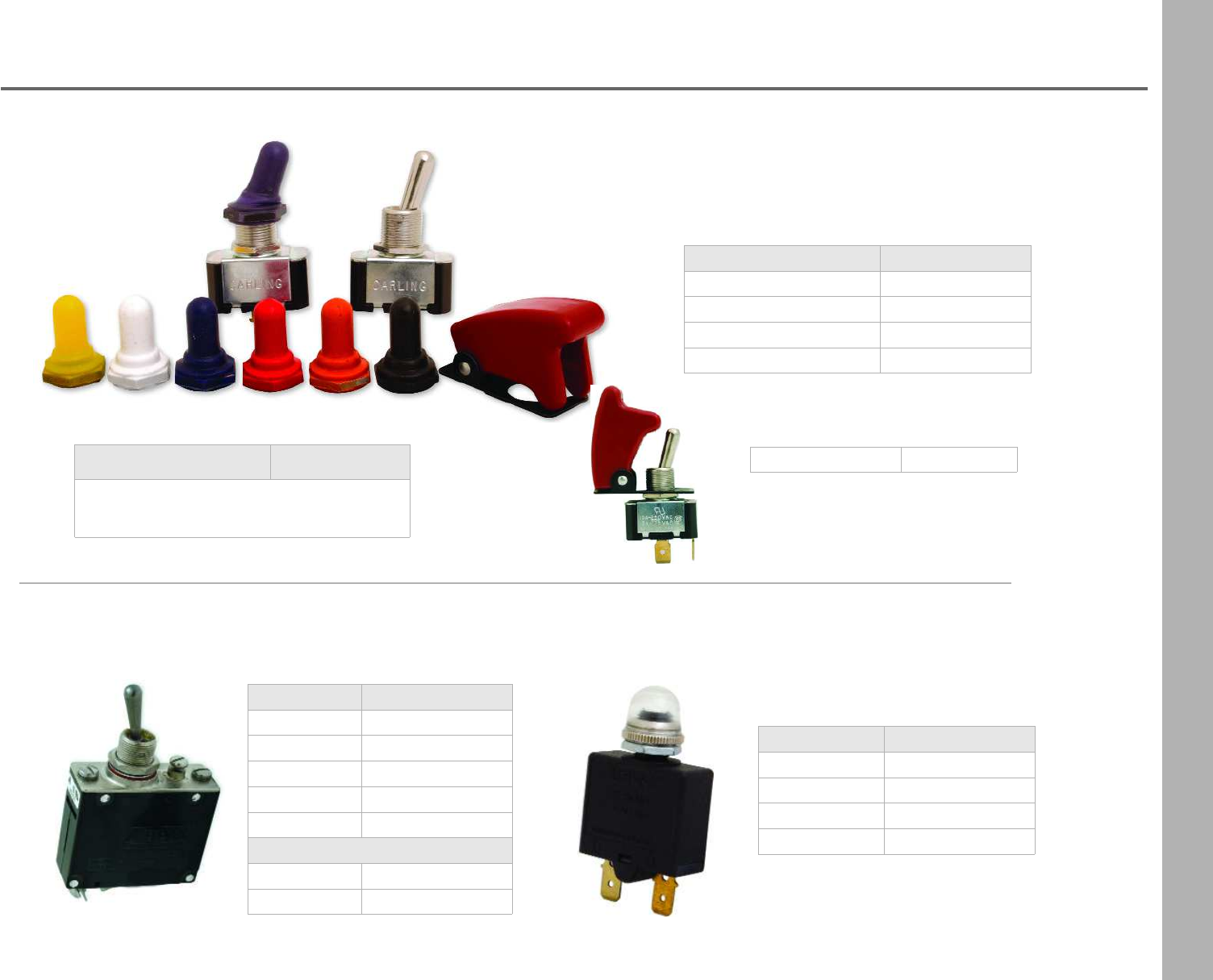
95
Switches
Toggle Switches
•nickel plated brass
•1/2” cutout
•25 amps at 12 VDC
•optional colored rubber boots
Description Part Number
on/off TSNF
on/off/on TSNFN
mom on/offTSMF
mom on/off/mom on TSMFM
rubber boot TSRB + color
boots available in: yellow, white, blue,
purple, red, orange or black
Toggle Switch Cover
red only TSC
Description Part Number
5 amp TBS5
10 amp TBS10
15 amp TBS15
20 amp TBS20
30 amp TBS30
Boots
boot- white TBSBBK
boot- black TBSBW
Circuit Breaker Toggle Switches
•requires 1/2” cutout
Description Part Number
10 amp PBCB10
15 amp PBCB15
20 amp PBCB20
boot only PBBCL
Push Button Circuit Breaker
•3/8” cutout
•clear boot sold separately
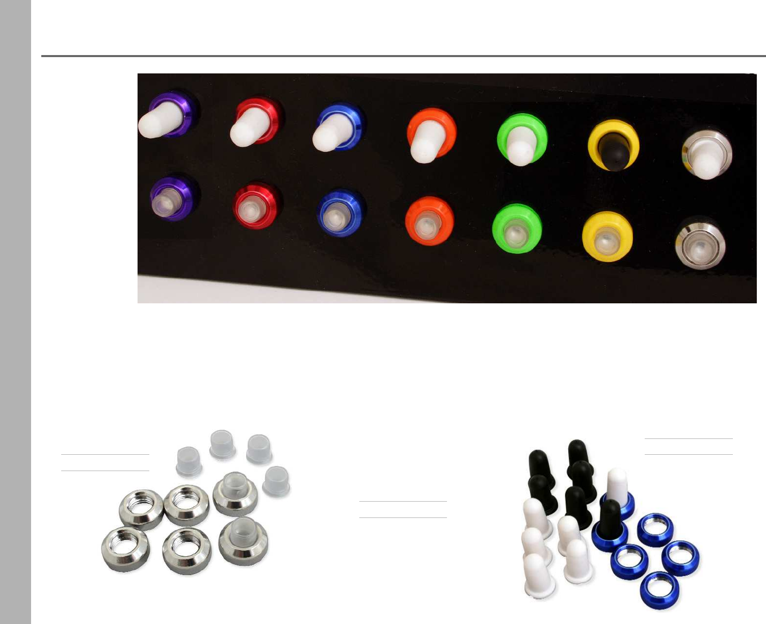
96
Xtreme Nut & Boot System
XCBNB + color
for Push Button
Circuit Breakers
- 3/8” threaded neck
- sold by the pack
pack includes:
- 6 clear boots, 6 nuts,
seals & wrench
for Toggle Switches
- 1/2-32” threaded neck
- sold by the pack
pack includes:
- 6 black boots, 6 white
boots, 6 nuts, seals &
wrench
for Circuit Breaker
Toggle Switches
XCBTSNB + color
XTNB + color
- 15/32” threaded neck
- sold by the pack
pack includes:
- 6 black boots, 6 white
boots, 6 nuts, seals &
wrench
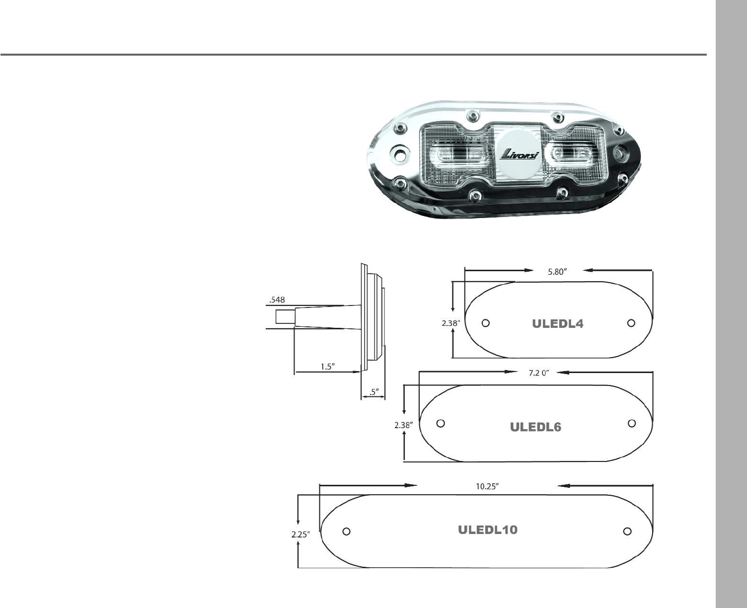
97
Underwater LED Lighting
These rugged lights beautifully light up the water around you
creating a stunning aura; they have even been known to attract
sea life. For use on boats and docks.
LED's are designed to have a long life span and these provide
over 40,000 hours of light. Built with internal self protection
circuitry, these lights will not burn you or your gel coat. This
product uses water to cool, but are engineered to and tested to
run continuously and safely out of the water. Lights will automati-
cally turn off when it reaches its max temperature and then
automatically turn back on after it cools.
LED Features:
•High intensity LED lighting
•Surface mount - no major hull penetration
•Fully Submersible - water cooling required
•316 stainless steel with polycarbonate lenses
•Long life- LED lamp life over 40000 hours
•Operating voltage 9 to 30 volts DC -
brightness does not change
•Standard wire length - 20 feet
•Internal digital switching power supply
•Self contained, no external driver to install
•Rugged design
•Low power consumption
•Internal surge suppression
•Internal temperature protection
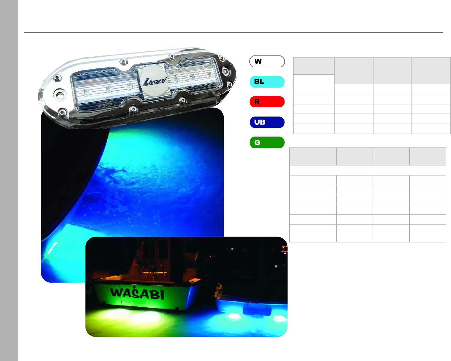
98
Underwater LED Lighting
Number of
LED Lights 4 6 10
Specifications
Watts 17 25 42
Amps @12v:1.4 @12v:2.1 @ 12v:3.5
Height 2.375" 2.375” 2.25”
Width 5.8" 7.2" 10.25"
Deep 2” 2” 2”
Lumen Output
White only 1000 1500 2500
Number of
LED Lights 4 6 10
LED Color
white ULEDL4W ULEDL6W ULEDL10W
blue ULEDL4BL ULEDL6BL ULEDL10BL
red ULEDL4R ULEDL6R ULEDL10R
ultra blue ULEDL4UB ULEDL6UB ULEDL10UB
green ULEDL4G ULEDL6G ULEDL10G
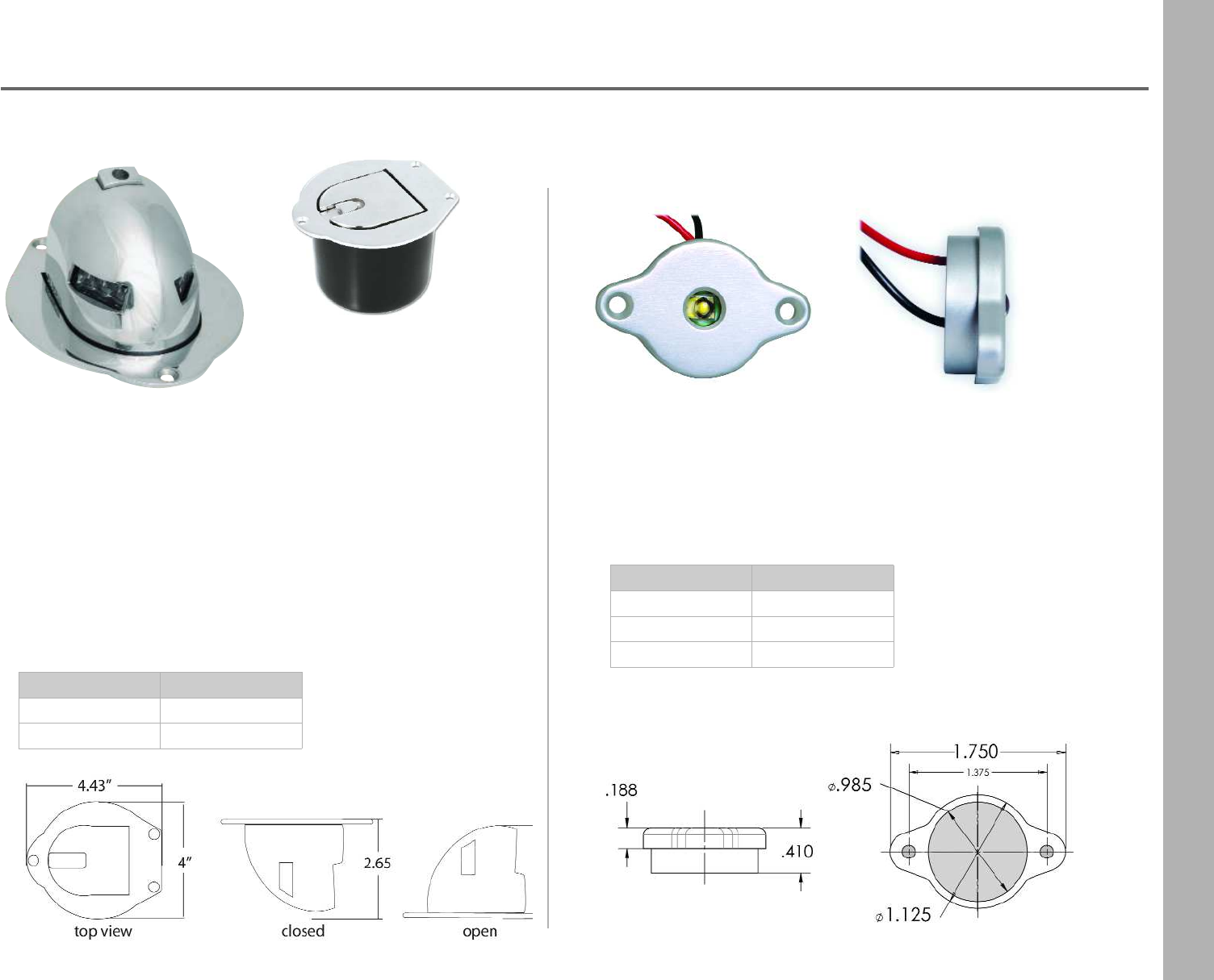
99
LED Navigation Lights
Flange Mount LED Lighting
•Not certified for use as nagivation lights
•Housing is machined from billet aluminum
•Environmentally sealed
•Bright LED can illuminate engine compartments
shown closed
with optional cup
Pop Up LED Bow Light
•Port and starboard light in one housing
•Marine grade 316 stainless steel
•Folds down flush when closed
•USCG approved for 2 nautical miles
•LED lights stay cool to the touch
•Optional cup for water run-off
•Light with cup measures 3 1/4” deep
•Light has 3 1/2” diameter cutout
Description Part Number
bow light LEDPUBL
water run off cup LEDPUBLWC
Description Part Number
red LEDR
green LEDG
white LEDW
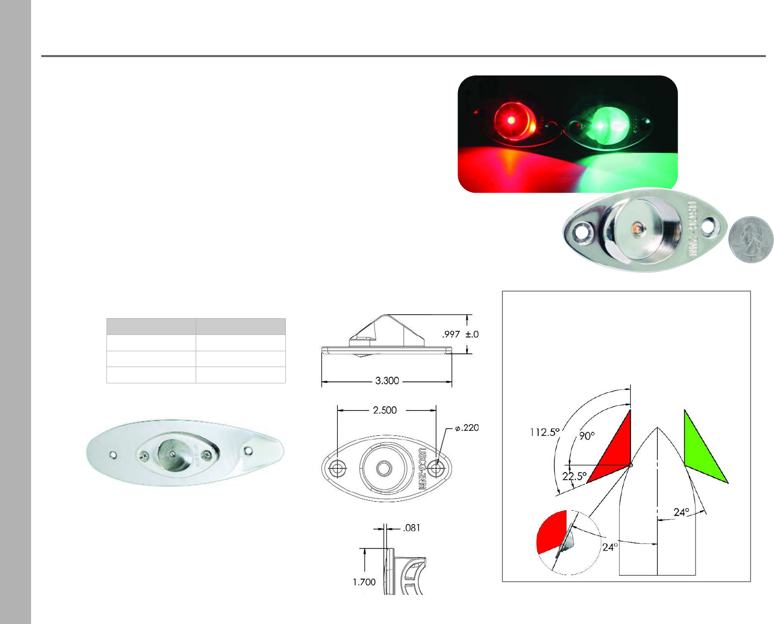
100
LED Navigation Lights
•Visible for 2 nautical miles
•For use on boats up to 65 feet
•Marine grade 316 stainless steel
•Available for 12 or 24 volt systems
•Completely waterproof, environmentally sealed
•NMMA accepted
•USCG approved for 2 nautical miles
•Meets ABYC standards
These Livorsi LED nav lights only consume 1/10th of an amp at 14
volts. This means a longer life and less rigging time replacing lights.
These lights are to be used on any vessel up to 65 feet and have a
visibility of 2 nautical miles.
Designed to be mounted on a vertical surface, to allow the light
pattern to be unobstructed from view.
Mounting angle for navigation lights is 24°
relative to centerline of boat.
ABYC Section A-16: The starboard sidelight
showing green, and the port sidelight showing red,
from dead ahead to 22.5° abaft the beam (90° +
22.5° + 112.5°) on their respective sides.
Description Part Number
port - red LEDNL2R
starboard - green LEDNL2G
adapter plate LEDNLAP
LEDNLAP
8” L x 2 1/4” W x 1/16” thick
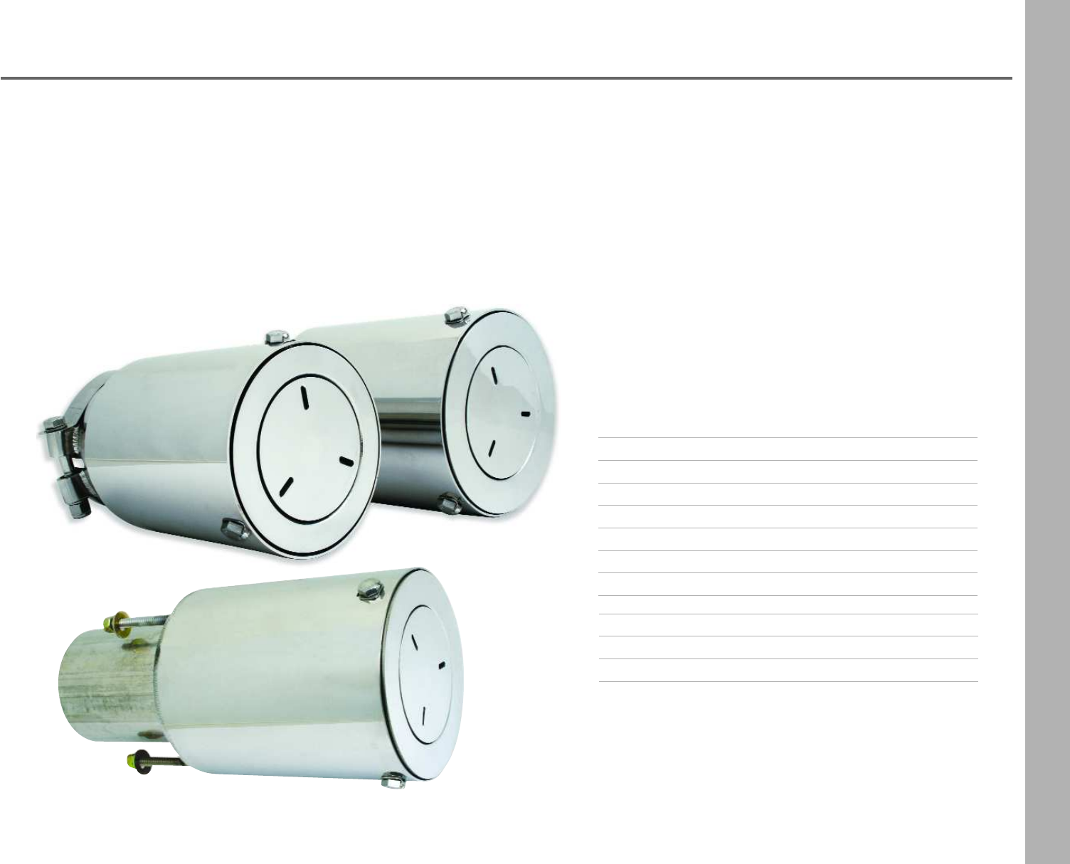
101
CMI’s Sound Elimination Mufflers
High Performance
CMI Sound Elimination Systems mufflers offer proven sound reduction
technology that enables boaters to operate their performance boats in
areas where sound emissions are restricted. This system should reduce
sound emissions to levels as low as 85 decibels (dB) in many applica-
tions, which is below most sound emission regulations. The mufflers are
engineered to reduce sound without restricting the exhaust or creating
unwanted backpressure, which can inhibit the engine from reaching
peak performance power.
•Mufflers can be installed on any exhaust system
with tailpipes ranging from four to six-inches in
diameter, which covers the full range of inboard
or stern drive-powered recreational and
performance boat applications up to 1200 horse
power.
•CMI Sound Elimination Systems mufflers are
made from 304 series stainless steel, and have
fewer moving parts than competitive models to
ensure long-lasting durability and reliability for
nearly any application.
Clamp-On
Transom Mount
Clamp On High Performance
FigureDescription Part Number
A4” x 5” under 600 HP SEMSCHP4
B 4.5” x 5” under 600 HP SEMSCHP4.5
C4” X 6” over 600 HP SEMSCHP4X6
D 4.5” X 6” over 600 HP SEMSCHP4.5X6
E5” X 6” all HP SEMSCHP5X6
Transom Mount High Performance
FigureDescription Part Number
F4” under 600 HP SEMSTHP4
See diagrams on the back of this page
to find the right muffler for your application.
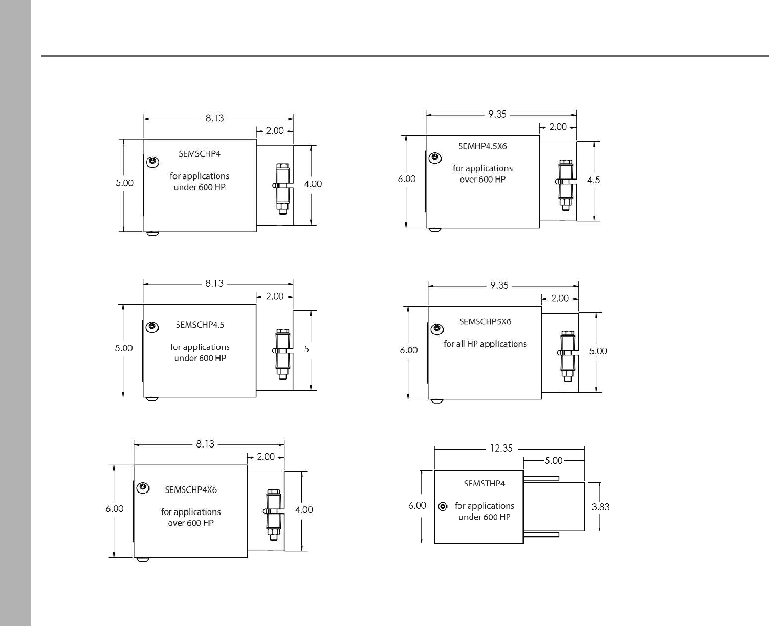
102
CMI’s Sound Elimination Mufflers
High Performance
A
B
C
D
E
F
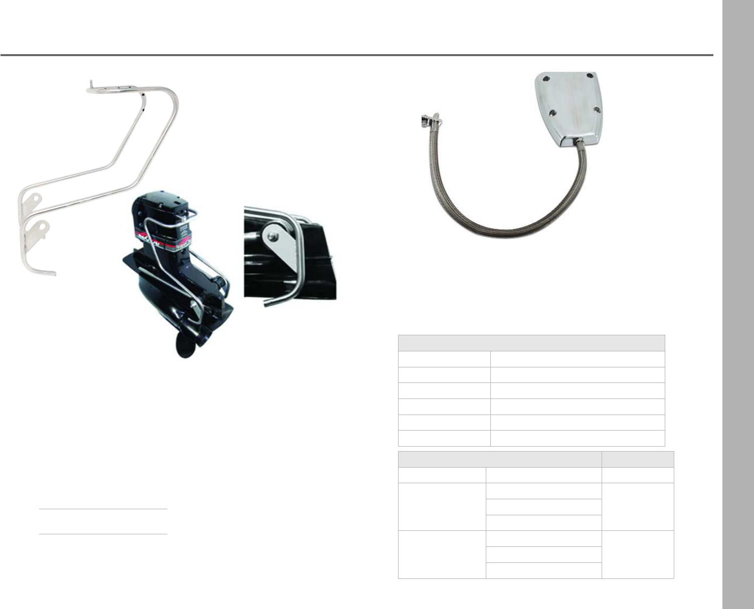
103
Drive Showers
Ultimate Bravo Drive Shower
•Mounts to the drive's tilt ram
•15 dump ports target sides & back of the drive
•Multiport system distributes continuous cool water
•Flow to top of the stern drive
•Lowers oil & bearing temperatures by 60°
•Fits all Bravo drives including: Imco & Latham steering
that mounts on back of the drive
Bravo Drive Cooling Shower
•Modern sleek fitted shower
•Coupled with a high volume pickup
•#10 stainless steel braided hose
Description Part Number
Cap / HardwareFits Drive Serial Number
ribbed- bolts
OW250000 & up
BDSX
OW240000 & up
OM906878 & up
ribbed- studs
OW240000 & up
BDSXR
OM05295-OM906877
OM906878 & up
Fits the following Drives
X1, X2, X3
XR/XZ
XZ1 XZ1 w/ Intergrated top
XR XR w/ Intergrated top
XR3 XR3 w/ Intergrated top
XR Sportmaster XR Sportmaster w/ intergrated top
Part Number BDSU
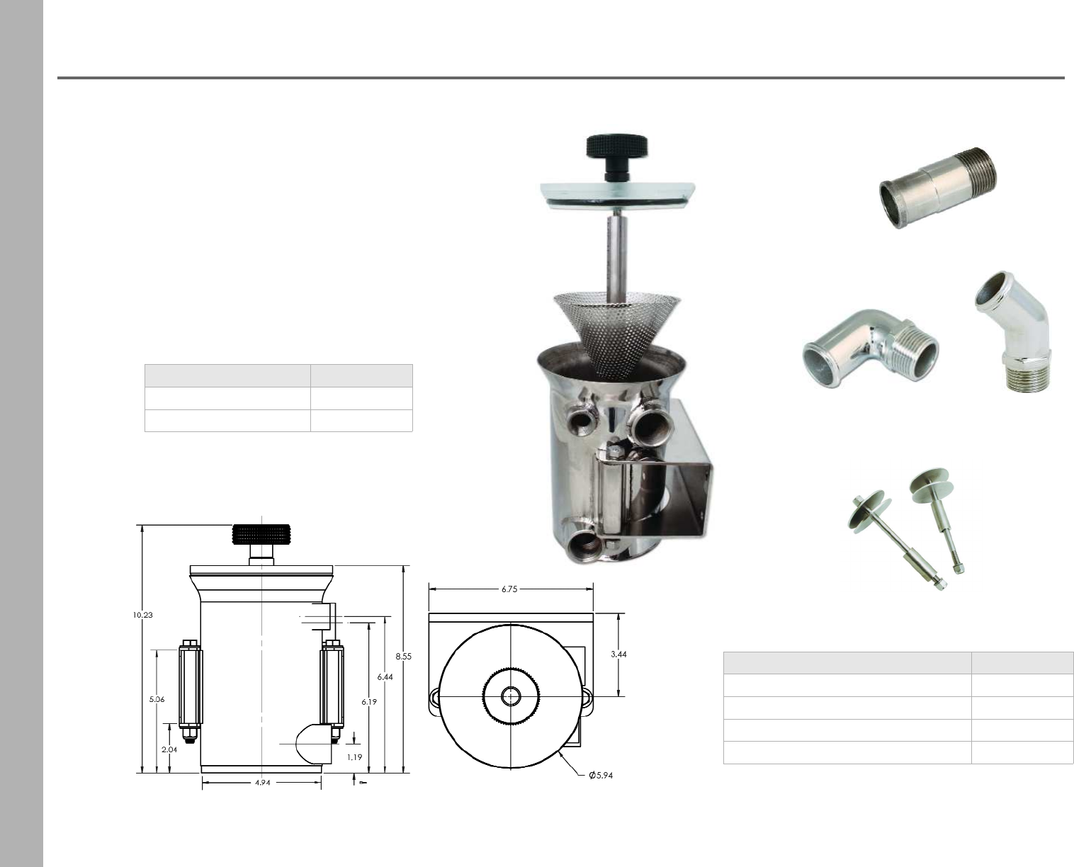
104
Sea Strainers
SS Sea Strainer
•Stainless steel construction
•Two bungs measure 1"
•One bung measures 1/2"
•Pressure tested at 150 PSI
•1" NPT fittings
•60 GPM flow at 22 PSI
•High impact 1" acrylic lid
•Removable stainless steel basket with easy lift handle
•Optional floor mount brackets & fittings available
Description Part Number
same side bungs SS5SS
straight through bungs SS5ST
Description Part Number
straight fitting GSSFS
90° slip on fitting GSSF90
45° fitting GSSF45
floor mount brackets SSFMB
GSSFS
GSSF90
SSFMB
GSSF45
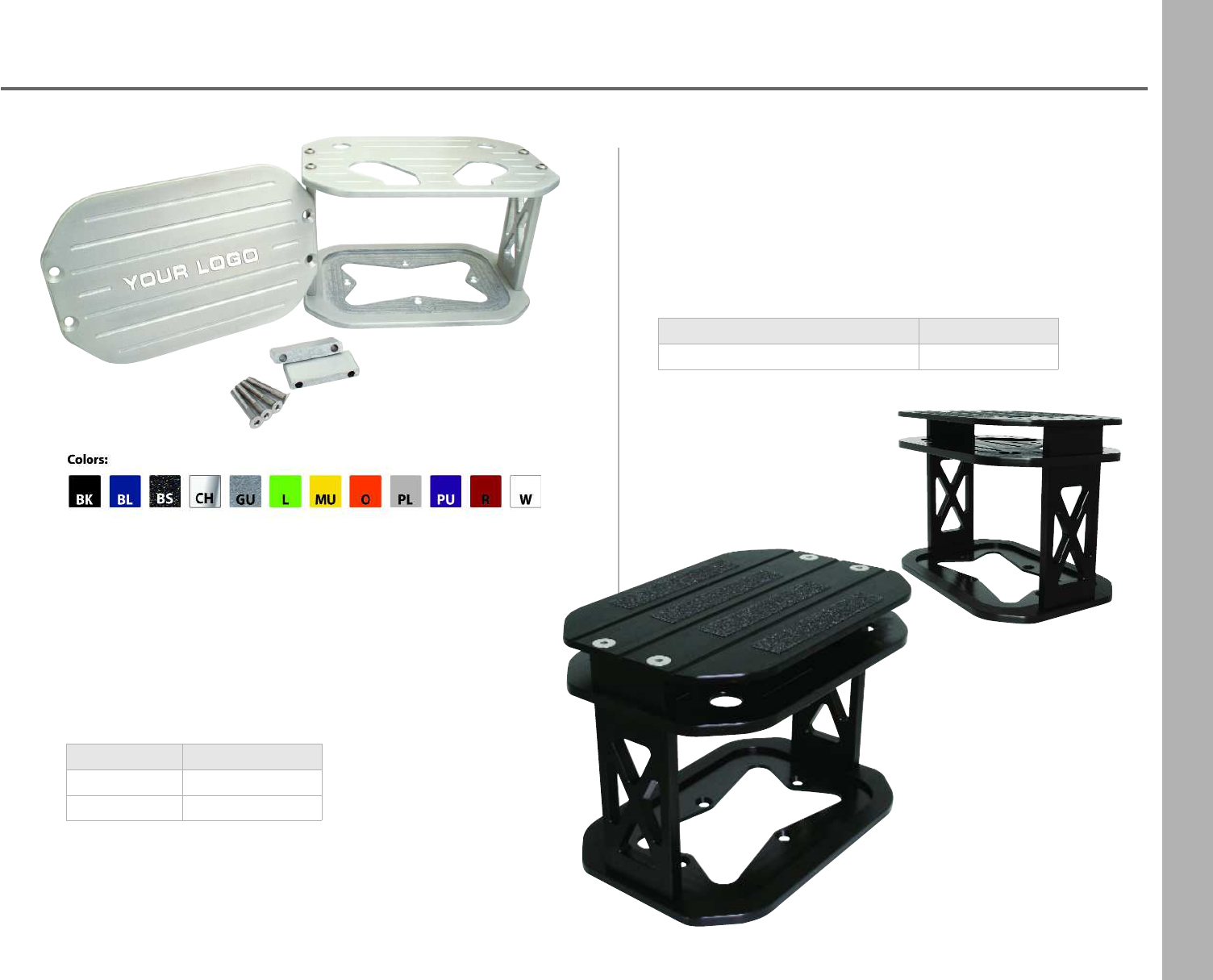
105
Optima Battery Boxes
Anodized Battery Box
•Machined from billet aluminum
•Black anodized finish is non-corrosive
•Box cover has a slip resistant surface
•Can be stringer mounted
•Measures: 11 15/16 in. L x 8 in. W x 6 5/8 in. H
Powder Coat Finish
•Machined from billet aluminum
•Corrosive resistand polish or powder coated finish
•Optional cover available
•Can be stringer mounted
•11-15/16” L x 8” W x 6 5/8” H
•Private Label available on cover
Description Part Number
boxBBBO + color
cover BBBCO + color
Description Part Number
box and cover - black only BBBO34A
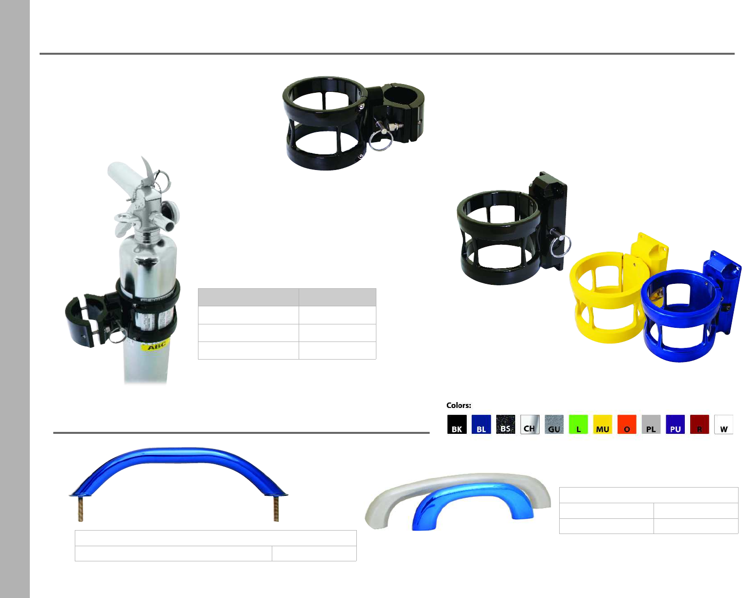
106
Fire Extinguisher and Mounting Hardware
Steel
11 3/4” overall (10 1/2” center to center) GHSSS11 + color
Aluminum
6 15/16” overallGHAS7 + color
11 7/16” overallGHAS12 + color
Grab Handles
Bar Mount
•Machined of billet aluminum
•Fits 1 1/2”, 1 3/4” and 2” tubing
•Black powder coat finish only
•Quick release pin
Flat Mount
•Machined of billet aluminum
•Available in powder coat colors or a clear coat
•Quick release pin
Fire Extinguisher
•Encased in marine approved chrome
•Dry ABC extinguisher
•2 1/2 lbs, refillable
•Extinguisher and mounts are sold separately
Description Part Number
fire extinguisher FE
bar mount FEBMKBK
flat mount FEMBK
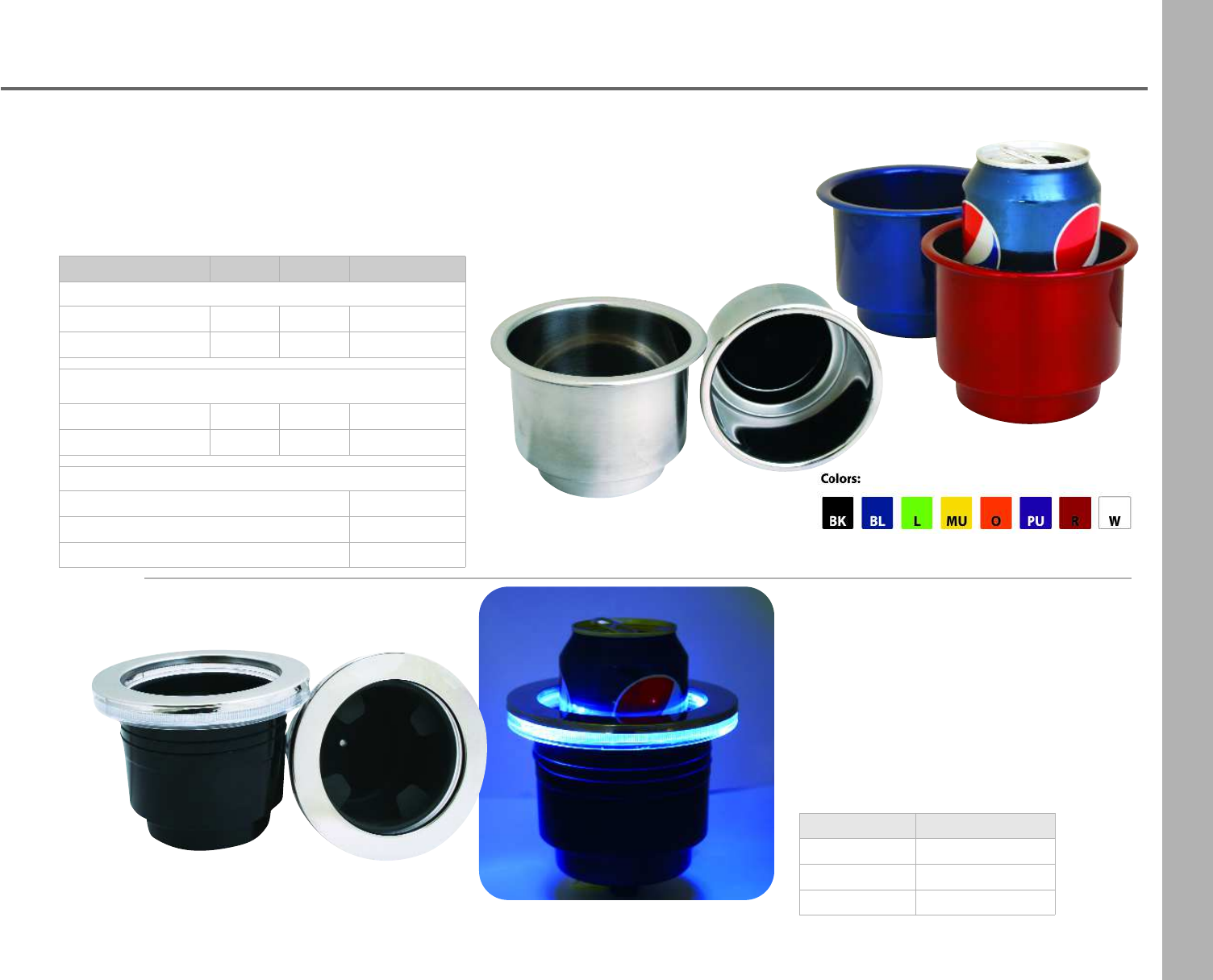
107
Beverage Holders
LED Lighted Beverage Holders
•3 7/8” cutout, 4 3/4” overal
•Fits cans, bottles and kuzis
•12 volt, included 12 inch harness
•Black cup, stainless steel rim
•3/8” drain fitting
•Removable rubber
Stainless Steel Beverage Holders
•Fits cans, bottles and kuzis
•304 stainless steel
•Optional fittings available
•Polish stainless steel or powder coat finish
Description Part Number
blue LBHBL
green LBHG
red LBHR
Description Cutout Overall Part Number
Stainless Steel Finish
small stainless 3 5/8” 4 1/8” SBHS
large stainless 3 3/4” 4 1/2” SBHL
Powder Coat Finish
small 3 5/8” 4 1/8” SBHS + color
large 3 3/4” 4 1/2” SBHL+ color
Drain Fittings for
3/8” straight push on SBHFS3/8
3 /8” 90° push on SBHF903/8
drain cap SBHC

Terms and Conditions
Livorsi Marine, Inc.
TERMS & CONDITIONS 2016
WARRANTY
All Livorsi Marine® products carry a limited one year warranty for repair or replacement at Livorsi's discretion. All Livorsi Marine® products are warranted to be free of defects in
material and workmanship. Users/Customers of Livorsi Marine®/Livorsi® products agree not to hold Livorsi Marine, Inc., its owner or employees responsible for any damages
occurring by improper installation or use of Livorsi Marine® or Livorsi® products. The company, owner or its employees will not be liable for more than the cost of the original
product and in no event will Livorsi Marine® or Livorsi® be liable for special, indirect or consequential damages of any kind whatsoever.
RETURNS
All returns purchased directly through Livorsi Marine must have an assigned RMA Number (Returns Merchandise Authorization). Please call customer service at 847-752-2700 or
email returns@livorsi.com to receive an RMA Number. Please allow at least 24 business hours for a return call or email. Any packages without a RMA number will be refused.
For warranty questions please call customer service at 847-752-2700 or email returns@livorsi.com. Livorsi Marine will not accept returns or warranty items unless purchased
directly from Livorsi Marine. For items purchased through a distributor or dealer, call the distributor or dealer for return or warranty questions and issues. For further questions or
technical help visit www.livorsi.com and click on Tech Tools or call customer service at 847-752-2700
Aminimum 15% restocking charge may apply to any returned items. Merchandise must be returned with shipping charges prepaid. Returns sent freight collect will be refused.
Please enclose a copy of the original purchase invoice with return. Livorsi Marine, Inc. will not accept returns past 60 days. Credit will not be issued on custom or private label
gauges. If a product returned to Livorsi Marine is tested and found to have no defects, the customer will be responsible for 20% restocking fee and replacement shipping costs if
applicable
.
PRODUCTS
Due to changes in technology, customer demand and company direction, products may change without notice. Check our website for updated products and availability.
Regardless of our line of products, our goals remain the same: QUALITY, OPTIONS AND AVAILABILITY!!
PAYMENT TERMS
Individuals may pay by Visa, MasterCard, American Express, Discover or cashier's check. Companies may pay by Visa, MasterCard, American Express, check, C.O.D., wire
transfer or on Net terms with prior credit approval.
PRICES
All prices are subject to change without verbal or written notice. Our price lists are intended as a guideline only. No responsibility is assumed for errors or omissions on product
or pricing information. Possession of discount price list does not guarantee those prices to customer.
ORDER PLACEMENT
You may phone 847-752-2700, fax 847-752-2415, email sales@livorsi.com or mail your orders to Livorsi Marine®, 715 Center Street, Grayslake, IL 60030. You may also e-mail
your order to sales@livorsi.com. Please be sure to include your name, address, phone number and specific ordering requests.
FREIGHT
All orders will be shipped UPS or FedEx, unless specified by customer. All orders are shipped F.O.B. Grayslake, Illinois. Any claims for shortage of product must be reported to
Livorsi Marine® within 24 hours of receipt of order. If the shipment arrives damaged, contact the shipper directly, not Livorsi Marine®. Do not return damaged product to Livorsi
Marine®.
Handling charges are based on the speed and type of shipment requested. i.e. $5 -ground, $6- 3day, $8- 2day, $10-next day, $15 International. Drop ship fees may be charged if
shipping to an address different from the billing address. An additional charge may be applied if customer requests special shipping company or instructions.
REFUSED SHIPMENTS
Shipments returned to Livorsi Marine® marked "refused" or "not in when driver called" will cause the customer's buying status to be frozen until related handling and shipping
charges are paid. Refusal of shipment does not release the customer from paying the related handling and shipping charges. Repeated refusal or returned shipments may cause
the customer's buying status to be revoked.

Toll Free: 877.548.5900
Phone: 847.752.2700
Email: sales@livorsi.com
www.livorsi.com
