Manual
User Manual:
Open the PDF directly: View PDF ![]() .
.
Page Count: 27
Unified measurement
software
UMS
Reference manual
Version: 2.19
DOI: 10.3929/ethz-b-000247100
by
Reto Pfenninger, Eva Sediva, Sören
Boyn, Jennifer L.M. Rupp
D-MATL, ETH Zürich
Table of Content
List of devices supported by UMS: ................................................................................................................ 3
Function reference: .......................................................................................................................................... 4
Preforming of memristors .............................................................................................................................. 4
Cyclic voltammetry ........................................................................................................................................ 7
Pulsed experiments ..................................................................................................................................... 12
Simple loggers ............................................................................................................................................. 17
Oven control programs ................................................................................................................................ 20
Impedance measurement ............................................................................................................................ 23
Mass flow controller ..................................................................................................................................... 24
Galvanostatic cycling ................................................................................................................................... 25
High precision galvanostatic cycling ........................................................................................................... 26
List of devices supported by UMS:
The unified measurement software currently supports the devices listed below. Please keep in mind that the
functionality was adapted to our needs so there might be functionalities which are not yet implemented in a
specific device.
Keithley measurement devices:
Keithley 740
Keithley 2000
Keithley 2001
Keithley 2182A
Keithley 2601B
Keithley 2602B
Keithley 2612B
Keithley 2700
Keithley 2701
Keithley 6517B
Keithley 7001
Keithley 6220
Keithley 4200 SCS
Tektronix devices:
Tektronix AFG2021
Tektronix AFG3021C
Power supplies:
TTI QL564TP
Impedance bridges:
Gamry Reference 600
Zahner IM6
Solartron 1260
Oven controllers:
Eurotherm 2404
Eurotherm 2416
Eurotherm 3216
Eurotherm 3500
Eurotherm nanodac
GPIB Adapters:
Prologix GPIB-USB Adapter
Prologix GPIB-Ethernet Adapter

Function reference:
General remarks:
If not stated otherwise, all function arguments are in SI units.
Arguments, which already have a default value, do not need to be specified if you want to keep them
at the default value.
Before passing the device to a function, make sure you initailized it.
Code examples are set in this particular font
Preforming of memristors
preforming_ramp(device,start_voltage,ramp_speed_1,top_voltage,hold_time,ramp_spe
ed_2,end_voltage,compliance_current=0,new_row=False, GUI=True)
Return value are the following arrays: [data_V_I,data_V_t,data_I_t]
This function is used to preform memristors before they are cycled.
Argument
Unit
Remark
device
Pass the device you want to use for this function. To date only
keithley_2601B, keithley_2602B and keithley_2612B and
keithley_6517B can be used. Keep in mind that keithley_6517B
has no compliance current capability.
start_voltage
V
Where you want to start
ramp_speed_1
V/s
top_voltage
V
hold_time
s
You can also set this to 0. Then it does not wait
ramp_speed_2
V/s
Needs to be negative
end_voltage
V
You can also set this voltage equal to bottom_voltage. Then you
only cycle in the positive branch
compliance_current
A
CC (Default=0 means no CC is applied)
new_row
Default:
False
Either True or False If set to True, the plotting window will make
a new row and the display looks nicer.
GUI
Default:
True
Either True or False If set to False, the plotting window will not
appear at all. Can be used for „silent“ measurements without
real-time graphical output.

preforming_ramp_with_current_limit(device,start_voltage,ramp_speed_1,top_voltage
,hold_time,ramp_speed_2,end_voltage,stop_current,new_row=False, GUI=True)
Return value are the following arrays: [data_V_I,data_V_t,data_I_t]
This function does basically the same as the above one, but was especially designed for the High resistance
meter Keithley 6517B which does not support compliance currents. Therefore we replaced it by a certain
„stop_current“.
Argument
Unit
Remark
device
Pass the device you want to use for this function. To date only
keithley_2601B, keithley_2602B and keithley_2612B and
keithley_6517B can be used. Keep in mind that keithley_6517B
has no compliance current capability.
start_voltage
V
Where you want to start
ramp_speed_1
V/s
top_voltage
V
hold_time
s
You can also set this to 0. Then it does not wait
ramp_speed_2
V/s
Needs to be negative
end_voltage
V
You can also set this voltage equal to bottom_voltage. Then you
only cycle in the positive branch
stop_current
A
If this specific current value is reached, the function immediately
stops and no further voltage is applied.
new_row
Default:
False
Either True or False If set to True, the plotting window will make
a new row and the display looks nicer.
GUI
Default:
True
Either True or False If set to False, the plotting window will not
appear at all. Can be used for „silent“ measurements without
real-time graphical output.

preforming_ramp_with_current_hold_time(device,start_voltage,ramp_speed_1,top_vol
tage,hold_time,ramp_speed_2,end_voltage,compliance_current=0,trigger_current=0,t
rigger_hold_time=0,new_row=False,GUI=True)
Return value are the following arrays: [data_V_I,data_V_t,data_I_t]
This function does a usual preforming as the preformin_ramp function with the additional possibility to add a
certain trigger_current after which the function only runs for the amount of time specified in trigger_hold_time
and then stops immediately even if the hold_time is set for some longer time.
Argument
Unit
Remark
device
Pass the device you want to use for this function. To date only
keithley_2601B, keithley_2602B and keithley_2612B and
keithley_6517B can be used. Keep in mind that keithley_6517B
has no compliance current capability.
start_voltage
V
Where you want to start
ramp_speed_1
V/s
top_voltage
V
hold_time
s
You can also set this to 0. Then it does not wait. In this case it
does not make sense to set this value low since you usually
want the current to rise over time till trigger_current is reached.
ramp_speed_2
V/s
Needs to be negative
end_voltage
V
You can also set this voltage equal to bottom_voltage. Then you
only cycle in the positive branch
compliance_current
A
CC (Default=0 means no CC is applied)
trigger_current
A
(Default=0 means deactivated) After the here specified current
has been reached (can be at any time), a second counter starts
to run which will wait for trigger_hold_time seconds to stop the
whole function
trigger_hold_time
s
(Default=0 means sudden stop after trigger_current has been
reached). This variable states how many seconds the function
should run more after trigger_current has been reached.
new_row
Default:
False
Either True or False If set to True, the plotting window will make
a new row and the display looks nicer.
GUI
Default:
True
Either True or False If set to False, the plotting window will not
appear at all. Can be used for „silent“ measurements without
real-time graphical output.
Cyclic voltammetry
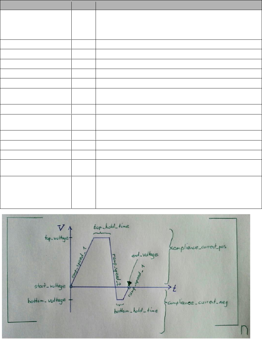
cycling(device,start_voltage,ramp_speed_1,top_voltage,top_hold_time,ramp_speed_2
,bottom_voltage,bottom_hold_time,end_voltage,n,compliance_current_pos=0,complian
ce_current_neg=0,new_row=False, GUI=True)
Return value are the following arrays: [data_V_I,data_V_t,data_I_t]
Argument
Unit
Remark
device
Pass the device you want to use for this function. To date only
keithley_2601B, keithley_2602B and keithley_2612B and
keithley_6517B can be used. Keep in mind that keithley_6517B
has no compliance current capability.
start_voltage
V
Where you want to start
ramp_speed_1
V/s
top_voltage
V
top_hold_time
s
You can also set this to 0. Then it does not wait
ramp_speed_2
V/s
Needs to be negative
bottom_voltage
V
You can also set this voltage equal to end_voltage. Then you
only cycle in the positive branch
bottom_hold_time
s
You can also set this to 0. Then it does not wait
end_voltage
V
You can also set this voltage equal to bottom_voltage. Then you
only cycle in the positive branch
n
Number of cycles you want to run
compliance_current_pos
A
CC in positive branch. Needs to be positive
compliance_current_neg
A
CC in negative branch. Needs to be positive
new_row
Either True or False If set to True, the plotting window will make
a new row and the display looks nicer.
GUI
Either True or False If set to False, the plotting window will not
appear at all. Can be used for „silent“ measurements without
real-time graphical output.

cycling_two_channels(device,start_voltage_1,start_voltage_2,ramp_speed_1_1,ramp_
speed_1_2,top_voltage_1,top_voltage_2,top_hold_time_1,top_hold_time_2,ramp_speed
_2_1,ramp_speed_2_2,bottom_voltage_1,bottom_voltage_2,bottom_hold_time_1,bottom_
hold_time_2,end_voltage_1,end_voltage_2,n_1,n_2,compliance_current_pos_1=0,compl
iance_current_pos_2=0,compliance_current_neg_1=0,compliance_current_neg_2=0,new_
row=False,GUI=True)
Return value are the following arrays:
[data_V_I_1,data_V_t_1,data_I_t_1,data_V_I_2,data_V_t_2,data_I_t_2]
Blue is for Channel A and Green for Channel B
Argument
Unit
Remark
device
Pass the device you want to use for this function. To date only
keithley_2602B and keithley_2612B can be used.
start_voltage_1
V
Where you want to start
ramp_speed_1_1
V/s
top_voltage_1
V
top_hold_time_1
s
You can also set this to 0. Then it does not wait
ramp_speed_2_1
V/s
Needs to be negative
bottom_voltage_1
V
You can also set this voltage equal to end_voltage. Then you
only cycle in the positive branch
bottom_hold_time_1
s
You can also set this to 0. Then it does not wait
end_voltage_1
V
You can also set this voltage equal to bottom_voltage. Then
you only cycle in the positive branch
n_1
Number of cycles you want to run
compliance_current_pos_1
A
CC in positive branch. Needs to be positive
compliance_current_neg_1
A
CC in negative branch. Needs to be positive
start_voltage_2
V
Where you want to start
ramp_speed_1_2
V/s
top_voltage_2
V
top_hold_time_2
s
You can also set this to 0. Then it does not wait
ramp_speed_2_2
V/s
Needs to be negative
bottom_voltage_2
V
You can also set this voltage equal to end_voltage. Then you
only cycle in the positive branch
bottom_hold_time_2
s
You can also set this to 0. Then it does not wait
end_voltage_2
V
You can also set this voltage equal to bottom_voltage. Then
you only cycle in the positive branch
n_2
Number of cycles you want to run
compliance_current_pos_2
A
CC in positive branch. Needs to be positive
compliance_current_neg_2
A
CC in negative branch. Needs to be positive
new_row
Either True or False If set to True, the plotting window will
make a new row and the display looks nicer.
GUI
Either True or False If set to False, the plotting window will
not appear at all. Can be used for „silent“ measurements
without real-time graphical output.
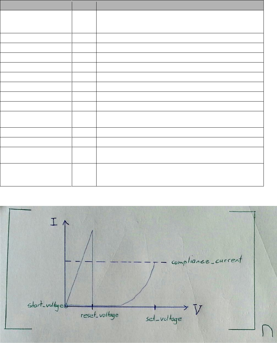
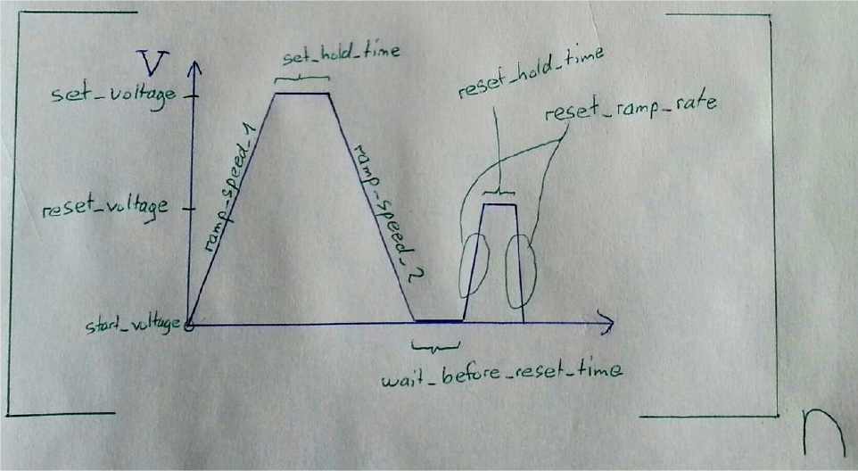
cycling_unipolar(device,start_voltage,ramp_speed_1,set_voltage,set_hold_time,com
pliance_current,ramp_speed_2,wait_before_reset_time,reset_voltage,reset_ramp_rat
e,reset_hold_time,n,new_row=False, GUI=True)
Return value are the following arrays: [data_V_I,data_V_t,data_I_t]
This function is optimized to test memristors for unipolarity. In normal cycling a compliance current is either
applied globally or not at all. It is therefore possible, that unipolar switching behavior can not be asessed
Argument
Unit
Remark
device
Pass the device you want to use for this function. To date only
keithley_2601B, keithley_2602B and keithley_2612B can be
used.
start_voltage
V
Where you want to start
ramp_speed_1
V/s
set_voltage
V
set_hold_time
s
You can also set this to 0. Then it does not wait
compliance_current
A
ramp_speed_2
V/s
Needs to be negative
wait_before_reset_time
s
You can also set this to 0. Then it does not wait
reset_voltage
V
reset_ramp_rate
V/s
This ramp rate is applied to both. Reset-ramp-up and reset-
ramp-down
reset_hold_time
s
You can also set this to 0. Then it does not wait
n
Number of cycles you want to run
new_row
Either True or False If set to True, the plotting window will make
a new row and the display looks nicer.
GUI
Either True or False If set to False, the plotting window will not
appear at all. Can be used for „silent“ measurements without
real-time graphical output.

cycling_current(device,start,ramp_speed_1,top,top_hold_time,ramp_speed_2,bottom,
bottom_hold_time,end,n,maximum_voltage,new_row=False,GUI=True)
Return value are the following arrays: [data_V_I,data_V_t,data_I_t]
Argument
Unit
Remark
device
Pass the device you want to use for this function. To date only
keithley_2601B, keithley_2602B and keithley_2612B can be
used. Keep in mind that keithley_6517B DOES NOT WORK for
this function as it has no compliance current capability.
start
A
The applied current with which you want to start
ramp_speed_1
A/s
top
A
The top current you want to reach. (However you have no
influence if your device will be conductive enough to ever
exactly reach that point.)
top_hold_time
s
You can also set this to 0. Then it does not wait
ramp_speed_2
A/s
Needs to be negative
bottom
A
You can also set this current equal to end. Then you only cycle
in the positive branch
bottom_hold_time
s
You can also set this to 0. Then it does not wait
end
A
You can also set this voltage equal to bottom. Then you only
cycle in the positive branch
n
Number of cycles you want to run
maximum_voltage
V
The global maximum voltage you allow the device to apply in
order to reach the beforehand specified ramps. Keep in mind
that the device itself also has some limitations regarding this
variable (mostly ether 40V or 200V depending on the device
used)
new_row
Either True or False If set to True, the plotting window will make
a new row and the display looks nicer.
GUI
Either True or False If set to False, the plotting window will not
appear at all. Can be used for „silent“ measurements without
real-time graphical output.
Pulsed experiments
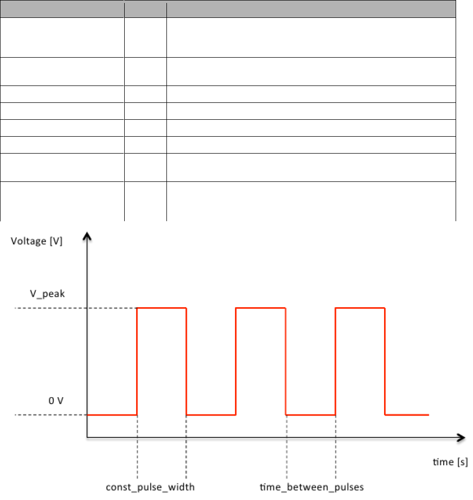
pulse_rnone(device_smu,device_function_generator,V_peak,const_pulse_width,time_b
etween_pulses, num_pulses,new_row=False,GUI=True)
Return value are the following arrays:
[data_V_t_2,data_I_t_2,data_cycle_R_2,data_cycle_post_R_2]
This function just measures the current responce to a series of voltage pulses - there is no reading voltage
and the currents starts and ends at zero voltage.
Argument
Unit
Remark
device_smu
Pass the device you want to use for this function. To date
keithley_2601B, keithley_2602B, keithley_2612B,
keithley_6517B can be used.
device_function_generator
Pass the device you want to use for this function. To date
tektronix_AFG2021C and tektronix_AFG3021C can be used.
V_peak
V
Specifiy the peak voltage you want to be applied to the device.
const_pulse_width
s
Specify the with of the individual pulses
time_between_pulses
s
Specify the wait time between different pulses
num_pulses
How many pulses should be applied in total till the function ends
new_row
Either True or False If set to True, the plotting window will make
a new row and the display looks nicer.
GUI
Either True or False If set to False, the plotting window will not
appear at all. Can be used for „silent“ measurements without
real-time graphical output.

pulse_rsquare(device_smu,device_function_generator,V_peak,const_pulse_width,time
_between_pulses, num_pulses,time_at_zero,
V_read,alternate=True,new_row=False,GUI=True)
Return value are the following arrays:
[data_V_t_2,data_I_t_2,data_cycle_R_2,data_cycle_post_R_2]
This function allows you to measure also the resistance during (depending on the time scale) and between
pulses. - that means that there is a square reading scheme between the pulses.
Argument
Unit
Remark
device_smu
Pass the device you want to use for this function. To date
keithley_2601B, keithley_2602B, keithley_2612B,
keithley_6517B can be used.
device_function_generator
Pass the device you want to use for this function. To date
tektronix_AFG2021C and tektronix_AFG3021C can be used.
V_peak
V
Specifiy the peak voltage you want to be applied to the device.
const_pulse_width
s
Specify the with of the individual pulses
time_between_pulses
s
Specify the wait time between different pulses
num_pulses
How many pulses should be applied in total till the function ends
time_at_zero
s
How long should the system remain at 0V
V_read
V
Specify the read voltage
alternate
Default:
True
Either True or False If set to True, every 2nd pulse has opposite
polarity
new_row
Either True or False If set to True, the plotting window will make
a new row and the display looks nicer.
GUI
Either True or False If set to False, the plotting window will not
appear at all. Can be used for „silent“ measurements without
real-time graphical output.
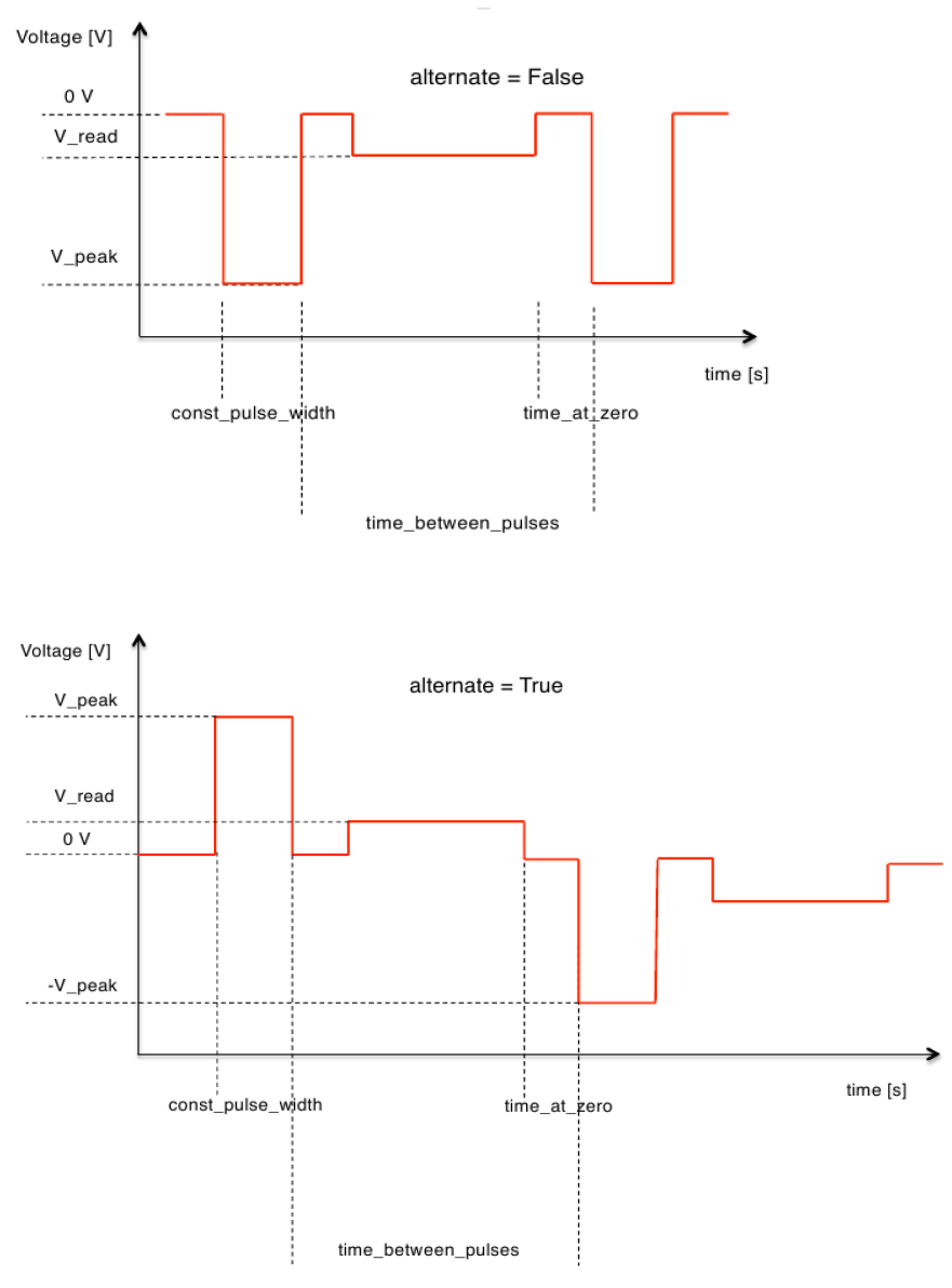
In case you put a negative V_peak voltage into the pulse_rsquare function then the reading voltage becomes
automatically also negative. This is due to voltage spikes occurring when changing voltage polarity.
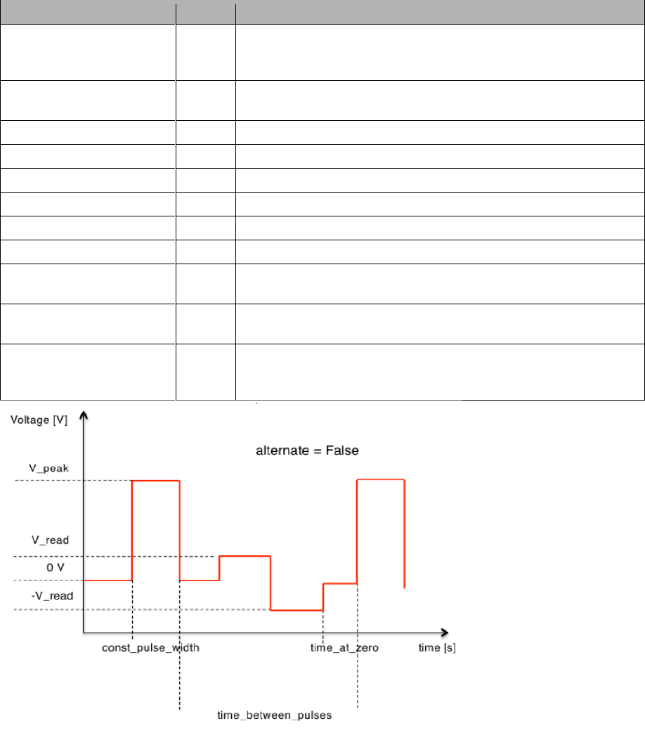
pulse_rbipolar(device_smu,device_function_generator,V_peak,const_pulse_width,tim
e_between_pulses, num_pulses,time_at_zero, V_read, alternate=True,
new_row=False,GUI=True)
Return value are the following arrays:
[data_V_t_2,data_I_t_2,data_cycle_R_2,data_cycle_post_R_2_plus,
data_cycle_post_R_2_minus]
This function allows you to measure also the resistance during (depending on the time scale) and between
pulses. There is a bipolar pulse reading scheme between the pulses. This is an advantage over a constant
reading scheme since the device will not be disturbed. No resistence will be measured during the time at zero.
This is just an option to leave the current to equilibrate.
Argument
Unit
Remark
device_smu
Pass the device you want to use for this function. To date
keithley_2601B, keithley_2602B, keithley_2612B,
keithley_6517B can be used.
device_function_generator
Pass the device you want to use for this function. To date
tektronix_AFG2021C and tektronix_AFG3021C can be used.
V_peak
V
Specifiy the peak voltage you want to be applied to the device.
const_pulse_width
s
Specify the with of the individual pulses
time_between_pulses
s
Specify the wait time between different pulses
num_pulses
How many pulses should be applied in total till the function ends
time_at_zero
s
How long should the system remain at 0V
V_read
V
Specify the read voltage
alternate
Default:
True
Either True or False If set to True, every 2nd pulse has opposite
polarity
new_row
Either True or False If set to True, the plotting window will make
a new row and the display looks nicer.
GUI
Either True or False If set to False, the plotting window will not
appear at all. Can be used for „silent“ measurements without
real-time graphical output.
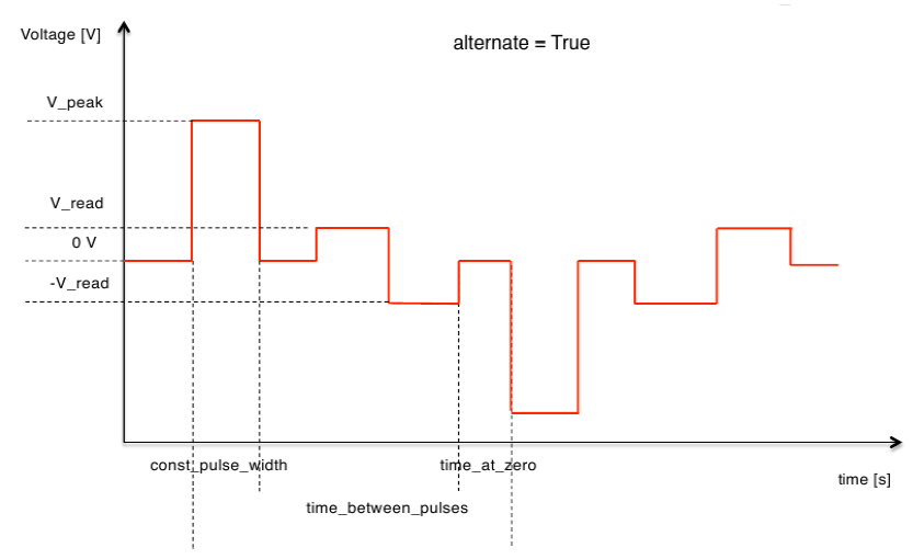
The bipolar read between the pulses ensures that no memristance change occurs during the reading process
(a change during a positive reading pulse will be reversed with a negative reading pulse). Is a good choice for
sensitive devices or higher reading voltages.

Simple loggers
Those functions are kept very simple for the case one just needs to monitor some measurement without
further requirements.
voltage_logger(device,total_measurement_time,bias_current=0,new_row=False,
GUI=True)
Argument
Unit
Remark
device
Pass the device you want to use for this function. To date
keithley_2601B, keithley_2602B, keithley_2612B,
keithley_6517B, keithley_2000, keithley_2001, keithley_2700,
keithley_2182A can be used.
total_measurement_time
s
How long you want to log the voltage
bias_current
A
Specifiy the bias current you want to be applied to the device.
Default = 0 means no bias at all
new_row
Either True or False If set to True, the plotting window will make
a new row and the display looks nicer.
GUI
Either True or False If set to False, the plotting window will not
appear at all. Can be used for „silent“ measurements without
real-time graphical output.
current_logger(device,total_measurement_time,bias_voltage=0,new_row=False,
GUI=True)
Argument
Unit
Remark
device
Pass the device you want to use for this function. To date
keithley_2601B, keithley_2602B, keithley_2612B,
keithley_6517B, keithley_2000, keithley_2001, keithley_2700,
keithley_2182A can be used.
total_measurement_time
s
How long you want to log the voltage
bias_voltage
V
Specifiy the bias voltage you want to be applied to the device.
Default = 0 means no bias at all
new_row
Either True or False If set to True, the plotting window will make
a new row and the display looks nicer.
GUI
Either True or False If set to False, the plotting window will not
appear at all. Can be used for „silent“ measurements without
real-time graphical output.

resistance_2w_logger(device,total_measurement_time,new_row=False, GUI=True)
Measures resistance with 2-wire setup
Argument
Unit
Remark
device
Pass the device you want to use for this function. To date
keithley_2601B, keithley_2602B, keithley_2612B,
keithley_6517B, keithley_2000, keithley_2001, keithley_2700,
keithley_2182A can be used.
total_measurement_time
s
How long you want to log the voltage
new_row
Either True or False If set to True, the plotting window will make
a new row and the display looks nicer.
GUI
Either True or False If set to False, the plotting window will not
appear at all. Can be used for „silent“ measurements without
real-time graphical output.
resistance_4w_logger(device,total_measurement_time,new_row=False, GUI=True)
Measures resistance with 4-wire setup
Argument
Unit
Remark
device
Pass the device you want to use for this function. To date
keithley_2601B, keithley_2602B, keithley_2612B,
keithley_6517B, keithley_2000, keithley_2001, keithley_2700,
keithley_2182A can be used.
total_measurement_time
s
How long you want to log the voltage
new_row
Either True or False If set to True, the plotting window will make
a new row and the display looks nicer.
GUI
Either True or False If set to False, the plotting window will not
appear at all. Can be used for „silent“ measurements without
real-time graphical output.
temperature_logger(device,total_measurement_time,sensor=“K“,num_of_channels=1,ne
w_row=False, GUI=True)
Argument
Unit
Remark
device
Pass the device you want to use for this function. To date
keithley_2000, keithley_2001, keithley_2700, keithley_2182A
can be used.
total_measurement_time
s
How long you want to log the voltage
sensor
Default:
K
Specify which type of thermocouple you will be using. Choose
from J,T,S,E,R,B,N,K
num_of_channels
Default:
1
Which channels do you want to use. (Not working at the
moment)
new_row
Either True or False If set to True, the plotting window will make
a new row and the display looks nicer.
GUI
Either True or False If set to False, the plotting window will not
appear at all. Can be used for „silent“ measurements without
real-time graphical output.

temperature_current_logger(device_temperature,device_smu,total_measurement_time,
bias_voltage,sensor=“K“,new_row=False, GUI=True)
Argument
Unit
Remark
device_temperature
Pass the device you want to use for this function. To date
keithley_2000, keithley_2001, keithley_2700, keithley_2182A
can be used.
device_smu
Pass the SMU device you want to use for this function. To date
keithley_2601B, keithley_2602B, keithley_2612B,
keithley_6517B can be used.
total_measurement_time
s
How long you want to log the voltage
bias_voltage
V
Put the voltage value the SMU should source during the
experiment.
sensor
Default:
K
Specify which type of thermocouple you will be using. Choose
from J,T,S,E,R,B,N,K
new_row
Either True or False If set to True, the plotting window will make
a new row and the display looks nicer.
GUI
Either True or False If set to False, the plotting window will not
appear at all. Can be used for „silent“ measurements without
real-time graphical output.

Oven control programs
sintering(device_temperature,device_oven,temperature_values,ramp_rate,stabilizat
ion_time,sensor=“K“,GUI=True)
Argument
Unit
Remark
device_temperature
Pass the device you want to use for this function. To
date keithley_2601B, keithley_2612B,
keithley_6517B, keithley_2000, keithley_2001,
keithley_2700, keithley_2182A can be used.
device_oven
Pass the oven device you want to use for this
function. To date eurotherm_2404, eurotherm_2416,
eurotherm_3216 can be used.
temperature_values
°C
Can be a single value like 850 or an array of values
like [200,400,600,800]. Then those values are all run
to with the ramp_rate specified and hold for as long
as stabilization_time
ramp_rates
K/min
NOT SI unit
Set the ramp rate(s). Can be a single number or an
array like [300,400,500]
stabilization_times
s
How long a temperature should be kept after having
ramped to that value.
sensor
Default:
K
Specify which type of thermocouple you will be using.
Choose from J,T,S,E,R,B,N,K
GUI
Either True or False If set to False, the plotting
window will not appear at all. Can be used for
„silent“ measurements without real-time graphical
output.

arrhenius_dc(device_temperature,device_smu,device_oven,temperature_values,ramp_r
ates,stabilization_times,voltage_values,measurement_time=60,continuous_voltage=T
rue,GUI=True)
Return value are the following arrays: [data_T_t,data_P_t,data_I_t,data_R_T]
Argument
Unit
Remark
device_temperature
Pass the device you want to use for this function. To date
keithley_2000, keithley_2001, keithley_2700, keithley_2182A
can be used.
device_smu
Pass the SMU device you want to use for this function. To date
keithley_2601B, keithley_2602B, keithley_2612B,
keithley_6517B can be used.
device_oven
Pass the oven device you want to use for this function. To date
eurotherm_2404, eurotherm_2416, eurotherm_3216 can be
used.
temperature_values
°C
Can be a single value like 850 or an array of values like
[200,400,600,800]. Then those values are all run to with the
ramp_rate specified and hold for as long as stabilization_time
ramp_rates
K/min
NOT SI
unit
Set the ramp rate(s). Can be a single number or an array like
[300,400,500]
stabilization_times
s
How long a temperature should be kept after having ramped to
that value.
voltage_values
V
[Array] or single number of voltage value(s) you want to apply to
the device at each temperature specified under
temperature_values.
measurement_time
s
How many seconds you want to perform the actual
measurement per each voltage specified. Default is 60 sec
continuous_voltage
Default:
True
Specify if you want the voltage to be applied during the whole
time (also while ramping) or just after the stabilization for the
time specified in measurement_time. If set to True, the variable
voltage_values cannot be an array but just a single value.
GUI
Either True or False If set to False, the plotting window will not
appear at all. Can be used for „silent“ measurements without
real-time graphical output.

arrhenius_ac(device_temperature,device_oven,device_impedance,temperature_values,
ramp_rates,stabilization_times,number_of_repetitions=1,start_frequency=0.1,end_f
requency=1.0e6,ac_amplitude=0.1,bias=0,num_points_per_decade=10,path="/home/elec
trochem/lost_data",GUI=True)
There is no return value to this function since the whole data gets already safed to a file specified.
Argument
Unit
Remark
device_temperature
Pass the device you want to use for this function. To date
keithley_2000, keithley_2001, keithley_2700, keithley_2182A
can be used.
device_oven
Pass the oven device you want to use for this function. To date
eurotherm_2404, eurotherm_2416, eurotherm_3216 can be
used.
device_impedance
Pass the impedance bridge device you want to use for this
function. To date Zahner_IM6, Solartron or Gamry Reference
600 can be used.
temperature_values
°C
Can be a single value like 850 or an array of values like
[200,400,600,800]. Then those values are all run to with the
ramp_rate specified and hold for as long as stabilization_time
ramp_rates
K/min
NOT SI
unit
Set the ramp rate(s). Can be a single number or an array like
[300,400,500]
stabilization_times
s
How long a temperature should be kept after having ramped to
that value.
number_of_repetitions
Specify how many times the impedance measurement should
be repeated to get better signal to noise. Default=1. This
variable should not be changed at the moment since it
produces unexpected result and does not work with all the
impedance bridges so far! You have been warned!
start_frequency
Hz
Specify the lower frequency boundary at which your device
should be measured. Default is 0.1 Hz. However the
measurement not always starts at this frequency. This depends
on the impedance bridge.
end_frequency
Hz
Specify the higher frequency boundary at which your device
should be measured. Default is 1 MHz. However the
measurement not always starts at this frequency. This depends
on the impedance bridge. Much higher frequency usually don't
make sense and you start measuring your not propperly setup
cables.
ac_amplitude
V
Specify the voltage amplitude with which you want to excite your
system. The higher the less noise but the more you also affect
and change the system by measuring it. Default is 0.1V
bias
V
Specify a bias voltage during impedance measurement to better
separate electrode contributions. Default is no bias
num_points_per_decade
How many datapoints should be measured on your final
logarithmic impedance plot. Default is 10 and mostly sufficient to
fit the data.
path
Filepath
Specify a path to which you have write-access where the
datafiles from the different spectra should be safed to. It is
suggested to make a new folder somewhere in the umdata path.
Default is /home/electrochem/lost_data
GUI
Either True or False If set to False, the plotting window will not
appear at all. Can be used for „silent“ measurements without
real-time graphical output.

Impedance measurement
impedance(device_impedance, start_frequency, end_frequency, ac_amplitude=0.05,
bias=0, num_points_per_decade=10, new_row=False, GUI=True)
Return value are the following arrays:
[data_Zi_Zr,data_freq_mod,data_bias_ampl_time_range_err_temp]
Argument
Unit
Remark
device_impedance
Pass the impedance bridge device you want to use for this
function. To date Zahner_IM6, Solartron or Gamry Reference
600 can be used.
start_frequency
Hz
Specify the lower frequency boundary at which your device
should be measured. Default is 0.1 Hz. However the
measurement not always starts at this frequency. This depends
on the impedance bridge.
end_frequency
Hz
Specify the higher frequency boundary at which your device
should be measured. Default is 1 MHz. However the
measurement not always starts at this frequency. This depends
on the impedance bridge. Much higher frequency usually don't
make sense and you start measuring your not propperly setup
cables.
ac_amplitude
V
Specify the voltage amplitude with which you want to excite your
system. The higher the less noise but the more you also affect
and change the system by measuring it. Default is 0.1V
bias
V
Specify a bias voltage during impedance measurement to better
separate electrode contributions. Default is no bias
num_points_per_decade
How many datapoints should be measured on your final
logarithmic impedance plot. Default is 10 and mostly sufficient to
fit the data.
new_row
Either True or False If set to True, the plotting window will make
a new row and the display looks nicer.
GUI
Either True or False If set to False, the plotting window will not
appear at all. Can be used for „silent“ measurements without
real-time graphical output.

Mass flow controller
mfc(device_mfc,stabilization_times,flow_rates,GUI=True)
Return value are the following arrays: [data_F_t,data_FP_t]
Pass the following device to this function as an example:
voegtlin_gsc = voegtlin_gsc("/dev/ttyUSB0",[12,3])
The first argument "/dev/ttyUSB0" is the corresponding USB port on that Linux-machine, and the array [12,3]
specifies that the Modbus-Addresses 12 and 3 are used by the devices we want to communicate with.
Argument
Unit
Remark
device_mfc
Pass the mass flow controller device you
want to use for this function. To date only
voegtlin_gsc can be used.
stabilization_times
s
Specify the time a certain flow should be
kept in each step. You can either use a
scalar if you only have one stabilization
time or an array if you have multiple.
flow_rates
[ string or modbus-address,
sccm ]
Specify for each stabilization step, which
flowmeters should have which set-flow. Use
a 3d-array for multiple flowmeters at
multiple steps. See below for more
information.
GUI
Either True or False If set to False, the
plotting window will not appear at all. Can
be used for „silent“ measurements without
real-time graphical output.
flow_rates example:
You can specify this array in 3 different ways.
It can be in the following manner
[ [ [ "gastype1" or modbusnumber , set_flow ],[...] ] , [...] ]
for example: [[["Air 5000",1000],["N2 300",50]],[["Air 5000",500],["N2 300",150]]]
Assuming you have two stabilization times, this will set Air-flow to 1000 sccm and N2 to 50 sccm in the first
step and Air-flow to 500 sccm and N2 to 150 sccm in the second step.
or if only one gas used:
[ [ "gastype1" or modbusnumber , set_flow ] , [...] ]
for example: [["Air 5000",1000],["Air 5000",700],["Air 5000",100]]
Assuming you have 3 stabilization times, this will set Air-flow to 1000 sccm in the first step to 700 sccm in the
second step and finally to 100 in the 3rd step.
or if only one gas and one flow used:
[ "gastype1" or modbusnumber , set_flow ]
for example: ["Air 5000",1000] In this case during all step 1000sccm Air will be used

Galvanostatic cycling
galvanostatic_cycling(device_smu,current_1,target_voltage_1,hold_time_1,hold_cur
rent_1,current_2,target_voltage_2,hold_time_2,hold_current_2,n=1,ocv_measurement
_time=0,set_I_zero_after_cycle=False,new_row=False,GUI=True)
Return value are the following arrays: [data_0,data_1,data_2,data_3]
Argument
Unit
Remark
device_smu
Pass the device you want to use for this function. To date
keithley_2601B, keithley_2602B, keithley_2612B can be
used.
current_1
A
Specify the constant current which should be applied in the
first stage of either charge or discharge. (Note: different
currents can be set for charge and discharge)
target_voltage_1
V
Specify the voltage to which the cell should be charged or
discharged
hold_time_1
s
Time to stay at target_voltage_1 after reaching it
hold_current_1
A
Wait at target_voltage_1 until the current drops to this value or
hold_time_1 is over, whatever condition comes first.
current_2
A
Specify the constant current which should be applied in the
second stage of either charge or discharge. (Note: different
currents can be set for charge and discharge)
target_voltage_2
V
Specify the voltage to which the cell should be charged or
discharged
hold_time_2
s
Time to stay at target_voltage_2 after reaching it
hold_current_2
A
Wait at target_voltage_2 until the current drops to this value or
hold_time_2 is over, whatever condition comes first.
n
Number of cycles the cell should be tested for. (Can be an
array for rate capability testing)
ocv_measurement_time
s
How long the open circuit voltage should be measured prior to
any cycling
Set_I_zero_after_cycle
Disconnects the electrochemical cell galvanically from the
measurement device after the cycle
new_row
Either True or False If set to True, the plotting window will
make a new row and the display looks nicer.
GUI
Either True or False If set to False, the plotting window will
not appear at all. Can be used for „silent“ measurements
without real-time graphical output.
Galvanostatic cycling examples:
You can specify arrays for the purpose of rate capability testing.
galvanostatic_cycling(device_smu,[10e-9,100e-9,10e-9], 4.1,0,0,[-10e-9,-100e-9,-
10e-9], 1.1,0,0,n=[10,5,10], ocv_measurement_time=60)
this example: will perform 10 cycles at 10 nA of current followed by 5 cycles at 100 nA and then go back to 10
cycles at 10 nA. OCV is measured for 1 minute and the cycling range is between 1.1 Volts and 4.1 Volts.

High precision galvanostatic cycling
This function is intended to be used in combination with a high precision current source such as Keithley 6220
series in order to cycle under most stable low currents. Note that the function is similar to the previous
description, but a second device file (the current source) has to be provided in addition. The current source is
exclusively dedicated to providing stable ultra-low currents.
galvanostatic_cycling_nano(device_voltmeter,device_current_source,current_1,targ
et_voltage_1,hold_time_1,hold_current_1,current_2,target_voltage_2,hold_time_2,h
old_current_2,n=1,ocv_measurement_time=0,set_I_zero_after_cycle=False,new_row=Fa
lse,GUI=True)
Return value are the following arrays: [data_0,data_1,data_2,data_3]
Argument
Unit
Remark
device_smu
Pass the device you want to use for this function. To date
keithley_2601B, keithley_2602B, keithley_2612B can be
used.
device_current_source
Pass the device you want to use for ultra-low high precision
current to be sourced. To date only keithley_6220 can be
used.
current_1
A
Specify the constant current which should be applied in the
first stage of either charge or discharge. (Note: different
currents can be set for charge and discharge)
target_voltage_1
V
Specify the voltage to which the cell should be charged or
discharged
hold_time_1
s
Time to stay at target_voltage_1 after reaching it
hold_current_1
A
Wait at target_voltage_1 until the current drops to this value or
hold_time_1 is over, whatever condition comes first.
current_2
A
Specify the constant current which should be applied in the
second stage of either charge or discharge. (Note: different
currents can be set for charge and discharge)
target_voltage_2
V
Specify the voltage to which the cell should be charged or
discharged
hold_time_2
s
Time to stay at target_voltage_2 after reaching it
hold_current_2
A
Wait at target_voltage_2 until the current drops to this value or
hold_time_2 is over, whatever condition comes first.
n
Number of cycles the cell should be tested for. (Can be an
array for rate capability testing)
ocv_measurement_time
s
How long the open circuit voltage should be measured prior to
any cycling
Set_I_zero_after_cycle
Disconnects the electrochemical cell galvanically from the
measurement device after the cycle
new_row
Either True or False If set to True, the plotting window will
make a new row and the display looks nicer.
GUI
Either True or False If set to False, the plotting window will
not appear at all. Can be used for „silent“ measurements
without real-time graphical output.

Galvanostatic cycling examples:
galvanostatic_cycling_nano(device_smu, device_current_source, 10e-9, 4.2,0,0,-
10e-9, 1.1,0,0,n=100, ocv_measurement_time=120)
this example: will perform 100 cycles at 10 nA of current. OCV is measured for 2 minute and the cycling range
is between 1.1 Volts and 4.2 Volts.
You can specify arrays for the purpose of rate capability testing.
galvanostatic_cycling_nano(device_smu, device_current_source, [10e-9,100e-9,10e-
9], 4.1,0,0,[-10e-9,-100e-9,-10e-9], 1.1,0,0,n=[10,5,10],
ocv_measurement_time=60)
this example: will perform 10 cycles at 10 nA of current followed by 5 cycles at 100 nA and then go back to 10
cycles at 10 nA. OCV is measured for 1 minute and the cycling range is between 1.1 Volts and 4.1 Volts.
