S COM 7K Owner's Manual Manual7k203i
User Manual: manual7k203i
Open the PDF directly: View PDF ![]() .
.
Page Count: 400 [warning: Documents this large are best viewed by clicking the View PDF Link!]
- Title Page
- Table of Contents
- Product Description
- Getting Started
- Programming Fundamentals
- Messages
- Message Buffer
- Message Handler
- Control Characters
- Routing and Unrouting Control Characters
- Synchronizing Messages and Commands
- CW Messages
- Beep Messages
- Single Tone Page Messages
- Two-Tone Sequential Page Messages
- Five-Six-Tone Page Messages
- DTMF Page Messages
- Control Character
- Format
- Delays
- Defaults
- DTMF Characters
- DTMF Duration Change Characters
- DTMF Custom Duration Change Characters
- DTMF Gap Change Characters
- DTMF Custom Gap Change Characters
- DTMF Pause Characters
- DTMF Custom Pause Characters
- DTMF Custom Changes (Duration, Gap, Pause)
- DTMF-Related Notes
- DTMF Character Set Tables Explained
- Synthesized Speech Messages
- Tone Codes
- Run-Time Variables
- Commands
- Enable/Disable CW
- Select Frequency of CW
- Send Next Message Slowly
- Select CW Speed
- Select Frequency of Owner-Fixed Frequency Beeps
- Select Programmable Messages
- Review Programmable Messages
- Select/Review/Play User Messages
- Send Message
- Select (Review) Command Response Messages
- Select (Review) Programmable Messages
- Security
- Macros
- Telephone Interface Functions
- Autopatch
- Phone Line Control Mode
- Reverse Patch
- Multiple Port Access
- Commands
- Select Autopatch Dialing Mode
- Select (Review) Autopatch Dialing Message
- Select (Review) Autopatch Error Messages
- Select (Review) Autopatch Dump Message
- Enable/Disable Autopatch Dialing Mixed-Mode
- Select Pause ("B") Digit Time
- Enable/Disable Pound Down (# Dump)
- Select Dialing Prefix
- Dump Autopatch Using a Code
- Select Autopatch Access-Triggered Macro
- Select Autopatch Dump-Triggered Macro
- Enable/Disable Full-Duplex Mode
- Enable/Disable Autopatch Privacy
- Enable/Disable Repeater-to-Phone DTMF Mute
- Enable/Disable ID Messages During Autopatch
- Require Dump Before Next Call
- Select Receiver-to-Autopatch-Triggered Macros
- Landline Hookflash
- Select Autopatch Timeout Timer
- Reset Autopatch Timeout Timer
- Select (Review) Autopatch Timeout Warning Message
- Access Autopatch (With Password)
- Access Autopatch (Without Password)
- Change Autopatch Access Password
- Enable/Disable Autopatch Access Without Password
- Go Off-Hook
- Select Autopatch Call Types
- Clear (or Enter) Accepted Number Table
- Clear (or Enter) Rejected Number Table
- Redial Last Number
- Clear Autopatch Redialer
- Clear Autopatch Call Counter
- Send Autopatch Call Count
- Select Phone Line Answer Mode
- Select (Review) Phone Line Answer Message
- Select Phone Line Answer Macro
- Select Control Mode Dump-Triggered Macro
- Select Phone Line Off-Hook Timer
- Monitor/Talk Out Via Phone
- Trigger Reverse Patch
- Answer Reverse Patch
- Select (Review) Reverse Patch Ringout Message
- Select Reverse Patch Ring-Triggered Macro
- Select Autopatch Receiver-Specific Access-Triggered Macro
- Select Autopatch Command Response Message Routing
- Clock and Calendar
- Scheduler
- CTCSS Functions
- DTMF Decoder
- Identifier
- Commands
- Select (Review) Identifier Messages
- Select ID-Triggered Macros
- Select ID Message Interval
- Select ID Pending Interval for Tx1 and Tx2
- Reset Initial ID Message to Normal Message
- Send Initial ID Message
- Select (Review) Programmable Tail Messages for Tx1
- Select (Review) Initial and Normal ID Tail Messages
- Enable/Disable ID Messages During Autopatch
- Commands
- Links
- Logic Inputs
- Logic Outputs
- Receiver Functions
- Transmitter Functions
- Transmitter Tail Sequence
- Commands
- Select Courtesy Delay
- Select Dropout Delay
- Select Transmitter Timeout Timer
- Reset Transmitter Timeout Timer
- Enable/Disable Transmitter
- Key Transmitter (Timed)
- Key Transmitter (Untimed)
- Enable/Disable Transmitter Minimum Unkey Delay
- Select Transmitter Minimum Unkey Delay
- Select Receiver-to-Transmitter-Triggered Macros
- Select Transmitter PTT-Triggered Macros
- Example: CTCSS Encode Control
- Repeater Functions
- Base Station Functions
- User Timers
- Remote Base Interface
- Remote Base Setup and Configuration
- User Functions: Controlling the Radios
- Defining Memory Channels using Macros
- RBI-1 User Function Outputs
- Commands
- Assign Remote Base Password
- Select Remote Base Access-Triggered Macro
- Select Remote Base Dump-Triggered Macro
- Select (Review) Remote Base Off Message
- Reset RBI-1
- Enable/Disable Access to the Remote Base
- User Function: Access Remote Base
- User Function: Dump Remote Base
- User Function: Speak Radio Configuration
- User Function: Select Memory Channel and Band
- User Function: Select VFO Frequency and Offset
- User Function: Select Transmitter Offset
- User Function: Enable/Disable Transmitter
- User Function: Enable/Disable Receiver
- User Function: Enable/Disable Radio Power
- User Function: Select Transmitter Power Output
- User Function: Select Frequency of CTCSS
- User Function: Enable/Disable CTCSS Encoder
- User Function: Enable/Disable CTCSS Decoder
- Macro Function: Send Queued Settings
- Select RBI-1 Number of User Function Outputs
- Select Individual RBI-1 User Function Outputs
- Enter RBI-1 User Function Output Group
- Programming Tables
- CW Character Set Tables
- Beep Character Set Tables
- DTMF Character Set Tables
- Synthesized Speech Vocabulary
- Message Run-Time Variables
- Message Control Characters
- Scheduler Day Code Table
- Tone Code Table
- Root Numbers by Number
- Event Macros by Number
- Messages by Number
- Tenth-Second Timers by Number
- Tenth-Minute Timers by Number
- Path Access Mode by Number
- Software Switches by Number
- Command Quick Reference
- Application Notes
- Installation
- Parts Lists and Schematics


This manual Copyright 2000 by S-COM Industries, All Rights Reserved.
Except where otherwise noted, no part of this manual may be duplicated in any form,
whether electronic, mechanical, or otherwise.
Published in the United States of America by:
S-COM Industries
P.O. Box 1546
LaPorte, CO 80535-1546
USA

Limited Warranty
This warranty gives you specific legal rights, and you may also have other rights which vary from state
to state.
Coverage
Except as specified below, this warranty covers all defects in material and workmanship in this product.
The following are not covered by the warranty:
• Damage to, or deterioration of, the external cabinet.
• Damage resulting from lightning, accident, misuse, abuse, or neglect.
• Damage resulting from failure to follow instructions contained in the owner's manual.
• Damage occurring during shipment of the product (claims must be presented to the carrier).
• Damage resulting from repair or attempted repair by anyone other than S-COM Industries.
• Damage resulting from causes other than product defects, including lack of technical skill,
competence, or experience of the user.
• Damage to any unit which has been altered or on which the serial number has been de-
faced, modified, or removed.
Enforcement
This warranty may be enforced only by the original purchaser. The warranty is not transferrable.
Length Of Warranty
For both labor and parts, this warranty will be effective for one (1) year from the date of original
purchase.
What We Will Pay For
We will pay all labor and material expenses for items covered by the warranty. Payment of shipping
charges is discussed in the next section of the warranty.
How You Can Get Warranty Service
Your unit must be serviced by S-COM's Service Department. Please do not return your unit to the factory
without prior authorization. You must pay any shipping charges if it is necessary to ship the product to
service. However, if the necessary repairs are covered by the warranty, we will pay the return
shipping charges to any destination within the U.S. Whenever warranty service is required, you must
present the original dated invoice or a photocopy.
S-COM's liability for any defective products is limited to repair or replacement of the product, at S-COM's
option.
S-COM reserves the right to make any changes in design or additions to, or improvements in, its products
without any obligation to install such additions or improvements in equipment previously sold. S-COM
further reserves the right to replace defective parts under warranty with different or improved parts.
This warranty is expressly in lieu of all other warranties, expressed or implied, including any implied
warranty of merchantability or fitness, and of all other obligations of liabilities on the part of S-COM.


Table of Contents
v
Table of Contents
Selected Tables ...................................................................................................................... xiii
Product Description .......................................... 1-1
Standard Hardware Features .................................................................................................... 1-1
Configuration....................................................................................................................... 1-1
Cabinet................................................................................................................................ 1-1
Main Board.......................................................................................................................... 1-2
Optional Hardware Features ..................................................................................................... 1-2
Telephone Interface Module ............................................................................................... 1-2
Speech Synthesis Module................................................................................................... 1-2
Audio Delay Module............................................................................................................ 1-2
Standard Software Features...................................................................................................... 1-2
CW Identifier....................................................................................................................... 1-2
CW Messages and Paging Formats................................................................................... 1-2
Timers................................................................................................................................. 1-3
Repeater Characteristics .................................................................................................... 1-3
Clock and Calendar ............................................................................................................ 1-3
Logic Inputs and Outputs .................................................................................................... 1-3
Command Language .......................................................................................................... 1-3
Getting Started................................................... 2-1
Power ON Initialization .............................................................................................................. 2-1
Initialize Controller............................................................................................................... 2-1
Cold Start ............................................................................................................................ 2-2
Warm Start.......................................................................................................................... 2-2
Default Condition ................................................................................................................ 2-2
Programming Fundamentals ............................ 3-1
Valid Digit and Time Detection .................................................................................................. 3-2
Control Command Structure...................................................................................................... 3-2
Example Control Command................................................................................................ 3-3
Command Response Messages ............................................................................................... 3-4
Acknowledgment................................................................................................................. 3-4
Errors .................................................................................................................................. 3-4
Special Keys.............................................................................................................................. 3-5
Star (*) and Carrier Drop as Terminators............................................................................ 3-5
Pound (#) as Clear or Abort Key......................................................................................... 3-5
DTMF Interdigit Timer ............................................................................................................... 3-6
DTMF Mute Delay ..................................................................................................................... 3-6
Messages............................................................ 4-1
Message Buffer ......................................................................................................................... 4-1
Message Handler ...................................................................................................................... 4-1
Control Characters .................................................................................................................... 4-2
Routing and Unrouting Control Characters ............................................................................... 4-3
Default................................................................................................................................. 4-3
Examples ............................................................................................................................ 4-4
Synchronizing Messages and Commands ................................................................................ 4-5
CW Messages........................................................................................................................... 4-6
Control Character................................................................................................................ 4-6

7K •
vi
Format................................................................................................................................. 4-6
Pre-Message Delay Character............................................................................................ 4-6
Wordspace Character......................................................................................................... 4-6
Frequency Change.............................................................................................................. 4-6
Speed Change .................................................................................................................... 4-7
CW Alphanumeric Characters ............................................................................................ 4-8
CW Punctuation and Related Characters........................................................................... 4-9
CW Frequency Change and Speed Change Characters.................................................. 4-10
Command: Enable/Disable CW ........................................................................................4-11
Command: Select Frequency of CW ................................................................................4-12
Command: Send Next Message Slowly ............................................................................4-13
Command: Select CW Speed ...........................................................................................4-14
Beep Messages....................................................................................................................... 4-16
Control Character.............................................................................................................. 4-16
Format............................................................................................................................... 4-16
Beep Parameters (General).............................................................................................. 4-16
Pre-Message Delay Character.......................................................................................... 4-16
Factory-Fixed-Frequency Beeps....................................................................................... 4-17
Owner-Fixed Frequency Beeps ........................................................................................ 4-18
Command: Select Frequency of Owner-Fixed Frequency Beeps .....................................4-19
Custom Beeps .................................................................................................................. 4-21
Custom Beep Delay.......................................................................................................... 4-21
Beep Gap Change Characters.......................................................................................... 4-21
Beep Duration Change Characters................................................................................... 4-22
Automatic Beep Gap ON Character ................................................................................. 4-22
Automatic Beep Gap OFF Character................................................................................ 4-23
Defaults............................................................................................................................. 4-23
Single Tone Page Messages................................................................................................... 4-23
Control Character.............................................................................................................. 4-23
Format............................................................................................................................... 4-23
Delays ............................................................................................................................... 4-23
Two-Tone Sequential Page Messages ................................................................................... 4-24
Control Character.............................................................................................................. 4-24
Format............................................................................................................................... 4-24
Delays ............................................................................................................................... 4-24
Five/Six-Tone Page Messages ............................................................................................... 4-25
Control Character.............................................................................................................. 4-25
Format............................................................................................................................... 4-25
Delays ............................................................................................................................... 4-25
DTMF Page Messages............................................................................................................ 4-26
Control Character.............................................................................................................. 4-26
Format............................................................................................................................... 4-26
Delays ............................................................................................................................... 4-26
Defaults............................................................................................................................. 4-26
DTMF Characters ............................................................................................................. 4-27
DTMF Duration Change Characters ................................................................................. 4-27
DTMF Custom Duration Change Characters.................................................................... 4-28
DTMF Gap Change Characters........................................................................................ 4-28
DTMF Custom Gap Change Characters .......................................................................... 4-28
DTMF Pause Characters .................................................................................................. 4-29
DTMF Custom Pause Characters..................................................................................... 4-29
DTMF Custom Changes (Duration • Gap • Pause) .......................................................... 4-30
DTMF-Related Notes........................................................................................................ 4-30
DTMF Character Set Tables Explained................................................................................... 4-31

Table of Contents
vii
Examples .......................................................................................................................... 4-31
Synthesized Speech Messages .............................................................................................. 4-33
Control Character.............................................................................................................. 4-33
Format............................................................................................................................... 4-33
Delay Character ................................................................................................................ 4-33
Pause Character............................................................................................................... 4-33
Timeout Timer................................................................................................................... 4-33
Synthesized Speech Vocabulary....................................................................................... 4-33
Tone Codes............................................................................................................................. 4-33
Tone Code Table Explained ............................................................................................. 4-34
Calculating Tone Codes.................................................................................................... 4-34
Run-Time Variables................................................................................................................. 4-45
Command: Select Programmable Messages ..........................................................................4-37
Command: Review Programmable Messages ........................................................................4-40
Command: Select/Review/Play User Messages .....................................................................4-41
Command: Send Message ......................................................................................................4-42
Command: Select/Review Command Response Messages ...................................................4-44
Security............................................................... 5-1
Command: Assign Control Operator Password ........................................................................5-2
Command: Assign Master Password ........................................................................................5-3
Command: Assign Control Operator Priviledge Level ...............................................................5-4
Command: Assign Control Operator Priviledge Level to a Range of Commands......................5-5
Command: Enable/Disable Front Panel Display .......................................................................5-6
Macros ................................................................ 6-1
Quantity of Macros .................................................................................................................... 6-1
Size of Macros........................................................................................................................... 6-1
Names of Macros ...................................................................................................................... 6-2
Contents of Macros ................................................................................................................... 6-2
Sequence of Execution.............................................................................................................. 6-3
Cautions .................................................................................................................................... 6-3
Applications of Macros .............................................................................................................. 6-3
Command: Create New Macro ..................................................................................................6-5
Command: Append To Macro ...................................................................................................6-7
Command: List Macro in CW or Speech....................................................................................6-9
Command: Erase Macro .........................................................................................................6-11
Command: Erase All Macros ...................................................................................................6-12
Command: Rename Macro .....................................................................................................6-13
Command: Pause ....................................................................................................................6-15
Command: Select Power ON-Triggered Macro .......................................................................6-16
Telephone Interface Functions......................... 7-1
Autopatch................................................................................................................................. 7-2
Accessing the Autopatch .................................................................................................... 7-2
Store-and-Forward Operation............................................................................................. 7-2
Dumping the Autopatch ...................................................................................................... 7-3
Autopatch Setup and Configuration........................................................................................... 7-3
Autopatch Dialer ................................................................................................................. 7-3
Examples ............................................................................................................................ 7-4
Autopatch Conversation Control ......................................................................................... 7-4
Autopatch Dialing Mode ............................................................................................................ 7-5
Command: Select Autopatch Dialing Mode ........................................................................7-6

7K •
viii
Command: Select/Review Autopatch Dialing Message ......................................................7-7
Command: Select/Review Autopatch Error Messages .......................................................7-8
Command: Select/Review Autopatch Dump Message .......................................................7-9
Command: Enable/Disable Autopatch Dialing Mixed-Mode .............................................7-10
Command: Select Pause ("B") Digit Time ........................................................................7-11
Command: Enable/Disable Pound Down (# Dump) .........................................................7-12
Command: Select Dialing Prefix .......................................................................................7-13
Command: Dump Autopatch Using a Code ......................................................................7-15
Command: Select Autopatch Access- and Dump-Triggered Macro .................................7-16
Command: Enable/Disable Full-Duplex Mode ..................................................................7-17
Command: Enable/Disable Autopatch Privacy .................................................................7-18
Command: Enable/Disable Repeater-to-Phone DTMF Mute ...........................................7-19
Command: Enable/Disable ID Messages During Autopatch ............................................7-20
Command: Require Dump Before Next Call .....................................................................7-21
Command: Select Receiver-to-Autopatch-Triggered Macros ...........................................7-22
Command: Landline Hookflash .........................................................................................7-23
Autopatch Timeout Timer........................................................................................................ 7-24
Command: Select Autopatch Timeout Timer ....................................................................7-25
Command: Reset Autopatch Timeout Timer ....................................................................7-26
Command: Select/Review Autopatch Timeout Warning Message ...................................7-27
Autopatch Access and Passwords .......................................................................................... 7-28
Command: Access Autopatch (With Password) ...............................................................7-29
Command: Access Autopatch (Without Password) ..........................................................7-30
Command: Change Autopatch Access Password ............................................................7-32
Command: Enable/Disable Autopatch Access Without Password ...................................7-33
Command: Go Off-Hook ...................................................................................................7-34
Autopatch Call Types .............................................................................................................. 7-35
Command: Select Autopatch Call Types ..........................................................................7-36
Autopatch Restrictions............................................................................................................. 7-38
Uses of Autopatch Restrictions......................................................................................... 7-38
Command: Clear (or Enter) Accepted Number Table ......................................................7-40
Command: Clear (or Enter) Rejected Number Table .......................................................7-42
Autopatch Redialer.................................................................................................................. 7-44
Command: Redial Last Number .......................................................................................7-45
Command: Clear Autopatch Redialer ...............................................................................7-46
Autopatch Call Counter ........................................................................................................... 7-47
Command: Clear Autopatch Call Counter .........................................................................7-48
Command: Send Autopatch Call Count ............................................................................7-49
Phone Line Control Mode..................................................................................................... 7-50
Phone Line Busy Input............................................................................................................. 7-50
Phone Line Busy Output.......................................................................................................... 7-50
Phone Line Answer Modes...................................................................................................... 7-50
Ring-In Delay .................................................................................................................... 7-52
Ringout Limit ..................................................................................................................... 7-52
Command: Select Phone Line Answer Mode ..........................................................................7-53
Command: Select (Review) Phone Line Answer Message .....................................................7-54
Command: Select Phone Line Answer Macro .........................................................................7-55
Command: Select Phone Line Dump-Triggered Macro ..........................................................7-56
Command: Select Phone Line Off-Hook Timer .......................................................................7-57
Command: Monitor/Talk Out Via Phone ..................................................................................7-58
Reverse Patch........................................................................................................................ 7-59
Command: Trigger Reverse Patch ..........................................................................................7-60
Command: Answer Reverse Patch .........................................................................................7-61

Table of Contents
ix
Command: Select (Review) Reverse Patch Ringout Message ...............................................7-62
Command: Select Reverse Patch Ring-Triggered Macro .......................................................7-63
Multiple Port Access ............................................................................................................ 7-64
Autopatch Audio Routing ........................................................................................................ 7-65
Autopatch Command Response Message Routing ............................................................... 7-65
Receiver-Specific Autopatch Access ...................................................................................... 7-66
Preventing Multiple Accesses ................................................................................................. 7-66
Command: Select Receiver-Specific Access-Triggered Macros .............................................7-67
Command: Select Command Response Message Routing ....................................................7-68
Clock and Calendar ........................................... 8-1
Command: Set Clock and Calendar ..........................................................................................8-2
Command: Adjust Daylight Savings Time .................................................................................8-4
Command: Reset Clock Seconds .............................................................................................8-6
Command: Adjust Clock Seconds .............................................................................................8-7
Scheduler ........................................................... 9-1
Command: Create Setpoint .......................................................................................................9-2
Scheduler Day Code Table ....................................................................................................... 9-3
Command: Delete One or More Setpoints ................................................................................9-6
Command: Enable/Disable Scheduler ......................................................................................9-7
CTCSS Functions ............................................ 10-1
Command: Enable/Disable CTCSS Encoder ..........................................................................10-2
Command: Select Frequency of CTCSS .................................................................................10-3
TS-32 Programming Table ..................................................................................................... 10-4
DTMF Decoder ................................................. 11-1
Command: Enable/Disable Command Response Messages .................................................11-2
Command: Select DTMF Priority/Scan ...................................................................................11-3
Command: Select DTMF Decoder Access Mode ...................................................................11-5
Command: Select DTMF Decoder Interdigit Timer .................................................................11-7
Command: Select DTMF Decoder Mute Delay .......................................................................11-8
Command: Enable/Disable DTMF Decoder Mute ...................................................................11-9
Command: Enable/Disable DTMF Long Tones .....................................................................11-10
Command: Select DTMF Long Tone Macros ........................................................................11-11
Command: Select DTMF Digit-Decoded Macro ....................................................................11-12
Identifier ........................................................... 12-1
Command: Select (or Review) Identifier Messages ................................................................12-3
Command: Select ID-Triggered Macros ..................................................................................12-4
Command: Select ID Message Interval ...................................................................................12-5
Command: Select ID Pending Interval ....................................................................................12-6
Command: Reset Initial ID Message To Normal .....................................................................12-7
Command: Send Initial ID Message ........................................................................................12-8
Command: Select Programmable Tail Messages for Tx1 ......................................................12-9
Command: Select/Review Initial and Normal ID Tail Message .............................................12-10
Command: Enable/Disable ID Messages During Autopatch .................................................12-11
Links ................................................................. 13-1
Command: Enable/Disable Path .............................................................................................13-2
Command: Select Audio Routing Priority ................................................................................13-3
Command: Select Path Access Mode .....................................................................................13-4

7K •
x
Logic Inputs ..................................................... 14-1
Command: Assign Macro To Logic Input ................................................................................14-2
Logic Outputs .................................................. 15-1
Command: Select Logic Outputs .............................................................................................15-2
Receiver Functions.......................................... 16-1
Command: Select Receiver Activity-Triggered Macros
Command: Select Receiver Post-Activity Timers ....................................................................16-2
Command: Select COR Pulse-Triggered Macro
Command: Select Pulse Parameters ......................................................................................16-4
Command: Enable/Disable End-of-Transmission Command Execution .................................16-6
Command: Select From-Start-of-Transmission Timer ............................................................16-8
Transmitter Functions..................................... 17-1
Transmitter Tail Sequence ..................................................................................................... 17-1
Courtesy Delay and Courtesy Message ........................................................................... 17-1
Dropout Delay and Dropout Message .............................................................................. 17-1
Transmitter Timeout Timer and Timeout Message ......................................................... 17-1
Transmitter Unkey Delay ................................................................................................. 17-2
Command: Select Courtesy Delay ..........................................................................................17-3
Command: Select Dropout Delay ............................................................................................17-4
Command: Select Transmitter Timeout Timer ........................................................................17-5
Command: Reset Transmitter Timeout Timer .........................................................................17-7
Command: Enable/Disable Transmitter ..................................................................................17-8
Command: Key Transmitter (Timed) .......................................................................................17-9
Command: Key Transmitter (Untimed) .................................................................................17-10
Command: Enable/Disable Transmitter Minimum Unkey Delay ...........................................17-11
Command: Select Transmitter Minimum Unkey Delay .........................................................17-12
Command: Select Receiver-to-Transmitter-Triggered Macros .............................................17-13
Command: Select Transmitter PTT-Triggered Macros .........................................................17-14
Repeater Functions ......................................... 18-1
Command: Select Repeater Access Mode (Path 1) ................................................................18-2
Command: Select Repeater Activity-Triggered Macros
Command: Select Repeater Activity Counter/Timer ................................................................18-4
Command: Select Anti-Kerchunker Parameters .....................................................................18-6
Command: Select Anti-Kerchunk No Hangtime Mode ............................................................18-8
Command: Select (Review) Courtesy Messages ....................................................................18-9
Command: Select Repeater Action-Triggered Macros .........................................................18-11
Base Station Functions................................... 19-1
Command: Enable/Disable Star/Pound Talkout ......................................................................19-2
Command: Select Talkout Transmitter Mode ..........................................................................19-4
Command: Enable/Disable Command Execution on Interdigit Timer .....................................19-5
User Timers ..................................................... 20-1
Command: Select Timeout Value ............................................................................................20-2
Command: Select Timer Event Macro ....................................................................................20-3
Command: Stop Timer ............................................................................................................20-4
Command: Start Timer (Retriggerable) ...................................................................................20-5
Command: Start Timer (One-Shot) .........................................................................................20-6
Example: Fan Control .......................................................................................................20-7
Example: An Activity Timer ...............................................................................................20-8

Table of Contents
xi
Remote Base Interface ................................... 21-1
Remote Base Setup and Configuration ...................................................................................21-2
Wiring ................................................................................................................................21-2
Switch Setting ...................................................................................................................21-2
Software Configuration .....................................................................................................21-2
Event-Triggered Macros ...................................................................................................21-3
Command: Assign Remote Base Password .....................................................................21-4
Command: Select Remote Base Access- and Dump-Triggered Macros .........................21-5
Command: Select (Review) Remote Base Off Message ..................................................21-6
Command: Reset RBI-1 ....................................................................................................21-7
Command: Enable/Disable Access to the Remote Base ..................................................21-8
User Functions: Controlling the Radios ................................................................................ 21-10
Defining Memory Channels using Macros ..................................................................... 21-11
User Function: Accessing the Remote Base ................................................................. 21-12
User Function: Dump Remote Base .............................................................................. 21-13
User Function: Speak Radio Configuration ................................................................... 21-14
User Function: Select Memory Channel and Band ........................................................ 21-16
User Function: Select VFO Frequency and Offset ........................................................ 21-17
User Function: Select Transmitter Offset ...................................................................... 21-19
User Function: Enable/Disable Transmitter ................................................................... 21-20
User Function: Enable/Disable Receiver ....................................................................... 21-21
User Function: Enable/Disable Radio Power ................................................................. 21-22
User Function: Select Transmitter Power Output .......................................................... 21-23
User Function: Select Frequency of CTCSS ................................................................. 21-24
User Function: Enable/Disable CTCSS Encoder ........................................................... 21-25
User Function: Enable/Disable CTCSS Decoder .......................................................... 21-26
Macro Function: Send Queued Settings ........................................................................ 21-27
RBI-1 User Function Outputs ............................................................................................... 21-28
Command: Select RBI-1 Number of User Function Outputs ..........................................21-29
User Function: Select Individual RBI-1 User Function Outputs ......................................21-30
User Function: Enter RBI-1 User Function Output Group ..............................................21-31
Programming Tables......................................... A-1
CW Character Set Tables ........................................................................................................ A-2
Beep Character Set Tables ...................................................................................................... A-4
DTMF Character Set Tables .................................................................................................... A-7
Synthesized Speech Vocabulary (Male) ................................................................................ A-10
Synthesized Speech Vocabulary (Female and Sound Effects) ............................................. A-15
Message Run-Time Variables................................................................................................ A-16
Message Control Characters ................................................................................................. A-17
Scheduler Day Code Table .................................................................................................... A-18
Tone Code Table.................................................................................................................... A-19
Root Numbers (Commands) by Number ............................................................................... A-22
Event Macros by Number ...................................................................................................... A-24
Messages by Number ............................................................................................................ A-27
Tenth-Second Timers by Number ......................................................................................... A-29
Tenth-Minute Timers by Number ........................................................................................... A-29
Path Access Mode by Number .............................................................................................. A-29
Software Switches by Number .............................................................................................. A-30
Command Quick Reference................................................................................................... A-32
Application Notes .............................................. B-1
Using the 7K as a Beacon Controller ....................................................................................... B-1
Positive Voltage TX Keying Circuit ........................................................................................... B-3

7K •
xii
Installation.......................................................... C-1
Theory of Operation.................................................................................................................. C-1
Pre-Programming .............................................................................................................. C-1
Default Information............................................................................................................. C-1
Power Supply..................................................................................................................... C-1
Repeater Interfacing .......................................................................................................... C-2
Control Receiver Interfacing .............................................................................................. C-2
External Device Interfacing................................................................................................ C-2
Audio Gating ...................................................................................................................... C-2
Tone Generation................................................................................................................ C-2
Memory Protection............................................................................................................. C-3
Cables ...................................................................................................................................... C-3
Repeater Receiver COR........................................................................................................... C-3
Repeater Transmitter PTT ....................................................................................................... C-5
Repeater Receiver Audio ......................................................................................................... C-6
Repeater Transmitter Audio ..................................................................................................... C-7
Repeater CTCSS Decoder....................................................................................................... C-8
Control Receiver COR.............................................................................................................. C-9
Control Receiver Audio........................................................................................................... C-10
DC Power ............................................................................................................................... C-10
Logic Inputs ............................................................................................................................ C-11
Logic Outputs ......................................................................................................................... C-11
Telephone Line Connection.................................................................................................... C-12
FCC Part 68 Rules........................................................................................................... C-13
Input and Output Connectors ................................................................................................. C-15
Audio Level Potentiometers.................................................................................................... C-16
Message Level Potentiometers .............................................................................................. C-17
DIP Switches .......................................................................................................................... C-18
Testing The Controller-To-Repeater Transmitter Interface.................................................... C-18
Testing The Controller-To-Repeater Receiver Interface........................................................ C-19
Testing The DTMF Decoder................................................................................................... C-19
Command Sources.......................................................................................................... C-20
Local Control.................................................................................................................... C-20
Performing the Tests ....................................................................................................... C-20
Falsing ............................................................................................................................. C-21
Real-Time Clock..................................................................................................................... C-21
Parts Lists and Schematics .............................. D-1
Controller Main Board .............................................................................................................. D-1
Speech Synthesizer Module (SSM) ....................................................................................... D-10
Telephone Interface Module (TIM) ........................................................................................ D-13
Audio Delay Module (ADM) ................................................................................................... D-17

Table of Contents
xiii
Selected Tables
A
Autopatch Call Types .........................................................................................7-35
B
Beep Duration Change Characters ......................................................... 4-22, A-5
Beep, Factory-Fixed Frequency ............................................................. 4-17, A-4
Beep Gap Change Characters .............................................................. 4-21, A-5
Beep, Owner-Fixed Frequency .............................................................. 4-18, A-4
Beep Parameters (General) .................................................................. 4-16, A-6
C
Command Quick Reference ............................................................................... A-33
Connectors, Input and Output ............................................................................. C-15
CW Alphanumeric Characters ................................................................. 4-8, A-2
CW Frequency and Speed Changes ...................................................... 4-10, A-3
CW Punctuation and Related Characters .................................................. 4-9, A-3
CW Speed .......................................................................................................4-13
D
DTMF Characters .............................................................................. 4-27, A-7
DTMF Custom Changes (Duration • Gap • Pause) ..................................... 4-30, A-9
DTMF Decoder Access Mode ..............................................................................11-5
DTMF Duration Change Characters ....................................................... 4-27, A-7
DTMF Gap Change Characters ............................................................. 4-28, A-8
DTMF Pause Characters ..................................................................... 4-29, A-8
E
Event Macros by Number ................................................................................... A-24
M
Message Control Character Definitions 4-3, A-17
Message Run-Time Variables ............................................................... 4-35, A-16
Messages by Number ....................................................................................... A-27
P
Potentiometers, Audio Level ............................................................................... C-16
Potentiometers, Message Level ........................................................................... C-17
Parts • Audio Delay Module (ADM) ....................................................................... D-17
Parts • Controller Main Board ................................................................................ D-1
Parts • Speech Synthesizer Module (SSM) ............................................................. D-10
Parts • Telephone Interface Module (TIM) .............................................................. D-13
Path Access Mode by Number ............................................................................ A-29
R
Root Numbers (Commands) by Number ................................................................ A-22

7K •
xiv
S
Scheduler Day Code Table ..................................................................... 9-3, A-18
Switches, Software, by Number ........................................................................... A-30
Switches, DIP .................................................................................................. C-18
Synthesized Speech Vocabulary (Female Voice and Sound Effects) ............................ A-15
Synthesized Speech Vocabulary (Male Voice) ........................................................ A-10
T
Tail Messages ................................................................................................12-10
Telephone Line Suppressors Market Sources ......................................................... C-13
Timers, Tenth-Minute, by Number ........................................................................ A-29
Timers, Tenth-Second, by Number ....................................................................... A-29
Tone Code Table ............................................................................................. A-19
TS-32 Programming ..........................................................................................10-4

Product Description
1-1
Chapter 1
Product
Description
The S-COM 7K is a high-quality, compact, microprocessor-based repeater
controller intended for use in amateur radio and commercial installations.
Incorporating advanced hardware and software designs, the 7K provides most-
often-needed control functions and powerful new features not found in any
comparably priced controller.
• The 7K is fully remotely programmable via DTMF commands over the
telephone or receiver ports—eliminating the inconvenience of returning
EPROMs, microcontroller ICs, and boards to the factory for reprogramming.
• No jumpers of diodes are needed for programming.
• Data is retained in non-volatile memory, ensuring that no information is lost
during power outages, making extra trips to the repeater site unnecessary.

7K • Chapter 1
1-2
Standard Hardware Features
Configuration
The standard 7K controller package consists of a main board mounted in a
mainframe cabinet, a set of mating connectors, and a manual. No options are
required to perform the most-often-needed repeater control functions.
Cabinet
The standard cabinet provides mounting for the main board and for optional
boards, and can be installed in a standard 19" wide equipment rack. The
cabinet is constructed of three parts: An iridite-plated chassis box, an iridite-
plated chassis cover, and a black front panel. The complete assembly is only 1-
3/4" high and 7" deep, allowing installation in any rack (including slim Motorola
racks).
Main Board
The 7K Main Board measures 6" deep by 9-3/4" wide, and can operate as a
stand-alone controller. The digital portion of the board contains the
microprocessor, memory, logic input/output, and real-time clock circuits. The
analog portion contains the DTMF encoder/decoder, audio crosspoint switch,
tone synthesis, and audio interface circuits. Three connectors (two DB25S and
one 2.5-mm power jack) are mounted on the main board. These connectors
protrude through cutouts in the rear of the cabinet, making the interior of the
cabinet free of wiring.
Optional Hardware Features
Telephone Interface Module
The Telephone Interface Module (TIM) is constructed on a 3" by 6" PC board,
and adds autopatch, reverse patch, and phone line control capabilities to the
7K. The module is registered with the FCC under Part 68 Rules, eliminating the
need for a separate telephone coupler. Transient protection and RFI filtering
are provided. All solid-state design eliminates mechanical relays. Built-in
electronic hybrid allows both half-duplex and full-duplex autopatch calls.
Supports both regenerated DTMF dialing and 10/20 PPS rotary dialing.
Speech Synthesis Module
The Speech Synthesis Module (SSM) is constructed on a 3" by 6" PC board,
and adds convenient, high-quality speech message capabilities to the 7K. The
SSM has its own microprocessor for controlling the speech synthesizer,
supplied with a large vocabulary. A third-order lowpass filter smooths analog
output of the synthesizer IC.

Product Description
1-3
Digital Audio Delay Module
The Digital Audio Delay Module (DADM) is constructed on a 2.1" by 2.7" PC
board, and removes squelch noise bursts and DTMF tone bursts from repeated
audio. As many as two DADMs may be installed in the cover of the 7K cabinet,
one each for receiver #1 and receiver #2. The DADM delays the audio from 12
to 197 milliseconds, adjustable via a dip switch.
Standard Software Features
CW Identifier
The software CW Identifier stores remotely-programmable multiple callsigns
with ID tail messages. Time between identifications is also programmable. CW
is internally mixed with repeat audio. The ID-er is polite, and attempts to
identify during breaks between transmissions.
CW Messages and Paging Formats
Most of the CW Messages are remotely programmable. CW pitch and speed
are programmable, and can be changed within a message. The character set
includes alphanumerics, punctuation, and a large library of “Beeps.” CW level
is set with a potentiometer.
The 7K supports the following paging formats: Single-tone (group call), two-
tone sequential, 5/6-tone, and DTMF. Pages may be stacked for convenient
call-up of ARES members, weather spotters, DX club members, on-the-air
meetings, etc.
Timers
All timers in the 7K are derived from the microprocessor's crystal-controlled
clock circuit for improved accuracy over other methods. Most timers are
remotely programmable, including: Courtesy Delay, Dropout Delay, Transmitter
Timeout, and Autopatch Timeout.
Repeater Characteristics
The character of a repeater can be varied with choices of Courtesy Messages,
Dropout Messages, Timeout Messages, and their associated timers. The
repeater can be placed into one of several access modes, or disabled.
Repeater characteristics can be changed by either a command or a transition
on one of the logic inputs.

7K • Chapter 1
1-4
Clock and Calendar
Time and date information may be obtained by inserting one or more Run-Time
Variables into any programmable message. CW readout is available from the
main board. Male and female voice readout is available if the optional SSM
board is installed.
A 100-setpoint Scheduler executes commands at programmable times and
dates.
Logic Inputs and Outputs
Logic inputs are used to detect a change of state in monitored devices at the
repeater site. Logic outputs can be manipulated by command to pulse or latch
a controlled device at the site.
Command Language
Commands are given to the 7K with an easy-to-use DTMF language. Security
is enhanced with a Password (PW) system, as well as programmable
restrictions on DTMF decode operation. A library of Macros may be defined for
repeater users. Macros may be created, deleted, renamed, and modified at any
time by authorized programmers.

Getting Started
2-1
Chapter 2
Getting Started
In this section, we will assume that you have either completed the installation
of the controller into the repeater, or you are simulating a repeater with
switches for COR signals, LEDs for PTT loads, and so on. To perform the
installation of your new controller, see the Installation appendix on page C-1.
If desired, the controller can be programmed on your workbench, then moved
to the repeater site for installation.
Note: Be sure to transport the controller in anti-static packing material. Large
electrostatic discharges can damage components and destroy the data stored
in memory.
Power ON Initialization
Initialize Controller
Each time power is applied to the controller, it will check to see if the Initialize
Push- Button is being pressed. (The initialize push-button is located in the right
rear corner of the main board.) At that moment, the controller will decide
whether to retrieve default information stored in the EPROM and write it into
the non-volatile RAM (push-button DOWN), or retain the previously-stored
information (push-button UP)
Note: If the initialize push-button is pressed at any other time, it will have no
effect. Likewise, since a specific sequence is needed to initialize your
controller, accidental contact with the push-button will not destroy your
programming efforts.
Controllers are initialized as part of the testing procedure at the factory.
However, we recommend that you do another initialization before attempting to
program the controller.

7K • Chapter 2
2-2
There may be other occasions when you will need to initialize the controller.
Some examples follow:
• The programming password was never written down, and was forgotten by
the programmer.
• A general erasing of all programming is desired, since the controller is being
transferred to a new repeater and will receive all new programming.
• You are installing a new software upgrade EPROM.
• It has been necessary to replace the battery, RAM IC, RAM controller IC, or
some other part in the non-volatile RAM circuit.
• In this last case, you must perform the initialization sequence twice to
ensure proper operation of the RAM controller IC.
To initialize the controller, follow these four steps:
• Remove power from the controller. This can be done by pulling out the 2.5
mm DC power plug.
• Press and hold down the initialize push-button.
• While holding down the push-button, restore power to the controller. This
can be done by inserting the 2.5 mm DC power plug.
• Continue holding down the push-button for several seconds after the power
has been restored.
Cold Start
An initialization is sometimes called a cold start. When a cold start occurs, the
controller will send ? RES C (reset, cold) in CW.
Warm Start
Applying power without doing an initialization is sometimes called a warm start.
When a warm start occurs, the controller will send ? RES (reset) in CW.
Default Condition
After an initialization, the controller's programming is in the Default Condition.
Default conditions are necessary if you want the controller to be able to operate
the repeater before you’ve had a chance to program it. An initialization can
therefore be though of as a quick pre-programming of the controller. Most
commands have default conditions. They remain in effect until you change
them through programming. The default conditions are described with the
commands in this manual.
Note: There is a push-ON jumper in the main board which is used to
disconnect the battery from the RAM IC. This jumper is removed during some
repair operations, and during current drain tests. Removing this jumper will not
initialize the controller. Removing and replacing the jumper will require an
initialization sequence before proper operation will resume

Programming Fundamentals
3-1
Chapter 3
Programming
Fundamentals
Note: Throughout this manual, numerous Programming Tables are used to
facillitate programming the controller. Most of these tables are reprinted in
Appendix A (on page A-1). Additionally, all commands used in this book appear
in the Command Quick Reference on page A-25.
You program the controller by entering strings of DTMF digits. These strings of
digits are referred to as Commands. A standard DTMF keyboard with 12 digits
may be used for nearly all commands. A few advanced features are available
to programmers with 16- button keyboards. The extra 4 lettered keys may be
used in passwords or macro names to increase the security of the system.
(See the Special Keys section on page 3-4.) The controller may be
programmed over any of the receiver inputs and the telephone line, if enabled.
The controller responds to valid commands by sending Acknowledgment
Messages (Acknowledgments). These responses may be disable if desired
using the Enable/Disable Command Response Messages command on page
11-2.

7K • Chapter 3
3-2
Valid Digit and Time Detection
As shipped from the factory, the DTMF decoder requires about 40mS to detect
a valid digit. The microprocessor scans the decoder once every 10mS to see if
a digit has been detected. Thus, it can take about 50mS to store a valid digit.
Allowing a 50mS pause between digits, the controller is able to store about 10
digits per second. Since these are best-case times, use longer durations and
pauses if you wish to reliably program the controller with automatic DTMF
sending equipment.
In the following section of the manual, we will discuss the basic structure of
control commands.
Control Command Structure
All control commands follow the format as shown in Figure 1.
(Add Figure Here!)
Figure 1
A control command always begins with a Security Password—generally
referred to as “Password,” and using the symbol “(PW)” in this manual.
• The default security password is 99.
• The password increases the security of the system.
• It can be changed at any time.
• The password can be 2, 4, or 6 digits long, and may consist of any
combination of the numbers 0–9, and the letters A, B, C and D.
• Star (*) and pound (#) are not allowed in passwords.
• The controller supports several passwords, used in programming the
system and in accessing the Autopatch.
Note: Choose a security password immediately! If you begin creating
macros using the default password and later wish to change it, all your
commands will have to be re- entered using the new password.

Programming Fundamentals
3-3
Following the security password is a Root Number, and sometimes, a
Post-Root Number. (Some of the tables in this manual use the term “Code” to
mean root number or post-root number.)
• The root number tells the controller which function the user wishes to
program.
• Root numbers are either 2 or 4 digits long, and consist only of the numbers
0–9. (Technically, when a root number is 4 digits long, a post-root number
comprises the second 2 digits. Generally, we use the term root number to
mean both the root and post- root number.)
• Each control command has a unique root number.
• The root number is fixed by the controller's internal software, and cannot be
changed.
Following the root number is one or more Data Digits.
• Data digits may be thought of as “variables.”
• Some commands are quite simple, and do not need any data digits. Other
commands require a string of data digits.
• A particular command may have more than one type of data digit (x, y, or
z).
• Do not confuse the types of variables with the number of data digits. The
number of symbols (x, y, or z) indicate the number of digits expected by the
controller. For example, “xx yyy zzzz” means enter two digits of data digit x,
3 digits of data digit y, and 4 digits of z.
Following the Data Digits (if any) is a Terminator.
• The terminator can be either the star character (*) or a carrier drop (if
enabled).
• The star character will always work as a terminator; in fact, it is necessary
when programming the controller via the telephone, since there is no carrier
to drop.
• The terminator tells the controller that the command has ended.
• It is necessary, since control commands vary in length.
• The terminator is similar to a “carriage return” on a computer keyboard, or
the “equals” key on a calculator.
Example Control Command
Here's an example of a control command:
99 63 00 0 *
Note: We've put spaces between some digits to help explain this example.
However, you do not need any pauses between the digits when you are
programming the controller.

7K • Chapter 3
3-4
• The security password in this example is 99, the default password. The
password tells the controller that you are a legitimate programmer.
• The root number is 63. This root number tells the controller that you wish to
control a software switch.
• The 00 specifies the switch, in this case it is the Transmitter 1
Enable/Disable switch.
• The data digits is 0. In this particular command, the 0 tells the controller to
disable transmitter 1.
• The terminator is “*,” which tells the controller that you have reached the
end of this particular command. The controller always waits for the
terminator before it processes a command.
If we make no mistakes in entering this command, the controller will respond
with a message, and turn OFF Transmitter 1. If a mistake is made in the
command, such as a data digit of 2, the controller will send an Error Message,
and Transmitter 1 will not change. If you enter a control command with an
incorrect password or a non-existent root number, the controller will not
respond to the command.
Command Response Messages
Acknowledgment
Most Control Commands respond in some way to tell you that they were
accepted by the controller, or that you made a mistake in entering the
command. The usual Acknowledgment Message is OK (sent in CW). If another
response is more appropriate, a different acknowledgment will be sent instead
of the OK.
Errors
When a mistake is made entering a command, an error message (error) is sent
in CW. There are two commonly-used error messages:
• ? err 1 means you have made an error in the number of keystrokes entered
for a particular command. If the command requires 5 keystrokes, for
example, and you entered 6, the response will be an error 1.
• ? err 2 means you have made an error in the data presented for a particular
command. If a timer, for example, has a range of 0 to 5.0 seconds, and you
entered 6.0 seconds, the response will be an error 2.
Command Response Messages can be turned ON and OFF using the
Enable/Disable Command Response Messages command on page 11-2.

Programming Fundamentals
3-5
Special Keys
There are two keys on your 12-button or 16-button DTMF keyboard which have
special meanings to the controller. They are the star (*) and pound (#) keys.
(Technically, the # is called an octothorpe, but we’ll just call it a Pound.). These
two characters are not allowed to be part of a password or macro name, and
they won't be found in root numbers or data digits.
Star (*) and Carrier Drop as Terminators
As mentioned earlier, the Star (*) digit serves as a terminator, indicating to the
controller that you have finished entering a command.
• The (*) will always work as a terminator.
• The (*) method cannot be turned OFF, and will terminate any command.
• You can also allow a carrier drop to work as a terminator if you wish.
• The carrier drop method can be turned ON and OFF.
Why do we have the two methods?
• It's easier to terminate a command by simply releasing the PTT (push-to-
talk) button on your microphone, saving you one keystroke (the *). However,
there could be a carrier on the repeater's input frequency some day when
you enter a command. If the carrier continues to hold up the repeater after
you've released the PTT button, your command won't be executed. Entering
the (*) at the end of the command will guarantee that the command is
properly terminated.
• A second reason for using the (*) terminator is that you may enter a series
of commands, one after the other, without releasing the PTT button. (You
do not have to wait for the acknowledgment message before entering the
next command.) You must, of course, use the (*) terminator when entering
commands from a Touch-Tone™ telephone, since there is no carrier drop
for the controller to detect.
Pound (#) as Clear or Abort Key
The pound (#) digit serves as the Clear or Abort key. It indicates to the
controller that you have made an error, and you wish to clear the command
buffer. (The command buffer is a holding area of the partially-entered
command.)
• The (#) key only works if a command is still in the buffer, and has not been
executed.
• When you enter the terminator, the command is immediately executed and
it is too late to clear the buffer.
• You may start entering the next command immediately after pressing the
(#) key.

7K • Chapter 3
3-6
• There is no acknowledgment message sent by the controller when a
command is cleared.
• Any digits following the (#) digit will be considered a new command.
DTMF Interdigit Timer
The controller uses a DTMF Interdigit Timer for the purpose of clearing the
command buffer if a command is not completely entered.
For example, if a user accidentally presses a digit, or if a digit is falsed into the
buffer, or if a user drives out of range or his signal flutters while entering a
command, the command buffer will have only a piece of a command. If the
controller had no time limit between digits, that piece of a command would stay
in the buffer. The controller would confuse it with the next command it receives.
The DTMF interdigit timer works as follows:
• When you release any DTMF key, the timer is started.
• If you do not enter another DTMF digit within the time limit, the controller will
clear the command buffer.
• The interdigit timer initially defaults to 5.0 seconds, but it can be
reprogrammed with a different value if desired.
DTMF Mute Delay
The controller has a DTMF Mute feature that prevents your DTMF commands
from being repeated. This feature can be turned ON and OFF for various
Receiver-Transmitter combinations using the Enable/Disable DTMF Decoder
Mute commands on page 11-9.
Unless your controller has been fitted with the optional Audio Delay Module,
there will be a short burst (40 to 50mS) of DTMF that is repeated at the
beginning of a digit. This short burst occurs because the controller requires
some time to detect the DTMF digit and shut OFF the audio gate.
To reduce the number of bursts, the controller will continue to mute the audio
for a while after you have released the DTMF key. Therefore, if you enter a
string of digits rapidly, there will be only a single burst (caused by the beginning
of the first digit). If you wait too long between digits, the muting will end. The
next digit you enter will cause a short burst at the beginning. The DTMF
Decoder Mute Delay initially defaults to 0.5 seconds, but it can be
reprogrammed with a different value if desired.

Messages
4-1
Chapter 4
Messages
The controller uses Messages to communicate with users of the repeater. Most
of the controller's messages are remotely programmable via DTMF commands.
Messages may be composed of combinations of CW (Morse) characters,
beeps, DTMF characters, synthesized speech words, and various paging
formats.
Message Buffer
A portion of the controller’s memory is dedicated to the Message Buffer. The
message buffer is used to temporarily store messages that the controller is
asked to send. The message buffer is a FIFO buffer (first-in, first-out), which
means that the first message to arrive in the buffer is the first one to be sent
out. The purpose of the message buffer is to prevent overruns when several of
the controller’s software programs want to send messages at the same time.
Each program sends its message to the message buffer: The messages are
then unloaded and transmitted by a program called the message handler.
Message Handler
The Message Handler needs to know what kind of message it is unloading—
and where it is to go—so that it can operate the proper hardware to send the
message. For example, a DTMF Message requires different hardware than a
speech synthesized message. A message intended for transmitter #1 requires
a different path be set up than a message intended for transmitter #2.
The way to tell the message handler the type of message and the routing of the
message desired is with special control characters. The control characters are
defined next.

7K • Chapter 4
4-2
Control Characters
Control Characters are small code groups which you place into a message to
give instructions to the message handler. The message handler recognizes
control characters because they always begin with 99.
When the message handler encounters a group of characters which begin with
99, it looks at the digits immediately following the 99 for the instructions. It then
performs the desired action.
Since none of the libraries (CW, beeps, synthesized speech, etc.) have
characters beginning with 99, the message handler won’t confuse library
characters with control characters. (Don’t be concerned if you program a tone
page or a custom code group that happens to contain a 99 sequence in the
data. Since the character group doesn’t begin with 99, it will be interpreted
correctly.
Note: Don’t confuse the 99 being discussed with the password (PW) used to
enter commands, which happens to default to 99. control characters are used
only within messages. You can change the password, but you cannot change
the control characters. They must always begin with 99.
Any message that you program into the controller can contain one or more
control characters. Control characters can occur anywhere in the message
depending on how you want the message to be sent. Of course, you will need
the Speech Synthesis Module option if you want to send a speech message,
and you’ll need a Telephone Interface Module option if you want to send a
message to the phone line.
It’s a good idea to begin every message you program with two control
characters: One defines the type of message you want to send. The other
selects the routing (audio path). If you don’t specify the message type, the
controller will assume you want to send a CW message. If you don’t specify the
routing, the controller will assume the message goes to transmitter #1, unless
the phone line is engaged in control mode. In that case, all messages go to the
phone line. Since many of your messages won’t fit these conditions, get into
the habit of specifying your choices with control characters.
The message handler executes control characters as it finds them in the
message. It does not “look ahead” to see if you will be changing any conditions.
Therefore, you must enter the control character ahead of the desired message.
We list the possible control characters next, then show some examples of their
use.

Messages
4-3
Control Character Definitions
Control Character Definition
9900 CW characters follow
9910 beep characters follow
9920 single-tone page follows
9930 two-tone page follows
9940 5/6-tone page follows
9950 DTMF characters follow
9960 synthesized speech characters follow
9981 route this message to transmitter #1 mixed
9982 route this message to transmitter #1 not mixed (clear)
9983 route this message to transmitter #2 mixed
9984 route to this message to transmitter #2 not mixed (clear)
9985 route this message to phone line mixed
9986 route this message to phone line not mixed (clear)
9987 do not route (cancel) to transmitter #1
9988 do not route (cancel) to transmitter #2
9989 do not route (cancel) to phone line
9999 Execute the macro that follows
As you can see, control characters 9900–9960 tell the message handler what
kind of message you want. Control characters 9981–9989 tell the message
handler how you want the message routed. 9999 synchronizes messages with
macros. We’ll discuss the 9900 through 9960 and 9999 control characters in
their appropriate sections to follow. We’ll discuss the Routing control characters
here.
Routing and Unrouting Control Characters
Default
The defaults for Routing and Unrouting Control Characters are as follows:
• CW and beep messages default to 9981 if the phone line is not active in the
control mode. That is, all CW and beep messages will be sent to transmitter
#1 and will be mixed with the receiver audio (if present); but will go to the
phone line if it is active.
• All pages and speech synthesized messages default to 9982 if the phone
line is not active in the control mode. That is, all pages and speech
messages will be sent to transmitter #1, and receiver audio will be muted. If
the phone line is active in control mode, speech messages will go to it;
Pages will be sent to both transmitter #1 and the phone line.

7K • Chapter 4
4-4
You can override these default conditions, since the “route” and “don’t route”
(Unroute or Cancel Route) control characters have higher priority than the
defaults. Specifying any routing will automatically cancel the default routing.
Examples
You can stack up routing and unrouting codes within a message, and you can
change your routing within a message. Here are some examples. For clarity,
we’ll just show your desired message as “(message).”
To send a message to transmitter #1 along with the receiver audio, enter:
(PW) 15 9981 (message) *
If the message is a page, you will want to sent it in the clear, with no receiver
audio present. Enter:
(PW) 15 9982 (message) *
Note: Password 15 is the command to send a message. It is not stored in the
controller, like a transmitter timeout message would be.
To send a message to transmitter #2, not mixed, enter:
(PW) 15 9984 (message) *
To send a message to both transmitters, not mixed, enter:
(PW) 15 9982 9984 (message) *
Routing accumulates within a message. If you enter:
(PW) 15 9982 (message 1) 9984 (message 2) *
Message 1 goes to transmitter #1, but both messages go to transmitter #2. If
you want message 1 to go to transmitter #1 and message 2 to go to transmitter
#2, you must cancel transmitter #1’s routing, like this:
(PW) 15 9982 (message 1) 9987 9984 (message 2) *.
We have been using the command “(PW) 15” in these examples, since that is
the way you send a one-time message. Or, you can send a message from a
macro by using this command. However, the controller supports many
programmable messages, such as IDs, courtesy messages, and so on. Feel
free to use control characters in these programmable messages as well as the
one-time message examples.
Routing and unrouting (cancel routing) control characters are only in effect for
the duration of the message. When the message ends, default routing takes
over. Our suggestion, then, is to enter control characters in each message you

Messages
4-5
program to be sure the controller follows your wishes. Most users expect CW
messages, beeps and perhaps speech messages to be mixed with repeat
audio, since sending them unmixed would mute repeat audio for the duration of
the message. However, pages, announcements, and so forth, may be sent
unmixed to ensure they are received and decoded properly.
Synchronizing Messages and Commands
In the controller, the Message Handler processes messages from the Message
Queue. The Command Executive processes commands and macros from the
Execution Queue. These queues are processed independently but
simultaneously. Messages and commands queued at the same time and
expected to operate in sequence can have unexpected results. That is, unless
you use the message control character to keep everything in synchronization.
Suppose you want to generate a DTMF page of “1234”, then switch on logic
output number 1. You might write a macro with the following commands:
(PW) 20 9000 (PW) 15 9950 01 02 03 04 *
(PW) 29 9000 (PW) 70 1 *
However, this command sequence will not have the expected results. The first
command queues the DTMF page to the message queue for execution then
immediately executes the command to turn on the logic output. The logic
output will change before the DTMF command has completed.
To cause the second line of the macro to wait until after the first line has sent
the DTMF page, you write this as two macros:
(PW) 20 9000 (PW) 15 9950 01 02 03 04 9999 9001 *
(PW) 20 9001 (PW) 70 1 *
“9999” in the macro 9000 is a Message Control Character that causes a macro
to be executed when the Message Handler reaches that point in the message.
The “9001” that follows the 9999 message control character is the name of the
macro to execute. This sequence operates as expected because the DTMF
page will complete before the command to turn on the logic output is executed.
Note: Macro names used with the 9999 Message Control Character must be 4
digits long. Add leading zeros if required.
This type of sequencing also has uses in Autopatch speed dial macros that dial
a pager, then send a DTMF page as the message to be displayed on the
dialed digital pager.

7K • Chapter 4
4-6
CW Messages
Control Character
When building a CW Message, the control character 9900 should be entered
before the actual CW characters. If a message does not begin with a control
character, the message handler will assume that the message should be sent
in CW. Therefore, a CW-only message would not require the 9900. A message
could be made up of mixed types, such as a series of beeps followed by CW
characters. In that case, the control character 9900 is needed before the CW
portion of the message.
Format
The format for CW messages is as follows:
• Enter the control character 9900.
• Enter the various CW character codes described in the CW Character Set
Tables which begin on page A-2 to create the desired message.
• You may end the CW message with the (*) character, or enter another
control character (99xx) and continue with another message type.
Pre-Message Delay Character
A special Pre-Message Delay Character, 54, can be programmed after the
control character 9900, but before the CW characters. The delay character (54)
causes the message handler to pause for 1 second before sending the CW
message. Any additional 54s found after the first one will be ignored. If the CW
message was preceded by any other message, the 54 will be ignored.
Wordspace Character
The Wordspace Character, 40, should be placed between the words in a CW
message. The message handler will automatically place a wordspace at the
end of a CW message, so you won't have to remember to do so. This feature
prevents two adjacent CW messages from being run together. Wordspace
characters can be used as pauses during a CW message. However, the length
of the pause will depend upon the current sending speed of the CW (words-
per-minute).
Frequency Change
The CW frequency (pitch) may be changed before—or during—a CW
message. This feature allows you to draw attention to a certain message (or
part of a message).
• A 6-digit character, 59xxxx, should be entered ahead of the CW characters
that are to be sent at the new frequency.
• The four digits following the 59, shown as “xxxx,” represent the new
frequency and are taken from the Tone Code Table on page A-20.
• The frequency may be changed as often as desired within a CW message
(even between each character).
The temporary frequency will stay in effect until either changed by other control
codes, or until the message buffer empties. Thus, if you will be using the

Messages
4-7
Frequency Change feature, it is a good practice to specify the frequency for
each CW message
If you wish to change the CW frequency for all CW messages, see the Select
Frequency of CW command on page 4-11.
Speed Change
The CW sending speed in WPM (words per minute) may be changed before,
or during, a CW message. The speed may be varied from 5 to 40 WPM in ten
steps. This feature allows you to draw attention to a certain CW message, or
make it more easily copied by those with modest CW skills.
• To temporarily change the sending speed of a CW message, enter a 2-digit
character from 60 to 69 ahead of the CW characters that are to be sent at
the new speed.
• The speed may be changed as often as desired within a CW message
(even between each character).
The temporary sending speed will stay in effect until either changed by other
control codes, or until the message buffer empties. Thus, if you will be using
the Speed Change feature, it is a good practice to specify the frequency for
each CW Message.
If you wish to change the sending speed for all CW messages, see the Select
Normal CW Speed and Select Slow CW Speed commands on pages 4-13 and
4-14 respectively.
If you wish to allow users to slow down CW messages, see the Send Next
Message Slowly command on page 4-12.

7K • Chapter 4
4-8
CW Alphanumeric Characters
The controller features a library of 54 alphanumeric CW characters, which are
comprised of numerals 0–9, letters A–Z, punctuation, and standard Morse
abbreviations.
• Each character is represented by a 2-digit code from 00 to 53.
• When building a CW message, be sure to use both digits of the code.
• Do not omit leading zeroes.
The following table shows CW Alphanumeric Characters and their related
control characters (codes).
CW Alphanumeric Characters
Control Character 9900
Character Code Character Code
000I 18
101J19
202K20
303L21
404M22
505N23
606O24
707P25
808Q26
909R27
A10S28
B11T29
C12U30
D13V31
E14W32
F15X33
G16Y34
H17Z35

Messages
4-9
CW Punctuation and Related Characters
The following table shows CW Punctuation and Related Characters and the
proper control characters (codes).
CW Punctuation and Related Characters
Control Character 9900
Character/Parameter Symbol Code
period . 36
comma , 37
fraction / 38
question ? 39
word space space 40
end-of-message (AR) 41
wait (AS) 42
break (BK) 43
double dash (BT) 44
end-of-work (SK) 45
hyphen - 46
colon : 47
semicolon ; 48
parenthesis () 49
apostrophe ’ 50
exclamation ! 51
quotation ” 52
understood (SN) 53
1.0 second pre-message delay 54

7K • Chapter 4
4-10
CW Frequency Change and Speed Change Characters
The following table shows CW Frequency and Speed Change Characters and
their codes.
CW Frequency and Speed Changes
Control Character 9900
Change Code
frequency 59xxxx (xxxx = tone code)
speed to 5 WPM 60
speed to 7 WPM 61
speed to 10 WPM 62
speed to 13 WPM 63
speed to 15 WPM 64
speed to 17 WPM 65
speed to 20 WPM 66
speed to 24 WPM 67
speed to 30 WPM 68
speed to 40 WPM 69
Messages
4-11
Enable/Disable CW
Enables or disables the CW sending function.
• Enter one digit, 0 for OFF (disabled), 1 for ON (enabled).
Command Form:
Command Form Data Digit
Enable/Disable CW (PW) 63 01 x * 0 = OFF (disabled)
1 = ON (enabled)
Acknowledgment: Sends nothing if disabled; OK if enabled
Errors:
Error Meaning
? err 1 wrong number of digits entered (disable only)
? err 2 illegal digit entered (disable only)
Default Condition: CW is ON (enabled)

7K • Chapter 4
4-12
Select Frequency of CW
Changes the frequency (pitch) of the CW.
• Enter the password, followed by the 4-digit root number shown, followed by
the 4-digit tone code for your desired frequency.
• The tone code is taken from the Tone Code Table on page A-20. Do not
omit leading zeroes. Tone codes may also be calculated, if desired.
• The frequency range is 100Hz to 5KHz, although most radio systems have
an audio response of 300Hz to 3KHz.
• To select frequencies for the Owner-Fixed Frequency Beeps and CTCSS,
see the applicable commands on pages 4-18 and 10-3.
Command Form:
Command Form Data Digits
Select Frequency of CW (PW) 06 00 xxxx * Tone Code Table
Acknowledgment: Sends OK
Errors:
Error Meaning
? err 1 wrong number of digits entered
? err 2 illegal code entered
Default Condition: CW Frequency is 1500 Hz; Tone Code is 0667
Examples:
Let's change the frequency of the CW to 1200Hz. The tone code for 1200Hz is
0833. The command is:
(PW) 06 00 0833 *

Messages
4-13
Send Next Message Slowly
Entering this command before entering a command with a CW
message causes the CW message to be sent slowly.
• The actual speed is set by the Select Slow CW Speed command on page
4-13.
• This command is most useful when placed into a macro for users.
• CW speed returns to normal after the CW memory empties.
Command Form:
Command Form
Send Next Message Slowly (PW) 11 *
Acknowledgment: None
Errors: None
Default Condition: CW is sent at the normal rate
Examples:
Assume that a macro, 3*, exists which sends the 12-hour time. Assume also
that a macro, 2*, exists which contains the Send Next Message Slowly
command. Then a user could enter:
2*
3*
This will cause the time-of-day to be sent at a slower rate than normal.
Note: The repeater courtesy message is also a CW message. If a user enters
2* and then releases the mike, the courtesy message will be sent slowly. Since
the speed then changes back to normal, entering a 3* will cause the time to be
sent at normal. Therefore, the user must enter the 2* and 3* in the same
transmission.

7K • Chapter 4
4-14
Select CW Speed
Select Normal CW Speed changes the speed at which CW
messages are normally sent.
Select Slow CW Speed changes the speed at which CW
messages are sent when preceded by the Send Next Message
Slowly command.
A single digit from 0–9 programs the desired speed.
• See the CW Speed Table below.
Command Form:
Command Form Data Digit
Select Normal CW Speed (PW) 12 x * CW Speed Table
Select Slow CW Speed (PW) 13 x * CW Speed Table
Data Digit CW Speed Data Digit CW Speed
0 5 WPM 5 17 WPM
1 7 WPM 6 20 WPM
2 10 WPM 7 24 WPM
3 13 WPM 8 30 WPM
4 15 WPM 9 40 WPM
Note: The above CW Speed Table is based on the number of milliseconds
duration of an element of CW (a dit = 1 element, a dah = 3 elements). Five
WPM corresponds to 240 mS/element, 7 WPM corresponds to 170
mS/element, 10 WPM corresponds to 120 mS/ element, and so on.
Acknowledgment: Sends OK

Messages
4-15
Errors:
Error Meaning
? err 1 wrong number of digits entered
? err 2 illegal digit entered
Default Condition:
Command Default Condition
Select Normal CW Speed 20 WPM
Select Slow CW Speed 15 WPM
Examples:
To change the normal CW sending speed to 17 words per minute, enter:
(PW) 12 5 *
To change the slow CW sending speed to 10 words per minute, enter:
(PW) 13 2 *
Note: There are two ways to change the speed of a CW message. One way is
to use the commands shown above; this is usually done upon installation. The
other method is to insert a speed change character into the message. The
latter is a temporary method, since the speed returns to normal after the
message is sent.

7K • Chapter 4
4-16
Beep Messages
Control Character
The control character 9910 must be entered before the actual beep characters
when building a beep message.
Note: Any message that does not have a control character will be interpreted
as a CW message.
Format
The format for beep messages is as follows:
• Enter the control character 9910.
• Then enter the various beep character codes described in the Beep
Character Set Tables beginning on page A-5 to create the desired
message.
• You may end the beep message with the (*) character, or enter another
control character (99xx) and continue with another message type.
Beep Parameters (General)
The following table shows the general parameters related to beep messages.
These parameters will be discussed in more detail in the sections which follow:
Beep Parameters (General)
Control Character 9910
Parameter Code
custom beep 57xxxxyy
custom beep delay 58xx
1 second pre-message delay 54
automatic beep gap OFF 55
automatic beep gap ON 56
Pre-Message Delay Character
A special pre-message delay character, 54, can be programmed—after the
control character 9910 but before the beep characters. The delay character
(54) causes the message handler to pause for 1 second before sending the
beep message. Any additional 54s found after the first one will be ignored. If
the beep message was preceded by any other message, the 54 will be ignored.

Messages
4-17
Factory-Fixed-Frequency Beeps
Forty-eight (48) beeps have been defined in frequency but have variable
duration. These beeps are programmed with the character codes 00–47 and
cover almost four octaves from 262Hz to 3951Hz. It is best to avoid beeps
below 300Hz and above 3000Hz, since most radio systems are designed for
300–3000Hz response.
The following table shows the Factory-Fixed Frequency Beeps:
This table includes associated note values for each frequency. However, these
note values are simply intended as a guide to the pitch of each beep and
should not be construed as musical in nature.
Factory-Fixed Frequency Beeps
Control Character 9910
Freq Note Beep Freq Note Beep Freq Note Beep
262Hz C3 00 659Hz E4 16 1661Hz G#5 32
277Hz C#3 01 698Hz F4 17 1760Hz A5 33
294Hz D3 02 740Hz F#4 18 1865Hz A#5 34
311Hz D#3 03 784Hz G4 19 1976Hz B5 35
330Hz E3 04 831Hz G#4 20 2093Hz C6 36
349Hz F3 05 880Hz A4 21 2217Hz C#6 37
370Hz F#3 06 932Hz A#4 22 2349Hz D6 38
392Hz G3 07 988Hz B4 23 2489Hz D#6 39
415Hz G#3 08 1046Hz C5 24 2637Hz E6 40
440Hz A3 09 1109Hz C#5 25 2794Hz F6 41
466Hz A#3 10 1175Hz D5 26 2960Hz F#6 42
494Hz B3 11 1244Hz D#5 27 3136Hz G6 43
523Hz C4 12 1319Hz E5 28 3322Hz G#6 44
554Hz C#4 13 1397Hz F5 29 3520Hz A6 45
587Hz D4 14 1480Hz F#5 30 3729Hz A#6 46
622Hz D#4 15 1568Hz G5 31 3951Hz B6 47

7K • Chapter 4
4-18
Owner-Fixed Frequency Beeps
Six (6) beeps are definable in frequency by the owner, and have variable
duration. The beeps default to factory-selected frequencies upon a cold start.
The frequencies may be changed, and the new frequencies will be retained
upon a warm start. These beeps are programmed with the character
codes 48-53.
The following table shows the Owner-Fixed Frequency Beeps:
Owner-Fixed Frequency Beeps
Control Character 9910
Beep Owner-Fixed Frequency (Fill-In) Default Condition
48 500Hz
49 750Hz
50 1000Hz
51 1250Hz
52 1500Hz
53 1750Hz
Messages
4-19
Select Frequency of Owner-Fixed Frequency Beeps
Changes the frequency (pitch) of the CW.
• Enter the password, followed by the 4-digit root number shown, followed by
the 4-digit tone code for your desired frequency.
• The tone code is taken from the Tone Code Table on page A-20. Do not
omit leading zeroes. Tone codes may also be calculated, if desired.
• The frequency range is 100Hz to 5KHz, although most radio systems have
an audio response of 300Hz to 3KHz.
• To select frequencies for CW and CTCSS, see the appropriate commands
on pages 4-11 and 10-3 respectively.
Command Form:
Command Form Data Digits
Select Frequency of Beep 48 (PW) 06 01 xxxx * Tone Code Table
Select Frequency of Beep 49 (PW) 06 02 xxxx * Tone Code Table
Select Frequency of Beep 50 (PW) 06 03 xxxx * Tone Code Table
Select Frequency of Beep 51 (PW) 06 04 xxxx * Tone Code Table
Select Frequency of Beep 52 (PW) 06 05 xxxx * Tone Code Table
Select Frequency of Beep 53 (PW) 06 06 xxxx * Tone Code Table
Acknowledgment: Sends OK
Errors:
Error Meaning
? err 1 wrong number of digits entered
? err 2 illegal code entered
Default Condition:
Command Default Condition Tone Code
Select Frequency of Beep 48 500Hz 2000
Select Frequency of Beep 49 750Hz 1333
Select Frequency of Beep 50 1000Hz 1000
Select Frequency of Beep 51 1250Hz 0800
Select Frequency of Beep 52 1500Hz 0667
Select Frequency of Beep 53 1750Hz 0571

7K • Chapter 4
4-20
Examples:
Let's change the frequency of beep 48 to 600Hz. The tone code for 600Hz is
1667. The command is:
(PW) 06 01 1667 *

Messages
4-21
Custom Beeps
Custom Beeps are defined on-the-fly in both frequency and duration.
• An 8-digit character, 57xxxxyy, defines the custom beep.
• The four digits following the 57, shown as xxxx, represent the frequency
and are taken from the Tone Code Table on page A-20.
• The next two digits, shown as yy, represent the duration in tens of
milliseconds.
Custom beeps allow you to create a unique message with any frequency and
any duration to 990mS. As an example, let's define a custom beep of 1275Hz
for 70mS. The custom beep code would be 57078407.
Custom Beep Delay
Duration for Custom Beep Delays is defined on-the-fly.
• A 4-digit character, 58xx, defines the custom delay.
• The two digits following the 58, shown as xx, represent the duration of the
delay in tens of milliseconds.
Although custom delays can be placed anywhere in a beep message, they go
well with custom beeps if you need to create a truly unique or specialized
signalling burst. For example, a string of custom beeps and custom delays
could be used to generate a string of ASCII characters of the proper tones for
use with modems.
Beep Gap Change Characters
Beep Gap Change Characters are used to introduce a silent period between
beeps. Ten (10) such characters have been defined from 10mS to 320mS
using the codes 60-69. Beep gap change characters may be used alone to
separate groups of beeps, or can be automatically placed after every beep by
using the Automatic Beep Gap ON Character (described on page 4-22). This
parameter is not changed at the end of the beep message.
The following table shows Beep Gap Change control characters:
Beep Gap Change Characters
Control Character 9910
Beep Gap Change Code
10mS 60
20mS 61
30mS 62
40mS 63
60mS 64
80mS 65
120mS 66
160mS 67
240mS 68
320mS 69

7K • Chapter 4
4-22
Note: Any time a beep gap change character is entered, its duration is
remembered by the message handler. When the automatic beep gap ON
character is encountered, the message handler will use the duration that it
remembered from the previous beep gap change character. This is also true of
the custom beep delay character.
Beep Duration Change Characters
Beep Duration Change characters are used to set the duration of the beep
characters that follow. Ten (10) beep duration change characters have been
defined from 10mS to 320mS using the codes 70–79. The beep duration may
be changed as often as desired within a beep message (even between each
beep). This parameter is not changed at the end of the beep message.
The following table shows Beep Duration Change Characters:
Beep Duration Change Characters
Control Character 9910
Beep Duration Change Code
10mS 70
20mS 71
30mS 72
40mS 73
60mS 74
80mS 75
120mS 76
160mS 77
240mS 78
320mS 79
Note: Any time a beep duration change is made (including a custom beep), the
duration will be remembered by the message handler. When any succeeding
beep is encountered, the message handler will use the duration that it
remembered from the previous beep duration change.
Automatic Beep Gap ON Character
The Automatic Beep Gap ON Character, 56, causes the message handler to
place a gap between each beep. The duration of the gap depends on that last
gap that was encountered. It defaults to 10mS upon a cold start.

Messages
4-23
Automatic Beep Gap OFF Character
The Automatic Beep Gap OFF Character, 55, causes the message handler to
send the beeps that follow in a series without any gaps between them.
Defaults
Upon a cold start, the following defaults will be forced:
• Beep duration = 60mS
• Beep gap duration = 10mS
• Automatic beep gap = OFF
Single Tone Page Messages
Control Character
The control character 9920 must be entered before the actual page code when
building a Single-Tone Page Message. If several single-tone pages are to be
sent, control character 9920 must exist before each page code.
Format
The format for single-tone page message is as follows:
• Enter the control character 9920.
• Enter four digits representing the frequency of the page tone, taken from
the Tone Code Table on page A-20.
• Enter two digits representing the duration of the page tone in tenths of
seconds.
• The range of duration is 0.1 to 9.9 seconds.
• You may end the message with the (*) character, or enter another control
character (99xx) and continue with another message type.
For example, the format of a single-tone page of 1050Hz of 8.0 seconds
(National Weather Service standard page) is 9920095280.
Delays
A 1-second Pre-Page Delay is created by the message handler for the first page
in a group. If additional pages follow, the pre-page delay is eliminated in
succeeding pages. A 3- second Post-Page Delay is created by the message
handler for all single-tone pages.

7K • Chapter 4
4-24
Two-Tone Sequential Page Messages
Control Character
the control character 9930 must be entered before the actual page code when
building a Two-Tone Sequential Page Message. If several two-tone pages are
to be sent, the control character 9930 must exist before each two-tone page
code.
Format
The format for two-tone sequential page messages is as follows:
• Enter the control character 9930.
• Enter four digits representing the frequency of the first tone, taken from the
Tone Code Table on page A-20.
• Enter two digits representing the duration of the first tone in tenths of
seconds. The range of duration is 0.1 to 9.9 seconds.
• Enter four digits representing the frequency of the second tone, taken from
the Tone Code Table.
• Enter two digits representing the duration of the second tone in tenths of
seconds.
• The range of duration is 0.1 to 9.9 seconds.
• You may end the message with the (*) character, or enter another control
character (99xx) and continue with another message type.
For example, the format of a two-tone sequential page of 349.0Hz for 1.0
seconds followed by 433.7Hz for 3.0 seconds is 9930286510230630.
Delays
A 1-second pre-page delay is created by the message handler for the first page
in a group. If additional pages follow, the pre-page delay is eliminated in
succeeding pages. A 1.3- second post-page delay is created by the message
handler for all two-tone sequential pages.

Messages
4-25
Five/Six-Tone Page Messages
Control Character
The control character 9940 must be entered before the actual page code when
building a 5/6-Tone Page Message. If several 5/6-tone pages are to be sent,
control character 9940 must exist before each 5/6-tone page code.
Format
The format for five/six-tone page messages is as follows:
• Enter the control character, 9940.
• Enter the preamble digit (0–9), followed by the five digits (0–9), followed by
1 if you wish to send the X (dual address) tone, or 0 if you do not wish to
send the X tone.
• You may end the message with the (*) character.
• If you wish to enter another control character (99xx) and continue with
another message type, you must add another digit to the end of the 5/6-
tone page. This is required because the normal format results in an odd
number of characters (11), and the message handler requires even
numbers of characters in each message.
For example, the format of the 5/6-tone page 1-13657X is 99401136571. If no
X tone is desired, the format is 99401136570. If this page were to be sent twice
in the same message, a bogus digit would be added at the end of the first page
to restore evenness to the command. The format would be 99401136571 0
99401136571. (Once again, the space is shown for clarity.)
Note: The message handler always requires a preamble digit. It will
automatically substitute the R tone for a repeated digit.
Delays
A 1-second Pre-Page Delay is created by the message handler for the first
page in a group. If additional pages follow, the pre-page delay is eliminated in
succeeding page. A 1- second Post-Page Delay is created by the message
handler for all 5/6-tone pages.

7K • Chapter 4
4-26
DTMF Page Messages
Control Character
The control character 9950 should be entered before the actual DTMF
character codes when building a DTMF Page Message. (Remember, if a
Message does not begin with a control character, the message handler will
assume the message should be sent in CW!)
Format
The format for DTMF page message is as follows:
• Enter the control character 9950.
• Then enter the various DTMF character codes described in the DTMF
Character Set Tables beginning on page A-8 to create the desired
message/page.
• You may end the DTMF message with the (*) character, or enter another
control character (99xx) and continue with another page type.
Delays
A 1-second Pre-Page Delay is created by the message handler for the first
page in a group. if additional pages follow, the pre-page delay is eliminated in
succeeding pages. A 1- second Post-Page Delay is created by the message
handler for all DTMF pages. If desired, a DTMF page can consist of several
DTMF digits, a pause, more DTMF digits, and so on. This feature allows you to
place a series of DTMF pages within one message.
Defaults
Until changed by the codes which follow, the DTMF tone duration is 100mS
and the gap between DTMF characters is 100mS.

Messages
4-27
DTMF Characters
There are 16 DTMF Characters: numerals 0 through 9, letters A through D, and
the symbols (*) and (#). Each character has a two-digit code, shown in the
DTMF Characters Table which follows (reprinted on page A-8). Enter the
appropriate two-digit code for each DTMF character that you wish to send.
The following table shows DTMF Characters and their related control
characters (codes):
DTMF Characters
Control Character 9950
DTMF Character Code DTMF Character Code
000808
101909
202A10
303B11
404C12
505D13
606* 14
707#15
DTMF Duration Change Characters
DTMF Duration Change Characters are used to set the duration of the DTMF
characters that follow. Ten (10) DTMF duration change characters have been
defined from 30mS to 200mS using the codes 20–29. The DTMF Duration may
be changed as often as desired within a DTMF message. This parameter is not
changed at the end of the DTMF message.
The following table shows DTMF Duration Change Characters:
DTMF Duration Change Characters
Control Character 9950
DTMF Duration Change Code
30mS 20
40mS 21
50mS 22
60mS 23
70mS 24
80mS 25
90mS 26
100mS 27
150mS 28
200mS 29

7K • Chapter 4
4-28
DTMF Custom Duration Change Characters
The easiest way to change the duration of the DTMF characters is to use the 2-
digit codes mentioned above. However, you may require other durations, so the
controller allows you to choose a Custom DTMF Duration Change. This
parameter may be set from 10mS to 9900mS (9.9seconds).
• Use the code “50xx,” where xx is a number from 01 to 99, to get durations
from 10mS to 990mS.
• Use the code “51xx,” where xx is a number from 01 to 99 to get durations
from 100mS to 9900mS.
Once you change the duration, it will stay at the new value indefinitely, or until
changed again by another code.
DTMF Gap Change Characters
Every DTMF character sent by the controller is followed by a DTMF Gap, or
silent period. You may wish to change the duration of the DTMF characters
from the default duration of 100mS. Ten of the most common durations are
shown in the DTMF Gap Change Characters Table. If you wish to change the
gap to one of the values shown, enter the two-digit code corresponding to your
choice. If the gap you want is not in the table, go to the custom DTMF gap
change description immediately below. Once you change the duration, it will
stay at the new value indefinitely, or until changed again by another code.
The following table shows DTMF Gap Change Characters:
DTMF Gap Change Characters
Control Character 9950
DTMF Gap Change Code
20mS 30
30mS 31
40mS 32
50mS 33
60mS 34
70mS 35
80mS 36
90mS 37
100mS 38
150mS 39
DTMF Custom Gap Change Characters
The easiest way to change the duration of the gap is to use the 2-digit codes
mentioned above. However, you may require other gap durations, so the
controller allows you to choose a Custom DTMF Gap Change. Duration of the
gap may be set from 10mS to 9900mS (9.9seconds).
• Use the code “52xx,” where xx is a number from 01 to 99, to get durations
from 10mS to 990mS.

Messages
4-29
• Use the code “53xx,” where xx is a number from 01 to 99 to get durations
from 100mS to 9900mS.
Once you change the DTMF gap, it will stay at the new value indefinitely, or
until changed again by another code.
Note: If you intend to program a large number of DTMF pages with varying
tone durations and, it would be a good idea to set up the proper duration
values at the beginning of each individual page. Otherwise, the old values from
the previous page will be used for the new page.
DTMF Pause Characters
Unlike a DTMF gap, which is automatically sent after each DTMF character, a
DTMF Pause Character may be inserted anywhere in a DTMF page. These
pauses are typically used to separate individual pages within a multi-page
message. Ten common pause durations are shown in the DTMF Pause
Characters Table. If you wish to insert a pause into a page, enter the two-digit
code corresponding to your choice.
If the DTMF Pause you want is not in the table, go to the custom DTMF pause
description below.
The following table shows DTMF Pause Characters:
DTMF Pause Characters
Control Character 9950
DTMF Pause Code
100mS 40
200mS 41
300mS 42
400mS 43
500mS 44
600mS 45
700mS 46
800mS 47
900mS 48
1000mS 49
DTMF Custom Pause Characters
The easiest way to insert a pause is to use the 2-digit codes mentioned above.
However, you may require other pauses, so the controller allows you to choose
a Custom DTMF Pause. Duration may be set from 10mS to 9900mS
(9.9seconds).
• Use the code “54xx,” where xx is a number from 01 to 99, to get durations
from 10mS to 990mS.

7K • Chapter 4
4-30
• Use the code “55xx,” where xx is a number from 01 to 99 to get durations
from 100mS to 9900mS.
Note: Since each DTMF character is followed by a DTMF gap, be sure to add
the DTMF gap duration to the DTMF pause duration if you want an accurate
idea of the time between two DTMF pages.
Pauses are additive. A long pause may be created by placing a series of
pauses together within the DTMF page.
DTMF Custom Changes (Duration • Gap • Pause)
The following table shows DTMF Custom Changes affecting duration, gap, and
pause. it is generally related to preceding sections.
DTMF Custom Changes (Duration Gap
Pause)
Control Character 9950
DTMF Custom Change Code Data Digit
custom DTMF duration change (10990mS) 50xx 0199 x 10mS
custom DTMF duration change (1009900mS) 51xx 0199 x 100mS
custom DTMF gap change (10990mS) 52xx 0199 x 10mS
custom DTMF gap change (1009900mS) 53xx 0199 x 100mS
custom DTMF pause (10990mS) 54xx 0199 x 10mS
custom DTMF pause (1009900mS) 55xx 0199 x 100mS
to ignore each custom DTMF change code enter 00 for xx in any o
f
above codes
DTMF-Related Notes
The DTMF decoder is turned OFF during DTMF pages to prevent the page
from being acted on by the controller. Since the DTMF encoder is shared
between the DTMF paging function and the DTMF autopatch function, there
may be a delay in paging while a number is dialed (or vice versa).

Messages
4-31
DTMF Character Set Tables Explained
The preceding section is somewhat complicated. Therefore, in an effort to
clarify some of the main points, the following explanation is given.
Format. The page begins with a 1.0-second delay, unless it was preceded with
a page. Then the delay is 50mS. When the page is finished, a 1.0-second post
delay occurs. If desired, a DTMF page can consist of several DTMF digits, a
pause, some more digits, a pause, and so on. This allows a series of pages all
contained in one message.
Defaults. Until changed by one of the above codes, the DTMF digit duration is
100mS and the gap between digits is 100mS. Once a DTMF duration change
or a DTMF gap change is made, it remains in effect indefinitely, until changed
by another code. If the user expects to require DTMF pages of varying
durations and gaps, it would be wise to set up the proper DTMF duration
change and DTMF gap change codes at the beginning of each page.
DTMF Custom Changes. DTMF Custom Changes allow the user to choose
durations, gaps, and pauses which are not listed in the various tables above.
These DTMF Custom Changes are found in their own table labeled “DTMF
Custom Changes (Duration • Gap • Pause)” on page 4-30 and are reprinted on
page A-10. The advantages in using codes from the regular tables (not the
DTMF Custom Changes Table) is that such codes require only two keystrokes.
DTMF Custom changes are more flexible, but require four keystrokes. If 00 is
entered for xx, the DTMF custom change will be ignored.
DTMF Pauses. Pauses are additive. Therefore, a series of DTMF Pause
Characters adds to the total DTMF pause. Since the DTMF encoder is shared
with the autopatch, there may be a short delay in either the DTMF page or the
autopatch dialing if both are asked to generate DTMF digits at the same time.
Each DTMF digit is always followed by a DTMF Gap. Therefore, the duration
of a DTMF Gap Change Character adds to the duration of a DTMF Pause
Character when calculating the delay between the last digit of one page and
the first digit of the next page.
Examples
To generate a simple page of the DTMF characters “1, 2, 3, A, B, C” at the
default durations of 100mS and the default DTMF gap of 100mS, you would
enter this:
(PW) 15 9950 01 02 03 10 11 12 *
To send the same characters, but with a duration of 50mS and a gap width of
50mS, you would enter this:
(PW) 15 9950 22 33 01 02 03 10 11 12 *

7K • Chapter 4
4-32
You can change the durations and gaps anywhere in the message. Here is a
page with 1, 2, 3 sent at 50mS/50mS and A, B, C sent at 150mS/100mS with a
1-second pause between the two pages:
(PW) 15 9950 22 33 01 02 03 49 28 38 10 11 12 *
Note: The digit duration will now be at 150mS, and the gap will now be at
100mS, since those are the last parameters which were used.
You can use DTMF custom duration change characters and DTMF custom gap
characters if you have special requirements. In this example, we will generate
two pages. The first will be “1, 2, 3” at 160mS/110mS. Then we’ll have a 5-
second pause, followed by “A, B, C” at 300mS/120mS
(PW) 15 9950 5016 5211 01 02 03 5550 5030 5212 10 11 12 *
Here’s the explanation: 9950 = control character to generate a DTMF Page;
5016 = DTMF custom duration change, 16 x 10mS = 160mS; 5211 = DTMF
custom gap change, 11 x 10mS = 110mS; 5550 = DTMFcustom pause change,
10 x 100 mS = 5 seconds; 5030 = DTMF custom duration change, 30 x 10mS
= 300mS; and 5212 = DTMF custom gap change, 12 x 10mS = 120mS.

Messages
4-33
Synthesized Speech Messages
Control Character
The control character 9960 must be entered before the actual speech word
codes when building a synthesized speech message.
Format
The format for Synthesized Speech Messages is as follows:
• Enter the control character 9960.
• Then enter the various speech word codes described in the Synthesized
Speech Vocabulary Tables beginning on page A-11 to create the desired
message.
• Each word is represented by a four-digit code.
• When building a synthesized speech message, be sure to use all four digits
of the code (do not omit leading zeroes).
• You may end the synthesized speech message with the (*) character, or
enter another control character (99xx) and continue with another message
type.
Delay Character
A special Pre-Message Delay Character, 0000, can be programmed after the
control character 9960 but before the word characters. The 0000 causes the
message handler to pause for 1 second before sending the synthesized
speech message. Any additional 0000s found after the first one will be ignored.
If the synthesized speech message was preceded by any other message, the
0000 will be ignored.
Pause Character
The Pause Character should be used to separate word groups in a synthesized
speech message. This character is shown in the vocabulary as (pause).
Timeout Timer
When a synthesized speech message is encountered by the message handler,
the message handler attempts to communicate with the speech synthesis
module and starts a 5-second Timeout Timer. If the module is disconnected or
inoperative, the message handler will disregard the message after the timer
expires.
Synthesized Speech Vocabulary
Synthesized speech messages utilize the Synthesized Speech Vocabulary
Tables beginning on page A-11. There are tables for male and female voice, as
well as sound effects.
Tone Codes
When entering tone frequencies for CW, beep, or paging messages, a Tone
Code is required. Tone Codes are 4-digit numbers representing the period of

7K • Chapter 4
4-34
the tone sine wave in microseconds. Tone codes may be either taken from the
Tone Code Table or calculated.
Tone Code Table Explained
The Tone Code Table was created to simplify your programming efforts by
listing frequencies from 100Hz to 3KHz (in 5Hz increments), and the
appropriate tone code for each frequency. The complete Tone Code Table
begins on page A-20 and look similar to this:
Tone Code Table (continued)
All Frequencies in Hz
Freq Code Freq Code Freq Code Freq Code Freq Code
100 9999 225 4444 350 2857 475 2105 600 1666
105 9523 230 4347 355 2816 480 2083 605 1652
110 9090 235 4255 360 2777 485 2061 610 1639
115 8695 240 4166 365 2739 490 2040 615 1626
120 8333 245 4081 370 2702 495 2020 620 1612
Note: Most radio systems have a response of 300Hz to 3KHz, and will not pass
tone frequencies outside this range.
Calculating Tone Codes
If you wish to program a tone frequency that is not listed in the Tone Code
Table, you will need to calculate its tone code. (This is particularly true of
paging tones, which are specified to tenths of Hertz.) To assist you in
calculating your tone codes, the following explanation is offered.
To determine your tone code, simply take the reciprocal of the tone frequency.
It is easily done on a calculator:
• Enter 1,000,000, then divide this number by the tone frequency in Hertz.
• The quotient, rounded off to a 4-digit whole number, is the tone code.
• If the result is 999 or less, you must insert a leading zero.
Here are some examples:
• The tone frequency is 1200Hz. What is the tone code? Dividing 1,000,000
by 1200 yields 833.3, so the tone code is 0833.
• The tone frequency of a single-tone page is 1050Hz.What is the tone code?
Dividing 1,000,000 by 1050 yields 952.4, so the tone code is 0952.
• The tone frequency is 398.1Hz. What is the tone code? Dividing 1,000,000
by 398.1 yields 2511.9, so the tone code is 2512.

Messages
4-35
Run-Time Variables
Run-Time Variables (RTV) are small code groups which you place into a
message to be expanded at “run time” (the instant the message is actually
transmitted by the controller). The message handler recognizes run-time
variables because they always begin with 98.
When the message handler encounters an RTV, it forms the appropriate
message and transmits it in place of the RTV code. You could, for example,
announce the time or date as part of an ID, autopatch termination, or other
occasion. You may precede and/or follow the RTV with other messages,
routing codes, and so on. RTVs may be placed in succession to form a single
expression.
Run-Time Variables
Run-Time Variable Meaning Example
9810 hour & minute, 12-hr format, CW 2 45
9811 AM/PM, CW PM
9812 hour & minute, 24-hr format, CW 14 45
9813 day of week, CW WED
9814 month, CW JAN
9815 day of Month, CW 1
9816 Seconds, CW 27 in CW
9820 hour & minute, 12-hr format, male two forty-five (male)
9821 AM/PM, male voice PM (male)
9822 hour & minute, 12-hr format, female two forty-five (female)
9823 AM/PM, female voice PM (female)
9824 hour & minute, 24-hr format, male 14 hours, 45 minutes
(male)
9825 same as 9824 without “hours” & “minutes” fourteen forty-five (male)
9826 day of week, male voice Wednesday (male)
9827 cardinal day-of-month, male voice one (male)
9828 ordinal day-of-month, male voice first (male)
9829 month, male voice January (male)
9830 “good morning/good afternoon/good evening”
(female voice)
good afternoon (female)
9831 “morning/afternoon/evening” afternoon (male)
9832 Seconds, male voice Twenty-seven (male)
9896 Call Count, CW 105
9897 Call Count, male voice One zero five (male)
9898 Software Version, CW 203
9899 Software Version, male voice Two point zero three
(male)

7K • Chapter 4
4-36
A feature of the clock and calendar RTVs is that the current time and date are
read and stored at the first RTV encountered in a message. If the time or date
“rolls over” during the message transmission, it will not affect the time or date
being sent.
RTV Notes
• 9820 and 9822, which are spoken 12-hour time RTVs, will say “o’clock” on
the hour (xx:00). Midnight to 11:59 = A.M.
• 9827 is used with the month outside the U.S., as in this example: “One
January.” 9828 is used with the month inside the U.S., as in this example:
“January First.”
• 9830 and 9831 switch from “afternoon” to “evening” at 6:00 PM
• The real-time clock and calendar features leap-year correction.
• 9816 and 9832, seconds in CW or speech, can be used to accurately set
the clock. (See Chapter 8, Clock and Calendar.)
Note: The voiced run-time variables require that your controller be fitted with a
speech synthesis module.
Here are some ideas: To send the time and AM or PM in voice, enter
(PW) 15 9820 9821 *
You would hear “two forty-five PM” or something similar.
To say “the time is ( ),” enter
(PW) 15 9960 0500 0514 0253 9820 9821 *
9960 is the control character for synthesized speech.
To say the software version, enter:
(PW) 15 9899 *
You can create similar commands to send “today is ( ),” “the date is ( ),” and so
on. Dumping the autopatch could announce “call complete at ( ).” The ID could
include “it is (Monday) (morning) on W0XYZ repeater.”
Note: It is not necessary to place the control code 9900 in front of CW run-time
variables or the control code 9960 in front of voiced run-time variables. The
RTV automatically inserts these control codes into the message. However, you
must enter control codes after the RTV if you have a different type of message
to follow

Messages
4-37
Select Programmable Messages
Selects or changes the various messages sent by the controller.
• Enter the password, followed by the 4-digit root number shown, followed by
the desired message.
• Any message may have any combination of message types, including CW,
beeps, page tones, etc.
• The maximum size of any message is 50 bytes (50 2-digit codes).
• You must count the control character. Therefore, any message could have
46 CW characters, 23 synthesized speech words, and so on.
• To delete a message, enter the password, the 4-digit root number, and the
(*) (do not enter any message).
• See the Select Initial and Normal ID Tail Message commands on page 12-8
for other programmable messages.
Command Form:
Command Form
Select Courtesy Message (PW) 31 10 (message) *
Select Dropout Message (PW) 31 13 (message) *
Select Pre-Timeout Message (PW) 31 16 (message) *
Select Post-Timeout Message (PW) 31 19 (message) *
Select Initial ID Message for TX1 (PW) 31 30 (message) *
Select Initial ID Message for TX2 (PW) 31 33 (message) *
Select Normal ID Message for TX1 (PW) 31 31 (message) *
Select Normal ID Message for TX2 (PW) 31 34 (message) *
Select Autopatch Dialing Message (PW) 31 40 (message) *
Select Autopatch Timeout Warning Message (PW) 31 41 (message) *
Select Phone Line Answer Message (PW) 31 50 (message) *
Select Reverse Patch Ringout Message (PW) 31 51 (message) *
Note: Since the default routing is to transmitter #1, no routing character is
needed for either TX1 ID. However, you must enter a routing character when
programming IDs for TX2, or the message will go to TX1 instead.
Acknowledgment: Sends OK

7K • Chapter 4
4-38
Errors:
Error Meaning
? err 1 too many digits entered
? err 2 illegal digit entered
Default Condition:
Command Default Condition
Select Courtesy Message 60mS 440Hz beep (9910 74 09)
Select Dropout Message (deleted)
Select Pre-Timeout Message TO (CW)
Select Post-Timeout Message TO (CW)
Select Initial ID Message for TX1 ID (CW)
Select Initial ID Message for TX2 9983 ID (CW letters with TX2 routing)
Select Normal ID Message for TX1 ID (CW)
Select Normal ID Message for TX2 9983 ID (CW letters with TX2 routing)
Select Autopatch Dialing Message AS (CW wait)
Select Autopatch Timeout Warning Message AR (CW end-of-message)
Select Phone Line Answer Message 3 beeps (9910 585076 09 2133)
Select Reverse Patch Ringout Message 55 (CW)
Examples:
Let's change the normal ID message to W0XYZ/R in CW. It is a good idea to
preface any CW message with the CW control character, 9900. Now, looking
up W0XYZ/R in the CW Character Set Tables beginning on page A-2, we find:
32 00 33 34 35 38 27.
The entire command to change the normal ID message looks like this:
(PW) 31 31 9900 32 00 33 34 35 38 27 *
may be entered in a continuous string of digits as follows:
(PW) 3131990032003334353827 *
Let's program a longer callsign into the initial ID message, using DE W9XYZ/R
CGO (Chicago) in CW as the message. The command looks like this:
(PW) 31 30 9900 13 14 40 32 09 33 34 35 38 27 40 12 16 24 *
Note: Wordspace character, 40, has been used twice. This separates the DE
from the W9XYZ/R, and separates the W9XYZ/R from CGO.

Messages
4-39
Let's now change the courtesy message to a burst of 2 beeps. We want the
two beeps to be 25 and 21, we want them each to be 40mS in duration, and we
want no gap between them.
Looking up this information in the Beep Character Set Tables beginning on
page A-5, we find: 55 turns the automatic beep gap OFF; 73 changes the beep
duration to 40mS; the control character for a beep message is 9910.
Therefore, the complete command to change the courtesy message looks like:
(PW) 31 10 9910 55 73 25 21 *

7K • Chapter 4
4-40
Review Programmable Messages
Plays back the various messages that have been programmed into
the controller.
• Enter the password, followed by the 4-digit root number shown.
• The controller will send the appropriate message for your examination.
• If you wish to change the message, see the Select Programmable
Messages command on page 4-35.
Command Form:
Command Form
Review Courtesy Message (PW) 34 10 *
Review Dropout Message (PW) 34 13 *
Review Pre-Timeout Message (PW) 34 16 *
Review Post-Timeout Message (PW) 34 19 *
Review Initial ID Message for TX1 (PW) 34 30 *
Review Initial ID Message for TX2 (PW) 34 33 *
Review Normal ID Message for TX1 (PW) 34 31 *
Review Normal ID Message for TX2 (PW) 34 34 *
Review Autopatch Dialing Message (PW) 34 40 *
Review Autopatch Timeout Warning Message (PW) 34 41 *
Review Phone Line Answer Message (PW) 34 50 *
Review Reverse Patch Ringout Message (PW) 34 51 *
Acknowledgment: Sends the appropriate message
Errors:
Error Meaning
? err 1 wrong number of digits entered
? err 2 illegal digit entered
Default: None

Messages
4-41
Select/Review/Play User Messages
Selects, changes, or reviews general purpose user-defined
messages.
• Enter the password, followed by the 4-digit root number shown, followed by
the desired message.
• Any message may have any combination of message types, including CW,
beeps, page tones, speech, etc.
• The maximum size of any message is 50 bytes (50 2-digit codes).
• You must count the control character. Therefore, any message could have
46 CW characters, 23 synthesized speech words, etc.
• To delete a message, enter the password, the 4-digit root number, and the
(*) (do not enter any message).
Command Form:
Command Form
Select User Message #1 (PW) 31 70 (message) *
Select User Message #2 (PW) 31 71 (message) *
Select User Message #3 (PW) 31 72 (message) *
Select User Message #4 (PW) 31 73 (message) *
Review/Play User Message #1 (PW) 34 70 *
Review/Play User Message #2 (PW) 34 71 *
Review/Play User Message #3 (PW) 34 72 *
Review/Play User Message #4 (PW) 34 73 *
Acknowledgment: Sends OK
Errors:
Error Meaning
? err 1 wrong number of digits entered
? err 2 illegal digit entered
Default Condition: No message.

7K • Chapter 4
4-42
Send Message
Sends a message when commanded.
Unlike the various Select Programmable Messages commands on page 4-35,
this command does not store the message in memory. It has two purposes:
• You can experiment with different messages types by entering this
command and listening for the results.
• You can place this command into a macro so that a message is sent when
the macro is executed.
Command Form:
Command Form
Send Message (PW) 15 (message) *
Acknowledgment: Sends the message
Errors:
Error Meaning
? err 1 too many digits entered
Default: None
Examples:
Let's send some CW characters, some beep characters, then some CW
characters again. The CW characters will be A, B, and C; the beeps will be 25
through 30 at 80mS durations with 20mS gaps between them; and the final CW
characters will be 1, 2, and 30 WPM and 1000Hz frequency.
Looking up the CW Alphanumeric Characters Table beginning on page A-2, we
see that the control character is 9900; A, B, and C are 10 11 12 respectively.
Looking up the Beep Character Set Tablesbeginning on page A-5, we see that
the control character is 9910;
• To get 80mS beep durations, we must enter 75 (from the Beep Duration
Change Characters Table)
• To get 20mS gaps we must enter 56 to turn the automatic beep gaps ON
(from the Beep Parameters (General) Table), and 61 to get 20mS beep
gaps (from the Beep Gap Change Characters Table).
Going to the CW Frequency and Speed Changes Table on page A-4, we see
that the control character is 9900 again. To get 30 WPM we must enter:
68

Messages
4-43
To get 1000Hz frequency, we must enter:
591000; and 1, 2, 3 is 01 02 03.
Therefore, our complete command to send this message is:
(PW) 15990010111299107556612526272829309900659100 0010203*
You may never have a need for a message like this, but this example shows
the flexibility available in the controller.

7K • Chapter 4
4-44
Select/Review Command Response Messages
Selects, changes, or reviews command response messages that
are sent when command responses are enabled.
• Enter the password, followed by the 4-digit root number shown, followed by
the desired message.
• Any message may have any combination of message types, including CW,
beeps, page tones, speech, etc.
• The maximum size of any message is 50 bytes (50 2-digit codes).
• You must count the control character. Therefore, any message could have
46 CW characters, 23 synthesized speech words, etc.
• To delete a message, enter the password, the 4-digit root number, and the
(*) (do not enter any message).
Command Form:
Command Form Default
Select OK Command Response Message (PW) 31 01 (message) * OK in CW
Select Error 1 Command Response
Message (PW) 31 02 (message) * ?ERR1 in CW
Select Error 2 Command Response
Message (PW) 31 03 (message) * ?ERR2 in CW
Review OK Command Response Message (PW) 34 01 * none
Review Error 1 Command Response
Message (PW) 34 02 * none
Review Error 1 Command Response
Message (PW) 34 03 * none
Acknowledgment: Sends OK
Errors:
Error Meaning
? err 1 wrong number of digits entered
? err 2 illegal digit entered
Default Condition: See default column of table.
Messages
4-45
Select/Review Programmable Messages
Selects, changes, or reviews programmable messages.
• Enter the password, followed by the 4-digit root number shown, followed by
the desired message.
• Any message may have any combination of message types, including CW,
beeps, page tones, speech, etc.
• The maximum size of any message is 50 bytes (50 2-digit codes).
• You must count the control character. Therefore, any message could have
46 CW characters, 23 synthesized speech words, etc.
• To delete a message, enter the password, the 4-digit root number, and the
(*) (do not enter any message).
Command Form:
Command Form Default
Select Warm Reset Message (PW) 31 00 (message) * ?RES in CW
Review Warm Reset Message (PW) 34 00 * none
Acknowledgment: Sends OK
Errors:
Error Meaning
? err 1 wrong number of digits entered
? err 2 illegal digit entered
Default Condition: See default column of table.

7K • Chapter 4
4-46

Security
5-1
Chapter 5
Security
One of the Security features used by the computer is a dual-password system.
There are two levels of command priviledges.
• The operators holding the Master Password are the higher level group,
since the master password may be used with all control commands.
• The operators holding the Control Operator Password are the lower level
group, since their password only works with certain owner-designated
control commands.
You may select the commands that are available to the control operators,
which range from none to all commands.
• The master password and the control operator password may be 2, 4, or 6
digits long.
• The passwords may contain the numbers 0-9, and the lettered keys A, B, C,
and D.
To enhance security at your site, you can disable the Front Panel Display.

7K • Chapter 5
5-2
Assign Control Operator Password
Assigns a new password for control operators.
• The new Control Operator Password may be 2, 4, or 6 digits in length.
• The new Control Operator Password may be any combination of the
numbers 0-9 and the letters A-D.
• Autopatch passwords are explained in the Autopatch section on page 7-2.
• Remote base passwords are explained in the Remote Base Interface
section on page 21-1.
Command Form:
Command Form
Assign Control Operator Password (PW) 92 (new control operator password) *
Acknowledgment: Sends OK
Errors:
Error Meaning
? err 1 wrong number of digits entered
Default Condition: No Control Operator Password is assigned
Examples:
Assume there there is no control operator password, the default condition. To
assign it to 95, enter this:
(PW) 92 95 *
"(PW)" must be the master password, since no control operator password
exists.
If the master password is 2A3B4C, enter this:
2A3B4C 92 95 *

Security
5-3
Assign Master Password
Assigns a new master password.
• The new Master Password may be 2, 4, or 6 digits in length.
• The new Master Password may be any combination of the numbers 0-9 and
the letters A-D.
• Autopatch passwords are explained in the Autopatch section on page 7-2.
• Remote base passwords are explained in the Remote Base Interface
section on page 21-1.
Command Form:
Command Form
Assign Master Password (PW) 93 (new master password) *
Acknowledgment: Sends OK
Errors:
Error Meaning
? err 1 wrong number of digits entered
Default Condition: Master Password defaults to 99
Examples:
Assume that the present master password is 99, the default password. To
change it to 1234, enter this:
99 93 1234 *
The new password is 1234 at this time. To change it to 2A3B4C, enter this:
1234 93 2A3B4C *

7K • Chapter 5
5-4
Assign Control Operator Privilege Level
Limits access of control operators to the repeater functions by
assigning privilege levels to control commands.
• Enter the root number of the command for which a privilege level change is
desired, then enter a 0 or 1 for the privilege level.
• 0 = control command may be used by either the master or the control
operator password.
• 1 = control command may be used only by the master password.
Command Form:
Command Form Data Digit
Assign Control Operator Privilege Level (PW) 94 (command
root number) x* 0 = used by either
password
1 = used by only
master password
Acknowledgment: Sends OK
Errors:
Error Meaning
? err 1 wrong number of digits entered
? err 2 illegal digit entered
Default Condition: All commands may be used by either password.
Example:
Assume the control operators have full priviledges, the default condition. To
prevent control operators from changing either the master password or the
control operator password, enter this:
(PW) 94 92 1 *
(PW) 94 93 1 *
Root 92 is the Assign Control Operator Password command on page 5-2.
Root 93 is the Assign Master Password command on page 5-3.
Note: If you want to prevent a control operator from accessing more than one
root code in a row, use the Assign Control Operator Privilege Level to a Range
of Commands command (see page 5-5.)

Security
5-5
Assign Control Operator Privilege Level to a
Range of Commands
Changes the Control Operator Privilege on a range of
commands.
• Enter the first and last root number of the command for which a privilege
level change is desired, then enter a 0 or 1 for the privilege level.
• 0 = control command may be used by either the master or the control
operator password.
• 1 = control command may be used only by the master password.
Command Form:
Command Form Data Digit
Assign Control Operator Privilege Level to a
Range of Commands (PW) 94 (first root
number) (last root
number) x*
0 = used by either
password
1 = used by only
master password
Acknowledgment: Sends OK
Errors:
Error Meaning
? err 1 wrong number of digits entered
? err 2 illegal digit entered
Default Condition: All commands may be used by either password.
Example:
Assume that you want to reset all privilege level entries for use by both
passwords, enter the following:
(PW) 94 00 99 0 *
Assume that you want to prevent control operators from changing passwords
or a privilege level enter the following:
(PW) 94 92 94 1 *
Note: If you want to prevent a control operator from accessing a single root
code use the Assign Control Operator Privilege Level command (see page
5-4.)
7K • Chapter 5
5-6
Enable/Disable Front Panel Display
Controls the Front Panel Display.
• By default the Front Panel Display is enabled.
• The Front Panel Display may be disabled to improve site security.
• The Power LED is always on.
• Enter one digit, 0 for OFF (disabled), 1 for ON (enabled).
Command Form:
Command Form Data Digit
Enable/Disable Front Panel Display (PW) 63 99 x * 0 = OFF (disabled)
1 = ON (enabled)
Acknowledgment: Sends OK
Errors:
Error Meaning
? err 1 wrong number of digits entered
? err 2 illegal digit entered
Default Condition: Front Panel Display is enabled.

Macros
6-1
Chapter 6
Macros
One of the most powerful features of your controller is its ability to store and
recall strings of commands in memory areas. These strings of commands are
called Macros. The names of the macros, and their contents, are fully
programmable. The default condition of the controller is empty; no macros exist
until you create them.
There are many advantages in using macros instead of the full programming
commands, including:
• Time Savings. Often-used or long commands can be stored in macros,
then executed by entering just the Macro Names.
• Fewer Errors. There is a much smaller likelihood of making an error when
entering a short macro name instead of a long series of digits. Mobile and
portable operators will appreciate the need to enter just a few digits to place
an autopatch call to an often- dialed number.
• Better Security. Create a library of macros for your users and restrict the
actual programming passwords to yourself and a few control operators. If a
macro becomes abused, rename or delete it.
• Better Control. Your controller can execute macros from Logic Inputs or
certain events, giving you more control over your system.
Quantity of Macros
Your controller supports a total of 280 macros. If you use, for example, 220
macros for autopatch autodial commands, you will still have 60 macros
available for your user library.
Size of Macros
Each macro may contain a maximum of 100 digits (keystrokes). Therefore, a
macro may contain a single command of 100 digits, or more commands of
fewer digits. The macro loses two digits each time you store (append) an
additional command, and it loses one more if the appended command has an
odd number of digits. Thus, a macro can’t contain a single command of 100

7K • Chapter 6
6-2
digits, or two commands totalling 98 digits, or three commands totalling 96, and
so forth.
If the amount of memory remaining in a macro is insufficient to store a desired
command, there may still be enough room to store the name of another macro.
“Chaining” another macro to the original macro expands the storage capacity
by another 100 digits.
Note: Commands must reside completely within a macro. You may not store
part of a command in a macro and continue it in another macro.
Names of Macros
You name the macro when you create it. Creating a macro causes the
controller to put the macro name in a directory so it can find the macro at
execution time. A macro can be renamed, since the controller can easily
replace the old macro name in the directory with a new one. A macro can be
deleted, since the controller can erase the name in the directory.
You can give a macro any name that is 1, 2, 3, or 4 characters in length and
does not contain a (*) or (#). Thus, you may use the characters 0 through 9 and
the lettered keys (A, B, C, and D). Names you could use included “7,” “123,”
“1234,” “3AC6,” and so on.
If the Macro Name has leading zeros, they will be ignored by the controller. For
example, the following macro names will all refer to the same macro: 5, 05,
005, 0005. You may execute the macro by entering any of these names. When
you chain a macro to another macro, you may enter the macro name into the
original macro by skipping the leading zeros.
Note: It is important to know that many of the programming commands in this
manual require a macro name to be entered in 4 digits, because the 4 digits act
as placeholders. You must use leading zeros if necessary, since skipping them
will cause the command to have the wrong format. Therefore, when creating a
new macro, or using any of the other commands that specify a 4-digit macro
name, enter leading zeros if the name has fewer than 4 digits.
Contents of Macros
You may store any sequence of digits into a macro except for the (*) and (#).
The (*) is entered last, to terminate the command and indicate the end of the
data to be stored. Since the (*) and (#) cannot occur in the data being stored,
you must store one command at a time. Store the first command in a macro
when you create it, and store any additional commands using the Append To
Macro command on page 6-7.
A macro, then, can store programming commands, other macro names, or
both. You can create Master Macros which contain the names of other macros,

Macros
6-3
and by simply entering the name of the master macro, you will cause all of
them to be executed.
Sequence of Execution
When a macro is executed, the commands (or other macro names) stored in
that macro are executed in the order they were stored. For example, assume
that a certain macro contains a programming command, then a macro name,
then another programming command. When this macro is executed, the first
programming command will be executed first. Then, the “imbedded” macro will
be fully executed. (This means that if the imbedded macro contains other
commands and other macros, they will all be executed before the remaining
items in the imbedded macro are executed.) Finally, the last programmming
command in the macro will be executed. Your controller has the ability to
queue up to 40 commands or macros at one time.
Cautions
Do not create a loop by creating a macro that calls its own name. Likewise, do
not create a series of macros that will eventually loop back and call the
originating macro. For example, don’t create a macro named 65, which calls
macro 66, which calls macro 67, which calls 65. The result will be a locked up
system that will require you enter 40 commands by hand to reinitialize itself, or
a trip to the site to do a warm start.
Note:The controller does not check the validity of the data stored in macros; it
simply stores whatever data you specify. If you create errors in the data you
store in macros, or if you change a command password after commands using
the password are stored in macros, the macros will not execute properly.
Applications of Macros
You can exucute a macro by entering its name, followed by the (*). You can
skip the (*) if you have turned ON the command execution on carrier drop
feature using the Enable/ Disable End-of-Transmission Command Execution
commands (page 16-6). You can instruct the controller to automatically execute
macros based on hardware or software. There are many of these Event-
Triggered Macros described throughout the manual. (Examples can be found
on pages 7-10, 16-2, and 16-4.)
If you create a macro that contains the autopatch sequence, the macro
becomes an Autodial Code. you can personalize the autodial by having it
identify the call with a message. here’s how its done.
• Create a macro, using the desired macro name, the autopatch access
password, and the telephone number.
• Append a command to the macro, using the same macro name, that sends
the message: (PW) 15 (your message) *

7K • Chapter 6
6-4
Whenever the macro name is entered, the controller will dial the telephone
number and announce the call as you programmed it. Autodials are great for
club members who often call family or friends.
Emergency autodials can also be created.
• Start the macro with commands to Reset The Autopatch Timeout Timer
(page 7-16), and perhaps enable the CTCSS encoder (for remote tape
recorders). (See page 10-2.)
• Reverse these commands using the Select Autopatch Dump-Triggered
Macro command on page 7-10.
Some groups use the autopatch only for emergency calls. In that case,
publicize the macros that dial emergency services. Keep the autopatch access
password concealed so that only macros can be used to access the autopatch.
Since macros can store any commands, not just autopatch commands, you
can create macros which change the personality of the repeater. An
Emergency Status Macro might change the ID and tail messages, and the
autopatch timeout timer; a Normal Status Macro could change these
parameters back to the usual settings.
A macro can be created to announce the beginning of a net by sending a tone
page and a speech synthesized message. Enter another macro to announce
the club meeting as part of the ID message a week before the meeting occurs.
(Long strings of digits are unnecessary each time if you program the macros
beforehand.)
A library of macros can be created to serve your club members. Some quick
examples might include:
• Send the time or date.
• Generate DTMF pages to activate selective call decoders (and the new
handhelds that have built-in DTMF decoders).
• Redial the autopatch or extend its timeout timer.
• Reset the repeater timeout timer.
• Pulse a tape cartridge machine that plays the latest club announcements.
Macros
6-5
Create New Macro
Places the name of the new macro in a directory, then places the
digits following the macro name into a storage area in memory.
• A new macro is a macro with a name that has not been used before.
• The digits that are stored in memory are shown below as Command, in the
command form section. Command may be either a control command, or the
name of another macro.
• If you are storing a control command, do not forget to include the control
command's password. In other words, the command stored into a macro
must be a complete, executable command or macro.
Command Form:
Command Form
Create New Macro (PW) 20 (macro name, command) *
Acknowledgment: Sends OK
Errors:
Error Meaning
? err 1 too few digits entered
? name used macro name already exists in the directory
? dir full directory is filled with the maximum number of
macros
? too big the command being entered for storage
exceeds the storage area allowed for a macro
Default Condition: No Macros exist
Examples:
Assume we wish to create a macro that turns ON Logic Output #1. The control
command would be:
(PW) 70 1 *
Since we do not wish to disclose the password to our users, we can simply
place this command into a macro. Let’s call the macro 6A (assume our users
have 16-button DTMF keyboards). Enter the following:

7K • Chapter 6
6-6
(PW) 20 006A (PW) 70 1 *
• If additional commands are to be executed by entering 6A, they can be
appended. See the Append to Macro command on page 6-7.
Note: The macro name is entered with leading zeroes, since the name chosen
is less that 4 digits long. Also, the command following the macro name is a
complete command, including password.
The acknowledgment message OK simply indicates that the Create New Macro
command was entered correctly, and that the controller created a new directory
entry with some digits stored in memory. It does not guarantee that the digits it
stored represented an executable command. It is possible to store garbage
digits in a macro just as easily as legitimate commands.
Macros
6-7
Append To Macro
This command is used to attach additional commands to a macro.
• The macro name (to be appended) must already exist in the directory.
• The stored information, shown below as Command, in the command form
section, may be a control command or another macro name (if you wish to
chain together several macros).
Command Form:
Command Form
Append to Macro (PW) 29 (macro name, command)*
Acknowledgment: Sends OK
Errors:
Error Meaning
? err 1 too few digits entered
? not found macro name does not exist in directory
? too big command being entered exceeds the storage
area remaining for this macro
Default: None
Examples:
Assume that a macro has been created to turn ON Logic Output #1, and that
its name is 6A. We wish to append a command that dials a telephone number
(i.e. accesses the autopatch). This way, entering 6A will result in the controller
both dialing the number and turning on the output.
Assuming the autopatch password is 10 (the default), and the number we wish
to dial is 663-6000, the command to dial is:
(PW) 29 006A 10 6636000 *
Note: The macro 6A must already exist before this additional command may
be appended. See the Create New Macro command on page 6-5.

7K • Chapter 6
6-8
Additional commands may be appended to a macro until the storage space for
that macro is used up.
• If more commands are needed than can fit into a single macro, simply
append the name of another macro to the original macro.
• This new macro is created and appended similarly to the original macro.
• If the new macro is filled, append another.
• This process can continue until the limit of 40 chained commands is
reached.
Note: The acknowledgment message OK simply indicates that the Append To
Macro command was entered correctly, and that the controller appended
whatever digits were given after the macro name. It does not guarantee that
the digits it stored represented an executable command. It is possible to store
“garbage” digits in a macro just as easily as legitimate commands.
Macros
6-9
List Macro
Examines the contents of a macro and sends it in either CW or
speech.
• Entering one of these commands causes the controller to send all stored
digits in CW or speech. In CW the (*) character is sent as a fraction bar (/);
in speech, the (*) character is sent as the word “enter”.
• The macro name must be entered using 4 digits.
• If the macro you wish to list has a shorter name, enter leading zeros.
Command Form:
Command Form
List Macro in CW (PW) 33 (macro name) *
List Macro in Speech (PW) 35 (macro name) *
Acknowledgment: Sends the contents of the macro in CW or speech.
Errors:
Error Meaning
? err 1 wrong number of digits entered
? not found macro name does not exist in the directory
Default Condition: None.
Example:
Assume that a macro exists with the name 6A. It contains two commands as
discussed in the Create New Macro and Append To Macro commands (see
pages 6-5 and 6-7). To make the example clearer, assume that the password
is 99.
When the commands were originally placed into the macro, they looked like
this:
(PW) 70 1 * and 10 663 6000 *
To examine this macro in CW, we would enter:
(PW) 33 006A *
The controller would then send:
99701/106636000/

7K • Chapter 6
6-10
To examine this macro in speech, we would enter:
(PW) 35 006A *
The controller would then speak:
“Nine nine seven zero one enter one zero six six three six zero zero zero
enter”
Macros
6-11
Erase Macro
Erases an existing macro.
• The macro name must be entered as 4 digits.
• If the name of the macro you are erasing has a shorter name, enter leading
zeroes.
• If you wish to erase all macros, see the Erase All Macros command on
page 6-11.
Command Form:
Command Form
Erase Macro (PW) 21 (macro name) *
Acknowledgment: Sends OK
Errors:
Error Meaning
? err 1 wrong number of digits entered
? err 2 macro name does not exist in the directory
Default: None
Examples:
Assume that a macro exists under the macro name 6A, and that it contains
several commands. To erase this macro, enter:
(PW) 21 006A *
After the above command is entered, macro 6A will no longer exist. The
storage area used by this macro will be released, and another macro can be
created to take its place. Macro name 6A, since it is now erased from the
directory, can be used as the name of a new macro.

7K • Chapter 6
6-12
Erase All Macros
Erases all existing macros. ••• USE WITH CARE •••
• If accidentally entered all macros will be lost.
• The zeroes in the command must be entered as a precaution to avoid
accidents.
• If you wish to erase one or more selected macros, see the Erase Macro
command on page 6-10.
Command Form:
Command Form
Erase All Macros (PW) 22 00 *
Acknowledgment: Sends OK
Errors:
Error Meaning
? err 1 wrong number of digits entered
? err 2 zeroes were not entered
Default: None
Macros
6-13
Rename Macro
Changes the name of an existing macro.
• The digits (contents) stored under the macro’s name are not affected.
• The macro names (old and new) must be entered using 4 digits.
• If either (or both) is shorter than 4 digits, enter leading zeroes.
Command Form:
Command Form
Rename Macro (PW) 27 (old name, new name) *
Acknowledgment: Sends OK
Errors:
Error Meaning
? err 1 wrong number of digits entered
? not found old name does not exist in the directory
? name used new name already exists in the directory
Default: None
Examples:
Assume that a macro exists under the name 6A, and that we wish to change its
name to 1000. Enter the following command:
(PW) 27 006A 1000 *
Note: A macro name of 1000 would cause a conflict if the autopatch password
were left at its default value of 10. Be sure to select your macro names and
passwords carefully.

7K • Chapter 6
6-14
Assume that we now wish to change its name to 789. Enter the following
command:
(PW) 27 1000 0789 *
Finally, let's change its name once more to simply D. Enter the following
command:
(PW) 27 0789 000D *
Here is a wrap-up of what we have done.
• Before its name was changed, the macro was executed by entering 6A.
• After the first name change, it was executed by entering 1000*.
• After the second name change, it was executed by entering 789*.
• After the third name change, it was executed by entering D.
You can see that a macro can have a short or long name, and its name can be
made up of numerals or letters (A, B, C, or D).

Macros
6-15
Pause
Causes the controller to stop the execution of the commands that
follow for the programmed amount of time.
• This results in a delay occurring between commands.
• Enter 3 digits corresponding to the number of seconds of pause desired.
Command Form:
Command Form Data Digit
Pause (PW) 98 xxx * (001–255)
= (1–255) seconds
Acknowledgment: None
Errors:
Error Meaning
? err 1 wrong number of digits entered
? err 2 illegal digit entered
Default Condition: No Pause
Examples:
To delay command execution 2 seconds, enter:
(PW) 98 2 *
To delay command execution 10 seconds, enter:
(PW) 98 10 *
Note: Very long delays are not recommended, as the controller will not store
commands which are input via DTMF during this time. However , macro
execution will not be affected, and Pause commands may be stored as desired
in strings of macros.

7K • Chapter 6
6-16
Select Power ON-Triggered Macro
Assigns a macro to be executed when the controller goes through a
warm startup.
• Enter a 4-digit macro name, using leading zeros if the macro is less than 4
digits long.
• To delete the assignment, enter no macro name.
Command Form:
Command Form
Select Power ON-Triggered Macro (PW) 26 00 (macro name) *
Acknowledgment: Sends OK
Errors:
Error Meaning
? err 1 wrong number of digits entered
? err 2 illegal digit entered
Default: None
Examples:
This command is useful for initializing hardware at the repeater site following a
power interuption. A macro can be created that momentarily switches ON one
of the logic outputs; this macro is then triggered by a restart. By the way, this
command has no effect after a cold start since all macros are deleted anyway.
As an example of how this command may be used, assume that macro 3456*
has been created. This command changes the CW frequency to a high pitch.
To trigger this macro from a restart enter:
(PW) 26 00 3456 *
If power at the repeater site should fail and return later, the controller will notify
you since the CW pitch is now higher. You may enter a macro or a control
command that changes the CW pitch back to normal, awaiting the next power
glitch.

Telephone Interface Functions
7-1
Chapter 7
Telephone
Interface
Functions
This section of the manual describes the autopatch, phone line control mode,
and reverse patch features of your controller. We use the term Autopatch to
describe a telephone call originated by the repeater user. Reverse Patch calls
are originated by a telephone user.

7K • Chapter 7
7-2
Autopatch
Your controller has many features that allow you to customize the operation of
the autopatch. The following discussion is simply an overview of autopatch
operation. Details begin on page 7-3.
Accessing the Autopatch
The Autopatch can be accessed in several ways:
• You can manually enter the required DTMF digits via you radio’s DTMF
keyboard. You can program the controller to require an Autopatch Access
Password ahead of the telephone number, or you can program the
controller to require only the telephone number.
• You can manually enter a macro name via your radio’s DTMF
keyboard.This previously-programmed macro would contain an autopatch
access password and telephone number as described above. The macro
feature requires far fewer digits to be entered to dial the autopatch, but
requires you store the numbers you wish to dial into macros before you can
use the macros.
• You can program the COR Pulse-Triggered Macro feature to execute one
of the macros mentioned above. (See page 16-4.) Then, a user would only
need to key his/her microphone PTT button several times to access the
autopatch and dial an emergency number. Only one number can be dialed
this way. Likewise, any of the Event-Triggered Macros can be used to dial
the autopatch by creating an “autodial” type of macro, then loading that
macro name into the proper event command.
Store-and-Forward Operation.
The autopatch dialer software uses Store-and-Forward Operation. This means
that the controller takes no action until the entire telephone number has been
entered. It then checks the number to see if it is acceptable. If acceptable, the
number is dialed using pulse (rotary) format or regenerated DTMF format. This
method is far superior to the older star (*) up patch, in which phone line access
is granted with just a DTMF (*).
The advantages of store-and-forward operation are:
• There is never a prolonged dial tone that results from a user entering the
(*), then not placing the call.
• Since the controller regenerates all DTMF digits going to the telephone line,
noisy or inaccurate tones from the receiver cannot cause misdials.
• The controller is never stuck in a mode where it must wait for a specific
command type to be entered before it can continue operation.
• In the store-and-forward scheme, every access command is completely
self-contained. Therefore, any other command can be entered before and

Telephone Interface Functions
7-3
after an Access Autopatch command. (The Access Autopatch commands
begin on page 7-28.)
• Other commands you might want to use during an autopatch include: Dump
Autopatch Using a Code (page 7-15), Redial Last Number (page 7-44),
Reset Autopatch Timeout Timer (page 7-26), or even access the patch to
place a new call (entering a new call while already in an autopatch will
cause the original call to be dumped and a new call to be dialed).
Dumping the Autopatch
The autopatch can be dumped in three ways:
• You can enter the Dump Autopatch Using a Code command on page 7-15.
This is not recommended, since the control code contains a programing
password which should be kept secure.
• You can enter a macro name. This previously-programmed macro would
contain the autopatch dump control code. This is the recommended
method.
• You can enter the (#) digit. This method works if you wish to have a simple,
one-character dump code which has little security. The Enable/Disable
Pound (# Dump) command is switchable ON or OFF (See page 7-12).
Autopatch Setup and Configuration
Autopatch Dialer
The Autopatch Dialer software looks for the lettered characters B, C, and D in a
phone number. The purposes of these three characters is as follows:
• B = pause in dialing (see page 7-11).
• C = dial the digits that follow in pulse (rotary) mode.
• D= dial the digits that follow in DTMF mode.
You will need a 16-button DTMF keyboard to enter these characters. (If you
program a phone number with the B, C, and D characters into a macro, and if
this macro name does not have any lettered characters, then a standard 12-
button keyboard can be used to enter the macro name.)
As you can see, the lettered characters are useful in instructing the controller
how to dial a special number. The lettered characters themselves are not
dialed. The call screening process—Autopatch Call Types Table (page 7-35),
Accepted Number Table (page 7-38), and Rejected Number Table (page
7-38)—ignores the lettered characters. You may freely place Bs, Cs and Ds in
a phone number and still have the number accurately screened for restrictions.
When a telephone number contains both rotary and DTMF dialing modes, it
requires that the Enable/Disable Autopatch Dialing Mixed-Mode command be
enabled. (See page 7-10.)

7K • Chapter 7
7-4
The lettered characters have only a temporary effect. Once the phone number
is dialed, the dialer will assume the next call will be dialed using the Standard
Mode. (By the way, the Select Autopatch Dialing Mode command (on page 7-6)
is used to select the standard mode.)
Examples
Let’s use some examples to illustrate this feature. Assume the standard mode
of dialing is rotary. Assume you must dial a local 7-digit number such as 987-
6543, pause for a second dial tone, then dial another number in DTMF, such
as 234 567 890. Enter your telephone number like this:
987 6543 B D 234 567 890
You will have to make an entry into the Accepted Number Table (page 7-38) so
that the controller will allow this 16-digit number. You can allow
“9876543234567890” or you can allow sixteen “A”s (which would allow any 16-
digit number to be dialed). In the above example, the controller would dial
9876543 in rotary (pulse) format, pause 5-seconds, then dial 234567890 in
DTMF.
Autopatch Conversation Control
During a standard half-duplex autopatch, the mobile operator always has
control of the conversation. When the mobile is transmitting, audio from the
receiver is fed to the phone line. Audio from the phone line is not allowed to
feed the transmitter. If Enable/Disable Autopatch Privacy is turned OFF
(disabled), the mobile audio is allowed to repeat. If Enable/Disable Autopatch
Privacy is turned ON (enabled), the mobile audio is not allowed to repeat. (See
page 7-18 for discussion of this command.)
When the mobile is listening, audio from the receiver is not allowed to feed the
phone line. Audio from the phone line is fed to the transmitter.
With this scheme, the mobile operator can cut off the telephone party by simply
pushing the PTT button.
During a full-duplex autopatch, audio feeds both ways for the duration of the
conversation. Operators do not have the ability to cut off the telephone party
with PTT, but must control the call with only the Dump Autopatch Using a Code
command on page 7-15.

Telephone Interface Functions
7-5
Autopatch Dialing Mode
The autopatch is capable of dialing the telephone number in three ways:
• Ten pulses per second (PPS), rotary.
• Twenty pulses per second (PPS), rotary.
• DTMF (Touch Tone™).
Ten PPS is the standard method. Twenty PPS works with some exchanges.
Use Touch Tone if you have the service in your area and have a Touch Tone
line at the repeater site.
7K • Chapter 7
7-6
Select Autopatch Dialing Mode
Programs the type of autopatch dialing.
• Enter one digit representing the dialing mode from the table below.
Command Form:
Command Form Data Digit
Select Autopatch Dialing Mode (PW) 61 x * 1 = 10 PPS
2 = 20 PPS
3 = DTMF
Data Digit Explanation
1 10 pulses per second, rotary dialing
2 20 pulses per second, rotary dialing
3 DTMF (Touch Tone™) dialing
(5 digits per second)
Acknowledgment: Sends OK
Errors:
Error Meaning
? err 1 wrong number of digits entered
? err 2 illegal digit entered
Default Condition: Autopatch Dialing Mode is 10 PPS rotary
Examples:
To change the dialing mode to 20 pulses per second, enter the following:
(PW) 61 2 *
To change the dialing mode to DTMF (Touch Tone™), enter the following:
(PW) 61 3 *

Telephone Interface Functions
7-7
Select (Review) Autopatch Dialing Message
This message is sent over the repeater transmitter when the
controller starts to dial the autopatch telephone number.
• Lets a user know the autopatch command was entered correctly.
Otherwise, a delay before ringing (especially when rotary dialing) may
convince the user that a call was rejected.
Command Form:
Command Form
Select Autopatch Dialing Message (PW) 31 40 (message) *
Review Autopatch Dialing Message (PW) 34 40 (message) *
Acknowledgment: Sends OK
Errors:
Error Meaning
? err 1 wrong number of digits entered
? err 2 illegal digit entered
Default Condition: Sends AS (wait) in CW

7K • Chapter 7
7-8
Select (Review) Autopatch Error Messages
One of these messages is sent over the repeater transmitter when
a telephone number cannot be dialed.
• The Off Message is sent when the Autopatch is off.
• The Busy Message is sent when the Busy Logic Input is active.
• The Reject Message is sent when the phone number entered by the user
or programmed in a macro matches an entry in the Reject Table.
• The Error Message is sent when a phone number entered by the user or
programmed in a macro does not match one of the enabled Call Types or
Accept Table entries.
• The No-Redial-Number Message is sent when a redial command has
been entered and there is no phone number in the redial buffer.
• If an autopatch message is not programmed, the default CW message will
be sent only when Command Responses are enabled.
Command Form:
Command Form Default
Select Autopatch Off Message (PW) 31 44 (message) * OFF in CW
Select Autopatch Busy Message (PW) 31 42 (message) * BZ in CW
Select Autopatch Reject Message (PW) 31 46 (message) * ?REJ in CW
Select Autopatch Error Message (PW) 31 45 (message) * ?ERR in CW
Select Autopatch No-Redial-Number
Message (PW) 31 47 (message) * CLR in CW
Review Autopatch Off Message (PW) 34 44 * none
Review Autopatch Busy Message (PW) 34 42 * none
Review Autopatch Reject Message (PW) 34 46 * none
Review Autopatch Error Message (PW) 34 45 * none
Review Autopatch No-Redial-Number
Message (PW) 34 47 * none
Acknowledgment: Sends OK
Errors: Error Meaning
? err 1 wrong number of digits entered
? err 2 illegal digit entered
Default Condition: The default CW message is sent only if Command
Responses are enabled.

Telephone Interface Functions
7-9
Select (Review) Autopatch Dump Message
This message is sent over the repeater transmitter when an
autopatch or reverse patch is terminated.
• Lets the user know that an autopatch or reverse patch was successfully
terminated.
• This message is not sent when Phone Line Control Mode call is terminated.
Command Form:
Command Form Default
Select Autopatch Dump Message (PW) 31 43 (message) * none
Review Autopatch Dump Message (PW) 34 43 * none
Acknowledgment: Sends OK
Errors:
Error Meaning
? err 1 wrong number of digits entered
? err 2 illegal digit entered
Default Condition: No message.
Example:
To program the dump message to say “Call complete at (time) on (day) (date)”,
e.g. “Call complete at 12:23 PM on Monday July 21st”, enter the following:
(PW) 31 43 9960 0067 0088 0039 9820
9821 0358 9826 9829 9828 *

7K • Chapter 7
7-10
Enable/Disable Autopatch Dialing Mixed-Mode
Controls whether mixed-mode dialing is allowed on the autopatch.
• Mixed-Mode dialing means both rotary and DTMF dialing are allowed.
• The dialer will dial only in the way allowed by the Select Autopatch Dialing
Mode command on page 7-6.
• If mixed-mode dialing is turned OFF (disabled), the controller will ignore any
C and D characters in the phone number. (C means dial in rotary, D means
dial in DTMF.)
• If mixed-mode dialing is turned ON (enabled), the dialer will switch back and
forth between rotary and DTMF dialing, according to C and D characters
found in the telephone number.
• Enter one digit, 0 for OFF (disabled), 1 for ON (enabled).
Command Form:
Command Form Data Digit
Enable/Disable Autopatch Dialing Mixed-
Mode (PW) 63 04 x * 0 = OFF (disabled)
1 = ON (enabled)
Acknowledgment: Sends OK
Errors:
Error Meaning
? err 1 wrong number of digits entered
? err 2 illegal digit entered
Default Condition: Autopatch Dialing Mixed-Mode Is OFF (disabled)

Telephone Interface Functions
7-11
Select Pause (“B”) Digit Time
Programs the amount the Pause Digit in a phone number delays.
• When the user dials a telephone number or a macro is programmed to dial
a telephone number, a pause digit (the DTMF character “B”) provides a
programmable delay (see page 7-3 for use).
• Enter 1, 2, or 3 digits representing the desired time of the pause in tenths of
seconds.
• The range of the time is 0.1 second to 10.0 seconds.
Command Form:
Command Form Data Digit
Select Pause (“B”) Digit Time (PW) 49 96 xxx * (001-100 in sst –
seconds and tenths)
= (00.1-10.0) seconds
Acknowledgment: Sends OK
Errors:
Error Meaning
? err 1 wrong number of digits entered
? err 2 illegal digit entered
Default Condition: 5 seconds.
Example:
To set the pause digit to 2 seconds, enter the following:
(PW) 49 96 20 *
Note: See Page 7-3, for instructions on using the pause digit when dialing.

7K • Chapter 7
7-12
Enable/Disable Pound Down (# Dump)
Allows the autopatch to be terminated with either the pound (#) key
or the longer control command.
• Some users want the ability to dump (hang up) the autopatch by entering
only the (#) key.
• When turned ON (enabled), the autopatch can be dumped with either the
(#) key or the longer control command.
• When turned OFF (disabled), the autopatch must be dumped with the
control command (or a macro containing the control command).
• Enter one digit, 0 for OFF (disabled), 1 for ON (enabled).
Command Form:
Command Form Data Digit
Enable/Disable Pound Down (# Dump) (PW) 63 05 x * 0 = OFF (disabled)
1 = ON (enabled)
Acknowledgment: Sends OK
Errors:
Error Meaning
? err 1 wrong number of digits entered
? err 2 illegal digit entered
Default Condition: Pound Down is OFF (disabled)
Note: The (#) key still retains its other meaning (clear the command buffer)
whether or not the pound down feature is enabled. That is, if the (#) key is
pressed when a partial command is in the buffer, the controller will only clear
the command buffer. If there is an autopatch or reverse patch in progress at
that time, it will not be dumped. However, if there are no characters in the
command buffer when the (#) key is pressed, the autopatch or reverse patch in
progress will be dumped.
Since the (#) key needs to be pressed for only a short time, it is easy for
troublemakers to dump a call in progress. This is the reason for allowing the
pound-down feature to be enabled and disabled.)

Telephone Interface Functions
7-13
Select Dialing Prefix
Defines a dialing sequence that will precede any outgoing call.
• A dialing prefix is automatically dialed by the autopatch when an outgoing
call is made.
• The prefix can contain up to 16 codes that represent DTMF/rotary digits,
pauses, or commands to switch from DTMF to rotary dialing and back.
• The prefix is not dialed when the Go Off-Hook command is entered.
• Delete the dialing prefix by entering the command with no prefix codes.
Command Form:
Command Form Data Digits
Select Dialing Prefix (PW) 83 10 (prefix) * see table below
Delete Dialing Prefix (PW) 83 10 * none
Acknowledgment: Sends OK
Code Function Code Function
00 DTMF or rotary digit 0 11 DTMF digit B
01 DTMF or rotary digit 1 12 DTMF digit C
02 DTMF or rotary digit 2 13 DTMF digit D
03 DTMF or rotary digit 3 14 DTMF digit *
04 DTMF or rotary digit 4 15 DTMF digit #
05 DTMF or rotary digit 5 16 1-second pause
06 DTMF or rotary digit 6 17 2-second pause
07 DTMF or rotary digit 7 18 5-second pause
08 DTMF or rotary digit 8 19 10-second pause
09 DTMF or rotary digit 9 20 dial the following digits in rotary mode
10 DTMF digit A 21 dial the following digits in DTMF
mode
Errors:
Error Meaning
? err 1 wrong number of digits entered
? err 2 illegal digit entered
Default Condition: No dialing prefix is defined.

7K • Chapter 7
7-14
Example 1:
If you have your autopatch plugged into an extension on a PBX and need to
dial 9 to get an outside line, enter the following:
(PW) 83 10 09 16 * ; dial 9, 1-second pause
Example 2:
If you want outgoing calls from your autopatch to block your phone number
from a Caller ID display unit, enter the following:
(PW) 83 10 14 06 07 16 * ; dial *67, 1-second pause
Example 3:
If you want to set up your autopatch to dial an outside line on a PBX by default,
but still want to be able to dial other extensions on the PBX, you can set the
default prefix in your Autopatch Dump-Triggered Macro (see page 7-16) by
entering:
(PW) 83 10 09 16 * ; dial 9, 1-second pause
This way your default Dialing Prefix is always reset after every call.
Then, create a macro that you dial before making a call to an extension on the
PBX. Create a macro by entering:
(PW) 20 0001 (PW) 83 10 * ; clear prefix
To make a call to an extension, enter:
1 * (APW) (extension number) *
For this example, assume your Autopatch Password is 10 and you are dialing
an extension of 123, then you would enter:
1*10123*
When you dump the call, the Autopatch Dump-Triggered Macro will reset the
Dialing Prefix to the default.

Telephone Interface Functions
7-15
Dump Autopatch Using a Code
Terminates (hangs up) either an autopatch or a reverse patch call.
• Since you will not want to divulge the password system to the autopatch
users, we suggest that this command be placed into the macro of your
choice. The macro would be used to dump all calls.
Command Form:
Command Form
Dump Autopatch Using a Code (PW) 83 *
Acknowledgment: None
Errors: None
Default Condition: None
Note: The controller also supports pound down dumping, described in the
Enable/Disable Pound Down (# Dump) command section on page 7-12.

7K • Chapter 7
7-16
Select Autopatch Access- and Dump-Triggered Macro
Assigns macros to be executed upon accessing or dumping the
autopatch.
• Enter the 4 digit macro name, using leading zeroes if the macro name is
less than 4 digits.
• To delete the assignment, enter the command with no macro name
specified.
• Also see the Select Autopatch Receiver-Specific Access-Triggered Macros
on page 7-67.
Command Form:
Command Form
Select Autopatch Access-Triggered Macro (PW) 26 12 (macro name) *
Select Autopatch Dump-Triggered Macro (PW) 26 13 (macro name) *
Acknowledgment: Sends OK
Errors:
Error Meaning
? err 1 wrong number of digits entered
? err 2 illegal digit entered
Default Condition: No Macros Exist
Note: The Autopatch Dump-Triggered Macro will be executed if the autopatch
“times out.” If a series of calls are made without dumping the autopatch
between calls, the autopatch dump-triggered macro will be executed at the end
of the last call.
Examples:
These commands make the autopatch much more flexible. For example, a
tape recorder can be turned ON and OFF by connecting it to a logic output. It
could then be either activated or de-activated by the autopatch access-
triggered and dump-triggered macros. The tape recorder can be located at a
remote site connected to a CTCSS decoder and receiver on the repeater’s
output frequency. The autopatch access-triggered and dump-triggered macros
can turn the controller’s CTCSS Encoder ON and OFF—and change its
frequency.

Telephone Interface Functions
7-17
Enable/Disable Full-Duplex Mode
Places the autopatch in or out of full-duplex mode.
Full-Duplex operation means that audio is gated both ways at the same time,
allowing the mobile to talk and listen simultaneously (assuming the mobile is
equipped with full-duplex RF gear). A disadvantage of full-duplex operation is
that the mobile cannot simply press the PTT button to quiet the voice of the
phoned party.
Normal operation of the autopatch is Half-Duplex, meaning that audio is gated
from the phone line to the transmitter when the mobile is listening, and gated
from the receiver to the phone line when the mobile is talking.
• Enter one digit, 0 for OFF (disabled), 1 for ON (enabled).
• Full-Duplex Mode will automatically be disabled when the call is dumped.
Command Form:
Command Form Data Digit
Enable/Disable Full-Duplex Mode (PW) 63 07 x * 0 = OFF (disabled)
1 = ON (enabled)
Acknowledgment: Sends OK
Errors:
Error Meaning
? err 1 wrong number of digits entered
? err 2 illegal digit entered
Default Condition: Full-Duplex Mode is OFF (disabled)

7K • Chapter 7
7-18
Enable/Disable Autopatch Privacy
Turns the Autopatch Privacy feature ON or OFF.
• When ON (enabled), the audio from the repeater receiver is not transmitted
(repeated) during an autopatch.
• When OFF (disabled), the audio is transmitted (repeated) similarly to the
normal operation of the repeater.
• Enter one digit, 0 for OFF (disabled), 1 for ON (enabled).
Command Form:
Command Form Data Digit
Enable/Disable Autopatch Privacy (PW) 63 06 x * 0 = OFF (disabled)
1 = ON (enabled)
Acknowledgment: Sends OK
Errors:
Error Meaning
? err 1 wrong number of digits entered
? err 2 illegal digit entered
Default Condition: Autopatch Privacy is OFF (disabled)
Examples:
This feature is temporary and remains in effect for the duration of only one
autopatch call. At the end of the call it is automatically turned OFF. This
command can be placed in a macro with the Access Autopatch commands
(beginning on page 7-28), thus making that macro a “privacy speed dial.”
It is important for control operators to ensure that amateur autopatches do not
involve business calls. This should be considered when allowing the use of the
Enable/Disable Autopatch Privacy, as the content of the conversation is not
easily determined by control operators.

Telephone Interface Functions
7-19
Enable/Disable Repeater-to-Phone DTMF Mute
Allows—or disallows—DTMF digits feeding the phone line from the
repeater.
This command does not affect the dialing of telephone numbers, since this
feature is in effect after the dialing is finished. The purpose of the command is
to prevent troublemakers from dialing a second phone number after a called
party hangs up. (Some exchanges return a “second dial tone” under those
conditions.)
• DTMF digits are detected and muted from the phone line when this feature
is ON (enabled).
• This feature would have to be turned OFF (disabled), however, when a
mobile station wishes to call a number and remotely control a device via
DTMF digits.
• Enter one digit, 0 for OFF (disabled), 1 for ON (enabled).
Command Form:
Command Form Data Digit
Enable/Disable Repeater-to-Phone DTMF
Mute (PW) 63 08 x * 0 = OFF (disabled)
1 = ON (enabled)
Acknowledgment: Sends OK
Errors:
Error Meaning
? err 1 wrong number of digits entered
? err 2 illegal digit entered
Default: Repeater-to-Phone DTMF Mute if OFF (disabled).

7K • Chapter 7
7-20
Enable/Disable ID Messages During Autopatch
Allows the Identifier to operate during an autopatch and reverse
patch.
• Enter this command to allow the identifier to operate during an autopatch.
• Enter one digit, 0 for OFF (disabled), 1 for ON (enabled).
• By default, the identifier is disabled during an autopatch.
• This command has no effect if executed during an autopatch. This
command will take effect on the next autopatch.
Command Form:
Command Form Data Digits
Enable/Disable ID During Autopatch (PW) 63 09 x * 0 = OFF (disabled)
1 = ON (enabled)
Acknowledgment: Sends OK
Errors:
Error Meaning
? err 1 wrong number of digits entered
? err 2 illegal digit entered
Default Condition: Disabled.
Example:
To enable the identifier during a patch, enter the following:
(PW) 63 09 1 *
To disable the identifier during a patch, enter the following:
(PW) 63 09 0 *

Telephone Interface Functions
7-21
Require Dump Before Next Call
Requires that a phone call in progress be dumped before another
call can be made.
• Enter this command to prevent another call from being made before the
current call is dumped by the user or timeout timer.
• By default, another call can be made while one is in progress. The current
call will automatically be dumped.
• Enter one digit, 0 for OFF (disabled), 1 for ON (enabled).
• This inhibits a user from dumping the patch with any command except the
patch dump command.
Command Form:
Command Form Data Digits
Require Dump Before Next Call (PW) 63 10 x * 0 = OFF (disabled)
1 = ON (enabled)
Acknowledgment: Sends OK
Errors:
Error Meaning
? err 1 wrong number of digits entered
? err 2 illegal digit entered
Default Condition: Disabled, dump is not require before a new call.
Example:
To require that a current call is dumped before another call is made, enter the
following:
(PW) 63 10 1 *
To allow another call to be made while a call is in progress, enter the following:
(PW) 63 10 0 *

7K • Chapter 7
7-22
Select Receiver-to-Autopatch-Triggered Macros
Allows the programmer to execute macros based on receiver-to-
autopatch activity.
• Macros can be executed based on receiver-to-autopatch activity.
• Enter the password, the 4-digit root number, and the 4-digit name of the
macro you wish to have executed at the transition, and the (*).
• If the macro name has fewer than 4 digits, enter leading zeros.
• If you wish to prevent a macro from being executed that was previously
assigned, enter just the password, the 4-digit root number, and the (*).
Command Form:
Command Form
Assign Macro to Any-Receiver-Active to
Autopatch (PW) 26 06 (macro name) *
Assign Macro to All-Receivers-Inactive to
Autopatch (PW) 26 07 (macro name) *
Acknowledgment: Sends OK
Errors:
Error Meaning
? err 1 wrong number of digits entered
? err 2 illegal digit entered
Default Condition: No macros assigned.

Telephone Interface Functions
7-23
Landline Hookflash
Causes a Hookflash to occur on the phone line.
• A hookflash (also called a flash) is an indication to a phone system to
perform an action, for example to pick up another call that is waiting or to
conference another party during an outgoing call.
• Enter this command to cause a hookflash.
• This command has no effect when no autopatch or reverse patch has been
made.
Command Form:
Command Form
Landline Hookflash (PW) 83 1 *
Acknowledgment: Sends OK
Errors:
Error Meaning
? err 1 wrong number of digits entered
? err 2 illegal digit entered
Default Condition: None
Example:
Cause a hookflash on the phone line during an autopatch:
(PW) 83 1 *
Note: This command will have either no effect or will disconnect your call if
your phone line is not equipped to respond to a hookflash.

7K • Chapter 7
7-24
Autopatch Timeout Timer
The Autopatch Timeout Timer controls the duration of the call. If the call
exceeds the time limit, it will be terminated by the controller.
When the time is within 30 seconds of “timing out,” the autopatch timeout timer
will start sending short Autopatch Timeout Warning Messages in CW. These
messages are sent every 5 seconds, and are programmable. A user may
extend the duration of his/her call by entering the Reset Autopatch Timeout
Timer command on page 7-26.
If the repeater owner does not want to make the Reset Autopatch Timeout
Timer command available to users, he/she should simply not create a macro
containing it. The command will remain a control command, protected by its
password.

Telephone Interface Functions
7-25
Select Autopatch Timeout Timer
Programs the maximum duration of an autopatch call.
• After the root number, enter 1, 2, or 3 digits representing the desired time in
tenths of minutes.
• The range of the timer is 0.1 minutes to 54.6 minutes. For example, 1 = 0.1
minutes (6 seconds); 30 = 3.0 minutes; 546 = 54.6 minutes.
• Leading zeroes are not required, so entering 030 for 3.0 minutes is the
same as entering 30.
• Enter 000 for infinity (timer disabled).
Command Form:
Command Form Data Digit
Select Autopatch Timeout Timer (PW) 65 xxx * 000 = infinity
(001–546) =
(0.1–54.6) minutes
Acknowledgment: Sends OK
Errors:
Error Meaning
? err 1 wrong number of digits entered
? err 2 illegal digit, or out of limit
Default Condition: Autopatch Timeout Timer is 3.0 minutes
Examples:
To set the timeout timer to 4.5 minutes, enter:
(PW) 65 45 *
To set the timeout timer to infinity, enter:
(PW) 65 000 *
To set the timer to 54.6 minutes (the maximum allowed without disabling the
autopatch timeout timer), enter
(PW) 65 546 *

7K • Chapter 7
7-26
Reset Autopatch Timeout Timer
Resets the Autopatch Timeout Timer.
• Allows call to proceed for another period of time as set by the Select
Autopatch Timeout Timer command on page 7-25.
Command Form:
Command Form
Reset Autopatch Timeout Timer (PW) 81 *
Acknowledgment: None
Errors: None
Default Condition: None

Telephone Interface Functions
7-27
Select (Review) Autopatch Timeout Warning Message
Programs (and reviews) the message that is sent during the last 30
seconds—before timeout—of the autopatch call.
• The Autopatch Timeout Warning Message is sent by the controller every 5
seconds for the last 30 seconds of an autopatch call.
• If the mobile station unkeys for a few seconds during the last 30 seconds of
the timer, the operator will recognize that the call is about to be terminated.
• Maximum message length is 25 characters.
Command Form:
Command Form
Select Autopatch Timeout Warning Message (PW) 31 41 (message) *
Review Autopatch Timeout Warning Message (PW) 34 41 *
Acknowledgment: Sends the Autopatch Timeout Warning Message (or OK, if
none)
Errors:
Error Meaning
? err 1 too many digits entered
? err 2 illegal CW Character entered
Default Condition: Autopatch Timeout Warning Message is AR in CW
Examples:
We suggest the autopatch timeout warning messages be noticeable enough
that the mobile takes immediate action to either terminate the call or reset the
autopatch timer. A sequence of beeps or DTMF digits might be a good
attention-getting message in this application.

7K • Chapter 7
7-28
Autopatch Access and Passwords
If security of the autopatch is important, you can require users to enter an
Autopatch Access Password immediately before the phone number to be
dialed.
If security is not a concern, the autopatch can be accessed by simply entering
the phone number itself. The pages which follow list the commands involved in
choosing the access you want.
For special applications, you can just pickup the phone the way you would at
home (see page 7-34).

Telephone Interface Functions
7-29
Access Autopatch (With Password)
Accesses the autopatch using the password method.
• Enter the Autopatch Access Password, followed by the telephone number,
and the star (*), if required. All digits are entered in a continuous string.
• Entering only the autopatch access password will not result in a dial tone.
• The autopatch access password may be any 2,4 or 6 digits.
• The phone number may be up to 35 digits in length, and may contain
special command digits (A, B, C, D).
• See the Change Autopatch Access Password on page 7-32 if you wish to
change the password.
Command Form:
Command Form
Access Autopatch (With Password) (autopatch access password) (phone number)
*
Acknowledgment: Sends the Autopatch Dialing Message
Errors:
Error Meaning
OFF autopatch is OFF (disabled)
? REJ rejected (number in Rejected Number Table)
? ERR rejected (number not allowed by AP Call Type)
BZ phone line is busy (Model 7K controller only)
Default Condition: Autopatch Access Password is set to 10.
Examples:
Assume that the autopatch access password is 10, and that the number you
wish to dial is 456-7890. To access the autopatch, enter:
10 4567890
When the above number is entered the controller will screen the telephone
number. (See the Autopatch Call Types and Autopatch Restrictions sections on
page 7-35 and 7-38 respectively.) If the number is acceptable, the controller
will send the autopatch dialing message and dial the number. If the number is
not acceptable, the controller will send one of the error messages listed above.

7K • Chapter 7
7-30
Access Autopatch (Without Password)
Accesses the autopatch without using the password method.
• Enter the telephone number, and the star (*), if required. All digits are
entered in a continuous string.
• The phone number may be up to 35 digits in length, and may contain
special command digits (A, B, C, D).
• See the Enable/Disable Autopatch Access Without Password command on
page 7-33.
Command Form:
Command Form
Access Autopatch (Without Password) (phone number) *
Acknowledgment: Sends the Autopatch Dialing Message
Errors:
Error Meaning
OFF autopatch is full OFF (disabled)
? REJ rejected (number in Rejected Number Table)
? ERR rejected (number not allowed by AP Call Type)
BZ phone line is busy (Model 7K controller only)
Default Condition: Access Autopatch (Without Password) is OFF (disabled)
Examples:
Assume that a number you wish to call is 456-7890. Enter the following:
4567890 *
When the above command is entered, the controller will screen the telephone
number 456-7890 according to the following tables you may have programmed:
• Autopatch Call Types Table (page 7-35).
• Accepted Number Table (page 7-38).
• Rejected Number Table (page 7-38).
and dial the number.
If the number is not acceptable, the controller will send one of the error
messages cited above.

Telephone Interface Functions
7-31
Note: The controller will examine the command after it has searched the Macro
Name Table. If a macro named “911” is found, it will be executed. If there is no
macro named “911,” the autopatch will dial 911 (if enabled).
The controller has no problem with telephone numbers that begin with the
same digits as macros if their lengths are different. In other words, the
controller will properly execute a macro named “6636,” and it will properly dial
“663-6000,” even though the first four digits are the same.
Remember, commands are not executed until the terminator is received.
Therefore, “6636” and “6636000” are entirely different commands to the
controller.
(By the way, the Macro Name Table exists only in the controller’s memory. As
such, it does not appear in print anywhere in this manual.)

7K • Chapter 7
7-32
Change Autopatch Access Password
Replaces the old Autopatch Access Password with a new one.
• The password refered to in this commandis the Autopatch Access
Password. It is different from both the Master and Control Operator
Passwords. It is only used to access the autopatch and not to modify
control functions.
• New autopatch access password is a 2, 4 or 6 digit number of any
combination of
0–9 and A–D.
Command Form:
Command Form
Change Autopatch Access Password (PW) 23 (new Autopatch Access Password) *
Acknowledgment: Sends OK
Errors:
Error Meaning
? err 1 wrong number of digits entered
Default Condition: Autopatch Access Password is set to 10.
Examples:
Assume that the autopatch access password is 10, and that you wish it
changed to A5. Enter the following command:
(PW) 23 A5 *
Note: This will prevent users without 16-button DTMF pads from accessing the
autopatch.
Now assume that the autopatch access password is to be changed again, this
time to 6146. Enter the following command:
(PW) 23 6146 *

Telephone Interface Functions
7-33
Enable/Disable Autopatch Access Without Password
Allows the autopatch to be accessed without using the Autopatch
Access Password.
• The autopatch can be accessed in two ways—with—or without an
autopatch access password.
• To access the autopatch without using the autopatch access password, this
command must be ON (enabled).
• Enter one digit, 0 for OFF (disabled), 1 for ON (enabled).
Command Form:
Command Form Data Digit
Enable/Disable Autopatch Access Without
Password (PW) 63 11 x * 0 = OFF (disabled)
1 = ON (enabled)
Acknowledgment: Sends OK
Errors:
Error Meaning
? err 1 wrong number of digits entered
? err 2 illegal digit entered
Default Condition: Defaults to OFF (cold start); Retained (warm start)
Examples:
Assume that the Enable/Disable Autopatch Access Without Password feature
is OFF (disabled), and you wish to turn it ON (enabled). Enter the following:
(PW) 63 11 1 *
If you wish to turn the feature OFF, enter the following:
(PW) 63 11 0 *

7K • Chapter 7
7-34
Go Off-Hook
Causes the phone line to go off-hook.
• Enter this command to cause the phone line to go off-hook without dialing a
phone number. This is like picking up a phone and getting dial tone.
• A second version of the command ignores the Busy Logic Input. This is like
picking up an extension telephone while the telephone line is already in use.
• This command has no effect if an autopatch or reverse patch is in progress.
Command Form:
Command Form
Go Off-Hook (PW) 83 2 *
Go Off-Hook, Ignore Busy Logic Input (PW) 83 3 *
Acknowledgment: Sends OK
Errors:
Error Meaning
? err 1 wrong number of digits entered
? err 2 illegal digit entered
Default Condition: None
Example:
To go off-hook on the patch, enter the following:
(PW) 83 2 *
To go off-hook on the patch even if the Busy Logic Input signals that the line is
busy, enter the following:
(PW) 83 3 *

Telephone Interface Functions
7-35
Autopatch Call Types
There are eight categories of telephone numbers recognized by the controller.
They are Autopatch Call Types. The Select Autopatch Call Types command
(on page 7-36) allows you to program the types of telephone calls that can be
made through the autopatch.
Autopatch Call Types
Numbers Call Types
0 operator
xxx-xxxx 7-digit local call
xxx-xxx-xxxx 10-digit local call
0-xxx-xxxx operator-assisted 7-digit call
1-xxx-xxxx 7-digit long distance call
0-xxx-xxx-xxxx operator assisted 10-digit call
1-xxx-xxx-xxxx 10-digit call long distance call
1-800-xxx-xxxx/1-888-xxx-xxxx toll free call
The controller may be programmed to allow any or all of the above autopatch
call types. In addition, it may be turned OFF (disabled) completely.
As you can see, this is a somewhat general way of screening calls. It has the
advantage of being programmed via a standard 12-button DTMF pad.
To screen call types more closely, see the Autopatch Restrictions section on
page 7-38. Autopatch restrictions allow screening by the individual digits,
shown as “x”s in the table above. A 16-button DTMF pad is required to screen
by blocks of numbers.

7K • Chapter 7
7-36
Select Autopatch Call Types
Selects the types of calls permitted by the autopatch.
• Entering this command will dump any autopatch call in progress.
• If the call type being selected is different from the one currently selected,
the autopatch redialer memory is cleared.
• Enter up to 8 digits from the Autopatch Call Types Table below.
• Entering no digits turns off the autopatch.
• Entering any digit from 0-8 will permit accepted numbers.
Command Form:
Command Form Data Digits
Select Autopatch Call Types (PW) 60 x * (0-8) Autopatch Call
Types Table below
Data Digit Autopatch Call Types Explanation
none no calls permitted autopatch OFF (disabled)
0 accepted numbers only accepted numbers only (see page 7-38)
1 0 operator
2 xxx-xxxx 7-digit local call
3 0-xxx-xxxx 7-digit operator-assisted/credit card call
4 1-xxx-xxxx 7-digit long distance call
5 0-xxx-xxx-xxxx 10-digit operator-assisted/credit card call
6 1-xxx-xxx-xxxx 10-digit long distance call
7 1-800-xxx-xxxx
1-888-xxx-xxxx toll free call
8 xxx-xxx-xxxx 10-digit local call
Acknowledgment: Sends OK
Errors:
Error Meaning
? err 1 wrong number of digits entered
? err 2 illegal digit entered
Default Condition: Autopatch is OFF (disabled), no calls permitted.

Telephone Interface Functions
7-37
Examples:
To turn the autopatch OFF (disabled), enter the following:
(PW) 60 *
To permit only accepted numbers, operator calls, and 7-digit local calls, enter
the following:
(PW) 60012*
In the above example, the 0 would not have to be entered, since the 1 or 2
already permits accepted numbers. To permit all 9 types of calls, enter the
following:
(PW) 60012345678*

7K • Chapter 7
7-38
Autopatch Restrictions
A feature of the autopatch is the ability to restrict calls to certain groups of
telephone numbers. This is done by building two tables in the controller’s
memory:
•An Accepted Number Table.
•A Rejected Number Table.
Note: Since these tables are only resident in memory, neither appear in this
manual. Programmers of the repeater may wish to keep a notebook of
accepted and rejected numbers.
Each time an autopatch call is placed, the telephone number is compared to
both tables. A decision is then made to allow—or not allow—the call to go
through.
Both the Accepted and Rejected Number Tables may contain specific
telephone numbers, or telephone numbers with “wild card” characters. This
feature allows groups of accepted or rejected numbers to be compared to the
number being dialed.
Uses of Autopatch Restrictions
There are many uses for autopatch restrictions:
• Certain troublesome numbers can be placed in the Rejected Number Table
using the command on page 7-42, and will not be dialed by either entering
the number via command or via macros.
• Commercial phone numbers could be restricted and “hints” could be made
to unpaid members.
• In major cities, it is possible to place a long-distance call to another
exchange by dialing a simple 7-digit number. To prevent the repeater phone
line from accumulating monthly long-distance charges, simply place the
local exchange numbers in the Accepted Number Table. Program the
Select Autopatch Call Types for only accepted numbers. (See page 7-36.)
• In some areas, important numbers (such as police or ambulance) require a
long-distance call. Since the owner may not want to open the repeater to all
long-distance calls, he may simply program those few important numbers
into the Accepted Number Table. Other long-distance calls will not be
permitted if the Autopatch Call Types Table does not include them. (See
Autopatch Call Types section on page 7-35 and the Select Autopatch Call
Types command on page 7-36.)
• Since the Autopatch Call Types Table does not include all types of calls
which might exist, the autopatch restrictions feature may be used again. For
example, some areas of the county have 911 emergency service. The


7K • Chapter 7
7-40
Clear (or Enter) Accepted Number Table
Clears ALL accepted numbers from the Accepted Number Table—
or—enters an accepted number into same.
• The Accepted Number Table exists only in the controller’s memory. As
such, there is no printing of it in this manual.
• Up to 40 entries are permitted.
• One phone number up to 18 digits long may be entered in each command.
• The phone number may be a specific number or it may contain the “A”
character as a wild card.
• To clear the Accepted Number Table, enter nothing after the 68 root
number.
• To insert the phone number into the Accepted Number Table, enter the
phone number after the 68.
Command Form:
Command Form
Clear All Accepted Numbers From Table (PW) 68 *
Enter Accepted Number Into Table (PW) 68 (phone number) *
Acknowledgment: Sends OK
Errors:
Error Meaning
? err 1 too many digits entered (more than 18)
? err 2 illegal character entered (B, C, or D)
? full table is full
Default Condition: Accepted Number Table is empty
Examples
Two telephone numbers, 911 and 234-5678, are to be accepted numbers. To
add them to the Accepted Number Table, enter the following:
(PW) 68 911 *
(PW) 68 234 5678 *

Telephone Interface Functions
7-41
Note: Only the phone number goes into the table, not the autopatch access
password plus the phone number. Two commands are needed, since only one
phone number may be entered at a time. These numbers will not be permitted
if the autopatch is completely OFF (disabled). At least one of the autopatch call
types must be selected if accepted numbers are to be permitted.
Now assume that all numbers in are code 414 are to be accepted. To
accomplish this enter the following:
(PW) 68 1 414 AAA AAAA *
The autopatch will now accept 1-(414)-000-0000 through 1-(414)-999-9999.
The “A” in the above example is used as a wild card to specify any number 0–9
is accepted.

7K • Chapter 7
7-42
Clear (or Enter) Rejected Number Table
Clears ALL rejected numbers from the Rejected Number Table—
or— enters a rejected number into same.
• The Rejected Number Table exists only in the controller’s memory. As such,
there is no printing of it in this manual.
• Up to 40 entries are permitted.
• One phone number up to 18 digits long may be entered in each command.
• The phone number may be a specific number or it may contain the A
character as a wild card.
• To clear the Rejected Number Table, enter nothing after the 67 root
number.
• To insert the phone number into the Rejected Number Table, enter the
phone number after the 67.
Command Form:
Command Form
Clear All Rejected Numbers From Table (PW) 67 *
Enter Rejected Number Into Table (PW) 67 (phone number) *
Acknowledgment: Sends OK
Errors:
Error Meaning
? err 1 too many digits entered (more than 18)
? err 2 illegal character entered (B, C, or D)
? full table is full
Default Condition: Rejected Number Table is empty
Examples:
Two telephone numbers, 345-6789 and 987-6543, are not permitted to be
dialed. To place them into the Rejected Number Table, enter the following:
(PW) 67 345 6789 *
(PW) 67 987 6543 *

Telephone Interface Functions
7-43
Note: Only the phone number goes into the table, not the autopatch access
password plus the phone number. Two command entries are needed, since
only one phone number may be entered at a time.
Now assume that all numbers in the 246 exchange are to be rejected. To
accomplish this, enter the following:
(PW) 67 246 AAAA *
The “A” is used as a wild card to specify any number 0–9 is rejected. After this
command is entered, the autopatch will reject any call to a 7-digit number with
246 exchange (246-0000) through (246-9999).

7K • Chapter 7
7-44
Autopatch Redialer
The Autopatch Redialer feature uses the Redial Last Number command (on
page 7-45) and allows you to redial an autopatch call without entering the
entire command over again. This is particularly useful if the number you called
was busy, or a no-answer, or if you forgot to mention something to the called
party.
The Redial Last Number command works up to 30 minutes from the time the
last call was placed. If more than 30 minutes have elapsed, the controller will
send CLR (dialer cleared). The 30 minute autopatch redialer timer will be reset
at each redial attempt.
Note: It is recommended that users do not use the Redial Last Number
command if they have not been monitoring the repeater for a while, since
another call may have been placed since their call.
The Clear Autopatch Redialer command (page 7-46) may be used after the
autopatch call is made to clear the dialer memory. This ensures that no user
can redial the last number, and protects the original caller (and called party)
from potential troublemakers.
Dialer memory is also cleared during either a warm or cold start, and when the
Select Autopatch Call Types command (page 7-36) changes the selected call
type.
Macros which have been created for autopatch “express dialing” also leave a
number in the dialer memory. Therefore, entering a Redial Last Number
command following one of these macros will result in a call to the express
dialed party.
An attempt to access the autopatch that is not successful—such as dialing a
long-distance number which is rejected—will not clear the autopatch redialer. It
also will not affect the autopatch redialer timer.

Telephone Interface Functions
7-45
Redial Last Number
Redials the last valid number entered into the autopatch.
• The Redial Last Number command works up to 30 minutes from the time
the last call was placed.
• If more than 30 minutes have elapsed, the controller will send CLR (dialer
cleared) at each redial attempt.
• The 30 minute autopatch redialer timer will be reset at each redial.
• Do not use the Redial Last Number command if you have not been
monitoring the repeater for a while, since another call may have been
placed since your last call.
Command Form:
Command Form
Redial Last Number (PW) 84 *
Acknowledgment: None
Errors: None
Default Condition: Autopatch Redialer memory is cleared

7K • Chapter 7
7-46
Clear Autopatch Redialer
Clears the Autopatch Redialer memory after an autopatch call.
• After this command is executed, entering the Redial Last Number command
on page 7-45 causes the controller to send CLR. The number will not be
dialed.
Command Form:
Command Form
Clear Autopatch Redialer (PW) 85 *
Acknowledgment: None
Errors: None
Default Condition: Autopatch Redialer memory is cleared

Telephone Interface Functions
7-47
Autopatch Call Counter
The Autopatch Call Counter keeps track of the number of autopatch calls
attempted. A call is attempted if the controller accepts the phone number as
being valid and begins to dial.
• The call counter starts at 000 and increments by one for each call. After
reaching 999 calls, the counter will start over at 000.
• The counter may be read in CW by entering the Send Autopatch Call Count
command on page 7-49. The counter may be cleared (forced to 000) by
entering the Clear Autopatch Call Counter command on page 7-48.
• The counter value may also be included in a CW or speech message. (See
page 4-35.)
• Uses for the call counter include monitoring autopatch activity, and reducing
the activity in cases where there are monthly limits on the number of calls
allowed.
7K • Chapter 7
7-48
Clear Autopatch Call Counter
Clears the Autopatch Call Counter.
• Enter the command in the form below.
Command Form:
Command Form
Clear Autopatch Call Counter (PW) 69 *
Acknowledgment: Sends “CALLS 000” in CW
Errors:
Error Meaning
? err 1 wrong number of digits entered
Default Condition: Autopatch Call Counter is set to 000.

Telephone Interface Functions
7-49
Send Autopatch Call Count
Sends the Autopatch Call Count in CW
• Enter the command in the form below.
• The Autopatch Call Count can also be included in a message and sent in
either CW or Speech. (See page 4-35.)
Command Form:
Command Form
Send Autopatch Call Count (PW) 86 *
Acknowledgment: Sends “CALLS xxx” in CW
Errors: None
Default Condition: Autopatch Call Counter is set to 000.
Example:
Assume that fifteen autopatch calls have been made to date. Enter the
following command:
(PW) 86 *
The following CW message will be sent in response:
CALLS 015

7K • Chapter 7
7-50
Phone Line Control Mode
Phone Line Busy Input
The Phone Line Busy Input is used to inform the controller that the phone line
is being used by another device, and that it should not access the line. This
input is normally held high by a pullup resistor. When this input is pulled down
to ground by an external device, it is asserted active.
If a “line relay” is connected to a standard telephone, its contacts can “busy-
out” the controller when the telephone is picked up.
The controller will ignore ringing on the phone line when the phone line busy
input is active. This feature is necessary, since the controller may be sharing
the phone line with a rotary phone. The rotary phone, when dialed, creates
interruptions in the phone line voltage which appear as ringing signals to the
controller. Such activity could cause the controller to go off-hook.
Phone Line Busy Output
The controller activates the Phone Line Busy Output during autopatches and
phone line control sessions to inform other devices at the repeater site that the
phone line is in use.
The Phone Line Busy Output is an open-drain power MOSFET device and may
be used the same way as logic outputs.
If several controllers are sharing the same phone line, connect all of the Phone
Line Busy Inputs and Phone Line Busy Outputs together. The first controller to
access the phone line will “busy-out” the remaining controllers.
Phone Line Answer Modes
Mode programs the controller for the way you want it to operate when it
receives incoming ringing signals from the phone company. Mode is single digit
0 to 4.
Mode 0
This is the Do Not Answer Mode.
Mode 1
After a delay of 00–99 incoming rings, begin ringout for reverse patch at a rate

Telephone Interface Functions
7-51
of 1 ringout message for each incoming ring. If answered by a mobile, connect.
If unanswered by the ringout limit of 00–99 rings, ignore further incoming
ringing.
In Mode 1, the controller does not connect the calling party to the mobile until
the mobile answers the call. The calling party hears only the ringback until
actually connected to a mobile. Setting the ring-in delay to zero means that the
ringout begins on the first incoming ring; a delay of 1 means that the ringout
begins after delaying one ring, or at the beginning of the second incoming ring.
Setting the ringout limit to zero is the same as putting the controller into Mode
0; it can’t ring out with a zero limit, so it will appear to ignore incoming ringing.
Mode 2
After a delay of 00–99 incoming rings, begin ringout for reverse patch at a rate
of 1 ringout message for each incoming ring. If answered by a mobile, connect.
If unanswered by the ringout limit of 00–99 rings, connect and go into phone
line control mode. Commands may be entered for 40 seconds. The line will
then disconnect unless the Select Phone Line Off-Hook Timer command (on
page 7-57) is used to extend the timer.
This mode behaves the same as Mode 1, except that the controller will allow
access to the phone line when the ringout limit is reached. While in phone line
control mode, another reverse patch command could be entered if desired.
Setting the ringout limit to zero is the same as putting the controller in Mode 3;
it can’t ring out with a zero limit, so it will go into phone line control mode after
the delay is finished.
Mode 3
After a delay of 00–99 incoming rings, connect and go into phone line control
mode. Commands may be entered for 40 seconds. The phone line will
disconnect unless the Select Phone Line Off-Hook Timer command (page
7-57) is used to extend the timer.
Setting the ring-in delay to zero means the controller will answer on the first
incoming ring; a delay of 1 means the controller will answer after delaying one
ring, or on the second ring. The ringout limit serves to set the number of
ringouts if the Trigger Reverse Patch command (page 7-60) is entered. If the
ringout limit is set to zero, the line will disconnect when a Trigger Reverse
Patch command is entered.
Mode 4
After a delay of 00–99 incoming rings, connect and go into phone line control
mode. The controller will look for DTMF digits; if no digits are received in 40
seconds, begin ringout for reverse patch at the rate of one ringout message
every 6 seconds. If answered by a mobile, connect. If unanswered by the
ringout limit of 00–99 rings, disconnect. If DTMF digits are received in the first
10 seconds, go into phone line control mode. The controller will not ring out for
the reverse patch. Commands may be entered for 10 seconds. The phone line
will then disconnect unless the Select Phone Line Off-Hook Timer command is
used to extend the timer.

7K • Chapter 7
7-52
Note: When the phone line is in a phone line control mode, you have 40
seconds to either enter your command(s) or “buy” more time. A short
command can easily be entered in the 40 seconds allowed. However, if you
have several programming jobs to do, be sure to enter the Select Phone Line
Off-Hook Timer command (page 7-57) to prevent the controller from hanging
up during programming. The Phone line timer can be reloaded at any time. If
you ask for a lot of time, be sure to dump the call when you have finished
programming. If you simply hang up, the controller will keep the phone off-hook
until the timer expires. No autopatch, reverse patch, or control by phone line
operations can occur while the phone line timer runs.
Ring-In Delay
Ring-In Delay is a two-digit number representing the number of rings the
controller ignores before performing operations. One of the benefits of having
ring-in delay is that it allows someone to pick up the phone if there is a phone
in parallel with the controller. If, for example, a maintenance phone line at a
radio or TV transmitter site can be used for repeater control purposes, you
want to be sure that the site owner can pick up the phone before the controller
goes off-hook. If no one picks up the phone after, say, 8 rings, the controller
can assume that the call is for it. Ring-in delay can be programmed from 00 to
99 rings.
Ringout Limit
Ringout Limit is a two-digit number representing the number of times the
controller may send the Reverse Patch Ringout Message (See the Reverse
Patch section on page 7-59.) Placing a limit on reverse patch ringout messages
prevents the annoyance of too many messages on a busy repeater. The
ringout limit can be programmed from 00 to 99 rings. If a control operator is
programming the controller, for example, and then triggers the reverse patch by
command, the number of ringouts will be set by the ringout limit value
previously commanded.

Telephone Interface Functions
7-53
Select Phone Line Answer Mode
Selects one of the Phone Line Answer Modes (and associated
Ring-In Delay and Ringout Limit).
• Mode 0 is for “do not answer.”
• Modes 1–4 are fully discussed in the Phone Line Answer Modes section on
page 7-50.
• Ring-in delay is 00 to 99 rings.
• Ringout limit is 00 to 99 rings.
Command Form:
Command Form Data Digit
Select Phone Line Answer Mode (Do Not
Answer Only) (PW) 64 x * x = 0 (do not answer)
Select Phone Line Answer Mode (PW) 64 x yy zz * x = mode 1–4
see page 7-50
y = ring-in delay
(00–99)
= (00–99) rings
z = ringout limit
(00–99)
= (00–99) rings
Acknowledgment: Sends OK
Errors:
Error Meaning
? err 1 wrong number of digits entered
? err 2 illegal digit entered
Default Condition: Mode = 3, Ring-In Delay = 2, Ringout Limit = 10
7K • Chapter 7
7-54
Select (Review) Phone Line Answer Message
Allows selection (or review) of the message that the controller
sends when it answers the phone line.
• The message is sent to the caller.
Command Form:
Command Form
Select Phone Line Answer Message (PW) 31 50 (message) *
Review Phone Line Answer Message (PW) 34 50 *
Acknowledgment: Sends OK
Errors:
Error Meaning
? err 1 wrong number of digits entered
? err 2 illegal digit entered
Default Condition: Sends 3 Beeps

Telephone Interface Functions
7-55
Select Phone Line Answer Macro
Assigns macro to be triggered when the controller answers the
phone line (Phone Line Answer Modes 2, 3, and 4).
• Enter the 4-digit macro name desired.
• Use leading zeros if needed.
• To delete the Phone Line Answer Macro, enter the command with no macro
name [i.e., (PW) 26 16 *].
Command Form:
Command Form
Select Phone Line Answer Macro (PW) 26 16 (macro name) *
Acknowledgment: Sends OK
Errors:
Error Meaning
? err 1 too many digits entered
? err 2 illegal digit entered
Default Condition: No macro is assigned to this function
Example:
If macro 1234 is to be executed when the controller answers the phone line
(modes 2, 3, or 4), the command is:
(PW) 26 16 1234 *

7K • Chapter 7
7-56
Select Control Mode Dump-Triggered Macro
Assigns a macro to be executed upon dumping the patch in Phone
Line Control Mode.
• Enter the 4-digit macro name using leading zeroes if the macro name is
less than 4 digits.
• To delete the assignment, enter the command with no macro name.
Command Form:
Command Form
Select Control Mode Dump-Triggered Macro (PW) 26 81 (macro name) *
Acknowledgment: Sends OK
Errors:
Error Meaning
? err 1 wrong number of digits entered
? err 2 illegal digit entered
Default Condition: No macro assigned.
Note: The Phone Line Control Mode Dump-Triggered Macro will be executed if
the patch “times out” while in Phone Line Control Mode.
Example:
This command makes the patch much more flexible. The dump macro can be
used to change messages, logic outputs, or to send a message.
To assign macro 9001 to execute when the patch is dumped from Phone Line
Control Mode, enter the following:
(PW) 26 81 9001 *

Telephone Interface Functions
7-57
Select Phone Line Off-Hook Timer
Reloads the phone line off-hook timer.
If you will be programming the controller and will need about ten minutes to do
the work, you may reload the timer for the required ten minutes. The timer may
be reloaded at any time after that, as well. Do not load the timer for very long
times unless you need them. If the phone line should become disconnected,
the controller will remain off-hook for the duration of the timer.
• After the root number, enter 1, 2, or 3 digits representing the desired time in
tenths of minutes.
• The range of the timer is 0.1 minutes to 54.6 minutes. For example, 1 = 0.1
minutes (6 seconds); 30 = 3.0 minutes; 546 = 54.6 minutes.
• Leading zeroes are not required, so entering 030 for 3.0 minutes is the
same as entering 30.
• Enter 000 for infinity (timer disabled).
• After the autopatch is dumped, the Phone Line Off-Hook Timer is reset to
40 seconds.
Command Form:
Command Form Data Digit
Select Phone Line Off-Hook Timer (PW) 79 xxx * 000 = infinity
(001–546) =
(0.1–54.6) minutes
Acknowledgment: Sends OK
Errors:
Error Meaning
? err 1 wrong number of digits entered
? err 2 illegal digit entered
Default Condition: 40 seconds

7K • Chapter 7
7-58
Monitor/Talk Out Via Phone
Allows the control operator to monitor or join the repeater
conversation.
• These features are accessible from the phone line when in Phone Line
Control Mode.
• Multiple receivers can be selected simultaneously. Audio will be routed by
priority. Select the priority using the Select Audio Routing Priority command
described on page 13-3.
• Both transmitters can be selected simultaneously. Audio will be routed to
both transmitters.
• Enter one digit, 0 for OFF (disabled), 1 for ON (enabled).
• When the autopatch is dumped, all Monitor/Talk Out paths are disabled.
Command Form:
Command Form Data Digit
Monitor Receiver #1 (Rx1) (PW) 63 23 x * 0 = OFF (disabled)
1 = ON (enabled)
Monitor Receiver #2 (Rx2) (PW) 63 24 x * 0 = OFF (disabled)
1 = ON (enabled)
Monitor Receiver #3 (Rx3) (PW) 63 25 x * 0 = OFF (disabled)
1 = ON (enabled)
Talk Out Transmitter #1 (Tx1) (PW) 63 26 x * 0 = OFF (disabled)
1 = ON (enabled)
Talk Out Transmitter #2 (Tx2) (PW) 63 27 x * 0 = OFF (disabled)
1 = ON (enabled)
Acknowledgment: Sends OK
Errors:
Error Meaning
? err 1 wrong number of digits entered
? err 2 illegal digit entered
Default Condition: All paths are disabled.
Examples:
The telephone caller (control operator) retains the DTMF decoder when
monitoring or talking out. The Select Phone Line Off-Hook Timer command
controls the length of the session (see page 7-57). You may monitor one or
more receivers then enable and disable talk out on one or both transmitters
during a conversation on the repeater.

Telephone Interface Functions
7-59
Reverse Patch
The Reverse Patch feature allows users to dial a number for the repeater site,
and be connected to a repeater user. The reverse patch can be used in two
ways. The controller can signal via a CW message that a user has dialed the
site, or the controller can wait for a command from the telephone party before
signalling via CW.
In the first mode, the telephone party never has access to the DTMF decoder.
The only function that a call to the site number possesses is to trigger a
reverse patch signal.
In the second mode, the telephone party is similar to a control operator. He/she
will be able to enter any command. To trigger a reverse patch, the proper
command will have to be entered from a Touch Tone™ telephone.
The first mode may be necessary in several situations. For example, in areas
without Touch Tone™ service, the controller will have to be configured to
trigger a reverse patch without requiring a command. Other exchanges reverse
the polarity of the telephone line loop voltage going to the telephone set after
the dialing process; this disables the DTMF encoder in the telephone. These
situations can be fixed by using a separate DTMF encoder in the first case, and
using a bridge rectifier to feed unipolar DC to the DTMF encoder in the second
case. However, it will still be difficult to trigger the Reverse Patch from a pay
phone, or a phone not equipped with DTMF capability, in rotary exchanges.

7K • Chapter 7
7-60
Trigger Reverse Patch
Causes the reverse patch sequence to start when entered from the
phone line.
• The DTMF decoder is switched from the phone line back to the repeater
receiver.
Command Form:
Command Form
Trigger Reverse Patch (PW) 87 *
Acknowledgment: None
Errors: None
Default: Reverse Patch is OFF (disabled)

Telephone Interface Functions
7-61
Answer Reverse Patch
Connects the telephone party to the repeater when entered from
the repeater receiver.
• The call progresses the same way as a standard autopatch.
Command Form:
Command Form
Answer Reverse Patch (PW) 88 *
Acknowledgment: None
Errors: None
Default: Reverse Patch is OFF (disabled)

7K • Chapter 7
7-62
Select (Review) Reverse Patch Ringout Message
This message is sent over the repeater transmitter when the Trigger
Reverse Patch command is invoked.
• The message is repeated at each ring, or at timed intervals, by the reverse
patch program.
• Do not make the message too long, to prevent messages from becoming
stacked up in the message handler.
Command Form:
Command Form
Select Reverse Patch Ringout Message (PW) 31 51 (message) *
Review Reverse Patch Ringout Message (PW) 34 51 *
Acknowledgment: Sends OK
Errors:
Error Meaning
? err 1 wrong number of digits entered
? err 2 illegal digit entered
Default Condition: Reverse Patch Ringout Message Is “55” In CW

Telephone Interface Functions
7-63
Select Reverse Patch Ring-Triggered Macro
Assigns a macro to be executed at the end of each ring on the
phone line.
• This macro is repeated at each ring by the reverse patch program.
• Enter the 4-digit macro name using leading zeroes if the macro name is
less than 4 digits.
• To delete the assignment, enter the command with no macro name.
Command Form:
Command Form
Select Ring-Triggered Macro (PW) 26 80 (macro name) *
Acknowledgment: Sends OK
Errors:
Error Meaning
? err 1 wrong number of digits entered
? err 2 illegal digit entered
Default Condition: No macro assigned.
Example:
To assign macro 9001 to execute at each ring, enter the following:
(PW) 26 80 9001 *

7K • Chapter 7
7-64
Multiple Port Access
The Autopatch can be configured for access by multiple controller ports.
These ports can be linked or operating separately. Because of the highly
flexible nature of the S-COM command set, a number of commands must be
entered to configure the Autopatch for access by multiple ports. If dynamic
reconfiguration is required, several macros must be created that properly
reconfigure the autopatch as paths are changed.
The default configuration of the Autopatch is the same as it was in firmware
versions before V2.03:
• Autopatch commands can be entered from any port.
• Autopatch command response messages, eg. Access, Dump, Busy,
Error, go only to transmitter #1.
• Audio to the phone line comes only from receiver #1.
• Audio from the phone line goes only to transmitter #1.
If this is your intended configuration, you don’t need to make any of the
configuration changes described in this section. Proceed to configure access
for multiple ports.
In order to properly accept commands from multiple receivers and to route
autopatch audio and response messages to both transmitters, several new
commands have been defined:
• Additional link paths have been defined for all receivers and both
transmitters. See the Enable/Disable Path command on page 13-2.
• Autopatch response messages, eg. Access, Dump, Busy, Error, are
now routable to either or both transmitters. See Select Autopatch
Command Response Message Routing on page 7-68.
• Autopatch access-triggered macros are now specific to each receiver.
The original access-triggered macro is executed when a receiver-
specific macro has not been defined. See Select Autopatch Access-
Triggered Macro on page 7-67.

Telephone Interface Functions
7-65
Autopatch Audio Routing
By default, the path from receiver #1 to the autopatch and the path from the
autopatch to transmitter #1 are enabled. To change the audio paths, use the
Enable/Disable Path command (see page 13-2).
For example, to allow audio from receivers #1 and #2 to be heard on the phone
line, enable paths 8 and 9 by entering the following commands:
(PW)63 87 1 * ; Rx1 to AP Enabled
(PW)63 88 1 * ; Rx2 to AP Enabled
To allow phone line audio to be heard on transmitters #1 and #2, enable
paths 10 and 11 by entering the following commands:
(PW)63 90 1 * ; AP to Tx1 Enabled
(PW)63 91 1 * ; AP to Tx2 Enabled
To allow audio from only receiver #2 to be heard on the phone line, disable
path 8 and enable path 9 by entering the following commands:
(PW)63 87 0 * ; Rx1 to AP Disabled
(PW)63 88 1 * ; Rx2 to AP Enabled
To allow phone line audio to be heard only on transmitter #2, disable path 10
and enable path 11 by entering the following commands:
(PW)63 90 0 * ; AP to Tx1 Disabled
(PW)63 91 1 * ; AP to Tx2 Enabled
If your configuration never changes, you may enter the commands once to set
up the routing that you require. If your configuration will change, you should
create macros to enable and disable the appropriate paths (see examples later
in this section).
Autopatch Command Response Message Routing
By default, when the autopatch is accessed, the Autopatch Dialing Message
(see page 7-7) is routed to transmitter #1. When the autopatch is dumped, the
Autopatch Dump Message (see page 7-9) is routed to transmitter #1. In a
system that is configured to operate ports Rx1/Tx1 and Rx2/Tx2 separately,
the autopatch message should go back to the port that originated the
command. Otherwise, the users on the other port could become confused by
an autopatch that appears to come up by itself. If ports Rx1/Tx1 and Rx2/Tx2
are linked, the autopatch messages should go out both ports. The Select
Autopatch Command Response Message Routing command (see page 7-68)
selects the routing of these messages.
For example, to route command responses to both transmitters, enter the
following commands:
(PW) 91 00 12 * ; Rx1 AP Resp Msgs to Tx1 and Tx2
(PW) 91 01 12 * ; Rx2 AP Resp Msgs to Tx1 and Tx2

7K • Chapter 7
7-66
To route receiver #1 command responses to transmitter #1 and receiver #2
command responses to transmitter #2, enter the following commands:
(PW) 91 001*;Rx1APResp Msgs to Tx1
(PW) 91 012*;Rx2APResp Msgs to Tx2
Receiver-Specific Autopatch Access
In order to be able to set up the audio routing properly, receiver-specific
access-triggered macros have been defined (see page 7-69). These macros
are executed when the autopatch is accessed from a specific receiver. If a
receiver-specific access-triggered macro is not defined, the original access-
triggered macro, now the default, is executed (see page 7-16).
When the Rx1/Tx1 and Rx2/Tx2 ports are linked together and you don’t intend
to have the users be able to link and delink the ports, you can just configure
the paths as defined in the section above.
When the ports are not linked, you need to define separate macros for
receiver #1 and receiver #2. These macros will configure the audio routing for
autopatch access from each port. To setup the routing for receiver #1, enter
the following commands:
(PW) 20 9000 (PW) 63 87 1 * ; Rx1 to AP Enabled
(PW) 29 9000 (PW) 63 90 1 * ; AP to Tx1 Enabled
(PW) 29 9000 (PW) 63 88 0 * ; Rx2 to AP Disabled
(PW) 29 9000 (PW) 63 91 0 * ; AP to Tx2 Disabled
(PW) 26 75 9000 * ; Assign Rx1 Macro
To setup the routing for receiver #2, enter the following commands:
(PW) 20 9001 (PW) 63 88 1 * ; Rx2 to AP Enabled
(PW) 29 9001 (PW) 63 91 1 * ; AP to Tx2 Enabled
(PW) 29 9001 (PW) 63 87 0 * ; Rx1 to AP Disabled
(PW) 29 9001 (PW) 63 90 0 * ; AP to Tx1 Disabled
(PW) 26 76 9001 * ; Assign Rx2 Macro
Preventing Multiple Accesses
When Rx1/Tx1 and Rx2/Tx2 are not linked, it is important to prevent an
autopatch in progress on one port from being interrupted by an access on the
other port. The Require Dump Before Next Call command configures this
option (see page 7-21). To prevent this access, enter the following command:
(PW) 63 10 1 * ;Require Dump Before Next Call
Telephone Interface Functions
7-67
Select Autopatch Receiver-Specific Access-Triggered
Macros
Assigns macros to be executed upon accessing the autopatch from
a specific receiver.
• Each receiver can be assigned its own access-triggered macro.
• If a macro is not assigned for a specific receiver, the default
access-triggered macro is executed (see page 7-10).
• Enter the password, the 4-digit root number, and the 4-digit name of the
macro you wish to have executed at the transition, and the (*).
• If the macro name has fewer than 4 digits, enter leading zeros.
• If you wish to prevent a macro from being executed that was previously
assigned, enter just the password, the 4-digit root number, and the (*).
Command Form:
Command Form
Assign Rx1 Autopatch Access-Triggered
Macro (PW) 26 75 (macro name) *
Assign Rx2 Autopatch Access-Triggered
Macro (PW) 26 76 (macro name) *
Assign Rx3 Autopatch Access-Triggered
Macro (PW) 26 77 (macro name) *
Acknowledgment: Sends OK
Errors:
Error Meaning
? err 1 wrong number of digits entered
? err 2 illegal digit entered
Default Condition: No macros assigned.

7K • Chapter 7
7-68
Select Autopatch Command Response Message
Routing
Allows programmer to specify where to route autopatch command
response messages by receiver.
• Each receiver can be assigned its command response message routing
when accessing the autopatch.
• This command affects the Dialing, Dump, Off, Busy, Reject, Error, and
No-Redial-Number messages. (See pages 7-6, 7-51, and 7-52.)
• Enter the password, the 4-digit root number, and 1 or 2 digits representing
the transmitters to play command responses messages, and the (*).
Command Form:
Command Form Data Digit
Select Rx1 Autopatch Command Response
Message Routing (PW) 91 00 x x * 1 = Tx1
2 = Tx2
Select Rx2 Autopatch Command Response
Message Routing (PW) 91 01 x x * 1 = Tx1
2 = Tx2
Select Rx3 Autopatch Command Response
Message Routing (PW) 91 02 x x * 1 = Tx1
2 = Tx2
Acknowledgment: Sends OK
Errors:
Error Meaning
? err 1 wrong number of digits entered
? err 2 illegal digit entered
Default Condition: No macros assigned.

Clock and Calendar
8-1
Chapter 8
Clock and
Calendar
The Controller features a year 2000-compliant hardware real-time clock and
calendar circuit with a lithium power source. Accurate time keeping is
maintained during loss of main power.
To announce the time or date, you place special codes called Message Run-
Time Variables into messages. See page 4-35 for more information.
The clock and calendar circuit is accurate to ±1 minute per month. For
improved accuracy, commands are provided to manually or automatically
adjust the clock to compensate for drift.

7K • Chapter 8
8-2
Set Clock and Calendar
Sets the clock and calendar.
• Enter all parameters shown below each time that you set the Clock and
Calendar.
• All parameters consist of two digits except the day-of-week, which is one
digit.
• The year parameter is needed for leap year correction.
• The clock and calendar is set when you release the (*) button.
• Seconds are automatically set to 00.
Command Form:
Command Form Data Digit
Set Clock and Calendar (PW) 25 (year,
month, day-of-month,
day-of-week, hour,
minute)*
from table below
Data Digit Explanation
00-99 year
01-12 (January is 01) month
01-31 day-of-month
0-6 (Sunday is 0) day-of-week
00-23 (24-hour format) hour
00-59 minute
Acknowledgment: Sends OK
Errors:
Error Meaning
? err 1 wrong number of digits entered
? err 2 illegal parameter:
any lettered key;
month = 00 or greater than 12;
day-of-month = 0 or greater than 31;
day-of-week greater than 6;
hour greater than 23;
minute greater than 59.
Default Condition: 00:00:00 on Wednesday, January 1, 1993.

Clock and Calendar
8-3
Example:
Let’s set the clock to 6:02 PM on Saturday, March 21, 1992.
The year is 92, the month is 03, the day-of-month is 21, the day-of-week is 6,
the hour is 18, and the minute is 02. The entire command is:
(PW) 25 92 03 21 6 18 02 *

7K • Chapter 8
8-4
Adjust Daylight Savings Time
Forces the clock to add, or subtract, 1-hour.
• This command simplifies the semiannual job of resetting the clock for
customers affected by Daylight Savings Time. Instead of resetting the
entire clock and calendar, use this command to add or subtract one hour.
• Don’t use the “fall back” command between midnight and 00:59 AM.
Otherwise, the hour will change to 23 (11:xx PM), but the day won’t roll
back. You will gain another day at midnight.
• Don’t use the “spring ahead” command between 11:00 PM and midnight.
Otherwise, the hour will change to 00, but the day won’t roll forward. You
will lose a day.
• If you are using the Scheduler to automatically “fall back”, use the version of
the “fall back” command with the inhibit. This prevents the scheduler from
executing the command more than once.
Command Form:
Command Form Data Digit
Adjust Daylight Savings Time (PW) 48 x * 0 = “fall back”
(subtract 1 from
hours)
1 = “spring ahead”
(add 1 to hours)
2 = “fall back”
prevented from
being executed a
second time for 61
minutes.
Acknowledgment: Sends OK
Errors:
Error Meaning
? err 1 wrong number of digits entered
? err 2 illegal digit entered
Default Condition: None

Clock and Calendar
8-5
Example:
To manually set the clock 1-hour ahead, enter the command:
(PW) 48 1 *
To automatically set the clock 1-hour ahead on March 30, 1997, at 2 AM using
the Scheduler, create a macro (9000 for this example) and a Scheduler
setpoint (00 for this example):
(PW) 20 9000 MPW 48 1 *
(PW) 28 00 9000 03 30 02 00 *
To manually set the clock 1-hour behind, enter the command:
(PW) 48 0 *
To automatically set the clock 1-hour behind on October 26, 1997, at 2 AM
using the Scheduler, create a macro (9001 for this example) and a Scheduler
setpoint (01 for this example):
(PW) 20 9001 MPW 48 2 *
(PW) 28 01 9001 10 26 02 00 *
Note: See Chapter 9, Scheduler, for more information on setting a Scheduler
setpoint.

7K • Chapter 8
8-6
Reset Clock Seconds
Forces the clock to set the seconds to zero.
• This command simplifies the periodic synchronization of the clock to a time
reference, either manually or automatically.
• If the seconds of the clock are ahead of the time reference by 1 to 29
seconds, the seconds will be reset to zero.
• If the seconds of the clock are behind the time reference by 1 to 30
seconds, the seconds will be reset to zero and the minute and hour will be
incremented, if required.
• Don’t use this command between 11:59 PM and 00:01 AM. Otherwise, the
time will be adjusted, but the day will be wrong.
Command Form:
Command Form Data Digit
Reset Clock Seconds (PW) 48 3 *
Acknowledgment: Sends OK
Errors:
Error Meaning
? err 1 wrong number of digits entered
Default Condition: None
Example:
To manually reset the seconds of the clock, enter the command:
(PW) 48 3 *
When entering the command, press and hold the star (*) at the end of the command.
Release the star when your time reference signals its zero mark. This will zero the
seconds of the clock in synchronization with your time reference.
To automatically reset the seconds of the clock from external hardware, connect the
hardware to a Logic Input. Create a macro (9000 in this example) and assign it to a
Logic Input (the Hi-To-Low transition of #1 in this example):
(PW) 20 9000 (PW) 48 3 *
(PW) 26 20 9000 *
Note: See Chapter 14, Logic Inputs, for more information on using Logic
Inputs.
Clock and Calendar
8-7
Adjust Clock Seconds
Forces the clock to add or subtract seconds.
• This command simplifies the periodic synchronization of the clock without a
time reference.
• This command is usually used with the Scheduler to allow the controller to
adjust its own time.
• Don’t use this command between 11:59 PM and 00:01 AM. Otherwise, the
time will be adjusted, but the day will be wrong.
• Use the Message Run-Time Variable 9816, “Seconds, CW”, or 9832
“Seconds, male voice” to check the amount of correction required.
• If you are using the Scheduler to automatically subtract seconds from the
clock, use the version of the Subtract Clock Seconds command with the
inhibit. This prevents the scheduler from executing the command more
than once.
Command Form:
Command Form Data Digit
Add Clock Seconds (PW) 48 4 (seconds)
*01-30 seconds
Subtract Clock Seconds (PW) 48 5 (seconds) 01-30 seconds
Subtract Clock Seconds, Inhibited For 2
Minutes (PW) 48 6 (seconds) 01-30 seconds
Acknowledgment: Sends OK
Errors:
Error Meaning
? err 1 wrong number of digits entered
? err 2 illegal digit entered
Default Condition: None
Example:
Using the Scheduler, the accuracy of the clock over long periods of time can be
improved. To know how much adjustment will be required, use the Reset
Clock Seconds command to manually synchronize the clock to a time
reference. A week later, enter the command to speak the seconds, for
example:
(PW) 15 9832 *

7K • Chapter 8
8-8
When entering the command, press and hold the star (*) at the end of the
command. Release the star when your time reference signals its zero mark.
This will cause the controller to speak the seconds reading on the clock at that
time.
Note the amount that the clock is off from the reference. This is the amount of
drift in the clock over a week. Take these readings each week at
approximately the same time to understand the amount of drift.
Since the adjustment commands will only adjust the clock up to 29 seconds
ahead or 30 seconds behind, you will need to set a Scheduler setpoint that
occurs when the drift is less than that. Once-a-week or once-a-month may be
appropriate depending on your situation.
To automatically adjust the seconds of the clock (subtract 7 seconds for this
example) on the first Monday of every month at 2:00 AM using the Scheduler,
create a macro (9000 for this example) and a Scheduler setpoint (00 for this
example):
(PW) 20 9000 MPW 48 6 07 *
(PW) 28 00 9000 99 42 02 00 *
Note that the ambient temperature that the controller is subjected to may
change the amount, and direction, of the clock drift. You may need to change
the adjustment at different times of the year.
Note: See Chapter 9, Scheduler, for more information on setting a Scheduler
setpoint.

Scheduler
9-1
Chapter 9
Scheduler
The 7K Controller features a powerful Scheduler program which accepts up to
100 time/date Setpoints. Each setpoint can be programmed to execute a
macro based on the month, day-of-month, day-of-week, hour, and minute of
the real-time clock and calendar, eg. midnight, December 31st. Wildcards can
be used to program recurring setpoints, eg. 9:00 AM on the first Saturday of
each month.
The setpoints are compared to the real-time clock/calendar at the start of each
new minute. If a match is found, the setpoint’s accompanying Macro command
is executed.
Since the real-time clock has a lithium power source, time-keeping is not
affected by loss of main power.
Leap years are automatically adjusted. The real-time clock and Scheduler are
Year-2000 compliant.
7K • Chapter 9
9-2
Create a Setpoint
Loads a setpoint into the Scheduler program.
• You must enter all parameters required by this command. You may force
the scheduler to ignore the month, day, hour, or minute by entering the
wildcard code, 99, for that particular parameter.
• The Scheduler supports 100 setpoints numbered 00 through 99. You may
create up to 10 setpoints which execute at the same minute. If more than
one setpoint executes at the same minute, the setpoints will be executed
with the lowest numbered setpoint first, the next higher setpoint second,
and so on.
• If the controller loses main power, time-keeping will continue, however,
setpoints will not be executed, since the microprocessor will be down.
Setpoints missed during the power failure will not be executed when power
returns.
Command Form:
Command Form Data Digit
Create setpoint (PW) 28 (setpoint
number, macro,
month, day, hour,
minute) *
from table below.
(Use Day Code Table
for day parameter.)
Data Digits Explanation
00-99 setpoint number, two digits
xxxx macro, 4 digits
01-12 or 99 month, 2 digits or wildcard
01-68 or 99 day, 2 digits (see Day Code Table, page 9-3.)
00-23 or 99 hour, 2 digits or wildcard
00-59 or 99 minute, 2 digits or wildcard

Scheduler
9-3
Scheduler Day Code Table
Day Code Explanation Day Code Explanation
01-31 calendar day-of-month 54 2nd Saturday of month
32 weekdays (Mon-Fri) 55 3rd Sunday of month
33 weekends (Sat-Sun) 56 3rd Monday of month
34 Sundays 57 3rd Tuesday of month
35 Mondays 58 3rd Wednesday of month
36 Tuesdays 59 3rd Thursday of month
37 Wednesdays 60 3rd Friday of month
38 Thursdays 61 3rd Saturday of month
39 Fridays 62 4th Sunday of month
40 Saturdays 63 4th Monday of month
41 1st Sunday of month 64 4th Tuesday of month
42 1st Monday of month 65 4th Wednesday of month
43 1st Tuesday of month 66 4th Thursday of month
44 1st Wednesday of month 67 4th Friday of month
45 1st Thursday of month 68 4th Saturday of month
46 1st Friday of month 69 5th Sunday of month
47 1st Saturday of month 70 5th Monday of month
48 2nd Sunday of month 71 5th Tuesday of month
49 2nd Monday of month 72 5th Wednesday of month
50 2nd Tuesday of month 73 5th Thursday of month
51 2nd Wednesday of month 74 5th Friday of month
52 2nd Thursday of month 75 5th Saturday of month
53 2nd Friday of month 99 every day (wild card)

7K • Chapter 9
9-4
Acknowledgment: Sends OK
Errors:
Error Meaning
? err 1 wrong number of digits entered
? err 2 illegal digit entered
Default Condition: No setpoints exist.
Example:
To execute macro 1234 every hour, on the hour, every day, every month, enter
the following:
(PW) 28 00 1234 99 99 99 00 * (Setpoint 00)
To execute macro 1234 every day at 6:15 AM, every month, enter the
following:
(PW) 28 01 1234 99 99 06 15 * (Setpoint 01)
To execute macro 1234 at 10:30 AM on the weekend (Saturday and Sunday),
every month, enter the following:
(PW) 28 02 1234 99 33 10 30 * (Setpoint 02)
To execute macro 1234 at midnight every Saturday in June, enter the
following:
(PW) 28 03 1234 06 40 00 00 * (Setpoint 03)
To execute macro 1234 at noon on April 15th, enter the following:
(PW) 28 04 1234 04 15 12 00 * (Setpoint 04)
To execute macro 1234 at 5:00 PM (17:00) on the first Thursday of every
month, enter the following:
(PW) 28 05 1234 99 45 17 00 * (Setpoint 05)
It is not necessary to fill in each setpoint starting from 00. Unprogrammed
setpoints that cause gaps in the sequence will be ignored by the Scheduler.
You can minimize the number of programmed setpoints with creative
programming. For example, you may wish to execute a macro at 10:00 PM
each day of the week except Sundays. Instead of creating six setpoints for
Monday through Saturday, create just two: one for Saturday, and one for
weekdays.

Scheduler
9-5
Note: When using wildcards, be sure of their function. For example, if you
create a setpoint where Month = 01, Day = 01, Hour = 00, and Minute = 00, the
macro will execute at midnight, January 1st. If you accidentally set Month = 01,
Day = 01, Hour = 99, and Minute = 99, assuming the macro will execute at the
start of January 1st, the unexpected will happen: the macro will execute every
minute of every hour for as long as it is January 1st (that is, from 00:00 January
1st until and including 12:59 PM (23:59) January 1st).
Suggested uses for the Scheduler include:
• Change the phone number dialed by a macro.
• Enable and disable a feature based on time of day (weekends could be
different from weekdays).
7K • Chapter 9
9-6
Delete One or More Setpoints
Deletes a single setpoint or a range of setpoints from the Scheduler
program.
• To delete a single setpoint, enter just the setpoint number.
• To delete a range of setpoints, enter the first and last setpoint number to be
deleted.
• Enter the 2-digit setpoints 00-99. Use a leading zero, if required.
Command Form:
Command Form Data Digit
Delete One Setpoint (PW) 28 (setpoint) * 00-99, setpoint
number
Delete Range of Setpoints (PW) 28 (first
setpoint) (last
setpoint) *
00-99, setpoint
number
Acknowledgment: Sends OK
Errors:
Error Meaning
? err 1 wrong number of digits entered
? err 2 illegal digit entered
Default Condition: No setpoints exist.
Example:
To delete setpoints 4 through 26, enter the following:
(PW) 28 04 26 *
To delete a single setpoint, 14, enter the following:
(PW) 28 14 *
Scheduler
9-7
Enable/Disable Scheduler
Allows the Scheduler to process scheduled events (setpoints).
• Enter this command to control if the Scheduler is allowed to process the
programmed scheduled events (setpoints).
• Enter one digit, 0 for OFF (disabled), 1 for ON (enabled).
Command Form:
Command Form Data Digits
Enable/Disable Scheduler (PW) 63 15 x * 0 = OFF (disabled)
1 = ON (enabled)
Acknowledgment: Sends OK
Errors:
Error Meaning
? err 1 wrong number of digits entered
? err 2 illegal digit entered
Default Condition: Enabled.
Example:
To disable the scheduler, enter the following:
(PW) 63 15 0 *
To enable the scheduler, enter the following:
(PW) 63 15 1 *

7K • Chapter 9
9-8
Notes:

CTCSS Functions
10-1
Chapter 10
CTCSS
Functions
The 7K Controller can control an outboard CTCSS encoder/decoder module
such as the Communications Specialists TS-32.
If the CTCSS encoder is connected to the 7K, the controller can turn the tone
ON and OFF through a dedicated audio gate on the main board.
If the CTCSS decoder frequency is controlled by DIP switches, the 7K can
change the frequency if connections are made between the DIP switches and
the 7K’s PLF1 through PLF6 outputs.
7K • Chapter 10
10-2
Enable/Disable CTCSS Encoder
Turns ON and OFF a customer-supplied CTCSS encoder.
• Feed the encoder audio output into the 7K at J2-23 (PL Encode In), and
drive the transmitter PL input from the 7K at J2-24 (PL Encode Out).
• You may place the encoder into one of three modes: OFF (disabled),
continuously ON (continuously enabled), and timed ON (timed enabled).
• When continuously enabled, the encoder will be enabled when Transmitter
1 is keyed and disabled just before the Tx1 Minimum Unkey Delay. You
can adjust the Tx1 Minimum Unkey Delay (see page 17-15) for proper
squelching of user radios.
• The Timed ON mode means the encoder is turned ON for an adjustable
amount of time at the beginning of each repeater key-up. This time is
adjustable from 2 seconds to 9 seconds.
• Enter one digit, 0 for OFF (disabled), 1 for continuously ON (enabled), and
2 through 9 for 2 to 9 seconds of timed ON operation.
Command Form:
Command Form Data Digit
Enable/Disable CTCSS Encoder (PW) 02 x * 0 = OFF (disabled)
1 = continuous ON
(2-9) = (2-9) seconds
timed ON (enabled)
Acknowledgment: Sends OK
Errors:
Error Meaning
? err 1 wrong number of digits entered
? err 2 illegal digit entered
Default Condition: CTCSS Encoder is OFF (disabled).
Example:
To put the CTCSS encoder into timed ON mode for 7 seconds, enter the
following:
(PW) 02 7 *
If monitoring stations have CTCSS decoders, they can hear the beginnings of
QSOs and find out who’s on the air, but do not have to listen to the rest of the
conversation.

CTCSS Functions
10-3
Select Frequency of CTCSS
Allows control of frequency of an external CTCSS encode/
decode module.
• Six outputs, labeled CTCSS Frequency #1 through CTCSS Frequency #6
are provided on the J2 connector of the 7K. If interfacing with a TS-32
encode/decode module, connect wires from CTCSS Frequency #1 through
CTCSS Frequency #5 to the 5 DIP switches on the TS-32. Open all 5
switches.
• In the TS-32 Programming Table which follows, the decimal numbers 0–63
represent the 64 possible combinations of the six outputs, with CTCSS
Frequency #1 being the least significant bit. Only 32 combinations affect the
TS-32, even though 64 combinations are available to the controller.
• Entering a 0 in the command forces all six outputs to the low state, which
corresponds to the lowest frequency (67.0Hz) of the TS-32.
• The six outputs are latched at the time a new command is given. The
customer may wish to control a device that is not a CTCSS module, and
should be aware that the outputs are lightly buffered by a 74C906 IC (+15V
OFF/10mA ON).
Command Form:
Command Form Data Digit
Select Frequency of CTCSS (PW) 03 xx * see TS-32
Programming Table
Acknowledgment: Sends OK
Errors:
Error Meaning
? err 1 wrong number of digits entered
? err 2 illegal digit entered
Default: All six outputs are OFF (open)
Note: Using this command to change the CTCSS frequency does not turn ON
or OFF the encoder/decoder, but simply changes the frequency. It is a way of
remotely “throwing” the switches on the module.
Another command exists which uses the same six outputs to control a different
device, the MX-315 CTCSS encoder IC made by MX-COM, Inc. The command
is (PW) 05 (0– 63) *. This command controls the latched outputs similarly to
the (PW) 03 (0–63) * command, but uses a lookup table to provide the proper
bit pattern for the MX-315. This command does not have a command page in
this manual. Contact the factory for details.

7K • Chapter 10
10-4
TS-32 Programming
Switch Number, 0 = Closed (ON) / 1 = Open (OFF)
# Freq Code 5 4 3 2 1
0 67.0 XZ 0 0 0 0 0
1 71.9 XA 0 0 0 0 1
2 74.4 WA 0 0 0 1 0
3 77.0 XB 0 0 0 1 1
4 79.7 SP 0 0 1 0 0
5 82.5 YZ 0 0 1 0 1
6 85.4 YA 0 0 1 1 0
7 88.5 YB 0 0 1 1 1
8 91.5 ZZ 0 1 0 0 0
9 94.8 ZA 0 1 0 0 1
10 97.4 ZB 0 1 0 1 0
11 100.0 1Z 0 1 0 1 1
12 103.5 1A 0 1 1 0 0
13 107.2 1B 0 1 1 0 1
14 110.9 2Z 0 1 1 1 0
15 114.8 2A 0 1 1 1 1
16 118.8 2B 1 0 0 0 0
17 123.0 3Z 1 0 0 0 1
18 127.3 3A 1 0 0 1 0
19 131.8 3B 1 0 0 1 1
20 136.5 4Z 1 0 1 0 0
21 141.3 4A 1 0 1 0 1
22 146.2 4B 1 0 1 1 0
23 151.4 5Z 1 0 1 1 1
24 156.7 5A 1 1 0 0 0
25 162.2 5B 1 1 0 0 1
26 167.9 6Z 1 1 0 1 1
27 173.8 6A 1 1 0 1 1
28 179.9 6B 1 1 1 0 0
29 186.2 7Z 1 1 1 0 1
30 192.8 7A 1 1 1 1 0
31 203.5 M1 1 1 1 1 1

DTMF Decoder
11-1
Chapter 11
DTMF Decoder
The 7K’s DTMF Decoder may be driven by the three receiver ports and the phone line.
The priorities of these devices and many other parameters regarding the decoder are
programmable.
7K • Chapter 11
11-2
Enable/Disable Command Response Messages
Turns ON or OFF the command responses (i.e. error and
acknowledgment messages) returned to the programmer.
Command Response Messages are the CW messages which are sent to assist
the programmer. Most commands send OK when properly entered, although
some send back the actual message that was entered. Other responses
include the various error messages that indicate bad data or incorrect number
of keystrokes.
• Enter one digit, 0 for OFF (disabled), 1 for ON (enabled).
Command Form:
Command Form Data Digit
Enable/Disable Command Response
Messages
(PW) 63 02 x * 0 = OFF (disabled)
1 = ON (enabled)
Acknowledgment: Sends OK
Errors:
Error Meaning
? err 1 wrong number of digits entered
? err 2 illegal digit entered
Default Condition: Command Response Messages are ON (enabled)
Examples:
When commands are placed into macros, command response messages may
be undesirable. To turn them OFF, enter:
(PW) 63 02 0 *
To turn them back ON, enter:
(PW) 63 02 1 *

DTMF Decoder
11-3
Select DTMF Priority/Scan
Selects the priority of the three devices feeding the DTMF decoder,
including placing one or more devices into the scan list.
• Enter four digits from the table indicating Priority Level or Scan for each of
the four devices.
• You may not enter all zeroes, implying that no device has access to the
decoder. You may not assign the same priority to more than one device,
except for “scan” (5). You may assign priority “0” (no access) to up to 3
devices.
Command Form:
Command Form Data Digit
Select DTMF Priority/Scan (PW) 89 (RX1, RX2,
RX3, PH) *
0 = no access to
DTMF decoder
1 = Priority 1 (highest
priority)
2 = Priority 2
3 = Priority 3
4 = Priority 4
5 = Scan this device
Acknowledgment: Sends OK
Errors:
Error Meaning
? err 1 wrong number of digits entered
? err 2 all zeroes, or digit greater than 5, or multiple
devices with same priority
Default Condition:
Device Default
RX1 Priority 3
RX2 Priority 4
RX3 Priority 1
PH (“PH” refers to the phone line) Priority 2

7K • Chapter 11
11-4
Examples:
You may re-arrange the priorities of the three receivers and phone line from the
default condition, which assumes that RX3 is a control receiver with the highest
priority. It assumes that the phone line control feature is second, followed by
the repeater receiver (RX1) and then the link receiver (RX2).
In addition to assigning priorities, you may cause the DTMF decoder to
sequentially scan certain (or all) devices. Scanned devices are checked for
DTMF only if no priority devices are active. If DTMF is detected on a scanned
device, the decoder will remain connected to the device until either the device
goes inactive, the DTMF Interdigit Timer expires, or a priority device goes
active.
The more devices you scan, the slower the response to DTMF will be. (Users
may have to hold the first DTMF digit slightly longer to “capture” the decoder.)
There are no priorities within the scan list; whichever device has DTMF first will
capture the DTMF decoder.
If you wish to give the phone line top priority, RX1 next priority, and scan RX2
and RX3, enter this:
(PW) 892551*

DTMF Decoder
11-5
Select DTMF Decoder Access Mode
Selects one of six possible DTMF Decoder Access Modes for each
receiver.
• Enter one digit, 0 through 5, from the table below.
Command Form:
Command Form Data Digit
Select Rx1-to-DTMF Decoder Access Mode (PW) 57 06 x * DTMF Decoder
Access Mode Table
(below)
Select Rx2-to-DTMF Decoder Access Mode (PW) 57 07 x * DTMF Decoder
Access Mode Table
(below)
Select Rx3-to-DTMF Decoder Access Mode (PW) 57 08 x * DTMF Decoder
Access Mode Table
(below)
Mode DTMF Access Explanation
0 No Access Activity on the COR and PL inputs is ignored.
1 Carrier Access Activity on the COR input will allow access to the DTMF
decoder. Activity on the PL input is ignored.
2 PL Access Activity on the PL input will allow access to the DTMF
decoder. Activity on the COR input is ignored.
3 And-PL Access Activity on both the COR and PL inputs simultaneously
will allow access to the DTMF decoder.
4 Or-PL Access Activity on either the COR or PL inputs will allow access
to the DTMF decoder.
5 Anti-PL Access Activity on the COR input simultaneously with no activity
on the PL input will allow access to the DTMF decoder.
Acknowledgment: Sends OK
Errors:
Error Meaning
? err 1 wrong number of digits entered
? err 2 illegal digit entered
Default Condition: DTMF Decoder Access is Mode 1 (Carrier Access) on all
receivers.

7K • Chapter 11
11-6
Note: These commands only affect the DTMF Decoder access mode. They
may be different from receiver access modes, if desired.
Warning: If you set the DTMF Decoder Access Mode on all receivers to
Mode 0 (No Access) you will only be able to control the controller via the phone
line!
Example:
To prevent DTMF commands from being decoded from Receiver 2, enter the
following command to change the mode to Mode 0 (No Access):
(PW) 57 07 0 *
Assume that the DTMF decoder for Receiver 1 is in Mode 1 (Carrier Access),
and that Mode 2 (PL Access) is desired. Enter the following command to
change the mode on Receiver 1:
(PW) 57 06 2 *
A better mode for many repeater installations is Mode 3 (And-PL Access). This
mode has better rejection of adjacent-channel interference than Mode 2 (PL
Access), since noise falsing from unsquelched audio is eliminated. Enter the
following command to change the mode on Receiver 1:
(PW) 57 06 3 *
Mode 4 (Or-PL Access) allows both Carrier Access and PL Access operation.
Since PL is more easily detected, PL users will find increased range. Carrier
Access users are unaffected. The squelch may be tightened to suppress band
opening problems.
Mode 5 (Anti-PL) is used when the repeater is on the same channel with a
PL-accessed repeater. Users of the second system are kept out of the Anti-PL
system.
DTMF Decoder
11-7
Select DTMF Decoder Interdigit Timer
Programs the maximum amount of time allowed between DTMF
digits received by the controller.
• If a delay occurs that is greater than the value specified in the command,
the command buffer in the controller will be cleared.
• Enter two digits in the range 01 to 99, representing 0.1 to 9.9 seconds.
Command Form:
Command Form Data Digit
Select DTMF Decoder Interdigit Timer (PW) 82 xx * (01–99) =
(0.1–9.9) seconds
Acknowledgment: Sends OK
Errors:
Error Meaning
? err 1 wrong number of digits entered
? err 2 illegal digit entered
Default Condition: DTMF Decoder Interdigit Time is 5.0 seconds
7K • Chapter 11
11-8
Select DTMF Decoder Mute Delay
Sets the amount of muting that occurs after a DTMF digit is
received by the controller.
• Enter one digit representing the delay duration; 0.0 through 0.9 seconds.
Command Form:
Command Form Data Digit
Select DTMF Decoder Mute Delay (PW) 96 x * (0–9) =
(0.0–0.9) seconds
Acknowledgment: Sends OK
Errors:
Error Meaning
? err 1 wrong number of digits entered
? err 2 illegal digit entered
Default Condition: DTMF Decoder Mute Delay is 0.5 seconds
Examples:
When a DTMF digit is recognized by the controller, it mutes the audio so that
the digit is not re-transmitted. Since some time is required by the controller to
decode the digit, a short burst of tone is re-transmitted. A timer is started for
the purpose of delaying the muting. This allows a string of DTMF digits to be
entered, with all but the first one fully muted. The Select DTMF Decoder Mute
Delay command shown above controls this timer.
• If set to zero, the muting will end when the DTMF digit is released.
• If set to 9, the muting will last 0.9 seconds beyond the release of the DTMF
digit.
Since a voice will occasionally trip the DTMF decoder, a long mute delay may
not be desired.
If a DTMF digit is held down for a continuous period of time, the controller will
stop muting after 10 seconds.
To change the mute delay to 0.3 seconds, for example, enter the following
command:
(PW) 96 3 *
DTMF Decoder
11-9
Enable/Disable DTMF Decoder Mute
Turns ON or OFF DTMF muting between any receiver and
transmitter pair.
• Enter one digit, 0 for OFF (disabled), 1 for ON (enabled).
Command Form:
Command Form Data Digit
Enable/Disable RX1-TX1 DTMF Mute (PW) 63 50 x * 0 = OFF (disabled)
1 = ON (enabled)
Enable/Disable RX2-TX1 DTMF Mute (PW) 63 51 x * 0 = OFF (disabled)
1 = ON (enabled)
Enable/Disable RX3-TX1 DTMF Mute (PW) 63 52 x * 0 = OFF (disabled)
1 = ON (enabled)
Enable/Disable RX1-TX2 DTMF Mute (PW) 63 53 x * 0 = OFF (disabled)
1 = ON (enabled)
Enable/Disable RX2-TX2 DTMF Mute (PW) 63 54 x * 0 = OFF (disabled)
1 = ON (enabled)
Enable/Disable RX3-TX2 DTMF Mute (PW) 63 55 x * 0 = OFF (disabled)
1 = ON (enabled)
Acknowledgment: Sends OK
Errors:
Error Meaning
? err 1 wrong number of digits entered
? err 2 illegal digit entered
Default Condition: All DTMF Decoder Mutes are ON (enabled)
Examples:
DTMF Muting is usually left ON (enabled) to prevent annoying DTMF digits
from being repeated, and to prevent listeners from learning command codes.
If it becomes necessary to signal some device that is monitoring Transmitter 1
or 2, you may turn OFF the muting associated with the desired receiver(s) and
transmitter(s).

7K • Chapter 11
11-10
Enable/Disable DTMF Long Tones
Turns ON or OFF the controller’s ability to execute macros based
on reception of long DTMF characters.
• Enter one digit, 0 for OFF (disabled), 1 for ON (enabled).
Command Form:
Command Form Data Digit
Enable/Disable DTMF Long Tones (PW) 63 68 x * 0 = OFF (disabled)
1 = ON (enabled)
Acknowledgment: Sends OK
Errors:
Error Meaning
? err 1 wrong number of digits entered
? err 2 illegal digit entered
Default Condition: DTMF Long Tone feature is OFF (disabled)
Examples:
A Long Tone is a DTMF digit sent by a user that lasts continuously for 3.0
seconds or longer. The controller can execute a different macro for each of the
16 possible long DTMF characters. This system is compatible with the ARRL’s
nationwide “LiTZ” (Long- Tone Zero) program, which asks amateurs to monitor
for a 3-second DTMF “0” sent by a user who is in an emergency situation.
The macro is executed on the trailing edge of the DTMF character. Since the
long tone is treated similar to a logic input by the controller, it becomes a stand-
alone signal instead of a character for the command buffer. There must not be
any other characters in the command buffer when the long tone is received.
The long tone character itself will not be stored into the command buffer.
After you have enabled this feature, see the Select DTMF Long Tone Macros
command on page 11-11 for information on assigning the appropriate macros
to the long DTMF characters.

DTMF Decoder
11-11
Select DTMF Long Tone Macros
Assigns a macro to be executed by the Long Tone shown.
• Enter the password, the 4-digit root number, the macro you wish to have
executed by the long tone, and the (*).
• If the macro has fewer than 4 digits, enter leading zeroes
• If you wish to prevent a macro from being executed that was previously
assigned, enter just the password, the 4-digit root number, and the (*).
Command Form:
Command Form
Assign Macro to Long Tone Zero (PW) 26 50 (macro name) *
Assign Macro to Long Tone One (PW) 26 51 (macro name) *
Assign Macro to Long Tone Two (PW) 26 52 (macro name) *
Assign Macro to Long Tone Three (PW) 26 53 (macro name) *
Assign Macro to Long Tone Four (PW) 26 54 (macro name) *
Assign Macro to Long Tone Five (PW) 26 55 (macro name) *
Assign Macro to Long Tone Six (PW) 26 56 (macro name) *
Assign Macro to Long Tone Seven (PW) 26 57 (macro name) *
Assign Macro to Long Tone Eight (PW) 26 58 (macro name) *
Assign Macro to Long Tone Nine (PW) 26 59 (macro name) *
Assign Macro to Long Tone A (PW) 26 60 (macro name) *
Assign Macro to Long Tone B (PW) 26 61 (macro name) *
Assign Macro to Long Tone C (PW) 26 62 (macro name) *
Assign Macro to Long Tone D (PW) 26 63 (macro name) *
Assign Macro to Long Tone Star (*) (PW) 26 64 (macro name) *
Assign Macro to Long Tone Pound (#) (PW) 26 65 (macro name) *
Acknowledgment: Sends OK
Errors:
Error Meaning
? err 1 wrong number of digits entered
? err 2 illegal digit entered
Default Condition: No macros assigned
7K • Chapter 11
11-12
Select DTMF Digit-Decoded Macro
Assigns a macro to be triggered when a DTMF digit is decoded.
• Can be used to implement a DTMF cover tone.
• Enter the 4-digit macro name desired. Use leading zeros if needed.
• To delete a macro, enter the command with no macro name.
Command Form:
Command Form
Select DTMF Digit-Decoded Macro (PW) 26 49 (macro name) *
Acknowledgment: Sends OK
Errors:
Error Meaning
? err 1 wrong number of digits entered
? err 2 illegal digit entered
Default Condition: None assigned.

Identifier
12-1
Chapter 12
Identifier
The Controller supports separate Identifiers (ID) for Transmitter #1 (Tx1) and
Transmitter #2 (Tx2). These identifiers are triggered by incoming signals from
the users and identify the transmitters only while they are being used.
Note: Due to the separate identifiers feature, many of the commands and
messages are specific to a particular transmitter. In the following text, all
references to commands, messages, macros, and so forth, may not include
distinctions for each transmitter. For example, we might refer to an Initial ID
Message command, when in fact, there are two commands that are similar:
Select Initial ID Message for Tx1 and Select Initial ID message for Tx2.
Therefore, users should be careful to choose the proper command form from
the command pages.
The first signal to be received will start an ID Cycle. Since the identifier is
“polite”, it will attempt to wait for the signal to disappear before sending an
identifier message. If the initial signal is received continuously until the
identifier timer expires, the Initial ID Message will be sent and the Impolite ID
Macro will be executed. Normally, following the initial keyup, the Initial ID
Message is sent and the Initial ID Macro is executed for each transmitter that
was keyed
During a conversation, the controller looks for the input signal to drop during
the ID Pending Interval prior to the expiration of the ID Message Interval timer.
If the signal drops during this period, the Normal ID Message is sent and the
Polite ID Macro is executed. If the signal does not drop by the time the ID
Message Interval time expires, the Impolite ID Message is sent and the
Impolite ID Macro is executed.
Because the controller “looks ahead” up to the ID Pending Interval time for the
signal to drop (as required by the polite ID feature), the identification may not
happen at precisely the same interval each time. If the ID Message Interval is
set to 10 minutes and the ID Pending Interval is set to 30 seconds, for
example, the identification can take place from 9 minutes 30 seconds to 10
minutes after the initial signal is received. The Select ID Message Interval for

7K • Chapter 12
12-2
Tx1 and Tx2 command (see page 12-5) sets the maximum interval between
identifications. The Select ID Pending Interval for Tx1 and Tx2 command (see
page 12-6) sets the amount of time that the controller “looks ahead” to insert a
polite ID and Select ID Message Interval minus Select ID Pending Interval sets
the minimum time between IDs on an active system.
When the conversation is finished and the ID timer expires for the last time, the
Normal ID Message is sent and the Polite ID Macro is executed. The identifier
always has the “last word”. No additional identification will be sent until a new
ID cycle is begun by an incoming signal.
You may program messages into the identifier by using the Select Identifier
Messages commands on page 12-3.
• The Initial ID Message may contain a greeting, club name, city, CTCSS
frequency, or other such information in addition to the callsign.
• The Normal ID Message is usually short, containing only the callsign,
since it is sent occasionally throughout a conversation between user
transmissions.
• The Impolite ID Message should be as short and inconspicuous as
possible since it is sent over a user’s transmission when a Normal ID
Message cannot be inserted between users’ transmissions.
The ID messages can be deleted and the ID macros used instead. For
example, the Initial ID Macro can pulse a logic output, starting a tape cartridge
machine or digital voice recorder on which the identification and greeting are
recorded.

Identifier
12-3
Select (Review) Identifier Messages
Define the Initial ID, Normal ID, and Impolite ID Messages for Tx1
and Tx2.
• Any message may be a combination of message types including CW,
beeps, page tones, speech, etc.
• The maximum size of any message is 50 bytes (50 2-digit codes). You
must count the control characters. Therefore, any message could have 46
CW characters, 23 synthesized speech words, etc.
• To delete a message, enter the password, the 4-digit root number, and the
(*); do not enter any message.
• If an Impolite ID Message is not programmed, the Normal ID message is
sent.
Command Form:
Command Form Default
Select Initial ID Message for TX1 (PW) 31 30 (message) * ID in CW
Select Normal ID Message for TX1 (PW) 31 31 (message) * ID in CW
Select Impolite ID Message for TX1 (PW) 31 32 (message) * none
Select Initial ID Message for TX2 (PW) 31 33 (message) * 9983 ID in CW
Select Normal ID Message for TX2 (PW) 31 34 (message) * 9983 ID in CW
Select Impolite ID Message for TX2 (PW) 31 35 (message) * none
Review Initial ID Message for TX1 (PW) 34 30 * none
Review Normal ID Message for TX1 (PW) 34 31 * none
Review Impolite ID Message for TX1 (PW) 34 32 * none
Review Initial ID Message for TX2 (PW) 34 33 * none
Review Normal ID Message for TX2 (PW) 34 34 * none
Review Impolite ID Message for TX2 (PW) 34 35 * none
Acknowledgment: Sends OK
Errors:
Error Meaning
? err 1 wrong number of digits entered
? err 2 illegal digit entered
Default Condition: TX1 is ID, TX2 is 9983 ID, both in CW.
Note: Be sure to enter a routing code for messages to TX2 or the message will
go to TX1 instead.
7K • Chapter 12
12-4
Select ID-Triggered Macros
Assigns macros to be triggered at the appropriate ID events.
• Enter the 4-digit macro name desired. Use leading zeros if needed.
• To delete a macro, enter the command with no macro name,
i.e. (PW) 26 05 *.
Command Form:
Command Form
Select Impolite ID Macro for TX1 (PW) 26 05 (macro name) *
Select Impolite ID Macro for TX2 (PW) 26 48 (macro name) *
Select Initial ID Macro for TX1 (PW) 26 03 (macro name) *
Select Initial ID Macro for TX2 (PW) 26 46 (macro name) *
Select Polite ID Macro for TX1 (PW) 26 04 (macro name) *
Select Polite ID Macro for TX2 (PW) 26 47 (macro name) *
Acknowledgment: Sends OK
Errors:
Error Meaning
? err 1 wrong number of digits entered
? err 2 illegal digit entered
Default Condition: No ID-Triggered Macros are assigned
Examples:
An ID-Triggered Macro is useful when some device is to be energized at ID
time instead of the controller’s internal message generation. For example,
macro 1234 can be created to pulse a logic output. This output can be wired to
the start line of a tape cartridge machine. The macro name is programmed into
the initial ID macro for TX1, so that the taped message is played only on initial
identifications. The command is:
(PW) 26 03 1234 *

Identifier
12-5
Select ID Message Interval
Programs the maximum interval at which ID messages occur.
• Because of the polite nature of the identifier, an ID may be earlier if there is
a recent carrier drop. (Select ID Pending Interval For Tx1 and Tx2 on page
12-6.)
• Enter 3 digits, 005 to 300, representing 0.5 to 30.0 minutes.
• Repeaters in US amateur service must identify at least every 10 minutes.
Command Form:
Command Form Data Digit
Select ID Message Interval for TX1 and TX2 (PW) 51 xxx * (005–300) =
(0.5–30.0) minutes
Acknowledgment: Sends OK
Errors:
Error Meaning
? err 1 wrong number of digits entered
? err 2 illegal digit entered
Default Condition: ID Message Interval is 3.0 minutes
Examples:
To change the ID message interval to 4.5 minutes, enter the following
command:
(PW) 51 45 *
To change the ID message interval to (9.9 minutes), enter the following
command:
(PW) 51 99 *

7K • Chapter 12
12-6
Select ID Pending Interval For Tx1 and Tx2
Programs the amount of time the controller “looks ahead” to send a
polite ID.
• The Pending ID Interval is the amount of time before the end of the ID
Message Interval (see page 12-5) that the controller looks for the repeater’s
carrier to drop to insert a polite ID.
• A longer interval allows more time for a polite ID to occur, but can cause an
ID to occur more often than required.
• Enter 1, 2, 3, or 4 digits, leading zeroes are not required.
Command Form:
Command Form Data Digits
Select ID Pending Interval for Tx1 and Tx2 (PW) 49 97 xxxx * (0300-1800) = 30.0-
180.0 seconds
Acknowledgment: Sends OK
Errors:
Error Meaning
? err 1 wrong number of digits entered
? err 2 illegal digit entered
Default Condition: The ID Pending Interval is 30 seconds.
Example:
To select an ID Pending Interval of 2 minutes (120.0 seconds), enter the
following:
(PW) 49 97 1200 *

Identifier
12-7
Reset Initial ID Message To Normal
Causes the Initial Id Message to be the same as the Normal ID
Message.
Command Form:
Command Form
Reset Initial ID Message to Normal for TX1 (PW) 54 *
Acknowledgment: Sends OK Command Response Message.
Errors:
Error Meaning
? err 1 wrong number of digits entered
Default Condition: Both Initial and Normal ID Messages are ID in CW.
Examples:
On occasion, you may want to change the initial ID message to something
special. For example, you could program W8ABC/R MRY XMAS, or W2XYZ/R
SWAPFEST SAT, etc. When the season or event is over simply enter:
(PW) 54 *

7K • Chapter 12
12-8
Send Initial ID Message
Forces the identifier to send the Initial ID Message for TX1, along
with any ID Tail Message that may be selected.
Command Form:
Command Form
Send Initial ID Message for TX1 (PW) 55 *
Acknowledgment: Sends ID
Errors:
Error Meaning
? err 1 wrong number of digits entered
Default: None

Identifier
12-9
Select (Review) Programmable
Tail Messages for Tx1
Defines the Initial and Normal ID Programmable Tail Messages for
Tx1.
• A Tail Message is sent immediately after its associated ID Message.
• Tail Messages provide a simple way to turn on and off a supplemental
message using the Select (Review) Initial and Normal ID Tail Messages
Command (see page 12-11).
• Any Programmable Tail Message may be a combination of message types
including CW, beeps, page tones, speech, etc.
• The maximum size of any message is 50 bytes (50 2-digit codes). You
must count the control characters. Therefore, any message could have 46
CW characters, 23 synthesized speech words, etc.
• To delete a message, enter the password, the 4-digit root number, and the
(*); do not enter any message.
• This command only establishes the contents of the programmable
message. Use the Select (Review) Initial and Normal ID Tail Messages
Command (see page 12-11) to enable the message.
Command Form:
Command Form Default
Select Initial ID Programmable Tail Message
for TX1 (PW) 31 28 (message) * none
Select Normal ID Programmable Tail
Message for TX1 (PW) 31 29 (message) * none
Review Initial ID Programmable Tail
Message for TX1 (PW) 34 28 * none
Review Normal ID Programmable Tail
Message for TX1 (PW) 34 29 * none
Acknowledgment: Sends OK
Errors:
Error Meaning
? err 1 wrong number of digits entered
? err 2 illegal digit entered
Default Condition: No message is programmed.
Example:
To program the Initial ID Programmable Tail Message for TX1 to say “Net at 8 PM”,
enter the command:
(PW) 31 28 9960 0331 0039 0129 0369 0287 *
7K • Chapter 12
12-10
Select (Review) Initial and Normal ID
Tail Messages
Defines the Initial and Normal ID Tail Messages for Tx1.
• Tail Messages are short CW or programmable messages that can be
appended to an ID message.
• The Tail Number (Data Digit “x”) can be 1 or 2 digits selected from the
following table.
• Enter the command with no Tail Number to disable the Tail Message.
Command Form:
Command Form Data Digit
Select Initial ID Tail Message for TX1 (PW) 50 0 xx * Tail Message
Table (below)
Select Normal ID Tail Message for TX1 (PW) 50 1 xx * Tail Message
Table (below)
Review Initial ID Tail Message for TX1 (PW) 50 0 99 * none
Review Normal ID Tail Message for TX1 (PW) 50 1 99 * none
Data Digit Message Data Digit Message Data Digit Message
0 (no message) 6 WX in CW 12 /R in CW
1 FEST in CW 7 ALERT in CW 13 LINK in CW
2 DUES in CW 8 WATCH in CW 14 RMT in CW
3 MEET in CW 9 WARN in CW 15 BAT in CW
4 NET in CW 10 RACES in CW 98 (programmable)
5 HI in CW 11 TGIF in CW (none) (no message)
Acknowledgment: Sends OK
Errors:
Error Meaning
? err 1 wrong number of digits entered
? err 2 illegal digit entered
Default Condition: Both Initial and Normal ID Tail Messages default to none.
Example:
To select NET in CW as an Initial ID Tail Message for TX1, enter the
command:
(PW) 5004*

Identifier
12-11
Enable/Disable ID Messages During Autopatch
Allows the Identifier to operate during an autopatch and reverse
patch.
• Enter this command to allow the identifier to operate during an autopatch.
• Enter one digit, 0 for OFF (disabled), 1 for ON (enabled).
• By default, the identifier is disabled during an autopatch.
• This command has no effect if executed during an autopatch. This
command will take effect on the next autopatch
Command Form:
Command Form Data Digits
Enable/Disable ID During Autopatch (PW) 63 09 x * 0 = OFF (disabled)
1 = ON (enabled)
Acknowledgment: Sends OK
Errors:
Error Meaning
? err 1 wrong number of digits entered
? err 2 illegal digit entered
Default Condition: Disabled.
Example:
To enable the identifier during a patch, enter the following:
(PW) 63 09 1 *
To disable the identifier during a patch, enter the following:
(PW) 63 09 0 *

7K • Chapter 12
12-12

Links
13-1
Chapter 13
Links
The 7K controller supports a total of 3 receivers, 2 transmitters, and an
autopatch. Any receiver may feed any transmitter or the autopatch by turning
on or off the 11 possible paths. Paths are defined in the Enable/Disable Path
command on page 13-2. The priority of the audio routed from each receiver to
each transmitter or the autopatch can be selected (see page 13-3). The
Access Mode of each receiver enabled to each transmitter can be selected
(see page 13-4).
7K • Chapter 13
13-2
Enable/Disable Path
Enables or disables the various Paths 1 through 11.
• Path 1 connects Receiver 1 to Transmitter 1.
• Path 2 connects Receiver 2 to Transmitter 1.
• Path 3 connects Receiver 3 to Transmitter 1.
• Path 4 connects Receiver 1 to Transmitter 2.
• Path 5 connects Receiver 2 to Transmitter 2.
• Path 6 connects Receiver 3 to Transmitter 2.
• Path 7 connects Receiver 1 to Autopatch/Reverse Patch.
• Path 8 connects Receiver 2 to Autopatch/Reverse Patch.
• Path 9 connects Receiver 3 to Autopatch/Reverse Patch.
• Path 10 connects Autopatch/Reverse Patch to Transmitter 1.
• Path 11 connects Autopatch/Reverse Patch to Transmitter 2.
• Paths enabled during Phone Line Control Mode use the Monitor/Talk Out
Via Phone command described on page 7-45.
Command Form:
Command Form Default
Enable/Disable Path 1 (Rx1 to Tx1) (PW) 63 81 x * ON (enabled)
Enable/Disable Path 2 (Rx2 to Tx1) (PW) 63 82 x * ON (enabled)
Enable/Disable Path 3 (Rx3 to Tx1) (PW) 63 83 x * ON (enabled)
Enable/Disable Path 4 (Rx1 to Tx2) (PW) 63 84 x * ON (enabled)
Enable/Disable Path 5 (Rx2 to Tx2) (PW) 63 85 x * ON (enabled)
Enable/Disable Path 6 (Rx3 to Tx2) (PW) 63 86 x * ON (enabled)
Enable/Disable Path 7 (Rx1 to AP) (PW) 63 87 x * ON (enabled)
Enable/Disable Path 8 (Rx2 to AP) (PW) 63 88 x * OFF (disabled)
Enable/Disable Path 9 (Rx3 to AP) (PW) 63 89 x * OFF (disabled)
Enable/Disable Path 10 (AP to Tx1) (PW) 63 90 x * ON (enabled)
Enable/Disable Path 11 (AP to Tx2) (PW) 63 91 x * OFF (disabled)
Data Digit:
Digit Meaning
0 OFF (disabled)
1 ON (enabled)
Acknowledgment: Sends OK
Errors:
Error Meaning
? err 1 wrong number of digits entered
? err 2 illegal digit entered
Links
13-3
Select Audio Routing Priority
Selects the priority of audio routed to the transmitters or phone line.
• For routing to transmitters, audio is only routed when the receiver-to-
transmitter path is enabled (see previous page).
• In the table, below, AP is the Autopatch/Reverse Patch. Audio is only
routed when the receiver-to-autopatch path is enabled (see previous page)
and an autopatch is in progress.
• In the table, below, LL is the landline operating in Phone Line Control Mode.
Audio is only routed when the receiver-to-landline monitor path is enabled
(see page 7-45) and phone line control mode is in progress.
• Enter the command to select the audio routing priority to modify; replace
each ‘x’ with one digit, 1 through 3, representing receivers 1 through 3, in
the order of priority from highest to lowest. All 3 receivers must be
specified.
Command Form:
Command Form Data Digit
Select Rx-to-Tx1 Audio Routing Priority (PW) 90 00 x x x * 1 = Rx1, 2 = Rx2,
3 = Rx3
Select Rx-to-Tx2 Audio Routing Priority (PW) 90 01 x x x * 1 = Rx1, 2 = Rx2,
3 = Rx3
Select Rx-to-AP Audio Routing Priority (PW) 90 02 x x x * 1 = Rx1, 2 = Rx2,
3 = Rx3
Select Rx-to-LL Audio Routing Priority (PW) 90 03 x x x * 1 = Rx1, 2 = Rx2,
3 = Rx3
Acknowledgment: Sends OK
Errors:
Error Meaning
? err 1 wrong number of digits entered
? err 2 illegal digit entered
Default Condition: Audio Routing Priority is Receiver 1, Receiver 2, then
Receiver 3.
Example:
To specify a priority of Receiver 2, Receiver 1, then Receiver 3 to
Transmitter 1, enter:
(PW) 90 00213*

7K • Chapter 13
13-4
Select Path Access Mode
Selects one of 7 possible Access Modes for each receiver-to-
transmitter path.
• Enter the command to select the path to modify; replace the ‘x’ with one
digit, 0 through 6, from Patch Access Mode table below.
Command Form:
Command Form Data Digit
Select Rx1-to-Tx1 Access Mode (PW) 57 00 x * Path Access Mode
Table (below)
Select Rx2-to-Tx1 Access Mode (PW) 57 01 x * Path Access Mode
Table (below)
Select Rx3-to-Tx1 Access Mode (PW) 57 02 x * Path Access Mode
Table (below)
Select Rx1-to-Tx2 Access Mode (PW) 57 03 x * Path Access Mode
Table (below)
Select Rx2-to-Tx2 Access Mode (PW) 57 04 x * Path Access Mode
Table (below)
Select Rx3-to-Tx2 Access Mode (PW) 57 05 x * Path Access Mode
Table (below)
Path Access Modes:
Mode Access Explanation
0 No Access Activity on the COR and PL inputs is ignored.
1 Carrier Access (COR) Activity on the COR input will enable the path. Activity
on the PL input is ignored.
2 PL Access Activity on the PL input will enable the path. Activity on
the COR input is ignored.
3 COR-And-PL Access Activity on both the COR and PL inputs simultaneously
will enable the path.
4 COR-Or-PL Access Activity on either the COR or PL inputs will enable the
path.
5 COR–And-Anti-PL
Access Activity on the COR input simultaneously with no activity
on the PL input will enable the path.
6 Always Access Activity on the COR and PL inputs is ignored. The path
is always enabled.
Acknowledgment: Sends OK
Errors:
Error Meaning
? err 1 wrong number of digits entered
? err 2 illegal digit entered

Links
13-5
Default Condition: Path Access is Mode 1 (Carrier Access) on all receivers to
all transmitters.
Note: These commands only affect the path access modes. They may be
different from DTMF Decoder access modes, if desired.
Examples:
To prevent audio from Receiver 2 from being routed to Transmitter 1, enter the
following command to change the mode to Mode 0 (No Access):
(PW) 57 01 0 *
Assume that the path for Receiver 1 to Transmitter 1 is in Mode 1 (Carrier
Access), and that Mode 2 (PL Access) is desired. Enter the following
command to change the mode:
(PW) 57 00 2 *
A better mode for many repeater installations is Mode 3 (And-PL Access). This
mode has better rejection of adjacent-channel interference than Mode 2 (PL
Access), since noise falsing from unsquelched audio is eliminated. Enter the
following command to change the mode on the path from Receiver 1 to
Transmitter 1 to Mode 3 (And-PL Access):
(PW) 57 00 3 *
Mode 4 (Or-PL Access) allows either Carrier Access or PL Access operation.
Since PL is more easily detected, PL users will find increased range. Carrier
Access users are unaffected. The squelch may be tightened to suppress
band-opening problems.
Mode 5 (Anti-PL) is used when the repeater is on the same channel with a
PL-accessed repeater. Users of the second system are kept out of the Anti-PL
system.
Mode 6 (Always Access) can be used to troubleshoot a receiver that may be
generating a bad COR signal or to enable an audio source that does not
generate a COR. To enable the path from Receiver 3 to Transmitter 1 without
the presence of a COR or PL signal, enter the following:
(PW) 57 02 6 *
To disable this path, enter the following:
(PW) 57 02 0 *

7K • Chapter 13
13-6

Logic Inputs
14-1
Chapter 14
Logic Inputs
The 7K Controller supports six uncommitted Logic Inputs for detecting changes
in conditions from sensors at the repeater site. In addition, the three COR
inputs, the three PL inputs, and the Phone Line Busy input are capable of
acting as logic inputs in addition to their normal duties.
Logic inputs are scanned for a transition from the High state to the Low state,
and from the Low state to the High state. When one of these transitions is
detected, the appropriate macro is executed.
Logic inputs can be used for alarms or indicators of such conditions as
burglary, high water, high SWR, overtemperature, and so on. The inputs are
held high with pullup resistors, and must be pulled down by the sensor.

7K • Chapter 14
14-2
Assign Macro To Logic Input
Assigns a macro to be executed by the transition shown.
• Enter the password, the 4-digit root number, the macro you wish to have
executed on the transition, and the (*).
• If the macro name has fewer than four digits, enter leading zeroes.
• If you wish to prevent a macro from being executed that was previously
assigned, enter just the password, the 4-digit root number, and the (*).
Command Form:
Command Form
Assign Macro to Logic Input 1 Hi-to-Lo (PW) 26 20 (macro name) *
Assign Macro to Logic Input 1 Lo-to-Hi (PW) 26 21 (macro name) *
Assign Macro to Logic Input 2 Hi-to-Lo (PW) 26 22 (macro name) *
Assign Macro to Logic Input 2 Lo-to-Hi (PW) 26 23 (macro name) *
Assign Macro to Logic Input 3 Hi-to-Lo (PW) 26 24 (macro name) *
Assign Macro to Logic Input 3 Lo-to-Hi (PW) 26 25 (macro name) *
Assign Macro to Logic Input 4 Hi-to-Lo (PW) 26 26 (macro name) *
Assign Macro to Logic Input 4 Lo-to-Hi (PW) 26 27 (macro name) *
Assign Macro to Logic Input 5 Hi-to-Lo (PW) 26 28 (macro name) *
Assign Macro to Logic Input 5 Lo-to-Hi (PW) 26 29 (macro name) *
Assign Macro to Logic Input 6 Hi-to-Lo (PW) 26 30 (macro name) *
Assign Macro to Logic Input 6 Lo-to-Hi (PW) 26 31 (macro name) *
Assign Macro to Phone Line Busy Input
Hi-to-Lo
(PW) 26 32 (macro name) *
Assign Macro to Phone Line Busy Input
Lo-to-Hi
(PW) 26 33 (macro name) *
Assign Macro to COR Input 1 Hi-to-Lo (PW) 26 34 (macro name) *
Assign Macro to COR Input 1 Lo-to-Hi (PW) 26 35 (macro name) *
Assign Macro to COR Input 2 Hi-to-Lo (PW) 26 36 (macro name) *
Assign Macro to COR Input 2 Lo-to-Hi (PW) 26 37 (macro name) *
Assign Macro to COR Input 3 Hi-to-Lo (PW) 26 38 (macro name) *
Assign Macro to COR Input 3 Lo-to-Hi (PW) 26 39 (macro name) *
Assign Macro to PL Input 1 Hi-to-Lo (PW) 26 40 (macro name) *
Assign Macro to PL Input 1 Lo-to-Hi (PW) 26 41 (macro name) *
Assign Macro to PL Input 2 Hi-to-Lo (PW) 26 42 (macro name) *
Assign Macro to PL Input 2 Lo-to-Hi (PW) 26 43 (macro name) *
Assign Macro to PL Input 3 Hi-to-Lo (PW) 26 44 (macro name) *
Assign Macro to PL Input 3 Lo-to-Hi (PW) 26 45 (macro name) *

Logic Inputs
14-3
Acknowledgment: Sends OK
Errors:
Error Meaning
? err 1 wrong number of digits entered
? err 2 illegal digit entered
Default Condition: No Macros assigned
Examples:
Let’s assume that Logic Input 1 has been wired to an intrusion switch. The
opened switch contacts are in series between the logic input and ground.
When the switch is tripped, the logic input sees a high level. We want this
transition to cause the CW pitch to change. To accomplish this, you must
create a macro that changes the CW pitch to the desired value. Let’s assume
that a macro already exists to do this, and its name is 0050.
Now, you must enter the command to assign this macro to logic input 1’s low-
to-high transition. The command is:
(PW) 26 21 0050 *
Note: This is now a latched condition. That is, once the switch is tripped and
the CW pitch is changed, the pitch will stay at the new value until commanded
back to normal. This may be desirable, since the switch could have been
tripped late at night. You would need to keep the CW pitch changed until
acknowledged, not changed back to normal when the switch goes back to its
original state.
Other applications require that the condition not be latched. For example: A
115V relay could be wired with its coil to the 115VAC line at the repeater site. If
it has a SPST contact available, the contact could be wired in series between a
logic input and ground. When the relay is energized and the contact is closed,
the repeater is operating from AC power. When the relay is de-energized and
the contact is open, the repeater is operating from battery power. The contact
provides this information to the controller, which could append BAT (or a similar
message) to the repeater tail message. Users would know that they should limit
transmissions when they hear the BAT message. When AC power is restored,
the controller would automatically turn OFF the BAT message.
To program the above scenario requires two macros: one to program BAT into
the dropout message, and one to program (nothing) into the dropout message.

7K • Chapter 14
14-4
Assume that two such macros already exist, and they are: 0700 programs BAT,
and 0701 removes BAT.
To assign these macros to logic input 2, enter the following commands:
(PW) 26 22 0701 * (removes message).
(PW) 26 23 0700 * (programs message).

Logic Outputs
15-1
Chapter 15
Logic Outputs
The controller has seven Logic Outputs that are available for your use in
operating auxiliary devices at the repeater site (the two transmitter PTT outputs
are not included in the 7 logic outputs). These outputs can be latched ON or
OFF, or can be momentarily pulsed ON or OFF.
“ON” refers to the state of an output when it is sinking current to ground; “OFF”
refers to the state of an output when it is open (floating).
7K • Chapter 15
15-2
Select Logic Outputs
Controls the seven Logic Outputs.
• List the outputs to be controlled by entering any combination of digits 1–7.
Command Form:
Command Form
Select Logic Outputs Latched OFF (PW) 71 (list the outputs) *
Select Logic Outputs Latched ON (PW) 70 (list the outputs) *
Select Logic Outputs Momentary OFF (PW) 73 (list the outputs) *
Select Logic Outputs Momentary ON (PW) 72 (list the outputs) *
Acknowledgment: Sends OK
Errors:
Error Meaning
? err 2 illegal digit entered
Default Condition: All Logic Outputs are OFF (disabled)
Examples:
There are several examples for logic outputs. To turn ON logic output 1, enter:
(PW) 70 1 *
To turn ON logic output 2, enter:
(PW) 70 2 * (Logic output 1 is still ON.)
To turn OFF both logic outputs, enter:
(PW) 71 1 2 *
To momentarily turn ON logic output 1, enter:
(PW) 72 1 *
To momentarily turn ON both logic outputs, enter:
(PW) 72 1 2 *
If logic output 2 is ON, you may momentarily turn it OFF by entering:
(PW) 73 2 *

Receiver Functions
16-1
Chapter 16
Receiver
Functions
The commands in this chapter relate to the three receiver ports.
Each receiver has access to either or both transmitters, if enabled (see the
Links chapter on page 13-1). Each receiver has access to the DTMF decoder,
if enabled (see the DTMF Decoder chapter on page 11-1).
The usual configuration has Receiver 1 as the repeater receiver, and Receivers
2 and 3 as link receivers. Or, Receiver 3 might be a control receiver with priority
access to the DTMF decoder. The final configuration is up to the programmer.

7K • Chapter 16
16-2
Select Receiver Activity-Triggered Macros
Select Receiver Post-Activity Timers
Allows the programmer to execute macros based on activity
detected by the receivers.
Receiver Post-Activity Timers delay the macro execution for a
programmable length of time after last activity.
• Each receiver has its own Start-of-Activity Macro, Post-Activity Macro, and
Post- Activity Timer.
• The Receiver Post-Activity Timer starts each time receiver activity ends.
When the timer expires, the macro associated with the receiver is executed.
The timers require two data digits representing the delay. “00-99” equals
0.0-9.9 minute delay.
• These macros execute based solely on receiver activity, and act
independently of the transmitter paths that the receivers drive.
• Be sure to set the corresponding receiver access mode for Receiver 1, 2,
and 3 using the Select Path Access Mode commands for Rx1-to-Tx1, Rx2-
to-Tx1, and/or Rx3-to-Tx1 on page 13-4.
Command Form:
Command Form Data Digit
Select RX1 Start-of-Activity Macro (PW) 26 67 (macro name) * not applicable
Select RX1 Post-Activity Macro (PW) 26 68 (macro name) * not applicable
Select RX2 Start-of-Activity Macro (PW) 26 69 (macro name) * not applicable
Select RX2 Post-Activity Macro (PW) 26 70 (macro name) * not applicable
Select RX3 Start-of-Activity Macro (PW) 26 71 (macro name) * not applicable
Select RX3 Post-Activity Macro (PW) 26 72 (macro name) * not applicable
Select RX1 Post-Activity Timer (PW) 99 00 xx * xx = duration = 00–99
= 0.0–0.0 minutes
Select RX2 Post-Activity Timer (PW) 99 01 xx * xx = duration = 00–99
= 0.0–0.0 minutes
Select RX3 Post-Activity Timer (PW) 99 02 xx * xx = duration = 00–99
= 0.0–0.0 minutes
Acknowledgment: Sends OK

Receiver Functions
16-3
Errors:
Error Meaning
? err 1 wrong number of digits entered
? err 2 illegal digit entered
Default Condition: No macros are assigned; Timers are 1.0 minute
Examples:
These macros execute based solely on receiver activity, and act independently
of the transmitter paths that the receivers drive. The setting of the
corresponding receiver path to Tx1 determines when there is receiver activity
even if the corresponding path is not enabled.
If Receiver 2 is a link receiver, for example, the link can be “knocked down”
(disabled) after several minutes of link inactivity.
These receiver-driven macros should not be confused with the Repeater
Activity-Triggered Macro feature, which requires that Path 1 (Receiver 1 to
Transmitter 1) be enabled. See the Enable/Disable Path 1 (RX1 to TX1)
command on page 13-2.

7K • Chapter 16
16-4
Select COR Pulse-Triggered Macro
Select Pulse Parameters
Selects macro to be executed when a user keys the microphone
PTT button several times in succession.
Sets required characteristics of received pulses.
The controller can execute a macro when a user keys his microphone PTT
button several times in succession. Two commands are used to set up this
feature: One command selects the macro to be executed, and the other sets
the parameters of the pulse string. For the Select COR Pulse-Triggered Macro
command:
• Macro Name is the macro to be executed.
• The macro will be executed on the falling edge of the last pulse.
• The macro will not be executed if any Pulse Parameters are not met.
Three variables affect the setting of Pulse Parameters:
• Pulse Count is the number of pulses that occur within the Minimum
Duration and Window Time parameters to trigger execution of the macro.
The range is 0 to 9 pulses.
• Minimum Duration (sometimes called Width) is the required duration of a
pulse, measured in 10mS counts. The range is 0001 to 9999 counts, or
00.01 (10mS) to 99.99 seconds. By requiring a certain minimum duration,
the controller can discriminate against narrow noise pulses. Use four digits.
• Window Time (sometimes called Window) is the overall time allowed for all
the pulses to be counted and is measured in 10mS increments. The range
is 0001 to 9999 counts, or 00.01 (10mS) to 99.99 seconds. Use four digits.
Command Form:
Command Form Data Digit
Select COR Pulse-Triggered Macro (PW) 26 17 (macro
name) *
none exist
Select Pulse Parameters (PW) 47 0 x yyyy zzzz
*
x = pulse count
= 0–9 pulses
y = minimum duration
= (0001–9999) =
= (00.01–99.99) sec
z = window time =
(0001–9999) =
(00.01–99.99) sec

Receiver Functions
16-5
Acknowledgment: Sends OK
Errors:
Error Meaning
? err 1 wrong number of digits entered
? err 2 illegal digit entered, or conflict in parameters
Default: No Macros exist;, Pulse Count is 3; Minimum Duration is 0.5 sec;
Window Time Is 5.0 sec
How it Works
The Window Timing Cycle starts at the leading edge of the first Pulse. If the
pulse is longer than the Minimum Duration programmed, it is counted. If the
correct number of pulses is counted before the Window “closes,” the
programmed COR Pulse-Triggered Macro will be executed upon the falling
edge of the last counted pulse.
The controller calculates a Maximum Pulse Duration and Maximum Dead Zone
(time between pulses) when you program the parameters. During a window
timing cycle, the controller is timing pulses and deadzones. The window cycle
will be aborted if the inter- pulse dead zone exceeds the maximum value; if any
pulse exceeds the maximum value; and if any pulse is less than the minimum
duration. This means that a new window timing cycle can begin as soon as the
old one is either properly executed or discarded for any reason.
Pulses are created by COR and PL signals and depend upon the repeater
access mode. If the repeater is in carrier access mode, the controller will count
pulses at the COR input. If the repeater is in And-PL access mode, the
controller will count pulses that are comprised of both COR and PL signals.
Examples:
To execute macro 1234 if 3 COR pulses of at least 0.5 seconds each are
detected within a 5.0-second window. Enter these two commands:
(PW) 26 17 1234 * ;(which assigns macro “1234”).
(PW) 47 0 3 0050 0500 * ;(which assigns parameters).
“0025” = 25 x 10mS = 250mS = 1/4 second and “0500” = 500 x 10mS = 5000mS = 5.0 seconds
The controller calculates that 4 pulses times 1/4 second each, which equals
one second pulse duration. The maximum dead zone is then 4 seconds, and
no pulse can exceed 4 1/ 4 seconds. The window will close if any of these
timers are exceeded.
The controller will respond with an error message if the pulse count, multiplied
by the minimum duration, exceeds the window time.
7K • Chapter 16
16-6
Enable/Disable End-of-Transmission
Command Execution
Allows commands to be terminated by ending the transmission
(releasing user PTT). This is in addition to the usual (*) character.
• The (*) character will terminate a command in any case.
• You may enable or disable this feature separately for each receiver.
• If this feature is enabled, the command will be executed 0.25 seconds after
the transmission ends.
• Enter one digit, 0 for OFF (disabled), 1 for ON (enabled).
Command Form:
Command Form Data Digit
Enable/Disable End-of-Transmission
Command Execution for RX1
(PW) 63 57 x * 0 = OFF (disabled)
1 = ON (enabled)
Enable/Disable End-of-Transmission
Command Execution for RX2
(PW) 63 58 x * 0 = OFF (disabled)
1 = ON (enabled)
Enable/Disable End-of-Transmission
Command Execution for RX3
(PW) 63 59 x * 0 = OFF (disabled)
1 = ON (enabled)
Acknowledgment: Sends OK
Errors:
Error Meaning
? err 1 wrong number of digits entered
? err 2 illegal digit entered
Default condition: End-of-Transmission Command Execution is OFF
(disabled) for all receivers; (*) character required to terminate all commands

Receiver Functions
16-7
Examples:
Whether or not this feature is enabled, the (*) character will always terminate a
command. This is particularly useful if an input signal keeps the receiver active
after a user enters a DTMF command.
If the feature is enabled, users can simply enter a command and release the
push-to-talk button instead of entering the trailing (*). The 0.25-second delay
prevents a partial command from being accidentally executed if the user’s
signal momentarily drops.
7K • Chapter 16
16-8
Select From-Start-of-Transmission Timer
Allows controller to “disconnect” the DTMF decoder from a receiver
if it appears no DTMF command will be entered during a
transmission.
• The DTMF decoder is free to find another source of DTMF commands if the
current user does not enter a digit within 5 seconds from start of
transmission (See the Select DTMF Priority/Scan command on page 11-3).
• Reduces DTMF “falsing”, since the DTMF decoder only listens during the
beginning of the transmission.
• Enter one digit, 0 for OFF (disabled), 1 for ON (enabled).
Command Form:
Command Form Data Digit
Enable/Disable From-Start-of-Transmission
Timer for RX1
(PW) 63 64 x * 0 = OFF (disabled)
1 = ON (enabled)
Enable/Disable From-Start-of-Transmission
Timer for RX2
(PW) 63 65 x * 0 = OFF (disabled)
1 = ON (enabled)
Enable/Disable From-Start-of-Transmission
Timer for RX3
PW) 63 66 x * 0 = OFF (disabled)
1 = ON (enabled)
Acknowledgment: Sends OK
Errors:
Error Meaning
? err 1 wrong number of digits entered
? err 2 illegal digit entered
Default Condition: From-Start-of-Transmission Timer is OFF (disabled) for all
receivers.
Examples:
If this feature is disabled, the receiver will feed the DTMF decoder for the
duration of the transmission (subject to its priority. (See the Select DTMF
Priority/Scan command on page 11-3).
If this feature is enabled, the receiver will feed the DTMF decoder for the first 5
seconds of the transmission (subject to its priority). If a user wishes to enter a
command and has already transmitted more than 5 seconds, he must unkey
and re-key before entering the command. Once a DTMF digit is entered, the
receiver will continue to feed the DTMF decoder for the remainder of the
transmission.

Transmitter Functions
17-1
Chapter 17
Transmitter
Functions
Transmitter Tail Sequence
There are a number of commands which control the Transmitter Tail
Sequence. Figure 2 will help in the understanding of them. The terms used in
these commands are defined as follows.
Courtesy Delay and Courtesy Message
When a transmitting station unkeys his/her microphone, the Courtesy Delay
starts. When the courtesy delay timer times out, the Courtesy Message is sent.
At the same time, the repeater Transmitter Timeout Timer is reset. The
purpose of the courtesy message is to inform the next station that he/she may
now transmit for the full duration of the transmitter timeout timer. The courtesy
delay encourages stations to allow a short break in their transmissions,
allowing other stations to break in.
Dropout Delay and Dropout Message
After the courtesy delay resets, another timer, the Dropout Delay starts. When
the dropout delay times out, the Dropout Message will be sent, and the
repeater transmitter will drop. (Dropout delay is sometimes referred to as Hang
Time.)
Transmitter Timeout Timer and Timeout Message
If a station transmits for a longer period than set by the Transmitter Timeout
Timer, the Timeout Message will be sent and the repeater transmitter will drop.
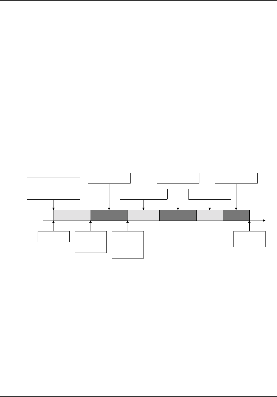
7K • Chapter 17
17-2
If a station can override the offending station and enter the Reset Transmitter
Timeout Timer command (on page 17-7), the transmitter will return to the air
and the timer will be reset. When the offending station releases his/her push-
to-talk button for at least one second (and no one has reset the timer for the
offending station), the timeout message will be sent again to inform him/her
that part of their transmission may have been lost.
Transmitter Unkey Delay
The Transmitter Unkey Delay holds the transmitter keyed for a programmable
period of time to prevent dropout between software keying requests. Event
macros can be defined that allow actions to occur at these events, eg. to
disable a CTCSS encoder before the transmitter is unkeyed (see page 17-14).
All the above delays and messages—as well as the transmitter timeout timer—
are fully programmable by the trustee. If, for example, the trustee does not
wish to have any courtesy delay or courtesy message, he/she may delete both.
In such case, the timer used for transmitter timeout timer will reset immediately
upon the user dropping his carrier. Figure 2 represents the Transmitter Tail
Sequence.
Figure 2
User Keys User Unkeys
Courtesy
Delay Starts
Transmitter
Timeout
Timer
Resets
Transmitter
Drops
Transmitter Keys
Transmitter Timeout
Timer Starts Courtesy Message Dropout Message
Courtesy Delay Dropout Delay
Time
Unkey Delay
Transmitter Functions
17-3
Select Courtesy Delay
Programs the Courtesy Delay time.
• The Courtesy Delay time is the delay from COR drop to when the
Transmitter Timeout Timer resets and the courtesy message begins. See
Figure 2 on page 17-2.
• Enter two digits, from 00 to 50, representing a delay time from 0.0 to 5.0
seconds.
Command Form:
Command Form Data Digit
Select Courtesy Delay (PW) 32 xx * (00–50) =
(0.0–5.0) seconds
Acknowledgment: Sends OK
Errors:
Error Meaning
? err 1 wrong number of digits entered
? err 2 illegal digit entered
Default Condition: Courtesy Delay is 0.5 seconds
Examples:
A generous amount of courtesy delay forces repeater users to delay their
transmissions, thus allowing other stations to break into the conversation. This
is something referred to as an anti-tailgating measure. A station that ignores
the courtesy message (indicating that the transmitter timeout timer has been
reset) runs the risk of timing out the repeater. That station will have to repeat
the portion of its transmission which was lost. To program the courtesy delay
for 1.4 seconds, for example, enter this command:
(PW) 32 14 *
Some repeater groups prefer no courtesy time; that is, the transmitter timeout
timer resets as soon as the COR drops. The courtesy message may also be
erased.
To program the courtesy delay for zero delay, enter this command:
(PW) 32 00 *

7K • Chapter 17
17-4
Select Dropout Delay
Sets the Dropout Delay time.
• The Dropout Delay time is the interval from the end of the Courtesy
Delay/Courtesy Message (and Reset Transmitter Timeout Timer) to the
moment the transmitter is unkeyed. See Figure 2 on page 17-2.
• Enter the two digits, from 00 to 50, representing a delay from 0.0 to 5.0
seconds.
Command Form:
Command Form Data Digit
Select Dropout Delay (PW) 30 xx * (00–50) =
(0.0–5.0) seconds
Acknowledgment: Sends OK
Errors:
Error Meaning
? err 1 wrong number of digits entered
? err 2 illegal digit entered
Default Condition: Dropout Delay is 3.0 seconds
Examples:
Owners of tube-type repeaters sometimes use long a dropout delay to lengthen
the lives of tubes and relays. Fewer transmitter keying transitions will occur,
since the users will keep the transmitter up for the duration of the conversation.
Dropout time for solid-state repeaters is mostly up to personal preference. To
program the dropout delay for 2.1 seconds, for example, enter this command:
(PW) 30 21 *
To program the dropout delay for maximum time, enter the following:
(PW) 30 00 *
Transmitter Functions
17-5
Select Transmitter Timeout Timer
Controls the maximum amount of time an input carrier signal may
be present.
• The Transmitter Timeout Timer starts timing when the COR becomes
active, and continues to run until reset.
• The timer is reset either by command (on page 17-7) or releasing the carrier
signal until the Courtesy Delay time elapses. See Figure 2 on page 17-2.
• Enter one, two, or three digits from 1 to 546 to set the transmitter timeout
timer to 0.1 to 54.6 minutes.
• To disable the timer completely, enter three zeroes.
Command Form:
Command Form Data Digit
Select Transmitter Timeout Timer (PW) 40 xxx * 000 = infinity
(001–546) =
(0.1–54.6) minutes
Acknowledgment: Sends OK
Errors:
Error Meaning
? err 1 wrong number of digits entered
? err 2 illegal digit entered
Default Condition: Transmitter Timeout Timer is 3.0 minutes
Examples:
Some of the ways to program the transmitter timeout timer follow: To change
the transmitter timeout timer from its existing value to 4.5 minutes, enter:
(PW) 40 45 *
To change the transmitter timeout timer to 10.0 minutes, enter:
(PW) 40 100 *
To set the timer for infinity (no timeout), enter:
(PW) 40 000 *

7K • Chapter 17
17-6
Note: The amount of time entered is in minutes and tenths of minutes.
Therefore, entering (PW) 40 3 * will set the timer to 0.3 minutes (18 seconds).
If you want 3.0 minutes, be sure to enter (PW) 40 30 *.
Leading zeroes are permitted. Therefore, entering (PW) 40 30 * would be the
same as entering (PW) 40 030 *.

Transmitter Functions
17-7
Reset Transmitter Timeout Timer
Resets the Transmitter Timeout Timer.
• If the transmitter timeout timer has been exceeded, this command will allow
the transmitter to return to the air.
Command Form:
Command Form
Reset Transmitter Timeout Timer (PW) 10 *
Acknowledgment: None
Errors: None
Default: None
Examples:
If the transmitting station has caused a timeout to occur, the receiving station
may be able to bring the transmitter back up. To do so would require the
receiving station to be able to override the offending station at the repeater site.
Entering the Reset Transmitter Timeout Timer command will reload the timer
as well as return the repeater transmitter to the air.
7K • Chapter 17
17-8
Enable/Disable Transmitter
Enables or disables the specified Transmitter (TX1 or TX2) while
not affecting receiver functions.
• The receiver will still be able to send commands to the controller, but the
transmitter will not be keyed upon receiving COR signals.
• See the various Key Transmitter commands beginning on page 17-9.
Command Form:
Command Form Data Digit
Enable/Disable Transmitter 1 (PW) 63 00 x * 0 = OFF (disabled)
1 = ON (enabled)
Enable/Disable Transmitter 2 (PW) 63 22 x * 0 = OFF (disabled)
1 = ON (enabled)
Acknowledgment: None
Errors:
Error Meaning
? err 1 wrong number of digits entered (disable only)
? err 2 illegal digit entered (disable only)
Default Condition: Both Transmitters TX1 and TX2 are ON (enabled)
Transmitter Functions
17-9
Key Transmitter (Timed)
Keys the specified Transmitter (TX1 or TX2) for a timed period.
• The specified transmitter will not key under this command if it has been
disabled using the Enable/Disable Transmitter command on page 17-8.
• Enter transmitter, 1 or 2.
• Enter a 1-, 2-, or 3-digit number representing the amount of time the
transmitter should key (in tenths of minutes).
• Enter nothing (or 000) to cancel key request.
Command Form:
Command Form Data Digit
Key Transmitter (Timed) (PW) 00 x yyy * x = transmitter =
(1 or 2)
yyy = (001–546) =
(0.1–54.6) minutes
or yyy = [ (nothing) ,
0, 00, 000] = cancel
key
Acknowledgment: Sends OK
Errors:
Error Meaning
? err 1 wrong number of digits entered
? err 2 illegal digits entered
Default Condition: Both Transmitters TX1 and TX2 are not requested to key

7K • Chapter 17
17-10
Key Transmitter (Untimed)
Keys the specified transmitter (TX1 or TX2) until canceled.
• The specified transmitter will not key under these commands if it has been
disabled using the Enable/Disable Transmitter command on page 17-8.
• Enter one digit, 0 for OFF (cancel), 1 for ON (key).
• The transmitter will remain keyed indefinitely, until canceled.
Command Form:
Command Form Data Digit
Key Transmitter 1 (Untimed) (PW) 63 41 x * 1 = key
0 = cancel key
Key Transmitter 2 (Untimed) (PW) 63 42 x * 1 = key
0 = cancel key
Acknowledgment: Sends OK
Errors:
Error Meaning
? err 1 wrong number of digits entered
? err 2 illegal digit entered
Default Conditions: Both Transmitters TX1 and TX2 are not requested to key
Transmitter Functions
17-11
Enable/Disable Transmitter Minimum Unkey Delay
Enables or disables the transmitter minimum unkey delay.
• A Minimum Unkey Delay is normally observed on Transmitter #1 to prevent
it from unkeying between software keying requests. If this delay is disabled,
the transmitter may drop out between messages or other activities that
require keying.
• The delay may be disabled in special applications (such as half-duplex
linking) where fast unkeying is desired.
Command Form:
Command Form Data Digit
Enable/Disable TX1 Minimum Unkey Delay (PW) 63 31 x * 0 = OFF (disabled)
1 = ON (enabled)
Enable/Disable TX2 Minimum Unkey Delay (PW) 63 32 x * 0 = OFF (disabled)
1 = ON (enabled)
Acknowledgment: Sends OK
Errors:
Error Meaning
? err 1 wrong number of digits entered
? err 2 illegal digit entered
Default Conditions: Minimum Unkey Delay for TX1 is ON (enabled);
for TX2 is OFF (disabled)
7K • Chapter 17
17-12
Select Transmitter Minimum Unkey Delay
Programs the minimum amount of time for a transmitter to unkey.
• A Transmitter 1 Minimum Unkey Delay can be programmed from 0 to 655.3
seconds.
• A Transmitter 2 Minimum Unkey Delay can be programmed from 0 to 655.3
seconds.
• Enter the timeout value as 1, 2, 3, or 4 digits, leading zeroes are not
required.
• A programmed Minimum Unkey Delay will not be present unless it is
enabled using the Enable/Disable Transmitter Minimum Unkey Delay
command (see page 17-11).
Command Form:
Command Form Data Digit
Select Tx1 Minimum Unkey Delay (PW) 49 98 xxxx * from table below
Select Tx2 Minimum Unkey Delay (PW) 49 99 xxxx * from table below
Data Digit Explanation
xxxx = 0000-6553 seconds in 0.1 second increments from 0.0 to
655.3 seconds as 1, 2, 3, or 4 digits
Acknowledgment: Sends OK
Errors:
Error Meaning
? err 1 wrong number of digits entered
? err 2 invalid timer or seconds parameter
Default Condition: None.
Example:
To set the Transmitter 1 Minimum Unkey Delay to 0.4 second, enter the command:
(PW) 49 98 4 *
To set the Transmitter 2 Minimum Unkey Delay to 5.0 seconds, enter the command:
(PW) 49 99 50 *
Transmitter Functions
17-13
Select Receiver-to-Transmitter-Triggered Macros
Allows the programmer to execute macros based on receiver-to-
transmitter activity.
• Macros can be executed based on receiver-to-transmitter activity.
• Enter the password, the 4-digit root number, and the 4-digit name of the
macro you wish to have executed at the transition, and the (*).
• If the macro name has fewer than 4 digits, enter leading zeros.
• If you wish to prevent a macro from being executed that was previously
assigned, enter just the password, the 4-digit root number, and the (*).
Command Form:
Command Form
Assign Macro to Any-Receiver-Active to Tx1 (PW) 26 11 (macro name) *
Assign Macro to All-Receivers-Inactive to
Tx1 (PW) 26 09 (macro name) *
Assign Macro to Any-Receiver-Active to Tx2 (PW) 26 73 (macro name) *
Assign Macro to All-Receivers-Inactive to
Tx2 (PW) 26 74 (macro name) *
Acknowledgment: Sends OK
Errors:
Error Meaning
? err 1 wrong number of digits entered
? err 2 illegal digit entered
Default Condition: No macros assigned.
7K • Chapter 17
17-14
Select Transmitter PTT-Triggered Macros
Allows the programmer to execute macros based on transmitter
keying.
• Each transmitter has its own PTT Inactive-to-Active Macro, PTT Active-to-
Inactive Before Unkey Delay Macro, and PTT Active-to-Inactive Macro.
• Enter the password, the 4-digit root number, and the 4-digit name of the
macro you wish to have executed at the transition, and the (*).
• If the macro name has fewer than 4 digits, enter leading zeros.
• If you wish to prevent a macro from being executed that was previously
assigned, enter just the password, the 4-digit root number, and the (*).
Command Form:
Command Form
Assign Macro to Tx1 PTT Inactive-to-Active (PW) 26 82 (macro name) *
Assign Macro to Tx1 PTT Active-to-Inactive
Before Unkey Delay (PW) 26 83 (macro name) *
Assign Macro to Tx1 PTT Active-to-Inactive (PW) 26 84 (macro name) *
Assign Macro to Tx2 PTT Inactive-to-Active (PW) 26 85 (macro name) *
Assign Macro to Tx2 PTT Active-to-Inactive
Before Unkey Delay (PW) 26 86 (macro name) *
Assign Macro to Tx2 PTT Active-to-Inactive (PW) 26 87 (macro name) *
Acknowledgment: Sends OK
Errors:
Error Meaning
? err 1 wrong number of digits entered
? err 2 illegal digit entered
Default Condition: No macros assigned.

Transmitter Functions
17-15
Example 1:
PTT-triggered macros provide a way to generate messages, control logic
outputs, start timers, etc., for functions that need to be synchronized to a
transmitter’s operation. The Inactive-to-Active macro is executed when the
transmitter is keyed. The Active-to-Inactive macro is executed when the
transmitter is unkeyed. The Active-to-Inactive Before Unkey Delay macro is
executed a programmable amount of time before the transmitter is actually
unkeyed.
As an example, let’s say that you have a CTCSS encoder on your repeater
transmitter and your repeater users program their radios to only open their
receivers when a CTCSS tone is present. If the CTCSS tone is always present
on your transmitter, then, when the transmitter unkeys, a squelch burst is heard
in your users’ receivers. To prevent the squelch burst, you could disable the
CTCSS tone on your transmitter a small amount of time before the transmitter
is unkeyed so that the users’ receivers would close before the squelch burst
could occur.
To control a CTCSS encoder, you would write two macros and assign them to
the Inactive-to-Active and Active-to-Inactive Before Unkey Delay-triggered
macros to enable and disable the CTCSS encoder using a Logic Output.
To create a macro that turns on Logic Output 7 to enable the CTCSS encoder,
enter the following:
(PW) 20 9107 (PW) 70 7 *
To create a macro that turns off Logic Output 7 to disable the CTCSS encoder,
enter the following:
(PW) 20 9108 (PW) 71 7 *
To assign these macros to the PTT-triggered events, enter the following:
(PW) 26 82 9107 *
(PW) 26 83 9108 *
PTT Tx Unkey Delay
Active-to-
Inactive Macro
Before-Unkey-
Delay Macro
Inactive-to-
Active Macro

7K • Chapter 17
17-16
To adjust the amount of time that the transmitter stays keyed after the tone
encoder is disabled, set the Transmitter Minimum Unkey Delay (see page 17-
15). For example, to set the Tx1 Minimum Unkey Delay to 0.4 seconds, enter
the following:
(PW) 49 98 4 *
Note: an alternate way to control a CTCSS tone on Transmitter 1 is to use the
controller’s dedicated CTCSS audio gate (see page 10-2). When enabled, this
audio gate opens to pass audio when Transmitter 1 is keyed and closes at the
beginning of the Tx1 Minimum Unkey Delay. You would use the Select Tx1
Minimum Unkey Delay command as in the example above to adjust the
amount of time the transmitter stays keyed after the CTCSS encoder is
disabled. This method does not require the use of PTT-triggered macros.
Example 2:
The PTT-triggered macros can be used with the User Timers to control
external equipment that should operate for a time after a transmitter is
unkeyed. See page 20-7 for an example of controlling a fan.

Repeater Functions
18-1
Chapter 18
Repeater
Functions
The commands in this chapter relate to the repeater, which we define as the
Receiver 1 and Transmitter 1 combination. Receivers 2 and 3, and Transmitter
2, are generally viewed as link devices, and are described in other chapters
(see Receiver Functions on page 16-1, Transmitter Functions on page 17-1,
and Links on page 13-1).

7K • Chapter 18
18-2
Select Repeater Access Mode (Path 1)
Selects one of seven possible Access Modes for Path 1.
• Enter one digit from the Repeater Access Mode Table below.
Command Form:
Command Form Data Digit (Mode)
Select Repeater Access Mode (Path 1) (PW) 57 00 x * Repeater Access
Mode Table (below)
Mode Repeater Access Explanation
0No Access Activity on the COR and PL inputs is ignored.
1Carrier Access Activity on the COR input will key the
transmitter; activity on the PL input is ignored.
2PL Access Activity on the PL input will key the transmitter;
activity on the COR input is ignored.
3And-PL Access Activity on both the COR and PL inputs
simultaneously will key the transmitter.
4Or-PL Access Activity on either the COR or PL inputs will key
the transmitter.
5Anti-PL Access Activity on the COR input simultaneously with
no activity on the PL input will key the
transmitter.
6Always Access Activity on the COR and PL inputs is ignored.
The path is always enabled.
Acknowledgment: Sends OK
Errors:
Error Meaning
? err 1 wrong number of digits entered
? err 2 illegal digit entered
Default Condition: Access Mode for Path 1 is Mode 1 (Carrier Access)
Note: Repeater access mode may be made different from DTMF decoder
access mode, if desired. (See page 11-5.)

Repeater Functions
18-3
Examples:
Assume that the repeater is in carrier access mode, and that PL access is
desired. The proper command would be:
(PW) 57 00 2 *
A better mode for many repeater installations is mode 3, And-PL access. This
mode has better rejection of adjacent-channel interference than mode 2, since
noise falsing from unsquelched audio is eliminated. Also, COR drops out more
quickly than PL, allowing a quick dropout result. Enter this command:
(PW) 57 00 3 *
Mode 4 allows both carrier access and PL operation. Since PL is more easily
detected, PL users will find increased range. Carrier access users are
unaffected. The squelch may be tightened to suppress band opening problems.
Anti-PL is used when the repeater is co- channel with another, PL-accessed
repeater. Users of the second system are kept out of the Anti-PL system.
If you broadcast Newsline Report, the no access mode (mode 0) means that
transmissions on the repeater input are ignored and can’t interfere with the
broadcast.
If you need to control the system on its input, place the DTMF decoder in a PL
mode.

7K • Chapter 18
18-4
Select Repeater Activity-Triggered Macros
Select Repeater Activity Counter/Timer
Allows the programmer to execute macros based on the activity of
the repeater.
Sets the Repeater Activity Counter/Timer (both the Event Count
and the Duration).
• No data digits are required for the macros.
• Select the Repeater Activity Counter/Timer (Event Count) using 1-digit, 0–9.
Setting the counter to 0 (zero) means that the Post-Activity Macro will
execute each activity cycle. Setting the counter to 1 means that the post-
activity macro will execute every other activity cycle, and so on. Setting the
counter to 9, therefore, means that the post- activity macro will execute
every 10th cycle.
• Select the Repeater Activity Counter/Timer (Duration) using 2 digits
representing the delay. (00–99) equals (0.0–9.9) minute delay.
Command Form:
Command Form Data Digit
Select Repeater Start-of-Activity Macro (PW) 26 14 (macro
name) *
not applicable
Select Repeater Post-Activity Macro (PW) 26 15 (macro
name) *
not applicable
Select Repeater Activity Counter/Timer (PW) 45 x yy* x = (event count) =
(0–9)
y = (duration) =
(00–99) = (0.0–9.9)
minute delay
Acknowledgment: Sends OK
Errors:
Error Meaning
? err 1 wrong number of digits entered
? err 2 illegal digit entered
Default: No Macros are assigned; Event Count is 0; Duration is 1.0 minutes

Repeater Functions
18-5
Example:
Applications for this feature include tape recording all repeater conversations,
in which case, the activity count would be set to zero. However, if a taped
message is to be played every 5th usage of the repeater, set the activity
counter/timer to 4.
The three related Select Repeater Activity-Triggered Macros commands allow
the programmer to execute macros based on repeater activity. For example, a
bulletin may be sent a few minutes after the last activity of the repeater. Since
the repeater was recently used, it is likely an audience still exists to hear the
message. Of course, the bulletin would be too repetitious to send every time
the repeater is used. In this light, the activity counter/ timer allows the
programmer to select how often to execute the macro.
The Repeater Start-of-Activity Macro is executed when a fresh key-up occurs.
This event starts an “activity cycle” which ends a certain time after the tail
finishes. If activity occurs before the activity counter/timer expires, the activity
cycle is simply extended. When the activity counter/timer finally expires, the
Repeater Post-Activity Macro is executed. The activity counter/timer, which
watches the number of activity cycles, is programmable in duration from 0–9.9
minutes and from 0–9 events.
Once the activity cycle has been completed, the start-of-activity macro is again
“armed” and ready to execute at the next key-up activity. This is true regardless
of whether the last repeater post-activity macro was actually executed (it may
have been waiting for the proper activity count).
Note: The Repeater Activity Counter/Timer starts when the dropout message is
sent.
7K • Chapter 18
18-6
Select Anti-Kerchunker Parameters
Programs the “Anti-Kerchunk” Key-up Delay and Re-Arm Delay for
the repeater.
• Users must key for the selected length of time before the repeater
transmitter keys.
• Once the Key-Up Delay is exceeded, the feature is disabled.
• The anti-kerchunker is Re-Armed if no activity is present for a selected
length of time after the repeater transmitter drops.
Command Form:
Command Form Data Digit
Select Key-Up Delay (PW) 80 xx * xx = duration =
(00–99) = (0.0–9.9)
seconds
Select Re-Arm Delay (PW) 99 10 xx * xx = duration =
(00–99) = (0.0–9.9)
minutes
Acknowledgment: Sends OK
Errors:
Error Meaning
? err 1 wrong number of digits entered
? err 2 illegal digit entered
Default Condition: Key-Up Delay is 0 seconds; Re-Arm Delay is to 0 minutes

Repeater Functions
18-7
Examples:
If you want to require a one-half second key-up delay, enter:
(PW) 80 05 *
Unless changed, the anti-kerchunker will re-arm as soon as the repeater
transmitter drops. If you want a 1.5 minute delay in re-arming, enter:
(PW) 99 10 15 *
To disable the anti-kerchunker, set the key-up delay to 0:
(PW) 80 00 *
7K • Chapter 18
18-8
Select Anti-Kerchunk No Hangtime Mode
Allows the programmer to modify the operation of the
Anti-Kerchunker.
• By default and when disabled, the Anti-Kerchunker does not key the
transmitter during the Key-Up Delay.
• By enabling the No Hangtime Mode, the transmitter is keyed during the
Key-Up Delay.
• Enter one digit, 0 for OFF (disabled), 1 for ON (enabled).
Command Form:
Command Form Data Digit
Select Anti-Kerchunk No Hangtime Mode (PW) 63 30 x * 0 = OFF (disabled)
1 = ON (enabled)
Acknowledgment: Sends OK
Errors:
Error Meaning
? err 1 wrong number of digits entered
? err 2 illegal digit entered
Default Condition: Disabled.
Repeater Functions
18-9
Select (Review) Courtesy Messages
Program unique Courtesy Messages for each receiver.
• Enter the password, the 4-digit root number, the desired message, and a
(*).
• Any message may be any combination of message types including CW,
beeps, page tones, speech, etc.
• The maximum size of any message is 50 bytes (50 2-digit codes).
• You must count the control character. Therefore, any message could have
46 CW characters, 23 synthesized speech words, and so on.
• To delete a message, enter the password, the 4-digit root number, and the
(*). Do not enter any message.
Command Form:
Command Form
Select Courtesy Message for Rx1 (PW) 31 10 (message) *
Select Courtesy Message for Rx2 (PW) 31 11 (message) *
Select Courtesy Message for Rx3 (PW) 31 12 (message) *
Review Courtesy Message for Rx1 (PW) 34 10 *
Review Courtesy Message for Rx2 (PW) 34 11 *
Review Courtesy Message for Rx3 (PW) 34 12 *
Acknowledgment: Sends OK
Errors:
Error Meaning
? err 1 wrong number of digits entered
? err 2 illegal digit entered
Default Condition:
Command Default Condition
Select Courtesy Message for Rx1 60mS 440 Hz beep (9910 74 09)
Select Courtesy Message for Rx2 60mS 660 Hz beep (9910 74 16)
Select Courtesy Message for Rx3 60mS 880 Hz beep (9910 74 21)

7K • Chapter 18
18-10
Example:
Suppose we want to change the courtesy message for Receiver 1 to a burst of
2 beeps. We want the two beeps to be 25 and 21, we want them to be 40mS
in duration, and we want no gap between them.
Looking up this information in the Beep Character Set Tables beginning on
page A-5, we find: 55 turns the automatic beep gap OFF; 73 changes the beep
duration to 40mS; and, the control character for a beep message is 9910.
Therefore, the complete command to change the courtesy message is:
(PW) 31 10 9910 55 73 25 21 *
Repeater Functions
18-11
Select Repeater Action-Triggered Macros
Allows the programmer to execute macros based on repeater
activity.
• Macros can be executed based on receiver activity, receiver inactivity and
when a courtesy message is sent.
• Enter the password, the 4-digit root number, and the 4-digit name of the
macro you wish to have executed at the transition, and the (*).
• If the macro name has fewer than 4 digits, enter leading zeros.
• If you wish to prevent a macro from being executed that was previously
assigned, enter just the password, the 4-digit root number, and the (*).
Command Form:
Command Form
Assign Macro to Any-Receiver-Active (PW) 26 11 (macro name) *
Assign Macro to All-Receivers-Inactive (PW) 26 09 (macro name) *
Assign Macro to Courtesy Message (PW) 26 10 (macro name) *
Assign Macro to Dropout Message (PW) 26 08 (macro name) *
Assign Macro to Repeater Timeout (PW) 26 18 (macro name) *
Assign Macro to Return-From-Repeater-
Timeout
(PW) 26 19 (macro name) *
Acknowledgment: Sends OK
Errors:
Error Meaning
? err 1 wrong number of digits entered
? err 2 illegal digit entered
Default Condition: No macros assigned.

7K • Chapter 18
18-12

Base Station Functions
19-1
Chapter 19
Base Station
Functions
The controller includes features that allow commercial customers to operate
Base Stations from standard dial-up phone lines or microwave links. The base
station is connected to the Receiver 1 and Transmitter 1 ports in place of a
repeater. The commands described in this chapter would not normally be used
if you are controlling a repeater instead of a base station.
Unlike a repeater, a base station operates half duplex—you must alternate
between transmitting and receiving. Therefore, commands are needed to place
the controller into half-duplex mode and to allow talkout from the phone line to
the transmitter.

7K • Chapter 19
19-2
Enable/Disable Star/Pound Talkout
Turns ON or OFF the Star/Pound (*/#) Talkout feature.
• This feature is used when controlling a Half-Duplex Base Station from a
standard dial-up phone line.
• When enabled, the phone line party has control of the DTMF decoder.
• Receiver #1 audio is fed to the phone line as soon as the feature is
enabled.
• The (*) button keys transmitter 1 and feeds phone line audio to the
transmitter. The (#) button unkeys transmitter 1 and feeds receiver 1 audio
to the phone line. You have 40 seconds from the time this feature is
enabled until the (*) must be entered. Otherwise, the controller will go on-
hook.
• This command must be entered each time a call is placed to the controller.
• Do not enable the Pound Down (# Dump) command on page 7-8 if you are
using Star/ Pound Talkout, since the (#) character will then terminate the
call.
• See the Select Talkout Transmitter Mode command on page 19-4.
Command Form:
Command Form Data Digit
Enable/Disable Star/Pound Talkout (PW) 63 13 x * 0 = OFF (disabled)
1 = ON (enabled)
Acknowledgment: Sends OK
Errors:
Error Meaning
? err 1 wrong number of digits entered
? err 2 illegal digit entered
Default Condition: Star/Pound Talkout is OFF (disabled)

Base Station Functions
19-3
Examples:
Dial the base station telephone number. When it answers, enter:
(PW) 63 13 1 *
This puts the controller into star/pound talkout mode. To exit the mode, enter:
(PW) 63 13 0 *.
Note: Be sure you have selected Base Station Mode with the Select Talkout
Transmitter Mode command on page 19-4.
7K • Chapter 19
19-4
Select Talkout Transmitter Mode
Selects either Repeater Mode or Base Station Mode for phone line
talkout applications.
• In Repeater Mode, transmitter #1 stays keyed during the entire
conversation. This is the usual mode for all repeater autopatch applications.
• In Base Station Mode, transmitter #1 is keyed and unkeyed by the (*) and
(#) characters sent by the phone line party.
• This command works only when the Enable/Disable Star/Pound Talkout
command is enabled (page 19-2).
• The selected mode does not change when the call is terminated.
Command Form:
Command Form Data Digit
Select Talkout Transmitter Mode (PW) 63 14 x * 0 = Repeater Mode
1 = Base Station
Mode
Acknowledgment: Sends OK
Errors:
Error Meaning
? err 1 wrong number of digits entered
? err 2 illegal digit entered
Default Condition: Repeater Mode is selected
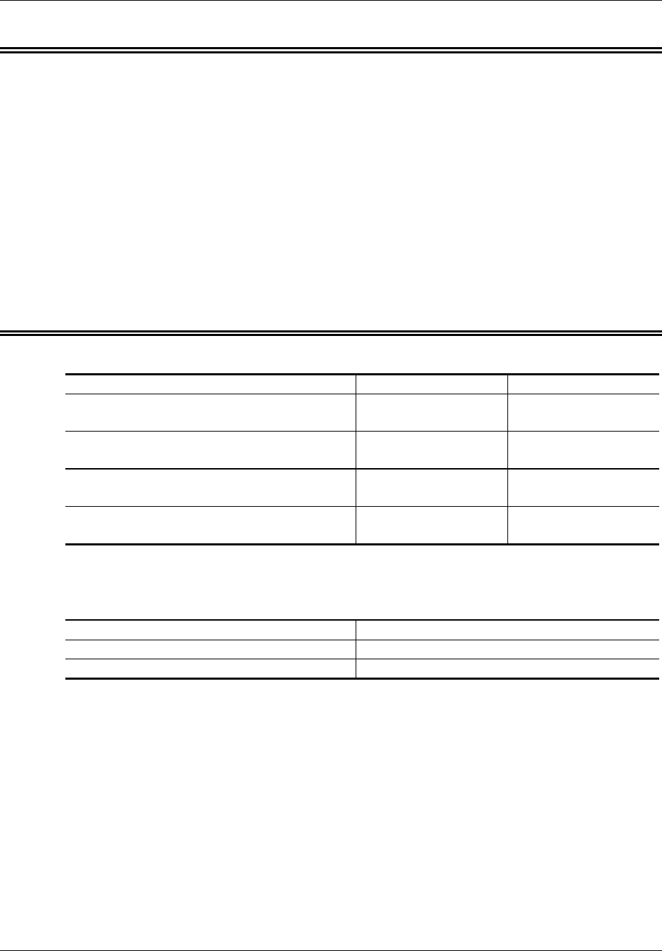
Base Station Functions
19-5
Enable/Disable Command Execution
on Interdigit Timer
Selects whether DTMF Interdigit Timer serves to cancel a partial
command or execute a command that is not terminated.
• Used by those commercial customers owning radios that lack the (*) and (#)
characters.
• Although commands can be executed on End-of-Transmission, that feature
cannot operate if a stuck mic exists in the system.
• Enter one digit, 0 for OFF (disabled), 1 for ON (enabled).
Command Form:
Command Form Data Digit
Enable/Disable Command Execution on
Interdigit Timer for RX1
(PW) 63 60 x * 0 = OFF (disabled)
1 = ON (enabled)
Enable/Disable Command Execution on
Interdigit Timer for RX2
(PW)•63 61 x * 0 = OFF (disabled)
1 = ON (enabled)
Enable/Disable Command Execution on
Interdigit Timer for RX3
(PW) 63 62 x * 0 = OFF (disabled)
1 = ON (enabled)
Enable/Disable Command Execution on
Interdigit Timer for Phone Line
(PW) 63 63 x * 0 = OFF (disabled)
1 = ON (enabled)
Acknowledgment: Sends OK
Errors:
Error Meaning
? err 1 wrong number of digits entered
? err 2 illegal digit entered
Default Condition: Command Execution on Interdigit Timer is OFF (disabled)
for all receivers
Examples:
Recall that the DTMF Interdigit Timer measures the time delay between DTMF
characters. Normally, the command buffer is cleared if this timer expires.
However, the command described here changes the meaning of the timer: If
the timer expires, the command is executed rather than cleared. The user
would enter his command, then wait for execution.

7K • Chapter 19
19-6
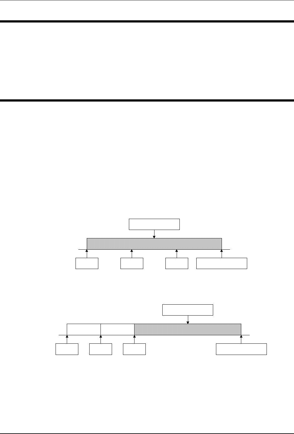
User Timers
20-1
Chapter 20
User Timers
The Controller features ten User Timers. These timers can be used to
implement timed operations not otherwise implemented by the controller.
The User Timers can be set in 0.1-second increments to 655.3 seconds
(slightly less than 11 minutes). When a timer times out, an event macro is
executed to perform a user-defined operation.
The User Timers can be operated as “one-shot” timers or as “retriggerable”
timers.
• One-shot timers are timers that are started and will time to completion.
Even if the start command is executed again, the duration of the timer will
be measured from the first start request:
• Retriggerable timers are timers that are started and can be restarted during
their programmed time. When retriggerable timers do time out, the time
period will be the full programmed time from the last restart command:
Start Start Start Execute Macro
Programmed Time
Restart RestartRestart Execute Macro
Programmed Time
7K • Chapter 20
20-2
Select Timeout Value
Programs the duration of a User Timer.
• The range of a one-shot or a retriggerable timer is from 0.1 second to 655.3
seconds.
• Enter the 2-digit number to select a timer. Use a leading zero.
• Enter the timeout value as 1, 2, 3, or 4 digits, leading zeroes are not
required.
• If the timer is running when this command is executed, the timer continues
to run until this new timeout value is reached. But, if the new timeout value
is less than the time already expired on the timer the new timeout value is
set, the timer is stopped, and the macro assigned to the timer is executed.
Command Form:
Command Form Data Digit
Set Timer Timeout Value (PW) 49 (timer) 03
(seconds) * from table below
Data Digit Explanation
Timer, 00-09 select one of 10 timers, 2 digits are required
Seconds, 0001-6553 seconds in 0.1 second increments from 0.1 to
655.3 seconds as 1, 2, 3, or 4 digits
Acknowledgment: Sends OK
Errors:
Error Meaning
? err 1 wrong number of digits entered
? err 2 invalid timer or seconds parameter
Default Condition: None.
Example:
To set the timeout duration of timer 00 to 27.0 seconds, enter the command:
(PW) 49 00 03 270 *
To set the timeout duration of timer 07 to 8 minutes (480 seconds), enter the
command:
(PW) 49 07 03 4800 *
User Timers
20-3
Select Timer Event Macro
Assigns the macro to be triggered when the one-shot or
retriggerable timer times out.
• Enter the 2-digit timer number and 4-digit macro name to be called upon
timeout of the timer. Use leading zeros if required.
• To remove the assignment to the macro, enter the command with no macro
name.
• If the timer is running when this command is executed, the timer will
continue to run. The last macro entered by this command will be executed
at the end of the timer period.
Command Form:
Command Form Data Digit
Assign Timer Event Macro (PW) 49 (timer) 02
(macro name) * from table below
Unassign Timer Event Macro (PW) 49 (timer) 02 * from table below
Data Digit Explanation
timer, 00-09 select one of 10 timers, 2 digits are required
macro name the name of the macro to be triggered
Acknowledgment: Sends OK
Errors:
Error Meaning
? err 1 wrong number of digits entered
? err 2 illegal digit entered
Default Condition: No macro assigned.
Example:
To assign macro 9101 to timer 00, enter the command:
(PW) 49 00 02 9101 *
To assign macro 9 to timer 04, enter the command:
(PW) 49 04 02 0009 *

7K • Chapter 20
20-4
Stop Timer
Stops the one-shot or retriggerable timer.
• Enter the 2-digit timer number. Use a leading zero.
• If the timer is running, it is stopped without triggering the macro.
• If the timer is stopped or has timed out, this command has no effect.
Command Form:
Command Form Data Digit
Stop Timer (PW) 49 (timer) 00 * from table below
Data Digit Explanation
timer, 00-09 select one of 10 timers, 2 digits are required
Acknowledgment: Sends OK
Errors:
Error Meaning
? err 1 wrong number of digits entered
? err 2 illegal digit entered
Default Condition: None.
Example:
To stop timer 00, enter the command:
(PW) 49 00 00 *
To stop timer 09, enter the command:
(PW) 49 09 00 *

User Timers
20-5
Start Timer (Retriggerable)
Starts the selected timer as a retriggerable timer.
• Enter the 2-digit timer number. Use a leading zero.
• If the timer is stopped, the timer is reset to zero time expired and started.
• If the timer is running, the timer is reset to zero time expired and continues.
Command Form:
Command Form Data Digit
Start/Restart Timer (Retriggerable) (PW) 49 (timer) 01 * from table below
Data Digit Explanation
timer, 00-09 select one of 10 timers, 2 digits are required
Acknowledgment: Sends OK
Errors:
Error Meaning
? err 1 wrong number of digits entered
? err 2 illegal digit entered
Default Condition: None.
Example:
To start retriggerable timer 00 or retrigger it, enter the command:
(PW) 49 00 01 *
To start retriggerable timer 02 or retrigger it, enter the command:
(PW) 49 02 01 *
7K • Chapter 20
20-6
Start Timer (One-Shot)
Starts the selected timer as a one-shot timer.
• Enter the 2-digit timer number. Use a leading zero.
• If the timer is stopped, the timer is set to zero time expired and started.
• If the timer is running, the command is ignored.
Command Form:
Command Form Data Digit
Start Timer (One-Shot) (PW) 49 (timer) 04 * from table below
Data Digit Explanation
timer, 00-09 select one of 10 timers, 2 digits are required
Acknowledgment: Sends OK
Errors:
Error Meaning
? err 1 wrong number of digits entered
? err 2 illegal digit entered
Default Condition: None.
Example:
To start one-shot timer 00, enter the command:
(PW) 49 00 04 *
To start one-shot timer 08, enter the command:
(PW) 49 08 04 *

User Timers
20-7
Example: Fan Control
Installing a fan to cool a repeater or link transmitter is always a good idea. It
can extend the life of the transmitter significantly. But, leaving the fan running
all the time will shorten the life of the fan.
To extend the life of the fan, the fan can be operated whenever the transmitter
is keyed and for a couple of minutes after. A User Timer can be used to
control the amount of time the fan stays on after the transmitter unkeys.
Three macros will be required to implement the fan control: one is triggered
when the transmitter is keyed, a second is triggered when the transmitter is
unkeyed, and a third is triggered when the timer times out. To control the fan,
a Logic Output will be used to power the fan through a switching device, e.g. a
relay or HexFET.
For this example, we’ll create macros 8701, 8702, and 8703. We’ll use timer
#9 and logic output #1.
First, setup the timer and assign the macros.
; Setup
(PW) 49 09 03 1200 * ; Set Timer 120.0 seconds
(PW) 49 09 02 8703 * ; Set Timer Macro
(PW) 26 82 8701 * ; Set Tx1 Active Macro
(PW) 26 84 8702 * ; Set Tx1 Inactive Macro
Enter the macro that is triggered when the transmitter is keyed. This macro
stops the timer and enables the logic output to activate the fan for the entire
time that the transmitter is keyed.
; Macro: Tx1 Active: Stop Timer, Logic Out On
(PW) 20 8701 (PW) 49 09 00 * ; stop timer
(PW) 29 8701 (PW) 701*;Logic Out 1 ON
Enter the macro that is triggered when the transmitter is unkeyed. This macro
starts the timer and leaves the fan on.
; Macro: Tx1 Inactive
(PW) 20 8702 (PW) 49 09 01 * ; start timer
Enter the macro that is triggered when the timer times out. This macro turns
off the fan.
; Macro: Timer Timeout
(PW) 20 8703 (PW) 711*;Logic Out 1 OFF

7K • Chapter 20
20-8
Example: An Activity Timer
The repeater and each receiver input has an activity timer available to cause a
macro to be triggered after activity on the repeater has ceased. But,
sometimes one activity timer is not enough. A User Timer can be used to
implement one or more additional activity timers.
Three macros will be required to implement the activity timer: one is triggered
when the repeater is activated by a receiver, a second is triggered when all
receivers are inactive, and a third is triggered when the timer times out. Our
example triggers a macro that speaks a message, but any commands can be
executed at that time.
For this example, we’ll create macros 8711, 8712, and 8713. We’ll use timer
#8.
First, setup the timer and assign the macros.
; Setup
(PW) 49 08 03 3000 * ; Set Timer 300.0 seconds
(PW) 49 08 02 8713 * ; Set Timer Macro
(PW) 26 11 8711 * ; Set Any-Rx-Active Macro
(PW) 26 09 8712 * ; Set All-Rx-Inactive Macro
Enter the macro that is triggered when any receiver is active. This macro stops
the timer.
; Macro: Any-Rx-Active: Stop Timer
(PW) 20 8711 (PW) 49 08 00 * ; stop timer
Enter the macro that is triggered when all receivers are inactive. This macro
starts the timer.
; Macro: All-Rx-Inactive
(PW) 20 8712 (PW) 49 08 01 * ; start timer
Enter the macro that is triggered when the timer times out. This macro can
perform any operation, but in our example it speaks a message.
; Macro: Timer Timeout, speak 1-second-pause + “Net”
(PW) 20 8713 (PW) 15 9960 0000 0331 *

Remote Base Interface
21-1
Chapter 21
Remote Base
Interface
Your controller has many features that allow you to customize the operation of
the controller when connected to a Doug Hall Electronics RBI-1 Remote Base
Interface. All of the capabilities of the RBI-1 are supported.
The 7K Remote Base Interface has the following features:
• All remote base user functions use a password that is different from the
Master, Control Operator, or Autopatch Passwords defined within the
controller. Because of this, users do not need to know these passwords to
use the remote base functions.
• User functions are optimized to minimize the number of keystrokes users
must enter to perform common functions.
• Macros can be used to define memory channels.
• Direct frequency entry allows easy frequency and transmitter offset
changes.
• The time-of-day scheduler can be used to control when the remote base
functions are available.
• The controller can speak the current radio configuration.
• Eight additional logic outputs on the RBI-1 are available for controlling
external devices.

7K • Chapter 21
21-2
Remote Base Setup and Configuration
Wiring
You will need to wire the RBI-1 to the controller using the connections shown in
the table, below. The first three wires allow the controller to send commands to
the RBI-1. The rest of the wires connect the RBI-1 to the controller’s Receiver
2 and Transmitter 2 connections.
7K RBI-1 Purpose
J3 Pin 16 J2 Pin 1 RBI-1 Reset
J3 Pin 17 J2 Pin 4 RBI-1 Clock
J3 Pin 18 J2 Pin 3 RBI-1 Data
J3 Pin 25 J2 Pin 9 Ground
J2 Pin 8 J2 Pin 6 Rx2 Audio In
J2 Pin 22 Shield
J2 Pin 15 J2 Pin 5 Tx2 Audio Out
J2 Pin 19 Shield
J2 Pin 3 J2 Pin 7 Rx2 COR
J2 Pin 11 J2 Pin 8 Tx2 PTT
Switch Setting
DIP Switch #2 is used to invert the Receiver 2 COR signal from the RBI-1. Set
the dip switch as follows:
DIP Switch #2 = OFF. This inverts COR #2 for Rx2.
Software Configuration
The radios connected to the RBI-1 only operate half-duplex -- they cannot
transmit and receive at the same time. The Link Paths of the controller define
which receivers are connected to which transmitters. By default, Receiver 2 is
connected to Transmitter 2. This link path must be disabled for proper
operation of the remote base interface.
(PW) 63 85 0 * ;Disable Path 5 (Rx2 to Tx2)
By default, the controller will send an identifier message to Transmitter 2.
Delete this message if you don’t want to send an ID message.
(PW) 31 33 * ;Delete Initial ID Message for Tx2
(PW) 31 34 * ;Delete Normal ID Message for Tx2
By default, the 7K will mute all DTMF tones from Receiver 1 to Transmitter 2.
If you wish to pass tones to Transmitter 2, enter the following command:
(PW) 63 53 0 * ;Disable Rx1-Tx2 DTMF Mute
By default, the remote base is disabled. To enable it for use, enter the
following command:
(PW) 63 71 1 * ;Enable Remote Base

Remote Base Interface
21-3
Event Triggered Macros
The system owner must create two macros that are triggered by user function
access to the remote base interface. These Event-Triggered Macros allow the
users to enter simple user function commands to access the remote base to
make use of it, and to dump the remote base when they are done with it.
Below are the recommended macros to use for this function. They can be
modified or enhanced as necessary.
Define a Remote Base Access-Triggered Macro to allow a user to access the
remote base interface. This macro is invoked automatically by the User
Function: Access Remote Base command. This macro enables the link paths
from the repeater receiver and transmitter and the remote base receiver and
transmitter. In addition, a message is sent to the user as an acknowledgment
that the remote base is now available.
(PW) 20 9000 (PW) 63 82 1 * ;Enable Path 2 (RX2 to TX1)
(PW) 29 9000 (PW) 63 84 1 * ;Enable Path 4 (RX1 to TX2)
;Send “Remote Up” Tones
(PW) 29 9000 (PW) 15 9910 54 48 49 50 *
Assign this macro to the Remote Base Access-Triggered Macro by entering the
following command:
(PW) 26 91 9000 *
Define a Remote Base Dump-Triggered Macro to allow a user to terminate
access to the remote base interface. This macro is invoked automatically by
the User Function: Dump Remote Base command. This macro disables the
link paths between the repeater receiver and transmitter and the remote base
receiver and transmitter. In addition, a message is sent to the user as an
acknowledgment that the remote base is no longer available.
(PW) 20 9001 (PW) 63 82 0 * ;Disable RX2 to TX1
(PW) 29 9001 (PW) 63 84 0 * ;Disable RX1 to TX2
; Send “Remote Down” Tones
(PW) 29 9001 (PW) 15 9910 54 50 49 48 *
Assign this macro to the Remote Base Dump-Triggered Macro by entering the
following command:
(PW) 26 90 9001 *

7K • Chapter 21
21-4
Assign Remote Base Password
Assigns a new password for remote base users.
• The new Remote Base Password may be 2, 4, or 6 digits in length.
• The new Remote Base Password may be any combination of the numbers
0-9 and the letters A-D.
Command Form:
Command Form
Assign Remote Base Password (PW) 39 02 (new remote base password) *
Acknowledgment: Sends OK
Errors:
Error Meaning
? err 1 wrong number of digits entered
Default Condition: Remote Base Password defaults to 98.
Example:
To change the remote base password to 22, enter the following:
(PW) 39 02 22 *
Remote Base Interface
21-5
Select Remote Base Access- and
Dump-Triggered Macros
Assigns macros to be executed upon accessing or dumping the
remote base.
• Enter the password, the 4-digit root number, and the 4-digit name of the
macro you wish to have executed at the transition, and the (*).
• If the macro name has fewer than 4 digits, enter leading zeros.
• If you wish to prevent a macro from being executed that was previously
assigned, enter just the password, the 4-digit root number, and the (*).
Command Form:
Command Form
Select Remote Base Access-Triggered
Macro (PW) 26 91 (macro name) *
Select Remote Base Dump-Triggered Macro (PW) 26 90 (macro name) *
Acknowledgment: Sends OK
Errors:
Error Meaning
? err 1 wrong number of digits entered
? err 2 illegal digit entered
Default Condition: No macros assigned.
Example:
These commands make the remote base interface much more flexible. For
example, when a user enters the Access Remote Base command, a macro can
be executed to enable the controller link paths, power up a remote base radio,
set the frequency, select an antenna, and rotate the antenna to point in a
particular direction; when a user enters the Dump Remote Base command, a
macro can be executed to disable the controller link paths and turn off the
power to the remote base radio.
7K • Chapter 21
21-6
Select (Review) Remote Base Off Message
This message is sent over the repeater transmitter when the remote
base is off.
• The Remote Base Off Message is sent when a User Function command
has been executed and the remote base has not been enabled (see
page 21-7).
• The message may be a combination of message types including CW,
beeps, page tones, speech, etc.
• The maximum size of the message is 50 bytes (50 2-digit codes). You must
count the control characters. Therefore, any message could have 46 CW
characters, 23 synthesized speech words, etc.
• To delete a message, enter the password, the 4-digit root number, and the
(*); do not enter any message.
• If this message is not programmed, the default CW message will be sent
only when Command Responses are enabled.
Command Form:
Command Form Default
Select Remote Base Off Message (PW) 31 60 (message) * OFF in CW
Review Remote Base Off Message (PW) 34 60 * none
Acknowledgment: Sends OK
Errors:
Error Meaning
? err 1 wrong number of digits entered
? err 2 illegal digit entered
Default Condition: The default CW message is sent only if Command
Responses are enabled.
Example:
To program the Remote Base Off Message to say “Remote Base Off”, enter
the command:
(PW) 31 60 9960 0000 0418 0049 0355 *

Remote Base Interface
21-7
Reset RBI-1
Perform a hardware reset of the RBI-1 and the attached remote
base radios.
• This command performs a reset of the RBI-1 and attached remote base
radios.
• The RBI-1 Reset output (7K J3-16) is pulsed to hard-reset the RBI-1.
• After the Reset occurs, the previous radio settings are sent to the RBI-1.
• This command may take several seconds to complete.
Command Form:
Command Form
Reset RBI-1 (PW) 39 91 *
Acknowledgment: Sends OK
Errors:
Error Meaning
? err 1 wrong number of digits entered
Default Condition: None.
Example:
To reset the RBI-1 and attached radios, enter the following:
(PW) 39 91 *

7K • Chapter 21
21-8
Enable/Disable Access to the Remote Base
A flexible control scheme controls access to the remote base.
• Turns ON or OFF the remote base interface.
• Enter 1 digit: 0 for OFF (disabled), 1 for ON (enabled).
• Remote Base Enable #1 is intended to be used by the Control Operator as
a master enable/disable of the remote base interface.
• Remote Base Enable #2 is intended to be used by the Time-of-Day
Scheduler to control the times when the remote base interface may be
used.
• Remote Base Enable #3 is intended to be used by the Control Operator to
override the Time-of-Day Scheduler to activate the remote base interface at
a time of day when the interface would be normally disabled.
• If the Time-of-Day Scheduler is not going to be utilized, only Remote Base
Enable #1 needs to be manipulated by the Control Operator.
• Programmer’s note: the remote base is enabled when the following
equation evaluates to TRUE: EN1 AND (EN2 OR EN3).
Command Form:
Command Form Data Digit
Enable/Disable Remote Base Enable #1 (PW) 63 71 x * 0 = OFF (disabled)
1 = ON (enabled)
Enable/Disable Remote Base Enable #2 (PW) 63 72 x * 0 = OFF (disabled)
1 = ON (enabled)
Enable/Disable Remote Base Enable #3 (PW) 63 73 x * 0 = OFF (disabled)
1 = ON (enabled)
Acknowledgment: Sends OK
Errors:
Error Meaning
? err 1 wrong number of digits entered
Default Condition: Enable #1 is OFF; Enable #2 is ON; Enable #3 is OFF.

Remote Base Interface
21-9
Example:
The Control Operator can enable the remote base interface by entering:
(PW) 63 71 1 *
The Control Operator can disable the remote base interface by entering:
(PW) 63 71 0 *
To have the Scheduler control remote base access, define Scheduler setpoints
to disable the remote base interface during afternoon drive times (4:00 P.M.
through 6:30 P.M.) Monday through Friday. This requires macros to be
executed by the Scheduler.
First, define macros containing the commands to enable and disable the
remote base interface using Enable #2:
(PW) 20 9002 (PW) 63 72 0 * ; disable remote base
(PW) 20 9003 (PW) 63 72 1 * ; enable remote base
Then, define Scheduler setpoints to execute these macros:
(PW) 28 00 9002 99 32 16 00 * ; disable at 4 PM
(PW) 28 01 9003 99 32 18 30 * ; enable at 6:30 PM

7K • Chapter 21
21-10
User Functions: Controlling the Radios
Users will operate the remote base radios using the User Functions commands
described on the following pages. These commands allow users to turn on and
off the remote base interface, change VFO frequency or memory channel,
transmitter offset and power, and change the operation of the CTCSS encoder
and decoder.
Note: not all features are available in all remote base radios. See the Doug
Hall Electronics RBI-1 Manual for availability of features in the radios that you
are using.
As the User Function commands are entered, they are immediately sent to the
RBI-1 and on to the radio, with only a small processing delay.
Note: User Function commands are preceded by the Remote Base Password
(shown as RBPW in the following pages) instead of the Master Password or
Control Operator Password (shown as PW where required).
Normally, the remote base interface is off. When a user wants to use the
remote base interface, he will enter the User Function: Access Remote Base
command. This causes the Remote Base Access-Triggered Macro to be
executed setting everything to initial settings that you defined.
The user can then specify a frequency or memory channel to monitor.
Direct Frequency Entry -- A user can directly enter a frequency to monitor or
operate. The transmitter can be initially disabled or it can be enabled with an
offset.
Radio Memory Channels -- A user can select a preprogrammed radio memory
channel. The memory channels can contain the frequency, offset, and CTCSS
information so that information does not need to be entered.
The user can change radio parameters as required to change frequency,
transmit power, CTCSS frequency, etc.
When done with the remote base interface, the user would enter the User
Function: Dump Remote Base. This causes the Remote Base Dump-Triggered
Macro to be executed disabling the interface.

Remote Base Interface
21-11
Defining Memory Channels using Macros
The macros of the 7K controller can be used to predefine memory channels for
easy selection of the most-used frequencies and radio configurations. Because
macros can hold complicated controller commands, changing channels can be
easily done using a short macro name.
The User Function commands described above cause each command to be
sent to the RBI-1 and remote base radio immediately. Since a macro can
contain many radio commands, many data transfers may have to take place to
setup the radio causing an unacceptable processing delay. The Macro
Function commands are queued in controller memory until the Macro Function:
Send Queued Settings command is executed. This causes all radio changes to
be sent in only one data transfer for minimum processing delay.
Here is an example of defining a memory channel using a controller macro.
The macro name we will define is 52. Let’s say that you want the macro to
select 146.520 MHz simplex, low power, and a CTCSS Frequency of 110.9 Hz.
To define the macro, you would enter:
(PW) 20 0052 (RBPW) 21 146520 2 * ;Freq and Offset
(PW) 29 0052 (RBPW) 23 1 * ;Tx Low Power
(PW) 29 0052 (RBPW) 27 15 * ;CTCSS Frequency
(PW) 29 0052 (RBPW) 39 * ;Send Queued Settings
; Pause, then say “Five-Two”
(PW) 29 0052 (PW) 15 9960 0000 0166 0538 *
To execute the macro, enter:
52 *

7K • Chapter 21
21-12
User Function: Access Remote Base
Access the remote base.
• Enter the Remote Base Password followed by a 1 and the star (*).
• Entering this command causes the Remote Base Access-Triggered Macro
to be executed.
• Note: if no Remote Base Access-Triggered Macro has been assigned, this
command will have no effect.
Command Form:
Command Form
Access Remote Base (RBPW) 1 *
Acknowledgment: Sends OK
Errors:
Error Meaning
OFF remote base is disabled
? err 1 wrong number of digits entered
? err 2 illegal digit entered
Default Condition: The remote base interface is initially off.
Example:
To access the remote base, enter the following
(RBPW) 1 *
Remote Base Interface
21-13
User Function: Dump Remote Base
Dump the remote base.
• Enter the Remote Base Password followed by a 0 and the star (*).
• Entering this command causes the Remote Base Dump-Triggered Macro to
be executed.
• Note: if no Remote Base Dump-Triggered Macro has been assigned, this
command will have no effect.
Command Form:
Command Form
Dump Remote Base (RBPW) 0 *
Acknowledgment: Sends OK
Errors:
Error Meaning
OFF remote base is disabled
? err 1 wrong number of digits entered
? err 2 illegal digit entered
Default Condition: The remote base interface is initially off.
Example:
To dump the remote base, enter the following
(RBPW) 0 *

7K • Chapter 21
21-14
User Function: Speak Radio Configuration
Speak the current remote base radio configuration.
• The current radio settings can be spoken by the controller in one of several
formats.
• Both abbreviated and detailed information is available.
• The controller will speak the Frequency or Memory Channel and whether
the Transmitter is On or Off. If On, it will speak the Transmitter Offset.
• The controller will speak the CTCSS frequency and whether it is enabled for
encode, decode, or both.
Command Form:
Command Form
Speak Frequency and Offset (RBPW) 19 *
Speak Frequency and Offset (RBPW) 19 0 *
Speak CTCSS Frequency (RBPW) 19 1 *
Speak All (RBPW) 19 2 *
Speak Abbreviated Frequency and Offset (RBPW) 19 3 *
Speak Abbreviated CTCSS Frequency (RBPW) 19 4 *
Speak Abbreviated All (RBPW) 19 5 *
Acknowledgment for Detailed Responses:
• When the VFO of the remote base radio is selected, the actual frequency is
spoken.
• When a memory channel of the remote base radio is selected, the memory
channel number is spoken.
• If the transmitter is disabled, the controller says “Transmit Off”.
• If the transmitter is enabled, the controller speaks the currently selected
offset: “Offset Minus”, “No Offset”, or “Offset Plus”. Special offsets are
supported. On the 1200 band, the controller may say “Offset Minus
Twenty”. On the 440 band, the controller may say “Offset Minus Minus”.
(See your radio manual for when this offset may be selected.)
• If no CTCSS tone is selected for encode or decode, the controller says
“CTCSS Off”.
• If a tone is selected for either encode or decode, the controllers says
“CTCSS” and the frequency. For example, for a CTCSS frequency of
123.0 Hz, it says “C T C S S one two three point zero hertz”.
• If a tone is selected for encode, the controller says “Transmit”.
• If a tone is selected for decode, the controller says “Receive”.
• If a tone is selected for encode and decode, the controller says “Transmit
And Receive”.

Remote Base Interface
21-15
Acknowledgment for Abbreviated Responses:
• When the VFO of the remote base radio is selected, an abbreviated version
of the actual frequency is spoken. For example, “545” is spoken for
“145.450” or “445.450”.
• When a memory channel of the remote base radio is selected, the memory
channel number is spoken.
• If the transmitter is enabled, the controller speaks the currently selected
offset: “Minus” or “Plus” or nothing for simplex.
• If no CTCSS tone is selected for encode or decode, there is no response.
• If a tone is selected for either encode or decode, the controllers says just
the CTCSS frequency. For example, for a CTCSS frequency of 123.0 Hz,
“one two three zero” is spoken.
Errors:
Error Meaning
OFF remote base is disabled
? err 1 wrong number of digits entered
? err 2 illegal digit entered
Default Condition: None.
Examples:
To have the controller speak just the frequency and transmitter status of the
remote base radio currently selected, enter the following:
(RBPW) 19 *
or:
(RBPW) 19 0 *
To verify the current CTCSS frequency and whether the radio is configured for
encode or decode, enter:
(RBPW) 19 1 *
The hear the complete status of the radio, enter:
(RBPW) 19 2 *
The hear an abbreviated status of the radio, enter:
(RBPW) 19 5 *

7K • Chapter 21
21-16
User Function: Select Memory Channel and Band
Selects a specific remote base radio and memory channel.
• The RBI-1 supports four bands: 144, 222, 440, and 1200.
• Memory channels range from 1 to the maximum number available in the selected
radio.
• If the remote base radio was powered off, this command turns it on and enables
the receiver.
• The remote base radio transmitter is disabled when this command is entered. To
enable the transmitter, see the User Function: Enable/Disable Transmitter
command.
• The CTCSS encoder and decoder frequency and enable/disable are set in the
memory channel of the radio. If not set in the radio, they can be controlled by User
Function commands.
• Note: this command only works on some of the radios that can be connected to
the RBI-1. See the RBI-1 manual for details.
Command Form:
Command Form
Select A Memory Channel and Band (RBPW) 40 (band) (channel) *
band =
1 = 144
2 = 220
4 = 440
8 = 1200
channel =
1 thru the maximum supported by the radio
Macro: Select A Memory Channel and Band
(Stored until (RBPW) 39 sent.) (RBPW) 20 (band) (channel) *
Acknowledgment: Sends OK
Errors:
Error Meaning
OFF remote base is disabled
? err 1 wrong number of digits entered
? err 2 illegal digit entered
Default Condition: None.
Example:
To select memory channel 1 in the 144 MHz radio, enter the following
(RBPW) 40 1 1 *
To select memory channel 12 in the 440 MHz radio, enter the following
(RBPW) 40 4 12 *

Remote Base Interface
21-17
User Function: Select VFO Frequency and Offset
Selects a specific remote base radio and enters a VFO frequency
and offset.
• Enter the frequency that you want the receiver of the remote base radio to
be set to.
• Optionally, enter the transmitter offset to be used. Transmitter offsets of
minus, simplex, plus, and special offsets can be selected.
• If the remote base radio was powered off, this command turns it on and
enables the receiver..
• If no transmitter offset is specified, the remote base transmitter is disabled.
To set a transmitter offset and enable the transmitter, use the User
Function: Select Transmitter Offset command.
• The CTCSS encoder and decoder are disabled.
• The transmitter power level remains at its previous setting.
Command Form:
Command Form
Select VFO Frequency and Offset (RBPW) 41 (frequency) (offset) *
frequency =
140.000-149.995 MHz, 6 digits
220.000-229.995 MHz, 6 digits
420.000-449.995 MHz, 6 digits
1240.000-1299.995 MHz, 7 digits
Note: the 1kHz digit can be only 5 or 0.
The ranges are subject to the limitations
of the radios in use.
offset =
1 = Minus
2 = Simplex
3 = Plus
0 = Special: On 1200, Minus 20; On 420-
440, special offset subject to limitations
of radio in use.
Macro: Select VFO Frequency and Offset
(Stored until (RBPW) 39 sent.) (RBPW) 21 (frequency) (offset) *
Acknowledgment: Sends OK
Errors:
Error Meaning
OFF remote base is disabled
? err 1 wrong number of digits entered
? err 2 illegal digit entered

7K • Chapter 21
21-18
Default Condition: None.
Example:
To set the VFO frequency on the 440 MHz radio to 446.000 MHz with the
transmitter disabled, enter the following
(RBPW) 41 446000 *
To set the VFO frequency on the 144 MHz radio to 146.940 MHz with a minus
offset, enter the following
(RBPW) 41 146940 1 *
To set the VFO frequency on the 144 MHz radio to 146.520 MHz simplex,
enter the following
(RBPW) 41 146520 2 *

Remote Base Interface
21-19
User Function: Select Transmitter Offset
Selects a transmitter offset on the currently active remote base
radio.
• Transmitter offsets of minus, simplex, plus, and special can be selected.
• This command has no effect when a memory channel is currently selected.
• If the remote base radio transmitter is disabled, it will be enabled.
Command Form:
Command Form
Select Transmitter Offset (RBPW) 42 (offset) *
offset =
1 = Minus
2 = Simplex
3 = Plus
0 = Special: On 1200, Minus 20; On 420-
440, special offset subject to limitations
of radio in use.
Macro: Select Transmitter Offset
(Stored until (RBPW) 39 sent.) (RBPW) 22 (offset) *
Acknowledgment: Sends OK
Errors:
Error Meaning
OFF remote base is disabled
? err 1 wrong number of digits entered
? err 2 illegal digit entered
Default Condition: The remote base interface is initially off.
Example:
To enable the transmitter and set the transmitter offset on the currently
selected radio to minus, enter the following:
(RBPW) 42 1 *
To enable the transmitter and set the transmitter offset on the currently
selected radio to simplex, enter the following:
(RBPW) 42 2 *
7K • Chapter 21
21-20
User Function: Enable/Disable Transmitter
Enables or disables the transmitter on the currently active remote
base radio.
• The transmitter can be enabled or disabled.
Command Form:
Command Form
Enable/Disable Transmitter (RBPW) 45 x *
0 = OFF (disable)
1 = ON (enable)
Macro: Select Enable/Disable Transmitter
(Stored until (RBPW) 39 sent.) (RBPW) 25 x *
Acknowledgment: Sends OK
Errors:
Error Meaning
OFF remote base is disabled
? err 1 wrong number of digits entered
? err 2 illegal digit entered
Default Condition: The transmitter is disabled when the Select VFO
Frequency and Offset is entered without an offset. The transmitter is disabled
when a memory channel is selected.
Example:
To enable the transmitter, enter the following:
(RBPW) 45 1 *
To disable the transmitter, enter the following:
(RBPW) 45 0 *
Remote Base Interface
21-21
User Function: Enable/Disable Receiver
Enables or disables the receiver on the currently active remote
base radio.
• The receiver can be enabled or disabled.
Command Form:
Command Form
Enable/Disable Receiver (RBPW) 44 x *
0 = OFF (disable)
1 = ON (enable)
Macro: Select Enable/Disable Receiver
(Stored until (RBPW) 39 sent.) (RBPW) 24 x *
Acknowledgment: Sends OK
Errors:
Error Meaning
OFF remote base is disabled
? err 1 wrong number of digits entered
? err 2 illegal digit entered
Default Condition: The receiver is enabled when a VFO frequency or memory
channel is selected.
Example:
To enable the receiver, enter the following:
(RBPW) 44 1 *
To disable the receiver, enter the following:
(RBPW) 44 0 *
7K • Chapter 21
21-22
User Function: Enable/Disable Radio Power
Enables or disables the power to the currently active remote base
radio.
• The radio power can be enabled or disabled.
• Note: not all radios that can be connected to the RBI-1 can have their
power controlled. See the RBI-1 manual for details.
Command Form:
Command Form
Enable/Disable Radio Power (RBPW) 46 x *
0 = OFF (disable)
1 = ON (enable)
Macro: Select Enable/Disable Radio Power
(Stored until (RBPW) 39 sent.) (RBPW) 26 x *
Acknowledgment: Sends OK
Errors:
Error Meaning
OFF remote base is disabled
? err 1 wrong number of digits entered
? err 2 illegal digit entered
Default Condition: Radio power is enabled when a VFO frequency or memory
channel is selected.
Example:
To turn the power on to the selected radio, enter the following:
(RBPW) 46 1 *
To turn the power off to the selected radio, enter the following:
(RBPW) 46 0 *

Remote Base Interface
21-23
User Function: Select Transmitter Power Output
Selects the transmitter power output level of the currently active
remote base radio.
• The transmitter power output level can be set to low, medium, or high.
• Note: not all radios that can be connected to the RBI-1 can have their
transmitter power output level controlled. See the RBI-1 manual for details.
Command Form:
Command Form
Select Transmitter Power Output (RBPW) 43 x *
1 = Low
2 = Medium
3 = High
Macro: Select Transmitter Power Output
(Stored until (RBPW) 39 sent.) (RBPW) 23 x *
Acknowledgment: Sends OK
Errors:
Error Meaning
OFF remote base is disabled
? err 1 wrong number of digits entered
? err 2 illegal digit entered
Default Condition: The current transmitter power output level is the power
output level that was last set. (The controller does not change the level in
response to any other commands.)
Example:
To set the transmitter power output level on the currently selected radio to
medium, enter the following:
(RBPW) 43 2 *
7K • Chapter 21
21-24
User Function: Select Frequency of CTCSS
Selects the frequency of the CTCSS Encoder and Decoder of the
currently active remote base radio.
• The CTCSS frequency is entered as a Tone Code that is looked up in a
table. See page 10-5 for frequencies from 67.0 through 203.5.
• Entering this command causes the CTCSS Encoder to be enabled and the
CTCSS Decoder to be disabled.
• This command has no effect if a memory channel of the currently active
radio is selected and the memory channel sets the CTCSS frequency.
• Note: not all radios that can be connected to the RBI-1 can have their
CTCSS frequency controlled. See the RBI-1 manual for details.
Command Form:
Command Form
Select CTCSS Frequency (RBPW) 47 (tone code) *
tone code =
(01-32, see page 10-5)
33 = 210.7 Hz
34 = 218.1 Hz
35 = 225.7 Hz
36 = 233.6 Hz
37 = 241.8 Hz
38 = 250.3 Hz
Macro: Select CTCSS Frequency
(Stored until (RBPW) 39 sent.) (RBPW) 27 (tone code) *
Acknowledgment: Sends OK
Errors:
Error Meaning
OFF remote base is disabled
? err 1 wrong number of digits entered
? err 2 illegal digit entered
Default Condition: None.
Example:
To set the CTCSS frequency to 82.5 Hz, lookup the Tone Code in the TS-32
Programming Table on page 10-5 and enter the following:
(RBPW) 47 6 *
To set the CTCSS frequency to 110.9 Hz, enter the following:
(RBPW) 47 15 *
Remote Base Interface
21-25
User Function: Enable/Disable CTCSS Encoder
Enables or disables the CTCSS Encoder on the currently active
remote base radio.
• The CTCSS Encoder can be enabled or disabled.
• This command has no effect if a memory channel of the currently active
radio is selected and the memory channel enables the CTCSS Encoder.
Command Form:
Command Form
Enable/Disable CTCSS Encoder (RBPW) 48 x *
0 = OFF (disable)
1 = ON (enable)
Macro: Select Enable/Disable CTCSS
Encoder
(Stored until (RBPW) 39 sent.)
(RBPW) 28 x *
Acknowledgment: Sends OK
Errors:
Error Meaning
OFF remote base is disabled
? err 1 wrong number of digits entered
? err 2 illegal digit entered
Default Condition: The CTCSS Encoder is enabled when a CTCSS frequency
is selected. The CTCSS Encoder is disabled when a VFO frequency is
selected.
Example:
To enable the CTCSS Encoder in the selected radio, enter the following:
(RBPW) 48 1 *
To disable the CTCSS Encoder in the selected radio, enter the following:
(RBPW) 48 0 *
7K • Chapter 21
21-26
User Function: Enable/Disable CTCSS Decoder
Enables or disables the CTCSS Decoder on the currently active
remote base radio.
• The CTCSS Decoder can be enabled or disabled.
• This command has no effect if a memory channel of the currently active
radio is selected and the memory channel enables the CTCSS Encoder or
Decoder.
Command Form:
Command Form
Enable/Disable CTCSS Decoder (RBPW) 49 x *
0 = OFF (disable)
1 = ON (enable)
Macro: Select Enable/Disable CTCSS
Decoder
(Stored until (RBPW) 39 sent.)
(RBPW) 29 x *
Acknowledgment: Sends OK
Errors:
Error Meaning
OFF remote base is disabled
? err 1 wrong number of digits entered
? err 2 illegal digit entered
Default Condition: The CTCSS Decoder is disabled when a CTCSS
frequency is selected. The CTCSS Decoder is also disabled when a VFO
frequency is selected.
Example:
To enable the CTCSS Decoder in the selected radio, enter the following:
(RBPW) 49 1 *
To disable the CTCSS Decoder in the selected radio, enter the following:
(RBPW) 49 0 *
Remote Base Interface
21-27
Macro Function: Send Queued Settings
Transfers the queued Macro settings to the remote base radio.
• The settings entered from the Macro commands are stored in the controller
memory until this command is executed.
• Settings are queued using Macro commands 20-29.
Command Form:
Command Form
Send Queued Settings (RBPW) 39 *
Acknowledgment: Sends OK
Errors:
Error Meaning
OFF remote base is disabled
? err 1 wrong number of digits entered
? err 2 illegal digit entered
Default Condition: None.
Example:
To send the queued settings stored in the controller memory to the remote
base radio, enter the following:
(RBPW) 39 *

7K • Chapter 21
21-28
RBI-1 User Function Outputs
The eight RBI-1 User Function Outputs are available for your use in operating
auxiliary devices at the repeater site. These outputs can be latched ON or
OFF. The outputs can be controlled individually or as a group.
“ON” refers to the state of an output when it is sinking current to ground; “OFF”
refers to the state of an output when it is open (floating).
Following a power failure or controller reset, the outputs are set to the state that
they were before the power failure or reset.
A number of the User Function Outputs can be grouped for control using
decimal numbers from 0 to 255. This type of command could be used to enter
rotator azimuths for control of an antenna rotator. Since not all outputs may
need to be used for rotator control, the number of outputs can be specified so
that the remaining outputs can be used for control of other auxiliary devices.
Here is an example of the use of the User Function Outputs. Suppose you
needed to control a rotator that needed six control lines to specify the azimuth
in which to point the antenna. You would connect the rotator controller to the
User Function Outputs starting from UF-1 as follows:
You would then issue the Select RBI-1 Number of User Function Outputs
command:
(PW) 39 90 6 *
to specify that only the first six User Function Outputs are to be controlled by
the Enter RBI-1 User Function Output Group. The rotator would then be
controlled by entering values in the range of zero (0) through sixty-three (63).
The remaining User Function Outputs, seven and eight, would be available for
auxiliary control.
The range of decimal numbers that may be entered in the group depends on
the number of User Function Outputs included in the group. The following table
defines the ranges. The group always starts with UF-1:
RBI-1 Pin Function RBI-1 Pin Function
UF-1 Rotator Control Line #0 UF-4 Rotator Control Line #3
UF-2 Rotator Control Line #1 UF-5 Rotator Control Line #4
UF-3 Rotator Control Line #2 UF-6 Rotator Control Line #5
Group Valid Decimal Numbers Group Valid Decimal Numbers
0none available 50 thru 31
10 or 1 60 thru 63
20 thru 3 70 thru 127
30 thru 7 80 thru 255
40 thru 15
Remote Base Interface
21-29
Select RBI-1 Number of User Function Outputs
Selects the number of RBI-1 User Function Outputs to be included
in the group.
• Enter a number from 0 to 8 to define how many outputs are to be controlled
as a group.
• The group always starts at UF-1.
• Programmer’s note: UF-8 is the Most Significant Bit (MSB); UF-1 is the
Least Significant Bit (LSB).
Command Form:
Command Form
Select RBI-1 Number of User Function
Outputs (PW) 39 90 (number of outputs) *
Acknowledgment: Sends OK
Errors:
Error Meaning
OFF remote base is disabled
? err 1 wrong number of digits entered
? err 2 illegal digit entered
Default Condition: All 8 outputs are included in the group.
Example:
To set the number of outputs in the group to 6, enter the following:
(PW) 39 90 6 *
7K • Chapter 21
21-30
Select Individual RBI-1 User Function Outputs
Control one or more RBI-1 User Function Outputs.
• Each output in a list of outputs may be latched ON or OFF.
• List the outputs to be controlled by entering any combination of digits 1
through 8.
Command Form:
Command Form
Select User Function Outputs Latched OFF (RBPW) 12 (list the outputs) *
Select User Function Outputs Latched ON (RBPW) 11 (list the outputs) *
Acknowledgment: Sends OK
Errors:
Error Meaning
OFF remote base is disabled
? err 1 wrong number of digits entered
? err 2 illegal digit entered
Default Condition: After a 7K cold reset, the outputs are off. After a power
failure, the outputs will be set to the state they were in before the power failure.
Example:
To turn ON user function output 1, enter the following:
(RBPW) 11 1 *
To turn OFF user function output 2, enter the following:
(RBPW) 12 2 *
To turn ON user function outputs 7 and 8, enter the following:
(RBPW) 11 7 8 *
Remote Base Interface
21-31
Enter RBI-1 User Function Output Group
Control a group of RBI-1 User Function Outputs.
• Enter a decimal number to control a group of outputs.
• The largest decimal number is determined by the number of outputs
selected by the Select Number Of User Function Outputs command
• Programmer’s Note: UF-8 is the Most Significant Bit (MSB); UF-1 is the
Least Significant Bit (LSB).
Command Form:
Command Form
Select User Function Output Group (RBPW) 10 (decimal number) *
decimal number =
(See table on page 26.)
Acknowledgment: Sends OK
Errors:
Error Meaning
OFF remote base is disabled
? err 1 wrong number of digits entered
? err 2 illegal digit entered
Default Condition: After a 7K cold reset, the outputs are off. After a power
failure, the outputs will be set to the state they were in before the power failure.
Example:
To output a value of 30 to the group of outputs, enter the following:
(RBPW) 10 30 *

7K • Chapter 21
21-32


7K • Appendix A
A-2
CW Character Set Tables
CW Alphanumeric Characters
Control Character 9900
Character Code Character Code
000I 18
101J19
202K20
303L21
404M22
505N23
606O24
707P25
808Q26
909R27
A10S28
B11T29
C12U30
D13V31
E14W32
F15X33
G16Y34
H17Z35
Programming Tables
A-3
CW Punctuation and Related
Characters
Control Character 9900
Character/Parameter Symbol Code
period . 36
comma , 37
fraction / 38
Question ? 39
word space space 40
end-of-message (AR) 41
wait (AS) 42
break (BK) 43
double dash (BT) 44
end-of-work (SK) 45
hyphen - 46
colon : 47
semicolon ; 48
parenthesis ( ) 49
apostrophe ’ 50
exclamation ! 51
quotation ” 52
understood (SN) 53
1.0 second pre-message delay 54
CW Frequency and Speed Changes
Control Character 9900
Change Code
frequency 59xxxx (xxxx = tone code)
speed to 5 WPM 60
speed to 7 WPM 61
speed to 10 WPM 62
speed to 13 WPM 63
speed to 15 WPM 64
speed to 17 WPM 65
speed to 20 WPM 66
speed to 24 WPM 67
speed to 30 WPM 68
speed to 40 WPM 69
7K • Appendix A
A-4
Beep Character Set Tables
Factory-Fixed Frequency Beeps
Control Character 9910
Freq Note Beep Freq Note Beep Freq Note Beep
262Hz C3 00 659Hz E4 16 1661Hz G#5 32
277Hz C#3 01 698Hz F4 17 1760Hz A5 33
294Hz D3 02 740Hz F#4 18 1865Hz A#5 34
311Hz D#3 03 784Hz G4 19 1976Hz B5 35
330Hz E3 04 831Hz G#4 20 2093Hz C6 36
349Hz F3 05 880Hz A4 21 2217Hz C#6 37
370Hz F#3 06 932Hz A#4 22 2349Hz D6 38
392Hz G3 07 988Hz B4 23 2489Hz D#6 39
415Hz G#3 08 1046Hz C5 24 2637Hz E6 40
440Hz A3 09 1109Hz C#5 25 2794Hz F6 41
466Hz A#3 10 1175Hz D5 26 2960Hz F#6 42
494Hz B3 11 1244Hz D#5 27 3136Hz G6 43
523Hz C4 12 1319Hz E5 28 3322Hz G#6 44
554Hz C#4 13 1397Hz F5 29 3520Hz A6 45
587Hz D4 14 1480Hz F#5 30 3729Hz A#6 46
622Hz D#4 15 1568Hz G5 31 3951Hz B6 47
Owner-Fixed Frequency Beeps
Control Character 9910
Beep Owner-Fixed Frequency (Fill-In) Default Condition
48 500Hz
49 750Hz
50 1000Hz
51 1250Hz
52 1500Hz
53 1750Hz
Programming Tables
A-5
Beep Duration Change Characters
Control Character 9910
Beep Duration Change Code
10mS 70
20mS 71
30mS 72
40mS 73
60mS 74
80mS 75
120mS 76
160mS 77
240mS 78
320mS 79
Beep Gap Change Characters
Control Character 9910
Beep Gap Change Code
10mS 60
20mS 61
30mS 62
40mS 63
60mS 64
80mS 65
120mS 66
160mS 67
240mS 68
320mS 69

7K • Appendix A
A-6
Beep Parameters (General)
Control Character 9910
Beep Parameter Code
custom beep 57xxxxyy
custom beep delay 58xx
1 second pre-message delay 54
automatic beep gap OFF 55
automatic beep gap ON 56
Programming Tables
A-7
DTMF Character Set Tables
DTMF Characters
Control Character 9950
DTMF Character Code DTMF Character Code
000808
101909
202A10
303B11
404C12
505D13
606* 14
707#15
DTMF Duration Change Characters
Control Character 9950
DTMF Duration Change Code
30mS 20
40mS 21
50mS 22
60mS 23
70mS 24
80mS 25
90mS 26
100mS 27
150mS 28
200mS 29
7K • Appendix A
A-8
DTMF Gap Change Characters
Control Character 9950
DTMF Gap Change Code
20mS 30
30mS 31
40mS 32
50mS 33
60mS 34
70mS 35
80mS 36
90mS 37
100mS 38
150mS 39
DTMF Pause Characters
Control Character 9950
DTMF Pause Code
100mS 40
200mS 41
300mS 42
400mS 43
500mS 44
600mS 45
700mS 46
800mS 47
900mS 48
1000mS 49

Programming Tables
A-9
DTMF Custom Changes
(Duration Gap Pause)
Control Character 9950
DTMF Custom Change Code Data Digit
custom DTMF duration change (10990mS) 50xx 0199 x 10mS
custom DTMF duration change (1009900mS) 51xx 0199 x 100mS
custom DTMF gap change (10990mS) 52xx 0199 x 10mS
custom DTMF gap change (1009900mS) 53xx 0199 x 100mS
custom DTMF pause (10990mS) 54xx 0199 x 10mS
custom DTMF pause (1009900mS) 55xx 0199 x 100mS
to ignore each custom DTMF change code enter 00 for xx in any
of above codes

7K • Appendix A
A-10
Synthesized Speech Vocabulary
(Male Voice)
Control Character 9960
Word Code Word Code Word Code
A0001 area 0035 calling 0068
abeam 0002 arrival 0036 calm 0069
abort 0003 as 0037 cancel 0070
about 0004 association 0038 caution 0071
above 0005 at 0039 ceiling 0072
accelerated 0006 atis 0040 Celsius 0073
acknowledge 0007 August 0041 center 0074
action 0008 auto- 0042 change 0075
adjust 0009 automatic 0043 Charlie 0076
advise 0010 autopilot 0044 check 0077
aerial 0011 auxiliary 0045 circuit 0078
affirmative 0012 B0046 clear 0079
afternoon 0013 band 0047 clearance 0080
air 0014 bank 0048 clearance delay 0081
air brakes 0015 base 0049 climb 0082
aircraft 0016 battery 0050 clock 0083
airport 0017 below 0051 closed 0084
airspeed 0018 between 0052 club 0085
alert 0019 big 0053 code 0086
all 0020 blowing 0054 come 0087
aloft 0021 boost 0055 complete 0088
alpha 0022 brake 0056 connect 0089
alternate 0023 braking 0057 contact 0090
altimeter 0024 bravo 0058 control 0091
altitude 0025 break 0059 converging 0092
amateur 0027 broken 0060 course 0093
amps 0028 busy 0061 cowl 0094
and 0029 button 0062 crane 0095
answer 0030 by 0063 crosswind 0096
approach 0031 C0064 crystals 0097
approaches 0032 cabin 0065 current 0098
April 0033 calibrate 0066 cycle 0099
A.P.U. 0034 call 0067 cylinder 0100
D0101 eleven 0135 flaps 0169
danger 0102 emergency 0136 flight1 0170
date 0103 engine 0137 flight2 0171

Programming Tables
A-11
day 0104 enter 0138 flight watch 0172
days 0105 equal 0139 flow 0173
December 0106 -er 0140 fog 0174
decrease 0107 error 0141 for- 0175
decreasing 0108 estimated 0142 forty 0176
degree 0109 E.T.A. 0143 four 0177
degrees 0110 evacuate 0144 fourteen 0178
delta 0111 evacuation 0145 fourth 0179
departure1 0112 evening 0146 foxtrot 0180
departure2 0113 exit 0147 freedom 0181
device 0114 expect 0148 freezing 0182
dialing 0115 F0149 frequency 0183
dinner 0116 Fahrenheit 0150 Friday 0184
direction 0117 fail 0151 from 0185
display 0118 failure 0152 front 0186
divided 0119 farad 0153 F.S.S. 0187
door 0120 fast 0154 fuel 0188
doors 0121 February 0155 full 0189
down 0122 feet 0156 G0190
downwind 0123 field 0157 galley 0191
drizzle 0124 fif- 0158 gallons 0192
dust 0125 fifteen 0159 gate 0193
E0126 fifth 0160 gauge 0194
east 0127 fifty 0161 gear 0195
echo 0128 filed 0162 get 0196
eight 0129 final 0163 glide 0197
eighteen 0130 fire 0164 go 0198
eighth 0131 first 0165 golf 0199
eighty 0132 five 0166 good bye 0200
electrician 0133 flameout 0167 grain 0201
elevation 0134 flap load 0168 green 0202
Greenwich 0203 immediately 0237 leg 0271
ground 0204 in 0238 less than 0272
gundish 0205 inbound 0239 level1 0273
gusting to 0206 inch 0240 level2 0274
H0207 increase 0241 level off 0275
hail 0208 increasing 0242 light 0276
half 0209 increasing to 0243 lights 0277
ham 0210 India 0244 Lima 0278
hamfest 0211 indicated 0245 line 0279
have 0212 inflight 0246 link 0280
haze 0213 information 0247 list 0281
heading 0214 -ing 0248 localizer 0282

7K • Appendix A
A-12
heavy 0215 inner 0249 long 0283
hello 0216 inspector 0250 low 0284
help 0217 instruments 0251 lower 0285
Henry 0218 intruder 0252 lunch 0286
hertz 0219 is 0253 M0287
high 0220 it 0254 machine 0288
hold 0221 J0255 magnetos 0289
home 0222 January 0256 maintain 0290
hotel 0233 Juliet 0257 man 0291
hour 0234 July 0258 manual 0292
hours 0225 June 0259 March 0293
hundred 0226 K0260 marker 0294
I0227 key 0261 May 0295
ice 0228 kilo 0262 mayday 0296
icing 0229 knots 0263 me 0297
identify 0230 L0264 mean 0298
idle 0231 land 0265 measure 0299
if 0232 landing 0266 meet 0300
I.F.R. 0233 landing gear 0267 meeting 0301
ignite 0234 launch 0268 mega 0302
ignition 0235 lean 0269 messages 0303
I.L.S. 0236 left 0270 meter 0304
micro 0305 ninth 0339 pass 0373
middle 0306 no 0340 passed 0374
midpoints 0307 noon 0341 patch 0375
mig 0308 north 0342 path 0376
mike 0309 northeast 0343 (pause) 0377
miles 0310 northwest 0344 pellets 0378
mill 0311 not 0345 per 0379
milli 0312 notam 0346 percent 0380
million 0313 no turn 0347 phone 0381
minus 0314 November 0348 pico 0382
minutes 0315 number 0349 plan 0383
mist 0316 O0350 please 0384
mixture 0317 obscured 0351 plus 0385
mobile 0318 o'clock 0352 P.M. 0386
moderate 0319 October 0353 point 0387
monday 0320 of 0354 police 0388
month 0321 off 0355 position 0389
more than 0322 ohm 0356 power 0390
morning 0323 oil 0357 press 0391
motor 0324 on 0358 pressure 0392
move 0325 one 0359 priority 0393

Programming Tables
A-13
moving 0326 open 0360 probe 0394
much 0327 operator 0361 props 0395
N0328 oscar 0362 pull 0396
near 0329 other 0363 pumps 0397
negative 0330 out 0364 push 0398
net 0331 outer 0365 Q0399
new 0332 over 0366 Quebec 0400
next 0333 overcast 0367 R0401
night 0334 overspeed 0368 radar 0402
nine 0335 P0369 radial 0403
niner 0336 page 0370 radio 0404
nineteen 0337 papa 0371 radios 0405
ninety 0338 partially 0372 rain 0406
raise 0407 select 0441 squawking 0475
range 0408 September 0442 stabilizer 0476
rate1 0409 sequence 0443 stall 0477
rate2 0410 service 0444 start 0478
ready 0411 set 0445 stop 0479
rear 0412 seven 0446 storm 0480
receive 0413 seventeen 0447 street 0481
red 0414 seventh 0448 Sunday 0482
refueling 0415 seventy 0449 switch 0483
release 0416 severe 0450 system 0484
remark 0417 short 0451 T0485
remote 0418 showers 0452 tacan 0486
repair 0419 shut 0453 tango 0487
repeat 0420 side 0454 tank 0488
repeater 0421 sierra 0455 target1 0489
rich 0422 sigmet 0456 target2 0490
right 0423 six 0457 taxi 0491
R nav 0424 sixteen 0458 -teen 0492
road 0425 sixteenth 0459 telephone 0493
Roger 0426 sixth 0460 temperature 0494
rollout 0427 sixty 0461 ten 0495
Romeo 0428 sleet 0462 tenth 0496
runway 0429 slope 0463 terminal 0497
R.V.R.s 0430 slow1 0464 test 0498
S0431 slow2 0465 -th 0499
/S/ sound 0432 smoke 0466 the 0500
safe 0433 snow 0467 thee 0501
sand 0434 south 0468 thin 0502
Saturday 0435 southeast 0469 thinly 0503
scattered 0436 southwest 0470 thir- 0504

7K • Appendix A
A-14
second 0437 speed 0471 third 0505
seconds 0438 spoilers 0472 thirteen 0506
security 0439 spray 0473 thirty 0507
selcal 0440 squawk 0474 this 0508
this is 0509 -ty 0539 watch 0569
thousand 0510 U0540 watts 0570
three 0511 under 0541 way 0571
thunderstorms 0512 undercarriage 0542 we 0572
Thursday 0513 unicom 0543 weather 0573
time 0514 uniform 0544 Wednesday 0574
timer 0515 unit 0545 week 0575
times 0516 unlimited 0546 welcome 0576
to- 0517 until 0547 west 0577
today 0518 up 0548 whiskey 0578
tommorow 0519 use1 (noun) 0549 white 0579
tonight 0520 use2 (verb) 0550 will 0580
tool 0521 V0551 wind 0581
too low 0522 vacuum 0552 windows 0582
tornado 0523 valley 0553 with 0583
touchdown 0524 valve 0554 wrong 0584
tower 0525 variable 0555 X0585
traffic 0526 vectors 0556 X-ray 0586
transmit 0527 verify 0557 Y0587
trim 0528 V.F.R. 0558 yankee 0588
true 0529 V.H.E. 0559 yellow 0589
Tuesday 0530 Victor 0560 yesterday 0590
turbulence 0531 visibility 0561 you 0591
turn1 0532 volts 0562 your 0592
turn2 0533 V.O.R. 0563 you’ve 0593
twelfth 0534 vortac 0564 Z0594
twelve 0535 W0565 zero 0595
twentieth 0536 wait 0566 zone 0596
twenty 0537 wake 0567 Zulu 0597
two 0538 warning 0568

Programming Tables
A-15
Synthesized Speech Vocabulary
(Female Voice and Sound Effects)
Control Character 9960
Word Code Word Code Word Code
afternoon 4097 ten 4122 laugh 2 4146
A.M. 4098 the 4123 laugh- diabolic 4147
eight 4099 thirteen 4124 music 4148
eighteen 4100 thirty 4125 Superman 4149
eleven 4101 three 4126 tic 4150
evening 4102 time 4127 TI first (football) 4151
fifteen 4103 twelve 4128 TI second
(football)
4152
fifty 4104 twenty 4129 toc 4153
five 4105 two 4130 tone 1 4154
forty 4106 Sound Effect Code tone 2 4155
four 4107 ball caught 4131 tone 3 4156
fourteen 4108 bat hitting ball 4132 tone 4 4157
good 4109 bugle call 4133 tone 5 4158
is 4110 chime 1 4134 tone A 4159
morning 4111 chime 2 4135 tone B 4160
nine 4112 chime 3 4136 tone D 4161
nineteen 4113 chime 4 4137 tone G 4162
o'clock 4114 crowd noise 4138 tone low B 4163
oh 4115 def-in-pos (f’tball) 4139 tone low C 4164
one 4116 explosion-long 4140 tone low G 4165
P.M. 4117 explosion-short 4141 tune 1 4166
seven 4118 Georgia Brown 4142 tune 2 4167
seventeen 4119 gunshot 4143 whistle 4168
six 4120 laser 4144 whistle - falling 4169
sixteen 4121 laugh 1 4145 whistle - rising 4170

7K • Appendix A
A-16
Message Run-Time Variables
Run-Time Variable Meaning Example
9810 hour & minute, 12-hr format CW 2 45 in CW
9811 AM/PM, CW PM in CW
9812 hour & minute, 24-hr format, CW 14 45 in CW
9813 day-of-week, CW WED in CW
9814 month, CW 1 in CW
9815 day-of-month, CW 1 in CW
9816 seconds, CW 27 in CW
9820 hour & minute, 12-hr format, male voice two forty-five (male)
9821 AM/PM, male voice PM (male)
9822 hour & minute, 12-hr format, female voice two forty-five (female)
9823 AM/PM, female voice PM (female)
9824 hour & minute, 24-hr format, male voice 14 hours, 45 minutes
(male)
9825 same as 9824 without “hours” & “minutes” fourteen forty-five (male)
9826 day-of-week, male voice Wednesday (male)
9827 cardinal day-of-month, male voice one (male)
9828 ordinal day-of-month, male voice first (male)
9829 month, male voice January (male)
9830 “good morning/good afternoon/good evening”,
female voice good afternoon (female)
9831 “morning/afternoon/evening”, male voice afternoon (male)
9832 seconds, male voice twenty-seven (male)
9896 Call Count, CW 105 in CW
9897 Call Count, male voice one zero five (male)
9898 Software Version, CW 203 in CW
9899 Software Version, male voice two point zero three
(male)

Programming Tables
A-17
Message Control Characters
Control Character Definition
9900 CW characters follow
9910 beep characters follow
9920 single-tone page follows
9930 two-tone page follows
9940 5/6-tone page follows
9950 DTMF characters follow
9960 synthesized speech characters follow
9981 route this message to transmitter #1 mixed with other audio
9982 route this message to transmitter #1 not mixed with other audio
9983 route this message to transmitter #2 mixed with other audio
9984 route this message to transmitter #2 not mixed with other audio
9985 route this message to phone line mixed with Rx audio
9986 route this message to phone line not mixed with Rx audio
9987 do not route remaining message audio to transmitter #1
9988 do not route remaining message audio to transmitter #2
9989 do not route remaining message audio to phone line
9990 save current routing settings
9991 restore saved routing settings
9999 xxxx execute macro xxxx after prior message audio has been sent

7K • Appendix A
A-18
Scheduler Day Code Table
Day Code Explanation Day Code Explanation
01-31 calendar day-of-month 54 2nd Saturday of month
32 weekdays (Mon-Fri) 55 3rd Sunday of month
33 weekends (Sat-Sun) 56 3rd Monday of month
34 Sundays 57 3rd Tuesday of month
35 Mondays 58 3rd Wednesday of month
36 Tuesdays 59 3rd Thursday of month
37 Wednesdays 60 3rd Friday of month
38 Thursdays 61 3rd Saturday of month
39 Fridays 62 4th Sunday of month
40 Saturdays 63 4th Monday of month
41 1st Sunday of month 64 4th Tuesday of month
42 1st Monday of month 65 4th Wednesday of month
43 1st Tuesday of month 66 4th Thursday of month
44 1st Wednesday of month 67 4th Friday of month
45 1st Thursday of month 68 4th Saturday of month
46 1st Friday of month 69 5th Sunday of month
47 1st Saturday of month 70 5th Monday of month
48 2nd Sunday of month 71 5th Tuesday of month
49 2nd Monday of month 72 5th Wednesday of month
50 2nd Tuesday of month 73 5th Thursday of month
51 2nd Wednesday of month 74 5th Friday of month
52 2nd Thursday of month 75 5th Saturday of month
53 2nd Friday of month 99 every day (wild card)

Programming Tables
A-19
Tone Code Table
All Frequencies in Hz
Freq Code Freq Code Freq Code Freq Code Freq Code
100 9999 225 4444 350 2857 475 2105 600 1666
105 9523 230 4347 355 2816 480 2083 605 1652
110 9090 235 4255 360 2777 485 2061 610 1639
115 8695 240 4166 365 2739 490 2040 615 1626
120 8333 245 4081 370 2702 495 2020 620 1612
125 8000 250 4000 375 2666 500 2000 625 1600
130 7692 255 3921 380 2631 505 1980 630 1587
135 7407 260 3846 385 2597 510 1960 635 1574
140 7142 265 3773 390 2564 515 1941 640 1562
145 6896 270 3703 395 2531 520 1923 645 1550
150 6666 275 3636 400 2500 525 1904 650 1538
155 6451 280 3571 405 2469 530 1886 655 1526
160 6250 285 3508 410 2439 535 1869 660 1515
165 6060 290 3448 415 2409 540 1851 665 1503
170 5882 295 3389 420 2380 545 1834 670 1492
175 5714 300 3333 425 2352 550 1818 675 1481
180 5555 305 3278 430 2325 555 1801 680 1470
185 5405 310 3225 435 2298 560 1785 685 1459
190 5263 315 3174 440 2272 565 1769 690 1449
195 5128 320 3125 445 2247 570 1754 695 1438
200 5000 325 3076 450 2222 575 1739 700 1428
205 4878 330 3030 455 2197 580 1724 705 1418
210 4761 335 2985 460 2173 585 1709 710 1408
215 4651 340 2941 465 2150 590 1694 715 1398
220 4545 345 2898 470 2127 595 1680 720 1388
725 1379 850 1176 975 1025 1100 0909 1225 0816
730 1369 855 1169 980 1020 1105 0904 1230 0813
735 1360 860 1162 985 1015 1110 0900 1235 0809
740 1351 865 1156 990 1010 1115 0896 1240 0806
745 1342 870 1149 995 1005 1120 0892 1245 0803
750 1333 875 1142 1000 1000 1125 0888 1250 0800
755 1324 880 1136 1005 0995 1130 0884 1255 0796
760 1315 885 1129 1010 0990 1135 0881 1260 0793
765 1307 890 1123 1015 0985 1140 0877 1265 0790
770 1298 895 1117 1020 0980 1145 0873 1270 0787
775 1290 900 1111 1025 0975 1150 0869 1275 0784
780 1282 905 1104 1030 0970 1155 0865 1280 0781
785 1273 910 1098 1035 0966 1160 0862 1285 0778
790 1265 915 1092 1040 0961 1165 0858 1290 0775
795 1257 920 1086 1045 0956 1170 0854 1295 0772

7K • Appendix A
A-20
800 1250 925 1081 1050 0952 1175 0851 1300 0769
805 1242 930 1075 1055 0947 1180 0847 1305 0766
810 1234 935 1069 1060 0943 1185 0843 1310 0763
815 1226 940 1063 1065 0938 1190 0840 1315 0760
820 1219 945 1058 1070 0934 1195 0836 1320 0757
825 1212 950 1052 1075 0930 1200 0833 1325 0754
830 1204 955 1047 1080 0925 1205 0829 1330 0751
835 1197 960 1041 1085 0921 1210 0826 1335 0749
840 1190 965 1036 1090 0917 1215 0823 1340 0746
845 1183 970 1030 1095 0913 1220 0819 1345 0743
1350 0740 1475 0677 1600 0625 1725 0579 1850 0540
1355 0738 1480 0675 1605 0623 1730 0578 1855 0539
1360 0735 1485 0673 1610 0621 1735 0576 1860 0537
1365 0732 1490 0671 1615 0619 1740 0574 1865 0536
1370 0729 1495 0668 1620 0617 1745 0573 1870 0534
1375 0727 1500 0666 1625 0615 1750 0571 1875 0533
1380 0724 1505 0664 1630 0613 1755 0569 1880 0531
1385 0722 1510 0662 1635 0611 1760 0568 1885 0530
1390 0719 1515 0660 1640 0609 1765 0566 1890 0529
1395 0716 1520 0657 1645 0607 1770 0564 1895 0527
1400 0714 1525 0655 1650 0606 1775 0563 1900 0526
1405 0711 1530 0653 1655 0604 1780 0561 1905 0524
1410 0709 1535 0651 1660 0602 1785 0560 1910 0523
1415 0706 1540 0649 1665 0600 1790 0558 1915 0522
1420 0704 1545 0647 1670 0598 1795 0557 1920 0520
1425 0701 1550 0645 1675 0597 1800 0555 1925 0519
1430 0699 1555 0643 1680 0595 1805 0554 1930 0518
1435 0696 1560 0641 1685 0593 1810 0552 1935 0516
1440 0694 1565 0638 1690 0591 1815 0550 1940 0515
1445 0692 1570 0636 1695 0589 1820 0549 1945 0514
1450 0689 1575 0634 1700 0588 1825 0547 1950 0512
1455 0687 1580 0632 1705 0586 1830 0546 1955 0511
1460 0684 1585 0630 1710 0584 1835 0544 1960 0510
1465 0682 1590 0628 1715 0583 1840 0543 1965 0508
1470 0680 1595 0626 1720 0581 1845 0542 1970 0507
1975 0506 2100 0476 2225 0449 2350 0425 2475 0404
1980 0505 2105 0475 2230 0448 2355 0424 2480 0403
1985 0503 2110 0473 2235 0447 2360 0423 2485 0402
1990 0502 2115 0472 2240 0446 2365 0422 2490 0401
1995 0501 2120 0471 2245 0445 2370 0421 2495 0400
2000 0500 2125 0470 2250 0444 2375 0421 2500 0400
2005 0498 2130 0469 2255 0443 2380 0420 2505 0399
2010 0497 2135 0468 2260 0442 2385 0419 2510 0398

Programming Tables
A-21
2015 0496 2140 0467 2265 0441 2390 0418 2515 0397
2020 0495 2145 0466 2270 0440 2395 0417 2520 0396
2025 0493 2150 0465 2275 0439 2400 0416 2525 0396
2030 0492 2155 0464 2280 0438 2405 0415 2530 0395
2035 0491 2160 0462 2285 0437 2410 0414 2535 0394
2040 0490 2165 0461 2290 0436 2415 0414 2540 0393
2045 0488 2170 0460 2295 0435 2420 0413 2545 0392
2050 0487 2175 0459 2300 0434 2425 0412 2550 0392
2055 0486 2180 0458 2305 0433 2430 0411 2555 0391
2060 0485 2185 0457 2310 0432 2435 0410 2560 0390
2065 0484 2190 0456 2315 0431 2440 0409 2565 0389
2070 0483 2195 0455 2320 0431 2445 0408 2570 0389
2075 0481 2200 0454 2325 0430 2450 0408 2575 0388
2080 0480 2205 0453 2330 0429 2455 0407 2580 0387
2085 0479 2210 0452 2335 0428 2460 0406 2585 0386
2090 0478 2215 0451 2340 0427 2465 0405 2590 0386
2095 0477 2220 0450 2345 0426 2470 0404 2595 0385
2600 0384 2725 0366 2850 0350 2975 0336
2605 0383 2730 0366 2855 0350 2980 0335
2610 0383 2735 0365 2860 0349 2985 0335
2615 0382 2740 0364 2865 0349 2990 0334
2620 0381 2745 0364 2870 0348 2995 0333
2625 0380 2755 0362 2875 0347 3000 0333
2630 0380 2760 0362 2880 0347
2635 0379 2765 0361 2885 0346
2640 0378 2770 0361 2890 0346
2645 0378 2775 0360 2895 0345
2650 0377 2780 0359 2900 0344
2655 0376 2785 0359 2905 0344
2660 0375 2790 0358 2910 0343
2665 0375 2795 0357 2915 0343
2670 0374 2755 0362 2920 0342
2675 0373 2800 0357 2925 0341
2680 0373 2805 0356 2930 0341
2685 0372 2810 0355 2935 0340
2690 0371 2815 0355 2940 0340
2695 0371 2820 0354 2945 0339
2700 0370 2825 0353 2950 0338
2705 0369 2830 0353 2955 0338
2710 0369 2835 0352 2960 0337
2715 0368 2840 0352 2965 0337
2720 0367 2845 0351 2970 0336

7K • Appendix A
A-22
Root Numbers (Commands) by Number
Page Number Description
17-9 00 Key Transmitter (Timed)
10-2 02 Enable/Disable CTCSS Encoder
10-3 03 Select Frequency of CTCSS
4-12
4-19 06 Select Frequency of CW/Beep
17-7 10 Reset Transmitter Timeout Timer
4-13 11 Send Next CW Message Slowly
4-14 12 Select Normal CW Speed
4-14 13 Select Slow CW Speed
4-42 15 Send Message
6-5 20 Create New Macro
6-11 21 Erase Macro
6-12 22 Erase All Macros
7-32 23 Change Autopatch Access Password
8-2 25 Set Clock and Calendar
A-24 26 Set Event-Triggered Macro (See table page A-24.)
6-13 27 Rename Macro
9-2
9-6 28 Create Scheduler Setpoint
6-7 29 Append to Macro
17-4 30 Select Transmitter Dropout Delay
A-27 31 Select Message (See table page A-27.)
17-3 32 Select Transmitter Courtesy Delay
6-9 33 List Macro in CW
A-27 34 Review Message (See table page A-27.)
6-9 35 List Macro in Speech
21-4 39 02 Assign Remote Base Password
21-29 39 90 Select RBI-1 Number of User Function Outputs in Group
21-7 39 91 Reset RBI-1
17-5 40 Select Transmitter Timeout Timer
18-4 45 Select Repeater Activity Counter/Timer
16-4 47 Select COR Pulse Parameters
8-4
8-6 48 Adjust Daylight Savings Time
20-1
A-29 49 User Timers
Set xxx.x Seconds Timers (See table page A-29.)
12-10 50 Select ID Tail Message
12-5 51 Select ID Message Interval
12-7 54 Reset Initial ID Message to Normal ID Message for Tx1

Programming Tables
A-23
Root Numbers (Commands) by Number
12-8 55 Send Initial ID Message for Tx1
A-29 57 Select Access Mode (See table page A-29.)
7-36 60 Select Autopatch Call Types
7-6 61 Select Autopatch Dialing Mode
A-30 63 Enable/Disable Software Switches (See page A-30.)
7-53 64 Select Phone Line Answer Mode
7-25 65 Select Autopatch Timeout Timer
7-42 67 Enter/Clear Autopatch Reject Number Table
7-40 68 Enter/Clear Autopatch Accepted Number Table
7-48 69 Clear Autopatch Call Counter
15-2 70 Select Logic Outputs Latched ON
15-2 71 Select Logic Outputs Latched OFF
15-2 72 Select Logic Outputs Momentary ON
15-2 73 Select Logic Outputs Momentary OFF
7-57 79 Select Phone Line Off-Hook Timer
18-6 80 Select Repeater Anti-Kerchunk Key-Up Delay
7-26 81 Reset Autopatch Timeout Timer
11-7 82 Select DTMF Decoder Interdigit Timer
7-15 83 Dump Autopatch Using A Code
7-23 83 1 Landline Hookflash
7-34 83 2 Autopatch Go Off-Hook
7-34 83 3 Autopatch Go Off-Hook, Ignore Busy Logic Input
7-13 83 10 Select/Delete Autopatch Dialing Prefix
7-45 84 Autopatch Redial Last Number
7-46 85 Clear Autopatch Redialer
7-49 86 Send Autopatch Call Count in CW
7-60 87 Trigger Reverse Patch
7-61 88 Answer Reverse Patch
11-3 89 Select DTMF Priority/Scan
13-3 90 Select Audio Routing Priorities
7-68 91 Select Autopatch Command Response Message Routing
5-2 92 Assign Control Operator Password
5-3 93 Assign Master Password
5-4
5-5 94 Assign Control Operator Privilege level
11-8 96 Select DTMF Decoder Mute Delay
6-15 98 Pause Command Execution
A-29 99 Select xx.x Minute Timers (See table page A-29.)

7K • Appendix A
A-24
Event Macros by Number
Assign with (PW) 26 (number) (macro) *
Erase with (PW) 26 (number) *
Page Number Description
6-16 00 Power-On Reset Macro
12-4 03 Initial ID Macro for Tx1
12-4 04 Normal ID Macro for Tx1
12-4 05 Impolite ID Macro for Tx1
7-22 06 Any-Receiver-Active-to-Autopatch-Triggered Macro
7-22 07 All-Receivers-Inactive-to-Autopatch-Triggered Macro
18-11 08 Dropout Message-Triggered Macro
18-11
17-13 09 All-Receivers-Inactive-to-Tx1-Triggered Macro
18-11 10 Courtesy Message-Triggered Macro
18-11
17-13 11 Any-Receiver-Active-to-Tx1-Triggered Macro
7-16 12 Autopatch Access-Triggered Macro
7-16 13 Autopatch Dump-Triggered Macro
18-4 14 Repeater Start-of-Activity Macro
18-4 15 Repeater Post-Activity Macro
7-55 16 Phone Line Answer Macro
16-4 17 COR Pulse-Triggered Macro
18-11 18 Repeater Timeout Macro
18-11 19 Repeater Return-From-Timeout Macro
14-2 20 Logic Input 1 Hi-to-Lo Macro
14-2 21 Logic Input 1 Lo-to-Hi Macro
14-2 22 Logic Input 2 Hi-to-Lo Macro
14-2 23 Logic Input 2 Lo-to-Hi Macro
14-2 24 Logic Input 3 Hi-to-Lo Macro
14-2 25 Logic Input 3 Lo-to-Hi Macro
14-2 26 Logic Input 4 Hi-to-Lo Macro
14-2 27 Logic Input 4 Lo-to-Hi Macro
14-2 28 Logic Input 5 Hi-to-Lo Macro
14-2 29 Logic Input 5 Lo-to-Hi Macro
14-2 30 Logic Input 6 Hi-to-Lo Macro
14-2 31 Logic Input 6 Lo-to-Hi Macro
14-2 32 Phone Line Busy Input Hi-to-Lo Macro
14-2 33 Phone Line Busy Input Lo-to-Hi Macro
14-2 34 COR Input 1 Hi-to-Lo Macro
14-2 35 COR Input 1 Lo-to-Hi Macro
14-2 36 COR Input 2 Hi-to-Lo Macro

Programming Tables
A-25
Event Macros by Number
Assign with (PW) 26 (number) (macro) *
Erase with (PW) 26 (number) *
14-2 37 COR Input 2 Lo-to-Hi Macro
14-2 38 COR Input 3 Hi-to-Lo Macro
14-2 39 COR Input 3 Lo-to-Hi Macro
14-2 40 PL Input 1 Hi-to-Lo Macro
14-2 41 PL Input 1 Lo-to-Hi Macro
14-2 42 PL Input 2 Hi-to-Lo Macro
14-2 43 PL Input 2 Lo-to-Hi Macro
14-2 44 PL Input 3 Hi-to-Lo Macro
14-2 45 PL Input 3 Lo-to-Hi Macro
12-4 46 Initial ID Macro for Tx2
12-4 47 Normal ID Macro for Tx2
12-4 48 Impolite ID Macro for Tx2
11-12 49 DTMF Digit Decoded-Triggered Macro
11-11 50 Long-Tone Zero Macro
11-11 51 Long-Tone One Macro
11-11 52 Long-Tone Two Macro
11-11 53 Long-Tone Three Macro
11-11 54 Long-Tone Four Macro
11-11 55 Long-Tone Five Macro
11-11 56 Long-Tone Six Macro
11-11 57 Long-Tone Seven Macro
11-11 58 Long-Tone Eight Macro
11-11 59 Long-Tone Nine Macro
11-11 60 Long-Tone A Macro
11-11 61 Long-Tone B Macro
11-11 62 Long-Tone C Macro
11-11 63 Long-Tone D Macro
11-11 64 Long-Tone Star (*) Macro
11-11 65 Long-Tone Pound (#) Macro
16-2 67 Rx1Start-of-Activity Macro
16-2 68 Rx1 Post-Activity Macro
16-2 69 Rx2 Start-of-Activity Macro
16-2 70 Rx2 Post-Activity Macro
16-2 71 Rx3 Start-of-Activity Macro
16-2 72 Rx3 Post-Activity Macro
17-13 73 Any-Receiver-Active-to-Tx2-Triggered Macro
17-13 74 All-Receivers-Inactive-to-Tx2-Triggered Macro
7-67 75 Autopatch Access-From-Rx1-Triggered Macro
7-67 76 Autopatch Access-From-Rx2-Triggered Macro
7-67 77 Autopatch Access-From-Rx3-Triggered Macro

7K • Appendix A
A-26
Event Macros by Number
Assign with (PW) 26 (number) (macro) *
Erase with (PW) 26 (number) *
7-63 80 Reverse Patch Ring-Triggered Macro
7-56 81 Control Line Dump Macro
17-14 82 Tx1 Inactive-to-Active Macro
17-14 83 Tx1 Active-to-Inactive Before Unkey Delay Macro
17-14 84 Tx1 Active-to-Inactive Macro
17-14 85 Tx2 Inactive-to-Active Macro
17-14 86 Tx2 Active-to-Inactive Before Unkey Delay Macro
17-14 87 Tx2 Active-to-Inactive Macro
21-5 90 Remote Base Access-Triggered Macro
21-5 91 Remote Base Dump-Triggered Macro

Programming Tables
A-27
Messages by Number
Program with (PW) 31 (number) (message) *
Review with (PW) 34 (number) *
Page Number Description Default
4-45 00 Warm Reset Message ?RES in CW
4-44 01 OK Command Response Message OK in CW
4-44 02 Error 1 Command Response Message ?ERR1 in CW
4-44 03 Error 2 Command Response Message ?ERR2 in CW
18-9 10 Courtesy Message for Rx1 60 mS
440 Hz
(74 09)
18-9 11 Courtesy Message for Rx2 60 mS
660 Hz
(74 16)
18-9 12 Courtesy Message for Rx3 60 mS
880 Hz
(74 21)
4-37 13 Dropout Message none
4-37 16 Pre-Timeout Message TO in CW
4-37 19 Post-Timeout Message TO in CW
12-9 28 Initial ID Programmable Tail Message for Tx1 none
12-9 29 Normal ID Programmable Tail Message for Tx1 none
12-3 30 Initial ID Message for Tx1 ID in CW
12-3 31 Normal ID Message for Tx1 ID in CW
12-3 32 Impolite ID Message for Tx1 none
12-3 33 Initial ID Message for Tx2 9983 ID in
CW
12-3 34 Normal ID Message for Tx2 9983 ID in
CW
12-3 35 Impolite ID Message for Tx2 none
7-7 40 Autopatch Dialing Message AS in CW
7-27 41 Autopatch Timeout Warning Message AR in CW
7-8 42 Landline Busy Message BZ in CW
7-9 43 Autopatch Dump Message none
7-8 44 Autopatch Off Message OFF in CW
7-8 45 Autopatch Error Message
(Invalid phone number) ?ERR
in CW
7-8 46 Autopatch Reject Message
(Match in Reject Table) ?REJ
in CW
7-8 47 Autopatch No-Redial-Number Message CLR in CW
7-54 50 Phone Line Answer Message 3 beeps
(74 09 21 33)
7-62 51 Reverse Patch Ringout Message 55 in CW


Programming Tables
A-29
Tenth-Second Timers by Number
User Timers: (PW) 49 (number) (function) (value) *
Other Timers: (PW) 49 (number) (value) *
Page Number Description
20-1 00-09 User Timers
7-11 96 Autopatch Pause (“B”) Digit Time
12-6 97 Select ID Pending Interval for Tx1 and Tx2
17-12 98 Select Tx1 Unkey Delay
17-12 99 Select Tx2 Unkey Delay
Tenth-Minute Timers by Number
(PW) 99 (number) (value) *
Page Number Description
16-2 00 Rx1 Post-Activity Timer
16-2 01 Rx2 Post-Activity Timer
16-2 02 Rx3 Post-Activity Timer
18-6 10 Repeater Anti-Kerchunk Re-Arm Delay
Path Access Mode by Number
(PW) 57 (number) (mode) *
Page Number Description
13-4
18-2 00 Rx1-to-Tx1 Access Mode (Path1)
13-4
18-2 01 Rx2-to-Tx1 Access Mode (Path2)
13-4
18-2 02 Rx3-to-Tx1 Access Mode (Path3)
13-4
18-2 03 Rx1-to-Tx2 Access Mode (Path4)
13-4
18-2 04 Rx2-to-Tx2 Access Mode (Path5)
13-4
18-2 05 Rx3-to-Tx2 Access Mode (Path6)
11-5 06 Rx1-to-DTMF Decoder Access Mode
11-5 07 Rx2-to-DTMF Decoder Access Mode
11-5 08 Rx3-to-DTMF Decoder Access Mode

7K • Appendix A
A-30
Software Switches by Number
(PW) 63 (number) (enable/disable) *
Page Number Description
17-8 00 Enable/Disable Transmitter 1
4-11 01 Enable/Disable CW
11-2 02 Enable/Disable Command Responses
7-10 04 Enable/Disable Autopatch Dialing Mixed-Mode
7-12 05 Enable/Disable Autopatch Pound Down (# Dump)
7-18 06 Enable/Disable Autopatch Privacy
7-17 07 Enable/Disable Autopatch Full-Duplex Mode
7-19 08 Enable/Disable Autopatch Repeater-to-Phone DTMF Mute
7-20 09 Enable/Disable ID During Autopatch
7-21 10 Require Autopatch Dump Before Next Call
7-33 11 Enable/Disable Autopatch Access Without Password
19-2 13 Enable/Disable Base Station Star/Pound Talkout
19-4 14 Select Base Station Talkout Transmitter Mode
9-7 15 Enable/Disable Scheduler
17-8 22 Enable/Disable Transmitter 2
7-58 23 Monitor Repeater Receiver #1 (Rx1)
7-58 24 Monitor Repeater Receiver #2 (Rx2)
7-58 25 Monitor Repeater Receiver #3 (Rx3)
7-58 26 Talk Out Transmitter #1 (Tx1)
7-58 27 Talk Out Transmitter #2 (Tx2)
18-8 30 Select Anti-Kerchunk No Hangtime Mode
17-11 31 Enable/Disable Tx1 Minimum Unkey Delay
17-11 32 Enable/Disable Tx2 Minimum Unkey Delay
17-10 41 Key Transmitter 1 (Untimed)
17-10 42 Key Transmitter 2 (Untimed)
11-9 50 Enable/Disable Rx1-Tx1 DTMF Mute
11-9 51 Enable/Disable Rx2-Tx1 DTMF Mute
11-9 52 Enable/Disable Rx3-Tx1 DTMF Mute
11-9 53 Enable/Disable Rx1-Tx2 DTMF Mute
11-9 54 Enable/Disable Rx2-Tx2 DTMF Mute
11-9 55 Enable/Disable Rx3-Tx2 DTMF Mute
16-6 57 Enable/Disable End-of-Transmission Command Execution for Rx1
16-6 58 Enable/Disable End-of-Transmission Command Execution for Rx2
16-6 59 Enable/Disable End-of-Transmission Command Execution for Rx3
19-5 60 Enable/Disable Command Execution on Interdigit Timer for Rx1
19-5 61 Enable/Disable Command Execution on Interdigit Timer for Rx2
19-5 62 Enable/Disable Command Execution on Interdigit Timer for Rx3

Programming Tables
A-31
Software Switches by Number
(PW) 63 (number) (enable/disable) *
19-5 63 Enable/Disable Command Execution on Interdigit Timer for Phone Line
16-8 64 Enable/Disable From-Start-of-Transmission Timer for Rx1
16-8 65 Enable/Disable From-Start-of-Transmission Timer for Rx2
16-8 66 Enable/Disable From-Start-of-Transmission Timer for Rx3
11-10 68 Enable/Disable DTMF Long Tones
21-8 70 Enable/Disable Remote Base -- Control Operator
21-8 71 Enable/Disable Remote Base -- Scheduler
21-8 72 Enable/Disable Remote Base -- Control Op Scheduler Override
13-2 81 Enable/Disable Path 1 (Rx1 to Tx1)
13-2 82 Enable/Disable Path 2 (Rx2 to Tx1)
13-2 83 Enable/Disable Path 3 (Rx3 to Tx1)
13-2 84 Enable/Disable Path 4 (Rx1 to Tx2)
13-2 85 Enable/Disable Path 5 (Rx2 to Tx2)
13-2 86 Enable/Disable Path 6 (Rx3 to Tx2)
13-2 87 Enable/Disable Path 7 (Rx1 to LL)
13-2 88 Enable/Disable Path 8 (Rx2 to LL)
13-2 89 Enable/Disable Path 9 (Rx3 to LL)
13-2 90 Enable/Disable Path 10 (LL to Tx1)
13-2 91 Enable/Disable Path 11 (LL to Tx2)
5-6 99 Enable/Disable Front Panel

7K • Appendix A
A-32
Command Quick Reference
This section of the manual may be copied by the registered owner and
distributed freely to users of the repeater controller. It may not be copied for
any other purpose.
No other portion of the manual may be copied.

Programming Tables
A-33
Command Quick Reference
Page Command Name Form and Data Digit Default User
4-1 Messages
4-11 Enable/Disable CW (PW) 63 01 x *
0 = OFF (disabled)
1 = ON (enabled)
ON
enabled
4-12 Select Frequency of CW (PW) 06 00 (tone code) *
See Tone Code Table on page A-20. 1500 Hz
4-13 Send Next CW Message Slowly (PW) 11 * normal rate
4-14 Select Normal CW Speed (PW) 12 x *
0 = 5 WPM 5 = 17 WPM
1 = 7 WPM 6 = 20 WPM
2 = 10 WPM 7 = 24 WPM
3 = 13 WPM 8 = 30 WPM
4 = 15 WPM 9 = 40 WPM
20 WPM
4-14 Select Slow CW Speed (PW) 13 x *
0 = 5 WPM 5 = 17 WPM
1 = 7 WPM 6 = 20 WPM
2 = 10 WPM 7 = 24 WPM
3 = 13 WPM 8 = 30 WPM
4 = 15 WPM 9 = 40 WPM
15 WPM
4-19 Select Frequency of Beep 48 (PW) 06 01 (tone code) *
See Tone Code Table on page A-20. 500 Hz
4-19 Select Frequency of Beep 49 (PW) 06 02 (tone code) *
See Tone Code Table on page A-20. 750 Hz
4-19 Select Frequency of Beep 50 (PW) 06 03 (tone code) *
See Tone Code Table on page A-20. 1000 Hz
4-19 Select Frequency of Beep 51 (PW) 06 04 (tone code) *
See Tone Code Table on page A-20. 1250 Hz
4-19 Select Frequency of Beep 52 (PW) 06 05 (tone code) *
See Tone Code Table on page A-20. 1500 Hz
4-19 Select Frequency of Beep 53 (PW) 06 06 (tone code) *
See Tone Code Table on page A-20. 1750 Hz
4-37 Select Courtesy Message (PW) 31 10 (message) * 60 mS
440 Hz
beep
(74 09)
4-37 Select Dropout Message (PW) 31 13 (message) * none
4-37 Select Pre-Timeout Message (PW) 31 16 (message) * TO in CW
4-37 Select Post-Timeout Message (PW) 31 19 (message) * TO in CW
4-37 Select Initial ID Message for Tx1 (PW) 31 30 (message) * ID in CW
4-37 Select Initial ID Message for Tx2 (PW) 31 33 (message) * 9983 ID
in CW
4-37 Select Normal ID Message for Tx1 (PW) 31 31 (message) * ID in CW
4-37 Select Normal ID Message for Tx2 (PW) 31 34 (message) * 9983 ID
in CW

7K • Appendix A
A-34
Command Quick Reference
Page Command Name Form and Data Digit Default User
4-37 Select Autopatch Dialing Message (PW) 31 40 (message) * AS in CW
4-37 Select Autopatch Timeout Warning
Message (PW) 31 41 (message) * AR in CW
4-37 Select Phone Line Answer Message (PW) 31 50 (message) * 3 beeps
(74 09 21
33 )
4-37 Select Reverse Patch Ringout Message (PW) 31 51 (message) * 55 in CW
4-40 Review Courtesy Message (PW) 34 10 (message) * none
4-40 Review Dropout Message (PW) 34 13 (message) * none
4-40 Review Pre-Timeout Message (PW) 34 16 (message) * none
4-40 Review Post-Timeout Message (PW) 34 19 (message) * none
4-40 Review Initial ID Message for Tx1 (PW) 34 30 (message) * none
4-40 Review Initial ID Message for Tx2 (PW) 34 33 (message) * 9983 ID
in CW
4-40 Review Normal ID Message for Tx1 (PW) 34 31 (message) * none
4-40 Review Normal ID Message for Tx2 (PW) 34 34 (message) * 9983 ID
in CW
4-40 Review Autopatch Dialing Message (PW) 34 40 (message) * AS in CW
4-40 Review Autopatch Timeout Warning
Message (PW) 34 41 (message) * none
4-40 Review Phone Line Answer Message (PW) 34 50 (message) * none
4-40 Review Reverse Patch Ringout Message (PW) 34 51 (message) * none
4-41 Select User Messages (PW) 31 xx (message) *
xx = 70, 71, 72, or 73 none
4-41 Review User Messages (PW) 34 xx *
xx = 70, 71, 72, or 73 none
4-42 Send Message (PW) 15 (message) * none
4-44 Select OK Command Response Message (PW) 31 01 (message) * OK in CW
4-44 Review OK Command Response
Message (PW) 34 01 * none
4-44 Select Keystroke Error Command
Response Message (PW) 31 02 (message) * ?ERR1 in
CW
4-44 Review Keystroke Error Command
Response Message (PW) 34 02 * none
4-44 Select Data Error Command Response
Message (PW) 31 03 (message) * ?ERR2 in
CW
4-44 Review Data Error Command Response
Message (PW) 34 03 * none
4-45 Select Warm Reset Message (PW) 31 00 (message) * ?RES in
CW
4-45 Review Warm Reset Message (PW) 34 00 * none
5-1 Security
5-2 Assign Control Operator Password (PW) 92 (new control operator PW) * no
password
5-3 Assign Master Password (PW) 93 (new master PW) * 99

Programming Tables
A-35
Command Quick Reference
Page Command Name Form and Data Digit Default User
5-4 Assign Control Operator Privilege Level (PW) 94 (root number, x) *
0 = master and control operator
1 = master only
all
commands
accessible
5-5 Assign Control Operator Privilege Level to
a Range of Commands (PW) 94 (first root number, last root
number, x) *
0 = master and control operator
1 = master only
all
commands
accessible
5-6 Enable/Disable Front Panel Display (PW) 63 99 x *
0 = OFF (disabled)
1 = ON (enabled)
ON
enabled
6-1 Macros
6-5 Create New Macro (PW) 20 (macro name, command) * no macros
6-7 Append to Macro (PW) 29 (macro name, command) * none
6-9 List Macro in CW (PW) 33 (macro name) * none
6-9 List Macro in Speech (PW) 35 (macro name) * none
6-11 Erase Macro (PW) 21 (macro name) * none
6-12 Erase All Macros (PW) 22 00 * none
6-13 Rename Macro (PW) 27 (old, new) * none
6-15 Pause (PW) 98 xxx *
(1-255) seconds none
6-16 Select Power ON-Triggered Macro (PW) 26 00 (macro name) * none
7-3 Autopatch Setup and Configuration
7-6 Select Autopatch Dialing Mode (PW) 61 x *
1 = 10 PPS rotary
2 = 20 PPS rotary
3 = 5 PPS DTMF
10 PPS
rotary
7-7 Select Autopatch Dialing Message (PW) 31 40 (message) * AS in CW
7-7 Review Autopatch Dialing Message (PW) 34 40 * AS in CW
7-8 Select Landline Busy Message (PW) 31 42 (message) * BZ in CW
7-8 Select Autopatch Off Message (PW) 31 44 (message) * OFF in CW
7-8 Select Autopatch Error Message
(Invalid phone number) (PW) 31 45 (message) * ?ERR
in CW
7-8 Select Autopatch Reject Message
(Match in Reject Table) (PW) 31 46 (message) * ?REJ
in CW
7-8 Select Autopatch No-Redial-Number
Message (PW) 31 47 (message) * CLR in CW
7-8 Review Autopatch Error Message (PW) 34 45 * ?ERR
in CW
7-8 Review Autopatch No-Redial-Number
Message (PW) 34 47 * CLR in CW
7-8 Review Autopatch Off Message (PW) 34 44 * OFF in CW
7-8 Review Autopatch Reject Message (PW) 34 46 * ?REJ
in CW
7-8 Review Landline Busy Message (PW) 34 42 * BZ in CW
7-9 Select Autopatch Dump Message (PW) 31 43 (message) * none

7K • Appendix A
A-36
Command Quick Reference
Page Command Name Form and Data Digit Default User
7-9 Review Autopatch Dump Message (PW) 34 43 * none
7-10 Enable/Disable Autopatch Dialing Mixed-
Mode (PW) 63 04 x *
0 = OFF (disabled)
1 = ON (enabled)
OFF
disabled
7-11 Autopatch Pause (“B”) Digit Time
(Note: does not affect the pause in an
Autopatch Dialing Prefix.)
(PW) 49 96 xxx *
(001-100)=0.1-10.0 seconds
010 = 1.0 seconds
020 = 2.0 seconds
100 = 10.0 seconds
5.0
seconds
7-12 Enable/Disable Pound Down (# Dump) (PW) 63 05 x *
0 = OFF (disabled)
1 = ON (enabled)
OFF
disabled
7-13 Select Autopatch Dialing Prefix (PW) 83 10 (prefix) *
Up to 16-digits.
00=0, 01=1, 02=2, 03=3, 04=4,
05=5, 06=6, 07=7, 08=8, 09=9,
10=A, 11=B, 12=C, 13=D, 14=*,
15=#, 16=1-Second Pause,
17=2-Second Pause, 18=5-Second
Pause, 19 = 10-Second Pause,
20=Rotary, 21=DTMF
none
7-13 Delete Autopatch Dialing Prefix (PW) 83 10 * none
7-15 Dump Autopatch Using a Code (PW) 83 * none
7-16 Select Autopatch Access-Triggered
Macro, Default (PW) 26 12 (macro name) * none
7-16 Select Autopatch Dump-Triggered Macro (PW) 26 13 (macro name) * none
7-17 Enable/Disable Full-Duplex Mode (PW) 63 07 x *
0 = OFF (disabled)
1 = ON (enabled)
OFF
disabled
7-18 Enable/Disable Autopatch Privacy (PW) 63 06 x *
0 = OFF (disabled)
1 = ON (enabled)
OFF
disabled
7-19 Enable/Disable Repeater-to-Phone DTMF
Mute (PW) 63 08 x *
0 = OFF (disabled)
1 = ON (enabled)
OFF
disabled
7-20 Enable/Disable ID During Autopatch (PW) 63 09 x *
0 = OFF (disabled)
1 = ON (enabled)
OFF
disabled
7-21 Require Dump Before Next Call (PW) 63 10 x *
0 = OFF (not required)
1 = ON (required)
OFF
not
required
7-22 Assign Macro to Any-Rx-Active to AP (PW) 26 06 (macro name) * none
7-22 Assign Macro to All-Rx-Inactive to AP (PW) 26 07 (macro name) * none
7-23 Landline Hookflash (PW) 83 1 * none

Programming Tables
A-37
Command Quick Reference
Page Command Name Form and Data Digit Default User
7-24 Autopatch Timeout Timer
7-25 Select Autopatch Timeout Timer (PW) 65 xxx *
(000-546) = 0.0-54.6 minutes
000 = infinity
001 = 0.1 minute
030 = 3.0 minutes
546 = 54.6 minutes ... etc.
3.0
minutes
7-26 Reset Autopatch Timeout Timer (PW) 81 * none
7-27 Select Autopatch Timeout Warning
Message (PW) 31 41 (message) * AR in CW
7-27 Review Autopatch Timeout Warning
Message (PW) 34 41 * none
7-28 Autopatch Access and Passwords
7-29 Access Autopatch With Password (AP access pswd) (phone number) * PW is 10
7-30 Access Autopatch Without Password (phone number) * OFF
(disabled)
7-32 Change Autopatch Access Password (PW) 23 (new AP access password) * PW is 10
7-33 Enable/Disable Autopatch Access
Without Password (PW) 63 11 x *
0 = OFF (disabled)
1 = ON (enabled)
OFF
disabled
7-34 Autopatch Go Off-Hook (PW) 83 2 * none
7-34 Autopatch Go Off-Hook, Ignore Busy
Logic Input (PW) 83 3 * none
7-35 Autopatch Call Types
7-36 Select Autopatch Call Types (PW) 60 x *
none = OFF (disabled)
0 = accepted numbers only
1 = operator (0)
2 = xxx-xxxx
3 = 0-xxx-xxxx
4 = 1-xxx-xxxx
5 = 0-xxx-xxx-xxxx
6 = 1-xxx-xxx-xxxx
7 = 1-800-xxx-xxxx, 1-888-xxx-xxxx
8 = xxx-xxx-xxxx
OFF
disabled
7-38 Autopatch Restrictions
7-40 Clear All Accepted Numbers From Table (PW) 68 * table
empty
7-40 Enter Accepted Number Into Table (PW) 68 (phone number) * table
empty
7-42 Clear All Rejected Numbers From Table (PW) 67 * table
empty
7-42 Enter Rejected Number Into Table (PW) 67 (phone number) * table
empty

7K • Appendix A
A-38
Command Quick Reference
Page Command Name Form and Data Digit Default User
7-44 Autopatch Redialer
7-45 Redial Last Number (PW) 84 * memory
cleared
7-46 Clear Autopatch Redialer (PW) 85 * memory
cleared
7-47 Autopatch Call Counter
7-48 Clear Autopatch Call Counter (PW) 69 * counter
000
7-49
4-35 Send Autopatch Call Count in CW (PW) 86 * counter
000
4-35 Send Autopatch Call Count in Speech (PW) 15 9897 * counter
000
7-50 Phone Line Control Mode
7-53 Select Phone Line Answer Mode, Do Not
Answer (PW) 64 0 * (see next
command)
7-53 Select Phone Line Answer Mode (PW) 64 x yy zz *
x = mode (1-4) (See page 7-38)
y = ring-in delay (00-99) rings
z = ringout limit (00-99) rings
mode 3,
ring-in
delay 2,
ringout
limit 1
7-54 Select Phone Line Answer Message (PW) 31 50 (message) * 3 beeps
(74 09 21
33)
7-54 Review Phone Line Answer Message (PW) 34 50 * none
7-55 Select Phone Line Answer Macro (PW) 26 16 (macro name) * none
7-56 Select Control Mode Dump-Triggered
Macro (PW) 26 81 (macro name) * none
7-57 Select Phone Line Off-Hook Timer (PW) 79 xxx *
(000-546)=0.1-54.6 minutes
000 = infinity
001 = 0.1 minute
030 = 3.0 minutes
546 = 54.6 minutes ... etc.
none
7-58 Monitor Repeater Receiver (Rx1) (PW) 63 23 x *
0 = OFF (disabled)
1 = ON (enabled)
OFF
disabled
7-58 Monitor Repeater Receiver (Rx2) (PW) 63 24 x *
0 = OFF (disabled)
1 = ON (enabled)
OFF
disabled
7-58 Monitor Repeater Receiver (Rx3) (PW) 63 25 x *
0 = OFF (disabled)
1 = ON (enabled)
OFF
disabled
7-58 Talk Out Tx1 (PW) 63 26 x *
0 = OFF (disabled)
1 = ON (enabled)
OFF
disabled
7-58 Talk Out Tx2 (PW) 63 27 x *
0 = OFF (disabled)
1 = ON (enabled)
OFF
disabled

Programming Tables
A-39
Command Quick Reference
Page Command Name Form and Data Digit Default User
7-59 Reverse Patch
7-60 Trigger Reverse Patch (PW) 87 * none
7-61 Answer Reverse Patch (PW) 88 * none
7-62 Select Reverse Patch Ringout Message (PW) 31 51 (message) * 55 in CW
7-62 Review Reverse Patch Ringout Message (PW) 34 51 * none
7-63 Select Ring-Triggered Macro (PW) 26 80 (macro name) *
Note: executes on each ring. none
7-64 Autopatch Multiple Port Access
7-67 Select Autopatch Access-Triggered
Macro from Rx1 (PW) 26 75 (macro name) * none
7-67 Select Autopatch Access-Triggered
Macro from Rx2 (PW) 26 76 (macro name) * none
7-67 Select Autopatch Access-Triggered
Macro from Rx3 (PW) 26 77 (macro name) * none
7-68 Select Rx1 Autopatch Command
Response Message Routing (PW) 91 00 x x *
1 = Tx1, 2 = Tx2 1 (Tx1)
7-68 Select Rx2 Autopatch Command
Response Message Routing (PW) 91 01 x x *
1 = Tx1, 2 = Tx2 1 (Tx1)
7-68 Select Rx3 Autopatch Command
Response Message Routing (PW) 91 02 x x *
1 = Tx1, 2 = Tx2 1 (Tx1)
8-1 Clock and Calendar
8-2 Set Clock and Calendar (PW) 25 (year, month, day-of-month,
day-of-week, hour, minute) *
year = 00-99
month = 01-12 (Jan is 01)
day-of-month = 01-31
day-of-week = 0-6 (Sun is 0)
hour = 00-23
minute = 00-59
00:00:00,
Wed, Jan
1, 1992
8-4 Adjust Daylight Savings Time (PW) 48 x *
0 = fall back (subtract 1 from hours)
1 = spring ahead (add 1 to hours)
2 = fall back (subtract 1 from hours,
inhibited for 61 minutes.)
none
8-6 Reset Clock Seconds (PW) 48 3 * none
8-7 Add Clock Seconds (PW) 48 4 (seconds) *
seconds = 01-30 none
8-7 Subtract Clock Seconds (PW) 48 5 (seconds) *
seconds = 01-30 none
8-7 Subtract Clock Seconds, Inhibited for 2
Minutes (PW) 48 6 (seconds) *
seconds = 01-30
(Inhibited for 2 minutes)
none

7K • Appendix A
A-40
Command Quick Reference
Page Command Name Form and Data Digit Default User
9-1 Scheduler
9-2 Create Setpoint (PW) 28 (setpoint, macro, month, day,
hour, minute) *
setpoint = 00-99, 2 digits
macro = 4 digits
month = 01-12 or 99, 2 digits
day = 01-75 or 99, 2 digits
(See Day Code Table page A-46.)
hour = 00-23 or 99, 2 digits
minute = 00-59 or 99, 2 digits
(Note: 99 is the wild card)
no
setpoints
9-6 Delete One Setpoint (PW) 28 (setpoint) *
setpoint = 00-99, 2 digits none
9-6 Delete Range of Setpoints (PW) 28 (first setpoint) (last setpoint) *
setpoint = 00-99, 2 digits none
9-7 Enable/Disable Scheduler (PW) 63 15 x *
0 = OFF (disabled)
1 = ON (enabled)
ON
enabled
10-1 CTCSS Functions
10-2 Enable/Disable CTCSS Encoder (PW) 02 x *
0 = disabled 5 = 5 seconds
1 = continuous 6 = 6 seconds
2 = 2 seconds 7 = 7 seconds
3 = 3 seconds 8 = 8 seconds
4 = 4 seconds 9 = 9 seconds
0
disabled
10-3 Select Frequency of CTCSS (PW) 03 xx *
(00-63)
See TS-32 Programming, page 10-5.
all outputs
open
11-1 DTMF Decoder
11-2 Enable/Disable Command Response
Messages (PW) 63 02 x *
0 = OFF (disabled)
1 = ON (enabled)
ON
enabled
11-3 Select DTMF Priority/Scan (PW) 89 (Rx1, Rx2, Rx3, PH) *
0 = no access to DTMF decoder
1 = Priority 1 (highest priority)
2 = Priority 2
3 = Priority 3
4 = Priority 4
5 = Scan this device
Priorities:
Rx1 = 3
Rx2 = 4
Rx3 = 1
PH = 2
11-5 Select Rx1-to-DTMF Decoder Access
Mode (PW) 57 06 x *
0 = no access
1 = carrier access
2 = PL access
3 = And-PL access
4 = Or-PL access
5 = Anti-PL access
1
carrier
access
11-5 Select Rx2-to-DTMF Decoder Access
Mode (PW) 57 07 x *
Same as above 1
carrier
access

Programming Tables
A-41
Command Quick Reference
Page Command Name Form and Data Digit Default User
11-5 Select Rx3-to-DTMF Decoder Access
Mode (PW) 57 08 x *
Same as above 1
carrier
access
11-7 Select DTMF Decoder Interdigit Timer (PW) 82 xx *
(01-99) = 0.1-9.9 seconds
01 = 0.1 seconds
05 = 0.5 seconds
10 = 1.0 seconds
99 = 9.9 seconds ... etc.
5.0
seconds
11-8 Select DTMF Decoder Mute Delay (PW) 96 x *
(0-9) = 0.0-0.9 seconds
0 = 0 seconds
1 = 0.1 seconds
2 = 0.2 seconds ... etc.
0.5
seconds
11-9 Enable/Disable Rx1-Tx1 DTMF Mute (PW) 63 50 x *
0 = OFF (disabled)
1 = ON (enabled)
ON
enabled
11-9 Enable/Disable Rx2-Tx1 DTMF Mute (PW) 63 51 x *
0 = OFF (disabled)
1 = ON (enabled)
ON
enabled
11-9 Enable/Disable Rx3-Tx1 DTMF Mute (PW) 63 52 x *
0 = OFF (disabled)
1 = ON (enabled)
ON
enabled
11-9 Enable/Disable Rx1-Tx2 DTMF Mute (PW) 63 53 x *
0 = OFF (disabled)
1 = ON (enabled)
ON
enabled
11-9 Enable/Disable Rx2-Tx2 DTMF Mute (PW) 63 54 x *
0 = OFF (disabled)
1 = ON (enabled)
ON
enabled
11-9 Enable/Disable Rx3-Tx2 DTMF Mute (PW) 63 55 x *
0 = OFF (disabled)
1 = ON (enabled)
ON
enabled
11-10 Enable/Disable DTMF Long Tones (PW) 63 68 x *
0 = OFF (disabled)
1 = ON (enabled)
OFF
disabled
11-11 Assign Macro to Long Tone Zero (PW) 26 50 (macro name) * none
11-11 Assign Macro to Long Tone One (PW) 26 51 (macro name) * none
11-11 Assign Macro to Long Tone Two (PW) 26 52 (macro name) * none
11-11 Assign Macro to Long Tone Three (PW) 26 53 (macro name) * none
11-11 Assign Macro to Long Tone Four (PW) 26 54 (macro name) * none
11-11 Assign Macro to Long Tone Five (PW) 26 55 (macro name) * none
11-11 Assign Macro to Long Tone Six (PW) 26 56 (macro name) * none
11-11 Assign Macro to Long Tone Seven (PW) 26 57 (macro name) * none
11-11 Assign Macro to Long Tone Eight (PW) 26 58 (macro name) * none
11-11 Assign Macro to Long Tone Nine (PW) 26 59 (macro name) * none
11-11 Assign Macro to Long Tone A (PW) 26 60 (macro name) * none
11-11 Assign Macro to Long Tone B (PW) 26 61 (macro name) * none
11-11 Assign Macro to Long Tone C (PW) 26 62 (macro name) * none
11-11 Assign Macro to Long Tone D (PW) 26 63 (macro name) * none

7K • Appendix A
A-42
Command Quick Reference
Page Command Name Form and Data Digit Default User
11-11 Assign Macro to Long Tone Star (*) (PW) 26 64 (macro name) * none
11-11 Assign Macro to Long Tone Pound (#) (PW) 26 65 (macro name) * none
11-12 Assign Macro to DTMF Digit Decoded (PW) 26 49 (macro name) * none
12-1 Identifier
12-3 Select Initial ID Message for Tx1 (PW) 31 30 (message) * ID in CW
12-3 Select Initial ID Message for Tx2 (PW) 31 33 (message) * 9983 ID in
CW
12-3 Select Normal ID Message for Tx1 (PW) 31 31 (message) * ID in CW
12-3 Select Normal ID Message for Tx2 (PW) 31 34 (message) * 9983 ID in
CW
12-3 Select Impolite ID Message for Tx1 (PW) 31 32 (message) * none
12-3 Select Impolite ID Message for Tx2 (PW) 31 35 (message) * none
12-3 Review Initial ID Message for Tx1 (PW) 34 30 * none
12-3 Review Initial ID Message for Tx2 (PW) 34 33 * none
12-3 Review Normal ID Message for Tx1 (PW) 34 31 * none
12-3 Review Normal ID Message for Tx2 (PW) 34 34 * none
12-3 Review Impolite ID Message for Tx1 (PW) 34 32 * none
12-3 Review Impolite ID Message for Tx2 (PW) 34 35 * none
12-4 Select Impolite ID Macro for Tx1 (PW) 26 05 (macro name) * none
12-4 Select Impolite ID Macro for Tx2 (PW) 26 48 (macro name) * none
12-4 Select Initial ID Macro for Tx1 (PW) 26 03 (macro name) * none
12-4 Select Initial ID Macro for Tx2 (PW) 26 46 (macro name) * none
12-4 Select Polite ID Macro for Tx1 (PW) 26 04 (macro name) * none
12-4 Select Polite ID Macro for Tx2 (PW) 26 47 (macro name) * none
12-5 Select ID Message Interval for Tx1 and
Tx2 (PW) 51 xxx *
(005-300) = 0.5-30.0 minutes
005 = 0.5 minutes
060 = 6.0 minute
099 = 9.9 minutes
300 = 30.0 minutes ... etc.
3.0
minutes
12-6 Select ID Pending Interval for Tx1 and
Tx2 (PW) 49 97 xxxx *
(0300-1800) = 30.0-180.0 seconds
0300 = 30.0 seconds
0600 = 60.0 seconds
1200 = 120.0 seconds
1800 = 180.0 seconds ... etc.
30.0
seconds
12-7 Reset Initial ID Message to Normal ID
Message for Tx1 (PW) 54 * none
12-8 Send Initial ID Message for Tx1 (PW) 55 * none
12-9 Select Initial ID Programmable Tail
Message for Tx1 (PW) 31 28 (message) * none
12-9 Select Normal ID Programmable Tail
Message for Tx1 (PW) 31 29 (message) * none
12-9 Review Initial ID Programmable Tail
Message for Tx1 (PW) 34 28 * none

Programming Tables
A-43
Command Quick Reference
Page Command Name Form and Data Digit Default User
12-9 Review Normal ID Programmable Tail
Message for Tx1 (PW) 34 29 * none
12-10 Select Initial ID Tail Message for Tx1 (PW) 50 0 xx *
xx = tail number 0-15 and 98
0 = (none) 9 = WARN
1 = FEST 10 = RACES
2 = DUES 11 = TGIF
3 = MEET 12 = /R
4 = NET 13 = LINK
5 = HI 14 = RMT (remote)
6 = WX 15 = BAT
7 = ALERT 98 = programmable
8 = WATCH (none) = no msg
none
12-10 Select Normal ID Tail Message for Tx1 (PW) 50 1 xx *
xx = tail number 0-15 and 98
0 = (none) 9 = WARN
1 = FEST 10 = RACES
2 = DUES 11 = TGIF
3 = MEET 12 = /R
4 = NET 13 = LINK
5 = HI 14 = RMT (remote)
6 = WX 15 = BAT
7 = ALERT 98 = programmable
8 = WATCH (none) = no msg
none
12-10 Review Initial ID Tail Message
for Tx1 (PW) 50 0 99 * none
12-10 Review Normal ID Tail Message
for Tx1 (PW) 50 1 99 * none
12-11 Enable/Disable ID During Autopatch (PW) 63 09 x *
0 = OFF (disabled)
1 = ON (enabled)
OFF
disabled
13-1 Links
13-2 Enable/Disable Path 1 (Rx1 to Tx1) (PW) 63 81 x *
0 = OFF (disabled
1 = ON (enabled)
ON
enabled
13-2 Enable/Disable Path 2 (Rx2 to Tx1) (PW) 63 82 x *
0 = OFF (disabled
1 = ON (enabled)
ON
enabled
13-2 Enable/Disable Path 3 (Rx3 to Tx1) (PW) 63 83 x *
0 = OFF (disabled
1 = ON (enabled)
ON
enabled
13-2 Enable/Disable Path 4 (Rx1 to Tx2) (PW) 63 84 x *
0 = OFF (disabled
1 = ON (enabled)
ON
enabled
13-2 Enable/Disable Path 5 (Rx2 to Tx2) (PW) 63 85 x *
0 = OFF (disabled
1 = ON (enabled)
ON
enabled
13-2 Enable/Disable Path 6 (Rx3 to Tx2) (PW) 63 86 x *
0 = OFF (disabled
1 = ON (enabled)
ON
enabled

7K • Appendix A
A-44
Command Quick Reference
Page Command Name Form and Data Digit Default User
13-2 Enable/Disable Path 7 (Rx1 to AP) (PW) 63 87 x *
0 = OFF (disabled
1 = ON (enabled)
ON
enabled
13-2 Enable/Disable Path 8 (Rx2 to AP) (PW) 63 88 x *
0 = OFF (disabled
1 = ON (enabled)
OFF
disabled
13-2 Enable/Disable Path 9 (Rx3 to AP) (PW) 63 89 x *
0 = OFF (disabled
1 = ON (enabled)
OFF
disabled
13-2 Enable/Disable Path 10 (AP to Tx1) (PW) 63 90 x *
0 = OFF (disabled
1 = ON (enabled)
ON
enabled
13-2 Enable/Disable Path 11 (AP to Tx2) (PW) 63 91 x *
0 = OFF (disabled
1 = ON (enabled)
OFF
disabled
13-3 Select Receiver-to-Tx1 Audio Routing
Priority (PW) 90 00 x x x *
x = 1, 2, 3
1 = Rx1, 2 = Rx2, 3 = Rx3
Routing
Priorities:
Rx1, Rx2,
Rx3
13-3 Select Receiver-to-Tx2 Audio Routing
Priority (PW) 90 01 x x x *
x = 1, 2, 3
1 = Rx1, 2 = Rx2, 3 = Rx3
Routing
Priorities:
Rx1, Rx2,
Rx3
13-3 Select Receiver-to-Autopatch Audio
Routing Priority (PW) 90 02 x x x *
x = 1, 2, 3
1 = Rx1, 2 = Rx2, 3 = Rx3
Routing
Priorities:
Rx1, Rx2,
Rx3
13-3 Select Receiver-to-Phone Line Monitor
Audio Routing Priority (PW) 90 03 x x x *
x = 1, 2, 3
1 = Rx1, 2 = Rx2, 3 = Rx3
Routing
Priorities:
Rx1, Rx2,
Rx3
13-4 Select Rx1-to-Tx1 Access Mode (Path 1) (PW) 57 00 x *
0 = no access
1 = carrier access
2 = PL access
3 = And-PL access
4 = Or-PL access
5 = Anti-PL access
6 = Always access
1
carrier
access
13-4 Select Rx2-to-Tx1 Access Mode (Path 2) (PW) 57 01 x *
Same as above 1
carrier
access
13-4 Select Rx3-to-Tx1 Access Mode (Path 3) (PW) 57 02 x *
Same as above 1
carrier
access
13-4 Select Rx1-to-Tx2 Access Mode (Path 4) (PW) 57 03 x *
Same as above 1
carrier
access
13-4 Select Rx2-to-Tx2 Access Mode (Path 5) (PW) 57 04 x *
Same as above 1
carrier
access
13-4 Select Rx3-to-Tx2 Access Mode (Path 6) (PW) 57 05 x *
Same as above 1
carrier
access

Programming Tables
A-45
Command Quick Reference
Page Command Name Form and Data Digit Default User
14-1 Logic Inputs
14-2 Assign Macro to Logic Input 1 Hi-to-Lo (PW) 26 20 (macro name) * none
14-2 Assign Macro to Logic Input 1 Lo-to-Hi (PW) 26 21 (macro name) * none
14-2 Assign Macro to Logic Input 2 Hi-to-Lo (PW) 26 22 (macro name) * none
14-2 Assign Macro to Logic Input 2 Lo-to-Hi (PW) 26 23 (macro name) * none
14-2 Assign Macro to Logic Input 3 Hi-to-Lo (PW) 26 24 (macro name) * none
14-2 Assign Macro to Logic Input 3 Lo-to-Hi (PW) 26 25 (macro name) * none
14-2 Assign Macro to Logic Input 4 Hi-to-Lo (PW) 26 26 (macro name) * none
14-2 Assign Macro to Logic Input 4 Lo-to-Hi (PW) 26 27 (macro name) * none
14-2 Assign Macro to Logic Input 5 Hi-to-Lo (PW) 26 28 (macro name) * none
14-2 Assign Macro to Logic Input 5 Lo-to-Hi (PW) 26 29 (macro name) * none
14-2 Assign Macro to Logic Input 6 Hi-to-Lo (PW) 26 30 (macro name) * none
14-2 Assign Macro to Logic Input 6 Lo-to-Hi (PW) 26 31 (macro name) * none
14-2 Assign Macro to Phone Line Busy Input
Hi-to-Lo (PW) 26 32 (macro name) * none
14-2 Assign Macro to Phone Line Busy Input
Lo-to-Hi (PW) 26 33 (macro name) * none
14-2 Assign Macro to COR Input 1 Hi-to-Lo (PW) 26 34 (macro name) * none
14-2 Assign Macro to COR Input 1 Lo-to-Hi (PW) 26 35 (macro name) * none
14-2 Assign Macro to COR Input 2 Hi-to-Lo (PW) 26 36 (macro name) * none
14-2 Assign Macro to COR Input 2 Lo-to-Hi (PW) 26 37 (macro name) * none
14-2 Assign Macro to COR Input 3 Hi-to-Lo (PW) 26 38 (macro name) * none
14-2 Assign Macro to COR Input 3 Lo-to-Hi (PW) 26 39 (macro name) * none
14-2 Assign Macro to PL Input 1 Hi-to-Lo (PW) 26 40 (macro name) * none
14-2 Assign Macro to PL Input 1 Lo-to-Hi (PW) 26 41 (macro name) * none
14-2 Assign Macro to PL Input 2 Hi-to-Lo (PW) 26 42 (macro name) * none
14-2 Assign Macro to PL Input 2 Lo-to-Hi (PW) 26 43 (macro name) * none
14-2 Assign Macro to PL Input 3 Hi-to-Lo (PW) 26 44 (macro name) * none
14-2 Assign Macro to PL Input 3 Lo-to-Hi (PW) 26 45 (macro name) * none
15-1 Logic Outputs
15-2 Select Logic Outputs Latched OFF (PW) 71 (list of outputs 1-7) * all OFF
disabled
15-2 Select Logic Outputs Latched ON (PW) 70 (list of outputs 1-7) * all OFF
disabled
15-2 Select Logic Outputs Momentary OFF (PW) 73 (list of outputs 1-7) * all OFF
disabled
15-2 Select Logic Outputs Momentary ON (PW) 72 (list of outputs 1-7) * all OFF
disabled
16-1 Receiver Functions
16-2 Select Rx1 Start-of-Activity Macro (PW) 26 67 (macro name) * none

7K • Appendix A
A-46
Command Quick Reference
Page Command Name Form and Data Digit Default User
16-2 Select Rx1 Post-Activity Macro (PW) 26 68 (macro name) * none
16-2 Select Rx2 Start-of-Activity Macro (PW) 26 69 (macro name) * none
16-2 Select Rx2 Post-Activity Macro (PW) 26 70 (macro name) * none
16-2 Select Rx3 Start-of-Activity Macro (PW) 26 71 (macro name) * none
16-2 Select Rx3 Post-Activity Macro (PW) 26 72 (macro name) * none
16-2 Select Rx1 Post-Activity Timer (PW) 99 00 xx *
(00-99) = 0.0-9.9 minutes. 1.0 minute
16-2 Select Rx2 Post-Activity Timer (PW) 99 01 xx *
(00-99) = 0.0-9.9 minutes. 1.0 minute
16-2 Select Rx3 Post-Activity Timer (PW) 99 02 xx *
(00-99) = 0.0-9.9 minutes. 1.0 minute
16-4 Select COR Pulse-Triggered Macro (PW) 26 17 (macro name) * none
16-4 Select COR Pulse Parameters (PW) 47 0 x yyyy zzzz *
x = pulse count
(0-9) = 0-9 pulses
0 = 0 pulses
1 = 1 pulse
5 = 5 pulses ... etc.
y = minimum duration
(0001-9999) = 0.01-99.99 seconds
0001 = 0.01 seconds
0010 = 0.10 seconds
0100 = 1.00 seconds
1000 = 10.00 seconds
9999 = 99.99 seconds ... etc.
z = window time
Same as minimum duration
3 pulses,
0.5 second
minimum
duration,
5.0 second
window
time
16-6 Enable/Disable End-of-Transmission
Command Execution for Rx1 (PW) 63 57 x *
0 = OFF (disabled)
1 = ON (enabled)
OFF
disabled
(*) required
to
terminate
commands
16-6 Enable/Disable End-of-Transmission
Command Execution for Rx2 (PW) 63 58 x *
0 = OFF (disabled)
1 = ON (enabled)
OFF
disabled
(*) required
to
terminate
commands
16-6 Enable/Disable End-of-Transmission
Command Execution for Rx3 (PW) 63 59 x *
0 = OFF (disabled)
1 = ON (enabled)
OFF
disabled
(*) required
to
terminate
commands
16-8 Enable/Disable From-Start-of-
Transmission Timer for Rx1 (PW) 63 64 x *
0 = OFF (disabled)
1 = ON (enabled)
OFF
disabled
16-8 Enable/Disable From-Start-of-
Transmission Timer for Rx2 (PW) 63 65 x *
0 = OFF (disabled)
1 = ON (enabled)
OFF
disabled

Programming Tables
A-47
Command Quick Reference
Page Command Name Form and Data Digit Default User
16-8 Enable/Disable From-Start-of-
Transmission Timer for Rx3 (PW) 63 66 x *
0 = OFF (disabled)
1 = ON (enabled)
OFF
disabled
17-1 Transmitter Functions
17-3 Select Courtesy Delay (PW) 32 xx *
(00-50) = 0.0-5.0 seconds
00 = 0.0 seconds
05 = 0.5 seconds
10 = 1.0 seconds
50 = 5.0 seconds ... etc.
0.0
seconds
17-4 Select Dropout Delay (PW) 30 xx *
(00-50) = 0.0-5.0 seconds
00 = 0.0 seconds
05 = 0.5 seconds
10 = 1.0 seconds
50 = 5.0 seconds ... etc.
3.0
seconds
17-5 Select Transmitter Timeout Timer (PW) 40 xxx *
(001-546) = 0.1-54.6 minutes
000 = infinity
001 = 0.1 minute
030 = 3.0 minutes
546 = 54.6 minutes ... etc.
3.0
minutes
17-7 Reset Transmitter Timeout Timer (PW) 10 * none
17-8 Enable/Disable Transmitter 1 (PW) 63 00 x *
0 = OFF (disabled)
1 = ON (enabled)
ON
enabled
17-8 Enable/Disable Transmitter 2 (PW) 63 22 x *
0 = OFF (disabled)
1 = ON (enabled)
ON
enabled
17-9 Key Transmitter (Timed) (PW) 00 x yyy *
x = transmitter
1 = Tx1
2 = Tx2
y = duration
000 = cancel tx key
(001-546) = 0.1-54.6 minutes
001 = 0.1 minute
010 = 1.0 minute
100 = 10.0 minutes
546 = 54.6 minutes ... etc.
Tx1 and
Tx2 not
requested
to key
17-10 Key Transmitter 1 (Untimed) (PW) 63 41 x *
0 = cancel tx key
1 = key tx
0
cancel tx
key
17-10 Key Transmitter 2 (Untimed) (PW) 63 42 x *
0 = cancel tx key
1 = key tx
0
cancel tx
key
17-11 Enable/Disable Tx1 Minimum Unkey
Delay (PW) 63 31 x *
0 = OFF (disabled)
1 = ON (enabled)
ON
enabled
17-11 Enable/Disable Tx2 Minimum Unkey
Delay (PW) 63 32 x *
0 = OFF (disabled)
1 = ON (enabled)
OFF
disabled

7K • Appendix A
A-48
Command Quick Reference
Page Command Name Form and Data Digit Default User
17-12 Select Tx1 Minimum Unkey Delay (PW) 49 98 xxxx *
(00-6553) = 0-655.3 second
0000 = 0.0 second
0001 = 0.1 second
0010 = 1.0 second
6553 = 655.3 seconds ... etc.
0.1 second
when
enabled
17-12 Select Tx2 Minimum Unkey Delay (PW) 49 99 xxxx *
(0000-6553) = 0-655.3 seconds
0000 = 0.0 second
0001 = 0.1 second
0010 = 1.0 second
0100 = 10.0 seconds
6553 = 655.3 seconds ... etc.
0.1 second
when
enabled
17-13 Assign Macro to Any-Rx-Active to Tx1 (PW) 26 11 (macro name) * none
17-13 Assign Macro to All-Rx-Inactive to Tx1 (PW) 26 09 (macro name) * none
17-13 Assign Macro to Any-Rx-Active to Tx2 (PW) 26 73 (macro name) * none
17-13 Assign Macro to All-Rx-Inactive to Tx2 (PW) 26 74 (macro name) * none
17-14 Assign Macro to Tx1 PTT Inactive-to-
Active (PW) 26 82 (macro name) * none
17-14 Assign Macro to Tx1 PTT Active-to-
Inactive Before Unkey Delay (PW) 26 83 (macro name) * none
17-14 Assign Macro to Tx1 PTT Active-to-
Inactive After Unkey Delay (PW) 26 84 (macro name) * none
17-14 Assign Macro to Tx2 PTT Inactive-to-
Active (PW) 26 85 (macro name) * none
17-14 Assign Macro to Tx2 PTT Active-to-
Inactive Before Unkey Delay (PW) 26 86 (macro name) * none
17-14 Assign Macro to Tx2 PTT Active-to-
Inactive After Unkey Delay (PW) 26 87 (macro name) * none
18-1 Repeater Functions
18-2 Select Repeater Access Mode (Path 1) (PW) 57 00 x *
0 = no access
1 = carrier access
2 = PL access
3 = And-PL access
4 = Or-PL access
5 = Anti-PL access
6 = Always access
1
carrier
access
18-4 Select Repeater Start-of-Activity Macro (PW) 26 14 (macro name) * none
18-4 Select Repeater Post-Activity Macro (PW) 26 15 (macro name) * none
18-4 Select Repeater Activity Counter/Timer (PW) 45 x yy *
x = event counter 0-9
0 = each time
1 = every other time ... etc.
y = duration
(00-99) = 0.0-9.9 minutes
0 event
count, 1.0
minute
duration
18-6 Select Anti-Kerchunk Key-Up Delay (PW) 80 xx *
(00-99) = 0.0-9.9 seconds 0 seconds
(disabled)
18-6 Select Anti-Kerchunk Re-Arm Delay (PW) 99 10 xx *
(00-99) = 0.0-9.9 minutes 0 minutes

Programming Tables
A-49
Command Quick Reference
Page Command Name Form and Data Digit Default User
18-8 Select Anti-Kerchunk No Hangtime Mode (PW) 63 30 x *
0 = OFF (disabled)
1 = ON (enabled)
OFF
disabled
18-9 Select Courtesy Message for Rx1 (PW) 31 10 (message) * 60 mS 440
Hz beep
(9910 74
09)
18-9 Select Courtesy Message for Rx2 (PW) 31 11 (message) * 60 mS 660
Hz beep
(9910 74
16)
18-9 Select Courtesy Message for Rx3 (PW) 31 12 (message) * 60 mS 880
Hz beep
(9910 74
21)
18-9 Review Courtesy Message for Rx1 (PW) 34 10 * none
18-9 Review Courtesy Message for Rx2 (PW) 34 11 * none
18-9 Review Courtesy Message for Rx3 (PW) 34 12 * none
18-11 Assign Macro to Any-Rx-Active to Tx1 (PW) 26 11 (macro name) * none
18-11 Assign Macro to All-Rx-Inactive to Tx1 (PW) 26 09 (macro name) * none
18-11 Assign Macro to Courtesy Message (PW) 26 10 (macro name) * none
18-11 Assign Macro to Dropout Message (PW) 26 08 (macro name) * none
18-11 Assign Macro to Repeater Timeout (PW) 26 18 (macro name) * none
18-11 Assign Macro to Return-From-Repeater-
Timeout (PW) 26 19 (macro name) * none
19-1 Base Station Functions
19-2 Enable/Disable Star/Pound Talkout (PW) 63 13 x *
0 = OFF (disabled)
1 = ON (enabled)
OFF
disabled
19-4 Select Talkout Transmitter Mode (PW) 63 14 x *
0 = Repeater Mode
1 = Base Station Mode
0,
Repeater
Mode
19-5 Enable/Disable Command Execution on
Interdigit Timer for Rx1 (PW) 63 60 x *
0 = OFF (disabled)
1 = ON (enabled)
OFF
disabled
19-5 Enable/Disable Command Execution on
Interdigit Timer for Rx2 (PW) 63 61 x *
0 = OFF (disabled)
1 = ON (enabled)
OFF
disabled
19-5 Enable/Disable Command Execution on
Interdigit Timer for Rx3 (PW) 63 62 x *
0 = OFF (disabled)
1 = ON (enabled)
OFF
disabled
19-5 Enable/Disable Command Execution on
Interdigit Timer for Phone Line (PW) 63 63 x *
0 = OFF (disabled)
1 = ON (enabled)
OFF
disabled

7K • Appendix A
A-50
Command Quick Reference
Page Command Name Form and Data Digit Default User
20-1 User Timers
20-2 Set Timer Timeout (PW) 49 xx 03 yyyy *
xx = timer number, 00-09
yyyy = timeout
(0001-6553) = 0.1-655.3 seconds
1.0 second
20-3 Assign Timer Event Macro (PW) 49 xx 02 (macro name)*
xx = timer number, 00-09 none
20-3 Unassign Timer Event Macro (PW) 49 xx 02 *
xx = timer number, 00-09 none
20-4 Stop Timer (PW) 49 xx 00 *
xx = timer number, 00-09 none
20-5 Start/Restart Timer (Retriggerable) (PW) 49 xx 01 *
xx = timer number, 00-09 none
20-6 Start Timer (One-Shot) (PW) 49 xx 04 *
xx = timer number, 00-09 none
21-1 Remote Base
21-2 Remote Base Configuration
21-4 Assign Remote Base Password (PW) 39 02 (new password)* 98
21-5 Select Remote Base Access-Triggered
Macro (PW) 26 91 (macro name) *
Note: invoked by Access Remote
Base command.
none
21-6 Select Remote Base Dump-Triggered
Macro (PW) 26 90 (macro name) *
Note: invoked by Dump Remote
Base command.
none
21-6 Select Remote Base Off Message (PW) 31 60 (message) * OFF in CW
21-6 Review Remote Base Off Message (PW) 34 60 * OFF in CW
21-7 Reset RBI-1 (PW) 39 91 * none
21-8 Enable/Disable Remote Base -- Control
Operator (PW) 63 71 x *
0 = OFF (disabled)
1 = ON (enabled)
Note: used by the Control Operator to
enable/disable the remote base.
Note: Remote Base enabled when
(En71 AND (En72 OR En73)) = TRUE.
OFF
disabled
21-8 Enable/Disable Remote Base --
Scheduler (PW) 63 72 x *
0 = OFF (disabled)
1 = ON (enabled)
Note: used by the Scheduler to
enable/disable the remote base.
Note: Remote Base enabled when
(En71 AND (En72 OR En73)) = TRUE.
ON
enabled
21-8 Enable/Disable Remote Base -- Control
Operator Override Scheduler Disable (PW) 63 73 x *
0 = OFF (disabled)
1 = ON (enabled)
Note: used by the Control Operator to
override a scheduler disable of the
remote base.
Note: Remote Base enabled when
(En71 AND (En72 OR En73)) = TRUE.
OFF
disabled

Programming Tables
A-51
Command Quick Reference
Page Command Name Form and Data Digit Default User
21-10 Remote Base User Commands
21-12 Access Remote Base (RBPW) 1 *
21-13 Dump Remote Base (RBPW) 0 *
21-14 Speak Radio Configuration (RBPW) 19 x *
0 = Frequency and Offset
1 = CTCSS Frequency
2 = Both
3 = Abbreviated Freq and Offset
4 = Abbreviated CTCSS Frequency
5 = Abbreviated Both
0
21-16 Select Memory Channel and Band (RBPW) 40 (band, channel) *
band =
1 = 144
2 = 222
4 = 440
8 = 1200
channel =
1 thru maximum supported
none
21-16 Macro: Select Memory Channel and Band (RBPW) 20 (band, channel) *
band =
1 = 144
2 = 222
4 = 440
8 = 1200
channel =
1 thru maximum supported
none
21-17 Select VFO Frequency and Offset (RBPW) 41 (frequency, offset) *
frequency
140.000 thru 149.995, 6-digits
220.000 thru 229.995, 6-digits
420.000 thru 449.995, 6-digits
1240.000 thru 1299.995, 7-digits
The 1kHz digit can be only 0 or 5.
offset
1 = Minus
2 = Simplex
3 = Plus
0 = On 1200, Minus 20. On 420-
440, special offset depending
on radio.
none
21-17 Macro: Select VFO Frequency and Offset (RBPW) 21 (frequency, offset) *
frequency =
140.000 thru 149.995, 6-digits
220.000 thru 229.995, 6-digits
420.000 thru 449.995, 6-digits
1240.000 thru 1299.995, 7-digits
The 1kHz digit can be only 0 or 5.
offset =
1 = Minus
2 = Simplex
3 = Plus
0 = On 1200, Minus 20. On 420-
440, special offset depending
on radio.
none

7K • Appendix A
A-52
Command Quick Reference
Page Command Name Form and Data Digit Default User
21-19 Select Transmitter Offset (RBPW) 42 (offset) *
offset:
1 = Minus
2 = Simplex
3 = Plus
0 = On 1200, Minus 20. On 420-
440, special offset depending
on radio.
none
21-19 Macro: Select Transmitter Offset (RBPW) 22 (offset) *
offset =
1 = Minus
2 = Simplex
3 = Plus
0 = On 1200, Minus 20. On 420-
440, special offset depending
on radio.
none
21-20 Enable/Disable Transmitter (RBPW) 45 x *
1 = Enable
0 = Disable
disabled
21-20 Macro: Enable/Disable Transmitter (RBPW) 25 x *
1 = Enable
0 = Disable
disabled
21-21 Enable/Disable Receiver (RBPW) 44 x *
1 = Enable
0 = Disable
enabled
21-21 Macro: Enable/Disable Receiver (RBPW) 24 x *
1 = Enable
0 = Disable
enabled
21-22 Enable/Disable Radio Power (RBPW) 46 x *
1 = Enable
0 = Disable
enabled
21-22 Macro: Enable/Disable Radio Power (RBPW) 26 x *
1 = Enable
0 = Disable
enabled
21-23 Select Transmitter Power Output (RBPW) 43 x *
1 = Low
2 = Medium
3 = High
none
21-23 Macro: Select Transmitter Power Output (RBPW) 23 x *
1 = Low
2 = Medium
3 = High
none
21-24 Select Frequency of CTCSS (RBPW) 47 (tone code) *
See Page 10-5 for frequencies of 67.0
through 203.5. Above 203.5, use:
33 = 210.7
24 = 218.1
35 = 225.7
36 = 233.6
37 = 241.8
38 = 250.3
none

Programming Tables
A-53
Command Quick Reference
Page Command Name Form and Data Digit Default User
21-24 Macro: Select Frequency of CTCSS (RBPW) 27 (tone code) *
See Page 10-5 for frequencies of 67.0
through 203.5. Above 203.5, use:
33 = 210.7
24 = 218.1
35 = 225.7
36 = 233.6
37 = 241.8
38 = 250.3
none
21-25 Enable/Disable CTCSS Encoder (RBPW) 48 x *
1 = Enable
0 = Disable
disabled
21-25 Macro: Enable/Disable CTCSS Encoder (RBPW) 28 x *
1 = Enable
0 = Disable
disabled
21-26 Enable/Disable CTCSS Decoder (RBPW) 49 x *
1 = Enable
0 = Disable
disabled
21-26 Macro: Enable/Disable CTCSS Decoder (RBPW) 29 x *
1 = Enable
0 = Disable
disabled
21-27 Send Current Settings (RBPW) 39 * none
21-28 Remote Base User Function Outputs
21-29 Select RBI-1 Number of User Function
Outputs in Group (PW) 39 90 (number in group) * 8
21-30 Select Individual RBI-1 User Function
Outputs Latched ON (RBPW) 11 (list of outputs 1-8) * none
21-30 Select Individual RBI-1 User Function
Outputs Latched OFF (RBPW) 12 (list of outputs 1-8) * none
21-31 Enter RBI-1 User Function Output Group (RBPW) 10 (decimal number) *
The decimal number can be set to 0
through the maximum set in the Select
Number of User Function Outputs
command. The following ranges are
available by number of outputs:
0 = none available
1 = 0 or 1
2 = 0 thru 3
3 = 0 thru 7
4 = 0 thru 15
5 = 0 thru 31
6 = 0 thru 63
7 = 0 thru 127
8 = 0 thru 255
none

7K • Appendix A
A-54

Application Notes
B-1
Appendix B
Application
Notes
Using the 7K as a Beacon Controller
Several customers are using the 7K Repeater Controller as a Beacon
Controller. The 7K does an excellent job at this, since the speed, pitch, and
interval of the ID-er are remotely programmable; It can also be turned ON
(enabled) and OFF (disabled) remotely. Here's how to do it:
• Set the Transmitter Timeout Timer for infinity (page 17-5).
• Program the ID Message Interval for the desired frequency of occurrence
(perhaps 1.0 minute). See page 12-5.
• Either ground the COR input (RX switch is ON), or open the COR input (RX
switch is OFF).
The transmitter will stay keyed indefinitely. The ID will be sent at the interval
selected by command. If desired, the actual ID Message can be changed
automatically by the 7K. This is accomplished by using the ID-Triggered Macro
capability (page 12-4): when the controller wishes to ID, it executes a macro.
The macro sends the CW ID, and also changes the ID-triggered-macro for the
next ID.
For example, let's assume that we have defined 5 CW ID messages that we
want the 7K to “rotate.” How do we program the 7K to do the rotation?
• Delete the messages (callsigns) that have been stored in the ID-er, if any.
See page 12-3.
• Create five macros. Let's call them 1000, 1001, 1002, 1003, and 1004.

7K • Appendix B
B-2
Place two commands into each macro; the first one is a Send Message
command (page 4-42) that has one of the desired callsigns in it, and the
second one reprograms the impolite ID macro using the Select Impolite ID
Macro command (page 12-4):
(PW) 20 1000 (PW) 15 (CW message #1) *
(PW) 29 1000 (PW) 26 05 1001 *
(PW) 20 1001 (PW) 15 (CW message #2) *
(PW) 29 1001 (PW) 26 05 1002 *
Continue building macros 1002, 1003, and 1004. At macro 1004 reprogram the
Select Impolite ID Macro command back to 1000:
(PW) 20 1004 (PW) 15 (CW message #5) *
(PW) 29 1004 (PW) 26 05 1000 *
Don't forget to program the Select Impolite ID Macro command (page 12-4) to
get the chain started:
(PW) 26 05 1000 *
You’ll also want to suppress the Enable/Disable Command Response
Messages command (see page 11-2) to keep from hearing OK each time a
macro is executed.
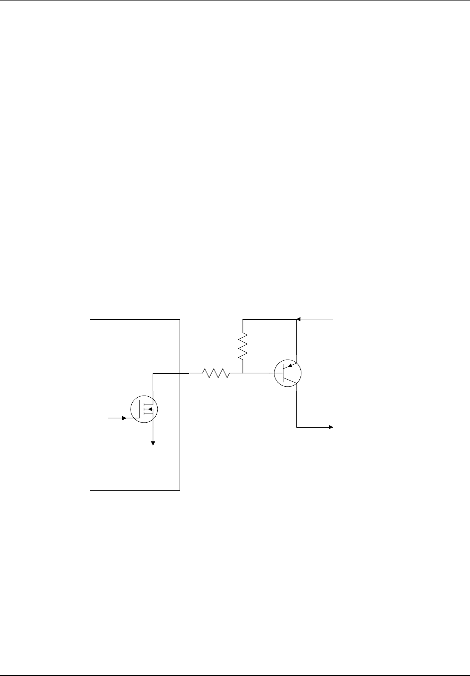
Application Notes
B-3
Positive Voltage TX Keying Circuit
Some transmitters require a positive voltage to be sourced into their PTT inputs
to key; removing the voltage unkeys the transmitter. This contrasts with the
style of transmitter that requires the PTT line to be grounded to key, opened to
unkey.
Transmitters that require positive voltage keying include models made by
Hamtronics, Maggiore, and the RCA 500 and 700-series repeaters.
A simple outboard circuit can be placed between the 7K controller and the
transmitter PTT. A PNP power transistor allows current to flow to the
transmitter to key, and opens the current path to unkey. Be sure to use a
sufficiently large PNP transistor for Q for Q1, as these transmitters or exciters
can draw considerable current. The TX DIP switch in the 7K controller should
be ON.
Q1 can be a 2N2904 if the transmitter/exciter draws 500 mA or less;
recommend TIP30 for loads of 1 A or less.
Q1
2K
4.7K
+13.6VDC
to TX PTT
(+13.6V = key)
(0V = unkey)
S-COM
PTT

7K • Appendix B
B-4

Installation
C-1
Appendix C
Installation
Theory of Operation
Great care was taken in the design of the controller to make it installer-friendly.
Audio and digital interfaces are universal in nature, so that a minimum of
external hardware is needed to complete the installation. Although the
controller’s “engine” is a powerful microprocessor, the command language is
designed to be flexible and easy to learn.
Pre-Programming
The controller needs to know your repeater’s callsign for its Identifier. You also
must tell it your choice of Courtesy Message, Transmitter Timeout Timer, and
so on. You can program the controller on your workbench, with an external
DTMF pad and other devices to simulate the repeater, or you can program the
controller after installation through one of the receiver ports.
Default Information
To make the installation easier, the controller comes pre-programmed with
certain default information stored in non-volatile memory. This is refered to as
the Default Condition of the device.
When you have finished the installation, you may overwrite the pre-
programmed default conditions by entering DTMF commands. Likewise, if it
ever becomes necessary, you may also force the controller into its original
default condition by using the Initialize Push-Button during a power-up
sequence. This procedure is explained in the Getting Started chapter on
page 2-1.
This initialize push-button procedure causes the controller to read the default
condition information from the EPROM and write it over the old information
stored in the non- volatile memory.
Power Supply
The controller has a modest power requirement which can be supplied by the
repeater’s power supply in most cases. The controller requires 12VDC at
approximately 125mA (Main Board with Telephone Interface Module). The

7K • Appendix C
C-2
optional Speech Synthesizer Module requires approximately 180mA more.
Power can be unregulated, since the controller contains internal regulators to
create both a 10VDC audio supply and a 5VDC digital supply. A third supply of
4.5VDC is created from the audio supply, and is used as the audio section’s
bias voltage.
Repeater Interfacing
In addition to the power supply, the controller requires a minimum of four
connections to the repeater: Receiver COR, Receiver Audio, Transmitter PTT,
and Transmitter Audio.
If you require subaudible tone operation, additional connections are provided
for a CTCSS Encoder/Decoder.
Note: Paths around the controller should not exist for either the COR-to-PTT
circuit or the RX audio-to-TX audio. Otherwise, the controller will not be able to
fully take charge of the repeater control functions.
Control Receiver Interfacing
If a control receiver is to be used, two additional connections are
required: Control Receiver COR and Control Receiver Audio.
Note: Each COR Input, CTCSS Decoder Input, and Transmitter PTT Output
has an associated DIP switch which is used to either invert—or not invert—the
signal. Thus, signals which are low-active or high-active can be
accommodated.
External Device Interfacing
The controller can sense the states of up to six external devices. Seven logic-
level power MOSFETS accomplish high-current switching (75mA).
Audio Gating
The controller uses two ICs—both of which are under microprocessor control:
An 8-by- 12 Analog Crosspoint Switch IC for main audio gating, and a Triple
SPDT Analog Gate IC for additional gating.
Extremely flexible system designs are possible since all audio sources
(receivers, tone generators, phone line, etc.) are fed into the crosspoint switch,
and all audio loads (transmitters, tone decoder, phone line) are driven from the
crosspoint switch.
Tone Generation
CW and paging tones are generated as square waves by an HD6340
Programmable Timer IC, then shaped by a Transconductance Amplifier to
reduce CW thumping. (This thumping effect is caused by the DC component in
the square wave pulse train). Tones are filtered by a Sixth-Order Switched-
Capacitor Lowpass Filter to yield sine waves. The lowpass filter is under

Installation
C-3
microprocessor control and tracks the tone frequency, so that a constant-
amplitude sine wave tone is created at any CW or paging tone frequency.
DTMF tones are generated by a MT8880 DTMF Transceiver IC.
Memory Protection
The controller contains circuitry to protect the data stored in RAM and to
maintain the clock and calendar even with no power applied to the controller.
A Dallas Semiconductor DS1644 Timekeeping RAM IC performs the following
tasks: It monitors the 5V logic supply, disables the RAM’s chip-enable input
when an out-of-tolerance condition is detected, and switches the RAM’s VCC
pin from the logic supply to the lithium battery when the logic supply falls too
low to maintain the data. The IC also contains the controller's Clock and
Calendar.
The Lithium Battery contained within the IC has better than a 10-year life due
to low (about 1 µA) current drawn by the RAM under backup conditions.
Cables
You will need to prepare either two or three Cables for the 7K controller.
• One cable is for DC power, using the 2.5mm plug provided.
• One cable is for repeater connections, using the DB25P provided.
• A third cable is for auxiliary connections, and is not needed for simple
installations. It uses the DB25S provided.
The following section of the manual describes the proper connection of the
7K’s circuits to your equipment, and the audio adjustments required.
Repeater Receiver COR
The controller requires a signal, generated by the repeater receiver, which
becomes active when an incoming carrier is detected. This signal is usually
called COR (Carrier Operated Relay) or COS (Carrier Operated Switch), and is
usually generated by the receiver’s Noise-Operated Squelch Circuit. Some
receivers don't have a COR or COS but have a Channel Busy LED Indicator,
which works similarly. At this point, it is unimportant whether the COR signal is
low active or high active, since the controller has sense-reversal DIP switches
(discussed later). The COR from your receiver should be connected to Pin #2
of J2 (the female DB25S connector).
To get a better idea of how to interface your particular COR signal to the
controller, let’s examine the controller’s COR Input Circuit. This circuit consists
of an NPN transistor, Q1A, and three resistors. Q1 is actually a DIP package
containing four 2n3904-type transistors. R10 is a DIP package containing
seven 10K resistors. R11 is a SIP package containing seven 4.7K resistors
with one common. One resistor from R10 and one resistor from R11 form a
three-to-one voltage divider. Therefore, the COR input voltage threshold is 3 x
0.7V, or about 2V. Your receiver’s COR driver must be capable of swinging

7K • Appendix C
C-4
above and below this 2V threshold as the incoming carrier is applied and
removed.
The third resistor mentioned above is R12 (4.7K), which is a “pullup” resistor
connected between the input pin and the controller’s +5V supply. The purpose
of the pullup resistor is to provide input current for the transistor in installations
using dry contacts, or an open- collector transistor driver, to feed the COR
input.
The purpose of the voltage divider mentioned above is to increase the
threshold of voltage needed to switch the input ON and OFF. If the divider were
not used, the input threshold would be only 0.7V, and some COR drivers would
keep the input “high” permanently.
• If your receiver’s COR circuit provides a pair of relay contacts to indicate
carrier detection, connect one contact to the COR input of the controller and
the other contact to ground.
• If your COR circuit provides and open-collector transistor (or open-drain
MOSFET), connect the signal to the COR input.
• If, however, your COR circuit sources a voltage (such as from a TTL logic
gate or an op amp comparator circuit), you may need to disable the
controller’s input.
To check your installation:
• Make the connection.
• Measure the voltage at the controller’s COR input pin with both the
controller and receiver powered up.
• The voltage should swing above and below the 2V threshold as an
incoming carrier is applied and removed.
Some COR drivers have low output impedances, and it is not necessary to clip
the pullup resistor. However, if the pullup resistor interferes with the operation
of your COR driver, you should clip one lead and lift the resistor to prevent it
making contact.
Finally, determine the “sense” of your receiver’s COR signal. That is, does the
COR signal go low or high when an incoming carrier is detected?
• If the COR goes low when a carrier is applied and returns high when the
carrier is removed, place DIP Switch #1 (part of S2) in the ON (closed)
position.
• If, however, the COR goes high when a carrier is applied and returns to low
the carrier is removed, place DIP Switch #1 in the OFF (open) position.

Installation
C-5
Repeater Transmitter PTT
Your transmitter will require a PTT (Push-To-Talk) Signal from the controller.
When this signal becomes active, the transmitter will Key (Transmit). At this
point, it is unimportant whether your transmitter’s PTT input is low active or
high active since the controller has sense-reversal DIP switches (discussed
later). The PTT input from your transmitter should be connected to Pin #10 of
J2 (the female DB25S connector).
To get a better idea of how to interface your particular PTT input to the
controller, let’s examine the controller’s PTT output circuit. This circuit consists
of a power MOSFET connected as an open-drain driver, plus a transient
suppressor connected between the output and ground. The suppressor
removes transients above about 40V, thereby protecting the MOSFET. The
MOSFET is a large (8 Amp) device in a TO-220 package, but it was not
selected for its high current capability. Rather, it was used because of its low
ON resistance (less than 1 Ω), making it a nearly perfect switch. The
MOSFET’s drain is connected to the PTT output, and its source is grounded.
When turned ON, the MOSFET appears to be a very low resistance between
the output and ground. When turned OFF, the MOSFET appears to be a very
high impedance, isolating the output from ground. Because of these
characteristics, the PTT circuit can control transmitters with a variety of PTT
inputs, from TLL-logic-compatible to large DC relay coils.
Some transmitters, including models made by Hamtronics, MELCO (Maggiore
Electronic Laboratory), and RCA (500-and 700-series), use a powered PTT
input arrangement, and cannot be keyed by an open-drain driver. These
transmitters require a positive voltage to be sourced into their PTT inputs to
key; removing the voltage unkeys the transmitter. The current requirement can
be substantial.
A simple outboard circuit can be placed between the controller’s PTT output
and the transmitter’s PTT input to satisfy these requirements. (See schematic
on page B-3.)
• Connect a large PNP transistor so that its emitter goes to the transmitter’s
+12V supply, its collector goes to the transmitter’s PTT input, and its base
goes to the controller’s PTT output through a 2K resistor (important).
• Connect a 4.7K resistor across the PNP transistor’s base and emitter.
• If the transmitter draws little current through its PTT (500mA or less), you
can use a 2N2904.
• If the transmitter draws 1 Amp or less, use a TIP30.
• When using this outboard circuit, place DIP Switch #7 (part of S2) in the ON
(closed) position.
• You may then skip to the Repeater Receiver Audio section which follows.
Unless you have used the outboard circuit described above, you must
determine the sense of your transmitter’s PTT input.
• Does the transmitter key when the PTT input is driven low or high? (The
majority of transmitters key when the PTT input is driven low.)
• If the transmitter keys when the PTT input is driven low and unkeys when
the PTT input is opened, place DIP Switch #7 (part of S2) in the ON
(closed) position.

7K • Appendix C
C-6
• If the transmitter keys when the PTT input is opened and unkeys when the
PTT input is driven low, place DIP Switch #7 in the OFF (open) position.
Repeater Receiver Audio
The controller requires audio from the repeater receiver. Connect the audio
from the repeater receiver to Pin #1 of J2 (the female DB25S connector).
To get a better idea of how to interface your particular receiver’s audio output
to the controller, let’s examine the controller’s repeater receiver audio input.
This circuit consists of an op amp connected as an AC-coupled inverting
amplifier, with two feedback resistors and one feedback capacitor. A 50K pot,
R97, is connected between the audio input and ground, and serves as an
adjustment for the audio going into the op amp. The input impedance of the
controller depends upon the pot setting, but will be 14KΩ or greater.The best
place to get receiver audio is the output of the receiver’s first audio preamplifier
stage (usually right after the discriminator). This point is often available at the
high end of the volume control pot. The preamplifier stage provides flat audio
from a low-impedance driver, often an op amp or an emitter-follower stage.
Note: Do not tap into the wiper of the volume control, or use the speaker driver
as the audio source; accidental adjustment of the volume control will affect the
repeat level. Speaker audio has a higher level of distortion than audio from
earlier stages.
The controller works best when driven with flat (not pre-emphasized) audio at a
level of 700mV RMS (2V peak-to-peak). At this level, the controller’s RX1 pot
(R97) will be in the mid range position when optimum audio is fed to internal
circuits. The controller’s actual input acceptance range is 200mV RMS (0.5V p-
p) to 2V RMS (5.6V p-p) as shipped from the factory, controllable by the RX1
pot.
If your receiver’s audio level is below the minimum of 200mV, you can increase
the op amp’s gain by cutting a feedback resistor.
• Resistor R30 (100K) has one lead marked “A”on the PC board; cut his lead
and lift the resistor.
• This operation changes the input acceptance to a new range of 70mV RMS
(0.2V p-p) to 700mV RMS (2V p-p).
• The midrange position of the RX1 pot will now correspond to 250mV RMS
(0.7V p- p).
Some repeater owners will prefer to drive the controller with pre-emphasized
audio from the receiver’s discriminator circuit.
• To accommodate this, the op amp stage must provide a -6dB/octave rolloff
response (de-emphasis), which results in flat audio being sent to the
controller’s circuits. (This is especially important for the DTMF decoder).
• Capacitor C67 (47pF) can be increased to 0.01µF if normal gain is used, or
to 0.0047µF if the high-gain modification has been done, to provide the
required de-emphasis.

Installation
C-7
After you have completed the repeater receiver audio interfacing, check the
audio level at Pin #1 of U37A. It should be 700mV RMS (2V p-p) when the
receiver is fed a fully- deviated 1KHz sine wave tone from a service monitor.
Repeater Transmitter Audio
Your transmitter will require audio from the controller. Connect the audio input
of the transmitter to Pin #14 of J2 (the female DB25S connector).
To get a better idea of how to interface your particular transmitter’s audio input
to the controller, let’s examine the controller’s repeater transmitter audio output
circuit. This circuit consists of two op amps and a number of discrete parts. The
first op amp, U34D, is an audio summer (mixer) with two inputs from the
crosspoint switch. Typically, one input carries repeat audio and the other
carries the CW ID tones; however, the controller’s software can switch a
number of sources to these mixed inputs. The second op amp, U34A, is the
transmitter audio driver. The output impedance of the driver is 600 Ω. A 50K
pot, R104, is connected between the two op amps and serves as the master
gain pot for the transmitter audio.
The controller’s driving capability depends upon the load impedance presented
by the transmitter’s audio input.
• If the controller is driving a load of 10KΩ or greater, the output level can be
adjusted from 200mV RMS (0.5V p-p) to 2V RMS (5.6V p-p).
• If the controller is driving a 600Ω load, the output level can be adjusted from
100mV RMS (0.3 p-p) to 1V RMS (2.8V p-p).
Note: In most 600Ω systems, nominal level is 0dBm, or 775mV RMS. This
corresponds to the 80% clockwise position of R104.
If your transmitter’s audio input is much more sensitive than the level figures
given above, or if you must drive the microphone input, the gain of the
transmitter audio driver op amp should be reduced.
• This is accomplished by cutting an input resistor, R75 (27K). Clip one lead
and lift the resistor. This modification reduces all audio sent to the
transmitter.
• If the controller is driving a load of 10KΩ or greater, the output level can be
adjusted form 40mV RMS (113mV p-p) to 400mV RMS (1.1V p-p).
• If the controller is driving a 600Ω load, the output level can be adjusted from
20mV RMS (56mV p-p) to 200mV RMS (565mV p-p).
Note: Although it is always a good idea to use shielded cable between the
controller’s audio connections and the repeater’s audio connections, it is
especially important to do so when driving sensitive mic inputs in transmitters.

7K • Appendix C
C-8
Repeater CTCSS Decoder
CTCSS, or Continuous Tone-Controlled Squelch System, is a convenient
problem solver for those bands that are being crowded with repeaters in
various parts of the country. In addition, the controller allows CTCSS to be
used as a qualifier for the entry of DTMF commands to increase the security of
the repeater system. Well-known trademarked names for CTCSS include: PL
or Private Line™ (Motorola), Channel Guard™ (General Electric), and Call
Guard™ (Johnson). Your repeater may already have a CTCSS Decoder built
in, or you may wish to install one of the add-on boards readily available from a
number of sources. The TS-64, from Communications Specialists, Inc.,
Orange, CA, 1-800-854-0547, http://www.com-spec.com, is a good example. This
device is crystal-controlled for stability, and allows switch selection of one of 64
CTCSS tone frequencies.
The CTCSS Decoder should be installed in your repeater receiver following the
instructions provided by the decoder manufacturer. The output from the
decoder is usually an open-collector transistor driver which is either low active
or high active. This signal should be connected to Pin #5 of J2 (the female
DB25S connector).
To check your installation:
• Measure the voltage at Pin #5 of J2 with the receiver, CTCSS decoder, and
controller powered up.
• The voltage should swing above and below the 2.1V threshold as an
incoming CTCSS tone is applied and removed.
You must also determine the sense of your CTCSS decoder output.
• Does the output go low or high when the correct CTDSS tone is received?
• If the output goes low when the tone is received and returns high when the
tone is removed, then place DIP Switch #4 in the ON (closed) position.
• If, however, the output goes high when the tone is received and returns low
when the tone is removed, the place DIP Switch #4 in the OFF (open)
position.
An additional feature of this controller is the ability to change the CTCSS
decoder’s frequency remotely. To do so requires that you use a CTCSS
decoder that has jumper- or switch-selectable tones, not pot-adjusted (tunable)
tones.
• You must remove any CTCSS frequency selection jumpers or open any DIP
switches to allow the controller to control the frequency.
• Connect wires from the frequency selection sides of the jumpers or DIP
switches to the CTCSS Frequency pins on the controller (see page C-16,
connector J2).
• Connect jumper or switch #1 to CTCSS Frequency #1, jumper or switch #2
to CTCSS Frequency #2, and so on.
• The TS-64 will use all 6 CTCSS Frequency connections.
• Other CTCSS decoders, eg. the TS-32, will need only 5.
• By entering the proper commands, you can tell the controller to connect the
jumpers or throw the switches on the decoder to change the tone
frequency.

Installation
C-9
Control Receiver COR
A control receiver is a wise addition to your repeater system, as it allows you to
control the repeater on a frequency other than the repeater’s input. Users of
the repeater will not notice any change in operation while the control channel is
occupied, except that the repeater will not accept any of their DTMF
commands. Additionally, any Command Response Messages will be sent over
the repeater transmitter that are caused by commands received from the
control channel (unless these response messages have been turned OFF by
command). When the control channel is released, all operations return to
normal.
If you want to implement a control channel function, you must supply both the
following from your control receiver: A COR signal and audio.
The control receiver COR signal can be either low active or high active. This
signal should be connected to Pin #4 of J2 (the female DB25S connector), the
RX3 COR Input.
No software currently exists to support the RX3 PL Input; therefore, if you wish
to use a CTCSS decoder on the control channel, you must connect the output
of the decoder to the RX3 COR Input.
Better yet, externally “and” together the COR and CTCSS decode signals, and
feed the result into the RX3 COR input. Unless the correct CTCSS tone is
recognized by the decoder, the controller will ignore the control receiver. The
control receiver COR input to the controller is similar to the repeater receiver
COR input. The voltage divider is made up of one resistor from network R10
and one resistor from network R11. The pullup resistor is R14. (You may refer
to the Repeater Receiver COR section on page C-3 for a discussion of the
hardware design of the input circuit.)
To check your installation:
• Measure the voltage at Pin #4 of J2 with the control receiver and controller
powered up.
• The voltage should swing above and below the 2.1V threshold as an
incoming carrier is applied and removed.
You must also determine the sense of your control receiver COR output signal.
• Does the output go low or high when an incoming carrier is detected and
returns high when the carrier is removed? If so, place DIP Switch #3 in the
ON (closed) position.
• If, however, the output goes high when the carrier is detected and returns
low when the carrier is removed, place DIP Switch #3 in the OFF (open)
position.
Note: If you do not use a control receiver, be sure DIP Switch #3 is in the ON
(closed) position. This configures the controller for a low-active COR signal.
The pullup resistor on the input will hold the input high, thus releasing the
DTMF decoder from the control channel.

7K • Appendix C
C-10
Control Receiver Audio
If you are adding a control receiver to your repeater system, you must supply
both a COR signal and an audio signal from the control receiver to the
controller. The COR signal has been previously discussed. Control Receiver
Audio should be connected to Pin #25 of J2 (the female DB25S connector),
shown in the schematics as RX3.
The design of the control receiver audio input is similarly to the design of the
repeater receiver audio input. Refer to the Repeater Receiver Audio section on
page C-6 for additional information. The control receiver level pot is R99.
• To increase the gain of the control receiver input stage, cut the lead labeled
“C” of resistor R37 (100K).
• To accommodate pre-emphasized audio, change capacitor C74 from 47pF
to 0.01µF if normal gain is used, or 0.0047µF if the high-gain modification
has been done.
After you have completed the control receiver audio interfacing, check the
audio level at Pin #8 of U37C. The level should be about 700mV RMS (2V p-p)
when the control receiver is fed a fully-deviated 1KHz sine wave tone from a
service monitor.
DC Power
The controller requires a power source of +12 to +15VDC.
Note: Do not exceed a supply voltage of +15V. The controller’s DC power
input is protected by a 15V transient suppressor, which will start to draw current
when the input voltage exceeds 15VDC.
The amount of current drawn by the controller depends upon the configuration.
• The 7K Main Board draws less than 125 mA.
• The Telephone Interface Module draws negligible current.
• The Speech Synthesis Module draws about 180 mA.
• A loaded system, then, can be expected to draw about 300 mA.
The controller does not require a regulated power source, since it contains
local voltage regulator ICs for its analog and digital circuits. However, The
power source must be free of “sags” that may occur, for example, when the
transmitter is keyed. If significant ripple is present on the power source output,
the ripple “peaks” must not exceed +15V. Ripple “valleys” must not fall below
+12V.
The controller contains circuitry to protect the data stored in memory during the
power outages. No external battery backup is needed to prevent loss of
memory data. Owners may wish to provide backup power to both the repeater
and the controller to ensure continuous service during utility power outages.

Installation
C-11
Power should be supplied to the controller via the 2.5mm x 5.5mm DC power
plug (supplied).
• The center hold forms the positive (+) connection.
• The sleeve forms the negative (-) connection.
Note: Owners of alternatively-powered repeaters (solar, fuel cell, battery, etc.)
should be aware that the 7K has been designed to behave predictably when
the DC power source is slowly reduced. Such behavior is important to prevent
damage to the energy source. For example, some controllers will suddenly stop
operating (i.e. reset) when a low voltage limit is reached. If an output, such as
the transmitter PTT line, was enabled at the time, and the transmitter PTT line,
was likewise enabled, the transmitter could stay keyed until the power source
failed.
Your S-COM controller will cease microprocessor operation when the power
supply voltage fails, but it will also reset the digital outputs at that time. This
condition will be held until the power source voltage drops considerably. With
little load on the source. This will take a long time to occur.
Logic Inputs
The controller has the ability to monitor logical (ON/OFF) devices at the
repeater site. There are 7 Logic Inputs for this purpose. Any of the 3 Receiver
COR Inputs and the 3 CTCSS Decoder Inputs may be used as additional logic
inputs. Each logic input has a hardware interface that is similar to the repeater
receiver COR input. Refer to the Repeater Receiver COR section on page C-3
for details on the design of the input circuit.
The controller can sense either a low-to-high or a high-to-low transition, or
both, on each logic input. Therefore, there is no need for Sense-Reversal DIP
Switches on the 7 logic inputs.
Logic inputs are very handy for informing the controller when some external
condition has changed. Examples include detection of high water, high SWR,
power failure, intrusion, and so on. Since the controller will execute macro
commands upon sensing a change, the owner can control the action that will
be taken. (This is a big improvement over controllers that take fixed action
when an input is tripped, such as appending an alarm CW message to the tail.)
Logic Outputs
The controller has the ability to control logical (ON/OFF) devices at the
repeater site. There are 7 Logic Outputs for this purpose.
Each logic output has a hardware interface that is similar to the transmitter PTT
output, except that the power MOSFET devices are smaller. Refer to the

7K • Appendix C
C-12
Repeater Transmitter PTT section on page C-5 for details on the design of the
output circuit.
The power MOSFETS used as logic output drivers appear as 5Ω resistances to
ground when in the conducting state (ON), and can sink up to 75mA. They
appear as open circuits when in the non-conducting state (OFF). Do not apply
over 40VDC, as the transient suppressors start conducting at 40V.
Since the drain connections of the MOSFETs are brought out to the connector
without pullup resistors, this configuration is called open drain (similar to open
collector circuits using bipolar transistors). An ohmmeter cannot be used to
check the logic outputs, since no change will be seen when the outputs are
turned ON and OFF. A DC power source and a load of some type will be
needed to see the outputs change state. If you need TLL- Compatible Outputs,
simply connect pullup resistors of 3KΩ from the desired outputs to the 5V
power supply of the TTL device being driven.
Logic outputs are very handy for controlling external devices and appliances at
the site. Loads include incandescent lamps, LEDs, integrated or discrete logic,
and relay coils.
Note: Although the power MOSFETS are protected by transient suppressors in
the controller, it is still important to wire diodes across inductive loads (such as
relays) in the non-conducting direction.
Each logic output may be commanded to be Latched ON or OFF, or
Momentary turned ON or OFF for 0.5 seconds.
The controller will remember the status of each logic output during power
outages. When power returns, the controller will turn the outputs ON or OFF to
match the conditions before the power loss. An initialization sequence will force
all outputs OFF.
Telephone Line Connection
If your controller is equipped with the Telephone Interface Module, you can
connect the controller to the telephone network. The 14-foot cable supplied
with your controller has a modular USOC (Universal Service Order Code) plug
at each end. This plug mates with the USOC RJ11C jack. Connect one end of
the cable to the controller, and the other end to the RJ11C jack at your
repeater site.
The Telephone Interface Module is registered under Part 68 of the FCC Rules
and Regulations for direct connection to the telephone line. A label is attached
on the rear of the cabinet, listing the registered number and ringer equivalence.
It reads:
Complies with Part 68, FCC Rules
FCC Registration No. GHZ37K-10180-DP-N
Ringer Equivalence: 1.3B

Installation
C-13
The Telephone Interface Module contains lightning protection circuitry.
However, it is still a good practice to install additional protection at the
telephone line service entrance. The following companies market phone line
suppressors:
Telephone Line Suppressors Market
Sources
Citel America, Inc. 1111 Parkcentre
Blvd., Suite 474 MiamiFL33169 (305)
621-0022 (FL) (800) 248-3548
L-COM Data Products 1755 Osgood
Street, Rt. 125 North AndoverMA01845
(617) 682-6936 (617) 689-9484 (FAX)
ITW Linx Communications Products 201
Scott Street Elk GroveIL60007 (312)
952-8844 (312) 952-1633 (FAX)
MCG Electronics Inc. 12 Burt Drive Deer
ParkNY11729 (516) 586-5125 Telex
645518
Telebyte Technology, Inc. 270 East
Pulaski Road GreenlawnNY11740 (516)
385-8184 (FAX) (800) 835-3298 (516)
423-3232
PolyPhaser Corporation 1425 Industrial
Way GardnervilleNV89410-1237 (800)
325-7170 (702) 782-4476 (FAX) Telex
272718
TII Industries, Inc. 1375 Akron Street
CopiagueNY11726 (516) 789-5020
(Sales) (516) 789-5000 Telex 144631
L.E.A. Dynatech 12516 Lakeland Road
Santa Fe SpringsCA90670 (213) 944-
0916 (800) 654-8087 (213) 944-0781
(FAX)
FCC Part 68 Rules
FCC rules and regulations, Part 68 require the following information be
provided to the user of FCC Registered Terminal Equipment:
Section 68.100 General.
Terminal equipment may be directly connected to the telephone network in
accordance with the rules and regulations … of this part.
Section 68.104 Standard Plugs And Jacks.
(a) General. “Except for telephone company-provided ringers, all connections
to the telephone network shall be made through standard (USOC) plugs and
standard telephone company-provided jacks, in such manner as to allow for
easy and immediate disconnection of the terminal equipment. Standard jacks
shall be so arranged that if the plug connected thereto is withdrawn, no
interference to the operation of the equipment at the customer’s premises
which remains connected to the telephone network shall occur by reason of
such withdrawal.”
Section 68.106 Notification to Telephone Company.
“Customers connecting terminal equipment or protective circuitry to the
telephone network shall, before such connection is made, give notice to the
telephone company of the particular line(s) to which such connection is to be
made, and shall provide to the telephone company the FCC Ringer
Equivalence of the registered terminal equipment or protective circuitry. The
customer shall give notice to the telephone company upon final disconnection
of such equipment or circuitry from the particular line(s).”

7K • Appendix C
C-14
Section 68.108 Incidence of Harm.
“Should terminal equipment or protective circuitry cause harm to the telephone
network, the telephone company shall, where practicable, notify the customer
that temporary discontinuance of service may be required; however, where
prior notice is not practicable, the telephone company may temporarily
discontinue service forthwith, if such action is reasonable in the circumstances.
In case of such temporary discontinuance, the telephone company shall
(1) promptly notify the customer of such temporary discontinuance, (2) afford
the customer the opportunity to correct the situation which gave rise to the
temporary discontinuance, and (3) inform the customer of the right to bring a
complaint to the Commission pursuant to the procedures set forth in Subpart
E of this part.”
Section 68.110 Compatibility of the Telephone Network and Terminal
Equipment.
(b) Changes in Telephone Company Facilities, Equipment Operations or
Procedures.
“The telephone company may make changes in its communications facilities,
equipment, operations or procedures, where such action is reasonably
required in the operation of its business and is not inconsistent with the rules
and regulations in the Part. If such changes can be reasonably expected to
render any customer’s terminal equipment incompatible with telephone
company communications facilities, or require modification or alteration of
such terminal equipment, or otherwise materially affect its use or
performance, the customer shall be given adequate notice in writing, to allow
the customer an opportunity to maintain uninterrupted service.”
Section 68.216 Repair of Registered Terminal Equipment and Registered
Protective Circuitry.
“Repair of registered terminal equipment and registered protective circuitry
shall be accomplished only by the manufacturer or assembler thereof or by
their authorized agent; however, routine repairs may be performed by a user, in
accordance with the instruction manual if the applicant certifies that such
routine repairs will not result in noncompliance with the rules in Subpart D of
this Part.”
Section 68.218 (b) Additional Instructions To User.
1. “… registered terminal equipment or protective circuitry may not be used
with party lines or coin lines.”
2. “… when trouble is experienced the customer shall disconnect the registered
equipment from the telephone line to determine if the registered equipment is
malfunctioning, and … if the registered equipment is malfunctioning, the use of
such equipment shall be discontinued until the problem has been corrected.”
3. “… the user must give notice to the telephone company in accordance with
the requirements of section 68.106 …”

Installation
C-15
Input and Output Connectors
Two 25-position D-subminiature connectors, one male and one female, are
mounted on the 7K Main Board for interfacing to external devices. J2 is a
female connector (DB25S). J3 is a male connector (DB25P). Use the mating
connectors supplied with the 7K for your cable assemblies.
Input and Output Connectors
Controller Main Board
Pin # J2 Female Connector J3 Male Connector
1 receiver #1 audio input logic input #1
2 receiver #1 COR logic input #2
3 receiver #2 COR logic input #3
4 receiver #3 COR logic input #4
5 receiver #1 CTCSS decoder logic input #5
6 receiver #2 CTCSS decoder logic input #6
7 receiver #3 CTCSS decoder phone line busy input
8 receiver #2 audio input logic output #1
9 CTCSS frequency #1 logic output #2
10 transmitter #1 PTT logic output #3
11 transmitter #2 PTT logic output #4
12 CTCSS frequency #2 logic output #5
13 CTCSS frequency #3 logic output #6
14 transmitter #1 audio output logic output #7
15 transmitter #2 audio output phone line busy output
16 CTCSS frequency #4 FC1 (reserved)
17 CTCSS frequency #5 FC2 (reserved)
18 CTCSS frequency #6 FC3 (reserved)
19 ground +5V test
20 ground +10V test
21 ground +12V test
22 ground ground
23 CTCSS encoder in ground
24 CTCSS encoder out ground
25 receiver #3 audio input ground
7K • Appendix C
C-16
Audio Level Potentiometers
The 7K Main Board contains 12 potentiometers. The pots are used to adjust
audio levels only. Signalling tones are digitally generated and do not require
frequency adjustment.
Audio Level Potentiometers
Controller Main Board
Pot Location Function
RX1 R97 adjusts audio level from receiver #1
RX2 R98 adjusts audio level from receiver #2
RX3 R99 adjusts audio level from receiver #3
TX1 R104 adjusts audio level to transmitter #1
TX2 R105 adjusts audio level to transmitter #2
CW-TX R102 adjusts level of CW feeding the transmitters
CW-PL R101 adjusts level of CW feeding the phone line
tone page R103 adjusts level of paging tones feeding the transmitters (1-tone, 2-
tone, 5/ 6-tone)
DTMF page R100 adjusts level of DTMF paging tones feeding the transmitters
AGCPL R107 adjusts audio level of phone line feeding the transmitters
(AGC’d)
PL R106 adjusts audio level of phone line feeding the DTMF decoder
(non- AGC’d)
speech R108 adjusts the level of the speech synthesizer
Note: There is also a pot on the Speech Synthesis Module, R3, which is used
to adjust the pitch of the synthesizer. This pot may be adjusted to suit your
taste.

Installation
C-17
Message Level Potentiometers
Five of the 12 pots located on the 7K Main Board are used to set levels
associated with messages. The five pots are shown in the table which follows:
Message Level Potentiometers
Controller Main Board
Pot Sets Level
R100 DTMF to transmitter
R101 CW to phone line
R102 CW to transmitter
R103 tone page to transmitter
R108 Speech Synthesizer Module
• All pots are adjusted clockwise to increase level, and counter-clockwise to
decrease level.
• R100 adjusts the level of the DTMF characters sent to the transmitter. The
level of DTMF characters sent to the phone line during autopatch dialing is
not adjustable.
• R101 adjusts the level of CW characters and beep characters sent into the
phone line.
• R102 adjusts the level of CW characters and beep characters sent to the
transmitter. Many repeater owners adjust the level of CW to a low deviation.
(.5–1.5KHz) to prevent interference with voice conversations.
• R103 adjusts the level of tone pages (single-tone, two-tone sequential, and
5/6-tone) sent to the transmitter. Typically, the deviation for these types of
pages is 3 to 3.3KHz. Pages sent to the phone line as acknowledgments
will be at the same level as CW characters sent to the phone line.
• R108 adjusts the level of the speech synthesizer, and controls the level of
speech characters to both the transmitter and the phone line.

7K • Appendix C
C-18
DIP Switches
The 7K Main Board contains a group of 8 DIP Switches. They are used to
invert the logic of the 3 COR inputs, the 3 CTCSS decoder inputs, and the 2
PTT outputs. In all cases, a switch in the ON (closed) position means low
active; a switch in the OFF (open) position means high active.
DIP Switches
Controller Main Board
Switch # Function
1 inverts receiver #1 COR
2 inverts receiver #2 COR
3 inverts receiver #3 COR
4 inverts CTCSS decoder for receiver #1
5 inverts CTCSS decoder for receiver #2
6 inverts CTCSS decoder for receiver #3
7 inverts transmitter #1 PTT
8 inverts transmitter #2 PTT
Testing The Controller-To-Repeater Transmitter
Interface
Apply power to both the controller and the repeater while monitoring the
repeater with an extra receiver. When power is applied, the transmitter should
key and send the reset CW message.
If the transmitter does not key at all:
• Check the wiring. Both the controller and the repeater should be powered
up.
• Check the connection between the controller’s PTT output and the
transmitter’s PTT input.
If the transmitter keying is acting “upside down” (unkeying during the message
but keying afterwards), reverse the repeater transmitter PTT DIP switch.
If the transmitter is keying properly but no CW message is heard, check the
wiring from the controller’s repeater transmitter audio output to the transmitter’s
audio input.
If the CW message is too loud or too soft:
• Adjust the CW-to-TX pot on the main board.
• See the Messages chapter on page 4-1.
• Turn the pot clockwise to increase the level, and counter-clockwise to
decrease the level.

Installation
C-19
If the CW message is still too loud with the pot turned nearly all the way down,
you may be attempting to drive the microphone input of the transmitter instead
of a later stage.
If you cannot drive a later stage, check the Transmitter Audio Output on page
C-7 for hints for decreasing the transmitter drive level.
Testing The Controller-To-Repeater Receiver Interface
Generate an RF signal on the repeater’s input frequency. The controller should
key the repeater transmitter. When the signal disappears, a short courtesy
beep should be heard. The transmitter should stay keyed for a few more
seconds, then it should unkey.
If this does not happen:
• Check the wiring between the repeater receiver’s COR driver and the
controller’s Receiver #1 COR Input.
• Check the voltage on the COR line to see if it swings above and below the
required threshold. (Check the voltage with the controller and receiver
connected, not just the open-circuit COR output from the receiver).
If the repeater is acting upside down (unkeying when a signal exists but keying
afterwards), reverse the Receiver #1 COR DIP Switch.
The default condition of the controller causes a 0.5-second delay between the
loss of carrier and the courtesy beep. The transmitter will stay keyed for an
additional 3.0 second dropout delay. These characteristics may all be changed
later, so do not be concerned if this is not the way you wish the repeater to act.
• Generate a modulated RF signal on the repeater’s input frequency (a
service monitor is quite helpful).
• Check the audio level as instructed in the Repeater Receiver Audio section
on page C-6.
• Check the transmitter for proper deviation, and
• Adjust the Transmitter #1 Audio Output pot as necessary.
Testing The DTMF Decoder
Your controller uses an 8800-Type DTMF Transceiver IC. This crystal-
controlled device encodes and decodes all 16 DTMF digits. It has an extremely
wide dynamic range (30 dB), and can detect digits that have as much as -6 dB
to +6 dB of twist.
Twist refers to the difference in amplitude between the two individual tones that
are summed to make up a DTMF digit. The more twist a system gives to DTMF
digits, the more difficult it is to detect the digits. In repeater systems, twist can
be caused by the user’s transmitter.
The audio fed into the transmitter is pre-emphasized before it is applied to the
limiter circuit. Pre-emphasis causes high frequency tones to have more
amplitude than low frequency tones, so the high frequency tone of a DTMF

7K • Appendix C
C-20
digit can be severely clipped while the low frequency tone is not. The result is
twist, and the solution is to keep the DTMF pad audio at a reasonably low level.
Twist can also be introduced by the repeater receiver if it has poor audio
response, or if a poor impedance match exists between the receiver and the
controller.
Command Sources
The DTMF decoder can monitor all receiver inputs and the phone line for
incoming digits. However, it can monitor only one device at a time. Therefore, a
priority scheme is used to determine which source feeds the decoder at any
given time. If no source is active, the decoder’s input is grounded.
Local Control
You can program the controller with a local DTMF keyboard, if desired.
• Connect the audio from the keyboard to the Receiver #1 Audio Input.
• Connect a switch between the RX #1 COR Input and ground.
• Whenever the switch is ON (closed), the controller will accept commands
from the keyboard.
• Alternately, you can use the same scheme with Receiver #3 and leave the
keyboard permanently connected.
Note: Return the switch to the OFF (open) position when finished
programming, so the repeater Receiver #1 can drive the DTMF decoder once
again.
Performing the Tests
Generate an RF signal on the repeater’s input frequency.
• While listening to the repeater output on an extra receiver, send some
DTMF digits to the repeater.
• You should hear a short burst of DTMF, followed by silence, as the
controller detects the digit and then mutes it.
• If the digits are passed through to the transmitter with no muting taking
place, the DTMF decoder is not recognizing the digits.
There are several areas to check:
• Check the audio level at the output of the Receiver #1 Audio Op Amp; it
should be 700 mV RMS (2V p-p) as discussed in the Repeater Transmitter
Audiosection on page C-7.
• Check the operation of the Receiver #1 COR Input. If the COR input isn't
active, the DTMF decoder will not be monitoring the repeater receiver
audio.
• Check the other receiver COR inputs and their associated DIP switches. If a
higher- priority input is active, the DTMF decoder will be monitoring that
input, not the repeater receiver.
• Check to see if a command was entered to disable the DTMF decoder from
the repeater receiver.

Installation
C-21
Falsing
Some user’s voices can contain frequency components that appear as DTMF
digits to the decoder. If such a digit is detected, falsing is said to occur. If the
DTMF muting feature is enabled, the result of falsing is the loss of repeat audio
for a syllable or two. In addition, an accidental digit is stored into the controller’s
command buffer. This last item is not usually a problem, however, because the
digit will be discarded after a few seconds when the controller discovers that
the digit was no part of a valid command. In any case, falsing is annoying and
can usually be cured to an acceptable extent.
Several solutions to falsing are available:
• Turn OFF the DTMF muting feature. Use the Select DTMF Decoder Mute
Delay command on page 11-8. If you do this, all DTMF digits will be
repeated. This is a simple fix, but it may not be acceptable for repeaters
that need security for DTMF commands.
• Don't overdrive the DTMF decoder. The higher the audio level to the
decoder, the more likely it is to false. Check the audio level at the output of
the receiver’s op amp. If over the recommended 700 mV RMS (2V p-p),
turn the audio level down. Overdriving the decoder will not help it decode
any better.
• Increase the DTMF decoder’s detect time. The decoder’s tone detect
time is controlled by resistor R7, which is 300K as shipped from the factory.
This provides a rather fast 40mS detect time (a telephone company
standard). Increasing R7 will require a longer detect time, thus reducing the
possibility of falsing. The disadvantage of slowing the detection time is that
some DTMF autodialers generate digits at a rapid rate; a long detection
time could result in missed digits. If autodialers are not a problem,
increasing the detection time will make a noticeable improvement in falsing.
Field experience has shown that changing R7 to 500K will solve minor
cases, and changing it to 1M will solve nearly all cases. The slower
response to DTMF digits has not been a problem for users, since the
increase in time is small by human operator standards.
Real-Time Clock
The Controller features a year 2000-compliant hardware real-time clock and
calendar circuit with a lithium power source. Accurate time keeping is
maintained during loss of main power.
The clock and calendar circuit is accurate to ±1 minute per month. For
improved accuracy, commands are provided to manually or automatically
adjust the clock to compensate for drift. (See page 8-1.)

7K • Appendix C
C-22
Parts Lists and Schematics
D-1
Appendix D
Parts Lists and
Schematics
Controller Main Board
Parts Controller Main Board
Dated 06-05-89 Revised 07-31-89 Revised 11-30-90 For Serial Numbers 207 and up Purchased After 12-90
Part # or Type Qty Location
Resistors
237¾ 1% 1/4W 1 R28
604¾ 1% 1/4W 2 R78, R86
1.69K¾ 1% 1/4W 1 R109
11.3K¾ 1% 1/4W 1 R50
14.0K¾ 1% 1/4W 1 R51
22.6K¾ 1% 1/4W 2 R61, R119
47¾ 5% 1/4W 7 R32, R56, R64, R70, R113, R114, R116
100¾ 5% 1/4W 2 R52, R90
1K¾ 5% 1/4W 1 R65
2K¾ 5% 1/4W 1 R115
4.7K¾ 5% 1/4W 20 R12, R13, R14, R15, R16, R17, R21, R22, R23, R24,
R25, R26, R27, R41, R42, R58, R110, R111, R112,
R118
10K¾ 5% 1/4W 9 R45, R49, R54, R55, R57, R60, R69, R77, R85
20K¾ 5% 1/4W 24 R29, R33, R36, R39, R40, R43, R44, R46, R47, R48,
R62, R63, R71, R72, R73, R79, R80, R81, R87, R88,
R89, R92, R94, R96

7K • Appendix D
D-2
22K¾ 5% 1/4W 1 R5
27K¾ 5% 1/4W 2 R75, R83
47K¾ 5% 1/4W 2 R6, R59
51K¾ 5% 1/4W 1 R117
68K¾ 5% 1/4W 4 R76, R84, R93, R95
82K¾ 5% 1/4W 2 R74, R82
100K¾ 5% 1/4W 5 R30, R34, R37, R53, R91
200K¾ 5% 1/4W 3 R31, R35, R38
300K¾ 5% 1/4W 1 R7
470K¾ 5% 1/4W 4 R66, R67, R68, R120
4.7K¾ 8-pin sip 5 R1, R8, R9, R11, R20
4.7K¾ 10-pin sip 4 R2, R3, R4, R18
10K¾ 14-pin DIP 2 R10, R19
50K¾ 3/8" pot 12 R97, R98, R99, R100, R101, R102, R103, R104, R105,
R106, R107, R108
Capacitors
3-23pF trimmer 1 C22
18pF ceramic NPO 3 C2, C3, C23
47pF ceramic NPO 3 C67, C71, C74
100pF ceramic 39 C28, C29, C30, C31, C32, C33, C34, C35, C36, C37,
C38, C39, C40, C42, C43, C46, C47, C48, C49, C50,
C51, C52, C53, C65, C69, C72, C98, C103, C111,
C112, C113, C114, C115, C116, C117, C118, C119,
C120, C121
470pF ceramic NPO 2 C96, C101
.001µF film 3 C16, C60, C86, C122
.0022µF film 1 C17
.0039µF film 1 C85
.1µF film 1 C20
.1µF MLC 28 C1, C4, C5, C6, C7, C8, C9, C10, C11, C12, C13, C14,
C15, C19, C21, C25, C26, C27, C41, C44, C45, C54,
C55, C56, C57, C58, C59, C110
.47µF film 16 C18, C66, C70, C73, C75, C76, C77, C78, C79, C81,
C84, C95, C100, C104, C105, C106
1µF tantalum 4 C24, C62, C63, C88
4.7µF tantalum 5 C87, C90, C91, C94, C99
10µF tantalum 13 C64, C68, C80, C82, C83, C89, C92, C93, C97, C102,
C107, C108, C109
330µF electrolytic 1 C61, C123
Diodes
1N4002 2 D12, D13
ICTE-15/MPTE-15 1 D11
SA40A 10 D1, D2, D3, D4, D5, D6, D7, D8, D9, D10

Parts Lists and Schematics
D-3
Transistors
2N3904 1 Q4
2N7000/VN10KM 9 Q7, Q8, Q9, Q10, Q11, Q12, Q13, Q14, Q15
MPQ3904 3 Q1, Q2, Q3
RFP12N08L 2 Q5, Q6
Integrated Circuits
27C256 factory program 1 U5
74C906 3 U29, U30, U31
74HC00 1 U24
74HC04 1 U26
74HC86 2 U27, U28
74HC138 2 U7, U8
74HC139 2 U6, U11
74HC251 2 U13, U14
74HC259 3 U15, U16, U17
74HC374 3 U18, U19, U20
74HC4078 1 U25
CA3080 1 U32
CD4053 1 U36
DS1210 1 U3
DS1232 1 U1
HD6340 1 U9
HD63B09 1 U2
HM62256LP 1 U4
ICM7170 1 U12
LM317 1 U21
LM7805 1 U22
LMC660 4 U33, U34, U37, U38
MF6CN-50 1 U23
MT8812 1 U35
MT8880 1 U10
Crystals
32.768KHz 1 Y2
3.579MHz 1 Y3
4.000MHz 1 Y1
Batteries
lithium 3V 2 B1, B2
Switches
push-button, momentary 1 S1
DIP switch, 8 pole 1 S2
Ferrite Beads
2943666661 1 L1

7K • Appendix D
D-4
Connectors
2-pin male header 2 P3(MEM), P5(RTC)
4-pin male header 2 P1(ADM1), P2(ADM2)
10-pin male header 1 P9(DISPLAY)
14-pin male header 1 P7(TIM)
16-pin male header 1 P8(SSM)
8-pin IC socket 3
14-pin IC socket 16
16-pin IC socket 10
20-pin IC socket 4
24-pin IC socket 1
28-pin IC socket 3
40-pin IC socket 2
2.5mm DC power jack 1 J1
DB25P PC mount 1 J3
DB25S PC mount 1 J2
Hardware
PC board 1
heat sink 5910B 2
4-40 x 3/8" machine screw 4
#4 int tooth lockwasher 4
4-40 hex nut 4
6-32 x 1/4" machine screw 2
6-32 hex nut 2

Parts Lists and Schematics
D-5
Main Board schematic page 1 of 4 to be provided.

7K • Appendix D
D-6
Main Board schematic page 2 of 4 to be provided.

Parts Lists and Schematics
D-7
Main Board schematic page 3 of 4 to be provided.

7K • Appendix D
D-8
Main Board schematic page 4 of 4 to be provided.

Parts Lists and Schematics
D-9
Main Board layout to be provided.

7K • Appendix D
D-10
Speech Synthesizer Module (SSM)
Parts: Speech Synthesizer Module (SSM)
Dated 05-05-89 Revised 04-08-91
Part # or Type Qty Location
Resistors
47¾ 5% 1/4W 3 R5, R10, R12
1K¾ 5% 1/4W 1 R11
1.2K¾ 5% 1/4W 1 R4
10K¾ 5% 1/4W 1 R1
20K¾ 5% 1/4W 3 R7, R8, R9
47K¾ 5% 1/4W 1 R2
100K¾ 5% 1/4W 1 R6
4.7K¾ 8-pin sip 1 RN1
4.7K¾ 10-pin sip 1 RN2
100K¾ 3/8" pot 1R3
Diodes
1N4002 2 D1, D2
ICTE-15/MPTE-15 1 D3
Capacitors
10pF ceramic NPO 1 C6
18pF ceramic NPO 1 C2
120pF ceramic NPO 1 C11
.0047µF film 1 C9
.039µF film 1 C10
.1µF MLC 9 C3, C4, C5, C13, C14, C15, C16, C17, C18
.47µF film 1 C8
1µF tantalum 1 C1
10µF tantalum 5 C7, C12, C19, C20, C24
22µF electrolytic 3 C21, C22, C23
Transistors
2N3904 1 Q1
Integrated Circuits
27C512 standard
vocabulary
1U5
27C512 expansion vocab 1 U6
74HC138 1 U4
74HC374 3 U7, U8, U9
LM7805 1 REG1
LM7906 1 REG2
Parts Lists and Schematics
D-11
LMC662/TLC272 1 U3
MC68705P3S 1 U1
Si7661 1 U10
TSP5220C 1 U2
Crystals
3.579545MHz 1 Y1
Connectors
16-pin (dual 8) header 1 P1
ribbon cable assembly 1
8-pin IC socket 2 for U3, U10
16-pin IC socket 1 for U4
20-pin IC socket 3 for U7, U8, U9
28-pin IC socket 4 for U1, U2, U5, U6
Hardware
PC board 1
heat sink 1 for REG1
6-32 x 1/4" machine screw 2 for REG1, REG2
6-32 hex nut 2 for REG1, REG2

7K • Appendix D
D-12
SSM schematic to be provided.

Parts Lists and Schematics
D-13
Telephone Interface Module (TIM)
Parts: Telephone Interface Module (TIM)
Dated 05-05-89
Part # or Type Qty Location
Resistors
1.00K¾ 1% 1/4W 2 R31, R50
3.01K¾ 1% 1/4W 1 R49
10.0K¾ 1% 1/4W 6 R2, R3, R8, R10, R15, R21
18.2K¾ 1% 1/4W 1 R18
20.0K¾ 1% 1/4W 5 R5, R9, R40, R46, R47
24.9K¾ 1% 1/4W 1 R22
49.9K¾ 1% 1/4W 4 R4, R37, R42, R48
22¾ 5% 1/4W 1 R14
22¾ 5% 1/4W 2 R52, R53
47¾ 5% 1/4W 2 R1, R17
100¾ 5% 1/4W 5 R6, R11, R12, R16, R30
620¾ 5% 1/4W 1 R23
1K¾ 5% 1/4W 8 R28, R32, R35, R38, R43, R51, R55, R56
1.5K¾ 5% 1/4W 1 R29
2.2K¾ 5% 1/4W 1 R54
2.7K¾ 5% 1/4W 1 R26
10K¾ 5% 1/4W 2 R27, R39
20K¾ 5% 1/4W 2 R34, R45
47K¾ 5% 1/4W 8 R7, R13, R19, R24, R33, R36, R41, R44
62K¾ 5% 1/4W 1 R20
240K¾ 5% 1/4W 1 R25
Capacitors
.001µF film 2 C14, C19
.0047µF film 1 C1
.01µF film 1 C15
.022µF film 1 C4
.1µF film 2 C2, C17
.47µF film 4 C6, C11, C13, C25
.47µF 250V met poly 1 C30
2.2µF tantalum 1 C18
4.7µF tantalum 13 C3,C5, C7, C8, C9, C20, C21, C22, C23, C24, C26,
C27, C28
10µF tantalum 2 C10, C16
10µF 50V elect 1 C29
22µF 25V elect 1 C12

7K • Appendix D
D-14
Diodes
1N4002 2 D5, D6
1N4732 4.7V 4 D1, D2, D4, D12
1N4735 6.2V 1 D7
1N914 5 D3,D8, D9, D10, D11
ICTE-15/MPTE-15 1 M1
Transistors
2N3904 2 Q2, Q3
2N3906 1 Q1
Integrated Circuits
CD4053 1 U2
CLM6500 2 VR1, VR2
ICM7555 1 U4
LCA110/LH1056 1 U5
LMC660/TLC274 2 U1, U3
TCM1520A 1 U7
TIL181 1 U6
Gas Discharge Tubes
DSA301LS-270 3 E1, E2, E3
Transformers
SPT-109 1 T1
Ferrite Beads
2943666661 2 L1, L2
Connectors
14-pin (dual 7) header 1 J1
ribbon cable assembly 1
modular jack 66011-001 1 J2
6-pin IC socket 2 (for U5, U6)
8-pin IC socket 2 (for U4, U7)
14-pin IC socket 2 (for U1, U3)
16-pin IC socket 1 (for U2)
Hardware
PC board 1

Parts Lists and Schematics
D-15
TIM Schematic to be provided.

7K • Appendix D
D-16
TIM Board Layout to be provided.

Parts Lists and Schematics
D-17
Audio Delay Module (ADM)
Parts: Audio Delay Module (ADM)
Part # or Type Qty Location
Resistors
4.99K¾ 1% 1/4W 1 R30
11.3K¾ 1% 1/4W 1 R13
14.0K¾ 1% 1/4W 1 R14
20.0K¾ 1% 1/4W 8 R3, R4, R5, R7, R8, R9, R10, R11
47¾ 5% 1/4W 4 R15, R21, R26, R31
100¾ 5% 1/4W 1 R16
120¾ 5% 1/4W 1 R32*
2.7K¾ 5% 1/4W 2 R27, R28
10K¾ 5% 1/4W 6 R1, R12, R17, R20, R22, R25
100K¾ 5% 1/4W 4 R2, R6, R18, R23
20K¾ pot 1 R29
100K¾ pot 2 R19, R24
Capacitors
100pF ceramic NPO 2 C5, C9
.001µF film 2 C11, C24
0039µF film 1 C7
.0047µF film 1 C3
.039µF film 2 C4, C8
.1µF film 4 C16, C18, C20, C22
.47µF film 6 C2, C6, C10, C17, C21, C25*
10µF tantalum 7 C1, C12, C13, C14, C15, C19, C23
Diodes
1N961B 10V 400mW zener 1 D1*
Integrated Circuits
7555 CMOS timer 1 U4
LMC660 CMOS op amp 1 U1
RD5108A delay 2 U2, U3
Connectors
4-pin male header,
1/4"post
1P1
8-pin IC sockets 2 (for U2 & U3)
ribbon cable assembly 1
Hardware
PC board 1

7K • Appendix D
D-18
• Model ADM/U (Universal) utilizes marked components.
• Model ADM/K (K series of repeater controllers) omits R32, C25, and D1;
R32 and C25 are replaced by wire jumpers

Parts Lists and Schematics
D-19
ADM Schematic to be provided.

7K • Appendix D
D-20
ADM Board Layout to be provided
