Manual Update 03
User Manual:
Open the PDF directly: View PDF ![]() .
.
Page Count: 13
January 16, 2018
1 of 4
Team Update 03
General
• Game Data Details: The 2018 Game Data Details article has been updated with additional
information about initial states and to match the game updates below.
• Drawing Updates: The Layout and Marking Diagram has been updated with the following
changes:
o FE-00041-02 has been added.
o FE-00041-03 has been added.
• 3D CAD Models Updates: Field Graphics have been added to the CAD Models download.
Rules & Expectations for
FIRST
Robotics Competition Events
No changes.
Game and Season Manual
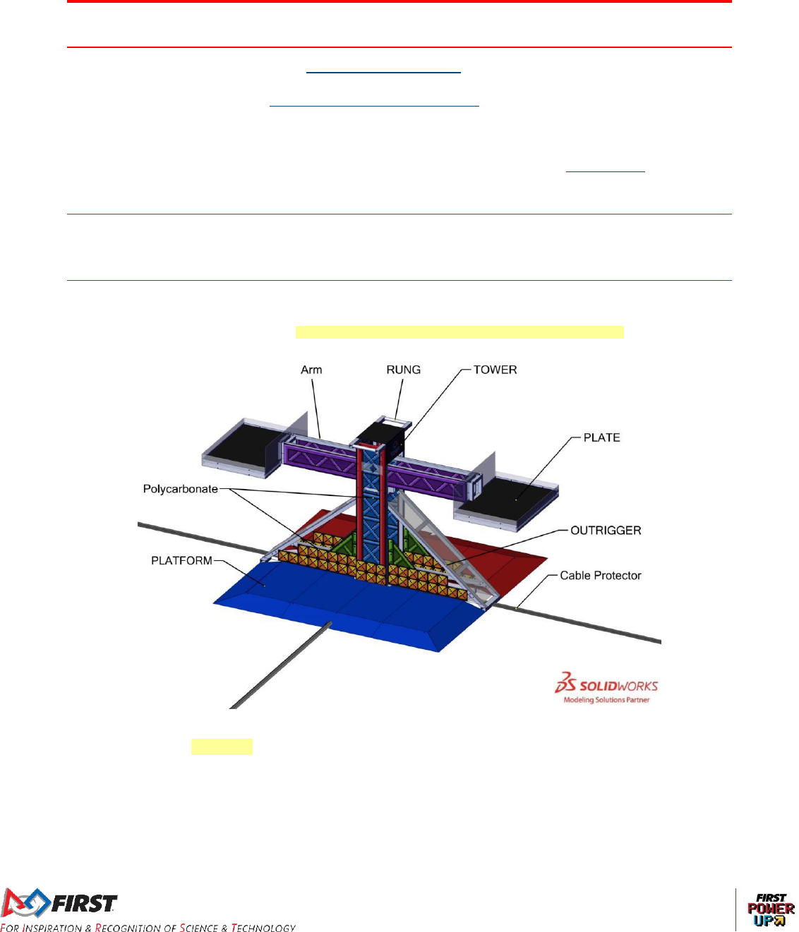
Section 3.3 SCALE
Figure 3-4: The SCALE (Note, cable protectors are shown, but are not part of the SCALE)
The BRICKS are graphics depicting golden squares surrounded by a black outline that extends 12 in.
(~30cm) above the horizontal surface of the PLATFORM.
January 16, 2018
2 of 4
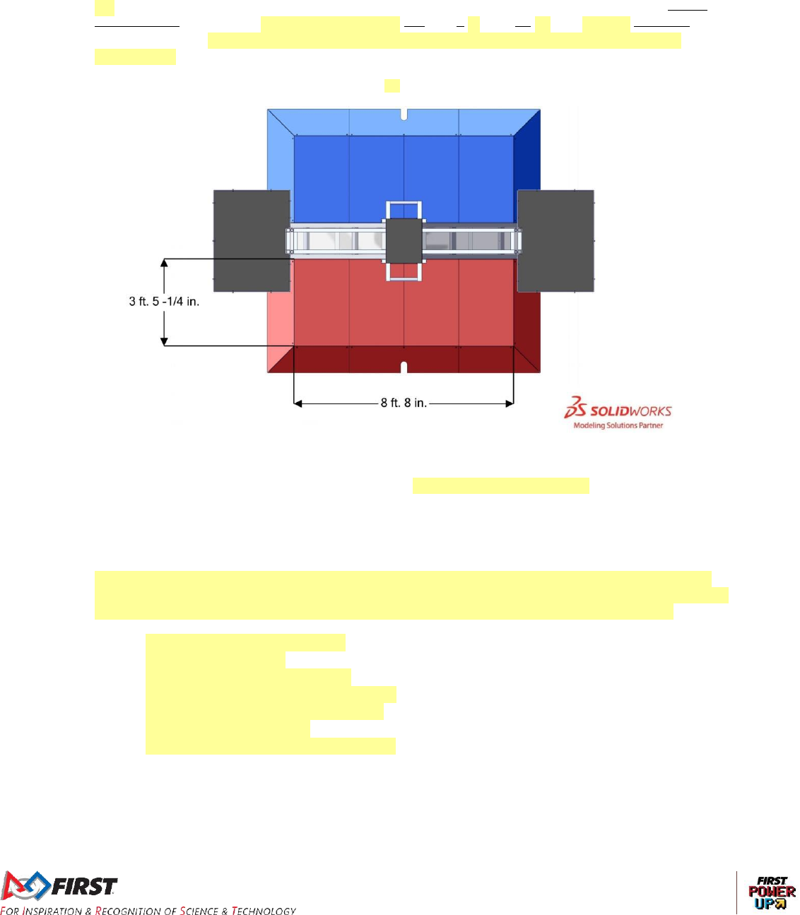
Section 3.3.5 PLATFORM
Located at the base of the SCALE, on each side, is a PLATFORM covered with ALLIANCE colored
HDPE. The TOWER and OUTRIGGERS separate one PLATFORM from the other. Each PLATFORM
top is 8 ft. 8 in. (~264 cm) wide by 3 ft. 5 ¼ in. (~105 cm) deep and 3 ½ in. (~9 cm) tall. The ramps
leading to the PLATFORM includes ramps with a are 1 ft. 1 ¾ in. (~33 32 cm) run and long with a
15.35 deg. angle. The ALLIANCE colored tape that abuts the PLATFORM ramps is part of the
PLATFORM.
Figure 3-11: PLATFORM top length and width dimensions
Section 3.9 Vision Targets
Vision targets are located on the SWITCH FENCE facing the ALLIANCE WALL using 2 in. (~5 cm)
strips of 3M 8830 Scotchlite Reflective Material and are used to highlight the locations of the PLATES
on the SWITCH.
Section 3.10 The FIELD Management System
FMS alerts participants to milestones in the MATCH using audio cues. Please note that audio cues
are intended to be a courtesy to participants and not intended as official MATCH markers. If there is a
discrepancy between an audio cue and the FIELD timers, the FIELD timers are the authority.
• MATCH Start: “Cavalry Charge”
• T=0 for AUTO: Buzzer
• Start of TELEOP: Three (3) Bells
• T-30 seconds in TELEOP: Train Whistle
• T=0 for TELEOP/MATCH end: Buzzer
• MATCH stopped: Foghorn
• POWER UP activated: “Linear Popping"
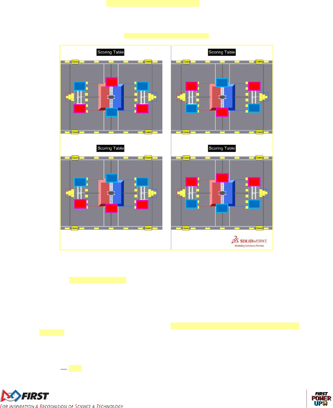
Section 4.1.1 Stages
Each MATCH is divided in to two stages. The first stage, called Autonomous (AUTO), is the first
fifteen (0:15) seconds of a MATCH in which ROBOTS operate without any DRIVE TEAM control or
input. Prior to the start of AUTO, the assignments of ALLIANCE colors for SWITCH and SCALE
January 16, 2018
3 of 4
PLATES are randomized among the four states in Figure 4-1 and transmitted to the OPERATOR
CONSOLE by the Field Management System (FMS). During AUTO, ROBOTS attempt to deliver
preloaded POWER CUBES to PLATES, retrieve additional POWER CUBES from around the FIELD,
and cross their AUTO LINE any time before the end of the stage.
Figure 4-1 Possible PLATE assignments
Section 4.6 Logistics
There will not be an ARCADE FAULT called for MATCHES that accidentally begin with an incorrect
number of, incorrectly positioned, or damaged POWER CUBES. Damaged POWER CUBES will not
be replaced until the next FIELD reset period. DRIVE TEAMS should alert the FIELD STAFF to any
missing or damaged POWER CUBES prior to the start of the MATCH.
Section 7.1 Before the MATCH
G04. Leave the POWER CUBES alone. Prior to the start of the MATCH, DRIVE TEAMS may not
rearrange the POWER CUBES within a PORTAL, staged on the FIELD (that are not staged inside a
ROBOT), or transfer POWER CUBES from one PORTAL to another.
Vi ola t ion : M ATCH wi ll not st a rt un til the s itu a tion i s c o rr ect ed .
Section 8.4 Budget Constraints & Fabrication Schedule
R22. At an each Event, Teams may have access to a WITHHOLDING ALLOWANCE.
January 16, 2018
4 of 4
Section 8.5 BUMPER Rules
R28.
A. consist of Arabic numerals at least 4 in. (~11 cm) high, at least ½ in. (~12.7 mm) in
stroke width, and be either white in color or outlined in white with a minimum 1/16 in.
(~1.6mm) outline
Section 8.8 Control, Command & Signals System
R65. The roboRIO Ethernet port must be connected to the Wireless Bridge port labeled “18-24
vPOE,” closest to the power connector (either directly, via a network switch, or via a CAT5 Ethernet
pigtail).
Section 8.9 Pneumatic System
R83. The only pneumatic system items permitted on ROBOTS include the items listed below.
E. Solenoid valves with a maximum ⅛ in. (nominal, ~6 mm) NPT, BSPP, or BSPT port
diameter,
R89. Only the compressor, relief valve (P/N: 16-004-011 or 16-004-003), pressure switch, pressure
vent plug, pressure gauge, storage tanks, tubing, pressure transducers, and connecting fittings may
be in the high-pressure pneumatic circuit upstream from the regulator.
Section 10.8 MATCH Replays
Over the course of the Tournament it may be necessary for a MATCH to be replayed. Typical causes
for replays are MATCHES that end in a tie during the Playoffs or if there is an ARCADE FAULT. An
ARCADE FAULT is an error in ARCADE operation that includes, but is not limited to:
A. broken FIELD elements due to
normal, expected game play or
ROBOT abuse of FIELD elements that affects the outcome of the MATCH for
their opponents.
A broken FIELD element caused by ROBOT abuse that affects the
outcome of the MATCH for their ALLIANCE is not an ARCADE FAULT.
B. power failure to a portion of the FIELD (tripping the circuit breaker in the PLAYER
STATION is not considered a power failure)
C. improper activation by the FMS
D. errors by FIELD staff (except those listed in Section 4.6)

January 12, 2018
1 of 3
Team Update 02
General
• Drawing Updates: The Field Drawings - FIRST POWER UP specific drawing package has been
updated with the following changes:
GE-18020 has been updated to include a missing overall length dimension.
GE-18060 has been updated to fix a note with an incorrect item number called out.
GE-18126 has been updated to fix a note with an incorrect item number called out.
GE-18127 has been added. Please note the height of GE-18127 supplied by SolidWorks,
Autodesk, and PTC is slightly taller than what is specified in Section 3.6.2 EXCHANGE.
We will be working with them to get those models updated.
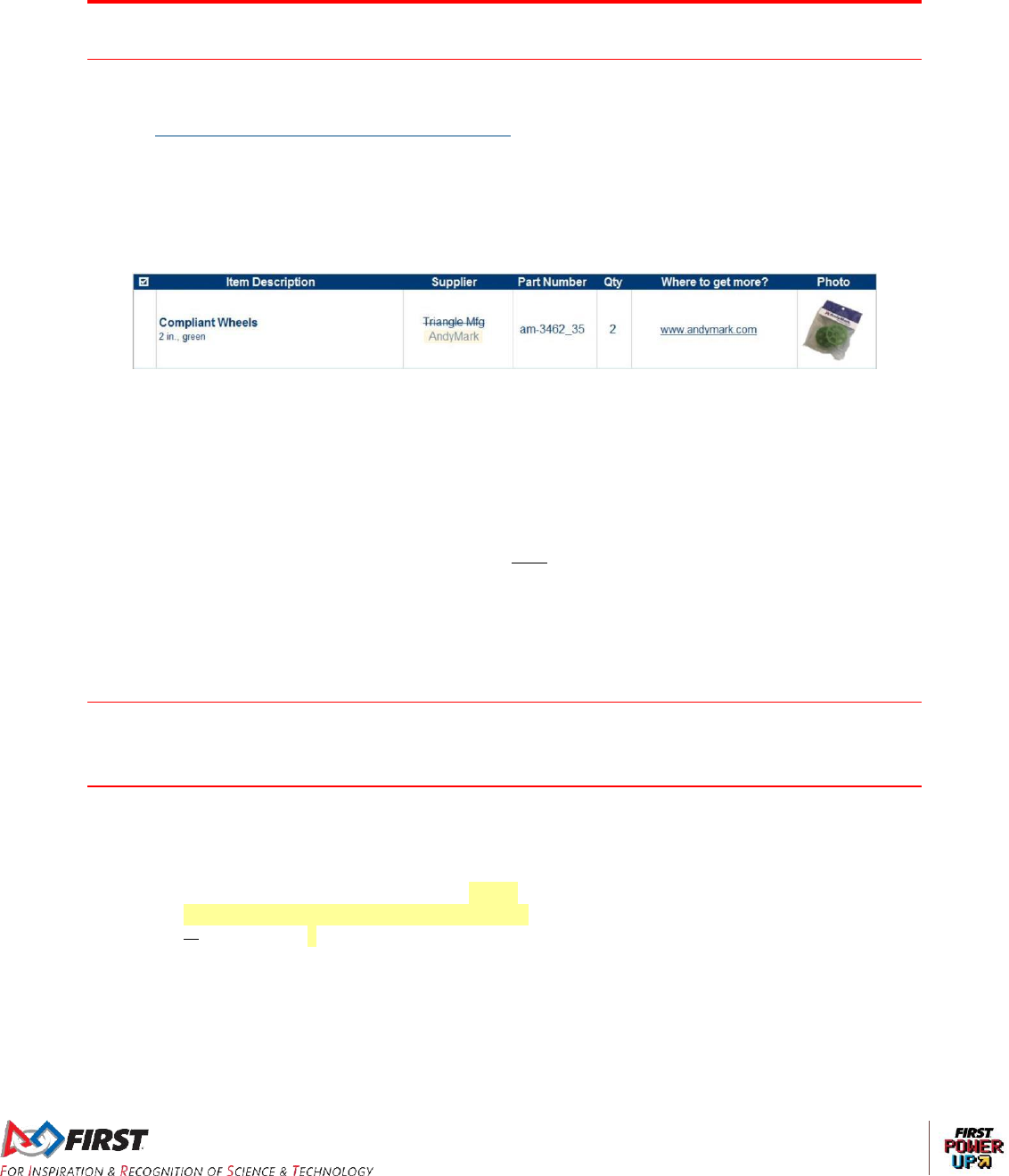
The Team Drawings drawing package has been updated with the following changes:
TE-18008 has been updated to fix BOM item number and part number agreement.
TE-18007 has been updated to fix BOM item number and part number agreement, and to
include changes to the following parts:
TE-18007-3 has been updated to correct overall length of part.
TE-18007-4 has been updated to correct overall length of part.
TE-18007-10 has been updated to correct overall length of part.
TE-18007-11 Has been updated to correct overall length of part.
The revisions to the Scale in the Team Drawings correct design mistakes that resulted in
differences between the team version of the Scale and the official Scale. The width of the Rung is
1 ft. 1 in. (down from 1 ft. 2 in.), the width of the Tower is 1 ft. 5 in. (down from 1 ft. 6 in.), and the
distance from the Rung to the face of the Tower is 8¼ in. (up from 6¼ in.)
While we try to ensure that critical dimensions in the wooden versions of Field elements match
their official counterparts, there are always discrepancies caused from using different building
materials. However, the discrepancies referenced above were due to design error and may
impact Robot design. We apologize, especially if these corrections affect your Robot designs.
• 360° Images: A link to 360° images of the FIRST POWER UP field taken during Field Tour
filming is included on the Game and Season webpage.
• 3D CAD Models: A link to FIRST POWER UP DS SolidWorks models is now included on the
Game and Season webpage.
• FIRST POWER UP Field images: A link to field images taken during Field Tour filming is now
included on the Game and Season webpage.
• Crate Construction: Think you’ll be shipping your Robot? The crate specifications are now
posted here.
Rules & Expectations for
FIRST
Robotics Competition Events
No changes.
Game and Season Manual
Section 3.6.3
Caution, there are may be orientations where all three (3) POWER
CUBES will not fit in a VAULT column, but if HUMAN PLAYERS place
POWER CUBES logo side up they’ll fit with room to spare.
January 12, 2018
2 of 3
Section 3.8 POWER CUBES
Each POWER CUBE weighs 3 ½ lbs (~1.6 kg) approximately 3 ¼ lbs (~1.5 kg). POWER CUBES
may be purchased from AndyMark (am-3818 and am-3741), Innovation First (217-6188 and 217-
6193), and Rev Robotics (REV-21-1217 and REV-21-1218).
Section 4.2 Scoring
Points are earned for establishing OWNERSHIP, with additional points
earned for each additional second of OWNERSHIP. For example, a team
that establishes OWNERSHIP of their SWITCH three (3) seconds after
the start of AUTO and maintains OWNERSHIP for five (5) seconds earns
two (2) points + ten (10) points, for a total of twelve (12) points.
The MATCH points listed in Table 4-1 for OWNERSHIP during the
TELEOP stage are increased if the BOOST POWER UP is played. See
Section 4.3 for details on BOOST.
AUTO-RUN and CLIMBING are both evaluated and scored by human
REFEREES. Teams are encouraged to make these actions obvious and
unambiguous.
Section 4.3 POWER UPS
An ALLIANCE plays a POWER UP by pressing the corresponding button on the VAULT. Only one (1)
instance of the FORCE or BOOST POWER UP can be active at a time. If an ALLIANCE pushes the
button for FORCE/BOOST while their other FORCE/BOOST is active, the button press is ignored.
The LEVITATE POWER UP can be played at any time during the TELEOP stage.
Section 7.6 Human Action Rules
H07.
A. the OPERATOR CONSOLE,
B. non-powered signaling devices,
C. reasonable decorative items,
D. special clothing and/or equipment required due to a disability,
E. devices used solely for planning or tracking strategy,
F. devices used solely to record gameplay,
G. non-powered Personal Protective Equipment (examples include, but aren’t limited to,
gloves, eye protection, and hearing protection)
Items brought to the ARCADE under allowances B-G must meet all of the following conditions:
do not connect or attach to the OPERATOR CONSOLE
do not connect or attach to the FIELD or ARCADE
do not connect or attach to another ALLIANCE member (other than items in
category G)
do not communicate with anything or anyone outside of the ARCADE.
do not communicate with the TECHNICIAN
do not include any form of enabled wireless electronic communication (e.g. radios,
walkie-talkies, cell phones, Bluetooth communications, Wi-Fi, etc.)
January 12, 2018
3 of 3
do not in any way affect the outcome of a MATCH, other than by allowing the
DRIVE TEAM to
a. plan or track strategy for the purposes of communication of that
strategy to other ALLIANCE members or
b. use items allowed per part B to communicate with the ROBOT
(provided A02 is not violated).
Section 8.3 ROBOT Safety & Damage Prevention
R07.
If the ROBOT includes protrusions that form the “leading edge” of the
ROBOT as it drives and the protrusions have a surface area of less than
1 in.2 (~6 cm2), it will invite detailed Inspection. For example, forklifts,
lifting arms, or grapplers may be carefully inspected for these hazards.
Section 8.5 BUMPER Rules
A note about the edit to R24: The original BUMPER ZONE did not leave any tolerance for noodle
alignment, wood alignment, fabric folds, etc., if using the BUMPER brackets that shipped with the
Drive Base Kit.
R24. BUMPERS must be located entirely within the BUMPER ZONE, which is the volume contained
between the floor and a virtual horizontal plane 7 in. (~17 cm) 7½ in. (~19 cm) above the floor in
reference to the ROBOT standing normally on a flat floor. BUMPERS do not have to be parallel to the
floor.
Section 8.9 Pneumatic System
R81.
Any pressure specification such as “working,” “operating,” “proof,”
“maximum,” “burst,” etc. may be used to satisfy the requirements of R81.
It is recommended that all pneumatic items be rated by their
manufacturers for a working pressure of at least 60 psi (~414 kPa).
January 9, 2018
1 of 6
Team Update 01
General
Drawing Packages
The Field Drawings – FIRST POWER UP specific drawing package has been updated with the
following changes:
- GE-18130 has been added
- GE-18101 and GE18025 have been updated to include GE-18130
Kickoff Kit Checklist: Black Tote
Safety Manual
Section 3.5.5 Charging and Handling
• Do not short out the battery terminals. If metal tools/parts contact the terminals simultaneously,
it will create a direct short circuit. This may cause high heat to develop in the battery
terminal/part/tool area and the battery could explode. To avoid the possibility of shorting out the
battery terminals and creating a hazardous situation it is required to cover all exposed battery
terminals and connections with appropriate non-insulating material such as electrical tape or
tubing.
It surprises us that we feel the need to say this, please don’t put the POWER CUBE cover on
anyone’s head and zip it closed; also, don’t eat it.
Rules & Expectations for
FIRST
Robotics Competition Events
No changes.
Game and Season Manual
Section 1.8 Question and Answer System
The Q&A is not a resource for
• rulings on hypothetical strategies or vague situations,
• challenging decisions made at past events, or
• a design reviews of a ROBOT system for legality.
The responses in the Q&A do not supersede the text in the manual, although every effort will be
made to eliminate inconsistencies between the two. While responses provided in the Q&A may be
used to aid discussion at each event, per Section 10.6 REFEREE Interaction and Section 9
Inspection & Eligibility Rules, REFEREES and Inspectors are the ultimate authority on rules. If you
have concerns about enforcement trends by volunteer authorities, please notify FIRST at
firstroboticscompetition@firstinspires.org.

January 9, 2018
2 of 6
Weak questions are overly broad, vague, and/or include no rule references. Some examples of
questions that will not be answered in the Q&A are:
• Is this part/design legal?
• How would should the a REFEREE have ruled if when this specific, hypothetical game play
happened?
Good questions ask generically about features of parts or designs, gameplay scenarios, or rules, and
often reference one or more relevant rules within the question. Some examples of questions that will
likely be answered in the Q&A are:
• A device we are considering using on the robot comes with purple AWG 40 wire, does this
comply with R?? and R??
• We’re not sure how to interpret how Rule G?? applies if Blue Robot A does X and Red Robot
B does Y, can you please clarify?
Section 3.1 Zones and Marking
STARTING LINE: a line of 2 in. (~5 cm), white gaffers tape that runs the width of the carpet and is 2
ft. 6 in. (~76 cm) behind the ALLIANCE WALL diamond plate, which includes the tape.
Section 3.3 SCALE
A cable protector extends from the center of each side of the PLATFORM and is 2 ½ in. (~6 cm) wide
and ¾ in. (~2 cm) high (Electriduct, Inc. CSX-3, black). The cable protector is attached to the field
with hook fastener, increasing the height to approximately ⅞ in. (~2 cm). These cable protectors
extend to the GUARDRAILS and the SWITCHES.
Section 3.4.1 SWITCH PLATES
The PLATES are 9 in. (~23 cm) above the carpet when the SWITCH is level. Like the SCALE, the
SWITCH tilts and rests in different positions based on the placement of POWER CUBES. During the
MATCH, the SWITCH is in one of three (3) two (2) states based on the magnitude of its tilt:
1. OWNERSHIP by the Red its ALLIANCE, or
2. OWNERSHIP by the Blue ALLIANCE, or
3. neither ALLIANCE has OWNERSHIP
If the outside edge of an ALLIANCE’S colored PLATE is positioned between 3 in. (~8 cm) and 6 in.
(~15 cm) above the FIELD carpet then the ALLIANCE has OWNERSHIP of the its SWITCH. If the
outside edge of an ALLIANCE colored PLATE is positioned between 12 in (~30 cm) 6 in (~15 cm)
and 15 in. (~38 cm) above the FIELD carpet then the opposing ALLIANCE has OWNERSHIP. When
neither ALLIANCE has OWNERSHIP of the SWITCH, the outside edges of the PLATES are between
6 in (~15 cm) and 12 in. (~30 cm) above the FIELD carpet. See Figure 3-15. The time required to
move between states is dependent on the weight difference and the distribution of the weight on the
SWITCH PLATES. Details on OWNERSHIP can be found in Section 4.2 Scoring.
Section 3.5 PLATE Lighting
Table 3-1: PLATE Lighting
Color
Pre-
MATCH
AUTO
TELEOP
Post-
MATCH
Blue (pulsing) with
solid red corners
N/A
Blue FORCE POWER UP
is active N/A
Blue FORCE POWER UP
is active
N/A
January 9, 2018
3 of 6
Red (pulsing)
N/A
Red OWNERSHIP or
FORCE POWER UP is
active
Red OWNERSHIP or
FORCE POWER UP is
active
N/A
Red (pulsing) with
solid blue corners
N/A
Red FORCE POWER UP
is active N/A
Red FORCE POWER UP
is active
N/A
Section 3.8 POWER CUBE
POWER CUBES may be purchased from AndyMark (am-3818 and am-3741), Innovation First (217-
6188 and 217-6193), and Rev Robotics (REV-21-1217 and REV-21-1218). Please note that due to
the use of recycled material in the manufacturing process, the batches of crates will vary slightly in
color, but not such that it’s perceptible with the cover in place.
Section 4.1.2 MATCH Setup
Prior to the start of each MATCH, POWER CUBES, elements used to affect the position of the
SCALE and SWITCHES and earn POWER UPS, are staged as shown in Figure 4-1. Staging details
are as follows:
A. Seven (7) in each PORTAL (on the carpet between the PORTAL wall and the STARTING
LINE), minus any preloaded POWER CUBES,
B. Six (6) next to each SWITCH. They are arranged approximately equidistant from each other
along the face of the FENCE closest to the SCALE, FIRST logo facing up
C. Ten (10) located in each ALLIANCE POWER CUBE PILE (in a pyramid formation, with six on
the bottom, three in the middle, and one on top, justified toward the SWITCH, FIRST logo
facing up)
Section 4.2: Scoring
The primary method of earning points in FIRST® POWER UPSM is by placing POWER CUBES on the
PLATES of the SWITCH or SCALE to establish OWNERSHIP. OWNERSHIP is a state of the
ALLIANCE’S SWITCH or SCALE where it is tilted in favor of an ALLIANCE colored PLATE, such that
the outside edge of the ALLIANCE colored PLATE is at or less than a specified height above the
carpet. ALLIANCES earn points when OWNERSHIP is established and additional points for each
additional second of OWNERSHIP.
…
An ALLIANCE has OWNERSHIP of their SWITCH when:
A. the SWITCH is tilted in favor of their ALLIANCE colored PLATE, such that the outside edge
of the ALLIANCE colored PLATE is at or less than 6 in. (~15 cm) from the floor for at least
one (1) second, or
B. they have played the FORCE POWER UP at level 1 or 3 (see Section 4.3 POWER UPS)
The Blue ALLIANCE’S SWITCH accumulates points for the Blue
ALLIANCE when the PLATE illuminated and pulsing with blue lights is
down.
The SWITCH does not accumulate points for either ALLIANCE when
the blue PLATE is above 6 in (~15 cm).
An ALLIANCE has OWNERSHIP of the SCALE when:
January 9, 2018
4 of 6
A. the SCALE is tilted in favor of their ALLIANCE colored PLATE, such that the outside edge of
the ALLIANCE’S colored PLATE is at or lower than 4 ft. 8 in. (~142 cm) from the floor for at
least one (1) second and there isn’t an active opponent’s Level 2 or 3 FORCE, or
B. they have played the FORCE POWER UP at level 2 or 3 (see Section 4.3 POWER UPS)
Note that points for the SWITCH and SCALE are accrued over time and
not a direct function of the number of POWER CUBES placed on the
SWITCH or SCALE.
Points are not taken away when OWNERSHIP changes, but rather stop
accumulating (if balanced) or start accumulating for the opposite
ALLIANCE if they take OWNERSHIP of the SCALE.
Note from the FRC Director on the edits to Table 4-1:
You will see we added a requirement in Table 4-1 requiring a ROBOT to not be in direct contact with their
PLATFORM to be considered CLIMBING. We believe this was already a requirement, given our
BUMPER rules, but adding the requirement in Table 4-1 was the most straightforward way of making this
clear.
Table 4-1: FIRST® POWER UPSM rewards
Action
Criteria
MATCH Points
Ranking
Points
AUTO
TELEOP
CLIMBING
For each ROBOT fully supported by the SCALE
(either directly or transitively) with BUMPERS fully
above the BRICKS at T=0, not in direct contact with
their PLATFORM, and not at all in the opponent’s
PLATFORM ZONE
-
30
-
Section 4.3: POWER UPS
Note from the FRC Director on the edits to Table 4-2:
These changes are an attempt to clarify how BOOST works. They do not significantly change the
points being earned under BOOST.
January 9, 2018
5 of 6
Table 4-2: POWER UPS
Section 8.3 ROBOT Safety & Damage Prevention
R07. Protrusions from the ROBOT and exposed surfaces on the ROBOT shall not pose hazards to
the ARCADE elements (including the POWER CUBES GAME PIECES) or people.
If the ROBOT includes protrusions that form the “leading edge” of the
ROBOT as it drives and have a surface area of less than 1 in.2 (~6 cm2),
it will invite detailed Inspection. For example, forklifts, lifting arms, or
grapplers may be carefully inspected for these hazards..
Section 8.6 Motors & Actuators
R33.
For servos, note that the roboRIO is limited to a max current output of
2.2A on the 6V rail (12.4W of electrical input power). Teams should
make sure that their total servo power usage remains below this limit at
all times.
This is the total number of each motor a Team may use on their ROBOT,
not the quantity per part number. For example, each team may use up to
six (6) CIM motors on their ROBOT, regardless of the quantity or
combination of each individual part number used.
Given the extensive amount of motors allowed on the ROBOT, Teams
are encouraged to consider the total power available from the ROBOT
Name
# of POWER
CUBES
Effect
Duration
(seconds)
LEVITATE
3
An additional CLIMBING ROBOT, up to a maximum of
three (3) ROBOTS, is credited to the ALLIANCE at the
end of the MATCH
N/A
FORCE
1
ALLIANCE earns OWNERSHIP points from their
SWITCH regardless of PLATE position
10
2
ALLIANCE earns OWNERSHIP points from the SCALE
regardless of PLATE position
10
3
ALLIANCE earns OWNERSHIP points from the SWITCH
and the SCALE regardless of PLATE position
10
BOOST
1
Increases the points for OWNERSHIP of the ALLIANCE’S
SWITCH from one (1) point per second to two (2) points
per second Doubles the points being earned by the
ALLIANCE for OWNERSHIP of their SWITCH.
10
2
Increases the points for OWNERSHIP of the SCALE from
one (1) point per second to two (2) points per second
Doubles the points being earned by the ALLIANCE for
OWNERSHIP of the SCALE.
10
3
Increases the points for OWNERSHIP of both the
ALLIANCE’S SWITCH and the SCALE from one (1) point
per second to two (2) points per second Doubles the
points earned by the ALLIANCE for OWNERSHIP of a)
their SWITCH and b) the SCALE.
10
January 9, 2018
6 of 6
battery during the design and build of the ROBOT. Drawing large
amounts of current from many motors at the same time could lead to
drops in ROBOT battery voltage that may result in tripping the main
breaker or trigger the brownout protection of the roboRIO. For more
information about the roboRIO brownout protection and measuring
current draw using the PDP, see roboRIO Brownout and Understanding
Current Draw.
R34.
F. The wiring harness of the Nidec Dynamo BLDC Motor may be modified as
documented by FIRST in the "Nidec Dynamo BLDC Motor with Controller"
Screensteps article.
Section 10.12 Advancement Between Tournaments
T17.
A FIRST® Robotics Competition Team listed in the Championship
Eligibility Criteria document is pre-qualified for the FIRST Championship
if the Team meets one of the following criteria:
A. member of the FIRST® Hall of Fame
B. an original and sustaining team since 1992
C. a 2017 FIRST Championship winner
D. a 2017 FIRST Championship Engineering Inspiration Award winner
E. a 2017 FIRST Championship Chairman’s Award Finalist
Section 11: GLOSSARY
Section 11: Glossary has been updated to include entries for ACTIVE DEVICE, CAW, FENCE, LRI,
RSL, SCALE, SIGNAL LEVEL, SWITCH, and VENDOR.
