Mirror Inst 1 Secret Door Installation Instr
User Manual:
Open the PDF directly: View PDF ![]() .
.
Page Count: 5
H OM E
CREATIVE
ENGINEERING
Installation Instructions
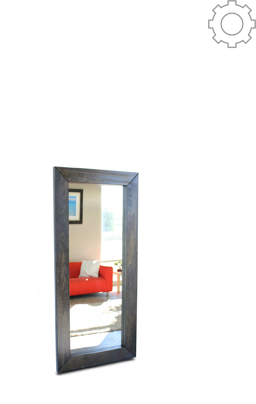
Mirror Secret Door
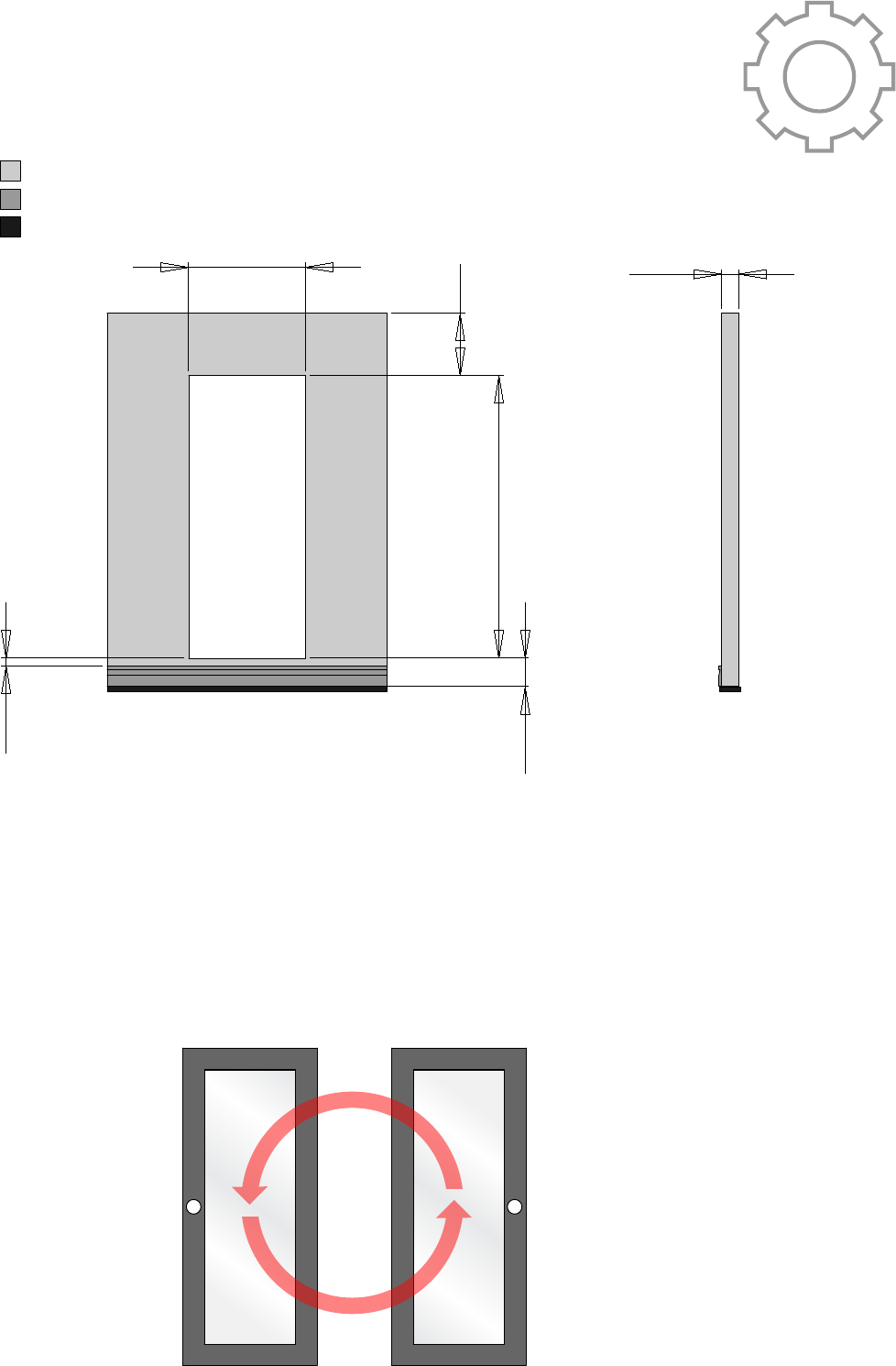
1. Prepare the wall opening
2. Choose hinge side.
4 1/2”
No less than 2 3/4”
32”
No less than 2 3/4” above molding (if present)
No less than 4.0” above finished floor
74”
Front View Side View
Wall
Baseboard
Floor
Installation of the mirror door requires a wall
opening with the below noted dimensions.
Opening dimensions may vary up to 1/8”.
H OM E
CREATIVE
ENGINEERING
Locate the white sticker on the mirror face frame.
This sticker indicates the non-hinged side of the
door. The door may be rotated 180 degrees to
switch the hinge side location. Do not remove the
sticker at this point.
Right Side Hinge Left Side Hinge
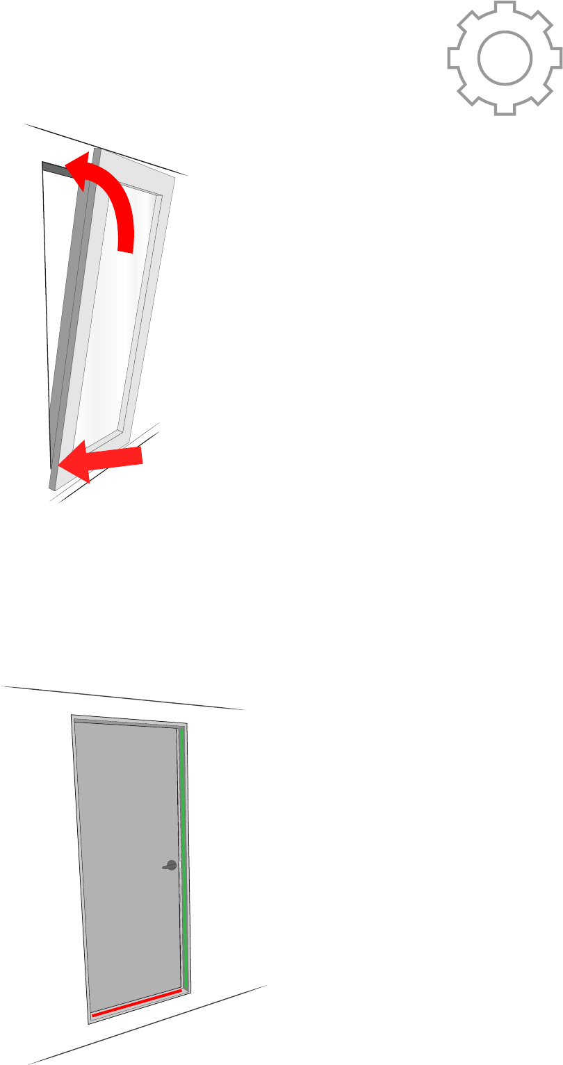
3. Fit frame into prepared opening.
4. Shim Door Frame
Rest the bottom edge of the door frame on the
bottom ledge of the opening. Rock the top of
the door into the opening.
H OM E
CREATIVE
ENGINEERING
Depending on the conditions of the prepared open-
ing it may be necessary to shim the frame to
achieve perfect operation. Use a level on the bottom
and side of the door frame and check for plumb and
level. Shim accordingly.
2
1
Ensure this surface is vertical
Ensure this surface is level
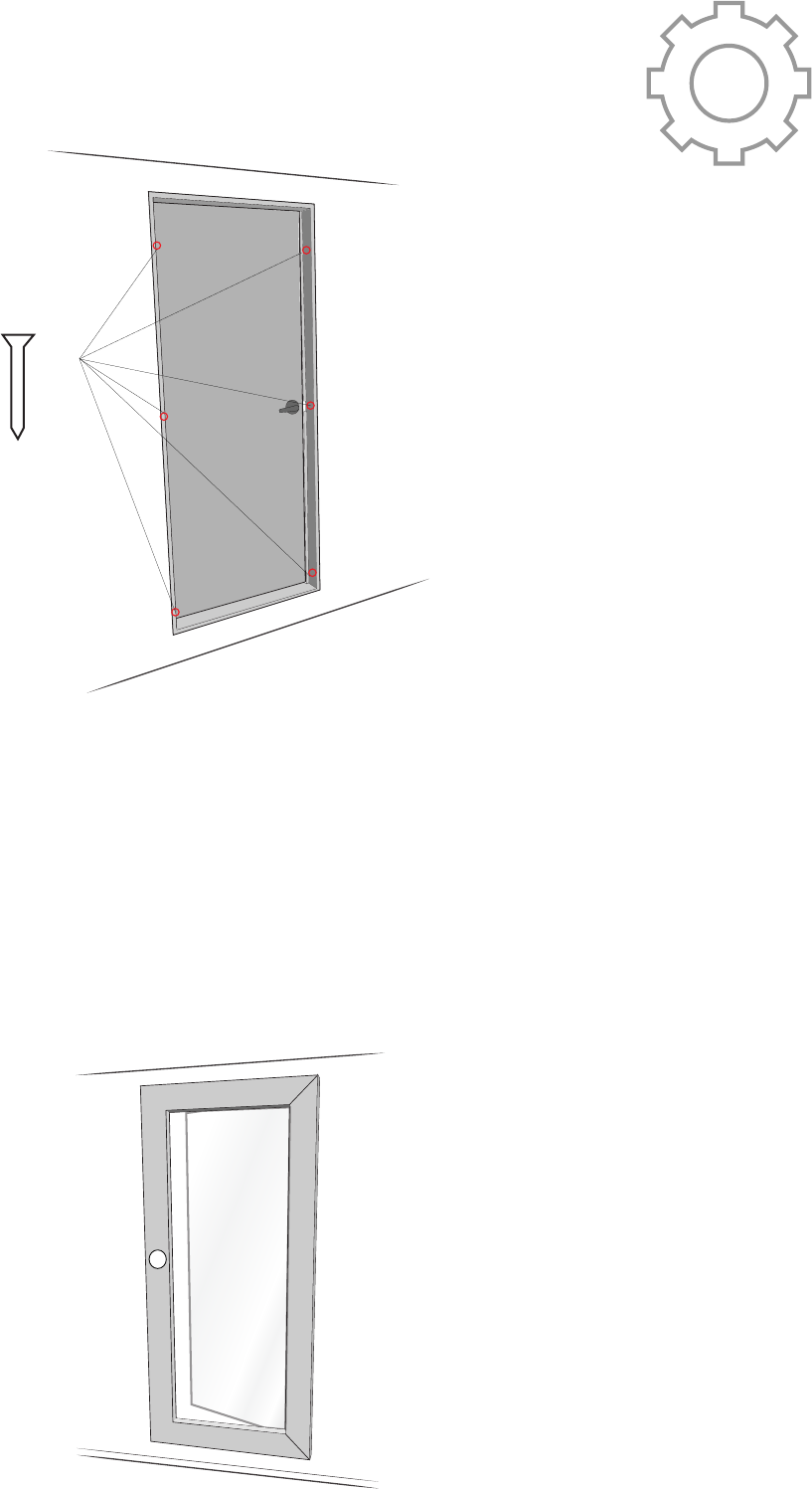
5. Secure frame to opening with wood screws.
6. Function Check
Using six 2.5” wood screws secure the frame
of the mirror door to the studs. These screws
may be puttied over or painted as desired.
H OM E
CREATIVE
ENGINEERING
Your door should now be ready to use. Run the
included magnet over the white sticker. While
holding the magnet over the sticker lightly push on
the mirror. Your door should now open. If the door is
rubbing on the frame check again for frame plumb-
ness and level. The sticker may now be removed.
2.5” Wood Screw
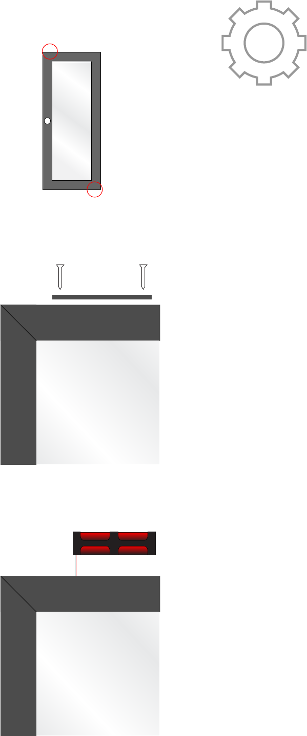
6. Battery Replacement.
The 8 x AA batteries that are preinstalled will
last for many thousands of cycles. If the batter-
ies die they may be easily replaced.
1. Locate battery cover location. This will either
be the upper left or lower right corner depend-
ing on your installation orientation and is
located on the perimeter edge of the frame.
2. Remove the two wood screws securing the
cover using a #2 phillips driver. Pull the wooden
cover from the frame
3. Pull battery tray from frame cavity. Remove
old batteries and reinstall fresh AA batteries.
H OM E
CREATIVE
ENGINEERING
