Mrbw Cst Manual V1.1
User Manual:
Open the PDF directly: View PDF ![]() .
.
Page Count: 28

ProtoThrottle
MANUAL
www.protothrottle.com
IOWA SCALED ENGINEERING – ELECTRONICS MADE EASY!

Thank you for purchasing the ProtoThrottle.
Our goal was to design and develop a wireless throttle
that provides the diesel modeler with the most realistic
experience operating their model locomotives.
The ProtoThrottle mimics a standard EMD control stand
including full detent throttle and reverser handles, a
spring-loaded horn handle, a push-on/push-off bell
button, and fully programmable front and rear head-
lights with a setting for ditch lights. In addition, the
ProtoThrottle comes with a robust faceplate machined
from aluminum, including prototype bezels, and anodized
to give the look and feel of a real control stand.
The ProtoThrottle comes with our commitment to your
satisfaction. We warranty the throttle from manufacturing
defects for one year, and if you should have any questions
or issues with the ProtoThrottle, please contact us.
Scott Thornton Michael Petersen Nathan Holmes
www.protothrottle.com

www.protothrottle.com
Table of Contents
ProtoThrottle Controls & Battery Install 4
Quick Start Guide 5
Main Screen 6
Engine Menu 7
Tonnage Menu 8
Load / Save Configuration Menus 9
Set Locomotive Menu 10
Force Function Menu 11
Configuration Function Menu 12
Notch Configuration Menu 14
Options Menu 15
System Menu 17
Communication Configuration Menu 18
Preferences Menu 19
Threshold Calibration Menu 21
Diagnostics Menu 22
Electronics Schematic 24
Licensing / Support 25
Open Source Development 26
Notes 27
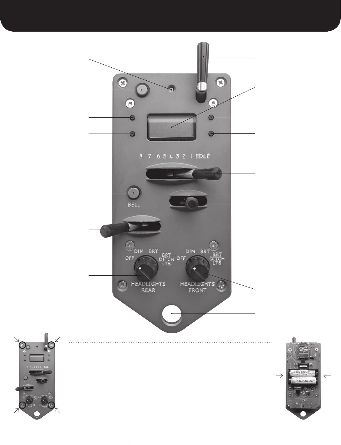
Menu button
Auxiliary button
Status light
Select button
Bell button
Brake handle
(Note: to apply the brake
move the handle to the
right; all the way to the
right optionally applies
the emergency brake)
Rear lights switch
ProtoThrottle Controls & Battery Install
www.protothrottle.com
Up button
LCD screen
Horn handle
Down button
Throttle handle
Reverser handle
(Note: centered position allows
no directional movement; to
the right is forward; to the left
is reverse. You can remember
the prototypical directions by
referencing the lights below.
e.g.: “front” is forward, “rear”
is reverse. The directions can
be reversed, e.g. for consists,
see page 16 under Reverser
Swap.)
Front lights switch
Lanyard attachment
The ProtoThrottle is powered by 2 AA batteries (not included). The batteries can be
alkaline or rechargeable NiMH.
To access the battery holder, unscrew the 4 phillips head screws on the corners of
the throttle’s faceplate; remove the box; IMPORTANT: when removing the batteries
from the holder, use one hand to hold both sides of the holder to prevent it from
bending away from the printed circuit board; insert batteries and reattach the box.
Do not over tighten the screws.
To conserve battery life: make sure the throttle handle is in “idle” position and the
reverser handle is in “centered” position when not in use. This will cause the throttle
to go to sleep after 5 minutes.
5
Quick Start Guide
www.protothrottle.com
The ProtoThrottle will work with any scale and with sound- or non-sound
decoders (though using sound enhances the control stand experience signifi-
cantly). Any DCC decoder compatible with the NMRA standards will work with
the ProtoThrottle because it uses standard DCC commands and functions via
your command station.. The ProtoThrottle is not a DCC system and will not
replace the system you use.
Check the Iowa Scaled Engineering website for the most current list of
supported DCC command stations: www.iascaled.com
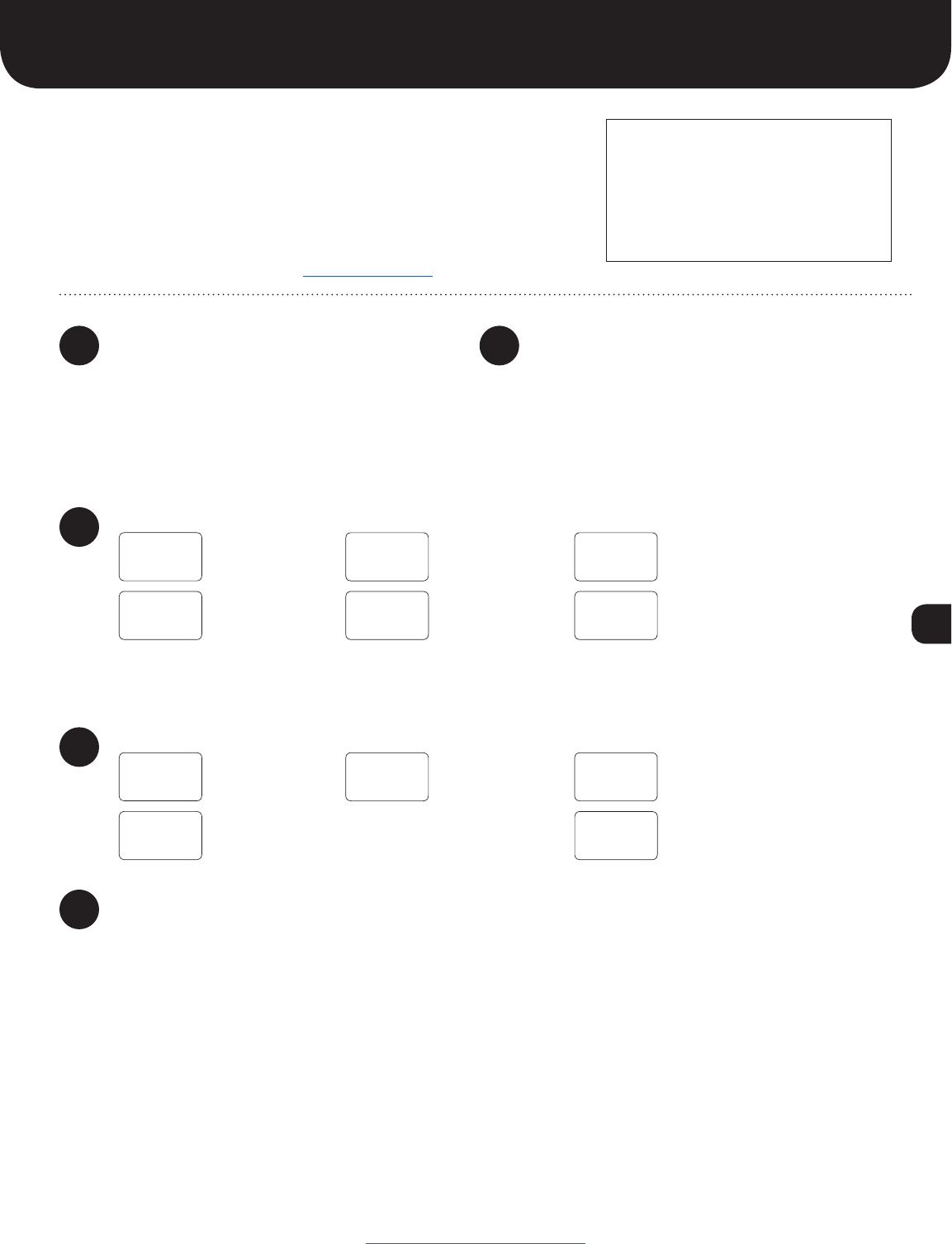
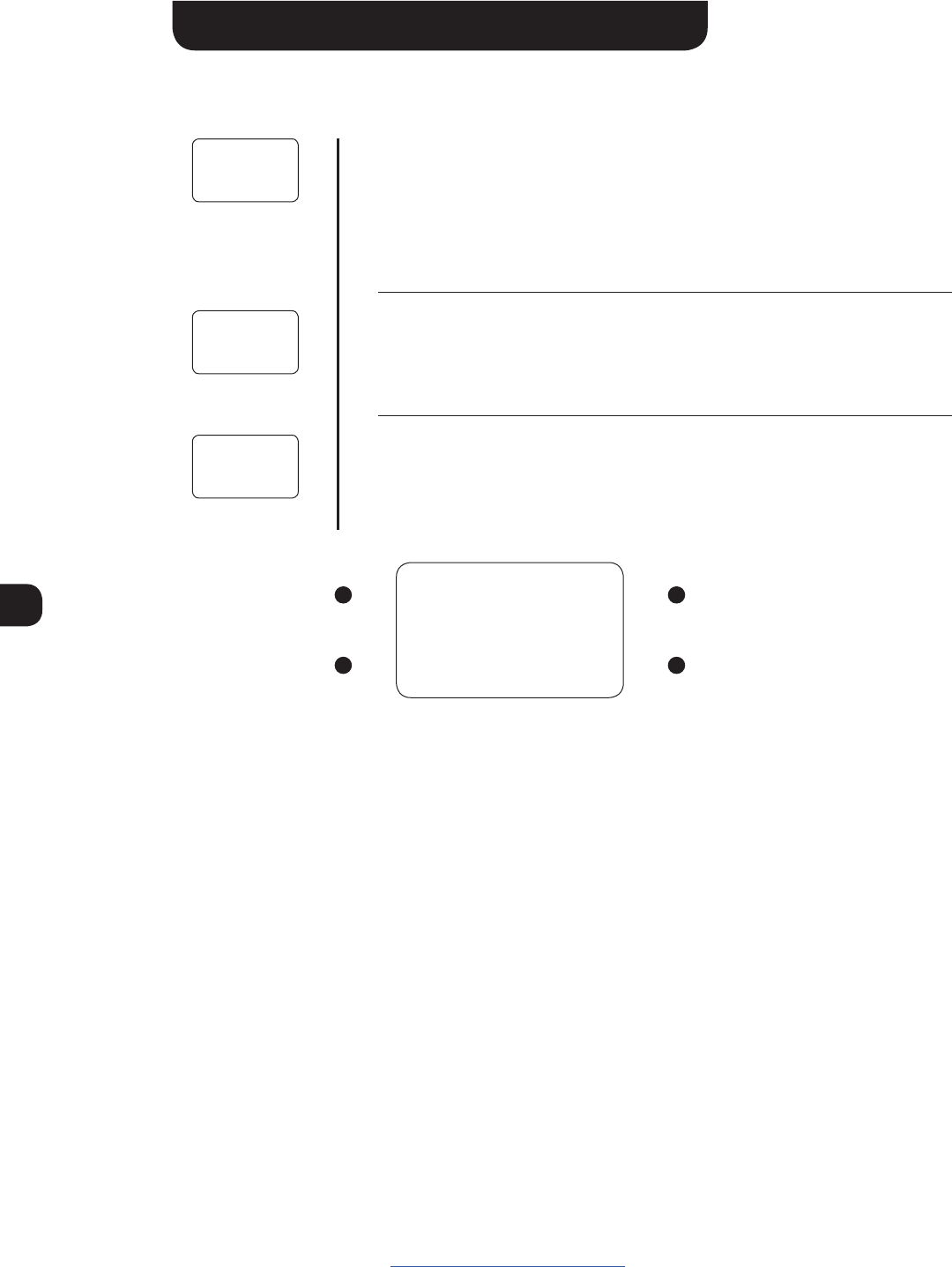
1. Configure your ProtoThrottle receiver using the
instructions provided with the receiver.
2. Make sure the base address of the ProtoThrottle
matches that of the receiver. (See page 18.)
3. If using multiple ProtoThrottles, set each throttle
to a unique ID. (See page 18.)
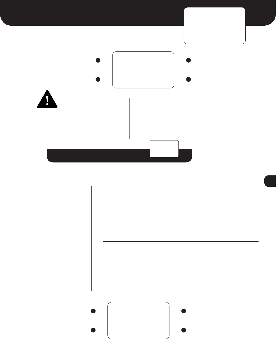
Using your DCC system, set acceleration momentum
(CV3) mid-range to moderately high so that the
ProtoThrottle will need to “notch up” to get the train
moving.
Set deceleration momentum (CV4) high or maximum.
This will allow the train to “coast” when the throttle is in
the idle position requiring the use of the brake to slow or
stop the train.
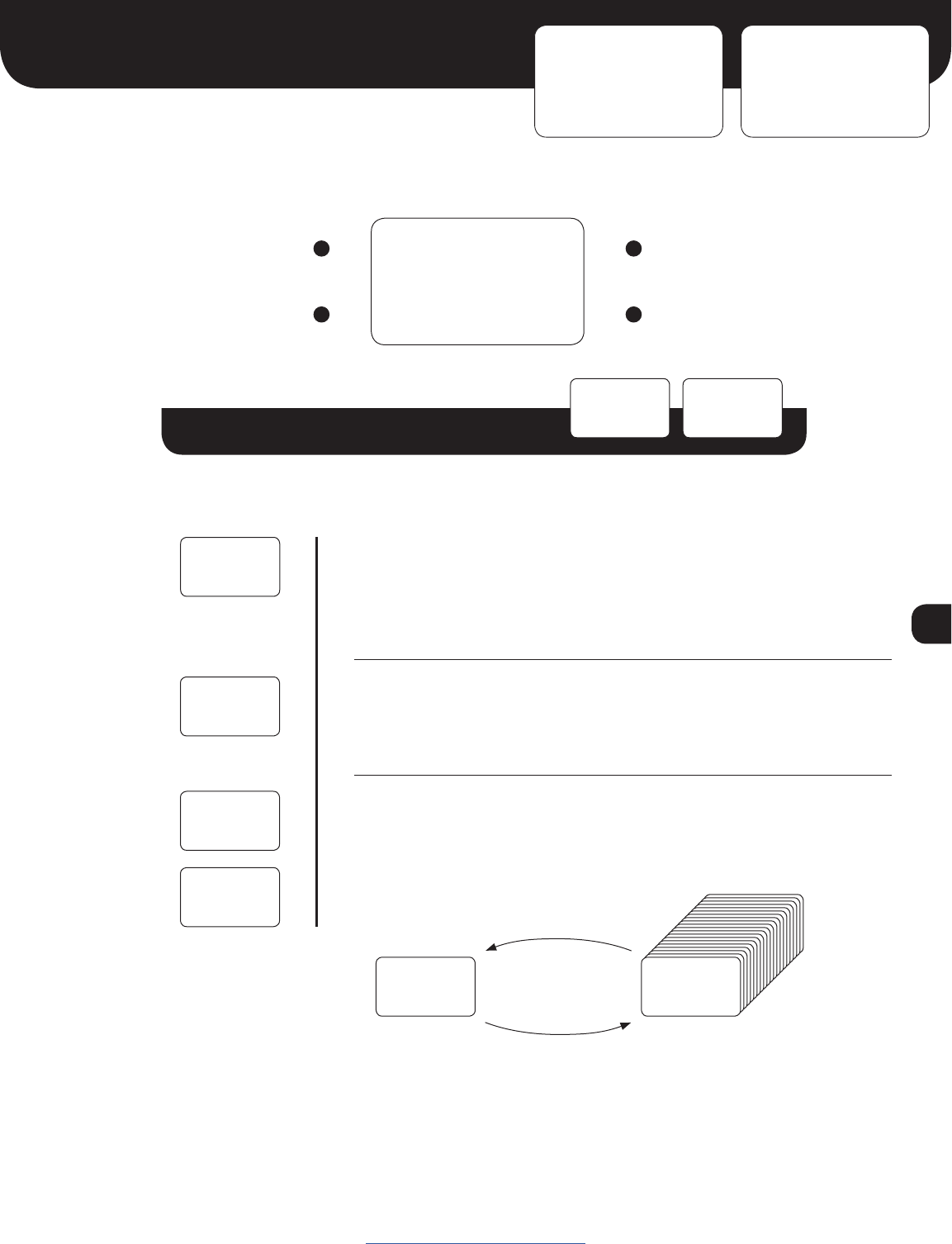
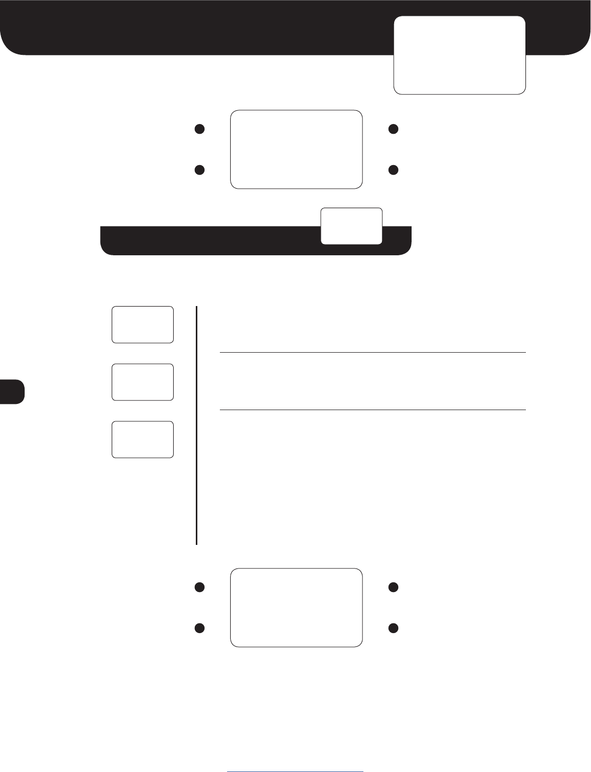
Input the locomotive number into the ProtoThrottle:
NOTE: the ProtoThrottle function settings are set to standard DCC function numbers by default.
If you need to change any function number, the steps are explained below:
NOTE: if the ProtoThrottle is in
”sleep” mode the LCD screen will
be dark, click any of the LCD
buttons to wake the throttle.
To check or set the horn, bell, and brake function numbers:
Enjoy operating your locomotive!
1
3
2
4
5
SET
- LOCO
CONFIG
- FUNC
0003
^
HORN
F02
4003
^
HORN
F07
4003
^
4795
^
SAVED!
1. Click the Menu
button 5 times
1. Click the Menu
button 7 times
Please read the entire manual to familiarize yourself with all the
features of the ProtoThrottle. See our website for more specific
instructions on programming lights and our future tonnage feature.
In addition, our website has detailed operational scenarios
developed by professional locomotive engineer, Tim Garland.
If you are not familiar with prototype operation from a engineer’s
perspective, Tim’s scenarios will give you insight on how to
operate more realistically using the ProtoThrottle.
2. Click the Select
button once
2. Click the Select
button once
3. Use the Up and
Down buttons to
change numbers
NOTE: see page 10 for how
to set a short (primary) address.
3. Click the Up or
Down button to change
the function number
4. Use the Menu
button to move
cursor right
SAVED! 5. Click the Select
button to save all
changes
BRAKE
F10
4. Click Menu button to toggle through the other
function choices. Repeat step 3 to change
additional function numbers.
5. After number is
input, click Select
button to save

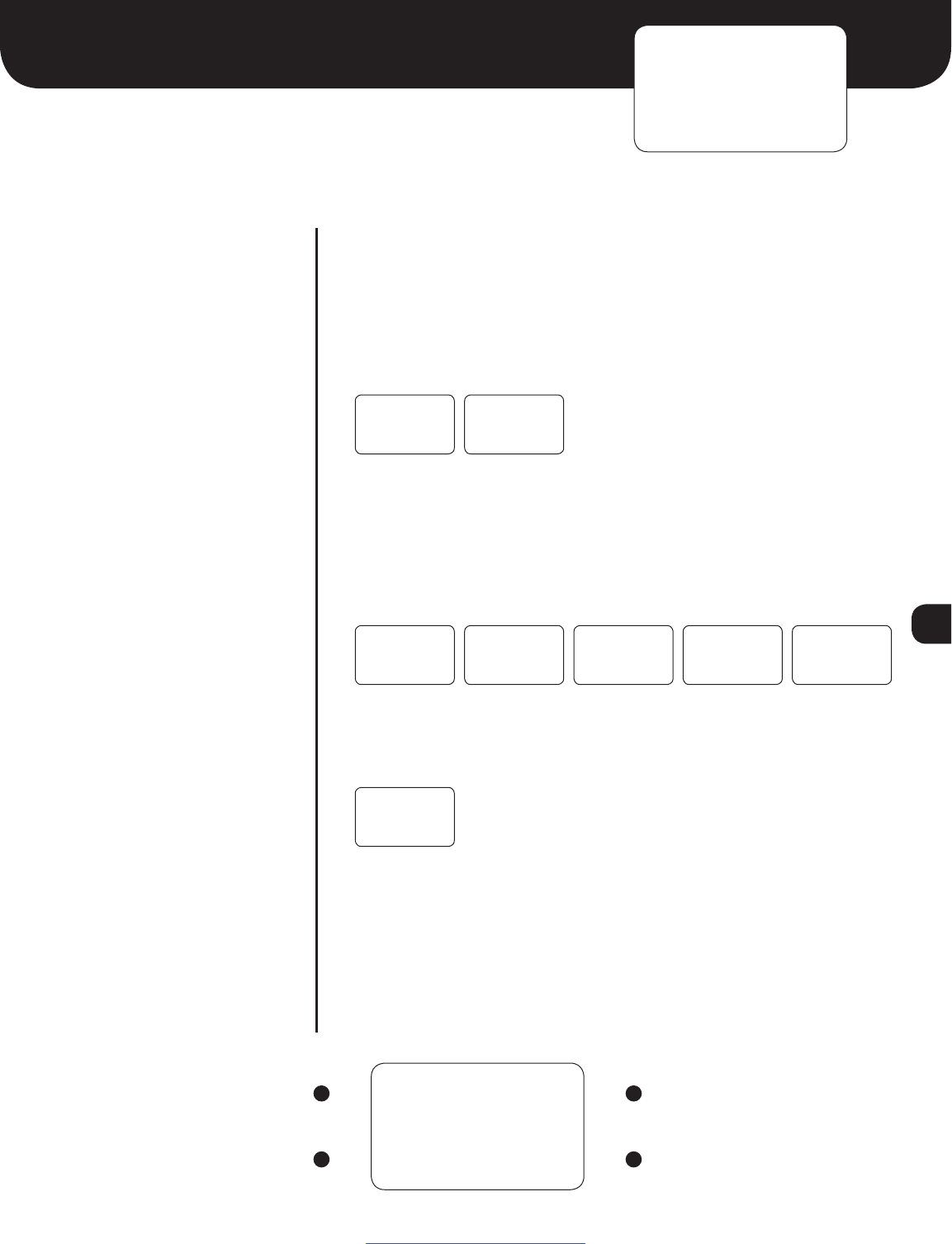
6
Main Screen
ELEMENT DESCRIPTION
0250
12:00
Locomotive Address. Long (extended) addresses are displayed directly
(e.g. 0250 0000 9999). Short (primary) addresses are displayed with
an ‘s’ prefix (e.g. s003 s000 s127).
In certain situations the locomotive address may be replaced by an alert
message:
EMRG Emergency stop is active!
Note: move the brake handle all the way left to deactivate.
REV! Reverser was moved with the throttle not in idle
The ProtoThrottle acts as a secondary display for Iowa Scaled
Engineering’s wireless fast clocks www.iascaled.com/store/MRBW-FCM
or the fast time provided by the NCE Cab Bus.
12-hour mode AM indicator 12-hour mode PM indicator
No AM or PM indicator when in 24-hour mode.
Battery Status: Batteries good Batteries low Replace batteries
Display will show LOW BATTERY when the batteries are critically low. Operation will not be possible
until the batteries are replaced.
When ”AX” is on screen the auxiliary button is active
Up/Down Button Status. On the main screen, the Up and Down
buttons can be assigned to functions. The on/off status of those
assigned functions are displayed on the LCD screen.
Function off
Function on
Note: pressing and holding the Menu button (upper left LCD button)
momentarily will return you to the main screen from any of the main
menus.
0250
12:00
www.protothrottle.com
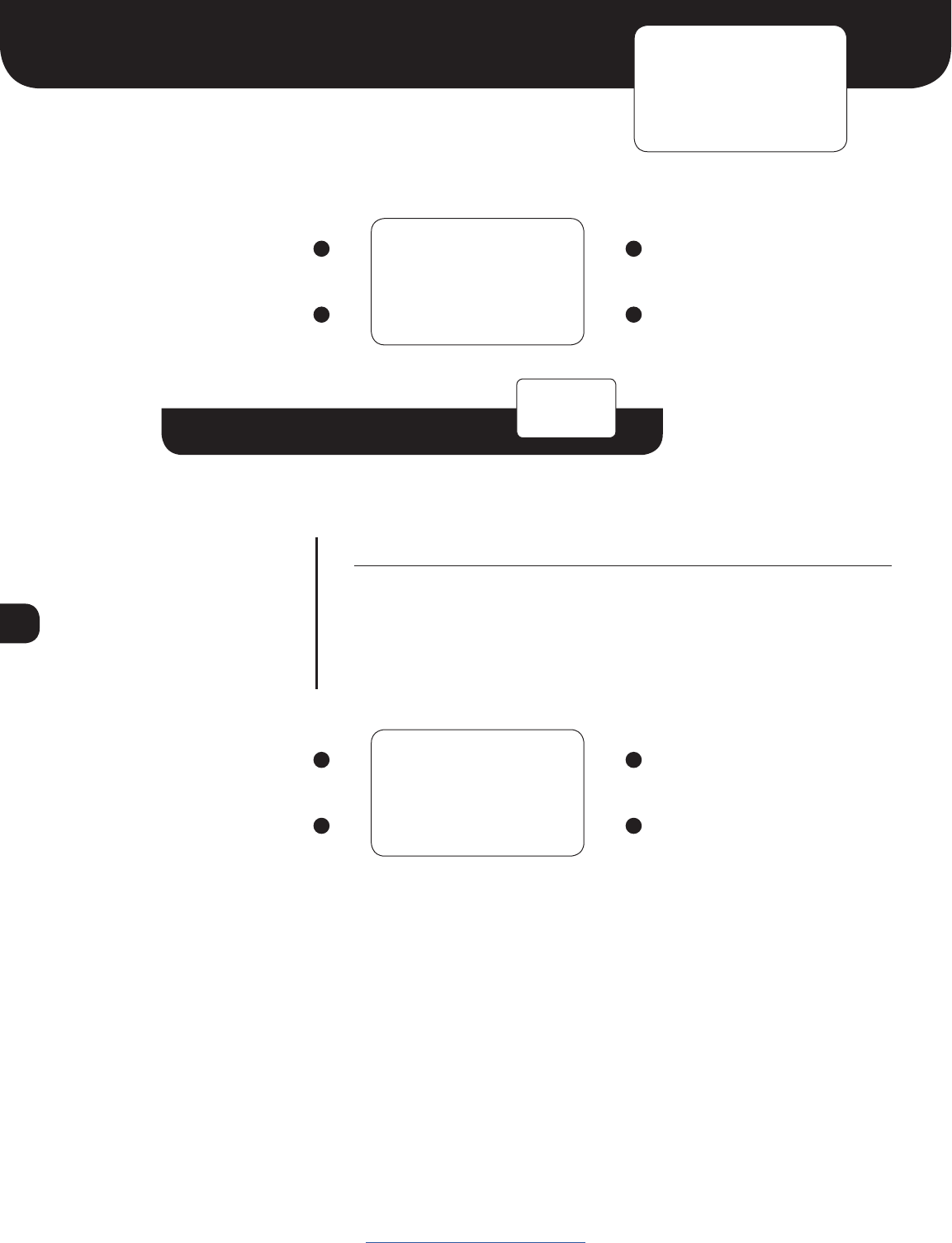
LCD Screen
Advance to Engine Menu Up
Toggle backlight on/off;
hold to power down throttle
Down
NOTE: these buttons
can be assigned a
function using the
Configure Function
menu
POWER
DOWN -~
Click “down button”
to turn off throttle
7
Engine Menu
DESCRIPTION
The behavior of the Engine menu depends on the configuration of the
ENG ON and ENG STOP settings in the Configure Function menu. For
DCC decoders that take a single function on/off to turn the prime mover
on/off (such as ESU Loksound or TCS WOWSound decoders), configure ENG
ON to that function number and set ENG STOP to off (F--). The Engine
menu will then change between OFF and ON when pressing the Up and
Down buttons.
If a decoder is edge triggered instead (requires a function on/off transition)
to turn the prime mover on and off (such as Soundtraxx Tsunami2), set
both ENG ON and ENG STOP to the appropriate function numbers.
In this case, the Engine menu will display STARTING and STOPPING be-
tween the ON and OFF settings as the assigned functions are sent to the
locomotive decoder.
If the throttle is not in idle when attempting to turn off the prime mover,
a warning will be displayed and the ENG STOP function will not be sent.
Move the throttle back to idle to continue.
Example #1, F8 for ESU Loksound or F12 for TCS WOWSound:
ENG ON = F08 ENG ON = F12
ENG STOP = F-- ENG STOP = F--
Example #2, F5 (on, RPM+) and F6 (off, RPM-) for Soundtraxx Tsunami 2:
ENG ON = F05
ENG STOP = F06
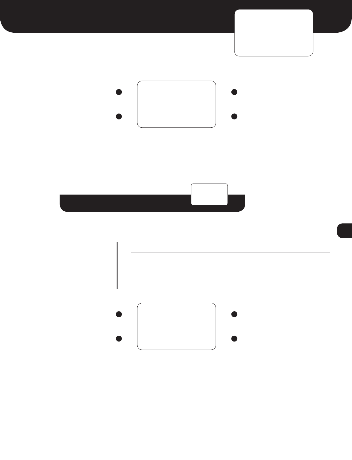
LCD Screen
Advance to Tonnage Menu Start or turn on prime mover
Return to Main Screen Stop or turn off prime mover
ENGINE
OFF
ENGINE
OFF
ENGINE
ON
ENGINE
OFF
ENGINE
STARTING
ENGINE
ON
ENGINE
STOPPING
ENGINE
OFF
www.protothrottle.com
ENGINE
NOT IDLE
8
Tonnage Menu
LCD Screen
Advance to Load Configuration Menu Increase tonnage value
Return to Main Screen Decrease tonnage value
LIGHT
ENGINE
LOW
WEIGHT
MEDIUM
WEIGHT
HEAVY
WEIGHT
ÿ
ÿ
www.protothrottle.com
Note: the tonnage feature is a future release.
Watch our website for updates.
9
Load / Save Configuration Menus
LCD Screen
LOAD CNF: Advance to SAVE CNF
SAVE CNF: Advance to Set
Locomotive Menu
Increase configuration number
Load selected configuration
(and return to Main Screen) or
Save current configuration
(and return to Main Screen)
Decrease configuration number
LOAD CNF
01: 0250
SAVE CNF
01: 0250
www.protothrottle.com
Load / Save Configuration Sub-Menu
01: Configuration Number. Up to 20 distinct configurations (locomotive
address, function mappings, throttle notch settings, options) can be
stored in the ProtoThrottle and loaded quickly using this menu.
0250 Locomotive Address. This is the locomotive address associated
with the selected configuration number.
Save Configuration screen saves the current loaded configuration
(with any changes you’ve made) into whatever configuration slot is on
the screen. In order to copy an established configuration, you must load
it into the throttle first before “saving” it to another slot.
Both the Load Configuration and Save Configuration functions will
ask you to confirm before executing by pressing the Down button.
To cancel, click the Menu button.
LOAD CNF
01: 0250
LOAD CNF
01: 0250
CURRENT
CONFIG
CONFIGS
1-20
SAVE CNF
01: 0250
ELEMENT DESCRIPTION
SAVE CNF
01: 0250
CONFIRM
LOAD? -~
CONFIRM
SAVE? -~ Load configuration
Save configuration
10
Set Locomotive Menu
Set Locomotive Sub-Menu
ELEMENT DESCRIPTION
0250
^
Locomotive Address.
Digit Selector.
LCD Screen
Move Digit Selector to the next digit Increase selected digit.
Save locomotive address and return to
Set Locomotive Menu
Decrease selected digit.
NOTE: To set a short (primary)
address, press the decrease button
once more when the first digit is zero.
You will see an “s” which indicates
“short”. Move the digit selector
to enter the remaining numbers.
For example, a single digit address
would be entered “s003”, a two digit
address “s025”, etc.
LCD Screen
Advance to Force Function Menu None
Enter Set Locomotive Sub-Menu None
SET
- LOCO
www.protothrottle.com
0250
^
11
Force Function Menu
Force Function Sub-Menu
ELEMENT DESCRIPTION
F00
---
Function Number. Available range from function 0 to function 28.
Function Setting.
--- Function can be controlled by a ProtoThrottle button or lever
ON Function forced on, regardless of any other button or control
OFF Function forced off, regardless of any other button or control
LCD Screen
Cycle through Function Numbers Cycle through Function Settings
Save function settings and return to
Force Function Menu
Cycle through Function Settings
LCD Screen
Advance to Configure Function Menu None
Enter Force Function Sub-Menu None
FORCE
- FUNC
www.protothrottle.com
F00 ---
NOTE: The Force Function menu allows any of the 29 standard DCC functions to be turned
ON or OFF, regardless of any other ProtoThrottle lever or button. These can be used to test
functions or control additional features of the decoder such as auxiliary, class, or lesser used
lights.

12
Configure Function Menu
Configure Function Sub-Menu
ELEMENT DESCRIPTION
HORN
F00
Control Name. The name of the ProtoThrottle button or handle to which
a function can be assigned.
HORN Horn lever
BELL Bell button
BRAKE Brake lever, when brake is activated
BRK OFF Brake lever, when in the full left position
AUX Aux button
ENG ON Prime mover ON/start function (see Engine menu for details)
ENG STOP Prime mover stop function (see Engine menu for details)
THR UNLK Function which, when active due to another control, allows
the throttle to send speed commands when the reverser is in centered
position. (e.g. Loksound Drive Hold)
REV SWAP Function which, when active due to another control, flips the
direction of the reverser
F.HEAD Front headlight; active in the Bright and Ditch Lights settings
F.DITCH Front ditch lights; active in the Ditch Lights setting
F.DIM #1 Front dim headlight function #1; active in the Dim setting
F.DIM #2 Front dim headlight function #2; active in the Dim setting
R.HEAD Rear headlight; active in the Bright and Ditch Lights settings
R.DITCH Rear ditch lights; active in the Ditch Lights setting
R.DIM #1 Rear dim headlight function #1; active in the Dim setting
R.DIM #2 Rear dim headlight function #2; active in the Dim setting
UP BTN Main screen Up button
DOWN BTN Main screen Down button
Function Number. The function to be activated when the associated
ProtoThrottle button is pressed or control is moved. Available settings
are none (F--) and functions 0 (F00) to 28 (F28).
Continued on next page
LCD Screen
Advance to Notch Configuration Menu Up
Enter Configure Function Sub-Menu Down
CONFIG
- FUNC
HORN
F02
www.protothrottle.com

13
LCD Screen
Cycle through Control Names Increase Function Number
Save function settings and return to
Configure Function Menu
Decrease Function Number.
Pressing this button when the
Function Number equals zero
turns the function off – no function
will be activated when the control
is operated.
www.protothrottle.com
Configure Function Sub-Menu
UP BTN
F00 MOM
Continued from previous page
MOM Momentary / Latching Function. Only appears for the Up and
Down button assignments.
MOM Momentary – the function is only active while the button is pressed
LAT Latching – the function toggles on and off with each press of the
button

14
Notch Configuration Menu
Notch Configuration Sub-Menu
ELEMENT DESCRIPTION
#
102
Notch Number.
Speed Step. The speed step to send when the throttle is in the selected
Notch Number. Range from 1 to 126 (128 speed step mode only). Idle is
always speed step zero.
LCD Screen
Advance to Options Menu None
Enter Notch Configuration Sub-Menu None
NOTCH
- CFG
NOTCH #
102
LCD Screen
Cycle through Notch Numbers Increase Speed Step
Save notch settings and return to
Notch Configuration Menu
Decrease Speed Step
www.protothrottle.com
15
Options Menu
Options Sub-Menu
ELEMENT DESCRIPTION
Variable Brake. When set to ON, the brake effect will be proportional to
the brake handle position. It is recommended to disable the emergency
brake when variable braking is enabled. When set to OFF, the brake will
be a simple on/off function.
Brake type:
PULSE braking
STEP braking (works with TCS WOWSound function)
Pulse braking. The brake function will be pulsed at a duty cycle cor-
responding to the brake handle position, simulating varying amounts of
braking force.
Step braking. This feature is for use with TCS WOWSound decoders
only. As the brake handle is moved to the right, a greater percentage of
the brake is applied.
NOTE: the only way to disengage the brake is to fully release the brake
handle completely to the left. Also, the emergency brake feature must
be disabled for step braking to work correctly.
Continued on next page
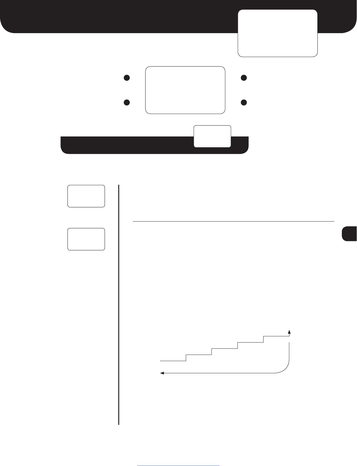
LCD Screen
Advance to Threshold Calibration Menu None
Enter Options Sub-Menu None
OPTIONS
-
VAR BRK
ON
www.protothrottle.com
VAR BRK
OFF
BRK TYPE
PULSE
Brake released
To disengage brake, handle must be
fully released to the left.
20%
0%
40%
60%
80%
100%
Brake fully
applied
NOTE: Only displayed
if variable brake is ON
16
LCD Screen
Cycle through Options Increase or set option value
Save setting and return
to Options Menu
Decrease or set option value
Options Sub-Menu
Continued from previous page
ELEMENT DESCRIPTION
Brake Pulse Rate
This sets the rate (0.2-1.0 second) at which brake commands are sent
during pulse braking. A smaller value results in smoother braking but can
result in a less responsive DCC system due to more commands being
sent on the throttle bus.
E-Stop on Brake Handle. When set to ON, the brake handle can set
emergency stop for the selected locomotive when moved completely
to the right. When set to OFF, the brake handle will not cause an
emergency stop to be set.
Reverser Swap. When set to ON, the reverser directions are swapped.
This can be used to correct for a locomotive whose direction is set
incorrectly or when changing the leading end of a back-to-back consist.
When set to OFF, the reverser directions are normal.
REV SWAP
OFF
BRK ESTP
ON
BRK RATE
0.5s
www.protothrottle.com
NOTE: Only displayed
if variable brake is
ON and brake type
is PULSE

17
www.protothrottle.com
System Menu
Options Sub-Menu
ELEMENT DESCRIPTION
When set to ON, only the following menus are available:
ENGINE, TONNAGE, LOAD CNF, SET LOCO, FORCE FUNC, and
SYSTEM.
When set to ON, advanced functions in the throttle are enabled. These
include the Threshold Calibration menu and the Transmit Interval and
Transmit Holdoff settings in the Preferences menu.
Battery OK Voltage. The voltage above which the
batteries are considered good.
Battery Warning Voltage. The batteries are low when the
voltage is between the OK and Warning levels.
The batteries need to be replaced when the voltage is between
the Warning and Critical levels.
NOTE: When the voltage falls below the Critical level, LOW BATTERY
will be displayed and operation of the throttle will not be possible.
LCD Screen
Advance to Communication
Configuration Menu
None
Enter System Sub-Menu None
SYSTEM
-
MENU LCK
ON
ADV FUNC
OFF
MENU LCK
OFF
BAT OKAY
2.2V
BAT WARN
2.0V
BAT CRIT
1.8V
18
Advance to Diagnostics Menu
Communication Configuration Menu
Communication Configuration Sub-Menu
ELEMENT DESCRIPTION
Throttle ID. Set each throttle to a unique ID using letters A-Z
Base Address. Set to the address of the ProtoThrottle receiver –
see reciever instructions.
Time Source Address. Selects the fast time source. Set to “BASE”
to display time information received from the command station
by the ProtoThrottle receiver. To use an Iowa Scaled Engineering
Wireless Fast Clock Master, set to the Node Address of the clock
(0x01 to 0xFE). Set to “ALL” to display any time information
received by the ProtoThrottle. The “ALL” setting works well with
a single receiver in a private setting, but may result in erratic time
display when multiple ProtoThrottle receivers are in close proximity
(e.g. a public train show).
LCD Screen
Advance to Preferences Menu None
Enter Communication
Configuration Sub-Menu
None
COMM
- CFG
THRTL ID
A
LCD Screen
Cycle through Address/ID Names Increase
Save Address/ID settings and return to
Communication Configuration Menu
Decrease
www.protothrottle.com
THRTL ID
A
BASE ADR
00
TIME ADR
BASE

19
Preferences Menu
Preferences Sub-Menu
ELEMENT DESCRIPTION
Sleep Delay. Time until the throttle automatically enters low power
mode. The throttle handle must be in idle, the reverser handle in
centered position, and no buttons or controls actuated for this time.
Range from 1 to 99 minutes.
Clock Timeout. Maximum time between fast clock time packets. If no
time information is received in this interval, the clock display will show
dashes to indicate it has lost communication with the fast clock master.
Range from 1 to 25 seconds.
Transmit Interval. Time between periodic wireless transmissions to the
ProtoThrottle receiver. This setting can only be changed if Advanced
Functions are ON in the SYSTEM menu.
Transmit Holdoff. Minimum time between wireless transmissions to the
ProtoThrottle receiver. This setting can only be changed if Advanced
Functions are ON in the SYSTEM menu.
LED Blink. When set to ON, the LED on the ProtoThrottle will blink
green when communication with a ProtoThrottle receiver is active.
When set to OFF, the LED will remain off when communication is active.
The LED will always blink red when no communication link has been
established.
Continued on next page
LCD Screen
Advance to Diagnostics Menu None
Enter Preferences Sub-Menu None
PREFS
- CFG
SLEEP
DLY: 5M
TIMEOUT
CLK: 10s
TX INTVL
1s
TX HLDOF
0.15s
www.protothrottle.com
LED BLNK
ON

20
LCD Screen
Cycle through preference settings Increase value or turn on setting
Save preference settings and
return to Preferences Menu
Decrease value or turn off setting
www.protothrottle.com
Preferences Sub-Menu
Continued from previous page
ELEMENT DESCRIPTION
Reverser Lock. When set to ON, the reverser can only change the
locomotive direction when then throttle is in idle, just like the prototype
(in fact, on the prototype, the reverser handle is locked and cannot be
moved). If the reverser is moved when the throttle is not in idle, the
direction will remain the same and the Main Screen will display REV!.
When set to OFF, the reverser is allowed to change the locomotive
direction regardless of the throttle setting.
REV LOCK
ON
21
Threshold Calibration Menu
Threshold Calibration Sub-Menu
ELEMENT DESCRIPTION
NAME
240
Control Name. The name of the ProtoThrottle control to be calibrated.
Hold the control in the desired location and press the Up button to set
the new calibration value.
HORN Threshold for the horn function activation
BRAKE Threshold for the brake function activation
BRAKE LOW Left brake handle stop
BRAKE HIGH Right brake handle stop; also threshold for emergency stop
Control Status. Shows the on/off status of the selected control.
OFF
ON
Internal ADC value for the selected control. Can normally be ignored,
unless you’re developing code for the ProtoThrottle or are just a nerd.
LCD Screen
Advance to Communication Configuration None
Enter Threshold Calibration Sub-Menu None
THRSHOLD
- CAL
HORN
240
LCD Screen
Cycle through Control Names Set new calibration value
Save threshold settings and return to
Threshold Calibration Menu
None
www.protothrottle.com
NOTE: These settings are
factory calibrated and do not,
under most circumstances,
need to be changed.
Modify them at your own risk!
NOTE: Only displayed if Advanced Functions
are ON in the SYSTEM menu

22
Diagnostics Menu
Diagnostics Sub-Menu
ELEMENT DESCRIPTION
Controls Display. Shows the current status of the ProtoThrottle controls
and buttons. Pressing the up/down buttons will toggle through the
current DCC function status.
Sleep Timeout. Shows the number of seconds until the throttle goes to
sleep.
Packet Timeout. Timer reset by each packet received from the
ProtoThrottle receiver. Communication is considered lost when the bar
reaches zero.
Received Signal Strength Indicator. Reports the strength of the
wireless connection to the throttle.
Fast Time Ratio. Reports the fast time ratio from the last update received.
Battery Voltage
ProtoThrottle Firmware Version
ProtoThrottle Firmware Short Git Hash
Continued on next page
LCD Screen
Return to Main Menu None
Enter Diagnostics Sub-Menu None
DIAGS
- CFG
0% I N
- -
SLEEP
300 sec
PKT TIME
[ÿÿÿÿ]
BATTERY
2.30V
FT RATIO
2.4:1
RSSI
-43dBm
VERSION
1.1.0
GIT REV
000000
www.protothrottle.com

23
Diagnostics Sub-Menu
ELEMENT DESCRIPTION
Base Type. The type of ProtoThrottle receiver to which the ProtoThrottle
is connected.
Base Unit Short Git Hash
Factory Reset. Press the Down button 5 times to reset the
ProtoThrottle to factory settings. WARNING: This will erase all
configuration settings, except those in the Threshold Calibration
menu, so use with caution!
BASE TYP
CAB BUS
BASE REV
000000
FACTORY
RESET 5~
LCD Screen
Cycle through diagnostics settings None
Return to Diagnostics Menu None
www.protothrottle.com
24
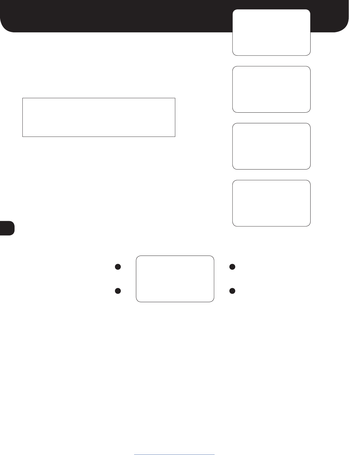
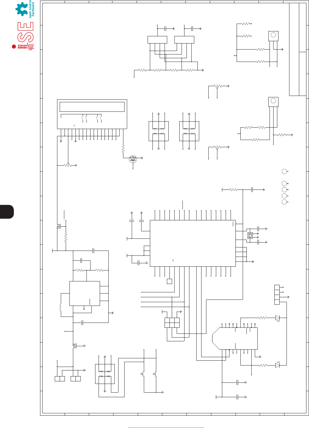
www.protothrottle.com
VBAT
GND
ICSP Header
C7
1uF
16V
Control Stand Throttle
mrbw−cst.sch
1 1 Michael Petersen
FILE: REVISION:
DRAWN BY: PAGE OF
TITLE
H
G
F
E
D
C
B
A
I
J
K
I
J
K
H
G
F
E
D
C
B
A
1234567891011
123456789101112 13 14 15 16 17
12 13 14 15 16 17
H1 H2 H3 H4
C9
22pF
16V, NP0
SOFTKEY1
1VCC
2DOUT
3DIN
4DO8
5RESET
6PWM0/RSSI
7PWM1
8N.C.
9DTR/SLEEP_RQ
10 GND 11
DIO4
12
CTS
13
ON/SLEEP
14
VREF
15
ASSOC
16
RTS
17
DIO3
18
DIO2
19
DIO1
20
DIO0
XBEE / XBEE−PRO
XU3
VBATSNS
1 2
3 4
5 6
MISO
SCK
RST
5V
MOSI
GND
J2
C11
8.2pF
16V, NP0
C10
1uF
16V
Notes:
1) All capacitors are ceramic (X7R/X5R) unless otherwise noted.
2) All capacitors and resistors are 0805 unless otherwise noted.
C8
22pF
16V, NP0
C6
0.1uF
16V
C4
0.1uF
16V
R1
499k
1%
R2
287k
1%
C2
33pF
16V
1SHDN
2
FB
4
VOUT
3PGOOD
8VIN
7
SGND
SW
5
6
PGND
9
GND
LTC3528
U1
LTC_DDB8
L1
MSS6132−472
4.7uH
C3
10uF
6.3V
C1
10uF
6.3V
R5
10k
1 2
SW2
PVA1 EE H2 1.2NV2
1 2
SW3
PVA1 EE H2 1.2NV2
Note: Latching pushbuttons.
Turn off pull−up when not polling.
BELL
DYNAMIC
B
C
A
SW4
25LB10−Q
Throttle
B
C
A
SW5
25LB30−Q
Reverser
VREV
5 4
100k
R6
8 1
100k
R6
REV_EN
VREV
Reverser Decode:
A/B=off/off, C=0V
A/B=on/off, C=1.65V
A/B=off/on, C=1.1V
A/B=on/on, C=1.98V
THRA
THRB
THR_EN
Must read continuously.
THR_EN only used in sleep.
VLIGHT_F
LIGHT_EN
VLIGHT_F
VLIGHT_R
THRA
THRB
THR_EN
VBATSNS
2
31
PTV09A−2020F−B104
P1
100k
VBRAKE
POTS_EN
VBRAKE
POTS_EN
LIGHT_EN
VREV
VLIGHT_F
VBRAKE
THRA
REV_EN
4
Reset
7
XTAL2
8
XTAL1
29
AREF
16 PD7 (OC2)
15 PD6 (ICP)
14 PD5 (OC1A)
13 PD4 (OC1B)
12 PD3 (TXD1/INT1)
11 PD2 (RXD1/INT0)
10 PD1 (TXD0)
9PD0 (RXD0)
3PB7 (SCK)
2PB6 (MISO)
1PB5 (MOSI)
44 PB4 (SS)
43 PB3 (AIN1)
42 PB2 (AIN0)
41 PB1 (T1)
40 PB0 (T0)
26
(TOSC2) PC7
25
(TOSC1) PC6
24
PC5
23
PC4
22
PC3
21
PC2
20
(SDA) PC1
19
(SCL) PC0
30
(ADC7) PA7
31
(ADC6) PA6
32
(ADC5) PA5
33
(ADC4) PA4
34
(ADC3) PA3
35
(ADC2) PA2
36
(ADC1) PA1
37
(ADC0) PA0
6
GND
18
GND
28
GND
39
GND
5
VCC
17
VCC
38
VCC
27
AVCC
U2
ATmega1284P
TQFP44
+3.3V
+3.3V
+3.3V
+3.3V
C5
0.1uF
16V
+3.3V
LCD_EN
SLEEP_EN
BELL
DYNAMIC
BACKLIGHT_EN
D7
D6
D5
D4
RS
E
2
31
P3
10k
SOFTKEY2
SOFTKEY0
SOFTKEY3
RS
E
+3.3V
LCD_EN
R3
100k
6
5
1
MP1
DMP2240UDM
D34
COM5
D46
D2 3
COM 2
D1 1
U4CPDT6−5V4−HF
D34
COM5
D46
D2 3
COM 2
D1 1
U6CPDT6−5V4−HF
D34
COM5
D46
D2 3
COM 2
D1 1
U5CPDT6−5V4−HF
72
100k
R6
6 3
100k
R6
SOFTKEY0
SOFTKEY1
1
2
J1
VSS (GND)
1
VDD (VCC)
2
V0
3
RS
4
R/W
5
E
6
SW0
7
SW1
8
SW2
11
SW3
12
DB4
13
DB5
14
DB6
15
DB7
16
A
17
K
18
LCD
9LEDG
10 LEDR
X1
R4
20
D7
D6
D5
D4
SOFTKEY2
SOFTKEY3
BACKLIGHT_EN
D
S
G
MN1
BSS138
LEDG
LEDR
LEDG
LEDR
81
100k
R10
8 1
100k
R7
5 4
100k
R7
7 2
100k
R7
6 3
100k
R7
THRB
VBAT
VHORN
VLIGHT_R
YELLOW
D1
RED
D2
4 1
R11 1k
3 2
R11 1k
1
2
3
4
JP1
1 3
2 4
Y1
11.0592MHz
H5
2
31
PTV09A−2020F−B104
P2
100k
VHORN
POTS_EN
SLEEP_EN
VHORN
1
2
J3
VBAT
Charger
LIGHT_EN
POTS_EN
4
2
3
MP1
DMP2240UDM
5 4
100k
R10
7 2
100k
R10
63
100k
R10
VLIGHT_R
1
2
3
4
A
SW6
KC14
1
2
3
4
A
SW7
KC14
C12
DNI
C13
DNI
1
TP1

25
www.protothrottle.com
Open Design
Iowa Scaled Engineering is committed to creating open designs that
users are free to build, modify, adapt, improve, and share with others.
Hardware
The design of the ProtoThrottle hardware is open source hardware,
and is made available under the terms of the Creative Commons
Attribution-Share Alike v3.0 license, a copy of which is available from:
http://creativecommons.org/licenses/by-sa/3.0/
Design files can be found on the Iowa Scaled Engineering’s Github site:
https://github.com/IowaScaledEngineering/mrbw-cst
Firmware
The official Iowa Scaled Engineering firmware for the ProtoThrottle is
free software: you can redistribute it and/or modify it under the terms
of the GNU General Public License as published by the Free Software
Foundation, either version 3 of the License, or (at your option) any
later version. A copy of the GNU GPL can be found at:
http://www.gnu.org/licenses/gpl.html
New firmware can be flashed into the ProtoThrottle through J2.
The six pins are a standard AVR 6-pin ISCP programmer connection.
We encourage you to join the ProtoThrottle group forum:
https://groups.io/g/ProtoThrottle
The forum will help with general and technical
questions regarding the ProtoThrottle.
Visit the Iowa Scaled Engineering website
to learn more about our full line of
model railroad electronics.
www.iascaled.com
support@iascaled.com
© 2018 Iowa Scaled Engineering, LLC and Designgrid, LLC
Manual 1.1 (updated version)

26
www.protothrottle.com
ProtoThrottle
Model: MRBW-CST
HW Version: 1.2
Iowa Scaled Engineering, LLC
22750 County Road 37
Elbert, CO 80106
support@iascaled.com
Contains FCC ID: OUR-XBEEPRO
This device complies with part 15 of the FCC Rules. Operation is subject to the following
two conditions: (1) This device may not cause harmful interference, and (2) this device
must accept any interference received, including interference that may cause undesired
operation.
Note: This equipment has been tested and found to comply with the limits for a Class B
digital device, pursuant to part 15 of the FCC Rules. These limits are designed to provide
reasonable protection against harmful interference in a residential installation. This equip-
ment generates, uses and can radiate radio frequency energy and, if not installed and
used in accordance with the instructions, may cause harmful interference to radio
communications. However, there is no guarantee that interference will not occur in
a particular installation. If this equipment does cause harmful interference to radio or
television reception, which can be determined by turning the equipment off and on,
the user is encouraged to try to correct the interference by one or more of the following
measures:
• Reorient or relocate the receiving antenna.
• Increase the separation between the equipment and receiver.
• Connect the equipment into an outlet on a circuit different from that
to which the receiver is connected.
• Consult the dealer or an experienced radio/TV technician for help.
Changes or modification to the device could void the user’s authority to operate the
equipment.
Contains Model XBee-PRO Radio, IC: 4214A-XBEEPRO
This device complies with Industry Canada’s licence-exempt RSSs. Operation is subject to
the following two conditions:
(1) This device may not cause interference; and
(2) This device must accept any interference, including interference that may
cause undesired operation of the device.
Cet appareil est conforme aux RSS exempts de licence d’Industrie Canada. L’opération est
soumise aux deux conditions suivantes:
(1) Cet appareil ne doit pas causer d’interférences; et
(2) Cet appareil doit accepter toute interférence, y compris les interférences susceptibles
de provoquer un fonctionnement indésirable de l’appareil.
Changes or modification to the device could void the user’s
authority to operate the equipment.
Des changements ou des modifications à l’appareil pourraient
annuler l’autorité de l’utilisateur à utiliser l’équipement.

27
Notes
www.protothrottle.com

www.protothrottle.com
IOWA SCALED ENGINEERING – ELECTRONICS MADE EASY!
