MSC 18K X Manual (Oct 2017) ALI
User Manual: msc-18k-x-manual
Open the PDF directly: View PDF ![]() .
.
Page Count: 34
Oct. 2017
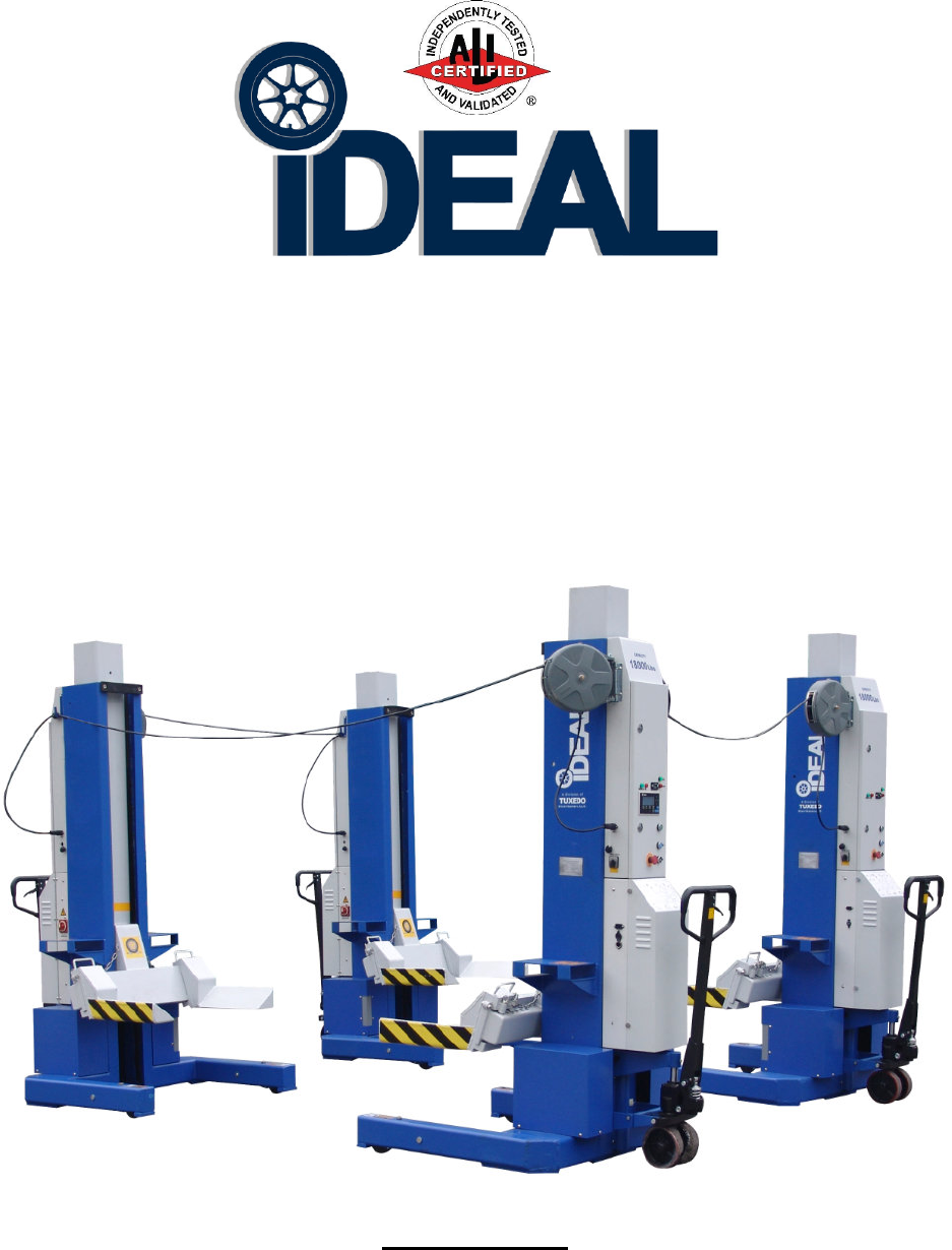
Mobile Column Lift Model Sets
MSC-18K-X-236, MSC-18K-X-472 & MSC-18K-X-6108
Capacity 18,000lbs / Each Column
Installation - Operation – Service Manual
IMPORTANT!!
READ MANUAL THOROUGHLY BEFORE INSTALLING, OPERATING, SERVICING
OR MAINTAINING LIFT
2
MSC-18K-X
Oct. 2017
INDEX
PREFACE--------------------------------------------------------------------------- PAGE 2
PRODUCT IDENTIFICATION-------------------------------------------------- PAGE 2
OWNER / EMPLOYER OBLIGATIONS------------------------------------- PAGE 3
IMPORTANT SAFETY INSTRUCTIONS----------------------------------- PAGE 4
LOCATION------------------------------------------------------------------------- PAGE 7
GENERAL INFORMATION ---------------------------------------------------- PAGE 9
SET-UP / INSTALLATION ------------------------------------------------------ PAGE 10
SYSTEM TESTING BEFORE ACTUAL USE------------------------------ PAGE 15
LIFTING OPERATION----------------------------------------------------------- PAGE 20
MAINTENANCE INSTRUCTIONS ------------------------------------------- PAGE 21
SERVICE --------------------------------------------------------------------------- PAGE 22
SYSTEM DIAGNOSTIC MESSAGES -------------------------------------- PAGE 24
EMERGENCY LOWERING PROCEDURE-------------------------------- PAGE 25
EXPLODED VIEWS & PARTS LISTS -------------------------------------- PAGE 26
LIMITED WARRANTY ---------------------------------------------------------- PAGE 34
PREFACE
Prior to the operation of your lift make sure that you have read the instructions thoroughly. These
instructions are found in this manual. Please note that your warranty can be voided if you do not read
the manual and understand its content.
If you have any questions, concerning operation, safety or application of your lift, please consult your
distributor.
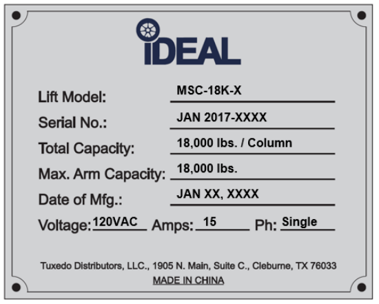
PRODUCT IDENTIFICATION
3
MSC-18K-X
Oct. 2017
OWNER / EMPLOYER OBLIGATIONS
1. The Owner/Employer shall ensure that lift operators are qualified and that they are trained in the
safe use and operation of the lift using the manufacturer’s operating instructions; ALI/SM10-1, ALI
Lifting it Right safety manual; ALI/ST-10 ALI Safety Tips card; ANSI/ALI ALOIM-2008 (R2013),
American National Standard for Automotive Lifts - Safety Requirements for Operation,
Inspection and Maintenance; ALI/WL400 Series, ALI Uniform Warning Label Decals/Placards;
and in the case of frame engaging lifts, ALI/LP-GUIDE, Vehicle Lifting Points/Quick Reference
Guide for Frame Engaging Lifts.
2. The Owner/Employer shall establish procedures to periodically inspect the lift in accordance with
the lift manufacturer’s instructions or ANSI/ALI ALOIM-2008 (R2013), American National
Standard for Automotive Lifts - Safety Requirements for Operation, Inspection and
Maintenance; and the Employer shall ensure that the lift inspectors are qualified and that they are
adequately trained in the inspection of the lift.
3. The Owner/Employer shall establish procedures to periodically maintain the lift in accordance with
the lift manufacturer’s instructions or ANSI/ALI ALOIM-2008 (R2013), American National
Standard for Automotive Lifts - Safety Requirements for Operation, Inspection and
Maintenance; and the Employer shall ensure that the lift maintenance personnel are qualified and
that they are adequately trained in the maintenance of the lift.
4. The Owner/Employer shall maintain the periodic inspection and maintenance records
recommended by the lift manufacturer’s instructions or ANSI/ALI ALOIM-2008 (R2013), American
National Standard for Automotive Lifts - Safety Requirements for Operation, Inspection and
Maintenance.
5. The Owner/Employer shall display the lift manufacturer’s operating instructions; ALI/SM 10-1, ALI
Lifting it Right safety manual; ALI/ST-10 ALI Safety Tips card; ANSI/ALI ALOIM-2008 (R2013),
American National Standard for Automotive Lifts - Safety Requirements for Operation,
Inspection and Maintenance; ALI/WL Series, ALI Uniform Warning Label Decals/Placards; and
in the case of frame engaging lifts, ALI/LP- GUIDE, Vehicle Lifting Points/Quick Reference
Guide for Frame Engaging Lifts in a conspicuous location in the lift area convenient to the
operator.
4
MSC-18K-X
Oct. 2017
6. The Owner/Operator shall provide necessary lockout/tag out means for energy sources per ANSI
Z244.1-1982 (R1993), Safety Requirements for the Lockout/Tag out of Energy Sources,
before beginning any lift repairs and maintenance.
7. The Owner/Employer shall not modify the lift in any manner without the prior written consent of the
manufacturer.
IMPORTANT SAFETY INSTRUCTIONS
(SAVE THESE INSTRUCTIONS)
Please deliver this manual to the lift owner and/or operator along with all other documentation
provided with the lift. Failure to operate this equipment as intended may cause injury or death.
When using this lift, basic safety precautions should always be followed, including the following:
1. Read all instructions in this manual and on the lift thoroughly before installing, operating, servicing
or maintaining the lift.
2. Care must be taken as burns can occur from touching hot parts.
3. Do not operate equipment with a damaged cord or if the equipment has been dropped or damaged
– until it has been examined by a qualified service person.
4. Do not let a cord hang over the edge of the table, bench, or counter or come in contact with hot
manifolds or moving fan blades.
5. If an extension cord is necessary, a cord with a current rating equal to or more than that of the
equipment should be used. Cords rated for less current than the equipment may overheat. Care
should be taken to arrange the cord so that it will not be tripped over or pulled.
6. Always unplug equipment from electrical outlet when not in use. Never use the cord to pull the plug
from the outlet. Grasp plug and pull to disconnect.
7. Let equipment cool completely before putting away. Loop cord loosely around equipment when
storing.
8. To reduce the risk of fire, do not operate equipment in the vicinity of open containers of flammable
liquids (gasoline).
5
MSC-18K-X
Oct. 2017
9. Adequate ventilation should be provided when working on operating internal combustion engines.
10. Keep hair, loose clothing, fingers, and all parts of body away from moving parts.
11. To reduce the risk of electric shock, do not use on wet surfaces or expose to rain.
12. Use only as described in this manual. Use only manufacturer’s recommended attachments.
13. ALWAYS WEAR SAFETY GLASSES. Everyday eyeglasses only have impact resistant lenses;
they are not safety glasses.
14. Inspect lift daily. Do not operate if it malfunctions or problems have been encountered. Never
operate lift if it has broken, damaged or worn parts.
15. Never attempt to overload the lift. The manufacturer’s rated capacity is shown on the identification
label on the power side column. Do not override the operating controls or the warranty will be void.
16. Only trained and authorized personnel should operate the lift. Do not allow customers or
bystanders to operate the lift or be in the lift area.
17. Position the lift support pads to contact the vehicle manufacturers recommended lifting points.
Raise the lift until the pads contact the vehicle. Check pads for secure contact with the vehicle.
18. CAUTION! Never work under the lift unless the mechanical safety locks are engaged.
19. Note that the removal or installation of some vehicle parts may cause a critical load shift in the
center of gravity and may cause the vehicle to become unstable. Refer to the vehicle
manufacturer’s service manual for recommended procedures.
20. Always keep the lift area free of obstruction and debris. Grease and oil spills should always be
cleaned up immediately.
21. Never raise vehicle with passengers inside.
22. Before lowering check area for any obstructions.
23. Before removing the vehicle from the lift area, position the columns to prevent damage to the lift
and /or vehicle.
6
MSC-18K-X
Oct. 2017
24. Check and adjust if need the correct air pressure in all tires before lifting. Do not exceed tire load
when raising vehicle.
25. DO NOT raise / lower only one side if a vehicle.
26. Lift only on same axle. Do not stagger between axles.
27. Do not drive over or pinch the electrical communication cables.
28. Do not remove hydraulic fittings while under pressure.
29. Check floor to ceiling height for clearance when vehicle is fully raised.
30. Use only qualified lift service personnel and genuine manufacturing parts to make repairs.
WARNING!! Failure by purchaser to provide the recommended mounting surface could result
in unsatisfactory lift performance, property damage, or personal injury.
7
MSC-18K-X
Oct. 2017
For additional safety instructions regarding lifting, lift types, warning labels, preparing to lift, vehicle
spotting, vehicle lifting, maintaining load stability, emergency procedures, vehicle lowering, lift
limitations, lift maintenance, good shop practices, installation, operator training and owner/employer
responsibilities, please refer to “Lifting It Right” (ALI/SM) and “Safety Tips” (ALI/ST) and vehicle lift
points for service garage lifting SAE J2184.
For additional instruction on general requirements for lift operation, please refer to “Automotive
Lift-Safety Requirements for Operation, Inspection and Maintenance” (ANSI/ALI ALOIM).
Installation shall be performed in accordance with ANSO/ALI ALIS, Safety Requirements for
Installation and Service of Automotive Lifts.
LOCATION
This lift has been evaluated for INDOOR USE ONLY with an operating ambient temperature range of
5 - 40°C (41-104°F)
ATTENTION! This lift is intended for indoor installation only. It is prohibited to
install this product outdoors. Operating environment temperature range should be
41 – 104 °F (5 – 40 °C). Failure to adhere will result in decertification, loss of
warranty, and possible damage to the equipment.
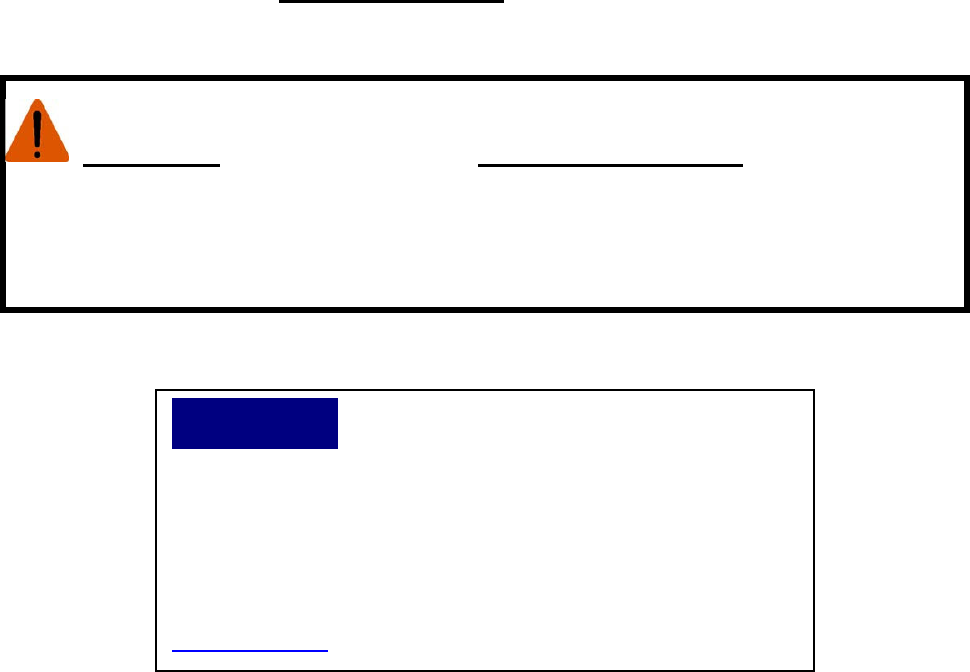
NOTICE
If attachments, accessories, or configuration
modifying components used on this lift are located in the load path
and affect operation of the lift, affect the lift electrical listing, or
affect intended vehicle accommodation; and if they are not certified
for use on this lift, then the certification of this lift shall become null
and void. Contact the participant for information pertaining to
certified attachments, accessories, or configuration modifying
components.
www.auolift.org
©
©©
©
2011 by ALI, Inc. ALI/WLSIA01
8
MSC-18K-X
Oct. 2017
SAFETY DECALS
These Decals Must Be Applied to Lift.
REFERENCE: AUTOMOTIVE LIFT INSTITUTE, Inc.
NOTE: SOME IMAGES IN THIS MANUAL ARE GENERIC AND MAY NOT RESEMBLE THE LIFT
YOU HAVE PURCHASED.

9
MSC-18K-X
Oct. 2017
1. GENERAL
INFORMATION
1.1 SPECIFICATIONS
Models # MSC-18K-X-236, MSC-18K-X-472 & MSC-18K-X-6108
Capacity 18,000 lbs. / Each Column
Pressure Relief Valve 2,030 psi Sealed Ex-Works
Pump motor 4HP ( 3Kw, DC24V, Max 125 Amp ) / Each Column
Battery charger power
supply Input: 100-140VAC, 60Hz, Single Phase
Output: 24VDC, Max 15 Amp
Operational Voltage 24 VDC
Lifting Height 67.1"
Column L / W / H 56.9” / 44.1” / 88.6” (Max Ht. 155.5”)
Fork Adjustable Range 12.6” - 22”
Fork length 17.9”
Lifting / Lowering Time 100 sec / 60 sec at load of 18,000 lbs / each column
Noise Level Max. 70 dB(A)
Set-up Indoors
Unit Weight 1,548 lbs. per Column
Maximum Distance
between Columns 32.8'
Min. Concrete Surface
Strength 3000 Psi
10
MSC-18K-X
Oct. 2017
2. SET-UP / INSTALLATION
Remark: Only move the lifting column with the forklift. Only raise the lifting column at the correct
points. Damage to lifting column and /or injury to persons may occur if the lifting column
is not moved in the correct manner.
2.1 PACKING LIST
The complete lift is a set of either two (2), four (4) or six (6) mobile column lifting units and one (1)
parts box, based on model type.
1. Each column is a self-contained unit.
2. The parts box contains: (Based on Model Type)
a) Either - One (1), Three (3) or Five (5) Communication Cable Reels.
b) Either - Eight (8), Sixteen (16) or twenty-four (24) Battery Clamps.
c) Either – One (1), Two (2) or Three (3) Sets of Combined Seal Washers and Filter
Meshes.
d) One (1) spare Electro-Magnetic Valve.
e) One (1) spare T-Connector.
f) Two (2) Keys for Column Door Interlock.
g) One (1) Magnet Ring. (Emergency Lowering Procedure)
Important document packet that includes, Installation, Operation and Maintenance Manual, ALI
Manual, “Lifting it Right”, Automotive Lift Safety Tips Placard, ALI “Lifting Points Guide”, ANSI/ALI
ALOIM:2008(R2013) Safety Requirements for Operation, Inspection and Maintenance.
Warranty Statement and Warranty Registration Instructions.
2.2 INSTALLATION REQUIREMENTS AND TOOLS / SUPPLIES
Foundation
Important
:
It is the user’s responsibility to provide a satisfactory installation area for the lift. Lifts
should only be installed on level concrete floors with a minimum thickness of four inches and half
(4.5") or 114 mm. Concrete must have a minimum strength of 3000 psi and should be aged thirty (30)
days prior to installation. Please consult an architect, contractor or engineer if doubt exists as to the
strength and feasibility of the floor to enable proper lift installation and operation. Do not use on
asphalt. Do not use on a suspended floor without approval from a licensed structural engineer.
A qualified person should be consulted to address seismic loads and other local or state
requirements.

11
MSC-18K-X
Oct. 2017
It is the user’s responsibility to provide all wiring for electrical hook-up prior to installation and to
insure that the electrical installation conforms to local building codes. Where required, it is the user’s
responsibility to provide an electrical isolation switch located in close proximity to the lift that will
enable emergency stop capability and isolate electrical power from the lift for any servicing
requirements.
Tools / Supplies
1. Cutting device to remove packaging.
2. Metric wrenches.
3. Allen wrenches.
4. Philips screw drivers.
5. Clean funnel for adding hydraulic oil.
6. Clean new * AW-32 Hydraulic Oil
(Hydraulic Oil needed per column 3.6 Gallons / 13.5 Liters)
*Note: Use only new fresh clean AW-32 Hydraulic Oil. The use of transmission fluids will void
the lift warranty.
NOTE: MSC-18K-X Lifts are NOT supplied with Batteries.
Customer must supply Batteries as recommended on Page 14.
Installation Instructions
When the lift arrives on site:
Check for any freight damages. The shipment should be thoroughly inspected as soon as it is
received. The signed bill of lading is acknowledgement by the carrier of receipt in good condition of
shipment covered by our invoice. If any of the goods called for on your bill of lading are shorted or
damaged, do not accept them until the carrier makes a notation on the freight bill of the missing or
damaged goods. Do this for your own protection. Check the contents of the accessory and hardware
boxes to make sure no parts are missing.
NOTE: IT IS DIFFICULT TO COLLECT FOR LOSS OR DAMAGE AFTER YOU HAVE GIVEN THE
CARRIER A CLEAR RECEIPT. THE LIFT MANUFACTURER IS NOT RESPONSIBLE FOR ANY
FREIGHT DAMAGE.
12
MSC-18K-X
Oct. 2017
2.3 UNPACKING AND HANDLING THE LIFTING COLUMN
Unpacking Procedure
• Remove all plastic wrap and cardboard. Be careful not to cut into the lower hydraulic hoses and
fittings or to scratch the paint or damage the safety decals.
• Carefully open the parts box, avoid cutting the enclosed communication cables.
• Take out all of the cable reels, battery clamps, spare parts and document packet.
Preparing Lift for Initial Startup
To transport the columns to a location within the service facility for setup, please use the pallet jack
attached to the column. Each column can be easily moved by lifting up and holding the lever on the
handle, by raising up & lowering down the pallet jack handle in a pumping motion, 3-5 times until the
column’s central base is lifted from the floor. You can now maneuver the lift columns to any location
by pulling the pallet jack handle to the desired location. Once you release the lever on the pallet jack
handle, the column will lower down to the ground. The lift shall not be operated unless the column
is fully lowered to the ground.
Filling the tank with hydraulic oil after the lower column cover is opened and the red plug on the
motor pump tank is removed. Use a clean funnel and add new hydraulic oil (AW-32) into the tank.
The oil level shall meet the indicating label on the tank. The approx. amount of oil per tank is 3.6Gal /
13.5 Liter.
After finished, reinstall the red plug back to the top of the tank. Close motor pump cover and secure
with bolts.
Note: The hydraulic system was tested during manufacturing. Each hydraulic cylinder and the power
unit tank was filled and cycled to test for leaks and for performance. During this process the
hydraulic cylinders were bleed to remove any air. The hydraulic oil was removed from the tank after
testing. Because residual oil at the bottom of the tank and inside the cylinder remain, additional
hydraulic system bleeding is not necessary.
To install the batteries, first take away the battery covers on both sides of each column. After the
battery is positioned, secure it with the battery clamps provided. Then connect the power cables to
the battery terminals. Repeat for other side.
Note: Ensure to correctly connect terminals: Red/Pos. = (+), Black/Neg. = (-)
13
MSC-18K-X
Oct. 2017
To charge the battery, if necessary. A battery charger is built into each column. Plug the battery
charger power supply cord into a 110 volt grounded electrical outlet. Charge each mobile column lifts
using a separate electrical outlet. Best performance will be obtained by charging all mobile column
batteries at the same time. While charging, the red CHARGING lamp will be lighted. After the
batteries are fully charged (about 10 hours), this red lamp will be off and the green FINISHED lamp
will be lighted
When the lifts are new, charge the batteries for the first time approx. 12-15 hours or until the charging
indicator light turns green. Battery charging after 20-30 cycles will typically take 6-8 hours. When the
batteries are fully charged, disconnect the electrical cable and store in the charger bay.
To install the communication cable reels, first insert the reel holding frame into the base on the
upper cover of the column. Then fix the reel on the base by screws. Plug the communication cable
end into the socket on that specific column.
Please Note the Important Safety Information below for use of Extension Cords:
An extension cord should not be used unless absolutely necessary. Use of improper extension
cords could result in a risk of fire or electric shock. If extension cords must be used, make sure the
following safety precautions are observed.
• That the pins of plug of the extension cord are the same number, size and shape of those of the
plug on the battery charger.
• That the extension cord is properly wired and in good electrical condition.
• That the wire in the extension cord is proper size as recommend below.
Minimum recommended wire size for various length extension cords used with each battery
charger:
Length of Cord 25' 50' 100'
Cord Gauge 16 Gauge 14 Gauge 12 Gauge
• Do not operate the battery charger with a damaged cord or plug.
• Do not operate the battery charger if it has received a sharp blow, been dropped or otherwise
damaged in any way.
• Do not disassemble the charger. Incorrect reassembly may result in a risk of electric shock or fire.
• To reduce the risk of electric shock, unplug the charger from outlet before attempting any
maintenance or cleaning. Disconnecting the leads will not reduce this risk.
• To reduce the risk of shock or spark, never touch the ring terminals together while the charger is
plugged into an outlet or extension cord.
• External connections to the battery charger shall comply with all local, state, and federal
regulations.

14
MSC-18K-X
Oct. 2017
Battery Requirement Information:
• Battery Quantity: 2ea per MSC Column - (Not included with MSC-18K-X Lifts)
• Battery Type: 12VDC Sealed Deep Cycle Battery
• Battery Size: BCI Group 31
• Battery Capacity: 105 AH (Amp/Hour) @ 20 HR (Hour Rate)
• Battery Terminals: Threaded Stud Terminals
WARNING
RISK OF EXPLOSIVE GASES
WORKING IN THE VICINITY OF A LEAD ACID BATTERY IS DANGEROUS.
BATTERIES CONTAIN SULFURIC ACID AND PRODUCE EXPLOSIVE GASES. A
BATTERY EXPLOSION COULD RESULT IN LOSS OF EYESIGHT OR SERIOUS
BURNS. FOR THIS REASON, IT IS OF UTMOST IMPORTANCE THAT YOU FOLLOW
THE INSTRUCTIONS EACH TIME YOU USE THE CHARGER.
TO REDUCE THE RISK OF BATTERY EXPLOSION, FOLLOW THESE
INSTRUCTIONS AND THOSE PUBLISHED BY THE BATTERY MANUFACTURER
FOR ANY EQUIPMENT YOU INTEND TO USE IN THE VICINITY OF THE BATTERY.
REVIEW CAUTIONARY MARKINGS ON THESE PRODUCTS AND ON ENGINE,
MOTOR OR OTHER EQUIPMENT REQUIRING BATTERY USAGE.
15
MSC-18K-X
Oct. 2017
3
.
System testing before actual use
(Do not do any testing with a vehicle)
Familiarize yourself with the electronic controls and warning lights by reviewing the
functions of each item listed below.
3.1 The Electronic Control Panels:
The electronic control system of MSC-18K-X includes one master and either one, three or five slave
control panels, based on the model type. Each column has one height sensor, one motor pump, and
one electromagnet safety latch.
Main Control
Panel
-
#
1 Column
16
MSC-18K-X
Oct. 2017
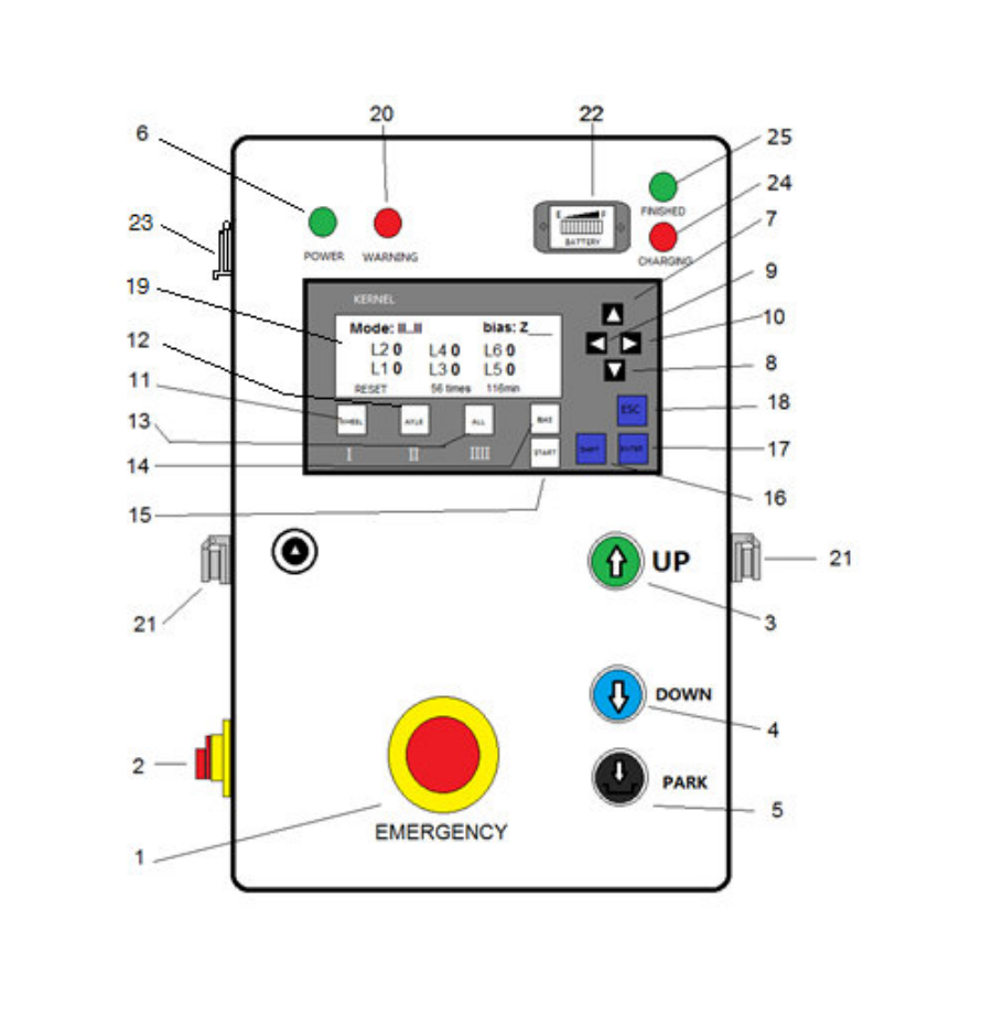
3.2 CONTROL PANEL DETAILS
1. EMERGENCY Button
To stop movements (lifting or lowering) immediately.
2. POWER Switch
Controls the power of the control panel or charging of the batteries.
3. ‘⇑
⇑⇑
⇑ ’
’’
’
( UP ) Button
Controls the lifting of the columns.
4. ‘⇓
⇓⇓
⇓ ’
’’
’
( DOWN ) Button
Controls the lowering of the columns.
5. ‘⇓
⇓⇓
⇓ ’
’’
’
( PARK ) Button
Controls the locking of the columns.
6. POWER Light
This light will go on when the control panel is power on.
7. 8. 9. 10. CURSOR Buttons
These buttons move cursor on the screen to edit items.
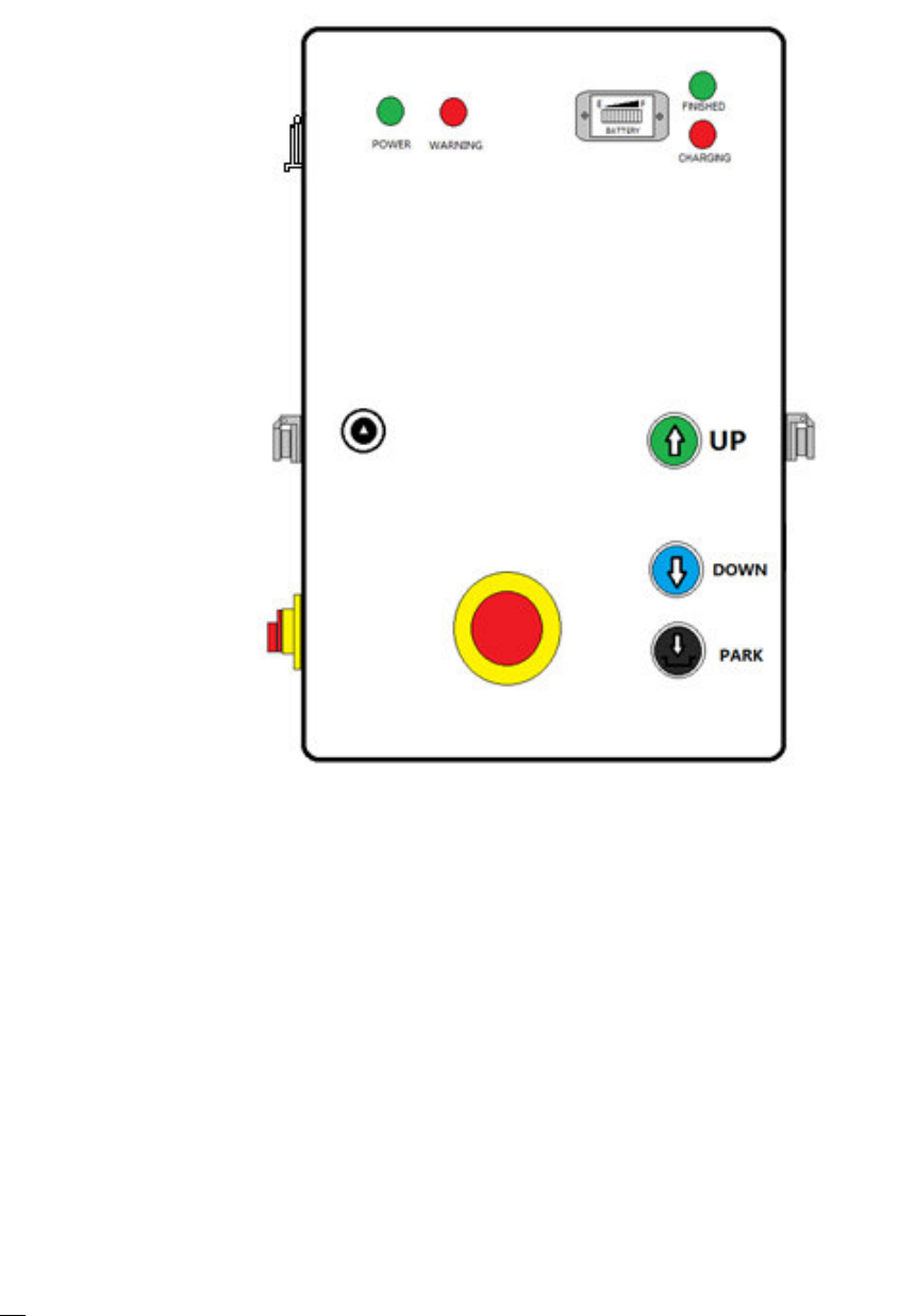
Sub Control Panels - #2, #3, #4, #5, #6 Columns
17
MSC-18K-X
Oct. 2017
11. 12. 13. MODE Buttons
To select between the functions: “WHEEL”, “AXLE” & “ALL”
14. BIAS Button
To set the zero point of height in initialization.
15. START Button
To start the running of the software.
16. SHIFT Button
This button is for the running of the program.
17. ENTER Button
This button serves confirming of instruction or entering sub menu.
18. ESC Button
Serves to enter or exit from menu; or from sub menu to upper lever menu.
19. LCD SCREEN
Display the height readings of columns & information
20. WARNING Light
This light will go on when the EMERGENCY button is pressed.
21. CABLE Port
This port is used for communication cable connection.
22. BATTERY Indicator
This indicator shows the output voltage of the batteries.
23. LED Light Socket
This socket provides the DC power for the LED light.
24. CHARGING Lamp
This is to indicate the batteries are in charging.
25. FINISHED Lamp
This is to indicate the batteries are fully charged.
Note:
Before turning on again the Power Switch, please wait for 20 seconds.
In “Axle” mode, are always paired as 1# & 2#, 3# & 4#, 5# & 6# per each vehicle axle.
In “ALL” mode, all columns move together.
In “Wheel” mode, each column moves individually.
In case of emergency, push down the ‘EMERGENCY’ button to stop. If any motor does not stop, turn
off the battery switch on column’s right side to make an immediate cease.
18
MSC-18K-X
Oct. 2017
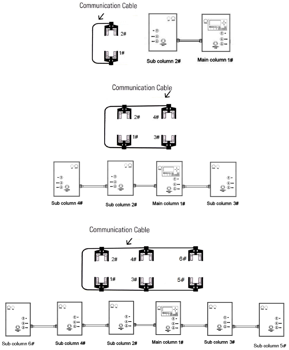
3.3 COLUMN POSITIONS & CONNECTIONS
Depending on the model type, a full combination consists of either 2, 4 or 6 lifting columns. The
position of the main column 1# should be located opposite of column 2# loading on the same axel
of vehicle. The columns 3# and 4# shall be at wheels of the same axel. If required, the same will
apply for columns 5# and 6#. (Figs. 3.3a, b, c)
Fig. 3.3a (Two Column Configuration)
Fig. 3.3b (Four Column Configuration)
Fig. 3.3c (Six Column Configuration)
19
MSC-18K-X
Oct. 2017
3.4 OPERATION TEST
The mobile column lifts are designed in such a way as to offer maximum flexibility and convenience.
A lifting system can consist of 4 lifting columns.
The mobile column lifts are set-up as following:
1. Position the lifting columns as indicated in 3.3 (Fig. 3.3.)
2. Then turn on the battery power switch of each column on the side.
3. Set the control box power switch on each sub column to left position (ON) first, the green Power
indicators will be on.
4. Then turn on the switch on main column to left (ON) and the LCD screen is lighted.
5. Wait until the LCD screen displays ‘Press START…’, then press the START button to start
running of the software.
6. Take care that the emergency stop button of each lifting column must been released.
Unloaded Rise:
1. Press and hold the “UP” button on the master 1# column panel, check if the carriages rise normally.
Repeat to try the other columns in same way.
2. Press and hold the “UP” button and allow the carriage to rise to its highest position. Check for any
hydraulic leaks.
Emergency Stop:
1. Push down the red emergency button to stop the lifts while rising.
2. Turn red emergency button to release it after test.
Lower Down:
1. Press and hold the “DOWN” button, the carriages will go up a little automatically to disengage the
safety locks first, then go down.
20
MSC-18K-X
Oct. 2017
Park:
1. Press and hold the ‘Park’ button, the carriage will go down until the safety lock is engaged.
Mode ‘Wheel’ or ‘Axle’ test:
1. Press the button ‘Wheel’ or ‘Axle’ or ‘All’ to change mode.
2. In ‘Wheel’ mode, only that button pressed column will operate.
3. In ‘Axle’ mode, only that button pressed pair columns will operate.
Note:
a. In WHEEL or AXLE mode, the lifting or lowering will be carried out only 5 seconds per
time.
b. In WHEEL or AXLE mode, the lifting or lowering will be stopped when the height
difference between all columns or axles is greater than 2” (50 mm)
c. It is normal that during the moving process you may notice one or more columns slow or
stop momentary. This occurs when the lift control system is synchronizing each column
to maintain leveling.
After you have read and understand all of the information in this manual and
finished the operations testing you are ready to proceed to lifting vehicles. All
technicians that will be using this equipment MUST read and understand all of the
safety and operation items in this manual.
4. LIFTING OPERATION
4.1 Load a Vehicle
:
1. Check and correct the tire pressure in each tire of the vehicle.
2. Position each mobile column adjacent to each tire on the vehicle. If the vehicle has dual rear
axles position the mobile columns to use on the drive axle.
Note: If an older vehicle has air bag suspension on the non-drive axles and mobile column are not
used, extra support for the axles may be needed to prevent air bag damage. Consult with the
vehicle manufacturer to determine if the air bag suspension has mechanical stops.
3. Adjust the lifting arms so they are at the narrowest position that will allow the arms to position
under the tires.
4. Move the lifting arms under the vehicle wheels then rest on ground.
Note: Always maintain approx. 6 inches of clearance between the column top and the vehicle body.
Note: The lift shall not be operated until the columns are fully lowered off dolly wheels.
21
MSC-18K-X
Oct. 2017
4.2 Operation
5. Connect all communication cables as show in Fig. 3.3
6. Turn on all the battery switches on columns. Then turn on all the power switch with the master
one in the last.
7. Depress the “UP” button and let columns rise approx. 6 inches. Release the “UP” button and
inspect all of the columns to insure that the lifting arms are positioned properly.
8. Depress the “UP” button again and raise the vehicle to the desired height.
Note: During the raising process you may notice one or more columns slow or stop lifting momentary.
This occurs when the lift control system is synchronizing each column to maintain level lifting.
This is normal.
9. After reaching to the desired height, press the “PARK” button. All lift columns will lower to the first
available safety lock position. When the lifts have settled onto the safety locks release the “Lock”
button. The vehicle is now safe and secured and ready for service.
10. To lower the lifts, check that all tools and equipment and has been removed from under the
vehicle. Press and hold the “DOWN” button. The lift will rise for a few seconds to allow the
safety lock disengaged. Then the lifts will lower down.
11. Before moving out the vehicle, move away all the columns from under the vehicle wheel first.
12. After finished one day’s work, turn off the power switch, disconnect the communication cables,
move the columns to the charging bay for charging.
5. Maintenance Instructions
CAUTION! If you are not familiar with vehicle lift maintenance, do not attempt repairs and contact the
factory/distributor for assistance. Use only experienced lift service technicians to perform lift
maintenance.
Daily:
• Check hydraulic system for leaks.
• Check the safety lock mechanism.
• Check communication cables for damage
• Inspect lifting arms to ensure they are in proper location & engaged in the locks.
22
MSC-18K-X
Oct. 2017
Monthly:
• Test the emergency stop button on all columns. Columns should stop immediately.
• Check the battery charging cables and cable ends.
• Inspect communication cables and cable ends for wear or damage.
• Check oil levels in hydraulic pump tank. Add oil on necessary.
Annually:
• Have an ALI Certified Lift inspector check all of your vehicle lifts and the safety systems for
wear or damage.
6. Service
CAUTION! If you are not familiar with vehicle lift service procedures, do not attempt repairs and
contact the factory/distributor for assistance. Use only experienced lift service technicians to perform
lift service.
Before and vehicle lift is serviced, follow the proper procedure for lock / out tag / out below.
Rules for Using Lockout Procedure
Use the Lockout Procedure whenever the lift is being repaired or serviced, waiting for repair when
current operation could cause possible injury to personnel, or for any other situation when
unintentional operation could injure personnel. No attempt shall be made to operate the lift when the
energy isolating device is locked out.
Purpose
This procedure establishes the minimum requirements for the lockout of energy that could cause
injury to personnel by the operation of lifts in need of repair or being serviced. All employees shall
comply with this procedure.
Responsibility
The responsibility for assuring that this procedure is followed is binding upon all employees and
service personnel from outside service companies (Installers, contactors, service repairmen). All
employees shall be instructed in the safety significance of the lockout procedure by the facility
owner/manager. Each new or transferred employee along with visiting outside service personnel shall
be instructed by the owner/manager (or assigned designee) in the purpose and use of the lockout
procedure
23
MSC-18K-X
Oct. 2017
Preparation
Employees authorized to perform lockout shall ensure that the appropriate energy isolating device
(circuit breaker, fuse, disconnect, etc.) is identified for the lift being locked out Other such devices for
other equipment may be located in close proximity of the appropriate energy isolating device. If the
identity of the device is in question, see the shop supervisor for resolution. Assure that proper
authorization is received prior to performing the lockout procedure.
Sequence of Lockout Procedure
Notify all affected employees that a lockout is being performed and the reason for it.
Unload the subject lift. Shut it down and assure the disconnect switch is "OFF" if one is provided on
the lift.
The authorized lockout person operates the main energy isolation device removing power to the
subject lift.
If this is a lockable device, the authorized lockout person places the assigned padlock on the device
to prevent its unintentional reactivation. An appropriate tag is applied stating the person's name, at
least 3"x 6" in size, an easily noticeably color, and states do not operate device or remove tag.
If this device is a non-lockable circuit breaker or fuse, replace with a "dummy" device and tag it
appropriately as mentioned above.
Attempt to operate lift to assure the lockout is working. Be sure to return any switches to the "OFF"
position.
The equipment is now locked out and ready for the required maintenance or service.
Restoring Equipment to Service
Assure the work on the lift is complete and the area is clear of tools, vehicles, and personnel.
At this point, the authorized person can remove the lock (or dummy circuit breaker or fuse) & tag and
activate the energy isolating device so that the lift may again be placed into operation.

24
MSC-18K-X
Oct. 2017
7. System Diagnostic Messages
The mobile column lifts have self-diagnostic systems that may display a fault message on the LCD
screen. Most fault messages indicate some sort of operator error and are designed so the user can
correct the most common operation mistakes without employing a service technician. Listed below
are the most common fault messages.
MESSAGE EXPLAINATION
1 PLC err, check & repower
a. Communication between master and slave columns failed.
(bad cable connection, antenna problem or some PLC lack
of power.)
b. Some PLC not working
Solution: System must be power off for checking then power
on again
2 Encode err, WHEEL/AXLE!
Some encoder is not working ( not powered, bad wired or in
error)
Solution: System must be power off for checking then power
on again
3 Asynch! WHEEL / AXLE mode
a. Too big difference in height reading (>1700mm), caused by
over turning
b. Some column not move (motor not running, carriage
locked)
c. Some encoder not turning (belt left the gear)
Solution: The height sensor (encoder) must be reset.
4 24Vdc insufficient
After moving stopped, one or more columns were found battery
in low voltage. The lift will not raise up any more but may lower
down.
Solution: To System must be power off for checking then
power on again
5 Locked by abnormal ope. One button is pressed within 2’ after previous button is
released.
Solution: To press any button on other column control panel.
6 Stop!
a. Emergency button is pressed.
b. Communication between columns is broken.
c. One or more column is power off.
d. Within 2 second after button is released.
Solution: Waiting for 2 seconds.
7 Manual adj.! Max. <5s / time Manually adjust column height. Maximum single operation for 5
seconds per time.
Solution: Press more time for more movement.
8 Reset! xx time xx min.
RESET state: one lift height is below 5 cm when in ALL mode.
Lift will be back in ZERO bias.
Free movement is possible and pair of column can be added or
taken away.
Note: Any operation will leave this in RESET state.
9 Reach end of travel
One column stops after reaching its height limit. (this column
will not raise when lower down)
25
MSC-18K-X
Oct. 2017
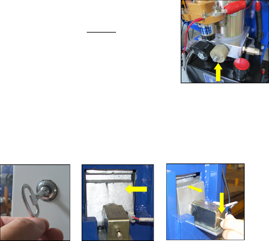
8. Emergency - Manual Lowering Procedure
WARNING!!
THIS PROCEDURE IS RECOMMENDED TO BE PERFORMED BY A QUALIFED SERVICE
PERSON AND/OR A FULLY TRAINED OPERATER
Note: Before performing this procedure, make sure there are no obstructions that will affect lowering
down.
In case of an emergency or without power, please use the supplied magnet ring found in the parts
box, to lower each column down manually. (Fig. 8.1)
1. Open the lower cabinet, by removing the screws to access the
power unit.
2. Locate the solenoid valve coil on the right side of power unit’s
valve body, then loosen hex nut to remove the valve coil from
the release valve.
3. Place the magnet ring on the release valve’s stem. The release
valve will open and the lift column will begin to lower down by
gravity. (See Note below) Fig. 8.1
Note: Before placing the magnet ring on release valve stem, ensure the safety latch is not in the
locked position, located inside the upper cabinet.
4. Using the key provided to open the upper cabinet door (Fig. 8.2), locate the safety latch
mechanism to ensure the safety latch is not in the locked position. (Fig 8.3).
5. If safety latch is in the locked position, pull the electro-magnet pin back by hand and hold to
disengage the safety latch to lower. (Fig. 8.4)
Fig. 8.2 Fig. 8.3 Fig. 8.4
Note: If a vehicle is loaded on the lift, columns can only be lowered down in 2” (5cm) increments each
time, one after another, to keep the vehicle in a safe level position.
For procedure assistance, please contact the factory/distributor.
26
MSC-18K-X
Oct. 2017
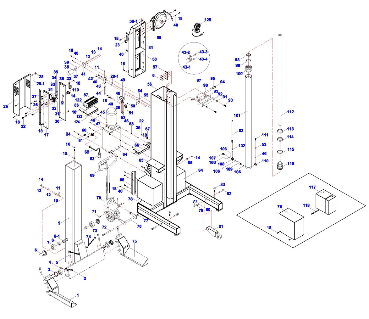
EXPLODED VIEWS & PARTS LISTS
Column Assembly
Drawing #1

27
MSC-18K-X
Oct. 2017
Column Assembly Parts List
ITEM Tux P/N M-Ref P/N DESCRIPTION QTY
1 MSC-18KX-01-001 DJ02-04000-000 Right Fork 1
2 MSC-18KX-01-002
5102-12035-000 Bolt, M12 x 35mm 2
3 MSC-18KX-01-003
DJ02-02003-000 Nylon Slider 2
4 MSC-18KX-01-004
5202-00012-000 Self-Lock Nut, M12 2
5 MSC-18KX-01-005
DJ02-00011-000 Pin 2
6 MSC-18KX-01-006
5114-05014-000 Socket Screw, M5 x 14mm 28
7 MSC-18KX-01-007
DJ02-02001-000 Roller 4
8 MSC-18KX-01-008
DJ02-02005-000 Copper Bushing 4
8-1 MSC-18KX-01-008.1
DJ02-02004-000 Washer 4
9 MSC-18KX-01-009
DJ02-02000-000 Carriage 1
10 MSC-18KX-01-010
DJ02-00021-000 Block Plate 1
11 MSC-18KX-01-011
DJ02-00017-000 Teeth Belt 1
12 MSC-18KX-01-012
5302-00004-000 Flat Washer, D4 9
13 MSC-18KX-01-013
5306-00004-000 Elastic Washer, D4 5
14 MSC-18KX-01-014
5110-04010-000 Screw, M4 x 10mm 8
15 MSC-18KX-01-015
5302-00010-000 Flat Washer, D10 7
16 MSC-18KX-01-016
5102-10035-000 Bolt, M10 x 35mm 1
17 MSC-18KX-01-017
DJ02-19003-M00 Right Side Plate 1
18 MSC-18KX-01-018
5115-06012-000 Screw, M6 x 12mm 42
22 MSC-18KX-01-022
5110-05014-000 Screw, M5 x 14mm 9
23 MSC-18KX-01-023
DJ02-00034-000 Small Hook 2
24 MSC-18KX-01-024
SJ03-14002-000 Fitting 1
25 MSC-18KX-01-025
DJ02-19001-000 Cover 1
26 MSC-18KX-01-026
5206-00005-000 Self-Lock Nut, M5 1
27 MSC-18KX-01-027
DJ02-19002-000 Hinge 1
28 MSC-18KX-01-028
5116-06012-000 Hand Screw, M6 x 12mm 2
28-1 MSC-18KX-01-028.1
DJ02-00039-000 Nylon Washer 4
30 MSC-18KX-01-030
DJ02-19100-A00 Left Side Plate 1
31 MSC-18KX-01-031
5202-00006-000 Nut, M6 4
32 MSC-18KX-01-032
BZ22-05503-MET Battery Switch 1
33 MSC-18KX-01-033
BZ22-05514-000 Fuse Case 1
34 MSC-18KX-01-034
BZ22-05516-000 Copper Plate 1
35 MSC-18KX-01-035
BZ22-05515-000 Fuse, 150A 1
36 MSC-18KX-01-036
5202-00008-000 Hex Nut, M8 4
37 MSC-18KX-01-037
DJ02-00019-000 Gear 1
38 MSC-18KX-01-038
DJ02-00016-000 Electro-Optical Encoder 1
39 MSC-18KX-01-039
5306-04005-000 Threaded Pin, M4 x 5mm 2
40 MSC-18KX-01-040
5306-00006-000 Spring Washer, D6 24
41 MSC-18K-01X-041
DJ02-00015-000 Support Board 1
42 MSC-18KX-01-042
5110-06020-000 Screw, M6 x 20mm 2
43 MSC-18KX-01-043
DJ02-11000-000 Wheel Support 1
43-1 MSC-18KX-01-043.1
DJ02-11003-000 Shaft 2
43-2 MSC-18KX-01-043.2
DJ02-11100-000 Roller Frame 1
43-3 MSC-18KX-01-043.3
DJ02-11001-000 Big Roller 1

28
MSC-18K-X
Oct. 2017
43-4 MSC-18KX-01-043.4
DJ02-11002-000 Small Roller 1
44 MSC-18KX-01-044
DJ02-00018-000 Weight Bar 1
45 MSC-18KX-01-045
5102-08020-000 Bolt, M8 x 20mm 4
46 MSC-18KX-01-046
5302-00008-000 Flat Washer, D8 8
47 MSC-18KX-01-047
5901-00010-000 O-Ring, D10 x 2.4 1
48 MSC-18KX-01-048
DJ02-00004-000 Coil Support Board 1
49 MSC-18KX-01-049
DJ02-00006-000 Electro-Magnet 1
50 MSC-18KX-01-050
5102-05040-000 Bolt, M5 x 40mm 1
51 MSC-18KX-01-051
DJ02-00031-000 Coil Fixing Board 1
52 MSC-18KX-01-052
5107-03010-000 Screw, M3 x 10mm 4
53 MSC-18KX-01-053
5306-00008-000 Spring Washer, D8 5
54 MSC-18KX-01-054
DJ02-00008-000 Lock Tongue 1
55 MSC-18KX-01-055
5402-04030-000 Cotter Pin, D4 x 30mm 1
56 MSC-18KX-01-056
DJ02-01000-MET Column 1
57 MSC-18KX-01-057
DJ02-00007-000 Slip Plate 2
58 MSC-18KX-01-058
QK02-11000-MET Control Box 1
58-1 MSC-18KX-01-058.1
DJ02-00007-A00 Cover, HP-22 1
59 MSC-18KX-01-059
QK04-00100-M00 Cable Reel 1
60 MSC-18KX-01-060
SJ03-14001-000 T-Fitting 1
61 MSC-18KX-01-061
SJ03-14005-000 Close Nut 1
62 MSC-18KX-01-062
DJ02-12000-000 Oil Pipe 1
63 MSC-18KX-01-063
DJ02-00030-000 Rubber Ring 1
64 MSC-18KX-01-064
DBZ22B-00 Motor Pump 1
65 MSC-18KX-01-065
5102-10020-000 Hex Screw, M10 x 20mm 1
66 MSC-18KX-01-066
DJ02-00033-000 Cover Support 2
67 MSC-18KX-01-067
BZ22-05511-000 Pipe Fixing Frame 1
68 MSC-18KX-01-068
DJ02-00029-000 Pipe Cover 1
69 MSC-18KX-01-069
DJ02-11000-000 Trolley 1
70 MSC-18KX-01-070
5402-05030-000 Cotter Pin, D5 x 30mm 2
71 MSC-18KX-01-071
DJ02-00001-000 Pin 2
72 MSC-18KX-01-072
DJ02-00032-000 Shaft 1
73 MSC-18KX-01-073
DJ02-00010-000 Ring, D4 x D35 4
74 MSC-18KX-01-074
DJ02-00009-000 Chain 2
75 MSC-18KX-01-075
DJ02-03000-000 Left Fork 1
76 MSC-18KX-01-076
DJ02-17000-000 Connecting Frame 1
77 MSC-18KX-01-077
5304-00016-000 Circlip, D16 2
78 MSC-18KX-01-078
DJ02-00004-MET Right, Battery Cover 1
79 MSC-18KX-01-079
5302-00016-000 Flat Washer, D16 2
80 MSC-18KX-01-080
DJ02-00014-000 Bushing 2
81 MSC-18KX-01-081
DJ02-06000-000 Front Wheel 2
82 MSC-18KX-01-082
DJ02-00013-000 Wheel Shaft 2
83 MSC-18KX-01-083
5102-16035-000 Hex Bolt, M16 x 35 2
84 MSC-18KX-01-084
DJ02-00003-MET Left, Battery Cover 1
85 MSC-18KX-01-085
DT01-06026-000
Nylon Tie Plate 1
86 MSC-18KX-01-086
DJ02-00019-MET Charger Board 1
87 MSC-18KX-01-087
BZ22-05509-MET Battery Charger 1
88 MSC-18KX-01-088
DJ02-15000-000 Fork Pocket 2

29
MSC-18K-X
Oct. 2017
89 MSC-18KX-01-089
5306-00010-000 Elastic Washer, D10 6
90 MSC-18KX-01-090
5102-14035-000 Socket Bolt, M14 x 35mm 2
91 MSC-18KX-01-091
DJ02-00036-000 Washer 2
92 MSC-18KX-01-092
DJ02-00035-000 Protecting Board 1
93 MSC-18KX-01-093
DJ02-10100-000 Roller Holder 1
94 MSC-18KX-01-094
5304-00025-000 Circlip, D25 2
95 MSC-18KX-01-095
DJ02-10102-002 Spacer 2
96 MSC-18KX-01-096
DJ02-10002-001 Shaft 1
97 MSC-18KX-01-097
DJ02-10001-000 Roller 1
98 MSC-18KX-01-098
5906-00070-000 Dust Ring, D70 1
99 MSC-18KX-01-099
DJ02-05005-000 Guide Belt - #2 1
100 MSC-18KX-01-100
DJ02-05004-000 Guide Ring 1
101 MSC-18KX-01-101
DJ02-05102-000 Cylinder Body 1
102 MSC-18KX-01-102
DJ02-09000-000 Safety Valve 1
106 MSC-18KX-01-106
DJ02-05007-000 Combined Washer 4
107 MSC-18KX-01-107
DJ02-05011-000 Oil Screw 1
108 MSC-18KX-01-108
DJ02-05010-000 Connector 1
109 MSC-18KX-01-109
DJ02-05008-000 Oil Fitting 1
110 MSC-18KX-01-110
DJ02-00027-000 Cylinder Fixing Board 1
111 MSC-18KX-01-111
5105-08025-000 Hex Screw, M8 x 25mm 1
112 MSC-18KX-01-112
DJ02-05003-000 Piston Rod 1
113 MSC-18KX-01-113
DJ02-05009-000 Position Bushing 1
114 MSC-18KX-01-114
DJ02-05002-000 Guide Belt - #1 2
115 MSC-18KX-01-115
5903-00795-000 Seal Ring 1
116 MSC-18KX-01-116
DJ02-05002-000 Piston 1
117 MSC-18KX-01-117
BZ22-05508-000 Battery 2
118 MSC-18KX-01-118
BZ22-00002-000 Hose Clamps 4
119 MSC-18KX-01-119
SL02-00041-A00 Socket 1
121 MSC-18KX-01-121
5206-00004-000 LED Lamp Socket, M4 2
122 MSC-18KX-01-122
5110-04010-000 Screw, M4 x 10mm 4
123 MSC-18KX-01-123
5302-00004-000 Flat Washer, D4 8
124 MSC-18KX-01-124
5206-00004-000 Lock Nut, M4 4
125 MSC-18KX-01-125
QK04-80001-FJ5 LED Lamp, 24VDC/27W 1
30
MSC-18K-X
Oct. 2017
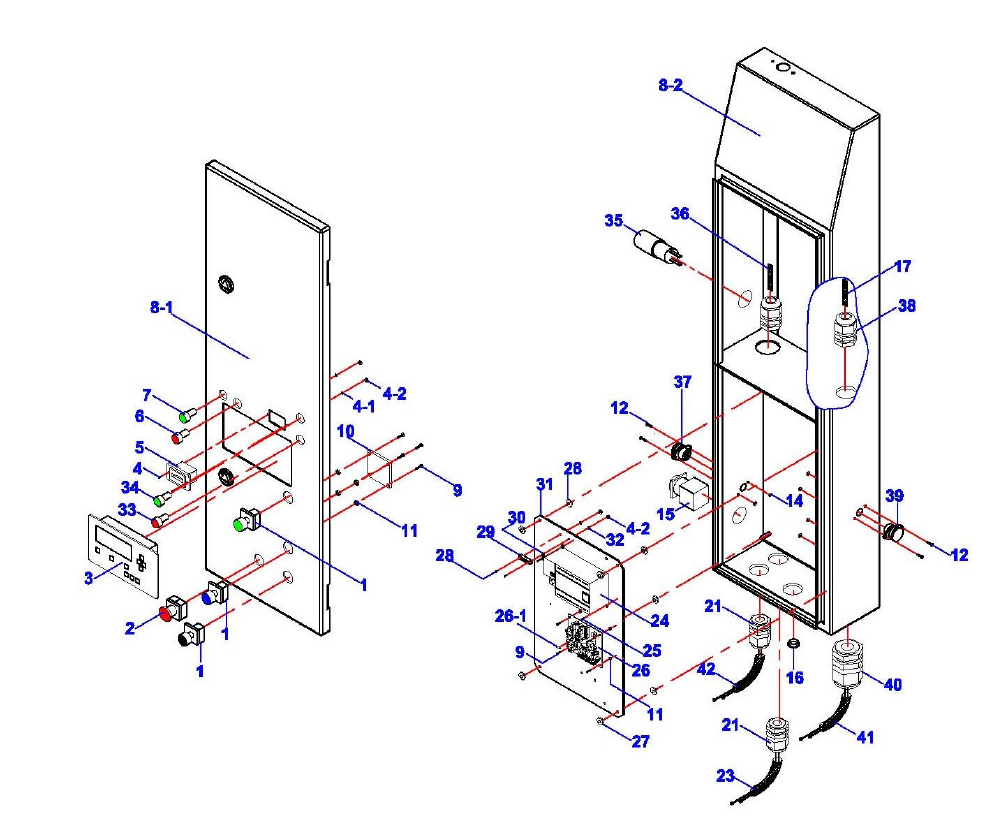
Control Panel Assembly
Drawing #2

31
MSC-18K-X
Oct. 2017
Control Panel Assembly Parts List
ITEM
Tux P/N M-Ref P/N DESCRIPTION QTY
1-1 MSC-18KX-02-001.1 DJ02-20002-000-Grn
Operation Button, Green 1
1-2 MSC-18KX-02-001.2
DJ02-20002-000-Blu
Operation Button, Blue
1
1-3 MSC-18KX-02-001.3
DJ02-20002-000-Blk
Operation Button, Black
1
2 MSC-18KX-02-002
DJ02-20003-000 Emergency Button, Red 1
3 MSC-18KX-02-003
DJ02-20010-000 Screen, Main 1
4 MSC-18KX-02-004
5110-00004-000 Screw, M4 x 12mm 2
4-1 MSC-18KX-02-004.1
5203-00004-000 Spring Washer, D4 2
4-2 MSC-18KX-02-004.2
5202-00004-000 Nut, M4 2
5 MSC-18KX-02-005
QK04-00012-000 Battery Meter Indicator 1
6 MSC-18KX-02-006
DJ02-20006-000 Red Lamp Indicator 1
7 MSC-18KX-02-007
DJ02-20005-000 Green Lamp Indicator 1
8-1 MSC-18KX-02-008.1
DJ03-13001-000 Main Panel (Sub) 1
8-2 MSC-18KX-02-008.2
QK02-11100-MET Case 1
9 MSC-18KX-02-009
5110-03008-000 Bolt, M3 x 8mm 12
10 MSC-18KX-02-010
QK02-20200-L60 Connecting PCB 1
11 MSC-18KX-02-011
QK02-10013-000 Spacer, M3 x 10mm 8
12 MSC-18KX-02-012
5110-03015-000 Screw, M3 x 15mm 6
14 MSC-18KX-02-014
5202-00003-000 Nut, M3 6
15 MSC-18KX-02-015
DJ04-20001-100 Power Switch 1
16 MSC-18KX-02-016
QK04-00011-000 Plug Cover, D16 1
17 MSC-18KX-02-017
DJ02-00200-000 Coil Cable 1
21 MSC-18KX-02-021
DT01-06023-000 Cable Nut, M16 2
22 MSC-18KX-02-022
QK04-30300-000 Charger Cable, Red / Black 1
24-1 MSC-18KX-02-024.1
DJ02-10002-000M PLC (Main) 1
24-2 MSC-18KX-02-024.2
DJ02-10002-000S PLC (Sub) 1
25 MSC-18KX-02-025
DJ02-10032-000 Screw, 3.5 x 15mm 2
26 MSC-18KX-02-026
QK04-13300-MZ2 Main PCB 1
26-1 MSC-18KX-02-026.1
JK01-10113-100 Delay Fuse, D5 x 20mm 1
27 MSC-18KX-02-027
5202-00006-000 Nut, M6 8
28 MSC-18KX-02-028
5110-04004-000 Screw 2
29 MSC-18KX-02-029
JK01-10010-000 Earthling End 1
30 MSC-18KX-02-030
JK01-JD000-000 Ground Label 1
31 MSC-18KX-02-031
QK06-10001-100 Bottom Plate 1
32 MSC-18KX-02-032
5301-00005-000 Flat Washer, D5 2
33 MSC-18KX-02-033
QK05-20006-H00 Battery Charger Indicator - Red 1
34 MSC-18KX-02-034
QK05-20005-H00 Battery Charger Indicator - Green 1
35 MSC-18KX-02-035
QK04-80002-FJ5 LED Lamp Socket, 12-24VDC 1
36 MSC-18KX-02-036
QK04-00015-000 LED Lamp Cable, Red / Black 1
37 MSC-18KX-02-037
QK04-50700-M00 Cable XS1, 11.8” 1
38 MSC-18KX-02-038
JK01-00004-000 Cable Nut, M20 2
39 MSC-18KX-02-039
QK04-50800-M00 Cable XS7, 3.9” 1
40 MSC-18KX-02-040
DJ02-00007-000 Cable Nut, M25 1
41 MSC-18KX-02-041
QK04-00013-M00 Battery Indicator Cable, 53” 1
42 MSC-18KX-02-042
QK04-30100-M00 Control Panel Cable, 25.6” 1
32
MSC-18K-X
Oct. 2017
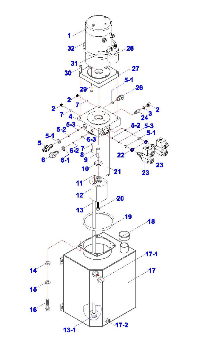
Power Unit Assembly
Drawing #3

33
MSC-18K-X
Oct. 2017
Power Unit Assembly Parts List
ITEM
Tux P/N M-Ref P/N DESCRIPTION QTY
1 MSC-18KX-03-001 BZ22-05001-300 DC Motor, 24VDC, 3KW, 125A 1
2 MSC-18KX-03-002
BZ01-04008-000 Close Nut, 9/16-18 UNF 1
3 MSC-18KX-03-003
5901-00118-000 O-Ring, D11.8 x D1.8 1
4 MSC-18KX-03-004
BZ22-04001-F00
Valve Block 1
5 MSC-18KX-03-005
BZ20-04002-000 Overflow Valve, 25Mpa 1
5-1 MSC-18KX-03-005.1
5901-00160-000 O-Ring, D16 x D2 4
5-2 MSC-18KX-03-005.2
5901-00125-000 Circlip, D12 x 1.5mm 3
5-3 MSC-18KX-03-005.3
5901-00095-000 O-Ring, D9.5 x D1.8 3
6 MSC-18KX-03-006
BZ20-04024-100 Main, Flow Control Valve 1
6-1 MSC-18KX-03-006.1
5901-00190-000 O-Ring, D19 x D2 1
6-2 MSC-18KX-03-006.2
5901-00130-000 Circlip, D13 x 1.5mm 1
6-3 MSC-18KX-03-006.3
5901-00130-000 O-Ring, D13 x D1.8 1
7 MSC-18KX-03-007
5601-00800-000 Steel Ball, D8 3
8 MSC-18KX-03-008
5109-10010-000 Threaded Pin, M10x1x10 3
9 MSC-18KX-03-009
BZ22-00003-B00
Connecting Rod, D20 x 34.5mm 1
10 MSC-18KX-03-010
5901-00277-000 O-Ring, D27.7 x D2.4 1
11 MSC-18KX-03-011
5901-00925-000 O-Ring, D9.25 x D1.78 1
12 MSC-18KX-03-012
BZ01-03000-F00
Gear Pump, 21Mpa 1
13 MSC-18KX-03-013
BZ20-01000-000 Suction Pipe, D18 x 350mm 1
13-1 MSC-18KX-03-013.1
BZ01-01002-000 Filter 1
14 MSC-18KX-03-014
5301-00006-000 Washer, D6 4
15 MSC-18KX-03-015
5303-00006-000 Elastic Washer, D6 4
16 MSC-18KX-03-016
5101-06012-000 Bolt, M6 x 12mm 4
17 MSC-18KX-03-017
BZ20-02100-300 Oil Tank 1
17-1 MSC-18KX-03-017.1
DJ02-00042-000 Fluid Level Indicator 1
17-2 MSC-18KX-03-017.2
BZ20-02101-000 Outlet Plug, M12 x 10mm 1
18 MSC-18KX-03-018
BZ20-02200-000 Tank Cover 1
19 MSC-18KX-03-019
5901-01120-000 O-Ring, D112 x D3.55 1
20 MSC-18KX-03-020
5105-08080-000 Screw, M8 x 80mm 2
21 MSC-18KX-03-021
BZ20-00001-000 Return Pipe, D10 x 260mm 2
22 MSC-18KX-03-022
BZ01-04011-000 Filter 2
23 MSC-18KX-03-023
BZ13-04100-000 Solenoid Release Valve, 24VDC 2
24 MSC-18KX-03-024
BZ20-04026-000 Sub, Flow Control Valve 1
26 MSC-18KX-03-026
BZ20-04007-000 Check Valve 1
27 MSC-18KX-03-027
BZ22-05008-B00
Motor Adaptor Plate 1
28 MSC-18KX-03-028
BZ22-05002-001 Unipolar DC Contactor, 24VDC, 200A 1
29 MSC-18KX-03-029
5105-05030-000 Screw, M5 x 30mm 4
30 MSC-18KX-03-030
5105-06025-000 Screw, M6 x 25mm 4
31 MSC-18KX-03-031
BZ22-05003-000 Contactor Support 1

34
MSC-18K-X
Oct. 2017
LIMITED WARRANTY
Structural Warranty:
The following parts and structural components carry a five year warranty:
Columns Arms Uprights Swivel Pins
Legs Carriages Overhead Beam
Tracks Cross Rails Top Rail Beam
Limited One-Year Warranty:
Tuxedo Distributors, LLC (iDEAL) offers a limited one-year warranty to the original purchaser of Lifts and Wheel Service
equipment in the United States and Canada. Tuxedo will replace, without charge, any part found defective in materials or
workmanship under normal use, for a period of one year after purchase. The purchaser is responsible for all shipping
charges. This warranty does not apply to equipment that has been improperly installed or altered or that has not been
operated or maintained according to specifications.
Other Limitations:
This warranty does not cover:
1. Parts needed for normal maintenance
2. Wear parts, including but not limited to cables, slider blocks, chains, rubber pads and pulleys
3. Replacement of lift and tire changer cylinders after the first 30 days. A seal kit and installation instructions will be
sent for repairs thereafter.
4. On-site labor
Upon receipt, the customer must visually inspect the equipment for any potential freight damage before signing clear on
the shipping receipt. Freight damage is not considered a warranty issue and therefore must be noted for any potential
recovery with the shipping company.
The customer is required to notify Tuxedo of any missing parts within 72 hours. Timely notification must be received to be
covered under warranty.
Tuxedo will replace any defective part under warranty at no charge as soon as such parts become available from the
manufacturer. No guarantee is given as to the immediate availability of replacement parts.
Tuxedo reserves the right to make improvements and/or design changes to its lifts without any obligation to previously sold,
assembled or fabricated equipment.
There is no other express warranty on the Tuxedo lifts and this warranty is exclusive of and in lieu of all other warranties,
expressed or implied, including all warranties of merchantability and fitness for a particular purpose.
To the fullest extent allowed by law, Tuxedo shall not be liable for loss of use, cost of cover, lost profits, inconvenience,
lost time, commercial loss or other incidental or consequential damages.
This Limited Warranty is granted to the original purchaser only and is not transferable or assignable.
Some states do not allow exclusion or limitation of consequential damages or how long an implied warranty lasts, so the
above limitations and exclusions may not apply. This warranty gives you specific legal rights and you may have other rights,
which may vary from state to state.
1905 N Main St Suite C, Cleburne, TX 76033
Ph 817-558-9337 / Fax 817-558-9740
