Service Manual 7210/6610 Level 1&2 Nokia 6610 Nhl4u, 7210 Nhl 4 1,2
User Manual: Phone Nokia 6610 NHL-4U - Service manuals and Schematics, Disassembly / Assembly. Free.
Open the PDF directly: View PDF ![]() .
.
Page Count: 19
- EXPLODED VIEW
- SPARE PARTS LIST
- 7210<>6610 COMPARISON
- INFRARED GONOGO TEST
- SW-UPDATE
- GENERAL REPAIR INFORMATION
- DISASSEMBLY INSTRUCTIONS (SEE ALSO VIDEO CLIPS)
- QUICK TROUBLE SHOOTER PART1
- QUICK TROUBLE SHOOTER PART2
- QUICK TROUBLE SHOOTER PART3
- ESD PROTECTION REQUIREMENTS
- SERVICE NOTES
- GONOGO TESTER
- BATTERY TESTER
PAGE 1 (19) Approved 1.0
Nokia Mobile Phones Customer Care E&A SQX 00444-en MWy
Technical Services, Repair Concepts Confidential 25.09.2002
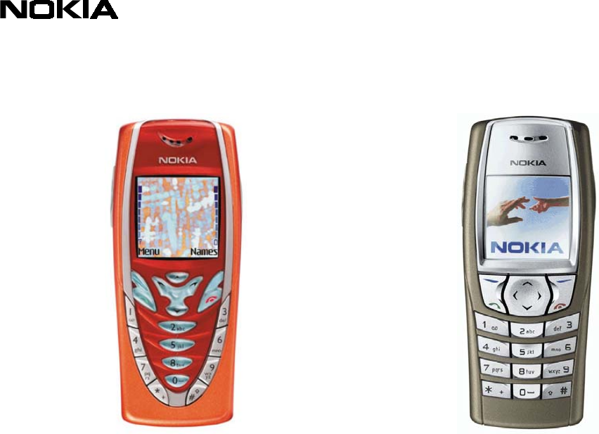
7210
NHL-4
6610
NHL-4U
Service Manual
Service Level 1&2
Copyright © Nokia Corporation. This material, including documentation and any related computer
programs, is protected by copyright controlled by Nokia Mobile Phones. All rights are reserved.
Copying, including reproducing, storing, adapting or translating, any or all of this material requires
the prior written consent of Nokia Mobile Phones. This material also contains confidential
information, which may not be disclosed to others without the prior written consent of Nokia Mobile
Phones.
Service Manual 7210/6610 Level 1&2 Copyright 2002 © Nokia Corporation

PAGE 2 (19) Approved 1.0
Nokia Mobile Phones Customer Care E&A SQX 00444-en MWy
Technical Services, Repair Concepts Confidential 25.09.2002
Introduction
The purpose of this document is to help Nokia service levels 1 and 2 workshop
technicians to carry out service to Nokia 7210 & 6610. This Service Manual is to be used
only by authorized Nokia service partners, and the content of it is confidential. Please
note that Nokia provides also other guidance documents (e.g. Service Bulletins) for
service partners, follow these regularly and comply with the given instructions.
While every endeavor has been made to ensure the accuracy of this document, some
errors may exist. If you find any errors or if you have further suggestions, Nokia should
be notified. Please keep in mind also that this documentation is continuously being
updated and modified, so watch always out for the newest version.
Warnings and Cautions
Please refer to the phone’s user guide for instructions relating to operation, care and maintenance
including important safety information. Note also the following:
Warnings:
1. CARE MUST BE TAKEN ON INSTALLATION IN VEHICLES FITTED WITH ELECTRONIC ENGINE
MANAGEMENT
SYSTEMS AND ANTI–SKID BRAKING SYSTEMS. UNDER CERTAIN FAULT CONDITIONS, EMITTED RF
ENERGY CAN AFFECT THEIR OPERATION. IF NECESSARY, CONSULT THE VEHICLE
DEALER/MANUFACTURER TO DETERMINE THE IMMUNITY OF VEHICLE ELECTRONIC SYSTEMS TO RF
ENERGY.
2. THE HANDPORTABLE TELEPHONE MUST NOT BE OPERATED IN AREAS LIKELY TO CONTAIN
POTENTIALLY EXPLOSIVE ATMOSPHERES EG PETROL STATIONS (SERVICE STATIONS), BLASTING AREAS
ETC.
3. OPERATION OF ANY RADIO TRANSMITTING EQUIPMENT, INCLUDING CELLULAR TELEPHONES, MAY
INTERFERE WITH THE FUNCTIONALITY OF INADEQUATELY PROTECTED MEDICAL DEVICES. CONSULT A
PHYSICIAN OR THE MANUFACTURER OF THE MEDICAL DEVICE IF YOU HAVE ANY QUESTIONS. OTHER
ELECTRONIC EQUIPMENT MAY ALSO BE SUBJECT TO INTERFERENCE.
Cautions:
1. Servicing and alignment must be undertaken by qualified personnel only.
2. Ensure all work is carried out at an anti–static workstation and that an anti–static wrist strap is
worn.
3. Ensure solder, wire, or foreign matter does not enter the telephone as damage may result.
4. Use only approved components as specified in the parts list.
5. Ensure all components, modules screws and insulators are correctly re–fitted after servicing and
alignment. Ensure all cables and wires are repositioned correctly.
6. All PC’s used with NMP Service Software for this produce must be bios and operating system ”Year
2000 Compliant”.
Service Manual 7210/6610 Level 1&2 Copyright 2002 © Nokia Corporation
PAGE 3 (19) Approved 1.0
Nokia Mobile Phones Customer Care E&A SQX 00444-en MWy
Technical Services, Repair Concepts Confidential 25.09.2002
Table of content
1. EXPLODED VIEW.................................................................................................................................... 4
2. SPARE PARTS LIST................................................................................................................................. 5
3. 7210<>6610 COMPARISON..................................................................................................................... 8
4. INFRARED GONOGO TEST .................................................................................................................. 9
5. SW-UPDATE ............................................................................................................................................ 10
6. GENERAL REPAIR INFORMATION ................................................................................................. 11
7. DISASSEMBLY INSTRUCTIONS (SEE ALSO VIDEO CLIPS) ...................................................... 12
8. QUICK TROUBLE SHOOTER PART1 ............................................................................................... 14
9. QUICK TROUBLE SHOOTER PART2 ............................................................................................... 15
10. ESD PROTECTION REQUIREMENTS........................................................................................... 17
11. SERVICE NOTES................................................................................................................................ 18
12. GONOGO TESTER............................................................................................................................. 19
13. BATTERY TESTER ............................................................................................................................ 19
Change History
Originator Status Version No. Date Comments
MWy Draft 0.1 01.08.2001 Initial draft
MWy Approved 1.0 25.09.2002 Approval by PHe
Service Manual 7210/6610 Level 1&2 Copyright 2002 © Nokia Corporation
PAGE 4 (19) Approved 1.0
Nokia Mobile Phones Customer Care E&A SQX 00444-en MWy
Technical Services, Repair Concepts Confidential 25.09.2002
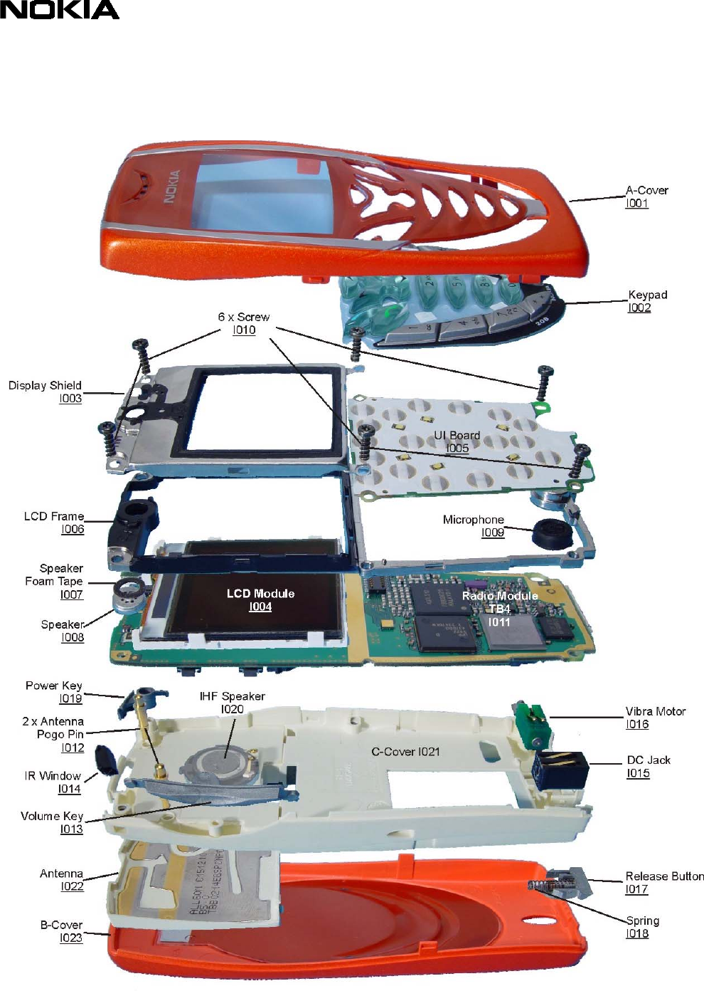
1. EXPLODED VIEW
Description: See corresponding ITEM/CIRCUIT REF of the SPL (Spare Parts List)
Service Manual 7210/6610 Level 1&2 Copyright 2002 © Nokia Corporation
PAGE 5 (19) Approved 1.0
Nokia Mobile Phones Customer Care E&A SQX 00444-en MWy
Technical Services, Repair Concepts Confidential 25.09.2002
2. SPARE PARTS LIST
SPARE PARTS
ITEM/
CIRCUIT REF.
QTY PART NO PART NAME
I003 1 9517173 DISPLAY SHIELD DMC04171 NHL-4
I004 1 4850261 LCD MODULE 130X130 COG COLOURSTN
I005 1 0201827
TK4 UI BOARD MODULE (7210)
I005 1 0201909
TK7 UI BOARD MODULE (6610)
I006 1 9467076 LCD FRAME DMC03935 NHL-4
I007 1 9470283 SPEAKER FOAM TAPE
I008 1 5140251 SPEAKER105+-3DB32R D8.1X2.25 PICO
I009 1 5140263 MIC+BOOT ASSY -42+-3DB D7.7X3MM
I010 6 6290107 SCREW 1.8X7.0 FE T6+ DMD05791 BLK
I012 2 5400263 ANTENNA POGO PIN L=8.7MM D=2.1MM
I013 1 9452236 VOLUME KEY DMD07492 NHL-4
I014 1 9452235 IR WINDOW DMD07490 NHL-4
I015 1 5400243 CONN DC-JACK 3.5MM 3POL SPR 90DEG
I016 1 6800057 VIB.MOTOR ASSY 1.3 VDC 11000 RPM
I017 1 9470205 RELEASE BUTTON NHL-4
I018 1 9510845 SPRING NHL-4
I019 1 9452237 POWER KEY DMD07491 NHL-4
I020 1 XXXXXXX SPEAKER HF 69+-2DB8R D16X4.36
I022 1 0660264
ANTENNA INT ANTENNA EGSM/PCN/PCS (7210)
I022 1 0660267
ANTENNA INT ANTENNA EGSM/PCN/PCS (6610)
SOLDERING COMPONENTS ONLY FOR LEVEL 2
ITEM/
CIRCUIT REF.
QTY PART NO PART NAME
S300 1 5209001 SM SW TACT SPST 12V 50MA SIDE KEY
S301 1 5209001 SM SW TACT SPST 12V 50MA SIDE KEY
S302 1 5409235 SM TACT SW TRAV 0.2 4.1X3.55X1.75
F100 1 5119019 SM FUSE F 1.5A 32V 0603
G300 1 4700131 CELL CAPACITOR 0.01MAH 3V3
V101 1 4864573 LED CL19WBVA WHITE
V102 1 4864573 LED CL19WBVA WHITE
V103 1 4864573 LED CL19WBVA WHITE
V104 1 4864573 LED CL19WBVA WHITE
V105 1 4864573 LED CL19WBVA WHITE
V106 1 4864573 LED CL19WBVA WHITE
Service Manual 7210/6610 Level 1&2 Copyright 2002 © Nokia Corporation
PAGE 6 (19) Approved 1.0
Nokia Mobile Phones Customer Care E&A SQX 00444-en MWy
Technical Services, Repair Concepts Confidential 25.09.2002
VARIANT PARTS (7210)
ITEM/
CIRCUIT REF.
QTY PART NO PART NAME
I001 9490782 A-COVER ASSY DMC03934 ORANGE
I001 9490783 A-COVER ASSY DMC03934 TURQUOISE
I001 9490784 A-COVER ASSY DMC03934 BROWN
I002 9790644 KEYPAD LATIN DMC04451 NHL-4
I002 9790710 KEYPAD ARABIC DMC05274 NHL-4
I002 9790711 KEYPAD CYRILLIC DMC05275 NHL-4
I002 9790712 KEYPAD GREEK DMC05276 NHL-4
I002 9790713 KEYPAD HEBREW DMC05277 NHL-4
I023 9490773 B-COVER ASSY DMC04484 ORANGE
I023 9490774 B-COVER ASSY DMC04484 TURQUOISE
I023 9490775 B-COVER ASSY DMC04484 BROWN
VARIANT PARTS (6610)
ITEM/
CIRCUIT REF.
QTY PART NO PART NAME
I001 9490826 A-COVER ASSY DMC05091 BLACK
I001 9490827 A-COVER ASSY DMC05091 WHITE
I001 9490888 A-COVER ASSY DMC05091 GREY
I002 9790719 KEYPAD LATIN DMC05167 HDJ13
I002 9790726 KEYPAD ARABIC DMC05296 HDJ13
I002 9790724 KEYPAD CYRILLIC DMC05294 HDJ13
I002 9790725 KEYPAD GREEK DMC05295 HDJ13
I002 9790727 KEYPAD HEBREW DMC05297 HDJ13
I023 9490833 B-COVER ASSY DMC05092 BLACK
I023 9490832 B-COVER ASSY DMC05092 WHITE
I023 9490889 B-COVER ASSY DMC08092 GREY
Service Manual 7210/6610 Level 1&2 Copyright 2002 © Nokia Corporation
PAGE 7 (19) Approved 1.0
Nokia Mobile Phones Customer Care E&A SQX 00444-en MWy
Technical Services, Repair Concepts Confidential 25.09.2002
SWAP UNITS (7210)
QTY PART NO PART NAME
0075544 NHL-4 N7210 SWAP ENGINE
0075545 NHL-4 N7210 SWAP ENGINE RUSSIA
0075546 NHL-4 N7210 SWAP ENGINE POLAND
0075547 NHL-4 N7210 SWAP ENGINE FRANCE
0075548 NHL-4 N7210 SWAP ENGINE TURKEY
0075549 NHL-4 N7210 SWAP ENGINE CZECH
SWAP UNITS (6610)
QTY PART NO PART NAME
0075812 NHL-4U N6610 SWAP ENGINE CZECH
0075813 NHL-4U N6610 SWAP ENGINE TURKEY
0075814 NHL-4U N6610 SWAP ENGINE FRANCE
0075815 NHL-4U N6610 SWAP ENGINE POLAND
0075816 NHL-4U N6610 SWAP ENGINE RUSSIA
0075817 NHL-4U N6610 SWAP ENGINE
SERVICE TOOLS
TYPE QTY PART NO PART NAME
0080541 FLS-4S SALES PACK E&A
0273460 BLD-3 BATTERY PACK
0770492 FLA-27 POS FLASH ADAPTER
0730218 XCS-1 SERVICE CABLE
0273636 DCV-14 DESK TOP STAND
0272169 AC TRAVEL CHARGER ACP-8E (EUR)
0272172 AC TRAVEL CHARGER ACP-8X (UK)
0273505 HDS-3 STEREO HEADSET
0770431 SRT-6 OPENING TOOL 5510
Service Manual 7210/6610 Level 1&2 Copyright 2002 © Nokia Corporation
PAGE 8 (19) Approved 1.0
Nokia Mobile Phones Customer Care E&A SQX 00444-en MWy
Technical Services, Repair Concepts Confidential 25.09.2002
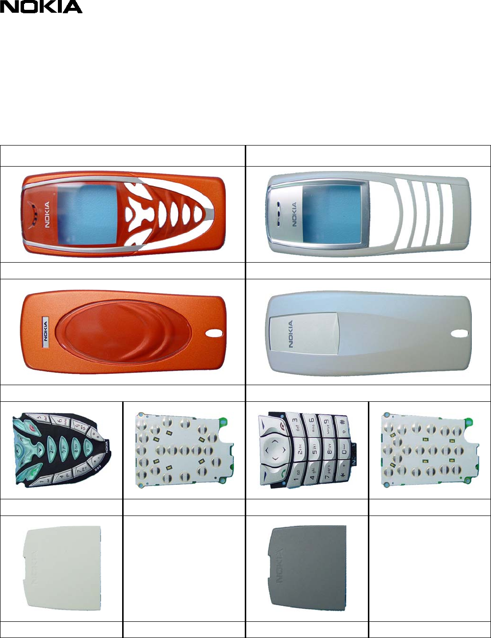
3. 7210<>6610 COMPARISON
There are not many differences between these two products. Only some mechanical
parts, the UI Board and Antenna are different (see Spare Parts Lists).
7210 6610
A-Cover, Item 001 A-Cover, Item 001
B-Cover, Item 023 B-Cover, Item 023
Keypad, Item 002 TK4, Item 005 Keypad, Item 002 TK7, Item 005
Antenna, Item 022 Antenna, Item 022
Service Manual 7210/6610 Level 1&2 Copyright 2002 © Nokia Corporation
PAGE 9 (19) Approved 1.0
Nokia Mobile Phones Customer Care E&A SQX 00444-en MWy
Technical Services, Repair Concepts Confidential 25.09.2002
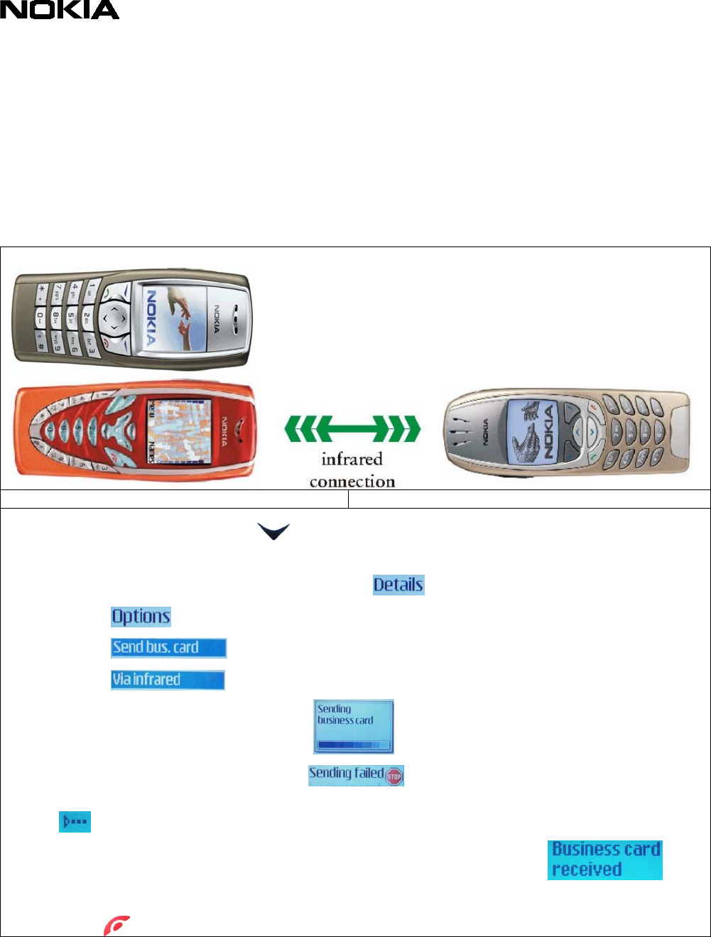
4. INFRARED GONOGO TEST
You need another infrared device (e.g. 6310i) to do a GoNoGo test. The infrared windows
of the devices must be directed to each other and should have a distance of approximate
15 cm.
Test unit Reference Unit
o From Home Menu, select key. This displays Phonebook entries. If phone and
SIM memory is empty, create one new entry.
o Choose one phonebook entry and select
o Select
o Select
o Select
o Sending in progress, please wait
o If sending of business card fails , make sure again, that infrared
windows are directed to each other. If infrared is activated in reference device
, try again sending.
o Test was successful, if you get this message on receiver device .
You will not get a confirmation on sender device.
o Press for Home Menu
Service Manual 7210/6610 Level 1&2 Copyright 2002 © Nokia Corporation
PAGE 10 (19) Approved 1.0
Nokia Mobile Phones Customer Care E&A SQX 00444-en MWy
Technical Services, Repair Concepts Confidential 25.09.2002
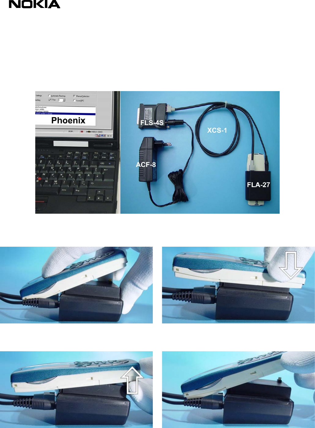
5. SW-UPDATE
To use FLS-4S Flash Dongle you have to follow the user guide inside the sales package. Please
check always for the latest version of flash software, which is available on Nokia Partner Web Site.
Flash Concept – (Point of Sales)
It is very important to follow this insertion and removal procedure, otherwise the contact pins of Flash
Adapter will be damaged.
Insert the Flash Adapter FLA-27 like a battery, start
at the battery connector side.
Now, push down the bottom side of the phone, do
not use too much force.
When removing the Flash Adapter, always start from
the bottom side of the unit.
Take away the unit now.
Service Manual 7210/6610 Level 1&2 Copyright 2002 © Nokia Corporation
PAGE 11 (19) Approved 1.0
Nokia Mobile Phones Customer Care E&A SQX 00444-en MWy
Technical Services, Repair Concepts Confidential 25.09.2002
6. GENERAL REPAIR INFORMATION
In this section the technician will get some general hints how to carry out repairs:
o Before starting the repair you must take care of ESD precautions like being in your ESD-area and
connecting your wristband.
o Use gloves to avoid corrosion and fingerprints.
o Protect windows and displays with a foil to avoid dust and scratches.
o When cleaning the pads you have to use a soft cloth and isopropanol. It is not allowed to use a
glass fiber pencil because it scratches the surface and will lead later on to corrosion.
o Mechanical parts, which didn’t repair the failure, can be reused, if they are not soldered.
o Use always original Nokia parts or accessories.
o Meet the torque requirements when assembling the unit (see also the document “torques for
transceiver assembly” on Partner Websites).
o Always use your own equipment for testing where you are sure that it works. E.g. if the customer
complains about charger function, please test the phone with your own charger to be sure if
phone or charger causes the malfunction.
o When doing the Faultlogger entries, always note the Item code, which caused the malfunction.
Also, fill in the appropriate part code from the assembly, if needed.
Following General Service Bulletins have to be followed:
SB-055 Common notice for good ventilation
SB-089: Don’t try to repair prototypes (indicated on Typelabel).
SB-107: Be sure that you have minimum hardware requirements in place.
SB-115: Handling of liquid damages.
SB-121: If one of your service tools cause malfunction, return the defective part.
SB-122: Soldering with manual hot air gun is totally forbidden because of the very sensitive
µBGA components and µVia technology.
SB-124 Service Policy for packaging serviced products
SB-131: Check these guidelines when refurbishing products.
SB-132: You can use a Golden Phone for inspecting your measuring equipment.
Please check Nokia Partner Web Site (PWS) for latest news and files on a regular basis.
This legend is valid for all parts of the Quick Trouble Shooter
Follow the steps until the problem is solved. If this doesn’t help, you are not authorized to go forward.
Only underlined components ( e.g. I007) can be changed.
Follow the arrows step by step
Pads or contacts: Check optical and mechanical condition as well as corrosion. Clean if
necessary.
Measure component for electrical functionality and change, if needed.
No more actions possible, send product to the appropriate service partner with higher
service level.
Service Manual 7210/6610 Level 1&2 Copyright 2002 © Nokia Corporation
PAGE 12 (19) Approved 1.0
Nokia Mobile Phones Customer Care E&A SQX 00444-en MWy
Technical Services, Repair Concepts Confidential 25.09.2002
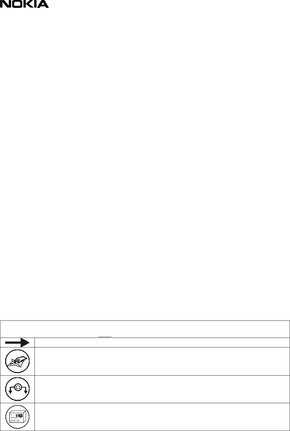
7. DISASSEMBLY INSTRUCTIONS (SEE ALSO VIDEO CLIPS)
Push the Release Button to the left before pulling up
the B-Cover.
Unlock the top guidance to remove the A-Cover.
Unscrew the six T6 screws, using the order shown.
For assembly, the reverse order and a torque of
17Ncm have to be used.
Take the modules from the C-Cover and unplug the
display connector by pulling the modules apart
carefully.
The Speaker is attached with double-sided adhesive
Foam Tape. Always use new tape when mounting the
S
p
eaker.
Do not damage the spring contacts, when removing
the Microphone.
Open the snaps with SRT-6 on both sides of the
Display Shield.
The Display Shield is attached with hooks at its
bottom side.
Service Manual 7210/6610 Level 1&2 Copyright 2002 © Nokia Corporation
PAGE 13 (19) Approved 1.0
Nokia Mobile Phones Customer Care E&A SQX 00444-en MWy
Technical Services, Repair Concepts Confidential 25.09.2002
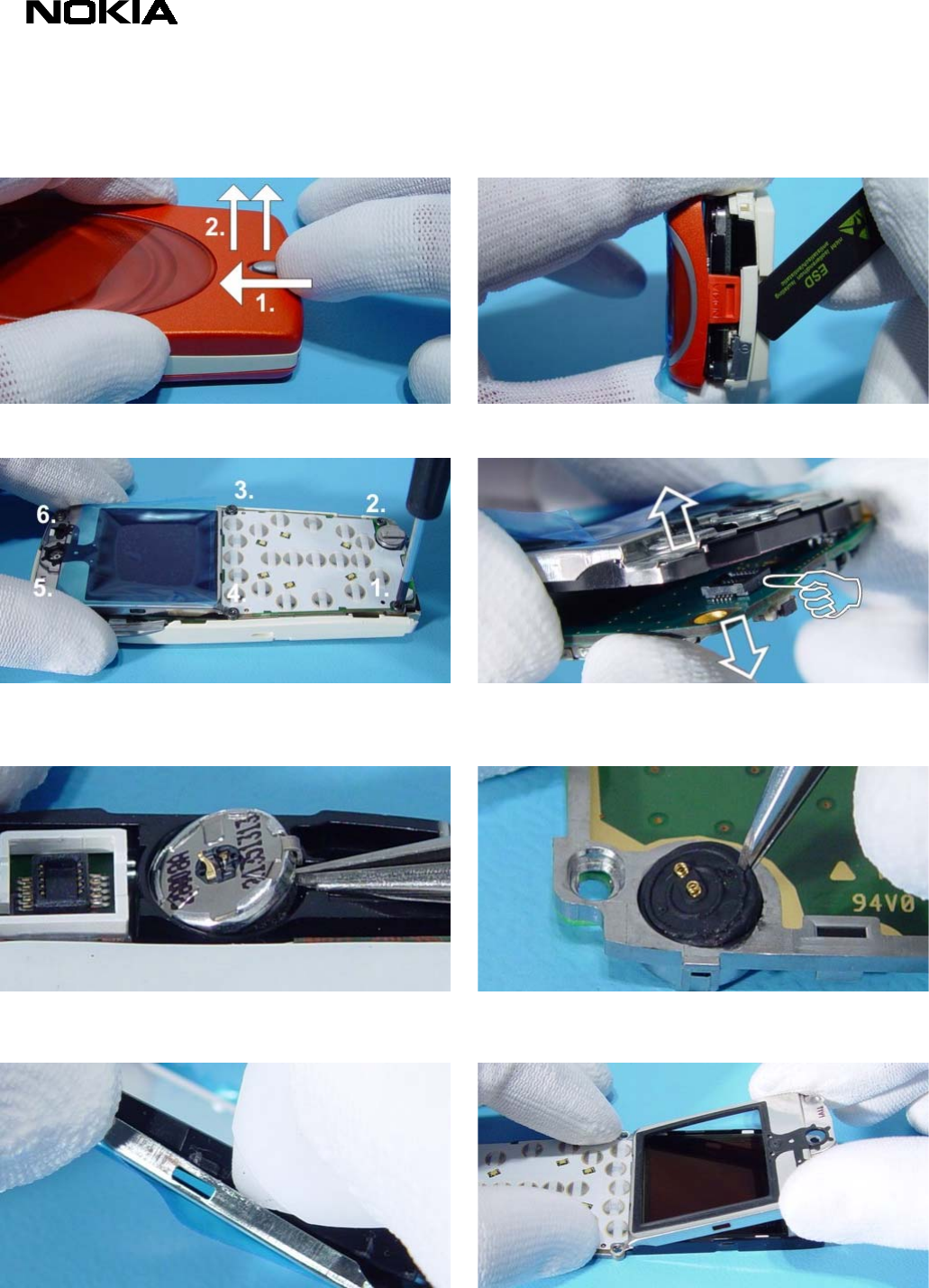
Take a clean cloth and press the LCD from the LCD
Frame.
Bend the frame a bit, shift the UI Board Module to
the right and then pull it up.
To remove the DC Jack, place tweezers between the
spring contacts and under the jack. You’ll need to
use additional force to pull the jack upwards.
Remove the Vibra Motor with the rubber and pull it
from its guidance.
Volume Key and the Infrared Window can be easily
removed with your fingers. The Power Key has to be
unlocked on the lower side first.
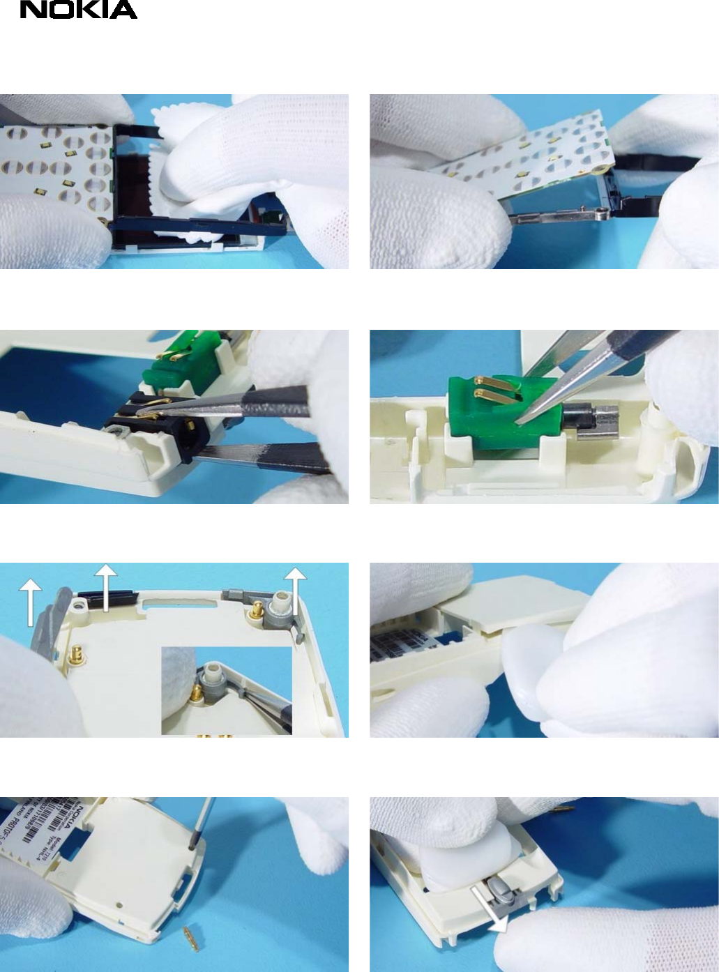
Unlock Antenna on both sides with SRT-6.
Antenna Pogo Pins can be removed by pushing with
Torx driver through the C-Cover.
If there is a need to change the Release Button, also
SRT-6 can be used.
Service Manual 7210/6610 Level 1&2 Copyright 2002 © Nokia Corporation
PAGE 14 (19) Approved 1.0
Nokia Mobile Phones Customer Care E&A SQX 00444-en MWy
Technical Services, Repair Concepts Confidential 25.09.2002
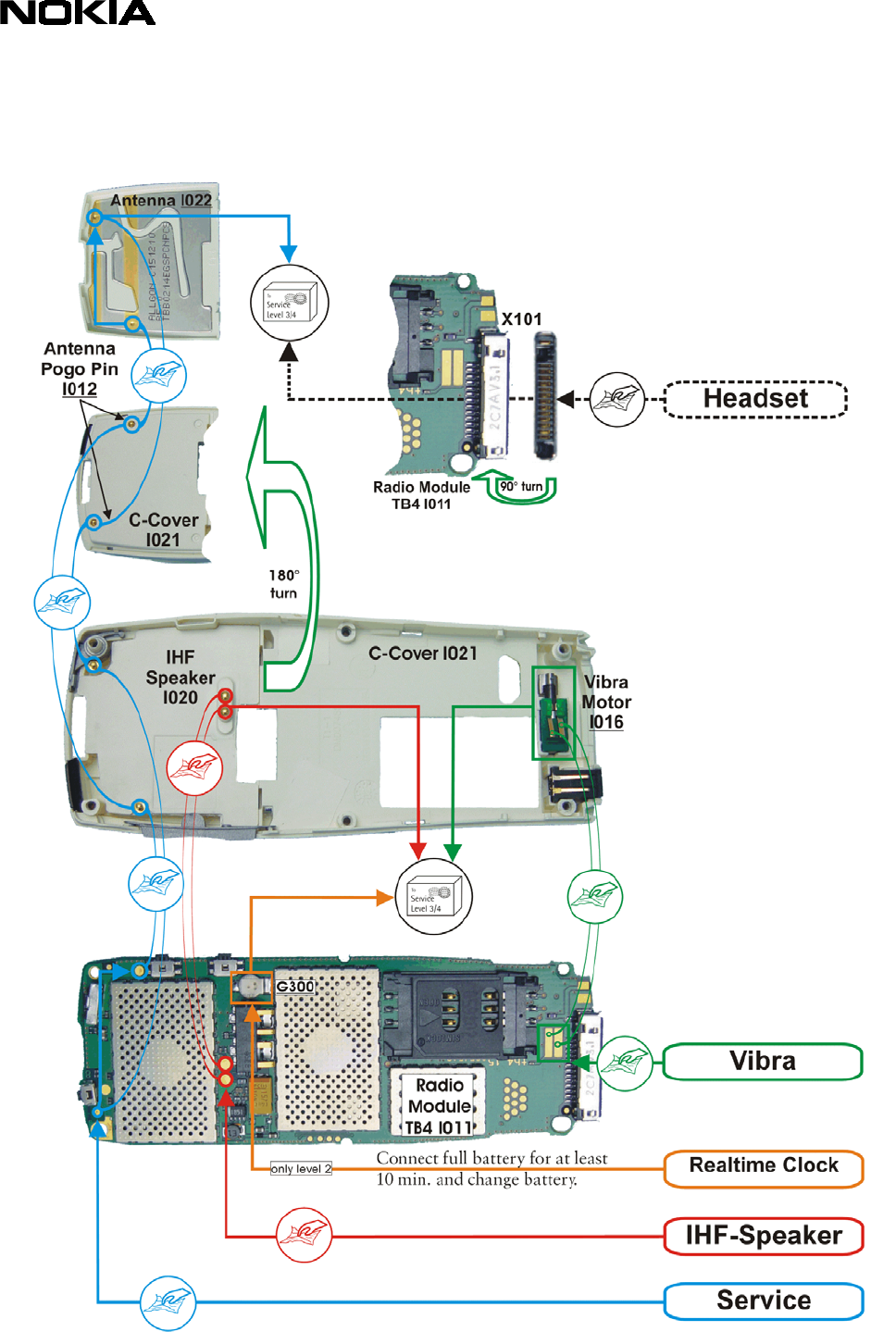
8. QUICK TROUBLE SHOOTER PART1
Service Manual 7210/6610 Level 1&2 Copyright 2002 © Nokia Corporation
PAGE 15 (19) Approved 1.0
Nokia Mobile Phones Customer Care E&A SQX 00444-en MWy
Technical Services, Repair Concepts Confidential 25.09.2002
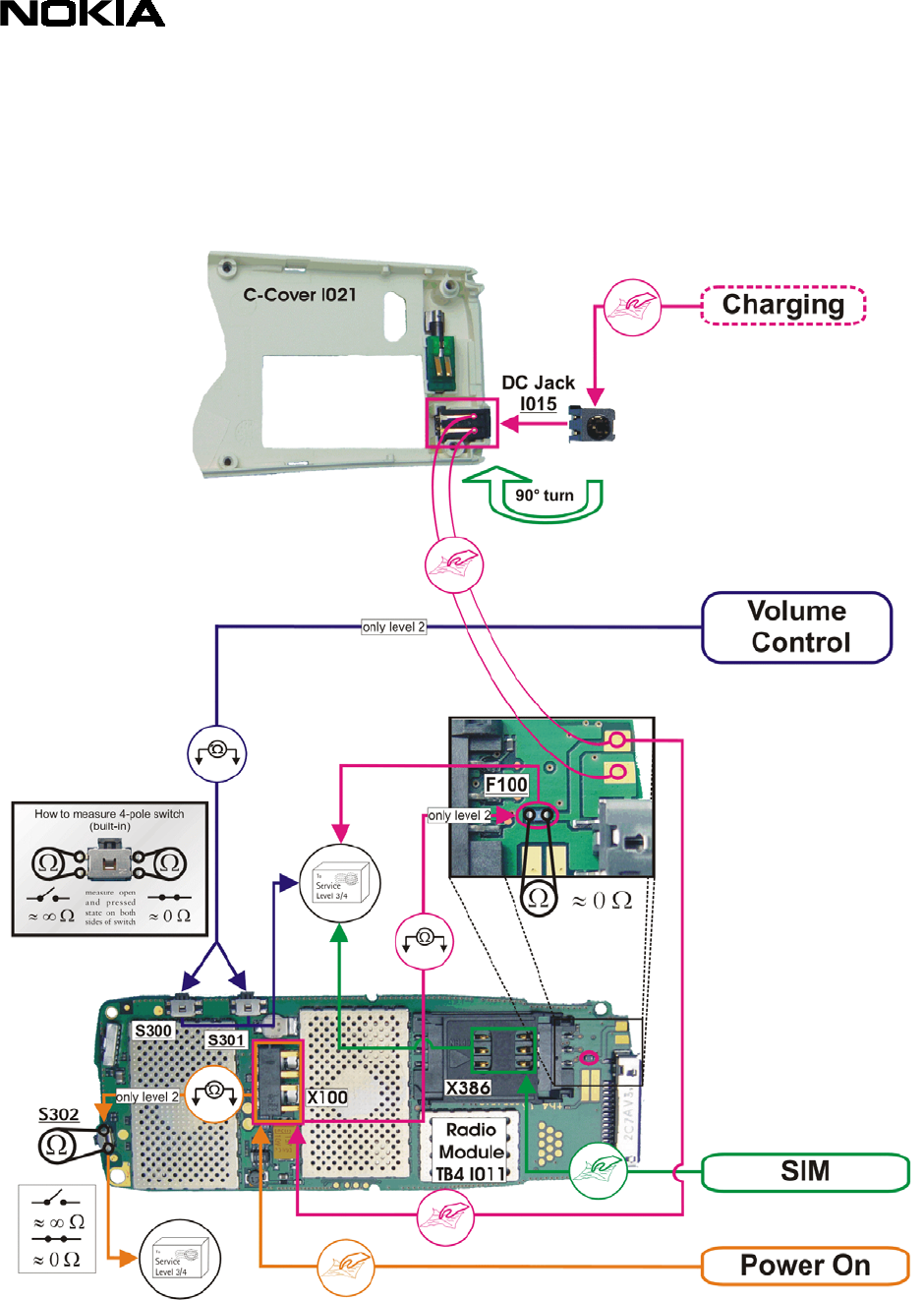
9. QUICK TROUBLE SHOOTER PART2
Service Manual 7210/6610 Level 1&2 Copyright 2002 © Nokia Corporation
PAGE 16 (19) Approved 1.0
Nokia Mobile Phones Customer Care E&A SQX 00444-en MWy
Technical Services, Repair Concepts Confidential 25.09.2002
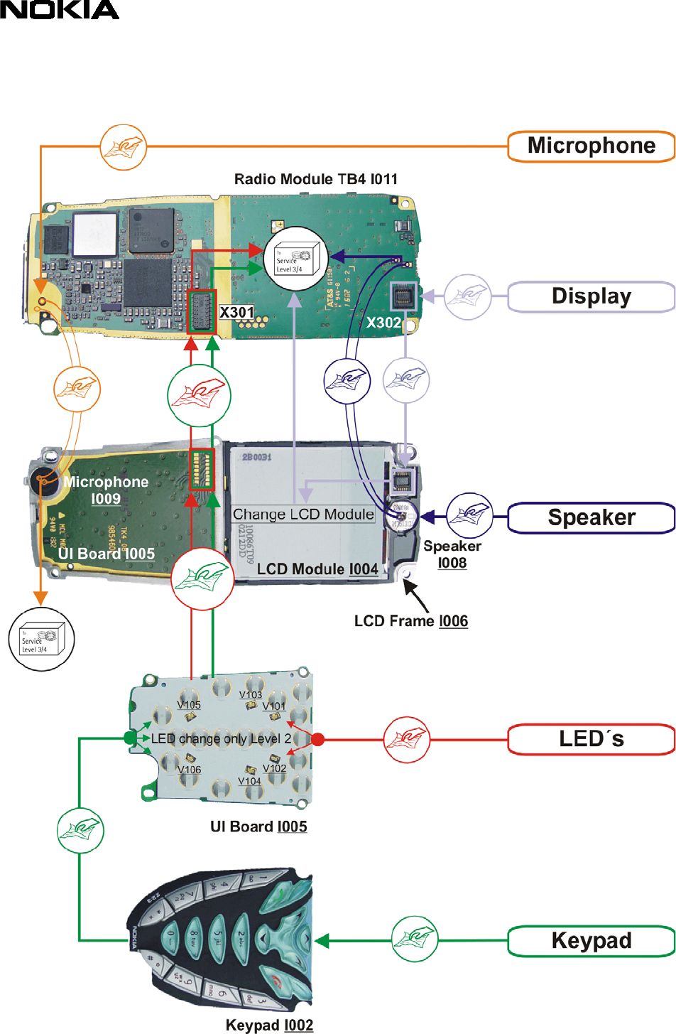
10. QUICK TROUBLE SHOOTER PART3
Service Manual 7210/6610 Level 1&2 Copyright 2002 © Nokia Corporation
PAGE 17 (19) Approved 1.0
Nokia Mobile Phones Customer Care E&A SQX 00444-en MWy
Technical Services, Repair Concepts Confidential 25.09.2002
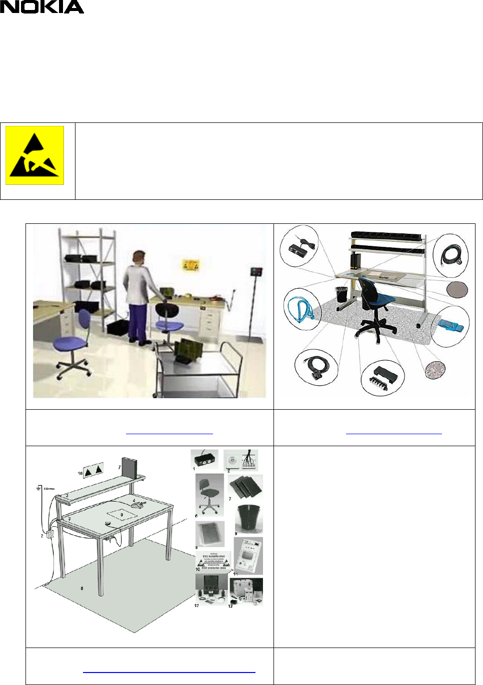
11. ESD PROTECTION REQUIREMENTS
Electrostatic discharge can easily damage the sensitive components of
electronic products. Therefore every Service Partner has to take care of
at least some precautions like ESD restricted area, floor, table, covering,
chair(s), shoes or arm wrist.
example configuration of an epa-area
source: www.armeka.com
example configuration of a workbench
source: www.warmbier.com
example workbench and testers
source: http://www.armekaengineering.com
Service Manual 7210/6610 Level 1&2 Copyright 2002 © Nokia Corporation
PAGE 18 (19) Approved 1.0
Nokia Mobile Phones Customer Care E&A SQX 00444-en MWy
Technical Services, Repair Concepts Confidential 25.09.2002
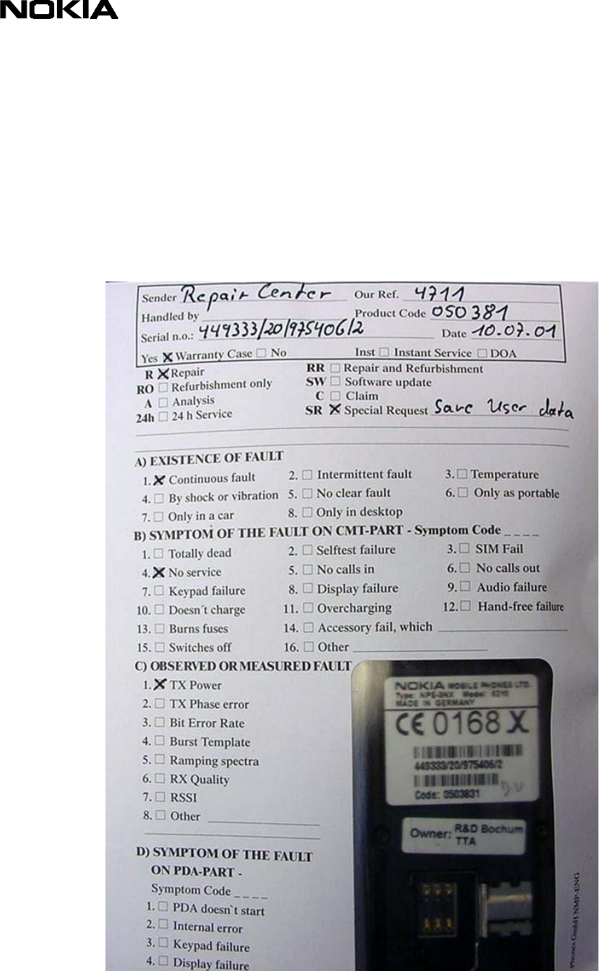
12. SERVICE NOTES
We recommend using Service Notes when shipping phones to other Service Partners. It
prevents the product from scratches, it is ESD-neutral and has the possibility to give
valuable feedback of the fault symptom through a structured form.
Please refer to the document Service Notes for faulty NMP transceiver on Partner Web
Site to get further information.
Service Manual 7210/6610 Level 1&2 Copyright 2002 © Nokia Corporation
PAGE 19 (19) Approved 1.0
Nokia Mobile Phones Customer Care E&A SQX 00444-en MWy
Technical Services, Repair Concepts Confidential 25.09.2002
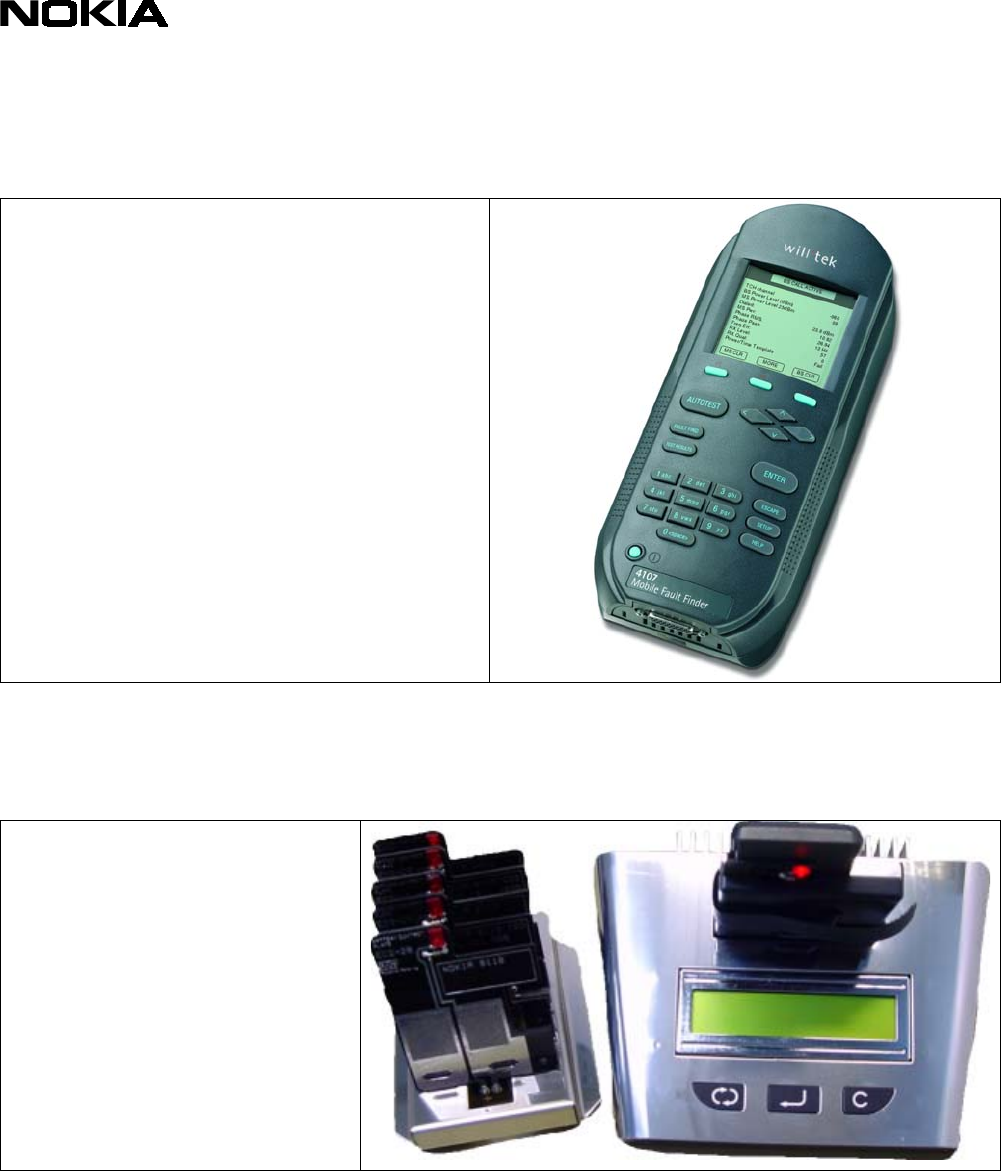
13. GONOGO TESTER
The will’tek GoNoGo Tester has to be
used to carry out the final test after
your service action to guarantee the
functionality of the phone.
Please refer to the actual
information in the Nokia Care
Point Extranet within the Partner
Web Site.
14. BATTERY TESTER
The Astratec battery tester
lets you test the capacity
of Nokia batteries.
Please refer to the actual
information in the Nokia
Care Point Extranet
within the Partner Web
Site.
Service Manual 7210/6610 Level 1&2 Copyright 2002 © Nokia Corporation
